Development of a Predictive Optimal Controller for Thermal Energy Storage Systems
Upload
khangminh22Category
view
1download
0
sustainability
Review
A Comprehensive Review of Thermal Energy Storage
Ioan Sarbu * ID and Calin Sebarchievici
Department of Building Services Engineering, Polytechnic University of Timisoara, Piata Victoriei, No. 2A,300006 Timisoara, Romania; [email protected]* Correspondence: [email protected]; Tel.: +40-256-403-991; Fax: +40-256-403-987
Received: 7 December 2017; Accepted: 10 January 2018; Published: 14 January 2018
Abstract: Thermal energy storage (TES) is a technology that stocks thermal energy by heating orcooling a storage medium so that the stored energy can be used at a later time for heating and coolingapplications and power generation. TES systems are used particularly in buildings and in industrialprocesses. This paper is focused on TES technologies that provide a way of valorizing solar heatand reducing the energy demand of buildings. The principles of several energy storage methodsand calculation of storage capacities are described. Sensible heat storage technologies, includingwater tank, underground, and packed-bed storage methods, are briefly reviewed. Additionally,latent-heat storage systems associated with phase-change materials for use in solar heating/coolingof buildings, solar water heating, heat-pump systems, and concentrating solar power plants as well asthermo-chemical storage are discussed. Finally, cool thermal energy storage is also briefly reviewedand outstanding information on the performance and costs of TES systems are included.
Keywords: storage system; phase-change materials; chemical storage; cold storage; performance
1. Introduction
Recent projections predict that the primary energy consumption will rise by 48% in 2040 [1].On the other hand, the depletion of fossil resources in addition to their negative impact on theenvironment has accelerated the shift toward sustainable energy sources. Renewable energies such assolar radiation, ocean waves, wind, and biogas have been playing a major role in reforming the naturalbalance and providing the needs of the growing population demand [2]. However, due to the climaticvagaries, the means of storing these types of renewable energy has become urgent [3]. This has lead toa need to develop efficient and sustainable methods of storing energy.
Energy storage has become an important part of renewable energy technology systems. Thermalenergy storage (TES) is a technology that stocks thermal energy by heating or cooling a storage mediumso that the stored energy can be used at a later time for heating and cooling applications [4] and powergeneration. TES systems are used particularly in buildings and in industrial processes. Advantages ofusing TES in an energy system include an increase in overall efficiency and better reliability, and itcan lead to better economics, reductions in investment and running costs, and less pollution of theenvironment, i.e., fewer carbon dioxide (CO2) emissions [5]. Solar thermal systems, unlike photovoltaicsystems with striving efficiencies, are industrially mature and utilize a major part of the Sun’s thermalenergy during the day. Yet, it does not have enough (thermal) backup to continue operating duringthe low or no solar radiation hours. TES is becoming particularly important for electricity storage incombination with concentrating solar power (CSP) plants where solar heat can be stored for electricityproduction when sunlight is not available. New materials are selected, characterized, and enhanced intheir thermo-physical properties to serve the purpose of a 24 h operation in an efficient TES system.
In Europe, it has been estimated that around 1.4 million GWh/year can be saved and 400 milliontons of CO2 emissions avoided, in buildings and in industrial sectors by more extensive use of heatand cold storage [6].
Sustainability 2018, 10, 191; doi:10.3390/su10010191 www.mdpi.com/journal/sustainability
Sustainability 2018, 10, 191 2 of 32
Storage density, in terms of the amount of energy per unit of volume or mass, is importantfor optimizing solar ratio (how much solar radiation is useful for the heating/cooling purposes),efficiency of appliances (solar thermal collectors and absorption chillers), and energy consumption forspace heating/coolingroom consumption. Therefore, the possibility of using phase-change materials(PCMs) in solar system applications is worth investigating. PCMs might be able to increase the energydensity of small-sized water storage tanks, reducing solar storage volume for a given solar fraction orincreasing the solar fraction for a given available volume [7].
It is possible to consider thermal storage on the hot and/or cold side of the plant. The formerallows the storage of hot water from the collectors (and from the auxiliary heater) to be supplied tothe generator of the absorption chiller (in cooling mode) or directly to the users (in heating mode).The latter allows the storage of cold water produced by the absorption chiller to be supplied to thecooling terminals inside the building. It is usual to identify three situations as “hot”, “warm”, and“cold” storage based on the different temperature ranges. Typically, a hot tank may work at 80–90 ◦C,a warm tank at 40–50 ◦C, and a cold tank at 7–15 ◦C [8].
While heat storage on the hot side of solar plants are always present because of heating and/ordomestic hot water (DHW) production, cold storage is justified in larger plants. Cold storages are usednot only to gain economic advantages from lower electricity costs (in the case of electric compressionchillers) depending on the time of day but also to lower the cooling power installed and to allow morecontinuous operation of the chiller [9].
The use of thermal storage, initially, could not provide effective backup but helped the system tothermally stabilize. Consequently, thermal storage found use in solar-assisted thermal systems [10].Since then, studying thermal energy storage technologies as well as the usability and effects ofboth sensible and latent heat storage in numerous applications increased, leading to a number ofreviews [11–15]. These reviews focused only on one side (cold or hot) or component of the system orone of its integral mechanism.
For example, Pintaldi et al. [16] reviewed thermal energy storage technologies and controlapproaches for solar cooling system. They mainly focused on types of thermal storages used insolar cooling applications, with emphasis on higher temperatures (>100 ◦C). Tian and Zhao [17]compiled various types of research in solar collectors and thermal energy storages used for solarthermal applications. Joybari et al. [18] compiled a review on PCM for cold storage for the applicationof domestic refrigeration, i.e., evaporator side only. The study performed by Oró et al. [19] also coveredice storage and air conditioning separately.
This paper is focused on the analysis of TES technologies that provides a way of valorizing solarheat and reducing the energy demand of buildings. The principles of several energy storage methodsand calculation of storage capacities are described. Sensible heat storage (SHS) technologies, includingthe use of water, underground, and packed-bed storage methods, are briefly reviewed. Latent-heatstorage (LHS) systems associated with PCMs for use in the solar heating and cooling of buildings, solarwater heating, heat-pump systems, and CSP plants as well as thermo-chemical storage (TCS) are alsodiscussed. Finally, cool thermal energy storage is also briefly reviewed and outstanding informationon the performance and costs of TES systems are included.
2. Classification and Characteristics of Storage Systems
Due to intermittency in availability and constant variation in solar radiation, TES found its placein thermodynamic systems. TES not only reduces the discrepancy between the demand and supply byconserving energy, but also improves the performance and thermal reliability of the system. Therefore,designing efficient and economical TES systems is of high importance. However, few solar thermalplants in the world have employed TES at a large scale. Additionally, the design of TES systems invarious domestic solar applications is currently being investigated [20]. Using a computational fluiddynamic approach is also a vastly used method to save money, where FLUENT software seems to besuccessfully used for different engineering applications [21].
Sustainability 2018, 10, 191 3 of 32
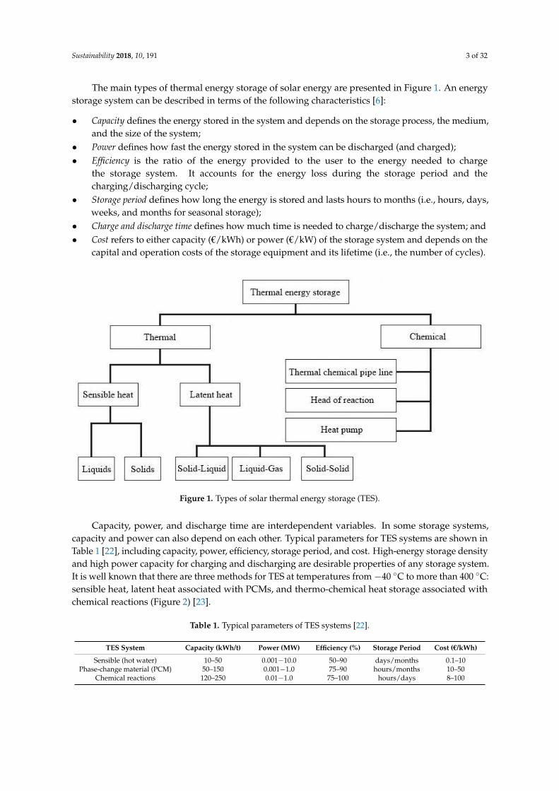
The main types of thermal energy storage of solar energy are presented in Figure 1. An energystorage system can be described in terms of the following characteristics [6]:
• Capacity defines the energy stored in the system and depends on the storage process, the medium,and the size of the system;
• Power defines how fast the energy stored in the system can be discharged (and charged);• Efficiency is the ratio of the energy provided to the user to the energy needed to charge
the storage system. It accounts for the energy loss during the storage period and thecharging/discharging cycle;
• Storage period defines how long the energy is stored and lasts hours to months (i.e., hours, days,weeks, and months for seasonal storage);
• Charge and discharge time defines how much time is needed to charge/discharge the system; and• Cost refers to either capacity (€/kWh) or power (€/kW) of the storage system and depends on the
capital and operation costs of the storage equipment and its lifetime (i.e., the number of cycles).
Sustainability 2018, 10, 191 3 of 32
computational fluid dynamic approach is also a vastly used method to save money, where FLUENT
software seems to be successfully used for different engineering applications [21].
The main types of thermal energy storage of solar energy are presented in Figure 1. An energy
storage system can be described in terms of the following characteristics [6]:
Capacity defines the energy stored in the system and depends on the storage process, the
medium, and the size of the system;
Power defines how fast the energy stored in the system can be discharged (and charged);
Efficiency is the ratio of the energy provided to the user to the energy needed to charge the
storage system. It accounts for the energy loss during the storage period and the
charging/discharging cycle;
Storage period defines how long the energy is stored and lasts hours to months (i.e., hours, days,
weeks, and months for seasonal storage);
Charge and discharge time defines how much time is needed to charge/discharge the system; and
Cost refers to either capacity (€/kWh) or power (€/kW) of the storage system and depends on
the capital and operation costs of the storage equipment and its lifetime (i.e., the number of
cycles).
Figure 1. Types of solar thermal energy storage (TES).
Capacity, power, and discharge time are interdependent variables. In some storage systems,
capacity and power can also depend on each other. Typical parameters for TES systems are shown
in Table 1 [22], including capacity, power, efficiency, storage period, and cost. High-energy storage
density and high power capacity for charging and discharging are desirable properties of any
storage system. It is well known that there are three methods for TES at temperatures from −40 °C
to more than 400 °C: sensible heat, latent heat associated with PCMs, and thermo-chemical heat
storage associated with chemical reactions (Figure 2) [23].
Table 1. Typical parameters of TES systems [22].
TES System Capacity (kWh/t) Power (MW) Efficiency (%) Storage Period Cost (€/kWh)
Sensible (hot water) 10–50 0.00110.0 50–90 days/months 0.1–10
Phase-change
material (PCM) 50–150 0.0011.0 75–90 hours/months 10–50
Chemical reactions 120–250 0.011.0 75–100 hours/days 8–100
Figure 1. Types of solar thermal energy storage (TES).
Capacity, power, and discharge time are interdependent variables. In some storage systems,capacity and power can also depend on each other. Typical parameters for TES systems are shown inTable 1 [22], including capacity, power, efficiency, storage period, and cost. High-energy storage densityand high power capacity for charging and discharging are desirable properties of any storage system.It is well known that there are three methods for TES at temperatures from−40 ◦C to more than 400 ◦C:sensible heat, latent heat associated with PCMs, and thermo-chemical heat storage associated withchemical reactions (Figure 2) [23].
Table 1. Typical parameters of TES systems [22].
TES System Capacity (kWh/t) Power (MW) Efficiency (%) Storage Period Cost (€/kWh)
Sensible (hot water) 10–50 0.001−10.0 50–90 days/months 0.1–10Phase-change material (PCM) 50–150 0.001−1.0 75–90 hours/months 10–50
Chemical reactions 120–250 0.01−1.0 75–100 hours/days 8–100
Sustainability 2018, 10, 191 4 of 32Sustainability 2018, 10, 191 4 of 32
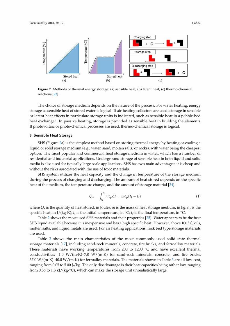
Figure 2. Methods of thermal energy storage: (a) sensible heat; (b) latent heat; (c) thermo-chemical
reactions [23].
The choice of storage medium depends on the nature of the process. For water heating, energy
storage as sensible heat of stored water is logical. If air-heating collectors are used, storage in
sensible or latent heat effects in particulate storage units is indicated, such as sensible heat in a
pebble-bed heat exchanger. In passive heating, storage is provided as sensible heat in building the
elements. If photovoltaic or photo-chemical processes are used, thermo-chemical storage is logical.
3. Sensible Heat Storage
SHS (Figure 2a) is the simplest method based on storing thermal energy by heating or cooling
a liquid or solid storage medium (e.g., water, sand, molten salts, or rocks), with water being the
cheapest option. The most popular and commercial heat storage medium is water, which has a
number of residential and industrial applications. Underground storage of sensible heat in both
liquid and solid media is also used for typically large-scale applications. SHS has two main
advantages: it is cheap and without the risks associated with the use of toxic materials.
SHS system utilizes the heat capacity and the change in temperature of the storage medium
during the process of charging and discharging. The amount of heat stored depends on the specific
heat of the medium, the temperature change, and the amount of storage material [24].
)(d ifpps
f
i
ttmctmcQt
t (1)
where Qs is the quantity of heat stored, in Joules; m is the mass of heat storage medium, in kg; cp is
the specific heat, in J/(kg·K); ti is the initial temperature, in °C; tf is the final temperature, in °C.
Table 2 shows the most used SHS materials and their properties [25]. Water appears to be the
best SHS liquid available because it is inexpensive and has a high specific heat. However, above 100
°C, oils, molten salts, and liquid metals are used. For air heating applications, rock bed type storage
materials are used.
Table 2. List of selected solid–liquid materials for sensible heat storage [25].
Medium Fluid Type Temperature Range (°C) Density (kg/m3) Specific Heat (J/(kg K))
Sand - 20 1555 800
Rock - 20 2560 879
Brick - 20 1600 840
Concrete - 20 2240 880
Granite - 20 2640 820
Aluminium - 20 2707 896
Cast iron - 20 7900 837
Water - 0–100 1000 4190
Calorie HT43 Oil 12–260 867 2200
Engine oil Oil ≤160 888 1880
Ethanol Organic liquid ≤78 790 2400
Propane Organic liquid ≤97 800 2500
Butane Organic liquid ≤118 809 2400
Figure 2. Methods of thermal energy storage: (a) sensible heat; (b) latent heat; (c) thermo-chemicalreactions [23].
The choice of storage medium depends on the nature of the process. For water heating, energystorage as sensible heat of stored water is logical. If air-heating collectors are used, storage in sensibleor latent heat effects in particulate storage units is indicated, such as sensible heat in a pebble-bedheat exchanger. In passive heating, storage is provided as sensible heat in building the elements.If photovoltaic or photo-chemical processes are used, thermo-chemical storage is logical.
3. Sensible Heat Storage
SHS (Figure 2a) is the simplest method based on storing thermal energy by heating or cooling aliquid or solid storage medium (e.g., water, sand, molten salts, or rocks), with water being the cheapestoption. The most popular and commercial heat storage medium is water, which has a number ofresidential and industrial applications. Underground storage of sensible heat in both liquid and solidmedia is also used for typically large-scale applications. SHS has two main advantages: it is cheap andwithout the risks associated with the use of toxic materials.
SHS system utilizes the heat capacity and the change in temperature of the storage mediumduring the process of charging and discharging. The amount of heat stored depends on the specificheat of the medium, the temperature change, and the amount of storage material [24].
Qs =∫ tf
ti
mcpdt = mcp(tf − ti) (1)
where Qs is the quantity of heat stored, in Joules; m is the mass of heat storage medium, in kg; cp is thespecific heat, in J/(kg·K); ti is the initial temperature, in ◦C; tf is the final temperature, in ◦C.
Table 2 shows the most used SHS materials and their properties [25]. Water appears to be the bestSHS liquid available because it is inexpensive and has a high specific heat. However, above 100 ◦C, oils,molten salts, and liquid metals are used. For air heating applications, rock bed type storage materialsare used.
Table 3 shows the main characteristics of the most commonly used solid-state thermalstorage materials [17], including sand-rock minerals, concrete, fire bricks, and ferroalloy materials.These materials have working temperatures from 200 to 1200 ◦C and have excellent thermalconductivities: 1.0 W/(m·K)–7.0 W/(m·K) for sand-rock minerals, concrete, and fire bricks;37.0 W/(m·K)–40.0 W/(m·K) for ferroalloy materials. The materials shown in Table 3 are all low-cost,ranging from 0.05 to 5.00 $/kg. The only disadvantage is their heat capacities being rather low, rangingfrom 0.56 to 1.3 kJ/(kg·◦C), which can make the storage unit unrealistically large.
Sustainability 2018, 10, 191 5 of 32
Table 2. List of selected solid–liquid materials for sensible heat storage [25].
Medium Fluid Type Temperature Range (◦C) Density (kg/m3) Specific Heat (J/(kg·K))
Sand - 20 1555 800Rock - 20 2560 879Brick - 20 1600 840
Concrete - 20 2240 880Granite - 20 2640 820
Aluminium - 20 2707 896Cast iron - 20 7900 837
Water - 0–100 1000 4190Calorie HT43 Oil 12–260 867 2200
Engine oil Oil ≤160 888 1880Ethanol Organic liquid ≤78 790 2400Propane Organic liquid ≤97 800 2500Butane Organic liquid ≤118 809 2400
Isotunaol Organic liquid ≤100 808 3000Isopentanol Organic liquid ≤148 831 2200
Octane Organic liquid ≤126 704 2400
Table 3. Solid-state sensible heat storage materials [17].
Storage Materials WorkingTemperature (◦C) Density (kg/m3)
Thermal Conductivity(W/(m·K))
Specific Heat(kJ/(kg·◦C))
Sand-rock minerals 200–300 1700 1.0 1.30Reinforced concrete 200–400 2200 1.5 0.85
Cast iron 200–400 7200 37.0 0.56NaCl 200–500 2160 7.0 0.85
Cast steel 200–700 7800 40.0 0.60Silica fire bricks 200–700 1820 1.5 1.00
Magnesia fire bricks 200–1200 3000 5.0 1.15
3.1. Water Tank Storage
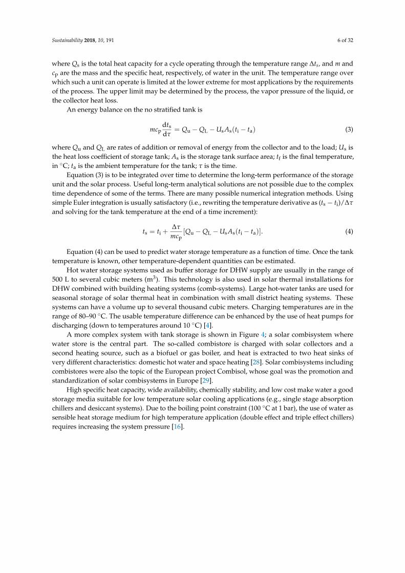
The most common material used in a sensible heat storage system is water. The use of hot-watertanks is a well-known technology for thermal energy storage [26]. Hot-water tanks serve the purposeof energy saving in water heating systems via solar energy and via co-generation (i.e., heat andpower) energy supply systems. State-of the-art projects [27] have shown that water tank storage is acost-effective storage option and that its efficiency can be further improved by ensuring optimal waterstratification in the tank and highly effective thermal insulation. Today’s research and development(R&D) activities focus, for example, on evacuated super-insulation with a thermal conductivity of0.01 W/(m·K) at 90 ◦C and 0.1 mbar and on an optimized system integration. A typical system inwhich a water tank is used is shown in Figure 3.
Sustainability 2018, 10, 191 5 of 32
Isotunaol Organic liquid ≤100 808 3000
Isopentanol Organic liquid ≤148 831 2200
Octane Organic liquid ≤126 704 2400
Table 3 shows the main characteristics of the most commonly used solid-state thermal storage
materials [17], including sand-rock minerals, concrete, fire bricks, and ferroalloy materials. These
materials have working temperatures from 200 to 1200 °C and have excellent thermal
conductivities: 1.0 W/(m·K)–7.0 W/(m·K) for sand-rock minerals, concrete, and fire bricks; 37.0
W/(m·K)–40.0 W/(m·K) for ferroalloy materials. The materials shown in Table 3 are all low-cost,
ranging from 0.05 to 5.00 $/kg. The only disadvantage is their heat capacities being rather low,
ranging from 0.56 to 1.3 kJ/(kg°C), which can make the storage unit unrealistically large.
Table 3. Solid-state sensible heat storage materials [17].
Storage Materials Working Temperature (°C) Density (kg/m3) Thermal Conductivity
(W/(m K))
Specific Heat
(kJ/(kg°C))
Sand-rock minerals 200–300 1700 1.0 1.30
Reinforced concrete 200–400 2200 1.5 0.85
Cast iron 200–400 7200 37.0 0.56
NaCl 200–500 2160 7.0 0.85
Cast steel 200–700 7800 40.0 0.60
Silica fire bricks 200–700 1820 1.5 1.00
Magnesia fire bricks 200–1200 3000 5.0 1.15
3.1. Water Tank Storage
The most common material used in a sensible heat storage system is water. The use of
hot-water tanks is a well-known technology for thermal energy storage [26]. Hot-water tanks serve
the purpose of energy saving in water heating systems via solar energy and via co-generation (i.e.,
heat and power) energy supply systems. State-of the-art projects [27] have shown that water tank
storage is a cost-effective storage option and that its efficiency can be further improved by ensuring
optimal water stratification in the tank and highly effective thermal insulation. Today’s research
and development (R&D) activities focus, for example, on evacuated super-insulation with a thermal
conductivity of 0.01 W/(m·K) at 90 °C and 0.1 mbar and on an optimized system integration. A
typical system in which a water tank is used is shown in Figure 3.
Figure 3. A typical system using water tank storage [4].
The energy storage capacity of a water (or other liquid) storage unit at uniform temperature
(i.e., fully mixed or no stratified) operating over a finite temperature difference is given by Equation
(1) redefined as
sps tmcQ (2)
where Qs is the total heat capacity for a cycle operating through the temperature range ∆ts, and m
and cp are the mass and the specific heat, respectively, of water in the unit. The temperature range
over which such a unit can operate is limited at the lower extreme for most applications by the
requirements of the process. The upper limit may be determined by the process, the vapor pressure
of the liquid, or the collector heat loss.
Figure 3. A typical system using water tank storage [4].
The energy storage capacity of a water (or other liquid) storage unit at uniform temperature (i.e.,fully mixed or no stratified) operating over a finite temperature difference is given by Equation (1)redefined as
Qs = mcp∆ts (2)
Sustainability 2018, 10, 191 6 of 32
where Qs is the total heat capacity for a cycle operating through the temperature range ∆ts, and m andcp are the mass and the specific heat, respectively, of water in the unit. The temperature range overwhich such a unit can operate is limited at the lower extreme for most applications by the requirementsof the process. The upper limit may be determined by the process, the vapor pressure of the liquid, orthe collector heat loss.
An energy balance on the no stratified tank is
mcpdts
dτ= Qu −QL −Us As(ti − ta) (3)
where Qu and QL are rates of addition or removal of energy from the collector and to the load; Us isthe heat loss coefficient of storage tank; As is the storage tank surface area; tf is the final temperature,in ◦C; ta is the ambient temperature for the tank; τ is the time.
Equation (3) is to be integrated over time to determine the long-term performance of the storageunit and the solar process. Useful long-term analytical solutions are not possible due to the complextime dependence of some of the terms. There are many possible numerical integration methods. Usingsimple Euler integration is usually satisfactory (i.e., rewriting the temperature derivative as (ts − ti)/∆τ
and solving for the tank temperature at the end of a time increment):
ts = ti +∆τ
mcp[Qu −QL −Us As(ti − ta)]. (4)
Equation (4) can be used to predict water storage temperature as a function of time. Once the tanktemperature is known, other temperature-dependent quantities can be estimated.
Hot water storage systems used as buffer storage for DHW supply are usually in the range of500 L to several cubic meters (m3). This technology is also used in solar thermal installations forDHW combined with building heating systems (comb-systems). Large hot-water tanks are used forseasonal storage of solar thermal heat in combination with small district heating systems. Thesesystems can have a volume up to several thousand cubic meters. Charging temperatures are in therange of 80–90 ◦C. The usable temperature difference can be enhanced by the use of heat pumps fordischarging (down to temperatures around 10 ◦C) [4].
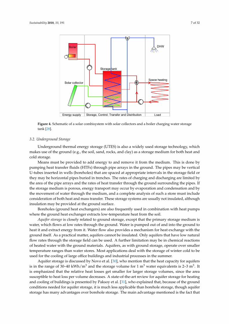
A more complex system with tank storage is shown in Figure 4; a solar combisystem wherewater store is the central part. The so-called combistore is charged with solar collectors and asecond heating source, such as a biofuel or gas boiler, and heat is extracted to two heat sinks ofvery different characteristics: domestic hot water and space heating [28]. Solar combisystems includingcombistores were also the topic of the European project Combisol, whose goal was the promotion andstandardization of solar combisystems in Europe [29].
High specific heat capacity, wide availability, chemically stability, and low cost make water a goodstorage media suitable for low temperature solar cooling applications (e.g., single stage absorptionchillers and desiccant systems). Due to the boiling point constraint (100 ◦C at 1 bar), the use of water assensible heat storage medium for high temperature application (double effect and triple effect chillers)requires increasing the system pressure [16].
Sustainability 2018, 10, 191 7 of 32
Sustainability 2018, 10, 191 6 of 32
An energy balance on the no stratified tank is
)(d
daissLu
sp ttAUQQ
tmc
(3)
where Qu and QL are rates of addition or removal of energy from the collector and to the load; Us is
the heat loss coefficient of storage tank; As is the storage tank surface area; tf is the final
temperature, in °C; ta is the ambient temperature for the tank; τ is the time.
Equation (3) is to be integrated over time to determine the long-term performance of the
storage unit and the solar process. Useful long-term analytical solutions are not possible due to the
complex time dependence of some of the terms. There are many possible numerical integration
methods. Using simple Euler integration is usually satisfactory (i.e., rewriting the temperature
derivative as (ts − ti)/∆τ and solving for the tank temperature at the end of a time increment):
)( aissLu
p
is ttAUQQmc
tt
.
(4)
Equation (4) can be used to predict water storage temperature as a function of time. Once the
tank temperature is known, other temperature-dependent quantities can be estimated.
Hot water storage systems used as buffer storage for DHW supply are usually in the range of
500 L to several cubic meters (m3). This technology is also used in solar thermal installations for
DHW combined with building heating systems (comb-systems). Large hot-water tanks are used for
seasonal storage of solar thermal heat in combination with small district heating systems. These
systems can have a volume up to several thousand cubic meters. Charging temperatures are in the
range of 80–90 °C. The usable temperature difference can be enhanced by the use of heat pumps for
discharging (down to temperatures around 10 °C) [4].
A more complex system with tank storage is shown in Figure 4; a solar combisystem where
water store is the central part. The so-called combistore is charged with solar collectors and a
second heating source, such as a biofuel or gas boiler, and heat is extracted to two heat sinks of very
different characteristics: domestic hot water and space heating [28]. Solar combisystems including
combistores were also the topic of the European project Combisol, whose goal was the promotion
and standardization of solar combisystems in Europe [29].
Figure 4. Schematic of a solar combisystem with solar collectors and a boiler charging water storage
tank [28]. Figure 4. Schematic of a solar combisystem with solar collectors and a boiler charging water storagetank [28].
3.2. Underground Storage
Underground thermal energy storage (UTES) is also a widely used storage technology, whichmakes use of the ground (e.g., the soil, sand, rocks, and clay) as a storage medium for both heat andcold storage.
Means must be provided to add energy to and remove it from the medium. This is done bypumping heat transfer fluids (HTFs) through pipe arrays in the ground. The pipes may be verticalU-tubes inserted in wells (boreholes) that are spaced at appropriate intervals in the storage field orthey may be horizontal pipes buried in trenches. The rates of charging and discharging are limited bythe area of the pipe arrays and the rates of heat transfer through the ground surrounding the pipes. Ifthe storage medium is porous, energy transport may occur by evaporation and condensation and bythe movement of water through the medium, and a complete analysis of such a store must includeconsideration of both heat and mass transfer. These storage systems are usually not insulated, althoughinsulation may be provided at the ground surface.
Boreholes (ground heat exchangers) are also frequently used in combination with heat pumpswhere the ground heat exchanger extracts low-temperature heat from the soil.
Aquifer storage is closely related to ground storage, except that the primary storage medium iswater, which flows at low rates through the ground. Water is pumped out of and into the ground toheat it and extract energy from it. Water flow also provides a mechanism for heat exchange with theground itself. As a practical matter, aquifers cannot be insulated. Only aquifers that have low naturalflow rates through the storage field can be used. A further limitation may be in chemical reactionsof heated water with the ground materials. Aquifers, as with ground storage, operate over smallertemperature ranges than water stores. Most applications deal with the storage of winter cold to beused for the cooling of large office buildings and industrial processes in the summer.
Aquifer storage is discussed by Novo et al. [30], who mention that the heat capacity for aquifersis in the range of 30–40 kWh/m3 and the storage volume for 1 m3 water equivalents is 2–3 m3. Itis emphasized that the relative heat losses get smaller for larger storage volumes, since the areasusceptible to heat loss per volume decreases. A state-of-the-art review for aquifer storage for heatingand cooling of buildings is presented by Paksoy et al. [31], who explained that, because of the groundconditions needed for aquifer storage, it is much less applicable than borehole storage, though aquiferstorage has many advantages over borehole storage. The main advantage mentioned is the fact that

Sustainability 2018, 10, 191 8 of 32
it is possible to achieve much higher power rates from an aquifer since water can be pumped at ahigh rate.
Cavern storage and pit storage are based on large underground water reservoirs created in thesubsoil to serve as TES systems. Caverns are the same in their principles of operation as the tanksdiscussed in the previous section. Energy is added to or removed from the store by pumping water intoor out of the storage unit. The major difference will be in the mechanisms for heat loss and the possiblethermal coupling with the ground. These storage options are technically feasible, but applicationsare limited because of the high investment costs. A German central solar heating plant with seasonalstorage is described by Bauer et al. [32], who also discuss the heat losses from certain installations.For example, for seasonal water storage with a volume of 12,000 m3 in Friedrichshafen, the yearlyheat losses from the store were between 322 and 482 MWh, yielding a storage utilization factor ofaround 60%. The solar fraction for this system was lower than expected (between 21 and 33% insteadof a projected 43%), and the reasons given are a higher heat demand from the buildings and higherreturn temperatures to the store. For a seasonal borehole storage evaluated by Heier et al. [33], theborehole storage itself is shown to have a yearly heat loss of approximately 50% of the solar energythat is charged into the store.
For high-temperature (i.e., above 100 ◦C) SHS, the technology of choice is based on the use ofliquids (e.g., oil or molten salts, the latter for temperatures up to 550 ◦C). For very high temperatures,solid materials (e.g., ceramics and concrete) are also taken into consideration. However, most of suchhigh-temperature-sensible TES options are still under development or demonstration.
3.3. Packed-Bed Storage
A packed-bed (pebble-bed) storage unit uses the heat capacity of a bed of loosely packedparticulate material to store energy. A fluid, usually air, is circulated through the bed to add orremove energy. A variety of solids may be used, rock and pebble being the most widely used materials.
A pebble-bed storage unit is shown in Figure 5. In operation, flow is maintained through the bedin one direction during addition of heat (usually downward) and in the opposite direction duringremoval of heat. Note that heat cannot be added and removed at the same time; this is in contrast towater storage systems, where simultaneous addition to and removal from storage is possible.
Sustainability 2018, 10, 191 8 of 32
For high-temperature (i.e., above 100 °C) SHS, the technology of choice is based on the use of
liquids (e.g., oil or molten salts, the latter for temperatures up to 550 °C). For very high
temperatures, solid materials (e.g., ceramics and concrete) are also taken into consideration.
However, most of such high-temperature-sensible TES options are still under development or
demonstration.
3.3. Packed-Bed Storage
A packed-bed (pebble-bed) storage unit uses the heat capacity of a bed of loosely packed
particulate material to store energy. A fluid, usually air, is circulated through the bed to add or
remove energy. A variety of solids may be used, rock and pebble being the most widely used
materials.
A pebble-bed storage unit is shown in Figure 5. In operation, flow is maintained through the
bed in one direction during addition of heat (usually downward) and in the opposite direction
during removal of heat. Note that heat cannot be added and removed at the same time; this is in
contrast to water storage systems, where simultaneous addition to and removal from storage is
possible.
Figure 5. Pebble-bed storage system [4].
A major advantage of a packed-bed storage unit is its high degree of stratification. The pebbles
near the entrance are heated, but the temperature of the pebbles near the exit remains unchanged
and the exit-air temperature remains very close to the initial bed temperature. As time progresses a
temperature front passes through the bed. When the bed is fully charged, its temperature is
uniform.
A packed bed in a solar heating system does not normally operate with constant inlet
temperature. During the day, the variable solar radiation, the ambient temperature, the collector
inlet temperature, load requirements, and other time-dependent conditions result in a variable
collector outlet temperature.
Many studies on the heating and cooling of packed beds have been published. The first
analytical study was by Schumann [34], and the basic assumptions leading to this model are a
one-dimensional plug flow, no axial conduction or dispersion, constant properties, no mass
transfer, no heat loss to the environment, and no temperature gradients within the solid particles.
The differential equations for the fluid and bed temperatures (tf, tb) are as follows:
)(ερ fbvffp,ff
fp,f ttkx
t
A
cmtc
(5)
)()ε1(ρ bfvb
bp,b ttkt
c
(6)
Figure 5. Pebble-bed storage system [4].
A major advantage of a packed-bed storage unit is its high degree of stratification. The pebblesnear the entrance are heated, but the temperature of the pebbles near the exit remains unchangedand the exit-air temperature remains very close to the initial bed temperature. As time progresses atemperature front passes through the bed. When the bed is fully charged, its temperature is uniform.
A packed bed in a solar heating system does not normally operate with constant inlettemperature. During the day, the variable solar radiation, the ambient temperature, the collector inlet
Sustainability 2018, 10, 191 9 of 32
temperature, load requirements, and other time-dependent conditions result in a variable collectoroutlet temperature.
Many studies on the heating and cooling of packed beds have been published. The first analyticalstudy was by Schumann [34], and the basic assumptions leading to this model are a one-dimensionalplug flow, no axial conduction or dispersion, constant properties, no mass transfer, no heat loss to theenvironment, and no temperature gradients within the solid particles. The differential equations forthe fluid and bed temperatures (tf, tb) are as follows:
ρfcp,fε∂tf∂τ
= −mfcp,f
A∂tf∂x
+ kv(tb − tf) (5)
ρbcp,b(1− ε)∂tb∂τ
= kv(tf − tb) (6)
where ρf is the fluid density; cp,f is the specific heat of fluid; ε is the bed void fraction; mf is thefluid mass; A is the bed cross-sectional area; kv is the volumetric (per unit bed volume) heat transfercoefficient between the bed and the fluid; τ is the time.
For an air-based system, the first term on the left-hand side of Equation (5) can be neglected andthe equations can be written as follows [35]:
∂tf∂(x/L)
= NTU(tb − tf) (7)
∂tb∂Θ
= NTU(tf − tb) (8)
NTU =kv ALmfcp,f
(9)
and the dimensionless time isΘ =
τmfcp,f
ρbcp,b(1− ε)AL(10)
where A is the bed cross-sectional area; L is the bed length; NTU is the effectiveness.Analytical solutions to these equations exist for a step change in inlet conditions and for cyclic
operation. For the long-term study of solar energy systems, these analytical solutions are not useful,and numerical techniques such as the finite-difference method must be employed.
Nems et al. [36] present the results of a study into a packed-bed filled with ceramic bricks.The designed storage installation is supposed to become part of a heating system installed in asingle-family house and eventually to be integrated with a concentrated solar collector adapted toclimate conditions in Poland. The system’s working medium is air. The investigated temperatureranges and air volume flow rates in the ceramic bed were dictated by the planned integration with asolar air heater. The analysis of the obtained characteristics allowed for the conclusion that the processof heat storage in ceramic brick has high efficiency, which, during the experiment, was in the range of72–93% for an airflow rate of 0.0050 m3/s and 74–96% for an airflow rate of 0.0068 m3/s. The choiceof ceramic bricks as the filling material was dictated by several reasons. Structural stability can beprovided more easily to a large bed filled with bricks than to a bed filled with, e.g., crushed stoneor pebbles. Brick is also an easily available material and has good thermal properties. Additionally,brick is resistant to high temperatures and tolerates a high number of charge/discharge cycles. Brickdoes not emit any harmful gases in high temperatures, which is important, as the storage unit is to belocated inside a residential house.
As demonstrated in [36], a system in which heat is stored in a sensible heat storage material, suchas ceramic brick, should be provided with a means to control airflow rate in order to maximize theeffectiveness of heat storage process, if the heat comes from a source of variable intensity, such as aconcentrated solar air collector.
Sustainability 2018, 10, 191 10 of 32
4. Latent-Heat or Phase-Change Storage
LHS materials are known as PCMs due to their property of releasing or absorbing energy with achange in physical state. The energy storage density increases and hence the volume is reduced, in thecase of LHS (Figure 2b). The heat is mainly stored in the phase-change process (at a quite constanttemperature) and it is directly connected to the latent heat of the substance. The use of an LHS systemusing PCMs is an effective way of storing thermal energy and has the advantages of high-energystorage density and the isothermal nature of the storage process.
The main advantage of using LHS over SHS is their capacity of storing heat at almost similartemperature range. Initially, these materials act like SHS materials in that the temperature rises linearlywith the system enthalpy; however, later, heat is absorbed or release at almost constant temperaturewith a change in physical state.
LHS is based on the heat absorption or release when a storage material undergoes a phase changefrom solid to liquid or liquid to gas or vice versa. The storage capacity Qs, in J, of the LHS system witha PCM medium [17] is given by
Qs =∫ tm
ti
mcpdt + m f ∆q +∫ tf
tmmcpdt (11)
Qs = m[cps(tm − ti) + f ∆q + cpl(tf − tm)
](12)
where tm is the melting temperature, in ◦C; m is the mass of PCM medium, in kg; cps is the averagespecific heat of the solid phase between ti and tm, in kJ/(kg·K); cpl is the average specific heat of theliquid phase between tm and tf, in J/(kg·K); f is the melt fraction; ∆q is the latent heat of fusion, inJ/kg. For example, Glauber’s salt (Na2SO4·10H2O) has cps ≈ 1950 J/(kg·◦C), cpl ≈ 3550 J/(kg·◦C), and∆q = 2.43 × 10⁵ J/kg at 34 ◦C.
The measurement techniques presently used for latent heat of fusion and melting temperatureof PCMs are (1) differential thermal analysis (DTA) and (2) differential scanning calorimeter(DSC) [17]. In DSC and DTA techniques, sample and reference materials are heated at a constantrate. The temperature difference between them is proportional to the difference in heat flow betweenthe two materials and the record is the DSC curve. The recommended reference material is alumina(Al2O3). Latent heat of fusion is calculated using the area under the peak, and the melting temperatureis estimated by the tangent at the point of greatest slope on the face portion of the peak.
Morrison and Abdel-Khalik [37] developed a model applicable to PCMs in small containers,where the length in the flow direction is L, the cross-sectional area of the material is A, and the wettedperimeter is P. The heat transfer fluid passes through the storage unit in the x direction at the massflow rate m and with inlet temperature tf,i.
The model is based on three assumptions: (1) during flow, axial conduction in the fluid isnegligible; (2) the Biot number is low enough that temperature gradients normal to the flow can beneglected; and (3) heat losses from the bed are negligible.
An energy balance on the material gives
∂u∂τ
=λs
ρs
∂2ts
∂x2 +UPρs A
(tf − ts) (13)
where u, ts, λs, and ρs are the specific internal energy, temperature, thermal conductivity, and densityof the PCM; tf and U are the circulating fluid temperature and overall heat transfer coefficient betweenthe fluid and PCM; τ is the time.
An energy balance on the fluid is
∂tf∂τ
+mρf Af
∂tf∂x
=UP
ρf Afcp,f(ts − tf) (14)
Sustainability 2018, 10, 191 11 of 32
where ρf, Af, and cp,f are the density, flow area, and specific heat of the fluid.The equation and boundary conditions for PCM storage can be simplified for particular cases.
It has been shown that axial conduction during flow is negligible, and if the fluid capacitance is small,Equations (13) and (14) become [35]
∂u∂Θ
= NTU(ts − tf) (15)
∂tf∂(x/L)
= NTU(tf − ts) (16)
where ratio Θ = τmcp,f/ρsAL and effectiveness NTU = UPL/(mcp,f).As depicted in Figure 1, the phase change process takes place in different modes: solid–solid,
liquid–gas, and solid–liquid. In the first case, heat is stored by transition between different kindsof crystallization forms. For liquid–gas systems, latent heat is very high, but there are problems instorage control due to the high volume variations during phase change. The most widespread are thesolid–liquid PCMs, which have a limited volume variation during latent heat exchange (generallyless than 10%) and a fairly high melting latent heat. Melting processes involve energy densities of100 kWh/m3 (e.g., ice) compared to a typical 25 kWh/m3 for SHS options. PCMs can be used for bothshort-term (daily) and long-term (seasonal) energy storage, using a variety of techniques and materials.Possible applications of PCMs are as follows:
− implementation in gypsum board, plaster, concrete, or other wall covering material being partof the building structure to enhance the thermal energy storage capacity, with main utilizationin peak-load shifting (and shaving) and solar energy [38] (in this application, typical operatingtemperature is 22–25 ◦C, but it can vary as a function of climate and heating/cooling loads);
− cold storage for cooling plants (operating temperature 7–15 ◦C) [26];− warm storage for heating plants (40–50 ◦C) [26];− hot storage for solar cooling and heating (80–90 ◦C) [26].
Any latent heat energy storage system therefore possesses at least following three components:
1. a suitable PCM with its melting point in the desired temperature range,2. a suitable heat exchange surface, and3. a suitable container compatible with the PCM.
4.1. Characteristics Proprieties of PCMs
PCMs have been used in thermal applications for a few decades. PCMs have
− thermo-physical properties (latent heat of transition and thermal conductivity should be high,and density and volume variations during phase-transition should be, respectively, high and lowin order to minimize storage volume),
− kinetic and chemical properties (super-cooling should be limited to a few degrees, and materialsshould have long-term chemical stability, compatibility with materials of construction, no toxicity,and no fire hazard), and
− economic advantages (low cost and large-scale availability of the PCMs are also very important).
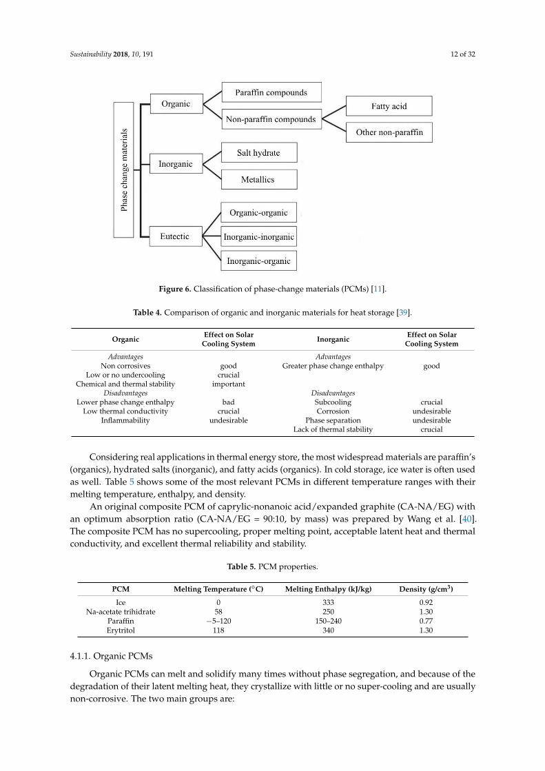
LHS materials are broadly classified based on their physical transformation for heat absorbingand desorbing capabilities. As seen from Figure 6, wide classifications of solid–liquid PCMs, whichare further classified into organic, inorganic, and eutectic materials, are presented. PCMs are classifiedas different groups depending on the material nature (paraffin, fatty acids, salt hydrates, etc.). A fewadvantages and disadvantages of organic and inorganic PCMs and their influence on solar coolingapplication are listed in Table 4 [39].
Sustainability 2018, 10, 191 12 of 32Sustainability 2018, 10, 191 12 of 32
Figure 6. Classification of phase-change materials (PCMs) [11].
Table 4. Comparison of organic and inorganic materials for heat storage [39].
Organic Effect on Solar Cooling
System Inorganic
Effect on Solar Cooling
System
Advantages Advantages
Non corrosives good Greater phase change
enthalpy good
Low or no undercooling crucial
Chemical and thermal
stability important
Disadvantages Disadvantages
Lower phase change
enthalpy bad Subcooling crucial
Low thermal conductivity crucial Corrosion undesirable
Inflammability undesirable Phase separation undesirable
Lack of thermal stability crucial
Considering real applications in thermal energy store, the most widespread materials are
paraffin’s (organics), hydrated salts (inorganic), and fatty acids (organics). In cold storage, ice water
is often used as well. Table 5 shows some of the most relevant PCMs in different temperature
ranges with their melting temperature, enthalpy, and density.
An original composite PCM of caprylic-nonanoic acid/expanded graphite (CA-NA/EG) with
an optimum absorption ratio (CA-NA/EG = 90:10, by mass) was prepared by Wang et al. [40]. The
composite PCM has no supercooling, proper melting point, acceptable latent heat and thermal
conductivity, and excellent thermal reliability and stability.
Table 5. PCM properties.
PCM Melting Temperature (°C) Melting Enthalpy
(kJ/kg) Density (g/cm3)
Ice 0 333 0.92
Na-acetate trihidrate 58 250 1.30
Paraffin −5–120 150–240 0.77
Erytritol 118 340 1.30
4.1.1. Organic PCMs
Figure 6. Classification of phase-change materials (PCMs) [11].
Table 4. Comparison of organic and inorganic materials for heat storage [39].
Organic Effect on SolarCooling System Inorganic Effect on Solar
Cooling System
Advantages AdvantagesNon corrosives good Greater phase change enthalpy good
Low or no undercooling crucialChemical and thermal stability important
Disadvantages DisadvantagesLower phase change enthalpy bad Subcooling crucial
Low thermal conductivity crucial Corrosion undesirableInflammability undesirable Phase separation undesirable
Lack of thermal stability crucial
Considering real applications in thermal energy store, the most widespread materials are paraffin’s(organics), hydrated salts (inorganic), and fatty acids (organics). In cold storage, ice water is often usedas well. Table 5 shows some of the most relevant PCMs in different temperature ranges with theirmelting temperature, enthalpy, and density.
An original composite PCM of caprylic-nonanoic acid/expanded graphite (CA-NA/EG) withan optimum absorption ratio (CA-NA/EG = 90:10, by mass) was prepared by Wang et al. [40].The composite PCM has no supercooling, proper melting point, acceptable latent heat and thermalconductivity, and excellent thermal reliability and stability.
Table 5. PCM properties.
PCM Melting Temperature (◦C) Melting Enthalpy (kJ/kg) Density (g/cm3)
Ice 0 333 0.92Na-acetate trihidrate 58 250 1.30
Paraffin −5–120 150–240 0.77Erytritol 118 340 1.30
4.1.1. Organic PCMs
Organic PCMs can melt and solidify many times without phase segregation, and because of thedegradation of their latent melting heat, they crystallize with little or no super-cooling and are usuallynon-corrosive. The two main groups are:
Sustainability 2018, 10, 191 13 of 32
(1) Paraffin waxes consist of a mixture of mostly straight chain n-alkenes CH3–(CH2)–CH3.The crystallization of the (CH3)– chain release a large amount of latent heat. Both the meltingpoint and latent heat of fusion increase with chain length. Due to cost consideration, however,only technical grade paraffin’s may be used as PCMs in latent heat storage systems. Paraffin issafe, reliable, predictable, less expensive, non-corrosive, and available in a large temperaturerange (5–80 ◦C) [11].
(2) Non-paraffin organic PCMs are the most numerous of the PCMs with highly varied properties.A number of esters, fatty acids, alcohols, and glycols suitable for energy storage have beenidentified [41]. Main features of these organic materials include high heat of fusion, inflammability,low thermal conductivity, low flash points, and instability at high temperatures.
Details of thermal properties, applications, and limitations of fatty acids are discussed in [42] andthose of sugar alcohols/polyols are found in [43,44].
4.1.2. Inorganic PCMs
Inorganic PCMs are (mostly) used in high-temperature solar applications and one of the mostreported challenges is their maintenance. At lower temperatures, they freeze; at high temperatures,they are difficult to handle. These PCMs do not super-cool appreciably and their melting enthalpies donot degrade with cycling. The two main types are as follows:
(1) Salt hydrate. This is classified as a congruent, incongruent, and semi-congruent meltingmethod [11]. They are alloys of inorganic salts (AB) and n kmol of water, forming a typical crystallinesolid of general formula AB·nH2O, whose solid–liquid transition is actually a dehydration andhydration of the salt. A salt hydrate usually melts either to a salt hydrate with fewer moles ofwater, i.e.,
AB · nH2O→ AB ·mH2O + (n−m)H2O (17)
or to its anhydrous form,AB · nH2O→ AB + nH2O. (18)
At the melting point, the hydrate crystals break-up into anhydrous salt and water, or into a lowerhydrate and water. One problem with most salt hydrates is that of incongruent melting caused by thefact that the released water of crystallization is not sufficient to dissolve all the solid phase present. Dueto density difference, the lower hydrate (or anhydrous salt) settles down at the bottom of the container.
Salt hydrates have been extensively studied in heat storage applications because of their positivecharacteristics: high latent heat of fusion per unit volume, a relatively high thermal conductivity(almost double that of paraffin), low corrosiveness, and compatibility with plastics. As an example,the main characteristics of some salts hydrate of the Phase Change Material Product Limited (UK) aredepicted in Table 6 [8]. Some disadvantages include incongruent melting and super-cooling, which canbe tackled in different ways (by adding thickening agents, by mechanical stirring, by encapsulating thePCM to reduce separation, etc.). Other problems include the spontaneity of salt hydrates and lowernumber of water moles during the discharge process. Adding chemicals can prevent the nucleationof lower salt hydrates, which preferentially increases the solubility of lower salt hydrates over theoriginal salt hydrates with a higher number of water moles.
Several research studies have shown the suitability of salt hydrates for thermal energy storage [45].These materials dissociate into anhydrous salts, release water vapor when subjected to heat source, andstore energy supplied for dehydration upon heating. A numerical study was conducted to investigatethe performance of three different salt hydrates, namely, magnesium sulfate (MgSO4·7H2O), cupricsulfate (CuSO4·5H2O), and gypsum (CaSO4·2H2O), in order to investigate their abilities to efficientlystore thermo-chemical energy. It was shown that cupric sulfate had the highest efficiency and requiredthe least heating time to initiate the chemical reaction.

Sustainability 2018, 10, 191 14 of 32
Table 6. Main thermo-physical characteristics of certain salt hydrates [8].
PCMType
Phase ChangeTemperature
(◦C)
Density(kg/m3)
Latent HeatCapacity(kJ/kg)
Volumetric HeatCapacity(MJ/m3)
Specific HeatCapacity
(kJ/(kg·K))
ThermalConductivity
(W/(m·K)
S89 89 1550 151 234 2.480 0.670S44 44 1584 100 158 1.610 0.430S7 7 1700 150 255 1.850 0.400
(2) Metallic. This category includes the low melting point metals and their alloys. They are scarcelyused in heat storage applications because of their low melting enthalpy per unit weight, even if theyhave high melting enthalpy per unit volume and high thermal conductivity [46]. Some of the featuresof these materials are as follows: (i) low heat of fusion per unit weight; (ii) high heat of fusion per unitvolume; (iii) high thermal conductivity; (iv) low specific heat; (v) relatively low vapor pressure. A listof selected metallics is given in Table 7. Such materials are used for their ability to help meet the highdemands of large capacity power plants.
Table 7. Melting point and latent heat of fusion for selected metallics [46].
No. Material Melting Point (◦C) Latent Heat (kJ/kg)
1 Gallium–gallium antimonyeutectic 29.8 -
2 Gallium 30.0 80.33 Cerro-low eutectic 58.0 90.94 Bi–Cd–In eutectic 61.0 25.05 Cerro-bend eutectic 70.0 32.66 Bi–Pb–In eutectic 70.0 29.07 Bi–In eutectic 72.0 25.08 Bi–Pb eutectic 125.0 -
An inorganic mixture based on an industrial by-product (bischofite) was developed andcharacterized for its application as a PCM for low-temperature thermal energy storage [47]. The mostappropriate composition was established as 40 wt % bischofite and 60 wt % Mg(NO3)2·6H2O.Thermo-physical properties, specific heat capacity, cycling, and thermal stability were determined.In addition, it was shown that supercooling may be reduced by increasing the quantity of material.
Organic PCMs have many advantages over inorganic PCMs, but they are flammable and have lowthermal conductivity. On the other hand, inorganic PCMs are cheaper, abundant, and nonflammableand have high heat storage capacity and thermal conductivities.
4.1.3. Eutectics
Eutectic materials are a combination of two or more low melting materials with similar (congruent)melting and freezing points; eutectics nearly always melt and freeze without segregation and havehigh thermal conductivities and densities. The weight percentage of each material can be varied toobtain variations in the melting point of the resulting eutectic mixture [11]. For this reason they are apromising type of PCM, even if they are actually less diffused than the other groups. However, theyhave low latent and specific heat capacities [48].
In fact, the temperature range is one of the main criteria for the suitability of a PCM in anyapplication. There are numerous thermal energy storage applications that use PCMs, which all fita particular range suitable for their optimum thermal performance [49]. Figure 7 presents a briefclassification system based on melting temperatures that, depending on the application desired, canhelp one decide which PCM to use [46].

Sustainability 2018, 10, 191 15 of 32Sustainability 2018, 10, 191 15 of 32
Figure 7. Categories of PCM based on melting point [46].
4.1.4. PCM Containment
Containment of PCMs helps contain the material in liquid and solid phases to prevent its
possible variation in chemical composition by interaction with its surroundings, to increase its
compatibility with other materials in the storage system, to increase its handiness, and to provide a
suitable surface for heat transfer. Types of containment studied are bulk storage in tank heat
exchangers, macro-encapsulation, and micro-encapsulation. The main characteristic of PCM bulk
systems is the need for more extensive heat transfer than that found in non-PCM tanks because the
heat storage density of the PCM is higher compared to other storage media. The different
approaches extensively used are inserting fins and using high conductivity particles, metal
structures, fibbers on the PCM side, direct contact heat exchangers, or the rolling cylinder method
[50].
The two other possibilities are macro- and micro-encapsulating [51]. Macro-encapsulating
consists in including a PCM in a tube, sphere, panel, cylinder, etc. and is the most widespread. The
choice of material (plastic or metallic-aluminum or steel) and the geometry affect the thermal
performance of the heat storage. Micro-encapsulating consists in a micro-sphere (diameter less than
1 mm) of PCM encapsulated in a very thin and high-molecular-weight polymer. The spheres are
then incorporated in some compatible material.
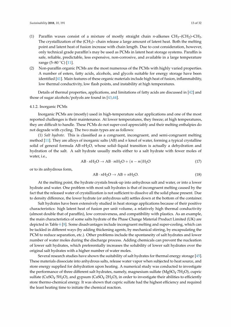
The developed capsules can be used in one-tank TES systems as shown in Figure 8. The heat is
transferred to or from a heat transfer fluid, as the heat transfer fluid flows through the space
between the capsules. During the charging mode, the hot fluid from the solar field is circulated
through the tank. The PCM inside the capsules absorbs latent heat and melts. During the
discharging mode, cooler heat transfer fluid is circulated through the tank to absorb heat from the
PCM, causing the encapsulated PCM to freeze. The heated fluid is then used to heat the power
block working fluid through a heat exchanger.
PCM encapsulation has been used extensively in building cooling systems where air is passed
through flat containers of PCM [52]. The effect of encapsulated PCM has a good scope in enhancing
the performance of LHS systems [53] used in the solar absorption cooling system.
Figure 7. Categories of PCM based on melting point [46].
4.1.4. PCM Containment
Containment of PCMs helps contain the material in liquid and solid phases to prevent its possiblevariation in chemical composition by interaction with its surroundings, to increase its compatibilitywith other materials in the storage system, to increase its handiness, and to provide a suitablesurface for heat transfer. Types of containment studied are bulk storage in tank heat exchangers,macro-encapsulation, and micro-encapsulation. The main characteristic of PCM bulk systems is theneed for more extensive heat transfer than that found in non-PCM tanks because the heat storagedensity of the PCM is higher compared to other storage media. The different approaches extensivelyused are inserting fins and using high conductivity particles, metal structures, fibbers on the PCM side,direct contact heat exchangers, or the rolling cylinder method [50].
The two other possibilities are macro- and micro-encapsulating [51]. Macro-encapsulating consistsin including a PCM in a tube, sphere, panel, cylinder, etc. and is the most widespread. The choice ofmaterial (plastic or metallic-aluminum or steel) and the geometry affect the thermal performance ofthe heat storage. Micro-encapsulating consists in a micro-sphere (diameter less than 1 mm) of PCMencapsulated in a very thin and high-molecular-weight polymer. The spheres are then incorporated insome compatible material.
The developed capsules can be used in one-tank TES systems as shown in Figure 8. The heat istransferred to or from a heat transfer fluid, as the heat transfer fluid flows through the space betweenthe capsules. During the charging mode, the hot fluid from the solar field is circulated through thetank. The PCM inside the capsules absorbs latent heat and melts. During the discharging mode,cooler heat transfer fluid is circulated through the tank to absorb heat from the PCM, causing theencapsulated PCM to freeze. The heated fluid is then used to heat the power block working fluidthrough a heat exchanger.
PCM encapsulation has been used extensively in building cooling systems where air is passedthrough flat containers of PCM [52]. The effect of encapsulated PCM has a good scope in enhancingthe performance of LHS systems [53] used in the solar absorption cooling system.
Organic PCMs can be encapsulated physic-mechanically, chemically, and physic-chemically.Various approaches to prepare the encapsulated PCM (organic) as a new kind of TES medium havebeen extensively developed and can be manufactured to suit the desired properties [54].
Sustainability 2018, 10, 191 16 of 32
Sustainability 2018, 10, 191 16 of 32
Figure 8. Direct contact TES system [52].
Organic PCMs can be encapsulated physic-mechanically, chemically, and physic-chemically.
Various approaches to prepare the encapsulated PCM (organic) as a new kind of TES medium have
been extensively developed and can be manufactured to suit the desired properties [54].
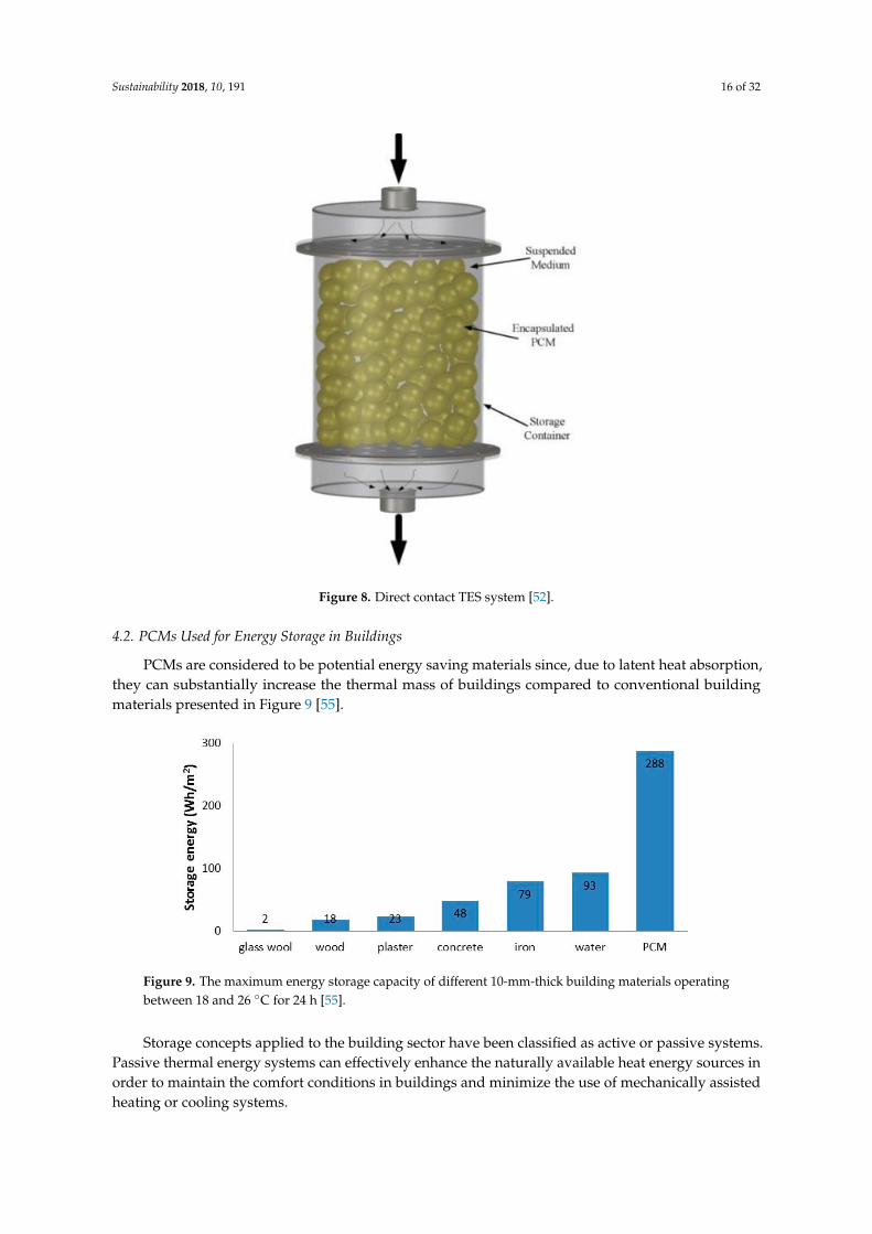
4.2. PCMs Used for Energy Storage in Buildings
PCMs are considered to be potential energy saving materials since, due to latent heat
absorption, they can substantially increase the thermal mass of buildings compared to conventional
building materials presented in Figure 9 [55].
Figure 9. The maximum energy storage capacity of different 10-mm-thick building materials
operating between 18 and 26 °C for 24 h [55].
Storage concepts applied to the building sector have been classified as active or passive
systems. Passive thermal energy systems can effectively enhance the naturally available heat energy
sources in order to maintain the comfort conditions in buildings and minimize the use of
mechanically assisted heating or cooling systems.
Figure 8. Direct contact TES system [52].
4.2. PCMs Used for Energy Storage in Buildings
PCMs are considered to be potential energy saving materials since, due to latent heat absorption,they can substantially increase the thermal mass of buildings compared to conventional buildingmaterials presented in Figure 9 [55].
Sustainability 2018, 10, 191 16 of 32
Figure 8. Direct contact TES system [52].
Organic PCMs can be encapsulated physic-mechanically, chemically, and physic-chemically.
Various approaches to prepare the encapsulated PCM (organic) as a new kind of TES medium have
been extensively developed and can be manufactured to suit the desired properties [54].
4.2. PCMs Used for Energy Storage in Buildings
PCMs are considered to be potential energy saving materials since, due to latent heat
absorption, they can substantially increase the thermal mass of buildings compared to conventional
building materials presented in Figure 9 [55].
Figure 9. The maximum energy storage capacity of different 10-mm-thick building materials
operating between 18 and 26 °C for 24 h [55].
Storage concepts applied to the building sector have been classified as active or passive
systems. Passive thermal energy systems can effectively enhance the naturally available heat energy
sources in order to maintain the comfort conditions in buildings and minimize the use of
mechanically assisted heating or cooling systems.
Figure 9. The maximum energy storage capacity of different 10-mm-thick building materials operatingbetween 18 and 26 ◦C for 24 h [55].
Storage concepts applied to the building sector have been classified as active or passive systems.Passive thermal energy systems can effectively enhance the naturally available heat energy sources inorder to maintain the comfort conditions in buildings and minimize the use of mechanically assistedheating or cooling systems.
Sustainability 2018, 10, 191 17 of 32
The use of active thermal energy systems provides a high degree of control of the indoor conditionsand improves the way of storing heat energy. These systems are usually integrated in buildings toprovide free cooling or to shift the thermal load from on-peak to off-peak conditions in severalapplications, such as DHW applications [56] and heating, ventilation, and air-conditioning (HVAC)systems [57].
4.2.1. Passive Technologies
The use of TES as a passive technology has the objective of providing thermal comfort withminimal use of HVAC energy. When high thermal-mass materials are used in buildings, passivesensible storage is the technology that allows for the storage of a high quantity of energy, providingthermal stability inside the building. Materials typically used are rammed earth, alveolar bricks,concrete, or stone.
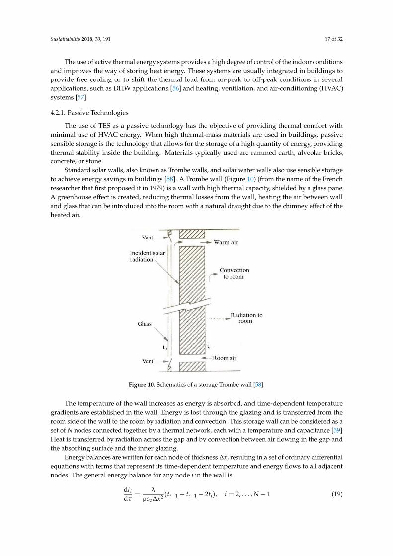
Standard solar walls, also known as Trombe walls, and solar water walls also use sensible storageto achieve energy savings in buildings [58]. A Trombe wall (Figure 10) (from the name of the Frenchresearcher that first proposed it in 1979) is a wall with high thermal capacity, shielded by a glass pane.A greenhouse effect is created, reducing thermal losses from the wall, heating the air between walland glass that can be introduced into the room with a natural draught due to the chimney effect of theheated air.
Sustainability 2018, 10, 191 17 of 32
The use of active thermal energy systems provides a high degree of control of the indoor
conditions and improves the way of storing heat energy. These systems are usually integrated in
buildings to provide free cooling or to shift the thermal load from on-peak to off-peak conditions in
several applications, such as DHW applications [56] and heating, ventilation, and air-conditioning
(HVAC) systems [57].
4.2.1. Passive Technologies
The use of TES as a passive technology has the objective of providing thermal comfort with
minimal use of HVAC energy. When high thermal-mass materials are used in buildings, passive
sensible storage is the technology that allows for the storage of a high quantity of energy, providing
thermal stability inside the building. Materials typically used are rammed earth, alveolar bricks,
concrete, or stone.
Standard solar walls, also known as Trombe walls, and solar water walls also use sensible
storage to achieve energy savings in buildings [58]. A Trombe wall (Figure 10) (from the name of
the French researcher that first proposed it in 1979) is a wall with high thermal capacity, shielded by
a glass pane. A greenhouse effect is created, reducing thermal losses from the wall, heating the air
between wall and glass that can be introduced into the room with a natural draught due to the
chimney effect of the heated air.
The temperature of the wall increases as energy is absorbed, and time-dependent temperature
gradients are established in the wall. Energy is lost through the glazing and is transferred from the
room side of the wall to the room by radiation and convection. This storage wall can be considered
as a set of N nodes connected together by a thermal network, each with a temperature and
capacitance [59]. Heat is transferred by radiation across the gap and by convection between air
flowing in the gap and the absorbing surface and the inner glazing.
Figure 10. Schematics of a storage Trombe wall [58].
Energy balances are written for each node of thickness Δx, resulting in a set of ordinary
differential equations with terms that represent its time-dependent temperature and energy flows
to all adjacent nodes. The general energy balance for any node i in the wall is
1,...,2),2(ρ
λ
d
d112
p
Nitttxc
tiii
i
(19)
where λ is the thermal conductivity of wall; ρ is the wall density; cp is the specific heat of wall; τ is
the time.
Figure 10. Schematics of a storage Trombe wall [58].
The temperature of the wall increases as energy is absorbed, and time-dependent temperaturegradients are established in the wall. Energy is lost through the glazing and is transferred from theroom side of the wall to the room by radiation and convection. This storage wall can be considered as aset of N nodes connected together by a thermal network, each with a temperature and capacitance [59].Heat is transferred by radiation across the gap and by convection between air flowing in the gap andthe absorbing surface and the inner glazing.
Energy balances are written for each node of thickness ∆x, resulting in a set of ordinary differentialequations with terms that represent its time-dependent temperature and energy flows to all adjacentnodes. The general energy balance for any node i in the wall is
dtidτ
=λ
ρcp∆x2 (ti−1 + ti+1 − 2ti), i = 2, . . . , N − 1 (19)
Sustainability 2018, 10, 191 18 of 32
where λ is the thermal conductivity of wall; ρ is the wall density; cp is the specific heat of wall; τ is thetime.
Equations for nodes 1 and N must take into account the node half thickness and the convectionand radiation heat transfer. The set of N equations are simultaneously solved for the time-dependenttemperatures at each of the nodes, and from this the energy stored in the wall (relative to a basetemperature troom) can be calculated.
If there is airflow through vents and to the room, the energy added to the room by this mechanismwill be macp,a(to − tr), where to is the outer glazing temperature, and tr is the room temperature.
PCM can be incorporated in construction materials using different methods, such as directincorporation, immersion, encapsulation, micro-encapsulation, and shape-stabilization. In directincorporation and immersion, potential leakage has to be assessed. When the PCM is encapsulated oradded in a shape-stabilized new material, a new layer appears in the construction system of the wall.
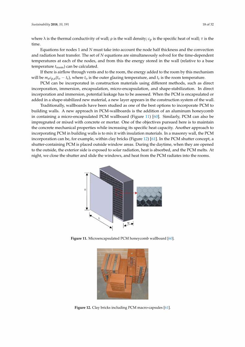
Traditionally, wallboards have been studied as one of the best options to incorporate PCM tobuilding walls. A new approach in PCM-wallboards is the addition of an aluminum honeycombin containing a micro-encapsulated PCM wallboard (Figure 11) [60]. Similarly, PCM can also beimpregnated or mixed with concrete or mortar. One of the objectives pursued here is to maintainthe concrete mechanical properties while increasing its specific heat capacity. Another approach toincorporating PCM in building walls is to mix it with insulation materials. In a masonry wall, the PCMincorporation can be, for example, within clay bricks (Figure 12) [61]. In the PCM shutter concept, ashutter-containing PCM is placed outside window areas. During the daytime, when they are openedto the outside, the exterior side is exposed to solar radiation, heat is absorbed, and the PCM melts. Atnight, we close the shutter and slide the windows, and heat from the PCM radiates into the rooms.
Sustainability 2018, 10, 191 18 of 32
Equations for nodes 1 and N must take into account the node half thickness and the convection
and radiation heat transfer. The set of N equations are simultaneously solved for the
time-dependent temperatures at each of the nodes, and from this the energy stored in the wall
(relative to a base temperature troom) can be calculated.
If there is airflow through vents and to the room, the energy added to the room by this
mechanism will be macp,a(to − tr), where to is the outer glazing temperature, and tr is the room
temperature.
PCM can be incorporated in construction materials using different methods, such as direct
incorporation, immersion, encapsulation, micro-encapsulation, and shape-stabilization. In direct
incorporation and immersion, potential leakage has to be assessed. When the PCM is encapsulated
or added in a shape-stabilized new material, a new layer appears in the construction system of the
wall.
Traditionally, wallboards have been studied as one of the best options to incorporate PCM to
building walls. A new approach in PCM-wallboards is the addition of an aluminum honeycomb in
containing a micro-encapsulated PCM wallboard (Figure 11) [60]. Similarly, PCM can also be
impregnated or mixed with concrete or mortar. One of the objectives pursued here is to maintain
the concrete mechanical properties while increasing its specific heat capacity. Another approach to
incorporating PCM in building walls is to mix it with insulation materials. In a masonry wall, the
PCM incorporation can be, for example, within clay bricks (Figure 12) [61]. In the PCM shutter
concept, a shutter-containing PCM is placed outside window areas. During the daytime, when they
are opened to the outside, the exterior side is exposed to solar radiation, heat is absorbed, and the
PCM melts. At night, we close the shutter and slide the windows, and heat from the PCM radiates
into the rooms.
Figure 11. Microencapsulated PCM honeycomb wallboard [60].
Figure 12. Clay bricks including PCM macro-capsules [61].
4.2.2. Active Technologies
The use of thermal energy storage in building active systems is an attractive and versatile
solution for several applications for new or retrofitted buildings, such as the implementation of RES
Figure 11. Microencapsulated PCM honeycomb wallboard [60].
Sustainability 2018, 10, 191 18 of 32
Equations for nodes 1 and N must take into account the node half thickness and the convection
and radiation heat transfer. The set of N equations are simultaneously solved for the
time-dependent temperatures at each of the nodes, and from this the energy stored in the wall
(relative to a base temperature troom) can be calculated.
If there is airflow through vents and to the room, the energy added to the room by this
mechanism will be macp,a(to − tr), where to is the outer glazing temperature, and tr is the room
temperature.
PCM can be incorporated in construction materials using different methods, such as direct
incorporation, immersion, encapsulation, micro-encapsulation, and shape-stabilization. In direct
incorporation and immersion, potential leakage has to be assessed. When the PCM is encapsulated
or added in a shape-stabilized new material, a new layer appears in the construction system of the
wall.
Traditionally, wallboards have been studied as one of the best options to incorporate PCM to
building walls. A new approach in PCM-wallboards is the addition of an aluminum honeycomb in
containing a micro-encapsulated PCM wallboard (Figure 11) [60]. Similarly, PCM can also be
impregnated or mixed with concrete or mortar. One of the objectives pursued here is to maintain
the concrete mechanical properties while increasing its specific heat capacity. Another approach to
incorporating PCM in building walls is to mix it with insulation materials. In a masonry wall, the
PCM incorporation can be, for example, within clay bricks (Figure 12) [61]. In the PCM shutter
concept, a shutter-containing PCM is placed outside window areas. During the daytime, when they
are opened to the outside, the exterior side is exposed to solar radiation, heat is absorbed, and the
PCM melts. At night, we close the shutter and slide the windows, and heat from the PCM radiates
into the rooms.
Figure 11. Microencapsulated PCM honeycomb wallboard [60].
Figure 12. Clay bricks including PCM macro-capsules [61].
4.2.2. Active Technologies
The use of thermal energy storage in building active systems is an attractive and versatile
solution for several applications for new or retrofitted buildings, such as the implementation of RES
Figure 12. Clay bricks including PCM macro-capsules [61].
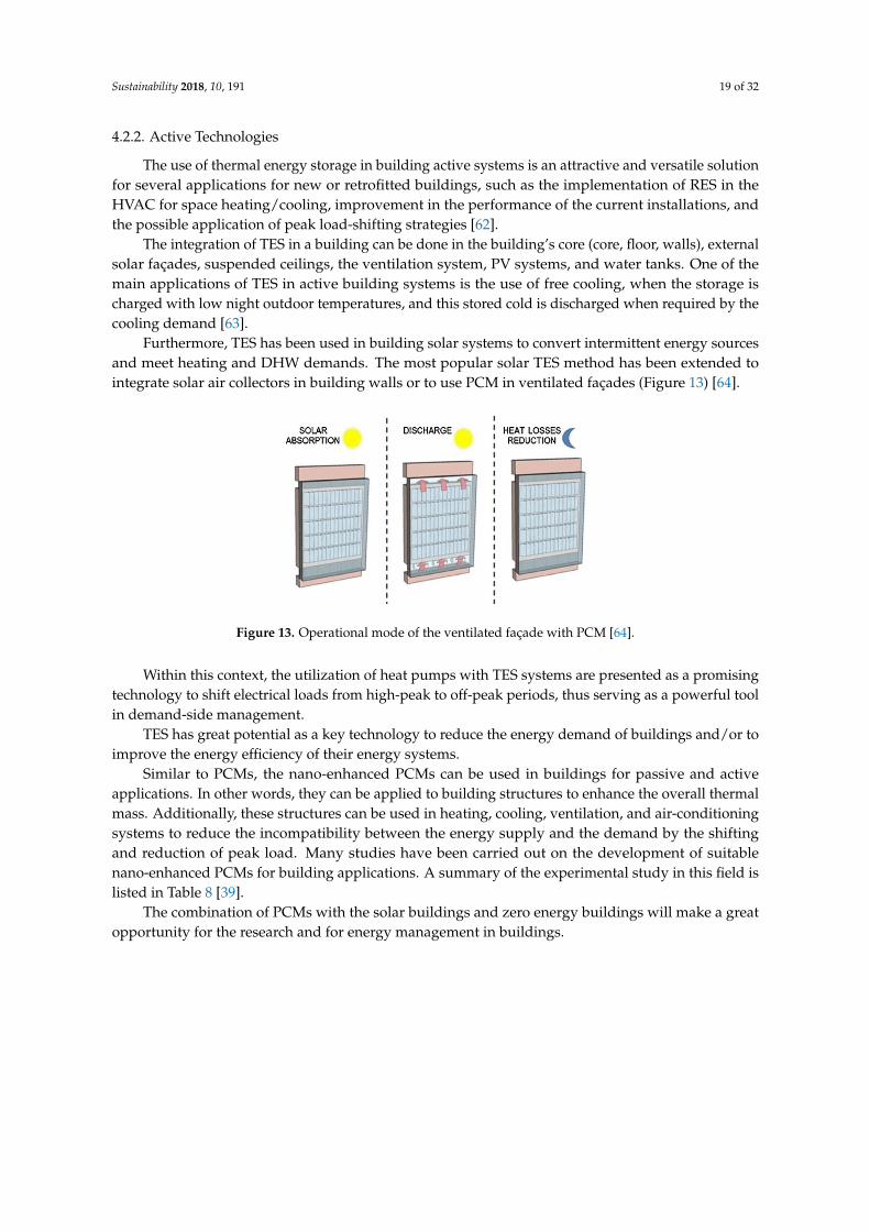
Sustainability 2018, 10, 191 19 of 32
4.2.2. Active Technologies
The use of thermal energy storage in building active systems is an attractive and versatile solutionfor several applications for new or retrofitted buildings, such as the implementation of RES in theHVAC for space heating/cooling, improvement in the performance of the current installations, andthe possible application of peak load-shifting strategies [62].
The integration of TES in a building can be done in the building’s core (core, floor, walls), externalsolar façades, suspended ceilings, the ventilation system, PV systems, and water tanks. One of themain applications of TES in active building systems is the use of free cooling, when the storage ischarged with low night outdoor temperatures, and this stored cold is discharged when required by thecooling demand [63].
Furthermore, TES has been used in building solar systems to convert intermittent energy sourcesand meet heating and DHW demands. The most popular solar TES method has been extended tointegrate solar air collectors in building walls or to use PCM in ventilated façades (Figure 13) [64].
Sustainability 2018, 10, 191 19 of 32
in the HVAC for space heating/cooling, improvement in the performance of the current
installations, and the possible application of peak load-shifting strategies [62].
The integration of TES in a building can be done in the building’s core (core, floor, walls),
external solar façades, suspended ceilings, the ventilation system, PV systems, and water tanks.
One of the main applications of TES in active building systems is the use of free cooling, when the
storage is charged with low night outdoor temperatures, and this stored cold is discharged when
required by the cooling demand [63].
Furthermore, TES has been used in building solar systems to convert intermittent energy
sources and meet heating and DHW demands. The most popular solar TES method has been
extended to integrate solar air collectors in building walls or to use PCM in ventilated façades
(Figure 13) [64].
Figure 13. Operational mode of the ventilated façade with PCM [64].
Within this context, the utilization of heat pumps with TES systems are presented as a
promising technology to shift electrical loads from high-peak to off-peak periods, thus serving as a
powerful tool in demand-side management.
TES has great potential as a key technology to reduce the energy demand of buildings and/or
to improve the energy efficiency of their energy systems.
Similar to PCMs, the nano-enhanced PCMs can be used in buildings for passive and active
applications. In other words, they can be applied to building structures to enhance the overall
thermal mass. Additionally, these structures can be used in heating, cooling, ventilation, and
air-conditioning systems to reduce the incompatibility between the energy supply and the demand
by the shifting and reduction of peak load. Many studies have been carried out on the development
of suitable nano-enhanced PCMs for building applications. A summary of the experimental study
in this field is listed in Table 8 [39].
The combination of PCMs with the solar buildings and zero energy buildings will make a great
opportunity for the research and for energy management in buildings.
Table 8. Summary of experimental studies on the applications of nano-enhanced PCMs in buildings
[39].
Authors Brief Title Highlights Ref.
Constantinescu et al. Nano-composite building
materials
Providing a nano-composite with appropriate
thermo-physical properties for energy storage (2010). [65]
Kalaiselvam Nano-enhanced PCM for
cooling
Improving the solidification and melting rate by
increasing the amount of nano-particles in the PCM
(2012).
[66]
Kumaresan et al. PCM-based nano-fluids for
cool storage
Reducing about 14.0 and 20.1% at the ambient
temperature of 9 °C and 12 °C, respectively (2013). [67]
Sayyar et al. Shape-stable nano-PCM Reducing the energy consumption for maintaining
the interior temperature by 79% (2014). [68]
Parameshwaran et al. Hybrid nano-composite
PCM
The freezing time of the nano-enhanced PCM was
lower than the pure PCM (2014). [69]
Figure 13. Operational mode of the ventilated façade with PCM [64].
Within this context, the utilization of heat pumps with TES systems are presented as a promisingtechnology to shift electrical loads from high-peak to off-peak periods, thus serving as a powerful toolin demand-side management.
TES has great potential as a key technology to reduce the energy demand of buildings and/or toimprove the energy efficiency of their energy systems.
Similar to PCMs, the nano-enhanced PCMs can be used in buildings for passive and activeapplications. In other words, they can be applied to building structures to enhance the overall thermalmass. Additionally, these structures can be used in heating, cooling, ventilation, and air-conditioningsystems to reduce the incompatibility between the energy supply and the demand by the shiftingand reduction of peak load. Many studies have been carried out on the development of suitablenano-enhanced PCMs for building applications. A summary of the experimental study in this field islisted in Table 8 [39].
The combination of PCMs with the solar buildings and zero energy buildings will make a greatopportunity for the research and for energy management in buildings.
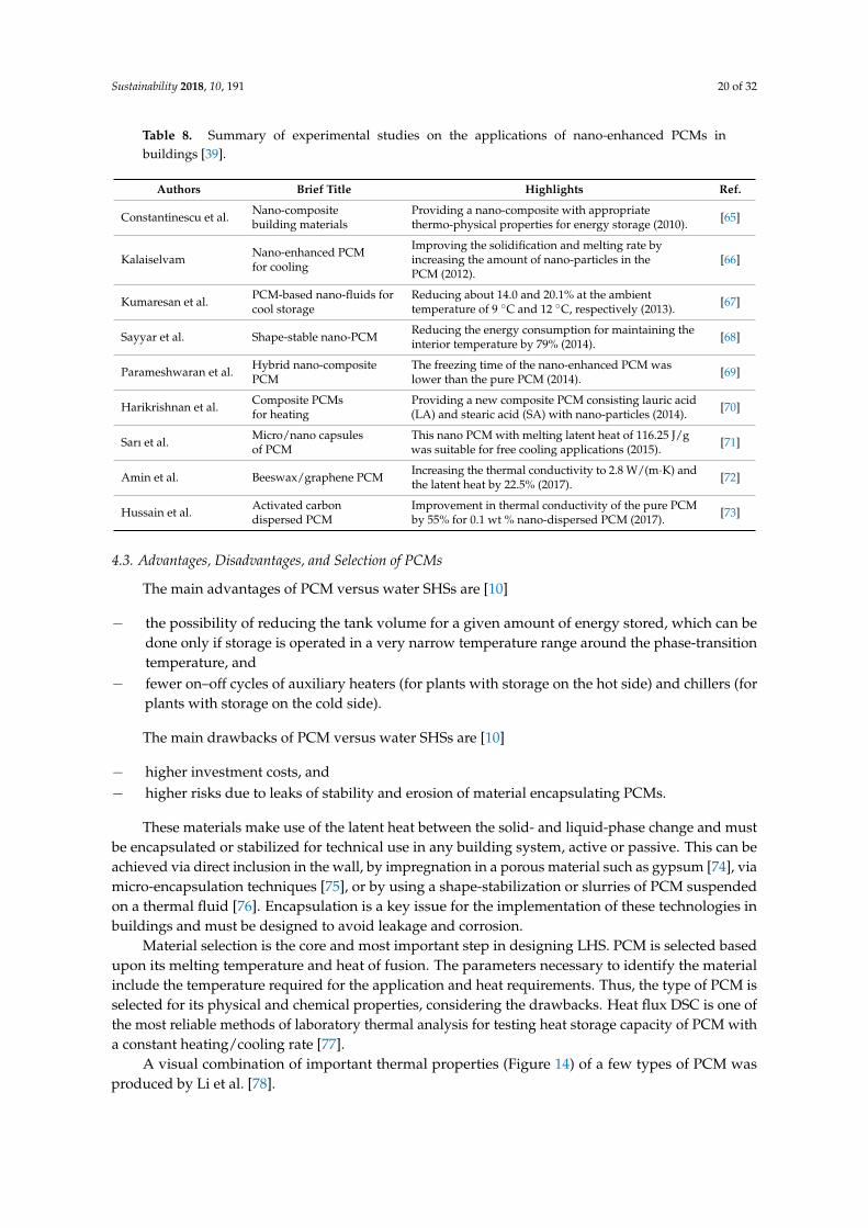
Sustainability 2018, 10, 191 20 of 32
Table 8. Summary of experimental studies on the applications of nano-enhanced PCMs inbuildings [39].
Authors Brief Title Highlights Ref.
Constantinescu et al. Nano-compositebuilding materials
Providing a nano-composite with appropriatethermo-physical properties for energy storage (2010). [65]
Kalaiselvam Nano-enhanced PCMfor cooling
Improving the solidification and melting rate byincreasing the amount of nano-particles in thePCM (2012).
[66]
Kumaresan et al. PCM-based nano-fluids forcool storage
Reducing about 14.0 and 20.1% at the ambienttemperature of 9 ◦C and 12 ◦C, respectively (2013). [67]
Sayyar et al. Shape-stable nano-PCM Reducing the energy consumption for maintaining theinterior temperature by 79% (2014). [68]
Parameshwaran et al. Hybrid nano-compositePCM
The freezing time of the nano-enhanced PCM waslower than the pure PCM (2014). [69]
Harikrishnan et al. Composite PCMsfor heating
Providing a new composite PCM consisting lauric acid(LA) and stearic acid (SA) with nano-particles (2014). [70]
Sarı et al. Micro/nano capsulesof PCM
This nano PCM with melting latent heat of 116.25 J/gwas suitable for free cooling applications (2015). [71]
Amin et al. Beeswax/graphene PCM Increasing the thermal conductivity to 2.8 W/(m·K) andthe latent heat by 22.5% (2017). [72]
Hussain et al. Activated carbondispersed PCM
Improvement in thermal conductivity of the pure PCMby 55% for 0.1 wt % nano-dispersed PCM (2017). [73]
4.3. Advantages, Disadvantages, and Selection of PCMs
The main advantages of PCM versus water SHSs are [10]
− the possibility of reducing the tank volume for a given amount of energy stored, which can bedone only if storage is operated in a very narrow temperature range around the phase-transitiontemperature, and
− fewer on–off cycles of auxiliary heaters (for plants with storage on the hot side) and chillers (forplants with storage on the cold side).
The main drawbacks of PCM versus water SHSs are [10]
− higher investment costs, and− higher risks due to leaks of stability and erosion of material encapsulating PCMs.
These materials make use of the latent heat between the solid- and liquid-phase change and mustbe encapsulated or stabilized for technical use in any building system, active or passive. This can beachieved via direct inclusion in the wall, by impregnation in a porous material such as gypsum [74], viamicro-encapsulation techniques [75], or by using a shape-stabilization or slurries of PCM suspendedon a thermal fluid [76]. Encapsulation is a key issue for the implementation of these technologies inbuildings and must be designed to avoid leakage and corrosion.
Material selection is the core and most important step in designing LHS. PCM is selected basedupon its melting temperature and heat of fusion. The parameters necessary to identify the materialinclude the temperature required for the application and heat requirements. Thus, the type of PCM isselected for its physical and chemical properties, considering the drawbacks. Heat flux DSC is one ofthe most reliable methods of laboratory thermal analysis for testing heat storage capacity of PCM witha constant heating/cooling rate [77].
A visual combination of important thermal properties (Figure 14) of a few types of PCM wasproduced by Li et al. [78].
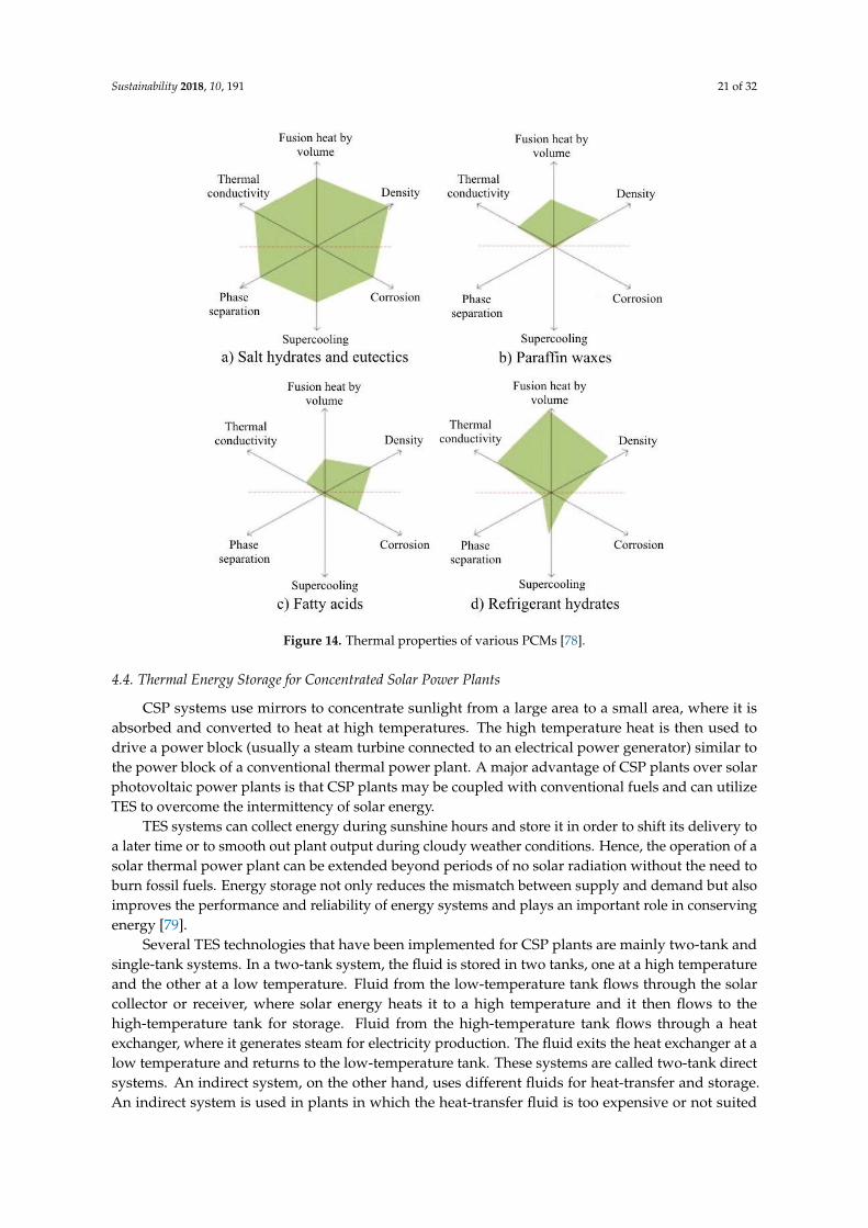
Sustainability 2018, 10, 191 21 of 32Sustainability 2018, 10, 191 21 of 32
Figure 14. Thermal properties of various PCMs [78].
4.4. Thermal Energy Storage for Concentrated Solar Power Plants
CSP systems use mirrors to concentrate sunlight from a large area to a small area, where it is
absorbed and converted to heat at high temperatures. The high temperature heat is then used to
drive a power block (usually a steam turbine connected to an electrical power generator) similar to
the power block of a conventional thermal power plant. A major advantage of CSP plants over solar
photovoltaic power plants is that CSP plants may be coupled with conventional fuels and can
utilize TES to overcome the intermittency of solar energy.
TES systems can collect energy during sunshine hours and store it in order to shift its delivery
to a later time or to smooth out plant output during cloudy weather conditions. Hence, the
operation of a solar thermal power plant can be extended beyond periods of no solar radiation
without the need to burn fossil fuels. Energy storage not only reduces the mismatch between
supply and demand but also improves the performance and reliability of energy systems and plays
an important role in conserving energy [79].
Several TES technologies that have been implemented for CSP plants are mainly two-tank and
single-tank systems. In a two-tank system, the fluid is stored in two tanks, one at a high
temperature and the other at a low temperature. Fluid from the low-temperature tank flows
through the solar collector or receiver, where solar energy heats it to a high temperature and it then
flows to the high-temperature tank for storage. Fluid from the high-temperature tank flows through
a heat exchanger, where it generates steam for electricity production. The fluid exits the heat
exchanger at a low temperature and returns to the low-temperature tank. These systems are called
two-tank direct systems. An indirect system, on the other hand, uses different fluids for
heat-transfer and storage. An indirect system is used in plants in which the heat-transfer fluid is too
expensive or not suited for use as the storage fluid. The storage fluid from the low-temperature
tank flows through an extra heat exchanger, where it is heated by the high-temperature
heat-transfer fluid. The high-temperature storage fluid then flows back to the high-temperature
storage tank. The fluid exits this heat exchanger at a low temperature and returns to the solar
collector or receiver, where it is heated back to a high temperature. Storage fluid from the
high-temperature tank is used to generate steam in the same manner as the two-tank direct system.
Figure 14. Thermal properties of various PCMs [78].
4.4. Thermal Energy Storage for Concentrated Solar Power Plants
CSP systems use mirrors to concentrate sunlight from a large area to a small area, where it isabsorbed and converted to heat at high temperatures. The high temperature heat is then used todrive a power block (usually a steam turbine connected to an electrical power generator) similar tothe power block of a conventional thermal power plant. A major advantage of CSP plants over solarphotovoltaic power plants is that CSP plants may be coupled with conventional fuels and can utilizeTES to overcome the intermittency of solar energy.
TES systems can collect energy during sunshine hours and store it in order to shift its delivery toa later time or to smooth out plant output during cloudy weather conditions. Hence, the operation of asolar thermal power plant can be extended beyond periods of no solar radiation without the need toburn fossil fuels. Energy storage not only reduces the mismatch between supply and demand but alsoimproves the performance and reliability of energy systems and plays an important role in conservingenergy [79].
Several TES technologies that have been implemented for CSP plants are mainly two-tank andsingle-tank systems. In a two-tank system, the fluid is stored in two tanks, one at a high temperatureand the other at a low temperature. Fluid from the low-temperature tank flows through the solarcollector or receiver, where solar energy heats it to a high temperature and it then flows to thehigh-temperature tank for storage. Fluid from the high-temperature tank flows through a heatexchanger, where it generates steam for electricity production. The fluid exits the heat exchanger at alow temperature and returns to the low-temperature tank. These systems are called two-tank directsystems. An indirect system, on the other hand, uses different fluids for heat-transfer and storage.An indirect system is used in plants in which the heat-transfer fluid is too expensive or not suited
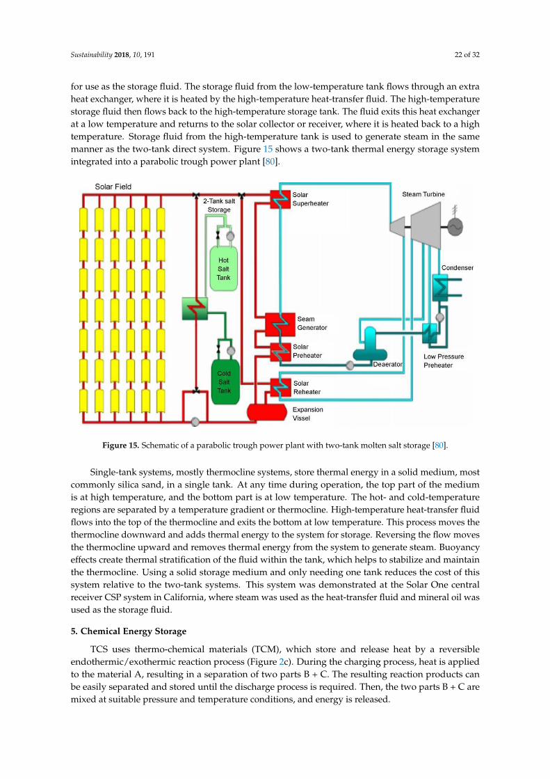
Sustainability 2018, 10, 191 22 of 32
for use as the storage fluid. The storage fluid from the low-temperature tank flows through an extraheat exchanger, where it is heated by the high-temperature heat-transfer fluid. The high-temperaturestorage fluid then flows back to the high-temperature storage tank. The fluid exits this heat exchangerat a low temperature and returns to the solar collector or receiver, where it is heated back to a hightemperature. Storage fluid from the high-temperature tank is used to generate steam in the samemanner as the two-tank direct system. Figure 15 shows a two-tank thermal energy storage systemintegrated into a parabolic trough power plant [80].
Sustainability 2018, 10, 191 22 of 32
Figure 15 shows a two-tank thermal energy storage system integrated into a parabolic trough
power plant [80].
Figure 15. Schematic of a parabolic trough power plant with two-tank molten salt storage [80].
Single-tank systems, mostly thermocline systems, store thermal energy in a solid medium,
most commonly silica sand, in a single tank. At any time during operation, the top part of the
medium is at high temperature, and the bottom part is at low temperature. The hot- and
cold-temperature regions are separated by a temperature gradient or thermocline.
High-temperature heat-transfer fluid flows into the top of the thermocline and exits the bottom at
low temperature. This process moves the thermocline downward and adds thermal energy to the
system for storage. Reversing the flow moves the thermocline upward and removes thermal energy
from the system to generate steam. Buoyancy effects create thermal stratification of the fluid within
the tank, which helps to stabilize and maintain the thermocline. Using a solid storage medium and
only needing one tank reduces the cost of this system relative to the two-tank systems. This system
was demonstrated at the Solar One central receiver CSP system in California, where steam was
used as the heat-transfer fluid and mineral oil was used as the storage fluid.
5. Chemical Energy Storage
TCS uses thermo-chemical materials (TCM), which store and release heat by a reversible
endothermic/exothermic reaction process (Figure 2c). During the charging process, heat is applied
to the material A, resulting in a separation of two parts B + C. The resulting reaction products can
be easily separated and stored until the discharge process is required. Then, the two parts B + C are
mixed at suitable pressure and temperature conditions, and energy is released.
The products B and C can be stored separately, and thermal losses from the storage units are
restricted to sensible heat effects, which are usually small compared to those of the heat of reaction.
Thermal decomposition of metal oxides for energy storage has been considered [81]. These
reactions may have an advantage in that the oxygen evolved can be used for other purposes or
discarded and that oxygen from the atmosphere can be used in the reverse reactions. Two examples
include the decomposition of potassium oxide
Figure 15. Schematic of a parabolic trough power plant with two-tank molten salt storage [80].
Single-tank systems, mostly thermocline systems, store thermal energy in a solid medium, mostcommonly silica sand, in a single tank. At any time during operation, the top part of the mediumis at high temperature, and the bottom part is at low temperature. The hot- and cold-temperatureregions are separated by a temperature gradient or thermocline. High-temperature heat-transfer fluidflows into the top of the thermocline and exits the bottom at low temperature. This process moves thethermocline downward and adds thermal energy to the system for storage. Reversing the flow movesthe thermocline upward and removes thermal energy from the system to generate steam. Buoyancyeffects create thermal stratification of the fluid within the tank, which helps to stabilize and maintainthe thermocline. Using a solid storage medium and only needing one tank reduces the cost of thissystem relative to the two-tank systems. This system was demonstrated at the Solar One centralreceiver CSP system in California, where steam was used as the heat-transfer fluid and mineral oil wasused as the storage fluid.
5. Chemical Energy Storage
TCS uses thermo-chemical materials (TCM), which store and release heat by a reversibleendothermic/exothermic reaction process (Figure 2c). During the charging process, heat is appliedto the material A, resulting in a separation of two parts B + C. The resulting reaction products canbe easily separated and stored until the discharge process is required. Then, the two parts B + C aremixed at suitable pressure and temperature conditions, and energy is released.
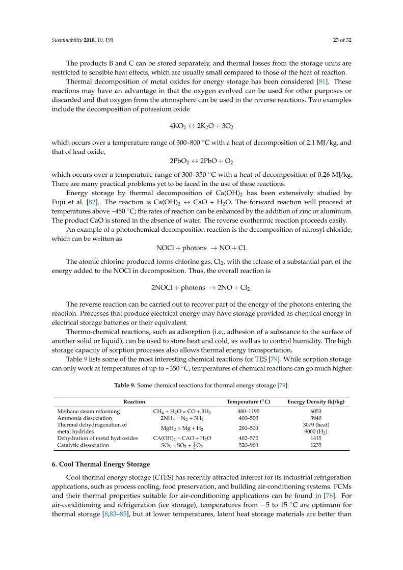
Sustainability 2018, 10, 191 23 of 32
The products B and C can be stored separately, and thermal losses from the storage units arerestricted to sensible heat effects, which are usually small compared to those of the heat of reaction.
Thermal decomposition of metal oxides for energy storage has been considered [81]. Thesereactions may have an advantage in that the oxygen evolved can be used for other purposes ordiscarded and that oxygen from the atmosphere can be used in the reverse reactions. Two examplesinclude the decomposition of potassium oxide
4KO2 ↔ 2K2O + 3O2
which occurs over a temperature range of 300–800 ◦C with a heat of decomposition of 2.1 MJ/kg, andthat of lead oxide,
2PbO2 ↔ 2PbO + O2
which occurs over a temperature range of 300–350 ◦C with a heat of decomposition of 0.26 MJ/kg.There are many practical problems yet to be faced in the use of these reactions.
Energy storage by thermal decomposition of Ca(OH)2 has been extensively studied byFujii et al. [82]. The reaction is Ca(OH)2 ↔ CaO + H2O. The forward reaction will proceed attemperatures above ~450 ◦C; the rates of reaction can be enhanced by the addition of zinc or aluminum.The product CaO is stored in the absence of water. The reverse exothermic reaction proceeds easily.
An example of a photochemical decomposition reaction is the decomposition of nitrosyl chloride,which can be written as
NOCl + photons → NO + Cl.
The atomic chlorine produced forms chlorine gas, Cl2, with the release of a substantial part of theenergy added to the NOCl in decomposition. Thus, the overall reaction is
2NOCl + photons → 2NO + Cl2.
The reverse reaction can be carried out to recover part of the energy of the photons entering thereaction. Processes that produce electrical energy may have storage provided as chemical energy inelectrical storage batteries or their equivalent.
Thermo-chemical reactions, such as adsorption (i.e., adhesion of a substance to the surface ofanother solid or liquid), can be used to store heat and cold, as well as to control humidity. The highstorage capacity of sorption processes also allows thermal energy transportation.
Table 9 lists some of the most interesting chemical reactions for TES [79]. While sorption storagecan only work at temperatures of up to ~350 ◦C, temperatures of chemical reactions can go much higher.
Table 9. Some chemical reactions for thermal energy storage [79].
Reaction Temperature (◦C) Energy Density (kJ/kg)
Methane steam reforming CH4 + H2O = CO + 3H2 480–1195 6053Ammonia dissociation 2NH3 = N2 + 3H2 400–500 3940Thermal dehydrogenation ofmetal hydrides MgH2 = Mg + H2 200–500 3079 (heat)
9000 (H2)Dehydration of metal hydroxides CA(OH)2 = CAO + H2O 402–572 1415Catalytic dissociation SO3 = SO2 + 1
2 O2 520–960 1235
6. Cool Thermal Energy Storage
Cool thermal energy storage (CTES) has recently attracted interest for its industrial refrigerationapplications, such as process cooling, food preservation, and building air-conditioning systems. PCMsand their thermal properties suitable for air-conditioning applications can be found in [76]. Forair-conditioning and refrigeration (ice storage), temperatures from −5 to 15 ◦C are optimum forthermal storage [8,83–85], but at lower temperatures, latent heat storage materials are better than
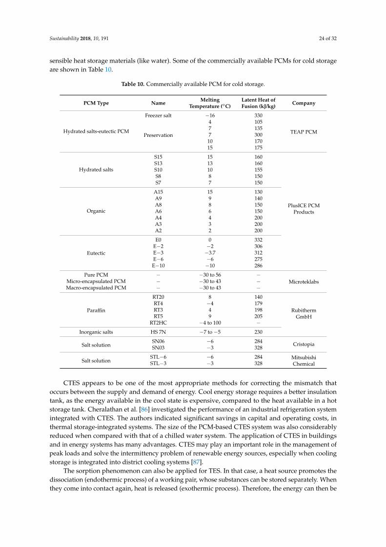
Sustainability 2018, 10, 191 24 of 32
sensible heat storage materials (like water). Some of the commercially available PCMs for cold storageare shown in Table 10.
Table 10. Commercially available PCM for cold storage.
PCM Type Name MeltingTemperature (◦C)
Latent Heat ofFusion (kJ/kg) Company
Hydrated salts-eutectic PCM
Freezer salt −16 330
TEAP PCMPreservation
4 1057 1357 30010 17015 175
Hydrated salts
S15 15 160
PlusICE PCMProducts
S13 13 160S10 10 155S8 8 150S7 7 150
Organic
A15 15 130A9 9 140A8 8 150A6 6 150A4 4 200A3 3 200A2 2 200
Eutectic
E0 0 332E−2 −2 306E−3 −3.7 312E−6 −6 275
E−10 −10 286
Pure PCM − −30 to 56 −MicroteklabsMicro-encapsulated PCM − −30 to 43 −
Macro-encapsulated PCM − −30 to 43 −
Paraffin
RT20 8 140
RubithermGmbH
RT4 −4 179RT3 4 198RT5 9 205
RT2HC −4 to 100 −Inorganic salts HS 7N −7 to −5 230
Salt solutionSN06 −6 284 CristopiaSN03 −3 328
Salt solutionSTL−6 −6 284 Mitsubishi
ChemicalSTL−3 −3 328
CTES appears to be one of the most appropriate methods for correcting the mismatch thatoccurs between the supply and demand of energy. Cool energy storage requires a better insulationtank, as the energy available in the cool state is expensive, compared to the heat available in a hotstorage tank. Cheralathan et al. [86] investigated the performance of an industrial refrigeration systemintegrated with CTES. The authors indicated significant savings in capital and operating costs, inthermal storage-integrated systems. The size of the PCM-based CTES system was also considerablyreduced when compared with that of a chilled water system. The application of CTES in buildingsand in energy systems has many advantages. CTES may play an important role in the management ofpeak loads and solve the intermittency problem of renewable energy sources, especially when coolingstorage is integrated into district cooling systems [87].
The sorption phenomenon can also be applied for TES. In that case, a heat source promotes thedissociation (endothermic process) of a working pair, whose substances can be stored separately. Whenthey come into contact again, heat is released (exothermic process). Therefore, the energy can then be
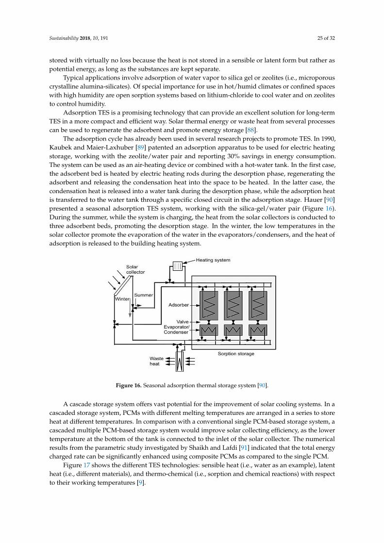
Sustainability 2018, 10, 191 25 of 32
stored with virtually no loss because the heat is not stored in a sensible or latent form but rather aspotential energy, as long as the substances are kept separate.
Typical applications involve adsorption of water vapor to silica gel or zeolites (i.e., microporouscrystalline alumina-silicates). Of special importance for use in hot/humid climates or confined spaceswith high humidity are open sorption systems based on lithium-chloride to cool water and on zeolitesto control humidity.
Adsorption TES is a promising technology that can provide an excellent solution for long-termTES in a more compact and efficient way. Solar thermal energy or waste heat from several processescan be used to regenerate the adsorbent and promote energy storage [88].
The adsorption cycle has already been used in several research projects to promote TES. In 1990,Kaubek and Maier-Laxhuber [89] patented an adsorption apparatus to be used for electric heatingstorage, working with the zeolite/water pair and reporting 30% savings in energy consumption.The system can be used as an air-heating device or combined with a hot-water tank. In the first case,the adsorbent bed is heated by electric heating rods during the desorption phase, regenerating theadsorbent and releasing the condensation heat into the space to be heated. In the latter case, thecondensation heat is released into a water tank during the desorption phase, while the adsorption heatis transferred to the water tank through a specific closed circuit in the adsorption stage. Hauer [90]presented a seasonal adsorption TES system, working with the silica-gel/water pair (Figure 16).During the summer, while the system is charging, the heat from the solar collectors is conducted tothree adsorbent beds, promoting the desorption stage. In the winter, the low temperatures in thesolar collector promote the evaporation of the water in the evaporators/condensers, and the heat ofadsorption is released to the building heating system.
Sustainability 2018, 10, 191 25 of 32
The adsorption cycle has already been used in several research projects to promote TES. In
1990, Kaubek and Maier-Laxhuber [89] patented an adsorption apparatus to be used for electric
heating storage, working with the zeolite/water pair and reporting 30% savings in energy
consumption. The system can be used as an air-heating device or combined with a hot-water tank.
In the first case, the adsorbent bed is heated by electric heating rods during the desorption phase,
regenerating the adsorbent and releasing the condensation heat into the space to be heated. In the
latter case, the condensation heat is released into a water tank during the desorption phase, while
the adsorption heat is transferred to the water tank through a specific closed circuit in the
adsorption stage. Hauer [90] presented a seasonal adsorption TES system, working with the
silica-gel/water pair (Figure 16). During the summer, while the system is charging, the heat from
the solar collectors is conducted to three adsorbent beds, promoting the desorption stage. In the
winter, the low temperatures in the solar collector promote the evaporation of the water in the
evaporators/condensers, and the heat of adsorption is released to the building heating system.
Figure 16. Seasonal adsorption thermal storage system [90].
A cascade storage system offers vast potential for the improvement of solar cooling systems. In
a cascaded storage system, PCMs with different melting temperatures are arranged in a series to
store heat at different temperatures. In comparison with a conventional single PCM-based storage
system, a cascaded multiple PCM-based storage system would improve solar collecting efficiency,
as the lower temperature at the bottom of the tank is connected to the inlet of the solar collector.
The numerical results from the parametric study investigated by Shaikh and Lafdi [91] indicated
that the total energy charged rate can be significantly enhanced using composite PCMs as
compared to the single PCM.
Figure 17 shows the different TES technologies: sensible heat (i.e., water as an example), latent
heat (i.e., different materials), and thermo-chemical (i.e., sorption and chemical reactions) with
respect to their working temperatures [9].
Figure 16. Seasonal adsorption thermal storage system [90].
A cascade storage system offers vast potential for the improvement of solar cooling systems. In acascaded storage system, PCMs with different melting temperatures are arranged in a series to storeheat at different temperatures. In comparison with a conventional single PCM-based storage system, acascaded multiple PCM-based storage system would improve solar collecting efficiency, as the lowertemperature at the bottom of the tank is connected to the inlet of the solar collector. The numericalresults from the parametric study investigated by Shaikh and Lafdi [91] indicated that the total energycharged rate can be significantly enhanced using composite PCMs as compared to the single PCM.
Figure 17 shows the different TES technologies: sensible heat (i.e., water as an example), latentheat (i.e., different materials), and thermo-chemical (i.e., sorption and chemical reactions) with respectto their working temperatures [9].
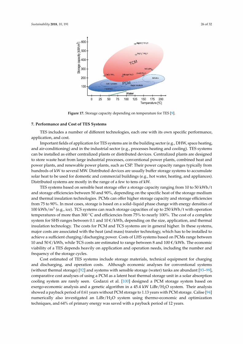
Sustainability 2018, 10, 191 26 of 32Sustainability 2018, 10, 191 26 of 32
Figure 17. Storage capacity depending on temperature for TES [9].
7. Performance and Cost of TES Systems
TES includes a number of different technologies, each one with its own specific performance,
application, and cost.
Important fields of application for TES systems are in the building sector (e.g., DHW, space
heating, and air-conditioning) and in the industrial sector (e.g., processes heating and cooling). TES
systems can be installed as either centralized plants or distributed devices. Centralized plants are
designed to store waste heat from large industrial processes, conventional power plants, combined
heat and power plants, and renewable power plants, such as CSP. Their power capacity ranges
typically from hundreds of kW to several MW. Distributed devices are usually buffer storage
systems to accumulate solar heat to be used for domestic and commercial buildings (e.g., hot water,
heating, and appliances). Distributed systems are mostly in the range of a few to tens of kW.
TES systems based on sensible heat storage offer a storage capacity ranging from 10 to 50
kWh/t and storage efficiencies between 50 and 90%, depending on the specific heat of the storage
medium and thermal insulation technologies. PCMs can offer higher storage capacity and storage
efficiencies from 75 to 90%. In most cases, storage is based on a solid–liquid phase change with
energy densities of 100 kWh/m3 (e.g., ice). TCS systems can reach storage capacities of up to 250
kWh/t with operation temperatures of more than 300 °C and efficiencies from 75% to nearly 100%.
The cost of a complete system for SHS ranges between 0.1 and 10 €/kWh, depending on the size,
application, and thermal insulation technology. The costs for PCM and TCS systems are in general
higher. In these systems, major costs are associated with the heat (and mass) transfer technology,
which has to be installed to achieve a sufficient charging/discharging power. Costs of LHS systems
based on PCMs range between 10 and 50 €/kWh, while TCS costs are estimated to range between 8
and 100 €/kWh. The economic viability of a TES depends heavily on application and operation
needs, including the number and frequency of the storage cycles.
Cost estimated of TES systems include storage materials, technical equipment for charging and
discharging, and operation costs. Although economic analyses for conventional systems (without
thermal storage) [92] and systems with sensible storage (water) tanks are abundant [93–99],
comparative cost analyses of using a PCM as a latent heat thermal storage unit in a solar absorption
cooling system are rarely seen. Godarzi et al. [100] designed a PCM storage system based on
exergo-economic analysis and a genetic algorithm in a 45.4 kW LiBr/H2O system. Their analysis
showed a payback period of 0.61 years without PCM storage to 1.13 years with PCM storage. Calise
[94] numerically also investigated an LiBr/H2O system using thermo-economic and optimization
techniques, and 64% of primary energy was saved with a payback period of 12 years.
TES systems for sensible heat are rather inexpensive as they consist basically of a simple tank
for the storage medium and the equipment to charge/discharge. Storage media (e.g., water, soil,
rocks, concrete or molten salts) are usually relatively cheap. However, the container of the storage
material requires effective thermal insulation, which may be an important element of the TES cost.
Figure 17. Storage capacity depending on temperature for TES [9].
7. Performance and Cost of TES Systems
TES includes a number of different technologies, each one with its own specific performance,application, and cost.
Important fields of application for TES systems are in the building sector (e.g., DHW, space heating,and air-conditioning) and in the industrial sector (e.g., processes heating and cooling). TES systemscan be installed as either centralized plants or distributed devices. Centralized plants are designedto store waste heat from large industrial processes, conventional power plants, combined heat andpower plants, and renewable power plants, such as CSP. Their power capacity ranges typically fromhundreds of kW to several MW. Distributed devices are usually buffer storage systems to accumulatesolar heat to be used for domestic and commercial buildings (e.g., hot water, heating, and appliances).Distributed systems are mostly in the range of a few to tens of kW.
TES systems based on sensible heat storage offer a storage capacity ranging from 10 to 50 kWh/tand storage efficiencies between 50 and 90%, depending on the specific heat of the storage mediumand thermal insulation technologies. PCMs can offer higher storage capacity and storage efficienciesfrom 75 to 90%. In most cases, storage is based on a solid–liquid phase change with energy densities of100 kWh/m3 (e.g., ice). TCS systems can reach storage capacities of up to 250 kWh/t with operationtemperatures of more than 300 ◦C and efficiencies from 75% to nearly 100%. The cost of a completesystem for SHS ranges between 0.1 and 10 €/kWh, depending on the size, application, and thermalinsulation technology. The costs for PCM and TCS systems are in general higher. In these systems,major costs are associated with the heat (and mass) transfer technology, which has to be installed toachieve a sufficient charging/discharging power. Costs of LHS systems based on PCMs range between10 and 50 €/kWh, while TCS costs are estimated to range between 8 and 100 €/kWh. The economicviability of a TES depends heavily on application and operation needs, including the number andfrequency of the storage cycles.
Cost estimated of TES systems include storage materials, technical equipment for chargingand discharging, and operation costs. Although economic analyses for conventional systems(without thermal storage) [92] and systems with sensible storage (water) tanks are abundant [93–99],comparative cost analyses of using a PCM as a latent heat thermal storage unit in a solar absorptioncooling system are rarely seen. Godarzi et al. [100] designed a PCM storage system based onexergo-economic analysis and a genetic algorithm in a 45.4 kW LiBr/H2O system. Their analysisshowed a payback period of 0.61 years without PCM storage to 1.13 years with PCM storage. Calise [94]numerically also investigated an LiBr/H2O system using thermo-economic and optimizationtechniques, and 64% of primary energy was saved with a payback period of 12 years.
Sustainability 2018, 10, 191 27 of 32
TES systems for sensible heat are rather inexpensive as they consist basically of a simple tank forthe storage medium and the equipment to charge/discharge. Storage media (e.g., water, soil, rocks,concrete or molten salts) are usually relatively cheap. However, the container of the storage materialrequires effective thermal insulation, which may be an important element of the TES cost.
In the case of UTES systems, boreholes and heat exchangers to activate the underground storageare the most important cost elements. Specific costs range from 0.1 to 10 €/kWh [6] and depend heavilyon local conditions.
PCM storage and TCS systems are significantly more complex and expensive than the storagesystems for sensible heat. In most cases (e.g., thermo-chemical reactors), they use enhanced heat andmass transfer technologies to achieve the required performance in terms of storage capacity and power,and the cost of the equipment is much higher than the cost for the storage material. The cost of systemsusing expensive micro-encapsulated PCMs, which avoid the use of heat exchange surfaces, can beeven higher.
The difference between the pure PCM and the complete TES system is even higher for active PCMinstallations. As an example, the costs of a calcium–chloride storage system for heat rejected from athermally driven absorption chiller includes the cost of calcium chloride, which is rather inexpensive(0.3 €/kg), and the cost of a container, a heat exchanger, and other components around 65 €/kWh [6].
Materials for TCS are also expensive, as they have to be prepared (e.g., pelletized or layered oversupporting structures). Also expensive are the containers and the auxiliary TCS equipment for bothheat and mass transfer during energy charging and discharging. TCS systems can be operated aseither open systems (i.e., basically packed beds of pellets at ambient pressure) or closed systems. Opensystems are often the cheapest option, while closed systems need sophisticated heat exchangers.
The overall economic evaluation of a TES system depends significantly on the specific applicationand operation needs, including the number and frequency of storage cycles.
TES technologies face certain barriers to market entry, and cost is a key issue. Other barriersrelate to material properties and stability, in particular for TCS. Each storage application needs aspecific TES design to fit specific boundary conditions and requirements. R&D activities focus on allTES technologies.
TES market development and penetration varies considerably, depending on the applicationfields and regions. Thus, TES potential for co-generation and district heating in Europe is associatedwith building stock. The implementation rate of co-generation is 10.2%, while the implementationof TES in these systems is assumed to be 15%. As far as TES for power applications is concerned,a driving sector is the CSP, where almost all new power plants in operation or under constructionare equipped with TES systems, mostly based on molten salt. This is perhaps the most importantdevelopment filed for large, centralized TES installations.
8. Conclusions and Future Trends
SHS is applicable to domestic systems, district heating, and industrial needs. The most popularand commercial heat storage medium is water, which has a number of residential and industrialapplications. Underground storage of sensible heat in both liquid and solid media is also used fortypically large-scale applications. However, TES systems based on SHS offer a storage capacity that islimited by the specific heat of the storage medium. Furthermore, SHS systems require proper designto discharge thermal energy at constant temperatures.
PCMs can offer a higher storage capacity that is associated with the latent heat of the phase change.PCMs also enable a target-oriented discharging temperature that is set by the constant temperature ofthe phase change. Melting temperature, latent heat of fusion, and PCM thermo-physical issues arethree basic factors influencing the selection of PCMs in any application. A high heat of fusion anda precise melting/solidification temperature (without subcooling) are two primary requirements inthe selection approach. Numerous mechanical and nano-level enhancements have been achieved to
Sustainability 2018, 10, 191 28 of 32
increase the heat transfer rate, which is promising. Micro-encapsulation increases the heat transfersurface area and is also a solution for phase segregation in salt hydrates.
Most of the literature is focused on routine and commercialized PCM materials such as paraffin.We recommend focusing on special PCMs with a wide temperature range such as salt hydrates andsynthesizing specialized PCMs suitable for specific building applications.
TCS can offer even higher storage capacities. Thermo-chemical reactions such as adsorption canbe used to accumulate and discharge heat and cold on demand and to control humidity in a variety ofapplications using different chemical reactants.
In CTES, materials with subzero temperatures are identified, but their thermal reliability,phase-segregation and subcooling issues have not been deeply studied. Studies on industrial (largescale) level thermal cold storage PCMs are hardly tested.
At present, TES systems based on sensible heat are commercially available, while TCS- andPCM-based storage systems are mostly under development and demonstration.
Support for the R&D of new storage materials, as well as policy measures and investmentincentives for TES integration in buildings, for industrial applications, and for variable renewablepower generation, is essential if its deployment is to be fostered. In future greenhouses, TES solutionscan combine heating–cooling–dehumidification functions and provide poly-generation possibilities.Further research on the possibility of thermo-chemical energy storage and the further development ofPCMs is needed for this option to be widely adopted in a more cost-effective manner.
Author Contributions: All authors conceived the research idea and the framework of this study.Calin Sebarchievici performed the theoretical study and Ioan Sarbu analyzed the data and wrote the paper.Both authors have read and approved the final manuscript.
Conflicts of Interest: The authors declare no conflict of interest.
References
1. European Commission. European Union Energy in Figures; Statistical Pocketbook; Publications Office of theEU: Luxembourg, Luxembourg, 2016.
2. Twidell, J.; Weir, T. Renewable Energy Resources; Routledge: London, UK, 2015.3. Iten, M.; Liu, S.; Shukla, A. A review on the air-PCM-TES application for free cooling and heating in the
buildings. Renew. Sustain. Energy Rev. 2016, 61, 175–186. [CrossRef]4. Sarbu, I.; Sebarchievici, C. Solar Heating and Cooling: Fundamentals, Experiments and Applications; Elsevier:
Oxford, UK, 2016.5. Dincer, I.; Rosen, M.A. Thermal Energy Storage: Systems and Application; John Wiley & Sons: Chichester,
UK, 2011.6. International Renewable Energy Agency (IRENA). The Energy Technology Systems Analysis Programmes
(ETSAP): Technology Brief E17; International Energy Agency: Paris, France, 2013. Available online:http://www.irena.org/Publications (accessed on 8 July 2015).
7. Medrano, M.; Yilmaz, M.O.; Nogue´s, M.; Martorell, I.; Roca, J.; Cabeza, L.F. Experimental evaluation ofcommercial heat exchangers for use as PCM thermal storage systems. Appl. Energy 2009, 86, 2047–2055.[CrossRef]
8. Noro, M.; Lazzarin, R.M.; Busato, F. Solar cooling and heating plants: An energy and economic analysis ofliquid sensible vs. phase change material (PCM) heat storage. Int. J. Refrig. 2014, 39, 104–116. [CrossRef]
9. Khan, M.M.A.; Saidur, R.; Al-Sulaimana, F.A. A review for phase change materials (PCMs) in solar absorptionrefrigeration systems. Renew. Sustain. Energy Rev. 2017, 76, 105–137. [CrossRef]
10. Chidambaram, L.A.; Ramana, A.S.; Kamaraj, G.; Velraj, R. Review of solar cooling methods and thermalstorage options. Renew. Sustain. Energy Rev. 2011, 15, 3220–3228. [CrossRef]
11. Sharma, A.; Tyagi, V.V.; Chen, C.R.; Buddhi, D. Review on thermal energy storage with phase changematerials and applications. Renew. Sustain. Energy Rev. 2009, 13, 318–345. [CrossRef]
12. Zhou, D.; Zhao, C.Y.; Tian, Y. Review on thermal energy storage with phase change materials (PCMs) inbuilding applications. Appl. Energy 2012, 92, 593–605. [CrossRef]
Sustainability 2018, 10, 191 29 of 32
13. Moreno, P.; Solé, C.; Castell, A.; Cabeza, L.F. The use of phase change materials in domestic heat pumpand air-conditioning systems for short term storage: A review. Renew. Sustain. Energy Rev. 2014, 39, 1–13.[CrossRef]
14. Liu, M.; Saman, W.; Bruno, F. Review on storage materials and thermal performance enhancement techniquesfor high temperature phase change thermal storage systems. Renew. Sustain. Energy Rev. 2012, 16, 2118–2132.[CrossRef]
15. Zhai, X.Q.; Wang, X.L.; Wang, T.; Wang, R.Z. A review on phase change cold storage in air-conditioningsystem: Materials and applications. Renew. Sustain. Energy Rev. 2013, 22, 108–120. [CrossRef]
16. Pintaldi, S.; Perfumo, C.; Sethuvenkatraman, S.; White, S.; Rosengarten, G. A review of thermal energystorage technologies and control approaches for solar cooling. Renew. Sustain. Energy Rev. 2015, 41, 975–995.[CrossRef]
17. Tian, Y.; Zhao, C.Y. A review of solar collectors and thermal energy storage in solar thermal applications.Appl. Energy 2013, 104, 538–553. [CrossRef]
18. Joybari, M.; Haghighat, F.; Moffat, J.; Sra, P. Heat and cold storage using phase change materials in domesticrefrigeration systems: The state-of-the-art review. Energy Build. 2015, 106, 111–124. [CrossRef]
19. Oró, E.; de Gracia, A.; Castell, A.; Farid, M.M.; Cabeza, L.F. Review on phase change materials (PCMs) forcold thermal energy storage applications. Appl. Energy 2012, 99, 513–533. [CrossRef]
20. Joseph, A.; Kabbara, M.; Groulx, D.; Allred, P.; White, M.A. Characterization and real-time testing ofphase-change materials for solar thermal energy storage. Int. J. Energy Res. 2016, 40, 61–70. [CrossRef]
21. Al-Abidi, A.A.; Bin Mat, S.; Sopian, K.; Sulaiman, M.Y.; Mohammed, A.T. CFD applications for latent heatthermal energy storage: A review. Renew. Sustain. Energy Rev. 2013, 20, 353–363. [CrossRef]
22. Hauer, A. Storage Technology Issues and Opportunities, International Low-Carbon Energy TechnologyPlatform. In Proceedings of the Strategic and Cross-Cutting Workshop “Energy Storage—Issues andOpportunities”, Paris, France, 15 February 2011.
23. De Garcia, A.; Cabeza, C.F. Phase change materials and thermal energy storage for buildings. Energy Build.2015, 103, 414–419. [CrossRef]
24. Kumar, A.; Shukla, S.K. A Review on Thermal Energy Storage Unit for Solar Thermal Power PlantApplication. Energy Procedia 2015, 74, 462–469. [CrossRef]
25. Ayappan, S.; Mayilsamy, K.; Sreenarayanan, V.V. Performance improvement studies in a solar greenhousedrier using sensible heat storage materials. Heat Mass Transf. 2016, 52, 459–467. [CrossRef]
26. Basecq, V.; Michaux, G.; Inard, C.; Blondeau, P. Short-term storage systems of thermal energy for buildings:A review. Adv. Build. Energy Res. 2013, 7, 66–119. [CrossRef]
27. International Energy Agency (IEA). Energy Conservation through Energy Storage (ECES) Programme; Brochure,International Energy Agency: Paris, France, 2016. Available online: http://www.iea-eces.org/files/090525_broschuere_eces.pdf (accessed on 10 October 2016).
28. Heier, J.; Bales, C.; Martin, V. Combining thermal energy storage with buildings—A review. Renew. Sustain.Energy Rev. 2015, 42, 1305–1325. [CrossRef]
29. Papillon, P.; Nielsen, J.E.; Cholin, X.; Letz, T.; Thür, A.; Kuhness, G. Solar CombisystemsPromotion and Standardization Final Report, Intelligent Energy Europe, CombiSol. 2010. Availableonline: https://ec.europa.eu/energy/intelligent/projects/sites/iee-projects/files/projects/documents/combisol_publishable_report_en.pdf (accessed on 10 July 2015).
30. Novo, A.V.; Bayon, J.R.; Castro-Fresno, D.; Rodriguez-Hernandez, J. Review of seasonal heat storage in largebasins: Water tanks and gravel-water pits. Appl. Energy 2010, 87, 390–397. [CrossRef]
31. Paksoy, H.; Snijders, A.; Stiles, L. State-of-the-art review of aquifer thermal energy storage systems for heatingand cooling buildings. In Proceedings of the Effstock Conference, Stockholm, Sweden, 5–17 June 2009.
32. Bauer, D.; Marx, R.; Nußbicker-Lux, J.; Ochs, F.; Heidemann, W.; Müller-Steinhagen, H. German central solarheating plants with seasonal heat storage. Sol. Energy 2010, 84, 612–623. [CrossRef]
33. Heier, J.; Bales, C.; Sotnikov, A.; Ponomarova, G. Evaluation of high temperature solar thermal seasonal boreholestorage. In Proceedings of the ISES Solar World Congress, Kassel, Germany, 28 August–2 September 2011.
34. Schumann, T.E.W. Heat transfer: A liquid flowing through a porous prism. J. Frankl. Inst. 1929, 208, 405–416.[CrossRef]
35. Duffie, J.A.; Beckman, W.A. Solar Engineering of Thermal Processes; Wiley & Sons, Inc.: Hoboken, NJ, USA, 2013.
Sustainability 2018, 10, 191 30 of 32
36. Nems, M.; Nems, A.; Kasperski, J.; Pomorski, M. Thermo-hydraulic analysis of heat storage filled with theceramic bricks dedicated to the solar air heating system. Materials 2017, 10, 940. [CrossRef] [PubMed]
37. Morrison, D.J.; Abdel-Khalik, S.I. Effects of phase-change energy storage on the performance of air-basedand liquid-based solar heating systems. Sol. Energy 1978, 20, 57–67. [CrossRef]
38. Kenisarin, M.; Mahkamov, K. Passive thermal control in residential buildings using phase change materials.Renew. Sustain. Energy Rev. 2016, 55, 371–398. [CrossRef]
39. Kasaeian, A.; Bahrami, L.; Pourfayaz, F.; Khodabandeh, E.; Yan, W.-M. Experimental studies on theapplications of PCMs and nano-PCMs in buildings: A critical review. Energy Build. 2017, 154, 96–112.[CrossRef]
40. Wang, Z.; Liu, S.; Ma, G.; Xie, S.; Du, G.; Sun, J.; Jia, Y. Preparation and properties of caprylic-nonanoicacid mixture/expanded graphite composite as phase change material for thermal energy storage. Int. J.Energy Res. 2017, 41, 2555–2564. [CrossRef]
41. Abhat, A. Development of a modular heat exchanger with integrated latent heat storage. In Germany Ministryof Science and Technology Bonn; Report No. BMFT FBT 81-050; Institut fuer Kemtechnik und Energiewandlunge.V.: Stuttgart, Germany, 1981.
42. Yuan, Y.; Zhang, N.; Tao, W.; Cao, X.; He, Y. Fatty acids as phase change materials: A review. Renew. Sustain.Energy Rev. 2014, 29, 482–498. [CrossRef]
43. Del Barrio, E.P.; Godin, A.; Duquesne, M.; Daranlot, J.; Jolly, J.; Alshaer, W.; Kouadio, T.; Sommier, A.Characterization of different sugar alcohols as phase change materials for thermal energy storage applications.Sol. Energy Mater. Sol. Cells 2017, 159, 560–569. [CrossRef]
44. Gunasekara, S.N.; Pan, R.; Chiu, J.N.; Martin, V. Polyols as phase change materials for surplus thermalenergy storage. Appl. Energy 2016, 162, 1439–1452. [CrossRef]
45. Al-Abbasi, O.; Abdelkefi, A.; Ghommem, M. Modeling and assessment of a thermochemical energy storageusing salt hydrates. Int. J. Energy Res. 2017, 41, 2149–2161. [CrossRef]
46. Ge, H.; Li, H.; Mei, S.; Liu, J. Low melting point liquid metal as a new class of phase change material: Anemerging frontier in energy area. Renew. Sustain. Energy Rev. 2013, 21, 331–346. [CrossRef]
47. Galazutdinova, Y.; Grágeda, M.; Cabeza, L.F.; Ushak, S. Novel inorganic binary mixture for low-temperatureheat storage applications. Int. J. Energy Res. 2017, 41, 2356–2364. [CrossRef]
48. Su, W.; Darkwa, J.; Kokogiannakis, G. Review of solid–liquid phase change materials and their encapsulationtechnologies. Renew. Sustain. Energy Rev. 2015, 48, 373–391. [CrossRef]
49. Sharma, R.K.; Ganesan, P.; Tyagi, V.V.; Metselaar, H.S.C.; Sandaran, S.C. Developments in organic solid–liquidphase change materials and their applications in thermal energy storage. Energy Convers. Manag. 2015, 95,193–228. [CrossRef]
50. Regin, A.F.; Solanki, S.C.; Saini, J.S. Heat transfer characteristics of thermal energy storage system usingPCM capsules: A review. Renew. Sustain. Energy Rev. 2008, 12, 2438–2458. [CrossRef]
51. Cabeza, L.F.; Castell, A.; Barreneche, C.; De Gracia, A.; Fernandez, A.I. Materials used as PCM in thermalenergy storage in buildings: A review. Renew. Sustain. Energy Rev. 2011, 15, 1675–1695. [CrossRef]
52. Amaral, C.; Vicente, R.; Marques, P.A.A.P.; Barros-Timmons, A. Phase change materials and carbonnanostructures for thermal energy storage: A literature review. Renew. Sustain. Energy Rev. 2017, 79,1212–1228. [CrossRef]
53. Liu, L.; Alva, G.; Huang, X.; Fang, G. Preparation, heat transfer and flow properties of microencapsulatedphase change materials for thermal energy storage. Renew. Sustain. Energy Rev. 2016, 66, 399–414. [CrossRef]
54. Khadiran, T.; Hussein, M.Z.; Zainal, Z.; Rusli, R. Encapsulation techniques for organic phase change materialsas thermal energy storage medium: A review. Sol. Energy Mater. Sol. Cells 2015, 143, 78–98. [CrossRef]
55. Hassan, A.; Laghari, M.S.; Rashid, Y. Micro-encapsulated, phase changes materials: A review ofencapsulation, safety and thermal characteristics. Sustainability 2016, 8, 1046. [CrossRef]
56. De Gracia, A.; Oro, E.; Farid, M.M.; Cabeza, L.F. Thermal analysis of including phase change material in adomestic hot water cylinder. Appl. Therm. Eng. 2011, 31, 3938–3945. [CrossRef]
57. Agyenim, F.; Hewitt, N. The development of a finned phase change material (PCM) storage system to takeadvantage of off-peak electricity tariff for improvement in cost of heat pump operation. Energy Build. 2010,42, 1552–1560. [CrossRef]
58. Saadatian, O.; Sopian, K.; Lim, C.H.; Asim, N.; Sulaiman, M.Y. Trombe walls: A review of opportunities andchallenges in research and development. Renew. Sustain. Energy Rev. 2012, 16, 6340–6351. [CrossRef]
Sustainability 2018, 10, 191 31 of 32
59. Ohanessian, P.; Charters, W.W.S. Thermal simulation of a passive solar house using a Trombe-Michel wallstructure. Sol. Energy 1978, 20, 275–281. [CrossRef]
60. Lai, C.; Hokoi, S. Thermal performance of an aluminum honeycomb wallboard incorporatingmicroencapsulated PCM. Energy Build. 2014, 73, 37–47. [CrossRef]
61. Silva, T.; Vicente, R.; Soares, N.; Ferreira, V. Experimental testing and numerical modelling of masonrywall solution with PCM incorporation: A passive construction solution. Energy Build. 2012, 49, 235–245.[CrossRef]
62. Sun, Y.; Wang, S.; Xiao, F.; Gao, D. Peak load shifting control using different cold thermal energy storagefacilities in commercial buildings: A review. Energy Convers. Manag. 2013, 71, 101–114. [CrossRef]
63. Waqas, A.; Din, Z.U. Phase change material (PCM) storage for free cooling of buildings: A review.Renew. Sustain. Energy Rev. 2013, 18, 607–625. [CrossRef]
64. De Gracia, A.; Navarro, L.; Castell, A.; Ruiz-Pardo, A.; Alvarez, S.; Cabeza, L.F. Experimental study of aventilated facade with PCM during winter period. Energy Build. 2012, 58, 324–332. [CrossRef]
65. Constantinescu, M.; Dumitrache, L.; Constantinescu, D.; Anghel, E.; Popa, V.; Stoica, A.; Olteanu, M. Latentheat nano composite building materials. Eur. Polym. J. 2010, 46, 2247–2254. [CrossRef]
66. Kalaiselvam, S.; Parameshwaran, R.; Harikrishnan, S. Analytical and experimental investigations ofnanoparticles embedded phase change materials for cooling application in modern buildings. Renew. Energy2012, 39, 375–387. [CrossRef]
67. Kumaresan, V.; Chandrasekaran, P.; Nanda, M.; Maini, A.; Velraj, R. Role of PCM based nanofluids for energyefficient cool thermal storage system. Int. J. Refrig. 2013, 36, 1641–1647. [CrossRef]
68. Sayyar, M.; Weerasiri, R.R.; Soroushian, P.; Lu, J. Experimental and numerical study of shape-stablephase-change nanocomposite toward energy-efficient building constructions. Energy Build. 2014, 75, 249–255.[CrossRef]
69. Parameshwaran, R.; Deepak, K.; Saravanan, R.; Kalaiselvam, S. Preparation, thermal and rheologicalproperties of hybrid nanocomposite phase change material for thermal energy storage. Appl. Energy 2014,115, 320–330. [CrossRef]
70. Harikrishnan, S.; Deenadhayalan, M.; Kalaiselvam, S. Experimental investigation of solidification andmelting characteristics of composite PCMs for building heating application. Energy Convers. Manag. 2014, 86,864–872. [CrossRef]
71. Sarı, A.; Alkan, C.; Özcan, A.N. Synthesis and characterization of micro/nanocapsules ofPMMA/capric–stearic acid eutectic mixture for low temperature-thermal energy storage in buildings.Energy Build. 2015, 90, 106–113. [CrossRef]
72. Amin, M.; Putra, N.; Kosasih, E.A.; Prawiro, E.; Luanto, R.A.; Mahlia, T. Thermal properties ofbeeswax/graphene phase change material as energy storage for building applications. Appl. Therm. Eng.2017, 112, 273–280. [CrossRef]
73. Hussain, S.I.; Dinesh, R.; Roseline, A.A.; Dhivya, S.; Kalaiselvam, S. Enhanced thermal performance andstudy the influence of sub cooling on activated carbon dispersed eutectic PCM for cold storage applications.Energy Build. 2017, 143, 17–24. [CrossRef]
74. Nomura, T.; Okinaka, N.; Akiyama, T. Impregnation of porous material with phase change material forthermal energy storage. Mater. Chem. Phys. 2009, 115, 846–850. [CrossRef]
75. Tyagi, V.V.; Kaushik, S.C.; Tyagi, S.K.; Akiyama, T. Development of phase change materials basedmicroencapsulated techno-logy for buildings: A review. Renew. Sustain. Energy Rev. 2011, 15, 1373–1391.[CrossRef]
76. Delgado, M.; Lazzaro, A.; Mazo, J.; Zalba, B. Review on phase change material emulsions andmicroencapsulated phase change material slurries: Materials, heat transfer studies and applications.Renew. Sustain. Energy Rev. 2012, 16, 253–273. [CrossRef]
77. Höhne, G.; Hemminger, W.; Wolfgang, F.; Flammersheim, H.-J. Differential Scanning Calorimetry; Springer:Heidelberg/Berlin, Germany, 2003.
78. Li, G.; Hwang, Y.; Radermacher, R. Review of cold storage materials for air conditioning application.Int. J. Refrig. 2012, 35, 2053–2077. [CrossRef]
79. Garg, H.P.; Mullick, S.C.; Bhargava, A.K. Solar Thermal Energy Storage; Springer: Boston, MA, USA, 2013.80. Herrmann, U.; Kelly, B.; Price, H. Two-tank molten salt storage for parabolic trough solar power plants.
Energy 2004, 29, 883–893. [CrossRef]
Sustainability 2018, 10, 191 32 of 32
81. Kerskes, H.; Mette, B.; Bertsch, F.; Asenbeck, S.; Drück, H. Chemical energy storage using reversiblesolid/gas-reactions(CWS)—Results of the research project. Energy Procedia 2012, 30, 294–304. [CrossRef]
82. Fujii, I.; Tsuchiya, K.; Higano, M.; Yamada, J. Studies of an energy storage system by use of the reversiblechemical reaction: CaO + H2O↔Ca(OH)2. Sol. Energy 1985, 34, 367–377. [CrossRef]
83. Azzouz, K.; Leducq, D.; Gobin, D. Enhancing the performance of household refrigerators with latent heatstorage: An experimental investigation. Int. J. Refrig. 2009, 32, 1634–1644. [CrossRef]
84. Marques, A.C.; Davies, G.F.; Evans, J.A.; Maidment, G.G.; Wood, I.D. Theoretical modelling and experimentalinvestigation of a thermal energy storage refrigerator. Energy 2013, 55, 457–465. [CrossRef]
85. Marques, A.C.; Davies, G.F.; Maidment, G.G.; Evans, J.A.; Wood, I.D. Novel design and performanceenhancement of domestic refrigerators with thermal storage. Appl. Therm. Eng. 2014, 63, 501–509. [CrossRef]
86. Cheralathan, M.; Verlaj, R.; Renganarayanan, S. Performance analysis on industrial refrigeration systemintegrated with encapsulated PCM-based cool thermal energy storage system. Int. J. Energy Res. 2007, 31,1398–1413. [CrossRef]
87. Ban, M.; Krajacic, G.; Grozdek, M.; Curko, T.; Dui, N. The role of cool thermal energy storage (CTES) in theintegration of renewable energy sources (RES) and peak load reduction. Energy 2012, 48, 108–117. [CrossRef]
88. Fernandes, M.S.; Brites, G.J.V.N.; Costa, J.J.; Gaspar, A.R.; Costa, V.A.F. Review and future trends of solaradsorption refrigeration systems. Renew. Sustain. Energy Rev. 2014, 39, 102–123. [CrossRef]
89. Kaubek, F.; Maier-Laxhuber, P. Adsorption Apparatus Used as an Electro-Heating Storage. U.S. PatentUS4956977 A, 18 September 1990.
90. Hauer, A. Adsorption systems for TES—Design and demonstration projects. In Thermal Energy Storage forSustainable Energy Consumption; Paksoy, H.O., Ed.; Springer: Amsterdam, The Netherlands, 2007.
91. Shaikh, S.; Lafdi, K. Effect of multiple phase change materials (PCMs) slab configurations on thermal energystorage. Energy Convers. Manag. 2006, 47, 2103–2117. [CrossRef]
92. Kizilkan, Ö.; Sencan, A.; Kalogirou, S.A. Thermoeconomic optimization of a LiBr absorption refrigerationsystem. Chem. Eng. Process. Process Intensif. 2007, 46, 1376–1384. [CrossRef]
93. Al-Ugla, A.A.; El-Shaarawi, M.A.I.; Said, S.A.M.; Al-Qutub, A.M. Techno-economic analysis of solar-assistedair-conditioning systems for commercial buildings in Saudi Arabia. Renew. Sustain. Energy Rev. 2016, 54,1301–1310. [CrossRef]
94. Calise, F.; D’Accadia, M.D.; Vanoli, L. Thermoeconomic optimization of solar heating and cooling systems.Energy Convers. Manag. 2011, 52, 1562–1573. [CrossRef]
95. Calise, F. Thermoeconomic analysis and optimization of high efficiency solar heating and cooling systemsfor different Italian school buildings and climates. Energy Build. 2010, 42, 992–1003. [CrossRef]
96. Eicker, U.; Pietruschka, D. Design and performance of solar powered absorption cooling systems in officebuildings. Energy Build. 2009, 41, 81–91. [CrossRef]
97. Al-Alili, A.; Islam, M.; Kubo, I.; Hwang, Y.; Radermacher, R. Modeling of a solar powered absorption cyclefor Abu Dhabi. Appl. Energy 2012, 93, 160–167. [CrossRef]
98. Hang, Y.; Qu, M.; Zhao, F. Economical and environmental assessment of an optimized solar cooling systemfor a medium-sized benchmark office building in Los Angeles, California. Renew. Energy 2011, 36, 648–658.[CrossRef]
99. Tsoutsos, T.; Aloumpi, E.; Gkouskos, Z.; Karagiorgas, M. Design of a solar absorption cooling system in aGreek hospital. Energy Build. 2010, 42, 265–272. [CrossRef]
100. Godarzi, A.; Jalilian, M.; Samimi, J.; Jokar, A.; Vesaghi, M.A. Design of a PCM storage system for a solarabsorption chiller based on exergoeconomic analysis and genetic algorithm. Int. J. Refrig. 2013, 36, 88–101.[CrossRef]
© 2018 by the authors. Licensee MDPI, Basel, Switzerland. This article is an open accessarticle distributed under the terms and conditions of the Creative Commons Attribution(CC BY) license (http://creativecommons.org/licenses/by/4.0/).
Copyright © 2022 FDOKUMEN