A batch-fabricated laser-micromachined PDMS actuator with stamped carbon grease electrodes
9
This content has been downloaded from IOPscience. Please scroll down to see the full text. Download details: IP Address: 118.26.57.13 This content was downloaded on 14/10/2013 at 21:15 Please note that terms and conditions apply. A batch-fabricated laser-micromachined PDMS actuator with stamped carbon grease electrodes View the table of contents for this issue, or go to the journal homepage for more 2011 J. Micromech. Microeng. 21 027002 (http://iopscience.iop.org/0960-1317/21/2/027002) Home Search Collections Journals About Contact us My IOPscience
-
Upload
independent -
Category
Documents
-
view
0 -
download
0
Transcript of A batch-fabricated laser-micromachined PDMS actuator with stamped carbon grease electrodes

This content has been downloaded from IOPscience. Please scroll down to see the full text.
Download details:
IP Address: 118.26.57.13
This content was downloaded on 14/10/2013 at 21:15
Please note that terms and conditions apply.
A batch-fabricated laser-micromachined PDMS actuator with stamped carbon grease
electrodes
View the table of contents for this issue, or go to the journal homepage for more
2011 J. Micromech. Microeng. 21 027002
(http://iopscience.iop.org/0960-1317/21/2/027002)
Home Search Collections Journals About Contact us My IOPscience

IOP PUBLISHING JOURNAL OF MICROMECHANICS AND MICROENGINEERING
J. Micromech. Microeng. 21 (2011) 027002 (8pp) doi:10.1088/0960-1317/21/2/027002
TECHNICAL NOTE
A batch-fabricated laser-micromachinedPDMS actuator with stamped carbongrease electrodesT Maleki1,2, G Chitnis2,3 and B Ziaie1,2,4
1 School of Electrical and Computer Engineering, Purdue University, West Lafayette, IN, USA2 Birck Nanotechnology Center, Purdue University, West Lafayette, IN, USA3 School of Mechanical Engineering, Purdue University, West Lafayette, IN, USA
E-mail: [email protected]
Received 3 October 2010, in final form 16 December 2010Published 18 January 2011Online at stacks.iop.org/JMM/21/027002
AbstractIn this note, we report on the development of a batch-fabricated laser-micromachinedelastomeric cantilever actuator composed of a polydimethylsiloxane (PDMS) bilayer(active/inactive) and soft-lithographically patterned conductive carbon grease electrodes. Thedescribed unimorph structure has a low actuation voltage and large out-of-plane displacement.For a 4 mm long, 1 mm wide, and 80 μm thick actuator, an out-of-plane displacement of 1.2mm and a maximum force of 25 μN were measured using 450 V actuation voltage.
(Some figures in this article are in colour only in the electronic version)
1. Introduction
Out-of-plane actuators are essential elements in many MEMSand microrobotic platforms [1–3]. Elastomeric actuatorsare an emerging class of electromechanical transducers thatare not only inexpensive and lightweight but also havethe ability to emulate the biological muscle in achievinghigh fracture toughness, large actuation strain, and inherentvibration damping [4–6]. Efforts in this area have beendevoted toward reducing the actuating voltage and increasingthe strain through various mechanical modifications (e.g., pre-stretching). Although some out-of-plane elastomeric actuatorshave been reported, they are mostly handmade and require acomplicated fabrication process involving stretch frames andpre-patterned dome-shape elastomers [7, 8]. In this note,we report on the development of a batch-fabricated laser-micromachined unimorph elastomeric actuator with large out-of-plane displacement.
The operational principle of the elastomeric unimorphactuator is illustrated in figure 1(a). The actuator consistsof a top active and a bottom inactive layer. The activelayer is a dielectric elastomer film sandwiched between
4 Author to whom any correspondence should be addressed.
two compliant electrodes. Applying a voltage between thecompliant electrodes, which are in intimate contact with theactive polymer film, induces a thickness compression and alateral/transverse stretch. The bending moment generatedhenceforth in the bilayer combination bends the cantileverin the direction demonstrated by the green arrow shown infigure 1(a). A more detailed schematic of the actuator isdepicted in figure 1(b). The active and inactive layers aremade of PDMS with conductive grease serving as electrodes.An advantage of using PDMS as the actuator material is theability to change its Young’s modulus through simple chemicalmodifications (more crosslinker results in stiffer PDMS)[9]. Conductive carbon grease (CW7200BLK, ChemtronicsCircuitworks, GA, USA) is chosen as the electrode due to itsgood adhesion to PDMS and low deformation resistance.
2. Design and simulation
Maxwell strain generated in the active layer upon theapplication of a voltage across the electrodes is given by [6]
eh = �h1
h1= − 1
Y1εε0E2 = − 1
Y1εε0
(V
h1
)2
, (1)
0960-1317/11/027002+08$33.00 1 © 2011 IOP Publishing Ltd Printed in the UK & the USA
J. Micromech. Microeng. 21 (2011) 027002 Technical Note
(a)
Active Layer
Inactive Layer
l
h1
h2
V
Bendingdirection
Inactive Layer
Bottom ElectrodeTop Electrode
Active Layer
(b)
Figure 1. (a) Cross section schematic of the elastomeric unimorph actuator, (b) a more detailed view showing different layers.
where h1 and Y1 are the thickness and Young’s modulus ofthe active layer, respectively, ε is the active layer dielectricconstant, ε0 is air electric permeability, E is the applied electricfield, and V is the applied voltage. Unlike conventionalelectrostatic air gap actuators, in elastomeric ones, theexpanding area of electrodes in the lateral direction alsocontributes to the generated force [10].
The induced longitudinal strain of the active layer el canbe written as [11]
el = �l
l= − eh(
Y2w2h2Y1w1h1
+ 1) , (2)
in which l is the length of the beam, and h2, Y2, and w2
are the thickness, Young’s modulus, and the width of theinactive layer, respectively. Due to the presence of the inactivelayer, the transverse contraction and its associated longitudinalexpansion induce a bending moment in the cantilever resultingin an out-of-plane deflection for which the curvature of thebeam, K, is given by [11]
K = 6h2(h1 + h2)εε0V2
Y1h1[αh4
1+ 2h1h2
(2h2
1+ 3h1h2 + 2h2
2
)+ h4
2α
] , (3)
where
α = Y1w1
Y2w2. (4)
As can be seen from equation (3), the curvature and hencethe deflection (K is proportional to the deflection) dependsnot only on the applied voltage (V2) but also on the activeand inactive layers’ thicknesses (h1 and h2) and their Young’s
moduli (Y1 and Y2). However, due to the higher power terms inthe denominator of equation (3), the dependence on the layerthicknesses is stronger than that of Young’s moduli.
Comsol MultiphysicsTM finite element simulation wasused to estimate the displacement versus applied voltage andother structural parameters. Figure 2(a) shows the simulationresults for a 1 mm wide cantilever with three different lengths(3, 4, and 5 mm) assuming 20 and 50 μm thick active andinactive layer thicknesses (for PDMS, Y = 750 kPa andε = 2.7). As expected, the displacement versus voltage isnonlinear and one can easily achieve mm-scale deflectionswith a modest actuation voltage, equation (3). Figure 2(b)shows the displacement versus normalized layer thicknesses(i.e. h2/h1 assuming 20 μm active layer thickness) when theactive layer is actuated with 450 V. For h2/h1 > 15, all threecurves merge and result in a negligible deflection. This isexpected since by ignoring smaller terms (i.e. ignoring h1 withrespect to h2 when h2/h1 > 15) in the denominator of equation(3), the beam curvature can be approximated by (assumingα = 1)
K ∼= 6εε0V2
Y1h1h22
, (5)
indicating a small curvature and hence a small tip deflection.For the smaller h2/h1 ratio (i.e. h2/h1 < 5), several terms in thedenominator have the same orders of magnitude (the last threeterms) resulting in a larger curvature and tip deflection.
To estimate the effect of stiffness variations on the actuatorperformance, we simulated several structures (3, 4, and 5 mmlong beams with 20 and 50 μm thick active and inactive layer
2

J. Micromech. Microeng. 21 (2011) 027002 Technical Note
0
0.5
1
1.5
2
0 50 100 150 200 250 300 350 400 450
Dis
plac
emen
t(m
m)
Applied Voltage (V)
Length = 3mm Length = 4mm Length = 5 mm
0
0.5
1
1.5
2
2.5
0 5 10 15 20 25
Dis
plac
emen
t(m
m)
Inactive layer thickness/Active layer thickness
length= 3 mm length= 4 mm length= 5 mm
0
0.5
1
1.5
2
2.5
3
3.5
500 600 700 800 900 1000
Dis
plac
emen
t(m
m)
Active layer Young s Modulus (kPa)
Length=3 mm Length=4 mm Length=5 mm
0
0.5
1
1.5
2
2.5
3
3.5
500 550 600 650 700 750 800 850 900 950 1000
Dis
plac
emen
t(m
m)
Inactive Layer Young's Modulus (kPa)
Length=3 mm Length=4 mm Length=5 mm
(a)
(d)
(b)
(c)
Figure 2. ComsolTM simulation results for an elastomeric unimorph actuator made of PDMS, (a) displacement versus voltage for a PDMSactuator with a 50 μm thick inactive and a 20 μm thick active layer, (b) deflection versus inactive/active layer thickness ratio,(c) displacement versus active layer’s Young’s modulus, and (d) displacement versus inactive layer’s Young’s modulus.
thicknesses when actuated by 500 V) with Young’s modulusvariations of 100%. As shown in figure 2(c), a 100% change inthe active layer’s Young’s modulus (inactive layer’s Young’smodulus = 750 kPa) can change the output displacement bymore than 50%, while the effect of the inactive layer’s Young’smodulus (active layer’s Young’s modulus = 750 kPa) ondeflection is much less, figure 2(d). These simulations suggestthat for a given voltage, it is advantageous to decrease theactive layer’s Young’s modulus while simultaneously increase
that of the inactive layer. This ensures a maximum outputdisplacement for an increased actuator rigidity and outputforce.
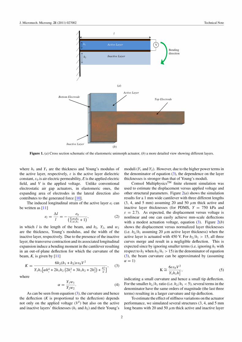
3. Fabrication process
Figure 3 illustrates the fabrication process incorporatingseveral important steps to ensure batch processability. Theseinclude soft lithography for printing the electrodes and
3
J. Micromech. Microeng. 21 (2011) 027002 Technical Note
Bottom Electrode
Laser-cut Elastomeric Actuator
(a)
(c)
Laser
Inked PDMSStamp
Silicon Substrate
PDMS InactiveLayer
(b)
Active Layer
Figure 3. Fabrication process for the elastomeric actuator, (a) stamping the bottom electrode on top of the spun-coated inactive PDMSlayer, (b) stamping the top electrode on top of the spun-coated active PDSM layer, and (c) final separation of individual actuators by lasermicromachining.
batch separation using laser micromachining. The processstarts with a 300 μm thick SU-8 (SU-8 2100, MicroChem)on a silicon wafer mold onto which the electrode PDMSstamp (Sylgard 184, Dow Corning, mixing ratio = 10:1)is cast and subsequently separated. Then, a thin layerof conductive carbon grease is prepared on a flat PDMSlayer and electrode stamp is inked against it. The 50 μmthick inactive PDMS layer is then spun coated on a pre-treated silicon wafer (tridecafluoro-(1,1,2,2,tetrahydrooctyl)-1-trichlorosilane, United Chemical Technologies, Inc.) andcured at 100 ◦C for 15 min. Subsequently, the first L-shapedelectrode layer (described above) is stamped onto the inactivePDMS layer, figure 3(a). Afterward, a 25 μm thick PDMS(15:1 ratio to decrease Young’s modulus and hence increase
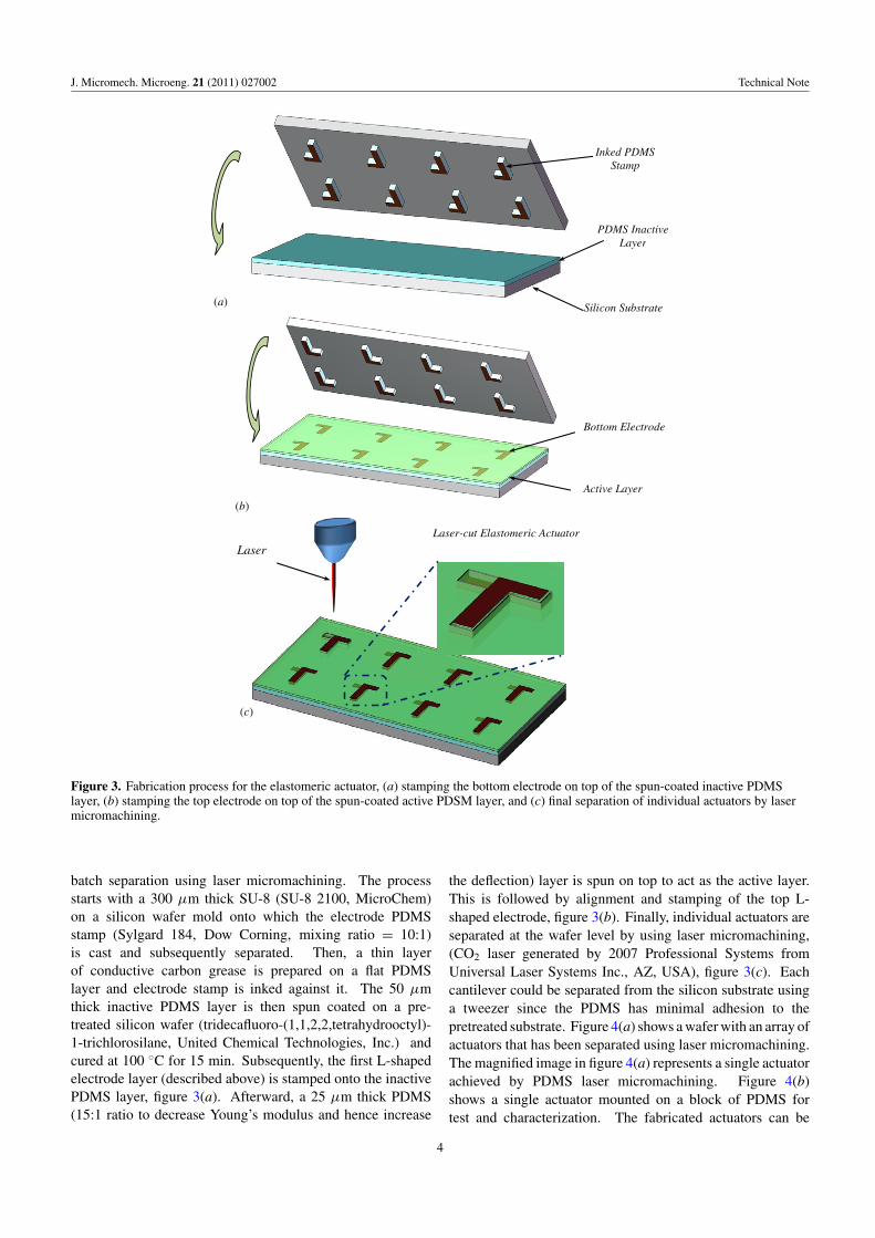
the deflection) layer is spun on top to act as the active layer.This is followed by alignment and stamping of the top L-shaped electrode, figure 3(b). Finally, individual actuators areseparated at the wafer level by using laser micromachining,(CO2 laser generated by 2007 Professional Systems fromUniversal Laser Systems Inc., AZ, USA), figure 3(c). Eachcantilever could be separated from the silicon substrate usinga tweezer since the PDMS has minimal adhesion to thepretreated substrate. Figure 4(a) shows a wafer with an array ofactuators that has been separated using laser micromachining.The magnified image in figure 4(a) represents a single actuatorachieved by PDMS laser micromachining. Figure 4(b)shows a single actuator mounted on a block of PDMS fortest and characterization. The fabricated actuators can be
4
J. Micromech. Microeng. 21 (2011) 027002 Technical Note
(a)
(b)
Laser Cut
3 mm
Figure 4. (a) Batch fabricated elastomeric actuators on a silicon wafer after separation by laser micromachining; magnified image showsthe laser cutting orientation; (b) measurement setup, a single actuator was mounted on a PDMS block.
Top electrode
Inactive Layer
Bottom electrode
Active layer
Sharp posts to puncture through thePDMS and create electrical connections
Silicon
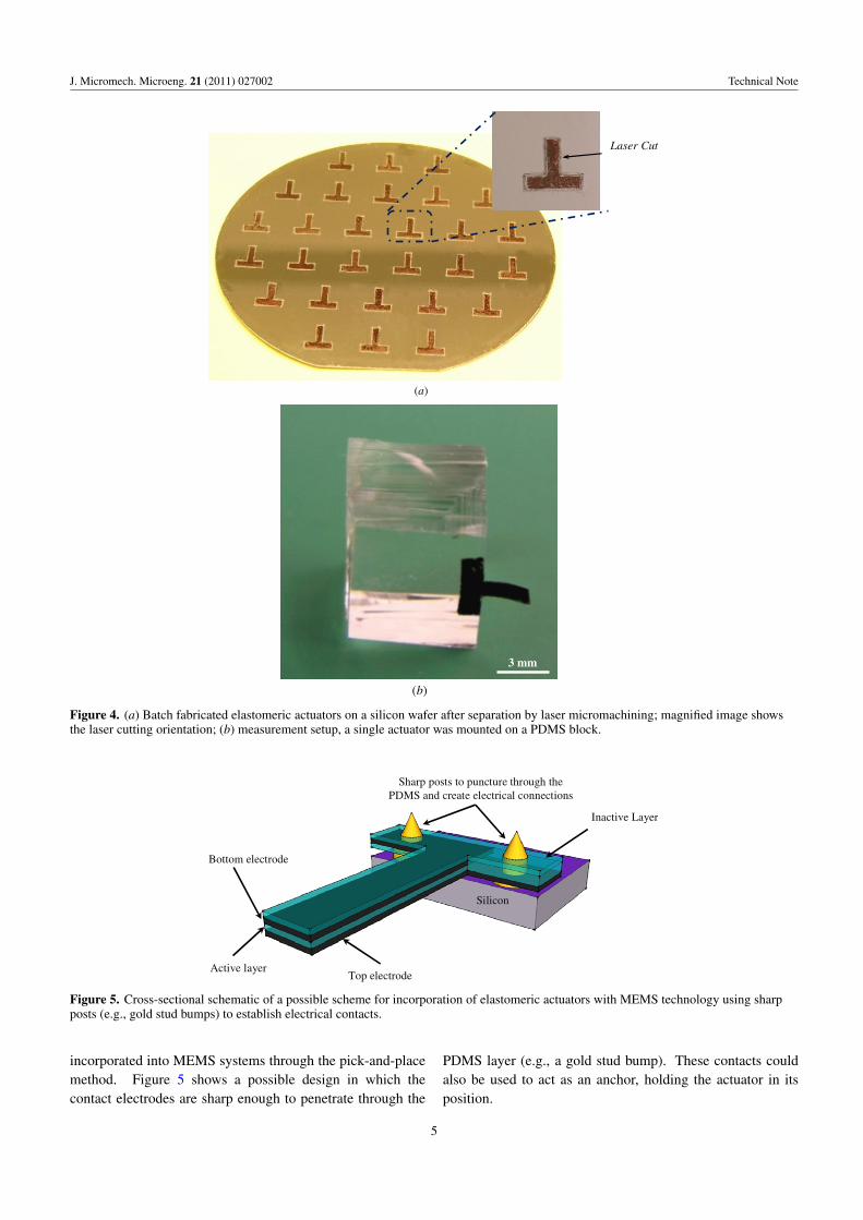
Figure 5. Cross-sectional schematic of a possible scheme for incorporation of elastomeric actuators with MEMS technology using sharpposts (e.g., gold stud bumps) to establish electrical contacts.
incorporated into MEMS systems through the pick-and-placemethod. Figure 5 shows a possible design in which thecontact electrodes are sharp enough to penetrate through the
PDMS layer (e.g., a gold stud bump). These contacts couldalso be used to act as an anchor, holding the actuator in itsposition.
5
J. Micromech. Microeng. 21 (2011) 027002 Technical Note
mm
4
3
2
1
0
mm
4
3
2
1
0
mm
(a) (b) (c)
4
3
2
1
0
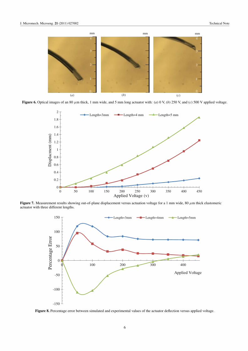
Figure 6. Optical images of an 80 μm thick, 1 mm wide, and 5 mm long actuator with: (a) 0 V, (b) 250 V, and (c) 500 V applied voltage.
0
0.2
0.4
0.6
0.8
1
1.2
1.4
1.6
1.8
2
0 50 100 150 200 250 300 350 400 450
Dis
plac
men
t(m
m)
Applied Voltage (v)
Length=3mm Length=4 mm Length=5 mm
Figure 7. Measurement results showing out-of-plane displacement versus actuation voltage for a 1 mm wide, 80 μm thick elastomericactuator with three different lengths.
-150
-100
-50
0
50
100
150
0 100 200 300 400
Per
cent
age
Err
or
Applied Voltage
Length=3mm Length=4mm Length=5mm
Figure 8. Percentage error between simulated and experimental values of the actuator deflection versus applied voltage.
6

J. Micromech. Microeng. 21 (2011) 027002 Technical Note
200 250 300 350 400 450
Out
putm
axim
umfo
rce
(µN
)
Applied Voltage (V)
Figure 9. Actuation voltage versus maximum force for a 4 mm long, 1 mm wide, and 80 μm thick elastomeric actuator.
4. Experimental results
After fabrication, the actuators were mounted on a PDMSblock and electrical connections were established by punchingneedle probes through the PDMS layers. Actuators were testedusing a high voltage power supply and their displacement wasmeasured through a video frame-grabber. Optical picturesof a 5 mm long actuator at different actuation voltages aredepicted in figure 6. Figure 7 shows tip-displacement versusapplied voltage for a 1 mm wide elastomeric actuator withthree different lengths (3, 4, and 5 mm). As can be seen,mm-scale actuation was achieved for voltages less than 500 V.To evaluate the experimental results against the simulation,the percentage error in the deflection, defined as 100 ×(DSimulated–DExperimental)/DSimulated, is plotted in figure 8. Ascan be seen, when the deflection is large, the experimentalresults closely follow the simulations for the 4 and 5 mmcantilevers while for the 3 mm actuator the deflection is lessthan the simulated results. This can be attributed to theexperimental setup, specifically the effect of punching needlesfor electrode contacts (needle penetration on the backendshortens the cantilever to some extent; this is more noticeableat smaller deflections as well as the shorter cantilevers (3 mmcantilever) at larger deflections). In another set of experiments,the maximum output force (clamped condition) versus appliedvoltage was measured for a 4 mm long actuator, and the resultis plotted in figure 9. A maximum force of 25 μN was achievedusing a 450 V actuation voltage.
5. Conclusions
In conclusion, we designed, simulated, and characterizeda batch-fabricated laser-micromachined elastomeric actuatorwith low actuation voltage and large out-of-plane deflection.Simulation results indicated that one can achieve largedeflections by using a soft active layer, while havinga reasonable stiffness by using a stiffer inactive layer.Furthermore, to achieve higher deflection, it is important to
keep the ratio of the inactive to active layer thickness to beless than 5. Three different size actuators were successfullyfabricated using this method and their performances werecharacterized. Millimeter-scale out-of-plane displacementwas achieved using a fairly low voltage (less than 500 V).A 4 mm long actuator was capable of applying 25 μN forceusing 450 V actuation voltage.
Acknowledgments
The authors would like to thank the staff at the BirckNanotechnology Center, Purdue University for their assistancein fabrication. They would also like to thank ProfessorCagri Cavran and Dr Chun-Li Chang for their help with lasermicromachining.
References
[1] Michael A, Kwok C Y, Yu K and Mackenzie M R 2008 Anovel bistable two-way actuated out-of-plane electrothermalmicrobridge J. Microelectromech. Syst. 17 58–68
[2] He S and Mrad R B 2008 Design, modeling, and demonstrationof a MEMS repulsive-force out-of-plane electrostatic microactuator J. Microelectromech. Syst. 17 532–47
[3] Ren K, Liu S, Lin M, Wang Y and Zhang Q M 2008 Acompact electroactive polymer actuator suitable forrefreshable Braille display Sensors Actuators A 143 335–42
[4] Plante J-S and Dubowsky S 2007 On the properties ofdielectric elastomer actuators and their design implicationsSmart Mater. Struct. 16 S227–36
[5] Lowe C, Zhang X and Kovacs G 2005 Dielectric elastomers inactuator technology Adv. Eng. Mater. 7 361–7
[6] O’Halloran A, O’Malley F and McHugh P 2008 A review ondielectric elastomer actuators, technology, applications, andchallenges J. Appl. Phys. 104 071101
[7] Kornbluh R, Pelrine R, Pei Q, Heydt R, Stanford S, Oh Sand Eckerle J 2002 Electroelastomers: applications ofdielectric elastomer transducers for actuation, generationand smart structures Proc. SPIE 4698 254–70
7

J. Micromech. Microeng. 21 (2011) 027002 Technical Note
[8] Carpi F, Frediani G, Mannini A and De Rossi D 2008Contractile and buckling actuators based on dielectricelastomers: devices and applications Adv. Sci. Technol.61 186–91
[9] Brown X Q, Ookawa K and Wong J Y 2005 Evaluation ofpolydimethylsiloxane scaffolds withphysiologically-relevant elastic moduli: interplay ofsubstrate mechanics and surface chemistry effects on
vascular smooth muscle cell response Biomaterials26 3123–9
[10] Krakovsky I, Romijn T and Posthuma de Boer A 1999 A fewremarks on the electrostriction of elastomers J. Appl. Phys.85 628–9
[11] Costen R C, Su J and Harrison J S 2001 Model for bendingactuators that use electrostrictive graft elastomers Proc.SPIE 4329 437–44
8