Simultaneous removal of oil and grease, and heavy metals from artificial bilge water using...
9
Simultaneous removal of oil and grease, and heavy metals from artificial bilge water using electro-coagulation/flotation Guillermo J. Rinc on a, * , Enrique J. La Motta b a Department of Civil and Environmental Engineering, University of New Orleans, 2045 Lakeshore Dr., Room 110, New Orleans, LA 70122, USA b Department of Civil and Environmental Engineering, University of New Orleans, 2045 Lakeshore Dr., Room 102, New Orleans, LA 70122, USA article info Article history: Received 23 August 2013 Received in revised form 11 April 2014 Accepted 3 May 2014 Available online Keywords: Bilge water Electro-coagulation Oil and grease Hexane extractable materials Heavy metals Wastewater treatment Continuous flow reactor Aluminum electrodes Carbon steel electrodes Pollution from ships abstract US and international regulations pertaining to the control of bilge water discharges from ships have concentrated their attention to the levels of oil and grease rather than to the heavy metal concentrations. The consensus is that any discharge of bilge water (and oily water emulsion within 12 nautical miles from the nearest land cannot exceed 15 parts per million (ppm). Since there is no specific regulation for metal pollutants under the bilge water section, reference standards regulating heavy metal concentrations are taken from the ambient water quality criteria to protect aquatic life. The research herein presented discusses electro-coagulation (EC) as a method to treat bilge water, with a focus on oily emulsions and heavy metals (copper, nickel and zinc) removal efficiency. Experiments were run using a continuous flow reactor, manufactured by Ecolotron, Inc., and a synthetic emulsion as artificial bilge water. The synthetic emulsion contained 5000 mg/L of oil and grease, 5 mg/L of copper, 1.5 mg/L of nickel, and 2.5 mg/l of zinc. The experimental results demonstrate that EC is very efficient in removing oil and grease. For oil and grease removal, the best treatment and cost efficiency was obtained when using a combination of carbon steel and aluminum electrodes, at a detention time less than one minute, a flow rate of 1 L/min and 0.6 A/cm 2 of current density. The final effluent oil and grease con- centration, before filtration, was always less than 10 mg/L. For heavy metal removal, the combination of aluminum and carbon steel electrodes, flow rate of 1 L/ min, effluent recycling, and 7.5 amps produced 99% zinc removal efficiency. Copper and nickel are harder to remove, and a removal efficiency of 70% was achieved. © 2014 Elsevier Ltd. All rights reserved. 1. Introduction In the United States, bilge water production is estimated in the millions of cubic meters per year (there is not a national report on the actual amounts of bilge water produced in the US). As a refer- ence, cruise ships operating in Southeast Alaska produce around 5e20 m 3 of bilge water every 24 h, that is 1800 to 7200 m 3 per year (Alaska Department of Environmental Conservation, 2000). The Environmental Protection Agency, (EPA) in conjunction with the Department of Defense (DoD), the Secretary of State, the Secretary of Commerce and several Federal Agencies, is developing the Uniform National Discharge Standards (UNDS), organized in three phases, for incidental liquid discharges from vessels of the US Armed Forces. From the Nature of Discharge Report for Surface Vessels Bilge Water, the annual mass loading of heavy metals in bilge water produced by US aircraft carriers is about 116 kg of copper, 57 kg of nickel, 299 kg of zinc, and 160 kg of iron (EPA, 1999). Even though the discharge of bilge water is strongly regulated, both inside and outside the country, the regulations have been focused more on controlling the discharge of oil and oily mixture than on the discharge of heavy metals. All vessels generate bilge water and most commissioned Armed Forces vessels are fitted with oil water separator (OWS) systems designed to prevent the discharge of oil in excess of 15 mg/L within 22.2 km (12 nautical miles), in accordance with OPNAVINST 5090.1B. In London, in 1973, the International Convention for the Pre- vention of Pollution from Ships (MARPOL, 1973) met and enforced, in 1978, the Regulation 16th, which states that any discharge of bilge water (and oily water emulsion) cannot exceed 15 parts per million (ppm) of oil content if the discharge is at 22.2 km (12 nautical miles) from the nearest land. The Unites States accepted the MARPOL Protocol and passed laws to enforce it, such as: the Clear Water Act (CWA, 1972; 33 U.S.C. * Corresponding author. Tel.: þ1 504 280 7089. E-mail address: [email protected] (G.J. Rinc on). Contents lists available at ScienceDirect Journal of Environmental Management journal homepage: www.elsevier.com/locate/jenvman http://dx.doi.org/10.1016/j.jenvman.2014.05.004 0301-4797/© 2014 Elsevier Ltd. All rights reserved. Journal of Environmental Management 144 (2014) 42e50
-
Upload
independent -
Category
Documents
-
view
0 -
download
0
Transcript of Simultaneous removal of oil and grease, and heavy metals from artificial bilge water using...
lable at ScienceDirect
Journal of Environmental Management 144 (2014) 42e50
Contents lists avai
Journal of Environmental Management
journal homepage: www.elsevier .com/locate/ jenvman
Simultaneous removal of oil and grease, and heavy metals fromartificial bilge water using electro-coagulation/flotation
Guillermo J. Rinc�on a, *, Enrique J. La Motta b
a Department of Civil and Environmental Engineering, University of New Orleans, 2045 Lakeshore Dr., Room 110, New Orleans, LA 70122, USAb Department of Civil and Environmental Engineering, University of New Orleans, 2045 Lakeshore Dr., Room 102, New Orleans, LA 70122, USA
a r t i c l e i n f o
Article history:Received 23 August 2013Received in revised form11 April 2014Accepted 3 May 2014Available online
Keywords:Bilge waterElectro-coagulationOil and greaseHexane extractable materialsHeavy metalsWastewater treatmentContinuous flow reactorAluminum electrodesCarbon steel electrodesPollution from ships
* Corresponding author. Tel.: þ1 504 280 7089.E-mail address: [email protected] (G.J. Rinc�on).
http://dx.doi.org/10.1016/j.jenvman.2014.05.0040301-4797/© 2014 Elsevier Ltd. All rights reserved.
a b s t r a c t
US and international regulations pertaining to the control of bilge water discharges from ships haveconcentrated their attention to the levels of oil and grease rather than to the heavy metal concentrations.The consensus is that any discharge of bilge water (and oily water emulsion within 12 nautical miles fromthe nearest land cannot exceed 15 parts per million (ppm). Since there is no specific regulation for metalpollutants under the bilge water section, reference standards regulating heavy metal concentrations aretaken from the ambient water quality criteria to protect aquatic life.
The research herein presented discusses electro-coagulation (EC) as a method to treat bilge water, witha focus on oily emulsions and heavy metals (copper, nickel and zinc) removal efficiency. Experimentswere run using a continuous flow reactor, manufactured by Ecolotron, Inc., and a synthetic emulsion asartificial bilge water. The synthetic emulsion contained 5000 mg/L of oil and grease, 5 mg/L of copper,1.5 mg/L of nickel, and 2.5 mg/l of zinc. The experimental results demonstrate that EC is very efficient inremoving oil and grease. For oil and grease removal, the best treatment and cost efficiency was obtainedwhen using a combination of carbon steel and aluminum electrodes, at a detention time less than oneminute, a flow rate of 1 L/min and 0.6 A/cm2 of current density. The final effluent oil and grease con-centration, before filtration, was always less than 10 mg/L.
For heavy metal removal, the combination of aluminum and carbon steel electrodes, flow rate of 1 L/min, effluent recycling, and 7.5 amps produced 99% zinc removal efficiency. Copper and nickel are harderto remove, and a removal efficiency of 70% was achieved.
© 2014 Elsevier Ltd. All rights reserved.
1. Introduction
In the United States, bilge water production is estimated in themillions of cubic meters per year (there is not a national report onthe actual amounts of bilge water produced in the US). As a refer-ence, cruise ships operating in Southeast Alaska produce around5e20 m3 of bilge water every 24 h, that is 1800 to 7200 m3 per year(Alaska Department of Environmental Conservation, 2000).
The Environmental Protection Agency, (EPA) in conjunctionwith the Department of Defense (DoD), the Secretary of State, theSecretary of Commerce and several Federal Agencies, is developingthe Uniform National Discharge Standards (UNDS), organized inthree phases, for incidental liquid discharges from vessels of the USArmed Forces. From the Nature of Discharge Report for SurfaceVessels Bilge Water, the annual mass loading of heavy metals in
bilge water produced by US aircraft carriers is about 116 kg ofcopper, 57 kg of nickel, 299 kg of zinc, and 160 kg of iron (EPA,1999).
Even though the discharge of bilge water is strongly regulated,both inside and outside the country, the regulations have beenfocused more on controlling the discharge of oil and oily mixturethan on the discharge of heavy metals. All vessels generate bilgewater andmost commissioned Armed Forces vessels are fitted withoil water separator (OWS) systems designed to prevent thedischarge of oil in excess of 15 mg/L within 22.2 km (12 nauticalmiles), in accordance with OPNAVINST 5090.1B.
In London, in 1973, the International Convention for the Pre-vention of Pollution from Ships (MARPOL, 1973) met and enforced,in 1978, the Regulation 16th, which states that any discharge ofbilge water (and oily water emulsion) cannot exceed 15 parts permillion (ppm) of oil content if the discharge is at 22.2 km (12nautical miles) from the nearest land.
The Unites States accepted the MARPOL Protocol and passedlaws to enforce it, such as: the ClearWater Act (CWA,1972; 33 U.S.C.
Symbols and abbreviations
APPS Act to Prevent Pollution from ShipsASTM American Standard Test MethodCo initial concentrationDC direct currentDMC dissolved metal concentrationDO dissolved oxygenDoD Department of DefenseE energy consumption (kWh)EC electrocoagulationEPA Environmental Protection AgencyHEM hexane extractable materialsI current intensity (Amps)IR infraredISE ion selective electrodem mass of contaminant (g)MARPOL International Convention for the Prevention of
Pollution from Ship
NMSA National Marine SanctuariesNTU Nephelometric Turbidity UnitOPA Oil Pollution ActOPNAVINST Office of the Chief of Naval Operations InstructionORP OxidationeReduction PotentialPFR plug-flow reactorRPM revolutions per minuteSAE Society of Automotive EngineersSBW Synthetic Bilge WaterSEC Specific Energy ConsumptionTDS total dissolved solidsTOC total organic carbonTPH total petroleum hydrocarbonsTSS total suspended solidsU Voltage (V)UNDS Uniform National Discharge StandardsW power (kW)
G.J. Rinc�on, E.J. La Motta / Journal of Environmental Management 144 (2014) 42e50 43
x 1301), which establishes the basic structure for regulating dis-charges of pollutants into the waters of the United States andregulating quality standards for surface waters; the National Ma-rine Sanctuaries Act (NMSA, 1988; 16 U.S.C. x 1431 et seq.), a lawthat protects marine resources and ecosystems, such as coral reefs,sunken historical vessels, or unique habitats, from degradationwhile facilitating public or private uses compatible with resourceprotection; the Oil Pollution Act (OPA, 1990; 33 U.S.C. x 2702 etseq.), that streamlined and strengthened EPA's ability to preventand respond to catastrophic oil spills; and the Act to PreventPollution from Ships (APPS, 2000; 33 U.S.C. x 1901 et seq.), federallaw that implements those provisions of MARPOL in United States.In addition, the Coast Guard has the primary responsibility toprescribe and enforce the regulation necessary to implement APPS2000 in the United States and has regulations pertain to manage-ment of the discharge of oil or oily mixtures into the sea from ships.
In summary, bilge water discharges are well controlled withregard to oil concentrations but are lacking in specific heavy metalconcentration limits. Since there is no specific regulation for metalpollutants under the bilge water section, reference standardsregulating heavy metal concentrations are taken from the ambientwater quality criteria to protect aquatic life (65 FR 31682 (EPA,2009)).
With impending future stringent regulations concerning thelevels of heavy metal and oil and grease that can be discharged incontinental waters, enhanced treatment methods with highremoval efficiency, low operation costs, short operation times andreduced use of additional chemical products are required. In thepresent article, electro-coagulation (EC) is discussed as a method totreat bilge water, with a focus on oily emulsions and heavy metals(copper, nickel and zinc) removal efficiency.
The objectives of this research include conducting experimentswith a continuous flow EC reactor to determine the factors affectingthe oil andmetals (copper, nickel and zinc) removal efficiency usinga synthetic bilge water. These factors included flow rate, electrodematerial, flotation unit configuration and current intensity. Oper-ational costs of this type of treatment are also discussed.
2. The electro-coagulation (EC) process
The EC process involves many chemicals and physical factors,where electrical current is applied to consumable electrodes that
generate, in the primary stage, coagulants due to electrolyticoxidation of the electrode. Immediately, in the secondary stage,contaminant destabilization, particulate suspension, and breakingof emulsions occur; after that, the ultimate stage, the formation offlocs, takes place due to the aggregation of destabilized particles(Mollah et al., 2004a,b). EC stages are detailed as follows (Chenet al., 2000a,b; Kobya et al., 2003; Chen, 2004; Mollah et al.,2004a,b; Heidmann and Camano, 2008; Merzouk et al., 2009;Thella et al., 2008):
The generation of metal ions in the EC process takes place asfollows:
At the carbon steel anode:
FeðsÞ/Fe2þðaqÞ þ 2e� (1)
FeðsÞ/Fe3þðaqÞ þ 3e� (2)
At the aluminum anode:
AlðsÞ/Al2þðaqÞ þ 2e� (3)
AlðsÞ/Al3þðaqÞ þ 3e� (4)
Metal ions are hydrolyzed forming hydroxides like AlðH2OÞ3þ6 ,
AlðH2OÞ5OH2þ, AlðH2OÞ4OH2þ, FeðOHÞ3 and these hydrolysis
products can produce AlðOHÞ2þ, AlðOHÞþ2 , Al2ðOHÞ4þ2 , AlðOHÞ�4Al6ðOHÞ3þ15 , Al7ðOHÞ4þ17 , Al8ðOHÞ4þ20 , Al13O4ðOHÞ7þ24 , Al13ðOHÞ5þ34 ,FeðH2OÞ3þ6 , FeðH2OÞ5ðOHÞ2þ, FeðH2OÞ4ðOHÞþ2 , Fe2ðH2OÞ8ðOHÞ4þ2 ,
Fe2ðH2OÞ6ðOHÞ4þ4 .Due to salinity in the water stream, chlorine is released ac-
cording to Eq. (6):At the anode:
2H2OðlÞ/4HþðaqÞ þ O2ðgÞ þ 4e� (5)
2Cl�/Cl2 þ 2e (6)
At the cathode:
G.J. Rinc�on, E.J. La Motta / Journal of Environmental Management 144 (2014) 42e5044
2H2OðlÞ þ 2e�/H2ðgÞ þ 2OH� (7)
2Hþ þ 2e�/H2ðgÞ[ (8)
Many authors include the evolution of oxygen at the anode (Eq.(5)). On the other hand, Moreno et al. (2009) reported that wheniron electrodes are used there is no formation of oxygen during ECeven though the presence of magnetite (Fe2O4) and maghemite(Fe2O3) in EC sludge could suggest it; these iron oxides are formedthrough dehydration of iron hydroxides. In some cases, iron oxidescan occur during the analysis of the flocs by filtration and samplepreparation.
The next step is wastewater destabilization and aggregation. Inthis stage, the destabilization of contaminants, breaking of emul-sion, particulate suspension and formation of flocs take place; also,the diffuse double layer is compressed, and ionic species areneutralized. Small flocs trap contaminants and are carried to thesurface by hydrogen bubbles when the bubbles emerge from thereactor; hence, the sludge layer is formed at the surface. Thesmaller the hydrogen bubble size, the more surface area providedto trap flocs and the more effective separation of contaminantsfromwater (Chen et al., 2000a,b). Even during the flotation process,there are heavy stable flocs that go downward, creating a sedimentlayer.
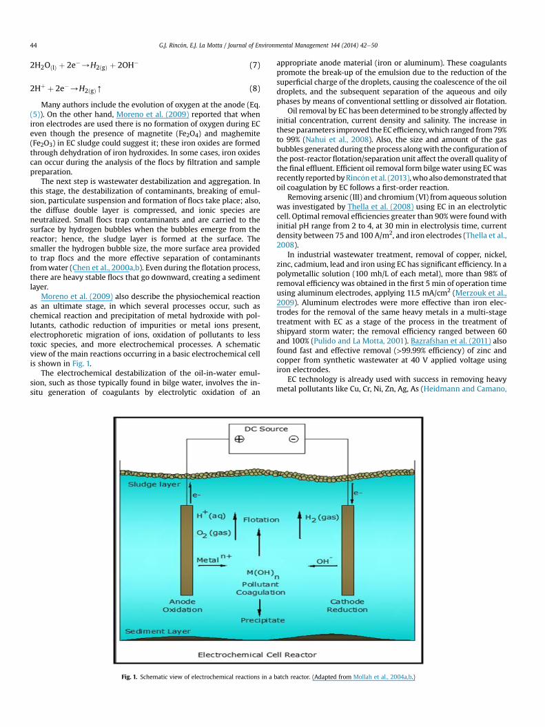
Moreno et al. (2009) also describe the physiochemical reactionas an ultimate stage, in which several processes occur, such aschemical reaction and precipitation of metal hydroxide with pol-lutants, cathodic reduction of impurities or metal ions present,electrophoretic migration of ions, oxidation of pollutants to lesstoxic species, and more electrochemical processes. A schematicview of the main reactions occurring in a basic electrochemical cellis shown in Fig. 1.
The electrochemical destabilization of the oil-in-water emul-sion, such as those typically found in bilge water, involves the in-situ generation of coagulants by electrolytic oxidation of an
Fig. 1. Schematic view of electrochemical reactions in a b
appropriate anode material (iron or aluminum). These coagulantspromote the break-up of the emulsion due to the reduction of thesuperficial charge of the droplets, causing the coalescence of the oildroplets, and the subsequent separation of the aqueous and oilyphases by means of conventional settling or dissolved air flotation.
Oil removal by EC has been determined to be strongly affected byinitial concentration, current density and salinity. The increase inthese parameters improved theECefficiency,which ranged from79%to 99% (Nahui et al., 2008). Also, the size and amount of the gasbubbles generatedduring theprocess alongwith the configurationofthe post-reactor flotation/separation unit affect the overall quality ofthe final effluent. Efficient oil removal form bilgewater using ECwasrecently reportedbyRinc�onet al. (2013),whoalsodemonstrated thatoil coagulation by EC follows a first-order reaction.
Removing arsenic (III) and chromium (VI) from aqueous solutionwas investigated by Thella et al. (2008) using EC in an electrolyticcell. Optimal removal efficiencies greater than 90%were foundwithinitial pH range from 2 to 4, at 30 min in electrolysis time, currentdensity between 75 and 100 A/m2, and iron electrodes (Thella et al.,2008).
In industrial wastewater treatment, removal of copper, nickel,zinc, cadmium, lead and iron using EC has significant efficiency. In apolymetallic solution (100 mh/L of each metal), more than 98% ofremoval efficiency was obtained in the first 5 min of operation timeusing aluminum electrodes, applying 11.5 mA/cm2 (Merzouk et al.,2009). Aluminum electrodes were more effective than iron elec-trodes for the removal of the same heavy metals in a multi-stagetreatment with EC as a stage of the process in the treatment ofshipyard storm water; the removal efficiency ranged between 60and 100% (Pulido and La Motta, 2001). Bazrafshan et al. (2011) alsofound fast and effective removal (>99.99% efficiency) of zinc andcopper from synthetic wastewater at 40 V applied voltage usingiron electrodes.
EC technology is already used with success in removing heavymetal pollutants like Cu, Cr, Ni, Zn, Ag, As (Heidmann and Camano,
atch reactor. (Adapted from Mollah et al., 2004a,b.)
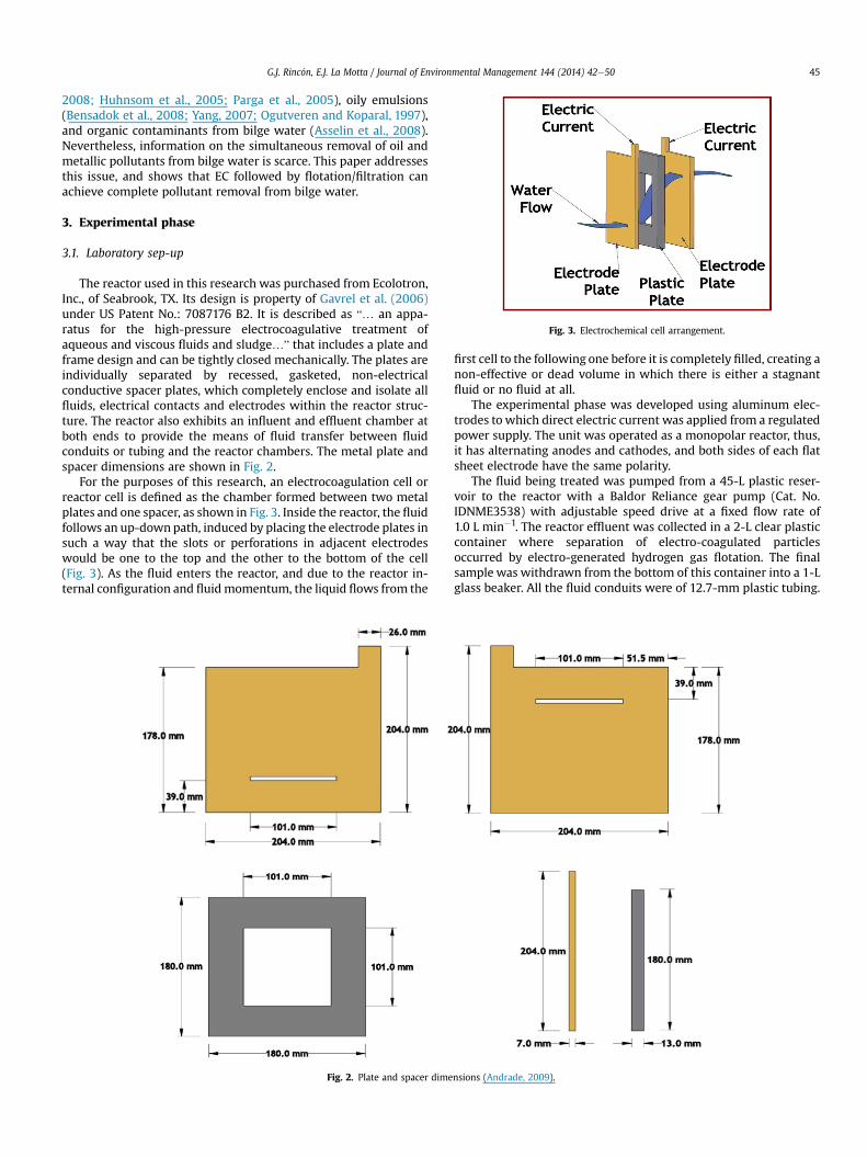
Fig. 3. Electrochemical cell arrangement.
G.J. Rinc�on, E.J. La Motta / Journal of Environmental Management 144 (2014) 42e50 45
2008; Huhnsom et al., 2005; Parga et al., 2005), oily emulsions(Bensadok et al., 2008; Yang, 2007; Ogutveren and Koparal, 1997),and organic contaminants from bilge water (Asselin et al., 2008).Nevertheless, information on the simultaneous removal of oil andmetallic pollutants from bilge water is scarce. This paper addressesthis issue, and shows that EC followed by flotation/filtration canachieve complete pollutant removal from bilge water.
3. Experimental phase
3.1. Laboratory sep-up
The reactor used in this research was purchased from Ecolotron,Inc., of Seabrook, TX. Its design is property of Gavrel et al. (2006)under US Patent No.: 7087176 B2. It is described as “… an appa-ratus for the high-pressure electrocoagulative treatment ofaqueous and viscous fluids and sludge…” that includes a plate andframe design and can be tightly closed mechanically. The plates areindividually separated by recessed, gasketed, non-electricalconductive spacer plates, which completely enclose and isolate allfluids, electrical contacts and electrodes within the reactor struc-ture. The reactor also exhibits an influent and effluent chamber atboth ends to provide the means of fluid transfer between fluidconduits or tubing and the reactor chambers. The metal plate andspacer dimensions are shown in Fig. 2.
For the purposes of this research, an electrocoagulation cell orreactor cell is defined as the chamber formed between two metalplates and one spacer, as shown in Fig. 3. Inside the reactor, the fluidfollows an up-downpath, induced by placing the electrode plates insuch a way that the slots or perforations in adjacent electrodeswould be one to the top and the other to the bottom of the cell(Fig. 3). As the fluid enters the reactor, and due to the reactor in-ternal configuration and fluidmomentum, the liquid flows from the
Fig. 2. Plate and spacer dime
first cell to the following one before it is completely filled, creating anon-effective or dead volume in which there is either a stagnantfluid or no fluid at all.
The experimental phase was developed using aluminum elec-trodes to which direct electric current was applied from a regulatedpower supply. The unit was operated as a monopolar reactor, thus,it has alternating anodes and cathodes, and both sides of each flatsheet electrode have the same polarity.
The fluid being treated was pumped from a 45-L plastic reser-voir to the reactor with a Baldor Reliance gear pump (Cat. No.IDNME3538) with adjustable speed drive at a fixed flow rate of1.0 L min�1. The reactor effluent was collected in a 2-L clear plasticcontainer where separation of electro-coagulated particlesoccurred by electro-generated hydrogen gas flotation. The finalsample was withdrawn from the bottom of this container into a 1-Lglass beaker. All the fluid conduits were of 12.7-mm plastic tubing.
nsions (Andrade, 2009).
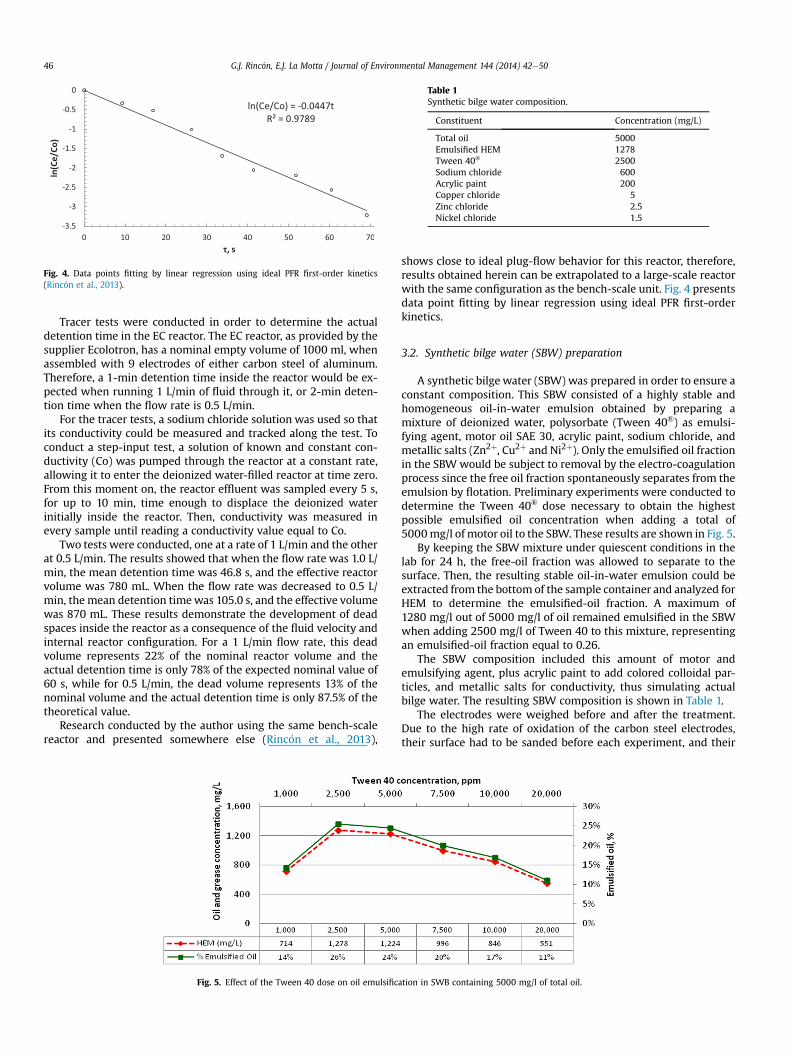
Fig. 4. Data points fitting by linear regression using ideal PFR first-order kinetics(Rinc�on et al., 2013).
Table 1Synthetic bilge water composition.
Constituent Concentration (mg/L)
Total oil 5000Emulsified HEM 1278Tween 40® 2500Sodium chloride 600Acrylic paint 200Copper chloride 5Zinc chloride 2.5Nickel chloride 1.5
G.J. Rinc�on, E.J. La Motta / Journal of Environmental Management 144 (2014) 42e5046
Tracer tests were conducted in order to determine the actualdetention time in the EC reactor. The EC reactor, as provided by thesupplier Ecolotron, has a nominal empty volume of 1000 ml, whenassembled with 9 electrodes of either carbon steel of aluminum.Therefore, a 1-min detention time inside the reactor would be ex-pected when running 1 L/min of fluid through it, or 2-min deten-tion time when the flow rate is 0.5 L/min.
For the tracer tests, a sodium chloride solution was used so thatits conductivity could be measured and tracked along the test. Toconduct a step-input test, a solution of known and constant con-ductivity (Co) was pumped through the reactor at a constant rate,allowing it to enter the deionized water-filled reactor at time zero.From this moment on, the reactor effluent was sampled every 5 s,for up to 10 min, time enough to displace the deionized waterinitially inside the reactor. Then, conductivity was measured inevery sample until reading a conductivity value equal to Co.
Two tests were conducted, one at a rate of 1 L/min and the otherat 0.5 L/min. The results showed that when the flow rate was 1.0 L/min, the mean detention time was 46.8 s, and the effective reactorvolume was 780 mL. When the flow rate was decreased to 0.5 L/min, the mean detention timewas 105.0 s, and the effective volumewas 870 mL. These results demonstrate the development of deadspaces inside the reactor as a consequence of the fluid velocity andinternal reactor configuration. For a 1 L/min flow rate, this deadvolume represents 22% of the nominal reactor volume and theactual detention time is only 78% of the expected nominal value of60 s, while for 0.5 L/min, the dead volume represents 13% of thenominal volume and the actual detention time is only 87.5% of thetheoretical value.
Research conducted by the author using the same bench-scalereactor and presented somewhere else (Rinc�on et al., 2013),
Fig. 5. Effect of the Tween 40 dose on oil emulsific
shows close to ideal plug-flow behavior for this reactor, therefore,results obtained herein can be extrapolated to a large-scale reactorwith the same configuration as the bench-scale unit. Fig. 4 presentsdata point fitting by linear regression using ideal PFR first-orderkinetics.
3.2. Synthetic bilge water (SBW) preparation
A synthetic bilge water (SBW) was prepared in order to ensure aconstant composition. This SBW consisted of a highly stable andhomogeneous oil-in-water emulsion obtained by preparing amixture of deionized water, polysorbate (Tween 40®) as emulsi-fying agent, motor oil SAE 30, acrylic paint, sodium chloride, andmetallic salts (Zn2þ, Cu2þ and Ni2þ). Only the emulsified oil fractionin the SBW would be subject to removal by the electro-coagulationprocess since the free oil fraction spontaneously separates from theemulsion by flotation. Preliminary experiments were conducted todetermine the Tween 40® dose necessary to obtain the highestpossible emulsified oil concentration when adding a total of5000mg/l of motor oil to the SBW. These results are shown in Fig. 5.
By keeping the SBW mixture under quiescent conditions in thelab for 24 h, the free-oil fraction was allowed to separate to thesurface. Then, the resulting stable oil-in-water emulsion could beextracted from the bottom of the sample container and analyzed forHEM to determine the emulsified-oil fraction. A maximum of1280 mg/l out of 5000 mg/l of oil remained emulsified in the SBWwhen adding 2500 mg/l of Tween 40 to this mixture, representingan emulsified-oil fraction equal to 0.26.
The SBW composition included this amount of motor andemulsifying agent, plus acrylic paint to add colored colloidal par-ticles, and metallic salts for conductivity, thus simulating actualbilge water. The resulting SBW composition is shown in Table 1.
The electrodes were weighed before and after the treatment.Due to the high rate of oxidation of the carbon steel electrodes,their surface had to be sanded before each experiment, and their
ation in SWB containing 5000 mg/l of total oil.
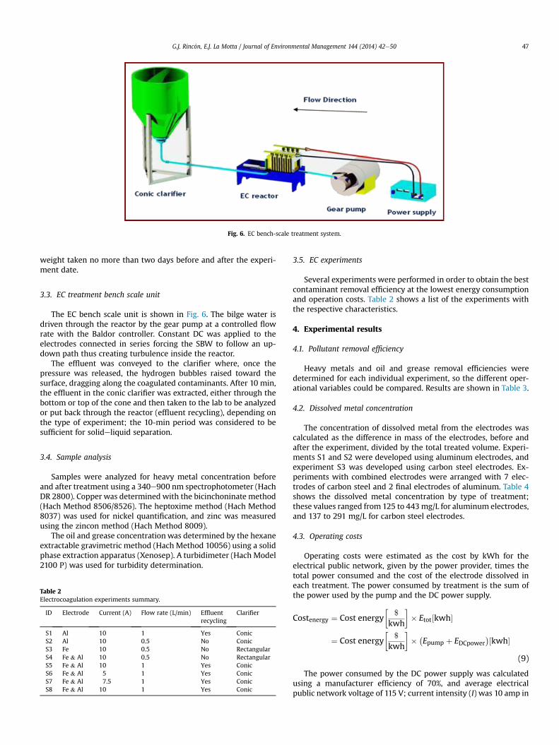
Fig. 6. EC bench-scale treatment system.
G.J. Rinc�on, E.J. La Motta / Journal of Environmental Management 144 (2014) 42e50 47
weight taken no more than two days before and after the experi-ment date.
3.3. EC treatment bench scale unit
The EC bench scale unit is shown in Fig. 6. The bilge water isdriven through the reactor by the gear pump at a controlled flowrate with the Baldor controller. Constant DC was applied to theelectrodes connected in series forcing the SBW to follow an up-down path thus creating turbulence inside the reactor.
The effluent was conveyed to the clarifier where, once thepressure was released, the hydrogen bubbles raised toward thesurface, dragging along the coagulated contaminants. After 10 min,the effluent in the conic clarifier was extracted, either through thebottom or top of the cone and then taken to the lab to be analyzedor put back through the reactor (effluent recycling), depending onthe type of experiment; the 10-min period was considered to besufficient for solideliquid separation.
3.4. Sample analysis
Samples were analyzed for heavy metal concentration beforeand after treatment using a 340e900 nm spectrophotometer (HachDR 2800). Copper was determined with the bicinchoninate method(Hach Method 8506/8526). The heptoxime method (Hach Method8037) was used for nickel quantification, and zinc was measuredusing the zincon method (Hach Method 8009).
The oil and grease concentration was determined by the hexaneextractable gravimetric method (Hach Method 10056) using a solidphase extraction apparatus (Xenosep). A turbidimeter (Hach Model2100 P) was used for turbidity determination.
Table 2Electrocoagulation experiments summary.
ID Electrode Current (A) Flow rate (L/min) Effluentrecycling
Clarifier
S1 Al 10 1 Yes ConicS2 Al 10 0.5 No ConicS3 Fe 10 0.5 No RectangularS4 Fe & Al 10 0.5 No RectangularS5 Fe & Al 10 1 Yes ConicS6 Fe & Al 5 1 Yes ConicS7 Fe & Al 7.5 1 Yes ConicS8 Fe & Al 10 1 Yes Conic
3.5. EC experiments
Several experiments were performed in order to obtain the bestcontaminant removal efficiency at the lowest energy consumptionand operation costs. Table 2 shows a list of the experiments withthe respective characteristics.
4. Experimental results
4.1. Pollutant removal efficiency
Heavy metals and oil and grease removal efficiencies weredetermined for each individual experiment, so the different oper-ational variables could be compared. Results are shown in Table 3.
4.2. Dissolved metal concentration
The concentration of dissolved metal from the electrodes wascalculated as the difference in mass of the electrodes, before andafter the experiment, divided by the total treated volume. Experi-ments S1 and S2 were developed using aluminum electrodes, andexperiment S3 was developed using carbon steel electrodes. Ex-periments with combined electrodes were arranged with 7 elec-trodes of carbon steel and 2 final electrodes of aluminum. Table 4shows the dissolved metal concentration by type of treatment;these values ranged from 125 to 443mg/L for aluminum electrodes,and 137 to 291 mg/L for carbon steel electrodes.
4.3. Operating costs
Operating costs were estimated as the cost by kWh for theelectrical public network, given by the power provider, times thetotal power consumed and the cost of the electrode dissolved ineach treatment. The power consumed by treatment is the sum ofthe power used by the pump and the DC power supply.
Costenergy ¼ Cost energy�
$
kwh
�� Etot½kwh�
¼ Cost energy�
$
kwh
�� �
Epump þ EDCpower�½kwh�
(9)
The power consumed by the DC power supply was calculatedusing a manufacturer efficiency of 70%, and average electricalpublic network voltage of 115 V; current intensity (I) was 10 amp in
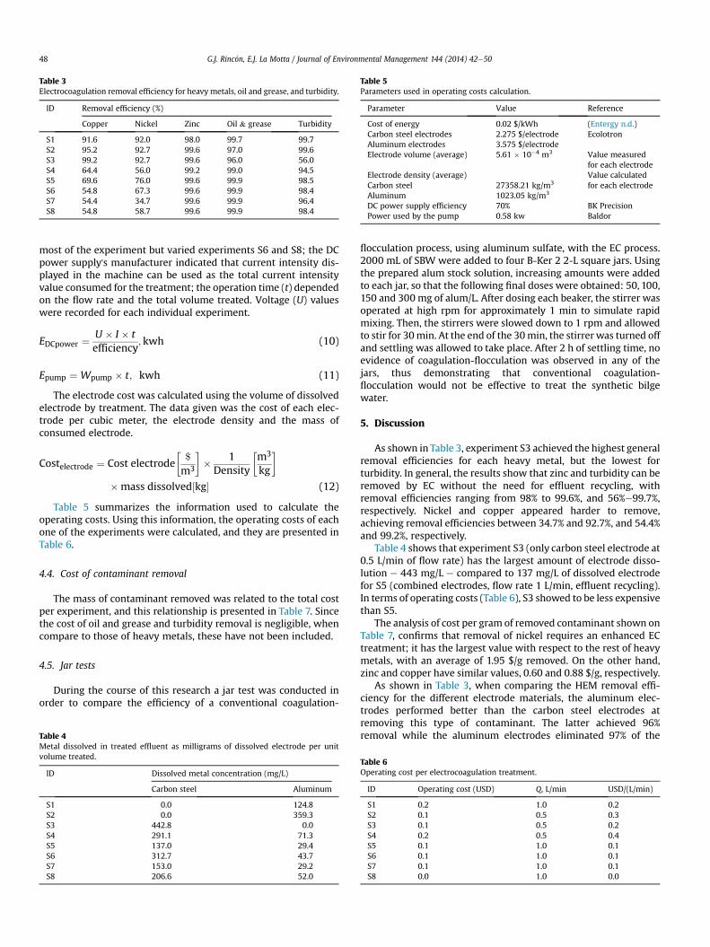
Table 3Electrocoagulation removal efficiency for heavymetals, oil and grease, and turbidity.
ID Removal efficiency (%)
Copper Nickel Zinc Oil & grease Turbidity
S1 91.6 92.0 98.0 99.7 99.7S2 95.2 92.7 99.6 97.0 99.6S3 99.2 92.7 99.6 96.0 56.0S4 64.4 56.0 99.2 99.0 94.5S5 69.6 76.0 99.6 99.9 98.5S6 54.8 67.3 99.6 99.9 98.4S7 54.4 34.7 99.6 99.9 96.4S8 54.8 58.7 99.6 99.9 98.4
Table 5Parameters used in operating costs calculation.
Parameter Value Reference
Cost of energy 0.02 $/kWh (Entergy n.d.)Carbon steel electrodes 2.275 $/electrode EcolotronAluminum electrodes 3.575 $/electrodeElectrode volume (average) 5.61 � 10�4 m3 Value measured
for each electrodeElectrode density (average) Value calculated
for each electrodeCarbon steel 27358.21 kg/m3
Aluminum 1023.05 kg/m3
DC power supply efficiency 70% BK PrecisionPower used by the pump 0.58 kw Baldor
G.J. Rinc�on, E.J. La Motta / Journal of Environmental Management 144 (2014) 42e5048
most of the experiment but varied experiments S6 and S8; the DCpower supply's manufacturer indicated that current intensity dis-played in the machine can be used as the total current intensityvalue consumed for the treatment; the operation time (t) dependedon the flow rate and the total volume treated. Voltage (U) valueswere recorded for each individual experiment.
EDCpower ¼U � I � tefficiency
; kwh (10)
Epump ¼ Wpump � t; kwh (11)
The electrode cost was calculated using the volume of dissolvedelectrode by treatment. The data given was the cost of each elec-trode per cubic meter, the electrode density and the mass ofconsumed electrode.
Costelectrode ¼ Cost electrode�$
m3
�� 1Density
�m3
kg
�
�mass dissolved½kg� (12)
Table 5 summarizes the information used to calculate theoperating costs. Using this information, the operating costs of eachone of the experiments were calculated, and they are presented inTable 6.
4.4. Cost of contaminant removal
The mass of contaminant removed was related to the total costper experiment, and this relationship is presented in Table 7. Sincethe cost of oil and grease and turbidity removal is negligible, whencompare to those of heavy metals, these have not been included.
4.5. Jar tests
During the course of this research a jar test was conducted inorder to compare the efficiency of a conventional coagulation-
Table 4Metal dissolved in treated effluent as milligrams of dissolved electrode per unitvolume treated.
ID Dissolved metal concentration (mg/L)
Carbon steel Aluminum
S1 0.0 124.8S2 0.0 359.3S3 442.8 0.0S4 291.1 71.3S5 137.0 29.4S6 312.7 43.7S7 153.0 29.2S8 206.6 52.0
flocculation process, using aluminum sulfate, with the EC process.2000 mL of SBW were added to four B-Ker 2 2-L square jars. Usingthe prepared alum stock solution, increasing amounts were addedto each jar, so that the following final doses were obtained: 50, 100,150 and 300 mg of alum/L. After dosing each beaker, the stirrer wasoperated at high rpm for approximately 1 min to simulate rapidmixing. Then, the stirrers were slowed down to 1 rpm and allowedto stir for 30min. At the end of the 30min, the stirrer was turned offand settling was allowed to take place. After 2 h of settling time, noevidence of coagulation-flocculation was observed in any of thejars, thus demonstrating that conventional coagulation-flocculation would not be effective to treat the synthetic bilgewater.
5. Discussion
As shown in Table 3, experiment S3 achieved the highest generalremoval efficiencies for each heavy metal, but the lowest forturbidity. In general, the results show that zinc and turbidity can beremoved by EC without the need for effluent recycling, withremoval efficiencies ranging from 98% to 99.6%, and 56%e99.7%,respectively. Nickel and copper appeared harder to remove,achieving removal efficiencies between 34.7% and 92.7%, and 54.4%and 99.2%, respectively.
Table 4 shows that experiment S3 (only carbon steel electrode at0.5 L/min of flow rate) has the largest amount of electrode disso-lution e 443 mg/L e compared to 137 mg/L of dissolved electrodefor S5 (combined electrodes, flow rate 1 L/min, effluent recycling).In terms of operating costs (Table 6), S3 showed to be less expensivethan S5.
The analysis of cost per gram of removed contaminant shown onTable 7, confirms that removal of nickel requires an enhanced ECtreatment; it has the largest value with respect to the rest of heavymetals, with an average of 1.95 $/g removed. On the other hand,zinc and copper have similar values, 0.60 and 0.88 $/g, respectively.
As shown in Table 3, when comparing the HEM removal effi-ciency for the different electrode materials, the aluminum elec-trodes performed better than the carbon steel electrodes atremoving this type of contaminant. The latter achieved 96%removal while the aluminum electrodes eliminated 97% of the
Table 6Operating cost per electrocoagulation treatment.
ID Operating cost (USD) Q, L/min USD/(L/min)
S1 0.2 1.0 0.2S2 0.1 0.5 0.3S3 0.1 0.5 0.2S4 0.2 0.5 0.4S5 0.1 1.0 0.1S6 0.1 1.0 0.1S7 0.1 1.0 0.1S8 0.0 1.0 0.0
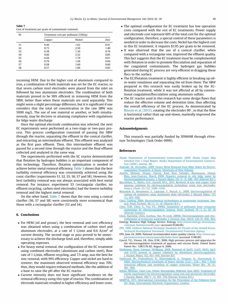
Table 7Cost of treatment per gram of contaminant removed.
ID Treatment cost per pollutant (USD/g)
Copper Nickel Zinc
S1 0.49 1.62 0.91S2 0.73 2.50 1.40S3 0.38 1.36 0.76S4 0.66 2.52 0.85S5 0.44 1.79 0.61S6 0.79 1.94 0.84S7 0.58 1.60 0.60S8 0.57 1.84 0.82
G.J. Rinc�on, E.J. La Motta / Journal of Environmental Management 144 (2014) 42e50 49
incoming HEM. Due to the higher cost of aluminum compared toiron, a combination of both materials was set for the EC reactor, sothat seven carbon steel electrodes were placed from the inlet onfollowed by two aluminum electrodes. The combination of bothmaterials proved to be 99% efficient in removing HEM from theSBW, better than when these materials are used separately. Thismight seem a slight percentage difference, but it is significant if oneconsiders that the total oil concentration in the raw SBW was5000 mg/L. The use of one material or another, or both simulta-neously, may be decisive in attaining compliance with regulationsfor bilge water discharge.
Once the optimal electrode combination was selected, the nextEC experiments were performed as a two-stage or two-pass pro-cess. This process configuration consisted of passing the SBWthrough the reactor, separating the effluent in the conical clarifier,and extracting an intermediate effluent. This effluent was analyzedas the first pass effluent. Then, this intermediate effluent waspassed for a second time through the reactor and the final effluentcollected and analyzed in the same way.
The experiments performed with the EC reactor demonstratedthat flotation by hydrogen bubbles is an important component ofthis technology. Therefore, flotation optimization is needed toachieve better metal removal efficiency. Table 3 shows that the bestturbidity removal efficiency was consistently achieved using theconic clarifier (experiments S1, S2, S5, S6, S7 and S8). However, thebest turbidity removal was not always associated with best metalremoval. For instance, experiment S3 (rectangular clarifier, noeffluent recycling, carbon steel electrodes) had the lowest turbidityremoval and the highest metal removal.
On the other hand, Table 7 shows that the runs using a conicalclarifier (S6, S7 and S8) were consistently more economical thanthose with a rectangular clarifier (S3 and S4).
6. Conclusions
� For HEM (oil and grease), the best removal and cost efficiencywas obtained when using a combination of carbon steel andaluminum electrodes, at a rate of 1 L/min and 0.6 A/cm2 ofcurrent density. The second stage or pass proved to be unnec-essary to achieve the discharge limit and, therefore, simply addsoperating expenses.
� For heavy metal removal, the configuration of the EC treatmentusing combined electrodes (aluminum and carbon steel), flowrate of 1 L/min, effluent recycling, and 7.5 amp, was the best forzinc removal, with 99% efficiency. Copper and nickel are hard toremove; the maximum observed removal efficiency was 70%;thus, they would require enhanced methods, like the addition ofa base to raise the pH after the EC reactor.
� Current intensity does not have significant incidence on theremoval efficiency using this type of reactor. The combination ofelectrodematerials resulted in higher efficiency and lower costs.
� The optimal configuration for EC treatment has low operationcosts compared with the rest of EC treatments. Power supplyand electrode cost represent 60% of the total cost for the optimalconfiguration; therefore, a special control of these parameters isneeded in order to decrease the costs. Nickel has the highest costin this EC treatment; it requires $1.95 per gram to be removed.
� It was observed that the use of a conical clarifier, whencompared with a rectangular one, improved the effluent quality.This fact suggests that the EC treatment must be complementedwith flotation in order to promote flocculation and separation ofthe coagulated contaminants. The hydrogen gas bubblesgenerated during EC process are very efficient in dragging theseflocs to the surface.
� The EC/Flotation treatment is highly efficient in breaking up oil-in-water emulsions and separating the oil from them. The SBWprepared in this research was easily broken up by the EC-flotation treatment, while it was not affected at all by conven-tional coagulation/flocculation using aluminum sulfate.
� The EC reactor used in this research has some design flaws thatreduce the effective volume and detention time, thus affectingthe overall efficiency of the EC process. As demonstrated byRinc�on et al. (2013), rotating the electrodes 90�, so that the flowis horizontal rather than up-and-down, markedly improved thereactor performance.
Acknowledgments
This research was partially funded by SPAWAR through eVen-ture Technologies (Task Order 0099).
References
Alaska Department of Environmental Conservation, 2000. Alaska Cruise ShipInitiative Part 1 Final Report. Alaska Department of Environmental Conserva-tion (ADEC), Juneau, AK.
Andrade, M., December, 2009. Heavy Metal Removal from Bilge Water by Electro-coagulation Treatment. A thesis. University of New Orleans.
Asselin, M�elanie, Drogui, Patrick, Kaur Brar, Satinder, Benmoussa, Hamel,Blais, Jean-Francois, March 2008. Organics removal in oily bilge water byelectrocoagulation process. J. Hazard. Mater. 151 (2e3), 446e455 (Elsevier B.V.).
Bazrafshan, E., Mahvi, A.H., Zazouli, M.A., 2011. Removal of zinc and copper fromaqueous solutions by electrocoagulation technology using iron electrodes.Asian J. Chem. 23 (12), 5506e5510.
Bensadok, K., Benammar, S., Lapicque, F., Nezzal, G., 2008. Electrocoagulation ofcutting oil emulsions using aluminium plate electrodes. J. Hazard. Mater. 152(1), 423e430.
Chen, Guohua, 2004. Electrochemical technologies in wastewater treatment. Sep-arat. Purif. Technol. 38 (1), 11e41 (Elsevier B.V.).
Chen, X.M., Chen, G., Yue, P.L., 2000a. Separation of pollutants from restaurantwastewater by electrocoagulation. Separat. Purif. Technol. 19 (1e2), 65e76(Elsevier Science).
Chen, Xueming, Chen, Guohua, Yue, Po Lock, 2000b. Electrocoagulation and elec-troflotation of restaurant wastewater. J. Environ. Eng. (ASCE) 126 (9), 858e863.
Entergy. Business High Voltage Service. Entergy. http://www.entergy-neworleans.com/your_business/tariffs.aspx (accessed 03.06.09).
EPA, 1999. Uniform National Discharge Standards for Vessels of the Armed Forces.Technical Development Document. Environmental Protection Agency.
EPA, June 24, 2009. National recommended water quality criteria. http://www.epa.gov/waterscience/criteria/wqctable/index.html (accessed 17.08.09).
Gavrel, T.G., Vinson, I.B., Otto, D.W., 2006. High pressure process and apparatus forthe electrocoagulative treatment of aqueous and viscous fluids. United StatesPatent No.: 7,087,176 B2, August 8, 2006.
Heidmann, Ilona, Camano, Wolfgang, 2008. Removal of Zn(II), Cu(II), Ni(II), Ag(I)and Cr(VI) present in aqeuos solutions by aluminium electrocoagulation.J. Hazard. Mater. 152, 931e941. Elsevier B.V.
Huhnsom, M., Pruksathorn, K., Damronglerd, S., Vergnes, H., Duverneuil, P.,2005. Electrochemical treatment of heavy metals (Cu2þ, Cr6þ, Ni2þ) fromindustrial effluent and modeling of copper reduction. Water Res. 39 (4),601e606.
Kobya, Mehmet, Taner Can, Orhan, Bayramoglu, Mahmut, June 2003. Treatment oftextile wastewaters by electrocoagulation using iron and aluminum electrodes.J. Hazard. Mater. 100 (1e3), 163e178 (Elsevier Science B.V.).
MARPOL, 1973. International Convention for the Prevention of the Pollution fromthe Ships. International Maritime Organization, London.

G.J. Rinc�on, E.J. La Motta / Journal of Environmental Management 144 (2014) 42e5050
Merzouk, B., Gourich, B., Sekki, A., Madani, K., Chibane, M., 2009. Removal turbidityand separation of heavy metals using electrocoagulation e electroflotationtechnique. J. Hazard. Mater. 164, 215e222 (Elsevier B.V.).
Mollah, Mohammad Y.A., et al., 2004a. Treatment of orange II azo-dye by electro-coagulation (EC) technique in a continuous flow cell using sacrificial ironelectrodes. J. Hazard. Mater. 109 (1e3), 165e171 (Elsevier Scientific Pub. Co.).
Mollah, Mohammad Y.A., Morkovsky, Paul, Gomes, Jewel A.G., Kesmez, Mehmet,Parga, Jos�e, Cocke, David L., 2004b. Fundamentals, present and future per-spectives of electrocoagulation. J. Hazard. Mater. 114 (1e3), 199e210 (ElesevierScientific Pub. Co.).
Moreno, Hector A., et al., 2009. Electrochemical reactions for electrocoagulationusing iron electrodes. Indust. Eng. Chem. Res. 48 (4), 2275e2282.
Nahui, F.N.B., et al., July 2008. Electroflotation of emulsified oil in industrial wastedevaluated with a full factorial design. Braz. J. Chem. Eng. 25 (03).
Ogutveren, Ulker Bakir, Koparal, Savas, 1997. Electrocoagulation for oil-wateremulsion treatment. J. Environ. Sci. Health 32 (9, 10), 2507e2520.
Parga, Jose R., et al., 2005. Arsenic removal via electrocoagulation from heavy metalcontaminated groundwater in La Comarca Lagunera Mexico. J. Hazard. Mater. B124, 247e254.
Pulido, Elena, Maria, La Motta, Enrique J., 2001. Heavy Metal Removal from ShipyardStorm Water Runoff by Electrochemical Treatment. PhD thesis. Deparment ofCivil and Environmental Engineering, University of New Orleans, New Orleans.
Rinc�on, Guillermo J., La Motta, Enrique J., Mickler, Blake, May 2013. Kinetics ofelectrocoagulation of hexane extractable materials in artificial bilge watertreatment. J. Ship Prod. Des. 29 (2), 57e65.
Thella, Kalpana, Verma, Bhawna, Srivastava, Vimal C., Srivastava, Kaushal K., April2008. Electrocoagulation study for the removal of arsenic and chromium fromaqueous solution. J. Environ. Sci. Health, Part A Toxic/Hazard. Subst. Environ.Eng. 43 (5), 554e562.
Yang, Chen-Lu, 2007. Electrochemical coagulation for oily water demulsification.Separat. Purif. Technol. 54, 388e395.