800xA for Safeguard, Graphic Library - ABB
394
Power and productivity for a better world™ 800xA for Safeguard Graphic Library System Version 6.0
-
Upload
khangminh22 -
Category
Documents
-
view
0 -
download
0
Transcript of 800xA for Safeguard, Graphic Library - ABB

Power and productivity
for a better world™
800xA for SafeguardGraphic Library
System Version 6.0


800xA for Safeguard Graphic Library
System Version 6.0

NOTICEThis document contains information about one or more ABB products and may include a description of or a reference to one or more standards that may be generally relevant to the ABB products. The presence of any such description of a standard or reference to a standard is not a representation that all of the ABB products referenced in this document support all of the features of the described or ref-erenced standard. In order to determine the specific features supported by a particular ABB product, the reader should consult the product specifications for the particular ABB product.
ABB may have one or more patents or pending patent applications protecting the intellectual property in the ABB products described in this document.
The information in this document is subject to change without notice and should not be construed as a commitment by ABB. ABB assumes no responsibility for any errors that may appear in this document.
Products described or referenced in this document are designed to be connected, and to communicate information and data via a secure network. It is the sole responsibility of the system/product owner to provide and continuously ensure a secure connection between the product and the system network and/or any other networks that may be connected.
The system/product owners must establish and maintain appropriate measures, including, but not lim-ited to, the installation of firewalls, application of authentication measures, encryption of data, installa-tion of antivirus programs, and so on, to protect the system, its products and networks, against security breaches, unauthorized access, interference, intrusion, leakage, and/or theft of data or information.
ABB verifies the function of released products and updates. However system/product owners are ulti-mately responsible to ensure that any system update (including but not limited to code changes, con-figuration file changes, third-party software updates or patches, hardware change out, and so on) is compatible with the security measures implemented. The system/product owners must verify that the system and associated products function as expected in the environment they are deployed.
In no event shall ABB be liable for direct, indirect, special, incidental or consequential damages of any nature or kind arising from the use of this document, nor shall ABB be liable for incidental or conse-quential damages arising from use of any software or hardware described in this document.
This document and parts thereof must not be reproduced or copied without written permission from ABB, and the contents thereof must not be imparted to a third party nor used for any unauthorized pur-pose.
The software or hardware described in this document is furnished under a license and may be used, copied, or disclosed only in accordance with the terms of such license. This product meets the require-ments specified in EMC Directive 2004/108/EC and in Low Voltage Directive 2006/95/EC.
TRADEMARKSAll rights to copyrights, registered trademarks, and trademarks reside with their respective owners.
Copyright © 2003-2015 by ABB.All rights reserved.
Release: October 2015Document number: 3BSE044423-600 A

3BSE044423-600 A 5
Table of Contents
About This User ManualGeneral ............................................................................................................................11
User Manual Conventions ...............................................................................................11
Feature Pack .........................................................................................................11
Warning, Caution, Information, and Tip Icons ....................................................12
Terminology.....................................................................................................................13
Released User Manuals and Release Notes.....................................................................14
Section 1 - Safeguard SubelementsBoolProperty....................................................................................................................15
FlameDetector .................................................................................................................16
InfraredDetector ..............................................................................................................17
Section 2 - Faceplates and Graphic ElementsAnalog Input ....................................................................................................................19
M_NameStatus01.................................................................................................19
M_Status01 ..........................................................................................................22
SD_Value01..........................................................................................................24
Digital Input.....................................................................................................................26
NameStatus01 ......................................................................................................26
NameBox01..........................................................................................................29
Selection01...........................................................................................................31
M_NameStatus01.................................................................................................33
M_Status01 ..........................................................................................................35
M_NameReset01..................................................................................................37
M_Reset01 ...........................................................................................................39

Table of Contents
6 3BSE044423-600 A
StatusBox01 ......................................................................................................... 40
FG_ValueText01 .................................................................................................. 43
FG_InhibitBox01 ................................................................................................. 44
FG_Toggle01 ....................................................................................................... 46
Digital Output.................................................................................................................. 48
NameBox01 ......................................................................................................... 48
StatusBox01 ......................................................................................................... 51
M_NameBox01.................................................................................................... 54
FG_Faceplate ....................................................................................................... 57
FG_Selection01 ................................................................................................... 60
FG_Button01 ....................................................................................................... 61
FG_NameBox01 .................................................................................................. 64
FG_StatusBox01.................................................................................................. 69
FG_ValueText01 .................................................................................................. 74
FG_Order01 ......................................................................................................... 75
FG_Toggle01 ....................................................................................................... 78
Fire Input ......................................................................................................................... 81
Faceplate ............................................................................................................ 81
Object Display for FINO, FINC and FISM ......................................................... 88
Object Display for FD (Autronica) ...................................................................... 96
Object Display for FD (AutroSafe) ................................................................... 103
Object Display for FD (Fireguard) .................................................................... 109
IndicatorBox01 .................................................................................................. 116
Name01 .......................................................................................................... 118
NameStatus01 .................................................................................................... 120
Detector01.......................................................................................................... 123
M_NameStatus01............................................................................................... 126
M_Status01 ........................................................................................................ 129
FG_NameBox01 ................................................................................................ 130
Gas Input ....................................................................................................................... 134
Faceplate .......................................................................................................... 134
Object Display GI .............................................................................................. 148

Table of Contents
3BSE044423-600 A 7
3BSE044423-600 A 7
Object Display AI ..............................................................................................158
NumericMV01 ...................................................................................................166
UnitMV01 ..........................................................................................................167
BargraphMV01...................................................................................................168
Name01 ...........................................................................................................172
FG_NameStatus01 .............................................................................................174
FG_Detector01 ...................................................................................................177
NameStatus01 ....................................................................................................179
Detector01 ..........................................................................................................184
M_NameStatus01...............................................................................................186
M_Status01 ........................................................................................................190
Fire Area Status Object (GENUSD1)............................................................................192
FG_Faceplate .....................................................................................................192
FG_OverviewFire01...........................................................................................201
FG_OverviewGas01...........................................................................................203
FG_OverviewWater01........................................................................................205
FG_OverviewHVAC01 ......................................................................................208
FG_OverviewCO201..........................................................................................210
FG_OverviewOut01 ...........................................................................................213
FG_AreaDetErr01 ..............................................................................................215
FG_AreaCO201 .................................................................................................218
FG_AreaWater01 ...............................................................................................220
FG_AreaHVAC01 ..............................................................................................222
SD_Input01 ........................................................................................................224
SD_Output01......................................................................................................227
SD_Level01........................................................................................................230
SD_Display01 ....................................................................................................233
SD_Display02 ....................................................................................................236
Normally Energized Output Bus Object (GENUSD5)..................................................241
FaceplateNE .......................................................................................................241
ObjectDisplayNE ...............................................................................................245
NameStatusNE01 ...............................................................................................258

Table of Contents
8 3BSE044423-600 A
Normally De-energized Output Bus Object (GENUSD6) ............................................ 262
FaceplateND ...................................................................................................... 262
ObjectDisplayND............................................................................................... 265
NameStatusND01 .............................................................................................. 276
Output Override Object (MMCX1)............................................................................... 278
FG_Faceplate ..................................................................................................... 278
FG_Override01 .................................................................................................. 285
FG_Override05 .................................................................................................. 288
Shutdown Level Object (MMCX2)............................................................................... 292
Faceplate .......................................................................................................... 292
IndicatorBoxSD01 ............................................................................................. 298
NameBoxSD01 .................................................................................................. 299
M_NameStatus01............................................................................................... 301
M_Status01 ........................................................................................................ 303
SD_NameCauseLevel01 .................................................................................... 304
SD_LevelLine01 ................................................................................................ 307
Safeguard Status Object (MMCX3).............................................................................. 309
FaceplateSG ....................................................................................................... 309
SystemStatusSG................................................................................................. 314
ObjectDisplaySG ............................................................................................... 325
NameSG01......................................................................................................... 332
NameSG02......................................................................................................... 333
Fireguard Object (GROUP)........................................................................................... 335
FaceplateFG ....................................................................................................... 335
Object Display for Fireguard ............................................................................. 340
NameFG01......................................................................................................... 349
Autronica Object (GROUP) .......................................................................................... 352
FaceplateBS ....................................................................................................... 352
NameBS01 ......................................................................................................... 357
AutroSafe Object (GROUP).......................................................................................... 359
FaceplateAS ....................................................................................................... 359
ControlAS .......................................................................................................... 361

Table of Contents
3BSE044423-600 A 9
3BSE044423-600 A 9
StartupStatusAS .................................................................................................364
ConfigStatusAS..................................................................................................366
NameAS01 .........................................................................................................367
Shutdown Valve Object (Genbin)..................................................................................369
SD_Faceplate .....................................................................................................369
SD_Control ........................................................................................................371
SD_Valve01........................................................................................................378
Appendix A - Logical Colors DefinitionsLogical Colors used in Faceplates .................................................................................386
Logical Colors used in Graphic Elements .....................................................................386
Revision History
Index

Table of Contents
10 3BSE044423-600 A

3BSE044423-600 A 11
About This User Manual
General
Any security measures described in this User Manual, for example, for user access, password security, network security, firewalls, virus protection, etc., represent possible steps that a user of an 800xA System may want to consider based on a risk assessment for a particular application and installation. This risk assessment, as well as the proper implementation, configuration, installation, operation, administration, and maintenance of all relevant security related equipment, software, and procedures, are the responsibility of the user of the 800xA System.
This user manual includes Graphic Libraries for 800xA for Safeguard.
User Manual ConventionsMicrosoft Windows conventions are normally used for the standard presentation of material when entering text, key sequences, prompts, messages, menu items, screen elements, etc.
Feature Pack
The Feature Pack content (including text, tables, and figures) included in this User Manual is distinguished from the existing content using the following two separators:

Warning, Caution, Information, and Tip Icons About This User Manual
12 3BSE044423-600 A
Feature Pack Functionality ______________________________________________________________________
<Feature Pack Content>
___________________________________________________________________________________________
Feature Pack functionality included in an existing table is indicated using a table footnote (*) :*Feature Pack Functionality
Feature Pack functionality in an existing figure is indicated using callouts.
Unless noted, all other information in this User Manual applies to 800xA Systems with or without a Feature Pack installed.
Warning, Caution, Information, and Tip Icons
This User Manual includes Warning, Caution, and Information where appropriate to point out safety related or other important information. It also includes Tip to point out useful hints to the reader. The corresponding symbols should be interpreted as follows:
Although Warning hazards are related to personal injury, and Caution hazards are associated with equipment or property damage, it should be understood that operation of damaged equipment could, under certain operational conditions, result
Electrical warning icon indicates the presence of a hazard which could result in electrical shock.
Warning icon indicates the presence of a hazard which could result in personal injury.
Caution icon indicates important information or warning related to the concept discussed in the text. It might indicate the presence of a hazard which could result in corruption of software or damage to equipment/property.
Information icon alerts the reader to pertinent facts and conditions.
Tip icon indicates advice on, for example, how to design your project or how to use a certain function

About This User Manual Terminology
3BSE044423-600 A 13
in degraded process performance leading to personal injury or death. Therefore, fully comply with all Warning and Caution notices.
Terminology
Term/Acronym Description
MB300 MasterBus 300, the control network communication protocol that is used by the AC 400 controllers.
Safeguard Safeguard 400 Series, safety controller based on the AC400 Series. Also refers to the previous model, Safeguard 3000.
SCS Safety Control System / Safety Control Station, the dual safety system configuration of SG 3000 / Safeguard 400 Series consisting of two equally configured safety controllers.
SC Safety Controller, refers to one of the nodes in a SCS.
SCA The safety controller with the lowest node number in a SCS.
SCB The safety controller with the highest node number in a SCS.
ESD system Emergency Shut-Down system.
PSD system Process Shut-Down system.
A complete and comprehensive list of terms is included in System 800xA System Guide Functional Description (3BSE038018*). The listing includes terms and definitions that apply to the 800xA System where the usage is different from commonly accepted industry standard definitions and definitions given in standard dictionaries such as Webster’s Dictionary of Computer Terms. Terms that uniquely apply to this User Manual are listed in the following table.

Released User Manuals and Release Notes About This User Manual
14 3BSE044423-600 A
Released User Manuals and Release NotesA complete list of all User Manuals and Release Notes applicable to System 800xA is provided in System 800xA Released User Manuals and Release Notes (3BUA000263*).
System 800xA Released User Manuals and Release Notes (3BUA000263*) is updated each time a document is updated or a new document is released. It is in pdf format and is provided in the following ways:
• Included on the documentation media provided with the system and published to ABB SolutionsBank when released as part of a major or minor release, Service Pack, Feature Pack, or System Revision.
• Published to ABB SolutionsBank when a User Manual or Release Note is updated in between any of the release cycles listed in the first bullet.
A product bulletin is published each time System 800xA Released User Manuals and Release Notes (3BUA000263*) is updated and published to ABB SolutionsBank.

3BSE044423-600 A 15
Section 1 Safeguard Subelements
This section describes basic subelements developed to be used in the Faceplates, Object Displays and Graphic Elements in 800xA for Safeguard. These are available in the Safeguard Sub Elements library in the Graphic Builder Toolbox.
The Subelements are not object aware and are not intended for use directly in Graphic Displays.
BoolPropertyPresentation:
Due to the high number of boolean property presentations in the Faceplates and Object Displays of the Objects in the Graphic Library product, a separate subelement is developed in order to standardize and increase the efficiency boolean presentation, that is value status and description label.
Properties (Appearance category):
Name Type Default Description
Label String BoolProperty1
Returns the name used in code to identify an object
OffColor COLOR Gray Color when Value is false (and Resolved is true)

FlameDetector Section 1 Safeguard Subelements
16 3BSE044423-600 A
The conditions are in priority order.
FlameDetector
Name Type Default Description
BorderColor Pen Green BorderColor (when Resolved is true)
FillColor OLE_COLOR Green Symbol fill Color (when Resolved is true)
Rotation Rotation 0 Rotation of the element.l
Presentation:
Subelement used in the Detector01 Graphic Element aspect for the Fire Input (FI) object.
Properties (Appearance category):
The conditions are in priority order.
OnColor COLOR Green Color when Value is true (and Resolved is true)
Resolved Boolean false Should be connected to <object property> .QualityOk
Value Boolean false Should be connected to <object property> .Value
Name Type Default Description

Section 1 Safeguard Subelements InfraredDetector
3BSE044423-600 A 17
InfraredDetector
Name Type Default Description
InfraredDetectorColor COLOR Black Symbol fill color.
ArrowDirection Rotation 0 Direction of the element.
Presentation:
Subelement used in the Detector01 Graphic Element aspect for the Gas Input (GI) object.
Properties (Appearance category):
The conditions are in priority order.

InfraredDetector Section 1 Safeguard Subelements
18 3BSE044423-600 A

3BSE044423-600 A 19
Section 2 Faceplates and Graphic Elements
This section describes faceplates and graphic elements installed and loaded with 800xA for Safeguard.
Analog Input
M_NameStatus01
12
3
4
Presentation:
Analog Input presentation, object name or description, and status. Used in Cause & Effect Matrix display.
Behavior:
No DescriptionDefault Presentation
Condition Remarks
1 Frame White SELECTED = 1 Object select frame
Dotted Yellow ALARM_BLK = 1 Alarm blocked by operator
FrameColor Frame Color Normal

M_NameStatus01 Section 2 Faceplates and Graphic Elements
20 3BSE044423-600 A
2 Name / Description
Red flash AL_UNACK = 1 Unacknowledged alarm
Red AlarmType =HighHigh and ABOVE_HI_LIM2 =1
Alarm High-High
Red AlarmType =High and ABOVE_HI_LIM1 =1
Alarm High
Red AlarmType =Low and ABOVE_LO_LIM1 =1
Alarm Low
Red AlarmType =LowLow and ABOVE_LO_LIM2 =1
Alarm Low-Low
Green Value Normal
3.1 Alarm Text HH AlarmType =HighHigh
H AlarmType =High
L AlarmType =Low
LL AlarmType =LowLow
3.2 Alarm Color Red AlarmType =HighHigh and ABOVE_HI_LIM2 =1
Alarm High-High
Red AlarmType =High and ABOVE_HI_LIM1 =1
Alarm High
Red AlarmType =Low and ABOVE_LO_LIM1 =1
Alarm Low
Red AlarmType =LowLow and ABOVE_LO_LIM2 =1
Alarm Low-Low
Grey Value .QualityOK Normal
No DescriptionDefault Presentation
Condition Remarks

Section 2 Faceplates and Graphic Elements M_NameStatus01
3BSE044423-600 A 21
The conditions are in priority order. Underlined parameters are configurable. Logically defined colors are used, see Appendix A, Logical Colors Definitions.
4 Status Square Dark Grey center
(AlarmType =HighHigh and ABOVE_HI_LIM2 =0) or(AlarmType =High and ABOVE_HI_LIM1 =0) or(AlarmType =Low and ABOVE_LO_LIM1 =0) or(AlarmType =LowLow and ABOVE_LO_LIM2 =0)
Unfilled, no alarm(not High-High alarm andnot High alarm and not Low-Low alarm andnot Low alarm)
Yellow UPD_BLK = 1 Input Update blocked
Cyan InhibitUsed = true and TESTED = 1
Inhibit
Red AlarmType =HighHigh and ABOVE_HI_LIM2 =1
Alarm High-High
Red AlarmType =High and ABOVE_HI_LIM1 =1
Alarm High
Red AlarmType =Low and ABOVE_LO_LIM1 =1
Alarm Low
Red AlarmType =LowLow and ABOVE_LO_LIM2 =1
Alarm Low-Low
Red DISTURBANCE =1 Alarm
Red ERROR =1 Error
Green Value .QualityOK -
Beige - Unresolved
No DescriptionDefault Presentation
Condition Remarks

Parameters AffectsOptions (bold is default)
Remarks
FrameColor 1. Frame Black, any color Color of frame in normal condition. (Conform to Cause & Effect grid)
AlarmType 2. Name / Description,3. Alarm Text,4. Status
High_High, High, Low, Low_Low
Alarm limit used on Analog Input,Refer to “Alarm” in Safety Builder (C&E Matrix)
InhibitUsed 4. Status true, false Default: Cyan status square when TESTED = 1. Refer to “Additional properties” in Safety Builder.
Status3D 4. Status false, true Default (false): flat status square,true: 3 Dimensional status square, sunken when square is filled.
BackgroundColor
Background Transparent, any
M_Status01 Section 2 Faceplates and Graphic Elements
22 3BSE044423-600 A
Configuration:
M_Status01Presentation:
Presentation of Status for Analog Input on Cause & Effect Matrix display (dynamic ‘dot’).
1

Section 2 Faceplates and Graphic Elements M_Status01
3BSE044423-600 A 23
Behavior:
The conditions are in priority order. Underlined parameters are configurable. Logically defined colors are used, see Appendix A, Logical Colors Definitions.
NoDescription
Default Presentation
Condition Remarks
1 Circle frame
White SELECTED = 1 Object selected
Dotted Yellow ALARM_BLK = 1 Alarm blocked by operator
Transparent Value Normal
Beige - Unresolved
1.2 Circle Color Green InhibitUsed = true and TESTED = 1
Inhibited Note: Alarm not visible !
Red AlarmType =HighHigh and ABOVE_HI_LIM2 =1
Alarm High-High
Red AlarmType =High and ABOVE_HI_LIM1 =1
Alarm High
Red AlarmType =Low and ABOVE_LO_LIM1 =1
Alarm Low
Red AlarmType =LowLow and ABOVE_LO_LIM2 =1
Alarm Low-Low
Green Value .QualityOK Normal

Parameters AffectsOptions (bold is default)
Remarks
AlarmType 1. Circle HighHigh, High, Low, LowLow
Alarm limit used on Analog Input,Refer to “Alarm” in Safety Builder (C&E Matrix)
InhibitUsed 1. Circle true, false Default: Green status circle when TESTED = 1, that is, Alarm indication is ‘hidden’. Refer to “Additional properties” in Safety Builder .
BackgroundColor
Background Transparent, any
SD_Value01 Section 2 Faceplates and Graphic Elements
24 3BSE044423-600 A
Configuration:
SD_Value01
132
Presentation:
Numeric presentation of analog input value and unit. Presentation of inhibit (TESTED property) included.
Behavior:

Section 2 Faceplates and Graphic Elements SD_Value01
3BSE044423-600 A 25
No DescriptionDefault Presentation
Condition Remarks
1 Select frame White SELECTED = 1 Object select frame
Dotted Yellow AL_BLK = 1 Alarm blocked by operator
Transparent Value Normal
2.1 Value Frame Gray FrameStyle = Raised or
FrameStyle =Sunken
3 Dimensional value box
Invisible FrameStyle =Flat 2 Dimensional value box
2.2 Value string "? ? ?" ERR = 1 I/O Error (Standard AI NLSID_Quest3 string)
White cross on red
Signal_status .QualityCode
No contact with Controller(standard unResolved indication)
Measured value VALUE Object value
2.3 Value color Red flashing AL_UNACK = 1 Unacknowledged alarm
Yellow BLOCKED =1 Input blocked
Red DISTURB = 1 Alarm
Cyan TESTED = 1 Inhibited
Red ERR = 1 I/O Error
Green Value QualityOK Normal
3.1 Unit string Unit Value .QualityOK Object unit
"Unit" - Unresolved

Digital Input Section 2 Faceplates and Graphic Elements
26 3BSE044423-600 A
The conditions are in priority order. Underlined parameters are configurable. Logically defined colors are used, see Appendix A, Logical Colors Definitions.
Configuration:
Digital Input
NameStatus01Presentation:
3.2 Unit color Cyan TESTED = 1 Inhibited
Yellow BLOCKED =1 Input blocked
Red ERR = 1 I/O Error
UnitNormalColor
Value .QualityOK Normal
Beige - Unresolved
Parameters Affects Options (bold is default) Remarks
FrameWidth 2. Valuey 0, (1..4)
FrameStyle 2. Value Flat, Raised, Sunken
ValueBackgroundColor
2. Value Black, any color Not logically defined
UnitVisible 3. Unit True, False
UnitNormalColor 3. Unit Green, any color Not logically defined
BackgroundColor Background Transparent, any
No DescriptionDefault Presentation
Condition Remarks

Section 2 Faceplates and Graphic Elements NameStatus01
3BSE044423-600 A 27
Digital Input presentation, object name and status letters, alarm, block, inhibit (tested), and error. (Value is not indicated).
Behavior:
No DescriptionDefault Presentation
Condition Remarks
1 Frame White SELECTED = 1 Object select frame
Dotted Yellow ALARM_BLK = 1
Alarm blocked by operator
Transparent Value Normal
2 Object Name
Red flash AL_UNACK = 1 Unacknowledged alarm
Cyan TESTED = 1 Inhibit
Yellow UPD_BLK = 1 Input Update blocked
Red DISTURBANCE =1
Alarm
Red ERROR =1 Error
Green Value .QualityOK
Normal
Beige - Unresolved (name: name)
3.1 Alarm Text A - Alarm indication
12
3 4 5

NameStatus01 Section 2 Faceplates and Graphic Elements
28 3BSE044423-600 A
3.2 Alarm Color Red flash AL_UNACK = 1 Unacknowledged alarm
Red DISTURBANCE =1
Alarm
Transparent Value .QualityOK
Normal
Beige - Unresolved
4.1 Override Text
B UPD_BLK = 1 Input Update blocked
I TESTED = 1 Inhibit
Bx AL_PERIOD_BLK = 1
Alarm period block (from AMPL logic)
Value .QualityOK
Normal (no text)
B - Unresolved
4.2 Override Color
Yellow UPD_BLK = 1 Input Update blocked
Cyan TESTED = 1 Inhibit
Yellow AL_PERIOD_BLK = 1
Alarm period block (from AMPL logic)
Transparent Value .QualityOK
Normal
Beige - Unresolved
5.1 Error Text E - Error indication
No DescriptionDefault Presentation
Condition Remarks

Section 2 Faceplates and Graphic Elements NameBox01
3BSE044423-600 A 29
The conditions are in priority order. Underlined parameters are configurable. Logically defined colors are used, see Appendix A, Logical Colors Definitions.
NameBox01Presentation:
Digital Input presentation, object name and value square. Inhibit indication (tested property) included.
Behavior:
5.2 Error Color Red ERROR = 1 Error
Transparent Value .QualityOK
Normal
Beige - Unresolved
5.3 BackgroundColor
Background Transparent, Any
No DescriptionDefault Presentation
Condition Remarks
1 Frame White SELECTED = 1 Object select frame
Dotted Yellow ALARM_BLK = 1 Alarm blocked by operator
Transparent Value Normal
Beige - Unresolved
No DescriptionDefault Presentation
Condition Remarks
12 3

NameBox01 Section 2 Faceplates and Graphic Elements
30 3BSE044423-600 A
The conditions are in priority order. Underlined parameters are configurable. Logically defined colors are used, see Appendix A, Logical Colors Definitions.
2 Object Name
Red flash AL_UNACK = 1 Unacknowledged alarm
Cyan TESTED = 1 Inhibit
Yellow UPD_BLK = 1 Input Update blocked
Red DISTURBANCE =1
Alarm
Red ERROR =1 Error
Green Value .QualityOK Normal
Beige - Unresolved (name: name)
3 Status Square
BackgroundColor center
VALUE = 0 and StatusInverted = false or (VALUE = 1 and StatusInverted = true)
Unfilled, open Input signal(or inverted)
Red flash AL_UNACK = 1 Unacknowledged alarm
Yellow UPD_BLK = 1 Input Update blocked
Red DISTURBANCE =1
Alarm (Filled if NORM_POS = 0)
Cyan TESTED = 1 Inhibit
Red ERROR =1 Error
Green Value .QualityOK Normal (Filled if NORM_POS = 1)
Beige - Unresolved
No DescriptionDefault Presentation
Condition Remarks

Section 2 Faceplates and Graphic Elements Selection01
3BSE044423-600 A 31
Configuration:
Selection01
No Description Default Presentation Condition Remarks
1 Frame White SELECTED = 1 Object selected
Dotted Yellow ALARM_BLK = 1 Alarm blocked
Invisible Value Normal
2.1 Asterisk Asterisk symbol - -
2.2 Asterisk Color
AsteriskColor Value .QualityOK -
Presentation:
Selection point for Digital Input.
Behavior:
Parameters AffectsOptions (bold is default)
Remarks
Status3D 3. Status false, true Default (false): flat status square,true: 3 Dimensional status square, sunken when square is filled.
StatusInverted 3. Status false, true Default: filled status square when VALUE = 1
BackgroundColor Background Transparent, Any
1
2

Parameters AffectsOptions (bold is default)
Remarks
AsteriskColor 2 Asterisk Green, any color
BackgroundColor Background Transparent, Any
Selection01 Section 2 Faceplates and Graphic Elements
32 3BSE044423-600 A
The conditions are in priority order. Underlined parameters are configurable. Logically defined colors are used, see Appendix A, Logical Colors Definitions.
Configuration:

Section 2 Faceplates and Graphic Elements M_NameStatus01
3BSE044423-600 A 33
M_NameStatus01Presentation:
Digital Input presentation, object name or description, and status. Used in Cause & Effect Matrix display.
Behavior:
No DescriptionDefault Presentation
Condition Remarks
1 Frame White SELECTED = 1 Object select frame
Dotted Yellow ALARM_BLK = 1 Alarm blocked by operator
FrameColor Value .QualityOK Normal
Beige - Unresolved
2 Name / Description
Red flash AL_UNACK = 1 Unacknowledged alarm
Red InputType =NormallyOpen and VALUE =1
Alarm (Closed NO input)
Red InputType =NormallyClosed and VALUE =0
Alarm (Open NC input)
Green Value .QualityOK Normal
Beige - Unresolved
3 Input type NC (Grey) InputType =NormallyClosed
12
3
4

M_NameStatus01 Section 2 Faceplates and Graphic Elements
34 3BSE044423-600 A
The conditions are in priority order. Underlined parameters are configurable. Logically defined colors are used, see Appendix A, Logical Colors Definitions.
NO (Grey) InputType =NormallyOpen
NO (Beige) - Unresolved
4 Status Square
Dark Grey center
VALUE = 0 Unfilled, open input
Yellow UPD_BLK = 1 Input Update blocked
Cyan InhibitUsed = true and TESTED = 1
Inhibit
Red InputType =NormallyOpen and VALUE =1
Alarm (Closed NO input)
Red InputType =NormallyClosed and VALUE =0
Alarm (Open NC input)
Red DISTURBANCE =1 Alarm
Red ERROR =1 Error
Green Value .QualityOK Normal
Beige - Unresolved
No DescriptionDefault Presentation
Condition Remarks

Parameters AffectsOptions (bold is default)
Remarks
FrameColor 1. Frame Black, any color
Color of frame in normal condition. (Conform to Cause & Effect grid)
InputType 2. Name / Description,3. Input Type,4. Status
NormallyOpen, NormallyClosed
Default: Alarm indication when VALUE = 1.Refer to “Alarm” in Safety Builder (C&E Matrix)
InhibitUsed 4. Status true, false Default: Cyan status square when TESTED = 1. Refer to “Additional properties” in Safety Builder .Default: FaceplateInhibit is used. (false: Faceplate is used)
Status3D 4. Status false, true Default (false): flat status square,true: 3 Dimensional status square, sunken when square is filled.
BackgroundColor
Background Transparent, Any
Section 2 Faceplates and Graphic Elements M_Status01
3BSE044423-600 A 35
Configuration:
M_Status01Presentation:
Presentation of Status for Digital Input on Cause & Effect Matrix display (dynamic ‘dot’).
Behavior:
1

No DescriptionDefault Presentation
Condition Remarks
1.1 Circle frame White SELECTED = 1
Object selected
Dotted Yellow ALARM_BLK = 1
Alarm blocked by operator
Invisible Value Normal
1.2 Circle Color Green InhibitUsed = true and TESTED = 1
Inhibited Note: Alarm not visible !
Red InputType =NormallyOpen and VALUE =1
Alarm (Closed NO input)
Red InputType =NormallyClosed and VALUE =0
Alarm (Open NC input)
Green Value Normal
Transparent - Unresolved.
M_Status01 Section 2 Faceplates and Graphic Elements
36 3BSE044423-600 A
The conditions are in priority order. Underlined parameters are configurable. Logically defined colors are used, see Appendix A, Logical Colors Definitions.

Parameters AffectsOptions (bold is default)
Remarks
InputType 1. Circle NormallyOpen, NormallyClosed
Default: Alarm indication when VALUE = 1.Refer to “Alarm” in Safety Builder (C&E Matrix)
InhibitUsed 1. Circle true, false Default: Green status circle when TESTED = 1, that is, Alarm indication is ‘hidden’.Refer to “Additional properties” in Safety Builder .Default: FaceplateInhibit is used. (false: Faceplate is used)
BackgroundColor Background Transparent, Any
Section 2 Faceplates and Graphic Elements M_NameReset01
3BSE044423-600 A 37
Configuration:
M_NameReset01
12
3
4
Presentation:
Static presentation of Object name and description for RESET Input on Cause & Effect Matrix display.
Behavior:

No DescriptionDefault Presentation
Condition Remarks
1 Frame White SELECTED = 1
Object select frame
Dotted Yellow ALARM_BLK = 1
Alarm blocked by operator
FrameColor Value Normal
2 Name / Description
Green Value .QualityOK
Normal
Beige - Unresolved
3.1 Static Text text StaticText
3.2 Static Text color Green VALUE = 1 High input (Reset active)
Grey Value .QualityOK
Unresolved
Beige - Unresolved
4 Status Square Green VALUE = 1 Filled, Reset activate
Green Value .QualityOK
Unfilled, open input
Beige - Unresolved
M_NameReset01 Section 2 Faceplates and Graphic Elements
38 3BSE044423-600 A
The conditions are in priority order. Underlined parameters are configurable. Logically defined colors are used, see Appendix A, Logical Colors Definitions.

Parameters AffectsOptions (bold is default)
Remarks
FrameColor 1. Frame Black, any color
Color of frame in normal condition. (Conform to Cause & Effect grid)
StaticText 3. Static Text
R, any character
Default: “R” to indicate “RESET” input. Refer to “DI Type” in Safety Builder.Option: “F” to indicate Manual Cause input, as opposed to process Cause input.
Status3D 4. Status false, true Default (false): flat status square,true: 3 Dimensional status square, sunken when square is filled.
BackgroundColor Background Transparent, Any
Section 2 Faceplates and Graphic Elements M_Reset01
3BSE044423-600 A 39
Configuration:
M_Reset01Presentation:
Presentation of Status for RESET Input on Cause & Effect Matrix display (dynamic square).
1

No DescriptionDefault Presentation
Condition Remarks
1.1 Square frame White SELECTED = 1
Object selected
Dotted Yellow ALARM_BLK = 1
Alarm blocked by operator
Green Value Normal
1.2 Square center Green VALUE = 1 Filled, Reset activate
Symbol Off
Value Center color
Parameters AffectsOptions (bold is default)
Remarks
BackgroundColor Background Transparent, Any
StatusBox01 Section 2 Faceplates and Graphic Elements
40 3BSE044423-600 A
Behavior:
The conditions are in priority order. Logically defined colors are used, see Appendix A, Logical Colors Definitions.
Configuration:
StatusBox01Presentation:
Digital Input presentation, Status. Inhibit (tested property) indication included.
12 3

Section 2 Faceplates and Graphic Elements StatusBox01
3BSE044423-600 A 41
Behavior:
No Description Default Presentation Condition Remarks
1 Select frame White SELECTED = 1 Object selected
Dotted Yellow ALARM_BLK = 1
Alarm blocked by operator
Invisible (GeneralBackColor)
Value .QualityOK
Invisible
Beige - Unresolved
2 Status square BackgroundColor Center
ERR = 1 I/O Error
BackgroundColor Center
VALUE = 0 and Inverted = false or(VALUE = 1 and Inverted = true)
Off (or Inverted)
Red Flash AL_UNACK = 1 Unacknowledged alarm
Yellow UPD_BLK = 1 Input Update blocked
Cyan TESTED = 1 Inhibited
Red DISTURB = 1 and DisturbanceUsed = true
Disturbance (NORM_TR=1) and DisturbanceUsed is set.
Green Value .QualityOK
Filled if On
BackgroundColor - Unresolved

StatusBox01 Section 2 Faceplates and Graphic Elements
42 3BSE044423-600 A
The conditions are in priority order. Underlined parameters are configurable. Logically defined colors are used, see Appendix A, Logical Colors Definitions.
Configuration:
3 Label E Red Flash AL_UNACK = 1 and ERR = 1
Unacknowledged alarm and Error
E Yellow UPD_BLK = 1 and ERR = 1
Blocked and Error
E Red ERR = 1 Error
Label Dark Grey VALUE = 1 On
Label Green Value .QualityOK
Off (or Inverted)
Label Beige - Unresolved
Parameters AffectsOptions (bold is default)
Remarks
Status3D 2. Square false, true Default (false): flat status square, true: 3 Dimensional status square in normal (green), sunken when square is filled.
Inverted 2. Square false, true
DisturbanceUsed 2. Square true, false
Label 3. Label " ", any letter
BackgroundColor Background Transparent, Any
No Description Default Presentation Condition Remarks

Section 2 Faceplates and Graphic Elements FG_ValueText01
3BSE044423-600 A 43
FG_ValueText01Presentation:
Text presentation of digital input value and / or Tested (if TestedUsed parameter is set).
Behavior:
No DescriptionDefault Presentation
Condition Remarks
1 Frame White SELECTED = 1 Object select frame
Dotted Yellow ALARM_BLK = 1 Alarm blocked
Invisible (GeneralBackColor)
Value .QualityOK Normal
BackgroundColor - Unresolved
2 Text TestedAndValueOnText (TestedAndValueOnColor)
TestedUsed = true and TESTED = 1 and VALUE = 1
Tested on and Value on
TestedAndValueOffText (TestedAndValueOffColor)
TestedUsed = true and TESTED = 1 and Value .QualityOK
Tested on and Value off
ValueOnText (ValueOnColor)
VALUE = 1 Value on
ValueOffText (ValueOffColor)
Value .QualityOK Value off
ValueOffText (Beige) - Unresolved
12

FG_InhibitBox01 Section 2 Faceplates and Graphic Elements
44 3BSE044423-600 A
The conditions are in priority order. Underlined parameters are configurable.Logically defined colors are used, see Appendix A, Logical Colors Definitions.
Configuration:
FG_InhibitBox01Presentation:
Presentation of group inhibit signal, e.g. Area-gas-detector inhibit. Inhibit is performed by setting the tested flag, and is presented in the Edge area. The center square indicates the inhibitable signal, which is typically “gas coincidence alarm” when the activation signal is “gas coincidence alarm, not inhibit”..
Parameter AffectOption (bold is default)
Remarks
TestedUsed 1. Text false, true If false; Only ValueOnText & ValueOffText are presentedIf true; All texts are displayed, and FaceplateInhibit is used
TestedAndValueOnTextTestedAndValueOffTextValueOnTextValueOffText
1. Text , any text Default: empty string
TestedAndValueOnColorTestedAndValueOffColorValueOnColorValueOffColor
1. Text Cyan, any colorCyan, any colorGreen, any colorGreen, any color
BackgroundColor Background Transparent, Any
1
2 43

Section 2 Faceplates and Graphic Elements FG_InhibitBox01
3BSE044423-600 A 45
Behavior:
No DescriptionDefault Presentation
Condition Remarks
1 Frame White SELECTED = 1 Object select frame
Dotted Yellow ALARM_BLK = 1 Alarm blocked by operator
Invisible Value Normal
BackgroundColor
- Unresolved
2 Inhibit (Edge)
Red ERROR = 1 Signal error
Yellow BLOCKED = 1 and BlockedUsed = true
Input update blocked
Cyan TESTED = 1 Inhibit
Red flash AL_UNACK = 1 Unacknowledged alarm
Red DISTURB = 1 Alarm (NORM_TR =1)
Green Value .QualityOK Normal
Beige - Unresolved
3 Alarm (Center)
Dark Grey ERROR = 1 Error
Red flash AL_UNACK = 1 Unacknowledged alarm
Red DISTURB = 1 Alarm (NORM_TR =1)
Green VALUE = 1 Value on (Event, no Alarm)
Dark Grey - Value off (Normal)
4.1 Label Text "E" ERROR = 1 Error
Label - -

FG_Toggle01 Section 2 Faceplates and Graphic Elements
46 3BSE044423-600 A
The conditions are in priority order. Underlined parameters are configurable. Logically defined colors are used, see Appendix A, Logical Colors Definitions.
Configuration:
FG_Toggle01Presentation:
One toggle button for control and presentation of Digital Input Value.Control performed directly, no Faceplate is displayed when selected.
4.2 Label color Dark Grey AL_UNACK = 1 Unacknowledged alarm
Yellow BLOCKED = 1 and BlockedVisible = true
Input update blocked
Red ERROR = 1 Error
Dark Grey VALUE = 1 Value on (Event, No alarm)
Green Value .QualityOK Value off (Normal)
Beige - Unresolved
Parameter Affect Option (bold is default) Remarks
Label 4. Label <empty>, any character Space for one character in default sized element.
BlockedUsed 2. Edge, 4. Label true, false True: Yellow edge when update blocked.
BackgroundColor Background Transparent, Any
No DescriptionDefault Presentation
Condition Remarks

Section 2 Faceplates and Graphic Elements FG_Toggle01
3BSE044423-600 A 47
Since the action depends on button status, this control must be used with care in a dual system..
Behavior:
The conditions are in priority order. Underlined parameters are configurable.
Configuration:
NoDescription
Default Presentation
Condition Remarks
1 Button Set VALUE when pressed
1.1 Button Sunken VALUE =1 Button pressed, Value = 1
Raised Value .qualityOK
Button released, Value = 0
Raised - Unresolved
1.2 Label OnCaption VALUE =1
OffCaption -
1.3 Labelcolor OnColorPressed VALUE =1 Button pressed, Value = 1
OffColorNotpressed
- Button released, Value = 0
Parameters AffectsOptions (bold is default)
Remarks
OnCaption 1. Button "On", any text Caption of button when value = 1
OnColorPressed 1. Button Black, any color
Text color on button when value = 1
OffCaption 1. Button "Off", any text Caption of button when value = 0
1 2

Digital Output Section 2 Faceplates and Graphic Elements
48 3BSE044423-600 A
FG_Toggle01 utilization
Example logic to use the control to give a 10 second pulse:
The input signal is blocked when value is low (class is set to 79 to disable bypass management), and for 10 seconds after value is set: Connect Value inverted to the input pin of a TOFF element. TP is set to 10. The TOFF element output pin is connected to the input blocked property.
Digital Output
NameBox01Presentation:
Digital Output presentation, object name and status (square).
OffColorNotpressed 1. Button Black, any color
Text color on button when value = 0
BackgroundColor Background Transparent, Any
Parameters AffectsOptions (bold is default)
Remarks
12 3

Section 2 Faceplates and Graphic Elements NameBox01
3BSE044423-600 A 49
Behavior:
No DescriptionDefault Presentation
Condition Remarks
1 Frame White SELECTED = 1 Object select frame
Dotted Yellow ALARM_BLK = 1 Alarm blocked by operator
Invisible Value .QualityOK Normal
Beige - Unresolved
2 Object Name Yellow OUTP_BLK = 1 Output blocked
Cyan MANMODE=1 Manual mode
Red ERROR =1 Error
Blue ValuePresentation=On_Off and((OutputType=ND and VALUE=1) or (OutputType=NE and VALUE=0))
AbNormal position and value presentation set to ‘On_Off’ .
Green Value .QualityOK Normal position (or value presentation set to ‘Normal_Abnormal’)
Beige - Unresolved (name: name)

NameBox01 Section 2 Faceplates and Graphic Elements
50 3BSE044423-600 A
The conditions are in priority order. Underlined parameters are configurable. Logically defined colors are used, see Appendix A, Logical Colors Definitions.
3 Value Square BackgroundColor or center
ValuePresentation=On_Off and VALUE = 0
Unfilled: low output and value presentation set to ‘On_Off’
BackgroundColor or center
ValuePresentation=Normal_Abnormal and ((OutputType=ND and VALUE=0) or (OutputType=NE and VALUE=1))
Unfilled: normal output and value presentation set to ‘Normal_Abnormal’
Cyan MANMODE = 1 Manual mode
Yellow OUTP_BLK = 1 Output blocked
TestedColor TESTED = 1 Test, Position fault, etc.
Blue ValuePresentation=On_Off and((OutputType=ND and VALUE=1) or (OutputType=NE and VALUE=0))
AbNormal position andvalue presentation set to ‘On_Off’ .
Green Value .QualityOK (High output and value presentation set to ‘Normal_Abnormal’)
Beige - Unresolved
No DescriptionDefault Presentation
Condition Remarks

Section 2 Faceplates and Graphic Elements StatusBox01
3BSE044423-600 A 51
Configuration:
StatusBox01Presentation:
Digital Output presentation, status (square).
Parameters AffectsOptions (bold is default)
Remarks
OutputType 2. Name, 3. Value
NormallyDeenergized, Normallyenergized
Default: Normally De -energized output,that is, “abnormal position” if VALUE=1.
ValuePresenta-tion
3. Value, (2. Name)
On_Off, Normal_Abnormal
On_Off: filled square when VALUE = 1.Normal_Abnormal: filled square if abnormal.
NOTE: Set parameter to On_Off to indicate abnormal position by blue color on status square and Name Set parameter to Normal_Abnormal to indicate abnormal position by a filled square. (Green color in both normal and abnormal position).
Status3D 3. Value false, true Default (false): flat status square, true: 3 Dimensional status square, sunken when square is filled.
TestedColor 3. Value red, any color Color for presentaion of TESTED property, used for testmode, position fault, etc.
BackgroundColor
Background Transparent, Any

StatusBox01 Section 2 Faceplates and Graphic Elements
52 3BSE044423-600 A
Behavior:
No DescriptionDefault Presentation
Condition Remarks
1 Frame White SELECTED = 1 Object select frame
Dotted Yellow ALARM_BLK = 1 Alarm blocked by operator
Invisible Value .QualityOK Normal
Beige - Unresolved
1 2

Section 2 Faceplates and Graphic Elements StatusBox01
3BSE044423-600 A 53
The conditions are in priority order. Underlined parameters are configurable. Logically defined colors are used, see Appendix A, Logical Colors Definitions.
2 Value Square BackgroundColor or center
ValuePresentation=On_Off and VALUE=0
Unfilled: low output and value presentation set to ‘On_Off’
BackgroundColor or center
ValuePresentation=Normal_Abnormal and ((OutputType=ND and VALUE=0) or (OutputType=NE and VALUE=1))
Unfilled: normal output and value presentation set to ‘Normal_Abnormal’
Cyan MANMODE = 1 Manual mode
Yellow OUTP_BLK = 1 Output blocked
Red ERROR =1 Error
TestedColor TESTED = 1 Test, Position fault, etc.
Blue ValuePresentation=On_Off and((OutputType=ND and VALUE=1) or (OutputType=NE and VALUE=0))
AbNormal position and value presentation set to ‘On_Off’ .
Green Value .QualityOK Normal
Beige filled ValuePresentation=On_Off andOutputType=NE
Unresolved (NE)
Beige unfilled - Unresolved (ND)
No DescriptionDefault Presentation
Condition Remarks

M_NameBox01 Section 2 Faceplates and Graphic Elements
54 3BSE044423-600 A
Configuration:
M_NameBox01Presentation:
Digital Output presentation, a label (object name, description, or text) and a square.The Cause & Effect output status is indicated on the label, and the output value is indicated on the square.
Parameters AffectsOptions (bold is default)
Remarks
OutputType 2. Value NormallyDeenergized, Normallyenergized
Default: Normally De -energized output,that is, “abnormal position” if VALUE=1.
ValuePresenta-tion
2. Value On_Off, Normal_Abnormal
On_Off: filled square when VALUE = 1.Normal_Abnormal: filled square if abnormal.
NOTE: Set parameter to On_Off to indicate abnormal position by blue color .Set parameter to Normal_Abnormal to indicate abnormal position by a filled square. (Green color in both normal and abnormal position).
Status3D 2. Value false, true Default (false): flat status square,true: 3 Dimensional status square, sunken when square is filled.
TestedColor 2. Value red, any color Color for presentaion of TESTED property, used for testmode, position fault, etc.
BackgroundColor
Background Transparent, Any

1
2
3
Section 2 Faceplates and Graphic Elements M_NameBox01
3BSE044423-600 A 55
The presentation is aslant in order to fit on the column top of the Cause & Effect diagram.
Behavior:
No DescriptionDefault Presentation
Condition Remarks
1 Frame White SELECTED = 1 Object select frame
Dotted Yellow ALARM_BLK = 1 Alarm blocked by operator
FrameColor Value Normal
2.1 Label Text Name:Name Label = Name and Value .QualityOK
Object Name
Name:Description Label = Description and Value .QualityOK
Object Description
LabelText (Label = Label_Text and Value .QualityOK
Configure -able Label
name: name - Unresolved

M_NameBox01 Section 2 Faceplates and Graphic Elements
56 3BSE044423-600 A
The conditions are in priority order. Underlined parameters are configurable. Logically defined colors are used, see Appendix A, Logical Colors Definitions.
2.2 Label Color Yellow OUTP_BLK = 1 Output blocked
Red ERROR =1 Error
Blue OutputType=ND and property 18 = 1 or (OutputType=NE and property 18 = 0)
AbNormal C&E status(Activation order or Shutdown order)
Green Value .QualityOK Normal C&E status
Beige - Unresolved (name: name)
3 Value Square Dark Grey center VALUE = 0 and Value .QualityOK
Unfilled: low output
Cyan MANMODE = 1 Manual mode
Yellow OUTP_BLK = 1 Output blocked
TestedColor TESTED = 1 Test, Position fault, etc.
Blue (OutputType=ND and VALUE=1) or (OutputType=NE and VALUE=0)
AbNormal position
Green Value .QualityOK Normal position
Beige - Unresolved
No DescriptionDefault Presentation
Condition Remarks

Section 2 Faceplates and Graphic Elements FG_Faceplate
3BSE044423-600 A 57
Configuration:
FG_FaceplateFaceplate for DOC signal for control of CO2 system mode, using the Grapic Element Selection01, an asterisk selection point.The signal is connected to the User Element CO2 in the fire area logic.
Parameters AffectsOptions (bold is default)
Remarks
FrameColor 1. Frame black, any color Color of frame in normal condition. Intended as a part of the Cause & Effect Matrix grid.
OutputType 2. Label, 3. Value
NormallyDeenergized, Normallyenergized
Default: Normally De -energized output,that is, “abnormal position” if VALUE=1.
Label 2. Label Name, Description, Label_Text
Default: C&E output is identified by presenting the Object Name.
LabelText 2. Label OUTPUT, any text Label to identify the Cause & Effect Matrix output.NOTE: Only visible if Label = Label_Text.
Status3D 3. Value false, true Default (false): flat value square, true: 3 Dimensional status square, sunken when square is filled.
TestedColor 3. Value red, any color Color for presentaion of TESTED property, used for testmode, position fault, etc.
BackgroundColor
Background Transparent, Any

FG_Faceplate Section 2 Faceplates and Graphic Elements
58 3BSE044423-600 A
Presentation:
Behavior:
No DescriptionDefault Presentation
Condition Remarks
1 Lock Button
2 Name and Description
21

Section 2 Faceplates and Graphic Elements FG_Faceplate
3BSE044423-600 A 59
FG_Control
Presentation:
Behavior (Activation):
NoButton Text
Action Response Remarks
2.2 Manual Set CO2 system in manual mode
Set VALUE = 1
Disabled if override not authorized,
2.3 Auto Set CO2 system in auto mode
Set VALUE = 0
Disabled if override not authorized,
1
3
2

FG_Selection01 Section 2 Faceplates and Graphic Elements
60 3BSE044423-600 A
Behavior (Presentation):
The conditions are in priority order. Logically defined colors are used,see Appendix A, Logical Colors Definitions.
FG_Selection01Presentation:
Selection point for (calculated) Digital Output. Used for mode selection object.Linked to FG_Faceplate.
No Description Default Presentation Condition Remarks
1 Mode description
Manual mode (Auto release inhibited) (Cyan)
VALUE = 1 System set in manual mode
Protection system in Auto mode (Green)
VALUE .QualityOK
System set in auto mode
System mode text (Beige) - Unresolved
2.1 Mode indication
Filled square (Cyan)
Unfilled square (Green)
Unfilled square (Beig)
VALUE = 1
VALUE .QualityOK
-
CO2 system in manual mode
CO2 system in auto mode
Unresolved
3 Override authorize
(Invisible) TESTED = 1 Override Authorize on
Override not authorized (Grey)
TESTED .QualityOK
Override Authorize off
Override not authorized (Beige)
- Unresolved
1 2

Section 2 Faceplates and Graphic Elements FG_Button01
3BSE044423-600 A 61
Behavior:
The conditions are in priority order. Underlined parameters are configurable.Logically defined colors are used, see Appendix A, Logical Colors Definitions.
Configuration:
FG_Button01Presentation:
3 Dimensional button presentation for Digital Output. Only Value indicated.Standard Faceplate displayed when selected.
No DescriptionDefault Presentation
Condition Remarks
1 Frame White SELECTED = 1 Object select frame
Dotted Yellow ALARM_BLK = 1
Alarm blocked by operator
Invisible Value .QualityOK
Normal
Beige - Unresolved
2 Asterisk White SELECTED = 1 Selected
Asterisk symbol (AsteriskColor)
Value .QualityOK
-
Beige - Unresolved
Parameters AffectsOptions (bold is default)
Remarks
AsteriskColor 2 Asterisk Green, any color
BackgroundColor Background Transparent, Any

FG_Button01 Section 2 Faceplates and Graphic Elements
62 3BSE044423-600 A
Used as operator interface ("command") for DOCs, calculated digital outputs(To give command without Faceplate, see FG_Order01).
Behavior:
No DescriptionDefault Presentation
Condition Remarks
1.1 Square frame Sunken (FrameColor / FrameColor2)
VALUE =1 and Not Inverted or VALUE =0 and Inverted
Button pressed, Value = 1or Inverted
Raised (FrameColor / FrameColor2)
Value .qualityOK
Button released, Value = 0 or Inverted
Beige - Unresolved
1.2 Square color OnColor VALUE =1 and Not Inverted or VALUE =0 and Inverted
Button pressed, Value = 1 or Inverted
OffColor Value .qualityOK
Button released, Value = 0 or Inverted
Beige - Unresolved
2.1 Label Label -
1 2

Section 2 Faceplates and Graphic Elements FG_Button01
3BSE044423-600 A 63
The conditions are in priority order. Underlined parameters are configurable.Logically defined colors are used, see Appendix A, Logical Colors Definitions.
Configuration:
2.2 Labelcolor LabelOnColor VALUE =1 and Not Inverted or VALUE =0 and Inverted
Button pressed, Value = 1 or Inverted
LabelOffColor Value Button released, Value = 0 or Inverted
Beige - Unresolved
Parameters Affects Options (bold is default) Remarks
Inverted 1. Square false, true
OnColor 1. Square Grey, any color Button pressed color
OffColor 1. Square Silver, any color Button released color
FrameColor 1. Square Very Light gray, any color
FrameColor2 1. Square Very Dark gray, any color
Label 2. Label "", any text
LabelOnColor 2. Label Red, any color
LabelOffColor 2. Label Green, any color
BackgroundColor Background Transparent, Any
No DescriptionDefault Presentation
Condition Remarks

FG_NameBox01 Section 2 Faceplates and Graphic Elements
64 3BSE044423-600 A
FG_NameBox01Presentation:
Presentation of logic status (signal name) and value (square) for Digital Output. This enables presentation of activation signal from PC logic even when the output is set in manual mode. Used on fire area maintenance displays. Refer to User Elements ND-OUT and NE_OUT. The presentation is also suitable for Cause & effect Matrix outputs.
Behavior:
No DescriptionDefault Presentation
Condition Remarks
1 Frame White SELECTED = 1 Object select frame
Dotted Yellow ALARM_BLK = 1 Alarm blocked by operator
Invisible Value .QualityOK Normal
Beige - Unresolved
12 3

Section 2 Faceplates and Graphic Elements FG_NameBox01
3BSE044423-600 A 65
2 Status (Name) color
(Neither Manual mode nor VALUE is indicated on name.)
Yellow OUTP_BLK = 1 Output blocked
Red ERROR =1 Error
Blue StatusProperty =31and property 31=1
AbNormal AMPL logic status.
Blue StatusProperty =18 and property 18=0 and OutputType=NE
AbNormal C&E NE status.
Blue StatusProperty =18 and property 18=1 and OutputType=ND
AbNormal C&E ND status.
Green Value .QualityOK Normal position.
Beige - Unresolved (name: name)
No DescriptionDefault Presentation
Condition Remarks

FG_NameBox01 Section 2 Faceplates and Graphic Elements
66 3BSE044423-600 A
The conditions are in priority order. Underlined parameters are configurable.Logically defined colors are used, see Appendix A, Logical Colors Definitions.
3 Value (Square) color
Dark Grey center
ValuePresentation=On_Off and VALUE = 0
Unfilled: low output and value presentation set to ‘On_Off’
Dark Grey center
ValuePresentation=Normal_Abnormal and ((OutputType=ND and VALUE=0) or (OutputType=NE and VALUE=1))
Unfilled: normal output and value presentation set to ‘Normal_Abnormal’
Cyan MANMODE = 1 Manual mode
Yellow OUTP_BLK = 1 Output blocked
Red TESTED = 1 Test, Position fault, etc.
Blue ValuePresentation=On_Off and((OutputType=ND and VALUE=1) or (OutputType=NE and VALUE=0))
AbNormal position and value presentation set to ‘On_Off’ .
Green Value .QualityOK Normal
Beige filled ValuePresentation=On_Off andOutputType=NE
Unresolved (NE)
Beige unfilled - Unresolved (ND)
No DescriptionDefault Presentation
Condition Remarks

Section 2 Faceplates and Graphic Elements FG_NameBox01
3BSE044423-600 A 67
Configuration:
Parameters AffectsOptions (bold is default)
Remarks
OutputType 2. Name, 3. Value
NormallyDeenergized, Normallyenergized
Default: Normally De -energized output,that is, “abnormal position” if VALUE=1.
StatusProperty 2. Name 31 AMPL, 18 CauseEffect
AMPL: Property 31, set by AMPL logic when output is activated /tripped (that is, property 31 =0 in normal position for both ND and NE outputs).
CauseEffect: Property 18, controlled by the Cause&Effect Matrix and set to the same value as the output (that is, property 18 =0 in normal position for ND outputs and property 18 =1 in normal position for NE outputs).
ValuePresenta-tion 3. Value On_Off, Normal_Abnormal
On_Off: filled square when VALUE = 1,blue color indicate abnormal position
Normal_Abnormal: filled square if abnormal,green in both normal and abnormal position
Status3D 3. Value false, true Default (false): flat status square,true: 3 Dimensional status square, sunken when square is filled.

FG_NameBox01 Section 2 Faceplates and Graphic Elements
68 3BSE044423-600 A
FG_NameBox01 utilization
For correct presentation of normally energized outputs, the parameter OutputType must be set to NormallyEnergized (default is NormallyDeenergized).
Generally, outputs in a Safety system should never be blocked. In default Safeguard configuration, activation of a blocked output will lead to forced shutdown. This means that blocking can not be used as a way of testing the logic without interfering with the field.
A solution is to set the output which shall be tested in manual mode. The logic will then not control the field, and activation order will not give forced shutdown. In addition, the AMPL logic must be connected to property 31 to enable presentation of the logic status. In the Cause&Effect Matrix logic, property 18 is used (already connected internally).
The Graphic Element FG_NameBox01 provides presentation of signal name and square for normally de-energized (ND) and normally energized (NE) outputs. Logic Status (AMPL or Cause & Effect) is indicated on name, and value is indicated on the square.
There are two alternatives on indication of value. This is controlled by the parameter ValuePresentation.
Alternative 1 (default): Both value (on/off) and status (normal/abnormal) are indicated. (This will also indicate the output type, as for example a green filled square will indicate a normally energized output.)
TestedColor 3. Value red, any color Color for presentaion of TESTED property, used for testmode, position fault, etc.Not Logically defined.
BackgroundColor Background Transparent, Any
Parameters AffectsOptions (bold is default)
Remarks

Table 1. Presentation of digital output value with the FG_NameBox01 Graphic Element.
Alternative
Property settings
ND presentation NE presentation
1 ValuePresentation = On_Off
Normal: Green open square.Abnormal: Blue filled square.
Normal: Green filled square.Abnormal: Blue open square.
2 ValuePresentation = Normal_Abnormal
Normal: Green open square.Abnormal: Green filled square.
Section 2 Faceplates and Graphic Elements FG_StatusBox01
3BSE044423-600 A 69
Alternative 2: Only status indicated (normal/abnormal) by square appearance. (Always green).
The parameter settings and the resulting presentation appearance is illustrated in Table 1.
FG_StatusBox01Presentation:
Presentation of logical status (square) for Digital Outputs. This enables presentation of activation signal from PC logic even when the output is set in manual mode. Refer to User Elements ND-OUT and NE_OUT. The presentation is also suitable for Cause & effect Matrix outputs.
Note: Neither Manual mode nor VALUE is indicated.
1 2

FG_StatusBox01 Section 2 Faceplates and Graphic Elements
70 3BSE044423-600 A
Behavior:
No DescriptionDefault Presentation
Condition Remarks
1 Frame White SELECTED = 1
Object select frame
Dotted Yellow ALARM_BLK = 1
Alarm blocked by operator
Invisible Value .QualityOK
Normal
Beige - Unresolved

Section 2 Faceplates and Graphic Elements FG_StatusBox01
3BSE044423-600 A 71
2 Status Dark Grey center StatusProperty =31and property 31=1 and OutputType=NE
Unfilled: Abnormal AMPL NE statusNOTE: Inverted presentation of AMPL NE status to give same visual effect as the NE ouput
Dark Grey center StatusProperty =31and property 31=0 and OutputType=ND
Unfilled: Normal AMPL ND status
Dark Grey center StatusProperty =18 and property 18=0
Unfilled: AbNormal C&E NE status or Normal C&E ND status
Yellow OUTP_BLK = 1 Output blocked
Red ERROR =1 Error
Blue StatusProperty =31and property 31=1 and OutputType=NE
AbNormal AMPL NE status.
Blue StatusProperty =31and property 31=1 and OutputType=ND
Abormal AMPL ND status
No DescriptionDefault Presentation
Condition Remarks

FG_StatusBox01 Section 2 Faceplates and Graphic Elements
72 3BSE044423-600 A
The conditions are in priority order. Underlined parameters are configurable.Logically defined colors are used, see Appendix A, Logical Colors Definitions.
Blue StatusProperty =18 and property 18=0 and OutputType=NE
AbNormal C&E NE status.
Blue StatusProperty =18 and property 18=1 and OutputType=ND
AbNormal C&E ND status.
Green Value .QualityOK
Normal (property 31 resolved)
Beige filled OutputType=NE
Unresolved (NE)
Beige unfilled - Unresolved (ND)
No DescriptionDefault Presentation
Condition Remarks

Section 2 Faceplates and Graphic Elements FG_StatusBox01
3BSE044423-600 A 73
Configuration:
Parameters AffectsOptions (bold is default)
Remarks
OutputType 2. Status NormallyDeenergized, Normallyenergized
Default: Normally De -energized output,that is, “abnormal position” if VALUE=1.
StatusProper-ty
2. Status 31 AMPL, 18 CauseEffect
AMPL: Property 31, set by AMPL logic when output is activated / tripped (that is, property 31 =0 in normal position for both ND and NE outputs).
CauseEffect: Property 18, controlled by the Cause&Effect Matrix and set to the same value as the output (that is, property 18 =0 in normal position for ND outputs and property 18 =1 in normal position for NE outputs).
Status3D 2. Status false, true Default (false): flat status square,true: 3 Dimensional status square , sunken when square is filled.
BackgroundColor
Background Transparent, Any

FG_ValueText01 Section 2 Faceplates and Graphic Elements
74 3BSE044423-600 A
FG_ValueText01Presentation:
Text presentation of Digital Output value.Configurable color and strings, both for value on and value off.
Behavior:
The conditions are in priority order. Underlined parameters are configurable.Logically defined colors are used, see Appendix A, Logical Colors Definitions.
No DescriptionDefault Presentation
Condition Remarks
1 Frame White SELECTED = 1 Object select frame
Dotted Yellow ALARM_BLK = 1
Alarm blocked by operator
Invisible Value .QualityOK
Normal
Beige - Unresolved
2 Text ValueOnText (ValueOnColor)
VALUE = 1 Value on
ValueOffText (ValueOffColor)
Value .QualityOK
Value off
ValueOffText (Beige)
- Unresolved
12

Section 2 Faceplates and Graphic Elements FG_Order01
3BSE044423-600 A 75
Configuration:
FG_Order01Presentation:
Two pushbuttons for control and presentation of Digital Output Value, On and Off.Control performed directly, no Faceplate is displayed when selectedA Cover is included (configurable), demanding two clicks to perform change of value (to avoid unawared action)(To give command from standard Faceplate, see FG_Button01.)
Parameter Affect Option (bold is default) Remarks
ValueOnText 2. Text , any text Default: empty string
ValueOffText 2. Text , any text Default, empty string
ValueOnColor 2. Text Green, any color
ValueOffColor 2. Text Green, any color
BackgroundColor Background Transparent, Any
1 2 3

FG_Order01 Section 2 Faceplates and Graphic Elements
76 3BSE044423-600 A
Behavior:
No DescriptionDefault Presentation
Condition Remarks
1.1 CoverLabel (Cover not visible) CoverVisible =False
CoverStyle =True, then Cover dissappears when clicked.
CoverCaptionOn VALUE =1 Static cover label
CoverCaptionOff Value .qualityOK Dynamic cover label, Value = 1
Raised - Unresolved
1.3 Labelcolor CoverCaptionOnColor
VALUE =1 Value = 1
CoverCaptionOffColor
Value .qualityOK Value = 0
Grey - Unresolved
2.1 Left Button Sunken VALUE =1 Button pressed, Value = 1
Raised Value .qualityOK Button released, Value = 0
Raised - Unresolved
2.2 Label OnCaption -
2.3 Labelcolor OnColorPressed VALUE =1 Button pressed, Value = 1
OnColorNotpressed - Button released, Value = 0

Section 2 Faceplates and Graphic Elements FG_Order01
3BSE044423-600 A 77
The conditions are in priority order. Underlined parameters are configurable.
Configuration:
3.1 Right Button Raised VALUE =1 Button released, Value = 1
Sunken Value .qualityOK Button pressed, Value = 0
Sunken - Unresolved
3.2 Label OffCaption -
3.3 Labelcolor OffColorNotpressed VALUE =1 Button released, Value = 1
OffColorPressed - Button pressed, Value = 0
Parameters AffectsOptions (bold is default)
Remarks
CoverVisible 1. Cover True, False Cover to avoid unawared action, that is, no action is performed on ‘first click’. Also, the Cover Captions can improve status indication.
CoverCaptionOn 1. Cover "Order", any text Only visible if CoverVisible = True
CoverCaptionOff 1. Cover "Order", any text Only visible if CoverVisible = True
CoverCaptionOnColor 1. Cover Black, any color Text color on Cover when value = 1
CoverCaptionOffColor 1. Cover Black, any color Text color onCover when value = 0
No DescriptionDefault Presentation
Condition Remarks

FG_Toggle01 Section 2 Faceplates and Graphic Elements
78 3BSE044423-600 A
FG_Toggle01Presentation:
One toggle button for control and presentation of Digital Output Value.Control performed directly, no Faceplate is displayed when selected.Since the action depends on button status, this control must be used with care in a dual system. (To ensure same action in both dual nodes, consider the Graphic Element FG_Order01).
OnCaption 2. Left Button "On", any text Caption of ON button
OnColorNotpressed 2. Left Button Black, any color Text color on ON button when value = 0
OnColorPressed 2. Left Button Black, any color Text color on ON button when value = 1
OffCaption 3. Right Button "Off", any text Caption of OFF button
OffColorNotpressed 3. Right Button Black, any color Text color on OFF button when value = 1
OffColorPressed 3. Right Button Black, any color Text color on OFF button when value = 0
BackgroundColor Background Transparent, Any
Parameters AffectsOptions (bold is default)
Remarks
1 2

Section 2 Faceplates and Graphic Elements FG_Toggle01
3BSE044423-600 A 79
Behavior:
The conditions are in priority order. Underlined parameters are configurable.
Configuration:
No DescriptionDefault Presentation
Condition Remarks
1 Button Set VALUE when pressed
1.1 Button Sunken VALUE =1 Button pressed, Value = 1
Raised Value .qualityOK
Button released, Value = 0
Raised - Unresolved
1.2 Label OnCaption VALUE =1
OffCaption -
1.3 Labelcolor OnColorPressed VALUE =1 Button pressed, Value = 1
OffColorNotpressed
- Button released, Value = 0
Parameters AffectsOptions (bold is default)
Remarks
OnCaption 1. Button "On", any text Caption of button when value = 1
OnColorPressed 1. Button Black, any color Text color on button when value = 1
OffCaption 1. Button "Off", any text Caption of button when value = 0

FG_Toggle01 Section 2 Faceplates and Graphic Elements
80 3BSE044423-600 A
FG_Toggle01 utilization
Example logic to use the control to give a 10 second pulse:
The output signal is set in manual when value is low (class is set to 79 to disable bypass management), using an Invertor (INV element). Value is connected to the input pin of a mono element, through a trigger. TP on the mono element is set to 10. The mono element output pin is connected to the output signal value.
OffColorNotpressed 1. Button Black, any color Text color on button when value = 0
BackgroundColor Background Transparent, Any
Parameters AffectsOptions (bold is default)
Remarks

Section 2 Faceplates and Graphic Elements Fire Input
3BSE044423-600 A 81
Fire Input
FaceplatePresentation:
4
2
3
1
5

Faceplate Section 2 Faceplates and Graphic Elements
82 3BSE044423-600 A
Behavior:
No DescriptionDefault Presentation
Condition Remarks
1 Lock Button
2 Name and Description
3 Status Field
3.1 Input Blk B Yellow UPD_BLK = 1
3.2 Print Blk P Yellow PRINT_BLK = 1
4
2
3
1
5

Section 2 Faceplates and Graphic Elements Faceplate
3BSE044423-600 A 83
The conditions are in priority order. Logically defined colors are used, see Appendix A, Logical Colors Definitions.
3.3 Error E Red ERROR = 1
3.4 Inhibit I Cyan INH = 1
4 Aspect links Alarm List position 0, 0, 9
Event List position 0, 0, 10
Object Display position 5, 5, 11
Trend Display position 6, 6, 12
5 Buttons
5.1 AL Set Alarm iif($’.:UPD_BLK’, 1, 0)
Enabled if blocked
5.7 R Reset Alarm iif($’.:UPD_BLK’, 1, 0)
Enabled if blocked
5.3 R L Reset Latch iif($’.:ALARM_LATCH’ And $’.:AL’=0, 1, 0)
Enabled if unack. alarm
5.2 Pre Set Prewarning iif($’.:UPD_BLK’ And $’.:DETECTOR_TYPE’=5, 1, 0)
Enabled if Fire Detector
5.8 R P Reset Prewarning iif($’.:UPD_BLK’ And $’.:DETECTOR_TYPE’=5, 1, 0)
Enabled if Fire Detector
No DescriptionDefault Presentation
Condition Remarks

Faceplate Section 2 Faceplates and Graphic Elements
84 3BSE044423-600 A
FiControlFI and FiReducedControl
Presentation:
Behavior (Activation):
No Button Text Action Response Remarks
4.2 Set Set Inhibit Set INH = 1
4.3 Reset Reset Inhibit Set INH = 0
5.2 Set Set Auto Inhibit
Set AUTO_INH = 1
Only visible for FINC (Normally Closed),
Only accessible when Alarm and not Blocked.
5.3 Reset Reset Auto Inhibit
Set AUTO_INH = 0
Only accessible for FINC (Normally Closed)
5
1
4
3
2
1 3
2

Section 2 Faceplates and Graphic Elements Faceplate
3BSE044423-600 A 85
Behavior: (Presentation)
No DescriptionDefault Presentation
Condition Remarks
1 Alarm Text (Color)
Alarm (Red) AL = 1 Alarm
Latched Alarm (Red) AL_L = 1 Not (DETECTOR_TYPE =5)
Latched alarm & Not FD
Prewarning (Red) PREWARN = 1 And DETECTOR_TYPE =5)
Prewarning & fD
(no indication) AL .QualityOK Normal condition
Latched Alarm (Beige)
- Unresolved
2 Alarm square Red AL = 1 Alarm
Red AL_L = 1 Not (DETECTOR_TYPE =5)
Latched alarm & Not FD
Red PREWARN = 1 And DETECTOR_TYPE =5)
Prewarning & fD
Green AL .QualityOK Normal condition
3 Inhibit Text (Color)
Inhibited (Cyan) INH = 1 Inhibited
Invisible (Light Blue) AL .QualityOK
Inhibited (Beige) - Unresolved

Faceplate Section 2 Faceplates and Graphic Elements
86 3BSE044423-600 A
The conditions are in priority order. Logically defined colors are used, see Appendix A, Logical Colors Definitions.
FiBlock
Presentation:
4.1 Inhibit Input indication
Filled square (Cyan)
Unfilled square (Green)
Disabled
INH = 1
-
AUTO_INH .QualityBad
Inhibited
Not Inhibited
Unresolved
5.1 Auto inhibit indication
Invisible
Filled square (Cyan)
Unfilled square (Green)
Unfilled square (Grey)
Disabled
DETECTOR_TYPE <> 1
AUTO_INH = 1
AL = 1 and BLOCKED = 0
-
AUTO_INH .QualityBad
Only visible if FINC (Normally Closed)
Auto inhibited
Not Auto Inhibited
Not accessible
Unresolved
No DescriptionDefault Presentation
Condition Remarks
1
2
3

Section 2 Faceplates and Graphic Elements Faceplate
3BSE044423-600 A 87
Behavior (Activation):
Behavior (Presentation):
The conditions are in priority order. Logically defined colors are used, see Appendix A, Logical Colors Definitions.
No Button Text Action Response Remarks
1.2 Block Set Input Block Set UPD_BLK = 1
1.3 Deblock Reset Input Block Set UPD_BLK = 0
2.2 Block Set Alarm Block Set ALARM_BLK = 1
2.3 Deblock Reset Alarm Block Set ALARM_BLK = 0
3.2 Block Set Printout Block Set PR_BLK = 1
3.3 Deblock Reset Printout Block Set PR_BLK = 0
No Description Default Presentation Condition Remarks
1.1 Block Input indication
Filled square (Yellow)
Unfilled square (Green)
Disabled
UPD_BLK = 1
-
UPD_BLK .QualityBad
Input Blocked
Input not blocked
Unresolved
2.1 Block Alarm indication
Filled square (Yellow)
Unfilled square (Green)
Disabled
ALARM_BLK = 1
-
ALARM_BLK .QualityBad
Alarm Blocked
Alarm not blocked
Unresolved
3.1 Block Printout indication
Filled square (Yellow)
Unfilled square (Green)
Disabled
PR_BLK = 1
-
PR_BLK .QualityBad
Printout Blocked
Printout not blocked
Unresolved

Object Display for FINO, FINC and FISM Section 2 Faceplates and Graphic Elements
88 3BSE044423-600 A
Object Display for FINO, FINC and FISMPresentation:
Behavior:
No DescriptionDefault Presentation
Condition Remarks
1 Lock Frame White SELECTED = 1 Object select frame
Grey SELECTED = 0
11
5 4 31 2
12 109 67 813

Section 2 Faceplates and Graphic Elements Object Display for FINO, FINC and FISM
3BSE044423-600 A 89
2 Header NAME and DESCR Object Name and Description
Red flashing AL_UNACK = 1 Unacknowledged
Yellow UPD_BLK = 1 Input blocked
Cyan INH = 1 Inhibited
Red ERR = 1 Error
Red DISTURB = 1 Alarm
Red AL_L = 1 Alarm Latched
Green AL .QualityOK Normal
Beige - Unresolved
3.1 Section Text Section (Grey)
AL .QualityOK Static text
Beige - Unresolved
3.2 Section Value Green PROC_SEC (SUBSYSTEM)
Process section
4.1 Class Text Class (Grey) AL .QualityOK Static text
Beige - Unresolved
4.2 Class Value Green CLASS Object class
5.1 Alarm Trim Curve
Green ALARM
No DescriptionDefault Presentation
Condition Remarks

Object Display for FINO, FINC and FISM Section 2 Faceplates and Graphic Elements
90 3BSE044423-600 A
5.2 Range Indicators
Alarm (Grey) AL . QualityOK Alarm indicator
Alarm (Beige)
- Unresolved
Latched (Grey)
AL . QualityOK Latched indicator
Latched (Beige)
- Unresolved
Normal (Grey)
AL . QualityOK Normal indicator
Normal (Beige)
- Unresolved
6 Loop Status LOOP STATUS (Grey)
Static text
6.1 Open Circuit Open Circuit (Red)
Open Circuit (Grey)
Open Circuit (Beige)
CABLE_BREAK = 1CABLE_BREAK .QualityOK-
Open CircuitNormal statusUnresolved
6.2 Short Circuit Short Circuit (Red)
Short Circuit (Grey)
Short Circuit (Beige)
SH_CIRC = 1SH_CIRC .QualityOK-
Short CircuitNormal statusUnresolved
No DescriptionDefault Presentation
Condition Remarks

Section 2 Faceplates and Graphic Elements Object Display for FINO, FINC and FISM
3BSE044423-600 A 91
6.3 Fatal Earth Fault
Fatal Earth Fault (Red)
Fatal Earth Fault (Grey)
Fatal Earth Fault (Beige)
F_EARTHF = 1F_EARTHF .QualityOK-
Fatal Earth FaultNormal statusUnresolved
6.4 Earth Fault Earth Fault (Red)
Earth Fault (Grey)
Earth Fault (Beige)
EARTHF = 1EARTHF .QualityOK-
Earth FaultNormal statusUnresolved
6.5 Power Fail Power Fail (Red)
Power Fail (Grey)
Power Fail (Beige)
POW_FAIL = 1POW_FAIL .QualityOK-
Power FailNormal statusUnresolved
6.6 Out of Range Out of Range (Red)
Out of Range (Grey)
Out of Range (Beige)
OUT_OF_R = 1OUT_OF_R .QualityOK-
Out of RangeNormal statusUnresolved
7 Signal Status SIGNAL STATUS (Grey)
Static text
No DescriptionDefault Presentation
Condition Remarks

Object Display for FINO, FINC and FISM Section 2 Faceplates and Graphic Elements
92 3BSE044423-600 A
7.1 Updated Updated (Green)
Updated (Grey)
Updated (Beige)
UPDATED = 1UPDATED .QualityOK-
UpdatedNot updatedUnresolved
7.2 Manual entry Manual entry (Green)
Manual entry (Grey)
Manual entry (Beige)
MAN_ENTR = 1MAN_ENTR .QualityOK-
Manual entryUnresolved
7.3 Alarm period block
Alarm period blk (Yellow)
Alarm period blk (Grey)
Alarm period blk (Beige)
AL_P_BLK = 1AL_P_BLK .QualityOK-
Alarm period blockNormal statusUnresolved
7.4 Disturbance Disturbance (Red)
Disturbance (Grey)
Disturbance (Beige)
DISTURBANCE = 1DISTURBANCE .QualityOK-
DisturbanceNormal statusUnresolved
7.5 Signal error Signal error (Red)
Signal error (Grey)
Signal error (Beige)
ERROR = 1ERROR .QualityOK-
Signal errorNormal statusUnresolved
No DescriptionDefault Presentation
Condition Remarks

Section 2 Faceplates and Graphic Elements Object Display for FINO, FINC and FISM
3BSE044423-600 A 93
7.6 Repeat Fail Block
Repeat Fail Block (Yellow)
Repeat Fail Block (Grey)
Repeat Fail Block (Beige)
RP_FAIL_BLK = 1RP_FAIL_BLK .QualityOK-
Repeat Fail BlockNormal statusUnresolved
7.7 Auto Repeat Inhibit
(Invisible)Auto
Repeat Inhibit (Cyan)
Auto Repeat Inhibit (Grey)
Auto Repeat Inhibit (Beige)
DETECTOR_TYPE <> 1AUTO_INH = 1AUTO_INH .QualityOK-
(Only visible if FINC)Auto Repeat InhibitNormal statusUnresolved
8 PARAMETERS
PARAMETERS (Grey)
Static text
8.1 Alarm block Alarm block (Yellow)
Alarm block (Grey)
Alarm block (Beige)
ALARM_BLK = 1ALARM_BLK .QualityOK-
Alarm blockNormal statusUnresolved
8.2 Print block Print block (Yellow)
Print block (Grey)
Print block (Beige)
PRINT_BLK = 1PRINT_BLK .QualityOK-
Print blockNormal statusUnresolved
No DescriptionDefault Presentation
Condition Remarks

Object Display for FINO, FINC and FISM Section 2 Faceplates and Graphic Elements
94 3BSE044423-600 A
8.3 Implemented Implemented (Green)
Implemented (Grey)
Implemented (Beige)
IMPLEMENTED = 1IMPLEMENTED .QualityOK-
ImplementedNormal statusUnresolved
8.4 Normal Treat Normal Treat (Green)
Normal Treat (Grey)
Normal Treat (Beige)
NORM_TR = 1NORM_TR .QualityOK-
Normal TreatNormal statusUnresolved
8.5 Repeat Fail Control
Repeat Fail Cntl (Green)
Repeat Fail Cntl (Grey)
Repeat Fail Cntl (Beige)
RP_F_CTL = 1RP_F_CTL .QualityOK-
Repeat Fail ControlNormal statusUnresolved
9 Alarm ALARM (Red)ALARM (Grey)ALARM (Beige)
AL = 1AL .QualityOK-
AlarmNormal statusUnresolved
No DescriptionDefault Presentation
Condition Remarks

Section 2 Faceplates and Graphic Elements Object Display for FINO, FINC and FISM
3BSE044423-600 A 95
10 Latched Alarm LATCHED ALARM (Red)LATCHED ALARM (Grey)LATCHED ALARM (Beige)
AL_L = 1AL_L .QualityOK-
AlarmNormal statusUnresolved
11 Inhibit Inhibit (Cyan)Inhibit (Grey)Inhibit (Beige)
INH = 1INH .QualityOK-
InhibitNormal statusUnresolved
12 Input Blocked Input Blocked (Yellow)Input Blocked (Grey)Input Blocked (Beige)
UPD_BLK = 1AL .QualityOK-
Input BlockedNormal statusUnresolved
13 Fire Input Type Normally Closed (FINC)(Grey)Normally Open (FINO) (Grey)Smoke (FISM) (Grey)Unknown detector type (Grey)Detector Type (Beige)
DETECTOR_TYPE = 1DETECTOR_TYPE = 3DETECTOR_TYPE = 4AL .QualityOK-
Fire Input Normally ClosedFire Input Normally OpenFire Input SmokeUnknownUnresolved
No DescriptionDefault Presentation
Condition Remarks

Object Display for FD (Autronica) Section 2 Faceplates and Graphic Elements
96 3BSE044423-600 A
The conditions are in priority order. Logically defined colors are used, see Appendix A, Logical Colors Definitions.
Object Display for FD (Autronica)Presentation:
Behavior:
No DescriptionDefault Presentation
Condition Remarks
1 Lock Frame White SELECTED = 1 Object select frame
Grey SELECTED = 0
11
5 4 31 2
12 109 67 813

Section 2 Faceplates and Graphic Elements Object Display for FD (Autronica)
3BSE044423-600 A 97
2 Header NAME and DESCR Object Name and Description
Red flashing AL_UNACK = 1 Unacknowledged
Yellow UPD_BLK = 1 Input blocked
Cyan INH = 1 Inhibited
Red ERR = 1 Error
Red DISTURB = 1 Alarm
Red AL_L = 1 Alarm Latched
Green AL .QualityOK Normal
Beige - Unresolved
3.1 Section Text Section (Grey) AL .QualityOK Static text
Beige - Unresolved
3.2 Section Value
Green PROC_SEC (SUBSYSTEM)
Process section
4.1 Class Text Class (Grey) AL .QualityOK Static text
Beige - Unresolved
4.2 Class Value Green CLASS Object class
5.1 Alarm Trim Curve
Green ALARM
5.2 Range Indicators
Alarm (Grey) AL . QualityOK Alarm indicator
Alarm (Beige) - Unresolved
Prewarn (Grey) Prewarn Prewarn indicator
Normal (Grey) AL . QualityOK Normal indicator
Normal (Beige) - Unresolved
No DescriptionDefault Presentation
Condition Remarks

Object Display for FD (Autronica) Section 2 Faceplates and Graphic Elements
98 3BSE044423-600 A
6 Loop Status LOOP STATUS (Grey)
Static text
6.1 High Consumption
High Consumption (Red)
High Consumption (Grey)
High Consumption (Beige)
CABLE_BREAK = 1CABLE_BREAK .QualityOK-
High ConsumptionNormal statusUnresolved
6.2 Isolated Isolated (Red)
Isolated (Grey)
Isolated (Beige)
SH_CIRC = 1SH_CIRC .QualityOK-
IsolatedNormal statusUnresolved
6.3 Short Anwer Pulse
Short Anwer Pulse (Red)
Short Anwer Pulse (Grey)
Short Anwer Pulse (Beige)
F_EARTHF = 1F_EARTHF .QualityOK-
Short Anwer PulseNormal statusUnresolved
6.4 Out of Range Out of Range (Red)
Out of Range (Grey)
Out of Range (Beige)
OUT_OF_R = 1OUT_OF_R .QualityOK-
Out of RangeNormal statusUnresolved
7 Signal Status SIGNAL STATUS (Grey)
Static text
No DescriptionDefault Presentation
Condition Remarks

Section 2 Faceplates and Graphic Elements Object Display for FD (Autronica)
3BSE044423-600 A 99
7.1 Updated Updated (Green)
Updated (Grey)
Updated (Beige)
UPDATED = 1UPDATED .QualityOK-
UpdatedNot updatedUnresolved
7.2 Manual entry Manual entry (Green)
Manual entry (Grey)
Manual entry (Beige)
MANUAL_ENTR = 1MANUAL_ENTR .QualityOK-
Manual entryUnresolved
7.3 Alarm period block
Alarm period blk (Yellow)
Alarm period blk (Grey)
Alarm period blk (Beige)
AL_P_BLK = 1AL_P_BLK .QualityOK-
Alarm period blockNormal statusUnresolved
7.4 Disturbance Disturbance (Red)
Disturbance (Grey)
Disturbance (Beige)
DISTURBANCE = 1DISTURBANCE .QualityOK-
DisturbanceNormal statusUnresolved
7.5 Signal error Signal error (Red)
Signal error (Grey)
Signal error (Beige)
ERROR = 1ERROR .QualityOK-
Signal errorNormal statusUnresolved
No DescriptionDefault Presentation
Condition Remarks

Object Display for FD (Autronica) Section 2 Faceplates and Graphic Elements
100 3BSE044423-600 A
7.6 Repeat Fail Block
Repeat Fail Block (Yellow)
Repeat Fail Block (Grey)
Repeat Fail Block (Beige)
REPEAT_FAIL_BLK = 1REPEAT_FAIL_BLK .QualityOK-
Repeat Fail BlockNormal statusUnresolved
7.7 Not visible AUTO_INH Only FINO, FINC, FISM.
7.8 Sensivity Sensivity (Grey)<value> (Green)<0> (Beige)
VALUE .QualityOK-
Static textSensivity valueUnresolved
8 PARAMETERS
PARAMETERS (Grey)
Static text
8.1 Alarm block Alarm block (Yellow)
Alarm blockt (Grey)
Alarm block (Beige)
ALARM_BLK = 1ALARM_BLK .QualityOK-
Alarm blockNormal statusUnresolved
8.2 Print block Print block (Yellow)
Print block (Grey)
Print block (Beige)
PRINT_BLK = 1PRINT_BLK .QualityOK-
Print blockNormal statusUnresolved
8.3 Implemented Implemented (Green)
Implemented (Grey)
Implemented (Beige)
IMPLEMENTED = 1IMPLEMENTED .QualityOK-
ImplementedNormal statusUnresolved
No DescriptionDefault Presentation
Condition Remarks

Section 2 Faceplates and Graphic Elements Object Display for FD (Autronica)
3BSE044423-600 A 101
8.4 Normal Treat Normal Treat (Green)
Normal Treat (Grey)
Normal Treat (Beige)
NORM_TREAT = 1NORM_TREAT .QualityOK-
Normal TreatNormal statusUnresolved
8.5 Repeat Fail Control
Repeat Fail Cntl (Green)
Repeat Fail Cntl (Grey)
Repeat Fail Cntl (Beige)
RP_F_CTL = 1RP_F_CTL .QualityOK-
Repeat Fail ControlNormal statusUnresolved
9 Alarm ALARM (Red)ALARM (Grey)ALARM (Beige)
AL = 1AL .QualityOK-
AlarmNormal statusUnresolved
10 Prewarning PREWARNING (Red)
PREWARNING (Grey)
PREWARNING (Beige)
PREWARN = 1PREWARN .QualityOK-
PrewarningNormal statusUnresolved
11 Inhibit Inhibit (Cyan)Inhibit (Grey)Inhibit (Beige)
INH = 1INH .QualityOK-
InhibitNormal statusUnresolved
No DescriptionDefault Presentation
Condition Remarks

Object Display for FD (Autronica) Section 2 Faceplates and Graphic Elements
102 3BSE044423-600 A
The conditions are in priority order. Logically defined colors are used, see Appendix A, Logical Colors Definitions.
12 Input Blocked
Input Blocked (Yellow)Input Blocked (Grey)Input Blocked (Beige)
UPD_BLK = 1AL .QualityOK-
Input BlockedNormal statusUnresolved
13 Fire Detector Type
Autronica (Grey)Unknown detector type (Grey)Detector Type (Beige)
DETECTOR_TYPE=5 & TYPE=0AL .QualityOK-
Autronica detectorUnknownUnresolved
No DescriptionDefault Presentation
Condition Remarks

Section 2 Faceplates and Graphic Elements Object Display for FD (AutroSafe)
3BSE044423-600 A 103
Object Display for FD (AutroSafe)Presentation:
Behavior:
No DescriptionDefault Presentation
Condition Remarks
1 Lock Frame White SELECTED = 1 Object select frame
Grey SELECTED = 0

Object Display for FD (AutroSafe) Section 2 Faceplates and Graphic Elements
104 3BSE044423-600 A
2 Header NAME and DESCR Object Name and Description
Red flashing AL_UNACK = 1 Unacknowledged
Yellow UPD_BLK = 1 Input blocked
Cyan INH = 1 Inhibited
Red ERR = 1 Error
Red DISTURB = 1 Alarm
Red AL_L = 1 Alarm Latched
Green AL .QualityOK Normal
Beige - Unresolved
3.1 Section Text Section (Grey) AL .QualityOK Static text
Beige - Unresolved
3.2 Section Value Green PROC_SEC (SUBSYSTEM)
Process section
4.1 Class Text Class (Grey) AL .QualityOK Static text
Beige - Unresolved
4.2 Class Value Green CLASS Object class
5.1 Alarm Trim Curve
Green ALARM
5.2 Range Indicators
Alarm (Grey) AL . QualityOK Alarm indicator
Alarm (Beige) - Unresolved
Prewarn (Grey) Prewarn Prewarn indicator
Normal (Grey) AL . QualityOK Normal indicator
Normal (Beige) - Unresolved
No DescriptionDefault Presentation
Condition Remarks

Section 2 Faceplates and Graphic Elements Object Display for FD (AutroSafe)
3BSE044423-600 A 105
6 Loop Status LOOP STATUS (Grey)
Static text
6.1 Pollution Pollution (Red)
Pollution(Grey)
Pollution(Beige)
CABLE_BREAK = 1CABLE_BREAK .QualityOK-
PollutionNormal statusUnresolved
6.2 Isolated Isolated (Red)
Isolated (Grey)
Isolated (Beige)
SH_CIRC = 1SH_CIRC .QualityOK-
IsolatedNormal statusUnresolved
6.3 Fault Reported Fault Reported(Red)
Fault Reported(Grey)
Fault Reported(Beige)
F_EARTHF = 1F_EARTHF .QualityOK-
Fault ReportedNormal statusUnresolved
7 Signal Status SIGNAL STATUS (Grey)
Static text
7.1 Updated Updated (Green)
Updated (Grey)
Updated (Beige)
UPDATED = 1UPDATED .QualityOK-
UpdatedNot updatedUnresolved
No DescriptionDefault Presentation
Condition Remarks

Object Display for FD (AutroSafe) Section 2 Faceplates and Graphic Elements
106 3BSE044423-600 A
7.2 Manual entry Manual entry (Green)
Manual entry (Grey)
Manual entry (Beige)
MANUAL_ENTR = 1MANUAL_ENTR .QualityOK-
Manual entryUnresolved
7.3 Alarm period block
Alarm period blk (Yellow)
Alarm period blk (Grey)
Alarm period blk (Beige)
AL_P_BLK = 1AL_P_BLK .QualityOK-
Alarm period blockNormal statusUnresolved
7.4 Disturbance Disturbance (Red)
Disturbance (Grey)
Disturbance (Beige)
DISTURBANCE = 1DISTURBANCE .QualityOK-
DisturbanceNormal statusUnresolved
7.5 Signal error Signal error (Red)
Signal error (Grey)
Signal error (Beige)
ERROR = 1ERROR .QualityOK-
Signal errorNormal statusUnresolved
7.6 Repeat Fail Block
Repeat Fail Block (Yellow)
Repeat Fail Block (Grey)
Repeat Fail Block (Beige)
REPEAT_FAIL_BLK = 1REPEAT_FAIL_BLK .QualityOK-
Repeat Fail BlockNormal statusUnresolved
No DescriptionDefault Presentation
Condition Remarks

Section 2 Faceplates and Graphic Elements Object Display for FD (AutroSafe)
3BSE044423-600 A 107
7.7 SMvalue SMvalue (Grey)<value> (Green)<0> (Beige)
VALUE .QualityOK-
Static textSMvalue valueUnresolved
8 PARAMETERS PARAMETERS (Grey)
Static text
8.1 Alarm block Alarm block (Yellow)
Alarm blockt (Grey)
Alarm block (Beige)
ALARM_BLK = 1ALARM_BLK .QualityOK-
Alarm blockNormal statusUnresolved
8.2 Print block Print block (Yellow)
Print block (Grey)
Print block (Beige)
PRINT_BLK = 1PRINT_BLK .QualityOK-
Print blockNormal statusUnresolved
8.3 Implemented Implemented (Green)
Implemented (Grey)
Implemented (Beige)
IMPLEMENTED = 1IMPLEMENTED .QualityOK-
ImplementedNormal statusUnresolved
8.4 Normal Treat Normal Treat (Green)
Normal Treat (Grey)
Normal Treat (Beige)
NORM_TREAT = 1NORM_TREAT .QualityOK-
Normal TreatNormal statusUnresolved
No DescriptionDefault Presentation
Condition Remarks

Object Display for FD (AutroSafe) Section 2 Faceplates and Graphic Elements
108 3BSE044423-600 A
8.5 Repeat Fail Control
Repeat Fail Cntl (Green)
Repeat Fail Cntl (Grey)
Repeat Fail Cntl (Beige)
RP_F_CTL = 1RP_F_CTL .QualityOK-
Repeat Fail ControlNormal statusUnresolved
9 Alarm ALARM (Red)ALARM (Grey)ALARM (Beige)
AL = 1AL .QualityOK-
AlarmNormal statusUnresolved
10 Prewarning PREWARNING (Red)
PREWARNING (Grey)
PREWARNING (Beige)
PREWARN = 1PREWARN .QualityOK-
PrewarningNormal statusUnresolved
11 Inhibit Inhibit (Cyan)Inhibit (Grey)Inhibit (Beige)
INH = 1INH .QualityOK-
InhibitNormal statusUnresolved
12 Input Blocked Input Blocked (Yellow)Input Blocked (Grey)Input Blocked (Beige)
UPD_BLK = 1AL .QualityOK-
Input BlockedNormal statusUnresolved
13 Fire Detector Type
AutroSafe (Grey)Unknown detector type (Grey)Detector Type (Beige)
DETECTOR_TYPE=5 & TYPE=1AL .QualityOK-
AutroSafe detectorUnknownUnresolved
No DescriptionDefault Presentation
Condition Remarks

Section 2 Faceplates and Graphic Elements Object Display for FD (Fireguard)
3BSE044423-600 A 109
The conditions are in priority order.
Object Display for FD (Fireguard)Presentation:
Behavior:
No DescriptionDefault Presentation
Condition Remarks
1 Lock Frame White SELECTED = 1 Object select frame
Grey SELECTED = 0
11
5 4 31 2
12 109 6 7 813

Object Display for FD (Fireguard) Section 2 Faceplates and Graphic Elements
110 3BSE044423-600 A
2 Header NAME and DESCR Object Name and Description
Red flashing AL_UNACK = 1 Unacknowledged
Yellow UPD_BLK = 1 Input blocked
Cyan INH = 1 Inhibited
Red ERR = 1 Error
Red DISTURB = 1 Alarm
Red AL_L = 1 Alarm Latched
Green AL .QualityOK Normal
Beige - Unresolved
3.1 Section Text Section (Grey) AL .QualityOK Static text
Beige - Unresolved
3.2 Section Value
Green PROC_SEC (SUBSYSTEM)
Process section
4.1 Class Text Class (Grey) AL .QualityOK Static text
Beige - Unresolved
4.2 Class Value Green CLASS Object class
5.1 Alarm Trim Curve
Green ALARM
5.2 Range Indicators
Alarm (Grey) AL . QualityOK Alarm indicator
Alarm (Beige) - Unresolved
Prewarn (Grey) Prewarn Prewarn indicator
Normal (Grey) AL . QualityOK Normal indicator
Normal (Beige) - Unresolved
No DescriptionDefault Presentation
Condition Remarks

Section 2 Faceplates and Graphic Elements Object Display for FD (Fireguard)
3BSE044423-600 A 111
6 Fireguard / Loop Status
FIREGUARD / LOOP STATUS (Grey)
Static text
6.1 Not visible CABLE_BREAK Ref. 7.9 Detector fault
6.2 Disconnected Zone(s)
Disconnected Zone(s) (Red)
Disconnected Zone(s) (Grey)
Disconnected Zone(s) (Beige)
SH_CIRC = 1SH_CIRC .QualityOK-
Disconnected Zone(s)Normal statusUnresolved
6.3 Not visible F_EARTHF Ref. 7.11 Double address
6.4 Fireguard Fault
Fireguard Fault (Red)
Fireguard Fault (Grey)
Fireguard Fault (Beige)
EARTHF = 1EARTHF .QualityOK-
Fireguard FaultNormal statusUnresolved
6.5 Loop Fault Loop Fault (Red)Loop Fault
(Grey)Loop Fault
(Beige)
POW_FAIL = 1POW_FAIL .QualityOK-
Loop FaultNormal statusUnresolved
6.6 Not visible OUT_OF_R Ref. 7.10 Det. not present
7 Signal Status SIGNAL STATUS (Grey)
Static text
7.1 Updated Updated (Green)
Updated (Grey)Updated (Beige)
UPDATED = 1UPDATED .QualityOK-
UpdatedNot updatedUnresolved
No DescriptionDefault Presentation
Condition Remarks

Object Display for FD (Fireguard) Section 2 Faceplates and Graphic Elements
112 3BSE044423-600 A
7.2 Manual entry Manual entry(Green)
Manual entry(Grey)
Manual entry (Beige)
MANUAL_ENTR = 1MANUAL_ENTR .QualityOK-
Manual entryUnresolved
7.3 Alarm period block
Alarm period blk (Yellow)
Alarm period blk (Grey)
Alarm period blk (Beige)
AL_P_BLK = 1AL_P_BLK .QualityOK-
Alarm period blockNormal statusUnresolved
7.4 Disturbance Disturbance (Red)
Disturbance (Grey)
Disturbance (Beige)
DISTURBANCE = 1DISTURBANCE .QualityOK-
DisturbanceNormal statusUnresolved
7.5 Signal error Signal error (Red)
Signal error (Grey)
Signal error (Beige)
ERROR = 1ERROR .QualityOK-
Signal errorNormal statusUnresolved
7.6 Repeat Fail Block
Repeat Fail Block (Yellow)
Repeat Fail Block (Grey)
Repeat Fail Block (Beige)
REPEAT_FAIL_BLK = 1REPEAT_FAIL_BLK .QualityOK-
Repeat Fail BlockNormal statusUnresolved
7.7 Not visible AUTO_INH Only FINO, FINC, FISM.
No DescriptionDefault Presentation
Condition Remarks

Section 2 Faceplates and Graphic Elements Object Display for FD (Fireguard)
3BSE044423-600 A 113
7.8 Sensivity Sensivity (Grey)<value> (Green)Sensivity (Beige)
VALUE .QualityOK-
Static textValueUnresolved
7.9 Detector Fault
Detector Fault (Red)
Detector Fault (Grey)
Detector Fault (Beige)
CABLE_BREAK = 1CABLE_BREAK .QualityOK-
Detector FaultNormal statusUnresolved
7.10 Detector not present
Detector not present (Red)
Detector not present (Grey)
Detector not present (Beige)
OUT_OF_R = 1OUT_OF_R .QualityOK-
Detector not presentNormal statusUnresolved
7.11 Double Address
Double Address (Red)
Double Address (Grey)
Double Address (Beige)
F_EARTHF = 1F_EARTHF .QualityOK-
Double AddressNormal statusUnresolved
8 PARAMETERS
PARAMETERS (Grey)
Static text
8.1 Alarm block Alarm block (Yellow)
Alarm blockt (Grey)
Alarm block (Beige)
ALARM_BLK = 1ALARM_BLK .QualityOK-
Alarm blockNormal statusUnresolved
No DescriptionDefault Presentation
Condition Remarks

Object Display for FD (Fireguard) Section 2 Faceplates and Graphic Elements
114 3BSE044423-600 A
8.2 Print block Print block (Yellow)
Print block (Grey)
Print block (Beige)
PRINT_BLK = 1PRINT_BLK .QualityOK-
Print blockNormal statusUnresolved
8.3 Implemented Implemented(Green)
Implemented(Grey)
Implemented(Beige)
IMPLEMENTED = 1IMPLEMENTED .QualityOK-
ImplementedNormal statusUnresolved
8.4 Normal Treat Normal Treat(Green)
Normal Treat (Grey)
Normal Treat (Beige)
NORM_TREAT = 1NORM_TREAT .QualityOK-
Normal TreatNormal statusUnresolved
8.5 Repeat Fail Control
Repeat Fail Cntl (Green)
Repeat Fail Cntl (Grey)
Repeat Fail Cntl (Beige)
RP_F_CTL = 1RP_F_CTL .QualityOK-
Repeat Fail ControlNormal statusUnresolved
9 Alarm ALARM (Red)ALARM (Grey)ALARM (Beige)
AL = 1AL .QualityOK-
AlarmNormal statusUnresolved
10 Prewarning PREWARNING (Red)PREWARNING (Grey)PREWARNING (Beige)
PREWARN = 1PREWARN .QualityOK-
PrewarningNormal statusUnresolved
No DescriptionDefault Presentation
Condition Remarks

Section 2 Faceplates and Graphic Elements Object Display for FD (Fireguard)
3BSE044423-600 A 115
The conditions are in priority order. Logically defined colors are used, see Appendix A, Logical Colors Definitions.
11 Inhibit Inhibit (Cyan)Inhibit (Grey)Inhibit (Beige)
INH = 1INH .QualityOK-
InhibitNormal statusUnresolved
12 Input Blocked
Input Blocked (Yellow)Input Blocked (Grey)Input Blocked (Beige)
UPD_BLK = 1AL .QualityOK-
Input BlockedNormal statusUnresolved
13.1 Detector Type text
Detector Type : (Grey)
AL .QualityOK Static text
Detector Type : (Beige)
- Unresolved
13.2 Detector Type
Apiration Detector (Grey)Input Output Unit (Grey)Ionization Detector (Grey)Zone Monitor Unit (Grey)Optical Detector (Grey)Heat detector (Grey)Manual Call Piont (Grey)Unknown Detector Type(Grey)Detector Type (Beige)
DETECTOR_TYPE = 5 and
TYPE = 10 and :
NO_OF_DEC = 11NO_OF_DEC = 12NO_OF_DEC = 13NO_OF_DEC = 14NO_OF_DEC = 15NO_OF_DEC = 16NO_OF_DEC = 17AL .QualityOK-
Fire detector (FD) and
Autronicat detector :
Apiration Detector Input Output UnitIonization DetectorZone Monitor Unit Optical Detector Heat detector Manual Call Piont Unknown (Unresolved)
No DescriptionDefault Presentation
Condition Remarks

IndicatorBox01 Section 2 Faceplates and Graphic Elements
116 3BSE044423-600 A
IndicatorBox01Presentation:
Fire Input presentation, Status.
Behavior:
No Description Default Presentation Condition Remarks
1 Select Frame
White SELECTED = 1
Object select frame
Dotted Yellow ALARM_BLK = 1
Alarm blocked by operator
Invisible AL .QualityOK
2 Status Square
Dark Grey center ERR = 1 I/O Error
Dark Grey center AL = 0 and Inverted = false or(AL = 1 and Inverted = true)
Off, not alarm (or Inverted)
Red Flash AL_UNACK = 1
Unacknowledged alarm
Yellow UPD_BLK = 1 Input Update blocked
Cyan INH = 1 and LatchedUsed = false
Inhibited
3
12

Section 2 Faceplates and Graphic Elements IndicatorBox01
3BSE044423-600 A 117
Cyan INH = 1 and AL_NIL = 0 andLatchedUsed = true
Inhibit unlatched (Included
for backward compatibility before
XMSGSYS 6.1/5)
Red DISTURB = 1 and DisturbanceUsed = true
Disturbance (NORM_TR=1) and DisturbanceUsed is set.
Red AL_LATCH = 1 and LatchedUsed = true
Alarm latched
Green AL Normal
3.1 Label Text E ERR = 1 Error
Label -
3.1 Label Color Red flash AL_UNACK = 1 and ERR = 1
Unacknowledged alarm and Error
Yellow UPD_BLK = 1 and ERR = 1
Blocked and Error
Red ERR = 1 Error
Dark Grey AL = 1 and Inverted = false or(AL = 0 and Inverted = true)
Alarm (or Inverted)
Green AL Off, not alarm (or Inverted)
No Description Default Presentation Condition Remarks

Name01 Section 2 Faceplates and Graphic Elements
118 3BSE044423-600 A
The conditions are in priority order. Underlined parameters are configurable. Logically defined colors are used, see Appendix A, Logical Colors Definitions.
Configuration:
Name01Presentation:
Fire Input presentation, object name.
Parameters AffectsOptions (bold is default)
Remarks
Status3D 2. Square false, true Default (false): flat status square, true: 3 Dimensional status square , sunken when square is filled.
Inverted 2. Square false, true
DisturbanceUsed 2. Square true, false
LatchedUsed 2. Square true, false
Label 3. Label “ “, any letter
BackgroundColor Background Transparent, Any
1
2

Section 2 Faceplates and Graphic Elements Name01
3BSE044423-600 A 119
Behavior:
The conditions are in priority order. Underlined parameters are configurable. Logically defined colors are used, see Appendix A, Logical Colors Definitions.
No DescriptionDefault Presentation
Condition Remarks
1 Frame White SELECTED = 1 Object select frame
Dotted Yellow
ALARM_BLK = 1 Alarm blocked by operator
Invisible AL .QualityOK Normal
Beige - Unresolved
2 Object Name NAME Object Name
Flashing Red
AL_UNACK = 1 Unacknowledged alarm
Yellow UPD_BLK = 1 Input Update blocked
Cyan INH = 1 and LatchedUsed = false
Inhibited
Cyan INH = 1 and AL_NIL = 0 and LatchedUsed = true
Inhibit unlatched
(Included for backward compatibility before XMS GSYS 6.1/5)
Red DISTURBANCE =1 Alarm
Red AL_L = 1 and LatchedUsed = True
Alarm Latched
Red ERROR =1 Error
Green - Normal
Beige - Unresolved (name: name)

Parameters AffectsOptions (bold is default)
Remarks
LatchedUsed 2. Name true, false
BackgroundColor Background Transparent, Any
NameStatus01 Section 2 Faceplates and Graphic Elements
120 3BSE044423-600 A
Configuration:
NameStatus01Presentation:
Fire Input presentation, object name and status.
Behavior:
No Description Default Presentation Condition Remarks
1 Frame White SELECTED = 1
Object select frame
Dotted Yellow ALARM_BLK = 1
Alarm blocked by operator
Invisible AL .QualityOK Normal
2 Object Name NAME Object Name
Flashing Red AL_UNACK = 1
Unacknowledged alarm
Yellow UPD_BLK = 1 Input Update blocked
1
3 4 52

Section 2 Faceplates and Graphic Elements NameStatus01
3BSE044423-600 A 121
Cyan INH = 1 and LatchedUsed = false
Inhibited
Cyan INH = 1 and AL_NIL = 0 and LatchedUsed = true
Inhibit unlatched
Red DISTURBANCE =1
Alarm
Red AL_L = 1 and LatchedUsed = True
Alarm Latched
Red ERROR =1 Error
Green AL Normal
3.1 Alarm Text AlarmText AL_UNACK = 1 And AL = 1
Unacknowledged and alarm
PrewarnText AL_UNACK = 1 And PREWARN = 1
Unacknowledged prewarnining
AlarmText AL_UNACK = 1
Unacknowledged (alarm)
No Description Default Presentation Condition Remarks

NameStatus01 Section 2 Faceplates and Graphic Elements
122 3BSE044423-600 A
AlarmText AL = 1 Alarm
AlarmText AL_L = 1 and LatchedUsed = True
Alarm Latched
PrewarnText PREWARN = 1
Prewarnining
AL .QualityOK Normal (no text)
AlarmText - Unresolved
3.2 Alarm Color Red flash AL_UNACK = 1
Unacknowledged alarm
Red AL =1 Alarm
Red AL_L = 1 and LatchedUsed = True
Alarm Latched
Red PREWARN = 1
Prewarning
Invisible AL .QualityOK Normal
Beige - Unresolved
4.1 Override Text BlockedText UPD_BLK = 1 Input Update blocked
InhibitText INH = 1 Inhibit
AL .QualityOK Normal (no text)
BlockedText - Unresolved
4.2 Override Color Yellow UPD_BLK = 1 Input Update blocked
Cyan INH = 1 Inhibit
Invisible AL .QualityOK Normal
5.1 Error Text ErrorText - Error indication
No Description Default Presentation Condition Remarks

Section 2 Faceplates and Graphic Elements Detector01
3BSE044423-600 A 123
The conditions are in priority order. Underlined parameters are configurable. Logically defined colors are used, see Appendix A, Logical Colors Definitions.
Configuration:
Detector01Presentation:
Fire Input presentation, detector symbol.
5.2 Error Color Red ERROR = 1 Error
Invisible (GeneralBackColor)
AL .QualityOK Normal
Beige - Unresolved
Parameters Affects Options (bold is default) Remarks
LatchedUsed 2. Name true, false
AlarmText 3. Alarm A, any character
PrewarnText 3. Alarm P, any character
BlockedText 4. Override B, any character
InhibitText 4. Override I, any character
ErrorText 5. Error E, any character
BackgroundColor Background Transparent, Any
No Description Default Presentation Condition Remarks
1 2

Detector01 Section 2 Faceplates and Graphic Elements
124 3BSE044423-600 A
Behavior:
The conditions are in priority order. Underlined parameters are configurable. Logically defined colors are used, see Appendix A, Logical Colors Definitions.
No DescriptionDefault Presentation
Condition Remarks
1 Frame White SELECTED = 1 Object select frame
Dotted Yellow ALARM_BLK = 1 Alarm blocked by operator
(same color as Symbol)
AL Frame is part of symbol
2 Symbol Red Flash AL_UNACK = 1 Unacknowledged alarm
Yellow UPD_BLK = 1 Input Update blocked
Cyan INH = 1 and LatchedUsed = false
Inhibited
Cyan INH = 1 and AL_NIL = 0 and LatchedUsed = true
Inhibit unlatched (included for backward compatibility before XMSGSYS 6.1/5)
Red DISTURBANCE =1 Alarm
Red AL_L and LatchedUsed = True
Alarm Latched
Red ERROR =1 Error
Green AL Normal

Section 2 Faceplates and Graphic Elements Detector01
3BSE044423-600 A 125
Configuration:
Parameters AffectsOptions (bold is default)
Remarks
LatchedUsed 2. Symbol true, false
DetectorType 2. Symbol 1, 2, 3, 4, 5, 6, 7, 8 or 9
Suggested size: width =600 for Flame symbol, width = 300 for other symbols.
1 - Heat-Fixed l
2 - Heat l
3 - Flame Right, Up, Left, Downl
4 - Manual
5 - Smoke (optical)
l
6. Smoke (ionization)
l
7 - Water Released
l
8 - Water Release
l
9 - CO2 Release
l

M_NameStatus01 Section 2 Faceplates and Graphic Elements
126 3BSE044423-600 A
M_NameStatus01
Presentation:
Presentation of Object name, description and status for Fire Input on Cause & Effect Matrix display.
Behavior:
FlameSymbolDirection Set direction of flame symbol
Right, Up, Left or Down
Only visible if DetectorType = 3 (Flame):Symbol is rotating anti-clockwise.
FlameDegreeAboveFloor Number presentation
0, any integer Only visible if number is not zero (default), and DetectorType = 3 (Flame).
BackgroundColor Background Transparent, Any
No DescriptionDefault Presentation
Condition Remarks
1 Frame White SELECTED = 1 Object select frame
Dotted Yellow ALARM_BLK = 1 Alarm blocked by operator
FrameColor AL .QualityOK Normal
Beige - Unresolved
Parameters AffectsOptions (bold is default)
Remarks
12
3
4

Section 2 Faceplates and Graphic Elements M_NameStatus01
3BSE044423-600 A 127
2 Name / Description
Flashing Red AL_UNACK = 1 Unacknowledged alarm
Red AL = 1 Alarm
Red AL_L = 1 and LatchedUsed = True
Alarm Latched
Green AL .QualityOK Normal
Beige - Unresolved
3.1 Alarm Text A AL = 1 Alarm
P PREWARN = 1 And DETECTOR_TYPE = 5
Prewarning & FD
A - -
3.2 Alarm Color Red AL = 1 Alarm
Red PREWARN = 1 And DETECTOR_TYPE = 5
Prewarning & FD
Grey AL .QualityOK Normal
Beige - Unresolved
No DescriptionDefault Presentation
Condition Remarks

Parameters AffectsOptions (bold is default)
Remarks
BackgroundColor Background Transparent, Any
M_NameStatus01 Section 2 Faceplates and Graphic Elements
128 3BSE044423-600 A
The conditions are in priority order. Underlined parameters are configurable. Logically defined colors are used, see Appendix A, Logical Colors Definitions.
Configuration:
4 Status Square Dark Grey center
AL = 0 Unfilled, no Alarm
Yellow UPD_BLK = 1 Input Update blocked
Cyan InhibitUsed = true and INH = 1 and LatchedUsed = false
Inhibited
Cyan InhibitUsed = true and INH = 1 andAL_NIL = 0 and LatchedUsed = true
Inhibit unlatched (Included for backward compatibility
before XMSGSYS 6.1/5)
Red ERROR = 1 Error
Red AL = 1 Alarm
Red AL_L = 1 and LatchedUsed = True
Alarm Latched
Green AL .QualityOK Normal
Beige - Unresolved
No DescriptionDefault Presentation
Condition Remarks

Section 2 Faceplates and Graphic Elements M_Status01
3BSE044423-600 A 129
M_Status01Presentation:
Presentation of Status for Fire Input on Cause & Effect Matrix display (dynamic ‘dot’).
Behavior:
NoDescription
Default Presentation Condition Remarks
1 Circle frame
White SELECTED = 1 Object selected
Dotted Yellow ALARM_BLK = 1 Alarm blocked by operator
Invisible AL Normal
1.2 Circle Color Green InhibitUsed = true and INH = 1 and LatchedUsed = false
Inhibited. Note: Alarm not visible !
Green InhibitUsed = true and INH = 1 andAL_NIL = 0 and LatchedUsed = true
Inhibit unlatched.(Alarm not visible)(Included for backward compatibility before XMSGSYS 6.1/5)
Red AL = 1 Alarm
Red AL_L = 1 and LatchedUsed = True
Alarm Latched
Green AL Normal
1

FG_NameBox01 Section 2 Faceplates and Graphic Elements
130 3BSE044423-600 A
The conditions are in priority order. Underlined parameters are configurable. Logically defined colors are used, see Appendix A, Logical Colors Definitions.
Configuration:
FG_NameBox01Presentation:
Fire Input presentation, name and status square, similar to Digital Input presentation.
Parameters AffectsOptions (bold is default)
Remarks
LatchedUsed 1. Circle true, false Default: Latched Alarm indicated.Refer to “Alarm” in Safety Builder (C&E Matrix)
InhibitUsed 1. Circle true, false Default: Green status circle when Inhibited, that is, Alarm indication is ‘hidden’.Refer to “Additional properties” in Safety Builder .
BackgroundColor Background Transparent, Any
1
2 3

Section 2 Faceplates and Graphic Elements FG_NameBox01
3BSE044423-600 A 131
Behavior:
No DescriptionDefault Presentation
Condition Remarks
1 Frame White SELECTED = 1 Object select frame
Dotted Yellow ALARM_BLK = 1 Alarm blocked by operator
Invisible (GeneralBackColor)
AL .QualityOK Normal
Beige - Unresolved
2 Object Name
Flashing Red AL_UNACK = 1 Unacknowledged alarm
Cyan INH = 1 and LatchedUsed = false
Inhibited
Cyan INH = 1 and AL_NIL = 0 and LatchedUsed = true
Inhibit unlatched (Included for backward compatibility before XMSGSYS 6.1/5)
Yellow UPD_BLK = 1 Input Update blocked
Red DISTURBANCE = 1 Disturbance (NORM_TR = 1)
Red AL_L = 1 and LatchedUsed = True
Alarm Latched
Red ERROR =1 Error
Green AL .QualityOK Normal
Beige - Unresolved (name: name)

FG_NameBox01 Section 2 Faceplates and Graphic Elements
132 3BSE044423-600 A
The conditions are in priority order. Underlined parameters are configurable. Logically defined colors are used, see Appendix A, Logical Colors Definitions.
3 Status Square
Dark Grey center AL = 0 Unfilled, no Alarm
Red flash AL_UNACK = 1 Unacknowledged alarm
Yellow UPD_BLK = 1 Input Update blocked
Cyan INH = 1 and LatchedUsed = false
Inhibited
Cyan INH = 1 and AL_NIL = 0 and LatchedUsed = true
Inhibit unlatched (Included for backward compatibility before XMSGSYS 6.1/5)
Red DISTURBANCE = 1 Disturbance (NORM_TR = 1)
Red AL_L = 1 and LatchedUsed = True
Alarm Latched
Red ERROR = 1 Error
Green AL .QualityOK Normal
Beige - Unresolved
No DescriptionDefault Presentation
Condition Remarks

When the Graphic Element is used for address -able fire detector (FD) objects, the parameter LatchedUsed must be set to false.
Section 2 Faceplates and Graphic Elements FG_NameBox01
3BSE044423-600 A 133
Configuration:
Parameters AffectsOptions (bold is default)
Remarks
LatchedUsed 2. Name, 3. status
true, false
Status3D 3. Status false, true Default (false): flat status square,true: 3 Dimensional status square, sunken when square is filled (alarm)
BackgroundColor Background Transparent, Any

Gas Input Section 2 Faceplates and Graphic Elements
134 3BSE044423-600 A
Gas Input
FaceplatePresentation:
4
2
3
1
5

Section 2 Faceplates and Graphic Elements Faceplate
3BSE044423-600 A 135
Behavior:
No DescriptionDefault Presentation
Condition Remarks
1 Lock Button
2 Name and Description
3 Status Field
3.1 Input Blk B Yellow UPD_BLK = 1
3.2 Print Blk P Yellow PRINT_BLK = 1
3.3 Test Mode T Yellow TEST = 1
4
2
3
1
5

Faceplate Section 2 Faceplates and Graphic Elements
136 3BSE044423-600 A
The conditions are in priority order. Logically defined colors are used, see Appendix A, Logical Colors Definitions.
3.4 Error E Red ERROR = 1
3.5 Inhibit I Cyan INH = 1
4 Aspect links Alarm List position 0, 0, 9
Event List position 0, 0, 10
Object Display
position 5, 5, 11
Trend Display position 6, 6, 12
5 Buttons
5.3 R Reset Latch UPD_BLK = 1 Set RSET_CH_LATCH =1
No DescriptionDefault Presentation
Condition Remarks

Section 2 Faceplates and Graphic Elements Faceplate
3BSE044423-600 A 137
GiControl and GiReducedControl
Presentation:
Behavior (Activation):
No Button Text Action Response Remarks
10.2 Set Set Inhibit Set INH = 1
10.3 Reset Reset Inhibit Set INH = 0
1
2
3
56
8
4
7
9
10
6
8
7 9

Faceplate Section 2 Faceplates and Graphic Elements
138 3BSE044423-600 A
Behavior (Presentation):
No DescriptionDefault Presentation
Condition Remarks
1 Range Max Black RANGEMAX Range Max of the MV value
2 High Limit LIM_HI_AL High limit indication
- LIM_HI_AL >= RANGE_MAX
Invisible
Filled Yellow VALUE>H1 = 1 and AL_BLK = 1
Unfilled Yellow
AL_BLK = 1
Filled Red VALUE>H1 = 1
Unfilled Grey - Normal
3.2 Bargraph indication
Measured value
VALUE_LEL Normal
3.3 Bargraph color Red flash AL_UNACK = 1 Unacknowledged alarm
Red DISTURB = 1 Alarm
Red ERROR = 1 I/O Error
Green VALUE_LEL .QualityOK Normal
Beige - Unresolved
4 Range Min Black RANGE_MIN Range Min of the MV value

Section 2 Faceplates and Graphic Elements Faceplate
3BSE044423-600 A 139
5 Low Limit 1 LIM_LO_AL Low limit indication
- LIM_LO_AL <= RANGE_MIN
Invisible
Filled Yellow VALUE<L1 = 1 and AL_BLK = 1
Unfilled Yellow
AL_BLK = 1
Filled Red VALUE<L1 = 1
Unfilled Grey -
6.1 Value Frame Raised UPD_BLK = 1 (BLOCKED = 1)
Input blocked
Flat UPD_BLK = 0 (BLOCKED = 0)
6.2 Value indication ? ? ? ERROR = 1 Error
White cross on red square
VALUE_LEL .QualityCode Unresolved
Measured value
VALUE_LEL Normal
6.3 Value color Red flash AL_UNACK = 1 Unacknowledged alarm
Red DISTURB = 1 Alarm
Red ERROR = 1 I/O Error
Black VALUE_LEL .QualityOK Normal
Beige - Unresolved
6.4 MV Unit Black UNIT Measured unit
No DescriptionDefault Presentation
Condition Remarks

Faceplate Section 2 Faceplates and Graphic Elements
140 3BSE044423-600 A
7 Alarm Text (Color)
High Alarm (Red)
HI_AL = 1 High Alarm
Latched High Alarm (Red)
HI_AL_L = 1 Latched high alarm
Low Alarm (Red)
LO_AL = 1 Low Alarm
Latched Low Alarm (Red)
LO_AL_L = 1 Latched low alarm
(no indication)
HI_AL .QualityOK Normal condition
Latched Low Alarm (Beige)
- Unresolved
8 Inhibit Text Inhibited (Cyan)
INH = 1 Inhibited
(Invisible) INH .QualityOK
Inhibited (Beige)
- Unresolved
No DescriptionDefault Presentation
Condition Remarks

Section 2 Faceplates and Graphic Elements Faceplate
3BSE044423-600 A 141
The conditions are in priority order. Logically defined colors are used, see Appendix A, Logical Colors Definitions.
9 Test mode Text Test mode (Yellow)
TEST = 1 Test mode activated
(Invisible) TEST .QualityOK
Inhibited (Beige)
- Unresolved
10.1 Inhibit Input indication
Filled square (Cyan)
Unfilled square (Green)
White cross on red square
INH = 1
-
AUTO_INH .QualityBad
Inhibited
Not Inhibited
Unresolved
No DescriptionDefault Presentation
Condition Remarks

Faceplate Section 2 Faceplates and Graphic Elements
142 3BSE044423-600 A
GiLimits1
Presentation:
Behavior:
No DescriptionDefault Presentation
Condition Remarks
1 ALARM LIMITS for MV
Alarm limits for MV
1.1 High alarm limit Text
High limit (Black)
Text in front of the value
1.2 High alarm limit Value
<value> (Black)
LIM_H_AL .QualityOK
High limit value
White cross on red square
VALUE_LEL .QualityCode
Unresolved
2.1 Low alarm limit Text
Low limit (Black)
Text in front of the value
1
2

Section 2 Faceplates and Graphic Elements Faceplate
3BSE044423-600 A 143
The conditions are in priority order. Logically defined colors are used, see Appendix A, Logical Colors Definitions.
GiBlock
Presentation:
Behavior (Activation):
2.2 Low alarm limit Value
<value> (Black)
LIM_L_AL .QualityOK
Low limit value
White cross on red square
VALUE_LEL .QualityCode
Unresolved
No Button Text Action Response Remarks
1.2 Block Set Input Block Set UPD_BLK = 1
1.3 Deblock Reset Input Block
Set UPD_BLK = 0
No DescriptionDefault Presentation
Condition Remarks
1
3
2

Faceplate Section 2 Faceplates and Graphic Elements
144 3BSE044423-600 A
Behavior (Presentation):
The conditions are in priority order. Logically defined colors are used, see Appendix A, Logical Colors Definitions.
2.2 Block Set Alarm Block Set ALARM_BLK = 1
2.3 Deblock Reset Alarm Block
Set ALARM_BLK = 0
3.2 Block Set Printout Block
Set PR_BLK = 1
3.3 Deblock Reset Printout Block
Set PR_BLK = 0
No Description Default Presentation Condition Remarks
1.1 Block Input indication
Filled square (Yellow)
Unfilled square (Green)
White cross on red square
UPD_BLK = 1
-
UPD_BLK .QualityBad
Input Blocked
Input not blocked
Unresolved
2.1 Block Alarm indication
Filled square (Yellow)
Unfilled square (Green)
White cross on red square
ALARM_BLK = 1
-
ALARM_BLK .QualityBad
Alarm Blocked
Alarm not blocked
Unresolved
3.1 Block Printout indication
Filled square (Yellow)
Unfilled square (Green)
White cross on red square
PR_BLK = 1
-
PR_BLK .QualityBad
Printout Blocked
Printout not blocked
Unresolved
No Button Text Action Response Remarks

Section 2 Faceplates and Graphic Elements Faceplate
3BSE044423-600 A 145
GiCalibration
Presentation:
Behavior (Activation):
No Button Text Action Response Remarks
1.2 Enter Enter Test mode
Set TEST = 1 Not visible for Analog Gas objects
1.3 Leave Leave Test mode
Set TEST = 0 Not visible for Analog Gas objects
8 Calibrate Calibrate (pulse)
Set CALIBRATE = 1
Enabled when Test mode is active and object is not Analog Gas.
1
8
7
3
2
9
4
5
6

Faceplate Section 2 Faceplates and Graphic Elements
146 3BSE044423-600 A
Behavior (Presentation):
No Description Default Presentation Condition Remarks
1.1 Test mode indication
Filled square (Yellow)
Unfilled square (Green)
White cross on red square
TESTED = 1
-
TESTED .QualityBad
Test mode active
Test mode not active
Unresolved
2 Calibration 0 Calibration 0 (Green)
CALD_0 (ZERO_SETPOINT) = 1
Calibration 0 % LEL
Calibration 0 (Black)
CALD_0 .QualityOK
Not calibrated
Calibration 0 (Beige)
- Unresolved
3 Calibration X Calibration X (Green)
CALD_X (X_SETPOINT) = 1
Calibration X % LEL
Calibration X (Black)
CALD_X .QualityOK
Not calibrated
Calibration X (Beige)
- Unresolved
4 Calibration error
Calibration error (Red)
CAL_ERR = 1 Calibration error
Calibration error (Black)
CAL_ERR .QualityOK
Normal status
Calibration error (Beige)
- Unresolved

Section 2 Faceplates and Graphic Elements Faceplate
3BSE044423-600 A 147
5 Loopfault in Test
Loopfault in Test (Red)
LF_IN_T = 1 Loop fault in test
Loopfault in Test (Black)
LF_IN_T .QualityOK
Normal status
Loopfault in Test (Beige)
- Unresolved
6 Sensivity Sensivity (Grey)<value> (Green)<0> (Beige)
SENSITIV (SENS_DRIFT)TESTED .QualityOK-
Static textSensivity valueUnresolved
7.1 Calibration Text
Calibration value (Grey)
TESTED .QualityOK
Test Mode entered
Calibration value (Beige)
- Unresolved
7.2 Calibration Value
Sunken (write protected)
TESTED = 0 Test Mode not entered
<value> (Black) CALIBRATION_VAL .QualityOK
Low limit value
<value> (Beige) - Unresolved
8 Calibrate Disabled TESTED = 0 or CALIBRATE .QualityBad
Test Mode not entered(or unresolved)
Calibrate (Black) - Calibrate command button
9 Not applicable indication
Calibration is not applicable for Analog detectors (Grey)
GI_SPARE_37 = 1 Analog GI
(not visible) - Catalytic GI or Calculated GI
No Description Default Presentation Condition Remarks

Object Display GI Section 2 Faceplates and Graphic Elements
148 3BSE044423-600 A
The conditions are in priority order. Logically defined colors are used, see Appendix A, Logical Colors Definitions.
Object Display GIPresentation:
Behavior:
No DescriptionDefault Presentation
Condition Remarks
1 Lock Frame White SELECTED = 1 Object select frame
Grey SELECTED = 0
13
5 4 32
14 109 11 781215
1 6
16

Section 2 Faceplates and Graphic Elements Object Display GI
3BSE044423-600 A 149
2 Header NAME and DESCR Object Name and Description
Red flashing AL_UNACK = 1 Unacknowledged
Yellow UPD_BLK = 1 (BLOCKED = 1)
Input blocked
Cyan INH = 1 Inhibited
Yellow TEST = 1 Test mode
Red DISTURB = 1 or ERR = 1 Alarm or Error
Red HI_AL_L = 1 Latched High Alarm
Red LO_AL_L = 1 Latched Low Alarm
Green VALUE_LEL .QualityOK Normal
Beige - Unresolved
3.1 Section Text Section (Grey) VALUE_LEL .QualityOK Static text
Beige - Unresolved
3.2 Section Value Green PROC_SEC (SUBSYSTEM)
Process section
4.1 Class Text Class (Grey) VALUE_LEL .QualityOK Static text
Beige - Unresolved
4.2 Class Value Green CLASS Object class
5.1 Alarm Trim Curve
Green VALUE_LEL
No DescriptionDefault Presentation
Condition Remarks

Object Display GI Section 2 Faceplates and Graphic Elements
150 3BSE044423-600 A
5.2 Range Indicators
Range Max (Grey)
VALUE_LEL . QualityOK Range Max indicator
Range Max (Beige)
- Unresolved
Range Min (Grey)
VALUE_LEL . QualityOK Range Min indicator
Range Min (Beige)
- Unresolved
6 Value Bargraph Green VALUE_LEL Measured value
High limit Yellow AL_BLK = 1 Alarm blocked
Red HI_AL = 1 High alarm
Grey VALUE_LEL .QualityOK Normal
Beige - Unresolved
Low limit Yellow AL_BLK = 1 Alarm blocked
Red LO_AL = 1 Low alarm
Grey VALUE_LEL .QualityOK Normal
Beige - Unresolved
7 Alarm Limits ALARM LIMITS Static text
7.1 Print block P block (Yellow)P block (Invisible)P block (Beige)
PRINT_BLK = 1PRINT_BLK .QualityOK-
Print blockNormal statusUnresolved
7.2 Alarm block B (Yellow)Bx (Yellow)B (Invisible)B (Beige)
AL_BLK = 1AL_P_BLK = 1AL_BLK .QualityOK-
Alarm blockAlarm periodic blockedNormal statusUnresolved
No DescriptionDefault Presentation
Condition Remarks

Section 2 Faceplates and Graphic Elements Object Display GI
3BSE044423-600 A 151
7.3 High alarm limit, ValueHigh alarm limit, Indication
<LIM_HI_AL>High alarm,
limit: (Red flash)High alarm,
limit: (Red)High alarm,
limit: (Grey)High alarm,
limit: (Beige)
LIM_HI_ALHI_AL_UNACK = 1HI_AL = 1HI_AL .QualityOK-
limit valueUnacknowledged High alarmHigh alarmHigh alarmNormal statusUnresolved
7.4 Low alarm limit, ValueLow alarm limit, Indication
<LIM_LO_AL>Low alarm,
limit: (Red flash)Low alarm,
limit (Red)Low alarm,
limit (Grey)Low alarm,
limit: (Beige)
LIM_LO_ALLO_AL_UNACK = 1LO_AL = 1LO_AL .QualityOK-
limit valueUnacknowledged Low alarmLow alarmNormal statusUnresolved
7.5 Latched High alarm
Latched High alarm (Red)
Latched High alarm (Grey)
Latched High alarm (Beige)
HI_AL_L = 1HI_AL_L .QualityOK-
Latched High alarmNormal statusUnresolved
No DescriptionDefault Presentation
Condition Remarks

Object Display GI Section 2 Faceplates and Graphic Elements
152 3BSE044423-600 A
7.6 Latched Low alarm
Latched Low alarm (Red)
Latched Low alarm (Grey)
Latched Low alarm (Beige)
LO_AL_L = 1LO_AL_L .QualityOK-
Latched Low alarmNormal statusUnresolved
8 STATUS Status
8.1 Power Fail Power Fail (Red)
Power Fail (Grey)
Power Fail (Beige)
POW_FAIL = 1POW_FAIL .QualityOK-
Power FailtNormal statusUnresolved
8.2 Loop Fail Loop Fail (Red)
Loop Fail (Grey)
Loop Fail (Beige)
LOOP_FAIL = 1LOOP_FAIL .QualityOK-
Loop FailtNormal statusUnresolved
8.3 Invisible LO_AL_IN_T Input Error only indicated in Analog GI Object Display
8.4 Invisible SENSITIV (SENS_DRIFT)
Ref. 11.4 Sensitivity.(AI current in Analog GI)
9 Status STATUS (Grey) Static text
No DescriptionDefault Presentation
Condition Remarks

Section 2 Faceplates and Graphic Elements Object Display GI
3BSE044423-600 A 153
9.1 Updated Updated (Green)
Updated (Grey)
Updated (Beige)
UPDATED = 1UPDATED .QualityOK-
UpdatedNot updatedUnresolved
9.2 Manual entry Manual entry (Green)
Manual entry (Grey)
Manual entry (Beige)
MAN_ENTR = 1MAN_ENTR .QualityOK-
Manual entryUnresolved
9.3 Alarm period block
Alarm period blk (Yellow)
Alarm period blk (Grey)
Alarm period blk (Beige)
AL_P_BLK = 1AL_P_BLK .QualityOK-
Alarm period blockNormal statusUnresolved
9.4 Disturbance Disturbance (Red)
Disturbance (Grey)
Disturbance (Beige)
DISTURBANCE = 1DISTURBANCE .QualityOK-
DisturbanceNormal statusUnresolved
9.5 Signal error Signal error (Red)
Signal error (Grey)
Signal error (Beige)
ERROR = 1ERROR .QualityOK-
Signal errorNormal statusUnresolved
No DescriptionDefault Presentation
Condition Remarks
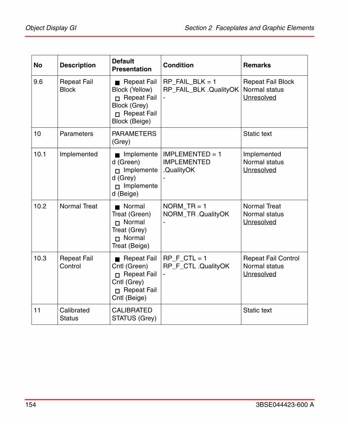
Object Display GI Section 2 Faceplates and Graphic Elements
154 3BSE044423-600 A
9.6 Repeat Fail Block
Repeat Fail Block (Yellow)
Repeat Fail Block (Grey)
Repeat Fail Block (Beige)
RP_FAIL_BLK = 1RP_FAIL_BLK .QualityOK-
Repeat Fail BlockNormal statusUnresolved
10 Parameters PARAMETERS (Grey)
Static text
10.1 Implemented Implemented (Green)
Implemented (Grey)
Implemented (Beige)
IMPLEMENTED = 1IMPLEMENTED .QualityOK-
ImplementedNormal statusUnresolved
10.2 Normal Treat Normal Treat (Green)
Normal Treat (Grey)
Normal Treat (Beige)
NORM_TR = 1NORM_TR .QualityOK-
Normal TreatNormal statusUnresolved
10.3 Repeat Fail Control
Repeat Fail Cntl (Green)
Repeat Fail Cntl (Grey)
Repeat Fail Cntl (Beige)
RP_F_CTL = 1RP_F_CTL .QualityOK-
Repeat Fail ControlNormal statusUnresolved
11 Calibrated Status
CALIBRATED STATUS (Grey)
Static text
No DescriptionDefault Presentation
Condition Remarks

Section 2 Faceplates and Graphic Elements Object Display GI
3BSE044423-600 A 155
11.1 Test mode entered
Test mode entered (Yellow)
Test mode entered (Grey)
Test mode entered (Beige)
TESTED = 1TESTED .QualityOK-
Test mode enteredNormal statusUnresolved
11.2 Calibration 0 % Calibration 0 <UNIT> (Green)
Calibration 0 <UNIT> (Grey)
Calibration 0 <UNIT> (Beige)
CALD_0(ZERO_SETPOINT) = 1 CALD_0 .QualityOK-
Calibration 0 % Not calibratedUnresolved
11.3 Calibration X % Calibration X <UNIT> (Green)
Calibration X <UNIT> (Grey)
Calibration X <UNIT> (Beige)
CALD_X(X_SETPOINT) = 1CALD_X .QualityOK-
Calibration X % Not calibratedUnresolved
11.4 Sensivity Sensivity (Grey)<value> (Green)<0> (Beige)
SENSITIV (SENS_DRIFT)SENSITIV .QualityOK-
Static textSensivity valueUnresolved
11.2 Calibration Error Calibration Error (Red)
Calibration Error (Grey)
Calibration Error (Beige)
CAL_ERR = 1CAL_ERR .QualityOK-
Calibration ErrorNormal statusUnresolved
No DescriptionDefault Presentation
Condition Remarks

Object Display GI Section 2 Faceplates and Graphic Elements
156 3BSE044423-600 A
11.3 Loop Fail in Test Loop Fail in Test (Red)
Loop Fail in Test (Grey)
Loop Fail in Test (Beige)
LF_IN_T = 1LF_IN_T.QualityOK-
Loop Fail in TestNormal statusUnresolved
12.1 Measured Value text
MV (Grey) Static text
12.2 Measured Value ? ? ? (Red) ERROR = 1 Error
<value> Green VALUE_LEL Value
White cross on red square
VALUE_LEL .QualityBad Unresolved
12.3 Measured Value Unit
<UNIT> VALUE_LEL .QualityOK Unit
UNIT (Beige) - Unresolved
13 Inhibit Inhibited (Cyan)Inhibited (Grey)Inhibited (Beige)
INH = 1VALUE_LEL .QualityOK-
InhibitNormal statusUnresolved
14 Input Blocked Input Blocked (Yellow)Input Blocked (Grey)Input Blocked (Beige)
UPD_BLK = 1 (BLOCKED =1)VALUE_LEL .QualityOK-
Input BlockedNormal statusUnresolved
No DescriptionDefault Presentation
Condition Remarks

Section 2 Faceplates and Graphic Elements Object Display GI
3BSE044423-600 A 157
The conditions are in priority order. Logically defined colors are used, see Appendix A, Logical Colors Definitions.
15 Test Mode Test Mode (Yellow)Test Mode (Grey)Test Mode (Beige)
TEST = 1VALUE_LEL.QualityOK-
Test ModeNormal statusUnresolved
16 Detector Type Analog detector (Grey)(no text)Detector type (Beige)
GI_SPARE_37 = 1VALUE_LEL .QualityOK-
Analog GICatalytic GI or Calculated GIUnresolved
No DescriptionDefault Presentation
Condition Remarks

Object Display AI Section 2 Faceplates and Graphic Elements
158 3BSE044423-600 A
Object Display AIPresentation:
Behavior:
No DescriptionDefault Presentation
Condition Remarks
1 Lock Frame White SELECTED = 1 Object select frame
Grey SELECTED = 0
13
5 4 32
16 109 781215
1 6
1114
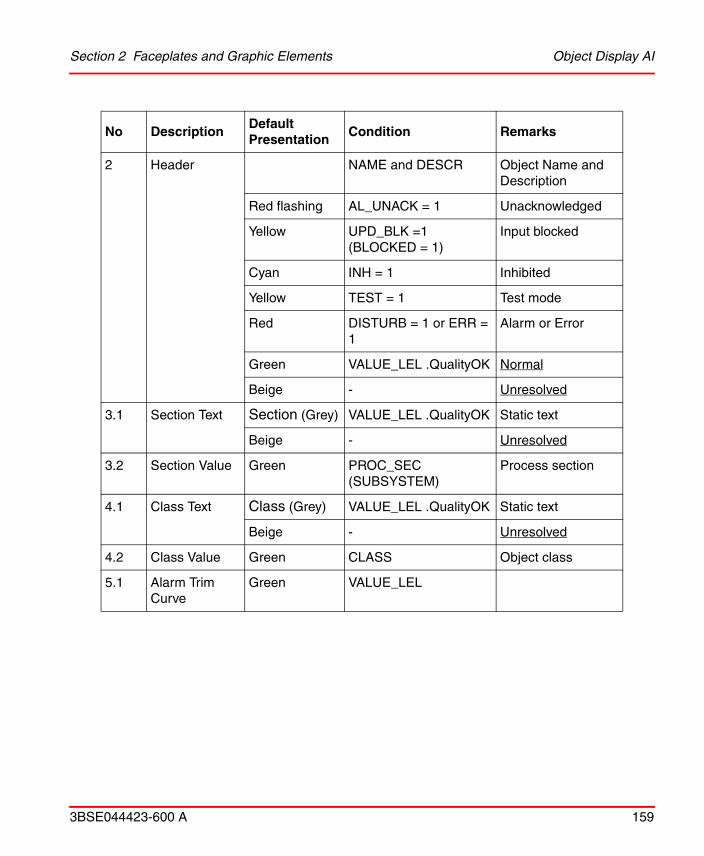
Section 2 Faceplates and Graphic Elements Object Display AI
3BSE044423-600 A 159
2 Header NAME and DESCR Object Name and Description
Red flashing AL_UNACK = 1 Unacknowledged
Yellow UPD_BLK =1 (BLOCKED = 1)
Input blocked
Cyan INH = 1 Inhibited
Yellow TEST = 1 Test mode
Red DISTURB = 1 or ERR = 1
Alarm or Error
Green VALUE_LEL .QualityOK Normal
Beige - Unresolved
3.1 Section Text Section (Grey) VALUE_LEL .QualityOK Static text
Beige - Unresolved
3.2 Section Value Green PROC_SEC (SUBSYSTEM)
Process section
4.1 Class Text Class (Grey) VALUE_LEL .QualityOK Static text
Beige - Unresolved
4.2 Class Value Green CLASS Object class
5.1 Alarm Trim Curve
Green VALUE_LEL
No DescriptionDefault Presentation
Condition Remarks

Object Display AI Section 2 Faceplates and Graphic Elements
160 3BSE044423-600 A
5.2 Range Indicators
Range Max (Grey)
VALUE_LEL . QualityOK
Range Max indicator
Range Max (Beige)
- Unresolved
Range Min (Grey)
VALUE_LEL . QualityOK
Range Min indicator
Range Min (Beige)
- Unresolved
6 Value Bargraph
Green VALUE_LEL Measured value
High limit Yellow AL_BLK = 1 Alarm blocked
Red HI_AL = 1 High alarm
Grey VALUE_LEL .QualityOK Normal
Beige - Unresolved
Low limit Yellow AL_BLK = 1 Alarm blocked
Red LO_AL = 1 Low alarm
Grey VALUE_LEL .QualityOK Normal
Beige - Unresolved
7 Alarm Limits ALARM LIMITS
Static text
7.1 Print block P block (Yellow)P block (Invisible)P block (Beige)
PRINT_BLK = 1PRINT_BLK .QualityOK-
Print blockNormal statusUnresolved
No DescriptionDefault Presentation
Condition Remarks

Section 2 Faceplates and Graphic Elements Object Display AI
3BSE044423-600 A 161
7.2 Alarm block B (Yellow)Bx (Yellow)B (Invisible)B (Beige)
AL_BLK = 1AL_P_BLK = 1AL_BLK .QualityOK-
Alarm blockAlarm periodic blockedNormal statusUnresolved
7.3 High alarm limit, ValueHigh alarm limit, Indication
<LIM_HI_AL>High alarm,
limit: (Red flash)
High alarm, limit: (Red)
High alarm, limit: (Grey)
High alarm, limit: (Beige)
LIM_HI_ALHI_AL_UNACK = 1HI_AL = 1HI_AL .QualityOK-
limit valueUnacknowledged High alarmHigh alarmHigh alarmNormal statusUnresolved
7.4 Low alarm limit, ValueLow alarm limit, Indication
<LIM_LO_AL>Low alarm,
limit: (Red flash)
Low alarm, limit (Red)
Low alarm, limit (Grey)
Low alarm, limit: (Beige)
LIM_LO_ALLO_AL_UNACK = 1LO_AL = 1LO_AL .QualityOK-
limit valueUnacknowledged Low alarmLow alarmNormal statusUnresolved
7.5 Latched High alarm
Latched High alarm (Red)
Latched High alarm (Grey)
Latched High alarm (Beige)
HI_AL_L = 1HI_AL_L .QualityOK-
Latched High alarmNormal statusUnresolved
No DescriptionDefault Presentation
Condition Remarks

Object Display AI Section 2 Faceplates and Graphic Elements
162 3BSE044423-600 A
7.6 Latched Low alarm
Latched Low alarm (Red)
Latched Low alarm (Grey)
Latched Low alarm (Beige)
LO_AL_L = 1LO_AL_L .QualityOK-
Latched Low alarmNormal statusUnresolved
8 STATUS Status
8.1 Maintenance Maintenance (Red)
Maintenance (Grey)
Maintenance (Beige)
POW_FAIL = 1POW_FAIL .QualityOK-
MaintenanceNormal statusUnresolved
8.2 Loop Fail Loop Fail (Red)
Loop Fail (Grey)
Loop Fail (Beige)
LOOP_FAIL = 1LOOP_FAIL .QualityOK-
Loop FailtNormal statusUnresolved
8.3 Input Error Input Error (Red)
Input Error (Grey)
Input Error (Beige)
LO_AL_IN_T = 1LO_AL_IN_T .QualityOK-
Input Error Normal statusUnresolved
8.4 Current labelCurrent value
Current : mA (Grey)<value> (Green)<0> (Beige)
SENS_DRIFT .QualityOK-
Static textCurrent value (SENSITIVITY)Unresolved
No DescriptionDefault Presentation
Condition Remarks

Section 2 Faceplates and Graphic Elements Object Display AI
3BSE044423-600 A 163
9 Status STATUS (Grey) Static text
9.1 Updated Updated (Green)
Updated (Grey)
Updated (Beige)
UPDATED = 1UPDATED .QualityOK-
UpdatedNot updatedUnresolved
9.2 Manual entry Manual entry (Green)
Manual entry (Grey)
Manual entry (Beige)
MAN_ENTR = 1MAN_ENTR .QualityOK-
Manual entryUnresolved
9.3 Alarm period block
Alarm period blk (Yellow)
Alarm period blk (Grey)
Alarm period blk (Beige)
AL_P_BLK = 1AL_P_BLK .QualityOK-
Alarm period blockNormal statusUnresolved
9.4 Disturbance Disturbance (Red)
Disturbance (Grey)
Disturbance (Beige)
DISTURBANCE = 1DISTURBANCE .QualityOK-
DisturbanceNormal statusUnresolved
9.5 Signal error Signal error (Red)
Signal error (Grey)
Signal error (Beige)
ERROR = 1ERROR .QualityOK-
Signal errorNormal statusUnresolved
No DescriptionDefault Presentation
Condition Remarks

Object Display AI Section 2 Faceplates and Graphic Elements
164 3BSE044423-600 A
9.6 Repeat Fail Block
Repeat Fail Block (Yellow)
Repeat Fail Block (Grey)
Repeat Fail Block (Beige)
RP_FAIL_BLK = 1RP_FAIL_BLK .QualityOK-
Repeat Fail BlockNormal statusUnresolved
10 Parameters PARAMETERS (Grey)
Static text
10.1 Implemented Implemented (Green)
Implemented (Grey)
Implemented (Beige)
IMPLEMENTED = 1IMPLEMENTED .QualityOK-
ImplementedNormal statusUnresolved
10.2 Normal Treat Normal Treat (Green)
Normal Treat (Grey)
Normal Treat (Beige)
NORM_TR = 1NORM_TR .QualityOK-
Normal TreatNormal statusUnresolved
10.3 Repeat Fail Control
Repeat Fail Cntl (Green)
Repeat Fail Cntl (Grey)
Repeat Fail Cntl (Beige)
RP_F_CTL = 1RP_F_CTL .QualityOK-
Repeat Fail ControlNormal statusUnresolved
11 Invisible No Calibration of Analog GI
12.1 Measured Value text
MV (Grey) Static text
12.2 Measured Value
? ? ? (Red) ERROR = 1 Error
No DescriptionDefault Presentation
Condition Remarks

Section 2 Faceplates and Graphic Elements Object Display AI
3BSE044423-600 A 165
The conditions are in priority order. Logically defined colors are used, see Appendix A, Logical Colors Definitions.
<value> Green VALUE_LEL Value
White cross on red square
VALUE_LEL .QualityBad
Unresolved
12.3 Measured Value Unit
<UNIT> VALUE_LEL .QualityOK Unit
UNIT (Beige) - Unresolved
13 Inhibit Inhibit (Cyan)Inhibit (Grey)Inhibit (Beige)
INH = 1VALUE_LEL .QualityOK-
InhibitNormal statusUnresolved
14 Input Blocked Input Blocked (Yellow)Input Blocked (Grey)Input Blocked (Beige)
UPD_BLK = 1 (BLOCKED = 1)VALUE_LEL .QualityOK-
Input BlockedNormal statusUnresolved
15 Invisible No Test mode on Analog GI
16 Detector Type Analog detector (Grey)(no text)Detector type (Beige)
GI_SPARE_37 = 1VALUE_LEL .QualityOK-
Analog GICatalytic GI or Calculated GIUnresolved
No DescriptionDefault Presentation
Condition Remarks

NumericMV01 Section 2 Faceplates and Graphic Elements
166 3BSE044423-600 A
NumericMV01Presentation:
Behavior:
No DescriptionDefault Presentation
Condition Remarks
1 Lock indication White SELECTED = 1 Object select frame
Dotted Yellow AL_BLK = 1 Alarm blocked by operator
Invisible Value_LEL .QualityOK
Normal
2.1 Value Frame Invisible FrameStyle = Flat or FrameWidth = 0
2 Dimension value presentation
Raised or Sunken
FrameStyle <> Flat and FrameWidth > 0
3 Dimension value presentation
2.2 Value indication ? ? ? ERROR = 1 Error
Measured value Value_LEL .QualityOK
Normal
1 2

Section 2 Faceplates and Graphic Elements UnitMV01
3BSE044423-600 A 167
The conditions are in priority order. Underlined parameters are configurable. Logically defined colors are used, see Appendix A, Logical Colors Definitions.
Configuration:
UnitMV01Presentation:
2.3 Value color Red flash AL_UNACK = 1 Unacknowledged alarm
Yellow UPD_BLK = 1 (BLOCKED =1)
Input blocked
Cyan INH =1 Inhibit
Red DISTURB = 1 Alarm
Red ERROR = 1 I/O Error
Green Value_LEL .QualityOK
Normal
Invisible - Unresolved
Parameters AffectsOptions (bold is default)
Remarks
FrameWidth 2. Value 3, (0..4)
FrameStyle 2. Value Flat, Raised, Sunken
BackgroundColor Background Transparent, Any
No DescriptionDefault Presentation
Condition Remarks
1

BargraphMV01 Section 2 Faceplates and Graphic Elements
168 3BSE044423-600 A
Behavior:
The conditions are in priority order. Logically defined colors are used, see Appendix A, Logical Colors Definitions.
Configuration:
BargraphMV01Presentation:
No DescriptionDefault Presentation
Condition Remarks
1 Unit Object unit
Cyan <UNIT> INH = 1 Inhibited
Green <UNIT> Value_LEL .QualityOK
Normal
Beige “UnitMV” - Unresolved
Parameters AffectsOptions (bold is default)
Remarks
BackgroundColor Background Transparent, Any
1
2
3
4
5
?

Section 2 Faceplates and Graphic Elements BargraphMV01
3BSE044423-600 A 169
Behavior:
No DescriptionDefault Presentation
Condition Remarks
1 Lock indication White SELECTED = 1 Object select frame
Dotted Yellow AL_BLK = 1 Alarm blocked by operator
Invisible Value_LEL .QualityOK Normal
2 Error indication ? ERROR = 1 Error
Measured value Value_LEL .QualityOK Normal
X - Unresolved
3.1 Value Bar Frame Invisible FrameStyle = Flat or FrameWidth = 0
2 Dimension value presentation
Raised or Sunken
FrameStyle <> Flat and FrameWidth > 0
3 Dimension value presentation
3.2 Value Color Red flash AL_UNACK = 1 Unacknowledged alarm
Yellow UPD_BLK = 1 (BLOCKED = 1)
Input blocked
Red DISTURB = 1 Alarm
Red (?) ERR = 1 Error
Green Value_LEL .QualityOK Normal condition
Invisible - Unresolved

BargraphMV01 Section 2 Faceplates and Graphic Elements
170 3BSE044423-600 A
4 High Limit LIM_H_AL Alarm High limit
Invisible LIM_HI_AL >= RANGE_MAX or LIM_HI_AL = 0
Cyan INH = 1 and LatchedUsed = false
Inhibited
Cyan INH = 1 and H_AL_NIL = 0and LatchedUsed = true
Inhibit unlatched(Included for backward compatibility before XMSGSYS 6.1/5)
Yellow AL_BLK = 1 Blocked
Red H_AL = 1 High alarm
Red H_AL_L = 1and LatchedUsed
High alarm latched
No DescriptionDefault Presentation
Condition Remarks

Section 2 Faceplates and Graphic Elements BargraphMV01
3BSE044423-600 A 171
The conditions are in priority order. Underlined parameters are configurable. Logically defined colors are used, see Appendix A, Logical Colors Definitions.
Configuration:
5 Low Limit 2 LIM_L_AL Alarm Low limit
Invisible LIM_LO_AL <= RANGE_MIN or LIM_LO_AL = 0
Cyan INH = 1 and LatchedUsed = false
Inhibited
Cyan INH = 1 and L_AL_NIL = 0 and LatchedUsed = true
Inhibit unlatched(Included for backward compatibility before XMSGSYS 6.1/5)
Yellow AL_BLK = 1 Blocked
Red L_AL = 1 Low alarm
Red L_AL_L = 1and LatchedUsed
Low alarm latched
Parameters AffectsOptions (bold is default)
Remarks
LatchedUsed 4. High limit, 5. Low limit true, false
FrameWidth 2. Bar Frame 3, (0...4)
FrameStyle 2. Bar Frame Flat, Raised, Sunken
Orientation Bargraph Horizontal, Vertical
BackgroundColor Background Transparent, Any
No DescriptionDefault Presentation
Condition Remarks

Name01 Section 2 Faceplates and Graphic Elements
172 3BSE044423-600 A
Name01Presentation:
Gas Input presentation, object name.
Behavior:
No DescriptionDefault Presentation
Condition Remarks
1 Frame White SELECTED = 1 Object select frame
Dotted Yellow ALARM_BLK = 1 Alarm blocked by operator
Invisible Value_LEL Normal
12

Section 2 Faceplates and Graphic Elements Name01
3BSE044423-600 A 173
The conditions are in priority order. Underlined parameters are configurable. Logically defined colors are used, see Appendix A, Logical Colors Definitions.
Configuration:
2 Object Name NAME Object Name
Flashing Red AL_UNACK = 1 Unacknowledged alarm
Yellow UPD_BLK = 1 Input Update blocked
Cyan INH = 1 and LatchedUsed = false
Inhibited
Cyan INH = 1 and L_AL_NIL = 0 and H_AL_NI = 0 and LatchedUsed = true
Inhibit unlatched(Included for backward compatibility before XMSGSYS 6.1/5)
Red DISTURBANCE =1 Alarm
Red (L_AL_L = 1 or H_AL_L )and LatchedUsed = True
Alarm Latched
Red ERROR =1 Error
Green Value_LEL Normal
Green - Unresolved (name: name)
Parameters Affects Options (bold is default) Remarks
LatchedUsed 2. Name true, false
BackgroundColor Background Transparent, Any
No DescriptionDefault Presentation
Condition Remarks

FG_NameStatus01 Section 2 Faceplates and Graphic Elements
174 3BSE044423-600 A
FG_NameStatus01Presentation:
Gas Input presentation for analog input fire detectors, name and status (similar to FI).
Behavior:
No DescriptionDefault Presentation
Condition Remarks
1 Frame White SELECTED = 1 Object select frame
Dotted Yellow ALARM_BLK = 1 Alarm blocked by operator
Invisible Value_LEL .QualityOK
Normal
Beige - Unresolved
12
4 53

Section 2 Faceplates and Graphic Elements FG_NameStatus01
3BSE044423-600 A 175
2 Object Name Red Flash AL_UNACK = 1 Unacknowledged alarm
Yellow UPD_BLK = 1 Input Update blocked
Cyan INH = 1 and LatchedUsed = false
Inhibited
Cyan INH = 1 and L_AL_NIL = 0 and H_AL_NI = 0 and LatchedUsed = true
Inhibit unlatched (Included for backward compatibility before XMSGSYS 6.1/5)
Red DISTURBANCE =1 Alarm
Red (L_AL_L = 1 or H_AL_L ) and LatchedUsed = True
Alarm Latched
Red ERROR =1 Error
Green Value_LEL .QualityOK
Normal
Green - Unresolved (name: name)
3.1 Alarm Text "H" HI_AL = 1 High alarm
"H" H_AL_L and LatchedUsed = True
High alarm Latched
"L" -
3.2 Alarm Color Red Flash HI_AL_UNACK = 1 Unacknowledged high alarm
Red Flash LO_AL_UNACK = 1
Unacknowledged low alarm
Red HI_AL = 1 High alarm
No DescriptionDefault Presentation
Condition Remarks

FG_NameStatus01 Section 2 Faceplates and Graphic Elements
176 3BSE044423-600 A
The conditions are in priority order. Underlined parameters are configurable. Logically defined colors are used, see Appendix A, Logical Colors Definitions.
Red HI_AL_L = 1 and LatchedUsed = true
High alarm latched
Red LO_AL = 1 Low alarm
Red LO_AL_L = 1 and LatchedUsed = true
Low alarm latched
Invisible Value_LEL .QualityOK
Normal
4.1 Inhibit / Block Text
BlockedText UPD_BLK = 1 Update blocked
TestText TESTED = 1 Input in test mode (for calibration)
InhibitText -
4.2 Inhibit / Block Color
Yellow UPD_BLK = 1 Update blocked
Yellow TESTED = 1 Input in test mode (for calibration)
Cyan INH = 1 and LatchedUsed = false
Inhibited
Cyan INH = 1 and L_AL_NIL = 0 and H_AL_NI = 0 and LatchedUsed = true
Inhibit unlatched (Included for backward compatibility before XMSGSYS 6.1/5)
Invisible Value_LEL .QualityOK
Normal
5.1 Error Text ErrorText
5.2 Error Color Red ERROR = 1 Error
Invisible Value_LEL Normal
No DescriptionDefault Presentation
Condition Remarks

Section 2 Faceplates and Graphic Elements FG_Detector01
3BSE044423-600 A 177
Configuration:
FG_Detector01Presentation:
Gas Input presentation, flame or heat detector symbol, similar to Fire Input presentation. Used for analog input fire detectors.
Behavior:
Parameters AffectsOptions (bold is default)
Remarks
LatchedUsed 2. Name true, false
BlockedText 4. Block / Inhibit B, any character
TestText 4. Block / Inhibit T, any character
InhibitText 4. Block / Inhibit I, any character
ErrorText 5. Error E, any character
BackgroundColor Background Transparent, Any
No DescriptionDefault Presentation
Condition Remarks
1 Frame White SELECTED = 1 Object select frame
Dotted Yellow ALARM_BLK = 1 Alarm blocked by operator
Invisible Value_LEL .QualityOK
Normal
12

FG_Detector01 Section 2 Faceplates and Graphic Elements
178 3BSE044423-600 A
The conditions are in priority order. Underlined parameters are configurable. Logically defined colors are used, see Appendix A, Logical Colors Definitions.
Configuration:
2 Symbol Red Flash AL_UNACK = 1 Unacknowledged alarm
Yellow UPD_BLK = 1 Input Update blocked
Cyan INH = 1 and LatchedUsed = false
Inhibited
Cyan INH = 1 and L_AL_NIL = 0 and H_AL_NI = 0 and LatchedUsed = true
Inhibit unlatched (Included for backward compatibility before XMSGSYS 6.1/5)
Red DISTURBANCE =1 Alarm
Red (L_AL_L = 1 or H_AL_L ) and LatchedUsed = True
Alarm Latched
Red ERROR =1 Error
Green Value_LEL .QualityOK
Normal
Green - Unresolved
Parameters AffectsOptions (bold is default)
Remarks
LatchedUsed 2. Symbol true, false
DetectorType 2. Symbol Suggested size: width =600 for Flame symbol, width = 300 for other symbols.
No DescriptionDefault Presentation
Condition Remarks

Section 2 Faceplates and Graphic Elements NameStatus01
3BSE044423-600 A 179
NameStatus01
Presentation:
Gas Input presentation, object name and status.
Heat-Fixed l
Heat l
Flame Right, Up, Left, Down
FlameSymbolDirection Set direction of flame symbol
Right, Up, Left or Down
Only visible if DetectorType = 3 (Flame):Symbol is rotating anti-clockwise.
FlameDegreeAboveFloor Number presentation
0, any integer Only visible if number is not zero (default), and DetectorType = 3 (Flame).
BackgroundColor Background Transparent, Any
Parameters AffectsOptions (bold is default)
Remarks
13 4 5 6 72

NameStatus01 Section 2 Faceplates and Graphic Elements
180 3BSE044423-600 A
Behavior:
No DescriptionDefault Presentation
Condition Remarks
1 Frame White SELECTED = 1 Object select frame
Dotted Yellow ALARM_BLK = 1 Alarm blocked by operator
Invisible Value_LEL .QualityOK
Normal
Invisible - Unresolved
2 Object Name NAME Object Name
Red flash AL_UNACK = 1 Unacknowledged alarm
Yellow UPD_BLK = 1 Input Update blocked
Cyan INH = 1 and LatchedUsed = false
Inhibited
Cyan INH = 1 and L_AL_NIL = 0 and H_AL_NI = 0 and LatchedUsed = true
Inhibit unlatched(Included for backward compatibility before XMSGSYS 6.1/5)
Red DISTURBANCE =1 Alarm
Red HI_AL_L = 1 and LatchedUsed = True
High Alarm Latched
Red L_AL_L = 1 and LatchedUsed = True
Low Alarm Latched
Red ERROR =1 Error
Green Value_LEL .QualityOK
Normal
Green - Unresolved (name: name)

Section 2 Faceplates and Graphic Elements NameStatus01
3BSE044423-600 A 181
3.1 Alarm Text H HI_AL_UNACK = 1 Unacknowledged high alarm
H HI_AL = 1 High Alarm
H HI_AL_L = 1 and LatchedUsed = True
Latched High Alarm
L LO_AL_UNACK = 1 Unacknowledged low alarm
L LO_AL = 1 Low Alarm
L LO_AL_L = 1 and LatchedUsed = True
Latched Low Alarm
Value_LEL .QualityOK
Normal (no text)
H - Unresolved
3.2 Alarm Color Red flash HI_AL_UNACK = 1 Unacknowledged high alarm
Red HI_AL =1 High Alarm
Red HI_AL_L = 1 and LatchedUsed = True
High Alarm Latched
Red flash LO_AL_UNACK = 1 Unacknowledged low alarm
Red LO_AL = 1 Low Alarm
Red L_AL_L = 1 and LatchedUsed = True
Low Alarm Latched
Invisible - Normal
No DescriptionDefault Presentation
Condition Remarks

NameStatus01 Section 2 Faceplates and Graphic Elements
182 3BSE044423-600 A
4.1 Override Text BlockedText UPD_BLK = 1 Input Update blocked
TestModeText TESTED = 1 Testmode entered
InhibitText INH = 1 Inhibit
Value_LEL .QualityOK
Normal (no text)
BlockedText - Unresolved
4.2 Override Color Yellow UPD_BLK = 1 Input Update blocked
Yellow TESTED = 1 Testmode entered
Cyan INH = 1 Inhibit
Invisible - Normal
5.1 Error Text ErrorText - Error indication
5.2 Error Color Red ERROR = 1 Error
Invisible - Normal
6.1 Value Text ? ? ? ERROR = 1 Error
Measured value - Value presentation
X X X Value_LEL .QualityOK
Unresolved
6.2 Value color Red ERROR = 1 I/O Error
Red HI_AL = 1 High Alarm
Red HI_AL_L = 1 and LatchedUsed = True
Latched High Alarm
Red LO_AL = 1 Low Alarm
Red LO_AL_L = 1 and LatchedUsed = True
Latched Low Alarm
Green Value_LEL Normal
No DescriptionDefault Presentation
Condition Remarks

Section 2 Faceplates and Graphic Elements NameStatus01
3BSE044423-600 A 183
The conditions are in priority order. Underlined parameters are configurable. Logically defined colors are used, see Appendix A, Logical Colors Definitions.
Configuration:
7.1 Bargraph value Measured value VAL_LEL Value presentation
7.2 Bargraph color Red HI_AL = 1 High Alarm
Red HI_AL_L = 1 and LatchedUsed = True
Latched High Alarm
Red LO_AL = 1 Low Alarm
Red LO_AL_L = 1 and LatchedUsed = True
Latched Low Alarm
Green Value_LEL Normal
7.3 Bargraph frame Red HI_AL = 1 High Alarm
Red LO_AL = 1 Low Alarm
Green Value_LEL Normal
Parameters Affects Options (bold is default) Remarks
LatchedUsed 2. Name true, false
BlockedText 4. Override B, any character
InhibitText 4. Override I, any character
TestModeText 4. Override T, any character
ErrorText 5. Error E, any character
BackgroundColor Background Transparent, Any
No DescriptionDefault Presentation
Condition Remarks

Detector01 Section 2 Faceplates and Graphic Elements
184 3BSE044423-600 A
Detector01Presentation:
Gas Input presentation, detector symbol.
Behavior:
No DescriptionDefault Presentation
Condition Remarks
1 Frame White SELECTED = 1 Object select frame
Dotted Yellow ALARM_BLK = 1 Alarm blocked by operator
Invisible Value_LEL .QualityOK And DetectorType = Infrared
No frame
(same color as Symbol)
Value_LEL .QualityOK Frame is part of symbol
2 Symbol Red Flash AL_UNACK = 1 Unacknowledged alarm
Yellow UPD_BLK = 1 Input Update blocked
Cyan INH = 1 and LatchedUsed = false
Inhibited
Cyan INH = 1 and L_AL_NIL = 0 and H_AL_NI = 0 and LatchedUsed = true
Inhibit unlatched (Included for backward compatibility before XMSGSYS 6.1/5)
Red DISTURBANCE =1 Alarm
1 2

Section 2 Faceplates and Graphic Elements Detector01
3BSE044423-600 A 185
The conditions are in priority order. Underlined parameters are configurable. Logically defined colors are used, see Appendix A, Logical Colors Definitions.
Configuration:
Red (L_AL_L = 1 or H_AL_L ) and LatchedUsed = True
Alarm Latched
Red ERROR =1 Error
Green - Normal
Parameters AffectsOptions (bold is default)
Remarks
LatchedUsed 2. Symbol true, false
DetectorType 2. Symbol
Gas l
Gas_Low l
Gas_High l
Infrared Right, Up, Left, Down
H2S l
No DescriptionDefault Presentation
Condition Remarks

M_NameStatus01 Section 2 Faceplates and Graphic Elements
186 3BSE044423-600 A
M_NameStatus01
Presentation:
Presentation of Object name, description and status for Gas Input on Cause & Effect Matrix display.
CO2l
H2 Gas l
Smoke (Early warning)
l
Gas small square
l
ArrowDirection Set direction of Infrared symbol
Right, Up, Left or Down
Only visible if DetectorType = Infrared beam gas detector
BackgroundColor Background Transparent, Any
Parameters AffectsOptions (bold is default)
Remarks
12
3
4

Section 2 Faceplates and Graphic Elements M_NameStatus01
3BSE044423-600 A 187
Behavior:
No DescriptionDefault Presentation
Condition Remarks
1 Frame White SELECTED = 1 Object select frame
Dotted Yellow ALARM_BLK = 1 Alarm blocked by operator
NormalFrameColor - Normal
2 Name / Description
Red flash AlarmType = High and HI_AL_UNACK = 1
Unacknowledged high alarm
Red flash AlarmType = Low and LO_AL_UNACK = 1
Unacknowledged low alarm
Red AlarmType =High and HI_AL =1
High Alarm
Red AlarmType =High and HI_AL_L =1 and LatchedUsed = true
High Alarm Latched
Red AlarmType =Low and LO_AL =1
Low Alarm
Red AlarmType =Low and LO_AL_L =1 and LatchedUsed = true
Low Alarm Latched
Green - Normal
3.1 Alarm Text H AlarmType =High
L AlarmType =Low

M_NameStatus01 Section 2 Faceplates and Graphic Elements
188 3BSE044423-600 A
3.2 Alarm Text Color
Red AlarmType =High and HI_AL =1
High Alarm
Red AlarmType =High and HI_AL_L =1 and LatchedUsed = true
High Alarm Latched
Red AlarmType =Low and LO_AL =1
Low Alarm
Red AlarmType =Low and LO_AL_L =1 and LatchedUsed = true
Low Alarm Latched
Grey Value_LEL .QualityOK
Normal
4 Status Square Dark Grey center (AlarmType =High and HI_AL =0) and (AlarmType =Low and LO_AL =0)
Unfilled, no alarm (not High alarm and not Low alarm)
Yellow UPD_BLK = 1 Input Update blocked
Cyan InhibitUsed = true and INH = 1 and LatchedUsed = false
Inhibited
Cyan InhibitUsed = true and INH = 1 and L_AL_NIL = 0 and H_AL_NI = 0and LatchedUsed = true
Inhibit unlatched (Included for backward compatibility before XMSGSYS 6.1/5)
No DescriptionDefault Presentation
Condition Remarks

Section 2 Faceplates and Graphic Elements M_NameStatus01
3BSE044423-600 A 189
The conditions are in priority order. Underlined parameters are configurable. Logically defined colors are used, see Appendix A, Logical Colors Definitions.
Configuration:
Red AlarmType =High and HI_AL =1
High Alarm
Red AlarmType =High and HI_AL_L =1 and LatchedUsed = true
High Alarm Latched
Red AlarmType =Low and LO_AL =1
Low Alarm
Red AlarmType =Low and LO_AL_L =1 and LatchedUsed = true
Low Alarm Latched
Red ERROR =1 Error
Green Value_LEL Normal
Parameters AffectsOptions (bold is default)
Remarks
NormalFrameColor 1. Frame Black, any color
Color of frame in normal condition. (Conform to Cause & Effect grid)
AlarmType 2. Name / Description,3. Alarm Text4. Status
High, Low Alarm limit used on Gas Input,Refer to “Alarm” in Safety Builder (C&E Matrix)
No DescriptionDefault Presentation
Condition Remarks

M_Status01 Section 2 Faceplates and Graphic Elements
190 3BSE044423-600 A
M_Status01
Presentation:
Presentation of Status for Gas Input on Cause & Effect Matrix display (dynamic ‘dot’).
LatchedUsed 2. Name / Description,3. Alarm Text4. Status
true, false Default: Latched Alarm indicated.Refer to “Alarm” in Safety Builder (C&E Matrix)
InhibitUsed 4. Status true, false Default: Cyan status square when Inhibited. Refer to “Additional properties” in Safety Builder .
Status3D 4. Status false, true Default (false): flat status square,true: 3 Dimensional status square, sunken when square is filled.
BackgroundColor Background Transparent, Any
Parameters AffectsOptions (bold is default)
Remarks
1

Section 2 Faceplates and Graphic Elements M_Status01
3BSE044423-600 A 191
Behavior:
The conditions are in priority order. Underlined parameters are configurable. Logically defined colors are used, see Appendix A, Logical Colors Definitions.
No DescriptionDefault Presentation
Condition Remarks
1.1 Circle frame White SELECTED = 1 Object selected
Dotted Yellow ALARM_BLK = 1 Alarm blocked by operator
Invisible - Normal
1.2 Circle Color Green InhibitUsed = true and INH = 1 and LatchedUsed = false
Inhibited. Note: Alarm not visible !
Green InhibitUsed = true and INH = 1 and L_AL_NIL = 0 and H_AL_NI = 0and LatchedUsed = true
Inhibit unlatched (Alarm not visible !)(Included for backward compatibility before XMSGSYS 6.1/5)
Red AlarmType =High and HI_AL =1
High Alarm
Red AlarmType =High and HI_AL_L =1 and LatchedUsed = true
High Alarm Latched
Red AlarmType =Low and LO_AL =1
Low Alarm
Red AlarmType =Low and LO_AL_L =1 and LatchedUsed = true
Low Alarm Latched
Green - Normal

Fire Area Status Object (GENUSD1) Section 2 Faceplates and Graphic Elements
192 3BSE044423-600 A
Configuration:
Fire Area Status Object (GENUSD1)
FG_FaceplateThis Faceplate is is used with Genusd objects used for safety area status presentation. The purpose of the dialog is to enable acknowledge of detector errors and protection feedback faults.The deviation from standard Genusd dialog is that only the Acknowledge button is present. The Faceplate (control element) presents the Fire area status signals.
The Genusd objects should be connected to the User Element VDU-A in the fire area PC logic.
Parameters AffectsOptions (bold is default)
Remarks
AlarmType 1. Circle High, Low Alarm limit used on Analog Input,Refer to “Alarm” in Safety Builder (C&E Matrix)
LatchedUsed All true, false Default: Latched Alarm indicated.Refer to “Alarm” in Safety Builder (C&E Matrix)
InhibitUsed 1. Circle true, false Default: Green status circle when Inhibited, that is, Alarm indication is ‘hidden’.Refer to “Additional properties” in Safety Builder .
BackgroundColor Background Transparent, Any

Section 2 Faceplates and Graphic Elements FG_Faceplate
3BSE044423-600 A 193
Presentation:
Behavior:
No DescriptionDefault Presentation
Condition Remarks
1 Lock Button
2 Name and Description
21

FG_Faceplate Section 2 Faceplates and Graphic Elements
194 3BSE044423-600 A
FG_Control
Presentation:
Behavior:
No DescriptionDefault Presentation
Condition Remarks
1 Fire area error Alarms: ALQ1, ALQ2, ALF1, ALF2, ALF3
1.1 FI det. error Text FI det. error
12

Section 2 Faceplates and Graphic Elements FG_Faceplate
3BSE044423-600 A 195
1.1 FI det. error Color
Red Flash
Red
Green
Beige
UA_ST_00=1
PC_ST_00=1
PC_ST_00 .QualityOK
-
FI detector error, unacknowledged
FI detector error, acknowledged (ALQ1=1)
No FI detector error
Unresolved
1.2 GI det. error Text
GI det. error
GI det. error Color
Red Flash
Red
Green
Beige
UA_ST_01=1
PC_ST_01=1
PC_ST_01 .QualityOK
-
GI detector error, unacknowledged
GI detector error, acknowledged (ALQ2=1)
No GI detector error
Unresolved
1.3 CO2 error Text CO2 error
CO2 error Color Red Flash
Red
Green
Beige
UA_ST_02=1
PC_ST_02=1
PC_ST_02 .QualityOK
-
CO2 system feedback fault, unack.
CO2 system feedback fault, ack. (ALF1=1)
No CO2 system feedback fault
Unresolved
1.4 Water error Text Water error
Water error Red Flash
Red
Green
Beige
UA_ST_03=1
PC_ST_03=1
PC_ST_03 .QualityOK
-
Water system feedback fault, unack.
Water system feedback fault, ack. (ALF2=1)
No Water system feedback fault
Unresolved
No DescriptionDefault Presentation
Condition Remarks

FG_Faceplate Section 2 Faceplates and Graphic Elements
196 3BSE044423-600 A
1.5 HVAC error Text HVAC error
HVAC error Color
Red Flash
Red
Green
Beige
UA_ST_04=1
PC_ST_04=1
PC_ST_04 .QualityOK
-
HVAC feedback fault, unack.
HVAC feedback fault, unack. (ALF3=1)
HVAC feedback fault, unack.
Unresolved
2 Fire area status Indications
2.1 FI inhibit Text FI inhibit
FI inhibit Color Cyan
Gray
Beige
PC-ST_16=1
PC-ST_16 .QualityOK
-
Any inhibited FI detector (M1=1)
No inhibited FI detector
Unresolved
2.2 GI inhibit Text GI inhibit
GI inhibit Color Cyan
Gray
Beige
PC-ST_17=1
PC-ST_17 .QualityOK
-
Any inhibited GI detector (M2=1)
No inhibited GI detector
Unresolved
2.3 FI alarm Text FI alarm
FI alarm Color Red
Gray
Beige
PC-ST_24=1
PC-ST_24 .QualityOK
-
Acknowledged FI detector alarm (IND1=1)
No Acknowledged FI detector alarm
Unresolved
No DescriptionDefault Presentation
Condition Remarks

Section 2 Faceplates and Graphic Elements FG_Faceplate
3BSE044423-600 A 197
2.4 GI alarm Text GI alarm
GI alarm Color Red
Gray
Beige
PC-ST_26=1
PC-ST_26 .QualityOK
-
Acknowledged GI detector alarm (IND3=1)
No Acknowledged GI detector alarm
Unresolved
2.5 FI unack Text FI unack
FI unack Color Red
Gray
Beige
PC-ST_25=1
PC-ST_25 .QualityOK
-
Unacknowledged FI detector alarm (IND2=1)
No Unacknowledged FI detector alarm
Unresolved
2.6 GI unack Text GI unack
GI unack Color Red
Gray
Beige
PC-ST_27=1
PC-ST_27 .QualityOK
-
Unacknowledged GI detector alarm (IND4=1)
No Unacknowledged GI detector alarm
Unresolved
2.7 CO2 order Text CO2 order
CO2 order Color
Blue
Gray
Beige
PC-ST_21 .QualityOK
-PC-ST_21 .QualityOK
-
CO2 system release ordered (BLK=1)
CO2 system release not ordered
Unresolved
No DescriptionDefault Presentation
Condition Remarks

FG_Faceplate Section 2 Faceplates and Graphic Elements
198 3BSE044423-600 A
2.8 Water order Text
Water order
Water order Color
Blue
Gray
Beige
PC-ST_19=1
PC-ST_19 .QualityOK
-
Water system release ordered (AUTO=1)
Water system release not ordered
Unresolved
2.9 HVAC order Text
HVAC order
HVAC order Color
Blue
Gray
Beige
PC-ST_10=1
PC-ST_10 .QualityOK
-
HVAC action ordered (INTLU3=1)
HVAC action not ordered
Unresolved
2.10 CO2 manual Text
CO2 manual
CO2 manual Color
Cyan
Gray
Beige
PC-ST_20=1
PC-ST_20 .QualityOK
-
CO2 system in manual mode (MAN=1)
CO2 system in auto mode
Unresolved
2.11 CO2 override Text
CO2 override
CO2 override Color
Cyan
Gray
Beige
PC-ST_22=1
PC-ST_22 .QualityOK
-
CO2 output overridden (STBY=1)
CO2 output not overridden
Unresolved
No DescriptionDefault Presentation
Condition Remarks

Section 2 Faceplates and Graphic Elements FG_Faceplate
3BSE044423-600 A 199
2.12 OUTP override Text
OUTP override
OUTP override Color
Cyan
Gray
Beige
PC-ST_12=1
PC-ST_12 .QualityOK
-
Any output overridden (INTLU5=1)
No output overridden
Unresolved
2.13 ISO valve Text ISO valve
ISO valve Color Cyan
Green
Beige
PC-ST_13=1
PC-ST_13 .QualityOK
-
Water isolation valve closed (INTLU6=1)
Water isolation valve open
Unresolved
2.14 CO2 released Text
CO2 released
CO2 released Color
Green
Green
Beige
PC-ST_08=1
PC-ST_08 .QualityOK
-
CO2 system released (INTLU1=1)
CO2 system not released
Unresolved
2.15 HVAC closed Text
HVAC closed
HVAC closed Color
Green
Gray
Beige
PC-ST_18=1
PC-ST_18 .QualityOK
-
All HVAC feedback activated (M3=1)
Not all HVAC feedback activated
Unresolved
2.16 Water released Text
Water released
Water released Color
Green
Gray
Beige
PC-ST_09=1
PC-ST_09 .QualityOK
-
Water system released (INTLU2=1)
Water system not released
Unresolved
No DescriptionDefault Presentation
Condition Remarks

FG_Faceplate Section 2 Faceplates and Graphic Elements
200 3BSE044423-600 A
The conditions are in priority order. Logically defined colors are used, see Appendix A, Logical Colors Definitions.
2.17 INTLU4 Text NA (Int4) Not applicable (Property not used)
INTLU4 Color PinkInvisible (light blue)
Beige
PC-ST_11=1PC-ST_11 .QualityOK
-
Not used, but activated.
2.18 F4 Text NA (F4) Not applicable (Property not used)
F4 Color Red flashPinkInvisible (light blue)
Beige
AU-ST_05=1PC-ST_05=1PC-ST_06 .QualityOK
-
Not used, but activated.
2.19 F5 Text NA (F5) Not applicable (Property not used)
F5 Color Red flashPinkInvisible (light blue)
Beige
AU-ST_06=1PC-ST_06=1PC-ST_06 .QualityOK
-
Not used, but activated.
2.20 F6 Text NA (F6) Not applicable (Property not used)
F6 Color Red flashPinkInvisible (light blue)
Beige
AU-ST_07=1PC-ST_07=1PC-ST_07 .QualityOK
-
Not used, but activated.
No DescriptionDefault Presentation
Condition Remarks

Section 2 Faceplates and Graphic Elements FG_OverviewFire01
3BSE044423-600 A 201
FG_OverviewFire01Presentation:
Presentation on an overview display, indicating status for FIRE detectors on underlying displays (alarm, error, inhibit and block). Used for Genusd objects connected to User Elements VDU-A and VDU-D.
The Graphic Element can be placed on top of a Aspect Link standard element. The element can not get focus, that is, activation (click) will not activate the operator dialog (Faceplate).
Behavior:
No Description Presentation Condition Remarks
1 Frame White SELECTED = 1 Object select frame
Dotted Yellow ALARM_BLK = 1
Alarm blocked by operator
Invisible - Normal
2.1 Alarm Text FireText
2.2 Alarm Color Red flash PC_ST_25 = 1 Unacknowledged Alarm (IND2=1)
Red PC_ST_24 = 1 Acknowledged Alarm (IND1=1)
Cyan PC_ST_16 = 1 Area or detector inhibit, or detector blocked if specified in FI-VOTE PC element. (M1=1)
Grey AU_ST_00 = 1 Unacknowledged detector error
Grey PC_ST_00 = 1 Detector error (ALQ1=1)
132

FG_OverviewFire01 Section 2 Faceplates and Graphic Elements
202 3BSE044423-600 A
The conditions are in priority order. Underlined parameters are configurable.Logically defined colors are used, see Appendix A, Logical Colors Definitions.
Green NormalLabelVisible = True and PC_ST_00 .QualityOK
Normal status, visible indication
White SELECTED = 1 Selected (To identify the ’invisible’ presentation)
Invisible - Normal status, invisible presentation
3.1 StatusText ErrorText: PC_ST_00 = 1 Detector error (ALQ1=1)
InhibitText PC_ST_16 = 1 Area or detector inhibit, or detector blocked if specified in FI-VOTE PC element.
PC_ST_00 .QualityOK
Normal status (no string)
X X X - Unresolved
3.2 Status Color Red flash AU_ST_00 = 1 Unacknowledged detector error
Red PC_ST_00 = 1 Acknowledged detector error
Cyan PC_ST_16 = 1 Area or detector inhibit, or detector blocked if specified in FI-VOTE PC element.
Invisible PC_ST_00 .QualityOK
Normal status (no string)
No Description Presentation Condition Remarks

Section 2 Faceplates and Graphic Elements FG_OverviewGas01
3BSE044423-600 A 203
Configuration:
FG_OverviewGas01Presentation:
Presentation on an overview display, indicating status for GAS detectors on underlying displays (alarm, error, inhibit and block). Used for Genusd objects connected to User Elements VDU-A and VDU-D.
The Graphic Element can be placed on top of a Aspect Link standard element. The element can not get focus, that is, activation (click) will not activate the operator dialog (Faceplate).
Behavior:
Parameter AffectOption (bold is default)
Remarks
FireText 2. Alarm FIRE, any text
ErrorText 3. Status ERROR, any text
InhibitText 3. Status INHIBIT, any text
NormalLabelVisible 2. Alarm False, True Default: No indication in normal condition
BackgroundColor Background Transparent, Any
No Description Presentation Condition Remarks
1 Frame White SELECTED = 1 Object select frame
Dotted Yellow ALARM_BLK = 1 Alarm blocked by operator
Invisible - Normal
132

FG_OverviewGas01 Section 2 Faceplates and Graphic Elements
204 3BSE044423-600 A
2.1 Alarm Text GasText
2.2 Alarm Color Red flash PC_ST_27 = 1 Unacknowledged Alarm (IND4=1)
Red PC_ST_26 = 1 Acknowledged Alarm (IND3=1)
Cyan PC_ST_17 = 1 Area or detector inhibit, or detector blocked if specified in FI-VOTE PC element. (M2=1)
Grey AU_ST_01 = 1 Unacknowledged detector error
Grey PC_ST_01 = 1 Detector error (ALQ2=1)
Green NormalLabelVisible = True and PC_ST_00 .QualityOK
Normal status, visible indication
White SELECTED = 1 Selected (To identify the ’invisible’ presentation)
Invisible - Normal status, invisible presentation
3.1 Status Text ErrorText: PC_ST_01 = 1 Detector error (ALQ2=1)
InhibitText PC_ST_17 = 1 Area or detector inhibit, or detector blocked if specified in FI-VOTE PC element.
Invisible - Normal status (no string)
No Description Presentation Condition Remarks

Section 2 Faceplates and Graphic Elements FG_OverviewWater01
3BSE044423-600 A 205
The conditions are in priority order. Underlined parameters are configurable.Logically defined colors are used, see Appendix A, Logical Colors Definitions.
Configuration:
FG_OverviewWater01Presentation:
Presentation on an overview display, indicating status for WATER protection systems on underlying displays (order, feedback error and released). Used for Genusd objects connected to User Elements VDU-A and VDU-D.
3.2 Status Color Red flash AU_ST_01 = 1 Unacknowledged detector error
Red PC_ST_01 = 1 Acknowledged detector error
Cyan PC_ST_17 = 1 Area or detector inhibit, or detector blocked if specified in FI-VOTE PC element.
Invisible - Normal status (no string)
Parameter AffectOption (bold is default)
Remarks
GasText 2. Alarm GAS, any text
ErrorText 3. Status ERROR, any text
InhibitText 3. Status INHIBIT, any text
NormalLabelVisible 2. Alarm False, True Default: No indication in normal condition
BackgroundColor Background Transparent, Any
No Description Presentation Condition Remarks

FG_OverviewWater01 Section 2 Faceplates and Graphic Elements
206 3BSE044423-600 A
The Graphic Element can be placed on top of a Aspect Link standard element. The element can not get focus, that is, activation (click) will not activate the operator dialog (Faceplate).
Behavior:
No Description Presentation Condition Remarks
1 Frame White SELECTED = 1 Object select frame
Dotted Yellow ALARM_BLK = 1 Alarm blocked by operator
Invisible - Normal
2.1 Order Text WaterText
2.2 Order Color Blue PC_ST_19 = 1 Water release order (AUTO=1)
Cyan PC_ST_13 = 1 Isolation valve closed (INTLU6=1)
Grey AU_ST_03 = 1 Unacknowledged feedback error
Grey PC_ST_03 = 1 Feedback error (ALF2=1)
Grey PC_ST_09 = 1 Water released (INTLU2=1)
Green NormalLabelVisible = True and PC_ST_00 .QualityOK
Normal status, visible indication
White SELECTED = 1 Selected (To identify the ’invisible’ presentation)
Invisible - Normal status, invisible presentation
132

Section 2 Faceplates and Graphic Elements FG_OverviewWater01
3BSE044423-600 A 207
The conditions are in priority order. Underlined parameters are configurable.Logically defined colors are used, see Appendix A, Logical Colors Definitions.
Configuration:
3.1 Feedback Text
ErrorText: PC_ST_03 = 1 Feedback error (ALF2=1)
ReleasedText PC_ST_09 = 1 Water released (INTLU2=1)
Invisible - Normal status (no string)
3.2 Feedback Color
Red flash AU_ST_03 = 1 Unacknowledged feedback error
Red PC_ST_03 = 1 Acknowledged feedback error
Blue PC_ST_19 = 1 Water release order (AUTO=1)
Green PC_ST_09 = 1 Water released (INTLU2=1)
Invisible - Normal status (no string)
Parameter AffectOption (bold is default)
Remarks
WaterText 2. Order WATER, any text
ErrorText 3. Feedback ERROR, any text
ReleasedText 3. Feedback RLSD, any text
NormalLabelVisible 2. Order False, True Default: No indication in normal condition
BackgroundColor Background Transparent, Any
No Description Presentation Condition Remarks

FG_OverviewHVAC01 Section 2 Faceplates and Graphic Elements
208 3BSE044423-600 A
FG_OverviewHVAC01Presentation:
Presentation on an overview display, indicating status for Actions, that is, orders with feedback supervision (e.g. HVAC systems) on underlying displays (order, feedback error and released).Used for Genusd objects connected to User Elements VDU-A and VDU-D.
The Graphic Element can be placed on top of a Aspect Link standard element. The element can not get focus, that is, activation (click) will not activate the operator dialog (Faceplate).
Behavior:
No Description Presentation Condition Remarks
1 Frame White SELECTED = 1 Object select frame
Dotted Yellow ALARM_BLK = 1
Alarm blocked by operator
Invisible - Normal
2.1 Order Text ActionText
132

Section 2 Faceplates and Graphic Elements FG_OverviewHVAC01
3BSE044423-600 A 209
2.2 Order Color Blue PC_ST_10 = 1 Action ordered (INTLU3=1)
Grey AU_ST_04 = 1 Unacknowledged feedback error
Grey PC_ST_04 = 1 Feedback error (ALF3=1)
Grey PC_ST_18 = 1 Action executed (not ordered) (M3=1)
Green NormalLabelVisible = True and PC_ST_00 .QualityOK
Normal status, visible indication
White SELECTED = 1 Selected (To identify the ’invisible’ presentation)
Invisible - Normal status, invisible presentation
3.1 Feedback Text ErrorText: PC_ST_04 = 1 Feedback error (ALF3=1)
FeedbackText PC_ST_18 = 1 Action executed (M3=1)
Invisible - Normal status (no string)
No Description Presentation Condition Remarks

FG_OverviewCO201 Section 2 Faceplates and Graphic Elements
210 3BSE044423-600 A
The conditions are in priority order. Underlined parameters are configurable.Logically defined colors are used, see Appendix A, Logical Colors Definitions.
Configuration:
FG_OverviewCO201Presentation:
Presentation on an overview display, indicating status for CO2 protection systems on underlying displays (order, system mode, feedback error and released). Used for Genusd objects connected to User Elements VDU-A and VDU-D.
3.2 Feedback Color
Red flash AU_ST_04 = 1 Unacknowledged feedback error
Red PC_ST_04 = 1 Acknowledged feedback error
Blue PC_ST_10 = 1 Action ordered (INTLU3=1)
Green PC_ST_18 = 1 Action executed (M3=1)
Invisible - Normal status (no string)
Parameter AffectOption (bold is default)
Remarks
ActionText 2. Order HVAC, any text
ErrorText 3. Feedback ERROR, any text
FeedbackText 3. Feedback CLOSED, any text
NormalLabelVisible 2. Order False, True Default: No indication in normal condition
BackgroundColor Background Transparent, Any
No Description Presentation Condition Remarks

Section 2 Faceplates and Graphic Elements FG_OverviewCO201
3BSE044423-600 A 211
The Graphic Element can be placed on top of a Aspect Link standard element. The element can not get focus, that is, activation (click) will not activate the operator dialog (Faceplate).
Behavior:
No Description Presentation Condition Remarks
1 Frame White SELECTED = 1
Object select frame
Dotted Yellow ALARM_BLK = 1
Alarm blocked by operator
Invisible - Normal
2.1 Order Text OverrideText PC_ST_22 = 1
CO2 output overridden (STBY=1)
ManualText PC_ST_20 = 1
CO2 system in manual mode (MAN=1)
CO2Text - -
2.2 Order Color Blue PC_ST_21 = 1
CO2 release order (BLK=1)
Cyan PC_ST_22 = 1
CO2 output overridden (STBY=1)
Cyan PC_ST_20 = 1
CO2 system in manual mode (MAN=1)
Grey AU_ST_02 = 1
Unacknowledged feedback error
132

FG_OverviewCO201 Section 2 Faceplates and Graphic Elements
212 3BSE044423-600 A
Grey PC_ST_02 = 1
Feedback error (ALF1=1)
Grey PC_ST_08 = 1
CO2 released (INTLU1=1)
Green NormalLabelVisible = True and PC_ST_00 .QualityOK
Normal status, visible indication
White SELECTED = 1
Selected (To identify the ’invisible’ presentation)
Invisible - Normal status, invisible presentation
3.1 Feedback Text ErrorText: PC_ST_02 = 1
Feedback error (ALF1=1)
ReleasedText PC_ST_08 = 1
CO2 released (INTLU1=1)
Invisible - Normal status (no string)
3.2 Feedback Color
Red flash AU_ST_02 = 1
Unacknowledged feedback error
Red PC_ST_02 = 1
Acknowledged feedback error
Blue PC_ST_21 = 1
CO2 release order (BLK=1)
Green PC_ST_08 = 1
CO2 released (INTLU1=1)
Invisible - Normal status (no string)
No Description Presentation Condition Remarks

Section 2 Faceplates and Graphic Elements FG_OverviewOut01
3BSE044423-600 A 213
The conditions are in priority order. Underlined parameters are configurable. Logically defined colors are used, see Appendix A, Logical Colors Definitions.
Configuration:
FG_OverviewOut01Presentation:
Presentation on an overview display, indicating status for OUTPUT OVERRIDE on underlying displays. Used for Genusd objects connected to User Elements VDU-A and VDU-D.
The Graphic Element can be placed on top of a Aspect Link standard element. The element can not get focus, that is, activation (click) will not activate the operator dialog (Faceplate).
Parameter AffectOption (bold is default)
Remarks
CO2Text 2. Order CO2, any text
OverrideText 2. Order CO2 OVR, any text
ManualText 2. Order CO2 MAN, any text
ErrorText 3. Feedback ERROR, any text
ReleasedText 3. Feedback RLSD, any text
NormalLabelVisible 2. Order False, True Default: No indication in normal condition
BackgroundColor Background Transparent, Any
12

FG_OverviewOut01 Section 2 Faceplates and Graphic Elements
214 3BSE044423-600 A
Behavior:
The conditions are in priority order. Underlined parameters are configurable. Logically defined colors are used, see Appendix A, Logical Colors Definitions.
Configuration:
No Description Presentation Condition Remarks
1 Frame White SELECTED = 1 Object select frame
Dotted Yellow ALARM_BLK = 1 Alarm blocked by operator
Invisible - Normal
2.1 Output Text OutputText
2.2 Output Color Cyan PC_ST_12 = 1 Any output overridden (INTLU5=1)
Green NormalLabelVisible = True and PC_ST_00 .QualityOK
Normal status, visible indication
White SELECTED = 1 Selected (To identify the ’invisible’ presentation)
Invisible - Normal status, invisible presentation
Parameter AffectOption (bold is default)
Remarks
OutText 2. Output OUT, any text
NormalLabelVisible 2. Output False, True Default: No indication in normal condition
BackgroundColor Background Transparent, Any

Section 2 Faceplates and Graphic Elements FG_AreaDetErr01
3BSE044423-600 A 215
FG_AreaDetErr01Presentation:
Presentation on a fire area detail display, indicating fire or gas detectors DETECTION ERROR. Used in order to achieve alarm
handling of detector fault. Used for Genusd objects connected to User Elements VDU-A and VDU-D.
Activation (click) of the GraphicElement will activate the FG_Faceplate, to enable acknowledge of detector error alarms.
Behavior:
No Description Presentation Condition Remarks
1 Frame White SELECTED = 1 Object select frame
Dotted Yellow ALARM_BLK = 1 Alarm blocked by operator
Invisible - Normal
2.1 Fire detector Text
FireText
3
4
1
2

FG_AreaDetErr01 Section 2 Faceplates and Graphic Elements
216 3BSE044423-600 A
2.2 Fire detector Color
Grey AU_ST_00 = 1 Unacknowledged Fire detector error
Grey PC_ST_00 = 1 Fire detector error (ALQ1=1)
Grey NormalVisible = true & PC_ST_00 .QualityOK
Normal status (visible)
Invisible PC_ST_00 .QualityOK
Normal status (not visible)
Beige - Unresolved
3.1 Fire error Text ErrorText AU_ST_00 = 1 Unacknowledged Gas detector error
ErrorText PC_ST_00 = 1 Fire detector error (ALQ1=1)
OkText PC_ST_00 .QualityOK
Normal status
XX - Unresolved
3.2 Fire error Color Red flash AU_ST_00 = 1 Unacknowledged Fire detector error
Red PC_ST_00 = 1 Acknowledged Fire detector error
Green NormalVisible = true & PC_ST_00 .QualityOK
Normal status (visible)
Invisible - Normal status (no string)
4.1 Gas detector Text
GasText
No Description Presentation Condition Remarks

Section 2 Faceplates and Graphic Elements FG_AreaDetErr01
3BSE044423-600 A 217
4.2 Gas detector Color
Grey AU_ST_01 = 1 Unacknowledged Gas detector error
Grey PC_ST_01 = 1 Gas detector error (ALQ2=1)
Grey NormalVisible = true & PC_ST_00 .QualityOK
Normal status (visible)
Invisible PC_ST_00 .QualityOK
Normal status
Beige - Unresolved
5.1 Gas error Text ErrorText AU_ST_01 = 1 Unacknowledged Gas detector error
ErrorText PC_ST_01 = 1 Gas detector error (ALQ2=1)
OkText PC_ST_00 .QualityOK
Normal status
XX - Unresolved
5.2 Gas error Color Red flash AU_ST_01 = 1 Unacknowledged Gas detector error
Red PC_ST_01= 1 Acknowledged Gas detector error
Green NormalVisible = true & PC_ST_00 .QualityOK
Normal status (visible)
Invisible PC_ST_00 .QualityOK
Normal status (not visible)
Beige - Unresolved
No Description Presentation Condition Remarks

FG_AreaCO201 Section 2 Faceplates and Graphic Elements
218 3BSE044423-600 A
The conditions are in priority order. Underlined parameters are configurable.Logically defined colors are used, see Appendix A, Logical Colors Definitions.
Configuration:
FG_AreaCO201Presentation:
Presentation a fire area detail display, indicating status for CO2 protection system.Used for Genusd objects connected to User Elements VDU-A.
Activation (click) of the GraphicElement will activate the FG_Faceplate, to enable acknowledge of detector error alarms.
Parameter AffectOption (bold is default)
Remarks
FireText 2. Fire detector FIRE DET., any text
GasText 4. Gas detector FIRE DET., any text
ErrorText 3. Fire error, 5. Gas error
ERROR, any text
OkText 3. Fire error, 5. Gas error
OK, any text Visible in normal condition if NormalVisible is true
NormalVisible 2. Fire detector, 3. Fire error, 4. Gas detector, 5. Gas error
False, True
BackgroundColor Background Transparent, Any
2
3
4
1

Section 2 Faceplates and Graphic Elements FG_AreaCO201
3BSE044423-600 A 219
Behavior:
No Description Presentation Condition Remarks
1 Frame White SELECTED = 1 Object select frame
Dotted Yellow ALARM_BLK = 1
Alarm blocked by operator
Invisible - Normal
2.1 Mode Text OverrideText PC_ST_22 = 1 CO2 output overridden (STBY=1)
ManualText PC_ST_20 = 1 CO2 system in manual mode (MAN=1)
AutoText - -
2.2 Mode Color Cyan PC_ST_22 = 1 CO2 output overridden (STBY=1)
Cyan PC_ST_20 = 1 CO2 system in manual mode (MAN=1)
Green PC_ST_00 .QualityOK
Normal status
Beige - Unresolved
3 Order square Blue PC_ST_21 = 1 CO2 release order (BLK=1)
Green PC_ST_00 .QualityOK
Normal status
Beige - Unresolved
4.1 Feedback square
PC_ST_08 = 1 Filled: CO2 released (INTLU1=1)
- Unfilled: CO2 not released

FG_AreaWater01 Section 2 Faceplates and Graphic Elements
220 3BSE044423-600 A
The conditions are in priority order. Underlined parameters are configurable.Logically defined colors are used, see Appendix A, Logical Colors Definitions.
Configuration:
FG_AreaWater01Presentation:
A fire area detail display indicates status for Water protection system.Used for Genusd objects connected to User Elements VDU-A. Activation (click) of
4.2 Feedback Color
Red flash AU_ST_02 = 1 Unacknowledged feedback error (ALF1=1)
Red PC_ST_02 = 1 Acknowledged feedback error
Blue PC_ST_21 = 1 CO2 release order (BLK=1)
Green PC_ST_00 .QualityOK
-
Beige - Unresolved
Parameter AffectOption (bold is default)
Remarks
OverrideText 2. Mode OVR, any text
ManualText 2. Mode MAN, any text
AutoText 2. Mode AUTO, any text
BackgroundColor Background Transparent, Any
No Description Presentation Condition Remarks

Section 2 Faceplates and Graphic Elements FG_AreaWater01
3BSE044423-600 A 221
the GraphicElement will activate the FG_Faceplate, to enable acknowledge of detector error alarms.
Behavior:
No Description Presentation Condition Remarks
1 Frame White SELECTED = 1 Object select frame
Dotted Yellow ALARM_BLK = 1 Alarm blocked by operator
Invisible - Normal
2.1 Mode Text IsolateValveText
2.2 Mode Color Cyan PC_ST_13 = 1 Water release valve closed (INTLU6=1)
Invisible PC_ST_00 .QualityOK
Normal status
Beige - Unresolved
3 Order square Blue PC_ST_19 = 1 Water release order (AUTO=1)
Green PC_ST_00 .QualityOK
Normal status
Beige - Unresolved
4.1 Feedback square
PC_ST_09 = 1 Filled: Water released (INTLU2=1)
- Unfilled: Water not released
2
3
4
1

FG_AreaHVAC01 Section 2 Faceplates and Graphic Elements
222 3BSE044423-600 A
The conditions are in priority order. Logically defined colors are used, see Appendix A, Logical Colors Definitions.
Configuration:
FG_AreaHVAC01Presentation:
Presentation a fire area detail display, indicating status for order with feedback supervision (e.g. HVAC). Used for Genusd objects connected to User Elements VDU-A.
Activation (click) of the GraphicElement will activate the FG_Faceplate, to enable acknowledge of detector error alarms.
4.2 Feedback Color
Red flash AU_ST_03 = 1 Unacknowledged feedback error
Red PC_ST_03 = 1 Acknowledged feedback error (ALF2=1)
Blue PC_ST_19 = 1 Water release order (AUTO=1)
Green PC_ST_00 .QualityOK
-
Beige - Unresolved
Parameter Affect Option (bold is default) Remarks
IsolateValveText 2. Mode ISO, any text
BackgroundColor Background Transparent, Any
No Description Presentation Condition Remarks
2
3
1

Parameter Affect Option (bold is default) Remarks
BackgroundColor Background Transparent, Any
Section 2 Faceplates and Graphic Elements FG_AreaHVAC01
3BSE044423-600 A 223
Behavior:
The conditions are in priority order. Logically defined colors are used, see Appendix A, Logical Colors Definitions.
Configuration:
No Description Presentation Condition Remarks
1 Frame White SELECTED = 1 Object select frame
Dotted Yellow ALARM_BLK = 1 Alarm blocked by operator
Invisible - Normal
2 Order square Blue PC_ST_10 = 1 Activation order (INTLU3=1)
Green PC_ST_00 .QualityOK
Normal status
Beige - Unresolved
3.1 Feedback square
PC_ST_18 = 1 Filled: HVAC feedback (closed) (M3=1)
- Unfilled: HVAC not closed
3.2 Feedback Color
Red flash AU_ST_04 = 1 Unacknowledged feedback error
Red PC_ST_04 = 1 Acknowledged feedback error (ALF3=1)
Blue PC_ST_10 = 1 Activation order (INTLU3=1)
Green PC_ST_00 .QualityOK
-
Beige - Unresolved

SD_Input01 Section 2 Faceplates and Graphic Elements
224 3BSE044423-600 A
SD_Input01Presentation:
Presentation on an overview display, indicating status for INPUTs in underlaying detail displays. Used for Genusd objects connected to User Element VDU-SD The Graphic Element can be placed on top of a Aspect Link standard element. The element can not get focus, that is, activation (click) will not activate the operator dialog (Faceplate).
Behavior:
No DescriptionDefault Presentation
Condition Remarks
1 Frame White SELECTED =1 Selected
Dotted Yellow AL_BLK =1 Alarm blocked
NormalColor - Normal
2.1 Label text Label
2. Label 3. Status1. Frame

Section 2 Faceplates and Graphic Elements SD_Input01
3BSE044423-600 A 225
2.2 Label color Red flash PC_ST_25 =1 Input alarm, unacknowledged (IND2 =1)
Red PC_ST_24 =1 Input alarm, acknowledged (IND1 =1)
Cyan PC_ST_16 =1 Input inhibit (or blocked) (1) (M1 =1)
Dark Grey PC_ST_17 =1 Input error (M2 =1) (To Indicate ’type of error’)
White SELECTED = 1 Selected (To identify the ’invisible’ presentation)
Green NormalLabelVisible = true and PC_ST_00 .QualityOK
Normal status (visible indication)
Invisible - Normal status (invisible)
3.1 Status text ErrorText PC_ST_17 =1 Input error (M2 =1)
InhibitText PC_ST_16 =1 Input inhibit (or blocked) (1
(M1 =1)
AlarmText PC_ST_24 =1 Input alarm, acknowledged (IND1 =1)
- Normal status (no text)
3.2 Status color Cyan PC_ST_16 =1 and PC_ST_17 =1 and PC_ST_24 =1
Inhibit and Error and Alarm(red Label and Cyan ErrorText)
Steady PC_ST_17 =1 Input error (M2 =1)
No DescriptionDefault Presentation
Condition Remarks

SD_Input01 Section 2 Faceplates and Graphic Elements
226 3BSE044423-600 A
The conditions are in priority order. Underlined parameters are configurable. Logically defined colors are used, see Appendix A, Logical Colors Definitions.
Configuration:
Cyan PC_ST_16 =1 Input inhibit (or blocked) (1
(M1 =1)
Red flashing PC_ST_25 =1 Input alarm, unacknowledged (IND2 =1)
Red steady PC_ST_24 =1 Input alarm, acknowledged
Invisible - Normal status
(1) Inputs should generally not be blocked. However, blocked flags are often included in the inhibit presentation logic to make any blocking visible.
Parameter AffectOption (bold is default)
Remarks
Label 1. Label INPUT, any text Right aligned (Element can be resized to fit text)
NormalLabelVisible
1. Label false, true Default: Invisible Label in normal condition.
AlarmText 3. Status ALARM, any text Left aligned
InhibitText 3. Status INHIBIT, any text Left aligned
ErrorText 3. Status ERROR, any text Left aligned
NormalColor 1.Frame,2. Label, 3. Status
Grey, any color
BackgroundColor Background Transparent, Any
No DescriptionDefault Presentation
Condition Remarks

Section 2 Faceplates and Graphic Elements SD_Output01
3BSE044423-600 A 227
SD_Output01Presentation:
Presentation on an overview display, indicating status for OUTPUTs in underlaying detail displays. Used for Genusd objects connected to User Element VDU-SD. The Graphic Element can be placed on top of a Aspect Link standard element. The element can not get focus, that is, activation (click) will not activate the operator dialog (Faceplate).
Behavior:
No DescriptionDefault Presentation
Condition Remarks
1 Frame White SELECTED = 1 Selected
Dotted Yellow AL_BLK = 1 Alarm blocked
NormalColor - Normal
2.1 Label text Label
2. Label 3. Status1. Frame

SD_Output01 Section 2 Faceplates and Graphic Elements
228 3BSE044423-600 A
2.2 Label color Blue PC_ST_09 = 1 Output activated / tripped (INTLU2 =1)
Cyan PC_ST_13 = 1 Valve overridden / Output in manual (INTLU6 =1)
Dark Grey PC_ST_12 = 1 Valve fault / Output error (INTLU5 =1) (To Indicate ’type of error’)
Green NormalLabelVisible = true and PC_ST_00 .QualityOK
Normal status (visible indication)
White SELECTED = 1 Selected (To identify the ’invisible’ presentation)
Invisible - Normal status
3.1 Status text ErrorText PC_ST_12 = 1 Valve fault / Output error (INTLU5 =1)
OverrideText PC_ST_13 = 1 Valve overridden / Output in manual (INTLU6 =1)
ActivatedText PC_ST_09 = 1 Output activated / tripped (INTLU2 =1)
Invisible - Normal status (no text)
No DescriptionDefault Presentation
Condition Remarks

Section 2 Faceplates and Graphic Elements SD_Output01
3BSE044423-600 A 229
The conditions are in priority order. Underlined parameters are configurable. Logically defined colors are used, see Appendix A, Logical Colors Definitions.
Configuration:
3.2 Status color Cyan PC_ST_13 = 1 and PC_ST_12 = 1 and PC_ST_09 = 1
Overridden and Error and Activated.(Blue Label and Cyan ErrorText)
Red PC_ST_12 = 1 Valve fault / Output error (INTLU5 =1)
Cyan PC_ST_13 = 1 Valve overridden / Output in manual (INTLU6 =1)
Blue PC_ST_09 = 1 Output activated / tripped (INTLU2 =1)
Invisible - Normal status
Parameter AffectOption (bold is default)
Remarks
Label 1. Label OUTPUT, any text Right aligned (Element can be resized to fit text)
NormalLabelVisible
1. Label false, true Default: Invisible Label in normal condition.
ActivatedText 2. Status TRIP, any text Left aligned
OverrideText 2. Status OVR, any text Left aligned
ErrorText 2. Status ERROR, any text Left aligned
No DescriptionDefault Presentation
Condition Remarks

SD_Level01 Section 2 Faceplates and Graphic Elements
230 3BSE044423-600 A
SD_Level01Presentation:
Presentation on an overview display, indicating status for shutdown LEVELs in underlaying detail displays. Used for Genusd objects connected to User Element VDU-SD. The Graphic Element can be placed on top of a Aspect Link standard element. The element can not get focus, that is, activation (click) will not activate the operator dialog (Faceplate).
NormalColor 1. Frame, 2 .Label, 3. Status
Grey, any color Backgound color.Default Color : ’Button Face’ windows definition,that is, same as default color on Aspect Link element.
BackgroundColor Background Transparent, Any
Parameter AffectOption (bold is default)
Remarks

2. Label 3. Status1. Frame
Section 2 Faceplates and Graphic Elements SD_Level01
3BSE044423-600 A 231
Behavior:
No DescriptionDefault Presentation
Condition Remarks
1 Frame White SELECTED =1 Selected
Dotted Yellow AL_BLK =1 Alarm blocked
Invisible - Normal
2.1 Label Text Label
2.2 Label Color Red PC_ST_08 =1 Cause activate / Level activated (INTLU1 =1)
Cyan PC_ST_10 =1 Shutdown cause override (INTLU3 =1)
White SELECTED = 1 Selected (To identify the ’invisible’ presentation)
Green NormalLabelVisible = true and PC_ST_00 .QualityOK
Normal status (visible indication)
Invisible - Normal status
3.1 Status text ResetPermittedText
PC_ST_18 =1 Reset permitted (M3 =1)
OverrideText PC_ST_10 =1 Shutdown cause override (INTLU3 =1)
ActivatedText PC_ST_08 =1 Cause activate / Level activated (INTLU1 =1)
Invisible - Normal status (no text)

SD_Level01 Section 2 Faceplates and Graphic Elements
232 3BSE044423-600 A
The conditions are in priority order. Underlined parameters are configurable. Logically defined colors are used, see Appendix A, Logical Colors Definitions.
Configuration:
3.2 Status color Cyan PC_ST_10 =1 Shutdown cause override (INTLU3 =1)
Green PC_ST_18 =1 Reset permitted (M3 =1)
Red PC_ST_08 =1 Cause activate / Level activated (INTLU1 =1)
Invisible - Normal status
Parameter AffectOption (bold is default)
Remarks
Label 1. Label ESD, any text Right aligned (Element can be resized to fit text)
NormalLabelVisible 1. Label false, true Default: Invisible Label in normal condition.
ActivatedText 2. Status ACT, any text Left aligned
OverrideText 2. Status OVR, any text Left aligned
ResetPermittedText 2. Status RePe, any text Left aligned
NormalColor 1. Frame, 2 .Label, 3. Status
Grey, any color
BackgroundColor Background Transparent, Any
No DescriptionDefault Presentation
Condition Remarks

Section 2 Faceplates and Graphic Elements SD_Display01
3BSE044423-600 A 233
SD_Display01Presentation:
Presentation in detail displays, indicating status for INPUTs, shutdown LEVELs, and OUTPUT’s in other detail displays. Activation (click) of the Graphic Element will present the Aspect specified on the ’DisplayName’ property.Used for Genusd objects connected to User Element VDU-SD.
Behavior:
No DescriptionDefault Presentation
Condition Remarks
1 Input / Level Left part of button
1.1 Area color Red flash PC_ST_25 =1 Input alarm, unacknowledged (IND2 =1)
Red PC_ST_24 =1 Input alarm, acknowledged (IND1 =1)
Red PC_ST_08 =1 Cause activate or Level activated (INTLU1 =1)
Cyan PC_ST_16 =1 Input inhibit (or blocked) (1) (M1 =1)
Cyan PC_ST_10 =1 Cause override (INTLU3 =1)
NormalColor PC_ST_00 .QualityOK
Normal status
Beige - Not resolved
21

SD_Display01 Section 2 Faceplates and Graphic Elements
234 3BSE044423-600 A
1.2 Label ErrorText PC_ST_17 =1 Input error (M2 =1)
ResetPermittedText
PC_ST_18 =1 Reset permitted (M3 =1)
InhibitText PC_ST_16 =1 and PC_ST_24 =1
Input inhibit and alarm (red background)
InhibitText PC_ST_16 =1 and PC_ST_08 =1
Input inhibit and Level Activated (red background)
OverrideText PC_ST_10 =1 and PC_ST_24 =1
Cause override and Input alarm (red background)
OverrideText PC_ST_10 =1 and PC_ST_08 =1
Cause override & Level Activated (red background)
PC_ST_00 .QualityOK
Normal status (no text)
"X" - Not resolved
2 Output Right part of button
2.1 Area color Blue PC_ST_09 =1 Output activated / tripped (INTLU2 =1)
Cyan PC_ST_13 =1 Valve overridden / Output in manual (INTLU6 =1)
NormalColor PC_ST_00 .QualityOK
Normal status
Beige - Not resolved
No DescriptionDefault Presentation
Condition Remarks

Section 2 Faceplates and Graphic Elements SD_Display01
3BSE044423-600 A 235
The conditions are in priority order. Underlined parameters are configurable. Logically defined colors are used, see Appendix A, Logical Colors Definitions.
Configuration:
2.2 Label ErrorText PC_ST_12 =1 Valve fault / Output error (INTLU5 =1)
OverrideText PC_ST_13 =1 And PC_ST_09 =1
Output Overridden And Activated (blue background)
PC_ST_00 .QualityOK
Normal status (no text)
"X" - Not resolved
(1) Inputs should generally not be blocked. However, blocked flags are often included in the inhibit presentation logic to make any blocking visible.
Parameter AffectOption (bold is default)
Remarks
DisplayName 1. Input, 2. Output :, <Aspect reference>
Syntax = <Object>:<Aspect>. refer to Aspect Link standard element, aspect property.
PresentationMode 1. Input, 2. Output Overlap, Base, Replace
InhibitText 1. Input I, any character
ResetPermittedText 1. Input (Level) R, any character
ErrorText 1 .Input, 2. Output E, any character
OverrideText 1. Input (Level), 2. Output
O, any character
No DescriptionDefault Presentation
Condition Remarks

SD_Display02 Section 2 Faceplates and Graphic Elements
236 3BSE044423-600 A
SD_Display02Presentation:
Presentation in detail displays, indicating status for INPUTs, shutdown LEVELs, and OUTPUT’s in other detail displays. Activation (click) of the Graphic Element will present the Aspect specified on the ’DisplayName’ property.Used for Genusd objects connected to User Element VDU-SD.
Behavior:
NormalColor 1 .Input, 2. Output Grey, any color
BackgroundColor Background Transparent, Any
No DescriptionDefault Presentation
Condition Remarks
1 Input / Level Left part of button
Parameter AffectOption (bold is default)
Remarks
21

Section 2 Faceplates and Graphic Elements SD_Display02
3BSE044423-600 A 237
1.1 Area color Red flash PC_ST_25 =1 Input alarm, unacknowledged (IND2 =1)
Red PC_ST_24 =1 Input alarm, acknowledged (IND1 =1)
Red PC_ST_08 =1 Cause activate or Level activated (INTLU1 =1)
Cyan PC_ST_16 =1 Input inhibit (or blocked) (1) (M1 =1)
Cyan PC_ST_10 =1 Cause override (INTLU3 =1)
NormalColor PC_ST_00 .QualityOK
Normal status
Beige - Not resolved
1.2 Label Color Cyan PC_ST_16 =1 and PC_ST_24 =1
Input inhibit and alarm (red background)
Cyan PC_ST_16 =1 and PC_ST_08 =1
Input inhibit and Level Activated
Cyan PC_ST_10 =1 and PC_ST_24 =1
Cause override and Input alarm
Cyan PC_ST_10 =1 and PC_ST_08 =1
Cause override and Level Activated
Black PC_ST_17 =1 and PC_ST_24 =1
Input Error and Input alarm
No DescriptionDefault Presentation
Condition Remarks

SD_Display02 Section 2 Faceplates and Graphic Elements
238 3BSE044423-600 A
Black PC_ST_17 =1 and PC_ST_08 =1
Input Error and Level Activated
Red PC_ST_17 =1 Input Error (M2) (cyan or normal background)
Green PC_ST_18 =1 Reset permitted (M3 =1)
Black - Normal status
1.3 Label ErrorText PC_ST_17 =1 Input error (M2 =1)
ResetPermittedText
PC_ST_18 =1 Reset permitted (M3 =1)
InhibitText PC_ST_16 =1 Input inhibit (or blocked) (M1 =1)
OverrideText PC_ST_10 =1 Cause override (INTLU3 =1)
PC_ST_00 .QualityOK
Normal status (no text)
"X" - Not resolved
2 Output Right part of button
2.1 Area color Blue PC_ST_09 =1 Output activated / tripped (INTLU2 =1)
Cyan PC_ST_13 =1 Valve overridden / Output in manual (INTLU6 =1)
NormalColor PC_ST_00 .QualityOK
Normal status
Beige - Not resolved
No DescriptionDefault Presentation
Condition Remarks

Section 2 Faceplates and Graphic Elements SD_Display02
3BSE044423-600 A 239
The conditions are in priority order. Underlined parameters are configurable. Logically defined colors are used, see Appendix A, Logical Colors Definitions.
Configuration:
2.2 Label color Cyan PC_ST_13 =1 And PC_ST_09 =1
Output Overridden And Activated (blue background)
Red PC_ST_12 =1 Valve fault / Output error (INTLU5 =1)
Black - Normal status
2.3 Label ErrorText PC_ST_12 =1 Valve fault / Output error (INTLU5 =1)
OverrideText PC_ST_13 =1 Output Overridden
PC_ST_00 .QualityOK
Normal status (no text)
"X" - Not resolved
(1) Inputs should generally not be blocked. However, blocked flags are often included in the inhibit presentation logic to make any blocking visible.
Parameter AffectOption (bold is default)
Remarks
DisplayName 1. Input, 2. Output :, <Aspect reference>
Syntax = <Object>:<Aspect>
InhibitText 1. Input I, any character
ResetPermittedText
1. Input (Level) R, any character
ErrorText 1 .Input, 2. Output E, any character
OverrideText 1. Input (Level), 2. Output O, any character
No DescriptionDefault Presentation
Condition Remarks

SD_Display02 Section 2 Faceplates and Graphic Elements
240 3BSE044423-600 A
NormalColor 1 .Input, 2. Output Grey, any color
BackgroundColor Background Transparent, Any
Parameter AffectOption (bold is default)
Remarks

Section 2 Faceplates and Graphic Elements Normally Energized Output Bus Object (GENUSD5)
3BSE044423-600 A 241
Normally Energized Output Bus Object (GENUSD5)
FaceplateNEPresentation:
Operator dialog for Normally Energized output bus object used for Safeguard 9000.
Behavior:
No DescriptionDefault Presentation
Condition Remarks
1 Lock Button
2 Name and Description
4
2
3
1
5

FaceplateNE Section 2 Faceplates and Graphic Elements
242 3BSE044423-600 A
The conditions are in priority order.. Logically defined colors are used, see Appendix A, Logical Colors Definitions.
3 Status Field
3.1 Print Blk P Yellow PRINT_BLK = 1
position 0,1,0
3.2 Fault F Red PC_ST_02 = 1
position 0,2,0
3.3 Warning W Red PC_ST_00 = 1
position 0,3,0
3.4 Isolate I Red PC_ST_08 = 1
position 0,4,0
3.5 Test running T Yellow PC_ST_16 = 1
position 0,5,0
4 Aspect links Object Display position 5, 5, 11
position 0,6,0
5 Buttons (None)
No DescriptionDefault Presentation
Condition Remarks

Section 2 Faceplates and Graphic Elements FaceplateNE
3BSE044423-600 A 243
ControlNE
Presentation:
Behavior:
No DescriptionDefault Presentation
Condition Remarks
1 Safety Controller A/B
SCA (Dark grey)
PC_ST_24 =1 (IND1 =1)
Receiving SideA status
SCB (Dark grey)
PC_ST_25 =1 (IND2 =1)
Receiving SideB status
"SC?" (Dark grey)
PC_ST_24 .QualityOK
(Side not defined)
"SC?" (Beige) - Unresolved
1
2
3
4
5

FaceplateNE Section 2 Faceplates and Graphic Elements
244 3BSE044423-600 A
2 Fault FAULT (Red flash)
AU_ST_02 = 1 Unacknowledged Fault
FAULT (Red) PC_ST_02 = 1 (ALF1 =1)
Fault
FAULT (Grey) PC_ST_02 .QualityOK
Normal status
FAULT (Beige) - Unresolved
3 Warning WARNING (Red flash)
AU_ST_00 = 1 Unacknowledged Warning
WARNING (Red)
PC_ST_00 = 1 (ALQ1 =1)
Warning
WARNING (Grey)
PC_ST_00 .QualityOK
Normal status
WARNING (Beige)
- Unresolved
4 Isolate ISOLATE (Red) PC_ST_08 = 1 (INTLU1 =1)
Controller side Isolated
ISOLATE (Grey) PC_ST_08 .QualityOK
Normal status
ISOLATE (Beige)
- Unresolved
No DescriptionDefault Presentation
Condition Remarks

Section 2 Faceplates and Graphic Elements ObjectDisplayNE
3BSE044423-600 A 245
The conditions are in priority order. Logically defined colors are used, see Appendix A, Logical Colors Definitions.
ObjectDisplayNEPresentation: Detail Presentation of Normally Energized output bus object Used for Safeguard 9000.
5 Test TEST RUNNING (Green)
PC_ST_16 = 1 (M1 =1)
Output Test running
TEST RUNNING (Grey)
PC_ST_16 .QualityOK
Normal status
TEST RUNNING (Beige)
- Unresolved
No DescriptionDefault Presentation
Condition Remarks

2
3
1
4
6 5
7
12
13
14
89
1011
ObjectDisplayNE Section 2 Faceplates and Graphic Elements
246 3BSE044423-600 A
Behavior:
No Description Default Presentation Condition Remark
1.1 Select Frame White SELECTED =1 Selected
Dotted Yellow AL_BLK =1 Alarm blocked
Grey -
1.2 Name and Description
Name:Name and Control Connection: DESCR
Object Name and Object Description

Section 2 Faceplates and Graphic Elements ObjectDisplayNE
3BSE044423-600 A 247
Red flash AU_ST_00 =1 or AU_ST_01 =1 or AU_ST_02 =1 or AU_ST_03 =1 or AU_ST_04 =1 or AU_ST_05 =1 or AU_ST_06 =1 or AU_ST_07 =1
Unacknowledged Alarm
Red PC_ST_00 =1 or PC_ST_01 =1 or PC_ST_02 =1 or PC_ST_03 =1 or PC_ST_04 =1 or PC_ST_05 =1 or PC_ST_06 =1 or PC_ST_07 =1
Alarm
Yellow EVENT_BLK =1 Event blocked
Green - Normal status
1.3 Section Section (Grey) SUBSYSTEM .QualityOK
Static text
Beige - Unresolved
Green PROC_SEC (SUBSYSTEM)
Process section
1.4 Class Class (Grey) CLASS .QualityOK
Static text
Beige - Unresolved
Green CLASS Object class
No Description Default Presentation Condition Remark

ObjectDisplayNE Section 2 Faceplates and Graphic Elements
248 3BSE044423-600 A
2 Safety Controller A/B
"SCA" (Grey) PC_ST_24 = 1 (IND1 =1)
Dual side A
"SCB" (Grey) PC_ST_25 = 1 (IND2 =1)
Dual side B
"SC?" (Grey) PC_ST_24 .QualityOK
(Side not defined)
"SC?" (Beige) - Unresolved
3 Operativ Status OPERATIV STATUS (Grey)
Static text
3.1 Isolated Isolated (Green)Isolated (Grey)
MV_INTEL, bit 0 = 1
IsolatedNormal status
3.2 Isolated Request
Isolated Request (Green)
Isolated Request (Grey)
MV_INTEL, bit 16 = 1
Isolated RequestNormal status
3.3 Not Operativ Not Operativ (Red )Not Operativ (Grey)
MV_INTEL, bit 8 = 1
Not OperativNormal status
3.4 Test Blocked Test Blocked (Yellow)Test Blocked (Grey)
MV_INTEL, bit 14 = 1
Isolated RequestNormal status
3.5 Test Running Test Running (Green)Test Running (Grey)
PC_ST_16 = 1 (M1 =1)
Test RunningNormal status
3.6 Test Completed Test Completed (Green)
Test Completed (Grey)
PC_ST_17 = 1 (M2 =1)
Test CompletedNormal status
4 Monitor Status MONITOR STATUS (Grey) Static text
4.1 APB Voltage lost
APB Voltage lost (Red)APB Voltage lost
(Grey)
MV_INTEL, bit 3 = 1
APB Voltage lostNormal status
No Description Default Presentation Condition Remark

Section 2 Faceplates and Graphic Elements ObjectDisplayNE
3BSE044423-600 A 249
4.2 APB Voltage Stuckt
APB Voltage Stuckt (Red)
APB Voltage Stuckt (Grey)
MV_INTEL, bit 4 = 1
APB Voltage StucktNormal status
4.3 Current Detected
Current Detected (Red)
Current Detected (Grey)
MV_INTEL, bit 5 = 1
Current DetectedNormal status
4.4 Signal Error Signal Error (Red )Signal Error (Grey)
MV_INTEL, bit 11 = 1
Signal ErrorNormal status
4.5 Isolate Status Error
Isolate Status Error (Red)
Isolate Status Error (Grey)
MV_INTEL, bit 6 = 1
Isolate Status ErrorNormal status
4.6 Operativ Status Error
Operativ Status Error (Red)
Operativ Status Error (Grey)
MV_INTEL, bit 7 = 1
Operativ Status ErrorNormal status
4.7 Crash Shutdown Error
Crash Shutdown Error (Red)
Crash Shutdown Error (Grey)
MV_INTEL, bit 10 = 1
Crash Shutdown ErrorNormal status
4.8 Bus Control Unit Removed
Bus Control Unit Removed (Red)
Bus Control Unit Removed (Grey)
MV_INTEL, bit 15 = 1
Bus Control Unit RemovedNormal status
5 Test Status TEST STATUS (Grey) Static text
5.1 APB Voltage lost
APB Voltage lost (Red)APB Voltage lost
(Grey)
MV_INTEL, bit 18 = 1
APB Voltage lostNormal status
No Description Default Presentation Condition Remark

ObjectDisplayNE Section 2 Faceplates and Graphic Elements
250 3BSE044423-600 A
5.2 APB Voltage Stuckt
APB Voltage Stuckt (Red)
APB Voltage Stuckt (Grey)
MV_INTEL, bit 19 = 1
APB Voltage StucktNormal status
5.3 APB Voltage Short Circuit
APB Voltage Short Circuit (Red)
APB Voltage Short Circuit (Grey)
MV_INTEL, bit 24 = 1
APB Voltage Short CircuitNormal status
5.4 Current Sensor Fault
Current Sensor Fault (Red)
Current Sensor Fault (Grey)
MV_INTEL, bit 17 = 1
Current Sensor FaultNormal status
5.5 Isolate Fault Isolate Fault (Red)Isolate Fault (Grey)
MV_INTEL, bit 21 = 1
Isolate FaultNormal status
5.6 Isolate Feedback Error
Isolate Feedback Error (Red)
Isolate Feedback Error (Grey)
MV_INTEL, bit 22 = 1
Isolate Feedback ErrorNormal status
5.7 Operativ Fault Operativ Fault (Red)Operativ Fault (Grey)
MV_INTEL, bit 20 = 1
Operativ FaultNormal status
5.8 Isolate Blocking Fault
Isolate Blocking Fault (Red)
Isolate Blocking Fault (Grey)
MV_INTEL, bit 25 = 1
Isolate Blocking FaultNormal status
5.9 Test Enable Stuck
Test Enable Stuck (Red)
Test Enable Stuck (Grey)
MV_INTEL, bit 26 = 1
Test Enable StuckNormal status
6 Output Group Status
OUTPUT GROUP STATUS (Grey)
Static text
6.1 MCB Tripped MCB Tripped (Red)MCB Tripped (Grey)
MV_INTEL, bit 1 = 1
MCB TrippedNormal status
No Description Default Presentation Condition Remark

Section 2 Faceplates and Graphic Elements ObjectDisplayNE
3BSE044423-600 A 251
6.2 Implemented Error
Implemented Error (Red)
Implemented Error (Grey)
MV_INTEL, bit 2 = 1
Implemented ErrorNormal status
6.3 Output Blocked Output Blocked (Yellow)
Output Blocked (Grey)
MV_INTEL, bit 9 = 1
Output BlockedNormal status
6.4 Shutdown Ordered
Shutdown Ordered (Green)
Shutdown Ordered (Grey)
MV_INTEL, bit 13 = 1
Shutdown OrderedNormal status
6.5 Output Selected
Output Selected (White)
Output Selected (Grey)
MV_INTEL, bit 28 = 1
Output SelectedNormal status
6.6 Output in Manual Mode
Output in Manual Mode (Cyan)
Output in Manual Mode (Grey)
MV_INTEL, bit 29 = 1
Output in Manual ModeNormal status
7 Output Number OUTPUT NUMBER 1 2 3 4 5 6 7 8 9 10 11
12 13 14 15 16 Static text
8 Output Status OUTPUT STATUS (Grey) Static text
8.1 Output status 1 (Green)(Green)
SP_INTEL_MMC, bit 0 = 1
NormalTripped
8.2 Output status 2 (Green)(Green)
SP_INTEL_MMC, bit 1 = 1
NormalTripped
8.3 Output status 3 (Green)(Green)
SP_INTEL_MMC, bit 2 = 1
NormalTripped
8.4 Output status 4 (Green)(Green)
SP_INTEL_MMC, bit 3 = 1
NormalTripped
8.5 Output status 5 (Green)(Green)
SP_INTEL_MMC, bit 4 = 1
NormalTripped
No Description Default Presentation Condition Remark

ObjectDisplayNE Section 2 Faceplates and Graphic Elements
252 3BSE044423-600 A
8.6 Output status 6 (Green)(Green)
SP_INTEL_MMC, bit 5 = 1
NormalTripped
8.7 Output status 7 (Green)(Green)
SP_INTEL_MMC, bit 6 = 1
NormalTripped
8.8 Output status 8 (Green)(Green)
SP_INTEL_MMC, bit 7 = 1
NormalTripped
8.9 Output status 9 (Green)(Green)
SP_INTEL_MMC, bit 8 = 1
NormalTripped
8.10 Output status 10
(Green)(Green)
SP_INTEL_MMC, bit 9 = 1
NormalTripped
8.11 Output status 11
(Green)(Green)
SP_INTEL_MMC, bit 10 = 1
NormalTripped
8.12 Output status 12
(Green)(Green)
SP_INTEL_MMC, bit 11 = 1
NormalTripped
8.13 Output status 13
(Green)(Green)
SP_INTEL_MMC, bit 12 = 1
NormalTripped
8.14 Output status 14
(Green)(Green)
SP_INTEL_MMC, bit 13 = 1
NormalTripped
8.15 Output status 15
(Green)(Green)
SP_INTEL_MMC, bit 14 = 1
NormalTripped
8.16 Output status 16
(Green)(Green)
SP_INTEL_MMC, bit 15 = 1
NormalTripped
9 Stuck Open STUCK OPEN (Grey) Static text
9.1 Stuck Open 1 (Red)(Invisible)
MIN_INTEL, bit 2 = 1-
Stuck Open 1Normal
9.2 Stuck Open 2 (Red)(Invisible)
MIN_INTEL, bit 6 = 1-
Stuck Open 2Normal status
No Description Default Presentation Condition Remark

Section 2 Faceplates and Graphic Elements ObjectDisplayNE
3BSE044423-600 A 253
9.3 Stuck Open 3 (Red)(Invisible)
MIN_INTEL, bit 10 = 1-
Stuck Open 3Normal status
9.4 Stuck Open 4 (Red)(Invisible)
MIN_INTEL, bit 14 = 1-
Stuck Open 4Normal status
9.5 Stuck Open 5 (Red)(Invisible)
MIN_INTEL, bit 18 = 1-
Stuck Open 5Normal status
9.6 Stuck Open 6 (Red)(Invisible)
MIN_INTEL, bit 22 = 1-
Stuck Open 6Normal status
9.7 Stuck Open 7 (Red)(Invisible)
MIN_INTEL, bit 26 = 1-
Stuck Open 7Normal status
9.8 Stuck Open 8 (Red)(Invisible)
MIN_INTEL, bit 30 = 1-
Stuck Open 8Normal status
9.9 Stuck Open 9 (Red)(Invisible)
MAX_INTEL, bit 2 = 1-
Stuck Open 9Normal status
9.10 Stuck Open 10 (Red)(Invisible)
MAX_INTEL, bit 6 = 1-
Stuck Open 10Normal status
9.11 Stuck Open 11 (Red)(Invisible)
MAX_INTEL, bit 10 = 1-
Stuck Open 11Normal status
9.12 Stuck Open 12 (Red)(Invisible)
MAX_INTEL, bit 14 = 1-
Stuck Open 12Normal status
No Description Default Presentation Condition Remark

ObjectDisplayNE Section 2 Faceplates and Graphic Elements
254 3BSE044423-600 A
9.13 Stuck Open 13 (Red)(Invisible)
MAX_INTEL, bit 18 = 1-
Stuck Open 13Normal status
9.14 Stuck Open 14 (Red)(Invisible)
MAX_INTEL, bit 22 = 1-
Stuck Open 14Normal status
9.15 Stuck Open 15 (Red)(Invisible)
MAX_INTEL, bit 26 = 1-
Stuck Open 15Normal status
9.16 Stuck Open 16 (Red)(Invisible)
MAX_INTEL, bit 30 = 1-
Stuck Open 16Normal status
10 Stuck Closed STUCK CLOSED (Grey) Static text
10.1 Stuck Closed 1 (Red)(Invisible)
MIN_INTEL, bit 1 = 1-
Stuck Closed 1Normal status
10.2 Stuck Closed 2 (Red)(Invisible)
MIN_INTEL, bit 5 = 1-
Stuck Closed 2Normal status
10.3 Stuck Closed 3 (Red)(Invisible)
MIN_INTEL, bit 9 = 1-
Stuck Closed 3Normal status
10.4 Stuck Closed 4 (Red)(Invisible)
MIN_INTEL, bit 13 = 1-
Stuck Closed 4Normal status
10.5 Stuck Closed 5 (Red)(Invisible)
MIN_INTEL, bit 17 = 1-
Stuck Closed 5Normal status
10.6 Stuck Closed 6 (Red)(Invisible)
MIN_INTEL, bit 21 = 1-
Stuck Closed 6Normal status
No Description Default Presentation Condition Remark

Section 2 Faceplates and Graphic Elements ObjectDisplayNE
3BSE044423-600 A 255
10.7 Stuck Closed 7 (Red)(Invisible)
MIN_INTEL, bit 25 = 1-
Stuck Closed 7Normal status
10.8 Stuck Closed 8 (Red)(Invisible)
MIN_INTEL, bit 29 = 1-
Stuck Closed 8Normal status
10.9 Stuck Closed 9 (Red)(Invisible)
MAX_INTEL, bit 1 = 1-
Stuck Closed 9Normal status
10.10 Stuck Closed 10
(Red)(Invisible)
MAX_INTEL, bit 5 = 1-
Stuck Closed 10Normal status
10.11 Stuck Closed 11
(Red)(Invisible)
MAX_INTEL, bit 9 = 1-
Stuck Closed 11Normal status
10.12 Stuck Closed 12
(Red)(Invisible)
MAX_INTEL, bit 13 = 1-
Stuck Closed 12Normal status
10.13 Stuck Closed 13
(Red)(Invisible)
MAX_INTEL, bit 17 = 1-
Stuck Closed 13Normal status
10.14 Stuck Closed 14
(Red)(Invisible)
MAX_INTEL, bit 21 = 1-
Stuck Closed 14Normal status
10.15 Stuck Closed 15
(Red)(Invisible)
MAX_INTEL, bit 25 = 1-
Stuck Closed 15Normal status
10.16 Stuck Closed 16
(Red)(Invisible)
MAX_INTEL, bit 29 = 1-
Stuck Closed 16Normal status
11 Diode Shorted DIODE SHORTED (Grey) Static text
No Description Default Presentation Condition Remark

ObjectDisplayNE Section 2 Faceplates and Graphic Elements
256 3BSE044423-600 A
11.1 Diode Shorted 1
(Red)(Invisible)
MIN_INTEL, bit 0 = 1-
Diode Shorted 1Normal status
11.2 Diode Shorted 2
(Red)(Invisible)
MIN_INTEL, bit 4 = 1-
Diode Shorted 2Normal status
11.3 Diode Shorted 3
(Red)(Invisible)
MIN_INTEL, bit 8 = 1-
Diode Shorted 3Normal status
11.4 Diode Shorted 4
(Red)(Invisible)
MIN_INTEL, bit 12 = 1-
Diode Shorted 4Normal status
11.5 Diode Shorted 5
(Red)(Invisible)
MIN_INTEL, bit 16 = 1-
Diode Shorted 5Normal status
11.6 Diode Shorted 6
(Red)(Invisible)
MIN_INTEL, bit 20 = 1-
Diode Shorted 6Normal status
11.7 Diode Shorted 7
(Red)(Invisible)
MIN_INTEL, bit 24 = 1-
Diode Shorted 7Normal status
11.8 Diode Shorted 8
(Red)(Invisible)
MIN_INTEL, bit 28 = 1-
Diode Shorted 8Normal status
11.9 Diode Shorted 9
(Red)(Invisible)
MAX_INTEL, bit 0 = 1-
Diode Shorted 9Normal status
11.10 Diode Shorted 10
(Red)(Invisible)
MAX_INTEL, bit 4 = 1-
Diode Shorted 10Normal status
No Description Default Presentation Condition Remark

Section 2 Faceplates and Graphic Elements ObjectDisplayNE
3BSE044423-600 A 257
11.11 Diode Shorted 11
(Red)(Invisible)
MAX_INTEL, bit 8 = 1-
Diode Shorted 11Normal status
11.12 Diode Shorted 12
(Red)(Invisible)
MAX_INTEL, bit 12 = 1-
Diode Shorted 12Normal status
11.13 Diode Shorted 13
(Red)(Invisible)
MAX_INTEL, bit 16 = 1-
Diode Shorted 13Normal status
11.14 Diode Shorted 14
(Red)(Invisible)
MAX_INTEL, bit 20 = 1-
Diode Shorted 14Normal status
11.15 Diode Shorted 15
(Red)(Invisible)
MAX_INTEL, bit 24 = 1-
Diode Shorted 15Normal status
11.16 Diode Shorted 16
(Red)(Invisible)
MAX_INTEL, bit 28 = 1-
Diode Shorted 16Normal status
12 Status STATUS (Grey) Static text
12.1 Implemented Implemented (Green)Implemented (Grey)
IMPLEMENTED = 1
ImplementedNormal status
12.2 Alarm Period Block
Alarm Period Block (Yellow)
Alarm Period Block (Grey)
AL_PERIOD_BLK = 1
Alarm Period BlockNormal status
12.3 Repeat Fail Block
Repeat Fail Block (Yellow)
Repeat Fail Block (Grey)
REPEAT_FAIL_BLK = 1
Repeat Fail BlockNormal status
13 Blocking BLOCKING (Grey) Static text
No Description Default Presentation Condition Remark

NameStatusNE01 Section 2 Faceplates and Graphic Elements
258 3BSE044423-600 A
The conditions are in priority order. Logically defined colors are used, see Appendix A, Logical Colors Definitions.
NameStatusNE01Presentation:
Presentation of Normally Energized output bus object, with indication of output status. Used for Safeguard 9000.
13.1 Alarm Block Alarm Block (Yellow)Alarm Block (Grey)
ALARM_BLK = 1 ALARM_BLK
Alarm BlockNormal status
13.2 Event Block Event Block (Yellow)Event Block (Grey)
EVENT_BLK = 1 EVENT_BLK
Event BlockNormal status
13.3 Printout Block Printout Block (Yellow)Printout Block (Grey)
PRINT_BLK = 1 PRINT _BLK
Printout BlockNormal status
14 Warning WARNING (Grey) Static text
14.1 Database Access
Database Access (Red)
Database Access (Grey)
PC_ST_00 = 1PC_ST_00
Database Access Normal status
No Description Default Presentation Condition Remark
2
4
1
3

Section 2 Faceplates and Graphic Elements NameStatusNE01
3BSE044423-600 A 259
Behavior:
No DescriptionDefault Presentation
Condition Remark
1 Frame White SELECTED =1 Selected
Dotted Yellow AL_BLK =1 Alarm blocked
Invisible - Normal
2.1 Name Text Name:Name Object Name
2.2 Name Red flash AU_ST_00 =1 or AU_ST_01 =1 or AU_ST_02 =1 or AU_ST_03 =1 or AU_ST_04 =1 or AU_ST_05 =1 or AU_ST_06 =1 or AU_ST_07 =1
Unacknowledged Alarm
Red PC_ST_00 =1 or PC_ST_01 =1 or PC_ST_02 =1 or PC_ST_03 =1 or PC_ST_04 =1 or PC_ST_05 =1 or PC_ST_06 =1 or PC_ST_07 =1
Alarm
Yellow EVENT_BLK =1 Event blocked
Green PC_ST_24 .QualityOK Normal status
Beige - Unresolved (name: name)

NameStatusNE01 Section 2 Faceplates and Graphic Elements
260 3BSE044423-600 A
3 Safety Controller A/B
SCA (Dark grey)
PC_ST_24 =1 (IND1 =1) : Receiving SideA status
SCB (Dark grey)
PC_ST_25 =1 (IND2 =1) Receiving SideB status
SC? (Dark grey) PC_ST_24 .QualityOK Side not defined)
SC? (Beige) - Unresolved
4 Status indication
4.1 Fault F (Red flash) AU_ST_02 = 1 Unacknowledged Fault
F (Red) PC_ST_02 = 1 (ALF1 =1) Fault
Invisible (GeneralBackColor)
PC_ST_24 .QualityOK Normal status
F (Beige) - Unresolved
4.2 Warning W (Red flash) AU_ST_00 = 1 Unacknowledged Warning
W (Red) PC_ST_00 = 1 (ALQ1 =1) Warning
Invisible (GeneralBackColor)
PC_ST_24 .QualityOK Normal status
W (Beige) - Unresolved
No DescriptionDefault Presentation
Condition Remark

Section 2 Faceplates and Graphic Elements NameStatusNE01
3BSE044423-600 A 261
The conditions are in priority order. Logically defined colors are used, see Appendix A, Logical Colors Definitions.
Configuration:
3.3 Isolate I (Red) PC_ST_08 = 1 (INTLU1 =1) Controller side Isolated
Invisible (GeneralBackColor)
PC_ST_24 .QualityOK Normal status
I (Beige) - Unresolved
3.4 Test T (Green) PC_ST_16 = 1 (M1 =1) Output Test running
Invisible (GeneralBackColor)
PC_ST_24 .QualityOK Normal status
T (Beige) - Unresolved
Parameter AffectOption (bold is default)
Remarks
BackgroundColor Background Transparent, Any
No DescriptionDefault Presentation
Condition Remark

Normally De-energized Output Bus Object (GENUSD6) Section 2 Faceplates and Graphic
262 3BSE044423-600 A
Normally De-energized Output Bus Object (GENUSD6)
FaceplateNDPresentation:
Operator dialog for Normally De-energized output bus object used for Safeguard 9000.
Behavior:
No DescriptionDefault Presentation
Condition Remarks
1 Lock Button
2 Name and Description
4
2
3
1
5

Section 2 Faceplates and Graphic Elements FaceplateND
3BSE044423-600 A 263
The conditions are in priority order. Logically defined colors are used, see Appendix A, Logical Colors Definitions.
ControlND
Presentation:
3 Status Field
3.1 Print Blk P Yellow PRINT_BLK = 1
position 0,1,0
3.2 Fault F Red PC_ST_02 = 1 position 0,2,0
3.3 Warning W Red PC_ST_00 = 1 position 0,3,0
3.4 Isolate I Red PC_ST_08 = 1 position 0,4,0
3.5 Test running T Yellow PC_ST_16 = 1 position 0,5,0
4 Aspect links Object Display position 5, 5, 11
position 0,6,0
5 Buttons (None)
No DescriptionDefault Presentation
Condition Remarks
1
2
3
4
5

FaceplateND Section 2 Faceplates and Graphic Elements
264 3BSE044423-600 A
Behavior:
No DescriptionDefault Presentation
Condition Remarks
1 Safety Controller A/B
SCA (Dark grey) PC_ST_24 =1 (IND1 =1)
Receiving SideA status
SCB (Dark grey) PC_ST_25 =1 (IND2 =1)
Receiving SideB status
SC? (Dark grey) PC_ST_24 .QualityOK
(Side not defined)
SC? (Beige) - Unresolved
2 Fault FAULT (Red flash)
AU_ST_02 = 1 Unacknowledged Fault
FAULT (Red) PC_ST_02 = 1 (ALF1 =1)
Fault
FAULT (Grey) PC_ST_02 .QualityOK
Normal status
FAULT (Beige) - Unresolved
3 Warning WARNING (Red flash)
AU_ST_00 = 1 Unacknowledged Warning
WARNING (Red)
PC_ST_00 = 1 (ALQ1 =1)
Warning
WARNING (Grey)
PC_ST_00 .QualityOK
Normal status
WARNING (Beige)
- Unresolved

Section 2 Faceplates and Graphic Elements ObjectDisplayND
3BSE044423-600 A 265
The conditions are in priority order. Logically defined colors are used, see Appendix A, Logical Colors Definitions.
ObjectDisplayNDPresentation:
Detail Presentation of Normally De-energized output bus object used for Safeguard 9000.
4 Isolate ISOLATE (Red) PC_ST_08 = 1 (INTLU1 =1)
Controller side Isolated
ISOLATE (Grey) PC_ST_08 .QualityOK
Normal status
ISOLATE (Beige)
- Unresolved
5 Test TEST RUNNING (Green)
PC_ST_16 = 1 (M1 =1)
Output Test running
TEST RUNNING (Grey)
PC_ST_16 .QualityOK
Normal status
TEST RUNNING (Beige)
- Unresolved
No DescriptionDefault Presentation
Condition Remarks

2
3
1
4
6 5
7
12
13
14
89
1011
ObjectDisplayND Section 2 Faceplates and Graphic Elements
266 3BSE044423-600 A
Behavior:
No Description Default Presentation Condition Remark
1.1 Select Frame White SELECTED =1
Selected
Dotted Yellow AL_BLK =1 Alarm blocked
Grey - Normal
1.2 Name and Description
Name:Name and Control Connection: DESCR
Object Name and Object Description

Section 2 Faceplates and Graphic Elements ObjectDisplayND
3BSE044423-600 A 267
Red flash AU_ST_00 =1 or AU_ST_01 =1 or AU_ST_02 =1 or AU_ST_03 =1 or AU_ST_04 =1 or AU_ST_05 =1 or AU_ST_06 =1 or AU_ST_07 =1
Unacknowledged Alarm
Red PC_ST_00 =1 or PC_ST_01 =1 or PC_ST_02 =1 or PC_ST_03 =1 or PC_ST_04 =1 or PC_ST_05 =1 or PC_ST_06 =1 or PC_ST_07 =1
Alarm
Yellow EVENT_BLK =1
Event blocked
Green - Normal status
1.3 Section Section (Grey) SUBSYSTEM .QualityOK
Static text
Beige - Unresolved
Green PROC_SEC (SUBSYSTEM)
Process section
No Description Default Presentation Condition Remark

ObjectDisplayND Section 2 Faceplates and Graphic Elements
268 3BSE044423-600 A
1.4 Class Class (Grey) CLASS .QualityOK
Static text
Beige - Unresolved
Green CLASS Object class
2 Safety Controller A/B
"SCA" (Grey) PC_ST_24 = 1 (IND1 =1)
Dual side A
"SCB" (Grey) PC_ST_25 = 1 (IND2 =1)
Dual side B
"SC?" (Grey) PC_ST_24 .QualityOK)
(Side not defined)
"SC?" (Beige) - Unresolved
3 Operativ Status OPERATIV STATUS (Grey)
Static text
3.1 Isolated Isolated (Green)Isolated (Grey)
MV_INTEL, bit 0 = 1
IsolatedNormal status
3.2 Test Blocked Test Blocked (Yellow)Test Blocked (Grey)
MV_INTEL, bit 6 = 1
Isolated RequestNormal status
3.3 Test Running Test Running (Green)Test Running (Grey)
PC_ST_16 = 1 (M1 =1)
Test RunningNormal status
3.4 Test Completed Test Completed (Green)
Test Completed (Grey)
PC_ST_17 = 1 (M2 =1)
Test CompletedNormal status
4 Monitor Status MONITOR STATUS (Grey) Static text
4.1 OPB Voltage lost APB Voltage lost (Red)
APB Voltage lost (Grey)
MV_INTEL, bit 3 = 1
OPB Voltage lostNormal status
No Description Default Presentation Condition Remark

Section 2 Faceplates and Graphic Elements ObjectDisplayND
3BSE044423-600 A 269
4.2 OPB Voltage Stuckt
APB Voltage Stuckt (Red)
APB Voltage Stuckt (Grey)
MV_INTEL, bit 4 = 1
OPB Voltage StucktNormal status
4.3 Current Detected
Current Detected (Red)
Current Detected (Grey)
MV_INTEL, bit 5 = 1
Current DetectedNormal status
4.4 Signal Error Signal Error (Red )Signal Error (Grey)
MV_INTEL, bit 2 = 1
Signal ErrorNormal status
5 Test Status TEST STATUS (Grey) Static text
5.1 APB Voltage lost APB Voltage lost (Red)
APB Voltage lost (Grey)
MV_INTEL, bit 18 = 1
APB Voltage lostNormal status
5.2 APB Voltage Stuckt
APB Voltage Stuckt (Red)
APB Voltage Stuckt (Grey)
MV_INTEL, bit 19 = 1
APB Voltage StucktNormal status
5.3 Current Sensor Fault
Current Sensor Fault (Red)
Current Sensor Fault (Grey)
MV_INTEL, bit 17 = 1
Current Sensor FaultNormal status
5.4 Test Enable Stuck
Test Enable Stuck (Red)
Test Enable Stuck (Grey)
MV_INTEL, bit 16 = 1
Test Enable StuckNormal status
6 Output Group Status
OUTPUT GROUP STATUS (Grey)
Static text
6.1 MCB Tripped MCB Tripped (Red)MCB Tripped (Grey)
MV_INTEL, bit 1 = 1
MCB TrippedNormal status
No Description Default Presentation Condition Remark

ObjectDisplayND Section 2 Faceplates and Graphic Elements
270 3BSE044423-600 A
6.2 Implemented Error
Implemented Error (Red)
Implemented Error (Grey)
MV_INTEL, bit 11 = 1
Implemented ErrorNormal status
6.3 Output Blocked Output Blocked (Yellow)
Output Blocked (Grey)
MV_INTEL, bit 10 = 1
Output BlockedNormal status
6.3 Manual Release Manual Release (Red)Manual Release
(Grey)
MV_INTEL, bit 8 = 1
Output BlockedNormal status
6.4 Lock Off Lock Off (Red)Lock Off (Grey)
MV_INTEL, bit 9 = 1
Shutdown OrderedNormal status
6.5 Output Selected Output Selected (White)
Output Selected (Grey)
MV_INTEL, bit 28 = 1
Output SelectedNormal status
6.6 Output in Manual Mode
Output in Manual Mode (Cyan)
Output in Manual Mode (Grey)
MV_INTEL, bit 29 = 1
Output in Manual ModeNormal status
7 Output Number OUTPUT NUMBER 1 2 3 4 5 6 7 8 9 10 11
12 13 14 15 16 Static text
8 Output Status OUTPUT STATUS (Grey) Static text
8.1 Output status 1 (Green)(Green)
SP_INTEL_MMC, bit 0 = 1
ActivatedNormal
8.2 Output status 2 (Green)(Green)
SP_INTEL_MMC, bit 1 = 1
ActivatedNormal
8.3 Output status 3 (Green)(Green)
SP_INTEL_MMC, bit 2 = 1
ActivatedNormal
No Description Default Presentation Condition Remark

Section 2 Faceplates and Graphic Elements ObjectDisplayND
3BSE044423-600 A 271
8.4 Output status 4 (Green)(Green)
SP_INTEL_MMC, bit 3 = 1
ActivatedNormal
8.5 Output status 5 (Green)(Green)
SP_INTEL_MMC, bit 4 = 1
ActivatedNormal
8.6 Output status 6 (Green)(Green)
SP_INTEL_MMC, bit 5 = 1
ActivatedNormal
8.7 Output status 7 (Green)(Green)
SP_INTEL_MMC, bit 6 = 1
ActivatedNormal
8.8 Output status 8 (Green)(Green)
SP_INTEL_MMC, bit 7 = 1
ActivatedNormal
8.9 Output status 9 (Green)(Green)
SP_INTEL_MMC, bit 8 = 1
NormalTripped
8.10 Output status 10 (Green)(Green)
SP_INTEL_MMC, bit 9 = 1
ActivatedNormal
8.11 Output status 11 (Green)(Green)
SP_INTEL_MMC, bit 10 = 1
ActivatedNormal
8.12 Output status 12 (Green)(Green)
SP_INTEL_MMC, bit 11 = 1
ActivatedNormal
8.13 Output status 13 (Green)(Green)
SP_INTEL_MMC, bit 12 = 1
ActivatedNormal
8.14 Output status 14 (Green)(Green)
SP_INTEL_MMC, bit 13 = 1
ActivatedNormal
8.15 Output status 15 (Green)(Green)
SP_INTEL_MMC, bit 14 = 1
ActivatedNormal
8.16 Output status 16 (Green)(Green)
SP_INTEL_MMC, bit 15 = 1
ActivatedNormal
9 Loop Open LOOP OPEN (Grey) Static text
9.1 Loop Open 1 (Red)(Invisible)
MIN_INTEL, bit 1 = 1-
Loop Open 1Normal status
No Description Default Presentation Condition Remark

ObjectDisplayND Section 2 Faceplates and Graphic Elements
272 3BSE044423-600 A
9.2 Loop Open 2 (Red)(Invisible)
MIN_INTEL, bit 5 = 1-
Loop Open 2Normal status
9.3 Loop Open 3 (Red)(Invisible)
MIN_INTEL, bit 9 = 1-
Loop Open 3Normal status
9.4 Loop Open 4 (Red)(Invisible)
MIN_INTEL, bit 13 = 1-
Loop Open 4Normal statusUnresolved
9.5 Loop Open 5 (Red)(Invisible)
MIN_INTEL, bit 17 = 1-
Loop Open 5Normal status
9.6 Loop Open 6 (Red)(Invisible)
MIN_INTEL, bit 21 = 1-
Loop Open 6Normal status
9.7 Loop Open 7 (Red)(Invisible)
MIN_INTEL, bit 25 = 1-
Loop Open 7Normal status
9.8 Loop Open 8 (Red)(Invisible)
MIN_INTEL, bit 29 = 1-
Loop Open 8Normal status
9.9 Loop Open 9 (Red)(Invisible)
MAX_INTEL, bit 1 = 1-
Loop Open 9Normal status
9.10 Loop Open 10 (Red)(Invisible)
MAX_INTEL, bit 5 = 1-
Loop Open 10Normal status
9.11 Loop Open 11 (Red)(Invisible)
MAX_INTEL, bit 9 = 1-
Loop Open 11Normal status
No Description Default Presentation Condition Remark

Section 2 Faceplates and Graphic Elements ObjectDisplayND
3BSE044423-600 A 273
9.12 Loop Open 12 (Red)(Invisible)
MAX_INTEL, bit 13 = 1-
Loop Open 12Normal status
9.13 Loop Open 13 (Red)(Invisible)
MAX_INTEL, bit 17 = 1-
Loop Open 13Normal status
9.14 Loop Open 14 (Red)(Invisible)
MAX_INTEL, bit 21 = 1-
Loop Open 14Normal status
9.15 Loop Open 15 (Red)(Invisible)
MAX_INTEL, bit 25 = 1-
Loop Open 15Normal status
9.16 Loop Open 16 (Red)(Invisible)
MAX_INTEL, bit 29 = 1-
Loop Open 16Normal status
10 Stuck Closed STUCK CLOSED (Grey) Static text
10.1 Stuck Closed 1 (Red)(Invisible)
MIN_INTEL, bit 0 = 1-
Stuck Closed 1Normal status
10.2 Stuck Closed 2 (Red)(Invisible)
MIN_INTEL, bit 4 = 1-
Stuck Closed 2Normal status
10.3 Stuck Closed 3 (Red)(Invisible)
MIN_INTEL, bit 8 = 1-
Stuck Closed 3Normal status
10.4 Stuck Closed 4 (Red)(Invisible)
MIN_INTEL, bit 12 = 1-
Stuck Closed 4Normal status
10.5 Stuck Closed 5 (Red)(Invisible)
MIN_INTEL, bit 16 = 1-
Stuck Closed 5Normal status
No Description Default Presentation Condition Remark

ObjectDisplayND Section 2 Faceplates and Graphic Elements
274 3BSE044423-600 A
10.6 Stuck Closed 6 (Red)(Invisible)
MIN_INTEL, bit 20 = 1-
Stuck Closed 6Normal status
10.7 Stuck Closed 7 (Red)(Invisible)
MIN_INTEL, bit 24 = 1-
Stuck Closed 7Normal status
10.8 Stuck Closed 8 (Red)(Invisible)
MIN_INTEL, bit 28 = 1-
Stuck Closed 8Normal status
10.9 Stuck Closed 9 (Red)(Invisible)
MAX_INTEL, bit 0 = 1-
Stuck Closed 9Normal status
10.10 Stuck Closed 10 (Red)(Invisible)
MAX_INTEL, bit 4 = 1-
Stuck Closed 10Normal status
10.11 Stuck Closed 11 (Red)(Invisible)
MAX_INTEL, bit 8 = 1-
Stuck Closed 11Normal status
10.12 Stuck Closed 12 (Red)(Invisible)
MAX_INTEL, bit 12 = 1-
Stuck Closed 12Normal status
10.13 Stuck Closed 13 (Red)(Invisible)
MAX_INTEL, bit 16 = 1-
Stuck Closed 13Normal status
10.14 Stuck Closed 14 (Red)(Invisible)
MAX_INTEL, bit 20 = 1-
Stuck Closed 14Normal status
10.15 Stuck Closed 15 (Red)(Invisible)
MAX_INTEL, bit 24 = 1-
Stuck Closed 15Normal status
No Description Default Presentation Condition Remark

Section 2 Faceplates and Graphic Elements ObjectDisplayND
3BSE044423-600 A 275
The conditions are in priority order. Logically defined colors are used, see Appendix A, Logical Colors Definitions.
10.16 Stuck Closed 16 (Red)(Invisible)
MAX_INTEL, bit 28 = 1-
Stuck Closed 16Normal status
12 Status STATUS (Grey) Static text
12.1 Implemented Implemented (Green)Implemented (Grey)
IMPLEMENTED = 1
ImplementedNormal status
12.2 Alarm Period Block
Alarm Period Block (Yellow)
Alarm Period Block (Grey)
AL_PERIOD_BLK = 1
Alarm Period BlockNormal status
12.3 Repeat Fail Block
Repeat Fail Block (Yellow)
Repeat Fail Block (Grey)
REPEAT_FAIL_BLK = 1
Repeat Fail BlockNormal status
13 Blocking BLOCKING (Grey) Static text
13.1 Alarm Block Alarm Block (Yellow)Alarm Block (Grey)
ALARM_BLK = 1ALARM_BLK
Alarm BlockNormal status
13.2 Event Block Event Block (Yellow)Event Block (Grey)
EVENT_BLK = 1EVENT_BLK
Event BlockNormal status
13.3 Printout Block Printout Block (Yellow)Printout Block (Grey)
PRINT_BLK = 1PRINT_BLK
Printout BlockNormal status
14 Warning WARNING (Grey) Static text
14.1 Database Access
Database Access (Red)
Database Access (Grey)
PC_ST_00 = 1PC_ST_00
Database Access Normal status
No Description Default Presentation Condition Remark

NameStatusND01 Section 2 Faceplates and Graphic Elements
276 3BSE044423-600 A
NameStatusND01Presentation:
Presentation of Normally De-energized output bus object, with indication of output status. Used for Safeguard 9000.
Behavior:
No DescriptionDefault Presentation
Condition Remark
1 Frame White SELECTED =1 Selected
Dotted Yellow AL_BLK =1 Alarm blocked
Invisible - Normal
2.1 Name Text Name:Name Object Name
2.2 Name Red flash AU_ST_00 =1 or AU_ST_01 =1 or AU_ST_02 =1 or AU_ST_03 =1 or AU_ST_04 =1 or AU_ST_05 =1 or AU_ST_06 =1 or AU_ST_07 =1
Unacknowledged Alarm
Red PC_ST_00 =1 or PC_ST_01 =1 or PC_ST_02 =1 or PC_ST_03 =1 or PC_ST_04 =1 or PC_ST_05 =1 or PC_ST_06 =1 or PC_ST_07 =1
Alarm
2
4
1
3

Section 2 Faceplates and Graphic Elements NameStatusND01
3BSE044423-600 A 277
Yellow EVENT_BLK =1 Event blocked
Green PC_ST_24 .QualityOK Normal status
Beige - Unresolved (name: name)
3 Safety Controller A/B
SCA (Dark grey) PC_ST_24 =1 (IND1 =1) Receiving SideA status
SCB (Dark grey) PC_ST_25 =1 (IND2 =1 Receiving SideB status
SC? (Dark grey) PC_ST_24 .QualityOK (Side not defined)
SC? (Beige) - Unresolved
4 Status indication
4.1 Fault F (Red flash) AU_ST_02 = 1 Unacknowledged Fault
F (Red) PC_ST_02 = 1 (ALF1 =1) Fault
Invisible (GeneralBackColor)
PC_ST_24 .QualityOK Normal status
F (Beige) - Unresolved
4.2 Warning W (Red flash) AU_ST_00 = 1 Unacknowledged Warning
W (Red) PC_ST_00 = 1 (ALQ1 =1) Warning
Invisible (GeneralBackColor)
PC_ST_24 .QualityOK Normal status
W (Beige) - Unresolved
No DescriptionDefault Presentation
Condition Remark

Output Override Object (MMCX1) Section 2 Faceplates and Graphic Elements
278 3BSE044423-600 A
The conditions are in priority order. Logically defined colors are used, see Appendix A, Logical Colors Definitions.
Configuration:
Output Override Object (MMCX1)
FG_FaceplateFaceplate for MMCX objects, with reftype =36, connected to User Element OUT-OVR. The dialog enables override of (up to five) activation orders from one fire area without affecting orders from other areas to the same output.The text properties in the MMCX database are used for descriptions of the various outputs, and appear on Faceplate element FG_Control.
3.3 Isolate I (Red) PC_ST_08 = 1 (INTLU1 =1) Controller side Isolated
Invisible (GeneralBackColor)
PC_ST_24 .QualityOK Normal status
I (Beige) - Unresolved
3.4 Test T (Green) PC_ST_16 = 1 (M1 =1) Output Test running
Invisible (GeneralBackColor)
PC_ST_24 .QualityOK Normal status
T (Beige) - Unresolved
Parameter AffectOption (bold is default)
Remarks
BackgroundColor Background Transparent, Any
No DescriptionDefault Presentation
Condition Remark

Section 2 Faceplates and Graphic Elements FG_Faceplate
3BSE044423-600 A 279
Presentation:
Behavior:
No DescriptionDefault Presentation
Condition Remarks
1 Lock Button
2 Name and Description
21

FG_Faceplate Section 2 Faceplates and Graphic Elements
280 3BSE044423-600 A
FG_Control
Presentation:
2 41
5
3

Section 2 Faceplates and Graphic Elements FG_Faceplate
3BSE044423-600 A 281
Behavior (Activation):
Behavior (Presentation):
NoButton Text
Action Response Remarks
3 a: Onb: Onc: Ond: One: On
Override output group 1Override output group 2Override output group 3Override output group 4Override output group 5
Set MORD_00 = 1Set MORD_01 = 1Set MORD_02 = 1Set MORD_03 = 1Set MORD_04 = 1
Disabled if override not authorized,
invisible if the corresponding TEXT properties are empty.
4 a: Offb: Offc: Offd: Offe: Off
Remove override on output group 1Remove override on output group 2Remove override on output group 3Remove override on output group 4Remove override on output group 5
Set MORD_05 = 1Set MORD_06 = 1Set MORD_07 = 1Set MORD_08 = 1Set MORD_09 = 1
Disabled if override not authorized,
invisible if the corresponding TEXT properties are empty.
No DescriptionDefault Presentation
Condition Remarks
1 Output groups

FG_Faceplate Section 2 Faceplates and Graphic Elements
282 3BSE044423-600 A
1 a Output 1 Text <I2_08TXT>
Output 1
IND2_08_PRES_TEXT.QualityOk
-
Text from MMCX object
Unresolved
Output 1 Text Color
Blue
Green
Beige
IND2_00 = 1
IND2_00 .QualityOK
-
Output 1 activated
Output 1 not activated
Unresolved
1 b Output 2 Text <I2_09TXT>
Output 2
IND2_09_PRES_TEXT.QualityOk
-
Text from MMCX object
Unresolved
Output 2 Text Color
Blue
Green
Beige
IND2_01 = 1
IND2_01 .QualityOK
-
Output 2 activated
Output 2 not activated
Unresolved
1 c Output 3 Text <I2_10TXT>
Output 3
IND2_10_PRES_TEXT.QualityOk
-
Text from MMCX object
Unresolved
Output 3 Text Color
Blue
Green
Beige
IND2_02 = 1
IND2_02 .QualityOK
-
Output 3 activated
Output 3 not activated
Unresolved
1 d Output 4 Text <I2_11TXT>
Output 4
IND2_11_PRES_TEXT.QualityOk
-
Text from MMCX object
Unresolved
Output 4 Text Color
Blue
Green
Beige
IND2_03 = 1
IND2_03 .QualityOK
-
Output 4 activated
Output 4 not activated
Unresolved
No DescriptionDefault Presentation
Condition Remarks

Section 2 Faceplates and Graphic Elements FG_Faceplate
3BSE044423-600 A 283
1 e Output 5 Text <I2_12TXT>
Output 5
IND2_12_PRES_TEXT.QualityOk
-
Text from MMCX objec
Unresolvedt
Output 5 Text Color
Blue
Green
Beige
IND2_04 = 1
IND2_04 .QualityOK
-
Output 5 activated
Output 5 not activated
Unresolved
2 Override indications
2 a Override1 indication
(Invisible)
Filled square (Cyan)
Unfilled square (Green)
White X on red square
IND2_08_PRES_TEXT = Empty & IND1_00 = 0
IND1_00 = 1
IND2_00 .QualityOK
-
No TEXT and not ovr.
Output 1 overridden
Output 1 not overridden
Unresolved
2 b Override2 indication
(Invisible)
Filled square (Cyan)
Unfilled square (Green)
White X on red square
IND2_09_PRES_TEXT = Empty & IND1_01 = 0
IND1_01 = 1
IND2_00 .QualityOK
-
No TEXT and not ovr.
Output 2 overridden
Output 2 not overridden
Unresolved
No DescriptionDefault Presentation
Condition Remarks

FG_Faceplate Section 2 Faceplates and Graphic Elements
284 3BSE044423-600 A
2 c Override3 indication
(Invisible)
Filled square (Cyan)
Unfilled square (Green)
White X on red square
IND2_10_PRES_TEXT = Empty & IND1_02 = 0
IND1_02 = 1
IND2_00 .QualityOK
-
No TEXT and not ovr.
Output 3 overridden
Output 3 not overridden
Unresolved
2 d Override4 indication
(Invisible)
Filled square (Cyan)
Unfilled square (Green)
White X on red square
IND2_11_PRES_TEXT = Empty & IND1_03 = 0
IND1_03 = 1
IND2_00 .QualityOK
-
No TEXT and not ovr.
Output 4 overridden
Output 4 not overridden
Unresolved
2 e Override5 indication
(Invisible)
Filled square (Cyan)
Unfilled square (Green)
White X on red square
IND2_12_PRES_TEXT = Empty & IND1_04 = 0
IND1_04 = 1
IND2_00 .QualityOK
-
No TEXT and not ovr.
Output 5 overridden
Output 5 not overridden
Unresolved
5.1 Authorize Text Override not authorized
No DescriptionDefault Presentation
Condition Remarks

Section 2 Faceplates and Graphic Elements FG_Override01
3BSE044423-600 A 285
The conditions are in priority order. Logically defined colors are used, see Appendix A, Logical Colors Definitions.
FG_Override01Presentation:
Presentation on fire area detail display, indicating OVERRIDE of common outputs. Used for MMCX objects connected to User Element OUT-OVR.
The Graphic Element is select sensitive and connected to the FG_Faceplate, which enables the operator to override 5 common outputs in PC logic by means of one MMCX object. (Without overriding the actual outputs).
5.2 Authorize Color Invisible (light blue)
IND2_08 = 1 Override Authorize On
Grey IND2_08 .QualityOK Override Authorize Off
Beige - Unresolved
No DescriptionDefault Presentation
Condition Remarks
2 31

FG_Override01 Section 2 Faceplates and Graphic Elements
286 3BSE044423-600 A
Behavior:
No DescriptionDefault Presentation
Condition Remarks
1 Frame White SELECTED = 1 Object select frame
Dotted Yellow ALARM_BLK = 1 Alarm blocked by operator
Invisible IND1_00 .QualityOK Normal
Beige - Unresolved
2.1 Output status Text I2_08TXTI2_09TXTI2_10TXTI2_11TXTI2_12TXTOutput ?
OutputNumber =1 & IND1_00 .QualityOKOutputNumber =2 & IND1_00 .QualityOKOutputNumber =3 & IND1_00 .QualityOKOutputNumber =4 & IND1_00 .QualityOKOutputNumber =5 & IND1_00 .QualityOKIND1_00 .QualityOK
Static text from object database text property, according to OutputNumber parameterUndefined output number
Output OutputNumber =1OutputNumber =2OutputNumber =3OutputNumber =4OutputNumber =5-
Unresolved

Section 2 Faceplates and Graphic Elements FG_Override01
3BSE044423-600 A 287
The conditions are in priority order. Underlined parameters are configurable. Logically defined colors are used, see Appendix A, Logical Colors Definitions.
2.2 Output status Color Blue OutputNumber =1 & IND20 =1 orOutputNumber =2 & IND21 =1 orOutputNumber =3 & IND22 =1 orOutputNumber =4 & IND23 =1 orOutputNumber =5 & IND24 =1
Output 1 activation orderedOutput 2 activation orderedOutput 3 activation orderedOutput 4 activation orderedOutput 5 activation ordered
NormalColor - Normal
3 Override square Cyan OutputNumber =1 & IND10 =1 orOutputNumber =2 & IND11 =1 orOutputNumber =3 & IND12 =1 orOutputNumber =4 & IND13 =1 orOutputNumber =5 & IND14 =1
Output 1 overriddenOutput 2 overriddenOutput 3 overriddenOutput 4 overriddenOutput 5 overridden
Blue OutputNumber =1 & IND20 =1 orOutputNumber =2 & IND21 =1 orOutputNumber =3 & IND22 =1 orOutputNumber =4 & IND23 =1 orOutputNumber =5 & IND24 =1
Output 1 activation orderedOutput 2 activation orderedOutput 3 activation orderedOutput 4 activation orderedOutput 5 activation ordered
Green - Normal
No DescriptionDefault Presentation
Condition Remarks

FG_Override05 Section 2 Faceplates and Graphic Elements
288 3BSE044423-600 A
Configuration:
FG_Override05Presentation:
Presentation on fire area detail display, indicating OVERRIDE of common outputs. Used for MMCX objects connected to User Element OUT-OVR. This Graphic Element displays an overview of all five output groups, which are overrideable by means of one MMCX object. In addition, area output override and output status is displayed.
Presentation of an output group is hidden if the respectiv text property is empty (that is, not used).
The Graphic Element is not select sensitive, hence it can be placed on top of a display-selection element.
Parameter AffectOption (bold is default)
Remarks
OutputNumber 2. Output, 3. Override
1, 2, 3, 4, 5 (0) Select which output to be presented (of the 5 output from the User Element OUT-OVR, described in Application Unit Fire & Gas User’s Guide).
BackgroundColor Background Transparent, any
2
3
2a 2b 2c 2d 2e 2f
3a 3b 3c 3d 3e 3f
1

Section 2 Faceplates and Graphic Elements FG_Override05
3BSE044423-600 A 289
Behavior:
No DescriptionDefault Presentation
Condition Remarks
1 Frame White SELECTED = 1 Object select frame
Dotted Yellow ALARM_BLK = 1 Alarm blocked by operator
Invisible (GeneralBackColor)
IND1_00 .QualityOK
Normal
Beige - Unresolved
2.1 Output label Text
a: I2_08TXTb: I2_09TXTc: I2_10TXTd: I2_11TXTe: I2_12TXTf: I2_13TXT
IND1_00 .QualityOk
Static text from object database text properties.
a: Outp 1b: Outp 2c: Outp 3d: Outp 4e: Outp 5f: AREA
- Unresolved

FG_Override05 Section 2 Faceplates and Graphic Elements
290 3BSE044423-600 A
2.2 Output label Color
a: Blueb: Bluec: Blued: Bluee: Bluef: Blue
a: IND20 = 1 b: IND21 = 1 c: IND22 = 1 d: IND23 = 1 e: IND24 = 1 f: IND26 = 1
Output 1 activatedOutput 2 activatedOutput 3 activatedOutput 4 activatedOutput 5 activatedAny area output activated
a: Greenb: Greenc: Greend: Greene: Greenf: Green
IND1_00 .QualityOK
Normal (Output 1 not activated)Normal (Output 2 not activated)Normal (Output 3 not activated)Normal (Output 4 not activated)Normal (Output 5 not activated)Normal (No area utputs activated)
Beige - Unresolved
3 Override square
a: Cyanb: Cyanc: Cyand: Cyane: Cyanf: Cyan
a: IND10 =1 orb: IND11 =1 orc: IND12 =1 ord: IND13 =1 ore: IND14 =1 or
f: IND25 = 1 and IND27 =1
Output 1 overriddenOutput 2 overriddenOutput 3 overriddenOutput 4 overriddenOutput 5 overriddenSome Area output overridden and All activated outputs are overridden
f: Blue center, Cyan edge(Area outputs only)
f: IND25 =1 and IND26 =1and IND27 =0
Some Area output overriddenand some Area outputs activated,but all activated are not overridden.
No DescriptionDefault Presentation
Condition Remarks

Section 2 Faceplates and Graphic Elements FG_Override05
3BSE044423-600 A 291
The conditions are in priority order. Underlined parameters are configurable. Logically defined colors are used, see Appendix A, Logical Colors Definitions.
a: Blueb: Bluec: Blued: Bluee: Bluef: Blue
a: IND20 =1 orb: IND21 =1 orc: IND22 =1 ord: IND23 =1 ore: IND24 =1 orf: IND26 = 1
Output 1 activation orderedOutput 2 activation orderedOutput 3 activation orderedOutput 4 activation orderedOutput 5 activation orderedAny Area Output activation ordered
a: Greenb: Greenc: Greend: Greene: Greenf: Green
IND2_08_PRES_TEXT. not emptyIND2_09_PRES_TEXT. not emptyIND2_10_PRES_TEXT. not emptyIND2_11_PRES_TEXT. not emptyIND2_12_PRES_TEXT. not emptyIND2_13_PRES_TEXT. not empty
Normal and TEXT property not empty
a, b, c, d, e, f: Invisible
IND1_00 .QualityOK
Normal and hidden (Empty TEXT)
Beige - Unresolved
No DescriptionDefault Presentation
Condition Remarks

Shutdown Level Object (MMCX2) Section 2 Faceplates and Graphic Elements
292 3BSE044423-600 A
Configuration:
Shutdown Level Object (MMCX2)
Faceplate
3
1
5
Presentation:
Faceplate for Cause & Effect Matrix Shutdown level object, MMCX with reftype 37.
Parameter AffectOption (bold is default)
Remarks
BackgroundColor Background Transparent, any

Section 2 Faceplates and Graphic Elements Faceplate
3BSE044423-600 A 293
Behavior:
The conditions are in priority order. Logically defined colors are used, see Appendix A, Logical Colors Definitions.
No DescriptionDefault Presentation
Condition Remarks
1 Lock Button
2 Name and Description
3 Status Field
3.1 Print Blk P Yellow PRINT_BLK = 1
position 0,1,1
4 Aspect links Alarm List position 0,4,10
Event List position 0,5,11
5 Buttons
5.1 Reset Shutdown Level Res Set MORD_10= 1
5.6 Activate Shutdown Level Act Set MORD_09= 1

Faceplate Section 2 Faceplates and Graphic Elements
294 3BSE044423-600 A
ControlSD
Presentation:
Behavior:
No DescriptionDefault Presentation
Condition Remarks
1 Shutdown SHUTDOWN (Grey)
Static text
1.1 Shutdown status color Red IND2_02 = 1 Shutdown cause alarm
Cyan IND2_00 = 1 Overridden
Green IND2_02 .QualityOK
Normal condition
Beige - Unresolved
2.1 Shutdown active status text
ACTIVE
1
6
4
2
3
5
7

Section 2 Faceplates and Graphic Elements Faceplate
3BSE044423-600 A 295
2.2 Shutdown active status color
Red IND2_02 = 1 Shutdown cause alarm
Invisible (light blue)
IND2_02 .QualityOK
Normal condition
Beige - Unresolved
3.1 Override status text OVERRIDDEN
3.2 Override status color Cyan IND2_00 = 1 Overridden
Invisible (light blue)
IND2_00 .QualityOK
Normal condition
Beige - Unresolved
4 Level LEVEL (Grey) Static text
5.2 Level status color Red IND2_01 = 1 Level activated
Green IND2_01 .QualityOK
Normal condition
Beige - Unresolved
5.1 Activated status text ACTIVATED
5.2 Activated status color Red IND2_01 = 1 Level activated
Invisible (light blue)
IND2_01 .QualityOK
Normal condition
Beige - Unresolved
6.1 By command status text BY COMMAND
6.2 By command status color
Red IND1_00 = 1 Commanded (from operator dialog)
Invisible (light blue)
IND1_00 .QualityOK
Normal condition
Beige - Unresolved
No DescriptionDefault Presentation
Condition Remarks

Faceplate Section 2 Faceplates and Graphic Elements
296 3BSE044423-600 A
The conditions are in priority order. Logically defined colors are used, see Appendix A, Logical Colors Definitions.
BlockSD
Presentation:
7.1 Reset permitted status text
RESET PERMITTED
7.2 Reset permitted status color
Green IND2_12 = 1 Reset of activated level permitted
Invisible (light blue)
IND2_12 .QualityOK
Normal condition
Beige - Unresolved
No DescriptionDefault Presentation
Condition Remarks
1
2
3

Section 2 Faceplates and Graphic Elements Faceplate
3BSE044423-600 A 297
Behavior (Activation):
Behavior (Presentation):
No Button Text Action Response Remarks
1.2 On Set Override MORD_06 = 1
1.3 Off Reset Overridek MORD_07 = 1
2.2 Block Set Alarm Block Set ALARM_BLK = 1
2.3 Deblock Reset Alarm Block
Set ALARM_BLK = 0
3.2 Block Set Printout Block
Set PR_BLK = 1
3.3 Deblock Reset Printout Block
Set PR_BLK = 0
No Description Default Presentation Condition Remarks
1.1 Override indication
Filled square (Cyan)
Unfilled square (Green)
White cross on red square
IND2_00 = 1
-
IND2_00 .QualityBad
Input Blocked
Input not blocked
Unresolved
2.1 Block Alarm indication
Filled square (Yellow)
Unfilled square (Green)
White cross on red square
ALARM_BLK = 1
-
ALARM_BLK .QualityBad
Alarm Blocked
Alarm not blocked
Unresolved
3.1 Block Printout indication
Filled square (Yellow)
Unfilled square (Green)
White cross on red square
PR_BLK = 1
-
PR_BLK .QualityBad
Printout Blocked
Printout not blocked
Unresolved

IndicatorBoxSD01 Section 2 Faceplates and Graphic Elements
298 3BSE044423-600 A
The conditions are in priority order. Logically defined colors are used, see Appendix A, Logical Colors Definitions.
IndicatorBoxSD01Presentation:
Presentation of shutdown level object, with indication of cause and level status. Used for objects defined as levels in the Safety Builder, Cause & Effect matrix (ref. type = 37).
Behavior:
No Description Default Presentation Condition Remark
1 Frame White SELECTED =1 Selected
Dotted Yellow AL_BLK =1 Alarm blocked
Invisible IND2_00 .QualityOK
Normal
Beige - Unresolved
2 Cause / Level Square Cause (alarm) and Level (latched) status
2.1 Square edge color = Cause
Cyan IND2_00 =1 Shutdown cause override (IND20 =1)
Red IND2_02 =1 Cause active (IND22 =1)
Green - Normal status
21

Parameter AffectOption (bold is default)
Remarks
Status3D 2. Square false, true Default (false): flat status square,true: 3 Dimensional status square , sunken when square is filled.
BackgroundColor Background Transparent, any
Section 2 Faceplates and Graphic Elements NameBoxSD01
3BSE044423-600 A 299
The conditions are in priority order. Underlined parameters are configurable. Logically defined colors are used, see Appendix A, Logical Colors Definitions.
Configuration:
NameBoxSD01Presentation:
Presentation of Shutdown Level object, MMCX with reftype 37, with indication of cause and level status. Used for objects defined as levels in the Safety Builder, Cause & Effect Matrix..
2.1 Square center color = Level
Red IND2_01 =1 Level activated (IND21 =1)
BackgroundColor - Normal status
No Description Default Presentation Condition Remark
2 31

NameBoxSD01 Section 2 Faceplates and Graphic Elements
300 3BSE044423-600 A
Behavior:
No DescriptionDefault Presentation
Condition Remark
1 Frame White SELECTED =1 Selected
Dotted Yellow AL_BLK =1 Alarm blocked
Red NormalFrameVisible = true and IND2_02 =1
Cause active (visible normal frame)
Green NormalFrameVisible = true and IND2 .QualityOK
Normal (visible normal frame)
Invisible IND2 .QualityOK Normal (invisible normal frame)
Beige - Unresolved
2.1 Name Text Name:Name Object Name
2.2 Name Color Cyan IND2_00 =1 Shutdown cause override (IND20 =1)
Red IND2_02 =1 Cause active (IND22 =1)
Red IND2_01 =1 Level activated (IND21 =1)
Green IND2 .QualityOK Normal status
Beige - Unresolved (name: name)

Section 2 Faceplates and Graphic Elements M_NameStatus01
3BSE044423-600 A 301
The conditions are in priority order. Underlined parameters are configurable. Logically defined colors are used, see Appendix A, Logical Colors Definitions.
Configuration:
M_NameStatus01Presentation:
Presentation of Object name, description and status for Cause & Effect Matrix Shutdown Level.
3 Level / Cause Red center IND2_01 =1 Level activated (IND21 =1)
Dark Grey center
- Level not activated
Red edge IND2_02 =1 Cause active (IND22 =1)
Green edge - Normal status
Parameter AffectOption (bold is default)
Remarks
NormalFrameVisible 1. Frame false, true Frame visible in normal condition, if set to true.
BackgroundColor Background Transparent, any
No DescriptionDefault Presentation
Condition Remark
12
3
4

M_NameStatus01 Section 2 Faceplates and Graphic Elements
302 3BSE044423-600 A
Behavior:
The conditions are in priority order. Underlined parameters are configurable. Logically defined colors are used, see Appendix A, Logical Colors Definitions.
No DescriptionDefault Presentation
Condition Remarks
1 Frame White SELECTED = 1
Object select frame
Dotted Yellow ALARM_BLK = 1
Alarm blocked by operator
FrameColor IND2 .QualityOK
Normal
Beige - Unresolved
2 Name / Description
Cyan IND2_00 =1 Shutdown cause override (IND20 =1)
Red IND2_02 =1 Cause active (IND22 =1)
Red IND2_01 =1 Level activated (IND21 =1)
Green IND2 .QualityOK
Normal
Beige - Unresolved
3 Signal Type Level (Grey) IND2 .QualityOK
Shutdown level
Level (Beige) - Unresolved
4 Level / Cause Red center IND2_01 =1 Level activated (IND21 =1)
Dark Grey center
IND2 .QualityOK
Level not activated
Red edge IND2_02 =1 Cause active (IND22 =1)
Green edge - Normal status

Section 2 Faceplates and Graphic Elements M_Status01
3BSE044423-600 A 303
Configuration:
M_Status01Presentation:
Presentation of Status for Shutdown Level on Cause & Effect Matrix display (dynamic ‘dot’).
Behavior:
Parameters AffectsOptions (bold is default)
Remarks
FrameColor 1. Frame Black, any color Color of frame in normal condition. (Conform to Cause & Effect grid)
Status3D 4. Status false, true Default (false): flat status square, true: 3 Dimensional status square, sunken when square is filled.
BackgroundColor Background Transparent, any
No Description Default Presentation Condition Remarks
1.1 Circle frame White SELECTED = 1
Object selected
Dotted Yellow ALARM_BLK = 1
Alarm blocked by operator
Invisible IND2 .QualityOK
Normal
Beige - Unresolved
1

SD_NameCauseLevel01 Section 2 Faceplates and Graphic Elements
304 3BSE044423-600 A
The conditions are in priority order. Logically defined colors are used, see Appendix A, Logical Colors Definitions.
Configuration:
SD_NameCauseLevel01Presentation:
Presentation of shutdown level object, MMCX with reference type 37, with indication of both cause and level status. Used for objects defined as levels in the Safety Builder, cause and effect matrix. Linked to the FaceplateSD, which enable Shutdown activation, reset and override commands.
1.2 Circle Color Red IND2_01 =1 Level activated (IND21 =1)
Green - Normal
Parameters AffectsOptions (bold is default)
Remarks
BackgroundColor Background Transparent, any
No Description Default Presentation Condition Remarks
2. Label
3. Cause1. Frame
4. Level

Section 2 Faceplates and Graphic Elements SD_NameCauseLevel01
3BSE044423-600 A 305
Behavior:
No DescriptionDefault Presentation
Condition Remark
1 Frame White SELECTED =1 Selected
Dotted Yellow AL_BLK =1 Alarm blocked
Red NormalFrameVisible = true and IND2_02 =1
Cause active (visible normal frame)
Green NormalFrameVisible = true and IND2_00 .QualityOK
Normal (visible normal frame)
Invisible IND2_00 .QualityOK
Normal (invisible normal frame)
Beige - Unresolved
2.1 Label Text Name:Name Label = Name and IND2_00 .QualityOK
Object Name
Name:Description Label = Description and IND2_00 .QualityOK
Object Description
LabelText (Label = Label_Text andIND2_00 .QualityOK
Configure -able Label
name: name - Unresolved

SD_NameCauseLevel01 Section 2 Faceplates and Graphic Elements
306 3BSE044423-600 A
The conditions are in priority order. Underlined parameters are configurable. Logically defined colors are used, see Appendix A, Logical Colors Definitions.
2.2 Label Color Red IND2_01 =1 Level activated (IND21 =1)
Cyan IND2_00 =1 Shutdown cause override (IND20 =1)
Red IND2_02 =1 Cause active (IND22 =1)
Green IND2_00 .QualityOK
Normal status
Beige - Unresolved (name: name)
3 Cause Cyan edge IND2_00 =1 Shutdown cause override (IND20 =1)
Red IND2_02 =1 Cause active (IND22 =1)
Green IND2_00 .QualityOK
Normal status
Beige - Unresolved
4 Level Red IND2_01 =1 Level activated (IND21 =1)
Green IND2_00 .QualityOK
Normal status
Beige - Unresolved
No DescriptionDefault Presentation
Condition Remark

Section 2 Faceplates and Graphic Elements SD_LevelLine01
3BSE044423-600 A 307
Configuration:
SD_LevelLine01Presentation:
Line -presentation of shutdown level object, MMCX with reference type 37, with indication of level status. Used for objects defined as levels in the Safety Builder, cause and effect matrix. The element can not get focus, that is, no Faceplate will be activated.
Parameter AffectOption (bold is default)
Remarks
NormalFrameVisible 1. Frame false, true Frame visible in normal condition, if set to true.
Label 2. Label Name, Description, Label_Text
Default: Shutdown level is identified by presenting the Object Name.
LabelText 2. Label ESD, any text Label to identify the Shutdown level.NOTE: Only visible if Label = Label_Text.
BackgroundColor Background Transparent, any
1

SD_LevelLine01 Section 2 Faceplates and Graphic Elements
308 3BSE044423-600 A
Behavior:
The conditions are in priority order. Underlined parameters are configurable. Logically defined colors are used, see Appendix A, Logical Colors Definitions.
Configuration:
No DescriptionDefault Presentation
Condition Remark
1 Line White SELECTED =1 Selected
Red IND2_01 =1 Level activated (IND21 =1)
Green IND2_00 .QualityOK
Normal status
Beige - Unresolved
Parameter Affect Option (bold is default) Remarks
Orientation 1. Line Horizontal, Vertical Line orientation
LineWidth 1. Line 8, any Width of line
BackgroundColor Background Transparent, any

Section 2 Faceplates and Graphic Elements Safeguard Status Object (MMCX3)
3BSE044423-600 A 309
Safeguard Status Object (MMCX3)
FaceplateSGPresentation:
Faceplate for Safeguard Status object, MMCX with reftype 38, defined in the Safeguard Configuration file.
4
21
3
5

FaceplateSG Section 2 Faceplates and Graphic Elements
310 3BSE044423-600 A
Behavior:
No DescriptionDefault Presentation
Condition Remarks
1 Lock Button
2 Name and Description
3 Status Field
3.1 Isolate commanded
ISO (red) IND2_00 =1 position 1,1,1
3.2 Local control Local Ctrl (green)
IND2_03 =1 position 2,2,2
4
21
3
5

Section 2 Faceplates and Graphic Elements FaceplateSG
3BSE044423-600 A 311
The conditions are in priority order. Logically defined colors are used, refer to Appendix A, Logical Colors Definitions.
3.3 Programs running PC RUN (green)
INTWB_03 =1And INTWB_05 =0
position 3,3,3
3.4 I/O Error I/O Error (red) IND1_02 =1 position 4,4,4
3.5 Print Blk P (Yellow) PRINT_BLK = 1
position 5,5,5
3.6 Local net request L Net Req. (green)
IND2_12 =1 position 0,0,6 (Extended faceplate only)
3.7 Local net block out L Net Block (yellow)
IND2_10 =1 position 0,0,7 (Extended faceplate only)
3.8 Dual net request D Net Req. (green)
IND2_13 =1 position 0,0,8 (Extended faceplate only)
3.9 Dual net block out D Net Block (yellow)
IND2_11 =1 position 0,0,9 (Extended faceplate only)
4 Aspect links Alarm List position 0, 0,10 (Extended faceplate only)
Event List position 0, 0,11 (Extended faceplate only)
Object Display position 0, 0, 9 position 6,6,12
5 Buttons (None, ref. Faceplate elements)
No DescriptionDefault Presentation
Condition Remarks

FaceplateSG Section 2 Faceplates and Graphic Elements
312 3BSE044423-600 A
MessagesSG
Presentation:
Behavior (Activation):
No Button Text Action Response Remarks
7 Rep Report messages
Set MORD_06= 1
Report messages into buffer
8 Rem Remove messages
Set MORD_03= 1
Remove reportable messages from buffer
9 F/L Go to end of buffer
Set MORD_02= 1
Step to First or Last message in buffer
10 Up arrow head Previous Message
Set MORD_01= 1
Step to previous message in buffer
11 Down arrow head
Next Message Set MORD_00= 1
Step to next message in buffer
1 2
3
5
4
6
1011
789

Section 2 Faceplates and Graphic Elements FaceplateSG
3BSE044423-600 A 313
Behavior: (Presentation):
No DescriptionDefault Presentation
Condition Remarks
1 Side A / B Side A (Black)Side B (Black)Side X (Beige)
INTWB, bit 0 = 1INTWB .QualityOK-
Dual controller ADual controller BUnresolved
2.1 Messages text Message: (Green)Messages: (Green)Messages: (Beige)
INTL_RES = 1INTL_RES .QualityOk-
One message-Unresolved
2.2 Messages number
(number) (Green)
INTL_RES Number of messages
3.1 Message text line 1
(I2_09TXT) (Green)
I2_09TXT Text from MMCX database
3.2 Message text line 2
(I2_10TXT) (Green)
I2_10TXT Text from MMCX database
3.3 Message text line 3
(I2_11TXT) (Green)
I2_11TXT Text from MMCX database
3.4 Message text line 4
(I2_12TXT) (Green)
I2_12TXT Text from MMCX database
3.5 Message text line 5
(I2_13TXT) (Green)
I2_13TXT Text from MMCX database
3.6 Message text line 6
(I2_14TXT) (Green)
I2_14TXT Text from MMCX database
4 Removable mark
(Removable) (Green(Invisible)(Removable) (Beige)
INTWB, bit 1 = 1INTWB .QualityOk-
Removable message in uper position(Not removable message)Unresolved

SystemStatusSG Section 2 Faceplates and Graphic Elements
314 3BSE044423-600 A
The conditions are in priority order. Logically defined colors are used, see Appendix A, Logical Colors Definitions.
SystemStatusSGPresentation:
5.1 Position text Pos (Green) Static texts
5.2 Position number (number) (Green)
INTL_RES_MAX Upper message position no.
6.1 Next Position text
Pos (Green) Static texts
6.2 Next position number
(number) (Green)
IRESMAX +1 (if < I_RES)
Lower message position no.
No DescriptionDefault Presentation
Condition Remarks
1
2
3
5
6
4
7
8
9
11
10
12
13

Section 2 Faceplates and Graphic Elements SystemStatusSG
3BSE044423-600 A 315
Behavior:
No DescriptionDefault Presentation
Condition Remarks
1 Isolate commanded Isolated (Red)Isolated (Grey)Isolated (Beige)
IND2_00 = 1IND2_00 .QualityOK-
Isolate commandedNot isloatedUnresolved
2 Local control Local control (Red)
Local control (Grey)
Local control (Beige)
IND2_03 = 1IND2_03 .QualityOK-
Local control (Isolated locally)Not isolated locallyUnresolved
3 I/O interface error I/O error (Red)I/O error (Grey)I/O error (Beige)
IND1_02 = 1IND1_02 .QualityOK-
I/O interface error NormalUnresolved
4 System error System error (Red)
System error (Grey)
System error (Beige)
IND1_00 = 1IND1_00 .QualityOK-
System error NormalUnresolved
5 Configuration error Config error (Red)
Config error (Grey)
Config error (Beige)
IND1_01 = 1IND1_01 .QualityOK-
Configuration error NormalUnresolved
6 C&E comm. error CE comm error (Red)
CE comm error (Grey)
CE comm error (Beige)
IND1_06 = 1IND1_06 .QualityOK-
C&E comm. error NormalUnresolved

SystemStatusSG Section 2 Faceplates and Graphic Elements
316 3BSE044423-600 A
7 Programs Running PC running (Green)
PC running (Grey)
PC running (Beige)
INTWB, bit 3 = 1 & bit5 =0INTWB .QualityOK-
Start-up finished & Prog. RunningAll AMPL Programs not runningUnresolved
8 Shutdown prewarning
SD prewarn (Red)
SD prewarn (Grey)
SD prewarn (Beige)
IND1_10 = 1IND1_10 .QualityOK-
Shutdown prewarning NormalUnresolved
9 Output isolation error
Output Iso error (Red)
Output Iso error (Grey)
Output Iso error (Beige)
IND1_04 = 1IND1_04 .QualityOK-
Output isolation error NormalUnresolved
10 Output instance error
Output error (Red)
Output error (Grey)
Output error (Beige)
IND1_03 = 1IND1_03 .QualityOK-
Output instance error NormalUnresolved
11 Readback error Readback error (Red)
Readback error (Grey)
Readbackx error (Beige)
IND1_05 = 1IND1_05 .QualityOK-
Readback error NormalUnresolved
No DescriptionDefault Presentation
Condition Remarks

Section 2 Faceplates and Graphic Elements SystemStatusSG
3BSE044423-600 A 317
The conditions are in priority order. Logically defined colors are used, see Appendix A, Logical Colors Definitions.
BypassManagementSG
Presentation:
12 C&E update error CE update error (Red)
CE update errpr (Grey)
CE update error (Beige)
IND1_07 = 1IND1_07 .QualityOK-
C&E update error NormalUnresolved
13 Side A / B Side A (Black)Side B (Black)Side X (Beige)
INTWB, bit 0 = 1INTWB .QualityOK-
Dual controller ADual controller BUnresolved
No DescriptionDefault Presentation
Condition Remarks
2
3
4
6
5
1

SystemStatusSG Section 2 Faceplates and Graphic Elements
318 3BSE044423-600 A
Behavior:
No Description Default Presentation Condition Remarks
1 Overrides allowed
<nn> Overrides allowed (Green)<nn> Overrides allowed (Grey)<nn> Overrides allowed (Beige)
INTL_PARAM >0INTL_PARAM .QualityOK-
Number of allowed overridesUnresolved
2 Overrides active
<nn> Overrides active (Cyan)<nn> Overrides active (Grey)<nn> Overrides active (Beige)
INTL_RES_MIN >0INTL_RES_MIN .QualityOK-
Number of active overridesUnresolved
3 Bypass authorized
Bypass authorized (Green)
Bypass authorized (Grey)
Bypass authorized (Beige)
IND2_02 =1IND2_02 .QualityOK-
Bypass authorizedBypass not authorizedUnresolved
4 Blocked object Blocked object (Yellow)
Blocked object (Grey)Blocked object (Beige)
INTWA, bit 2 = 1INTWA, bit 2 .QualityOK-
Blocked objectNo objects blockedUnresolved

Section 2 Faceplates and Graphic Elements SystemStatusSG
3BSE044423-600 A 319
The conditions are in priority order. Logically defined colors are used, see Appendix A, Logical Colors Definitions.
IsolateSG
Presentation:
5 Override reset warning
Override reset warning (Red)
Override reset warning (Grey)
Override reset warning (Beige)
IND1_09 = 1IND1_09 .QualityOK-
Override reset warningNormalUnresolved
6 Side A / B Side A (Black)Side B (Black)Side X (Beige)
INTWB, bit 0 = 1INTWB .QualityOK-
Dual controller ADual controller BUnresolved
No Description Default Presentation Condition Remarks
123
4
5

SystemStatusSG Section 2 Faceplates and Graphic Elements
320 3BSE044423-600 A
Behavior (Activation):
Behavior (Presentation):
The conditions are in priority order. Logically defined colors are used, see Appendix A, Logical Colors Definitions.
NoButton Text
Action Response Remarks
1 Iso Isolate outputs Set MORD_04Set MORD_10
If Dual controller AIf Dual controller B
2 Re Reset output isolation
Set MORD_05Set MORD_11
If Dual controller AIf Dual controller B
3 Test Start Isolate Test Set MORD_08Set MORD_09
If Dual controller AIf Dual controller B
No Description Default Presentation Condition Remarks
4 Isolate commanded
All output stage units are isolated (Red)
(Invisible))All output stage units are isolated (Beige)
IND2_00 = 1IND2_00 .QualityOK-
Isolate commandedNot isloatedUnresolved
5 Local control by local command (red))Local command activated (red))Local control (Grey)Local command activated (Beige)
IND2_03 = 1 & IND2_00 = 1IND2_03 = 1IND2_03 .QualityOK-
Isolated by local commandLocal command, not all isolatedNot isolated locallyUnresolved

Section 2 Faceplates and Graphic Elements SystemStatusSG
3BSE044423-600 A 321
CEcommunicationSG
Presentation:
Behavior (Activation):
No Button Text Action Response Remarks
3.2 Block Block Local communication
Set MORD_12 = 1,Set MORD_14 = 1
If Dual controller AIf Dual controller B
3.3 Deblock Deblock Local communication
Set MORD_12 = 0,Set MORD_14 = 0
If Dual controller AIf Dual controller B
2
3
4
6
5
1

SystemStatusSG Section 2 Faceplates and Graphic Elements
322 3BSE044423-600 A
Behavior (Presentation):
6.2 Block Block Dual communication
Set MORD_13 = 1,Set MORD_15 = 1
If Dual controller AIf Dual controller B
6.3 Deblock Deblock Dual communication
Set MORD_13 = 0,Set MORD_15 = 0
If Dual controller AIf Dual controller B
No DescriptionDefault Presentation
Condition Remarks
1 Local side Local side network (Black)
- Static frame heading
2 Local requested Communication requested (Green)
IND2_12 = 1
Communication NOT requested (Grey)
IND2_12 .QualityOK
3.1 Block Local indication
Filled square (Yellow)
Unfilled square (Green)
White cross on red square
IND2_10 = 1
-
IND2_10 .QualityBad
Local network Blocked
Local network not blocked
Unresolved
4 Dual side Local side network (Black)
- Static frame heading
No Button Text Action Response Remarks

Section 2 Faceplates and Graphic Elements SystemStatusSG
3BSE044423-600 A 323
The conditions are in priority order. Logically defined colors are used, see Appendix A, Logical Colors Definitions.
BlockSG
Presentation:
5 Dual requested Communication requested (Green)
IND2_13 = 1
Communication NOT requested (Grey)
IND2_13 .QualityOK
6.1 Block Dual indication
Filled square (Yellow)
Unfilled square (Green)
White cross on red square
IND2_11 = 1
-
IND2_11 .QualityBad
Dual network Blocked
Dual network not blocked
Unresolved
No DescriptionDefault Presentation
Condition Remarks
1
2

SystemStatusSG Section 2 Faceplates and Graphic Elements
324 3BSE044423-600 A
Behavior (Activation):
Behavior (Presentation):
The conditions are in priority order. Logically defined colors are used, see Appendix A, Logical Colors Definitions.
No Button Text Action Response Remarks
1.1 Block Set Alarm Block Set ALARM_BLK = 1
1.2 Deblock Reset Alarm Block
Set ALARM_BLK = 0
2.1 Block Set Printout Block
Set PR_BLK = 1
2.2 Deblock Reset Printout Block
Set PR_BLK = 0
No DescriptionDefault Presentation
Condition Remarks
1.1 Block Alarm indication
Filled square (Yellow)
Unfilled square (Green)
White cross on red square
ALARM_BLK = 1
-
ALARM_BLK .QualityBad
Alarm Blocked
Alarm not blocked
Unresolved
2.1 Block Printout indication
Filled square (Yellow)
Unfilled square (Green)
White cross on red square
PR_BLK = 1
-
PR_BLK .QualityBad
Printout Blocked
Printout not blocked
Unresolved

Section 2 Faceplates and Graphic Elements ObjectDisplaySG
3BSE044423-600 A 325
ObjectDisplaySGPresentation:
4
23
1
6
7
5
98

ObjectDisplaySG Section 2 Faceplates and Graphic Elements
326 3BSE044423-600 A
Behavior:
No DescriptionDefault Presentation
Condition Remarks
1 Lock Frame White SELECTED = 1 Object select frame
Dotted Yellow AL_BLK =1 Alarm blocked
Grey -
2 Header NAME and DESCR Object Name and Description
Red flashing AU_IND = 1 Unacknowledged
Red IND1_08 = 1 or IND1_09 = 1 or IND1_10 = 1
Any Error (Config, I /O, Output, C&E) or Override reset warning or Shutdown warning.
Green INTWB_00 .QualityOK
Normal (name.name)
Beige - Unresolved
3 Side A / B SIDE A (Grey)SIDE B (Grey)SIDE X (Beige)
INTWB_00 = 1INTWB_00 .QualityOK-
Dual controller ADual controller BUnresolved
4 Safety System Messages
SAFETY SYSTEM MESSAGES (Grey)
Static text
4.1 Total Total number of messages: (Green)
- Static texts
4.2 Total No. of Messages
(number) (Grey)
INTL_RES Number of messages

Section 2 Faceplates and Graphic Elements ObjectDisplaySG
3BSE044423-600 A 327
4.3 Message text line 1
(I2_09TXT) (Green)
I2_09TXT Text from MMCX database
4.4 Message text line 2
(I2_10TXT) (Green)
I2_10TXT Text from MMCX database
4.5 Message text line 3
(I2_11TXT) (Green)
I2_11TXT Text from MMCX database
4.6 Message text line 4
(I2_12TXT) (Green)
I2_12TXT Text from MMCX database
4.7 Message text line 5
(I2_13TXT) (Green)
I2_13TXT Text from MMCX database
4.8 Message text line 6
(I2_14TXT) (Green)
I2_14TXT Text from MMCX database
4.9 Position Position: (Green))
Static texts
4.10 Message position (number) (Grey)
INTL_RES_MAX Upper message position no.
4.11 Acknowledge mark
(Remove-able) (Green)
INTWB_01 = 1 Remove -able message
4.12 Next Position Position: (Green))
Static texts
4.13 Next Message position
(number) (Grey)
IRESMAX +1 (if < I_RES)
Lower message position no.
5 System Status System Status Static text
5.1 Programs Running Programs running (Green)
Programs running (Grey)
INTWB, bit3 = 1 & bit5 =0INTWB_00 .QualityOK-
Start-up finished & Prog. RunningAll AMPL Programs not running
No DescriptionDefault Presentation
Condition Remarks

ObjectDisplaySG Section 2 Faceplates and Graphic Elements
328 3BSE044423-600 A
5.2 Isolate commanded
Isolate commanded (Red)
Isolate commanded (Grey)
IND2_00 = 1IND2_00 .QualityOK-
Isolate commandedNot isloated
5.3 Local control Local control (Red)
Local control (Grey)
IND2_03 = 1IND2_03 .QualityOK-
Local control (Isolated locally)Not isolated locally
5.4 Shutdown prewarning
Shutdown prewarning (Red)
Shutdown prewarning (Grey)
IND1_10 = 1IND1_10 .QualityOK-
Shutdown prewarning Normal
5.5 System error System error (Red)
System error (Grey)
IND1_00 = 1IND1_00 .QualityOK-
System error Normal
5.6 Configuration error Configuration error (Red)
Configuration error (Grey)
IND1_01 = 1IND1_01 .QualityOK-
Configuration error Normal
5.7 I/O interface error I/O interface error (Red)
I/O interface error (Grey)
IND1_02 = 1IND1_02 .QualityOK-
I/O interface error Normal
No DescriptionDefault Presentation
Condition Remarks

Section 2 Faceplates and Graphic Elements ObjectDisplaySG
3BSE044423-600 A 329
5.8 Output instance error
Output instance error (Red)
Output instance error (Grey)
IND1_03 = 1IND1_03 .QualityOK-
Output instance error Normal
5.9 Output isolation error
Output isolation error (Red)
Output isolation error (Grey)
IND1_04 = 1IND1_04 .QualityOK-
Output isolation error Normal
5.10 Readback error Readback error (Red)
Readback error (Grey)
IND1_05 = 1IND1_05 .QualityOK-
Readback error Normal
5.11 C&E comm. error C&E comm. error (Red)
C&E comm. error (Grey)
IND1_06 = 1IND1_06 .QualityOK-
C&E comm. error Normal
5.12 C&E update error C&E update error (Red)
C&E updatex error (Grey)
IND1_07 = 1IND1_07 .QualityOK-
C&E update error Normal
6 Bypass management
Bypass management:
Static text
No DescriptionDefault Presentation
Condition Remarks

ObjectDisplaySG Section 2 Faceplates and Graphic Elements
330 3BSE044423-600 A
6.1 Overrides allowed <nn> Overrides allowed (Green)<nn> Overrides allowed (Grey)
INTL_PARAM >0INTL_PARAM .QualityOK-
Number of allowed overrides
6.2 Overrides active <nn> Overrides active (Cyan)<nn> Overrides active (Grey)
INTL_RES_MIN >0INTL_RES_MIN .QualityOK-
Number of active overrides
6.3 Bypass authorized Bypass authorized (Green)
Bypass authorized (Grey)
IND2_02 =1IND2_02 .QualityOK-
Bypass authorizedBypass not authorized
6.4 Blocked object Blocked object (Yellow)
Blocked object (Grey)
INTWB_02 = 1INTWB_02 .QualityOK-
Blocked objectNo objects blocked
6.5 Override reset warning
Override reset warning (Red)
Override reset warning (Grey)
IND1_09 = 1IND1_09 .QualityOK-
Override reset warningNormal
7 C&E Communication
C&E Communication
Static text
7.1 Local request Local request (Green)
Local request (Grey)
IND2_12 =1IND2_12 .QualityOK-
C&E Local request configuredC&E Local request not configured
No DescriptionDefault Presentation
Condition Remarks

Section 2 Faceplates and Graphic Elements ObjectDisplaySG
3BSE044423-600 A 331
The conditions are in priority order. Logically defined colors are used, see Appendix A, Logical Colors Definitions.
7.2 Local blocked Local blocked (Yellow)
Local blocked (Grey)
IND2_10 = 1IND2_10 .QualityOK-
C&E Local communication blockedNormal
7.3 Dual request Dual request (Green)
Dual request (Grey)
IND2_13 = 1IND2_13 .QualityOK-
C&E Dual request configuredC&E Dual request not configured
7.4 Dual blocked Dual blocked (Yellow)
Dual blocked (Grey)
IND2_11 = 1IND2_11 .QualityOK-
C&E Dual communication blockedNormal
8 Alarm block Alarm block (Yellow)
Alarm block (Grey)
ALARM_BLK = 1ALARM_BLK .QualityOK-
Alarm blockNormal status
9 Printout block Printout block (Yellow)
Printout block (Grey)
PR_BLK = 1PR_BLK .QualityOK-
Printout blockNormal
No DescriptionDefault Presentation
Condition Remarks

NameSG01 Section 2 Faceplates and Graphic Elements
332 3BSE044423-600 A
NameSG01Presentation:
Name presentation of Safeguard Status object, MMCX with reftype 38, defined in the Safeguard Configuration file.
Behavior:
The conditions are in priority order. Logically defined colors are used, see Appendix A, Logical Colors Definitions.
No DescriptionDefault Presentation
Condition Remark
1 Frame White SELECTED =1 Selected
Dotted Yellow AL_BLK =1 Alarm blocked
Invisible INTWB_00 .QualityOK
Normal
Beige - Unresolved
2.1 Name Text Name:Name Object Name
2.2 Name Color Red flash AU_IND =1 Any unacknowledged alarm
Red IND1_08 = 1 or IND1_09 = 1 or IND1_10 = 1
I /O Error or Override reset warningor Shutdown warning.
Green - Normal status
21

Section 2 Faceplates and Graphic Elements NameSG02
3BSE044423-600 A 333
Configuration:
NameSG02Presentation:
Name and controller ‘side’ presentation of Safeguard object, MMCX with reftype 38, defined in the Safeguard Configuration file.
Behavior:
Parameter Affect Option (bold is default) Remarks
BackgroundColor Background Transparent, any
No DescriptionDefault Presentation
Condition Remark
1 Frame White SELECTED =1 Selected
Dotted Yellow AL_BLK =1 Alarm blocked
Invisible INTWB_00 .QualityOK Normal
Beige - Unresolved
2 Side A / B SIDE A: (Black)SIDE B: (Black)SIDE X (Beige)
INTWB, bit 0 = 1INTWB_00 .QualityOK-
Dual controller ADual controller BUnresolved
3.1 Name Text Name:Name Object Name
3
12

NameSG02 Section 2 Faceplates and Graphic Elements
334 3BSE044423-600 A
The conditions are in priority order. Logically defined colors are used, see Appendix A, Logical Colors Definitions.
Configuration:
3.2 Name Color Red flash AU_IND =1 Any unacknowledged alarm
Red IND1_08 = 1 or IND1_09 = 1 or IND1_10 = 1
I /O Error or Override reset warningor Shutdown warning.
Green - Normal status
Parameter Affect Option (bold is default) Remarks
BackgroundColor Background Transparent, any
No DescriptionDefault Presentation
Condition Remark
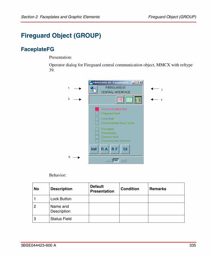
Section 2 Faceplates and Graphic Elements Fireguard Object (GROUP)
3BSE044423-600 A 335
Fireguard Object (GROUP)
FaceplateFGPresentation:
Operator dialog for Fireguard central communication object, MMCX with reftype 39.
Behavior:
No DescriptionDefault Presentation
Condition Remarks
1 Lock Button
2 Name and Description
3 Status Field
4
2
3
1
5

FaceplateFG Section 2 Faceplates and Graphic Elements
336 3BSE044423-600 A
The conditions are in priority order. Logically defined colors are used, see Appendix A, Logical Colors Definitions.
ControlFG
Presentation:
3.1 Print Blk P Yellow PRINT_BLK = 1
position 0, 1, 0
4 Aspect links Alarm List position 0, 4, 0
Event List position 0, 5, 0
Object Display position 0, 6, 0
5 Buttons (None, ref. Faceplate elements)
No DescriptionDefault Presentation
Condition Remarks
1
2
3
5
6
7
4
8
9

Section 2 Faceplates and Graphic Elements FaceplateFG
3BSE044423-600 A 337
Behavior:
No Description Default Presentation Condition Remarks
1 Communication Fault
Communication fault (Red)
IND2_00 = 1 Communication fault
Communication fault (Green)
IND2_00 .QualityOK Normal status
Communication fault (Beige)
- Unresolved
2 Fireguard Fault Fireguard fault (Red)
IND1_00 = 1 Or IND1_01 = 1 Or IND1_02 = 1 Or IND1_04 = 1 Or IND1_05 = 1
Fireguard Fault
Fireguard fault (Green)
IND1_00 .QualityOK Normal status
Fireguard fault (Beige)
- Unresolved
3 Loop Fault Loop fault (Red) IND1_10 = 1 Or IND1_11 = 1 Or IND1_12 = 1 Or IND1_13 = 1
Loop Fault
Loop fault (Green) IND1_10 .QualityOK Normal status
Loop fault (Beige) - Unresolved

FaceplateFG Section 2 Faceplates and Graphic Elements
338 3BSE044423-600 A
4 Disconnected loop / zone
Disconnected loop/zone (Yellow)
IND1_06 = 1 Or IND1_07 = 1 Or IND1_08 = 1 Or IND1_09 = 1 Or IND2_01 = 1
Disconnected loopor Disconnected zone
Disconnected loop/zone (Green)
IND1_06 .QualityOK Normal status
Disconnected loop/zone (Beige)
- Unresolved
5 Fire Alarm Fire Alarm (Red) IND1_14 = 1 Or IND1_15 = 1 Or IND2_02 = 1 Or IND2_03 = 1
Fire Alarm
Fire Alarm (Green) IND1_14 .QualityOK Normal status
Fire Alarm (Beige) - Unresolved
6 Prewarning Prewarning (Red) IND2_04 = 1 Or IND2_05 = 1 Or IND2_06 = 1 Or IND2_07 = 1
Prewarning
Prewarning (Green)
IND2_04 .QualityOK Normal status
Prewarning (Beige) - Unresolved
No Description Default Presentation Condition Remarks

Section 2 Faceplates and Graphic Elements FaceplateFG
3BSE044423-600 A 339
The conditions are in priority order. Logically defined colors are used, see Appendix A, Logical Colors Definitions.
7 Detector fault Detector fault (Red)
IND2_08 = 1 Or IND2_09 = 1 Or IND2_10 = 1 Or IND2_11 = 1
Detector fault
Detector fault (Green)
IND2_08 .QualityOK Normal status
Detector fault (Beige)
- Unresolved
8 Disconnected detector
Disconnected detector (Yellow)
IND2_12 = 1 Or IND2_13 = 1 Or IND2_14 = 1 Or IND2_15 = 1
Disconnected detector
Disconnected detector (Green)
IND2_08 .QualityOK Normal status
Disconnected detector (Beige)
- Unresolved
9 Command buttons
9.1 Initialize Initialize Fireguard Set MORD_00 = 1 Initialize Fireguard
9.2 Reset Alarm Reset Alarm Set MORD_01 = 1 Reset Fire Alarm
9.3 Reset Fault Reset Fault Set MORD_02 = 1 Reset Fault & Prewarning
9.4 Silence Silence Sounder Set MORD_03 = 1 Silence Sounder
No Description Default Presentation Condition Remarks

Do not activate the “Initialize Fireguard” command during normal operation. This command will lead to normalization of all FD (Fire Detector) objects while the communication is initialized. Use only if the communication does not start or in re-configuration situations.
Object Display for Fireguard Section 2 Faceplates and Graphic Elements
340 3BSE044423-600 A
Object Display for FireguardPresentation:
1 2
345
121314
2015161718
7 9 8 10
6
11
19

Section 2 Faceplates and Graphic Elements Object Display for Fireguard
3BSE044423-600 A 341
Behavior:
No DescriptionDefault Presentation
Condition Remarks
1 Lock Frame White SELECTED = 1 Object select frame
Grey SELECTED = 0
2 Header NAME and DESCR Name and Description
Red flashing AU_IND = 1 Unacknowledged
Yellow AL_BLK=1 or AL_PERIOD_BLK=1
Comm. object blocked
Yellow IND1_06 = 1 or IND1_07= 1 or IND1_08 = 1 or IND1_09= 1 or IND2_01
Disconnected loop / zone
Red IND1_00 = 1 or IND1_01 = 1 orIND1_02 = 1 or IND1_04 = 1 orIND1_05 = 1 or IND1_10 = 1 orIND1_11 = 1 or IND1_12 = 1 orIND1_13 = 1 or IND2_00 = 1
Disturbance or Error
Green Name .QualityOK Normal (name.name)
Beige - Unresolved

Object Display for Fireguard Section 2 Faceplates and Graphic Elements
342 3BSE044423-600 A
3 Alarm block Alarm block (Yellow)
AL_BLK = 1 Alarm block
Alarm block (Grey)
- Normal status
4 Alarm period block
Alarm period block (Yellow)
AL_PE_BLK = 1 Alarm period block
Alarm period block (Grey)
- Normal status
5 Print block Print block (Yellow)
PRINT_BLK = 1 Print block
Print block (Grey)
- Normal status
6 Fireguard Control panel
FIREGUARD CONTROL PANEL (Grey)
Static text
7 System System (Grey) Static text
7.1 Fireguard identity
Fireguard identity <INTW_A> (Green)
INTW_A .QualityOK Identity number
Fireguard identity (Beige)
- Unresolved
8 Fireguard status
Fireguard status (Grey)
Static text
8.1 Communication fault
Communication fault (Red)
IND2_00 = 1 Communication fault
Communication fault (Grey)
IND2_00 .QualityOK Normal status
No DescriptionDefault Presentation
Condition Remarks

Section 2 Faceplates and Graphic Elements Object Display for Fireguard
3BSE044423-600 A 343
8.2 Earth fault Earth fault (Red)
IND1_00 = 1 Earth fault
Earth fault (Grey)
- Normal status
8.3 Eeprom checksum fault
Eeprom checksum fault (Red)
IND1_01 = 1 Eeprom checksum fault
Eeprom checksum fault (Grey)
- Normal status
8.4 Sounder circuit fault
Sounder circuit fault (Red)
IND1_02 = 1 Eeprom checksum fault
Sounder circuit fault (Grey)
- Normal status
8.5 Disconnected zone(s)
Disconnected zones(s) (Yellow)
IND2_01 = 1 Eeprom checksum fault
Disconnected zones(s) (Grey)
- Normal status
9 Detector status Detector status (Grey)
Static text
9.1 Number of Alarms
Number of Alarms <REAL_RES> (Red)
REAL_RES > 0 Alarms
Number of Alarms <REAL_RES> (Grey)
REAL_RES .QualityOK Normal
Number of Alarms <REAL_RES> (Beige)
- Unresolved
No DescriptionDefault Presentation
Condition Remarks

Object Display for Fireguard Section 2 Faceplates and Graphic Elements
344 3BSE044423-600 A
9.2 Number of Faults
Number of Faults <INTL_RES> (Red)
INTL_RES > 0 Faults
Number of Faults <INTL_RES> (Grey)
INTL_RES .QualityOK Normal
Number of Faults <INTL_RES> (Beige)
- Unresolved
9.3 Number of Disconnected
No. of Disconnected <REAL_A> (Yellow)
REAL_A > 0 Disconnected
No. of Disconnected <REAL_A> (Grey)
REAL_A .QualityOK Normal
No. of Disconnected <REAL_A> (Beige)
- Unresolved
10 Power supply Power supply (Grey)
Static text
10.1 Main supply fault
Main supply fault (Red)
IND1_04 = 1 Main supply fault
Main supply fault (Grey)
- Normal status
10.2 Battery fault Battery fault (Red)
IND1_05 = 1 Battery fault
Battery fault (Grey)
- Normal status
No DescriptionDefault Presentation
Condition Remarks

Section 2 Faceplates and Graphic Elements Object Display for Fireguard
3BSE044423-600 A 345
11 Fire loops FIRE LOOPS (Grey)
Static text
12.1 Loop TB01 identity
<nn> Loop identity (Green)
INTL_RES_MAX .QualityOK
<I_RES_MAX, byte 4>
12.2 Loop TB02 identity
<nn> Loop identity (Green)
INTL_RES_MAX .QualityOK
<I_RES_MAX, byte 3>
12.3 Loop TBA1 identity
<nn> Loop identity (Green)
INTL_RES_MAX .QualityOK
<I_RES_MAX, byte 2>
12.4 Loop TBA2 identity
<nn> Loop identity (Green)
INTL_RES_MAX .QualityOK
<I_RES_MAX, byte 1>
13.1 Loop1 fault Loop fault (Red)
IND1_10 = 1 Loop 1 fault
Loop fault (Grey)
- Normal status
13.2 Loop 2 fault Loop fault (Red)
IND1_11 = 1 Loop 2 fault
Loop fault (Grey)
- Normal status
13.3 Loop 3 fault Loop fault (Red)
IND1_12 = 1 Loop 3 fault
Loop fault (Grey)
- Normal status
13.4 Loop 4 fault Loop fault (Red)
IND1_13 = 1 Loop 4 fault
Loop fault (Grey)
- Normal status
No DescriptionDefault Presentation
Condition Remarks

Object Display for Fireguard Section 2 Faceplates and Graphic Elements
346 3BSE044423-600 A
14.1 Loop1 disconnected
Disconnected (Red)
IND1_06 = 1 Loop 1 disconnected
Disconnected (Grey)
- Normal status
14.2 Loop 2 disconnected
Disconnected (Red)
IND1_07 = 1 Loop 2 disconnected
Disconnected (Grey)
- Normal status
14.3 Loop 3 disconnected
Disconnected (Red)
IND1_08 = 1 Loop 3 disconnected
Disconnected (Grey)
- Normal status
14.4 Loop 4 disconnected
Disconnected (Red)
IND1_09 = 1 Loop 4 disconnected
Disconnected (Grey)
- Normal status
15.1 Detectors in Loop 1
<REAL_B> Detectors in loop (Green)
REAL_B .QualityOK Detectors
15.2 Detectors in Loop 2
<REAL_C> Detectors in loop (Green)
REAL_C .QualityOK Detectors
15.3 Detectors in Loop 3
<REAL_D> Detectors in loop (Green)
REAL_D .QualityOK Detectors
15.4 Detectors in Loop 4
<REAL_E> Detectors in loop (Green)
REAL_E .QualityOK Detectors
No DescriptionDefault Presentation
Condition Remarks

Section 2 Faceplates and Graphic Elements Object Display for Fireguard
3BSE044423-600 A 347
16.1 Loop1 Alarm Alarm (Red) IND1_14 = 1 Alarm
Alarm (Grey) - Normal status
16.2 Loop 2 Alarm Alarm (Red) IND1_15 = 1 Alarm
Alarm (Grey) - Normal status
16.3 Loop 3 Alarm Alarm (Red) IND2_02 = 1 Alarm
Alarm (Grey) - Normal status
16.4 Loop 4 Alarm Alarm (Red) IND2_03 = 1 Alarm
Alarm (Grey) - Normal status
17.1 Loop1 Prewarn Prewarn (Red) IND2_04 = 1 Prewarn
Prewarn (Grey)
- Normal status
17.2 Loop 2 Prewarn
Prewarn (Red) IND2_05 = 1 Prewarn
Prewarn (Grey)
- Normal status
17.3 Loop 3 Prewarn
Prewarn (Red) IND2_06 = 1 Prewarn
Prewarn (Grey)
- Normal status
17.4 Loop 4 Prewarn
Prewarn (Red) IND2_07 = 1 Prewarn
Prewarn (Grey)
- Normal status
18.1 Loop1 Detector fault
Detector fault (Red)
IND2_08 = 1 Detector fault
Detector fault (Grey)
- Normal status
No DescriptionDefault Presentation
Condition Remarks

Object Display for Fireguard Section 2 Faceplates and Graphic Elements
348 3BSE044423-600 A
18.2 Loop 2 Detector fault
Detector fault (Red)
IND2_09 = 1 Detector fault
Detector fault (Grey)
- Normal status
18.3 Loop 3 Detector fault
Detector fault (Red)
IND2_10 = 1 Detector fault
Detector fault (Grey)
- Normal status
18.4 Loop 4 Detector fault
Detector fault (Red)
IND2_11 = 1 Detector fault
Detector fault (Grey)
- Normal status
19.1 Loop1 Det. disconnected
Any disconnected (Yellow)
IND2_12 = 1 Detector disconnected
Any disconnected (Grey)
- Normal status
19.2 Loop 2 Det. disconnected
Any disconnected (Yellow)
IND2_13 = 1 Detector disconnected
Any disconnected (Grey)
- Normal status
19.3 Loop 3 Det. disconnected
Any disconnected (Yellow)
IND2_14 = 1 Detector disconnected
Any disconnected (Grey)
- Normal status
No DescriptionDefault Presentation
Condition Remarks

Section 2 Faceplates and Graphic Elements NameFG01
3BSE044423-600 A 349
The conditions are in priority order. Logically defined colors are used, see Appendix A, Logical Colors Definitions.
NameFG01Presentation:
Presentation of Fireguard central communication object.
19.4 Loop 4 Det. disconnected
Any disconnected (Yellow)
IND2_15 = 1 Detector disconnected
Any disconnected (Grey)
- Normal status
20.1 Loop 1 not configured
(not visible) (I_RES_MAX, byte 4) > 0 Loop id > 0
20.2 Loop 2 not configured
(not visible) (I_RES_MAX, byte 3) > 0 Loop id > 0
20.3 Loop 3 not configured
(not visible) (I_RES_MAX, byte 2) > 0 Loop id > 0
Loop not configured (Grey)
- Other Loop ind. hidden
20.4 Loop 4 not configured
(not visible) (I_RES_MAX, byte 1) > 0 Loop id > 0
Loop not configured (Grey)
- Other Loop ind. hidden
No DescriptionDefault Presentation
Condition Remarks
21

NameFG01 Section 2 Faceplates and Graphic Elements
350 3BSE044423-600 A
Behavior:
The conditions are in priority order. Logically defined colors are used, see Appendix A, Logical Colors Definitions.
No DescriptionDefault Presentation
Condition Remark
1 Frame White SELECTED =1 Selected
Dotted Yellow AL_BLK =1 Alarm blocked
Invisible IND1_00 .QualityOK Normal
Beige - Unresolved
2 Name Color Red flash AU_IND =1 Unacknowledged Alarm
Yellow IND1_06 = 1 Or IND1_07 = 1 Or IND1_08 = 1 Or IND1_09 = 1 Or IND2_01 = 1
Disconnected loop
Red IND1_00 = 1 Or IND1_01 = 1 Or IND1_02 = 1 Or IND1_04 = 1 Or IND1_05 = 1
Fireguard fault
Red IND1_10 = 1 Or IND1_11 = 1 Or IND1_12 = 1 Or IND1_13 = 1
Loop fault
Red IND2_00 Communication fault
Green IND1_00 .QualityOK Normal status
Beige - Unresolved (name: name)

Section 2 Faceplates and Graphic Elements NameFG01
3BSE044423-600 A 351
Configuration:
Parameter Affect Option (bold is default) Remarks
BackgroundColor Background Transparent, any

Autronica Object (GROUP) Section 2 Faceplates and Graphic Elements
352 3BSE044423-600 A
Autronica Object (GROUP)
FaceplateBSPresentation:
Operator dialog for Autronica BS central communication object, MMCX with reftype 39.
4
2
3
1
5

Section 2 Faceplates and Graphic Elements FaceplateBS
3BSE044423-600 A 353
Behavior:
The conditions are in priority order. Logically defined colors are used, see Appendix A, Logical Colors Definitions.
No DescriptionDefault Presentation
Condition Remarks
1 Lock Button
2 Name and Description
3 Status Field
3.4 Print Blk P Yellow PRINT_BLK = 1
4 Aspect links Alarm List position 0, 0, 9
Event List position 0, 0, 10
Object Display
position 5, 5, 11
Trend Display
position 6, 6, 12
5 Buttons (None, ref. Faceplate elements)

FaceplateBS Section 2 Faceplates and Graphic Elements
354 3BSE044423-600 A
ControlBS
Presentation:
Behavior:
No DescriptionDefault Presentation
Condition Remarks
1 Detector status
E (red) BOOL_H = 1 Detector Error
A (red) BOOL_G = 1 Detector Alarm
P (red) BOOL_F = 1 Detector Prewarning
Invisible NAME .QualityOK Normal status
A (Beige) - Unresolved
1 2
3
4

Section 2 Faceplates and Graphic Elements FaceplateBS
3BSE044423-600 A 355
2 BS-30 Status Error (red) BOOL_E = 1 BS-30 Error
Warning (red) BOOL_D = 1 BS-30 Warning
Normal (Green) NAME .QualityOK Normal status
Normal (Beige) - Unresolved
3 Loop Status Loop 0 (Red) IND1_01 = 1 Loop Error
3.0 Loop 0 Status Loop 0 (Red) IND1_01 = 1 Loop Error
Loop 0 (Green) IND1_01 .QualityOK Normal status
Loop 0 (Beige) - Unresolved
3.1 Loop 1 (Red) IND1_02 = 1 Loop Error
Loop 1 (Green) IND1_02 .QualityOK Normal status
Loop 1 (Beige) - Unresolved
3.2 Loop 2 (Red) IND1_03 = 1 Loop Error
Loop 2 (Green) IND1_03 .QualityOK Normal status
Loop 2 (Beige) - Unresolved
3.3 Loop 3 (Red) IND1_04 = 1 Loop Error
Loop 3 (Green) IND1_04 .QualityOK Normal status
Loop 3 (Beige) - Unresolved
3.4 Loop 4 (Red) IND1_05 = 1 Loop Error
Loop 4 (Green) IND1_05 .QualityOK Normal status
Loop 4 (Beige) - Unresolved
3.5 Loop 5 (Red) IND1_06 = 1 Loop Error
Loop 5 (Green) IND1_06 .QualityOK Normal status
Loop 5 (Beige) - Unresolved
No DescriptionDefault Presentation
Condition Remarks

FaceplateBS Section 2 Faceplates and Graphic Elements
356 3BSE044423-600 A
3.6 Loop 6 (Red) IND1_07 = 1 Loop Error
Loop 6 (Green) IND1_07 .QualityOK Normal status
Loop 6 (Beige) - Unresolved
3.7 Loop 7 (Red) IND1_08 = 1 Loop Error
Loop 7 (Green) IND1_08 .QualityOK Normal status
Loop 7 (Beige) - Unresolved
3.8 Loop 8 (Red) IND1_09 = 1 Loop Error
Loop 8 (Green) IND1_09 .QualityOK Normal status
Loop 8 (Beige) - Unresolved
3.9 Loop 9 (Red) IND1_10 = 1 Loop Error
Loop 9 (Green) IND1_10 .QualityOK Normal status
Loop9 (Beige) - Unresolved
3.10 Loop 10 (Red) IND1_12 = 1 Loop Error
Loop 10 (Green) IND1_12 .QualityOK Normal status
Loop 10 (Beige) - Unresolved
3.11 Loop 11 (Red) IND1_13 = 1 Loop Error
Loop 11 (Green) IND1_13 .QualityOK Normal status
Loop 11 (Beige) - Unresolved
3.12 Loop 12 (Red) IND1_14 = 1 Loop Error
Loop 12 (Green) IND1_14 .QualityOK Normal status
Loop12 (Beige) - Unresolved
No DescriptionDefault Presentation
Condition Remarks

Section 2 Faceplates and Graphic Elements NameBS01
3BSE044423-600 A 357
The conditions are in priority order. Logically defined colors are used, see Appendix A, Logical Colors Definitions.
NameBS01Presentation:
Presentation of Autonica BS central communication object.
3.13 Loop 13 (Red) IND1_15 = 1 Loop Error
Loop 13 (Green) IND1_15 .QualityOK Normal status
Loop13 (Beige) - Unresolved
4.14 Loop 14 (Red) IND2_00 = 1 Loop Error
Loop 14(Green) IND2_00 .QualityOK Normal status
Loop14 (Beige) - Unresolved
3.15 Loop 15 (Red) IND2_01 = 1 Loop Error
Loop 15 (Green) IND2_01 .QualityOK Normal status
Loop15 (Beige) - Unresolved
5 Command buttons
5.1 Silence Silence Set MORD_00 = 1 Silence Sounder
5.1 Accept Accept Set MORD_01 = 1 Accept alarms
5.2 Reset Alarm Reset Set MORD_02 = 1 Reset Autronica BS central
No DescriptionDefault Presentation
Condition Remarks
21

NameBS01 Section 2 Faceplates and Graphic Elements
358 3BSE044423-600 A
Behavior:
The conditions are in priority order. Logically defined colors are used, see Appendix A, Logical Colors Definitions.
NoDescription
Default Presentation
Condition Remark
1 Frame White SELECTED =1 Selected
Dotted Yellow AL_BLK =1 Alarm blocked
Invisible IND1_00 .QualityOK Normal
Beige - Unresolved
2 Name Color Red flash AU_IND =1 Unacknowledged Alarm
Red BOOL_E = 1 or BOOL_D = 1 BS-30 Error or Warning
Red BOOL_H = 1 or BOOL_G = 1 or BOOL_F = 1
Detector Error or Alarm or Prewarning
Red IND1_01 = 1 or IND1_02 or IND1_03 orIND1_04 = 1 or IND1_05 or IND1_06 orIND1_07 = 1 or IND1_08 or IND1_09 orIND1_10 = 1 or IND1_12 or IND1_13 orIND1_14 = 1 or IND1_15 or IND2_00 orIND2_01 = 1
Loop Error (Loop 0 to Loop 15)
Green IND1_00 .QualityOK Normal status
Beige - Unresolved (name: name)

Parameter Affect Option (bold is default) Remarks
BackgroundColor Background Transparent, any
Section 2 Faceplates and Graphic Elements AutroSafe Object (GROUP)
3BSE044423-600 A 359
Configuration:
AutroSafe Object (GROUP)
FaceplateASPresentation:
Operator dialog for AutroSafe central communication object, MMCX with reftype 39.

FaceplateAS Section 2 Faceplates and Graphic Elements
360 3BSE044423-600 A
Behavior:
The conditions are in priority order.
No DescriptionDefault Presentation
Condition Remarks
1 Lock Button
2 Name and Description
3 Aspect links Alarm List position 0, 0, 4
Event List position 0, 0, 5
4 and 5 Status and Configuration
(Ref. Faceplate element ControlAS)

Section 2 Faceplates and Graphic Elements ControlAS
3BSE044423-600 A 361
ControlASPresentation:

ControlAS Section 2 Faceplates and Graphic Elements
362 3BSE044423-600 A
Behavior:
No DescriptionDefault Presentation
Condition Remarks
1 AutroSafe Status
Error (red) BOOL_E = 1 or
IND2_02=1 or
IND2_05=1 or
IND2_06=1 or
IND2_07=1 or
IND2_10=1 or AU_IND=1
AutroSafe Error
Warning (red) BOOL_D = 1 or
IND2_00=1
AutroSafe Warning
Normal (Green) NAME .QualityOK Normal status
2.1 Error Indication
Red BOOL_E = 1 Error flag
ErrorText ERROR Text behind the indication
red BOOL_E = 1
Normal (Green)
2.2 Config Error Config Error flags
Config ErrorText
Config Error Text behind the indication
Red IND2_02=1 or
IND2_05=1 or
IND2_06=1 or
IND2_07=1 or
IND2_10=1
Normal (Green)

Section 2 Faceplates and Graphic Elements ControlAS
3BSE044423-600 A 363
2.3 Disconnected Disconnected flags
Disconnected Text
Disconnected Text behind the indication
Red IND2_00=1
Normal (Green)
2.4 Warning Indication
Warnings flags
Warning Text Warning Text behind the indication
Red BOOL_D=1
Normal (Green)
3 Configuration
3.1 AutroSafe Version
Static text
AutroSafe Version Text
IND2_10_PRES_TEXT
3.2 Filename Static text
Config Filename Text
IND2_11_PRES_TEXT
3.3 Date Static text
Config DateText
IND2_12_PRES_TEXT
3.4 Time Static text
Config Time Text
IND2_13_PRES_TEXT
No DescriptionDefault Presentation
Condition Remarks

StartupStatusAS Section 2 Faceplates and Graphic Elements
364 3BSE044423-600 A
StartupStatusASPresentation:
4 Command buttons
4.1 Reset Alarm Reset Set MORD_02 = 1 Reset AutroSafe Fire Panel
No DescriptionDefault Presentation
Condition Remarks

Section 2 Faceplates and Graphic Elements StartupStatusAS
3BSE044423-600 A 365
Behavior:
No DescriptionDefault Presentation
Condition Remarks
1 System State Starting Up Starting Up Offline
Verifying Configuration Operational
Text showing current system state.
Session State None None
Disconnected
Synchronizing Sequence Number
Logging Off from AutroSafe
Logging On to AutroSafe
Logged On
Text showing current system state.
Verify State None None
Checking Configuration Info
Verifying Detectors
Completed OK
Failed
Text showing current system state.
2 Indications Gray Error Indications
2.1 Fatal Error Gray Red if IND1_00=1
2.2 Warning Gray Red if IND1_11=1
2.3 Not in Operational State
Gray Red if IND2_00=1
2.4 Communication Link Error
Gray Red if IND2_01=1

ConfigStatusAS Section 2 Faceplates and Graphic Elements
366 3BSE044423-600 A
ConfigStatusAS
Presentation:
2.5 Zone In Test Reported from AutroSafe
Gray Red if IND2_03=1
2.6 Command to AutroSafe Timed Out
Gray Red if IND2_04=1
2.7 FDRT Supervision Timed Out
Gray Red if IND2_08=1
2.8 Max CRC Errors Detected
Gray Red if IND2_09=1
2.9 No Command Response
Gray Red if IND2_12=1
2.10 AutroSafe Reset in Progress
Gray Red if IND2_15=1
No DescriptionDefault Presentation
Condition Remarks

Section 2 Faceplates and Graphic Elements NameAS01
3BSE044423-600 A 367
Behavior:
NameAS01Presentation:
No DescriptionDefault Presentation
Condition Remarks
1 Indications Gray Config Indications
1.1 Wrong Configuration Id in AutroSafe
Gray Red if IND2_02=1
1.2 Wrong SW Version in AutroSafe
Gray Red if IND2_05=1
1.3 Verify Configuration, Detector Name Mismatch
Gray Red if IND2_06=1
1.4 Wrong Panel Id (OZ1 name) in AutroSafe
Gray Red if IND2_07=1
1.5 Configuration Error in FD Database
Gray Red if IND2_10=1
1.6 Detector not Configured in Safeguard
Gray Red if IND2_11=1

NameAS01 Section 2 Faceplates and Graphic Elements
368 3BSE044423-600 A
Presentation of AutroSafe central communication object
Behavior:
No DescriptionDefault Presentation
Condition Remark
1 Frame White SELECTED =1 Selected
Dotted Yellow AL_BLK =1 Alarm blocked
Invisible (GeneralBackColor)
IND1_00 .QualityOK Normal
Beige - Unresolved
2 Name Color Red flash ALARM_UNACK=1 or AU_IND =1
Unacknowledged Alarm
Red BOOL_E=1 or BOOL_D=1 or IND2_00=1 or IND2_02=1 or IND2_05=1 or IND2_06=1 or IND2_07=1 or IND2_10=1
Error
Green IND1_00 .QualityOK Normal status
Beige - Unresolved

Section 2 Faceplates and Graphic Elements Shutdown Valve Object (Genbin)
3BSE044423-600 A 369
Shutdown Valve Object (Genbin)
SD_FaceplateThis Faceplate provides operator control of a digital output using a valve interface. A Genbin object is connected to the User Elements VAL1-CE and VAL2-CE. This Faceplate and the User Elements enable operator control of the concerned outputs in the cause and effect matrix.The Faceplate can be used with the User Element VAL1 for operator control of an output not connected to the Cause & Effect Matrix. The SD_Faceplate is used with the Graphic Element SD_Valve01.
Presentation:
4
2
3
1
5

SD_Faceplate Section 2 Faceplates and Graphic Elements
370 3BSE044423-600 A
Behavior:
NoDescription
Default Presentation
Condition Remarks
1 Lock Button
2 Name and Description
3 Status Field
3.1 Alarm Blk B Yellow ALARM_BLK = 1 Alarm blocked
3.2 Print Blk P Yellow PRINT_BLK = 1 Printout blocked
3.4 Error E Red PC_ST_01 = 1 Position error
3.5 Override O Cyan PC_ST_21 = 1 Overridden
4 Aspect links
(None)
5 Buttons
5.1 Op Open Valve order set MORD_08 = 1 (ORDONOP =1)
5.7 Cls Close Valve order set MORD_09 = 1 (ORDOFCL =1)
5.8 Cen set in Central control
set MORD_01 = 1 (ORDCEN =1)
5.9 Loc set in Local control
set MORD_02 = 1 (ORDLOC =1)
5.5 Ovr Override ON set MORD_06 = 1 (ORDBLK =1)
5.11 Ooff Override OFF set MORD_07 = 1 (ORDSTBY =1)

Section 2 Faceplates and Graphic Elements SD_Control
3BSE044423-600 A 371
The conditions are in priority order. Logically defined colors are used, see Appendix A, Logical Colors Definitions.
SD_ControlPresentation:.
Behavior:
No DescriptionDefault Presentation
Condition Remarks
1.1 Safe position text
Fail Open valve PC_ST_18 =1 Safe position = Open valve (REM =1)
Fail Close valve PC_ST_18 .QualityOK
Safe position = Close valve (REM =0)
Safe position - Unresolved
1.2 Safe position color
Gray PC_ST_18 .QualityOK
Resolved
Beige - Unresolved
2. Override not allowed
5. Alarm blocked
6. Position fault
1. Safe position
4. Printout blocked
3. Mode
7. Shutdown
10. Open order
11. Close order
8. Shutdown warning9. Override
12. Open position
13. Closed position
14. Valve
15. Traveling

SD_Control Section 2 Faceplates and Graphic Elements
372 3BSE044423-600 A
2.1 Override not allwed text
Override not Authorized
2.2 Override not allowed color
Light blue (invisible)
PC_ST_08 =1 Override Authorize on (INTMODE =1)
Gray PC_ST_08 .QualityOK
Override Authorize off (INTMODE =0)
Beige - Unresolved
3.1 Mode indication text
Local PC_ST_17 =1 Local mode (LOC =1, CEN =0)
Central - Central mode (LOC =0, CEN =1)
3.2 Mode indication color
Green PC_ST_17 .QualityOK
Resolved
Beige - Unresolved
4.1 Printout blocked text
P
4.2 Printout blocked color
Yellow: PR_BLK =1 Printout blocked
Light blue (invisible)
PR_BLK .QualityOK
Printout not blocked
Beige - Unresolved
5.1 Alarm blocked text
B AL_BLK =1 Alarm blocked by operator
Bx AUTO_BLK =1 Alarm blocked form PC program
Be EV_BLK =1 Event blocked
(no text) AL_BLK .QualityOK
Normal status
B - Unresolved
No DescriptionDefault Presentation
Condition Remarks

Section 2 Faceplates and Graphic Elements SD_Control
3BSE044423-600 A 373
5.2 Alarm blocked color
Yellow AL_BLK .QualityOK
Resolved
Beige - Unresolved
6.1 Position fault text Position fault
6.2 Position fault color
Red flash AU_ST_01 =1 Feedback error unack. (ALFBE =1 unack.)
Red PC_ST_01 =1 Feedback error (ALFBE =1)
Light blue (invisible)
PC_ST_01 .QualityOK
Normal status
Beige - Unresolved
7.1 Shutdown text ShutDown
7.2 Shutdown color Red PC_ST_09 =1 Shutdown activated (INTPROC =1)
Light blue (invisible)
PC_ST_09 .QualityOK
Shutdown reset (INTPROC =0)
Beige - Unresolved
8.1 Shutdown Warning text
while (connecting "Shutdown" and "Overridden")
8.2 Shutdown Warning color
Red flash AU_ST_00 =1 Shutdown while overridden, unack. (LSIGNE =1 unack.)
Light blue (invisible)
AU_ST_00 .QualityOK
(Not unacknowledged)
Beige - Unresolved
No DescriptionDefault Presentation
Condition Remarks

SD_Control Section 2 Faceplates and Graphic Elements
374 3BSE044423-600 A
9.1 Override text Overridden
9.2 Override color Red flash AU_ST_00 =1 Shutdown while overridden, unack. (LSIGNE =1 unack.)
Cyan PC_ST_21 =1 Overridden (BLK =1)
Light blue (invisible)
PC_ST_21 .QualityOK
Not overridden (BLK =0)
Beige - Unresolved
10.1 Open order blocked
red PC_ST_09 =1 & PC_ST_21 =0 & PC_ST_18 =0
Order not available.(Shutdown (INTPROC =1) & not overridden (BLK =0) & fail close valve (REM =0))
10.2 Open order Square
Green PC_ST_24 =0 Close order (INDONOP =0)
Green PC_ST_20 =1 Valve open limit (MAN = 1)
Green flashing
- Valve opening (Open order & Not Open limit)
Beige Not PC_ST_24 .QualityOK
Unresolved
10.3 Open order String
Open ordered
No DescriptionDefault Presentation
Condition Remarks

Section 2 Faceplates and Graphic Elements SD_Control
3BSE044423-600 A 375
10.4 Open order String color
Green PC_ST_24 =1 Open order (valve opening) (INDONOP =1)
Light blue (invisible)
PC_ST_24 .QualityOK
Close order (INDONOP =0)
Beige - Unresolved
11.1 Close order blocked
red PC_ST_09 =1 & PC_ST_21 =0 & PC_ST_18 =1
Order not available(Shutdown (INTPROC =1) & not overridden (BLK =0) & fail open valve (REM =1))
11.2 Close order Square
Green PC_ST_24 =1 Open order (INDONOP =1)
Green PC_ST_19 =1 Valve close limit (AUTO = 1)
Green flashing
PC_ST_24.QualityOK
Valve closing (Close order & Not Close limit)
Beige - Unresolved
11.3 Close order String
Close ordered
11.4 Close order String color
Green PC_ST_24 =0 & PC_ST_24 .QualityOK
Close order (valve closing) (INDONOP =0)
Light blue (invisible)
PC_ST_24 .QualityOK
Open order (INDONOP =1)
Beige - Unresolved
No DescriptionDefault Presentation
Condition Remarks

SD_Control Section 2 Faceplates and Graphic Elements
376 3BSE044423-600 A
12.1 Open position Square
Green PC_ST_20 =1 Valve open limit (MAN =1)
Green PC_ST_20 .QualityOK
Not Valve open limit (MAN =0)
Beige - Unresolved
12.2 Open position String
OPN Limit sw.
12.3 Open position String color
Green PC_ST_20 .QualityOK
Resolved
Beige - Unresolved
13.1 Close position Square
Green PC_ST_19 =1 Valve close limit (AUTO =1)
Green PC_ST_19 .QualityOK
Not Valve close limit (AUTO =0)
Beige - Unresolved
13.2 Close position String
CLS Limit sw.
13.3 Close position String color
Green PC_ST_19 .QualityOK
Resolved
Beige - Unresolved
No DescriptionDefault Presentation
Condition Remarks

Section 2 Faceplates and Graphic Elements SD_Control
3BSE044423-600 A 377
14.1 Valve Frame Color
Red flash AU_ST_01 = 1 Traveling fault, unack (ALFBE =1 unack)
Red PC_ST_01 = 1 Traveling fault (ALFBE =1)
Green flash PC_ST_25 = 1 Traveling (opening or closing) (INDCH =1)
Cyan PC_ST_21 = 1 Shutdown Override (BLK =1)
Green PC_ST_24 .QualityOK
Resolved
Beige - Unresolved
14.2 Valve Center Color
Dark Grey PC_ST_24 = 0 &PC_ST_24 .QualityOK
Close ordered (INDONOP =0)
Red flash AU_ST_01 = 1 Traveling fault .unack (ALFBE =1 unack)
Red PC_ST_01 = 1 Traveling fault (ALFBE =1)
Green flash PC_ST_25 = 1 Traveling (opening or closing) (INDCH =1)
Green PC_ST_24 .QualityOk
Open ordered
Light blue (invisible)
- Unresolved
15.1 Traveling text Traveling
No DescriptionDefault Presentation
Condition Remarks

SD_Valve01 Section 2 Faceplates and Graphic Elements
378 3BSE044423-600 A
The conditions are in priority order. Logically defined colors are used, see Appendix A, Logical Colors Definitions.
SD_Valve01Presentation:
Presentation of shutdown valve outputs controlled from Cause & Effect matrix (Safety Builder). Used together with User Elements VAL1-CE, VAL2-CE or VAL1.Indication of Local mode and Shutdown order. Alarm on Traveling fault and Shutdown while overridden. The Graphic Element is used together with the SD_Faceplate.
15.2 Traveling color Green flash PC_ST_25 =1 Traveling (opening or closing) (INDCH =1)
Light blue (invisible)
PC_ST_25 .QualityOK
Not Traveling (INDCH =0)
Beige - Unresolved
No DescriptionDefault Presentation
Condition Remarks
1
42 3
5

Section 2 Faceplates and Graphic Elements SD_Valve01
3BSE044423-600 A 379
Behavior:
No DescriptionDefault Presentation
Condition Remarks
1 Select Line Object status frame
White SELECTED = 1
Object selected
Dotted Yellow AL_BLK = 1 Alarm blocked by operator
Dotted Yellow PR_BLK = 1 Printout blocked
Dotted Yellow EV_BLK = 1 Event blocked
Cyan PC_ST_21 = 1
Shutdown Override (BLK =1)
Red flash AU_ST_01 = 1
Traveling fault .unack (ALFBE =1 unack)
Red PC_ST_01 = 1
Traveling fault (ALFBE =1)
Green flash PC_ST_25 = 1
Traveling (opening or closing) (INDCH =1)
Invisible
2 Mode LocalText Local mode indication
Invisible ModeVisible = false
No mode indication
Green PC_ST_17 = 1
Local mode (LOC = 1, CEN = 0)
Invisible PC_ST_00 .QualityOK
Central mode (LOC = 0, CEN = 1)
Beige - Unresolved

SD_Valve01 Section 2 Faceplates and Graphic Elements
380 3BSE044423-600 A
3 Actuator Invisible ActuatorType = None
No actuator
Red flash AU_ST_01 = 1
Traveling fault .unack (ALFBE =1 unack)
Red PC_ST_01 = 1
Traveling fault (ALFBE =1)
ActuatorNormalColor PC_ST_00 .QualityOK
Normal
Beige - Unresolved
4 Shutdown ShutdownText Shutdown order indication
Invisible ShutdownVisible = False
No shutdown indication
Red flash AU_ST_00 =1
Shutdown while overridden, unack(ALSIGNE =1 unack)
Red PC_ST_00 =1
Shutdown while overridden(ALSIGNE =1)
Red PC_ST_09 =1
Shutdown activated (INTPROC =1)
Invisible PC_ST_00 .QualityOK
Shutdown reset
Beige - Unresolved
No DescriptionDefault Presentation
Condition Remarks

Section 2 Faceplates and Graphic Elements SD_Valve01
3BSE044423-600 A 381
5.1 Valve Frame Style
2D Style FrameStyle =Flat
3D Style FrameStyle = Raised or FrameStyle =Sunken
5.2 Valve Frame Color
Red flash AU_ST_01 = 1
Traveling fault .unack (ALFBE =1 unack)
Red PC_ST_01 = 1
Traveling fault (ALFBE =1)
Green flash PC_ST_25 = 1
Traveling (opening or closing) (INDCH =1)
Cyan PC_ST_21 = 1
Shutdown Override (BLK =1)
ValveNormalColor FrameStyle =Flat &PC_ST_00 .QualityOk
Open Valve, 2D
FrameNormalColor / FrameNormalColor2
PC_ST_00 .QualityOk
Open Valve, 3D
Beige - Unresolved
5.3 Valve Center Color
Dark Grey PC_ST_24 = 0
Close ordered (INDONOP =0)
Red flash AU_ST_01 = 1
Traveling fault .unack (ALFBE =1 unack)
Red PC_ST_01 = 1
Traveling fault (ALFBE =1)
Green flash PC_ST_25 = 1
Traveling (opening or closing) (INDCH =1)
No DescriptionDefault Presentation
Condition Remarks

SD_Valve01 Section 2 Faceplates and Graphic Elements
382 3BSE044423-600 A
The conditions are in priority order. Underlined parameters are configurable. Logically defined colors are used, see Appendix A, Logical Colors Definitions.
Configuration:
ValveNormalColor PC_ST_00 .QualityOk
Open ordered
Beige - Unresolved
Parameters AffectsOptions (bold is default)
Remarks
ModeVisible 2. Mode True, False
LocalText 2. Mode L, any Text
ActuatorNormalColor
3. Actuator Green, any color Not logically defined
ActuatorType 3. Actuator None, Manual, Regulation.
ShutdownVisible 4. Shutdown
True, False
ShutdownText 4. Shutdown
Sd, any Text
FrameWidth 5. Valve 3, (3.. ) Width of valve edge, that is, should not be zero.
FrameStyle 5. Valve Flat, Raised, Sunken
2 -dimension valve if FrameStyle = Flat.
FrameNormalCo-lor
5. Valve Light Green, any color
Not logically defined (Not used if FrameStyle = Flat
FrameNormalCo-lor2
5. Valve Dark Green, any color
Not logically defined (Not used if FrameStyle = Flat
No DescriptionDefault Presentation
Condition Remarks

Section 2 Faceplates and Graphic Elements SD_Valve01
3BSE044423-600 A 383
ValveNormalCo-lor
5. Valve Green, any color Not logically defined (To enable adjustment to process medium color)
Orientation All Horizontal, Vertical
Valve orientation
BackgroundColor Background Transparent, Any
Parameters AffectsOptions (bold is default)
Remarks

SD_Valve01 Section 2 Faceplates and Graphic Elements
384 3BSE044423-600 A

3BSE044423-600 A 385
Appendix A Logical Colors Definitions
In System 800xA, logical definitions are used for colors. The Logical Colors definition aspects are located in the Workplace Structure. A Safety Colors group is defined to present the Inhibit function.
Some of the Graphic Elements have color properties. The default value of these properties are not Logically defined. If a property is changed, a Logically defined color should be selected in the Expression Builder.
In order to utilize the Logical color definitions as ‘global standard colors’, most of the Graphic Elements described here does not have (configurable) color properties. The following tables show the colors that are used and their definition.

Logical Colors used in Faceplates Appendix A Logical Colors Definitions
386 3BSE044423-600 A
Logical Colors used in Faceplates
Default presentation Logical Color Name RGB Value Color group name
Red (alarm) FaceplateHighAlarm RGB(255, 30, 102) Process Graphics Colors
Red (error) FaceplateIndError RGB(217, 26, 88) Process Graphics Colors
Red flash (unack. alarm)
FaceplateUnackHighAlarm
RGB(255, 30, 102) /RGB(185, 4, 58) /RGB(185, 4, 58)
Process Graphics Colors
Green flash (travel) FaceplateIndNotice RGB( 81, 145, 17) /RGB( 38, 69, 7)
Process Graphics Colors
Yellow (blocked) FaceplateIndBlocked RGB(255, 245, 51) Process Graphics Colors
Black (normal) FaceplateFg RGB(0, 0, 0) Process Graphics Colors
Light blue (Background)
FaceplateBg RGB(153, 185, 193) Process Graphics Colors
Green (normal) FaceplateIndNormal RGB( 81, 145, 10) Process Graphics Colors
Grey (static text) limit RGB(119, 119, 119) General Colors
Beige (unresolved) static RGB(207, 194, 163) General Colors
Cyan (Inhibit) FaceplateInhibit RGB(175, 239, 238) Safety Colors
Logical Colors used in Graphic Elements
Default presentation Logical Color Name RGB Value Color group name
White (selected) selected RGB(255, 255, 255) Event Colors
Red (alarm) HighAlarmSymbol RGB(255, 30, 102) Event Colors

Appendix A Logical Colors Definitions Logical Colors used in Graphic Elements
3BSE044423-600 A 387
Red (alarm) HighAlarmText RGB(255, 51, 102) Event Colors
Red flash(unack. alarm)
unackHighAlarm RGB(255, 51, 102) /RGB(185, 4, 58) /RGB(185, 4, 58)
Event Colors
Yellow (blocked) blockedSymbol RGB(255, 245, 51) Event Colors
Yellow (blocked) blockedText RGB(255, 245, 102) Event Colors
Green (normal) symbol2Normal RGB(102, 204, 0) Object Colors
Green (normal) text2Normal RGB(128, 191, 64) Object Colors
Light Green (normal, 3D)
symbol2Emphasize RGB(128, 255, 0) Object Colors
Dark Green (normal, 3D)
symbol2Reduce RGB( 69, 138, 0) Object Colors
Green flash (travel) symbol2Notice RGB(102, 204, 0) /RGB( 60, 120, 0)
Object Colors
Blue (activated) actuator RGB( 0, 0, 255) Object Colors
Dark Grey (closed / off)
symbolOff RGB( 81, 81, 81) Object Colors
Background GeneralBackColor RGB( 51, 102, 102) Process Graphics Colors
Grey (normal limit ind.)
limit RGB(119, 119, 119) General Colors
Beige (unresolved) static RGB(207, 194, 163) General Colors
Cyan (manual mode) manMode RGB(128, 230, 227) Object Colors
Cyan (Inhibit) Inhibit RGB(128, 230, 227) Safety Colors
Red (Error) Error RGB(255, 0, 120) Safety Colors
Default presentation Logical Color Name RGB Value Color group name

Logical Colors used in Graphic Elements Appendix A Logical Colors Definitions
388 3BSE044423-600 A

3BSE044423-600 A 389
Revision History
This section provides information on the revision history of this User Manual.
The following table lists the revision history of this User Manual.
Revision Index
Description Date
- First version published for 800xA 6.0 August 2014
A Removed Fire and Gas detector subelements from the section Safeguard Subelements, as VBPG is not supported in System 800xA 6.0.
October 2015

390 3BSE044423-600 A

3BSE044423-600 391
AAI
M_NameStatus01 19M_Status01 22SD_Value01 24
CConfigStatusAS 366
DDI
FG_InhibitBox01 44FG_Toggle01 46FG_ValueText01 43M_NameReset01 37M_NameStatus01 33M_Reset01 39M_Status01 35NameBox01 29NameStatus01 26Selection01 31StatusBox01 40
DOFG_Button01 61FG_Control 59FG_Faceplate 57FG_NameBox01 64FG_Order01 75FG_Selection01 60FG_StatusBox01 69FG_Toggle01 78FG_ValueText01 74M_NameBox01 54NameBox01 48StatusBox01 51
FFI
Detector01 123Faceplate 81FG_NameBox01 130FiBlock 86FiControlFI 84FiReducedControl 84IndicatorBox01 116M_NameStatus01 126M_Status01 129NameStatus01 120Object Display for FD (Autronica) 96Object Display for FD (Fireguard) 109Object Display for FINO, FINC and FISM 88
GGenbin
SD_Control 371SD_Faceplate 369SD_Valve01 378
GENUSD1SD_Display01 233SD_Display02 236SD_Input01 224SD_Level01 230SD_Output01 227
Genusd1FG_AreaCO201 218FG_AreaDetErr01 215FG_AreaHVAC01 222FG_AreaWater01 220FG_Control 194FG_Faceplate 192FG_OverviewCO201 210
Index

Index
392 3BSE044423-600
Index
392 3BSE044423-600
FG_OverviewFire01 201FG_OverviewGas01 203FG_OverviewHVAC01 208FG_OverviewOut01 213FG_OverviewWater01 205
GENUSD5ControlNE 243FaceplateNE 241NameStatusNE01 258ObjectDisplayNE 245
GENUSD6ControlND 263FaceplateND 262NameStatusND01 276ObjectDisplayND 265
GIBargraphMV01 168Detector01 184Faceplate 134FG_Detector01 177FG_NameStatus01 174GiBlock 143GiCalibration 145GiControl 137GiLimits1 142GiReducedControl 137M_NameStatus01 186M_Status01 190NameStatus01 179NumericMV01 166Object Display 148Object Display, Analog GI 158UnitMV01 167
GROUPControlAS 361ControlBS 354ControlFG 336FaceplateBS 352FaceplateFG 335NameAS01 367
NameBS01 357NameFG01 349Object Display for Fireguard 340
MMMCX
FG_Control 280FG_Faceplate 278FG_Override01 285FG_Override05 288
MMCX2BlockSD 296ControlSD 294Faceplate 292IndicatorBoxSD01 298M_NameStatus01 301M_Status01 303SD_LevelLine01 307SD_NameCauseLevel01 304
MMCX3BlockSG 323BypassManagementSG 317CEcommunicationSG 321FaceplateSG 309IsolateSG 319MessagesSG 312NameSG01 332NameSG02 333ObjectDisplaySG 325Safeguard Display 325SystemStatusSG 314
SStartupStatusAS 364Subelements
BoolProperty 15FlameDetector 16InfraredDetector 17


Power and productivity for a better worldTM
Contact us
Copyright © 2015 ABB.All rights reserved.
3BS
E04
4423
-600
Awww.abb.com/800xAwww.abb.com/controlsystems