7210 SAS M, T, R6, R12, Mxp, Sx, S Basic System ...
750
© 2021 Nokia. Use subject to Terms available at: www.nokia.com 7210 SERVICE ACCESS SWITCH | RELEASE 21.9.R1 7210 SAS-M, T, R6, R12, Mxp, Sx, S Basic System Configuration Guide 3HE 17358 AAAB TQZZA Edition: 01 September 2021 7210 SAS-M, T, R6, R12, Mxp, Sx, S Basic System Configuration Guide
-
Upload
khangminh22 -
Category
Documents
-
view
0 -
download
0
Transcript of 7210 SAS M, T, R6, R12, Mxp, Sx, S Basic System ...
© 2021 Nokia. Use subject to Terms available at: www.nokia.com
7210 SERVICE ACCESS SWITCH | RELEASE 21.9.R1
7210 SAS-M, T, R6, R12, Mxp, Sx, S Basic System Configuration Guide
3HE 17358 AAAB TQZZA
Edition: 01
September 2021
7210 SAS-M, T, R6, R12, Mxp, Sx, S Basic System Configuration Guide
7210 SAS-M, T, R6, R12, Mxp, Sx, S Basic SystemConfiguration Guide
2 © 2021 Nokia. Use subject to Terms available at: www.nokia.com
3HE 17358 AAAB TQZZA
Nokia is committed to diversity and inclusion. We are continuously reviewing our customer documentation and consulting with standards bodies to ensure that terminology is inclusive and aligned with the industry. Our future customer documentation will be updated accordingly.
This document includes Nokia proprietary and confidential information, which may not be distributed or disclosed to any third parties without the prior written consent of Nokia.
This document is intended for use by Nokia’s customers (“You”/”Your”) in connection with a product purchased or licensed from any company within Nokia Group of Companies. Use this document as agreed. You agree to notify Nokia of any errors you may find in this document; however, should you elect to use this document for any purpose(s) for which it is not intended, You understand and warrant that any determinations You may make or actions You may take will be based upon Your independent judgment and analysis of the content of this document.
Nokia reserves the right to make changes to this document without notice. At all times, the controlling version is the one available on Nokia’s site.
No part of this document may be modified.
NO WARRANTY OF ANY KIND, EITHER EXPRESS OR IMPLIED, INCLUDING BUT NOT LIMITED TO ANY WARRANTY OF AVAILABILITY, ACCURACY, RELIABILITY, TITLE, NON-INFRINGEMENT, MERCHANTABILITY OR FITNESS FOR A PARTICULAR PURPOSE, IS MADE IN RELATION TO THE CONTENT OF THIS DOCUMENT. IN NO EVENT WILL NOKIA BE LIABLE FOR ANY DAMAGES, INCLUDING BUT NOT LIMITED TO SPECIAL, DIRECT, INDIRECT, INCIDENTAL OR CONSEQUENTIAL OR ANY LOSSES, SUCH AS BUT NOT LIMITED TO LOSS OF PROFIT, REVENUE, BUSINESS INTERRUPTION, BUSINESS OPPORTUNITY OR DATA THAT MAY ARISE FROM THE USE OF THIS DOCUMENT OR THE INFORMATION IN IT, EVEN IN THE CASE OF ERRORS IN OR OMISSIONS FROM THIS DOCUMENT OR ITS CONTENT.
Copyright and trademark: Nokia is a registered trademark of Nokia Corporation. Other product names mentioned in this document may be trademarks of their respective owners.
© 2021 Nokia.
7210 SAS-M, T, R6, R12, Mxp, Sx, S Basic System Configuration Guide
3HE 17358 AAAB TQZZA © 2021 Nokia. Use subject to Terms available at: www.nokia.com
3
Table of Contents1 Getting Started..............................................................................171.1 About This Guide.......................................................................................171.1.1 Document Structure and Content ..............................................................181.2 7210 SAS Modes of Operation..................................................................181.3 7210 SAS Port Modes...............................................................................211.4 7210 SAS System Configuration Process .................................................23
2 CLI Usage ......................................................................................252.1 CLI Structure .............................................................................................252.2 Navigating in the CLI .................................................................................252.2.1 CLI Contexts..............................................................................................252.2.2 Basic CLI Commands................................................................................262.2.3 CLI Environment Commands ....................................................................292.2.4 CLI Monitor Commands.............................................................................292.3 Getting Help in the CLI ..............................................................................302.4 The CLI Command Prompt........................................................................332.5 Displaying Configuration Contexts ............................................................332.6 EXEC Files ................................................................................................332.7 Entering CLI Commands ...........................................................................342.7.1 Command Completion...............................................................................342.7.2 Unordered Parameters ..............................................................................342.7.3 Editing Keystrokes.....................................................................................352.7.4 Absolute Paths ..........................................................................................362.7.5 History .......................................................................................................372.7.6 Entering Numerical Ranges.......................................................................382.7.7 Pipe/Match.................................................................................................392.7.8 Redirection ................................................................................................422.8 Configuration Rollback ..............................................................................422.8.1 Feature Behavior .......................................................................................442.8.2 Rescue Configuration ................................................................................502.8.3 Operational Guidelines ..............................................................................502.8.4 Configuration Guidelines and Restrictions ................................................522.9 Basic Command Reference.......................................................................532.9.1 Command Hierarchies...............................................................................532.9.1.1 Basic CLI Commands................................................................................532.9.1.2 Show Commands ......................................................................................532.9.1.3 Monitor Commands ...................................................................................542.9.1.4 Environment Commands...........................................................................542.9.2 Command Descriptions .............................................................................542.9.2.1 Global Commands.....................................................................................552.9.2.2 CLI Environment Commands ....................................................................692.9.2.3 Show Commands ......................................................................................742.9.2.4 Monitor CLI Commands.............................................................................75

7210 SAS-M, T, R6, R12, Mxp, Sx, S Basic SystemConfiguration Guide
4 © 2021 Nokia. Use subject to Terms available at: www.nokia.com
3HE 17358 AAAB TQZZA
3 File System Management.............................................................893.1 The File System.........................................................................................893.1.1 Compact Flash Devices.............................................................................893.1.2 USB Storage Device..................................................................................913.1.3 Storage Locations for Accounting, Logs, Index File, and Images .............923.1.4 Configuration Guidelines for Storing the TiMOS, boot.tim, bof.cfg,
ndx, sdx, and nvsys.info File .....................................................................933.1.5 URLs..........................................................................................................943.1.6 Wildcards...................................................................................................953.2 File Management Tasks ............................................................................963.2.1 Modifying File Attributes ...........................................................................963.2.2 Creating Directories...................................................................................973.2.3 Copying Files.............................................................................................973.2.4 Moving Files ..............................................................................................983.2.5 Removing Files and Deleting Directories ..................................................993.2.6 Displaying Directory and File Information..................................................993.3 File Command Reference........................................................................1013.3.1 Command Hierarchy................................................................................1013.3.1.1 Configuration Commands........................................................................1013.3.2 Command Descriptions ...........................................................................1013.3.2.1 Configuration Commands........................................................................101
4 Boot Options ...............................................................................1154.1 System Initialization.................................................................................1154.1.1 Contents of Factory-shipped 7210 SAS Systems ..................................1174.1.2 System Boot Option Modes.....................................................................1174.1.2.1 Auto-init Mode .........................................................................................1184.1.2.2 Manual Mode ..........................................................................................1214.1.3 Bootstrap Load Process ..........................................................................1224.1.4 7210 SAS Boot Options and Procedures ................................................1244.1.4.1 System Boot Options on 7210 SAS-M ....................................................1244.1.4.2 System Boot Options on 7210 SAS-T, 7210 SAS-R6, and
7210 SAS-R12.........................................................................................1254.1.4.3 System Boot Options for 7210 SAS-Mxp, 7210 SAS-S 1/10GE,
7210 SAS-Sx 1/10GE, and 7210 SAS-Sx 10/100GE..............................1274.1.4.4 System Boot Options for 7210 SAS-Sx 1/10GE,
7210 SAS-S 1/10GE, 7210 SAS-Sx 10/100GE, and 7210 SAS-Mxp in Satellite Mode..........................................................................................128
4.1.4.5 System Boot Options for 7210 SAS-Mxp, 7210 SAS-S 1/10GE, 7210 SAS-Sx 1/10GE, and 7210 SAS-Sx 10/100GE in Standalone Mode ....................................................................................130
4.2 Configuration File and TiMOS Image Loading ........................................1364.2.1 Boot Sequence and Image Loading ........................................................1364.2.2 BOF Chassis-Role and Host-Type Parameters for
7210 SAS-Sx 1/10GE, 7210 SAS-S 1/10GE, 7210 SAS-Sx 10/100GE, and 7210 SAS-Mxp ........................................................................................141
4.2.3 Configuration Notes for 7210 SAS-Sx 1/10GE, 7210 SAS-S 1/10GE, 7210 SAS-Sx 10/100GE, and 7210 SAS-Mxp......144
4.3 Persistence..............................................................................................146

7210 SAS-M, T, R6, R12, Mxp, Sx, S Basic System Configuration Guide
3HE 17358 AAAB TQZZA © 2021 Nokia. Use subject to Terms available at: www.nokia.com
5
4.4 Configuration Guidelines for Auto-init and Manual Mode .......................1464.5 Resetting the Node to the Factory Default Setting ..................................1484.6 OOB Ethernet Management Port ............................................................1524.6.1 IPv6 Configuration Guidelines in OOB Node Management ....................1524.7 Security for Console Port and Ethernet Management Port .....................1524.8 Initial System Startup Process Flow ........................................................1534.9 Configuration Notes.................................................................................1534.10 Configuring Boot File Options with CLI....................................................1554.10.1 BOF Configuration Overview...................................................................1554.10.2 Basic BOF Configuration .........................................................................1554.10.3 Common Configuration Tasks .................................................................1574.10.3.1 Searching for the BOF.............................................................................1584.10.3.2 Sample Output of BOF Configuration on Bootup for 7210 SAS
Platforms .................................................................................................1584.10.3.3 Accessing the CLI....................................................................................1654.10.3.4 Console Connection ................................................................................1654.10.3.5 Procedure to Connect to a Console ........................................................1664.10.3.6 Location of Console Ports on 7210 SAS Platforms .................................1664.10.3.7 Configuring BOF Parameters ..................................................................1764.11 Service Management Tasks ....................................................................1784.11.1 System Administration Commands .........................................................1794.11.1.1 Viewing the Current Configuration ..........................................................1794.11.1.2 Modifying and Saving a Configuration.....................................................1804.11.1.3 Deleting BOF Parameters .......................................................................1814.11.1.4 Saving a Configuration to a Different Filename.......................................1824.11.1.5 Rebooting ................................................................................................1834.12 BOF Command Reference ......................................................................1854.12.1 Command Hierarchies.............................................................................1854.12.1.1 Configuration Commands........................................................................1854.12.1.2 Show Commands ....................................................................................1864.12.2 Command Descriptions ...........................................................................1864.12.2.1 Configuration Commands........................................................................1864.12.2.2 Show Commands ....................................................................................212
5 Virtual Chassis............................................................................2235.1 Overview..................................................................................................2235.1.1 Node Roles in the VC..............................................................................2245.1.2 Permitted Platform Combinations in a VC...............................................2255.2 Provisioning and Booting Up the VC in Standalone Mode ......................2265.2.1 Required BOF Parameters .....................................................................2275.2.2 Manually Configuring Nodes to Boot as CPM-IMM in a VC ....................2285.2.3 Manually Booting a VC IMM-Only Node..................................................2295.2.4 Configuring an IMM-Only Node in a VC ..................................................2315.2.5 Provisioning the Card Type for All Nodes in a VC...................................2325.3 Provisioning Service Entities ...................................................................2335.4 Preprovisioning a VC...............................................................................2335.5 Configuring a System Resource Profile for a VC ....................................2345.6 VC Boot Scenarios ..................................................................................2365.6.1 First Time Manual Boot of Nodes in the Stack ........................................236

7210 SAS-M, T, R6, R12, Mxp, Sx, S Basic SystemConfiguration Guide
6 © 2021 Nokia. Use subject to Terms available at: www.nokia.com
3HE 17358 AAAB TQZZA
5.6.2 Subsequent Reboot of the Stack (with Correct BOF Present) ................2405.7 Replacing and Upgrading a Node in a VC...............................................2405.7.1 Replacing a Standby/Active CPM-IMM Node with Another CPM-
IMM Node................................................................................................2415.7.2 Replacing an IMM-only Node with Another Node....................................2425.7.3 Replacing the Current Active CPM node with Another Node ..................2435.7.4 Expanding a VC by Adding a New IMM-only Node .................................2445.7.5 Removing a Node from a VC (Standby CPM or IMM).............................2445.7.6 Adding a New Standby CPM Node Into an Existing VC..........................2445.7.7 Configuration Guidelines for Upgrading, Adding, or Removing a
VC Node..................................................................................................2445.8 VC Split Scenarios...................................................................................2455.9 Virtual Chassis Command Reference .....................................................2475.9.1 Command Hierarchies.............................................................................2475.9.1.1 Configuration Commands........................................................................2475.9.2 Command Descriptions ...........................................................................2475.9.2.1 Configuration Commands........................................................................247
6 System Management ..................................................................2496.1 System Management Parameters ...........................................................2496.1.1 System Information..................................................................................2496.1.1.1 System Name..........................................................................................2496.1.1.2 System Contact .......................................................................................2506.1.1.3 System Location ......................................................................................2506.1.1.4 System Coordinates ................................................................................2506.1.1.5 Naming Objects .......................................................................................2516.1.1.6 CLLI .........................................................................................................2516.1.2 System Time ...........................................................................................2516.1.2.1 Time Zones..............................................................................................2516.1.2.2 Network Time Protocol ............................................................................2536.1.2.3 SNTP Time Synchronization ...................................................................2556.1.2.4 CRON......................................................................................................2566.2 High Availability .......................................................................................2576.2.1 HA Features ............................................................................................2576.2.1.1 Redundancy ............................................................................................2586.2.1.2 Nonstop Forwarding and Routing on 7210 SAS-R6 and
7210 SAS-R12.........................................................................................2616.2.1.3 CPM Switchover on 7210 SAS-R6 and 7210 SAS-R12 ..........................2626.3 Temperature Threshold Alarm and Fan Speed .......................................2636.3.1 Synchronization .......................................................................................2646.3.1.1 Configuration and boot-env Synchronization...........................................2646.3.1.2 State Database Synchronization .............................................................2646.4 Synchronization and Redundancy...........................................................2656.4.1 Active and Standby Designations on 7210 SAS-R6 and
7210 SAS-R12.........................................................................................2666.4.2 Active and Standby Designations on 7210 SAS-Sx/S 1/10GE in
Standalone-VC Mode ..............................................................................2676.4.3 When the Active CPM Goes Offline ........................................................267
7210 SAS-M, T, R6, R12, Mxp, Sx, S Basic System Configuration Guide
3HE 17358 AAAB TQZZA © 2021 Nokia. Use subject to Terms available at: www.nokia.com
7
6.4.4 Configuration Guidelines for Synchronization of Active and Standby CPM on 7210 SAS-R6 and 7210 SAS-R12 ..............................268
6.5 Network Synchronization.........................................................................2696.5.1 Central Synchronization Subsystem........................................................2716.5.2 Synchronization Options Available on 7210 SAS Platforms....................2736.5.3 Synchronization Status Messages .........................................................2756.5.4 DS1 Signals.............................................................................................2756.5.5 E1 Signals ...............................................................................................2756.5.6 Synchronous Ethernet .............................................................................2766.5.6.1 Using Synchronous Ethernet Timing for T1/E1 MDA ..............................2776.5.6.2 Clock Source Quality Level Definitions....................................................2776.5.7 Adaptive Clock Recovery ........................................................................2806.5.8 IEEE 1588v2 PTP....................................................................................2816.5.8.1 PTP Clock Synchronization .....................................................................2896.5.8.2 Performance Considerations ...................................................................2916.5.8.3 PTP End-to-End Transparent Clock ........................................................2916.5.8.4 PTP Message Transparent Forwarding...................................................2936.5.8.5 PTP Capabilities ......................................................................................2956.5.8.6 PTP Ordinary Slave Clock for Frequency................................................2966.5.9 PTP Boundary Clock for Frequency and Time........................................2976.5.10 1PPS and 10MHz Output Interface .........................................................2986.5.11 Configuration Guidelines and Restrictions for PTP ................................2986.5.12 Configuration to Change Reference from SyncE to PTP on
7210 SAS-M ............................................................................................3006.5.13 Configuration Example to Use PTP and SyncE References on
7210 SAS-Mxp, 7210 SAS-R6, 7210 SAS-R12, 7210 SAS-Sx 1/10GE, and 7210 SAS-T .................................................302
6.6 Management of 1830 VWM ....................................................................3036.6.1 Introduction..............................................................................................3036.6.2 Feature Description .................................................................................3046.6.2.1 1830 CWDM Shelf Layout and Description .............................................3056.6.2.2 1830 DWDM Shelf Layout and Description .............................................3066.6.3 1830 VWM Configuration Guidelines and Restrictions............................3086.6.3.1 1830 VWM LED Functionality .................................................................3096.7 Link Layer Discovery Protocol (LLDP).....................................................3116.8 System Resource Allocation....................................................................3126.8.1 Allocation of Ingress Internal TCAM Resources......................................3126.8.2 Allocation of Egress Internal TCAM Resources ......................................3156.8.3 System Resource Allocation Examples...................................................3156.8.4 7210 SAS-R6 and 7210 SAS-R12 Configuration Guidelines for
System Resource Profile .........................................................................3176.9 System Configuration Process Overview ................................................3186.10 Configuration Notes.................................................................................3186.11 Configuring System Management with CLI .............................................3196.11.1 Saving Configurations .............................................................................3196.11.2 Basic System Configuration ...................................................................3206.11.3 Common Configuration Tasks .................................................................3206.11.3.1 System Information..................................................................................3216.11.3.2 Configuring Backup Copies .....................................................................344

7210 SAS-M, T, R6, R12, Mxp, Sx, S Basic SystemConfiguration Guide
8 © 2021 Nokia. Use subject to Terms available at: www.nokia.com
3HE 17358 AAAB TQZZA
6.11.4 System Administration Parameters .........................................................3466.11.4.1 Validating the Golden Bootstrap Image...................................................3466.11.4.2 Updating the Golden Bootstrap Image ....................................................3476.11.4.3 Disconnect...............................................................................................3476.11.4.4 Set-time ...................................................................................................3486.11.4.5 Display-config ..........................................................................................3486.11.4.6 Tech-support ...........................................................................................3496.11.4.7 Save ........................................................................................................3506.11.4.8 Reboot .....................................................................................................3506.11.4.9 Post-Boot Configuration Extension Files .................................................3516.11.5 System Timing.........................................................................................3546.11.5.1 CLI command Syntax for 7210 SAS Platforms........................................3546.11.5.2 Entering Edit Mode..................................................................................3576.11.5.3 Configuring Timing References ...............................................................3586.11.5.4 Using the revert Command......................................................................3586.11.5.5 Other Editing Commands ........................................................................3596.11.5.6 Forcing a Specific Reference ..................................................................3596.11.6 Configuring System Monitoring Thresholds.............................................3606.11.6.1 Creating Events .......................................................................................3606.11.6.2 System Alarm Contact Inputs ..................................................................3626.11.7 Configuring 1830 VWM ...........................................................................3626.11.8 Configuring LLDP ....................................................................................3656.12 System Command Reference .................................................................3676.12.1 Command Hierarchies.............................................................................3676.12.1.1 Configuration Commands........................................................................3686.12.1.2 VWM Shelf Management Commands for 7210 SAS-R6 and
7210 SAS-R12.........................................................................................3696.12.1.3 VWM Shelf Management Commands for 7210 SAS-M,
7210 SAS-T, and 7210 SAS-Mxp............................................................3696.12.1.4 System Alarm Commands.......................................................................3706.12.1.5 PTP Commands .....................................................................................3706.12.1.6 System Time Commands ........................................................................3716.12.1.7 CRON Commands...................................................................................3726.12.1.8 Script Control Commands .......................................................................3736.12.1.9 System Administration (Admin) Commands............................................3736.12.1.10 High Availability (Redundancy) Commands ............................................3746.12.1.11 Configuration Rollback Commands for the 7210 SAS-R6,
7210 SAS-R12, and 7210 SAS-Mxp .......................................................3746.12.1.12 Multi-chassis LAG Commands ................................................................3756.12.1.13 System Port LAG MAC Assignment Commands for
7210 SAS-Mxp standalone, 7210 SAS-T, 7210 SAS-Sx 10/100GE standalone, and 7210 SAS-Sx/S 1/10GE: standalone and standalone-VC................376
6.12.1.14 System Alarm Contact Commands .........................................................3766.12.1.15 System Synchronization Commands for 7210 SAS-M............................3766.12.1.16 System Synchronization Commands for 7210 SAS-T.............................3776.12.1.17 System Synchronization Commands for 7210 SAS-Mxp ........................3786.12.1.18 System Synchronization Commands for 7210 SAS-R6 and
7210 SAS-R12 ........................................................................................379
7210 SAS-M, T, R6, R12, Mxp, Sx, S Basic System Configuration Guide
3HE 17358 AAAB TQZZA © 2021 Nokia. Use subject to Terms available at: www.nokia.com
9
6.12.1.19 System Synchronization Commands for 7210 SAS-Sx 1/10GE, 7210 SAS-S 1/10GE, and 7210 SAS-Sx 10/100GE................................379
6.12.1.20 LLDP System Commands .......................................................................3806.12.1.21 System Resource-Profile Commands for 7210 SAS-M...........................3816.12.1.22 System Resource-Profile Commands for 7210 SAS-T ...........................3826.12.1.23 System Resource-Profile Commands for 7210 SAS-Mxp .......................3836.12.1.24 System Resource-Profile Router Commands for 7210 SAS-M,
7210 SAS-T, 7210 SAS-Mxp, 7210 SAS-Sx 1/10GE, and 7210 SAS-Sx 10/100GE..........................................................................384
6.12.1.25 System Resource-Profile Commands Related to BGP LU FRR and LDPoRSVP FRR for 7210 SAS-M, 7210 SAS-T, 7210 SAS-Mxp, 7210 SAS-Sx 1/10GE, and 7210 SAS-Sx 10/100GE..............................384
6.12.1.26 System Resource-Profile Commands for 7210 SAS-Sx/S 1/10GE and 7210 SAS-Sx 10/100GE...................................................................385
6.12.1.27 System Resource-Profile Commands for a Virtual Chassis ....................3866.12.1.28 System Resource-Profile Commands for 7210 SAS-R6 and
7210 SAS-R12.........................................................................................3876.12.1.29 System Resource Profile Commands for MAC Authentication................3886.12.1.30 Global System Resource Profile Commands for 7210 SAS-R6
and 7210 SAS-R12..................................................................................3886.12.1.31 Global System Resource Profile Commands for a Virtual Chassis .........3896.12.1.32 Show Commands ....................................................................................3906.12.1.33 Clear Commands.....................................................................................3916.12.1.34 Debug Commands...................................................................................3916.12.2 Command Descriptions ...........................................................................3916.12.2.1 Configuration Commands........................................................................3916.12.2.2 Show Commands ....................................................................................5786.12.2.3 Clear Commands.....................................................................................6776.12.2.4 Debug Commands...................................................................................680
7 Appendix: 7210 SAS Boot Procedures.....................................6837.1 Procedure to Boot Using Auto-init Mode .................................................6857.2 Procedures to Boot Using Manual Mode.................................................6887.2.1 Procedure to Boot from the Image on Flash in Manual Mode .................6897.2.2 Procedure to Boot from the Network in Manual Mode Using Uplink
Ports ........................................................................................................6947.2.3 Procedure to Boot from the Network in Manual Mode Using the
OOB Ethernet Management Port ............................................................7007.3 Procedure to Boot When the BOF is Present Locally..............................7077.4 Procedure to Boot in the Satellite Mode..................................................7097.5 Procedure to Boot in the Standalone-VC Mode ......................................714
8 Standards and Protocol Support ..............................................723
7210 SAS-M, T, R6, R12, Mxp, Sx, S Basic SystemConfiguration Guide
10 © 2021 Nokia. Use subject to Terms available at: www.nokia.com
3HE 17358 AAAB TQZZA

7210 SAS-M, T, R6, R12, Mxp, Sx, S Basic System Configuration Guide
3HE 17358 AAAB TQZZA © 2021 Nokia. Use subject to Terms available at: www.nokia.com
11
List of Tables1 Getting Started..............................................................................17Table 1 Supported Modes of Operation and Configuration Methods ....................20Table 2 Supported Port Modes by Mode of Operation ..........................................22Table 3 7210 SAS Platforms Supporting Port Modes ...........................................22Table 4 Configuration Process ..............................................................................24
2 CLI Usage ......................................................................................25Table 5 Console Control Commands ...................................................................26Table 6 Command Syntax Symbols .....................................................................28Table 7 CLI Environment Commands ..................................................................29Table 8 CLI Monitor Command Contexts ..............................................................30Table 9 Online Help Commands ..........................................................................30Table 10 Output from tree Command ......................................................................32Table 11 Command Editing Keystrokes .................................................................35Table 12 CLI Range Use Limitations ......................................................................38Table 13 Regular Expression Symbols ..................................................................41Table 14 Special Characters ..................................................................................41Table 15 Output Fields: Alias .................................................................................74Table 16 Allowed Values for Port and Encapsulation Types ...................................85
3 File System Management.............................................................89Table 17 Storage Locations on 7210 SAS Platforms .............................................89Table 18 URL Types and Syntax .............................................................................94Table 19 File Command Local and Remote File System Support ...........................94
4 Boot Options ...............................................................................115Table 20 Contents Shipped with the System on 7210 SAS .................................117Table 21 Uplink Ports Used for 7210 SAS Platforms and Variants in
Satellite Mode ........................................................................................129Table 22 7210 SAS-Sx/S 1/10GE, 7210 SAS-Sx 10/100GE, and
7210 SAS-Mxp Boot Loader Actions for chassis-role and host-type Parameters ............................................................................................143
Table 23 Console Configuration Parameter Values ..............................................165Table 24 Output Fields: BOF ................................................................................217
5 Virtual Chassis............................................................................223Table 25 Supported Node Combinations for CPM-IMM Configuration .................225Table 26 Card Types for 7210 SAS-Sx 1/10GE Platform ......................................232Table 27 Card Types for 7210 SAS-S 1/10GE Platform .......................................232
6 System Management ..................................................................249Table 28 System-defined Time Zones ..................................................................252Table 29 Over-Temperature Threshold for 7210 SAS Devices .............................263Table 30 Revertive, non-Revertive Timing Reference Switching Operation .........273

7210 SAS-M, T, R6, R12, Mxp, Sx, S Basic SystemConfiguration Guide
12 © 2021 Nokia. Use subject to Terms available at: www.nokia.com
3HE 17358 AAAB TQZZA
Table 31 Synchronization Options for 7210 SAS Platforms ..................................274Table 32 Synchronization Message Coding and Source Priorities ........................278Table 33 Synchronization Message Coding and Source Priorities ........................279Table 34 IP/UDP Unicast and Ethernet Multicast Support ....................................283Table 35 Local Clock Parameters When Profile is Set to ieee1588-2008 .............285Table 36 Local Clock Parameters When Profile is Set to itu-telecom-freq ............286Table 37 Local Clock Parameters When Profile is Set to g8275dot1-2014 ...........287Table 38 Support Message Rates for Slave and Master Clock States ..................295Table 39 LED Functionality for 7210 SAS and 1830 VWM (CWDM) ....................309Table 40 LED Functionality for 7210 SAS and 1830 VWM (DWDM) ....................310Table 41 System-defined Time Zones ..................................................................324Table 42 Card Type Acronyms for 1830 CWDM Devices .....................................406Table 43 Card Type Acronyms for 1830 DWDM Devices .....................................407Table 44 Number of Resources Available for ACL-SAP-Egress ..........................520Table 45 Number of Resources Available for IPv6-128Bit-Match-Enable ............522Table 46 Number of Resources Available for MAC-IPv4-Match-Enable ..............523Table 47 Number of Resources Available for MAC-IPv6-64Bit-Match-
Enable ...................................................................................................524Table 48 Number of Resources Available for ETH-CFM .......................................526Table 49 Ingress Internal TCAM Resource Sharing (Platforms and
Features) ................................................................................................532Table 50 Number of Resources Available for ACL-SAP-Ingress ..........................536Table 51 Number of Resources Available for IPv4-IPv6-128-Match-Enable ........537Table 52 Number of Resources Available for IPv4-MAC-Match-Enable ...............540Table 53 Number of Resources Available for IPv4-Match-Enable .......................541Table 54 Number of Resources Available for IPv4-Match-Enable ........................542Table 55 Number of Resources Available for IPv6-64-Only-Match-Enable .........544Table 56 Number of Resources Available for MAC-Match-Enable ......................545Table 57 Number of Resources Available for MAC-Match-Enable ......................547Table 58 Number of Resources Available for ETH-CFM ......................................548Table 59 Number of Resources Available for IPv6-IPv4-Match-Enable ................553Table 60 Number of Resources Allocated to QoS Access Port Ingress
Policies on 7210 SAS Platforms ............................................................555Table 61 Number of Resources Available for QoS-SAP-Ingress-Resource ..........557Table 62 Number of Resources Available for SAP-Aggregate-Meter ..................560Table 63 Number of Resources Available for Maximum IP Subnets ....................566Table 64 Number of Resources Available for Maximum IPv6 Routes ...................571Table 65 Output Fields: System Connections .......................................................580Table 66 Output Fields: System CPU ....................................................................583Table 67 Output Fields: Cron Schedule ................................................................585Table 68 Output Fields: Global System Resource Profile .....................................587Table 69 Output Fields: System Information .........................................................592Table 70 Output Fields: Memory Pool ...................................................................595Table 71 Output Fields: NTP .................................................................................598Table 72 Output Fields: Oper-group ......................................................................602Table 73 Output Fields: Rollback ..........................................................................603Table 74 Output Fields: System Resource Profile .................................................613Table 75 Output Fields: System PTP ....................................................................620Table 76 Output Fields: PTP Peer .........................................................................623
7210 SAS-M, T, R6, R12, Mxp, Sx, S Basic System Configuration Guide
3HE 17358 AAAB TQZZA © 2021 Nokia. Use subject to Terms available at: www.nokia.com
13
Table 77 Output Fields: PTP Peers .......................................................................626Table 78 Output Fields: PTP Port ..........................................................................629Table 79 Output Fields: PTP Statistics ..................................................................631Table 80 Output Fields: PTP Unicast ....................................................................632Table 81 Output Fields: System SNTP ..................................................................634Table 82 Output Fields: System Threshold ..........................................................635Table 83 Output Fields: System Time ...................................................................637Table 84 Output Fields: VWM-shelf ......................................................................643Table 85 Output Fields: System Time Range ........................................................649Table 86 Output Fields: Redundancy Multi-Chassis All ........................................651Table 87 Output Fields: Multi-Chassis Sync ..........................................................653Table 88 Output Fields: Synchronization ...............................................................654Table 89 Output Fields: System Timing ...............................................................655Table 90 Output Fields: Sync Interface Timing .....................................................661Table 91 Output Fields: Script ..............................................................................663Table 92 Output Fields: Script Policy ...................................................................666Table 93 Output Fields: Chassis ..........................................................................672Table 94 Output Fields: Alarm Contact Input ........................................................675Table 95 Output Fields: Pools ..............................................................................676
7 Appendix: 7210 SAS Boot Procedures.....................................683Table 96 7210 SAS Boot Procedure Overview ....................................................684

7210 SAS-M, T, R6, R12, Mxp, Sx, S Basic SystemConfiguration Guide
14 © 2021 Nokia. Use subject to Terms available at: www.nokia.com
3HE 17358 AAAB TQZZA
7210 SAS-M, T, R6, R12, Mxp, Sx, S Basic System Configuration Guide
3HE 17358 AAAB TQZZA © 2021 Nokia. Use subject to Terms available at: www.nokia.com
15
List of Figures2 CLI Usage ......................................................................................25Figure 1 Rollback Operation ....................................................................................43Figure 2 Configuration Rollback ..............................................................................46
4 Boot Options ...............................................................................115Figure 3 Flash Drive Directory Structure ...............................................................116Figure 4 System Initialization: Bootstrap Load Process ........................................123Figure 5 System Initialization: Bootstrap Process Overview .................................137Figure 6 System Initialization: Bootstrap Process for Manual Mode .....................138Figure 7 System Initialization: Bootstrap Process for Auto-init Mode with
Partial BOF..............................................................................................139Figure 8 System Initialization: Bootstrap Process for Auto-init Mode ....................140Figure 9 System Initialization: TiMOS Boot ...........................................................141Figure 10 System Startup Process Flow .................................................................153Figure 11 Front Panel: 7210 SAS-M 24F ...............................................................167Figure 12 Front Panel: 7210 SAS-M 24F 2XFP (ETR)............................................167Figure 13 Front Panel: 7210 SAS-T (Non-ETR Variant)..........................................168Figure 14 Front Panel: 7210 SAS-T (ETR Variant) .................................................168Figure 15 Front Panel: 7210 SAS-R6 Console Port ................................................168Figure 16 Front Panel: 7210 SAS-R12 Console Port ..............................................169Figure 17 Front Panel: 7210 SAS-Mxp Console Port ..............................................170Figure 18 Front Panel: 7210 SAS-Sx 1/10GE 24-Port Variant ................................172Figure 19 Front Panel: 7210 SAS-Sx 1/10GE 48-Port Fiber Variant.......................172Figure 20 Rear Panel: 7210 SAS-Sx 1/10GE Fiber Variant ....................................172Figure 21 Front Panel: 7210 SAS-Sx 10/100GE 64SFP+ 4CFP4 ..........................175Figure 22 Front Panel: 7210 SAS-Sx 10/100GE 64SFP+ 4QSFP28 ......................176
6 System Management ..................................................................249Figure 23 Conventional Network Timing Architecture (North American
Nomenclature) .........................................................................................270Figure 24 Logical Model of Synchronization Reference Selection on
7210 SAS ................................................................................................272Figure 25 Peer Clocks .............................................................................................282Figure 26 Ethernet Multicast Ports ..........................................................................284Figure 27 Messaging Sequence Between the PTP Slave Clock
and PTP Master Clocks...........................................................................288Figure 28 PTP Slave Clock and Master Clock Synchronization Timing
Computation ............................................................................................290Figure 29 Logical Model for Using PTP/1588 for Network Synchronization
on 7210 SAS Platforms ...........................................................................291Figure 30 Slave Clock..............................................................................................296Figure 31 Boundary Clock .......................................................................................297Figure 32 Optical Ring with 7210 SAS and 1830 VWM Passive Optical unit ..........304Figure 33 1830 CWDM Shelf Layout .......................................................................306Figure 34 1830 DWDM Shelf Layout .......................................................................306
7210 SAS-M, T, R6, R12, Mxp, Sx, S Basic SystemConfiguration Guide
16 © 2021 Nokia. Use subject to Terms available at: www.nokia.com
3HE 17358 AAAB TQZZA
Figure 35 System Configuration and Implementation Flow.....................................318

7210 SAS-M, T, R6, R12, Mxp, Sx, S Basic System Configuration Guide
Getting Started
3HE 17358 AAAB TQZZA © 2021 Nokia. Use subject to Terms available at: www.nokia.com
17
1 Getting StartedThis chapter provides an overview of the document organization and content, and describes the terminology used in this guide.
1.1 About This Guide
This guide describes system concepts and provides configuration examples to configure the boot option file (BOF) on the following 7210 SAS platforms, operating in one of the modes described in Table 1. If multiple modes of operation apply, they are explicitly noted in the topic.
• 7210 SAS-M• 7210 SAS-Mxp• 7210 SAS-R6• 7210 SAS-R12• 7210 SAS-Sx/S 1/10GE• 7210 SAS-Sx 10/100GE• 7210 SAS-T
See section 1.2 for information about the modes of operation supported by the 7210 SAS product family.
Note: Unless explicitly noted otherwise, the phrase “Supported on all 7210 SAS platforms as described in this document” is used to indicate that the topic and CLI commands apply to all the 7210 SAS platforms in the following list, when operating in the specified modes only.
• network mode of operation7210 SAS-M, 7210 SAS-Mxp, 7210 SAS-R6, 7210 SAS-R12, 7210 SAS-Sx/S 1/10GE, 7210 SAS-Sx 10/100GE, and 7210 SAS-T
• standalone mode of operation7210 SAS-Mxp, 7210 SAS-Sx/S 1/10GE, 7210 SAS-Sx 10/100GE
• standalone-VC mode of operation7210 SAS-Sx/S 1/10GE
If the topic and CLI commands are supported on the 7210 SAS-M and 7210 SAS-T platforms operating in the access-uplink mode, it is explicitly indicated, where applicable.
Getting Started
18
7210 SAS-M, T, R6, R12, Mxp, Sx, S Basic SystemConfiguration Guide
© 2021 Nokia. Use subject to Terms available at: www.nokia.com
3HE 17358 AAAB TQZZA
1.1.1 Document Structure and Content
This guide uses the following structure to describe features and configuration content.
• This guide is organized into functional chapters and provides concepts and descriptions of the implementation flow. Each chapter describes a software area and provides CLI syntax and command usage to configure parameters for the functional area.
• Command outputs shown in this guide are examples only; actual displays may differ depending on supported functionality and user configuration.
• Refer to the 7210 SAS-M, T, R6, R12, Mxp, Sx, S Basic System Configuration Guide for boot options to configure the satellite mode of operation on the router. Refer to the 7750 SR software user guides for information about service and protocol provisioning, and operating the 7210 SAS router in satellite mode.
• Unless explicitly noted, the CLI commands and their configuration is similar for both network and access-uplink operating modes for features applicable to both modes of operation.
1.2 7210 SAS Modes of Operation
Unless explicitly noted, the phrase “mode of operation” and “operating mode” refers to the current operating mode of the 7210 SAS router. Each operating mode provides configuration access to a specific group of CLI commands.
The following modes of operation are supported by the 7210 SAS product family.
Note: This guide generically covers Release 21.x.Rx content and may include some content that will be released in later maintenance loads. Refer to the 7210 SAS Software Release Notes 21.x.Rx, part number 3HE 17379 000x TQZZA, for information about features supported in each load of the Release 21.x.Rx software.
Note: Not all CLI commands are supported on all 7210 SAS platforms in all modes of operation. Users can only configure CLI commands supported by the current operating mode of the router. Refer to the 7210 SAS Software Release Notes 21.x.Rx, part number 3HE 17379 000x TQZZA, and to the appropriate 7210 SAS software user guide for information about features and capabilities supported by a 7210 SAS platform when operating in a specific mode.
7210 SAS-M, T, R6, R12, Mxp, Sx, S Basic System Configuration Guide
Getting Started
3HE 17358 AAAB TQZZA © 2021 Nokia. Use subject to Terms available at: www.nokia.com
19
• access-uplink In the access-uplink operating mode, the 7210 SAS router uplinks to the network using Layer 2 Ethernet VLAN switching (without IP/MPLS). Platforms Supported: 7210 SAS-D, 7210 SAS-Dxp, 7210 SAS-K 2F1C2T, 7210 SAS-K 2F6C4T, 7210 SAS-K 3SFP+ 8C, 7210 SAS-M, and 7210 SAS-T
• network In the network operating mode, the 7210 SAS router uses IP/MPLS uplinks to the network. The IP routing protocols and MPLS functionality is available; refer to the appropriate 7210 SAS software user guide for more information about supported features. Platforms Supported: 7210 SAS-K 2F6C4T, 7210 SAS-K 3SFP+ 8C, 7210 SAS-M, 7210 SAS-Mxp, 7210 SAS-R6, 7210 SAS-R12, 7210 SAS-Sx/S 1/10GE, 7210 SAS-Sx 10/100GE, and 7210 SAS-T
• satellite In the satellite operating mode, the 7210 SAS platform uses high-capacity uplinks (for example, 10GE ports on the 7210 SAS-Mxp and 100GE ports on the 7210 SAS-Sx 10/100GE) to connect to the 7750 SR host. The 7210 SAS router is managed by the 7750 SR host. There is no direct CLI access to the satellite node, and all services and protocols are configured on the host. Platforms Supported: 7210 SAS-Mxp, 7210 SAS-Sx/S 1/10GE, and 7210 SAS-Sx 10/100GE
• standaloneIn the standalone operating mode, the 7210 SAS platform supports IP/MPLS uplinks. It is operated and managed independently. The functionality and features available on the standalone 7210 SAS platform are similar to the network operating mode. The standalone mode is primarily used to differentiate between a node being managed by the 7750 SR host (in the satellite operating mode), and a node managed independently (standalone operating mode). Platforms Supported: 7210 SAS-Mxp, 7210 SAS-Sx/S 1/10GE, and 7210 SAS-Sx 10/100GE
• standalone-VCIn the standalone-VC operating mode, a set of 7210 SAS devices are stacked to provide larger 1GE/10GE port density and control-plane redundancy. The stack of nodes is provisioned and managed as a single chassis, and not as individual nodes. The functionality and features available on the 7210 SAS platform are similar to the network operating mode, with additional capabilities, such as control-plane redundancy with non-stop routing and non-stop services. Platforms Supported: 7210 SAS-Sx/S 1/10GE

Getting Started
20
7210 SAS-M, T, R6, R12, Mxp, Sx, S Basic SystemConfiguration Guide
© 2021 Nokia. Use subject to Terms available at: www.nokia.com
3HE 17358 AAAB TQZZA
For 7210 SAS platforms that support multiple explicit modes of operation (Table 1), the operating mode must be configured in the Boot Option File (BOF) to ensure the router boots up in the specified mode. For example, the 7210 SAS-M supports access-uplink and network modes of operation, and the 7210 SAS-Sx/S 1/10GE supports satellite, standalone, and standalone-VC mode of operations. In some cases, the 7210 SAS router operates in a specific mode implicitly, and explicit configuration is not required.
Refer to the appropriate Basic System Configuration Guide for boot options and information about how to boot the 7210 SAS platform in a specific operating mode.
Table 1 lists the supported modes of operation and the configuration methods for the 7210 SAS platforms. Unless explicitly noted otherwise, the operating mode is supported on all variants of the specific 7210 SAS platform.
Table 1 Supported Modes of Operation and Configuration Methods
7210 SAS Platform Mode of Operation and Configuration Method
Network Access-Uplink Standalone Standalone-VC Satellite
7210 SAS-D Implicit Implicit
7210 SAS-Dxp Implicit Implicit
7210 SAS-K 2F1C2T Implicit Implicit
7210 SAS-K 2F6C4T 2 Port Mode 4 Configuration
Port Mode 4 Configuration
Implicit
7210 SAS-K 3SFP+ 8C 2 Port Mode 4 Configuration
Port Mode 4 Configuration
Implicit
7210 SAS-M Explicit BOF Configuration
Explicit BOF Configuration
Implicit
7210 SAS-Mxp Implicit 3 Explicit BOF Configuration
Explicit BOF Configuration
7210 SAS-R6 1 Implicit Implicit
7210 SAS-R12 1 Implicit Implicit
7210 SAS-Sx/S 1/10GE Implicit 3 Explicit BOF Configuration
Explicit BOF Configuration
Explicit BOF Configuration
7210 SAS-Sx 10/100GE Implicit 3 Explicit BOF Configuration
Explicit BOF Configuration
Explicit BOF Configuration
7210 SAS-T Explicit BOF Configuration
Explicit BOF Configuration
Implicit
7210 SAS-M, T, R6, R12, Mxp, Sx, S Basic System Configuration Guide
Getting Started
3HE 17358 AAAB TQZZA © 2021 Nokia. Use subject to Terms available at: www.nokia.com
21
Notes:1. Supports MPLS uplinks only and implicitly operates in network mode2. By default, the 7210 SAS-K 2F6C4T and 7210 SAS-K 3SFP+ 8C boot up in the network mode of
operation. These platforms also allow the use of access-uplink port mode (without explicit BOF configuration), which provides the option to use Layer 2 uplinks instead of IP/MPLS uplinks to the network core, similar to the 7210 SAS-K 2F1C2T router.
3. Implicitly operates in network mode when standalone mode of operation is configured4. See section 1.3 for information about port mode configuration
1.3 7210 SAS Port Modes
Unless explicitly noted, the phrase “port mode” refers to the current port configuration of the 7210 SAS node. The 7210 SAS platform supports the configuration of the following port modes.
• access port mode Access ports are configured for customer-facing traffic if Service Access Points (SAPs) are required. The appropriate encapsulation type must be configured to distinguish the services on the port; services are configured on the port based on the encapsulation value. Access ports can be configured on all the 7210 SAS platforms.
• access-uplink port modeAccess-uplink ports provide native Ethernet connectivity in service provider transport or in an infrastructure network. With this option, the encap-type can be configured to only QinQ. Access-uplink SAPs, which are QinQ SAPs, can only be configured on an access-uplink port to allow the operator to differentiate multiple services being carried over a single uplink port. This is the default port mode of a 7210 SAS node in the access-uplink mode of operation.
• network port mode Network ports are configured for network-facing traffic in the service provider transport or infrastructure network, and provide IP/MPLS uplinks. This is the default port mode of a 7210 SAS node in the network or standalone mode of operation.
• hybrid port mode Hybrid ports are configured for access and network facing traffic, and allow a single port to operate in both access and network modes.
Port modes available for configuration on a 7210 SAS node are determined by the current mode of operation of the router.
Getting Started
22
7210 SAS-M, T, R6, R12, Mxp, Sx, S Basic SystemConfiguration Guide
© 2021 Nokia. Use subject to Terms available at: www.nokia.com
3HE 17358 AAAB TQZZA
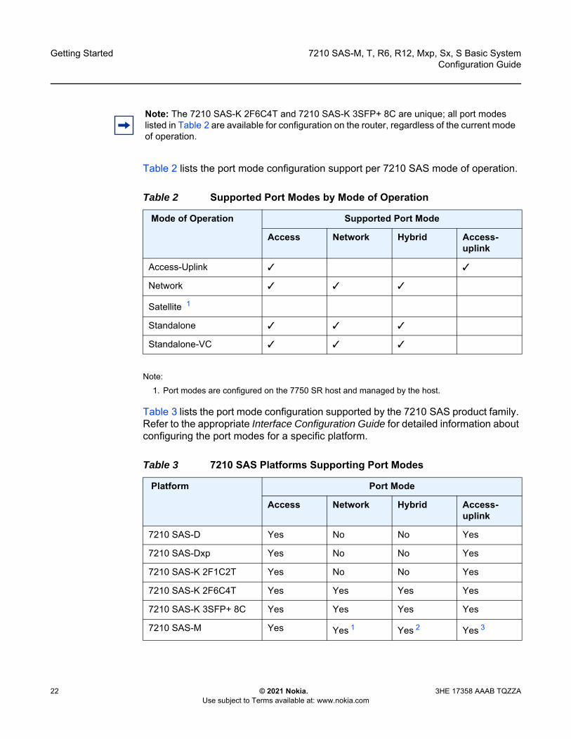
Table 2 lists the port mode configuration support per 7210 SAS mode of operation.
Note:1. Port modes are configured on the 7750 SR host and managed by the host.
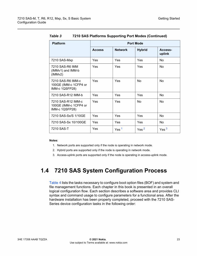
Table 3 lists the port mode configuration supported by the 7210 SAS product family. Refer to the appropriate Interface Configuration Guide for detailed information about configuring the port modes for a specific platform.
Note: The 7210 SAS-K 2F6C4T and 7210 SAS-K 3SFP+ 8C are unique; all port modes listed in Table 2 are available for configuration on the router, regardless of the current mode of operation.
Table 2 Supported Port Modes by Mode of Operation
Mode of Operation Supported Port Mode
Access Network Hybrid Access-uplink
Access-Uplink ✓ ✓
Network ✓ ✓ ✓
Satellite 1
Standalone ✓ ✓ ✓
Standalone-VC ✓ ✓ ✓
Table 3 7210 SAS Platforms Supporting Port Modes
Platform Port Mode
Access Network Hybrid Access-uplink
7210 SAS-D Yes No No Yes
7210 SAS-Dxp Yes No No Yes
7210 SAS-K 2F1C2T Yes No No Yes
7210 SAS-K 2F6C4T Yes Yes Yes Yes
7210 SAS-K 3SFP+ 8C Yes Yes Yes Yes
7210 SAS-M Yes Yes 1 Yes 2 Yes 3
7210 SAS-M, T, R6, R12, Mxp, Sx, S Basic System Configuration Guide
Getting Started
3HE 17358 AAAB TQZZA © 2021 Nokia. Use subject to Terms available at: www.nokia.com
23
Notes:1. Network ports are supported only if the node is operating in network mode.2. Hybrid ports are supported only if the node is operating in network mode.3. Access-uplink ports are supported only if the node is operating in access-uplink mode.
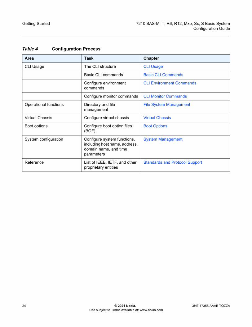
1.4 7210 SAS System Configuration Process
Table 4 lists the tasks necessary to configure boot option files (BOF) and system and file management functions. Each chapter in this book is presented in an overall logical configuration flow. Each section describes a software area and provides CLI syntax and command usage to configure parameters for a functional area. After the hardware installation has been properly completed, proceed with the 7210 SAS-Series device configuration tasks in the following order:
7210 SAS-Mxp Yes Yes Yes No
7210 SAS-R6 IMM (IMMv1) and IMM-b (IMMv2)
Yes Yes Yes No
7210 SAS-R6 IMM-c 100GE (IMM-c 1CFP4 or IMM-c 1QSFP28)
Yes Yes No No
7210 SAS-R12 IMM-b Yes Yes Yes No
7210 SAS-R12 IMM-c 100GE (IMM-c 1CFP4 or IMM-c 1QSFP28)
Yes Yes No No
7210 SAS-Sx/S 1/10GE Yes Yes Yes No
7210 SAS-Sx 10/100GE Yes Yes Yes No
7210 SAS-T Yes Yes 1 Yes 2 Yes 3
Table 3 7210 SAS Platforms Supporting Port Modes (Continued)
Platform Port Mode
Access Network Hybrid Access-uplink
Getting Started
24
7210 SAS-M, T, R6, R12, Mxp, Sx, S Basic SystemConfiguration Guide
© 2021 Nokia. Use subject to Terms available at: www.nokia.com
3HE 17358 AAAB TQZZA
Table 4 Configuration Process
Area Task Chapter
CLI Usage The CLI structure CLI Usage
Basic CLI commands Basic CLI Commands
Configure environment commands
CLI Environment Commands
Configure monitor commands CLI Monitor Commands
Operational functions Directory and file management
File System Management
Virtual Chassis Configure virtual chassis Virtual Chassis
Boot options Configure boot option files (BOF)
Boot Options
System configuration Configure system functions, including host name, address, domain name, and time parameters
System Management
Reference List of IEEE, IETF, and other proprietary entities
Standards and Protocol Support
7210 SAS-M, T, R6, R12, Mxp, Sx, S Basic System Configuration Guide
CLI Usage
3HE 17358 AAAB TQZZA © 2021 Nokia. Use subject to Terms available at: www.nokia.com
25
2 CLI UsageThis chapter provides information about using the command-line interface (CLI).
2.1 CLI Structure
Nokia’s Operating System (OS) CLI is a command-driven interface accessible through the console, Telnet and secure shell (SSH). The CLI can be used for configuration and management of routers.
The CLI command tree is a hierarchical inverted tree. At the highest level is the ROOT level. Below this level are other tree levels with the major command groups; for example, configuration commands and show commands are levels below ROOT.
The CLI is organized so related commands with the same scope are at the same level or in the same context. Sublevels or subcontexts have related commands with a more refined scope.
2.2 Navigating in the CLI
This section provides additional navigational and CLI syntax information.
2.2.1 CLI Contexts
Use the CLI to access, configure, and manage Nokia 7210 SAS devices. CLI commands are entered at the command line prompt. Access to specific CLI commands is controlled by the permissions set by your system administrator. Entering a CLI command makes navigation possible from one command context (or level) to another.
When you initially enter a CLI session, you are in the ROOT context. Navigate to another level by entering the name of successively lower contexts. For example, enter either the configure or show commands at the ROOT context to navigate to the config or show context, respectively. For example, at the command prompt, enter config. The active context displays in the command prompt.

CLI Usage
26
7210 SAS-M, T, R6, R12, Mxp, Sx, S Basic SystemConfiguration Guide
© 2021 Nokia. Use subject to Terms available at: www.nokia.com
3HE 17358 AAAB TQZZA
A:ALU-7210# configA:ALU-7210>config#
In a CLI context, you can enter commands at that context level by entering the text. It is also possible to include a command in a lower context as long as the command is formatted in the correct command and parameter syntax.
The following example shows two methods to navigate to a service SAP ingress level:
Method 1:
A:ALU-7210# config service epipe 6 sap 1/1/2 ingress
Method 2:
A:ALU-7210# configureA:ALU-7210>config# serviceA:ALU-7210>config>service# epipe 6A:ALU-7210>config>service>epipe# sap 1/1/2A:ALU-7210>config>service>epipe>sap# ingressA:ALU-7210>config>service>epipe>sap>ingress#
The CLI returns an error message when the syntax is incorrect.
A:ALU-7210>config>service>epipe# sapp^
Error: Bad command.A:ALU-7210>config>service>epipe#
2.2.2 Basic CLI Commands
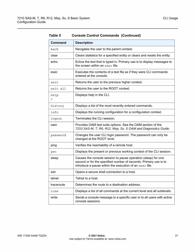
The console control commands are the commands that are used for navigating within the CLI and displaying information about the console session. Most of these commands are implemented as global commands. They can be entered at any level in the CLI hierarchy with the exception of the password command, which must be entered at the ROOT level. The console control commands are described in Table 5.
Table 5 Console Control Commands
Command Description
<Ctrl-c> Aborts the pending command.
<Ctrl-z> Terminates the pending command line and returns to the ROOT context.
7210 SAS-M, T, R6, R12, Mxp, Sx, S Basic System Configuration Guide
CLI Usage
3HE 17358 AAAB TQZZA © 2021 Nokia. Use subject to Terms available at: www.nokia.com
27
back Navigates the user to the parent context.
clear Clears statistics for a specified entity or clears and resets the entity.
echo Echos the text that is typed in. Primary use is to display messages to the screen within an exec file.
exec Executes the contents of a text file as if they were CLI commands entered at the console.
exit Returns the user to the previous higher context.
exit all Returns the user to the ROOT context.
help
?
Displays help in the CLI.
history Displays a list of the most recently entered commands.
info Displays the running configuration for a configuration context.
logout Terminates the CLI session.
oam Provides OAM test suite options. See the OAM section of the 7210 SAS-M, T, R6, R12, Mxp, Sx, S OAM and Diagnostics Guide.
password Changes the user CLI login password. The password can only be changed at the ROOT level.
ping Verifies the reachability of a remote host.
pwc Displays the present or previous working context of the CLI session.
sleep Causes the console session to pause operation (sleep) for one second or for the specified number of seconds. Primary use is to introduce a pause within the execution of an exec file.
ssh Opens a secure shell connection to a host.
telnet Telnet to a host.
traceroute Determines the route to a destination address.
tree Displays a list of all commands at the current level and all sublevels.
write Sends a console message to a specific user or to all users with active console sessions.
Table 5 Console Control Commands (Continued)
Command Description

CLI Usage
28
7210 SAS-M, T, R6, R12, Mxp, Sx, S Basic SystemConfiguration Guide
© 2021 Nokia. Use subject to Terms available at: www.nokia.com
3HE 17358 AAAB TQZZA
The list of all system global commands is displayed by entering help globals in the CLI. For example:
A:ALU-7210>config>service# help globalsback - Go back a level in the command treeecho - Echo the text that is typed inenable-admin - Enable the user to become a system administratorexec - Execute a file - use -echo to show the commands and
prompts on the screenexit - Exit to intermediate mode - use option all to exit to
root prompthelp - Display helphistory - Show command historyinfo - Display configuration for the present nodelogout - Log off this systemoam + OAM Test Suiteping - Verify the reachability of a remote hostpwc - Show the present working contextsleep - Sleep for specified number of secondsssh - SSH to a hosttelnet - Telnet to a hosttraceroute - Determine the route to a destination addresstree - Display command tree structure from the context of
executionwrite - Write text to another user
A:ALU-7210>config>service#
Table 6 describes command syntax symbols.
Table 6 Command Syntax Symbols
Symbol Description
| A vertical line indicates that one of the parameters within the brackets or braces is required.tcp-ack {true|false}
[ ] Brackets indicate optional parameters. redirects [number seconds]
< > Angle brackets indicate that you must enter text based on the parameter inside the brackets.interface <interface-name>
{ } Braces indicate that one of the parameters must be selected.default-action {drop|forward}
[{ }] Braces within square brackets indicates that you must choose one of the optional parameters.
• sdp sdp-id [ {gre | mpls} ] vpls service-id [svc-sap-type {null-star | dot1q | dot1q-preserve}]
Bold Commands in bold indicate commands and keywords.
7210 SAS-M, T, R6, R12, Mxp, Sx, S Basic System Configuration Guide
CLI Usage
3HE 17358 AAAB TQZZA © 2021 Nokia. Use subject to Terms available at: www.nokia.com
29
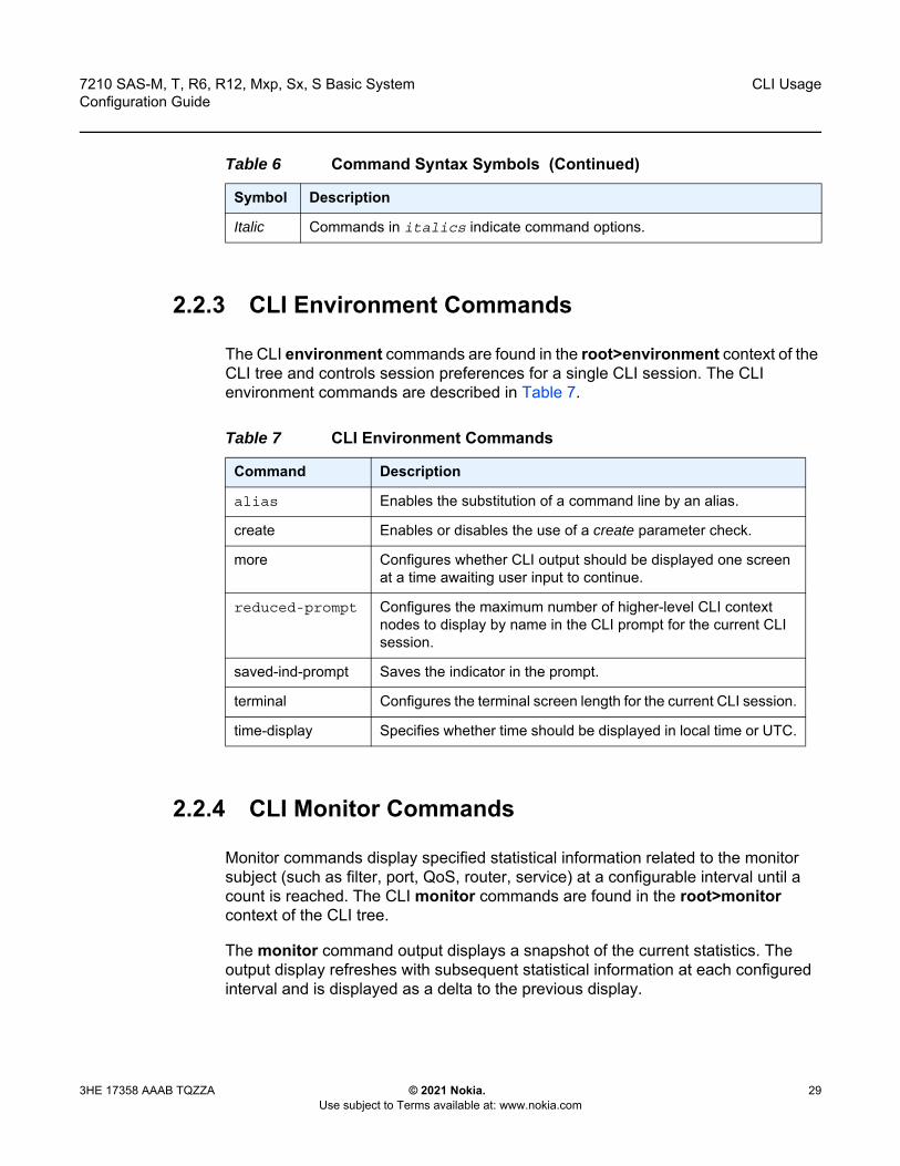
2.2.3 CLI Environment Commands
The CLI environment commands are found in the root>environment context of the CLI tree and controls session preferences for a single CLI session. The CLI environment commands are described in Table 7.
2.2.4 CLI Monitor Commands
Monitor commands display specified statistical information related to the monitor subject (such as filter, port, QoS, router, service) at a configurable interval until a count is reached. The CLI monitor commands are found in the root>monitor context of the CLI tree.
The monitor command output displays a snapshot of the current statistics. The output display refreshes with subsequent statistical information at each configured interval and is displayed as a delta to the previous display.
Italic Commands in italics indicate command options.
Table 6 Command Syntax Symbols (Continued)
Symbol Description
Table 7 CLI Environment Commands
Command Description
alias Enables the substitution of a command line by an alias.
create Enables or disables the use of a create parameter check.
more Configures whether CLI output should be displayed one screen at a time awaiting user input to continue.
reduced-prompt Configures the maximum number of higher-level CLI context nodes to display by name in the CLI prompt for the current CLI session.
saved-ind-prompt Saves the indicator in the prompt.
terminal Configures the terminal screen length for the current CLI session.
time-display Specifies whether time should be displayed in local time or UTC.
CLI Usage
30
7210 SAS-M, T, R6, R12, Mxp, Sx, S Basic SystemConfiguration Guide
© 2021 Nokia. Use subject to Terms available at: www.nokia.com
3HE 17358 AAAB TQZZA
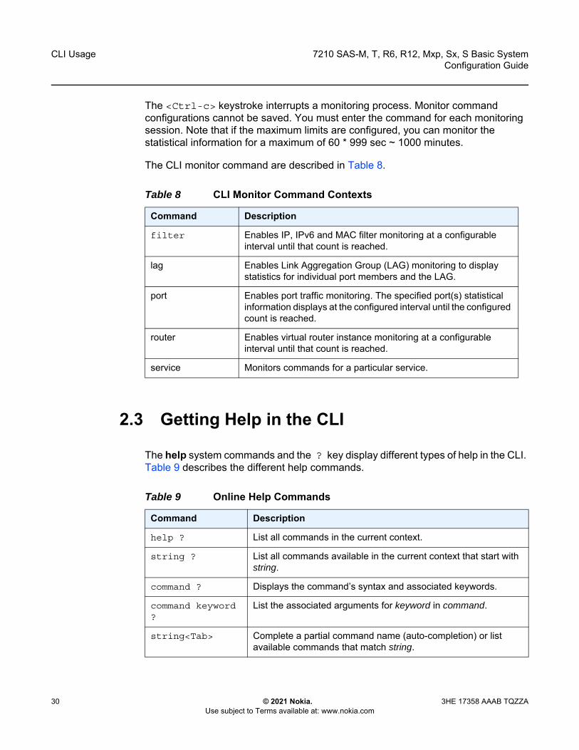
The <Ctrl-c> keystroke interrupts a monitoring process. Monitor command configurations cannot be saved. You must enter the command for each monitoring session. Note that if the maximum limits are configured, you can monitor the statistical information for a maximum of 60 * 999 sec ~ 1000 minutes.
The CLI monitor command are described in Table 8.
2.3 Getting Help in the CLI
The help system commands and the ? key display different types of help in the CLI. Table 9 describes the different help commands.
Table 8 CLI Monitor Command Contexts
Command Description
filter Enables IP, IPv6 and MAC filter monitoring at a configurable interval until that count is reached.
lag Enables Link Aggregation Group (LAG) monitoring to display statistics for individual port members and the LAG.
port Enables port traffic monitoring. The specified port(s) statistical information displays at the configured interval until the configured count is reached.
router Enables virtual router instance monitoring at a configurable interval until that count is reached.
service Monitors commands for a particular service.
Table 9 Online Help Commands
Command Description
help ? List all commands in the current context.
string ? List all commands available in the current context that start with string.
command ? Displays the command’s syntax and associated keywords.
command keyword ?
List the associated arguments for keyword in command.
string<Tab> Complete a partial command name (auto-completion) or list available commands that match string.

7210 SAS-M, T, R6, R12, Mxp, Sx, S Basic System Configuration Guide
CLI Usage
3HE 17358 AAAB TQZZA © 2021 Nokia. Use subject to Terms available at: www.nokia.com
31
The tree and tree detail system commands are help commands useful when searching for a command in a lower-level context.
Table 10 shows a partial list of the tree and tree detail command output entered at the config level.

CLI Usage
32
7210 SAS-M, T, R6, R12, Mxp, Sx, S Basic SystemConfiguration Guide
© 2021 Nokia. Use subject to Terms available at: www.nokia.com
3HE 17358 AAAB TQZZA
Table 10 Output from tree Command
A:ALU-7210>config# treeconfigure+---card| +---card-type| +---mda| | +---access| | +---mda-type| | +---network| | +---shutdown| +---shutdown+---cron| +---action| | +---expire-time| | +---lifetime| | +---max-completed| | +---results| | +---script| | +---shutdown| +---schedule| | +---action| | +---count| | +---day-of-month| | +---description| | +---end-time| | +---hour| | +---interval| | +---minute| | +---month| | +---shutdown| | +---type| | +---weekday| +---script| | +---description| | +---location| | +---shutdown| +---time-range| | +---absolute| | +---daily| | +---description| | +---weekdays| | +---weekend| | +---weekly| +---tod-suite| | +---description| | +---egress| | | +---filter| | | +---qos| | | +---scheduler-policy| | +---ingress| | | +---filter| | | +---qos| | | +---scheduler-policy+---dot1ag| +---domain| | +---association|...
*A:ALA-12>config# tree detailconfigure+---card <slot-number>| no card <slot-number>| +---card-type <card-type>| | no card-type| +---mda <mda-slot>| | no mda <mda-slot>| | +---access| | +---mda-type <mda-type>| | | no mda-type| | +---network| | +---no shutdown| | | shutdown| +---no shutdown| | shutdown+---cron| +---action <action-name> [owner <action-owner>]| | no action <action-name> [owner <action-owner>]| | +---expire-time {<seconds>|forever}| | +---lifetime {<seconds>|forever}| | +---max-completed <unsigned>| | +---no results| | | results <file-url>| | +---no script| | | script <script-name> [owner <script-owner>]| | +---no shutdown| | | shutdown| +---no schedule <schedule-name> [owner <schedule-owner>]| | schedule <schedule-name> [owner <schedule-owner>]| | +---action <action-name> [owner <action-owner>]| | | no action| | +---count <number>| | | no count| | +---day-of-month {<day-number> [..<day-number>]|all}| | | no day-of-month| | +---description <description-string>| | | no description| | +---end-time [<date>|<day-name>] <time>| | | no end-time| | +---hour {<hour-number> [..<hour-number>]|all}| | | no hour| | +---interval <seconds>| | | no interval| | +---minute {<minute-number> [..<minute-number>]|all}| | | no minute| | +---month {<month-number> [..<month-number>]|<month-name> [..<month-nam>]|all}| | | no month| | +---no shutdown| | | shutdown| | +---type <schedule-type>| | +---weekday {<weekday-number> [..<weekday-number>]|<day-name> [..<day-nme>]|all}|...
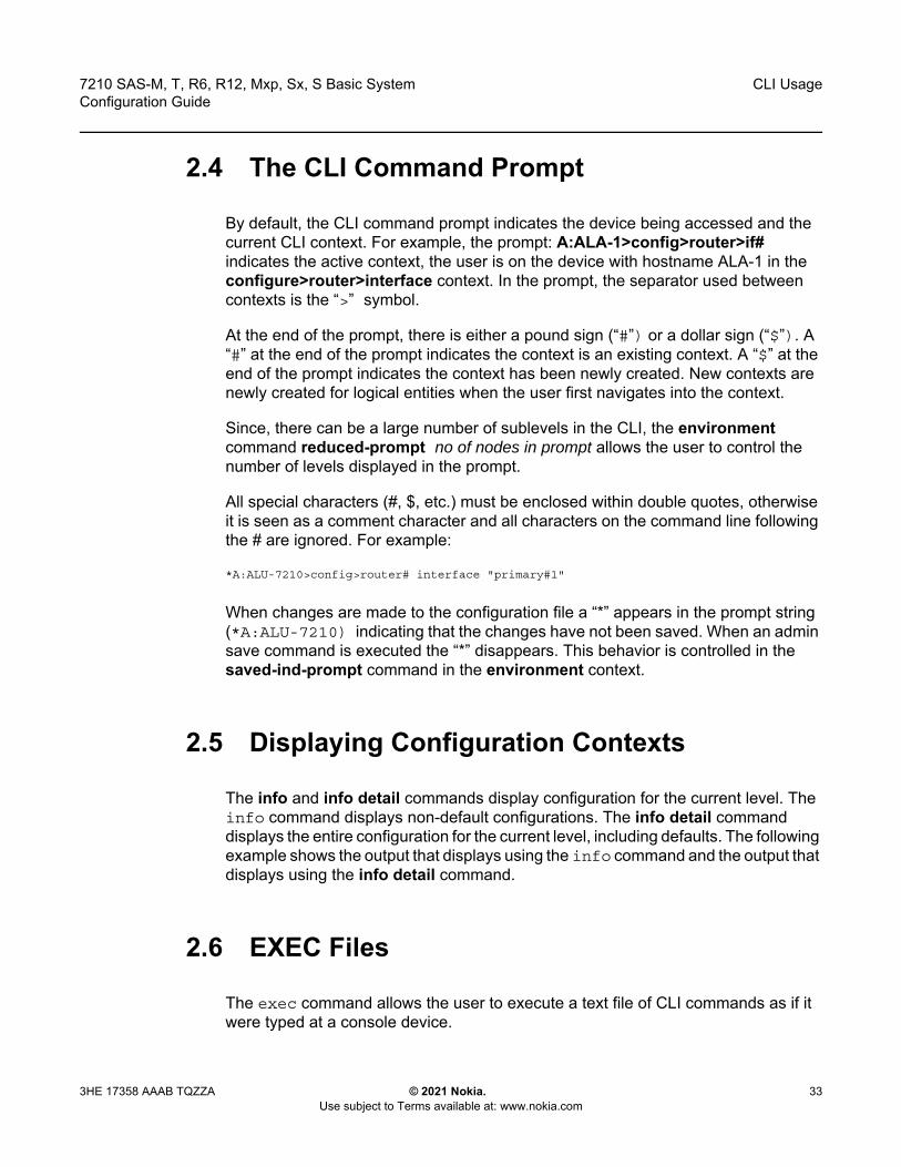
7210 SAS-M, T, R6, R12, Mxp, Sx, S Basic System Configuration Guide
CLI Usage
3HE 17358 AAAB TQZZA © 2021 Nokia. Use subject to Terms available at: www.nokia.com
33
2.4 The CLI Command Prompt
By default, the CLI command prompt indicates the device being accessed and the current CLI context. For example, the prompt: A:ALA-1>config>router>if# indicates the active context, the user is on the device with hostname ALA-1 in the configure>router>interface context. In the prompt, the separator used between contexts is the “>” symbol.
At the end of the prompt, there is either a pound sign (“#”) or a dollar sign (“$”). A “#” at the end of the prompt indicates the context is an existing context. A “$” at the end of the prompt indicates the context has been newly created. New contexts are newly created for logical entities when the user first navigates into the context.
Since, there can be a large number of sublevels in the CLI, the environment command reduced-prompt no of nodes in prompt allows the user to control the number of levels displayed in the prompt.
All special characters (#, $, etc.) must be enclosed within double quotes, otherwise it is seen as a comment character and all characters on the command line following the # are ignored. For example:
*A:ALU-7210>config>router# interface "primary#1"
When changes are made to the configuration file a “*” appears in the prompt string (*A:ALU-7210) indicating that the changes have not been saved. When an admin save command is executed the “*” disappears. This behavior is controlled in the saved-ind-prompt command in the environment context.
2.5 Displaying Configuration Contexts
The info and info detail commands display configuration for the current level. The info command displays non-default configurations. The info detail command displays the entire configuration for the current level, including defaults. The following example shows the output that displays using the info command and the output that displays using the info detail command.
2.6 EXEC Files
The exec command allows the user to execute a text file of CLI commands as if it were typed at a console device.
CLI Usage
34
7210 SAS-M, T, R6, R12, Mxp, Sx, S Basic SystemConfiguration Guide
© 2021 Nokia. Use subject to Terms available at: www.nokia.com
3HE 17358 AAAB TQZZA
The exec command and the associated exec files can be used to conveniently execute a number of commands that are always executed together in the same order. For example, an exec command can be used by a user to define a set of commonly used standard command aliases.
The echo command can be used within an exec command file to display messages on screen while the file executes.
2.7 Entering CLI Commands
This section provides information about entering CLI commands and parameters.
2.7.1 Command Completion
The CLI supports both command abbreviation and command completion. If the keystrokes entered are enough to match a valid command, the CLI displays the remainder of the command syntax when the <Tab> key or space bar is pressed. When typing a command, the <Tab> key or space bar invokes auto-completion. If the keystrokes entered are definite, auto-completion will complete the command. If the letters are not sufficient to identify a specific command, pressing the <Tab> key or space bar will display commands matching the letters entered. System commands are available in all CLI context levels.
2.7.2 Unordered Parameters
In a context, the CLI accepts command parameters in any order as long as the command is formatted in the correct command keyword and parameter syntax. Command completion will still work as long as enough recognizable characters of the command are entered.
The following output shows different static-route command syntax and an example of the command usage.
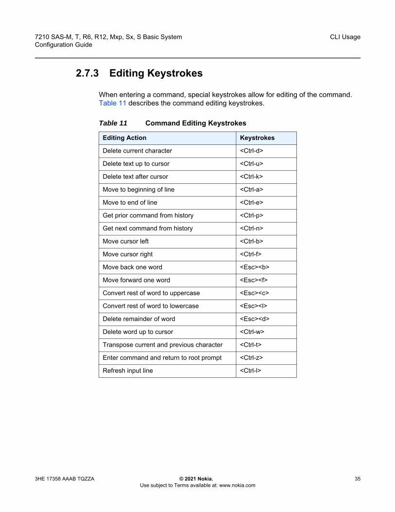
7210 SAS-M, T, R6, R12, Mxp, Sx, S Basic System Configuration Guide
CLI Usage
3HE 17358 AAAB TQZZA © 2021 Nokia. Use subject to Terms available at: www.nokia.com
35
2.7.3 Editing Keystrokes
When entering a command, special keystrokes allow for editing of the command. Table 11 describes the command editing keystrokes.
Table 11 Command Editing Keystrokes
Editing Action Keystrokes
Delete current character <Ctrl-d>
Delete text up to cursor <Ctrl-u>
Delete text after cursor <Ctrl-k>
Move to beginning of line <Ctrl-a>
Move to end of line <Ctrl-e>
Get prior command from history <Ctrl-p>
Get next command from history <Ctrl-n>
Move cursor left <Ctrl-b>
Move cursor right <Ctrl-f>
Move back one word <Esc><b>
Move forward one word <Esc><f>
Convert rest of word to uppercase <Esc><c>
Convert rest of word to lowercase <Esc><l>
Delete remainder of word <Esc><d>
Delete word up to cursor <Ctrl-w>
Transpose current and previous character <Ctrl-t>
Enter command and return to root prompt <Ctrl-z>
Refresh input line <Ctrl-l>
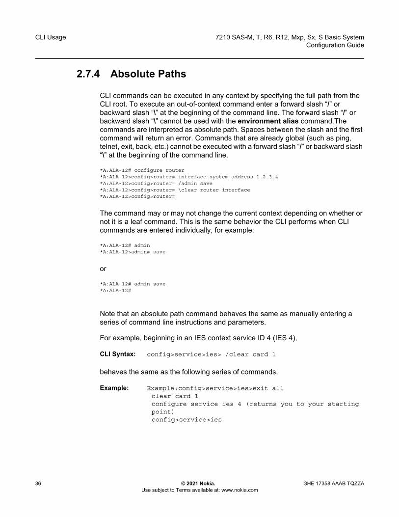
CLI Usage
36
7210 SAS-M, T, R6, R12, Mxp, Sx, S Basic SystemConfiguration Guide
© 2021 Nokia. Use subject to Terms available at: www.nokia.com
3HE 17358 AAAB TQZZA
2.7.4 Absolute Paths
CLI commands can be executed in any context by specifying the full path from the CLI root. To execute an out-of-context command enter a forward slash “/” or backward slash “\” at the beginning of the command line. The forward slash “/” or backward slash “\” cannot be used with the environment alias command.The commands are interpreted as absolute path. Spaces between the slash and the first command will return an error. Commands that are already global (such as ping, telnet, exit, back, etc.) cannot be executed with a forward slash “/” or backward slash “\” at the beginning of the command line.
*A:ALA-12# configure router*A:ALA-12>config>router# interface system address 1.2.3.4*A:ALA-12>config>router# /admin save*A:ALA-12>config>router# \clear router interface*A:ALA-12>config>router#
The command may or may not change the current context depending on whether or not it is a leaf command. This is the same behavior the CLI performs when CLI commands are entered individually, for example:
*A:ALA-12# admin*A:ALA-12>admin# save
or
*A:ALA-12# admin save*A:ALA-12#
Note that an absolute path command behaves the same as manually entering a series of command line instructions and parameters.
For example, beginning in an IES context service ID 4 (IES 4),
CLI Syntax: config>service>ies> /clear card 1
behaves the same as the following series of commands.
Example: Example:config>service>ies>exit allclear card 1configure service ies 4 (returns you to your starting point) config>service>ies
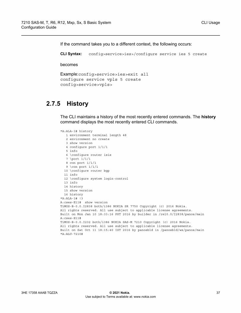
7210 SAS-M, T, R6, R12, Mxp, Sx, S Basic System Configuration Guide
CLI Usage
3HE 17358 AAAB TQZZA © 2021 Nokia. Use subject to Terms available at: www.nokia.com
37
If the command takes you to a different context, the following occurs:
CLI Syntax: config>service>ies>/configure service ies 5 create
becomes
Example:config>service>ies>exit allconfigure service vpls 5 createconfig>service>vpls>
2.7.5 History
The CLI maintains a history of the most recently entered commands. The history command displays the most recently entered CLI commands.
*A:ALA-1# history1 environment terminal length 482 environment no create3 show version4 configure port 1/1/15 info6 \configure router isis7 \port 1/1/18 con port 1/1/19 \con port 1/1/1
10 \configure router bgp11 info12 \configure system login-control13 info14 history15 show version16 history
*A:ALA-1# !3A:cses-E11# show versionTiMOS-B-0.0.I2838 both/i386 NOKIA SR 7750 Copyright (c) 2016 Nokia.All rights reserved. All use subject to applicable license agreements.Built on Mon Jan 10 18:33:16 PST 2016 by builder in /rel0.0/I2838/panos/mainA:cses-E11#TiMOS-B-0.0.I232 both/i386 NOKIA SAS-M 7210 Copyright (c) 2016 Nokia.All rights reserved. All use subject to applicable license agreements.Built on Sat Oct 11 18:15:40 IST 2016 by panosbld in /panosbld/ws/panos/main*A:ALU-7210#
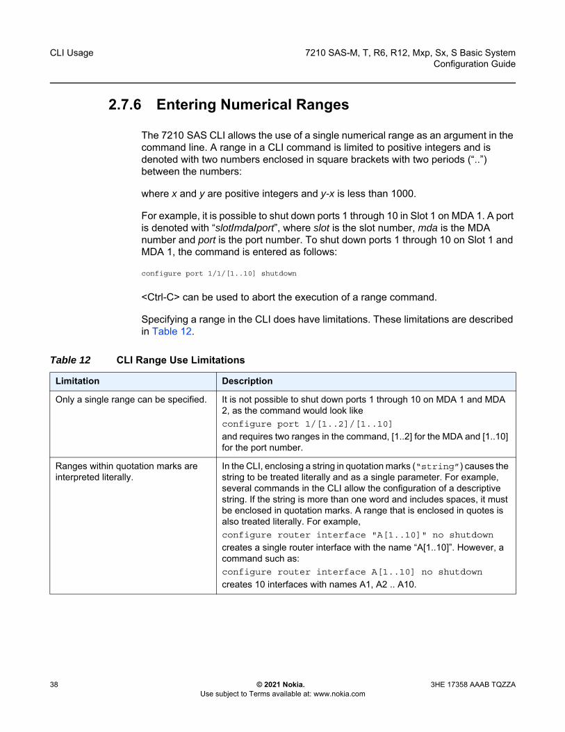
CLI Usage
38
7210 SAS-M, T, R6, R12, Mxp, Sx, S Basic SystemConfiguration Guide
© 2021 Nokia. Use subject to Terms available at: www.nokia.com
3HE 17358 AAAB TQZZA
2.7.6 Entering Numerical Ranges
The 7210 SAS CLI allows the use of a single numerical range as an argument in the command line. A range in a CLI command is limited to positive integers and is denoted with two numbers enclosed in square brackets with two periods (“..”) between the numbers:
where x and y are positive integers and y-x is less than 1000.
For example, it is possible to shut down ports 1 through 10 in Slot 1 on MDA 1. A port is denoted with “slot/mda/port”, where slot is the slot number, mda is the MDA number and port is the port number. To shut down ports 1 through 10 on Slot 1 and MDA 1, the command is entered as follows:
configure port 1/1/[1..10] shutdown
<Ctrl-C> can be used to abort the execution of a range command.
Specifying a range in the CLI does have limitations. These limitations are described in Table 12.
Table 12 CLI Range Use Limitations
Limitation Description
Only a single range can be specified. It is not possible to shut down ports 1 through 10 on MDA 1 and MDA 2, as the command would look likeconfigure port 1/[1..2]/[1..10]
and requires two ranges in the command, [1..2] for the MDA and [1..10] for the port number.
Ranges within quotation marks are interpreted literally.
In the CLI, enclosing a string in quotation marks (“string”) causes the string to be treated literally and as a single parameter. For example, several commands in the CLI allow the configuration of a descriptive string. If the string is more than one word and includes spaces, it must be enclosed in quotation marks. A range that is enclosed in quotes is also treated literally. For example,configure router interface "A[1..10]" no shutdown
creates a single router interface with the name “A[1..10]”. However, a command such as:configure router interface A[1..10] no shutdown
creates 10 interfaces with names A1, A2 .. A10.

7210 SAS-M, T, R6, R12, Mxp, Sx, S Basic System Configuration Guide
CLI Usage
3HE 17358 AAAB TQZZA © 2021 Nokia. Use subject to Terms available at: www.nokia.com
39
2.7.7 Pipe/Match
The 7210 SAS devices support the pipe feature to search one or more files for a specific character string or pattern.
Note: When using the pipe/match command the variables and attributes must be spelled correctly. The attributes following the command and must come before the expression/pattern. The following are examples of the pipe/match command to complete different tasks:
• Task: Capture all the lines that include “echo” and redirect the output to a file on the compact flash:admin display-config | match “echo” > cf3cf1:\echo_list.txt
• Task: Display all the lines that do not include “echo”:admin display-config | match invert-match “echo”
• Task: Display the first match of “vpls” in the configuration file:admin display-config | match max-count 1 “vpls”
• Task: Display everything in the configuration after finding the first instance of “interface”:admin display-config | match post-lines 999999 interface
The range cannot cause a change in contexts.
Commands should be formed in such a way that there is no context change upon command completion. For example, configure port 1/1/[1..10]
will attempt to change ten different contexts. When a range is specified in the CLI, the commands are executed in a loop. On the first loop execution, the command changes contexts, but the new context is no longer valid for the second iteration of the range loop. A “Bad Command” error is reported and the command aborts.
Command completion may cease to work when entering a range.
After entering a range in a CLI command, command and key completion, which occurs by pressing the <Tab> or spacebar, may cease to work. If the command line entered is correct and unambiguous, the command works correctly; otherwise, an error is returned.
Table 12 CLI Range Use Limitations (Continued)
Limitation Description
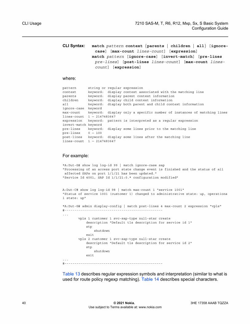
CLI Usage
40
7210 SAS-M, T, R6, R12, Mxp, Sx, S Basic SystemConfiguration Guide
© 2021 Nokia. Use subject to Terms available at: www.nokia.com
3HE 17358 AAAB TQZZA
CLI Syntax: match pattern context {parents | children | all} [ignore-case] [max-count lines-count] [expression]
match pattern [ignore-case] [invert-match] [pre-lines pre-lines] [post-lines lines-count] [max-count lines-count] [expression]
where:
pattern string or regular expressioncontext keyword: display context associated with the matching lineparents keyword: display parent context informationchildren keyword: display child context informationall keyword: display both parent and child context informationignore-case keywordmax-count keyword: display only a specific number of instances of matching lineslines-count 1 — 2147483647expression keyword: pattern is interpreted as a regular expressioninvert-match keywordpre-lines keyword: display some lines prior to the matching linepre-lines 0 — 100post-lines keyword: display some lines after the matching linelines-count 1 — 2147483647
For example:
*A:Dut-G# show log log-id 99 | match ignore-case sap"Processing of an access port state change event is finished and the status of allaffected SAPs on port 1/1/21 has been updated."
"Service Id 4001, SAP Id 1/1/21:0.* configuration modified"
A:Dut-C# show log log-id 98 | match max-count 1 "service 1001""Status of service 1001 (customer 1) changed to administrative state: up, operational state: up"
*A:Dut-G# admin display-config | match post-lines 4 max-count 2 expression "vpls"#--------------------------------------------------...
vpls 1 customer 1 svc-sap-type null-star createdescription "Default tls description for service id 1"stp
shutdownexit
vpls 2 customer 1 svc-sap-type null-star createdescription "Default tls description for service id 2"stp
shutdownexit
...#--------------------------------------------------
Table 13 describes regular expression symbols and interpretation (similar to what is used for route policy regexp matching). Table 14 describes special characters.

7210 SAS-M, T, R6, R12, Mxp, Sx, S Basic System Configuration Guide
CLI Usage
3HE 17358 AAAB TQZZA © 2021 Nokia. Use subject to Terms available at: www.nokia.com
41
Table 13 Regular Expression Symbols
String Description
. Matches any single character.
[ ] Matches a single character that is contained within the brackets. [abc] matches “a”, “b”, or “c”. [a-z] matches any lowercase letter. [A-Z] matches any uppercase letter.[0-9] matches any number.
[^ ] Matches a single character that is not contained within the brackets. [^abc] matches any character other than “a”, “b”, or “c”. [^a-z] matches any single character that is not a lowercase letter.
^ Matches the start of the line (or any line, when applied in multiline mode)
$ Matches the end of the line (or any line, when applied in multiline mode)
() Define a “marked subexpression”. Every matched instance will be available to the next command as a variable.
* A single character expression followed by “*” matches zero or more copies of the expression.
{m,n} Matches at least m and at most n repetitions of the term
{m} Matches exactly m repetitions of the term
{m,} Matches m or more repetitions of the term
? The preceding item is optional and matched at most once.
+ The preceding item is matched one or more times.
- Used between start and end of a range.
\ An escape character to indicate that the following character is a match criteria and not a grouping delimiter.
> Redirect output
Table 14 Special Characters
Options Similar to Description
[:upper:] [A-Z] uppercase letters
[:lower:] [a-z] lowercase letters
[:alpha:] [A-Za-z] upper- and lowercase letters
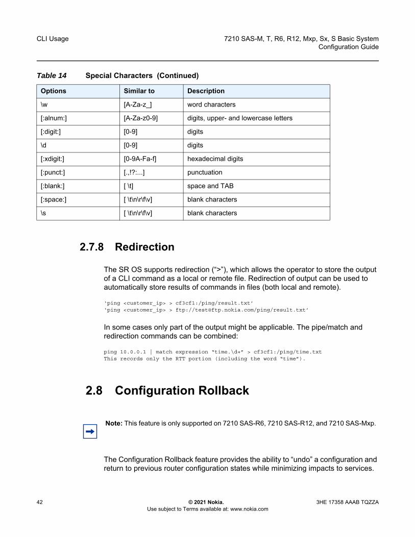
CLI Usage
42
7210 SAS-M, T, R6, R12, Mxp, Sx, S Basic SystemConfiguration Guide
© 2021 Nokia. Use subject to Terms available at: www.nokia.com
3HE 17358 AAAB TQZZA
2.7.8 Redirection
The SR OS supports redirection (“>”), which allows the operator to store the output of a CLI command as a local or remote file. Redirection of output can be used to automatically store results of commands in files (both local and remote).
‘ping <customer_ip> > cf3cf1:/ping/result.txt’‘ping <customer_ip> > ftp://[email protected]/ping/result.txt’
In some cases only part of the output might be applicable. The pipe/match and redirection commands can be combined:
ping 10.0.0.1 | match expression “time.\d+” > cf3cf1:/ping/time.txtThis records only the RTT portion (including the word “time”).
2.8 Configuration Rollback
The Configuration Rollback feature provides the ability to “undo” a configuration and return to previous router configuration states while minimizing impacts to services.
\w [A-Za-z_] word characters
[:alnum:] [A-Za-z0-9] digits, upper- and lowercase letters
[:digit:] [0-9] digits
\d [0-9] digits
[:xdigit:] [0-9A-Fa-f] hexadecimal digits
[:punct:] [.,!?:...] punctuation
[:blank:] [ \t] space and TAB
[:space:] [ \t\n\r\f\v] blank characters
\s [ \t\n\r\f\v] blank characters
Table 14 Special Characters (Continued)
Options Similar to Description
Note: This feature is only supported on 7210 SAS-R6, 7210 SAS-R12, and 7210 SAS-Mxp.

7210 SAS-M, T, R6, R12, Mxp, Sx, S Basic System Configuration Guide
CLI Usage
3HE 17358 AAAB TQZZA © 2021 Nokia. Use subject to Terms available at: www.nokia.com
43
This feature gives the operator better control and visibility over router configurations and reduces operational risk while increasing flexibility and providing powerful recovery options.
Configuration rollback is useful in cases where configuration changes are made, but the operator later decides not to keep the changes (for example, when experimenting or when problems are identified in the configuration during actual network operation).
The advantages of this feature are as follows.
• By not having to reboot the router, changes made to a router configuration have minimal impact on services provided by the 7210 SAS.
• There is no impact to areas of configuration that did not change, but there are some exceptions.
Configuration parameters that changed (or items that a changed configuration has dependencies on) are first removed (return to default), and the previous values are then restored (can be briefly service impacting in changed areas).
A history of changes is preserved using checkpoint IDs that allow rollback to different points, as well as examination of changes made, as shown in Figure 1.
Figure 1 Rollback Operation
Active Config
Commit / Rollback FileCommit /
Rollback FileRollback
CheckpointFiles
rollback save
SNMP(SAM)
CLI commands
(config)
rollback revert
sw0688

CLI Usage
44
7210 SAS-M, T, R6, R12, Mxp, Sx, S Basic SystemConfiguration Guide
© 2021 Nokia. Use subject to Terms available at: www.nokia.com
3HE 17358 AAAB TQZZA
2.8.1 Feature Behavior
The following list describes detailed behavior and CLI usage of the rollback feature.
• The user can create a rollback checkpoint, and later, return to this checkpoint with minimal impacts to services by using the following command.admin>rollback# save [comment comment-string]comment-string: a 255 character comment associated with the checkpoint
• Rollback checkpoints include all current operationally active configurations:- changes from direct CLI commands in the configuration branch- SNMP sets
• Rollback checkpoints do not include BOF configuration information. The BOF file (and BOF configuration) is not part of a rollback save or rollback. A rollback does not change any of the BOF configuration. The BOF contains basic information for the node and does not change frequently (mostly during initial commissioning of the node).
• A rollback save command can be automatically executed (scheduled, for example, monthly) using the CRON facility.
• The latest rollback checkpoint file uses a suffix of “.rb”. The next latest rollback checkpoint file has a suffix of “.rb.1”, the next oldest has a suffix of “rb.2”, etc.:file-url.rb <--- latest rollback filefile-url.rb.1
…file-url.rb.9 <--- oldest rollback file
• When a rollback save [no “-”] is executed, the system shifts the file suffix of all the previous checkpoints by 1 (new ID= old ID+1). If there are already as many checkpoint files as the maximum number supported, the last checkpoint file is deleted.
• The maximum number of rollback checkpoints is configurable and defaults to 10 (the latest files and files 1 through 9, where checkpoint file 9 is deleted during the next rollback-save).
• The location and name of the rollback checkpoint files are configurable to be local storage (e.g. compact flash) or remote storage. The file URL must not contain a suffix (just a path/directory and filename). The suffix for rollback checkpoint files is .rb and is automatically appended to rollback checkpoint files. config>system>rollback# rollback-location file-url
• There is no default rollback location. If a location is not specified (or it is cleared using no rollback-location) and a rollback save is attempted, the rollback save will fail and return an error message.
7210 SAS-M, T, R6, R12, Mxp, Sx, S Basic System Configuration Guide
CLI Usage
3HE 17358 AAAB TQZZA © 2021 Nokia. Use subject to Terms available at: www.nokia.com
45
• On the 7210 SAS-R6 and 7210 SAS-R12, the entire set of rollback checkpoint files can be copied from the active CPM CF to the inactive CPM CF. This synchronization is done through the following command:admin>redundancy# rollback-sync
• The operator can enable automatic synchronization of rollback checkpoint files between the active CPM and inactive CPM. When this automatic synchronization is enabled, a rollback save will cause the new checkpoint file to be saved to both the active and standby. The suffixes of the old checkpoint files on both active and standby CPMs are increased.
config>redundancy# [no] rollback-sync
• config>redundancy>synchronize {boot-env|config} and admin>redundancy>synchronize {boot-env|config}” do not apply to rollback checkpoint files. These commands do not manually or automatically synchronize rollback checkpoint files. The dedicated rollback-sync commands must be used to sync rollback checkpoint files.
• Rollback files can be deleted using a dedicated rollback checkpoint deletion command:admin>rollback# delete {latest-rb | checkpoint-id}- Deleting a rollback checkpoint causes the suffixes to be adjusted
(decremented) for all checkpoints older than the one that was deleted (to close the “hole” in the list of checkpoint files and create room to create another checkpoint).
- If configure>redundancy>rollback-sync is enabled, a rollback delete will also delete the equivalent checkpoint on the standby CF and shuffle the suffixes on the standby CF.
- If an operator manually deletes a rollback checkpoint file using file delete, the suffixes of the checkpoint files are not shuffled, nor is the equivalent checkpoint file deleted from the standby CF. This manual deletion creates a “hole” in the checkpoint file list until enough new checkpoints have been created to roll the “hole” off the end of the list.
• As shown in Figure 2, support for rolling back to a previous configuration (a saved rollback checkpoint) with minimal impact on services. The previous configuration will be loaded and take operational effect:admin>rollback# revert [latest-rb | checkpoint-id]
Note: The automatic synchronize only causes the one new checkpoint file to be copied to both CFs (the other 9 checkpoints are not automatically copied from active to standby, but that can be done manually using the admin>redundancy>rollback-sync command).

CLI Usage
46
7210 SAS-M, T, R6, R12, Mxp, Sx, S Basic SystemConfiguration Guide
© 2021 Nokia. Use subject to Terms available at: www.nokia.com
3HE 17358 AAAB TQZZA
Figure 2 Configuration Rollback
• A rollback revert does not affect the currently stored rollback checkpoint files (no deletions or renumbering). This means that if an operator issues a “rollback revert 3” and issues a “rollback-save”, the resulting rollback checkpoint files “file-url.rb” and “file-url.rb.4” will contain the same rollback state/configuration.
• The boot-good-exec or boot-bad-exec are not automatically executed after a rollback.
• Impacts to the running services are minimized during a rollback.- There is no impact in areas of configuration that did not change, except for
some exceptions.
time
SNMP set
CLI config
rollback save rollbackcheckpoint
rollback save rollbackcheckpoint
rollback save rollbackcheckpoint
rollback revert 2
rollback revert latest
time
SNMP set
CLI config
rollback save rollbackcheckpoint
rollback save rollbackcheckpoint
rollback save rollbackcheckpoint
rollback revert 2
rollback revert latest
sw0684

7210 SAS-M, T, R6, R12, Mxp, Sx, S Basic System Configuration Guide
CLI Usage
3HE 17358 AAAB TQZZA © 2021 Nokia. Use subject to Terms available at: www.nokia.com
47
- Configuration parameters that changed (or items that a changed configuration has dependencies on) are first removed and the previous values are restored (can be briefly service impacting in changed areas). Some examples are as follows:
• If the SAP ingress policy num-qos-resources value is different in the active configuration and in comparison to the value in the rollback checkpoint, all the SAPs are deleted and created again. This is done to guarantee that configuration of all the SAPs succeeds when moving to the previous configuration.
• Changing some of the parameters in the SAP egress policy requires the port to be shut down. Therefore, when moving to a previous configuration results in change of these values, the port is shut down, the old SAP egress policy is removed, and the new SAP egress policy is applied.
• A rollback will undo any SNMP sets or direct CLI configuration commands that occurred since the last checkpoint creation.
• During the period when a node is processing a rollback revert command, both CLI commands from other users and SNMP commands will continue to be processed. The only commands that are blocked during a rollback revert are other rollback commands including revert, save, and compare (only one rollback command can be executing at a time on one node).
• Commands are available to view and compare the various rollback checkpoints to current operating and candidate configurations.- Rollback checkpoint files are not guaranteed to be in any particular format.
They are not interchangeable with normal configuration files or exec scripts. A normal configuration file (from an admin save) cannot be renamed as a rollback checkpoint and a rollback can be executed as long as the hardware change was an addition of hardware to the node (for example, added a new IOM into a previously empty slot).
- a rollback is not guaranteed to work if hardware was removed or changed (for example, the IOM was removed or an MDA was swapped for a different MDA type).
• Rollback across a change to the following parameters is not supported:- system resource profile commands- PTP commands
• Rollback is supported even after an admin reboot is performed (or the primary configuration in the BOF is changed and an admin reboot is performed). Admin reboot does not “break the chain” for rollback.
• The Configuration Rollback feature is incompatible with the use of Time Of Day (ToD) policies and functionality. Rollback save and rollback revert operations are blocked if any ToD policies are active (for example, assigned to objects such as a SAP).
CLI Usage
48
7210 SAS-M, T, R6, R12, Mxp, Sx, S Basic SystemConfiguration Guide
© 2021 Nokia. Use subject to Terms available at: www.nokia.com
3HE 17358 AAAB TQZZA
• Any configuration or state change performed under the debug branch of CLI is not saved in the rollback checkpoint file nor impacted by a rollback.
• Rollbacks to a checkpoint created in a more recent release is not supported.• The following list captures some side effects and specific behaviors of a
rollback revert. Some of these side effects are not related purely to configuration (that is, in the CLI configuration branch) and may have interactions with tools commands, RADIUS, etc.- SAA jobs that are running when a rollback revert is initiated, and need
configuration changes due to the rollback, will be stopped. If the SAA job is a continuous type, it will be re-started as part of the rollback revert after the configuration changes have been applied (just as if the operator had typed no shutdown for the continuous SAA job). Non-continuous SAA jobs that were modified by the rollback need to be manually restarted if they need to be run again.
- If max-nbr-mac-addr is reduced as part of the revert but the number of MAC addresses in the forwarding database is greater than the maximum number of MAC addresses, the rollback is aborted before any actions are taken and an informative error message is provided. The operator must take actions to remove the MAC addresses to proceed with the rollback.
- If a force-switchover command has been applied to a spoke SDP FEC of a dynamic multi-segment pseudowire, and a rollback revert needs to change the admin state of the spoke SDP FEC (for example, to modify spoke SDP FEC parameters that may be dependent on admin state), the rollback revert will automatically remove the force-switchover and the node will revert to whatever is the best spoke SDP in the redundant set.
- Rollback impacts the configuration state of the router, and as with normal operator CLI or SNMP configuration changes, additional actions or steps may need to occur before certain configuration changes take operational effect. The following are some examples.
• Configuration changes that require a shutdown and no shutdown to be done by an operator to take operational effect also need a manual shutdown and no shutdown to be performed by the operator to take operational effect after a rollback if the rollback changes those configuration items. Some examples include:
• Changes to autonomous system or confederation values require a BGP shutdown and no shutdown.
• Changes to VPRN max-routes require a shutdown and no shutdown on the VPRN service.
• Changes to an OSPF or ISIS export limit require a shutdown and no shutdown on OSPF or ISIS.

7210 SAS-M, T, R6, R12, Mxp, Sx, S Basic System Configuration Guide
CLI Usage
3HE 17358 AAAB TQZZA © 2021 Nokia. Use subject to Terms available at: www.nokia.com
49
• Configuration changes to an MSAP policy that requires a tools>perform>subscriber-mgmt>eval-msap command to take operational effect on subscribers that are already active. Rollback will change the MSAP policy configuration, but if it is required to have the configuration changes applied to the active subscribers, the operator will have to run the eval-msap tools command.
• Changes to the SAP egress policy require a port shutdown and no shutdown. This is done automatically by the software when it detects a change.
• Changes to the number of QoS resources in the SAP ingress policy results in deletion and creation of all the SAPs. This is done to ensure that the configuration can be successfully recreated using the SDX file.
- Any uncommitted changes (that is, the begin command was entered and some changes were made, but the commit command was never entered) in the following areas will be lost/cleared when a rollback revert is initiated:
• config>router>policy-options • config>system>sync-if-timing
• Some card and MDA commands require a reboot, remove, or rebuild of an entire card or XMA/MDA. When these commands need to be executed as part of a rollback, the impacted cards/MDAs will be listed in a warning and the operator will be prompted with a single y/n prompt to decide whether to proceed or not. This prompting will not occur for a rollback initiated via SNMP, nor if the operator uses the now keyword with the rollback revert command. Some examples of card and MDA commands that may cause a prompt are the following:- config>card>card-type- config>card>mda- config>card>mda>mda-type
• Although the use of the control-C key combination is not recommended during a rollback revert, it is supported through CLI and SNMP. Interrupting a rollback revert may leave the router in a state that is not necessarily something between the old active configuration and the rollback checkpoint since the rollback processing may have been in the middle of tearing things down or rebuilding configurations. A strong warning is issued in this case to indicate that the operator must examine the configuration and potentially issue another rollback revert to return to a known (and coherent) configuration.
• A high availability CPM switchover during a rollback revert will cause the rollback operation to abort. The newly active CPM will have an indeterminate configuration. When an HA switchover occurs during a rollback (or within a few seconds of a rollback completing), the operator is advised to repeat the rollback revert operation to the same checkpoint.

CLI Usage
50
7210 SAS-M, T, R6, R12, Mxp, Sx, S Basic SystemConfiguration Guide
© 2021 Nokia. Use subject to Terms available at: www.nokia.com
3HE 17358 AAAB TQZZA
2.8.2 Rescue Configuration
A special rescue configuration checkpoint can be created that an operator can rollback revert to at any time. The rescue configuration has its own keyword (rescue) and does not use the same rolling suffix indexes as the normal rollback checkpoints. This allows the operator to easily return to the rescue configuration state without having to consider a checkpoint index, and ensures that the rescue checkpoint is always available (does not roll off the bottom of the list of checkpoints).
The operator should define a basic rescue configuration that is known to work and give correct management access to the node.
The location and filename of the rescue file are configurable. The 7210 SAS appends an .rc suffix to the specified rescue filename.
2.8.3 Operational Guidelines
The following points provide some operational guidance on the usage of rollback.
• Both admin save and rollback save should be done periodically:• Do an admin save to back up a complete configuration file that can be used
during router reboot.- used with a reboot as a last resort- Do an admin save after any major hardware changes or major service
changes.- should be done after any software upgrade
• Do a rollback save to create a rollback checkpoint.- used for intermediate checkpoints that can be recovered with minimal
impacts to services- should be done each time that a moderate amount of configuration changes
have been made- should be done after any hardware changes- should be done after any software upgrade- can also be scheduled with CRON (for example, once every 1 or 2 weeks)
• A new rescue save must be created when hardware is changed.• Rollback checkpoint files are not editable nor compatible/interchangeable with
configuration files (generated with admin save).

7210 SAS-M, T, R6, R12, Mxp, Sx, S Basic System Configuration Guide
CLI Usage
3HE 17358 AAAB TQZZA © 2021 Nokia. Use subject to Terms available at: www.nokia.com
51
• Avoid repeatedly executing rollback save without also occasionally executing admin save. If you really get into a bad situation, you may have to use one of your admin save configurations as the primary configuration for an admin reboot.
• After a software upgrade has occurred and the system is operating as expected, it is recommended to create a rollback checkpoint file using the admin>rollback>save command and to save the configuration using admin>save. This ensures that a good checkpoint fully compatible with the new release is available shortly after the upgrade.
• A set of rollback checkpoints can be created to support busy/quiet days or weekend/weekdays and CRON can be used to shift between them.
• It is recommended to create a rollback checkpoint before a rollback revert is initiated (especially if there have been significant configuration changes since the last checkpoint was created). If the rollback is especially significant (a lot of major changes) it is also a good practice to do an admin save just in case a full reboot is required to recover from an issue.
• A rollback failure may occur in some limited cases where the node needs a long time to complete one of the resulting configuration changes. If a rollback fails during execution, it should be attempted again. The second attempt will typically complete the remaining configuration changes required to fully revert to the desired checkpoint.
• On the 7210 SAS-R6 and 7210 SAS-R12, when a new backup CPM is commissioned, the user should issue the admin>redundancy>rollback-sync to copy the entire set of rollback files from the active CPM checkpoint file (CF) to the new standby CPM CF. If the operator needs the system to automatically copy new rollback checkpoints to both CFs whenever a new checkpoint is created, the config>redundancy>rollback-sync should be configured.
• On the 7210 SAS-R6 and 7210 SAS-R12, a high availability CPM switchover during a rollback revert will cause the rollback operation to abort. The newly active CPM will have an indeterminate configuration. A log event is created and the operator is advised to repeat the rollback revert operation to the same checkpoint.
• A rollback checkpoint file stores the rollback location and the local and remote maximum checkpoint values, and as such a rollback revert operation can change those values. If an operator changes the local and remote maximum checkpoint values, it is recommended to delete all the existing checkpoints otherwise a subsequent rollback revert could change the max values back to a previous value.
CLI Usage
52
7210 SAS-M, T, R6, R12, Mxp, Sx, S Basic SystemConfiguration Guide
© 2021 Nokia. Use subject to Terms available at: www.nokia.com
3HE 17358 AAAB TQZZA
• If a warning prompt (y/n) is displayed when a rollback revert is initiated, it is highly suggested to respond ‘no’ to the warning prompt the first time, save a rollback checkpoint before attempting this rollback revert, and execute the rollback>revert again and respond ‘yes’. If the rollback encounters problems, a revert to the saved checkpoint can be used to return to the initial configuration state.
2.8.4 Configuration Guidelines and Restrictions
The following are the limitations of the configuration rollback feature for the 7210 SAS-R6, 7210 SAS-R12, and 7210 SAS-Mxp.
• Resource profile policy changes cannot be rolled back. That is, if there is a change in resource policy/parameters between active configuration and checkpoint, rollback will not proceed.
• PTP is not supported.• For SAP ingress QoS, due to the slice information available in the .sdx file,
whenever there is a change in ingress QoS policy attached to a SAP, or if there are any additional SAPs in the checkpoint file, all SAPs are torn down and rebuilt. The user will be prompted before this occurs.
• A SAP that has a change in egress QoS policy will be shut down and will do a no shutdown after a delay.
• During rollback, all ports and SAPs are shut down and brought back up again. This brings down traffic and control protocols that have been initiated or are transitioning through the node during rollback.
• Rollback is not permitted when there is a change to port-scheduler-mode.• Back-to-back rollbacks, particularly scaled ones, are not recommended. Users
must allow sufficient time for the system to process the current rollback before initiating a new one.
• On the 7210 SAS-R6 and 7210 SAS-R12, if there are additional differences in resource profile templates between two rollback points, the rollback procedure does not roll back any changes. An error message is displayed asking the user to undo these resource profile template changes manually.
• Rollback is not allowed between two rollback points if there are changes in the slice allocation in the same resource profile template. On the 7210 SAS-R6 and 7210 SAS-R12, the restriction also applies for a template that is not associated with any card.
• On the 7210 SAS-R6 and 7210 SAS-R12, if the resource profile templates are the same across two different rollback points but the attachment to the card is different, it may result in resource allocation failures in scaling scenarios.

7210 SAS-M, T, R6, R12, Mxp, Sx, S Basic System Configuration Guide
CLI Usage
3HE 17358 AAAB TQZZA © 2021 Nokia. Use subject to Terms available at: www.nokia.com
53
2.9 Basic Command Reference
2.9.1 Command Hierarchies
• Basic CLI Commands• Monitor Commands• Environment Commands
2.9.1.1 Basic CLI Commands
— back— clear — echo [text-to-echo] [extra-text-to-echo] [more-text] — enable-admin— exec [-echo] [-syntax] filename | eof-marker-string— exit [all]— help— history— info [detail]— logout— password— ping {ip-address | dns-name} [rapid | detail] [ttl time-to-live] [tos type-of-service] [size bytes]
[pattern pattern] [source ip-address] [interval seconds] [{next-hop ip-address} | {interface interface-name} | bypass-routing] [count requests] [do-not-fragment] [router router-instance | service-name service-name] [timeout timeout]
— pwc [previous]— sleep [seconds]— ssh [ip-addr | dns-name |username@ip-addr] [-l username] [-v SSH-version] [router router-
instance] — telnet [ip-address | dns-name] [port] [router router-instance] — traceroute {ip-address | dns-name} [ttl value] [wait milliseconds] [no-dns] [source ip-
address] [tos type-of-service] [router router-instance]— tree [detail]— write {user | broadcast} message-string
2.9.1.2 Show Commands
show— alias
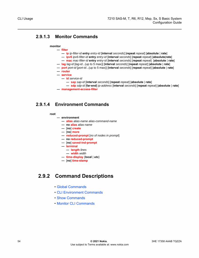
CLI Usage
54
7210 SAS-M, T, R6, R12, Mxp, Sx, S Basic SystemConfiguration Guide
© 2021 Nokia. Use subject to Terms available at: www.nokia.com
3HE 17358 AAAB TQZZA
2.9.1.3 Monitor Commands
monitor— filter
— ip ip-filter-id entry entry-id [interval seconds] [repeat repeat] [absolute | rate]— ipv6 ipv6-filter-id entry entry-id [interval seconds] [repeat repeat] [absolute|rate]— mac mac-filter-id entry entry-id [interval seconds] [repeat repeat] [absolute | rate]
— lag lag-id [lag-id...(up to 5 max)] [interval seconds] [repeat repeat] [absolute | rate]— port port-id [port-id...(up to 5 max)] [interval seconds] [repeat repeat] [absolute | rate]— router— service
— id service-id— sap sap-id [interval seconds] [repeat repeat] [absolute | rate]— sdp sdp-id [far-end] ip-address [interval seconds] [repeat repeat] [absolute | rate]
— management-access-filter
2.9.1.4 Environment Commands
root— environment
— alias alias-name alias-command-name— no alias alias-name— [no] create— [no] more— reduced-prompt [no of nodes in prompt]— no reduced-prompt— [no] saved-ind-prompt— terminal
— length lines— width width
— time-display {local | utc}— [no] time-stamp
2.9.2 Command Descriptions
• Global Commands• CLI Environment Commands• Show Commands• Monitor CLI Commands

7210 SAS-M, T, R6, R12, Mxp, Sx, S Basic System Configuration Guide
CLI Usage
3HE 17358 AAAB TQZZA © 2021 Nokia. Use subject to Terms available at: www.nokia.com
55
2.9.2.1 Global Commands
enable-admin
Syntax enable-admin
Context <global>
Description
The enable-admin command is in the default profile. By default, all users are given access to this command.
When the enable-admin command is entered, the user is prompted for a password. If the password is correct, the user is given unrestricted access to all commands.
The minimum length of the password is determined by the minimum-length command. The complexity requirements for the password is determined by the complexity command.
The following is an example of a password configuration.
A:ALA-1>config>system>security# info----------------------------------------------...
passwordaging 365minimum-length 8attempts 5 time 5 lockout 20admin-password "rUYUz9XMo6I" hash
exit...----------------------------------------------A:ALA-1>config>system>security#
Use one of the following options to verify that a user is in the enable-admin mode.
• Administrators cab use the show users command to know which users are in this mode.• Enter the enable-admin command again at the root prompt and an error message will
be returned.
The following is an example output for the show users command.
A:ALA-1# show users===============================================================================User Type From Login time Idle time===============================================================================admin Console -- 10AUG2006 13:55:24 0d 19:42:22
Note: See the description for the admin-password command. If the admin-password is configured in the config>system>security>password context, any user can enter a special administrative mode by entering the enable-admin command.
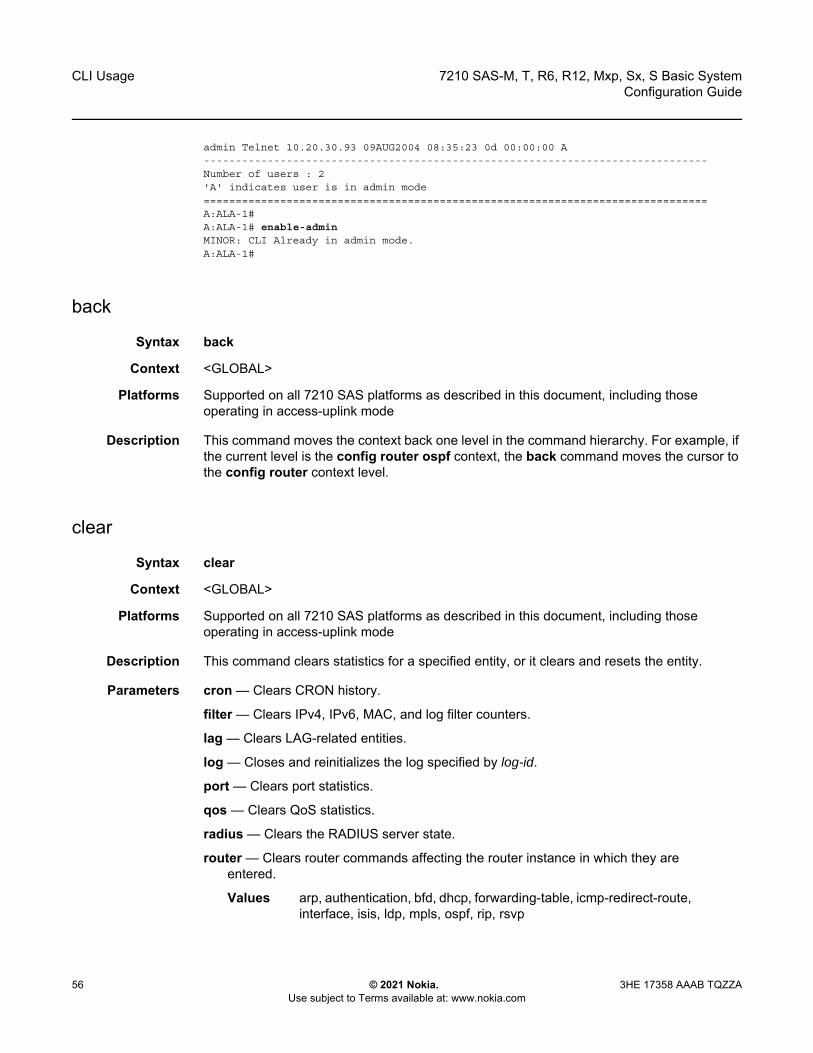
CLI Usage
56
7210 SAS-M, T, R6, R12, Mxp, Sx, S Basic SystemConfiguration Guide
© 2021 Nokia. Use subject to Terms available at: www.nokia.com
3HE 17358 AAAB TQZZA
admin Telnet 10.20.30.93 09AUG2004 08:35:23 0d 00:00:00 A-------------------------------------------------------------------------------Number of users : 2'A' indicates user is in admin mode===============================================================================A:ALA-1#A:ALA-1# enable-adminMINOR: CLI Already in admin mode.A:ALA-1#
back
Syntax back
Context <GLOBAL>
Platforms Supported on all 7210 SAS platforms as described in this document, including those operating in access-uplink mode
Description This command moves the context back one level in the command hierarchy. For example, if the current level is the config router ospf context, the back command moves the cursor to the config router context level.
clear
Syntax clear
Context <GLOBAL>
Platforms Supported on all 7210 SAS platforms as described in this document, including those operating in access-uplink mode
Description This command clears statistics for a specified entity, or it clears and resets the entity.
Parameters cron — Clears CRON history.
filter — Clears IPv4, IPv6, MAC, and log filter counters.
lag — Clears LAG-related entities.
log — Closes and reinitializes the log specified by log-id.
port — Clears port statistics.
qos — Clears QoS statistics.
radius — Clears the RADIUS server state.
router — Clears router commands affecting the router instance in which they are entered.
Values arp, authentication, bfd, dhcp, forwarding-table, icmp-redirect-route, interface, isis, ldp, mpls, ospf, rip, rsvp
7210 SAS-M, T, R6, R12, Mxp, Sx, S Basic System Configuration Guide
CLI Usage
3HE 17358 AAAB TQZZA © 2021 Nokia. Use subject to Terms available at: www.nokia.com
57
saa — Clears the SAA test results.
screen — Clears the console or telnet screen.
service — Clears service ID and statistical entities.
system — Clears or re-enables a previously failed reference.
tacplus — Clears the TACACS+ server state.
trace — Clears the trace log.
echo
Syntax echo [text-to-echo] [extra-text-to-echo] [more-text]
Context <GLOBAL>
Platforms Supported on all 7210 SAS platforms as described in this document, including those operating in access-uplink mode
Description This command echoes arguments on the command line. The primary use of this command is to allow messages to be displayed to the screen in files executed with the exec command.
Parameters text-to-echo — Specifies a text string to be echoed up to 256 characters.
extra-text-to-echo — Specifies more text to be echoed up to 256 characters.
more-text — Specifies more text to be echoed up to 256 characters.
exec
Syntax exec [-echo] [-syntax] {filename | [eof_string]}
Context <GLOBAL>
Platforms Supported on all 7210 SAS platforms as described in this document, including those operating in access-uplink mode
Description This command executes the contents of a text file as if they were CLI commands entered at the console.
Exec commands do not have no versions.
The following commands are related to the exec command:
• boot-bad-exec Use this command to configure a URL for a CLI script to exec following a failed configuration boot.
• boot-good-exec

CLI Usage
58
7210 SAS-M, T, R6, R12, Mxp, Sx, S Basic SystemConfiguration Guide
© 2021 Nokia. Use subject to Terms available at: www.nokia.com
3HE 17358 AAAB TQZZA
Use this command to configure a URL for a CLI script to exec following a successful configuration boot.
Parameters -echo — Keyword to echo the contents of the exec file to the session screen as it executes.
Default Echo disabled.
-syntax — Keyword to perform a syntax check of the file without executing the commands. Syntax checking finds invalid commands and keywords, but it will not be able to validate erroneous user-configured parameters.
Default Execute file commands.
file-name — The text file with CLI commands to execute.
<< — Stdin can be used as the source of commands for the exec command. When stdin is used as the exec command input, the command list is terminated with <Ctrl-C>, “EOF<Return>” or “eof_string<Return>”.If an error occurs entering an exec file sourced from stdin, all commands after the command returning the error will be silently ignored. The exec command will indicate the command error line number when the stdin input is terminated with an end-of-file input.
eof_string — Specifies the ASCII printable string used to indicate the end of the exec file when stdin is used as the exec file source. <Ctrl-C> and “EOF” can always be used to terminate an exec file sourced from stdin.
Default <Ctrl-C>, EOF
exit
Syntax exit [all]
Context <GLOBAL>
Platforms Supported on all 7210 SAS platforms as described in this document, including those operating in access-uplink mode
Description This command returns to the context from which the current level was entered. For example, if you navigated to the current level on a context by context basis, then the exit command only moves the cursor back one level.
A:Dut-G# configureA:Dut-G>config# serviceA:Dut-G>config>service# vpls 1A:Dut-G>config>service>vpls# exitA:Dut-G>config>service# exitA:Dut-G>config# exit
If you navigated to the current level by entering a command string, then the exit command returns the cursor to the context in which the command was initially entered.
7210 SAS-M, T, R6, R12, Mxp, Sx, S Basic System Configuration Guide
CLI Usage
3HE 17358 AAAB TQZZA © 2021 Nokia. Use subject to Terms available at: www.nokia.com
59
The following is a sample configuration output.
A:Dut-G# configure service vpls 1A:Dut-G>config>service>vpls# exitA:Dut-G#The exit all command moves the cursor all the way back to the root level.
The exit all command moves the cursor all the way back to the root level.
A:Dut-G# configureA:Dut-G>config# serviceA:Dut-G>config>service# vpls 1A:Dut-G>config>service>vpls# exit allA:Dut-G#
Parameters all — Keyword to exit back to the root CLI context.
help
Syntax helphelp edithelp globalhelp special-characters
Context <GLOBAL>
Platforms Supported on all 7210 SAS platforms as described in this document, including those operating in access-uplink mode
Description This command provides a brief description of the help system. The following information is displayed:
Help may be requested at any point by hitting a question mark '?'.In case of an executable node, the syntax for that node will be displayed with anexplanation of all parameters.In case of sub-commands, a brief description is provided.Global Commands:Help on global commands can be observed by issuing "help globals" at any time.Editing Commands:Help on editing commands can be observed by issuing "help edit" at any time.
Parameters edit — Keyword to display help on editing. The following output displays available editing keystrokes.
Delete current character.....................Ctrl-dDelete text up to cursor.....................Ctrl-uDelete text after cursor.....................Ctrl-kMove to beginning of line....................Ctrl-aMove to end of line..........................Ctrl-eGet prior command from history...............Ctrl-pGet next command from history................Ctrl-nMove cursor left.............................Ctrl-bMove cursor right............................Ctrl-f

CLI Usage
60
7210 SAS-M, T, R6, R12, Mxp, Sx, S Basic SystemConfiguration Guide
© 2021 Nokia. Use subject to Terms available at: www.nokia.com
3HE 17358 AAAB TQZZA
Move back one word...........................Esc-bMove forward one word........................Esc-fConvert rest of word to uppercase............Esc-cConvert rest of word to lowercase............Esc-lDelete remainder of word.....................Esc-dDelete word up to cursor.....................Ctrl-wTranspose current and previous character.....Ctrl-tEnter command and return to root prompt......Ctrl-zRefresh input line...........................Ctrl-l
global — Keyword to display help on global commands.The following output displays the available global commands.
back - Go back a level in the command treeecho - Echo the text that is typed inexec - Execute a file - use -echo to show the commands and
prompts on the screenexit - Exit to intermediate mode - use option all to exit to
root prompthelp - Display helphistory - Show command historyinfo - Display configuration for the present nodelogout - Log off this systemoam + OAM Test Suiteping - Verify the reachability of a remote hostpwc - Show the present working contextsleep - Sleep for specified number of secondsssh - SSH to a hosttelnet - Telnet to a hosttraceroute - Determine the route to a destination addresstree - Display command tree structure from the context of
executionwrite - Write text to another user
special-characters — Keyword to display help on special characters. Use the following CLI commands to display more information about commands and command syntax:
? — Lists all commands in the current context.
string? — Lists all commands available in the current context that start with the string.
command ? — Displays command syntax and associated keywords.
string<Tab> or string<Space> — Completes a partial command name (auto-completion) or list available commands that match the string.
history
Syntax history
Context <GLOBAL>
Platforms Supported on all 7210 SAS platforms as described in this document, including those operating in access-uplink mode

7210 SAS-M, T, R6, R12, Mxp, Sx, S Basic System Configuration Guide
CLI Usage
3HE 17358 AAAB TQZZA © 2021 Nokia. Use subject to Terms available at: www.nokia.com
61
Description This command lists the last 30 commands entered in this session.
Re-execute a command in the history with the !n command, where n is the line number associated with the command in the history output.
For example:
A:ALA-1# history68 info69 exit70 info71 filter72 exit all73 configure74 router75 info76 interface "test"77 exit78 reduced-prompt79 info80 interface "test"81 icmp unreachables exit all82 exit all83 reduced-prompt84 configure router85 interface86 info87 interface "test"88 info89 reduced-prompt90 exit all91 configure92 card 193 card-type94 exit95 router96 exit97 history
A:ALA-1# !91A:ALA-1# configureA:ALA-1>config#
info
Syntax info [detail]
Context <GLOBAL>
Platforms Supported on all 7210 SAS platforms as described in this document, including those operating in access-uplink mode
Description This command displays the running configuration for the configuration context.
CLI Usage
62
7210 SAS-M, T, R6, R12, Mxp, Sx, S Basic SystemConfiguration Guide
© 2021 Nokia. Use subject to Terms available at: www.nokia.com
3HE 17358 AAAB TQZZA
The output of this command is similar to the output of a show config command. This command, however, lists the configuration of the context where it is entered and all branches below that context level.
By default, the command only enters the configuration parameters that vary from the default values. The detail keyword causes all configuration parameters to be displayed.
Parameters detail — Displays all configuration parameters, including parameters at their default values.
logout
Syntax logout
Context <GLOBAL>
Platforms Supported on all 7210 SAS platforms as described in this document, including those operating in access-uplink mode
Description This command logs out of the router session.
When the logout command is issued from the console, the login prompt is displayed, and any log IDs directed to the console are discarded. When the console session resumes (regardless of the user), the log output to the console resumes.
When a Telnet session is terminated from a logout command, all log IDs directed to the session are removed. When a user logs back in, the log IDs must be recreated.
password
Syntax password
Context <ROOT>
Platforms Supported on all 7210 SAS platforms as described in this document, including those operating in access-uplink mode
Description This command changes a user CLI login password.
When a user logs in after the administrator forces a new-password-at-login, or the password has expired (aging), then this command is automatically invoked.
When this command is invoked, the user is prompted to enter the old password, the new password, and the new password again to verify the correct input.
If a user fails to create a new password after the administrator forces a new-password-at-login or after the password has expired, the user is denied access to the CLI.
7210 SAS-M, T, R6, R12, Mxp, Sx, S Basic System Configuration Guide
CLI Usage
3HE 17358 AAAB TQZZA © 2021 Nokia. Use subject to Terms available at: www.nokia.com
63
ping
Syntax ping {ip-address | dns-name} [rapid | detail] [ttl time-to-live] [tos type-of-service] [size bytes] [pattern pattern] [source ip-address] [interval seconds] [{next-hop ip-address} | {interface interface-name} | bypass-routing] [count requests] [do-not-fragment] [router router-instance | service-name service-name] [timeout timeout]
Context <GLOBAL>
Platforms Supported on all 7210 SAS platforms as described in this document, including those operating in access-uplink mode
Description This command is the TCP/IP utility to verify IP reachability.
Parameters ip-address | dns-name — Specifies the remote host to ping. The IP address or the DNS name (if DNS name resolution is configured) can be specified.
Values ipv4-address - a.b.c.dipv6-address - x:x:x:x:x:x:x:x[-interface]x:x:x:x:x:x:x:x [-interface]x:x:x:x:x:x:d.d.d.dx: 0 — FFFF Hd: 0 — 255 D
rapid | detail — The rapid keyword specifies to send ping requests rapidly. The results are reported in a single message, not in individual messages for each ping request. By default, five ping requests are sent before the results are reported. To change the number of requests, include the count option.The detail keyword includes in the output the interface on which the ping reply was received.The following is a sample configuration.
*A:ALU-7210# ping 192.xxx.xxx.xxxPING 192.xxx.xxx.xxx 56 data bytes64 bytes from 192.xxx.xxx.xxx: icmp_seq=1 ttl=64 time<10ms.64 bytes from 1192.xxx.xxx.xxx: icmp_seq=2 ttl=64 time<10ms.64 bytes from 192.xxx.xxx.xxx: icmp_seq=3 ttl=64 time<10ms.64 bytes from 192.xxx.xxx.xxx: icmp_seq=4 ttl=64 time<10ms.64 bytes from 192.xxx.xxx.xxx: icmp_seq=5 ttl=64 time<10ms.
---- 192.xxx.xxx.xxx PING Statistics ----5 packets transmitted, 5 packets received, 0.00% packet lossround-trip min < 10ms, avg < 10ms, max < 10ms, stddev < 10ms*A:ALU-7210#
ttl time-to-live — Specifies the IP Time To Live (TTL) value to include in the ping request, expressed as a decimal integer.
Values 0 to128

CLI Usage
64
7210 SAS-M, T, R6, R12, Mxp, Sx, S Basic SystemConfiguration Guide
© 2021 Nokia. Use subject to Terms available at: www.nokia.com
3HE 17358 AAAB TQZZA
tos type-of-service — Specifies the type-of-service (TOS) bits in the IP header of the ping packets, expressed as a decimal integer.
Values 0 to 255
size bytes — Specifies the size in bytes of the ping request packets.
Default 56 bytes (actually 64 bytes because 8 bytes of ICMP header data are added to the packet)
Values 0 to 65507
pattern pattern — Specifies a 16-bit pattern string to include in the ping packet, expressed as a decimal integer.
Values 0 to 16384
source ip-address — Specifies the source IP address to use in the ping requests in dotted decimal notation.
Default The IP address of the egress IP interface.
Values ipv4-address - a.b.c.dipv6-address - x:x:x:x:x:x:x:x[-interface]x:x:x:x:x:x:x:x [-interface]x:x:x:x:x:x:d.d.d.dx: 0 — FFFF Hd: 0 — 255 D
interval seconds — Specifies the interval in seconds between consecutive ping requests, expressed as a decimal integer.
Default 1
Values 1 to 10000
next-hop ip-address — This option disregards the routing table and will send this packet to the specified next hop address. This address must be on an adjacent router that is attached to a subnet that is common between this and the next-hop router.
Default per the routing table
Values ipv4-address - a.b.c.dipv6-address - x:x:x:x:x:x:x:x[-interface]x:x:x:x:x:x:d.d.d.d[-interface]x - [0..FFFF]Hd - [0..255]D
interface interface-name — Specifies the interface name.
bypass-routing — Keyword to send the ping request to a host on a directly attached network bypassing the routing table. The host must be on a directly attached network or an error is returned.

7210 SAS-M, T, R6, R12, Mxp, Sx, S Basic System Configuration Guide
CLI Usage
3HE 17358 AAAB TQZZA © 2021 Nokia. Use subject to Terms available at: www.nokia.com
65
count requests — Specifies the number of ping requests to send to the remote host, expressed as a decimal integer.
Default 5
Values 1 to 10000
do-not-fragment — Specifies that the request frame should not be fragmented. This option is particularly useful in combination with the size parameter for maximum MTU determination.
router router-instance — Specifies the router name or service ID.
Default Base
Values router-name: Base, management service-id: 1 to 2147483647
timeout timeout — Specifies the timeout in seconds.
Default 5
Values 1 to 10
service-name service-name — Specifies a unique service name, up to 64 characters to identify the service.
Values [64 chars max]
pwc
Syntax pwc [previous]
Context <GLOBAL>
Platforms Supported on all 7210 SAS platforms as described in this document, including those operating in access-uplink mode
Description This command displays the present or previous working context of the CLI session. The pwc command provides a user who is in the process of dynamically configuring a chassis a way to display the current or previous working context of the CLI session. The pwc command displays a list of the CLI nodes that hierarchically define the current context of the CLI instance of the user.
The following is a sample configuration output.
A:Dut-G>config>service>vpls# pwc-------------------------------------------------------------------------------Present Working Context :-------------------------------------------------------------------------------<root>configureservicevpls 1
-------------------------------------------------------------------------------A:Dut-G>config>service>vpls#

CLI Usage
66
7210 SAS-M, T, R6, R12, Mxp, Sx, S Basic SystemConfiguration Guide
© 2021 Nokia. Use subject to Terms available at: www.nokia.com
3HE 17358 AAAB TQZZA
When the previous keyword is specified, the previous context displays. This is the context entered by the CLI parser upon execution of the exit command. The current context of the CLI is not affected by the pwc command.
Parameters previous — Keyword to display the previous present working context.
sleep
Syntax sleep [seconds]
Context <GLOBAL>
Platforms Supported on all 7210 SAS platforms as described in this document, including those operating in access-uplink mode
Description This command causes the console session to pause operation (sleep) for 1 second (default) or for the specified number of seconds.
Parameters seconds — Specifies the number of seconds for the console session to sleep, expressed as a decimal integer.
Default 1
Values 1 to 100
ssh
Syntax ssh [ip-addr | dns-name |username@ip-addr] [-l username] [-v SSH-version] [router router-instance| service-name service-name]
Context <GLOBAL>
Platforms Supported on all 7210 SAS platforms as described in this document, including those operating in access-uplink mode
Description This command initiates a client Secure Shell (SSH) session with the remote host and is independent from the administrative or operational state of the SSH server. However, to be the target of an SSH session, the SSH server must be operational.
Quitting SSH while in the process of authentication is accomplished by either executing a Ctrl-c or "~." (tilde and dot), assuming the “~” is the default escape character for SSH session.
Parameters ip-address | host-name — Specifies the remote host for an SSH session. The IP address or the DNS name (if DNS name resolution is configured) can be specified.
-l user — Specifies the user name to use when opening the SSH session.
router router-instance — Specifies the router name or service ID.

7210 SAS-M, T, R6, R12, Mxp, Sx, S Basic System Configuration Guide
CLI Usage
3HE 17358 AAAB TQZZA © 2021 Nokia. Use subject to Terms available at: www.nokia.com
67
Default Base
telnet
Syntax telnet [ip-address | dns-name] [port] [router router-instance]
Context <GLOBAL>
Platforms Supported on all 7210 SAS platforms as described in this document, including those operating in access-uplink mode
Description This command opens a Telnet session to a remote host. Telnet servers in 7210 SAS networks limit a Telnet clients to three login attempts. The Telnet server disconnects the Telnet client session after the third attempt has failed. The number of attempts for a Telnet client session is not user-configurable.
Parameters ip-address — Specifies the IP address or the DNS name (if DNS name resolution is configured).
Values ipv4-address a.b.c.d
Values ipv6-address x:x:x:x:x:x:x:x (eight 16-bit pieces)x:x:x:x:x:x:d.d.d.d
x: [0 .. FFFF]H d: [0 .. 255]D
dns-name — Specifies the DNS name (if DNS name resolution is configured), up to 128 characters.
port — Specifies the TCP port number to use to Telnet to the remote host, expressed as a decimal integer.
Default 23
Values 1 to 65535
router router-instance — Specifies the router name or service ID.
Values router-name:Base, management service-id: 1 to 2147483647
Default Base
traceroute
Syntax traceroute {ip-address | dns-name} [ttl ttl] [wait milliseconds] [no-dns] [source ip-address] [tos type-of-service] [router router-instance]
Context <GLOBAL>

CLI Usage
68
7210 SAS-M, T, R6, R12, Mxp, Sx, S Basic SystemConfiguration Guide
© 2021 Nokia. Use subject to Terms available at: www.nokia.com
3HE 17358 AAAB TQZZA
Platforms Supported on all 7210 SAS platforms as described in this document, including those operating in access-uplink mode
Description The TCP/IP traceroute utility determines the route to a destination address. Aborting a traceroute with the Ctrl-c could require issuing a second Ctrl-c before the prompt is returned.
The following is a sample configuration output.
A:ALA-1# traceroute 192.168.xx.xx4traceroute to 192.168.xx.xx4, 30 hops max, 40 byte packets1 192.168.xx.xx4 0.000 ms 0.000 ms 0.000 ms
A:ALA-1#
Parameters ip-address | dns-name — Specifies the remote address to traceroute. The IP address or the DNS name (if DNS name resolution is configured) can be specified.
Values ipv4-address a.b.c.dipv6-address x:x:x:x:x:x:x:x (eight 16-bit pieces)
x:x:x:x:x:x:d.d.d.d x: [0 .. FFFF]H d: [0 .. 255]D
ttl ttl — Specifies the maximum Time-To-Live (TTL) value to include in the traceroute request, expressed as a decimal integer.
Values 1 to 255
wait milliseconds — Specifies the time in milliseconds to wait for a response to a probe, expressed as a decimal integer.
Default 5000
Values 1 to 60000
no-dns — Keyword to specify not to perform a DNS lookup for the specified host.
Default DNS lookups are performed
source ip-address — Specifies the source IP address to use as the source of the probe packets in dotted decimal notation. If the IP address is not one of the device interfaces, an error is returned.
tos type-of-service — Specifies the type-of-service (TOS) bits in the IP header of the probe packets, expressed as a decimal integer.
Values 0 to 255
router router-instance — Specifies the router name or service ID.
Values router-name: Base, managementservice-id: 1 to 2147483647
Default Base
7210 SAS-M, T, R6, R12, Mxp, Sx, S Basic System Configuration Guide
CLI Usage
3HE 17358 AAAB TQZZA © 2021 Nokia. Use subject to Terms available at: www.nokia.com
69
tree
Syntax tree [detail]
Context <GLOBAL>
Platforms Supported on all 7210 SAS platforms as described in this document, including those operating in access-uplink mode
Description This command displays the command hierarchy structure from the present working context.
Parameters detail — Keyword to include parameter information for each command displayed in the tree output.
write
Syntax write {user | broadcast} message-string
Context <GLOBAL>
Platforms Supported on all 7210 SAS platforms as described in this document, including those operating in access-uplink mode
Description This command sends a console message to a specific user or to all users with active console sessions.
Parameters user — Specifies the name of a user with an active console session to which to send a console message.
Values any valid CLI username
broadcast — Keyword to send the message-string to all users logged into the router.
message-string — Specifies the message string to send. Allowed values are any string up to 250 characters composed of printable, 7-bit ASCII characters. If the string contains special characters (#, $, spaces, and others), the entire string must be enclosed within double quotes.
2.9.2.2 CLI Environment Commands
alias
Syntax alias alias-name alias-command-lineno alias alias-name
Context environment

CLI Usage
70
7210 SAS-M, T, R6, R12, Mxp, Sx, S Basic SystemConfiguration Guide
© 2021 Nokia. Use subject to Terms available at: www.nokia.com
3HE 17358 AAAB TQZZA
Platforms Supported on all 7210 SAS platforms as described in this document, including those operating in access-uplink mode
Description This command enables the substitution of a command line by an alias.
Use the alias command to create alternative names for an entity or command string that are r easier to remember and understand. If the string contains special characters (#, $, spaces, and others), the entire string must be enclosed within double quotes. Only a single command can be present in the command string.
The alias command can be entered in any context but must be created in the environment context.
For example, to create an alias named soi to display OSPF interfaces, enter:
alias soi “show router ospf interface”
Parameters alias-name — Specifies the alias name. Do not use a valid command string for the alias. If the alias specified is an actual command, this causes the command to be replaced by the alias.
alias-command-line — Specifies the command line to be associated with the alias.
create
Syntax [no] create
Context environment
Platforms Supported on all 7210 SAS platforms as described in this document, including those operating in access-uplink mode
Description This command is required to create a new OS entity.
The no form of the command disables requiring the create keyword.
Default create
more
Syntax [no] more
Context environment
Platforms Supported on all 7210 SAS platforms as described in this document, including those operating in access-uplink mode
7210 SAS-M, T, R6, R12, Mxp, Sx, S Basic System Configuration Guide
CLI Usage
3HE 17358 AAAB TQZZA © 2021 Nokia. Use subject to Terms available at: www.nokia.com
71
Description This command enables per-screen CLI output, meaning that the output is displayed on a screen-by-screen basis. The terminal screen length can be modified with the terminal command. The following prompt appears at the end of each screen of paginated output:
Press any key to continue (Q to quit)
The no form of the command displays the output all at once. If the output length is longer than one screen, the entire output will be displayed, which may scroll the screen.
Default more
reduced-prompt
Syntax reduced-prompt [no of nodes in prompt]no reduced-prompt
Context environment
Platforms Supported on all 7210 SAS platforms as described in this document, including those operating in access-uplink mode
Description This command configures the maximum number of higher CLI context levels to display in the CLI prompt for the current CLI session. This command is useful when configuring features that are several node levels deep, causing the CLI prompt to become too long. By default, the CLI prompt displays the system name and the complete context in the CLI.
The number of nodes specified indicates the number of higher-level contexts that can be displayed in the prompt. For example, if reduced-prompt is set to 2, the two highest contexts from the present working context are displayed by name with the hidden (reduced) contexts compressed into a ellipsis (“…”).
The following is a sample configuration output.
A:ALA-1>environment# reduced-prompt 2A:ALA-1>vonfig>router# interface to-103A:ALA-1>...router>if#
The setting is not saved in the configuration. It must be reset for each CLI session or stored in an exec script file.
The no form of the command reverts to the default.
Default no reduced-prompt
Parameters no of nodes in prompt — Specifies the maximum number of higher-level nodes displayed by name in the prompt, expressed as a decimal integer.
Default 2
Values 0 to 15

CLI Usage
72
7210 SAS-M, T, R6, R12, Mxp, Sx, S Basic SystemConfiguration Guide
© 2021 Nokia. Use subject to Terms available at: www.nokia.com
3HE 17358 AAAB TQZZA
saved-ind-prompt
Syntax [no] saved-ind-prompt
Context environment
Platforms Supported on all 7210 SAS platforms as described in this document, including those operating in access-uplink mode
Description This command enables saved indicator in the prompt. When changes are made to the configuration file a “*” appears in the prompt string indicating that the changes have not been saved. When an admin save command is executed, the “*” disappears.
The following is a sample configuration output.
*A:ALA-48# admin saveWriting file to ftp://xxx.xxx.xx.xx/./sim48/sim48-config.cfgSaving configuration .... Completed.A:ALA-48#
terminal
Syntax [no] terminal
Context environment
Platforms Supported on all 7210 SAS platforms as described in this document
Description Commands in this context configure the terminal screen length and width for the current CLI session.
length
Syntax length lines
Context environment>terminal
Platforms Supported on all 7210 SAS platforms as described in this document
Description This command sets the terminal screen length (number of lines).
Default 24
Parameters lines — Specifies the number of lines for the terminal screen length, expressed as a decimal integer.
Values 1 to 512
7210 SAS-M, T, R6, R12, Mxp, Sx, S Basic System Configuration Guide
CLI Usage
3HE 17358 AAAB TQZZA © 2021 Nokia. Use subject to Terms available at: www.nokia.com
73
width
Syntax width width
Context environment>terminal
Platforms Supported on all 7210 SAS platforms as described in this document
Description This command sets the terminal screen width (number of characters).
Default 80
Parameters width — Specifies the number of characters for the terminal screen width, expressed as a decimal integer.
Values 1 to 512
time-display
Syntax time-display {local | utc}
Context environment
Platforms Supported on all 7210 SAS platforms as described in this document, including those operating in access-uplink mode
Description This command displays timestamps in the CLI session based on local time or Coordinated Universal Time (UTC).
The system keeps time internally in UTC and is capable of displaying the time in either UTC or local time based on the time zone configured.
This configuration command is only valid for times displayed in the current CLI session. This includes displays of event logs, traps and all other places where a timestamp is displayed.
In general all timestamps are shown in the time selected. This includes log entries destined for console/session, memory, or SNMP logs. Log files on compact flash are maintained and displayed in UTC format.
Default time-display local — Displays time stamps based on the local time.
time-stamp
Syntax time-stamp
Context environment
Platforms Supported on all 7210 SAS platforms as described in this document, including those operating in access-uplink mode

CLI Usage
74
7210 SAS-M, T, R6, R12, Mxp, Sx, S Basic SystemConfiguration Guide
© 2021 Nokia. Use subject to Terms available at: www.nokia.com
3HE 17358 AAAB TQZZA
Description This command displays timestamps in the CLI session.
2.9.2.3 Show Commands
alias
Syntax alias
Context <root>
Platforms Supported on all 7210 SAS platforms as described in this document, including those operating in access-uplink mode
Description This command shows a list of existing aliases.
Output The following output is an example of alias information, and Table 15 describes the output fields.
Sample Output
A:ALA-103>config>system# show alias==============================================================================Alias-Name Alias-command-name==============================================================================sri show router interfacesse show service service-using epipessvpls show service service-using vplsssi show service service-using ies------------------------------------------------------------------------------Number of aliases : 5==============================================================================A:ALA-103>config>system#
Table 15 Output Fields: Alias
Label Description
Alias-Name Displays the name of the alias
Alias-command-name The command and parameter syntax that define the alias
Number of aliases The total number of aliases configured on the router

7210 SAS-M, T, R6, R12, Mxp, Sx, S Basic System Configuration Guide
CLI Usage
3HE 17358 AAAB TQZZA © 2021 Nokia. Use subject to Terms available at: www.nokia.com
75
2.9.2.4 Monitor CLI Commands
filter
Syntax filter
Context monitor
Platforms Supported on all 7210 SAS platforms as described in this document, including those operating in access-uplink mode
Description Commands in this context configure criteria to monitor IP and MAC filter statistics.
ip
Syntax ip ip-filter-id entry entry-id [interval seconds] [repeat repeat] [absolute | rate]
Context monitor>filtermonitor>management-access-filter
Platforms Supported on all 7210 SAS platforms as described in this document, including those operating in access-uplink mode
Description This command enables IP filter monitoring. The statistical information for the specified IP filter entry is displayed at the configured interval until the configured count is reached.
The first screen displays the current statistics related to the specified IP filter. The subsequent statistical information listed for each interval is displayed as a delta to the previous screen output.
When the keyword rate is specified, the rate per second for each statistic is displayed instead of the delta.
Monitor commands are similar to show commands, but only statistical information is displayed. Monitor commands display the selected statistics according to the configured number of times at the interval specified.
Parameters ip-filter-id — Displays detailed information for the specified filter ID and its filter entries.
Values 1 to 65535
entry entry-id — Displays information on the specified filter entry ID for the specified filter ID only.
Values 1 to 65535
interval seconds — Specifies the interval for each display in seconds.
Default 5 seconds
Values 3 to 60
CLI Usage
76
7210 SAS-M, T, R6, R12, Mxp, Sx, S Basic SystemConfiguration Guide
© 2021 Nokia. Use subject to Terms available at: www.nokia.com
3HE 17358 AAAB TQZZA
repeat repeat — Specifies how many times the command is repeated.
Default 10
Values 1 to 999
absolute — Keyword to display raw statistics, without processing. No calculations are performed on the delta or rate statistics.
rate — Keyword to display the rate per second for each statistic instead of the delta.
Output The following is output is an example of filter IP statistics.
Sample Output
A:ALA-1>monitor# filter ip 10 entry 1 interval 3 repeat 3 absolute===============================================================================Monitor statistics for IP filter 10 entry 1===============================================================================At time t = 0 sec (Base Statistics)-------------------------------------------------------------------------------Ing. Matches: 0 Egr. Matches : 0-------------------------------------------------------------------------------At time t = 3 sec (Mode: Absolute)-------------------------------------------------------------------------------Ing. Matches: 0 Egr. Matches : 0-------------------------------------------------------------------------------At time t = 6 sec (Mode: Absolute)-------------------------------------------------------------------------------Ing. Matches: 0 Egr. Matches : 0-------------------------------------------------------------------------------At time t = 9 sec (Mode: Absolute)-------------------------------------------------------------------------------Ing. Matches: 0 Egr. Matches : 0===============================================================================A:ALA-1>monitor#
A:ALA-1>monitor# filter ip 10 entry 1 interval 3 repeat 3 rate===========================================================================Monitor statistics for IP filter 10 entry 1===========================================================================At time t = 0 sec (Base Statistics)---------------------------------------------------------------------------Ing. Matches: 0 Egr. Matches : 0---------------------------------------------------------------------------At time t = 3 sec (Mode: Rate)---------------------------------------------------------------------------Ing. Matches: 0 Egr. Matches : 0---------------------------------------------------------------------------At time t = 6 sec (Mode: Rate)---------------------------------------------------------------------------Ing. Matches: 0 Egr. Matches : 0---------------------------------------------------------------------------At time t = 9 sec (Mode: Rate)---------------------------------------------------------------------------Ing. Matches: 0 Egr. Matches : 0===========================================================================A:ALA-1>monitor#
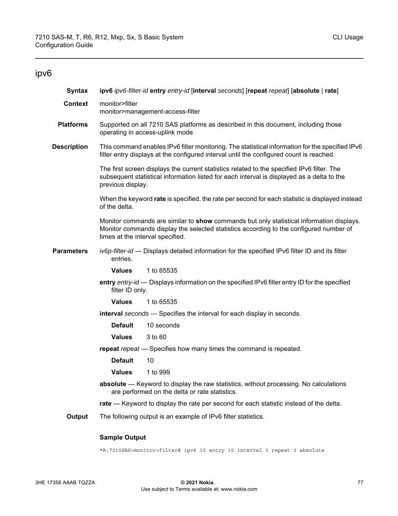
7210 SAS-M, T, R6, R12, Mxp, Sx, S Basic System Configuration Guide
CLI Usage
3HE 17358 AAAB TQZZA © 2021 Nokia. Use subject to Terms available at: www.nokia.com
77
ipv6
Syntax ipv6 ipv6-filter-id entry entry-id [interval seconds] [repeat repeat] [absolute | rate]
Context monitor>filtermonitor>management-access-filter
Platforms Supported on all 7210 SAS platforms as described in this document, including those operating in access-uplink mode
Description This command enables IPv6 filter monitoring. The statistical information for the specified IPv6 filter entry displays at the configured interval until the configured count is reached.
The first screen displays the current statistics related to the specified IPv6 filter. The subsequent statistical information listed for each interval is displayed as a delta to the previous display.
When the keyword rate is specified, the rate per second for each statistic is displayed instead of the delta.
Monitor commands are similar to show commands but only statistical information displays. Monitor commands display the selected statistics according to the configured number of times at the interval specified.
Parameters iv6p-filter-id — Displays detailed information for the specified IPv6 filter ID and its filter entries.
Values 1 to 65535
entry entry-id — Displays information on the specified IPv6 filter entry ID for the specified filter ID only.
Values 1 to 65535
interval seconds — Specifies the interval for each display in seconds.
Default 10 seconds
Values 3 to 60
repeat repeat — Specifies how many times the command is repeated.
Default 10
Values 1 to 999
absolute — Keyword to display the raw statistics, without processing. No calculations are performed on the delta or rate statistics.
rate — Keyword to display the rate per second for each statistic instead of the delta.
Output The following output is an example of IPv6 filter statistics.
Sample Output
*A:7210SAS>monitor>filter# ipv6 10 entry 10 interval 3 repeat 3 absolute
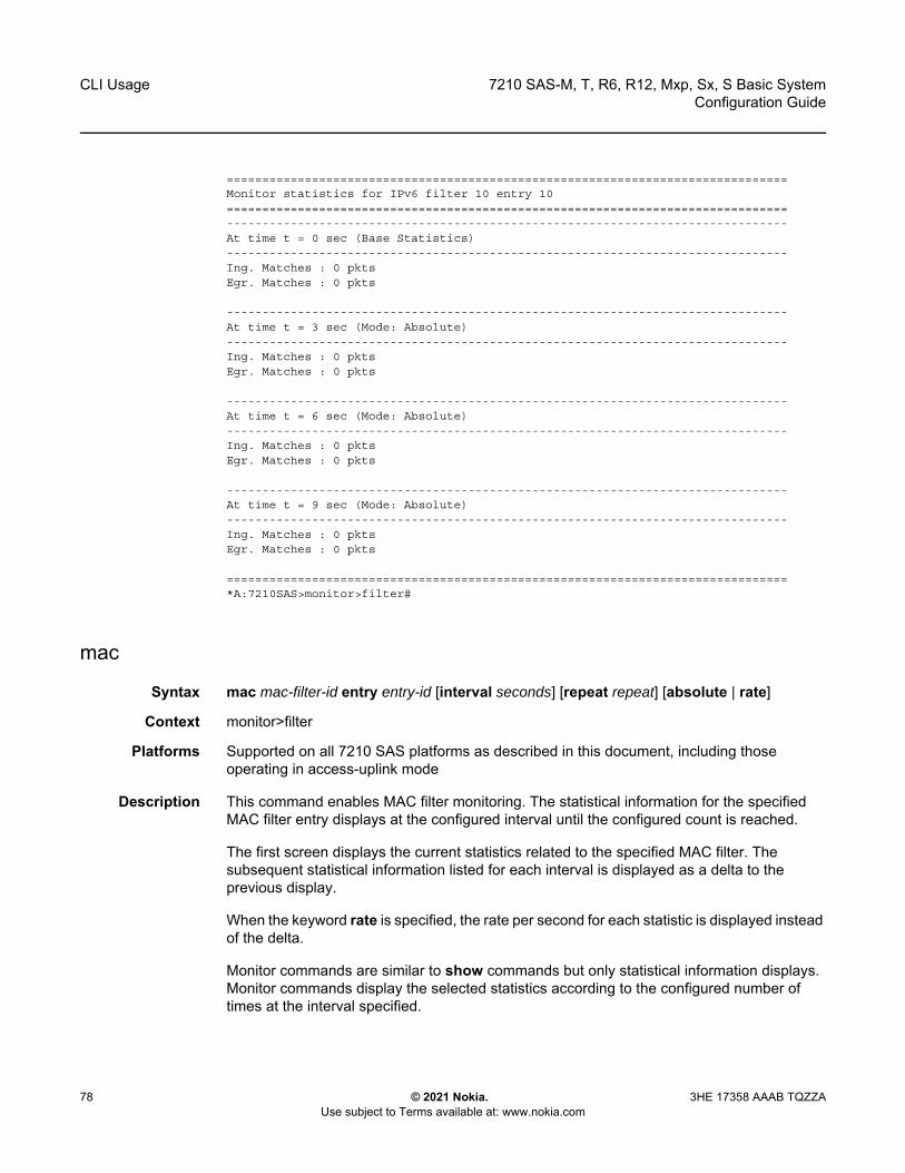
CLI Usage
78
7210 SAS-M, T, R6, R12, Mxp, Sx, S Basic SystemConfiguration Guide
© 2021 Nokia. Use subject to Terms available at: www.nokia.com
3HE 17358 AAAB TQZZA
===============================================================================Monitor statistics for IPv6 filter 10 entry 10===============================================================================-------------------------------------------------------------------------------At time t = 0 sec (Base Statistics)-------------------------------------------------------------------------------Ing. Matches : 0 pktsEgr. Matches : 0 pkts
-------------------------------------------------------------------------------At time t = 3 sec (Mode: Absolute)-------------------------------------------------------------------------------Ing. Matches : 0 pktsEgr. Matches : 0 pkts
-------------------------------------------------------------------------------At time t = 6 sec (Mode: Absolute)-------------------------------------------------------------------------------Ing. Matches : 0 pktsEgr. Matches : 0 pkts
-------------------------------------------------------------------------------At time t = 9 sec (Mode: Absolute)-------------------------------------------------------------------------------Ing. Matches : 0 pktsEgr. Matches : 0 pkts
===============================================================================*A:7210SAS>monitor>filter#
mac
Syntax mac mac-filter-id entry entry-id [interval seconds] [repeat repeat] [absolute | rate]
Context monitor>filter
Platforms Supported on all 7210 SAS platforms as described in this document, including those operating in access-uplink mode
Description This command enables MAC filter monitoring. The statistical information for the specified MAC filter entry displays at the configured interval until the configured count is reached.
The first screen displays the current statistics related to the specified MAC filter. The subsequent statistical information listed for each interval is displayed as a delta to the previous display.
When the keyword rate is specified, the rate per second for each statistic is displayed instead of the delta.
Monitor commands are similar to show commands but only statistical information displays. Monitor commands display the selected statistics according to the configured number of times at the interval specified.
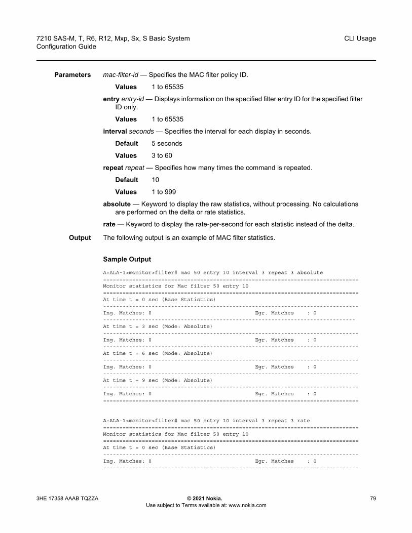
7210 SAS-M, T, R6, R12, Mxp, Sx, S Basic System Configuration Guide
CLI Usage
3HE 17358 AAAB TQZZA © 2021 Nokia. Use subject to Terms available at: www.nokia.com
79
Parameters mac-filter-id — Specifies the MAC filter policy ID.
Values 1 to 65535
entry entry-id — Displays information on the specified filter entry ID for the specified filter ID only.
Values 1 to 65535
interval seconds — Specifies the interval for each display in seconds.
Default 5 seconds
Values 3 to 60
repeat repeat — Specifies how many times the command is repeated.
Default 10
Values 1 to 999
absolute — Keyword to display the raw statistics, without processing. No calculations are performed on the delta or rate statistics.
rate — Keyword to display the rate-per-second for each statistic instead of the delta.
Output The following output is an example of MAC filter statistics.
Sample Output
A:ALA-1>monitor>filter# mac 50 entry 10 interval 3 repeat 3 absolute===============================================================================Monitor statistics for Mac filter 50 entry 10===============================================================================At time t = 0 sec (Base Statistics)-------------------------------------------------------------------------------Ing. Matches: 0 Egr. Matches : 0------------------------------------------------------------------------------At time t = 3 sec (Mode: Absolute)-------------------------------------------------------------------------------Ing. Matches: 0 Egr. Matches : 0-------------------------------------------------------------------------------At time t = 6 sec (Mode: Absolute)-------------------------------------------------------------------------------Ing. Matches: 0 Egr. Matches : 0-------------------------------------------------------------------------------At time t = 9 sec (Mode: Absolute)-------------------------------------------------------------------------------Ing. Matches: 0 Egr. Matches : 0===============================================================================
A:ALA-1>monitor>filter# mac 50 entry 10 interval 3 repeat 3 rate===============================================================================Monitor statistics for Mac filter 50 entry 10===============================================================================At time t = 0 sec (Base Statistics)-------------------------------------------------------------------------------Ing. Matches: 0 Egr. Matches : 0-------------------------------------------------------------------------------
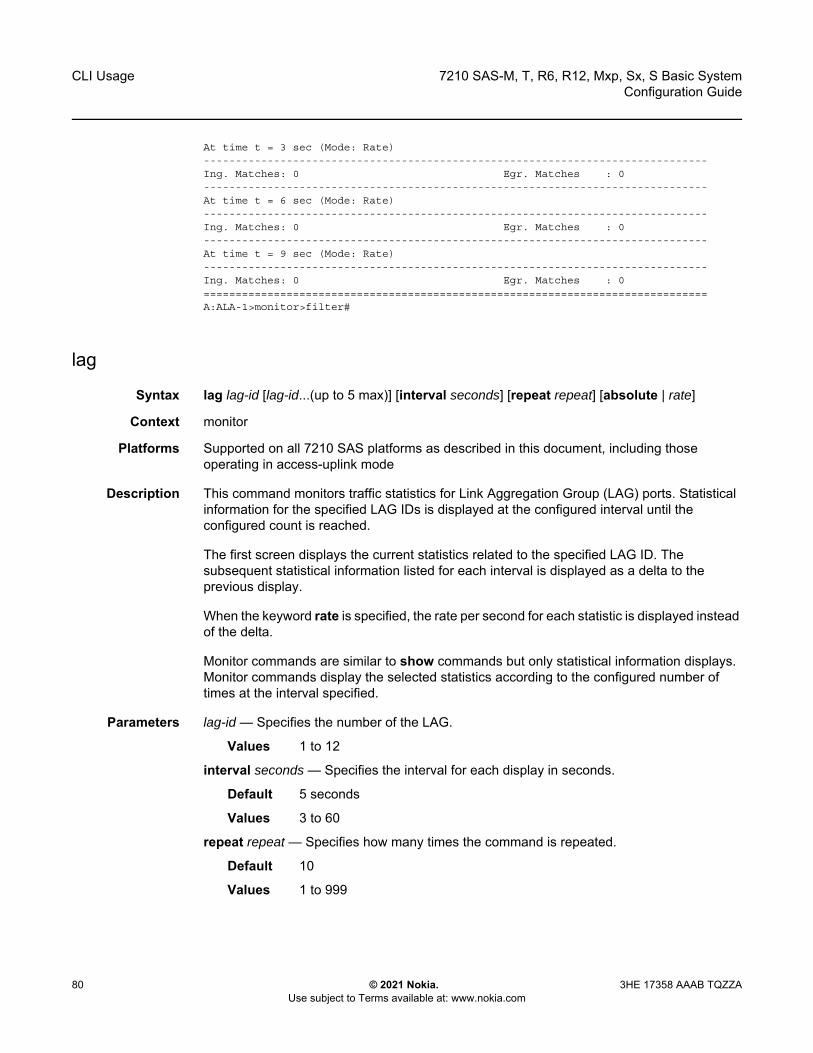
CLI Usage
80
7210 SAS-M, T, R6, R12, Mxp, Sx, S Basic SystemConfiguration Guide
© 2021 Nokia. Use subject to Terms available at: www.nokia.com
3HE 17358 AAAB TQZZA
At time t = 3 sec (Mode: Rate)-------------------------------------------------------------------------------Ing. Matches: 0 Egr. Matches : 0-------------------------------------------------------------------------------At time t = 6 sec (Mode: Rate)-------------------------------------------------------------------------------Ing. Matches: 0 Egr. Matches : 0-------------------------------------------------------------------------------At time t = 9 sec (Mode: Rate)-------------------------------------------------------------------------------Ing. Matches: 0 Egr. Matches : 0===============================================================================A:ALA-1>monitor>filter#
lag
Syntax lag lag-id [lag-id...(up to 5 max)] [interval seconds] [repeat repeat] [absolute | rate]
Context monitor
Platforms Supported on all 7210 SAS platforms as described in this document, including those operating in access-uplink mode
Description This command monitors traffic statistics for Link Aggregation Group (LAG) ports. Statistical information for the specified LAG IDs is displayed at the configured interval until the configured count is reached.
The first screen displays the current statistics related to the specified LAG ID. The subsequent statistical information listed for each interval is displayed as a delta to the previous display.
When the keyword rate is specified, the rate per second for each statistic is displayed instead of the delta.
Monitor commands are similar to show commands but only statistical information displays. Monitor commands display the selected statistics according to the configured number of times at the interval specified.
Parameters lag-id — Specifies the number of the LAG.
Values 1 to 12
interval seconds — Specifies the interval for each display in seconds.
Default 5 seconds
Values 3 to 60
repeat repeat — Specifies how many times the command is repeated.
Default 10
Values 1 to 999
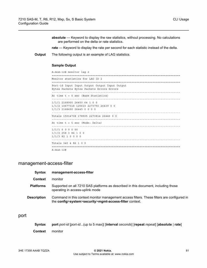
7210 SAS-M, T, R6, R12, Mxp, Sx, S Basic System Configuration Guide
CLI Usage
3HE 17358 AAAB TQZZA © 2021 Nokia. Use subject to Terms available at: www.nokia.com
81
absolute — Keyword to display the raw statistics, without processing. No calculations are performed on the delta or rate statistics.
rate — Keyword to display the rate per second for each statistic instead of the delta.
Output The following output is an example of LAG statistics.
Sample Output
A:ALA-12# monitor lag 2===============================================================================Monitor statistics for LAG ID 2===============================================================================Port-id Input Input Output Output Input OutputBytes Packets Bytes Packets Errors Errors-------------------------------------------------------------------------------At time t = 0 sec (Base Statistics)-------------------------------------------------------------------------------1/1/1 2168900 26450 64 1 0 01/1/2 10677318 125610 2273750 26439 0 01/1/3 2168490 26445 0 0 0 0-------------------------------------------------------------------------------Totals 15014708 178505 2273814 26440 0 0-------------------------------------------------------------------------------At time t = 5 sec (Mode: Delta)-------------------------------------------------------------------------------1/1/1 0 0 0 0 001/1/2 258 3 86 1 0 01/1/3 82 1 0 0 0 0-------------------------------------------------------------------------------Totals 340 4 86 1 0 0===============================================================================A:ALA-12#
management-access-filter
Syntax management-access-filter
Context monitor
Platforms Supported on all 7210 SAS platforms as described in this document, including those operating in access-uplink mode
Description Command in this context monitor management access filters. These filters are configured in the config>system>security>mgmt-access-filter context.
port
Syntax port port-id [port-id...(up to 5 max)] [interval seconds] [repeat repeat] [absolute | rate]
Context monitor

CLI Usage
82
7210 SAS-M, T, R6, R12, Mxp, Sx, S Basic SystemConfiguration Guide
© 2021 Nokia. Use subject to Terms available at: www.nokia.com
3HE 17358 AAAB TQZZA
Platforms Supported on all 7210 SAS platforms as described in this document, including those operating in access-uplink mode
Description This command enables port traffic monitoring. The specified ports statistical information is displayed at the configured interval until the configured count is reached.
The first screen displays the current statistics related to the specified ports. The subsequent statistical information listed for each interval is displayed as a delta to the previous display.
When the keyword rate is specified, the rate per second for each statistic is displayed instead of the delta.
Monitor commands are similar to show commands but only statistical information displays. Monitor commands display the selected statistics according to the configured number of times at the interval specified.
Parameters port port-id — Specifies up to 5 port IDs.
interval seconds — Specifies the interval for each display in seconds.
Default 10 seconds
Values 3 to 60
repeat repeat — Specifies how many times the command is repeated.
Default 10
Values 1 to 999
absolute — Keyword to display the raw statistics, without processing. No calculations are performed on the delta or rate statistics.
rate — Keyword to display the rate per second for each statistic instead of the delta.
Output The following output is an example of port statistics.
Sample Output
A:ALA-12>monitor# port 1/1/4 interval 3 repeat 3 absolute===============================================================================Monitor statistics for Port 1/1/4===============================================================================
Input Output-------------------------------------------------------------------------------At time t = 0 sec (Base Statistics)-------------------------------------------------------------------------------Octets 0 0Packets 39 175Errors 0 0-------------------------------------------------------------------------------At time t = 3 sec (Mode: Absolute)-------------------------------------------------------------------------------Octets 0 0Packets 39 175Errors 0 0-------------------------------------------------------------------------------
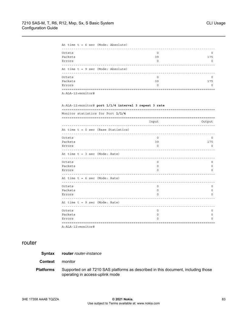
7210 SAS-M, T, R6, R12, Mxp, Sx, S Basic System Configuration Guide
CLI Usage
3HE 17358 AAAB TQZZA © 2021 Nokia. Use subject to Terms available at: www.nokia.com
83
At time t = 6 sec (Mode: Absolute)-------------------------------------------------------------------------------Octets 0 0Packets 39 175Errors 0 0-------------------------------------------------------------------------------At time t = 9 sec (Mode: Absolute)-------------------------------------------------------------------------------Octets 0 0Packets 39 175Errors 0 0===============================================================================A:ALA-12>monitor#
A:ALA-12>monitor# port 1/1/4 interval 3 repeat 3 rate===============================================================================Monitor statistics for Port 1/1/4===============================================================================
Input Output-------------------------------------------------------------------------------At time t = 0 sec (Base Statistics)-------------------------------------------------------------------------------Octets 0 0Packets 39 175Errors 0 0-------------------------------------------------------------------------------At time t = 3 sec (Mode: Rate)-------------------------------------------------------------------------------Octets 0 0Packets 0 0Errors 0 0-------------------------------------------------------------------------------At time t = 6 sec (Mode: Rate)-------------------------------------------------------------------------------Octets 0 0Packets 0 0Errors 0 0-------------------------------------------------------------------------------At time t = 9 sec (Mode: Rate)-------------------------------------------------------------------------------Octets 0 0Packets 0 0Errors 0 0===============================================================================A:ALA-12>monitor#
router
Syntax router router-instance
Context monitor
Platforms Supported on all 7210 SAS platforms as described in this document, including those operating in access-uplink mode
CLI Usage
84
7210 SAS-M, T, R6, R12, Mxp, Sx, S Basic SystemConfiguration Guide
© 2021 Nokia. Use subject to Terms available at: www.nokia.com
3HE 17358 AAAB TQZZA
Description Commands in this context configure criteria to monitor statistical information for BGP, LDP, MPLS, OSPF, and RSVP protocols.
Parameters router-instance — Specifies the router name or service ID.
Values router-name: Base, management service-id: 1 to 2147483647
Default Base
service
Syntax service
Context monitor
Platforms Supported on all 7210 SAS platforms as described in this document, including those operating in access-uplink mode
Description Commands in this context configure criteria to monitor specific service SAP criteria.
id
Syntax id service-id
Context monitor>service
Platforms Supported on all 7210 SAS platforms as described in this document, including those operating in access-uplink mode
Description This command displays statistics for a specific service, specified by the service-id, at the configured interval until the configured count is reached.
The first screen displays the current statistics related to the service-id. The subsequent statistical information listed for each interval is displayed as a delta to the previous display.
When the keyword rate is specified, the “rate per second” for each statistic is displayed instead of the delta.
Monitor commands are similar to show commands but only statistical information displays. Monitor commands display the selected statistics according to the configured number of times at the interval specified.
Parameters service-id — Specifies the unique service identification number of the service in the service domain.

7210 SAS-M, T, R6, R12, Mxp, Sx, S Basic System Configuration Guide
CLI Usage
3HE 17358 AAAB TQZZA © 2021 Nokia. Use subject to Terms available at: www.nokia.com
85
sap
Syntax sap sap-id [interval seconds] [repeat repeat] [absolute | rate]
Context monitor>service>id
Platforms Supported on all 7210 SAS platforms as described in this document, including those operating in access-uplink mode
Description This command monitors statistics for a SAP associated with this service.
This command displays statistics for a specific SAP, identified by the port-id and encapsulation value, at the configured interval until the configured count is reached.
The first screen displays the current statistics related to the SAP. The subsequent statistical information listed for each interval is displayed as a delta to the previous display. When the keyword rate is specified, the rate per second for each statistic is displayed instead of the delta.
Monitor commands are similar to show commands but only statistical information displays. Monitor commands display the selected statistics according to the configured number of times at the interval specified.
Parameters sap-id — Specifies the physical port identifier portion of the SAP definition.
Values sap-id:null[port-id | lag-id]dot1q [port-id | lag-id]:* | qtagqinq [port-id | lag-id]:qtag1.qtag2port-id slot/mda/portlag-idlag-idlag keywordid1 to 200qtag10 to 4094qtag2 *, 0 to 4094dlci 16 to 022
port-id — Specifies the physical port ID in the slot/mda/port format.If the card in the slot has Media Dependent Adapters (MDAs) installed, the port-id must be in the slot_number/MDA_number/port_number format. For example 1/2/3 specifies port 3 on MDA 2 in slot 1.
qtag1, qtag2 — Specifies the encapsulation value used to identify the SAP on the port or sub-port. If this parameter is not specifically defined, the default value is 0. The values depends on the encapsulation type configured for the interface. The following table describes the allowed values for the port and encapsulation types.
Table 16 Allowed Values for Port and Encapsulation Types
Port Type Encap-Type Allowed Values Comments
Ethernet Null 0 The SAP is identified by the port.

CLI Usage
86
7210 SAS-M, T, R6, R12, Mxp, Sx, S Basic SystemConfiguration Guide
© 2021 Nokia. Use subject to Terms available at: www.nokia.com
3HE 17358 AAAB TQZZA
Values qtag1: 0 to 4094qtag2 : * | 0 to 4094
interval seconds — Specifies the interval for each display in seconds.
Default 11 seconds
Values 11 to 60
repeat repeat — Specifies how many times the command is repeated.
Default 10
Values 1 to 999
absolute — Keyword to display the absolute rate-per-second value for each statistic.
rate — Keyword to display the rate per second for each statistic instead of the delta.
sdp
Syntax sdp {sdp-id | far-end ip-address} [interval seconds] [repeat repeat] [absolute | rate]
Context monitor>service>id service-id
Platforms Supported on all 7210 SAS platforms as described in this document, including those operating in access-uplink mode
Description This command monitors statistics for a SDP binding associated with this service.
Parameters sdp-id — Specifies the SDP identifier.
Values 1 to 17407
absolute — Keyword to display the absolute rate per second value for each statistic.
far-end ip-address — Specifies the system address of the far-end 7210 SAS for the SDP in dotted decimal notation.
interval seconds — Specifies the interval for each display, in seconds.
Default 11 seconds
Values 11 to 60
rate — Keyword to display the rate per second for each statistic instead of the delta.
Ethernet Dot1q 0 to 4094 The SAP is identified by the 802.1Q tag on the port. A 0 qtag1 value also accepts untagged packets on the dot1q port.
Ethernet QinQ qtag1: 0 to 4094qtag2: 0 to 4094
The SAP is identified by two 802.1Q tags on the port. A 0 qtag1 value also accepts untagged packets on the dot1q port.
Table 16 Allowed Values for Port and Encapsulation Types (Continued)
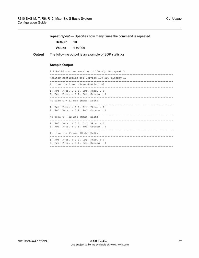
7210 SAS-M, T, R6, R12, Mxp, Sx, S Basic System Configuration Guide
CLI Usage
3HE 17358 AAAB TQZZA © 2021 Nokia. Use subject to Terms available at: www.nokia.com
87
repeat repeat — Specifies how many times the command is repeated.
Default 10
Values 1 to 999
Output The following output is an example of SDP statistics.
Sample Output
A:ALA-12# monitor service id 100 sdp 10 repeat 3===============================================================================Monitor statistics for Service 100 SDP binding 10===============================================================================At time t = 0 sec (Base Statistics)-------------------------------------------------------------------------------I. Fwd. Pkts. : 0 I. Dro. Pkts. : 0E. Fwd. Pkts. : 0 E. Fwd. Octets : 0-------------------------------------------------------------------------------At time t = 11 sec (Mode: Delta)-------------------------------------------------------------------------------I. Fwd. Pkts. : 0 I. Dro. Pkts. : 0E. Fwd. Pkts. : 0 E. Fwd. Octets : 0-------------------------------------------------------------------------------At time t = 22 sec (Mode: Delta)-------------------------------------------------------------------------------I. Fwd. Pkts. : 0 I. Dro. Pkts. : 0E. Fwd. Pkts. : 0 E. Fwd. Octets : 0-------------------------------------------------------------------------------At time t = 33 sec (Mode: Delta)-------------------------------------------------------------------------------I. Fwd. Pkts. : 0 I. Dro. Pkts. : 0E. Fwd. Pkts. : 0 E. Fwd. Octets : 0===============================================================================

CLI Usage
88
7210 SAS-M, T, R6, R12, Mxp, Sx, S Basic SystemConfiguration Guide
© 2021 Nokia. Use subject to Terms available at: www.nokia.com
3HE 17358 AAAB TQZZA

7210 SAS-M, T, R6, R12, Mxp, Sx, S Basic System Configuration Guide
File System Management
3HE 17358 AAAB TQZZA © 2021 Nokia. Use subject to Terms available at: www.nokia.com
89
3 File System ManagementThis chapter describes the file system management.
3.1 The File System
The 7210 SAS file system is used to store files used and generated by the system, for example, image files, configuration files, logging files, and accounting files.
The file commands allow you to copy, create, move, and delete files and directories, navigate to a different directory, display file or directory contents and the image version.
3.1.1 Compact Flash Devices
The file system is based on a DOS file system. The 7210 SAS devices provide several storage options, including internal flash and USB.
The following compact flash devices are supported:
• internal non-removable flash, cf1:\ • external removable compact flash or external removable SD card, cf2:\• external USB slot, uf1:\
The device names are relative device names in that they refer to the devices local to the control processor running the current console session. As in the DOS file system, the colon (“:”) at the end of the name indicates it is a device.
Table 17 lists the storage locations available on specific 7210 SAS platforms.
Table 17 Storage Locations on 7210 SAS Platforms
7210 SAS Platforms Storage Locations
cf1:\ cf2:\ uf1:\
7210 SAS-M ✓ ✓
7210 SAS-Mxp ✓ ✓ 1 ✓
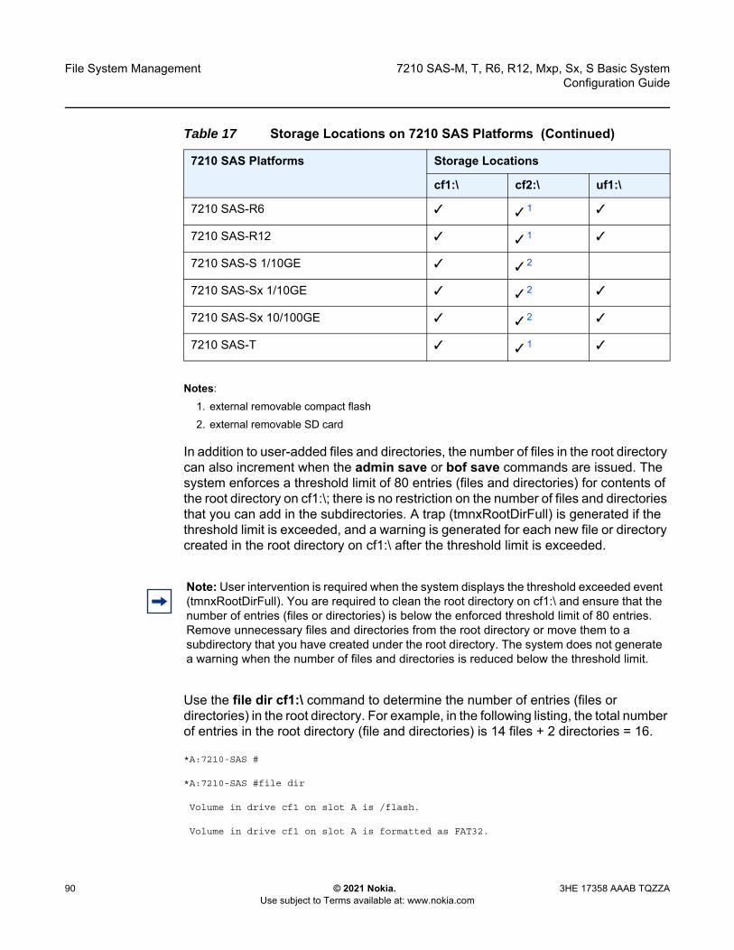
File System Management
90
7210 SAS-M, T, R6, R12, Mxp, Sx, S Basic SystemConfiguration Guide
© 2021 Nokia. Use subject to Terms available at: www.nokia.com
3HE 17358 AAAB TQZZA
Notes:1. external removable compact flash2. external removable SD card
In addition to user-added files and directories, the number of files in the root directory can also increment when the admin save or bof save commands are issued. The system enforces a threshold limit of 80 entries (files and directories) for contents of the root directory on cf1:\; there is no restriction on the number of files and directories that you can add in the subdirectories. A trap (tmnxRootDirFull) is generated if the threshold limit is exceeded, and a warning is generated for each new file or directory created in the root directory on cf1:\ after the threshold limit is exceeded.
Use the file dir cf1:\ command to determine the number of entries (files or directories) in the root directory. For example, in the following listing, the total number of entries in the root directory (file and directories) is 14 files + 2 directories = 16.
*A:7210-SAS #
*A:7210-SAS #file dir
Volume in drive cf1 on slot A is /flash.
Volume in drive cf1 on slot A is formatted as FAT32.
7210 SAS-R6 ✓ ✓ 1 ✓
7210 SAS-R12 ✓ ✓ 1 ✓
7210 SAS-S 1/10GE ✓ ✓ 2
7210 SAS-Sx 1/10GE ✓ ✓ 2 ✓
7210 SAS-Sx 10/100GE ✓ ✓ 2 ✓
7210 SAS-T ✓ ✓ 1 ✓
Table 17 Storage Locations on 7210 SAS Platforms (Continued)
7210 SAS Platforms Storage Locations
cf1:\ cf2:\ uf1:\
Note: User intervention is required when the system displays the threshold exceeded event (tmnxRootDirFull). You are required to clean the root directory on cf1:\ and ensure that the number of entries (files or directories) is below the enforced threshold limit of 80 entries. Remove unnecessary files and directories from the root directory or move them to a subdirectory that you have created under the root directory. The system does not generate a warning when the number of files and directories is reduced below the threshold limit.

7210 SAS-M, T, R6, R12, Mxp, Sx, S Basic System Configuration Guide
File System Management
3HE 17358 AAAB TQZZA © 2021 Nokia. Use subject to Terms available at: www.nokia.com
91
Directory of cf1:\
10/12/2011 10:37p 4248394 boot.tim10/17/2011 07:28a 524 sasm.sdx10/26/2011 10:06p 828 bof.cfg10/27/2011 09:04p <DIR> act-collect10/27/2011 09:06p <DIR> act10/17/2011 07:30a 0 test1.txt10/26/2011 10:43p 5360 sasm.cfg10/11/2011 06:42a 28821599 both.tim10/26/2011 10:42p 14597 bootlog.txt10/19/2011 04:22a 832 bof.cfg.110/17/2011 07:37a 827 test110/17/2011 07:38a 827 tes210/17/2011 07:38a 827 tes310/17/2011 07:39a 827 tes356710/17/2011 07:38a 827 tes35610/18/2011 10:46p 5481 sasm.cfg.1
14 File(s) 33117369 bytes.2 Dir(s) 80470016 bytes free.
*A:7210-SAS #
3.1.2 USB Storage Device
The 7210 SAS platform supports the use of the USB interface as an alternate storage location that provides a larger storage capacity than the internal flash. You can use a USB storage device to store TiMOS images, configuration files, accounting records, and log files. The BOF can point to images on the USB and you can use the USB to load TiMOS images and configuration files.
The following guidelines and caveats apply to the use of USB storage devices.
• The option to load the boot loader (boot.tim) from a USB storage device is not supported on the 7210 SAS-M. the boot.tim boot loader image required to boot the device must be stored on the compact flash (cf1:).
• The option to load the boot loader (boot.tim) from a USB storage device is supported on 7210 SAS-T, 7210 SAS-Sx 1/10GE, 7210 SAS-Sx 10/100GE, 7210 SAS-Mxp, 7210 SAS-R6, and 7210 SAS-R12.
• USB ports are supported on all 7210 SAS platforms as described in this document, except 7210 SAS-S 1/10GE.
• Refer to the 7210 SAS OS Software Release Notes for a list of USB devices and capacities that are supported on the 7210 SAS.
• When a USB device is unplugged or removed from the system, a major alarm is raised. The alarm can be cleared using the shutdown command.
File System Management
92
7210 SAS-M, T, R6, R12, Mxp, Sx, S Basic SystemConfiguration Guide
© 2021 Nokia. Use subject to Terms available at: www.nokia.com
3HE 17358 AAAB TQZZA
• The 7210 SAS auto detects the device type when any supported device is connected to the USB interface. Only approved USB mass storage device and optical clip-on devices plugged in to the USB port are recognized as valid devices. The use of unsupported devices generates error logs.
• Nokia recommends that the user should run the shutdown command before removing the USB storage device.
3.1.3 Storage Locations for Accounting, Logs, Index File, and Images
The default location for accounting records, logs, and others is set to point to cf1:\.
The following applies to storage locations on 7210 SAS-T, 7210 SAS-Mxp, 7210 SAS-Sx/S 1/10GE, 7210 SAS-Sx 10/100GE, 7210 SAS-R6, and 7210 SAS-R12 platforms.
• On the 7210 SAS-T, 7210 SAS-R6, and 7210 SAS-R12, the default location for accounting records and logs is set to cf1:\. The user can change it to either cf2:\ or uf1:\.
• If the license is purchased for the 7210 SAS-T and 7210 SAS-Mxp, these platforms are factory-shipped with the boot.tim and the BOF on cf1:\. Nokia recommends that you should not move these files from cf1:\ on these platforms.
• If the license is purchased for the 7210 SAS-Sx 1/10GE, 7210 SAS-S 1/10GE, 7210 SAS-Sx 10/100GE, 7210 SAS-R6, and 7210 SAS-R12, these platforms are factory-shipped with the boot.tim and starter BOF on cf2:\. The user can choose to copy these files to the internal flash cf1:\, if need be.
Note: This feature is supported on all 7210 SAS platforms as described in this document, except the 7210 SAS-M.
Note: Nokia recommends you should not store frequently written objects such as accounting records, system logs, and others on the internal flash (cf1:\), as it is non-replaceable. to store only systems images, configuration files, persistence database, nvsys.info, and QoS SAP resource map (the sdx file). Use the external flash (cf2:\) or use uf1:\ to store frequently written objects (as applicable).

7210 SAS-M, T, R6, R12, Mxp, Sx, S Basic System Configuration Guide
File System Management
3HE 17358 AAAB TQZZA © 2021 Nokia. Use subject to Terms available at: www.nokia.com
93
• The boot.tim and BOF can be stored on one of these locations: cf1:\ or cf2:\ or uf1:\. The bof.cfg is stored in the same location as the boot loader (boot.tim) used to boot the system. For example, if the boot loader (boot.tim) on cf2:\ is used to boot the system, the BOF created during auto-init or manual intervention during first-time boot will be created on cf2:\ and used subsequently.
• TiMOS images (both.tim) can be stored in one of these locations: cf1:\ or cf2:\ or uf1:\, with appropriate configuration of the BOF (that is, primary, secondary, and tertiary locations pointing to the appropriate place).
• The ndx and sdx files are generated at the location specified in the BOF parameter of the configuration file. If the user does not specify the location in the BOF, the ndx and sdx files are in the same location as the default configuration file. The default configuration file is created in the same location as the TiMOS image used to boot the system.For example, if no configuration file location is specified in the BOF and the TiMOS image (both.tim) located in uf1:\ is used to boot the system, the default configuration file, the index file, the sdx file, and nvsys.info file created on uf1:\ and used subsequently. If the user specifies cf2:\ as the location of the configuration file in the BOF, the configuration file, the index file, the sdx file, and nvsys.info file are created on cf2:\ and used subsequently.
For more information about the use of storage locations on 7210 SAS-R6 and 7210 SAS-R12 when using redundant CPM configuration, see Configuration Guidelines for Synchronization of Active and Standby CPM on 7210 SAS-R6 and 7210 SAS-R12.
3.1.4 Configuration Guidelines for Storing the TiMOS, boot.tim, bof.cfg, ndx, sdx, and nvsys.info File
The following are configuration guidelines for storing files.
• Store the boot.tim and bof.cfg on cf1:\. Create a backup of the boot.tim and bof.cfg on cf2:\ or uf1:\.
• Store the both.tim, configuration file (and as a result, the ndx, sdx, and nvsys.info) on cf2:\. Create regular backups of these files in one of the following locations: cf2:\ or uf1:\ or create a backup on SAM (Service Access Manager) or the network management station.
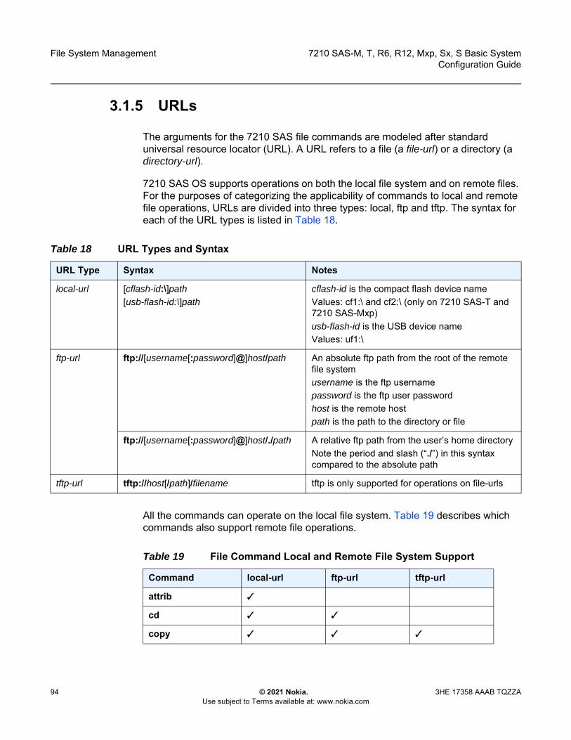
File System Management
94
7210 SAS-M, T, R6, R12, Mxp, Sx, S Basic SystemConfiguration Guide
© 2021 Nokia. Use subject to Terms available at: www.nokia.com
3HE 17358 AAAB TQZZA
3.1.5 URLs
The arguments for the 7210 SAS file commands are modeled after standard universal resource locator (URL). A URL refers to a file (a file-url) or a directory (a directory-url).
7210 SAS OS supports operations on both the local file system and on remote files. For the purposes of categorizing the applicability of commands to local and remote file operations, URLs are divided into three types: local, ftp and tftp. The syntax for each of the URL types is listed in Table 18.
All the commands can operate on the local file system. Table 19 describes which commands also support remote file operations.
Table 18 URL Types and Syntax
URL Type Syntax Notes
local-url [cflash-id:\]path[usb-flash-id:\]path
cflash-id is the compact flash device nameValues: cf1:\ and cf2:\ (only on 7210 SAS-T and 7210 SAS-Mxp)usb-flash-id is the USB device nameValues: uf1:\
ftp-url ftp://[username[:password]@]host/path An absolute ftp path from the root of the remote file systemusername is the ftp usernamepassword is the ftp user passwordhost is the remote hostpath is the path to the directory or file
ftp://[username[:password]@]host/./path A relative ftp path from the user’s home directoryNote the period and slash (“./”) in this syntax compared to the absolute path
tftp-url tftp://host[/path]/filename tftp is only supported for operations on file-urls
Table 19 File Command Local and Remote File System Support
Command local-url ftp-url tftp-url
attrib ✓
cd ✓ ✓
copy ✓ ✓ ✓
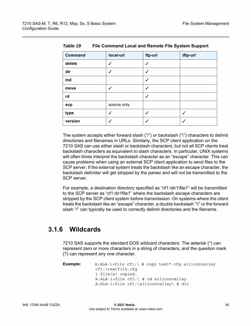
7210 SAS-M, T, R6, R12, Mxp, Sx, S Basic System Configuration Guide
File System Management
3HE 17358 AAAB TQZZA © 2021 Nokia. Use subject to Terms available at: www.nokia.com
95
The system accepts either forward slash (“/”) or backslash (“\”) characters to delimit directories and filenames in URLs. Similarly, the SCP client application on the 7210 SAS can use either slash or backslash characters, but not all SCP clients treat backslash characters as equivalent to slash characters. In particular, UNIX systems will often times interpret the backslash character as an “escape” character. This can cause problems when using an external SCP client application to send files to the SCP server. If the external system treats the backslash like an escape character, the backslash delimiter will get stripped by the parser and will not be transmitted to the SCP server.
For example, a destination directory specified as “cf1:\dir1\file1” will be transmitted to the SCP server as “cf1:dir1file1” where the backslash escape characters are stripped by the SCP client system before transmission. On systems where the client treats the backslash like an “escape” character, a double backslash “\\” or the forward slash “/” can typically be used to correctly delimit directories and the filename.
3.1.6 Wildcards
7210 SAS supports the standard DOS wildcard characters. The asterisk (*) can represent zero or more characters in a string of characters, and the question mark (?) can represent any one character.
Example: A:ALA-1>file cf1:\ # copy test*.cfg siliconvalleycf1:\testfile.cfg1 file(s) copied.A:ALA-1>file cf1:\ # cd siliconvalleyA:ALA-1>file cf1:\siliconvalley\ # dir
delete ✓ ✓
dir ✓ ✓
md ✓
move ✓ ✓
rd ✓
scp source only
type ✓ ✓ ✓
version ✓ ✓ ✓
Table 19 File Command Local and Remote File System Support
Command local-url ftp-url tftp-url

File System Management
96
7210 SAS-M, T, R6, R12, Mxp, Sx, S Basic SystemConfiguration Guide
© 2021 Nokia. Use subject to Terms available at: www.nokia.com
3HE 17358 AAAB TQZZA
Volume in drive cf1 on slot A has no label.Directory of cf1:\siliconvalley\05/10/2006 11:32p <DIR> .05/10/2006 11:14p <DIR> ..05/10/2006 11:32p 7597 testfile.cfg 1 File(s) 7597 bytes. 2 Dir(s) 1082368 bytes free.A:ALA-1>file cf1:\siliconvalley\ #
3.2 File Management Tasks
This section describes system file management tasks including copying, moving, displaying and deleting files; modifying file attributes; and creating, displaying, and deleting directories.
3.2.1 Modifying File Attributes
The system administrator can change the read-only attribute in the local file. Enter the attrib command with no options to display the contents of the directory and the file attributes.
Use the following CLI syntax to modify file attributes:
CLI Syntax: file> attrib [+r | -r] file-url
The following example shows command syntax usage:
Example: # filefile cf1:\ # attrib file cf1:\ # attrib +r BOF.SAVfile cf1:\ # attrib
Note: In the preceding example, instead of cf1:\ user can specify uf1:\ to manage the file attributes of the file located on the USB drive.
Note: When a file system operation is performed with a command that can potentially delete or overwrite a file system entry (such as the copy, delete, move, rd, or scp command), a prompt appears to confirm the action. The force keyword performs these file management operations without displaying the confirmation prompt.
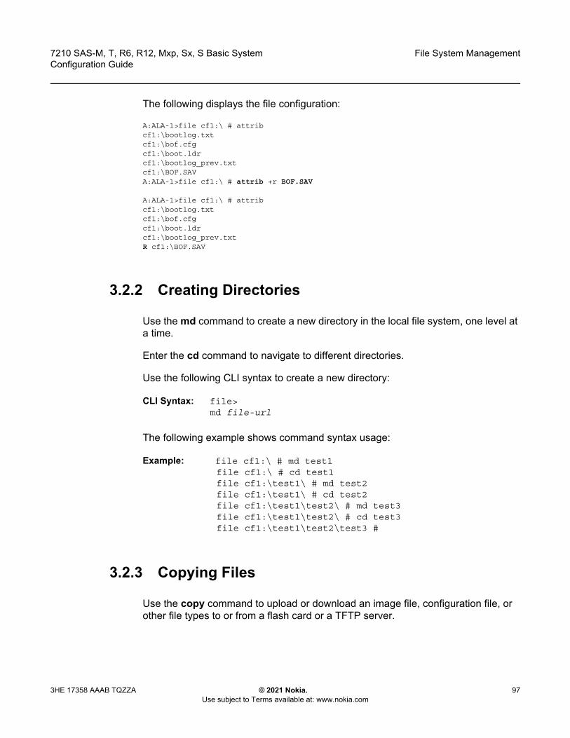
7210 SAS-M, T, R6, R12, Mxp, Sx, S Basic System Configuration Guide
File System Management
3HE 17358 AAAB TQZZA © 2021 Nokia. Use subject to Terms available at: www.nokia.com
97
The following displays the file configuration:
A:ALA-1>file cf1:\ # attribcf1:\bootlog.txtcf1:\bof.cfgcf1:\boot.ldrcf1:\bootlog_prev.txtcf1:\BOF.SAVA:ALA-1>file cf1:\ # attrib +r BOF.SAV
A:ALA-1>file cf1:\ # attribcf1:\bootlog.txtcf1:\bof.cfgcf1:\boot.ldrcf1:\bootlog_prev.txtR cf1:\BOF.SAV
3.2.2 Creating Directories
Use the md command to create a new directory in the local file system, one level at a time.
Enter the cd command to navigate to different directories.
Use the following CLI syntax to create a new directory:
CLI Syntax: file> md file-url
The following example shows command syntax usage:
Example: file cf1:\ # md test1file cf1:\ # cd test1file cf1:\test1\ # md test2file cf1:\test1\ # cd test2file cf1:\test1\test2\ # md test3file cf1:\test1\test2\ # cd test3file cf1:\test1\test2\test3 #
3.2.3 Copying Files
Use the copy command to upload or download an image file, configuration file, or other file types to or from a flash card or a TFTP server.

File System Management
98
7210 SAS-M, T, R6, R12, Mxp, Sx, S Basic SystemConfiguration Guide
© 2021 Nokia. Use subject to Terms available at: www.nokia.com
3HE 17358 AAAB TQZZA
The scp command copies files between hosts on a network. It uses SSH for data transfer, and uses the same authentication and provides the same security as SSH.
The source file for the scp command must be local. The file must reside on the router. The destination file has to be of the format: user@host:file-name. The destination does not need to be local.
Use the following CLI syntax to copy files:
CLI Syntax: file> copy source-file-url dest-file-url [force]scp local-file-url destination-file-url [router router name | service-id] [force]
The following example shows command syntax usage:
Example: A:ALA-1>file cf1:\ # copy 104.cfg cf1:\test1\test2\test3\test.cfgA:ALA-1>file cf1:\ # scp file1 [email protected]:cf1:\file1A:ALA-1>file cf1:\ # scp file2 [email protected]:/user2/file2A:ALA-1>file cf1:\ # scp cf1:/file3 [email protected]:cf1:\file3
3.2.4 Moving Files
Use the move command to move a file or directory from one location to another.
Use the following CLI syntax to move files:
CLI Syntax: file> move old-file-url new-file-url [force]
The following example shows command syntax usage:
Example: A:ALA-1>file cf1:\test1\test2\test3\ # move test.cfg cf1:\test1cf1:\test1\test2\test3\test.cfgA:ALA-1>file cf1:\test1\test2\test3\ # cd ..A:ALA-1>file cf1:\test1\test2\ # cd ..A:ALA-1>file cf1:\test1\ # dir
Directory of cf1:\test1\05/04/2006 07:58a <DIR> .05/04/2006 07:06a <DIR> ..05/04/2006 07:06a <DIR> test205/04/2006 07:58a 25278 test.cfg1 File(s) 25278 bytes.3 Dir(s) 1056256 bytes free.
A:ALA-1>file cf1:\test1\ #

7210 SAS-M, T, R6, R12, Mxp, Sx, S Basic System Configuration Guide
File System Management
3HE 17358 AAAB TQZZA © 2021 Nokia. Use subject to Terms available at: www.nokia.com
99
3.2.5 Removing Files and Deleting Directories
Use the delete and rd commands to delete files and remove directories. Directories must be empty before they can be removed. When file or directories are deleted they cannot be recovered.
Use the following CLI syntax to delete files and remove directories:
CLI Syntax: file> delete file-url [force]rd file-url [force]
The following example shows command syntax usage:
A:ALA-1>file cf1:\test1\ # delete test.cfgA:ALA-1>file cf1:\test1\ # delete abc.cfgA:ALA-1>file cf1:\test1\test2\ # cd test3A:ALA-1>file cf1:\test1\test2\test3\ # cd ..A:ALA-1>file cf1:\test1\test2\ # rd test3A:ALA-1>file cf1:\test1\test2\ # cd ..A:ALA-1>file cf1:\test1\ # rd test2A:ALA-1>file cf1:\test1\ # cd ..A:ALA-1>file cf1:\ # rd test1A:ALA-1>file cf1:\ #
3.2.6 Displaying Directory and File Information
Use the dir command to display a list of files on a file system.Use the type command to display the contents of a file. Use the version command to display the version of a cpm.tim or iom.tim file.
Use the following CLI syntax to display directory and file information:
CLI Syntax: file> dir [file-url]type file-urlversion file-url
The following displays an example of the command syntax:
*A:card-1>file cf1:\ # dirVolume in drive cf1 on slot A is /flash.
Volume in drive cf1 on slot A is formatted as FAT32.
Directory of cf1:\
10/22/2008 10:30a 8849 bootlog.txt

File System Management
100
7210 SAS-M, T, R6, R12, Mxp, Sx, S Basic SystemConfiguration Guide
© 2021 Nokia. Use subject to Terms available at: www.nokia.com
3HE 17358 AAAB TQZZA
10/22/2008 10:30a 733 bof.cfg10/22/2008 10:29a 5531 bootlog_prev.txt02/01/2001 09:25a 3528373 boot.tim02/01/2001 09:21a 4860 config.cfg10/22/2008 11:07a <DIR> test110/17/2008 07:32p 724 env.cfg10/15/2008 03:38p 9499 snake.cfg
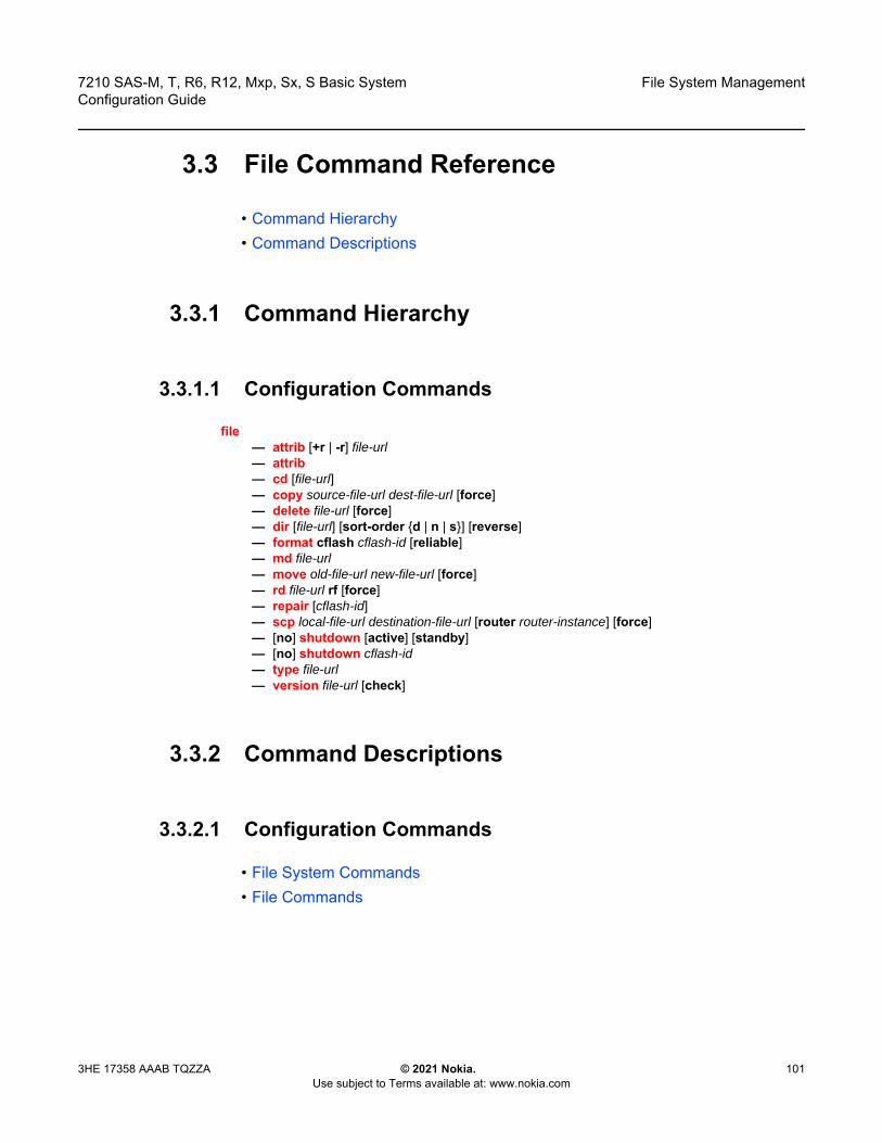
7210 SAS-M, T, R6, R12, Mxp, Sx, S Basic System Configuration Guide
File System Management
3HE 17358 AAAB TQZZA © 2021 Nokia. Use subject to Terms available at: www.nokia.com
101
3.3 File Command Reference
• Command Hierarchy• Command Descriptions
3.3.1 Command Hierarchy
3.3.1.1 Configuration Commands
file — attrib [+r | -r] file-url— attrib— cd [file-url]— copy source-file-url dest-file-url [force]— delete file-url [force]— dir [file-url] [sort-order {d | n | s}] [reverse]— format cflash cflash-id [reliable]— md file-url— move old-file-url new-file-url [force]— rd file-url rf [force]— repair [cflash-id]— scp local-file-url destination-file-url [router router-instance] [force]— [no] shutdown [active] [standby] — [no] shutdown cflash-id— type file-url— version file-url [check]
3.3.2 Command Descriptions
3.3.2.1 Configuration Commands
• File System Commands• File Commands

File System Management
102
7210 SAS-M, T, R6, R12, Mxp, Sx, S Basic SystemConfiguration Guide
© 2021 Nokia. Use subject to Terms available at: www.nokia.com
3HE 17358 AAAB TQZZA
3.3.2.1.1 File System Commands
shutdown
Syntax [no] shutdown [cflash-id]
Context file
Platforms Supported on all 7210 SAS platforms as described in this document, including those operating in access-uplink mode
Description This command disables the drive. This command is available for use only with removable storage drives. The removable storage drives differ among the 7210 SAS platforms. It cannot be used with the internal non-removable compact flash.
The no form of this command enables the drive.
Default no shutdown
Parameters cflash-id — Specifies the device identifier.
Values uf1: (7210 SAS-M)cf1:, cf2:, uf1: (7210 SAS-T, 7210 SAS-Sx/S 1/10GE: standalone and standalone-VC, 7210 SAS-Sx 10/100GE, and 7210 SAS-Mxp)cf2:, cf2-A:, cf2-B:, uf1:, uf1-A:, uf1-B: (7210 SAS-R6 and 7210 SAS-R12)cf1:, cf2: (7210 SAS-Sx/S 1/10GE: standalone and standalone-VC)
3.3.2.1.2 File Commands
attrib
Syntax attrib [+r | -r] file-urlattrib
Context file
Platforms Supported on all 7210 SAS platforms as described in this document, including those operating in access-uplink mode
Description This command sets or resets the read-only attribute for a file in the local file system. To list all files and their current attributes enter attrib or attrib x where x is either the filename or a wild-card (*).

7210 SAS-M, T, R6, R12, Mxp, Sx, S Basic System Configuration Guide
File System Management
3HE 17358 AAAB TQZZA © 2021 Nokia. Use subject to Terms available at: www.nokia.com
103
When an attrib command is entered to list a specific file or all files in a directory, the file’s attributes are displayed with or without an “R” preceding the filename. The “R” implies that the +r is set and that the file is read-only. Files without the “R” designation implies that the -r is set and that the file is read-write-all.
Parameters file-url — Specifies the URL for the local file.+r Sets the read-only attribute on the specified file.-r Clears/resets the read-only attribute on the specified file.
Values
+r — Keyword to set the read-only attribute on the specified file.
-r — Keyword to reset the read-only attribute on the specified file.
cd
Syntax cd [file-url]
Context file
Platforms Supported on all 7210 SAS platforms as described in this document, including those operating in access-uplink mode
Description This command displays or changes the current working directory in the local file system.
file-url — local-url | remote-url local-url — [cflash-id/ | usb-flash-id] [file-path]remote-url — [{ftp:// | tftp://} login:pswd@remote-locn/] [file- path]remote-locn — [hostname | ipv4-address | ipv6-address]
ipv4-address — a.b.c.dipv6-address — x:x:x:x:x:x:x:x[-interface]x:x:x:x:x:x:d.d.d.d[-interface]x — 0 to FFFF (hexadecimal)d — 0 to 255 (decimal)interface — a string up to 32, for link local addresses
cflash-id or usb-flash-id — uf1: (7210 SAS-M)cf1:, cf2:, uf1: (7210 SAS-T, 7210 SAS-Sx/S 1/10GE: standalone and standalone-VC, 7210 SAS-Sx 10/100GE, and 7210 SAS-Mxp)cf2:, cf2-A:, cf2-B:, uf1:, uf1-A:, uf1-B: (7210 SAS-R6 and 7210 SAS-R12)cf1:, cf2: (7210 SAS-Sx/S 1/10GE: standalone and standalone-VC)

File System Management
104
7210 SAS-M, T, R6, R12, Mxp, Sx, S Basic SystemConfiguration Guide
© 2021 Nokia. Use subject to Terms available at: www.nokia.com
3HE 17358 AAAB TQZZA
Parameters file-url — Specifies the URL or filename.
Values
none — Displays the current working directory.
.. — Specifies the parent directory. This can be used in place of an actual directory name in a directory-url.
directory-url — Specifies the destination directory.
copy
Syntax copy source-file-url dest-file-url [force]
Context file
Platforms Supported on all 7210 SAS platforms as described in this document, including those operating in access-uplink mode
Description This command copies a file or all files in a directory from a source URL to a destination URL. At least one of the specified URLs should be a local URL. The optional wild-card (*) can be used to copy multiple files that share a common (partial) prefix and/or (partial) suffix. When a file is copied to a destination with the same file name, the original file is overwritten by the new file specified in the operation. The following prompt appears if the destination file already exists:
“Overwrite destination file (y/n)?”
file-url — local-url | remote-url local-url — [cflash-id/ | usb-flash-id] [file-path]remote-url — [{ftp:// | tftp://} login:pswd@remote-locn/] [file- path]remote-locn — [hostname | ipv4-address | ipv6-address]
ipv4-address — a.b.c.dipv6-address — x:x:x:x:x:x:x:x[-interface]x:x:x:x:x:x:d.d.d.d[-interface] x — 0 to FFFF (hexadecimal)d — 0 to 255 (decimal)interface — a string up to 32, for link local addresses
cflash-id or usb-flash-id — uf1: (7210 SAS-M)cf1:, cf2:, uf1: (7210 SAS-T, 7210 SAS-Sx/S 1/10GE: standalone and standalone-VC, 7210 SAS-Sx 10/100GE, and 7210 SAS-Mxp)cf2:, cf2-A:, cf2-B:, uf1:, uf1-A:, uf1-B: (7210 SAS-R6 and 7210 SAS-R12)cf1:, cf2: (7210 SAS-Sx/S 1/10GE: standalone and standalone-VC)
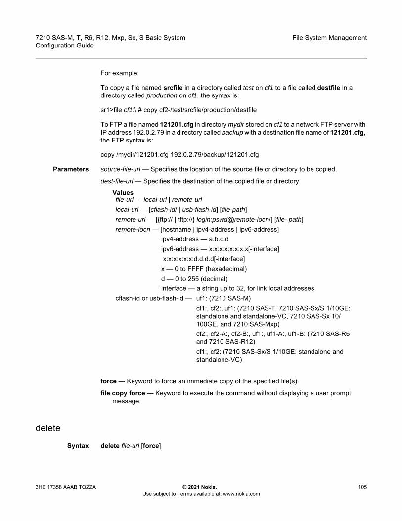
7210 SAS-M, T, R6, R12, Mxp, Sx, S Basic System Configuration Guide
File System Management
3HE 17358 AAAB TQZZA © 2021 Nokia. Use subject to Terms available at: www.nokia.com
105
For example:
To copy a file named srcfile in a directory called test on cf1 to a file called destfile in a directory called production on cf1, the syntax is:
sr1>file cf1:\ # copy cf2-/test/srcfile/production/destfile
To FTP a file named 121201.cfg in directory mydir stored on cf1 to a network FTP server with IP address 192.0.2.79 in a directory called backup with a destination file name of 121201.cfg, the FTP syntax is:
copy /mydir/121201.cfg 192.0.2.79/backup/121201.cfg
Parameters source-file-url — Specifies the location of the source file or directory to be copied.
dest-file-url — Specifies the destination of the copied file or directory.
Values
force — Keyword to force an immediate copy of the specified file(s).
file copy force — Keyword to execute the command without displaying a user prompt message.
delete
Syntax delete file-url [force]
file-url — local-url | remote-url local-url — [cflash-id/ | usb-flash-id] [file-path]remote-url — [{ftp:// | tftp://} login:pswd@remote-locn/] [file- path]remote-locn — [hostname | ipv4-address | ipv6-address]
ipv4-address — a.b.c.dipv6-address — x:x:x:x:x:x:x:x[-interface]
x:x:x:x:x:x:d.d.d.d[-interface]x — 0 to FFFF (hexadecimal)d — 0 to 255 (decimal)interface — a string up to 32, for link local addresses
cflash-id or usb-flash-id — uf1: (7210 SAS-M)cf1:, cf2:, uf1: (7210 SAS-T, 7210 SAS-Sx/S 1/10GE: standalone and standalone-VC, 7210 SAS-Sx 10/100GE, and 7210 SAS-Mxp)cf2:, cf2-A:, cf2-B:, uf1:, uf1-A:, uf1-B: (7210 SAS-R6 and 7210 SAS-R12)cf1:, cf2: (7210 SAS-Sx/S 1/10GE: standalone and standalone-VC)
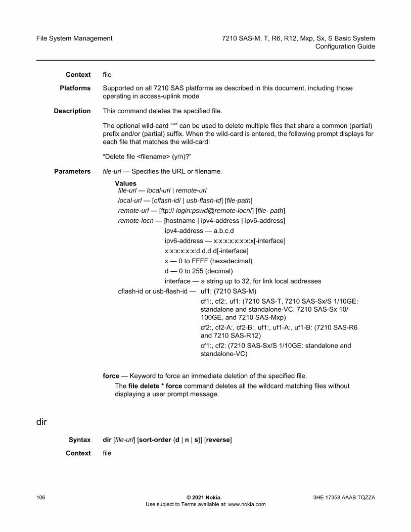
File System Management
106
7210 SAS-M, T, R6, R12, Mxp, Sx, S Basic SystemConfiguration Guide
© 2021 Nokia. Use subject to Terms available at: www.nokia.com
3HE 17358 AAAB TQZZA
Context file
Platforms Supported on all 7210 SAS platforms as described in this document, including those operating in access-uplink mode
Description This command deletes the specified file.
The optional wild-card “*” can be used to delete multiple files that share a common (partial) prefix and/or (partial) suffix. When the wild-card is entered, the following prompt displays for each file that matches the wild-card:
“Delete file <filename> (y/n)?”
Parameters file-url — Specifies the URL or filename.
Values
force — Keyword to force an immediate deletion of the specified file. The file delete * force command deletes all the wildcard matching files without displaying a user prompt message.
dir
Syntax dir [file-url] [sort-order {d | n | s}] [reverse]
Context file
file-url — local-url | remote-url local-url — [cflash-id/ | usb-flash-id] [file-path]remote-url — [ftp:// login:pswd@remote-locn/] [file- path]remote-locn — [hostname | ipv4-address | ipv6-address]
ipv4-address — a.b.c.dipv6-address — x:x:x:x:x:x:x:x[-interface]x:x:x:x:x:x:d.d.d.d[-interface]x — 0 to FFFF (hexadecimal)d — 0 to 255 (decimal)interface — a string up to 32, for link local addresses
cflash-id or usb-flash-id — uf1: (7210 SAS-M)cf1:, cf2:, uf1: (7210 SAS-T, 7210 SAS-Sx/S 1/10GE: standalone and standalone-VC, 7210 SAS-Sx 10/100GE, and 7210 SAS-Mxp)cf2:, cf2-A:, cf2-B:, uf1:, uf1-A:, uf1-B: (7210 SAS-R6 and 7210 SAS-R12)cf1:, cf2: (7210 SAS-Sx/S 1/10GE: standalone and standalone-VC)

7210 SAS-M, T, R6, R12, Mxp, Sx, S Basic System Configuration Guide
File System Management
3HE 17358 AAAB TQZZA © 2021 Nokia. Use subject to Terms available at: www.nokia.com
107
Platforms Supported on all 7210 SAS platforms as described in this document, including those operating in access-uplink mode
Description This command displays a list of files and subdirectories in a directory.
Parameters file-url — Specifies the URL or filename. Use the file-url with the optional wildcard (*) to reduce the number of files to list.
Values
sort-order {d | n | s} — Specifies the sort order.
Values d — daten — names — size
reverse — Specifies to reverse the sort order.
Default lists all files in the present working directory
file
Syntax file
Context <root>
Platforms Supported on all 7210 SAS platforms as described in this document, including those operating in access-uplink mode
file-url — local-url | remote-url local-url — [cflash-id/ | usb-flash-id] [file-path]remote-url — [ftp:// login:pswd@remote-locn/] [file- path]remote-locn — [hostname | ipv4-address | ipv6-address]
ipv4-address — a.b.c.dipv6-address — x:x:x:x:x:x:x:x[-interface]x:x:x:x:x:x:d.d.d.d[-interface]x — 0 to FFFF (hexadecimal)d — 0 to 255 (decimal)interface — a string up to 32, for link local addresses
cflash-id or usb-flash-id — uf1: (7210 SAS-M)cf1:, cf2:, uf1: (7210 SAS-T, 7210 SAS-Sx/S 1/10GE: standalone and standalone-VC, 7210 SAS-Sx 10/100GE, and 7210 SAS-Mxp)cf2:, cf2-A:, cf2-B:, uf1:, uf1-A:, uf1-B: (7210 SAS-R6 and 7210 SAS-R12)cf1:, cf2: (7210 SAS-Sx/S 1/10GE: standalone and standalone-VC)

File System Management
108
7210 SAS-M, T, R6, R12, Mxp, Sx, S Basic SystemConfiguration Guide
© 2021 Nokia. Use subject to Terms available at: www.nokia.com
3HE 17358 AAAB TQZZA
Description This command enables access to the context to enter and perform file system operations. When entering the file context, the prompt changes to reflect the present working directory. Navigating the file system with the cd command results in a changed prompt.
The exit all command leaves the file system/file operation context and returns to the <root> CLI context. The state of the present working directory is maintained for the CLI session. Entering the file command returns the cursor to the working directory where the exit command was issued.
format
Syntax format cflash cflash-id
Context root>file
Platforms Supported on all 7210 SAS platforms as described in this document, including those operating in access-uplink mode
Description This command formats the compact flash. The compact flash must be shutdown before starting the format.
Parameters cflash-id — Specifies the compact flash type.
Values cflash-id — uf1: (7210 SAS-M)cf1:, cf2:, uf1: (7210 SAS-T, 7210 SAS-Sx/S 1/10GE:
standalone and standalone-VC, 7210 SAS-Sx 10/100GE, and 7210 SAS-Mxp)
cf2:, cf2-A:, cf2-B:, uf1:, uf1-A:, uf1-B: (7210 SAS-R6 and 7210 SAS-R12)
cf1:, cf2: (7210 SAS-Sx/S 1/10GE: standalone and standalone-VC)
md
Syntax md file-url
Context file
Platforms Supported on all 7210 SAS platforms as described in this document, including those operating in access-uplink mode
Description This command creates a new directory in a file system.
Directories can only be created one level at a time.
7210 SAS-M, T, R6, R12, Mxp, Sx, S Basic System Configuration Guide
File System Management
3HE 17358 AAAB TQZZA © 2021 Nokia. Use subject to Terms available at: www.nokia.com
109
Parameters file-url — Specifies the URL or filename.
Values
move
Syntax move old-file-url new-file-url [force]
Context file
Platforms Supported on all 7210 SAS platforms as described in this document, including those operating in access-uplink mode
Description This command moves a local file, system file, or a directory. If the target already exists, the command fails and an error message displays.
Parameters old-file-url new-file url — Specifies the file or directory to be moved and the new destination to place the old file URL.
Values
file-url — local-url | remote-url local-url — [cflash-id/ | usb-flash-id] [file-path]remote-url — [ftp:// login:pswd@remote-locn/] [file- path]remote-locn — [hostname | ipv4-address | ipv6-address]
ipv4-address — a.b.c.dipv6-address — x:x:x:x:x:x:x:x[-interface]x:x:x:x:x:x:d.d.d.d[-interface]x — 0 to FFFF (hexadecimal)d — 0 to 255 (decimal)interface — a string up to 32, for link local addresses
cflash-id or usb-flash-id — uf1: (7210 SAS-M)cf1:, cf2:, uf1: (7210 SAS-T, 7210 SAS-Sx/S 1/10GE: standalone and standalone-VC, 7210 SAS-Sx 10/100GE, and 7210 SAS-Mxp)cf2:, cf2-A:, cf2-B:, uf1:, uf1-A:, uf1-B: (7210 SAS-R6 and 7210 SAS-R12)cf1:, cf2: (7210 SAS-Sx/S 1/10GE: standalone and standalone-VC)
file-url — local-url | remote-url local-url — [cflash-id/ | usb-flash-id] [file-path]remote-url — [ftp:// login:pswd@remote-locn/] [file- path]
File System Management
110
7210 SAS-M, T, R6, R12, Mxp, Sx, S Basic SystemConfiguration Guide
© 2021 Nokia. Use subject to Terms available at: www.nokia.com
3HE 17358 AAAB TQZZA
force — Keyword to force an immediate move of the specified file. The file move force command is executed without displaying a user prompt message.
rd
Syntax rd file-url rf [force]
Context file
Platforms Supported on all 7210 SAS platforms as described in this document, including those operating in access-uplink mode
Description The rd command is used to delete a directory.
If a directory has files and no sub-directories, the force option must be used to force delete the directory and files it contains.
Parameters file-url — Specifies the directory to be removed.
Values
remote-locn — [hostname | ipv4-address | ipv6-address]ipv4-address — a.b.c.dipv6-address — x:x:x:x:x:x:x:x[-interface]x:x:x:x:x:x:d.d.d.d[-interface]x — 0 to FFFF (hexadecimal)d — 0 to 255 (decimal)interface — a string up to 32, for link local addresses
cflash-id or usb-flash-id — uf1: (7210 SAS-M)cf1:, cf2:, uf1: (7210 SAS-T, 7210 SAS-Sx/S 1/10GE: standalone and standalone-VC, 7210 SAS-Sx 10/100GE, and 7210 SAS-Mxp)cf2:, cf2-A:, cf2-B:, uf1:, uf1-A:, uf1-B: (7210 SAS-R6 and 7210 SAS-R12)cf1:, cf2: (7210 SAS-Sx/S 1/10GE: standalone and standalone-VC)
file-url — local-url | remote-url local-url — [cflash-id/ | usb-flash-id] [file-path]remote-url — [ftp:// login:pswd@remote-locn/] [file- path]

7210 SAS-M, T, R6, R12, Mxp, Sx, S Basic System Configuration Guide
File System Management
3HE 17358 AAAB TQZZA © 2021 Nokia. Use subject to Terms available at: www.nokia.com
111
rf — Keyword to force a recursive delete.
force — Keyword to force an immediate deletion of the specified directory. The rd file-url force command is executed without displaying a user prompt message.
repair
Syntax repair [cflash-id]
Context file
Platforms Supported on all 7210 SAS platforms as described in this document, including those operating in access-uplink mode
Description This command checks a compact flash device for errors and repairs any errors found.
Parameters cflash-id — Specifies the compact flash slot ID to be shutdown or enabled. If no cflash-id is specified, the drive referred to by the current working directory is assumed.
Values uf1: (7210 SAS-M)cf1:, cf2:, uf1: (7210 SAS-T, 7210 SAS-Sx/S 1/10GE: standalone and standalone-VC, 7210 SAS-Sx 10/100GE, and 7210 SAS-Mxp)cf2:, cf2-A:, cf2-B:, uf1:, uf1-A:, uf1-B: (7210 SAS-R6 and 7210 SAS-R12)cf1:, cf2: (7210 SAS-Sx/S 1/10GE: standalone and standalone-VC)
remote-locn — [hostname | ipv4-address | ipv6-address]ipv4-address — a.b.c.dipv6-address — x:x:x:x:x:x:x:x[-interface]x:x:x:x:x:x:d.d.d.d[-interface]x — 0 to FFFF (hexadecimal)d — 0 to 255 (decimal)interface — a string up to 32, for link local addresses
cflash-id or usb-flash-id — uf1: (7210 SAS-M)cf1:, cf2:, uf1: (7210 SAS-T, 7210 SAS-Sx/S 1/10GE: standalone and standalone-VC, 7210 SAS-Sx 10/100GE, and 7210 SAS-Mxp)cf2:, cf2-A:, cf2-B:, uf1:, uf1-A:, uf1-B: (7210 SAS-R6 and 7210 SAS-R12)cf1:, cf2: (7210 SAS-Sx/S 1/10GE: standalone and standalone-VC)
File System Management
112
7210 SAS-M, T, R6, R12, Mxp, Sx, S Basic SystemConfiguration Guide
© 2021 Nokia. Use subject to Terms available at: www.nokia.com
3HE 17358 AAAB TQZZA
scp
Syntax scp local-file-url destination-file-url [router router-instance] [force]
Context file
Platforms Supported on all 7210 SAS platforms as described in this document, including those operating in access-uplink mode
Description This command copies a local file to a remote host file system. It uses ssh for data transfer, and uses the same authentication and provides the same security as ssh. The following prompt appears:
“Are you sure (y/n)?” The destination must specify a user and a host.
Parameters local-file-url — Specifies the local source file or directory.
Values
destination-file-url — Specifies the destination file.
user — Specifies the SSH user.
host — Specifies the remote host IP address of DNS name.
file-path — Specifies the destination path.
router-instance — Specifies the router name or service ID.
Values router-instance — user@hostname:file-path] | router-nameuser — up to 32 charactershostname — [dns-name | ipv4-address | ipv6-address]
ipv4-address — a.b.c.dipv6-address — x:x:x:x:x:x:x:x[-interface] x:x:x:x:x:x:d.d.d.d[-interface] x — 0 to FFFF (hexadecimal) d — 0 to 255 (decimal) interface — up to 32 characters max,
for link local addressesdns-name — up to 128 characters
local-file-url — [cflash-id/] [file-path]cflash-id or usb-flash-id — uf1: (7210 SAS-M)
cf1:, cf2:, uf1: (7210 SAS-T, 7210 SAS-Sx/S 1/10GE: standalone and standalone-VC, 7210 SAS-Sx 10/100GE, and 7210 SAS-Mxp)cf2:, cf2-A:, cf2-B:, uf1:, uf1-A:, uf1-B: (7210 SAS-R6 and 7210 SAS-R12)cf1:, cf2: (7210 SAS-Sx/S 1/10GE: standalone and standalone-VC)
7210 SAS-M, T, R6, R12, Mxp, Sx, S Basic System Configuration Guide
File System Management
3HE 17358 AAAB TQZZA © 2021 Nokia. Use subject to Terms available at: www.nokia.com
113
file-path — up to 200 characters directory length, up to 99 characters each router-name: Base, Management
Default - Base
force — Keyword to force an immediate copy of the specified file.The file scp local-file-url destination-file-url [router] force command executes without displaying a user prompt message.
type
Syntax type file-url
Context file
Platforms Supported on all 7210 SAS platforms as described in this document, including those operating in access-uplink mode
Description This command displays the contents of a text file.
Parameters file-url — Specifies the file name of the target file.
Valuesfile-url — local-url | remote-url local-url — [cflash-id/ | usb-flash-id] [file-path]remote-url —[ftp:// login:pswd@remote-locn/] [file- path]remote-locn — [hostname | ipv4-address | ipv6-address]
ipv4-address — a.b.c.dipv6-address — x:x:x:x:x:x:x:x[-interface]x:x:x:x:x:x:d.d.d.d[-interface]x — 0 to FFFF (hexadecimal)d — 0 to 255 (decimal)interface — a string up to 32, for link local addresses
cflash-id or usb-flash-id — uf1: (7210 SAS-M)cf1:, cf2:, uf1: (7210 SAS-T, 7210 SAS-Sx/S 1/10GE: standalone and standalone-VC, 7210 SAS-Sx 10/100GE, and 7210 SAS-Mxp)cf2:, cf2-A:, cf2-B:, uf1:, uf1-A:, uf1-B: (7210 SAS-R6 and 7210 SAS-R12)cf1:, cf2: (7210 SAS-Sx/S 1/10GE: standalone and standalone-VC)
File System Management
114
7210 SAS-M, T, R6, R12, Mxp, Sx, S Basic SystemConfiguration Guide
© 2021 Nokia. Use subject to Terms available at: www.nokia.com
3HE 17358 AAAB TQZZA
version
Syntax version file-url [check]
Context file
Platforms Supported on all 7210 SAS platforms as described in this document, including those operating in access-uplink mode
Description This command displays the version of a TiMOS file.
Parameters file-url — Specifies the file name of the target file.
Values
check — Keyword to validates the .tim file.
file-url — local-url | remote-url local-url — [cflash-id/ | usb-flash-id] [file-path]remote-url —[ftp:// login:pswd@remote-locn/] [file- path]remote-locn — [hostname | ipv4-address | ipv6-address]
ipv4-address — a.b.c.dipv6-address — x:x:x:x:x:x:x:x[-interface]x:x:x:x:x:x:d.d.d.d[-interface]x — 0 to FFFF (hexadecimal)d — 0 to 255 (decimal)interface — a string up to 32, for link local addresses
cflash-id or usb-flash-id — uf1: (7210 SAS-M)cf1:, cf2:, uf1: (7210 SAS-T, 7210 SAS-Sx/S 1/10GE: standalone and standalone-VC, 7210 SAS-Sx 10/100GE, and 7210 SAS-Mxp)cf2:, cf2-A:, cf2-B:, uf1:, uf1-A:, uf1-B: (7210 SAS-R6 and 7210 SAS-R12)cf1:, cf2: (7210 SAS-Sx/S 1/10GE: standalone and standalone-VC)
7210 SAS-M, T, R6, R12, Mxp, Sx, S Basic System Configuration Guide
Boot Options
3HE 17358 AAAB TQZZA © 2021 Nokia. Use subject to Terms available at: www.nokia.com
115
4 Boot OptionsThis chapter provides information about configuring boot option parameters.
4.1 System Initialization
When the 7210 SAS device is powered on, the system executes the boot.tim file (also known as the boot loader or the bootstrap image) from the file system located on one of the storage media available on the 7210 SAS platform. The boot.tim file is the image that reads and executes the system initialization commands configured in the Boot Option File (BOF).
If the boot.tim file is absent or invalid, and cannot be loaded, the platform-specific handling is as follows:
• 7210 SAS-MOn this platform, the boot ROM loads the golden bootstrap image. The golden bootstrap image is equivalent to a boot.tim file, but it is present outside the file system, and can be updated and checked using special CLI commands.
• 7210 SAS-Mxp, 7210 SAS-R6, 7210 SAS-R12, 7210 SAS-T, 7210 SAS-S 1/10GE, 7210 SAS-Sx 1/10GE, and 7210 SAS-Sx 10/100GE
Note: Some 7210 SAS platforms (including 7210 SAS-Mxp, 7210 SAS-R6, 7210 SAS-R12, 7210 SAS-T, 7210 SAS-S 1/10GE, 7210 SAS-Sx 1/10GE, and 7210 SAS-Sx 10/100GE) do not ship with the bootstrap image. For these platforms, you must use one of the following devices to access the boot.tim file to boot the system. Insert the device containing the bootstrap image in the specified storage media location before powering on the system, as follows:
• external flashInsert the compact flash into the external compact flash slot.
• SD cardInsert the SD card into the SD card slot.
• USB deviceInsert the USB storage device into the USB port.
Refer to the appropriate chassis installation guide for more information about the prerequisites for the specific 7210 SAS platform. See Contents of Factory-shipped 7210 SAS Systems for a list of contents shipped with the system on each 7210 SAS platform.
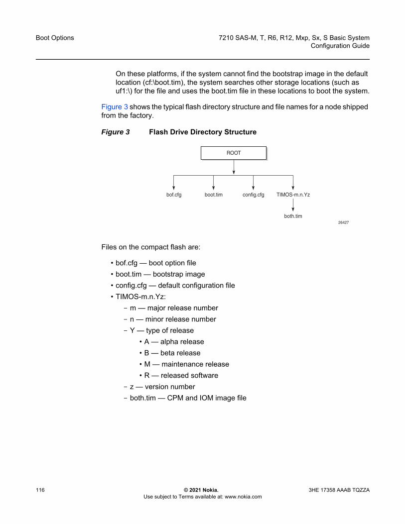
Boot Options
116
7210 SAS-M, T, R6, R12, Mxp, Sx, S Basic SystemConfiguration Guide
© 2021 Nokia. Use subject to Terms available at: www.nokia.com
3HE 17358 AAAB TQZZA
On these platforms, if the system cannot find the bootstrap image in the default location (cf:\boot.tim), the system searches other storage locations (such as uf1:\) for the file and uses the boot.tim file in these locations to boot the system.
Figure 3 shows the typical flash directory structure and file names for a node shipped from the factory.
Figure 3 Flash Drive Directory Structure
Files on the compact flash are:
• bof.cfg — boot option file• boot.tim — bootstrap image• config.cfg — default configuration file• TIMOS-m.n.Yz:
- m — major release number- n — minor release number- Y — type of release
• A — alpha release• B — beta release• M — maintenance release• R — released software
- z — version number- both.tim — CPM and IOM image file
bof.cfg boot.tim config.cfg TIMOS-m.n.Yz
both.tim
ROOT
26427

7210 SAS-M, T, R6, R12, Mxp, Sx, S Basic System Configuration Guide
Boot Options
3HE 17358 AAAB TQZZA © 2021 Nokia. Use subject to Terms available at: www.nokia.com
117
4.1.1 Contents of Factory-shipped 7210 SAS Systems
Table 20 lists the contents that are shipped with the system on each 7210 SAS platform.
Notes:1. No images are shipped on cf1:\. The user can purchase the software that is shipped with the
boot.tim, starter BOF, and TiMOS image on cf2:\.2. No images are shipped on cf1:\. The user must purchase a software license to obtain an image on
the SD card. The SD card can be inserted into the SD card slot on the chassis to boot up the node. The software is shipped with the boot.tim, starter BOF, and TiMOS image.
4.1.2 System Boot Option Modes
When the system executes the boot.tim file, the bootstrap image searches for and processes the BOF. The user has the option to modify the BOF manually and save it (see Manual Mode for more information), or to retrieve the BOF from the network (see Auto-init Mode for more information).
Table 20 Contents Shipped with the System on 7210 SAS
7210 SAS Platforms System Contents
boot.tim File
Golden Bootstrap Image
BOF TiMOS Image
cf1:\ cf2:\
7210 SAS-M ✓ ✓ ✓
7210 SAS-Mxp 1 ✓ ✓ ✓
7210 SAS-R6 1 ✓ ✓ ✓
7210 SAS-R12 1 ✓ ✓ ✓
7210 SAS-S 1/10GE 2 ✓ ✓ ✓
7210 SAS-Sx 1/10GE 2 ✓ ✓ ✓
7210 SAS-Sx 10/100GE 2 ✓ ✓ ✓
7210 SAS-T 1 ✓ ✓ ✓
Boot Options
118
7210 SAS-M, T, R6, R12, Mxp, Sx, S Basic SystemConfiguration Guide
© 2021 Nokia. Use subject to Terms available at: www.nokia.com
3HE 17358 AAAB TQZZA
Depending on whether the node is factory-shipped with the BOF, the user can obtain and use the BOF as follows. See Table 20 for information about which platforms are factory-shipped with the BOF.
• On 7210 SAS nodes that are factory-shipped with the BOF, use one of the following manual mode options: - boot the system in manual mode by using the starter BOF; the system uses
the default both.tim, as configured in the default BOF- boot the system by interrupting the default boot process and manually edit
the contents of the BOF to create a new BOFRefer to the appropriate 7210 SAS chassis installation guide for more information about editing and creating a new BOF for the specific 7210 SAS platform.
• On 7210 SAS nodes that are factory-shipped without a BOF, the file is not present when the system is powered on for the first time. Use one of the following options to obtain a BOF for the system:- boot the system by manually creating a BOF (manual mode)- boot the system by retrieving the BOF from the network, using DHCP to
retrieve the network location of the BOF (auto-init mode); auto-init mode is the default boot procedure if there is no manual intervention during the first boot of the node
Refer to the appropriate chassis installation guide for more information about using the available system boot options for the specific 7210 SAS platform.
4.1.2.1 Auto-init Mode
Note:
• If the operator executes the reset command in the boot loader prompt or the admin>reboot auto-init command in the TiMOS CLI, 7210 SAS resets the current BOF, reboots, and initiates auto-init mode after the reboot.
• The operator can manage a 7210 SAS node through an external physical network. Managing a node through an external physical network secures the management network by restricting access to service customers and service data.
Note: Auto-init is supported on all 7210 SAS platforms as described in this document, except the 7210 SAS-R6, 7210 SAS-R12, and platforms operating in standalone-VC mode.
7210 SAS-M, T, R6, R12, Mxp, Sx, S Basic System Configuration Guide
Boot Options
3HE 17358 AAAB TQZZA © 2021 Nokia. Use subject to Terms available at: www.nokia.com
119
During the first boot or a reboot after the execution of the admin>reboot auto-init command, if the user does not intervene to create the BOF in the manual mode, the system, by default, runs the auto-init procedure after a wait time. The default wait time is 3 seconds. Two designated ports are used for auto-init: front panel port 1 and 2. Auto-init requires a DHCP server to be configured in the network and reachable by the system. DHCP requests are directed out of one uplink port at a time because all other ports in the system are down.
If a DHCP server is present in the network, the system expects to receive an IP address, default gateway information, and a BOF location in the response returned by the DHCP server. Upon receiving these parameters from the DHCP server, the system applies the IP configuration and downloads the BOF from the location specified by the DHCP server. The BOF is saved in the flash drive and used for subsequent reboots. The bootstrap image processes the BOF parameters to boot the system. See Configuration File and TiMOS Image Loading for information about the BOF processing.
Before the node attempts to use DHCP to obtain the BOF and image files, you can configure the following link parameters in the BOF to suit your deployment needs:
• the uplink ports to use• VLAN ID used• link speed• duplex setting for the link• auto-negotiation capability for the link
Note: Some systems use other ports in addition to front panel port 1 and 2. See Configuration Notes for 7210 SAS-Sx 1/10GE, 7210 SAS-S 1/10GE, 7210 SAS-Sx 10/100GE, and 7210 SAS-Mxp for information about specific ports used to send DHCP request for 7210 SAS platforms.
Note: DHCP uses the values specified in the partial BOF to retrieve the complete BOF from the network. If you configure the preceding parameters in the partial BOF, Nokia recommends using the same values for the locally modified BOF as in the BOF downloaded from the network.
Boot Options
120
7210 SAS-M, T, R6, R12, Mxp, Sx, S Basic SystemConfiguration Guide
© 2021 Nokia. Use subject to Terms available at: www.nokia.com
3HE 17358 AAAB TQZZA
To update the preceding BOF parameters, use console access and break the boot sequence. Then, enter the auto keyword and follow the prompts to update the BOF parameters. Enter exit when you are done. The boot loader software uses these parameters to configure the link appropriately and sends out the DHCP requests to obtain the BOF. The BOF obtained through DHCP must contain the location of the image file and configuration file (and values for other BOF parameters). If the DHCP process is successful, the BOF obtained from the network is copied to the local flash.
The system first attempts to use uplinkA and then uplinkB parameters to receive a successful response from the DHCP server. If there is no response on both uplink ports, the boot procedure is restarted, during which the user can choose to enter the manual mode or allow the system to default to the auto-init procedure again.
If the image fails to download through the auto-init process, the system loads the TiMOS image by using the both.tim file located on the local flash (that is, cf1:\both.tim and cf1:\*TIMOS*\both.tim). After the TiMOS image is loaded and bootup is successful, the user can choose to continue using the same image by entering the admin>auto-init stop command within a fixed amount of time, as prompted. Running the admin>auto-init stop command creates a BOF and saves it on the local flash, with the image location pointing to the image on the flash. If the user does not run this command when prompted, the system reboots again and attempts to find an image through the auto-init process (that is, by sending DHCP requests).
Caution: The parameter values in the BOF downloaded from the network must match those configured in the partial BOF. If there is a mismatch between the values retrieved from the network (that is, the network BOF is not configured to match the new values) and the user-configured values in the partial BOF, the next reboot of the system will fail. For example, specifying different auto-negotiate values in the two BOFs may cause the system to fail to bring up the link, which will cause the auto-init procedure and subsequent reboots to fail.
A mismatch may also cause the system to require twice the number of network resources. For example, the use of different VLAN ID values causes the system to require twice the number of resources for two services (one for each VLAN ID).
See Figure 5 for more information about the bootstrap process and system initialization.

7210 SAS-M, T, R6, R12, Mxp, Sx, S Basic System Configuration Guide
Boot Options
3HE 17358 AAAB TQZZA © 2021 Nokia. Use subject to Terms available at: www.nokia.com
121
4.1.2.1.1 Ping Check in Auto-init Mode
After successful bootup using the Auto-init Mode procedure, the software initiates a ping check to ensure that the system has IP connectivity. The software loads the configuration file and attempts to ping the destination node three times using the IP address specified in the ping-address BOF parameter. If the ping check does not succeed, the system is rebooted with the BOF reset after 1 minute and the boot process is repeated. If the address in the BOF is zero or the ping address is not specified, the ping check is not performed.
4.1.2.2 Manual Mode
Manual mode has two options.
• Either use the starter BOF or configure the BOF to point to a local image to use the image files on the flash that are shipped with the node.
• Configure the BOF to retrieve the image files from the network.
If the user opts for the manual mode boot procedure using the network to retrieve the images and configuration for the first-time boot, the required parameters must be specified for a successful system boot. Manual mode configurations require authentication. The default password is password. BOF parameters that should be configured include the following:
• image path• configuration file path• uplinkA parameters (port number, VLAN ID, IP/mask, static route) • uplinkB parameters (port number, VLAN ID, IP/mask, static route)• eth-mgmt-disable
Note: The following caveats apply for manual mode on 7210 SAS platforms.
• UplinkA and uplinkB parameters are only supported on the 7210 SAS-M, 7210 SAS-T, 7210 SAS-Mxp, 7210 SAS-Sx/S 1/10GE operating in standalone mode, and 7210 SAS-Sx 10/100GE.
• On 7210 SAS-R6 and 7210 SAS-R12, the out-of-band (OOB) Ethernet management port can be used to retrieve the image and configuration file from the network.
• The auto-init mode is not supported on 7210 7210 SAS-Sx/S 1/10GE (standalone-VC), 7210 SAS-R6, and 7210 SAS-R12.
Boot Options
122
7210 SAS-M, T, R6, R12, Mxp, Sx, S Basic SystemConfiguration Guide
© 2021 Nokia. Use subject to Terms available at: www.nokia.com
3HE 17358 AAAB TQZZA
Provisions to configure two uplinks is supported in the BOF for port redundancy. If the image path and configuration file path are local, the IP address and routing information for uplinkA and uplinkB is not required. Optionally, the user can obtain IP parameters through DHCP by configuring 0 (zero) for the IP address of the uplink port. In this case, the DHCP server should be configured to grant the IP address and the default gateway information used to reach the server where the image and configuration files are located. After the BOF configuration is complete, a BOF with configured parameters is created in the flash that can be used for subsequent reboots. The bootstrap image then processes the BOF parameters to boot the system. See Configuration File and TiMOS Image Loading for information about BOF processing.
The eth-mgmt-disable parameter indicates whether the out-of-band Ethernet management port is enabled during the boot process. On a 7210 SAS node where a previous version of the BOF exists, the boot process uses the existing parameter values for uplinkA and uplinkB ports to boot the TIMOS image. The OOB port is disabled by default. The user has the option to enable the Ethernet management port and use it to boot the system.
4.1.3 Bootstrap Load Process
Figure 4 shows the bootstrap load process.
See 7210 SAS Boot Options and Procedures for more information about platform-specific supported boot options, and how the specific system processes these options and loads the bootstrap image file (boot.tim), the TiMOS image (both.tim) and the configuration file to make the system operational and ready for use.
Note: The golden bootstrap image shown in Figure 4 is only supported on the 7210 SAS-M.
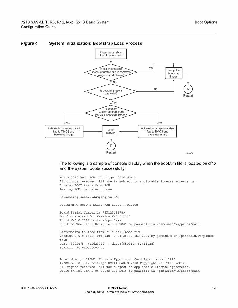
7210 SAS-M, T, R6, R12, Mxp, Sx, S Basic System Configuration Guide
Boot Options
3HE 17358 AAAB TQZZA © 2021 Nokia. Use subject to Terms available at: www.nokia.com
123
Figure 4 System Initialization: Bootstrap Load Process
The following is a sample of console display when the boot.tim file is located on cf1:/ and the system boots successfully.
Nokia 7210 Boot ROM. Copyright 2016 Nokia.All rights reserved. All use is subject to applicable license agreements.Running POST tests from ROMTesting ROM load area...done
Relocating code...Jumping to RAM
Performing second stage RAM test....passed
Board Serial Number is 'SN123456789'Bootlog started for Version V-0.0.I317Build V-0.0.I317 bootrom/mpc 7xxxBuilt on Tue Jan 6 02:23:14 IST 2009 by panosbld in /panosbld/ws/panos/main
?Attempting to load from file cf1:/boot.timVersion L-0.0.I312, Fri Jan 2 04:26:32 IST 2009 by panosbld in /panosbld/ws/panos/maintext:(3002475-->12623392) + data:(550940-->2414128)Starting at 0xb000000...
Total Memory: 512MB Chassis Type: sas Card Type: badami_7210TiMOS-L-0.0.I312 boot/mpc NOKIA SAS-M 7210 Copyright (c) 2016 Nokia.All rights reserved. All use subject to applicable license agreements.Built on Fri Jan 2 04:26:32 IST 2016 by panosbld in /panosbld/ws/panos/main
sw0450
Power on or rebootStart Bootrom code
Load goldenbootstrap
image
Loadboot.tim
Yes
Yes
Yes
No
No
No
Is golden bootstrapimage requested due to bootstrap
image upgrade failure?
Is boot.tim presentand valid?
Is boot.timversion different from
last valid bootstrap image?
Indicate bootstrap-updatedflag to TiMOS andbootstrap image
Indicate bootstrap-no-updateflag to TiMOS andbootstrap image
Restart
R
Restart
R

Boot Options
124
7210 SAS-M, T, R6, R12, Mxp, Sx, S Basic SystemConfiguration Guide
© 2021 Nokia. Use subject to Terms available at: www.nokia.com
3HE 17358 AAAB TQZZA
TiMOS BOOT LOADER
...
4.1.4 7210 SAS Boot Options and Procedures
The location of the boot.tim bootstrap image varies per 7210 SAS platform and depends on the storage locations supported by the platform. The boot option modes to find and load the boot.tim bootstrap image file also vary per 7210 SAS platform.
This section provides information about the supported boot option modes and storage locations for the following 7210 SAS platforms:
• System Boot Options on 7210 SAS-M• System Boot Options on 7210 SAS-T, 7210 SAS-R6, and 7210 SAS-R12• System Boot Options for 7210 SAS-Mxp, 7210 SAS-S 1/10GE, 7210 SAS-Sx 1/
10GE, and 7210 SAS-Sx 10/100GE• System Boot Options for 7210 SAS-Sx 1/10GE, 7210 SAS-S 1/10GE,
7210 SAS-Sx 10/100GE, and 7210 SAS-Mxp in Satellite Mode• System Boot Options for 7210 SAS-Mxp, 7210 SAS-S 1/10GE, 7210 SAS-Sx 1/
10GE, and 7210 SAS-Sx 10/100GE in Standalone Mode
4.1.4.1 System Boot Options on 7210 SAS-M
This platform supports the following options to retrieve the boot.tim and TiMOS images (both.tim) required to boot the system:
• local storage — internal flash (cf1:\)• network (with auto-init mode)• network (without auto-init mode)
Note: The use of a boot.tim file on a USB storage for booting up is not supported on the 7210 SAS-M. The boot.tim is present in cf1:\, or the golden bootstrap image in cf1:\ is used. The 7210 SAS-M supports the use of only a both.tim (TiMOS image) file on the USB storage device.

7210 SAS-M, T, R6, R12, Mxp, Sx, S Basic System Configuration Guide
Boot Options
3HE 17358 AAAB TQZZA © 2021 Nokia. Use subject to Terms available at: www.nokia.com
125
During bootup, the bootrom searches for the boot.tim image in the internal flash (cf1:\) and uses the image obtained from this location to load the bootstrap image. If the boot.tim image is not found in this location, the boot procedure fails. If the boot.tim image is found, the system searches for bof.cfg (the boot options file) in the root directory on the storage device. That is, if boot.tim is found on cf1:\, the system also looks for bof.cfg in cf1:\bof.cfg.
If bof.cfg is found, the system uses the BOF to locate the TiMOS software (both.tim file), configuration file, and other boot parameters, and processes them to boot the system. If the BOF is not found, the system attempts to retrieve the BOF from the network using the auto-init mode and create a new BOF as part of the auto-init process.
Refer to the appropriate 7210 SAS chassis installation guide for more information about booting the system using these options.
4.1.4.2 System Boot Options on 7210 SAS-T, 7210 SAS-R6, and 7210 SAS-R12
These 7210 SAS platforms support the following options to retrieve the boot.tim and TiMOS/SROS images (both.tim) required to boot the system:
• internal flash (cf1:\)• external flash (cf2:\)• external USB flash (uf1:\)• network (with auto-init)
This option is supported only on the 7210 SAS-T.• network (without auto-init)
Because multiple storage locations are available for the bootstrap image boot.tim file on the 7210 SAS-T, 7210 SAS-R6, and 7210 SAS-R12, these platforms do not support the golden bootstrap image.
During bootup, the bootrom searches for the boot.tim in the following locations in the specified order and uses the image obtained from the first location where boot.tim is found to load the bootstrap image:
• cf1:\ (internal USB)• cf2:\ (external flash)• uf1:\ (external USB)
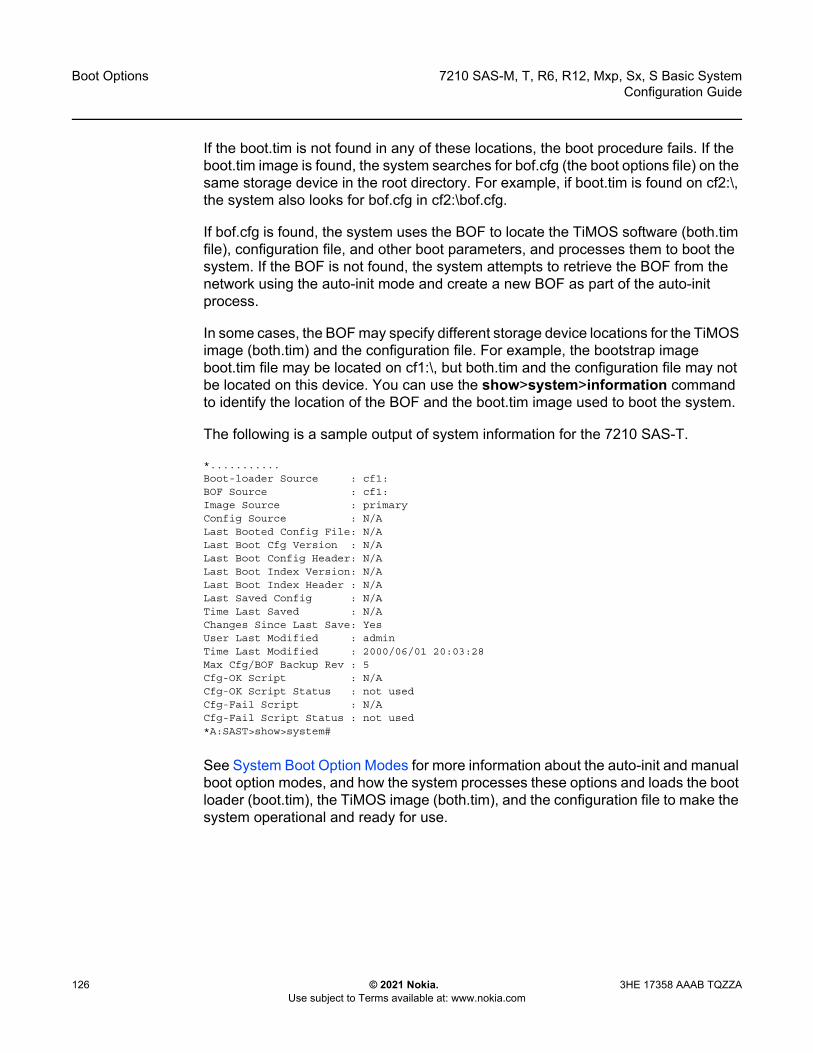
Boot Options
126
7210 SAS-M, T, R6, R12, Mxp, Sx, S Basic SystemConfiguration Guide
© 2021 Nokia. Use subject to Terms available at: www.nokia.com
3HE 17358 AAAB TQZZA
If the boot.tim is not found in any of these locations, the boot procedure fails. If the boot.tim image is found, the system searches for bof.cfg (the boot options file) on the same storage device in the root directory. For example, if boot.tim is found on cf2:\, the system also looks for bof.cfg in cf2:\bof.cfg.
If bof.cfg is found, the system uses the BOF to locate the TiMOS software (both.tim file), configuration file, and other boot parameters, and processes them to boot the system. If the BOF is not found, the system attempts to retrieve the BOF from the network using the auto-init mode and create a new BOF as part of the auto-init process.
In some cases, the BOF may specify different storage device locations for the TiMOS image (both.tim) and the configuration file. For example, the bootstrap image boot.tim file may be located on cf1:\, but both.tim and the configuration file may not be located on this device. You can use the show>system>information command to identify the location of the BOF and the boot.tim image used to boot the system.
The following is a sample output of system information for the 7210 SAS-T.
*...........Boot-loader Source : cf1:BOF Source : cf1:Image Source : primaryConfig Source : N/ALast Booted Config File: N/ALast Boot Cfg Version : N/ALast Boot Config Header: N/ALast Boot Index Version: N/ALast Boot Index Header : N/ALast Saved Config : N/ATime Last Saved : N/AChanges Since Last Save: YesUser Last Modified : adminTime Last Modified : 2000/06/01 20:03:28Max Cfg/BOF Backup Rev : 5Cfg-OK Script : N/ACfg-OK Script Status : not usedCfg-Fail Script : N/ACfg-Fail Script Status : not used*A:SAST>show>system#
See System Boot Option Modes for more information about the auto-init and manual boot option modes, and how the system processes these options and loads the boot loader (boot.tim), the TiMOS image (both.tim), and the configuration file to make the system operational and ready for use.
7210 SAS-M, T, R6, R12, Mxp, Sx, S Basic System Configuration Guide
Boot Options
3HE 17358 AAAB TQZZA © 2021 Nokia. Use subject to Terms available at: www.nokia.com
127
4.1.4.3 System Boot Options for 7210 SAS-Mxp, 7210 SAS-S 1/10GE, 7210 SAS-Sx 1/10GE, and 7210 SAS-Sx 10/100GE
These platforms can operate in the satellite mode or standalone mode, according to the following considerations.
• In the satellite mode of operation, these 7210 SAS platforms do not need an assigned IP address because they are managed by the 7750 SR host. The user must connect the correct ports to the 7750 SR host and power on the node. The node automatically fetches the BOF, the image, and the configuration required to operate in satellite mode.See System Boot Options for 7210 SAS-Sx 1/10GE, 7210 SAS-S 1/10GE, 7210 SAS-Sx 10/100GE, and 7210 SAS-Mxp in Satellite Mode for a detailed procedure used to boot these 7210 SAS platforms.
• In the standalone mode of operation, these 7210 SAS platforms provide IP/MPLS functionality. The platforms need an assigned IP address and can be managed independently. See System Boot Options for 7210 SAS-Mxp, 7210 SAS-S 1/10GE, 7210 SAS-Sx 1/10GE, and 7210 SAS-Sx 10/100GE in Standalone Mode for procedures to boot these 7210 SAS platforms.
The operating mode that the 7210 SAS platform or node uses to boot up is determined by the chassis-role and host-type BOF parameters. Nokia recommends configuring similar values for both parameters to ensure that the node boots up in the correct mode. Failure to do so will result in an error and the node will not boot up. See BOF Chassis-Role and Host-Type Parameters for 7210 SAS-Sx 1/10GE, 7210 SAS-S 1/10GE, 7210 SAS-Sx 10/100GE, and 7210 SAS-Mxp for more information about BOF parameter settings to boot up the nodes in standalone mode and satellite mode.
Note: See the Virtual Chassis chapter for information about boot up and configuration of the 7210 SAS-Sx/S 1/10GE operating in standalone-VC mode.

Boot Options
128
7210 SAS-M, T, R6, R12, Mxp, Sx, S Basic SystemConfiguration Guide
© 2021 Nokia. Use subject to Terms available at: www.nokia.com
3HE 17358 AAAB TQZZA
The following sections describe the system initialization process for 7210 SAS-Mxp, 7210 SAS-S 1/10GE, 7210 SAS-Sx 1/10GE, and 7210 SAS-Sx 10/100GE in both standalone mode and satellite mode, and the role of the chassis-role and host-type BOF parameters:
• System Boot Options for 7210 SAS-Sx 1/10GE, 7210 SAS-S 1/10GE, 7210 SAS-Sx 10/100GE, and 7210 SAS-Mxp in Satellite Mode
• System Boot Options for 7210 SAS-Mxp, 7210 SAS-S 1/10GE, 7210 SAS-Sx 1/10GE, and 7210 SAS-Sx 10/100GE in Standalone Mode
• Configuration Notes for 7210 SAS-Sx 1/10GE, 7210 SAS-S 1/10GE, 7210 SAS-Sx 10/100GE, and 7210 SAS-Mxp
4.1.4.4 System Boot Options for 7210 SAS-Sx 1/10GE, 7210 SAS-S 1/10GE, 7210 SAS-Sx 10/100GE, and 7210 SAS-Mxp in Satellite Mode
These platforms support the use of the external SD card slot or external compact flash (cf2:\) to boot the system. Use the storage media supplied with the purchase of a valid satellite mode license. After you insert the storage media in the external storage media slot, ensure that the satellite is connected to the host before you power on the system.
Table 21 lists the uplink ports used for 7210 SAS platforms and their variants. To boot up in satellite mode, the uplinks must be connected to the host ports, as described in Table 21.
Note:
• Nokia recommends using the external SD card slot (cf2:\) on the 7210 SAS-Sx/S 1/10GE and 7210 SAS-Sx 10/100GE or the external compact flash (cf2:\) on the 7210 SAS-Mxp to boot up the node the first time.
• To change the chassis role and the mode in which the platform will boot up, manually interrupt the boot process and use the BOF menu option to configure the chassis-role parameter value. You can also revert the parameter value to the factory default setting of factory-default.
• To boot up in standalone mode, it is not required to update the BOF to include the host-type parameter. To maintain backward compatibility, the node boots up in standalone mode if the chassis-role parameter is set to factory-default (the value set when it is shipped from the factory), and the host-type parameter is set to none.
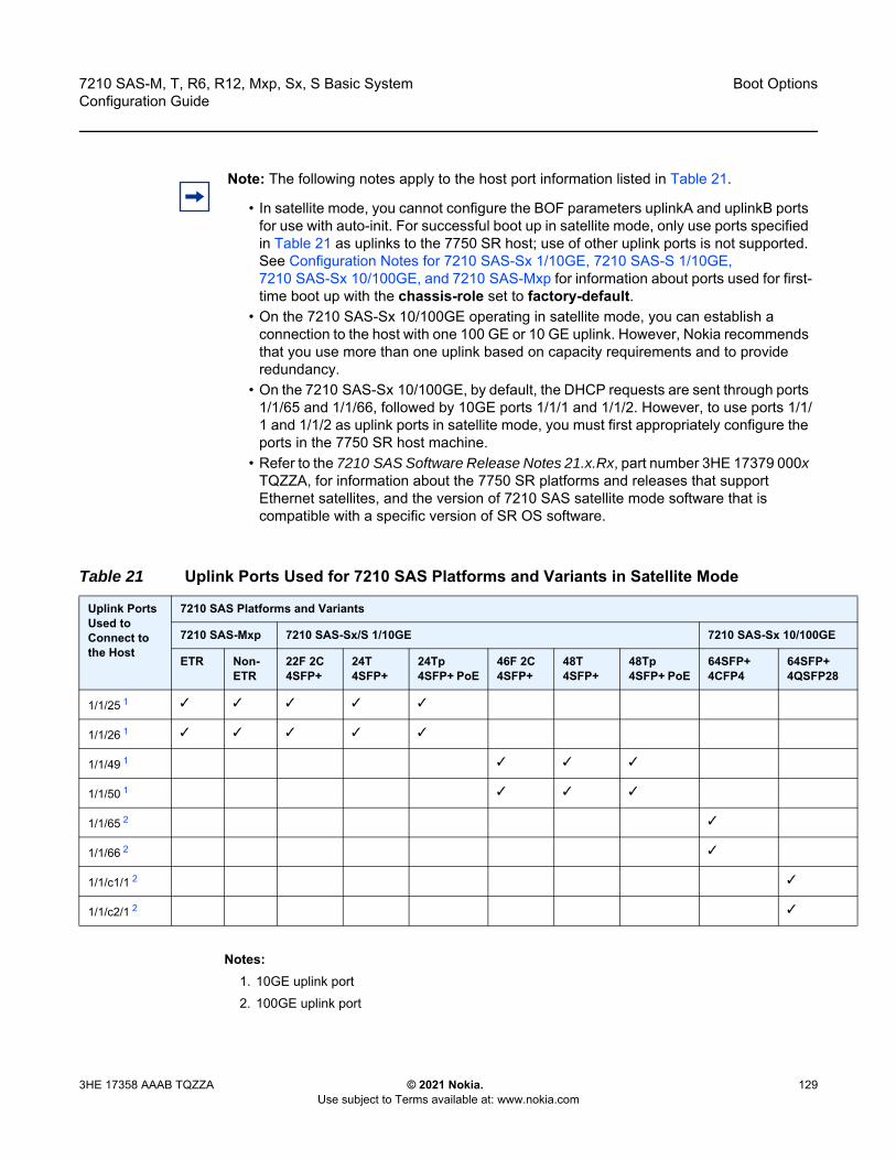
7210 SAS-M, T, R6, R12, Mxp, Sx, S Basic System Configuration Guide
Boot Options
3HE 17358 AAAB TQZZA © 2021 Nokia. Use subject to Terms available at: www.nokia.com
129
Notes:1. 10GE uplink port2. 100GE uplink port
Note: The following notes apply to the host port information listed in Table 21.
• In satellite mode, you cannot configure the BOF parameters uplinkA and uplinkB ports for use with auto-init. For successful boot up in satellite mode, only use ports specified in Table 21 as uplinks to the 7750 SR host; use of other uplink ports is not supported. See Configuration Notes for 7210 SAS-Sx 1/10GE, 7210 SAS-S 1/10GE, 7210 SAS-Sx 10/100GE, and 7210 SAS-Mxp for information about ports used for first-time boot up with the chassis-role set to factory-default.
• On the 7210 SAS-Sx 10/100GE operating in satellite mode, you can establish a connection to the host with one 100 GE or 10 GE uplink. However, Nokia recommends that you use more than one uplink based on capacity requirements and to provide redundancy.
• On the 7210 SAS-Sx 10/100GE, by default, the DHCP requests are sent through ports 1/1/65 and 1/1/66, followed by 10GE ports 1/1/1 and 1/1/2. However, to use ports 1/1/1 and 1/1/2 as uplink ports in satellite mode, you must first appropriately configure the ports in the 7750 SR host machine.
• Refer to the 7210 SAS Software Release Notes 21.x.Rx, part number 3HE 17379 000x TQZZA, for information about the 7750 SR platforms and releases that support Ethernet satellites, and the version of 7210 SAS satellite mode software that is compatible with a specific version of SR OS software.
Table 21 Uplink Ports Used for 7210 SAS Platforms and Variants in Satellite Mode
Uplink Ports Used to Connect to the Host
7210 SAS Platforms and Variants
7210 SAS-Mxp 7210 SAS-Sx/S 1/10GE 7210 SAS-Sx 10/100GE
ETR Non-ETR
22F 2C 4SFP+
24T 4SFP+
24Tp 4SFP+ PoE
46F 2C 4SFP+
48T 4SFP+
48Tp 4SFP+ PoE
64SFP+ 4CFP4
64SFP+ 4QSFP28
1/1/25 1 ✓ ✓ ✓ ✓ ✓
1/1/26 1 ✓ ✓ ✓ ✓ ✓
1/1/49 1 ✓ ✓ ✓
1/1/50 1 ✓ ✓ ✓
1/1/65 2 ✓
1/1/66 2 ✓
1/1/c1/1 2 ✓
1/1/c2/1 2 ✓

Boot Options
130
7210 SAS-M, T, R6, R12, Mxp, Sx, S Basic SystemConfiguration Guide
© 2021 Nokia. Use subject to Terms available at: www.nokia.com
3HE 17358 AAAB TQZZA
After the uplinks are connected and the node is powered up, the satellite node sends out DHCP packets. The host matches the MAC address in the DHCP packet against the host configuration to identify the satellite and provides the correct BOF to the satellite node for booting up. The BOF sets the host-type command to satellites and also provides the location of the TiMOS (SR OS) image and configuration file. The boot loader fetches the TiMOS image and configuration file and boots up in satellite mode.
4.1.4.5 System Boot Options for 7210 SAS-Mxp, 7210 SAS-S 1/10GE, 7210 SAS-Sx 1/10GE, and 7210 SAS-Sx 10/100GE in Standalone Mode
When operating in standalone mode, these 7210 SAS platforms support the following options to boot the system:
• internal flash (cf1:\)• external SD card slot (cf2:\)• external USB flash (uf1:\) (not available for 7210 SAS-S 1/10GE)• network (with auto-init; auto-init is not supported on platforms operating in
standalone-VC mode)• network (without auto-init)
Because multiple storage locations are available for the boot loader (boot.tim) on the 7210 SAS-Sx 1/10GE, 7210 SAS-S 1/10GE, and 7210 SAS-Sx 10/100GE, these platforms do not support the golden bootstrap image.
During bootup, the bootrom searches for the boot.tim in the following locations in the specified order and uses the image obtained from the first location where boot.tim is found to load the bootstrap image:
• cf1:\ (internal USB)
Note: When operating the 7210 SAS platform in satellite mode, Nokia recommends to use only the auto-init procedure to retrieve the BOF and other boot parameters from the host. Other procedures, such as the manual configuration of the BOF, are not allowed. See Auto-init Mode for more information.
Note: See the Virtual Chassis chapter for information about boot up and configuration of the 7210 SAS-Sx/S 1/10GE operating in standalone-VC mode.

7210 SAS-M, T, R6, R12, Mxp, Sx, S Basic System Configuration Guide
Boot Options
3HE 17358 AAAB TQZZA © 2021 Nokia. Use subject to Terms available at: www.nokia.com
131
• cf2:\ (external SD card slot)• uf1:\ (external USB) (if available)
If the boot.tim is not found in any of the locations, the boot procedure fails. If the boot.tim is found in one of these locations, the system searches for bof.cfg (the boot option file) on the same storage device in the root directory. For example, if boot.tim is found on cf2:\, the system also looks for bof.cfg in cf2:\bof.cfg.
If the BOF is found, the system uses the BOF to locate the TiMOS software (both.tim file), configuration file and other boot parameters and processes them to boot the system. If the BOF is not found, the system attempts auto-init to retrieve the BOF from the network and create a new BOF as part of the auto-init process.
In some cases, the BOF may specify different storage device locations for the TiMOS image (both.tim) and the configuration file. For example, the boot.tim file may be located on cf1:\, but both.tim and the configuration file may be located on cf2:\. Use the show>system>information command to identify the location of the BOF and the boot.tim image used to boot the system.
The following is a sample output of system information for the 7210 SAS-Sx/S 1/10GE.
A:7210SAS>show>system# information
===============================================================================System Information
Note: The following notes apply to 7210 SAS platforms configured in standalone mode.
• To perform a first-time bootup on a factory-shipped node, you are required to buy the software license and use the storage media (for example, SD card of compact flash) obtained to boot up the system. To boot up in standalone mode, it is not required to modify the BOF received during auto-init mode process to include the host-type parameter. To maintain backward compatibility, the node will boot up in standalone mode if the chassis-role parameter is set to factory-default (the value set when it is shipped from factory) and the host-type parameter is not set to any value (none).
• The auto-init procedure for 7210 SAS-Mxp, 7210 SAS-Sx 1/10GE, 7210 SAS-1/10GE, and 7210 SAS-Sx 10/100GE remains unchanged and is the same as the other 7210 SAS platforms. Operators can continue to use the auto-init procedure that was used in previous releases. The ports used for first-time boot up when chassis-role is set to factory-default is described in section Configuration Notes for 7210 SAS-Sx 1/10GE, 7210 SAS-S 1/10GE, 7210 SAS-Sx 10/100GE, and 7210 SAS-Mxp.
• When operating in standalone mode, 7210 SAS-Mxp, 7210 SAS-Sx 1/10GE, 7210 SAS-S 1/10GE, and 7210 SAS-Sx 10/100GE support the option of either configuring the BOF manually (see section Manual Mode for more information about the procedure used) or retrieving the BOF using autoinit (see section Auto-init Mode for more information about the procedure used).

Boot Options
132
7210 SAS-M, T, R6, R12, Mxp, Sx, S Basic SystemConfiguration Guide
© 2021 Nokia. Use subject to Terms available at: www.nokia.com
3HE 17358 AAAB TQZZA
===============================================================================System Name : hw_sass_duthSystem Type : 7210 SAS-Sx/S 1/10GE 48Tp4SFP+ (PoE)-1System Version : B-8.0.B1-238System Contact :System Location :System Coordinates :System Up Time : 0 days, 00:03:52.99 (hr:min:sec)
SNMP Port : 161SNMP Engine ID : 0000197f0000a47b2cc669d3SNMP Engine Boots : 42SNMP Max Message Size : 1500SNMP Admin State : EnabledSNMP Oper State : EnabledSNMP Index Boot Status : Not PersistentSNMP Sync State : N/A
Tel/Tel6/SSH/FTP Admin : Enabled/Disabled/Enabled/DisabledTel/Tel6/SSH/FTP Oper : Up/Down/Up/Down
Boot-loader Source : cf1:BOF Source : cf1:Image Source : primaryConfig Source : primaryLast Booted Config File: cf1:\bala_default_config.cfgLast Boot Cfg Version : THU JAN 13 01:53:35 2000 UTCLast Boot Config Header: # TiMOS-B-8.0.B1-225 both/hops NOKIA SAS-Sx
48T4SFP+ 7210 Copyright (c) 2016 Nokia.# All rights reserved. All use subject to
applicable license agreements. # Built on Thu Apr 1421:25:57 IST 2016 by builder in /home/builder/8.0B1/panos/main # Generated THU JAN 13 01:53:35 2016 UTC
Last Boot Index Version: N/ALast Boot Index Header : # TiMOS-B-8.0.B1-225 both/hops NOKIA SAS-Sx
48T4SFP+ 7210 Copyright (c) 2016 Nokia.# All rights reserved. All use subject to
applicable license agreements. # Built on Thu Apr 1421:25:57 IST 2016 by builder in /home/builder/8.0B1/panos/main # Generated THU JAN 13 01:53:35 2016 UTC
Last Saved Config : N/ATime Last Saved : N/AChanges Since Last Save: NoMax Cfg/BOF Backup Rev : 5Cfg-OK Script : N/ACfg-OK Script Status : not usedCfg-Fail Script : N/ACfg-Fail Script Status : not used
Management IP Addr : xx.xxx.xx.xx/24Primary DNS Server : N/ASecondary DNS Server : N/ATertiary DNS Server : N/ADNS Domain : (Not Specified)DNS Resolve Preference : ipv4-onlyBOF Static Routes :
To Next Hopxx.xxx.x.x/16 xx.xxx.xx.x

7210 SAS-M, T, R6, R12, Mxp, Sx, S Basic System Configuration Guide
Boot Options
3HE 17358 AAAB TQZZA © 2021 Nokia. Use subject to Terms available at: www.nokia.com
133
xxx.x.x.x/8 xx.xxx.xx.x
ICMP Vendor Enhancement: Disabled===============================================================================
===============================================================================System Oper Group Information===============================================================================Name Oper Creation Hold Hold Members Monitor
Status Origin UpTime DnTime(secs) (secs)
-------------------------------------------------------------------------------No Matching Entries===============================================================================A:7210SAS-Sx>show>system#
The following is a sample output of system information for the 7210 SAS-Sx 10/100GE.
*A:7210SAS>show>system# information
===============================================================================System Information===============================================================================System Name : NS1633T0067System Type : 7210 SAS-Sx 64SFP+4CFP4-1Chassis-role Config value : standaloneHost-type Config value : standaloneChassis Operating Mode : standaloneSystem Version : B-9.0.B1-246System Contact :System Location :System Coordinates :System Up Time : 16 days, 19:05:26.61 (hr:min:sec)
SNMP Port : 161SNMP Engine ID : 0000197f0000d099d58f5e41SNMP Engine Boots : 44SNMP Max Message Size : 1500SNMP Admin State : DisabledSNMP Oper State : DisabledSNMP Index Boot Status : Not PersistentSNMP Sync State : N/A
Tel/Tel6/SSH/FTP Admin : Disabled/Disabled/Enabled/DisabledTel/Tel6/SSH/FTP Oper : Down/Down/Up/Down
Boot-loader Source : cf2:BOF Source : cf2:Image Source : primaryConfig Source : N/ALast Booted Config File : N/ALast Boot Cfg Version : N/ALast Boot Config Header: N/ALast Boot Index Version : N/ALast Boot Index Header : N/ALast Saved Config : N/A
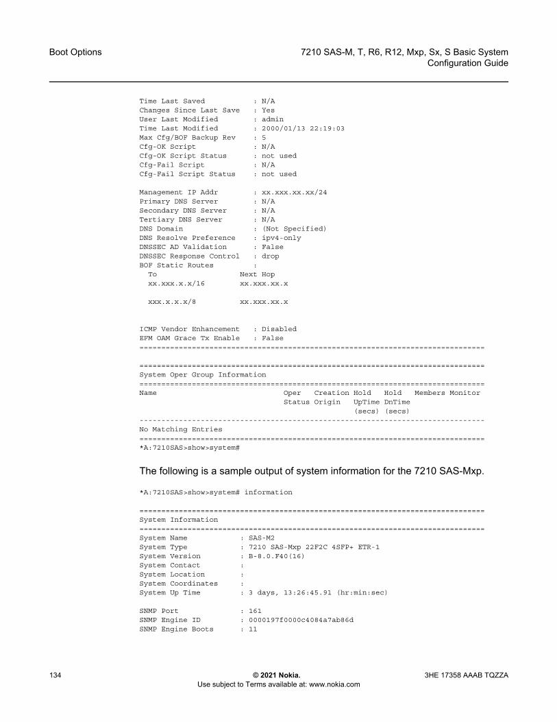
Boot Options
134
7210 SAS-M, T, R6, R12, Mxp, Sx, S Basic SystemConfiguration Guide
© 2021 Nokia. Use subject to Terms available at: www.nokia.com
3HE 17358 AAAB TQZZA
Time Last Saved : N/AChanges Since Last Save : YesUser Last Modified : adminTime Last Modified : 2000/01/13 22:19:03Max Cfg/BOF Backup Rev : 5Cfg-OK Script : N/ACfg-OK Script Status : not usedCfg-Fail Script : N/ACfg-Fail Script Status : not used
Management IP Addr : xx.xxx.xx.xx/24Primary DNS Server : N/ASecondary DNS Server : N/ATertiary DNS Server : N/ADNS Domain : (Not Specified)DNS Resolve Preference : ipv4-onlyDNSSEC AD Validation : FalseDNSSEC Response Control : dropBOF Static Routes :
To Next Hopxx.xxx.x.x/16 xx.xxx.xx.x
xxx.x.x.x/8 xx.xxx.xx.x
ICMP Vendor Enhancement : DisabledEFM OAM Grace Tx Enable : False===============================================================================
===============================================================================System Oper Group Information===============================================================================Name Oper Creation Hold Hold Members Monitor
Status Origin UpTime DnTime(secs) (secs)
-------------------------------------------------------------------------------No Matching Entries===============================================================================*A:7210SAS>show>system#
The following is a sample output of system information for the 7210 SAS-Mxp.
*A:7210SAS>show>system# information
===============================================================================System Information===============================================================================System Name : SAS-M2System Type : 7210 SAS-Mxp 22F2C 4SFP+ ETR-1System Version : B-8.0.F40(16)System Contact :System Location :System Coordinates :System Up Time : 3 days, 13:26:45.91 (hr:min:sec)
SNMP Port : 161SNMP Engine ID : 0000197f0000c4084a7ab86dSNMP Engine Boots : 11
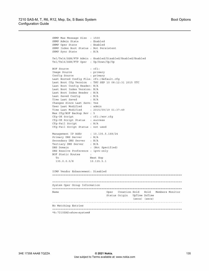
7210 SAS-M, T, R6, R12, Mxp, Sx, S Basic System Configuration Guide
Boot Options
3HE 17358 AAAB TQZZA © 2021 Nokia. Use subject to Terms available at: www.nokia.com
135
SNMP Max Message Size : 1500SNMP Admin State : EnabledSNMP Oper State : EnabledSNMP Index Boot Status : Not PersistentSNMP Sync State : N/A
Tel/Tel6/SSH/FTP Admin : Enabled/Disabled/Enabled/EnabledTel/Tel6/SSH/FTP Oper : Up/Down/Up/Up
BOF Source : cf1:Image Source : primaryConfig Source : primaryLast Booted Config File: cf1:/default.cfgLast Boot Cfg Version : THU SEP 10 08:12:31 2015 UTCLast Boot Config Header: N/ALast Boot Index Version: N/ALast Boot Index Header : N/ALast Saved Config : N/ATime Last Saved : N/AChanges Since Last Save: YesUser Last Modified : adminTime Last Modified : 2015/09/19 01:37:49Max Cfg/BOF Backup Rev : 5Cfg-OK Script : cf1:/env.cfgCfg-OK Script Status : successCfg-Fail Script : N/ACfg-Fail Script Status : not used
Management IP Addr : 10.135.5.168/24Primary DNS Server : N/ASecondary DNS Server : N/ATertiary DNS Server : N/ADNS Domain : (Not Specified)DNS Resolve Preference : ipv4-onlyBOF Static Routes :
To Next Hop135.0.0.0/8 10.135.5.1
ICMP Vendor Enhancement: Disabled===============================================================================
===============================================================================System Oper Group Information===============================================================================Name Oper Creation Hold Hold Members Monitor
Status Origin UpTime DnTime(secs) (secs)
-------------------------------------------------------------------------------No Matching Entries===============================================================================*A:7210SAS>show>system#

Boot Options
136
7210 SAS-M, T, R6, R12, Mxp, Sx, S Basic SystemConfiguration Guide
© 2021 Nokia. Use subject to Terms available at: www.nokia.com
3HE 17358 AAAB TQZZA
4.2 Configuration File and TiMOS Image Loading
The bootstrap image processes the initialization parameters from the BOF and attempts to locate the configuration file configured in the BOF. Up to three locations can be configured for the system to search for the configuration file. The locations can be local or remote. The first location searched is the primary configuration location. If not found, the secondary configuration location is searched, and lastly, the tertiary configuration location is searched.
If the configuration file is in a remote location, the bootstrap process saves it on the flash as cf1:/default.cfg. Users must not delete this file or create a file with this name. The configuration file includes chassis, IOM, MDA, and port configurations, as well as system, routing, and service configurations.
Like the configuration file, three locations can be configured for the system to search for the files that contain the both.tim (SR OS/TiMOS) image. The locations can be local or remote. The first location searched is the primary image location. If not found, the secondary image location is searched, and lastly, the tertiary image location is searched.
4.2.1 Boot Sequence and Image Loading
This section describes the booting sequence of the 7210 SAS platforms when they are powered on, and how they obtain the TiMOS image file, the BOF, the configuration file loads, the image, and the configuration file to bring up the platform.
• Figure 4 shows the bootstrap load process.
Note: The configuration and image loading information described in this section applies to all the 7210 SAS platforms with the following exceptions.
• On 7210 SAS-R6 and 7210 SAS-R12, the following caveats apply:- only manual mode using OOB port or Ethernet management port is supported- obtaining an IP address and other parameters using DHCP with the OOB port is
not supported- auto-init is not supported
• On 7210 SAS-M, 7210 SAS-T, and 7210 SAS-Mxp, both manual mode and auto-init mode is supported.
• On 7210 SAS-Sx 1/10GE, 7210 SAS-S 1/10GE, and 7210 SAS-Sx 10/100GE, the manual mode is used only to boot the platform in standalone mode.
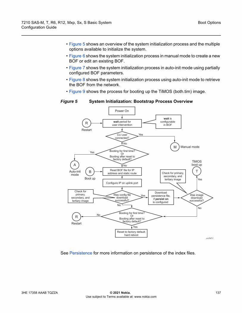
7210 SAS-M, T, R6, R12, Mxp, Sx, S Basic System Configuration Guide
Boot Options
3HE 17358 AAAB TQZZA © 2021 Nokia. Use subject to Terms available at: www.nokia.com
137
• Figure 5 shows an overview of the system initialization process and the multiple options available to initialize the system.
• Figure 6 shows the system initialization process in manual mode to create a new BOF or edit an existing BOF.
• Figure 7 shows the system initialization process in auto-init mode using partially configured BOF parameters.
• Figure 8 shows the system initialization process using auto-init mode to retrieve the BOF from the network.
• Figure 9 shows the process for booting up the TiMOS (both.tim) image.
Figure 5 System Initialization: Bootstrap Process Overview
See Persistence for more information on persistence of the index files.
sw0451
wait period foruser intervention
Read BOF file for IPaddress and static route
Configure IP on uplink port
Booting for first time?Or
Booting after reset tofactory default?
Booting for first time?Or
Booting after reset tofactory default?
Reset to factory default;hard reboot
CLI userconnected?
Was config filedownload
successful?
Was imagedownload
successful?
wait isconfigurable
in BOF
Check forprimary,
secondary, andtertiary image
Check for primary,secondary, andtertiary image
Downloadpersistence file,
if persist onis configured
Power On
Manual mode
TiMOSboot up
Restart
Restart
Boot up
Auto-initmode
R
B
M
T
A
R
Yes
Yes
Yes
Yes
Yes
No
No
No
No
No
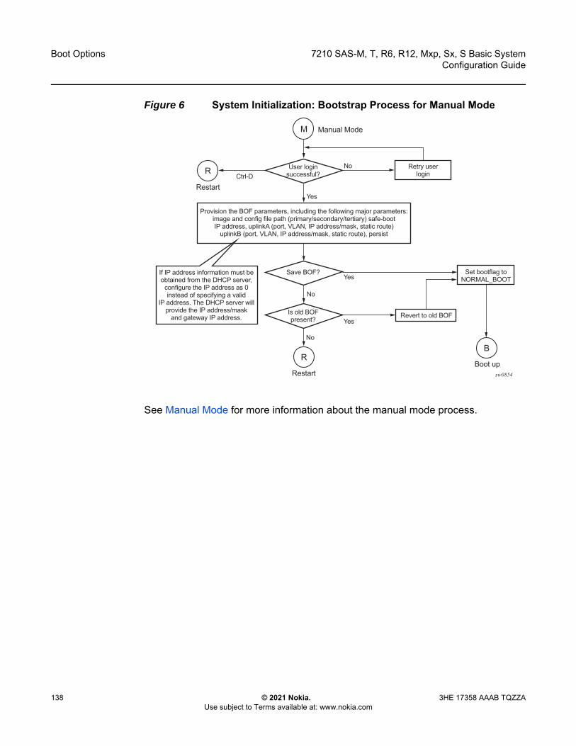
Boot Options
138
7210 SAS-M, T, R6, R12, Mxp, Sx, S Basic SystemConfiguration Guide
© 2021 Nokia. Use subject to Terms available at: www.nokia.com
3HE 17358 AAAB TQZZA
Figure 6 System Initialization: Bootstrap Process for Manual Mode
See Manual Mode for more information about the manual mode process.
sw0854
Retry userlogin
If IP address information must beobtained from the DHCP server,
configure the IP address as 0instead of specifying a valid
IP address. The DHCP server willprovide the IP address/mask
and gateway IP address.
User loginsuccessful?
Is old BOFpresent?
Save BOF? Set bootflag toNORMAL_BOOT
Revert to old BOF
Provision the BOF parameters, including the following major parameters:image and config file path (primary/secondary/tertiary) safe-bootIP address, uplinkA (port, VLAN, IP address/mask, static route)
uplinkB (port, VLAN, IP address/mask, static route), persist
Manual Mode
Restart
Restart
Boot up
M
RB
R
Yes
Ctrl-D
Yes
Yes
No
No
No

7210 SAS-M, T, R6, R12, Mxp, Sx, S Basic System Configuration Guide
Boot Options
3HE 17358 AAAB TQZZA © 2021 Nokia. Use subject to Terms available at: www.nokia.com
139
Figure 7 System Initialization: Bootstrap Process for Auto-init Mode with Partial BOF
See Auto-init Mode for more information on operating in the auto-init mode with a partial BOF.
sw0452
Retry userlogin
User loginsuccessful?
Is old BOFpresent?
Was bofsave successful?
PartialBOF?
Set bootflag toAUTO_BOOT
Revert to old BOF and setbootflag to NORMAL_BOOT
Provision partial BOF parameters - supported parametersare uplink port, speed, duplex, auto-negotiate, and VLAN ID
Enter keyword auto at the prompt toprovide partial BOF parameters
for auto-init mode
Manual Mode
Boot upRestart
Restart
Auto-init mode
M
RB
A
R
Yes
Ctrl-D
Yes Yes
Yes
No
No
No
No
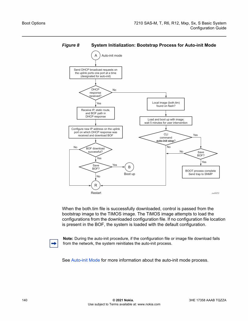
Boot Options
140
7210 SAS-M, T, R6, R12, Mxp, Sx, S Basic SystemConfiguration Guide
© 2021 Nokia. Use subject to Terms available at: www.nokia.com
3HE 17358 AAAB TQZZA
Figure 8 System Initialization: Bootstrap Process for Auto-init Mode
When the both.tim file is successfully downloaded, control is passed from the bootstrap image to the TiMOS image. The TiMOS image attempts to load the configurations from the downloaded configuration file. If no configuration file location is present in the BOF, the system is loaded with the default configuration.
See Auto-init Mode for more information about the auto-init mode process.
sw0453
DHCPresponsereceived?
Receive IP, static route,and BOF path inDHCP response
Configure new IP address on the uplinkport on which DHCP response was
received and download BOF
Send DHCP broadcast requests onthe uplink ports one port at a time
(designated for auto-init)
Load and boot up with image;wait 5 minutes for user intervention
Local image (both.tim)found on flash?
CLIcommand
auto-init stop?
BOOT process completeSend trap to SNMP
SaveBOF?
BOF downloadsuccessful?
SaveBOF?
Boot up
Restart
Auto-init mode
B
A
Yes
Yes
YesYes
Yes
No
NoNo
No
No
R
Note: During the auto-init procedure, if the configuration file or image file download fails from the network, the system reinitiates the auto-init process.

7210 SAS-M, T, R6, R12, Mxp, Sx, S Basic System Configuration Guide
Boot Options
3HE 17358 AAAB TQZZA © 2021 Nokia. Use subject to Terms available at: www.nokia.com
141
Figure 9 System Initialization: TiMOS Boot
4.2.2 BOF Chassis-Role and Host-Type Parameters for 7210 SAS-Sx 1/10GE, 7210 SAS-S 1/10GE, 7210 SAS-Sx 10/100GE, and 7210 SAS-Mxp
On the 7210 SAS-Sx 1/10GE, 7210 SAS-S 1/10GE, 7210 SAS-Sx 10/100GE and 7210 SAS-Mxp, the operator can configure the chassis-role and host-type boot parameters to operate the 7210 SAS node in standalone mode or satellite mode. The values configured for these parameters must be consistent for boot up to proceed correctly. Table 22 describes the boot loader action when the chassis-role and host-type parameters are set to one of the allowed values.
The bof>host-type command can be set to one of the following values:
• none (factory default setting)• standalone
sw0476
Apply downloadedconfiguration
Load TiMOS
TiMOS boot up T
Boot processcomplete
Send trap to SNMP
Reset to factorydefault,
hard reboot
Boot processcomplete
Send trap to SNMP
Ping safe-boot IPaddress if
configured (in BOF)
Three trials with5 minute intervals
Yes
Yes
No
No
Bootingfor first time?
OrBooting after reset to
factory default?
Ping response receivedfor safe-boot IP address within
15 minutes?
Boot Options
142
7210 SAS-M, T, R6, R12, Mxp, Sx, S Basic SystemConfiguration Guide
© 2021 Nokia. Use subject to Terms available at: www.nokia.com
3HE 17358 AAAB TQZZA
• satellites
The chassis-role boot parameter (not available in the BOF) can be set to one of the following values:
• factory-defaultBy default, the chassis-role boot parameter value is set to factory-default when the 7210 SAS-Sx 1/10GE, 7210 SAS-S 1/10GE, 7210 SAS-Sx 10/100GE and 7210 SAS-Mxp are shipped from the factory. In the factory-default setting, the user can use auto-init to retrieve the BOF and boot the node in either standalone or satellite mode by setting the host-type parameter in the BOF. By default, the boot loader assigns a value of none to the host-type parameter and uses this value if the host-type parameter is not explicitly received in the BOF. As a result, in the factory-default setting, the user can boot the node in standalone mode without setting the host-type parameter to an explicit value (which maintains backward compatibility).
• standaloneThis parameter setting forces the node to operate in standalone mode. In the standalone setting, the host-type parameter value in the BOF (retrieved through auto-init, present locally, or configured manually) must be set to either standalone or none. If host-type is set to satellites, the boot loader detects a mismatch and does not boot up.
• satelliteThis parameter setting forces the node to operate only in satellite mode. In the satellite setting, the host-type parameter value in the BOF (retrieved through autoinit, present locally, or configured manually) must be set to satellites. If host-type is set to standalone, the boot loader detects a mismatch and does not boot up.
Table 22 describes the boot loader action when the chassis-role and host-type parameters are set to one of the allowed values.

7210 SAS-M, T, R6, R12, Mxp, Sx, S Basic System Configuration Guide
Boot Options
3HE 17358 AAAB TQZZA © 2021 Nokia. Use subject to Terms available at: www.nokia.com
143
Table 22 7210 SAS-Sx/S 1/10GE, 7210 SAS-Sx 10/100GE, and 7210 SAS-Mxp Boot Loader Actions for chassis-role and host-type Parameters
Boot Parameter: chassis-role
BOF Parameter: host-type
Boot Loader Action
factory-default satellites • The user sets chassis-role to satellite. • The system boots up successfully in satellite mode.• On subsequent reboots, the system will continue to boot up in
satellite mode.
standalone • The user sets chassis-role to standalone. • The system boots up successfully in standalone mode.• On subsequent reboots, the system will continue to boot up in
standalone mode.
none(host-type is not set to any value explicitly)
• The chassis-role value is unchanged from factory-default. • The system boots up successfully in standalone mode.• On subsequent reboots, the system will continue to boot up in
standalone mode, if the value of host-type is not set explicitly (that is, it is set to none).
standalone standalone • The chassis-role value is unchanged from standalone. • The system boots up successfully in standalone mode.• On subsequent reboots, the system will continue to boot up in
standalone mode.
satellites The boot loader detects a mismatch and returns an error. Depending on the context of the boot loader, it will take one of the following actions.
• If the boot loader is in auto-init, it will retry auto-init to fetch a new BOF with the correct value for host-type.
• If the boot loader was interrupted to configure the BOF parameters manually, it will go back to provide an option for the user to change the value of host-type to the correct value.
none • The value of chassis-role is unchanged from standalone. • The system boots up successfully in standalone mode.• On subsequent reboots, the system will continue to boot up in
standalone mode if the host-type value is not set explicitly (that is, the value is set to none).
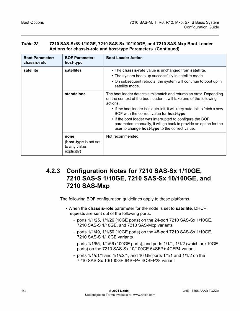
Boot Options
144
7210 SAS-M, T, R6, R12, Mxp, Sx, S Basic SystemConfiguration Guide
© 2021 Nokia. Use subject to Terms available at: www.nokia.com
3HE 17358 AAAB TQZZA
4.2.3 Configuration Notes for 7210 SAS-Sx 1/10GE, 7210 SAS-S 1/10GE, 7210 SAS-Sx 10/100GE, and 7210 SAS-Mxp
The following BOF configuration guidelines apply to these platforms.
• When the chassis-role parameter for the node is set to satellite, DHCP requests are sent out of the following ports:- ports 1/1/25, 1/1/26 (10GE ports) on the 24-port 7210 SAS-Sx 1/10GE,
7210 SAS-S 1/10GE, and 7210 SAS-Mxp variants- ports 1/1/49, 1/1/50 (10GE ports) on the 48-port 7210 SAS-Sx 1/10GE,
7210 SAS-S 1/10GE variants- ports 1/1/65, 1/1/66 (100GE ports), and ports 1/1/1, 1/1/2 (which are 10GE
ports) on the 7210 SAS-Sx 10/100GE 64SFP+ 4CFP4 variant- ports 1/1/c1/1 and 1/1/c2/1, and 10 GE ports 1/1/1 and 1/1/2 on the
7210 SAS-Sx 10/100GE 64SFP+ 4QSFP28 variant
satellite satellites • The chassis-role value is unchanged from satellite. • The system boots up successfully in satellite mode.• On subsequent reboots, the system will continue to boot up in
satellite mode.
standalone The boot loader detects a mismatch and returns an error. Depending on the context of the boot loader, it will take one of the following actions.
• If the boot loader is in auto-init, it will retry auto-init to fetch a new BOF with the correct value for host-type.
• If the boot loader was interrupted to configure the BOF parameters manually, it will go back to provide an option for the user to change host-type to the correct value.
none(host-type is not set to any value explicitly)
Not recommended
Table 22 7210 SAS-Sx/S 1/10GE, 7210 SAS-Sx 10/100GE, and 7210 SAS-Mxp Boot Loader Actions for chassis-role and host-type Parameters (Continued)
Boot Parameter: chassis-role
BOF Parameter: host-type
Boot Loader Action
7210 SAS-M, T, R6, R12, Mxp, Sx, S Basic System Configuration Guide
Boot Options
3HE 17358 AAAB TQZZA © 2021 Nokia. Use subject to Terms available at: www.nokia.com
145
The boot loader continuously iterates over the previously mentioned ports, sending out DHCP requests until the boot loader receives a response from the host.
• When the chassis-role parameter for the node is set to standalone, DHCP requests are sent out of the following ports:- ports 1/1/27, 1/1/28 (10GE ports) and ports 1/1/1, 1/1/2 (1GE ports) on the
24-port 7210 SAS-Sx 1/10GE, 7210 SAS-S 1/10GE, and 7210 SAS-Mxp variants
- ports 1/1/51, 1/1/52 (10GE ports) and ports 1/1/1, 1/1/2 (1GE ports) on the 48-port 7210 SAS-Sx/S 1/10GE, and 7210 SAS-S 1/10GE variants
- ports 1/1/67, 1/1/68 (100GE ports) and ports 1/1/1, 1/1/2 (10GE ports) on the 7210 SAS-Sx 10/100GE 64SFP+ 4CFP4 variant
- ports 1/1/c3/1 and 1/1/c4/1, and 10 GE ports 1/1/1 and 1/1/2 on the 7210 SAS-Sx 10/100GE 64SFP+ 4QSFP28 variant
In addition, the boot loader will attempt to load the TiMOS image (both.tim) from the local flash if autoinit fails (that is, no responses were received from the DHCP server).
• When the node is shipped from the factory (with the chassis-role set to factory-default) and powered up for the first time, the node sends out DHCP requests on the following ports: - 10GE ports 1/1/25, 1/1/26, 1/1/27, and 1/1/28 on the 24-port
7210 SAS-Sx 1/10GE, 7210 SAS-S 1/10GE, and 7210 SAS-Mxp- 10GE ports 1/1/49, 1/1/50, 1/1/51 and 1/1/52 on the 48-port
7210 SAS-Sx 1/10GE and 7210 SAS-S 1/10GE - the first two 1GE ports, 1/1/1 and 1/1/2, on all 7210 SAS-Sx/S 1/10GE and
7210 SAS-Mxp variantsOn a 7210 SAS-Sx 10/100GE CFP4 platform shipped from the factory, the DHCP requests are sent out of the first two 10GE ports (1/1/1 and 1/1/2) and all 100GE ports (1/1/65, 1/1/66, 1/1/67, and 1/1/68). On a 7210 SAS-Sx 10/100GE 64SFP+ 4QSFP28 variant, the DHCP requests are sent out of ports 1/1/c1/1, 1/1/c2/1, 1/1/c3/1, and 1/1/c4/1, and the first two 10 GE ports (1/1/1 and 1/1/2). To change this, connect to the console and modify the chassis-role parameter value to either satellite or standalone, as required. After the chassis-role parameter is updated, the node attempts autoinit to retrieve the BOF.
Boot Options
146
7210 SAS-M, T, R6, R12, Mxp, Sx, S Basic SystemConfiguration Guide
© 2021 Nokia. Use subject to Terms available at: www.nokia.com
3HE 17358 AAAB TQZZA
4.3 Persistence
Optionally, the BOF persist parameter can specify whether the system should preserve system indexes when a save command is executed. During a subsequent boot, the index file is read along with the configuration file. As a result, a number of system indexes are preserved between reboots, including the interface index. If persistence is not required and the configuration file is successfully processed, the system becomes operational. If persistence is required, a matching x.ndx file must be located and successfully processed before the system can become operational. Matching files (configuration and index files) must have the same filename prefix such as test123.cfg and test123.ndx, and are created at the same time when a save command is executed. The persistence option must be enabled to deploy the Network Management System (NMS). The default is off.
Traps, logs, and console messages are generated if problems occur and SNMP shuts down for all SNMP gets and sets; however, traps are issued.
4.4 Configuration Guidelines for Auto-init and Manual Mode
This section describes the configuration guidelines for the auto-init and manual modes.
• The Ethernet management port does not support auto-init mode. The use of DHCP to obtain the BOF from the network and other system parameters is currently not supported on Ethernet management ports.
• In auto-init mode, DHCP requests sent out by the node are in two formats. The system attempts to communicate with the DHCP server in these two formats, one after another (if necessary). - Initially, the DHCP requests are sent out with a priority VLAN tag (VLAN ID
= 0, dot1p PCP bits set to 7).- If no response is received from the DHCP server after the DHCP request is
sent, DHCP requests are sent without VLAN tags (that is, null-tagged packets).
• In auto-init mode, the BOF can be downloaded through FTP or TFTP based on the information a client receives from the DHCP server. The DHCP client tries the following options to obtain the BOF name and the server IP address: - using the vendor-specific option
7210 SAS-M, T, R6, R12, Mxp, Sx, S Basic System Configuration Guide
Boot Options
3HE 17358 AAAB TQZZA © 2021 Nokia. Use subject to Terms available at: www.nokia.com
147
The client searches for option 43 in the DHCP reply. This provides the URL, which has to be accessed through FTP. For example: ftp://abcd:[email protected]/test/bof.cfg. If this file is found the client retrieves this file.
- collating server-name and file-nameIf option 43 is not found in the DHCP reply, a URL is formed by using the tftp-server name and the boot-file retrieved via TFTP. The IP address of the TFTP server is obtained from DHCP option 66 or the "sname" field of a DHCP message, and the filename on the TFTP server is obtained from DHCP option 67 or the "file" field of a DHCP message.
• In manual mode, if the OOB port is enabled (that is, if no eth-mgmt-disable is configured), the OOB port is used to download the TIMOS image file and configuration file specified in the BOF, and the system boot is successfully completed. If a system boot fails, the uplinkA and uplinkB parameters are used to retrieve the TIMOS image and configuration files.
• On the 7210 SAS-M 24F 2XFP (10GigE) (both standard and ETR variants), DHCP requests are sent out of ports 1/1/25 and 1/1/26 as part of auto-init. The system attempts to obtain the system parameters and BOF location by sending out DHCP requests on the following ports in this order: 1/1/1, 1/1/2, 1/1/25, and 1/1/26. The system sends out the DHCP request on a single port at a specific time and waits for the DHCP server to respond. If a successful server response is received, the auto-init process uses the information to boot up the system. If no response is received from the server within a stipulated time, the system sends out DHCP requests on the next port in the list based on the preceding order, looping through all the ports until a successful response is received from the server, or the user interrupts the boot process.
• On a factory-shipped 7210 SAS-T device, the system attempts the auto-init process (that is, sends DHCP requests) using the first two 1GE ports (1/1/1 and 1/1/2 on 7210 SAS-T) and the last two 10GE ports (1/1/25 and 1/1/26 on 7210 SAS-T). See System Boot Options for 7210 SAS-Sx 1/10GE, 7210 SAS-S 1/10GE, 7210 SAS-Sx 10/100GE, and 7210 SAS-Mxp in Satellite Mode and System Boot Options for 7210 SAS-Mxp, 7210 SAS-S 1/10GE, 7210 SAS-Sx 1/10GE, and 7210 SAS-Sx 10/100GE in Standalone Mode for information about ports used for bootup on these platforms.
• On the 7210 SAS-M 24F 2XFP, the 10G MDA cannot be used for auto-init. The use of DHCP to obtain the BOF is not supported with the 10G MDA.
• When using auto-init with partial BOF configuration, the user has the option to either stop auto-init by logging in to the node and using the console to run the admin>auto-init stop command or let auto-init continue.
• The user can intervene to stop auto-init at any time when auto-init is in progress. The system logs the progress of auto-init. The system emits the LED light until auto-init is complete or when the user stops the auto-init process.
Boot Options
148
7210 SAS-M, T, R6, R12, Mxp, Sx, S Basic SystemConfiguration Guide
© 2021 Nokia. Use subject to Terms available at: www.nokia.com
3HE 17358 AAAB TQZZA
4.5 Resetting the Node to the Factory Default Setting
From release 4.0 onward, you can use the bof>bof-password command to modify the factory default BOF password password.
The user must enter the correct BOF password to edit the BOF parameters. If the incorrect password is entered three times consecutively, the system prompts the user, after the third attempt, to reset the BOF password to the factory default.
If the user chooses not to reset the BOF password, the system prompts the user to enter the password again. If the user chooses to reset the password to factory default, the system also resets the flash to factory defaults (removes all files from the flash drive, except the boot image file (cf1:\boot.tim) and TiMOS image file (cf1:\both.tim)) as a security measure to prevent malicious access to the configuration file.
After password reset, the node is rebooted with the factory default settings; the BOF parameters are also set to default values. The user must now setup the box using the same steps that were used during first-time boot up of the factory-shipped box. After the system boots up with this setup, use the factory default password password to edit the BOF parameters, and use the bof>bof-password command to change the password again.
The following sample logs show the system console prompts that are displayed when the user forgets the password and chooses to reset the password to the factory default setting. The BOF contents before and after the reset are also displayed.
Note:
• The BOF password can be changed from the default value to any other user-defined value only at the TiMOS level.
• Nokia strongly recommends that the user should not rename cf1:\boot.tim and cf1:\both.tim if the system needs to retain them during the password recovery procedure.
• Nokia strongly recommends that the user should retain a backup copy of all the image files, configuration files, and other data.
Note: The BOF parameters are set to default values after a password reset.
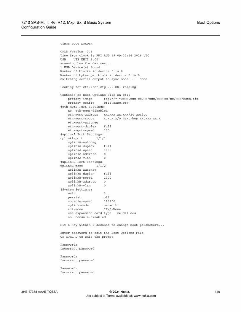
7210 SAS-M, T, R6, R12, Mxp, Sx, S Basic System Configuration Guide
Boot Options
3HE 17358 AAAB TQZZA © 2021 Nokia. Use subject to Terms available at: www.nokia.com
149
TiMOS BOOT LOADER
CPLD Version: 2.1Time from clock is FRI AUG 19 09:22:46 2016 UTCUSB: USB EHCI 1.00scanning bus for devices...1 USB Device(s) foundNumber of blocks in device 0 is 0Number of bytes per block in device 0 is 0Switching serial output to sync mode... done
Looking for cf1:/bof.cfg ... OK, reading
Contents of Boot Options File on cf1:primary-image ftp://*:*@xxx.xxx.xx.xx/xxx/xx/xxx/xx/xxx/both.timprimary-config cf1:\sasm.cfg
#eth-mgmt Port Settings:no eth-mgmt-disabledeth-mgmt-address xx.xxx.xx.xxx/24 activeeth-mgmt-route x.x.x.x/0 next-hop xx.xxx.xx.xeth-mgmt-autonegeth-mgmt-duplex fulleth-mgmt-speed 100
#uplinkA Port Settings:uplinkA-port 1/1/1
uplinkA-autoneguplinkA-duplex fulluplinkA-speed 1000uplinkA-address 0uplinkA-vlan 0
#uplinkB Port Settings:uplinkB-port 1/1/2
uplinkB-autoneguplinkB-duplex fulluplinkB-speed 1000uplinkB-address 0uplinkB-vlan 0
#System Settings:wait 3persist offconsole-speed 115200uplink-mode networkacl-mode IPv6-Noneuse-expansion-card-type m4-ds1-cesno console-disabled
Hit a key within 3 seconds to change boot parameters...
Enter password to edit the Boot Options FileOr CTRL-D to exit the prompt
Password:Incorrect password
Password:Incorrect password
Password:Incorrect password
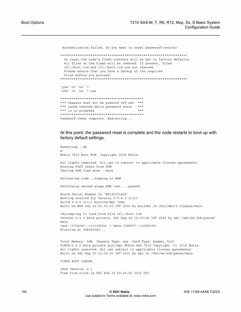
Boot Options
150
7210 SAS-M, T, R6, R12, Mxp, Sx, S Basic SystemConfiguration Guide
© 2021 Nokia. Use subject to Terms available at: www.nokia.com
3HE 17358 AAAB TQZZA
Authentication failed, Do you want to reset password?(yes/no)
*******************************************************************On reset,the node's flash contents will be set to factory defaults.All files on the flash will be removed. If present, filescf1:/boot.tim and cf1:/both.tim are not removed.Please ensure that you have a backup of the requiredfiles before you proceed.
*******************************************************************
'yes' or 'no' ?'yes' or 'no' ? yes
*********************************************** Chassis must not be powered off nor ****** cards removed while password reset ****** is in progress ***********************************************Password reset complete. Restarting...
At this point, the password reset is complete and the node restarts to boot up with factory default settings.
Resetting...OKøNokia 7210 Boot ROM. Copyright 2016 Nokia.
All rights reserved. All use is subject to applicable license agreements.Running POST tests from ROMTesting ROM load area...done
Relocating code...Jumping to RAM
Performing second stage RAM test....passed
Board Serial Number is 'NS1023C1436'Bootlog started for Version 9-V-0.0.I1111Build V-0.0.I1111 bootrom/mpc 7xxxBuilt on Wed Jun 29 21:55:30 IST 2016 by builder in /builder/0.0/panos/main
?Attempting to load from file cf1:/boot.timVersion L-4.0.beta-private, Sat Aug 20 12:59:26 IST 2016 by abc /abc/ws-40b/panos/maintext:(3706043-->13139264) + data:(528557-->2068192)Starting at 0xb000000...
Total Memory: 1GB Chassis Type: sas Card Type: badami_7210TiMOS-L-4.0.beta-private boot/mpc NOKIA SAS 7210 Copyright (c) 2016 Nokia.All rights reserved. All use subject to applicable license agreements.Built on Sat Aug 20 12:59:26 IST 2016 by abc in /abc/ws-40b/panos/main
TiMOS BOOT LOADER
CPLD Version: 2.1Time from clock is FRI AUG 19 09:24:05 2016 UTC

7210 SAS-M, T, R6, R12, Mxp, Sx, S Basic System Configuration Guide
Boot Options
3HE 17358 AAAB TQZZA © 2021 Nokia. Use subject to Terms available at: www.nokia.com
151
USB: USB EHCI 1.00scanning bus for devices...1 USB Device(s) foundNumber of blocks in device 0 is 0Number of bytes per block in device 0 is 0Switching serial output to sync mode... done
Looking for cf1:/bof.cfg ... not foundCould not find bof.cfg on any of the local drives.
Default Settings----------------#eth-mgmt Port Settings:
eth-mgmt-disabled#uplinkA Port Settings:uplinkA-port 1/1/1
uplinkA-autoneguplinkA-duplex fulluplinkA-speed 1000uplinkA-address 0uplinkA-vlan 0
#uplinkB Port Settings:uplinkB-port 1/1/2
uplinkB-autoneguplinkB-duplex fulluplinkB-speed 1000uplinkB-address 0uplinkB-vlan 0
#System Settings:wait 3persist offconsole-speed 115200uplink-mode networkacl-mode IPv6-Noneuse-expansion-card-type m4-ds1-cesno console-disabled
Hit a key within 1 second to change boot parameters...Enter password to edit the Boot Options FileOr CTRL-D to exit the promptPassword:
Note: At this password prompt, you are required to enter the default password password .

Boot Options
152
7210 SAS-M, T, R6, R12, Mxp, Sx, S Basic SystemConfiguration Guide
© 2021 Nokia. Use subject to Terms available at: www.nokia.com
3HE 17358 AAAB TQZZA
4.6 OOB Ethernet Management Port
The 7210 SAS platforms support the OOB Ethernet management port for management of the node. An OOB Ethernet port can be used to download the TiMOS image file and the configuration file by creating a BOF manually. The OOB management port allows for use of both IPv4 and IPv6. See IPv6 Configuration Guidelines in OOB Node Management for information about platforms that support IPv6 for the OOB management port.
Refer to the 7210 SAS OS Software Release Notes 11.0Rx for information about the specific software release that supports OOB management port and IPv6.
4.6.1 IPv6 Configuration Guidelines in OOB Node Management
The following are the configuration guidelines for IPv6 on an OOB management port of the node.
• The management port on the management router instance only supports host functionality.
• It is required that an IPv4 address is configured in the BOF. A BOF that contains only IPv6 addresses is not supported.
• IPv6 duplicate address detection is not supported.• IPv6 auto-configuration is not supported.• IPv6 over IPv4 tunneling is not supported.• IPv6 path MTU discovery is not supported.• The router discovery option is not supported on the management port.
4.7 Security for Console Port and Ethernet Management Port
The 7210 SAS OS supports disabling the console port and OOB Ethernet management port. In remote deployments, operators can choose to disable user access to the node through the console and through the Ethernet management port to prevent unauthorized and malicious access. Use the bof>console-disabled command to disable the console and the bof>eth-mgmt-disabled command to disable the use of the Ethernet management port.
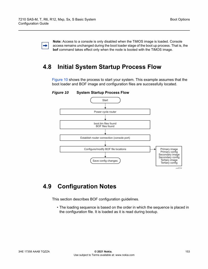
7210 SAS-M, T, R6, R12, Mxp, Sx, S Basic System Configuration Guide
Boot Options
3HE 17358 AAAB TQZZA © 2021 Nokia. Use subject to Terms available at: www.nokia.com
153
4.8 Initial System Startup Process Flow
Figure 10 shows the process to start your system. This example assumes that the boot loader and BOF image and configuration files are successfully located.
Figure 10 System Startup Process Flow
4.9 Configuration Notes
This section describes BOF configuration guidelines.
• The loading sequence is based on the order in which the sequence is placed in the configuration file. It is loaded as it is read during bootup.
Note: Access to a console is only disabled when the TiMOS image is loaded. Console access remains unchanged during the boot loader stage of the boot up process. That is, the bof command takes effect only when the node is booted with the TiMOS image.
sw0534
Start
boot.tim files foundBOF files found
Establish router connection (console port)
Configure/modify BOF file locations Primary imagePrimary config
Secondary imageSecondary config
Tertiary imageTertiary config
Power cycle router
Save config changes

Boot Options
154
7210 SAS-M, T, R6, R12, Mxp, Sx, S Basic SystemConfiguration Guide
© 2021 Nokia. Use subject to Terms available at: www.nokia.com
3HE 17358 AAAB TQZZA
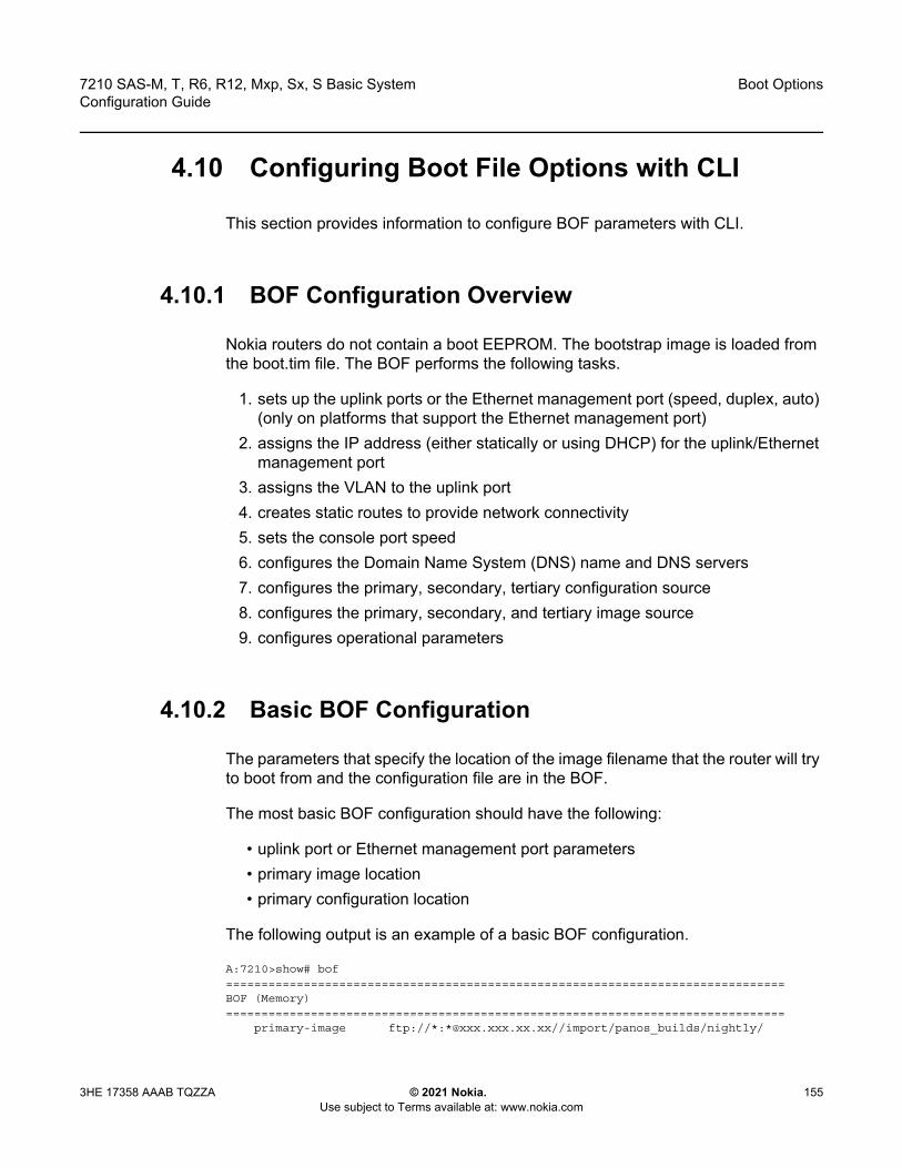
7210 SAS-M, T, R6, R12, Mxp, Sx, S Basic System Configuration Guide
Boot Options
3HE 17358 AAAB TQZZA © 2021 Nokia. Use subject to Terms available at: www.nokia.com
155
4.10 Configuring Boot File Options with CLI
This section provides information to configure BOF parameters with CLI.
4.10.1 BOF Configuration Overview
Nokia routers do not contain a boot EEPROM. The bootstrap image is loaded from the boot.tim file. The BOF performs the following tasks.
1. sets up the uplink ports or the Ethernet management port (speed, duplex, auto) (only on platforms that support the Ethernet management port)
2. assigns the IP address (either statically or using DHCP) for the uplink/Ethernet management port
3. assigns the VLAN to the uplink port4. creates static routes to provide network connectivity5. sets the console port speed6. configures the Domain Name System (DNS) name and DNS servers7. configures the primary, secondary, tertiary configuration source8. configures the primary, secondary, and tertiary image source9. configures operational parameters
4.10.2 Basic BOF Configuration
The parameters that specify the location of the image filename that the router will try to boot from and the configuration file are in the BOF.
The most basic BOF configuration should have the following:
• uplink port or Ethernet management port parameters• primary image location• primary configuration location
The following output is an example of a basic BOF configuration.
A:7210>show# bof===============================================================================BOF (Memory)===============================================================================
primary-image ftp://*:*@xxx.xxx.xx.xx//import/panos_builds/nightly/
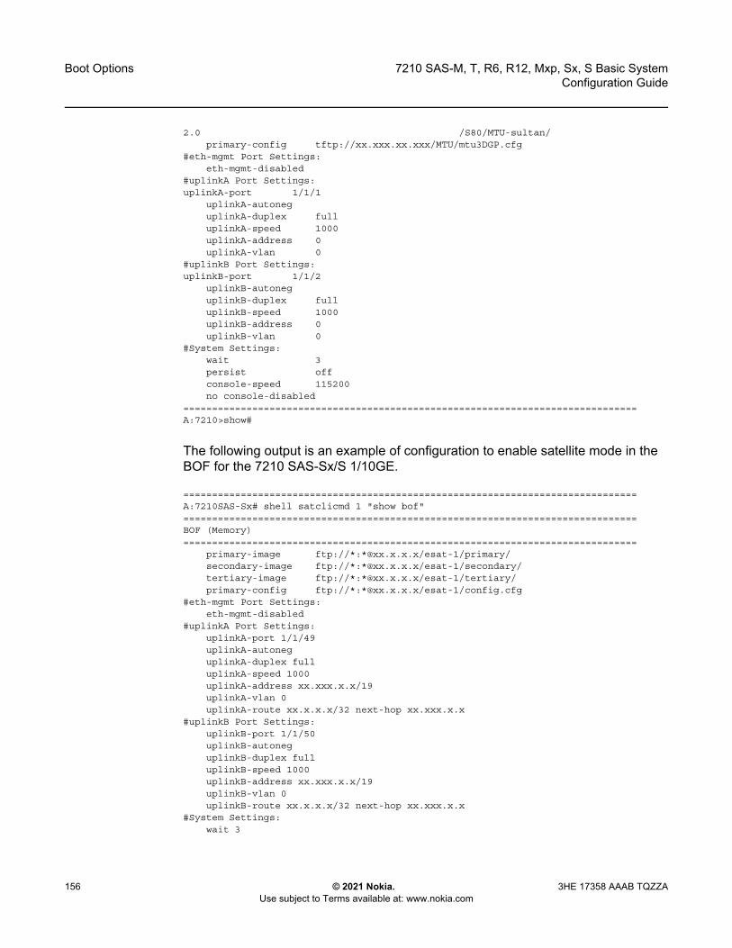
Boot Options
156
7210 SAS-M, T, R6, R12, Mxp, Sx, S Basic SystemConfiguration Guide
© 2021 Nokia. Use subject to Terms available at: www.nokia.com
3HE 17358 AAAB TQZZA
2.0 /S80/MTU-sultan/primary-config tftp://xx.xxx.xx.xxx/MTU/mtu3DGP.cfg
#eth-mgmt Port Settings:eth-mgmt-disabled
#uplinkA Port Settings:uplinkA-port 1/1/1
uplinkA-autoneguplinkA-duplex fulluplinkA-speed 1000uplinkA-address 0uplinkA-vlan 0
#uplinkB Port Settings:uplinkB-port 1/1/2
uplinkB-autoneguplinkB-duplex fulluplinkB-speed 1000uplinkB-address 0uplinkB-vlan 0
#System Settings:wait 3persist offconsole-speed 115200no console-disabled
===============================================================================A:7210>show#
The following output is an example of configuration to enable satellite mode in the BOF for the 7210 SAS-Sx/S 1/10GE.
===============================================================================A:7210SAS-Sx# shell satclicmd 1 "show bof"===============================================================================BOF (Memory)===============================================================================
primary-image ftp://*:*@xx.x.x.x/esat-1/primary/secondary-image ftp://*:*@xx.x.x.x/esat-1/secondary/tertiary-image ftp://*:*@xx.x.x.x/esat-1/tertiary/primary-config ftp://*:*@xx.x.x.x/esat-1/config.cfg
#eth-mgmt Port Settings:eth-mgmt-disabled
#uplinkA Port Settings:uplinkA-port 1/1/49uplinkA-autoneguplinkA-duplex fulluplinkA-speed 1000uplinkA-address xx.xxx.x.x/19uplinkA-vlan 0uplinkA-route xx.x.x.x/32 next-hop xx.xxx.x.x
#uplinkB Port Settings:uplinkB-port 1/1/50uplinkB-autoneguplinkB-duplex fulluplinkB-speed 1000uplinkB-address xx.xxx.x.x/19uplinkB-vlan 0uplinkB-route xx.x.x.x/32 next-hop xx.xxx.x.x
#System Settings:wait 3
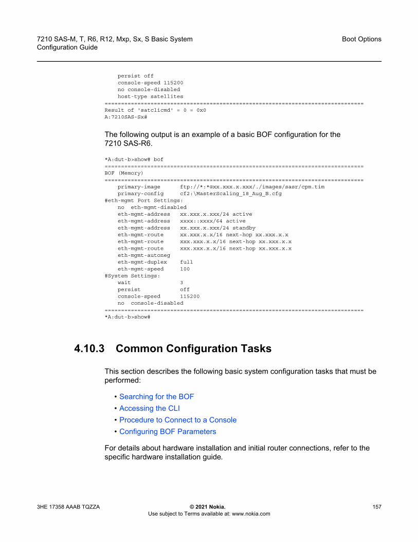
7210 SAS-M, T, R6, R12, Mxp, Sx, S Basic System Configuration Guide
Boot Options
3HE 17358 AAAB TQZZA © 2021 Nokia. Use subject to Terms available at: www.nokia.com
157
persist offconsole-speed 115200no console-disabledhost-type satellites
===============================================================================Result of 'satclicmd' = 0 = 0x0A:7210SAS-Sx#
The following output is an example of a basic BOF configuration for the 7210 SAS-R6.
*A:dut-b>show# bof===============================================================================BOF (Memory)===============================================================================
primary-image ftp://*:*@xx.xxx.x.xxx/./images/sasr/cpm.timprimary-config cf2:\MasterScaling_18_Aug_B.cfg
#eth-mgmt Port Settings:no eth-mgmt-disabledeth-mgmt-address xx.xxx.x.xxx/24 activeeth-mgmt-address xxxx::xxxx/64 activeeth-mgmt-address xx.xxx.x.xxx/24 standbyeth-mgmt-route xx.xxx.x.x/16 next-hop xx.xxx.x.xeth-mgmt-route xxx.xxx.x.x/16 next-hop xx.xxx.x.xeth-mgmt-route xxx.xxx.x.x/16 next-hop xx.xxx.x.xeth-mgmt-autonegeth-mgmt-duplex fulleth-mgmt-speed 100
#System Settings:wait 3persist offconsole-speed 115200no console-disabled
===============================================================================*A:dut-b>show#
4.10.3 Common Configuration Tasks
This section describes the following basic system configuration tasks that must be performed:
• Searching for the BOF• Accessing the CLI• Procedure to Connect to a Console• Configuring BOF Parameters
For details about hardware installation and initial router connections, refer to the specific hardware installation guide.

Boot Options
158
7210 SAS-M, T, R6, R12, Mxp, Sx, S Basic SystemConfiguration Guide
© 2021 Nokia. Use subject to Terms available at: www.nokia.com
3HE 17358 AAAB TQZZA
4.10.3.1 Searching for the BOF
The BOF should be on the same drive as the bootstrap image file. If the system cannot load or cannot find the BOF, the system checks whether the boot sequence was manually interrupted or else continues with the auto-init mode. The system prompts for a different image and configuration location.
4.10.3.2 Sample Output of BOF Configuration on Bootup for 7210 SAS Platforms
This section provides sample output of a BOF configuration boot sequence for the following 7210 SAS platforms:
• Sample Output: BOF Configuration on Bootup for 7210 SAS-M, 7210 SAS-Mxp, and 7210 SAS-T
• Sample Output: BOF Configuration on Bootup for 7210 SAS-R6 and 7210 SAS-R12
• Sample Output: BOF Configuration on Bootup for 7210 SAS-Sx/S 1/10GE
4.10.3.2.1 Sample Output: BOF Configuration on Bootup for 7210 SAS-M, 7210 SAS-Mxp, and 7210 SAS-T
The following is a sample output of a manually interrupted boot sequence on the 7210 SAS-M, 7210 SAS-Mxp, and 7210 SAS-T.
Hit a key within 3 seconds to change boot parameters...
Enter password to edit the Boot Options FileOr CTRL-D to exit the prompt
You must supply some required Boot Options. At any prompt, you can type:"restart" - restart the query mode."reboot" - reboot."exit" - boot with with existing values."reset" - reset the bof and reboot.
Press ENTER to begin, or 'flash' to enter firmware update, or the shell password...
Software Location
Note: Auto-init is not supported on the 7210 SAS-R6 and 7210 SAS-R12; use the starter BOF or create a BOF manually to boot the system.
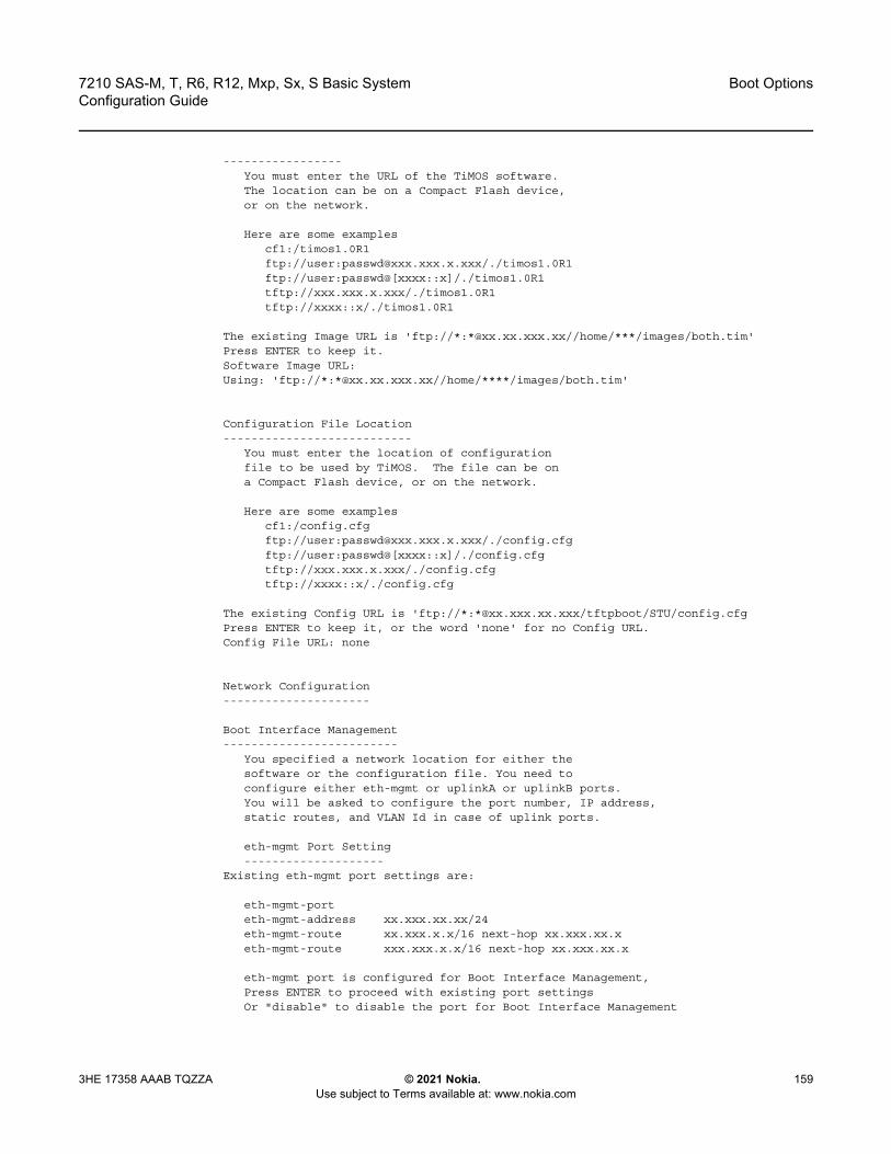
7210 SAS-M, T, R6, R12, Mxp, Sx, S Basic System Configuration Guide
Boot Options
3HE 17358 AAAB TQZZA © 2021 Nokia. Use subject to Terms available at: www.nokia.com
159
-----------------You must enter the URL of the TiMOS software.The location can be on a Compact Flash device,or on the network.
Here are some examplescf1:/timos1.0R1ftp://user:[email protected]/./timos1.0R1ftp://user:passwd@[xxxx::x]/./timos1.0R1tftp://xxx.xxx.x.xxx/./timos1.0R1tftp://xxxx::x/./timos1.0R1
The existing Image URL is 'ftp://*:*@xx.xx.xxx.xx//home/***/images/both.tim'Press ENTER to keep it.Software Image URL:Using: 'ftp://*:*@xx.xx.xxx.xx//home/****/images/both.tim'
Configuration File Location---------------------------
You must enter the location of configurationfile to be used by TiMOS. The file can be ona Compact Flash device, or on the network.
Here are some examplescf1:/config.cfgftp://user:[email protected]/./config.cfgftp://user:passwd@[xxxx::x]/./config.cfgtftp://xxx.xxx.x.xxx/./config.cfgtftp://xxxx::x/./config.cfg
The existing Config URL is 'ftp://*:*@xx.xxx.xx.xxx/tftpboot/STU/config.cfgPress ENTER to keep it, or the word 'none' for no Config URL.Config File URL: none
Network Configuration---------------------
Boot Interface Management-------------------------
You specified a network location for either thesoftware or the configuration file. You need toconfigure either eth-mgmt or uplinkA or uplinkB ports.You will be asked to configure the port number, IP address,static routes, and VLAN Id in case of uplink ports.
eth-mgmt Port Setting--------------------
Existing eth-mgmt port settings are:
eth-mgmt-porteth-mgmt-address xx.xxx.xx.xx/24eth-mgmt-route xx.xxx.x.x/16 next-hop xx.xxx.xx.xeth-mgmt-route xxx.xxx.x.x/16 next-hop xx.xxx.xx.x
eth-mgmt port is configured for Boot Interface Management,Press ENTER to proceed with existing port settingsOr "disable" to disable the port for Boot Interface Management
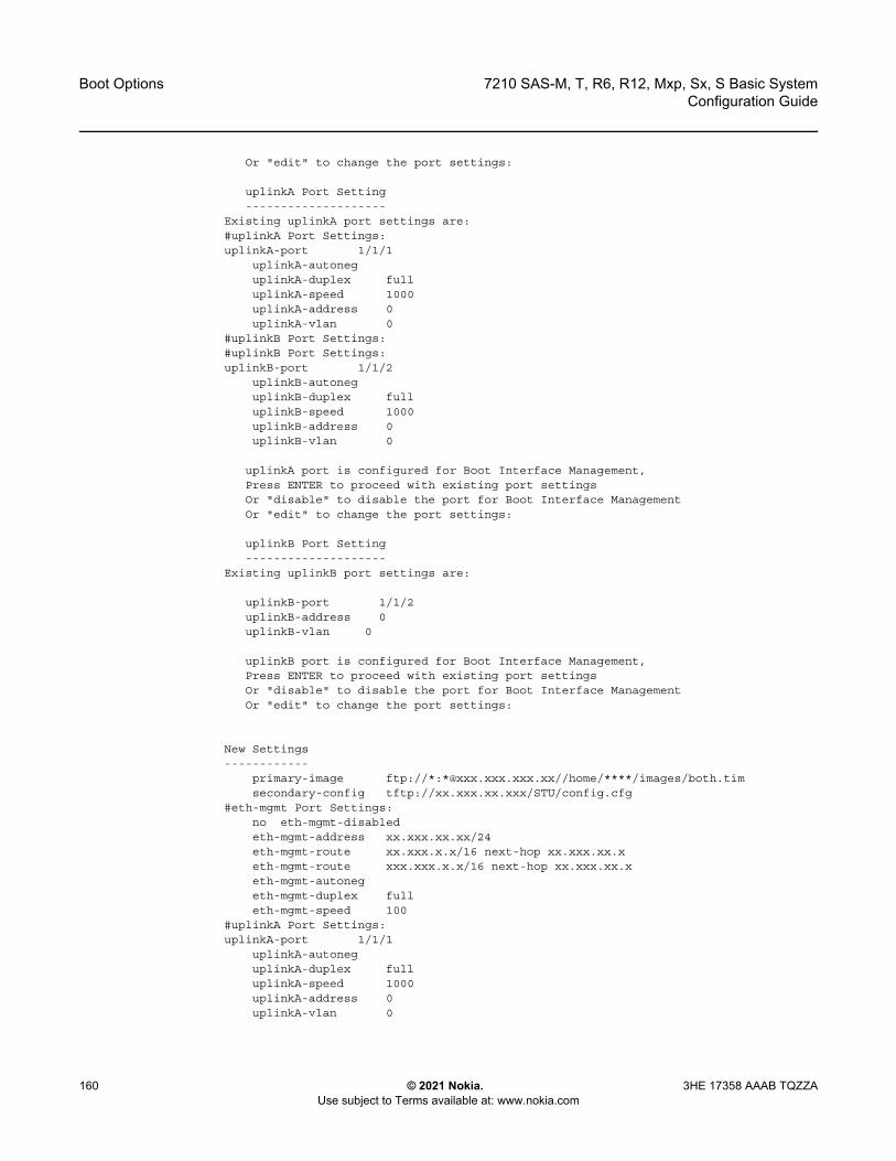
Boot Options
160
7210 SAS-M, T, R6, R12, Mxp, Sx, S Basic SystemConfiguration Guide
© 2021 Nokia. Use subject to Terms available at: www.nokia.com
3HE 17358 AAAB TQZZA
Or "edit" to change the port settings:
uplinkA Port Setting--------------------
Existing uplinkA port settings are:#uplinkA Port Settings:uplinkA-port 1/1/1
uplinkA-autoneguplinkA-duplex fulluplinkA-speed 1000uplinkA-address 0uplinkA-vlan 0
#uplinkB Port Settings:#uplinkB Port Settings:uplinkB-port 1/1/2
uplinkB-autoneguplinkB-duplex fulluplinkB-speed 1000uplinkB-address 0uplinkB-vlan 0
uplinkA port is configured for Boot Interface Management,Press ENTER to proceed with existing port settingsOr "disable" to disable the port for Boot Interface ManagementOr "edit" to change the port settings:
uplinkB Port Setting--------------------
Existing uplinkB port settings are:
uplinkB-port 1/1/2uplinkB-address 0uplinkB-vlan 0
uplinkB port is configured for Boot Interface Management,Press ENTER to proceed with existing port settingsOr "disable" to disable the port for Boot Interface ManagementOr "edit" to change the port settings:
New Settings------------
primary-image ftp://*:*@xxx.xxx.xxx.xx//home/****/images/both.timsecondary-config tftp://xx.xxx.xx.xxx/STU/config.cfg
#eth-mgmt Port Settings:no eth-mgmt-disabledeth-mgmt-address xx.xxx.xx.xx/24eth-mgmt-route xx.xxx.x.x/16 next-hop xx.xxx.xx.xeth-mgmt-route xxx.xxx.x.x/16 next-hop xx.xxx.xx.xeth-mgmt-autonegeth-mgmt-duplex fulleth-mgmt-speed 100
#uplinkA Port Settings:uplinkA-port 1/1/1
uplinkA-autoneguplinkA-duplex fulluplinkA-speed 1000uplinkA-address 0uplinkA-vlan 0
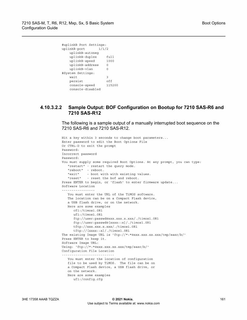
7210 SAS-M, T, R6, R12, Mxp, Sx, S Basic System Configuration Guide
Boot Options
3HE 17358 AAAB TQZZA © 2021 Nokia. Use subject to Terms available at: www.nokia.com
161
#uplinkB Port Settings:uplinkB-port 1/1/2
uplinkB-autoneguplinkB-duplex fulluplinkB-speed 1000uplinkB-address 0uplinkB-vlan 0
#System Settings:wait 3persist offconsole-speed 115200console-disabled
4.10.3.2.2 Sample Output: BOF Configuration on Bootup for 7210 SAS-R6 and 7210 SAS-R12
The following is a sample output of a manually interrupted boot sequence on the 7210 SAS-R6 and 7210 SAS-R12.
Hit a key within 3 seconds to change boot parameters...Enter password to edit the Boot Options FileOr CTRL-D to exit the promptPassword:Incorrect passwordPassword:You must supply some required Boot Options. At any prompt, you can type:
"restart" - restart the query mode."reboot" - reboot."exit" - boot with with existing values."reset" - reset the bof and reboot.
Press ENTER to begin, or 'flash' to enter firmware update...Software Location-----------------
You must enter the URL of the TiMOS software.The location can be on a Compact Flash device,a USB flash drive, or on the network.Here are some examples
cf1:/timos1.0R1uf1:/timos1.0R1ftp://user:[email protected]/./timos1.0R1ftp://user:passwd@[xxxx::x]/./timos1.0R1tftp://xxx.xxx.x.xxx/./timos1.0R1tftp://[xxxx::x]/./timos1.0R1
The existing Image URL is 'ftp://*:*@xxx.xxx.xx.xxx/tmp/sasr/b/'Press ENTER to keep it.Software Image URL:Using: 'ftp://*:*@xxx.xxx.xx.xxx/tmp/sasr/b/'Configuration File Location---------------------------
You must enter the location of configurationfile to be used by TiMOS. The file can be ona Compact Flash device, a USB flash drive, oron the network.Here are some examples
uf1:/config.cfg

Boot Options
162
7210 SAS-M, T, R6, R12, Mxp, Sx, S Basic SystemConfiguration Guide
© 2021 Nokia. Use subject to Terms available at: www.nokia.com
3HE 17358 AAAB TQZZA
cf1:/config.cfgftp://user:[email protected]/./config.cfgftp://user:passwd@[xxxx::x]/./config.cfgtftp://xxx.xxx.x.xxx/./config.cfgtftp://[xxxx::x]/./config.cfg
The existing Config URL is 'uf1:\SASR2553.cfg'Press ENTER to keep it, or the word 'none' for no Config URL.Config File URL:Using: 'uf1:\SASR2553.cfg'Network Configuration---------------------
You specified a network location for either thesoftware or the configuration file. You need toassign an IP(v6) address for this system.The IP address should be entered in standarddotted decimal form with a network length.
example: 192.168.1.169/24Existing eth-mgmt port settings are:
eth-mgmt-porteth-mgmt-address xx.xxx.xx.xx/24 activeeth-mgmt-address xx.xxx.xx.xx/24 standbyeth-mgmt-address 0 activeeth-mgmt-address 0 standbyeth-mgmt-route x.x.x.x/24 next-hop xx.xxx.xx.xeth-mgmt-route x.x.x.x/24 next-hop xx.xxx.xx.xeth-mgmt-route xx.xxx.x.x/16 next-hop xx.xxx.xx.xeth-mgmt-route xxx.x.x.x/8 next-hop xx.xxx.xx.xeth-mgmt port is configured for Boot Interface Management,Press ENTER to proceed with existing port settingsOr "disable" to disable the port for Boot Interface ManagementOr "edit" to change the port settings: editYou need to assign an IP address for this port.The IP address should be entered in standarddotted decimal form with a network length.example: 192.168.1.169/24
The existing eth-mgmt Active IP address is xx.xxx.xx.xx/24. Press ENTER to keep it.Enter eth-mgmt Active IP Address : xx.xxx.xx.xx/24
In case of an IPv6, the IPv6 address should beentered in standard colon hexadecimal notationwith a prefix length.
example: 3FFE::1/112Enter eth-mgmt Active IPv6 Address (Type 0 if none desired): 0The existing eth-mgmt Standby IP address is xx.xxx.xx.xx/24. Press ENTER to keep it.Enter eth-mgmt Standby IP Address : xx.xxx.xx.xx/24
In case of an IPv6, the IPv6 address should beentered in standard colon hexadecimal notationwith a prefix length.
example: 3FFE::1/112Enter eth-mgmt Standby IPv6 Address (Type 0 if none desired): 0
You specified network locations which might requirestatic routes to reach. You will be asked toenter static routes until all the locations becomereachable.Static routes should be entered in the following format:prefix/mask next-hop ip-addressexample: 192.168.0.0/16 next-hop 192.168.1.254
A static route to the Primary Image exists: xxx.x.x.x/8 next-hop xx.xxx.xx.xDo you want to keep it? (yes/no) yWould you like to add a static route? (yes/no) yes
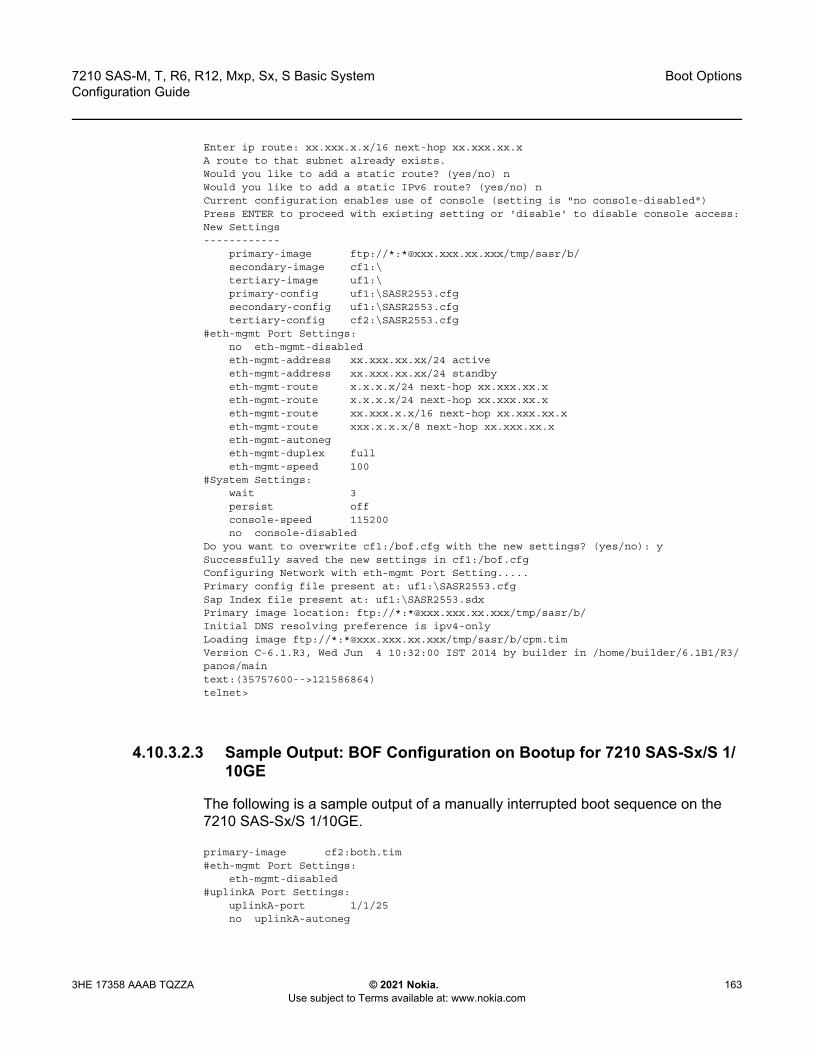
7210 SAS-M, T, R6, R12, Mxp, Sx, S Basic System Configuration Guide
Boot Options
3HE 17358 AAAB TQZZA © 2021 Nokia. Use subject to Terms available at: www.nokia.com
163
Enter ip route: xx.xxx.x.x/16 next-hop xx.xxx.xx.xA route to that subnet already exists.Would you like to add a static route? (yes/no) nWould you like to add a static IPv6 route? (yes/no) nCurrent configuration enables use of console (setting is "no console-disabled")Press ENTER to proceed with existing setting or 'disable' to disable console access:New Settings------------
primary-image ftp://*:*@xxx.xxx.xx.xxx/tmp/sasr/b/secondary-image cf1:\tertiary-image uf1:\primary-config uf1:\SASR2553.cfgsecondary-config uf1:\SASR2553.cfgtertiary-config cf2:\SASR2553.cfg
#eth-mgmt Port Settings:no eth-mgmt-disabledeth-mgmt-address xx.xxx.xx.xx/24 activeeth-mgmt-address xx.xxx.xx.xx/24 standbyeth-mgmt-route x.x.x.x/24 next-hop xx.xxx.xx.xeth-mgmt-route x.x.x.x/24 next-hop xx.xxx.xx.xeth-mgmt-route xx.xxx.x.x/16 next-hop xx.xxx.xx.xeth-mgmt-route xxx.x.x.x/8 next-hop xx.xxx.xx.xeth-mgmt-autonegeth-mgmt-duplex fulleth-mgmt-speed 100
#System Settings:wait 3persist offconsole-speed 115200no console-disabled
Do you want to overwrite cf1:/bof.cfg with the new settings? (yes/no): ySuccessfully saved the new settings in cf1:/bof.cfgConfiguring Network with eth-mgmt Port Setting.....Primary config file present at: uf1:\SASR2553.cfgSap Index file present at: uf1:\SASR2553.sdxPrimary image location: ftp://*:*@xxx.xxx.xx.xxx/tmp/sasr/b/Initial DNS resolving preference is ipv4-onlyLoading image ftp://*:*@xxx.xxx.xx.xxx/tmp/sasr/b/cpm.timVersion C-6.1.R3, Wed Jun 4 10:32:00 IST 2014 by builder in /home/builder/6.1B1/R3/panos/maintext:(35757600-->121586864)telnet>
4.10.3.2.3 Sample Output: BOF Configuration on Bootup for 7210 SAS-Sx/S 1/10GE
The following is a sample output of a manually interrupted boot sequence on the 7210 SAS-Sx/S 1/10GE.
primary-image cf2:both.tim#eth-mgmt Port Settings:
eth-mgmt-disabled#uplinkA Port Settings:
uplinkA-port 1/1/25no uplinkA-autoneg
Boot Options
164
7210 SAS-M, T, R6, R12, Mxp, Sx, S Basic SystemConfiguration Guide
© 2021 Nokia. Use subject to Terms available at: www.nokia.com
3HE 17358 AAAB TQZZA
uplinkA-duplex fulluplinkA-speed 10000uplinkA-address 0uplinkA-vlan 0
#uplinkB Port Settings:uplinkB-port 1/1/26no uplinkB-autoneguplinkB-duplex fulluplinkB-speed 10000uplinkB-address 0uplinkB-vlan 0
#System Settings:wait 3persist offconsole-speed 115200no console-disabledprimary-image ftp://*:*@xxx.xxx.xx.x/./images/SASS-hops-both.tim
#eth-mgmt Port Settings:eth-mgmt-disabled
#uplinkA Port Settings:uplinkA-port 1/1/1uplinkA-autoneguplinkA-duplex fulluplinkA-speed 1000uplinkA-address xxx.xxx.xx.xxx/24uplinkA-vlan 0uplinkA-route xxx.xxx.x.x/16 next-hop xxx.xxx.xx.x
#System Settings:wait 3persist offconsole-speed 115200no console-disabled
primary-image ftp://*:*@xx.xxx.xx.xxx/./images/SASS-hops-both.tim#eth-mgmt Port Settings:
no eth-mgmt-disabledeth-mgmt-address xx.xxx.xx.xxx/24 activeeth-mgmt-route xx.xxx.x.x/16 next-hop xx.xxx.xx.xxxeth-mgmt-autonegeth-mgmt-duplex fulleth-mgmt-speed 100
#System Settings:wait 3persist offconsole-speed 115200no console-disabled
primary-image uf1:both.tim#eth-mgmt Port Settings:
eth-mgmt-disabled#uplinkA Port Settings:
uplinkA-port 1/1/25no uplinkA-autoneguplinkA-duplex fulluplinkA-speed 10000uplinkA-address 0uplinkA-vlan 0
#uplinkB Port Settings:uplinkB-port 1/1/26no uplinkB-autoneguplinkB-duplex full

7210 SAS-M, T, R6, R12, Mxp, Sx, S Basic System Configuration Guide
Boot Options
3HE 17358 AAAB TQZZA © 2021 Nokia. Use subject to Terms available at: www.nokia.com
165
uplinkB-speed 10000uplinkB-address 0uplinkB-vlan 0
#System Settings:wait 3persist offconsole-speed 115200no console-disabled
4.10.3.3 Accessing the CLI
To access the CLI to configure the software for the first time, follow these steps.
1. When the power to the chassis is turned on, the 7210 SAS software automatically begins the boot sequence.
2. When the boot loader and BOF image and configuration files are successfully located, establish a router connection (console session).
See Console Connection for information about establishing a console connection.
4.10.3.4 Console Connection
To establish a console connection, you will need the following:
• an ASCII terminal or a PC running terminal emulation software set to the parameters described in Table 23
• a standard serial cable connector for connecting to a RS232 port (provides a RJ45 connector)
Table 23 lists the console configuration parameter values.
Table 23 Console Configuration Parameter Values
Parameter Value
Baud 115,200
Data bits 8
Parity None
Stop bits 1
Flow control None
Boot Options
166
7210 SAS-M, T, R6, R12, Mxp, Sx, S Basic SystemConfiguration Guide
© 2021 Nokia. Use subject to Terms available at: www.nokia.com
3HE 17358 AAAB TQZZA
4.10.3.5 Procedure to Connect to a Console
Perform this procedure to establish a console connection to any platform.
1. Connect the terminal to the Console port on the front panel using the serial cable. See Location of Console Ports on 7210 SAS Platforms for information about the console port and its placement on the 7210 SAS platforms.
2. Power on the terminal.3. Establish the connection by pressing the <Enter> key a few times on your
terminal keyboard.4. At the router prompt, enter the login and password.
The default login is admin.The default password is admin.
4.10.3.6 Location of Console Ports on 7210 SAS Platforms
This section provides console port information, supported variants, and modes of operation for the following 7210 SAS platforms:
• 7210 SAS-M Console Port• 7210 SAS-T Console Port• 7210 SAS-R6 Console Port• 7210 SAS-R12 Console Port• 7210 SAS-Mxp Console Port• 7210 SAS-Sx 1/10GE Console Port• 7210 SAS-S 1/10GE Console Port• 7210 SAS-Sx 10/100GE Console Port
4.10.3.6.1 7210 SAS-M Console Port
The 7210 SAS-M is a multilayer service-aware MPLS-capable switch. It supports two modes of operation:
• access-uplink mode (only L2 uplinks)• network mode (L2 or MPLS uplinks)
The switch is available as two variants, as follows:
• 7210 SAS-M 24F with support for up to 24 100/1000 SFP ports (see Figure 11)
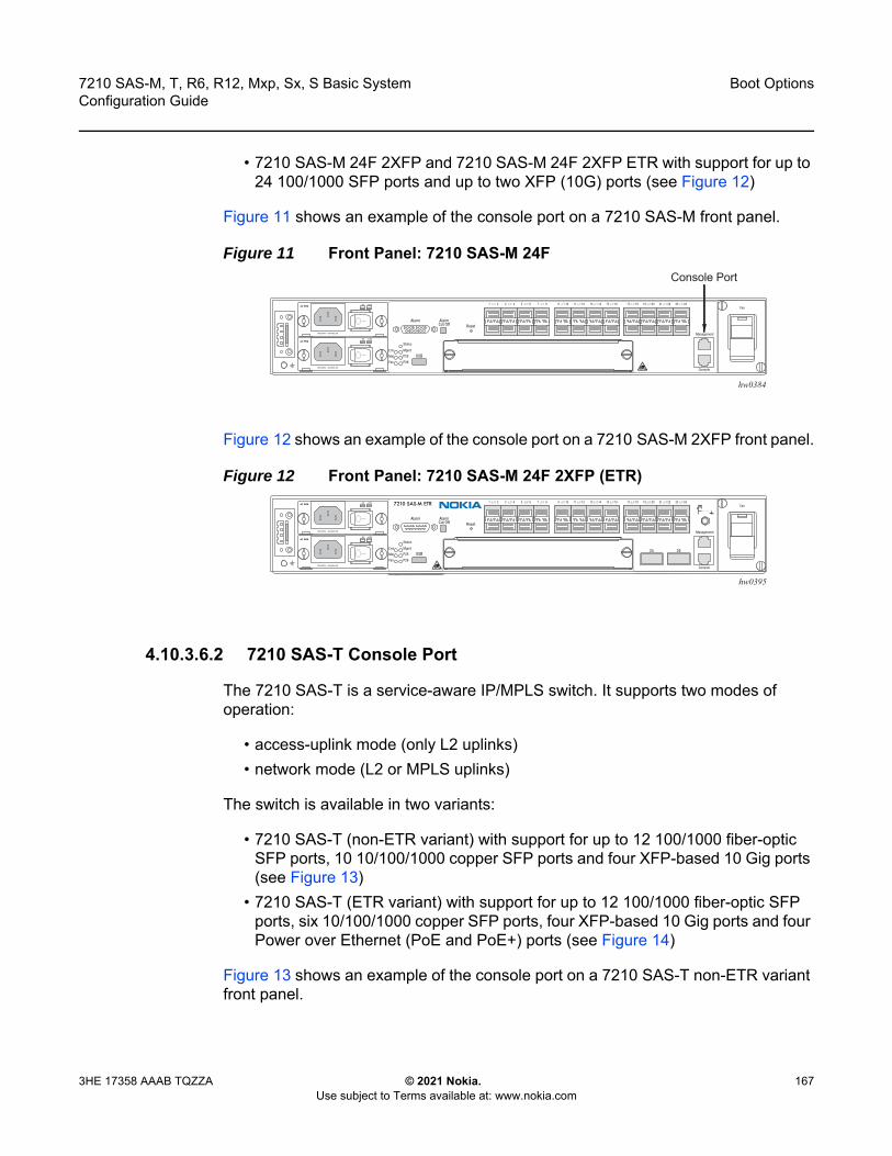
7210 SAS-M, T, R6, R12, Mxp, Sx, S Basic System Configuration Guide
Boot Options
3HE 17358 AAAB TQZZA © 2021 Nokia. Use subject to Terms available at: www.nokia.com
167
• 7210 SAS-M 24F 2XFP and 7210 SAS-M 24F 2XFP ETR with support for up to 24 100/1000 SFP ports and up to two XFP (10G) ports (see Figure 12)
Figure 11 shows an example of the console port on a 7210 SAS-M front panel.
Figure 11 Front Panel: 7210 SAS-M 24F
Figure 12 shows an example of the console port on a 7210 SAS-M 2XFP front panel.
Figure 12 Front Panel: 7210 SAS-M 24F 2XFP (ETR)
4.10.3.6.2 7210 SAS-T Console Port
The 7210 SAS-T is a service-aware IP/MPLS switch. It supports two modes of operation:
• access-uplink mode (only L2 uplinks)• network mode (L2 or MPLS uplinks)
The switch is available in two variants:
• 7210 SAS-T (non-ETR variant) with support for up to 12 100/1000 fiber-optic SFP ports, 10 10/100/1000 copper SFP ports and four XFP-based 10 Gig ports (see Figure 13)
• 7210 SAS-T (ETR variant) with support for up to 12 100/1000 fiber-optic SFP ports, six 10/100/1000 copper SFP ports, four XFP-based 10 Gig ports and four Power over Ethernet (PoE and PoE+) ports (see Figure 14)
Figure 13 shows an example of the console port on a 7210 SAS-T non-ETR variant front panel.
Crit
hw0384
Console Port
Crit
hw0395
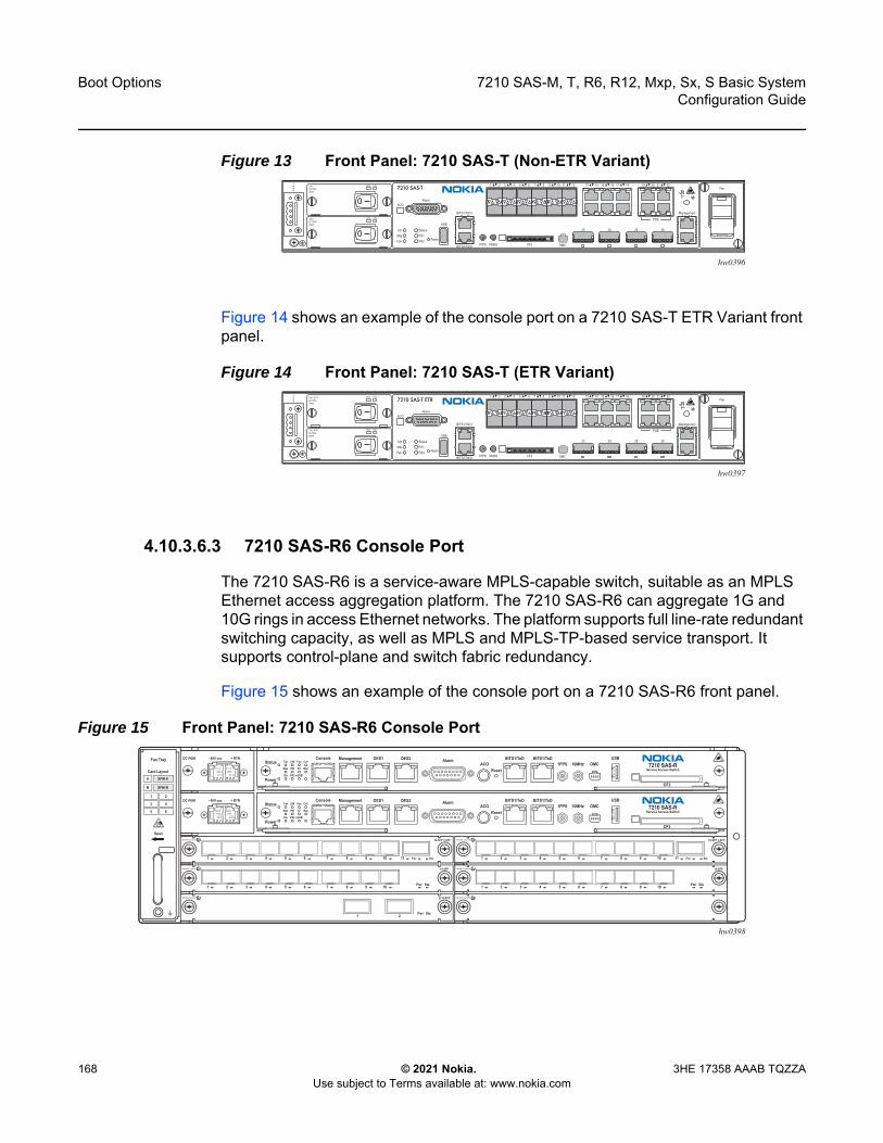
Boot Options
168
7210 SAS-M, T, R6, R12, Mxp, Sx, S Basic SystemConfiguration Guide
© 2021 Nokia. Use subject to Terms available at: www.nokia.com
3HE 17358 AAAB TQZZA
Figure 13 Front Panel: 7210 SAS-T (Non-ETR Variant)
Figure 14 shows an example of the console port on a 7210 SAS-T ETR Variant front panel.
Figure 14 Front Panel: 7210 SAS-T (ETR Variant)
4.10.3.6.3 7210 SAS-R6 Console Port
The 7210 SAS-R6 is a service-aware MPLS-capable switch, suitable as an MPLS Ethernet access aggregation platform. The 7210 SAS-R6 can aggregate 1G and 10G rings in access Ethernet networks. The platform supports full line-rate redundant switching capacity, as well as MPLS and MPLS-TP-based service transport. It supports control-plane and switch fabric redundancy.
Figure 15 shows an example of the console port on a 7210 SAS-R6 front panel.
Figure 15 Front Panel: 7210 SAS-R6 Console Port
CritMajFan
StatusPS1PS2
USB
Alarm
+24V +12V+24VDC PEM200W
+24V +12V+24VDC PEM200W
CF2 OMC
23 24 25 26
Management
POE
Fan
1PPSBITS2/ToD2
BITS1/ToD1
10MHz
ACO
1 2 3 4 5 6 7 8 9 10 11 12 13 14 15 16 17 18 19 20 21 22–A+A–B+B
hw0396
Reset
CritMajFan
StatusPS1PS2
USB
Alarm
+24V +12V+24V ETRDC PEM200W
+24V +12V+24V ETRDC PEM200W
CF2 OMC
23 24 25 26
Management
POE
Fan
1PPSBITS2/ToD2
BITS1/ToD1
10MHz
ACO
1 2 3 4 5 6 7 8 9 10 11 12 13 14 15 16 17 18 19 20 21 22–A+A–B+B
hw0397
Reset
7210 SAS-T ETR
hw0398
Fan Tray
Card Layout
Open
A
B
Tim 24V Fan Crit
Mas PSI CF Maj
Sla PS2 eUSB
StatusConsole Management OES1 OES2 Alarm
ACO 1PPS 10MHz OMCUSB
CF2
7210 SAS-RService Access Switch
BITS1/ToD BITS1/ToD
Reset
Power
Tim 24V Fan Crit
Mas PSI CF Maj
Sla PS2 eUSB
StatusConsole Management OES1 OES2 Alarm
ACO 1PPS 10MHz OMCUSB
CF2
7210 SAS-RService Access Switch
BITS1/ToD BITS1/ToD
Reset
Power
10-SFP 1-XFP
1 2 3 4 5 6 7 8 11109 Pwr Sta
10-SFP 1-XFP
1 2 3 4 5 6 7 8 11109 Pwr Sta
10-SFP
1 2 3 4 5 6 7 8 109 Pwr Sta
10-SFP
1 2 3 4 5 6 7 8 109 Pwr Sta
2x10-XFP
Pwr Sta21
+ RTN- 48V DC PEM
+ RTN- 48V DC PEM
SFM A
1 2
3 4
5 6
SFM B
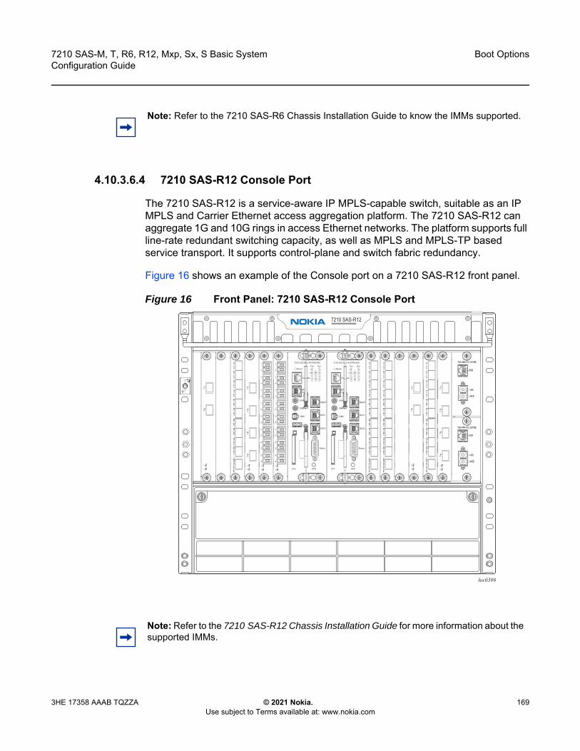
7210 SAS-M, T, R6, R12, Mxp, Sx, S Basic System Configuration Guide
Boot Options
3HE 17358 AAAB TQZZA © 2021 Nokia. Use subject to Terms available at: www.nokia.com
169
4.10.3.6.4 7210 SAS-R12 Console Port
The 7210 SAS-R12 is a service-aware IP MPLS-capable switch, suitable as an IP MPLS and Carrier Ethernet access aggregation platform. The 7210 SAS-R12 can aggregate 1G and 10G rings in access Ethernet networks. The platform supports full line-rate redundant switching capacity, as well as MPLS and MPLS-TP based service transport. It supports control-plane and switch fabric redundancy.
Figure 16 shows an example of the Console port on a 7210 SAS-R12 front panel.
Figure 16 Front Panel: 7210 SAS-R12 Console Port
Note: Refer to the 7210 SAS-R6 Chassis Installation Guide to know the IMMs supported.
hw0399
Note: Refer to the 7210 SAS-R12 Chassis Installation Guide for more information about the supported IMMs.

Boot Options
170
7210 SAS-M, T, R6, R12, Mxp, Sx, S Basic SystemConfiguration Guide
© 2021 Nokia. Use subject to Terms available at: www.nokia.com
3HE 17358 AAAB TQZZA
4.10.3.6.5 7210 SAS-Mxp Console Port
The 7210 SAS-Mxp is a non-blocking, service-aware IP/MPLS switch that supports the SR OS with 64Gbps (full-duplex) of switching capacity. It is available in two variants: Standard (Standard operating temperature range), and ETR (Extended Temperature Range). The 7210 SAS-Mxp can be operated in standalone or satellite mode.
The 7210 SAS-Mxp ETR CC (Conformal Coating) variant is conformally coated to provide additional protection against environmental contaminants that cause corrosion of the components when the platform is deployed in harsh environments. The 7210 SAS-Mxp ETR CC includes a -48V DC power supply. It supports an extended operating range of –40° to 149°F (–40° to 65°C) and includes two PoE/PoE+ ports.
Figure 17 shows an example of the console port on a 7210 SAS-Mxp front panel.
Figure 17 Front Panel: 7210 SAS-Mxp Console Port
4.10.3.6.6 7210 SAS-Sx 1/10GE Console Port
The 7210 SAS-Sx 1/10GE is an IP/MPLS Ethernet device for business service applications and Ethernet mobile backhaul applications to be used as an access device or as an access aggregation device. It can also be operated in satellite mode, where it provides port expansion, allowing users to break out the 10GE ports on the 7x50 to 1GE ports.
7210 SAS-Sx 1/10GE is available in six variants:
• 7210 SAS-Sx 1/10GE 46F 2C 4SFP+ • 7210 SAS-Sx 1/10GE 22F 2C 4SFP+• 7210 SAS-Sx 1/10GE 48T 4SFP+• 7210 SAS-Sx 1/10GE 24T 4SFP+• 7210 SAS-Sx 1/10GE 48Tp 4SFP+ PoE • 7210 SAS-Sx 1/10GE 24Tp 4SFP+ PoE
hw0400

7210 SAS-M, T, R6, R12, Mxp, Sx, S Basic System Configuration Guide
Boot Options
3HE 17358 AAAB TQZZA © 2021 Nokia. Use subject to Terms available at: www.nokia.com
171
All variants are 1RU platforms, designed to be NEBS compliant, supporting line-rate switching on all the ports, with the option for a redundant hot-swappable power supply. They also provide a console port and out-of-band Ethernet management interface on the rear of the chassis.
• The 7210 SAS-Sx 1/10GE 46F 2C 4SFP+ and 7210 SAS-Sx 1/10GE 22F 2C 4SFP+ allow for 48 SFP ports and 24 SFP ports respectively, along with an option to use copper interfaces on two ports.
• The 7210 SAS-Sx 1/10GE 48T 4SFP+ and 7210 SAS-Sx 1/10GE 24T 4SFP+ allow for 48 10/100/1000Mbps copper ports and 24 10/100/1000Mbps copper ports respectively.
• The 7210 SAS-Sx 1/10GE 48Tp 4SFP+ PoE and 7210 SAS-Sx 1/10GE 24Tp 4SFP+ POE allow for 48 10/100/1000Mbps copper ports and 24 10/100/1000Mbps copper ports respectively, along with option to use PoE/PoE+, with a maximum of 720W of power being available to PoE devices across all the ports.
In addition, all variants support 4 x 10GE SFP+ ports that can be used as uplinks.
The following variants support the use of a 1GE fiber-optic SFP in a 10GE SFP+ port:
• 7210 SAS-Sx 1/10GE 48T 4SFP+• 7210 SAS-Sx 1/10GE 24T 4SFP+• 7210 SAS-Sx 1/10GE 48Tp 4SFP+ PoE • 7210 SAS-Sx 1/10GE 24Tp 4SFP+ PoE
With this functionality, operators can use either 1GE or 10GE fiber uplinks. This enhancement provides the flexibility of using SFP+ ports as 1GE uplinks with the capability to move to 10GE uplinks as bandwidth demands grow. This functionality is supported for standalone mode only.
For a list of SFPs supported for 1GE operation, contact your Nokia representative.
The 7210 SAS-Sx 1/10GE can be operated in two modes – Standalone mode and Satellite mode.
Note:
• Before using a 1GE SFP in an SFP+ port, the SFP+ port speed must be set to 1000 Mb/s with the config>port>ethernet>speed command; otherwise, an error message is generated indicating that the SFP is unsupported. For information about setting the port speed, refer to the Ethernet Port Commands section of the 7210 SAS-M, T, R6, R12, Mxp, Sx, S Interface Configuration Guide.
• SFP+ ports that support SFPs do not support speeds of 10 Mb/s or 100 Mb/s.
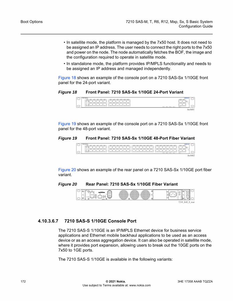
Boot Options
172
7210 SAS-M, T, R6, R12, Mxp, Sx, S Basic SystemConfiguration Guide
© 2021 Nokia. Use subject to Terms available at: www.nokia.com
3HE 17358 AAAB TQZZA
• In satellite mode, the platform is managed by the 7x50 host. It does not need to be assigned an IP address. The user needs to connect the right ports to the 7x50 and power on the node. The node automatically fetches the BOF, the image and the configuration required to operate in satellite mode.
• In standalone mode, the platform provides IP/MPLS functionality and needs to be assigned an IP address and managed independently.
Figure 18 shows an example of the console port on a 7210 SAS-Sx 1/10GE front panel for the 24-port variant.
Figure 18 Front Panel: 7210 SAS-Sx 1/10GE 24-Port Variant
Figure 19 shows an example of the console port on a 7210 SAS-Sx 1/10GE front panel for the 48-port variant.
Figure 19 Front Panel: 7210 SAS-Sx 1/10GE 48-Port Fiber Variant
Figure 20 shows an example of the rear panel on a 7210 SAS-Sx 1/10GE port fiber variant.
Figure 20 Rear Panel: 7210 SAS-Sx 1/10GE Fiber Variant
4.10.3.6.7 7210 SAS-S 1/10GE Console Port
The 7210 SAS-S 1/10GE is an IP/MPLS Ethernet device for business service applications and Ethernet mobile backhaul applications to be used as an access device or as an access aggregation device. It can also be operated in satellite mode, where it provides port expansion, allowing users to break out the 10GE ports on the 7x50 to 1GE ports.
The 7210 SAS-S 1/10GE is available in the following variants:
hw0401RPSPS2PS1 Fan
13 14 15 16 17 18 19 20 21 22 23 24 25 26 2711 129 107 85 63 41 2
Stat
hw0402RPSPS2PS1 StatFan
13 14 15 16 17 18 19 20 21 22 23 24 25 26 27 28 29 30 31 32 33 34 35 36 37 38 39 40 41 42 43 44 45 46 49 50 51 5247 4811 129 107 85 63 41 2
7210_SAS_S_rear
7210 SAS-M, T, R6, R12, Mxp, Sx, S Basic System Configuration Guide
Boot Options
3HE 17358 AAAB TQZZA © 2021 Nokia. Use subject to Terms available at: www.nokia.com
173
• 7210 SAS-S 1/10GE 48F 4SFP+ AC• 7210 SAS-S 1/10GE 48F 4SFP+ DC• 7210 SAS-S 1/10GE 24F 4SFP+ AC • 7210 SAS-S 1/10GE 24F 4SFP+ DC • 7210 SAS-S 1/10GE 48T 4SFP+ AC• 7210 SAS-S 1/10GE 48T 4SFP+ DC• 7210 SAS-S 1/10GE 24T 4SFP+ AC• 7210 SAS-S 1/10GE 24T 4SFP+ DC• 7210 SAS-S 1/10GE 48Tp 4SFP+ AC PoE • 7210 SAS-S 1/10GE 24Tp 4SFP+ AC PoE
The variants are 1RU platforms, supporting line-rate switching on all the ports, with a single AC or DC integrated power supply and an option for redundant hot-swappable power supplies. They also provide a console port and OOB Ethernet management interface. The user has the option to use either 48-port or 24-port fiber or copper variants. All the variants support 4 x 10GE SFP+ ports.
The 7210 SAS-S 1/10GE 48Tp 4SFP+ AC PoE and 7210 SAS-S 1/10GE 24Tp 4SFP+ AC POE allow for 48 10/100/1000Mbps copper ports and 24 10/100/1000Mbps copper ports respectively, along with option to use PoE/PoE+, with a maximum of 720W of power being available to PoE devices across all the ports.
The following variants support the use of a 1GE fiber-optic SFP in a 10GE SFP+ port:
• 7210 SAS-S 1/10GE 48T 4SFP+ AC• 7210 SAS-S 1/10GE 48T 4SFP+ DC• 7210 SAS-S 1/10GE 24T 4SFP+ AC• 7210 SAS-S 1/10GE 24T 4SFP+ DC
With this functionality, operators can use either 1GE or 10GE fiber uplinks. This enhancement provides the flexibility of using SFP+ ports as 1GE uplinks with the capability to move to 10GE uplinks as bandwidth demands grow. This functionality is supported for standalone mode only.
For a list of SFPs supported for 1GE operation, contact your Nokia representative.

Boot Options
174
7210 SAS-M, T, R6, R12, Mxp, Sx, S Basic SystemConfiguration Guide
© 2021 Nokia. Use subject to Terms available at: www.nokia.com
3HE 17358 AAAB TQZZA
The 7210 SAS-S 1/10GE can be operated in two modes: standalone mode and satellite mode.
• In satellite mode, it provides port expansion function and the platform is managed by the 7x50 host. It does not need to be assigned an IP address. User needs to connect the right ports to the 7x50 and power on the node. The node automatically fetches the BOF, the image and the configuration required to operate in satellite mode.
• In standalone mode, the platform provides IP/MPLS functionality and needs to be assigned an IP address and managed independently.
4.10.3.6.8 7210 SAS-Sx 10/100GE Console Port
The 7210 SAS-Sx 10/100GE 64SFP+ 4CFP4 and 7210 SAS-Sx 10/100GE 64SFP+ 4QSFP28 variants each provide 64 1GE/10GE SFP+ ports and 4 100GE CFP4 or QSFP28 ports, providing a platform for high-density 10GE Ethernet access and access aggregation with 100GE uplinks.
Both variants are 1.5RU platforms, with front access to all the 10GE and 100GE service interfaces. Both provide redundant hot-swappable power supplies (AC, -48V DC) and a non-removable set of fans on the rear of the chassis for cooling, with detection and notification of single fan failure. Both variants provide a Console port and out-of-band Ethernet management interface on the rear of the chassis.
Both variants support the use of a 1GE fiber-optic SFP in a 10GE SFP+ port. With this functionality, a single platform can be used to deliver both 1GE and 10GE services. This enables operators to continue to provide 1GE service or to build a 1GE access network and simultaneously migrate to deliver 10GE service and build a 10GE access network to address the growing bandwidth needs driven by cloud applications and migration to 4G/5G mobile networks. For a list of SFPs supported for 1GE operation, contact your Nokia representative.
Note:
• Before using a 1GE SFP in an SFP+ port, the SFP+ port speed must be set to 1000 Mb/s with the config>port>ethernet>speed command; otherwise, an error message is generated indicating that the SFP is unsupported. For information about setting the port speed, refer to the Ethernet Port Commands section of the 7210 SAS-M, T, R6, R12, Mxp, Sx, S Interface Configuration Guide.
• SFP+ ports that support SFPs do not support speeds of 10 Mb/s or 100 Mb/s.
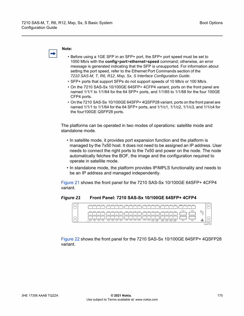
7210 SAS-M, T, R6, R12, Mxp, Sx, S Basic System Configuration Guide
Boot Options
3HE 17358 AAAB TQZZA © 2021 Nokia. Use subject to Terms available at: www.nokia.com
175
The platforms can be operated in two modes of operations: satellite mode and standalone mode.
• In satellite mode, it provides port expansion function and the platform is managed by the 7x50 host. It does not need to be assigned an IP address. User needs to connect the right ports to the 7x50 and power on the node. The node automatically fetches the BOF, the image and the configuration required to operate in satellite mode.
• In standalone mode, the platform provides IP/MPLS functionality and needs to be an IP address and managed independently.
Figure 21 shows the front panel for the 7210 SAS-Sx 10/100GE 64SFP+ 4CFP4 variant.
Figure 21 Front Panel: 7210 SAS-Sx 10/100GE 64SFP+ 4CFP4
Figure 22 shows the front panel for the 7210 SAS-Sx 10/100GE 64SFP+ 4QSFP28 variant.
Note:
• Before using a 1GE SFP in an SFP+ port, the SFP+ port speed must be set to 1000 Mb/s with the config>port>ethernet>speed command; otherwise, an error message is generated indicating that the SFP is unsupported. For information about setting the port speed, refer to the Ethernet Port Commands section of the 7210 SAS-M, T, R6, R12, Mxp, Sx, S Interface Configuration Guide.
• SFP+ ports that support SFPs do not support speeds of 10 Mb/s or 100 Mb/s.• On the 7210 SAS-Sx 10/100GE 64SFP+ 4CFP4 variant, ports on the front panel are
named 1/1/1 to 1/1/64 for the 64 SFP+ ports, and 1/1/65 to 1/1/68 for the four 100GE CFP4 ports.
• On the 7210 SAS-Sx 10/100GE 64SFP+ 4QSFP28 variant, ports on the front panel are named 1/1/1 to 1/1/64 for the 64 SFP+ ports, and 1/1/c1, 1/1/c2, 1/1/c3, and 1/1/c4 for the four100GE QSFP28 ports.
hw0743

Boot Options
176
7210 SAS-M, T, R6, R12, Mxp, Sx, S Basic SystemConfiguration Guide
© 2021 Nokia. Use subject to Terms available at: www.nokia.com
3HE 17358 AAAB TQZZA
Figure 22 Front Panel: 7210 SAS-Sx 10/100GE 64SFP+ 4QSFP28
4.10.3.7 Configuring BOF Parameters
See the following sections for sample output of a BOF configuration on 7210 SAS platforms:
• Sample Output: BOF Configuration for 7210 SAS-M, 7210 SAS-T, and 7210 SAS-Mxp
• Sample Output: BOF Configuration for 7210 SAS-R6• Sample Output: BOF Configuration for 7210 SAS-R12• Sample Output: BOF Configuration for 7210 SAS-Sx/S 1/10GE
4.10.3.7.1 Sample Output: BOF Configuration for 7210 SAS-M, 7210 SAS-T, and 7210 SAS-Mxp
The following is a sample output of a BOF configuration for the 7210 SAS-M, 7210 SAS-T, and 7210 SAS-Mxp.
A:7210>show# bof===============================================================================BOF (Memory)===============================================================================
primary-image ftp://*:*@xxx.xxx.xxx.xx//import/panos_builds/nightly/2.0 /S80/MTU-sultan/
primary-config tftp://xx.xxx.xx.xxx/MTU/mtu3DGP.cfg#eth-mgmt Port Settings:
eth-mgmt-disabled#uplinkA Port Settings:
uplinkA-port 1/1/24uplinkA-address xx.xxx.xx.xx/24
uplinkA-autoneguplinkA-duplex fulluplinkA-speed 1000
uplinkA-vlan 0#uplinkB Port Settings:
uplinkB-port 1/1/2uplinkB-address 0
uplinkB-autoneguplinkB-duplex fulluplinkB-speed 1000
hw0744
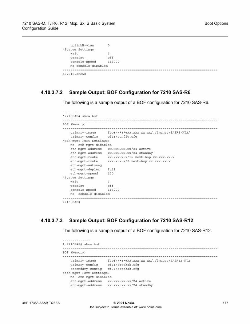
7210 SAS-M, T, R6, R12, Mxp, Sx, S Basic System Configuration Guide
Boot Options
3HE 17358 AAAB TQZZA © 2021 Nokia. Use subject to Terms available at: www.nokia.com
177
uplinkB-vlan 0#System Settings:
wait 3persist offconsole-speed 115200no console-disabled
===============================================================================A:7210>show#
4.10.3.7.2 Sample Output: BOF Configuration for 7210 SAS-R6
The following is a sample output of a BOF configuration for 7210 SAS-R6.
--------*7210SAS# show bof===============================================================================BOF (Memory)===============================================================================
primary-image ftp://*:*@xx.xxx.xx.xx/./images/SASR6-KT2/primary-config cf1:\config.cfg
#eth-mgmt Port Settings:no eth-mgmt-disabledeth-mgmt-address xx.xxx.xx.xx/24 activeeth-mgmt-address xx.xxx.xx.xx/24 standbyeth-mgmt-route xx.xxx.x.x/16 next-hop xx.xxx.xx.xeth-mgmt-route xxx.x.x.x/8 next-hop xx.xxx.xx.xeth-mgmt-autonegeth-mgmt-duplex fulleth-mgmt-speed 100
#System Settings:wait 3persist offconsole-speed 115200no console-disabled
===============================================================================7210 SAS#
4.10.3.7.3 Sample Output: BOF Configuration for 7210 SAS-R12
The following is a sample output of a BOF configuration for 7210 SAS-R12.
--------------A:7210SAS# show bof===============================================================================BOF (Memory)===============================================================================
primary-image ftp://*:*@xx.xxx.xx.xx/./images/SASR12-KT2primary-config cf1:\sreekak.cfgsecondary-config cf2:\sreekak.cfg
#eth-mgmt Port Settings:no eth-mgmt-disabledeth-mgmt-address xx.xxx.xx.xx/24 activeeth-mgmt-address xx.xxx.xx.xx/24 standby
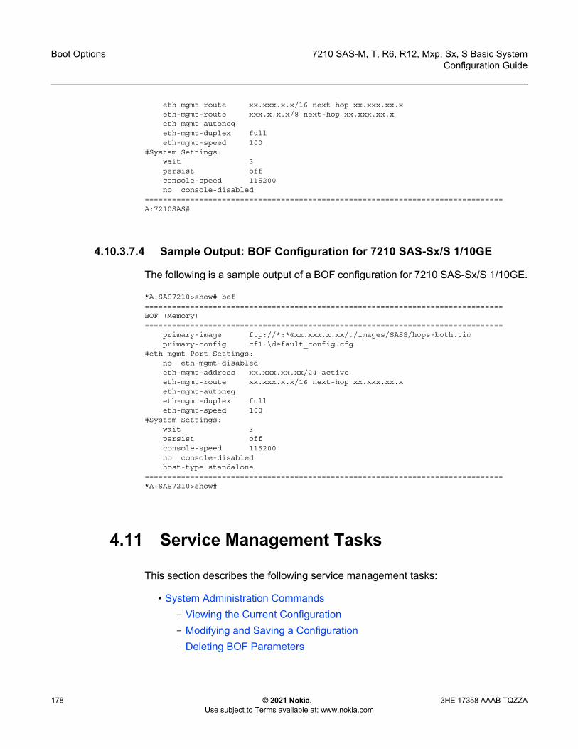
Boot Options
178
7210 SAS-M, T, R6, R12, Mxp, Sx, S Basic SystemConfiguration Guide
© 2021 Nokia. Use subject to Terms available at: www.nokia.com
3HE 17358 AAAB TQZZA
eth-mgmt-route xx.xxx.x.x/16 next-hop xx.xxx.xx.xeth-mgmt-route xxx.x.x.x/8 next-hop xx.xxx.xx.xeth-mgmt-autonegeth-mgmt-duplex fulleth-mgmt-speed 100
#System Settings:wait 3persist offconsole-speed 115200no console-disabled
===============================================================================A:7210SAS#
4.10.3.7.4 Sample Output: BOF Configuration for 7210 SAS-Sx/S 1/10GE
The following is a sample output of a BOF configuration for 7210 SAS-Sx/S 1/10GE.
*A:SAS7210>show# bof===============================================================================BOF (Memory)===============================================================================
primary-image ftp://*:*@xx.xxx.x.xx/./images/SASS/hops-both.timprimary-config cf1:\default_config.cfg
#eth-mgmt Port Settings:no eth-mgmt-disabledeth-mgmt-address xx.xxx.xx.xx/24 activeeth-mgmt-route xx.xxx.x.x/16 next-hop xx.xxx.xx.xeth-mgmt-autonegeth-mgmt-duplex fulleth-mgmt-speed 100
#System Settings:wait 3persist offconsole-speed 115200no console-disabledhost-type standalone
===============================================================================*A:SAS7210>show#
4.11 Service Management Tasks
This section describes the following service management tasks:
• System Administration Commands- Viewing the Current Configuration- Modifying and Saving a Configuration- Deleting BOF Parameters

7210 SAS-M, T, R6, R12, Mxp, Sx, S Basic System Configuration Guide
Boot Options
3HE 17358 AAAB TQZZA © 2021 Nokia. Use subject to Terms available at: www.nokia.com
179
- Saving a Configuration to a Different Filename- Rebooting
4.11.1 System Administration Commands
Use the following administrative commands to perform management tasks.
CLI Syntax: A:ALA-1# adminauto-init stopcheck-golden-bootstrapdebug-save [<file-url>]disconnect [address <ip-address> | username <user-
name> | {console|telnet|ftp|ssh}]display-config[no] enable-techreboot [upgrade][auto-init][now]save [file-url] [detail] [index]set-time <date> <time>tech-support <file-url>update-golden-bootstrap [file-url]
4.11.1.1 Viewing the Current Configuration
Use one of the following CLI commands to display the current configuration. The detail option displays all default values. The index option displays only the persistent indexes. The info command displays context-level information.
CLI Syntax: admin# display-config [detail|index]info detail
The following is a sample configuration file.
*A:sim169# admin display-config# TiMOS-B-0.0.I218 both/i386 NOKIA SAS-M 7210 Copyright (c) 2016.# All rights reserved. All use subject to applicable license agreements.# Built on Fri Sep 26 20:46:58 IST 2016 by panosbld in /panosbld/ws/panos/main
# Generated THU JUN 23 19:19:22 2016 UTC
exit allconfigure#--------------------------------------------------echo "System Configuration"#--------------------------------------------------
system
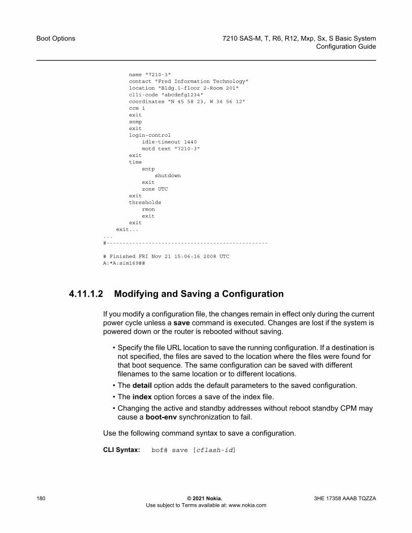
Boot Options
180
7210 SAS-M, T, R6, R12, Mxp, Sx, S Basic SystemConfiguration Guide
© 2021 Nokia. Use subject to Terms available at: www.nokia.com
3HE 17358 AAAB TQZZA
name "7210-3"contact "Fred Information Technology"location "Bldg.1-floor 2-Room 201"clli-code "abcdefg1234"coordinates "N 45 58 23, W 34 56 12"ccm 1exitsnmpexitlogin-control
idle-timeout 1440motd text "7210-3"
exittime
sntpshutdown
exitzone UTC
exitthresholds
rmonexit
exitexit...
...#--------------------------------------------------
# Finished FRI Nov 21 15:06:16 2008 UTCA:*A:sim169##
4.11.1.2 Modifying and Saving a Configuration
If you modify a configuration file, the changes remain in effect only during the current power cycle unless a save command is executed. Changes are lost if the system is powered down or the router is rebooted without saving.
• Specify the file URL location to save the running configuration. If a destination is not specified, the files are saved to the location where the files were found for that boot sequence. The same configuration can be saved with different filenames to the same location or to different locations.
• The detail option adds the default parameters to the saved configuration. • The index option forces a save of the index file.• Changing the active and standby addresses without reboot standby CPM may
cause a boot-env synchronization to fail.
Use the following command syntax to save a configuration.
CLI Syntax: bof# save [cflash-id]
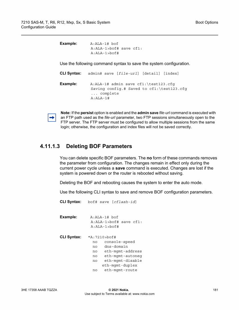
7210 SAS-M, T, R6, R12, Mxp, Sx, S Basic System Configuration Guide
Boot Options
3HE 17358 AAAB TQZZA © 2021 Nokia. Use subject to Terms available at: www.nokia.com
181
Example: A:ALA-1# bofA:ALA-1>bof# save cf1:A:ALA-1>bof#
Use the following command syntax to save the system configuration.
CLI Syntax: admin# save [file-url] [detail] [index]
Example: A:ALA-1# admin save cf1:\test123.cfgSaving config.# Saved to cf1:\test123.cfg... completeA:ALA-1#
4.11.1.3 Deleting BOF Parameters
You can delete specific BOF parameters. The no form of these commands removes the parameter from configuration. The changes remain in effect only during the current power cycle unless a save command is executed. Changes are lost if the system is powered down or the router is rebooted without saving.
Deleting the BOF and rebooting causes the system to enter the auto mode.
Use the following CLI syntax to save and remove BOF configuration parameters.
CLI Syntax: bof# save [cflash-id]
Example: A:ALA-1# bofA:ALA-1>bof# save cf1:A:ALA-1>bof#
CLI Syntax: *A:7210>bof# no console-speed no dns-domain no eth-mgmt-address no eth-mgmt-autoneg no eth-mgmt-disable eth-mgmt-duplex no eth-mgmt-route
Note: If the persist option is enabled and the admin save file-url command is executed with an FTP path used as the file-url parameter, two FTP sessions simultaneously open to the FTP server. The FTP server must be configured to allow multiple sessions from the same login; otherwise, the configuration and index files will not be saved correctly.
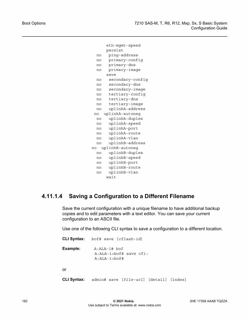
Boot Options
182
7210 SAS-M, T, R6, R12, Mxp, Sx, S Basic SystemConfiguration Guide
© 2021 Nokia. Use subject to Terms available at: www.nokia.com
3HE 17358 AAAB TQZZA
eth-mgmt-speed persist no ping-address no primary-config no primary-dns no primary-image save no secondary-config no secondary-dns no secondary-image no tertiary-config no tertiary-dns no tertiary-image no uplinkA-address no uplinkA-autoneg no uplinkA-duplex no uplinkA-speed no uplinkA-port no uplinkA-route no uplinkA-vlan no uplinkB-address no uplinkB-autoneg no uplinkB-duplex no uplinkB-speed no uplinkB-port no uplinkB-route no uplinkB-vlan wait
4.11.1.4 Saving a Configuration to a Different Filename
Save the current configuration with a unique filename to have additional backup copies and to edit parameters with a text editor. You can save your current configuration to an ASCII file.
Use one of the following CLI syntax to save a configuration to a different location.
CLI Syntax: bof# save [cflash-id]
Example: A:ALA-1# bofA:ALA-1>bof# save cf1:A:ALA-1>bof#
or
CLI Syntax: admin# save [file-url] [detail] [index]
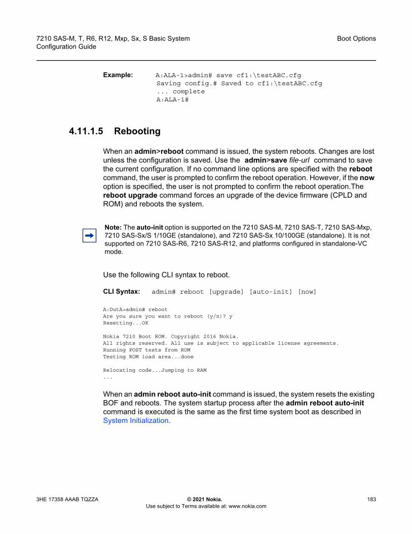
7210 SAS-M, T, R6, R12, Mxp, Sx, S Basic System Configuration Guide
Boot Options
3HE 17358 AAAB TQZZA © 2021 Nokia. Use subject to Terms available at: www.nokia.com
183
Example: A:ALA-1>admin# save cf1:\testABC.cfgSaving config.# Saved to cf1:\testABC.cfg... completeA:ALA-1#
4.11.1.5 Rebooting
When an admin>reboot command is issued, the system reboots. Changes are lost unless the configuration is saved. Use the admin>save file-url command to save the current configuration. If no command line options are specified with the reboot command, the user is prompted to confirm the reboot operation. However, if the now option is specified, the user is not prompted to confirm the reboot operation.The reboot upgrade command forces an upgrade of the device firmware (CPLD and ROM) and reboots the system.
Use the following CLI syntax to reboot.
CLI Syntax: admin# reboot [upgrade] [auto-init] [now]
A:DutA>admin# rebootAre you sure you want to reboot (y/n)? yResetting...OK
Nokia 7210 Boot ROM. Copyright 2016 Nokia.All rights reserved. All use is subject to applicable license agreements.Running POST tests from ROMTesting ROM load area...done
Relocating code...Jumping to RAM...
When an admin reboot auto-init command is issued, the system resets the existing BOF and reboots. The system startup process after the admin reboot auto-init command is executed is the same as the first time system boot as described in System Initialization.
Note: The auto-init option is supported on the 7210 SAS-M, 7210 SAS-T, 7210 SAS-Mxp, 7210 SAS-Sx/S 1/10GE (standalone), and 7210 SAS-Sx 10/100GE (standalone). It is not supported on 7210 SAS-R6, 7210 SAS-R12, and platforms configured in standalone-VC mode.
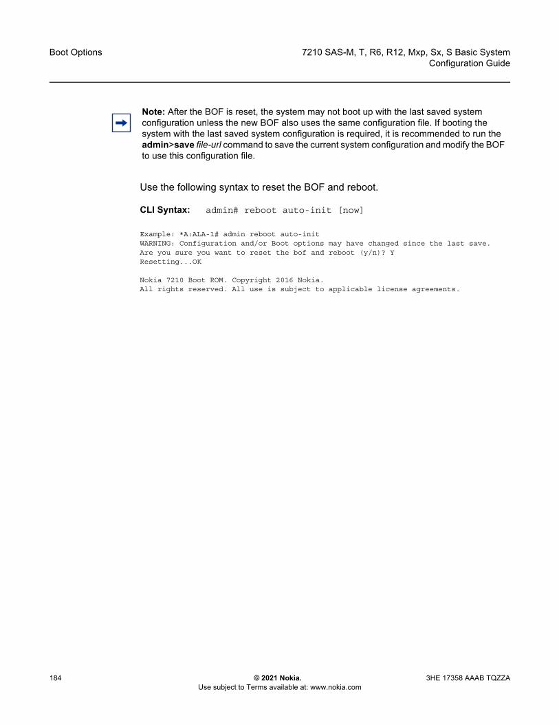
Boot Options
184
7210 SAS-M, T, R6, R12, Mxp, Sx, S Basic SystemConfiguration Guide
© 2021 Nokia. Use subject to Terms available at: www.nokia.com
3HE 17358 AAAB TQZZA
Use the following syntax to reset the BOF and reboot.
CLI Syntax: admin# reboot auto-init [now]
Example: *A:ALA-1# admin reboot auto-initWARNING: Configuration and/or Boot options may have changed since the last save.Are you sure you want to reset the bof and reboot (y/n)? YResetting...OK
Nokia 7210 Boot ROM. Copyright 2016 Nokia.All rights reserved. All use is subject to applicable license agreements.
Note: After the BOF is reset, the system may not boot up with the last saved system configuration unless the new BOF also uses the same configuration file. If booting the system with the last saved system configuration is required, it is recommended to run the admin>save file-url command to save the current system configuration and modify the BOF to use this configuration file.

7210 SAS-M, T, R6, R12, Mxp, Sx, S Basic System Configuration Guide
Boot Options
3HE 17358 AAAB TQZZA © 2021 Nokia. Use subject to Terms available at: www.nokia.com
185
4.12 BOF Command Reference
4.12.1 Command Hierarchies
4.12.1.1 Configuration Commands
bof— bof-password password— [no] console-disabled— console-speed baud-rate— no console-speed— dns-domain dns-name — no dns-domain— [no] eth-mgmt-address ip-prefix/ip-prefix-length [active | standby]— [no] eth-mgmt-autoneg — [no] eth-mgmt-disabled — eth-mgmt-duplex {full | half} — [no] eth-mgmt-route ip-prefix/ip-prefix-length next-hop ip-address — eth-mgmt-speed speed — host-type host-type— no host-type— [no] no-service-ports {port-id | port-id}— persist {on | off}— ping-address ip-address— no ping-address— primary-config file-url — no primary-config— primary-dns ip-address— no primary-dns [ip-address]— primary-image file-url — no primary-image— save [cflash-id ]— secondary-config file-url — no secondary-config— secondary-dns ip-address— no secondary-dns [ip-address]— secondary-image file-url — no secondary-image— tertiary-config file-url — no tertiary-config— tertiary-dns ip-address— no tertiary-dns [ip-address]— tertiary-image file-url — no tertiary-image— uplink-mode {access-uplink | network} — uplinkA-address ip-address/mask— no uplinkA-address
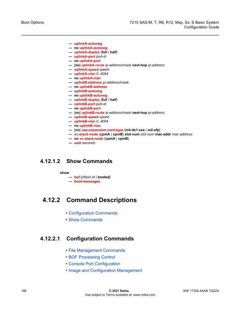
Boot Options
186
7210 SAS-M, T, R6, R12, Mxp, Sx, S Basic SystemConfiguration Guide
© 2021 Nokia. Use subject to Terms available at: www.nokia.com
3HE 17358 AAAB TQZZA
— uplinkA-autoneg— no uplinkA-autoneg— uplinkA-duplex {full | half}— uplinkA-port port-id— no uplinkA-port— [no] uplinkA-route ip-address/mask next-hop ip-address— uplinkA-speed speed— uplinkA-vlan 0..4094— no uplinkA-vlan— uplinkB-address ip-address/mask— no uplinkB-address— uplinkB-autoneg— no uplinkB-autoneg— uplinkB-duplex {full | half}— uplinkB-port port-id— no uplinkB-port— [no] uplinkB-route ip-address/mask next-hop ip-address— uplinkB-speed speed— uplinkB-vlan 0..4094— no uplinkB-vlan— [no] use-expansion-card-type {m4-ds1-ces | m2-xfp}— vc-stack-node {cpmA | cpmB} slot-num slot-num mac-addr mac-address— no vc-stack-node {cpmA | cpmB}— wait seconds
4.12.1.2 Show Commands
show— bof [cflash-id | booted] — boot-messages
4.12.2 Command Descriptions
• Configuration Commands• Show Commands
4.12.2.1 Configuration Commands
• File Management Commands• BOF Processing Control• Console Port Configuration• Image and Configuration Management
7210 SAS-M, T, R6, R12, Mxp, Sx, S Basic System Configuration Guide
Boot Options
3HE 17358 AAAB TQZZA © 2021 Nokia. Use subject to Terms available at: www.nokia.com
187
• DNS Configuration Commands
4.12.2.1.1 File Management Commands
bof
Syntax bof
Context <ROOT>
Platforms Supported on all 7210 SAS platforms as described in this document, including those operating in access-uplink mode
Description This command configures the boot options file (BOF) for the specified local storage device.
A BOF file specifies where the system searches for runtime images, configuration files, and other operational parameters during system initialization.
BOF parameters can be modified, and changes can be saved to a specified compact flash. The BOF must be located in the root directory of either an internal or external compact flash local to the system and have the mandatory filename of bof.cfg.
When modifications are made to in-memory parameters that are currently in use or operating, the changes are effective immediately. For example, if the console speed is changed, the change takes place immediately.
Only one entry of the BOF configuration command statement can be saved after the statement has been found to be syntactically correct.
No default BOF exists.
save
Syntax save [cflash-id]
Context bof
Platforms Supported on all 7210 SAS platforms as described in this document, including those operating in access-uplink mode
Description This command uses the boot option parameters currently in memory and writes them from the BOF to the compact flash.
The BOF is located in the root directory of the internal compact flash drive local to the system and has the mandatory filename bof.cfg.
Command usage:
Boot Options
188
7210 SAS-M, T, R6, R12, Mxp, Sx, S Basic SystemConfiguration Guide
© 2021 Nokia. Use subject to Terms available at: www.nokia.com
3HE 17358 AAAB TQZZA
• bof save This configuration saves the BOF to the flash drive.
• bof save cf1:This configuration saves the BOF to cf1:\.
Default Saves must be explicitly executed. BOF is saved at the same location as the location of boot.tim used for booting the system.
Parameters cflash-id — The compact flash ID where the bof.cfg is to be saved.
Values uf1: (7210 SAS-M)cf1: | cf2: | uf1: (7210 SAS-T, 7210 SAS-Sx 1/10GE, 7210 SAS-Sx 10/100GE, and 7210 SAS-Mxp)cf2: | cf2-A: | cf2-B: | uf1: | uf1-A: | uf1-B: (7210 SAS-R6 and 7210 SAS-R12)cf1: | cf2: (7210 SAS-S 1/10GE)
Default cf1:
4.12.2.1.2 BOF Processing Control
wait
Syntax wait seconds
Context bof
Platforms Supported on all 7210 SAS platforms as described in this document, including those operating in access-uplink mode
Description This command configures a pause, in seconds, at the start of the boot process that allows the user to interrupt system initialization at the console.
When the user interrupts system initialization, the user is allowed to manually override the parameters defined in the BOF.
Only one wait command can be defined in the BOF.
Default 3
Parameters seconds — Specifies the length of the pause at the start of the boot process, in seconds
Values 1 to 10

7210 SAS-M, T, R6, R12, Mxp, Sx, S Basic System Configuration Guide
Boot Options
3HE 17358 AAAB TQZZA © 2021 Nokia. Use subject to Terms available at: www.nokia.com
189
4.12.2.1.3 Console Port Configuration
bof-password
Syntax bof-password password
Context bof
Platforms Supported on all 7210 SAS platforms as described in this document, including those operating in access-uplink mode
Description This command configures a BOF password. The user must provide this password to edit the BOF parameters in the boot loader.
It also implements a mechanism for password recovery. If the user forgets the password, it can be reset to the factory default. As a security measure, to prevent a malicious access to the configuration files, when the password is reset to the factory default, the system also resets the flash to factory defaults (that is, it removes all files from the flash except for the boot image file (cf1:\boot.tim) and TiMOS image file (cf1:\both.tim)) and reboots the node with the factory default settings.
After boot up, the user must set up the box using the same steps used to boot the box the first time when it was received from the factory. Use the factory default password password to edit the BOF parameters after the boot up subsequent to reboot and choose to change the password again.
Default password
Parameters password — Specifies the BOF password, up to 20 characters.
console-disabled
Syntax [no] console-disabled
Context bof
Platforms Supported on all 7210 SAS platforms as described in this document, including those operating in access-uplink mode
Description This command allows the user to enable or disable the serial port console for use.
Note: Nokia recommends that the user does not rename cf1:\boot.tim and cf1:\both.tim, if the system needs to retain them during the password recovery procedure. Additionally, Nokia highly recommends that the user makes a backup of all the image files, configuration files, and other data.

Boot Options
190
7210 SAS-M, T, R6, R12, Mxp, Sx, S Basic SystemConfiguration Guide
© 2021 Nokia. Use subject to Terms available at: www.nokia.com
3HE 17358 AAAB TQZZA
In remote deployments, this command provides additional security mechanism for the user. The console can be disabled to prevent unauthorized system access.
The no form of this command enables the console.
Default no console-disabled
console-speed
Syntax console-speed baud-rateno console-speed
Context bof
Platforms Supported on all 7210 SAS platforms as described in this document, including those operating in access-uplink mode
Description This command configures the console port baud rate.
When this command is issued to edit the BOF used for the most recent boot, the BOF and the active configuration are changed immediately.
The no form of this command reverts to the default value.
Default 115200
Parameters baud-rate — The console port baud rate, expressed as a decimal integer.
Values 9600, 19200, 38400, 57600, 115200
4.12.2.1.4 Image and Configuration Management
persist
Syntax persist {on | off}
Context bof
Note: The console is always available for use when the device is booting up. This command is applicable only after the TiMOS image (both.tim) is up and running successfully. If the user executes this command in the BOF CLI context, the command takes effect only during the next boot. A BOF save operation must be performed after executing the console-disabled command.
7210 SAS-M, T, R6, R12, Mxp, Sx, S Basic System Configuration Guide
Boot Options
3HE 17358 AAAB TQZZA © 2021 Nokia. Use subject to Terms available at: www.nokia.com
191
Platforms Supported on all 7210 SAS platforms as described in this document, including those operating in access-uplink mode
Description This command configures whether the system will preserve system indexes when a save command is executed. During a subsequent boot, the index file is read along with the configuration file. As a result, a number of system indexes are preserved between reboots, including the interface index and others. This reduces resynchronizations of the Network Management System (NMS) with the affected network element.
In the event that persist is on and the reboot with the appropriate index file fails, SNMP is operationally shut down to prevent the management system from accessing and possibly synchronizing with a partially booted or incomplete network element. Use the config>system>snmp>no shutdown command to enable SNMP access.
If persist is enabled and the admin>save file-url command is executed with an FTP path used as the file-url parameter, two FTP sessions simultaneously open to the FTP server. The FTP server must be configured to allow multiple sessions from the same login; otherwise, the configuration and index files will not be saved correctly.
Default off
Parameters on — Keyword to preserve the system index when saving the configuration.
off — Keyword to disable system index saves between reboots.
primary-config
Syntax primary-config file-urlno primary-config
Context bof
Platforms Supported on all 7210 SAS platforms as described in this document, including those operating in access-uplink mode
Description This command configures the name and location of the primary configuration file.
Note: • Persistency files (.ndx) are saved on the same disk as the configuration files and the
image files. • When an operator sets the location for the persistency file, the system will checks to
ensure that the disk has enough free space. If this there is not enough free space, persistency does not become active and a trap is generated. In this case, the operator must free adequate disk space. Until disk space is freed, the system performs a space availability check every 30 seconds. As soon as the space is available, persistency will become active on the next (30 second) check.
Boot Options
192
7210 SAS-M, T, R6, R12, Mxp, Sx, S Basic SystemConfiguration Guide
© 2021 Nokia. Use subject to Terms available at: www.nokia.com
3HE 17358 AAAB TQZZA
The system attempts to use the configuration specified in primary-config. If the specified file cannot be located, the system automatically attempts to obtain the configuration from the location specified in secondary-config and then the tertiary-config.
If an error in the configuration file is encountered, the boot process aborts.
The no form of this command removes the primary-config configuration.
Parameters file-url — Specifies the primary configuration file location, expressed as a file URL.
Values file-url [local-url | remote-url] (up to 180 characters)local-url [<cflash-id/> | <usb-flash-id>][file-path]remote-url[{ftp://|tftp://} login:pswd@remote-locn/][file-path]cflash-idcf1:, cf2 usb-flash-id uf1:uf1: (7210 SAS-M)cf1:|cf2:|uf1: (7210 SAS-T, 7210 SAS-Sx 1/10GE, 7210 SAS-Sx 10/100GE, and 7210 SAS-Mxp)cf2: | cf2-A: | cf2-B: | uf1: | uf1-A: | uf1-B: (7210 SAS-R6 and 7210 SAS-R12)cf1: | cf2: (7210 SAS-S 1/10GE)
primary-image
Syntax primary-image file-url no primary image
Context bof
Platforms Supported on all 7210 SAS platforms as described in this document, including those operating in access-uplink mode
Description This command configures the primary directory location for runtime image file loading.
The system attempts to load all runtime image files configured in the primary-image first. If this fails, the system attempts to load the runtime images from the location configured in the secondary-image. If the secondary image load fails, the tertiary image specified in tertiary-image is used.
The no form of this command removes the primary-image configuration.
Parameters file-url — Specifies the location-url can be either local (this flash) or a remote FTP server.
Values file-url [local-url | remote-url] (up to 180 characters)local-url [<cflash-id/> | <usb-flash-id>][file-path]remote-url[{ftp://|tftp://} login:pswd@remote-locn/][file-path]cflash-idcf1:, cf2 usb-flash-id uf1:uf1: (7210 SAS-M)
7210 SAS-M, T, R6, R12, Mxp, Sx, S Basic System Configuration Guide
Boot Options
3HE 17358 AAAB TQZZA © 2021 Nokia. Use subject to Terms available at: www.nokia.com
193
cf1:|cf2:|uf1: (7210 SAS-T, 7210 SAS-Sx 1/10GE, 7210 SAS-Sx 10/100GE, and 7210 SAS-Mxp)cf2: | cf2-A: | cf2-B: | uf1: | uf1-A: | uf1-B: (7210 SAS-R6 and 7210 SAS-R12)cf1: | cf2: (7210 SAS-S 1/10GE)
secondary-config
Syntax secondary-config file-url no secondary-config
Context bof
Platforms Supported on all 7210 SAS platforms as described in this document, including those operating in access-uplink mode
Description This command configures the name and location of the secondary configuration file.
The system attempts to use the configuration as specified in secondary-config if the primary config cannot be located. If the secondary-config file cannot be located, the system attempts to obtain the configuration from the location specified in the tertiary-config.
If an error in the configuration file is encountered, the boot process aborts.
The no form of the command removes the secondary-config configuration.
Parameters file-url — The secondary configuration file location, expressed as a file URL.
Values file-url [local-url | remote-url] (up to 180 characters)local-url [<cflash-id/> | <usb-flash-id>][file-path]remote-url[{ftp://|tftp://} login:pswd@remote-locn/][file-path]cflash-idcf1:, cf2 usb-flash-id uf1:uf1: (7210 SAS-M)cf1:|cf2:|uf1: (7210 SAS-T, 7210 SAS-Sx 1/10GE, 7210 SAS-Sx 10/100GE, and 7210 SAS-Mxp)cf2: | cf2-A: | cf2-B: | uf1: | uf1-A: | uf1-B: (7210 SAS-R6 and 7210 SAS-R12)cf1: | cf2: (7210 SAS-S 1/10GE)
secondary-image
Syntax secondary-image file-urlno secondary-image
Context bof
Boot Options
194
7210 SAS-M, T, R6, R12, Mxp, Sx, S Basic SystemConfiguration Guide
© 2021 Nokia. Use subject to Terms available at: www.nokia.com
3HE 17358 AAAB TQZZA
Platforms Supported on all 7210 SAS platforms as described in this document, including those operating in access-uplink mode
Description This command configures the secondary directory location for runtime image file loading.
The system attempts to load all runtime image files configured in the primary-image first. If this fails, the system attempts to load the runtime images from the location configured in the secondary-image. If the secondary image load fails, the tertiary image specified in tertiary-image is used.
The no form of the command removes the secondary-image configuration.
Parameters file-url — The file-url can be either local (this local flash) or a remote FTP server.
Values file-url [local-url | remote-url] (up to 180 characters)local-url [<cflash-id/> | <usb-flash-id>][file-path]remote-url[{ftp://|tftp://} login:pswd@remote-locn/][file-path]cflash-idcf1:, cf2 usb-flash-id uf1:uf1: (7210 SAS-M)cf1: | cf2: | uf1: (7210 SAS-T, 7210 SAS-Sx 1/10GE, 7210 SAS-Sx 10/100GE, and 7210 SAS-Mxp)cf2: | cf2-A: | cf2-B: | uf1: | uf1-A: | uf1-B: (7210 SAS-R6 and 7210 SAS-R12)cf1: | cf2: (7210 SAS-S 1/10GE)
tertiary-config
Syntax tertiary-config file-urlno tertiary-config
Context bof
Platforms Supported on all 7210 SAS platforms as described in this document, including those operating in access-uplink mode
Description This command configures the name and location of the tertiary configuration file.
The system attempts to use the configuration specified in tertiary-config if both the primary and secondary config files cannot be located. If this file cannot be located, the system boots with the factory default configuration.
If an error in the configuration file is encountered, the boot process aborts.
The no form of the command removes the tertiary-config configuration.
7210 SAS-M, T, R6, R12, Mxp, Sx, S Basic System Configuration Guide
Boot Options
3HE 17358 AAAB TQZZA © 2021 Nokia. Use subject to Terms available at: www.nokia.com
195
Parameters file-url — The tertiary configuration file location, expressed as a file URL.
Values local-url [<cflash-id/> | <usb-flash-id>][file-path]cflash-idcf1:, cf2 usb-flash-iduf1:remote-url[{ftp://|tftp://} login:pswd@remote-locn/][file-path]local-url uf1: (7210 SAS-M)cf1: | cf2: | uf1: (7210 SAS-T, 7210 SAS-Sx 1/10GE, 7210 SAS-Sx 10/100GE, and 7210 SAS-Mxp)cf2: | cf2-A: | cf2-B: | uf1: | uf1-A: | uf1-B: (7210 SAS-R6 and 7210 SAS-R12)cf1: | cf2: (7210 SAS-S 1/10GE)
tertiary-image
Syntax tertiary-image file-urlno tertiary-image
Context bof
Platforms Supported on all 7210 SAS platforms as described in this document, including those operating in access-uplink mode
Description This command configures the tertiary directory location for runtime image file loading.
The system attempts to load all runtime image files configured in the primary-image first. If this fails, the system attempts to load the runtime images from the location configured in the secondary-image. If the secondary image load fails, the tertiary image specified in tertiary-image is used.
The no form of this command removes the tertiary-image configuration.
Parameters file-url — The location-url can be either local (this flash) or a remote FTP server.
Values file-url [local-url | remote-url] (up to 180 characters)local-url [<cflash-id/> | <usb-flash-id>][file-path]remote-url[{ftp://|tftp://} login:pswd@remote-locn/][file-path]cflash-idcf1:, cf2usb-flash-iduf1:uf1: (7210 SAS-M)cf1: | cf2: | uf1: (7210 SAS-T, 7210 SAS-Sx 1/10GE, 7210 SAS-Sx 10/100GE, and 7210 SAS-Mxp)cf2: | cf2-A: | cf2-B: | uf1: | uf1-A: | uf1-B: (7210 SAS-R6 and 7210 SAS-R12)cf1: | cf2: (7210 SAS-S 1/10GE)
Boot Options
196
7210 SAS-M, T, R6, R12, Mxp, Sx, S Basic SystemConfiguration Guide
© 2021 Nokia. Use subject to Terms available at: www.nokia.com
3HE 17358 AAAB TQZZA
uplink-mode
Syntax uplink-mode {access-uplink| network}
Context bof
Platforms 7210 SAS-M (network mode and access-uplink mode) and 7210 SAS-T (network mode and access-uplink mode)
Description This command configures the system in either access-uplink mode or network mode.
In access-uplink mode, the device allows for configuration of the port in access-uplink mode and allows for use of access-uplink SAPs for service configuration. In this mode, the system boots up with all ports configured in access mode. The user can modify the port mode to access-uplink after system boot up, but the software does not allow the mode to be set to network. The software allows the user to configure services to use only either access SAPs or access-uplink SAPs, but not MPLS-based SDPs. This mode is supported on the 7210 SAS-M and 7210 SAS-T.
In network mode, the device allows for configuration of the port in network mode and allows the use of network IP interfaces and MPLS-based SDPs for service configuration. In this mode, the system boots up with all ports configured in network mode. The user can modify the port mode to access after system boot up, but the software does not allow the mode to be set to access-uplink. The software allows the user to configure services to use only either access SAPs or MPLS-based SDPs, but not access uplink SAPs. This mode is supported on the 7210 SAS-M and 7210 SAS-T.
Default network
Parameters access-uplink — Keyword to allow for configuration of the port in access-uplink mode and usage of access-uplink SAPs for service configuration
network — Keyword to allow for configuration of the port in network mode and usage of network IP interfaces and MPLS based SDPs for service configuration.
ping-address
Syntax ping-address ip-address no ping-address
Context bof
Platforms 7210 SAS-M (network mode and access-uplink mode), 7210 SAS-Mxp, 7210 SAS-Sx/S 1/10GE, 7210 SAS-Sx 10/100GE, 7210 SAS-T (network mode and access-uplink mode)
Note: Ensure that service entities related to MPLS mode are not enabled when the device is configured in access-uplink mode and vice-versa. The system does not enforce this.
7210 SAS-M, T, R6, R12, Mxp, Sx, S Basic System Configuration Guide
Boot Options
3HE 17358 AAAB TQZZA © 2021 Nokia. Use subject to Terms available at: www.nokia.com
197
Description This command configures the IP address used for a ping-test after the system boots.
The no form of this command removes the ping-address configuration. Setting a value of 0 also removes the ping-address configuration.
Parameters ip-address — Specifies an IPv4 IP address in the form a.b.c.d, for example, 10.1.2.10.
uplinkA-address
Syntax uplinkA-address ip-address/maskno uplinkA-address
Context bof
Platforms 7210 SAS-M (network mode and access-uplink mode), 7210 SAS-Mxp, 7210 SAS-Sx/S 1/10GE, 7210 SAS-Sx 10/100GE, 7210 SAS-T (network mode and access-uplink mode)
Description This command configures the uplinkA address.
The no form of this command sets the uplinkA to use DHCP to get the IP and the show bof value reflects 0 for this parameter.
Parameters ip-address — Specifies the IP address of the BOF. This address must be unique within the subnet and specified in dotted decimal notation.
Values a.b.c.d
mask — Specifies the subnet mask length when the IP prefix is specified in CIDR notation. When the IP prefix is specified in CIDR notation, a forward slash (/) separates the ip-addr from the mask-length parameter. The mask length parameter indicates the number of bits used for the network portion of the IP address; the remainder of the IP address is used to determine the host portion of the IP address.
Values 1 to 30
uplinkB-address
Syntax uplinkB-address ip-address/maskno uplinkB-address
Context bof
Platforms 7210 SAS-M (network mode and access-uplink mode), 7210 SAS-Mxp, 7210 SAS-Sx/S 1/10GE, 7210 SAS-Sx 10/100GE, 7210 SAS-T (network mode and access-uplink mode)
Description This command configures the uplink-B address.
The no form of this command sets the uplinkB to use DHCP to get the IP and the show bof value reflects 0 for this parameter.
Boot Options
198
7210 SAS-M, T, R6, R12, Mxp, Sx, S Basic SystemConfiguration Guide
© 2021 Nokia. Use subject to Terms available at: www.nokia.com
3HE 17358 AAAB TQZZA
Parameters ip-address — Specifies the IP address of the BOF. This address must be unique within the subnet and specified in dotted decimal notation.
Values a.b.c.d
mask — Specifies the subnet mask length when the IP prefix is specified in CIDR notation. When the IP prefix is specified in CIDR notation, a forward slash (/) separates the ip-address from the mask parameter. The mask parameter indicates the number of bits used for the network portion of the IP address; the remainder of the IP address is used to determine the host portion of the IP address.
Values 1 to 30
uplinkA-autoneg
Syntax [no] uplinkA-autoneg
Context bof
Platforms 7210 SAS-M (network mode and access-uplink mode), 7210 SAS-Mxp, 7210 SAS-Sx/S 1/10GE, 7210 SAS-Sx 10/100GE, 7210 SAS-T (network mode and access-uplink mode)
Description This command enables speed and duplex auto-negotiation on the uplinkA port in the running configuration and the boot option file (BOF).
The no form of this command disables the auto-negotiate feature on this port.
#uplinkA Port Settings:uplinkA-port 1/1/26no uplinkA-autoneguplinkA-duplex fulluplinkA-speed 10000uplinkA-address 0uplinkA-vlan 0
Default uplinkA-autoneg
uplinkB-autoneg
Syntax [no] uplinkB-autoneg
Context bof
Note: The uplinkA-autoneg command is not valid for 10gig ports. Therefore, whenever the user selects 10gig ports as uplinkA port, the uplinkA-autoneg command is defaulted to no uplinkA-autoneg, speed as uplinkA-speed 10000, duplex as uplinkA-duplex full, as shown in the following output example.

7210 SAS-M, T, R6, R12, Mxp, Sx, S Basic System Configuration Guide
Boot Options
3HE 17358 AAAB TQZZA © 2021 Nokia. Use subject to Terms available at: www.nokia.com
199
Platforms 7210 SAS-M (network mode and access-uplink mode), 7210 SAS-Mxp, 7210 SAS-Sx/S 1/10GE, 7210 SAS-Sx 10/100GE, 7210 SAS-T (network mode and access-uplink mode)
Description This command enables speed and duplex auto-negotiation on the uplinkB port in the running configuration and the BOF.
The no form of this command disables the auto-negotiate feature on this port.
#uplinkB Port Settings:uplinkB-port 1/1/26no uplinkB-autoneguplinkB-duplex fulluplinkB-speed 10000uplinkB-address 0uplinkB-vlan 0
Default uplinkB-autoneg
uplinkA-duplex
Syntax uplinkA-duplex {full | half}
Context bof
Platforms 7210 SAS-M (network mode and access-uplink mode), 7210 SAS-Mxp, 7210 SAS-Sx/S 1/10GE, 7210 SAS-Sx 10/100GE, 7210 SAS-T (network mode and access-uplink mode)
Description This command configures the duplex mode of the uplinkA port when auto-negotiation is disabled in the running configuration and the BOF.
It also allows for the configuration of the duplex mode of the Ethernet port. If the port is configured to auto-negotiate, this parameter will be ignored.
#uplinkA Port Settings:uplinkA-port 1/1/26no uplinkA-autoneguplinkA-duplex full
Note: The uplinkB-autoneg command is not valid for 10gig ports. Therefore, whenever the user selects 10gig ports as uplinkB-port, the uplinkB-autoneg command defaults to no uplinkB-autoneg, speed as uplinkB-speed 10000, duplex as uplinkB-duplex full, as shown in the following output example.
Note: The uplinkA-autoneg command is not valid for 10gig ports, therefore, whenever the user selects 10gig ports as uplinkA-port, the uplinkA-autoneg command is defaulted to no uplinkA-autoneg, speed as uplinkA-speed 10000, duplex as uplinkA-duplex full, as shown in the following output sample.

Boot Options
200
7210 SAS-M, T, R6, R12, Mxp, Sx, S Basic SystemConfiguration Guide
© 2021 Nokia. Use subject to Terms available at: www.nokia.com
3HE 17358 AAAB TQZZA
uplinkA-speed 10000uplinkA-address 0uplinkA-vlan 0
Default uplinkA-duplex full
Parameters full — Keyword to set the link to full duplex mode.
half — Keyword to set the link to half duplex mode.
uplinkB-duplex
Syntax uplinkB-duplex {full | half}
Context bof
Platforms 7210 SAS-M (network mode and access-uplink mode), 7210 SAS-Mxp, 7210 SAS-Sx/S 1/10GE, 7210 SAS-Sx 10/100GE, 7210 SAS-T (network mode and access-uplink mode)
Description This command configures the duplex mode of the uplinkB port when auto-negotiation is disabled in the running configuration and the BOF.
This configuration command allows for the configuration of the duplex mode of the Ethernet port. If the port is configured to auto-negotiate, this parameter will be ignored.
#uplinkB Port Settings:uplinkB-port 1/1/26no uplinkB-autoneguplinkB-duplex fulluplinkB-speed 10000uplinkB-address 0uplinkB-vlan 0
Default uplinkB-duplex full
Parameters full — Keyword to set the link to full duplex mode.
half — Keyword to set the link to half duplex mode.
Note: The uplinkB-autoneg command is not valid for 10gig ports. Therefore, whenever the user selects 10gig ports as uplinkB-port, the uplinkB-autoneg command defaults to no uplinkB-autoneg, speed as uplinkB-speed 10000, duplex as uplinkB-duplex full, as shown in the following output sample.
7210 SAS-M, T, R6, R12, Mxp, Sx, S Basic System Configuration Guide
Boot Options
3HE 17358 AAAB TQZZA © 2021 Nokia. Use subject to Terms available at: www.nokia.com
201
uplinkA-port
Syntax uplinkA-port port-idno uplinkA-port
Context bof
Platforms 7210 SAS-M (network mode and access-uplink mode), 7210 SAS-Mxp, 7210 SAS-Sx/S 1/10GE, 7210 SAS-Sx 10/100GE, 7210 SAS-T (network mode and access-uplink mode)
Description This command configures the primary port to be used for boot up.
The no form of this command removes all the uplinkA parameters from the BOF.
Parameters port-id — Specifies the primary port to be used for boot up in the slot/mda/port format.
uplinkB-port
Syntax uplinkB-port port-idno uplinkB-port
Context bof
Platforms 7210 SAS-M (network mode and access-uplink mode), 7210 SAS-Mxp, 7210 SAS-Sx/S 1/10GE, 7210 SAS-Sx 10/100GE, 7210 SAS-T (network mode and access-uplink mode)
Description This command configures the secondary port to be used for boot up.
The no form of this command removes all the uplinkB parameters from the BOF.
Parameters port-id — Specifies the secondary port to be used for boot up in the slot/mda/port format.
uplinkA-route
Syntax [no] uplinkA-route ip-address/mask next-hop ip-address
Context bof
Platforms 7210 SAS-M (network mode and access-uplink mode), 7210 SAS-Mxp, 7210 SAS-Sx/S 1/10GE, 7210 SAS-Sx 10/100GE, 7210 SAS-T (network mode and access-uplink mode)
Description This command configures an uplinkA static route.
Parameters ip-address — Specifies the IP address of the BOF. This address must be unique within the subnet and specified in dotted decimal notation.
Values a.b.c.d
Boot Options
202
7210 SAS-M, T, R6, R12, Mxp, Sx, S Basic SystemConfiguration Guide
© 2021 Nokia. Use subject to Terms available at: www.nokia.com
3HE 17358 AAAB TQZZA
mask — Specifies the subnet mask length when the IP prefix is specified in CIDR notation. When the IP prefix is specified in CIDR notation, a forward slash (/) separates the ip-address from the mask parameter. The mask parameter indicates the number of bits used for the network portion of the IP address; the remainder of the IP address is used to determine the host portion of the IP address.
Values 0 to 32
next-hop ip-address — Specifies the next hop IP address used to reach the destination.
uplinkB-route
Syntax [no] uplinkB-route ip-address/mask next-hop ip-address
Context bof
Platforms 7210 SAS-M (network mode and access-uplink mode), 7210 SAS-Mxp, 7210 SAS-Sx/S 1/10GE, 7210 SAS-Sx 10/100GE, 7210 SAS-T (network mode and access-uplink mode)
Description This command configures an uplinkB static route.
Parameters ip-address — Specifies the IP address of the BOF. This address must be unique within the subnet and specified in dotted decimal notation.
Values a.b.c.d
mask — Specifies the subnet mask length when the IP prefix is specified in CIDR notation. When the IP prefix is specified in CIDR notation, a forward slash (/) separates the ip-address from the mask parameter. The mask parameter indicates the number of bits used for the network portion of the IP address. The remainder of the IP address is used to determine the host portion of the IP address.
Values 0 to 32
next-hop ip-address — Specifies the next-hop IP address used to reach the destination.
uplinkA-speed
Syntax uplinkA-speed speed
Context bof
Platforms 7210 SAS-M (network mode and access-uplink mode), 7210 SAS-Mxp, 7210 SAS-Sx/S 1/10GE, 7210 SAS-Sx 10/100GE, 7210 SAS-T (network mode and access-uplink mode)
Description This command configures the speed for the uplinkA port when auto-negotiation is disabled in the running configuration and the BOF.
If the port is configured to auto-negotiate, this parameter is ignored.
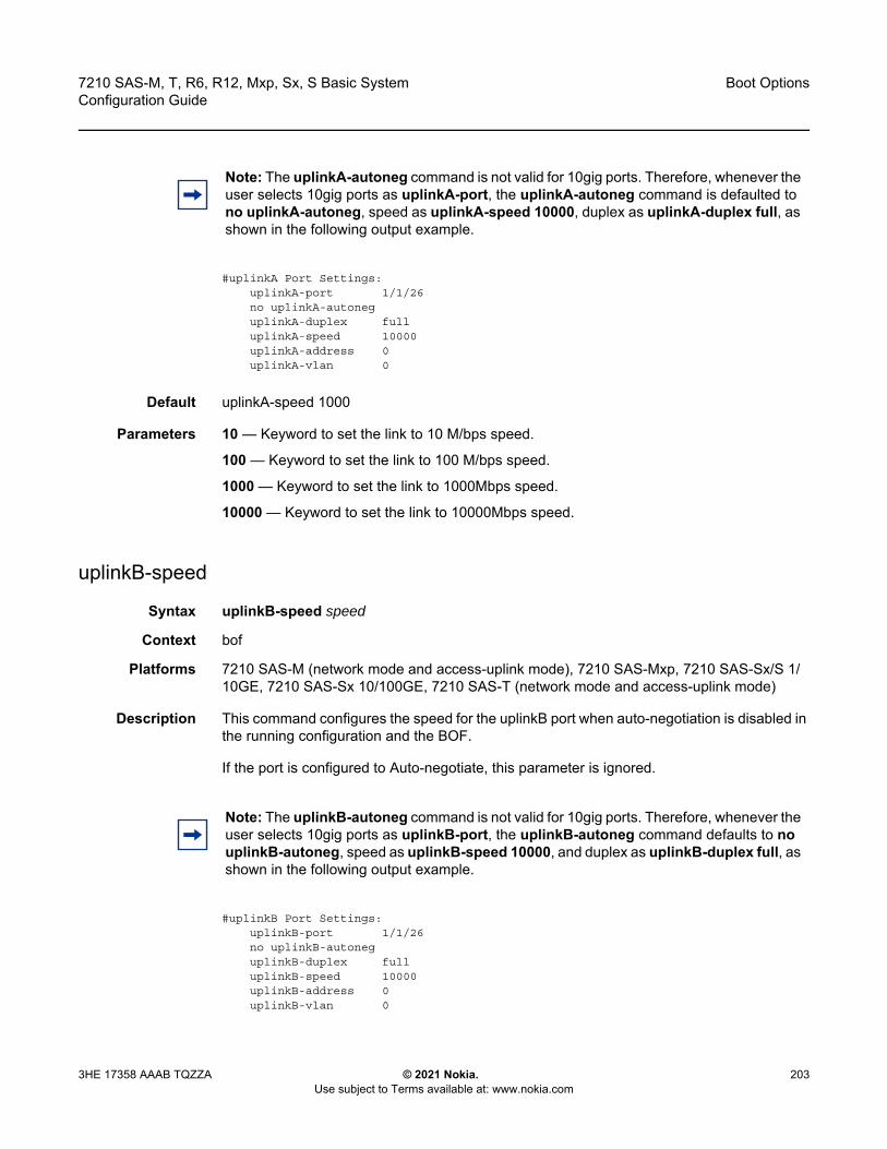
7210 SAS-M, T, R6, R12, Mxp, Sx, S Basic System Configuration Guide
Boot Options
3HE 17358 AAAB TQZZA © 2021 Nokia. Use subject to Terms available at: www.nokia.com
203
#uplinkA Port Settings:uplinkA-port 1/1/26no uplinkA-autoneguplinkA-duplex fulluplinkA-speed 10000uplinkA-address 0uplinkA-vlan 0
Default uplinkA-speed 1000
Parameters 10 — Keyword to set the link to 10 M/bps speed.
100 — Keyword to set the link to 100 M/bps speed.
1000 — Keyword to set the link to 1000Mbps speed.
10000 — Keyword to set the link to 10000Mbps speed.
uplinkB-speed
Syntax uplinkB-speed speed
Context bof
Platforms 7210 SAS-M (network mode and access-uplink mode), 7210 SAS-Mxp, 7210 SAS-Sx/S 1/10GE, 7210 SAS-Sx 10/100GE, 7210 SAS-T (network mode and access-uplink mode)
Description This command configures the speed for the uplinkB port when auto-negotiation is disabled in the running configuration and the BOF.
If the port is configured to Auto-negotiate, this parameter is ignored.
#uplinkB Port Settings:uplinkB-port 1/1/26no uplinkB-autoneguplinkB-duplex fulluplinkB-speed 10000uplinkB-address 0uplinkB-vlan 0
Note: The uplinkA-autoneg command is not valid for 10gig ports. Therefore, whenever the user selects 10gig ports as uplinkA-port, the uplinkA-autoneg command is defaulted to no uplinkA-autoneg, speed as uplinkA-speed 10000, duplex as uplinkA-duplex full, as shown in the following output example.
Note: The uplinkB-autoneg command is not valid for 10gig ports. Therefore, whenever the user selects 10gig ports as uplinkB-port, the uplinkB-autoneg command defaults to no uplinkB-autoneg, speed as uplinkB-speed 10000, and duplex as uplinkB-duplex full, as shown in the following output example.
Boot Options
204
7210 SAS-M, T, R6, R12, Mxp, Sx, S Basic SystemConfiguration Guide
© 2021 Nokia. Use subject to Terms available at: www.nokia.com
3HE 17358 AAAB TQZZA
Default uplinkB-speed 1000
Parameters 10 — Keyword to set the link to 10 m/bps speed.
100 — Keyword to set the link to 100 m/bps speed.
1000 — Keyword to set the link to 1000 m/bps speed.
10000 — Keyword to set the link to 10000 m/bps speed.
uplinkA-vlan
Syntax uplinkA-vlan 0..4094no uplinkA-vlan
Context bof
Platforms 7210 SAS-M (network mode and access-uplink mode), 7210 SAS-Mxp, 7210 SAS-Sx/S 1/10GE, 7210 SAS-Sx 10/100GE, 7210 SAS-T (network mode and access-uplink mode)
Description This command configures a VLAN ID to be used on uplinkA.
The no form of this command is used to send untagged packets on uplinkA.
Parameters 0...4094 — Specifies the VLAN ID.
Values 0 to 4049
uplinkB-vlan
Syntax uplinkB-vlan 0..4094no uplinkB-vlan
Context bof
Platforms 7210 SAS-M (network mode and access-uplink mode), 7210 SAS-Mxp, 7210 SAS-Sx/S 1/10GE, 7210 SAS-Sx 10/100GE, 7210 SAS-T (network mode and access-uplink mode)
Description This command configures a VLAN ID to be used on uplinkB.
The no form of this command is used to send untagged packets on uplinkB.
Parameters 0...4094 — Specifies the VLAN ID.
Values 0 to 4049
eth-mgmt-address
Syntax [no] eth-mgmt-address ip-prefix/ip-prefix-length [active | standby]
7210 SAS-M, T, R6, R12, Mxp, Sx, S Basic System Configuration Guide
Boot Options
3HE 17358 AAAB TQZZA © 2021 Nokia. Use subject to Terms available at: www.nokia.com
205
Context bof
Platforms Supported on all 7210 SAS platforms as described in this document, including those operating in access-uplink mode
Description This command assigns an IP address to the management Ethernet port in the running configuration and the BOF. Deleting a BOF address entry is not allowed from a telnet session.
The no form of this command deletes the IP address assigned to the Ethernet port.
Default no eth-mgmt-address
Parameters ip-prefix/ip-prefix-length — Specifies the IP address in dotted decimal notation.
Values ipv4-prefix a.b.c.d (host bits must be 0)ipv6-prefix - x:x:x:x:x:x:x:x (eight 16-bit pieces)x:x:x:x:x:x:d.d.d.dx - [0..FFFF]Hd - [0..255]Dipv4-prefix-length: 0 to 32ipv6-prefix-length: 0 to 128
active — Specifies that the specified IP address applies to the active CPM (supported only on 7210 SAS-R6 and 7210 SAS-R12, and to 7210 SAS-Sx 1/10GE and 7210 SAS-S 1/10GE in standalone-VC)
standby — Specifies that the specified IP address applies to the standby CPM (supported only on 7210 SAS-R6 and 7210 SAS-R12, and to 7210 SAS-Sx 1/10GE and 7210 SAS-S 1/10GE in standalone-VC)
eth-mgmt-autoneg
Syntax [no] eth-mgmt-autoneg
Context bof
Note: The following caveats apply for the eth-mgmt-address command:• The active and standby options are only available on the 7210 SAS-R6 and
7210 SAS-R12, and on the 7210 SAS-Sx 1/10GE and 7210 SAS-S 1/10GE when the chassis-role parameter is set to standalone-vc.
• On the 7210 SAS-Sx 1/10GE and 7210 SAS-S 1/10GE, choosing the active option configures the IP address on the active CPM node, and is used by the network manager to operate the virtual chassis (VC). Choosing the standby option configures the IP address on the standby CPM node.

Boot Options
206
7210 SAS-M, T, R6, R12, Mxp, Sx, S Basic SystemConfiguration Guide
© 2021 Nokia. Use subject to Terms available at: www.nokia.com
3HE 17358 AAAB TQZZA
Platforms Supported on all 7210 SAS platforms as described in this document, including those operating in access-uplink mode
Description This command enables speed and duplex auto-negotiation on the management Ethernet port in the running configuration and the BOF.
The no form of this command disables the auto-negotiate feature on this port.
Default eth-mgmt-autoneg
eth-mgmt-disabled
Syntax [no] eth-mgmt-disabled
Context bof
Platforms Supported on all 7210 SAS platforms as described in this document, including those operating in access-uplink mode
Description This command allows the user to enable or disable the out-of-band management Ethernet port for use during boot up.
The no form of this command enables the port.
Default eth-mgmt-disabled
eth-mgmt-duplex
Syntax eth-mgmt-duplex {full | half}
Context bof
Platforms Supported on all 7210 SAS platforms as described in this document, including those operating in access-uplink mode
Description This command configures the duplex mode of the management Ethernet port when auto-negotiation is disabled in the running configuration and the BOF.
This configuration command allows for the configuration of the duplex mode of the Ethernet port. If the port is configured to auto-negotiate, this parameter will be ignored.
Default eth-mgmt-duplex full
Parameters full — Keyword to set the link to full duplex mode.
half — Keyword to set the link to half duplex mode.

7210 SAS-M, T, R6, R12, Mxp, Sx, S Basic System Configuration Guide
Boot Options
3HE 17358 AAAB TQZZA © 2021 Nokia. Use subject to Terms available at: www.nokia.com
207
eth-mgmt-route
Syntax [no] eth-mgmt-route ip-prefix/ip-prefix-length next-hop ip-address
Context bof
Platforms Supported on all 7210 SAS platforms as described in this document, including those operating in access-uplink mode
Description This command configures a static route entry for the management Ethernet port in the running configuration and the BOF.
This command allows manual configuration of static routing table entries. These static routes are only used by traffic generated by the Ethernet port. To reduce configuration, manual address aggregation should be applied where possible.
A static default (0.0.0.0 or 0) route cannot be configured on the management Ethernet port. A maximum of ten static routes can be configured on the management Ethernet port.
The no form of this command deletes the static route.
Parameters ip-prefix\ip-prefix-length — Specifies the destination address of the static route in dotted decimal notation.
Values ip-prefix|ip-prefix-length: ipv4-prefix a.b.c.d (host bits must be zero) ipv4-prefix-le 0 to 32ipv6-prefix - x:x:x:x:x:x:x:x (eight 16-bit pieces)x:x:x:x:x:x:d.d.d.dx - [0..FFFF]Hd - [0..255]Dipv6-prefix-le - 0 to 128
next-hop ip-address — Specifies the next hop IP address used to reach the destination.
Values ipv4-address - a.b.c.dipv6-address - x:x:x:x:x:x:x:x (eight 16-bit pieces)x:x:x:x:x:x:d.d.d.dx - [0..FFFF]Hd - [0..255]D
eth-mgmt-speed
Syntax eth-mgmt-speed speed
Context bof
Platforms Supported on all 7210 SAS platforms as described in this document, including those operating in access-uplink mode
Description This command configures the speed for the management Ethernet port when auto-negotiation is disabled in the running configuration and the BOF.
Boot Options
208
7210 SAS-M, T, R6, R12, Mxp, Sx, S Basic SystemConfiguration Guide
© 2021 Nokia. Use subject to Terms available at: www.nokia.com
3HE 17358 AAAB TQZZA
If the port is configured to Auto-negotiate, this parameter is ignored.
Default speed 100
speed 1000 (applicable only to 7210 SAS-R6 and 7210 SAS-R12)
Parameters 10 — Keyword to set the link to 10 M/bps speed.
100 — Keyword to set the link to 100 M/bps speed.
1000 — Keyword to set the link to 1000 M/bps speed (applicable only to 7210 SAS-R6 and 7210 SAS-R12).
host-type
Syntax host-type host-type no host-type
Context bof
Platforms 7210 SAS-Mxp, 7210 SAS-Sx/S 1/10GE (standalone and standalone-VC), and 7210 SAS-Sx 10/100GE
Description This command configures the host system.
When operating in satellite mode, the setting for the host-type BOF parameter must be consistent with the value of the chassis-role parameter; otherwise, on reboot the node will not boot up correctly. See BOF Chassis-Role and Host-Type Parameters for 7210 SAS-Sx 1/10GE, 7210 SAS-S 1/10GE, 7210 SAS-Sx 10/100GE, and 7210 SAS-Mxp for more information.
It is not necessary to configure the host-type value when the chassis role is set to standalone.
For nodes that are destined to operate in a virtual chassis (VC) set up, it is not necessary to configure the host-type value when the bootloader chassis-role parameter is set to standalone-vc.
The no form of this command removes the host-type setting.
Default no host-type
Parameters host-type — Specifies the value of the host type for the system.
Values satellites | standalone | standalone-vc
satellites — The node boots up in satellite mode when the host-type parameter is set to satellites and the chassis-role is set to satellite or factory-default.
standalone — The node boots up in standalone mode when the host-type parameter is set to standalone.

7210 SAS-M, T, R6, R12, Mxp, Sx, S Basic System Configuration Guide
Boot Options
3HE 17358 AAAB TQZZA © 2021 Nokia. Use subject to Terms available at: www.nokia.com
209
standalone-vc — The node boots up in standalone VC mode when the host-type parameter is set to standalone-vc.
use-expansion-card-type
Syntax [no] use-expansion-card-type { m4-ds1-ces | m2-xfp }
Context bof
Platforms 7210 SAS-M (network mode and access-uplink mode)
Description This parameter identifies the expansion card type to the system before boot up. The system allocates appropriate resources based on this information. The system allows only provisioning of the MDA currently specified in the BOF. A log message is displayed if an MDA type mismatch is detected. The system has to be rebooted if this parameter is changed.
For 7210 SAS-M devices in access-uplink mode, only the 2x10G MDA is supported. Therefore, the value of this parameter must be set to m2-xfp.
Default m4-ds1-ces
Parameters m4-ds1-ces — Keyword to identify a 4- port T1/E1 CES MDA.
m2-xfp — Keyword to identify a 2- port 10G Ethernet MDA.
no-service-ports
Syntax [no] no-service-ports {port-id | port-id}
Context bof
Platforms 7210 SAS-M 24F 2XFP (network mode and access-uplink mode) and 7210 SAS-M 24F 2XFP ETR (network mode and access-uplink mode)
Description 7210 SAS-M 24F 2XFP and 7210 SAS-M 24F 2XFP ETR devices support only 26 Ethernet ports when the 2x10G MDA is in use.
When the 2x10G MDA is in use, this command specifies the 26 Ethernet ports to be used, among the total of 28 Ethernet ports available. The remaining two Ethernet ports are not used and the service traffic received on these ports is not processed. Any of the 24x1G fixed Ethernet ports, 2x10G fixed Ethernet ports, or 2x10G MDA Ethernet ports can be specified by the user. Two ports as a list of two port-id tuple can also be specified.
Boot Options
210
7210 SAS-M, T, R6, R12, Mxp, Sx, S Basic SystemConfiguration Guide
© 2021 Nokia. Use subject to Terms available at: www.nokia.com
3HE 17358 AAAB TQZZA
Parameters port-id — Identifies the ports in the system using the notation chassis/slot/port-number. For example, 1/1/1 refers to the front panel fixed port 1 on the chassis, and 1/2/1 refers to port 1 on the 2x10G MDA inserted into the system.
4.12.2.1.5 DNS Configuration Commands
dns-domain
Syntax dns-domain dns-nameno dns-domain
Context bof
Platforms Supported on all 7210 SAS platforms as described in this document, including those operating in access-uplink mode
Description This command configures the domain name used when performing DNS address resolution. This is a required parameter if DNS address resolution is required. Only a single domain name can be configured. If multiple domain statements are configured, the last one encountered is used.
The no form of this command removes the domain name from the configuration.
Default no dns-domain
Parameters dns-name — Specifies the DNS domain name up to 32 characters.
primary-dns
Syntax primary-dns ip-addressno primary-dns [ip-address]
Context bof
Platforms Supported on all 7210 SAS platforms as described in this document, including those operating in access-uplink mode
Note: • The user can specify both ports to be the ones on the 2x10G MDA.• The system ignores the value of the no-service-ports parameter if the use-expansion-
card-type value is m4-ds1-ces.• It is recommended not to connect the ports configured as no-service-ports to another
device.
7210 SAS-M, T, R6, R12, Mxp, Sx, S Basic System Configuration Guide
Boot Options
3HE 17358 AAAB TQZZA © 2021 Nokia. Use subject to Terms available at: www.nokia.com
211
Description This command configures the primary DNS server used for DNS name resolution. DNS name resolution can be used when executing ping, traceroute, and service-ping, and also when defining file URLs. DNS name resolution is not supported when DNS names are embedded in configuration files.
The no form of this command removes the primary DNS server from the configuration.
Default no primary-dns
Parameters ip-address — The IP address of the primary DNS server.
Values ipv4-address - a.b.c.dipv6-address - x:x:x:x:x:x:x:x (eight 16-bit pieces)x:x:x:x:x:x:d.d.d.dx - [0..FFFF]Hd - [0..255]D
secondary-dns
Syntax secondary-dns ip-addressno secondary-dns [ip-address]
Context bof
Platforms Supported on all 7210 SAS platforms as described in this document, including those operating in access-uplink mode
Description This command configures the secondary DNS server for DNS name resolution. The secondary DNS server is used only if the primary DNS server does not respond.
DNS name resolution can be used when executing ping, traceroute, and service-ping, and also when defining file URLs. DNS name resolution is not supported when DNS names are embedded in configuration files.
The no form of this command removes the secondary DNS server from the configuration.
Default no secondary-dns
Parameters ip-address — Specifies the IP address of the secondary DNS server.
Values ipv4-address - a.b.c.dipv6-address - x:x:x:x:x:x:x:x (eight 16-bit pieces)x:x:x:x:x:x:d.d.d.dx - [0..FFFF]Hd - [0..255]D
tertiary-dns
Syntax tertiary-dns ip-address
Boot Options
212
7210 SAS-M, T, R6, R12, Mxp, Sx, S Basic SystemConfiguration Guide
© 2021 Nokia. Use subject to Terms available at: www.nokia.com
3HE 17358 AAAB TQZZA
no tertiary-dns [ip-address]
Context bof
Platforms Supported on all 7210 SAS platforms as described in this document, including those operating in access-uplink mode
Description This command configures the tertiary DNS server for DNS name resolution. The tertiary DNS server is used only if the primary DNS server and the secondary DNS server do not respond.
DNS name resolution can be used when executing ping, traceroute, and service-ping, and also when defining file URLs. DNS name resolution is not supported when DNS names are embedded in configuration files.
The no form of this command removes the tertiary DNS server from the configuration.
Default no tertiary-dns
Parameters ip-address — Specifies the IP address of the tertiary DNS server.
Values ipv4-address - a.b.c.dipv6-address - x:x:x:x:x:x:x:x (eight 16-bit pieces)x:x:x:x:x:x:d.d.d.dx - [0..FFFF]Hd - [0..255]D
4.12.2.2 Show Commands
bof
Syntax bof [cflash-id | booted]
Context show
Platforms Supported on all 7210 SAS platforms as described in this document, including those operating in access-uplink mode
Description This command shows the BOF executed on last system boot or on the specified device.
If no device is specified, the BOF used in the last system boot displays. If the BOF has been modified since the system boot, a message displays.
Parameters cflash-id — Specifies the cflash directory name.
Values uf1: (7210 SAS-M)cf1: | cf2: | uf1: (7210 SAS-T, 7210 SAS-Sx 1/10GE (standalone and standalone-VC), 7210 SAS-Sx 10/100GE, and 7210 SAS-Mxp)
7210 SAS-M, T, R6, R12, Mxp, Sx, S Basic System Configuration Guide
Boot Options
3HE 17358 AAAB TQZZA © 2021 Nokia. Use subject to Terms available at: www.nokia.com
213
cf2: | cf2-A: | cf2-B: | uf1: | uf1-A: | uf1-B: (7210 SAS-R6 and 7210 SAS-R12)cf1: | cf2: (7210 SAS-S 1/10GE (standalone and standalone-VC))
booted — Keyword to display the boot option file used to boot the system.
Output The following output samples are examples of BOF information, and Table 24 describes the output fields.
• Sample output for 7210 SAS-M and 7210 SAS-T (network mode)• Sample output for 7210 SAS-M (access-uplink mode)• Sample output for 7210 SAS-Mxp• Sample output for 7210 SAS-R6• Sample output for 7210 SAS-Sx/S 1/10GE• Sample output for 7210 SAS-Sx 10/100GE
Sample output for 7210 SAS-M and 7210 SAS-T (network mode)
*A:ALA# show bof cf1:===============================================================================BOF on cf1:===============================================================================
primary-image ftp://*:*@xx.xxx.xx.xx/./images/auto-boot/solution/bothx.timsecondary-image ftp://*:*@xx.xxx.xx.xx/./images/auto-boot/solution/bothx.timtertiary-image ftp://*:*@xx.xxx.xx.xx/./images/auto-boot/solution/both.timprimary-dns xxx.xxx.xxx.xxxdns-domain in.lucent.comping xx.xxx.xx.xx
#uplinkA Port Settings:uplinkA-port 1/1/1uplinkA-address xxx.xxx.x.xx/24
uplinkA-autoneguplinkA-duplexfulluplinkA-speed1000
uplinkA-vlan 0uplinkA-route xx.xxx.x.x/16 next-hop xxx.xxx.x.x
#uplinkB Port Settings:uplinkB-port 1/1/2uplinkB-address 0
uplinkB-autoneguplinkB-duplexfulluplinkB-speed1000
uplinkB-vlan 0#System Settings:
wait 3persist onconsole-speed 115200no console-disabled
===============================================================================*A:ALA#*A:ALA# show bof booted===============================================================================System booted with BOF===============================================================================
primary-image ftp://*:*@xx.xxx.xx.xx/./images/auto-boot/solution/bothx.tim
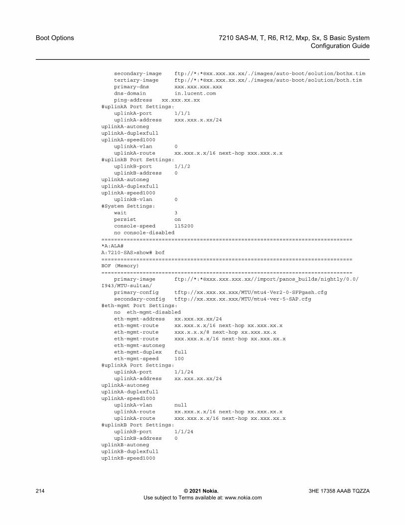
Boot Options
214
7210 SAS-M, T, R6, R12, Mxp, Sx, S Basic SystemConfiguration Guide
© 2021 Nokia. Use subject to Terms available at: www.nokia.com
3HE 17358 AAAB TQZZA
secondary-image ftp://*:*@xx.xxx.xx.xx/./images/auto-boot/solution/bothx.timtertiary-image ftp://*:*@xx.xxx.xx.xx/./images/auto-boot/solution/both.timprimary-dns xxx.xxx.xxx.xxxdns-domain in.lucent.comping-address xx.xxx.xx.xx
#uplinkA Port Settings:uplinkA-port 1/1/1uplinkA-address xxx.xxx.x.xx/24
uplinkA-autoneguplinkA-duplexfulluplinkA-speed1000
uplinkA-vlan 0uplinkA-route xx.xxx.x.x/16 next-hop xxx.xxx.x.x
#uplinkB Port Settings:uplinkB-port 1/1/2uplinkB-address 0
uplinkA-autoneguplinkA-duplexfulluplinkA-speed1000
uplinkB-vlan 0#System Settings:
wait 3persist onconsole-speed 115200no console-disabled
===============================================================================*A:ALA#A:7210-SAS>show# bof===============================================================================BOF (Memory)===============================================================================
primary-image ftp://*:*@xxx.xxx.xxx.xx//import/panos_builds/nightly/0.0/I943/MTU-sultan/
primary-config tftp://xx.xxx.xx.xxx/MTU/mtu4-Ver2-0-SFPgash.cfgsecondary-config tftp://xx.xxx.xx.xxx/MTU/mtu4-ver-5-SAP.cfg
#eth-mgmt Port Settings:no eth-mgmt-disabledeth-mgmt-address xx.xxx.xx.xx/24eth-mgmt-route xx.xxx.x.x/16 next-hop xx.xxx.xx.xeth-mgmt-route xxx.x.x.x/8 next-hop xx.xxx.xx.xeth-mgmt-route xxx.xxx.x.x/16 next-hop xx.xxx.xx.xeth-mgmt-autonegeth-mgmt-duplex fulleth-mgmt-speed 100
#uplinkA Port Settings:uplinkA-port 1/1/24uplinkA-address xx.xxx.xx.xx/24
uplinkA-autoneguplinkA-duplexfulluplinkA-speed1000
uplinkA-vlan nulluplinkA-route xx.xxx.x.x/16 next-hop xx.xxx.xx.xuplinkA-route xxx.xxx.x.x/16 next-hop xx.xxx.xx.x
#uplinkB Port Settings:uplinkB-port 1/1/24uplinkB-address 0
uplinkB-autoneguplinkB-duplexfulluplinkB-speed1000

7210 SAS-M, T, R6, R12, Mxp, Sx, S Basic System Configuration Guide
Boot Options
3HE 17358 AAAB TQZZA © 2021 Nokia. Use subject to Terms available at: www.nokia.com
215
uplinkB-vlan 0#System Settings:
wait 3persist offconsole-speed 115200uplink-mode access-uplinkno-service-ports 1/1/24 1/1/2use-expansion-card-type m2-xfpno console-disabled
===============================================================================A:7210-SAS>show#
Sample output for 7210 SAS-M (access-uplink mode)
*A:7210-SAS-M>bof# show bof===============================================================================BOF (Memory)===============================================================================
primary-image ftp://*:*@xxx.xxx.xxx.xx//tftpboot/apai/both.timprimary-config ftp://*:*@xx.xxx.x.xxx/./images/mtuUplink.cfgprimary-dns xxx.xxx.xxx.xxx
#eth-mgmt Port Settings:eth-mgmt-disabled
#uplinkA Port Settings:uplinkA-port 1/1/24uplinkA-address xx.xxx.x.xxx/24
uplinkA-autoneguplinkA-duplexfulluplinkA-speed1000
uplinkA-vlan nulluplinkA-route xx.x.x.x/8 next-hop xx.xxx.x.xuplinkA-route xx.xxx.x.x/16 next-hop xx.xxx.x.xuplinkA-route xxx.xxx.x.x/16 next-hop xx.xxx.x.x
#System Settings:wait 3persist offconsole-speed 115200uplink-mode access-uplinkno console-disabled
===============================================================================*A:7210-SAS-M>bof#
Sample output for 7210 SAS-Mxp
*A:7210SAS>show# bof===============================================================================BOF (Memory)===============================================================================
primary-image ftp://*:*@xxx.xxx.xxx.xx/./pkhosla/SASM2/both.timprimary-config ftp://*:*@xxx.xxx.xxx.xx/./pkhosla/SASM2/config2.cfg
#eth-mgmt Port Settings:no eth-mgmt-disabledeth-mgmt-address xx.xxx.x.xxx/24 activeeth-mgmt-route xxx.x.x.x/8 next-hop xx.xxx.x.xeth-mgmt-autonegeth-mgmt-duplex fulleth-mgmt-speed 100
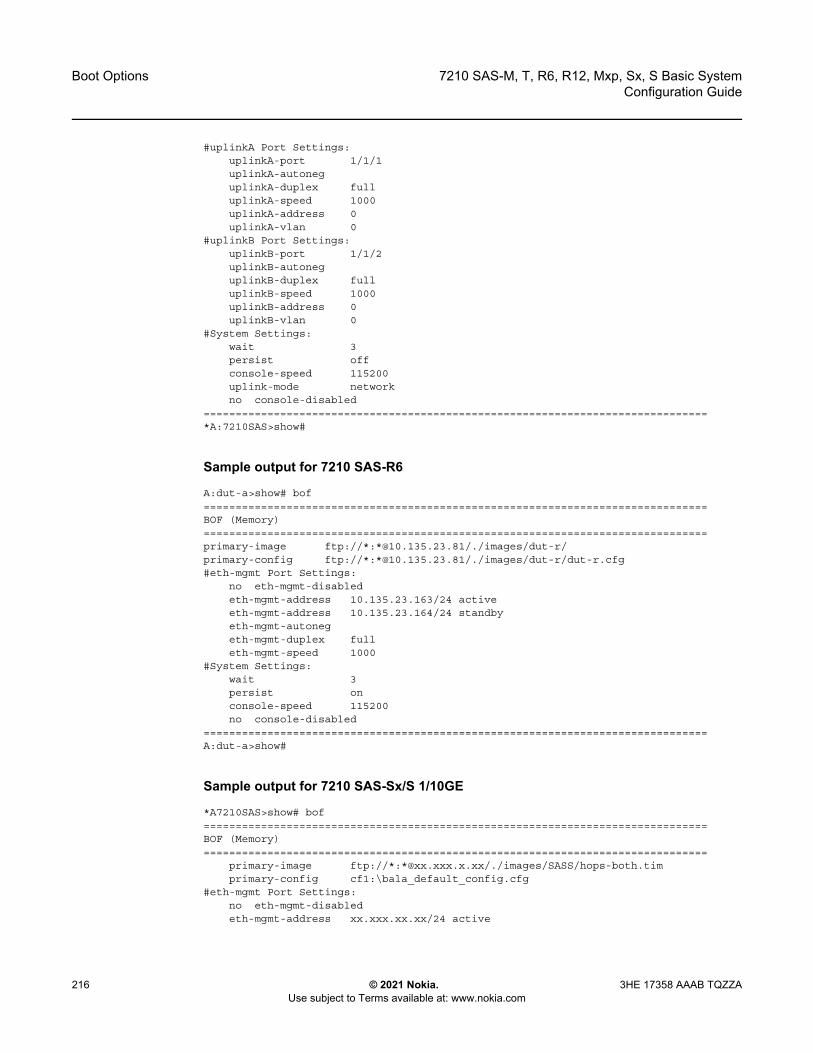
Boot Options
216
7210 SAS-M, T, R6, R12, Mxp, Sx, S Basic SystemConfiguration Guide
© 2021 Nokia. Use subject to Terms available at: www.nokia.com
3HE 17358 AAAB TQZZA
#uplinkA Port Settings:uplinkA-port 1/1/1uplinkA-autoneguplinkA-duplex fulluplinkA-speed 1000uplinkA-address 0uplinkA-vlan 0
#uplinkB Port Settings:uplinkB-port 1/1/2uplinkB-autoneguplinkB-duplex fulluplinkB-speed 1000uplinkB-address 0uplinkB-vlan 0
#System Settings:wait 3persist offconsole-speed 115200uplink-mode networkno console-disabled
===============================================================================*A:7210SAS>show#
Sample output for 7210 SAS-R6
A:dut-a>show# bof===============================================================================BOF (Memory)===============================================================================primary-image ftp://*:*@10.135.23.81/./images/dut-r/primary-config ftp://*:*@10.135.23.81/./images/dut-r/dut-r.cfg#eth-mgmt Port Settings:
no eth-mgmt-disabledeth-mgmt-address 10.135.23.163/24 activeeth-mgmt-address 10.135.23.164/24 standbyeth-mgmt-autonegeth-mgmt-duplex fulleth-mgmt-speed 1000
#System Settings:wait 3persist onconsole-speed 115200no console-disabled
===============================================================================A:dut-a>show#
Sample output for 7210 SAS-Sx/S 1/10GE
*A7210SAS>show# bof===============================================================================BOF (Memory)===============================================================================
primary-image ftp://*:*@xx.xxx.x.xx/./images/SASS/hops-both.timprimary-config cf1:\bala_default_config.cfg
#eth-mgmt Port Settings:no eth-mgmt-disabledeth-mgmt-address xx.xxx.xx.xx/24 active

7210 SAS-M, T, R6, R12, Mxp, Sx, S Basic System Configuration Guide
Boot Options
3HE 17358 AAAB TQZZA © 2021 Nokia. Use subject to Terms available at: www.nokia.com
217
eth-mgmt-route xx.xxx.x.x/16 next-hop xx.xxx.xx.xeth-mgmt-autonegeth-mgmt-duplex fulleth-mgmt-speed 100
#System Settings:wait 3persist offconsole-speed 115200no console-disabledhost-type standalone
===============================================================================*A7210SAS>show#
Sample output for 7210 SAS-Sx 10/100GE
*A:7210SAS>show# bof===============================================================================BOF (Memory)===============================================================================
primary-image ftp://*:*@xxx.xxx.xxx.xx/./images/SASS/hops-both.tim#eth-mgmt Port Settings:
no eth-mgmt-disabledeth-mgmt-address xx.xxx.xx.xx/24 activeeth-mgmt-route xx.xxx.x.x/16 next-hop xx.xxx.xx.xeth-mgmt-route xxx.x.x.x/8 next-hop xx.xxx.xx.xeth-mgmt-autonegeth-mgmt-duplex fulleth-mgmt-speed 1000
#System Settings:wait 3persist offconsole-speed 115200no console-disabledhost-type standalone
===============================================================================*A:7210SAS>show#
Table 24 Output Fields: BOF
Label Description
primary-image The primary location of the directory that contains the runtime images of both CPM and IOM
primary-config The primary location of the file that contains the configuration
primary-dns The primary DNS server for resolution of host names to IP addresses
secondary-image The secondary location of the directory that contains the runtime images of both CPM and IOM
secondary-config The secondary location of the file that contains the configuration
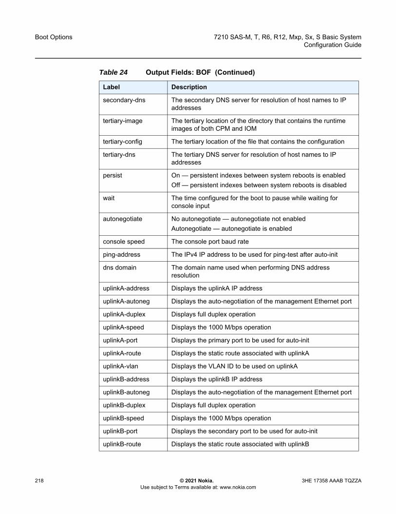
Boot Options
218
7210 SAS-M, T, R6, R12, Mxp, Sx, S Basic SystemConfiguration Guide
© 2021 Nokia. Use subject to Terms available at: www.nokia.com
3HE 17358 AAAB TQZZA
secondary-dns The secondary DNS server for resolution of host names to IP addresses
tertiary-image The tertiary location of the directory that contains the runtime images of both CPM and IOM
tertiary-config The tertiary location of the file that contains the configuration
tertiary-dns The tertiary DNS server for resolution of host names to IP addresses
persist On — persistent indexes between system reboots is enabledOff — persistent indexes between system reboots is disabled
wait The time configured for the boot to pause while waiting for console input
autonegotiate No autonegotiate — autonegotiate not enabledAutonegotiate — autonegotiate is enabled
console speed The console port baud rate
ping-address The IPv4 IP address to be used for ping-test after auto-init
dns domain The domain name used when performing DNS address resolution
uplinkA-address Displays the uplinkA IP address
uplinkA-autoneg Displays the auto-negotiation of the management Ethernet port
uplinkA-duplex Displays full duplex operation
uplinkA-speed Displays the 1000 M/bps operation
uplinkA-port Displays the primary port to be used for auto-init
uplinkA-route Displays the static route associated with uplinkA
uplinkA-vlan Displays the VLAN ID to be used on uplinkA
uplinkB-address Displays the uplinkB IP address
uplinkB-autoneg Displays the auto-negotiation of the management Ethernet port
uplinkB-duplex Displays full duplex operation
uplinkB-speed Displays the 1000 M/bps operation
uplinkB-port Displays the secondary port to be used for auto-init
uplinkB-route Displays the static route associated with uplinkB
Table 24 Output Fields: BOF (Continued)
Label Description

7210 SAS-M, T, R6, R12, Mxp, Sx, S Basic System Configuration Guide
Boot Options
3HE 17358 AAAB TQZZA © 2021 Nokia. Use subject to Terms available at: www.nokia.com
219
boot-messages
Syntax boot-messages
Context show
Platforms Supported on all 7210 SAS platforms as described in this document, including those operating in access-uplink mode
Description This command shows boot messages generated during the last system boot.
Output The following output is an example of boot message information.
Sample Output
===============================================================================cf1:/bootlog.txt===============================================================================Bootlog started for Version V-0.0.I317Build V-0.0.I317 bootrom/mpc 7xxxBuilt on Tue Jan 6 02:23:14 IST 2016 by panosbld in /panosbld/ws/panos/main
?Attempting to load from file cf1:/boot.timVersion L-0.0.I312, Fri Jan 2 04:26:32 IST 2009 by panosbld in /panosbld/ws/panos/
uplinkB-vlan Displays the VLAN ID to be used on uplinkB
uplink-mode This parameter displays the uplink mode of the device7210 SAS-M devices can be configured in either network mode or access-uplink mode
no-service-ports Displays the ports on which service traffic is not processed
use-expansion-card-type
Displays the expansion card type
console-disabled Displays the status of serial port console
eth-mgmt-disabled Displays if Ethernet management is disabled
eth-mgmt-address Displays the Ethernet management address
eth-mgmt-route Displays the Ethernet Management route
eth-mgmt-autoneg Displays if auto-negotiate is enabled
eth-mgmt-duplex Displays the mode of the Ethernet management port
eth-mgmt-speed Displays the Ethernet management speed
Table 24 Output Fields: BOF (Continued)
Label Description

Boot Options
220
7210 SAS-M, T, R6, R12, Mxp, Sx, S Basic SystemConfiguration Guide
© 2021 Nokia. Use subject to Terms available at: www.nokia.com
3HE 17358 AAAB TQZZA
maintext:(3002475-->12623392) + data:(550940-->2414128)Starting at 0xb000000...
Total Memory: 512MB Chassis Type: sas Card Type: badami_7210TiMOS-L-0.0.I312 boot/mpc NOKIA SAS-M 7210 Copyright (c) 2016 Nokia.All rights reserved. All use subject to applicable license agreements.Built on Fri Jan 2 04:26:32 IST 2016 by panosbld in /panosbld/ws/panos/main
TiMOS BOOT LOADERExtended checks enabled with overhead of 36BTime from clock is THU JAN 08 16:04:05 2016 UTCSwitching serial output to sync mode... done
Looking for cf1:/bof.cfg ... OK, reading
Contents of Boot Options File on cf1:primary-image ftp://*:*@xxx.xxx.xxx.xx/import/panos_nightly_builds/1.0/B1-
12/STU-sultan/both.timprimary-config cf1:\config.cfg
#uplinkA Port Settings:uplinkA-port 1/1/13
uplinkA-autoneguplinkA-duplexfulluplinkA-speed1000
uplinkA-address xx.xxx.xx.xxx/24uplinkA-vlan nulluplinkA-route xx.xxx.x.x/16 next-hop xx.xxx.xx.xuplinkA-route xxx.xxx.x.x/16 next-hop xx.xxx.xx.x
#uplinkB Port Settings:uplinkB-port 1/1/2uplinkB-address 0
uplinkB-autoneguplinkB-duplexfulluplinkB-speed1000
uplinkB-vlan 0#System Settings:
wait 3persist offconsole-speed 115200
Hit a key within 1 second to change boot parms...Configuring Network with uplinkA Port Setting.....Primary config file present at: cf1:\config.cfg
Primary image location: ftp://*:*@xxx.xxx.xxx.xx/import/panos_nightly_builds/1.0/B1-12/STU-sultan/both.timInitializing uplinkA port using IP addr xx.xxx.xx.xxx.Loading image ftp://*:*@xxx.xxx.xxx.xx/import/panos_nightly_builds/1.0/B1-12/STU-sultan/both.timVersion B-1.0.B1-12, Wed Jan 7 00:58:35 IST 2016 by builder in /builder/ws/panos/maintext:(27022791-->84574868) + data:(1921023-->10720420)Executing TiMOS image at 0x100000
Total Memory: 512MB Chassis Type: sas Card Type: badami_7210TiMOS-B-1.0.B1-12 both/mpc NOKIA 7210 Copyright (c) 2016 Nokia.All rights reserved. All use subject to applicable license agreements.Built on Wed Jan 7 00:58:35 IST 2016 by builder in /builder/ws/panos/main
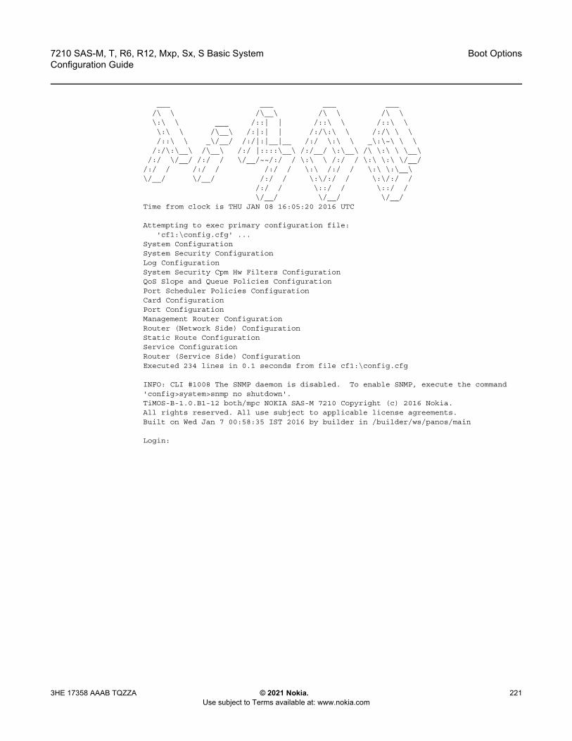
7210 SAS-M, T, R6, R12, Mxp, Sx, S Basic System Configuration Guide
Boot Options
3HE 17358 AAAB TQZZA © 2021 Nokia. Use subject to Terms available at: www.nokia.com
221
___ ___ ___ ___/\ \ /\__\ /\ \ /\ \\:\ \ ___ /::| | /::\ \ /::\ \\:\ \ /\__\ /:|:| | /:/\:\ \ /:/\ \ \/::\ \ _\/__/ /:/|:|__|__ /:/ \:\ \ _\:\~\ \ \
/:/\:\__\ /\__\ /:/ |::::\__\ /:/__/ \:\__\ /\ \:\ \ \__\/:/ \/__/ /:/ / \/__/~~/:/ / \:\ \ /:/ / \:\ \:\ \/__/
/:/ / /:/ / /:/ / \:\ /:/ / \:\ \:\__\\/__/ \/__/ /:/ / \:\/:/ / \:\/:/ /
/:/ / \::/ / \::/ /\/__/ \/__/ \/__/
Time from clock is THU JAN 08 16:05:20 2016 UTC
Attempting to exec primary configuration file:'cf1:\config.cfg' ...
System ConfigurationSystem Security ConfigurationLog ConfigurationSystem Security Cpm Hw Filters ConfigurationQoS Slope and Queue Policies ConfigurationPort Scheduler Policies ConfigurationCard ConfigurationPort ConfigurationManagement Router ConfigurationRouter (Network Side) ConfigurationStatic Route ConfigurationService ConfigurationRouter (Service Side) ConfigurationExecuted 234 lines in 0.1 seconds from file cf1:\config.cfg
INFO: CLI #1008 The SNMP daemon is disabled. To enable SNMP, execute the command'config>system>snmp no shutdown'.TiMOS-B-1.0.B1-12 both/mpc NOKIA SAS-M 7210 Copyright (c) 2016 Nokia.All rights reserved. All use subject to applicable license agreements.Built on Wed Jan 7 00:58:35 IST 2016 by builder in /builder/ws/panos/main
Login:
Boot Options
222
7210 SAS-M, T, R6, R12, Mxp, Sx, S Basic SystemConfiguration Guide
© 2021 Nokia. Use subject to Terms available at: www.nokia.com
3HE 17358 AAAB TQZZA

7210 SAS-M, T, R6, R12, Mxp, Sx, S Basic System Configuration Guide
Virtual Chassis
3HE 17358 AAAB TQZZA © 2021 Nokia. Use subject to Terms available at: www.nokia.com
223
5 Virtual ChassisThis chapter provides information about the parameters required to create a virtual chassis and how to configure them. A virtual chassis is also known as a stack of nodes.
Topics in this chapter include provisioning, booting, and preprovisioning the virtual chassis; provisioning service entities; replacing and upgrading nodes; and virtual chassis boot scenarios and split scenarios.
5.1 Overview
The 7210 SAS supports the grouping together, or stacking, of a set of nodes to create a virtual chassis (VC). The following nodes can be stacked to form a VC:
• the 7210 SAS-Sx 1/10GE and its variants• the 7210 SAS-S 1/10GE and its variants
A VC provides operational simplicity because it uses a single IP address and MAC address for the set of stacked nodes. The set of nodes can be provisioned and monitored as a single platform rather than as individual nodes. For example, users can provision services for all ports in the VC without having to log in and access each node individually. As well, the NSP NFM-P management system can manage and monitor the VC as a single platform rather than the individual nodes that comprise it.
In addition to operational simplicity, a VC increases service reliability by providing redundancy in the following ways.
• If the node running control plane protocols in the VC fails, a standby node will take over the master node function, minimizing service loss.
• Access devices can be connected using a mechanism such as LAG or G.8032 so that the impact of a node failure in a VC is minimized for services on the access device.
Up to three nodes can be provisioned in a single VC. Nodes can be added to or removed from the VC to increase the total available ports or to replace a failed unit.
The nodes of the VC are connected through their stacking ports. The total capacity provided by the stacking ports is equivalent to the sum of the bandwidth provided by the individual port. The stacking ports are used for forwarding service traffic and for exchanging management and control messages between the nodes in the VC. The VC control traffic is prioritized over other traffic on the stacking ports.
Virtual Chassis
224
7210 SAS-M, T, R6, R12, Mxp, Sx, S Basic SystemConfiguration Guide
© 2021 Nokia. Use subject to Terms available at: www.nokia.com
3HE 17358 AAAB TQZZA
The 7210 SAS supports VC in standalone mode.
Nodes in the VC can take on the role of active CPM, standby CPM, or line card (also known as an IMM). In a VC, two of the nodes can be designated as CPM nodes (along with a built in IMM) and the other node is designated as an IMM-only node. See Node Roles in the VC for more information. Each of the nodes in the VC is provisioned as a card, similar to the cards in a chassis.
A VC can support uplink over-subscription, where only a few uplinks from the end nodes of the stack are connected to the network, and all customer services are delivered through these uplink ports.
A VC can also support a configuration where the uplinks are not over-subscribed and operators can connect any number of ports from each node in the stack to the network core. In release 11.0, the VC software module keeps track of the shortest path from a specific source IMM to a destination IMM and uses it to forward packets through the stack using the stacking ports.
A VC can operate as a Layer 2 device, where only VLANs are used for uplink connectivity, or as a full-fledged IP/MPLS platform with support for IP/MPLS-based Layer 2 and Layer 3 VPNs.
5.1.1 Node Roles in the VC
The VC supports a minimum of one and up to a maximum of four nodes. The nodes in a VC are modeled in software as either CPM nodes or IMM nodes. The CPMs and the IMMs are interconnected through stacking ports.
In a VC, CPMs perform a dual role and will also act as IMMs. Consequently, a CPM is referred to as a CPM-IMM node and the IMM is referred to as an IMM-only node. Nodes in a VC are IMM-only nodes by default, but an IMM-only node is not mandatory in a VC.
If only one node is configured in the VC (minimum requirement), it must be a CPM-IMM node. A maximum of two CPM-IMM nodes can be configured on the VC to provide control plane redundancy. In this case, the remaining nodes must be IMM nodes. If more than two CPM-IMM nodes are configured, the software logs an error. The user can also configure a VC with one CPM-IMM and one IMM-only node; however, this configuration does not provide control-plane redundancy.
Note: The following functionality is currently not supported on VCs:
• Synchronous Ethernet network synchronization• 1588v2 PTP network synchronization

7210 SAS-M, T, R6, R12, Mxp, Sx, S Basic System Configuration Guide
Virtual Chassis
3HE 17358 AAAB TQZZA © 2021 Nokia. Use subject to Terms available at: www.nokia.com
225
During the boot process, the system designates one of the configured CPM-IMM nodes as the active and the other as the standby CPM-IMM. If the active CPM-IMM fails, the standby CPM-IMM takes over the active role. It is possible to upgrade an existing IMM-only node to be a CPM-IMM node so that if an existing CPM-IMM node fails, another node can take on its role. See Configuration Guidelines for Upgrading, Adding, or Removing a VC Node for more information about upgrading an IMM-only node to a CPM-IMM node. It is also possible to add a new node to the VC as a CPM-IMM node in the event that an existing CPM-IMM node must be replaced; however, there are restrictions. See Permitted Platform Combinations in a VC for more information. For information about adding and removing nodes in different scenarios, see VC Boot Scenarios.
5.1.2 Permitted Platform Combinations in a VC
Not all combinations of 7210 SAS-Sx 1/10GE and 7210 SAS-S 1/10GE platform variants can be configured as CPM-IMM nodes and assume the role of the active and standby CPM in a VC. Only platforms with similar capabilities can be configured as CPM-IMM nodes.
This restriction does not apply to nodes acting as IMM-only nodes. Any 7210 SAS-Sx 1/10GE variant or 7210 SAS-S 1/10GE variant (PoE and non-PoE, fiber and copper) can be configured as an IMM-only node to operate with any of the supported combinations of CPM-IMM nodes.
Table 25 lists the supported combinations of 7210 SAS-Sx 1/10GE and 7210 SAS-S 1/10GE variants that can be configured as CPM-IMM nodes.
Table 25 Supported Node Combinations for CPM-IMM Configuration
CPM-A CPM-B CPM-IMM
7210 SAS-Sx 1/10GE (any variant) 7210 SAS-S 1/10GE (any variant) No
7210 SAS-S 1/10GE (any variant) 7210 SAS-S 1/10GE (any variant) Yes
7210 SAS-Sx 1/10GE (any variant) 7210 SAS-Sx 1/10GE (any variant)
Yes

Virtual Chassis
226
7210 SAS-M, T, R6, R12, Mxp, Sx, S Basic SystemConfiguration Guide
© 2021 Nokia. Use subject to Terms available at: www.nokia.com
3HE 17358 AAAB TQZZA
5.2 Provisioning and Booting Up the VC in Standalone Mode
The 7210 SAS supports manual bootup for a VC.
To provision a node to belong to a VC, it must be configured with the chassis-role parameter set to standalone-vc. The chassis-role parameter is a BOF parameter in the boot loader context.
Of the two nodes configured as CPM-IMM, one becomes the active CPM and the other becomes the standby CPM, ready to move to the active role should the current active CPM fail.The node designated as the active CPM uses the configuration file available locally or remotely at boot up. It distributes the configuration to all members of the VC. Setting the chassis-role parameter to standalone-vc ensures that the member nodes of the VC do not use any local configuration at boot up.
The IMM-only node configuration and the service configuration is always done on the active CPM. The active CPM-IMM node distributes the configuration information to other VC members when the user has saved the TiMOS configuration.The IMM-only nodes receive the service configuration from the active CPM through VC management messages, while the standby CPM receives the service configuration through the high availability (HA) reconcile mechanism.
The active CPM-IMM also sends out VC management packets with VC configuration information to IMM-only member nodes. The IMM-only nodes use the management packets to obtain the VC configuration and join the VC.
The VC requires a single IP address and MAC address to be managed as a single entity. The current active CPM owns the IP address and responds to all the messages sent to this IP address and uses the MAC address as required (for example, for ARP).
The show>chassis command displays power, fan, and alarm statuses of the VC by consolidating the statuses of all cards provisioned in the VC. The show>card command displays power, fan, and alarm statuses for individual cards.
See Procedure to Boot in the Standalone-VC Mode for information about booting the 7210 SAS-Sx/S 1/10GE in standalone-VC mode, including the booting sequenced, BOF prompts, and sample logs.
7210 SAS-M, T, R6, R12, Mxp, Sx, S Basic System Configuration Guide
Virtual Chassis
3HE 17358 AAAB TQZZA © 2021 Nokia. Use subject to Terms available at: www.nokia.com
227
5.2.1 Required BOF Parameters
When the node is shipped from the factory, the chassis-role parameter in the boot loader file is set to factory-default. For the node to be part of a VC, the user must explicitly set the chassis-role parameter in the boot loader to standalone-vc.
The user must also configure the following boot loader parameters to operate the VC:
• vc-stack-nameConfigure the boot loader parameter vc-stack-name on the active CPM-IMM node to identify the VC of which the nodes are members. A node configured with a vc-stack-name of “my-stack” is a member node of the VC “my-stack”. The system-name variable in the configure system name command can be reused as the boot loader vc-stack-name value. A node cannot be added to a VC if its vc-stack-name value does not match that of the current active CPM-IMM.
• vc-stack-node-typeSpecify the node role as either cpm-imm or imm-only using the boot loader BOF parameter vc-stack-node-type. The default setting is imm-only. Users need to modify the default only for nodes that can take on the role of CPM by changing the setting to cpm-imm. The BOF parameter does not need to be modified for nodes whose role is IMM. Users can configure two nodes in the stack to be cpm-imm nodes.
In addition, to operate the VC users must also configure the following commands in the TiMOS BOF context:
• vc-stack-nodeUse the command bof>vc-stack-node {cpmA | cpmB} slot-num slot-num mac-addr mac-address to configure the slot number and the MAC address of the CPM nodes. The VC stack node cpmA and cpmB parameters can also be configured through the boot loader BOF menu prompts.
Note: Before these boot loader parameters are configured, verity that the chassis-role must be set to standalone-vc.

Virtual Chassis
228
7210 SAS-M, T, R6, R12, Mxp, Sx, S Basic SystemConfiguration Guide
© 2021 Nokia. Use subject to Terms available at: www.nokia.com
3HE 17358 AAAB TQZZA
The slot number identifies a specific node in the VC (similar to the slot ID of a card in a chassis-based system) and is used in addressing service objects created during provisioning. The slot number also is used to light up the correct LED on the front-panel of the node, enabling operators to see which slot is configured with the VC node (the stack LED also denotes that the node is part of a VC and is fully functional). The slot number of the active and standby CPM-IMMs can be set to any number from 1 to 8, as long as it is not in use by another VC member node. An arbitration process during the boot phase ensures that one of the CPM nodes is the active CPM and the other is the standby CPM.The MAC address must match the base MAC address printed on the label of the chassis.
• eth-mgt-addressConfigure the management IP address for the two CPM nodes using the command bof>eth-mgmt-address ip-prefix/ip-prefix-length [active | standby]. The Ethernet management IP address configured as active provides the IP address of the active node, which a management station can use to operate the stack. The management IP address configured as standby provides connectivity to the standby node.
5.2.2 Manually Configuring Nodes to Boot as CPM-IMM in a VC
The CPM-IMM nodes are configured through the BOF and do not require further configuration to be part of the VC. Perform the following steps to manually boot and configure CPM-IMM nodes in a VC.
Step 1. Identify the two nodes that will take on the CPM role.Step 2. Ensure there is console access to the CPM nodes to drive the boot
process. See the following for information: Procedure to Connect to a Console, 7210 SAS-S 1/10GE Console Port, and 7210 SAS-Sx 10/100GE Console Port.
Step 3. Ensure the CPM nodes are powered on.Step 4. Ensure that the SD card delivered with the software license containing the
boot loader (boot.tim) and TiMOS software is installed in the SD card slot.Step 5. Manually interrupt the boot process at the boot loader BOF prompt and
configure the following: i. specify standalone-vc for the chassis-role parameterii. specify a name for the vc-stack-name parameteriii. specify cpm-imm for the vc-stack-node-type parameter
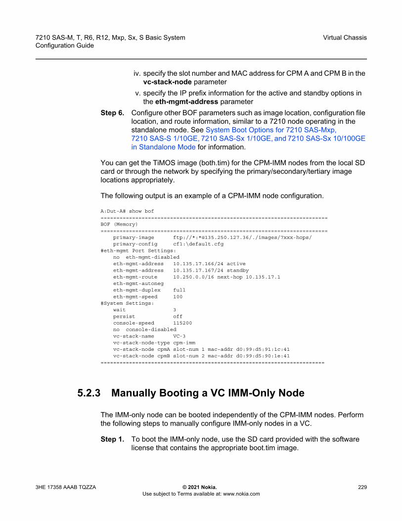
7210 SAS-M, T, R6, R12, Mxp, Sx, S Basic System Configuration Guide
Virtual Chassis
3HE 17358 AAAB TQZZA © 2021 Nokia. Use subject to Terms available at: www.nokia.com
229
iv. specify the slot number and MAC address for CPM A and CPM B in the vc-stack-node parameter
v. specify the IP prefix information for the active and standby options in the eth-mgmt-address parameter
Step 6. Configure other BOF parameters such as image location, configuration file location, and route information, similar to a 7210 node operating in the standalone mode. See System Boot Options for 7210 SAS-Mxp, 7210 SAS-S 1/10GE, 7210 SAS-Sx 1/10GE, and 7210 SAS-Sx 10/100GE in Standalone Mode for information.
You can get the TiMOS image (both.tim) for the CPM-IMM nodes from the local SD card or through the network by specifying the primary/secondary/tertiary image locations appropriately.
The following output is an example of a CPM-IMM node configuration.
A:Dut-A# show bof========================================================================BOF (Memory)========================================================================
primary-image ftp://*:*@135.250.127.36/./images/7xxx-hops/primary-config cf1:\default.cfg
#eth-mgmt Port Settings:no eth-mgmt-disabledeth-mgmt-address 10.135.17.166/24 activeeth-mgmt-address 10.135.17.167/24 standbyeth-mgmt-route 10.250.0.0/16 next-hop 10.135.17.1eth-mgmt-autonegeth-mgmt-duplex fulleth-mgmt-speed 100
#System Settings:wait 3persist offconsole-speed 115200no console-disabledvc-stack-name VC-3vc-stack-node-type cpm-immvc-stack-node cpmA slot-num 1 mac-addr d0:99:d5:91:1c:41vc-stack-node cpmB slot-num 2 mac-addr d0:99:d5:90:1e:41
=======================================================================
5.2.3 Manually Booting a VC IMM-Only Node
The IMM-only node can be booted independently of the CPM-IMM nodes. Perform the following steps to manually configure IMM-only nodes in a VC.
Step 1. To boot the IMM-only node, use the SD card provided with the software license that contains the appropriate boot.tim image.
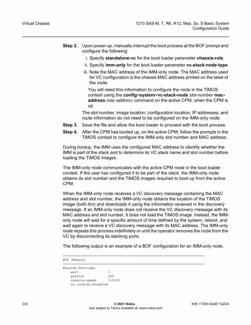
Virtual Chassis
230
7210 SAS-M, T, R6, R12, Mxp, Sx, S Basic SystemConfiguration Guide
© 2021 Nokia. Use subject to Terms available at: www.nokia.com
3HE 17358 AAAB TQZZA
Step 2. Upon power up, manually interrupt the boot process at the BOF prompt and configure the following:
i. Specify standalone-vc for the boot loader parameter chassis-role.ii. Specify imm-only for the boot loader parameter vc-stack-node-type.iii. Note the MAC address of the IMM-only node. The MAC address used
for VC configuration is the chassis MAC address printed on the label of the node.
You will need this information to configure the node in the TiMOS context using the config>system>vc-stack-node slot-number mac-address mac-address command on the active CPM, when the CPM is up.
The slot number, image location, configuration location, IP addresses, and route information do not need to be configured on the IMM-only node.
Step 3. Save the file and allow the boot loader to proceed with the boot process. Step 4. After the CPM has booted up, on the active CPM, follow the prompts in the
TiMOS context to configure the IMM-only slot number and MAC address.
During bootup, the IMM uses the configured MAC address to identify whether the IMM is part of the stack and to determine its VC stack name and slot number before loading the TiMOS images.
The IMM-only node communicates with the active CPM node in the boot loader context. If the user has configured it to be part of the stack, the IMM-only node obtains its slot number and the TiMOS images required to boot up from the active CPM.
When the IMM-only node receives a VC discovery message containing the MAC address and slot number, the IMM-only node obtains the location of the TiMOS image (both.tim) and downloads it using the information received in the discovery message. If an IMM-only node does not receive the VC discovery message with its MAC address and slot number, it does not load the TiMOS image. Instead, the IMM-only node will wait for a specific amount of time defined by the system, reboot, and wait again to receive a VC discovery message with its MAC address. The IMM-only node repeats this process indefinitely or until the operator removes the node from the VC by disconnecting its stacking ports.
The following output is an example of a BOF configuration for an IMM-only node.
========================================================================BOF (Memory)========================================================================#System Settings:
wait 3persist offconsole-speed 115200no console-disabled

7210 SAS-M, T, R6, R12, Mxp, Sx, S Basic System Configuration Guide
Virtual Chassis
3HE 17358 AAAB TQZZA © 2021 Nokia. Use subject to Terms available at: www.nokia.com
231
vc-stack-node-type imm-only=======================================================================
Users cannot use the console or Telnet to view the BOF or execute the BOF commands on an IMM-only node. To update the VC parameters associated with the IMM-only node, users should reboot the node, interrupt the boot process, and use the menu prompts displayed in the boot loader context.
5.2.4 Configuring an IMM-Only Node in a VC
To configure an IMM-only node in the VC, use the command config>system>vc-stack-node slot-number mac-address mac-address [create].
An IMM-only node in a VC is identified by its slot-number and its MAC address. The slot number assigned to the node can be an arbitrary number from 1 to 8. It is used in service provisioning to identify ports on a VC member node, and on service objects on those ports. The port on a VC member node is identified using the format slot-id/1/port-id;sap-id. For example, port 20 on the front panel of a VC member node in slot 4 with a SAP ID of 300 is identified as 4/1/20:300.
Slot numbers are unique to each VC, which are identified by their vc-stack-name, and can be reused across different VCs. Software ensures the uniqueness of the slot number in each VC by raising an error if two nodes in the same VC are assigned the same slot number.
When an IMM-only node boots up, it uses the MAC address and slot number received in the VC discovery messages sent by the CPM node to discover VC configuration information. The MAC address used for VC configuration is the chassis MAC address printed on the label of the node. If it does not match the MAC address retrieved from the EEPROM, the node will not be able use the VC configuration information. For CPM-IMM nodes, this will result in boot failure. The IMM-only nodes will wait indefinitely for a VC discovery message with the correct MAC address from the CPM-IMM node, or until the operator removes the node from the VC by disconnecting its stacking ports.
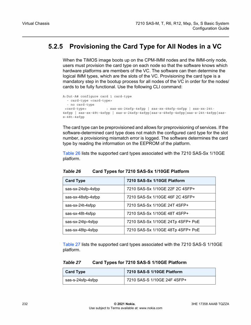
Virtual Chassis
232
7210 SAS-M, T, R6, R12, Mxp, Sx, S Basic SystemConfiguration Guide
© 2021 Nokia. Use subject to Terms available at: www.nokia.com
3HE 17358 AAAB TQZZA
5.2.5 Provisioning the Card Type for All Nodes in a VC
When the TiMOS image boots up on the CPM-IMM nodes and the IMM-only node, users must provision the card type on each node so that the software knows which hardware platforms are members of the VC. The software can then determine the logical IMM types, which are the slots of the VC. Provisioning the card type is a mandatory step in the bootup process for all nodes of the VC in order for the nodes/cards to be fully functional. Use the following CLI command:
A:Dut-A# configure card 1 card-type- card-type <card-type>- no card-type
<card-type> : sas-sx-24sfp-4sfpp | sas-sx-48sfp-4sfpp | sas-sx-24t-4sfpp | sas-sx-48t-4sfpp | sas-s-24sfp-4sfpp|sas-s-48sfp-4sfpp|sas-s-24t-4sfpp|sas-s-48t-4sfpp
The card type can be preprovisioned and allows for preprovisioning of services. If the software-determined card type does not match the configured card type for the slot number, a provisioning mismatch error is logged. The software determines the card type by reading the information on the EEPROM of the platform.
Table 26 lists the supported card types associated with the 7210 SAS-Sx 1/10GE platform.
Table 27 lists the supported card types associated with the 7210 SAS-S 1/10GE platform.
Table 26 Card Types for 7210 SAS-Sx 1/10GE Platform
Card Type 7210 SAS-Sx 1/10GE Platform
sas-sx-24sfp-4sfpp 7210 SAS-Sx 1/10GE 22F 2C 4SFP+
sas-sx-48sfp-4sfpp 7210 SAS-Sx 1/10GE 46F 2C 4SFP+
sas-sx-24t-4sfpp 7210 SAS-Sx 1/10GE 24T 4SFP+
sas-sx-48t-4sfpp 7210 SAS-Sx 1/10GE 48T 4SFP+
sas-sx-24tp-4sfpp 7210 SAS-Sx 1/10GE 24Tp 4SFP+ PoE
sas-sx-48tp-4sfpp 7210 SAS-Sx 1/10GE 48Tp 4SFP+ PoE
Table 27 Card Types for 7210 SAS-S 1/10GE Platform
Card Type 7210 SAS-S 1/10GE Platform
sas-s-24sfp-4sfpp 7210 SAS-S 1/10GE 24F 4SFP+

7210 SAS-M, T, R6, R12, Mxp, Sx, S Basic System Configuration Guide
Virtual Chassis
3HE 17358 AAAB TQZZA © 2021 Nokia. Use subject to Terms available at: www.nokia.com
233
5.3 Provisioning Service Entities
The nodes in a VC are represented as the cards of a chassis. Each card is assigned a slot number. Using the slot number, services are provisioned on the card using the format slot-number/mda-number/port-number:sap-id, where the slot-number is configured for every node/card, the mda-number is always set to 1 for all 7210 SAS-Sx/S 1/10GE platforms supporting VC, and the port-number corresponds to the front-panel Ethernet port number and ranges from 1 to 28 or from 1 to 52 for 7210 SAS-Sx/S 1/10GE platforms.
5.4 Preprovisioning a VC
To preprovision a VC, users must configure the card-type for the slot they want to preprovision. When the card type is configured, the ports are automatically created for that slot, allowing configuration of the services using the ports of the slot.
The vc-stack-node command can be configured later and is independent of the card-type configuration. The vc-stack-node configuration identifies the slot and the MAC address of the node and is used only by the IMM-only node to become part of the VC. If the software detects a mismatch between the hardware type of the IMM-only node and the configured/provisioned card type, it logs an error and reboots the card, allowing the user to correct the value and fix the problem.
sas-s-48sfp-4sfpp 7210 SAS-S 1/10GE 48F 4SFP+
sas-s-24t-4sfpp 7210 SAS-S 1/10GE 24T 4SFP+
sas-s-48t-4sfpp 7210 SAS-S 1/10GE 48T 4SFP+
sas-s-24tp-4sfpp 7210 SAS-S 1/10GE 24Tp 4SFP+ PoE
sas-s-48tp-4sfpp 7210 SAS-S 1/10GE 48Tp 4SFP+ PoE
Table 27 Card Types for 7210 SAS-S 1/10GE Platform (Continued)
Card Type 7210 SAS-S 1/10GE Platform
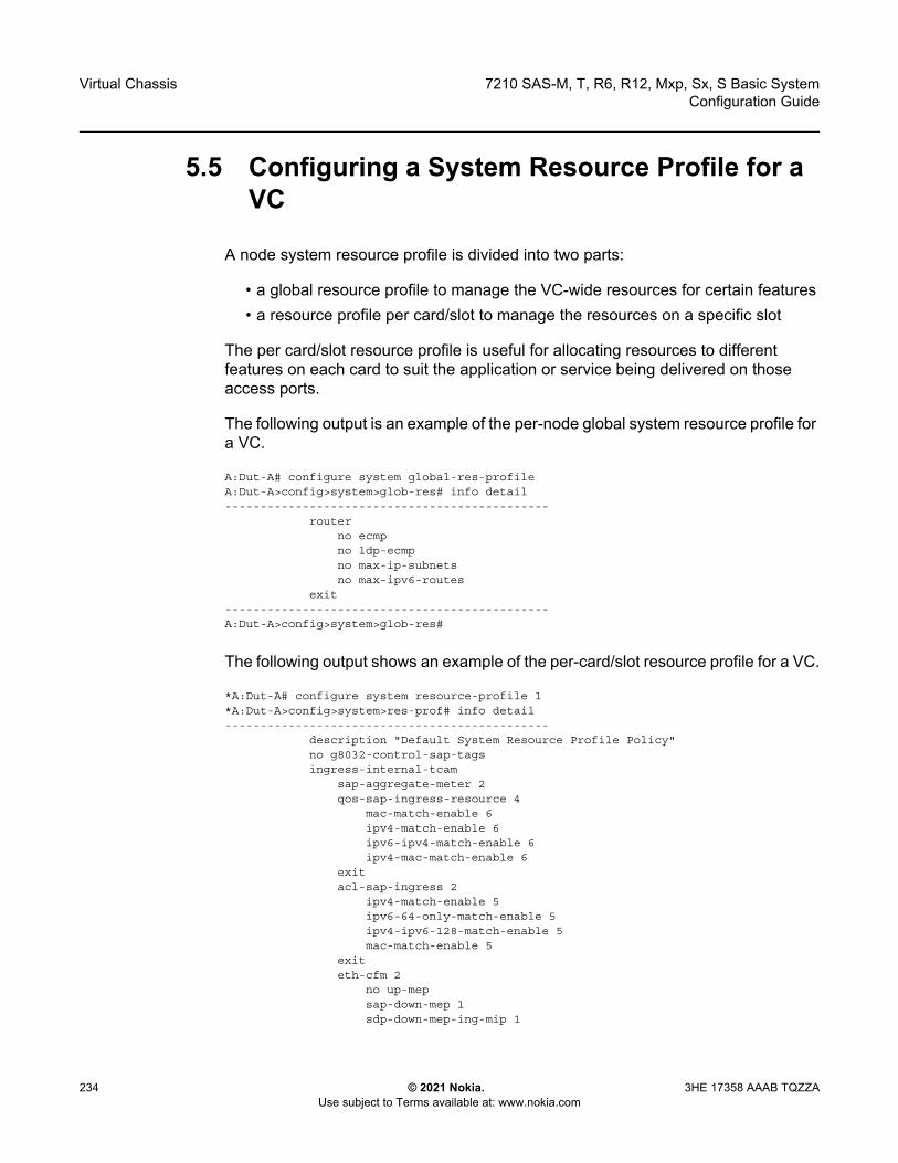
Virtual Chassis
234
7210 SAS-M, T, R6, R12, Mxp, Sx, S Basic SystemConfiguration Guide
© 2021 Nokia. Use subject to Terms available at: www.nokia.com
3HE 17358 AAAB TQZZA
5.5 Configuring a System Resource Profile for a VC
A node system resource profile is divided into two parts:
• a global resource profile to manage the VC-wide resources for certain features• a resource profile per card/slot to manage the resources on a specific slot
The per card/slot resource profile is useful for allocating resources to different features on each card to suit the application or service being delivered on those access ports.
The following output is an example of the per-node global system resource profile for a VC.
A:Dut-A# configure system global-res-profileA:Dut-A>config>system>glob-res# info detail----------------------------------------------
routerno ecmpno ldp-ecmpno max-ip-subnetsno max-ipv6-routes
exit----------------------------------------------A:Dut-A>config>system>glob-res#
The following output shows an example of the per-card/slot resource profile for a VC.
*A:Dut-A# configure system resource-profile 1*A:Dut-A>config>system>res-prof# info detail----------------------------------------------
description "Default System Resource Profile Policy"no g8032-control-sap-tagsingress-internal-tcam
sap-aggregate-meter 2qos-sap-ingress-resource 4
mac-match-enable 6ipv4-match-enable 6ipv6-ipv4-match-enable 6ipv4-mac-match-enable 6
exitacl-sap-ingress 2
ipv4-match-enable 5ipv6-64-only-match-enable 5ipv4-ipv6-128-match-enable 5mac-match-enable 5
exiteth-cfm 2
no up-mepsap-down-mep 1sdp-down-mep-ing-mip 1

7210 SAS-M, T, R6, R12, Mxp, Sx, S Basic System Configuration Guide
Virtual Chassis
3HE 17358 AAAB TQZZA © 2021 Nokia. Use subject to Terms available at: www.nokia.com
235
exitexitegress-internal-tcam
acl-sap-egress 2mac-ipv4-match-enable 2no ipv6-128bit-match-enableno mac-ipv6-64bit-match-enableno mac-match-enable
exitno egress-sap-aggregate-meter
exit----------------------------------------------*A:Dut-A# show card 1 active-resource-profile=======================================================================Active System Resource Profile Information=======================================================================-----------------------------------------------------------------------IPv6 FIB-----------------------------------------------------------------------max-ipv6-routes : disable-----------------------------------------------------------------------Router-----------------------------------------------------------------------max-ip-subnets : 2000----------------------------------------------------------------------------------------------------------------------------------------------Router-----------------------------------------------------------------------system-max-ecmp : 1L3-max-ecmp-groups : 1024Ldp-max-ecmp-groups : disableLdp-ecmp-percent-value : disable-----------------------------------------------------------------------Ingress Internal CAM : 8-----------------------------------------------------------------------Sap Ingress Qos resource : 4 Sap Aggregate Meter (#) : 2-----------------------------------------------------------------------IPv4 Resource : max Mac Resource : maxIPv4-IPv6 Resource : disable IPv4-Mac Resource : max-------------------------------------------------------------------------------Net Ingress Qos resource : disable--------------------------------------------------------------------------------------------------------------------------------------------------------------Sap Ingress ACL resource : 2-------------------------------------------------------------------------------IPv4 Resource : max Mac Resource : maxIPv4-IPv6 128 bit Resource : disable IPv6 64 bit Resource : disable--------------------------------------------------------------------------------------------------------------------------------------------------------------Eth CFM : 2-------------------------------------------------------------------------------sap-down-mep : 1 up-mep : disablesdp-down-mep-ing-mip : 1-------------------------------------------------------------------------------Egress Internal CAM : 2--------------------------------------------------------------------------------------------------------------------------------------------------------------Sap Egress ACL resource : 2-------------------------------------------------------------------------------

Virtual Chassis
236
7210 SAS-M, T, R6, R12, Mxp, Sx, S Basic SystemConfiguration Guide
© 2021 Nokia. Use subject to Terms available at: www.nokia.com
3HE 17358 AAAB TQZZA
Mac and IPv4 Resource : 2 Mac-only Resource : disableIPv6 128 bit Resource : disable Mac and IPv6 64 bit Resour*: disable--------------------------------------------------------------------------------------------------------------------------------------------------------------Egr sap agg-meter : disable-------------------------------------------------------------------------------MBS pool : Node-------------------------------------------------------------------------------Decommissioned Ports : Not Applicable-------------------------------------------------------------------------------===============================================================================* indicates that the corresponding row element may have been truncated.# indicates that the value will take effect only after reboot or clear card.
5.6 VC Boot Scenarios
This section describes the required configurations and the expected behaviors of different boot up scenarios.
5.6.1 First Time Manual Boot of Nodes in the Stack
The following steps outline how to manually bring up a VC using nodes shipped from the factory that are being booted up for the first time.
Users can boot up a single node or a set of nodes that are to be part of a VC. As well, users can power up one node, all the nodes, or a set of nodes; there is no restriction on the power sequence. The following steps describe the sequence when all nodes are booted up together; however, the steps here do not dictate the order of service provisioning and do not preclude preprovisioning of services on the active CPM. Service preprovisioning is allowed after the VC configuration, including the VC node member configuration, is complete.
Step 1. Identify the two nodes that will take on the CPM role.Step 2. Ensure there is console access to each CPM node to drive the boot
process. See the following for information: 7210 SAS-Sx 10/100GE Console Port, 7210 SAS-S 1/10GE Console Port, and Procedure to Connect to a Console.
Step 3. Ensure the CPM nodes are powered on.
Note: The CPM-IMM nodes are configured through the BOF and do not require further configuration to be part of the VC.

7210 SAS-M, T, R6, R12, Mxp, Sx, S Basic System Configuration Guide
Virtual Chassis
3HE 17358 AAAB TQZZA © 2021 Nokia. Use subject to Terms available at: www.nokia.com
237
Step 4. Ensure that the SD card containing the boot loader (boot.tim) and TiMOS (both.tim) software is installed in the SD card slot for each CPM node.In Release 11.0, the TiMOS image (both.tim) for the CPM-IMM nodes can be obtained from the local SD card or obtained through the network by specifying the primary/secondary/tertiary image locations appropriately.
Step 5. On the node that will be the active CPM for the first time boot, log in through the console port and manually interrupt the boot process.The boot prompt appears.
Step 6. Configure BOF parameters as follows:- specify standalone-vc for the boot loader parameter chassis-role- specify a name for the boot loader parameter vc-stack-name- specify cpm-imm for the boot loader parameter vc-stack-node-type - specify the slot number and MAC address of each CPM-IMM node in
the bof>vc-stack-node command- specify the management IP address for the active and standby CPM-
IMM nodes in the bof>eth-mgmt-address command- configure the TiMOS image location- configure the configuration file location
See System Boot Options for 7210 SAS-Mxp, 7210 SAS-S 1/10GE, 7210 SAS-Sx 1/10GE, and 7210 SAS-Sx 10/100GE in Standalone Mode for information about configuring BOF parameters.The following output shows an example of a BOF configuration for a CPM-IMM node.
A:Dut-A# show bof========================================================================BOF (Memory)========================================================================
primary-image ftp://*:*@135.250.127.36/./images/7xxx-hops/primary-config cf1:\default.cfg
#eth-mgmt Port Settings:no eth-mgmt-disabledeth-mgmt-address 10.135.17.166/24 activeeth-mgmt-address 10.135.17.167/24 standbyeth-mgmt-route 10.250.0.0/16 next-hop 10.135.17.1eth-mgmt-autonegeth-mgmt-duplex fulleth-mgmt-speed 100
#System Settings:wait 3persist offconsole-speed 115200no console-disabledvc-stack-name VC-3vc-stack-node-type cpm-immvc-stack-node cpmA slot-num 1 mac-addr d0:99:d5:91:1c:41vc-stack-node cpmB slot-num 2 mac-addr d0:99:d5:90:1e:41
=======================================================================

Virtual Chassis
238
7210 SAS-M, T, R6, R12, Mxp, Sx, S Basic SystemConfiguration Guide
© 2021 Nokia. Use subject to Terms available at: www.nokia.com
3HE 17358 AAAB TQZZA
Step 7. On the node that will be the standby CPM for the first time boot, log in through the console port and manually interrupt the boot process.The boot prompt appears.
Step 8. Configure BOF parameters as follows:- specify standalone-vc for the boot loader parameter chassis-role- specify a name for or the boot loader parameter vc-stack-name- specify cpm-imm for the boot loader parameter vc-stack-node-type - specify the slot number and MAC address of each CPM-IMM node in
the bof>vc-stack-node command- configure the TiMOS image location
The CPM-IMM nodes undergo an arbitration process where the node assigned the lower slot number gets chosen as the active CPM node. The node chosen as the active CPM node loads the TiMOS image and boots up as the active CPM-IMM node. The standby CPM also proceeds with boot up. However, it does not have the VC configuration on first-time boot and needs to wait for the active CPM to provide the VC configuration through VC management messages.
Step 9. Identify the node that will take on the IMM role.Step 10. Ensure there is console access to the IMM node to drive the boot process.Step 11. Ensure that the SD card containing the appropriate boot loader (boot.tim)
software is installed in the SD card slot.Step 12. Power up the node that will be the IMM node, log in through the console
port and manually interrupt the boot process.The boot prompt appears.
Step 13. Configure the boot loader BOF parameter chassis-role as standalone-vc.The boot loader parameter vc-stack-node-type retains its default value of imm-only.
The VC stack name, slot number, image location, configuration location, IP addresses, and route information do not need to be configured on the IMM-only node. The following output shows an example of a BOF configuration for a IMM-only node.
========================================================================BOF (Memory)
Note: The vc-stack-node-type parameter is stored in the boot flash (and not in the boot option file) and must be modified using the BOF menu prompts.

7210 SAS-M, T, R6, R12, Mxp, Sx, S Basic System Configuration Guide
Virtual Chassis
3HE 17358 AAAB TQZZA © 2021 Nokia. Use subject to Terms available at: www.nokia.com
239
========================================================================#System Settings:
wait 3persist offconsole-speed 115200no console-disabledvc-stack-node-type imm-only
=======================================================================
Step 14. After the IMM-only BOF parameters are configured, save the BOF by typing Yes when prompted to save the BOF. Let the boot loader proceed with the boot process.The IMM-only node waits to receive VC configuration information from the active CPM-IMM node.
Step 15. Take note of the MAC address of the node chosen as the IMM-only node. The MAC address is the chassis MAC address printed on the label of the node.
Step 16. At the TiMOS prompt on the active CPM node, proceed with the VC configuration by using the config>system>vc-stack>vc-stack-node command to configure the IMM-only node slot number and MAC address.
When the VC configuration information has been committed in the CLI, the active CPM node sends the VC configuration to all other nodes in the VC through VC management messages over the stacking ports.
When the IMM-only nodes receive the VC management messages from the active CPM, they confirm the VC configuration by matching their chassis address to the MAC address contained in the VC message.They then retrieve the TiMOS image from the active CPM and use it to boot up.
While booting up with the TiMOS image, the standby CPM node undergoes another CPM election arbitration process, which results in the node detecting itself as standby. The node then executes the HA reconcile process and synchronizes its management and control plane state with the active CPM. It receives the current running configuration with the VC configuration and the current BOF configuration present on the active CPM.
The VC is now ready for use.
Virtual Chassis
240
7210 SAS-M, T, R6, R12, Mxp, Sx, S Basic SystemConfiguration Guide
© 2021 Nokia. Use subject to Terms available at: www.nokia.com
3HE 17358 AAAB TQZZA
5.6.2 Subsequent Reboot of the Stack (with Correct BOF Present)
This scenario assumes that the BOF configured on each node during the first time boot up is saved locally and contains the VC configuration required for the node to boot up. It also assumes that the chassis-role parameter in the bootflash is set to standalone-vc for each node.
The following sequence occurs in the boot loader context and in the TiMOS context. There is no user intervention required.
• In the boot loader context, all the nodes in the VC read their bootflash and the BOFs that are present locally, and receive their VC configuration.
• In the boot loader context, the nodes configured as cpm-imm go through a CPM election process and the node with the lower slot number is chosen as the active CPM. Both nodes proceed to boot up using the TiMOS image (both.tim).
• In the TiMOS context, both the cpm-imm nodes again read the BOFs that are present locally and receive their VC configuration.
• In the boot loader context, the imm-only nodes wait to receive VC management messages from the active CPM, when the active CPM has booted up. When the imm-only nodes receive VC management messages that contain their MAC address and slot number, they proceed to boot up using the TiMOS image (both.tim). A local copy of the TiMOS image is used if it matches the version available on the active CPM; otherwise, the imm-only nodes retrieve the newer version from the active CPM. The imm-only nodes do not participate in the CPM election process.
• In the TiMOS context, the cpm-imm nodes go through the CPM election arbitration process to elect the active CPM node. The active CPM node then initializes the chassis manager and initiates a HA reconcile process with the standby CPM node.
If both the cpm-imm nodes come up as active, which is detected by both nodes receiving each other's VC management messages claiming themselves to be active, the node with the higher slot number reboots itself.
5.7 Replacing and Upgrading a Node in a VC
This section describes how to:
• replace a CPM-IMM node or IMM-only node• upgrade an existing IMM-only node to a CPM-IMM node
7210 SAS-M, T, R6, R12, Mxp, Sx, S Basic System Configuration Guide
Virtual Chassis
3HE 17358 AAAB TQZZA © 2021 Nokia. Use subject to Terms available at: www.nokia.com
241
• downgrade a CPM-IMM node to an IMM-only node
5.7.1 Replacing a Standby/Active CPM-IMM Node with Another CPM-IMM Node
When replacing a node, the SD card used to boot the replacement node must contain a version of the boot.tim and both.tim images that match that of the active CPM. If the versions do not match, the bootup will not be successful.
If a VC is configured with only a single CPM-IMM node and that node fails, the entire VC is down, including the IMM-only nodes. The IMM-only nodes reboot if they do not hear from the active CPM node after some time.
If the stacking ports are not connected together to form a ring connecting all the nodes of the VC, any failure in the VC (whether a link or a node failure) will isolate some nodes off of the VC, affecting all the services on those nodes. In addition, if the uplink is through one of the nodes that has been isolated or has failed, services using the uplink for the entire VC are affected. The procedure here assumes a ring of stacking ports is configured.
In the following scenario, it is assumed that a CPM-IMM node has failed and needs to be replaced. It is assumed that a redundant CPM node is configured and another CPM-IMM node is currently active. The replacement node might be a new node from the factory or a node that has been previously used as an IMM node.
Step 1. Use the MAC address or slot number to determine whether the failed node is CPM-A or CPM-B. The node to be added as a CPM-IMM node must be configured based on which one failed. For the purposes of this example, it is assumed that CPM-B (the standby CPM) has failed.
Step 2. Disconnect the stacking port on the failed node and complete the stacking ring.
Step 3. On the active CPM, remove the configuration of the failed CPM-IMM node (CPM-B) from the BOF using the bof no vc-stack-node command.
Step 4. On the active CPM, add the configuration of the new CPM-IMM node as CPM-B to the BOF using the bof vc-stack-node command.
Step 5. Save the BOF for the configuration to take effect immediately. Step 6. If the replacement node is an existing IMM-only node, follow these steps.
i. Remove the IMM-only node configuration from the configuration file of the active CPM using the config system vc-stack no vc-stack-node command.
ii. Connect to the console of the IMM-only node.
Virtual Chassis
242
7210 SAS-M, T, R6, R12, Mxp, Sx, S Basic SystemConfiguration Guide
© 2021 Nokia. Use subject to Terms available at: www.nokia.com
3HE 17358 AAAB TQZZA
iii. Reboot the node by toggling the power button.iv. On boot up, interrupt the boot process and configure the node as CPM-
IMM (CPM-B) by configuring the following BOF parameters:• specify cpm-imm for vc-stack-node-type• specify the slot number and MAC address of each CPM-IMM node
in the bof>vc-stack-node commandStep 7. If the replacement node is a new node, follow these steps.
i. Physically connect the new node into the VC ring (the stacking ports are connected to form a ring so that an alternate path always exists).
ii. Reboot the node.iii. Connect to the console of the new node.iv. Power on the node.v. On boot up, interrupt the boot process and configure the node as CPM-
IMM node by configuring the following boot loader parameters: • specify cpm-imm for vc-stack-node-type• specify the slot number and MAC address of each CPM-IMM node
in the bof vc-stack-node commandStep 8. Save the BOF and let the boot proceed.
The node comes up as a standby CPM node and talks to the active CPM to start the HA synchronization process. The master LED on the standby CPM will be blinking. The master LED on the active CPM will glow steady.
Services are not interrupted during the preceding process because the active CPM (CPM-A) is present and has not been rebooted (assuming the active CPM has an uplink to the network). If one of the IMM-only nodes was converted to a CPM-IMM node, the services on that IMM are affected as the node is rebooted to effect the change to a CPM-IMM node.
5.7.2 Replacing an IMM-only Node with Another Node
In this scenario, it is assumed that the IMM-only node has failed and needs to be replaced. The replacement node can be a new node from the factory or a node that has been previously used as an IMM node in another VC. In the former case, the procedure is similar to adding a node received from factory; see First Time Manual Boot of Nodes in the Stack starting at Step 9.
The SD card used to boot the node must contain a version of the TiMOS image (boot.tim) that matches that of the active CPM. If the version do not match, the boot will not be successful.

7210 SAS-M, T, R6, R12, Mxp, Sx, S Basic System Configuration Guide
Virtual Chassis
3HE 17358 AAAB TQZZA © 2021 Nokia. Use subject to Terms available at: www.nokia.com
243
If a ring of stacking ports is not configured, any failure in the stack (either a link or node failure) will isolate some nodes off of the stack, affecting all the services on those nodes. In addition, if the uplink is available through one of the nodes that is now isolated or failed, services using the uplink for the entire VC are affected.
The following procedure assumes a ring is configured and that the replacement node had been previously used as an IMM node in another VC.
Step 1. Disconnect the stacking port of the failed IMM-only node.Step 2. Connect to the console of the active CPM node.Step 3. On the active CPM node, use the no vc-stack-node command to remove
the failed IMM-only node configuration from the configuration file of the active CPM.
Step 4. On the active CPM node, add the configuration for the new IMM-only node using the config>system>vc-stack>vc-stack-node command, specifying the MAC address of the new IMM-only node and reusing the same slot number as the failed IMM-only node.
Step 5. Connect to the console of the replacement IMM node. Step 6. Connect the new IMM node to the stacking ring. Step 7. Reboot the IMM node by toggling the power to itStep 8. On boot up, interrupt the boot process and specify imm-only for the vc-
stack-node-type boot loader. Step 9. Save the BOF configuration and let the boot proceed.
The node will boot up as an IMM-only node. The appropriate stack LED on the front panel of the node will glow steady.
Services are not interrupted, as the active CPM (CPM-A) is present and has not been rebooted (assuming the active CPM has an uplink to the network). If one of the IMM-only nodes is converted to a CPM-IMM node, the services on that IMM node are affected as the node is rebooted to effect the change to a CPM-IMM node.
5.7.3 Replacing the Current Active CPM node with Another Node
If the active CPM node needs to be replaced and has not failed, switchover to the standby CPM can be forced before using the procedure outlined in Replacing a Standby/Active CPM-IMM Node with Another CPM-IMM Node.

Virtual Chassis
244
7210 SAS-M, T, R6, R12, Mxp, Sx, S Basic SystemConfiguration Guide
© 2021 Nokia. Use subject to Terms available at: www.nokia.com
3HE 17358 AAAB TQZZA
5.7.4 Expanding a VC by Adding a New IMM-only Node
This scenario is similar to Replacing an IMM-only Node with Another Node except that instead of replacing an existing IMM-only node, a new node is being added. This requires the configuration file on the active CPM to be updated by adding the new IMM-only node VC configuration parameters using the config>system>vc-stack>vc-stack-node command, without deleting or modifying any existing VC configuration parameters.
5.7.5 Removing a Node from a VC (Standby CPM or IMM)
If the node to be removed is the standby CPM-IMM node, see Replacing a Standby/Active CPM-IMM Node with Another CPM-IMM Node and update the BOF on the active CPM node by removing the VC configuration parameters for the node being removed.
If the node to be removed is an IMM-only node, see Replacing an IMM-only Node with Another Node and update the configuration file on the active CPM node by removing the VC configuration parameters for the node being removed.
5.7.6 Adding a New Standby CPM Node Into an Existing VC
This scenario is similar to Replacing a Standby/Active CPM-IMM Node with Another CPM-IMM Node, with the VC configuration information of the new CPM-IMM node being added to the BOF of the active CPM node.
5.7.7 Configuration Guidelines for Upgrading, Adding, or Removing a VC Node
The following configuration guidelines apply for upgrading, adding, or removing a VC node.
• When upgrading an IMM-only node to a CPM-IMM node, ensure connectivity is available between the IMM and the current active CPM-IMM node over the stacking links.
7210 SAS-M, T, R6, R12, Mxp, Sx, S Basic System Configuration Guide
Virtual Chassis
3HE 17358 AAAB TQZZA © 2021 Nokia. Use subject to Terms available at: www.nokia.com
245
• A power cycle may be required if the role is changed from a CPM-IMM node to an IMM-only node.
5.8 VC Split Scenarios
A VC split can occur as a result of the following failures in a VC:
• a single stacking link failure • a single node failure• a double failure consisting of two failed links, two failed nodes fail, or a failed link
and a failed node
In the event of single stacking link failure in a VC, all nodes including the active and standby CPM-IMM nodes can continue to communicate with each other. There is no impact on the control plane and no services are lost because an alternate path exists around the point of failure. Services on all the IMM-only nodes continue to forward traffic; however, there might be an impact to the switching throughput as the stacking port bandwidth reduces by half.
Similarly, in the event of a single node failure in a VC, the VC can continue to operate with the active CPM-IMM node (or the standby CPM-IMM node if the active failed). There is no impact to the control plane or services and services on all the IMM continue to forward traffic. However, services provisioned on the failed node are lost and there might be an impact to the switching throughput as the stacking port bandwidth reduces by half.
If a double failure occurs, because two links fail, or two nodes fail, or a link and a node fail, the VC will have two islands of nodes/cards. One of these islands needs to own the VC. To decide which island of nodes will own the VC and continue normal functions, the following occurs:
• If an island has only IMM-only nodes, they all reboot.• If one of the islands has both active and standby CPM-IMM nodes, nothing
happens to the nodes in that island. They continue to work as normal and services configured on these nodes continue to operate in the VC without impact. The nodes on the second island reboot.
• If one of the islands has the active CPM-IMM node and the other has the standby CPM-IMM node, the island with the greater number of nodes continues to be functional in the VC and all the nodes in the other island reboot. If software determines that the island with the active CPM-IMM is also the island with the greater number of nodes, that island continues normal operation while the nodes

Virtual Chassis
246
7210 SAS-M, T, R6, R12, Mxp, Sx, S Basic SystemConfiguration Guide
© 2021 Nokia. Use subject to Terms available at: www.nokia.com
3HE 17358 AAAB TQZZA
in island with the standby CPM-IMM all reboot (including the standby node). If software determines that the island with the standby CPM-IMM is the island with the greater number of nodes, the standby node takes the role of active CPM-IMM and that island continues operations. The nodes in the other island all reboot.
• If both islands have the same number of nodes, the node that was the standby CPM-IMM node before the failure occurred becomes the active CPM-IMM. All the nodes in the island with the previously active CPM-IMM node (that is, active before the failure) will reboot. While rebooting, if the CPM-IMM node is unable to contact the current active node in boot.tim, they will reboot again. The IMM-only node will reboot and wait to hear from the active CPM (basically, it will wait for the operator to fix the problem and join the islands).
CPM-IMM nodes store information to detect whether a reboot is occurring due to a VC split. If a split has occurred, the node attempts to connect to the current active CPM-IMM. When it talks to the active CPM-IMM and boots up successfully, it clears the stored VC split information. If the CPM-IMM node is unable to talk to the current active CPM node, it will reboot and start the process all over again until it can successfully talk to an active CPM.
Users can clear the VC split information stored in the database and stop the reboot process by interrupting the boot process and providing a Yes response at the boot loader prompt to clear the VC split information.
7210 SAS-M, T, R6, R12, Mxp, Sx, S Basic System Configuration Guide
Virtual Chassis
3HE 17358 AAAB TQZZA © 2021 Nokia. Use subject to Terms available at: www.nokia.com
247
5.9 Virtual Chassis Command Reference
5.9.1 Command Hierarchies
5.9.1.1 Configuration Commands
bof— vc-stack-node {cpmA | cpmB} slot-num slot-num mac-addr mac-address— no vc-stack-node {cpmA | cpmB}
5.9.2 Command Descriptions
5.9.2.1 Configuration Commands
5.9.2.1.1 Standalone Virtual Chassis (VC) Commands
vc-stack-node
Syntax vc-stack-node {cpmA | cpmB} slot-num slot-num mac-addr mac-addressno vc-stack-node {cpmA | cpmB}
Context bof
Platforms 7210 SAS-S 1/10GE and 7210 SAS-Sx 1/10GE: standalone-vc mode
Description This command configures the nodes that will be CPM-IMM nodes in a virtual chassis (VC).
The slot number can be set to any number from 1 to 8 as long as it is not in use by another VC member node. The slot number identifies a specific node or card in the VC similar to the slot ID of a card in a chassis-based system, and is used in addressing service objects created during provisioning.
Note: See BOF Command Reference for more information about BOF commands.

Virtual Chassis
248
7210 SAS-M, T, R6, R12, Mxp, Sx, S Basic SystemConfiguration Guide
© 2021 Nokia. Use subject to Terms available at: www.nokia.com
3HE 17358 AAAB TQZZA
An arbitration process in the boot phase ensures that one of the CPM-capable nodes is the active CPM and the other is the standby CPM. Internally software will always assign CPM A as the active CPM-IMM node and CPM B as the standby CPM-IMM node. Ports on the logical IMM which is part of the CPM are referred to using the same format as IMM-only nodes (slot-id/1/port-id).
The MAC address must match the chassis MAC address of the node.
The no form of the command removes the node from the VC.
Parameters cpmA — Specifies the active CPM-IMM.
cpmB — Specifies the standby CPM-IMM.
slot-num — Specifies the slot number of the node.
Values 1 to 8
mac-address — Specifies the chassis MAC address of the node.
Values xx:xx:xx:xx:xx:xx or xx-xx-xx-xx-xx-xx

7210 SAS-M, T, R6, R12, Mxp, Sx, S Basic System Configuration Guide
System Management
3HE 17358 AAAB TQZZA © 2021 Nokia. Use subject to Terms available at: www.nokia.com
249
6 System ManagementThis chapter provides information about configuring basic system management parameters.
6.1 System Management Parameters
System management commands allow you to configure basic system management functions such as the system name, the router’s location and coordinates, and Common Language Location Identifier (CLLI) code, as well as time zones, Network Time Protocol (NTP), Simple Network Time Protocol (SNTP) properties, CRON and synchronization properties.
6.1.1 System Information
System information components include the following:
• System Name• System Contact• System Location• System Coordinates• Naming Objects• CLLI
6.1.1.1 System Name
The system name is the MIB II (RFC 1907, Management Information Base for Version 2 of the Simple Network Management Protocol (SNMPv2)) sysName object. By convention, this text string is the fully-qualified domain name of the node. The system name can be any ASCII printable text string up to 32 characters.

System Management
250
7210 SAS-M, T, R6, R12, Mxp, Sx, S Basic SystemConfiguration Guide
© 2021 Nokia. Use subject to Terms available at: www.nokia.com
3HE 17358 AAAB TQZZA
6.1.1.2 System Contact
The system contact is the MIB II sysContact object. By convention, this text string is a textual identification of the contact person for this managed node, together with information about how to contact this person.The system contact can be any ASCII printable text string up to 80 characters.
6.1.1.3 System Location
The system location is the MIB II sysLocation object, which is a text string conventionally used to describe the physical location of the node; for example, “Bldg MV-11, 1st Floor, Room 101”. The system location can be any ASCII printable text string up to 80 characters.
6.1.1.4 System Coordinates
The Nokia Chassis MIB tmnxChassisCoordinates object defines the system coordinates. This text string indicates the Global Positioning System (GPS) coordinates of the location of the chassis.
Two-dimensional GPS positioning offers latitude and longitude information as a four dimensional vector:
<direction, hours, minutes, seconds>
where:
direction is one of the four basic values: N, S, W, E
hours ranges from 0 to 180 (for latitude) and 0 to 90 for longitude
minutes and seconds range from 0 to 60.
<W, 122, 56, 89> is an example of longitude and <N, 85, 66, 43> is an example of latitude.
System coordinates can be expressed in different notations; for example:
• N 45 58 23, W 34 56 12• N37 37' 00 latitude, W122 22' 00 longitude• N36*39.246' W121*40.121
7210 SAS-M, T, R6, R12, Mxp, Sx, S Basic System Configuration Guide
System Management
3HE 17358 AAAB TQZZA © 2021 Nokia. Use subject to Terms available at: www.nokia.com
251
The system coordinates can be any ASCII printable text string up to 80 characters.
6.1.1.5 Naming Objects
It is discouraged to configure named objects with a name that starts with “tmnx” and with the “_” symbol.
6.1.1.6 CLLI
A CLLI code string for the device is an 11-character standardized geographic identifier that uniquely identifies the geographic location of places and certain functional categories of equipment unique to the telecommunications industry. The CLLI code is stored in the Nokia Chassis MIB tmnxChassisCLLICode object.
The CLLI code can be any ASCII printable text string of up to 11 characters.
6.1.2 System Time
The 7210 SAS routers are equipped with a real-time system clock for time-keeping purposes. When set, the system clock always operates on Coordinated Universal Time (UTC), but the software has options for local time translation and system clock synchronization.
System time parameters include:
• Time Zones• Network Time Protocol• SNTP Time Synchronization• CRON
6.1.2.1 Time Zones
Setting a time zone allows times to be displayed in the local time rather than in UTC. The supports both user-defined and system-defined time zones.
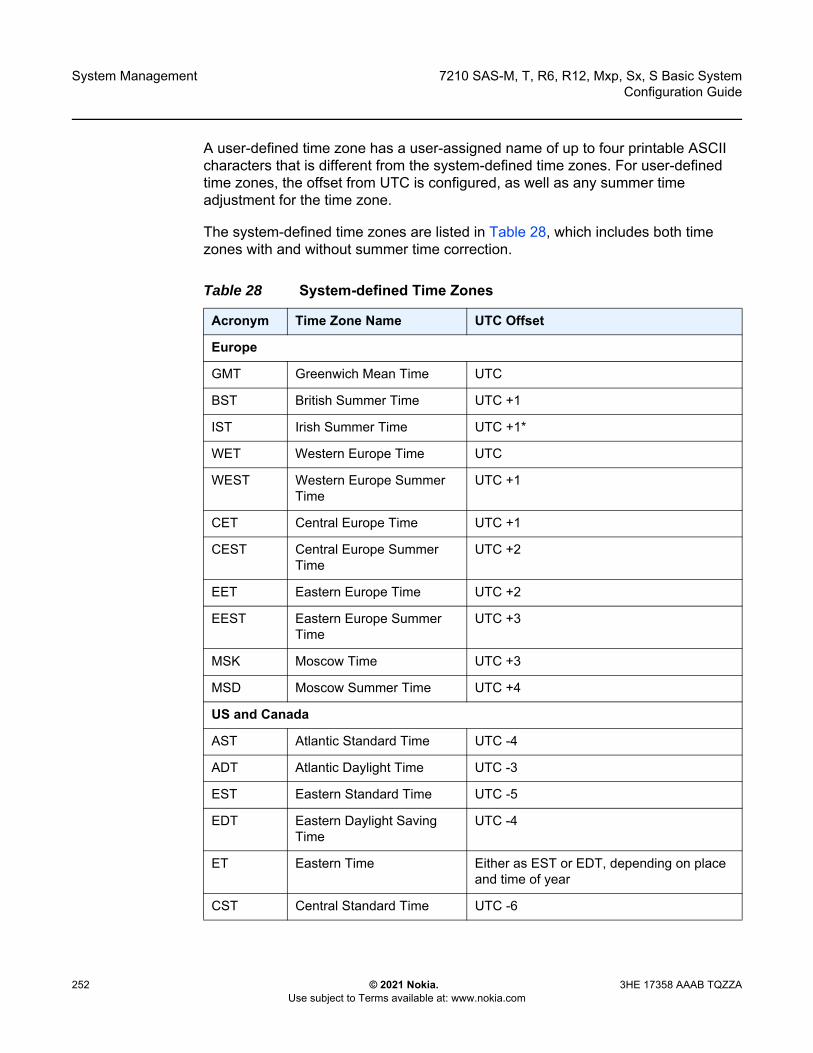
System Management
252
7210 SAS-M, T, R6, R12, Mxp, Sx, S Basic SystemConfiguration Guide
© 2021 Nokia. Use subject to Terms available at: www.nokia.com
3HE 17358 AAAB TQZZA
A user-defined time zone has a user-assigned name of up to four printable ASCII characters that is different from the system-defined time zones. For user-defined time zones, the offset from UTC is configured, as well as any summer time adjustment for the time zone.
The system-defined time zones are listed in Table 28, which includes both time zones with and without summer time correction.
Table 28 System-defined Time Zones
Acronym Time Zone Name UTC Offset
Europe
GMT Greenwich Mean Time UTC
BST British Summer Time UTC +1
IST Irish Summer Time UTC +1*
WET Western Europe Time UTC
WEST Western Europe Summer Time
UTC +1
CET Central Europe Time UTC +1
CEST Central Europe Summer Time
UTC +2
EET Eastern Europe Time UTC +2
EEST Eastern Europe Summer Time
UTC +3
MSK Moscow Time UTC +3
MSD Moscow Summer Time UTC +4
US and Canada
AST Atlantic Standard Time UTC -4
ADT Atlantic Daylight Time UTC -3
EST Eastern Standard Time UTC -5
EDT Eastern Daylight Saving Time
UTC -4
ET Eastern Time Either as EST or EDT, depending on place and time of year
CST Central Standard Time UTC -6

7210 SAS-M, T, R6, R12, Mxp, Sx, S Basic System Configuration Guide
System Management
3HE 17358 AAAB TQZZA © 2021 Nokia. Use subject to Terms available at: www.nokia.com
253
6.1.2.2 Network Time Protocol
The Network Time Protocol (NTP) is defined in RFC 1305, Network Time Protocol (Version 3) Specification, Implementation and Analysis. It allows participating network nodes to keep time more accurately and maintain time in a more synchronized manner between the participating network nodes.
CDT Central Daylight Saving Time
UTC -5
CT Central Time Either as CST or CDT, depending on place and time of year
MST Mountain Standard Time UTC -7
MDT Mountain Daylight Saving Time
UTC -6
MT Mountain Time Either as MST or MDT, depending on place and time of year
PST Pacific Standard Time UTC -8
PDT Pacific Daylight Saving Time
UTC -7
PT Pacific Time Either as PST or PDT, depending on place and time of year
HST Hawaiian Standard Time UTC -10
AKST Alaska Standard Time UTC -9
AKDT Alaska Standard Daylight Saving Time
UTC -8
Australia
AWST Western Standard Time (e.g., Perth)
UTC +8
ACST Central Standard Time (e.g., Darwin)
UTC +9.5
AEST Eastern Standard/Summer Time (e.g., Canberra)
UTC +10
Table 28 System-defined Time Zones (Continued)
Acronym Time Zone Name UTC Offset
System Management
254
7210 SAS-M, T, R6, R12, Mxp, Sx, S Basic SystemConfiguration Guide
© 2021 Nokia. Use subject to Terms available at: www.nokia.com
3HE 17358 AAAB TQZZA
NTP uses stratum levels to define the number of hops from a reference clock. The reference clock is treated as a stratum-0 device that is assumed to be accurate with little or no delay. Stratum-0 servers cannot be used in a network. However, they can be directly connected to devices that operate as stratum-1 servers. A stratum-1 server is an NTP server with a directly-connected device that provides Coordinated Universal Time (UTC), such as a GPS or atomic clock.
The 7210 SAS devices cannot act as stratum-1 servers but can act as stratum-2 devices because a network connection to an NTP server is required.
The higher stratum levels are separated from the stratum-1 server over a network path, thus a stratum-2 server receives its time over a network link from a stratum-1 server. A stratum-3 server receives its time over a network link from a stratum-2 server.
If the internal PTP process is used as a time source for System Time and OAM, it must be specified as a server for NTP. If PTP is specified, the prefer parameter must also be specified. After PTP has established a UTC traceable time from an external grandmaster source, that clock will always be the time source into NTP, even if PTP goes into time holdover.
The following NTP elements are supported:
• server mode In this mode, the node advertises the ability to act as a clock source for other network elements. By default, the node will, by default, transmits NTP packets in NTP version 4 mode.
• authentication keysThese keys implement increased security support in carrier and other networks. Both DES and MD5 authentication are supported, as well as multiple keys.
• symmetric active modeIn this mode, the NTP is synchronized with a specific node that is considered more trustworthy or accurate than other nodes carrying NTP in the system. This mode requires that a specific peer is set.
• broadcastIn this mode, the node receives or sends using a broadcast address.
• alert when NTP server is not available
Note: Use of the internal PTP time source for NTP promotes the internal NTP server to stratum 1 level. This may impact the NTP network topology.
7210 SAS-M, T, R6, R12, Mxp, Sx, S Basic System Configuration Guide
System Management
3HE 17358 AAAB TQZZA © 2021 Nokia. Use subject to Terms available at: www.nokia.com
255
When none of the configured servers are reachable on the node, the system reverts to manual timekeeping and issues a critical alarm. When a server becomes available, a trap is issued indicating that standard operation has resumed.
• NTP and SNTPIf both NTP and SNTP are enabled on the node, SNTP transitions to an operationally down state. If NTP is removed from the configuration or shut down, SNTP resumes an operationally up state.
• gradual clock adjustmentBecause several applications (such as Service Assurance Agent (SAA)) can use the clock, if a major adjustment (128 ms or more) is needed, it is performed by programmatically stepping the clock. If a minor (less than 128 ms) adjustment is needed, it is performed by either speeding up or slowing down the clock.
• rate limit events and trapsTo avoid the generation of excessive events and traps the NTP module rate limits the generation of events and traps to three per second. At that point, a single trap is generated to indicate that event and trap squashing is taking place.
6.1.2.3 SNTP Time Synchronization
To synchronize the system clock with outside time sources, the 7210 SAS devices include a Simple Network Time Protocol (SNTP) client. As defined in RFC 2030, SNTP Version 4 is an adaptation of NTP. SNTP typically provides time accuracy within 100 ms of the time source. SNTP can only receive the time from NTP servers; it cannot be used to provide time services to other systems. SNTP is a compact, client-only version of NTP. SNTP does not authenticate traffic.
In the 7210 SAS software, the SNTP client can be configured in both unicast client modes (point-to-point) and broadcast client modes (point-to-multipoint). SNTP should be used only at the extremities of the synchronization subnet. SNTP clients should operate only at the highest stratum (leaves) of the subnet and in configurations where no NTP or SNTP client is dependent on another SNTP client for synchronization. SNTP time servers should operate only at the root (stratum 1) of the subnet and then only in configurations where no other source of synchronization other than a reliable radio clock is available.

System Management
256
7210 SAS-M, T, R6, R12, Mxp, Sx, S Basic SystemConfiguration Guide
© 2021 Nokia. Use subject to Terms available at: www.nokia.com
3HE 17358 AAAB TQZZA
6.1.2.4 CRON
The CRON feature supports the SAA functions and time-based policy scheduling to meet time of day requirements. CRON functionality includes the ability to specify the commands to be run, their scheduling, including one-time only functionality (oneshot), interval and calendar functions, and the storage location for the script output. CRON can also specify the relationship between input, output, and schedule. Scheduled reboots, peer turn ups, service assurance agent tests, and OAM events, such as connectivity checks or troubleshooting runs, can also be scheduled.
CRON features are saved to the configuration file.
CRON features run serially with at least 255 separate schedules and scripts. Each instance can support a schedule where the event is repeatedly executed.
The following CRON elements are supported:
• actionThis configures parameters for a script including the maximum amount of time to keep the results from a script run, the maximum amount of time a script may run, the maximum number of script runs to store and the location to store the results.
• scheduleThe schedule function configures the type of schedule to run, including one-time only (oneshot), periodic, or calendar-based runs. All runs are determined by month, day of month or weekday, hour, minute and interval (seconds).
• scriptThe script command opens a new nodal context that contains information about a script.
• time rangeACLs and QoS policy configurations may be enhanced to support time-based matching. CRON configuration includes time-matching with the schedule sub-command. Schedules are based on events; time-range defines an end-time used as a match criteria.
• time of dayTime of Day (TOD) suites are useful when configuring many types of time-based policies or when a large number of SAPs require the same type of TOD changes. The TOD suite may be configured while using specific ingress or egress ACLs or QoS policies, and is an enhancement of the ingress and egress CLI trees.
7210 SAS-M, T, R6, R12, Mxp, Sx, S Basic System Configuration Guide
System Management
3HE 17358 AAAB TQZZA © 2021 Nokia. Use subject to Terms available at: www.nokia.com
257
6.2 High Availability
This section describes the high availability (HA) routing options and features that service providers can use to reduce vulnerability at the network or service provider edge and alleviate the effect of a lengthy outage on IP networks.
HA is an important feature in service provider routing systems. The unprecedented growth of IP services and applications in service provider networks is driven by the demand from the enterprise and residential communities. Downtime can be very costly, and, in addition to lost revenue, customer information and business-critical communications can be lost. HA is the combination of continuous uptime over long periods (Mean Time Between Failures (MTBF)) and the speed at which failover or recovery occurs (Mean Time To Repair (MTTR)).
The advantage of HA routing is evident at the network or service provider edge, where thousands of connections are hosted. Rerouting options around a failed piece of equipment are often limited, or, a single access link exists to a customer because of the additional cost of redundant links. As service providers converge business-critical services, such as real-time voice (VoIP), video, and VPN applications over their IP networks, the requirements for HA become more stringent compared to the requirements for best-effort data.
Network and service availability become critical aspects in advanced IP service offerings, which dictate that the IP routers used to build the foundations of these networks must be resilient to component and software outages.
6.2.1 HA Features
As more and more critical commercial applications move to IP networks, providing HA services becomes increasingly important. This section describes HA features for 7210 SAS devices.
Note: HA with control plane redundancy is only supported on the 7210 SAS-R6 and 7210 SAS-R12. Control plane redundancy is not supported on the 7210 SAS-M, 7210 SAS-Mxp, 7210 SAS-Sx/S 1/10GE, 7210 SAS-Sx 10/100GE, and 7210 SAS-T.

System Management
258
7210 SAS-M, T, R6, R12, Mxp, Sx, S Basic SystemConfiguration Guide
© 2021 Nokia. Use subject to Terms available at: www.nokia.com
3HE 17358 AAAB TQZZA
6.2.1.1 Redundancy
Redundancy features enable duplication of data elements to maintain service continuation in case of outages or component failure.
6.2.1.1.1 Software Redundancy on 7210 SAS-R6 and 7210 SAS-R12
Software outages are challenging even when baseline hardware redundancy is in place. A balance should be maintained when providing HA routing, otherwise router problems typically propagate not only throughout the service provider network, but also externally to other connected networks that potentially belong to other service providers. This could affect customers on a broad scale. The 7210 SAS-R6 and 7210 SAS-R12 devices support several software availability features that contribute to the percentage of time that a router is available to process and forward traffic.
All routing protocols specify minimum time intervals in which the peer device must receive an acknowledgment before it disconnects the session.
• OSPF default session timeout is approximately 40 seconds. The timeout intervals are configurable.
• BGP default session timeout is approximately 120 seconds. The timeout intervals are configurable.
Therefore, router software must recover faster than the specified time interval to maintain up time.
6.2.1.1.2 Configuration Redundancy on 7210 SAS-R6 and 7210 SAS-R12
Features configured on the active device CFM or CPM are also saved on the standby CFM or CPM. If the active device CFM or CPM fails, these features are brought up on the standby device that takes over the mastership and becomes the active CFM or CPM.
Even with modern modular and stable software, the failure of route processor hardware or software can cause the router to reboot or cause other service impacting events. In the best circumstances, failure leads to the initialization of a redundant route processor, which hosts the standby software configuration, to become the active processor. The following options are available:
• warm standby

7210 SAS-M, T, R6, R12, Mxp, Sx, S Basic System Configuration Guide
System Management
3HE 17358 AAAB TQZZA © 2021 Nokia. Use subject to Terms available at: www.nokia.com
259
The router image and configuration is already loaded on the standby route processor. However, the standby could still take a few minutes to become effective because it must first reinitialize connections by bringing up Layer 2 connections and Layer 3 routing protocols, and then rebuild the routing tables.
• hot standbyThe router image, configuration, and network state are already loaded on the standby; it receives continual updates from the active route processor and the swap-over is immediate. Newer generation routers, like the 7210 SAS routers have extra processing built into the system so that router performance is not affected by frequent synchronization, which consumes increased system resources.
6.2.1.1.3 Component Redundancy
7210 SAS component redundancy is critical to reducing MTTR for the routing system.
Component redundancy consists of the following:
• redundant power supply The use of 2 power supplies is supported for redundant power supplies. A power module can be removed without impact on traffic when redundant power supplies are in use. The power supply is hot swappable. The 7210 SAS-S 1/10GE platform supports a single fixed non-removable integrated power supply and a hot-swappable power supply.
• fan module
Note: This feature is supported on all 7210 SAS platforms as described in this document, including those operating in access-uplink mode.
Note:
• On the 7210 SAS-S 1/10GE platform, if the device is booted with a power entry module and there is a power supply, the system detects the power supply. If the device is booted with a power entry module but there is no power supply, the system does not detect the “power-supply type”. This occurrence is reported as none and the PS LED is OFF.
• On the 7210 SAS-S 1/10GE platform, there is no DC input failure detection that is classified separately. In the case of a failure, the system reports the DC power value as “failed.”
System Management
260
7210 SAS-M, T, R6, R12, Mxp, Sx, S Basic SystemConfiguration Guide
© 2021 Nokia. Use subject to Terms available at: www.nokia.com
3HE 17358 AAAB TQZZA
Failure of one or more fans does not impact traffic. Failure of a single fan is detected and notified. The fan tray and fan module is hot-swappable. - On the 7210 SAS-R6 and 7210 SAS-R12, the fan module/tray contains 6
fans.- On the 7210 SAS-M, 7210 SAS-Mxp, and 7210 SAS-T, the fan module/tray
contains 3 fans.- On the 7210 SAS-Sx 1/10GE, 7210 SAS-S 1/10GE, and 7210 SAS-Sx 10/
100GE, the fan module is not supported. The devices contain a fixed set of 3 fans with filters on both sides of the chassis.
- On the 7210 SAS-R6 and 7210 SAS-R12, 2 x Switch Fabric/Control Processor Module (SF/CPM) can be used to provide control plane redundancy with non-stop routing and non-stop services. The SF/CPM is hot-swappable.
6.2.1.1.4 Remote Power Supply on 7210 SAS-Sx 1/10GE Platforms
You can use an external remote power supply (RPS) as the third power supply for the 7210 SAS-Sx 1/10GE copper variants. With an RPS, a common external power supply is used as the redundant power supply for a stack of 7210 SAS-Sx 1/10GE nodes. This provides a cost-effective option to supply power to a stack of units.
Additional configuration is not required to use an RPS on the node. The presence of an RPS is detected automatically, and the show>chassis>power-supply command displays information about the RPS and its status.
For information about installing RPS, refer to the 7210 SAS-Sx/SAS-S RPS Chassis Installation Guide.
6.2.1.1.5 Service Redundancy on 7210 SAS-R6 and 7210 SAS-R12
All service-related statistics are kept during a switchover. Services, SDPs, and SAPs will remain up with a minimum loss of forwarded traffic during a CFM/CPM switchover.
7210 SAS-M, T, R6, R12, Mxp, Sx, S Basic System Configuration Guide
System Management
3HE 17358 AAAB TQZZA © 2021 Nokia. Use subject to Terms available at: www.nokia.com
261
6.2.1.1.6 Accounting Configuration Redundancy on 7210 SAS-R6 and 7210 SAS-R12
When there is a switchover and the standby CFM/CPM becomes active, the accounting servers are checked and if they are administratively up and capable of coming online (media present, and others), the standby is brought online; new accounting files are created at this point. Users must manually copy the accounting records from the failed CFM/CPM.
6.2.1.2 Nonstop Forwarding and Routing on 7210 SAS-R6 and 7210 SAS-R12
In a control plane failure or a forced switchover event, the router continues to forward packets using the existing stale forwarding information. Nonstop forwarding requires clean control plane and data plane separation. Usually the forwarding information is distributed to the IMMs.
6.2.1.2.1 Nonstop Forwarding on 7210 SAS-R6 and 7210 SAS-R12
In a control plane failure or a forced switchover event, the router continues to forward packets using the existing stale forwarding information.
Nonstop forwarding is used to notify peer routers to continue forwarding and receiving packets, even if the route processor (control plane) is not working or is in a switch-over state. Nonstop forwarding requires clean control plane and data plane separation and usually the forwarding information is distributed to the line cards.
This method of availability has both advantages and disadvantages. Nonstop forwarding continues to forward packets using the existing stale forwarding information during a failure. This may cause routing loops and black holes; surrounding routers must adhere to separate extension standards for each protocol. Each vendor must support protocol extensions for router interoperability.

System Management
262
7210 SAS-M, T, R6, R12, Mxp, Sx, S Basic SystemConfiguration Guide
© 2021 Nokia. Use subject to Terms available at: www.nokia.com
3HE 17358 AAAB TQZZA
6.2.1.2.2 Nonstop Routing on 7210 SAS-R6 and 7210 SAS-R12
The Nonstop Routing (NSR) feature on 7210 SAS devices ensures that routing neighbors are unaware of a routing process fault. If a fault occurs, a reliable and deterministic activity switch to the inactive control complex occurs; the routing topology and reachability are not affected, even during routing updates. NSR achieves HA through parallelization by maintaining up-to-date routing state information, at all times, on the standby route processor. This is achieved independent of protocols or protocol extensions and provides a more robust solution than graceful restart protocols between network routers.
The NSR implementation on the 7210 SAS routers supports all routing protocols. It allows existing sessions (BGP, LDP, OSPF, and others) to be retained during a CFM or CPM switchover, including the support for MPLS signaling protocols. No change is visible to the peers.
Protocol extensions are not required. There are no interoperability issues and defining protocol extensions for each protocol is not required. Unlike nonstop forwarding and graceful restart, the forwarding information in NSR is always up to date, which eliminates possible black holes or forwarding loops.
Traditionally, addressing HA issues has been patched through nonstop forwarding solutions. The NSR implementation overcomes these limitations by delivering an intelligent, hitless failover solution. This enables a carrier-class foundation for transparent networks that is required to support business IP services backed by stringent SLAs. This level of HA support poses a major issue for conventional routers whose architectural design limits or prevents them from implementing NSR.
6.2.1.3 CPM Switchover on 7210 SAS-R6 and 7210 SAS-R12
During a switchover, system control and routing protocol execution are transferred from the active to the standby CPM.
An automatic switchover may occur under the following conditions:
• a fault condition that causes the active CPM to crash or reboot• the active CPM is declared down (not responding)• online removal of the active CPM
A manual switchover may occur under the following conditions:
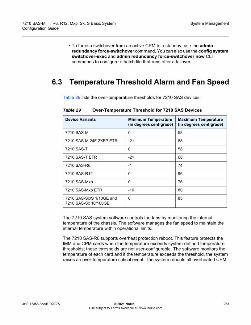
7210 SAS-M, T, R6, R12, Mxp, Sx, S Basic System Configuration Guide
System Management
3HE 17358 AAAB TQZZA © 2021 Nokia. Use subject to Terms available at: www.nokia.com
263
• To force a switchover from an active CPM to a standby, use the admin redundancy force-switchover command. You can also use the config system switchover-exec and admin redundancy force-switchover now CLI commands to configure a batch file that runs after a failover.
6.3 Temperature Threshold Alarm and Fan Speed
Table 29 lists the over-temperature thresholds for 7210 SAS devices.
The 7210 SAS system software controls the fans by monitoring the internal temperature of the chassis. The software manages the fan speed to maintain the internal temperature within operational limits.
The 7210 SAS-R6 supports overheat protection reboot. This feature protects the IMM and CPM cards when the temperature exceeds system-defined temperature thresholds; these thresholds are not user-configurable. The software monitors the temperature of each card and if the temperature exceeds the threshold, the system raises an over-temperature critical event. The system reboots all overheated CPM
Table 29 Over-Temperature Threshold for 7210 SAS Devices
Device Variants Minimum Temperature(in degrees centigrade)
Maximum Temperature(in degrees centigrade)
7210 SAS-M 0 58
7210 SAS-M 24F 2XFP ETR -21 68
7210 SAS-T 0 58
7210 SAS-T ETR -21 68
7210 SAS-R6 -1 74
7210 SAS-R12 0 96
7210 SAS-Mxp 0 76
7210 SAS-Mxp ETR -10 80
7210 SAS-Sx/S 1/10GE and 7210 SAS-Sx 10/100GE
0 85
System Management
264
7210 SAS-M, T, R6, R12, Mxp, Sx, S Basic SystemConfiguration Guide
© 2021 Nokia. Use subject to Terms available at: www.nokia.com
3HE 17358 AAAB TQZZA
cards and powers off all overheated IMM cards to reduce the heat generated, which consequently cools down the chassis. The system powers back on the IMM cards after the temperature is reduced. Operators are still required to take immediate action for an over-temperature critical event. Refer to the 7210 SAS-R6 Chassis Installation Guide for more information about maintaining the operating temperature.
6.3.1 Synchronization
This section describes the synchronization between the CPMs or CFMs.
6.3.1.1 Configuration and boot-env Synchronization
Configuration and boot-env synchronization are supported in the admin>redundancy>synchronize and config>redundancy>synchronize contexts.
6.3.1.2 State Database Synchronization
If a new standby CPM or CFM is inserted into the system, it synchronizes with the active CPM or CFM upon a successful boot process.
If the standby CPM or CFM is rebooted, it synchronizes with the active CPM or CFM after a successful boot process.
When configuration or state changes occur, an incremental synchronization is conducted from the active CPM or CFM to the standby CPM or CFM.
If the synchronization fails, the standby CPM or CFM does not reboot automatically. Use the show redundancy synchronization command to display synchronization output information.
Note: Nokia recommends that when planning their availability design, operators must consider CPM card reboot handling that is caused when the system temperature exceeds system-defined thresholds. Failure to build in network redundancy may result in network and service downtime.

7210 SAS-M, T, R6, R12, Mxp, Sx, S Basic System Configuration Guide
System Management
3HE 17358 AAAB TQZZA © 2021 Nokia. Use subject to Terms available at: www.nokia.com
265
If the active and standby CPMs or CFMs are not synchronized for any reason, you can manually synchronize the standby CPM or CFM by rebooting the standby by issuing the admin reboot standby command on the active or the standby CPM or CFM.
6.4 Synchronization and Redundancy
The 7210 SAS-R6 and 7210 SAS-R12, and the 7210 SAS-Sx/S 1/10GE configured in the standalone-VC mode support CPM redundancy. Redundancy methods facilitate system synchronization between the active and standby CPMs so they maintain identical operational parameters, which prevents inconsistencies in the event of a CPM failure.
When automatic system synchronization is enabled for an entity, save or delete file operations that are configured on the primary, secondary or tertiary choices on the active CPM file system are mirrored in the standby CPM file system.
Although software configurations and images can be copied or downloaded from remote locations, synchronization can only occur locally between compact flash drives (cf1: and cf2:).
Synchronization can occur:
• automaticallyAutomatic synchronization is disabled by default. To enable automatic synchronization, run the config>redundancy>synchronize command with the boot-env parameter or the config parameter. When the boot-env parameter is specified, the BOF, boot.ldr, configuration, and image files are automatically synchronized. When the config parameter is specified, only the configuration files are automatically synchronized.Automatic synchronization also occurs whenever the BOF is modified and when an admin>save command is entered with no filename specified.
• manuallyTo execute synchronization manually, run the admin>redundancy> synchronize command with the boot-env parameter or the config parameter. When the boot-env parameter is specified, the BOF, boot.ldr, configuartion, and image files are synchronized. When the config parameter is specified, only the configuration files are synchronized.The following output is an example of information displayed during a manual synchronization of configuration files.
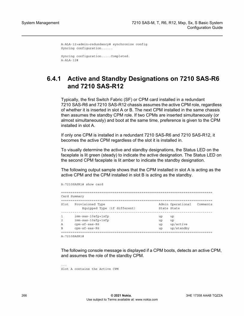
System Management
266
7210 SAS-M, T, R6, R12, Mxp, Sx, S Basic SystemConfiguration Guide
© 2021 Nokia. Use subject to Terms available at: www.nokia.com
3HE 17358 AAAB TQZZA
A:ALA-12>admin>redundancy# synchronize configSyncing configuration......
Syncing configuration.....Completed.A:ALA-12#
6.4.1 Active and Standby Designations on 7210 SAS-R6 and 7210 SAS-R12
Typically, the first Switch Fabric (SF) or CPM card installed in a redundant 7210 SAS-R6 and 7210 SAS-R12 chassis assumes the active CPM role, regardless of whether it is inserted in slot A or B. The next CPM installed in the same chassis then assumes the standby CPM role. If two CPMs are inserted simultaneously (or almost simultaneously) and boot at the same time, preference is given to the CPM installed in slot A.
If only one CPM is installed in a redundant 7210 SAS-R6 and 7210 SAS-R12, it becomes the active CPM regardless of the slot it is installed in.
To visually determine the active and standby designations, the Status LED on the faceplate is lit green (steady) to indicate the active designation. The Status LED on the second CPM faceplate is lit amber to indicate the standby designation.
The following output sample shows that the CPM installed in slot A is acting as the active CPM and the CPM installed in slot B is acting as the standby.
A:7210SASR1# show card
===============================================================================Card Summary===============================================================================Slot Provisioned Type Admin Operational Comments
Equipped Type (if different) State State-------------------------------------------------------------------------------1 imm-sas-10sfp+1xfp up up2 imm-sas-10sfp+1xfp up upA cpm-sf-sas-R6 up up/activeB cpm-sf-sas-R6 up up/standby===============================================================================A:7210SASR1#
The following console message is displayed if a CPM boots, detects an active CPM, and assumes the role of the standby CPM.
...Slot A contains the Active CPM
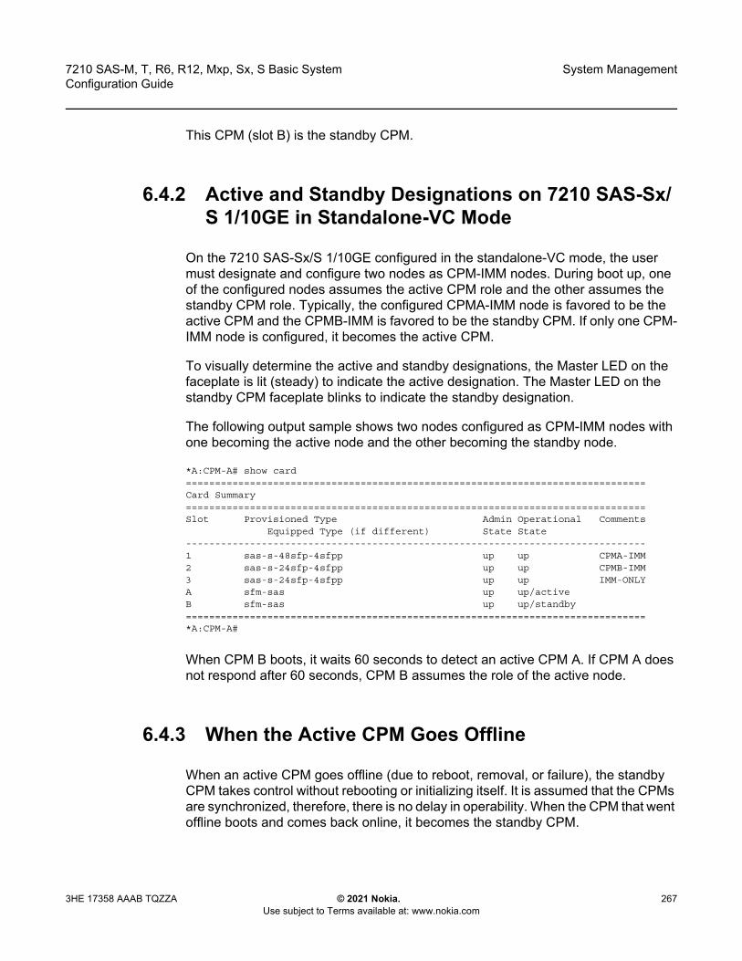
7210 SAS-M, T, R6, R12, Mxp, Sx, S Basic System Configuration Guide
System Management
3HE 17358 AAAB TQZZA © 2021 Nokia. Use subject to Terms available at: www.nokia.com
267
This CPM (slot B) is the standby CPM.
6.4.2 Active and Standby Designations on 7210 SAS-Sx/S 1/10GE in Standalone-VC Mode
On the 7210 SAS-Sx/S 1/10GE configured in the standalone-VC mode, the user must designate and configure two nodes as CPM-IMM nodes. During boot up, one of the configured nodes assumes the active CPM role and the other assumes the standby CPM role. Typically, the configured CPMA-IMM node is favored to be the active CPM and the CPMB-IMM is favored to be the standby CPM. If only one CPM-IMM node is configured, it becomes the active CPM.
To visually determine the active and standby designations, the Master LED on the faceplate is lit (steady) to indicate the active designation. The Master LED on the standby CPM faceplate blinks to indicate the standby designation.
The following output sample shows two nodes configured as CPM-IMM nodes with one becoming the active node and the other becoming the standby node.
*A:CPM-A# show card===============================================================================Card Summary===============================================================================Slot Provisioned Type Admin Operational Comments
Equipped Type (if different) State State-------------------------------------------------------------------------------1 sas-s-48sfp-4sfpp up up CPMA-IMM2 sas-s-24sfp-4sfpp up up CPMB-IMM3 sas-s-24sfp-4sfpp up up IMM-ONLYA sfm-sas up up/activeB sfm-sas up up/standby===============================================================================*A:CPM-A#
When CPM B boots, it waits 60 seconds to detect an active CPM A. If CPM A does not respond after 60 seconds, CPM B assumes the role of the active node.
6.4.3 When the Active CPM Goes Offline
When an active CPM goes offline (due to reboot, removal, or failure), the standby CPM takes control without rebooting or initializing itself. It is assumed that the CPMs are synchronized, therefore, there is no delay in operability. When the CPM that went offline boots and comes back online, it becomes the standby CPM.

System Management
268
7210 SAS-M, T, R6, R12, Mxp, Sx, S Basic SystemConfiguration Guide
© 2021 Nokia. Use subject to Terms available at: www.nokia.com
3HE 17358 AAAB TQZZA
The following console message is displayed when the active CPM goes offline and the standby CPM assumes the active role:
Active CPM in Slot A has stoppedSlot B is now active CPM
Attempting to exec configuration file:'cf1:/config.cfg' ...
...
Executed 49,588 lines in 8.0 seconds from file cf1:\config.cfg
6.4.4 Configuration Guidelines for Synchronization of Active and Standby CPM on 7210 SAS-R6 and 7210 SAS-R12
The following configuration guidelines apply when synchronizing the active and standby CPMs on the 7210 SAS-R6 and 7210 SAS-R12 systems.
• The active and standby CPM should boot from same boot drives (cf1:\, cf2:\, or uf:\). For example, if the active CPM is booted from cf1:\, the standby CPM must use cf1:\ to bootup. Although it is possible to make the CPMs operational by booting them using any drive on active and standby, Nokia recommends that the same drives should be used to boot the system.
• The user should ensure that a valid bootstrap image (boot.tim) and BOF (bof.cfg) exist in the cf1:\, cf2:\, or uf1:\ drive of both active and stand-by CPM cards. The user must verify that bof.cfg resides on the same drive as the boot.tim.
• The TiMOS application images (cpm.tim and iom.tim) and the configuration file can reside in any location (local or remote), but the locations in the BOF should be configured identically on both active and standby CPM for primary, secondary, and tertiary locations.
• Boot-env synchronization must be performed before config synchronization. To do so, run the admin redundancy synchronize boot-env command, followed by the admin redundancy synchronize config command.
• Synchronization can only occur locally between compact flash drives cf1:Active to cf1:Standby, cf2:Active to cf2:Standby, and uf1:Active to uf1:Standby. Synchronization across different drives is not supported.

7210 SAS-M, T, R6, R12, Mxp, Sx, S Basic System Configuration Guide
System Management
3HE 17358 AAAB TQZZA © 2021 Nokia. Use subject to Terms available at: www.nokia.com
269
• If the active and standby CPM are not synchronized for some reason, users can manually synchronize the standby CPM by running the admin redundancy synchronize boot-env CLI command, and rebooting the standby CPM by running the admin reboot standby command.
6.5 Network Synchronization
This section describes the network synchronization capabilities available on7210 SAS platforms. These capabilities involve multiple approaches to network timing, including Synchronous Ethernet, PTP/1588v2, adaptive timing, and others. These features address barriers to entry as follows:
• provide synchronization quality required by mobile networks, such as radio operations and circuit emulation services (CES) transport
• augment and potentially replace the existing (SONET/SDH) timing infrastructure and deliver high quality network timing for time-sensitive wireline applications
Network synchronization is commonly distributed in a hierarchical master-slave topology at the physical layer, as shown in Figure 23.
Note: See the information in this section and refer to the 7210 SAS OS Software Release Notes 11.0Rx for information about network synchronization options supported on each 7210 SAS platform.
Note: Synchronous Ethernet and IEEE1588v2 PTP are not supported on virtual chassis (VCs).
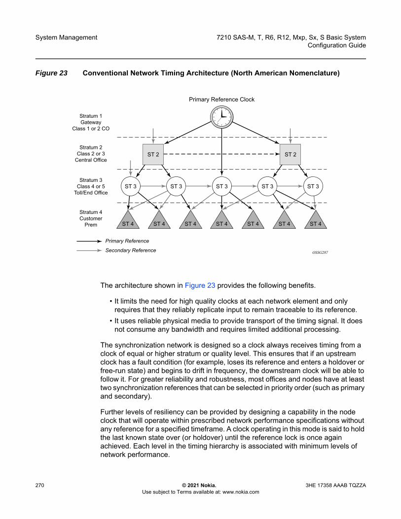
System Management
270
7210 SAS-M, T, R6, R12, Mxp, Sx, S Basic SystemConfiguration Guide
© 2021 Nokia. Use subject to Terms available at: www.nokia.com
3HE 17358 AAAB TQZZA
Figure 23 Conventional Network Timing Architecture (North American Nomenclature)
The architecture shown in Figure 23 provides the following benefits.
• It limits the need for high quality clocks at each network element and only requires that they reliably replicate input to remain traceable to its reference.
• It uses reliable physical media to provide transport of the timing signal. It does not consume any bandwidth and requires limited additional processing.
The synchronization network is designed so a clock always receives timing from a clock of equal or higher stratum or quality level. This ensures that if an upstream clock has a fault condition (for example, loses its reference and enters a holdover or free-run state) and begins to drift in frequency, the downstream clock will be able to follow it. For greater reliability and robustness, most offices and nodes have at least two synchronization references that can be selected in priority order (such as primary and secondary).
Further levels of resiliency can be provided by designing a capability in the node clock that will operate within prescribed network performance specifications without any reference for a specified timeframe. A clock operating in this mode is said to hold the last known state over (or holdover) until the reference lock is once again achieved. Each level in the timing hierarchy is associated with minimum levels of network performance.
OSSG287
ST 2
ST 3 ST 3 ST 3 ST 3 ST 3
ST 2
Primary Reference Clock
Stratum 1Gateway
Class 1 or 2 CO
ST 4 ST 4 ST 4ST 4 ST 4 ST 4 ST 4
Stratum 2Class 2 or 3
Central Office
Stratum 3Class 4 or 5
Toll/End Office
Stratum 4Customer
Prem
Primary Reference
Secondary Reference
7210 SAS-M, T, R6, R12, Mxp, Sx, S Basic System Configuration Guide
System Management
3HE 17358 AAAB TQZZA © 2021 Nokia. Use subject to Terms available at: www.nokia.com
271
Each synchronization capable port can be independently configured to transmit data using the node reference timing. In addition, some TDM channels can use adaptive timing or loop timing.
Transmission of a reference clock through a chain of Ethernet equipment requires that all equipment supports Synchronous Ethernet. A single piece of equipment that is not capable of performing Synchronous Ethernet breaks the chain. Ethernet frames will still get through but downstream devices should not use the recovered line timing because it will not be traceable to an acceptable stratum source.
6.5.1 Central Synchronization Subsystem
The timing subsystem has a central clock located on the CPM. The timing subsystem performs several functions of the network element clock as defined by Telcordia (GR-1244-CORE) and ITU-T G.781 standards.
The central clock uses the available timing inputs to train its local oscillator. The number of timing inputs available to train the local oscillator varies per platform. The priority order of these references must be specified. This is a simple ordered list of inputs: (ref1, ref2, BITS (if available)).
The CPM clock output can drive the clocking for all line cards in the system. The routers support selection of the node reference using Quality Level (QL) indications. The recovered clock can derive its timing from one of the references available on that platform.
The recovered clock can derive the timing from any of the following references (also shown in Figure 24):
• synchronous Ethernet portsOn the 7210 SAS-M (includes all variants), 7210 SAS-T (includes all variants), 7210 SAS-R6, 7210 SAS-R12, 7210 SAS-Sx 1/10GE (all variants), 7210 SAS-S 1/10GE (all variants), and 7210 SAS-Sx 10/100GE
• 1588v2/PTP slave portOn the 7210 SAS-M (includes all variants), 7210 SAS-T (includes all variants), 7210 SAS-R6, 7210 SAS-R12, 7210 SAS-Sx 1/10GE(all variants)
Figure 24 shows a logical model of synchronization reference selection for the platforms, and Table 31 provides a list of supported interfaces for each platform.

System Management
272
7210 SAS-M, T, R6, R12, Mxp, Sx, S Basic SystemConfiguration Guide
© 2021 Nokia. Use subject to Terms available at: www.nokia.com
3HE 17358 AAAB TQZZA
Figure 24 Logical Model of Synchronization Reference Selection on 7210 SAS
When the CES MDA is used on the 7210 SAS-M (all variants), in addition to the preceding references, the recovered clock derives the timing from either of the following references:
• T1/E1 CES channel (not available for node reference)• T1/E1 port (for loop-timing; not available for node reference)
On the 7210 SAS-Mxp, 7210 SAS-R6, 7210 SAS-R12, and 7210 SAS-T, in addition to PTP and SyncE references, the recovered clock can be configured to derive the timing (frequency reference) from the BITS interface.
When quality Level (QL) selection mode is disabled, the reversion setting controls when the central clock can reselect a previously failed reference.
Table 30 lists the selection followed for two references in both revertive and non-revertive modes.
26997
SyncE
1588
T1/E1
ref1
BITSOutput
Selector
Internal(Node)TimingReference
BITSoutT1/E12048 kHz
ref2
ptp
BITSin
Quality Level Override
T1/E1 BITSin
Qualifier
Qualifier
Qualifier
Qualifier
Qualifier
QualityLevel (QL)
QualityLevel (QL)
QualityLevel (QL)
QualityLevel (QL)
QualityLevel (QL)
Mode 1) Priority reference orderMode 2) QL then priority reference order
ReferenceSelector
Digital PhaseLocked Loop(DPLL)
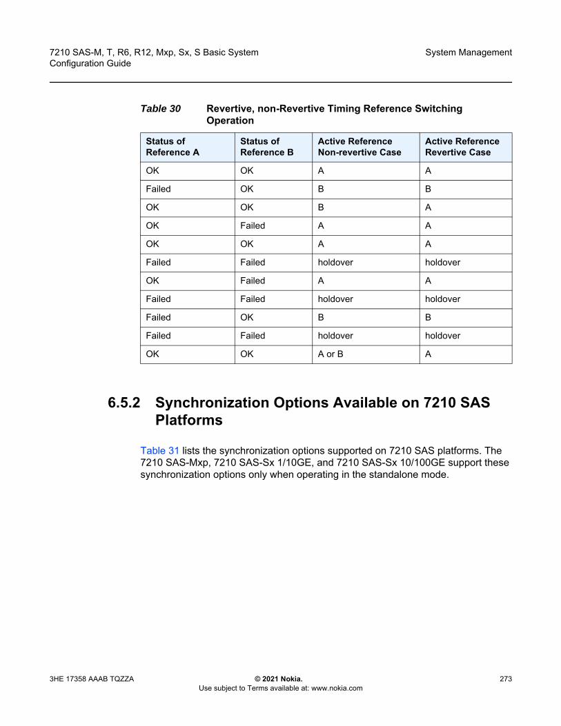
7210 SAS-M, T, R6, R12, Mxp, Sx, S Basic System Configuration Guide
System Management
3HE 17358 AAAB TQZZA © 2021 Nokia. Use subject to Terms available at: www.nokia.com
273
6.5.2 Synchronization Options Available on 7210 SAS Platforms
Table 31 lists the synchronization options supported on 7210 SAS platforms. The 7210 SAS-Mxp, 7210 SAS-Sx 1/10GE, and 7210 SAS-Sx 10/100GE support these synchronization options only when operating in the standalone mode.
Table 30 Revertive, non-Revertive Timing Reference Switching Operation
Status of Reference A
Status of Reference B
Active Reference Non-revertive Case
Active Reference Revertive Case
OK OK A A
Failed OK B B
OK OK B A
OK Failed A A
OK OK A A
Failed Failed holdover holdover
OK Failed A A
Failed Failed holdover holdover
Failed OK B B
Failed Failed holdover holdover
OK OK A or B A
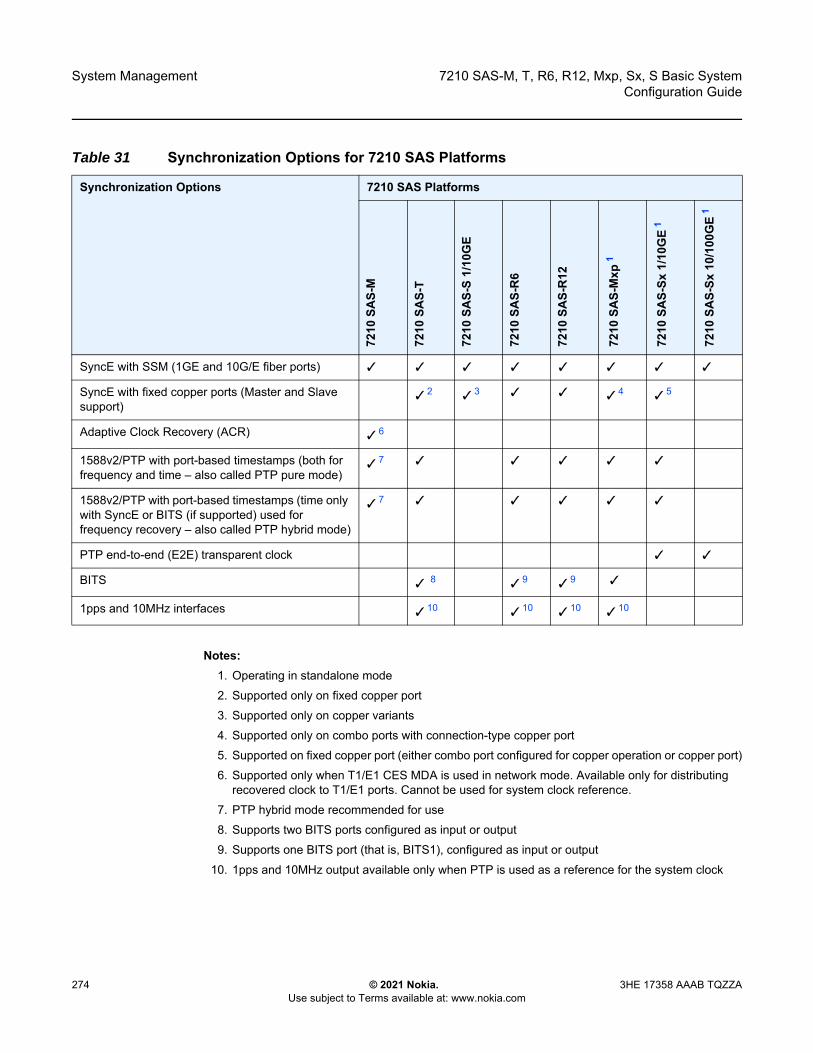
System Management
274
7210 SAS-M, T, R6, R12, Mxp, Sx, S Basic SystemConfiguration Guide
© 2021 Nokia. Use subject to Terms available at: www.nokia.com
3HE 17358 AAAB TQZZA
Notes:1. Operating in standalone mode2. Supported only on fixed copper port 3. Supported only on copper variants4. Supported only on combo ports with connection-type copper port 5. Supported on fixed copper port (either combo port configured for copper operation or copper port)6. Supported only when T1/E1 CES MDA is used in network mode. Available only for distributing
recovered clock to T1/E1 ports. Cannot be used for system clock reference.7. PTP hybrid mode recommended for use8. Supports two BITS ports configured as input or output 9. Supports one BITS port (that is, BITS1), configured as input or output
10. 1pps and 10MHz output available only when PTP is used as a reference for the system clock
Table 31 Synchronization Options for 7210 SAS Platforms
Synchronization Options 7210 SAS Platforms
7210
SAS-
M
7210
SAS-
T
7210
SAS-
S1/
10G
E
7210
SAS-
R6
7210
SAS-
R12
7210
SAS-
Mxp
1
7210
SAS-
Sx1/
10G
E1
7210
SAS-
Sx10
/100
GE
1
SyncE with SSM (1GE and 10G/E fiber ports) ✓ ✓ ✓ ✓ ✓ ✓ ✓ ✓
SyncE with fixed copper ports (Master and Slave support)
✓ 2 ✓ 3 ✓ ✓ ✓ 4 ✓ 5
Adaptive Clock Recovery (ACR) ✓ 6
1588v2/PTP with port-based timestamps (both for frequency and time – also called PTP pure mode)
✓ 7 ✓ ✓ ✓ ✓ ✓
1588v2/PTP with port-based timestamps (time only with SyncE or BITS (if supported) used for frequency recovery – also called PTP hybrid mode)
✓ 7 ✓ ✓ ✓ ✓ ✓
PTP end-to-end (E2E) transparent clock ✓ ✓
BITS ✓ 8 ✓ 9 ✓ 9 ✓
1pps and 10MHz interfaces ✓ 10 ✓ 10 ✓ 10 ✓ 10

7210 SAS-M, T, R6, R12, Mxp, Sx, S Basic System Configuration Guide
System Management
3HE 17358 AAAB TQZZA © 2021 Nokia. Use subject to Terms available at: www.nokia.com
275
6.5.3 Synchronization Status Messages
Synchronization Status Messages (SSM) are supported on devices that support Synchronous Ethernet. SSM allows the synchronization distribution network to determine the quality level of the clock sourcing a specific synchronization trail and also allows a network element to select the best of multiple input synchronization trails. SSMs are defined for various transport protocols (including SONET/SDH, T1/E1, and Synchronous Ethernet), for interaction with office clocks (such as BITS or SSUs) and embedded network element clocks.
SSM allows equipment to autonomously provision and reconfigure (by reference switching) their synchronization references, while helping to avoid the creation of timing loops. These messages are particularly useful for synchronization re-configurations when timing is distributed in both directions around a ring.
6.5.4 DS1 Signals
DS1 signals can carry the quality level value of the timing source information using the SSM that is transported within the 1544 kb/s signal Extended Super Frame (ESF) Data Link (DL), as described in ITU-T Recommendation G.704. No such provision is extended to SF formatted DS1 signals.
The format of the ESF DL messages is 0xxx xxx0 1111 1111, with the rightmost bit transmitted first. The 6 bits denoted by xxx xxx contain the message; some of these messages are reserved for synchronization messaging. It takes 32 frames (4 ms) to transmit all 16 bits of a complete DL.
6.5.5 E1 Signals
E1 signals can carry the quality level value of the timing source information using the SSM, as described in ITU-T Recommendation G.704.
One of the Sa4 to Sa8 bits is allocated for SSMs; choosing the Sa bit that carries the SSM is user-configurable. To prevent ambiguities in pattern recognition, it is necessary to align the first bit (San1) with frame 1 of a G.704 E1 multiframe.
The San bits are numbered (n = 4, 5, 6, 7, 8). A San bit is organized as a 4-bit nibble San1 to San4. San1 is the most significant bit, and San4 is the least significant bit.
The message set in San1 to San4 is a copy of the set defined in SDH bits 5 to 8 of byte S1.

System Management
276
7210 SAS-M, T, R6, R12, Mxp, Sx, S Basic SystemConfiguration Guide
© 2021 Nokia. Use subject to Terms available at: www.nokia.com
3HE 17358 AAAB TQZZA
6.5.6 Synchronous Ethernet
Traditionally, Ethernet-based networks employ a physical layer transmitter clock derived from an inexpensive +/-100ppm crystal oscillator and the receiver locks onto it. Because data is packetized and can be buffered, there is no need for long-term frequency stability or for consistency between frequencies of different links.
Synchronous Ethernet is a variant of the line timing that derives the physical layer transmitter clock from a high-quality frequency reference, replacing the crystal oscillator with a frequency source traceable to a primary reference clock. This change is transparent to the other Ethernet layers and does not affect their operation. The receiver at the far end of the link is locked to the physical layer clock of the received signal, and ensures access to a highly accurate and stable frequency reference. In a manner analogous to conventional hierarchical master-slave network synchronization, this receiver can lock the transmission clock of other ports to this frequency reference, and establish a fully time-synchronous network.
Unlike methods that rely on sending timing information in packets over an unclocked physical layer, Synchronous Ethernet is not affected by impairments introduced by higher levels of networking technology (packet loss, packet delay variation). The frequency accuracy and stability in Synchronous Ethernet typically exceeds networks with unsynchronized physical layers.
Synchronous Ethernet allows operators to gracefully integrate existing systems and future deployments into a conventional industry-standard synchronization hierarchy. The concept is analogous to SONET/SDH system timing capabilities. The operator can select any (optical) Ethernet port as a candidate timing reference. The recovered timing from this port is used to time the system (for example, the CPM will lock to this provisioned reference selection). The operator then can ensure that all system output is locked to a stable traceable frequency source.
Note:
• The use of Synchronous Ethernet as a candidate reference and for distribution of recovered reference is supported on all 7210 SAS platforms as described in this document, except those operating in standalone-VC mode.
• Synchronous Ethernet using fiber Ethernet ports, including 10G and 100G (if available), is supported on all 7210 SAS platforms as described in this document, except those operating in standalone-VC mode.
• Please ensure that the SFP or XFP or SFP+ parts used with the SFP, XFP, and SFP+ ports support Synchronous Ethernet.
• Synchronous Ethernet is not supported on virtual chassis (VCs).
7210 SAS-M, T, R6, R12, Mxp, Sx, S Basic System Configuration Guide
System Management
3HE 17358 AAAB TQZZA © 2021 Nokia. Use subject to Terms available at: www.nokia.com
277
Synchronous Ethernet using fixed copper ports is supported only on the 7210 SAS-T, 7210 SAS-R6, 7210 SAS-R12, 7210 SAS-Sx 1/10GE, 7210 SAS-S 1/10GE and 7210 SAS-Mxp. The fixed copper ports can be used as a candidate reference (Master) or for distribution of recovered reference (Slave). If the port is a fixed copper Ethernet port and in 1000BASE-T mode of operation, there is a dependency on the 802.3 link timing for the Synchronous Ethernet functionality (refer to ITU-T G.8262). The 802.3 standard link Master-Slave timing states must align with the desired direction of Synchronous Ethernet timing flow. When a fixed copper Ethernet port is specified as an input reference for the node or when it is removed as an input reference for the node, an 802.3 link auto-negotiation is triggered to ensure the link timing aligns properly.
The SSM of Synchronous Ethernet uses an Ethernet OAM PDU that uses the slow protocol subtype. For a complete description of the format and processing, refer to ITU-T G.8264.
6.5.6.1 Using Synchronous Ethernet Timing for T1/E1 MDA
Only on 7210 SAS-M and all its variants, the timing recovered from Synchronous Ethernet is available for use with the T1/E1 MDA. Operators can use a stable frequency for timing the T1/E1 ports in applications where ACR is not suitable for use. Refer to the 7210 SAS OS R11.0Rx Software Release Notes for more information about specific software releases in which this feature is supported.
6.5.6.2 Clock Source Quality Level Definitions
This section describes the clock source quality levels identified for tracking network timing flow in accordance with the network deployment options defined in Recommendation G.803 and G.781. The Option I network is developed on the original European SDH model; Option II network is a network developed on the North American SONET model.
In addition to the QL values received over SSM of an interface, the standards define the following additional codes for internal use.
• QL INVx is generated internally by the system if and when an unallocated SSM value is received, where x represents the binary value of this SSM. Within the SR OS, these independent values are assigned as the single value QL-INVALID.
• QL FAILED is generated internally by the system if and when the terminated network synchronization distribution trail is in the signal fail state.
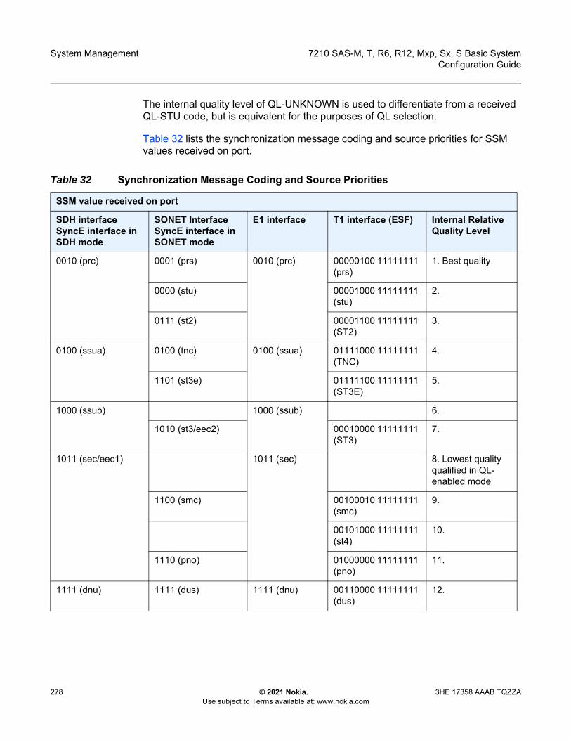
System Management
278
7210 SAS-M, T, R6, R12, Mxp, Sx, S Basic SystemConfiguration Guide
© 2021 Nokia. Use subject to Terms available at: www.nokia.com
3HE 17358 AAAB TQZZA
The internal quality level of QL-UNKNOWN is used to differentiate from a received QL-STU code, but is equivalent for the purposes of QL selection.
Table 32 lists the synchronization message coding and source priorities for SSM values received on port.
Table 32 Synchronization Message Coding and Source Priorities
SSM value received on port
SDH interface SyncE interface in SDH mode
SONET InterfaceSyncE interface in SONET mode
E1 interface T1 interface (ESF) Internal Relative Quality Level
0010 (prc) 0001 (prs) 0010 (prc) 00000100 11111111 (prs)
1. Best quality
0000 (stu) 00001000 11111111 (stu)
2.
0111 (st2) 00001100 11111111 (ST2)
3.
0100 (ssua) 0100 (tnc) 0100 (ssua) 01111000 11111111 (TNC)
4.
1101 (st3e) 01111100 11111111 (ST3E)
5.
1000 (ssub) 1000 (ssub) 6.
1010 (st3/eec2) 00010000 11111111 (ST3)
7.
1011 (sec/eec1) 1011 (sec) 8. Lowest quality qualified in QL-enabled mode
1100 (smc) 00100010 11111111 (smc)
9.
00101000 11111111 (st4)
10.
1110 (pno) 01000000 11111111 (pno)
11.
1111 (dnu) 1111 (dus) 1111 (dnu) 00110000 11111111 (dus)
12.
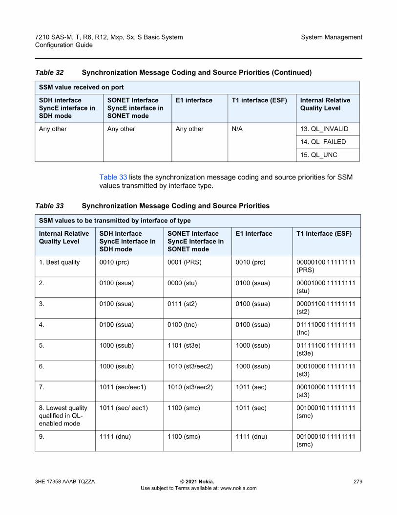
7210 SAS-M, T, R6, R12, Mxp, Sx, S Basic System Configuration Guide
System Management
3HE 17358 AAAB TQZZA © 2021 Nokia. Use subject to Terms available at: www.nokia.com
279
Table 33 lists the synchronization message coding and source priorities for SSM values transmitted by interface type.
Any other Any other Any other N/A 13. QL_INVALID
14. QL_FAILED
15. QL_UNC
Table 32 Synchronization Message Coding and Source Priorities (Continued)
SSM value received on port
SDH interface SyncE interface in SDH mode
SONET InterfaceSyncE interface in SONET mode
E1 interface T1 interface (ESF) Internal Relative Quality Level
Table 33 Synchronization Message Coding and Source Priorities
SSM values to be transmitted by interface of type
Internal Relative Quality Level
SDH Interface SyncE interface in SDH mode
SONET InterfaceSyncE interface in SONET mode
E1 Interface T1 Interface (ESF)
1. Best quality 0010 (prc) 0001 (PRS) 0010 (prc) 00000100 11111111 (PRS)
2. 0100 (ssua) 0000 (stu) 0100 (ssua) 00001000 11111111 (stu)
3. 0100 (ssua) 0111 (st2) 0100 (ssua) 00001100 11111111 (st2)
4. 0100 (ssua) 0100 (tnc) 0100 (ssua) 01111000 11111111 (tnc)
5. 1000 (ssub) 1101 (st3e) 1000 (ssub) 01111100 11111111 (st3e)
6. 1000 (ssub) 1010 (st3/eec2) 1000 (ssub) 00010000 11111111 (st3)
7. 1011 (sec/eec1) 1010 (st3/eec2) 1011 (sec) 00010000 11111111 (st3)
8. Lowest quality qualified in QL-enabled mode
1011 (sec/ eec1) 1100 (smc) 1011 (sec) 00100010 11111111 (smc)
9. 1111 (dnu) 1100 (smc) 1111 (dnu) 00100010 11111111 (smc)

System Management
280
7210 SAS-M, T, R6, R12, Mxp, Sx, S Basic SystemConfiguration Guide
© 2021 Nokia. Use subject to Terms available at: www.nokia.com
3HE 17358 AAAB TQZZA
6.5.7 Adaptive Clock Recovery
ACR is a timing-over-packet technology that transports timing information via periodic packet delivery over a pseudowire. ACR is used when there is no other Stratum 1 traceable clock available.
There is no extra equipment cost to implement ACR in a network because ACR uses the packet arrival rate of a TDM pseudowire to regenerate a clock signal. The nodes in the network that are traversed between endpoints do not need special ACR capabilities. However, because the TDM pseudowire is transported over Layer 2 links, the packet flow is susceptible to PDV.
Use the following recommendations to achieve the best ACR performance.
10. 1111 (dnu) 1111 (dus) 1111 dnu 00101000 11111111 (st4)
11. 1111 (dnu) 1110 (pno) 1111 (dnu) 01000000 11111111 (pno)
12. 1111 (dnu) 1111 (dus) 1111 (dnu) 00110000 11111111 (dus)
13. 1111 (dnu) 1111 (dus) 1111 (dnu) 00110000 11111111 (dus)
14. 1111 (dnu) 1111 (dus) 1111 (dnu) 00110000 11111111 (dus)
15. 1011 (sec/eec1) 1010 (st3/eec2) 1011 (sec) 00010000 11111111 (st3)
Table 33 Synchronization Message Coding and Source Priorities (Continued)
SSM values to be transmitted by interface of type
Internal Relative Quality Level
SDH Interface SyncE interface in SDH mode
SONET InterfaceSyncE interface in SONET mode
E1 Interface T1 Interface (ESF)
Note:
• Adaptive Clock Recovery (ACR) is supported only with CES MDAs on the 7210 SAS-M configured in network mode.
• ACR is supported only on the 7210 SAS-M (both ETR and non-ETR variant) configured in network mode with T1/E1 CES MDAs.

7210 SAS-M, T, R6, R12, Mxp, Sx, S Basic System Configuration Guide
System Management
3HE 17358 AAAB TQZZA © 2021 Nokia. Use subject to Terms available at: www.nokia.com
281
• A packet rate of 1000 pps to 4000 pps is recommended. Lower packet rates cause ACR to be more susceptible to PDV in the network.
• Limit the number of nodes traversed between the source-end and the ACR-end of the TDM pseudowire.
• Enable QoS in the network with the TDM pseudowire enabled for ACR classified as NC (network control).
• Maintain a constant temperature; temperature variations affect the natural frequency on the internal oscillators in the 7210 SAS.
• Ensure that the network does not contain a timing loop when it is designed.
There are five potential ACR states:
• normal• phase tracking• frequency tracking• holdover• free-run
When a port’s ACR state is normal, phase tracking, or frequency tracking, the recovered ACR clock is treated as a qualified reference source for the SSU. If this reference source is used, transitions between any of these three states will not affect SSU operation.
When a port’s ACR state is free-run or holdover, the recovered ACR clock is disqualified as a reference source for the SSU. If this reference source is used, transitions to either of these two states will cause the SSU to drop the reference and switch to the next highest prioritized reference source. This can potentially be SSU holdover.
6.5.8 IEEE 1588v2 PTP
The Precision Time Protocol (PTP) is a timing-over-packet protocol defined in the IEEE 1588v2 standard 1588 PTP 2008.
PTP may be deployed as an alternative timing-over-packet option to ACR. PTP provides the capability to synchronize network elements to a Stratum-1 clock or primary reference clock (PRC) traceable source over a network that may or may not be PTP-aware. PTP has several advantages over ACR. It is a standards-based protocol, has lower bandwidth requirements, can transport both frequency and time, and can potentially provide better performance.
The basic types of PTP devices are the following:

System Management
282
7210 SAS-M, T, R6, R12, Mxp, Sx, S Basic SystemConfiguration Guide
© 2021 Nokia. Use subject to Terms available at: www.nokia.com
3HE 17358 AAAB TQZZA
• ordinary clock• boundary clock• end-to-end transparent clock• peer-to-peer transparent clock
Table 31 lists the 7210 SAS platform support for the different types of PTP devices.
The 7210 SAS communicates with peer 1588v2 clocks, as shown in Figure 25. These peers can be ordinary clock slaves or boundary clocks. The communication can be based on either unicast IPv4 sessions transported through IP interfaces or Ethernet multicast PTP packets transported through an Ethernet port.
Figure 25 Peer Clocks
IP/UDP unicast and Ethernet multicast support for the 7210 SAS platforms is listed in Table 34.
sw0393
Ordinary ClockMaster 10.4.1.1
Ordinary ClockSlave
10.2.1.1
7210 SAS10.0.1.1
Peer 10.3.1.1Peer 10.4.1.1
Ordinary ClockSlave
10.1.1.1
Boundary Clock10.3.1.1
Configured Peers
Discovered Peers
Note: PTP is supported on all 7210 SAS platforms as described in this document, except the 7210 SAS-Sx 10/100GE and 7210 SAS-Sx/S 1/10GE operating in standalone-VC mode. See Configuration Guidelines and Restrictions for PTP for a list of PTP profiles, and the configuration guidelines and restrictions.
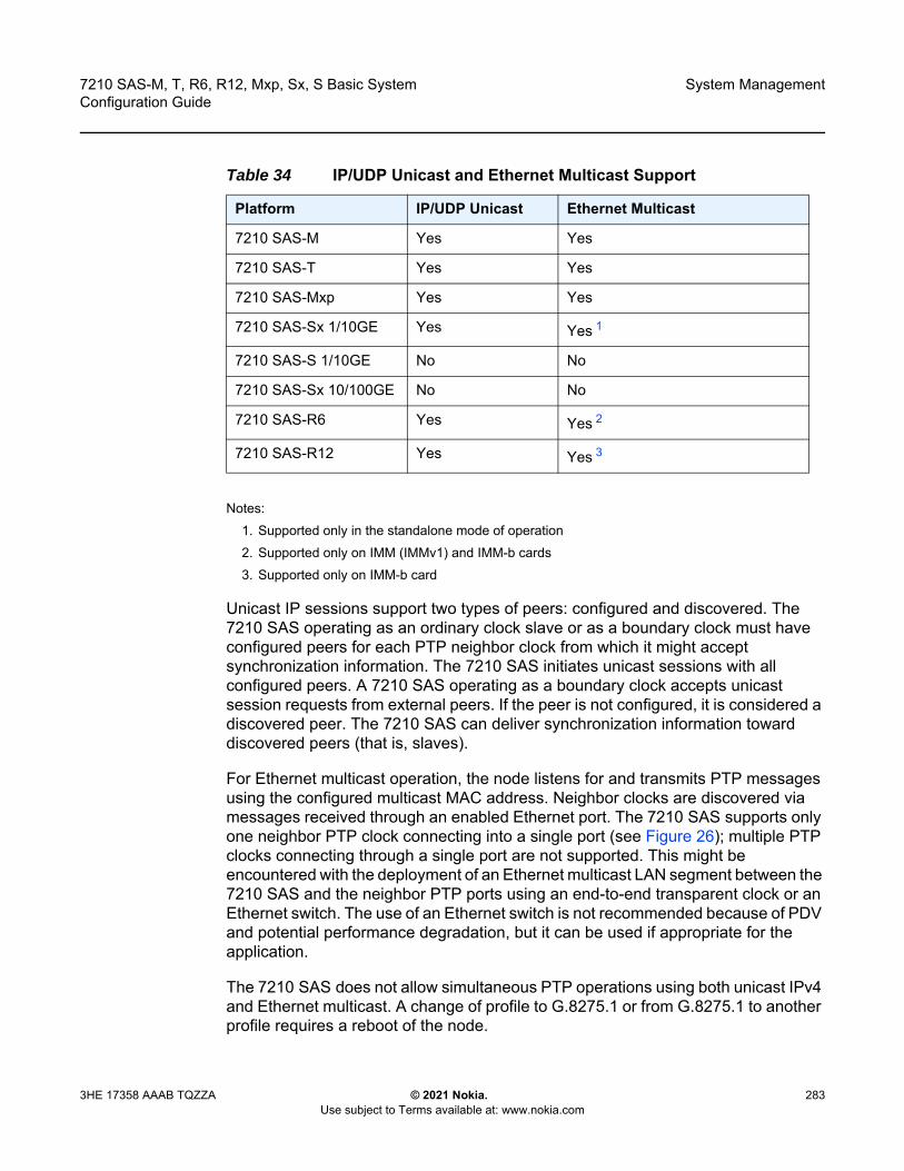
7210 SAS-M, T, R6, R12, Mxp, Sx, S Basic System Configuration Guide
System Management
3HE 17358 AAAB TQZZA © 2021 Nokia. Use subject to Terms available at: www.nokia.com
283
Notes:1. Supported only in the standalone mode of operation2. Supported only on IMM (IMMv1) and IMM-b cards 3. Supported only on IMM-b card
Unicast IP sessions support two types of peers: configured and discovered. The 7210 SAS operating as an ordinary clock slave or as a boundary clock must have configured peers for each PTP neighbor clock from which it might accept synchronization information. The 7210 SAS initiates unicast sessions with all configured peers. A 7210 SAS operating as a boundary clock accepts unicast session requests from external peers. If the peer is not configured, it is considered a discovered peer. The 7210 SAS can deliver synchronization information toward discovered peers (that is, slaves).
For Ethernet multicast operation, the node listens for and transmits PTP messages using the configured multicast MAC address. Neighbor clocks are discovered via messages received through an enabled Ethernet port. The 7210 SAS supports only one neighbor PTP clock connecting into a single port (see Figure 26); multiple PTP clocks connecting through a single port are not supported. This might be encountered with the deployment of an Ethernet multicast LAN segment between the 7210 SAS and the neighbor PTP ports using an end-to-end transparent clock or an Ethernet switch. The use of an Ethernet switch is not recommended because of PDV and potential performance degradation, but it can be used if appropriate for the application.
The 7210 SAS does not allow simultaneous PTP operations using both unicast IPv4 and Ethernet multicast. A change of profile to G.8275.1 or from G.8275.1 to another profile requires a reboot of the node.
Table 34 IP/UDP Unicast and Ethernet Multicast Support
Platform IP/UDP Unicast Ethernet Multicast
7210 SAS-M Yes Yes
7210 SAS-T Yes Yes
7210 SAS-Mxp Yes Yes
7210 SAS-Sx 1/10GE Yes Yes 1
7210 SAS-S 1/10GE No No
7210 SAS-Sx 10/100GE No No
7210 SAS-R6 Yes Yes 2
7210 SAS-R12 Yes Yes 3
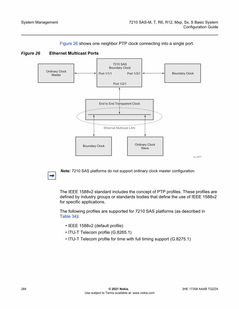
System Management
284
7210 SAS-M, T, R6, R12, Mxp, Sx, S Basic SystemConfiguration Guide
© 2021 Nokia. Use subject to Terms available at: www.nokia.com
3HE 17358 AAAB TQZZA
Figure 26 shows one neighbor PTP clock connecting into a single port.
Figure 26 Ethernet Multicast Ports
The IEEE 1588v2 standard includes the concept of PTP profiles. These profiles are defined by industry groups or standards bodies that define the use of IEEE 1588v2 for specific applications.
The following profiles are supported for 7210 SAS platforms (as described in Table 34):
• IEEE 1588v2 (default profile)• ITU-T Telecom profile (G.8265.1)• ITU-T Telecom profile for time with full timing support (G.8275.1)
sw_0127
7210 SASBoundary Clock
Port 1/2/1
Port 1/1/1 Port 1/3/1
Boundary Clock
Boundary Clock
Ordinary ClockSlave
Ethernet Multicast LAN
Ordinary ClockMaster
End to End Transparent Clock
Note: 7210 SAS platforms do not support ordinary clock master configuration.
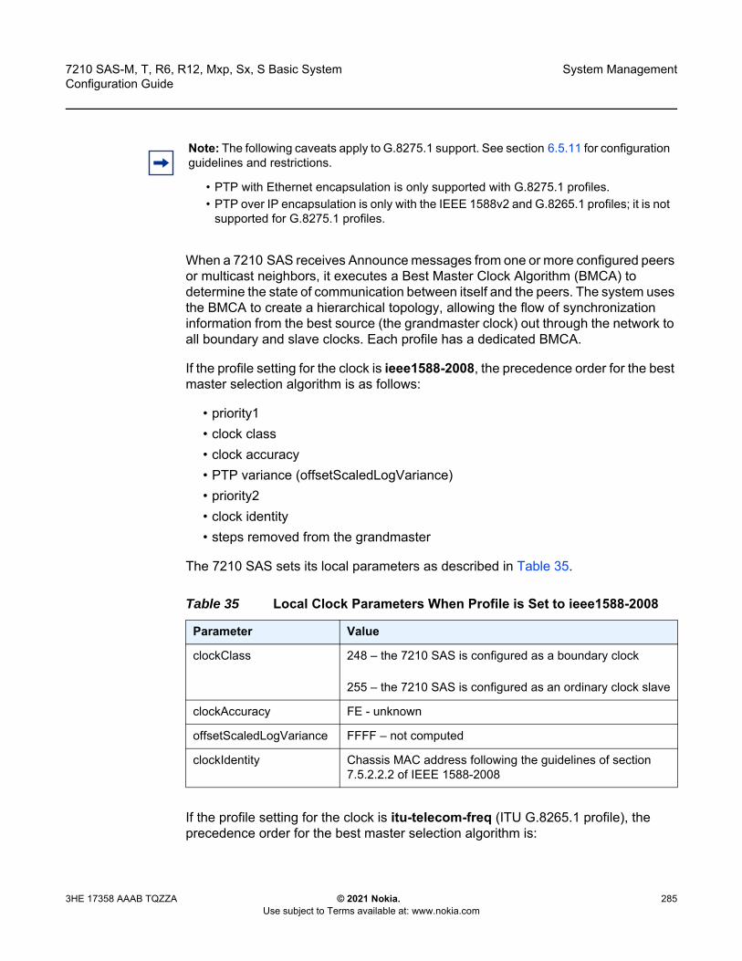
7210 SAS-M, T, R6, R12, Mxp, Sx, S Basic System Configuration Guide
System Management
3HE 17358 AAAB TQZZA © 2021 Nokia. Use subject to Terms available at: www.nokia.com
285
When a 7210 SAS receives Announce messages from one or more configured peers or multicast neighbors, it executes a Best Master Clock Algorithm (BMCA) to determine the state of communication between itself and the peers. The system uses the BMCA to create a hierarchical topology, allowing the flow of synchronization information from the best source (the grandmaster clock) out through the network to all boundary and slave clocks. Each profile has a dedicated BMCA.
If the profile setting for the clock is ieee1588-2008, the precedence order for the best master selection algorithm is as follows:
• priority1• clock class• clock accuracy• PTP variance (offsetScaledLogVariance)• priority2• clock identity• steps removed from the grandmaster
The 7210 SAS sets its local parameters as described in Table 35.
If the profile setting for the clock is itu-telecom-freq (ITU G.8265.1 profile), the precedence order for the best master selection algorithm is:
Note: The following caveats apply to G.8275.1 support. See section 6.5.11 for configuration guidelines and restrictions.
• PTP with Ethernet encapsulation is only supported with G.8275.1 profiles. • PTP over IP encapsulation is only with the IEEE 1588v2 and G.8265.1 profiles; it is not
supported for G.8275.1 profiles.
Table 35 Local Clock Parameters When Profile is Set to ieee1588-2008
Parameter Value
clockClass 248 – the 7210 SAS is configured as a boundary clock
255 – the 7210 SAS is configured as an ordinary clock slave
clockAccuracy FE - unknown
offsetScaledLogVariance FFFF – not computed
clockIdentity Chassis MAC address following the guidelines of section 7.5.2.2.2 of IEEE 1588-2008

System Management
286
7210 SAS-M, T, R6, R12, Mxp, Sx, S Basic SystemConfiguration Guide
© 2021 Nokia. Use subject to Terms available at: www.nokia.com
3HE 17358 AAAB TQZZA
• clock class• PTSF (Packet Timing Signal Fail) - Announce Loss (miss 3 Announce
messages or do not get an Announce message for 6 seconds)• priority
The 7210 SAS sets its local parameters as described in Table 36.
The ITU-T profile is for use in environments with only ordinary clock masters and slaves for frequency distribution. The default profile should be used for all other cases.
If the profile setting for the clock is g8275dot1-2014, the precedence order for the best master selection algorithm is very similar to that used with the default profile. It ignores the priority1 parameter, includes a localPriority parameter, and includes the ability to force a port to never enter the slave state (master-only). The precedence is as follows:
• clock class• clock accuracy• PTP variance (offsetScaledLogVariance)• priority2• localPriority• clock identity• steps removed from the grandmaster
The 7210 SAS sets its local parameters as described in Table 37.
Table 36 Local Clock Parameters When Profile is Set to itu-telecom-freq
Parameter Value
clockClass 80-110 – value corresponding to the QL out of the central clock of the 7210 SAS as per Table 1/G.8265.1
255 – the 7210 SAS is configured as an ordinary clock slave

7210 SAS-M, T, R6, R12, Mxp, Sx, S Basic System Configuration Guide
System Management
3HE 17358 AAAB TQZZA © 2021 Nokia. Use subject to Terms available at: www.nokia.com
287
The 7210 SAS can support a limited number of configured peers (possible master or neighbor boundary clocks) and a limited number of discovered peers (slaves).These peers use the unicast negotiation procedures to request service from the 7210 SAS clock. A neighbor boundary clock counts for two peers (both a configured and a discovered peer) toward the maximum limit.
The number of configured Ethernet ports is not restricted.
On the 7210 SAS-M, 7210 SAS-Mxp, 7210 SAS-R6, 7210 SAS-R12, 7210 SAS-Sx 1/10GE, and 7210 SAS-T, there are limits on the number of slaves enforced in the implementation for unicast and multicast slaves. Refer to the scaling guide for the appropriate release for the specific unicast message limits related to PTP.
On the 7210 SAS-M, when multicast messaging on Ethernet ports is enabled, the PTP load must be monitored to ensure that the load does not exceed the capabilities (configured values). There are several commands that can be used for this monitoring, including:
• show system cpu identifies the load of the PTP software process. If the “capacity usage” reaches 100%, the PTP software process on the 7210 SAS is at its limit of transmitting and/or receiving PTP packets.
Because the user cannot control the number of PTP messages received by the 7210 SAS over its Ethernet ports, the following statistics commands can be used to identify the source of the message load:
• show system ptp statistics displays aggregate packet rates
Table 37 Local Clock Parameters When Profile is Set to g8275dot1-2014
Parameter Value
clockClass 165 – the 7210 SAS is configured as a boundary clock and the boundary clock was previously locked to a grandmaster with clock class of 6
248 – the 7210 SAS is configured as a boundary clock
255 – the 7210 SAS is configured as an ordinary clock slave
clockAccuracy FE – unknown
offsetScaledLogVariance FFFF – not computed
clockIdentity Chassis MAC address following the guidelines of section 7.5.2.2.2 of IEEE 1588-2008

System Management
288
7210 SAS-M, T, R6, R12, Mxp, Sx, S Basic SystemConfiguration Guide
© 2021 Nokia. Use subject to Terms available at: www.nokia.com
3HE 17358 AAAB TQZZA
• show system ptp port and show system ptp port port-id [detail] display received packet rates
Figure 27 shows the unicast negotiation procedure performed between a slave and a peer clock that is selected to be the master clock. The slave clock will request Announce messages from all peer clocks but only request Sync and Delay_Resp messages from the clock selected to be the master clock.
Figure 27 Messaging Sequence Between the PTP Slave Clock and PTP Master Clocks
OSSG666
AnnounceDurationInterval
SyncDurationInterval
Signaling (Announce-grant)
Signaling (Announce-grant)
Signaling (Sync-grant)
Signaling (Sync-grant)
Sync
Sync
Announce
Announce
Announce
Signaling (Announce-request)
Signaling (Sync-request)
Signaling (Sync-request)
Signaling (Announce-request)
PacketMaster
PacketSlave
UnicastRenewal
Interval

7210 SAS-M, T, R6, R12, Mxp, Sx, S Basic System Configuration Guide
System Management
3HE 17358 AAAB TQZZA © 2021 Nokia. Use subject to Terms available at: www.nokia.com
289
6.5.8.1 PTP Clock Synchronization
The IEEE 1588v2 standard synchronizes the frequency and time from a master clock to one or more slave clocks over a packet stream. This packet-based synchronization can be over unicast IP/UDP unicast or Ethernet multicast.
As part of the basic synchronization timing computation, event messages are defined for synchronization messaging between the PTP slave clock and PTP master clock. A one-step or two-step synchronization operation can be used; the two-step operation requires a follow-up message after each synchronization message.
During startup, the PTP slave clock receives synchronization messages from the PTP master clock before a network delay calculation is made. Prior to any delay calculation, the delay is assumed to be zero. A drift compensation is activated after a number of synchronization message intervals occur. The expected interval between the reception of synchronization messages is user-configurable.
Figure 28 shows the basic synchronization timing computation between the PTP slave clock and PTP best master; the offset of the slave clock is shown referenced to the best master signal during startup.
Note:
• The 7210 SAS-M supports only two-step master port operation.• The 7210 SAS-Mxp, 7210 SAS-R6, 7210 SAS-R12, 7210 SAS-Sx 1/10GE, and
7210 SAS-T support only one-step master port operation.• All platforms can operate slave ports that receive from a one-step or two-step master
port.

System Management
290
7210 SAS-M, T, R6, R12, Mxp, Sx, S Basic SystemConfiguration Guide
© 2021 Nokia. Use subject to Terms available at: www.nokia.com
3HE 17358 AAAB TQZZA
Figure 28 PTP Slave Clock and Master Clock Synchronization Timing Computation
When the IEEE 1588v2 standard is used for distribution of a frequency reference, the slave calculates a message delay from the master to the slave based on the timestamps exchanged. A sequence of these calculated delays contains information about the relative frequencies of the master clock and slave clock, but also includes a noise component related to the PDV experienced across the network. The slave must filter the PDV effects to extract the relative frequency data and then adjust the slave frequency to align with the master frequency.
When the IEEE 1588v2 standard is used for distribution of time, the 7210 SAS calculates the offset between the 7210 SAS time base and the external master clock time base based on the four timestamps exchanged. The 7210 SAS determines the offset adjustment, and between these adjustments, it maintains the progression of time using the frequency from the central clock of the node. This allows time to be maintained using a Synchronous Ethernet input source even if the IEEE 1588v2 communications fail. When using IEEE 1588v2 for time distribution, the central clock should, at a minimum, have the PTP input reference enabled.
Figure 29 shows the logical model for using PTP/1588 for network synchronization.
Master Slave
Sync
Follow_up (t1)
Delay_req
Delay_resp (t4)
38
40
42
44
46
48
50
52
54
56
58
60
62
40
42
44
46
48
50
52
54
56
58
60
62
64
O = Offset = Slave - Master
t1, t2, t3, t4 Are Measured Valuest2 - t1 = Delay + Offset = 51 - 44 = 7t4 - t3 = Delay - Offset = 57 - 56 = 1Delay = ((t2 - t1) + (t4 - t3))/2 = 4Offset = ((t2 - t1) - (t4 - t3))/2 = 3
D = Delayt1
t4
t2
O D
OSSG732
t3
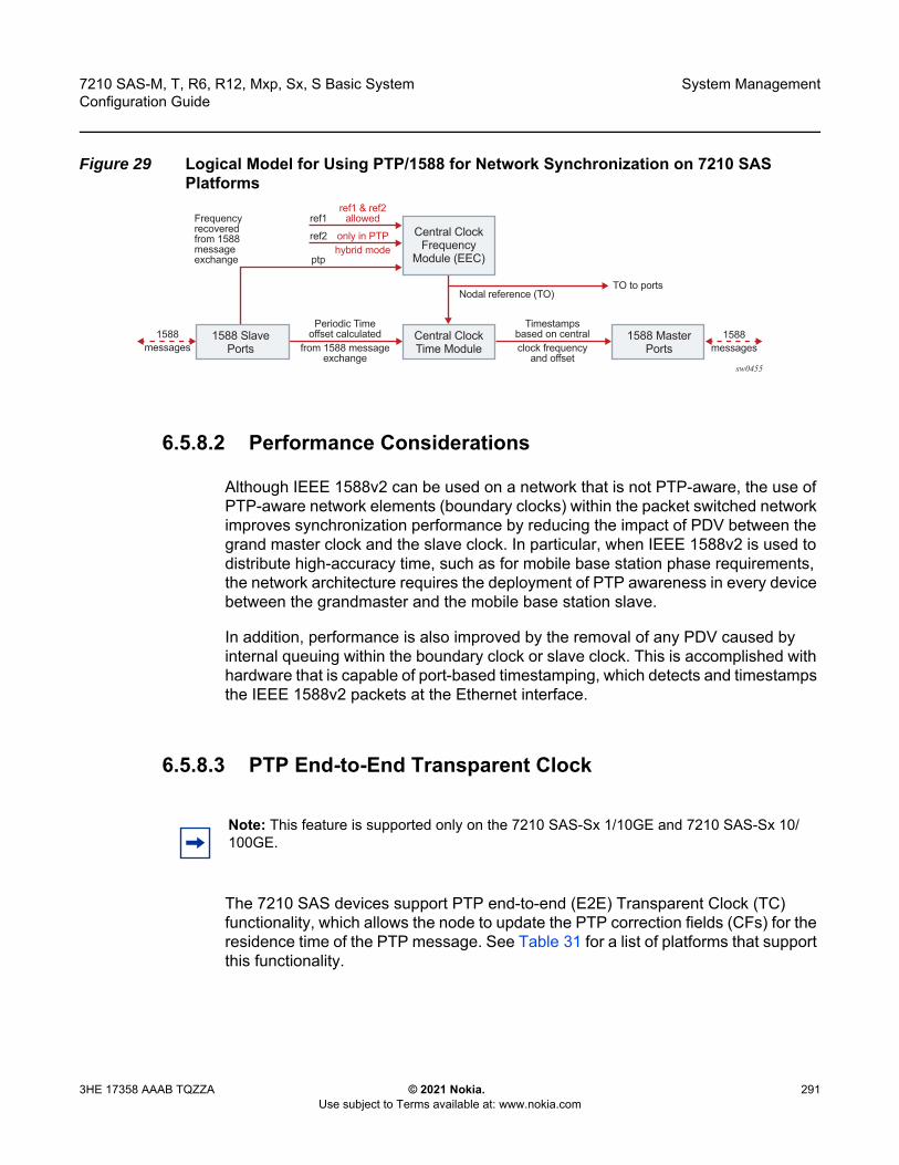
7210 SAS-M, T, R6, R12, Mxp, Sx, S Basic System Configuration Guide
System Management
3HE 17358 AAAB TQZZA © 2021 Nokia. Use subject to Terms available at: www.nokia.com
291
Figure 29 Logical Model for Using PTP/1588 for Network Synchronization on 7210 SAS Platforms
6.5.8.2 Performance Considerations
Although IEEE 1588v2 can be used on a network that is not PTP-aware, the use of PTP-aware network elements (boundary clocks) within the packet switched network improves synchronization performance by reducing the impact of PDV between the grand master clock and the slave clock. In particular, when IEEE 1588v2 is used to distribute high-accuracy time, such as for mobile base station phase requirements, the network architecture requires the deployment of PTP awareness in every device between the grandmaster and the mobile base station slave.
In addition, performance is also improved by the removal of any PDV caused by internal queuing within the boundary clock or slave clock. This is accomplished with hardware that is capable of port-based timestamping, which detects and timestamps the IEEE 1588v2 packets at the Ethernet interface.
6.5.8.3 PTP End-to-End Transparent Clock
The 7210 SAS devices support PTP end-to-end (E2E) Transparent Clock (TC) functionality, which allows the node to update the PTP correction fields (CFs) for the residence time of the PTP message. See Table 31 for a list of platforms that support this functionality.
sw0455
Central ClockTime Module
Central ClockFrequency
Module (EEC)
1588 MasterPorts
1588 SlavePorts
1588messages
1588messages
TO to portsNodal reference (TO)
ref1Frequency recoveredfrom 1588 messageexchange
ref1 & ref2allowed
only in PTPhybrid mode
ref2
ptp
Periodic Timeoffset calculated
from 1588 messageexchange
Timestampsbased on centralclock frequency
and offset
Note: This feature is supported only on the 7210 SAS-Sx 1/10GE and 7210 SAS-Sx 10/100GE.

System Management
292
7210 SAS-M, T, R6, R12, Mxp, Sx, S Basic SystemConfiguration Guide
© 2021 Nokia. Use subject to Terms available at: www.nokia.com
3HE 17358 AAAB TQZZA
A CLI option is provided to enable the PTP port-based hardware timestamp on ports that receive and forward PTP messages. To enable the TC function, PTP must not be enabled on the node. When the timestamp option is enabled, the node identifies standards-based messages and updates the CF for PTP IP/UDP multicast and unicast messages, and for the PTP Ethernet multicast and unicast messages. The CF is updated for the residence time of the PTP message. Downstream PTP slaves that receive the PTP message use the updated CF to measure the delay between the master and themselves.
You can enable the TC option by running the configure>port>ethernet>ptp-hw-timestamp command on ports (both ingress and egress) on which residence time in the PTP message must be updated when the message is in transit through the node. You can disable the residence time update by running the no form of the command on both ingress and egress ports, as required. No additional CLI commands are required to enable the PTP TC option.
Nokia recommends the following operational guidelines and examples for enabling and using the PTP TC feature.
• Assume port 1/1/10 is connected to a PTP master clock (using a port, a SAP, or an IES IP interface) and 1/1/15 is connected to a PTP slave clock (using a port, a SAP, or an IES IP interface). To enable PTP TC in this scenario, you must enable the ptp-hw-timestamp command on both ports. To disable PTP TC, run the no form of the command on both ports.
• Assume port 1/1/10 is connected to a PTP master clock (using a port, a SAP, or an IES IP interface) and ports 1/1/15 and 1/1/16 have PTP slaves (using a port, a SAP, or an IES IP interface), with a PTP session to the PTP master clock that is connected on port 1/1/10. To enable PTP TC, the ptp-hw-timestamp command must be enabled on all three ports. In this scenario, it is not possible to disable PTP TC only towards the slave connected on port 1/1/15. The functionality must be disabled on all three ports. Additionally, note that the PTP messages coming in on port 1/1/10 are not forwarded out of any ports other than 1/1/15 and 1/1/16, when the ptp-hw-timestamp command is enabled on port 1/1/10. Nokia recommends that when a set of PTP ports are enabled for ptp-hw-timestamp, the operator must ensure that PTP messages are forwarded to only the specific set of ports where the TC option is enabled, and not to other ports. Forwarding PTP messages to other ports that do not belong to the specific set may result in incorrect updates.
• You can enable PTP TC for a set of SAPs and also transparently forward PTP packets on other SAPs, while both SAPs share a common uplink to forward PTP messages. To implement this scenario, use MPLS tunnels with network ports as the uplinks. Nokia recommends the following configuration.
7210 SAS-M, T, R6, R12, Mxp, Sx, S Basic System Configuration Guide
System Management
3HE 17358 AAAB TQZZA © 2021 Nokia. Use subject to Terms available at: www.nokia.com
293
- PTP hardware port-based timestamping must be disabled on the access ports where SAPs are configured. These access ports are typically used to connect to either PTP master or PTP slaves that need to establish and exchange PTP messages transparently.
- PTP hardware port-based timestamping must be enabled on the access ports where SAPs are configured and the TC function is required. These access ports are typically used to connect to either the PTP master or PTP slaves.
- PTP hardware port-based timestamping must be enabled on the network ports where the MPLS tunnels originate and terminate. In this case, the PTP TC function updates only the PTP messages that are not MPLS encapsulated.
- See PTP Message Transparent Forwarding for additional support information.
6.5.8.4 PTP Message Transparent Forwarding
On bootup, port-based hardware timestamping is enabled by default on all ports on the 7210 SAS-Mxp, 7210 SAS-R6, 7210 SAS-R12, 7210 SAS-Sx 1/10GE, and 7210 SAS-T, and the node processes both transit packets and locally destined PTP packets. Use the ptp-hw-timestamp command to disable port-based hardware timestamping in the following cases:
• to allow the node to transparently forward PTP packets when MPLS uplinks are used
• when PTP is enabled and used to synchronize and time the node (that is, PTP messages are originated and terminated by the node acting as a PTP OC-slave or BC)
• on ports that receive PTP packets that will be forwarded transparently
When PTP port-based hardware timestamp is disabled, the node does not update the correction field in PTP messages. Refer to the 7210 SAS-M, T, R6, R12, Mxp, Sx, S Interface Configuration Guide for more information about the ptp-hw-timestamping command.
Note: When PTP is enabled on the 7210 SAS-M (operating in both network mode and access-uplink mode) for node synchronization, port-based hardware timestamping is enabled on all ports by default, and only locally-destined PTP packets are processed by the node. PTP IP/UDP messages that are not addressed to the node are forwarded transparently without additional configuration.

System Management
294
7210 SAS-M, T, R6, R12, Mxp, Sx, S Basic SystemConfiguration Guide
© 2021 Nokia. Use subject to Terms available at: www.nokia.com
3HE 17358 AAAB TQZZA
For example, to enable transparent forwarding of PTP packets over MPLS tunnels, when access ports with configured SAPs are used to connect the PTP master or PTP slaves, the ptp-hw-timestamp command can be used to disable PTP port-based hardware timestamping on these access ports.
The following guidelines must be considered for transparent PTP packet forwarding.
• By default, PTP port-based hardware timestamping is enabled on all ports at bootup. To allow transparent PTP packet forwarding, the feature must be disabled using the configure>port>no ptp-hw-timestamp command.
• On 7210 SAS-Mxp, 7210 SAS-T, 7210 SAS-R6, 7210 SAS-R12, 7210 SAS-Sx 10/100GE, and 7210 SAS-Sx 1/10GE, if the ptp-hw-timestamp command is enabled by executing the command on a set of ports, the node processes PTP packets that transit those ports to update the correction field for the packet residence time in the node. This allows for accurate computation by PTP time and frequency recovery algorithms on PTP slave clocks that are connected to those ports.
• The command to enable PTP hardware timestamps for packets transiting the node should be configured on both the ingress and egress port where PTP packets are expected to be received and sent from (and where they need to be processed to update correction time). Configuring the PTP hardware timestamp command on only the ingress port or egress port is not recommended because this will result in incorrect updates to the correction field.
• For 7210 SAS-R6 and 7210 SAS-R12 platforms with IMM-b (IMMv2) and IMM-c cards, and for the 7210 SAS-Mxp and 7210 SAS-Sx 1/10GE, to enable transparent forwarding of PTP packets over MPLS tunnels, PTP hardware port-based timestamping must be disabled on the access ports where SAPs are configured. These access ports are used to connect to either PTP master or PTP slaves that need to establish and exchange PTP messages transparently. PTP hardware port-based timestamping does not need to be disabled on the network ports where the MPLS tunnels originate and terminate. This means that these network ports can be used for PTP packet exchange when the node is a PTP boundary clock or ordinary clock slave. If the requirement is to forward PTP packets transparently when MPLS uplinks are not used or when a hybrid port with a SAP is used, PTP hardware port-based timestamping must be disabled on the access port and hybrid port.
Note: The ptp-hw-timestamp command is only supported on the 7210 SAS-T, 7210 SAS-Mxp, 7210 SAS-R6, 7210 SAS-R12, 7210 SAS-Sx 1/10GE, and 7210 SAS-Sx 10/100GE. Port-based hardware timestamping can be used for transparent PTP packet forwarding if PTP is enabled and used to time the node (that is, PTP messages are originated and terminated by the node acting as a PTP OC-slave or BC).
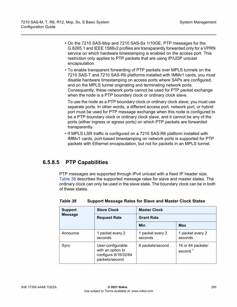
7210 SAS-M, T, R6, R12, Mxp, Sx, S Basic System Configuration Guide
System Management
3HE 17358 AAAB TQZZA © 2021 Nokia. Use subject to Terms available at: www.nokia.com
295
• On the 7210 SAS-Mxp and 7210 SAS-Sx 1/10GE, PTP messages for the G.8265.1 and IEEE 1588v2 profiles are transparently forwarded only for a VPRN service on which hardware timestamping is enabled on the access port. This restriction only applies to PTP packets that are using IP/UDP unicast encapsulation.
• To enable transparent forwarding of PTP packets over MPLS tunnels on the 7210 SAS-T and 7210 SAS-R6 platforms installed with IMMv1 cards, you must disable hardware timestamping on access ports where SAPs are configured, and on the MPLS tunnel originating and terminating network ports. Consequently, these network ports cannot be used for PTP packet exchange when the node is a PTP boundary clock or ordinary clock slave. To use the node as a PTP boundary clock or ordinary clock slave, you must use separate ports. In other words, a different access port, network port, or hybrid port must be used for PTP message exchange when this node is configured to be a PTP boundary clock or ordinary clock slave, and it cannot be any of the ports (either ingress or egress ports) on which PTP packets are forwarded transparently.
• If MPLS LSR traffic is configured on a 7210 SAS-R6 platform installed with IMMv1 cards, port-based timestamping on network ports is supported for PTP packets with Ethernet encapsulation, but not for packets in an MPLS tunnel.
6.5.8.5 PTP Capabilities
PTP messages are supported through IPv4 unicast with a fixed IP header size. Table 38 describes the supported message rates for slave and master states. The ordinary clock can only be used in the slave state. The boundary clock can be in both of these states.
Table 38 Support Message Rates for Slave and Master Clock States
Support Message
Slave Clock Master Clock
Request Rate Grant Rate
Min Max
Announce 1 packet every 2 seconds
1 packet every 2 seconds
1 packet every 2 seconds
Sync User-configurable with an option to configure 8/16/32/64 packets/second
8 packets/second 16 or 64 packets/second 1

System Management
296
7210 SAS-M, T, R6, R12, Mxp, Sx, S Basic SystemConfiguration Guide
© 2021 Nokia. Use subject to Terms available at: www.nokia.com
3HE 17358 AAAB TQZZA
Note:1. Maximum PPS depends on the profile in use
State and statistics data for each master clock are available to assist in the detection of failures or unusual situations.
6.5.8.6 PTP Ordinary Slave Clock for Frequency
Traditionally, only clock frequency is required to ensure smooth transmission in a synchronous network. The PTP ordinary clock with slave capability on the 7210 SAS provides another option to reference a Stratum-1 traceable clock across a packet switched network. The recovered clock can be referenced by the internal SSU and distributed to all slots and ports.
Figure 30 shows a PTP ordinary slave clock network configuration.
Figure 30 Slave Clock
Delay_Resp User-configurable with an option to configure 8/16/32/64 packets/second
8 packets/second 16 or 64 packets/second 1
Duration 300 seconds 1 second 1000 seconds
Table 38 Support Message Rates for Slave and Master Clock States
Support Message
Slave Clock Master Clock
Request Rate Grant Rate
Min Max
PacketNetwork
1588v2GrandMaster
PTP Slave1588v2GrandMaster
OSSG737

7210 SAS-M, T, R6, R12, Mxp, Sx, S Basic System Configuration Guide
System Management
3HE 17358 AAAB TQZZA © 2021 Nokia. Use subject to Terms available at: www.nokia.com
297
6.5.9 PTP Boundary Clock for Frequency and Time
Although IEEE 1588v2 can function across a packet network that is not PTP-aware, performance may be unsatisfactory and unpredictable. PDV across the packet network varies with the number of hops, link speeds, utilization rates, and the inherent behavior of routers. By using routers with boundary clock functionality in the path between the grandmaster clock and the slave clock, one long path over many hops is split into multiple shorter segments, allowing better PDV control and improved slave performance. This allows PTP to function as a valid timing option in more network deployments and allows for better scalability and increased robustness in certain topologies, such as rings.
Boundary clocks can simultaneously function as a PTP slave of an upstream grandmaster (ordinary clock) or boundary clock, and as a PTP master of downstream slaves (ordinary clock) and boundary clocks. The time scale recovered in the slave side of the boundary clock is used by the master side of the boundary clock. This allows time distribution across the boundary clock.
Figure 31 shows routers with boundary clock functionality in the path between grandmaster clock and the slave clock.
Figure 31 Boundary Clock
PacketNetwork
1588v2GrandMaster
PTP Slave
PTP Slave
PTP Slave
PTPBoundary
Clock
PTPBoundary
Clock
PTPBoundary
Clock
OSSG741
1588v2GrandMaster

System Management
298
7210 SAS-M, T, R6, R12, Mxp, Sx, S Basic SystemConfiguration Guide
© 2021 Nokia. Use subject to Terms available at: www.nokia.com
3HE 17358 AAAB TQZZA
6.5.10 1PPS and 10MHz Output Interface
The 7210 SAS-T, 7210 SAS-Mxp, 7210 SAS-R6, and 7210 SAS-R12 support 1PPS and 10 MHz output interfaces. These interfaces output the recovered signal from the system clock when PTP is enabled.
6.5.11 Configuration Guidelines and Restrictions for PTP
The following guidelines and restrictions apply for PTP configuration.
• On 7210 SAS devices, only a single profile (IEEE 1588v2, G.8265.1, or G.8275.1) can be enabled for all PTP communications (both towards its master and slave connections) at any point in time.
• The PTP G.8275.1 profile is supported only on the 7210 SAS-M, 7210 SAS-Mxp,7210 SAS-R6, 7210 SAS-R12, 7210 SAS-Sx 1/10GE (standalone), and 7210 SAS-T devices. On the 7210 SAS-R6, the G.8275.1 profile is supported only for IMMv1 and IMMv2 cards. On the 7210 SAS-R12, the G.8275.1 profile is supported only for IMMv2 cards. When using the G.8275.1 profile, the following restrictions apply.- The delay and sync requests are set to 16 pps by default and are not
configurable. - The announce rate is set to 8 pps by default and is not configurable. - A change of profile to G.8275.1 or from G.8275.1 to another profile requires
a reboot of the node. - Only a single multicast slave is supported per port.
• PTP with Ethernet encapsulation is supported only with the G.8275.1 profile. • PTP over IP encapsulation is not supported with the G.8275.1 profile. It is
supported only with the IEEE 1588v2 and G.8265.1 profiles. • PTP slave capability is available on all the ports on the 7210 SAS-M,
7210 SAS-Mxp, 7210 SAS-R6, 7210 SAS-R12, 7210 SAS-Sx 1/10GE, and 7210 SAS-T.
Note: 1pps and 10MHz signals are available only when PTP is enabled.
7210 SAS-M, T, R6, R12, Mxp, Sx, S Basic System Configuration Guide
System Management
3HE 17358 AAAB TQZZA © 2021 Nokia. Use subject to Terms available at: www.nokia.com
299
• When changing the clock-type to or from a boundary clock on the 7210 SAS-Mxp, 7210 SAS-R6, 7210 SAS-R12, 7210 SAS-Sx 1/10GE, and 7210 SAS-T platforms, the node must be rebooted for the change to take effect. Nokia recommends taking appropriate measures to minimize service disruption during the reboot process.
• On the 7210 SAS-M, use of PTP and SyncE as a reference simultaneously is not allowed. Either SyncE or PTP can be configured as a reference, but not both together.
• The 7210 SAS-Mxp, 7210 SAS-R6, 7210 SAS-R12, 7210 SAS-Sx 1/10GE, and 7210 SAS-T support the use of PTP and SyncE as a reference simultaneously; that is, on these platforms, the ref-order can be set to config>system>sync-if-timing>ref-order ref1 ref2 ptp.
• The 7210 SAS-M, 7210 SAS-Mxp, 7210 SAS-R6, 7210 SAS-R12, 7210 SAS-Sx 1/10GE, and 7210 SAS-T support the PTP hybrid mode of operation. Frequency recovery is provided by the central clock through either SyncE or BITS, depending on which reference is configured. PTP is used for time recovery only. In this mode, the node can recover very stable frequency using a reduced PTP packet rate.
• The 7210 SAS-M uses CPU processing cycles for frequency and time recovery. Use of PTP hybrid mode reduces the amount of CPU processing cycles needed, helping customers scale better.
• To enable PTP hybrid mode on the 7210 SAS-Mxp, 7210 SAS-R6, 7210 SAS-R12, 7210 SAS-Sx 1/10GE, and 7210 SAS-T, run the config>system>ptp>clock>freq-source ssu CLI command. To enable pure PTP mode, the user must execute the command config>system>ptp>clock>freq-source ptp. For a change of value from ssu to ptp (or vice-versa) to take effect, the operator must save the configuration changes and reboot the node.
• On the 7210 SAS-R6 and 7210 SAS-R12, only the BITS1 port can be used to provide a reference to the system clock or to distribute the reference. The use of the BITS2 port is not supported.
• On the 7210 SAS-T and 7210 SAS-Mxp, both the BITS1 and BITS2 ports can be used to provide a reference to the system clock or to distribute the reference.
• On the 7210 SAS-M, Nokia strongly recommends using PTP in hybrid mode only. Hybrid mode facilitates reduced PTP packet rates and improved scalability.
System Management
300
7210 SAS-M, T, R6, R12, Mxp, Sx, S Basic SystemConfiguration Guide
© 2021 Nokia. Use subject to Terms available at: www.nokia.com
3HE 17358 AAAB TQZZA
• On the 7210 SAS-Mxp, 7210 SAS-R6, 7210 SAS-R12, 7210 SAS-Sx 1/10GE, and 7210 SAS-T, an IP address must be configured under config>system>security>source-address>application ptp, before PTP can be enabled for use. The use of the system IPv4 interface address or other loopback IPv4 interface address is recommended for PTP applications. The IPv4 address of an IPv4 interface over a port can also be used. The PTP software uses the configured IP address as the source IP address for both configured peers and discovered peers.
• On the 7210 SAS-Mxp, 7210 SAS-R6, 7210 SAS-R12, and 7210 SAS-T, 1 pps and 10 MHz interface signals should only be used when PTP is enabled. Use these signals only after determining that the system is configured to use PTP as a reference and is locked to PTP.
• The 7210 SAS-S 1/10GE does not support IEEE 1588v2 PTP.• On the 7210 SAS-Mxp, 7210 SAS-R6, 7210 SAS-R12, 7210 SAS-Sx 1/10GE,
and 7210 SAS-T, PTP port-based timestamping is enabled by default on all ports for all PTP packets at system bootup. - When this feature is enabled, PTP packets are not forwarded transparently
through the node, regardless of the service used and whether PTP is configured as a system clock reference. To enable transparent forwarding, refer to PTP Message Transparent Forwarding.
- Regardless of whether PTP is enabled (configure>sync-if-timing>ptp>no shutdown) or disabled (configure>sync-if-timing>ptp>shutdown), the timestamp value stored in the correction-field (CF) is updated for all PTP packets that are in transit through the node. This affects all PTP packets that are not originated or terminated on the node. To prevent this occurrence, disable PTP port-based hardware timestamps on specific (all or select) ports by configuring the configure>port>no ptp-hw-timestamp CLI command on ports where PTP packets are in transit. When the feature is disabled, PTP packets in transit are transparently forwarded without changing the timestamp value.
6.5.12 Configuration to Change Reference from SyncE to PTP on 7210 SAS-M
On 7210 SAS-M, use of PTP and SyncE as a reference simultaneously is not allowed. The user can configure either SyncE or PTP as a reference, but not both at the same time.
Perform the following configuration steps to change the reference from SyncE to PTP.

7210 SAS-M, T, R6, R12, Mxp, Sx, S Basic System Configuration Guide
System Management
3HE 17358 AAAB TQZZA © 2021 Nokia. Use subject to Terms available at: www.nokia.com
301
Step 1. To configure standalone PTP as a reference, run the following commands:configure >system >ptp >no shutdown
config> system> sync-if-timing> beginptpno shutdownexitref-order ptp [Must be configured]
config> system> sync-if-timing> commit
After the preceding commands are run, the frequency and time are provided by PTP only.
Step 2. To change the reference to syncE, run the following commands:config> system> sync-if-timing> beginptpshutdownexit
config> system> sync-if-timing> commit
config> system> sync-if-timing> beginref1source-port 1/1/10no shutdownexit
ref2source-port 1/1/11no shutdownexit
ref-order ref1 ref2 --------> Or, the ref-order you want [But Must be configured]
revert ---------------------> If you want ref-order you have setup to take effect
ql-selection -------------------> Optional, if we need Quality to be considered.
config> system> sync-if-timing> commit
After the preceding commands are run, the frequency is provided by SyncE and TOD is provided by PTP [configure>system>ptp>no shutdown]. This is called PTP Hybrid mode.
Step 3. To revert to standalone PTP from SyncE, run the following commands:config> system> sync-if-timing> beginref1
Note: This procedure is required only on 7210 SAS-M nodes.

System Management
302
7210 SAS-M, T, R6, R12, Mxp, Sx, S Basic SystemConfiguration Guide
© 2021 Nokia. Use subject to Terms available at: www.nokia.com
3HE 17358 AAAB TQZZA
source-port 1/1/10 --------------------> Not Required if port is already configured, but in admin down stateshutdownexit
ref2source-port 1/1/11 --------------------> Not Required if port is already configured, but in admin down stateshutdownexit
config> system> sync-if-timing> commit
config> system> sync-if-timing> beginptpno shutdownexit
ref-order ptp [Must be configured]
config> system> sync-if-timing> commit
After the preceding commands are run, the frequency and time are provided by PTP [configure>system>ptp>no shutdown] only. This is a standalone PTP mode.
6.5.13 Configuration Example to Use PTP and SyncE References on 7210 SAS-Mxp, 7210 SAS-R6, 7210 SAS-R12, 7210 SAS-Sx 1/10GE, and 7210 SAS-T
The 7210 SAS-Mxp, 7210 SAS-R6, 7210 SAS-R12, 7210 SAS-Sx 1/10GE, and 7210 SAS-T support the configuration of PTP and SyncE references at the same time. On these platforms, ref-order can be set to config>system>sync-if-timing>ref-order ref1 ref2 ptp.
The following configuration example shows the use of PTP and syncE references simultaneously:
*A:SAS-T-B>config>system>sync-if-timing# info detail----------------------------------------------
ql-selectionref-order ptp ref1 ref2 --
> All three reference can be configured simultaneouslyref1
source-port 1/1/1no shutdownno ql-override
exit

7210 SAS-M, T, R6, R12, Mxp, Sx, S Basic System Configuration Guide
System Management
3HE 17358 AAAB TQZZA © 2021 Nokia. Use subject to Terms available at: www.nokia.com
303
ref2source-port 1/1/7no shutdownno ql-override
exitptp
no ql-overrideno shutdown
exitrevert
----------------------------------------------
6.6 Management of 1830 VWM
The 7210 SAS supports the use and management of the 1830 VWM CWDM and 1830 VWM DWDM clip-on device. 1830 VWM is a family of cost-optimized managed WDM passive devices, which is add-on shelf/NE and provides CWDM/DWDM extension to devices that do not have in-built CWDM/DWDM capabilities. The 1830 VWM can act as a Fixed Channel Optical Add-Drop Multiplexer (FOADM) or multiplexer/demultiplexer unit. It allows operators to use the existing fiber (or use less fiber) and increase the bandwidth capacity available for carrying service traffic.
For more information about 1830 VWM, see 1830 VWM product user guides.
To manage the device, the operator should plug in the 1830 VWM shelf to the USB port on the 7210 SAS-M. The 7210 SAS-T, 7210 SAS-Mxp, 7210 SAS-R6, and 7210 SAS-R12 manage the 1830 VWM device using the Optical Management Console (OMC) port.
6.6.1 Introduction
The 1830 VWM device can be used in point-to-point or ring deployments to multiplex multiple CWDM/DWDM channels over a single fiber. Either the existing fiber is reused or a single fiber is used to meet the increasing demand for service bandwidth. Up to 8 fixed CWDM channels are multiplexed over a single fiber using this unit.
Figure 32 shows 5 CWDM channels that are multiplexed over a single fiber.
Note: This feature is only supported on the 7210 SAS-M, 7210 SAS-T, 7210 SAS-Mxp, 7210 SAS-R6, and 7210 SAS-R12.
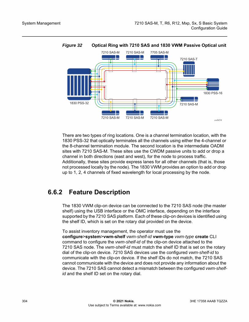
System Management
304
7210 SAS-M, T, R6, R12, Mxp, Sx, S Basic SystemConfiguration Guide
© 2021 Nokia. Use subject to Terms available at: www.nokia.com
3HE 17358 AAAB TQZZA
Figure 32 Optical Ring with 7210 SAS and 1830 VWM Passive Optical unit
There are two types of ring locations. One is a channel termination location, with the 1830 PSS-32 that optically terminates all the channels using either the 4-channel or the 8-channel termination module. The second location is the intermediate OADM sites with 7210 SAS-M. These sites use the CWDM passive units to add or drop a channel in both directions (east and west), for the node to process traffic. Additionally, these sites provide express lanes for all other channels (that is, those not processed locally by the node). The 1830 VWM provides an option to add or drop up to 1, 2, 4 channels of fixed wavelength for local processing by the node.
6.6.2 Feature Description
The 1830 VWM clip-on device can be connected to the 7210 SAS node (the master shelf) using the USB interface or the OMC interface, depending on the interface supported by the 7210 SAS platform. Each of these clip-on devices is identified using the shelf ID, which is set on the rotary dial provided on the device.
To assist inventory management, the operator must use the configure>system>vwm-shelf vwm-shelf-id vwm-type vwm-type create CLI command to configure the vwm-shelf-id of the clip-on device attached to the 7210 SAS node. The vwm-shelf-id must match the shelf ID that is set on the rotary dial of the clip-on device. 7210 SAS devices use the configured vwm-shelf-id to communicate with the clip-on device. If the shelf IDs do not match, the 7210 SAS cannot communicate with the device and does not provide any information about the device. The 7210 SAS cannot detect a mismatch between the configured vwm-shelf-id and the shelf ID set on the rotary dial.
sw04547210 SAS-M7210 SAS-M7210 SAS-M
1830 PSS-32 7210 SAS-M
7210 SAS-T
1830 PSS-16
7210 SAS-M 7705 SAS-M7210 SAS-M
7210 SAS-M, T, R6, R12, Mxp, Sx, S Basic System Configuration Guide
System Management
3HE 17358 AAAB TQZZA © 2021 Nokia. Use subject to Terms available at: www.nokia.com
305
Depending on the type of supported interface, USB or OMC, the 7210 SAS node can manage only a fixed number of 1830 VWM devices. The software prevents attempts to configure more 1830 VWM devices than can be supported by the interface in use. Use the show command supported by the 7210 SAS devices to display the shelf inventory and alarm status information provided by the clip-on device.
In addition to inventory management, 7210 SAS supports provisioning of cards inserted into the slots available on the 1830 VWM devices. Before the card can be managed by the 7210 SAS, the user must provision the card and card type (also known as module type). The 7210 SAS detects and reports provisioning mismatches for the card. It also detects and reports insertion and removal of the card/module from the slot on the 1830 VWM device.
The 1830 DWDM supports active and passive units. The first 1830 DWDM device that is connected to a 7210 SAS node using the OMC port or the USB port must be equipped with active DWDM controllers; passive DWDM controllers can be used in the other chassis connected to the first device in a stacked configuration. In other words, the first 1830 DWDM device that is connected to the OMC port or the USB port of the 7210 SAS node must not be a passive 1830 DWDM device, but subsequent chassis in the stacked configuration can be equipped with passive DWDM controllers. Refer to the 1830 VWM User Guide for information about making the decision to equip active or passive DWDM controllers on the other chassis in the stacked configuration.
6.6.2.1 1830 CWDM Shelf Layout and Description
Figure 33 shows an example of the 1830 CWDM passive device.
Note: The 7210 SAS also auto detects the device type when any supported device is connected to the USB interface. Only approved USB mass storage devices and optical clip-on devices plugged in to the USB port are recognized as valid devices. Use of unsupported devices results in the generation of an error log. A shelf created by the user will be operationally down when an unrecognized device is plugged into the USB port. The user can interchange the device connected to the USB port without requiring a reboot. For example, when the 7210 SAS is operating with a clip-on device you can pull out the clip-on device and plug-in a USB mass-storage device to copy image files or other files, and then plug back a clip-on device.
Note: The 1830 CWDM shelf shown in Figure 33 is an example. For definitive information about the 1830 CWDM device and support, refer to the 1830 CWDM product manuals.

System Management
306
7210 SAS-M, T, R6, R12, Mxp, Sx, S Basic SystemConfiguration Guide
© 2021 Nokia. Use subject to Terms available at: www.nokia.com
3HE 17358 AAAB TQZZA
Figure 33 1830 CWDM Shelf Layout
In Figure 33, Slot 1 is dedicated to the controller card. The controller card, which is named using the acronym EC-CW for the 1830 CWDM device, does not require explicit provisioning. The card type is automatically provisioned when the user configures the 1830 VWM shelf type.
If the controller card is not present in Slot 1 of the shelf, the 1830 CWDM device operates as a passive filter and is not managed by the 7210 SAS. The 7210 SAS provides inventory and equipment management capability only when the controller card is present in the shelf and connected to the 7210 SAS.
Slot 2 and Slot 3 shown in Figure 33 can be equipped with supported CWDM filter cards. The user must provision the cards that populate the slots. The 7210 SAS software checks to ensure a match between the equipped and provisioned card type; an event is logged if a mismatch is detected.
6.6.2.2 1830 DWDM Shelf Layout and Description
Figure 34 shows the 1830 DWDM shelf and the entities that can be managed by 7210 SAS.
Figure 34 1830 DWDM Shelf Layout
The following information applies to the management of the 1830 DWDM shown in Figure 34.
hw0385
Slot #1Power & Control
Slot #2OADM or Mux/Demux (Line card)
Slot #3OADM or Mux/Demux (Line card)
hw0386
Slot #1Power & Control
Slot #3Filter/Amplifier/BPM (Line card)
Slot #2Power & Control
Slot #4Filter/Amplifier/BPM (Line card)
Slot #5FANS or1-Wire
7210 SAS-M, T, R6, R12, Mxp, Sx, S Basic System Configuration Guide
System Management
3HE 17358 AAAB TQZZA © 2021 Nokia. Use subject to Terms available at: www.nokia.com
307
• Slot 1 and Slot 2 host the DWDM Power and Controller modules (either EC-DW or EC-DWA). These slots host the Equipment Controller; power is provided by the Service NE (using EC-DW unit) or the TRU (using EC-DWA unit) in accordance with the system configuration and the Equipment Controller used. A rotary switch located on the top side of the Equipment Controller is used to set the SHELF_ID. In a stacked configuration, each Shelf_ID must be uniquely set. The Shelf_ID must be identical for the active and standby controllers in a shelf.
• Slot 1 and Slot 2 are not directly provisioned by the user in the 7210 SAS. The user must provision and configure the vwm-type managed by the 7210 SAS. The vwm-type can be provisioned as ec-cw, ec-dw, or ec-dwa, indicating that the shelf is a CWDM passive shelf or a DWDM passive shelf or a DWDM active shelf.
• The first 1830 DWDM device that is connected to the OMC port or the USB port of the 7210 SAS node must be equipped with the active DWDM controllers; it must not be a passive 1830 DWDM device. However, subsequent chassis connected to the first 1830 DWDM device in a stacked configuration can be equipped with passive DWDM controllers.
• Slot 3 and Slot 4 are capable of hosting DWDM filters (MUX/Demux), optical amplifiers, and Bulk Power Management (BPM) module. These slots must be explicitly provisioned on the 7210 SAS to allow management by the 7210 SAS. The 7210 SAS can manage the following cards:- all DWDM filter (remote and manual filter and all of 2-channel, 4-channel
and 8-channel)- fan module- BPM module (which allows for the aggregation of 44 DWDM channels using
SFD44 unit) is not supported • The 7210 SAS host tracks the following events related to the modules in Slot 3
and Slot 4:- line card/module removal and insertion- provisioning mismatch, if the provisioned line card does not match the
equipped line card- LoS alarm reported by the card/module for remote filter. The LoS alarm is
cleared by the ec-dw/ec-dwa based on the threshold configured VOA.- monitoring power levels for remote filter is not supported and configuration
of power thresholds for automatic power monitoring feature supported by the remote filter units is not allowed
- 1830 DWDM fan module insertion and removal • Slot 5 hosts the fans or the Inventory Extension Module (IN/MOD). If the
7210 SAS is managing the 1830 device, provisioning Slot 5 is not supported. As a result, only the fan module can be equipped in the slot; IN/MOD is not supported.
System Management
308
7210 SAS-M, T, R6, R12, Mxp, Sx, S Basic SystemConfiguration Guide
© 2021 Nokia. Use subject to Terms available at: www.nokia.com
3HE 17358 AAAB TQZZA
6.6.3 1830 VWM Configuration Guidelines and Restrictions
The 7210 SAS manages the 1830 VWM CWDM/DWDM clip-on device, and inventory, and displays information about the clip-on device including part numbers, clip-on type, manufacturing dates, firmware revision, and status of alarms. The 7210 SAS also supports provisioning of modules that can be inserted into the available slots on the 1830 device. The following are the configuration guidelines and restrictions that apply to the 1830 VWM.
• The shelf-ID on the rotary dial must be set to a numeric value between 1 to 7. Digits higher than 7 are not supported by 7210 SAS devices.
• The 1830 VWM clip-on device is connected to a master-shelf (for example, a 7210 SAS device). Each clip-on device is identified using the shelf ID set on the rotary dial provided on the device. To aid inventory management, the user must configure the vwm-shelf-id of the clip-on device attached to the USB interface or the OMC interface. The vwm-shelf-id must match the shelf ID that is set using the rotary dial on the clip-on device. The 7210 SAS uses the configured vwm-shelf-id to communicate with the clip-on device. If the two shelf IDs do not match, the 7210 SAS cannot interact with other devices and is unable to provide information about the device. The 7210 SAS cannot detect a mismatch between the configured vwm-shelf-id and the shelf ID set on the rotary dial.
• The 7210 SAS provides a show command to display the alarm status information communicated by the clip-on device.
• The 7210 SAS only recognizes approved USB mass storage and optical clip-on devices need as valid devices when plugged in the USB port. All other devices are treated as unsupported and cause the 7210 SAS to generate an error log. A shelf created by the user is operationally down when an unrecognized device is plugged into the USB port.
• OMC ports must be used for 1830 DWDM device management on 7210 SAS-T and 7210 SAS-Mxp. USB ports are not supported on these platforms.
• Management of the 1830 DWDM device is not supported on the 7210 SAS-R6 and 7210 SAS-R12.
• Only a single 1830 CWDM or DWDM device can be managed using the USB interface.
• The management capabilities available through USB and OMC port are similar.• The first 1830 DWDM device that is connected to the OMC port or the USB port
of the 7210 SAS node must be equipped with active DWDM controllers; it must not be a passive 1830 DWDM device. However, subsequent chassis connected to the first 1830 DWDM device in a stacked configuration are allowed to be equipped with passive DWDM controllers. For more information about stacking configuration, refer to the 1830 VWM product manuals.

7210 SAS-M, T, R6, R12, Mxp, Sx, S Basic System Configuration Guide
System Management
3HE 17358 AAAB TQZZA © 2021 Nokia. Use subject to Terms available at: www.nokia.com
309
• The number of DWDM or CWDM devices that are supported in a stacked configuration managed by the 7210 SAS is limited. Please contact your Nokia representative for information about the number of units supported.
• In a stacked or cascaded configuration, all 1830 VWM units connected to the 7210 SAS must be of a similar type, either ec-cw or ec-dw/ec-dwa. A mix of CWDM and DWDM types is not supported.
6.6.3.1 1830 VWM LED Functionality
Table 39 and Table 40 describe the LED functionality of the device.
Note: The 1830 VWM allows for a mix of passive DWDM and active DWDM devices in a stacked configuration; the configuration is supported on all 7210 SAS platforms.
Table 39 LED Functionality for 7210 SAS and 1830 VWM (CWDM)
Events 7210 SAS major alarm LED
Optical shelf controller LED
Optical shelf line card LED
Shelf admin up and shelf is physically connected to 7210 SASThe shelf becomes operational up by default
No color Green Amber/green based on whether line card provisioned correctly or not
Shelf is operationally up No color Green Amber/green based on whether card-type provisioned correctly or not
Line card admin up and operational down when card-type not provisioned correctly (that is, mismatch between provisioned and equipped type)
Red Green Amber for that line card LED
Line card admin up and operational up when card-type correctly provisioned
No color Green Green for that line card LED
Line card removed Amber LED glows
Green No LED glows (line card is removed)
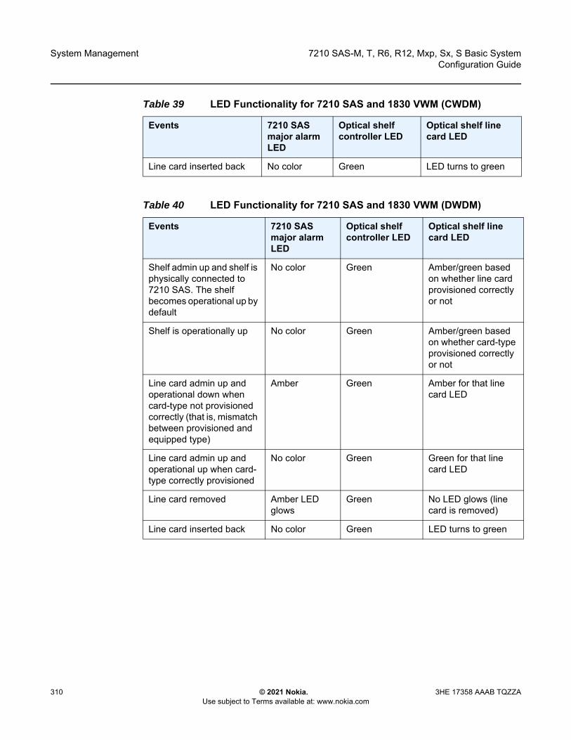
System Management
310
7210 SAS-M, T, R6, R12, Mxp, Sx, S Basic SystemConfiguration Guide
© 2021 Nokia. Use subject to Terms available at: www.nokia.com
3HE 17358 AAAB TQZZA
Line card inserted back No color Green LED turns to green
Table 40 LED Functionality for 7210 SAS and 1830 VWM (DWDM)
Events 7210 SAS major alarm LED
Optical shelf controller LED
Optical shelf line card LED
Shelf admin up and shelf is physically connected to 7210 SAS. The shelf becomes operational up by default
No color Green Amber/green based on whether line card provisioned correctly or not
Shelf is operationally up No color Green Amber/green based on whether card-type provisioned correctly or not
Line card admin up and operational down when card-type not provisioned correctly (that is, mismatch between provisioned and equipped type)
Amber Green Amber for that line card LED
Line card admin up and operational up when card-type correctly provisioned
No color Green Green for that line card LED
Line card removed Amber LED glows
Green No LED glows (line card is removed)
Line card inserted back No color Green LED turns to green
Table 39 LED Functionality for 7210 SAS and 1830 VWM (CWDM)
Events 7210 SAS major alarm LED
Optical shelf controller LED
Optical shelf line card LED
7210 SAS-M, T, R6, R12, Mxp, Sx, S Basic System Configuration Guide
System Management
3HE 17358 AAAB TQZZA © 2021 Nokia. Use subject to Terms available at: www.nokia.com
311
6.7 Link Layer Discovery Protocol (LLDP)
The IEEE 802.1ab Link Layer Discovery Protocol (LLDP) is a unidirectional protocol that uses the MAC layer to transmit specific information about the capabilities and status of the local device. The LLDP can send as well as receive information from a remote device stored in the related MIB (or MIBs).
The LLDP does not contain a mechanism to solicit information received from other LLDP agents or to confirm the receipt of information. However, LLDP provides the flexibility to enable a transmitter and receiver separately, and the following LLDP agent configurations are allowed:
• only transmit information• only receive information• transmit and receive information
The information fields in each LLDP frame are contained in an LLDP Data Unit (LLDPDU) as a sequence of variable length information elements. Each information element includes Type, Length, and Value fields (TLVs).
• Type indicates the nature of information being transmitted.• Length indicates the length of the information string in octets.• Value is the actual information that is transmitted. (For example, a binary bit map
or an alphanumeric string that can contain one or more fields).
Each LLDPDU contains four mandatory TLVs and optional TLVs selected by the Network Management. The following is the format of an LLDPDU:
• Chassis ID TLV• Port ID TLV• Time To Live (TTL) TLV• zero or more optional TLVs, depending on the maximum size of the LLDPDU
allowed• End of LLDPDU TLV
A concatenated string formed by the Chassis ID TLV and the Port ID TLV is used by a recipient to identify an LLDP port or agent. The combination of the Port ID and Chassis ID TLVs remains unchanged until the port or agent is operational.
System Management
312
7210 SAS-M, T, R6, R12, Mxp, Sx, S Basic SystemConfiguration Guide
© 2021 Nokia. Use subject to Terms available at: www.nokia.com
3HE 17358 AAAB TQZZA
The TTL field of a Time-To-Live TLV can be a zero or non-zero value. A zero TTL field value notifies the receiving LLDP agent to immediately discard all information related to sending LLDP agent. A non-zero TTL field value indicates the time duration for which the receiving LLDP agent should retain the information of the sending LLDP agent. The receiving LLDP agent discards all information related to the sending LLDP agent after the time interval indicated in the TTL field is complete.
The End Of LLDPDU TLV indicates the end of the LLDPDU.
The following information is included in the protocol as defined by the IEEE 802.1ab standard.
• Connectivity and management information about the local station to adjacent stations on the same IEEE 802 LAN is advertised.
• Network management information from adjacent stations on the same IEEE 802 LAN is received.
• It operates with all IEEE 802 access protocols and network media.• Network management information schema and object definitions suitable for
storing connection information about adjacent stations is established.• It supports compatibility with a number of MIBs.
6.8 System Resource Allocation
This section describes system resource allocation including the allocation of TCAM resources, configuration guidelines and examples.
6.8.1 Allocation of Ingress Internal TCAM Resources
In previous releases, the system statically allocated ingress TCAM resources for use by SAP ingress QoS classification, SAP ingress access control list (ACLs), identifying and sending CFM OAM packets to CPU for local processing, and so on. The resource allocation is not user-configurable. With the introduction of new capabilities including IPv6 classification, UP MEP support, and G8032-fast-flood, the static allocation of resources by software does not meet requirements of customers who typically want to use different features.
Note: A TTL zero value is used to signal that the sending LLDP port has initiated a port shutdown procedure.

7210 SAS-M, T, R6, R12, Mxp, Sx, S Basic System Configuration Guide
System Management
3HE 17358 AAAB TQZZA © 2021 Nokia. Use subject to Terms available at: www.nokia.com
313
The user can allocate a fixed amount of resources per system (or per card on 7210 SAS-R6 and 7210 SAS-R12 devices) for QoS, ACLs, CFM/Y.1731 MEPs and other features. Of these, some parameters are boot-time parameters and others are run-time. A change in the current value of a boot-time parameter needs a node reboot or, on 7210 SAS-R6 and 7210 SAS-R12 devices, a card reset using the reset command, before the new value takes effect. Change in the current value of a parameter that is designated run-time takes effect immediately if the software determines that resources are available for use to accommodate the change.
On the 7210 SAS-M, 7210 SAS-T, 7210 SAS-Sx/S 1/10GE, 7210 SAS-Sx 10/100GE, and 7210 SAS-Mxp, the system resource profile parameters are available using the config>system>resource-profile CLI context and the defined parameters are applicable to the entire node. On the 7210 SAS-R6 and 7210 SAS-R12, the parameters are defined as a system resource profile policy that the user must configure and associate with the IMM. The software reads the configured policy and allocates resources appropriately per IMM, allowing users to allocate resources to different features per IMM. On the 7210 SAS-R6 and 7210 SAS-R12, some system resource profile parameters apply to the entire node and not just the IMM. For more information, see System Resource-Profile Router Commands for 7210 SAS-M, 7210 SAS-T, 7210 SAS-Mxp, 7210 SAS-Sx 1/10GE, and 7210 SAS-Sx 10/100GE.
During bootup, the system reads the resource profile parameters and allocates resources to features in the order they appear in the configuration file.
Because resources are shared, the user must ensure that the sum total of such resources does not exceed the limit supported by the IMM or node. If the system determines that it cannot allocate the requested resources, the feature is disabled. For example, if the system determines that it cannot allocate resources for g8032-fast-flood, it disables the feature from use and G8032 eth-rings will not be able to use fast-flood mechanisms). Another example is the case where the system determines that it cannot allocate resources for IPv4-based SAP Ingress ACL classification, the system will not allow users to use IPv4-based SAP ingress ACL classification feature and fails the configuration when it comes upon the first SAP in the configuration file that uses an IPv4-based SAP ingress ACL policy.
For boot-time parameters, such as g8032-fast-flood-enable, the user must ensure that the configured services match the resources allocated. If the system determines that it cannot allocate resources to services, it fails the configuration file at the first instance where it encounters a command to which resources cannot be allocated. The available resources can be allocated to different features.
Note: The order in which the command appears in the configuration file is important.

System Management
314
7210 SAS-M, T, R6, R12, Mxp, Sx, S Basic SystemConfiguration Guide
© 2021 Nokia. Use subject to Terms available at: www.nokia.com
3HE 17358 AAAB TQZZA
For ACL and QoS resources, the user has the option to allocate resources to limit usage per feature, regardless of the match criteria used. The sum of all resources used for different SAP ingress classification match-criteria is limited by the amount of resources allocated for SAP ingress classification. The user can also allocate resources by specific match criteria. The user can enable any supported match criteria and associate a fixed amount of resources with each match criteria in fixed sizes; the chunk size is dependent on the platform.
The system allocates resources based on the order of appearance in the configuration file, and fails any match criteria if the system does not have any more resources to allocate. In addition, the max keyword can be used to indicate that the system needs to allocate resources when they are first required, as long as the maximum amount of resources allocated for that feature is not exceeded or the maximum amount of resources available in the system is not exceeded. The 7210 SAS platforms allocate resources to each feature and match-criteria in fixed-size chunks.
The no form of the resource-profile command disables the use of the corresponding match criteria or feature by deallocating all the resources allocated to the criteria or feature. For example:
1. Configuring the system resource-profile internal-ingress-tcam qos-sap-ingress-resource no mac-match-enable command deallocates all the resources allocated to SAP ingress QoS classification MAC match criteria. After this command is run, users cannot associate a SAP ingress policy with MAC match criteria defined to a SAP. Resources allocated to other criteria are unaffected and can continue to be used.
2. Configuring the system resource-profile internal-ingress-tcam eth-cfm no up-mep command deallocates all the resources allocated to CFM UP MEP. After this command is run, user cannot configure UP MEP.
If the system successfully runs the no command, it frees up resources used by the chunk or slice and make the resources, or the entire chunk/slice, available for use by other features. Before deallocating resources, the software checks if a service object is using the resource and fails the command if the object is in use. If resources are in use, they can be freed up by deleting a SAP, removing a policy association with a SAP, deleting a MEP, and so on. Some commands under the system resource-profile context do not take effect immediately and require a system reboot before the change occurs and resources are freed. The following is the handling of freed resources.
• If some entries in a slice are freed, they are made available for use by other SAPs using the same feature to which the chunk is allocated.
• If an entire chunk is freed, it is returned to the system free pool for possible use by other features.

7210 SAS-M, T, R6, R12, Mxp, Sx, S Basic System Configuration Guide
System Management
3HE 17358 AAAB TQZZA © 2021 Nokia. Use subject to Terms available at: www.nokia.com
315
For more information about specific CLI commands and features that use system resource allocation, refer to the CLI command and feature descriptions in the appropriate 7210 SAS software user manual.
6.8.2 Allocation of Egress Internal TCAM Resources
Before the introduction of new capabilities, such as IPv6 match criteria, the system allocated egress TCAM resources on bootup for use by different criteria in SAP egress access control lists (ACLs) and other purposes; the resource allocation was not user configurable. With the introduction of new capabilities, such as IPv6 match criteria in egress, the static allocation of resources by software may not meet customer requirements if they want to use different features. Therefore, to facilitate user configuration and resource allocation in accordance with user needs, the ingress internal TCAM resource allocation capabilities have been extended to include the egress internal TCAM resources.
For information about specific CLI commands and features that use system resource allocation, refer to the CLI command and feature descriptions in the appropriate 7210 SAS software user manuals.
6.8.3 System Resource Allocation Examples
This section provides system resource allocation examples.
Example 1:
config> system> resource-profile......
acl-sap-ingress 3mac-match-enable maxipv4-match-enable 1no ipv6_128-ipv4-match-enableno ipv6_64-only-match-enable
exit...
In the preceding CLI example, the system performs the following actions.
• 3 chunks are allocated for use by the SAP ingress ACL entries.
Note: The commands in the config>system>resource-profile context, which require a reboot to take effect, are read and implemented by the system only during bootup. These commands do not take effect if the exec command is used to run the configuration file.

System Management
316
7210 SAS-M, T, R6, R12, Mxp, Sx, S Basic SystemConfiguration Guide
© 2021 Nokia. Use subject to Terms available at: www.nokia.com
3HE 17358 AAAB TQZZA
• 1 chunk is allocated for use by SAP ingress ACL entries that use ipv4-criteria. The system fails the configuration when the number of ACL entries that use ipv4-criteria exceeds the configured limit (that is, the system does not allocate in excess of the configured limit of 1 chunk).
• A chunk is allocated for use by SAP ingress ACL entries that use mac-criteria. After the max keyword is specified, the system allocates 1 chunk for use when an ingress ACL policy (with mac-criteria entries defined) is associated with a SAP. The system can allocate up to 2 chunks because the max keyword is used. More chunks are allocated when the user configures a SAP that uses mac-criteria and all entries in the allocated chunks are used up. The system fails the configuration if the number of ACL entries with mac-criteria exceeds the limit of 2 chunks allocated to SAP ingress ACL match (that is, the system does not allocate in excess of the configured limit of 3 chunks; up to 2 chunks of the configured 3 chunk limit are allocated to mac-criteria and 1 chunk is allocated to ipv4-criteria).
• The system fails a user attempt to use SAP ingress ACLs with IPv6 match criteria (and other combinations listed in the preceding list items), because the user has disabled these criteria.
Example 2:
config> system> resource-profile>...
acl-sap-ingress 3mac-match-enable maxipv4-match-enable 1no ipv6_128-ipv4-match-enableipv6_64-only-match-enable max
exit...
In the preceding CLI example, the system performs the following actions.
• 3 chunks are allocated for use by the SAP ingress ACL entries. These resources are available for use with mac-criteria, ipv4-criteria and ipv6-64-bit match criteria.
• 1 chunk is allocated for use by SAP ingress ACL entries that use ipv4-criteria. The system fails the configuration if the number of ACL entries using ipv4-criteria exceeds the configured limit (that is, the system does not allocate more than the configured limit of 1 chunk).
• 1 chunk is allocated for use by SAP ingress ACL entries that use mac-criteria when the user associates an ingress ACL policy (with mac-criteria entries defined) with a SAP. Because the max keyword is used, the system can allocate more chunks, if a chunk is available for use.
7210 SAS-M, T, R6, R12, Mxp, Sx, S Basic System Configuration Guide
System Management
3HE 17358 AAAB TQZZA © 2021 Nokia. Use subject to Terms available at: www.nokia.com
317
In this example, (assuming a SAP with an ingress ACL policy that uses ipv6-64-bit criteria is configured), as no additional chunks are available, mac-criteria cannot allocate more than 1 chunk (even if the max keyword is specified). The system fails the configuration if the number of ACL entries with mac-criteria exceeds the limit of 1 chunk allocated to SAP ingress ACL mac-criteria (that is, the system does not allocate more than the configured limit of 3 chunks = 1 for mac-criteria + for ipv4-criteria + 1 for ipv6-criteria).
• A chunk is allocated for use by SAP ingress ACL entries that use ipv6-64-bit criteria when the user associates an ingress ACL policy (with ipv6-64-bit-criteria entries defined) with a SAP. Because the max keyword is specified, the system can allocate more chunks, if a chunk is available for use.In this example, as there are no more chunks available, ipv6-64-bit criteria cannot allocate more than 1 chunk (even if the max keyword is specified). The system fails the configuration when the number of ACL entries with ipv6-64-bit criteria exceeds the limit of one chunk allocated to SAP ingress ACL match (that is, the system does not allocate more than the configured limit of 3 chunks = 1 for mac-criteria + 1 for ipv4-criteria + 1 for ipv6-64-bit criteria).
• The system fails any attempt to use SAP ingress ACLs with ipv6-128 bit match criteria (and the other combinations listed above), because the user has disabled these criteria.
In Example 2, the user can run no ipv4-match-enable command to disable the use of ipv4-criteria. The system checks for SAPs that use ipv4-criteria and if found, fails the command; otherwise, the chunk freed for use with either mac-criteria or ipv6-64-bit criteria. The entire chunk is allocated to mac-criteria if the first SAP that needs resources requests for mac-criteria and no entries in the chunk are already allocated to mac-criteria, which leaves no resources for use by ipv6-64-bit criteria. In the same way, the entire chunk is allocated to ipv6-64-bit criteria, if the first SAP that needs resources requests for ipv6-64-bit criteria and no entries in the chunk are already allocated to ipv6-64-bit criteria, which leaves no resources for use by mac-criteria.
6.8.4 7210 SAS-R6 and 7210 SAS-R12 Configuration Guidelines for System Resource Profile
The following configuration guidelines apply to 7210 SAS-R6 and 7210 SAS-R12.
• The user can change the system-resource policy attached to a card/IMM in the following cases:- when the card/IMM state is unprovisioned- when the card/IMM is provisioned but not equipped
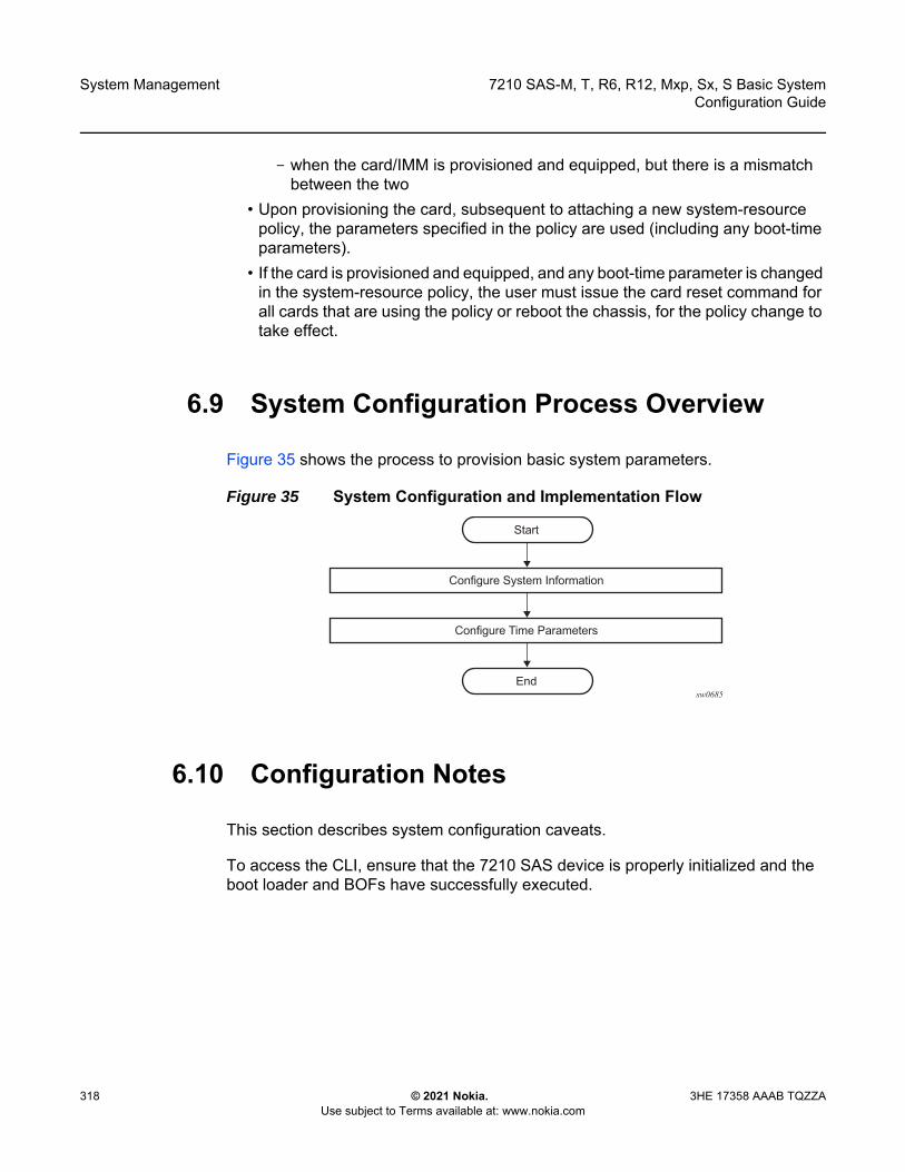
System Management
318
7210 SAS-M, T, R6, R12, Mxp, Sx, S Basic SystemConfiguration Guide
© 2021 Nokia. Use subject to Terms available at: www.nokia.com
3HE 17358 AAAB TQZZA
- when the card/IMM is provisioned and equipped, but there is a mismatch between the two
• Upon provisioning the card, subsequent to attaching a new system-resource policy, the parameters specified in the policy are used (including any boot-time parameters).
• If the card is provisioned and equipped, and any boot-time parameter is changed in the system-resource policy, the user must issue the card reset command for all cards that are using the policy or reboot the chassis, for the policy change to take effect.
6.9 System Configuration Process Overview
Figure 35 shows the process to provision basic system parameters.
Figure 35 System Configuration and Implementation Flow
6.10 Configuration Notes
This section describes system configuration caveats.
To access the CLI, ensure that the 7210 SAS device is properly initialized and the boot loader and BOFs have successfully executed.
sw0685
Start
Configure Time Parameters
Configure System Information
End
7210 SAS-M, T, R6, R12, Mxp, Sx, S Basic System Configuration Guide
System Management
3HE 17358 AAAB TQZZA © 2021 Nokia. Use subject to Terms available at: www.nokia.com
319
6.11 Configuring System Management with CLI
This section provides information about configuring system management features with CLI.
6.11.1 Saving Configurations
Whenever configuration changes are made, the modified configuration must be saved so the changes are not lost when the system is rebooted. The system uses the configuration and image files, as well as other operational parameters necessary for system initialization, according to the locations specified in the boot option file (BOF) parameters. See Boot Options for more information about boot option files.
Configuration files are saved by executing implicit or explicit command syntax.
• An explicit save writes the configuration to the location specified in the save command syntax using the file-url option.
• An implicit save writes the configuration to the file specified in the primary configuration location.If the file-url option is not specified in the save command syntax, the system attempts to save the current configuration to the current BOF primary configuration source. If the primary configuration source (path and/or filename) has changed since the last boot, the new configuration source is used.
Use the detail option of the save command to save both default and non-default configuration parameters.
The index option ensures that the system preserves system indexes when a save command is executed, regardless of the persistent status in the BOF. During a subsequent boot, the index file is read along with the configuration file. As a result, a number of system indexes are preserved between reboots, including the interface index, LSP IDs, and path IDs. This reduces resynchronizations of the Network Management System (NMS) with the affected network element.
If the save attempt fails at the destination, an error occurs and is logged. The system does not try to save the file to the secondary or tertiary configuration sources unless the path and filename are explicitly named with the save command.

System Management
320
7210 SAS-M, T, R6, R12, Mxp, Sx, S Basic SystemConfiguration Guide
© 2021 Nokia. Use subject to Terms available at: www.nokia.com
3HE 17358 AAAB TQZZA
6.11.2 Basic System Configuration
This section provides information to configure system parameters and provides configuration examples of common configuration tasks. The minimal system parameters that should be configured are:
• System Information Parameters• Coordinates• System Time Elements
The following example displays a basic system configuration.
A:ALA-12>config>system# info#------------------------------------------
name "ALA-12"coordinates "Unknown"snmpsecurity
snmpcommunity "private" rwa version both
exitexittime
ntpserver 192.168.15.221no shutdown
exitsntp
shutdownexitzone GMT
exit----------------------------------------------A:ALA-12>config>system#
6.11.3 Common Configuration Tasks
This section provides an overview of the following tasks that must be performed to configure system parameters, and describes the associated CLI commands.
• System Information• Coordinates• System Time Elements• System Administration Parameters
7210 SAS-M, T, R6, R12, Mxp, Sx, S Basic System Configuration Guide
System Management
3HE 17358 AAAB TQZZA © 2021 Nokia. Use subject to Terms available at: www.nokia.com
321
6.11.3.1 System Information
This section describes the basic system information parameters to configure the physical location of the router, contact information, location information for the router such as an address, floor, and room number, global positioning system (GPS) coordinates, and system name.
Use the CLI syntax displayed in this section to configure the following system components:
• System Information Parameters• System Time Elements
6.11.3.1.1 System Information Parameters
This section describes the system information parameters.
General system parameters include:
• Name• Contact• Location• CLLI Code• Coordinates
Name
Use the system name command to configure a name for the device. The name is used in the prompt string. Only one system name can be configured. If multiple system names are configured, the last one encountered overwrites the previous entry.
Use the following CLI syntax to configure the system name.
CLI Syntax: config>systemname <system-name>
Example: config>system# name ALA-12
The following is a sample configuration for the system name command.
sysName@domain>config>system# info
System Management
322
7210 SAS-M, T, R6, R12, Mxp, Sx, S Basic SystemConfiguration Guide
© 2021 Nokia. Use subject to Terms available at: www.nokia.com
3HE 17358 AAAB TQZZA
#------------------------------------------echo "System Configuration "#------------------------------------------
name "ALA-12". . .
exit----------------------------------------------
sysName@domain>config>system#
Contact
Use the contact command to specify the name of a system administrator, IT staff member, or other administrative entity.
Use the following syntax to specify the contact name.
CLI Syntax: config>systemcontact <contact-name>
The following example shows the command usage to specify the contact name.
Example: config>system# contact “Fred Information Technology”
Location
Use the location command to specify the system location of the device. For example, enter the city, building address, floor, and room number where the router is located.
Use the following CLI syntax to configure the location.
CLI Syntax: config>systemlocation <location>
The following example shows the command usage to configure the location of the device.
Example: config>system# location “Bldg.1-floor 2-Room 201”
CLLI Code
The Common Language Location Code (CLLI code) is an 11-character standardized geographic identifier that is used to uniquely identify the geographic location of a router.

7210 SAS-M, T, R6, R12, Mxp, Sx, S Basic System Configuration Guide
System Management
3HE 17358 AAAB TQZZA © 2021 Nokia. Use subject to Terms available at: www.nokia.com
323
Use the following CLI command syntax to define the CLLI code.
CLI Syntax: config>systemclli-code <clli-code>
The following example shows the command usage to define the CLLI code.
Example: config>system# clli-code abcdefg1234
6.11.3.1.2 Coordinates
Use the optional coordinates command to specify the GPS location of the device. If the string contains special characters (#, $, spaces, etc.), the entire string must be enclosed within double quotes.
Use the following CLI syntax to configure the location.
CLI Syntax: config>systemcoordinates coordinates
The following example shows the command usage to configure the location.
Example: config>system# coordinates "N 45 58 23, W 34 56 12"
The following is a sample configuration output of the general system commands.
sysName@domain>config>system# info#------------------------------------------echo "System Configuration "#------------------------------------------name "ALA-12"
contact "Fred Information Technology"location "Bldg.1-floor 2-Room 201"clli-code "abcdefg1234"coordinates "N 45 58 23, W 34 56 12"
. . .exit
----------------------------------------------A:ALA-12>config>system#
6.11.3.1.3 System Time Elements
The system clock maintains time according to Coordinated Universal Time (UTC). Configure information time zone and summer time (daylight savings time) parameters to correctly display time according to the local time zone.
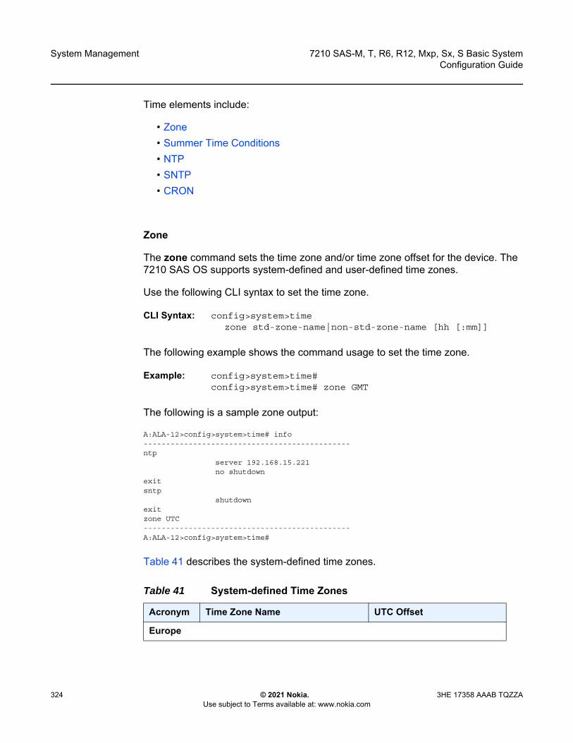
System Management
324
7210 SAS-M, T, R6, R12, Mxp, Sx, S Basic SystemConfiguration Guide
© 2021 Nokia. Use subject to Terms available at: www.nokia.com
3HE 17358 AAAB TQZZA
Time elements include:
• Zone• Summer Time Conditions• NTP• SNTP• CRON
Zone
The zone command sets the time zone and/or time zone offset for the device. The 7210 SAS OS supports system-defined and user-defined time zones.
Use the following CLI syntax to set the time zone.
CLI Syntax: config>system>timezone std-zone-name|non-std-zone-name [hh [:mm]]
The following example shows the command usage to set the time zone.
Example: config>system>time#config>system>time# zone GMT
The following is a sample zone output:
A:ALA-12>config>system>time# info----------------------------------------------ntp
server 192.168.15.221no shutdown
exitsntp
shutdownexitzone UTC----------------------------------------------A:ALA-12>config>system>time#
Table 41 describes the system-defined time zones.
Table 41 System-defined Time Zones
Acronym Time Zone Name UTC Offset
Europe

7210 SAS-M, T, R6, R12, Mxp, Sx, S Basic System Configuration Guide
System Management
3HE 17358 AAAB TQZZA © 2021 Nokia. Use subject to Terms available at: www.nokia.com
325
GMT Greenwich Mean Time UTC
WET Western Europe Time UTC
WEST Western Europe Summer Time UTC +1 hour
CET Central Europe Time UTC +1 hour
CEST Central Europe Summer Time UTC +2 hours
EET Eastern Europe Time UTC +2 hours
EEST Eastern Europe Summer Time UTC +3 hours
MSK Moscow Time UTC +3 hours
MSD Moscow Summer Time UTC +4 hours
US and Canada
AST Atlantic Standard Time UTC -4 hours
ADT Atlantic Daylight Time UTC -3 hours
EST Eastern Standard Time UTC -5 hours
EDT Eastern Daylight Saving Time UTC -4 hours
CST Central Standard Time UTC -6 hours
CDT Central Daylight Saving Time UTC -5 hours
MST Mountain Standard Time UTC -7 hours
MDT Mountain Daylight Saving Time UTC -6 hours
PST Pacific Standard Time UTC -8 hours
PDT Pacific Daylight Saving Time UTC -7 hours
HST Hawaiian Standard Time UTC -10 hours
AKST Alaska Standard Time UTC -9 hours
AKDT Alaska Standard Daylight Saving Time UTC -8 hours
Australia and New Zealand
AWST Western Standard Time (e.g., Perth) UTC +8 hours
ACST Central Standard Time (e.g., Darwin) UTC +9.5 hours
AEST Eastern Standard/Summer Time (e.g., Canberra)
UTC +10 hours
Table 41 System-defined Time Zones (Continued)
Acronym Time Zone Name UTC Offset

System Management
326
7210 SAS-M, T, R6, R12, Mxp, Sx, S Basic SystemConfiguration Guide
© 2021 Nokia. Use subject to Terms available at: www.nokia.com
3HE 17358 AAAB TQZZA
Summer Time Conditions
The config>system>time>dst-zone context configures the start and end dates and offset for summer time or daylight savings time to override system defaults or for user-defined time zones.
When configured, the time is adjusted by adding the configured offset when summer time starts and subtracting the configured offset when summer time ends.
Use the following CLI syntax to configure daylight savings time.
CLI Syntax: config>system>timedst-zone zone-name
end {end-week} {end-day} {end-month} [hours-minutes]
offset offsetstart {start-week} {start-day} {start-month}
[hours-minutes]
The following example shows the command usage to configure daylight savings time.
Example: config>system# timeconfig>system>time# dst-zone ptconfig>system>time>dst-zone# start second sunday april 02:00end first sunday october 02:00config>system>time>dst-zone# offset 0
If the time zone configured is listed in Table 41, the starting and ending parameters and offset do not need to be configured with this command unless there is a need to override the system defaults. The command will return an error if the start and ending dates and times are not available either in Table 41 or entered as optional parameters in this command.
The following is a sample output for the configured parameters.
A:ALA-48>config>system>time>dst-zone# info----------------------------------------------
NZT New Zealand Standard Time UTC +12 hours
NZDT New Zealand Daylight Saving Time UTC +13 hours
Table 41 System-defined Time Zones (Continued)
Acronym Time Zone Name UTC Offset

7210 SAS-M, T, R6, R12, Mxp, Sx, S Basic System Configuration Guide
System Management
3HE 17358 AAAB TQZZA © 2021 Nokia. Use subject to Terms available at: www.nokia.com
327
start second sunday april 02:00end first sunday october 02:00offset 0
----------------------------------------------A:ALA-48>config>system>time>dst-zone# offset 0
NTP
Network Time Protocol (NTP) is defined in RFC 1305, Network Time Protocol (Version 3) Specification, Implementation and Analysis. It enables participating network nodes to keep time more accurately and maintain time in a synchronized manner between all participating network nodes.
NTP time elements include:
• Authentication-check• Authentication-key• Broadcast• Broadcastclient• NTP-Server• Peer• Server
Authentication-check
The authentication-check command provides the option to skip the rejection of NTP PDUs that do not match the authentication key or authentication type requirements. The default behavior when authentication is configured is to reject all NTP PDUs that have a mismatch in either the authentication key-id, type, or key.
When authentication-check is configured, NTP PDUs are authenticated on receipt. However, mismatches cause a counter to be incremented, one counter for key-id, one for type, and one for key value mismatches.
Use the following CLI syntax to authenticate NTP PDUs on receipt.
CLI Syntax: config>system>time>ntpauthentication-check
The following example shows the command usage to authenticate NTP PDUs on receipt.
System Management
328
7210 SAS-M, T, R6, R12, Mxp, Sx, S Basic SystemConfiguration Guide
© 2021 Nokia. Use subject to Terms available at: www.nokia.com
3HE 17358 AAAB TQZZA
Example: config>system>time>ntp# config>system>time>ntp# authentication-checkconfig>system>time>ntp# no shutdown
Authentication-key
This command configures an authentication key ID, key type, and key used to authenticate NTP PDUs sent to and received from other network elements participating in the NTP protocol. For authentication to work, the authentication key ID, authentication type and authentication key value must match.
Use the following CLI syntax to configure an authentication key ID, key type, and key.
CLI Syntax: config>system>time>ntpauthentication-key key-id {key key} [hash | hash2]
type {des|message-digest}
The following example shows the command usage to configure an authentication key-id, key type, and key.
Example: config>system>time>ntp# config>system>time>ntp# authentication-key 1 key A type desconfig>system>time>ntp# no shutdown
The following sample configuration shows NTP disabled with the authentication-key parameter enabled.
A:sim1>config>system>time>ntp# info----------------------------------------------
shutdownauthentication-key 1 key "OAwgNUlbzgI" hash2 type des
----------------------------------------------A:sim1>config>system>time>ntp#
Broadcast
The broadcast command is used to transmit broadcast packets on a specific subnet.
Use the following CLI syntax to transmit broadcast packets.
CLI Syntax: config>system>time>ntpbroadcast [router router-name]{interface
ip-int-name}[key-id key-id] [version version][ttl ttl]

7210 SAS-M, T, R6, R12, Mxp, Sx, S Basic System Configuration Guide
System Management
3HE 17358 AAAB TQZZA © 2021 Nokia. Use subject to Terms available at: www.nokia.com
329
The following example shows the command usage to transmit broadcast packets.
Example: config>system>time>ntp# config>system>time>ntp# broadcast interface int11 version 4 ttl 127config>system>time>ntp# no shutdown
The following sample configuration of the system>time context shows NTP enabled with the broadcast command configured.
A:sim1>config>system>time# info detail----------------------------------------------
ntpno shutdownauthentication-checkntp-serverbroadcast interface int11 version 4 ttl 127
exitA:sim1>config>system>time#
The following sample configuration shows NTP enabled in the config context with the broadcast command configured. At this level, the NTP broadcast commands are displayed at the end of the output after the router interfaces are shown.
A:sim1>config info
....
#--------------------------------------------------echo "System Time NTP Configuration"#--------------------------------------------------
systemtime
ntpbroadcast interface toboth
exitexit
exitA:sim1>config
Broadcastclient
The broadcastclient command enables listening to NTP broadcast messages on the specified interface.
Use the following CLI syntax to enable listening to NTP broadcast messages.
CLI Syntax: config>system>time>ntp
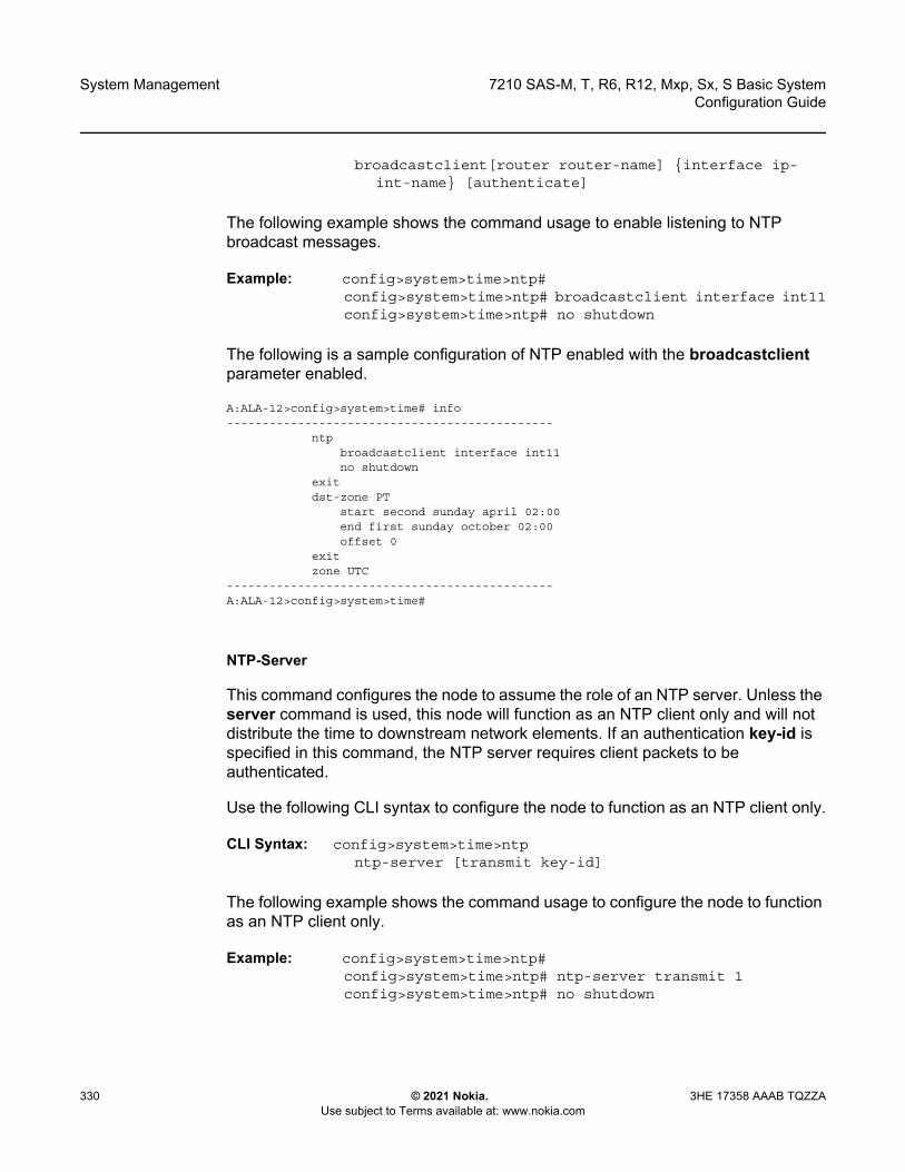
System Management
330
7210 SAS-M, T, R6, R12, Mxp, Sx, S Basic SystemConfiguration Guide
© 2021 Nokia. Use subject to Terms available at: www.nokia.com
3HE 17358 AAAB TQZZA
broadcastclient[router router-name] {interface ip-int-name} [authenticate]
The following example shows the command usage to enable listening to NTP broadcast messages.
Example: config>system>time>ntp# config>system>time>ntp# broadcastclient interface int11config>system>time>ntp# no shutdown
The following is a sample configuration of NTP enabled with the broadcastclient parameter enabled.
A:ALA-12>config>system>time# info----------------------------------------------
ntpbroadcastclient interface int11no shutdown
exitdst-zone PT
start second sunday april 02:00end first sunday october 02:00offset 0
exitzone UTC
----------------------------------------------A:ALA-12>config>system>time#
NTP-Server
This command configures the node to assume the role of an NTP server. Unless the server command is used, this node will function as an NTP client only and will not distribute the time to downstream network elements. If an authentication key-id is specified in this command, the NTP server requires client packets to be authenticated.
Use the following CLI syntax to configure the node to function as an NTP client only.
CLI Syntax: config>system>time>ntpntp-server [transmit key-id]
The following example shows the command usage to configure the node to function as an NTP client only.
Example: config>system>time>ntp# config>system>time>ntp# ntp-server transmit 1config>system>time>ntp# no shutdown
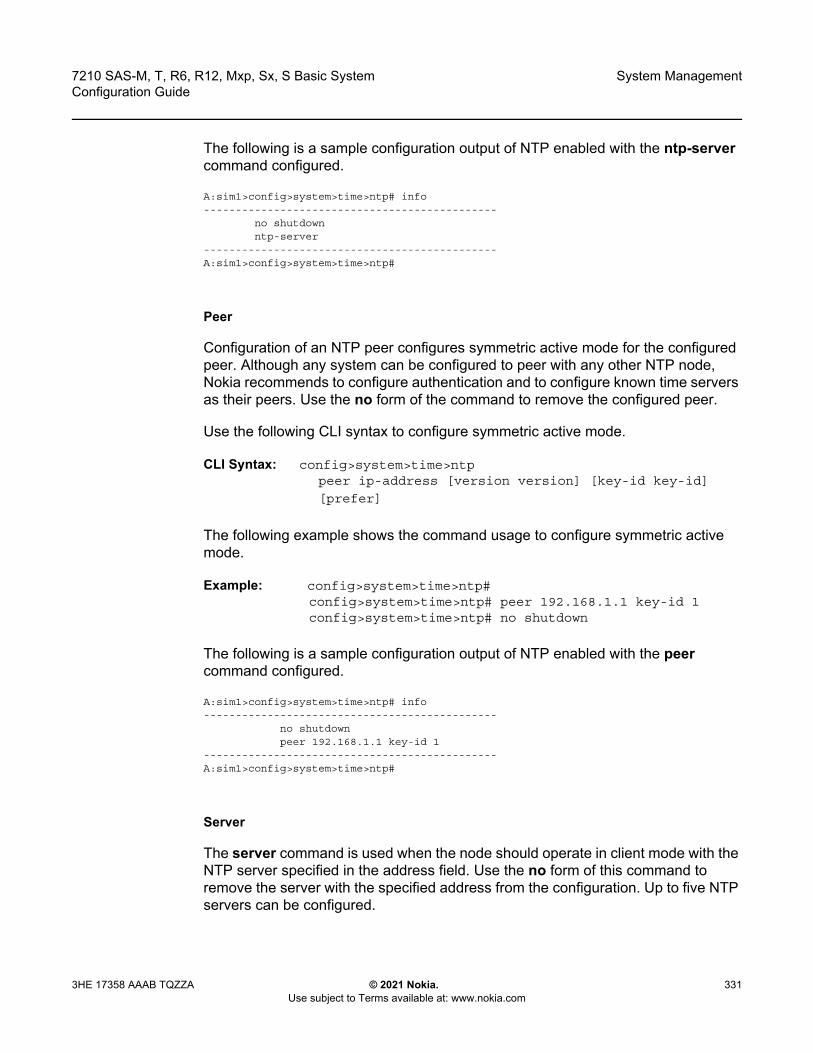
7210 SAS-M, T, R6, R12, Mxp, Sx, S Basic System Configuration Guide
System Management
3HE 17358 AAAB TQZZA © 2021 Nokia. Use subject to Terms available at: www.nokia.com
331
The following is a sample configuration output of NTP enabled with the ntp-server command configured.
A:sim1>config>system>time>ntp# info----------------------------------------------
no shutdownntp-server
----------------------------------------------A:sim1>config>system>time>ntp#
Peer
Configuration of an NTP peer configures symmetric active mode for the configured peer. Although any system can be configured to peer with any other NTP node, Nokia recommends to configure authentication and to configure known time servers as their peers. Use the no form of the command to remove the configured peer.
Use the following CLI syntax to configure symmetric active mode.
CLI Syntax: config>system>time>ntppeer ip-address [version version] [key-id key-id]
[prefer]
The following example shows the command usage to configure symmetric active mode.
Example: config>system>time>ntp# config>system>time>ntp# peer 192.168.1.1 key-id 1config>system>time>ntp# no shutdown
The following is a sample configuration output of NTP enabled with the peer command configured.
A:sim1>config>system>time>ntp# info----------------------------------------------
no shutdownpeer 192.168.1.1 key-id 1
----------------------------------------------A:sim1>config>system>time>ntp#
Server
The server command is used when the node should operate in client mode with the NTP server specified in the address field. Use the no form of this command to remove the server with the specified address from the configuration. Up to five NTP servers can be configured.

System Management
332
7210 SAS-M, T, R6, R12, Mxp, Sx, S Basic SystemConfiguration Guide
© 2021 Nokia. Use subject to Terms available at: www.nokia.com
3HE 17358 AAAB TQZZA
Use the following CLI syntax to configure the node to operate in client mode.
CLI Syntax: config>system>time>ntpserver {ip-address |ptp}[key-id key-id] [version
version] [prefer]
The following example shows the command usage to configure the node to operate in client mode.
Example: config>system>time>ntp# config>system>time>ntp# server 192.168.1.1 key-id 1config>system>time>ntp# no shutdown
The following is a sample configuration of NTP enabled with the server command configured.
A:7210SAS>config>system>time>ntp# info----------------------------------------------
ntp-serverserver ptp preferbroadcast interface "a1"no shutdown
----------------------------------------------A:7210SAS>config>system>time>ntp#
SNTP
SNTP is a compact, client-only version of the NTP. SNTP can only receive the time from SNTP/NTP servers; it cannot be used to provide time services to other systems. SNTP can be configured in either broadcast or unicast client mode.
SNTP time elements include:
• Broadcast-client• Server-address
Use the following CLI syntax to configure the SNTP.
CLI Syntax: config>systemtimesntp
broadcast-client server-address ip-address [version version-number]
[normal|preferred] [interval seconds]no shutdown

7210 SAS-M, T, R6, R12, Mxp, Sx, S Basic System Configuration Guide
System Management
3HE 17358 AAAB TQZZA © 2021 Nokia. Use subject to Terms available at: www.nokia.com
333
Broadcast-client
The broadcast-client command enables listening at the global device level to SNTP broadcast messages on interfaces with broadcast client enabled.
Use the following CLI syntax to enable listening to SNTP broadcast messages at the global device level.
CLI Syntax: config>system>time>sntp
broadcast-client
The following example shows the command usage to enable listening to SNTP broadcast messages at the global device level.
Example: config>system>time>sntp# config>system>time>sntp# broadcast-client config>system>time>sntp# no shutdown
The following is a sample configuration output of SNTP enabled with the broadcast-client command enabled.
A:ALA-12>config>system>time# info----------------------------------------------
sntpbroadcast-clientno shutdown
exitdst-zone PT
start second sunday april 02:00end first sunday october 02:00offset 0
exitzone GMT
----------------------------------------------A:ALA-12>config>system>time#
Server-address
The server-address command configures an SNTP server for SNTP unicast client mode.
Use the following CLI syntax to configure an SNTP server for unicast client mode.
CLI Syntax: config>system>time>sntp#
config>system>time>sntp# server-address ip-
address version version-number]
[normal|preferred] [interval seconds]
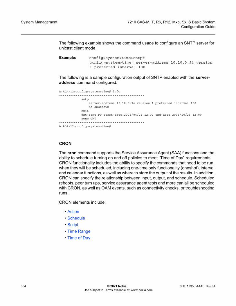
System Management
334
7210 SAS-M, T, R6, R12, Mxp, Sx, S Basic SystemConfiguration Guide
© 2021 Nokia. Use subject to Terms available at: www.nokia.com
3HE 17358 AAAB TQZZA
The following example shows the command usage to configure an SNTP server for unicast client mode.
Example: config>system>time>sntp#config>system>time# server-address 10.10.0.94 version1 preferred interval 100
The following is a sample configuration output of SNTP enabled with the server-address command configured.
A:ALA-12>config>system>time# info----------------------------------------------
sntpserver-address 10.10.0.94 version 1 preferred interval 100no shutdown
exitdst-zone PT start-date 2006/04/04 12:00 end-date 2006/10/25 12:00zone GMT
----------------------------------------------A:ALA-12>config>system>time#
CRON
The cron command supports the Service Assurance Agent (SAA) functions and the ability to schedule turning on and off policies to meet “Time of Day” requirements. CRON functionality includes the ability to specify the commands that need to be run, when they will be scheduled, including one-time only functionality (oneshot), interval and calendar functions, as well as where to store the output of the results. In addition, CRON can specify the relationship between input, output, and schedule. Scheduled reboots, peer turn ups, service assurance agent tests and more can all be scheduled with CRON, as well as OAM events, such as connectivity checks, or troubleshooting runs.
CRON elements include:
• Action• Schedule• Script• Time Range• Time of Day
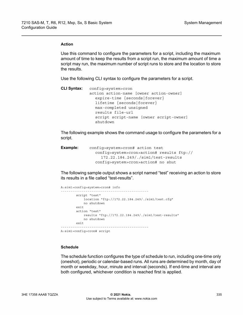
7210 SAS-M, T, R6, R12, Mxp, Sx, S Basic System Configuration Guide
System Management
3HE 17358 AAAB TQZZA © 2021 Nokia. Use subject to Terms available at: www.nokia.com
335
Action
Use this command to configure the parameters for a script, including the maximum amount of time to keep the results from a script run, the maximum amount of time a script may run, the maximum number of script runs to store and the location to store the results.
Use the following CLI syntax to configure the parameters for a script.
CLI Syntax: config>system>cronaction action-name [owner action-owner]
expire-time {seconds|forever}lifetime {seconds|forever}max-completed unsignedresults file-urlscript script-name [owner script-owner]shutdown
The following example shows the command usage to configure the parameters for a script.
Example: config>system>cron# action testconfig>system>cron>action# results ftp://
172.22.184.249/./sim1/test-resultsconfig>system>cron>action# no shut
The following sample output shows a script named “test” receiving an action to store its results in a file called “test-results”.
A:sim1>config>system>cron# info----------------------------------------------
script "test"location "ftp://172.22.184.249/./sim1/test.cfg"no shutdown
exitaction "test"
results "ftp://172.22.184.249/./sim1/test-results"no shutdown
exit----------------------------------------------A:sim1>config>cron# script
Schedule
The schedule function configures the type of schedule to run, including one-time only (oneshot), periodic or calendar-based runs. All runs are determined by month, day of month or weekday, hour, minute and interval (seconds). If end-time and interval are both configured, whichever condition is reached first is applied.
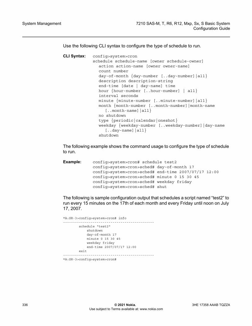
System Management
336
7210 SAS-M, T, R6, R12, Mxp, Sx, S Basic SystemConfiguration Guide
© 2021 Nokia. Use subject to Terms available at: www.nokia.com
3HE 17358 AAAB TQZZA
Use the following CLI syntax to configure the type of schedule to run.
CLI Syntax: config>system>cronschedule schedule-name [owner schedule-owner]
action action-name [owner owner-name] count numberday-of-month {day-number [..day-number]|all}description description-stringend-time [date | day-name] timehour {hour-number [..hour-number] | all}interval seconds minute {minute-number [..minute-number]|all} month {month-number [..month-number]|month-name
[..month-name]|all} no shutdown type {periodic|calendar|oneshot} weekday {weekday-number [..weekday-number]|day-name
[..day-name]|all}shutdown
The following example shows the command usage to configure the type of schedule to run.
Example: config>system>cron# schedule test2config>system>cron>sched# day-of-month 17 config>system>cron>sched# end-time 2007/07/17 12:00config>system>cron>sched# minute 0 15 30 45 config>system>cron>sched# weekday friday config>system>cron>sched# shut
The following is sample configuration output that schedules a script named “test2” to run every 15 minutes on the 17th of each month and every Friday until noon on July 17, 2007.
*A:SR-3>config>system>cron# info----------------------------------------------
schedule "test2"shutdownday-of-month 17minute 0 15 30 45weekday fridayend-time 2007/07/17 12:00
exit----------------------------------------------*A:SR-3>config>system>cron#
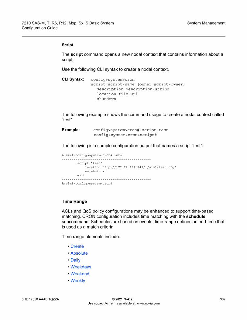
7210 SAS-M, T, R6, R12, Mxp, Sx, S Basic System Configuration Guide
System Management
3HE 17358 AAAB TQZZA © 2021 Nokia. Use subject to Terms available at: www.nokia.com
337
Script
The script command opens a new nodal context that contains information about a script.
Use the following CLI syntax to create a nodal context.
CLI Syntax: config>system>cronscript script-name [owner script-owner]
description description-stringlocation file-url shutdown
The following example shows the command usage to create a nodal context called “test”.
Example: config>system>cron# script testconfig>system>cron>script#
The following is a sample configuration output that names a script “test”:
A:sim1>config>system>cron# info----------------------------------------------
script "test"location "ftp://172.22.184.249/./sim1/test.cfg"no shutdown
exit----------------------------------------------A:sim1>config>system>cron#
Time Range
ACLs and QoS policy configurations may be enhanced to support time-based matching. CRON configuration includes time matching with the schedule subcommand. Schedules are based on events; time-range defines an end-time that is used as a match criteria.
Time range elements include:
• Create• Absolute• Daily• Weekdays• Weekend• Weekly
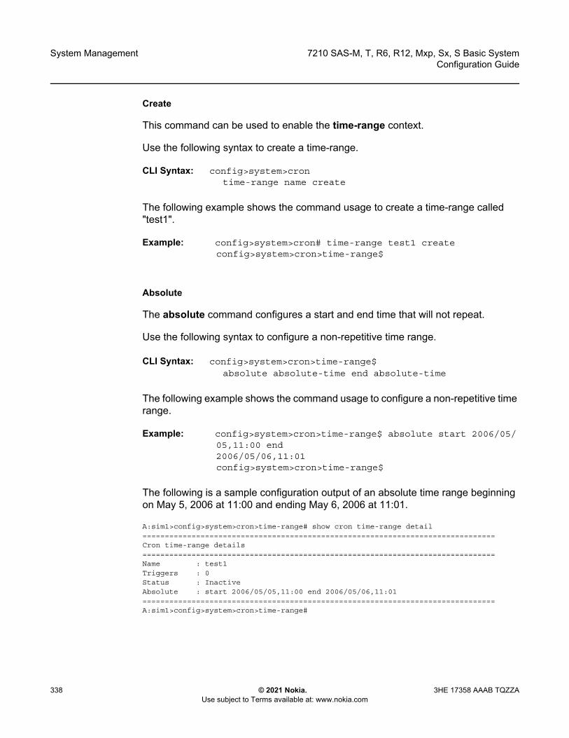
System Management
338
7210 SAS-M, T, R6, R12, Mxp, Sx, S Basic SystemConfiguration Guide
© 2021 Nokia. Use subject to Terms available at: www.nokia.com
3HE 17358 AAAB TQZZA
Create
This command can be used to enable the time-range context.
Use the following syntax to create a time-range.
CLI Syntax: config>system>crontime-range name create
The following example shows the command usage to create a time-range called "test1".
Example: config>system>cron# time-range test1 createconfig>system>cron>time-range$
Absolute
The absolute command configures a start and end time that will not repeat.
Use the following syntax to configure a non-repetitive time range.
CLI Syntax: config>system>cron>time-range$absolute absolute-time end absolute-time
The following example shows the command usage to configure a non-repetitive time range.
Example: config>system>cron>time-range$ absolute start 2006/05/05,11:00 end 2006/05/06,11:01config>system>cron>time-range$
The following is a sample configuration output of an absolute time range beginning on May 5, 2006 at 11:00 and ending May 6, 2006 at 11:01.
A:sim1>config>system>cron>time-range# show cron time-range detail===============================================================================Cron time-range details===============================================================================Name : test1Triggers : 0Status : InactiveAbsolute : start 2006/05/05,11:00 end 2006/05/06,11:01===============================================================================A:sim1>config>system>cron>time-range#
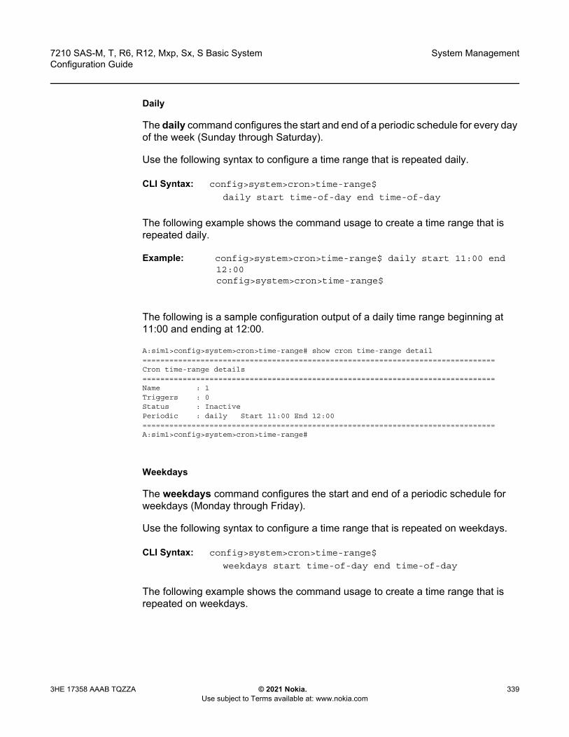
7210 SAS-M, T, R6, R12, Mxp, Sx, S Basic System Configuration Guide
System Management
3HE 17358 AAAB TQZZA © 2021 Nokia. Use subject to Terms available at: www.nokia.com
339
Daily
The daily command configures the start and end of a periodic schedule for every day of the week (Sunday through Saturday).
Use the following syntax to configure a time range that is repeated daily.
CLI Syntax: config>system>cron>time-range$
daily start time-of-day end time-of-day
The following example shows the command usage to create a time range that is repeated daily.
Example: config>system>cron>time-range$ daily start 11:00 end 12:00config>system>cron>time-range$
The following is a sample configuration output of a daily time range beginning at 11:00 and ending at 12:00.
A:sim1>config>system>cron>time-range# show cron time-range detail===============================================================================Cron time-range details===============================================================================Name : 1Triggers : 0Status : InactivePeriodic : daily Start 11:00 End 12:00===============================================================================A:sim1>config>system>cron>time-range#
Weekdays
The weekdays command configures the start and end of a periodic schedule for weekdays (Monday through Friday).
Use the following syntax to configure a time range that is repeated on weekdays.
CLI Syntax: config>system>cron>time-range$
weekdays start time-of-day end time-of-day
The following example shows the command usage to create a time range that is repeated on weekdays.
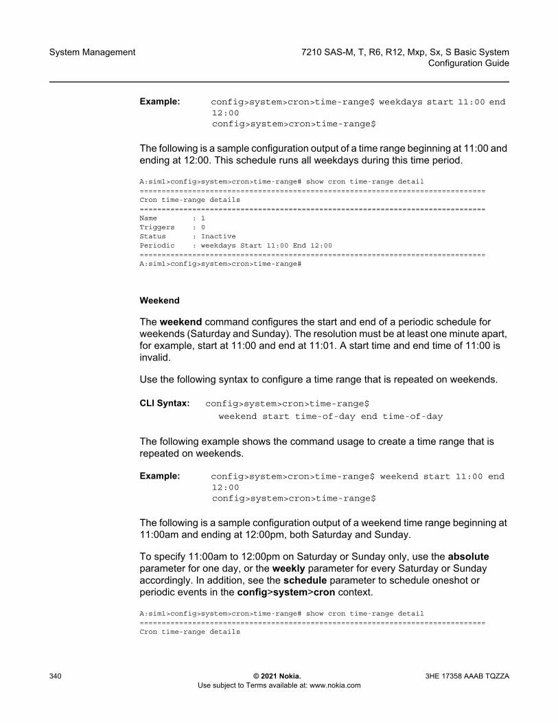
System Management
340
7210 SAS-M, T, R6, R12, Mxp, Sx, S Basic SystemConfiguration Guide
© 2021 Nokia. Use subject to Terms available at: www.nokia.com
3HE 17358 AAAB TQZZA
Example: config>system>cron>time-range$ weekdays start 11:00 end 12:00config>system>cron>time-range$
The following is a sample configuration output of a time range beginning at 11:00 and ending at 12:00. This schedule runs all weekdays during this time period.
A:sim1>config>system>cron>time-range# show cron time-range detail===============================================================================Cron time-range details===============================================================================Name : 1Triggers : 0Status : InactivePeriodic : weekdays Start 11:00 End 12:00===============================================================================A:sim1>config>system>cron>time-range#
Weekend
The weekend command configures the start and end of a periodic schedule for weekends (Saturday and Sunday). The resolution must be at least one minute apart, for example, start at 11:00 and end at 11:01. A start time and end time of 11:00 is invalid.
Use the following syntax to configure a time range that is repeated on weekends.
CLI Syntax: config>system>cron>time-range$
weekend start time-of-day end time-of-day
The following example shows the command usage to create a time range that is repeated on weekends.
Example: config>system>cron>time-range$ weekend start 11:00 end 12:00config>system>cron>time-range$
The following is a sample configuration output of a weekend time range beginning at 11:00am and ending at 12:00pm, both Saturday and Sunday.
To specify 11:00am to 12:00pm on Saturday or Sunday only, use the absolute parameter for one day, or the weekly parameter for every Saturday or Sunday accordingly. In addition, see the schedule parameter to schedule oneshot or periodic events in the config>system>cron context.
A:sim1>config>system>cron>time-range# show cron time-range detail===============================================================================Cron time-range details
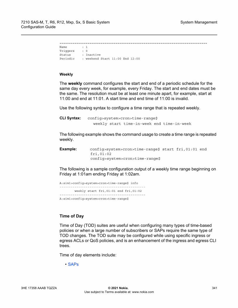
7210 SAS-M, T, R6, R12, Mxp, Sx, S Basic System Configuration Guide
System Management
3HE 17358 AAAB TQZZA © 2021 Nokia. Use subject to Terms available at: www.nokia.com
341
===============================================================================Name : 1Triggers : 0Status : InactivePeriodic : weekend Start 11:00 End 12:00
Weekly
The weekly command configures the start and end of a periodic schedule for the same day every week, for example, every Friday. The start and end dates must be the same. The resolution must be at least one minute apart, for example, start at 11:00 and end at 11:01. A start time and end time of 11:00 is invalid.
Use the following syntax to configure a time range that is repeated weekly.
CLI Syntax: config>system>cron>time-range$
weekly start time-in-week end time-in-week
The following example shows the command usage to create a time range is repeated weekly.
Example: config>system>cron>time-range$ start fri,01:01 end fri,01:02config>system>cron>time-range$
The following is a sample configuration output of a weekly time range beginning on Friday at 1:01am ending Friday at 1:02am.
A:sim1>config>system>cron>time-range$ info----------------------------------------------
weekly start fri,01:01 end fri,01:02----------------------------------------------A:sim1>config>system>cron>time-range$
Time of Day
Time of Day (TOD) suites are useful when configuring many types of time-based policies or when a large number of subscribers or SAPs require the same type of TOD changes. The TOD suite may be configured while using specific ingress or egress ACLs or QoS policies, and is an enhancement of the ingress and egress CLI trees.
Time of day elements include:
• SAPs

System Management
342
7210 SAS-M, T, R6, R12, Mxp, Sx, S Basic SystemConfiguration Guide
© 2021 Nokia. Use subject to Terms available at: www.nokia.com
3HE 17358 AAAB TQZZA
• Egress• Ingress
SAPs• If a TOD Suite is assigned to a SAP, statistics collection are not collected for that
SAP.• When an item is configured both on SAP level and in the TOD suite assigned to
the SAP, the TOD-suite defined value takes precedence.• A policy or filter assignment configured directly on a SAP has a lower priority
than any assignment in a TOD Suite. Therefore, it is possible that a new direct configuration has no immediate effect. If the configuration is made by CLI, a warning is given.
Egress
This command is an enhancement for specific egress policies. Use this command to create time-range based associations of previously created filter lists, QoS and scheduler policies. Multiple policies may be included and each must be assigned a different priority; in case time-ranges overlap, the priority will be used to determine the prevailing policy. Only a single reference to a policy may be included without a time-range.
Filters
In a TOD suite, filters that have entries with time-ranges may not be selected. Similarly, filter entries with a time-range may not be created while a TOD suite refers to that filter. QoS policies and filters referred to by a TOD suite must have scope “template” (default).
Use the following syntax to configure TOD-suite egress parameters.
CLI Syntax: config>system>crontod-suite tod-suite-name create
egress filter ip ip-filter-id [time-range time-range-name]
[priority priority]filter ipv6 ipv6-filter-id [time-range time-range-
name] [priority priority]filter mac mac-filter-id[time-range time-range-
name] [priority priority]
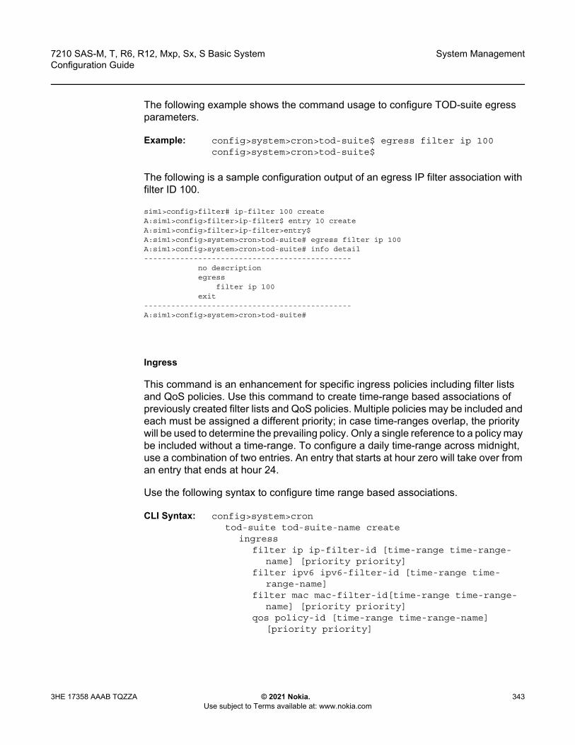
7210 SAS-M, T, R6, R12, Mxp, Sx, S Basic System Configuration Guide
System Management
3HE 17358 AAAB TQZZA © 2021 Nokia. Use subject to Terms available at: www.nokia.com
343
The following example shows the command usage to configure TOD-suite egress parameters.
Example: config>system>cron>tod-suite$ egress filter ip 100 config>system>cron>tod-suite$
The following is a sample configuration output of an egress IP filter association with filter ID 100.
sim1>config>filter# ip-filter 100 createA:sim1>config>filter>ip-filter$ entry 10 createA:sim1>config>filter>ip-filter>entry$A:sim1>config>system>cron>tod-suite# egress filter ip 100A:sim1>config>system>cron>tod-suite# info detail----------------------------------------------
no descriptionegress
filter ip 100exit
----------------------------------------------A:sim1>config>system>cron>tod-suite#
Ingress
This command is an enhancement for specific ingress policies including filter lists and QoS policies. Use this command to create time-range based associations of previously created filter lists and QoS policies. Multiple policies may be included and each must be assigned a different priority; in case time-ranges overlap, the priority will be used to determine the prevailing policy. Only a single reference to a policy may be included without a time-range. To configure a daily time-range across midnight, use a combination of two entries. An entry that starts at hour zero will take over from an entry that ends at hour 24.
Use the following syntax to configure time range based associations.
CLI Syntax: config>system>crontod-suite tod-suite-name create
ingressfilter ip ip-filter-id [time-range time-range-
name] [priority priority]filter ipv6 ipv6-filter-id [time-range time-
range-name]filter mac mac-filter-id[time-range time-range-
name] [priority priority]qos policy-id [time-range time-range-name]
[priority priority]
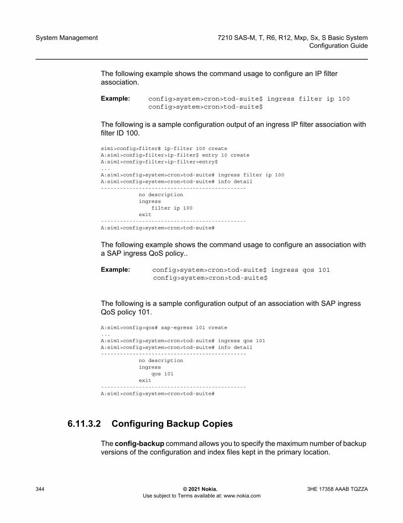
System Management
344
7210 SAS-M, T, R6, R12, Mxp, Sx, S Basic SystemConfiguration Guide
© 2021 Nokia. Use subject to Terms available at: www.nokia.com
3HE 17358 AAAB TQZZA
The following example shows the command usage to configure an IP filter association.
Example: config>system>cron>tod-suite$ ingress filter ip 100 config>system>cron>tod-suite$
The following is a sample configuration output of an ingress IP filter association with filter ID 100.
sim1>config>filter# ip-filter 100 createA:sim1>config>filter>ip-filter$ entry 10 createA:sim1>config>filter>ip-filter>entry$...A:sim1>config>system>cron>tod-suite# ingress filter ip 100A:sim1>config>system>cron>tod-suite# info detail----------------------------------------------
no descriptioningress
filter ip 100exit
----------------------------------------------A:sim1>config>system>cron>tod-suite#
The following example shows the command usage to configure an association with a SAP ingress QoS policy..
Example: config>system>cron>tod-suite$ ingress qos 101config>system>cron>tod-suite$
The following is a sample configuration output of an association with SAP ingress QoS policy 101.
A:sim1>config>qos# sap-egress 101 create...A:sim1>config>system>cron>tod-suite# ingress qos 101A:sim1>config>system>cron>tod-suite# info detail----------------------------------------------
no descriptioningress
qos 101exit
----------------------------------------------A:sim1>config>system>cron>tod-suite#
6.11.3.2 Configuring Backup Copies
The config-backup command allows you to specify the maximum number of backup versions of the configuration and index files kept in the primary location.
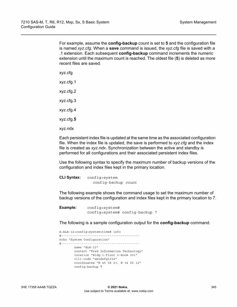
7210 SAS-M, T, R6, R12, Mxp, Sx, S Basic System Configuration Guide
System Management
3HE 17358 AAAB TQZZA © 2021 Nokia. Use subject to Terms available at: www.nokia.com
345
For example, assume the config-backup count is set to 5 and the configuration file is named xyz.cfg. When a save command is issued, the xyz.cfg file is saved with a .1 extension. Each subsequent config-backup command increments the numeric extension until the maximum count is reached. The oldest file (5) is deleted as more recent files are saved.
xyz.cfg
xyz.cfg.1
xyz.cfg.2
xyz.cfg.3
xyz.cfg.4
xyz.cfg.5
xyz.ndx
Each persistent index file is updated at the same time as the associated configuration file. When the index file is updated, the save is performed to xyz.cfg and the index file is created as xyz.ndx. Synchronization between the active and standby is performed for all configurations and their associated persistent index files.
Use the following syntax to specify the maximum number of backup versions of the configuration and index files kept in the primary location.
CLI Syntax: config>systemconfig-backup count
The following example shows the command usage to set the maximum number of backup versions of the configuration and index files kept in the primary location to 7.
Example: config>system# config>system# config-backup 7
The following is a sample configuration output for the config-backup command.
A:ALA-12>config>system>time# info#------------------------------------------echo "System Configuration"#------------------------------------------
name "ALA-12"contact "Fred Information Technology"location "Bldg.1-floor 2-Room 201"clli-code "abcdefg1234"coordinates "N 45 58 23, W 34 56 12"config-backup 7
System Management
346
7210 SAS-M, T, R6, R12, Mxp, Sx, S Basic SystemConfiguration Guide
© 2021 Nokia. Use subject to Terms available at: www.nokia.com
3HE 17358 AAAB TQZZA
...----------------------------------------------A:ALA-12>config>system>time#
6.11.4 System Administration Parameters
This section describes the CLI syntax to configure the following system administration parameters.
• Validating the Golden Bootstrap Image• Updating the Golden Bootstrap Image• Disconnect• Set-time• Display-config• Tech-support• Save• Reboot• Post-Boot Configuration Extension Files
6.11.4.1 Validating the Golden Bootstrap Image
The admin>check-golden-bootstrap command validates the current golden bootstrap image and displays its version. A default golden bootstrap image is installed on each 7210 SAS-M device.
Use the following syntax to validate the golden boot strap image.
CLI Syntax: admin check-golden-bootstrap
The following example shows the command usage to validate the golden boot strap image.
Example: admin# check-golden-bootstrap
The following is a sample output.
version TiMOS-L-0.0.I312Golden Bootstrap Image validation successful
7210 SAS-M, T, R6, R12, Mxp, Sx, S Basic System Configuration Guide
System Management
3HE 17358 AAAB TQZZA © 2021 Nokia. Use subject to Terms available at: www.nokia.com
347
6.11.4.2 Updating the Golden Bootstrap Image
The admin>update-golden-bootstrap command validates the input file, which must be a 7210 SAS-M bootstrap image, and updates the golden bootstrap image with the contents of this file.
Use the following syntax to update the golden bootstrap image.
CLI Syntax: adminupdate-golden-bootstrap [<file-url>]
The following example shows the command usage to update the golden bootstrap image.
Example: admin# update-golden-bootstrap boot.tim
The following is a sample output.
Updating Golden Bootstrap Image from "boot.tim"This operation must not be interruptedUpdating Golden Bootstrap image .... Completed.
6.11.4.3 Disconnect
The disconnect command immediately disconnects a user from a console, Telnet, FTP, or SSH session.
Use the following syntax to disconnect a user from a session.
CLI Syntax: admindisconnect [address ip-address |username user-name
|{console|telnet|ftp|ssh}]
The following example shows the command usage to disconnect a user from a session.
Example: admin# disconnect
The following is a sample output of the disconnect command.
Note: Configuration modifications are saved to the primary image file.
System Management
348
7210 SAS-M, T, R6, R12, Mxp, Sx, S Basic SystemConfiguration Guide
© 2021 Nokia. Use subject to Terms available at: www.nokia.com
3HE 17358 AAAB TQZZA
ALA-1>admin# disconnectALA-1>admin# Logged out by the administratorConnection to host lost.
C:\>
6.11.4.4 Set-time
Use the set-time command to set the system date and time. The time entered should be accurate for the time zone configured for the system. The system will convert the local time to UTC before saving to the system clock, which is always set to UTC. If SNTP or NTP is enabled (no shutdown), this command cannot be used. The set-time command does not take into account any daylight saving offset, if defined.
Use the following syntax to set the date and time.
CLI Syntax: adminset-time date time
The following example shows the command usage to set the date and time.
Example: admin# set-time 2007/02/06 04:10:00
The following is a sample output of the set-time command.
ALA-2# admin set-time 2007/02/06 04:10:00ALA-2# show timeThu Feb 2 04:10:04 GMT 2007ALA-2#
6.11.4.5 Display-config
The display-config command displays the running configuration of the system.
Use the following syntax to display the running configuration of the system.
CLI Syntax: admindisplay-config [detail] [index]
The following example shows the command usage to display the running configuration of the system.
Example: admin# display-config detail
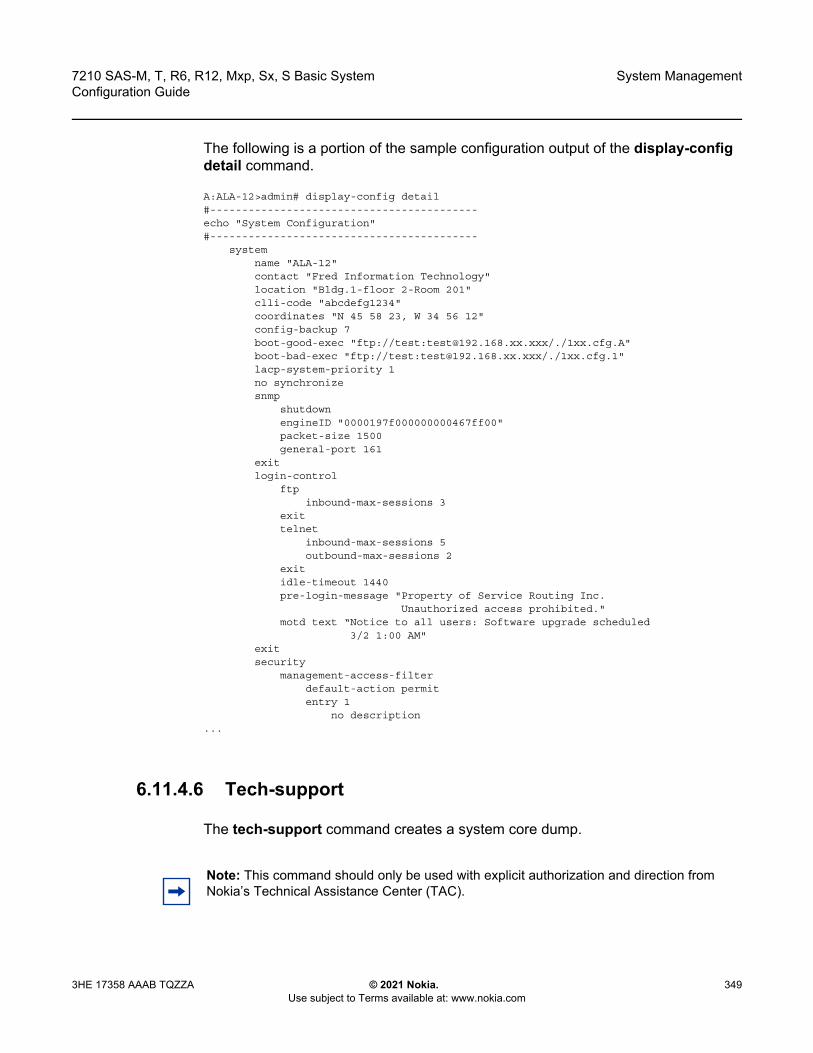
7210 SAS-M, T, R6, R12, Mxp, Sx, S Basic System Configuration Guide
System Management
3HE 17358 AAAB TQZZA © 2021 Nokia. Use subject to Terms available at: www.nokia.com
349
The following is a portion of the sample configuration output of the display-config detail command.
A:ALA-12>admin# display-config detail#------------------------------------------echo "System Configuration"#------------------------------------------
systemname "ALA-12"contact "Fred Information Technology"location "Bldg.1-floor 2-Room 201"clli-code "abcdefg1234"coordinates "N 45 58 23, W 34 56 12"config-backup 7boot-good-exec "ftp://test:[email protected]/./1xx.cfg.A"boot-bad-exec "ftp://test:[email protected]/./1xx.cfg.1"lacp-system-priority 1no synchronizesnmp
shutdownengineID "0000197f000000000467ff00"packet-size 1500general-port 161
exitlogin-control
ftpinbound-max-sessions 3
exittelnet
inbound-max-sessions 5outbound-max-sessions 2
exitidle-timeout 1440pre-login-message "Property of Service Routing Inc.
Unauthorized access prohibited."motd text “Notice to all users: Software upgrade scheduled
3/2 1:00 AM"exitsecurity
management-access-filterdefault-action permitentry 1
no description...
6.11.4.6 Tech-support
The tech-support command creates a system core dump.
Note: This command should only be used with explicit authorization and direction from Nokia’s Technical Assistance Center (TAC).
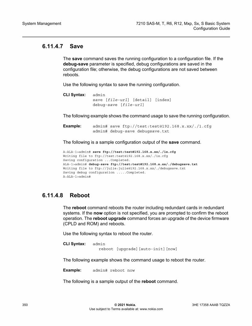
System Management
350
7210 SAS-M, T, R6, R12, Mxp, Sx, S Basic SystemConfiguration Guide
© 2021 Nokia. Use subject to Terms available at: www.nokia.com
3HE 17358 AAAB TQZZA
6.11.4.7 Save
The save command saves the running configuration to a configuration file. If the debug-save parameter is specified, debug configurations are saved in the configuration file; otherwise, the debug configurations are not saved between reboots.
Use the following syntax to save the running configuration.
CLI Syntax: adminsave [file-url] [detail] [index] debug-save [file-url]
The following example shows the command usage to save the running configuration.
Example: admin# save ftp://test:[email protected]/./1.cfgadmin# debug-save debugsave.txt
The following is a sample configuration output of the save command.
A:ALA-1>admin# save ftp://test:[email protected]/./1x.cfgWriting file to ftp://test:[email protected]/./1x.cfgSaving configuration ...Completed.ALA-1>admin# debug-save ftp://test:[email protected]/./debugsave.txtWriting file to ftp://julie:[email protected]/./debugsave.txtSaving debug configuration .....Completed.A:ALA-1>admin#
6.11.4.8 Reboot
The reboot command reboots the router including redundant cards in redundant systems. If the now option is not specified, you are prompted to confirm the reboot operation. The reboot upgrade command forces an upgrade of the device firmware (CPLD and ROM) and reboots.
Use the following syntax to reboot the router.
CLI Syntax: adminreboot [upgrade][auto-init][now]
The following example shows the command usage to reboot the router.
Example: admin# reboot now
The following is a sample output of the reboot command.

7210 SAS-M, T, R6, R12, Mxp, Sx, S Basic System Configuration Guide
System Management
3HE 17358 AAAB TQZZA © 2021 Nokia. Use subject to Terms available at: www.nokia.com
351
A:ALA-1>admin# reboot nowAre you sure you want to reboot (y/n)? yRebooting...Using preloaded VxWorks boot loader....
When an admin reboot auto-init command is issued, the system resets the existing BOF and reboots. The system startup process after the admin reboot auto-init command is executed is the same as the first time system boot described in System Initialization.
Use the following syntax to reset the BOF and reboot.
CLI Syntax: admin# reboot auto-init [now]
The following is a sample output of the admin reboot auto-init command.
Example: *A:ALA-1# admin reboot auto-initWARNING: Configuration and/or Boot options may have changed since the last save.Are you sure you want to reset the bof and reboot (y/n)? YResetting...OK
Nokia 7210 Boot ROM. Copyright 2016 Nokia.All rights reserved. All use is subject to applicable license agreements.
6.11.4.9 Post-Boot Configuration Extension Files
Two post-boot configuration extension files are supported and are triggered when either a successful or failed boot configuration file is processed. The commands specify URLs for the CLI scripts that are run following the completion of the boot-up configuration. A URL must be specified or no action is taken. The commands are persistent between router reboots and are included in the configuration saves (admin>save).
Use the following syntax to configure a URL for a CLI script that runs when the boot-up configuration is completed.
CLI Syntax: config>system boot-bad-exec file-urlboot-good-exec file-url
Note: After the BOF is reset, the system may not boot up with the last saved system configuration unless the new BOF also uses the same configuration file. If you require the system to boot up with the last saved system configuration, Nokia recommends that you should run the admin>save file-url command to save the current system configuration and modify the BOF to use this configuration.

System Management
352
7210 SAS-M, T, R6, R12, Mxp, Sx, S Basic SystemConfiguration Guide
© 2021 Nokia. Use subject to Terms available at: www.nokia.com
3HE 17358 AAAB TQZZA
The following example shows the command usage to configure a URL for a CLI script that runs when the boot-up configuration is completed.
Example: config>system# boot-bad-exec ftp://test:[email protected]/./fail.cfgconfig>system# boot-good-exec ftp://test:[email protected]/./ok.cfg
The following is a sample command output.
*A:ALA# configure system*A:ALA>config>system# info----------------------------------------------#--------------------------------------------------echo "System Configuration"#--------------------------------------------------
name "ALA"boot-good-exec "cf1:\good.cfg"boot-bad-exec "cf1:\bad.cfg"snmp
shutdownexitlogin-control
idle-timeout disablepre-login-message "ala-1" name
exittime
ntpauthentication-key 1 key "SV3BxZCsIvI" hash type message-digestserver 10.135.16.130peer 10.0.0.1 key-id 1no shutdown
exitsntp
server-address 10.135.16.90 preferredno shutdown
exitzone UTC
exitthresholds
rmonexit
exit#--------------------------------------------------echo "System Security Configuration"#--------------------------------------------------
securityhash-control read-version all write-version 1telnet-serverftp-server
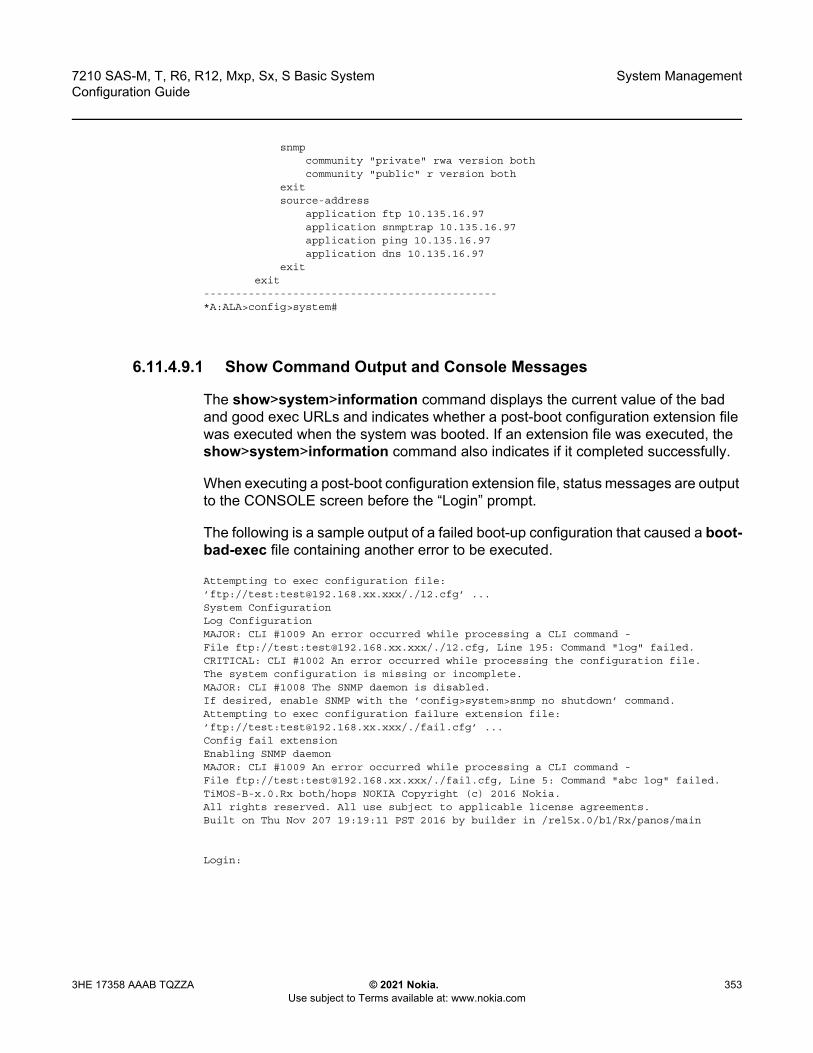
7210 SAS-M, T, R6, R12, Mxp, Sx, S Basic System Configuration Guide
System Management
3HE 17358 AAAB TQZZA © 2021 Nokia. Use subject to Terms available at: www.nokia.com
353
snmpcommunity "private" rwa version bothcommunity "public" r version both
exitsource-address
application ftp 10.135.16.97application snmptrap 10.135.16.97application ping 10.135.16.97application dns 10.135.16.97
exitexit
----------------------------------------------*A:ALA>config>system#
6.11.4.9.1 Show Command Output and Console Messages
The show>system>information command displays the current value of the bad and good exec URLs and indicates whether a post-boot configuration extension file was executed when the system was booted. If an extension file was executed, the show>system>information command also indicates if it completed successfully.
When executing a post-boot configuration extension file, status messages are output to the CONSOLE screen before the “Login” prompt.
The following is a sample output of a failed boot-up configuration that caused a boot-bad-exec file containing another error to be executed.
Attempting to exec configuration file:’ftp://test:[email protected]/./12.cfg’ ...System ConfigurationLog ConfigurationMAJOR: CLI #1009 An error occurred while processing a CLI command -File ftp://test:[email protected]/./12.cfg, Line 195: Command "log" failed.CRITICAL: CLI #1002 An error occurred while processing the configuration file.The system configuration is missing or incomplete.MAJOR: CLI #1008 The SNMP daemon is disabled.If desired, enable SNMP with the ’config>system>snmp no shutdown’ command.Attempting to exec configuration failure extension file:’ftp://test:[email protected]/./fail.cfg’ ...Config fail extensionEnabling SNMP daemonMAJOR: CLI #1009 An error occurred while processing a CLI command -File ftp://test:[email protected]/./fail.cfg, Line 5: Command "abc log" failed.TiMOS-B-x.0.Rx both/hops NOKIA Copyright (c) 2016 Nokia.All rights reserved. All use subject to applicable license agreements.Built on Thu Nov 207 19:19:11 PST 2016 by builder in /rel5x.0/b1/Rx/panos/main
Login:
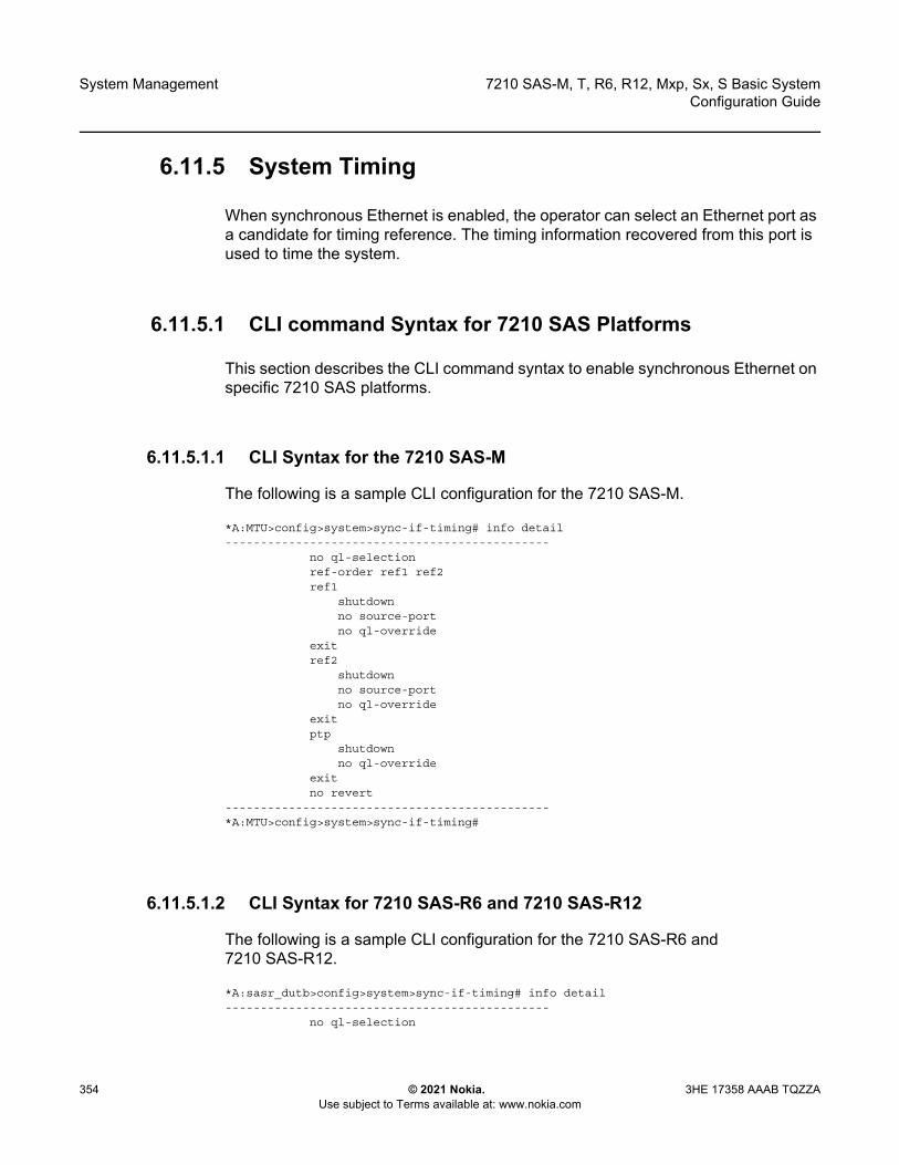
System Management
354
7210 SAS-M, T, R6, R12, Mxp, Sx, S Basic SystemConfiguration Guide
© 2021 Nokia. Use subject to Terms available at: www.nokia.com
3HE 17358 AAAB TQZZA
6.11.5 System Timing
When synchronous Ethernet is enabled, the operator can select an Ethernet port as a candidate for timing reference. The timing information recovered from this port is used to time the system.
6.11.5.1 CLI command Syntax for 7210 SAS Platforms
This section describes the CLI command syntax to enable synchronous Ethernet on specific 7210 SAS platforms.
6.11.5.1.1 CLI Syntax for the 7210 SAS-M
The following is a sample CLI configuration for the 7210 SAS-M.
*A:MTU>config>system>sync-if-timing# info detail----------------------------------------------
no ql-selectionref-order ref1 ref2ref1
shutdownno source-portno ql-override
exitref2
shutdownno source-portno ql-override
exitptp
shutdownno ql-override
exitno revert
----------------------------------------------*A:MTU>config>system>sync-if-timing#
6.11.5.1.2 CLI Syntax for 7210 SAS-R6 and 7210 SAS-R12
The following is a sample CLI configuration for the 7210 SAS-R6 and 7210 SAS-R12.
*A:sasr_dutb>config>system>sync-if-timing# info detail----------------------------------------------
no ql-selection
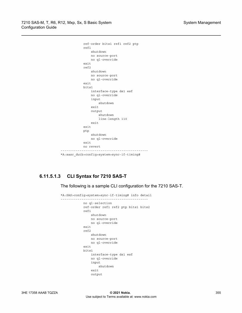
7210 SAS-M, T, R6, R12, Mxp, Sx, S Basic System Configuration Guide
System Management
3HE 17358 AAAB TQZZA © 2021 Nokia. Use subject to Terms available at: www.nokia.com
355
ref-order bits1 ref1 ref2 ptpref1
shutdownno source-portno ql-override
exitref2
shutdownno source-portno ql-override
exitbits1
interface-type ds1 esfno ql-overrideinput
shutdownexitoutput
shutdownline-length 110
exitexitptp
shutdownno ql-override
exitno revert
----------------------------------------------*A:sasr_dutb>config>system>sync-if-timing#
6.11.5.1.3 CLI Syntax for 7210 SAS-T
The following is a sample CLI configuration for the 7210 SAS-T.
*A:SAS>config>system>sync-if-timing# info detail----------------------------------------------
no ql-selectionref-order ref1 ref2 ptp bits1 bits2ref1
shutdownno source-portno ql-override
exitref2
shutdownno source-portno ql-override
exitbits1
interface-type ds1 esfno ql-overrideinput
shutdownexitoutput
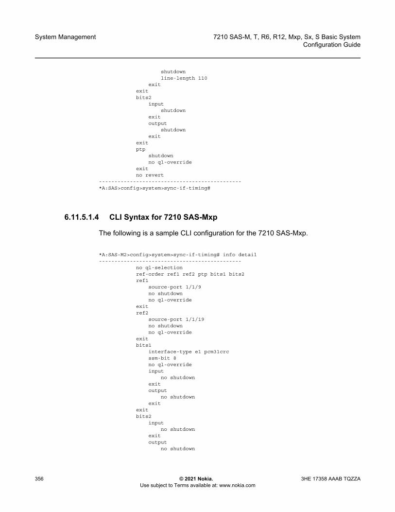
System Management
356
7210 SAS-M, T, R6, R12, Mxp, Sx, S Basic SystemConfiguration Guide
© 2021 Nokia. Use subject to Terms available at: www.nokia.com
3HE 17358 AAAB TQZZA
shutdownline-length 110
exitexitbits2
inputshutdown
exitoutput
shutdownexit
exitptp
shutdownno ql-override
exitno revert
----------------------------------------------*A:SAS>config>system>sync-if-timing#
6.11.5.1.4 CLI Syntax for 7210 SAS-Mxp
The following is a sample CLI configuration for the 7210 SAS-Mxp.
*A:SAS-M2>config>system>sync-if-timing# info detail----------------------------------------------
no ql-selectionref-order ref1 ref2 ptp bits1 bits2ref1
source-port 1/1/9no shutdownno ql-override
exitref2
source-port 1/1/19no shutdownno ql-override
exitbits1
interface-type e1 pcm31crcssm-bit 8no ql-overrideinput
no shutdownexitoutput
no shutdownexit
exitbits2
inputno shutdown
exitoutput
no shutdown
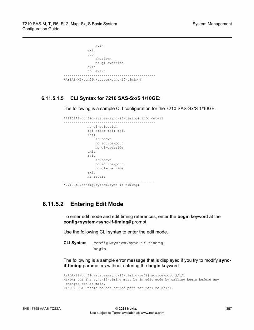
7210 SAS-M, T, R6, R12, Mxp, Sx, S Basic System Configuration Guide
System Management
3HE 17358 AAAB TQZZA © 2021 Nokia. Use subject to Terms available at: www.nokia.com
357
exitexitptp
shutdownno ql-override
exitno revert
----------------------------------------------*A:SAS-M2>config>system>sync-if-timing#
6.11.5.1.5 CLI Syntax for 7210 SAS-Sx/S 1/10GE:
The following is a sample CLI configuration for the 7210 SAS-Sx/S 1/10GE.
*7210SAS>config>system>sync-if-timing# info detail----------------------------------------------
no ql-selectionref-order ref1 ref2ref1
shutdownno source-portno ql-override
exitref2
shutdownno source-portno ql-override
exitno revert
----------------------------------------------*7210SAS>config>system>sync-if-timing#
6.11.5.2 Entering Edit Mode
To enter edit mode and edit timing references, enter the begin keyword at the config>system>sync-if-timing# prompt.
Use the following CLI syntax to enter the edit mode.
CLI Syntax: config>system>sync-if-timing
begin
The following is a sample error message that is displayed if you try to modify sync-if-timing parameters without entering the begin keyword.
A:ALA-12>config>system>sync-if-timing>ref1# source-port 2/1/1MINOR: CLI The sync-if-timing must be in edit mode by calling begin before anychanges can be made.
MINOR: CLI Unable to set source port for ref1 to 2/1/1.

System Management
358
7210 SAS-M, T, R6, R12, Mxp, Sx, S Basic SystemConfiguration Guide
© 2021 Nokia. Use subject to Terms available at: www.nokia.com
3HE 17358 AAAB TQZZA
A:ALA-12>config>system>sync-if-timing>ref1#
6.11.5.3 Configuring Timing References
The following is a sample configuration of timing reference parameters.
Example:
config>system# sync-if-timingconfig>system>sync-if-timing# beginconfig>system>sync-if-timing# ref1config>system>sync-if-timing>ref1# source-port 1/1/1config>system>sync-if-timing>ref1# no shutdownconfig>system>sync-if-timing>ref1# exitconfig>system>sync-if-timing# ref2config>system>sync-if-timing>ref2# source-port 1/1/2config>system>sync-if-timing>ref2# no shutdownconfig>system>sync-if-timing>ref2# exitconfig>system>sync-if-timing>commit
The following is a sample output of the timing reference parameters.
*7210-SAS>config>system>sync-if-timing#info detail
----------------------------------------------ref-order ref1 ref2ref1source-port 1/1/1no shutdownexitref2source-port 1/1/2no shutdownexitno revert----------------------------------------------
6.11.5.4 Using the revert Command
The revert command allows the clock to revert to a higher-priority reference if the current reference goes offline or becomes unstable.
Note: Use commit to save or abort to discard the changes made in a session.
7210 SAS-M, T, R6, R12, Mxp, Sx, S Basic System Configuration Guide
System Management
3HE 17358 AAAB TQZZA © 2021 Nokia. Use subject to Terms available at: www.nokia.com
359
If revertive switching is enabled, the highest-priority valid timing reference is used. If a reference with a higher priority becomes valid, a switchover to that reference is initiated. If a failure on the current reference occurs, the next highest reference takes over.
If non-revertive switching is enabled, the active reference always remains selected while it is valid, even if a higher priority reference becomes available. If the active reference becomes invalid, a reference switchover to a valid reference with the highest priority is initiated. The failed reference is eligible for selection when it becomes operational.
Use the following syntax to revert the clock to a higher priority reference.
CLI Syntax: config>system>sync-if-timing revert
6.11.5.5 Other Editing Commands
Other editing commands are:
• commit: saves changes made to the timing references during a session. Modifications are not persistent across system boots unless this command is entered.
• abort: discards changes that have been made to the timing references during a session.
Use the following syntax to abort or commit changes made to a timing reference.
CLI Syntax: config>system>sync-if-timingabortcommit
6.11.5.6 Forcing a Specific Reference
You can force the system synchronous timing output to use a specific reference.
Note: The debug sync-if-timing force-reference command should only be used to test and debug problems. After the system timing reference input has been forced, it will not revert to another reference unless explicitly reconfigured, or if the forced reference fails, or if the received QL code is QL-DNU/DUS and QL selection is enabled.

System Management
360
7210 SAS-M, T, R6, R12, Mxp, Sx, S Basic SystemConfiguration Guide
© 2021 Nokia. Use subject to Terms available at: www.nokia.com
3HE 17358 AAAB TQZZA
When the debug sync-if-timing force-reference command is run, the current system synchronous timing output is immediately referenced from the specified reference input. The reference must be qualified.
Debug configurations are not saved between reboots.
Use the following syntax to reference the current system synchronous timing output from the specifies reference input.
CLI Syntax: debug>sync-if-timingforce-reference {ref1 | ref2}
The following example shows the command usage to reference the current system synchronous timing output from the specifies reference input.
Example: debug>sync-if-timing# force-reference
6.11.6 Configuring System Monitoring Thresholds
This section describes how to configure system monitoring thresholds.
6.11.6.1 Creating Events
The event command controls the generation and notification of threshold crossing events configured with the alarm command. When a threshold crossing event is triggered, the rmon event configuration optionally specifies whether an entry in the RMON-MIB log table will be created to record the event. It can also specify whether an SNMP notification (trap) will be generated for the event. There are two notifications for threshold crossing events; a rising alarm and a falling alarm.ping-address.
Creating an event entry in the RMON-MIB log table does not create a corresponding entry in the 7210 SAS event logs. However, when the event is set to trap, the generation of a rising alarm or falling alarm notification creates an entry in the event logs and that is distributed to the configured log destinations, including console, session, memory, file, syslog, or SNMP trap destination. The logger message includes a rising or falling threshold crossing event indicator, the sample type (absolute or delta), the sampled value, the threshold value, the rmon-alarm-id, the associated rmon-event-id, and the sampled SNMP object identifier.
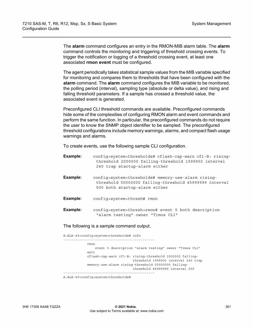
7210 SAS-M, T, R6, R12, Mxp, Sx, S Basic System Configuration Guide
System Management
3HE 17358 AAAB TQZZA © 2021 Nokia. Use subject to Terms available at: www.nokia.com
361
The alarm command configures an entry in the RMON-MIB alarm table. The alarm command controls the monitoring and triggering of threshold crossing events. To trigger the notification or logging of a threshold crossing event, at least one associated rmon event must be configured.
The agent periodically takes statistical sample values from the MIB variable specified for monitoring and compares them to thresholds that have been configured with the alarm command. The alarm command configures the MIB variable to be monitored, the polling period (interval), sampling type (absolute or delta value), and rising and falling threshold parameters. If a sample has crossed a threshold value, the associated event is generated.
Preconfigured CLI threshold commands are available. Preconfigured commands hide some of the complexities of configuring RMON alarm and event commands and perform the same function. In particular, the preconfigured commands do not require the user to know the SNMP object identifier to be sampled. The preconfigured threshold configurations include memory warnings, alarms, and compact flash usage warnings and alarms.
To create events, use the following sample CLI configuration.
Example: config>system>thresholds# cflash-cap-warn cf1-B: rising-threshold 2000000 falling-threshold 1999900 interval 240 trap startup-alarm either
Example: config>system>thresholds# memory-use-alarm rising-threshold 50000000 falling-threshold 45999999 interval 500 both startup-alarm either
Example: config>system>thresh# rmon
Example: config>system>thresh>rmon# event 5 both description "alarm testing" owner "Timos CLI"
The following is a sample command output.
A:ALA-49>config>system>thresholds# info----------------------------------------------
rmonevent 5 description "alarm testing" owner "Timos CLI"
exitcflash-cap-warn cf1-B: rising-threshold 2000000 falling-
threshold 1999900 interval 240 trapmemory-use-alarm rising-threshold 50000000 falling-
threshold 45999999 interval 500----------------------------------------------A:ALA-49>config>system>thresholds#
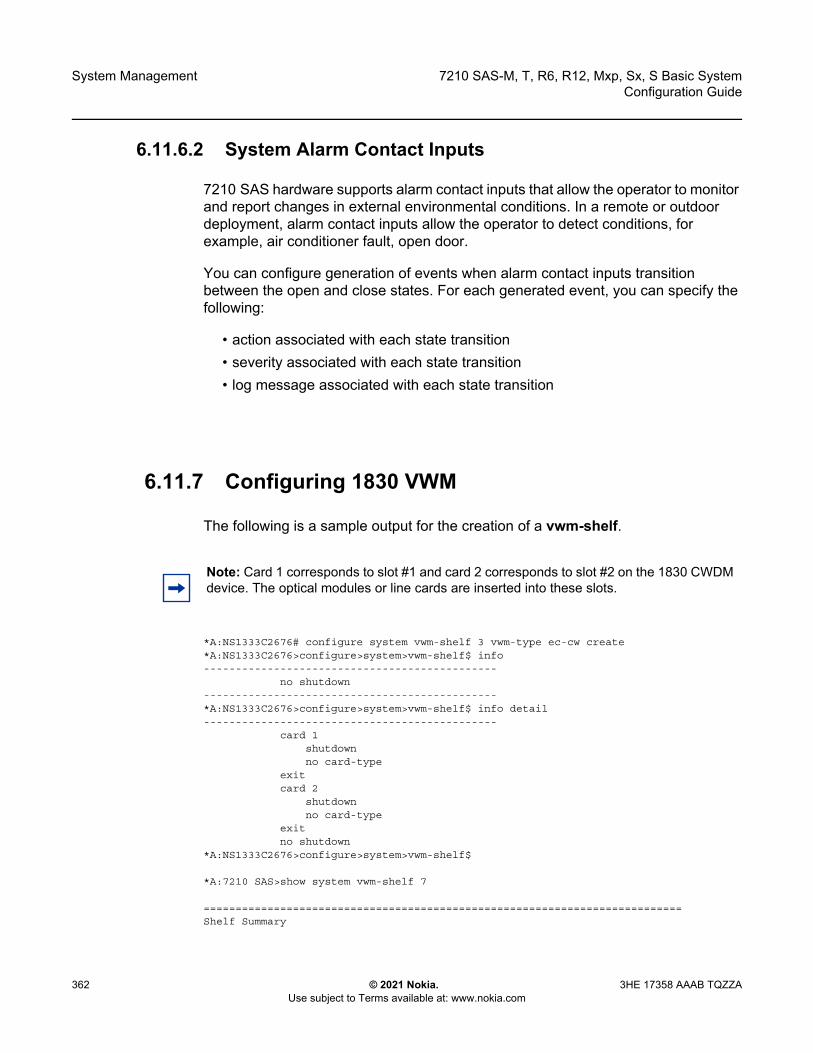
System Management
362
7210 SAS-M, T, R6, R12, Mxp, Sx, S Basic SystemConfiguration Guide
© 2021 Nokia. Use subject to Terms available at: www.nokia.com
3HE 17358 AAAB TQZZA
6.11.6.2 System Alarm Contact Inputs
7210 SAS hardware supports alarm contact inputs that allow the operator to monitor and report changes in external environmental conditions. In a remote or outdoor deployment, alarm contact inputs allow the operator to detect conditions, for example, air conditioner fault, open door.
You can configure generation of events when alarm contact inputs transition between the open and close states. For each generated event, you can specify the following:
• action associated with each state transition• severity associated with each state transition• log message associated with each state transition
6.11.7 Configuring 1830 VWM
The following is a sample output for the creation of a vwm-shelf.
*A:NS1333C2676# configure system vwm-shelf 3 vwm-type ec-cw create*A:NS1333C2676>configure>system>vwm-shelf$ info----------------------------------------------
no shutdown----------------------------------------------*A:NS1333C2676>configure>system>vwm-shelf$ info detail----------------------------------------------
card 1shutdownno card-type
exitcard 2
shutdownno card-type
exitno shutdown
*A:NS1333C2676>configure>system>vwm-shelf$
*A:7210 SAS>show system vwm-shelf 7
===========================================================================Shelf Summary
Note: Card 1 corresponds to slot #1 and card 2 corresponds to slot #2 on the 1830 CWDM device. The optical modules or line cards are inserted into these slots.

7210 SAS-M, T, R6, R12, Mxp, Sx, S Basic System Configuration Guide
System Management
3HE 17358 AAAB TQZZA © 2021 Nokia. Use subject to Terms available at: www.nokia.com
363
===========================================================================Shelf-ID USB/ Shelf Admin Oper Number of
OMC Type State State Equipped slots---------------------------------------------------------------------------7 OMC CWDM UP UP 2
===========================================================================Slot Summary===========================================================================Slot-ID Provisioned Equipped Admin Oper
Type Type State State---------------------------------------------------------------------------1 Not Provisioned SFC1D DOWN DOWN2 Not Provisioned SFC2A&B DOWN DOWNA CWDM CWDM UP UP===========================================================================*A:7210SAS#
*A:7210SAS# show system vwm-shelf 7 detail
===========================================================================Shelf Summary===========================================================================Shelf-ID USB/ Shelf Admin Oper Number of
OMC Type State State Equipped slots---------------------------------------------------------------------------7 OMC CWDM UP UP 2
===========================================================================Slot Summary===========================================================================Slot-ID Provisioned Equipped Admin Oper
Type Type State State---------------------------------------------------------------------------1 SFC1D SFC1D UP UP2 SFC2A&B SFC2A&B UP UPA CWDM CWDM UP UP
===========================================================================1830 VWM Shelf Controller-A Hardware Data===========================================================================No of Slots : 2Part Number : 3KC19297AAAB01CLEI code : WOCUAZNUTAUnit Mnemonic : EC-CWSerial Number : EZ444555666Manufacturing Date : 12112000Administrative state : UPOperational state : UPFirmware version : --------------Current Alarm state : Cleared
===========================================================================1830 VWM Slot/Module Hardware Data===========================================================================Slot Number : 1Provisioned type : SFC1DEquipped type : Equipped (SFC1D)
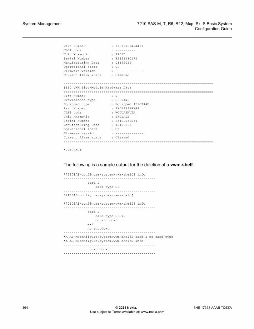
System Management
364
7210 SAS-M, T, R6, R12, Mxp, Sx, S Basic SystemConfiguration Guide
© 2021 Nokia. Use subject to Terms available at: www.nokia.com
3HE 17358 AAAB TQZZA
Part Number : 3KC19289AEAA01CLEI code : ----------Unit Mnemonic : SFC1DSerial Number : EZ121130171Manufacturing Date : 03192012Operational state : UPFirmware version : --------------Current Alarm state : Cleared
===========================================================================1830 VWM Slot/Module Hardware Data===========================================================================Slot Number : 2Provisioned type : SFC2A&BEquipped type : Equipped (SFC2A&B)Part Number : 3KC19289AKAACLEI code : WOCUAZNUTAUnit Mnemonic : SFC2A&BSerial Number : EZ120630634Manufacturing Date : 12122000Operational state : UPFirmware version : --------------Current Alarm state : Cleared===========================================================================
*7210SAS#
The following is a sample output for the deletion of a vwm-shelf.
*7210SAS>configure>system>vwm-shelf$ info----------------------------------------------
card 2card-type SF
----------------------------------------------7210SAS>configure>system>vwm-shelf$
*7210SAS>configure>system>vwm-shelf$ info----------------------------------------------
card 2card-type SFC1Dno shutdown
exitno shutdown
----------------------------------------------*A AS-M>configure>system>vwm-shelf$ card 2 no card-type*A AS-M>configure>system>vwm-shelf$ info----------------------------------------------
no shutdown----------------------------------------------

7210 SAS-M, T, R6, R12, Mxp, Sx, S Basic System Configuration Guide
System Management
3HE 17358 AAAB TQZZA © 2021 Nokia. Use subject to Terms available at: www.nokia.com
365
6.11.8 Configuring LLDP
Use the following syntax to configure LLDP.
CLI Syntax: config>system>lldptx-interval <interval>tx-hold-multiplier <multiplier>reinit-delay <time>notification-interval <time>tx-credit-max <count>message-fast-tx <time>message-fast-init <count>shutdown
The following is a sample LLDP port configuration.
*A:7210-SAS>config>port>ethernet>lldp# info----------------------------------------------
dest-mac nearest-bridgeadmin-status tx-rxtx-tlvs port-desc sys-captx-mgmt-address system
exit----------------------------------------------*A:7210-SAS>config>port>ethernet>lldp#
The following is a sample global system LLDP configuration.
A:7210-SAS>config>system>lldp# info----------------------------------------------
tx-interval 10tx-hold-multiplier 2reinit-delay 5notification-interval 10
----------------------------------------------A:7210-SAS>config>system>lldp#
System Management
366
7210 SAS-M, T, R6, R12, Mxp, Sx, S Basic SystemConfiguration Guide
© 2021 Nokia. Use subject to Terms available at: www.nokia.com
3HE 17358 AAAB TQZZA
7210 SAS-M, T, R6, R12, Mxp, Sx, S Basic System Configuration Guide
System Management
3HE 17358 AAAB TQZZA © 2021 Nokia. Use subject to Terms available at: www.nokia.com
367
6.12 System Command Reference
6.12.1 Command Hierarchies
• Configuration Commands- System Information Commands- Virtual Chassis (VC) Configuration Commands - VWM Shelf Management Commands for 7210 SAS-R6 and 7210 SAS-R12- VWM Shelf Management Commands for 7210 SAS-M, 7210 SAS-T, and
7210 SAS-Mxp- System Alarm Commands- PTP Commands- System Time Commands- CRON Commands- Script Control Commands- System Administration (Admin) Commands- High Availability (Redundancy) Commands- Configuration Rollback Commands for the 7210 SAS-R6, 7210 SAS-R12,
and 7210 SAS-Mxp- Multi-chassis LAG Commands- System Port LAG MAC Assignment Commands for 7210 SAS-Mxp
standalone, 7210 SAS-T, 7210 SAS-Sx 10/100GE standalone, and 7210 SAS-Sx/S 1/10GE: standalone and standalone-VC
- System Alarm Contact Commands- System Synchronization Commands
• System Synchronization Commands for 7210 SAS-M• System Synchronization Commands for 7210 SAS-T• System Synchronization Commands for 7210 SAS-Mxp• System Synchronization Commands for 7210 SAS-R6 and
7210 SAS-R12• System Synchronization Commands for 7210 SAS-Sx 1/10GE,
7210 SAS-S 1/10GE, and 7210 SAS-Sx 10/100GE- LLDP System Commands- System Resource-Profile and Resource-Profile Router Commands
• System Resource-Profile Commands for 7210 SAS-M

System Management
368
7210 SAS-M, T, R6, R12, Mxp, Sx, S Basic SystemConfiguration Guide
© 2021 Nokia. Use subject to Terms available at: www.nokia.com
3HE 17358 AAAB TQZZA
• System Resource-Profile Commands for 7210 SAS-T• System Resource-Profile Commands for 7210 SAS-Mxp• System Resource-Profile Router Commands for 7210 SAS-M,
7210 SAS-T, 7210 SAS-Mxp, 7210 SAS-Sx 1/10GE, and 7210 SAS-Sx 10/100GE
• System Resource-Profile Commands Related to BGP LU FRR and LDPoRSVP FRR for 7210 SAS-M, 7210 SAS-T, 7210 SAS-Mxp, 7210 SAS-Sx 1/10GE, and 7210 SAS-Sx 10/100GE
• System Resource-Profile Commands for 7210 SAS-Sx/S 1/10GE and 7210 SAS-Sx 10/100GE
• System Resource-Profile Commands for a Virtual Chassis • System Resource-Profile Commands for 7210 SAS-R6 and
7210 SAS-R12• System Resource Profile Commands for MAC Authentication• Global System Resource Profile Commands for 7210 SAS-R6 and
7210 SAS-R12• Global System Resource Profile Commands for a Virtual Chassis
• Show Commands• Clear Commands• Debug Commands
6.12.1.1 Configuration Commands
6.12.1.1.1 System Information Commands
config— system
— boot-bad-exec file-url— no boot-bad-exec — boot-good-exec file-url— no boot-good-exec— chassis
— allow-imm-family imm-family— no allow-imm-family
— clli-code clli-code— no clli-code— config-backup count— no config-backup— contact contact-name— no contact
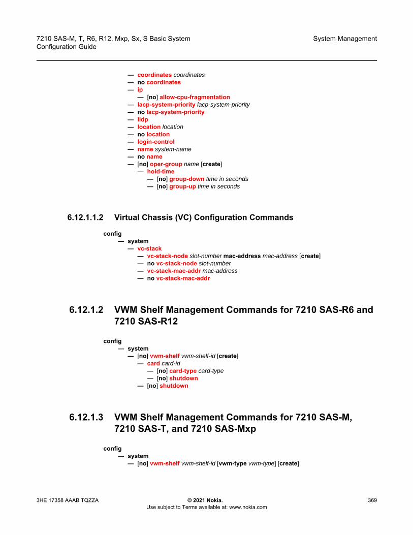
7210 SAS-M, T, R6, R12, Mxp, Sx, S Basic System Configuration Guide
System Management
3HE 17358 AAAB TQZZA © 2021 Nokia. Use subject to Terms available at: www.nokia.com
369
— coordinates coordinates— no coordinates— ip
— [no] allow-cpu-fragmentation— lacp-system-priority lacp-system-priority— no lacp-system-priority— lldp— location location— no location— login-control— name system-name— no name— [no] oper-group name [create]
— hold-time— [no] group-down time in seconds— [no] group-up time in seconds
6.12.1.1.2 Virtual Chassis (VC) Configuration Commands
config— system
— vc-stack — vc-stack-node slot-number mac-address mac-address [create]— no vc-stack-node slot-number — vc-stack-mac-addr mac-address — no vc-stack-mac-addr
6.12.1.2 VWM Shelf Management Commands for 7210 SAS-R6 and 7210 SAS-R12
config— system
— [no] vwm-shelf vwm-shelf-id [create] — card card-id
— [no] card-type card-type— [no] shutdown
— [no] shutdown
6.12.1.3 VWM Shelf Management Commands for 7210 SAS-M, 7210 SAS-T, and 7210 SAS-Mxp
config— system
— [no] vwm-shelf vwm-shelf-id [vwm-type vwm-type] [create]
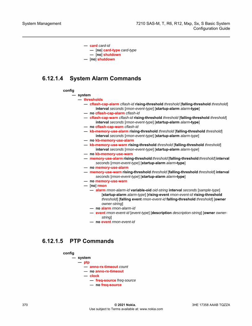
System Management
370
7210 SAS-M, T, R6, R12, Mxp, Sx, S Basic SystemConfiguration Guide
© 2021 Nokia. Use subject to Terms available at: www.nokia.com
3HE 17358 AAAB TQZZA
— card card-id— [no] card-type card-type— [no] shutdown
— [no] shutdown
6.12.1.4 System Alarm Commands
config— system
— thresholds— cflash-cap-alarm cflash-id rising-threshold threshold [falling-threshold threshold]
interval seconds [rmon-event-type] [startup-alarm alarm-type]— no cflash-cap-alarm cflash-id— cflash-cap-warn cflash-id rising-threshold threshold [falling-threshold threshold]
interval seconds [rmon-event-type] [startup-alarm alarm-type]— no cflash-cap-warn cflash-id — kb-memory-use-alarm rising-threshold threshold [falling-threshold threshold]
interval seconds [rmon-event-type] [startup-alarm alarm-type]— no kb-memory-use-alarm— kb-memory-use-warn rising-threshold threshold [falling-threshold threshold]
interval seconds [rmon-event-type] [startup-alarm alarm-type]— no kb-memory-use-warn— memory-use-alarm rising-threshold threshold [falling-threshold threshold] interval
seconds [rmon-event-type] [startup-alarm alarm-type]— no memory-use-alarm— memory-use-warn rising-threshold threshold [falling-threshold threshold] interval
seconds [rmon-event-type] [startup-alarm alarm-type]— no memory-use-warn— [no] rmon
— alarm rmon-alarm-id variable-oid oid-string interval seconds [sample-type] [startup-alarm alarm-type] [rising-event rmon-event-id rising-threshold threshold] [falling event rmon-event-id falling-threshold threshold] [owner owner-string]
— no alarm rmon-alarm-id— event rmon-event-id [event-type] [description description-string] [owner owner-
string]— no event rmon-event-id
6.12.1.5 PTP Commands
config— system
— ptp— anno-rx-timeout count— no anno-rx-timeout — clock
— freq-source freq-source— no freq-source
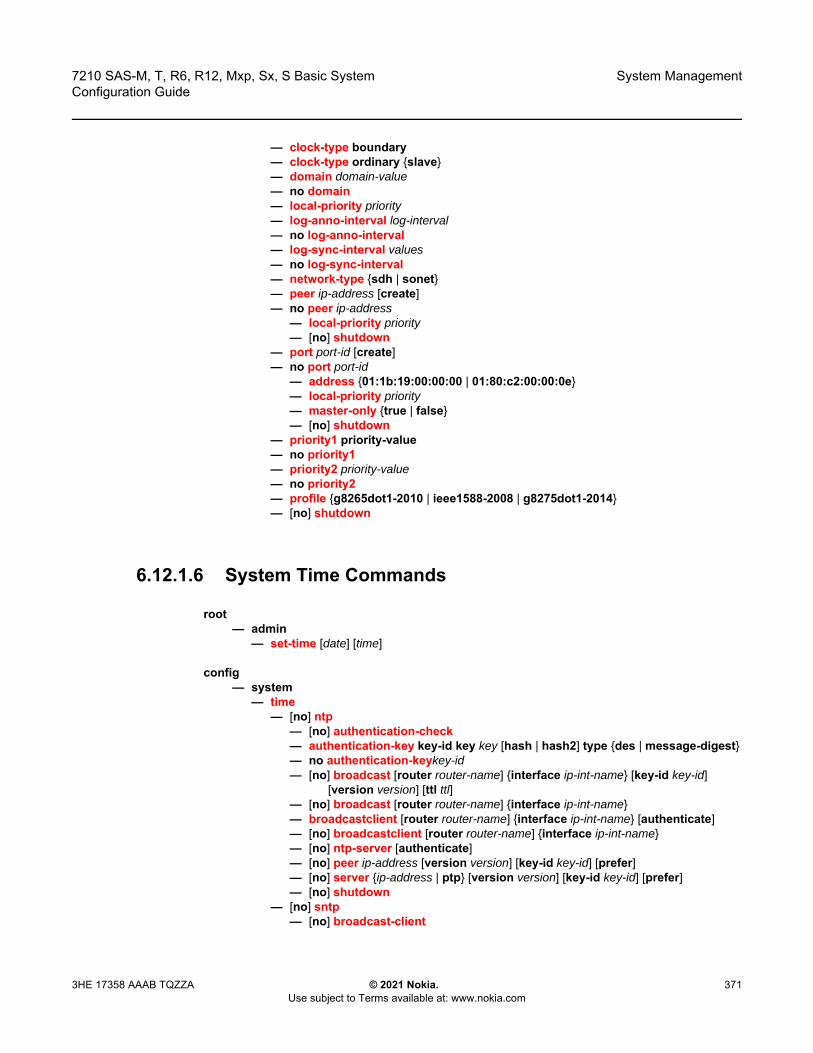
7210 SAS-M, T, R6, R12, Mxp, Sx, S Basic System Configuration Guide
System Management
3HE 17358 AAAB TQZZA © 2021 Nokia. Use subject to Terms available at: www.nokia.com
371
— clock-type boundary— clock-type ordinary {slave}— domain domain-value— no domain — local-priority priority— log-anno-interval log-interval— no log-anno-interval — log-sync-interval values— no log-sync-interval — network-type {sdh | sonet}— peer ip-address [create]— no peer ip-address
— local-priority priority— [no] shutdown
— port port-id [create]— no port port-id
— address {01:1b:19:00:00:00 | 01:80:c2:00:00:0e}— local-priority priority— master-only {true | false}— [no] shutdown
— priority1 priority-value— no priority1— priority2 priority-value— no priority2— profile {g8265dot1-2010 | ieee1588-2008 | g8275dot1-2014}— [no] shutdown
6.12.1.6 System Time Commands
root— admin
— set-time [date] [time]
config— system
— time— [no] ntp
— [no] authentication-check— authentication-key key-id key key [hash | hash2] type {des | message-digest}— no authentication-keykey-id— [no] broadcast [router router-name] {interface ip-int-name} [key-id key-id]
[version version] [ttl ttl]— [no] broadcast [router router-name] {interface ip-int-name}— broadcastclient [router router-name] {interface ip-int-name} [authenticate]— [no] broadcastclient [router router-name] {interface ip-int-name}— [no] ntp-server [authenticate]— [no] peer ip-address [version version] [key-id key-id] [prefer]— [no] server {ip-address | ptp} [version version] [key-id key-id] [prefer]— [no] shutdown
— [no] sntp— [no] broadcast-client
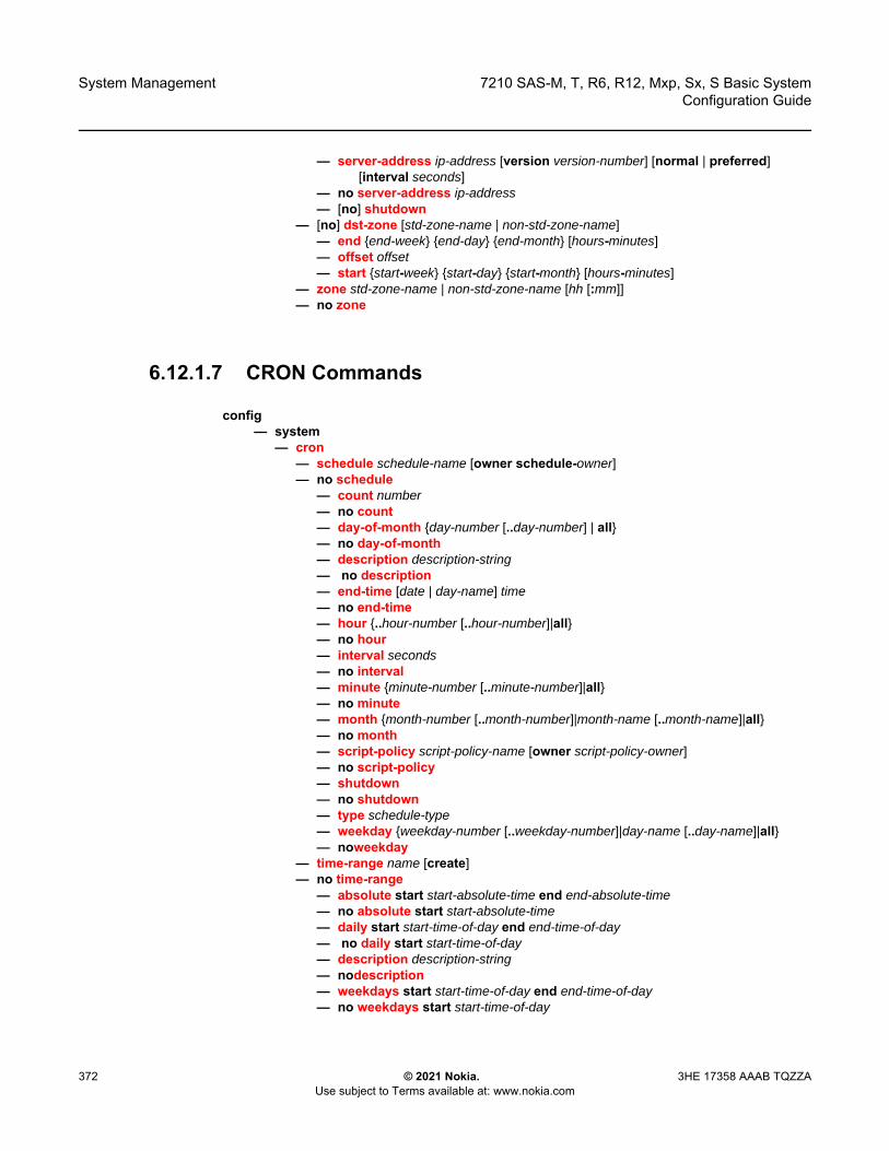
System Management
372
7210 SAS-M, T, R6, R12, Mxp, Sx, S Basic SystemConfiguration Guide
© 2021 Nokia. Use subject to Terms available at: www.nokia.com
3HE 17358 AAAB TQZZA
— server-address ip-address [version version-number] [normal | preferred] [interval seconds]
— no server-address ip-address— [no] shutdown
— [no] dst-zone [std-zone-name | non-std-zone-name]— end {end-week} {end-day} {end-month} [hours-minutes]— offset offset— start {start-week} {start-day} {start-month} [hours-minutes]
— zone std-zone-name | non-std-zone-name [hh [:mm]] — no zone
6.12.1.7 CRON Commands
config— system
— cron— schedule schedule-name [owner schedule-owner]— no schedule
— count number— no count— day-of-month {day-number [..day-number] | all}— no day-of-month — description description-string — no description — end-time [date | day-name] time— no end-time — hour {..hour-number [..hour-number]|all} — no hour— interval seconds — no interval— minute {minute-number [..minute-number]|all} — no minute — month {month-number [..month-number]|month-name [..month-name]|all}— no month — script-policy script-policy-name [owner script-policy-owner]— no script-policy— shutdown— no shutdown— type schedule-type — weekday {weekday-number [..weekday-number]|day-name [..day-name]|all}— noweekday
— time-range name [create]— no time-range
— absolute start start-absolute-time end end-absolute-time— no absolute start start-absolute-time— daily start start-time-of-day end end-time-of-day— no daily start start-time-of-day— description description-string — nodescription — weekdays start start-time-of-day end end-time-of-day— no weekdays start start-time-of-day
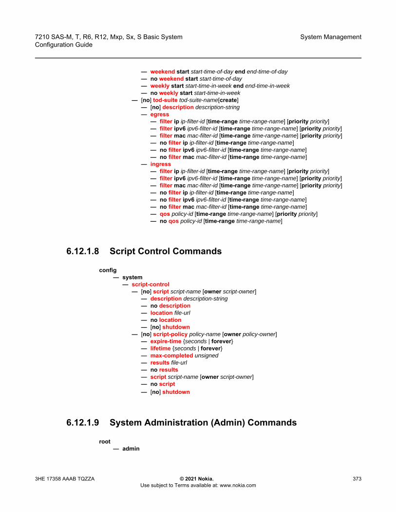
7210 SAS-M, T, R6, R12, Mxp, Sx, S Basic System Configuration Guide
System Management
3HE 17358 AAAB TQZZA © 2021 Nokia. Use subject to Terms available at: www.nokia.com
373
— weekend start start-time-of-day end end-time-of-day— no weekend start start-time-of-day— weekly start start-time-in-week end end-time-in-week— no weekly start start-time-in-week
— [no] tod-suite tod-suite-name[create] — [no] description description-string — egress
— filter ip ip-filter-id [time-range time-range-name] [priority priority] — filter ipv6 ipv6-filter-id [time-range time-range-name] [priority priority] — filter mac mac-filter-id [time-range time-range-name] [priority priority]— no filter ip ip-filter-id [time-range time-range-name] — no filter ipv6 ipv6-filter-id [time-range time-range-name] — no filter mac mac-filter-id [time-range time-range-name]
— ingress— filter ip ip-filter-id [time-range time-range-name] [priority priority] — filter ipv6 ipv6-filter-id [time-range time-range-name] [priority priority]— filter mac mac-filter-id [time-range time-range-name] [priority priority] — no filter ip ip-filter-id [time-range time-range-name] — no filter ipv6 ipv6-filter-id [time-range time-range-name]— no filter mac mac-filter-id [time-range time-range-name]— qos policy-id [time-range time-range-name] [priority priority] — no qos policy-id [time-range time-range-name]
6.12.1.8 Script Control Commands
config— system
— script-control— [no] script script-name [owner script-owner]
— description description-string— no description— location file-url— no location— [no] shutdown
— [no] script-policy policy-name [owner policy-owner]— expire-time {seconds | forever}— lifetime {seconds | forever}— max-completed unsigned— results file-url— no results— script script-name [owner script-owner]— no script— [no] shutdown
6.12.1.9 System Administration (Admin) Commands
root— admin
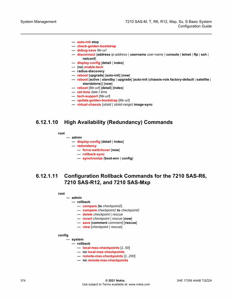
System Management
374
7210 SAS-M, T, R6, R12, Mxp, Sx, S Basic SystemConfiguration Guide
© 2021 Nokia. Use subject to Terms available at: www.nokia.com
3HE 17358 AAAB TQZZA
— auto-init stop— check-golden-bootstrap— debug-save file-url— disconnect {address ip-address | username user-name | console | telnet | ftp | ssh |
netconf}— display-config [detail | index]— [no] enable-tech— radius-discovery— reboot [upgrade] [auto-init] [now]— reboot [active | standby | upgrade] [auto-init {chassis-role factory-default | satellite |
standalone}] [now]— reboot [file-url] [detail] [index]— set-time date / time— tech-support [file-url]— update-golden-bootstrap [file-url] — virtual-chassis {slotid | slotid-range} image-sync
6.12.1.10 High Availability (Redundancy) Commands
root— admin
— display-config [detail | index]— redundancy
— force-switchover [now]— rollback-sync— synchronize {boot-env | config}
6.12.1.11 Configuration Rollback Commands for the 7210 SAS-R6, 7210 SAS-R12, and 7210 SAS-Mxp
root— admin
— rollback— compare [to checkpoint2]— compare checkpoint1 to checkpoint2— delete checkpoint | rescue— revert checkpoint | rescue [now]— save [comment comment] [rescue]— view [checkpoint | rescue]
config— system
— rollback— local-max-checkpoints [1..50]— no local-max-checkpoints— remote-max-checkpoints [1..200]— no remote-max-checkpoints
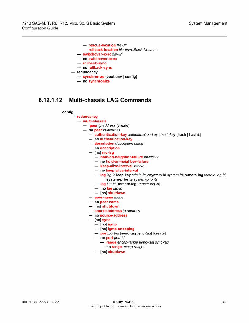
7210 SAS-M, T, R6, R12, Mxp, Sx, S Basic System Configuration Guide
System Management
3HE 17358 AAAB TQZZA © 2021 Nokia. Use subject to Terms available at: www.nokia.com
375
— rescue-location file-url— rollback-location file-url/rollback filename
— switchover-exec file-url— no switchover-exec— rollback-sync— no rollback-sync
— redundancy— synchronize {boot-env | config}— no synchronize
6.12.1.12 Multi-chassis LAG Commands
config— redundancy
— multi-chassis— peer ip-address [create]— no peer ip-address
— authentication-key authentication-key | hash-key [hash | hash2]— no authentication-key— description description-string— no description— [no] mc-lag
— hold-on-neighbor-failure multiplier— no hold-on-neighbor-failure— keep-alive-interval interval— no keep-alive-interval— lag lag-id lacp-key admin-key system-id system-id [remote-lag remote-lag-id]
system-priority system-priority— lag lag-id [remote-lag remote-lag-id]— no lag lag-id— [no] shutdown
— peer-name name— no peer-name— [no] shutdown— source-address ip-address— no source-address— [no] sync
— [no] igmp— [no] igmp-snooping— port port-id [sync-tag sync-tag] [create]— no port port-id
— range encap-range sync-tag sync-tag— no range encap-range
— [no] shutdown
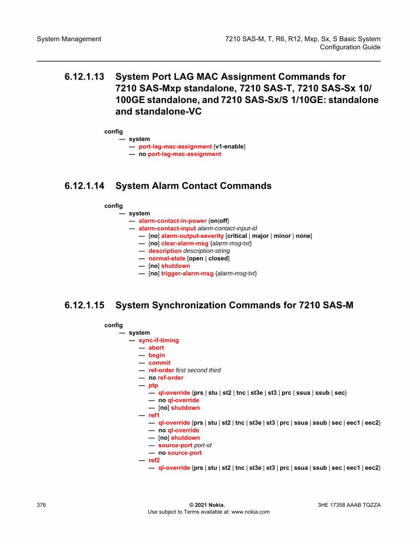
System Management
376
7210 SAS-M, T, R6, R12, Mxp, Sx, S Basic SystemConfiguration Guide
© 2021 Nokia. Use subject to Terms available at: www.nokia.com
3HE 17358 AAAB TQZZA
6.12.1.13 System Port LAG MAC Assignment Commands for 7210 SAS-Mxp standalone, 7210 SAS-T, 7210 SAS-Sx 10/100GE standalone, and 7210 SAS-Sx/S 1/10GE: standalone and standalone-VC
config— system
— port-lag-mac-assignment [v1-enable]— no port-lag-mac-assignment
6.12.1.14 System Alarm Contact Commands
config— system
— alarm-contact-in-power {on|off}— alarm-contact-input alarm-contact-input-id
— [no] alarm-output-severity [critical | major | minor | none] — [no] clear-alarm-msg {alarm-msg-txt}— description description-string— normal-state [open | closed]— [no] shutdown— [no] trigger-alarm-msg {alarm-msg-txt}
6.12.1.15 System Synchronization Commands for 7210 SAS-M
config— system
— sync-if-timing— abort— begin— commit— ref-order first second third— no ref-order— ptp
— ql-override {prs | stu | st2 | tnc | st3e | st3 | prc | ssua | ssub | sec}— no ql-override— [no] shutdown
— ref1— ql-override {prs | stu | st2 | tnc | st3e | st3 | prc | ssua | ssub | sec | eec1 | eec2}— no ql-override— [no] shutdown— source-port port-id— no source-port
— ref2— ql-override {prs | stu | st2 | tnc | st3e | st3 | prc | ssua | ssub | sec | eec1 | eec2}
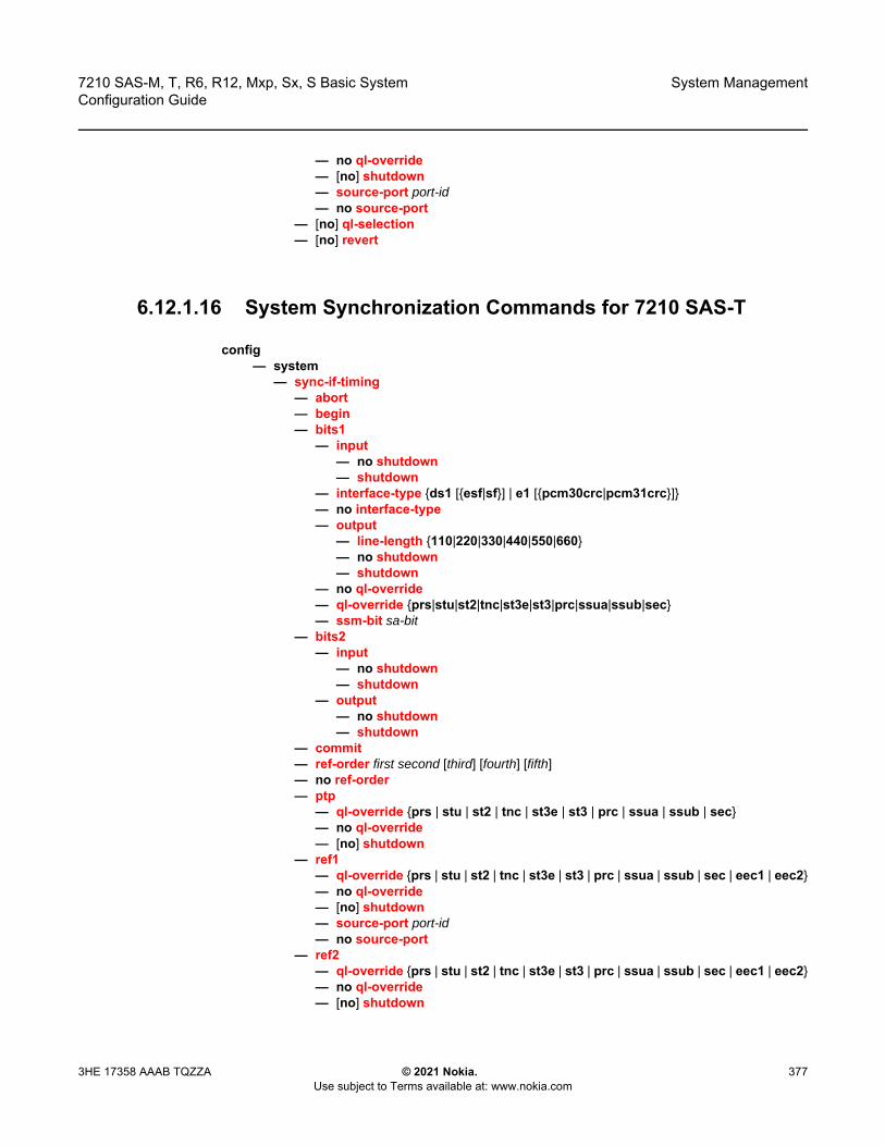
7210 SAS-M, T, R6, R12, Mxp, Sx, S Basic System Configuration Guide
System Management
3HE 17358 AAAB TQZZA © 2021 Nokia. Use subject to Terms available at: www.nokia.com
377
— no ql-override— [no] shutdown— source-port port-id— no source-port
— [no] ql-selection— [no] revert
6.12.1.16 System Synchronization Commands for 7210 SAS-T
config— system
— sync-if-timing— abort— begin— bits1
— input— no shutdown— shutdown
— interface-type {ds1 [{esf|sf}] | e1 [{pcm30crc|pcm31crc}]}— no interface-type— output
— line-length {110|220|330|440|550|660}— no shutdown— shutdown
— no ql-override— ql-override {prs|stu|st2|tnc|st3e|st3|prc|ssua|ssub|sec}— ssm-bit sa-bit
— bits2— input
— no shutdown— shutdown
— output— no shutdown— shutdown
— commit— ref-order first second [third] [fourth] [fifth]— no ref-order— ptp
— ql-override {prs | stu | st2 | tnc | st3e | st3 | prc | ssua | ssub | sec}— no ql-override— [no] shutdown
— ref1— ql-override {prs | stu | st2 | tnc | st3e | st3 | prc | ssua | ssub | sec | eec1 | eec2}— no ql-override— [no] shutdown— source-port port-id— no source-port
— ref2— ql-override {prs | stu | st2 | tnc | st3e | st3 | prc | ssua | ssub | sec | eec1 | eec2}— no ql-override— [no] shutdown
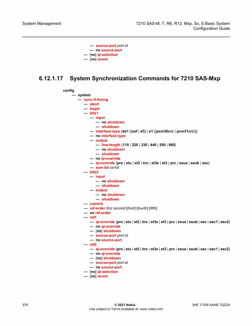
System Management
378
7210 SAS-M, T, R6, R12, Mxp, Sx, S Basic SystemConfiguration Guide
© 2021 Nokia. Use subject to Terms available at: www.nokia.com
3HE 17358 AAAB TQZZA
— source-port port-id— no source-port
— [no] ql-selection— [no] revert
6.12.1.17 System Synchronization Commands for 7210 SAS-Mxp
config— system
— sync-if-timing— abort— begin— bits1
— input— no shutdown— shutdown
— interface-type {ds1 [{esf | sf}] | e1 [{pcm30crc | pcm31crc}]}— no interface-type— output
— line-length {110 | 220 | 330 | 440 | 550 | 660}— no shutdown— shutdown
— no ql-override— ql-override {prs | stu | st2 | tnc | st3e | st3 | prc | ssua | ssub | sec}— ssm-bit sa-bit
— bits2— input
— no shutdown— shutdown
— output— no shutdown— shutdown
— commit— ref-order first second [third] [fourth] [fifth]— no ref-order— ref1
— ql-override {prs | stu | st2 | tnc | st3e | st3 | prc | ssua | ssub | sec | eec1 | eec2}— no ql-override— [no] shutdown— source-port port-id— no source-port
— ref2— ql-override {prs | stu | st2 | tnc | st3e | st3 | prc | ssua | ssub | sec | eec1 | eec2}— no ql-override— [no] shutdown— source-port port-id— no source-port
— [no] ql-selection— [no] revert
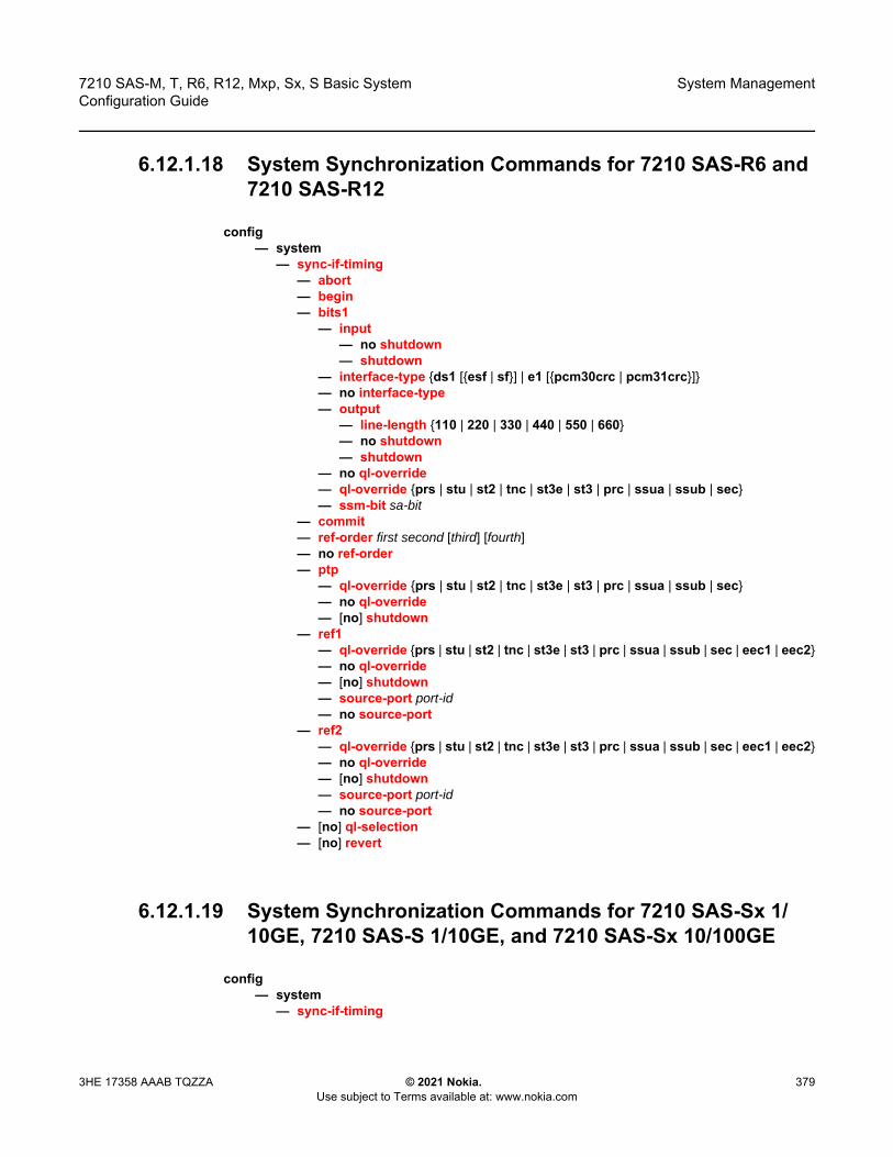
7210 SAS-M, T, R6, R12, Mxp, Sx, S Basic System Configuration Guide
System Management
3HE 17358 AAAB TQZZA © 2021 Nokia. Use subject to Terms available at: www.nokia.com
379
6.12.1.18 System Synchronization Commands for 7210 SAS-R6 and 7210 SAS-R12
config— system
— sync-if-timing— abort— begin— bits1
— input— no shutdown— shutdown
— interface-type {ds1 [{esf | sf}] | e1 [{pcm30crc | pcm31crc}]}— no interface-type— output
— line-length {110 | 220 | 330 | 440 | 550 | 660}— no shutdown— shutdown
— no ql-override— ql-override {prs | stu | st2 | tnc | st3e | st3 | prc | ssua | ssub | sec}— ssm-bit sa-bit
— commit— ref-order first second [third] [fourth]— no ref-order— ptp
— ql-override {prs | stu | st2 | tnc | st3e | st3 | prc | ssua | ssub | sec}— no ql-override— [no] shutdown
— ref1— ql-override {prs | stu | st2 | tnc | st3e | st3 | prc | ssua | ssub | sec | eec1 | eec2}— no ql-override— [no] shutdown— source-port port-id— no source-port
— ref2— ql-override {prs | stu | st2 | tnc | st3e | st3 | prc | ssua | ssub | sec | eec1 | eec2}— no ql-override— [no] shutdown— source-port port-id— no source-port
— [no] ql-selection— [no] revert
6.12.1.19 System Synchronization Commands for 7210 SAS-Sx 1/10GE, 7210 SAS-S 1/10GE, and 7210 SAS-Sx 10/100GE
config— system
— sync-if-timing
System Management
380
7210 SAS-M, T, R6, R12, Mxp, Sx, S Basic SystemConfiguration Guide
© 2021 Nokia. Use subject to Terms available at: www.nokia.com
3HE 17358 AAAB TQZZA
— abort— begin— commit— ref-order first second third— no ref-order— ref1
— ql-override {prs | stu | st2 | tnc | st3e | st3 | prc | ssua | ssub | sec | eec1 | eec2}— no ql-override— [no] shutdown— source-port port-id— no source-port
— ref2— ql-override {prs | stu | st2 | tnc | st3e | st3 | prc | ssua | ssub | sec | eec1 | eec2}— no ql-override— [no] shutdown— source-port port-id— no source-port
— [no] ql-selection— [no] revert
6.12.1.20 LLDP System Commands
configure— system
— lldp — lldp-med
— network-policy network-policy-id [create] — no network-policy network-policy-id — application-type {voice | voice-signaling | guest-voice | guest-voice-signaling
| soft-phone-voice | video-conferencing | streaming-video | video-signaling}
— no application-type — dot1p dot1p-value— no dot1p — ip-dscp ip-dscp— no ip-dscp — vlan-id 0..4094— no vlan-id — [no] vlan-tag-present
— message-fast-tx time— no message-fast-tx— message-fast-tx-init count— no message-fast-tx-init— notification-interval time— no notification-interval— reinit-delay time— no reinit-delay— [no] shutdown— tx-credit-max count— no tx-credit-max— tx-hold-multiplier multiplier

7210 SAS-M, T, R6, R12, Mxp, Sx, S Basic System Configuration Guide
System Management
3HE 17358 AAAB TQZZA © 2021 Nokia. Use subject to Terms available at: www.nokia.com
381
— no tx-hold-multiplier— tx-interval interval— no tx-interval
6.12.1.21 System Resource-Profile Commands for 7210 SAS-M
configure— system
— resource-profile— no resource-profile
— decommission— entry entry-id port port-range to port-range— no entry entry-id
— egress-internal-tcam— acl-sap-egress [num-resources]— no acl-sap-egress
— ipv4-ipv6-128-match-enable num-resources— no ipv4-ipv6-128-match-enable— mac-ipv4-match-enable num-resources— no mac-ipv4-match-enable— mac-ipv6-64bit-match-enable num-resources— no mac-ipv6-64bit-match-enable— mac-match-enable num-resources— no mac-match-enable
— egress-sap-aggregate-meter— no egress-sap-aggregate-meter num-resources
— eth-cfm— [no] symmetric-qos-downmeps
— g8032-fast-flood-enable — no g8032-fast-flood-enable — ingress-internal-tcam
— acl-sap-ingress [num-resources]— no acl-sap-ingress
— ipv4-ipv6-128-match-enable num-resources— no ipv4-ipv6-128-match-enable— ipv4-match-enable num-resources— no ipv4-match-enable— ipv6-64-only-match-enable num-resources— no ipv6-64-only-match-enable— mac-match-enable num-resources — no mac-match-enable
— eth-cfm [num-resources] — no eth-cfm
— up-mep num-resources — no up-mep
— qos-sap-ingress-resource num-resources— no qos-sap-ingress-resource
— ipv4-mac-match-enable num-resources— no ipv4-mac-match-enable— ipv4-match-enable num-resources— no ipv4-match-enable
System Management
382
7210 SAS-M, T, R6, R12, Mxp, Sx, S Basic SystemConfiguration Guide
© 2021 Nokia. Use subject to Terms available at: www.nokia.com
3HE 17358 AAAB TQZZA
— ipv6-ipv4-match-enable num-resources— no ipv6-ipv4-match-enable— mac-match-enable num-resources— no mac-match-enable
— no sap-aggregate-meter— sap-aggregate-meter num-resources
6.12.1.22 System Resource-Profile Commands for 7210 SAS-T
configure— system
— resource-profile— no resource-profile
— decommission— entry entry-id port port-range to port-range— no entry entry-id
— egress-internal-tcam— acl-sap-egress [num-resources]— no acl-sap-egress
— ipv4-ipv6-128-match-enable num-resources— no ipv4-ipv6-128-match-enable— mac-ipv4-match-enable num-resources— no mac-ipv4-match-enable— mac-ipv6-64bit-match-enable num-resources— no mac-ipv6-64bit-match-enable— mac-match-enable num-resources— no mac-match-enable
— egress-sap-aggregate-meter— no egress-sap-aggregate-meter num-resources
— ingress-internal-tcam— acl-sap-ingress [num-resources]— no acl-sap-ingress
— ipv4-ipv6-128-match-enable num-resources— no ipv4-ipv6-128-match-enable— ipv4-match-enable num-resources— no ipv4-match-enable— ipv6-64-only-match-enable num-resources— no ipv6-64-only-match-enable— mac-match-enable num-resources — no mac-match-enable
— g8032-fast-flood-enable — no g8032-fast-flood-enable — eth-cfm [num-resources] — no eth-cfm
— up-mep num-resources — no up-mep
— qos-sap-ingress-resource num-resources— no qos-sap-ingress-resource
— ipv4-mac-match-enable num-resources— no ipv4-mac-match-enable— ipv4-match-enable num-resources
7210 SAS-M, T, R6, R12, Mxp, Sx, S Basic System Configuration Guide
System Management
3HE 17358 AAAB TQZZA © 2021 Nokia. Use subject to Terms available at: www.nokia.com
383
— no ipv4-match-enable— ipv6-ipv4-match-enable num-resources— no ipv6-ipv4-match-enable— mac-match-enable num-resources— no mac-match-enable
— no sap-aggregate-meter— sap-aggregate-meter num-resources
— qos — mbs-pool {node | port}— no mbs-pool
6.12.1.23 System Resource-Profile Commands for 7210 SAS-Mxp
configure— system
— resource-profile— no resource-profile
— egress-internal-tcam— acl-sap-egress [num-resources]— no acl-sap-egress
— ipv4-ipv6-128-match-enable num-resources— no ipv4-ipv6-128-match-enable— mac-ipv4-match-enable num-resources— no mac-ipv4-match-enable— mac-ipv6-64bit-match-enable num-resources— no mac-ipv6-64bit-match-enable— mac-match-enable num-resources— no mac-match-enable
— ingress-internal-tcam— acl-sap-ingress [num-resources]— no acl-sap-ingress
— ipv4-ipv6-128-match-enable num-resources— no ipv4-ipv6-128-match-enable— ipv4-match-enable num-resources— no ipv4-match-enable— ipv6-64-only-match-enable num-resources— no ipv6-64-only-match-enable— mac-match-enable num-resources — no mac-match-enable
— eth-cfm [num-resources] — no eth-cfm
— down-mep num-resources— no down-mep — up-mep num-resources — no up-mep
— ip-mpls-protocols num-resources— no ip-mpls-protocols— qos-access-port-ingress-resource num-resources— no qos-access-port-ingress-resource— qos-sap-egress-resource num-resources — no qos-sap-egress-resource
System Management
384
7210 SAS-M, T, R6, R12, Mxp, Sx, S Basic SystemConfiguration Guide
© 2021 Nokia. Use subject to Terms available at: www.nokia.com
3HE 17358 AAAB TQZZA
— qos-sap-ingress-resource num-resources— no qos-sap-ingress-resource
— ip-dscp-port-if-match-enable num-resources — no ip-dscp-port-if-match-enable — ipv4-mac-match-enable num-resources— no ipv4-mac-match-enable— ipv4-match-enable num-resources— no ipv4-match-enable— ipv6-ipv4-match-enable num-resources— no ipv6-ipv4-match-enable— mac-match-enable num-resources— no mac-match-enable
— no sap-aggregate-meter— sap-aggregate-meter num-resources
— qos — no port-scheduler-mode — port-scheduler-mode
— sap-scale-mode mode— no sap-scale-mode
6.12.1.24 System Resource-Profile Router Commands for 7210 SAS-M, 7210 SAS-T, 7210 SAS-Mxp, 7210 SAS-Sx 1/10GE, and 7210 SAS-Sx 10/100GE
configure— system
— resource-profile— router
— ecmp max-routes-dest— no ecmp — ldp-ecmp percent-value— no ldp-ecmp— max-ipv6-routes number— no max-ipv6-routes— max-ip-subnets number— no max-ip-subnets
6.12.1.25 System Resource-Profile Commands Related to BGP LU FRR and LDPoRSVP FRR for 7210 SAS-M, 7210 SAS-T, 7210 SAS-Mxp, 7210 SAS-Sx 1/10GE, and 7210 SAS-Sx 10/100GE
configure— system
— resource-profile
7210 SAS-M, T, R6, R12, Mxp, Sx, S Basic System Configuration Guide
System Management
3HE 17358 AAAB TQZZA © 2021 Nokia. Use subject to Terms available at: www.nokia.com
385
— enable-bgp3107-frr— no enable-bgp3107-frr— enable-ldporsvp-frr— no enable-ldporsvp-frr
6.12.1.26 System Resource-Profile Commands for 7210 SAS-Sx/S 1/10GE and 7210 SAS-Sx 10/100GE
configure— system
— resource-profile — no resource-profile
— egress-internal-tcam— acl-sap-egress [num-resources]— no acl-sap-egress
— [no] ipv6-128bit-match-enable num-resources— mac-ipv4-match-enable num-resources— no mac-ipv4-match-enable— mac-ipv6-64bit-match-enable num-resources— no mac-ipv6-64bit-match-enable— mac-match-enable num-resources— no mac-match-enable
— egress-sap-aggregate-meter num-resources— no egress-sap-aggregate-meter num-resources
— ingress-internal-tcam— acl-sap-ingress [num-resources]— no acl-sap-ingress
— ipv4-ipv6-128-match-enable num-resources— no ipv4-ipv6-128-match-enable— ipv4-match-enable num-resources— no ipv4-match-enable— ipv6-64-only-match-enable num-resources— no ipv6-64-only-match-enable— mac-match-enable num-resources — no mac-match-enable
— eth-cfm [num-resources] — no eth-cfm
— up-mep num-resources — no up-mep — down-mep num-resources — no down-mep
— qos-access-port-ingress-resource num-resources — no qos-access-port-ingress-resource — qos-sap-ingress-resource [num-resources]— no qos-sap-ingress-resource
— ipv4-mac-match-enable num-resources— no ipv4-mac-match-enable— ipv4-match-enable num-resources— no ipv4-match-enable— ipv6-ipv4-match-enable num-resources
System Management
386
7210 SAS-M, T, R6, R12, Mxp, Sx, S Basic SystemConfiguration Guide
© 2021 Nokia. Use subject to Terms available at: www.nokia.com
3HE 17358 AAAB TQZZA
— no ipv6-ipv4-match-enable— mac-match-enable num-resources— no mac-match-enable
— no sap-aggregate-meter— sap-aggregate-meter num-resources
— sap-scale-mode mode — no sap-scale-mode
6.12.1.27 System Resource-Profile Commands for a Virtual Chassis
configure— system
— resource-profile — no resource-profile
— description description-string — no description— egress-internal-tcam
— acl-sap-egress [num-resources]— no acl-sap-egress
— [no] ipv6-128bit-match-enable num-resources— mac-ipv4-match-enable num-resources— no mac-ipv4-match-enable— mac-ipv6-64bit-match-enable num-resources— no mac-ipv6-64bit-match-enable— mac-match-enable num-resources— no mac-match-enable
— egress-sap-aggregate-meter num-resources— no egress-sap-aggregate-meter num-resources
— g8032-control-sap-tags vlan-range— no g8032-control-sap-tags— ingress-internal-tcam
— acl-sap-ingress [num-resources]— no acl-sap-ingress
— ipv4-ipv6-128-match-enable num-resources— no ipv4-ipv6-128-match-enable— ipv4-match-enable num-resources— no ipv4-match-enable— ipv6-64-only-match-enable num-resources— no ipv6-64-only-match-enable— mac-match-enable num-resources — no mac-match-enable
— eth-cfm [num-resources] — no eth-cfm
— up-mep num-resources — no up-mep — sap-down-mep num-resources — no sap-down-mep — sdp-down-mep-ing-mip num-resources — no sdp-down-mep-ing-mip
— no qos-sap-ingress-resource— qos-sap-ingress-resource [num-resources]
7210 SAS-M, T, R6, R12, Mxp, Sx, S Basic System Configuration Guide
System Management
3HE 17358 AAAB TQZZA © 2021 Nokia. Use subject to Terms available at: www.nokia.com
387
— ipv4-mac-match-enable num-resources— no ipv4-mac-match-enable— ipv4-match-enable num-resources— no ipv4-match-enable— ipv6-ipv4-match-enable num-resources— no ipv6-ipv4-match-enable— mac-match-enable num-resources— no mac-match-enable
— no sap-aggregate-meter— sap-aggregate-meter num-resources
6.12.1.28 System Resource-Profile Commands for 7210 SAS-R6 and 7210 SAS-R12
configure— system
— resource-profile policy-id [create]— no resource-profile policy-id
— description description-string— no description— egress-internal-tcam
— acl-sap-egress [num-resources]— no acl-sap-egress
— [no] ipv6-128bit-match-enable num-resources— mac-ipv4-match-enable num-resources— no mac-ipv4-match-enable— mac-ipv6-64bit-match-enable num-resources— no mac-ipv6-64bit-match-enable— mac-match-enable num-resources— no mac-match-enable
— egress-sap-aggregate-meter num-resources— no egress-sap-aggregate-meter num-resources— eth-cfm [num-resources]— no eth-cfm
— bidir-mip-egress [num-resources]— no bidir-mip-egress
— g8032-control-sap-tags vlan-range— no g8032-control-sap-tags— ingress-internal-tcam
— acl-sap-ingress [num-resources]— no acl-sap-ingress
— ipv4-ipv6-128-match-enable num-resources— no ipv4-ipv6-128-match-enable— ipv4-match-enable num-resources— no ipv4-match-enable— ipv6-64-only-match-enable num-resources— no ipv6-64-only-match-enable— mac-match-enable num-resources — no mac-match-enable
— cpu-protection [num-resources]
System Management
388
7210 SAS-M, T, R6, R12, Mxp, Sx, S Basic SystemConfiguration Guide
© 2021 Nokia. Use subject to Terms available at: www.nokia.com
3HE 17358 AAAB TQZZA
— no cpu-protection] — eth-cfm [num-resources] — no eth-cfm
— up-mep num-resources — no up-mep — down-mep num-resources — no down-mep
— qos-access-port-ingress-resource num-resources— no qos-access-port-ingress-resource— qos-network-ingress-resource [num-resources]— no qos-network-ingress-resource— qos-sap-egress-resource num-resources— no qos-sap-egress-resource— qos-sap-ingress-resource [num-resources]— no qos-sap-ingress-resource
— ip-dscp-port-if-match-enable num-resources — no ip-dscp-port-if-match-enable — ipv4-mac-match-enable num-resources— no ipv4-mac-match-enable— ipv4-match-enable num-resources— no ipv4-match-enable— ipv6-ipv4-match-enable num-resources— no ipv6-ipv4-match-enable— mac-match-enable num-resources— no mac-match-enable
— no sap-aggregate-meter— sap-aggregate-meter num-resources
6.12.1.29 System Resource Profile Commands for MAC Authentication
configure— system
— resource-profile policy-id [create]— no resource-profile policy-id
— egress-internal-tcam— mac-auth-res num-resources
— ingress-internal-tcam— mac-auth-res num-resources
6.12.1.30 Global System Resource Profile Commands for 7210 SAS-R6 and 7210 SAS-R12
configure— system
— global-res-profile— enable-bgp3107-frr

7210 SAS-M, T, R6, R12, Mxp, Sx, S Basic System Configuration Guide
System Management
3HE 17358 AAAB TQZZA © 2021 Nokia. Use subject to Terms available at: www.nokia.com
389
— no enable-bgp3107-frr— enable-ldporsvp-frr— no enable-ldporsvp-frr— qos
— no port-scheduler-mode— port-scheduler-mode
— router— no ecmp— ecmp— ldp-ecmp percent-value— no ldp-ecmp— no max-ipv6-routes— max-ipv6-routes number— no max-ip-subnets— max-ip-subnets number
— sap-scale-mode mode — no sap-scale-mode — sf-ingress-internal-tcam
— eth-cfm-upmeps max_slices— eth-cfm-upmeps— g8032-fast-flood max_slices— no g8032-fast-flood— mpls-p2mp max_slices— no mpls-p2mp
6.12.1.31 Global System Resource Profile Commands for a Virtual Chassis
configure— system
— global-res-profile— enable-bgp3107-frr— no enable-bgp3107-frr— enable-ldporsvp-frr— no enable-ldporsvp-frr— router
— no ecmp— ecmp— ldp-ecmp percent-value— no ldp-ecmp— no max-ipv6-routes— max-ipv6-routes number— no max-ip-subnets— max-ip-subnets number

System Management
390
7210 SAS-M, T, R6, R12, Mxp, Sx, S Basic SystemConfiguration Guide
© 2021 Nokia. Use subject to Terms available at: www.nokia.com
3HE 17358 AAAB TQZZA
6.12.1.32 Show Commands
show— alarm-contact-input alarm-contact-input-id [detail]— alarm-contact-input all — chassis [environment] [power-supply]— system
— chassis [imm-family]— chassis {active | configured}— connection [address ip-address [interface interface-name]] [port port-number] [detail]— cpu [sample-period seconds] — cron
— schedule action-name [owner owner-name]— tod-suite tod-suite-name [detail] associations failed-associations— time-range name associations [detail]
— global-res-profile [detail] — global-res-profile {active | configured}— information— lldp— memory-pools— ntp [{peers | peer peer-address} | {servers | server server-address} | [all]] [detail]— rollback [rescue]— resource-profile [active|configured] policy-id [detail]— ptp
— peer ip-address [router router-instance | service-name service-name] [detail]— peers [router router-instance | service-name service-name] [detail]— port port-id [detail]— statistics— unicast [router router-instance | service-name service-name]
— sntp— sync-if-timing— script-control
— script [script-name] [owner script-owner]— script-policy script-policy-name [owner owner-name]— script-policy run-history [run-state]
— thresholds— time— vwm-shelf vwm-shelf-id [detail] — time
— redundancy— multi-chassis
— all [detail]— mc-lag peer [ip-address] [lag lag-id]— mc-lag [peer ip-address [lag lag-id]] statistics— sync [peer ip-address]— sync peer ip-address detail
— synchronization— pools— force-reference— oper-group [group-name]— oper-group group-name [detail]— oper-group group-name [monitoring]— uptime
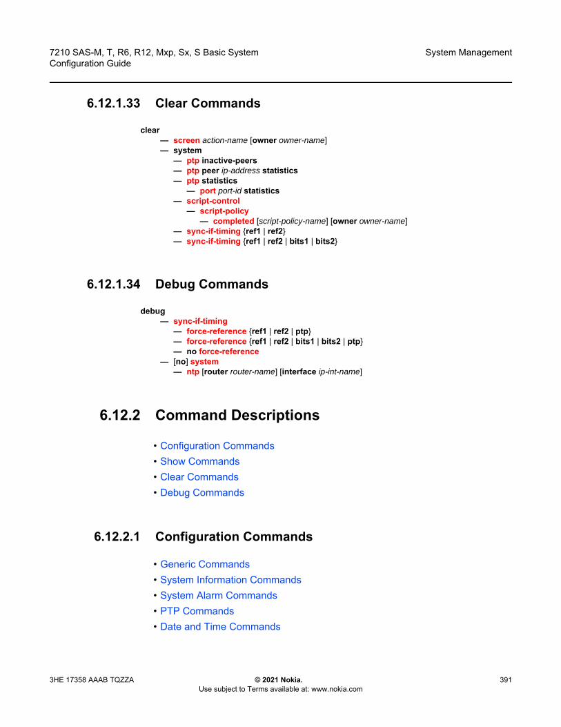
7210 SAS-M, T, R6, R12, Mxp, Sx, S Basic System Configuration Guide
System Management
3HE 17358 AAAB TQZZA © 2021 Nokia. Use subject to Terms available at: www.nokia.com
391
6.12.1.33 Clear Commands
clear— screen action-name [owner owner-name]— system
— ptp inactive-peers— ptp peer ip-address statistics— ptp statistics
— port port-id statistics— script-control
— script-policy— completed [script-policy-name] [owner owner-name]
— sync-if-timing {ref1 | ref2}— sync-if-timing {ref1 | ref2 | bits1 | bits2}
6.12.1.34 Debug Commands
debug— sync-if-timing
— force-reference {ref1 | ref2 | ptp}— force-reference {ref1 | ref2 | bits1 | bits2 | ptp} — no force-reference
— [no] system— ntp [router router-name] [interface ip-int-name]
6.12.2 Command Descriptions
• Configuration Commands• Show Commands• Clear Commands• Debug Commands
6.12.2.1 Configuration Commands
• Generic Commands• System Information Commands• System Alarm Commands• PTP Commands• Date and Time Commands
System Management
392
7210 SAS-M, T, R6, R12, Mxp, Sx, S Basic SystemConfiguration Guide
© 2021 Nokia. Use subject to Terms available at: www.nokia.com
3HE 17358 AAAB TQZZA
• System Synchronization Commands• Generic Commands• System Administration Commands• System Alarm Contact Commands• Redundancy Commands• Rollback Commands• Peer Commands• MC-LAG Commands• LLDP System Commands• LLDP Ethernet Port Commands• System Resource-Profile Commands• Global System Resource Profile Commands
6.12.2.1.1 Generic Commands
shutdown
Syntax [no] shutdown
Context config>system>ptpconfig>system>time>ntpconfig>system>time>sntpconfig>system>cron>schedconfig>system>script-control>script-policyconfig>system>script-control>scriptconfig>system>sync-if-timing>ref1config>system>sync-if-timing>ref2config>redundancy>multi-chassis>peerconfig>redundancy>multi-chassis>peer>mc-lag
Platforms Supported on all 7210 SAS platforms as described in this document, including platforms configured in the access-uplink operating mode
Description
This command administratively disables the entity. When disabled, an entity does not change, reset, or remove any configuration settings or statistics.
Note: The config>redundancy>multi-chassis>peer and config>redundancy>multi-chassis>peer>mc-lag contexts are not supported on 7210 SAS platforms configured in the access-uplink operating mode

7210 SAS-M, T, R6, R12, Mxp, Sx, S Basic System Configuration Guide
System Management
3HE 17358 AAAB TQZZA © 2021 Nokia. Use subject to Terms available at: www.nokia.com
393
The operational state of the entity is disabled as well as the operational state of any entities contained within. Many objects must be shut down before they may be deleted.
The no form of this command places the entity into an administratively enabled state.
Default no shutdown
Special Cases PTP Protocol Handling — Applies only to 7210 SAS-Mxp. When the no shutdown command is issued in the configure>system>ptp context, resources are allocated to enable processing of the protocol by the node. When the shutdown command is issued in the configure>system>ptp context, the resources are deallocated.
description
Syntax description description-stringno description
Context config>system>cron>schedconfig>system>cron>time-rangeconfig>system>cron>tod-suiteconfig>system>script-control>scriptconfig>redundancy>multi-chassis>peer
Platforms Supported on all 7210 SAS platforms as described in this document, including platforms configured in the access-uplink operating mode
Description
This command creates a text description stored in the configuration file for a configuration context.
The description command associates a text string with a configuration context to help identify the content in the configuration file.
The no form of this command removes the string from the configuration.
Parameters string — Specifies the description character string. Allowed values are any string up to 80 characters composed of printable, 7-bit ASCII characters. If the string contains special characters (#, $, spaces, and so on), the entire string must be enclosed within double quotes.
Note: Resources for PTP are allocated when the protocol is enabled in the base routing instance. Resources are deallocated when the configuration of the last PTP context under the base routing instance is shutdown
Note: The config>redundancy>multi-chassis>peer context is not supported on 7210 SAS platforms configured in the access-uplink operating mode

System Management
394
7210 SAS-M, T, R6, R12, Mxp, Sx, S Basic SystemConfiguration Guide
© 2021 Nokia. Use subject to Terms available at: www.nokia.com
3HE 17358 AAAB TQZZA
6.12.2.1.2 System Information Commands
boot-bad-exec
Syntax boot-bad-exec file-urlno boot-bad-exec
Context config>system
Platforms Supported on all 7210 SAS platforms as described in this document, including platforms configured in the access-uplink operating mode
Description This command configures a URL for a CLI script to exec following a failure of a boot-up configuration. The command specifies a URL for the CLI scripts to be run following the completion of the boot-up configuration. A URL must be specified or no action is taken.
The commands are persistent between router reboots and are included in the configuration saves (admin save).
See the exec command for related commands. This command executes the contents of a text file as if they were commands entered at the console.
Default no boot-bad-exec
Parameters file-url — Specifies the location and name of the CLI script file executed following failure of the boot-up configuration file execution. When this parameter is not specified, no CLI script file is executed.
Values file url — local-url | remote-url: 255 chars maxlocal-url — [cflash-id/ | usb-flash-id][file-path]remote-url — [{ftp://} login:pswd@remote-locn/][file-path]remote-locn — [hostname | ipv4-address]
ipv4-address — a.b.c.d
usb-flash-id — uf1: (7210 SAS-M, 7210 SAS-T, 7210 SAS-Mxp, 7210 SAS-Sx 1/10GE: standalone and standalone-VC, and 7210 SAS-Sx 10/100GE)uf1:, uf1-A:, uf1-B: (7210 SAS-R6 and 7210 SAS-R12)
cflash-id — cf1:, cf2: (7210 SAS-T, 7210 SAS-Mxp, 7210 SAS-Sx 10/100GE, and 7210 SAS-Sx/S 1/10GE: standalone and standalone-VC)cf2:, cf2-A:, cf2-B: (7210 SAS-R6 and 7210 SAS-R12)

7210 SAS-M, T, R6, R12, Mxp, Sx, S Basic System Configuration Guide
System Management
3HE 17358 AAAB TQZZA © 2021 Nokia. Use subject to Terms available at: www.nokia.com
395
boot-good-exec
Syntax boot-good-exec file-urlno boot-good-exec
Context config>system
Platforms Supported on all 7210 SAS platforms as described in this document, including platforms configured in the access-uplink operating mode
Description Use this command to configure a URL for a CLI script to exec following the success of a boot-up configuration.
See the exec command for related commands. This command executes the contents of a text file as if they were commands entered at the console.
Default no boot-good-exec
Parameters file-url — Specifies the location and name of the CLI script file executed following failure of the boot-up configuration file execution. When this parameter is not specified, no CLI script file is executed.
Values file url — local-url | remote-url: 255 chars maxlocal-url — [cflash-id/ | usb-flash-id][file-path]remote-url — [{ftp://} login:pswd@remote-locn/][file-path]remote-locn — [hostname | ipv4-address]
ipv4-address — a.b.c.d
allow-imm-family
Syntax allow-imm-family imm-familyno allow-imm-family
Context config>system>chassis
usb-flash-id — uf1: (7210 SAS-M, 7210 SAS-T, 7210 SAS-Mxp, 7210 SAS-Sx 1/10GE: standalone and standalone-VC, and 7210 SAS-Sx 10/100GE)uf1:, uf1-A:, uf1-B: (7210 SAS-R6 and 7210 SAS-R12)
cflash-id — cf1:, cf2: (7210 SAS-T, 7210 SAS-Mxp, 7210 SAS-Sx 10/100GE, and 7210 SAS-Sx/S 1/10GE: standalone and standalone-VC)cf2:, cf2-A:, cf2-B: (7210 SAS-R6 and 7210 SAS-R12)

System Management
396
7210 SAS-M, T, R6, R12, Mxp, Sx, S Basic SystemConfiguration Guide
© 2021 Nokia. Use subject to Terms available at: www.nokia.com
3HE 17358 AAAB TQZZA
Platforms 7210 SAS-R6 and 7210 SAS-R12
Description This command allows the users to configure the type of IMM they plan to use with the chassis. On the 7210 SAS-R6, a mix of IMMv1 and IMMv2 is not allowed to be used in the same chassis. In other words, the user can populate the chassis with either all IMMv1 IMMs or with all IMMv2 IMMs. The type of IMM planned to be used in a chassis needs to be configured up-front, so that on system boot, the software can allocate appropriate resources based on the IMM type.
The software checks that the IMMs provisioned (and equipped) in the chassis is a member of the IMM family type currently configured (active value) by the user. If the user provisioned IMM does not match the IMM types allowed, the software detects a errors in provisioning mismatch and marks the operational state of the IMM to be down.
Default no allow-imm-family
Parameters imm-family — Specifies the type of IMM family type to be used in a chassis.
Values imm-sas-r, imm-sas-r-b, imm-sas-r-c
clli-code
Syntax clli-code clli-codeno clli-code
Context config>system
Platforms Supported on all 7210 SAS platforms as described in this document, including platforms configured in the access-uplink operating mode
Description This command creates a Common Language Location Identifier (CLLI) code string for the router. A CLLI code is an 11-character standardized geographic identifier that uniquely identifies geographic locations and certain functional categories of equipment unique to the telecommunications industry.
Note: • The chassis by default will support IMMv1 family (that is, 1st generation of
7210 SAS-R6 IMMs). The default profile of the chassis remains the same, unless modified by the user.
• The user can add in support for any IMM family type by repeated execution of this command. IMM Family type will be added, only if the current supported family types are compatible with each other, else an error is returned. In other words, if the user specifies both IMMv1 and IMMv2 the command errors out when the user executes the command to add the IMM family IMMv2.
• A change in the current value of IMM family requires a reboot of the node to take effect. therefore, the user configured value for IMM family type takes effect only after the next reboot.

7210 SAS-M, T, R6, R12, Mxp, Sx, S Basic System Configuration Guide
System Management
3HE 17358 AAAB TQZZA © 2021 Nokia. Use subject to Terms available at: www.nokia.com
397
No CLLI validity checks other than truncating or padding the string to eleven characters are performed.
Only one CLLI code can be configured, if multiple CLLI codes are configured the last one entered overwrites the previous entry.
The no form of this command removes the CLLI code.
Parameters clli-code — Specifies the 11 character string CLLI code. Any printable, seven bit ASCII characters can be used within the string. If the string contains special characters (#, $, spaces, and so on), the entire string must be enclosed within double quotes. If more than 11 characters are entered, the string is truncated. If less than 11 characters are entered the string is padded with spaces.
config-backup
Syntax config-backup countno config-backup
Context config>system
Platforms Supported on all 7210 SAS platforms as described in this document, including platforms configured in the access-uplink operating mode
Description This command configures the maximum number of backup versions maintained for configuration files and BOF.
For example, assume count is set to 5, and the configuration file is called xyz.cfg. When a save command is executed, the file xyz.cfg is saved with a .1 extension. Each subsequent config-backup command increments the numeric extension until the maximum count is reached.
xyz.cfgxyz.cfg.1xyz.cfg.2xyz.cfg.3xyz.cfg.4xyz.cfg.5xyz.ndx
Each persistent index file is updated at the same time as the associated configuration file. When the index file is updated, the save is performed to xyz.cfg and the index file is created as xyz.ndx. Synchronization between the active and standby is performed for all configurations and their associated persistent index files.
The no form of this command reverts the configuration to the default value.
Default 5

System Management
398
7210 SAS-M, T, R6, R12, Mxp, Sx, S Basic SystemConfiguration Guide
© 2021 Nokia. Use subject to Terms available at: www.nokia.com
3HE 17358 AAAB TQZZA
Parameters count — Specifies the maximum number of backup revisions.
Values 1 to 9
contact
Syntax contact contact-nameno contact
Context config>system
Platforms Supported on all 7210 SAS platforms as described in this document, including platforms configured in the access-uplink operating mode
Description This command creates a text string that identifies the contact name for the device.
Only one contact can be configured, if multiple contacts are configured the last one entered will overwrite the previous entry.
The no form of this command reverts to the default.
Parameters contact-name — Specifies the contact name character string. The string may be up to 80 characters. Any printable, seven-bit ASCII characters can be used within the string. If the string contains special characters (#, $, spaces, and so on), the entire string must be enclosed within double quotes.
coordinates
Syntax coordinates coordinatesno coordinates
Context config>system
Platforms Supported on all 7210 SAS platforms as described in this document, including platforms configured in the access-uplink operating mode
Description This command creates a text string that identifies the system coordinates for the device location. For example, the command coordinates “37.390 -122.0550" is read as latitude 37.390 north and longitude 122.0550 west.
Only one set of coordinates can be configured. If multiple coordinates are configured, the last one entered overwrites the previous entry.
The no form of this command reverts to the default value.
7210 SAS-M, T, R6, R12, Mxp, Sx, S Basic System Configuration Guide
System Management
3HE 17358 AAAB TQZZA © 2021 Nokia. Use subject to Terms available at: www.nokia.com
399
Parameters coordinates — Specifies the coordinates describing the device location character string. The string may be up to 80 characters. Any printable, seven-bit ASCII characters can be used within the string. If the string contains special characters (#, $, spaces, and so on), the entire string must be enclosed within double quotes. If the coordinates are subsequently used by an algorithm that locates the exact position of this node then the string must match the requirements of the algorithm.
ip
Syntax ip
Context config>system
Platforms 7210 SAS-Mxp
Description Commands in this context configure system-wide IP router parameters.
allow-cpu-fragmentation
Syntax [no] allow-cpu-fragmentation
Context config>system>ip
Platforms 7210 SAS-Mxp
Description This command enables CPU-based IP fragmentation. When allow-cpu-fragmentation is enabled, the CPM extracts oversized IPv4 packets from the datapath, fragments them using the system CPU, and inserts the fragmented packets back into the datapath. Refer to the 7210 SAS-M, T, R6, R12, Mxp, Sx, S Router Configuration Guide for more information about IP fragmentation.
The no form of this command disables CPU-based IP fragmentation.
Default no allow-cpu-fragmentation
lacp-system-priority
Syntax lacp-system-priority lacp-system-priorityno lacp-system-priority
Context config>system
Platforms Supported on all 7210 SAS platforms as described in this document, including platforms configured in the access-uplink operating mode
System Management
400
7210 SAS-M, T, R6, R12, Mxp, Sx, S Basic SystemConfiguration Guide
© 2021 Nokia. Use subject to Terms available at: www.nokia.com
3HE 17358 AAAB TQZZA
Description This command configures the Link Aggregation Control Protocol (LACP) system priority on aggregated Ethernet interfaces. LACP allows the operator to aggregate multiple physical interfaces to form one logical interface.
Default 32768
Parameters lacp-system-priority — Specifies the LACP system priority.
Values 1 to 65535
location
Syntax location locationno location
Context config>system
Platforms Supported on all 7210 SAS platforms as described in this document, including platforms configured in the access-uplink operating mode
Description This command creates a text string that identifies the system location for the device.
Only one location can be configured. If multiple locations are configured, the last one entered overwrites the previous entry.
The no form of this command reverts to the default value.
Parameters location — Specifies the location as a character string. The string may be up to 80 characters. Any printable, seven-bit ASCII characters can be used within the string. If the string contains special characters (#, $, spaces, and so on), the entire string must be enclosed within double quotes.
login-control
Syntax login-control
Context config>system
Platforms Supported on all 7210 SAS platforms as described in this document, including platforms configured in the access-uplink operating mode
Description Commands in this context configure login control.
name
Syntax name system-nameno name
7210 SAS-M, T, R6, R12, Mxp, Sx, S Basic System Configuration Guide
System Management
3HE 17358 AAAB TQZZA © 2021 Nokia. Use subject to Terms available at: www.nokia.com
401
Context config>system
Platforms Supported on all 7210 SAS platforms as described in this document, including platforms configured in the access-uplink operating mode
Description This command creates a system name string for the device.
For example, system-name parameter ALA-1 for the name command configures the device name as ALA-1.
Only one system name can be configured. If multiple system names are configured, the last one encountered overwrites the previous entry.
The no form of this command reverts to the default value.
Default the default system name is set to the chassis serial number which is read from the backplane EEPROM
Parameters system-name — Specifies the system name as a character string. The string may be up to 32 characters. Any printable, seven-bit ASCII characters can be used within the string. If the string contains special characters (#, $, spaces, and so on), the entire string must be enclosed within double quotes.
oper-group
Syntax oper-group name [create]no oper-group
Context config>system
Platforms Only supported on 7210 SAS platforms configured in the access-uplink operating mode
Description This command creates a system-wide group name which can be used to associate a number of service objects (for example, ports). The status of the group is derived from the status of its members. The status of the group can then be used to influence the status of non-member objects. For example, when a group status is marked as down, the objects that monitor the group change their status accordingly.
The no form of this command removes the group. All the object associations need to be removed before the no form of the command can be executed.
Default no oper-group
Parameters name — Specifies the operational group identifier, up to 32 characters.
create — Keyword to create the configuration context. Once the context is created, it is possible to navigate into the context without the create keyword.
System Management
402
7210 SAS-M, T, R6, R12, Mxp, Sx, S Basic SystemConfiguration Guide
© 2021 Nokia. Use subject to Terms available at: www.nokia.com
3HE 17358 AAAB TQZZA
hold-time
Syntax hold-time
Context config>system>oper-group
Platforms Only supported on 7210 SAS platforms configured in the access-uplink operating mode
Description Commands in this context configure hold time information.
group-down
Syntax [no] group-down time in seconds
Context config>system>oper-group>hold-time
Platforms Only supported on 7210 SAS platforms configured in the access-uplink operating mode
Description This command configures the number of seconds to wait before notifying clients monitoring this group when its operational status transitions from down to up. A value of zero indicates that transitions are reported immediately to monitoring clients.
The no form reverts the value to the default.
Default 0
Parameters time in seconds — Specifies the time, in seconds.
Values 0 to 3600
group-up
Syntax [no] group-up time in seconds
Context config>system>oper-group>hold-time
Platforms Only supported on 7210 SAS platforms configured in the access-uplink operating mode
Description This command configures the number of seconds to wait before notifying clients monitoring this group when its operational status transitions from up to down.
The no form reverts the value to the default.
Default 4
Parameters time in seconds — Specifies the time, in seconds.
Values 0 to 3600
7210 SAS-M, T, R6, R12, Mxp, Sx, S Basic System Configuration Guide
System Management
3HE 17358 AAAB TQZZA © 2021 Nokia. Use subject to Terms available at: www.nokia.com
403
vwm-shelf
Syntax [no] vwm-shelf vwm-shelf-id [create]
Context config>system
Platforms 7210 SAS-R6 and 7210 SAS-R12
Description Commands in this context configure the shelf information for 1830 VWM clip-on device.
The user must create the VWM clip-on device and provision the shelf ID to allow the 7210 SAS software to communicate with the shelf and retrieve information. The value specified in the vwm-shelf-id parameter must match the shelf ID set using the rotary dial on the clip-on device. If these shelf IDs do not match, the 7210 SAS devices will not be able to interact to the device and does not provide any information about the device. The software cannot detect a mismatch between the value of the configured vwm-shelf-id and the shelf ID set on the rotary dial.
In prior releases, the software allows user to configure only a single clip-on device for management by specifying a single shelf ID. The software does not allow for configuration of more than a single clip-on shelf.
A fixed number of 1830 VWM devices can be managed by the 7210 SAS devices. The limit depends on the interface used to connect to the 1830 device. The user must provision all the shelves that are connected to the 7210 SAS device.
The no form of this command removes the configured shelf ID and the software removes all the information it has for the shelf.
Parameters vwm-shelf-id — Specifies the 1830 VWM clip-on device attached to a 7210 SAS device.
Values 1 to 7
create — Keyword to create the shelf ID.
vwm-shelf
Syntax [no] vwm-shelf vwm-shelf-id [vwm-type vwm-type] [create]
Context config>system
Platforms 7210 SAS-M (network and access-uplink), 7210 SAS-T (network and access-uplink), and 7210 SAS-Mxp
Description Commands in this context configure the shelf information for 1830 VWM clip-on device.
Note: The vwm-shelf-id can take values in the range 1 to 7. This implies that the rotary switch on the connected optical clip-on device must be set to a value in this range.
System Management
404
7210 SAS-M, T, R6, R12, Mxp, Sx, S Basic SystemConfiguration Guide
© 2021 Nokia. Use subject to Terms available at: www.nokia.com
3HE 17358 AAAB TQZZA
The user must create the VWM clip-on device and provision the shelf ID to allow the 7210 SAS software to communicate with the shelf and retrieve information. The value specified in the vwm-shelf-id parameter must match the shelf ID set using the rotary dial on the clip-on device. If these shelf IDs do not match, the 7210 SAS devices will not be able to interact to the device and does not provide any information about the device. 7210 SAS software cannot detect a mismatch between the value of the configured vwm-shelf-id and the shelf ID set on the rotary dial.
A fixed number of 1830 VWM devices can be managed by the 7210 SAS devices. The limit depends on the interface used to connect to the 1830 device. The user must provision all the shelves that are connected to the 7210 SAS device.
The vmw-type enables the context to configure the shelf type information for 1830 VWM clip-on device. The user must provision the shelf-type of the connected 1830 device. The software uses this information to match with the shelf-type retrieved from the device and raise a trap/event when there is a mismatch and marks the shelf as operationally down. Additionally, in a cascaded configuration, if there is a mismatch in provisioning of the shelf, the 7210 SAS does not attempt to retrieve information of the shelves that follow the mis-configured shelf.
The no form of this command removes the configured shelf ID and the software removes all the information it has for the shelf.
Parameters vwm-shelf-id — Specifies the 1830 VWM clip-on device attached to 7210 SAS device.
Values 1 to 7
vwm-type — Specifies the shelf type information for 1830 VWM clip-on device.
Values ec-cw, ec-dw, ec-dwa
ec-cw — Specifies the controller card to be of type passive 1830 VWM CWDM controller.
ec-dw — Specifies the controller type to be passive 1830 VWM DWDM controller.
ec-dwa — Specifies the controller type to be active 1830 VWM DWDM controller.
create — Keyword to create the vwm-shelf-id.
Note: • The vwm-shelf-id can take values in the range 1 to 7. This implies that the rotary switch
on the connected optical clip-on device must be set to a value in this range.• For management of DWDM using the 7210 SAS-M, 7210 SAS-T, 7210 SAS-R6 and
7210 SAS-R12 through OMC interface, the main shelf (that is, the first shelf) to which the node is connected should have EC-DWA. If connected through OMC interface, the shelf ID can be 1 to 7 and if connected through USB interface, the shelf ID should be 0.
• If the main shelf has any other shelf ID (that is, 1 to 7), the shelf will not become operational.
7210 SAS-M, T, R6, R12, Mxp, Sx, S Basic System Configuration Guide
System Management
3HE 17358 AAAB TQZZA © 2021 Nokia. Use subject to Terms available at: www.nokia.com
405
card
Syntax card card-id
Context config>system>vwm-shelf
Platforms 7210 SAS-M (network and access-uplink), 7210 SAS-T (network and access-uplink), 7210 SAS-Mxp, 7210 SAS-R6 and 7210 SAS-R12
Description Commands in this context provision the information for the modules that can be plugged into the slots on the 1830 VWM clip-on device.
This command provides the user better control over the modules plugged into the 1830 CWDM device slots. The user can preprovision acceptable modules by configuring the card-type parameter with the appropriate vwm-acronym. Modules are identified using the card type acronyms listed in Table 42 and Table 43.
The no form of this command removes the configured card ID and the software forgets all the information it has for the card. The software will not raise any events/traps/alarms for the card and clear all pending events/traps/alarms/LEDs.
Parameters card-id — Specifies the card on the 1830 VWM clip-on device attached to 7210 SAS. Card ID 1 identifies the module in slot #1 of the 1830 CWDM device and Card ID 2 identifies the module in slot #2 of the 1830 CWDM device.
Values 1, 2
shutdown
Syntax [no] shutdown
Context config>system>vwm-shelf
Platforms 7210 SAS-M (network and access-uplink), 7210 SAS-T (network and access-uplink), 7210 SAS-Mxp, 7210 SAS-R6 and 7210 SAS-R12
Description This command administratively disables the management of the clip-on device identified by the parameter vwm-shelf-id. When this command is executed, the software will clear all pending events/traps/alarms related to this shelf.
The no form of this command administratively enables the management of the clip-on device. The software raises appropriate events/traps/alarms for the device.
Default no shutdown
card-type
Syntax [no] card-type card-type

System Management
406
7210 SAS-M, T, R6, R12, Mxp, Sx, S Basic SystemConfiguration Guide
© 2021 Nokia. Use subject to Terms available at: www.nokia.com
3HE 17358 AAAB TQZZA
Context config>system>vwm-shelf>card
Platforms 7210 SAS-M (network and access-uplink), 7210 SAS-T (network and access-uplink), 7210 SAS-Mxp, 7210 SAS-R6 and 7210 SAS-R12
Description This command provides the user a better control over the modules plugged into the 1830 CWDM device slots. The user can preprovision acceptable modules by configuring the card-type parameter with the appropriate card-type vwm-acronym. The modules are identified using the acronyms listed below.
The 7210 SAS validates the configured card-types with the card-type acronym retrieved from the clip-on device and checks the following.
• If the configured card-type matches the card type acronym retrieved from the clip-on device, the 7210 SAS allows management of the module.
• If the configured card-type does not match the card type acronym retrieved from the clip-on device, the 7210 SAS raises an event to alert the user of mismatch in configuration. The event results in a major alarm with the major LED set. In such a case, the card status displays “Provisioning Mismatch” error.
• The mismatch event/trap is cleared if the module is replaced with the one that has a correct card type acronym. Any pending trap/event, major alarm and major LED is cleared.
If the user set the card to administratively up and the module is missing, the 7210 SAS raises an event/trap. The event results in a major alarm with the major LED set to the appropriate color. If the user has preprovisioned the card and administratively shut it down, the software does not attempt to match the module’s identifier (if the module is equipped in the slot) and clears any pending alarms. The software retrieves any information about the equipped module to aid the user with provisioning.
The no form of this command removes and clears the card-type information. Until the card-type is provisioned, the software does not raise any events/traps/alarms for the card and clears all pending events/traps/alarms/LEDs.
Table 42 lists the acronyms defined by the optical group. For more information, see the Product overview guide for 1830 VWM. This is used to preprovision the acceptable modules that can be equipped in the slots of the clip-on device.
Table 42 Card Type Acronyms for 1830 CWDM Devices
Module Description Acronym
1830 VWM 1-CH CWDM FILTER (AB VARIANT) - CH1 (1471nm) SFC1A
1830 VWM 1-CH CWDM FILTER (AC VARIANT) - CH1 (1491nm) SFC1B
1830 VWM 1-CH CWDM FILTER (AD VARIANT) - CH1 (1511nm) SFC1C
1830 VWM 1-CH CWDM FILTER (AE VARIANT) - CH1 (1531nm) SFC1D
1830 VWM 1-CH CWDM FILTER (AF VARIANT) - CH1 (1551nm) SFC1E
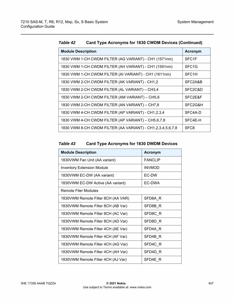
7210 SAS-M, T, R6, R12, Mxp, Sx, S Basic System Configuration Guide
System Management
3HE 17358 AAAB TQZZA © 2021 Nokia. Use subject to Terms available at: www.nokia.com
407
1830 VWM 1-CH CWDM FILTER (AG VARIANT) - CH1 (1571nm) SFC1F
1830 VWM 1-CH CWDM FILTER (AH VARIANT) - CH1 (1591nm) SFC1G
1830 VWM 1-CH CWDM FILTER (AI VARIANT) - CH1 (1611nm) SFC1H
1830 VWM 2-CH CWDM FILTER (AK VARIANT) - CH1,2 SFC2A&B
1830 VWM 2-CH CWDM FILTER (AL VARIANT) – CH3,4 SFC2C&D
1830 VWM 2-CH CWDM FILTER (AM VARIANT) – CH5,6 SFC2E&F
1830 VWM 2-CH CWDM FILTER (AN VARIANT) – CH7,8 SFC2G&H
1830 VWM 4-CH CWDM FILTER (AP VARIANT) - CH1,2,3,4 SFC4A-D
1830 VWM 4-CH CWDM FILTER (AP VARIANT) – CH5,6,7,8 SFC4E-H
1830 VWM 8-CH CWDM FILTER (AA VARIANT) - CH1,2,3,4,5,6,7,8 SFC8
Table 43 Card Type Acronyms for 1830 DWDM Devices
Module Description Acronym
1830VWM Fan Unit (AA variant) FANCLIP
Inventory Extension Module INVMOD
1830VWM EC-DW (AA variant) EC-DW
1830VWM EC-DW Active (AA variant) EC-DWA
Remote Filer Modules
1830VWM Remote Filter 8CH (AA VAR) SFD8A_R
1830VWM Remote Filter 8CH (AB Var) SFD8B_R
1830VWM Remote Filter 8CH (AC Var) SFD8C_R
1830VWM Remote Filter 8CH (AD Var) SFD8D_R
1830VWM Remote Filter 4CH (AE Var) SFD4A_R
1830VWM Remote Filter 4CH (AF Var) SFD4B_R
1830VWM Remote Filter 4CH (AG Var) SFD4C_R
1830VWM Remote Filter 4CH (AH Var) SFD4D_R
1830VWM Remote Filter 4CH (AJ Var) SFD4E_R
Table 42 Card Type Acronyms for 1830 CWDM Devices (Continued)
Module Description Acronym

System Management
408
7210 SAS-M, T, R6, R12, Mxp, Sx, S Basic SystemConfiguration Guide
© 2021 Nokia. Use subject to Terms available at: www.nokia.com
3HE 17358 AAAB TQZZA
1830VWM Remote Filter 4CH (AK Var) SFD4F_R
1830VWM Remote Filter 4CH (AL Var) SFD4G_R
1830VWM Remote Filter 4CH (AM Var) SFD4H_R
1830VWM Remote Filter 2CH (AN Var) SFD2A_R
1830VWM Remote Filter 2CH (AP Var) SFD2B_R
1830VWM Remote Filter 2CH (AQ Var) SFD2C_R
1830VWM Remote Filter 2CH (AR Var) SFD2D_R
1830VWM Remote Filter 2CH (AS Var) SFD2E_R
1830VWM Remote Filter 2CH (AT Var) SFD2F_R
1830VWM Remote Filter 2CH (AU Var) SFD2G_R
1830VWM Remote Filter 2CH (AV Var) SFD2H_R
1830VWM Remote Filter 2CH (AW Var) SFD2I_R
1830VWM Remote Filter 2CH (AZ Var) SFD2L_R
1830VWM Remote Filter 2CH (BA Var) SFD2M_R
1830VWM Remote Filter 2CH (BB Var) SFD2N_R
1830VWM Remote Filter 2CH (BC Var) SFD2O_R
1830VWM Remote Filter 2CH (BD Var) SFD2P_R
1830 VWM SSY SFD Automatic2CH (BC Var)
SFD2Q_R
1830 VWM SSY SFD Automatic2CH (BD Var)
SFD2R_R
DWDM Filters with manual control
1830VWM Manual Filter 8CH (AAVar) SFD8A
1830VWM Manual Filter 8CH (AB Var) SFD8B
1830VWM Manual Filter 8CH (AC Var) SFD8C
1830VWM Manual Filter 8CH (AD Var) SFD8D
1830VWM Manual Filter 4CH (AE Var) SFD4A
1830VWM Manual Filter 4CH (AF Var) SFD4B
Table 43 Card Type Acronyms for 1830 DWDM Devices (Continued)
Module Description Acronym

7210 SAS-M, T, R6, R12, Mxp, Sx, S Basic System Configuration Guide
System Management
3HE 17358 AAAB TQZZA © 2021 Nokia. Use subject to Terms available at: www.nokia.com
409
1830VWM Manual Filter 4CH (AG Var) SFD4C
1830VWM Manual Filter 4CH (AH Var) SFD4D
1830VWM Manual Filter 4CH (AJ Var) SFD4E
1830VWM Manual Filter 4CH (AK Var) SFD4F
1830VWM Manual Filter 4CH (AL Var) SFD4G
1830VWM Manual Filter 4CH (AM Var) SFD4H
1830VWM Manual Filter 2CH (AN Var) SFD2A
1830VWM Manual Filter 2CH (AP Var) SFD2B
1830VWM Manual Filter 2CH (AQ Var) SFD2C
1830VWM Manual Filter 2CH (AR Var) SFD2D
1830VWM Manual Filter 2CH (AS Var) SFD2E
1830VWM Manual Filter 2CH (AT Var) SFD2F
1830VWM Manual Filter 2CH (AU Var) SFD2G
1830VWM Manual Filter 2CH (AV Var) SFD2H
1830VWM Manual Filter 2CH (AWVar) SFD2I
1830VWM Manual Filter 2CH (AX Var) SFD2L
1830VWM Manual Filter 2CH (AY Var) SFD2M
1830VWM Manual Filter 2CH (AZ Var) SFD2N
1830VWM Manual Filter 2CH (BAVar) SFD2O
1830VWM Manual Filter 2CH (BB Var) SFD2P
1830VWM Manual Filter 2CH (BC Var) SFD2Q
1830VWM Manual Filter 2CH (BD Var) SFD2R
Amplifier Modules
1830 VWM Fixed Gain Ampl (AAVar) EALPFG
Table 43 Card Type Acronyms for 1830 DWDM Devices (Continued)
Module Description Acronym

System Management
410
7210 SAS-M, T, R6, R12, Mxp, Sx, S Basic SystemConfiguration Guide
© 2021 Nokia. Use subject to Terms available at: www.nokia.com
3HE 17358 AAAB TQZZA
Parameters card-type — Specifies an identifier used to match the configured slot module with the equipped slot module. Table 42 and Table 43 provides the list of acronyms that can be used to identify the supported modules usable with the clip-on device.
Values SFC1A, SFC1B, SFC1C, SFC1D, SFC1E, SFC1F, SFC1G, SFC1H, SFC2A&B, SFC2C&D, SFC2E&F, SFC2G&H, SFC4A-D, SFC4E-H, SFC8 (CWDM)ANY, EALPFG SFD8A_R, SFD8B_R, SFD8C_R, SFD8D_R, SFD4A_R, SFD4B_R, SFD4C_R, SFD4D_R, SFD4E_R, SFD4F_R, SFD4G_R, SFD4H_R, SFD2A_R, SFD2B_R, SFD2C_R, SFD2D_R, SFD2E_R, SFD2F_R, SFD2G_R, SFD2H_R,SFD2I_R, SFD2L_R, SFD2M_R, SFD2N_R, SFD2O_R, SFD2P_R, SFD2Q_R, SFD2R_R, SFD8A, SFD8B, SFD8C, SFD8D, SFD4A, SFD4B, SFD4C, SFD4D, SFD4E, SFD4F, SFD4G, SFD4H, SFD2A, SFD2B, SFD2C, SFD2D, SFD2E, SFD2F, SFD2G, SFD2H, SFD2I, SFD2L, SFD2M, SFD2N, SFD2O, SFD2P, SFD2Q, SFD2R (DWDM)ascii-string — Can use ASCII alphabets or numbers. Valid card-type acronyms are listed in the Table 43.
shutdown
Syntax [no] shutdown
Context config>system>vwm-shelf>card
Platforms 7210 SAS-M (network and access-uplink), 7210 SAS-T (network and access-uplink), 7210 SAS-Mxp, 7210 SAS-R6 and 7210 SAS-R12
Description This command allows the user to administratively disable the management of a specific module inserted in a slot on the clip-on device. When this command is executed, the 7210 SAS software clears all pending events/traps/alarms/LED related to this card.
The no form of this command allows the user to administratively enable the management of the card on the clip-on device. The software raises appropriate events/traps/alarms for the card.
Default no shutdown
6.12.2.1.3 Virtual Chassis (VC) Configuration Commands
vc-stack
Syntax vc-stack
Context config>system

7210 SAS-M, T, R6, R12, Mxp, Sx, S Basic System Configuration Guide
System Management
3HE 17358 AAAB TQZZA © 2021 Nokia. Use subject to Terms available at: www.nokia.com
411
Platforms 7210 SAS-Sx 1/10GE: standalone-VC and 7210 SAS-S 1/10GE: standalone-VC
Description Commands in this context configure VC parameters.
vc-stack-node
Syntax vc-stack-node slot-number mac-address mac-address [create]no vc-stack-node slot-number
Context config>system>vc-stack
Platforms 7210 SAS-Sx 1/10GE (standalone-VC) and 7210 SAS-S 1/10GE (standalone-VC)
Description This command configures an IMM-only node in a virtual chassis (VC) configuration. This command is performed on the active CPM node in the VC to which the IMM-only node belongs.
An IMM-only node in a VC is identified by its slot-number and its MAC address. The slot number assigned to the node can be an arbitrary number from 1 to 8. It is used in service provisioning to identify ports on a VC member node, and on service objects on those ports. The port on a VC member node is identified using the format slot-id/1/port-id. For example, port 20 on the front panel of a VC member node in slot 4 is identified as 4/1/20; SAPs configured on those ports are identified as 4/1/20:300.
Slot numbers are unique to each VC which are identified by their vc-stack-node, and can be reused across different VCs. The software ensures the uniqueness of the slot number in each VC by raising an error if two nodes in the same VC are assigned the same slot number.
The MAC address used for VC configuration is the chassis MAC address printed on the label of the node. The MAC address of the IMM-only node is also visible using the console connection.
When an IMM-only node boots up, it uses the MAC address and slot number received in the VC discovery messages sent by the CPM node so that it can boot up in VC mode.
The no form of this command removes the IMM-node from the VC.
Parameters slot-number — Specifies the slot assigned to an IMM-only node in a VC.
Values 1 to 8
create — Keyword to create the node in a VC.
mac-address — Specifies the chassis MAC address of the IMM-only node.
vc-stack-mac-addr
Syntax vc-stack-mac-addr mac-addressno vc-stack-node

System Management
412
7210 SAS-M, T, R6, R12, Mxp, Sx, S Basic SystemConfiguration Guide
© 2021 Nokia. Use subject to Terms available at: www.nokia.com
3HE 17358 AAAB TQZZA
Context config>system>vc-stack
Platforms 7210 SAS-Sx 1/10GE (standalone-VC) and 7210 SAS-S 1/10GE (standalone-VC)
Description This command configures a MAC address for a VC. This command provides an option to assign a MAC address other than the chassis MAC belonging to the CPM-A node. By assigning the MAC address instead of using the chassis MAC address belonging to the CPM-A node, operators do not need to change the MAC address when the CPM-A card is physically replaced with another card.
The no form of this command reverts the value to the default MAC address specified in the BOF.
Parameters mac-address — Specifies the MAC address of the VC.
6.12.2.1.4 System Alarm Commands
thresholds
Syntax thresholds
Context config>system
Platforms Supported on all 7210 SAS platforms as described in this document, including platforms configured in the access-uplink operating mode
Description Commands in this context configure monitoring thresholds.
kb-memory-use-alarm
Syntax kb-memory-use-alarm rising-threshold threshold [falling-threshold threshold] interval seconds [rmon-event-type] [startup-alarm alarm-type]
no kb-memory-use-warn
Context config>system>thresholds
Platforms Supported on all 7210 SAS platforms as described in this document, including platforms configured in the access-uplink operating mode
Description This command configures memory use, in kilobytes, alarm thresholds.
The no form of this command removes the parameters from the configuration.
7210 SAS-M, T, R6, R12, Mxp, Sx, S Basic System Configuration Guide
System Management
3HE 17358 AAAB TQZZA © 2021 Nokia. Use subject to Terms available at: www.nokia.com
413
Parameters rising-threshold threshold — Specifies a threshold for the sampled statistic. A single threshold crossing event is generated when the current sampled value is greater than or equal to this threshold, and the value at the last sampling interval was less than this threshold. A single threshold crossing event will also be generated if the first sample taken is greater than or equal to this threshold and the associated startup-alarm is equal to rising or either.After a rising threshold crossing event is generated, another such event will not be generated until the sampled value falls below this threshold and reaches less than or equal the falling-threshold value.
Default 0
Values –2147483648 to 2147483647
falling-threshold threshold — Specifies a threshold for the sampled statistic. A single threshold crossing event is generated when the current sampled value is less than or equal to this threshold, and the value at the last sampling interval was greater than this threshold. A single threshold crossing event will also be generated if the first sample taken is less than or equal to this threshold and the associated startup-alarm is equal to falling or either.After a falling threshold crossing event is generated, another such event will not be generated until the sampled value rises above this threshold and reaches greater than or equal the rising-threshold value.
Default 0
Values –2147483648 to 2147483647
interval seconds — Specifies the polling period over which the data is sampled and compared with the rising and falling thresholds
Values 1 to 2147483647
rmon-event-type — Specifies the type of notification action to be taken when this event occurs
Values log — An entry is made in the RMON-MIB log table for each event occurrence. This does not create a TiMOS logger entry. The RMON-MIB log table entries can be viewed using the show system thresholds command. trap — A TiMOS logger event is generated. The TiMOS logger utility then distributes the notification of this event to its configured log destinations which may be CONSOLE, telnet session, memory log, cflash file, syslog, or SNMP trap destinations logs. both — Both an entry in the RMON-MIB logTable and a TiMOS logger event are generated.none — No action is taken.
Default both

System Management
414
7210 SAS-M, T, R6, R12, Mxp, Sx, S Basic SystemConfiguration Guide
© 2021 Nokia. Use subject to Terms available at: www.nokia.com
3HE 17358 AAAB TQZZA
startup-alarm alarm-type — Specifies the alarm that may be sent when this alarm is first created. If the first sample is greater than or equal to the rising threshold value and startup-alarm is equal to rising or either, a single rising threshold crossing event is generated. If the first sample is less than or equal to the falling threshold value and startup-alarm is equal to falling or either, a single falling threshold crossing event is generated.
Values rising, falling, either
Default either
kb-memory-use-warn
Syntax kb-memory-use-warn rising-threshold threshold [falling-threshold threshold] interval seconds [rmon-event-type] [startup-alarm alarm-type]
no kb-memory-use-warn
Context config>system>thresholds
Platforms Supported on all 7210 SAS platforms as described in this document, including platforms configured in the access-uplink operating mode
Description This command configures memory usage, in kilobytes, for warning thresholds
Parameters rising-threshold threshold — Specifies a threshold for the sampled statistic. A single threshold crossing event is generated when the current sampled value is greater than or equal to this threshold, and the value at the last sampling interval was less than this threshold. A single threshold crossing event will also be generated if the first sample taken is greater than or equal to this threshold and the associated startup-alarm is equal to rising or either.After a rising threshold crossing event is generated, another such event will not be generated until the sampled value falls below this threshold and reaches less than or equal the falling-threshold value.
Values –2147483648 to 2147483647
Default 0
falling-threshold threshold — Specifies a threshold for the sampled statistic. A single threshold crossing event is generated when the current sampled value is less than or equal to this threshold, and the value at the last sampling interval was greater than this threshold. A single threshold crossing event will also be generated if the first sample taken is less than or equal to this threshold and the associated startup-alarm is equal to falling or either. After a falling threshold crossing event is generated, another such event will not be generated until the sampled value rises above this threshold and reaches greater than or equal the rising-threshold value.
Values –2147483648 to 2147483647
Default 0
7210 SAS-M, T, R6, R12, Mxp, Sx, S Basic System Configuration Guide
System Management
3HE 17358 AAAB TQZZA © 2021 Nokia. Use subject to Terms available at: www.nokia.com
415
interval seconds — Specifies the polling period over which the data is sampled and compared with the rising and falling thresholds.
Values 1 to 2147483647
rmon-event-type — Specifies the type of notification action to be taken when this event occurs.
Values log — An entry is made in the RMON-MIB log table for each event occurrence. This does not create a TiMOS logger entry. The RMON-MIB log table entries can be viewed using the show system thresholds command. trap — A TiMOS logger event is generated. The TiMOS logger utility then distributes the notification of this event to its configured log destinations which may be CONSOLE, telnet session, memory log, cflash file, syslog, or SNMP trap destinations logs. both — Both an entry in the RMON-MIB logTable and a TiMOS logger event are generated.none — No action is taken.
Default both
startup-alarm alarm-type — Specifies the alarm that may be sent when this alarm is first created. If the first sample is greater than or equal to the rising threshold value and startup-alarm is equal to rising or either, a single rising threshold crossing event is generated. If the first sample is less than or equal to the falling threshold value and startup-alarm is equal to falling or either, a single falling threshold crossing event is generated.
Values rising, falling, either
Default either
cflash-cap-alarm
Syntax cflash-cap-alarm cflash-id rising-threshold threshold [falling-threshold threshold] interval seconds [rmon-event-type] [startup-alarm alarm-type]
no cflash-cap-alarm cflash-id
Context config>system>thresholds
Platforms Supported on all 7210 SAS platforms as described in this document, including platforms configured in the access-uplink operating mode
Description This command enables capacity monitoring of the compact flash specified in this command. The severity level is alarm. Both a rising and falling threshold can be specified.
The no form of this command removes the configured compact flash threshold alarm.
Parameters cflash-id — Specifies the name of the cflash device to be monitored.
Values uf1: (7210 SAS-M)

System Management
416
7210 SAS-M, T, R6, R12, Mxp, Sx, S Basic SystemConfiguration Guide
© 2021 Nokia. Use subject to Terms available at: www.nokia.com
3HE 17358 AAAB TQZZA
cf1:, cf2:, uf1: (7210 SAS-T, 7210 SAS-Sx 1/10GE: standalone and standalone-VC, 7210 SAS-Sx 10/100GE, and 7210 SAS-Mxp)cf2:, cf2-A:, cf2-B:, uf1:, uf1-A:, uf1-B: (7210 SAS-R6 and 7210 SAS-R12)cf1:, cf2: (7210 SAS-S 1/10GE: standalone and standalone-VC)
rising-threshold threshold — Specifies a threshold for the sampled statistic. A single threshold crossing event is generated when the current sampled value is greater than or equal to this threshold, and the value at the last sampling interval was less than this threshold. A single threshold crossing event will also be generated if the first sample taken is greater than or equal to this threshold and the associated startup-alarm is equal to rising or either.After a rising threshold crossing event is generated, another such event will not be generated until the sampled value falls below this threshold and reaches less than or equal the falling-threshold value.
Values –2147483648 to 2147483647
Default 0
falling-threshold threshold — Specifies a threshold for the sampled statistic. A single threshold crossing event is generated when the current sampled value is less than or equal to this threshold, and the value at the last sampling interval was greater than this threshold. A single threshold crossing event will also be generated if the first sample taken is less than or equal to this threshold and the associated startup-alarm is equal to falling or either.After a rising threshold crossing event is generated, another such event will not be generated until the sampled value raises above this threshold and reaches greater than or equal the rising-threshold value.
Values –2147483648 to 2147483647
Default 0
interval seconds — Specifies the polling period, in seconds, over which the data is sampled and compared with the rising and falling thresholds.
Values 1 to 2147483647
rmon-event-type — Specifies the type of notification action to be taken when this event occurs
Values log — An entry is made in the RMON-MIB log table for each event occurrence. This does not create a TiMOS logger entry. The RMON-MIB log table entries can be viewed using the show system thresholds command. trap — A TiMOS logger event is generated. The TiMOS logger utility then distributes the notification of this event to its configured log destinations which may be CONSOLE, telnet session, memory log, cflash file, syslog, or SNMP trap destinations logs. both — Both an entry in the RMON-MIB logTable and a TiMOS logger event are generated.

7210 SAS-M, T, R6, R12, Mxp, Sx, S Basic System Configuration Guide
System Management
3HE 17358 AAAB TQZZA © 2021 Nokia. Use subject to Terms available at: www.nokia.com
417
none — No action is taken.
Default both
startup-alarm alarm-type — Specifies the alarm that may be sent when this alarm is first created. If the first sample is greater than or equal to the rising threshold value and startup-alarm is equal to rising or either, a single rising threshold crossing event is generated. If the first sample is less than or equal to the falling threshold value and startup-alarm is equal to falling or either, a single falling threshold crossing event is generated.
Default either
Values rising, falling, either
cflash-cap-warn
Syntax cflash-cap-warn cflash-id rising-threshold threshold [falling-threshold threshold] interval seconds [rmon-event-type] [startup-alarm alarm-type]
no cflash-cap-warn cflash-id
Context config>system>thresholds
Platforms Supported on all 7210 SAS platforms as described in this document, including platforms configured in the access-uplink operating mode
Description This command enables capacity monitoring of the compact flash specified in this command. The severity level is warning. Both a rising and falling threshold can be specified.
The no form of this command removes the configured compact flash threshold warning.
Parameters cflash-id — Specifies the name of the cflash device to be monitored.
Values uf1: (7210 SAS-M)cf1:, cf2:, uf1: (7210 SAS-T, 7210 SAS-Sx 1/10GE: standalone and standalone-VC, 7210 SAS-Sx 10/100GE, and 7210 SAS-Mxp)cf2:, cf2-A:, cf2-B:, uf1:, uf1-A:, uf1-B: (7210 SAS-R6 and 7210 SAS-R12)cf1:, cf2: (7210 SAS-S 1/10GE: standalone and standalone-VC)
rising-threshold threshold — Specifies a threshold for the sampled statistic. A single threshold crossing event is generated when the current sampled value is greater than or equal to this threshold, and the value at the last sampling interval was less than this threshold. A single threshold crossing event will also be generated if the first sample taken is greater than or equal to this threshold and the associated startup-alarm is equal to rising or either.

System Management
418
7210 SAS-M, T, R6, R12, Mxp, Sx, S Basic SystemConfiguration Guide
© 2021 Nokia. Use subject to Terms available at: www.nokia.com
3HE 17358 AAAB TQZZA
After a rising threshold crossing event is generated, another such event will not be generated until the sampled value falls below this threshold and reaches less than or equal the falling-threshold value.
Values –2147483648 to 2147483647
Default 0
falling-threshold threshold — Specifies a threshold for the sampled statistic. A single threshold crossing event is generated when the current sampled value is less than or equal to this threshold, and the value at the last sampling interval was greater than this threshold. A single threshold crossing event will also be generated if the first sample taken is less than or equal to this threshold and the associated startup-alarm is equal to falling or either.After a rising threshold crossing event is generated, another such event will not be generated until the sampled value raises above this threshold and reaches greater than or equal the rising-threshold value.
Values –2147483648 to 2147483647
Default 0
interval seconds — Specifies the polling period over which the data is sampled and compared with the rising and falling thresholds.
Values 1 to 2147483647
rmon-event-type — Specifies the type of notification action to be taken when this event occurs.
Values log — An entry is made in the RMON-MIB log table for each event occurrence. This does not create a TiMOS logger entry. The RMON-MIB log table entries can be viewed using the show system thresholds command. trap — A TiMOS logger event is generated. The TiMOS logger utility then distributes the notification of this event to its configured log destinations which may be CONSOLE, telnet session, memory log, cflash file, syslog, or SNMP trap destinations logs. both — Both an entry in the RMON-MIB logTable and a TiMOS logger event are generated.none — No action is taken.
Default both
startup-alarm alarm-type — Specifies the alarm that may be sent when this alarm is first created. If the first sample is greater than or equal to the rising threshold value and startup-alarm is equal to rising or either, a single rising threshold crossing event is generated. If the first sample is less than or equal to the falling threshold value and startup-alarm is equal to falling or either, a single falling threshold crossing event is generated.
Values rising, falling, either
Default either
7210 SAS-M, T, R6, R12, Mxp, Sx, S Basic System Configuration Guide
System Management
3HE 17358 AAAB TQZZA © 2021 Nokia. Use subject to Terms available at: www.nokia.com
419
memory-use-alarm
Syntax memory-use-alarm rising-threshold threshold [falling-threshold threshold] interval seconds [rmon-event-type] [startup-alarm alarm-type]
no memory-use-alarm
Context config>system>thresholds
Platforms Supported on all 7210 SAS platforms as described in this document, including platforms configured in the access-uplink operating mode
Description The memory thresholds are based on monitoring the TIMETRA-SYSTEM-MIB sgiMemoryUsed object. This object contains the amount of memory currently used by the system. The severity level is Alarm. The absolute sample type method is used.
The no form of this command removes the configured memory threshold warning.
Parameters rising-threshold threshold — Specifies a threshold for the sampled statistic. A single threshold crossing event is generated when the current sampled value is greater than or equal to this threshold, and the value at the last sampling interval was less than this threshold. A single threshold crossing event will also be generated if the first sample taken is greater than or equal to this threshold and the associated startup-alarm is equal to rising or either.After a rising threshold crossing event is generated, another such event will not be generated until the sampled value falls below this threshold and reaches less than or equal the falling-threshold value.
Default 0
Values –2147483648 to 2147483647
falling-threshold threshold — Specifies a threshold for the sampled statistic. A single threshold crossing event is generated when the current sampled value is less than or equal to this threshold, and the value at the last sampling interval was greater than this threshold. A single threshold crossing event will also be generated if the first sample taken is less than or equal to this threshold and the associated startup-alarm is equal to falling or either.After a rising threshold crossing event is generated, another such event will not be generated until the sampled value raises above this threshold and reaches greater than or equal the rising-threshold value.
Values –2147483648 to 2147483647
Default 0
interval seconds — Specifies the polling period over which the data is sampled and compared with the rising and falling thresholds.
Values 1 to 2147483647

System Management
420
7210 SAS-M, T, R6, R12, Mxp, Sx, S Basic SystemConfiguration Guide
© 2021 Nokia. Use subject to Terms available at: www.nokia.com
3HE 17358 AAAB TQZZA
rmon-event-type — Specifies the type of notification action to be taken when this event occurs.
Values log — An entry is made in the RMON-MIB log table for each event occurrence. This does not create a TiMOS logger entry. The RMON-MIB log table entries can be viewed using the show system thresholds CLI command. trap — A TiMOS logger event is generated. The TiMOS logger utility then distributes the notification of this event to its configured log destinations which may be CONSOLE, telnet session, memory log, cflash file, syslog, or SNMP trap destinations logs. both — Both a entry in the RMON-MIB logTable and a TiMOS logger event are generated.none — No action is taken.
Default both
startup-alarm alarm-type — Specifies the alarm that may be sent when this alarm is first created. If the first sample is greater than or equal to the rising threshold value and startup-alarm is equal to rising or either, a single rising threshold crossing event is generated. If the first sample is less than or equal to the falling threshold value and startup-alarm is equal to falling or either, a single falling threshold crossing event is generated.
Values rising, falling, either
Default either
memory-use-warn
Syntax memory-use-warn rising-threshold threshold [falling-threshold threshold] interval seconds [rmon-event-type] [startup-alarm alarm-type]
no memory-use-warn
Context config>system>thresholds
Platforms Supported on all 7210 SAS platforms as described in this document, including platforms configured in the access-uplink operating mode
Description The memory thresholds are based on monitoring MemoryUsed object. This object contains the amount of memory currently used by the system. The severity level is Alarm.
The absolute sample type method is used.
The no form of this command removes the configured compact flash threshold warning.
7210 SAS-M, T, R6, R12, Mxp, Sx, S Basic System Configuration Guide
System Management
3HE 17358 AAAB TQZZA © 2021 Nokia. Use subject to Terms available at: www.nokia.com
421
Parameters rising-threshold threshold — Specifies a threshold for the sampled statistic. A single threshold crossing event is generated when the current sampled value is greater than or equal to this threshold, and the value at the last sampling interval was less than this threshold. A single threshold crossing event will also be generated if the first sample taken is greater than or equal to this threshold and the associated startup-alarm is equal to rising or either.After a rising threshold crossing event is generated, another such event will not be generated until the sampled value falls below this threshold and reaches less than or equal the falling-threshold value.
Default 0
Values –2147483648 to 2147483647
falling-threshold threshold — Specifies a threshold for the sampled statistic. A single threshold crossing event is generated when the current sampled value is less than or equal to this threshold, and the value at the last sampling interval was greater than this threshold. A single threshold crossing event will also be generated if the first sample taken is less than or equal to this threshold and the associated startup-alarm is equal to falling or either.After a rising threshold crossing event is generated, another such event will not be generated until the sampled value raises above this threshold and reaches greater than or equal the rising-threshold value.
Default 0
Values –2147483648 to 2147483647
interval seconds — Specifies the polling period over which the data is sampled and compared with the rising and falling thresholds.
Values 1 to 2147483647
rmon-event-type — Specifies the type of notification action to be taken when this event occurs.
Values log — An entry is made in the RMON-MIB log table for each event occurrence. This does not create a TiMOS logger entry. The RMON-MIB log table entries can be viewed using the show system thresholds CLI command. trap — A TiMOS logger event is generated. The TiMOS logger utility then distributes the notification of this event to its configured log destinations which may be CONSOLE, telnet session, memory log, cflash file, syslog, or SNMP trap destinations logs. both — Both a entry in the RMON-MIB logTable and a TiMOS logger event are generated.none — No action is taken.
Default both

System Management
422
7210 SAS-M, T, R6, R12, Mxp, Sx, S Basic SystemConfiguration Guide
© 2021 Nokia. Use subject to Terms available at: www.nokia.com
3HE 17358 AAAB TQZZA
startup-alarm alarm-type — Specifies the alarm that may be sent when this alarm is first created. If the first sample is greater than or equal to the rising threshold value and startup-alarm is equal to rising or either, a single rising threshold crossing event is generated. If the first sample is less than or equal to the falling threshold value and startup-alarm is equal to falling or either, a single falling threshold crossing event is generated.
Values rising, falling, either
Default either
rmon
Syntax rmon
Context config>system>thresholds
Platforms Supported on all 7210 SAS platforms as described in this document, including platforms configured in the access-uplink operating mode
Description Commands in this context configure generic RMON alarms and events.
Generic RMON alarms can be created on any SNMP object-ID that is valid for RMON monitoring (for example, an integer-based datatype).
The configuration of an event controls the generation and notification of threshold crossing events configured with the alarm command.
alarm
Syntax alarm rmon-alarm-id variable-oid oid-string interval seconds [sample-type] [startup-alarm alarm-type] [rising-event rmon-event-id rising-threshold threshold] [falling-event rmon-event-id falling threshold threshold] [owner owner-string]
no alarm rmon-alarm-id
Context config>system>thresholds>rmon
Platforms Supported on all 7210 SAS platforms as described in this document, including platforms configured in the access-uplink operating mode
Description This command configures an entry in the RMON-MIB alarm Table. This command controls the monitoring and triggering of threshold crossing events. In order for notification or logging of a threshold crossing event to occur there must be at least one associated rmon>event configured.
7210 SAS-M, T, R6, R12, Mxp, Sx, S Basic System Configuration Guide
System Management
3HE 17358 AAAB TQZZA © 2021 Nokia. Use subject to Terms available at: www.nokia.com
423
The agent periodically takes statistical sample values from the MIB variable specified for monitoring and compares them to thresholds that have been configured with the alarm command. The alarm command configures the MIB variable to be monitored, the polling period (interval), sampling type (absolute or delta value), and rising and falling threshold parameters. If a sample has crossed a threshold value, the associated event is generated.
The no form of this command removes an rmon-alarm-id from the configuration.
Parameters rmon-alarm-id — Specifies the alarm being configured. The number of alarms that can be created is limited to 1200.
Values 1 to 65535
variable-oid oid-string — Specifies the variable to be sampled. Only SNMP variables that resolve to an ASN.1 primitive type of integer (integer, Integer32, Counter32, Counter64, Gauge, or TimeTicks) may be sampled. The oid-string may be expressed using either the dotted string notation or as object name plus dotted instance identifier. For example, "1.3.6.1.2.1.2.2.1.10.184582144" or "ifInOctets.184582144".The oid-string has a maximum length of 255 characters
interval seconds — Specifies the polling period over which the data is sampled and compared with the rising and falling thresholds. In the case of delta type sampling, the interval should be set short enough that the sampled variable is very unlikely to increase or decrease by more than 2147483647 - 1 during a single sampling interval. To avoid creating unnecessary processing overhead, the interval value should not be set too low.
Values 1 to 2147483647
sample-type — Specifies the method of sampling the selected variable and calculating the value to be compared against the thresholds.
Default absolute
Values absolute — Specifies that the value of the selected variable will be compared directly with the thresholds at the end of the sampling interval. delta — Specifies that the value of the selected variable at the last sample will be subtracted from the current value, and the difference compared with the thresholds.
startup-alarm alarm-type — Specifies the alarm that may be sent when this alarm is first created. If the first sample is greater than or equal to the rising threshold value an startup-alarm is equal to rising or either, a single rising threshold crossing event is generated. If the first sample is less than or equal to the falling threshold value and startup-alarm is equal to falling or either, a single falling threshold crossing event is generated.
Default either
Values rising, falling, either
System Management
424
7210 SAS-M, T, R6, R12, Mxp, Sx, S Basic SystemConfiguration Guide
© 2021 Nokia. Use subject to Terms available at: www.nokia.com
3HE 17358 AAAB TQZZA
rising-event rmon-event-id — Specifies the action to be taken when a rising threshold crossing event occurs. If there is no corresponding event configured for the specified rmon-event-id, then no association exists and no action is taken. If the rising-event rmon-event-id has a value of zero (0), no associated event exists.If a rising-event rmon-event-id is configured, the CLI requires a rising threshold to also be configured.
Default 0
Values 0 to 65535
rising-threshold threshold — Specifies a threshold for the sampled statistic. A single threshold crossing event is generated when the current sampled value is greater than or equal to this threshold, and the value at the last sampling interval was less than this threshold. A single threshold crossing event will also be generated if the first sample taken is greater than or equal to this threshold and the associated startup-alarm is equal to rising or either.After a rising threshold crossing event is generated, another such event will not be generated until the sampled value falls below this threshold and reaches less than or equal the falling threshold value.
Values –2147483648 to 2147483647
Default 0
falling-event rmon-event-id — Specifies the action to be taken when a falling threshold crossing event occurs. If there is no corresponding event configured for the specified rmon-event-id, then no association exists and no action is taken. If the falling-event has a value of zero (0), no associated event exists.If a falling event is configured, the CLI requires a falling-threshold to also be configured.
Values –2147483648 to 2147483647
Default 0
falling-threshold threshold — Specifies a threshold for the sampled statistic. A single threshold crossing event is generated when the current sampled value is less than or equal to this threshold, and the value at the last sampling interval was greater than this threshold. A single threshold crossing event will also be generated if the first sample taken is less than or equal to this threshold and the associated startup-alarm is equal to falling or either.After a rising threshold crossing event is generated, another such event will not be generated until the sampled value rises above this threshold and reaches greater than or equal the rising-threshold value.
Values –2147483648 to 2147483647
Default 0
7210 SAS-M, T, R6, R12, Mxp, Sx, S Basic System Configuration Guide
System Management
3HE 17358 AAAB TQZZA © 2021 Nokia. Use subject to Terms available at: www.nokia.com
425
owner owner — Specifies the owner. The owner identifies the creator of this alarm. It defaults to “TiMOS CLI”. This parameter is defined primarily to allow entries that have been created in the RMON-MIB alarmTable by remote SNMP managers to be saved and reloaded in a CLI configuration file. The owner will not normally be configured by CLI users and can be a maximum of 80 characters.
Default TiMOS CLI
event
Syntax event rmon-event-id [event-type] [description description-string] [owner owner-string]no event rmon-event-id
Context config>system>thresholds>rmon
Platforms Supported on all 7210 SAS platforms as described in this document, including platforms configured in the access-uplink operating mode
Description This command configures an entry in the RMON-MIB event table. The event command controls the generation and notification of threshold crossing events configured with the alarm command. When a threshold crossing event is triggered, the rmon>event configuration optionally specifies if an entry in the RMON-MIB log table should be created to record the occurrence of the event. It may also specify that an SNMP notification (trap) should be generated for the event. The RMON-MIB defines two notifications for threshold crossing events: Rising Alarm and Falling Alarm.
Creating an event entry in the RMON-MIB log table does not create a corresponding entry in the TiMOS event logs. However, when the event-type is set to trap, the generation of a Rising Alarm or Falling Alarm notification creates an entry in the TiMOS event logs and that is distributed to whatever TiMOS log destinations are configured: CONSOLE, session, memory, file, syslog, or SNMP trap destination.
The TiMOS logger message includes a rising or falling threshold crossing event indicator, the sample type (absolute or delta), the sampled value, the threshold value, the rmon-alarm-id, the associated rmon-event-id and the sampled SNMP object identifier.
This no form of this command removes an rmon-event-id from the configuration.
Parameters rmon-event-type — Specifies the type of notification action to be taken when this event occurs.
Values log — An entry is made in the RMON-MIB log table for each event occurrence. This does not create a TiMOS logger entry. The RMON-MIB log table entries can be viewed using the show system thresholds command. trap — A TiMOS logger event is generated. The TiMOS logger utility then distributes the notification of this event to its configured log destinations which may be CONSOLE, telnet session, memory log, cflash file, syslog, or SNMP trap destinations logs.

System Management
426
7210 SAS-M, T, R6, R12, Mxp, Sx, S Basic SystemConfiguration Guide
© 2021 Nokia. Use subject to Terms available at: www.nokia.com
3HE 17358 AAAB TQZZA
both — Both an entry in the RMON-MIB logTable and a TiMOS logger event are generated.none — No action is taken.
Default both
description description-string — Specifies a user configurable string that can be used to identify the purpose of this event. This is an optional parameter and can be up to 80 characters. If the string contains special characters (#, $, spaces, and so on), the entire string must be enclosed within double quotes.
owner owner — Specifies the creator of this alarm. This parameter is defined primarily to allow entries that have been created in the RMON-MIB alarmTable by remote SNMP managers to be saved and reloaded in a CLI configuration file. The owner will not normally be configured by CLI users and can be a maximum of 80 characters.
Default TiMOS CLI
6.12.2.1.5 PTP Commands
ptp
Syntax ptp
Context config>system
Platforms 7210 SAS-M (network and access-uplink), 7210 SAS-Mxp, 7210 SAS-R6, 7210 SAS-R12, 7210 SAS-Sx 1/10GE (standalone), 7210 SAS-T (network and access-uplink)
Description Commands in this context configure parameters for IEEE 1588-2008, Precision Time Protocol.
anno-rx-timeout
Syntax anno-rx-timeout countno anno-rx-timeout
Context config>system>ptp
Platforms 7210 SAS-M (network and access-uplink), 7210 SAS-Mxp, 7210 SAS-R6, 7210 SAS-R12, 7210 SAS-Sx 1/10GE (standalone), 7210 SAS-T (network and access-uplink)
Description This command configures the PTP announce receipt timeout count in the Announce message.
The no form of this command reverts the count to the default value.

7210 SAS-M, T, R6, R12, Mxp, Sx, S Basic System Configuration Guide
System Management
3HE 17358 AAAB TQZZA © 2021 Nokia. Use subject to Terms available at: www.nokia.com
427
Default anno-rx-timeout 3
Parameters count — Specifies the PTP announce receipt timeout count.
Values 2 to 10
clock
Syntax clock
Context config>system>ptp
Platforms 7210 SAS-Mxp, 7210 SAS-R6, 7210 SAS-R12, 7210 SAS-Sx 1/10GE (standalone), 7210 SAS-T (network and access-uplink)
Description Commands in this context configure the source of frequency reference for PTP.
freq-source
Syntax freq-source freq-sourceno freq-source
Context config>system>ptp>clock
Platforms 7210 SAS-Mxp, 7210 SAS-R6, 7210 SAS-R12, 7210 SAS-Sx 1/10GE (standalone), 7210 SAS-T (network and access-uplink)
Description This command provides a stable frequency reference obtained through one of the line references (SyncE or bits) for the PTP clock. This is achieved by specifying the frequency source for PTP to be ssu. This mode of operation where PTP is used only for time recovery and SyncE or BITS is used for frequency recovery is known as PTP hybrid mode.
If the frequency reference is set to ssu, PTP is running in hybrid mode (if PTP is also in a no shutdown state), using the recovered frequency provided by the central clock through either of the configured references (SyncE or BITS, whichever is configured as a reference for the central clock). When this parameter is set to ssu, PTP cannot be configured as a reference in the ref-order. The CLI blocks this configuration. The reverse is also true; that is, if PTP is configured under ref-order, this parameter cannot be set to ssu.
If set to ptp, PTP runs in pure mode, potentially being configured as a frequency reference in ref-order.
The no form of this command reverts to the default value.
Note: See Configuration Guidelines and Restrictions for PTP for information on the restrictions when using this command.

System Management
428
7210 SAS-M, T, R6, R12, Mxp, Sx, S Basic SystemConfiguration Guide
© 2021 Nokia. Use subject to Terms available at: www.nokia.com
3HE 17358 AAAB TQZZA
Default freq-source ptp
Parameters freq-source — Specifies whether PTP is used for frequency and time recovery or only for time recovery. If ptp is specified, PTP is used for both frequency and time recovery. If ssu is specified, PTP is used only for time recovery.
Values ptp, ssu
clock-type
Syntax clock-type boundaryclock-type ordinary slave
Context config>system>ptp
Platforms 7210 SAS-M (network and access-uplink), 7210 SAS-Mxp, 7210 SAS-R6, 7210 SAS-R12, 7210 SAS-Sx 1/10GE (standalone), and 7210 SAS-T (network and access-uplink)
Description This command configures the type of clock. The clock-type can only be changed when PTP is shutdown.
When changing the clock-type to or from a boundary clock on the 7210 SAS-R6, 7210 SAS-R12, 7210 SAS-Mxp, and 7210 SAS-T platforms, the node must be rebooted for the change to take effect. Ensure that measures are taken to minimize service disruption during the reboot process.
Default ordinary slave
Parameters boundary — Keyword to configure the clock as a boundary clock capable of functioning as both a master and slave concurrently.
ordinary slave — Keyword to configure the clock as an ordinary PTP slave.
domain
Syntax domain domainno domain
Context config>system>ptp
Platforms 7210 SAS-M (network and access-uplink), 7210 SAS-Mxp, 7210 SAS-R6, 7210 SAS-R12, 7210 SAS-Sx 1/10GE (standalone), and 7210 SAS-T (network and access-uplink)
Description This command configures the PTP domain.
The domain cannot be changed unless PTP is shut down.
If the PTP profile is changed, the domain is changed to the default domain for the new PTP profile.
7210 SAS-M, T, R6, R12, Mxp, Sx, S Basic System Configuration Guide
System Management
3HE 17358 AAAB TQZZA © 2021 Nokia. Use subject to Terms available at: www.nokia.com
429
The no form of this command reverts to the default configuration.The default value is dependent on the configured profile.
Default 0 for ieee1588-20084 for g8265dot1-201024 for g8275dot1-2014
Parameters domain — Specifies the PTP domain.
Values 0 to 255 for ieee1588-20080 to 255 for g8265dot1-201024 to 43 for g8275dot1-2014
local-priority
Syntax local-priority priority
Context config>system>ptpconfig>system>ptp>peerconfig>system>ptp>port
Platforms 7210 SAS-M (network and access-uplink), 7210 SAS-Mxp, 7210 SAS-R6, 7210 SAS-R12, 7210 SAS-Sx 1/10GE (standalone), and 7210 SAS-T (network and access-uplink)
Description This command configures the local priority used to choose between PTP masters in the best master clock algorithm (BMCA). This setting is relevant when the profile is set to g8265dot1-2010 or g8275dot1-2014. The parameter is ignored when the profile is set to ieee1588-2008. The value 1 is the highest priority and 255 is the lowest priority.
For g8265dot1-2010, this command sets the priority to select between master clocks with the same quality.
For g8275dot1-2014, this command sets the value of the localPriority associated with the Announce messages received from the external clocks (ptp>peer or ptp>port), or the local clock (PTP).
Default local-priority 128
Parameters priority — Specifies the value of the local priority.
Values 1 to 255
log-anno-interval
Syntax log-anno-interval log-intervalno log-anno-interval
Context config>system>ptp
System Management
430
7210 SAS-M, T, R6, R12, Mxp, Sx, S Basic SystemConfiguration Guide
© 2021 Nokia. Use subject to Terms available at: www.nokia.com
3HE 17358 AAAB TQZZA
Platforms 7210 SAS-M (network and access-uplink), 7210 SAS-Mxp, 7210 SAS-R6, 7210 SAS-R12, 7210 SAS-Sx 1/10GE (standalone), and 7210 SAS-T (network and access-uplink)
Description This command configures the PTP Announce interval.
The no form of this command reverts to the default value.
Default log-anno-interval 1
Parameters log-interval — Specifies the PTP Announce interval, specified as the logarithm to the base 2, in seconds.
Values –3 to 4, where –3 = 0.125 s, –2 = 0.25 s, –1 = 0.5 s, 0 = 1 s, 1 = 2 s, 2 = 4 s, 3 = 8 s, 4 = 16 s
log-sync-interval
Syntax log-sync-interval valuesno log-sync-interval
Context config>system>ptp
Platforms 7210 SAS-M (network and access-uplink), 7210 SAS-Mxp, 7210 SAS-R6, 7210 SAS-R12, 7210 SAS-Sx 1/10GE (standalone), and 7210 SAS-T (network and access-uplink)
Description This command configures the message interval used for transmission of multicast synchronization messages.
This command applies only if the profile is set to ieee1588-2008 or g8265dot1-2010. It does not apply when g8275dot1-2014 is configured. When the profile is set to g8275dot1-2014, the value is set to –4 (16 packets/s) and cannot be changed.
For multicast messages used on PTP Ethernet ports, this command configures the message interval used for synchronization messages transmitted by the local node when the port is in the master state.
The no form of this command reverts the message interval to the default value.
Default –6 (64 packets/s) for ieee1588-2008–6 (64 packets/s) for g8265dot1-2010–4 (16 packets/s) for g8275dot1-2014
Parameters values — Specifies the message interval, in log form.
Values –6 to –3, where –6 = 64 packets/s, –5 = 32 packets/s, –4 = 16 packets/s, –3 = 8 packets/s
7210 SAS-M, T, R6, R12, Mxp, Sx, S Basic System Configuration Guide
System Management
3HE 17358 AAAB TQZZA © 2021 Nokia. Use subject to Terms available at: www.nokia.com
431
network-type
Syntax network-type {sdh | sonet}
Context config>system>ptp
Platforms 7210 SAS-M (network and access-uplink), 7210 SAS-Mxp, 7210 SAS-R6, 7210 SAS-R12, 7210 SAS-Sx 1/10GE (standalone), and 7210 SAS-T (network and access-uplink)
Description This command configures the codeset used to encode the QL values into PTP clockClass values when the profile is configured for G.8265.1. The codeset is defined in G.8265.1, Table 1.
This configuration only applies to the range of values observed in the clockClass values transmitted out of the node in Announce messages. The 7210 SAS supports the reception of any valid value in G.8265.1, Table 1.
Default network-type sdh
Parameters sdh — Specifies the values used on a G.781 Option 1 compliant network.
sonet — Specifies the values used on a G.781 Option 2 compliant network.
peer
Syntax peer ip-address [create]no peer ip-address
Context config>system>ptp
Platforms 7210 SAS-M (network and access-uplink), 7210 SAS-Mxp, 7210 SAS-R6, 7210 SAS-R12, 7210 SAS-Sx 1/10GE (standalone), and 7210 SAS-T (network and access-uplink)
Description Commands in this context configure parameters associated with remote PTP peers.
If the clock-type is ordinary slave or boundary, and PTP is not shut down, the last peer cannot be deleted. This prevents the user from having PTP enabled without any peer configured and enabled.
The no form of this command deletes the specified peer.
Parameters ip-address — Specifies the IPv4 address of the remote peer.
Values a.b.c.d
create — Keyword to create the peer.
Note: The maximum supported number of PTP peers depends on the supported PTP PPS rate on 7210 SAS platforms. Contact a Nokia representative for more information.

System Management
432
7210 SAS-M, T, R6, R12, Mxp, Sx, S Basic SystemConfiguration Guide
© 2021 Nokia. Use subject to Terms available at: www.nokia.com
3HE 17358 AAAB TQZZA
shutdown
Syntax [no] shutdown
Context configure>system>ptp>peer
Platforms 7210 SAS-M (network and access-uplink), 7210 SAS-Mxp, 7210 SAS-R6, 7210 SAS-R12, 7210 SAS-Sx 1/10GE (standalone), and 7210 SAS-T (network and access-uplink)
Description This command disables or enables a specific PTP peer. Shutting down a peer sends cancel unicast negotiation messages on any established unicast sessions. When the peer is shut down, all received packets from the peer are ignored.
If the clock-type is ordinary slave or boundary, and PTP is not shut down, the last enabled peer cannot be shut down. This prevents the user from having PTP enabled without any peer configured and enabled.
Default no shutdown
port
Syntax port port-id [create]no port port-id
Context config>system>ptp
Platforms 7210 SAS-M (network and access-uplink), 7210 SAS-Mxp, 7210 SAS-R6, 7210 SAS-R12, 7210 SAS-Sx 1/10GE (standalone), and 7210 SAS-T (network and access-uplink)
Description This command configures PTP over Ethernet on the physical port. The PTP process transmits and receives PTP messages through the port using Ethernet encapsulation (as opposed to UDP/IPv4 encapsulation).
The frames are transmitted with no VLAN tags even if the port is configured for dot1q or qinq modes for encap-type. In addition, the received frames from the external PTP clock must also be untagged.
There are two reserved multicast addresses allocated for PTP messages, as defined in IEEE 1588-2008 Annex F (see the address command for more information). Either address can be configured for the PTP messages sent through this port.
This command applies only if the PTP profile is set to g8275dot1-2014.
Changing the encapsulation or the port type of the Ethernet port is not permitted when PTP Ethernet multicast operation is configured on the port. To change the encapsulation or port type, the physical port must be shut down.
The no form of this command deletes the specified PTP port.
7210 SAS-M, T, R6, R12, Mxp, Sx, S Basic System Configuration Guide
System Management
3HE 17358 AAAB TQZZA © 2021 Nokia. Use subject to Terms available at: www.nokia.com
433
Parameters port-id — Specifies a physical port.
Values slot/mda/port
create — Keyword to create the PTP port.
address
Syntax address {01:1b:19:00:00:00 | 01:80:c2:00:00:0e}
Context config>system>ptp>port
Platforms 7210 SAS-M (network and access-uplink), 7210 SAS-Mxp, 7210 SAS-R6, 7210 SAS-R12, 7210 SAS-Sx 1/10GE (standalone), and 7210 SAS-T (network and access-uplink)
Description This command configures the MAC address to be used as the multicast destination MAC address for transmitted PTP messages.
This command applies only if the PTP profile is set to g8275dot1-2014.
The IEEE Std 1588-2008 Annex F defines two reserved addresses for PTP messages:
• 01-1B-19-00-00-00 — for all messages except peer delay mechanism messages• 01-80-C2-00-00-0E — for peer delay mechanism messages
The system accepts PTP messages received using either destination MAC address, regardless of the address configured by this command.
Default 01:1b:19:00:00:00
master-only
Syntax master-only {true | false}
Context config>system>ptp>port
Platforms 7210 SAS-M (network and access-uplink), 7210 SAS-Mxp, 7210 SAS-R6, 7210 SAS-R12, 7210 SAS-Sx 1/10GE (standalone), and 7210 SAS-T (network and access-uplink)
Description This command prevents the local port from ever entering the slave state. This can be used to ensure that the 7210 SAS never draws synchronization from the attached external device.
This command only applies if the profile is set to g8275dot1-2014.
If the clock-type command is set to ordinary slave, the master-only value is set the false.
Parameters true — Keyword to prevent the local port from entering the slave state.
false — Keyword to allow the local port to enter the slave state or slave state.
System Management
434
7210 SAS-M, T, R6, R12, Mxp, Sx, S Basic SystemConfiguration Guide
© 2021 Nokia. Use subject to Terms available at: www.nokia.com
3HE 17358 AAAB TQZZA
shutdown
Syntax [no] shutdown
Context config>system>ptp>port
Platforms 7210 SAS-M (network and access-uplink), 7210 SAS-Mxp, 7210 SAS-R6, 7210 SAS-R12, 7210 SAS-Sx 1/10GE (standalone), and 7210 SAS-T (network and access-uplink)
Description This command disables or enables a specific PTP port. When the PTP port is shut down, all PTP Ethernet messages are dropped on the IOM. They are not counted in the PTP message statistics. No PTP packets are transmitted by the node toward this port.
If the clock-type is ordinary slave or boundary, and PTP is not shut down, the last enabled port cannot be shut down. This prevents the user from having PTP enabled without any means to synchronize the local clock to a parent clock.
This command only applies if the profile is set to g8275dot1-2014.
Default no shutdown
Special Cases PTP Protocol Handling — Applies only to 7210 SAS-Mxp. When the first instance of the PTP protocol is created and the no shutdown command is issued in the base routing instance, resources are allocated to enable CPU processing of the protocol. The resources are deallocated when the last instance is removed from the configuration using the shutdown command.
priority1
Syntax priority1 priority-valueno priority1
Context config>system>ptp
Platforms 7210 SAS-M (network and access-uplink), 7210 SAS-Mxp, 7210 SAS-R6, 7210 SAS-R12, 7210 SAS-Sx 1/10GE (standalone), 7210 SAS-T (network and access-uplink)
Description This command configures the priority1 value of the local clock. This parameter is only used when the profile is set to ieee1588-2008 or This command configures the priority1 value of the local clock. The command applies only if the profile is set to ieee1588-2008. This value is used by the BMCA to determine which clock should provide timing for the network. It is also used as the advertised value in Announce messages and as the local clock value in data set comparisons.This value is used by the BMCA to determine which clock should provide timing for the network
The no form of this command reverts to the default value.
Default priority1 128
7210 SAS-M, T, R6, R12, Mxp, Sx, S Basic System Configuration Guide
System Management
3HE 17358 AAAB TQZZA © 2021 Nokia. Use subject to Terms available at: www.nokia.com
435
Parameters priority-value — Specifies the value of the priority1 field.
Values 0 to 255
priority2
Syntax priority2 priority-valueno priority2
Context config>system>ptp
Platforms 7210 SAS-M (network and access-uplink), 7210 SAS-Mxp, 7210 SAS-R6, 7210 SAS-R12, 7210 SAS-Sx 1/10GE (standalone), 7210 SAS-T (network and access-uplink)
Description This command configures the priority2 value of the local clock. This parameter is only used when the profile is set to ieee1588-2008 or g8275dot1-2014. This value is used by the BMCA to determine which clock should provide timing for the network. It is also used as the advertised value in Announce messages and as the local clock value in data set comparisons.
The no form of this command reverts to the default value.
Default priority2 128
Parameters priority-value — Specifies the value of the priority2 field.
Values 0 to 255
profile
Syntax profile {g8265dot1-2010 | ieee1588-2008 | g8275dot1-2014}
Context config>system>ptp
Platforms 7210 SAS-M (network and access-uplink), 7210 SAS-Mxp, 7210 SAS-R6, 7210 SAS-R12, 7210 SAS-Sx 1/10GE (standalone), and 7210 SAS-T (network and access-uplink)
Description This command configures the profile for the internal PTP clock. This profile defines the BMCA behavior.
The profile cannot be changed unless PTP is shut down.
When the profile is changed, the domain is changed to the default value for the new profile. On some 7210 SAS platforms, a profile change requires a node reboot. See Configuration Guidelines and Restrictions for PTP for more information.
Descriptions in the config>system>ptp context indicate whether the command is applicable based on the configured profile.
Default profile g826dot1-2010
System Management
436
7210 SAS-M, T, R6, R12, Mxp, Sx, S Basic SystemConfiguration Guide
© 2021 Nokia. Use subject to Terms available at: www.nokia.com
3HE 17358 AAAB TQZZA
Parameters g8265dot1-2010 — Keyword to conform to the ITU-T G.8265.1 specification.
ieee1588-2008 — Keyword to conform to the 2008 version of the IEEE 1588 standard.
g8275dot1-2014 — Keyword to conform to the ITU-T G.8275.1 specification.
6.12.2.1.6 Date and Time Commands
set-time
Syntax set-time [date] [time]
Context admin
Platforms Supported on all 7210 SAS platforms as described in this document, including platforms configured in the access-uplink operating mode
Description This command sets the local system time.
The time entered should be accurate for the time zone configured for the system. The system will convert the local time to UTC before saving to the system clock which is always set to UTC. This command does not take into account any daylight saving offset if defined.
Parameters date — Specifies the local date and time accurate to the minute in the YYYY/MM/DD format.
Values YYYY is the four-digit yearMM is the two-digit monthDD is the two-digit date
time — Specifies the time (accurate to the second) in the hh:mm[:ss] format. If no seconds value is entered, the seconds are set to 00.
Values hh is the two-digit hour in 24 hour format (00=midnight, 12=noon)mm is the two-digit minute
Default 0
time
Syntax time
Context config>system
Platforms Supported on all 7210 SAS platforms as described in this document, including platforms configured in the access-uplink operating mode

7210 SAS-M, T, R6, R12, Mxp, Sx, S Basic System Configuration Guide
System Management
3HE 17358 AAAB TQZZA © 2021 Nokia. Use subject to Terms available at: www.nokia.com
437
Description Commands in this context configure the system time zone and time synchronization parameters.
Network Time Protocol Commands
ntp
Syntax [no] ntp
Context config>system>time
Platforms Supported on all 7210 SAS platforms as described in this document, including platforms configured in the access-uplink operating mode
Description Commands in this context configure Network Time Protocol (NTP) and its operation. This protocol defines a method to accurately distribute and maintain time for network elements. Furthermore this capability allows for the synchronization of clocks between the various network elements.
The no form of this command stops the execution of NTP and removes its configuration.
authentication-check
Syntax [no] authentication-check
Context config>system>time>ntp
Platforms Supported on all 7210 SAS platforms as described in this document
Description This command provides the option to skip the rejection of NTP PDUs that do not match the authentication key ID, type or key requirements. The default behavior when authentication is configured is to reject all NTP protocol PDUs that have a mismatch in either the authentication key ID, type or key.
When authentication-check is enabled, NTP PDUs are authenticated on receipt. However, mismatches cause a counter to be increased, one counter for type and one for key ID, one for type, value mismatches. These counters are visible in a show command.
The no form of this command allows authentication mismatches to be accepted; the counters however are maintained.
Default authentication-check — rejects authentication mismatches

System Management
438
7210 SAS-M, T, R6, R12, Mxp, Sx, S Basic SystemConfiguration Guide
© 2021 Nokia. Use subject to Terms available at: www.nokia.com
3HE 17358 AAAB TQZZA
authentication-key
Syntax authentication-key key-id {key key} [hash | hash2] type {des | message-digest}no authentication-key key-id
Context config>system>time>ntp
Platforms Supported on all 7210 SAS platforms as described in this document, including platforms configured in the access-uplink operating mode
Description This command sets the authentication key ID, type and key used to authenticate NTP PDUs sent to or received by other network elements participating in the NTP protocol. For authentication to work, the authentication key ID, type and key value must match.
The no form of this command removes the authentication key.
Parameters key-id — Specifies the authentication key ID that will be used by the node when transmitting or receiving Network Time Protocol packets.Entering the authentication-key command with a key ID value that matches an existing configuration key will result in overriding the existing entry. Recipients of the NTP packets must have the same authentication key ID, type, and key value in order to use the data transmitted by this node. This is an optional parameter.
Values 1 to 255
key — Specifies the authentication key associated with the configured key ID, the value configured in this parameter is the actual value used by other network elements to authenticate the NTP packet. The key can be any combination of ASCII characters up to maximum 32 characters for message-digest (MD5) or maximum 8 characters for DES (length limits are not encrypted). If spaces are used in the string, enclose the entire string in quotation marks (“.”).
hash — Specifies that the key is entered in an encrypted form. If the hash or hash2 parameter is not used, the key is assumed to be in a non-encrypted, clear text form. For security, all keys are stored in encrypted form in the configuration file with the hash or hash2 parameter specified.
hash2 — Specifies that the key is entered in a more complex encrypted form that involves more variables then the key value alone, this means that hash2 encrypted variable can’t be copied and pasted. If the hash or hash2 parameter is not used, the key is assumed to be in a non-encrypted, clear text form. For security, all keys are stored in encrypted form in the configuration file with the hash or hash2 parameter specified.
type — Specifies if DES or message-digest authentication is used.
Values des — Specifies that DES authentication is used for this keymessage-digest — Specifies that MD5 authentication, in accordance with RFC 2104, is used for this key.

7210 SAS-M, T, R6, R12, Mxp, Sx, S Basic System Configuration Guide
System Management
3HE 17358 AAAB TQZZA © 2021 Nokia. Use subject to Terms available at: www.nokia.com
439
broadcast
Syntax broadcast [router router-name] {interface ip-int-name} [key-id key-id] [version version] [ttl ttl]
no broadcast [router router-name] {interface ip-int-name}
Context config>system>time>ntp
Platforms Supported on all 7210 SAS platforms as described in this document, including platforms configured in the access-uplink operating mode
Description This command configures the node to transmit NTP packets on a given interface. Broadcast and multicast messages can easily be spoofed, thus, authentication is strongly recommended.
The no form of this command removes the address from the configuration.
Parameters router — Specifies the router name used to transmit NTP packets. Base is the default.
Values Base, management
Default Base
ip-int-name — Specifies the local interface on which to transmit NTP broadcast packets, up to 32 characters. If the string contains special characters (#, $, spaces, and so on), the entire string must be enclosed within double quotes.
key-id key-id — Specifies the authentication key and authentication type used by this node to receive and transmit NTP packets to and from an NTP server and peers. If an NTP packet is received by this node both authentication key and authentication type must be valid otherwise the packet will be rejected and an event/trap generated.
Values 1 to 255
version version — Specifies the NTP version number that is generated by this node. This parameter does not need to be configured when in client mode in which case all versions will be accepted.
Values 2 to 4
Default 4
ttl ttl — Specifies the IP Time To Live (TTL) value.
Values 1 to 255
broadcastclient
Syntax broadcastclient [router router-name] {interface ip-int-name} [authenticate]no broadcastclient [router router-name] {interface ip-int-name}
Context config>system>time>ntp
System Management
440
7210 SAS-M, T, R6, R12, Mxp, Sx, S Basic SystemConfiguration Guide
© 2021 Nokia. Use subject to Terms available at: www.nokia.com
3HE 17358 AAAB TQZZA
Platforms Supported on all 7210 SAS platforms as described in this document, including platforms configured in the access-uplink operating mode
Description This command configures the node to receive broadcast packets on a given subnet. Broadcast and multicast messages can easily be spoofed, thus, authentication is strongly recommended. If broadcast is not configured then received NTP broadcast traffic will be ignored. Use the show command to view the state of the configuration.
The no form of this command removes the address from the configuration.
Parameters router router-name — Specifies the router name used to receive NTP packets.
Values Base, management
Default Base
interface ip-int-name — Specifies the local interface on which to receive NTP broadcast packets, up to 32 characters. If the string contains special characters (#, $, spaces, and so on), the entire string must be enclosed within double quotes.
authenticate — Specifies whether or not to require authentication of NTP PDUs. When enabled, NTP PDUs are authenticated upon receipt.
ntp-server
Syntax ntp-server [authenticate]no ntp-server
Context config>system>time>ntp
Platforms Supported on all 7210 SAS platforms as described in this document, including platforms configured in the access-uplink operating mode
Description This command configures the node to assume the role of an NTP server. Unless the server command is used, this node will function as an NTP client only and will not distribute the time to downstream network elements.
Default no ntp-server
Parameters authenticate — Keyword to make authentication a requirement. If authentication is required, the authentication key ID received in a message must have been configured in the authentication-key command, and that the key ID type and value must also match.
peer
Syntax peer ip-address [key-id key-id] [version version] [prefer]no peer ip-address
Context config>system>time>ntp
7210 SAS-M, T, R6, R12, Mxp, Sx, S Basic System Configuration Guide
System Management
3HE 17358 AAAB TQZZA © 2021 Nokia. Use subject to Terms available at: www.nokia.com
441
Platforms Supported on all 7210 SAS platforms as described in this document, including platforms configured in the access-uplink operating mode
Description This command configures symmetric active mode for an NTP peer. Although any system can be configured to peer with any other NTP node it is recommended to configure authentication and to configure known time servers as their peers.
The no form of this command removes the configured peer.
Parameters ip-address — Specifies the IP address of the peer that requires a peering relationship to be set up.
key-id key-id — Specifies the key-id that identifies the configured authentication key and authentication type used by this node to transmit NTP packets to an NTP peer. Successful authentication requires that both peers must have configured the same authentication key ID, type and key value.If an NTP packet is received by this node, the authentication key ID, type, and key value must be valid otherwise the packet will be rejected and an event/trap generated.
Values 1 to 255
version version — Specifies the NTP version number that is generated by this node. This parameter does not need to be configured when in client mode in which case all three nodes are accepted.
Default 4
Values 2 to 4
prefer — Specifies the preferred peer. When configuring more than one peer, one remote system can be configured as the preferred peer. When a second peer is configured as preferred, the new entry overrides the old entry.
server
Syntax server {ip address | ptp} [key-id key-id] [version version] [prefer]no server ip address
Context config>system>time>ntp
Platforms Supported on all 7210 SAS platforms as described in this document, including platforms configured in the access-uplink operating mode
Description This command is used when the node should operate in client mode with the NTP server specified in the address field of this command.
Up to five NTP servers can be configured.

System Management
442
7210 SAS-M, T, R6, R12, Mxp, Sx, S Basic SystemConfiguration Guide
© 2021 Nokia. Use subject to Terms available at: www.nokia.com
3HE 17358 AAAB TQZZA
If the internal PTP process is to be used as a source of time for System Time and OAM time then it must be specified as a server for NTP. If PTP is specified then the prefer parameter must also be specified. Once PTP has established a UTC traceable time from an external grandmaster then it shall always be the source for time into NTP even if PTP goes into time holdover.
The no form of this command removes the server with the specified address from the configuration.
Parameters ip-address — Specifies the IP address of a node that acts as an NTP server to this network element.
Values a.b.c.d
ptp — Keyword to configure the internal PTP process as a time server into the NTP process. The prefer keyword is mandatory with this server option. The ptp keyword is supported only on the 7210 SAS-M, 7210 SAS-Mxp, 7210 SAS-R6, 7210 SAS-R12, 7210 SAS-Sx/S 1/10GE (standalone), and 7210 SAS-T.
key-id key-id — Specifies the configured authentication key and authentication type used by this node to transmit NTP packets to an NTP server. If an NTP packet is received by this node, the authentication key ID, type, and key value must be valid otherwise the packet will be rejected and an event/trap generated.
Values 1 to 255
version version — Specifies the NTP version number that is expected by this node.
Default 4
Values 2 to 4
prefer — Specifies the preferred peer. When configuring more than one peer, one remote system can be configured as the preferred peer. When a second peer is configured as preferred, the new entry overrides the old entry.
SNTP Commands
sntp
Syntax [no] sntp
Context config>system>time
Note: Use of the internal PTP time source for NTP will promote the internal NTP server to stratum 1 level. This may impact the NTP network topology.
7210 SAS-M, T, R6, R12, Mxp, Sx, S Basic System Configuration Guide
System Management
3HE 17358 AAAB TQZZA © 2021 Nokia. Use subject to Terms available at: www.nokia.com
443
Platforms Supported on all 7210 SAS platforms as described in this document, including platforms configured in the access-uplink operating mode
Description This command creates the context to edit the Simple Network Time Protocol (SNTP).
SNTP can be configured in either broadcast or unicast client mode. SNTP is a compact, client-only version of the NTP. SNTP can only receive the time from SNTP/NTP servers. It cannot be used to provide time services to other systems.
The system clock is adjusted automatically during system initialization and periodically to ensure that the local time is close to server’s time. However, if the time difference between the SNTP/NTP server and the system clock is more than 2.5 seconds, the software corrects the system time gradually adjusted over an interval.
SNTP is created in an administratively enabled state (no shutdown).
The no form of this command removes the SNTP instance and configuration. SNTP does not need to be administratively disabled when removing the SNTP instance and configuration.
Default no sntp
broadcast-client
Syntax [no] broadcast-client
Context config>system>time>sntp
Platforms Supported on all 7210 SAS platforms as described in this document, including platforms configured in the access-uplink operating mode
Description This command enables listening to SNTP/NTP broadcast messages on interfaces with broadcast client enabled at global device level.
If this global parameter is configured, the ntp-broadcast parameter must be configured on selected interfaces on which NTP broadcasts are transmitted.
SNTP must be shutdown prior to changing either to or from broadcast mode.
The no form of this command disables broadcast client mode.
Default no broadcast-client
server-address
Syntax server-address ip-address [version version-number] [normal | preferred][interval seconds]no server-address
System Management
444
7210 SAS-M, T, R6, R12, Mxp, Sx, S Basic SystemConfiguration Guide
© 2021 Nokia. Use subject to Terms available at: www.nokia.com
3HE 17358 AAAB TQZZA
Context config>system>time>sntp
Platforms Supported on all 7210 SAS platforms as described in this document, including platforms configured in the access-uplink operating mode
Description This command creates an SNTP server for unicast client mode.
Parameters ip-address — Specifies the IP address of the SNTP server.
version version-number — Specifies the SNTP version supported by this server.
Values 1 to 3
Default 3
normal | preferred — Specifies the preference value for this SNTP server. When more than one time-server is configured, one server can have preference over others. The value for that server should be set to preferred. Only one server in the table can be a preferred server.
Default normal
interval seconds — Specifies the frequency at which this server is queried.
Values 64 to 1024
Default 64
CRON Commands
cron
Syntax cron
Context config>system
Platforms Supported on all 7210 SAS platforms as described in this document, including platforms configured in the access-uplink operating mode
Description Commands in this context create scripts, script parameters and schedules that support the Service Assurance Agent (SAA) functions.
CRON features are saved to the configuration file on both primary and backup control modules. If a control module switchover occurs, CRON events are restored when the new configuration is loaded. If a control module switchover occurs during the execution of a CRON script, the failover behavior will be determined by the contents of the script.
schedule
Syntax schedule schedule-name [owner schedule-owner]
7210 SAS-M, T, R6, R12, Mxp, Sx, S Basic System Configuration Guide
System Management
3HE 17358 AAAB TQZZA © 2021 Nokia. Use subject to Terms available at: www.nokia.com
445
[no] schedule
Context config>system>cron
Platforms Supported on all 7210 SAS platforms as described in this document, including platforms configured in the access-uplink operating mode
Description This command configures the type of schedule to run, including one-time only (oneshot), periodic or calendar-based runs. All runs are determined by month, day of month or weekday, hour, minute and interval (seconds).
The no form of this command removes the context from the configuration.
Parameters schedule-name — Specifies the name of the schedule.
owner schedule-owner — Specifies the owner name of the schedule.
count
Syntax count number
Context config>system>cron>sched
Platforms Supported on all 7210 SAS platforms as described in this document, including platforms configured in the access-uplink operating mode
Description This command configures the total number of times a CRON interval schedule is run. For example, if the interval is set to 600 and the count is set to 4, the schedule runs 4 times at 600 second intervals.
Parameters number — Specifies the number of times the schedule is run.
Values 1 to 65535
Default 65535
day-of-month
Syntax day-of-month {day-number [..day-number] all}[no] day-of-month
Context config>system>cron>sched
Platforms Supported on all 7210 SAS platforms as described in this document, including platforms configured in the access-uplink operating mode
Description This command specifies which days of the month that the schedule will occur. Multiple days of the month can be specified. When multiple days are configured, each of them will cause the schedule to trigger. If a day-of-month is configured without configuring the month, weekday, hour and minute commands, the event will not execute.
System Management
446
7210 SAS-M, T, R6, R12, Mxp, Sx, S Basic SystemConfiguration Guide
© 2021 Nokia. Use subject to Terms available at: www.nokia.com
3HE 17358 AAAB TQZZA
Using the weekday command as well as the day-of-month command will cause the script to run twice. For example, consider that “today” is Monday January 1. If “Tuesday January 5” is configured, the script will run on Tuesday (tomorrow) as well as January 5 (Friday).
See the month, weekday, hour, and minute commands for more information.
The no form of this command removes the specified day-of-month from the list.
Parameters day-number — Specifies the day. The positive integers specify the day of the month counting from the first of the month. The negative integers specify the day of the month counting from the last day of the month. For example, configuring day-of-month -5, 5 in a month that has 31 days will specify the schedule to occur on the 27th and 5th of that month.Integer values must map to a valid day for the month in question. For example, February 30 is not a valid date.
Values 1 to 31, -31 to -1 (maximum 62 day-numbers)
all — Specifies all days of the month.
end-time
Syntax end-time [date | day-name] time[no] end-time
Context config>system>cron>sched
Platforms Supported on all 7210 SAS platforms as described in this document, including platforms configured in the access-uplink operating mode
Description This command is used concurrently with type periodic or calendar. Using the type of periodic, end-time determines at which interval the schedule will end. Using the type of calendar, end-time determines on which date the schedule will end.
When no end-time is specified, the schedule runs forever.
Parameters date — Specifies the date to schedule a command.
Values YYYY:MM:DD in year:month:day number format
day-name — Specifies the day of the week to schedule a command.
Values sunday, monday, tuesday, wednesday, thursday, friday, saturday
time — Specifies the time of day to schedule a command.
Values hh:mm in hour:minute format
hour
Syntax hour {..hour-number [..hour-number] | all}
7210 SAS-M, T, R6, R12, Mxp, Sx, S Basic System Configuration Guide
System Management
3HE 17358 AAAB TQZZA © 2021 Nokia. Use subject to Terms available at: www.nokia.com
447
[no] hour
Context config>system>cron>sched
Platforms Supported on all 7210 SAS platforms as described in this document, including platforms configured in the access-uplink operating mode
Description This command specifies which hour to schedule a command. Multiple hours of the day can be specified. When multiple hours are configured, each of them will cause the schedule to trigger. The day-of-month or weekday must also be specified. All days of the month or weekdays can be specified. If an hour is configured without configuring the month, weekday, day-of-month and minute commands, the event will not execute.
See the month, weekday, day-of-month, and minute commands for more information.
The no form of this command removes the specified hour from the configuration.
Parameters hour-number — Specifies the hour to schedule a command.
Values 0 to 23 (maximum 24 hour-numbers)
all — Specifies all hours.
interval
Syntax interval seconds[no] interval
Context config>system>cron>sched
Platforms Supported on all 7210 SAS platforms as described in this document, including platforms configured in the access-uplink operating mode
Description This command specifies the interval between runs of an event.
Parameters seconds — Specifies the interval, in seconds, between runs of an event.
Values 30 to 4,294,967,295
minute
Syntax minute {minute-number [..minute-number]| all} [no] minute
Context config>system>cron>sched
Platforms Supported on all 7210 SAS platforms as described in this document, including platforms configured in the access-uplink operating mode
System Management
448
7210 SAS-M, T, R6, R12, Mxp, Sx, S Basic SystemConfiguration Guide
© 2021 Nokia. Use subject to Terms available at: www.nokia.com
3HE 17358 AAAB TQZZA
Description This command specifies the minute to schedule a command. Multiple minutes of the hour can be specified. When multiple minutes are configured, each of them will cause the schedule to occur. If a minute is configured, but no hour or day is configured, the event will not execute. If a minute is configured without configuring the month, weekday, day-of-month and hour commands, the event will not execute.
See the month, weekday, day-of-month, and hour commands for more information.
The no form of this command removes the specified minute from the configuration.
Parameters minute-number — Specifies the minute to schedule a command.
Values 0 to 59 (maximum 60 minute-numbers)
all — Specifies all minutes.
month
Syntax month {month-number [..month-number] | month-name [..month-name] | all} no month
Context config>system>cron>sched
Platforms Supported on all 7210 SAS platforms as described in this document, including platforms configured in the access-uplink operating mode
Description This command specifies the month when the event should be executed. Multiple months can be specified. When multiple months are configured, each of them will cause the schedule to trigger. If a month is configured without configuring the weekday, day-of-month, hour, and minute commands, the event will not execute.
See the weekday, day-of-month, hour and minute commands for more information.
The no form of this command removes the specified month from the configuration.
Parameters month-number — Specifies a month by number.
Values 1 to 12 (maximum 12 month-numbers)
all — Specifies all months.
month-name — Specifies a month by name.
Values january, february, march, april, may, june, july, august, september, october, november, december (maximum 12 month names)
type
Syntax type {schedule-type}
Context config>system>cron>sched

7210 SAS-M, T, R6, R12, Mxp, Sx, S Basic System Configuration Guide
System Management
3HE 17358 AAAB TQZZA © 2021 Nokia. Use subject to Terms available at: www.nokia.com
449
Platforms Supported on all 7210 SAS platforms as described in this document, including platforms configured in the access-uplink operating mode
Description This command specifies how the system should interpret the commands contained within the schedule node.
Parameters schedule-type — Specifies the type of schedule for the system to interpret the commands contained within the schedule node.
Values periodic — Specifies a schedule which runs at a given interval. The interval must be specified for this feature to run successfully.calendar — Specifies a schedule which runs based on a calendar. The month, weekday, day-of-month, hour, and minute must be specified for this feature to run successfully.oneshot — Specifies a schedule which runs one time only. As soon as the first event specified in these parameters takes place and the associated event occurs, the schedule enters a shutdown state. month, weekday, day-of-month, hour, and minute must be specified for this feature to run successfully.See interval, month, weekday, day-of-month, hour and minute for more information.
Default periodic
weekday
Syntax weekday {weekday-number [..weekday-number]|day-name [..day-name]| all}no weekday
Context config>system>cron>sched
Platforms Supported on all 7210 SAS platforms as described in this document, including platforms configured in the access-uplink operating mode
Description This command specifies which days of the week that the schedule will fire on. Multiple days of the week can be specified. When multiple days are configured, each of them will cause the schedule to occur. If a weekday is configured without configuring the month, day-of-month, hour, and minute commands, the event will not execute.
See the month, day-of-month, hour and minute commands for more information.
Using the weekday command as well as the day-of month command will cause the script to run twice. For example, consider that “today” is Monday January 1. If “Tuesday January 5” is configured, the script will run on Tuesday (tomorrow) as well as January 5 (Friday).
The no form of this command removes the specified weekday from the configuration.
Parameters day-number — Specifies a weekday by number.
Values 1 to 7 (maximum 7 week-day-numbers)
System Management
450
7210 SAS-M, T, R6, R12, Mxp, Sx, S Basic SystemConfiguration Guide
© 2021 Nokia. Use subject to Terms available at: www.nokia.com
3HE 17358 AAAB TQZZA
day-name — Specifies a day by name.
Values sunday, monday, tuesday, wednesday, thursday, friday, saturday (maximum 7 weekday names)
all — Specifies all days of the week.
Time Range Commands
time-range
Syntax time-range name [create]no time-range
Context config>system>cron
Platforms Supported on all 7210 SAS platforms as described in this document, including platforms configured in the access-uplink operating mode
Description This command configures a time range.
The no form of this command removes the name of the time-range from the configuration.
Parameters name — Specifies a name for the time range, up to 32 characters.
absolute
Syntax absolute start start-absolute-time end end-absolute-timeno absolute
Context config>system>cron>time-range
Platforms Supported on all 7210 SAS platforms as described in this document, including platforms configured in the access-uplink operating mode
Description This command configures an absolute time interval that will not repeat.
The no form of this command removes the absolute time range from the configuration.
Parameters start absolute-time — Specifies starting parameters for the absolute time-range.
Values absolute-time — year/month/day,hh:mmyear — 2005 to 2099month — 1 to 12day — 1 to 31hh — 0 to 23mm — 0 to 59
7210 SAS-M, T, R6, R12, Mxp, Sx, S Basic System Configuration Guide
System Management
3HE 17358 AAAB TQZZA © 2021 Nokia. Use subject to Terms available at: www.nokia.com
451
end absolute-time — Specifies end parameters for the absolute time-range.
Values absolute-time — year/month/day,hh:mmyear — 2005 to 2099month — 1 to 12day — 1 to 31hh — 0 to 23mm — 0 to 59
daily
Syntax daily start start-time-of-day end end-time-of-day no daily start
Context config>system>cron>time-range
Platforms Supported on all 7210 SAS platforms as described in this document, including platforms configured in the access-uplink operating mode
Description This command configures the start and end of a schedule for every day of the week. To configure a daily time-range across midnight, use a combination of two entries. An entry that starts at hour zero will take over from an entry that ends at hour 24.
The no form of this command removes the daily time parameters from the configuration.
Parameters start-time-of-day — Specifies the starting time for the time range.
Values start-time-of-day — hh:mmhh — 0 to 23mm — 0 to 59
end-time-of-day — Specifies the ending time for the time range.
Values end-time-of-day — hh:mmhh — 0 to 23mm — 0 to 59
weekdays
Syntax weekdays start start-time-of-day end end-time-of-dayno weekdays start
Context config>system>cron>time-range
Platforms Supported on all 7210 SAS platforms as described in this document, including platforms configured in the access-uplink operating mode
Description This command configures the start and end of a weekday schedule.
The no form of this command removes the weekday parameters from the configuration.
System Management
452
7210 SAS-M, T, R6, R12, Mxp, Sx, S Basic SystemConfiguration Guide
© 2021 Nokia. Use subject to Terms available at: www.nokia.com
3HE 17358 AAAB TQZZA
Parameters start-time-of-day — Specifies the starting time for the time range.
Values start-time-of-day — hh:mmhh — 0 to 23mm — 0 to 59
end-time-of-day — Specifies the ending time for the time range.
Values end-time-of-day — hh:mmhh — 0 to 23mm — 0 to 59
weekend
Syntax weekend start start-time-of-day end end-time-of-dayno weekend start
Context config>system>cron>time-range
Platforms Supported on all 7210 SAS platforms as described in this document, including platforms configured in the access-uplink operating mode
Description This command configures a time interval for every weekend day in the time range.
The resolution must be at least one minute apart; for example, start at 11:00 and end at 11:01. An 11:00 start and end time is invalid. This example configures a start at 11:00 and an end at 11:01 on both Saturday and Sunday.
The no form of this command removes the weekend parameters from the configuration.
Parameters start-time-of-day — Specifies the starting time for the time range.
Values start-time-of-day — hh:mmhh — 0 to 23mm — 0 to 59
end-time-of-day — Specifies the ending time for the time range.
Values end-time-of-day — hh:mmhh — 0 to 23mm — 0 to 59
weekly
Syntax weekly start start-time-in-week end end-time-in-weekno weekly start
Context config>system>cron>time-range
Platforms Supported on all 7210 SAS platforms as described in this document, including platforms configured in the access-uplink operating mode
7210 SAS-M, T, R6, R12, Mxp, Sx, S Basic System Configuration Guide
System Management
3HE 17358 AAAB TQZZA © 2021 Nokia. Use subject to Terms available at: www.nokia.com
453
Description This command configures a weekly periodic interval in the time range.
This command configures the start and end of a schedule for the same day every week; for example, every Friday. The start and end dates must be the same. The resolution must be at least one minute apart, for example, start at 11:00 and end at 11:01. A start time and end time of 11:00 is invalid.
The no form of this command removes the weekly parameters from the configuration.
Default no time-range
Parameters start start-time-in-week — Specifies the start day and time of the week.
Values start-time-in-week — day,hh:mmday — sun, mon, tue, wed, thu, fri, sat
sunday, monday, tuesday, wednesday, thursday, friday, saturday
hh — 0 to 23mm — 0 to 59
end end-time-in-week — Specifies the end day and time of the week.
Values end-time-in-week — day,hh:mmday — sun, mon, tue, wed, thu, fri, sat
sunday, monday, tuesday, wednesday, thursday, friday, saturday
hh — 0 to 23mm — 0 to 59
Time of Day Commands
tod-suite
Syntax tod-suite tod-suite name createno tod-suite
Context config>system>cron
Platforms Supported on all 7210 SAS platforms as described in this document, including platforms configured in the access-uplink operating mode
Description Commands in this context modify time of day (TOD) parameters.
Default no tod-suite
System Management
454
7210 SAS-M, T, R6, R12, Mxp, Sx, S Basic SystemConfiguration Guide
© 2021 Nokia. Use subject to Terms available at: www.nokia.com
3HE 17358 AAAB TQZZA
egress
Syntax egress
Context config>system>cron>tod-suite
Platforms Supported on all 7210 SAS platforms as described in this document, including platforms configured in the access-uplink operating mode
Description This command enables the TOD suite egress parameters.
ingress
Syntax ingress
Context config>system>cron>tod-suite
Platforms Supported on all 7210 SAS platforms as described in this document, including platforms configured in the access-uplink operating mode
Description This command enables the TOD suite ingress parameters.
filter
Syntax filter ipip-filter-id [time-range time-range-name] [priority priority]no filter ip ip-filter-id [time-range time-range-name]filter ipv6ipv6-filter-id [time-range time-range-name] [priority priority]no filter ipv6 ipv6-filter-id [time-range time-range-name]filter macmac-filter-id [time-range time-range-name] [priority priority]no filter mac mac-filter-id [time-range time-range-name]
Context config>system>cron>tod-suite>egressconfig>system>cron>tod-suite>ingress
Platforms Supported on all 7210 SAS platforms as described in this document, including platforms configured in the access-uplink operating mode
Description This command creates time-range based associations of previously created filter policies. Multiple policies may be included and each must be assigned a different priority; in case time-ranges overlap, the priority will be used to determine the prevailing policy. Only a single reference to a policy may be included without a time-range.
Parameters ip-filter ip-filter-id — Specifies an IP filter for this tod-suite.
Values 1 to 65535
ipv6-filter ip-filter-id — Specifies an IPv6 filter for this tod-suite.
Values 1 to 65535
7210 SAS-M, T, R6, R12, Mxp, Sx, S Basic System Configuration Guide
System Management
3HE 17358 AAAB TQZZA © 2021 Nokia. Use subject to Terms available at: www.nokia.com
455
time-range time-range-name — Specifies a name for the time-range, up to 32 characters. If the time-range is not populated the system will assume the assignment to mean “all times”. Only one entry without a time-range is allowed for every type of policy. The system does not allow the user to specify more than one policy with the same time-range and priority.
priority priority — Specifies the priority of the time-range. Only one time-range assignment of the same type and priority is allowed.
Values 1 to 10
mac mac-filter-id — Specifies a MAC filter for this tod-suite.
Values 1 to 65535
qos
Syntax qos policy-id [time-range time-range-name] [priority priority] no qos policy-id [time-range time-range-name]
Context config>system>cron>tod-suite>ingress
Platforms Supported on all 7210 SAS platforms as described in this document, including platforms configured in the access-uplink operating mode
Description This command creates time-range based associations of previously created QoS policies. Multiple policies may be included and each must be assigned a different priority; in case time-ranges overlap, the priority will be used to determine the prevailing policy. Only a single reference to a policy may be included without a time-range.
The no form of this command reverts to the default.
Parameters policy-id — Specifies an egress QoS policy for this tod-suite.
Values 1 to 65535
time-range time-range-name — Specifies a name for the time-range, up to 32 characters. If the time-range is not populated the system will assume the assignment to mean “all times”. Only one entry without a time-range is allowed for every type of policy. The system does not allow the user to specify more than one policy with the same time-range and priority.
Default "NO-TIME-RANGE" policy
priority priority — Specifies the priority of the time-range. Only one time-range assignment of the same type and priority is allowed.
Values 1 to 10
Default 5

System Management
456
7210 SAS-M, T, R6, R12, Mxp, Sx, S Basic SystemConfiguration Guide
© 2021 Nokia. Use subject to Terms available at: www.nokia.com
3HE 17358 AAAB TQZZA
scheduler-policy
Syntax [no] scheduler-policy scheduler-policy-name [time-range time-range-name] [priority priority]
Context config>system>cron>tod-suite>egressconfig>system>cron>tod-suite>ingress
Platforms Supported on all 7210 SAS platforms as described in this document, including platforms configured in the access-uplink operating mode
Description This command creates time-range based associations of previously created scheduler policies. Multiple policies may be included and each must be assigned a different priority; in case time-ranges overlap, the priority will be used to determine the prevailing policy. Only a single reference to a policy may be included without a time-range.
Parameters scheduler-policy-name — Specifies a scheduler policy for this tod-suite, up to 32 characters.
time-range time-range-name — Specifies the name of the time-range, up to 32 characters. If the time-range is not populated the system will assume the assignment to mean “all times”. Only one entry without a time-range is allowed for every type of policy. The system does not allow the user to specify more than one policy and the same time-range and priority.
priority priority — Specifies the time-range priority. Only one time-range assignment of the same type and priority is allowed.
Values 1 to 10
Script Control Commands
script-control
Syntax script-control
Context config>system
Platforms Supported on all 7210 SAS platforms as described in this document, including platforms configured in the access-uplink operating mode
Description Commands in this context configure the script and script parameters.
script
Syntax script script-name [owner script-owner]no script

7210 SAS-M, T, R6, R12, Mxp, Sx, S Basic System Configuration Guide
System Management
3HE 17358 AAAB TQZZA © 2021 Nokia. Use subject to Terms available at: www.nokia.com
457
Context config>system>script-control>script-policyconfig>system>script-control
Platforms Supported on all 7210 SAS platforms as described in this document, including platforms configured in the access-uplink operating mode
Description This command is used to configure a script to be run.
The no form of this command removes the script.
Default no script
Parameters script-name — Specifies the name of the script, up to 32 characters.
script-owner — Specifies the name of the script owner, up to 32 characters.The owner is an arbitrary name and not necessarily a user name. Commands in the scripts are not authorized against the owner.
Default “TiMOS CLI”
location
Syntax location file-urlno location
Context config>system>script-control>script
Platforms Supported on all 7210 SAS platforms as described in this document, including platforms configured in the access-uplink operating mode
Description This command is used to identify the location of a script to be scheduled.
The no form of this command removes the location.
Default no location
Parameters file-url — Specifies the location to search for scripts.
Values file-url — local-url | remote-urllocal-url — [cflash-id/] [file-path]
255 chars maximum, including cflash-id directory length 99 characters maximum each
remote url — [{ftp:// | tftp://}| login:password@remote-location/][file-path]255 characters maximum directory length 99 characters maximum each
remote-location — [hostname | ipv4-address | ipv6-address] ipv4-address — a.b.c.d ipv6-address — x:x:x:x:x:x:x:x[-interface]

System Management
458
7210 SAS-M, T, R6, R12, Mxp, Sx, S Basic SystemConfiguration Guide
© 2021 Nokia. Use subject to Terms available at: www.nokia.com
3HE 17358 AAAB TQZZA
x:x:x:x:x:x:d.d.d.d[-interface] x — 0 to FFFF (hexadecimal)
d — 0 to 255 (decimal)interface — 32 characters maximum, for link
local addresses cflash-id — cf1:usb-flash-id — uf1:
script-policy
Syntax [no] script-policy policy-name [owner policy-owner]
Context config>system>script-controlconfig>system>cron>schedule
Platforms Supported on all 7210 SAS platforms as described in this document, including platforms configured in the access-uplink operating mode
Description Commands in this context configure script policy parameters for a script.
Parameters policy-name — Specifies the name of the policy, up to 32 characters.
policy-owner — Specifies the name of the policy owner, up to 32 characters.The owner is an arbitrary name and not necessarily a user name. Commands in the scripts are not authorized against the owner.
Default “TiMOS CLI”
expire-time
Syntax expire-time {seconds | forever}
Context config>system>script-control>script-policy
Platforms Supported on all 7210 SAS platforms as described in this document, including platforms configured in the access-uplink operating mode
Description This command is used to configure the maximum length of time to keep the run history status entry from a script run.
Default expire-time 3600
Parameters seconds — Specifies the time to keep the run history status entry, in seconds.
Values 0 to 21474836
forever — Keyword to run the history status entry indefinitely.
7210 SAS-M, T, R6, R12, Mxp, Sx, S Basic System Configuration Guide
System Management
3HE 17358 AAAB TQZZA © 2021 Nokia. Use subject to Terms available at: www.nokia.com
459
lifetime
Syntax lifetime {seconds | forever}
Context config>system>script-control>script-policy
Platforms Supported on all 7210 SAS platforms as described in this document, including platforms configured in the access-uplink operating mode
Description This command is used to configure the maximum length of time that a script may run.
Default lifetime 3600
Parameters seconds — Specifies the maximum amount of time that a script may run, in seconds.
Values 0 to 21474836
forever — Keyword to allow a script to run indefinitely.
max-completed
Syntax max-completed unsigned
Context config>system>script-control>script-policy
Platforms Supported on all 7210 SAS platforms as described in this document, including platforms configured in the access-uplink operating mode
Description This command enables user to configure the maximum number of scripts to keep the run history status entries.
Default max-completed 1
Parameters unsigned — Specifies the maximum number of script run history status entries to keep.
Values 1 to 1500
results
Syntax results file-urlno results
Context config>system>script-control>script-policy
Platforms Supported on all 7210 SAS platforms as described in this document, including platforms configured in the access-uplink operating mode
Description This command specifies the location where the system writes the output of an event script’s execution.
System Management
460
7210 SAS-M, T, R6, R12, Mxp, Sx, S Basic SystemConfiguration Guide
© 2021 Nokia. Use subject to Terms available at: www.nokia.com
3HE 17358 AAAB TQZZA
The no form of this command removes the file location from the configuration. Scripts will not execute if there is no result location defined.
Default no results
Parameters file-url — Specifies the location to send the CLI output from script runs. The file-url is a location, directory, and filename prefix to which a data and timestamp suffix is added when the results files are created during a script run, as follows:file-url_YYYYMMDD-hhmmss.uuuuuu.outwhere: YYYYMMDD — date
hhmmss — hours, minutes, and secondsuuuuuu — microseconds (padded to 6 characters with leading zeros)
Values file-url — local-url | remote-urllocal-url — [cflash-id/] [file-path]
255 chars maximum, including cflash-id directory length 99 characters maximum each
remote url — [{ftp:// | tftp://}| login:password@remote-location/][file-path]
255 characters maximumdirectory length 99 characters maximum each
remote-location — [hostname | ipv4-address | ipv6-address] ipv4-address — a.b.c.d ipv6-address — x:x:x:x:x:x:x:x[-interface]
x:x:x:x:x:x:d.d.d.d[-interface] x — 0 to FFFF (hexadecimal)
d — 0 to 255 (decimal)interface — 32 characters maximum, for link
local addresses cflash-id — cf1:usb-flash-id — uf1:
System Time Commands
dst-zone
Syntax [no] dst-zone [std-zone-name | non-std-zone-name]
Context config>system>time
Platforms Supported on all 7210 SAS platforms as described in this document, including platforms configured in the access-uplink operating mode

7210 SAS-M, T, R6, R12, Mxp, Sx, S Basic System Configuration Guide
System Management
3HE 17358 AAAB TQZZA © 2021 Nokia. Use subject to Terms available at: www.nokia.com
461
Description This command configures the start and end dates and offset for summer time or daylight savings time to override system defaults or for user defined time zones.
When configured, the time is adjusted by adding the configured offset when summer time starts and subtracting the configured offset when summer time ends.
If the time zone configured is listed in Table 28, the starting and ending parameters and offset do not need to be configured with this command unless it is necessary to override the system defaults. The command returns an error if the start and ending dates and times are not available either in Table 28 on or entered as optional parameters in this command.
Up to five summer time zones may be configured, for example, for five successive years or for five different time zones. Configuring a sixth entry will return an error message. If no summer (daylight savings) time is supplied, it is assumed no summer time adjustment is required.
The no form of this command removes a configured summer (daylight savings) time entry.
Parameters std-zone-name — Specifies the standard time zone name. The standard name must be a system-defined zone in Table 28. For zone names in the table that have an implicit summer time setting, for example MDT for Mountain Daylight Saving Time, the remaining start-date, end-date and offset parameters need to be provided unless it is necessary to override the system defaults for the time zone.
Values ADT, AKDT, CDT, CEST, EDT, EEST, MDT, PDT, WEST, NDT, NZDT
non-std-zone-name — Specifies the non-standard time zone name, up to 5 characters. See zone for more information about creating a user-defined name.
end
Syntax end {end-week} {end-day} {end-month} [hours-minutes]
Context config>system>time>dst-zone
Platforms Supported on all 7210 SAS platforms as described in this document, including platforms configured in the access-uplink operating mode
Description This command configures start of summer time settings.
Parameters end-week — Specifies the starting week of the month when the summer time will end.
Values first, second, third, fourth, last
Default first
end-day — Specifies the starting day of the week when the summer time will end.
Values sunday, monday, tuesday, wednesday, thursday, friday, saturday
Default sunday

System Management
462
7210 SAS-M, T, R6, R12, Mxp, Sx, S Basic SystemConfiguration Guide
© 2021 Nokia. Use subject to Terms available at: www.nokia.com
3HE 17358 AAAB TQZZA
end-month — Specifies the starting month of the year when the summer time will take effect.
Values january, february, march, april, may, june, july, august, september, october, november, december
Default january
hours — Specifies the hour at which the summer time will end.
Values 0 to 24
Default 0
minutes — Specifies the number of minutes, after the hours defined by the hours parameter, when the summer time will end.
Values 0 to 59
Default 0
offset
Syntax offset offset
Context config>system>time>dst-zone
Platforms Supported on all 7210 SAS platforms as described in this document, including platforms configured in the access-uplink operating mode
Description This command specifies the number of minutes that will be added to the time when summer time takes effect. The same number of minutes will be subtracted from the time when the summer time ends.
Parameters offset — Specifies the number of minutes added to the time at the beginning of summer time and subtracted at the end of summer time, expressed as an integer.
Default 60
Values 0 to 60
start
Syntax start {start-week} {start-day} {start-month} [hours-minutes]
Context config>system>time>dst-zone
Platforms Supported on all 7210 SAS platforms as described in this document, including platforms configured in the access-uplink operating mode
Description This command configures start of summer time settings.
7210 SAS-M, T, R6, R12, Mxp, Sx, S Basic System Configuration Guide
System Management
3HE 17358 AAAB TQZZA © 2021 Nokia. Use subject to Terms available at: www.nokia.com
463
Parameters start-week — Specifies the starting week of the month when the summer time will take effect.
Values first, second, third, fourth, last
Default first
start-day — Specifies the starting day of the week when the summer time will take effect.
Values sunday, monday, tuesday, wednesday, thursday, friday, saturday
Default sunday
start-month — Specifies the starting month of the year when the summer time will take effect.
Values january, february, march, april, may, june, july, august, september, october, november, december
Default january
hours — Specifies the hour at which the summer time will take effect.
Values 0 to 23
Default 0
minutes — Specifies the number of minutes, after the hours defined by the hours parameter, when the summer time will take effect.
Values 0 to 59
Default 0
zone
Syntax zone [std-zone-name | non-std-zone-name] [hh [:mm]]no zone
Context config>system>time
Platforms Supported on all 7210 SAS platforms as described in this document, including platforms configured in the access-uplink operating mode
Description This command sets the time zone and time zone offset for the device.
The OS supports system-defined and user-defined time zones. The system-defined time zones are listed in Table 28.
For user-defined time zones, the zone and the UTC offset must be specified.
The no form of this command reverts to the default of Coordinated Universal Time (UTC). If the time zone in use was a user-defined time zone, the time zone will be deleted. If a dst-zone command has been configured that references the zone, the summer commands must be deleted before the zone can be reset to UTC.
System Management
464
7210 SAS-M, T, R6, R12, Mxp, Sx, S Basic SystemConfiguration Guide
© 2021 Nokia. Use subject to Terms available at: www.nokia.com
3HE 17358 AAAB TQZZA
Default zone utc
Parameters std-zone-name — Specifies the standard time zone name. The standard name must be a system-defined zone, listed in Table 28. For zone names in the table that have an implicit summer time setting, for example MDT for Mountain Daylight Saving Time, the remaining start-date, end-date and offset parameters need to be provided unless it is necessary to override the system defaults for the time zone.For system-defined time zones, a different offset cannot be specified. If a new time zone is needed with a different offset, the user must create a new time zone. Note that some system-defined time zones have implicit summer time settings which causes the switchover to summer time to occur automatically; configuring the dst-zone parameter is not required.
Values MT, WET, CET, EET, MSK, MSD, AST, NST, EST, CST, MST, PST, HST, AKST, AWST, ACST, AEST, NZST, UTC
non-std-zone-name — Specifies the non-standard time zone name, up to 5 characters.
hh [:mm] — Specifies the hours and minutes offset from UTC time, expressed as integers. Some time zones do not have an offset that is an integral number of hours. In these instances, the minutes-offset must be specified. For example, the time zone in Pirlanngimpi, Australia UTC + 9.5 hours.
Values hh — -11 to 12mm — 0 to 59
Default hh — 0mm — 0
6.12.2.1.7 System Synchronization Commands
sync-if-timing
Syntax sync-if-timing
Context config>system
Platforms Supported on all 7210 SAS platforms as described in this document, including platforms configured in the access-uplink operating mode; not supported on 7210 SAS platforms configured in the standalone-VC operating mode
Description Commands in this context create or modify timing reference parameters.
abort
Syntax abort
7210 SAS-M, T, R6, R12, Mxp, Sx, S Basic System Configuration Guide
System Management
3HE 17358 AAAB TQZZA © 2021 Nokia. Use subject to Terms available at: www.nokia.com
465
Context config>system>sync-if-timing
Platforms Supported on all 7210 SAS platforms as described in this document, including platforms configured in the access-uplink operating mode; not supported on 7210 SAS platforms configured in the standalone-VC operating mode
Description This command discards changes that have been made to the synchronous interface timing configuration during a session.
begin
Syntax begin
Context config>system>sync-if-timing
Platforms Supported on all 7210 SAS platforms as described in this document, including platforms configured in the access-uplink operating mode; not supported on 7210 SAS platforms configured in the standalone-VC operating mode
Description This command creates or edits the system synchronous interface timing configuration.
bits1
Syntax bits1
Context config>system>sync-if-timing
Platforms 7210 SAS-T (network and access-uplink), 7210 SAS-Mxp, 7210 SAS-R6 and 7210 SAS-R12
Description Commands in this context configure parameters for the Building Integrated Timing Supply (BITS).
Note: • The 7210 SAS-R6 supports the configuration of only the BITS1 interface for use as an
input or output reference. The 7210 SAS-R12 has only a single BITS port on the front panel, unlike the 7210 SAS-R6, which has two ports. Therefore, this command is invalid for the 7210 SAS-R12.
• The 7210 SAS-T and 7210 SAS-Mxp allow for configuration of both BITS1 and BITS2 interface as an input and output reference.
• On the 7210 SAS-T and 7210 SAS-Mxp, the BITS1 configuration parameters such as bits-interface-type, line-length, and source-reference are inherited for BITS2 interface. CLI commands are available that provide the user an option to administratively control the BITS2 interface, allowing them to shutdown or enable the BITS2 input and output independently of BITS1 interface. Read the other commands for more information.
System Management
466
7210 SAS-M, T, R6, R12, Mxp, Sx, S Basic SystemConfiguration Guide
© 2021 Nokia. Use subject to Terms available at: www.nokia.com
3HE 17358 AAAB TQZZA
shutdown
Syntax [no] shutdown
Context config>system>sync-if-timing>bits1>inputconfig>system>sync-if-timing>bits1>output
Platforms 7210 SAS-T (network and access-uplink), 7210 SAS-Mxp, 7210 SAS-R6 and 7210 SAS-R12
Description This command administratively disables the entity. When disabled, an entity does not change, reset, or remove any configuration settings or statistics.
The operational state of the entity is disabled as well as the operational state of any entities contained within. Many objects must be shut down before they may be deleted.
The no form of this command places the entity into an administratively enabled state.
Default no shutdown
bits2
Syntax bits2
Context config>system>sync-if-timing
Platforms 7210 SAS-T (network and access-uplink) and 7210 SAS-Mxp
Description Commands in this context configure parameters for the Building Integrated Timing Supply (BITS).
shutdown
Syntax [no] shutdown
Note: • The 7210 SAS-R6 and 7210 SAS-R12 only support the configuration of the BITS1
interface for use as an input or output reference. • The 7210 SAS-T and 7210 SAS-Mxp support the configuration of both BITS1 and
BITS2 interface as an input and output reference.• On the 7210 SAS-T and 7210 SAS-Mxp, the BITS1 configuration parameters such as
bits-interface-type, line-length, source-reference, and so on, are inherited for the BITS2 interface. CLI commands are available to administratively control the BITS2 interface, allowing the user to shutdown or enable the BITS2 input and output independently of the BITS1 interface.
7210 SAS-M, T, R6, R12, Mxp, Sx, S Basic System Configuration Guide
System Management
3HE 17358 AAAB TQZZA © 2021 Nokia. Use subject to Terms available at: www.nokia.com
467
Context config>system>sync-if-timing>bits2>inputconfig>system>sync-if-timing>bits2>output
Platforms 7210 SAS-T (network and access-uplink) and 7210 SAS-Mxp
Description This command administratively disables the entity. When disabled, an entity does not change, reset, or remove any configuration settings or statistics.
The operational state of the entity is disabled as well as the operational state of any entities contained within. Many objects must be shut down before they may be deleted.
The no form of this command places the entity into an administratively enabled state.
Default no shutdown
input
Syntax input
Context config>system>sync-if-timing>bits1config>system>sync-if-timing>bits2
Platforms 7210 SAS-T (network and access-uplink), 7210 SAS-Mxp, 7210 SAS-R6 and 7210 SAS-R12
Description Commands in this context configure the external BITS timing reference input from the node. The user has the option to enable or disable the BITS interface input independently of each other.
output
Syntax output
Context config>system>sync-if-timing>bits1config>system>sync-if-timing>bits2
Note: • The 7210 SAS-R6 and 7210 SAS-R12 only support the configuration of the BITS1
interface for use as an input or output reference. • The 7210 SAS-T and 7210 SAS-Mxp support the configuration of both BITS1 and
BITS2 interface as an input and output reference. • On the 7210 SAS-T and 7210 SAS-Mxp, the BITS1 configuration parameters such as
bits-interface-type, line-length and source-reference are inherited for the BITS2 interface. CLI commands are available to administratively control the BITS2 interface, allowing the user to shutdown or enable the BITS2 input and output independently of the BITS1 interface.

System Management
468
7210 SAS-M, T, R6, R12, Mxp, Sx, S Basic SystemConfiguration Guide
© 2021 Nokia. Use subject to Terms available at: www.nokia.com
3HE 17358 AAAB TQZZA
Platforms 7210 SAS-T (network and access-uplink), 7210 SAS-Mxp, 7210 SAS-R6 and 7210 SAS-R12
Description Commands in this context configure the external BITS timing reference output from the node. The user has the option to enable or disable the BITS interface output independently of each other.
interface-type
Syntax interface-type {ds1 [{esf | sf}] | e1 [{pcm30crc | pcm31crc}]}no interface-type
Context config>system>sync-if-timing>bits1
Platforms 7210 SAS-T (network and access-uplink), 7210 SAS-Mxp, 7210 SAS-R6 and 7210 SAS-R12
Description This command configures the BITS port to support one of the available interface types, through T1/DS1 or E1 synchronization interface and the desired framing with that interface type.
The no form of this command reverts to the default configuration.
Default ds1 esf
Parameters ds1 esf — Specifies Extended Super Frame (ESF). This is a framing type used on DS1 circuits that consists of 24 192-bit frames, The 193rd bit provides timing and other functions.
Note: • The 7210 SAS-R6 and 7210 SAS-R12 only support the configuration of the BITS1
interface for use as an input or output reference. • The 7210 SAS-T and 7210 SAS-Mxp support the configuration of both BITS1 and
BITS2 interface as an input and output reference. • On the 7210 SAS-T and 7210 SAS-Mxp, the BITS1 configuration parameters such as
bits-interface-type, line-length, source-reference, and so on, are inherited for the BITS2 interface. CLI commands are available to administratively control the BITS2 interface, allowing the user to shutdown or enable the BITS2 input and output independently of the BITS1 interface.
Note: On the 7210 SAS-T and 7210 SAS-Mxp, BITS2 inherits the values configured for BITS1.

7210 SAS-M, T, R6, R12, Mxp, Sx, S Basic System Configuration Guide
System Management
3HE 17358 AAAB TQZZA © 2021 Nokia. Use subject to Terms available at: www.nokia.com
469
ds1 sf — Specifies Super Frame (SF), also called D4 framing. This is a common framing type used on DS1 circuits. SF consists of 12 192-bit frames. The 193rd bit provides error checking and other functions. ESF supersedes SF.
e1 pcm30crc — Specifies the pulse code modulation (PCM) type. PCM30CRC uses PCM to separate the signal into 30 user channels with CRC protection.
e1 pcm31crc — Specifies the pulse code modulation (PCM) type. PCM31CRC uses PCM to separate the signal into 31 user channels with CRC protection.
line-length
Syntax line-length {110, 220, 330, 440, 550, 660}
Context config>system>sync-if-timing>bits1>output
Platforms 7210 SAS-T, 7210 SAS-Mxp, 7210 SAS-R6 and 7210 SAS-R12
Description This command configures the line-length parameter of the BITS output. This is the distance in feet between the network element and the office clock (BITS/SSU).
This command is only applicable when the BITS interface-type is DS1.
Default 110
Parameters 110 — Specifies that the distance is from 0 to 110 feet.
220 — Specifies that the distance is from 110 to 220 feet.
330 — Specifies that the distance is from 220 to 330 feet.
440 — Specifies that the distance is from 330 to 440 feet.
550 — Specifies that the distance is from 440 to 550 feet.
660 — Specifies that the distance is from 550 to 660 feet.
ssm-bit
Syntax ssm-bit sa-bit
Context config>system>sync-if-timing>bits1
Platforms 7210 SAS-T (network and access-uplink), 7210 SAS-Mxp, 7210 SAS-R6 and 7210 SAS-R12
Note: On the 7210 SAS-T and 7210 SAS-Mxp, BITS2 inherits the values configured for BITS1.
System Management
470
7210 SAS-M, T, R6, R12, Mxp, Sx, S Basic SystemConfiguration Guide
© 2021 Nokia. Use subject to Terms available at: www.nokia.com
3HE 17358 AAAB TQZZA
Description This command configures which sa-bit to use for conveying SSM information when the BITS interface-type is E1.
SSM is not available when the BITS interface-type is either T1/DS1 SF synchronization interface.
Default 8
Parameters sa-bit — Specifies the sa-bit value.
Values 4 to 8
commit
Syntax commit
Context config>system>sync-if-timing
Platforms Supported on all 7210 SAS platforms as described in this document, including platforms configured in the access-uplink operating mode; not supported on 7210 SAS platforms configured in the standalone-VC operating mode
Description This command saves changes made to the system synchronous interface timing configuration.
ptp
Syntax ptp
Context config>system>sync-if-timing
Platforms 7210 SAS-M (network and access-uplink), 7210 SAS-T (network and access-uplink), 7210 SAS-Mxp, 7210 SAS-R6, 7210 SAS-R12, 7210 SAS-Sx 1/10GE (standalone), 7210 SAS-Sx 10/100GE
Description Commands in this context configure parameters for system timing via IEEE 1588-2008, Precision Time Protocol.
This command is only available on the systems supporting the 1588-2008 frequency recovery engine.
Note: On the 7210 SAS-T and 7210 SAS-Mxp, BITS2 inherits the values configured for BITS1.
7210 SAS-M, T, R6, R12, Mxp, Sx, S Basic System Configuration Guide
System Management
3HE 17358 AAAB TQZZA © 2021 Nokia. Use subject to Terms available at: www.nokia.com
471
ql-override
Syntax ql-override {prs | stu | st2 | tnc | st3e | st3 | sec | prc | ssu-a | ssu-b}no ql-override
Context config>system>sync-if-timing>ptpconfig>system>sync-if-timing>ref1config>system>sync-if-timing>ref2config>system>sync-if-timing>bits1
Platforms Supported on all 7210 SAS platforms as described in this document, including platforms configured in the access-uplink operating mode; not supported on 7210 SAS platforms configured in the standalone-VC operating mode
Description
This command configures the QL value to be used for the reference for SETS input selection and BITS output. This value overrides any value received by that reference's SSM process.
Default no ql-override
Parameters prs — Specifies the SONET Primary Reference Source Traceable.
stu — Specifies the SONET Synchronous Traceability Unknown.
st2 — Specifies the SONET Stratum 2 Traceable.
tnc — Specifies the SONET Transit Node Clock Traceable.
st3e — Specifies the SONET Stratum 3E Traceable.
st3 — Specifies the SONET Stratum 3 Traceable.
prc — Specifies the SDH Primary Reference Clock Traceable.
ssu-a — Specifies the SDH Primary Level Synchronization Supply Unit Traceable.
ssu-b — Specifies the SDH Second Level Synchronization Supply Unit Traceable.
sec — Specifies the SDH Synchronous Equipment Clock Traceable.
ql-selection
Syntax [no] ql-selection
Context config>system>sync-if-timing
Note: • The config>system>sync-if-timing>ptp context is not supported on 7210 SAS-Sx
10/100GE and 7210 SAS-S 1/10GE platforms.• The config>system>sync-if-timing>bits1 context is not supported on 7210 SAS-Sx
10/100GE, 7210 SAS-S 1/10GE, and 7210 SAS-M platforms.

System Management
472
7210 SAS-M, T, R6, R12, Mxp, Sx, S Basic SystemConfiguration Guide
© 2021 Nokia. Use subject to Terms available at: www.nokia.com
3HE 17358 AAAB TQZZA
Platforms Supported on all 7210 SAS platforms as described in this document, including platforms configured in the access-uplink operating mode; not supported on 7210 SAS platforms configured in the standalone-VC operating mode
Description This command specifies that the selection of system timing reference and BITS output timing reference (if available on the platform) takes into account quality level. This command turns-on or turns-off SSM encoding as a means of timing reference selection.
Default no ql-selection
ref-order
Syntax ref-order first second third [fourth] [fifth]ref-order ptpno ref-order
Context config>system>sync-if-timing
Platforms Supported on all 7210 SAS platforms as described in this document, including platforms configured in the access-uplink operating mode; not supported on 7210 SAS platforms configured in the standalone-VC operating mode
Description This command organizes the priority order of the timing references. The synchronous equipment timing subsystem can lock to different timing reference inputs, those specified in the ref1, ref2 and ptp command configuration.
If a reference source is disabled, the clock from the next reference source as defined by ref-order is used. If all reference sources are disabled, then clocking is derived from a local oscillator.
If a sync-if-timing reference is linked to a source port that is operationally down, the port is no longer qualified as a valid reference. Depending on the platform used, either SFP or Fixed copper ports can be used as a reference.
Note: • On the 7210 SAS-M, if PTP is specified as reference, the other reference cannot be
specified as syncE. That is, use of PTP and syncE as a reference is mutually exclusive. • On the 7210 SAS-T, 7210 SAS-Mxp, 7210 SAS-R6, and 7210 SAS-R12, all three
timing references can be enabled at the same time. In other words, it is allowed to specify the syncE and PTP references simultaneously. Only syncE and BITS are allowed as a reference.
• The third, fourth, and fifth parameters are not supported on the 7210 SAS-M.• The 7210 SAS-Sx 1/10GE (standalone) only supports the first and second parameters
and it is allowed to specify the syncE and PTP references simultaneously.• The7210 SAS-S 1/10GE (standalone and standalone-VC) and 7210 SAS-Sx 10/
100GE (standalone-VC) only support first and second parameters.
7210 SAS-M, T, R6, R12, Mxp, Sx, S Basic System Configuration Guide
System Management
3HE 17358 AAAB TQZZA © 2021 Nokia. Use subject to Terms available at: www.nokia.com
473
The no form of this command reverts the reference order to the default values.
Default bits1 bits2 ref1 ref2 (7210 SAS-Mxp)
ref1 ref2 ptp bits1 bits2 (7210 SAS-T)
ref1 ref2 (7210 SAS-M, 7210 SAS-Sx/S 1/10GE: standalone and standalone-VC, 7210 SAS-Sx/S 1/10GE and 7210 SAS-Sx 10/100GE)
bits1 ref1 ref2 ptp (7210 SAS-R6 and 7210 SAS-R12)
Parameters first — Specifies the first timing reference to use in the reference order sequence.
second — Specifies the second timing reference to use in the reference order sequence.
third — Specifies the third timing reference to use in the reference order sequence. This parameter is supported only on 7210 SAS-T, 7210 SAS-Mxp, 7210 SAS-R6, and 7210 SAS-R12 devices.
fourth — Specifies the fourth timing reference to use in the reference order sequence. This parameter is supported only on 7210 SAS-T, 7210 SAS-Mxp, 7210 SAS-R6, and 7210 SAS-R12 devices.
fifth — Specifies the fifth timing reference to use in the reference order sequence. This parameter is supported only on 7210 SAS-T and 7210 SAS-Mxp devices.
ptp — Specifies that PTP must be used as a timing reference.
ref1
Syntax ref1
Context config>system>sync-if-timing
Platforms Supported on all 7210 SAS platforms as described in this document, including platforms configured in the access-uplink operating mode; not supported on 7210 SAS platforms configured in the standalone-VC operating mode
Description Commands in this context configure parameters for the first timing reference.
ref2
Syntax ref2
Context config>system>sync-if-timing
Platforms Supported on all 7210 SAS platforms as described in this document, including platforms configured in the access-uplink operating mode; not supported on 7210 SAS platforms configured in the standalone-VC operating mode
Description Commands in this context configure parameters for the second timing reference.
System Management
474
7210 SAS-M, T, R6, R12, Mxp, Sx, S Basic SystemConfiguration Guide
© 2021 Nokia. Use subject to Terms available at: www.nokia.com
3HE 17358 AAAB TQZZA
revert
Syntax [no] revert
Context config>system>sync-if-timing
Platforms Supported on all 7210 SAS platforms as described in this document, including platforms configured in the access-uplink operating mode; not supported on 7210 SAS platforms configured in the standalone-VC operating mode
Description This command allows the clock to revert to a higher priority reference if the current reference goes offline or becomes unstable.
If revertive switching is enabled, the highest-priority valid timing reference will be used. If a reference with a higher priority becomes valid, a reference switch over to that reference will be initiated. If a failure on the current reference occurs, the next highest reference takes over.
If non-revertive switching is enabled, the valid active reference always remains selected, even if a higher-priority reference becomes available. If this reference becomes invalid, a reference switch over to a valid reference with the highest priority will be initiated. When the failed reference becomes operational, it is eligible for selection.
Default no revert
source-port
Syntax source-port port-idno source-port
Context config>system>sync-if-timing>ref1config>system>sync-if-timing>ref2
Platforms Supported on all 7210 SAS platforms as described in this document, including platforms configured in the access-uplink operating mode; not supported on 7210 SAS platforms configured in the standalone-VC operating mode
Description This command configures the source port for timing reference ref1 or ref2. If the port is unavailable or the link is down, the reference sources are reevaluated according to the reference order configured using the ref-order command.
The no form of this command deletes the source port from the reference.
Parameters port-id — Specifies the physical port.
Values slot/mda/port
7210 SAS-M, T, R6, R12, Mxp, Sx, S Basic System Configuration Guide
System Management
3HE 17358 AAAB TQZZA © 2021 Nokia. Use subject to Terms available at: www.nokia.com
475
6.12.2.1.8 Generic Commands
shutdown
Syntax [no] shutdown
Context config>system>time>sntpconfig>system>lldpconfig>system>sync-if-timing>ptp
Platforms Supported on all 7210 SAS platforms as described in this document, including platforms configured in the access-uplink operating mode
Description
This command administratively disables an entity. When disabled, an entity does not change, reset, or remove any configuration settings or statistics.
The operational state of the entity is disabled as well as the operational state of any entities contained within. Many objects must be shut down before they may be deleted.
The no form of this command administratively enables an entity.
Unlike other commands and parameters where the default state is not indicated in the configuration file, the shutdown and no shutdown states are always indicated in system generated configuration files.
The no form of this command places an entity in an administratively enabled state.
description
Syntax description description-stringno description
Context config>system>time>sntp
Platforms Supported on all 7210 SAS platforms as described in this document, including platforms configured in the access-uplink operating mode
Description The command creates a string that can be used to identify the purpose of this event. This is an optional parameter and can be 80 characters. If the string contains special characters (#, $, spaces, and so on), the entire string must be enclosed within double quotes.
Note: The config>system>sync-if-timing>ptp context is not supported on 7210 SAS-Sx 10/100GE-Sx 10/100GE and 7210 SAS-S 1/10GE platforms.
System Management
476
7210 SAS-M, T, R6, R12, Mxp, Sx, S Basic SystemConfiguration Guide
© 2021 Nokia. Use subject to Terms available at: www.nokia.com
3HE 17358 AAAB TQZZA
6.12.2.1.9 System Administration Commands
admin
Syntax admin
Context <root>
Platforms Supported on all 7210 SAS platforms as described in this document
Description Commands in this context configure administrative system commands. Only authorized users can execute the commands in the admin context.
check-golden-bootstrap
Syntax check-golden-bootstrap
Context admin
Platforms 7210 SAS-M (network and access-uplink), 7210 SAS-T (network and access-uplink)
Description This command validates the current golden bootstrap image, and displays its version, if found to be valid. If the golden bootstrap image is not found to be a valid, an error message is displayed to that effect.
auto-init
Syntax auto-init stop
Context admin
Platforms Supported on all 7210 SAS platforms as described in this document, including platforms configured in the access-uplink operating mode; not supported on 7210 SAS-R6, 7210 SAS-R12, and 7210 SAS platforms configured in the standalone-VC operating mode
Description This command specifies that the system saves the BOF with the BOF parameter primary-image pointing to the both.tim on the local flash. When the system boots up for the first-time, auto-init can potentially use the TiMOS images available on the local flash to boot up and provide a user login prompt. With this command, user is provided with an option to stop the auto-init process and complete successful boot.
If the user does not use this command to stop the auto-init process, the system reboots and attempts to find the BOF again using DHCP.

7210 SAS-M, T, R6, R12, Mxp, Sx, S Basic System Configuration Guide
System Management
3HE 17358 AAAB TQZZA © 2021 Nokia. Use subject to Terms available at: www.nokia.com
477
debug-save
Syntax debug-save file-url
Context admin
Platforms Supported on all 7210 SAS platforms as described in this document, including platforms configured in the access-uplink operating mode
Description This command saves existing debug configuration. Debug configurations are not preserved in configuration saves.
Parameters file-url — Specifies the file URL location to save the debug configuration.
Values file-url — local-url | remote-urllocal-url — [cflash-id/ | usb-flash-id] [file-path]
255 chars maximum, including cflash-id directory length 99 characters maximum each
remote url — [{ftp://} login:password@remote-location/][file-path]
255 characters maximumdirectory length 99 characters maximum each
remote-location — [hostname | ipv4-address] ipv4-address — a.b.c.d
disconnect
Syntax disconnect {address ip-address | username user-name | console | telnet | ftp | ssh | netconf}
Context admin
usb-flash-id — uf1: (7210 SAS-M, 7210 SAS-T, 7210 SAS-Mxp, 7210 SAS-Sx 1/10GE: standalone and standalone-VC, and 7210 SAS-Sx 10/100GE)uf1:, uf1-A:, uf1-B: (7210 SAS-R6 and 7210 SAS-R12)
cflash-id — cf1:, cf2: (7210 SAS-T, 7210 SAS-Mxp, 7210 SAS-Sx 10/100GE, and 7210 SAS-Sx/S 1/10GE: standalone and standalone-VC)cf2:, cf2-A:, cf2-B: (7210 SAS-R6 and 7210 SAS-R12)
System Management
478
7210 SAS-M, T, R6, R12, Mxp, Sx, S Basic SystemConfiguration Guide
© 2021 Nokia. Use subject to Terms available at: www.nokia.com
3HE 17358 AAAB TQZZA
Platforms Supported on all 7210 SAS platforms as described in this document, including platforms configured in the access-uplink operating mode
Description This command disconnects a user from a console, Telnet, FTP, or SSH session.
If any of the console, Telnet, FTP, SSH, or NETCONF options are specified, only the respective console, Telnet, FTP, SSH, or NETCONF sessions are affected.
If no console, Telnet, FTP, SSH, or NETCONF options are specified, all sessions from the IP address or from the specified user are disconnected.
Any task that the user is executing is terminated. FTP files accessed by the user will not be removed.
A major severity security log event is created specifying what was terminated and by whom.
Parameters address ip-address — Specifies the IP address to disconnect, specified in dotted decimal notation.
Values ipv4-address — a.b.c.dipv6-address — x:x:x:x:x:x:x:x (eight 16-bit pieces)
x:x:x:x:x:x:d.d.d.dx — 0 to FFFF (hexadecimal)d — 0 to 255 (decimal)
username user-name — Specifies the name of the user.
console — Keyword to disconnect the console session.
telnet — Keyword to disconnect the Telnet session.
ftp — Keyword to disconnect the FTP session.
ssh — Keyword to disconnect the SSH session.
netconf — Keyword to disconnect the NETCONF session.
display-config
Syntax display-config [detail | index]
Context admin
Platforms Supported on all 7210 SAS platforms as described in this document, including platforms configured in the access-uplink operating mode
Description This command displays the system’s running configuration.
By default, only non-default settings are displayed.
Parameters detail — Displays default and non-default configuration parameters.
index — Displays only persistent-indexes.

7210 SAS-M, T, R6, R12, Mxp, Sx, S Basic System Configuration Guide
System Management
3HE 17358 AAAB TQZZA © 2021 Nokia. Use subject to Terms available at: www.nokia.com
479
reboot
Syntax reboot [active | standby | upgrade] [auto-init {chassis-role factory-default | satellite | standalone}] [now]
Context admin
Platforms Supported on all 7210 SAS platforms as described in this document, including platforms configured in the access-uplink operating mode; not supported on 7210 SAS platforms configured in the standalone-VC operating mode
Description This command is used only to reboot the system, initiate an upgrade of the firmware along with a reboot of the node, or initiate an auto-init boot procedure along with a reboot of the node.
If no options are specified, the user is prompted to confirm the reboot operation. For example:
ALA-1>admin# rebootAre you sure you want to reboot (y/n)?
If the now option is specified, no boot confirmation messages appear.
Parameters active — Keyword to reboot the active CPM. This keyword is only supported on 7210 SAS-R6 and 7210 SAS-R12 platforms.
standby — Keyword to reboot the standby CPM. This keyword is only supported on 7210 SAS-R6 and 7210 SAS-R12 platforms.
upgrade — Keyword to upgrade card firmware (CPLD and ROM) during chassis reboot. The 7210 SAS OS and the boot.tim support functionality to perform automatic firmware upgrades. The automatic upgrade must be enabled in the 7210 SAS OS Command Line Interface (CLI) when rebooting the system.When the upgrade keyword is specified, a chassis flag is set for the boot loader (boot.tim) and on the subsequent boot of the 7210 SAS OS on the chassis, any firmware images requiring upgrading will be upgraded automatically. If an 7210 SAS is rebooted with the admin reboot command (without the upgrade keyword), the firmware images are left intact.During any firmware upgrade, automatic or manual, it is imperative that during the upgrade procedure:
• Power must NOT be switched off or interrupted.• The system must NOT be reset.• No cards are inserted or removed.
Any of the above conditions may render cards inoperable requiring a return of the card for resolution.
now — Keyword to force a reboot of the router immediately without an interactive confirmation.
auto-init — Keyword to reset the BOF and initiates a reboot. This keyword is not supported on 7210 SAS-R6 and 7210 SAS-R12 platforms.
System Management
480
7210 SAS-M, T, R6, R12, Mxp, Sx, S Basic SystemConfiguration Guide
© 2021 Nokia. Use subject to Terms available at: www.nokia.com
3HE 17358 AAAB TQZZA
chassis-role — Specifies the operating mode of the chassis at boot up. This keyword is only supported on 7210 SAS-Sx/S 1/10GE, 7210 SAS-Sx 10/100GE, and 7210 SAS-Mxp platforms.
Values factory-default, satellite, standalone
save
Syntax save [file-url] [detail] [index]
Context admin
Platforms Supported on all 7210 SAS platforms as described in this document
Description This command saves the running configuration to a configuration file. For example:
A:ALA-1>admin# save ftp://test:[email protected]/./100.cfgSaving configuration .........Completed.
By default, the running configuration is saved to the primary configuration file.
Parameters file-url — Specifies the file URL location to save the configuration file.
Values file-url — local-url | remote-urllocal-url — [cflash-id/] [file-path]
255 chars maximum, including cflash-id directory length 99 characters maximum each
remote url — [{ftp:// | tftp://}login:password@remote-location/][file-path]255 characters maximum
directory length 99 characters maximum eachremote-location — [hostname | ipv4-address | ipv6-address]
ipv4-address — a.b.c.d ipv6-address — x:x:x:x:x:x:x:x[-interface] x:x:x:x:x:x:d.d.d.d[-interface] x — 0 to FFFF (hexadecimal) d — 0 to 255 (decimal)interface — 32 characters maximum, for link
local addresses
7210 SAS-M, T, R6, R12, Mxp, Sx, S Basic System Configuration Guide
System Management
3HE 17358 AAAB TQZZA © 2021 Nokia. Use subject to Terms available at: www.nokia.com
481
Default the primary configuration file location
detail — Keyword to save both default and non-default configuration parameters.
index — Keyword to force a save of the persistent index file regardless of the persistent status in the BOF file. The index option can also be used to avoid an additional boot required while changing your system to use the persistence indexes.
enable-tech
Syntax [no] enable-tech
Context admin
Platforms Supported on all 7210 SAS platforms as described in this document, including platforms configured in the access-uplink operating mode
Description This command enables the shell and kernel commands.
tech-support
Syntax tech-support file-url
Context admin
Platforms Supported on all 7210 SAS platforms as described in this document, including platforms configured in the access-uplink operating mode
Description This command creates a system core dump.
usb-flash-id — uf1: (7210 SAS-M, 7210 SAS-T, 7210 SAS-Mxp, 7210 SAS-Sx 1/10GE: standalone and standalone-VC, and 7210 SAS-Sx 10/100GE)uf1:, uf1-A:, uf1-B: (7210 SAS-R6 and 7210 SAS-R12)
cflash-id — cf1:, cf2: (7210 SAS-T, 7210 SAS-Mxp, 7210 SAS-Sx 10/100GE, and 7210 SAS-Sx/S 1/10GE: standalone and standalone-VC)cf2:, cf2-A:, cf2-B: (7210 SAS-R6 and 7210 SAS-R12)
Note: This command should only be used with authorized direction from the Nokia Technical Assistance Center (TAC).

System Management
482
7210 SAS-M, T, R6, R12, Mxp, Sx, S Basic SystemConfiguration Guide
© 2021 Nokia. Use subject to Terms available at: www.nokia.com
3HE 17358 AAAB TQZZA
Parameters file-url — Specifies the file URL location to save the binary file.
Values file-url — local-url | remote-urllocal-url — [cflash-id/ | usb-flash-id]] [file-path]
255 chars maximum, including cflash-id directory length 99 characters maximum each
remote url — [{ftp://}login:password@remote-location/][file-path]255 characters maximum
directory length 99 characters maximum eachremote-location — [hostname | ipv4-address]
ipv4-address — a.b.c.d
update-golden-bootstrap
Syntax update-golden-bootstrap [file-url]
Context admin
Platforms 7210 SAS-M (network and access-uplink) and 7210 SAS-T (network and access-uplink)
Description This command updates the golden bootstrap image with the file URL, after validating it as a bootstrap image for the 7210 SAS platforms.
Default cf1:/boot.tim
Parameters file-url — Specifies the file URL.
Values file-url — local-url
Note: This command should only be used with authorized direction from the Nokia Technical Assistance Center (TAC).
usb-flash-id — uf1: (7210 SAS-M, 7210 SAS-T, 7210 SAS-Mxp, 7210 SAS-Sx 1/10GE: standalone and standalone-VC, and 7210 SAS-Sx 10/100GE)uf1:, uf1-A:, uf1-B: (7210 SAS-R6 and 7210 SAS-R12)
cflash-id — cf1:, cf2: (7210 SAS-T, 7210 SAS-Mxp, 7210 SAS-Sx 10/100GE, and 7210 SAS-Sx/S 1/10GE: standalone and standalone-VC)cf2:, cf2-A:, cf2-B: (7210 SAS-R6 and 7210 SAS-R12)
7210 SAS-M, T, R6, R12, Mxp, Sx, S Basic System Configuration Guide
System Management
3HE 17358 AAAB TQZZA © 2021 Nokia. Use subject to Terms available at: www.nokia.com
483
255 characters maxlocal-url — [cflash-id/][file-path]cflash-id — cf1:, cf2 (only on 7210 SAS-T)
virtual-chassis
Syntax virtual-chassis {slotid | slotid-range} image-sync
Context admin
Platforms 7210 SAS-Sx 1/10GE standalone-VC, 7210 SAS-S 1/10GE: standalone-VC
Description This command upgrades the boot.tim file on the IMM-only node in a virtual chassis (VC) and ensures that on the next reboot of the node, the newer bootloader image is used to boot the system. Bootloader images are copied to all the available storage locations on the card, ensuring that a back up copy is available in the event that the primary storage device fails.
The boot.tim file can be upgraded on a single IMM-only node or on a range of IMM-only nodes in a VC.
The image-sync keyword initiates image synchronization of the IMM-only node. It copies the boot.tim from the active CPM to the card/node identified by the slot-id or slotid-range parameter.
Parameters slotid — Specifies the card slot number.
Values 1 to 8
slotid-range — Specifies the card slot numbers for a range of cards.
Values 1 to 8
image-sync — Keyword to initiate image synchronization of the IMM-only node.
6.12.2.1.10 System Alarm Contact Commands
alarm-contact-in-power
Syntax alarm-contact-in-power {on | off}
Context config>system
Platforms 7210 SAS-T (network and access-uplink), 7210 SAS-Mxp, 7210 SAS-R6 and 7210 SAS-R12
System Management
484
7210 SAS-M, T, R6, R12, Mxp, Sx, S Basic SystemConfiguration Guide
© 2021 Nokia. Use subject to Terms available at: www.nokia.com
3HE 17358 AAAB TQZZA
Description This command allows the user to enable a supply of +24V power to the alarm input. With this feature, users can use the power supplied through the alarm input pin to supply power to the external sensor devices, and Equipment cabinet door sensors, and so on connected to the alarm input, instead of using an external power source for the external sensor devices.
If the users want to use an external power source, they disable the supply of power to the alarm input pin by using this command. By default, power is not supplied to the alarm input pin
Default off
Parameters on — Keyword to turn on power to the alarm input pin.
off — Keyword to turn off power to the alarm input pin.
alarm-contact-input
Syntax alarm-contact-input alarm-contact-input-id
Context config>system
Platforms 7210 SAS-M (network and access-uplink), 7210 SAS-T (network and access-uplink), 7210 SAS-Mxp, 7210 SAS-R6 and 7210 SAS-R12
Description Commands in this context configure one of four available alarm contact input pins.
Parameters alarm-contact-input-id — Specifies the alarm contact input pin.
Values 1 to 4 (7210 SAS-M, 7210 SAS-T, and 7210 SAS-Mxp)
Values 1 to 3 (7210 SAS-R6 and 7210 SAS-R12)
alarm-output-severity
Syntax [no] alarm-output-severity {critical | major | minor | none}
Context config>system>alarm-contact-input
Platforms 7210 SAS-M (network and access-uplink), 7210 SAS-T (network and access-uplink), 7210 SAS-Mxp, 7210 SAS-R6 and 7210 SAS-R12
Description This command allows the user to relay alarms from the alarm-contact input to the alarm-contact output by associating an appropriate alarm-contact output with the alarm-contact input. The system generates or clears the alarm-contact output when it triggers or clears the alarm for the associated alarm-contact input.
Note: Read the 7210 SAS device specific Installation Guides for a description of how to connect the external sensor devices to use this capability.

7210 SAS-M, T, R6, R12, Mxp, Sx, S Basic System Configuration Guide
System Management
3HE 17358 AAAB TQZZA © 2021 Nokia. Use subject to Terms available at: www.nokia.com
485
If multiple alarm-contact input pins share an alarm-contact output, the system generates the alarm-contact output even if any one of the alarm-contact input is triggered and the system clears alarm-contact output only when all the alarm-contact input pins are cleared.
The severity parameter configured by the user determines the appropriate alarm-contact output to be used for generation and clearing the alarm.
Default major
Parameters critical — Specifies that a critical alarm output is generated or cleared.
major — Specifies that a major alarm output is generated or cleared.
minor — Specifies that a minor alarm output is generated or cleared. This parameter is only supported on 7210 SAS-T and 7210 SAS-Mxp.
none — Specifies that no alarm output is generated or cleared.
clear-alarm-msg
Syntax [no] clear-alarm-msg {alarm-msg-text}
Context config>system>alarm-contact-input
Platforms 7210 SAS-M (network and access-uplink), 7210 SAS-T network and access-uplink), 7210 SAS-Mxp, 7210 SAS-R6 and 7210 SAS-R12
Description This command allows the user to configure a text message for use along with SNMP trap and Log message that are sent when the system clears an alarm. The system generates a default message if the message is not configured.
The no form of this command removes the configured alarm clear message.
Parameters alarm-msg-text — Specifies a printable character string, up to 160 characters.
description
Syntax description description-string
Context config>system>alarm-contact-input
Platforms 7210 SAS-M (network and access-uplink), 7210 SAS-T (network and access-uplink), 7210 SAS-Mxp, 7210 SAS-R6 and 7210 SAS-R12
Note: The system relays the alarm-contact input to the appropriate alarm-contact output only if the alarm-contact output is available on the platform.
System Management
486
7210 SAS-M, T, R6, R12, Mxp, Sx, S Basic SystemConfiguration Guide
© 2021 Nokia. Use subject to Terms available at: www.nokia.com
3HE 17358 AAAB TQZZA
Description This command describes an alarm contact input pin. The description provides an indication of the usage or attribute of the pin. It is stored in the CLI configuration file and helps the user in identifying the purpose of the pin.
normal-state
Syntax normal-state [open | closed]
Context config>system>alarm-contact-input
Platforms 7210 SAS-M (network and access-uplink), 7210 SAS-T (network and access-uplink), 7210 SAS-Mxp, 7210 SAS-R6 and 7210 SAS-R12
Description This command configures the normal state to be associated with the alarm-contact input. When the system detects a transition from the normal state, an alarm is generated. The alarm is cleared when the system detects a transition is back to the normal state.
Parameters open — Specifies an open normal-state. When the system detects a transition to the closed state, an alarm is generated. The alarm is cleared when the system detects a transition back to the open state.
closed — Specifies a closed normal-state. When the system detects a transition to the open state, and alarm is generated. The alarm is cleared when the system detects a transition back to the closed state.
shutdown
Syntax [no] shutdown
Context config>system>alarm-contact-input
Platforms 7210 SAS-M (network and access-uplink), 7210 SAS-T (network and access-uplink), 7210 SAS-Mxp, 7210 SAS-R6 and 7210 SAS-R12
Description This command stops tracking the state changes associated with the alarm contact input.The system does not generate or clear the alarms for the alarm-contact input, but if an alarm is generated for the alarm-contact-input, the system clears the alarm when the shutdown command is executed.
The no form of this command starts tracking the state changes associated with the alarm contact input.
Default shutdown
trigger-alarm-msg
Syntax [no] trigger-alarm-msg {alarm-msg-text}
7210 SAS-M, T, R6, R12, Mxp, Sx, S Basic System Configuration Guide
System Management
3HE 17358 AAAB TQZZA © 2021 Nokia. Use subject to Terms available at: www.nokia.com
487
Context config>system>alarm-contact-input
Platforms 7210 SAS-M (network and access-uplink), 7210 SAS-T (network and access-uplink), 7210 SAS-Mxp, 7210 SAS-R6 and 7210 SAS-R12
Description This command allows the user to configure a text message for use along with SNMP trap and Log message that are sent when the system generates an alarm. The system generates a default message if the message is not configured.
The no form of this command removes the configured alarm trigger message.
Parameters alarm-msg-text — Specifies a printable character string, up to 160 characters.
6.12.2.1.11 Redundancy Commands
redundancy
Syntax redundancy
Context adminconfig
Platforms 7210 SAS-R6, 7210 SAS-R12, 7210 SAS-Sx/S 1/10GE: standalone-VC
Description Commands in this context configure redundancy operations.
rollback-sync
Syntax rollback-sync
Context admin>redundancy
Platforms 7210 SAS-R6 and 7210 SAS-R12
Description This command copies the entire set of rollback checkpoint files from the active CPM CF to the inactive CPM CF.
synchronize
Syntax synchronize {boot-env | config}
Context admin>redundancy
Platforms 7210 SAS-R6, 7210 SAS-R12, 7210 SAS-Sx/S 1/10GE (standalone-VC)

System Management
488
7210 SAS-M, T, R6, R12, Mxp, Sx, S Basic SystemConfiguration Guide
© 2021 Nokia. Use subject to Terms available at: www.nokia.com
3HE 17358 AAAB TQZZA
Description This command performs a synchronization of the standby CPM’s images and/or configuration files to the active CPM. Either the boot-env or config parameter must be specified.
In the admin>redundancy context, this command performs a manually triggered standby CPM synchronization. When the standby CPM takes over operation following a failure or reset of the active CPM, it is important to ensure that the active and standby CPM have identical operational parameters. This includes the saved configuration, CPM and XCMIOM images.
The active CPM ensures that the active configuration is maintained on the standby CPM. However, to ensure smooth operation under all circumstances, runtime images and system initialization configurations must also be automatically synchronized between the active and standby CPM. If synchronization fails, alarms and log messages that indicate the type of error that caused the failure of the synchronization operation are generated. When the error condition ceases to exist, the alarm is cleared.
Only files stored on the router are synchronized. If a configuration file or image is stored in a location other than on a local compact flash, the file is not synchronized; for example, storing a configuration file on an FTP server.
The no form of this command removes the parameter from the configuration.
Parameters boot-env — Keyword to synchronize all files required for the boot process (loader, BOF, images, and config).
config — Keyword to synchronize only the primary, secondary, and tertiary configuration files.
display-config
Syntax display-config [detail | index]
Context admin
Platforms Supported on all 7210 SAS platforms as described in this document
Description This command displays the system’s running configuration.
By default, only non-default settings are displayed.
Parameters detail — Displays default and non-default configuration parameters.
index — Displays only persistent-indexes.
force-switchover
Syntax force-switchover [now]
Context admin>redundancy

7210 SAS-M, T, R6, R12, Mxp, Sx, S Basic System Configuration Guide
System Management
3HE 17358 AAAB TQZZA © 2021 Nokia. Use subject to Terms available at: www.nokia.com
489
Platforms 7210 SAS-R6, 7210 SAS-R12, and 7210 SAS-Sx/S 1/10GE: standalone-VC
Description This command forces a switchover to the standby CPM/CFM card. The primary CPM/CFM reloads its software image and becomes the secondary CPM/CFM.
Parameters now — Keyword to force the switchover to the redundant CPM/CFM card immediately.
switchover-exec
Syntax switchover-exec file-urlno switchover-exec
Context config>system
Platforms 7210 SAS-R6, 7210 SAS-R12, and 7210 SAS-Sx/S 1/10GE: standalone-VC
Description This command specifies the location and name of the CLI script file executed following a redundancy switchover from the previously active CPM/CFM card. A switchover can happen because of a fatal failure or by manual action.
The CLI script file can contain commands for environment settings, debug (excluding mirroring settings), and other commands not maintained by the configuration redundancy.
The following commands are not supported in the switchover-exec file: clear, configure, candidate, oam, tools, oam, ping, traceroute, mstat, mtrace and mrinfo.
If the file-url parameter is not specified, no CLI script file is executed.
Parameters file-url — Specifies the location and name of the CLI script file.
Values file url — local-url | remote-url 255 chars maxlocal-url — [cflash-id/] [file-path]remote-url — [{ftp:// | tftp://} login:pswd@remote-locn/] [file-path]cflash-id — cf1:, cf1-A:, cf1-B:, cf2:, cf2-A:, cf2-B:, cf3:, cf3-A:, cf3-B:
rollback-sync
Syntax [no] rollback-sync
Context config>redundancy
Platforms 7210 SAS-R6 and 7210 SAS-R12

System Management
490
7210 SAS-M, T, R6, R12, Mxp, Sx, S Basic SystemConfiguration Guide
© 2021 Nokia. Use subject to Terms available at: www.nokia.com
3HE 17358 AAAB TQZZA
Description The command enables automatic synchronization of rollback checkpoint files between the active CPM and inactive CPM. When automatic synchronization is enabled, a rollback save will cause the new checkpoint file to be saved on both the active and standby CPMs. The suffixes of the old checkpoint files on both active and standby CPMs are incremented. Automatic synchronization only causes the ONE new checkpoint file to be copied to both CFs (the other 9 checkpoints are not automatically copied from active to standby but that can be done manually with admin>red>rollback-sync).
Automatic synchronization of rollback checkpoint files across CPMs is only performed if the rollback-location is configured as a local file-url (for example, "cf3:/rollback-files/rollback). Synchronization is not done if the rollback-location is remote.
synchronize
Syntax synchronize {boot-env | config}no synchronize
Context config>redundancy
Platforms 7210 SAS-R6 and 7210 SAS-R12
Description This command enables automatic synchronization of the standby CPM/CFM’s images and config files to the active CPM/CFM. Either the boot-env or config parameter must be specified.
When the standby CPM/CFM takes over operation following a failure or reset of the active CPM/CFM, it is important to ensure that the active and standby CPM/CFMs have identical operational parameters. This includes the saved configuration, CPM and IOM images. This includes the saved configuration and CFM images.
The active CPM/CFM ensures that the active configuration is maintained on the standby CPM/CFM. However, to ensure smooth operation under all circumstances, runtime images and system initialization configurations must also be automatically synchronized between the active and standby CPM/CFM.
If synchronization fails, alarms and log messages that indicate the type of error that caused the failure of the synchronization operation are generated. When the error condition ceases to exist, the alarm is cleared.
Only files stored on the router are synchronized. If a configuration file or image is stored in a location other than on a local compact flash, the file is not synchronized; for example, storing a configuration file on an FTP server.
Note: The config red sync {boot-env | config} and admin red sync {boot-env | config} commands do not apply to rollback checkpoint files. These commands do not manually or automatically sync rollback checkpoint files. The dedicated rollback-sync command must be used to sync rollback checkpoint files.

7210 SAS-M, T, R6, R12, Mxp, Sx, S Basic System Configuration Guide
System Management
3HE 17358 AAAB TQZZA © 2021 Nokia. Use subject to Terms available at: www.nokia.com
491
The no form of this command removes the parameter from the configuration.
Default config
Parameters boot-env — Keyword to synchronize all files required for the boot process (loader, BOF, images, and config).
config — Keyword to synchronize only the primary, secondary, and tertiary configuration files.
multi-chassis
Syntax multi-chassis
Context config>redundancy
Platforms Supported on all 7210 SAS platforms as described in this document
Description Commands in this context configure multi-chassis parameters.
peer-name
Syntax peer-name nameno peer-name
Context config>redundancy>multi-chassis>peer
Platforms Supported on all 7210 SAS platforms as described in this document
Description This command specifies a peer name.
Parameters name — Specifies the peer name, up to 32 characters. Any printable, seven-bit ASCII characters can be used within the string. If the string contains special characters (#, $, spaces, and so on), the entire string must be enclosed within double quotes.
source-address
Syntax source-address ip-addressno source-address
Context config>redundancy>multi-chassis>peer
Platforms Supported on all 7210 SAS platforms as described in this document
Description This command specifies the source address used to communicate with the multi-chassis peer.
System Management
492
7210 SAS-M, T, R6, R12, Mxp, Sx, S Basic SystemConfiguration Guide
© 2021 Nokia. Use subject to Terms available at: www.nokia.com
3HE 17358 AAAB TQZZA
Parameters ip-address — Specifies the source address used to communicate with the multi-chassis peer.
Values a.b.c.d (no multicast address)
sync
Syntax [no] sync
Context config>redundancy>multi-chassis>peer
Platforms Supported on all 7210 SAS platforms as described in this document
Description Commands in this context configure synchronization parameters.
igmp
Syntax [no] igmp
Context config>redundancy>multi-chassis>peer>sync
Platforms Supported on all 7210 SAS platforms as described in this document
Description This command specifies whether IGMP protocol information should be synchronized with the multi-chassis peer.
Default no igmp
igmp-snooping
Syntax [no] igmp-snooping
Context config>redundancy>multi-chassis>peer>sync
Platforms Supported on all 7210 SAS platforms as described in this document
Description This command specifies whether IGMP snooping information should be synchronized with the multi-chassis peer.
Default no igmp-snooping
port
Syntax port port-id [sync-tag sync-tag] [create]no port port-id

7210 SAS-M, T, R6, R12, Mxp, Sx, S Basic System Configuration Guide
System Management
3HE 17358 AAAB TQZZA © 2021 Nokia. Use subject to Terms available at: www.nokia.com
493
Context config>redundancy>multi-chassis>peer>sync
Platforms Supported on all 7210 SAS platforms as described in this document
Description This command specifies the port to be synchronized with the multi-chassis peer and a synchronization tag to be used while synchronizing this port with the multi-chassis peer.
Parameters port-id — Specifies the port to be synchronized with the multi-chassis peer.
Values slot/mda/port or lag-id or pw-id
sync-tag — Specifies a synchronization tag, up to 32 characters, to be used while synchronizing this port with the multi-chassis peer.
create — Keyword to create an entry.
range
Syntax range encap-range sync-tag sync-tagno range encap-range
Context config>redundancy>multi-chassis>peer>sync>port
Platforms Supported on all 7210 SAS platforms as described in this document
Description This command configures a range of encapsulation values.
Parameters encap-range — Specifies a range of encapsulation values on a port to be synchronized with a multi-chassis peer.
Values dot1q — start-qtag-end-qtagstart-qtag — 0 to 4094end-qtag — 0 to 4094
qinq — qtag1.start-qtag2-qtag1.end-qtag2-start-qtag1.*end-qtag1.* qtag1 —1 to 4090 start-qtag1 — 1 to 4090 start-qtag2 — 1 to 4090 end-qtag1 — 1 to 4090
sync-tag sync-tag — Specifies a synchronization tag, up to 32 characters, to be used while synchronizing this encapsulation value range with the multi-chassis peer.
System Management
494
7210 SAS-M, T, R6, R12, Mxp, Sx, S Basic SystemConfiguration Guide
© 2021 Nokia. Use subject to Terms available at: www.nokia.com
3HE 17358 AAAB TQZZA
6.12.2.1.12 System Port LAG MAC Assignment Commands for 7210 SAS-Mxp standalone, 7210 SAS-T, 7210 SAS-Sx 10/100GE standalone, and 7210 SAS-Sx/S 1/10GE: standalone and standalone-VC
port-lag-mac-assignment
Syntax port-lag-mac-assignment [v1-enable]no port-lag-mac-assignment
Context config>system
Platforms 7210 SAS-Mxp standalone, 7210 SAS-T (network mode and access-uplink mode), 7210 SAS-Sx 10/100GE standalone, and 7210 SAS-Sx/S 1/10GE: standalone and standalone-VC
Description This command enables new MAC address assignments to avoid an overlap between port MAC addresses and LAG MAC addresses.
In the current default assignments of MAC addresses to ports and LAGs, the MAC addresses that are allocated to the LAGs overlap with the MAC addresses of the physical ports; for example, the MAC address assigned by the system to LAG 1 is the same as the MAC address of port 27.
Use this command to change the MAC address assignment scheme to ensure that the LAG MAC addresses are not the same as the MAC addresses of the physical ports. The new scheme is referred to in the system as “v1.”
A reboot is required for this command to take effect.
The no form of this command reverts to the default MAC address assignment scheme for ports and LAGs. The use of the default configuration is not recommended; it is available only to maintain the current mode of operation, if absolutely necessary.
Parameters v1-enable — Mandatory keyword that forces the system to use the new scheme of MAC address assignment.
Warning: The MAC address for some ports will change after this command is run. Ensure required changes are made to other service objects (for example, CFM up MEPs, and so on) that reference local MAC addresses, and to MAC addresses that reference remote peer devices, if required. Failure to make such changes could result in unpredictable behavior.

7210 SAS-M, T, R6, R12, Mxp, Sx, S Basic System Configuration Guide
System Management
3HE 17358 AAAB TQZZA © 2021 Nokia. Use subject to Terms available at: www.nokia.com
495
6.12.2.1.13 Rollback Commands
compare
Syntax compare [to checkpoint2]compare checkpoint1 to checkpoint2
Context admin>rollback
Platforms 7210 SAS-R6, 7210 SAS-R12, and 7210 SAS-Mxp
Description This command displays the differences between rollback checkpoints and the active operational configuration, with checkpoint1 as the base/first file to which checkpoint2 is compared.
When no parameters are defined, this command compares the active configuration to the most recent rollback file. when the checkpoint2 parameter is defined, this command compares the active configuration to the specified file. When both checkpoint parameters are defined, this command compares one specified file to another specified file.
A compare operation does not check authorization of each line of output. Permission to execute the compare command should only be given to users who are allowed to view the entire system configuration.
The defaults for checkpoint1 and checkpoint2 are context-aware and differ based on the branch in which the command is executed. In general, the default for checkpoint1 matches the context from which the command is issued.
Parameters checkpoint1, checkpoint2 — Specifies the configuration files to use as comparison sources.
Values active-cfg — The active operational system configuration.rescue — The rollback rescue file from the configured rescue location.latest-rb — The most recent rollback checkpoint file from the configured rollback location, with the suffix *.rb.checkpoint-id — The ID value of a specific rollback checkpoint file from the configured rollback location with the suffix *.rb.x. The range is 1 to 9 but the maximum value depends on the local and remote checkpoints. See local-max-checkpoints and remote-max-checkpoints for more information.
delete
Syntax delete checkpoint | rescue
Context admin>rollback

System Management
496
7210 SAS-M, T, R6, R12, Mxp, Sx, S Basic SystemConfiguration Guide
© 2021 Nokia. Use subject to Terms available at: www.nokia.com
3HE 17358 AAAB TQZZA
Platforms 7210 SAS-R6, 7210 SAS-R12, and 7210 SAS-Mxp
Description This command deletes a rollback checkpoint file and decrements the suffix ID numbers of all older rollback checkpoint files.
If the config redundancy rollback-sync command is enabled, the rollback delete command will also delete the equivalent checkpoint in the standby checkpoint file and shuffle the suffixes on the standby CF.
It is not advised to manually delete a rollback checkpoint (for example, using the file delete command). If a rollback checkpoint file is manually deleted without using the admin rollback delete command then the suffixes of the checkpoint files are NOT shuffled, nor is the equivalent checkpoint file deleted from the standby CF. This manual deletion creates a “hole” in the checkpoint file list until enough new checkpoints have been created to roll the “hole” off the end of the list.
Parameters checkpoint | rescue — Specifies the rollback checkpoint or rescue file to delete.
Values rescue — The rollback rescue file from the configured rescue location.latest-rb — The most recent rollback checkpoint file from the configured rollback location, with the suffix *.rb.checkpoint-id — The ID value of a specific rollback checkpoint file from the configured rollback location with the suffix *.rb.x. The range is 1 to 9 but the maximum value depends on the local and remote max checkpoints. See local-max-checkpoints and remote-max-checkpoints for more information.
revert
Syntax revert checkpoint | rescue [now]
Context admin>rollback
Platforms 7210 SAS-R6, 7210 SAS-R12, and 7210 SAS-Mxp
Description This command initiates a configuration rollback revert operation that will return the configuration state of the node to a previously saved checkpoint. The rollback revert minimizes impacts to running services. There are no impacts in areas of configuration that did not change since the checkpoint. Configuration parameters that changed (or items on which changed configuration have dependencies) are first removed (revert to default) and the previous values are then restored (can be briefly service impacting in changed areas).
Parameters checkpoint | rescue — Specifies the rollback checkpoint or rescue file to revert to.
Values rescue — The rollback rescue file from the configured rescue location.latest-rb — The most recent rollback checkpoint file from the configured rollback location, with the suffix *.rb.

7210 SAS-M, T, R6, R12, Mxp, Sx, S Basic System Configuration Guide
System Management
3HE 17358 AAAB TQZZA © 2021 Nokia. Use subject to Terms available at: www.nokia.com
497
checkpoint-id — The ID value of a specific rollback checkpoint file from the configured rollback location with the suffix *.rb.x. The range is 1 to 9 but the maximum value depends on the local and remote max checkpoints. See local-max-checkpoints and remote-max-checkpoints for more information.
now — Keyword to force a rollback reversion without prompting for confirmation.
save
Syntax save [comment comment] [rescue]
Context admin>rollback
Platforms 7210 SAS-R6, 7210 SAS-R12, and 7210 SAS-Mxp
Description This command saves the current operational configuration as a rollback checkpoint file at the configured rollback location, using the filename specified by the rollback-location command, with the suffix *.rb. The suffixes of all previously saved rollback checkpoint files are automatically incremented by one (*.rb becomes *.rb.1, *.rb.1 becomes *.rb.2, and so on).
If the optional rescue keyword is not used, this command saves a rollback checkpoint at the location and with the filename specified by the rollback location with a suffix of ".rb". The previously saved checkpoints will have their suffixes incremented by one (.rb.1 becomes.rb.2, etc). If there are already as many checkpoint files as the maximum number supported, the last checkpoint file is deleted.
By default, there can be a maximum of 10 rollback checkpoint files, the latest with suffix *.rb and nine older files with suffixes *.rb.1 through *.rb.9. If the maximum number of checkpoint files is reached and a new one is saved, the oldest checkpoint file is deleted. The maximum number of rollback checkpoint files that can be saved can be configured with the local-max-checkpoints and remote-max-checkpoints commands.
If the rescue keyword is used, this command saves the current operational configuration as a rescue rollback file at the location and with the filename specified by the rescue-location command. The rescue file uses the suffix *.rc. There can be only one rescue file saved at a time. Saving a new rescue file deletes and replaces any existing rescue file.
A valid rollback checkpoint and rescue location must be configured with the rollback-location and rescue-location commands before saving a checkpoint or rescue file.
See rollback-location, rescue-location, local-max-checkpoints and remote-max-checkpoints for more information.
Parameters comment comment — Specifies a string, up to 255 characters, describing the associated rollback checkpoint file.
rescue — Keyword to save the current operational configuration as a rescue file.
System Management
498
7210 SAS-M, T, R6, R12, Mxp, Sx, S Basic SystemConfiguration Guide
© 2021 Nokia. Use subject to Terms available at: www.nokia.com
3HE 17358 AAAB TQZZA
view
Syntax view [checkpoint | rescue]
Context admin>rollback
Platforms 7210 SAS-R6, 7210 SAS-R12, and 7210 SAS-Mxp
Description This command displays the configuration settings saved in a rollback checkpoint or rescue file, or the active operational system configuration.
Parameters checkpoint | rescue — Specifies the configuration file to view.
Values rescue — The rollback rescue file from the configured rescue location.latest-rb — The most recent rollback checkpoint file from the configured rollback location, with the suffix *.rb.checkpoint-id — The ID value of a specific rollback checkpoint file from the configured rollback location with the suffix *.rb.x. The range is 1 to 9 but the maximum value depends on the local and remote max checkpoints. See local-max-checkpoints and remote-max-checkpoints for more information.
local-max-checkpoints
Syntax local-max-checkpoints [1..50]no local-max-checkpoints
Context config>system>rollback
Platforms 7210 SAS-R6, 7210 SAS-R12, and 7210 SAS-Mxp
Description This command configures the maximum number of rollback checkpoint files when the rollback location is on the local compact flash.
Default 10
Parameters 1..50 — Specifies the maximum number of rollback checkpoint files.
remote-max-checkpoints
Syntax remote-max-checkpoints [1..200]no remote-max-checkpoints
Context config>system>rollback
Platforms 7210 SAS-R6, 7210 SAS-R12, and 7210 SAS-Mxp

7210 SAS-M, T, R6, R12, Mxp, Sx, S Basic System Configuration Guide
System Management
3HE 17358 AAAB TQZZA © 2021 Nokia. Use subject to Terms available at: www.nokia.com
499
Description This command configures the maximum number of rollback checkpoint files that can be saved on a remote device.
Default 10
Parameters 1..200 — Specifies the maximum number of rollback checkpoint files.
rescue-location
Syntax no rescue-location file-url
Context config>system>rollback
Platforms 7210 SAS-R6, 7210 SAS-R12, and 7210 SAS-Mxp
Description The location and filename of the rescue configuration is configurable to be local (on the compact flash) or remote. The suffix “.rc” will be automatically appended to the filename when a rescue configuration file is saved. Trivial FTP (tftp) is not supported for remote locations.
A valid rescue location must be configured before a rescue configuration is saved.
rollback-location
Syntax no rollback-location file-url
Context config>system>rollback
Platforms 7210 SAS-R6, 7210 SAS-R12, and 7210 SAS-Mxp
Description This command configures the location and generic filename of the rollback rescue configuration file.
A rescue file can be saved locally on the compact flash or on a remote device. The file URL must not contain a suffix, just a path/directory and filename. The suffixes for rollback checkpoint files are “.rb”, ".rb.1", ..., ".rb.9" and are automatically appended to rollback checkpoint files.
A valid rollback-location must be configured before a rollback save command is executed.
Parameters file-url — Specifies the local or remote file path for the rollback rescue configuration file.
Values file-url — local-url | remote-urllocal-url — [cflash-id/] [file-path]
255 chars maximum, including cflash-id directory length 99 characters maximum each
remote url — [{ftp://} login:password@remote-location] [file-path]255 characters maximumdirectory length 99 characters maximum each

System Management
500
7210 SAS-M, T, R6, R12, Mxp, Sx, S Basic SystemConfiguration Guide
© 2021 Nokia. Use subject to Terms available at: www.nokia.com
3HE 17358 AAAB TQZZA
remote-location — [hostname | ipv4-address | ipv6-address] ipv4-address — a.b.c.dipv6-address — x:x:x:x:x:x:x:x[-interface]
x:x:x:x:x:x:d.d.d.d[-interface] x — 0 to FFFF (hexadecimal)
d — 0 to 255 (decimal)interface — 32 characters maximum, for link
local addressescflash-id — cf1:, cf2usb-flash-id — uf1:
6.12.2.1.14 Peer Commands
peer
Syntax peer ip-address [create]no peer ip-address
Context config>redundancy>multi-chassis
Platforms Supported on all 7210 SAS platforms as described in this document
Description This command configures a multi-chassis redundancy peer.
Parameters ip-address — Specifies a peer IP address. Multicast address are not allowed.
Values a.b.c.d
create — Keyword to create the configuration context.
authentication-key
Syntax authentication-key authentication-key | hash-key [hash | hash2]no authentication-key
Context config>redundancy>multi-chassis>peer
Platforms Supported on all 7210 SAS platforms as described in this document
Description This command configures the authentication key used between this node and the multi-chassis peer. The authentication key can be any combination of letters or numbers.

7210 SAS-M, T, R6, R12, Mxp, Sx, S Basic System Configuration Guide
System Management
3HE 17358 AAAB TQZZA © 2021 Nokia. Use subject to Terms available at: www.nokia.com
501
Parameters authentication-key — Specifies the authentication key. Allowed values are any string up to 20 characters composed of printable, 7-bit ASCII characters. If the string contains special characters (#, $, spaces, and so on), the entire string must be enclosed within double quotes.
hash-key — Specifies the hash key. The key can be any combination of ASCII characters up to 33 (hash1-key) or 55 (hash2-key) characters (encrypted). If spaces are used in the string, the entire string must be enclosed within double quotes.
hash — Specifies that the key is entered in an encrypted form. If the hash or hash2 parameter is not used, the key is assumed to be in a non-encrypted, clear text form. For security, all keys are stored in encrypted form in the configuration file with the hash or hash2 parameter specified.
hash2 — Specifies that the key is entered in a more complex encrypted form that involves more variables then the key value alone, this means that hash2 encrypted variable cannot be copied and pasted. If the hash or hash2 parameter is not used, the key is assumed to be in a non-encrypted, clear text form. For security, all keys are stored in encrypted form in the configuration file with the hash or hash2 parameter specified.
6.12.2.1.15 MC-LAG Commands
mc-lag
Syntax [no] mc-lag
Context config>redundancy>multi-chassis>peer>mc-lag
Platforms Supported on all 7210 SAS platforms as described in this document
Description Commands in this context configure multi-chassis LAG operations and related parameters.
The no form of this command administratively disables multi-chassis LAG. MC-LAG can only be issued only when mc-lag is shutdown.
hold-on-neighbor-failure
Syntax hold-on-neighbor-failure multiplierno hold-on-neighbor-failure
Context config>redundancy>multi-chassis>peer>mc-lag
Platforms Supported on all 7210 SAS platforms as described in this document
System Management
502
7210 SAS-M, T, R6, R12, Mxp, Sx, S Basic SystemConfiguration Guide
© 2021 Nokia. Use subject to Terms available at: www.nokia.com
3HE 17358 AAAB TQZZA
Description This command specifies the interval that the standby node will wait for packets from the active node before assuming a redundant-neighbor node failure. This delay in switch-over operation is required to accommodate different factors influencing node failure detection rate, such as IGP convergence, or HA switch-over times and to prevent the standby node to take action prematurely.
The no form of this command reverts to the default value.
Default 3
Parameters multiplier — Specifies the time interval that the standby node will wait for packets from the active node before assuming a redundant-neighbor node failure.
Values 2 to 25
keep-alive-interval
Syntax keep-alive-interval intervalno keep-alive-interval
Context config>redundancy>multi-chassis>peer>mc-lag
Platforms Supported on all 7210 SAS platforms as described in this document
Description This command sets the interval at which keep-alive messages are exchanged between two systems participating in MC-LAG. These keep-alive messages are used to determine remote-node failure and the interval is set in deciseconds.
The no form of this command reverts to the default value.
Default 1s (10 hundreds of milliseconds means interval value of 10)
Parameters interval — Specifies the time interval expressed in deciseconds.
Values 5 to 500
lag
Syntax lag lag-id lacp-key admin-key system-id system-id [remote-lag remote-lag-id] system-priority system-priority
lag lag-id [remote-lag remote-lag-id]no lag lag-id
Context config>redundancy>multi-chassis>peer>mc-lag
Platforms Supported on all 7210 SAS platforms as described in this document

7210 SAS-M, T, R6, R12, Mxp, Sx, S Basic System Configuration Guide
System Management
3HE 17358 AAAB TQZZA © 2021 Nokia. Use subject to Terms available at: www.nokia.com
503
Description This command defines a LAG that is forming a redundant pair for MC-LAG with a LAG configured on the given peer. The same LAG group can be defined only in the scope of one peer.
The same lacp-key, system-id, and system-priority must be configured on both nodes of the redundant pair in order for MC-LAG to become operational. In order for MC-LAG to become operational, all of the parameters (lacp-key, system-id, system-priority) must be configured the same on both nodes of the same redundant pair.
The partner system (the system connected to all links forming MC-LAG) will consider all ports using the same lacp-key, system-id, and system-priority as the part of the same LAG. In order to achieve this in MC operation, both redundant-pair nodes have to be configured with the same values. In case of a mismatch, MC-LAG is kept operationally down.
Parameters lag-id — Specifies the LAG identifier, expressed as a decimal integer. Specifying the lag-id allows the mismatch between lag-id on the redundant pair. If no lag-id is specified, it is assumed that the neighbor system uses the same lag-id as a part of the given MC-LAG. If no matching MC-LAG group can be found between neighbor systems, the individual LAGs will operate as usual (no MC-LAG operation is established).
Values 1 to 25
lacp-key admin-key — Specifies a 16 bit key that needs to be configured in the same manner on both sides of the MC-LAG in order for the MC-LAG to come up.
Values 1 to 65535
system-id system-id — Specifies a 6 byte value expressed in the same notation as MAC address.
Values xx:xx:xx:xx:xx:xx xx — 00 to FF
remote-lag remote-lag-id — Specifies the LAG ID on the remote system.
Values 1 to 800
system-priority system-priority — Specifies the system priority to be used in the context of the MC-LAG. The partner system will consider all ports using the same lacp-key, system-id, and system-priority as part of the same LAG.
Values 1 to 65535
6.12.2.1.16 LLDP System Commands
lldp
Syntax lldp
Context config>system

System Management
504
7210 SAS-M, T, R6, R12, Mxp, Sx, S Basic SystemConfiguration Guide
© 2021 Nokia. Use subject to Terms available at: www.nokia.com
3HE 17358 AAAB TQZZA
Platforms Supported on all 7210 SAS platforms as described in this document, including platforms configured in the access-uplink operating mode
Description Commands in this context configure system-wide Link Layer Discovery Protocol parameters.
lldp-med
Syntax lldp-med
Context config>system>lldp
Platforms 7210 SAS-Sx/S 1/10GE: standalone and standalone-VC
Description This command creates the context to configure system-wide LLDP Media Endpoint Discovery (LLDP-MED) information.
network-policy
Syntax network-policy network-policy-id [create]no network-policy network-policy-id
Context config>system>lldp>lldp-med
Platforms 7210 SAS-Sx/S 1/10GE: standalone and standalone-VC
Description This command configures network policies, which send configuration information using LLDP-MED TLVs. The configured policy specifies the network policy configuration that must be provided to the LLDP-MED endpoint device. Multiple policies can be configured with different application types.
By default, the system creates network policy 1, which is not associated with a port. The user must explicitly configure a policy for use with a port, or use the default network policy 1, and enable transmission and reception of LLDP-MED TLVs on the port.
The no form of the command removes the configured network policy ID.
Parameters network-policy-id — Specifies the network policy ID.
Values 1 to 65535
create — Keyword to create a network policy.
application-type
Syntax application-type {voice | voice-signaling | guest-voice | guest-voice-signaling | soft-phone-voice | video-conferencing | streaming-video | video-signaling}
no application-type

7210 SAS-M, T, R6, R12, Mxp, Sx, S Basic System Configuration Guide
System Management
3HE 17358 AAAB TQZZA © 2021 Nokia. Use subject to Terms available at: www.nokia.com
505
Context config>system>lldp>lldp-med>network-policy
Platforms 7210 SAS-Sx/S 1/10GE: standalone and standalone-VC
Description This command configures the application type for the specified network policy.
The configured application-type is used to match with the application type received from an LLDP-MED endpoint device and provides the endpoint device with the network policy configured for the requested application type.
The no form of this command configures the Network Policy TLV to send the application type value “not_specified” to the LLDP-MED endpoint device.
Default no application-type
Parameters voice — Keyword to configure the voice application type for the network policy.
voice-signaling — Keyword to configure the voice signaling application type for the network policy.
guest-voice — Keyword to configure the guest voice application type for the network policy.
guest-voice-signaling — Keyword to configure the guest voice signaling application type for the network policy.
soft-phone-voice — Keyword to configure the soft phone voice application type for the network policy.
video-conferencing — Keyword to configure the video conferencing application type for the network policy.
streaming-video — Keyword to configure the video streaming application type for the network policy.
video-signaling — Keyword to configure the video signaling application type for the network policy.
dot1p
Syntax dot1p dot1p-valueno dot1p
Context config>system>lldp>lldp-med>network-policy
Platforms 7210 SAS-Sx/S 1/10GE: standalone and standalone-VC
Description This command configures the dot1p value for the network policy.
The no form of this command reverts to the default value.
Default dot1p 0
System Management
506
7210 SAS-M, T, R6, R12, Mxp, Sx, S Basic SystemConfiguration Guide
© 2021 Nokia. Use subject to Terms available at: www.nokia.com
3HE 17358 AAAB TQZZA
Parameters dot1p-value — Specifies the dot1p value.
Values 0 to 7
ip-dscp
Syntax ip-dscp ip-dscpno ip-dscp
Context config>system>lldp>lldp-med>network-policy
Platforms 7210 SAS-Sx/S 1/10GE: standalone and standalone-VC
Description This command configures the IP DSCP value for the network policy.
The no form of this command reverts to the default value.
Default ip-dscp 0
Parameters ip-dscp — Specifies the IP DSCP value.
Values 0 to 63
vlan-id
Syntax vlan-id 0..4094no vlan-id
Context config>system>lldp>lldp-med>network-policy
Platforms 7210 SAS-Sx/S 1/10GE: standalone and standalone-VC
Description This command configures the VLAN ID for the network policy.
The no form of this command reverts to the default value.
Default vlan-id 0
Parameters 0..4094 — Specifies the VLAN ID.
Values 0 to 4094
vlan-tag-present
Syntax [no] vlan-tag-present
Context config>system>lldp>lldp-med>network-policy
Platforms 7210 SAS-Sx/S 1/10GE: standalone and standalone-VC
7210 SAS-M, T, R6, R12, Mxp, Sx, S Basic System Configuration Guide
System Management
3HE 17358 AAAB TQZZA © 2021 Nokia. Use subject to Terms available at: www.nokia.com
507
Description This command configures the application specified by the application-type to use a VLAN tagged packet, using the configured VLAN ID in the VLAN tag.
The no form of this command disables the use of a VLAN tag.
Default no vlan-tag-present
message-fast-tx
Syntax message-fast-tx timeno message-fast-tx
Context config>system>lldp
Platforms Supported on all 7210 SAS platforms as described in this document, including platforms configured in the access-uplink operating mode
Description This command configures the duration of the fast transmission period.
Parameters time — Specifies the fast transmission period, in seconds.
Values 1 to 3600
Default 1
message-fast-tx-init
Syntax message-fast-tx-init countno message-fast-tx-init
Context config>system>lldp
Platforms Supported on all 7210 SAS platforms as described in this document, including platforms configured in the access-uplink operating mode
Description This command configures the number of LLDPDUs to send during the fast transmission period.
Parameters count — Specifies the number of LLDPDUs to send during the fast transmission period.
Values 1 to 8
Default 4
notification-interval
Syntax notification-interval timeno notification-interval
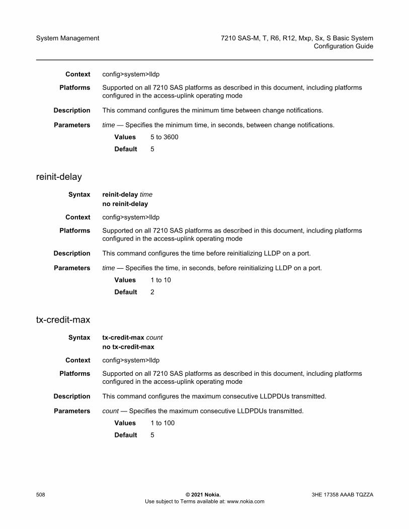
System Management
508
7210 SAS-M, T, R6, R12, Mxp, Sx, S Basic SystemConfiguration Guide
© 2021 Nokia. Use subject to Terms available at: www.nokia.com
3HE 17358 AAAB TQZZA
Context config>system>lldp
Platforms Supported on all 7210 SAS platforms as described in this document, including platforms configured in the access-uplink operating mode
Description This command configures the minimum time between change notifications.
Parameters time — Specifies the minimum time, in seconds, between change notifications.
Values 5 to 3600
Default 5
reinit-delay
Syntax reinit-delay timeno reinit-delay
Context config>system>lldp
Platforms Supported on all 7210 SAS platforms as described in this document, including platforms configured in the access-uplink operating mode
Description This command configures the time before reinitializing LLDP on a port.
Parameters time — Specifies the time, in seconds, before reinitializing LLDP on a port.
Values 1 to 10
Default 2
tx-credit-max
Syntax tx-credit-max countno tx-credit-max
Context config>system>lldp
Platforms Supported on all 7210 SAS platforms as described in this document, including platforms configured in the access-uplink operating mode
Description This command configures the maximum consecutive LLDPDUs transmitted.
Parameters count — Specifies the maximum consecutive LLDPDUs transmitted.
Values 1 to 100
Default 5
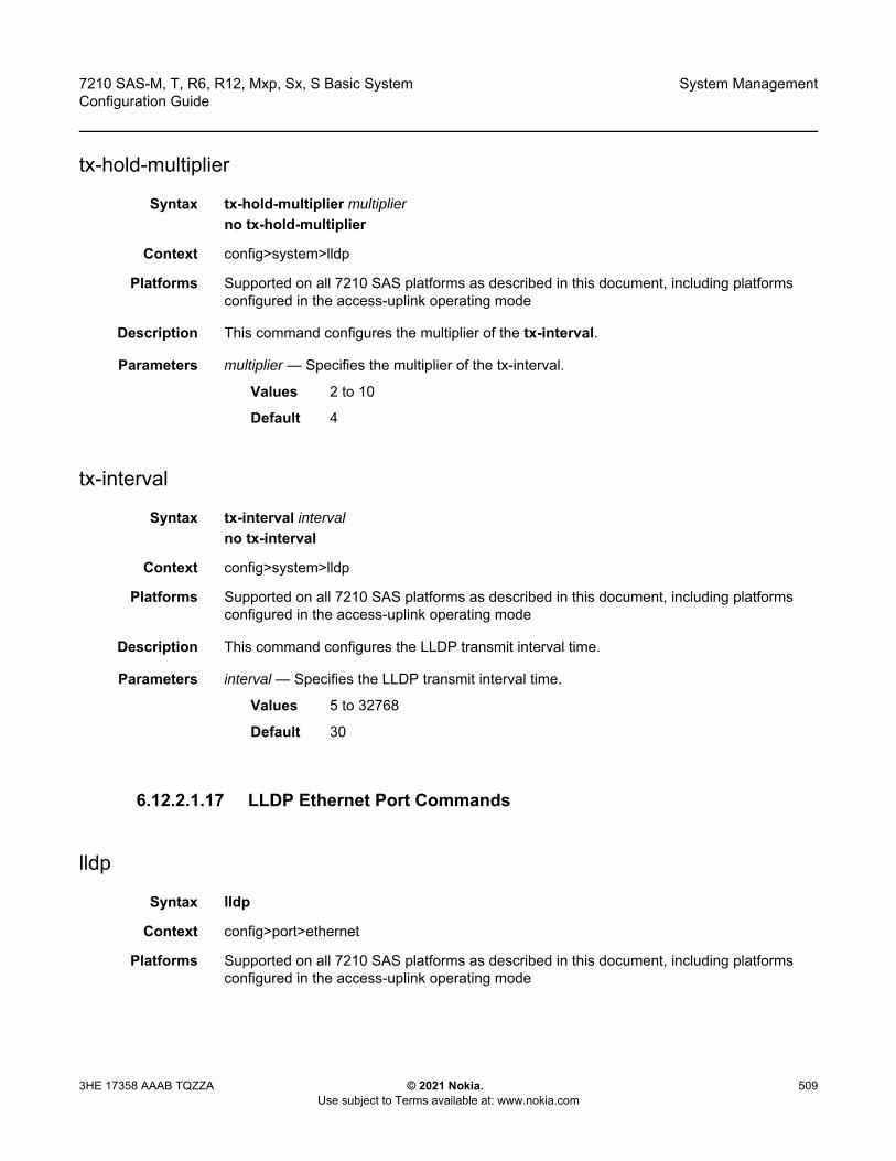
7210 SAS-M, T, R6, R12, Mxp, Sx, S Basic System Configuration Guide
System Management
3HE 17358 AAAB TQZZA © 2021 Nokia. Use subject to Terms available at: www.nokia.com
509
tx-hold-multiplier
Syntax tx-hold-multiplier multiplierno tx-hold-multiplier
Context config>system>lldp
Platforms Supported on all 7210 SAS platforms as described in this document, including platforms configured in the access-uplink operating mode
Description This command configures the multiplier of the tx-interval.
Parameters multiplier — Specifies the multiplier of the tx-interval.
Values 2 to 10
Default 4
tx-interval
Syntax tx-interval intervalno tx-interval
Context config>system>lldp
Platforms Supported on all 7210 SAS platforms as described in this document, including platforms configured in the access-uplink operating mode
Description This command configures the LLDP transmit interval time.
Parameters interval — Specifies the LLDP transmit interval time.
Values 5 to 32768
Default 30
6.12.2.1.17 LLDP Ethernet Port Commands
lldp
Syntax lldp
Context config>port>ethernet
Platforms Supported on all 7210 SAS platforms as described in this document, including platforms configured in the access-uplink operating mode

System Management
510
7210 SAS-M, T, R6, R12, Mxp, Sx, S Basic SystemConfiguration Guide
© 2021 Nokia. Use subject to Terms available at: www.nokia.com
3HE 17358 AAAB TQZZA
Description Commands in this context configure Link Layer Discovery Protocol (LLDP) parameters on the specified port.
dest-mac
Syntax dest-mac {bridge-mac}
Context config>port>ethernet>lldp
Platforms Supported on all 7210 SAS platforms as described in this document, including platforms configured in the access-uplink operating mode
Description This command configures destination MAC address parameters.
Parameters bridge-mac — Specifies destination bridge MAC type to use by LLDP.
Values nearest-bridge — Specifies to use the nearest bridgenearest-non-tpmr — Specifies to use the nearest non-Two-Port MAC Relay (TPMR)nearest-customer — Specifies to use the nearest customer
admin-status
Syntax admin-status {rx | tx | tx-rx | disabled}
Context config>port>ethernet>lldp>dstmac
Platforms Supported on all 7210 SAS platforms as described in this document, including platforms configured in the access-uplink operating mode
Description This command specifies the administratively desired status of the local LLDP agent.
Parameters rx — Specifies that the LLDP agent will receive, but will not transmit LLDP frames on this port.
tx — Specifies that the LLDP agent will transmit LLDP frames on this port and will not store any information about the remote systems connected.
tx-rx — Specifies that the LLDP agent will transmit and receive LLDP frames on this port.
disabled — Specifies that the LLDP agent will not transmit or receive LLDP frames on this port. If there is remote systems information which is received on this port and stored in other tables, before the port's admin status becomes disabled, the information will naturally age out.
notification
Syntax [no] notification
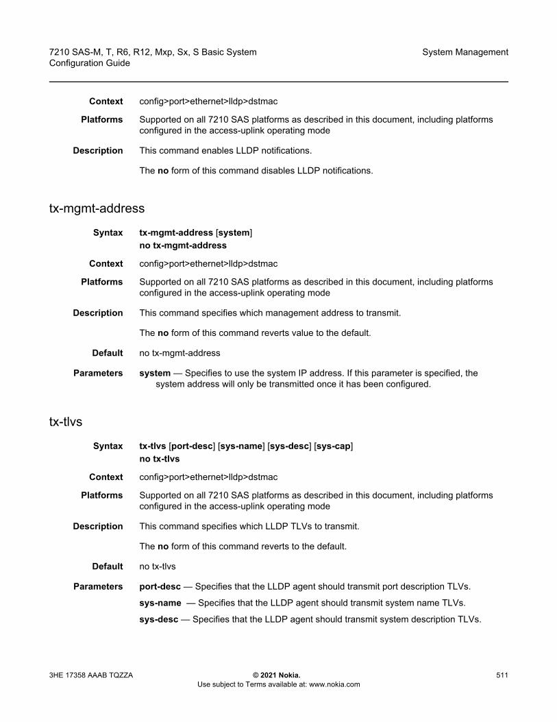
7210 SAS-M, T, R6, R12, Mxp, Sx, S Basic System Configuration Guide
System Management
3HE 17358 AAAB TQZZA © 2021 Nokia. Use subject to Terms available at: www.nokia.com
511
Context config>port>ethernet>lldp>dstmac
Platforms Supported on all 7210 SAS platforms as described in this document, including platforms configured in the access-uplink operating mode
Description This command enables LLDP notifications.
The no form of this command disables LLDP notifications.
tx-mgmt-address
Syntax tx-mgmt-address [system]no tx-mgmt-address
Context config>port>ethernet>lldp>dstmac
Platforms Supported on all 7210 SAS platforms as described in this document, including platforms configured in the access-uplink operating mode
Description This command specifies which management address to transmit.
The no form of this command reverts value to the default.
Default no tx-mgmt-address
Parameters system — Specifies to use the system IP address. If this parameter is specified, the system address will only be transmitted once it has been configured.
tx-tlvs
Syntax tx-tlvs [port-desc] [sys-name] [sys-desc] [sys-cap]no tx-tlvs
Context config>port>ethernet>lldp>dstmac
Platforms Supported on all 7210 SAS platforms as described in this document, including platforms configured in the access-uplink operating mode
Description This command specifies which LLDP TLVs to transmit.
The no form of this command reverts to the default.
Default no tx-tlvs
Parameters port-desc — Specifies that the LLDP agent should transmit port description TLVs.
sys-name — Specifies that the LLDP agent should transmit system name TLVs.
sys-desc — Specifies that the LLDP agent should transmit system description TLVs.
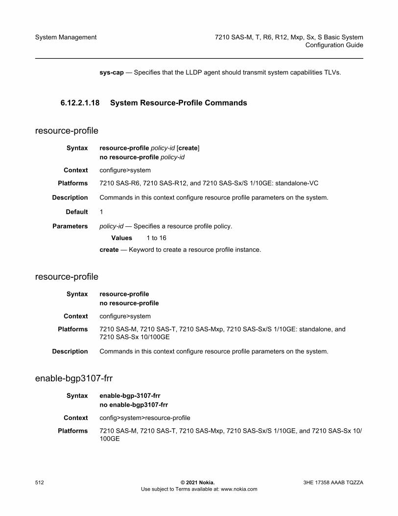
System Management
512
7210 SAS-M, T, R6, R12, Mxp, Sx, S Basic SystemConfiguration Guide
© 2021 Nokia. Use subject to Terms available at: www.nokia.com
3HE 17358 AAAB TQZZA
sys-cap — Specifies that the LLDP agent should transmit system capabilities TLVs.
6.12.2.1.18 System Resource-Profile Commands
resource-profile
Syntax resource-profile policy-id [create]no resource-profile policy-id
Context configure>system
Platforms 7210 SAS-R6, 7210 SAS-R12, and 7210 SAS-Sx/S 1/10GE: standalone-VC
Description Commands in this context configure resource profile parameters on the system.
Default 1
Parameters policy-id — Specifies a resource profile policy.
Values 1 to 16
create — Keyword to create a resource profile instance.
resource-profile
Syntax resource-profileno resource-profile
Context configure>system
Platforms 7210 SAS-M, 7210 SAS-T, 7210 SAS-Mxp, 7210 SAS-Sx/S 1/10GE: standalone, and 7210 SAS-Sx 10/100GE
Description Commands in this context configure resource profile parameters on the system.
enable-bgp3107-frr
Syntax enable-bgp-3107-frrno enable-bgp3107-frr
Context config>system>resource-profile
Platforms 7210 SAS-M, 7210 SAS-T, 7210 SAS-Mxp, 7210 SAS-Sx/S 1/10GE, and 7210 SAS-Sx 10/100GE

7210 SAS-M, T, R6, R12, Mxp, Sx, S Basic System Configuration Guide
System Management
3HE 17358 AAAB TQZZA © 2021 Nokia. Use subject to Terms available at: www.nokia.com
513
Description This command enables the allocation of MPLS FIB and protection group resources required for enabling uniform fast reroute (FRR) for BGP RFC3107 LU routes resolved using RSVP-TE LSPs. This is a per-node configuration and enabling the command affects all BGP LU routes.
The no form of this command disables the use of uniform FRR for BGP LU routes.
Default no enable-bgp3107-frr
enable-ldporsvp-frr
Syntax enable-ldporsvp-frrno enable-ldporsvp-frr
Context config>system>resource-profile
Platforms 7210 SAS-M, 7210 SAS-T, 7210 SAS-Mxp, 7210 SAS-Sx/S 1/10GE, and 7210 SAS-Sx 10/100GE
Description This command enables the allocation of MPLS FIB and protection group resources required for enabling uniform FRR for LDP-over-RSVP LSPs (LDP FECs resolved using RSVP-TE LSPs). This is a per-node configuration and enabling the command affects all LDP-over-RSVP LSPs.
The no form of this command disables the use of uniform FRR for LDP-over-RSVP LSPs.
Default no enable-ldporsvp-frr
g8032-fast-flood-enable
Syntax [no] g8032-fast-flood-enable
Caution: If the command is enabled, the amount of resources required is twice the amount required without uniform FRR, and the number of BGP LU routes that can be accommodated in the MPLS FIB is therefore halved if uniform FRR is enabled. Ensure that sufficient MPLS resources are available to accommodate all required BGP LU routes before using this command.
Caution: If the command is enabled, the amount of resources required is twice the amount required without uniform FRR, and the number of LDP-over-RSVP LSPs that can be accommodated in the MPLS FIB is therefore halved if uniform FRR is enabled. Ensure that sufficient MPLS resources are available to accommodate all required LDP-over-RSVP LSPs before using this command.

System Management
514
7210 SAS-M, T, R6, R12, Mxp, Sx, S Basic SystemConfiguration Guide
© 2021 Nokia. Use subject to Terms available at: www.nokia.com
3HE 17358 AAAB TQZZA
Context configure>system>resource-profile (7210 SAS-M)configure>system>resource-profile>ingress-internal-tcam (7210 SAS-T)
Platforms 7210 SAS-M and 7210 SAS-T
Description This command configures the G.8032 fast-flood feature. When this command is executed, it is stored in the configuration file after admin save is executed. A system reboot is required for this command to take effect.
It is recommended to enable this command to improve service failover time due to failures in the ring path. When fast flood is enabled, on failure detection in one of the paths of the ETH-ring, along with MAC flush, the system starts to flood the traffic on-to the available path.
If this command is present in the configuration file, on reboot, the system allocates resources for G.8032, by reducing the amount of resources available for use with ACLs. When this command is used, G.8032 fastflood needs an entire chunk with “512” entries, therefore the amount of resources available for use with ACLs is reduced by “512”. The user needs to free up resources used by ACLs and make them available for use by G.8032, before enabling this command. The user should ensure that the resource usage of ACLs has been appropriately modified before reboot, to make way for use of this feature. The user can free up resources by either disabling the use of ACLs with a SAP or deleting a SAP, so that an entire chunk of 512 entries is available.
Before enabling the g8032-fast-flood-enable command, the user must check if sufficient resources are available. The tools dump system-resources command is available to check if sufficient resources are available. The 'Ingress Shared CAM Entries' field, shown in the output below tools dump system resources command, must be more than or equal to 512 (the ‘Free’ column in the following output).
| Total | Allocated | Free-------------------------------+-----------+-----------+------------Ingress Shared CAM Entries | 0 | 0 | 512
The no form of this command removes the allocated resources for use by G.8032.The entire resource pool is available for use by ACLs. The no form of this command takes affect only on reboot.
Default no g8032-fast-flood-enable
decommission
Syntax decommission
Context config>system>resource-profile
Platforms 7210 SAS-M (network and access-uplink) and 7210 SAS-T (network and access-uplink)
7210 SAS-M, T, R6, R12, Mxp, Sx, S Basic System Configuration Guide
System Management
3HE 17358 AAAB TQZZA © 2021 Nokia. Use subject to Terms available at: www.nokia.com
515
Description Commands in this context decommission a port. Ports which are decommissioned using this command are not available for provisioning services. The packet buffers are taken away from the decommissioned port and allocated to port(s) as specified by the entries configured under the decommission command. This command allocates more packet buffers to a certain port or group of ports and enables those ports to absorb larger bursts.
entry
Syntax entry entry-id port port-range to port-rangeno entry entry-id
Context config>system>resource-profile>decommission
Platforms 7210 SAS-M (network and access-uplink) and 7210 SAS-T (network and access-uplink)
Description This command decommissions a port or group of ports and allocates buffers to ports that need more packet buffers for absorbing larger bursts. It allows the user to configure the entries which list the ports to be decommissioned. Ports whose packet buffers are taken away are given on the left-hand of the to keyword, and ports to which buffers are allocated to are given on the right-hand side.
This command allows the user to specify either a port or a group of ports on both sides, using a list or range of ports. This allows the user to decommission a single port and allocate buffers to a single port or group of ports, or decommission a group of ports and allocate buffers to a single port or group of ports.
Packet buffers taken away from a port or group of ports specified on the left-hand side are distributed equally among the group of ports, if the right-hand side of the to keyword specifies a group of ports or to the configured port if the right-hand side specifies a single port. Packet buffers are added to the MBS pool of the port (the MBS pool is shared by the 8 queues on the port) and the CBS portion of the queues is not modified.
The administrative and operational states of the port are not affected by configuring the port in a decommission entry.
The software maintains two lists of entries, one which is in effect currently and one which has been modified by the user and takes effect during the next reboot. These lists can be displayed using the show command. The configuration file always stores the list of entries as configured by the user so that upon reboot, the modified entries and new entries (if any) take effect.
Note: • Any changes to the command, example - modifying the list of ports in existing entries
or execution of no entry command or addition of new entries, takes effect only after a reboot of the node. The user is allowed to make change when the node is up, but the changes does not happen until a reboot of the system.
• The ports on the CES MDA cannot be specified in the decommission command.
System Management
516
7210 SAS-M, T, R6, R12, Mxp, Sx, S Basic SystemConfiguration Guide
© 2021 Nokia. Use subject to Terms available at: www.nokia.com
3HE 17358 AAAB TQZZA
The following guidelines are to be adhered while configuring the entry command.
• A port cannot be specified more than once in any of the entries. In other words, if two entries specify the same port ID, the software errors out the last entry which has the same port ID.
• A port appearing on the left-hand side of the to keyword in any entry cannot appear on the right-hand side of any other entries (including the same entry) and the converse also holds true.
• If the user has specified a group of ports using a port range, the software expands the range to a list of ports and then makes the required checks (that is, checks listed in the first and second bullets) for each port in the list with the list of currently configured group of ports.
• Either a port ID or a list of port ID or port ID ranges can be specified on the left-hand side and the right hand-side of the ‘to’ keyword. See the following description for port ID specification to know more about the restrictions that apply when configuring a port range and list of ports.
• The list of entries is processed in the ascending order of the entry IDs, that is, an entry with a lower entry ID is processed before entry with a higher entry ID.
The no form of this command removes the entry from the list of decommissioned ports. The no form of this command requires a reboot to take effect.
The following examples show the list of ports, range of ports, and a combination of list of ports and range of ports that can be specified.
List of ports can be specified as:
• 1/1/1, 1/1/2, 1/2/1, 1/1/10 is allowed• 1/1/10, 1/1/2, 1/1/9, 1/1/5 is allowed
Range of ports can be specified as:
• 1/1/2-1/1/5 is allowed• 1/2/1-1/2/2 is allowed• 1/1/10-1/1/2 is not allowed• 1/1/1 – 1/2/2 is not allowed
A combination of list of ports and range of ports can be specified as:
• 1/1/5,1/1/6,1/1/10-1/1/15,1/1/25 is allowed• 1/1/5,1/1/6,1/1/10-1/1/12,1/1/13-1/1/15 is allowed• 1/1/5,1/1/6,1/1/10-1/1/12,1/2/1-1/2/2 is allowed
Parameters entry-id — Specifies a number in the range 1 to 30. A maximum of 30 entries can be created by the user.
Values 1 to 30
7210 SAS-M, T, R6, R12, Mxp, Sx, S Basic System Configuration Guide
System Management
3HE 17358 AAAB TQZZA © 2021 Nokia. Use subject to Terms available at: www.nokia.com
517
port-range — Specifies the port, list of ports, a port range, or a combination of these that are being decommissioned when they appear on the left-hand side of the to keyword. This parameter identifies the port or group of ports that receives the packet buffers from the decommissioned ports. A group of ports can be specified as a list of ports or as a range of ports. The list of ports can be specified in any order using a comma to separate the list of ports, while a port range must always be specified in the ascending order of port IDs (in other words, the first port number specified in the range must be greater than the second port number in the range) and a single range cannot refer to ports on different MDA or different IMMs or different slots.
egress-internal-tcam
Syntax egress-internal-tcam
Context configure>system>resource-profile
Platforms Supported on all 7210 SAS platforms as described in this document, including platforms configured in the access-uplink operating mode
Description Commands in this context allocate resources from the egress internal TCAM pool.
The egress internal TCAM resource pool is shared by multiple features. The resources are allocated to features in chunks of fixed size; multiple features cannot share the same chunk. The users can allocate the available resources based on their feature scaling requirements. The system allocates resources to the feature from its allocated chunk until the chunk runs out of resources. The users can reallocate chunks of resources from features that do not need to be enabled.
To free up the resources for use by one or more features, modify the configuration to release the chunks of resources that are in use by other features. For example, to free up a chunk of resources allocated to egress ACLs MAC criteria and allocate it to IP criteria, perform the following steps.
1. Remove the association of SAPs with egress ACLs that use a MAC criteria policy.2. Change the resource profile configuration to allocate the chunk to IP criteria.3. Create and associate the SAPs with the IP criteria.
To free up a chunk of resources used by egress ACLs and allocate it to the SAP egress aggregate meter (on platforms that support this feature), perform the following steps.
1. Remove the association of SAPs with egress ACLs.2. Change the resource profile configuration to reduce the chunk resources allocated to
egress ACLs (and reduce the value of chunks in use by the egress ACLs match criteria).3. Allocate the chunk of resources to the SAP egress aggregate meter feature (on
platforms that support this feature).4. Configure the SAPs with the aggregate meter rate.

System Management
518
7210 SAS-M, T, R6, R12, Mxp, Sx, S Basic SystemConfiguration Guide
© 2021 Nokia. Use subject to Terms available at: www.nokia.com
3HE 17358 AAAB TQZZA
The egress internal TCAM resource pool is shared among the following features on different platforms:
• 7210 SAS-M access-uplink modeEgress ACLs (all of IPv4, IPv6, MAC match-criteria), Per SAP Egress Aggregate Meter, and MAC authentication
• 7210 SAS-T access-uplink modeEgress ACLs (all of IPv4, IPv6, MAC match-criteria), Per SAP Egress Aggregate Meter, and MAC authentication
• 7210 SAS-M network modePer SAP Egress Aggregate Meter, Egress ACLs (all of IPv4, IPv6, and MAC match-criteria), and MAC authentication
• 7210 SAS-T network modePer SAP Egress Aggregate meter, Egress ACLs (all of IPv4, IPv6, and MAC match-criteria), and MAC authentication
• 7210 SAS-Mxp modeEgress ACLs (all of IPv4, IPv6, and MAC match-criteria) and MAC authentication
• 7210 SAS-Sx 1/10GE mode (standalone and standalone-VC)Per SAP Egress Aggregate meter, Egress ACLs (all of IPv4, IPv6, and MAC match-criteria), and MAC authentication
• 7210 SAS-S 1/10GE mode (standalone and standalone-VC)Per SAP Egress Aggregate meter, Egress ACLs (all of IPv4, IPv6, and MAC match-criteria), and MAC authentication
• 7210 SAS-Sx 10/100GE modePer SAP Egress Aggregate meter and Egress ACLs (all of IPv4, IPv6, and MAC match-criteria)
• 7210 SAS-R6 IMMv1, IMMv2, and IMM-cPer SAP Egress Aggregate meter, Egress ACLs (all of IPv4, IPv6, and MAC match-criteria), Ethernet CFM (bi-directional MIP), and MAC authentication
• 7210 SAS-R12 IMMv1, IMMv2, and IMM-cPer SAP Egress Aggregate meter and Egress ACLs (all of IPv4, IPv6, and MAC match-criteria), Ethernet CFM (bi-directional MIP)

7210 SAS-M, T, R6, R12, Mxp, Sx, S Basic System Configuration Guide
System Management
3HE 17358 AAAB TQZZA © 2021 Nokia. Use subject to Terms available at: www.nokia.com
519
acl-sap-egress
Syntax acl-sap-egress [num-resources]no acl-sap-ingress
Context configure>system>resource-profile>egress-internal-tcam
Platforms Supported on all 7210 SAS platforms as described in this document, including platforms configured in the access-uplink operating mode
Description This command enables the user to allocate maximum resources for use by egress filter policies using any of the supported match criteria. This command limits the total amount of chunks allocated for use by egress filter policies to the value specified by num-resources. In other words, the cumulative sum of chunks allocated to different match criteria supported by filter policies cannot exceed the value configured with num-resources.
Note: • In some scenarios, reassigning a chunk of resources among features may require the
node to be rebooted. See the CLI description of the feature for detailed information.• The egress internal TCAM pool of resources is available per node on the 7210 SAS-M,
7210 SAS-T, 7210 SAS-Sx/S 1/10GE (standalone), 7210 SAS-Sx 10/100GE, and 7210 SAS-Mxp. On the 7210 SAS-Sx/S 1/10GE (standalone-VC), 7210 SAS-R6, and 7210 SAS-R12, it is available as a per-IMM pool of resources.
• It is possible to configure a resource profile per node or per card in a virtual chassis.• The number of chunks and the number of resources per chunk varies for the 7210 SAS
platforms. Contact your Nokia technical support representative for more information.• To be enabled, some features require the allocation of a specific number of chunks
(greater than 1). If the minimum number of chunks is not assigned, the system cannot allocate the required resources to the feature, which causes the command associated with the feature to fail.
Note: • The resources in the egress-internal-tcam resource pool are shared with other features
(for example, SAP egress aggregate meter). To assign resources to this feature, resources may be reallocated from other features by disabling the policies association with a SAP, and others.
• On the 7210 SAS platforms, some of the Egress ACL match criteria require a minimum amount of resources greater than 1, to be allocated before the match criteria can be used. In other words, use of SAP egress aggregate meter is mutually exclusive to use of egress ACLs with the following match criteria - mac-ipv4 match, ipv6-128bit match, mac-ipv6-64bit match. All these match criteria require a minimum of 2 resources. SAP egress aggregate meter and egress ACLs MAC match criteria can be enabled simultaneously, with each feature sharing the available resources equally among them.

System Management
520
7210 SAS-M, T, R6, R12, Mxp, Sx, S Basic SystemConfiguration Guide
© 2021 Nokia. Use subject to Terms available at: www.nokia.com
3HE 17358 AAAB TQZZA
The no form of this command specifies that the software does not allocate any resources for use by egress filter policies. If no resources are allocated for use, the software fails all attempts to associate a service entity (for example, SAP and IP interface) with a filter policy using any of the match criteria.
Parameters num-resources — Specifies the amount of resources that can be allocated for use by ACL policies.
Values Table 44 lists the parameter values.
egress-sap-aggregate-meter
Syntax [no] egress-sap-aggregate-meter num-resources
Context configure>system>resource-profile>egress-internal-tcam
Platforms 7210 SAS-M (network and access-uplink), 7210 SAS-T (network and access-uplink), 7210 SAS-Sx/S 1/10GE: standalone and standalone-VC, 7210 SAS-Sx 10/100GE, 7210 SAS-R6 and 7210 SAS-R12
Table 44 Number of Resources Available for ACL-SAP-Egress
Platforms Min value (per node)
Max value (per node)
Default Values
7210 SAS-M (per node) 0 2 2
7210 SAS-T Network mode (per node) 0 2 2
7210 SAS-R6 (per IMMv1) 0 2 2
7210 SAS-R6 and 7210 SAS-R12(per IMMv2)
0 2 2
7210 SAS-R6 and 7210 SAS-R12 (per IMM-c)
0 2 2
7210 SAS-Mxp (per node) 0 2 2
7210 SAS-Sx 1/10GE (per node) (standalone)
0 2 2
7210 SAS-Sx 1/10GE (standalone-VC) 0 2 2
7210 SAS-S 1/10GE (per node) (standalone)
0 2 2
7210 SAS-S 1/10GE (standalone-VC) 0 2 2
7210 SAS-Sx 10/100GE (per node) 0 2 2
7210 SAS-M, T, R6, R12, Mxp, Sx, S Basic System Configuration Guide
System Management
3HE 17358 AAAB TQZZA © 2021 Nokia. Use subject to Terms available at: www.nokia.com
521
Description This command allocates resources for use by SAP egress aggregate policer from the egress-internal-tcam resource pool. This command limits the total amount of chunks allocated for use by SAP egress aggregate meter to the value specified by the num-resources parameter.
The no form of this command specifies that software does not allocate any resources for use by the SAP egress aggregate policer. If no resources are allocated for use, the software fails all attempts to enable the configuration of the sap-aggregate-meter command for a SAP.
Default no egress-sap-aggregate-meter
Parameters num-resources — Specifies the maximum amount of resources for use by this filter match criteria.
Values 0 to 2
Default 0
ipv6-128bit-match-enable
Syntax [no] ipv6-128bit-match-enable num-resources
Context configure>system>resource-profile>egress-internal-tcam>acl-sap-egress
Platforms Supported on all 7210 SAS platforms as described in this document, including platforms configured in the access-uplink operating mode
Description This command allocates maximum resources for use by egress filter policies using ipv6 criteria with 128-bit IPv6 addresses.
The resources cannot be shared with any other egress filter policies that specify other match criteria. Refer to the 7210 SAS-M, T, R6, R12, Mxp, Sx, S Router Configuration Guide for more information on resource allocation and fields available for use.
Note: • The resources in the egress-internal-tcam resource pool are shared with other features
(for example, SAP egress aggregate meter). To assign resources to this feature, resources may be reallocated from other features by disabling the policies association with a SAP, and others.
• On the 7210 SAS platforms, some of the Egress ACL match criteria require a minimum amount of resources greater than 1, to be allocated before the match criteria can be used. In other words, use of SAP egress aggregate meter is mutually exclusive to use of egress ACLs with the following match criteria - mac-ipv4 match, ipv6-128bit match, mac-ipv6-64bit match. All these match criteria require a minimum of 2 resources. SAP egress aggregate meter and egress ACLs MAC match criteria can be enabled simultaneously, with each feature sharing the available resources equally among them.

System Management
522
7210 SAS-M, T, R6, R12, Mxp, Sx, S Basic SystemConfiguration Guide
© 2021 Nokia. Use subject to Terms available at: www.nokia.com
3HE 17358 AAAB TQZZA
The no form of this command specifies that the software does not allocate any resources for use by egress filter policies using ipv6 criteria with 128-bit IPv6 addresses. If no resources are allocated for use, the software fails all attempts to associate a service entity (for example, SAP and IP interface) with a filter policy using this match criteria.
Default no ipv6-128bit-match-enable
Parameters num-resources — Specifies the maximum amount of resources for use by this filter match criteria. A minimum value of 2 (indicating two chunks of resources) must be allocated to use this match-criteria. If not, association of a policy with ipv6-128bit criteria to a SAP will fail. It is mutually exclusive to use of SAP egress aggregate meter.
Values Table 45 lists the parameter values.
mac-ipv4-match-enable
Syntax [no] mac-ipv4-match-enable num-resources
Context configure>system>resource-profile>egress-internal-tcam>acl-sap-egress
Platforms Supported on all 7210 SAS platforms as described in this document, including platforms configured in the access-uplink operating mode
Table 45 Number of Resources Available for IPv6-128Bit-Match-Enable
Platforms Min value (per node)
Max value (per node)
Default Values
7210 SAS-M (per node) 0 2 0
7210 SAS-T access-uplink mode (per node) 0 2 0
7210 SAS-T network mode (per node) 0 2 0
7210 SAS-Sx 1/10GE (standalone) 0 2 0
7210 SAS-Sx 1/10GE (standalone-VC) 0 2 0
7210 SAS-S 1/10GE (standalone) 0 2 0
7210 SAS-S 1/10GE (standalone-VC) 0 2 0
7210 SAS-Sx 10/100GE 0 2 0
7210 SAS-Mxp 0 2 0
7210 SAS-R6 and 7210 SAS-R12 0 2 0
7210 SAS-R6 (per IMM) 0 0 2

7210 SAS-M, T, R6, R12, Mxp, Sx, S Basic System Configuration Guide
System Management
3HE 17358 AAAB TQZZA © 2021 Nokia. Use subject to Terms available at: www.nokia.com
523
Description This command allocates maximum resources for use by egress filter policies using IPv4 criteria or MAC criteria. The resources allocated are allocated on a first-come-first-serve basis among service entities (for example, SAP and IP interface) using IPv4 and MAC criteria egress filter policies.
The resources cannot be shared with any other egress filter policies that specify other match criteria. Refer to the 7210 SAS-M, T, R6, R12, Mxp, Sx, S Router Configuration Guide for more information on resource allocation and fields available for use.
The no form of this command specifies that the software does not allocate any resources for use by egress filter policies using MAC or IPv4 criteria. If no resources are allocated for use, the software fails all attempts to associate a service entity (for example, SAP and IP interface) with a filter policy using this match criteria.
Default mac-ipv4-match-enable 2 (to maintain backward compatibility with earlier releases)
Parameters num-resources — Specifies the maximum amount of resources for use by this filter match criteria. A minimum value of 2 (indicating two chunks of resources) must be allocated to use this match-criteria. If not, association of a policy with mac and ipv4 criteria to a SAP will fail. It is mutually exclusive to use of SAP egress aggregate meter.
Values Table 46 lists the parameter values.
Table 46 Number of Resources Available for MAC-IPv4-Match-Enable
Platforms Min value (per node)
Max value (per node)
Default Values
7210 SAS-M (per node) 0 2 0
7210 SAS-T access-uplink mode (per node) 0 2 0
7210 SAS-T network mode (per node) 0 2 0
7210 SAS-S 1/10GE (per node) (standalone) 0 2 0
7210 SAS-Sx 1/10GE standalone-VC) 0 2 2
7210 SAS-S 1/10GE (per node) (standalone) 0 2 0
7210 SAS-S 1/10GE (standalone-VC) 0 2 2
7210 SAS-Sx 10/100GE (per node) 0 2 2
7210 SAS-R6 and 7210 SAS-R12 IMM-c (per node)
0 2 2
7210 SAS-Mxp 0 2 0
7210 SAS-R6 IMMv1 and IMMv2 0 2 0
7210 SAS-R12 IMMv2 0 2 0

System Management
524
7210 SAS-M, T, R6, R12, Mxp, Sx, S Basic SystemConfiguration Guide
© 2021 Nokia. Use subject to Terms available at: www.nokia.com
3HE 17358 AAAB TQZZA
mac-ipv6-64bit-match-enable
Syntax [no] mac-ipv6-64bit-match-enable num-resources
Context configure>system>resource-profile>egress-internal-tcam>acl-sap-egress
Platforms Supported on all 7210 SAS platforms as described in this document, including platforms configured in the access-uplink operating mode
Description This command allocates maximum resources for use by egress filter policies using MAC criteria or IPv6 criteria using only the upper 64-bits of the IPv6 addresses. The resources allocated are allocated on a first-come-first-serve basis among service entities (for example, SAP and IP interface) using IPv6 64-bit and MAC criteria egress filter policies.
The resources cannot be shared with any other egress filter policies that specify other match criteria. Refer to the 7210 SAS-M, T, R6, R12, Mxp, Sx, S Router Configuration Guide for more information on resource allocation and fields available for use.
The no form of this command specifies that the software does not allocate any resources for use by egress filter policies using MAC or IPv6 64-bit criteria. If no resources are allocated for use, the software fails all attempts to associate a service entity (for example SAP and IP interface) with a filter policy using this match criteria.
Default no mac-ipv6-64bit-match-enable
Parameters num-resources — Specifies the maximum amount of resources for use by this filter match criteria. A minimum value of 2 (indicating two chunks of resources) must be allocated to use this match-criteria. If not, association of a policy with mac and ipv6 64bit criteria to a SAP will fail. It is mutually exclusive to use of SAP egress aggregate meter.
Values Table 47 lists the parameter values.
Table 47 Number of Resources Available for MAC-IPv6-64Bit-Match-Enable
Platforms Min value (per node)
Max value (per node)
Default Values
7210 SAS-M (per node) 0 2 0
7210 SAS-T access-uplink mode (per node) 0 2 0
7210 SAS-T network mode (per node) 0 2 0
7210 SAS-Sx 1/10GE (per node) (standalone)
0 2 0
7210 SAS-Sx 1/10GE (standalone-VC) 0 2 0
7210 SAS-S 1/10GE (per node) (standalone) 0 2 0

7210 SAS-M, T, R6, R12, Mxp, Sx, S Basic System Configuration Guide
System Management
3HE 17358 AAAB TQZZA © 2021 Nokia. Use subject to Terms available at: www.nokia.com
525
mac-match-enable
Syntax [no] mac-match-enable num-resources
Context configure>system>resource-profile>egress-internal-tcam>acl-sap-egress
Platforms Supported on all 7210 SAS platforms as described in this document, including platforms configured in the access-uplink operating mode
Description This command allocates maximum resources for use by egress filter policies using MAC criteria. The resources allocated are allocated on a first-come-first-serve basis among service entities (for example, SAP and IP interface) using MAC criteria egress filter policies. This option provides the use of all available resources exclusively by MAC criteria egress filter policies and provides larger number of policies to be used.
The resources cannot be shared with any other egress filter policies that specify other match criteria. Refer to the 7210 SAS-M, T, R6, R12, Mxp, Sx, S Router Configuration Guide for more information on resource allocation and fields available for use.
The no form of this command specifies that the software does not allocate any resources for use by egress filter policies using MAC criteria. If no resources are allocated for use, the software fails all attempts to associate a service entity (for example, SAP and IP interface) with a filter policy using this match criteria.
Default no mac-match-enable
7210 SAS-S 1/10GE (standalone-VC) 0 2 0
7210 SAS-Sx 10/100GE (per node) 0 2 0
7210 SAS-Mxp 0 2 0
7210 SAS-R6 IMMv1 and IMMv2 0 2 0
7210 SAS-R12 IMMv2 0 2 0
7210 SAS-R6 and 7210 SAS-R12 IMM-c 0 2 0
Table 47 Number of Resources Available for MAC-IPv6-64Bit-Match-Enable (Continued)
Platforms Min value (per node)
Max value (per node)
Default Values
Note: It is possible to use MAC policies by allocating resources that are shared with other match criteria. This option allows for better scaling.
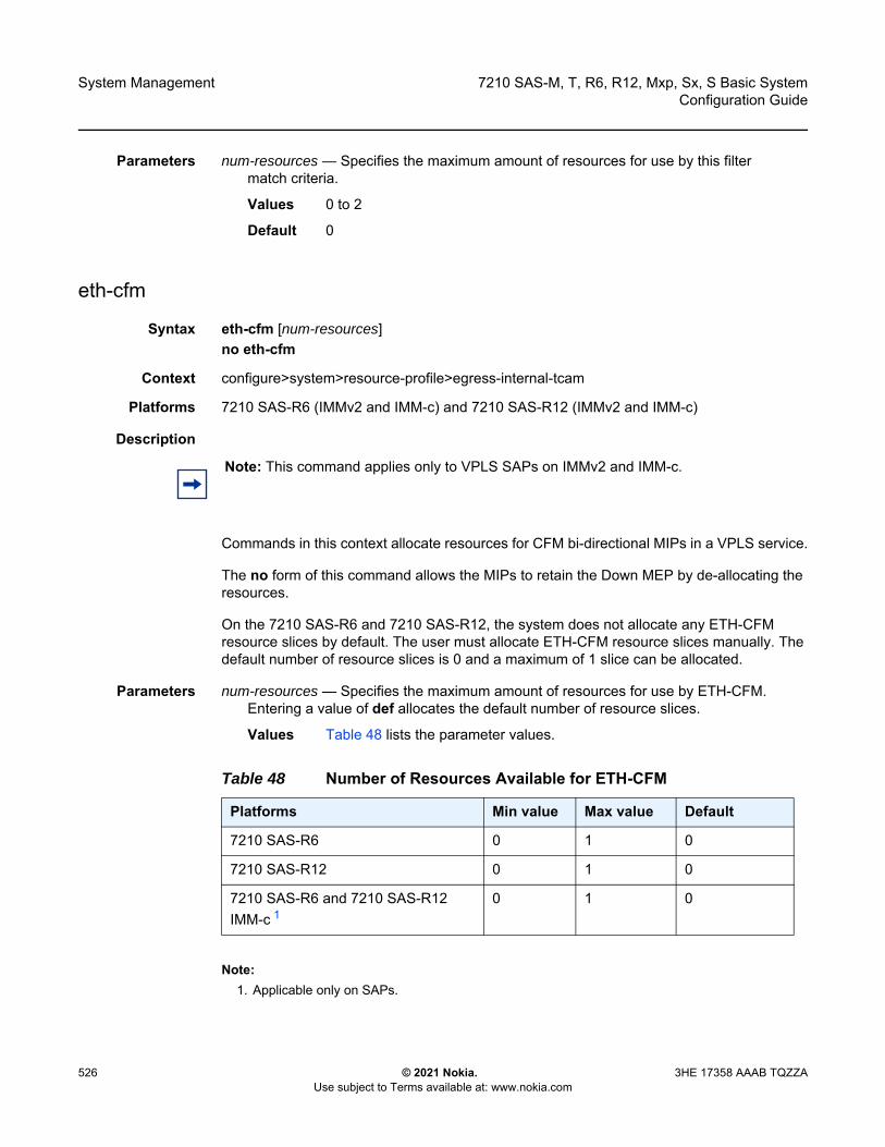
System Management
526
7210 SAS-M, T, R6, R12, Mxp, Sx, S Basic SystemConfiguration Guide
© 2021 Nokia. Use subject to Terms available at: www.nokia.com
3HE 17358 AAAB TQZZA
Parameters num-resources — Specifies the maximum amount of resources for use by this filter match criteria.
Values 0 to 2
Default 0
eth-cfm
Syntax eth-cfm [num-resources]no eth-cfm
Context configure>system>resource-profile>egress-internal-tcam
Platforms 7210 SAS-R6 (IMMv2 and IMM-c) and 7210 SAS-R12 (IMMv2 and IMM-c)
Description
Commands in this context allocate resources for CFM bi-directional MIPs in a VPLS service.
The no form of this command allows the MIPs to retain the Down MEP by de-allocating the resources.
On the 7210 SAS-R6 and 7210 SAS-R12, the system does not allocate any ETH-CFM resource slices by default. The user must allocate ETH-CFM resource slices manually. The default number of resource slices is 0 and a maximum of 1 slice can be allocated.
Parameters num-resources — Specifies the maximum amount of resources for use by ETH-CFM. Entering a value of def allocates the default number of resource slices.
Values Table 48 lists the parameter values.
Note:1. Applicable only on SAPs.
Note: This command applies only to VPLS SAPs on IMMv2 and IMM-c.
Table 48 Number of Resources Available for ETH-CFM
Platforms Min value Max value Default
7210 SAS-R6 0 1 0
7210 SAS-R12 0 1 0
7210 SAS-R6 and 7210 SAS-R12 IMM-c 1
0 1 0

7210 SAS-M, T, R6, R12, Mxp, Sx, S Basic System Configuration Guide
System Management
3HE 17358 AAAB TQZZA © 2021 Nokia. Use subject to Terms available at: www.nokia.com
527
bidir-mip-egress
Syntax bidir-mip-egress [num-resources]no bidir-mip-egress
Context configure>system>resource-profile>egress-internal-tcam>eth-cfm
Platforms 7210 SAS-R6 (IMMv2 and IMM-c) and 7210 SAS-R12 (IMMv2 and IMM-c)
Description This command allocates resources for the VPLS bi-directional MIP (both ingress and egress directions) on SAPs only from the egress internal TCAM resource pool.
The no form of this command allocates no resources to this feature.
Default no bidir-mip-egress
Parameters num-resources — Specifies the number of resources to allocate.
Values 0 to 1
mac-auth-res
Syntax mac-auth-res num-resourcesno mac-auth-res
Context config>system>resource-profile>egress-internal-tcamconfig>system>resource-profile>ingress-internal-tcam
Platforms 7210 SAS-Mxp (standalone), 7210 SAS-R6 (all IMMs), 7210 SAS-Sx/S 1/10GE (standalone), 7210 SAS-T (network and access-uplink operating modes)
Note: • The resources in the egress internal TCAM resource pool are shared with other
features.To assign resources to a specific feature, resources can be reallocated from other features. For example, you can release resources by disabling the policies associated with a SAP.
• Resources must be allocated from this pool before bi-directional MIPs can be configured on VPLS SAPs.
• Bi-directional MIPs on VPLS SAPs can be enabled only when the bidir-mip-egress resource slice is allocated and vpls-sap-bidir is enabled in the configure>service>vpls>eth-cfm context.
System Management
528
7210 SAS-M, T, R6, R12, Mxp, Sx, S Basic SystemConfiguration Guide
© 2021 Nokia. Use subject to Terms available at: www.nokia.com
3HE 17358 AAAB TQZZA
Description This command configures the allocation of resources for MAC authentication from the ingress internal TCAM pool and egress internal TCAM pool. Resources must be allocated from both ingress and egress TCAM pools before MAC authentication can be used. If resources are not allocated from both pools, the system returns an error message and MAC authentication cannot be enabled.
The configured number of resources specifies the number of resource pool slices allocated for use by MAC authentication. One entry is used for each authenticated source MAC address. The maximum number of MAC addresses that can be authenticated is limited by the number of entries allocated to the feature using this command. The maximum number of MAC address entries is limited by the maximum number of entries available in the ingress internal TCAM pool and the egress internal TCAM pool.
The no form of this command removes all resources allocated to MAC authentication; further attempts to enable MAC authentication on an Ethernet port using the mac-auth command will fail unless resources are first reallocated using the mac-auth-res command. The no form of the mac-auth-res command cannot be executed when MAC authentication is enabled on at least one port.
Default no mac-auth-res
Parameters num-resources — Specifies the number of resources to allocate for MAC authentication. Configuring a value of 0 is equivalent to configuring no mac-auth-res and effectively disables MAC authentication.
Values 0 to 1
g8032-control-sap-tags
Syntax [no] g8032-control-sap-tags vlan-range
Context configure>system>resource-profile
Platforms 7210 SAS-Sx/S 1/10GE: standalone and standalone-VC, 7210 SAS-R6, 7210 SAS-R12
Description This command configures the range of VLANs per IMM to be used internally with G8032 MEPs that support hardware CCM message processing.
Use one of the VLANs configured with this command to configure the VLAN for the G8032 MEP configure>eth-ring>path>eth-cfm>mep>control-sap-tag.
Default no g8032-control-sap-tags
Note: Users must ensure that the VLANs configured for use with G8032 MEPs are not configured for any of the SAPs configured on the IMM.
7210 SAS-M, T, R6, R12, Mxp, Sx, S Basic System Configuration Guide
System Management
3HE 17358 AAAB TQZZA © 2021 Nokia. Use subject to Terms available at: www.nokia.com
529
Parameters vlan-range — Specifies the range of VLANs per IM.
Values start-vlan — 3000 to 3512 (7210 SAS-R6 and 7210 SAS-R12)512 to 768 (7210 SAS-Sx 1/10GE:standalone and standalone-VC)
end -vlan — 3000 to 3512 (7210 SAS-R6 and 7210 SAS-R12) 512 to 768 (7210 SAS-Sx 1/10GE:standalone and standalone-VC)
qos-sap-egress-resource
Syntax qos-sap-egress-resource num-resources no qos-sap-egress-resource
Context config>system>res-prof>ingress-internal-tcam
Platforms 7210 SAS-R6, 7210 SAS-R12, and 7210 SAS-Mxp
Description This command configures resource allocation for SAP-based egress queuing from the ingress-internal-tcam resource pool. If port-based queuing is disabled, users must allocate resources for SAP-based egress queuing using this command. If no resources are allocated, SAPs cannot be created.
When port-based queuing is enabled, resources can be taken away from SAP-based egress queues and allocated to other features that share the ingress-internal-tcam pool (for example, SAP ingress QoS and Ingress ACLs).
The no form of this command reverts to the default value.
Default 0
Parameters num-resources — Specifies the amount of resources that are allocated towards SAP-based egress queues.
Values 0 to 2
eth-cfm
Syntax eth-cfm
Context configure>system>resource-profile
Platforms 7210 SAS-M
Note: This command is not supported on IMM-c cards. SAP functionality with per SAP egress queues is not supported on IMM-c cards.
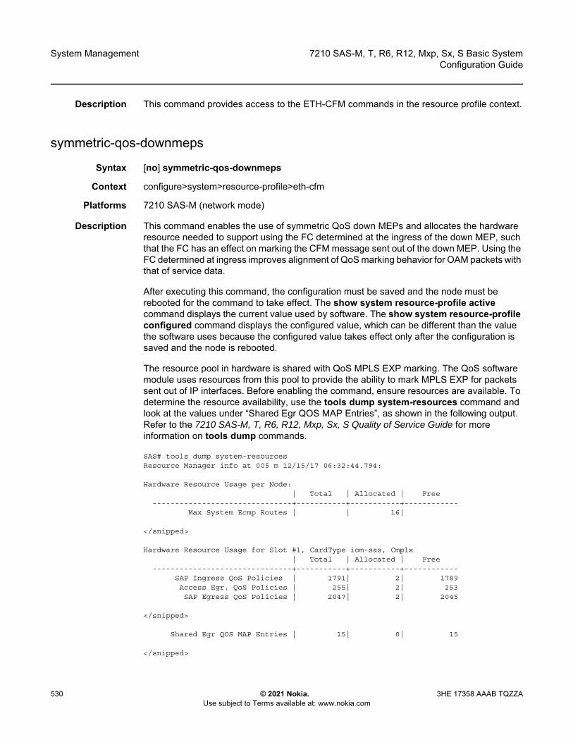
System Management
530
7210 SAS-M, T, R6, R12, Mxp, Sx, S Basic SystemConfiguration Guide
© 2021 Nokia. Use subject to Terms available at: www.nokia.com
3HE 17358 AAAB TQZZA
Description This command provides access to the ETH-CFM commands in the resource profile context.
symmetric-qos-downmeps
Syntax [no] symmetric-qos-downmeps
Context configure>system>resource-profile>eth-cfm
Platforms 7210 SAS-M (network mode)
Description This command enables the use of symmetric QoS down MEPs and allocates the hardware resource needed to support using the FC determined at the ingress of the down MEP, such that the FC has an effect on marking the CFM message sent out of the down MEP. Using the FC determined at ingress improves alignment of QoS marking behavior for OAM packets with that of service data.
After executing this command, the configuration must be saved and the node must be rebooted for the command to take effect. The show system resource-profile active command displays the current value used by software. The show system resource-profile configured command displays the configured value, which can be different than the value the software uses because the configured value takes effect only after the configuration is saved and the node is rebooted.
The resource pool in hardware is shared with QoS MPLS EXP marking. The QoS software module uses resources from this pool to provide the ability to mark MPLS EXP for packets sent out of IP interfaces. Before enabling the command, ensure resources are available. To determine the resource availability, use the tools dump system-resources command and look at the values under “Shared Egr QOS MAP Entries”, as shown in the following output. Refer to the 7210 SAS-M, T, R6, R12, Mxp, Sx, S Quality of Service Guide for more information on tools dump commands.
SAS# tools dump system-resourcesResource Manager info at 005 m 12/15/17 06:32:44.794:
Hardware Resource Usage per Node:| Total | Allocated | Free
-------------------------------+-----------+-----------+------------Max System Ecmp Routes | | 16|
</snipped>
Hardware Resource Usage for Slot #1, CardType iom-sas, Cmplx| Total | Allocated | Free
-------------------------------+-----------+-----------+------------SAP Ingress QoS Policies | 1791| 2| 1789Access Egr. QoS Policies | 255| 2| 253SAP Egress QoS Policies | 2047| 2| 2045
</snipped>
Shared Egr QOS MAP Entries | 15| 0| 15
</snipped>
7210 SAS-M, T, R6, R12, Mxp, Sx, S Basic System Configuration Guide
System Management
3HE 17358 AAAB TQZZA © 2021 Nokia. Use subject to Terms available at: www.nokia.com
531
Using the resource pool to enable symmetric QoS for down MEPs reduces the number of resources available for the egress LSP EXP marking map by one.
The no form of this command removes allocated resources.
Default no symmetric-qos-downmeps
ingress-internal-tcam
Syntax ingress-internal-tcam
Context configure>system>resource-profile
Platforms Supported on all 7210 SAS platforms as described in this document, including platforms configured in the access-uplink operating mode
Description Commands in this context allocate ingress internal TCAM resources.
The ingress internal TCAM resource pool is shared by multiple features. The resources are allocated in chunks of fixed size; multiple features cannot share the same chunk. The users can allocate the available resources based on their feature scaling requirements. The resource usage for different features is provided in the CLI description. The system allocates resources to the feature from its allocated chunk until the chunk runs out of resources. The users can reallocate chunks of resources from features that do not need to be enabled.
To free up the resources for use by one or more features, modify the configuration to release chunks of resources that are in use by other features. For example, to free up a chunk of resources allocated to ingress ACLs MAC criteria and allocate the chunk to IP criteria, perform the following steps.
1. Remove the association of all the SAPs with ingress ACLs that use a MAC criteria policy.2. Change the resource profile configuration to allocate the chunk to IP criteria.3. Create (can be done before hand) and associate the SAPs with IP criteria.
For another example, to free up a chunk of resources used by ingress ACLs and allocate it towards SAP ingress QoS classification, perform the following steps.
1. Remove the association of all the SAPs with ingress ACLs.2. Change the resource profile configuration to reduce the chunk resources allocated to
ingress ACLs (and also to reduce the amount configured for specific match-criteria).3. Allocate the chunk of resources to SAP ingress QoS classification feature.4. Configure the SAPs with the SAP ingress QoS policies.
Table 49 describes the sharing of the ingress internal TCAM resource pool among the features on different 7210 SAS platforms.
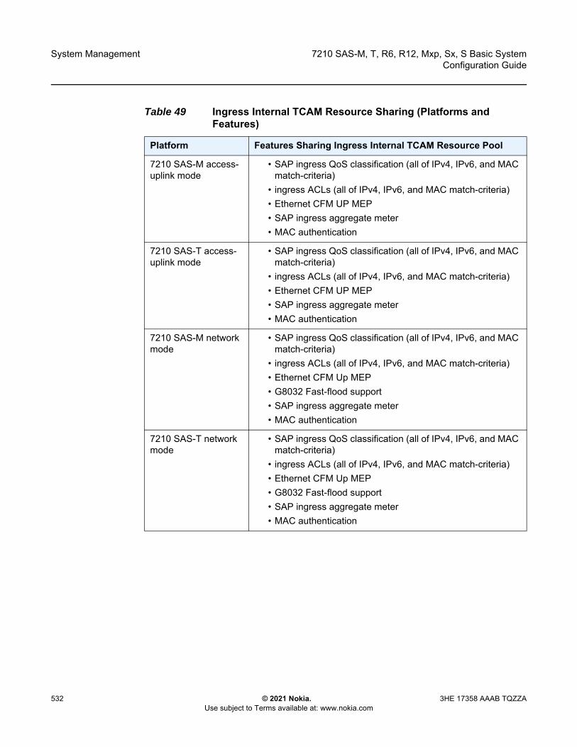
System Management
532
7210 SAS-M, T, R6, R12, Mxp, Sx, S Basic SystemConfiguration Guide
© 2021 Nokia. Use subject to Terms available at: www.nokia.com
3HE 17358 AAAB TQZZA
Table 49 Ingress Internal TCAM Resource Sharing (Platforms and Features)
Platform Features Sharing Ingress Internal TCAM Resource Pool
7210 SAS-M access-uplink mode
• SAP ingress QoS classification (all of IPv4, IPv6, and MAC match-criteria)
• ingress ACLs (all of IPv4, IPv6, and MAC match-criteria)• Ethernet CFM UP MEP • SAP ingress aggregate meter• MAC authentication
7210 SAS-T access-uplink mode
• SAP ingress QoS classification (all of IPv4, IPv6, and MAC match-criteria)
• ingress ACLs (all of IPv4, IPv6, and MAC match-criteria)• Ethernet CFM UP MEP • SAP ingress aggregate meter• MAC authentication
7210 SAS-M network mode
• SAP ingress QoS classification (all of IPv4, IPv6, and MAC match-criteria)
• ingress ACLs (all of IPv4, IPv6, and MAC match-criteria)• Ethernet CFM Up MEP• G8032 Fast-flood support• SAP ingress aggregate meter • MAC authentication
7210 SAS-T network mode
• SAP ingress QoS classification (all of IPv4, IPv6, and MAC match-criteria)
• ingress ACLs (all of IPv4, IPv6, and MAC match-criteria)• Ethernet CFM Up MEP• G8032 Fast-flood support• SAP ingress aggregate meter • MAC authentication

7210 SAS-M, T, R6, R12, Mxp, Sx, S Basic System Configuration Guide
System Management
3HE 17358 AAAB TQZZA © 2021 Nokia. Use subject to Terms available at: www.nokia.com
533
7210 SAS-Mxp • SAP ingress QoS classification (all of IPv4, IPv6, and MAC match-criteria)
• ingress ACLs (all of IPv4, IPv6, and MAC match-criteria)• Ethernet CFM Up MEP, ingress MIPs, and Epipe
bidirectional MIPs• SAP ingress aggregate meter • MAC authentication• access port ingress QoS policies• network port QoS policies• IP-MPLS control plane protocols
7210 SAS-R6 and 7210 SAS-R12
On the 7210 SAS-R6 and 7210 SAS-R12, the features that share the resource pool are different based on the IMM card type.
On IMMv1, IMMv2, and IMM-c cards 1, this resource pool is shared among the following features:
• SAP ingress QoS classification (all of IPv4, IPv6, and MAC match-criteria)
• ingress ACLs (all of IPv4, IPv6, and MAC match-criteria)• Ethernet CFM MEP (Up and Down), ingress MIPs, and
Epipe bidirectional MIPs• SAP ingress aggregate meter• network port and IP interface ingress QoS classification• SAP egress based queuing and scheduling (not applicable
to IMM-c cards)• CPU protection• MAC authentication (7210 SAS-R6 only)• access port ingress QoS policies
7210 SAS-Sx 1/10GE (standalone)
• SAP ingress QoS classification (IPv4 and IPv6 match-criteria)
• ingress ACLs (all of IPv4, IPv6, and MAC match-criteria)• Ethernet CFM Up MEP, Down MEP, ingress MIPs, and
Epipe bidirectional MIPs• SAP ingress aggregate meter • access port ingress QoS policies • MAC authentication
Table 49 Ingress Internal TCAM Resource Sharing (Platforms and Features) (Continued)
Platform Features Sharing Ingress Internal TCAM Resource Pool

System Management
534
7210 SAS-M, T, R6, R12, Mxp, Sx, S Basic SystemConfiguration Guide
© 2021 Nokia. Use subject to Terms available at: www.nokia.com
3HE 17358 AAAB TQZZA
Note:1. IMMv1 and IMM-c cards cannot be installed in the same 7210 SAS-R6 chassis. IMMv1 cards are
not supported on the 7210 SAS-R12.
7210 SAS-Sx 1/10GE (standalone-VC)
• SAP ingress QoS classification (IPv4 and IPv6 match-criteria)
• ingress ACLs (all of IPv4, IPv6, and MAC match-criteria)• Ethernet CFM Up MEP, SAP Down MEP, SDP Down MEP,
ingress MIPs, and Epipe bidirectional MIPs• SAP ingress aggregate meter • MAC authentication
7210 SAS-S 1/10GE (standalone)
• SAP ingress QoS classification (IPv4 and IPv6 match-criteria)
• ingress ACLs (all of IPv4, IPv6, and MAC match-criteria)• Ethernet CFM Up MEP, Down MEP, ingress MIPs, and
Epipe bidirectional MIPs• SAP ingress aggregate meter • access port ingress QoS policies • MAC authentication
7210 SAS-S 1/10GE (standalone-VC)
• SAP ingress QoS classification (IPv4 and IPv6 match-criteria)
• ingress ACLs (all of IPv4, IPv6, and MAC match-criteria)• Ethernet CFM Up MEP, SAP Down MEP, SDP Down MEP,
ingress MIPs, and Epipe bidirectional MIPs• SAP ingress aggregate meter • MAC authentication
7210 SAS-Sx 10/100GE
• SAP ingress QoS classification (IPv4 and IPv6 match-criteria)
• ingress ACLs (all of IPv4, IPv6, and MAC match-criteria)• Ethernet CFM Up MEP, Down MEP, ingress MIPs, and
Epipe bidirectional MIPs• access port ingress QoS policies
Table 49 Ingress Internal TCAM Resource Sharing (Platforms and Features) (Continued)
Platform Features Sharing Ingress Internal TCAM Resource Pool

7210 SAS-M, T, R6, R12, Mxp, Sx, S Basic System Configuration Guide
System Management
3HE 17358 AAAB TQZZA © 2021 Nokia. Use subject to Terms available at: www.nokia.com
535
acl-sap-ingress
Syntax acl-sap-ingress [num-resources]no acl-sap-ingress
Context configure>system>resource-profile>ingress-internal-tcam
Platforms Supported on all 7210 SAS platforms as described in this document, including platforms configured in the access-uplink operating mode
Description This command allocates maximum resources for use by ingress filter policies using any of the supported match criteria. This command limits the total amount of chunks allocated for use by ingress filter policies to the value specified by num-resources. In other words, the cumulative sum of chunks allocated to different match criteria supported by ingress filter policies cannot exceed the value configured with num-resources.
Ingress ACL resources are shared with SAP ingress aggregate meter. See the sap-aggregate-meter command for more information.
The no form of this command removes any allocated resources for use by filter policies. Consequently, the software fails all attempts to associate a service entity (for example, SAP and IP interface) with a filter policy using any of the match criteria.
Parameters num-resources — Specifies the amount of resources that can be allocated for use by ACL policies.
Note: • In some scenarios, reassigning a chunk of resources among features may require the
node to be rebooted. See the CLI description of the specific feature for more information.
• The ingress internal TCAM pool of resources is available per node on the 7210 SAS-M, 7210 SAS-T, 7210 SAS-Mxp, 7210 SAS-Sx/S 1/10GE (standalone), and 7210 SAS-Sx 10/100GE. On the 7210 SAS-Sx/S 1/10GE (standalone-VC), 7210 SAS-R6, and 7210 SAS-R12, it is available as a per-IMM pool of resources.
• The number of chunks and the number of resources per chunk varies among the different platforms. Contact your Nokia technical support representative for more information.
• To be enabled, some features require the allocation of a specific number of chunks (greater than 1). If the minimum number of chunks is not assigned, the system cannot allocate the required resources to the feature, which causes the command associated with the feature to fail.

System Management
536
7210 SAS-M, T, R6, R12, Mxp, Sx, S Basic SystemConfiguration Guide
© 2021 Nokia. Use subject to Terms available at: www.nokia.com
3HE 17358 AAAB TQZZA
Some platforms include the value def. If the user specifies def, the software allocates the default amount of resources based on the 7210 SAS platform. On the 7210 SAS-R6 and 7210 SAS-R12, the amount of default resources allocated also varies based on the IMM plugged into the slot.
Values Table 50 lists the parameter values and the values used for the def keyword on different 7210 SAS platforms and on different IMM types.
Note:1. The maximum value is 9 if qos-network-ingress-resource is configured as 0.
ipv4-ipv6-128-match-enable
Syntax [no] ipv4-ipv6-128-match-enable
Context configure>system>resource-profile>ingress-internal-tcam>acl-sap-ingress
Table 50 Number of Resources Available for ACL-SAP-Ingress
Platforms Min value (per node)
Max value (per node)
Default Values
7210 SAS-M (per node) 0 5 5
7210 SAS-T access-uplink mode (per node)
0 7 3
7210 SAS-T network mode (per node) 0 6 3
7210 SAS-R6 (per IMMv1) 0 10 2
7210 SAS-R6 and 7210 SAS-R12 (per IMMv2)
0 10 3
7210 SAS-R6 and 7210 SAS-R12 (per IMM-c)
0 8 1 3
7210 SAS-Mxp (per node) 0 10 3
7210 SAS-Sx 1/10GE (per node) (standalone)
0 6 3
7210 SAS-Sx 1/10GE (standalone-VC) 0 5 2
7210 SAS-S 1/10GE (per node) (standalone)
0 6 3
7210 SAS-S 1/10GE (standalone-VC) 0 5 2
7210 SAS-Sx 10/100GE (per node) 0 4 1

7210 SAS-M, T, R6, R12, Mxp, Sx, S Basic System Configuration Guide
System Management
3HE 17358 AAAB TQZZA © 2021 Nokia. Use subject to Terms available at: www.nokia.com
537
Platforms Supported on all 7210 SAS platforms as described in this document, including platforms configured in the access-uplink operating mode
Description This command allocates maximum resources for use by ingress filter policies using ipv6 criteria with 128-bit IPv6 addresses.
The resources can be shared with IPv4 ingress filter policies. Refer to the 7210 SAS-M, T, R6, R12, Mxp, Sx, S Router Configuration Guide for more information on how to allow filter policies using IPv4 criteria to share resources with filter policies that use IPv6 criteria with 128-bit address and resource allocation and fields available for use.
The no form of this command specifies that the software does not allocate any resources for use by ingress filter policies using ipv6 criteria with 128-bit IPv6 addresses. If no resources are allocated for use, the software fails all attempts to associate a service entity (for example, SAP and IP interface) with an ingress filter policy using this match criteria.
Parameters num-resources — Specifies the maximum amount of resources for use by this filter match criteria. Some platforms include the value max. If the user specifies max, the software allocates one chunk when the first SAP is associated with an ingress filter policy using this match criteria. It continues to allocate resources to the service entity associated with an ingress filter policy using this criteria, as long as the total amount of resources allocated does not exceed the resources allocated to ingress filter policies (configured with the config system resource-profile ingress-internal-tcam acl-sap-ingress command) and chunks are available for use.
Values Table 51 lists the parameter values.
Table 51 Number of Resources Available for IPv4-IPv6-128-Match-Enable
Platforms Min value (per node)
Max value (per node)
Default Values
7210 SAS-M (per node) 0 5 0
7210 SAS-T access-uplink mode (per node) 0 7 3
7210 SAS-T Network Mode (per node) 0 6 3
7210 SAS-R6 (per IMMv1) 0 (per IMM) 5 max
7210 SAS-R6 and 7210 SAS-R12 (per IMMv2)
0 (per IMM) 7 max
7210 SAS-R6 and 7210 SAS-R12 (per IMM-c) 0 (per IMM) 7 1 max
7210 SAS-Mxp (per node) 0 10 max
7210 SAS-Sx 1/10GE (per node) (standalone) 0 6 max
7210 SAS-Sx 1/10GE (standalone-VC) 0 5 max

System Management
538
7210 SAS-M, T, R6, R12, Mxp, Sx, S Basic SystemConfiguration Guide
© 2021 Nokia. Use subject to Terms available at: www.nokia.com
3HE 17358 AAAB TQZZA
Note:1. The maximum value is 9 if acl-sap-ingress is configured as 9.
ip-dscp-port-if-match-enable
Syntax ip-dscp-port-if-match-enable num-resources no ip-dscp-port-if-match-enable
Context configure>system>resource-profile>ingress-internal-tcam>qos-sap-ingress-resource
Platforms 7210 SAS-Mxp, 7210 SAS-R6 and 7210 SAS-R12
Description This command allocates resources for use by SAP ingress QoS policies that use IP DSCP table-based classification.
The available resources are used by software to allocate policers for SAPs whose ingress policy uses the IP DSCP table-based classification policy. The users need to allocate resources from the ingress internal TCAM pool before DSCP classification can be used. This means users need to take away resources from other features such as mac-match criteria from the SAP ingress classification or ACL ingress to allocate resources for DSCP classification.
Refer to the 7210 SAS-M, T, R6, R12, Mxp, Sx, S Quality of Service Guide for more information on resource allocation and fields available for use.
The no form of this command does not allocate any resources for use by SAP ingress QoS policies using a DSCP table-based classification policy. If no resources are allocated for use, the software fails all attempts to associate a service entity (for example, SAP and IP interface) with a SAP ingress QoS policy using the DSCP table-based classification policy.
Parameters num-resources — Specifies the maximum amount of resources (slices) for use by the DSCP table-based classification policy. Each slice has a fixed number of entries. DSCP table-based classification requires exclusive use of the allocated resources.
7210 SAS-S 1/10GE (per node) (standalone) 0 6 max
7210 SAS-S 1/10GE (standalone-VC) 0 5 max
7210 SAS-Sx 10/100GE (per node) 0 4 max
Table 51 Number of Resources Available for IPv4-IPv6-128-Match-Enable (Continued)
Platforms Min value (per node)
Max value (per node)
Default Values
7210 SAS-M, T, R6, R12, Mxp, Sx, S Basic System Configuration Guide
System Management
3HE 17358 AAAB TQZZA © 2021 Nokia. Use subject to Terms available at: www.nokia.com
539
If the user specifies max, the software allocates one chunk when the first SAP is associated with an ingress filter policy using this match criteria. It continues to allocate resources to SAPs associated with an ingress filter policy using this criteria, provided that the total amount of resources allocated does not exceed the resources allocated to qos-sap-ingress-qos resource pool (configured with the config system resource-profile ingress-internal-tcam qos-sap-ingress-resource command) and chunks are available for use.
Values 0 to 10, max (7210 SAS-Mxp)0 to 12, max (7210 SAS-R6 and 7210 SAS-R12)
Default 0
ipv4-mac-match-enable
Syntax ipv4-mac-match-enable num-resourcesno ipv4-mac-match-enable
Context configure>system>resource-profile>ingress-internal-tcam>qos-sap-ingress-resource
Platforms Supported on all 7210 SAS platforms as described in this document, including platforms configured in the access-uplink operating mode
Description This command allocates maximum resources for use by SAP ingress QoS policies using both MAC (any) and IPv4 criteria (any) criteria in a policy.
The available resources is used by software to allocate resources for SAP ingress policies using the following criteria - either both IPv4 criteria any and MAC criteria any, only mac criteria any, only ipv4 criteria, dot1p-only criteria, ipv4 dscp-only criteria and ipv6 dscp-only criteria. It is not used for SAP ingress policies that use ipv6 criteria any.
Refer to the 7210 SAS-M, T, R6, R12, Mxp, Sx, S Quality of Service Guide for more information on resource allocation.
The no form of this command specifies that the software does not allocate any resources for use by SAP ingress QoS policies using both MAC and IPv4 criteria. If no resources are allocated for use, then software fails all attempts to associate a service entity (for example, SAP and IP interface) with an ingress filter policy or SAP ingress QoS policy using this match criteria.
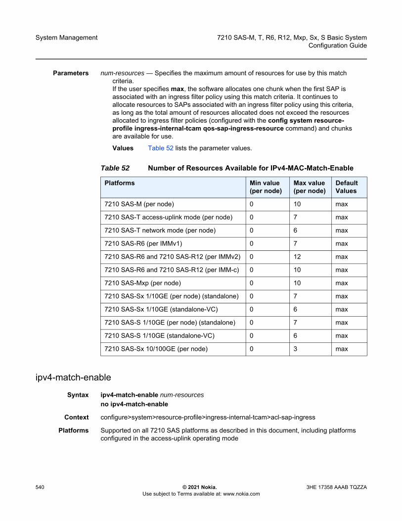
System Management
540
7210 SAS-M, T, R6, R12, Mxp, Sx, S Basic SystemConfiguration Guide
© 2021 Nokia. Use subject to Terms available at: www.nokia.com
3HE 17358 AAAB TQZZA
Parameters num-resources — Specifies the maximum amount of resources for use by this match criteria. If the user specifies max, the software allocates one chunk when the first SAP is associated with an ingress filter policy using this match criteria. It continues to allocate resources to SAPs associated with an ingress filter policy using this criteria, as long as the total amount of resources allocated does not exceed the resources allocated to ingress filter policies (configured with the config system resource-profile ingress-internal-tcam qos-sap-ingress-resource command) and chunks are available for use.
Values Table 52 lists the parameter values.
ipv4-match-enable
Syntax ipv4-match-enable num-resourcesno ipv4-match-enable
Context configure>system>resource-profile>ingress-internal-tcam>acl-sap-ingress
Platforms Supported on all 7210 SAS platforms as described in this document, including platforms configured in the access-uplink operating mode
Table 52 Number of Resources Available for IPv4-MAC-Match-Enable
Platforms Min value (per node)
Max value (per node)
Default Values
7210 SAS-M (per node) 0 10 max
7210 SAS-T access-uplink mode (per node) 0 7 max
7210 SAS-T network mode (per node) 0 6 max
7210 SAS-R6 (per IMMv1) 0 7 max
7210 SAS-R6 and 7210 SAS-R12 (per IMMv2) 0 12 max
7210 SAS-R6 and 7210 SAS-R12 (per IMM-c) 0 10 max
7210 SAS-Mxp (per node) 0 10 max
7210 SAS-Sx 1/10GE (per node) (standalone) 0 7 max
7210 SAS-Sx 1/10GE (standalone-VC) 0 6 max
7210 SAS-S 1/10GE (per node) (standalone) 0 7 max
7210 SAS-S 1/10GE (standalone-VC) 0 6 max
7210 SAS-Sx 10/100GE (per node) 0 3 max
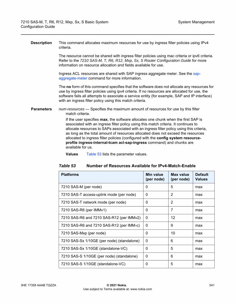
7210 SAS-M, T, R6, R12, Mxp, Sx, S Basic System Configuration Guide
System Management
3HE 17358 AAAB TQZZA © 2021 Nokia. Use subject to Terms available at: www.nokia.com
541
Description This command allocates maximum resources for use by ingress filter policies using IPv4 criteria.
The resource cannot be shared with ingress filter policies using mac criteria or ipv6 criteria. Refer to the 7210 SAS-M, T, R6, R12, Mxp, Sx, S Router Configuration Guide for more information on resource allocation and fields available for use.
Ingress ACL resources are shared with SAP ingress aggregate meter. See the sap-aggregate-meter command for more information.
The no form of this command specifies that the software does not allocate any resources for use by ingress filter policies using ipv4 criteria. If no resources are allocated for use, the software fails all attempts to associate a service entity (for example, SAP and IP interface) with an ingress filter policy using this match criteria.
Parameters num-resources — Specifies the maximum amount of resources for use by this filter match criteria. If the user specifies max, the software allocates one chunk when the first SAP is associated with an ingress filter policy using this match criteria. It continues to allocate resources to SAPs associated with an ingress filter policy using this criteria, as long as the total amount of resources allocated does not exceed the resources allocated to ingress filter policies (configured with the config system resource-profile ingress-internal-tcam acl-sap-ingress command) and chunks are available for us.
Values Table 53 lists the parameter values.
Table 53 Number of Resources Available for IPv4-Match-Enable
Platforms Min value (per node)
Max value (per node)
Default Values
7210 SAS-M (per node) 0 5 max
7210 SAS-T access-uplink mode (per node) 0 2 max
7210 SAS-T network mode (per node) 0 2 max
7210 SAS-R6 (per IMMv1) 0 7 max
7210 SAS-R6 and 7210 SAS-R12 (per IMMv2) 0 12 max
7210 SAS-R6 and 7210 SAS-R12 (per IMM-c) 0 9 max
7210 SAS-Mxp (per node) 0 10 max
7210 SAS-Sx 1/10GE (per node) (standalone) 0 6 max
7210 SAS-Sx 1/10GE (standalone-VC) 0 5 max
7210 SAS-S 1/10GE (per node) (standalone) 0 6 max
7210 SAS-S 1/10GE (standalone-VC) 0 5 max

System Management
542
7210 SAS-M, T, R6, R12, Mxp, Sx, S Basic SystemConfiguration Guide
© 2021 Nokia. Use subject to Terms available at: www.nokia.com
3HE 17358 AAAB TQZZA
ipv4-match-enable
Syntax ipv4-match-enable num-resourcesno ipv4-match-enable
Context configure>system>resource-profile>ingress-internal-tcam>qos-sap-ingress-resource
Platforms Supported on all 7210 SAS platforms as described in this document, including platforms configured in the access-uplink operating mode
Description This command allocates maximum resources for use by SAP ingress QoS policies using IPv4 criteria (any).
The resource cannot be shared with SAP ingress QoS filter policies using mac criteria or ipv6 criteria. Refer to the 7210 SAS-M, T, R6, R12, Mxp, Sx, S Quality of Service Guide for more information on resource allocation and fields available for use.
The no form of this command specifies that the software does not allocate any resources for use by SAP ingress QoS policies using ipv4 criteria. If no resources are allocated for use, the software fails all attempts to associate a service entity (for example, SAP and IP interface) with a SAP ingress QoS policy using this match criteria.
Parameters num-resources — Specifies the maximum amount of resources for use by this filter match criteria. If the user specifies max, the software allocates one chunk when the first SAP is associated with a SAP ingress QoS policy using this match criteria. It continues to allocate resources to SAPs associated with a SAP ingress QoS policy using this criteria, as long as the total amount of resources allocated does not exceed the resources allocated to SAP ingress QoS policies (configured with the config system resource-profile ingress-internal-tcam qos-sap-ingress- resource command) and chunks are available for use.
Values Table 54 lists the parameter values.
7210 SAS-Sx 10/100GE (per node) 0 4 max
Table 53 Number of Resources Available for IPv4-Match-Enable
Platforms Min value (per node)
Max value (per node)
Default Values
Table 54 Number of Resources Available for IPv4-Match-Enable
Platforms Min value (per node)
Max value (per node)
Default Values
7210 SAS-M (per node) 0 10 max

7210 SAS-M, T, R6, R12, Mxp, Sx, S Basic System Configuration Guide
System Management
3HE 17358 AAAB TQZZA © 2021 Nokia. Use subject to Terms available at: www.nokia.com
543
ipv6-64-only-match-enable
Syntax ipv6-64-only-match-enable num-resourcesno ipv6-64-only-match-enable
Context configure>system>resource-profile>ingress-internal-tcam>acl-sap-ingress
Platforms Supported on all 7210 SAS platforms as described in this document, including platforms configured in the access-uplink operating mode
Description This command allocates maximum resources for use by ingress filter policies using ipv6 criteria with 64-bit IPv6 addresses. Refer to the 7210 SAS-M, T, R6, R12, Mxp, Sx, S Router Configuration Guide for more information on resource allocation and fields available for use.
The resources cannot be shared with IPv4 filter policies or IPv6 filter policies specifying 128-bit addresses.
Ingress ACL resources are shared with SAP ingress aggregate meter. See the sap-aggregate-meter command for more information.
7210 SAS-T access-uplink mode (per node)
0 7 max
7210 SAS-T network mode (per node) 0 6 max
7210 SAS-R6 (per IMMv1) 0 7 max
7210 SAS-R6 and 7210 SAS-R12 (per IMMv2)
0 12 max
7210 SAS-R6 and 7210 SAS-R12 (per IMM-c)
0 10 max
7210 SAS-Mxp (per node) 0 10 max
7210 SAS-Sx 1/10GE (per node) (standalone)
0 7 max
7210 SAS-Sx 1/10GE (standalone-VC) 0 6 max
7210 SAS-S 1/10GE (per node) (standalone)
0 7 max
7210 SAS-S 1/10GE (standalone-VC) 0 6 max
7210 SAS-Sx 10/100GE (per node) 0 3 max
Table 54 Number of Resources Available for IPv4-Match-Enable
Platforms Min value (per node)
Max value (per node)
Default Values

System Management
544
7210 SAS-M, T, R6, R12, Mxp, Sx, S Basic SystemConfiguration Guide
© 2021 Nokia. Use subject to Terms available at: www.nokia.com
3HE 17358 AAAB TQZZA
The no form of this command specifies that the software does not allocate any resources for use by filter policies using ipv6 criteria with 64-bit IPv6 addresses. If no resources are allocated for use, the software fails all attempts to associate a service entity (for example, SAP and IP interface) with an ingress filter policy using this match criteria.
Parameters num-resources — Specifies the maximum amount of resources for use by this filter match criteria. If the user specifies max, the software allocates one chunk when the first SAP is associated with an ingress filter policy using this match criteria. It continues to allocate resources to SAPs associated with an ingress filter policy using this criteria, as long as the total amount of resources allocated does not exceed the resources allocated to ingress filter policies (configured with the config system resource-profile ingress-internal-tcam acl-sap-ingress command) and chunks are available for use.
Values Table 55 lists the parameter values.
mac-match-enable
Syntax mac-match-enable num-resourcesno mac-match-enable
Table 55 Number of Resources Available for IPv6-64-Only-Match-Enable
Platforms Min value (per node)
Max value (per node)
Default Values
7210 SAS-M (per node) 0 5 max
7210 SAS-T Access-uplink mode (per node) 0 7 max
7210 SAS-T Network Mode (per node) 0 6 max
7210 SAS-R6 and 7210 SAS-R12 (per IMM) 0 5 max
7210 SAS-R6 and 7210 SAS-R12 IMM-c (per IMM)
0 9 max
7210 SAS-Mxp (per node) 0 10 max
7210 SAS-Sx 1/10GE (per node) (standalone)
0 6 0
7210 SAS-Sx 1/10GE (standalone-VC) 0 5 max
7210 SAS-S 1/10GE (per node) (standalone) 0 6 0
7210 SAS-S 1/10GE (standalone-VC) 0 5 max
7210 SAS-Sx 10/100GE (per node) 0 4 0
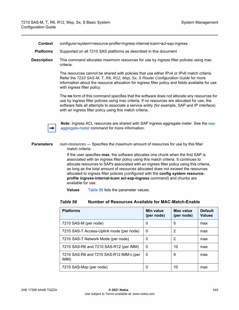
7210 SAS-M, T, R6, R12, Mxp, Sx, S Basic System Configuration Guide
System Management
3HE 17358 AAAB TQZZA © 2021 Nokia. Use subject to Terms available at: www.nokia.com
545
Context configure>system>resource-profile>ingress-internal-tcam>acl-sap-ingress
Platforms Supported on all 7210 SAS platforms as described in this document
Description This command allocates maximum resources for use by ingress filter policies using mac criteria.
The resources cannot be shared with policies that use either IPv4 or IPv6 match criteria. Refer the 7210 SAS-M, T, R6, R12, Mxp, Sx, S Router Configuration Guide for more information about the resource allocation for ingress filter policy and fields available for use with ingress filter policy.
The no form of this command specifies that the software does not allocate any resources for use by ingress filter policies using mac criteria. If no resources are allocated for use, the software fails all attempts to associate a service entity (for example, SAP and IP interface) with an ingress filter policy using this match criteria.
Parameters num-resources — Specifies the maximum amount of resources for use by this filter match criteria. If the user specifies max, the software allocates one chunk when the first SAP is associated with an ingress filter policy using this match criteria. It continues to allocate resources to SAPs associated with an ingress filter policy using this criteria, as long as the total amount of resources allocated does not exceed the resources allocated to ingress filter policies (configured with the config system resource-profile ingress-internal-tcam acl-sap-ingress command) and chunks are available for use.
Values Table 56 lists the parameter values.
Note: Ingress ACL resources are shared with SAP ingress aggregate meter. See the sap-aggregate-meter command for more information.
Table 56 Number of Resources Available for MAC-Match-Enable
Platforms Min value (per node)
Max value (per node)
Default Values
7210 SAS-M (per node) 0 5 max
7210 SAS-T Access-Uplink mode (per node) 0 2 max
7210 SAS-T Network Mode (per node) 0 2 max
7210 SAS-R6 and 7210 SAS-R12 (per IMM) 0 10 max
7210 SAS-R6 and 7210 SAS-R12 IMM-c (per IMM)
0 9 max
7210 SAS-Mxp (per node) 0 10 max
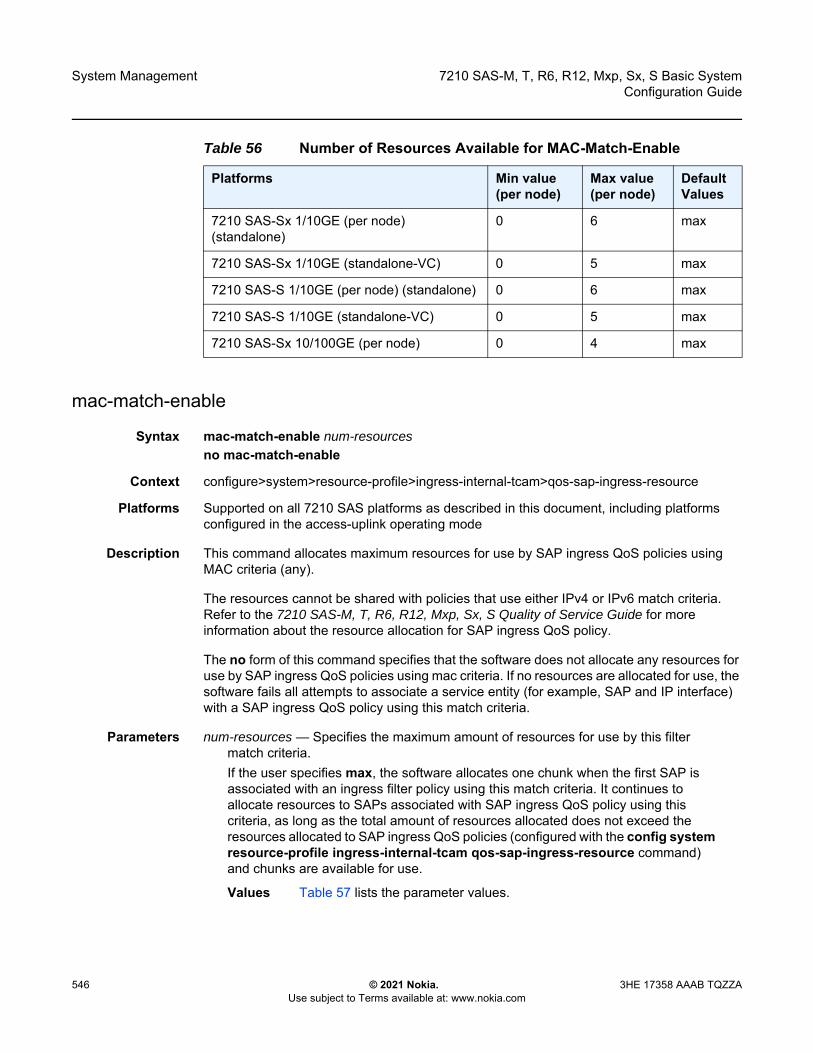
System Management
546
7210 SAS-M, T, R6, R12, Mxp, Sx, S Basic SystemConfiguration Guide
© 2021 Nokia. Use subject to Terms available at: www.nokia.com
3HE 17358 AAAB TQZZA
mac-match-enable
Syntax mac-match-enable num-resourcesno mac-match-enable
Context configure>system>resource-profile>ingress-internal-tcam>qos-sap-ingress-resource
Platforms Supported on all 7210 SAS platforms as described in this document, including platforms configured in the access-uplink operating mode
Description This command allocates maximum resources for use by SAP ingress QoS policies using MAC criteria (any).
The resources cannot be shared with policies that use either IPv4 or IPv6 match criteria. Refer to the 7210 SAS-M, T, R6, R12, Mxp, Sx, S Quality of Service Guide for more information about the resource allocation for SAP ingress QoS policy.
The no form of this command specifies that the software does not allocate any resources for use by SAP ingress QoS policies using mac criteria. If no resources are allocated for use, the software fails all attempts to associate a service entity (for example, SAP and IP interface) with a SAP ingress QoS policy using this match criteria.
Parameters num-resources — Specifies the maximum amount of resources for use by this filter match criteria.If the user specifies max, the software allocates one chunk when the first SAP is associated with an ingress filter policy using this match criteria. It continues to allocate resources to SAPs associated with SAP ingress QoS policy using this criteria, as long as the total amount of resources allocated does not exceed the resources allocated to SAP ingress QoS policies (configured with the config system resource-profile ingress-internal-tcam qos-sap-ingress-resource command) and chunks are available for use.
Values Table 57 lists the parameter values.
7210 SAS-Sx 1/10GE (per node) (standalone)
0 6 max
7210 SAS-Sx 1/10GE (standalone-VC) 0 5 max
7210 SAS-S 1/10GE (per node) (standalone) 0 6 max
7210 SAS-S 1/10GE (standalone-VC) 0 5 max
7210 SAS-Sx 10/100GE (per node) 0 4 max
Table 56 Number of Resources Available for MAC-Match-Enable
Platforms Min value (per node)
Max value (per node)
Default Values

7210 SAS-M, T, R6, R12, Mxp, Sx, S Basic System Configuration Guide
System Management
3HE 17358 AAAB TQZZA © 2021 Nokia. Use subject to Terms available at: www.nokia.com
547
cpu-protection
Syntax cpu-protection [num-resources]no cpu-protection
Context configure>system>resource-profile>ingress-internal-tcam
Platforms 7210 SAS-R6 and 7210 SAS-R12
Description This command allocates CAM entries and meters for CPU protection rules and policies by removing entries from other features that share the ingress internal TCAM resource pool.
Default cpu-protection 0
Table 57 Number of Resources Available for MAC-Match-Enable
Platforms Min value (per node)
Max value (per node)
Default Values
7210 SAS-M (per node) 0 10 max
7210 SAS-T Access-Uplink mode (per node)
0 7 max
7210 SAS-T Network Mode (per node) 0 6 max
7210 SAS-R6 (per IMMv1) 0 7 max
7210 SAS-R6 and 7210 SAS-R12 (per IMMv2)
0 12 max
7210 SAS-R6 and 7210 SAS-R12 (per IMM-c)
0 10 max
7210 SAS-Mxp (per node) 0 10 max
7210 SAS-Sx 1/10GE (per node) (standalone)
0 7 max
7210 SAS-Sx 1/10GE (standalone-VC) 0 6 max
7210 SAS-S 1/10GE (per node) (standalone)
0 7 max
7210 SAS-S 1/10GE (standalone-VC) 0 6 max
7210 SAS-Sx 10/100GE (per node) 0 3 max

System Management
548
7210 SAS-M, T, R6, R12, Mxp, Sx, S Basic SystemConfiguration Guide
© 2021 Nokia. Use subject to Terms available at: www.nokia.com
3HE 17358 AAAB TQZZA
Parameters num-resources — Specifies the number of resources. Specifying the def keyword specifies the default number of resources.
Values 0 to 2, def
Default 0
eth-cfm
Syntax eth-cfm num-resourcesno eth-cfm
Context configure>system>resource-profile>ingress-internal-tcam
Platforms Supported on all 7210 SAS platforms as described in this document, including platforms configured in the access-uplink operating mode
Description This command allocates resources for CFM Up MEPs, CFM Down MEPs, ingress MIPs, and bidirectional MIPs (ingress and egress MIPs).
The no form of this command specifies that the software does not allocate any resources for use by CFM UP MEPs, and it will allocate the default amount of resources for CFM Down MEPs.
Parameters num-resources — Specifies the maximum number of resources available for use by ETH-CFM.
Values Table 58 lists the parameter values.
Note: On most 7210 SAS platforms, ingress MIPs and bidirectional MIP resources are allocated from the Down MEP and Up MEP resource pool. See the down-mep and up-mep commands for more information.
Table 58 Number of Resources Available for ETH-CFM
Platforms Min value (per node)
Max value (per node)
Default
7210 SAS-M (per node) 0 1 0
7210 SAS-T Access-Uplink mode (per node) 0 1 0
7210 SAS-T Network mode (per node) 0 1 0
7210 SAS-R6 (per IMMv1) 1 3 1
7210 SAS-R6 and 7210 SAS-R12 (per IMMv2)
1 3 1

7210 SAS-M, T, R6, R12, Mxp, Sx, S Basic System Configuration Guide
System Management
3HE 17358 AAAB TQZZA © 2021 Nokia. Use subject to Terms available at: www.nokia.com
549
down-mep
Syntax down-mep num-resourcesno down-mep
Context configure>system>resource-profile>ingress-internal-tcam>eth-cfm
Platforms 7210 SAS-Mxp, 7210 SAS-R6, 7210 SAS-R12, 7210 SAS-Sx/S 1/10GE, and 7210 SAS-Sx 10/100GE
Description This command enables the user to allocate more resources and increase the number of CFM/Y.1731 Down MEPs. By default, the system allocates a single slice for use with Down MEP.
Resources from this pool are allocated towards the following:
• down MEP on SDP binding• on the 7210 SAS-Mxp, 7210 SAS-Sx/S 1/10GE (standalone), and 7210 SAS-Sx 10/
100GE (standalone), ingress and egress MIPs for Epipe SAPs and Epipe SDP bindings• on the 7210 SAS-R6 and 7210 SAS-R12, ingress and egress MIPs (that is, bidirectional
MIPs) for Epipe SAPs and Epipe SDP bindings
7210 SAS-R6 and 7210 SAS-R12 (per IMM-c)
1 3 1
7210 SAS-Mxp (per node) 1 3 1
7210 SAS-Sx 1/10GE (per node) (standalone)
1 3 1
7210 SAS-Sx 1/10GE (standalone-VC) 2 4 2
7210 SAS-S 1/10GE (per node) (standalone)
1 3 1
7210 SAS-S 1/10GE (standalone-VC) 2 4 2
7210 SAS-Sx 10/100GE (per node) 1 3 1
Table 58 Number of Resources Available for ETH-CFM (Continued)
Platforms Min value (per node)
Max value (per node)
Default
Note: On the 7210 SAS-R6 and 7210 SAS-R12, bidirectional MIPs also use the Up MEP resource pool.

System Management
550
7210 SAS-M, T, R6, R12, Mxp, Sx, S Basic SystemConfiguration Guide
© 2021 Nokia. Use subject to Terms available at: www.nokia.com
3HE 17358 AAAB TQZZA
• On the 7210 SAS-R6 and 7210 SAS-R12, this is a per-IMM resource. For SAPs, the resources are required only on the IMM for which the SAP is allocated. For SDP bindings, resources are required on all IMMs because MPLS packets could be received on any network port.
• Some entries are reserved for system internal use.
The no form of this command is not supported. At least a single slice must be allocated for use with Down MEPs because some of the resources are reserved for system internal use. The software enforces it and errors out an attempt to change it to a value less than 1.
Parameters num-resources — Specifies the maximum amount of resources for use by down-mep.
Values 1 to 3
Default 1
sap-down-mep
Syntax sap-down-mep num-resourcesno sap-down-mep
Context configure>system>resource-profile>ingress-internal-tcam>eth-cfm
Platforms 7210 SAS-Sx/S 1/10GE: standalone-VC
Description This command configures resources for CFM/Y.1731 down MEPs on SAPs.
The no form of this command removes resources for down MEPs on SAPs.
Default 1
Parameters num-resources — Specifies the maximum amount of resources for use by down MEPs on SAPs.
Values 1
sdp-down-mep-ing-mip
Syntax sdp-down-mep-ing-mip num-resourcesno sdp-down-mep-ing-mip
Context configure>system>resource-profile>ingress-internal-tcam>eth-cfm
Platforms 7210 SAS-Sx/S 1/10GE: standalone-VC
Description This command configures resources for CFM/Y.1731 Down MEPs on SDPs and ingress MIPs on SAPs and SDP bindings. In addition, resources for bidirectional MIPs configured on an Epipe SAP and Epipe SDP binding are allocated from this pool.

7210 SAS-M, T, R6, R12, Mxp, Sx, S Basic System Configuration Guide
System Management
3HE 17358 AAAB TQZZA © 2021 Nokia. Use subject to Terms available at: www.nokia.com
551
The no form of this command removes resources for Down MEPs on SDPs, ingress MIPs, and bidirectional MIPs.
Default sdp-down-mep-ing-mip 1
Parameters num-resources — Specifies the maximum amount of resources for use by Down MEPs on SDPs and ingress MIPs.
Values 1 to 2
up-mep
Syntax up-mep num-resourcesno up-mep
Context configure>system>resource-profile>ingress-internal-tcam>eth-cfm
Platforms Supported on all 7210 SAS platforms as described in this document, including platforms configured in the access-uplink operating mode
Description This command allocates resources for CFM Up MEPs.
Resources for Up MEPs created on SAPs and SDP bindings are allocated from this pool.
The no form of this command specifies that the software does not allocate any resources for use by CFM Up MEPs. If no resources are allocated for use, the software fails all attempts to configure an Up MEP and bidirectional MIPs on applicable platforms (see preceding Note:).
Default up-mep 0
Note: On the 7210 SAS-Sx/S 1/10GE operating in standalone-VC mode, bidirectional MIPs configured on Epipe SAPs and Epipe SDP bindings also require resources from the Up MEP resource pool.
Note: • On the 7210 SAS-R6 and 7210 SAS-R12, when an Up MEP on an SDP binding is
created, resources are allocated for the Up MEP on all IMMs, and when an Up MEP on a SAP is created, resources are allocated only on the IMM for which the SAP is configured or on the set of IMMs if the SAP is configured over a LAG.
• On the 7210 SAS-R6 and 7210 SAS-R12, resources from this pool are used only for Up MEPs configured in Epipe services. Up MEPs configured in a VPLS service use resources from a different pool.
• On the 7210 SAS-R6 and 7210 SAS-R12, and on the 7210 SAS-Sx/S 1/10GE operating in standalone-VC mode, resources from this pool are also used for bidirectional MIPs configured on Epipe SAPs and Epipe SDP bindings.
System Management
552
7210 SAS-M, T, R6, R12, Mxp, Sx, S Basic SystemConfiguration Guide
© 2021 Nokia. Use subject to Terms available at: www.nokia.com
3HE 17358 AAAB TQZZA
Parameters num-resources — Specifies the maximum number of resources available for use by CFM Up MEPs.
Values 0 to 2 (7210 SAS-R6, 7210 SAS-R12, 7210 SAS-Sx/S 1/10GE: standalone and standalone-VC, 7210 SAS-Sx 10/100GE, 7210 SAS-Mxp)0 to 1 (7210 SAS-M and 7210 SAS-T)
ipv6-ipv4-match-enable
Syntax ipv6-ipv4-match-enable num-resourcesno ipv6-ipv4-match-enable
Context configure>system>resource-profile>ingress-internal-tcam>qos-sap-ingress-resource
Platforms Supported on all 7210 SAS platforms as described in this document, including platforms configured in the access-uplink operating mode
Description This command allocates resources from the SAP ingress QoS resource pool for ipv6-criteria. Users need to use this command before using IPv6 criteria SAP ingress QoS policies.
These resources can be shared with SAP ingress policies that use IPv4 criteria.
Refer to the 7210 SAS-M, T, R6, R12, Mxp, Sx, S Router Configuration Guide for more information about the resource allocation for ingress filter policy and fields available for use with ingress filter policy.
Refer to the 7210 SAS-M, T, R6, R12, Mxp, Sx, S Quality of Service Guide for more information about the resource allocation for SAP ingress QoS policy.
The no form of this command specifies that the software does not allocate any resources for use by ingress SAP QoS policies using IPv6 criteria. If no resources are allocated for use, the software fails all attempts to associate a service entity (for example, SAP and IP interface) with an ingress filter policy using this match criteria.
Parameters num-resources — Specifies the maximum amount of resources for use by this SAP ingress Qos policy match criteria.If the user specifies max, the software allocates one chunk when the first SAP is associated with a SAP ingress QoS policy using this match criteria. It continues to allocate resources to SAPs associated with SAP ingress QoS policy using this criteria, as long as the total amount of resources allocated does not exceed the resources allocated to SAP ingress QoS policies (configured with the command config system resource-profile ingress-internal-tcam qos-sap-ingress-resource command) and chunks are available for use.
Values Table 59 lists the parameter values.
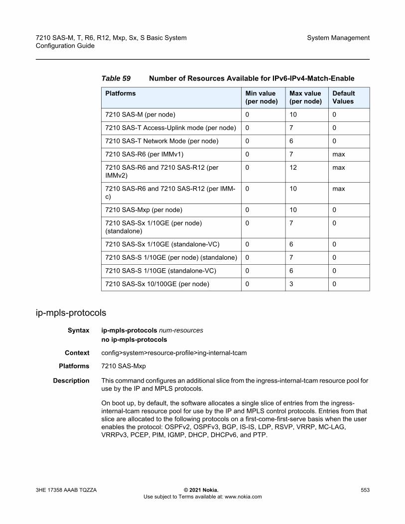
7210 SAS-M, T, R6, R12, Mxp, Sx, S Basic System Configuration Guide
System Management
3HE 17358 AAAB TQZZA © 2021 Nokia. Use subject to Terms available at: www.nokia.com
553
ip-mpls-protocols
Syntax ip-mpls-protocols num-resourcesno ip-mpls-protocols
Context config>system>resource-profile>ing-internal-tcam
Platforms 7210 SAS-Mxp
Description This command configures an additional slice from the ingress-internal-tcam resource pool for use by the IP and MPLS protocols.
On boot up, by default, the software allocates a single slice of entries from the ingress-internal-tcam resource pool for use by the IP and MPLS control protocols. Entries from that slice are allocated to the following protocols on a first-come-first-serve basis when the user enables the protocol: OSPFv2, OSPFv3, BGP, IS-IS, LDP, RSVP, VRRP, MC-LAG, VRRPv3, PCEP, PIM, IGMP, DHCP, DHCPv6, and PTP.
Table 59 Number of Resources Available for IPv6-IPv4-Match-Enable
Platforms Min value (per node)
Max value (per node)
Default Values
7210 SAS-M (per node) 0 10 0
7210 SAS-T Access-Uplink mode (per node) 0 7 0
7210 SAS-T Network Mode (per node) 0 6 0
7210 SAS-R6 (per IMMv1) 0 7 max
7210 SAS-R6 and 7210 SAS-R12 (per IMMv2)
0 12 max
7210 SAS-R6 and 7210 SAS-R12 (per IMM-c)
0 10 max
7210 SAS-Mxp (per node) 0 10 0
7210 SAS-Sx 1/10GE (per node) (standalone)
0 7 0
7210 SAS-Sx 1/10GE (standalone-VC) 0 6 0
7210 SAS-S 1/10GE (per node) (standalone) 0 7 0
7210 SAS-S 1/10GE (standalone-VC) 0 6 0
7210 SAS-Sx 10/100GE (per node) 0 3 0
System Management
554
7210 SAS-M, T, R6, R12, Mxp, Sx, S Basic SystemConfiguration Guide
© 2021 Nokia. Use subject to Terms available at: www.nokia.com
3HE 17358 AAAB TQZZA
However, the default single slice of entries is not sufficient if all IP and MPLS control-plane protocols are enabled simultaneously. To allocate an additional slice to IP and MPLS protocols, use this command to set the value of num-resources to 2.
The no form of this command reverts to the default value.
Default ip-mpls-protocols 1
Parameters num-resources — Specifies the number of slices to be allocated for IP and MPLS control-plane protocols.
Values 1, 2
qos-access-port-ingress-resource
Syntax qos-access-port-ingress-resource num-resourcesno qos-access-port-ingress-resource
Context configure>system>res-profile>ing-internal-tcam
Platforms 7210 SAS-Mxp, 7210 SAS-R6, 7210 SAS-R12, 7210 SAS-Sx/S 1/10GE (standalone), and 7210 SAS-Sx 10/100GE (standalone)
Description
This command allocates ingress internal TCAM resources to access-ingress port policies when the access port is configured in port mode. If adequate TCAM resources are not allocated, setting the access-ingress-qos-mode command to port-mode is not allowed.
If access ports are currently configured to use a port-based access ingress QoS policy, setting the qos-access-port-ingress-resource command to 0 (which will set the number of resources allocated to the access port ingress QoS policy to 0) is not allowed. Resources allocated to access ingress QoS policies are used to allocate meter resources for the port-based access ingress QoS policy.
Note: The software allocates protocol entries when the protocol is enabled and deallocates the protocol entries when the protocol (and all instances of the protocol, if any) is disabled. See the relevant CLI command descriptions for more information about resource allocation for specific protocols. To display information about the utilization of resources allocated to IP and MPLS protocols, use the tools>dump>system-resources CLI command.
Note: This command is not supported on a 7210 SAS-R6 equipped with the IMMv1 card.
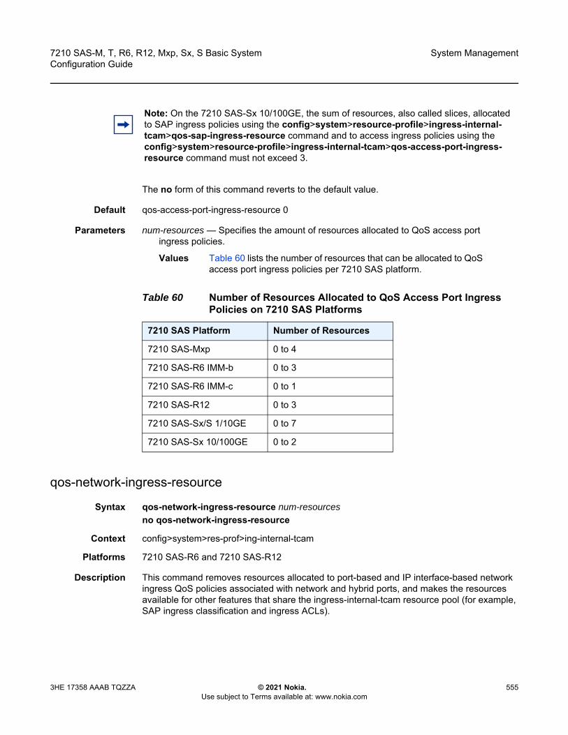
7210 SAS-M, T, R6, R12, Mxp, Sx, S Basic System Configuration Guide
System Management
3HE 17358 AAAB TQZZA © 2021 Nokia. Use subject to Terms available at: www.nokia.com
555
The no form of this command reverts to the default value.
Default qos-access-port-ingress-resource 0
Parameters num-resources — Specifies the amount of resources allocated to QoS access port ingress policies.
Values Table 60 lists the number of resources that can be allocated to QoS access port ingress policies per 7210 SAS platform.
qos-network-ingress-resource
Syntax qos-network-ingress-resource num-resourcesno qos-network-ingress-resource
Context config>system>res-prof>ing-internal-tcam
Platforms 7210 SAS-R6 and 7210 SAS-R12
Description This command removes resources allocated to port-based and IP interface-based network ingress QoS policies associated with network and hybrid ports, and makes the resources available for other features that share the ingress-internal-tcam resource pool (for example, SAP ingress classification and ingress ACLs).
Note: On the 7210 SAS-Sx 10/100GE, the sum of resources, also called slices, allocated to SAP ingress policies using the config>system>resource-profile>ingress-internal-tcam>qos-sap-ingress-resource command and to access ingress policies using the config>system>resource-profile>ingress-internal-tcam>qos-access-port-ingress-resource command must not exceed 3.
Table 60 Number of Resources Allocated to QoS Access Port Ingress Policies on 7210 SAS Platforms
7210 SAS Platform Number of Resources
7210 SAS-Mxp 0 to 4
7210 SAS-R6 IMM-b 0 to 3
7210 SAS-R6 IMM-c 0 to 1
7210 SAS-R12 0 to 3
7210 SAS-Sx/S 1/10GE 0 to 7
7210 SAS-Sx 10/100GE 0 to 2
System Management
556
7210 SAS-M, T, R6, R12, Mxp, Sx, S Basic SystemConfiguration Guide
© 2021 Nokia. Use subject to Terms available at: www.nokia.com
3HE 17358 AAAB TQZZA
The no form of this command reverts to the default value.
Default qos-network-ingress-resource 0
Parameters num-resources — Specifies the number of resources allocated to network ingress QoS policy queues.
Values 0, 2, def
qos-sap-ingress-resource
Syntax qos-sap-ingress-resource num-resourcesno qos-sap-ingress-resource
Context configure>system>resource-profile>ing-internal-tcam
Platforms Supported on all 7210 SAS platforms as described in this document, including platforms configured in the access-uplink operating mode
Description This command allocates maximum resources for use by SAP ingress QoS policies using any of the supported match criteria. This command limits the total amount of chunks allocated for use by SAP ingress QoS policies to the value specified by num-resources. That is, the cumulative sum of chunks allocated to different match criteria supported by SAP ingress QoS policies cannot exceed the value configured with num-resources.
Note: • The minimum num-resources configurable is 0 and the maximum num-resources
configurable is 2. The default num-resources is 2 for the default system resource profile and user-configured system resource profile. A value of 1 is not allowed.
• If the user configures the value 2, one slice is allocated to the network QoS policy IP interface, and one slice is allocated to the network QoS policy port.
• A reboot is not required after assigning a new value to the qos-network-ingress-resource command. That is, the value of this command can be changed from 0 to 2 if there are resources available in the ingress-internal-tcam pool. Similarly, the value can be changed from 2 to 0 if no network or hybrid ports are configured. If a network port or hybrid port is configured, changing the value from 2 to 0 is fails and the system sends an error message.
Note: On the 7210 SAS-Sx 10/100GE, the sum of resources, also called slices, allocated to SAP ingress policies using the config>system>resource-profile>ingress-internal-tcam>qos-sap-ingress-resource command and to access ingress policies using the config>system>resource-profile>ingress-internal-tcam>qos-access-port-ingress-resource command must not exceed 3.

7210 SAS-M, T, R6, R12, Mxp, Sx, S Basic System Configuration Guide
System Management
3HE 17358 AAAB TQZZA © 2021 Nokia. Use subject to Terms available at: www.nokia.com
557
If no resources are allocated for use, the software fails all attempts to associate a service entity (for example, SAP and IP interface) with a SAP ingress QoS policy using any of the match criteria.)
The no form of this command specifies that the software does not allocate any resources for use by SAP ingress QoS policies.
Parameters num-resources — Specifies the amount of resources that can be allocated for use by SAP ingress QoS policies. If the user specifies def, the software allocates the default amount of resources based on the 7210 SAS platform. On 7210 SAS-R6 and 7210 SAS-R12, the amount of default resources allocated also varies based on the IMM plugged into the slot.
Values Table 61 lists the parameter values and provides the values used for def keyword on different 7210 SAS platforms and on different IMM types.
Table 61 Number of Resources Available for QoS-SAP-Ingress-Resource
Platforms Min value (per node)
Max value (per node)
Default Values
7210 SAS-M (per node) 0 10 5
7210 SAS-T Access-uplink mode (per node)
0 7 4
7210 SAS-T Network Mode (per node) 0 6 3
7210 SAS-R6 (per IMMv1) 0 7 3
7210 SAS-R6 and 7210 SAS-R12 (per IMMv2)
0 12 5
7210 SAS-R6 and 7210 SAS-R12 (per IMM-c)
0 10 4
7210 SAS-Mxp (per node) 0 10 5
7210 SAS-Sx 1/10GE (per node) (standalone)
0 7 4
7210 SAS-Sx 1/10GE (standalone-VC) 0 6 4
7210 SAS-S 1/10GE (per node) (standalone)
0 7 4
7210 SAS-S 1/10GE (standalone-VC) 0 6 4
7210 SAS-Sx 10/100GE (per node) 0 3 3
System Management
558
7210 SAS-M, T, R6, R12, Mxp, Sx, S Basic SystemConfiguration Guide
© 2021 Nokia. Use subject to Terms available at: www.nokia.com
3HE 17358 AAAB TQZZA
qos-sap-egress-resource
Syntax qos-sap-egress-resource num-resourcesno qos-sap-egress-resource
Context config>system>res-prof>ing-internal-tcam
Platforms 7210 SAS-R6 and 7210 SAS-R12 (only supported on IMMv1 and IMMv2 cards, it is not supported on IMM-c cards)
Description This command configures resource allocation for SAP-based egress queuing. If port-based queuing is disabled, then users must allocate resources for SAP-based egress queuing using this command. If no resources are allocated, SAPs cannot be created.
When port-based queuing is enabled, resources can be taken away from SAP-based egress queues and allocated to other features that share the ingress-internal-tcam pool (for example, SAP ingress qos and Ingress ACLs).
The no form of this command reverts to the default value.
Default 0
Parameters num-resources — Specifies the amount of resources that are allocated towards SAP-based egress queues.
Values 0 to 2
sap-aggregate-meter
Syntax sap-aggregate-meter num-resourceno sap-aggregate-meter
Context configure>system>resource-profile>ingress-internal-tcam
Platforms Supported on all 7210 SAS platforms as described in this document, including platforms configured in the access-uplink operating mode; not supported on the 7210 SAS-Sx 1/10GE and 7210 SAS-Sx 10/100GE
Description This command allocates maximum resources for use by meters/policers used to implement SAP ingress aggregate meter functionality from the global pool of ingress CAM resources. Before using the configure service sap ingress aggregate-meter-rate command, the user must ensure that resources are allocated to aggregate meters using this command.
Note: For the command to take effect, the node must be restarted after making the change.
7210 SAS-M, T, R6, R12, Mxp, Sx, S Basic System Configuration Guide
System Management
3HE 17358 AAAB TQZZA © 2021 Nokia. Use subject to Terms available at: www.nokia.com
559
This command allocates meter resources from the available global ingress CAM resource pool. By default, when resources are allocated to SAP ingress QoS policy, along with the CAM classification entries, meter resources are also allocated. Hence, if the user needs to use SAP aggregate meter functionality they cannot allocate all the available resources in the global resource pool to SAP ingress QoS policies and ETH-CFM UP MEP. They need to allocate some resources for use by SAP aggregate meter (or SAP ingress ACLs or G8032-fast-flood feature).
By default, when resources are allocated for ingress ACLs (and G8032 in 7210 SAS-M network mode only), only classification entries are used and meters resources are not used. SAP aggregate meter resources can use meters from this pool of meter resources. In other words, SAP aggregate meters are stolen from the unused meters in the resources allocated to ingress ACLs.
If the user allocates resources for ingress ACLs (or for G8032-fast-flood feature in 7210 SAS-M network mode only) and configures resources for SAP aggregate meter using this command, the software does the following.
• It does not allocate any additional resources from the available global ingress CAM resource pool to SAP aggregate meter, if it can allocate the required number of meters from the chunks/resources allocated to ingress ACLs (or from resources allocated to G8032-fast-flood in 7210 SAS-M network mode only). For example, if the user has allocated 2 chunks of 512 entries each for ingress ACLs and then configures sap-aggregate-meter to use 2 chunks to use about 512 aggregate meters, the software will not allocate any additional entries from the available global resource pool.
• If the number of ingress ACL resources allocated by user is less than the number of resources assigned by the user to sap-aggregate-meter (or if no resources are allocated to G8032), then it allocates the difference from the available global ingress CAM resource pool. For example, if the user has allocated 1 chunk of 512 entries for ingress ACLs and then configures sap-aggregate-meter to use 2 chunks to use about 512 aggregate meters, the software will allocate 1 additional chunk (2 chunks required for SAP aggregate - 1 chunk alloted to ingress ACLs) for use with SAP aggregate meter. The classification entries associated with additional chunk alloted for SAP aggregate-meter can be used by the ingress ACLs policies. It cannot be used by SAP ingress QoS policies and eth-cfm UP MEP.
Similar checks as above are performed when the user allocates resources for SAP aggregate meters using this command and then configures resources for ingress ACLs (or for G8032-fast-flood feature). That is, the software does the following.
• It does not allocate any additional entries from the available global ingress CAM resource pool to ingress ACLs, if it can allocate the required number of classification entries from the chunks allocated to SAP aggregate meter feature. For example, if the user has allocated 2 chunks of 512 entries each for SAP aggregate meters and then configures ingress ACLs to use 2 chunks to use about 512 classification entries, the software will not allocate any additional entries from the available global resource pool.

System Management
560
7210 SAS-M, T, R6, R12, Mxp, Sx, S Basic SystemConfiguration Guide
© 2021 Nokia. Use subject to Terms available at: www.nokia.com
3HE 17358 AAAB TQZZA
• If the number of SAP aggregate meter resources allocated by user is less than the number of resources requested by the user for ingress ACLs, then it allocates the difference from the available global ingress CAM resource pool. For example, if the user has allocated 1 chunk of 512 entries for SAP aggregate meters and then configures ingress ACLs to use 2 chunks, the software will allocate 1 additional chunk (2 chunks required for ingress ACLs - 1 chunk alloted to SAP aggregate meter) for use with ingress ACLs. The meter resources associated with additional chunk alloted for ingress ACLs can be assigned to the SAP aggregate feature, if need be.
Refer to the 7210 SAS-M, T, R6, R12, Mxp, Sx, S Quality of Service Guide and the 7210 SAS-M, T, R6, R12, Mxp, Sx, S Router Configuration Guide for more information about use of SAP aggregate feature, ingress CAM resource allocation, and use of ACLs policies respectively.
The no form of this command specifies that the software does not allocate any resources for use by SAP ingress aggregate meter. If no resources are allocated for use, the software fails all attempts to associate an aggregate-meter with SAP ingress.
Parameters num-resources — Specifies the maximum amount of resources for use by this filter match criteria.If the user specifies def, the software allocates the default amount of resources based on the 7210 SAS platform. On 7210 SAS-R6 and 7210 SAS-R12, the amount of default resources allocated also varies based on the IMM plugged into the slot.
Values Table 62 lists the parameter values and provides the values used for def keyword on different 7210 SAS platforms and on different IMM types.
Table 62 Number of Resources Available for SAP-Aggregate-Meter
Platforms Min value (per node)
Max value (per node)
Default Values
7210 SAS-M (per node) 0 1 0
7210 SAS-T Access-uplink mode (per node)
0 2 2
7210 SAS-R6 (per IMMv1) 0 4 2
7210 SAS-R6 and 7210 SAS-R12 (per IMMv2)
0 4 3
7210 SAS-R6 and 7210 SAS-R12 (per IMM-c)
0 4 3
7210 SAS-Mxp (per node) 0 4 3
7210 SAS-Sx 1/10GE (per node) (standalone)
0 3 3
7210 SAS-Sx 1/10GE (standalone-VC) 0 3 2
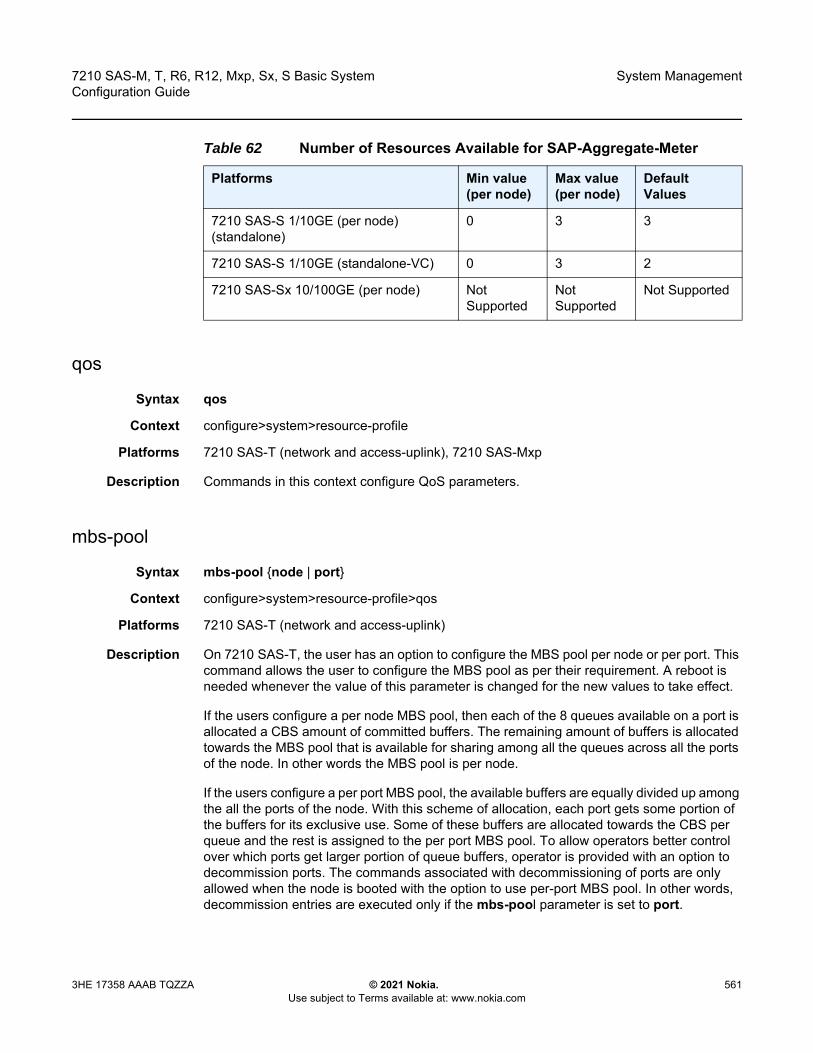
7210 SAS-M, T, R6, R12, Mxp, Sx, S Basic System Configuration Guide
System Management
3HE 17358 AAAB TQZZA © 2021 Nokia. Use subject to Terms available at: www.nokia.com
561
qos
Syntax qos
Context configure>system>resource-profile
Platforms 7210 SAS-T (network and access-uplink), 7210 SAS-Mxp
Description Commands in this context configure QoS parameters.
mbs-pool
Syntax mbs-pool {node | port}
Context configure>system>resource-profile>qos
Platforms 7210 SAS-T (network and access-uplink)
Description On 7210 SAS-T, the user has an option to configure the MBS pool per node or per port. This command allows the user to configure the MBS pool as per their requirement. A reboot is needed whenever the value of this parameter is changed for the new values to take effect.
If the users configure a per node MBS pool, then each of the 8 queues available on a port is allocated a CBS amount of committed buffers. The remaining amount of buffers is allocated towards the MBS pool that is available for sharing among all the queues across all the ports of the node. In other words the MBS pool is per node.
If the users configure a per port MBS pool, the available buffers are equally divided up among the all the ports of the node. With this scheme of allocation, each port gets some portion of the buffers for its exclusive use. Some of these buffers are allocated towards the CBS per queue and the rest is assigned to the per port MBS pool. To allow operators better control over which ports get larger portion of queue buffers, operator is provided with an option to decommission ports. The commands associated with decommissioning of ports are only allowed when the node is booted with the option to use per-port MBS pool. In other words, decommission entries are executed only if the mbs-pool parameter is set to port.
7210 SAS-S 1/10GE (per node) (standalone)
0 3 3
7210 SAS-S 1/10GE (standalone-VC) 0 3 2
7210 SAS-Sx 10/100GE (per node) Not Supported
Not Supported
Not Supported
Table 62 Number of Resources Available for SAP-Aggregate-Meter
Platforms Min value (per node)
Max value (per node)
Default Values

System Management
562
7210 SAS-M, T, R6, R12, Mxp, Sx, S Basic SystemConfiguration Guide
© 2021 Nokia. Use subject to Terms available at: www.nokia.com
3HE 17358 AAAB TQZZA
If the mbs-pool parameter is set to node and decommission entries are configured, then an error should be reported. All decommission entries must be removed if the mbs-pool parameter needs to be changed from port to node.
Default node
Parameters node — Keyword to use per-node MBS pool.
port — Keyword to use per-port MBS pool, along with an option to relocate buffers to ports that need better burst handling capability using the decommissioning commands.
port-scheduler-mode
Syntax port-scheduler-modeno port-scheduler-mode
Context config>system>resource-profile>qos
Platforms 7210 SAS-Mxp
Description This command configures the queuing mode to be used for SAPs configured on all the ports of the node.
When port-scheduler-mode is enabled, software allocates 8 egress queues per port and all the SAPs configured on the access port or hybrid port will share the 8 egress queues for traffic sent out of that port. In this mode, SAPs configured on hybrid port shares the egress queues with network port traffic. Enabling port-scheduler-mode affects the behavior for all the SAPs configured on all the access and hybrid port. In this mode, per SAP egress queues are not available.
In this mode, resources allocated towards SAP egress queues in the ingress-internal-tcam pool are not required by this feature and can be allocated towards other features. See the qos-sap-egress-resource command for more information.
The no form of this command disables port-scheduler-mode, causing per SAP egress queues to be available for use. Refer to the 7210 SAS-M, T, R6, R12, Mxp, Sx, S Quality of Service Guide for more information on the two modes.
Enabling or disabling port-scheduler-mode requires a reboot of the node.
Default no port-scheduler-mode
router
Syntax router
Context configure>system>resource-profileconfigure>system>global-res-profile

7210 SAS-M, T, R6, R12, Mxp, Sx, S Basic System Configuration Guide
System Management
3HE 17358 AAAB TQZZA © 2021 Nokia. Use subject to Terms available at: www.nokia.com
563
Platforms Supported on all 7210 SAS platforms as described in this document
Description
Commands in this context configure router parameters that is applicable to the entire chassis (in other words it applies to all IMMs).
ecmp
Syntax ecmp max-routes-destno ecmp
Context configure>system>resource-profile>routerconfigure>system>global-res-profile>router
Platforms Supported on all 7210 SAS platforms as described in this document
Description
This command configures the maximum amount of routes of same cost to the same IP destination/prefix when path sharing is enabled using IP ECMP. To enable optimum usage of hardware resources, software allocates hardware resources in groups of fixed number of entries. A group is a set of IP next-hop entries used by ECMP routes. The number of IP next-hop entries per group (which in turn dictates the maximum number of shared IP paths per IP destination/prefix) is also specified with commands. The software uses the same group if all the IP next-hop in use for the ECMP routes is the same.
This parameter also dictates the maximum number of paths that a single LDP FEC can use.
Note: The configure>system>resource-profile context is supported on the 7210 SAS-M, 7210 SAS-T, 7210 SAS-Mxp, 7210 SAS-Sx/S 1/10GE: standalone, and 7210 SAS-Sx 10/100GE. The configure>system>global-res-profile context is supported on the 7210 SAS-R6, 7210 SAS-R12, and 7210 SAS-Sx/S 1/10GE: standalone-VC.
Note: The configure>system>resource-profile context is supported on the 7210 SAS-M, 7210 SAS-T, 7210 SAS-Mxp, 7210 SAS-Sx/S 1/10GE: standalone, and 7210 SAS-Sx 10/100GE. The configure>system>global-res-profile context is supported on the 7210 SAS-R6, 7210 SAS-R12, and 7210 SAS-Sx/S 1/10GE: standalone-VC.

System Management
564
7210 SAS-M, T, R6, R12, Mxp, Sx, S Basic SystemConfiguration Guide
© 2021 Nokia. Use subject to Terms available at: www.nokia.com
3HE 17358 AAAB TQZZA
This command does not enable the use of IP ECMP. To enable IP ECMP, the user must use the config router ecmp command. The number of routes specified using the config router ecmp command cannot exceed the number of routes specified by this command, though it can be lesser. If its lesser, the software will use only the specified number routes. Specifying a lesser number of routes with config router ecmp will result in wastage of hardware resources. To enable LDP ECMP, see the configure system resource-profile router ldp-ecmp command.
Default 1
Parameters max-routes-dest — Specifies the number of ECMP routes.
Values 1 to 16
ldp-ecmp
Syntax ldp-ecmp percent-valueno ldp-ecmp
Context configure>system>resource-profile>router configure>system>global-res-profile>router
Platforms Supported on all 7210 SAS platforms as described in this document
Description
This command enables LDP ECMP and configures the percentage of the total amount of hardware ECMP resources to be allocated for use by LDP ECMP FECs.
The remaining amount of resources are allocated for use by IP ECMP. In other words, the hardware ECMP resources are shared by IP ECMP and LDP ECMP and this command allow user to allocate resources to them.
Note: • This command is a boot-time parameter and any change will take effect only after a
reboot. • On 7210 SAS-R6 and 7210 SAS-R12, the value specified with this command is used
across all IMMs in the chassis.
Note: The configure>system>resource-profile context is supported on the 7210 SAS-M, 7210 SAS-T, 7210 SAS-Mxp, 7210 SAS-Sx/S 1/10GE: standalone, and 7210 SAS-Sx 10/100GE. The configure>system>global-res-profile context is supported on the 7210 SAS-R6, 7210 SAS-R12, and 7210 SAS-Sx/S 1/10GE: standalone-VC.

7210 SAS-M, T, R6, R12, Mxp, Sx, S Basic System Configuration Guide
System Management
3HE 17358 AAAB TQZZA © 2021 Nokia. Use subject to Terms available at: www.nokia.com
565
The no form disables LDP ECMP (by allocating zero resources to it) and the system installs only a single next-hop for every LDP FEC.
The user can change the value of resources allocated towards IP ECMP routes and LDP ECMP FECs without requiring a reboot of the node as long as the following conditions are met. The configure system resource-profile router ldp-ecmp command cannot be modified until the value of the configure router ecmp command is set to 1. It is similar to the behavior available for the configure system resource-profile router ecmp command. The value cannot be changed until the value of the configure router ecmp command is set to 1.
Default no ldp-ecmp
Parameters percent-value — Specifies the percentage of ECMP hardware resources to allocate to LDP ECMP. The rest is allocated towards IP ECMP.
Values 0 to 100
max-ip-subnets
Syntax max-ip-subnets numberno max-ip-subnets
Context configure>system>resource-profile>routerconfigure>system>global-res-profile>router
Platforms Supported on all 7210 SAS platforms as described in this document
Description
This command configures the number of directly connected IP interfaces and subnets (both IPv4 and IPv6) the user plans to use on the node, so that only the requisite number of entries in the L3 forwarding table are allocated. On the 7210 SAS platforms, the hardware L3 forwarding table (that is, the IP IFB) stores the IP routes (both IPv4 and IPv6) received from routing peers and also stores the IP address prefix for the directly connected interfaces. The rest are available for use by IP routes received from peers.
Note: On 7210 SAS-R6 and 7210 SAS-R12, it is a system wide limit, applicable to all IMMs. If the user changes this value dynamically, the system adjusts the usage among IP and LDP ECMP as per the configuration.
Note: The configure>system>resource-profile>router context is supported on the 7210 SAS-M, 7210 SAS-T, 7210 SAS-Mxp, 7210 SAS-Sx/S 1/10GE: standalone, and 7210 SAS-Sx 10/100GE. The configure>system>global-res-profile>router context is supported on the 7210 SAS-R6, 7210 SAS-R12, and 7210 SAS-Sx/S 1/10GE: standalone-VC.
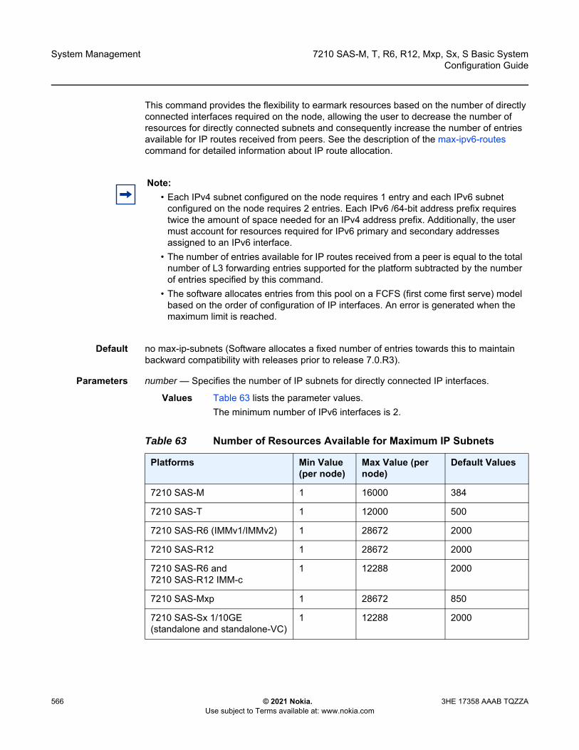
System Management
566
7210 SAS-M, T, R6, R12, Mxp, Sx, S Basic SystemConfiguration Guide
© 2021 Nokia. Use subject to Terms available at: www.nokia.com
3HE 17358 AAAB TQZZA
This command provides the flexibility to earmark resources based on the number of directly connected interfaces required on the node, allowing the user to decrease the number of resources for directly connected subnets and consequently increase the number of entries available for IP routes received from peers. See the description of the max-ipv6-routes command for detailed information about IP route allocation.
Default no max-ip-subnets (Software allocates a fixed number of entries towards this to maintain backward compatibility with releases prior to release 7.0.R3).
Parameters number — Specifies the number of IP subnets for directly connected IP interfaces.
Values Table 63 lists the parameter values. The minimum number of IPv6 interfaces is 2.
Note: • Each IPv4 subnet configured on the node requires 1 entry and each IPv6 subnet
configured on the node requires 2 entries. Each IPv6 /64-bit address prefix requires twice the amount of space needed for an IPv4 address prefix. Additionally, the user must account for resources required for IPv6 primary and secondary addresses assigned to an IPv6 interface.
• The number of entries available for IP routes received from a peer is equal to the total number of L3 forwarding entries supported for the platform subtracted by the number of entries specified by this command.
• The software allocates entries from this pool on a FCFS (first come first serve) model based on the order of configuration of IP interfaces. An error is generated when the maximum limit is reached.
Table 63 Number of Resources Available for Maximum IP Subnets
Platforms Min Value (per node)
Max Value (per node)
Default Values
7210 SAS-M 1 16000 384
7210 SAS-T 1 12000 500
7210 SAS-R6 (IMMv1/IMMv2) 1 28672 2000
7210 SAS-R12 1 28672 2000
7210 SAS-R6 and 7210 SAS-R12 IMM-c
1 12288 2000
7210 SAS-Mxp 1 28672 850
7210 SAS-Sx 1/10GE (standalone and standalone-VC)
1 12288 2000
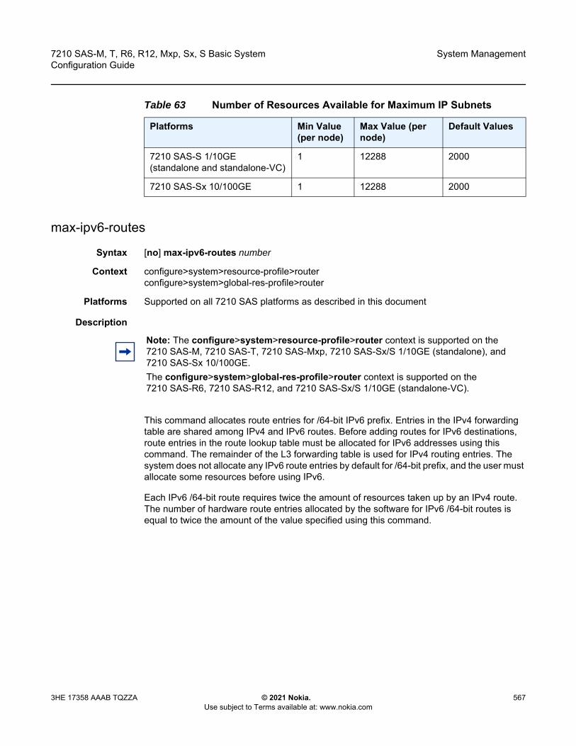
7210 SAS-M, T, R6, R12, Mxp, Sx, S Basic System Configuration Guide
System Management
3HE 17358 AAAB TQZZA © 2021 Nokia. Use subject to Terms available at: www.nokia.com
567
max-ipv6-routes
Syntax [no] max-ipv6-routes number
Context configure>system>resource-profile>router configure>system>global-res-profile>router
Platforms Supported on all 7210 SAS platforms as described in this document
Description
This command allocates route entries for /64-bit IPv6 prefix. Entries in the IPv4 forwarding table are shared among IPv4 and IPv6 routes. Before adding routes for IPv6 destinations, route entries in the route lookup table must be allocated for IPv6 addresses using this command. The remainder of the L3 forwarding table is used for IPv4 routing entries. The system does not allocate any IPv6 route entries by default for /64-bit prefix, and the user must allocate some resources before using IPv6.
Each IPv6 /64-bit route requires twice the amount of resources taken up by an IPv4 route. The number of hardware route entries allocated by the software for IPv6 /64-bit routes is equal to twice the amount of the value specified using this command.
7210 SAS-S 1/10GE (standalone and standalone-VC)
1 12288 2000
7210 SAS-Sx 10/100GE 1 12288 2000
Table 63 Number of Resources Available for Maximum IP Subnets
Platforms Min Value (per node)
Max Value (per node)
Default Values
Note: The configure>system>resource-profile>router context is supported on the 7210 SAS-M, 7210 SAS-T, 7210 SAS-Mxp, 7210 SAS-Sx/S 1/10GE (standalone), and 7210 SAS-Sx 10/100GE. The configure>system>global-res-profile>router context is supported on the 7210 SAS-R6, 7210 SAS-R12, and 7210 SAS-Sx/S 1/10GE (standalone-VC).

System Management
568
7210 SAS-M, T, R6, R12, Mxp, Sx, S Basic SystemConfiguration Guide
© 2021 Nokia. Use subject to Terms available at: www.nokia.com
3HE 17358 AAAB TQZZA
Note: • For this command to take effect, reboot the node after making the change. • On the 7210 SAS-M, 7210 SAS-T, and 7210 SAS-R6 IMMv1, a separate route table is
used for IPv6 /128-bit prefix route lookup. A limited amount of IPv6 /128-bit prefixes is supported. The software enables lookups in this table by default; no user configuration is required to enable IPv6 /128-bit route lookup.
• On the 7210 SAS-R6 and 7210 SAS-R12 with IMMv2, 7210 SAS-Sx/S 1/10GE (standalone and standalone-VC), 7210 SAS-Sx 10/100GE, and 7210 SAS-Mxp, the IPv6 /128-bit prefixes are allocated by software on boot up. The resources are taken from the IP FIB shared with IPv4 and IPv6 /64-bit route entries. That is, unlike platforms like 7210 SAS-M and others, a separate route table is not available in hardware on these platforms. This affects the scaling of IPv4 routes when IPv6 /64-bit routes are allocated. See the following bullets for more information.
• On the 7210 SAS-R6 and 7210 SAS-R12 IMMv2 card, 7210 SAS-Sx/S 1/10GE (standalone and standalone-VC), 7210 SAS-Sx 10/100GE, and 7210 SAS-Mxp, each IPv6 /128-bit route entry/address prefix requires 4 entries in the IP hardware route table, each IPv6 /64-bit address prefix requires 2 entries and each IPv4 route entry/address prefix requires 1 entry.
• The creation of IPv6 IP interfaces without allocating IPv6 route entries is allowed. However, only IPv6 hosts on the same IPv6 subnet are reachable.
• On the 7210 SAS-R6 and 7210 SAS-R12, the value configured using this command is used across all IMMs in the chassis.
• The number of available IPv4 route entries in the L3 forwarding table is equal to the total L3 forwarding entries supported for the platform subtracted by the total number of entries reserved by this command and the number of entries reserved for IP subnets using the max-ip-subnets command. See the following bullets for more information.
• On the 7210 SAS-M, 7210 SAS-T, and 7210 SAS-R6 IMMv1 card, the maximum number of IPv4 prefixes without any IPv6 interfaces configured and IPv6 /64-bit routes (that is, the max-ipv6-routes command is set to a value of zero) is equal to the maximum size of the route table supported for the platform. Contact a Nokia representative to learn more about the routing table scaling limits for each 7210 SAS platform.
7210 SAS-M, T, R6, R12, Mxp, Sx, S Basic System Configuration Guide
System Management
3HE 17358 AAAB TQZZA © 2021 Nokia. Use subject to Terms available at: www.nokia.com
569
Note: (Continued) • On the 7210 SAS-R6 and 7210 SAS-R12 IMMv2 card, 7210 SAS-Sx/S 1/10GE
(standalone and standalone-VC), and 7210 SAS-Mxp, a pool of 4K IPv4 entries are allocated on system bootup primarily for use by about 256 /128-bit IPv6 addresses. The remaining entries can be shared with IPv4 prefix, if IPv6 is not enabled on the node. That is, without IPv6 enabled on the node, the maximum number of IPv4 prefixes possible is equal to the maximum size of the route table supported for the platform, reduced by 1K entries. The 1K entries correspond to those reserved by the system for allocation to IPv6 /128-bit addresses. Note that the maximum number of IPv4 prefixes includes the amount of addresses allocated for directly connected IP subnets (the user has an option to reserve the amount required for directly connected IPv4 subnets by configuring the max-ip-subnets command) and IPv4 routes statically configured on the node or learned dynamically using a routing protocol. For example, if the maximum size of the route table supported on the node is 32K, the total number of IPv4 prefixes (including both directly connected subnets and routes statically configured or dynamically learned using a routing protocol) is 31K (the 1K route entries are used to allocate up to 256 /128-bit IPv6 addresses). The maximum size of the route table quoted in the example is for illustration purposes only.
• On the 7210 SAS-R6 and 7210 SAS-R12 IMMv2 card, 7210 SAS-Sx/S 1/10GE (standalone and standalone-VC), and 7210 SAS-Mxp, the maximum number of IPv4 prefixes possible with IPv6 /64-bit routes configured is equal to the maximum size that the route table supports for the platform, reduced by the sum of the number of routes configured for IPv6 /64-bit prefixes and an amount of 4K entries (reserved for /128-bit IPv6 addresses). The user has an option to reserve resources used for IPv6 /64-bit prefix using the max-ipv6-routes command. When max-ipv6-routes is configured using a value greater than zero, the IPv4 prefixes can no longer use the space reserved for IPv6 /128-bit addresses. The software enforces the maximum number of IPv6 prefixes possible as less than the max-ipv6-routes value. Using the preceding example, if the maximum size of the route table supported on the node is 32K, total number of IPv4 prefixes (only dynamically learned ones using a routing protocol) is about 25K, assuming max-ipv6-routes is set to 1000 and max-ip-subnets is set to 1000. That is, 32K – (4K + 2 * 1K + 1K) = 25K (recollect each IPv6 /64-bit route entry requires twice the space of IPv4 route entry). The maximum size of the route table quoted in the example is for illustration purposes only.
• On the 7210 SAS-R6 and 7210 SAS-R12 IMMv2 card, 7210 SAS-Sx/S 1/10GE (standalone and standalone-VC), 7210 SAS-Sx 10/100GE, and 7210 SAS-Mxp, the maximum number of IPv6 /64-bit routes is equal to the number of routes configured using the max-ipv6-routes command. Using the preceding example, if the maximum size of the route table supported on the node is 32K, maximum number of IPv6 /64-bit prefixes (including only dynamically learned ones, using a routing protocol) is about 13500, assuming max-ipv6-routes is set to 13K and max-ip-subnets is set to 1000. The number of IPv4 routes allowed is zero (32K – (4K + 2 * 13500 + 1K) = 0 (recollect each IPv6 /64-bit route entry requires twice the space of IPv4 route entry). The maximum size of the route table quoted in the example is for illustration purposes only.

System Management
570
7210 SAS-M, T, R6, R12, Mxp, Sx, S Basic SystemConfiguration Guide
© 2021 Nokia. Use subject to Terms available at: www.nokia.com
3HE 17358 AAAB TQZZA
The following is the allocation scheme implemented for 7210 SAS-R6 and 7210 SAS-R12 IMM-c cards.
• Software partitions the hardware table into two - Partition #1 with 4k (4*1204) 32-bit entries and Partition #2 with 12k (12*1024) entries.
• Partition #1 can fit 128-bit IPv6 address and takes 4 * 32-bit entries each, 32-bit IPv4 entries taking one entry each (1*32-bit entry), and 64-bit IPv6 address taking 4 * 32-bit entries each; Lets call this L3-FIB-P1.
• Partition #2 can fit 32-bit IPv4 entries taking one entry each, and 64-bit IPv6 address taking 2 * 32-bit entries each; Lets call this L3-FIB-P2.
• Software reserves space for 256 128-bit IPv6 addresses in partition #1 (L3-FIB-P1); taking away 1024 32-bit entries and leaving around 3072 32-bit entries for use by either IPv4 prefixes or IPv6 prefixes. In other words, a maximum of 3072 IPv4 prefixes can fit in the remaining space if all of them were to be allocated to IPv4 or a maximum of 768 IPv6 (64-bit) prefixes can fit in the remaining space if all of them were to be allocated to IPv6.; Lets call the remaining space L3-FIB-P1-R.
• Software reserves max-ip-subnets 32-bit entries from partition #2 for use by directly connected IPv4 and IPv6 interfaces with IPv4/IPv6 address assigned. ‘max-ip-subnets’ is a configurable CLI parameter and allows user to reserve the amount of space required for directly connected IP interfaces. IPv6 directly connected interfaces are allocated space from this reserved only if the IPv6 address prefix is less than equal to 64-bit. They are allocated two entries each per IPv6 64-bit address prefix. IPv6 directly connected interfaces with IPv6 address prefix greater than 64-bit is allocated entries from partition #1. All IPv4 directly connected IP interfaces are allocated one entry each from this reserved space. The remaining space is used to store prefixes learned by the node. Lets call the remaining space L3-FIB-P2-R.
• L3-FIB-P2-R and L3-FIB-P1-R is used for allocating entries towards routes learned by the node statically or dynamically using a routing protocol. The software starts to allocate entries from L3-FIB-P2-R for both IPv4 addresses and IPv6 64-bit addresses, until all the resources are used up. It then allocates entries from L3-FIB-P1-R for both IPv4 and IPv6 addresses, until all of it is used up.
• If the user has configured max-ipv6-routes, the software reserves space for it in L3-FIB-P2-R for use by IPv6 routes. The amount of space reserved is equivalent to 2 * max-ipv6-routes. The remaining space in L3-FIB-P2-R and L3-FIB-P1-R is available for IPv4 routes. For example, if max-ipv6-routes is set to 1000, then 2000 /32-bit entries are allocated from L3-FIB-P2-R and reserved for IPv6 routes. The rest along with available entries in L3-FIB-P1-R are available for use by IPv4.
The no form of this command specifies that the software does not allocate any resources for use by IPv6 routes.
Default no max-ipv6-routes
Parameters number — Specifies the maximum amount of entries to be used for IPv6 routes. Maximum values can be achieved assuming all the resources are allocated to IPv6 routes.
Values Table 64 lists the parameter values.
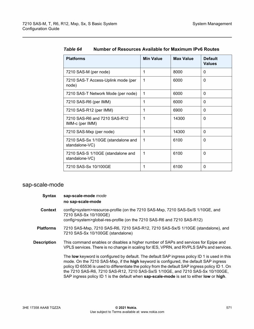
7210 SAS-M, T, R6, R12, Mxp, Sx, S Basic System Configuration Guide
System Management
3HE 17358 AAAB TQZZA © 2021 Nokia. Use subject to Terms available at: www.nokia.com
571
sap-scale-mode
Syntax sap-scale-mode modeno sap-scale-mode
Context config>system>resource-profile (on the 7210 SAS-Mxp, 7210 SAS-Sx/S 1/10GE, and 7210 SAS-Sx 10/100GE)config>system>global-res-profile (on the 7210 SAS-R6 and 7210 SAS-R12)
Platforms 7210 SAS-Mxp, 7210 SAS-R6, 7210 SAS-R12, 7210 SAS-Sx/S 1/10GE (standalone), and 7210 SAS-Sx 10/100GE (standalone)
Description This command enables or disables a higher number of SAPs and services for Epipe and VPLS services. There is no change in scaling for IES, VPRN, and RVPLS SAPs and services.
The low keyword is configured by default. The default SAP ingress policy ID 1 is used in this mode. On the 7210 SAS-Mxp, if the high keyword is configured, the default SAP ingress policy ID 65536 is used to differentiate the policy from the default SAP ingress policy ID 1. On the 7210 SAS-R6, 7210 SAS-R12, 7210 SAS-Sx/S 1/10GE, and 7210 SAS-Sx 10/100GE, SAP ingress policy ID 1 is the default when sap-scale-mode is set to either low or high.
Table 64 Number of Resources Available for Maximum IPv6 Routes
Platforms Min Value Max Value Default Values
7210 SAS-M (per node) 1 8000 0
7210 SAS-T Access-Uplink mode (per node)
1 6000 0
7210 SAS-T Network Mode (per node) 1 6000 0
7210 SAS-R6 (per IMM) 1 6000 0
7210 SAS-R12 (per IMM) 1 6900 0
7210 SAS-R6 and 7210 SAS-R12 IMM-c (per IMM)
1 14300 0
7210 SAS-Mxp (per node) 1 14300 0
7210 SAS-Sx 1/10GE (standalone and standalone-VC)
1 6100 0
7210 SAS-S 1/10GE (standalone and standalone-VC)
1 6100 0
7210 SAS-Sx 10/100GE 1 6100 0
System Management
572
7210 SAS-M, T, R6, R12, Mxp, Sx, S Basic SystemConfiguration Guide
© 2021 Nokia. Use subject to Terms available at: www.nokia.com
3HE 17358 AAAB TQZZA
To switch between the low and high modes, the user must remove all SAP configurations, change the mode, reboot the node, and reconfigure the SAPs and services.
The mandatory QoS configurations required to achieve higher SAP and service scaling are as follows.
• Access port-based egress queuing and shaping must be configured on all ports, including service delivery ports and uplinks.
• On the 7210 SAS-Mxp, either access port-based ingress classification or SAP ingress table-based classification and table-based policing (service meters) can be configured on uplinks for higher SAP scaling.
• On the 7210 SAS-R6, 7210 SAS-R12, 7210 SAS-Sx/S 1/10GE, and 7210 SAS-Sx 10/100GE, access port-based ingress classification and policing must be configured for higher SAP scaling.
• On the 7210 SAS-Mxp, Epipe and VPLS SAPs must use SAP ingress table-based classification and table-based policing on service delivery ports for higher SAP scaling. The 7210 SAS-R6, 7210 SAS-R12, 7210 SAS-Sx/S 1/10GE, and 7210 SAS-Sx 10/100GE do not support table-based policing (service meters) for SAP ingress policing.
• On the 7210 SAS-Mxp, 7210 SAS-R6, and 7210 SAS-R12, IES and VPRN SAPs can use table-based classification.
• R-VPLS SAPs must use CAM-based classification and policing.
The no form of this command disables the use of high SAP and service scaling for Epipe and VPLS services.
Default no sap-scale-mode
Parameters mode — Specifies the SAP scale mode.
Values high, low
high — Keyword to enable higher SAP and service scaling.
low — Keyword to disable higher SAP and service scaling.
6.12.2.1.19 Global System Resource Profile Commands
global-res-profile
Syntax global-res-profile
Context config>system
Note: Refer to the 7210 SAS-M, T, Mxp, Sx, S Services Guide and 7210 SAS-R6, R12 Services Guide for more information about high SAP scale mode and low SAP scale mode.

7210 SAS-M, T, R6, R12, Mxp, Sx, S Basic System Configuration Guide
System Management
3HE 17358 AAAB TQZZA © 2021 Nokia. Use subject to Terms available at: www.nokia.com
573
Platforms 7210 SAS-R6, 7210 SAS-R12, and 7210 SAS-Sx/S 1/10GE: standalone
Description Commands in this context configure the CAM resources.
enable-bgp3107-frr
Syntax enable-bgp-3107-frrno enable-bgp3107-frr
Context config>system>global-res-profile
Platforms 7210 SAS-R6, 7210 SAS-R12, and 7210 SAS-Sx/S 1/10GE (standalone-VC)
Description This command enables the allocation of MPLS FIB and protection group resources required for enabling uniform FRR for BGP RFC3107 LU routes resolved using RSVP-TE LSPs. This is a per-node configuration and enabling the command affects all BGP LU routes.
The no form of this command disables the use of uniform FRR for BGP LU routes.
Default no enable-bgp3107-frr
enable-ldporsvp-frr
Syntax enable-ldporsvp-frrno enable-ldporsvp-frr
Context config>system>global-res-profile
Platforms 7210 SAS-R6, 7210 SAS-R12, and 7210 SAS-Sx/S 1/10GE (standalone-VC)
Description This command enables the allocation of MPLS FIB and protection group resources required for enabling uniform FRR for LDP-over-RSVP LSPs (LDP FECs resolved using RSVP-TE LSPs). This is a per-node configuration and enabling the command affects all LDP-over-RSVP LSPs.
Caution: If the command is enabled, the amount of resources required is twice the amount required without uniform FRR, and the number of BGP LU routes that can be accommodated in the MPLS FIB is therefore halved if uniform FRR is enabled. Ensure that sufficient MPLS resources are available to accommodate all required BGP LU routes before using this command.
System Management
574
7210 SAS-M, T, R6, R12, Mxp, Sx, S Basic SystemConfiguration Guide
© 2021 Nokia. Use subject to Terms available at: www.nokia.com
3HE 17358 AAAB TQZZA
The no form of this command disables the use of uniform FRR for LDP-over-RSVP LSPs.
Default no enable-ldporsvp-frr
qos
Syntax qos
Context config>system>glob-res-profile
Platforms 7210 SAS-R6, 7210 SAS-R12, and 7210 SAS-Sx/S 1/10GE: standalone
Description Commands in this context configure the QoS resources.
port-scheduler-mode
Syntax no port-scheduler-modeport-scheduler-mode
Context config>system>glob-res-profile
Platforms 7210 SAS-R6 and 7210 SAS-R12 (supported only on IMMv2 cards)
Description This command lets user select the queuing mode to be used for SAPs configured on all the ports of the node.
When port-scheduler-mode is enabled, software allocates 8 egress queues per port and all the SAPs configured on the access port or hybrid port will share the 8 egress queues for traffic sent out of that port. In this mode, SAPs configured on hybrid port shares the egress queues with network port traffic. Enabling port-scheduler-mode affects the behavior for all the SAPs configured on all the access and hybrid port. In this mode, per SAP egress queues are not available.
In this mode, resources allocated towards SAP egress queues in the ingress-internal-tcam pool are not required by this feature and can be allocated towards other features. See the qos-sap-egress-resource command for more information.
When port-scheduler-mode is disabled using the no form of this command, per SAP egress queues are available for use. Refer to the 7210 SAS-M, T, R6, R12, Mxp, Sx, S Quality of Service Guide for more information about the two modes.
Caution: If the command is enabled, the amount of resources required is twice the amount required without uniform FRR, and the number of LDP-over-RSVP LSPs that can be accommodated in the MPLS FIB is therefore halved if uniform FRR is enabled. Ensure that sufficient MPLS resources are available to accommodate all required LDP-over-RSVP LSPs before using this command.

7210 SAS-M, T, R6, R12, Mxp, Sx, S Basic System Configuration Guide
System Management
3HE 17358 AAAB TQZZA © 2021 Nokia. Use subject to Terms available at: www.nokia.com
575
Enabling or disabling port-scheduler-mode requires a reboot of the node.
Default no port-scheduler-mode
sf-ingress-internal-tcam
Syntax sf-ingress-internal-tcam
Context config>system>glob-res-profile
Platforms 7210 SAS-R6 and 7210 SAS-R12
Description Commands in this context configure the CAM resources available in the SF/CPM.
The sf-ingress-internal-tcam resource pool is shared by multiple features. The resources are allocated in chunks of fixed size. The user is provided an option to allocate the available resources based on their scaling requirements for the features. The resource usage for different features is provided in the CLI description for the feature. Resources are allocated to features in chunks of fixed size. It is not possible to for a chunk to be shared by multiple features. There are a few exceptions which are specified explicitly. The software allocates resources from the chunk to the feature to which it is allocated until it runs out of all resources in the chunk. If available, user can allocate more chunks to the feature (by taking away chunks of resources from other features which do not need to be enabled).
To free up the resources for use by other features, users need to modify the configuration such that the chunks of resources in use by other features are freed. For example, to free up a chunk of resources allocated to UP MEPs and allocate it to P2MP LSPs, user will need to remove the configuration of UP MEPs for all the SAPs, then change the resource profile configuration to allocate the chunk to P2MP LSPs. Another scenario would be, to free up a chunk of resources and allocate it to another feature.
The sf-ingress-internal-tcam resource pool is shared among the following features on different platforms:
• 7210 SAS-R6 and 7210 SAS-R12It is global per node resource pool. It is shared among UP MEPs, G8032 Fast-flood, and NG-MVPN P2MP LSPs.
System Management
576
7210 SAS-M, T, R6, R12, Mxp, Sx, S Basic SystemConfiguration Guide
© 2021 Nokia. Use subject to Terms available at: www.nokia.com
3HE 17358 AAAB TQZZA
eth-cfm-upmeps
Syntax eth-cfm-upmeps max_slicesno eth-cfm-upmeps
Context config>system>glob-res-profile>sf-ingress-internal-tcam
Platforms 7210 SAS-R6 and 7210 SAS-R12
Description This command allocates resources towards UP MEP from the sf-ingress-internal-tcam pool. The value specified here allocates a fixed number of entries for use with this feature. Entries are allocated by software from this pool whenever UP MEP is configured in a VPLS service (either on a SAP or a SDP). The number of entries required per MEP depends on the level of the MEP.
The no form of this command does not allocate any resources for use by CFM UP MEPs. If no resources are allocated for use, the software fails all attempts to configure an UP MEP.
Parameters max_slices — Specifies the number of slice to be allocated for VPLS UP MEP feature. Each slice has many resource entries which is used to identify and process VPLS UP MEP messages.
Values 0 to 6
g8032-fast-flood
Syntax g8032-fast-flood max_slicesno g8032-fast-flood
Context config>system>glob-res-profile>sf-ingress-internal-tcam
Platforms 7210 SAS-R6 and 7210 SAS-R12
Note: • While reassigning chunk of resources among features, in some scenarios a reboot of
the node might be required. See the CLI description of the specific feature to know more.
• The number of chunks and the number of resources per chunk varies among the different platforms. Contact your ALU/Nokia representative for more information.
• On 7210 SAS-R6, the number of resources per slice/chunk varies. Hence, the number of resources allocated to a feature varies based on the order of allocation of resources among the different features. It might be necessary to allocate more slices to a feature to achieve desired scaling.
• For some features a minimum number of chunks (greater than 1) must be allocated to enable the feature functionality. If this is not done software cannot allocate the required number of resources and it will fail the command associated with the feature.

7210 SAS-M, T, R6, R12, Mxp, Sx, S Basic System Configuration Guide
System Management
3HE 17358 AAAB TQZZA © 2021 Nokia. Use subject to Terms available at: www.nokia.com
577
Description This command configures the amount of ingress internal CAM resources available in the SF/CPM for use by G8032 fast-flood mechanism. These are used to implement G8032 fast-flood for data services protected using G8032 ring protection mechanism. The amount of slices determines the amount of data services that can be protected by G8032 and use the fast-flood mechanism to reduce the convergence time on a ring failure and switchover.
The difference between resource usage on IMMv1 and IMMv2 is described as follows.
• On IMMv1, resources are used to implement the G8032 fast-flood mechanism for both VPLS services and RVPLS services.
• On IMMv2, resources are used to implement the G8032 fast-flood mechanism for only RVPLS services. These resources are used only if G8032 is enabled for RVPLS services. The G8032 fast-flood mechanism is also implemented for VPLS services, but no user configuration is required and it does not need resources to be allocated from the sf-ingress-internal-tcam pool.
Parameters max_slice — Specifies the number of slices to be allocated for the G8032 fast-flood mechanism. Each slice has many resource entries that are used to implement G8032 fast flood for multiple data services protected by G8032.
Values 1 to 7
mpls-p2mp
Syntax mpls-p2mp max_slicesno mpls-p2mp
Context config>system>glob-res-profile>sf-ingress-internal-tcam
Platforms 7210 SAS-R6 and 7210 SAS-R12
Description This command allows the user to configure the resources to be used for NG-MVPN P2MP LSPs. The users must allocate some resources using the command before configuring NG-MVPN. It might be necessary to free up resources allocated to other features to allocate resources for it.
On 7210 SAS-R6, the number of resources per slice/chunk varies. Hence, the number of resources allocated to a feature varies based on the order of allocation of resources among different features. It might be necessary to allocate more slices to a feature to achieve desired scaling.
The no form of this command does not allocate any resources for use by P2MP LSPs used with NG-MVPN feature. If no resources are allocated for use, the software will not be able to setup P2MP LSPs for use with NG-MVPN.
Parameters max_slice — Specifies the number of slices to be allocated for NG-MVPN P2MP LSPs.
Values 0 to 3
Default 1

System Management
578
7210 SAS-M, T, R6, R12, Mxp, Sx, S Basic SystemConfiguration Guide
© 2021 Nokia. Use subject to Terms available at: www.nokia.com
3HE 17358 AAAB TQZZA
6.12.2.2 Show Commands
6.12.2.2.1 System Commands
chassis
Syntax chassis imm-family [imm-family]chassis imm-family {active | configured}
Context show>system
Platforms 7210 SAS-R6 and 7210 SAS-R12
Description This command lists the IMM types allowed to be provisioned (and equipped) in the chassis for the specified type of IMM family.
With the active option, this command displays the current active configuration of the IMM family. In other words, it indicates the list of allowed IMMs that can be used in the chassis.
With the configured option, this command displays the user configured value for the IMM family, which will take effect on the next reboot.
Parameters imm-family — Specifies the IMM family type to display the list of supported IMMs under this family.
Values imm-sas-r, imm-sas-r-b, imm-sas-r-c, all
active — Displays the current active configuration.
configured — Displays the current configured value which will take effect on next reboot.
Output The following output is an example of IMM family information.
Sample Output
*A:sasr_dutb>show>system# chassis imm-family all
===============================================================================IMM FAMILY INFORMATION===============================================================================IMM-TYPE IMM-FAMILY SUPPORTED-------------------------------------------------------------------------------imm-sas-10sfp+1xfp imm-sas-r Defaultimm-sas-10sfp imm-sas-r Defaultimm-sas-2xfp imm-sas-r Defaultimm-sas-b-4sfp+ imm-sas-r-b ----imm-sas-b-2sfp+ imm-sas-r-b ----imm-sas-b-10sfp-1sfp+ imm-sas-r-b ----imm-sas-b-11csfp imm-sas-r-b ----
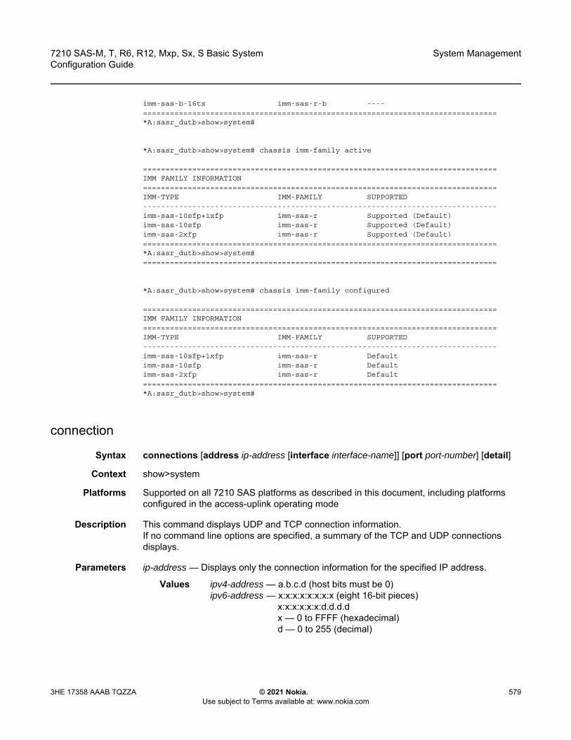
7210 SAS-M, T, R6, R12, Mxp, Sx, S Basic System Configuration Guide
System Management
3HE 17358 AAAB TQZZA © 2021 Nokia. Use subject to Terms available at: www.nokia.com
579
imm-sas-b-16tx imm-sas-r-b ----===============================================================================*A:sasr_dutb>show>system#
*A:sasr_dutb>show>system# chassis imm-family active
===============================================================================IMM FAMILY INFORMATION===============================================================================IMM-TYPE IMM-FAMILY SUPPORTED-------------------------------------------------------------------------------imm-sas-10sfp+1xfp imm-sas-r Supported (Default)imm-sas-10sfp imm-sas-r Supported (Default)imm-sas-2xfp imm-sas-r Supported (Default)===============================================================================*A:sasr_dutb>show>system#===============================================================================
*A:sasr_dutb>show>system# chassis imm-family configured
===============================================================================IMM FAMILY INFORMATION===============================================================================IMM-TYPE IMM-FAMILY SUPPORTED-------------------------------------------------------------------------------imm-sas-10sfp+1xfp imm-sas-r Defaultimm-sas-10sfp imm-sas-r Defaultimm-sas-2xfp imm-sas-r Default===============================================================================*A:sasr_dutb>show>system#
connection
Syntax connections [address ip-address [interface interface-name]] [port port-number] [detail]
Context show>system
Platforms Supported on all 7210 SAS platforms as described in this document, including platforms configured in the access-uplink operating mode
Description This command displays UDP and TCP connection information.If no command line options are specified, a summary of the TCP and UDP connections displays.
Parameters ip-address — Displays only the connection information for the specified IP address.
Values ipv4-address — a.b.c.d (host bits must be 0)ipv6-address — x:x:x:x:x:x:x:x (eight 16-bit pieces)
x:x:x:x:x:x:d.d.d.dx — 0 to FFFF (hexadecimal)d — 0 to 255 (decimal)

System Management
580
7210 SAS-M, T, R6, R12, Mxp, Sx, S Basic SystemConfiguration Guide
© 2021 Nokia. Use subject to Terms available at: www.nokia.com
3HE 17358 AAAB TQZZA
port-number — Displays only the connection information for the specified port number.
Values 0 to 65535
detail — Displays TCP statistics.
Output The following outputs are examples of system connections information, and the asspciated tables describes the output fields.
• Sample Output, Table 65• Sample Output (Detail)
Sample Output
A:ALA-12# show system connections===============================================================================Connections :===============================================================================Proto RecvQ TxmtQ Local Address Remote Address State-------------------------------------------------------------------------------TCP 0 0 0.0.0.0.21 0.0.0.0.0 LISTENTCP 0 0 0.0.0.0.23 0.0.0.0.0 LISTENTCP 0 0 0.0.0.0.179 0.0.0.0.0 LISTENTCP 0 0 10.0.0.xxx.51138 10.0.0.104.179 SYN_SENTTCP 0 0 10.0.0.xxx.51139 10.0.0.91.179 SYN_SENTTCP 0 0 10.10.10.xxx.646 0.0.0.0.0 LISTENTCP 0 0 10.10.10.xxx.646 10.10.10.104.49406 ESTABLISHEDTCP 0 0 10.1.0.1.51140 10.1.0.2.179 SYN_SENTTCP 0 993 192.168.x.xxx.23 192.168.x.xx.xxxx ESTABLISHEDUDP 0 0 0.0.0.0.123 0.0.0.0.0 ---UDP 0 0 0.0.0.0.646 0.0.0.0.0 ---UDP 0 0 0.0.0.0.17185 0.0.0.0.0 ---UDP 0 0 10.10.10.xxx.646 0.0.0.0.0 ---UDP 0 0 xxx.0.0.1.50130 xxx.0.0.1.17185 ----------------------------------------------------------------------------------No. of Connections: 14===============================================================================A:ALA-12#
Table 65 Output Fields: System Connections
Label Description
Proto Displays the socket protocol, either TCP or UDP
RecvQ Displays the number of input packets received by the protocol
TxmtQ Displays the number of output packets sent by the application
Local Address Displays the local address of the socketThe socket port is separated by a period.
Remote Address Displays the remote address of the socketThe socket port is separated by a period.

7210 SAS-M, T, R6, R12, Mxp, Sx, S Basic System Configuration Guide
System Management
3HE 17358 AAAB TQZZA © 2021 Nokia. Use subject to Terms available at: www.nokia.com
581
Sample Output (Detail)
A:ALA-12# show system connections detail-------------------------------------------------------------------------------TCP Statistics
-------------------------------------------------------------------------------packets sent : 659635data packets : 338982 (7435146 bytes)data packet retransmitted : 73 (1368 bytes)ack-only packets : 320548 (140960 delayed)URG only packet : 0window probe packet : 0window update packet : 0control packets : 32packets received : 658893acks : 338738 for (7435123 bytes)duplicate acks : 23ack for unsent data : 0packets received in-sequence : 334705 (5568368 bytes)completely duplicate packet : 2 (36 bytes)packet with some dup. data : 0 (0 bytes)out-of-order packets : 20 (0 bytes)packet of data after window : 0 (0 bytes)window probe : 0window update packet : 3packets received after close : 0discarded for bad checksum : 0discarded for bad header offset field : 0discarded because packet too short : 0connection request : 4connection accept : 24connections established (including accepts) : 27connections closed : 26 (including 2 drops)embryonic connections dropped : 0segments updated rtt : 338742 (of 338747 attempts)retransmit timeouts : 75connections dropped by rexmit timeout : 0persist timeouts : 0keepalive timeouts : 26keepalive probes sent : 0connections dropped by keepalive : 1pcb cache lookups failed : 0===============================================================================A:ALA-12#
State Listen — The protocol state is in the listen modeEstablished — The protocol state is established
Table 65 Output Fields: System Connections (Continued)
Label Description (Continued)

System Management
582
7210 SAS-M, T, R6, R12, Mxp, Sx, S Basic SystemConfiguration Guide
© 2021 Nokia. Use subject to Terms available at: www.nokia.com
3HE 17358 AAAB TQZZA
cpu
Syntax cpu [sample-period seconds]
Context show>system
Platforms Supported on all 7210 SAS platforms as described in this document, including platforms configured in the access-uplink operating mode
Description This command displays CPU utilization per task over a sample period.
Parameters sample-period seconds — Specifies the number of seconds over which to sample CPU task utilization.
Default 1
Values 1 to 5
Output The following output is an example of CPU information, and Table 66 describes the output fields.
Sample Output
*A:cses-E11# show system cpu sample-period 2===============================================================================CPU Utilization (Sample period: 2 seconds)===============================================================================Name CPU Time CPU Usage Capacity
(uSec) Usage-------------------------------------------------------------------------------BFD 10 ~0.00% ~0.00%BGP 0 0.00% 0.00%CFLOWD 61 ~0.00% ~0.00%Cards & Ports 8,332 0.41% 0.08%DHCP Server 79 ~0.00% ~0.00%ICC 408 0.02% 0.01%IGMP/MLD 1,768 0.08% 0.08%IOM 17,197 0.85% 0.31%IP Stack 4,080 0.20% 0.09%IS-IS 1,213 0.06% 0.06%ISA 2,496 0.12% 0.07%LDP 0 0.00% 0.00%Logging 32 ~0.00% ~0.00%MPLS/RSVP 2,380 0.11% 0.08%MSDP 0 0.00% 0.00%Management 5,969 0.29% 0.15%OAM 907 0.04% 0.02%OSPF 25 ~0.00% ~0.00%PIM 5,600 0.27% 0.27%RIP 0 0.00% 0.00%RTM/Policies 0 0.00% 0.00%Redundancy 3,635 0.18% 0.13%SIM 1,462 0.07% 0.04%SNMP Daemon 0 0.00% 0.00%Services 2,241 0.11% 0.05%Stats 0 0.00% 0.00%Subscriber Mgmt 2,129 0.10% 0.04%
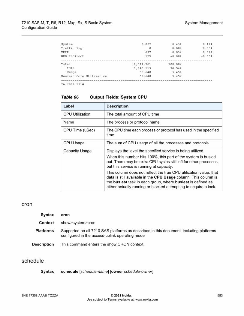
7210 SAS-M, T, R6, R12, Mxp, Sx, S Basic System Configuration Guide
System Management
3HE 17358 AAAB TQZZA © 2021 Nokia. Use subject to Terms available at: www.nokia.com
583
System 8,802 0.43% 0.17%Traffic Eng 0 0.00% 0.00%VRRP 697 0.03% 0.02%WEB Redirect 125 ~0.00% ~0.00%-------------------------------------------------------------------------------Total 2,014,761 100.00%
Idle 1,945,113 96.54%Usage 69,648 3.45%
Busiest Core Utilization 69,648 3.45%===============================================================================*A:cses-E11#
cron
Syntax cron
Context show>system>cron
Platforms Supported on all 7210 SAS platforms as described in this document, including platforms configured in the access-uplink operating mode
Description This command enters the show CRON context.
schedule
Syntax schedule [schedule-name] [owner schedule-owner]
Table 66 Output Fields: System CPU
Label Description
CPU Utilization The total amount of CPU time
Name The process or protocol name
CPU Time (uSec) The CPU time each process or protocol has used in the specified time
CPU Usage The sum of CPU usage of all the processes and protocols
Capacity Usage Displays the level the specified service is being utilizedWhen this number hits 100%, this part of the system is busied out. There may be extra CPU cycles still left for other processes, but this service is running at capacity.This column does not reflect the true CPU utilization value; that data is still available in the CPU Usage column. This column is the busiest task in each group, where busiest is defined as either actually running or blocked attempting to acquire a lock.
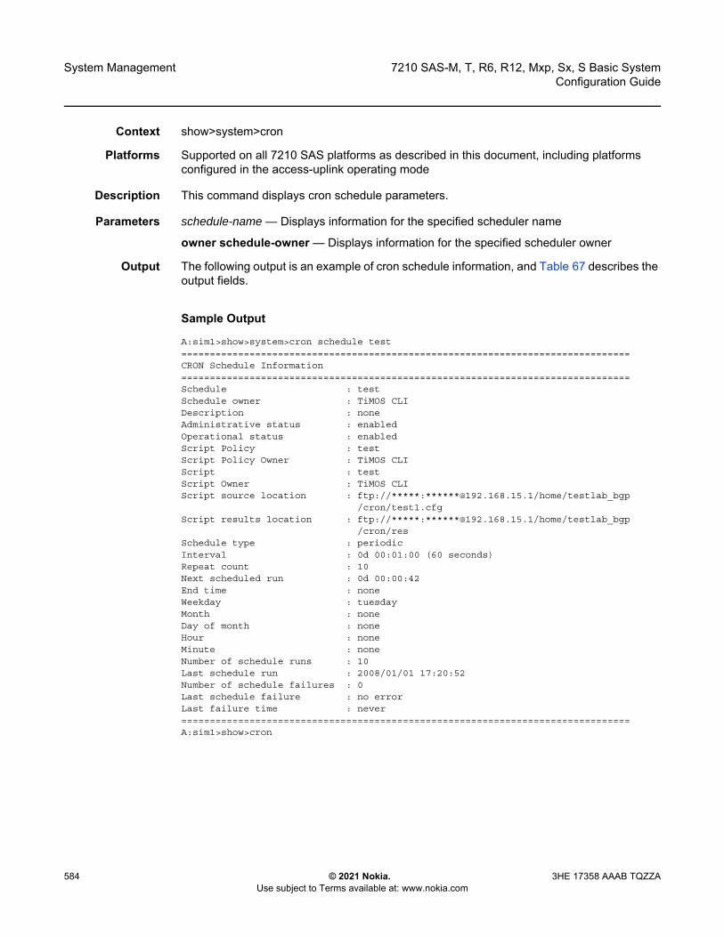
System Management
584
7210 SAS-M, T, R6, R12, Mxp, Sx, S Basic SystemConfiguration Guide
© 2021 Nokia. Use subject to Terms available at: www.nokia.com
3HE 17358 AAAB TQZZA
Context show>system>cron
Platforms Supported on all 7210 SAS platforms as described in this document, including platforms configured in the access-uplink operating mode
Description This command displays cron schedule parameters.
Parameters schedule-name — Displays information for the specified scheduler name
owner schedule-owner — Displays information for the specified scheduler owner
Output The following output is an example of cron schedule information, and Table 67 describes the output fields.
Sample Output
A:sim1>show>system>cron schedule test===============================================================================CRON Schedule Information===============================================================================Schedule : testSchedule owner : TiMOS CLIDescription : noneAdministrative status : enabledOperational status : enabledScript Policy : testScript Policy Owner : TiMOS CLIScript : testScript Owner : TiMOS CLIScript source location : ftp://*****:******@192.168.15.1/home/testlab_bgp
/cron/test1.cfgScript results location : ftp://*****:******@192.168.15.1/home/testlab_bgp
/cron/resSchedule type : periodicInterval : 0d 00:01:00 (60 seconds)Repeat count : 10Next scheduled run : 0d 00:00:42End time : noneWeekday : tuesdayMonth : noneDay of month : noneHour : noneMinute : noneNumber of schedule runs : 10Last schedule run : 2008/01/01 17:20:52Number of schedule failures : 0Last schedule failure : no errorLast failure time : never===============================================================================A:sim1>show>cron
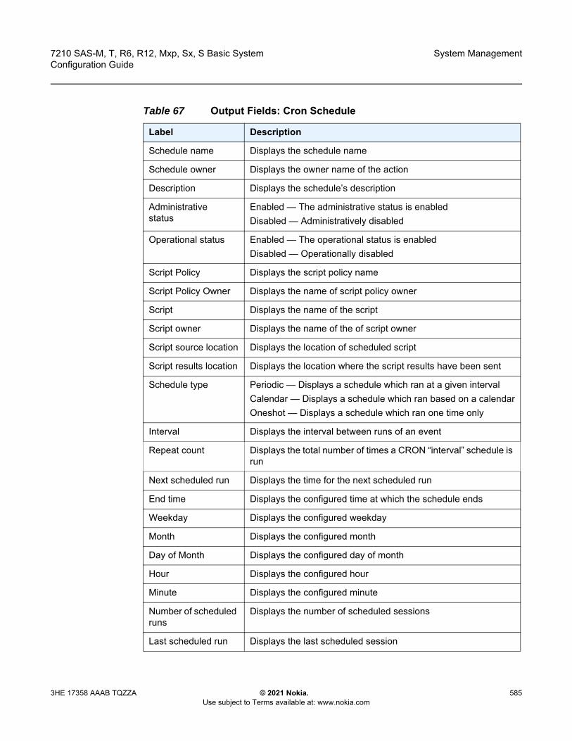
7210 SAS-M, T, R6, R12, Mxp, Sx, S Basic System Configuration Guide
System Management
3HE 17358 AAAB TQZZA © 2021 Nokia. Use subject to Terms available at: www.nokia.com
585
Table 67 Output Fields: Cron Schedule
Label Description
Schedule name Displays the schedule name
Schedule owner Displays the owner name of the action
Description Displays the schedule’s description
Administrative status
Enabled — The administrative status is enabledDisabled — Administratively disabled
Operational status Enabled — The operational status is enabledDisabled — Operationally disabled
Script Policy Displays the script policy name
Script Policy Owner Displays the name of script policy owner
Script Displays the name of the script
Script owner Displays the name of the of script owner
Script source location Displays the location of scheduled script
Script results location Displays the location where the script results have been sent
Schedule type Periodic — Displays a schedule which ran at a given intervalCalendar — Displays a schedule which ran based on a calendarOneshot — Displays a schedule which ran one time only
Interval Displays the interval between runs of an event
Repeat count Displays the total number of times a CRON “interval” schedule is run
Next scheduled run Displays the time for the next scheduled run
End time Displays the configured time at which the schedule ends
Weekday Displays the configured weekday
Month Displays the configured month
Day of Month Displays the configured day of month
Hour Displays the configured hour
Minute Displays the configured minute
Number of scheduled runs
Displays the number of scheduled sessions
Last scheduled run Displays the last scheduled session
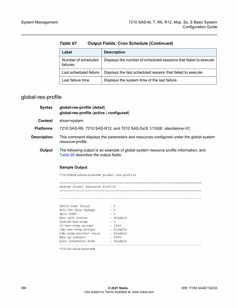
System Management
586
7210 SAS-M, T, R6, R12, Mxp, Sx, S Basic SystemConfiguration Guide
© 2021 Nokia. Use subject to Terms available at: www.nokia.com
3HE 17358 AAAB TQZZA
global-res-profile
Syntax global-res-profile [detail]global-res-profile {active | configured}
Context show>system
Platforms 7210 SAS-R6, 7210 SAS-R12, and 7210 SAS-Sx/S 1/10GE: standalone-VC
Description This command displays the parameters and resources configured under the global system resource-profile.
Output The following output is an example of global system resource profile information, and Table 68 describes the output fields.
Sample Output
*7210SASR>show>system# global-res-profile
============================================================================System Global Resource Profile============================================================================
----------------------------------------------------------------------------
G8032 Fast Flood : 5Eth-Cfm Vpls Upmeps : 0Mpls P2MP : 1Max-ipv6-routes : disableSystem-max-ecmp : 1L3-max-ecmp-groups : 1945Ldp-max-ecmp-groups : disableLdp-ecmp-percent-value : disableMax-ip-subnets : 2000port-scheduler-mode : disable----------------------------------------------------------------------------*7210R>show>system#
Number of scheduled failures
Displays the number of scheduled sessions that failed to execute
Last scheduled failure Displays the last scheduled session that failed to execute
Last failure time Displays the system time of the last failure
Table 67 Output Fields: Cron Schedule (Continued)
Label Description
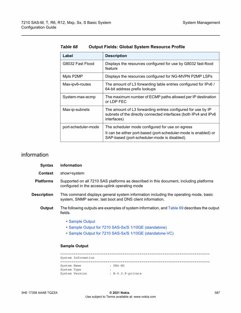
7210 SAS-M, T, R6, R12, Mxp, Sx, S Basic System Configuration Guide
System Management
3HE 17358 AAAB TQZZA © 2021 Nokia. Use subject to Terms available at: www.nokia.com
587
information
Syntax information
Context show>system
Platforms Supported on all 7210 SAS platforms as described in this document, including platforms configured in the access-uplink operating mode
Description This command displays general system information including the operating mode, basic system, SNMP server, last boot and DNS client information.
Output The following outputs are examples of system information, and Table 69 describes the output fields.
• Sample Output• Sample Output for 7210 SAS-Sx/S 1/10GE (standalone)• Sample Output for 7210 SAS-Sx/S 1/10GE (standalone-VC)
Sample Output
===============================================================================System Information===============================================================================System Name : PE4-M2System Type :System Version : B-9.0.F-private
Table 68 Output Fields: Global System Resource Profile
Label Description
G8032 Fast Flood Displays the resources configured for use by G8032 fast-flood feature
Mpls P2MP Displays the resources configured for NG-MVPN P2MP LSPs
Max-ipv6-routes The amount of L3 forwarding table entries configured for IPv6 /64-bit address prefix lookups
System-max-ecmp The maximum number of ECMP paths allowed per IP destination or LDP FEC
Max-ip-subnets The amount of L3 forwarding entries configured for use by IP subnets of the directly connected interfaces (both IPv4 and IPv6 interfaces)
port-scheduler-mode The scheduler mode configured for use on egressIt can be either port-based (port-scheduler-mode is enabled) or SAP-based (port-scheduler-mode is disabled).
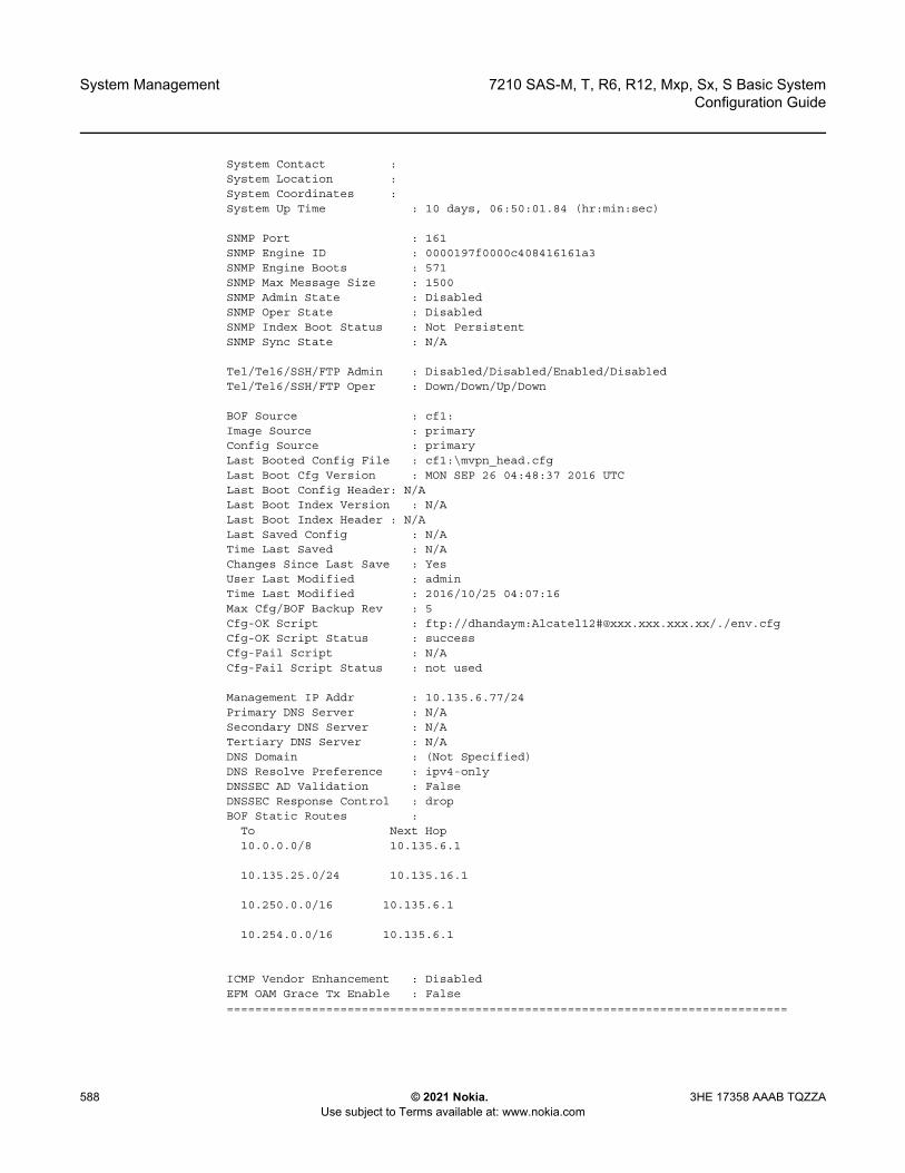
System Management
588
7210 SAS-M, T, R6, R12, Mxp, Sx, S Basic SystemConfiguration Guide
© 2021 Nokia. Use subject to Terms available at: www.nokia.com
3HE 17358 AAAB TQZZA
System Contact :System Location :System Coordinates :System Up Time : 10 days, 06:50:01.84 (hr:min:sec)
SNMP Port : 161SNMP Engine ID : 0000197f0000c408416161a3SNMP Engine Boots : 571SNMP Max Message Size : 1500SNMP Admin State : DisabledSNMP Oper State : DisabledSNMP Index Boot Status : Not PersistentSNMP Sync State : N/A
Tel/Tel6/SSH/FTP Admin : Disabled/Disabled/Enabled/DisabledTel/Tel6/SSH/FTP Oper : Down/Down/Up/Down
BOF Source : cf1:Image Source : primaryConfig Source : primaryLast Booted Config File : cf1:\mvpn_head.cfgLast Boot Cfg Version : MON SEP 26 04:48:37 2016 UTCLast Boot Config Header: N/ALast Boot Index Version : N/ALast Boot Index Header : N/ALast Saved Config : N/ATime Last Saved : N/AChanges Since Last Save : YesUser Last Modified : adminTime Last Modified : 2016/10/25 04:07:16Max Cfg/BOF Backup Rev : 5Cfg-OK Script : ftp://dhandaym:Alcatel12#@xxx.xxx.xxx.xx/./env.cfgCfg-OK Script Status : successCfg-Fail Script : N/ACfg-Fail Script Status : not used
Management IP Addr : 10.135.6.77/24Primary DNS Server : N/ASecondary DNS Server : N/ATertiary DNS Server : N/ADNS Domain : (Not Specified)DNS Resolve Preference : ipv4-onlyDNSSEC AD Validation : FalseDNSSEC Response Control : dropBOF Static Routes :
To Next Hop10.0.0.0/8 10.135.6.1
10.135.25.0/24 10.135.16.1
10.250.0.0/16 10.135.6.1
10.254.0.0/16 10.135.6.1
ICMP Vendor Enhancement : DisabledEFM OAM Grace Tx Enable : False===============================================================================
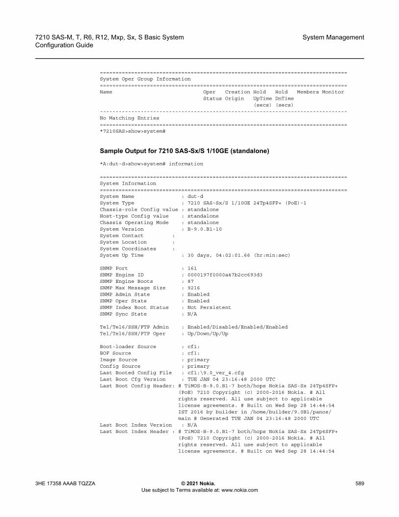
7210 SAS-M, T, R6, R12, Mxp, Sx, S Basic System Configuration Guide
System Management
3HE 17358 AAAB TQZZA © 2021 Nokia. Use subject to Terms available at: www.nokia.com
589
===============================================================================System Oper Group Information===============================================================================Name Oper Creation Hold Hold Members Monitor
Status Origin UpTime DnTime(secs) (secs)
-------------------------------------------------------------------------------No Matching Entries===============================================================================*7210SAS>show>system#
Sample Output for 7210 SAS-Sx/S 1/10GE (standalone)
*A:dut-d>show>system# information
===============================================================================System Information===============================================================================System Name : dut-dSystem Type : 7210 SAS-Sx/S 1/10GE 24Tp4SFP+ (PoE)-1Chassis-role Config value : standaloneHost-type Config value : standaloneChassis Operating Mode : standaloneSystem Version : B-9.0.B1-10System Contact :System Location :System Coordinates :System Up Time : 30 days, 04:02:01.66 (hr:min:sec)
SNMP Port : 161SNMP Engine ID : 0000197f0000a47b2cc693d3SNMP Engine Boots : 87SNMP Max Message Size : 9216SNMP Admin State : EnabledSNMP Oper State : EnabledSNMP Index Boot Status : Not PersistentSNMP Sync State : N/A
Tel/Tel6/SSH/FTP Admin : Enabled/Disabled/Enabled/EnabledTel/Tel6/SSH/FTP Oper : Up/Down/Up/Up
Boot-loader Source : cf1:BOF Source : cf1:Image Source : primaryConfig Source : primaryLast Booted Config File : cf1:\9.0_ver_4.cfgLast Boot Cfg Version : TUE JAN 04 23:16:48 2000 UTCLast Boot Config Header: # TiMOS-B-9.0.B1-7 both/hops Nokia SAS-Sx 24Tp4SFP+
(PoE) 7210 Copyright (c) 2000-2016 Nokia. # Allrights reserved. All use subject to applicablelicense agreements. # Built on Wed Sep 28 14:44:54IST 2016 by builder in /home/builder/9.0B1/panos/main # Generated TUE JAN 04 23:16:48 2000 UTC
Last Boot Index Version : N/ALast Boot Index Header : # TiMOS-B-9.0.B1-7 both/hops Nokia SAS-Sx 24Tp4SFP+
(PoE) 7210 Copyright (c) 2000-2016 Nokia. # Allrights reserved. All use subject to applicablelicense agreements. # Built on Wed Sep 28 14:44:54

System Management
590
7210 SAS-M, T, R6, R12, Mxp, Sx, S Basic SystemConfiguration Guide
© 2021 Nokia. Use subject to Terms available at: www.nokia.com
3HE 17358 AAAB TQZZA
IST 2016 by builder in /home/builder/9.0B1/panos/main # Generated TUE JAN 04 23:16:48 2000 UTC
Last Saved Config : N/ATime Last Saved : N/AChanges Since Last Save : YesUser Last Modified : adminTime Last Modified : 2000/01/23 10:26:17Max Cfg/BOF Backup Rev : 5Cfg-OK Script : N/ACfg-OK Script Status : not usedCfg-Fail Script : N/ACfg-Fail Script Status : not used
Management IP Addr : 10.135.8.152/24Management IP Addr : 2001:dbe::44/64Primary DNS Server : N/ASecondary DNS Server : N/ATertiary DNS Server : N/ADNS Domain : (Not Specified)DNS Resolve Preference : ipv4-onlyDNSSEC AD Validation : FalseDNSSEC Response Control : dropBOF Static Routes :
To Next Hop10.135.0.0/16 10.135.8.1
10.0.0.0/8 10.135.8.1
ICMP Vendor Enhancement : DisabledEFM OAM Grace Tx Enable : False===============================================================================
===============================================================================System Oper Group Information===============================================================================Name Oper Creation Hold Hold Members Monitor
Status Origin UpTime DnTime(secs) (secs)
-------------------------------------------------------------------------------No Matching Entries===============================================================================*A:dut-d>show>system#
Sample Output for 7210 SAS-Sx/S 1/10GE (standalone-VC)
*A:dut-d>show>system# information
===============================================================================System Information===============================================================================System Name : Dut-ASystem Type : 7210 SAS-VCChassis-role Config value : standalone-vcHost-type Config value : noneChassis Operating Mode : standalone-vcSystem Version : B-10.0.S-privateSystem Contact :

7210 SAS-M, T, R6, R12, Mxp, Sx, S Basic System Configuration Guide
System Management
3HE 17358 AAAB TQZZA © 2021 Nokia. Use subject to Terms available at: www.nokia.com
591
System Location :System Coordinates :System Active Slot : ASystem Up Time : 0 days, 09:32:03.18 (hr:min:sec)SNMP Port : 161SNMP Engine ID : 0000197f0000d099d5911c41SNMP Engine Boots : 785SNMP Max Message Size : 1500SNMP Admin State : EnabledSNMP Oper State : EnabledSNMP Index Boot Status : Not PersistentSNMP Sync State : OKTel/Tel6/SSH/FTP Admin : Enabled/Disabled/Enabled/EnabledTel/Tel6/SSH/FTP Oper : Up/Down/Up/UpBoot-loader Source : cf1:BOF Source : cf1:Image Source : primaryConfig Source : primaryLast Booted Config File : cf1:\default.cfgLast Boot Cfg Version : SAT JAN 01 19:17:10 2000 UTCLast Boot Config Header: # TiMOS-B-0.0.private both/hops Nokia SAS-S 24F4SFP+
7210 Copyright (c) 2000-2018 Nokia. # All rightsreserved. All use subject to applicable licenseagreements. # Built on Thu Feb 8 21:49:20 IST 2018by aalapati in /home/aalapati/Work/WsHost/HEAD/panos/main # Generated SAT JAN 01 19:17:10 2000 UTC
Last Boot Index Version : N/ALast Boot Index Header : # TiMOS-B-0.0.private both/hops Nokia SAS-S 24F4SFP+
7210 Copyright (c) 2000-2018 Nokia. # All rightsreserved. All use subject to applicable licenseagreements. # Built on Thu Feb 8 21:49:20 IST 2018by aalapati in /home/aalapati/Work/WsHost/HEAD/panos/main # Generated SAT JAN 01 19:17:10 2000 UTC
Last Saved Config : N/ATime Last Saved : N/AChanges Since Last Save : NoMax Cfg/BOF Backup Rev : 5Cfg-OK Script : ftp://*:*@192.168.36.8/./images/env.cfgCfg-OK Script Status : failedCfg-Fail Script : N/ACfg-Fail Script Status : not usedManagement IP Addr : 10.135.17.166/24Primary DNS Server : N/ASecondary DNS Server : N/ATertiary DNS Server : N/ADNS Domain : (Not Specified)DNS Resolve Preference : ipv4-onlyDNSSEC AD Validation : FalseDNSSEC Response Control : dropBOF Static Routes :
To Next Hop10.250.0.0/16 10.135.17.1
ICMP Vendor Enhancement : DisabledEFM OAM Grace Tx Enable : False=============================================================================

System Management
592
7210 SAS-M, T, R6, R12, Mxp, Sx, S Basic SystemConfiguration Guide
© 2021 Nokia. Use subject to Terms available at: www.nokia.com
3HE 17358 AAAB TQZZA
Table 69 Output Fields: System Information
Label Description
System Name The configured system name
System Type Indicates whether or not the node is operating in a virtual chassis
Chassis-role Config value
Supported only on 7210 SAS-Sx/S 1/10GE devices. Displays the configured value for boot parameter chassis-role
Host-type Config value
Supported only on 7210 SAS-Sx/S 1/10GE devices. Displays the configured value for BOF parameter host-type
Chassis Operating Mode
The current operating mode of the node/chassisIt can be in satellite mode, standalone mode, or standalone-vc mode depending on the configuration of the chassis-role and host-type parameters. Supported only on 7210 SAS-Sx 1/10GE devices
Software Version Indicates the version of the software
System Contact A text string that describes the system contact information
System Location A text string that describes the system location
System Coordinates A text string that describes the system coordinates
System Active Slot Indicates which slot is used for the active CPM (CPM-A or CPM-B)
System Up Time The time since the last boot
SNMP Port The port number used by this node to receive SNMP request messages and to send replies
SNMP Engine ID The SNMP engineID to uniquely identify the SNMPv3 node
SNMP Engine Boots The number of time the SNMP agent has restartedIt is typically equivalent to the number of times the node has rebooted.
SNMP Max Message Size
The maximum SNMP packet size generated by this node
SNMP Admin State Enabled — SNMP is administratively enabled and runningDisabled — SNMP is administratively shut down and not running
SNMP Oper State Enabled — SNMP is operationally enabledDisabled — SNMP is operationally disabled
SNMP Index Boot Status
Persistent — System indexes are saved between rebootsNot Persistent — System indexes are not saved between reboots

7210 SAS-M, T, R6, R12, Mxp, Sx, S Basic System Configuration Guide
System Management
3HE 17358 AAAB TQZZA © 2021 Nokia. Use subject to Terms available at: www.nokia.com
593
SNMP Sync State Indicates whether the SNMP persistence information database has been successfully synchronized between the active and standby CPMThis field is available on 7210 SAS-R6, 7210 SAS-R12, and 7210 SAS-Sx/S 1/10GE: standalone-vc platforms.
Tel/Tel6/SSH/FTP/ Admin
The administrative state of the Telnet, Telnet IPv6, SSH, and FTP sessions
Tel/Tel6/SSH/FTP/ Oper
The operational state of the Telnet, Telnet _IPv6, SSH, and FTP sessions
Boot-loader source The location of the bootloader
BOF source The location of the BOF
Image Source Primary — Indicates that the directory location for runtime image file was loaded from the primary sourceSecondary — Indicates that the directory location for runtime image file was loaded from the secondary source.Tertiary — Indicates that the directory location for runtime image file was loaded from the tertiary source
Config Source Primary — Indicates that the directory location for configuration file was loaded from the primary sourceSecondary — Indicates that the directory location for configuration file was loaded from the secondary sourceTertiary — Indicates that the directory location for configuration file was loaded from the tertiary source
Last Booted Config File
The URL and filename of the last loaded configuration file
Last Boot Cfg Version The date and time of the last boot
Last Boot Config Header
Displays header information such as image version, date built, date generated
Last Boot Index Version
The version of the persistence index file read when the card was last rebooted
Last Boot Index Header
The header of the persistence index file read when the card was last rebooted
Last Saved Config The location and filename of the last saved configuration file
Time Last Saved The date and time of the last time configuration file was saved
Table 69 Output Fields: System Information (Continued)
Label Description (Continued)

System Management
594
7210 SAS-M, T, R6, R12, Mxp, Sx, S Basic SystemConfiguration Guide
© 2021 Nokia. Use subject to Terms available at: www.nokia.com
3HE 17358 AAAB TQZZA
memory-pools
Syntax memory-pools
Changes Since Last Save
Yes — there are unsaved configuration file changesNo — there are no unsaved configuration file changes
Time Last Modified The date and time of the last modification
Max Cfg/BOF Backup Rev
The maximum number of backup revisions maintained for a configuration file. This value also applies to the number of revisions maintained for the BOF file
Cfg-OK Script URL — The location and name of the CLI script file executed following successful completion of the boot-up configuration file execution
Cfg-OK Script Status Successful/Failed — The results from the execution of the CLI script file specified in the Cfg-OK Script locationNot used — No CLI script file was executed
Cfg-Fail Script URL — The location and name of the CLI script file executed following a failed boot-up configuration file executionNot used — No CLI script file was executed
Cfg-Fail Script Status Successful/Failed — The results from the execution of the CLI script file specified in the Cfg-Fail Script locationNot used — No CLI script file was executed
Management IP Addr The management IP address and mask
Primary DNS Server The IP address of the primary DNS server
Secondary DNS Server
The IP address of the secondary DNS server
Tertiary DNS Server The IP address of the tertiary DNS server
DNS Domain The DNS domain name of the node
BOF Static Routes To — The static route destinationNext — Hop The next hop IP address used to reach the destinationMetric — Displays the priority of this static route versus other static routesNone — No static routes are configured
Table 69 Output Fields: System Information (Continued)
Label Description (Continued)
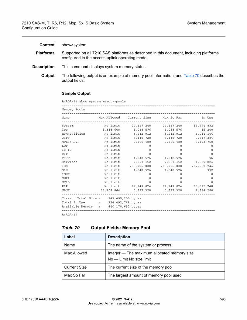
7210 SAS-M, T, R6, R12, Mxp, Sx, S Basic System Configuration Guide
System Management
3HE 17358 AAAB TQZZA © 2021 Nokia. Use subject to Terms available at: www.nokia.com
595
Context show>system
Platforms Supported on all 7210 SAS platforms as described in this document, including platforms configured in the access-uplink operating mode
Description This command displays system memory status.
Output The following output is an example of memory pool information, and Table 70 describes the output fields.
Sample Output
A:ALA-1# show system memory-pools===============================================================================Memory Pools===============================================================================Name Max Allowed Current Size Max So Far In Use-------------------------------------------------------------------------------System No limit 24,117,248 24,117,248 16,974,832Icc 8,388,608 1,048,576 1,048,576 85,200RTM/Policies No limit 5,242,912 5,242,912 3,944,104OSPF No limit 3,145,728 3,145,728 2,617,384MPLS/RSVP No limit 9,769,480 9,769,480 8,173,760LDP No limit 0 0 0IS-IS No limit 0 0 0RIP No limit 0 0 0VRRP No limit 1,048,576 1,048,576 96Services No limit 2,097,152 2,097,152 1,589,824IOM No limit 205,226,800 205,226,800 202,962,744SIM No limit 1,048,576 1,048,576 392IGMP No limit 0 0 0MMPI No limit 0 0 0MFIB No limit 0 0 0PIP No limit 79,943,024 79,943,024 78,895,248MBUF 67,108,864 5,837,328 5,837,328 4,834,280-------------------------------------------------------------------------------Current Total Size : 343,495,200 bytesTotal In Use : 324,492,768 bytesAvailable Memory : 640,178,652 bytes===============================================================================A:ALA-1#
Table 70 Output Fields: Memory Pool
Label Description
Name The name of the system or process
Max Allowed Integer — The maximum allocated memory sizeNo — Limit No size limit
Current Size The current size of the memory pool
Max So Far The largest amount of memory pool used

System Management
596
7210 SAS-M, T, R6, R12, Mxp, Sx, S Basic SystemConfiguration Guide
© 2021 Nokia. Use subject to Terms available at: www.nokia.com
3HE 17358 AAAB TQZZA
ntp
Syntax ntp [{peers | peer peer-address} | {servers | server server-address} |[all]] [detail]
Context show>system
Platforms Supported on all 7210 SAS platforms as described in this document
Description This command displays NTP protocol configuration and state.
Output The following output is an example of NTP information, and Table 71 describes the output fields.
Sample Output
A:7210>config>system>time>ntp# show system ntp===============================================================================NTP Status===============================================================================Enabled : Yes Stratum : 3Admin Status : up Oper Status : upServer enabled : No Server keyId : noneSystem Ref Id : 192.168.15.221 Auth Check : Yes===============================================================================A:7210
A:7210# show system ntp all===============================================================================NTP Status===============================================================================Configured : Yes Stratum : 1Admin Status : up Oper Status : upServer Enabled : Yes Server Authenticate : NoClock Source : PTPAuth Check : YesCurrent Date & Time: 2013/03/19 20:18:50 UTC==============================================================================================================================================================NTP Active Associations===============================================================================State Reference ID St Type A Poll Reach Offset(ms)Remote
In Use The current amount of the memory pool currently in use
Current Total Size The sum of the Current Size column
Total In Use The sum of the In Use column
Available Memory The amount of available memory
Table 70 Output Fields: Memory Pool (Continued)
Label Description
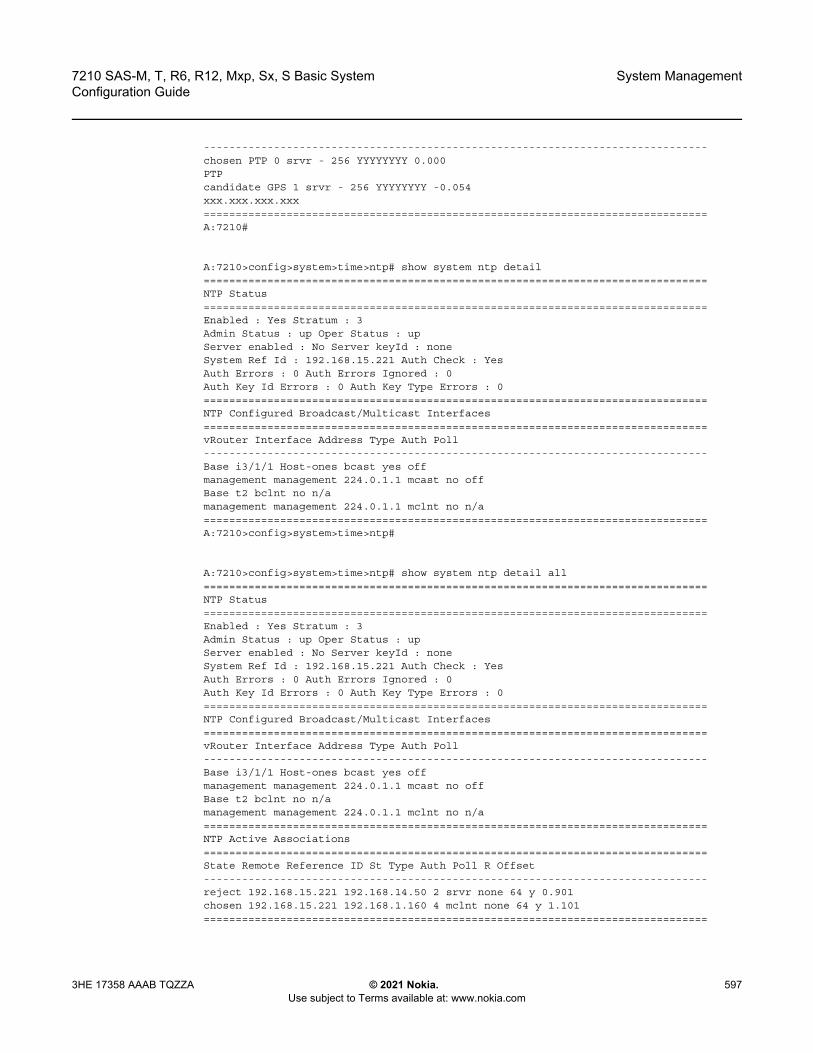
7210 SAS-M, T, R6, R12, Mxp, Sx, S Basic System Configuration Guide
System Management
3HE 17358 AAAB TQZZA © 2021 Nokia. Use subject to Terms available at: www.nokia.com
597
-------------------------------------------------------------------------------chosen PTP 0 srvr - 256 YYYYYYYY 0.000PTPcandidate GPS 1 srvr - 256 YYYYYYYY -0.054xxx.xxx.xxx.xxx===============================================================================A:7210#
A:7210>config>system>time>ntp# show system ntp detail===============================================================================NTP Status===============================================================================Enabled : Yes Stratum : 3Admin Status : up Oper Status : upServer enabled : No Server keyId : noneSystem Ref Id : 192.168.15.221 Auth Check : YesAuth Errors : 0 Auth Errors Ignored : 0Auth Key Id Errors : 0 Auth Key Type Errors : 0===============================================================================NTP Configured Broadcast/Multicast Interfaces===============================================================================vRouter Interface Address Type Auth Poll-------------------------------------------------------------------------------Base i3/1/1 Host-ones bcast yes offmanagement management 224.0.1.1 mcast no offBase t2 bclnt no n/amanagement management 224.0.1.1 mclnt no n/a===============================================================================A:7210>config>system>time>ntp#
A:7210>config>system>time>ntp# show system ntp detail all===============================================================================NTP Status===============================================================================Enabled : Yes Stratum : 3Admin Status : up Oper Status : upServer enabled : No Server keyId : noneSystem Ref Id : 192.168.15.221 Auth Check : YesAuth Errors : 0 Auth Errors Ignored : 0Auth Key Id Errors : 0 Auth Key Type Errors : 0===============================================================================NTP Configured Broadcast/Multicast Interfaces===============================================================================vRouter Interface Address Type Auth Poll-------------------------------------------------------------------------------Base i3/1/1 Host-ones bcast yes offmanagement management 224.0.1.1 mcast no offBase t2 bclnt no n/amanagement management 224.0.1.1 mclnt no n/a===============================================================================NTP Active Associations===============================================================================State Remote Reference ID St Type Auth Poll R Offset-------------------------------------------------------------------------------reject 192.168.15.221 192.168.14.50 2 srvr none 64 y 0.901chosen 192.168.15.221 192.168.1.160 4 mclnt none 64 y 1.101===============================================================================
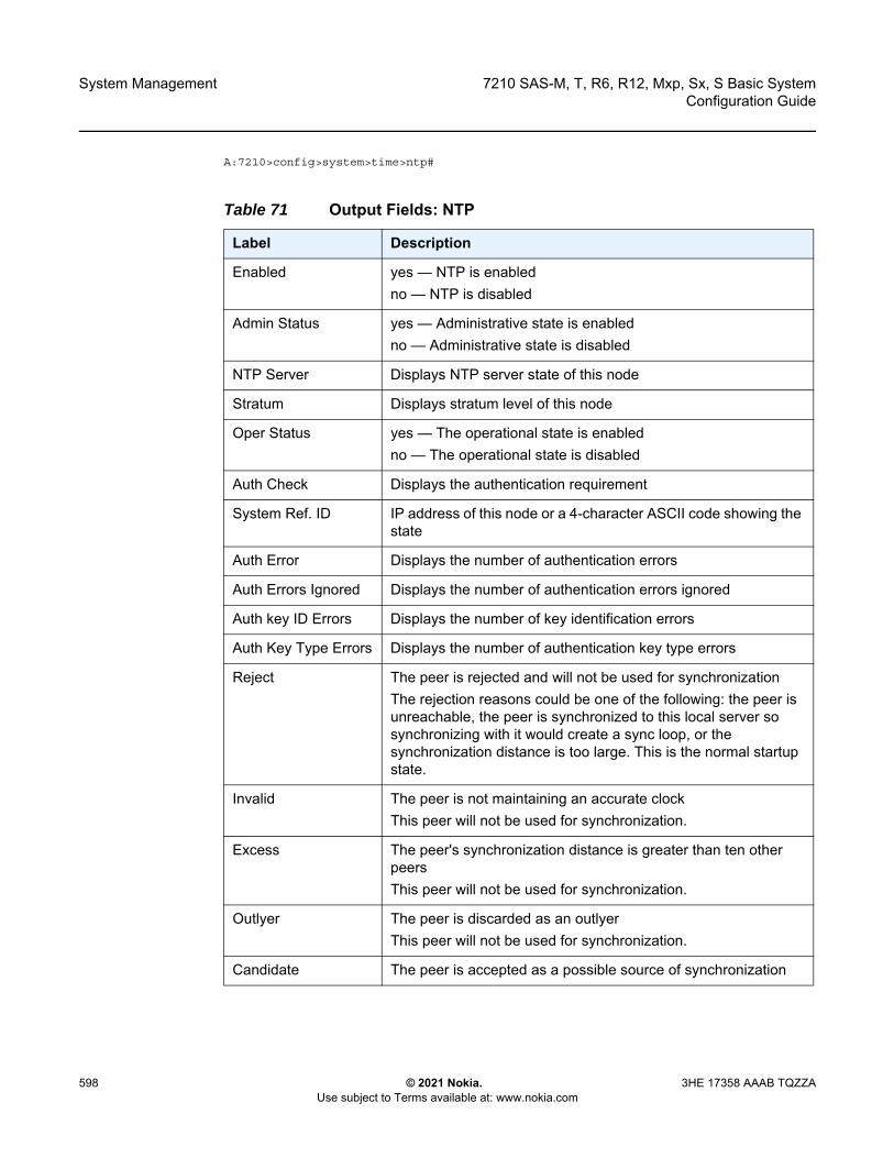
System Management
598
7210 SAS-M, T, R6, R12, Mxp, Sx, S Basic SystemConfiguration Guide
© 2021 Nokia. Use subject to Terms available at: www.nokia.com
3HE 17358 AAAB TQZZA
A:7210>config>system>time>ntp#
Table 71 Output Fields: NTP
Label Description
Enabled yes — NTP is enabledno — NTP is disabled
Admin Status yes — Administrative state is enabledno — Administrative state is disabled
NTP Server Displays NTP server state of this node
Stratum Displays stratum level of this node
Oper Status yes — The operational state is enabledno — The operational state is disabled
Auth Check Displays the authentication requirement
System Ref. ID IP address of this node or a 4-character ASCII code showing the state
Auth Error Displays the number of authentication errors
Auth Errors Ignored Displays the number of authentication errors ignored
Auth key ID Errors Displays the number of key identification errors
Auth Key Type Errors Displays the number of authentication key type errors
Reject The peer is rejected and will not be used for synchronizationThe rejection reasons could be one of the following: the peer is unreachable, the peer is synchronized to this local server so synchronizing with it would create a sync loop, or the synchronization distance is too large. This is the normal startup state.
Invalid The peer is not maintaining an accurate clockThis peer will not be used for synchronization.
Excess The peer's synchronization distance is greater than ten other peersThis peer will not be used for synchronization.
Outlyer The peer is discarded as an outlyerThis peer will not be used for synchronization.
Candidate The peer is accepted as a possible source of synchronization
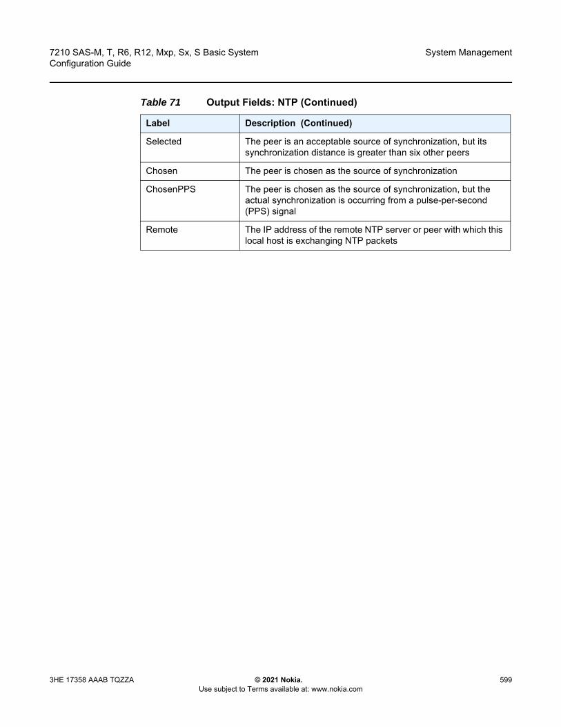
7210 SAS-M, T, R6, R12, Mxp, Sx, S Basic System Configuration Guide
System Management
3HE 17358 AAAB TQZZA © 2021 Nokia. Use subject to Terms available at: www.nokia.com
599
Selected The peer is an acceptable source of synchronization, but its synchronization distance is greater than six other peers
Chosen The peer is chosen as the source of synchronization
ChosenPPS The peer is chosen as the source of synchronization, but the actual synchronization is occurring from a pulse-per-second (PPS) signal
Remote The IP address of the remote NTP server or peer with which this local host is exchanging NTP packets
Table 71 Output Fields: NTP (Continued)
Label Description (Continued)

System Management
600
7210 SAS-M, T, R6, R12, Mxp, Sx, S Basic SystemConfiguration Guide
© 2021 Nokia. Use subject to Terms available at: www.nokia.com
3HE 17358 AAAB TQZZA
Reference ID When stratum is between 0 and 15 this field shows the IP address of the remote NTP server or peer with which the remote is exchanging NTP packetsFor reference clocks, this field shows the identification assigned to the clock, such as, “.GPS.”For an NTP server or peer, if the client has not yet synchronized to a server/peer, the status cannot be determined and displays the following codes:Peer Codes:ACST — The association belongs to any cast serverAUTH — Server authentication failed. Wait while the association is restarted.AUTO — Autokey sequence failed. Wait while the association is restarted. BCST — The association belongs to a broadcast serverCRPT — Cryptographic authentication or identification failed. The details should be in the system log file or the cryptostats statistics file, if configured. No further messages will be sent to the server. DENY — Access denied by remote server. No further messages will be sent to the server. DROP — Lost peer in symmetric mode. Wait while the association is restarted. RSTR — Access denied due to local policy. No further messages will be sent to the server. INIT — The association has not yet synchronized for the first timeMCST — The association belongs to a manycast serverNKEY — No key found. Either the key was never installed or is not trusted. RATE — Rate exceeded. The server has temporarily denied access because the client exceeded the rate threshold. RMOT — The association from a remote host running ntpdc has had unauthorized attempted access.STEP — A step change in system time has occurred, but the association has not yet re-synchronized. System Codes:INIT — The system clock has not yet synchronized for the first timeSTEP — A step change in system time has occurred, but the system clock has not yet re-synchronized
Table 71 Output Fields: NTP (Continued)
Label Description (Continued)

7210 SAS-M, T, R6, R12, Mxp, Sx, S Basic System Configuration Guide
System Management
3HE 17358 AAAB TQZZA © 2021 Nokia. Use subject to Terms available at: www.nokia.com
601
oper-group
Syntax oper-group [group-name]oper-group group-name [detail]oper-group group-name [monitoring]
Context show>system
Platforms Supported only on 7210 SAS platforms configured in the access-uplink operating mode
Description This command displays oper-group information, member count, monitor-client count, and status in a single line for each of the configured oper-groups.
Output The following output is an example of oper-group information, and Table 72 describes the output fields.
Show Output
*A:7210SAS>show>system# oper-group
===============================================================================System Oper Group Information===============================================================================Name Oper Creation Hold Hold Members Monitor
Status Origin UpTime DnTime(secs) (secs)
-------------------------------------------------------------------------------test up manual 4 0 1 1-------------------------------------------------------------------------------Entries found: 1===============================================================================*A:7210SAS>show>system#
*A:7210SAS>show>system# oper-group test monitoring
St Stratum level of this node
Auth yes — Authentication is enabledno — Authentication is disabled
Poll Polling interval in seconds
R Yes — The NTP peer or server has been reached at least once in the last 8 pollsNo — The NTP peer or server has not been reached at least once in the last 8 polls
Offset The time between the local and remote UTC time, in milliseconds
Table 71 Output Fields: NTP (Continued)
Label Description (Continued)

System Management
602
7210 SAS-M, T, R6, R12, Mxp, Sx, S Basic SystemConfiguration Guide
© 2021 Nokia. Use subject to Terms available at: www.nokia.com
3HE 17358 AAAB TQZZA
===============================================================================System Oper Group Information===============================================================================Oper Group : testCreation Origin : manual Oper Status : upHold DownTime : 0 secs Hold UpTime : 4 secsMembers : 0 Monitoring : 0===============================================================================*A:7210SAS>show>system#
rollback
Syntax rollback [rescue]
Context show>system
Platforms 7210 SAS-R6, 7210 SAS-R12, and 7210 SAS-Mxp
Description This command displays rollback configuration and state.
Parameters rescue — Keyword to revert to the rescue checkpoint.
Output The following output is an example of rollback configuration and state information, and Table 73 describes the output fields.
Sample Output
A:7210SAS>show>system# rollback
===============================================================================Rollback Information===============================================================================Rollback Location : NoneMax Local Rollback Files : 10
Table 72 Output Fields: Oper-group
Label Description
Name Displays the name of the oper-group
Oper Status The operational status of the oper-group
Creation Origin Displays if it was created manually
Hold Up Time The configured HOLD UP time
Hold Dn Time The configured HOLD down time
Members Displays the number of members of the oper-group
Monitor Displays the number of monitoring clients

7210 SAS-M, T, R6, R12, Mxp, Sx, S Basic System Configuration Guide
System Management
3HE 17358 AAAB TQZZA © 2021 Nokia. Use subject to Terms available at: www.nokia.com
603
Max Remote Rollback Files : 10Save
Last Rollback Save Result : NoneLast Save Completion Time : N/A
RevertIn Progress : NoLast Revert Initiated User : N/ALast Revert Checkpoint File: N/ALast Revert Result : NoneLast Revert Initiated Time : N/ALast Revert Completion Time: N/A
DeleteLast Rollback Delete Result: None
===============================================================================Rollback Files===============================================================================Idx Suffix Creation Time Release User
Comment-------------------------------------------------------------------------------No Matching Entries===============================================================================A:7210SAS>show>system#
Table 73 Output Fields: Rollback
Label Description
Rollback Information
Rollback Location The location where rollback checkpoint files will be saved
Max Local Rollback Files
The maximum number of rollback checkpoint files that will be saved to a local server
Max Remote RollbackFiles
The maximum number of rollback checkpoint files that will be saved to a remote server
Save
Last Rollback Save Result
The status of the last rollback checkpoint save
Last Save CompletionTime
The date and time the last rollback checkpoint file save operation was completed
Revert
In Progress Indicates if a system rollback reversion is in progress
Last Revert Initiated User
The username of the person who initiated the last system rollback reversion
Last Revert Checkpoint File
The location of the last rollback checkpoint file
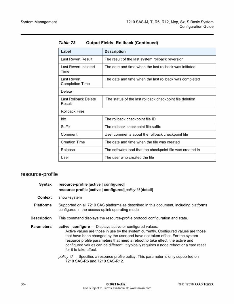
System Management
604
7210 SAS-M, T, R6, R12, Mxp, Sx, S Basic SystemConfiguration Guide
© 2021 Nokia. Use subject to Terms available at: www.nokia.com
3HE 17358 AAAB TQZZA
resource-profile
Syntax resource-profile [active | configured]resource-profile [active | configured] policy-id [detail]
Context show>system
Platforms Supported on all 7210 SAS platforms as described in this document, including platforms configured in the access-uplink operating mode
Description This command displays the resource-profile protocol configuration and state.
Parameters active | configure — Displays active or configured values. Active values are those in use by the system currently. Configured values are those that have been changed by the user and have not taken effect. For the system resource profile parameters that need a reboot to take effect, the active and configured values can be different. It typically requires a node reboot or a card reset for it to take effect.
policy-id — Specifies a resource profile policy. This parameter is only supported on 7210 SAS-R6 and 7210 SAS-R12.
Last Revert Result The result of the last system rollback reversion
Last Revert Initiated Time
The date and time when the last rollback was initiated
Last Revert Completion Time
The date and time when the last rollback was completed
Delete
Last Rollback Delete Result
The status of the last rollback checkpoint file deletion
Rollback Files
Idx The rollback checkpoint file ID
Suffix The rollback checkpoint file suffix
Comment User comments about the rollback checkpoint file
Creation Time The date and time when the file was created
Release The software load that the checkpoint file was created in
User The user who created the file
Table 73 Output Fields: Rollback (Continued)
Label Description

7210 SAS-M, T, R6, R12, Mxp, Sx, S Basic System Configuration Guide
System Management
3HE 17358 AAAB TQZZA © 2021 Nokia. Use subject to Terms available at: www.nokia.com
605
detail — Displays detailed information. This keyword is only supported on 7210 SAS-R6 and 7210 SAS-R12.
Output The following outputs are examples of resource profile information, and Table 74 describes the output fields.
• Sample Output for 7210 SAS-M• Sample Output for 7210 SAS-T• Sample Output for 7210 SAS-R6 and 7210 SAS-R12 devices• Sample Output (with ‘def’ configured)• Sample Output for 7210 SAS-R6 IMMv2• Sample Output for 7210 SAS-Mxp• Sample Output for 7210 SAS-Sx/S 1/10GE devices• Sample Output for 7210 SAS-Sx 10/100GE devices
Sample Output for 7210 SAS-M
*A:7210>show>system# resource-profileA:SAS-MX>show>system# resource-profile
===============================================================================Active System Resource Profile Information===============================================================================-------------------------------------------------------------------------------IPv6 FIB-------------------------------------------------------------------------------max-ipv6-routes : disable-------------------------------------------------------------------------------Router-------------------------------------------------------------------------------max-ip-subnets : 384
---------------------------------------------------------------------------------------------------------------------------------------------------------------------------------------------------------------------------------------------Router-------------------------------------------------------------------------------system-max-ecmp : 1
--------------------------------------------------------------------------------------------------------------------------------------------------------------Ingress Internal CAM-------------------------------------------------------------------------------Sap Ingress Qos resource : 5 Sap Aggregate Meter : 1-------------------------------------------------------------------------------IPv4 Resource : max Mac Resource : maxIPv4-IPv6 Resource : disable
-------------------------------------------------------------------------------Sap Ingress ACL resource : 5-------------------------------------------------------------------------------IPv4 Resource : max Mac Resource : maxIPv4-IPv6 128 bit Resource : disable IPv6 64 bit Resource : disable
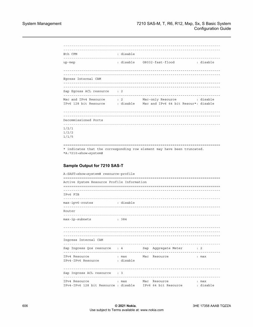
System Management
606
7210 SAS-M, T, R6, R12, Mxp, Sx, S Basic SystemConfiguration Guide
© 2021 Nokia. Use subject to Terms available at: www.nokia.com
3HE 17358 AAAB TQZZA
--------------------------------------------------------------------------------------------------------------------------------------------------------------Eth CFM : disable-------------------------------------------------------------------------------up-mep : disable G8032-fast-flood : disable
--------------------------------------------------------------------------------------------------------------------------------------------------------------Egress Internal CAM--------------------------------------------------------------------------------------------------------------------------------------------------------------Sap Egress ACL resource : 2-------------------------------------------------------------------------------Mac and IPv4 Resource : 2 Mac-only Resource : disableIPv6 128 bit Resource : disable Mac and IPv6 64 bit Resour*: disable
--------------------------------------------------------------------------------------------------------------------------------------------------------------Decommissioned Ports-------------------------------------------------------------------------------1/2/11/2/21/1/5
===============================================================================* indicates that the corresponding row element may have been truncated.*A:7210>show>system#
Sample Output for 7210 SAS-T
A:SAST>show>system# resource-profile===============================================================================Active System Resource Profile Information===============================================================================-------------------------------------------------------------------------------IPv6 FIB-------------------------------------------------------------------------------max-ipv6-routes : disable-------------------------------------------------------------------------------Router-------------------------------------------------------------------------------max-ip-subnets : 384
---------------------------------------------------------------------------------------------------------------------------------------------------------------------------------------------------------------------------------------------Ingress Internal CAM-------------------------------------------------------------------------------Sap Ingress Qos resource : 4 Sap Aggregate Meter : 2-------------------------------------------------------------------------------IPv4 Resource : max Mac Resource : maxIPv4-IPv6 Resource : disable
-------------------------------------------------------------------------------Sap Ingress ACL resource : 3-------------------------------------------------------------------------------IPv4 Resource : max Mac Resource : maxIPv4-IPv6 128 bit Resource : disable IPv6 64 bit Resource : disable
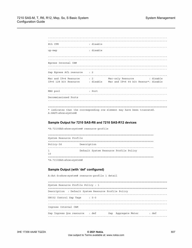
7210 SAS-M, T, R6, R12, Mxp, Sx, S Basic System Configuration Guide
System Management
3HE 17358 AAAB TQZZA © 2021 Nokia. Use subject to Terms available at: www.nokia.com
607
--------------------------------------------------------------------------------------------------------------------------------------------------------------Eth CFM : disable-------------------------------------------------------------------------------up-mep : disable
--------------------------------------------------------------------------------------------------------------------------------------------------------------Egress Internal CAM--------------------------------------------------------------------------------------------------------------------------------------------------------------Sap Egress ACL resource : 2-------------------------------------------------------------------------------Mac and IPv4 Resource : 2 Mac-only Resource : disableIPv6 128 bit Resource : disable Mac and IPv6 64 bit Resour*: disable
-------------------------------------------------------------------------------MBS pool : Port-------------------------------------------------------------------------------Decommissioned Ports-------------------------------------------------------------------------------
===============================================================================* indicates that the corresponding row element may have been truncated.A:SAST>show>system#
Sample Output for 7210 SAS-R6 and 7210 SAS-R12 devices
*A:7210SAS>show>system# resource-profile
======================================================================System Resource Profile======================================================================Policy-Id Description----------------------------------------------------------------------1 Default System Resource Profile Policy10======================================================================*A:7210SAS>show>system#
Sample Output (with ‘def’ configured)
A:dut-b>show>system# resource-profile 1 detail
===============================================================================System Resource Profile Policy : 1===============================================================================Description : Default System Resource Profile Policy-------------------------------------------------------------------------------G8032 Control Sap Tags : 0-0--------------------------------------------------------------------------------------------------------------------------------------------------------------Ingress Internal CAM-------------------------------------------------------------------------------Sap Ingress Qos resource : def Sap Aggregate Meter : def-------------------------------------------------------------------------------
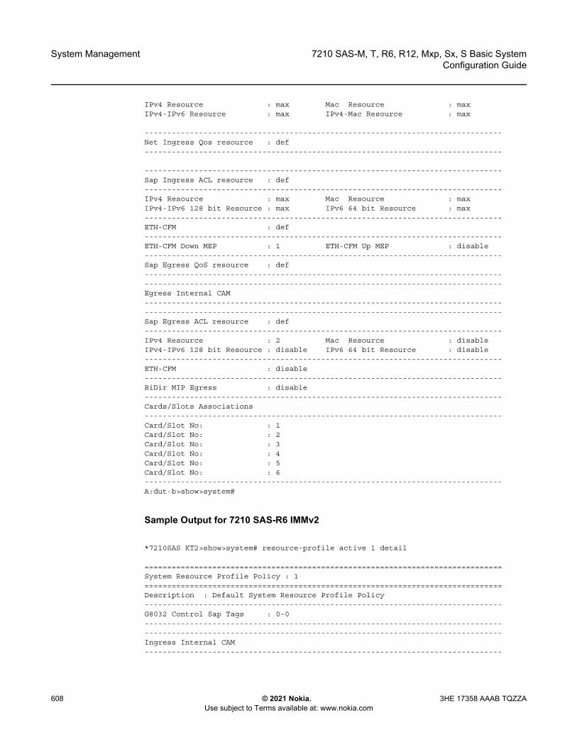
System Management
608
7210 SAS-M, T, R6, R12, Mxp, Sx, S Basic SystemConfiguration Guide
© 2021 Nokia. Use subject to Terms available at: www.nokia.com
3HE 17358 AAAB TQZZA
IPv4 Resource : max Mac Resource : maxIPv4-IPv6 Resource : max IPv4-Mac Resource : max
-------------------------------------------------------------------------------Net Ingress Qos resource : def-------------------------------------------------------------------------------
-------------------------------------------------------------------------------Sap Ingress ACL resource : def-------------------------------------------------------------------------------IPv4 Resource : max Mac Resource : maxIPv4-IPv6 128 bit Resource : max IPv6 64 bit Resource : max-------------------------------------------------------------------------------ETH-CFM : def-------------------------------------------------------------------------------ETH-CFM Down MEP : 1 ETH-CFM Up MEP : disable-------------------------------------------------------------------------------Sap Egress QoS resource : def--------------------------------------------------------------------------------------------------------------------------------------------------------------Egress Internal CAM--------------------------------------------------------------------------------------------------------------------------------------------------------------Sap Egress ACL resource : def-------------------------------------------------------------------------------IPv4 Resource : 2 Mac Resource : disableIPv4-IPv6 128 bit Resource : disable IPv6 64 bit Resource : disable-------------------------------------------------------------------------------ETH-CFM : disable-------------------------------------------------------------------------------BiDir MIP Egress : disable-------------------------------------------------------------------------------Cards/Slots Associations-------------------------------------------------------------------------------Card/Slot No: : 1Card/Slot No: : 2Card/Slot No: : 3Card/Slot No: : 4Card/Slot No: : 5Card/Slot No: : 6-------------------------------------------------------------------------------A:dut-b>show>system#
Sample Output for 7210 SAS-R6 IMMv2
*7210SAS KT2>show>system# resource-profile active 1 detail
===============================================================================System Resource Profile Policy : 1===============================================================================Description : Default System Resource Profile Policy-------------------------------------------------------------------------------G8032 Control Sap Tags : 0-0--------------------------------------------------------------------------------------------------------------------------------------------------------------Ingress Internal CAM-------------------------------------------------------------------------------
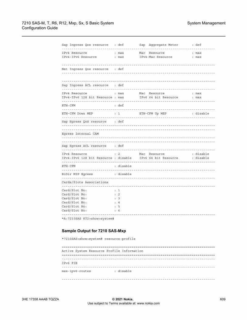
7210 SAS-M, T, R6, R12, Mxp, Sx, S Basic System Configuration Guide
System Management
3HE 17358 AAAB TQZZA © 2021 Nokia. Use subject to Terms available at: www.nokia.com
609
Sap Ingress Qos resource : def Sap Aggregate Meter : def-------------------------------------------------------------------------------IPv4 Resource : max Mac Resource : maxIPv4-IPv6 Resource : max IPv4-Mac Resource : max
-------------------------------------------------------------------------------Net Ingress Qos resource : def-------------------------------------------------------------------------------
-------------------------------------------------------------------------------Sap Ingress ACL resource : def-------------------------------------------------------------------------------IPv4 Resource : max Mac Resource : maxIPv4-IPv6 128 bit Resource : max IPv6 64 bit Resource : max-------------------------------------------------------------------------------ETH-CFM : def-------------------------------------------------------------------------------ETH-CFM Down MEP : 1 ETH-CFM Up MEP : disable-------------------------------------------------------------------------------Sap Egress QoS resource : def--------------------------------------------------------------------------------------------------------------------------------------------------------------Egress Internal CAM--------------------------------------------------------------------------------------------------------------------------------------------------------------Sap Egress ACL resource : def-------------------------------------------------------------------------------IPv4 Resource : 2 Mac Resource : disableIPv4-IPv6 128 bit Resource : disable IPv6 64 bit Resource : disable-------------------------------------------------------------------------------ETH-CFM : disable-------------------------------------------------------------------------------BiDir MIP Egress : disable-------------------------------------------------------------------------------Cards/Slots Associations-------------------------------------------------------------------------------Card/Slot No: : 1Card/Slot No: : 2Card/Slot No: : 3Card/Slot No: : 4Card/Slot No: : 5Card/Slot No: : 6-------------------------------------------------------------------------------*A:7210SAS KT2>show>system#
Sample Output for 7210 SAS-Mxp
*7210SAS>show>system# resource-profile
===============================================================================Active System Resource Profile Information===============================================================================-------------------------------------------------------------------------------IPv6 FIB-------------------------------------------------------------------------------max-ipv6-routes : disable
-------------------------------------------------------------------------------

System Management
610
7210 SAS-M, T, R6, R12, Mxp, Sx, S Basic SystemConfiguration Guide
© 2021 Nokia. Use subject to Terms available at: www.nokia.com
3HE 17358 AAAB TQZZA
Router-------------------------------------------------------------------------------max-ip-subnets : 850
--------------------------------------------------------------------------------------------------------------------------------------------------------------Router-------------------------------------------------------------------------------system-max-ecmp : 1L3-max-ecmp-groups : 1024
-------------------------------------------------------------------------------Ingress Internal CAM : 11-------------------------------------------------------------------------------Sap Ingress Qos resource : 5 Sap Aggregate Meter (#) : 3-------------------------------------------------------------------------------IPv4 Resource : max Mac Resource : maxIPv4-IPv6 Resource : disable IPv4-Mac Resource : max
-------------------------------------------------------------------------------Net Ingress Qos resource : disable-------------------------------------------------------------------------------
-------------------------------------------------------------------------------Sap Ingress ACL resource : 3-------------------------------------------------------------------------------IPv4 Resource : max Mac Resource : maxIPv4-IPv6 128 bit Resource : disable IPv6 64 bit Resource : disable
--------------------------------------------------------------------------------------------------------------------------------------------------------------Eth CFM : 1-------------------------------------------------------------------------------down-mep : 1 up-mep : disable
:
-------------------------------------------------------------------------------Sap Egress QoS resource : 2--------------------------------------------------------------------------------------------------------------------------------------------------------------Egress Internal CAM : 2--------------------------------------------------------------------------------------------------------------------------------------------------------------Sap Egress ACL resource : 2-------------------------------------------------------------------------------Mac and IPv4 Resource : 2 Mac-only Resource : disableIPv6 128 bit Resource : disable Mac and IPv6 64 bit Resour*: disable
--------------------------------------------------------------------------------------------------------------------------------------------------------------Port Scheduler Policy : disable-------------------------------------------------------------------------------===============================================================================* indicates that the corresponding row element may have been truncated.# indicates that the value
Sample Output for 7210 SAS-Sx/S 1/10GE devices

7210 SAS-M, T, R6, R12, Mxp, Sx, S Basic System Configuration Guide
System Management
3HE 17358 AAAB TQZZA © 2021 Nokia. Use subject to Terms available at: www.nokia.com
611
A:7210SAS>show>system# resource-profile
===============================================================================Active System Resource Profile Information===============================================================================--------------------------------------------------------------------------------------------------------------------------------------------------------------Router-------------------------------------------------------------------------------system-max-ecmp : 1L3-max-ecmp-groups : 1024Ldp-max-ecmp-groups : disableLdp-ecmp-percent-value : disable
-------------------------------------------------------------------------------Ingress Internal CAM : 8-------------------------------------------------------------------------------Sap Ingress Qos resource : 4 Sap Aggregate Meter (#) : 3-------------------------------------------------------------------------------IPv4 Resource : max Mac Resource : maxIPv4-IPv6 Resource : disable IPv4-Mac Resource : max
-------------------------------------------------------------------------------Net Ingress Qos resource : disable-------------------------------------------------------------------------------
-------------------------------------------------------------------------------Sap Ingress ACL resource : 3-------------------------------------------------------------------------------IPv4 Resource : max Mac Resource : maxIPv4-IPv6 128 bit Resource : disable IPv6 64 bit Resource : disable
--------------------------------------------------------------------------------------------------------------------------------------------------------------Eth CFM : 1-------------------------------------------------------------------------------down-mep : 1 up-mep : disable
:
-------------------------------------------------------------------------------Egress Internal CAM : 2--------------------------------------------------------------------------------------------------------------------------------------------------------------Sap Egress ACL resource : 2-------------------------------------------------------------------------------Mac and IPv4 Resource : 2 Mac-only Resource : disableIPv6 128 bit Resource : disable Mac and IPv6 64 bit Resour*: disable
--------------------------------------------------------------------------------------------------------------------------------------------------------------Egr sap agg-meter : disable-------------------------------------------------------------------------------MBS pool : Node-------------------------------------------------------------------------------Decommissioned Ports-------------------------------------------------------------------------------
===============================================================================
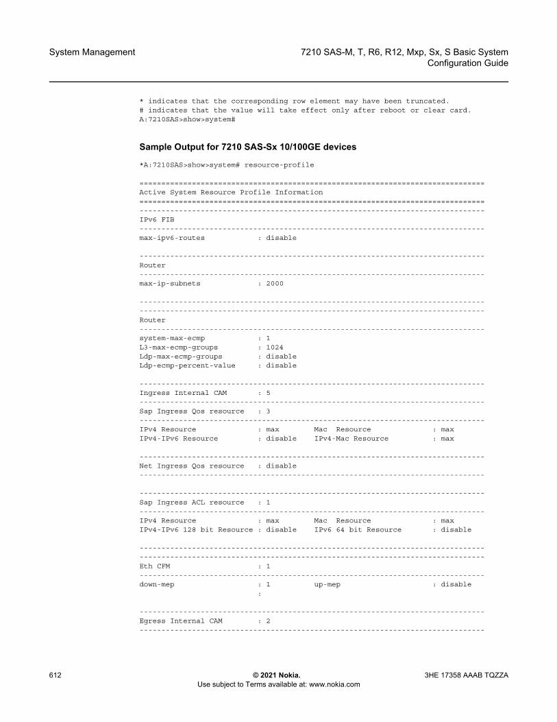
System Management
612
7210 SAS-M, T, R6, R12, Mxp, Sx, S Basic SystemConfiguration Guide
© 2021 Nokia. Use subject to Terms available at: www.nokia.com
3HE 17358 AAAB TQZZA
* indicates that the corresponding row element may have been truncated.# indicates that the value will take effect only after reboot or clear card.A:7210SAS>show>system#
Sample Output for 7210 SAS-Sx 10/100GE devices
*A:7210SAS>show>system# resource-profile
===============================================================================Active System Resource Profile Information===============================================================================-------------------------------------------------------------------------------IPv6 FIB-------------------------------------------------------------------------------max-ipv6-routes : disable
-------------------------------------------------------------------------------Router-------------------------------------------------------------------------------max-ip-subnets : 2000
--------------------------------------------------------------------------------------------------------------------------------------------------------------Router-------------------------------------------------------------------------------system-max-ecmp : 1L3-max-ecmp-groups : 1024Ldp-max-ecmp-groups : disableLdp-ecmp-percent-value : disable
-------------------------------------------------------------------------------Ingress Internal CAM : 5-------------------------------------------------------------------------------Sap Ingress Qos resource : 3-------------------------------------------------------------------------------IPv4 Resource : max Mac Resource : maxIPv4-IPv6 Resource : disable IPv4-Mac Resource : max
-------------------------------------------------------------------------------Net Ingress Qos resource : disable-------------------------------------------------------------------------------
-------------------------------------------------------------------------------Sap Ingress ACL resource : 1-------------------------------------------------------------------------------IPv4 Resource : max Mac Resource : maxIPv4-IPv6 128 bit Resource : disable IPv6 64 bit Resource : disable
--------------------------------------------------------------------------------------------------------------------------------------------------------------Eth CFM : 1-------------------------------------------------------------------------------down-mep : 1 up-mep : disable
:
-------------------------------------------------------------------------------Egress Internal CAM : 2-------------------------------------------------------------------------------
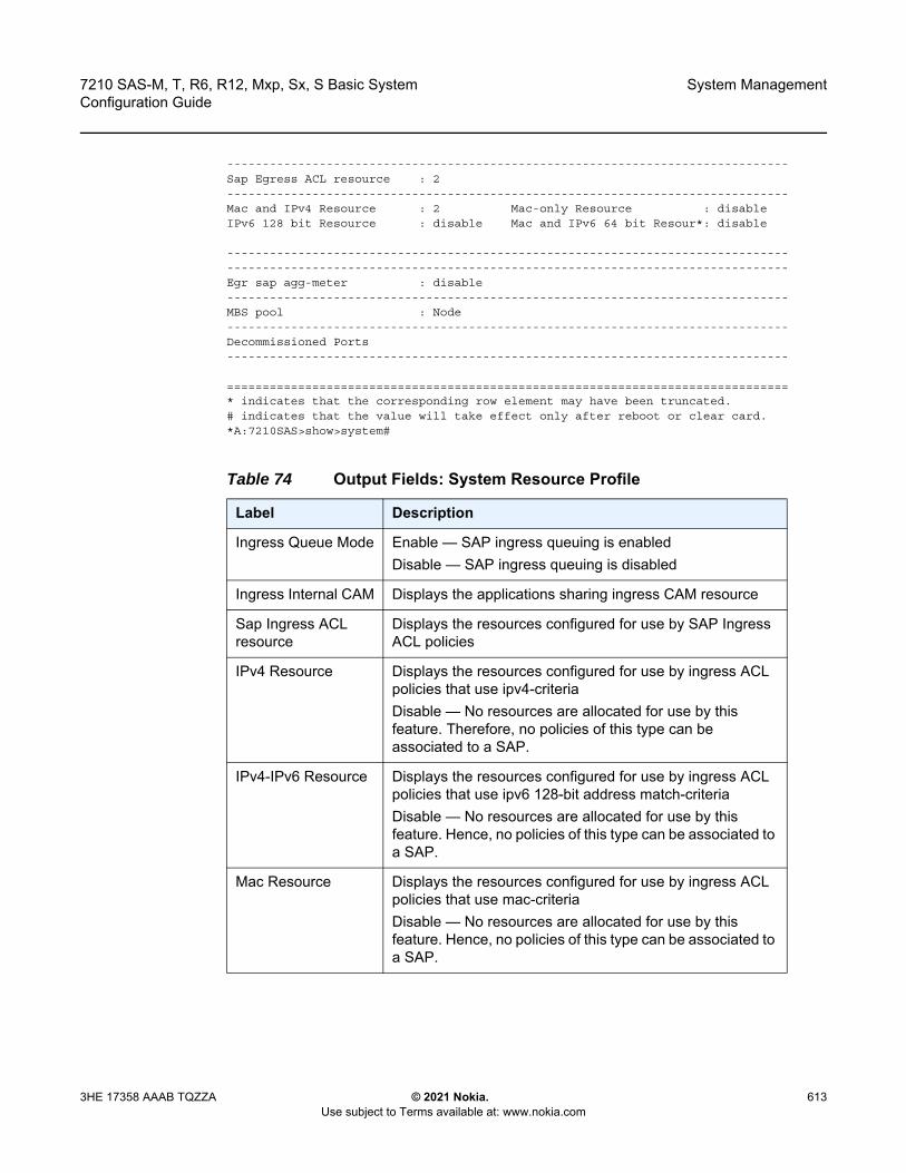
7210 SAS-M, T, R6, R12, Mxp, Sx, S Basic System Configuration Guide
System Management
3HE 17358 AAAB TQZZA © 2021 Nokia. Use subject to Terms available at: www.nokia.com
613
-------------------------------------------------------------------------------Sap Egress ACL resource : 2-------------------------------------------------------------------------------Mac and IPv4 Resource : 2 Mac-only Resource : disableIPv6 128 bit Resource : disable Mac and IPv6 64 bit Resour*: disable
--------------------------------------------------------------------------------------------------------------------------------------------------------------Egr sap agg-meter : disable-------------------------------------------------------------------------------MBS pool : Node-------------------------------------------------------------------------------Decommissioned Ports-------------------------------------------------------------------------------
===============================================================================* indicates that the corresponding row element may have been truncated.# indicates that the value will take effect only after reboot or clear card.*A:7210SAS>show>system#
Table 74 Output Fields: System Resource Profile
Label Description
Ingress Queue Mode Enable — SAP ingress queuing is enabledDisable — SAP ingress queuing is disabled
Ingress Internal CAM Displays the applications sharing ingress CAM resource
Sap Ingress ACL resource
Displays the resources configured for use by SAP Ingress ACL policies
IPv4 Resource Displays the resources configured for use by ingress ACL policies that use ipv4-criteriaDisable — No resources are allocated for use by this feature. Therefore, no policies of this type can be associated to a SAP.
IPv4-IPv6 Resource Displays the resources configured for use by ingress ACL policies that use ipv6 128-bit address match-criteriaDisable — No resources are allocated for use by this feature. Hence, no policies of this type can be associated to a SAP.
Mac Resource Displays the resources configured for use by ingress ACL policies that use mac-criteriaDisable — No resources are allocated for use by this feature. Hence, no policies of this type can be associated to a SAP.

System Management
614
7210 SAS-M, T, R6, R12, Mxp, Sx, S Basic SystemConfiguration Guide
© 2021 Nokia. Use subject to Terms available at: www.nokia.com
3HE 17358 AAAB TQZZA
IPv6-64 bit Resource Displays the resources configured for use by ingress ACL policies that use ipv6 64-bit address match-criteriaDisable — No resources are allocated for use by this feature. Therefor, no policies of this type can be associated to a SAP.
Eth CFM Groups the context for resources consumed by Ethernet CFM applications
up-mep Displays the resources configured for use by UP MEPDisable — No resources are allocated for use by this feature. Therefore, no UP MEPs can be created.
Sap Ingress QoS resource
The total amount of ingress internal CAM chunks configured for use by SAP ingress classification
Mac and IPv4 Resource
The total amount of egress internal CAM chunks configured for use by MAC and IPv4 egress ACL match criteria policies
Mac-only Resource The total amount of egress internal CAM chunks configured for use only by MAC egress ACL match criteria policies
IPv6 128 bit Resource
The total amount of egress internal CAM chunks configured for use only by IPv6 egress ACL match criteria policies (128-bit IPv6 address can be specified in the match criteria)
Mac and IPv6 64 bit Resource
The total amount of egress internal CAM chunks configured for use by MAC and IPv6 egress ACL match criteria policies (only 64-bit higher order bits of the IPv6 address can be specified in the match criteria)
system-max-ecmp Displays the maximum number of routes that will be allocated per IP destination/prefix in hardware when the user enables ECMP path sharing using multiple routes
Sap Egress ACL resource
Displays the egress ACL resource allocation configured for various match criteria
Egress Internal CAM Displays the resource allocation configured for the egress internal CAM
IPv6 FIB Displays the amount of IPv6 FIB size configured for use by IPv6 routing
G8032-fast-flood Displays the resources configured for use by G8032 fast-flood featureDisable — No resources are allocated for use by this feature
Table 74 Output Fields: System Resource Profile (Continued)
Label Description

7210 SAS-M, T, R6, R12, Mxp, Sx, S Basic System Configuration Guide
System Management
3HE 17358 AAAB TQZZA © 2021 Nokia. Use subject to Terms available at: www.nokia.com
615
ptp
Syntax ptp
Context show>system
Platforms 7210 SAS-M (network and access-uplink), 7210 SAS-Mxp, 7210 SAS-R6, 7210 SAS-R12, 7210 SAS-Sx 10/100GE, 7210 SAS-T (network and access-uplink)
Description This command displays the parameters for IEEE 1588-2008/ Precision Time Protocol (PTP) information.
Output The following output is an example of PTP information, and Table 75 describes the output fields.
Sample Output
A:7210SAS>show>system# ptp==============================================================================IEEE 1588/PTP Clock Information===============================================================================-------------------------------------------------------------------------------Local Clock-------------------------------------------------------------------------------Clock Type : boundary PTP Profile : IEEE 1588-2008Domain : 0 Network Type : sdhAdmin State : up Oper State : upAnnounce Interval : 1 pkt/2 s Announce Rx Timeout: 3 intervalsClock Id : 846991fffea8c8f5 Clock Class : 248 (default)Clock Accuracy : unknown Clock Variance : ffff (not computed)Clock Priority1 : 128 Clock Priority2 : 128
Decommissioned Ports
The list of ports which have been decommissioned by the userServices cannot be configured on these ports
MBS pool Displays the value configured for mbs-poolAvailable only on 7210 SAS-T
BiDir MIP Egress Displays the amount of resources allocated towards Bi-dir MIP functionality in the egress-internal-tcam resource pool Available only on 7210 SAS-R6 and 7210 SAS-R12
Port Scheduler Policy
disabled — Indicates that SAP-based egress queues for access SAPs is configured per nodeenabled — Indicates that port-based queues are configured for access SAPs
Table 74 Output Fields: System Resource Profile (Continued)
Label Description

System Management
616
7210 SAS-M, T, R6, R12, Mxp, Sx, S Basic SystemConfiguration Guide
© 2021 Nokia. Use subject to Terms available at: www.nokia.com
3HE 17358 AAAB TQZZA
PTP Recovery State: acquiring Last Changed : 01/07/2020 16:57:06Frequency Offset : +0.000 ppb Frequency Source : ssu-------------------------------------------------------------------------------Parent Clock-------------------------------------------------------------------------------IP Address : 192.168.10.5 Router : BaseParent Clock Id : 00b0aefffe02e5e5 Remote PTP Port : 1GM Clock Id : 00b0aefffe02e5e5 GM Clock Class : 6GM Clock Accuracy : within 100 ns GM Clock Variance : 0x6400 (3.7E-09)GM Clock Priority1: 128 GM Clock Priority2 : 128-------------------------------------------------------------------------------Time Information-------------------------------------------------------------------------------Timescale : PTPCurrent Time : 2020/01/07 17:43:58.0 (UTC)Frequency Traceable : yesTime Traceable : yesTime Source : GPS===============================================================================
*A:Dut-F>config>system>ptp# show system ptp========== =====================================================================IEEE 1588/PTP Clock Information===============================================================================-------------------------------------------------------------------------------Local Clock-------------------------------------------------------------------------------Clock Type : boundary PTP Profile : ITU-T G.8275.1Domain : 24 Network Type : sdhAdmin State : up Oper State : upAnnounce Interval : 8 pkt/s Announce Rx Timeout: 3 intervalsClock Id : 846991fffea8c8f5 Clock Class : 248 (default)Clock Accuracy : unknown Clock Variance : ffff (not computed)Clock Priority1 : 128 Clock Priority2 : 128PTP Recovery State: disabledFrequency Offset : n/a Frequency Source : ssu-------------------------------------------------------------------------------Parent Clock-------------------------------------------------------------------------------Port : 1/1/13 Remote MAC Address : a0:f3:e4:1a:7f:6eParent Clock Id : a0f3e4fffe1a7f5d Remote PTP Port : 16GM Clock Id : 00b0aefffe000030 GM Clock Class : 6GM Clock Accuracy : within 100 ns GM Clock Variance : 0x4e5d (1.8E-15)GM Clock Priority1: 128 GM Clock Priority2 : 128-------------------------------------------------------------------------------Time Information-------------------------------------------------------------------------------Timescale : PTPCurrent Time : 2020/01/07 09:22:32.0 (UTC)Frequency Traceable : yesTime Traceable : yesTime Source : GPS===============================================================================
*A:Dut-F>config>system>ptp# show system ptp peer 192.168.10.5===============================================================================IEEE 1588/PTP Peer Information===============================================================================Router : Base

7210 SAS-M, T, R6, R12, Mxp, Sx, S Basic System Configuration Guide
System Management
3HE 17358 AAAB TQZZA © 2021 Nokia. Use subject to Terms available at: www.nokia.com
617
IP Address : 192.168.10.5 Announce Direction : rxAdmin State : up G.82x5.1 Priority : n/aSync Interval : 16 pkt/sLocal PTP Port : 1 PTP Port State : slaveClock Id : 00b0aefffe02e5e5 Remote PTP Port : 1GM Clock Class : 6GM Clock Accuracy : within 100 ns GM Clock Variance : 0x6400 (3.7E-09)GM Clock Priority1: 128 GM Clock Priority2 : 128Steps Removed : 0 Parent Clock : yes===============================================================================*A:Dut-F>config>system>ptp#
*A:Dut-G>config>system>ptp# show system ptp port 1/1/1===============================================================================IEEE 1588/PTP Ethernet Port Information===============================================================================Port : 1/1/1PTP Admin State : up PTP Oper State : upLocal MAC Addr : d0:00:d5:e7:94:ef Mulicast MAC Addr : 01:1b:19:00:00:00Cfg Sync Rate : 16 pkt/s Cfg Delay Req Rate : 16 pkt/sMaster-Only : false G.8275.1 Priority : 128PTP Port Number : 1 PTP Port State : masterNeighbors : 0 Timestamp Point : port===============================================================================*A:Dut-G>config>system>ptp#
show system ptp port 1/1/2 detail===============================================================================IEEE 1588/PTP Ethernet Port Information===============================================================================Port : 1/1/2PTP Admin State : up PTP Oper State : upLocal MAC Addr : d0:00:d5:e7:94:ef Mulicast MAC Addr : 01:1b:19:00:00:00Cfg Sync Rate : 16 pkt/s Cfg Delay Req Rate : 16 pkt/sMaster-Only : false G.8275.1 Priority : 128PTP Port Number : 1 PTP Port State : slaveNeighbors : 1 Timestamp Point : port============================================================================================================================================IEEE 1588/PTP Ethernet Port Neighbor Clocks=============================================================Port MAC Address Clock Id Rx Packet Rate-------------------------------------------------------------1/1/2 84:69:91:a8:c8:f8 846991fffea8c8f5 33-------------------------------------------------------------No. of Neighbor Clocks: 1============================================================================================================================================IEEE 1588/PTP Ethernet Port Packet Statistics===============================================================================
Input Output-------------------------------------------------------------------------------PTP Packets 114 15516
Announce 24 5158Sync 47 10315Follow Up 0 0Delay Request 0 43Delay Response 43 0Signaling 0 0

System Management
618
7210 SAS-M, T, R6, R12, Mxp, Sx, S Basic SystemConfiguration Guide
© 2021 Nokia. Use subject to Terms available at: www.nokia.com
3HE 17358 AAAB TQZZA
Other 0 0Event Packets timestamped at port 0 0Event Packets timestamped at cpm 0 0
Discards 0 0Bad PTP domain 0 0Alternate Master 0 0Out Of Sequence 0 0Other 0 0
===============================================================================
*A:Dut-F>config>system>ptp# show system ptp statistics===============================================================================IEEE 1588/PTP Packet Statistics===============================================================================
Input Output-------------------------------------------------------------------------------PTP Packets 62792 32900
Announce 972 0Sync 30897 0Follow Up 0 0Delay Request 0 30883Delay Response 30883 0Signaling 40 2017
Request Unicast Transmission TLVs 0 2016Announce 0 1990Sync 0 13Delay Response 0 13
Grant Unicast Transmission (Accepted) TLVs 40 0Announce 14 0Sync 13 0Delay Response 13 0
Grant Unicast Transmission (Denied) TLVs 0 0Announce 0 0Sync 0 0Delay Response 0 0
Cancel Unicast Transmission TLVs 0 1Announce 0 1Sync 0 0Delay Response 0 0
Ack Cancel Unicast Transmission TLVs 0 0Announce 0 0Sync 0 0Delay Response 0 0
Other TLVs 0 0Other 0 0
Discards 0 0Other 0 0
==============================================================================================================================================================IEEE 1588/PTP Frequency Recovery State Statistics===============================================================================State Seconds-------------------------------------------------------------------------------Initial 0Acquiring 12Phase-Tracking 0Locked 1928Hold-over 0===============================================================================

7210 SAS-M, T, R6, R12, Mxp, Sx, S Basic System Configuration Guide
System Management
3HE 17358 AAAB TQZZA © 2021 Nokia. Use subject to Terms available at: www.nokia.com
619
===============================================================================IEEE 1588/PTP Message Rates Per Second===============================================================================
UDP/IP EthernetPacket Type Input Output Input Output-------------------------------------------------------------------------------Announce 0 0 0 0Sync 0 0 0 0Follow Up 0 0 0 0Delay Request 0 0 0 0Delay Response 0 0 0 0Other 0 0 0 0-------------------------------------------------------------------------------Total 0 0 0 0======================
===============================================================================IEEE 1588/PTP Frequency Recovery State Statistics===============================================================================State Seconds-------------------------------------------------------------------------------Initial 44Acquiring 0Phase-Tracking 0Locked 0Hold-over 10===============================================================================
===============================================================================IEEE 1588/PTP Event Statistics===============================================================================Event Sync Flow Delay Flow-------------------------------------------------------------------------------Packet Loss 2 3Excessive Packet Loss 0 0Excessive Phase Shift Detected 0 0Too Much Packet Delay Variation 0 0===============================================================================
===============================================================================IEEE 1588/PTP Message Rates Per Second===============================================================================
UDP/IP EthernetPacket Type Input Output Input Output-------------------------------------------------------------------------------Announce 0 0 16 0Sync 0 0 32 0Follow Up 0 0 32 0Delay Request 0 0 0 4Delay Response 0 0 4 0Other 0 0 0 0-------------------------------------------------------------------------------Total 0 0 84 4===============================================================================A:7210SAS>show>system#

System Management
620
7210 SAS-M, T, R6, R12, Mxp, Sx, S Basic SystemConfiguration Guide
© 2021 Nokia. Use subject to Terms available at: www.nokia.com
3HE 17358 AAAB TQZZA
Table 75 Output Fields: System PTP
Label Description
Clock Type Displays the local PTP clock type: • ordinarySlave — The system is always a slave clock in the
master-slave hierarchy. The system derives its timing from one or more master clocks in the network.
• ordinaryMaster — The system is a grandmaster clock in the master-slave hierarchy. The system provides timing to multiple slave clocks in the network.
• boundary — The system is a boundary clock, which may be anywhere in the master-slave clock hierarchy. It can obtain timing from a master clock, and provide timing to multiple slave clocks.
• transparent-e2e
PTP Profile Displays the PTP profile: ieee-1588, itu-telecom-freq, g8275dot1- 2014, or g8275dot2-2016
Domain Displays the PTP device domain
Network Type Indicates whether SONET or SDH values are being used for encoding synchronous status messages
Local Clock
Admin State Up — The local PTP clock is administratively enabledDown — The local clock is administratively shut down and not running
Oper State Up — The local clock is operationally enabled and runningDown — The local clock is operationally disabled and not running
Announce Interval Displays the configured announce interval value
Announce Rx Timeout
Displays the configured announce Rx timeout value
Clock Id Displays a unique 64-bit number assigned to the clock
Clock Class Displays the local clock class
Clock Accuracy Displays the local clock accuracy designation
Clock Variance Displays the local clock variance
Clock Priority1 Displays the first priority value of the local clock, used by the Best Master Clock Algorithm (BMCA) to determine which clock should provide timing for the network
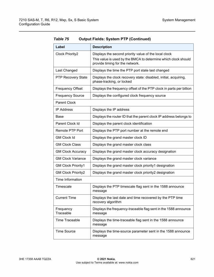
7210 SAS-M, T, R6, R12, Mxp, Sx, S Basic System Configuration Guide
System Management
3HE 17358 AAAB TQZZA © 2021 Nokia. Use subject to Terms available at: www.nokia.com
621
Clock Priority2 Displays the second priority value of the local clockThis value is used by the BMCA to determine which clock should provide timing for the network.
Last Changed Displays the time the PTP port state last changed
PTP Recovery State Displays the clock recovery state: disabled, initial, acquiring, phase-tracking, or locked
Frequency Offset Displays the frequency offset of the PTP clock in parts per billion
Frequency Source Displays the configured clock frequency source
Parent Clock
IP Address Displays the IP address
Base Displays the router ID that the parent clock IP address belongs to
Parent Clock Id Displays the parent clock identification
Remote PTP Port Displays the PTP port number at the remote end
GM Clock Id Displays the grand master clock ID
GM Clock Class Displays the grand master clock class
GM Clock Accuracy Displays the grand master clock accuracy designation
GM Clock Variance Displays the grand master clock variance
GM Clock Priority1 Displays the grand master clock priority1 designation
GM Clock Priority2 Displays the grand master clock priority2 designation
Time Information
Timescale Displays the PTP timescale flag sent in the 1588 announce message
Current Time Displays the last date and time recovered by the PTP time recovery algorithm
Frequency Traceable
Displays the frequency-traceable flag sent in the 1588 announce message
Time Traceable Displays the time-traceable flag sent in the 1588 announce message
Time Source Displays the time-source parameter sent in the 1588 announce message
Table 75 Output Fields: System PTP (Continued)
Label Description
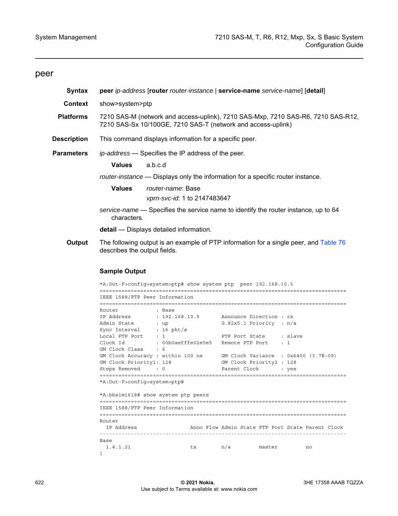
System Management
622
7210 SAS-M, T, R6, R12, Mxp, Sx, S Basic SystemConfiguration Guide
© 2021 Nokia. Use subject to Terms available at: www.nokia.com
3HE 17358 AAAB TQZZA
peer
Syntax peer ip-address [router router-instance | service-name service-name] [detail]
Context show>system>ptp
Platforms 7210 SAS-M (network and access-uplink), 7210 SAS-Mxp, 7210 SAS-R6, 7210 SAS-R12, 7210 SAS-Sx 10/100GE, 7210 SAS-T (network and access-uplink)
Description This command displays information for a specific peer.
Parameters ip-address — Specifies the IP address of the peer.
Values a.b.c.d
router-instance — Displays only the information for a specific router instance.
Values router-name: Basevprn-svc-id: 1 to 2147483647
service-name — Specifies the service name to identify the router instance, up to 64 characters.
detail — Displays detailed information.
Output The following output is an example of PTP information for a single peer, and Table 76 describes the output fields.
Sample Output
*A:Dut-F>config>system>ptp# show system ptp peer 192.168.10.5===============================================================================IEEE 1588/PTP Peer Information===============================================================================Router : BaseIP Address : 192.168.10.5 Announce Direction : rxAdmin State : up G.82x5.1 Priority : n/aSync Interval : 16 pkt/sLocal PTP Port : 1 PTP Port State : slaveClock Id : 00b0aefffe02e5e5 Remote PTP Port : 1GM Clock Class : 6GM Clock Accuracy : within 100 ns GM Clock Variance : 0x6400 (3.7E-09)GM Clock Priority1: 128 GM Clock Priority2 : 128Steps Removed : 0 Parent Clock : yes===============================================================================*A:Dut-F>config>system>ptp#
*A:bksim1618# show system ptp peers===============================================================================IEEE 1588/PTP Peer Information===============================================================================Router
IP Address Anno Flow Admin State PTP Port State Parent Clock-------------------------------------------------------------------------------Base
1.4.1.21 tx n/a master no1

7210 SAS-M, T, R6, R12, Mxp, Sx, S Basic System Configuration Guide
System Management
3HE 17358 AAAB TQZZA © 2021 Nokia. Use subject to Terms available at: www.nokia.com
623
1.2.1.20 rx+tx up master no1.3.1.19 rx up slave yes
21.1.1.21 tx n/a master no
-------------------------------------------------------------------------------No. of PTP Peers: 4===============================================================================
*A:bksim1618# show system ptp peers router Base===============================================================================IEEE 1588/PTP Peer Information===============================================================================Router
IP Address Anno Flow Admin State PTP Port State Parent Clock-------------------------------------------------------------------------------Base
1.4.1.21 tx n/a master no-------------------------------------------------------------------------------No. of PTP Peers: 1===============================================================================*A:bksim1618# show system ptp peers router 1===============================================================================IEEE 1588/PTP Peer Information===============================================================================Router
IP Address Anno Flow Admin State PTP Port State Parent Clock-------------------------------------------------------------------------------1
1.2.1.20 rx+tx up master no1.3.1.19 rx up slave yes
-------------------------------------------------------------------------------No. of PTP Peers: 2===============================================================================
Table 76 Output Fields: PTP Peer
Label Description
Router Displays the router
IP Address Displays the IP address
Announce Direction Displays the direction of flow of announce packets
Admin State Up — the PTP peer clock is administratively enabledDown — the PTP peer clock is administratively shut down and not running
Sync Interval Displays the configured sync interval value
Local PTP Port Displays the local PTP port
PTP Port State Displays the PTP port state: initializing, listening, uncalibrated, slave, master, or passive
Remote PTP Port Displays the PTP port number at the remote end
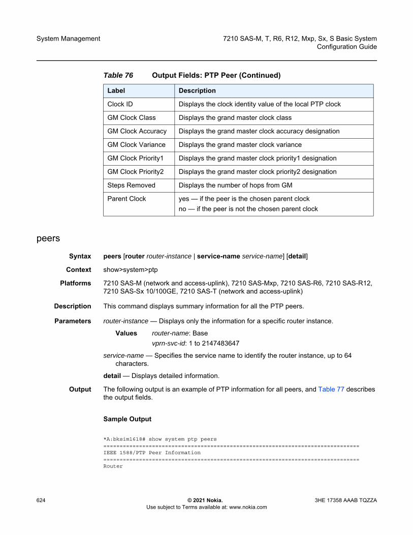
System Management
624
7210 SAS-M, T, R6, R12, Mxp, Sx, S Basic SystemConfiguration Guide
© 2021 Nokia. Use subject to Terms available at: www.nokia.com
3HE 17358 AAAB TQZZA
peers
Syntax peers [router router-instance | service-name service-name] [detail]
Context show>system>ptp
Platforms 7210 SAS-M (network and access-uplink), 7210 SAS-Mxp, 7210 SAS-R6, 7210 SAS-R12, 7210 SAS-Sx 10/100GE, 7210 SAS-T (network and access-uplink)
Description This command displays summary information for all the PTP peers.
Parameters router-instance — Displays only the information for a specific router instance.
Values router-name: Basevprn-svc-id: 1 to 2147483647
service-name — Specifies the service name to identify the router instance, up to 64 characters.
detail — Displays detailed information.
Output The following output is an example of PTP information for all peers, and Table 77 describes the output fields.
Sample Output
*A:bksim1618# show system ptp peers===============================================================================IEEE 1588/PTP Peer Information===============================================================================Router
Clock ID Displays the clock identity value of the local PTP clock
GM Clock Class Displays the grand master clock class
GM Clock Accuracy Displays the grand master clock accuracy designation
GM Clock Variance Displays the grand master clock variance
GM Clock Priority1 Displays the grand master clock priority1 designation
GM Clock Priority2 Displays the grand master clock priority2 designation
Steps Removed Displays the number of hops from GM
Parent Clock yes — if the peer is the chosen parent clockno — if the peer is not the chosen parent clock
Table 76 Output Fields: PTP Peer (Continued)
Label Description
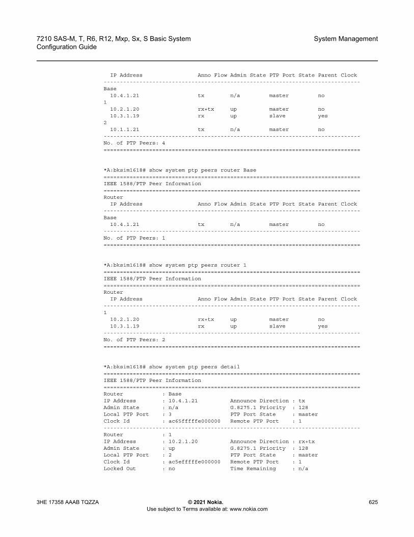
7210 SAS-M, T, R6, R12, Mxp, Sx, S Basic System Configuration Guide
System Management
3HE 17358 AAAB TQZZA © 2021 Nokia. Use subject to Terms available at: www.nokia.com
625
IP Address Anno Flow Admin State PTP Port State Parent Clock-------------------------------------------------------------------------------Base
10.4.1.21 tx n/a master no1
10.2.1.20 rx+tx up master no10.3.1.19 rx up slave yes
210.1.1.21 tx n/a master no
-------------------------------------------------------------------------------No. of PTP Peers: 4===============================================================================
*A:bksim1618# show system ptp peers router Base===============================================================================IEEE 1588/PTP Peer Information===============================================================================Router
IP Address Anno Flow Admin State PTP Port State Parent Clock-------------------------------------------------------------------------------Base
10.4.1.21 tx n/a master no-------------------------------------------------------------------------------No. of PTP Peers: 1===============================================================================
*A:bksim1618# show system ptp peers router 1===============================================================================IEEE 1588/PTP Peer Information===============================================================================Router
IP Address Anno Flow Admin State PTP Port State Parent Clock-------------------------------------------------------------------------------1
10.2.1.20 rx+tx up master no10.3.1.19 rx up slave yes
-------------------------------------------------------------------------------No. of PTP Peers: 2===============================================================================
*A:bksim1618# show system ptp peers detail===============================================================================IEEE 1588/PTP Peer Information===============================================================================Router : BaseIP Address : 10.4.1.21 Announce Direction : txAdmin State : n/a G.8275.1 Priority : 128Local PTP Port : 3 PTP Port State : masterClock Id : ac65fffffe000000 Remote PTP Port : 1-------------------------------------------------------------------------------Router : 1IP Address : 10.2.1.20 Announce Direction : rx+txAdmin State : up G.8275.1 Priority : 128Local PTP Port : 2 PTP Port State : masterClock Id : ac5efffffe000000 Remote PTP Port : 1Locked Out : no Time Remaining : n/a
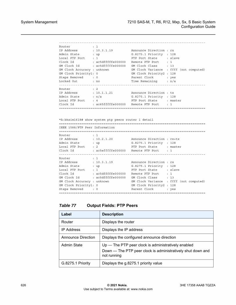
System Management
626
7210 SAS-M, T, R6, R12, Mxp, Sx, S Basic SystemConfiguration Guide
© 2021 Nokia. Use subject to Terms available at: www.nokia.com
3HE 17358 AAAB TQZZA
-------------------------------------------------------------------------------Router : 1IP Address : 10.3.1.19 Announce Direction : rxAdmin State : up G.8275.1 Priority : 128Local PTP Port : 1 PTP Port State : slaveClock Id : ac5dfffffe000000 Remote PTP Port : 1GM Clock Id : ac5dfffffe000000 GM Clock Class : 13GM Clock Accuracy : unknown GM Clock Variance : ffff (not computed)GM Clock Priority1: 0 GM Clock Priority2 : 128Steps Removed : 0 Parent Clock : yesLocked Out : no Time Remaining : n/a-------------------------------------------------------------------------------Router : 2IP Address : 10.1.1.21 Announce Direction : txAdmin State : n/a G.8275.1 Priority : 128Local PTP Port : 4 PTP Port State : masterClock Id : ac65fffffe000000 Remote PTP Port : 1===============================================================================
*A:bksim1618# show system ptp peers router 1 detail===============================================================================IEEE 1588/PTP Peer Information===============================================================================Router : 1IP Address : 10.2.1.20 Announce Direction : rx+txAdmin State : up G.8275.1 Priority : 128Local PTP Port : 2 PTP Port State : masterClock Id : ac5efffffe000000 Remote PTP Port : 1-------------------------------------------------------------------------------Router : 1IP Address : 10.3.1.19 Announce Direction : rxAdmin State : up G.8275.1 Priority : 128Local PTP Port : 1 PTP Port State : slaveClock Id : ac5dfffffe000000 Remote PTP Port : 1GM Clock Id : ac5dfffffe000000 GM Clock Class : 13GM Clock Accuracy : unknown GM Clock Variance : ffff (not computed)GM Clock Priority1: 0 GM Clock Priority2 : 128Steps Removed : 0 Parent Clock : yes===============================================================================
Table 77 Output Fields: PTP Peers
Label Description
Router Displays the router
IP Address Displays the IP address
Announce Direction Displays the configured announce direction
Admin State Up — The PTP peer clock is administratively enabledDown — The PTP peer clock is administratively shut down and not running
G.8275.1 Priority Displays the g.8275.1 priority value

7210 SAS-M, T, R6, R12, Mxp, Sx, S Basic System Configuration Guide
System Management
3HE 17358 AAAB TQZZA © 2021 Nokia. Use subject to Terms available at: www.nokia.com
627
port
Syntax port port-id [detail]
Context show>system>ptp
Platforms 7210 SAS-M (network and access-uplink), 7210 SAS-Mxp, 7210 SAS-R6, 7210 SAS-R12, 7210 SAS-Sx 10/100GE, 7210 SAS-T (network and access-uplink)
Description This command displays PTP port information.
Parameters port-id — Specifies the port ID.
Values slot/mda/port
detail — Displays detailed information.
Output The following output is an example of PTP port information, and Table 78 describes the output fields.
Sample Output
A:bksim1618# show system ptp port===============================================================================IEEE 1588/PTP Ethernet Port Summary Information
Sync Interval Displays the configured sync interval value
Local PTP Port Displays the local PTP port
PTP Port State Displays the PTP port state
Remote PTP Port Displays the PTP port number at the remote end
Clock ID Displays the clock identity value of the local PTP clock
GM Clock Class Displays the grand master clock class
GM Clock Accuracy Displays the grand master clock accuracy designation
GM Clock Variance Displays the grand master clock variance
GM Clock Priority1 Displays the grand master clock priority1 designation
GM Clock Priority2 Displays the grand master clock priority2 designation
Steps Removed Displays the number of hops from GM
Parent Clock yes — if the peer is the chosen parent clockno — if the peer is not the chosen parent clock
Table 77 Output Fields: PTP Peers (Continued)
Label Description
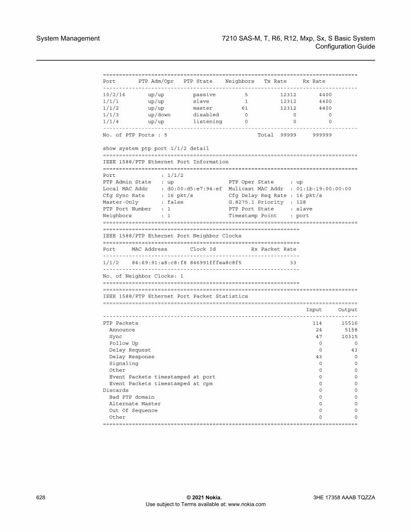
System Management
628
7210 SAS-M, T, R6, R12, Mxp, Sx, S Basic SystemConfiguration Guide
© 2021 Nokia. Use subject to Terms available at: www.nokia.com
3HE 17358 AAAB TQZZA
===============================================================================Port PTP Adm/Opr PTP State Neighbors Tx Rate Rx Rate-------------------------------------------------------------------------------10/2/16 up/up passive 5 12312 44001/1/1 up/up slave 1 12312 44001/1/2 up/up master 61 12312 44001/1/3 up/down disabled 0 0 01/1/4 up/up listening 0 0 0-------------------------------------------------------------------------------No. of PTP Ports : 5 Total 99999 999999
show system ptp port 1/1/2 detail===============================================================================IEEE 1588/PTP Ethernet Port Information===============================================================================Port : 1/1/2PTP Admin State : up PTP Oper State : upLocal MAC Addr : d0:00:d5:e7:94:ef Mulicast MAC Addr : 01:1b:19:00:00:00Cfg Sync Rate : 16 pkt/s Cfg Delay Req Rate : 16 pkt/sMaster-Only : false G.8275.1 Priority : 128PTP Port Number : 1 PTP Port State : slaveNeighbors : 1 Timestamp Point : port============================================================================================================================================IEEE 1588/PTP Ethernet Port Neighbor Clocks=============================================================Port MAC Address Clock Id Rx Packet Rate-------------------------------------------------------------1/1/2 84:69:91:a8:c8:f8 846991fffea8c8f5 33-------------------------------------------------------------No. of Neighbor Clocks: 1============================================================================================================================================IEEE 1588/PTP Ethernet Port Packet Statistics===============================================================================
Input Output-------------------------------------------------------------------------------PTP Packets 114 15516
Announce 24 5158Sync 47 10315Follow Up 0 0Delay Request 0 43Delay Response 43 0Signaling 0 0Other 0 0Event Packets timestamped at port 0 0Event Packets timestamped at cpm 0 0
Discards 0 0Bad PTP domain 0 0Alternate Master 0 0Out Of Sequence 0 0Other 0 0
===============================================================================
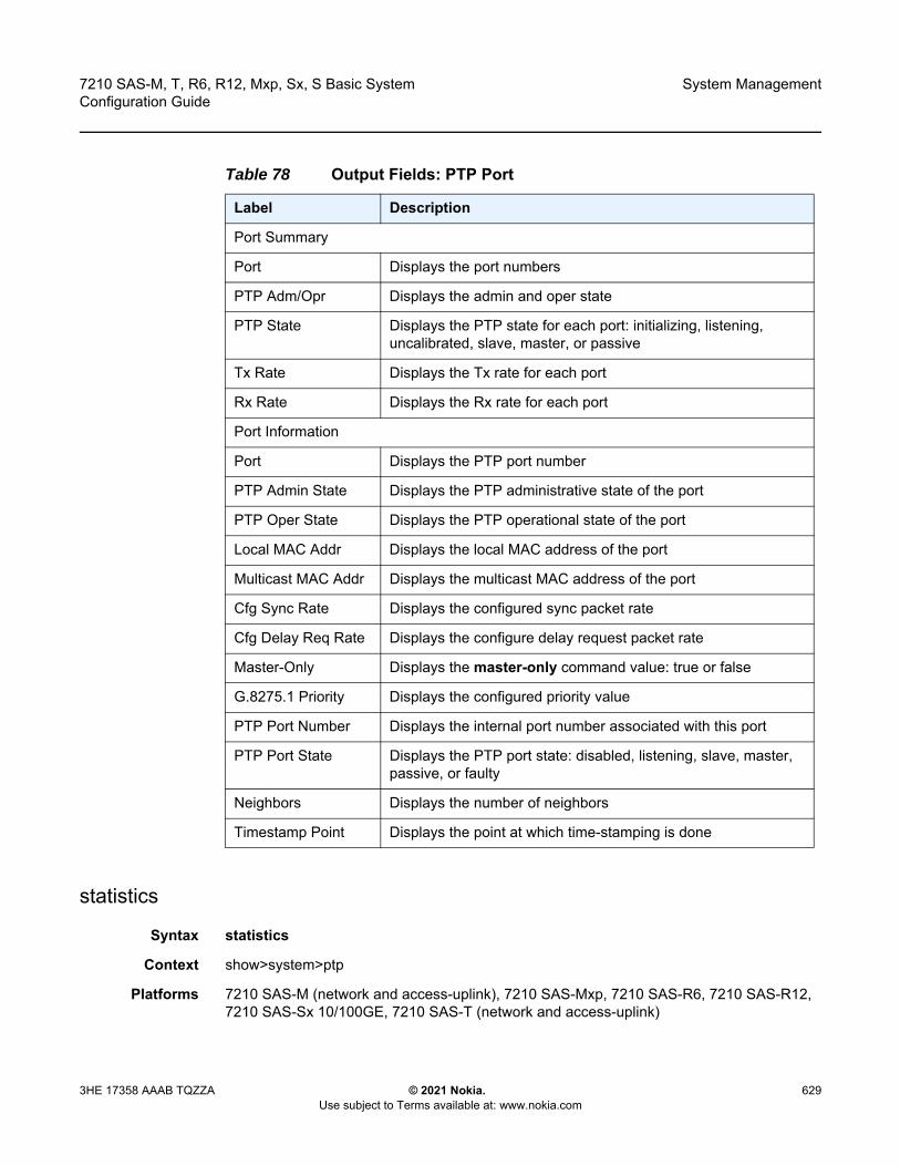
7210 SAS-M, T, R6, R12, Mxp, Sx, S Basic System Configuration Guide
System Management
3HE 17358 AAAB TQZZA © 2021 Nokia. Use subject to Terms available at: www.nokia.com
629
statistics
Syntax statistics
Context show>system>ptp
Platforms 7210 SAS-M (network and access-uplink), 7210 SAS-Mxp, 7210 SAS-R6, 7210 SAS-R12, 7210 SAS-Sx 10/100GE, 7210 SAS-T (network and access-uplink)
Table 78 Output Fields: PTP Port
Label Description
Port Summary
Port Displays the port numbers
PTP Adm/Opr Displays the admin and oper state
PTP State Displays the PTP state for each port: initializing, listening, uncalibrated, slave, master, or passive
Tx Rate Displays the Tx rate for each port
Rx Rate Displays the Rx rate for each port
Port Information
Port Displays the PTP port number
PTP Admin State Displays the PTP administrative state of the port
PTP Oper State Displays the PTP operational state of the port
Local MAC Addr Displays the local MAC address of the port
Multicast MAC Addr Displays the multicast MAC address of the port
Cfg Sync Rate Displays the configured sync packet rate
Cfg Delay Req Rate Displays the configure delay request packet rate
Master-Only Displays the master-only command value: true or false
G.8275.1 Priority Displays the configured priority value
PTP Port Number Displays the internal port number associated with this port
PTP Port State Displays the PTP port state: disabled, listening, slave, master, passive, or faulty
Neighbors Displays the number of neighbors
Timestamp Point Displays the point at which time-stamping is done

System Management
630
7210 SAS-M, T, R6, R12, Mxp, Sx, S Basic SystemConfiguration Guide
© 2021 Nokia. Use subject to Terms available at: www.nokia.com
3HE 17358 AAAB TQZZA
Description This command displays the message and error statistics for the node.
Output The following output is an example of PTP statistics information, and Table 79 describes the output fields.
Sample Output
*A:Dut-F>config>system>ptp# show system ptp statistics===============================================================================IEEE 1588/PTP Packet Statistics===============================================================================
Input Output-------------------------------------------------------------------------------PTP Packets 104674 53958
Announce 1616 0Sync 51502 0Follow Up 0 0Delay Request 0 51489Delay Response 51489 0Signaling 67 2469
Request Unicast Transmission TLVs 0 2469Announce 0 2425Sync 0 22Delay Response 0 22
Grant Unicast Transmission (Accepted) TLVs 67 0Announce 23 0Sync 22 0Delay Response 22 0
Grant Unicast Transmission (Denied) TLVs 0 0Announce 0 0Sync 0 0Delay Response 0 0
Cancel Unicast Transmission TLVs 0 1Announce 0 1Sync 0 0Delay Response 0 0
Ack Cancel Unicast Transmission TLVs 0 0Announce 0 0Sync 0 0Delay Response 0 0
Other TLVs 0 0Other 0 0
Discards 0 0Other 0 0
==============================================================================================================================================================IEEE 1588/PTP Frequency Recovery State Statistics===============================================================================State Seconds-------------------------------------------------------------------------------Initial 0Acquiring 12Phase-Tracking 0Locked 3219Hold-over 0===============================================================================
===============================================================================

7210 SAS-M, T, R6, R12, Mxp, Sx, S Basic System Configuration Guide
System Management
3HE 17358 AAAB TQZZA © 2021 Nokia. Use subject to Terms available at: www.nokia.com
631
IEEE 1588/PTP Message Rates Per Second===============================================================================
UDP/IP EthernetPacket Type Input Output Input Output-------------------------------------------------------------------------------Announce 0 0 0 0Sync 0 0 0 0Follow Up 0 0 0 0Delay Request 0 0 0 0Delay Response 0 0 0 0Other 0 0 0 0-------------------------------------------------------------------------------Total 0 0 0 0==================================
unicast
Syntax unicast [router router-instance | service-name service-name]
Context show>system>ptp
Platforms 7210 SAS-M (network and access-uplink), 7210 SAS-Mxp, 7210 SAS-R6, 7210 SAS-R12, 7210 SAS-Sx 10/100GE, 7210 SAS-T (network and access-uplink)
Description This command displays unicast negotiation information.
Parameters router-instance — Displays only the information for a specific router instance.
Values router-name: Basevprn-svc-id: 1 to 2147483647
service-name — Specifies the service name to identify the router instance, up to 64 characters.
Table 79 Output Fields: PTP Statistics
Label Description
PTP Packet Statistics
The following input/output statistics are provided for PTP packets:
• Announce• Sync• Follow Up• Delay Request• Delay Response• Signaling• Other

System Management
632
7210 SAS-M, T, R6, R12, Mxp, Sx, S Basic SystemConfiguration Guide
© 2021 Nokia. Use subject to Terms available at: www.nokia.com
3HE 17358 AAAB TQZZA
Output The following output is an example of PTP unicast information, and Table 80 describes the output fields.
Sample Output
*A:Dut-C# show system ptp unicast===============================================================================IEEE 1588/PTP Unicast Negotiation Information===============================================================================Router
IP Address Dir Type Rate Duration State Time-------------------------------------------------------------------------------100
10.0.0.1 Rx Announce 1 pkt/2 s 300 Granted 02/07/2014 16:52:3510.0.0.1 Rx Sync 64 pkt/s 300 Granted 02/07/2014 16:52:3910.0.0.1 Tx DelayReq 64 pkt/s 300 Granted 02/07/2014 16:52:3910.0.0.1 Rx DelayRsp 64 pkt/s 300 Granted 02/07/2014 16:52:39
200192.168.0.2 Tx Announce 1 pkt/2 s 300 Granted 02/07/2014 16:50:47192.168.0.2 Tx Sync 64 pkt/s 300 Granted 02/07/2014 16:50:52192.168.0.2 Rx DelayReq 64 pkt/s 300 Granted 02/07/2014 16:50:52192.168.0.2 Tx DelayRsp 64 pkt/s 300 Granted 02/07/2014 16:50:52
-------------------------------------------------------------------------------PTP Peers : 2Total Packet Rate : 385 packets/second===============================================================================
A:bksim1618# show system ptp router 1 unicast===============================================================================IEEE 1588/PTP Unicast Negotiation Information===============================================================================Router
IP Address Dir Type Rate Duration State Time-------------------------------------------------------------------------------1
10.2.1.20 Rx Announce 1 pkt/2 s 300 Granted 04/21/2013 19:14:1910.2.1.20 Tx Announce 1 pkt/2 s 300 Granted 04/21/2013 19:13:2510.2.1.20 Tx Sync 64 pkt/s 300 Granted 04/21/2013 19:13:3010.2.1.20 Rx DelayReq 64 pkt/s 300 Granted 04/21/2013 19:13:3010.2.1.20 Tx DelayRsp 64 pkt/s 300 Granted 04/21/2013 19:13:3010.3.1.19 Rx Announce 1 pkt/2 s 300 Granted 04/21/2013 19:13:1610.3.1.19 Rx Sync 64 pkt/s 300 Granted 04/21/2013 19:13:2110.3.1.19 Tx DelayReq 64 pkt/s 300 Granted 04/21/2013 19:13:2110.3.1.19 Rx DelayRsp 64 pkt/s 300 Granted 04/21/2013 19:13:21
-------------------------------------------------------------------------------PTP Peers : 2Total Packet Rate : 385 packets/second===============================================================================*A:bksim1618#
Table 80 Output Fields: PTP Unicast
Label Description
Router IP Address Displays the IP address of the router

7210 SAS-M, T, R6, R12, Mxp, Sx, S Basic System Configuration Guide
System Management
3HE 17358 AAAB TQZZA © 2021 Nokia. Use subject to Terms available at: www.nokia.com
633
sntp
Syntax sntp
Context show>system
Platforms Supported on all 7210 SAS platforms as described in this document, including platforms configured in the access-uplink operating mode
Description This command displays SNTP protocol configuration and state.
Output The following output is an example of SNTP information, and Table 81 describes SNTP output fields.
Sample Output
*A:pc-4.0# show system sntp===============================================================================SNTP Status===============================================================================Admin Status : up Oper Status : up Mode : broadcast==============================================================================================================================================================SNTP Servers===============================================================================SNTP Server Version Preference Interval-------------------------------------------------------------------------------10.135.16.90 3 Preferred 64-------------------------------------------------------------------------------No. of SNTP Servers: 1===============================================================================*A:pc-4.0#
Dir Displays the direction of the unicast information: either Rx or Tx
Type Displays the message type
Rate Displays the rate of the unicast information, in packets per second
Duration Displays the lease duration for the session
State Displays the state
Time Displays the time the unicast information was received
PTP Peers Displays the number of PTP peers
Total Packet Rate Displays the total packet rate, in packets per second
Table 80 Output Fields: PTP Unicast (Continued)
Label Description
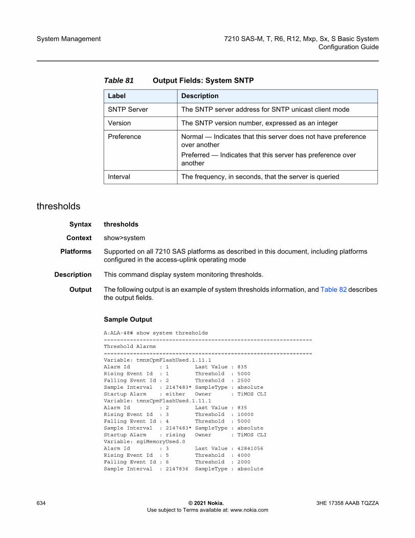
System Management
634
7210 SAS-M, T, R6, R12, Mxp, Sx, S Basic SystemConfiguration Guide
© 2021 Nokia. Use subject to Terms available at: www.nokia.com
3HE 17358 AAAB TQZZA
thresholds
Syntax thresholds
Context show>system
Platforms Supported on all 7210 SAS platforms as described in this document, including platforms configured in the access-uplink operating mode
Description This command display system monitoring thresholds.
Output The following output is an example of system thresholds information, and Table 82 describes the output fields.
Sample Output
A:ALA-48# show system thresholds================================================================Threshold Alarms================================================================Variable: tmnxCpmFlashUsed.1.11.1Alarm Id : 1 Last Value : 835Rising Event Id : 1 Threshold : 5000Falling Event Id : 2 Threshold : 2500Sample Interval : 2147483* SampleType : absoluteStartup Alarm : either Owner : TiMOS CLIVariable: tmnxCpmFlashUsed.1.11.1Alarm Id : 2 Last Value : 835Rising Event Id : 3 Threshold : 10000Falling Event Id : 4 Threshold : 5000Sample Interval : 2147483* SampleType : absoluteStartup Alarm : rising Owner : TiMOS CLIVariable: sgiMemoryUsed.0Alarm Id : 3 Last Value : 42841056Rising Event Id : 5 Threshold : 4000Falling Event Id : 6 Threshold : 2000Sample Interval : 2147836 SampleType : absolute
Table 81 Output Fields: System SNTP
Label Description
SNTP Server The SNTP server address for SNTP unicast client mode
Version The SNTP version number, expressed as an integer
Preference Normal — Indicates that this server does not have preference over anotherPreferred — Indicates that this server has preference over another
Interval The frequency, in seconds, that the server is queried
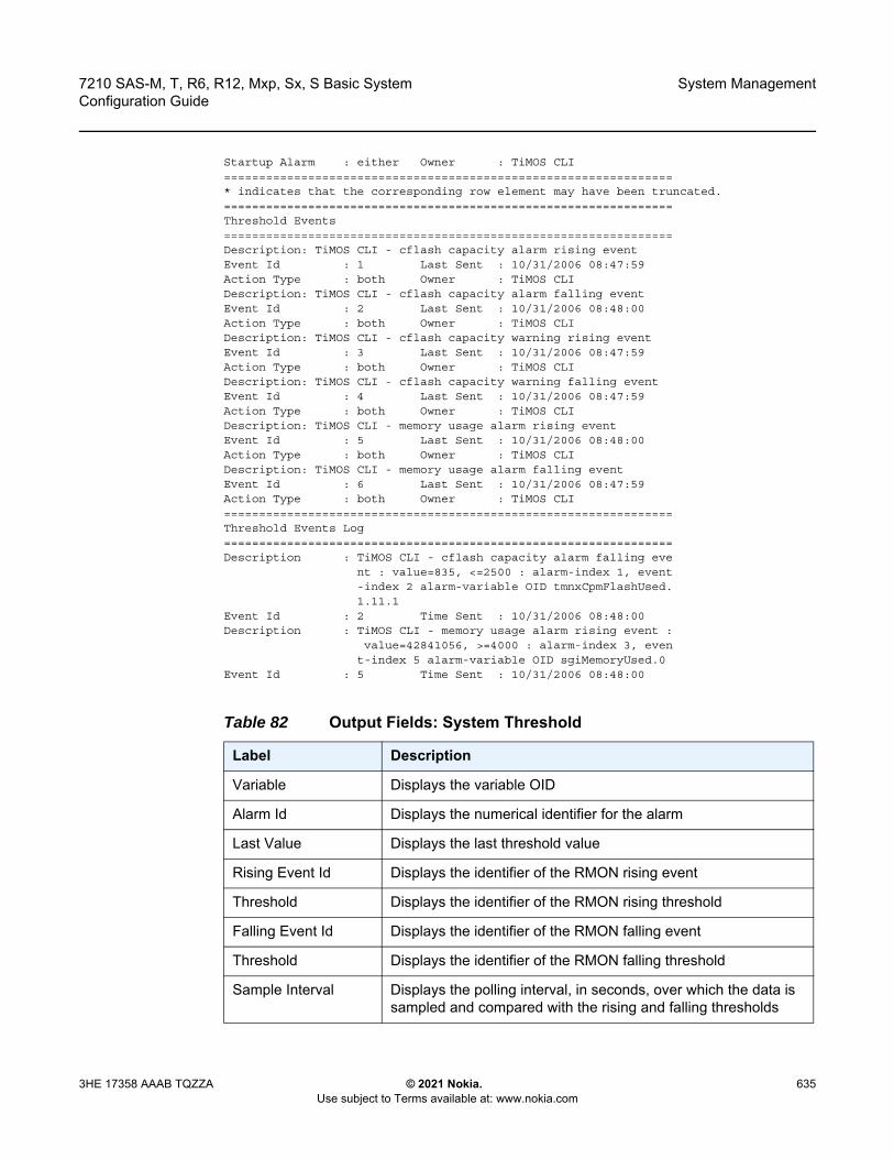
7210 SAS-M, T, R6, R12, Mxp, Sx, S Basic System Configuration Guide
System Management
3HE 17358 AAAB TQZZA © 2021 Nokia. Use subject to Terms available at: www.nokia.com
635
Startup Alarm : either Owner : TiMOS CLI================================================================* indicates that the corresponding row element may have been truncated.================================================================Threshold Events================================================================Description: TiMOS CLI - cflash capacity alarm rising eventEvent Id : 1 Last Sent : 10/31/2006 08:47:59Action Type : both Owner : TiMOS CLIDescription: TiMOS CLI - cflash capacity alarm falling eventEvent Id : 2 Last Sent : 10/31/2006 08:48:00Action Type : both Owner : TiMOS CLIDescription: TiMOS CLI - cflash capacity warning rising eventEvent Id : 3 Last Sent : 10/31/2006 08:47:59Action Type : both Owner : TiMOS CLIDescription: TiMOS CLI - cflash capacity warning falling eventEvent Id : 4 Last Sent : 10/31/2006 08:47:59Action Type : both Owner : TiMOS CLIDescription: TiMOS CLI - memory usage alarm rising eventEvent Id : 5 Last Sent : 10/31/2006 08:48:00Action Type : both Owner : TiMOS CLIDescription: TiMOS CLI - memory usage alarm falling eventEvent Id : 6 Last Sent : 10/31/2006 08:47:59Action Type : both Owner : TiMOS CLI================================================================Threshold Events Log================================================================Description : TiMOS CLI - cflash capacity alarm falling eve
nt : value=835, <=2500 : alarm-index 1, event-index 2 alarm-variable OID tmnxCpmFlashUsed.1.11.1
Event Id : 2 Time Sent : 10/31/2006 08:48:00Description : TiMOS CLI - memory usage alarm rising event :
value=42841056, >=4000 : alarm-index 3, event-index 5 alarm-variable OID sgiMemoryUsed.0
Event Id : 5 Time Sent : 10/31/2006 08:48:00
Table 82 Output Fields: System Threshold
Label Description
Variable Displays the variable OID
Alarm Id Displays the numerical identifier for the alarm
Last Value Displays the last threshold value
Rising Event Id Displays the identifier of the RMON rising event
Threshold Displays the identifier of the RMON rising threshold
Falling Event Id Displays the identifier of the RMON falling event
Threshold Displays the identifier of the RMON falling threshold
Sample Interval Displays the polling interval, in seconds, over which the data is sampled and compared with the rising and falling thresholds
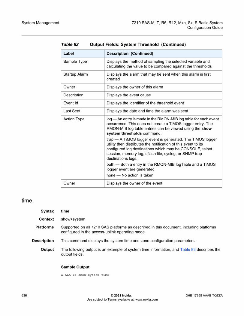
System Management
636
7210 SAS-M, T, R6, R12, Mxp, Sx, S Basic SystemConfiguration Guide
© 2021 Nokia. Use subject to Terms available at: www.nokia.com
3HE 17358 AAAB TQZZA
time
Syntax time
Context show>system
Platforms Supported on all 7210 SAS platforms as described in this document, including platforms configured in the access-uplink operating mode
Description This command displays the system time and zone configuration parameters.
Output The following output is an example of system time information, and Table 83 describes the output fields.
Sample Output
A:ALA-1# show system time
Sample Type Displays the method of sampling the selected variable and calculating the value to be compared against the thresholds
Startup Alarm Displays the alarm that may be sent when this alarm is first created
Owner Displays the owner of this alarm
Description Displays the event cause
Event Id Displays the identifier of the threshold event
Last Sent Displays the date and time the alarm was sent
Action Type log — An entry is made in the RMON-MIB log table for each event occurrence. This does not create a TiMOS logger entry. The RMON-MIB log table entries can be viewed using the show system thresholds command.trap — A TiMOS logger event is generated. The TiMOS logger utility then distributes the notification of this event to its configured log destinations which may be CONSOLE, telnet session, memory log, cflash file, syslog, or SNMP trap destinations logs. both — Both a entry in the RMON-MIB logTable and a TiMOS logger event are generatednone — No action is taken
Owner Displays the owner of the event
Table 82 Output Fields: System Threshold (Continued)
Label Description (Continued)
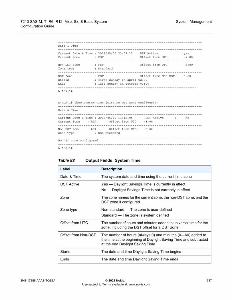
7210 SAS-M, T, R6, R12, Mxp, Sx, S Basic System Configuration Guide
System Management
3HE 17358 AAAB TQZZA © 2021 Nokia. Use subject to Terms available at: www.nokia.com
637
===============================================================================Date & Time===============================================================================Current Date & Time : 2006/05/05 23:03:13 DST Active : yesCurrent Zone : PDT Offset from UTC : -7:00-------------------------------------------------------------------------------Non-DST Zone : PST Offset from UTC : -8:00Zone type : standard-------------------------------------------------------------------------------DST Zone : PDT Offset from Non-DST : 0:60Starts : first sunday in april 02:00Ends : last sunday in october 02:00============================================================================A:ALA-1#
A:ALA-1# show system time (with no DST zone configured)===============================================================================Date & Time===============================================================================Current Date & Time : 2006/05/12 11:12:05 DST Active : noCurrent Zone : APA Offset from UTC : -8:00-------------------------------------------------------------------------------Non-DST Zone : APA Offset from UTC : -8:00Zone Type : non-standard-------------------------------------------------------------------------------No DST zone configured===============================================================================A:ALA-1#
Table 83 Output Fields: System Time
Label Description
Date & Time The system date and time using the current time zone
DST Active Yes — Daylight Savings Time is currently in effectNo — Daylight Savings Time is not currently in effect
Zone The zone names for the current zone, the non-DST zone, and the DST zone if configured
Zone type Non-standard — The zone is user-definedStandard — The zone is system defined
Offset from UTC The number of hours and minutes added to universal time for the zone, including the DST offset for a DST zone
Offset from Non-DST The number of hours (always 0) and minutes (0—60) added to the time at the beginning of Daylight Saving Time and subtracted at the end Daylight Saving Time
Starts The date and time Daylight Saving Time begins
Ends The date and time Daylight Saving Time ends
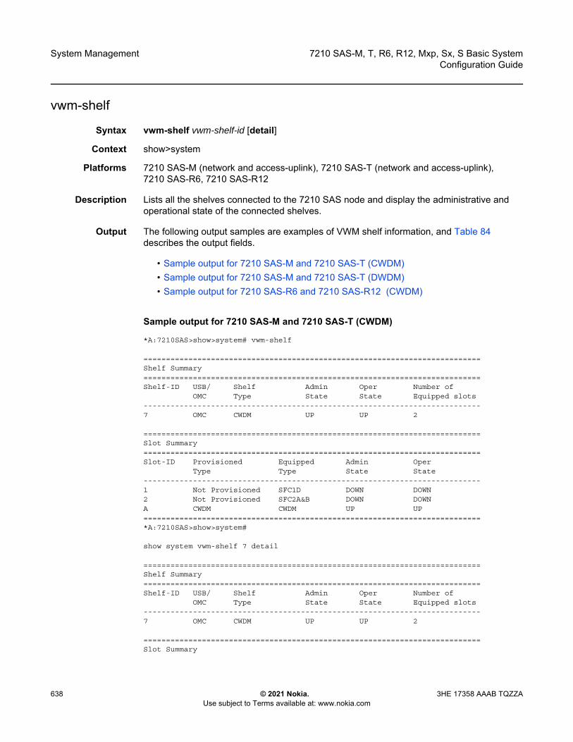
System Management
638
7210 SAS-M, T, R6, R12, Mxp, Sx, S Basic SystemConfiguration Guide
© 2021 Nokia. Use subject to Terms available at: www.nokia.com
3HE 17358 AAAB TQZZA
vwm-shelf
Syntax vwm-shelf vwm-shelf-id [detail]
Context show>system
Platforms 7210 SAS-M (network and access-uplink), 7210 SAS-T (network and access-uplink), 7210 SAS-R6, 7210 SAS-R12
Description Lists all the shelves connected to the 7210 SAS node and display the administrative and operational state of the connected shelves.
Output The following output samples are examples of VWM shelf information, and Table 84 describes the output fields.
• Sample output for 7210 SAS-M and 7210 SAS-T (CWDM)• Sample output for 7210 SAS-M and 7210 SAS-T (DWDM)• Sample output for 7210 SAS-R6 and 7210 SAS-R12 (CWDM)
Sample output for 7210 SAS-M and 7210 SAS-T (CWDM)
*A:7210SAS>show>system# vwm-shelf
===========================================================================Shelf Summary===========================================================================Shelf-ID USB/ Shelf Admin Oper Number of
OMC Type State State Equipped slots---------------------------------------------------------------------------7 OMC CWDM UP UP 2
===========================================================================Slot Summary===========================================================================Slot-ID Provisioned Equipped Admin Oper
Type Type State State---------------------------------------------------------------------------1 Not Provisioned SFC1D DOWN DOWN2 Not Provisioned SFC2A&B DOWN DOWNA CWDM CWDM UP UP===========================================================================*A:7210SAS>show>system#
show system vwm-shelf 7 detail
===========================================================================Shelf Summary===========================================================================Shelf-ID USB/ Shelf Admin Oper Number of
OMC Type State State Equipped slots---------------------------------------------------------------------------7 OMC CWDM UP UP 2
===========================================================================Slot Summary
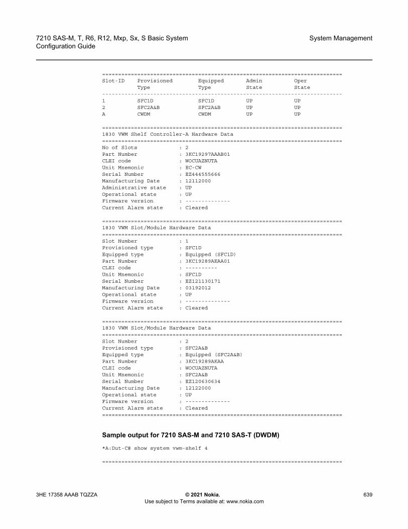
7210 SAS-M, T, R6, R12, Mxp, Sx, S Basic System Configuration Guide
System Management
3HE 17358 AAAB TQZZA © 2021 Nokia. Use subject to Terms available at: www.nokia.com
639
===========================================================================Slot-ID Provisioned Equipped Admin Oper
Type Type State State---------------------------------------------------------------------------1 SFC1D SFC1D UP UP2 SFC2A&B SFC2A&B UP UPA CWDM CWDM UP UP
===========================================================================1830 VWM Shelf Controller-A Hardware Data===========================================================================No of Slots : 2Part Number : 3KC19297AAAB01CLEI code : WOCUAZNUTAUnit Mnemonic : EC-CWSerial Number : EZ444555666Manufacturing Date : 12112000Administrative state : UPOperational state : UPFirmware version : --------------Current Alarm state : Cleared
===========================================================================1830 VWM Slot/Module Hardware Data===========================================================================Slot Number : 1Provisioned type : SFC1DEquipped type : Equipped (SFC1D)Part Number : 3KC19289AEAA01CLEI code : ----------Unit Mnemonic : SFC1DSerial Number : EZ121130171Manufacturing Date : 03192012Operational state : UPFirmware version : --------------Current Alarm state : Cleared
===========================================================================1830 VWM Slot/Module Hardware Data===========================================================================Slot Number : 2Provisioned type : SFC2A&BEquipped type : Equipped (SFC2A&B)Part Number : 3KC19289AKAACLEI code : WOCUAZNUTAUnit Mnemonic : SFC2A&BSerial Number : EZ120630634Manufacturing Date : 12122000Operational state : UPFirmware version : --------------Current Alarm state : Cleared===========================================================================
Sample output for 7210 SAS-M and 7210 SAS-T (DWDM)
*A:Dut-C# show system vwm-shelf 4
===========================================================================

System Management
640
7210 SAS-M, T, R6, R12, Mxp, Sx, S Basic SystemConfiguration Guide
© 2021 Nokia. Use subject to Terms available at: www.nokia.com
3HE 17358 AAAB TQZZA
Shelf Summary===========================================================================Shelf-ID USB/ Shelf Admin Oper Number of
OMC Type State State Equipped slots---------------------------------------------------------------------------4 USB DWDM UP UP 2
===========================================================================Slot Summary===========================================================================Slot-ID Provisioned Equipped Admin Oper
Type Type State State---------------------------------------------------------------------------1 SFD4F_R SFD4F_R UP UP2 SFD8D_R SFD8D_R UP UPA DWDM DWDM UP UP/ActiveB DWDM DWDM UP UP/Stanby===========================================================================
*A:Dut-C#
A:Dut-C# show system vwm-shelf 4 detail
===========================================================================Shelf Summary===========================================================================Shelf-ID USB/ Shelf Admin Oper Number of
OMC Type State State Equipped slots---------------------------------------------------------------------------4 USB DWDM UP UP 2
===========================================================================Slot Summary===========================================================================Slot-ID Provisioned Equipped Admin Oper
Type Type State State---------------------------------------------------------------------------1 SFD4F_R SFD4F_R UP UP2 SFD8D_R SFD8D_R UP UPA DWDM DWDM UP UP/ActiveB DWDM DWDM UP UP/Stanby
===========================================================================1830 VWM Shelf Controller-A Hardware Data===========================================================================No of Slots : 2Part Number : 3KC19319AAAA01CLEI code : WOCUA1LUTAUnit Mnemonic : EC-DWSerial Number : EZ1242A9967Manufacturing Date : 13022000Administrative state : UPOperational state : UP/ActiveFirmware version : --------------Current Alarm state : Cleared
===========================================================================1830 VWM Shelf Controller-B Hardware Data
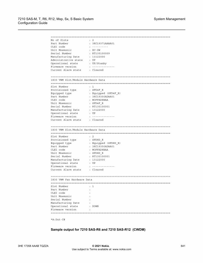
7210 SAS-M, T, R6, R12, Mxp, Sx, S Basic System Configuration Guide
System Management
3HE 17358 AAAB TQZZA © 2021 Nokia. Use subject to Terms available at: www.nokia.com
641
===========================================================================No of Slots : 2Part Number : 3KC19371AAAA01CLEI code : ----------Unit Mnemonic : EC-DWSerial Number : RT135100009Manufacturing Date : 13122000Administrative state : UPOperational state : UP/StanbyFirmware version : --------------Current Alarm state : Cleared
===========================================================================1830 VWM Slot/Module Hardware Data===========================================================================Slot Number : 1Provisioned type : SFD4F_REquipped type : Equipped (SFD4F_R)Part Number : 3KC19350ADAA01CLEI code : WOFFAD8BAAUnit Mnemonic : SFD4F_RSerial Number : RT135100001Manufacturing Date : 13122000Operational state : UPFirmware version : --------------Current Alarm state : Cleared
===========================================================================1830 VWM Slot/Module Hardware Data===========================================================================Slot Number : 2Provisioned type : SFD8D_REquipped type : Equipped (SFD8D_R)Part Number : 3KC19350ADAA01CLEI code : WOFFAD8BAAUnit Mnemonic : SFD8D_RSerial Number : RT135100001Manufacturing Date : 13122000Operational state : UPFirmware version : --------------Current Alarm state : Cleared
===========================================================================1830 VWM Fan Hardware Data===========================================================================Slot Number : 1Part Number :CLEI code :Unit Mnemonic :Serial Number :Manufacturing Date :Operational state : DOWNFirmware version :===========================================================================
*A:Dut-C#
Sample output for 7210 SAS-R6 and 7210 SAS-R12 (CWDM)

System Management
642
7210 SAS-M, T, R6, R12, Mxp, Sx, S Basic SystemConfiguration Guide
© 2021 Nokia. Use subject to Terms available at: www.nokia.com
3HE 17358 AAAB TQZZA
*A:7210SAS# show system vwm-shelf 7
===========================================================================Shelf Summary===========================================================================Shelf-ID USB/ Shelf Admin Oper Number of
OMC Type State State Equipped slots---------------------------------------------------------------------------7 OMC CWDM UP UP 2
===========================================================================Slot Summary===========================================================================Slot-ID Provisioned Equipped Admin Oper
Type Type State State---------------------------------------------------------------------------1 SFC1D SFC1D UP UP2 SFC2A&B SFC2A&B UP UPA CWDM CWDM UP UP===========================================================================
*A:7210SAS# show system vwm-shelf 7 detail
===========================================================================Shelf Summary===========================================================================Shelf-ID USB/ Shelf Admin Oper Number of
OMC Type State State Equipped slots---------------------------------------------------------------------------7 OMC CWDM UP UP 2
===========================================================================Slot Summary===========================================================================Slot-ID Provisioned Equipped Admin Oper
Type Type State State---------------------------------------------------------------------------1 SFC1D SFC1D UP UP2 SFC2A&B SFC2A&B UP UPA CWDM CWDM UP UP
===========================================================================1830 VWM Shelf Controller-A Hardware Data===========================================================================No of Slots : 2Part Number : 3KC19297AAAB01CLEI code : WOCUAZNUTAUnit Mnemonic : EC-CWSerial Number : EZ444555666Manufacturing Date : 12112000Administrative state : UPOperational state : UPFirmware version : --------------Current Alarm state : Cleared
===========================================================================1830 VWM Slot/Module Hardware Data===========================================================================Slot Number : 1
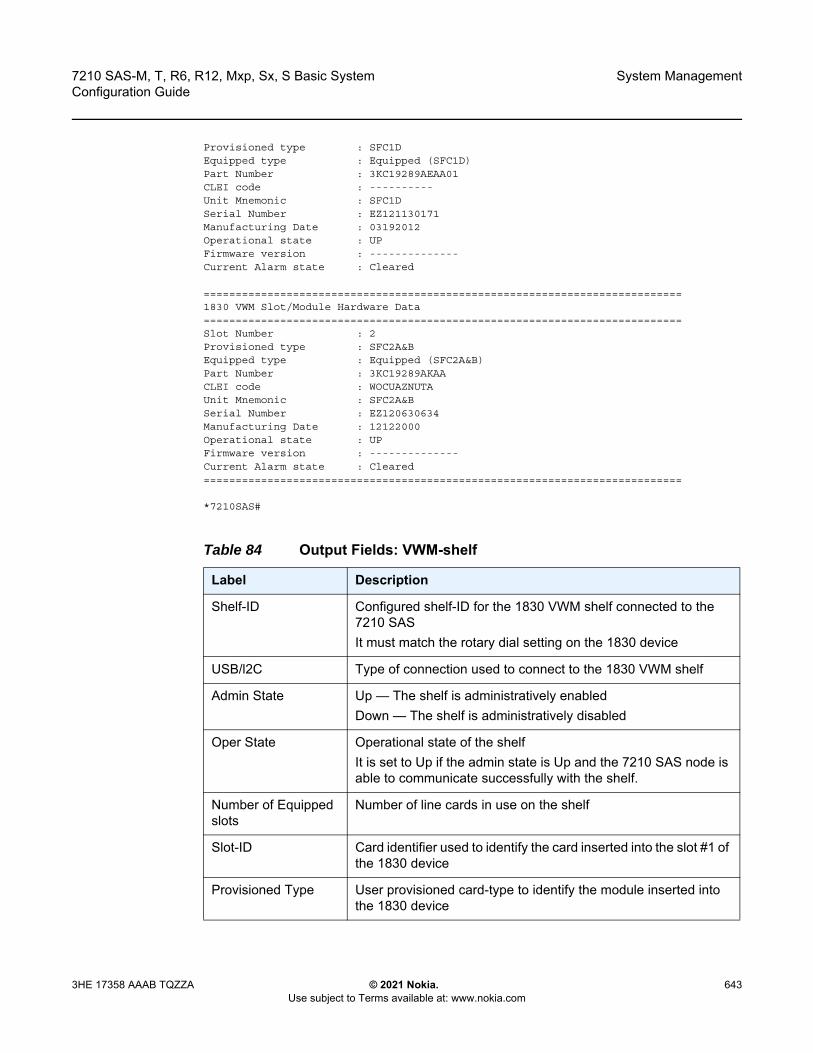
7210 SAS-M, T, R6, R12, Mxp, Sx, S Basic System Configuration Guide
System Management
3HE 17358 AAAB TQZZA © 2021 Nokia. Use subject to Terms available at: www.nokia.com
643
Provisioned type : SFC1DEquipped type : Equipped (SFC1D)Part Number : 3KC19289AEAA01CLEI code : ----------Unit Mnemonic : SFC1DSerial Number : EZ121130171Manufacturing Date : 03192012Operational state : UPFirmware version : --------------Current Alarm state : Cleared
===========================================================================1830 VWM Slot/Module Hardware Data===========================================================================Slot Number : 2Provisioned type : SFC2A&BEquipped type : Equipped (SFC2A&B)Part Number : 3KC19289AKAACLEI code : WOCUAZNUTAUnit Mnemonic : SFC2A&BSerial Number : EZ120630634Manufacturing Date : 12122000Operational state : UPFirmware version : --------------Current Alarm state : Cleared===========================================================================
*7210SAS#
Table 84 Output Fields: VWM-shelf
Label Description
Shelf-ID Configured shelf-ID for the 1830 VWM shelf connected to the 7210 SASIt must match the rotary dial setting on the 1830 device
USB/l2C Type of connection used to connect to the 1830 VWM shelf
Admin State Up — The shelf is administratively enabledDown — The shelf is administratively disabled
Oper State Operational state of the shelfIt is set to Up if the admin state is Up and the 7210 SAS node is able to communicate successfully with the shelf.
Number of Equipped slots
Number of line cards in use on the shelf
Slot-ID Card identifier used to identify the card inserted into the slot #1 of the 1830 device
Provisioned Type User provisioned card-type to identify the module inserted into the 1830 device

System Management
644
7210 SAS-M, T, R6, R12, Mxp, Sx, S Basic SystemConfiguration Guide
© 2021 Nokia. Use subject to Terms available at: www.nokia.com
3HE 17358 AAAB TQZZA
time
Syntax time
Context show
Platforms Supported on all 7210 SAS platforms as described in this document, including platforms configured in the access-uplink operating mode
Description This command displays the current day, date, time and time zone.
The time is displayed either in the local time zone or in UTC depending on the setting of the root level time-display command for the console session.
Output The following output is an example of time information.
Sample Output
A:ALA-49# show timeTue Oct 31 12:17:15 GMT 2006
Equipped Type The card-type currently inserted into the slot on the 1830 device
No of Slots The number of slots available on the 1830 device
Part Number The 1830 VWM CWDM device part number
CLEI code CLEI code of the 1830 device
Unit Mnemonic The Mnemonic string used to identify the card
Serial Number The 1830 device serial number
Manufacturing Date The manufacturing date of the card
Administrative state The administrative state of the 1830 deviceIf the shelf or card is provisioned and if no shutdown is executed, the this field displays UP, else it displays 'Down'.
Operational state The operational state of the 1830 deviceIt is set to UP if the 7210 SAS device is able to communicate and retrieve information from the 1830 device connected to it. It is set to Down otherwise.
Current Alarm state Displays if alarm is active or cleared
Table 84 Output Fields: VWM-shelf (Continued)
Label Description
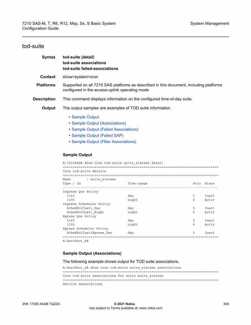
7210 SAS-M, T, R6, R12, Mxp, Sx, S Basic System Configuration Guide
System Management
3HE 17358 AAAB TQZZA © 2021 Nokia. Use subject to Terms available at: www.nokia.com
645
tod-suite
Syntax tod-suite [detail] tod-suite associationstod-suite failed-associations
Context show>system>cron
Platforms Supported on all 7210 SAS platforms as described in this document, including platforms configured in the access-uplink operating mode
Description This command displays information on the configured time-of-day suite.
Output The output samples are examples of TOD suite information.
• Sample Output• Sample Output (Associations)• Sample Output (Failed Associations)• Sample Output (Failed SAP)• Sample Output (Filter Associations)
Sample Output
A:7210SAS# show cron tod-suite suite_sixteen detail===============================================================================Cron tod-suite details===============================================================================Name : suite_sixteenType / Id Time-range Prio State-------------------------------------------------------------------------------Ingress Qos Policy
1160 day 5 Inact1190 night 6 Activ
Ingress Scheduler PolicySchedPolCust1_Day day 5 InactSchedPolCust1_Night night 6 Activ
Egress Qos Policy1160 day 5 Inact1190 night 6 Activ
Egress Scheduler PolicySchedPolCust1Egress_Day day 5 Inact
===============================================================================A:kerckhot_4#
Sample Output (Associations)
The following example shows output for TOD suite associations.A:kerckhot_4# show cron tod-suite suite_sixteen associations===============================================================================Cron tod-suite associations for suite suite_sixteen===============================================================================Service associations

System Management
646
7210 SAS-M, T, R6, R12, Mxp, Sx, S Basic SystemConfiguration Guide
© 2021 Nokia. Use subject to Terms available at: www.nokia.com
3HE 17358 AAAB TQZZA
-------------------------------------------------------------------------------Service Id : 1 Type : VPLSSAP 1/1/1:1SAP 1/1/1:2SAP 1/1/1:3SAP 1/1/1:4SAP 1/1/1:5SAP 1/1/1:6SAP 1/1/1:20
-------------------------------------------------------------------------------Number of SAP's : 7Customer Multi-Service Site associations-------------------------------------------------------------------------------Multi Service Site: mss_1_1-------------------------------------------------------------------------------Number of MSS's: 1===============================================================================A:kerckhot_4#
Sample Output (Failed Associations)
The following example shows output for TOD suite failed-associations.A:kerckhot_4# show cron tod-suite suite_sixteen failed-associations===============================================================================Cron tod-suite associations failed===============================================================================tod-suite suite_sixteen : failed association for SAP-------------------------------------------------------------------------------Service Id : 1 Type : VPLS
SAP 1/1/1:2SAP 1/1/1:3SAP 1/1/1:4SAP 1/1/1:5SAP 1/1/1:6SAP 1/1/1:20
-------------------------------------------------------------------------------tod-suite suite_sixteen : failed association for Customer MSS-------------------------------------------------------------------------------None-------------------------------------------------------------------------------Number of tod-suites failed/total : 1/1===============================================================================A:kerckhot_4#
Sample Output (Failed SAP)
Zooming in on one of the failed SAPs, the assignments of QoS and scheduler policies are shown as not as intended.A:kerckhot_4# show service id 1 sap 1/1/1:2===============================================================================Service Access Points(SAP)===============================================================================Service Id : 1SAP : 1/1/1:2 Encap : q-tagDot1Q Ethertype : 0x8100 QinQ Ethertype : 0x8100Admin State : Up Oper State : Up
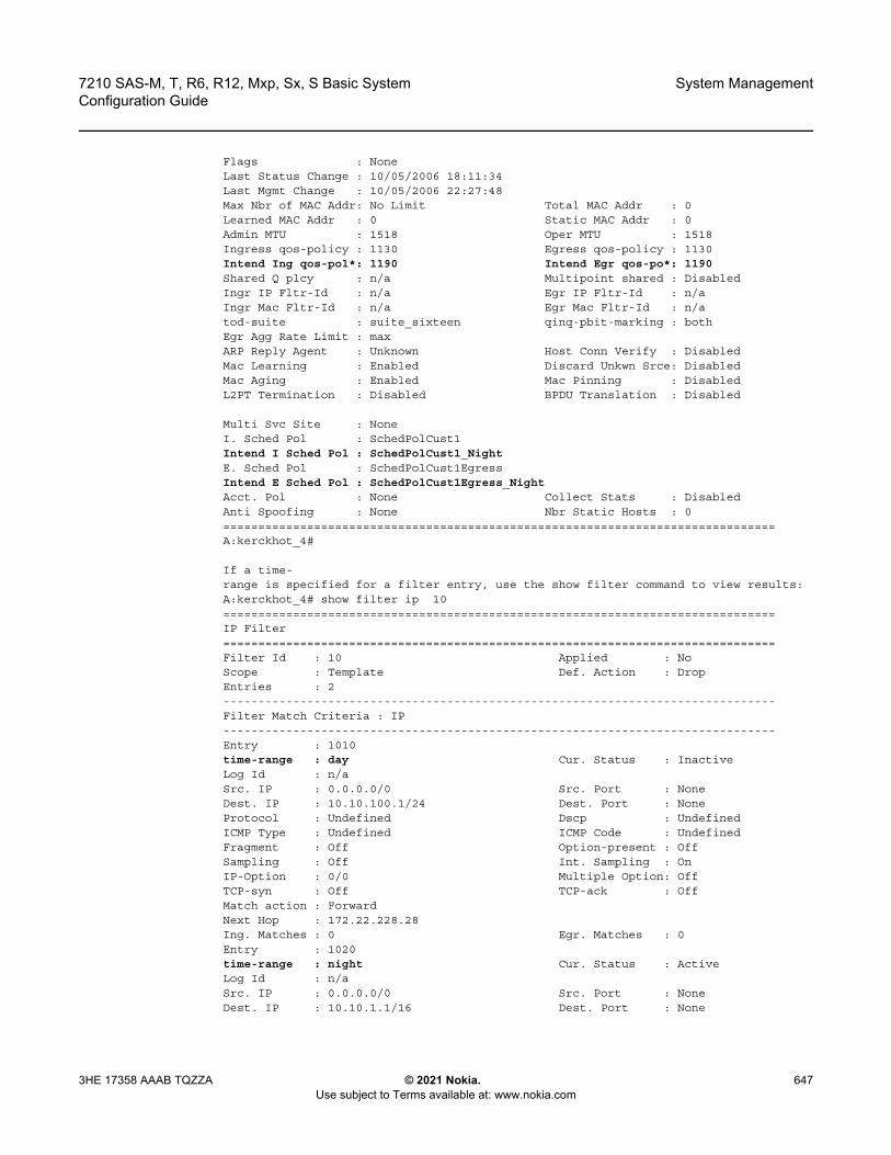
7210 SAS-M, T, R6, R12, Mxp, Sx, S Basic System Configuration Guide
System Management
3HE 17358 AAAB TQZZA © 2021 Nokia. Use subject to Terms available at: www.nokia.com
647
Flags : NoneLast Status Change : 10/05/2006 18:11:34Last Mgmt Change : 10/05/2006 22:27:48Max Nbr of MAC Addr: No Limit Total MAC Addr : 0Learned MAC Addr : 0 Static MAC Addr : 0Admin MTU : 1518 Oper MTU : 1518Ingress qos-policy : 1130 Egress qos-policy : 1130Intend Ing qos-pol*: 1190 Intend Egr qos-po*: 1190Shared Q plcy : n/a Multipoint shared : DisabledIngr IP Fltr-Id : n/a Egr IP Fltr-Id : n/aIngr Mac Fltr-Id : n/a Egr Mac Fltr-Id : n/atod-suite : suite_sixteen qinq-pbit-marking : bothEgr Agg Rate Limit : maxARP Reply Agent : Unknown Host Conn Verify : DisabledMac Learning : Enabled Discard Unkwn Srce: DisabledMac Aging : Enabled Mac Pinning : DisabledL2PT Termination : Disabled BPDU Translation : Disabled
Multi Svc Site : NoneI. Sched Pol : SchedPolCust1Intend I Sched Pol : SchedPolCust1_NightE. Sched Pol : SchedPolCust1EgressIntend E Sched Pol : SchedPolCust1Egress_NightAcct. Pol : None Collect Stats : DisabledAnti Spoofing : None Nbr Static Hosts : 0===============================================================================A:kerckhot_4#
If a time-range is specified for a filter entry, use the show filter command to view results:A:kerckhot_4# show filter ip 10===============================================================================IP Filter===============================================================================Filter Id : 10 Applied : NoScope : Template Def. Action : DropEntries : 2-------------------------------------------------------------------------------Filter Match Criteria : IP-------------------------------------------------------------------------------Entry : 1010time-range : day Cur. Status : InactiveLog Id : n/aSrc. IP : 0.0.0.0/0 Src. Port : NoneDest. IP : 10.10.100.1/24 Dest. Port : NoneProtocol : Undefined Dscp : UndefinedICMP Type : Undefined ICMP Code : UndefinedFragment : Off Option-present : OffSampling : Off Int. Sampling : OnIP-Option : 0/0 Multiple Option: OffTCP-syn : Off TCP-ack : OffMatch action : ForwardNext Hop : 172.22.228.28Ing. Matches : 0 Egr. Matches : 0Entry : 1020time-range : night Cur. Status : ActiveLog Id : n/aSrc. IP : 0.0.0.0/0 Src. Port : NoneDest. IP : 10.10.1.1/16 Dest. Port : None
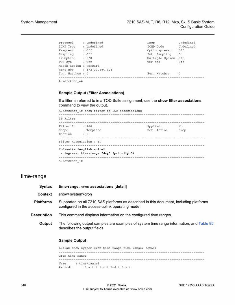
System Management
648
7210 SAS-M, T, R6, R12, Mxp, Sx, S Basic SystemConfiguration Guide
© 2021 Nokia. Use subject to Terms available at: www.nokia.com
3HE 17358 AAAB TQZZA
Protocol : Undefined Dscp : UndefinedICMP Type : Undefined ICMP Code : UndefinedFragment : Off Option-present : OffSampling : Off Int. Sampling : OnIP-Option : 0/0 Multiple Option: OffTCP-syn : Off TCP-ack : OffMatch action : ForwardNext Hop : 172.22.184.101Ing. Matches : 0 Egr. Matches : 0===============================================================================A:kerckhot_4#
Sample Output (Filter Associations)
If a filter is referred to in a TOD Suite assignment, use the show filter associations command to view the output.A:kerckhot_4# show filter ip 160 associations===============================================================================IP Filter===============================================================================Filter Id : 160 Applied : NoScope : Template Def. Action : DropEntries : 0-------------------------------------------------------------------------------Filter Association : IP-------------------------------------------------------------------------------Tod-suite "english_suite"- ingress, time-range "day" (priority 5)
===============================================================================A:kerckhot_4#
time-range
Syntax time-range name associations [detail]
Context show>system>cron
Platforms Supported on all 7210 SAS platforms as described in this document, including platforms configured in the access-uplink operating mode
Description This command displays information on the configured time ranges.
Output The following output samples are examples of system time range information, and Table 85 describes the output fields
Sample Output
A:ala# show system cron time-range time-range2 detail===============================================================================Cron time-range===============================================================================Name : time-range1Periodic : Start * * * * End * * * *
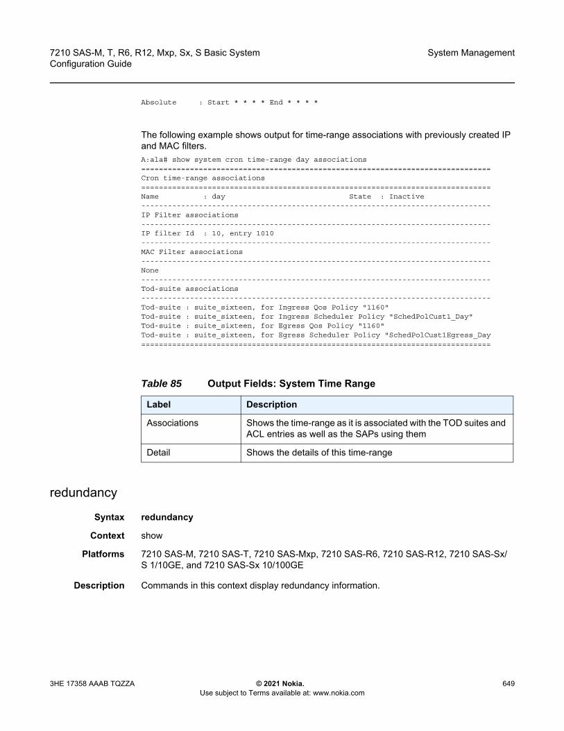
7210 SAS-M, T, R6, R12, Mxp, Sx, S Basic System Configuration Guide
System Management
3HE 17358 AAAB TQZZA © 2021 Nokia. Use subject to Terms available at: www.nokia.com
649
Absolute : Start * * * * End * * * *
The following example shows output for time-range associations with previously created IP and MAC filters.A:ala# show system cron time-range day associations===============================================================================Cron time-range associations===============================================================================Name : day State : Inactive-------------------------------------------------------------------------------IP Filter associations-------------------------------------------------------------------------------IP filter Id : 10, entry 1010-------------------------------------------------------------------------------MAC Filter associations-------------------------------------------------------------------------------None-------------------------------------------------------------------------------Tod-suite associations-------------------------------------------------------------------------------Tod-suite : suite_sixteen, for Ingress Qos Policy "1160"Tod-suite : suite_sixteen, for Ingress Scheduler Policy "SchedPolCust1_Day"Tod-suite : suite_sixteen, for Egress Qos Policy "1160"Tod-suite : suite_sixteen, for Egress Scheduler Policy "SchedPolCust1Egress_Day===============================================================================
redundancy
Syntax redundancy
Context show
Platforms 7210 SAS-M, 7210 SAS-T, 7210 SAS-Mxp, 7210 SAS-R6, 7210 SAS-R12, 7210 SAS-Sx/S 1/10GE, and 7210 SAS-Sx 10/100GE
Description Commands in this context display redundancy information.
Table 85 Output Fields: System Time Range
Label Description
Associations Shows the time-range as it is associated with the TOD suites and ACL entries as well as the SAPs using them
Detail Shows the details of this time-range
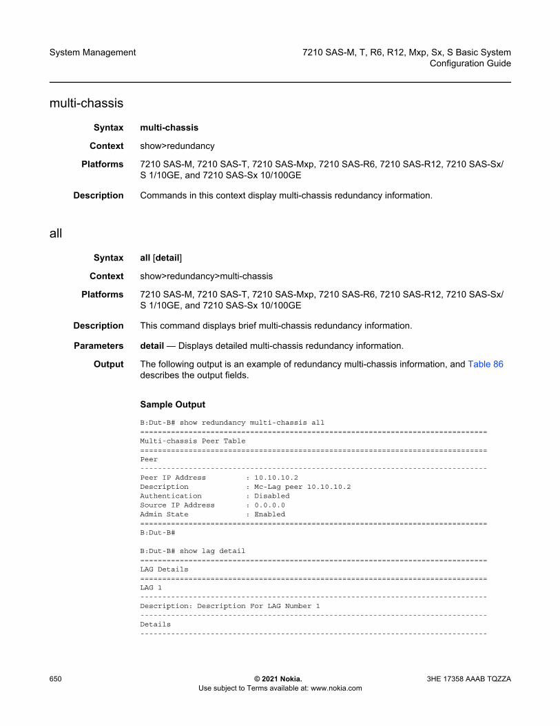
System Management
650
7210 SAS-M, T, R6, R12, Mxp, Sx, S Basic SystemConfiguration Guide
© 2021 Nokia. Use subject to Terms available at: www.nokia.com
3HE 17358 AAAB TQZZA
multi-chassis
Syntax multi-chassis
Context show>redundancy
Platforms 7210 SAS-M, 7210 SAS-T, 7210 SAS-Mxp, 7210 SAS-R6, 7210 SAS-R12, 7210 SAS-Sx/S 1/10GE, and 7210 SAS-Sx 10/100GE
Description Commands in this context display multi-chassis redundancy information.
all
Syntax all [detail]
Context show>redundancy>multi-chassis
Platforms 7210 SAS-M, 7210 SAS-T, 7210 SAS-Mxp, 7210 SAS-R6, 7210 SAS-R12, 7210 SAS-Sx/S 1/10GE, and 7210 SAS-Sx 10/100GE
Description This command displays brief multi-chassis redundancy information.
Parameters detail — Displays detailed multi-chassis redundancy information.
Output The following output is an example of redundancy multi-chassis information, and Table 86 describes the output fields.
Sample Output
B:Dut-B# show redundancy multi-chassis all===============================================================================Multi-chassis Peer Table===============================================================================Peer-------------------------------------------------------------------------------Peer IP Address : 10.10.10.2Description : Mc-Lag peer 10.10.10.2Authentication : DisabledSource IP Address : 0.0.0.0Admin State : Enabled===============================================================================B:Dut-B#
B:Dut-B# show lag detail===============================================================================LAG Details===============================================================================LAG 1-------------------------------------------------------------------------------Description: Description For LAG Number 1-------------------------------------------------------------------------------Details-------------------------------------------------------------------------------
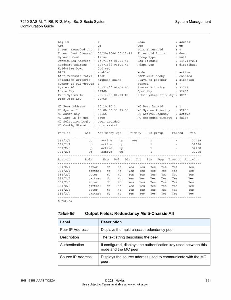
7210 SAS-M, T, R6, R12, Mxp, Sx, S Basic System Configuration Guide
System Management
3HE 17358 AAAB TQZZA © 2021 Nokia. Use subject to Terms available at: www.nokia.com
651
Lag-id : 1 Mode : accessAdm : up Opr : upThres. Exceeded Cnt : 9 Port Threshold : 0Thres. Last Cleared : 05/20/2006 00:12:35 Threshold Action : downDynamic Cost : false Encap Type : nullConfigured Address : 1c:71:ff:00:01:41 Lag-IfIndex : 1342177281Hardware Address : 1c:71:ff:00:01:41 Adapt Qos : distributeHold-time Down : 0.0 secLACP : enabled Mode : activeLACP Transmit Intvl : fast LACP xmit stdby : enabledSelection Criteria : highest-count Slave-to-partner : disabledNumber of sub-groups: 1 Forced : -System Id : 1c:71:ff:00:00:00 System Priority : 32768Admin Key : 32768 Oper Key : 32666Prtr System Id : 20:f4:ff:00:00:00 Prtr System Priority : 32768Prtr Oper Key : 32768
MC Peer Address : 10.10.10.2 MC Peer Lag-id : 1MC System Id : 00:00:00:33:33:33 MC System Priority : 32888MC Admin Key : 32666 MC Active/Standby : activeMC Lacp ID in use : true MC extended timeout : falseMC Selection Logic : peer decidedMC Config Mismatch : no mismatch-------------------------------------------------------------------------------Port-id Adm Act/Stdby Opr Primary Sub-group Forced Prio-------------------------------------------------------------------------------331/2/1 up active up yes 1 - 32768331/2/2 up active up 1 - 32768331/2/3 up active up 1 - 32768331/2/4 up active up 1 - 32768-------------------------------------------------------------------------------Port-id Role Exp Def Dist Col Syn Aggr Timeout Activity-------------------------------------------------------------------------------331/2/1 actor No No Yes Yes Yes Yes Yes Yes331/2/1 partner No No Yes Yes Yes Yes Yes Yes331/2/2 actor No No Yes Yes Yes Yes Yes Yes331/2/2 partner No No Yes Yes Yes Yes Yes Yes331/2/3 actor No No Yes Yes Yes Yes Yes Yes331/2/3 partner No No Yes Yes Yes Yes Yes Yes331/2/4 actor No No Yes Yes Yes Yes Yes Yes331/2/4 partner No No Yes Yes Yes Yes Yes Yes===============================================================================B:Dut-B#
Table 86 Output Fields: Redundancy Multi-Chassis All
Label Description
Peer IP Address Displays the multi-chassis redundancy peer
Description The text string describing the peer
Authentication If configured, displays the authentication key used between this node and the MC peer
Source IP Address Displays the source address used to communicate with the MC peer.

System Management
652
7210 SAS-M, T, R6, R12, Mxp, Sx, S Basic SystemConfiguration Guide
© 2021 Nokia. Use subject to Terms available at: www.nokia.com
3HE 17358 AAAB TQZZA
mc-lag
Syntax mc-lag [lag lag-id]mc-lag peer ip-address [lag lag-id]] statistics
Context show>redundancy>multi-chassis
Platforms Supported on all 7210 SAS platforms as described in this document
Description This command displays multi-chassis LAG information.
Parameters lag lag-id — Displays information for the specified LAG identifier.
Values 1 to 20020064
sync
Syntax sync [peer ip-address]sync peer ip-address detailsync [peer ip-address] statistics
Context show>redundancy>multi-chassis
Platforms 7210 SAS-M, 7210 SAS-T, 7210 SAS-Mxp, 7210 SAS-R6, 7210 SAS-R12, 7210 SAS-Sx/S 1/10GE, and 7210 SAS-Sx 10/100GE
Description This command displays synchronization information.
Parameters peer ip-address — Displays the synchronization information of the specified multi-chassis redundancy peer.
Output The following output is an example of redundancy multi-chassis synchronization information, and Table 87 describes the output fields.
Sample Output
*A:subscr_mgt_2# show redundancy multi-chassis sync===============================================================================Multi-chassis Peer Table===============================================================================Peer-------------------------------------------------------------------------------Peer IP Address : 10.10.10.20
Admin State Displays the administrative state of the peer
Table 86 Output Fields: Redundancy Multi-Chassis All (Continued)
Label Description

7210 SAS-M, T, R6, R12, Mxp, Sx, S Basic System Configuration Guide
System Management
3HE 17358 AAAB TQZZA © 2021 Nokia. Use subject to Terms available at: www.nokia.com
653
Description : Mc-Lag peer 10.10.10.20Authentication : DisabledSource IP Address : 0.0.0.0Admin State : Enabled-------------------------------------------------------------------------------Sync-status-------------------------------------------------------------------------------Client Applications : SUBMGMTSync Admin State : UpSync Oper State : UpDB Sync State : inSyncNum Entries : 1Lcl Deleted Entries : 0Alarm Entries : 0Rem Num Entries : 1Rem Lcl Deleted Entries : 0Rem Alarm Entries : 0===============================================================================A:subscr_mgt_2#
Table 87 Output Fields: Multi-Chassis Sync
Label Description
Peer IP Address Displays the multi-chassis redundancy peer
Description The text string describing the peer
Authentication If configured, displays the authentication key used between this node and the multi-chassis peer
Source IP Address Displays the source address used to communicate with the multi-chassis peer
Admin State Displays the administrative state of the peer
Client Applications Displays the list of client applications synchronized between 7210 SAS devices
Sync Admin State Displays the administrative state of the synchronization
Sync Oper State Displays the operation state of the synchronization
DB Sync State Displays the database state of the synchronization
Num Entries Displays the number of entries on local router
Lcl Deleted Entries Displays the number of deleted entries made at the local router
Alarm Entries Displays the alarm entries on the local router
Rem Num Entries Displays the number of entries on the remote router
Rem Lcl Deleted Entries
Displays the number of locally deleting entries made by the remote router
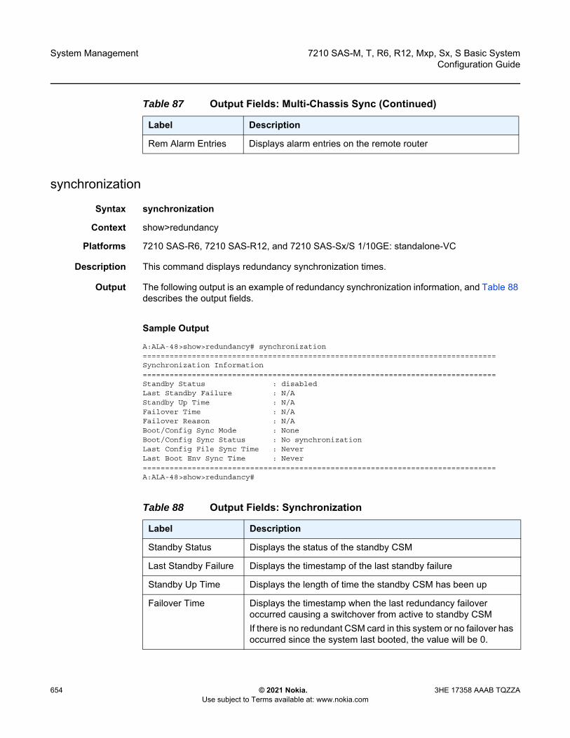
System Management
654
7210 SAS-M, T, R6, R12, Mxp, Sx, S Basic SystemConfiguration Guide
© 2021 Nokia. Use subject to Terms available at: www.nokia.com
3HE 17358 AAAB TQZZA
synchronization
Syntax synchronization
Context show>redundancy
Platforms 7210 SAS-R6, 7210 SAS-R12, and 7210 SAS-Sx/S 1/10GE: standalone-VC
Description This command displays redundancy synchronization times.
Output The following output is an example of redundancy synchronization information, and Table 88 describes the output fields.
Sample Output
A:ALA-48>show>redundancy# synchronization===============================================================================Synchronization Information===============================================================================Standby Status : disabledLast Standby Failure : N/AStandby Up Time : N/AFailover Time : N/AFailover Reason : N/ABoot/Config Sync Mode : NoneBoot/Config Sync Status : No synchronizationLast Config File Sync Time : NeverLast Boot Env Sync Time : Never===============================================================================A:ALA-48>show>redundancy#
Rem Alarm Entries Displays alarm entries on the remote router
Table 87 Output Fields: Multi-Chassis Sync (Continued)
Label Description
Table 88 Output Fields: Synchronization
Label Description
Standby Status Displays the status of the standby CSM
Last Standby Failure Displays the timestamp of the last standby failure
Standby Up Time Displays the length of time the standby CSM has been up
Failover Time Displays the timestamp when the last redundancy failover occurred causing a switchover from active to standby CSMIf there is no redundant CSM card in this system or no failover has occurred since the system last booted, the value will be 0.
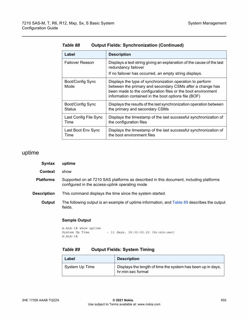
7210 SAS-M, T, R6, R12, Mxp, Sx, S Basic System Configuration Guide
System Management
3HE 17358 AAAB TQZZA © 2021 Nokia. Use subject to Terms available at: www.nokia.com
655
uptime
Syntax uptime
Context show
Platforms Supported on all 7210 SAS platforms as described in this document, including platforms configured in the access-uplink operating mode
Description This command displays the time since the system started.
Output The following output is an example of uptime information, and Table 89 describes the output fields.
Sample Output
A:ALA-1# show uptimeSystem Up Time : 11 days, 18:32:02.22 (hr:min:sec)A:ALA-1#
Failover Reason Displays a text string giving an explanation of the cause of the last redundancy failoverIf no failover has occurred, an empty string displays.
Boot/Config Sync Mode
Displays the type of synchronization operation to perform between the primary and secondary CSMs after a change has been made to the configuration files or the boot environment information contained in the boot options file (BOF)
Boot/Config Sync Status
Displays the results of the last synchronization operation between the primary and secondary CSMs
Last Config File Sync Time
Displays the timestamp of the last successful synchronization of the configuration files
Last Boot Env Sync Time
Displays the timestamp of the last successful synchronization of the boot environment files
Table 88 Output Fields: Synchronization (Continued)
Label Description
Table 89 Output Fields: System Timing
Label Description
System Up Time Displays the length of time the system has been up in days, hr:min:sec format

System Management
656
7210 SAS-M, T, R6, R12, Mxp, Sx, S Basic SystemConfiguration Guide
© 2021 Nokia. Use subject to Terms available at: www.nokia.com
3HE 17358 AAAB TQZZA
sync-if-timing
Syntax sync-if-timing
Context show>system
Platforms Supported on all 7210 SAS platforms as described in this document, including platforms configured in the access-uplink operating mode; not supported on 7210 SAS platforms configured in the standalone-VC operating mode
Description This command displays synchronous interface timing information.
Output The following outputs are examples of synchronous interface timing information, and Table 90 describes the output fields.
• Sample Output for 7210 SAS-M• Sample Output for 7210 SAS-R6 and 7210 SAS-R12• Sample Output for 7210 SAS-T and 7210 SAS-Mxp• Sample Output for 7210 SAS-Sx/S 1/10GE• Sample Output for 7210 SAS-Sx 10/100GE
Sample Output for 7210 SAS-M
The following is a sample output for a node locked to the active BITS input and directing the signal on ref1 to the BITS output.*A:MTU>show>system# sync-if-timing
===============================================================================System Interface Timing Operational Info===============================================================================System Status CPM A : Master Free Run
Reference Input Mode : Non-revertiveQuality Level Selection : DisabledReference Selected : noneSystem Quality Level : st3
Reference Order : ref1 ref2
Reference Input 1Admin Status : downRx Quality Level : unknownQuality Level Override : noneQualified For Use : No
Not Qualified Due To : disabledSelected For Use : No
Not Selected Due To : disabledSource Port : None
Reference Input 2Admin Status : downRx Quality Level : unknownQuality Level Override : noneQualified For Use : No
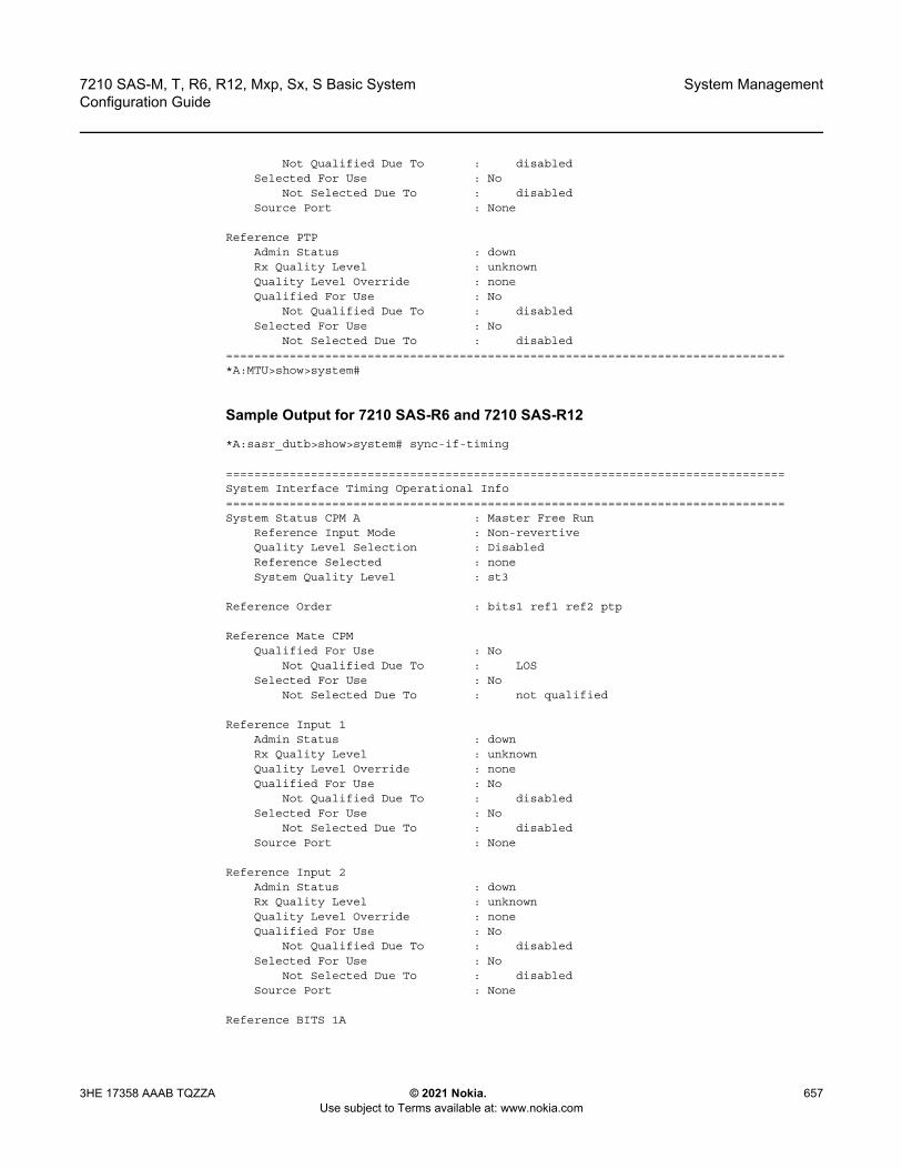
7210 SAS-M, T, R6, R12, Mxp, Sx, S Basic System Configuration Guide
System Management
3HE 17358 AAAB TQZZA © 2021 Nokia. Use subject to Terms available at: www.nokia.com
657
Not Qualified Due To : disabledSelected For Use : No
Not Selected Due To : disabledSource Port : None
Reference PTPAdmin Status : downRx Quality Level : unknownQuality Level Override : noneQualified For Use : No
Not Qualified Due To : disabledSelected For Use : No
Not Selected Due To : disabled===============================================================================*A:MTU>show>system#
Sample Output for 7210 SAS-R6 and 7210 SAS-R12
*A:sasr_dutb>show>system# sync-if-timing
===============================================================================System Interface Timing Operational Info===============================================================================System Status CPM A : Master Free Run
Reference Input Mode : Non-revertiveQuality Level Selection : DisabledReference Selected : noneSystem Quality Level : st3
Reference Order : bits1 ref1 ref2 ptp
Reference Mate CPMQualified For Use : No
Not Qualified Due To : LOSSelected For Use : No
Not Selected Due To : not qualified
Reference Input 1Admin Status : downRx Quality Level : unknownQuality Level Override : noneQualified For Use : No
Not Qualified Due To : disabledSelected For Use : No
Not Selected Due To : disabledSource Port : None
Reference Input 2Admin Status : downRx Quality Level : unknownQuality Level Override : noneQualified For Use : No
Not Qualified Due To : disabledSelected For Use : No
Not Selected Due To : disabledSource Port : None
Reference BITS 1A
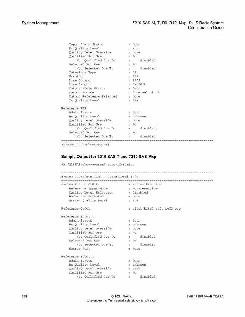
System Management
658
7210 SAS-M, T, R6, R12, Mxp, Sx, S Basic SystemConfiguration Guide
© 2021 Nokia. Use subject to Terms available at: www.nokia.com
3HE 17358 AAAB TQZZA
Input Admin Status : downRx Quality Level : stuQuality Level Override : noneQualified For Use : No
Not Qualified Due To : disabledSelected For Use : No
Not Selected Due To : disabledInterface Type : DS1Framing : ESFLine Coding : B8ZSLine Length : 0-110ftOutput Admin Status : downOutput Source : internal clockOutput Reference Selected : noneTx Quality Level : N/A
Reference PTPAdmin Status : downRx Quality Level : unknownQuality Level Override : noneQualified For Use : No
Not Qualified Due To : disabledSelected For Use : No
Not Selected Due To : disabled===============================================================================*A:sasr_dutb>show>system#
Sample Output for 7210 SAS-T and 7210 SAS-Mxp
*A:7210SAS>show>system# sync-if-timing
===============================================================================System Interface Timing Operational Info===============================================================================System Status CPM A : Master Free Run
Reference Input Mode : Non-revertiveQuality Level Selection : DisabledReference Selected : noneSystem Quality Level : st3
Reference Order : bits1 bits2 ref1 ref2 ptp
Reference Input 1Admin Status : downRx Quality Level : unknownQuality Level Override : noneQualified For Use : No
Not Qualified Due To : disabledSelected For Use : No
Not Selected Due To : disabledSource Port : None
Reference Input 2Admin Status : downRx Quality Level : unknownQuality Level Override : noneQualified For Use : No
Not Qualified Due To : disabled

7210 SAS-M, T, R6, R12, Mxp, Sx, S Basic System Configuration Guide
System Management
3HE 17358 AAAB TQZZA © 2021 Nokia. Use subject to Terms available at: www.nokia.com
659
Selected For Use : NoNot Selected Due To : disabled
Source Port : None
Reference BITS 1Input Admin Status : downRx Quality Level : stuQuality Level Override : noneQualified For Use : No
Not Qualified Due To : disabledSelected For Use : No
Not Selected Due To : disabledInterface Type : DS1Framing : ESFLine Coding : B8ZSLine Length : 0-110ftOutput Admin Status : downOutput Source : internal clockOutput Reference Selected : noneTx Quality Level : N/A
Reference BITS 2Input Admin Status : downRx Quality Level : stuQuality Level Override : noneQualified For Use : No
Not Qualified Due To : disabledSelected For Use : No
Not Selected Due To : disabledInterface Type : DS1Framing : ESFLine Coding : B8ZSLine Length : 0-110ftOutput Admin Status : downOutput Source : internal clockOutput Reference Selected : noneTx Quality Level : N/A
Reference PTPAdmin Status : downRx Quality Level : unknownQuality Level Override : noneQualified For Use : No
Not Qualified Due To : disabledSelected For Use : No
Not Selected Due To : disabled===============================================================================*A:7210SAS>show>system#
Sample Output for 7210 SAS-Sx/S 1/10GE
A:7210Sx>show>system# sync-if-timing
===============================================================================System Interface Timing Operational Info===============================================================================System Status CPM A : Master Free Run
Reference Input Mode : Non-revertive
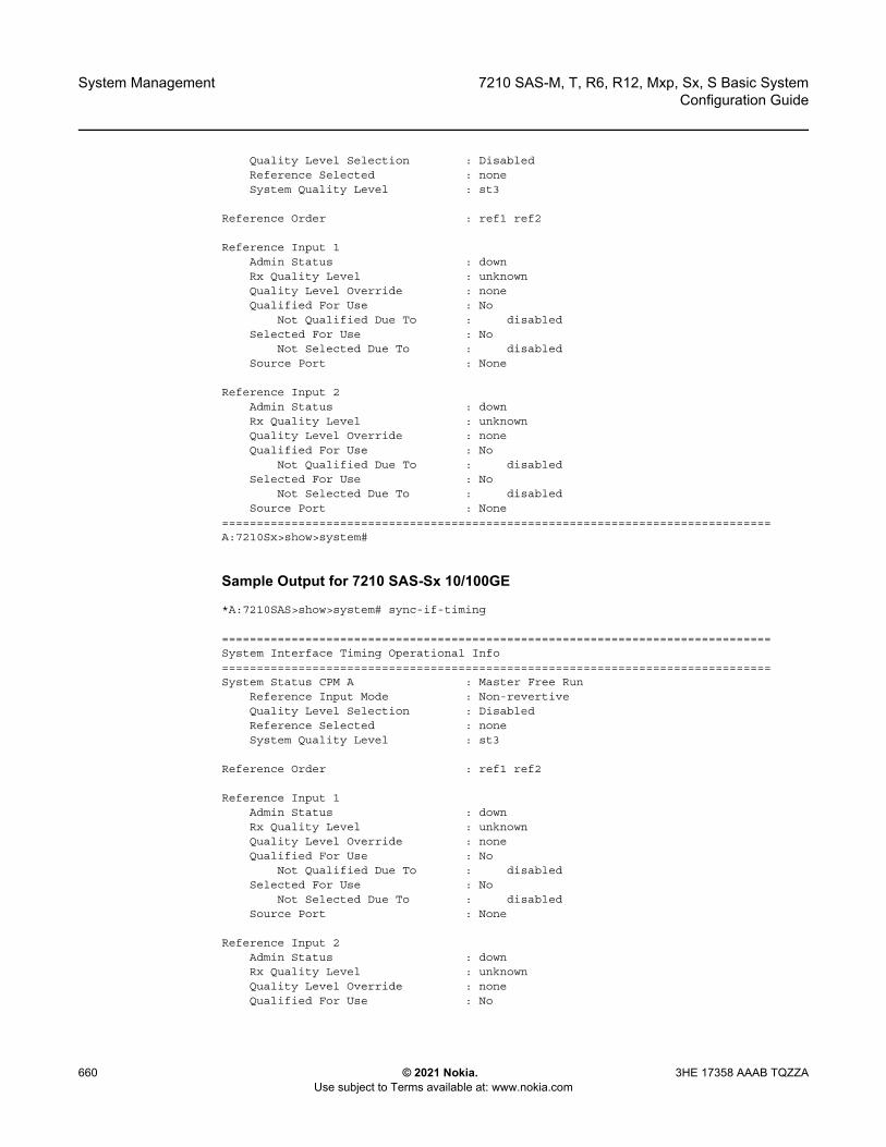
System Management
660
7210 SAS-M, T, R6, R12, Mxp, Sx, S Basic SystemConfiguration Guide
© 2021 Nokia. Use subject to Terms available at: www.nokia.com
3HE 17358 AAAB TQZZA
Quality Level Selection : DisabledReference Selected : noneSystem Quality Level : st3
Reference Order : ref1 ref2
Reference Input 1Admin Status : downRx Quality Level : unknownQuality Level Override : noneQualified For Use : No
Not Qualified Due To : disabledSelected For Use : No
Not Selected Due To : disabledSource Port : None
Reference Input 2Admin Status : downRx Quality Level : unknownQuality Level Override : noneQualified For Use : No
Not Qualified Due To : disabledSelected For Use : No
Not Selected Due To : disabledSource Port : None
===============================================================================A:7210Sx>show>system#
Sample Output for 7210 SAS-Sx 10/100GE
*A:7210SAS>show>system# sync-if-timing
===============================================================================System Interface Timing Operational Info===============================================================================System Status CPM A : Master Free Run
Reference Input Mode : Non-revertiveQuality Level Selection : DisabledReference Selected : noneSystem Quality Level : st3
Reference Order : ref1 ref2
Reference Input 1Admin Status : downRx Quality Level : unknownQuality Level Override : noneQualified For Use : No
Not Qualified Due To : disabledSelected For Use : No
Not Selected Due To : disabledSource Port : None
Reference Input 2Admin Status : downRx Quality Level : unknownQuality Level Override : noneQualified For Use : No
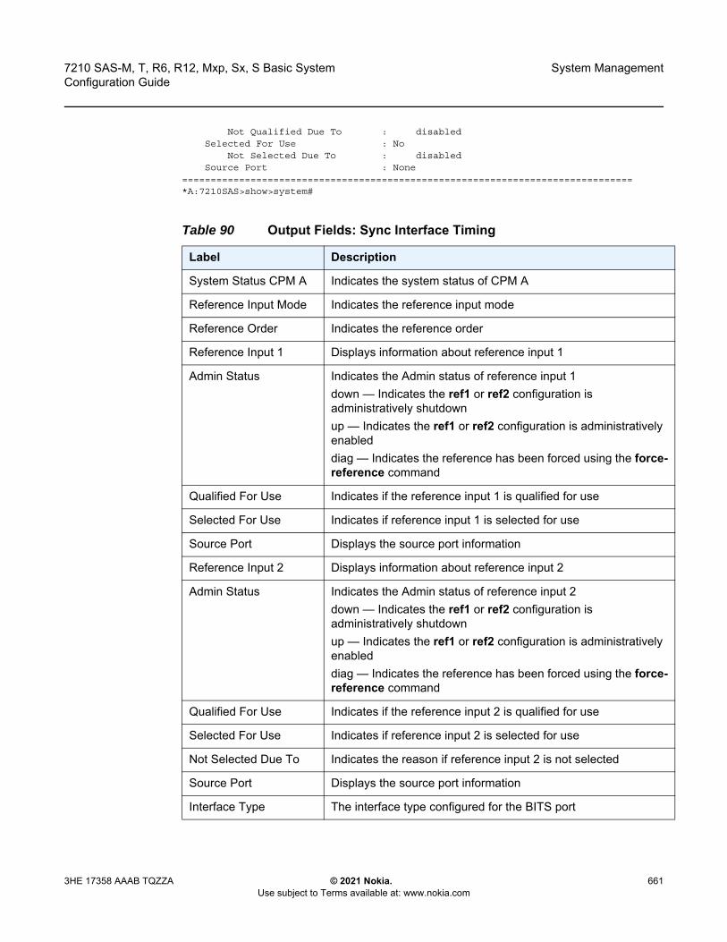
7210 SAS-M, T, R6, R12, Mxp, Sx, S Basic System Configuration Guide
System Management
3HE 17358 AAAB TQZZA © 2021 Nokia. Use subject to Terms available at: www.nokia.com
661
Not Qualified Due To : disabledSelected For Use : No
Not Selected Due To : disabledSource Port : None
===============================================================================*A:7210SAS>show>system#
Table 90 Output Fields: Sync Interface Timing
Label Description
System Status CPM A Indicates the system status of CPM A
Reference Input Mode Indicates the reference input mode
Reference Order Indicates the reference order
Reference Input 1 Displays information about reference input 1
Admin Status Indicates the Admin status of reference input 1down — Indicates the ref1 or ref2 configuration is administratively shutdownup — Indicates the ref1 or ref2 configuration is administratively enableddiag — Indicates the reference has been forced using the force-reference command
Qualified For Use Indicates if the reference input 1 is qualified for use
Selected For Use Indicates if reference input 1 is selected for use
Source Port Displays the source port information
Reference Input 2 Displays information about reference input 2
Admin Status Indicates the Admin status of reference input 2down — Indicates the ref1 or ref2 configuration is administratively shutdownup — Indicates the ref1 or ref2 configuration is administratively enableddiag — Indicates the reference has been forced using the force-reference command
Qualified For Use Indicates if the reference input 2 is qualified for use
Selected For Use Indicates if reference input 2 is selected for use
Not Selected Due To Indicates the reason if reference input 2 is not selected
Source Port Displays the source port information
Interface Type The interface type configured for the BITS port
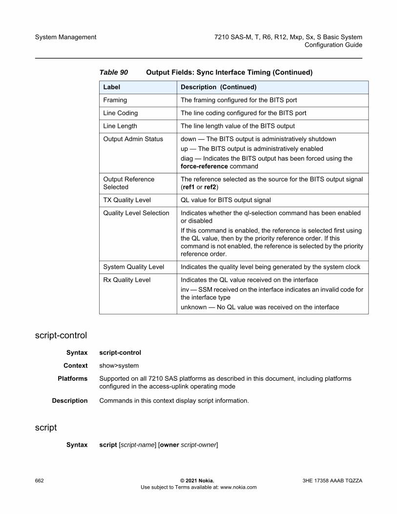
System Management
662
7210 SAS-M, T, R6, R12, Mxp, Sx, S Basic SystemConfiguration Guide
© 2021 Nokia. Use subject to Terms available at: www.nokia.com
3HE 17358 AAAB TQZZA
script-control
Syntax script-control
Context show>system
Platforms Supported on all 7210 SAS platforms as described in this document, including platforms configured in the access-uplink operating mode
Description Commands in this context display script information.
script
Syntax script [script-name] [owner script-owner]
Framing The framing configured for the BITS port
Line Coding The line coding configured for the BITS port
Line Length The line length value of the BITS output
Output Admin Status down — The BITS output is administratively shutdownup — The BITS output is administratively enableddiag — Indicates the BITS output has been forced using the force-reference command
Output Reference Selected
The reference selected as the source for the BITS output signal (ref1 or ref2)
TX Quality Level QL value for BITS output signal
Quality Level Selection Indicates whether the ql-selection command has been enabled or disabledIf this command is enabled, the reference is selected first using the QL value, then by the priority reference order. If this command is not enabled, the reference is selected by the priority reference order.
System Quality Level Indicates the quality level being generated by the system clock
Rx Quality Level Indicates the QL value received on the interfaceinv — SSM received on the interface indicates an invalid code for the interface typeunknown — No QL value was received on the interface
Table 90 Output Fields: Sync Interface Timing (Continued)
Label Description (Continued)
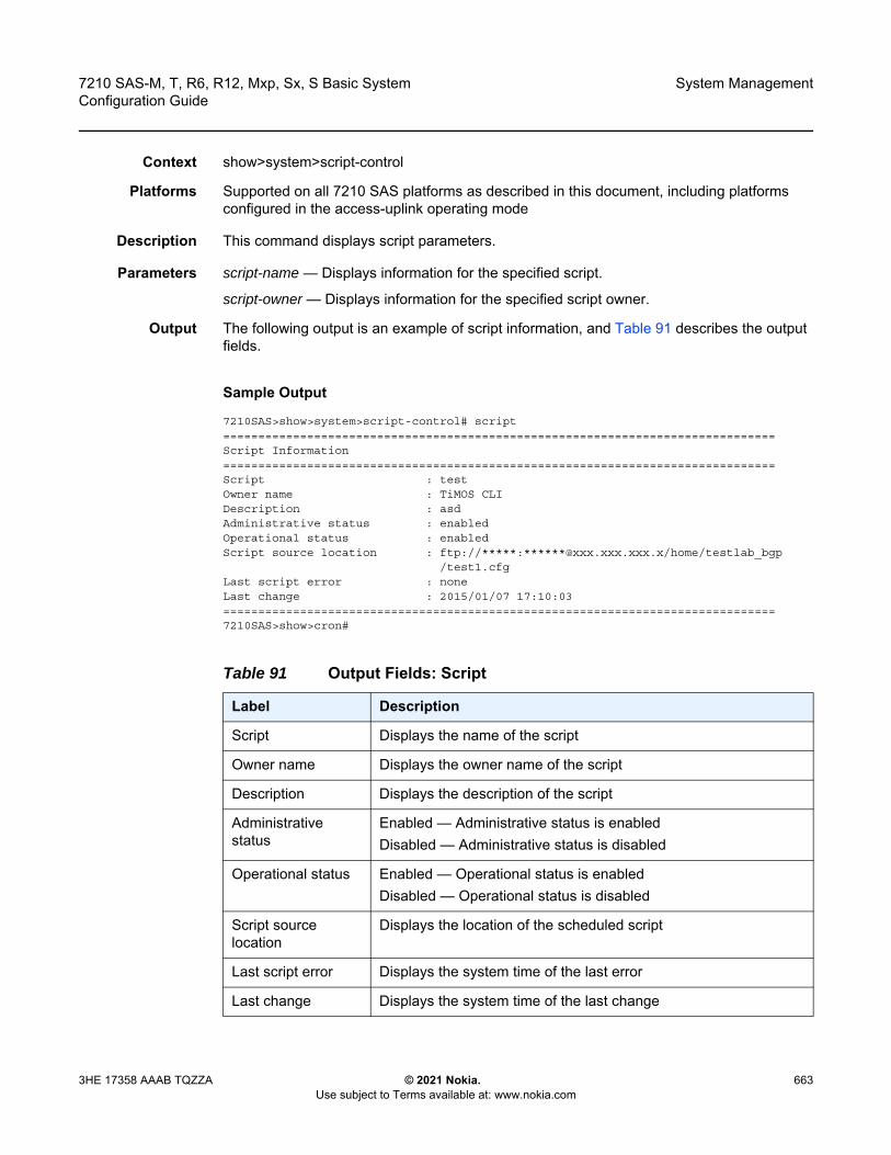
7210 SAS-M, T, R6, R12, Mxp, Sx, S Basic System Configuration Guide
System Management
3HE 17358 AAAB TQZZA © 2021 Nokia. Use subject to Terms available at: www.nokia.com
663
Context show>system>script-control
Platforms Supported on all 7210 SAS platforms as described in this document, including platforms configured in the access-uplink operating mode
Description This command displays script parameters.
Parameters script-name — Displays information for the specified script.
script-owner — Displays information for the specified script owner.
Output The following output is an example of script information, and Table 91 describes the output fields.
Sample Output
7210SAS>show>system>script-control# script===============================================================================Script Information===============================================================================Script : testOwner name : TiMOS CLIDescription : asdAdministrative status : enabledOperational status : enabledScript source location : ftp://*****:******@xxx.xxx.xxx.x/home/testlab_bgp
/test1.cfgLast script error : noneLast change : 2015/01/07 17:10:03===============================================================================7210SAS>show>cron#
Table 91 Output Fields: Script
Label Description
Script Displays the name of the script
Owner name Displays the owner name of the script
Description Displays the description of the script
Administrative status
Enabled — Administrative status is enabledDisabled — Administrative status is disabled
Operational status Enabled — Operational status is enabledDisabled — Operational status is disabled
Script source location
Displays the location of the scheduled script
Last script error Displays the system time of the last error
Last change Displays the system time of the last change
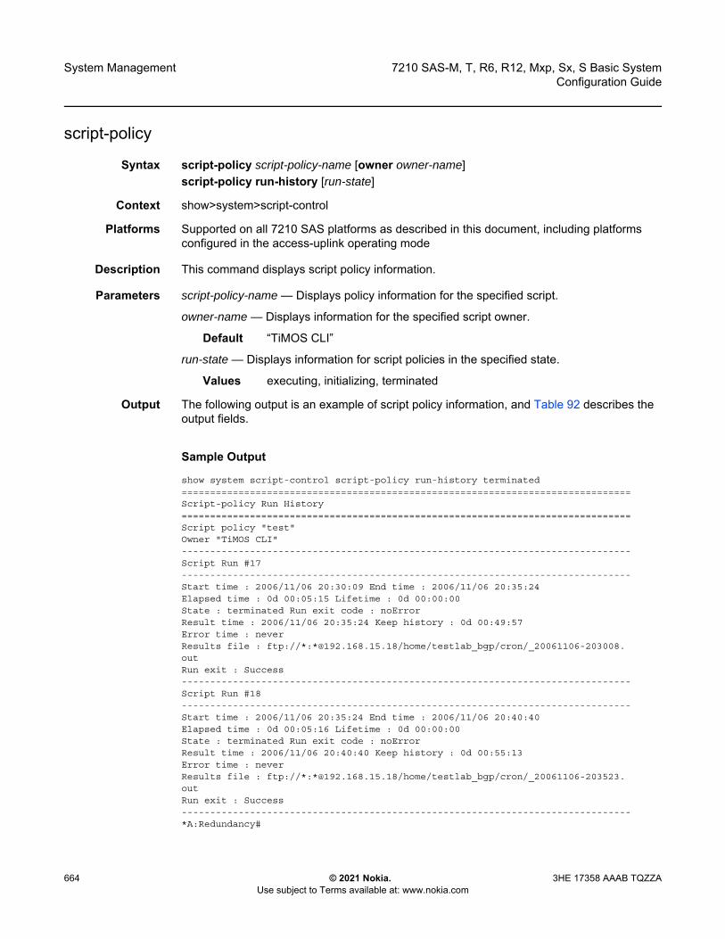
System Management
664
7210 SAS-M, T, R6, R12, Mxp, Sx, S Basic SystemConfiguration Guide
© 2021 Nokia. Use subject to Terms available at: www.nokia.com
3HE 17358 AAAB TQZZA
script-policy
Syntax script-policy script-policy-name [owner owner-name]script-policy run-history [run-state]
Context show>system>script-control
Platforms Supported on all 7210 SAS platforms as described in this document, including platforms configured in the access-uplink operating mode
Description This command displays script policy information.
Parameters script-policy-name — Displays policy information for the specified script.
owner-name — Displays information for the specified script owner.
Default “TiMOS CLI”
run-state — Displays information for script policies in the specified state.
Values executing, initializing, terminated
Output The following output is an example of script policy information, and Table 92 describes the output fields.
Sample Output
show system script-control script-policy run-history terminated===============================================================================Script-policy Run History===============================================================================Script policy "test"Owner "TiMOS CLI"-------------------------------------------------------------------------------Script Run #17-------------------------------------------------------------------------------Start time : 2006/11/06 20:30:09 End time : 2006/11/06 20:35:24Elapsed time : 0d 00:05:15 Lifetime : 0d 00:00:00State : terminated Run exit code : noErrorResult time : 2006/11/06 20:35:24 Keep history : 0d 00:49:57Error time : neverResults file : ftp://*:*@192.168.15.18/home/testlab_bgp/cron/_20061106-203008.outRun exit : Success-------------------------------------------------------------------------------Script Run #18-------------------------------------------------------------------------------Start time : 2006/11/06 20:35:24 End time : 2006/11/06 20:40:40Elapsed time : 0d 00:05:16 Lifetime : 0d 00:00:00State : terminated Run exit code : noErrorResult time : 2006/11/06 20:40:40 Keep history : 0d 00:55:13Error time : neverResults file : ftp://*:*@192.168.15.18/home/testlab_bgp/cron/_20061106-203523.outRun exit : Success-------------------------------------------------------------------------------*A:Redundancy#
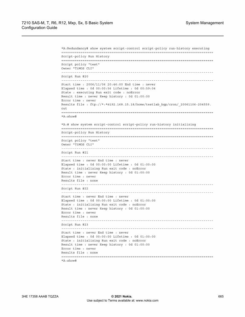
7210 SAS-M, T, R6, R12, Mxp, Sx, S Basic System Configuration Guide
System Management
3HE 17358 AAAB TQZZA © 2021 Nokia. Use subject to Terms available at: www.nokia.com
665
*A:Redundancy# show system script-control script-policy run-history executing===============================================================================Script-policy Run History===============================================================================Script policy "test"Owner "TiMOS CLI"-------------------------------------------------------------------------------Script Run #20-------------------------------------------------------------------------------Start time : 2006/11/06 20:46:00 End time : neverElapsed time : 0d 00:00:56 Lifetime : 0d 00:59:04State : executing Run exit code : noErrorResult time : never Keep history : 0d 01:00:00Error time : neverResults file : ftp://*:*@192.168.15.18/home/testlab_bgp/cron/_20061106-204559.out===============================================================================*A:show#
*A:# show system script-control script-policy run-history initializing===============================================================================Script-policy Run History===============================================================================Script policy "test"Owner "TiMOS CLI"-------------------------------------------------------------------------------Script Run #21-------------------------------------------------------------------------------Start time : never End time : neverElapsed time : 0d 00:00:00 Lifetime : 0d 01:00:00State : initializing Run exit code : noErrorResult time : never Keep history : 0d 01:00:00Error time : neverResults file : none-------------------------------------------------------------------------------Script Run #22-------------------------------------------------------------------------------Start time : never End time : neverElapsed time : 0d 00:00:00 Lifetime : 0d 01:00:00State : initializing Run exit code : noErrorResult time : never Keep history : 0d 01:00:00Error time : neverResults file : none-------------------------------------------------------------------------------Script Run #23-------------------------------------------------------------------------------Start time : never End time : neverElapsed time : 0d 00:00:00 Lifetime : 0d 01:00:00State : initializing Run exit code : noErrorResult time : never Keep history : 0d 01:00:00Error time : neverResults file : none===============================================================================*A:show#
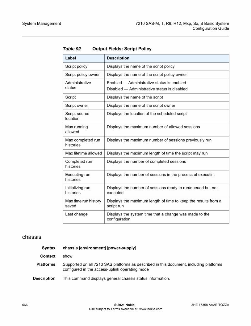
System Management
666
7210 SAS-M, T, R6, R12, Mxp, Sx, S Basic SystemConfiguration Guide
© 2021 Nokia. Use subject to Terms available at: www.nokia.com
3HE 17358 AAAB TQZZA
chassis
Syntax chassis [environment] [power-supply]
Context show
Platforms Supported on all 7210 SAS platforms as described in this document, including platforms configured in the access-uplink operating mode
Description This command displays general chassis status information.
Table 92 Output Fields: Script Policy
Label Description
Script policy Displays the name of the script policy
Script policy owner Displays the name of the script policy owner
Administrative status
Enabled — Administrative status is enabledDisabled — Administrative status is disabled
Script Displays the name of the script
Script owner Displays the name of the script owner
Script source location
Displays the location of the scheduled script
Max running allowed
Displays the maximum number of allowed sessions
Max completed run histories
Displays the maximum number of sessions previously run
Max lifetime allowed Displays the maximum length of time the script may run
Completed run histories
Displays the number of completed sessions
Executing run histories
Displays the number of sessions in the process of executin.
Initializing run histories
Displays the number of sessions ready to run/queued but not executed
Max time run history saved
Displays the maximum length of time to keep the results from a script run
Last change Displays the system time that a change was made to the configuration

7210 SAS-M, T, R6, R12, Mxp, Sx, S Basic System Configuration Guide
System Management
3HE 17358 AAAB TQZZA © 2021 Nokia. Use subject to Terms available at: www.nokia.com
667
For a virtual chassis (VC), this command displays information about the entire VC. Hardware information can be displayed for individual CPMs, IMMs, power supplies, and fans.
Parameters environment — Displays chassis environmental status information.
Default all chassis information
power-supply — Displays only power-supply information.
Output The following outputs are examples of chassis information, and Table 93 describes the output fields.
• Sample Output for 7210 SAS-M• Sample Output for 7210 SAS-T• Sample Output for 7210 SAS-Sx/S 1/10GE• Sample Output for 7210 SAS-Sx 10/100GE• Sample Output for 7210 SAS-Sx 1/10GE with RPS• Sample Output for a 7210 SAS Virtual Chassis• Sample Output for 7210 SAS-Sx/S 1/10GE in Standalone VC Mode
Sample Output for 7210 SAS-M
A:7210-SAS-M# show chassis power-supply===============================================================================Chassis Information===============================================================================Power Supply Information
Number of power supplies : 2
Power supply number : 1Configured power supply type : ac singleStatus : upAC power : within range
Power supply number : 2Configured power supply type : dc (+24V)Status : not equipped
===============================================================================A:7210-SAS-M#
A:7210-SAS-M# show chassis power-supply===============================================================================Chassis Information===============================================================================Power Supply Information
Number of power supplies : 2
Power supply number : 1Configured power supply type : dc (+24V)Status : upDC power : within rangeInput power : within rangeOutput power : within range
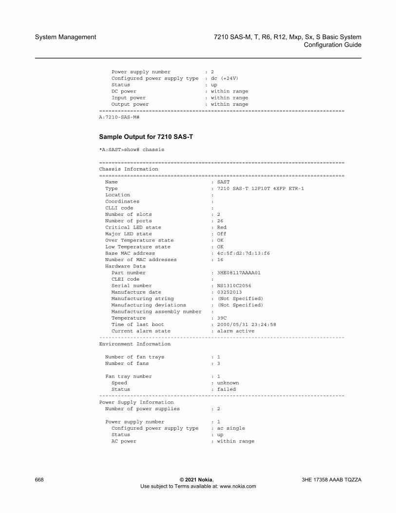
System Management
668
7210 SAS-M, T, R6, R12, Mxp, Sx, S Basic SystemConfiguration Guide
© 2021 Nokia. Use subject to Terms available at: www.nokia.com
3HE 17358 AAAB TQZZA
Power supply number : 2Configured power supply type : dc (+24V)Status : upDC power : within rangeInput power : within rangeOutput power : within range
===============================================================================A:7210-SAS-M#
Sample Output for 7210 SAS-T
*A:SAST>show# chassis
===============================================================================Chassis Information===============================================================================
Name : SASTType : 7210 SAS-T 12F10T 4XFP ETR-1Location :Coordinates :CLLI code :Number of slots : 2Number of ports : 26Critical LED state : RedMajor LED state : OffOver Temperature state : OKLow Temperature state : OKBase MAC address : 4c:5f:d2:7d:13:f6Number of MAC addresses : 16Hardware Data
Part number : 3HE08117AAAA01CLEI code :Serial number : NS1310C2056Manufacture date : 03252013Manufacturing string : (Not Specified)Manufacturing deviations : (Not Specified)Manufacturing assembly number :Temperature : 39CTime of last boot : 2000/05/31 23:24:58Current alarm state : alarm active
-------------------------------------------------------------------------------Environment Information
Number of fan trays : 1Number of fans : 3
Fan tray number : 1Speed : unknownStatus : failed
-------------------------------------------------------------------------------Power Supply Information
Number of power supplies : 2
Power supply number : 1Configured power supply type : ac singleStatus : upAC power : within range

7210 SAS-M, T, R6, R12, Mxp, Sx, S Basic System Configuration Guide
System Management
3HE 17358 AAAB TQZZA © 2021 Nokia. Use subject to Terms available at: www.nokia.com
669
Power supply number : 2Configured power supply type : noneStatus : not equipped
===============================================================================*A:SAST>show#
Sample Output for 7210 SAS-Sx/S 1/10GE
A:7210Sx>show# chassis
===============================================================================Chassis Information===============================================================================
Name : hw_sass_duthType : 7210 SAS-Sx/S 1/10GE 48Tp4SFP+ (PoE)-1Location :Coordinates :CLLI code :Number of slots : 2Number of ports : 52
System LED state : GreenOver Temperature state : OKBase MAC address : a4:7b:2c:c6:69:d3Number of MAC addresses : 512Hardware Data
Part number : 1160400046CLEI code :Serial number : 01160400046Manufacture date :Manufacturing deviations : (Not Specified)Manufacturing assembly number : 82-0827-01Temperature : 59CTime of last boot : 2000/01/01 01:32:34Current alarm state : alarm cleared
-------------------------------------------------------------------------------Environment Information
Number of fan trays : 1Number of fans : 1
Fan tray number : 1Speed : half speedStatus : up
-------------------------------------------------------------------------------Power Supply Information
Number of power supplies : 2
Power supply number : 1Configured power supply type : ac singleStatus : upAC power : within range
Power supply number : 2Configured power supply type : noneStatus : failedDC power : out of range
===============================================================================A:7210Sx>show#
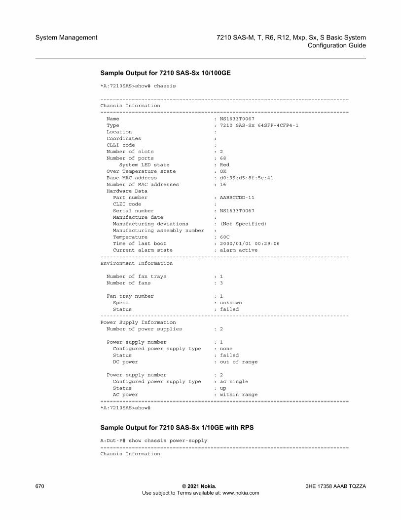
System Management
670
7210 SAS-M, T, R6, R12, Mxp, Sx, S Basic SystemConfiguration Guide
© 2021 Nokia. Use subject to Terms available at: www.nokia.com
3HE 17358 AAAB TQZZA
Sample Output for 7210 SAS-Sx 10/100GE
*A:7210SAS>show# chassis
===============================================================================Chassis Information===============================================================================
Name : NS1633T0067Type : 7210 SAS-Sx 64SFP+4CFP4-1Location :Coordinates :CLLI code :Number of slots : 2Number of ports : 68
System LED state : RedOver Temperature state : OKBase MAC address : d0:99:d5:8f:5e:41Number of MAC addresses : 16Hardware Data
Part number : AABBCCDD-11CLEI code :Serial number : NS1633T0067Manufacture date :Manufacturing deviations : (Not Specified)Manufacturing assembly number :Temperature : 60CTime of last boot : 2000/01/01 00:29:06Current alarm state : alarm active
-------------------------------------------------------------------------------Environment Information
Number of fan trays : 1Number of fans : 3
Fan tray number : 1Speed : unknownStatus : failed
-------------------------------------------------------------------------------Power Supply Information
Number of power supplies : 2
Power supply number : 1Configured power supply type : noneStatus : failedDC power : out of range
Power supply number : 2Configured power supply type : ac singleStatus : upAC power : within range
===============================================================================*A:7210SAS>show#
Sample Output for 7210 SAS-Sx 1/10GE with RPS
A:Dut-P# show chassis power-supply===============================================================================Chassis Information
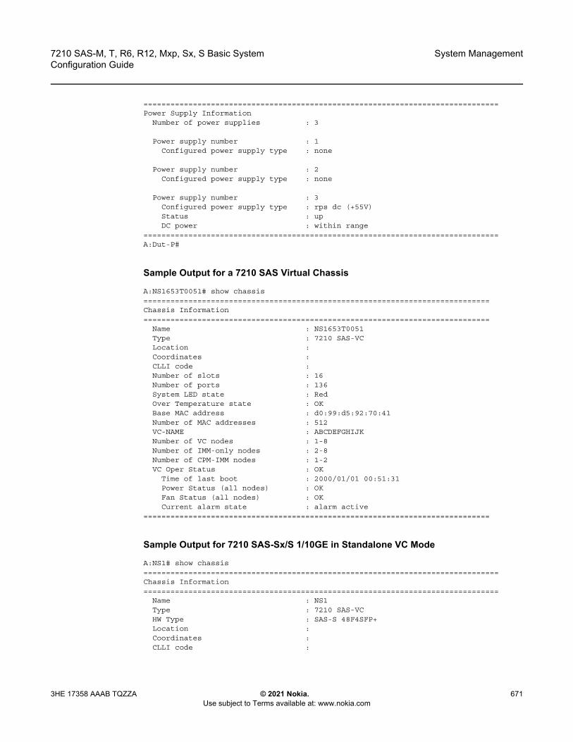
7210 SAS-M, T, R6, R12, Mxp, Sx, S Basic System Configuration Guide
System Management
3HE 17358 AAAB TQZZA © 2021 Nokia. Use subject to Terms available at: www.nokia.com
671
===============================================================================Power Supply Information
Number of power supplies : 3
Power supply number : 1Configured power supply type : none
Power supply number : 2Configured power supply type : none
Power supply number : 3Configured power supply type : rps dc (+55V)Status : upDC power : within range
===============================================================================A:Dut-P#
Sample Output for a 7210 SAS Virtual Chassis
A:NS1653T0051# show chassis=============================================================================Chassis Information=============================================================================
Name : NS1653T0051Type : 7210 SAS-VCLocation :Coordinates :CLLI code :Number of slots : 16Number of ports : 136System LED state : RedOver Temperature state : OKBase MAC address : d0:99:d5:92:70:41Number of MAC addresses : 512VC-NAME : ABCDEFGHIJKNumber of VC nodes : 1-8Number of IMM-only nodes : 2-8Number of CPM-IMM nodes : 1-2VC Oper Status : OK
Time of last boot : 2000/01/01 00:51:31Power Status (all nodes) : OKFan Status (all nodes) : OKCurrent alarm state : alarm active
=============================================================================
Sample Output for 7210 SAS-Sx/S 1/10GE in Standalone VC Mode
A:NS1# show chassis===============================================================================Chassis Information===============================================================================
Name : NS1Type : 7210 SAS-VCHW Type : SAS-S 48F4SFP+Location :Coordinates :CLLI code :
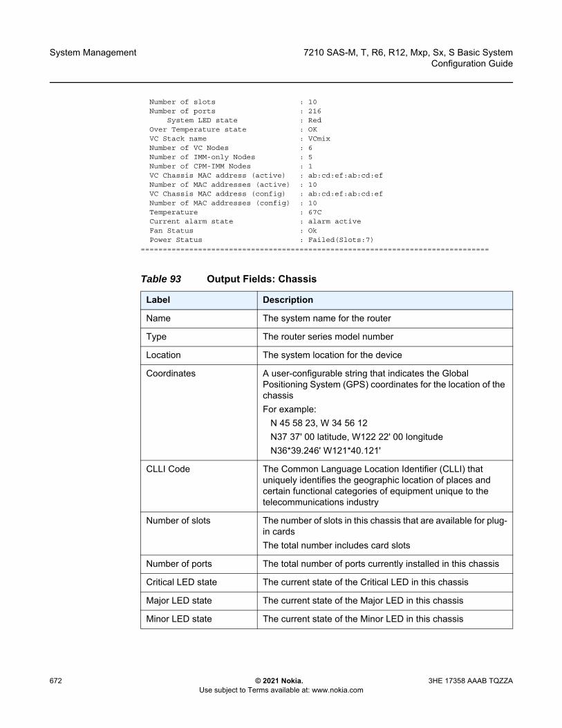
System Management
672
7210 SAS-M, T, R6, R12, Mxp, Sx, S Basic SystemConfiguration Guide
© 2021 Nokia. Use subject to Terms available at: www.nokia.com
3HE 17358 AAAB TQZZA
Number of slots : 10Number of ports : 216
System LED state : RedOver Temperature state : OKVC Stack name : VCmixNumber of VC Nodes : 6Number of IMM-only Nodes : 5Number of CPM-IMM Nodes : 1VC Chassis MAC address (active) : ab:cd:ef:ab:cd:efNumber of MAC addresses (active) : 10VC Chassis MAC address (config) : ab:cd:ef:ab:cd:efNumber of MAC addresses (config) : 10Temperature : 67CCurrent alarm state : alarm activeFan Status : OkPower Status : Failed(Slots:7)
===============================================================================
Table 93 Output Fields: Chassis
Label Description
Name The system name for the router
Type The router series model number
Location The system location for the device
Coordinates A user-configurable string that indicates the Global Positioning System (GPS) coordinates for the location of the chassisFor example: N 45 58 23, W 34 56 12 N37 37' 00 latitude, W122 22' 00 longitude N36*39.246' W121*40.121'
CLLI Code The Common Language Location Identifier (CLLI) that uniquely identifies the geographic location of places and certain functional categories of equipment unique to the telecommunications industry
Number of slots The number of slots in this chassis that are available for plug-in cardsThe total number includes card slots
Number of ports The total number of ports currently installed in this chassis
Critical LED state The current state of the Critical LED in this chassis
Major LED state The current state of the Major LED in this chassis
Minor LED state The current state of the Minor LED in this chassis
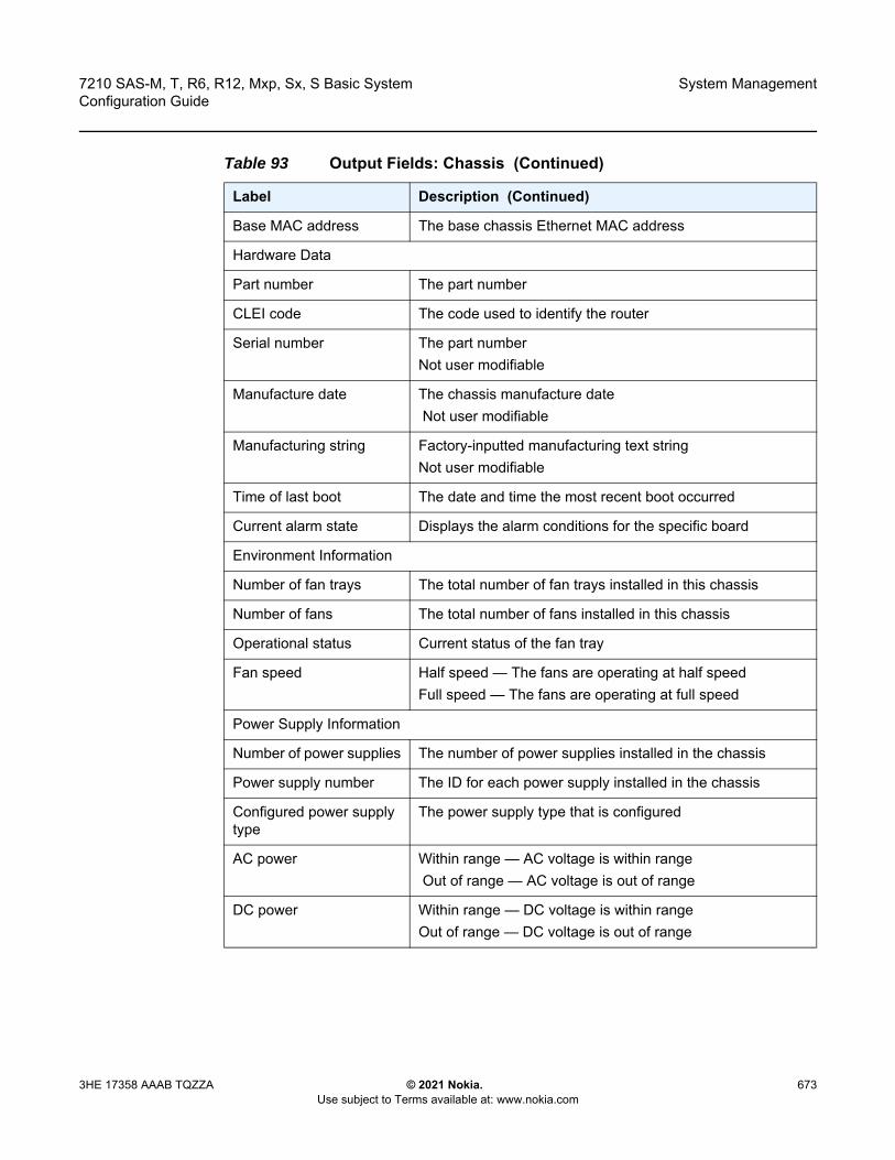
7210 SAS-M, T, R6, R12, Mxp, Sx, S Basic System Configuration Guide
System Management
3HE 17358 AAAB TQZZA © 2021 Nokia. Use subject to Terms available at: www.nokia.com
673
Base MAC address The base chassis Ethernet MAC address
Hardware Data
Part number The part number
CLEI code The code used to identify the router
Serial number The part numberNot user modifiable
Manufacture date The chassis manufacture date Not user modifiable
Manufacturing string Factory-inputted manufacturing text stringNot user modifiable
Time of last boot The date and time the most recent boot occurred
Current alarm state Displays the alarm conditions for the specific board
Environment Information
Number of fan trays The total number of fan trays installed in this chassis
Number of fans The total number of fans installed in this chassis
Operational status Current status of the fan tray
Fan speed Half speed — The fans are operating at half speedFull speed — The fans are operating at full speed
Power Supply Information
Number of power supplies The number of power supplies installed in the chassis
Power supply number The ID for each power supply installed in the chassis
Configured power supply type
The power supply type that is configured
AC power Within range — AC voltage is within range Out of range — AC voltage is out of range
DC power Within range — DC voltage is within rangeOut of range — DC voltage is out of range
Table 93 Output Fields: Chassis (Continued)
Label Description (Continued)

System Management
674
7210 SAS-M, T, R6, R12, Mxp, Sx, S Basic SystemConfiguration Guide
© 2021 Nokia. Use subject to Terms available at: www.nokia.com
3HE 17358 AAAB TQZZA
alarm-contact-input
Syntax alarm-contact-input all
Context show>alarm-contact-input
Platforms 7210 SAS-M (netowrk and access-uplink), 7210 SAS-T (network and access-uplink), 7210 SAS-Mxp, 7210 SAS-R6, and, 7210 SAS-R12
Description This command displays information of all the alarm contact input pins.
Output The following output is an example of alarm contact input information, and Table 94 describes the output fields.
Sample Output
*A:7210-2# show alarm-contact-input 1===============================================================================Alarm Contact Input===============================================================================
Alarm Input Pin Number : 1Alarm Input Pin Current State : DisabledAlarm Output Pin Used : Major
===============================================================================*A:7210-2#
*A:7210-2# show alarm-contact-input 1 detail===============================================================================Alarm Contact Input===============================================================================
Alarm Input Pin Number : 1Alarm Input Pin Description :Alarm Input Pin Current State : DisabledAlarm Output Pin Used : MajorLast State Change : 05/19/2010 11:28:09
===============================================================================*A:7210-2#
Over temp Within range — The current temperature is within the acceptable rangeOut of range — The current temperature is above the acceptable range
Status Up — The specified power supply is upDown — The specified power supply is down
Table 93 Output Fields: Chassis (Continued)
Label Description (Continued)

7210 SAS-M, T, R6, R12, Mxp, Sx, S Basic System Configuration Guide
System Management
3HE 17358 AAAB TQZZA © 2021 Nokia. Use subject to Terms available at: www.nokia.com
675
*A:7210-2# show alarm-contact-input all===============================================================================Alarm Contact Input===============================================================================
Alarm Input Pin Number : 1Alarm Input Pin Description :Alarm Input Pin Current State : DisabledAlarm Output Pin Used : MajorLast State Change : 05/19/2010 11:28:09Alarm Input Pin Number : 2Alarm Input Pin Description :Alarm Input Pin Current State : DisabledAlarm Output Pin Used : MajorLast State Change : 05/19/2010 11:28:09Alarm Input Pin Number : 3Alarm Input Pin Description :Alarm Input Pin Current State : DisabledAlarm Output Pin Used : MajorLast State Change : 05/19/2010 11:28:09Alarm Input Pin Number : 4Alarm Input Pin Description :Alarm Input Pin Current State : DisabledAlarm Output Pin Used : MajorLast State Change : 05/19/2010 11:28:09
===============================================================================*A:7210-2#
pools
Syntax pools
Context show
Platforms Supported on all 7210 SAS platforms as described in this document
Description This command displays information on the buffer allocation and buffer usage per port.
Output The following output is an example of pools information, and Table 95 describes the output fields.
Table 94 Output Fields: Alarm Contact Input
Label Description
Alarm input pin Number Indicates the pin alarm input pin number
Alarm input pin Description Describes the alarm indicating its usage or attribute
Alarm input pin current state Indicates the current state of the alarm contact input pin
Alarm output pin used Indicates the alarm output pin used
Last state change time Indicates the previous state change time
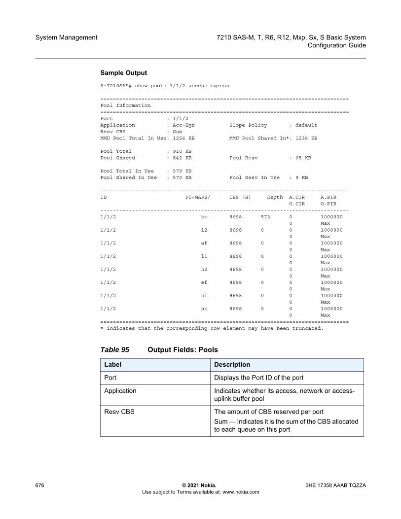
System Management
676
7210 SAS-M, T, R6, R12, Mxp, Sx, S Basic SystemConfiguration Guide
© 2021 Nokia. Use subject to Terms available at: www.nokia.com
3HE 17358 AAAB TQZZA
Sample Output
A:7210SAS# show pools 1/1/2 access-egress
===============================================================================Pool Information===============================================================================Port : 1/1/2Application : Acc-Egr Slope Policy : defaultResv CBS : SumMMU Pool Total In Use: 1256 KB MMU Pool Shared In*: 1236 KB
Pool Total : 910 KBPool Shared : 842 KB Pool Resv : 68 KB
Pool Total In Use : 579 KBPool Shared In Use : 570 KB Pool Resv In Use : 9 KB
-------------------------------------------------------------------------------ID FC-MAPS/ CBS (B) Depth A.CIR A.PIR
O.CIR O.PIR-------------------------------------------------------------------------------1/1/2 be 8698 573 0 1000000
0 Max1/1/2 l2 8698 0 0 1000000
0 Max1/1/2 af 8698 0 0 1000000
0 Max1/1/2 l1 8698 0 0 1000000
0 Max1/1/2 h2 8698 0 0 1000000
0 Max1/1/2 ef 8698 0 0 1000000
0 Max1/1/2 h1 8698 0 0 1000000
0 Max1/1/2 nc 8698 0 0 1000000
0 Max===============================================================================* indicates that the corresponding row element may have been truncated.
Table 95 Output Fields: Pools
Label Description
Port Displays the Port ID of the port
Application Indicates whether its access, network or access-uplink buffer pool
Resv CBS The amount of CBS reserved per portSum — Indicates it is the sum of the CBS allocated to each queue on this port

7210 SAS-M, T, R6, R12, Mxp, Sx, S Basic System Configuration Guide
System Management
3HE 17358 AAAB TQZZA © 2021 Nokia. Use subject to Terms available at: www.nokia.com
677
6.12.2.3 Clear Commands
screen
Syntax screen
Context clear
MMU Pool Total In Use Number of system wide buffers in useThis includes the shared buffers as well as the per queue committed buffers.
Pool Total The total amount of buffer allocated to this pool
Pool Shared The total amount of buffers allocated towards MBS portion, which is shared by all the queues
Pool Total In Use The total amount of buffers in use
Pool Shared In Use The total amount of shared buffers in use
Slope Policy The slope policy ID in use
MMU Pool Shared In Number of system wide shared buffers currently in useThis does not include the committed buffers allocated to each queue.
Pool Resv The total amount of buffers allocated towards CBS for all the queues
Pool Resv In Use Total amount of CBS buffers in use
ID Identifies the port
FC-MAPS Identifies the FC
Depth The current depth of the queue
CBS The CBS portion allocated to the queue
A.CIR/PIR Configured values of CIR and PIR rates (that is, value before adaptation rule is applied)
O.CIR/PIR Operational value of CIR/PIR after applying the adaptation rule
Table 95 Output Fields: Pools (Continued)
Label Description
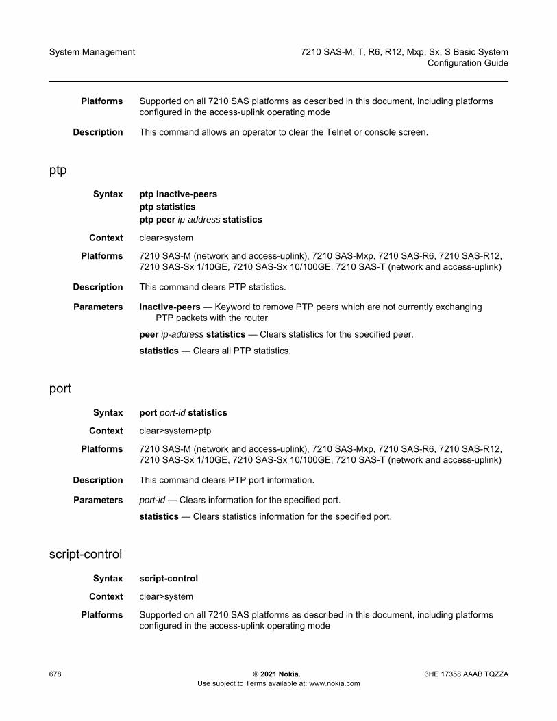
System Management
678
7210 SAS-M, T, R6, R12, Mxp, Sx, S Basic SystemConfiguration Guide
© 2021 Nokia. Use subject to Terms available at: www.nokia.com
3HE 17358 AAAB TQZZA
Platforms Supported on all 7210 SAS platforms as described in this document, including platforms configured in the access-uplink operating mode
Description This command allows an operator to clear the Telnet or console screen.
ptp
Syntax ptp inactive-peersptp statisticsptp peer ip-address statistics
Context clear>system
Platforms 7210 SAS-M (network and access-uplink), 7210 SAS-Mxp, 7210 SAS-R6, 7210 SAS-R12, 7210 SAS-Sx 1/10GE, 7210 SAS-Sx 10/100GE, 7210 SAS-T (network and access-uplink)
Description This command clears PTP statistics.
Parameters inactive-peers — Keyword to remove PTP peers which are not currently exchanging PTP packets with the router
peer ip-address statistics — Clears statistics for the specified peer.
statistics — Clears all PTP statistics.
port
Syntax port port-id statistics
Context clear>system>ptp
Platforms 7210 SAS-M (network and access-uplink), 7210 SAS-Mxp, 7210 SAS-R6, 7210 SAS-R12, 7210 SAS-Sx 1/10GE, 7210 SAS-Sx 10/100GE, 7210 SAS-T (network and access-uplink)
Description This command clears PTP port information.
Parameters port-id — Clears information for the specified port.
statistics — Clears statistics information for the specified port.
script-control
Syntax script-control
Context clear>system
Platforms Supported on all 7210 SAS platforms as described in this document, including platforms configured in the access-uplink operating mode
7210 SAS-M, T, R6, R12, Mxp, Sx, S Basic System Configuration Guide
System Management
3HE 17358 AAAB TQZZA © 2021 Nokia. Use subject to Terms available at: www.nokia.com
679
Description Commands in this context clear script information.
script-policy
Syntax script-policy
Context clear>system>script-control
Platforms Supported on all 7210 SAS platforms as described in this document, including platforms configured in the access-uplink operating mode
Description Commands in this context clear script policy information.
completed
Syntax completed [script-policy-name] [owner owner-name]
Context clear>system>script-control>script-policy
Platforms Supported on all 7210 SAS platforms as described in this document, including platforms configured in the access-uplink operating mode
Description This command clears completed script run history entries.
Parameters script-policy-name — Clears history entries only for the specified script-policy.
owner-name — Clears history entries only for script-policies with the specified owner.
Default “TiMOS CLI”
sync-if-timing
Syntax sync-if-timing {ref1 | ref2 | bits1 | bits2}
Context clear>system
Platforms Supported on all 7210 SAS platforms as described in this document, including platforms configured in the access-uplink operating mode; not supported on platforms configured in the standalone-VC operating mode
Description This command individually clears (re-enable) a previously failed reference. As long as the reference is one of the valid options, this command is always executed. An inherent behavior enables the reverted mode which causes a re-evaluation of all available references.
Parameters ref1 — Clears the first timing reference.
ref2 — Clears the second timing reference.

System Management
680
7210 SAS-M, T, R6, R12, Mxp, Sx, S Basic SystemConfiguration Guide
© 2021 Nokia. Use subject to Terms available at: www.nokia.com
3HE 17358 AAAB TQZZA
bits1 — Clears the BITS1 port reference. This keyword is only supported on 7210 SAS-Mxp, 7210 SAS-T, 7210 SAS-R6 and 7210 SAS-R12 platforms.
bits2 — Clears the BITS2 port reference. This keyword is only supported on 7210 SAS-T and 7210 SAS-Mxp platforms.
trace
Syntax trace log
Context clear
Platforms Supported on all 7210 SAS platforms as described in this document
Description This command allows an operator to clear the trace log.
6.12.2.4 Debug Commands
sync-if-timing
Syntax sync-if-timing
Context debug
Platforms Supported on all 7210 SAS platforms as described in this document, including platforms configured in the access-uplink operating mode
Description Commands in this context debug synchronous interface timing references.
force-reference
Syntax force-reference {ref1 | ref2 | bits1 | bits2 | ptp}no force-reference
Context debug>sync-if-timing
Platforms Supported on all 7210 SAS platforms as described in this document, including platforms configured in the access-uplink operating mode; not supported on platforms configured in the satndalone-VC operating mode
Description This command forces the system synchronous timing output to use a specific reference.
7210 SAS-M, T, R6, R12, Mxp, Sx, S Basic System Configuration Guide
System Management
3HE 17358 AAAB TQZZA © 2021 Nokia. Use subject to Terms available at: www.nokia.com
681
When the debug force-reference command is executed, the current system synchronous timing output is immediately referenced from the specified reference input. If the specified input is not available (shutdown), or in a disqualified state, the timing output will enter the holdover state based on the previous input reference.
Parameters ref1 — Specifies that the clock will use the first timing reference.
ref2 — Specifies that the clock will use the second timing reference.
ptp — Specifies that the clock will use ptp as a timing reference. This keyword is only supported on 7210 SAS-M, 7210 SAS-T, 7210 SAS-Sx 1/10GE, 7210 SAS-R6, 7210 SAS-R12, and 7210 SAS-Mxp platforms.
bits1 — Specifies that the clock will use the BITS1 port as timing reference. This keyword is only supported on 7210 SAS-Mxp, 7210 SAS-T, 7210 SAS-R6 and 7210 SAS-R12 platforms.
bits2 — Specifies that the clock will use BITS2 port as the timing reference. This keyword is only supported on 7210 SAS-M and 7210 SAS-T platforms.
system
Syntax [no] system
Context debug
Platforms Supported on all 7210 SAS platforms as described in this document, including platforms configured in the access-uplink operating mode
Description This command displays system debug information.
ntp
Syntax ntp [router router-name] [interface ip-int-name]
Context debug>system
Platforms Supported on all 7210 SAS platforms as described in this document, including platforms configured in the access-uplink operating mode
Description This command enables and configures debugging for NTP.
The no form of this command disables debugging for NTP.
Note: This command should be used for testing and debugging purposes only. After the system timing reference input has been forced, it will not revert back to another reference at any time. The state of this command is not persistent between system boots.
System Management
682
7210 SAS-M, T, R6, R12, Mxp, Sx, S Basic SystemConfiguration Guide
© 2021 Nokia. Use subject to Terms available at: www.nokia.com
3HE 17358 AAAB TQZZA
Parameters router-name — Base, management
Default Base
ip-int-name — Specifies the name of the IP interface. The name can be up to 32 characters and must begin with a letter. If the string contains special characters (#, $, spaces, and so on), the entire string must be enclosed within double quotes.

7210 SAS-M, T, R6, R12, Mxp, Sx, S Basic System Configuration Guide
Appendix: 7210 SAS Boot Procedures
3HE 17358 AAAB TQZZA © 2021 Nokia. Use subject to Terms available at: www.nokia.com
683
7 Appendix: 7210 SAS Boot ProceduresThis chapter describes the booting procedures for 7210 SAS devices.
This chapter provides information about booting a factory-shipped 7210 SAS device for the first time. It also includes information to boot the 7210 SAS device after subsequent reboots that are initiated by issuing the admin reboot command. For subsequent reboots, the BOF and the TiMOS image are stored on the local flash.
The 7210 SAS supports two modes for a first-time boot of a factory-shipped node or to boot the node after the admin>reboot auto-init command is executed. The supported boot modes are:
• auto-init modeIn this mode, the boot procedure uses an external DHCP server to provide the IP address and other IP parameters, and the BOF configuration, which contains the image location and the configuration file location. This mode does not require user intervention and provides an option for zero-touch provisioning of the node.This method also provides an option to modify the default values of the BOF parameters used for auto-init and customize a specific set of BOF parameters so that auto-init is supported in the customer network environment. See Auto-init Mode for a list of BOF parameters that the user can modify.The user requires console access to modify BOF parameters. After the partial BOF is saved, the system continues using the auto-init mode procedure to boot, with auto-init using the modified values of the BOF parameters that the user has provided.
• manual modeIn this mode, the boot procedure requires user intervention to complete the process. During the boot process, the user must log in to the console on the node and configure the IP address, other IP parameters, and the location of the image file and configuration file. The following options are supported to boot the 7210 SAS device in manual mode:- boot from the image on flash- boot from the network using uplink ports- boot from the network using the OOB Ethernet management port
Table 96 lists the supported boot procedures for 7210 SAS devices.

Appendix: 7210 SAS Boot Procedures
684
7210 SAS-M, T, R6, R12, Mxp, Sx, S Basic SystemConfiguration Guide
© 2021 Nokia. Use subject to Terms available at: www.nokia.com
3HE 17358 AAAB TQZZA
Table 96 7210 SAS Boot Procedure Overview
Section Description
Procedure to Boot Using Auto-init Mode
This procedure uses the auto-init mode to boot the 7210 SAS device.
Procedures to Boot Using Manual Mode
This procedure uses the manual mode to boot the 7210 SAS device. In manual mode, the device can be booted from the local flash or it can be booted from the network using an uplink port or the OOB Ethernet management port. The following procedures apply:
• Procedure to Boot from the Image on Flash in Manual ModeThis procedure uses the manual mode to boot the 7210 SAS device from the local flash.
• Procedure to Boot from the Network in Manual Mode Using Uplink PortsThis procedure uses the manual mode to boot the 7210 SAS device from the network using an uplink port.
• Procedure to Boot from the Network in Manual Mode Using the OOB Ethernet Management PortThis procedure uses the manual mode to boot from the 7210 SAS device from the network using the OOB Ethernet management port.
Procedure to Boot When the BOF is Present Locally
This procedure uses the BOF that is present locally to boot the 7210 SAS device.
Procedure to Boot in the Satellite Mode
This procedure boots the 7210 SAS device in the satellite mode.
Procedure to Boot in the Standalone-VC Mode
This procedure boots the 7210 SAS device in the standalone-VC mode.
Note: Console outputs shown in this chapter are examples only; actual displays may differ depending on the 7210 SAS platform, supported functionality, and user configuration.
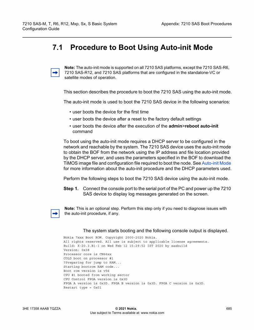
7210 SAS-M, T, R6, R12, Mxp, Sx, S Basic System Configuration Guide
Appendix: 7210 SAS Boot Procedures
3HE 17358 AAAB TQZZA © 2021 Nokia. Use subject to Terms available at: www.nokia.com
685
7.1 Procedure to Boot Using Auto-init Mode
This section describes the procedure to boot the 7210 SAS using the auto-init mode.
The auto-init mode is used to boot the 7210 SAS device in the following scenarios:
• user boots the device for the first time• user boots the device after a reset to the factory default settings• user boots the device after the execution of the admin>reboot auto-init
command
To boot using the auto-init mode requires a DHCP server to be configured in the network and reachable by the system. The 7210 SAS device uses the auto-init mode to obtain the BOF from the network using the IP address and file location provided by the DHCP server, and uses the parameters specified in the BOF to download the TiMOS image file and configuration file required to boot the node. See Auto-init Mode for more information about the auto-init procedure and the DHCP parameters used.
Perform the following steps to boot the 7210 SAS device using the auto-init mode.
Step 1. Connect the console port to the serial port of the PC and power up the 7210 SAS device to display log messages generated on the screen.
The system starts booting and the following console output is displayed. Nokia 7xxx Boot ROM. Copyright 2000-2020 Nokia.All rights reserved. All use is subject to applicable license agreements.Build: X-20.3.B1-1 on Wed Feb 12 15:29:52 IST 2020 by sasbuildVersion: 0x38Processor core is CN66xxCOLD boot on processor #1?Preparing for jump to RAM...Starting bootrom RAM code...Boot rom version is v56CPU #1 booted from working sectorCPU Control FPGA version is 0x3DFPGA A version is 0x3D. FPGA B version is 0x3D. FPGA C version is 0x3D.Restart type = 0x01
Note: The auto-init mode is supported on all 7210 SAS platforms, except the 7210 SAS-R6, 7210 SAS-R12, and 7210 SAS platforms that are configured in the standalone-VC or satellite modes of operation.
Note: This is an optional step. Perform this step only if you need to diagnose issues with the auto-init procedure, if any.

Appendix: 7210 SAS Boot Procedures
686
7210 SAS-M, T, R6, R12, Mxp, Sx, S Basic SystemConfiguration Guide
© 2021 Nokia. Use subject to Terms available at: www.nokia.com
3HE 17358 AAAB TQZZA
>>>Validate SDRAM from 0x000000007fdfff80 to 0x0000000080000000 (decrementing)>>>Testing SDRAM from 0x0000000002200000 to 0x000000007fdfff80>>>Testing SDRAM from 0xffffffffe0000000 to 0xffffffffe2000000Power on Diagnostics passedBoard Serial Number is 'NS1715T0019'
Total Memory: 2GB Chassis Type: 0xa Card Type: 0x43TiMOS-V-20.3.B1-1 bootrom/hops Nokia SAS-Sx 64SFP+4cfp4 7210 Copyright (c) 2000-2020 Nokia.All rights reserved. All use subject to applicable license agreements.Built on Wed Feb 12 15:28:49 IST 2020 by sasbuild in /home/sasbuild/20.3B1/panos/mSearching for boot.tim on local drives:Attempting to load file cf1:/boot.timVersion L-20.3.B1-1, Wed Feb 12 15:31:09 IST 2020 by sasbuild in /home/sasbuild/20.3B1/panos/maintext:(13818400-->40990080) + data:(3162656-->19580220)Starting at 0x18000000...
Total Memory: 2GB Chassis Type: 0xa Card Type: 0x43TiMOS-L-20.3.B1-1 boot/hops Nokia SAS-Sx 64SFP+4cfp4 7210 Copyright (c) 2000-2020 Nokia.All rights reserved. All use subject to applicable license agreements.Built on Wed Feb 12 15:31:09 IST 2020 by sasbuild in /home/sasbuild/20.3B1/panos/main
TiMOS BOOT LOADERTime from clock is WED MAR 04 09:23:22 2020 UTCSwitching serial output to sync mode... doneChassis-role is set to : factory-default
Step 2. The system lists the default settings and the following console output is displayed.
Looking for cf1:/bof.cfg ... OK, reading
Contents of Boot Options File on cf1:#eth-mgmt Port Settings:
eth-mgmt-disabled#uplinkA Port Settings:
uplinkA-port 1/1/65no uplinkA-autoneguplinkA-duplex fulluplinkA-speed 100000uplinkA-address 0uplinkA-vlan 0
#uplinkB Port Settings:uplinkB-port 1/1/66no uplinkB-autoneguplinkB-duplex fulluplinkB-speed 100000uplinkB-address 0uplinkB-vlan 0
#System Settings:wait 3persist offconsole-speed 115200no console-disabled
Hit a key within 1 second to change boot parameters...
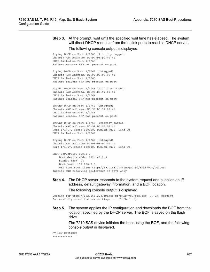
7210 SAS-M, T, R6, R12, Mxp, Sx, S Basic System Configuration Guide
Appendix: 7210 SAS Boot Procedures
3HE 17358 AAAB TQZZA © 2021 Nokia. Use subject to Terms available at: www.nokia.com
687
Step 3. At the prompt, wait until the specified wait time has elapsed. The system will direct DHCP requests from the uplink ports to reach a DHCP server. The following console output is displayed.
Trying DHCP on Port 1/1/65 (Priority tagged)Chassis MAC Address: D0:99:D5:97:02:41DHCP failed on Port 1/1/65Failure reason: SFP not present on port
Trying DHCP on Port 1/1/65 (Untagged)Chassis MAC Address: D0:99:D5:97:02:41DHCP failed on Port 1/1/65Failure reason: SFP not present on port
Trying DHCP on Port 1/1/66 (Priority tagged)Chassis MAC Address: D0:99:D5:97:02:41DHCP failed on Port 1/1/66Failure reason: SFP not present on port
Trying DHCP on Port 1/1/66 (Untagged)Chassis MAC Address: D0:99:D5:97:02:41DHCP failed on Port 1/1/66Failure reason: SFP not present on port
Trying DHCP on Port 1/1/67 (Priority tagged)Chassis MAC Address: D0:99:D5:97:02:41Port 1/1/67, Speed:100000, Duplex:Full, Link:Up.DHCP failed on Port 1/1/67
Trying DHCP on Port 1/1/67 (Untagged)Chassis MAC Address: D0:99:D5:97:02:41Port 1/1/67, Speed:100000, Duplex:Full, Link:Up.
DHCP Server:192.168.2.8Boot device addr: 192.168.2.9Subnet mask: 24Boot host: 192.168.2.8Url from Boot file: tftp://192.168.2.8/images-pf/SASS/voy/bof.cfg
Initial DNS resolving preference is ipv4-only
Step 4. The DHCP server responds to the system request and supplies an IP address, default gateway information, and a BOF location. The following console output is displayed.
Looking for tftp://192.168.2.8/images-pf/SASS/voy/bof.cfg ... OK, readingSuccessfully saved the new settings in cf1:/bof.cfg
Step 5. The system applies the IP configuration and downloads the BOF from the location specified by the DHCP server. The BOF is saved on the flash drive.The 7210 SAS device initiates the boot using the BOF, and the following console output is displayed.
My New Settings------------
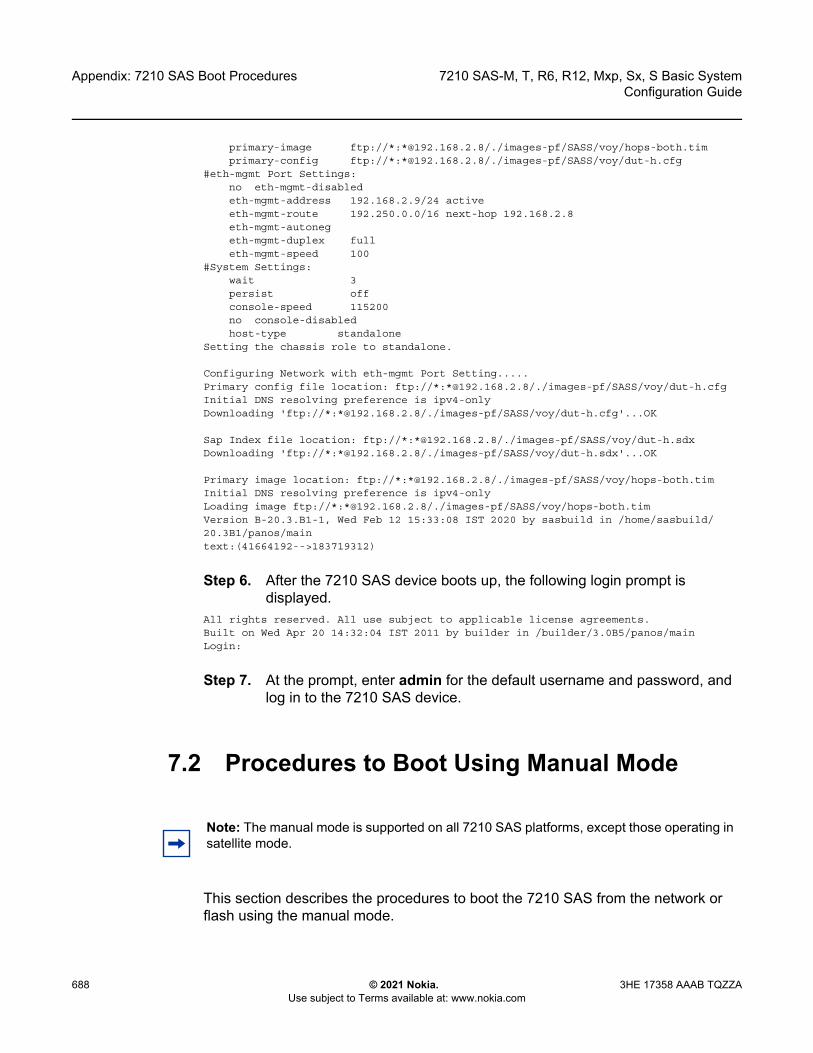
Appendix: 7210 SAS Boot Procedures
688
7210 SAS-M, T, R6, R12, Mxp, Sx, S Basic SystemConfiguration Guide
© 2021 Nokia. Use subject to Terms available at: www.nokia.com
3HE 17358 AAAB TQZZA
primary-image ftp://*:*@192.168.2.8/./images-pf/SASS/voy/hops-both.timprimary-config ftp://*:*@192.168.2.8/./images-pf/SASS/voy/dut-h.cfg
#eth-mgmt Port Settings:no eth-mgmt-disabledeth-mgmt-address 192.168.2.9/24 activeeth-mgmt-route 192.250.0.0/16 next-hop 192.168.2.8eth-mgmt-autonegeth-mgmt-duplex fulleth-mgmt-speed 100
#System Settings:wait 3persist offconsole-speed 115200no console-disabledhost-type standalone
Setting the chassis role to standalone.
Configuring Network with eth-mgmt Port Setting.....Primary config file location: ftp://*:*@192.168.2.8/./images-pf/SASS/voy/dut-h.cfgInitial DNS resolving preference is ipv4-onlyDownloading 'ftp://*:*@192.168.2.8/./images-pf/SASS/voy/dut-h.cfg'...OK
Sap Index file location: ftp://*:*@192.168.2.8/./images-pf/SASS/voy/dut-h.sdxDownloading 'ftp://*:*@192.168.2.8/./images-pf/SASS/voy/dut-h.sdx'...OK
Primary image location: ftp://*:*@192.168.2.8/./images-pf/SASS/voy/hops-both.timInitial DNS resolving preference is ipv4-onlyLoading image ftp://*:*@192.168.2.8/./images-pf/SASS/voy/hops-both.timVersion B-20.3.B1-1, Wed Feb 12 15:33:08 IST 2020 by sasbuild in /home/sasbuild/20.3B1/panos/maintext:(41664192-->183719312)
Step 6. After the 7210 SAS device boots up, the following login prompt is displayed.
All rights reserved. All use subject to applicable license agreements.Built on Wed Apr 20 14:32:04 IST 2011 by builder in /builder/3.0B5/panos/mainLogin:
Step 7. At the prompt, enter admin for the default username and password, and log in to the 7210 SAS device.
7.2 Procedures to Boot Using Manual Mode
This section describes the procedures to boot the 7210 SAS from the network or flash using the manual mode.
Note: The manual mode is supported on all 7210 SAS platforms, except those operating in satellite mode.
7210 SAS-M, T, R6, R12, Mxp, Sx, S Basic System Configuration Guide
Appendix: 7210 SAS Boot Procedures
3HE 17358 AAAB TQZZA © 2021 Nokia. Use subject to Terms available at: www.nokia.com
689
The manual mode can be used to boot the 7210 SAS device in the following scenarios:
• user boots the device for the first time• user boots the device after a reset to the factory default settings, or after
executing the admin>reboot auto-init command (this command is not supported on the 7210 SAS-R6 and 7210 SAS-R12, and 7210 SAS platforms configured in the standalone-VC mode of operation)
In all scenarios, the user must create a local BOF by connecting a console to the node and interrupting the boot process to configure the BOF parameters. The following sections provide the details for configuring the BOF parameters under different scenarios.
The manual mode has two options:
• 7210 SAS device is booted from the local image on flash; see section 7.2.1 (supported on all 7210 SAS platforms, except those operating in the satellite mode)
• 7210 SAS device is booted from the network using an uplink port (section 7.2.2; supported on all 7210 SAS platforms, except the 7210 SAS-R6 and 7210 SAS-R12) or the Ethernet management port (section 7.2.3; supported on all 7210 SAS platforms when the Ethernet management port is available)
7.2.1 Procedure to Boot from the Image on Flash in Manual Mode
The 7210 SAS-M and 7210 SAS-D are factory-shipped with the boot.tim and both.tim (TiMOS image) on the internal flash. These devices attempt to boot using the auto-init mode when they are booted for the first time from factory. If the auto-init mode fails, the node loads with the image on the flash. If the user wants to continue using this image, they must connect to a console and execute the admin auto-init stop command in the TiMOS prompt. If the user does not execute this command, the device reboots and attempts the auto-init mode procedure again.
Note: This procedure is not supported for 7210 SAS platforms configured in the satellite mode of operation.

Appendix: 7210 SAS Boot Procedures
690
7210 SAS-M, T, R6, R12, Mxp, Sx, S Basic SystemConfiguration Guide
© 2021 Nokia. Use subject to Terms available at: www.nokia.com
3HE 17358 AAAB TQZZA
For the 7210 SAS-Dxp, 7210 SAS-K 2F1C2T, 7210 SAS-K 2F6C4T, 7210 SAS-K 3SFP+ 8C, 7210 SAS-Mxp, 7210 SAS-R6, 7210 SAS-R12, 7210 SAS-Sx/S 1/10GE, 7210 SAS-Sx 10/100GE, and 7210 SAS-T, the user must buy a software license that is factory-shipped with the TiMOS image on a flash or SD card device. The user must plug the flash or SD card device in the designated slot for the external flash or SD card device and power on the unit.
Perform the following steps to boot the system in the manual mode from the local image on the flash.
Step 1. Connect the 7210 SAS console port to the serial port of the PC, and power up the 7210 SAS device. The system starts booting and the following console output is displayed.
Nokia 7xxx Boot ROM. Copyright 2000-2020 Nokia.All rights reserved. All use is subject to applicable license agreements.Build: X-20.3.B1-1 on Wed Feb 12 15:29:52 IST 2020 by sasbuildVersion: 0x38Processor core is CN66xxCOLD boot on processor #1?Preparing for jump to RAM...Starting bootrom RAM code...Boot rom version is v56CPU #1 booted from working sectorCPU Control FPGA version is 0x3DFPGA A version is 0x3D. FPGA B version is 0x3D. FPGA C version is 0x3D.Restart type = 0x01>>>Validate SDRAM from 0x000000007fdfff80 to 0x0000000080000000 (decrementing)>>>Testing SDRAM from 0x0000000002200000 to 0x000000007fdfff80>>>Testing SDRAM from 0xffffffffe0000000 to 0xffffffffe2000000Power on Diagnostics passedBoard Serial Number is 'NS1720T0009'
Total Memory: 2GB Chassis Type: 0xa Card Type: 0x43TiMOS-V-20.3.B1-1 bootrom/hops Nokia SAS-Sx 64SFP+4CFP4 7210 Copyright (c) 2000-2020 Nokia.All rights reserved. All use subject to applicable license agreements.Built on Wed Feb 12 15:28:49 IST 2020 by sasbuild in /home/sasbuild/20.3B1/panos/m
Searching for boot.tim on local drives:Attempting to load file cf1:/boot.timVersion L-20.3.B1-1, Wed Feb 12 15:31:09 IST 2020 by sasbuild in /home/sasbuild/20.3B1/panos/maintext:(13818400-->40990080) + data:(3162656-->19580220)Starting at 0x18000000...
Total Memory: 2GB Chassis Type: 0xa Card Type: 0x43TiMOS-L-20.3.B1-1 boot/hops Nokia SAS-Sx 64SFP+4CFP4 7210 Copyright (c) 2000-2020 Nokia.All rights reserved. All use subject to applicable license agreements.
Note: Refer to the corresponding 7210 SAS chassis installation guide for information about equipment required to setup the device.

7210 SAS-M, T, R6, R12, Mxp, Sx, S Basic System Configuration Guide
Appendix: 7210 SAS Boot Procedures
3HE 17358 AAAB TQZZA © 2021 Nokia. Use subject to Terms available at: www.nokia.com
691
Built on Wed Feb 12 15:31:09 IST 2020 by sasbuild in /home/sasbuild/20.3B1/panos/main
TiMOS BOOT LOADERTime from clock is SUN MAR 15 15:19:08 2020 UTCSwitching serial output to sync mode... doneChassis-role is set to : factory-default
Step 2. The system lists the default settings and the following console output is displayed.
Looking for cf1:/bof.cfg ... OK, readingContents of Boot Options File on cf1:#eth-mgmt Port Settings:
eth-mgmt-disabled#uplinkA Port Settings:
uplinkA-port 1/1/65no uplinkA-autoneguplinkA-duplex fulluplinkA-speed 100000uplinkA-address 0uplinkA-vlan 0
#uplinkB Port Settings:uplinkB-port 1/1/66no uplinkB-autoneguplinkB-duplex fulluplinkB-speed 100000uplinkB-address 0uplinkB-vlan 0
#System Settings:wait 3persist offconsole-speed 115200no console-disabled
Hit a key within 3 seconds to change boot parameters...
Step 3. At the prompt, press any key to initiate boot parameter updates.The following console output is displayed.
Enter password to edit the Boot Options FileOr CTRL-D to exit the prompt
Waiting for 30 seconds to enter passwordPassword:
Step 4. At the prompt, enter the default password password, and initiate the BOF edit.The system accepts the password and the following console output is displayed.
You must supply some required Boot Options. At any prompt, you can type:"restart" - restart the query mode."reboot" - reboot."exit" - boot with with existing values."diag" - enter the diag shell."reset" - reset the bof and reboot.
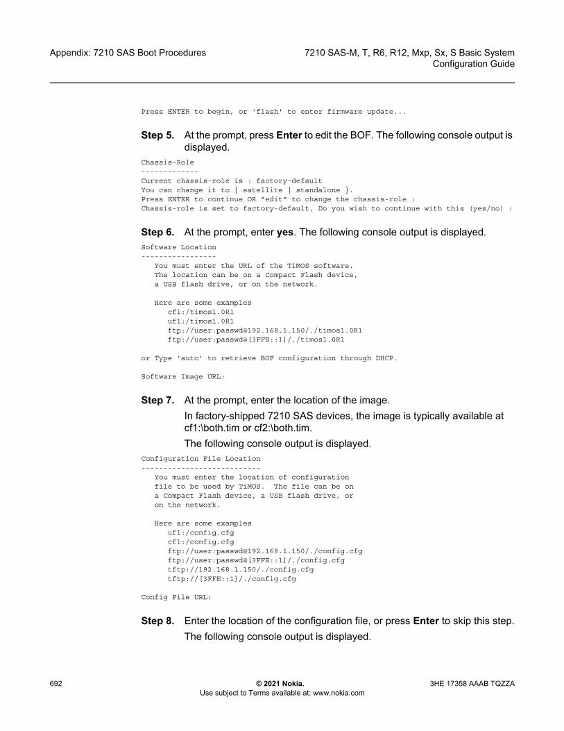
Appendix: 7210 SAS Boot Procedures
692
7210 SAS-M, T, R6, R12, Mxp, Sx, S Basic SystemConfiguration Guide
© 2021 Nokia. Use subject to Terms available at: www.nokia.com
3HE 17358 AAAB TQZZA
Press ENTER to begin, or 'flash' to enter firmware update...
Step 5. At the prompt, press Enter to edit the BOF. The following console output is displayed.
Chassis-Role-------------Current chassis-role is : factory-defaultYou can change it to { satellite | standalone }.Press ENTER to continue OR "edit" to change the chassis-role :Chassis-role is set to factory-default, Do you wish to continue with this (yes/no) :
Step 6. At the prompt, enter yes. The following console output is displayed.Software Location-----------------
You must enter the URL of the TiMOS software.The location can be on a Compact Flash device,a USB flash drive, or on the network.
Here are some examplescf1:/timos1.0R1uf1:/timos1.0R1ftp://user:[email protected]/./timos1.0R1ftp://user:passwd@[3FFE::1]/./timos1.0R1
or Type 'auto' to retrieve BOF configuration through DHCP.
Software Image URL:
Step 7. At the prompt, enter the location of the image. In factory-shipped 7210 SAS devices, the image is typically available at cf1:\both.tim or cf2:\both.tim. The following console output is displayed.
Configuration File Location---------------------------
You must enter the location of configurationfile to be used by TiMOS. The file can be ona Compact Flash device, a USB flash drive, oron the network.
Here are some examplesuf1:/config.cfgcf1:/config.cfgftp://user:[email protected]/./config.cfgftp://user:passwd@[3FFE::1]/./config.cfgtftp://192.168.1.150/./config.cfgtftp://[3FFE::1]/./config.cfg
Config File URL:
Step 8. Enter the location of the configuration file, or press Enter to skip this step.The following console output is displayed.

7210 SAS-M, T, R6, R12, Mxp, Sx, S Basic System Configuration Guide
Appendix: 7210 SAS Boot Procedures
3HE 17358 AAAB TQZZA © 2021 Nokia. Use subject to Terms available at: www.nokia.com
693
Current configuration enables use of console (setting is "no console-disabled")Press ENTER to proceed with existing setting or 'disable' to disable console access:
Step 9. At the prompt, press Enter. The following console output is displayed.New Settings------------
primary-image cf2:/both.timprimary-config uf1:/sassx64.cfg
#eth-mgmt Port Settings:eth-mgmt-disabled
#uplinkA Port Settings:uplinkA-port 1/1/65no uplinkA-autoneguplinkA-duplex fulluplinkA-speed 100000uplinkA-address 0uplinkA-vlan 0
#uplinkB Port Settings:uplinkB-port 1/1/66no uplinkB-autoneguplinkB-duplex fulluplinkB-speed 100000uplinkB-address 0uplinkB-vlan 0
#System Settings:wait 3persist offconsole-speed 115200no console-disabled
Do you want to overwrite cf1:/bof.cfg with the new settings? (yes/no):
Step 10. At the prompt, enter yes. The 7210 SAS device begins to boot with the new settings. The following console output is displayed.
Successfully saved the new settings in cf1:/bof.cfg
Configuring Network with uplinkA Port Setting.....Primary config file present at: uf1:/sassx64.cfg
Skipping missing or bad Sap index file 'uf1:/sassx64.sdx'
Primary image location: cf2:/both.timLoading image cf2:\both.timVersion B-20.3.B1-1, Wed Feb 12 15:33:08 IST 2020 by sasbuild in /home/sasbuild/20.3B1/panos/maintext:(41664192-->183719312) + data:(7133216-->49945144)Executing TiMOS image at 0x2800000
Step 11. After the 7210 SAS device boots up, the following login prompt is displayed.
All rights reserved. All use subject to applicable license agreements.Built on Wed Apr 20 14:32:04 IST 2011 by builder in /builder/3.0B5/panos/mainLogin:
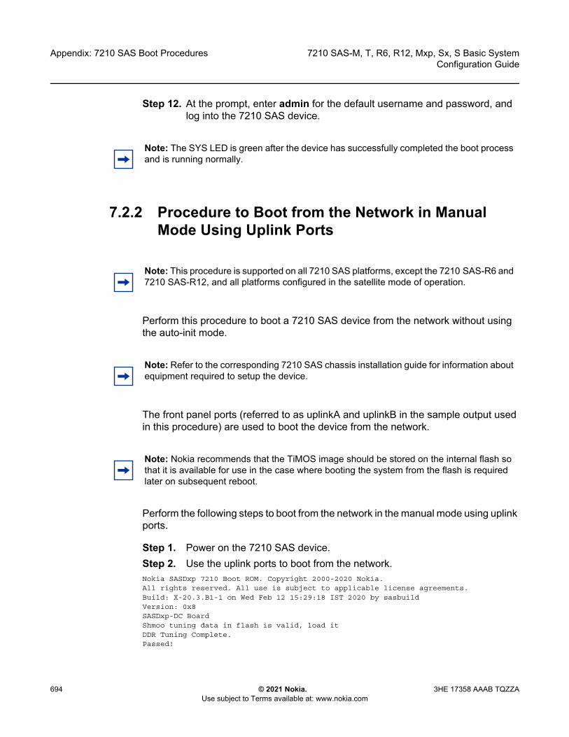
Appendix: 7210 SAS Boot Procedures
694
7210 SAS-M, T, R6, R12, Mxp, Sx, S Basic SystemConfiguration Guide
© 2021 Nokia. Use subject to Terms available at: www.nokia.com
3HE 17358 AAAB TQZZA
Step 12. At the prompt, enter admin for the default username and password, and log into the 7210 SAS device.
7.2.2 Procedure to Boot from the Network in Manual Mode Using Uplink Ports
Perform this procedure to boot a 7210 SAS device from the network without using the auto-init mode.
The front panel ports (referred to as uplinkA and uplinkB in the sample output used in this procedure) are used to boot the device from the network.
Perform the following steps to boot from the network in the manual mode using uplink ports.
Step 1. Power on the 7210 SAS device.Step 2. Use the uplink ports to boot from the network.Nokia SASDxp 7210 Boot ROM. Copyright 2000-2020 Nokia.All rights reserved. All use is subject to applicable license agreements.Build: X-20.3.B1-1 on Wed Feb 12 15:29:18 IST 2020 by sasbuildVersion: 0x8SASDxp-DC BoardShmoo tuning data in flash is valid, load itDDR Tuning Complete.Passed!
Note: The SYS LED is green after the device has successfully completed the boot process and is running normally.
Note: This procedure is supported on all 7210 SAS platforms, except the 7210 SAS-R6 and 7210 SAS-R12, and all platforms configured in the satellite mode of operation.
Note: Refer to the corresponding 7210 SAS chassis installation guide for information about equipment required to setup the device.
Note: Nokia recommends that the TiMOS image should be stored on the internal flash so that it is available for use in the case where booting the system from the flash is required later on subsequent reboot.
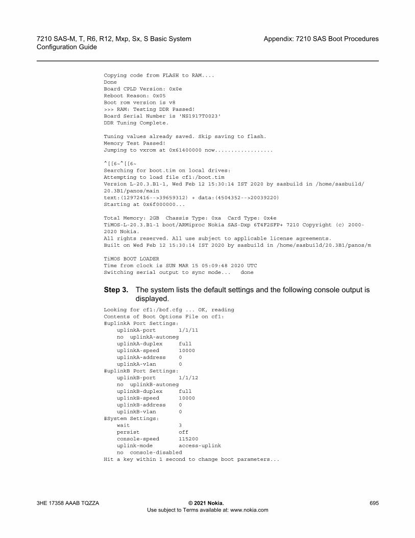
7210 SAS-M, T, R6, R12, Mxp, Sx, S Basic System Configuration Guide
Appendix: 7210 SAS Boot Procedures
3HE 17358 AAAB TQZZA © 2021 Nokia. Use subject to Terms available at: www.nokia.com
695
Copying code from FLASH to RAM....DoneBoard CPLD Version: 0x0eReboot Reason: 0x05Boot rom version is v8>>> RAM: Testing DDR Passed!Board Serial Number is 'NS1917T0023'DDR Tuning Complete.
Tuning values already saved. Skip saving to flash.Memory Test Passed!Jumping to vxrom at 0x61400000 now..................
^[[6~^[[6~Searching for boot.tim on local drives:Attempting to load file cf1:/boot.timVersion L-20.3.B1-1, Wed Feb 12 15:30:14 IST 2020 by sasbuild in /home/sasbuild/20.3B1/panos/maintext:(12972416-->39659312) + data:(4504352-->20039220)Starting at 0x6f000000...
Total Memory: 2GB Chassis Type: 0xa Card Type: 0x4eTiMOS-L-20.3.B1-1 boot/ARMiproc Nokia SAS-Dxp 6T4F2SFP+ 7210 Copyright (c) 2000-2020 Nokia.All rights reserved. All use subject to applicable license agreements.Built on Wed Feb 12 15:30:14 IST 2020 by sasbuild in /home/sasbuild/20.3B1/panos/m
TiMOS BOOT LOADERTime from clock is SUN MAR 15 05:09:48 2020 UTCSwitching serial output to sync mode... done
Step 3. The system lists the default settings and the following console output is displayed.
Looking for cf1:/bof.cfg ... OK, readingContents of Boot Options File on cf1:#uplinkA Port Settings:
uplinkA-port 1/1/11no uplinkA-autoneguplinkA-duplex fulluplinkA-speed 10000uplinkA-address 0uplinkA-vlan 0
#uplinkB Port Settings:uplinkB-port 1/1/12no uplinkB-autoneguplinkB-duplex fulluplinkB-speed 10000uplinkB-address 0uplinkB-vlan 0
#System Settings:wait 3persist offconsole-speed 115200uplink-mode access-uplinkno console-disabled
Hit a key within 1 second to change boot parameters...
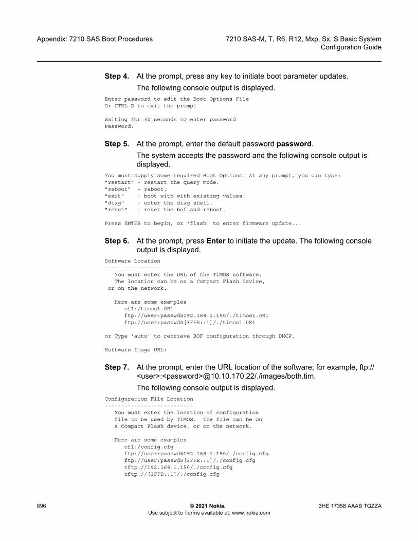
Appendix: 7210 SAS Boot Procedures
696
7210 SAS-M, T, R6, R12, Mxp, Sx, S Basic SystemConfiguration Guide
© 2021 Nokia. Use subject to Terms available at: www.nokia.com
3HE 17358 AAAB TQZZA
Step 4. At the prompt, press any key to initiate boot parameter updates. The following console output is displayed.
Enter password to edit the Boot Options FileOr CTRL-D to exit the prompt
Waiting for 30 seconds to enter passwordPassword:
Step 5. At the prompt, enter the default password password.The system accepts the password and the following console output is displayed.
You must supply some required Boot Options. At any prompt, you can type:"restart" - restart the query mode."reboot" - reboot."exit" - boot with with existing values."diag" - enter the diag shell."reset" - reset the bof and reboot.
Press ENTER to begin, or 'flash' to enter firmware update...
Step 6. At the prompt, press Enter to initiate the update. The following console output is displayed.
Software Location-----------------
You must enter the URL of the TiMOS software.The location can be on a Compact Flash device,
or on the network.
Here are some examplescf1:/timos1.0R1ftp://user:[email protected]/./timos1.0R1ftp://user:passwd@[3FFE::1]/./timos1.0R1
or Type 'auto' to retrieve BOF configuration through DHCP.
Software Image URL:
Step 7. At the prompt, enter the URL location of the software; for example, ftp://<user>:<password>@10.10.170.22/./images/both.tim.The following console output is displayed.
Configuration File Location---------------------------
You must enter the location of configurationfile to be used by TiMOS. The file can be ona Compact Flash device, or on the network.
Here are some examplescf1:/config.cfgftp://user:[email protected]/./config.cfgftp://user:passwd@[3FFE::1]/./config.cfgtftp://192.168.1.150/./config.cfgtftp://[3FFE::1]/./config.cfg
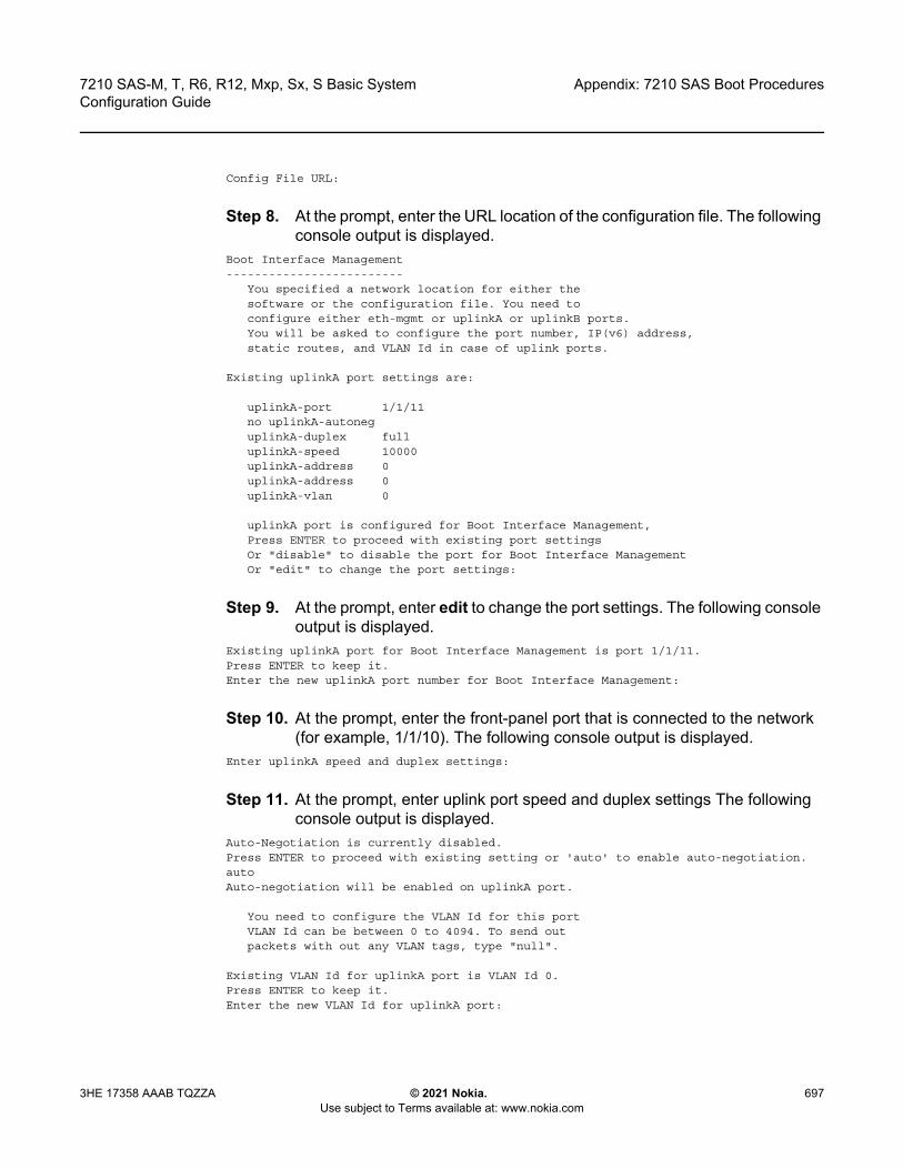
7210 SAS-M, T, R6, R12, Mxp, Sx, S Basic System Configuration Guide
Appendix: 7210 SAS Boot Procedures
3HE 17358 AAAB TQZZA © 2021 Nokia. Use subject to Terms available at: www.nokia.com
697
Config File URL:
Step 8. At the prompt, enter the URL location of the configuration file. The following console output is displayed.
Boot Interface Management-------------------------
You specified a network location for either thesoftware or the configuration file. You need toconfigure either eth-mgmt or uplinkA or uplinkB ports.You will be asked to configure the port number, IP(v6) address,static routes, and VLAN Id in case of uplink ports.
Existing uplinkA port settings are:
uplinkA-port 1/1/11no uplinkA-autoneguplinkA-duplex fulluplinkA-speed 10000uplinkA-address 0uplinkA-address 0uplinkA-vlan 0
uplinkA port is configured for Boot Interface Management,Press ENTER to proceed with existing port settingsOr "disable" to disable the port for Boot Interface ManagementOr "edit" to change the port settings:
Step 9. At the prompt, enter edit to change the port settings. The following console output is displayed.
Existing uplinkA port for Boot Interface Management is port 1/1/11.Press ENTER to keep it.Enter the new uplinkA port number for Boot Interface Management:
Step 10. At the prompt, enter the front-panel port that is connected to the network (for example, 1/1/10). The following console output is displayed.
Enter uplinkA speed and duplex settings:
Step 11. At the prompt, enter uplink port speed and duplex settings The following console output is displayed.
Auto-Negotiation is currently disabled.Press ENTER to proceed with existing setting or 'auto' to enable auto-negotiation.autoAuto-negotiation will be enabled on uplinkA port.
You need to configure the VLAN Id for this portVLAN Id can be between 0 to 4094. To send outpackets with out any VLAN tags, type "null".
Existing VLAN Id for uplinkA port is VLAN Id 0.Press ENTER to keep it.Enter the new VLAN Id for uplinkA port:

Appendix: 7210 SAS Boot Procedures
698
7210 SAS-M, T, R6, R12, Mxp, Sx, S Basic SystemConfiguration Guide
© 2021 Nokia. Use subject to Terms available at: www.nokia.com
3HE 17358 AAAB TQZZA
Step 12. At the prompt, perform one of the following.a. Enter null to send out packets without VLAN tags.b. Enter the a VLAN tag ID for the uplink port.
The following console output is displayed.Using port 1/1/1 as uplinkA port for Boot Interface Management
You need to assign an IP address for this port.The IP address should be entered in standarddotted decimal form with a network length.example: 192.168.1.169/24Or type "0" to obtain IP address and static routethrough DHCP. Existing IP address and static routeswill be deleted.
Enter uplinkA IP Address (Type 0 if none desired):
Step 13. At the prompt, enter the port IP address and mask that the device should use (for example, 10.135.4.172/10).
Step 14. Because the FTP server is on a different subnet, enter the IP routing information. The following console output is displayed.
You specified network locations which might requirestatic routes to reach. You will be asked toenter static routes until all the locations becomereachable.Static routes should be entered in the following format:prefix/mask next-hop ip-addressexample: 192.168.0.0/16 next-hop 192.168.1.254
Would you like to add a static route? (yes/no)
Step 15. At the prompt, type yes and press Enter to add a static route.Enter route:
Step 16. Enter a static route to the FTP server subnet (for example, 10.10.170.0/10 next-hop 10.135.4.1). The following console output is displayed.
Existing uplinkB port settings are:
uplinkB-port 1/1/12no uplinkB-autoneguplinkB-duplex fulluplinkB-speed 10000uplinkB-address 0uplinkB-address 0uplinkB-vlan 0
uplinkB port is configured for Boot Interface Management,Press ENTER to proceed with existing port settingsOr "disable" to disable the port for Boot Interface ManagementOr "edit" to change the port settings:
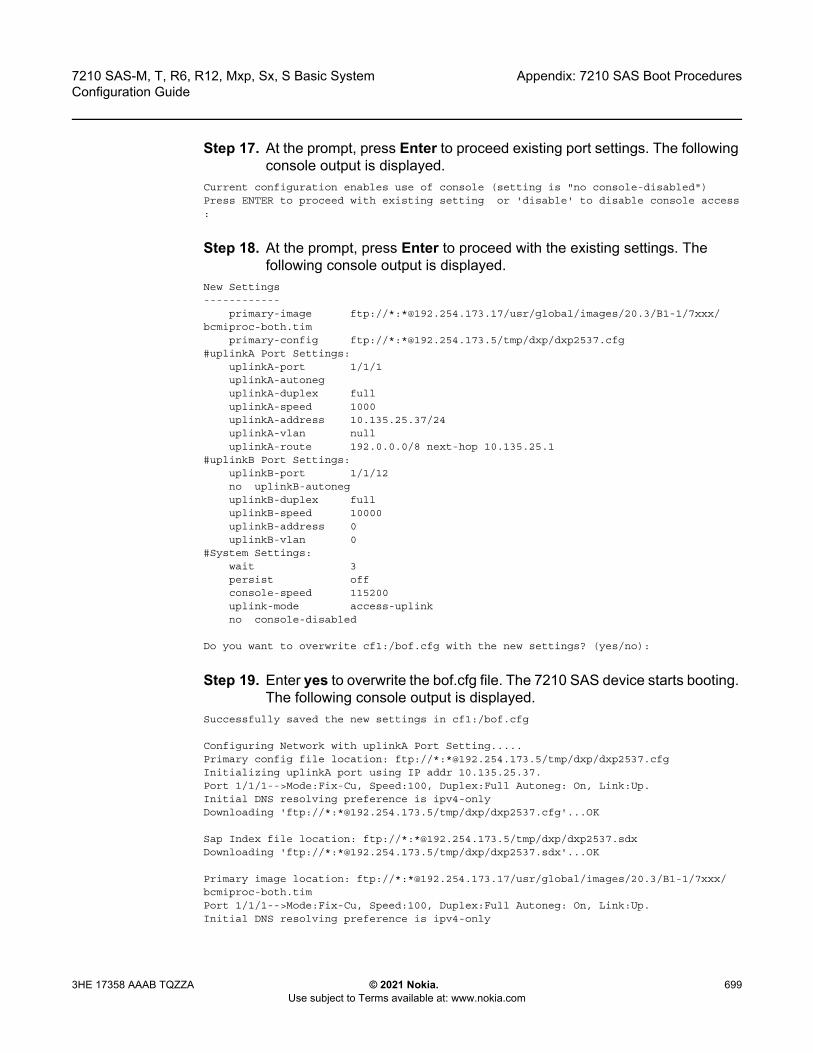
7210 SAS-M, T, R6, R12, Mxp, Sx, S Basic System Configuration Guide
Appendix: 7210 SAS Boot Procedures
3HE 17358 AAAB TQZZA © 2021 Nokia. Use subject to Terms available at: www.nokia.com
699
Step 17. At the prompt, press Enter to proceed existing port settings. The following console output is displayed.
Current configuration enables use of console (setting is "no console-disabled")Press ENTER to proceed with existing setting or 'disable' to disable console access:
Step 18. At the prompt, press Enter to proceed with the existing settings. The following console output is displayed.
New Settings------------
primary-image ftp://*:*@192.254.173.17/usr/global/images/20.3/B1-1/7xxx/bcmiproc-both.tim
primary-config ftp://*:*@192.254.173.5/tmp/dxp/dxp2537.cfg#uplinkA Port Settings:
uplinkA-port 1/1/1uplinkA-autoneguplinkA-duplex fulluplinkA-speed 1000uplinkA-address 10.135.25.37/24uplinkA-vlan nulluplinkA-route 192.0.0.0/8 next-hop 10.135.25.1
#uplinkB Port Settings:uplinkB-port 1/1/12no uplinkB-autoneguplinkB-duplex fulluplinkB-speed 10000uplinkB-address 0uplinkB-vlan 0
#System Settings:wait 3persist offconsole-speed 115200uplink-mode access-uplinkno console-disabled
Do you want to overwrite cf1:/bof.cfg with the new settings? (yes/no):
Step 19. Enter yes to overwrite the bof.cfg file. The 7210 SAS device starts booting. The following console output is displayed.
Successfully saved the new settings in cf1:/bof.cfg
Configuring Network with uplinkA Port Setting.....Primary config file location: ftp://*:*@192.254.173.5/tmp/dxp/dxp2537.cfgInitializing uplinkA port using IP addr 10.135.25.37.Port 1/1/1-->Mode:Fix-Cu, Speed:100, Duplex:Full Autoneg: On, Link:Up.Initial DNS resolving preference is ipv4-onlyDownloading 'ftp://*:*@192.254.173.5/tmp/dxp/dxp2537.cfg'...OK
Sap Index file location: ftp://*:*@192.254.173.5/tmp/dxp/dxp2537.sdxDownloading 'ftp://*:*@192.254.173.5/tmp/dxp/dxp2537.sdx'...OK
Primary image location: ftp://*:*@192.254.173.17/usr/global/images/20.3/B1-1/7xxx/bcmiproc-both.timPort 1/1/1-->Mode:Fix-Cu, Speed:100, Duplex:Full Autoneg: On, Link:Up.Initial DNS resolving preference is ipv4-only
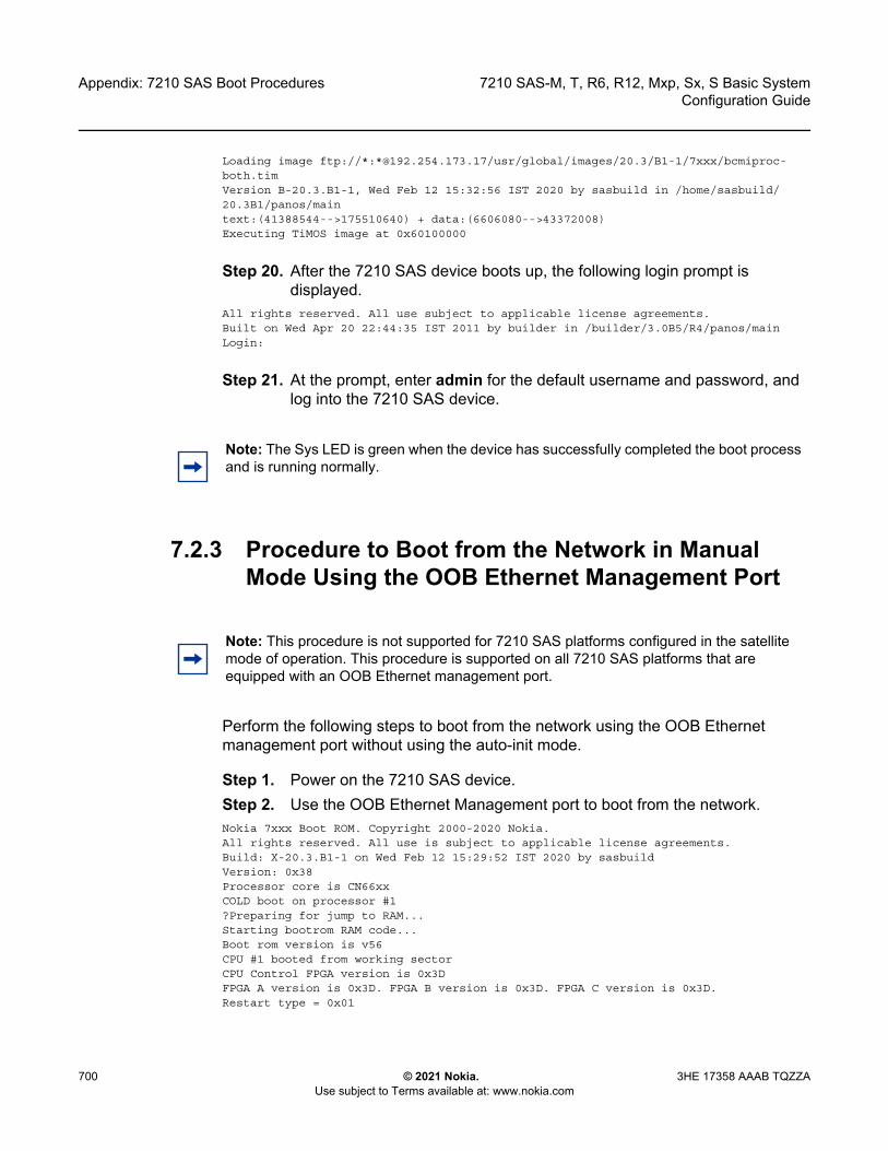
Appendix: 7210 SAS Boot Procedures
700
7210 SAS-M, T, R6, R12, Mxp, Sx, S Basic SystemConfiguration Guide
© 2021 Nokia. Use subject to Terms available at: www.nokia.com
3HE 17358 AAAB TQZZA
Loading image ftp://*:*@192.254.173.17/usr/global/images/20.3/B1-1/7xxx/bcmiproc-both.timVersion B-20.3.B1-1, Wed Feb 12 15:32:56 IST 2020 by sasbuild in /home/sasbuild/20.3B1/panos/maintext:(41388544-->175510640) + data:(6606080-->43372008)Executing TiMOS image at 0x60100000
Step 20. After the 7210 SAS device boots up, the following login prompt is displayed.
All rights reserved. All use subject to applicable license agreements.Built on Wed Apr 20 22:44:35 IST 2011 by builder in /builder/3.0B5/R4/panos/mainLogin:
Step 21. At the prompt, enter admin for the default username and password, and log into the 7210 SAS device.
7.2.3 Procedure to Boot from the Network in Manual Mode Using the OOB Ethernet Management Port
Perform the following steps to boot from the network using the OOB Ethernet management port without using the auto-init mode.
Step 1. Power on the 7210 SAS device.Step 2. Use the OOB Ethernet Management port to boot from the network.Nokia 7xxx Boot ROM. Copyright 2000-2020 Nokia.All rights reserved. All use is subject to applicable license agreements.Build: X-20.3.B1-1 on Wed Feb 12 15:29:52 IST 2020 by sasbuildVersion: 0x38Processor core is CN66xxCOLD boot on processor #1?Preparing for jump to RAM...Starting bootrom RAM code...Boot rom version is v56CPU #1 booted from working sectorCPU Control FPGA version is 0x3DFPGA A version is 0x3D. FPGA B version is 0x3D. FPGA C version is 0x3D.Restart type = 0x01
Note: The Sys LED is green when the device has successfully completed the boot process and is running normally.
Note: This procedure is not supported for 7210 SAS platforms configured in the satellite mode of operation. This procedure is supported on all 7210 SAS platforms that are equipped with an OOB Ethernet management port.
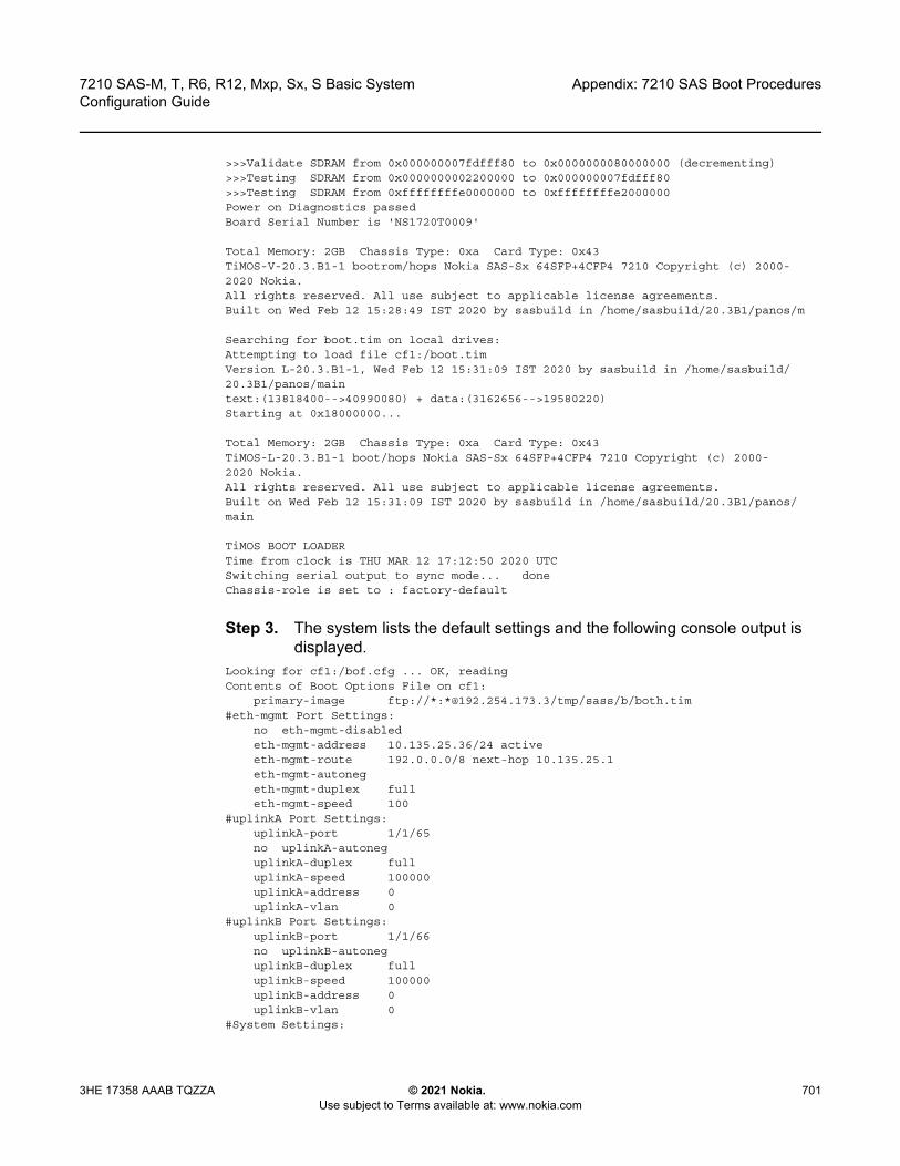
7210 SAS-M, T, R6, R12, Mxp, Sx, S Basic System Configuration Guide
Appendix: 7210 SAS Boot Procedures
3HE 17358 AAAB TQZZA © 2021 Nokia. Use subject to Terms available at: www.nokia.com
701
>>>Validate SDRAM from 0x000000007fdfff80 to 0x0000000080000000 (decrementing)>>>Testing SDRAM from 0x0000000002200000 to 0x000000007fdfff80>>>Testing SDRAM from 0xffffffffe0000000 to 0xffffffffe2000000Power on Diagnostics passedBoard Serial Number is 'NS1720T0009'
Total Memory: 2GB Chassis Type: 0xa Card Type: 0x43TiMOS-V-20.3.B1-1 bootrom/hops Nokia SAS-Sx 64SFP+4CFP4 7210 Copyright (c) 2000-2020 Nokia.All rights reserved. All use subject to applicable license agreements.Built on Wed Feb 12 15:28:49 IST 2020 by sasbuild in /home/sasbuild/20.3B1/panos/m
Searching for boot.tim on local drives:Attempting to load file cf1:/boot.timVersion L-20.3.B1-1, Wed Feb 12 15:31:09 IST 2020 by sasbuild in /home/sasbuild/20.3B1/panos/maintext:(13818400-->40990080) + data:(3162656-->19580220)Starting at 0x18000000...
Total Memory: 2GB Chassis Type: 0xa Card Type: 0x43TiMOS-L-20.3.B1-1 boot/hops Nokia SAS-Sx 64SFP+4CFP4 7210 Copyright (c) 2000-2020 Nokia.All rights reserved. All use subject to applicable license agreements.Built on Wed Feb 12 15:31:09 IST 2020 by sasbuild in /home/sasbuild/20.3B1/panos/main
TiMOS BOOT LOADERTime from clock is THU MAR 12 17:12:50 2020 UTCSwitching serial output to sync mode... doneChassis-role is set to : factory-default
Step 3. The system lists the default settings and the following console output is displayed.
Looking for cf1:/bof.cfg ... OK, readingContents of Boot Options File on cf1:
primary-image ftp://*:*@192.254.173.3/tmp/sass/b/both.tim#eth-mgmt Port Settings:
no eth-mgmt-disabledeth-mgmt-address 10.135.25.36/24 activeeth-mgmt-route 192.0.0.0/8 next-hop 10.135.25.1eth-mgmt-autonegeth-mgmt-duplex fulleth-mgmt-speed 100
#uplinkA Port Settings:uplinkA-port 1/1/65no uplinkA-autoneguplinkA-duplex fulluplinkA-speed 100000uplinkA-address 0uplinkA-vlan 0
#uplinkB Port Settings:uplinkB-port 1/1/66no uplinkB-autoneguplinkB-duplex fulluplinkB-speed 100000uplinkB-address 0uplinkB-vlan 0
#System Settings:

Appendix: 7210 SAS Boot Procedures
702
7210 SAS-M, T, R6, R12, Mxp, Sx, S Basic SystemConfiguration Guide
© 2021 Nokia. Use subject to Terms available at: www.nokia.com
3HE 17358 AAAB TQZZA
wait 3persist offconsole-speed 115200no console-disabled
Hit a key within 3 seconds to change boot parameters...
Step 4. At the prompt, press any key to initiate boot parameter updates. The following console output is displayed.
Enter password to edit the Boot Options FileOr CTRL-D to exit the prompt
Waiting for 30 seconds to enter passwordPassword:
Step 5. At the prompt, enter the default password password.The system accepts the password and the following console output is displayed.
You must supply some required Boot Options. At any prompt, you can type:"restart" - restart the query mode."reboot" - reboot."exit" - boot with with existing values."diag" - enter the diag shell."reset" - reset the bof and reboot.
Press ENTER to begin, or 'flash' to enter firmware update...
Step 6. At the prompt, press Enter to initiate the update. The following console output is displayed.
Chassis-Role-------------Current chassis-role is : factory-defaultYou can change it to { satellite | standalone }.Press ENTER to continue OR "edit" to change the chassis-role :Chassis-role is set to factory-default, Do you wish to continue with this (yes/no) :
Step 7. At the prompt, enter yes. The following console output is displayed.Software Location-----------------You must enter the URL of the TiMOS software.The location can be on a Compact Flash device,or on the network.
Here are some examplescf1:/timos1.0R1ftp://user:[email protected]/./timos1.0R1tftp://192.168.1.150/./timos1.0R1
Software Image URL:
Step 8. At the prompt, enter the URL location of the software; for example, ftp://<user>:<password>@10.10.170.22/./images/both.tim.

7210 SAS-M, T, R6, R12, Mxp, Sx, S Basic System Configuration Guide
Appendix: 7210 SAS Boot Procedures
3HE 17358 AAAB TQZZA © 2021 Nokia. Use subject to Terms available at: www.nokia.com
703
The following console output is displayed.Configuration File Location---------------------------You must enter the location of configurationfile to be used by TiMOS. The file can be ona Compact Flash device, or on the network.
Here are some examplescf1:/config.cfgftp://user:[email protected]/./config.cfgtftp://192.168.1.150/./config.cfg
No existing Config URLPress ENTER, or type 'none' for no Config URL.Config File URL:
Step 9. At the prompt, enter none. The following console output is displayed.
Boot Interface Management-------------------------
You specified a network location for either thesoftware or the configuration file. You need toconfigure either eth-mgmt or uplinkA or uplinkB ports.You will be asked to configure the port number, IP(v6) address,static routes, and VLAN Id in case of uplink ports.
Existing eth-mgmt port settings are:eth-mgmt-porteth-mgmt-address 10.135.25.36/24eth-mgmt-address 0eth-mgmt-route 192.0.0.0/8 next-hop 10.135.25.1
eth-mgmt port is configured for Boot Interface Management,Press ENTER to proceed with existing port settingsOr "disable" to disable the port for Boot Interface ManagementOr "edit" to change the port settings:
Step 10. At the prompt, enter edit to change the port settings. The following console output is displayed.
You need to assign an IP address for this port.The IP address should be entered in standarddotted decimal form with a network length.example: 192.168.1.169/24
The existing eth-mgmt IP address is 10.135.25.36/24. Press ENTER to keep it.Enter eth-mgmt IP Address (Type 0 if none desired):
Step 11. At the prompt, enter the port IP address and mask that the device should use (for example, 10.135.4.172/10). The following console output is displayed.
In case of an IPv6, the IPv6 address should beentered in standard colon hexadecimal notationwith a prefix length.
example: 3FFE::1/112

Appendix: 7210 SAS Boot Procedures
704
7210 SAS-M, T, R6, R12, Mxp, Sx, S Basic SystemConfiguration Guide
© 2021 Nokia. Use subject to Terms available at: www.nokia.com
3HE 17358 AAAB TQZZA
Enter eth-mgmt IPv6 Address (Type 0 if none desired):
Step 12. At the prompt, enter 0. The following console output is displayed.No eth-mgmt IPv6 Address configured
You specified network locations which might requirestatic routes to reach. You will be asked toenter static routes until all the locations becomereachable.Static routes should be entered in the following format:prefix/mask next-hop ip-addressexample: 192.168.0.0/16 next-hop 192.168.1.254
A static route to the Primary Image exists: 192.0.0.0/8 next-hop 10.135.25.1Do you want to keep it? (yes/no)
Step 13. At the prompt, enter no. The following console output is displayed.Enter route to Primary Image at 192.254.173.3:
Step 14. At the prompt, enter the static route for the specified primary image location. The following console output is displayed.
A static route to the Primary Config exists: 192.0.0.0/8 next-hop 10.135.25.1Do you want to keep it? (yes/no)
Step 15. At the prompt, enter yes. The following console output is displayed.Enter route to Primary Config at 192.254.173.3 192.0.0.0/8 next-hop 10.135.25.1
Step 16. At the prompt, enter a static route for the specified primary configuration location. The following console output is displayed.
Would you like to add a static route? (yes/no)
Step 17. At the prompt, enter yes. The following console output is displayed.Enter ip route:
Step 18. At the prompt, enter a static route to the FTP server subnet (for example, 10.10.170.0/10 next-hop 10.135.4.1). The following console output is displayed.
Would you like to add another static route? (yes/no)
Step 19. At the prompt, enter no. The following console output is displayed.Would you like to add another static IPv6 route?
Step 20. At the prompt, enter no. The following console output is displayed.Existing uplinkA port settings are:
uplinkA-port 1/1/65
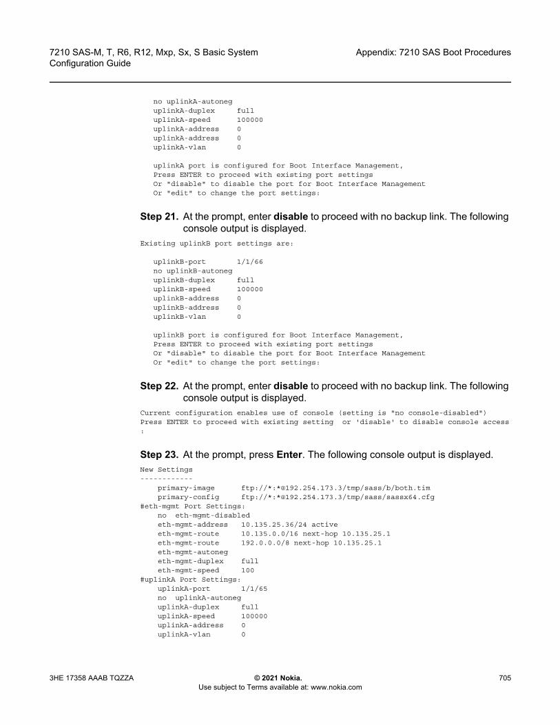
7210 SAS-M, T, R6, R12, Mxp, Sx, S Basic System Configuration Guide
Appendix: 7210 SAS Boot Procedures
3HE 17358 AAAB TQZZA © 2021 Nokia. Use subject to Terms available at: www.nokia.com
705
no uplinkA-autoneguplinkA-duplex fulluplinkA-speed 100000uplinkA-address 0uplinkA-address 0uplinkA-vlan 0
uplinkA port is configured for Boot Interface Management,Press ENTER to proceed with existing port settingsOr "disable" to disable the port for Boot Interface ManagementOr "edit" to change the port settings:
Step 21. At the prompt, enter disable to proceed with no backup link. The following console output is displayed.
Existing uplinkB port settings are:
uplinkB-port 1/1/66no uplinkB-autoneguplinkB-duplex fulluplinkB-speed 100000uplinkB-address 0uplinkB-address 0uplinkB-vlan 0
uplinkB port is configured for Boot Interface Management,Press ENTER to proceed with existing port settingsOr "disable" to disable the port for Boot Interface ManagementOr "edit" to change the port settings:
Step 22. At the prompt, enter disable to proceed with no backup link. The following console output is displayed.
Current configuration enables use of console (setting is "no console-disabled")Press ENTER to proceed with existing setting or 'disable' to disable console access:
Step 23. At the prompt, press Enter. The following console output is displayed.New Settings------------
primary-image ftp://*:*@192.254.173.3/tmp/sass/b/both.timprimary-config ftp://*:*@192.254.173.3/tmp/sass/sassx64.cfg
#eth-mgmt Port Settings:no eth-mgmt-disabledeth-mgmt-address 10.135.25.36/24 activeeth-mgmt-route 10.135.0.0/16 next-hop 10.135.25.1eth-mgmt-route 192.0.0.0/8 next-hop 10.135.25.1eth-mgmt-autonegeth-mgmt-duplex fulleth-mgmt-speed 100
#uplinkA Port Settings:uplinkA-port 1/1/65no uplinkA-autoneguplinkA-duplex fulluplinkA-speed 100000uplinkA-address 0uplinkA-vlan 0
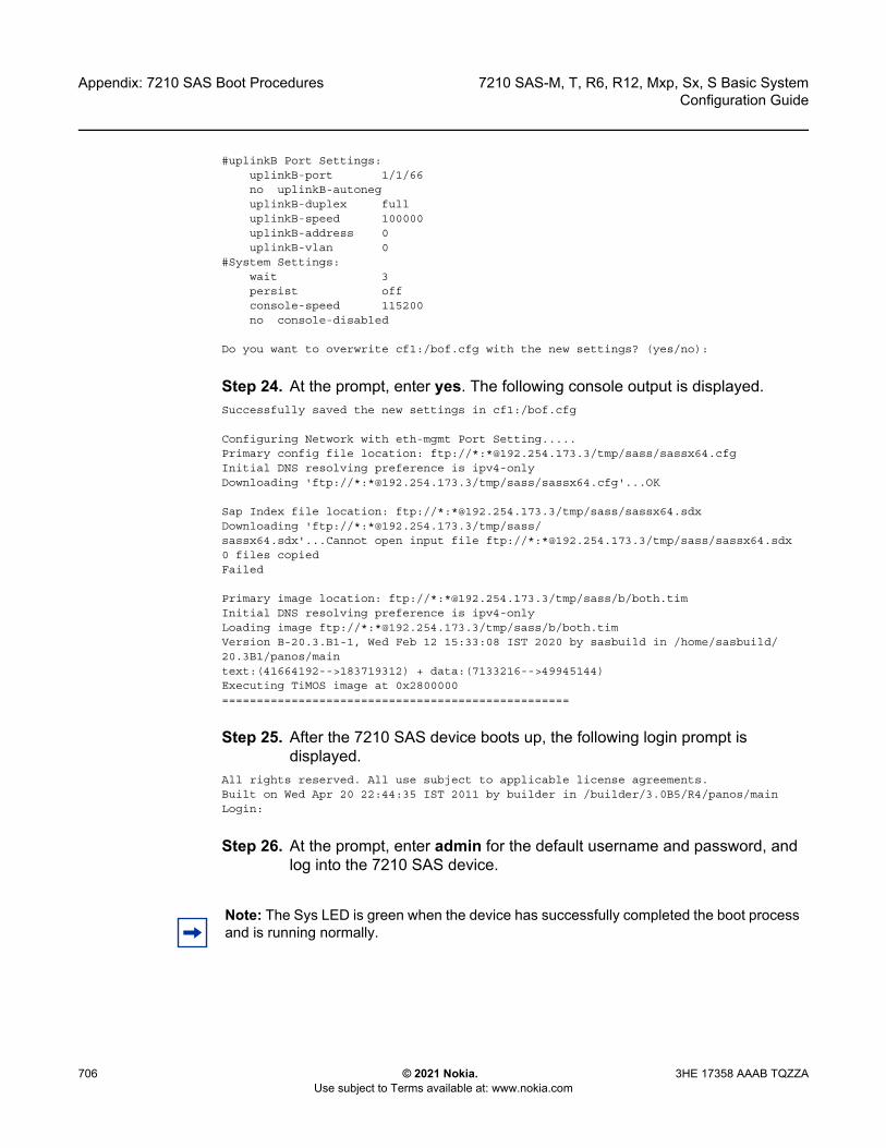
Appendix: 7210 SAS Boot Procedures
706
7210 SAS-M, T, R6, R12, Mxp, Sx, S Basic SystemConfiguration Guide
© 2021 Nokia. Use subject to Terms available at: www.nokia.com
3HE 17358 AAAB TQZZA
#uplinkB Port Settings:uplinkB-port 1/1/66no uplinkB-autoneguplinkB-duplex fulluplinkB-speed 100000uplinkB-address 0uplinkB-vlan 0
#System Settings:wait 3persist offconsole-speed 115200no console-disabled
Do you want to overwrite cf1:/bof.cfg with the new settings? (yes/no):
Step 24. At the prompt, enter yes. The following console output is displayed.Successfully saved the new settings in cf1:/bof.cfg
Configuring Network with eth-mgmt Port Setting.....Primary config file location: ftp://*:*@192.254.173.3/tmp/sass/sassx64.cfgInitial DNS resolving preference is ipv4-onlyDownloading 'ftp://*:*@192.254.173.3/tmp/sass/sassx64.cfg'...OK
Sap Index file location: ftp://*:*@192.254.173.3/tmp/sass/sassx64.sdxDownloading 'ftp://*:*@192.254.173.3/tmp/sass/sassx64.sdx'...Cannot open input file ftp://*:*@192.254.173.3/tmp/sass/sassx64.sdx0 files copiedFailed
Primary image location: ftp://*:*@192.254.173.3/tmp/sass/b/both.timInitial DNS resolving preference is ipv4-onlyLoading image ftp://*:*@192.254.173.3/tmp/sass/b/both.timVersion B-20.3.B1-1, Wed Feb 12 15:33:08 IST 2020 by sasbuild in /home/sasbuild/20.3B1/panos/maintext:(41664192-->183719312) + data:(7133216-->49945144)Executing TiMOS image at 0x2800000==================================================
Step 25. After the 7210 SAS device boots up, the following login prompt is displayed.
All rights reserved. All use subject to applicable license agreements.Built on Wed Apr 20 22:44:35 IST 2011 by builder in /builder/3.0B5/R4/panos/mainLogin:
Step 26. At the prompt, enter admin for the default username and password, and log into the 7210 SAS device.
Note: The Sys LED is green when the device has successfully completed the boot process and is running normally.

7210 SAS-M, T, R6, R12, Mxp, Sx, S Basic System Configuration Guide
Appendix: 7210 SAS Boot Procedures
3HE 17358 AAAB TQZZA © 2021 Nokia. Use subject to Terms available at: www.nokia.com
707
7.3 Procedure to Boot When the BOF is Present Locally
This section describes the procedure to boot the 7210 SAS after a reboot, when the BOF and image files are present locally, or when the node is shipped from factory with a BOF and an image on the flash.
See Table 20 for a list of factory-shipped contents for each 7210 SAS device.
Step 1. Execute a reboot of the 7210 SAS device. The system starts booting and the following console output is displayed.
Resetting...OK
Nokia 7xxx Boot ROM. Copyright 2000-2020 Nokia.All rights reserved. All use is subject to applicable license agreements.Build: X-20.3.B1-1 on Wed Feb 12 15:29:52 IST 2020 by sasbuildVersion: 0x38Processor core is CN66xxCOLD boot on processor #1?Preparing for jump to RAM...Starting bootrom RAM code...Boot rom version is v56CPU #1 booted from working sectorCPU Control FPGA version is 0x3DFPGA A version is 0x3D. FPGA B version is 0x3D. FPGA C version is 0x3D.Restart type = 0x01>>>Validate SDRAM from 0x000000007fdfff80 to 0x0000000080000000 (decrementing)>>>Testing SDRAM from 0x0000000002200000 to 0x000000007fdfff80>>>Testing SDRAM from 0xffffffffe0000000 to 0xffffffffe2000000Power on Diagnostics passedBoard Serial Number is 'NS1715T0019'
Total Memory: 2GB Chassis Type: 0xa Card Type: 0x43TiMOS-V-20.3.B1-1 bootrom/hops Nokia SAS-Sx 64SFP+4CFP4 7210 Copyright (c) 2000-2020 Nokia.All rights reserved. All use subject to applicable license agreements.Built on Wed Feb 12 15:28:49 IST 2020 by sasbuild in /home/sasbuild/20.3B1/panos/m
Searching for boot.tim on local drives:Attempting to load file cf1:/boot.timCannot open "cf1:/boot.tim".Attempting to load file cf2:/boot.timCannot open "cf2:/boot.tim".Attempting to load file uf1:/boot.timVersion L-20.3.B1-1, Wed Feb 12 15:31:09 IST 2020 by sasbuild in /home/sasbuild/20.3B1/panos/maintext:(13818400-->40990080) + data:(3162656-->19580220)Starting at 0x18000000...
Total Memory: 2GB Chassis Type: 0xa Card Type: 0x43TiMOS-L-20.3.B1-1 boot/hops Nokia SAS-Sx 64SFP+4CFP4 7210 Copyright (c) 2000-2020 Nokia.All rights reserved. All use subject to applicable license agreements.Built on Wed Feb 12 15:31:09 IST 2020 by sasbuild in /home/sasbuild/20.3B1/panos/

Appendix: 7210 SAS Boot Procedures
708
7210 SAS-M, T, R6, R12, Mxp, Sx, S Basic SystemConfiguration Guide
© 2021 Nokia. Use subject to Terms available at: www.nokia.com
3HE 17358 AAAB TQZZA
main
TiMOS BOOT LOADERTime from clock is WED MAR 04 11:18:16 2020 UTCSwitching serial output to sync mode... doneChassis-role is set to : standalone
Looking for uf1:/bof.cfg ... OK, reading
Step 2. The system locates the BOF on a local drive. The system reads the contents of the BOF and displays it on the console.The following console output is displayed.
Contents of Boot Options File on uf1:primary-image uf1:\both.tim
#eth-mgmt Port Settings:eth-mgmt-disabled
#uplinkA Port Settings:uplinkA-port 1/1/67no uplinkA-autoneguplinkA-duplex fulluplinkA-speed 100000uplinkA-address 0uplinkA-vlan 0
#uplinkB Port Settings:uplinkB-port 1/1/68no uplinkB-autoneguplinkB-duplex fulluplinkB-speed 100000uplinkB-address 0uplinkB-vlan 0
#System Settings:wait 3persist offconsole-speed 115200no console-disabled
Hit a key within 1 second to change boot parameters...
Step 3. At the prompt, wait until the specified wait time has elapsed. The boot process can be interrupted at the prompt if necessary to change the boot parameters (for example, the image location). In this example, it is assumed that changes to the BOF are not required.The following console output is displayed.
Configuring Network with uplinkA Port Setting.....No existing config file URL
Primary image location: uf1:\both.timLoading image uf1:\both.timVersion B-20.3.B1-1, Wed Feb 12 15:33:08 IST 2020 by sasbuild in /home/sasbuild/20.3B1/panos/maintext:(41664192-->183719312) + data:(7133216-->49945144)Executing TiMOS image at 0x2800000
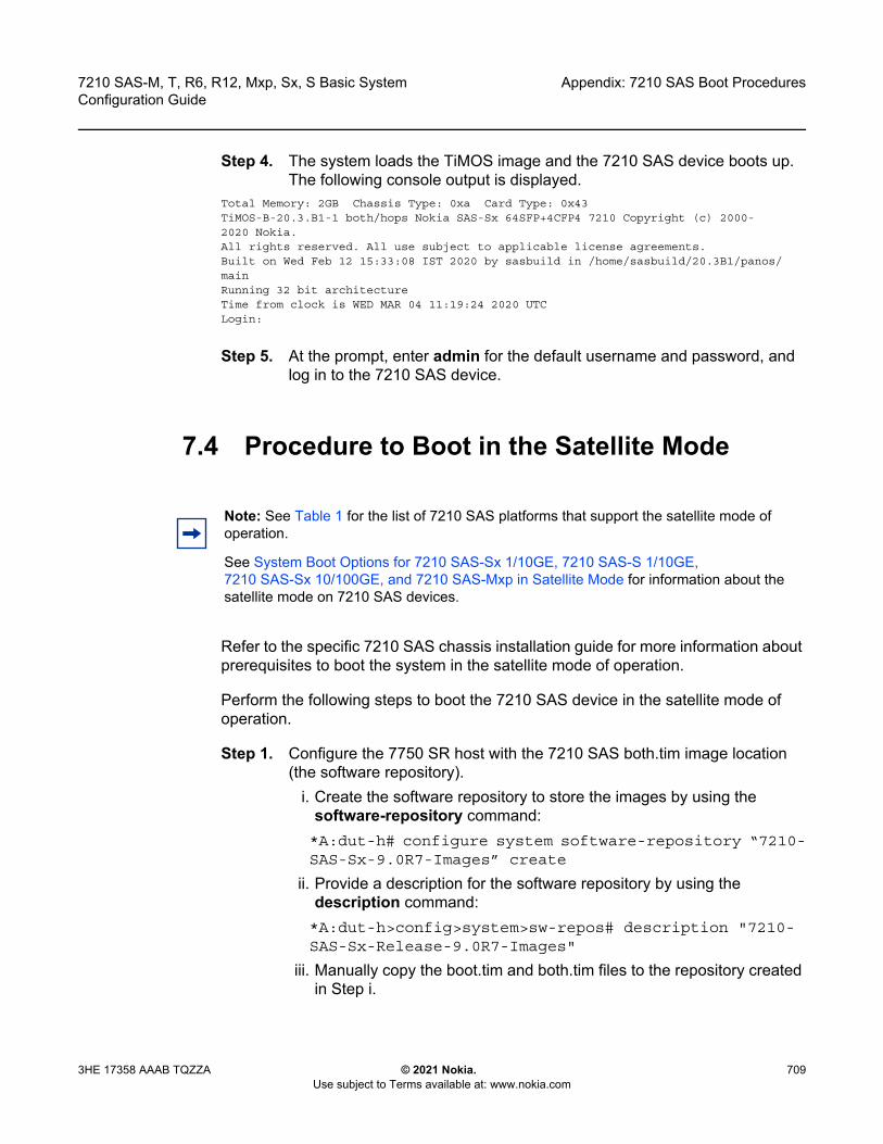
7210 SAS-M, T, R6, R12, Mxp, Sx, S Basic System Configuration Guide
Appendix: 7210 SAS Boot Procedures
3HE 17358 AAAB TQZZA © 2021 Nokia. Use subject to Terms available at: www.nokia.com
709
Step 4. The system loads the TiMOS image and the 7210 SAS device boots up. The following console output is displayed.
Total Memory: 2GB Chassis Type: 0xa Card Type: 0x43TiMOS-B-20.3.B1-1 both/hops Nokia SAS-Sx 64SFP+4CFP4 7210 Copyright (c) 2000-2020 Nokia.All rights reserved. All use subject to applicable license agreements.Built on Wed Feb 12 15:33:08 IST 2020 by sasbuild in /home/sasbuild/20.3B1/panos/mainRunning 32 bit architectureTime from clock is WED MAR 04 11:19:24 2020 UTCLogin:
Step 5. At the prompt, enter admin for the default username and password, and log in to the 7210 SAS device.
7.4 Procedure to Boot in the Satellite Mode
Refer to the specific 7210 SAS chassis installation guide for more information about prerequisites to boot the system in the satellite mode of operation.
Perform the following steps to boot the 7210 SAS device in the satellite mode of operation.
Step 1. Configure the 7750 SR host with the 7210 SAS both.tim image location (the software repository).
i. Create the software repository to store the images by using the software-repository command:*A:dut-h# configure system software-repository “7210-SAS-Sx-9.0R7-Images” create
ii. Provide a description for the software repository by using the description command:*A:dut-h>config>system>sw-repos# description "7210-SAS-Sx-Release-9.0R7-Images"
iii. Manually copy the boot.tim and both.tim files to the repository created in Step i.
Note: See Table 1 for the list of 7210 SAS platforms that support the satellite mode of operation.
See System Boot Options for 7210 SAS-Sx 1/10GE, 7210 SAS-S 1/10GE, 7210 SAS-Sx 10/100GE, and 7210 SAS-Mxp in Satellite Mode for information about the satellite mode on 7210 SAS devices.

Appendix: 7210 SAS Boot Procedures
710
7210 SAS-M, T, R6, R12, Mxp, Sx, S Basic SystemConfiguration Guide
© 2021 Nokia. Use subject to Terms available at: www.nokia.com
3HE 17358 AAAB TQZZA
Do not copy the files to a sub-folder in the repository.iv. Configure the location of the 7210 SAS both.tim and boot.tim by using
the primary-location command:*A:dut-h>config>system>sw-repos# primary-location "cf1:/7210-SAS-Sx-9.0R7/images/"
v. From the config>system>software-repository context, issue the info command to verify the configuration of the image location. The following output is displayed.
*A:dut-h>config>system>sw-repos# info---------------------------------------------------------------
description "7210-SAS-Sx-Release-9.0R7-Images"primary-location "cf1:/7210-SAS-Sx-9.0R7/images/"
---------------------------------------------------------------*A:dut-h>config>system>sw-repos#
Step 2. Configure the Ethernet satellite on the 7750 SR host.See Table 21 for information about uplink ports used on 7210 SAS platforms operating in the satellite mode.
i. Configure the Ethernet satellite with ID 1 by using the eth-sat command:*A:dut-h#configure system satellite eth-sat 1 create
ii. Configure the Ethernet satellite description by using the description command:A:dut-h>config>system>eth-sat# description “Ethernet Satellite 1”
iii. Configure the 7210 SAS device MAC address connected to the 7750 SR host by using the mac-address command:A:dut-h>config>system>eth-sat#mac-address a4:7b:2c:13:bc:48
The MAC address is used by the 7750 SR host to provide the correct configuration to the system. If the MAC address is not configured, the 7750 SR host will not respond to DHCP requests from the system.
iv. Configure the software repository by using the software-repository command:*A:dut-h>config>system>eth-sat# software-repository “7210-SAS-Sx-9.0R7-Images”
Note: In this example, the 7210 SAS device is identified by satellite ID 1 and its type is set to es64-10gb-sfpp+4-100gb-qsfp28. The satellite identifier (that is, esat-1, in this example) is used to refer to the entire satellite node when configuring services on the 7750 SR host.
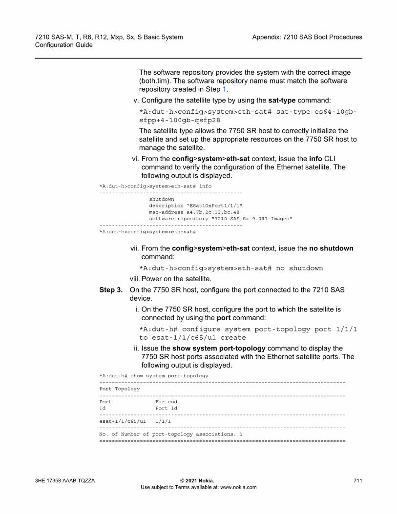
7210 SAS-M, T, R6, R12, Mxp, Sx, S Basic System Configuration Guide
Appendix: 7210 SAS Boot Procedures
3HE 17358 AAAB TQZZA © 2021 Nokia. Use subject to Terms available at: www.nokia.com
711
The software repository provides the system with the correct image (both.tim). The software repository name must match the software repository created in Step 1.
v. Configure the satellite type by using the sat-type command:*A:dut-h>config>system>eth-sat# sat-type es64-10gb-sfpp+4-100gb-qsfp28
The satellite type allows the 7750 SR host to correctly initialize the satellite and set up the appropriate resources on the 7750 SR host to manage the satellite.
vi. From the config>system>eth-sat context, issue the info CLI command to verify the configuration of the Ethernet satellite. The following output is displayed.
*A:dut-h>config>system>eth-sat# info----------------------------------------------
shutdowndescription “ESat1OnPort1/1/1"mac-address a4:7b:2c:13:bc:48software-repository "7210-SAS-Sx-9.0R7-Images"
----------------------------------------------*A:dut-h>config>system>eth-sat#
vii. From the config>system>eth-sat context, issue the no shutdown command: *A:dut-h>config>system>eth-sat# no shutdown
viii. Power on the satellite.Step 3. On the 7750 SR host, configure the port connected to the 7210 SAS
device.i. On the 7750 SR host, configure the port to which the satellite is
connected by using the port command:*A:dut-h# configure system port-topology port 1/1/1 to esat-1/1/c65/u1 create
ii. Issue the show system port-topology command to display the 7750 SR host ports associated with the Ethernet satellite ports. The following output is displayed.
*A:dut-h# show system port-topology===============================================================================Port Topology===============================================================================Port Far-endId Port Id-------------------------------------------------------------------------------esat-1/1/c65/u1 1/1/1-------------------------------------------------------------------------------No. of Number of port-topology associations: 1===============================================================================

Appendix: 7210 SAS Boot Procedures
712
7210 SAS-M, T, R6, R12, Mxp, Sx, S Basic SystemConfiguration Guide
© 2021 Nokia. Use subject to Terms available at: www.nokia.com
3HE 17358 AAAB TQZZA
iii. Issue the show system satellite command to display the status of the satellite. The following output is displayed.
*A:dut-h# show system satellite===============================================================================Satellite Information===============================================================================SatID Provisioned Type Admin Oper
Equipped Type (if different) State State-------------------------------------------------------------------------------esat-1 es64-10gb-sfpp+4-100gb-qsfp28 up provisioned
(not equipped)-------------------------------------------------------------------------------No. of Satellites: 1===============================================================================*A:dut-h#
Step 4. Power on the Ethernet satellite.i. Power on the 7210 SAS device.The satellite will use the bootloader on the SD card inserted in cf2:\ (SD card slot on the rear of the chassis) and initiate the boot procedure.The 7210 SAS device sends DHCP requests out of its uplink ports.The 7750 SR host uses the MAC address in the received packets and matches it against MAC addresses provided in the Ethernet satellite configuration on the 7750 SR host. After finding a match, the 7750 SR host uses the configured image and an appropriate configuration file, generates a BOF, and sends it to the system (the host-type parameter in the BOF generated by the 7750 SR host is set to satellite).The 7210 SAS boot loader uses the BOF to retrieve the images and the configuration file, and uses them to boot the platform in the satellite mode (because the host-type is set to satellite).The satellite transitions through the following states: provisioned, booting, and up.
ii. Issue the show system satellite command to determine the boot status of the satellite. The following output is displayed.
*A:dut-h# show system satellite===============================================================================Satellite Information===============================================================================SatID Provisioned Type Admin Oper
Equipped Type (if different) State State-------------------------------------------------------------------------------esat-1 es64-10gb-sfpp+4-100gb-qsfp28 up provisioned
(not equipped)-------------------------------------------------------------------------------No. of Satellites: 1===============================================================================*A:dut-h#
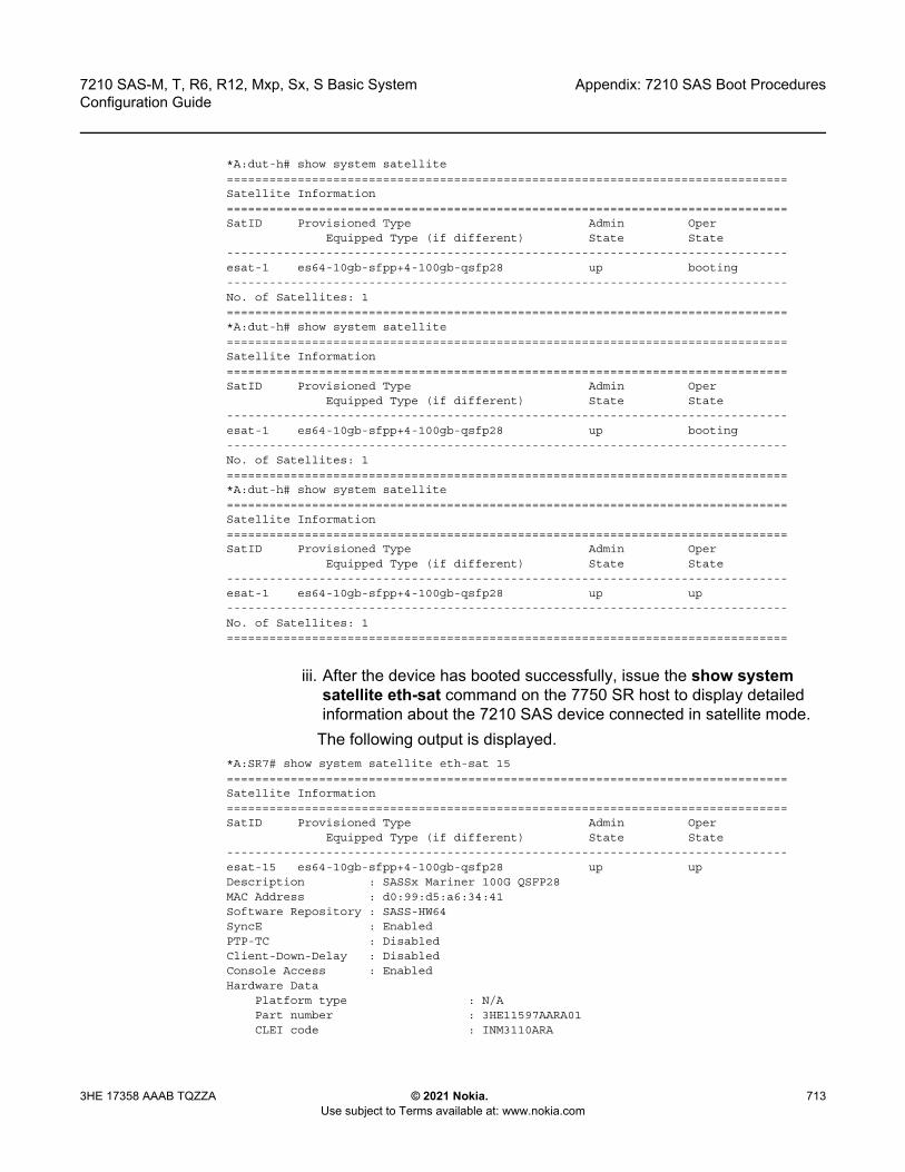
7210 SAS-M, T, R6, R12, Mxp, Sx, S Basic System Configuration Guide
Appendix: 7210 SAS Boot Procedures
3HE 17358 AAAB TQZZA © 2021 Nokia. Use subject to Terms available at: www.nokia.com
713
*A:dut-h# show system satellite===============================================================================Satellite Information===============================================================================SatID Provisioned Type Admin Oper
Equipped Type (if different) State State-------------------------------------------------------------------------------esat-1 es64-10gb-sfpp+4-100gb-qsfp28 up booting-------------------------------------------------------------------------------No. of Satellites: 1===============================================================================*A:dut-h# show system satellite===============================================================================Satellite Information===============================================================================SatID Provisioned Type Admin Oper
Equipped Type (if different) State State-------------------------------------------------------------------------------esat-1 es64-10gb-sfpp+4-100gb-qsfp28 up booting-------------------------------------------------------------------------------No. of Satellites: 1===============================================================================*A:dut-h# show system satellite===============================================================================Satellite Information===============================================================================SatID Provisioned Type Admin Oper
Equipped Type (if different) State State-------------------------------------------------------------------------------esat-1 es64-10gb-sfpp+4-100gb-qsfp28 up up-------------------------------------------------------------------------------No. of Satellites: 1===============================================================================
iii. After the device has booted successfully, issue the show system satellite eth-sat command on the 7750 SR host to display detailed information about the 7210 SAS device connected in satellite mode.
The following output is displayed.*A:SR7# show system satellite eth-sat 15===============================================================================Satellite Information===============================================================================SatID Provisioned Type Admin Oper
Equipped Type (if different) State State-------------------------------------------------------------------------------esat-15 es64-10gb-sfpp+4-100gb-qsfp28 up upDescription : SASSx Mariner 100G QSFP28MAC Address : d0:99:d5:a6:34:41Software Repository : SASS-HW64SyncE : EnabledPTP-TC : DisabledClient-Down-Delay : DisabledConsole Access : EnabledHardware Data
Platform type : N/APart number : 3HE11597AARA01CLEI code : INM3110ARA
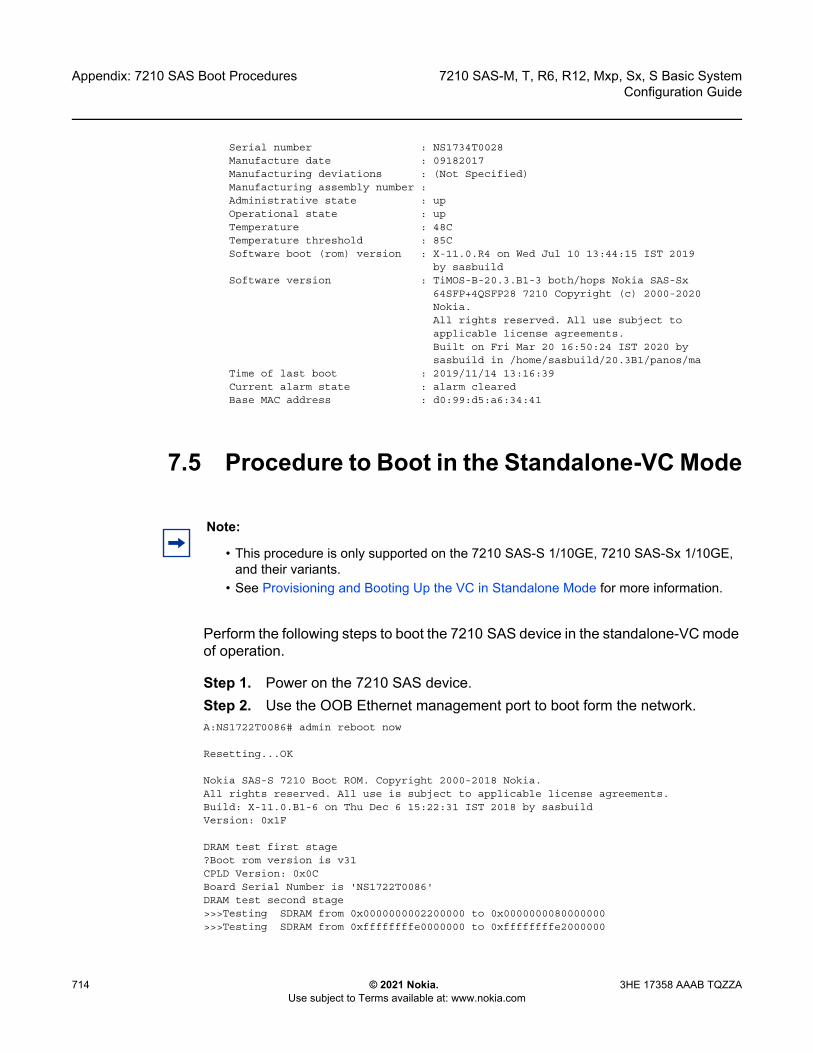
Appendix: 7210 SAS Boot Procedures
714
7210 SAS-M, T, R6, R12, Mxp, Sx, S Basic SystemConfiguration Guide
© 2021 Nokia. Use subject to Terms available at: www.nokia.com
3HE 17358 AAAB TQZZA
Serial number : NS1734T0028Manufacture date : 09182017Manufacturing deviations : (Not Specified)Manufacturing assembly number :Administrative state : upOperational state : upTemperature : 48CTemperature threshold : 85CSoftware boot (rom) version : X-11.0.R4 on Wed Jul 10 13:44:15 IST 2019
by sasbuildSoftware version : TiMOS-B-20.3.B1-3 both/hops Nokia SAS-Sx
64SFP+4QSFP28 7210 Copyright (c) 2000-2020Nokia.All rights reserved. All use subject toapplicable license agreements.Built on Fri Mar 20 16:50:24 IST 2020 bysasbuild in /home/sasbuild/20.3B1/panos/ma
Time of last boot : 2019/11/14 13:16:39Current alarm state : alarm clearedBase MAC address : d0:99:d5:a6:34:41
7.5 Procedure to Boot in the Standalone-VC Mode
Perform the following steps to boot the 7210 SAS device in the standalone-VC mode of operation.
Step 1. Power on the 7210 SAS device.Step 2. Use the OOB Ethernet management port to boot form the network. A:NS1722T0086# admin reboot now
Resetting...OK
Nokia SAS-S 7210 Boot ROM. Copyright 2000-2018 Nokia.All rights reserved. All use is subject to applicable license agreements.Build: X-11.0.B1-6 on Thu Dec 6 15:22:31 IST 2018 by sasbuildVersion: 0x1F
DRAM test first stage?Boot rom version is v31CPLD Version: 0x0CBoard Serial Number is 'NS1722T0086'DRAM test second stage>>>Testing SDRAM from 0x0000000002200000 to 0x0000000080000000>>>Testing SDRAM from 0xffffffffe0000000 to 0xffffffffe2000000
Note:
• This procedure is only supported on the 7210 SAS-S 1/10GE, 7210 SAS-Sx 1/10GE, and their variants.
• See Provisioning and Booting Up the VC in Standalone Mode for more information.

7210 SAS-M, T, R6, R12, Mxp, Sx, S Basic System Configuration Guide
Appendix: 7210 SAS Boot Procedures
3HE 17358 AAAB TQZZA © 2021 Nokia. Use subject to Terms available at: www.nokia.com
715
Loading VxRom image .......
Board Serial Number is 'NS1722T0086'
Total Memory: 2GB Chassis Type: 0xa Card Type: 0x14TiMOS-V-11.0.B1-6 bootrom/hops Nokia SAS-S 24T4SFP+ 7210 Copyright (c) 2000-2018 Nokia.All rights reserved. All use subject to applicable license agreements.Built on Thu Dec 6 15:21:48 IST 2018 by sasbuild in /home/sasbuild/11.0B1/panos/main
Searching for boot.tim on local drives:Attempting to load file cf1:/boot.timVersion L-11.0.B1-21, Wed Feb 27 12:30:02 IST 2019 by sasbuild in /home/sasbuild/11.0B1/panos/maintext:(13790784-->40910320) + data:(3160736-->19576100)Starting at 0x18000000...
Total Memory: 2GB Chassis Type: 0xa Card Type: 0x14TiMOS-L-11.0.B1-21 boot/hops Nokia SAS-S 24T4SFP+ 7210 Copyright (c) 2000-2019 Nokia.All rights reserved. All use subject to applicable license agreements.Built on Wed Feb 27 12:30:02 IST 2019 by sasbuild in /home/sasbuild/11.0B1/panos/main
TiMOS BOOT LOADERTime from clock is SAT JAN 01 00:15:24 2000 UTCSwitching serial output to sync mode... doneChassis-role is set to : standalone
Step 3. The system lists the default settings and the following console output is displayed.
Looking for cf1:/bof.cfg ... OK, reading
Contents of Boot Options File on cf1:#eth-mgmt Port Settings:
eth-mgmt-disabled#uplinkA Port Settings:
uplinkA-port 1/1/27no uplinkA-autoneguplinkA-duplex fulluplinkA-speed 10000uplinkB-address 0uplinkB-vlan 0
#System Settings:wait 3persist offconsole-speed 115200no console-disabled
Hit a key within 3 seconds to change boot parameters...
Step 4. At the prompt, press any key to initiate boot parameter updates.The following console output is displayed.
Enter password to edit the Boot Options FileOr CTRL-D to exit the prompt
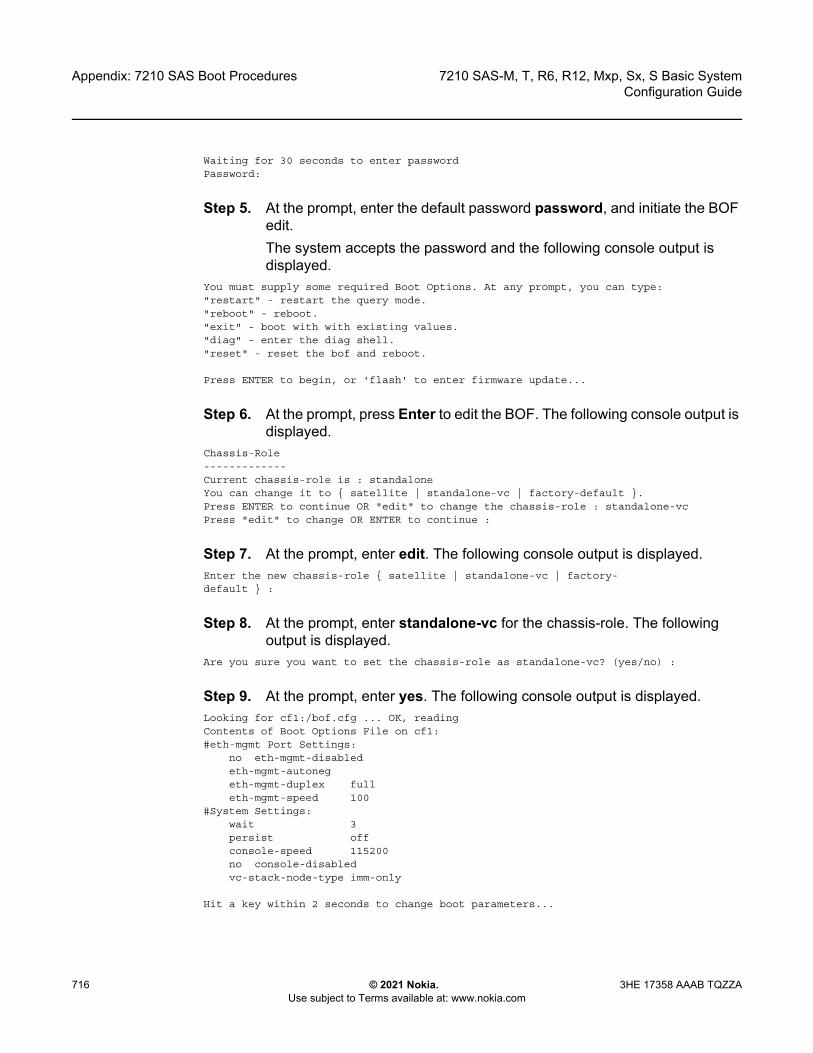
Appendix: 7210 SAS Boot Procedures
716
7210 SAS-M, T, R6, R12, Mxp, Sx, S Basic SystemConfiguration Guide
© 2021 Nokia. Use subject to Terms available at: www.nokia.com
3HE 17358 AAAB TQZZA
Waiting for 30 seconds to enter passwordPassword:
Step 5. At the prompt, enter the default password password, and initiate the BOF edit.The system accepts the password and the following console output is displayed.
You must supply some required Boot Options. At any prompt, you can type:"restart" - restart the query mode."reboot" - reboot."exit" - boot with with existing values."diag" - enter the diag shell."reset" - reset the bof and reboot.
Press ENTER to begin, or 'flash' to enter firmware update...
Step 6. At the prompt, press Enter to edit the BOF. The following console output is displayed.
Chassis-Role-------------Current chassis-role is : standaloneYou can change it to { satellite | standalone-vc | factory-default }.Press ENTER to continue OR "edit" to change the chassis-role : standalone-vcPress "edit" to change OR ENTER to continue :
Step 7. At the prompt, enter edit. The following console output is displayed.Enter the new chassis-role { satellite | standalone-vc | factory-default } :
Step 8. At the prompt, enter standalone-vc for the chassis-role. The following output is displayed.
Are you sure you want to set the chassis-role as standalone-vc? (yes/no) :
Step 9. At the prompt, enter yes. The following console output is displayed.Looking for cf1:/bof.cfg ... OK, readingContents of Boot Options File on cf1:#eth-mgmt Port Settings:
no eth-mgmt-disabledeth-mgmt-autonegeth-mgmt-duplex fulleth-mgmt-speed 100
#System Settings:wait 3persist offconsole-speed 115200no console-disabledvc-stack-node-type imm-only
Hit a key within 2 seconds to change boot parameters...
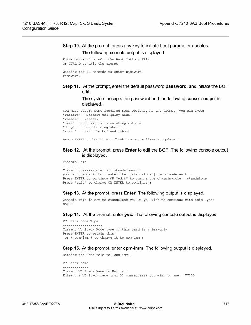
7210 SAS-M, T, R6, R12, Mxp, Sx, S Basic System Configuration Guide
Appendix: 7210 SAS Boot Procedures
3HE 17358 AAAB TQZZA © 2021 Nokia. Use subject to Terms available at: www.nokia.com
717
Step 10. At the prompt, press any key to initiate boot parameter updates.The following console output is displayed.
Enter password to edit the Boot Options FileOr CTRL-D to exit the prompt
Waiting for 30 seconds to enter passwordPassword:
Step 11. At the prompt, enter the default password password, and initiate the BOF edit.The system accepts the password and the following console output is displayed.
You must supply some required Boot Options. At any prompt, you can type:"restart" - restart the query mode."reboot" - reboot."exit" - boot with with existing values."diag" - enter the diag shell."reset" - reset the bof and reboot.
Press ENTER to begin, or 'flash' to enter firmware update...
Step 12. At the prompt, press Enter to edit the BOF. The following console output is displayed.
Chassis-Role-------------Current chassis-role is : standalone-vcyou can change it to { satellite | standalone | factory-default }.Press ENTER to continue OR "edit" to change the chassis-role : standalonePress "edit" to change OR ENTER to continue :
Step 13. At the prompt, press Enter. The following output is displayed.Chassis-role is set to standalone-vc, Do you wish to continue with this (yes/no) :
Step 14. At the prompt, enter yes. The following console output is displayed.VC Stack Node Type--------------------Current Vc Stack Node type of this card is : imm-onlyPress ENTER to retain this,or { cpm-imm } to change it to cpm-imm :
Step 15. At the prompt, enter cpm-imm. The following output is displayed.Setting the Card role to 'cpm-imm'.
VC Stack Name-------------Current VC Stack Name in Bof is :Enter the VC Stack name (max 32 characters) you wish to use : VC123
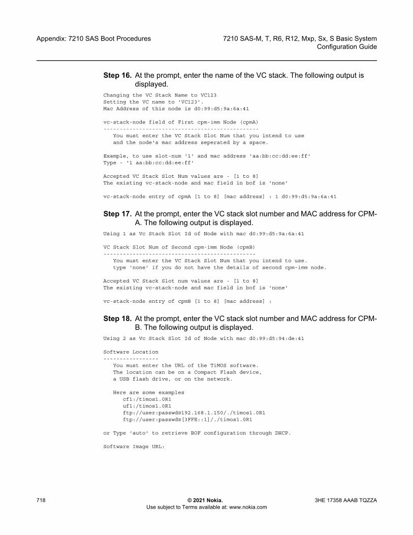
Appendix: 7210 SAS Boot Procedures
718
7210 SAS-M, T, R6, R12, Mxp, Sx, S Basic SystemConfiguration Guide
© 2021 Nokia. Use subject to Terms available at: www.nokia.com
3HE 17358 AAAB TQZZA
Step 16. At the prompt, enter the name of the VC stack. The following output is displayed.
Changing the VC Stack Name to VC123Setting the VC name to 'VC123'.Mac Address of this node is d0:99:d5:9a:6a:41
vc-stack-node field of First cpm-imm Node (cpmA)------------------------------------------------
You must enter the VC Stack Slot Num that you intend to useand the node's mac address seperated by a space.
Example, to use slot-num '1' and mac address 'aa:bb:cc:dd:ee:ff'Type - '1 aa:bb:cc:dd:ee:ff'
Accepted VC Stack Slot Num values are - [1 to 8]The existing vc-stack-node and mac field in bof is 'none'
vc-stack-node entry of cpmA [1 to 8] [mac address] : 1 d0:99:d5:9a:6a:41
Step 17. At the prompt, enter the VC stack slot number and MAC address for CPM-A. The following output is displayed.
Using 1 as Vc Stack Slot Id of Node with mac d0:99:d5:9a:6a:41
VC Stack Slot Num of Second cpm-imm Node (cpmB)-----------------------------------------------
You must enter the VC Stack Slot Num that you intend to use.type 'none' if you do not have the details of second cpm-imm node.
Accepted VC Stack Slot num values are - [1 to 8]The existing vc-stack-node and mac field in bof is 'none'
vc-stack-node entry of cpmB [1 to 8] [mac address] :
Step 18. At the prompt, enter the VC stack slot number and MAC address for CPM-B. The following output is displayed.
Using 2 as Vc Stack Slot Id of Node with mac d0:99:d5:94:de:41
Software Location-----------------
You must enter the URL of the TiMOS software.The location can be on a Compact Flash device,a USB flash drive, or on the network.
Here are some examplescf1:/timos1.0R1uf1:/timos1.0R1ftp://user:[email protected]/./timos1.0R1ftp://user:passwd@[3FFE::1]/./timos1.0R1
or Type 'auto' to retrieve BOF configuration through DHCP.
Software Image URL:
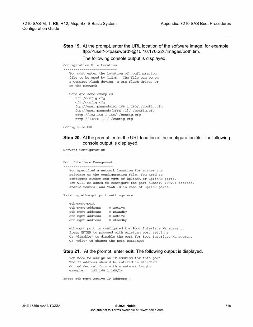
7210 SAS-M, T, R6, R12, Mxp, Sx, S Basic System Configuration Guide
Appendix: 7210 SAS Boot Procedures
3HE 17358 AAAB TQZZA © 2021 Nokia. Use subject to Terms available at: www.nokia.com
719
Step 19. At the prompt, enter the URL location of the software image; for example, ftp://<user>:<password>@10.10.170.22/./images/both.tim.The following console output is displayed.
Configuration File Location---------------------------
You must enter the location of configurationfile to be used by TiMOS. The file can be ona Compact Flash device, a USB flash drive, oron the network.
Here are some examplesuf1:/config.cfgcf1:/config.cfgftp://user:[email protected]/./config.cfgftp://user:passwd@[3FFE::1]/./config.cfgtftp://192.168.1.150/./config.cfgtftp://[3FFE::1]/./config.cfg
Config File URL:
Step 20. At the prompt, enter the URL location of the configuration file. The following console output is displayed.
Network Configuration---------------------
Boot Interface Management-------------------------
You specified a network location for either thesoftware or the configuration file. You need toconfigure either eth-mgmt or uplinkA or uplinkB ports.You will be asked to configure the port number, IP(v6) address,static routes, and VLAN Id in case of uplink ports.
Existing eth-mgmt port settings are:
eth-mgmt-porteth-mgmt-address 0 activeeth-mgmt-address 0 standbyeth-mgmt-address 0 activeeth-mgmt-address 0 standby
eth-mgmt port is configured for Boot Interface Management,Press ENTER to proceed with existing port settingsOr "disable" to disable the port for Boot Interface ManagementOr "edit" to change the port settings:
Step 21. At the prompt, enter edit. The following output is displayed.You need to assign an IP address for this port.The IP address should be entered in standarddotted decimal form with a network length.example: 192.168.1.169/24
Enter eth-mgmt Active IP Address :
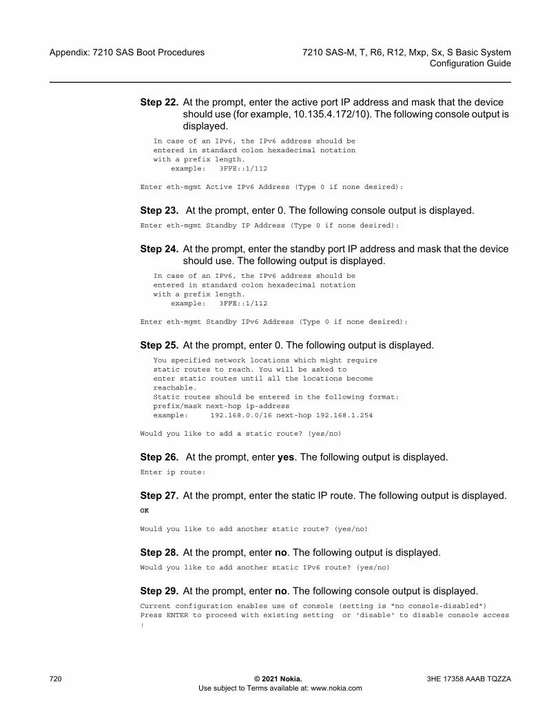
Appendix: 7210 SAS Boot Procedures
720
7210 SAS-M, T, R6, R12, Mxp, Sx, S Basic SystemConfiguration Guide
© 2021 Nokia. Use subject to Terms available at: www.nokia.com
3HE 17358 AAAB TQZZA
Step 22. At the prompt, enter the active port IP address and mask that the device should use (for example, 10.135.4.172/10). The following console output is displayed.
In case of an IPv6, the IPv6 address should beentered in standard colon hexadecimal notationwith a prefix length.
example: 3FFE::1/112
Enter eth-mgmt Active IPv6 Address (Type 0 if none desired):
Step 23. At the prompt, enter 0. The following console output is displayed.Enter eth-mgmt Standby IP Address (Type 0 if none desired):
Step 24. At the prompt, enter the standby port IP address and mask that the device should use. The following output is displayed.
In case of an IPv6, the IPv6 address should beentered in standard colon hexadecimal notationwith a prefix length.
example: 3FFE::1/112
Enter eth-mgmt Standby IPv6 Address (Type 0 if none desired):
Step 25. At the prompt, enter 0. The following output is displayed.You specified network locations which might requirestatic routes to reach. You will be asked toenter static routes until all the locations becomereachable.Static routes should be entered in the following format:prefix/mask next-hop ip-addressexample: 192.168.0.0/16 next-hop 192.168.1.254
Would you like to add a static route? (yes/no)
Step 26. At the prompt, enter yes. The following output is displayed.Enter ip route:
Step 27. At the prompt, enter the static IP route. The following output is displayed.OK
Would you like to add another static route? (yes/no)
Step 28. At the prompt, enter no. The following output is displayed.Would you like to add another static IPv6 route? (yes/no)
Step 29. At the prompt, enter no. The following console output is displayed.Current configuration enables use of console (setting is "no console-disabled")Press ENTER to proceed with existing setting or 'disable' to disable console access:

7210 SAS-M, T, R6, R12, Mxp, Sx, S Basic System Configuration Guide
Appendix: 7210 SAS Boot Procedures
3HE 17358 AAAB TQZZA © 2021 Nokia. Use subject to Terms available at: www.nokia.com
721
Step 30. At the prompt, press Enter. The following console output is displayed.New Settings------------
primary-image ftp://*:*@10.135.24.85/./img/sass/both.timprimary-config ftp://*:*@10.135.24.85/./cfg/sass/dutE_vcCfg.txt
#eth-mgmt Port Settings:no eth-mgmt-disabledeth-mgmt-address 10.135.24.94/24 activeeth-mgmt-address 10.135.24.95/24 standbyeth-mgmt-route 135.0.0.0/8 next-hop 10.135.24.1eth-mgmt-autonegeth-mgmt-duplex fulleth-mgmt-speed 100
#System Settings:wait 3persist offconsole-speed 115200no console-disabledvc-stack-name VC123vc-stack-node-type cpm-immvc-stack-node cpmA slot-num 1 mac-addr d0:99:d5:9a:6a:41vc-stack-node cpmB slot-num 2 mac-addr d0:99:d5:94:de:41
Do you want to overwrite cf1:/bof.cfg with the new settings? (yes/no):
Step 31. At the prompt, enter yes. The 7210 SAS device begins to boot with the new settings. The following console output is displayed.
Successfully saved the new settings in cf1:/bof.cfg
******************* VC Mode ********************Configuring Network with eth-mgmt Port Setting.....Primary config file location: ftp://*:*@10.135.24.85/./cfg/sass/dutE_vcCfg.txtInitial DNS resolving preference is ipv4-onlyDownloading 'ftp://*:*@10.135.24.85/./cfg/sass/dutE_vcCfg.txt'...OK
Sap Index file location: ftp://*:*@10.135.24.85/./cfg/sass/dutE_vcCfg.sdxDownloading 'ftp://*:*@10.135.24.85/./cfg/sass/dutE_vcCfg.sdx'...OK
Primary image location: ftp://*:*@10.135.24.85/./img/sass/both.timInitial DNS resolving preference is ipv4-onlyLoading image ftp://*:*@10.135.24.85/./img/sass/both.timVersion B-11.0.S127b, Tue May 7 04:46:24 IST 2019 by sasbuild in /home/sasbuild/11.0S/panos/maintext:(41482848-->183530192) + data:(7134144-->49884044)Executing TiMOS image at 0x2800000
Step 32. After the 7210 SAS device boots up, the following login prompt is displayed.
All rights reserved. All use subject to applicable license agreements.Built on Wed Apr 20 14:32:04 IST 2011 by builder in /builder/3.0B5/panos/mainLogin:
Step 33. At the prompt, enter admin for the default username and password, and log into the 7210 SAS device.
Appendix: 7210 SAS Boot Procedures
722
7210 SAS-M, T, R6, R12, Mxp, Sx, S Basic SystemConfiguration Guide
© 2021 Nokia. Use subject to Terms available at: www.nokia.com
3HE 17358 AAAB TQZZA
7210 SAS-M, T, R6, R12, Mxp, Sx, S Basic System Configuration Guide
Standards and Protocol Support
3HE 17358 AAAB TQZZA © 2021 Nokia. Use subject to Terms available at: www.nokia.com
723
8 Standards and Protocol Support
BGPdraft-ietf-idr-add-paths-04, Advertisement of Multiple Paths in BGP is supported on
M(N), T(N), Mxp, Sx/S-1/10GE, Sx-10/100GE, R6, and R12draft-ietf-sidr-origin-validation-signaling-04, BGP Prefix Origin Validation State
Extended Community is supported on K12, K30, M(N), T(N), Mxp, Sx/S-1/10GE, Sx-10/100GE, Sx/S-1/10GE-VC, R6, and R12
RFC 1772, Application of the Border Gateway Protocol in the Internet is supported on K12, K30, M(N), T(N), Mxp, Sx/S-1/10GE, Sx-10/100GE, Sx/S-1/10GE-VC, R6, and R12
RFC 1997, BGP Communities Attribute is supported on K12, K30, M(N), T(N), Mxp, Sx/S-1/10GE, Sx-10/100GE, Sx/S-1/10GE-VC, R6, and R12
RFC 2385, Protection of BGP Sessions via the TCP MD5 Signature Option is supported on K12, K30, M(N), T(N), Mxp, Sx/S-1/10GE, Sx-10/100GE, Sx/S-1/10GE-VC, R6, and R12
RFC 2439, BGP Route Flap Damping is supported on K12, K30, M(N), T(N), Mxp, Sx/S-1/10GE, Sx-10/100GE, Sx/S-1/10GE-VC, R6, and R12
RFC 2545, Use of BGP-4 Multiprotocol Extensions for IPv6 Inter-Domain Routing is supported on K12, M(N), T(N), Mxp, Sx/S-1/10GE, Sx-10/100GE, Sx/S-1/10GE-VC, R6, and R12
RFC 2858, Multiprotocol Extensions for BGP-4 is supported on K12, K30, M(N), T(N), Mxp, Sx/S-1/10GE, Sx-10/100GE, Sx/S-1/10GE-VC, R6, and R12
RFC 2918, Route Refresh Capability for BGP-4 is supported on K12, K30, M(N), T(N), Mxp, Sx/S-1/10GE, Sx-10/100GE, Sx/S-1/10GE-VC, R6, and R12
RFC 3107, Carrying Label Information in BGP-4 is supported on K12, K30, M(N), T(N), Mxp, Sx/S-1/10GE, Sx-10/100GE, Sx/S-1/10GE-VC, R6, and R12
RFC 3392, Capabilities Advertisement with BGP-4 is supported on K12, K30, M(N), T(N), Mxp, Sx/S-1/10GE, Sx-10/100GE, Sx/S-1/10GE-VC, R6, and R12
RFC 4271, A Border Gateway Protocol 4 (BGP-4) is supported on K12, K30, M(N), T(N), Mxp, Sx/S-1/10GE, Sx-10/100GE, Sx/S-1/10GE-VC, R6, and R12
RFC 4360, BGP Extended Communities Attribute is supported on K12, K30, M(N), T(N), Mxp, Sx/S-1/10GE, Sx-10/100GE, Sx/S-1/10GE-VC, R6, and R12
Note: The information provided in this chapter is subject to change without notice and may not apply to all platforms.
Nokia assumes no responsibility for inaccuracies.
Standards and Protocol Support
724
7210 SAS-M, T, R6, R12, Mxp, Sx, S Basic SystemConfiguration Guide
© 2021 Nokia. Use subject to Terms available at: www.nokia.com
3HE 17358 AAAB TQZZA
RFC 4364, BGP/MPLS IP Virtual Private Networks (VPNs) is supported on K12, K30, M(N), T(N), Mxp, Sx/S-1/10GE, Sx-10/100GE, R6, and R12
RFC 4456, BGP Route Reflection: An Alternative to Full Mesh Internal BGP (IBGP) is supported on K12, K30, M(N), T(N), Mxp, Sx/S-1/10GE, Sx-10/100GE, Sx/S-1/10GE-VC, R6, and R12
RFC 4659, BGP-MPLS IP Virtual Private Network (VPN) Extension for IPv6 VPN is supported on K12, K30, M(N), T(N), Mxp, Sx/S-1/10GE, Sx-10/100GE, R6, and R12
RFC 4684, Constrained Route Distribution for Border Gateway Protocol/MultiProtocol Label Switching (BGP/MPLS) Internet Protocol (IP) Virtual Private Networks (VPNs) is supported on K12, K30, M(N), T(N), Mxp, Sx/S-1/10GE, Sx-10/100GE, Sx/S-1/10GE-VC, R6, and R12
RFC 4724, Graceful Restart Mechanism for BGP (Helper Mode) is supported on K12, K30, M(N), T(N), Mxp, Sx/S-1/10GE, Sx-10/100GE, Sx/S-1/10GE-VC, R6, and R12
RFC 4760, Multiprotocol Extensions for BGP-4 is supported on K12, K30, M(N), T(N), Mxp, Sx/S-1/10GE, Sx-10/100GE, Sx/S-1/10GE-VC, R6, and R12
RFC 4798, Connecting IPv6 Islands over IPv4 MPLS Using IPv6 Provider Edge Routers (6PE) is supported on K12, K30, M(N), T(N), Mxp, Sx/S-1/10GE, Sx-10/100GE, R6, and R12
RFC 4893, BGP Support for Four-octet AS Number Space is supported on K12, K30, M(N), T(N), Mxp, Sx/S-1/10GE, Sx-10/100GE, Sx/S-1/10GE-VC, R6, and R12
RFC 5004, Avoid BGP Best Path Transitions from One External to Another is supported on K12, K30, M(N), T(N), Mxp, Sx/S-1/10GE, Sx-10/100GE, Sx/S-1/10GE-VC, R6, and R12
RFC 5291, Outbound Route Filtering Capability for BGP-4 is supported on K12, K30, M(N), T(N), X, Mxp, Sx/S-1/10GE, Sx-10/100GE, Sx/S-1/10GE-VC, R6, and R12
RFC 5668, 4-Octet AS Specific BGP Extended Community is supported on K12, K30, M(N), T(N), Mxp, Sx/S-1/10GE, Sx-10/100GE, Sx/S-1/10GE-VC, R6, and R12
RFC 6811, Prefix Origin Validation is supported on K12, K30, M(N), T(N), Mxp, Sx/S-1/10GE, Sx-10/100GE, Sx/S-1/10GE-VC, R6, and R12
Circuit EmulationRFC 4553, Structure-Agnostic Time Division Multiplexing (TDM) over Packet
(SAToP) is supported on M(N)
Note: Only R6 and R12 support RR server functionality. The rest of the platforms support only client function.
7210 SAS-M, T, R6, R12, Mxp, Sx, S Basic System Configuration Guide
Standards and Protocol Support
3HE 17358 AAAB TQZZA © 2021 Nokia. Use subject to Terms available at: www.nokia.com
725
RFC 5086, Structure-Aware Time Division Multiplexed (TDM) Circuit Emulation Service over Packet Switched Network (CESoPSN) is supported on M(N)
RFC 5287, Control Protocol Extensions for the Setup of Time-Division Multiplexing (TDM) Pseudowires in MPLS Networks is supported on M(N)
EthernetIEEE 802.1AB, Station and Media Access Control Connectivity Discovery is
supported on D, Dxp, K5, K12, K30, M(A,N), T(A,N), Mxp, Sx/S-1/10GE, Sx-10/100GE, Sx/S-1/10GE-VC, R6, and R12
TIA-1057, LLDP for Media endpoint devices is supported on Sx/S-1/10GE and Sx/S-1/10GE-VC
IEEE 802.1ad, Provider Bridges is supported on D, Dxp, K5, K12, K30, M(A,N), T(A,N), Mxp, Sx/S-1/10GE, Sx-10/100GE, Sx/S-1/10GE-VC, R6, and R12
IEEE 802.1ag, Connectivity Fault Management is supported on D, Dxp, K5, K12, K30, M(A,N), T(A,N), Mxp, Sx/S-1/10GE, Sx-10/100GE, Sx/S-1/10GE-VC, R6, and R12
IEEE 802.1ah, Provider Backbone Bridges is supported on M(N) and T(N)IEEE 802.1ax, Link Aggregation is supported on D, Dxp, K5, K12, K30, M(A,N),
T(A,N), Mxp, Sx/S-1/10GE, Sx-10/100GE, Sx/S-1/10GE-VC, R6, and R12IEEE 802.1D, MAC Bridges is supported on D, Dxp, K5, K12, K30, M(A,N), T(A,N),
Mxp, Sx/S-1/10GE, Sx-10/100GE, Sx/S-1/10GE-VC, R6, and R12IEEE 802.1p, Traffic Class Expediting is supported on D, E, Dxp, K5, K12, K30,
M(A,N), T(A,N), X, Mxp, Sx/S-1/10GE, Sx-10/100GE, Sx/S-1/10GE-VC, R6, and R12
IEEE 802.1Q, Virtual LANs is supported on D, Dxp, K5, K12, K30, M(A,N), T(A,N), Mxp, Sx/S-1/10GE, Sx-10/100GE, Sx/S-1/10GE-VC, R6, and R12
IEEE 802.1s, Multiple Spanning Trees is supported on D, Dxp, K5, K12, K30, M(A,N), T(A,N), Mxp, Sx/S-1/10GE, Sx-10/100GE, Sx/S-1/10GE-VC, R6, and R12
IEEE 802.1w, Rapid Reconfiguration of Spanning Tree is supported on D, Dxp, K5, K12, K30, M(A,N), T(A,N), Mxp, Sx/S-1/10GE, Sx-10/100GE, Sx/S-1/10GE-VC, R6, and R12
IEEE 802.1X, Port Based Network Access Control is supported on D, Dxp, K5, K12, K30, M(A,N), T(A,N), Mxp, Sx/S-1/10GE, Sx-10/100GE, Sx/S-1/10GE-VC, R6, and R12
IEEE 802.3ab, 1000BASE-T is supported on D, Dxp, K5, K12, K30, M(A,N), T(A,N), Mxp, Sx/S-1/10GE, Sx-10/100GE, Sx/S-1/10GE-VC, R6, and R12
IEEE 802.3ac, VLAN Tag is supported on D, Dxp, K5, K12, K30, M(A,N), T(A,N), Mxp, Sx/S-1/10GE, Sx-10/100GE, Sx/S-1/10GE-VC, R6, and R12
IEEE 802.3ad, Link Aggregation is supported on D, Dxp, K5, K12, K30, M(A,N), T(A,N), Mxp, Sx/S-1/10GE, Sx-10/100GE, Sx/S-1/10GE-VC, R6, and R12

Standards and Protocol Support
726
7210 SAS-M, T, R6, R12, Mxp, Sx, S Basic SystemConfiguration Guide
© 2021 Nokia. Use subject to Terms available at: www.nokia.com
3HE 17358 AAAB TQZZA
IEEE 802.3ae, 10 Gb/s Ethernet is supported on Dxp, K30, M(A,N), T(A,N), Mxp, Sx/S-1/10GE, Sx-10/100GE, Sx/S-1/10GE-VC, R6, and R12
IEEE 802.3ah, Ethernet in the First Mile is supported on D, Dxp, K5, K12, K30, M(A,N), T(A,N), Mxp, Sx/S-1/10GE, Sx-10/100GE, Sx/S-1/10GE-VC, R6, and R12
IEEE 802.3ba, 40 Gb/s and 100 Gb/s Ethernet is supported on R6, R12, and Sx-10/100GE
IEEE 802.3i, Ethernet is supported on D, Dxp, K5, K12, K30, M(A,N), T(A,N), Mxp, Sx/S-1/10GE, Sx-10/100GE, Sx/S-1/10GE-VC, R6, and R12
IEEE 802.3u, Fast Ethernet is supported on D, Dxp, K5, K12, K30, M(A,N), T(A,N), Mxp, Sx/S-1/10GE, Sx-10/100GE, Sx/S-1/10GE-VC, R6, and R12
IEEE 802.3z, Gigabit Ethernet is supported on D, Dxp, K5, K12, K30, M(A,N), T(A,N), Mxp, Sx/S-1/10GE, Sx-10/100GE, Sx/S-1/10GE-VC, R6, and R12
IEEE 802.3af, Power Over Ethernet (PoE) is supported on T-ETR, Mxp-ETR, and Sx/S-1/10GE
IEEE 802.3af, Power Over Ethernet (PoE) is supported on T-ETR, Mxp-ETR, and Sx/S-1/10GE
ITU-T G.8032, Ethernet Ring Protection Switching is supported on D, Dxp, K5, K12, K30, M(A,N), T(A,N), Mxp, Sx/S-1/10GE, Sx-10/100GE, Sx/S-1/10GE-VC, R6, and R12
ITU-T Y.1731, OAM functions and mechanisms for Ethernet based networks is supported on D, Dxp, K5, K12, K30, M(A,N), T(A,N), Mxp, Sx/S-1/10GE, Sx-10/100GE, Sx/S-1/10GE-VC, R6, and R12
EVPNdraft-snr-bess-evpn-proxy-arp-nd-00, Proxy-ARP/ND function in EVPN networks is
supported on K12, K30, Mxp, R6, and R12RFC 7432, BGP MPLS-Based Ethernet VPN is supported on K12, K30, Mxp, R6,
and R12
Note: Sx/S-1/10GE only on PoE variant and Sx-1/10GE fiber variant with two fixed copper ports.
Note: Sx/S-1/10GE only on PoE variant and Sx-1/10GE fiber variant with two fixed copper ports.

7210 SAS-M, T, R6, R12, Mxp, Sx, S Basic System Configuration Guide
Standards and Protocol Support
3HE 17358 AAAB TQZZA © 2021 Nokia. Use subject to Terms available at: www.nokia.com
727
Fast Reroutedraft-ietf-rtgwg-lfa-manageability-08, Operational management of Loop Free
Alternates is supported on K12, K30, M(N), T(N), Mxp, Sx/S-1/10GE, Sx-10/100GE, Sx/S-1/10GE-VC, R6, and R12
RFC 5286, Basic Specification for IP Fast Reroute: Loop-Free Alternates is supported on K12, K30, M(N), T(N), Mxp, Sx/S-1/10GE, Sx-10/100GE, Sx/S-1/10GE-VC, R6, and R12
RFC 7490, Remote Loop-Free Alternate (LFA) Fast Reroute (FRR) is supported on K12, K30, Mxp, Sx/S-1/10GE,R6, and R12
Internet Protocol (IP) — Generaldraft-grant-tacacs-02, The TACACS+ Protocol is supported on D, Dxp, K5, K12, K30,
M(A,N), T(A,N), Mxp, Sx/S-1/10GE, Sx-10/100GE, Sx/S-1/10GE-VC, R6, and R12
draft-ietf-vrrp-unified-spec-02, Virtual Router Redundancy Protocol Version 3 for IPv4 and IPv6 is supported on Mxp
RFC 768, User Datagram Protocol is supported on D, Dxp, K5, K12, K30, M(A,N), T(A,N), Mxp, Sx/S-1/10GE, Sx-10/100GE, Sx/S-1/10GE-VC, R6, and R12
RFC 793, Transmission Control Protocol is supported on D, Dxp, K5, K12, K30, M(A,N), T(A,N), Mxp, Sx/S-1/10GE, Sx-10/100GE, Sx/S-1/10GE-VC, R6, and R12
RFC 854, TELNET Protocol Specifications is supported on D, Dxp, K5, K12, K30, M(A,N), T(A,N), Mxp, Sx/S-1/10GE, Sx-10/100GE, Sx/S-1/10GE-VC, R6, and R12
RFC 951, Bootstrap Protocol (BOOTP) is supported on D, Dxp, K5, K12, K30, M(A,N), T(A,N), Mxp, Sx/S-1/10GE, Sx-10/100GE, Sx/S-1/10GE-VC, R6, and R12
RFC 1034, Domain Names - Concepts and Facilities is supported on D, Dxp, K5, K12, K30, M(A,N), T(A,N), Mxp, Sx/S-1/10GE, Sx-10/100GE, Sx/S-1/10GE-VC, R6, and R12
RFC 1035, Domain Names - Implementation and Specification is supported on D, Dxp, K5, K12, K30, M(A,N), T(A,N), Mxp, Sx/S-1/10GE, Sx-10/100GE, Sx/S-1/10GE-VC, R6, and R12
RFC 1350, The TFTP Protocol (revision 2) is supported on D, Dxp, K5, K12, K30, M(A,N), T(A,N), Mxp, Sx/S-1/10GE, Sx-10/100GE, Sx/S-1/10GE-VC, R6, and R12
Note: With Segment Routing.

Standards and Protocol Support
728
7210 SAS-M, T, R6, R12, Mxp, Sx, S Basic SystemConfiguration Guide
© 2021 Nokia. Use subject to Terms available at: www.nokia.com
3HE 17358 AAAB TQZZA
RFC 1534, Interoperation between DHCP and BOOTP is supported on D, Dxp, K5, K12, K30, M(A,N), T(A,N), Mxp, Sx/S-1/10GE, Sx-10/100GE, Sx/S-1/10GE-VC, R6, and R12
RFC 1542, Clarifications and Extensions for the Bootstrap Protocol is supported on D, Dxp, K5, K12, K30, M(A,N), T(A,N), Mxp, Sx/S-1/10GE, Sx-10/100GE, Sx/S-1/10GE-VC, R6, and R12
RFC 2131, Dynamic Host Configuration Protocol is supported on D, Dxp, K5, K12, K30, M(A,N), T(A,N), Mxp, Sx/S-1/10GE, Sx-10/100GE, Sx/S-1/10GE-VC, R6, and R12
RFC 2347, TFTP Option Extension is supported on D, Dxp, K5, K12, K30, M(A,N), T(A,N), Mxp, Sx/S-1/10GE, Sx-10/100GE, Sx/S-1/10GE-VC, R6, and R12
RFC 2348, TFTP Blocksize Option is supported on D, Dxp, K5, K12, K30, M(A,N), T(A,N), Mxp, Sx/S-1/10GE, Sx-10/100GE, Sx/S-1/10GE-VC, R6, and R12
RFC 2349, TFTP Timeout Interval and Transfer Size Options is supported on D, Dxp, K5, K12, K30, M(A,N), T(A,N), Mxp, Sx/S-1/10GE, Sx-10/100GE, Sx/S-1/10GE-VC, R6, and R12
RFC 2428, FTP Extensions for IPv6 and NATs is supported on D, Dxp, K12, K30, M(A,N), T(A,N), Mxp, Sx/S-1/10GE, Sx-10/100GE, Sx/S-1/10GE-VC, R6, and R12
RFC 2865, Remote Authentication Dial In User Service (RADIUS) is supported on D, Dxp, K5, K12, K30, M(A,N), T(A,N), Mxp, Sx/S-1/10GE, Sx-10/100GE, Sx/S-1/10GE-VC, R6, and R12
RFC 2866, RADIUS Accounting is supported on D, Dxp, K5, K12, K30, M(A,N), T(A,N), Mxp, Sx/S-1/10GE, Sx-10/100GE, Sx/S-1/10GE-VC, R6, and R12
RFC 3046, DHCP Relay Agent Information Option (Option 82) is supported on D, Dxp, K5, K12, K30, M(A,N), T(A,N), Mxp, Sx/S-1/10GE, Sx-10/100GE, Sx/S-1/10GE-VC, R6, and R12
RFC 3596, DNS Extensions to Support IP version 6 is supported on D, Dxp, K12, K30, M(A,N), T(A,N), Mxp, Sx/S-1/10GE, Sx-10/100GE, Sx/S-1/10GE-VC, R6, and R12
RFC 3768, Virtual Router Redundancy Protocol (VRRP) is supported on K12, K30, M(N), T(N), Mxp, Sx/S-1/10GE, Sx-10/100GE, Sx/S-1/10GE-VC, R6, and R12
RFC 4250, The Secure Shell (SSH) Protocol Assigned Numbers is supported on D, Dxp, K5, K12, K30, M(A,N), T(A,N), Mxp, Sx/S-1/10GE, Sx-10/100GE, Sx/S-1/10GE-VC, R6, and R12
RFC 4251, The Secure Shell (SSH) Protocol Architecture is supported on D, Dxp, K5, K12, K30, M(A,N), T(A,N), Mxp, Sx/S-1/10GE, Sx-10/100GE, Sx/S-1/10GE-VC, R6, and R12
RFC 4252, The Secure Shell (SSH) Authentication Protocol is supported on D, Dxp, K5, K12, K30, M(A,N), T(A,N), Mxp, Sx/S-1/10GE, Sx-10/100GE, Sx/S-1/10GE-VC, R6, and R12
7210 SAS-M, T, R6, R12, Mxp, Sx, S Basic System Configuration Guide
Standards and Protocol Support
3HE 17358 AAAB TQZZA © 2021 Nokia. Use subject to Terms available at: www.nokia.com
729
RFC 4253, The Secure Shell (SSH) Transport Layer Protocol is supported on D, Dxp, K5, K12, K30, M(A,N), T(A,N), Mxp, Sx/S-1/10GE, Sx-10/100GE, Sx/S-1/10GE-VC, R6, and R12
RFC 4254, The Secure Shell (SSH) Connection Protocol is supported on D, Dxp, K5, K12, K30, M(A,N), T(A,N), Mxp, Sx/S-1/10GE, Sx-10/100GE, Sx/S-1/10GE-VC, R6, and R12
RFC 4632, Classless Inter-domain Routing (CIDR): The Internet Address Assignment and Aggregation Plan is supported on D, Dxp, K5, K12, K30, M(A,N), T(A,N), Mxp, Sx/S-1/10GE, Sx-10/100GE, Sx/S-1/10GE-VC, R6, and R12
RFC 5880, Bidirectional Forwarding Detection (BFD) is supported on K12, K30, M(N), T(N), Mxp, Sx/S-1/10GE, Sx-10/100GE, Sx/S-1/10GE-VC, R6, and R12
RFC 5881, Bidirectional Forwarding Detection (BFD) IPv4 and IPv6 (Single Hop) is supported on K12, K30, M(N), T(N), Mxp, Sx/S-1/10GE, Sx-10/100GE, Sx/S-1/10GE-VC, R6, and R12
RFC 5883, Bidirectional Forwarding Detection (BFD) for Multihop Paths is supported on K12, K30, M(N), T(N), Mxp, Sx/S-1/10GE, Sx-10/100GE, Sx/S-1/10GE-VC, R6, and R12
RFC 6528, Defending against Sequence Number Attacks is supported on D, E, Dxp, K5, K12, K30, M(A,N), T(A,N), Mxp, Sx/S-1/10GE, Sx-10/100GE, Sx/S-1/10GE-VC, R6, and R12
RFC 7130, Bidirectional Forwarding Detection (BFD) on Link Aggregation Group (LAG) Interfaces is supported on T(N), R6, and R12
Note: All 7210 SAS platforms support password- and publickey-based user authentication. The 7210 SAS-D supports only password-based authentication.
Note: IPv4 only on all platforms listed. IPv4 and IPv6 only on Mxp
Note: IPv4 only on all platforms listed. IPv4 and IPv6 only on Mxp.
Note: IPv4 only on all platforms listed. IPv4 and IPv6 only on Mxp.

Standards and Protocol Support
730
7210 SAS-M, T, R6, R12, Mxp, Sx, S Basic SystemConfiguration Guide
© 2021 Nokia. Use subject to Terms available at: www.nokia.com
3HE 17358 AAAB TQZZA
IP — MulticastRFC 1112, Host Extensions for IP Multicasting is supported on K12, K30, M(N), T(N),
Mxp, Sx/S-1/10GE, Sx-10/100GE, Sx/S-1/10GE-VC, R6, and R12
RFC 2236, Internet Group Management Protocol, Version 2 is supported on K12, K30, M(N), T(N), Mxp, Sx/S-1/10GE, Sx-10/100GE, Sx/S-1/10GE-VC, R6, and R12
RFC 3306, Unicast-Prefix-based IPv6 Multicast Addresses is supported on D, Dxp, K5, K12, K30, M(A,N), T(A,N), Mxp, Sx/S-1/10GE, Sx-10/100GE, Sx/S-1/10GE-VC, R6, and R12
RFC 3376, Internet Group Management Protocol, Version 3 is supported on K12, K30, M(N), T(N), Mxp, Sx/S-1/10GE, Sx-10/100GE, Sx/S-1/10GE-VC, R6, and R12
RFC 3446, Anycast Rendevous Point (RP) mechanism using Protocol Independent Multicast (PIM) and Multicast Source Discovery Protocol (MSDP) is supported on K12, K30, M(N), T(N), Mxp, Sx/S-1/10GE, Sx-10/100GE, Sx/S-1/10GE-VC, R6, and R12
RFC 4601, Protocol Independent Multicast - Sparse Mode (PIM-SM): Protocol Specification (Revised) is supported on K12, K30, M(N), T(N), Mxp, Sx/S-1/10GE, Sx-10/100GE, Sx/S-1/10GE-VC, R6, and R12
RFC 4604, Using Internet Group Management Protocol Version 3 (IGMPv3) and Multicast Listener Discovery Protocol Version 2 (MLDv2) for Source-Specific Multicast is supported on K12, K30, M(N), T(N), Mxp, Sx/S-1/10GE, Sx-10/100GE, Sx/S-1/10GE-VC, R6, and R12
RFC 4607, Source-Specific Multicast for IP is supported on K12, K30, M(N), T(N), Mxp, Sx/S-1/10GE, Sx-10/100GE, Sx/S-1/10GE-VC, R6, and R12
RFC 4608, Source-Specific Protocol Independent Multicast in 232/8 is supported on K12, K30, M(N), T(N), Mxp, Sx/S-1/10GE, Sx-10/100GE, Sx/S-1/10GE-VC, R6, and R12
Note: IGMP v1, v2, v3 is supported.
Note: MSDP not supported.
Note: MLD not supported.

7210 SAS-M, T, R6, R12, Mxp, Sx, S Basic System Configuration Guide
Standards and Protocol Support
3HE 17358 AAAB TQZZA © 2021 Nokia. Use subject to Terms available at: www.nokia.com
731
RFC 4610, Anycast-RP Using Protocol Independent Multicast (PIM) is supported on K12, K30, M(N), T(N), Mxp, Sx/S-1/10GE, Sx-10/100GE, Sx/S-1/10GE-VC, R6, and R12
RFC 5059, Bootstrap Router (BSR) Mechanism for Protocol Independent Multicast (PIM) is supported on K12, K30, M(N), T(N), Mxp, Sx/S-1/10GE, Sx-10/100GE, Sx/S-1/10GE-VC, R6, and R12
RFC 5384, The Protocol Independent Multicast (PIM) Join Attribute Format is supported on K12, K30, M(N), T(N), Mxp, Sx/S-1/10GE, Sx-10/100GE, Sx/S-1/10GE-VC, R6, and R12
RFC 6513, Multicast in MPLS/BGP IP VPNs is supported on T(N), Mxp, Sx/S-1/10GE, Sx/S-1/10GE-VC, R6, and R12
RFC 6514, BGP Encodings and Procedures for Multicast in MPLS/IP VPNs is supported on T(N), Mxp, Sx/S-1/10GE, Sx/S-1/10GE-VC, R6, and R12
RFC 6515, IPv4 and IPv6 Infrastructure Addresses in BGP Updates for Multicast VPNs is supported on T(N), Mxp, Sx/S-1/10GE, Sx/S-1/10GE-VC, R6, and R12
RFC 6625, Wildcards in Multicast VPN Auto-Discover Routes is supported on T(N), Mxp, Sx/S-1/10GE, Sx/S-1/10GE-VC, R6, and R12
RFC 6826, Multipoint LDP In-Band Signaling for Point-to-Multipoint and Multipoint-to-Multipoint Label Switched Path is supported on T(N), Mxp, Sx/S-1/10GE, Sx/S-1/10GE-VC, R6, and R12
Note: Only IPv4.
Note: Only IPv4.
Note: Only IPv4.
Note: Only IPv4.
Standards and Protocol Support
732
7210 SAS-M, T, R6, R12, Mxp, Sx, S Basic SystemConfiguration Guide
© 2021 Nokia. Use subject to Terms available at: www.nokia.com
3HE 17358 AAAB TQZZA
RFC 7246, Multipoint Label Distribution Protocol In-Band Signaling in a Virtual Routing and Forwarding (VRF) Table Context is supported on T(N), Mxp, Sx/S-1/10GE, Sx/S-1/10GE-VC, R6, and R12
RFC 7385, IANA Registry for P-Multicast Service Interface (PMSI) Tunnel Type Code Points is supported on T(N), Mxp, Sx/S-1/10GE, Sx/S-1/10GE-VC, R6, and R12
IP — Version 4RFC 791, Internet Protocol is supported on D, Dxp, K5, K12, K30, M(A,N), T(A,N),
Mxp, Sx/S-1/10GE, Sx-10/100GE, Sx/S-1/10GE-VC, R6, and R12RFC 792, Internet Control Message Protocol is supported on D, Dxp, K5, K12, K30,
M(A,N), T(A,N), Mxp, Sx/S-1/10GE, Sx-10/100GE, Sx/S-1/10GE-VC, R6, and R12
RFC 826, An Ethernet Address Resolution Protocol is supported on D, Dxp, K5, K12, K30, M(A,N), T(A,N), Mxp, Sx/S-1/10GE, Sx-10/100GE, Sx/S-1/10GE-VC, R6, and R12
RFC 1519, Classless Inter-Domain Routing (CIDR): an Address Assignment and Aggregation Strategy is supported on D, Dxp, K5, K12, K30, M(A,N), T(A,N), Mxp, Sx/S-1/10GE, Sx-10/100GE, Sx/S-1/10GE-VC, R6, and R12
RFC 1812, Requirements for IPv4 Routers is supported on D, Dxp, K5, K12, K30, M(A,N), T(A,N), Mxp, Sx/S-1/10GE, Sx-10/100GE, Sx/S-1/10GE-VC, R6, and R12
RFC 1981, Path MTU Discovery for IP version 6 is supported on K12, K30, M(N), T(N), X, Mxp, Sx/S-1/10GE, Sx-10/100GE, Sx/S-1/10GE-VC, R6, and R12
RFC 2401, Security Architecture for Internet Protocol is supported on K12, K30, M(N), T(N), Mxp, Sx/S-1/10GE, Sx-10/100GE, Sx/S-1/10GE-VC, R6, and R12
Note: Only IPv4.
Note: Only IPv4.
Note: Only IPv4.
7210 SAS-M, T, R6, R12, Mxp, Sx, S Basic System Configuration Guide
Standards and Protocol Support
3HE 17358 AAAB TQZZA © 2021 Nokia. Use subject to Terms available at: www.nokia.com
733
RFC 2460, Internet Protocol, Version 6 (IPv6) Specification is supported on D, Dxp, K12, K30, M(A, N), T(A, N), Mxp, Sx/S-1/10GE, Sx-10/100GE, Sx/S-1/10GE-VC, R6, and R12
IP — Version 6RFC 2464, Transmission of IPv6 Packets over Ethernet Networks is supported on D,
Dxp, K12, K30, M(A, N), T(A, N), Mxp, Sx/S-1/10GE, Sx-10/100GE, Sx/S-1/10GE-VC, R6, and R12
RFC 3021, Using 31-Bit Prefixes on IPv4 Point-to-Point Links is supported on K12, K30, M(N), T(N), Mxp, Sx/S-1/10GE, Sx-10/100GE, Sx/S-1/10GE-VC, R6, and R12
RFC 3122, Extensions to IPv6 Neighbor Discovery for Inverse Discovery Specification is supported on K12, K30, M(A, N), T(A, N), Mxp, Sx/S-1/10GE, Sx-10/100GE, Sx/S-1/10GE-VC, R6, and R12
RFC 3587, IPv6 Global Unicast Address Format is supported on D, Dxp, K12, K30, M(A, N), T(A, N), Mxp, Sx/S-1/10GE, Sx-10/100GE, Sx/S-1/10GE-VC, R6, and R12
RFC 4007, IPv6 Scoped Address Architecture is supported on D, Dxp, K12, K30, M(A, N), T(A, N), Mxp, Sx/S-1/10GE, Sx-10/100GE, Sx/S-1/10GE-VC, R6, and R12
Note: Supported only for OSPFv3 authentication; not supported for services.
Note: D, Dxp, M(A) and T(A) for Management only.
Note: D, Dxp, M(A) and T(A) for Management only.
Note: D, Dxp, M(A) and T(A) for Management only.
Note: D, Dxp, M(A) and T(A) for Management only.
Standards and Protocol Support
734
7210 SAS-M, T, R6, R12, Mxp, Sx, S Basic SystemConfiguration Guide
© 2021 Nokia. Use subject to Terms available at: www.nokia.com
3HE 17358 AAAB TQZZA
RFC 4193, Unique Local IPv6 Unicast Addresses is supported on D, Dxp, K12, K30, M(A, N), T(A, N), Mxp, Sx/S-1/10GE, Sx-10/100GE, Sx/S-1/10GE-VC, R6, and R12
RFC 4291, Internet Protocol Version 6 (IPv6) Addressing Architecture is supported on D, Dxp, K12, K30, M(A, N), T(A, N), Mxp, Sx/S-1/10GE, Sx-10/100GE, Sx/S-1/10GE-VC, R6, and R12
RFC 4443, Internet Control Message Protocol (ICMPv6) for the Internet Protocol Version 6 (IPv6) Specification is supported on D, Dxp, K12, K30, M(A, N), T(A, N), Mxp, Sx/S-1/10GE, Sx-10/100GE, Sx/S-1/10GE-VC, R6, and R12
RFC 4861, Neighbor Discovery for IP version 6 (IPv6) is supported on D, Dxp, K12, K30, M(A, N), T(A, N), Mxp, Sx/S-1/10GE, Sx-10/100GE, Sx/S-1/10GE-VC, R6, and R12
RFC 4862, IPv6 Stateless Address Autoconfiguration (Router Only) is supported on K12, K30, M(N), T(N), Mxp, Sx/S-1/10GE, Sx-10/100GE, Sx/S-1/10GE-VC, R6, and R12
RFC 5095, Deprecation of Type 0 Routing Headers in IPv6 is supported on K12, K30, M(N), T(N), Mxp, Sx/S-1/10GE, Sx-10/100GE, Sx/S-1/10GE-VC, R6, and R12
RFC 5952, A Recommendation for IPv6 Address Text Representation is supported on D, Dxp, K12, K30, M(A, N), T(A, N), Mxp, Sx/S-1/10GE, Sx-10/100GE, Sx/S-1/10GE-VC, R6, and R12
Note: D, Dxp, M(A) and T(A) for Management only.
Note: D, Dxp, M(A) and T(A) for Management only
Note: D, Dxp, M(A) and T(A) for Management only.
Note: D, Dxp, M(A) and T(A) for Management only.
Note: D, Dxp, M(A) and T(A) for Management only.
7210 SAS-M, T, R6, R12, Mxp, Sx, S Basic System Configuration Guide
Standards and Protocol Support
3HE 17358 AAAB TQZZA © 2021 Nokia. Use subject to Terms available at: www.nokia.com
735
RFC 6106, IPv6 Router Advertisement Options for DNS Configuration is supported on K12, K30, M(N), T(N), Mxp, Sx/S-1/10GE, Sx-10/100GE, Sx/S-1/10GE-VC, R6, and R12
RFC 6164, Using 127-Bit IPv6 Prefixes on Inter-Router Links is supported on K12, K30, M(N), T(N), Mxp, Sx/S-1/10GE, Sx-10/100GE, Sx/S-1/10GE-VC, R6, and R12
IPsecRFC 2401, Security Architecture for the Internet Protocol is supported on K12, K30,
M(N), T(N), Mxp, Sx/S-1/10GE, Sx-10/100GE, Sx/S-1/10GE-VC, R6, and R12
RFC 2406, IP Encapsulating Security Payload (ESP) is supported on K12, K30, M(N), T(N), Mxp, Sx/S-1/10GE, Sx-10/100GE, Sx/S-1/10GE-VC, R6, and R12
IS-ISdraft-ietf-isis-mi-02, IS-IS Multi-Instance is supported on K12, K30, M(N), T(N), Mxp,
Sx/S-1/10GE, Sx-10/100GE, Sx/S-1/10GE-VC, R6, and R12draft-ietf-isis-segment-routing-extensions-04, IS-IS Extensions for Segment Routing
is supported on K12, K30, Mxp, Sx/S-1/10GE, R6, and R12draft-kaplan-isis-ext-eth-02, Extended Ethernet Frame Size Support is supported on
K12, K30, M(N), T(N), Mxp, Sx/S-1/10GE, Sx-10/100GE, Sx/S-1/10GE-VC, R6, and R12
ISO/IEC 10589:2002, Second Edition, Nov. 2002, Intermediate system to Intermediate system intra-domain routeing information exchange protocol for use in conjunction with the protocol for providing the connectionless-mode Network Service (ISO 8473) is supported on K12, K30, M(N), T(N), Mxp, Sx/S-1/10GE, Sx-10/100GE, Sx/S-1/10GE-VC, R6, and R12
RFC 1195, Use of OSI IS-IS for Routing in TCP/IP and Dual Environments is supported on K12, K30, M(N), T(N), Mxp, Sx/S-1/10GE, Sx-10/100GE, Sx/S-1/10GE-VC, R6, and R12
RFC 3359, Reserved Type, Length and Value (TLV) Codepoints in Intermediate System to Intermediate System is supported on K12, K30, M(N), T(N), Mxp, Sx/S-1/10GE, Sx-10/100GE, Sx/S-1/10GE-VC, R6, and R12
Note: Only for use with OSPFv3 authentication; not supported for services.
Note: Only for use with OSPFv3 authentication; not supported for services.
Standards and Protocol Support
736
7210 SAS-M, T, R6, R12, Mxp, Sx, S Basic SystemConfiguration Guide
© 2021 Nokia. Use subject to Terms available at: www.nokia.com
3HE 17358 AAAB TQZZA
RFC 3719, Recommendations for Interoperable Networks using Intermediate System to Intermediate System (IS-IS) is supported on K12, K30, M(N), T(N), Mxp, Sx/S-1/10GE, Sx-10/100GE, Sx/S-1/10GE-VC, R6, and R12
RFC 3787, Recommendations for Interoperable IP Networks using Intermediate System to Intermediate System (IS-IS) is supported on K12, K30, M(N), T(N), Mxp, Sx/S-1/10GE, Sx-10/100GE, Sx/S-1/10GE-VC, R6, and R12
RFC 4971, Intermediate System to Intermediate System (IS-IS) Extensions for Advertising Router Information is supported on K12, K30, M(N), T(N), Mxp, Sx/S-1/10GE, Sx-10/100GE, Sx/S-1/10GE-VC, R6, and R12
RFC 5120, M-ISIS: Multi Topology (MT) Routing in IS-IS is supported on K12, M(N), T(N), X, Mxp, Sx/S-1/10GE, Sx-10/100GE, R6, and R12
RFC 5130, A Policy Control Mechanism in IS-IS Using Administrative Tags is supported on K12, K30, M(N), T(N), Mxp, Sx/S-1/10GE, Sx-10/100GE, Sx/S-1/10GE-VC, R6, and R12
RFC 5301, Dynamic Hostname Exchange Mechanism for IS-IS is supported on K12, K30, M(N), T(N), Mxp, Sx/S-1/10GE, Sx-10/100GE, Sx/S-1/10GE-VC, R6, and R12
RFC 5302, Domain-wide Prefix Distribution with Two-Level IS-IS is supported on K12, K30, M(N), T(N), Mxp, Sx/S-1/10GE, Sx-10/100GE, Sx/S-1/10GE-VC, R6, and R12
RFC 5303, Three-Way Handshake for IS-IS Point-to-Point Adjacencies is supported on K12, K30, M(N), T(N), Mxp, Sx/S-1/10GE, Sx-10/100GE, Sx/S-1/10GE-VC, R6, and R12
RFC 5304, IS-IS Cryptographic Authentication is supported on K12, K30, M(N), T(N), Mxp, Sx/S-1/10GE, Sx-10/100GE, Sx/S-1/10GE-VC, R6, and R12
RFC 5305, IS-IS Extensions for Traffic Engineering TE is supported on K12, K30, M(N), T(N), Mxp, Sx/S-1/10GE, Sx-10/100GE, Sx/S-1/10GE-VC, R6, and R12
RFC 5306, Restart Signaling for IS-IS (Helper Mode) is supported on K12, K30, M(N), T(N), Mxp, Sx/S-1/10GE, Sx-10/100GE, Sx/S-1/10GE-VC, R6, and R12
RFC 5308, Routing IPv6 with IS-IS is supported on K12, M(N), T(N), Mxp, Sx/S-1/10GE, Sx-10/100GE, R6, and R12
RFC 5309, Point-to-Point Operation over LAN in Link State Routing Protocols is supported on K12, K30, M(N), T(N), Mxp, Sx/S-1/10GE, Sx-10/100GE, Sx/S-1/10GE-VC, R6, and R12
RFC 5310, IS-IS Generic Cryptographic Authentication is supported on K12, K30, M(N), T(N), Mxp, Sx/S-1/10GE, Sx-10/100GE, Sx/S-1/10GE-VC, R6, and R12
RFC 6232, Purge Originator Identification TLV for IS-IS is supported on K12, K30, M(N), T(N), Mxp, Sx/S-1/10GE, Sx-10/100GE, Sx/S-1/10GE-VC, R6, and R12
RFC 6233, IS-IS Registry Extension for Purges is supported on K12, K30, M(N), T(N), Mxp, Sx/S-1/10GE, Sx-10/100GE, Sx/S-1/10GE-VC, R6, and R12
draft-ietf-isis-mi-02, IS-IS Multi-Instance is supported on K12, K30, M(N), T(N), Mxp, Sx/S-1/10GE, Sx-10/100GE, Sx/S-1/10GE-VC, R6, and R12
7210 SAS-M, T, R6, R12, Mxp, Sx, S Basic System Configuration Guide
Standards and Protocol Support
3HE 17358 AAAB TQZZA © 2021 Nokia. Use subject to Terms available at: www.nokia.com
737
draft-ietf-isis-segment-routing-extensions-04, IS-IS Extensions for Segment Routing is supported on K12, K30, Mxp, Sx/S-1/10GE, R6, and R12
Managementdraft-ieft-snmpv3-update-mib-05, Management Information Base (MIB) for the
Simple Network Management Protocol (SNMP) is supported on D, Dxp, K5, K12, K30, M(A,N), T(A,N), Mxp, Sx/S-1/10GE, Sx-10/100GE, Sx/S-1/10GE-VC, R6, and R12
draft-ietf-idr-bgp4-mib-05, Definitions of Managed Objects for the Fourth Version of Border Gateway Protocol (BGP-4) is supported on K12, K30, M(N), T(N), Mxp, Sx/S-1/10GE, Sx-10/100GE, Sx/S-1/10GE-VC, R6, and R12
draft-ietf-isis-wg-mib-06, Management Information Base for Intermediate System to Intermediate System (IS-IS) is supported on K12, K30, M(N), T(N), Mxp, Sx/S-1/10GE, Sx-10/100GE, Sx/S-1/10GE-VC, R6, and R12
draft-ietf-mpls-ldp-mib-07, Definitions of Managed Objects for the Multiprotocol Label Switching, Label Distribution Protocol (LDP) is supported on K12, K30, M(N), T(N), Mxp, Sx/S-1/10GE, Sx-10/100GE, Sx/S-1/10GE-VC, R6, and R12
draft-ietf-mpls-lsr-mib-06, Multiprotocol Label Switching (MPLS) Label Switching Router (LSR) Management Information Base Using SMIv2 is supported on K12, K30, M(N), T(N), Mxp, Sx/S-1/10GE, Sx-10/100GE, Sx/S-1/10GE-VC, R6, and R12
draft-ietf-mpls-te-mib-04, Multiprotocol Label Switching (MPLS) Traffic Engineering Management Information Base is supported on K12, K30, M(N), T(N), Mxp, Sx/S-1/10GE, Sx-10/100GE, Sx/S-1/10GE-VC, R6, and R12
draft-ietf-ospf-mib-update-08, OSPF Version 2 Management Information Base is supported on K12, K30, M(N), T(N), Mxp, Sx/S-1/10GE, Sx-10/100GE, Sx/S-1/10GE-VC, R6, and R12
ianaaddressfamilynumbers-mib, IANA-ADDRESS-FAMILY-NUMBERS-MIB is supported on K12, K30, M(N), T(N), Mxp, Sx/S-1/10GE, Sx-10/100GE, Sx/S-1/10GE-VC, R6, and R12
ianaiftype-mib, IANAifType-MIB is supported on D, Dxp, K5, K12, K30, M(A,N), T(A,N), Mxp, Sx/S-1/10GE, Sx-10/100GE, Sx/S-1/10GE-VC, R6, and R12
ianaiprouteprotocol-mib, IANA-RTPROTO-MIB is supported on K12, K30, M(N), T(N), Mxp, Sx/S-1/10GE, Sx-10/100GE, Sx/S-1/10GE-VC, R6, and R12
IEEE8021-CFM-MIB, IEEE P802.1ag(TM) CFM MIB is supported on D, K5, K12, K30, M(A,N), T(A,N), Mxp, Sx/S-1/10GE, Sx-10/100GE, Sx/S-1/10GE-VC, R6, and R12
Note: K12, K30, and M(N) support only a single instance and can operate in multi-instance deployment as it supports the processing of TLVs for multi-instance support.
Standards and Protocol Support
738
7210 SAS-M, T, R6, R12, Mxp, Sx, S Basic SystemConfiguration Guide
© 2021 Nokia. Use subject to Terms available at: www.nokia.com
3HE 17358 AAAB TQZZA
IEEE8021-PAE-MIB, IEEE 802.1X MIB is supported on D, E, Dxp, K5, K12, K30, M(A,N), T(A,N), X, Mxp, Sx/S-1/10GE, Sx-10/100GE, Sx/S-1/10GE-VC, R6, and R12
IEEE8023-LAG-MIB, IEEE 802.3ad MIB is supported on D, Dxp, K5, K12, K30, M(A,N), T(A,N), Mxp, Sx/S-1/10GE, Sx-10/100GE, Sx/S-1/10GE-VC, R6, and R12
LLDP-MIB, IEEE P802.1AB(TM) LLDP MIB is supported on D, Dxp, K5, K12, K30, M(A,N), T(A,N), Mxp, Sx/S-1/10GE, Sx-10/100GE, Sx/S-1/10GE-VC, R6, and R12
RFC 1157, A Simple Network Management Protocol (SNMP) is supported on D, Dxp, K5, K12, K30, M(A,N), T(A,N), Mxp, Sx/S-1/10GE, Sx-10/100GE, Sx/S-1/10GE-VC, R6, and R12
RFC 1215, A Convention for Defining Traps for use with the SNMP is supported on D, Dxp, K5, K12, K30, M(A,N), T(A,N), Mxp, Sx/S-1/10GE, Sx-10/100GE, Sx/S-1/10GE-VC, R6, and R12
RFC 1724, RIP Version 2 MIB Extension is supported on MxpRFC 2021, Remote Network Monitoring Management Information Base Version 2
using SMIv2 is supported on D, Dxp, K5, K12, K30, M(A,N), T(A,N), Mxp, Sx/S-1/10GE, Sx-10/100GE, Sx/S-1/10GE-VC, R6, and R12
RFC 2115, Management Information Base for Frame Relay DTEs Using SMIv2 is supported on D, Dxp, K5, K12, K30, M(A,N), T(A,N), Mxp, Sx/S-1/10GE, Sx-10/100GE, Sx/S-1/10GE-VC, R6, and R12
RFC 2138, Remote Authentication Dial In User Service (RADIUS) is supported on D, Dxp, K5, K12, K30, M(A,N), T(A,N), Mxp, Sx/S-1/10GE, Sx-10/100GE, Sx/S-1/10GE-VC, R6, and R12
RFC 2206, RSVP Management Information Base using SMIv2 is supported on K12, K30, M(N), T(N), Mxp, Sx/S-1/10GE, Sx-10/100GE, Sx/S-1/10GE-VC, R6, and R12
RFC 2213, Integrated Services Management Information Base using SMIv2 is supported on D, Dxp, K5, K12, K30, M(A,N), T(A,N), Mxp, Sx/S-1/10GE, Sx-10/100GE, Sx/S-1/10GE-VC, R6, and R12
RFC 2494, Definitions of Managed Objects for the DS0 and DS0 Bundle Interface Type is supported on M(N)
RFC 2571, An Architecture for Describing SNMP Management Frameworks is supported on D, Dxp, K5, K12, K30, M(A,N), T(A,N), Mxp, Sx/S-1/10GE, Sx-10/100GE, Sx/S-1/10GE-VC, R6, and R12
RFC 2572, Message Processing and Dispatching for the Simple Network Management Protocol (SNMP) is supported on D, Dxp, K5, K12, K30, M(A,N), T(A,N), Mxp, Sx/S-1/10GE, Sx-10/100GE, Sx/S-1/10GE-VC, R6, and R12
RFC 2573, SNMP Applications is supported on D, Dxp, K5, K12, K30, M(A,N), T(A,N), Mxp, Sx/S-1/10GE, Sx-10/100GE, Sx/S-1/10GE-VC, R6, and R12

7210 SAS-M, T, R6, R12, Mxp, Sx, S Basic System Configuration Guide
Standards and Protocol Support
3HE 17358 AAAB TQZZA © 2021 Nokia. Use subject to Terms available at: www.nokia.com
739
RFC 2574, User-based Security Model (USM) for version 3 of the Simple Network Management Protocol (SNMPv3) is supported on D, Dxp, K5, K12, K30, M(A,N), T(A,N), Mxp, Sx/S-1/10GE, Sx-10/100GE, Sx/S-1/10GE-VC, R6, and R12
RFC 2575, View-based Access Control Model (VACM) for the Simple Network Management Protocol (SNMP) is supported on D, E, Dxp, K5, K12, K30, M(A,N), T(A,N), X, Mxp, Sx/S-1/10GE, Sx-10/100GE, Sx/S-1/10GE-VC, R6, and R12
RFC 2578, Structure of Management Information Version 2 (SMIv2) is supported on D, Dxp, K5, K12, K30, M(A,N), T(A,N), Mxp, Sx/S-1/10GE, Sx-10/100GE, Sx/S-1/10GE-VC, R6, and R12
RFC 2579, Textual Conventions for SMIv2 is supported on D, Dxp, K5, K12, K30, M(A,N), T(A,N), Mxp, Sx/S-1/10GE, Sx-10/100GE, Sx/S-1/10GE-VC, R6, and R12
RFC 2787, Definitions of Managed Objects for the Virtual Router Redundancy Protocol is supported on K12, M(N), T(N), Mxp, Sx/S-1/10GE, Sx-10/100GE, Sx/S-1/10GE-VC, R6, and R12
RFC 2819, Remote Network Monitoring Management Information Base is supported on D, Dxp, K5, K12, K30, M(A,N), T(A,N), Mxp, Sx/S-1/10GE, Sx-10/100GE, Sx/S-1/10GE-VC, R6, and R12
RFC 2856, Textual Conventions for Additional High Capacity Data Types is supported on D, Dxp, K5, K12, K30, M(A,N), T(A,N), Mxp, Sx/S-1/10GE, Sx-10/100GE, Sx/S-1/10GE-VC, R6, and R12
RFC 2863, The Interfaces Group MIB is supported on D, Dxp, K5, K12, K30, M(A,N), T(A,N), Mxp, Sx/S-1/10GE, Sx-10/100GE, Sx/S-1/10GE-VC, R6, and R12
RFC 2864, The Inverted Stack Table Extension to the Interfaces Group MIB is supported on D, Dxp, K5, K12, K30, M(A,N), T(A,N), Mxp, Sx/S-1/10GE, Sx-10/100GE, Sx/S-1/10GE-VC, R6, and R12
RFC 2933, Internet Group Management Protocol MIB is supported on D, Dxp, K5, K12, K30, M(A,N), T(A,N), Mxp, Sx/S-1/10GE, Sx-10/100GE, Sx/S-1/10GE-VC, R6, and R12
RFC 3014, Notification Log MIB is supported on D, Dxp, K5, K12, K30, M(A,N), T(A,N), Mxp, Sx/S-1/10GE, Sx-10/100GE, Sx/S-1/10GE-VC, R6, and R12
RFC 3164, The BSD syslog Protocol is supported on D, Dxp, K5, K12, K30, M(A,N), T(A,N), Mxp, Sx/S-1/10GE, Sx-10/100GE, Sx/S-1/10GE-VC, R6, and R12
RFC 3165, Definitions of Managed Objects for the Delegation of Management Scripts is supported on D, Dxp, K5, K12, K30, M(A,N), T(A,N), Mxp, Sx/S-1/10GE, Sx-10/100GE, Sx/S-1/10GE-VC, R6, and R12
RFC 3231, Definitions of Managed Objects for Scheduling Management Operations is supported on D, Dxp, K5, K12, K30, M(A,N), T(A,N), Mxp, Sx/S-1/10GE, Sx-10/100GE, Sx/S-1/10GE-VC, R6, and R12

Standards and Protocol Support
740
7210 SAS-M, T, R6, R12, Mxp, Sx, S Basic SystemConfiguration Guide
© 2021 Nokia. Use subject to Terms available at: www.nokia.com
3HE 17358 AAAB TQZZA
RFC 3273, Remote Network Monitoring Management Information Base for High Capacity Networks is supported on D, Dxp, K5, K12, K30, M(A,N), T(A,N), Mxp, Sx/S-1/10GE, Sx-10/100GE, Sx/S-1/10GE-VC, R6, and R12
RFC 3416. Version 2 of the Protocol Operations for the Simple Network Management Protocol (SNMP) is supported on D, Dxp, K5, K12, K30, M(A,N), T(A,N), Mxp, Sx/S-1/10GE, Sx-10/100GE, Sx/S-1/10GE-VC, R6, and R12
RFC 3417, Transport Mappings for the Simple Network Management Protocol (SNMP) (SNMP over UDP over IPv4) is supported on D, Dxp, K5, K12, K30, M(A,N), T(A,N), Mxp, Sx/S-1/10GE, Sx-10/100GE, Sx/S-1/10GE-VC, R6, and R12
RFC 3419, Textual Conventions for Transport Addresses is supported on D, Dxp, K5, K12, K30, M(A,N), T(A,N), Mxp, Sx/S-1/10GE, Sx-10/100GE, Sx/S-1/10GE-VC, R6, and R12
RFC 3584, Coexistence between Version 1, Version 2, and Version 3 of the Internet-standard Network Management Framework is supported on D, Dxp, K5, K12, K30, M(A,N), T(A,N), Mxp, Sx/S-1/10GE, Sx-10/100GE, Sx/S-1/10GE-VC, R6, and R12
RFC 3593, Textual Conventions for MIB Modules Using Performance History Based on 15 Minute Intervals is supported on Dxp, K5, K12, K30, M(A,N), T(A,N), X, Mxp, Sx/S-1/10GE, Sx-10/100GE, Sx/S-1/10GE-VC, R6, and R12
RFC 3635, Definitions of Managed Objects for the Ethernet-like Interface Types is supported on D, E, Dxp, K5, K12, K30, M(A,N), T(A,N), Mxp, Sx/S-1/10GE, Sx-10/100GE, Sx/S-1/10GE-VC, R6, and R12
RFC 3826, The Advanced Encryption Standard (AES) Cipher Algorithm in the SNMP User-based Security Model is supported on D, Dxp, K5, K12, K30, M(A,N), T(A,N), Mxp, Sx/S-1/10GE, Sx-10/100GE, Sx/S-1/10GE-VC, R6, and R12
RFC 3877, Alarm Management Information Base (MIB) is supported on D, Dxp, K5, K12, K30, M(A,N), T(A,N), Mxp, Sx/S-1/10GE, Sx-10/100GE, Sx/S-1/10GE-VC, R6, and R12
RFC 3895, Definitions of Managed Objects for the DS1, E1, DS2, and E2 Interface Types is supported on M(N)
RFC 4001, Textual Conventions for Internet Network Addresses is supported on D, Dxp, K5, K12, K30, M(A,N), T(A,N), Mxp, Sx/S-1/10GE, Sx-10/100GE, Sx/S-1/10GE-VC, R6, and R12
RFC 4022, Management Information Base for the Transmission Control Protocol (TCP) is supported on D, Dxp, K5, K12, K30, M(A,N), T(A,N), Mxp, Sx/S-1/10GE, Sx-10/100GE, Sx/S-1/10GE-VC, R6, and R12
Note: Support for DS1, E1 only.

7210 SAS-M, T, R6, R12, Mxp, Sx, S Basic System Configuration Guide
Standards and Protocol Support
3HE 17358 AAAB TQZZA © 2021 Nokia. Use subject to Terms available at: www.nokia.com
741
RFC 4113, Management Information Base for the User Datagram Protocol (UDP) is supported on D, Dxp, K5, K12, K30, M(A,N), T(A,N), Mxp, Sx/S-1/10GE, Sx-10/100GE, Sx/S-1/10GE-VC, R6, and R12
RFC 4220, Traffic Engineering Link Management Information Base is supported on K12, K30, M(N), T(N), Mxp, Sx/S-1/10GE, Sx-10/100GE, Sx/S-1/10GE-VC, R6, and R12
RFC 4292, IP Forwarding Table MIB is supported on K12, K30, M(N), T(N), Mxp, Sx/S-1/10GE, Sx-10/100GE, Sx/S-1/10GE-VC, R6, and R12
RFC 4293, Management Information Base for the Internet Protocol (IP) is supported on D, Dxp, K5, K12, K30, M(A,N), T(A,N), Mxp, Sx/S-1/10GE, Sx-10/100GE, Sx/S-1/10GE-VC, R6, and R12
RFC 6241, Network Configuration Protocol (NETCONF) is supported on K5, K12, R6, and R12
RFC 6242, Using the NETCONF Protocol over Secure Shell (SSH) is supported on K5, K12, R6, and R12
MPLS — GeneralRFC 3031, Multiprotocol Label Switching Architecture is supported on K12, K30,
M(N), T(N), Mxp, Sx/S-1/10GE, Sx-10/100GE, Sx/S-1/10GE-VC, R6, and R12RFC 3032, MPLS Label Stack Encoding is supported on K12, K30, M(N), T(N), Mxp,
Sx/S-1/10GE, Sx-10/100GE, Sx/S-1/10GE-VC, R6, and R12RFC 3443, Time To Live (TTL) Processing in Multi-Protocol Label Switching (MPLS)
Networks is supported on K12, K30, M(N), T(N), Mxp, Sx/S-1/10GE, Sx-10/100GE, Sx/S-1/10GE-VC, R6, and R12
RFC 4182, Removing a Restriction on the use of MPLS Explicit NULL is supported on K12, K30, M(N), T(N), Mxp, Sx/S-1/10GE, Sx-10/100GE, Sx/S-1/10GE-VC, R6, and R12
RFC 5332, MPLS Multicast Encapsulations is supported on T(N), Mxp, Sx/S-1/10GE, Sx/S-1/10GE-VC, R6, and R12
MPLS — GMPLSdraft-ietf-ccamp-rsvp-te-srlg-collect-04, RSVP-TE Extensions for Collecting SRLG
Information is supported on K12, K30, M(N), T(N), Mxp, Sx/S-1/10GE, Sx-10/100GE, Sx/S-1/10GE-VC, R6, and R12
MPLS — LDPdraft-pdutta-mpls-ldp-adj-capability-00, LDP Adjacency Capabilities is supported on
K12, K30, M(N), T(N), Mxp, Sx/S-1/10GE, Sx-10/100GE, Sx/S-1/10GE-VC, R6, and R12

Standards and Protocol Support
742
7210 SAS-M, T, R6, R12, Mxp, Sx, S Basic SystemConfiguration Guide
© 2021 Nokia. Use subject to Terms available at: www.nokia.com
3HE 17358 AAAB TQZZA
draft-pdutta-mpls-ldp-v2-00, LDP Version 2 is supported on K12, K30, M(N), T(N), Mxp, Sx/S-1/10GE, Sx-10/100GE, Sx/S-1/10GE-VC, R6, and R12
draft-pdutta-mpls-tldp-hello-reduce-04, Targeted LDP Hello Reduction is supported on K12, K30, M(N), T(N), Mxp, Sx/S-1/10GE, Sx-10/100GE, Sx/S-1/10GE-VC, R6, and R12
RFC 3037, LDP Applicability is supported on K12, K30, M(N), T(N), Mxp, Sx/S-1/10GE, Sx-10/100GE, Sx/S-1/10GE-VC, R6, and R12
RFC 3478, Graceful Restart Mechanism for Label Distribution Protocol (Helper Mode) is supported on K12, K30, M(N), T(N), Mxp, Sx/S-1/10GE, Sx-10/100GE, Sx/S-1/10GE-VC, R6, and R12
RFC 5036, LDP Specification is supported on K12, K30, M(N), T(N), Mxp, Sx/S-1/10GE, Sx-10/100GE, Sx/S-1/10GE-VC, R6, and R12
RFC 5283, LDP Extension for Inter-Area Label Switched Paths (LSPs) is supported on K12, K30, M(N), T(N), Mxp, Sx/S-1/10GE, Sx-10/100GE, Sx/S-1/10GE-VC, R6, and R12
RFC 5443, LDP IGP Synchronization is supported on K12, K30, M(N), T(N), Mxp, Sx/S-1/10GE, Sx-10/100GE, Sx/S-1/10GE-VC, R6, and R12
RFC 5561, LDP Capabilities is supported on K12, K30, M(N), T(N), Mxp, Sx/S-1/10GE, Sx-10/100GE, Sx/S-1/10GE-VC, R6, and R12
RFC 6388, Label Distribution Protocol Extensions for Point-to-Multipoint and Multipoint-to-Multipoint Label Switched Paths is supported on T(N), Mxp, Sx/S-1/10GE, Sx/S-1/10GE-VC, R6, and R12
MPLS — MPLS-TPRFC 5586, MPLS Generic Associated Channel is supported on T(N), R6, and R12RFC 5921, A Framework for MPLS in Transport Networks is supported on T(N), R6,
and R12RFC 5960, MPLS Transport Profile Data Plane Architecture is supported on T(N),
R6, and R12RFC 6370, MPLS Transport Profile (MPLS-TP) Identifiers is supported on T(N), R6,
and R12RFC 6378, MPLS Transport Profile (MPLS-TP) Linear Protection is supported on
T(N), R6, and R12RFC 6426, MPLS On-Demand Connectivity and Route Tracing is supported on T(N),
R6, and R12RFC 6428, Proactive Connectivity Verification, Continuity Check and Remote Defect
indication for MPLS Transport Profile is supported on T(N), R6, and R12
Note: P2MP LSPs only.

7210 SAS-M, T, R6, R12, Mxp, Sx, S Basic System Configuration Guide
Standards and Protocol Support
3HE 17358 AAAB TQZZA © 2021 Nokia. Use subject to Terms available at: www.nokia.com
743
RFC 6478, Pseudowire Status for Static Pseudowires is supported on T(N), R6, and R12
RFC 7213, MPLS Transport Profile (MPLS-TP) Next-Hop Ethernet Addressing is supported on T(N), R6, and R12
MPLS — OAMRFC 6424, Mechanism for Performing Label Switched Path Ping (LSP Ping) over
MPLS Tunnels is supported on K12, K30, M(N), T(N), Mxp, Sx/S-1/10GE, Sx-10/100GE, Sx/S-1/10GE-VC, R6, and R12
RFC 6425, Detecting Data Plane Failures in Point-to-Multipoint Multiprotocol Label Switching (MPLS) - Extensions to LSP Ping is supported on T(N), Mxp, R6, and R12
MPLS — RSVP-TERFC 2702, Requirements for Traffic Engineering over MPLS is supported on K12,
K30, M(N), T(N), Mxp, Sx/S-1/10GE, Sx-10/100GE, Sx/S-1/10GE-VC, R6, and R12
RFC 2747, RSVP Cryptographic Authentication is supported on K12, K30, M(N), T(N), Mxp, Sx/S-1/10GE, Sx-10/100GE, Sx/S-1/10GE-VC, R6, and R12
RFC 2961, RSVP Refresh Overhead Reduction Extensions is supported on K12, K30, M(N), T(N), Mxp, Sx/S-1/10GE, Sx-10/100GE, Sx/S-1/10GE-VC, R6, and R12
RFC 3097, RSVP Cryptographic Authentication -- Updated Message Type Value is supported on K12, K30, M(N), T(N), Mxp, Sx/S-1/10GE, Sx-10/100GE, Sx/S-1/10GE-VC, R6, and R12
RFC 3209, RSVP-TE: Extensions to RSVP for LSP Tunnels is supported on K12, K30, M(N), T(N), Mxp, Sx/S-1/10GE, Sx-10/100GE, Sx/S-1/10GE-VC, R6, and R12
RFC 3477, Signalling Unnumbered Links in Resource ReSerVation Protocol - Traffic Engineering (RSVP-TE) is supported on K12, K30, M(N), T(N), Mxp, Sx/S-1/10GE, Sx-10/100GE, Sx/S-1/10GE-VC, R6, and R12
RFC 4090, Fast Reroute Extensions to RSVP-TE for LSP Tunnels is supported on K12, K30, M(N), T(N), Mxp, Sx/S-1/10GE, Sx-10/100GE, Sx/S-1/10GE-VC, R6, and R12
RFC 4561, Definition of a Record Route Object (RRO) Node-Id Sub-Object is supported on K12, K30, M(N), T(N), Mxp, Sx/S-1/10GE, Sx-10/100GE, Sx/S-1/10GE-VC, R6, and R12
RFC 4875, Extensions to Resource Reservation Protocol - Traffic Engineering (RSVP-TE) for Point-to-Multipoint TE Label Switched Paths (LSPs) is supported on T(N), Mxp, Sx/S-1/10GE, Sx/S-1/10GE-VC, R6, and R12
Standards and Protocol Support
744
7210 SAS-M, T, R6, R12, Mxp, Sx, S Basic SystemConfiguration Guide
© 2021 Nokia. Use subject to Terms available at: www.nokia.com
3HE 17358 AAAB TQZZA
RFC 4950, ICMP Extensions for Multiprotocol Label Switching is supported on K12, K30, M(N), T(N), Mxp, Sx/S-1/10GE, Sx-10/100GE, Sx/S-1/10GE-VC, R6, and R12
RFC 5817, Graceful Shutdown in MPLS and Generalized MPLS Traffic Engineering Networks is supported on K12, K30, M(N), T(N), Mxp, Sx/S-1/10GE, Sx-10/100GE, Sx/S-1/10GE-VC, R6, and R12
OSPFdraft-ietf-ospf-prefix-link-attr-06, OSPFv2 Prefix/Link Attribute Advertisement is
supported on K12, K30, M(N), T(N), Mxp, Sx/S-1/10GE, Sx-10/100GE, Sx/S-1/10GE-VC, R6, and R12
draft-ietf-ospf-segment-routing-extensions-04, OSPF Extensions for Segment Routing is supported on K12, K30, Mxp, Sx/S-1/10GE, R6, and R12
RFC 1765, OSPF Database Overflow is supported on K12, K30, M(N), T(N), Mxp, Sx/S-1/10GE, Sx-10/100GE, Sx/S-1/10GE-VC, R6, and R12
RFC 2328, OSPF Version 2 is supported on K12, K30, M(N), T(N), Mxp, Sx/S-1/10GE, Sx-10/100GE, Sx/S-1/10GE-VC, R6, and R12
RFC 3101, The OSPF Not-So-Stubby Area (NSSA) Option is supported on K12, K30, M(N), T(N), Mxp, Sx/S-1/10GE, Sx-10/100GE, Sx/S-1/10GE-VC, R6, and R12
RFC 3509, Alternative Implementations of OSPF Area Border Routers is supported on K12, K30, M(N), T(N), Mxp, Sx/S-1/10GE, Sx-10/100GE, Sx/S-1/10GE-VC, R6, and R12
RFC 3623, Graceful OSPF Restart Graceful OSPF Restart (Helper Mode) is supported on K12, K30, M(N), T(N), Mxp, Sx/S-1/10GE, Sx-10/100GE, Sx/S-1/10GE-VC, R6, and R12
RFC 3630, Traffic Engineering (TE) Extensions to OSPF Version 2 is supported on K12, K30, M(N), T(N), Mxp, Sx/S-1/10GE, Sx-10/100GE, Sx/S-1/10GE-VC, R6, and R12
RFC 4222, Prioritized Treatment of Specific OSPF Version 2 Packets and Congestion Avoidance is supported on K12, K30, M(N), T(N), Mxp, Sx/S-1/10GE, Sx-10/100GE, Sx/S-1/10GE-VC, R6, and R12
RFC 4552, Authentication/Confidentiality for OSPFv3 is supported on K12, M(N), T(N), Mxp, Sx/S-1/10GE, Sx-10/100GE, R6, and R12
RFC 4576, Using a Link State Advertisement (LSA) Options Bit to Prevent Looping in BGP/MPLS IP Virtual Private Networks (VPNs) is supported on K12, K30, M(N), T(N), Mxp, Sx/S-1/10GE, Sx-10/100GE, R6, and R12
RFC 4577, OSPF as the Provider/Customer Edge Protocol for BGP/MPLS IP Virtual Private Networks (VPNs) is supported on K12, K30, M(N), T(N), Mxp, Sx/S-1/10GE, Sx-10/100GE, R6, and R12

7210 SAS-M, T, R6, R12, Mxp, Sx, S Basic System Configuration Guide
Standards and Protocol Support
3HE 17358 AAAB TQZZA © 2021 Nokia. Use subject to Terms available at: www.nokia.com
745
RFC 4970, Extensions to OSPF for Advertising Optional Router Capabilities is supported on K12, K30, M(N), T(N), Mxp, Sx/S-1/10GE, Sx-10/100GE, Sx/S-1/10GE-VC, R6, and R12
RFC 5185, OSPF Multi-Area Adjacency is supported on K12, K30, M(N), T(N), Mxp, Sx/S-1/10GE, Sx-10/100GE, Sx/S-1/10GE-VC, R6, and R12
RFC 5187, OSPFv3 Graceful Restart (Helper Mode) is supported on K12, K30, M(N), T(N), Mxp, Sx/S-1/10GE, Sx-10/100GE, R6, and R12
RFC 5243, OSPF Database Exchange Summary List Optimization is supported on K12, K30, M(N), T(N), Mxp, Sx/S-1/10GE, Sx-10/100GE, Sx/S-1/10GE-VC, R6, and R12
RFC 5250, The OSPF Opaque LSA Option is supported on K12, K30, M(N), T(N), Mxp, Sx/S-1/10GE, Sx-10/100GE, Sx/S-1/10GE-VC, R6, and R12
RFC 5309, Point-to-Point Operation over LAN in Link State Routing Protocols is supported on K12, K30, M(N), T(N), Mxp, Sx/S-1/10GE, Sx-10/100GE, Sx/S-1/10GE-VC, R6, and R12
RFC 5340, OSPF for IPv6 is supported on K12, K30, M(N), T(N), Mxp, Sx/S-1/10GE, Sx-10/100GE, Sx/S-1/10GE-VC, R6, and R12
RFC 5838, Support of Address Families in OSPFv3 is supported on K12, K30, M(N), T(N), Mxp, Sx/S-1/10GE, Sx-10/100GE, Sx/S-1/10GE-VC, R6, and R12
RFC 6987, OSPF Stub Router Advertisement is supported on K12, K30, M(N), T(N), Mxp, Sx/S-1/10GE, Sx-10/100GE, Sx/S-1/10GE-VC, R6, and R12
draft-ietf-ospf-prefix-link-attr-06, OSPFv2 Prefix/Link Attribute Advertisement is supported on K12, K30, Mxp, Sx/S-1/10GE, R6, and R12
draft-ietf-ospf-segment-routing-extensions-04, OSPF Extensions for Segment Routing is supported on K12, K30, Mxp, Sx/S-1/10GE, R6, and R12
Pseudowiredraft-ietf-l2vpn-vpws-iw-oam-04, OAM Procedures for VPWS Interworking is
supported on K12, K30, M(N), T(N), Mxp, Sx/S-1/10GE, Sx-10/100GE, Sx/S-1/10GE-VC, R6, and R12
RFC 3916, Requirements for Pseudo- Wire Emulation Edge-to-Edge (PWE3) is supported on K12, K30, M(N), T(N), Mxp, Sx/S-1/10GE, Sx-10/100GE, Sx/S-1/10GE-VC, R6, and R12
RFC 3985, Pseudo Wire Emulation Edge-to-Edge (PWE3) is supported on K12, K30, M(N), T(N), Mxp, Sx/S-1/10GE, Sx-10/100GE, Sx/S-1/10GE-VC, R6, and R12
RFC 4385, Pseudo Wire Emulation Edge-to-Edge (PWE3) Control Word for Use over an MPLS PSN is supported on K12, K30, M(N), T(N), Mxp, Sx/S-1/10GE, Sx-10/100GE, Sx/S-1/10GE-VC, R6, and R12
RFC 4446, IANA Allocations for Pseudowire Edge to Edge Emulation (PWE3) is supported on K12, K30, M(N), T(N), Mxp, Sx/S-1/10GE, Sx-10/100GE, Sx/S-1/10GE-VC, R6, and R12
Standards and Protocol Support
746
7210 SAS-M, T, R6, R12, Mxp, Sx, S Basic SystemConfiguration Guide
© 2021 Nokia. Use subject to Terms available at: www.nokia.com
3HE 17358 AAAB TQZZA
RFC 4447, Pseudowire Setup and Maintenance Using the Label Distribution Protocol (LDP) is supported on K12, K30, M(N), T(N), Mxp, Sx/S-1/10GE, Sx-10/100GE, Sx/S-1/10GE-VC, R6, and R12
RFC 4448, Encapsulation Methods for Transport of Ethernet over MPLS Networks is supported on K12, K30, M(N), T(N), Mxp, Sx/S-1/10GE, Sx-10/100GE, Sx/S-1/10GE-VC, R6, and R12
RFC 5659, An Architecture for Multi-Segment Pseudowire Emulation Edge-to-Edge is supported on K12, K30, M(N), T(N), Mxp, Sx/S-1/10GE, Sx-10/100GE, Sx/S-1/10GE-VC, R6, and R12
RFC 6073, Segmented Pseudowire is supported on K12, K30, M(N), T(N), Mxp, Sx/S-1/10GE, Sx-10/100GE, Sx/S-1/10GE-VC, R6, and R12
RFC 6310, Pseudowire (PW) Operations, Administration, and Maintenance (OAM) Message Mapping is supported on K12, K30, M(N), T(N), Mxp, Sx/S-1/10GE, Sx-10/100GE, Sx/S-1/10GE-VC, R6, and R12
RFC 6391, Flow-Aware Transport of Pseudowires over an MPLS Packet Switched Network is supported on K12, K30, Mxp, R6, and R12
RFC 6718, Pseudowire Redundancy is supported on K12, K30, M(N), T(N), Mxp, Sx/S-1/10GE, Sx-10/100GE, Sx/S-1/10GE-VC, R6, and R12
RFC 6870, Pseudowire Preferential Forwarding Status bit is supported on K12, K30, M(N), T(N), Mxp, Sx/S-1/10GE, Sx-10/100GE, Sx/S-1/10GE-VC, R6, and R12
RFC 7023, MPLS and Ethernet Operations, Administration, and Maintenance (OAM) Interworking is supported on K12, K30, M(N), T(N), Mxp, Sx/S-1/10GE, Sx-10/100GE, Sx/S-1/10GE-VC, R6, and R12
RFC 7267, Dynamic Placement of Multi-Segment Pseudowires is supported on K12, K30, M(N), T(N), Mxp, Sx/S-1/10GE, Sx-10/100GE, Sx/S-1/10GE-VC, R6, and R12
Quality of ServiceRFC 2430, A Provider Architecture for Differentiated Services and Traffic
Engineering (PASTE) is supported on D, Dxp, K5, K12, K30, M(A,N), T(A,N), Mxp, Sx/S-1/10GE, Sx-10/100GE, Sx/S-1/10GE-VC, R6, and R12
RFC 2474, Definition of the Differentiated Services Field (DS Field) in the IPv4 and IPv6 Headers is supported on D, Dxp, K5, K12, K30, M(A,N), T(A,N), Mxp, Sx/S-1/10GE, Sx-10/100GE, Sx/S-1/10GE-VC, R6, and R12
RFC 2598, An Expedited Forwarding PHB is supported on D, Dxp, K5, K12, K30, M(A,N), T(A,N), Mxp, Sx/S-1/10GE, Sx-10/100GE, Sx/S-1/10GE-VC, R6, and R12
RFC 3140, Per Hop Behavior Identification Codes is supported on D, Dxp, K5, K12, K30, M(A,N), T(A,N), Mxp, Sx/S-1/10GE, Sx-10/100GE, Sx/S-1/10GE-VC, R6, and R12
7210 SAS-M, T, R6, R12, Mxp, Sx, S Basic System Configuration Guide
Standards and Protocol Support
3HE 17358 AAAB TQZZA © 2021 Nokia. Use subject to Terms available at: www.nokia.com
747
RFC 3260, New Terminology and Clarifications for Diffserv is supported on D, Dxp, K5, K12, K30, M(A,N), T(A,N), Mxp, Sx/S-1/10GE, Sx-10/100GE, Sx/S-1/10GE-VC, R6, and R12
RIPRFC 1058, Routing Information Protocol is supported on MxpRFC 2082, RIP-2 MD5 Authentication is supported on MxpRFC 2453, RIP Version 2 is supported on Mxp
TimingGR-1244-CORE, Clocks for the Synchronized Network: Common Generic Criteria,
Issue 3, May 2005 is supported on D-ETR, Dxp-ETR, K5, K12, K30, M(A,N), T(A,N), Mxp, Sx/S-1/10GE, Sx-10/100GE, R6, and R12
GR-253-CORE, SONET Transport Systems: Common Generic Criteria. Issue 3, September 2000 is supported on D-ETR, Dxp-ETR, K5, K12, K30, M(A,N), T(A,N), Mxp, Sx/S-1/10GE, Sx-10/100GE, R6, and R12
IEEE 1588-2008, IEEE Standard for a Precision Clock Synchronization Protocol for Networked Measurement and Control Systems is supported on D-ETR, Dxp-ETR, K5, K12, K30, M(A,N), T(A,N), Mxp, Sx-1/10GE, R6, and R12
ITU-T G.781, Synchronization layer functions, issued 09/2008 is supported on D-ETR, Dxp-ETR, K5, K12, K30, M(A,N), T(A,N), Mxp, Sx/S-1/10GE, Sx-10/100GE, R6, and R12
ITU-T G.813, Timing characteristics of SDH equipment slave clocks (SEC), issued 03/2003 is supported on D-ETR, Dxp-ETR, K5, K12, K30, M(A,N), T(A,N), Mxp, Sx/S-1/10GE, Sx-10/100GE, R6, and R12
ITU-T G.8261, Timing and synchronization aspects in packet networks, issued 04/2008 is supported on D-ETR, Dxp-ETR, K5, K12, K30, M(A,N), T(A,N), Mxp, Sx/S-1/10GE, Sx-10/100GE, R6, and R12
ITU-T G.8262, Timing characteristics of synchronous Ethernet equipment slave clock (EEC), issued 08/2007 is supported on D-ETR, Dxp-ETR, K5, K12, K30, M(A,N), T(A,N), Mxp, Sx/S-1/10GE, Sx-10/100GE, R6, and R12
ITU-T G.8264, Distribution of timing information through packet networks, issued 10/2008 is supported on D-ETR, Dxp-ETR, K5, K12, K30, M(A,N), T(A,N), Mxp, Sx/S-1/10GE, Sx-10/100GE, R6, and R12
Note: Dxp ETR does not support IEEE default profile.
Standards and Protocol Support
748
7210 SAS-M, T, R6, R12, Mxp, Sx, S Basic SystemConfiguration Guide
© 2021 Nokia. Use subject to Terms available at: www.nokia.com
3HE 17358 AAAB TQZZA
ITU-T G.8265.1, Precision time protocol telecom profile for frequency synchronization, issued 10/2010 is supported on D-ETR, K5, K12, K30, M(A,N), T(A,N), Mxp, Sx-1/10GE, R6, and R12
ITU-T G.8275.1, Precision time protocol telecom profile for phase/time synchronization with full timing support from the network, issued 07/2014 is supported on Dxp-ETR, K12, K30, M(N), T(A,N), Mxp, Sx-1/10GE, R6, and R12
RFC 5905, Network Time Protocol Version 4: Protocol and Algorithms Specification is supported on D, Dxp, K5, K12, K30, M(A,N), T(A,N), Mxp, Sx/S-1/10GE, Sx-10/100GE, Sx/S-1/10GE-VC, R6, and R12
VPLSRFC 4761, Virtual Private LAN Service (VPLS) Using BGP for Auto-Discovery and
Signaling is supported on K12, K30, M(N), T(N), Mxp, Sx/S-1/10GE, Sx-10/100GE, Sx/S-1/10GE-VC, R6, and R12
RFC 4762, Virtual Private LAN Service (VPLS) Using Label Distribution Protocol (LDP) Signaling is supported on K12, K30, M(N), T(N), Mxp, Sx/S-1/10GE, Sx-10/100GE, Sx/S-1/10GE-VC, R6, and R12
RFC 5501, Requirements for Multicast Support in Virtual Private LAN Services is supported on K12, K30, M(N), T(N), Mxp, Sx/S-1/10GE, Sx-10/100GE, Sx/S-1/10GE-VC, R6, and R12
RFC 6074, Provisioning, Auto-Discovery, and Signaling in Layer 2 Virtual Private Networks (L2VPNs) is supported on K12, K30, M(N), T(N), Mxp, Sx/S-1/10GE, Sx-10/100GE, Sx/S-1/10GE-VC, R6, and R12
Note: On the 7210 SAS, only BGP-AD is supported with TLDP signaling for PW. No BGP signaling is supported for PW establishment.
Customer Document and Product Support
Customer DocumentationCustomer Documentation Welcome Page
Technical SupportProduct Support Portal
Documentation FeedbackCustomer Documentation Feedback

© 2021 Nokia.3HE 17358 AAAB TQZZA