600 025 STATE PROJECT COORDINATION UNIT Diploma in ...
146
1 GOVERNMENT OF TAMILNADU DIRECTORATE OF TECHNICAL EDUCATION CHENNAI – 600 025 STATE PROJECT COORDINATION UNIT Diploma in Electronics And Communication Engineering Course Code: 1040 M – Scheme e-TEXTBOOK on ADVANCED COMMUNICATION SYSTEMS for V Semester DECE Convener for ECE Discipline: Dr.M.JeganMohan,M.E.,MBA.,Ph.D.,(Management).,Ph.D.,(Engg).,M.I.S.T.E., Principal, Govt. Polytechnic College, Uthappanaickanoor, Usilampatti, Madurai – 625 536 Team Members for Advanced communication systems 1.Mr.A.Sudakar,BE.,M.E., TPEVR Govt.Polytechnic College, vellore. 2.Mr.J.Ramakrishnan,BE.,PGDCA.,M.E Sakthi Polytechnic College, Erode 3. Mr.N.R.Sivakumar,BE.,M.E., Kongu polytechnic college Perunthurai, Erode Validated by Dr. S.J.Thiruvengadam, M.E.,Ph.D Professor/ECE department Thiyagaraja Engineering College, Madurai – 625 015
-
Upload
khangminh22 -
Category
Documents
-
view
4 -
download
0
Transcript of 600 025 STATE PROJECT COORDINATION UNIT Diploma in ...

1
GOVERNMENT OF TAMILNADU DIRECTORATE OF TECHNICAL EDUCATION
CHENNAI – 600 025
STATE PROJECT COORDINATION UNIT
Diploma in Electronics And Communication Engineering
Course Code: 1040
M – Scheme
e-TEXTBOOK on
ADVANCED COMMUNICATION SYSTEMS for
V Semester DECE Convener for ECE Discipline:
Dr.M.JeganMohan,M.E.,MBA.,Ph.D.,(Management).,Ph.D.,(Engg).,M.I.S.T.E.,
Principal, Govt. Polytechnic College, Uthappanaickanoor, Usilampatti, Madurai – 625 536 Team Members for Advanced communication systems
1.Mr.A.Sudakar,BE.,M.E., TPEVR Govt.Polytechnic College, vellore. 2.Mr.J.Ramakrishnan,BE.,PGDCA.,M.E Sakthi Polytechnic College, Erode 3. Mr.N.R.Sivakumar,BE.,M.E., Kongu polytechnic college Perunthurai, Erode
Validated by
Dr. S.J.Thiruvengadam, M.E.,Ph.D
Professor/ECE department
Thiyagaraja Engineering College,
Madurai – 625 015

2
GOVERNMENT OF TAMILNADU DIRECTORATE OF TECHNICAL EDUCATION
CHENNAI – 600 025
STATE PROJECT COORDINATION UNIT
Diploma in Electronics and Communication Engineering
Course Code: 1040
M – Scheme
e-TEXTBOOK on
ADVANCED COMMUNICATION SYSTEMS for
V Semester DECE
Convener for ECE Discipline:
Dr.M.JeganMohan,M.E.,MBA.,Ph.D.,(Management).,Ph.D.,(Engg).,M.I.S.T.E.,
Principal, Govt. Polytechnic College, Uthappanaickanoor, Usilampatti, Madurai – 625 536 Team Members for Advanced communication systems 1.Mr.A.Sudakar,BE.,M.E., TPEVR Govt.Polytechnic College,
vellore. 2. Mr.J.Ramakrishnan,BE.,PGDCA.,M.E Sakthi Polytechnic College,
Erode 3. Mr.N.R.Sivakumar,BE.,M.E.,
Kongu polytechnic college Perunthurai,Erode
Validated by
Dr. S.J.Thiruvengadam,M.E.,Ph.D
Professor/ECE department
Thiyagaraja Engineering College,
Madurai – 625 015

3
UNIT-1 RADAR AND NAVIGATIONAL AIDS:
Basic Radar System– Applications – Radar Range Equation (Qualitative Treatment Only) – Factors
Influencing Maximum Range – Basic Pulsed Radar System – Block Diagram – Display Methods- A -
Scope, PPI Display - Instrument Landing System – Ground Controlled Approach System.
TELEPHONY AND FAX: Telephone System–Public Switched Telephone Network (PSTN) -
Electronic Switching System – Block Diagram – ISDN – Architecture, Features - Video Phone –
Block Diagram. FACSIMILE COMMUNICATION SYSTEM: Facsimile Sender-Cylindrical
Scanning – Facsimile Receiver- Synchronization – Phasing - Index Of Cooperation (IOC) - Direct
Recording.
UNIT-II DIGITAL COMMUNICATION:
Basic Elements Of Digital Communication System - Block Diagram-Characteristics Of Data
Transmission Circuits - Bandwidth Requirement – Speed - Baud Rate - Noise - Crosstalk – Distortion.
DIGITAL CODES: ASCII Code – EBCDIC Code - Error Detection Codes – Parity Check Codes –
Redundant Codes - Error Correction Codes – Retransmission- Forward Error Correcting Code –
Hamming Code - Digital Modulation Techniques – ASK, FSK, PSK, QPSK
Modulation/Demodulation Techniques (Only Block Diagram And Operation).
UNIT-III OPTICAL COMMUNICATION:
Optical Communication System – Block Diagram – Advantages Of Optical Fiber Communication
Systems – Principles Of Light Transmission In A Fiber Using Ray Theory – Single Mode Fibers,
Multimode Fibers – Step Index Fibers, Graded Index Fibers (Basic Concepts Only) – Attenuation In
Optical Fibers – Absorption Losses, Scattering Losses, Bending Losses, Core And Cladding Losses
Optical Sources – LED - Semiconductor LASER – Principles – Optical Detectors – PIN And APD
Diodes - Connectors - Splices – Couplers – Optical Transmitter – Block Diagram – Optical Receiver
– Block Diagram - Application Of Optical Fibers – Networking, Industry And Military Applications.
UNIT-IV SATELLITE COMMUNICATION:
Satellite system: Kepler’s I,II,II laws – orbits – launching orbits – types - Geostationary synchronous
satellites - Advantages – Apogee – Perigee - Active and passive satellite - Earth eclipse of satellite.
Antenna: Parabolic reflector antenna – cassegrain antenna. Space segment: Power supply- Attitude
control- station keeping – Transponders – TT and C subsystem – Antenna subsystem. Earth segment:
Block diagram of Transmit receive earth station - Satellite mobile services - Basics of GPS.
MICROWAVE COMMUNICATION: Microwave frequency ranges - microwave devices –
Parametric amplifiers –Travelling wave tubes – simple block diagram of microwave transmitter,
receiver and microwave link repeater
UNIT-V MOBILE COMMUNICATION:
(Qualitative Treatment only) Cellular telephone– fundamental concepts – Simplified Cellular
telephone system - frequency reuse – Interference – Co-channel Interference – Adjacent Channel
Interference – Improving coverage and capacity in cellular systems - cell splitting – sectoring –
Roaming and Handoff – Basics of blue tooth technology. SATELLITE MULTIPLE ACCESS
TECHNIQUES: TDMA, FDMA, CDMA. Digital cellular system – Global system for mobile
communications (GSM) –GSM services - GSM System Architecture – Basics of GPRS.

4
SYLLABUS
UNIT – I
RADAR AND NAVIGATION AIDS 5-23
UNIT – II
DIGITAL COMMUNICATION 24-53
UNIT – III
OPTICAL COMMUNICATION 54-84
UNIT – IV
SATELLITE COMMUNICATION 85-114
UNIT – IV
MOBILE COMMUNICATION 115-142
CONTENTS

5
Unit – 1
Radar and Navigational Aids
Introduction
Radar is a device used to monitor objects present far away with the help of radio
waves. It is used to check whether any object is present in the area under search, the
distance from the radar to the object and the velocity of the object, based on need.
Navigational aids are the devices used to help the vehicles moving in sea or air where no
sign boards could be used.
Radar- fundamentals
The term RADAR refers to RAdio Detection And Ranging. It contains a transmitter and a
receiver, each connected to a directional antenna. The transmitter sends a Ultra High
Frequency (UHF) or Microwave signal and the reflected echo signal from the target is
measured at the receiver. If pulsed signal used in the transmitter, the distance between the
transmitter and the target will be calculated by calculating the time taken by the signal to
reach receiver. If Continuous wave is used in the transmitter, the speed and direction of
movement of the target will be calculated by measuring the difference in frequency of the
signal as per Doppler effect.
Basic Radar System
The block diagram of pulsed radar shown in fig.1.1 consists of a transmitter and
receiver, each connected to a directional antenna. The transmitter is capable of sending out
a large UHF or microwave power through the antenna.

6
The receiver collects as much energy as possible from the echoes reflected in its
direction by the target, and process the received signal and displays this information in a
suitable way.
The receiving antenna is same as the transmitting antenna. This is achieved through a
kind of time division multiplexing arrangements, since the radio energy is sent out in the form
of pulses. The pulse is transmitted through the antenna. Echo signals or reflected signals
from the object reach the antenna after some time delay. Because of this time delay same
antenna is used for transmission and reception using Time Division Multiplexing Techniques.
Applications
The major applications of Radars include but not limited to searching a target in free
space or sea, tracking a target to follow the trajectory of the target, altitude measurement of
a aircraft.
Radar can be employed as navigational aid in several ways. It has numerous military
uses. Radar equipment in an aircraft can provide useful information for navigation. Radar
equipment on a ship gives the information about the land masses, other ships etc .
In military services radar is used for aiming guns at ship, aircraft, directing guided
missiles etc. In addition radar finds important uses in aiding the landing of aircraft, in
monitoring air traffic, in the airports and in enabling the height of the aircraft above ground.
Radar range equation
As the distance between the RADAR Transmitter and the target increases, the
reflected signal power that reaches the RADAR Receiver decreases. There will be a
minimum identifiable power that the RADAR Receiver can handle properly. This minimum
power decides the maximum distance between the RADAR and the target, which is
commonly known as Maximum Range of the RADAR. The maximum range Rmax is
obtained when the received power is equal to the minimum received power of the receiver
Pmin. The maximum range Rmax is given by
𝑅𝑚𝑎𝑥 = {𝑃𝑡 𝐴0
2 𝑆
4𝜋𝜆2𝑃𝑚𝑖𝑛}
1
4 -----------------------------------------------
Where Pt = Peak value of the transmitted pulse power.
A0 = capture area of the receiving antenna .
S = Effective cross section area of the Target (Commonly known as Radar cross section)
Pmin = minimum received power
λ = wavelength of the transmitted signal
1

7
Factors influencing Maximum Range
The radar equation is given by
𝑅𝑚𝑎𝑥 = {𝑃𝑡 𝐴0
2 𝑆
4𝜋𝜆2𝑃𝑚𝑖𝑛}
1
4 ---------------------------------------------------------------
1. From the above equation the maximum range is proportional to the fourth root of the
peak transmitted pulse power. The peak power must be increased 16 times to double
the maximum range, keeping all the other parameters in the equation constant. Such
a power increase obviously becomes very expensive.
2. A decrease in minimum receivable power will have the same effect as raising the
transmitting power and is thus very attractive alternate to it.
3. Radar range equation also shows that maximum range proportional to the square
root of the capture area of the antenna and therefore directly proportional to its
diameter. Hence doubling a given maximum radar range is to be double the effective
diameter of the antenna.
4. Also the Rmax can be increased by increasing frequency. Increasing the frequency
has a limit. The beam width of an antenna is proportional to the ratio of the
wavelength to the diameter of the antenna. Hence any increase in diameter to
wavelength ratio will reduce beam width.
5. Finally, the radar equation shows that the maximum radar range depends on the
target area.
Basic pulsed radar system
The block diagram of fig 1.2 shows a typical high power pulsed radar set. The trigger
source provides pulses for the modulator provides rectangular voltage pulses. This voltage
pulses is used as the supply voltage for the output tube; thus switching it ON and OFF.
2

8
This tube may be a magnetron oscillator, or an amplifier such as the klystron,
travelling wave tube or cross field. The transmitter portion of the radar is terminated with the
duplexer, which passes the output pulses to the antenna for transmission.
The receiver is connected to the antenna when no transmission is taking place. This
is done by the duplexer. Mixer is the first stage in the receiver. It has a low noise figure. The
main receiver gain is provided at an intermediate frequency of 30 or 60MHz.
The IF amplifiers are tuned to the same frequency and having identical bandpass
characteristics. Finally the detector is a schottky-barrier diode, whose output is amplified by
a video amplifier having the same bandwidth as the IF amplifier. Its output is then fed to a
display unit. The display unit is very often a cathode ray tube.
Display methods
The output of a radar receiver is displayed in a number of ways. The following three
ways are most commonly used.
They are
i) A scope
ii) Plan Position Indicator (PPI)
iii) Direct feeding to a computer
Additional information, such as height, speed or velocity may be shown on separate
displays.
A Scope display

9
The operation of the display device is similar to a Cathode Ray Oscilloscope. A sweep
waveform is applied to the horizontal deflection plates of a Cathode Ray Tube(CRT). The
beam moves slowly from left to right across the screen of CRT and then back to the starting
point .
In the absence of any received signal, the display is a horizontal line in the A scope
display. The demodulated receiver output is applied to the vertical deflection plates and
causes the beam to move vertical direction in the display as shown in the fig. 1.3
Displacement from the left hand side of the CRT corresponds to the range of the
target. The first ‘blip’ is due to the transmitted pulse. The other blips correspond to reflections
from the nearby objects, followed by noise. The various targets then show up as large blips.
The height of each blip corresponds to the strength of the returned echo, While the distance
from the reference blips is a measure of the it’s range.
A scope presentation is suitable for tracking since the echoes returned from one
direction only are displayed.
Plan Position Indicator(PPI)
• Plan position indicator is the most widely used for form of intensity modulation.
• In this case a sawtooth timing wave deflects a cathode ray spot radially outward
from the centre. It is synchronized with the transmitted pulse.
• The distance outward from the centre of the display is proportional to the distance
of the echo-producing target from the radar transmitter.
• The angular direction of the sawtooth ray spot indicates the direction in which the
antenna beam is directed.
The signals from the receiver output are applied to the control electrode of the cathode
ray tube. The bias on the control electrode is adjusted to slightly greater than cutoff.
Thus a signal of significant amplitude causes the spot to be turned on. The result is
that the echoes from the target are presented as bright spots which give range and azimuth
of the target in polar co-ordinates. The PPI display is used in search radars and is very
particularly suitable when conical scanning is used.
10
Automatic target detection
The manual radar performance may be erratic or inaccurate. Hence the output of
radar receiver is processed in a computer system prior to display on the radar screen.
Analog computers may also be used for the reception and interpretation of the received data
together with automatic tracking and missile pointing. Based on the reflected signals, the
distance of the objects from the radar and the velocity of the object will be calculated by the
computer and displayed in the monitor, without any need for human intervention. Since
these systems work without human intervention they are called as automatic target detection
systems.
Navigational aids
Radar can be employed as navigational aid in several ways. It has numerous military
uses. Radar equipment in an aircraft can provide useful information for navigation. Radar
equipment on a ship gives the information about the land masses, other ships etc .
In military services radar is used for aiming guns at ship, aircraft, directing guided
missiles etc. In addition radar finds important uses in aiding the landing of aircraft, in
monitoring air traffic, in the airports and in enabling the height of the aircraft above ground.
Aircraft landing systems
The ability to land an aircraft under conditions of low or zero visibility is one of the most
important factors determining the reliability of air travel. Two electronic systems are used
primarily for aircraft landing system. They are the
(i) Instrument Landing System(ILS)
(ii) Ground Controlled Approach(GCA)
Both of these arrangements are fundamentally blind approach systems. The final
landing is normally carried out visually after the electronics system has brought the aircraft
out of the overcast in the correct position to complete a landing.
Instrument Landing System(ILS)
The essential elements of the instrument landing system, illustrated in fig.1.4 consist
of a runway localizer, glide-path equipment and marker beacons.
The runway localizer provides the lateral guidance that enables the airplane to
approach the runway from the proper direction. They consist of special form of two-course
horizontally polarized very high-frequency radio range. With this radio range an equisignal
course is obtained as shown in fig. 1.5. The runway localizer range differs from the long-
wave radio range.

11
Fig. 1.4. Instrument Landing System
In the runway localizer the radiated wave consists of a single carrier wave. The
carrier wave is simultaneously amplitude modulated with modulation frequencies of 90 and
150 Hertz.
The two patterns of fig.1.5. then correspond to the relative strengths of the 90 and
150 Hertz sidebands, respectively, as a function of direction. Thus the equisignal course
directions are indicated by equality in the strengths of the two modulations. The two
modulated signals are separated by suitable filters in the receiver output, and then
separately rectified, and then applied with opposite polarity to a zero-center meter. Equal
tone amplitudes hence produce no meter deflection. If there is any difference in the tone
strength of the two signal, then the stronger signal will deflect the pointer in a way that
indicates the direction to be taken by the aircraft to “correct” its flight.
Fig 1.5 Directional Pattern of Localizer and Glide Path in ILS.
Marker beacons are used to indicate position along the localizer path as shown in
fig.1.4. They consist of low-power very high-frequency transmitters exciting antenna

12
systems. This antenna system produce fan- shaped beams. The beams are so oriented that
the broad dimension of the fan is at right angles to the localizer path. The different markers
are identified by means of tone modulations, and by dot-and- dash keying.
The glide-path equipment, provides an equisignal path type of guidance in the
vertical plane similar to the guidance in azimuth provided by the equisignal path of the
localizer. The proper glide angle is in the range 2 to 5 degree.
The receiver for the glide path signals separates the two modulation tones, which are
then rectified and applied with opposite polarity to a zero-center meter.
This indication is normally combined with the localizer indication by housing the two
meter movements in a common case in such a manner that localizer and glide-path pointers
are, respectively, vertical and horizontal when not deflected. Thus any flight corrections
required to follow the prescribed courses in both vertical and horizontal planes can be
obtained by a quick glance at one meter face.
Ground Controlled Approach(GCA)
The ground-controlled approach system employs two radars. The first is for general
surveillance, and for control of the traffic pattern of aircraft in the vicinity of the landing field.
The second is a high-resolution short-range set that is used to conduct the actual landing.
This second radar has two displays: one arranged to present elevation as a vertical
displacement, and range as a horizontal displacement while other presents azimuth on a PPI
indicator. An appropriate glide path is indicated on the first display. The direction of approach
is indicated by second display.
An aircraft to be landed with this system is first brought into the proper position for
starting its descent by means of the surveillance radar. A controller at the indicators of the
high-resolution radar set then takes over, and from moment to moment issues instructions to
the pilot as to what must be done to keep the plane on the desired glidepath. Thus the
aircraft is ”talked” down a path corresponding to a proper landing, so that when its breaks
through the overcast, it should be in the proper position to permit the landing to be
completed visually.
If for any reason the aircraft cannot be talked into the proper glide path, it is
instructed to discontinue the landing and turn back for a second attempt.
Advantage of GCA
The ground-controlled approach system has the advantage that no equipment is
required in the aircraft other than an ordinary radio receiver, and that the ground installation
can be mobile.
Dis-advantage of GCA
The disadvantages are that there are a number of human links in the chain.
Telephony and fax
Telephone System

13
Telephone system were originally developed for conveying human speech (voice). They
are also used for data transport also. Data transport is obtained using modems. The
telephone networks which connects the two subscriber are called public telephone
network(PTN). Because PTN interconnects the subscribers through one or more switches it
is also called public switched telephone network(PSTN).
Public switched telephone network(PSTN)
In public switch telephone network the switching centers are organized into five
classes as shown in Fig 1.6. They are
1. Regional offices (class1)
2. Sectional offices (class2)
3. Primary offices (class3)
4. Toll offices (class4)
5. End offices (class5)
Fig. 1.6. PSTN Hierarchy
Subscriber telephone are connected through local loops to end office(or central
offices). End offices are connected to one toll office. Several toll offices are connected to a
primary office. Several primary offices are connected to a sectional office. Several sectional
offices are connected to one regional office.
In the past, telephones used rotary or pulse dialing. In that system the digital signals
were sent to the end office for each number dialed. This type of dialing gives errors during
the dialing process because of human errors.

14
Today dialing is done through the touch tone technique. In this method instead of
sending a digital signal, the user sends two small bursts of analog signal the frequency of
the signals sent depends on the row and column of the pressed pad. Fig.1.7. shows a 12
tone touch tone dialing system. When a user dials for example, the number 5, two bursts of
analog signals with frequencies 770 and 1336Hz are sent to the end office.
1209 Hz 1336 Hz 1477 Hz 1663 Hz
697 Hz 1 2 3 A
770 Hz 4 5 6 B
852 Hz 7 8 9 C
941 Hz * 0 # D
Fig. 1.7. Touch Tone dialing system
Electronic switching system
Fig 1.8. shows a simplified diagram illustrating how two telephone sets(subscribers)
are inter-connected through a central office dial switch. Each subscriber is connected to the
switch through a local loop. The switch is an electronic switching system (ESS machine).
The local loops are terminated at the calling and called stations in telephone set and at the
central office ends to switching machines.

15
Fig. 1.8 Electronic Switching System
When the calling party’s telephone set goes off hook (i.e. lifting the handset off the
cradle), the switch hook in the telephone set is released, completing a dc path between tip
and the ring of the loop through the microphone. The ESS machine senses a dc current in
the loop and recognizes this as an off-hook condition. The procedure is referred to as loop
start operation since the loop is completed through the telephone set.
Completing a local telephone call between two subscribers connected to the same
telephone switch is accomplished through a standard set of procedures that is given below.
Step 1 Calling station goes off hook

16
Step 2 After detecting a dc current flow on the loop, the switching machine returns an
audible dial tone to the calling station, acknowledging that the caller has access to the
Switching machine.
Step 3 The caller dials the destination telephone number using one of two methods:
mechanical dial pulsing or dual-tone multi frequency touch tone signals.
Step 4 when the switching machine detects the first dialed number, it removes the dial
tone
from the loop.
Step 5 The switch interprets the telephone number and then locates the local loop for the
destination telephone number.
Step 6 Before ringing the destination telephone, the switching machine tests the
destination Loop for dc current to see if it is idle(on hook) or in use(off hook). At the same
time the Switching machine locates the signal path through the switch between the two local
Loops.
Step 7 If the destination telephone is off hook, the switching machine sends a station busy
signal back to the calling station.
Step 8 If the destination telephone is on hook, the switching machine sends a ringing
signal to the destination telephone on the local loop and at the same time sends a ring back
signal to the calling station to give the caller some assurance that some process is
happening.
Step 9 When the destination answers the telephone, it completes the loop, causing dc
current to flow.
Step 10 The switch recognizes the dc current as the station answering the telephone. At
this
time, the switch removes the ringing and ring-back signals and completes the path through
the switch, allowing the calling and called parties to begin their conversation.
Step 11 When either end goes on hook, the switching machine detects an open circuit on
that loop and then drops the connections through the switch.
Integrated services digital network
The data and telephone communication industry is continually changing to meets the
demands of telephone, video, and computer communication systems. Today more and more
people have a need to communicate with each other then ever before. In order to meet
these needs, old standards are being updated and new standards developed and
implemented almost on a daily basis.

17
The integrated services digital network (ISDN) is a proposed network designed by the
major telephone companies for providing worldwide telecommunications support of voice,
data, video, and facsimile information within the same network. ISDN is the integration of a
wide range of services into a single multipurpose network. ISDN is a network that proposes
to interconnect an unlimited number of independent users through a common
communication network.
Principles of ISDN
The main feature of the ISDN concept is to support a wide range of voice (telephone)
and non-voice(digital data) applications in the same network using a limited number of
standardized facilities. ISDNs support a wide variety of applications, including both switched
and non-switched (dedicated) connections. The 64-kbps digital connection is the basic
building block of ISDN.
Customers gain access to the ISDN system through a local interface connected to a
digital transmission medium called a digital pipe. There are several sizes of pipe available
with varying capacities (i.e bit rates), depending on customer need. For example, a
residential customer may require only small capacity to accommodate a telephone and a
personal computer. However, an office complex may require a pipe with sufficient capacity to
handle a large number of digital telephones interconnected through an on-premise private
branch exchange (PBX) or a large number of computer on a local area network(LAN).
ISDN Architecture
Fig 1.9 shows a block diagram of the architecture for ISDN functions. The ISDN
network is designed to support an entirely new physical connection for the customer. Various
protocols are provide that allow the exchange of control information between the customer’s
device and the ISDN network. There are three basic types of ISDN channels
1) B channel:64 Kbps
2) D channel:16 Kbps or 64 Kbps
3) H channel:384 Kbps
1536 Kbps
1920 Kbps

18
Fig. 1.9 ISDN Architecture
In ISDN standards, the residential users of the network are provided a basic access
consisting of three full duplex, time division multiplexed digital channels, two operating at 64
Kbps (designated B channels, for bearer)and one at 16 Kbps (designated as D channel, for
data). The D channel is used for carrying signaling information and for exchanging network
control information. One B channel is used for digitally encoded voice and the other for data
transmission.
The 2B+D service is called basic rate interface(BRI). BRI system requires bandwidth
that can accommodate two 64 Kbps B channels and one 16 Kbps D channel and other
special bits. Hence total BRI bit rate is 192 Kbps.
Features of ISDN
The features of ISDN are given below
1) ISDN support a wide range of voice(telephone) and non-voice(digital data)
applications in the same network using a limited number of standardized facilities.
2) ISDN support both switch and non-switched(dedicated) connections.
3) An ISDN will contain intelligence for the purpose of providing services features,
maintenance and network management functions.
4) The 64-Kbps digital connection is the basic building block of ISDN. New services
introduced into the ISDN should be compatible with 64 Kbps switched digital
connections.
5) Standards developed for OSI (open system interconnection) can be used for ISDN.
6) ISDN can be implemented in a variety of configurations according to national
conditions.

19
Video phones
Video phones are operated in the principle of television transmission and reception. The
voice communication takes place through radio link in the UHF band. The scene is sensed
by a (camera) pick up tube. The video signal from the camera pick up tube is amplitude
modulated. The voice signal from the telephone is frequency modulated. The relative
location of picture and sound carrier frequencies remains the same as conventional TV
system. If the channel bandwidth is from a to b MHz, then the picture carrier = (a+1.25)MHz
and the sound carrier = (b-0.25)MHz. Solid state image sensors are used for picking up the
figure/scene. LCD screen is used for display.
The communication takes place through one of the following means.
1. Coaxial cable links
2. Microwave space communication
3. Satellite communication
Fig. 1.10. Video Phone
The schematic block diagram of a videophone system is given in fig.1.10. The picture
signal from the camera is amplified and goes to modulating amplifier, where the video signal
is amplitude modulated and combined with the frequency modulated, voice signal and goes
to transmitting antenna. When the user dials the number for outgoing calls, the dial pulses
produced tones, and the call is processed through the switching telephone network. The
modulated tone is transmitted. When the call is received at the destination, the person called
will ‘off hook’ his hand set. At that moment, its transmitter will turned ON and an
acknowledgement signal is sent back using the 2150Hz tone back to the caller control
terminal.
However upon receipt of the acknowledgement signal the video, voice combining
network at both ends are switched on and the amplitude modulated picture is combined with
the frequency modulated voice and transmitted through co-axial line.

20
Thus an audio-cum video path is established between the calling person and called
person. At the receiving end the picture, voice are separated at the video detector at the end
of the call, when the call is closed, the combining networks will be switched OFF.
Such video phones are widely used as inter-communication device in industries, business
establishments, research centers and big organizations.
Facsimile communication systems
In a telecommunication system it is often required to transmit signals of visual nature,
in addition to basic signals consists of speech, music or telegraph codes. In facsimile
transmission an exact reproduction of a document or picture or still photograph is provided
at the receiving end. Television system differs from facsimile in that the scene may be
‘live’(i.e., include movement). The television transmission requires a larger bandwidth while
the facsimile transmission is made possible over telephone lines.
Uses
i) Transmission of photographs. Example: for the press
ii) Transmission of documents ,weather maps and so on
iii) transmission of language texts for which the teleprinter is not suitable
(example:Chinese)
Facsimile sender
The message to be scanned takes one of the following three forms:
i) A single page, which is usually wrapped around a cylindrical drum in the sender
to permit scanning to take place.
ii) Narrow continuous tape.
iii) Continuous sheet paper which may be thought of as broad tape.
There are two methods of scanning used
1. Optical scanning, in which lights spot traverses the message.
2. Resistance scanning ,in which the characters of the message offer varying
resistance, and these are brought into circuit by means of a stylus touching and
moving over them.
Cylindrical scanning
In this method, the message is first fixed around the drum by means of clips. The drum
is then rotated simultaneously about its axis and traverses along it under a fixed scanning
spot. The light reflected from the scanning area is focused on to a photocell. The electrical
output of the photocell represents the signal.

21
Fig.1.11 Cylindrical Scanning
Fig 1.11 illustrates the arrangement of this system. The chopper disk converts the
signal into a modulated wave and the carrier frequency is determined by the speed of the
disk. the modulated signal is easier to amplify then a direct signal from the photocell.
The area of the message illumination is comparatively large, and mask with small
aperture forms the spot which illuminates the photocell. In the usual scanning arrangements
the spot follows a spiraled path around the drum. An alternate arrangement is to scan in a
series of closed rings. The spot moving from one ring to the next as the fixing clips pass
under it. But this method is not commonly used.
Facsimile receiver
The mechanical aspects of scanning in the receiver are very similar to those in the
sender and very often identical equipment is used at both ends. Scanning in the receiver
produces an optical output from the electrical input. This process is reverse to what happens
in the transmitter. In order for the received signal to have the correct relationship to the
transmitted signal, it is necessary for the signals to be synchronized, to be passed correctly
and to have the same height/breath ratio.
Synchronization
If the message is documentary, it is sufficient to use synchronous motors for both
transmitter and receiver, and operate on frequency control supply mains. When the picture is
transmitted, a synchronizing signal must be sent and it has a frequency of 1020
Hz(international standards). The sender speed bears a known relationship to this and the
receiver speed is adjusted by means of a stroboscope to correspond to the relationship with
an accuracy of 1 in about 105.
When the signal is modulated on to a carrier, it is necessary to send the carrier along
with the sideband transmitted. The carrier being present enables the exact 1020Hz
synchronizing signals to be recovered. A local oscillator at the receiver is adequate for
recovery of the signal. The effect of incorrect phasing is shown in fig. 1.12 (B)

22
Fig. 1.12 A – Input B – Effect of incorrect Synchronization C – Effect of
Incorrect Phasing
Phasing
Correct phasing is necessary to ensure that the image of the clips holding the paper
to the drum does not intersect the transmitted picture pulley phasing adjustment for each
picture transmitted is carried out as follows.
The operator at the receiver first adjusts the speed to correct value by means of the
synchronizing signal and then sets the drum in the correct starts position. This is held in
position by a switch. At the sender, a pulsed signal is send to indicate the start of the
transmission and the pulse releases the switch holding the receiver drum. The effect of
incorrect phasing is shown in fig. 1.12(C)
Index of co-operation
The ratio height/breadth must be the same for both the transmitted and received
pictures and this in turn depends on the scanning pitch and the diameters on the drums used
in the sender and the receiver. Index of Cooperation is defined as the product of total line
length and the number of lines per unit length divided by π.
Fig. 1.13 Sender and Receiver Correlation in FAX.
23
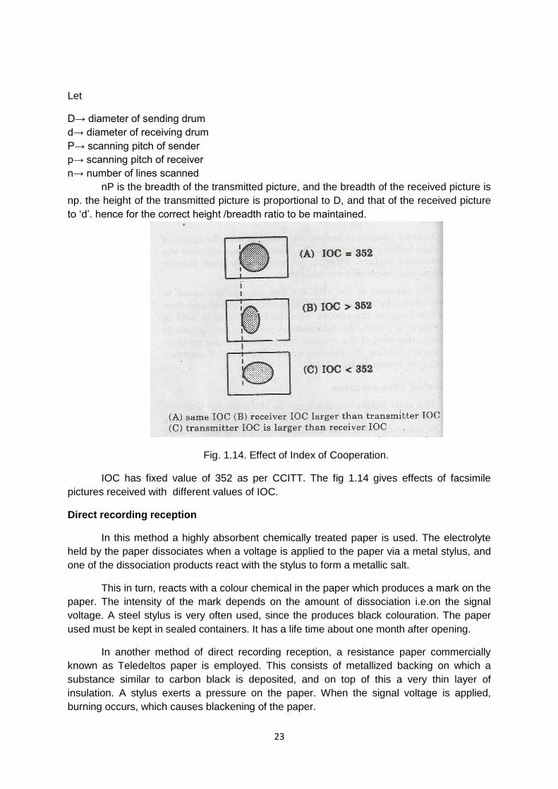
Let
D→ diameter of sending drum
d→ diameter of receiving drum
P→ scanning pitch of sender
p→ scanning pitch of receiver
n→ number of lines scanned
nP is the breadth of the transmitted picture, and the breadth of the received picture is
np. the height of the transmitted picture is proportional to D, and that of the received picture
to ‘d’. hence for the correct height /breadth ratio to be maintained.
Fig. 1.14. Effect of Index of Cooperation.
IOC has fixed value of 352 as per CCITT. The fig 1.14 gives effects of facsimile
pictures received with different values of IOC.
Direct recording reception
In this method a highly absorbent chemically treated paper is used. The electrolyte
held by the paper dissociates when a voltage is applied to the paper via a metal stylus, and
one of the dissociation products react with the stylus to form a metallic salt.
This in turn, reacts with a colour chemical in the paper which produces a mark on the
paper. The intensity of the mark depends on the amount of dissociation i.e.on the signal
voltage. A steel stylus is very often used, since the produces black colouration. The paper
used must be kept in sealed containers. It has a life time about one month after opening.
In another method of direct recording reception, a resistance paper commercially
known as Teledeltos paper is employed. This consists of metallized backing on which a
substance similar to carbon black is deposited, and on top of this a very thin layer of
insulation. A stylus exerts a pressure on the paper. When the signal voltage is applied,
burning occurs, which causes blackening of the paper.

24
REVIEW QUESTIONS
PART –A
1. Define RADAR.
2. Define the maximum range of RADAR.
3. State the different types of display method used in RADAR.
4. Expand PSTN?
5. Mention the types of aircraft landing system.
6. What is telephone?
7. Define video phone.
8. What is ISDN?
9. What is FAX?
10. What is IOC?
PART-B
1. Draw the block diagram of pulsed RADAR.
2. Mention the applications of RADAR.
3. Mention the three important display methods used in RADAR.
4. Define aircraft landing system and mention its types.
5. State the features of ISDN.
6. Write note on synchronization.
7. Explain phasing.
8. Write note on facsimile receiver.
PART-C
1. (A) Explain radar range equation.
(B) Explain the factors influencing maximum range.
2. (A) Explain A-scope display.
(B) Explain PPI display.
3. With the block diagram explain the working of pulsed radar system.
4. Explain the working of Instrument Landing System with necessary diagrams.
5. (A) Explain Ground Controlled Approach.
(B) with block diagram explain the working of video phone.
6. With the block diagram explain the working of public telephone network.
7. Explain the working of electronic switching system with necessary block diagram.
8. Draw the architecture of ISDN and explain it?
9. (A) Write short note on facsimile sender.
(B) Explain synchronization in facsimile receiver.
10. (A) Write short note on facsimile receiver.
(B) Explain phasing in facsimile receiver.
11. (A) Explain index of co-operation in facsimile receiver.
(B) Explain the cylindrical scanning used in facsimile systems.

25
UNIT 2
DIGITAL COMMUNICATION
Introduction
Digital technology is a branch of Electronics and communication. It utilizes digital
signals, which appear in discrete steps. An analog signal is a continuous signal.
In a digital communication system, the output of the data source is transmitted from
one place to another . The data system is required to transmit rectangular pulses at a rate
ranging from 100 to 500 Kbits per second.
Typical application of this system are:
• Computer to computer communication
• Computer interrogation (either for data storing or data manipulation and calculation)
• Programming
• Data collection
• Telemetry and alarm system
• Financial credit information
• Transfer travel and accommodation booking services
The digital communication is basically divided into two types. They are
• On-line system
In an on-line system the data is transmitted directly to or from a computer.
The on-line system may be either real time or on-real time system. If the
system requires rapid response then it is a real time system. In on-real
system the data transmission speed is much delayed.
• Off-line system
In an Off-line system data is transmitted to or from an intermediate storage
point such as card, a paper tape punch, magnetic tape or disc.
The digital communication is basically divided into three types based upon
transmission as:
1. Simplex
A one-way channel connection is known as simplex.
2. Semi-Duplex
An either way transmission requires semi-duplexer connection.
3. Full-Duplex
A full-duplexer is the one in which the data can be sent in both directions
simultaneously.

26
2.1.1 BASIC ELEMENTS OF DIGITAL COMMUNICATION SYSTEM
A digital information source produces a finite set of possible messages. A typewriter
is a good example of digital source. There is a finite number of characters (messages) that
can be emitted by a source.
A digital communication system transfers information from a digital source to a sink.
A digital waveform is defined as a function of time that can have only a discrete set of
values. As the digital waveform is a binary waveform, only two values exist.
An electronic digital communication system usually has voltages and currents that
have digital signals.
However if an analog signal has to be conveyed it is converted into digital signal by
using Analog to Digital Converter before communication over the channels. Because an
analog signal is a function of time that has a continuous range of values.
For example , for a line transmission of digital information a binary 1 information
may be transmitted by using a sine wave of 1000 Hz , and a sine wave of 500 Hz is
transmitted to represent a binary 0. Thus the digital information is transmitted by use of
analog waveforms derived from an analog source.
2.1.2 Block diagram of digital communication system
In digital communication, digital signals ,the coded representations of information,
which are transmitted.
Fig 2.1 Block diagram a Digital Communication System
(Courtesy pg no 4 Digital communications Simon Haykin john wiley)
The block diagram of basic elements of digital communication system is shown in fig.2.1.

27
The description of blocks is shown below:
INFORMATION SOURCE
The information source generates the message signal to be transmitted. . In the case
of an digital source , the information source produces a message signal which is of
discrete and random in nature ,not continuously varying with time.
In case of an analog source, the information is analog, which is continuously
varying with time. The analog signal can be converted in to digital signal by sampling and
quantization using an Analog to Digital Converter.
✓ A source of information generates a message; examples are human voice, television picture, teletype data, atmospheric temperature and pressure.
✓ In these examples, the message is nor electrical in nature, and so a transducer is used to convert it into and electrical waveform called the message signal.
✓ The waveform is also referred to as a base band signal the term ‘ base band’ is used to denote the band of frequencies representing the message signal generated at the source.
✓ The message signal can be of and analog or digital type.
✓ In analog signal both amplitudes and time vary continuously over their respective intervals. A speech signal, a television signal, and a signal location are examples of analog signals.
✓ In a digital signal, both amplitude and tome take discrete values. Computer data and telegraph signals are examples of digital signals.
✓ An analog signal can always be converted into digital form by combining three basic operations: sampling, quantizing, and encoding as shown in the block diagram.
✓ In the sampling operation, only sample values of the analog signal at uniformly spaced discrete instants of time are retained.
✓ In the quantizing operations, each sample value is approximated by the nearest level in a finite set of discrete levels. In the encoding operation, the selected level is represented by a code word that consists of a prescribed number of code elements.
SOURCE ENCODER
The symbols provided by the information source are given to the source encoder.
These symbols cannot be transmitted directly. They are first converted into digital form by
the source encoder.
The source encoder assigns code words to the symbols. For every distinct symbol
there is unique code word. They assign a set of code to a particular data by choosing a
unique value in the data set. Typical source encoders are pulse code modulators, delta
modulators, vector quantizer etc.

28
In source coding, the encode maps the digital signal generated at the source output into another signals in digital form. The mapping is one-to-one and used to eliminate or reduce redundancy. So as to provide an efficient representation of the source output
CHANNEL ENCODER
The channel encoder converts the message or information signal in the form of
binary sequence in a transmittable form. During signal communication, noise and
interference may be added with signal. To avoid these errors, channel encoding is done.
The channel encoder adds some redundant binary bits to the input sequence. These
redundant bits are added with some properly defined logic.
✓ In channel coding the objective is for the encoder to map the incoming digital signal into a channel input and for the decoder to map the channel output into an output digital signal so that the effect of channel encoder and decoder enables reliable communication over a noisy channel.
✓ This is done by introducing redundancy ina prscribed fashion in the channel encoder and using it in the decoder to reconstruct the original encoder input as accurately as possible.
✓ In source coding, we remove redundancy, whereas in channel coding we introduce controlled redundancy to overcome channel noise effect.
✓ we may perform source coding alone, channel coding alone, or the two together. In the latter case, naturally, the source encoding is performed as shown in fig.
✓ in the receiver, we produce in the reverse order: channel decoding is performed first, followed by channel encoding in the transmitter as shown in fig.
✓ in the receiver, we produce in the reverse order channel decoding is performed first, followed by source decoding for any combination is used, the result is and improvement in system performance achieved at the cost of increased circuit complexity.
CHANNEL
The communication channel is a physical medium used for transmitting signals from
a Transmitter to a distant Receiver .It forms the information backbone of any digital
communication system. Higher data rate is also possible using Optical Fiber Cables.
In wireless system this channel consists of atmosphere. A multi hop system may
integrate coaxial cables, fiber optic cables ,microwave links to complete the link . Global
communication is very easily possible due to satellite channel.
DIGITAL DEMODULATOR
The digital demodulator converts the input modulated signal obtained through the
communication channel to a sequence of binary bits.
The digital modulator maps the input binary sequence to analog signal waveform so
that it can be transmitted un distorted over along communication channel.

29
The following modulators are used ,where the digital on –off signals are used to key- in
generating equivalent modulated analog signals suitable for transmission over a band width
limited analog transmission line of short haul or long haul systems.
1 Amplitude Shift Keying (ASK)
2 Frequency Shift Keying (FSK)
3 Phase Shift Keying (PSK)
CHANNEL DECODER
The channel decoder reconstructs error free accurate bit sequence and reduces the effects
of channel noise and distortion.
SOURCE DECODER
The source decoder performs reverse operation of source encoder. It converts the binary
output of channel encoder into a symbol sequence. Both variable length and fixed length
decoders are possible. Some decoders use memory to store the code words.
Advantages of digital communication
• Relatively inexpensive digital circuits can be used.
• Privacy is preserved by using data encryption.
• Greater dynamic range (the difference between the largest and smallest value) is
possible.
• Data from Voice, Video and Data sources can be merged and transmitted over a
common digital transmission system.
• In long distance systems, noise does not accumulate from repeater to repeater,
as in analog systems.
• Errors detected are small, even when there is a large amount of noise on the
received signal, ie. S/N Ratio is high in Digital Systems.
• Errors are often corrected by the use of error correction coding.
Disadvantages of digital communication
• Generally, more bandwidth is required than that for analog systems.
• Synchronization is required.
2.1.3 Characteristics of digital transmission circuits
2.1.3.1 Bandwidth requirement of data transmission circuits
Data in most systems use pulse type of energy. The data stream is similar to a square-wave
signal with rapid transitions from one voltage level to another. The repetition rate of the data

30
word depends on the binary representation of the data word.
Fig 2.Bit rate compared to frequency with return to Zero/RZ and non return to Zero/NRZ
output(Courtesy :pgno 267 Electronic communications- Robert Schoenbeck)
For instance, if an 8-bit word has the value 01010101, the resulting voltage graph
represents a series of four square waves with each negative half cycle equal to each positive
half cycle. If however the data word has the form 00001111, the voltage graph would appear
as a single square wave with equal negative and positive half cycles, but longer than firs
one.
Figure 2.2 shows the voltage graphs for these and other binary words. The data
circuits must provide a bandwidth for the data transmission.
Fig Digital waveforms showing frequency variations for different codes Pg no
503 Electronic communication George Kennedy ,Mc GRaw Hill

31
Since many data transmissions utilize telephone channels, the bandwidth of the
telephone is an appropriate consideration. The internationally accepted standard telephone
channel occupies the frequency range of 300 to 3400 Hz his referred to within the industry
as a 4 KHz channel. HF radio and submarine cables frequency range is 300 – 2800 Hz. The
signals which fall outside the channel bandwidth are attenuated by filters, so that they will
not interface with each other signals.
When data is sent over telephone channels the speed must be limited to ensure
that the required bandwidth of the data transmission should not exceed telephone channel
bandwidth. If the data is transmitted with greater speed, it requires larger bandwidth to
accommodate it.
2.1.3.2 Speed of data transmission circuits
The rate of data transfer depends upon several aspects of transmission channel. The
transmission speed of a communication channel is described in baud rate. Band is the unit
of signaling speed. In a system, in which all pulses have equal duration, the speed in bauds
is equal to the maximum rate at which signal pulses are transmitted.
In a system in which all pulses have equal duration, the speed in bauds expresses
the numbers of pulses transfer per second. One cycle of transmission must contain a
maximum of 2 bauds. The maximum signaling speed in bauds is equal to twice the
bandwidth of the channel. It should be achieved only in an ideal channel which had no noise
or distortion.
The information can be transferred at a rate equal to or different from the baud rate.
Multilevel and encoded data elements can be used to provide information transfer rates as
speeds greater than the baud rate.
For example; a data stream is converted into a 2-bit pair pattern. The 2-bit pattern
has maximum values of 4, as 00, 01, 10 and 11. Each of the 2-bit pairs is converted to a
phase values in the data set, 00 is being represented by 90, 01 by 180, 10 by 270 and 11 by
0 (=360). Each of the 2-bit elements is called a ‘dibit’. This is therefore, a four level code.
Dibit-encoded data can be transmitted by using half the numbers of bauds required for non-
encoded data.
The data rates of common system are limited to a maximum rate about 10,800bps for
a voice graded channel. Faster data rates are prevented by noise other than random in a
channel and other channel limitations.
2.1.3.3 BAUD RATE in data transmission circuits
Baud is a unit of signaling speed. Generally ,the information may transfer at a rate equal to
or different from the baud rate. Multi level and encoded data elements can be used to
provide information transfer rates at speed greater than the baud rate.
For example, if the data streams are converted to 2-bit pairs, each 2 bit pair can have only
one o four values 00, 01, 10 and 11. Each of the 2 bit pair is converted to a phase value in
the data set. The value 00 being represented by 90, 01 by 180, 10 by 270 and 11 by 360
(0). Each of the 2 bit elements is called a dibit. Dibit-encoded data can be transmitted by
using half the number of bauds for the non-encoded data.

32
In a system in which all pulses have equal duration, the speed in bauds is equal to the
maximum rate at which signal pulses are transmitted. The maximum signaling speed in
bauds is equal to twice the bandwidth of the channel.
2.1.3.4 Noise in data transmission circuits
The sampling theorem status that all amplitude values of a signal can be determined
by sampling the signal at a rate equal to at least twice the bandwidth. Noise may affect this
sampling process because the noise pulse will be interpreted as a data bit. This is shown in
fig.. if the noise occurs at the sampling time, mark will be developed only if the amplitude of
the noise is greater than the sampling level.
Fig Effect of Noise on a Digital Signal(Courtesy:pg no 26 Wireless
communication networks-WILLIAM Stallings ,Pearson Education)

33
A noise free channel would be necessary to preclude noise-induced data errors, but noise-
free channels don’t exist in practice.
Fig Data Stream with Noise Pulse (Courtesy:pg no 532 Electronic communication
systems, George Kennedy ,Bernard DavisTata Mc Graw Hill)
The effect of the noise on the data channel can be reduced by increasing the signal to noise
ratio. For an ideal 3-KHZ channel, the NYQUIST RATE (Twice the bandwidth) would be
6000 bps. A binary system using this channel would require a minimum signal-to-noise ratio
of 3.1 or 4.8dB
It can be shown that a system using three-level code must have a signal-to-noise
ratio of 8.5 db or 3.7 db greater, for equal performance in the channel. Improvement in the
signal to noise ratio makes use of multilevel encoding feasible.
2.1.3.5 CROSS TALK in data transmission circuits
Any transmission system which conveys more than one signal simultaneously ca experience
cross talk. Cross talk is the reception of portions of a signal from one channel to another
channel.
Fig. A balanced transmission circuit using transformers and twisted pair cable.
Solid arrows indicate in-phase signals, dashed lines depict out of phase noise or
cross talk
In modern transmission systems which convey many channels of voice and data
simultaneously, the systems will become loaded, o heavily utilized. So that the control of
levels become very important in order to preclude cross talk. This can be avoided by
developing specific level-setting parameters.

34
Cross talk can occur through electromagnetic interaction between adjacent wires. If the
wires of two signal-carrying circuits run parallel with each other, it is possible for the signal
from one circuit to be induced by electromagnetic radiation into the second circuit. This type
of cross talk is reduced b using twisted pair cables and balanced circuits along with
shielding.
In a balanced circuit, a transformer is placed at each end of the circuit. The transformers are
carefully constructed to provide the centre tap which is the exact electrical centre of the
winding, which connects to the transmission circuit. The centre tap at each end is grounded.
As shown in the figure 2.4, twisted pair cables are used for the transmission circuit hence
noise or signals from other circuits will be induced into both wires at equal levels.
When the cross talk or noise reaches the transformer, it enters as out of phase signals from
the two wires and cancels out in the transformer in phase. Each side of the transformer
forms a circuit with ground and the signal transfers through the transformer intact. The cross
talk and noise are reduced, but the signal is unaffected.
Another way to reduce cross talk is to use shielded cables. If the twisted pairs are placed
inside a braided or metal foil shield, the induction between pairs cannot take place easily.
The shields are grounded to drain off the induced signals and noise.
2.1.3.6 DISTORTION in data transmission circuits
Communication channels tend to react to signals of different speeds within their pass band
in different ways. Specifically signals of different frequencies can be passed b a channel with
different values of amplitude attenuation and at different propagation speeds.
This results in distortion.
Fig Circuit Equalization(Courtesy:pg no 535 Electronic communication systems
George Kennedy ,Bernard Davis,Tata Mc Graw Hill )
Phase delay distortion is produced in phase modulation. This distortion occurs in a channel
when signals of the frequency are passed through the circuit at a different speed than other
signals. The resulting distortion can take the form of inter symbol interference.

35
2.2. DIGITAL CODES
Different types of equipments are in computer systems to send and receive data through he
devices like keyboards, video terminals, printers, paper tape punches and readers, and
magnetic storage devices. Each of these types of equipment generates and receives data in
the form of codes. The fact that all use encoded data, however does not mean that all use
the same code. Several common codes are used in digital data systems as below:
1 ENTROPY / SOURCE CODING
2 ERROR DETECTION CODES
3 ERROR CORRECTION CODES
Some codes are advantageous when used in different applications. Modern computers can
be easily deal with different codes by simply converting them to the code used by the
computer. The common codes used are Baudot code, binary code, ASCII code, EBCDIC
code, Hollerith code etc.
Some bit stuffing is done often to detect the transmission errors using error codes like parity
bit codes.
Similarly redundantly bits are added as additional bits to detect and correct the error bits
received at a distant receiver.. Hagel Berger Code, Hamming Codes are some examples of
these types of Error Correcting Codes.
2.2.1 ENTROPY / SOURCE CODING
An important problem in communications is the efficient representation of data
generated by a discrete source. The process by Which this representation is accomplished
is called Source encoding. The device that performs the representation is called a source
encoder. For the source encoder to be efficient,
We require Knowledge of statistics of the source. In particular, if some source
symbols are know to be more probable than others, then We may exploit this feature in the
generation of a source code by assigning short code-words to frequent source symbols, and
long code-words to rare source symbols .
We refer to such a source code as a variable-length code. The Morse code is an
example of a variable-length code. In the Morse code, the letters of the alphabet and
numerals are encoded into streams of marks and spaces, denoted as dots “.’’ And dashes
“-’’, respectively. Since in the English language, the letter E occurs more frequently than the
letter Q , for example, the Morse code encodes E into a single dot \ “.’’, the shortest code –
word in the code, and encodes E into “--.-’’, the longest code-word in the code.
Our primary interest is in the development of an efficient source encoder that satisfies two
functional requirements:
1.The code-words produced by the encoder are in binary from.

36
2.The source code is uniquely decodable, so that the original source sequence can be
reconstructed perfectly from the encoded binary sequence.
2.2.1.1. ASCII CODE
ASCII Stands American Standard Code for Information Interchange.
It is a seven bit code. the seven bits are formed, based on a standard progression. The first
three MSB bits represent whether a number, letter or character is coded. The last four bits
represent the actual code of number, letter or character.
Totally it contains 128 combinations of characters. 26 combinations represent letters in
uppercase and another 26 for representing lowercase letters. 10 combinations are used or
numerals. The remaining combinations are used to represent functions, punctuation marks
and various special characters.
Fig American Standard Code for Information Interchange (ASCII) .Three most Significant
bits at the top of the chart.;four least Significant bits at the left side of the chart. (Courtesy:
pg no 535 Electronic communication systems George Kennedy ,Bernard Davis,Tata
Mc Graw Hill)
The number 6 is represented as 011 from the top of the chart ,from the MSB group and
followed by 0110 from the left from the LSB group
To represent the letter A the code ‘100 0001’ is used.
Similarly, to represent the letter B the code ‘100 0010’ is used.
In both cases the first 3 bits are same. But the remaining four bits change according to a
standard progressive value, i.e. it varies from 0000 to 1111 respectively.

37
Similarly the first three bits also follow a standard progression from 000 to 111. Number ‘2’ is
coded as 011 0010 and the letter B is coded as 100 0010. The representation of ASCII code
is shown in the table..
ADVANTAGES
➢ Error detection can be achieved by increasing the total numbers of
bits to 8. The parity bit is adder as the 8 bit, usually the MSB.
➢ It can be easily used in a computer. Modern computer uses
hexadecimal code for their internal computations. Since ASCII is an 8
bit code with parity bit, it can be easily accommodated in computer as
8-bit data.
Use: it is widely used in modern computers.
2.2.1.2. EBCDIC CODE
EBCDIC code stands Extended Binary Coded DECIMAL Inter Change Code.
It is an 8 bit fixed length code. Here all the 8 bits are used for representing the information.
This code is developed in 1962 by the International Business Machines Corporation (IBM).
This code is used almost exclusively with IBM mainframe computers and peripheral
equipments. It is also based on the binary coded decimal format. The name binary coded
decimal was selected because the second hexa character for all letter and digit codes
contains only the hexa values from 0 to 9, which has the same binary sequence as BCD
codes.
This code also follows a standard binary progression for coding. This code has totally 256
combinations. Some alphabets and some numerals of EBCDIC code is shown in the
tablebelow.

38
Fig.2, Extended Binary Coded Decimal Interchange Code (EBCDIC) (Courtesy: pg no 540
Electronic communication systems George Kennedy ,Bernard Davis,Tata McGraw
Hill)
In this code A is represented as 1100 0001 and B is represented as 1100 0010. Here the
MSB two bits are same (11), but the LSB 4 bits change progressively from 0000 to 1001 in
BCD.
Similarly ‘a’ is represented as 1000 0001 and b is represented as 1000 0010. Here the MSB
two bits are also same (10) but the LSB 4 bits change progressively from 0000 to 1001 in
BCD.
In this Code “0” is represented as 1111 0000 and ‘9’ is represented as 1111 1001. Here the
MSB 4 bits are same, but the lower 4 bits are progressively varying from 0000 to 1001 in
BCD.
ADVANTAGES:
➢ It is similar to ASCII code. It can be readily used in computer.
➢ Total number of combinations is higher.
DISADVANTAGES:
➢ Here all the 8--bits are used for data encoding. There is no
provision for parity bi. Here error correction is not possible.
2.2.2 ERROR DETECTION AND CORRECTION CODES
During transmission of the data signal, error may be produced by noise and
transmission system impairment. The error correction at the receiver section is more
complicated. So it is necessary for data users to determine the importance of the
transmitted data and to decide what level of error detection and correction is suitable for that
data.
2.2.2 Error Detection Codes
The 5-bit Baudot code provides no error detection at all, because it uses all 5-bits to
represent characters. If only one bit is translated (by error) to its opposite value, a totally
different character will be received. This change is not detected by the receiver. Hence to
find out the error, other codes are provided for error control adding additional bits.
2.2.1.1 Parity Check Code
The most widely used approach, for detecting errors that arise in storing and moving
word , is the use of a parity check bit added to each character code group. Codes of this
type are called parity check codes. A parity bit( 0 or 1) is added to the end of the character
code block according to some logical process. There are two types of parity codes, namely

39
1) EVEN PARITY and
2) ODD PARITY
Fig Vertical and Horizontal Parity used with paper tape code (Courtesy: pg no 543
Electronic communication systems George Kennedy ,Bernard Davis,Tata Mc Graw
Hill )
Even parity means adding an extra bit to the group of bits to make the whole number of
1's as even. for instance, consider a word 0111.this word contains three 1's.so we add one
more 1 at the end of this word to make the whole word as 01111, having even number of 1's
.this new word can be moved and stored by the computer, and can be checked for even
parity at different points to assure that no errors have crept into the word. similarly, in case of
odd parity, add one more bit on the end of character, to make the whole word as odd
number of 1's.
At the receiver, the block addition is accomplished with the parity bit intact, and
appropriate addition is made. if the sum provides the wrong parity, an error during
transmission will be assumed and the data will be retransmitted.
Parity bit added to each character block provides what is called vertical parity.
Parity bit can also be added to rows of code bits. This is called horizontal parity.
Fig Error detection using vertical and Horizontal Parity(Courtesy: pg no 543 Electronic
communication systems George Kennedy ,Bernard Davis,Tata Mc Graw Hill )
The code bits are associated into blocks of specific length with the horizontal parity
bits following each block. By using the two parity schemes concurrently, it becomes possible

40
to determine which bit is an error. this is explained in fig. Here even parity is expected for
both horizontal parity and vertical parity.
Note, here one column and one row each display improper parity. By finding the
intersection of the row and column, the bit in error can be identified, by simply changing the
bit to the opposite value. it will restore proper parity both horizontally and vertically. These
types of parity arrangements are sometimes called geometric codes.
2.2.1.2 Redundant Code
Most error-detection systems use some form of redundancy to check whether the
received data contains errors. That means, additional data is sent with the basic data. The
redundancy takes the form of transmitting the information twice and comparing the two sets
of data to see that they are the same. If a discrepancy is noted between the two sets of data,
an error is assumed and the data is caused to be retransmitted. When the two sets of data
are same, error free transmission is assumed.
Retransmission of the entire message is very inefficient because the second
transmission of a message is 100 present redundant. In all cases the redundant bits of
information are unnecessary to the meaning of the original message
2.2.3 Error Correction Codes
Calculated use of redundancy in the form of additional bits called check bits/blocks are
added to the message bits .
When a code word Zi is transmitted via a noisy channel and Z is received the transmission
error corresponds to e=Z-Zi.
The algebraic coding adds algebraic structure to the code words set so that the
error is easily expressed.
Error correction is an important aspect of data transmission. the process involved
with error correction normally results in an increase in the number of bits per second which
are transmitted, and naturally this increases the cost of transmission.
The procedures which permit error correction at the receiver location are
complicated. so it is necessary for data users to determine the importance of the
transmitted data and to decide what level of detection and correction is suitable for that data.
Some types of error correction methods are explained below.
2.2.3.1 Retransmission
The more popular method of error correction is re transmission of the erroneous
information.
As this method of retransmission involves more expenditure , some form of
automatic system is needed. Such a system which has been developed for use is called
automatic request for repeat (ARQ), Only When the positive acknowledgement(ACK) signal
is sent to the transmission station, and the next block is transmitted.
The parity of each block is checked at the receiving level. if no error is noted, a

41
positive acknowledge(ACK)is sent to the transmit station, and the next block is transmitted.
If any parity error is detected, a negative acknowledgment (NAK) is sent to the
transmitting station, so the transmitting station will repeat the block of data.
The parity check is again made and transmission continues according to be the result
of the parity check.
Types of Retransmission:
1 Discrete ARQ
2 Continuous ARQ
2.2.3.2 Forward Error Correction Code
For increasing the transmission efficiency, error correction at the receiver without
retransmission of erroneous data is naturally preferred
If the error correction is made by the receiver station without retransmission, it is
called forward error-correcting codes .it is done by including sufficient redundancy in the
transmitted data. . a number of such methods are also available.
A forward error correcting code uses the matrix sum as shown in the figure. It
illustrates the use of a three level matrix sum system.
Here the sum of rows is equal to the sum of columns.. The transmitted message
consists of the information bits and the letters representing the sum of each column and row
and the total. when the signal is received, the matrix is reconstructed and the sums are
checked to determine whether they agree with original sums this is important for the
encoding scheme's ability to find and correct errors
.
Fig Forward Error Correction Code –Three level matrix sum forward error correcting code

42
a) Message in triplets b) triplets as numbers with check sums c)Received data with
error d)Error check and correction
If they agree, then error free transmission is assumed, but if they disagree ,error
must be present and corrected by the adjusting the sum value.
As shown in figure , the row and column discrepancies are identified in the matrix
cell and that is corrected by replacing the incorrect number with the value which agrees with
the check sums. Thus the message can be restored to the correct form.
Such error correction requires intervention by a computer or by a smart terminal of
some kind. This correction is particularly well suited to applications which place a high value
on the timeliness of data reception.
A three level matrix sum code will provide for approximately 90 percent error
correction confidence level. Larger matrices will increase this confidence level significantly.
The larger matrix has the additional benefit of increasing the ratio of information bits to error
check bits. As the result of increase in the level of matrix , transmission efficiency
increased to, 81% for the nine-level matrix versus 56% for the three-level matrix.
2.2.3.3 Hamming Code
In the Hamming code several parity-check bits are added to a data word. Consider
the data word 1101, in the hamming code three parity bits are added to the data bits as
shown below:
1 0 1 0 1 0 1 [p- parity bits]
1 2 3 4 5 6 7 [Bit Location]
p1 p2 D p3 D D D [D-Data bit]
The first parity bit,p1 provides even parity from a check of bit locations 3,5 and 7,which
are 1,1 and 1 respectively.p1 will therefore be 1 to achieve the data as even parity.p2 checks
the location of bits 3,6 and 7,to make even parity and is therefore 0 in this case. Finally, p3
checks the locations 5,6 and7 to make even parity and is 0 here. Hence resulting in a 7 bit
word called Hamming Code .
If the data word is altered during transmission, so that the location six changes from a '0'
to a '1' the parity will no longer be correct. The hamming encoding permits evaluation of the
parity bits to determine where error occurs. This is accomplished by assigning a 1 to any
parity bit which is incorrect and 0 to one which is correct. if the three parity bits are all
correct,000 results and no errors can be assumed. In the case of the above described error,
the code has the form,
p1(which checks location 3,5 and 7) should now be a 1 and is therefore correct. It will
be given a '0'.p2 checks 3,6 and 7 and is therefore incorrect. It receives the value of '1'. p3
checks 5,6 and 7 and should be a 1,but it is wrong here, and so it receives a value of 1.The
three values result in the binary word 110(p3 p2 p1),which has the decimal value of 6.this
means that the location containing the error is six,

43
The number of Hamming code bits are determined by the following expression:
2n ≥≥ m+n+1
Where n= the number of parity bits and m=the number of bits in each data character
The hamming code is therefore capable of locating a single error and the receiver is able to
pin point the error without retransmission of data.
But the Hamming code fails if multiple errors occur in a single data block..
2.2.4 Digital Modulation Techniques (Only Block Diagram and Operation)
Computers talk with each other over analog Public telephone lines as they are deployed
globally and used by more population
There would be more degradation of data streams sent over the lines due to higher
harmonic content of the digital signala and limited frequency response of the lines
So a system called MODEM is used to convert digital input train of pulses into analog signals
at one end of the transmission line of a network by a modulator present in the unit. Similarly
the demodulator unit converts back the presented to its input back in to the digital data.
Modems are also called as Data Sets or the Data Communication Equipment(DCE).
Both analog and digital modulation systems use analog carriers to transport the information.
In analog modulation the information signal is analog ,where as in digital modulation the
information signal is discrete, random, digital signal, which can be a computer generated
data or a digitally encoded analog signal.
V(t)= V sin (2 π.ft+ θ) ………2.1
Referring to the equation a digitally modulated ASK (Amplitude Shift Keying ) is
produced when the Amplitude ,V of the carrier is varied according to the instantaneous
value of the digital modulating signal.

44
When the Frequency f of the carrier is varied according to the instantaneous value of
a digital modulating signal the digitally modulated ASK (Frequency Shift Keying ) is
produced.
When the Phase θ of the carrier is varied according to the instantaneous value of a
digital modulating signal the digitally modulated PSK ( Phase Shift Keying ) is produced.
When both the Amplitude ,V and Phase θ of the carrier is varied according to the
instantaneous value of a digital modulating signal the digitally modulated QAM (Quadrature
Amplitude Modulation ) is produced.
When a Digital data is modulated on to a carrier wave carrier it shifts the digital data from
the baseband region into a pass band region of the frequency spectrum.
2.2.4.1 ASK Modulation/ Demodulation Techniques
In amplitude shift keying (ASK) modulation, the digital signal is switched in
between amplitude level of digital. In this system the carrier signal is ON and OFF, in
accordance with the digital binary input signal. The carrier signal is transmitted during the
high level(1)input, conversely the carrier signal is blocked during low(0) level input.
This method is also called ON-OFF keying(OOK).
The block diagram of ASK modulator is shown in the fig.2.9.The carrier oscillator produces
sine wave signal with carrier frequency.

45
The digital controlled switch operates in accordance with the digital binary input
signal. The switch is closed when the digital binary input is high (1). conversely the switch is
opened when the digital binary input is low(O).
During the switch closure period, the carrier signal is passed to its out put. similarly
during the switch open period, no signal is passed to its output. So the output of switch is a
amplitude shift keying signal. the waveforms of binary amplitude shift keying is shown in the
fig.2.10.
ASK demodulator
The block diagram of ASK demodulator is shown in the fig.2.11. this demodulator
requires a carrier recovery circuit which is used to generate a local carrier signal exactly
synchronized to the transmitted carrier. The carrier frequency produced in the recovery
circuit is used to lock the VCO in PLL. the local generated carrier signal and the received
modulated signal, both are applied to the multiplier circuit directly.

46
The multiplier produces a 1 (high) level signal at its output when the carrier signal is
come to its input, otherwise it produces a 0 (low) level signal at its output. The unwanted
signal produced at its output is removed by the LPF net work.
2.2.4.2 FSK Modulation/ Demodulation Techniques
The simplest form of binary data modulation be represented in a phone line, is to let a pure
single frequency sine wave represent a binary ‘1 value and another sine wave with a
different frequency to represent binary ‘0’
The block diagram of FSK modulator is shown in the fig 2.12. The stream of digital
signal is given to the mark switch and the inverter. The mark oscillator produces a sine wave
signal with the carrier frequency of f1. Similarly the space oscillator produces the another
sins wave signal with the carrier frequency of f2.
The binary digital input signal and the signal from the mark oscillator are applied to
the mark switch. Similarly the inverted binary digital input signal and the signal from the
space oscillator are applied to the space switch directly
If the input binary signal is 1 (high), the mark switch will be closed. Now the signal
from the mark oscillator with frequency f1 is passed to the summing amplifier through the
mark switch. The mark signal which is a high voltage signal is inverted by the inverter and
becomes low voltage signal. So the space switch is open. As a result the signal from the

47
space oscillator does not reach the summing amplifier.
If the signal is a space signal, the mark switch will be opened. So the signal from the
mark oscillator does not reach the summing amplifier. Since the signal is inverted and given
as the input to the space switch, the space switch will be closed. So the signal from the
space oscillator will reach the summing amplifier.
If the digital input signal is 1 (high), the output of summing amplifier will be the signal
with the frequency of f1. Conversely if the digital input signal is 0 (low) then the output of the
digital input digital signal different frequencies are transmitted through the summing
amplifier. The waveforms of FSK modulator is shown in the fig.2.13.
FSK demodulator
The block diagram of FSK demodulator is shown in the fig.2.14. the modulated FSK
signal is applied to the input of demodulator. The mark signal with the frequency f1 is passed
through the mark band pass filter and detected by the mark detector.
This signal is given as input to the non-inverting input of the difference amplifier.
Similarly the space signal with the frequency f2 is passed by the space band pass
filter and detected by the space band pass filter and detected by the space detector. This

48
demodulated signal is given as input to the inverting input of the difference amplifier.
The output of the difference amplifier will be the signal with positive voltage, if the
signal with frequency f1 reach the input of the difference amplifier. This represents the digital
signal '1' . Conversely the output of difference amplifier will be the signal with the negative
voltage, if the signal with frequency f2 reach the input of the difference amplifier. This
represents the digital signal 0.
2.2.4.3 PSK Modulation/ Demodulation Techniques
The block diagram of PSK modulator is shown in the fig.2.15. In this system the
phase of the carrier signal is varied in accordance with the level of digital signal. The input
digital signal is applied to the mark switch directly.
Similarly the input digital signal is applied to the space switch through an inverter.
The inverter inverts the digital input signal. The oscillator produces sine wave carrier signal
with the frequency of "f". This signal is applied to the mark switch directly, and applied to the
space switch through 180 phase shifter.
The carrier signal is applied to both switches are with same frequency but out of
phase.
PSK Modulator BLOCK DIAGRAM(Courtesy:PG NO 70 Schoenbeck Advanced Electronic
Communication Systems)
If the input digital is 1 (high) the mark switch is closed, the oscillator is directly
applied to the summing amplifier. Similarly if the digital input signal is low, the space switch
is closed, now the 180 phase shifted carrier signal with same frequency is applied to the
summing amplifier. The summing amplifier combine the two signals. The signals produce at
the output of summing amplifier has phase differences. The phase difference occurred when

49
the input digital signal varying from 0 to 1 or 1 to 0.
The waveforms of PSK modulator is shown in the fig. 2.16 .
PSK demodulator
The block diagram of PSK demodulator is shown in fig2.17. The modulated PSK
signal is applied to the synchronous local oscillator. The synchronous local oscillator is a
carrier recovery oscillator. The synchronous local oscillator works with the principle of PLL.
When the PLL goes to the lock state, the signal from the output of synchronous local
oscillator is in original carrier frequency. The signal from the output of synchronous local
oscillator is applied to the non-inverting input of difference amplifier. The PSK signal is
applied to the inverting input of same difference amplifier.
PSK Demodulator BLOCK DIAGRAM (Courtesy:PG NO 70 Schoenbeck Advanced
Electronic Communication Systems)
The difference amplifier compares the two input signals, and its output is applied to
the detector circuit. The detector produces original digital output signal.

50
In general, multiple PSK system has more advantages than single bit binary PSK
system. The speed of this system is varied in accordance with the number of phase
changes. The PSK system is very much used becaus noise could not affected this system.
2.2.4.4 QPSK Modulation/ Demodulation Techniques
QPSK is called a quaternary phase shift keying or quadrature phase shift keying.
It is an another from of angle modulated constant amplitude digital modulation.
With QPSK, four output phases are possible for a single carrier frequency. Because
of there are four output phases, there must be four different input conditions.
Because the digital input to a QPSK modulator is a binary signal, to produce four
different input combinations, the modulator requires more than a single input bit to determine
the input condition.
With two bits, there are four possible conditions exists as: 00,01,10 and 11.
Therefore with QPSK, the binary input data are combined into group of two bits, called dibits.
In the modulator, each di bit code generates one of the four possible output phases
(+450,+1350, -450, and -1350 ).Therefore, for each two dibit clocked into the modulator, a
single output change occurs, and the rate of change at the output is equal to one half the
input bit rate (i.e., two input bits produce one output phase change).
QPSK modulator
The block diagram of a QPSK transmitter is shown in the fig.2.18. Two bits (a di bit)
are clocked into the bit splitter. After both bits have been serially fed they are simultaneously
parallelly outputted. One bit is directed to the "l" channel and the other to the "Q" channel.

51
QPSK Modulator BLOCK DIAGRAM(Courtesy:PG NO 66 Wayne Tomasi- Advanced
Electronic Communication Systems)
The I bit modulates a carrier that is in phase with the reference oscillator (hence the
name I for "in phase" channel) and the Q bit modulates a carrier that is 90 out of phase (or”
in quadrature”) with the reference carrier (hence the name Q for "quadrature" channel).
It can be seen that a dibit has been split into the I and Q channels as Shown Below:
For a logic 1=+1V and a logic 0=-1V, two
phases are possible at the output of I balanced
modulator(+ sin wcType equation here. t and - sin
wc t) and also two phases are possible at the
output of Q balanced modulator (+sin wc t and -sin
wc t).
When the linear summer combines the two
quadrature signals, there are four possible resultant
phasors given by the expression: +sin wc t + cos
wc t, +sin wc t - cos wc t, -sin wc t+cos wc t, -sin wc t- cos wc t.
With QPSK each of the four possible output phasor has exactly the same amplitude.
Therefore the binary information must be encoded entirely in the phase of the output signal.
The angular separation between any two adjacent phases in QPSK is 90 . Therefore
a QPSK signal can undergo almost a + 45 or -45 shift in phase during transmission and still
retain the correct encoded information when demodulated at the receiver. The truth table of
QPSK modulator is shown below.
The output phase versus time relationship for a QPSK modulator is shown in the fig.
2.19.
Binary Input QPSK output . phase
Q I
0
0
1
1
0
1
0
1
-135 o
-45o
+135 o
+45 o

52
QPSK Reception (Demodulator)
The block diagram of a QPSK receiver is shown in fig 2.20. The power splitter
directs the input QPSK signal to the I and Q product detectors and the carrier recovery
circuit reproduces the original transmit carrier oscillator signal.
Fig QPSK Demodulator BLOCK DIAGRAM (Courtesy:PG NO 70 Wayne Tomasi -
Advanced Electronic Communication Systems)
The recovered carrier must be frequency and phase coherent with the transmited
reference carrier. The QPSK signal is demodulated in the I and Q product detectors, which
generates the original I and Q data bits.
The output of the product detectors are fed to the bit combining circuit, where they
are converted from parallel I and Q data channels to a single binary output data stream.

53
Review Questions
Part –A 2 Marks
1What is a Digital Signal ?
2 What is an ADC ?
3 What is Noise ?
4 What is a Channel ?
5 Define Even Parity
6 What is an ASCII Code ?
7 What is OOK ?
8 Draw PSK waveform
9 What is Cross Talk ?
10 What an ARQ ?
Part –B 3 Marks
1 Compare Analog and Digital Signals
2 Mention the characteristics of Digital Signal Transmission
3 Mention the Blocks in a Digital Communication System
4 Mention the uses of Equalisers
5 Explain Nyquist Rate
6 Explain Baud Rate
7 Explain about Baudot Code
8 Explain FSK
9 How can we improve the speed of a Transmission Line
10 What is the use of Twisted pair of wires ?
Part –C 10 Marks
1 Explain the Digital Transmission System with a Block Diagram
2 Explain the Characteristics of Digital Transmission System
3 Explain the Source Codes
3 Explain Error Detection Codes

54
4 Explain Error Detection Codes
5 Explain about Equalisers and Mention its Types
6 Explain the working of a ASK Modulator and De Modulator
7 Explain the working of a FSK Modulator and De Modulator
8 Explain the working of a PSK Modulator and De Modulator
9 Explain the working of a QPSK Modulator and De Modulator
10 Describe about the Advantages and Disadvantages of Digital Communication Systems

55
Unit-III
Optical Communications
Need for OFC:
Many media services such as data base, video, communication, conference,
telepedition etc uses personal computers. To store and process high volume of data, need
larger bandwidth. But telephones and coaxial cable are unable to meet this demand. So
optical fiber cable (or) communication occurs.
Basic Principle:
The LASER, IR light emitting diodes are used to produce light rays. Hence they are
called as source. We use OFC optical fiber cable as a channel between transmitter and
receiver. Similarly at receiver end, we use light detectors such as photo diode or PIN diode
to convert light energy into electrical energy.
Optical fiber characteristics:
• It has dielectric wave guide.
• Its transfer light rays from one end to another end by means of successive
reflection or refraction.
• Wave guide (or) OFC confines electromagnetic energy within its surface and
guide (or) pass energy parallel to the axis.
• Optical fiber operate in a frequency ranging between 1012 to 1016 Hz
Optical fiber communication system block diagram:
Main blocks of optical fiber communication system are,
1) Transmitter
2) Channel (or) OFC
3) Receiver

56
Source
Optical Fiber Cable Optical Fiber Cable
Destination
Fig.3.1 Optical Fiber Communication system Block diagram
Transmitter:
Transmitter consists of following sub blocks,
Voltage to current converter
Light source
Source to fiber interface
In the transmitter, light source is modulated by digital or analog signal. So it is called
light intensity modulation. The Light Emitting Diode (LED) (or) Injection LASER Diode
(ILD) are used as Light source. Amount of light emitted by either LED (or) laser is
defined by drive current. Amount of light emitted by light source is varied with respect to
input digital (or) analog data. Hence it is called light intensity modulation. The source to
fiber coupler is a mechanical interface. It is used to couple light limited by light source
into the OFC.
Analog (or) Digital
Interface
Voltage-to-Current
Converter
Light
Source
Source-to-fiber
interface
Signal
Regenerator
Fiber-to-light
detector
interface
Light
Detector
Current-to-Voltage
Converter
Analog (or) Digital
Interface
Signal
Regenerator

57
Channel or OFC:
Optical Fiber Cable is used as a channel. OFC is made up of glass or plastic core
surrounded by cladding which is also glass. The whole structure is covered with plastic
jacket or insulator. Based on the distance within the channel we are providing one or more
regenerator or repeater which is used to reconstruct input signal.
Receiver:
Receiver consists of
• Fiber to light detector interface
• Photo detector
• Current to voltage converter
Fiber to light detector interface is a mechanical interface. It is used to couple maximum
amount of light energy coming out from the cable into the light detector. Photo Transistor,
PIN diode or APD (Avalanche photo diode) are used as light detectors. Light detector is
used to convert light energy into electrical energy (current). Current to voltage converter is
used to produce output voltage with respect to the original input source or data.
Advantage of optical fibers:
1. An optical fiber has very high information transfer rate Gigabits/sec.
2. Fiber attenuation is independent of signal band width. This is the difference
between fiber and conventional communication channels (twisted, pair, cables,
wave guide)
3. The advantages of fiber are low loss, very wideband, flexible and light weight.
4. Unlike co-axial cables and microwave links, the optical systems are immune to
crosstalk and electromagnetic interference.
5. The diameter of the fiber cable is less than the diameter of the coaxial cable.
6. For large capacity of utilities, fiber optic systems are cheaper than the coaxial
cable or microwave link.
7. Increased signal security.
8. System reliability is more and ease of maintenance.
Ray theory or propagation through optical fiber cable:
Medium (2) (rarer)
ᶱ2 n2-refractive index of medium(2)
n1 >n2
ᶱ1
Medium (1) (denser)
n1-refractive index of medium(1)
Fig.3.2 (a)

58
Optical fiber cable will transfer light energy from one end to another end.
Whenever a light enters from denser medium (refractive index is higher) to a rarer medium
(refractive index is lower) light ray bend towards the normal.
Snell’s law states that
n1 sin 𝜃1=n2 sin 𝜃2 -------------------- (1)
Where n1= refractive index of denser medium
n2= refractive index of rarer medium
Ө1= angle in incidence
Ө2=angle of refraction
Medium (2)
(n2)
900
Øc Medium (1)
(n1)
Fig.3.2 (b)
Critical angle:
Critical angle is defined as that angle of incidence for which angle of refraction is 90.
Substituting or applying this condition in snell’s law, we get
N1 sin 𝜃 𝑐=n2 sin 𝜃 90. ------------------- (2)
sin 𝜃 𝑐 =n2/n1 ------------------ (3)
Where oc=critical angle
When angle of incidence higher than critical angle, total internal reflection takes place.
Total internal reflection:
Cladding
Core
Fig.3.2 (c)
Total internal reflection is propagation of light ray within the optical fiber by means of
successive reflection in between core and cladding area.
Total internal reflection occurs in the fiber when the following condition satisfies.

59
1. The fiber core has a refractive index n1, which is greater than the refractive index of
cladding material.
2. The angle of incidence is greater than critical angle oc.
sin 𝜃 𝑐=n2/n1
Optical fiber cables types:
OFC
Single mode step index Multi mode
Step index Graded
Multi mode index multimode
Optical fiber cable Structure
Fig.3.3 (structure of optical fiber cable)
The structure of optical fiber consists of a single solid dielectric cylinder of radius ‘a’ and
index of refraction n1 as shown in figure. This cylinder is known as the core of the fiber. The
core is surrounded by solid dielectric cladding which has a refractive index n2 that is less
than n1.
Uses of cladding:
• The cladding reduces the scattering loss.
• It ads mechanical strength to the fiber.
• It protects the core from absorbing surface contaminants with which it could
come into contact.
Single mode step index fiber:
Refractive index of the core is uniform. Only single light ray will pass through the
core. There are two types:

60
1. Single mode step index fiber with air cladding.
2. Single mode step index fiber with glass cladding.
Here core diameter is smaller one. Refractive index of the core is 1.5.
Uses:
• Telecommunication and data industry.
Fig. 3.3(a) Single mode step index (air cladding)
Source to fiber
Aperture
Fig. 3.3 (b) Single mode step index (glass cladding)
Advantages:
• Minimum dispersion.
• Is wider external accepting leangle.
• Wider bandwidth and higher transmission rate or higher bit rate.
Disadvantages:
• Very week fiber difficult to slice or terminate.
Multi mode step index fiber:
Refractive index of the core is uniform. Here core diameter is larger. More number of
light rays is allowed to pass inside the core.

61
Advantages:
• Easier to manufacture.
• Since core diameter is larger, coupling of light ray into the fiber or taking out is
easier.
Disadvantages:
• More dispersion occurs light ray get distortion due to difference in propagation time.
• Lesser bandwidth, lesser bit rate.
Multi mode graded index fiber:
Core has a non uniform refractive index. Center of the core has higher density (high
refractive index value). Refractive index decreases gradually from centre to the outer
surface.
Fig.3.4
Light ray travelling at the center will be with less speed and will travel lesser distance.
But light ray travelling in the outer surface will travel with larger speed and long distance.
So at the end both rays will reach receiver end at the same time.
Attenuation or losses in the fiber optical cable:
When light ray propagate within optical fiber cable, it gets or under goes attenuation
or loss which reduce the power.
There are four types of losses:

62
1. Absorption loss
2. Scattering loss
3. Bending loss
4. Core and Cladding loss
Absorption is related to fiber material. Scattering is due to fiber material defect and
structural imperfections. Bending and core and cladding losses occurs duel to variation in
fiber geometry. Unit of attenuation is (db/km).
Absorption losses:
Absorption losses are caused by five different mechanisms.
1. Absorption by atomic defects in glass composition.
2. Absorption by impurity atoms in the glass material.
3. Intrinsic Absorption by the basic atoms of the fiber material.
4. Ultraviolet Absorption
5. Infrared Absorption
Many Absorption losses occur due to imperfect in atomic structure of fiber
material.
Example:
1. Missing molecule.
2. Large number of atoms.
3. Presence of impurity in fiber material with change energy level.
Scattering losses:
Scattering losses occur due to
i) Microscopic variations in the material density.
ii) Compositional fluctuations.
iii) Structural in homogeneities or defects occurring during fiber manufacture.
Structural in homogeneities occur due to molecular variation. Compositional fluctuations
occur to variation in oxide content. This in turn very refractive index. This gives Rayleigh
scattering losses.

63
Fig. 3.5 Rayleigh scattering loss as a function of wavelength
Bending loss:
This is one type of radiative loss. It occurs when we make a bend in optical fiber
while laying.
There are two types of bend.
1. Macroscopic bending
2. Microscopic bending
Macroscopic bending:
Macroscopic bends having radii that are large compared with fiber diameter. Large
curvature radiation losses are known as bending losses. When slight bend occur, loss is
very small. When radius of curvature gets decreased, loss will increase.
Another form of radiation loss occurs due to small micro bends in the cladding
surface of the optical fiber. This occurs due to manufacturing defect as shown in the figure.
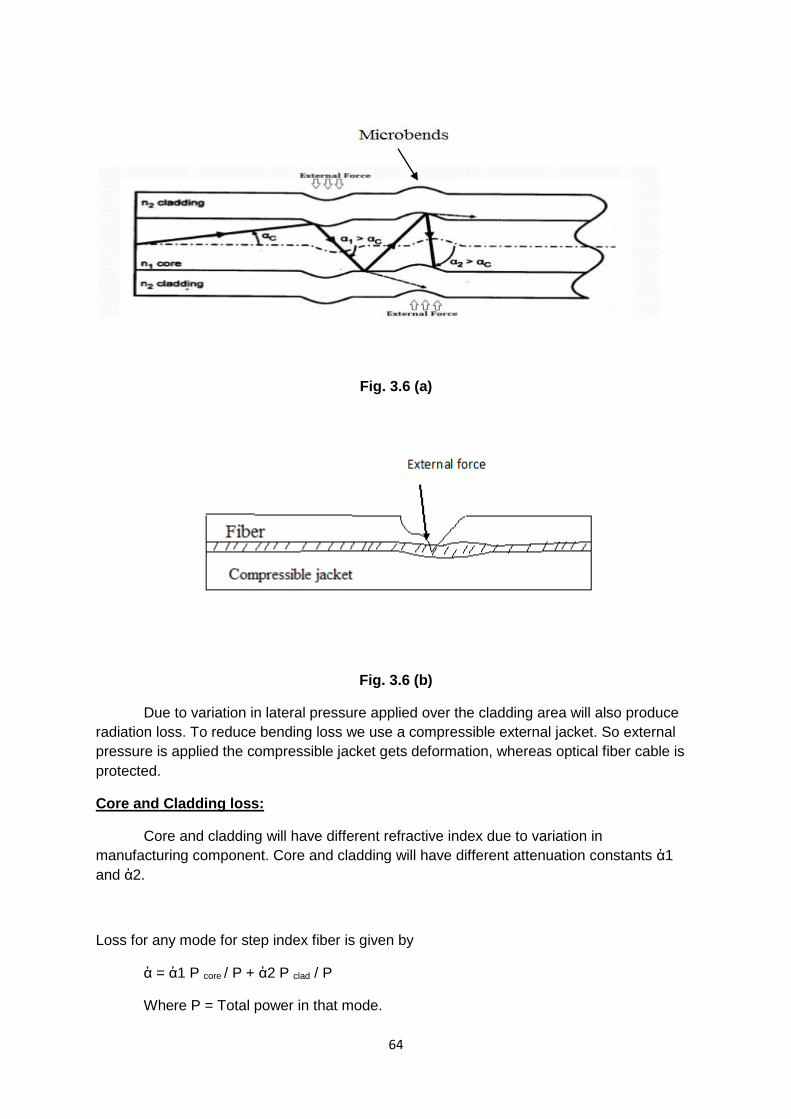
64
Fig. 3.6 (a)
Fig. 3.6 (b)
Due to variation in lateral pressure applied over the cladding area will also produce
radiation loss. To reduce bending loss we use a compressible external jacket. So external
pressure is applied the compressible jacket gets deformation, whereas optical fiber cable is
protected.
Core and Cladding loss:
Core and cladding will have different refractive index due to variation in
manufacturing component. Core and cladding will have different attenuation constants ἀ1
and ἀ2.
Loss for any mode for step index fiber is given by
ἀ = ἀ1 P core / P + ἀ2 P clad / P
Where P = Total power in that mode.

65
Optical source and detectors or light source and detectors:
In optical communication system, at the transmitter end we are using two types of
light sources.
1. LED (Light Emitting Diode)
2. ILD (Injection LASER Diode)
LASER-Light amplification by Stimulated Emission of Radiation. Similarly at the receiver end
we are using photo detectors or light detectors. Such as,
1) PIN Photo diode (Positive Intrinsic Negative)
2) APD (Avalanche Photo Diode)
Optical source or light source:
Normally LED will have lower performance and low cost.
Its spectral width=30 nm to 50 nm
But laser will have higher cost and higher performance.
Led (Light Emitting Diode)
LED’s are chosen for networks of bit rate 100-200 mb/s.
Advantages of LED:
• It requires less complex drive circuitry than the laser diodes.
• Manufacturing cost is less.
• Optical power Output is high.
LED types:
1. Surface emitter LED
2. Edge emitter LED
Characteristics of LED:
• High radiance output (power of light source)
• A fast emission response time.
• High quantum efficiency.
Basic principle:
When a voltage is applied to the leads of the source, electrons are able to recombine
with electron holes within the device, releasing energy in the form of photons.

66
Surface Emitter LED:
Fig. 3.7 (surface emitter LED )
In surface emitter LED Light emitting region is perpendicular to the fiber axis. The well
like structure is created in the substrate by means of etching process. In this well, fiber is
fixed using cement .Active region diameter is 50 um, 2.5 um thickness. Etched well
structure is used to concentrate or focus emitted light into optical fiber cable.
Edge Emitter LED:
Light emitting active region is placed between two guiding layers. This guiding layer will
focus emitter carriers into active region once again. Light ray will be emitted along the axis or
parallel to the axis. Hence it produce light ray with more directional pattern. Mostly surface
emitter LED’s are used, Because they emit more light.

67
Fig. 3.8 (Edge Emitter LED)
Semiconductor LASER or LASER
LASER consists of semiconductor P-N junction. Mostly constructed by gases, liquid and
solid. In fiber optic we use only semiconductor LASER.
Laser operation will have the following three principles:
1. Photon absorption
2. Spontaneous emission
3. Stimulated emission
Photon absorption:
Fig. 3.9 (a) Absorption
Normally there are two states of energy level
1. E1 (gnd state) energy level

68
2. E2 (higher energy level or excited energy level)
Usually state transient occur by either photon absorption or photon emission. In our
example when external photon of energy hv12 strike the system. Electron in lower state
absorbs the power and changes to higher state E2.
Spontaneous emission:
Fig. 3.9 (b) Spontaneous emission
For longer time no photon will exist in higher energy state. Since higher energy state
is unstable state, so it changes to ground state (lower energy state) by realizing hv12.This is
called Spontaneous emission.
Stimulated emission:
Fig. 3.9 (c) Stimulated emission
Using external photons electrons in existed state can be made to jump over ground state
and this process is called stimulated emission. Now we get twice the amount of energy
levels which is shown in the diagram.
Normally in thermal equilibrium state, number of exited electrons will be small when
compared to ground state electrons. But to get a large amount of energy by means of
stimulated emission, the conditions to be reversed. That is more number of electron should
exist in excited state. This is called population inversion. Population inversion is achieved by
means of technique called pumping.

69
Laser construction and working principle:
Fig. 3.10 (Construction and Working Diagram Of LASER)
The construction of LASER is similar to semiconductor LED but ends of junctions are
highly polished.
Lasing:
Since the end walls are highly polished, released carriers one again reflected and
focused to the active region. Next, they make free electron to recombine with free holes and
in turn release photons with high energy level. This process is called lasing. This process is
repeated giving high coherent and high quantum output light energy. Lasing will occur after a
particular current level which is called threshed current.
Characteristics:
Fig. 3.11

70
Advantages of ILD (Injection LASER Diode) over LED:
• ILD coherent (orderly) light, where as LEDs emit incoherent (disorderly) light.
The light emitted from LED can be easily coupled into optical fiber cable. This
reduces coupling losses and allows smaller fibers to be used.
• The radiant Output power from an ILD is greater than that at higher bit rates
those LEDs.
• ILDs can be used at higher bit rates that LEDs.
• Reduced wavelength dispersion.
Disadvantage of ILDs:
• ILDs are 10 times more expensive than LEDs.
• As it operates at higher power level, its life time is small.
• ILDs are more temperature dependent than LEDs.
PIN photo detectors or light detectors:
• In optical fiber communication at receiver end we are using photo detectors to
convert received light energy equivalent electrical voltage or current.
• Here we use two detectors.
1. PIN photo detector
2. APD (Avalanche Photo Diode)
PIN photo detectors:
Construction:
Fig. 3.12 (construction diagram of PIN photo detectors)

71
Here diode consists of p-n layer deported by lightly doped intrinsic
(ie.region).Normally diode is reverse bias as shown in diagram. So first layer act as a
depletion layer.
Principle:
When incident photon energy is higher than band gap energy of semiconductor, than
the photon releases it energy and make an electron to jump from valance band to
conduction band. This releases electron pairs. These released carriers are called photo
carriers. Here intrinsic region thickness is large enough so that the carriers will absorb more
light.
Fig. 3.13
So more number of carriers will be separated and collected in reverse bias junction.
This produce current flow in the external circuit. This current is called photo current.
Characteristic of photo current:
1. High quantum efficiency.
2. Response speed.
Factor which defines above characteristics are:
1. Band gap energy
2. Wavelength of light energy
3. Doping and thickness of PIN layer.

72
APD diodes:
Basic principle:
In avalanche photo diode the current get internally multiply before it enters Input
circuit of the amplifier. This process is called carrier multiplication. For carrier multiplication
takes place photo generated carrier should pass through high electric field region. In
high electric field region photo carriers get high energy. Due to this high energy carrier’s
ionization. Generated carries one second collides with bounded electrons by collide on them.
This cause is known as impact ionization. Generated carriers one second collide with
bounded electrons and lad to impact ionization. This effect is known as avalanche effect.
Construction:
Construction is called reach through construction to obtain carrier multiplication.
Initially p type substrate is taken then i(𝜋) region is constructed by means of deposition over
the 𝑝𝑡 substrate.
Fig. 3.14 (construction diagram of APD diode)
Again less concerted p type layer are diffusion is made this is followed by 𝑛𝑡 layer
(heavily doped).
Layer construction:
𝜋 Layer is intrinsic material layer. At ordinary or low reveres bias voltage most
voltage drop is across 𝑃𝑁+ junction. Thus is junction width increases. At a particular voltage
called avalanche voltage avalanche breakdown will occurs. Now depletion layer reach
through I layer or 𝜋 layer. Light enter the diode through 𝑃𝑡 region and get absorbed in the 𝜋
region.
When light is absorbed photon gives up the energy and creates new hole electron
pair. This electron hole pairs are separated in 𝜋 region.Then photo generated electron drift
through high electric field. In high electric field region carrier multiplication takes place.

73
Connectors or optical fiber connectors:
Connectors are used for making temporary joint between two optical fiber cables.
Good connector requirement:
1. Low coupling losses
2. Interchangeability
3. Ease of assembly
4. Low environment sensitivity
5. Low cost and reliable construction
6. Ease of connection.
Connector Types
Based on Configuration Based on Channel
Screw on Push pull Single channel Multi
Channel
Base on coupling mechanism of light
Butt joint Expanded Beam
Straight sleeve Tapered sleeve
Butt joint connectors:
Butt joint connector uses metal or ceramic or mudded plastic ferrule for each fiber.
Alignment of fiber is made by alignment sleeve.

74
Types:
1. Straight sleeve connector
Fig. 3.15
2. Tapered sleeve connector or bi conical connector
Fig. 3.16
In both connectors length of sleeve and guide ring on ferrule determine the separation of
fiber.
Extended beam connectors:
Fig. 3.17
In this type we use two lenses on each end of the fiber. Lenses are used to focus
expanded beam on to the core of the receiver fiber or collimate the light coming out of the
transmitting fiber. Distance between lenses fiber equal to focal length of lenses:
Advantage:
• Less dependent on external alignment.

75
Splicing techniques or splices:
Permanent joint format between two individual optical fibers in the field or factory is
known as fiber splices.
Types:
1. Fusion splice
Fig. 3.18
2. V-groove mechanical splice
Fig. 3.19

76
3. Elastic tube splice
Fig. 3.20
Fiber couplers:
Fiber couplers are branching devices that split all the light from main fiber into two or
more fiber and vice versa.
Combiner Splitter
Fig. 3.21(a) Fig. 3.21(b)
Types:
1. Wave length division multiplex coupler
2. Three port coupler
Types:
a) semitransparent mirror method coupler
b) lateral off set method coupler
Wave length division multiplex coupler:
In this method optical signals with different wave length are transmitted in single
fiber. Using splitter or combiner method:

77
Fig. 3.22(a) Fig. 3.22(b)
Three port coupler:
1) Lateral offset method coupler:
• Light from input fibers is coupled to OUTPUT fiber according to degree of
overlap.
• Amount of power distributed to the OUTPUT fiber depends on amount lateral
offset between the fibers.
• Used for coupling multi mode step index fiber.
2) Semitransparent mirror methods:
• Here partially reflecting mirror placed at end face of the fiber at an
angle of45°.
• Mirror acts as a beam splitter.
• Hence the path of input power coupled to the output fiber.
• Used for coupling multi mode, single mode fiber.
Optical transmitter block diagram
Here we take either digital or analog signal (data).This signal will modulate the light
source. Voltage to current converter act as electrical interface between input act and the light
source. In transmitter we use light source either as LED or LASER.

78
Source
Optical Fiber Cable Optical Fiber Cable
Fig. 3.23
Voltage to current converter converts input voltage to a current which is used to drive light
source.
Light intensity modulation:
Output emitted light of the light source is made proportional to Input signal voltage by
means of varying the intensity of light. This is called light intensity modulation.
Source to fiber interface or coupler:
It is an optical lens. It is mechanical interface. It is used to couple emitter light from
light source into the optical fiber
Fig. 3.24
Then optical fiber is glass or silica, core and cladding covered with plastic jacket or
sheath. In between the channel at frequent distance we use regenerative repeater or signal
regenerator for remove the noise and regenerate the original signal.
We use optical detectors as i) PIN photo diode or ii) APD. Photo detector is used to
convert received optical energy into equivalent electric current (energy).Initial amplification is
Analog (or) Digital
Interface
Source-to-fiber
interface
Light
Source
Voltage-to-Current
Converter
Signal
Regenerator
Signal
Regenerator

79
performed using pre amplifier circuit. Here noise level gets removed. Main amplifier circuit
used to provide additional low noise amplification for the next blocks. During transmission
received signal get distorted. This is may occur due to various factors.
To compose this distortion we provide equalizer. Filter section is used to include S/N
ratio and preserve the shape of the signal.
Application of optical fiber
1. Networking
2. Industrial Application
3. Military Application
Network Topologies:
Optical fibers are used for connecting computers which are called network topologies.
There are four types of connection or configuration
1) Linear Bus Topology
2) Ring Topology
3) Star Topology
4) Mesh Topology
Linear bus Topology:
Fig. 3.25 (a)

80
Optical fiber cable is used for interconnection which is called bus. Connection
between computer and bus is made through optical coupler. This coupler may be either
active or passive device and also convert optical signal into electrical baseband signal.
Ring Topology:
Consecutive nodes are connected by point to point links. Data packets along with
address are transmit from one node to another node around the ring. Interface or coupler will
read the address and suppose belong to that station it accept or otherwise pass to the next
node.
Fig. 3.25 (b)
Star Topology:
Fig. 3.25 (c)
All the nodes are connected to central node or hub. It is either active or passive
device. It is a control node which controls all routing message within the network.

81
Mesh Topology:
Fig. 3.25 (d)
If suppose there are n number of nodes, there will be 2n number of optical links.
Based on the application, the connection between nodes will vary. It provides various link
path or multipath incase if there is any link or node failures.
Industrial Applications:
Optical fibers are used in situation where explosive and corrosive gases are used.
i) Pressure or temperature measurement
Here single mode fiber optical phase sensors are used for measurement of pressure
or temperature in industry. Initially light from laser source is passed through reference fiber
and also through a optical fiber connected in measuring environment.
When any pressure or temperature changes will change optical fiber length, core
diameter and refractive index with respect to reference fiber. This gives change in optical
light phase. There is a phase difference between two light races. This change will provide
temperature or pressure measurement.

82
Fig. 3.26
Here we use optical flow sensor meter. In this apparatus multimode optical fiber is
inserted across the pipe. From which liquid flows it will stretch the fiber. Turbulence over the
fiber across light ray to oscillate. The frequency of oscillation is made proportional to flow
rate.
Hence light gets intensity modulated. This modulated intensity is measured by
modulation sensor which indicates the flow rate.
Optical displacement sensor:
Here intensity modulated light ray is transmitted and mean while made reflected by
target and received by the detector. Function of time difference between starting and end
time will be equated or given. The distance between fiber and target. Now it any
displacement occurs that displacement of the target is measured using optical detector.
Fig. 3.27

83
Military Applications:
One of the military applications for optical fiber communications in military mobiles
such as aircraft and tanks. For short and long distance communication links in military optical
fibers are used.
Short distance optical fibers systems are utilized to connect closely spaced items of
electronic equipment. These operate over distances from several centimeters to a few
hundred meters at transmission rates between 50 bauds and 4.8 kbits/s.
Long distance applications include torpedo and missile guidance, information links
between military vessels and maritime.

84
UNIT-III
PART- A
1. What is light pipe?
2. Mention any two advantages of optical fiber
3. Mention any two disadvantages of optical fiber.
4. Define critical angle
5. What is step index fiber?
6. What is step index fiber?
7. Define multimode fiber
8. Define single mode fiber
9. Mention the types of fibers
10. Define attenuation in fibers
11. Mention the various types of absorption losses
12. Mention the various types of scattering losses
13. Define bending losses
14. Mention the various light sources used in fiber optic communications
15. State the different types of light detectors used in fiber optic communication
16. Define splice and connector in optical fibers
17. Mention the various types of the fiber splicing techniques
18. Mention the various types of connectors
19. State the advantages of butter jacket
20. What is coupler
21. State the different types of coupler
22. Mention the various applications of optical fiber.
PART-B
1. State the advantages of optical fiber communication system
2. State the disadvantages of optical fiber communication system
3. Explain the effects of lights rays in optical fiber
4. State the difference between single mode fiber and multimode fiber
5. Define losses in fiber and mention its types
6. Define scattering losses and mention its types
7. Explain core and cladding losses
8. Define connectors and splices and mention its types
9. Define coupler and mention the various types of couplers
10. Explain networking in optical fibers
PART- C
1. (a) with the block diagram explain optical communication system
(b) explain absorption losses

85
2. (a) Explain the needs and advantages of optical fiber
(b) Explain scattering losses
3. (a) Explain the principles of lights transmissions in a fiber using ray theory
(b) Explain bending losses
4. (a) Explain single mode fiber and multimode fiber
(b) With the diagrams explain any two applications of optical fiber
5. (a) Explain single mode step index fiber and graded index fiber
(b) Explain attenuations in fiber
6. (a) Explain the various types of losses in fibers
(b) Draw the block diagram of optical receiver and explain its operation
7. (a) With the diagram explain LED optical sources
(b) Explain the various types of connectors used in optical fibers
8. (a) Explain LASER with diagram
(b) Explain the various types of couplers used in optical fibers
9. (a) Explain PIN photo diode with diagram
(b) Explain the various types of couplers used in optical fibers
10. (a) Explain APD with diagram
(b) With the block diagram explain optical transmitter

86
UNIT-IV
SATELLITE COMMUNICATION
Satellite communication
Global communication is achieved with the use of satellite system. Practical satellite
system is shown in the diagram. Satellite in the space is used for making link between the
many earth stations or control station located on the various places within the earth surface.
End user is connected to the earth station through terrestrial network.
Fig.4.1Basic block diagram
Terrestrial network may be telephone switch. Users generate baseband signal
(message).The signal is processed and transmitted to satellite at the earth station. This
process is called uplink and the frequency used is called uplink frequency. Satellite will
receive the signal from earth station.
There are two types of satellites.
1. Active Satellite.
2. Passive Satellite
Active satellite:
In Active Satellite received signal is demodulated, get removed of noise, amplify and
sent back to the ground earth station.

87
Passive satellite:
In Passive Satellite there is no processing of the signal. The received signal is
reflected back to the ground earth station without any process. Mostly now a day’s only
active satellite are used. The signal transmitted form satellite to earth station will be in lower
frequency and is called downlink frequency.
Components of satellite or Active satellite:
Satellite has on-board, highly directional transmitting and receiving antennas.
Accurate positioning and control mechanism are used in satellite. Power requirement are
obtained from solar cells. Nickel cadmium batteries will provide power ellipse. Typical uplink
and downlink frequency are 6/4 GHZ. Practically uplink of 5.725 to 7.075 GHZ and a
downlink of 3.4 to 4.8 GHZ is used.
Kepler’s orbital laws:
Kepler’s first law
Kepler’s orbital law states that satellite will follow elliptical orbital path in its orbit
around the primary body (earth). Ellipse will have two focal points (or foci) f1 and f2 shown
below.
b
b
a a
Fig.4.2
In two bodies system (earth, satellite) centre of the mass is called barycentre and lies
on any one of the foci. The foci which coincide with the centre of the earth is selected as
reference foci.
Semi major axis = a
Semi minor axis = b
Eccentricity of the ellipse is given by (Centre of ellipse)
𝑒 =√𝑎2−b2
𝑎 ------------------ (1.1)
Major axis Minor axis
Centre of ellipse

88
Kepler’s second law:
Kepler’s second law states that for equal time intervals the satellite sweeps out equal
areas in the orbital plane, focused at the barycentre.
S2 S2
sS
Fig.4.3
S1 and S2 are the two distance in the orbit.
Whereas A1 and A2 are two areas as per second law
A1=A2
The velocity is greatest at the point of closer to the earth (perigee) and the speed is
least at the farthest point from earth (termed as apogee).
Kepler’s third law:
Kepler’s third law state that square of the periodic time of the orbit is proportional to
cube of mean distance between two bodies.
Mean distance is equal to semi major axis.
𝑎3∞𝑃02
a = A𝑃02/3
------------------------------ (1.2)
a= mean distance
Where A is constant, P= Periodic time of orbit.
Satellite orbit close to the earth will be affected by
1. Atmospheric drag
2. Earth magnetic field etc
`Similarly for distance satellite main disturbing force will be gravitational pull between
sun and moon.
Earth

89
Satellite orbits:
Most of the satellites are called orbital satellites which are non synchronous. These
non synchronous satellites will follow either elliptical or circular pattern. The direction will be
either clockwise or counter clockwise.
Circular Orbit:
Direction of Rotation
CCW CW
Satellite (ws)
Fig.4.4
Elliptical Orbit:
Direction of Rotation
CCW CW
Satellite (ws)
Fig.4.5
CCW Rotation
North Pole Earth
North Pole Earth

90
Prograde orbit:
In circular orbit satellite rotates (counter clockwise) attain angular velocity greater
than that of the earth (𝑤𝑠 > 𝑤𝑒) and this type of orbit is called prograde orbit.
Retrograde orbit:
The satellite rotate in clockwise rotation (opposite to that of earth) with an angular
velocity less than that of the earth (𝑤𝑠 < 𝑤𝑒) and this type of orbit is called retrograde orbit.
Mostly non synchronous satellite rotates in prograde orbit.
Disadvantages of orbital or non synchronous orbit:
• Position of the satellite is to vary time to time.
• Need complicated and expensive tracking equipment.
Advantages:
Propulsion rocket are not required on board the 10 keep satellite on this respective orbits.
Based on distance the satellite are two types from earth:
1. Low Earth Orbit (LEO).
2. Medium Earth Orbit (MEO) or Geosynchronous Earth Orbit (GEO).
The Geo-synchronous satellites are high-altitude satellites operating in the 2GHZ to
18GHZ frequency spectrum with orbits 22,300 miles above earth.
Types of satellite orbit:
1. Polar orbit.
2. Inclined elliptical orbit
3. The equatorial geosynchronous orbit.
polor
Equatorial
Fig.4.6
geocenter Equator

91
Polar orbit:
Rotate over the north and south poles of the earth. It is low altitude and closer to
earth. It can cover 100 percent over earth surface. Angle of inclination of satellite is90°.
The inclined elliptical orbit:
• Not widely used.
• Most coverage area will be farthest distance point of the orbit (apogee area).
Advantages:
• Mainly covers polar region.
• Most of the time connected to earth control station.
Geostationary synchronous orbit:
Periodic time is the time required for one complete orbital rotation. In synchronous
orbit, periodic time is integer multiple or sub multiple of earth rotational period. So
geostationary orbit is a synchronous orbit. This orbit is widely used. The satellite rotation
period is same of earth (23 hours and 56 minutes).
Geosynchronous satellites are called as Geo stationary satellites because these
satellites travel in direction same to the earth rotation and in the same speed of earth
rotation. So at any time satellite appears as stationary when view from earth station.
This satellite follow circular pattern in equatorial area at a height of 35786km. Other
name of geosynchronous satellite orbit is Clarke orbit.
Fig.4.7
Doppler shift in frequency:
Doppler shift in frequency results when there is a relative movement between source
(earth station) and receiver (satellite).

92
But in geosynchronous orbit there is no relative movement between satellite and
earth. Hence there is no Doppler shift infrequency.
Global coverage:
A single satellite or geosynchronous satellite covers 42.2% of earth surface. If three
satellites are placed 120° apart from each other, it will give global coverage of earth surface.
Advantages:
• The satellite remains almost stationary relative to the earth antennas. Hence
computer controlled tracking is not required. A fixed antenna is satisfactory.
• There is no break in transmission, since geosynchronous satellite is
permanently in view from earth station.
• A geosynchronous satellite can cover 42.5% of the earth’s surface. A large
number of earth stations may thus intercommunicate.
• Three satellites will give global coverage.
• There is no Doppler shift frequency.
Disadvantages:
• North and south polar are not covered fully.
• The received signal power is weak, because of the distance of the satellite
from the earth is 36,000km. The signal propagation delay is 270 millisecond.
• Geosynchronous satellite require sophisticated and heavy propulsion device
onboard to keep them in fixed orbit.
• High technology is required to place a geosynchronous satellite in its orbit.
Orbital Terms:
Fig.4.8
Apogee:
The point in an orbit that is located farthest from earth.

93
Perigee:
The point in an orbit that is closest to the earth.
Active satellite Passive satellite
Active satellite contains electronic equipment
called transponder.
Passive satellites do not contain the
electronic section or transponder.
The active satellite receives the signal,
amplifies it, changes the frequency and
retransmits the signal (down link) back to the
earth.
Passive satellites reflect signal back to the
earth. There is no gain device to amplify or
modify the signal.
Communication capabilities or efficiency is
higher.
Communication capabilities are poor.
Example: Geosynchronous satellites send by
the human.
Example: Moon.
Earth Eclipse of Satellite:
When the satellite longitude is east of the earth station, satellite enters eclipse during
day light (and early evening) hours for the earth station as shown in fig.4.9. When the
satellite longitude is west of the earth station, eclipse does not occur until earth station is in
darkness. Thus satellite longitude which are west, rather than east of earth station are
desirable.
Fig.4.9
Parabolic reflector:
Two basic kinds of antennas are used in the earth stations. They are
• Parabolic reflector (also called parabolic antenna).
• Cassegrain antenna.

94
Parabolic antenna:
From high power Amp
To Low Noise Amplifier
Fig.4.10
Parabolic antenna uses a reflector in semi sphere structure as shown in diagram. It
has a focal point fy where feed phase centre is located. Here feed is connected to HPA (High
Power Amplifier) and LNA (Low Noised Amplifier) through an OMT (Orthogonal Mode
Transducer).It is a three port network.
Transmitting mode
When the antenna is transmitting the signal, energy from the output of HPA is
radiated at focal point by the feed and illuminates the reflector. The reflector reflects and
focuses the signal energy into a narrow beam.
Receiver mode
When the parabolic is in the receiver mode it captures the signal energy and converges it
on the focal point which is then received by the feed and routed to input of LNA.
Advantages:
This kind of paraboloid is easily steered and offers high gain.
OM
T

95
Disadvantages:
• Feeder losses are high.
• Needs large focal length.
Cassegrain antenna:
It is a better modification of parabolic reflector antenna. It contains two reflectors.
• Main parabolid reflectors.
• Hyperboloid sub reflector.
Main parabolid reflectors focal point is coincident with the virtual focal point of the
Hyperboloid sub reflector. Feed horn or phase centre of the feed horn is located at original
focal point of sub reflector.
To LNA
Fig.4.11
Transmit mode:
When the antenna is in transmitting mode firstly the signal energy from output of HPA
is radiated at the real focal point of the sub reflector by the feed that illuminate the convex
surface of the sub-reflector.
The sub reflector reflects the signal energy back to the parabolic main reflector
through hyperboloid sub reflector. The reflected energy is then reflected by the main reflector
and it forms antenna beam.

96
Receive mode:
In receiving mode, signal energy captured by main reflector is directed towards the
sub reflector. Sub reflector reflects the signal energy back to the focal point where phase
centre of the feed horn is located. Now this feed horn receives this incoming energy. This
energy is routed to LNA (Low Noise Amplifier) through OMT.
Advantages:
• Less spill over.
• Uniform illumination of the reflector is achieved.
• Pointing accuracy.
Space segment:
In communication satellites, there are many sub system. These sub system are
mainly classified into two groups.
1) Communication subsystem:
Communication subsystem is called payload. It contains repeaters, transponders and
antennas. It performs the main function that is communication between satellite and earth
station.
2) Supporting Subsystem or Other Subsystem:
These includes
• Power stabilization
• Propulsion
• Station keeping
• Altitude control and
• Telemetry Tracking and Command (TTC)
Transponder:
Transponder is a main part of communication satellite or payload. It is combination of
transmitter and responder. It is an electronic section that lies in between or links transmitting
and receiving antennas.
Supporting subsystem:
Power supply
Electric power is needed for the satellite system to run space craft and
communication subsystem. Electric power is obtained from solar cells when satellite is
stationary. But during satellite launching period electromechanical accumulator will provide
electric power or power supply.
Solar cell:
These are photo voltaic cell convert solar energy into electrical energy. Solar cell
generates 1 to 2 kW power. They are made up of aluminium and gallium arsenide. When

97
solar power failure occurs, (during solar eclipse) storage power is needed. So we use
nickel cadmium batteries. Battery voltage is 20 to 40V with 20 to 50 ampere/ hour rating.
Altitude control:
Altitude control is keeping the satellite in its orbital height on the space. For this
satellite has number of equipment for controlling the altitude. Altitude control is necessary
because we use highly directional antenna. Reasons for change in the altitude are,
1. Variation in the gravitation force between earth and moon.
2. Solar radiation.
So orientation of the satellite changes. So now altitude control detects the change
and initiates necessary arrangement to make satellite to come its original position. We use
horizon detectors (infrared sensor) for altitude control as one method.
Horizon detector working:
Horizon detector uses 4 sensors. It detect rim of the earth and convert earth into 4
segment. Each sensor is responsible for each quadrant. Centre of earth is taken as
reference point. When there is any change in the orientation particular sensor (one or two)
will generate control signal. This control signal produce restoring torque which brings
satellite into correct position.
Types of controlling torque generation:
1. Passive altitude control
2. Active altitude control
Passive altitude control
Here stabilization of satellite is achieving using satellite energy supply only.
Example:
• Spin stabilization.
• Gravity gradient stabilization.
Active altitude control:
Here corrective torque are apply in opposite to or counteract to the disturbance torque. They
are generated by using,
1. Momentum wheel
2. Electromagnetic body
Here satellite altitude is defined by three axis roll, pitch, & yaw (RPY) axis.
To earth’s centre Roll Axis

98
Yaw Rotation Roll Rotation
Pitch Rotation
Pitch Axis (Normal to Orbital plane)
Fig.4.12
The entire three axes pass through centre of gravity of the satellite. Yaw axis is
directed towards earth centre. Pitch axis is normal to orbital plane. Roll axis is
perpendicular to other two axis.
Station keeping:
Sometimes due to certain factors satellite is drifted from its orbital paths.
The factors are,
1. Variation in earth gravity.
2. Solar radiation.
3. Gravitational pull between sun and moon.
So we need counteraction for this drift and once again satellite placed in its original
orbital path. This process is called station keeping. This counteraction is provided by firing
small jet rockets. These jets will produce pulses once for every 2 or 3 weeks. So satellite will
drift back to its original position.
Two types of station keeping
1. East-west station keeping
2. North-south station keeping.
Due to gravitational pull between sun and moon satellite also drift in latitude position.
This makes the satellite to inclined up to certain degree. So as usual counteraction is
produce at the appropriate time provided by jets and the inclination is made zero, this is
called North South station keeping
Transponder:
It is used to link transmitting and receiving antenna. It is an electronic system or
section is mainly used for frequency conversion.

99
Block diagram
Fig.4.13
Main blocks of transponder are
1. Duplexer
2. Front end converter
3. Carrier processing unit
4. Power amplifier.
Transponder does the following functions:
1. Front end receive the signal in uplink frequency and remove noise and give free
amplification
2. Frequency transaction from uplink to downlink is done by carrier processing unit.
3. Finally power amplifier increases the gain or power level. So that signal can be
retransmitted to earth.
Duplexer
Duplexer is a switching unit which uses for single antenna for transmission and
reception.
Front end converter:
To Carrier Processing
From
Antenna
RF Front End
Fig.4.14
Satellite
Antenna Duplexer
Front End Carrier
Processing
Power
Amolifier
RF
Filter
Equalizer Low Noise
Amplifier

100
Front end converter includes following section
• RF filter
• Equalizer
• Low noise amplifier
RF filter is removing the RF noise. Equalizer cancels the delay distortion. Low noise
amplifier has high power gain with low noise contribution.
Carrier processing unit:
From To diplexer&
Antenna duplexer Antenna
Stable Oscillator
Fig.4.15
Carrier processing unit is used for frequency translation from uplink frequency to
downlink frequency. There are four different methods for frequency translation.
1. RF to RF conversion or translation.
2. RF to IF conversion or translation.
3. IF Remodulation.
4. IF modulation and RF Remodulation.
In our system, direct RF to RF conversion method is used involving mixer system as
shown above.
Power amplifier:
Last stage of transponder is power amplifier. Here we use travelling Wave
Tube (TWT) amplifier for increasing the gain, before transmitting down to the earth.
Telemetry, tracking and command (TTC)
TTC will carry out all of the control signals to make the satellite in working. Main
functions are
• Informs the status of the satellite to the ground control station.
• Calculating the angular and range measurement of the satellite.
Receiving the command signals from the ground control station to initiate stations
keeping & operation of the onboard equipments. Telemetry system provides data’s to the
ground. This data’s gives status or condition of the satellite system. The data’s are
obtained from large no.of sensors mounted on satellite. For command operation, satellite
RF Front
End
Power
Amolifier
Frequency
Mult. ~

101
contains a receiver. This receiver is used only to get command signal from TTC control from
earth station.
Tracking
Tracking consists of determining the current orbit of the satellite. It can be observe
any shift called Doppler shift in carrier frequency which gives the range of satellite. When
there is any change in velocity or acceleration (determine using velocity (or) accelerometer
sensor) will also give change in orbit.
Thermal control
Satellite receive thermal radiation from sun, earth etc. Satellite equipments also
produce heat. But for proper operation of satellite equipments are free from variation in
temperature.
Methods used to get constant temperature environment are
• Thermal blankets and shields is used to provide insulation.
• Radiation mirrors are used to remove heat from communication equipments.
Antenna subsystem
Antenna serves as an interface between earth control station and communication
satellite system. Antennas receive uplink signal and transmit the downlink signal. Mainly
highly directional antennas with high gain are used.
Satellite sub system consists of
1. Dipole antenna
2. Helical antenna
3. Horn antenna
4. Antenna arrays
5. Parabolic reflector.
Mostly parabolic reflectors are used because of highly directional pattern. The gain of
the reflector antenna can be increased and beam width made narrower by increasing the
diameter of the reflector and decreasing the wavelength. Large reflector antennas are also
user for communication satellite.
Earth segment or earth station:
The earth segment consist of transmit and receive earth station for effective satellite
communication. It consists of
1. Ground terminal that control and monitor satellite.
2. Communication between various earth stations that operate via satellite.
It is equipped with telemetry & telecommunication equipment. It monitors satellite status
using telemetry function. It also controls the signal levels reached to the particular satellite by
other earth station for proper operation of satellite. Typical block diagram is shown below

102
From LNA
Fig.4.16
Major subsystems are
1. Antenna and feed
2. Tracking and serve control.
3. Low noise amplifier.
4. High power amplifier.
5. Up and down converters.
6. Modulators and demodulators
7. Baseband and multiplex equipment.
8. Power supply system.
Antenna and feed:
For heavy routes system or station reflects parabolic reflector antenna of 10 to 15 m
diameter is used. For thin route system diameter of 3m are used. Factor defining antenna
systems are
1. Type of mount
2. Steerability
3. Gain
4. Beam width
5. Side lobe levels
6. Pointing accuracy
7. Wind speed
Types of mount:
There are three types of mount
1. Azimuth elevation mount
2. X-Y mount.
3. Equatorial mount.
Mainly Cassegrain antenna system is used.
Diplexer Para Amp Down
Converter
Demodulator
Base Band
Equipment
High Power
Amplifier
Low Noise
Amplifier
Up Converter Modulator

103
Tracking & serve system
To get high gain of the antenna, beam is aligned or pointed towards the satellite.
Antenna has to keep track of the satellite. There are four types of tracking.
1. Manual tracking.
2. Auto tracking.
3. Programme tracking.
4. Step tracking.
Manual tracking
In manual tracking antenna position is adjusted manually by looking signal quality.
This is used for station for larger bandwidth. In auto tracking method, feedback control
system is used to get the error signal & generate counter signal to nullify the error. In
programme tracking method, control action is generated using computer.
Low noise amplifier
Pre amplifier or low noise amplifier section is used to amplify received signal with
very low gain or weak. Usually FET amplifiers are used.
High power amplifier section or system
Transmitter power required range is between few watts for telephone and upto
3kwatt for television signal. Power requirement mainly depends on antenna gain. Power
amplifier gets input in few milliwatt and amplify them to few kilowatt. We use either klystron
or travelling wave tube (TWT) amplifier.
Up and down converter
Up converter are used to convert 70MHZ carrier to uplink frequency of 6 GHZ range.
This is done in two states.
1. 70 MHZ carrier is converted to IF range of 500-800MHZ.
2. This IF is converted to 6 GHZ uplink frequency.
Similarly down converter is also in two states.
Modulator and demodulator
After suitable multiplexing modulates the 70 MHZ carrier frequency. Television signal
is frequency modulated. Television signal is either frequency division multiplexed and
frequency modulated Otherwise time division multiplexed and then phase shift keyed.

104
Power supply system
Power supply system should provide uninterrupted power supply for proper earth
station working. It consists of
1. Rectifier unit
2. Inverter
3. Battery backup
4. Diesel generators
5. Associated switching arrangement
Satellite mobile services
Mobile services of small earth station is portable. The portable earth station will move
within specific coverage area. The antenna system will move in all direction. Main application
is global shipping. Mainly there are two types of earth station.
1. Coast earth station(CES)
2. Ship earth station(SES)
There are two standards used in mobile earth station
1. Standard A
2. Standard C
Standard A
Standard A consists of two sub units
1. Above deck equipment (ADE).
2. Aeronautical communication services through satellite.
ADE consists of
1. Parabolic antenna.
2. Diplexer unit.
3. High power amplifier for transmission.
4. LNA for reception.
5. Power supply unit.
Standard C
Standard c uses ground earth station (GES).They provide link between terrestrial
system and satellite network. They operate in c-band. Main parts are
1. 12 metre antenna
2. RF to IF conversion equipment.
3. Access and signal equipments.

105
GPS (Global Positioning System)
The Global Positioning satellite system are used for navigation of
• Ships
• Aircrafts and in surveying
Features
• The GPS space segment consists of 24 satellites in medium earth orbit
(MEO) at an altitude of 20,200 km with an orbital inclination of 550 km.
• The satellites are clustered in groups of four, called constellation, with each
constellation separated by 600 km longitude.
• The same satellite appears in the same position in the sky twice a day a day.
• The orbits of the 24 GPS satellite ensure that at anytime, anywhere in the
worlds a GPS receiver can pick up the signal s from at least four satellites.
GPS provides the following
• 24-hours worldwide services
• Extremely accurate, three-dimensional location information.
• Extremely accurate velocity information.
• Precise timing services.
• Continuous real-time information.
• Accessibility to an unlimited number of worldwide users.
GPS position location finding
Below diagram is used to find position location of GPS
Satellite 1 Satellite 2
Satellite 3
R1 R2 R3
. GPS Receiver
Fig.4.17
Three satellite provide distance information i.e. range 𝑅𝑖 from receiver to node points.
These 𝑅𝑖 is assumed to the radius of sphere from with particular satellite at its centre.

106
Receiver will be lies at the intersection of three spheres. So the receiver will locate the
position latitude, longitude of a place.
GPS Receiver
Receiving Antenna
LNA IF AMP
Clock Navigation
Message
Clock
Fig.4.18
The antenna is circularly polarized antenna with an LNA connected to it. For down
conversion we use superhetrodyne receiver which will generate IF signal with bandwidth
2MHZ. This IF is sampled and processed using I and Q sampling techniques by means of
A/D converter and DSP (digital signal processing) .Microprocessor carries out the timing
measurements and calculates the receiver’s position.
There are two frequency bands L1 and L2 used by GPS satellite. The L2 signal is
modulated with 10.23 Mbps bit sequence called the p code. This is used by military
positioning systems. The L1 frequency carrier is modulated by 1.023Mbps that is used for
public use.
Microwave communication
Microwave signal has short wavelength (in terms 10−6 metre or
micrometer).Frequency ranges between 500 MHZ to 300GHZ.
Microwave transmitter
Down
Converter
A/D
Converter
Digital Signal
Processor
Microprocessor
Local
Oscillator
Display

107
Microwave Transmitter
Baseband Section Modulator IF section Mixer section RF section Tx
Baseband input
Fig.4.19
Pre-emphasis network
Usually high frequency signal will have lower amplitude. So it is necessary to
increase the amplitude and this process is called pre-emphasis.
Modulation
Lower baseband signal is frequency modulated and upper baseband signal is phase
modulated. For modulation we use 70MHZ IF as carrier frequency. Output of modulater will
be FM narrowband signal. This is first conversion.
Mixer/converter
IF frequency is up-converted to microwave frequency using mixer, microwave
oscillator and band pass filter. By this conversion IF frequency converted to RF frequency
using heterodyne process. Instead of mixer if multiplier is used frequency bandwidth will be
larger or higher.
Microwave generator
Microwave generator include or consist of crystal oscillator followed by few number of
frequency multiplier.
Power amplifier stage
Power amplifier is used to increase gain of RF signal and transmit via antenna.
Pre-emphasis
network
Modulator IF Amplifiers and
band pass filter Mixer/
Convert
er
RF
Amplifiers
and band
pass filter
Microwave
generator

108
Microwave receiver
Microwave Receiver
Baseband Section Demodulator IF section Mixer section RF section Rx
Baseband OUTPUT
Fig.4.20
Received microwave signal is passed through channel separation network.
Channel separation network provide filtering, isolation and separate individual
microwave channel to the respective receiver.
Down conversion
Band pass filter, mixer and microwave oscillator down convert RF microwave
frequency into IF frequency.
Demodulator
IF frequency is fed to FM demodulator. Output of FM detector or demodulator will be
base band signal.
De-emphasis
Finally baseband signal is converted to original amplitude using de-emphasis circuit.
Advantages
• Because of their high operating frequencies, micro wave radio system carry
larger information.
• Short wavelength hence small antennas are used.
• Minimum delay times.
• Minimum crosstalk between voice channels.
Microwave devices
1. Multicavity klystron.
2. Reflex klystron.
De-emphasis
network
Demodulator IF Amplifiers and
band pass filter
Mixer/
Convert
er
Microwave
generator
RF
Amplifiers
and band
pass filter

109
3. Magnetron.
4. Travelling wave tube (TWT).
5. Cross field amplifier.
6. Backward wave oscillator.
7. Gunn diode.
8. PIN diode.
Microwave link repeater
When the distance between microwave transmitter and receiver lies between 15
miles to 40 miles, there is no need for repeater. If suppose distance above 40 miles then
microwave repeaters are needed.
Definition
A microwave repeater is receiver and transmitter placed back to back. A microwave
repeater does the following function. Receive the signal, amplify, reshape and transmit to the
next repeater station.
Block diagram
Fig.4.21
Types
1. IF
2. Baseband
3. RF
Microwave
Transmitter
Receiver Transmitter
Microwave Repeater
Microwave
Receiver

110
Microwave repeater circuit diagram (IF band or IF repeater)
Receiver IF signals Transmitter
Rx Antenna
IF IF
RF RF
Fig.4.22
IF repeater is also called as superhetrodyne repeater. Initially received RF signal is
down converted to fixed IF frequency. Then only repeater functions such as amplification &
reshaping of signal is done. Again IF signal is up converted to RF microwave frequency and
transmitted to next repeater.
Parametric amplifier
Basic principle:
Parametric amplifier uses LC tank circuit. Here reactance of capacitor is varied to
increase the gain of the device. Usually varactor diode is used as active device.
Working principle:
Consider an LC tank or tuning circuit. When capacitor plates are moved apart then
voltage between them is positive maximum and some work is done on the capacitor. This
work (or) energy will increase the previous voltage across the capacitor (amplification).When
capacitor plates are moved closer together then the voltage between them will be zero.
Again when plates are moved apart, voltage across will be negative maximum. Now also
some work is done which will increase the voltage across the capacitor (amplification).This
amplification process is done at regular interval.
When we apply some signal as source signal to the parametric amplifier and another
signal as input signal, then input signal get amplified by taking the energy from source
signal.
BPF Mixer
Microwave Generator
IF amp and
filter
BPF RF Amplifier
circuit Mixer
IF amp and
filter

111
Amplification mechanism
a. Signal input voltage
b. Pumping voltage
c. Output voltage build-up
Fig.4.23

112
Parametric amplifier circuit
Fig.4.24
Principle
The principle of amplifier is based on varying a parameter of a capacitor to pump-up
the input signal to higher amplitude.
Circuit explanation
Here small input signal (𝑓𝑠 ) & a pumping signal ( 𝑓𝑝) are applied to varactor diode.
The input signal 𝑓𝑠 is amplified with respect to variation in capacitance of varactor diode.
Energy used to vary the capacitance is obtained from pumping signal.
Travelling wave tube (TWT)
Travelling wave tube uses a helical path. Electron gun is used to produce very
narrow electron beam. This electron beam is send through centre of the helical path. Helix is
made positive with respect to cathode and collector. Thus the beam is attracted by the
collector with the high velocity. The beam is also made narrow using a focusing electron and
it does not touch the helix. Input signal is applied to input end of the helix.
The electric field due to this signal propagate around the helix with the speed
different from speed of light. Speed of the electric field is equal to velocity of light multiply by
ratio of helical pitch to the helix circumference. Hence electric field velocity is made slow and
equal to electron beam velocity. Now electron beam and the helical RF field interact. This
lead to electron bunching.
Electron bunching
Electron beam get focused at every helical path giving energy to the input RF electric
field, which gives or produce amplification of the signal is called electron bunching.

113
Fig.4.25
Amplification mechanism
Initially RF field will be lesser in amplitude. Electron beam will be emitted from
cathode at intervals. When electron beam pass through gap of the helix, velocity modulation
takes place. At adjacent turns of helix, electron bunching takes place. When the initial bunch
of electron reaches next turn of the helix, the variation in phase of the input signal will
change the electron bunch. This results some more or additional bunching of electron. So
once again input signal get amplified. This process continues till the input signal reaches the
output end and reaches with maximum value at the end.

114
UNIT- IV
PART-A
1. Define satellite communication
2. Define kepler’s first law
3. Define kepler’s second law
4. Define kepler’s third law
5. Mention the different types of satellite orbits
6. Define geostationary orbit
7. Mention the height of geostationary orbit
8. Define LEO and MEO
9. Define active satellite
10. Define apogee and perigee
11. Define passive satellite
12. Define earth eclipse
13. What is the use of launching orbit?
14. Define antenna
15. Define attitude control
16. What is station keeping
17. Define transponder
18. Define TTC sub system
19. What is the use of antenna subsystem?
20. Mention the parts of ground segments of a satellite communication system
21. What is INTELSAT?
22. Define GPS
23. How many satellites are used in GPS?
24. Define MSAT
25. DEFINE microwaves
26. Mention the range of microwaves frequency
27. Mention any two types of microwaves devices
28. What is the use of parametric amplifier’
29. What are the advantages of parametric amplifier
30. Explain TWT
31. What is the use of microwave repeater
32. Define launching orbit? And mention its types
PART- B
1. Draw the general structure of a satellite communication system
2. Explain kepler’s first law
3. Define orbit and mention its types
4. Explain orbit and mention its types
5. State the advantages and disadvantages of geostationary satellites
6. Explain apogee and perigee
7. Explain earth eclipse of satellite
8. Explain transponders
9. State the features of mobile satellite

115
PART- C
1. (a) Briefly explain Kepler’s I,II & III laws
(b) Explain LEO & MEO
2. (a) Explain the different types of orbits used in satellite communications
(b) With the diagram explain attitude control in satellites’
3. (a) Briefly explain geostationary orbit
(b) With a block diagram explain the operation of microwaves link repeater
4. (a) Explain apogee and perigee with diagram
(b) Explain MSAT
5. (a) Explain active and passive satellites
(b) Briefly explain GTS system
6. (a) Write notes on earth eclipse of satellite
(b) With the block diagram explain transmit receive earth station
7. (a) Explain parabolic reflector antenna
(b) Briefly explain launching orbits
8. (a) Explain Cassegrain antenna
(b) Explain TT & C subsystems
9. (a) Explain station keeping in satellites
(b) Explain the operation of microwaves transmitter with block diagram
10. (a) Explain the operative of transponder’
(b) Explain travelling wave tube with diagram
11. (a) With diagram explain parametric amplifier
(b) Explain attitude control

116
UNIT V
5.1 MOBILE COMMUNICATION (Qualitative Treatment Only)
5.1.1 Cellular Telephone
5.1.1. Introduction
The cellular radio mobile telephone services is the latest development in modern
communication systems. It plays an important role in providing safety measures and warning
to traffic jams, road accidents, breakdown cases etc., for assistance to ambulance, police
and fire-brigades for immediate help and assistance to the scene of occurrence of disasters
During the second world war, the mobile radio transmitter were used by the allied
forces from the front lines to give pre-warnings to the base stations for quick necessary
actions. The first commercial mobile radio telephone services were developed by M/SBell @
Co. in the USA in 1964 in six channels in 150 MHz band
In cellular telephone system, the same channel frequency may be used several times
in the same city for which the given area is divided in to a number of regions or cells. Each
being served by a specific band of frequencies, and none of the cells surrounding a given
cell, employing the same frequency.
The major objectives of cellular system are shown below
i. The system should provide service to hand-held portable phones as also to mobile
phones, and should support a built-in tariff charging system.
ii. Any mobile unit may call another mobile unit in the same specified area and the
quality of services should be same that of a wired telephone system.
iii. As soon as mobile station leaves the site of a cell to enter the site of another cell, the
channel should automatically switch to the new cell to ensure un intercepted service.
5.1.2. Fundamental concepts
With the cellular concept, each area is further divided into hexagonal-shaped cells
that fit together to form a honey comb pattern as shown in the fig.5.1 (a).
Fig 5.1

117
The hexagon shape was chosen because it provides the most effective transmission by
approximating a circular pattern while eliminating gaps inherently present between adjacent
circles. A cell is defined by its physical size and more importantly, by the size of population
and traffic patterns. The number of cells per system and size of the cells are not specified by
FCC (Federal Communications Commission). It has been assigned in accordance with
anticipated traffic patterns.
Each geographical area is allocated a fixed number of cellular voice channels.
Fig 5.2
The figure shows the Hexagonal cell grid is superimposed over a metropolitan area
The physical size of a cell varies, depending on user density and calling patterns. For
example, large cells (called macro cells ) typically have a radius between 1 mile and 15
miles, with base station transmit power between 1W and 6W. The smallest cells (called
microcells) typically have a radius of 1500 feet or less, with base station transmit powers
between 0.1W and 1W.
A cell configuration with two sizes of cells is shown in the fig.5.1(b).
Fig 5.3
Microcells are used most often in high-density areas such as found in large cities and inside
buildings. Macro cells may overlay clusters of microcells with slow moving mobile unit using

118
the microcells and faster moving units using the macro cells. The mobile unit is able to
identify itself as either fast or slow moving.
In well shielded areas or areas with levels of interference, cellular radio signals are
too weak to provide reliable communications indoor. In these areas very small cells, called
pico cells are used.
In hexagonal shaped cells, the base station transmitter can be located in three
places. They are
i. Center excited cells - Here the base station transmitter is located in the center of a
cell, as shown in the fig.5.2 (a).
ii. Edge excited cells - Here the base station transmitter is located in the vertices of a
cell, as shown in the fig.5.2 (b).
iii. Corner excited cells - Here the base station transmitter is located in the corner of a
cell, as shown in the fig.5.2 (c).
Fig 5.4
Omni directional antennas are normally used in center excited cells, and sectored
directional antennas are used in edge and corner excited cells.
Cells are grouped into cluster. Each cluster utilizes the entire available radio
spectrum.
The reason for clustering is that adjacent cells cannot use the same frequency
spectrum because of interference. So the frequency bands have to be split in to chunks and
distributed among the cells of a cluster. The number of cells in a cluster is cluster size or
frequency reuse factor.
Two types of interference are important in a cellular system.
i. Co-channel interference- The interference due to using the same frequencies in
cells of different cluster is referred to as co-channel interference.
The cells that use the same set of frequencies or channels are called co-channel
cells.
ii. Adjacent channel interference – The interferencefrom different frequency channels
used within a cluster whose side-lobes overlap is overlap is called adjacent channel
interference.
The allocation of channels within the cluster and between cluster must be done so as
to minimize both of these.

119
5.1.3. Simplified cellular telephone system
A cellular communication system provides a wireless connectivity between cellular phones
or with PSTN
Fig 5.5
Walkee-talkee is a mobile and a wireless phone not a cellular phone. Cellular system can
accommodate large number of subscribers over a large geographical area divided into cells
on a pre specified frequency range.
A cellular system consists of a mobile phone /station or a cell phone, a base stations, mobile
switching centre ,Gate way Mobile switch switching centre.
mobile station is a simple mobile phone ,while base stations consists of several transmitters
and receivers which simultaneously handles full duplex communications and consists of
several towers which carries transmitting and receiving antennas.
A number of base stations are connected with mscs through microwave link or using
telephone cables or through leased lines depending on the distance of separation and
number of users.
The base station acts as a bridge between , mobile station and mobile switching centre .
A cellular telephone system provide a wireless connection to the PSTN (Public
Switched Telephone Network) for any user location within the radio range of the system.
Cellular system accommodate a large geographic area, within a limited frequency spectrum.
Cellular system provide high quality service compared with landline telephone system.
Fig.5.3 shows a basic cellular system, which consists of mobile stations, base station
and a mobile switching center (MSC). The mobile switching center is sometimes called
mobile telephone switching office (MTSO), since it is responsible for connecting all mobiles
to the PSTN in a cellular system. Each mobile communication via radio with one of the base
station and may be handed-off to any number of base station throughout the duration of a
cell.

120
Fig 5.6
The cell transmitting antenna is a single driven Omni directional element mounted on
top of the transmitting tower
The cell receiving antenna system is kept on third of the way down the transmitting
tower consists of six half wave vertical dipole antennas each with 900 corner reflector. the
position of the dipole w rt the corner reflector gives each assembly a 600 beam width
radiation pattern(6X60=3600)
The mobile station consists of a transceiver, an antenna, and control circuitry, and
may be mounted in a vehicle or used as a portable handheld unit. The base station consists
of several transmitters and receivers which simultaneously handle full duplex
communications. The base station serves as a bridge between all mobile users in the cell
and connects the simultaneous mobile calls via telephone lines or microwave lines to the
MSC.
The MSC co-ordinates the activities of all of the base stations and connects the
entire cellular system to the PSTN. A typical MSC handles 10000 cellular subscribers and
5000 simultaneous conversations at a time.
Communication between the base station and mobiles is defined by a standard
common air interface (CAI) that specifies four different channels.
The channels used for voice transmission from the base station to mobile are called
forward voice channels (FVC).
The channels used for voice transmission from mobiles to the base stations are
called reverse voice channels (RVC). The two channels responsible for initiating mobile
calls are the Forward Control Channels (FCC) and Reverse Control Channels (RCC).Control
channels are often called set up channels because they are only involved in setting up a call
and moving it to an unused voice channel.
When a cellular phone is turned ON, but it is not get engaged in a call, it first scans
the group of forward control channels to determine the one with the strongest signal and
then monitors that control channel until the signal drops below a unable level. At this point it
again scans the control channels in search of the strongest base station signal.

121
The 5% of the total number of channels are control channels, and 95% are dedicated
to voice and data traffic for the end users. The controls channels are standardized over the
entire geographic area.
When a telephone call is placed to a mobile user, the MSC dispatches the request to
all base stations in the cellular system. The mobile identification number (MIN) which is the
subscriber’s telephone number, is then broadcast as a paging message over all of the
forward control channels throughout the cellular system. The mobile receives the paying
message sent by the base station which it monitors, and responds by identifying itself over
the reverse control channel. The base station relays the acknowledgement sent by the
mobile and informs the MSC of the handshake. Then the MSC instructs the base station to
move the call to an unused voice channel within the cell. Typically, between 10 to 60 voice
channels and just one control channel are used in each cell’s base station. The base station
signals the mobile to change frequencies to an unused forward and reverse voice channels
to instruct the mobile telephone to ring, thereby instructing the mobile user to answer the
phone.
Once a call is on progress, the MSC adjust the transmitted power of the mobile and
changes the channels of the mobile unit and base stations in order to maintain call quality as
the subscriber moves in and out of range of each base station. This is called a hand-off.
When a mobile originates a call, a call initiation request is sent on the reverse control
channel. With this request the mobile unit transmits its telephone number (MIN), electronic
serial number (ESN), and the telephone number of the called parity. The mobile also
transmit a station class mark (SCM) which indicates what the maximum transmitter power
level is for the particular user. The cell base station receives this data and sends it to the
called party through the PSTN, and instructs the base station and mobile user to move to an
forward and reverse voice channel pair to allow the conversation to begin
Fig 5.7
All cellular systems provide a service called roaming. This allows subscribers to
operate in service areas other than the one from which service is subscribed.
Depending on the manufactures and system configuration, the MSC is known by
different names

122
i. Mobile Telephone Switching Office (MTSO) – This name is given by Telephone
Laboratories.
ii. Electronic Mobile X change (EMX) : This name is given by Motorola
iii. AEX – by Ericcson
iv. NEAX – by NEC
v. Switching Mobile Center (SMC) and Master Mobile Center (MMC) – by Novatel
5.1.4. Frequency reuse
The same spectrum can support multiple users separated by a distance is the
primary approach for efficiently using the spectrum. The reusing of available spectrum is
called ‘frequency reuse’.
Cellular radio systems relay on an intelligent allocation and reuse of channels
throughout a coverage region. Each cellular base station is allocation a group of radio
channels to be used within a small geographic area called cell. The base station antenna are
designed to achieve the desired coverage within the particular cell by limiting the coverage
area to within the boundaries of a cell different cells that are separated from each other by
distance large enough to keep interference levels within tolerable limits. The design process
of selecting and allocating channel groups for all cellular base stations within a system is
also called frequency reuse or frequency planning.
Fig 5.8
Fig.5.4 illustrates the concepts of cellular of cellular frequency reuse; where cells
labeled with the same letter use the same group of channels. The hexagonal cell shape
shown in the figure is a simple model of the radio coverage for each base station. The actual
coverage of a cell is known as the ‘footprint’.
To understand the frequency reuse concept, consider a cellular system which has a
total of S duplex channels available for use. If each cell is allocated a group of K channels

123
(K<S), and if the S channels are divided among N cells in to unique and disjoint channel
groups, which each have the same number of channels.
Fig 5.9
The total number of available radio channels can be expressed as
S=KN
The N cells which collectively use the complex set of available frequencies is called a
‘cluster’. If a cluster replicated M times within the system, the total number of duplex
channels C, can be used as a measure of capacity and is given by
C=MKN=MS
The capacity of a cellular system is directly proportional to the number of times a
cluster is replicated in a fixed service area. The factor N is called the cluster size and is
typically equal to 4, 7 or 12. If the cluster size N is reduced while the cell size is kept
constant, more cluster are required to cover a given area, and hence more capacity (a larger
value of C) is achieved.
A larger cluster size causes the ratio between the cell radius and the distance
between co-channel cells to decrease, leading to weaker co-channel interference.
Conversely, a smaller cluster size indicates that co-channel cells are located much closer
together.
The values of N is a function of how much interference a mobile or base station can
tolerate, while maintaining a sufficient quality of communications. The smallest possible
values of N is desirable in order to maximize capacity over a given coverage area.
The frequency reuse factor of a cellular system is given by 1/N, since each cell within
a cluster is only assigned 1/N of the total available channels in the system.

124
5.1.5. Interference
Interference is the major limiting factor in the performance of cellular radio systems.
The sources of interference include the following factors.
i. Another mobile in the same cell
ii. A cell in progress in a neighboring cell
iii. Other base stations operating in the same frequency in the same frequency band
iv. Any non cellular system which inadvertently leaks energy in to the cellular frequency
band.
Interference on voice channels causes cross talk, where the subscriber hears
interference in the background due to an undesired transmission. On controls
channels, interference leads to missed and blocked calls due to errors in the digital
signaling. Interference is more severe in urban areas, due to greater RF noise floor
and the large number of base stations and mobiles. The two major types of system
generated cellular interference are co-channel interference and adjacent channel
interference.
5.1.5.1 Co-channel interference
Frequency reuse implies that in a given coverage area there are several cells that
use the same set of frequencies. These cells are called co-channel cells. The interference
between signals from these cells is called co-channel interference. Co-channel interference
can be produced by simply increasing the carrier power of the transmitter. This is because
an increase in carrier transmit power increases the interference to neighboring co-channel
cells. To reduce co-channel interference, co-channel cells must be physically separated by a
minimum distance to provide sufficient isolation due to propagation.
Fig 5.10
Co-channel interference is illustrated in the fig.5.5. The base station in cell A of
cluster 1 is transmitting on frequency F1, and at the same time, the base station in cell A of
cluster 2 is transmitting on the same frequency. Although the two cells are in different
clusters, they both use the A group of frequencies. The mobile unit is luster 2 is receiving the
same frequency from two different base stations. Although the mobile unit is under the
control of the base station in cluster 2, the signal from cluster 1 is received at a lower power
level as co-channel interference.
Interference between cells is proportional not to the distance between the two cells
but rather to the distance to the cell’s radius. Since a cell’s radius is proportional to transmit

125
power, more radio channels can be added to a system by either (1) decreasing the transmit
power per cell, (2) making cells smaller, or (3) fitting allocated coverage area with new cells.
When the size of each cell is approximately the same and the base stations transmit
the same power, the co-channel interference ratio is independent of the transmitted power
and becomes a function of the cell (R) and the distance between centers of the nearest co-
channel cells (D).
By increasing the ratio of D/R, the spatial separation between co-channel cells
relative to the coverage distance of a cell is increased. The parameter Q, called the co-
channel reuse ratio, is related to the cluster size.
For a hexagonal geometry , Q = D/R =√3N
A small value of Q provides larger capacity, since the cluster size N is small, whereas
a large value of Q improves the transmission quality, due to a smaller level of co-channel
interference.
5.1.5.2. Adjacent channel interference
Interference resulting from signals which are adjacent in frequency to the desired
signal is called adjacent channel interference. Adjacent channel interference results from
imperfect receiver filters which allow nearby frequencies to leak in to the pass band.
The problem can be particularly serious if an adjacent channels user is transmitting in
very close range to a subscriber’s receiver, while the receiver attempts to receive a base
station on the desired channel. This is referred to as the near-far effect, where a nearby
transmitter captures the receiver of the subscriber. Alternatively, the near-far effect occurs
when a mobile close to a base station transmit on a channel close to one being used by a
weak mobile.
Fig 5.11
Adjacent channel interference is shown in the fig.5.6 Mobile unit 1 receiving
frequency F1 from base station A is transmitting frequency F2 to mobile unit 2. Because

126
mobile unit 2 is much farther from the base station than mobile unit 1, F2 is transmitted at a
much higher power level than F1.
Mobile unit 1 is located very close to the base station, and F2 is located next to F1 in
the frequency spectrum (i.e., the adjacent channel). Therefore mobile unit 1 is receiving F2 at
a much higher power level than F1. Because of the high power level, the filters in mobile unit
1 cannot block all the energy from F2, and the signal intended for mobile unit 2 interfere with
mobile unit 1’s reception of F1. The F1 does not interfere with mobile unit 2’s reception
because F1 is received at a much lower power level than F2.
Adjacent channel interference can be minimized through careful filtering and channel
assignments. Since each cell is given only a fraction of the available channels, a cell need
not be assigned channels which are all adjacent in frequency.
By keeping the frequency separation between each channel in a given cell as large
as possible, the adjacent channel interference may be reduced considerably. If the
frequency reuse factor is large (eg. Small N) the separation between adjacent channels at
the base station may not be sufficient to keep the adjacent channels interference level within
tolerable limits.
5.1.6. Improving coverage and capacity in cellular systems
As the demand for wireless service increases, the number of channels assigned to a
cell becomes insufficient to support the required number of users. At this point cellular
design technique are needed to provide more channels per unit coverage area. The
technique such as cell splitting, sectoring and coverage zone approaches are used to
expand the capacity of cellular systems.
5.1.6.1 Cell splitting
Cell splitting is a process of subdividing highly congested cells into smaller cells,
each with its own base station and a corresponding reduction in antenna height and
transmitter power. Cell splitting increases the capacity of a cellular system since it increases
the number of times that channels are reused. The new cells have a small radius than the
original cells called microcells.
The purpose of cell splitting is to increase the channel capacity and improve the
availability and reliability of a cellular telephone network. When a cell reaches maximum
capacity, that means when the number of subscribers wishing to place a call at any given
time equals the number of channels in the cell, this is called the maximum traffic load of the
cell. If a new cell is initiated in an area where all the channels are in use, a condition called

127
blocking occurs. A high occurrence of blocking indicates that a system is overloaded.
Fig 5.12
Splitting cell areas create new cells, providing an increase in the degree of frequency
reuse, thus increasing the channels capacity of a cellular network. Cell splitting provides for
orderly growth in a cellular system. The major drawback of cell splitting is that it results in
more base station transfer (hand offs) per call and a higher processing load per subscriber.
The concept of cell splitting is shown in the fig.5.7. Macro cells are divided into mini
cells, which are then further divided in to microcells as traffic density increases. Each time a
cell is split, its transmit power is reduced. Cell splitting increases the channel capacity of a
cellular telephone system by rescaling the system the system and increasing the number of
channels per unit area (channels capacity). Hence cell splitting decreases the radius while
maintaining the same co-channel reuse ratio (D/R).
The cell splitting merely scales the geometry of the cluster. In this case the radius of
each new microcell is half that of the original cell.
5.1.6.2. Sectoring
In cell splitting method the cell radius is decreased and keeping the co-channel reuse
ratio D/R unchanged, which will increase the number of channels per unit area. In another
way to increase capacity is to capacity is to keep the cell radius unchanged and decrease
the D/R ratio; called sectoring. The sectoring increases SIR (Signal to Interference ratio) so
that the cluster size may be reduced. In this method, first the SIR is improved using
directional antennas, then improve capacity by reduced the number of cells in a cluster, thus
increasing the frequency reuse. To do this method successfully, it is necessary to reduce the

128
relative interference without decreasing the transmit power.
Fig 5.13
The co-channel interference in a cellular system may be decreased by replacing a
single omni directional antenna at the base station by several directional antennas, each
radiating within a specified sector. The smaller areas are called sectors. By using directional
antenna, a given cell will receive interference and transmit with only a fraction of the
available co-channel cells.
The technique for decreasing co-channel interference and thus increasing system
performance by using directional antennas is called sectoring. The factor by co-channel
interference is reduced depends on the amount of sectoring used. A cell is normally
partitioned into three 1200 sectors or six 600 sectors as shown in the fig.5.8.
5.1.7 Roaming and Hand off
When a mobile unit moves from its own service area to another service area is called
roaming. This allows subscribers to operate in service areas other than the one which
service is subscribed .When a mobile enters a city or geographic area that is different from
its home service area, it is registered as a roamer in the new service area . This is
accomplished over the FCC , since each roamer is camped on to an FCC at all times.
Every several minutes , the MSC issues a global command over each FCC in the
system, asking for all mobiles Which are previously unregistered to report their MIN and
ESN over the RCC.
New unregistered mobiles in the system periodically report back their subscriber
information upon receiving the registration request, and the MSC then uses the MIN/ESN
data to request billing status authorization for billing purposes, the MSC registers the
subscriber as a valid roamer. Once registered, roaming mobiles are allowed to receive and

129
place calls from that area, and billing is routed automatically to the subscriber’s home
service provider.
Once of the most important features of a cellular system is its ability to transfer calls that
are already in progress from one site controller to another as the mobile unit moves from
cell to cell within the cellular network. The base stations include converting the call to an
available channel within new cell’s allocated frequency subset. The transfer of a mobile unit
from one base station’s control to another base station’s control is called as handoff (or
handover). Handoff of should be performed as a infrequently as possible and be completely
transparent to the subscriber. That means the subscriber cannot perceive that their facility
has been switched from one base station.
A handoff consists of four stages. They are
1) Initiation - Either the mobile unit or the network determines the
need for a
Hand-off and initiates the necessary procedures.
2) Resource reservation - Appropriate network procedures reserve the resources
needed to
support the hand-off (ie., a voice and a control
channel )
3) Execution - The actual transfer of control from one base station to
another base
Station takes place.
4) Completion - Unnecessary network resources are relinquished and
made available
to other mobile unites.
A connection that is momentarily broken during cell-to-cell transfer is called a hard hand
off.A hard hand off is break-before-make-process. In hard hand off, the mobile unit breaks it
connection with a one base station before establishing connection with a new base station.
Hard hand off generally occur when a mobile unit is passed between disjoined system with
different assignment, air interface characteristics or technologies.
A flawless hand off is called a soft hand off. It normally takes approximately 200ms. It is
imperceptible to voice telephone users. With a sort hand off a mobile unit establishes
contact with the new base station before giving up its current radio channel by transmitting
coded speech signals two base station simultaneously. Both base stations send their
received signals to the MTSO, which estimates the quality of two signals and determines
when the transfer should occur. A soft hand off requires that the two base stations operate
synchronously with one another. Fig.5.9 shows how a base station transfer is accomplished
when a mobile unit moves from one cell in to another. The mobile unit is moving away from
base station 1. (ie, Towards base station 2). When the mobile unit is at positions W and X, it
is well with in the range of base stations 1 and very distant from base station 2. However
then the mobile unit reaches position Y, it receives signals from base stations 1 and base
station 2 approximately at same power level, and the two base stations should be setting up
for a hand off. When the mobile unit crosses from cell 1 into cell 2, the hand off should be
executed and completed.
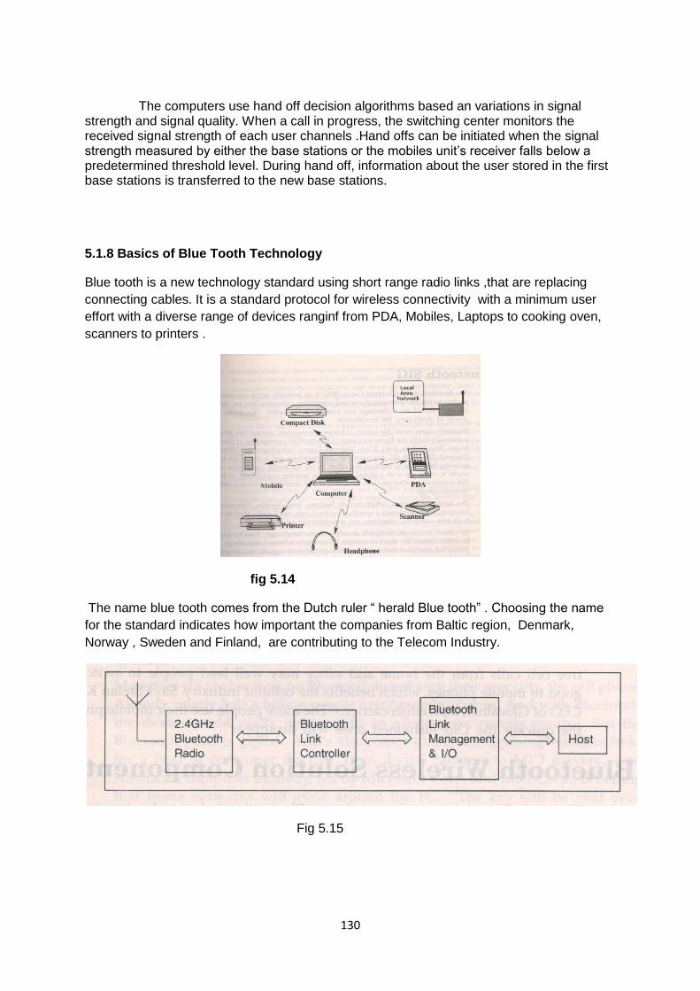
130
The computers use hand off decision algorithms based an variations in signal strength and signal quality. When a call in progress, the switching center monitors the received signal strength of each user channels .Hand offs can be initiated when the signal strength measured by either the base stations or the mobiles unit’s receiver falls below a predetermined threshold level. During hand off, information about the user stored in the first base stations is transferred to the new base stations.
5.1.8 Basics of Blue Tooth Technology
Blue tooth is a new technology standard using short range radio links ,that are replacing
connecting cables. It is a standard protocol for wireless connectivity with a minimum user
effort with a diverse range of devices ranginf from PDA, Mobiles, Laptops to cooking oven,
scanners to printers .
fig 5.14
The name blue tooth comes from the Dutch ruler “ herald Blue tooth” . Choosing the name
for the standard indicates how important the companies from Baltic region, Denmark,
Norway , Sweden and Finland, are contributing to the Telecom Industry.
Fig 5.15

131
Blutooth is a global wireless communication standard that connects devices together over a
certain range.it was invented by telecom vendor ericsson in 1994.it is a standarizad protocol
for sendind and receiving data via a 2.4GHZ wireless link.the blutooth devices can
communicate at ranges of upto 10metres.
A blutooth device user radio waves instead of wires or cables to connect to a phone or
computer. A blutooth product,like a cell or watch contains a tiny computer chip with a
blutooth radio and software that makes it easy to connec.when two blutooth devices want to
communicate to each other , they need to pair.communication between blutooth devices
happens over short rande,adhoc networks known as piconts.piconet is a network of device
connected using blutooth.
5.2 SATELLITE MULTIPLE ACCESS TECHNIQUES
The radio spectrum is shared by the mobile users simultaneously.
The sharing may be based on frequency or time or code. The wireless telephony applies
duplexing technique ,which enables talking and listening at the same time like FDD
frequency Division Duplexing which offeres two bands of frequencies for every user.The
simples channel consists of a forward and a reverse channel and so each duplex channel
consists of one simplex channel.
These forward and reverse channels are separated with a frequency band in the entire
system. The time division duplesxing known as TDD makes use of time instead of
frequency to have the same forward and reverse channels.
Both FDD and TDD have advantages and dis advantages. These multiple access schemes
with any one of these techniques is used in wire less communication systems
DIFFERENT MULTIPLE ACCESS TECHNIQUES:
THE THREE important multiple access techniques are:
1 TIME DIVISION MULTIPLE ACCESS
2 FREQUENCY DIVISION MULTIPLE ACCESS
3 CODE DIVISION MULTIPLE ACCESS
5.2.1 Time Division Multiple Access (TDMA)
Several users share the time slots of the entire available time.Each duplex channel (TDD)has individual time slots for forward and reverse time slots to have bidirectional

132
communication. A TDD time slot on the same frequency is shown in the diagram:
Fig 5.16 This TDD mode enables every transceiver to operate as a transmitter or
receiver .This TDD is generally used in cordless phones. The TDMA principle is shown. in
TDMAsystem the entire spectrum is divided into times slots where a single user is allowed to
use the radio channel in a time slot.
In TDMA digital data transmission and digital modulation are allowed. Many users can
access their channel in their respective time slots. The transmission from several users are
interlaced into a single frame as shown
Fig 5.17
In this format the preamble field contains the synchronization information and address
informations.The guard bits use allow synchronization of different receivers between various
frames and time slots.

133
It is assumed that there are N number of time slots for N number of users so that each user
access the channel in their allowed time slot.
Some TDMA features: 1)Each user of tdma multiple access scheme shares same carrier
frequency but with non over lapping time slots
5.2.2 Frequency Division Multiple Access
Fig 5.18 In FDMA, all users share the satellite at the same time, but each transmits in its own unique frequency band. This is most commonly employed with analog modulation, where signals are present all the time. The available transponder bandwidth is divided among the users the all can transmit simultaneously, as illustrated in the fig.5.10. FDMA is the simplest form of multiple accessing. In it an earth station is permanently assigned a carrier frequency ( or several carrier frequencies for a busy stations ) and a bandwidth around that carrier frequency . The stations frequency modulates all of its outgoing traffic-whatever the destination-on that carrier. In fixed frequency operation each carrier is assigned a dedicated frequency band for the uplink and other carrier utilizes that band. In demand multiple access (DMA) frequency bands are shared by several carrier, with a particular band assigned at the time of need, depending on availability. Individual carrier spectra in a FDMA system must be sufficiently separated from each other and to prevent carrier cross talk. A high power carrier will affect the adjacent low power carrier. However, excessive separation causes needles waste of satellite bandwidth. FDMA involves relatively simple frequency tuning for accessing and providing essentially independent channel on off operation.

134
The carrier frequencies and bandwidth assigned to all earth stations constitute a satellites frequency plane. Every station that operates in FDMA network must be able to receive at least one carrier from all the stations in the network. In conversional telephonic systems, bidirectional communication is possible simultaneously and it is essential for cellular communication also. Such a simultaneous talk and listen facility is known as duplexer. Under frequency multiplexing \duplexing is done using frequency and hence it is termed as frequency division duplexing FDD. In FDD,the duplex channel contains dual simplex channels namely forward and reverse channel as in figure. The forward frequency band provides radio traffic from base station BTS TO THE MOBILE UNIT where as the reverse frequency radio band provodes radio traffic from mobile unit TO THE BASBASE STATION. A duplexdevice is kept in mobile unit and base station for enabling simultaneous conversion. Some features of FDMA scheme: 1)FDMA requires proper filtering at receiver side to avoid agjacent channel interferences ACI 2) In FDMA scheme ,if a channel is not in use it will be idle and it will not be used by some other uses.Hence there is a chance of resourse wastage 3)FDMA Channel can handle one phone circuitl at a time. Types: 1) fixed assignment multiple access FAMA 2)Demand assignment multiple access DAMA Non linera effects in FDMA SCHEME OF MULTIPLEXING: In This scheme ,same antenna at base station is shared by several radio channels.the power amplifiers are operated near saturation region for getting maximum possible power,efficiency and it is non linear.these cause spreading of signals over the entire frequency domain resulting in intermodulation frequency generation.it will enhance interferences in actual signal and IM must be minimised.
5.2.3 Code Division Multiple Access (CDMA)
In CDMA, many earth stations simultaneously transmit orthogonally coded spread-spectrum signals that occupy the same frequency band. Decoding systems receive the combined transmissions from many stations and recover one of them. That is in CDMA scheme; users can transmit simultaneously and also share the frequency allocation. The frequency hopping with CDMA is illustrated in the fig. 5.13. 3 In this system, a number of users occupy all of a transponder band width all of the time. The signals from different users are encoded, so that information from an individual transmitter can be detected and recovered only by a properly synchronized receiving stations that knows the code being used . That is each receiving station has its own code, called its address and a transmitting station simply modulates its transmission with the address of the intended receiver whenever it wishes to send a message to that receiver. Carrier separation is achieved at an earth station by identifying the carrier with the proper address. These addresses are usually in the form of periodic binary sequence that either modulate the carrier directly or change the frequency state of the carrier. Address identification is accomplished by carrier correlation operation. Digital address is obtained for code generators.

135
A station address generator continually cycles through its address sequence, which are superimposed on the carrier along with the data. CDMA is more suited for military tactical communication environment where many small groups of mobile stations are briefly at irregular intervals
. Fig 5.19
Since same channel is shared by several users, there may be a problem of near far
effect. In CDMA, the main advantage when compared to oter multiple access schems is
reduced level of interference. Since each user/ subscriber is allocated an individual pseudo
random codeword that is orthogonal to all other codewords of remaining users at the
receiving end the receiver selectively tunes to receive the intented signal of the users.
Proper power control measures are done in CDMA to avoid near far problems.
Some featuers of CDMA multiple access scheme:
1)If the spreading sequences are not exactly orthogonal from one user and to
another users may be a chance of self jamming problem in CDMA. Hense this
spreading sequence or pseudo random noise code has to be carefully planned and
then it should be multiplied with the message signal.
2)CDMA has better soft capacity limit than TDMA and FDMA methods.
3)Radio signal strength indicator RSSI is being used in CDMA to have better power
control.

136
Types
1)Fixed assignment multiple access
2)Demand assignment multiple access
5.2.4 Digital Cellular System
Cellular systems which use digital modulation technique are called digital cellular systems. Digital systems offer large improvement in capacity and system performance. In the late 1980’s the United States Digital cellular system (USDC) was developed to support more users in a fixed spectrum allocation. USDC is a time division multiple access (TDMA) system. USDC offer as much as six times the capacity of AMPS. The USDC standard uses the same 45MHZ FDD scheme as AMPS. The dual
mode USDC/AMPS system was standardized as interim standard 54 ( IS-54) by the
electronic industries north American Digital cellular (NADC) , as it had been installed in
Canada and Mexico. The USDC system was designed to share the same frequencies reuse
plan, and base stations as AMPS , so that base stations and subscriber unit could be
equipped with both AMPS and USDC channels , within in the same piece of equipment . To
maintain compatibility with AMPS phones, USDC forward and reverse control channels use
exactly the same signaling technique as AMPS.
5.2.4.1 Global System for Mobile Communications (GSM)
Global system for mobile (GSM) is a second standard. it was developed to solve the fragmentation problems of the first cellular system in Europe . GSM was the world’s first cellular system to specify digital modulation and network level architecture and services. It is the world’s most popular 2G ( second generation) technology. GSM was originally developed to serve as the pan European cellular service and promised a wide range of network services through the use of ISDN ,now GSM is the world’s most popular standard for new cellular radio and personal communication equipment throughout the world . As of 2001 , there were over 350 millions GSM subscribers worldwide. 4 GSM was first introduced into European market in 1991. In 1992, GSM changed its name to the global system for mobile communications for marketing reasons. By the end of 1993 several non-European countries in south America, Asia and Australia had adopted GSM, which support personal communication service (PCS) in the 1.8GHZ to 2.0GHZ radio bands recently created by government throughout the world.
5.2.4.2 GSM Services
GSM service follows ISDN guidelines and are classified as either tele service or data services. Tele services include standard mobile telephony and mobile originated traffic. Data service includes computer-to-computer communication and packet switched traffic. User services may be divided into three categories. Telephone Services – This service include emergency calling and facsimiles. GSM also support Videotex and teletex , though they are not integral parts of the GSM standard.

137
Bearer services or data services - This service includes packet switched protocols and data rates from 300 bps to 9.6 kbps. Data may be transmitted using either a transparent mode ( where GSM provides standard channel coding for the user data ) or non transparent mode ( where GSM offers special coding efficiencies based on the particular data services ).
Supplementary ISDN services – This services are digital in nature, and include all diversions, closed users groups, and caller identifications. These services are not available in analog mobile networks. Supplementary services also include short messaging services (SMS), which allows GSM subscribers and base stations to transmit alphanumeric pages of limited length. SMS may be used for safety and advisory applications, such as the broadcast of highway or weather information to all GSM subscribers within reception range. Subscribers Identity module ( SIM ) is one of the most remarkable features of GSM .SIM is a memory device that stores information such as the subscriber’s identification number , the networks and countries where the subscribers is entitled to services , privacy keys and other user specific information. A subscriber uses the SIM with a four digit personal ID number to activate services from any GSM phone.
SMS available as smart card (credit card sized cards that may be inserted into to any GSM phone) or plug-in modules . Without a SIM installed, all GSM mobiles are identical and non operational. Subscriber may plug their SIM into any suitable such as hotel phone, public phone or any portable or mobile phone and then able to have all incoming GSM calls routed to that terminal and have all outgoing calls billed to their home phones , no matter where they are in the world.
5 A second remarkable feature of GSM is the air privacy which is provided by the system. Unlike analog FM cellular phone systems which can be readily monitored, it is virtually impossible to eavesdrop on a GSM radio transmission. The privacy is made possible by encrypting the digital bit stream sent by a GSM transmitter, according to a specific secret cryptographic key that is known only the cellular carrier . This key changes with time for each user. Every carrier and GSM equipment manufacture must sign memorandum of understanding ( MOU) before developing GSM equipment or developing a GSM system .the MOU is an international agreement which allows the sharing of cryptographic algorithms and other proprietary information between countries and carriers.
5.2.4.3GSMSsystemArchitecture
The GSM system architecture consists of three major interconnected subsystems. They are 1) Base station subsystem (BSS) , 2) Network and switching subsystems , 3) Operation support subsystem ( OSS ).The subsystems interlaced between themselves and with the users through certain network interfaces. The mobile station (MS) is also a subsystem, but is usually considered to be part of the BSS for architecture purpose. The BSS, also known as the radio subsystem, provides and manages radio transmission paths between the mobile switching center (MSC). The BSS also manages the radio interface between the mobile stations and all over subsystems of GSM. Each BSS consists of many base station controllers (BSCs) which connects the MS to the NSS via MSCs The NSS manages the switching functions of the systems and allows the MSCs to communicate with other networks such as PSTN and ISDN.

138
Fig 5.20 The OSS supports the operation and maintenance of GSM and allows system engineers to monitor, diagnose and trouble shoot all aspects of the GSM system . This subsystem interacts with the other GSM subsystems. The block diagram of GSM architecture is shown in the fig.5.14. The mobile stations (MSs) communicate with the base station subsystem (BSS) over the radio air interface. The BSS consists of many BSCs which connect to a signal MSC. Each BSC can controls up to several hundred Base Transceiver stations (BTSs) . Some of the BTSs may be co-located at the BSC, and others may be remotely distributed and physically connected to the BSC by microwave link or dedicated leased lines.
The various interfaces used in GSM are illustrated in the fig .5.15 The interface which connects a BTS to a BSC is called AbIS interface . The abis interface carriers traffic and maintenance data , and is specified by GSM to be standardized for all manufactures . practically same manufacture BTS and BSC equipments may be used for avoiding subtle differences. The BSCs are physically connected to the MSC through dedicated/leased lines or microwave link. The interface between a BSC and a MSC is called the A interface , which is standardized within GSM . The A interface uses an SS7 protocol called the signaling correction control part (SCCP) . It supports communication between the MSC and the BSS as well as network messages between the individual subscribers and the MSC. An interface

139
allows a service provider to use base stations and switching equipment made by different manufactures.
The NSS handles the switching of GSM call between external networks and the BSCs in the radio subsystem. The MSC is the central unit in the NSS and controls the traffic among all of the BSCs. There are three different data bases in NSS. They are 1) Home location registers ( HLR) , 2) Visitor location register ( VLR ) , and 3) Authentication center (AUC ) . The HLR is a data base which contains subscriber information and location information for each user who resides in the same city as the MSC. Each subscriber in a particular GSM market is assigned a unique international mobile subscriber Identify (IMSI) . This number is used to identify each home user. The VLR is a database which temporarily stores the IMSI and customer information for each roaming subscriber who is visiting the coverage area of a particular MSC. The VLR is linked between several adjoining MSCs in a particular region and contains subscription information of every visiting user in the area. Once a roaming mobile is logged in the VLR, the MSC sends the necessary information to the visiting subscriber’s HLR, so that calls to the roaming mobile can be appropriately routed over the PSTN by the roaming user’s HLR. The Authentication center is a strongly protected data which handles the authentication and encryption keys for every single subscriber in the HLR and VLR. The Authentication center contains a register called the Equipment Identify Register (EIR) which identifies stolen or fraudulently altered phones that transmit identify data that does not match with information contained in either the HLR or VLR. The OSS supports one or several operation maintenance centers ( OMC ) , which are used to monitor and maintain the performance of each MS, BS, BSC and MSC within a GSM system. The OSS has the following three functions: 1) To maintain all telecommunications hardware and network operations with a particular market, 2) To manage all charging and billing procedures , and 3) To manage all mobile equipment in the system.

140
Fig 5.21
5.2.5 Basics of General Packet Radio Systems ( GPRS)
GPRS (General Packet Radio Service) is a service within the GSM network, just like the two most popular services SMS and voice connections. GPRS is used for transmitting data in the GSM network in the form of packets. The connection to the remote station is not Reserved and left open during the entire connection time, but is occupied only at the time of actual data transmission
With the GPRS network, several channels are occupied at the same time for data transmission whenever data needs to be transmitted. Whenever a GPRS device is not receiving or sending data, the channels are available for other services and other GPRS subscribers. By way of this dynamic allotment of resources the utilization of the existing radio infrastructure is clearly optimized. A drawback of the system is that the available bandwidth may drop when many users try to access the GPRS network at the same time. In addition, the data is also compressed by means of special coding process ( CS-1….CS-4 ),so as to ensure further data rate enhancement. The maximum transmission speed in the GPRS network is theoretically 172,2 Kbit/sec. The devices available on the market offer a maximum transmission speed of 85,6 Kbit/sec. The dynamic allotment of resources permits a method of billing. The billing is not based on connect time, but rather on the volume, block size and billing period of the data to be transmitted. 8 times slots and 4 coding schemes (CS) with different data transmission rates are available, CS1 with 9,05kbit/s, cs2 with 13,4kbit/s ,CS3 with 15,6kbit/s,CS4 with 21,4kbit/s. This results a theoretical total data rate of 171,2kbit/s when bundling all eight time slots with coding scheme. The adjustment of the transmission speed is made dynamically depending on the HF transmission characteristics by switching between the coding schemes.

141
UNIT- V
Review question
PART –A -2 MARKS
1 What is a Cellular Telephone System?
2 Why does the Physical area is divided into Hexagonal-Shaped cells
3 What are Corner Excited Cells ?
4 Mention important types Satellite Multiple Access
5 What are Reverse Voice Channels (RVC)?
6 Mention the types of Hand-off
7 What are the uses of Mobile Identification Number (MIN)
8 What is a MSC
9 What is ‘ Frequency Reuse’
10 The actual coverage of a cell is known as the………. a) footprint b)photo print
c)trajectory
PART –B -3 MARKS
1 What are Microcells ?
2 Explain Co-channel interference
3 Mention about Adjacent channel interference
4 Mention about Forward control channels (FCC)
5 Explain hand-off.
6 What are the different names gives for a MSC
7 Explain about’ frequency reuse’ or ‘frequency planning’
8 Define Interference
9 Compare the two types of Interferences
10.Mention the methods to Improving coverage and capacity in cellular systems

142
PART –C-10 MARKS
1 Explain about Sectoring
2 Explain about Cell Splitting
3 Explain Roaming
4 Explain Hand off
5 Explain the basics of Blue Tooth Technology
6 Describe TDMA with neat diagrams
7 Describe FDMA with neat diagrams
8 Describe CDMA with neat diagrams
9 Describe about GSM system Architecture
10 Explain the Basics of General Packet Radio Systems ( GPRS)

143

144

145

146


![[TC 025] Alvenaria estrutural_2020 - dcc@ufpr](https://static.fdokumen.com/doc/165x107/631358cfaca2b42b580d255f/tc-025-alvenaria-estrutural2020-dccufpr.jpg)