HumaStar 600 - Egm Medikal
132
HumaStar 600 | User Manual Cat No. 16660/001
-
Upload
khangminh22 -
Category
Documents
-
view
0 -
download
0
Transcript of HumaStar 600 - Egm Medikal

HumaStar 600| User Manual
Cat No. 16660/001


REVISION LIST OF THE MANUAL
Rev. /DATE. REVISION DESCRIPTION
01/2007-09 First edition
02/2007-11 Correction of typing errors
03/2008-03 New features of SW 1.7.1 implemented
04/2008-10 New features of SW 1.7.3 implemented(calibration status, reagent status, ISE module update)
05/2009-01 Typing errors corrected
06/2010-05 New features of SW 1.8.1 implemented(clot detection, power user, wear, BCR for controls and standards)
07/2011-06 Update for software 1.8.1 r2011.05.30
08/2011-09 Correction dimension
09/2014-12 Adding of System Wash Solution, chapter of ISE module excluded
10/2017-05 Update for Software 2.5.0
SYSTEM VERSION
COPYRIGHT
Copyright 2017, Human Gesellschaft für Biochemica und Diagnostica mbH, Wiesbaden, Germa-
ny. All rights reserved.
No part of this documentation may be reproduced in any form, nor processed, copied or distrib-
uted by means of electronic systems, without prior permission of Human GmbH in writing. Since
all precautionary measures were taken into account in producing these operating instructions,
the manufacturer accepts no responsibility for any errors or omissions. This includes any liability
for damage that could arise from possible incorrect operation based on this information. Subject
to changes without notice as result of technical development.
SERVICE UND SUPPORT


CONTENTS
TABLE OF CONTENTS
1 SAFETY INSTRUCTIONS 5
1.1 INTRODUCTION 5
1.2 USER WARRANTY 5
1.3 INTENDED USE OF THE INSTRUMENT [IVD] 6
1.4 GENERAL SAFETY WARNINGS 6
1.5 DISPOSAL MANAGEMENT CONCEPT 7
1.6 INSTRUMENT DISINFECTION 7
1.7 BIOHAZARD WARNING 8
1.8 ADDITIONAL LABELS 8
2 INTRODUCTION 9
3 SYSTEM DESCRIPTION 11
3.1 UNPACKING 11
3.2 INSTALLATION 11
3.2.1 Installation Requirements 11
3.2.2 Electrical connections 12
3.2.3 Hydraulics 12
3.2.4 Handling of biological fluids 13
3.2.5 Computer setup 14
3.2.6 Parameters 15
3.2.7 Tools 23
3.3 PARTS OF THE INSTRUMENT 28
3.3.1 Front view 28
3.3.2 Top view 28
3.3.3 Left side 29
3.3.4 Samples and sample sectors 29
3.3.5 Reagents 30
3.3.6 Barcodes 30
3.3.7 Cuvettes 30
3.4 SOFTWARE FUNCTIONS OVERVIEW 31
3.4.1 Levels of access 31
3.4.2 Data menu 32
3.4.3 Main Screen 33
3.4.4 Quick Key Menus 36

4 GET READY FOR OPERATION 41
4.1 AUTOMATIC OPERATION 41
4.1.1 Clot detector 42
5 ROUTINE TASKS 43
5.1 REAGENTS 43
5.1.1 Reagent tray 43
5.1.2 Loading barcoded reagents, Diluent and Cleaning Solutions 44
5.1.3 Loading non barcoded reagents and solutions 45
5.1.4 Removing reagents and solutions 45
5.1.5 Refilling reagent bottles (only for open channels) 47
5.1.6 Method assignment to trays 47
5.2 SAMPLES 47
5.2.1 Working with patients 48
5.2.2 Defining sample data and tests 49
5.2.3 Removing a sample 50
5.2.4 Removing tests 51
5.2.5 Copy data 51
5.2.6 Loading samples 52
5.2.7 Removing a sample 53
5.2.8 Placing a sector on the tray 53
5.2.9 Removing a sector 54
5.2.10 Loading a STAT 54
5.2.11 Reports 55
5.3 TEST RESULTS 56
5.3.1 Acceptance of Results 57
5.3.2 Reflex Tests 57
5.3.3 Printout of results 57
5.3.4 Cuvette 57
5.4 CALIBRATION 58
5.4.1 Calibrator sets 59
5.4.2 Requesting a calibration 61
5.4.3 Ordering a calibration 63
5.4.4 Calibration acceptance 63
5.4.5 Automatic calibration 64
5.5 REAGENT BLANK 65
5.6 QUALITY CONTROL 67
5.6.1 Creating a control set 69
5.6.2 Requesting a control 71
5.6.3 Processing a control 72

CONTENTS
5.6.4 Processed controls 72
5.7 TWIN QC 75
5.7.1 QC scheduler 78
5.8 WORKING WITH LIS 80
5.9 DEFINITION AND USE OF SAMPLE PROFILES 80
5.9.1 Defining a sample profile 80
6 DEFINITION OF METHODS 81
6.1 METHOD TYPES AND CALCULATIONS 81
6.1.1 Endpoint 82
6.1.2 Fixed Point 83
6.1.3 Kinetics 84
6.2 METHOD PARAMETERS 84
6.2.1 Common parameters 84
6.2.2 Main Page 85
6.2.3 Quantitative 88
6.2.4 Limits 89
6.2.5 Reference classes 91
6.2.6 Advanced features 92
6.2.7 Consumption 94
6.2.8 Reagent substitution 95
6.2.9 Kits 96
6.3 SOLUTIONS 97
6.4 OPTIONS 98
6.5 CALCULATED METHODS 99
6.6 EXTERNAL METHODS 100
6.7 UNITS AND LIMITS 101
6.8 DEVELOPEMENT OF A METHOD 101
7 ISE MODULE CAT.-NO. 16663-03 103
8 MAINTENANCE 105
8.1 SCHEDULER 105
8.1.1 Schedule 106
8.1.2 Status 107
8.2 DAILY MAINTENANCE 108
8.2.1 Inspection and Cleaning of Probes 108
8.2.2 Check and Replace System Solutions 108
8.2.3 Empty Waste Bottle 109
8.2.4 Hydraulic Testing – System Flush 109
8.3 WEEKLY MAINTENANCE 110
8.3.1 Intensive Cuvette Cleaning 110
8.3.2 Cuvette Water Blank 111
8.3.3 Service Backup 111
8.4 MONTHLY MAINTENANCE 112
8.4.1 Photometer Calibration 112
8.4.2 Washer Volume Calibration 113
8.4.3 Clean System Bottles 114
8.4.4 Intensive Washer Cleaning 115
8.5 MAINTENANCE ON DEMAND 116
8.5.1 Cuvette Change 116
8.5.2 Lamp Replacement 117
8.5.3 Pump tube replacement 117
8.6 COUNTERS 117
9 TROUBLESHOOTING 119
9.1 MESSAGES AND WARNINGS 119
9.2 VISIBLE FAULTS 119
9.2.1 General faults 119
9.2.2 Measurement inconsistencies 120
10 APPENDIX 123
10.1 TECHNICAL SPECIFICATION 123
Safety InStructIonS 5
1 SAFETY INSTRUCTIONS
1.1 IntroductionThis manual is considered as a part of the instrument; it has to be at the oper-
ator’s hand as well as at the maintenance operator’s availability. For accurate
installation, use and maintenance, please read the following instructions care-
fully. In order to avoid instrument damage or personal injury, carefully read the
”GENERAL SAFETY WARNINGS”, describing the suitable operating procedures. In
case of breakdowns or any troubles with the instrument, apply to the local Tech-
nical Service.
1.2 User WarrantyHUMAN warrants that instruments sold by one of its authorised representa-
tives shall be free of any defect in material or workmanship, provided that this
warranty shall apply only to defects which become apparent within one year
from the date of delivery of the new instrument to the purchaser.
The HUMAN representative shall replace or repair any defective item at no
charge, except for transportation expenses to the point of repair.
This warranty excludes the HUMAN representative from liability to replace any
item considered as expendable in the course of normal usage, e.g.: lamps, valves,
syringes, glassware, fuses, diskettes, tubing etc.
The HUMAN representative shall be relieved of any liability under this warranty
if the product is not used in accordance with the manufacturer‘s instructions,
altered in any way not specified by HUMAN, not regularly maintained, used with
equipment not approved by HUMAN or used for purposes for which it was not
designed.
HUMAN shall be relieved of any obligation under this warranty, unless a com-
pleted installation / warranty registration form is received by HUMAN within
15 days of installation of this product.
This warranty does not apply to damages incurred in shipment of goods. Any
damage so incurred shall be reported to the freight carrier for settlement or
claim.

HumaStar 600 | User manual
6
1.3 Intended Use of the Instrument [IVD]
The instrument is intended for in vitro diagnostic application by professional
users. It has to be used for the expected purposes and in perfect technical con-
ditions, by qualified personnel, in working conditions and maintenance opera-
tions as described in this manual, according to the GENERAL SAFETY WARNINGS.
This manual contains instructions for professional qualified operators.
The external PC must not be used for purposes other than those designated in
this manual. The analyzer is designated for indoor use only. Recommendation
provided in the leaflet for all reagents and consumables have to be observed.
1.4 General Safety WarningsUse only chemical reagents and accessories specified and supplied by HUMAN
and/or mentioned in this manual. Place the product so that it has proper ven-
tilation.
The instrument should be installed on a stationary flat working surface, free
from vibrations.
Do not operate in area with excessive dust.
Work at room temperature and humidity, according to the specifications listed
in this manual.
Do not operate this instrument with covers and panels removed.
Only use the power cord specified for this product, with the grounding conduc-
tor of the power cord connected to earth ground.
Use only the fuse type and rating specified by the manufacturer for this instru-
ment, use of fuses with improper ratings may pose electrical and fire hazards.
To avoid fire or shock hazard, observe all ratings and markings on the instru-
ment.
Do not power the instrument in potentially explosive environment or at risk of
fire.
Prior to cleaning and/or maintaining the instrument, switch off the instrument
and remove the power cord.
For cleaning use only materials specified in this manual, otherwise parts may
become damaged. It is recommended always to wear protective apparel and eye
protection while using this instrument. Respective warning symbols, if appear-
ing in this manual, should be carefully considered.

Safety InStructIonS 7
1.5 Disposal Management ConceptThe currently valid local regulations governing disposal must be observed. It is in
the responsibility of the user to arrange proper disposal of the individual com-
ponents.
All parts which may comprise potentially infectious materials have to be dis-
infected by suitable validated procedures (autoclaving, chemical treatment)
prior to disposal. Applicable local regulations for disposal have to be carefully
observed.
The instruments and electronic accessories (without batteries, power packs etc.)
must be disposed off according to the regulations for the disposal of electronic
components.
Batteries, power packs and similar power source have to be dismounted from
electric/electronic parts and disposed off in accordance with applicable local
regulations.
1.6 Instrument DisinfectionAnalytical instruments for in vitro diagnostic involve the handling of human
samples and controls which should be considered at least potentially infectious.
Therefore every part and accessory of the respective instrument which may have
come into contact with such samples must equally be considered as potentially
infectious.
Before doing any servicing on the instrument it is very important to thorough-
ly disinfect all possibly contaminated parts. Before the instrument is removed
from the laboratory for disposal or servicing, it must be decontaminated. De-
contamination should be performed by authorised well-trained personnel only,
observing all necessary safety precautions. Instruments to be returned have to
be accompanied by a decontamination certificate completed by the responsible
laboratory manager. If a decontamination certificate is not supplied, the return-
ing laboratory will be responsible for charges resulting from non-acceptance of
the instrument by the servicing centre, or from authority’s interventions.

HumaStar 600 | User manual
8
1.7 Biohazard warningAnalytical instruments for in vitro diagnostic application involve the handling
of human samples, calibrators and controls which should be considered at least
potentially infectious. Therefore every part and accessory of the respective in-
strument which may have come into contact with such samples must equally
be considered as potentially infectious.
For safety reasons, we have labeled instruments with the „BIOHAZARD“ warn-
ing label below.
1.8 Additional LabelsThe labels used on Human products are among those specified by the interna-
tional Organisation for Standardization (ISO).
They are placed at critical points on each instrument as a warning of the risks
involved.
While operating any of our instruments take note of these and observe the
precautions described.
Warning Electrical Risk - This label indicates the operator of the
presence of high electrical voltage.
Warning Danger: This label indicates a potential hazard which, if not
avoided, can result in injury to an operator and/or serious property
damage. Please read the manual for instructions before opening.
FIGURE 1
Biological Hazard Symbol

IntroductIon 9
2 INTRODUCTIONThe HumaStar 600 is a reliable in vitro diagnostic chemistry analyzer for auto-
matic testing of routine clinical chemistry tests and electrolytes.
Being real random access, this HumaStar 600 is the ideal solution for medium
to large size labs, with a throughput of more than 600 photometric tests/hour
(720 tests/hour with ISE).
Continuous process can be achieved as samples sectors can be loaded quick-
ly and simply allowing nonstop operation. Sectors can hold primary tubes and
small sample cups.
Refrigerated reagent tray can hold up to 48 different containers ranging from
20 to 70ml depending on configuration.
The optional ISE unit gets electrochemical measurement of Na+, K+ and Cl- elec-
trolytes with automatic urine sample dilution. The instrument is controlled
by a PC workstation that has graphical -user friendly- interface software. The
software provides total control over the analyzing process and gives easy ac-
cess to advanced statistical functions and reports. Versatile method setup com-
prises end point, fixed point, kinetics, ISE, coagulation, calculated and externals.
Optional features include:
- Flexible pre- and post washing for each test to prevent carryover.
- Auto rerun with automatic dilution of samples which are out of linear range.
- Automatically duplicate for result confirmation
- Extra volume dispensing of water or reagent to improve accuracy.
- Reagent integrity check for safe operation.
- Automatic predilution for calibrators, controls, blanks and samples to fit any
method insert.
- Curve and linear calibration with unlimited number of standards for highest
accuracy.
- Onboard sample and reagent bar code reading assure positive identification.
- Capacity sensor monitors sample and reagent volumes.
- Instant mixing during dispense gives precise initial reaction time.
- Automatic acceptance of calibrators, control and samples increase the walk
away time.
- Current activity monitor screen indicates to the operator when the routine
will be finished
- Clot detector
- Low water consumption.

HumaStar 600 | User manual
10

SyStem deScrIptIon 11
3 SYSTEM DESCRIPTION
3.1 UnpackingRemove all the parts from their package.
When unpacking the instrument, please make sure that the following items are
contained in the packing. In case of damage or missing item, please contact the
supplier immediately.
Quantity Description [REF]
1 Software CD 166612 Reaction cuvettes (box of 1200) 16661/12 Drying block kit 16661/111 Reagent recipients with cap (x 30) vol. 70 ml 16661/21 Reagent recipients with cap (x 30) vol. 25 ml 16661/32 Peristaltic Pump tubing kit x 3 16661/42 Sample tubes 13 mm. kit x 100 16661/51 Halogen lamp 12V 20W 16661/75 Sample Rack 16661/151 Serial Cable 16661/161 User Manual 16660/001
3.2 Installation
3.2.1 INSTALLATION REQUIREMENTS
Carefully read the safety instructions included in this manual.
Install the instrument on a hard floor with a resistance of at least 50 kg/cm2; use,
if possible, ceramic or stone floor.
Avoid carpets or very soft rubber.
Mains should be close to the instrument (less than two meters) and must fulfill
local regulations.
Free access to main switch is required. A distance of 50 cm from the left side
of instrument to nearest table or wall is advisable. Right side must have a free
space of at least 30 cm for ventilation purposes.
Space must be empty over instrument to 2.10 m. Avoid using shelves, walls or
screens above instrument.
Instrument is mounted on wheels and can be moved towards the front for ser-
vicing and cleaning purposes. Allow free space of about two times the instru-
ment depth.
TABLE 1

HumaStar 600 | User manual
12
3.2.2 ELECTRICAL CONNECTIONS
Plug in the mains cord to a socket with ground connection. The power require-
ments for the HumaStar 600 are as follows: 100~240 VAC, 50/60 Hz, 1400 VA
maximum.
Maximum voltage between ground and neutral lead: 0.5 volts.
There is a J9 serial port type RS232C connector in the rear part of the instrument.
Connect the HumaStar 600 to the computer serial port using the provided cable.
Tighten retaining screws.
3.2.3 HYDRAULICS
The waste deposit collects the drainage of the probe washing stations and
occasional waste from the dispensing stations and cuvette washers. Place the
emptied bottle in the correct location and orientation (see Figure 23).
Pay attention that the funnel is inside the bottle neck. The waste bottle has a
capacity of 20 L and the wash solution bottle of 10 L. To perpare the system
wash solution, purified water should be used with less than 2 µS/cm and less
than 100 CFU/mL to avoid contamination of the system with ions and bacteria.
Described specification fall in CLSI Type 2 water catergory.
Level metering is made by means of a load cell system (scale) for wash solu-
tion- and waste bottle. Warning messages will appear before the system wash
solution is empty and the waste bottle full.
Put the pump tubing of the washing pumps in place. Take out the plastic protec-
tion tube (typically yellow) from the probe arm‘s vertical shaft before operating.
The system is ready to use. Flush the system at least 3 times in order to ensure
that all bubbles have been removed from the tubing and syringe.
Instrument is Installation Cat-
egory II. Instrument requires
protective ground connection.
Verify ground connection before
installing the instrument.
User must be warned about
the use of instrument under
abnormal grounding conditions.
It is advisable not to complete in-
stallation under poor ground con-
ditions.
Preparation of System Wash
Solution IFU of Wash Add
Ref 18971.

SyStem deScrIptIon 13
3.2.4 HANDLING OF BIOLOGICAL FLUIDS
Before connecting wash and drain lines, be sure to remember and understand
regulations and cautions about potentially dangerous biological fluids.
Keep in mind the following considerations:
1. Due to the presence of biological fluids, some instrument areas are poten-
tially dangerous. They are warned with the symbol see Figure 1.
Dispensing tips, reaction cuvettes and drain fluid bottle are the most endan-
gered areas.
FIGURE 2
Never dispose potentially
dangerous fluids on public
drain system.
Refer to chapter 1.5.

HumaStar 600 | User manual
14
1. Sample handling, drain fluid disposal and reaction cuvettes replacement
must be done with safety disposable gloves manufactured according local
regulations for biological fluids handling.
2. Drain fluid must be neutralized. The addition of 0,5 % Sodium Hypochlorite
is suggested.
3. Verify and use local regulations on discarding pathological fluids.
4. If instrument is to be translated to other location or stored for a long period,
perform at least 5 purge cycles, remove cleaning solution bottle and repeat
purge cycles until drain lines are empty. Neutralize and dispose drain fluid.
3.2.5 COMPUTER SETUP
Follow the instruction set of the computer‘s manufacturer to connect and oper-
ate the computer system.
The minimum requirements for the computer are:
Processor Intel Core i3 or higher
Memory 4 Gb Ram
Video board Graphics Enging GeForce 8400 or equivalentMonitor 17“ (VIS 15.7“)Display resolution 1024x768 (vertical refresh > 70 Hz)Colour quality 16 bitsHard drive 500 Gb SATA 3 7200 rpm or betterCD-Drive CD-RW or DVD-RW or DVD-RUSB port 2.0 or higherKeyboard 105-key Performance keyboardPointing device USB mouseSoundcard Integrated 16 bit (optional)Speakers (optional)Network adapter Ethernet 10/100 Mbits
Serial PortRS-232 serial port Additional serial port for LIS connection, (USB to RS232 adapter – optional)
Operating system Win 7 (32 and 64 bit), Win 10 (64 bit)Compatible printer Any Windows™ compatible printer maybe installed.
The computer should be used only for the operation of the instrument. Any oth-
er programms beside the instrument software may cause instument malfunc-
tion and /or breakdown.
The visual effects to best performance.Change the setting of the operating system. Under properties Advanced options visual effects select “Adjust for best performance”.
TABLE 2

SyStem deScrIptIon 15
Setting of the Anti Virus Software
We recommend the use of Anti Virus Software on the Personal Computer of the
HumaStar 600. The HumaStar 600 “Rayo” directory has to be excluded from the
scanning process. Please refer to the documentation of the Anti Virus Software
Don‘t use the predefined MS Windows folders.
3.2.6 PARAMETERS
There are few parameters for software and instrument use accessible to opera-
tor. They are located in:
3.2.6.1 Software
Includes pages for communications, LIS and bar code reader.
FIGURE 3

HumaStar 600 | User manual
16
General
1. Communications: Select serial port according to your computer setting and
specification. If setting is wrong, the HumaStar 600 temporarily checks for
other port; but if no ports are free, program might not work properly.
2. Language: Select among languages already set in the translator. Changes
will come into effect when program is closed and re-opened.
3. Historic: Defines size in days and numbers that calibrators, controls and
samples will stay in ‘’upper’’ memory. Controls and samples above these
days will be stored at the cumulative historic files and can be recalled.
4. Random access: Two options are provided: batch and full random access.
5. Coagulation: (Service only - not in use):
6. Online printing: Enables printing; selector of printout of pending acceptance
samples and printout of manually accepted results.
7. Automatic: Selection of active warnings and software behavior on a number
of different routine analysis. ISE processing check can be enabled by default
with a parameter. The DI empty warning can stop dilutions if checked and
issue warning, but continue (with warning) if not checked.
8. Automatic acceptance: Sample results can be autoamtically accepted when
they are within the reference range, after an automatic repeat and/or when
a calibration is reused.
9. Patient window: Selection of display
10. Sample Default Type: Defines which sample type will be used as default on
the sample requistion screen.
FIGURE 4

SyStem deScrIptIon 17
11. Reagent integrity check: run the reagent integrity check at each start of sam-
ples or only once a day.
12. Clot behavior: Enables the use of clot detection and offers additional options
in analyzer behavior in case that a clot is detected. Options: only flag - a flag
is added to the result, invalidate - the result will be deleted. The function to
aspirate the same sample again, can be enabled or disabled. Refer also to
section 4.1.1.
Press Apply Changes in order to save the changes.
QC
1. Westgard Rules: options to select rules which should be evaluated at Levey
Jenning Plots at the “QC Done” window.
2. Summary: Option to select QC results which should be highlighted at the
“OC Statistics” window.
Press Apply Changes in order to save the changes.
FIGURE 5

HumaStar 600 | User manual
18
BCR
1. BCR: Barcode reading can be activated for sectors, samples and reagents by
checking the corresponding box. When sectors are provided with bar code
identification, it is not necessary to define a number for sector loading.
2. Reagent configuration: Select setting according to your requirements. This
selector defines options for Method, bottle type, expiration date format and
starting position. In case of closed parameters, values are predefined and no
intervention is necessary.
3. Sample configuration: If Id position is not selected, all barcode digits are read.
4. Reagent no read behaviour: If reagent barcode is activated two options are
available for barcode reading error messages. The message can show up
each time an error accures or at the end of the reagent barcode reading.
5. Lot Number: To use multiple lots for the same reagent select the box “Mix
lots”.
Press Apply Changes in order to save the changes.
FIGURE 6

SyStem deScrIptIon 19
LIMS
1. Enabled: Select to activated and set informations for the communication
with host computer.
2. Options: Select parameters according to specifications of your LIMS provider.
3.2.6.2 Use
Use parameters are split in several sections: Cuvette absorbance limits, ISE and
definitions of sample vials.
FIGURE 7
FIGURE 8

HumaStar 600 | User manual
20
1. Cuvette blank: Upper- and lower limits for the cuvette check (air) can be set.
The tolerance value indicates the allowed absorbance variation of the first
reading after cuvette change and the actual reading.
2. Sample vials: Two different sample diameters vials can be defined. This fea-
ture is useful to define pediatric vials. Volume calculations require careful
section measurement for each defined vial.
3. ISE: Sample prewash can be enabled or disabled. For details, refer to ISE User
Manual REF 16663/1.
3.2.6.3 Report
FIGURE 9
FIGURE 10

SyStem deScrIptIon 21
This section allows sorting how methods are ordered in report and printout. Keys
Up and Down allow moving methods to different positions in the final printout.
If not enabled, sorting will take place alphabetically.
Press Apply Changes in order to save the changes.
3.2.6.4 Sector definition
In this section user defines the number of sectors that are available on the
analyzer.
FIGURE 11
FIGURE 12

HumaStar 600 | User manual
22
Up to 99 sample tray sectors can be programed and up to five can be on board
at the same time.
On the right side of the screen all programed sectors are displayed. Press
New to add an other sector. To define it as a STAT, tick the box “STAT sector”
and press Ok . All samples placed on a STAT sector will be processed with
priority.
3.2.6.5 Debug
FIGURE 13

SyStem deScrIptIon 23
In this section hardware and and hardware check functions can be activated or
deactivated.
To minimize down time following parts can be temporary deactiated: front- or
back arm and washer. In case the system is conneted to a water supply and
drain system the sensors for DI water and waste should be deactivated. During
routine use the reaction cover check should be activated. If the function “Only
safte results” is enabled, test with following flag: “wrong direction”, “initial ab-
sorbance limit”, “high consumption”, “correlation coefficient < 0.8” and “unsta-
ble ion” can not be accepted.
3.2.7 TOOLS
3.2.7.1 Translator
Translator operates on the language selected in Software parameters.
There are two basic ways of translating: translation control and dictionary.
Translation Control
To translate by translation control, place mouse pointer on the screen and
phrase whose translation must be modified; press keys Shift + Control + C. The
following screen will open:
FIGURE 14
Always end any modification
by pressing the
CTRL + SHIFT + C keys.

HumaStar 600 | User manual
24
Left column is the Instrument Internal Language (mostly English); second and
third column are the present translation, if any. A new “Local” translation will
modify only the screen the Translation control window has been opened. All
modifications done in “Global” will effect all entries in the software.
Modifications take effect only when program is restarted. When a given trans-
lation is empty, system will use Internal language, no matter which language is
selected.
Translation with Dictionary:
FIGURE 15
FIGURE 16

SyStem deScrIptIon 25
Translation can be done using the dictonary tool.
When any entry is selected, upper window shows internal text and lower win-
dow, the translation, if present. Sorting can be performed by internal or by
translation. There is also a built-in search tool. Entries can be deleted by press-
ing the corresponding button.
3.2.7.2 Modify reports
Customized report can be modified in
FIGURE 17
FIGURE 18

HumaStar 600 | User manual
26
At top right there are four bands (title,header, data and footer) which split the
report in four separat sections:
To enable or disable a band use the function “Edit Bands”.
By clicking on the + button next to each band a variable number of additional
text captions will appear. It is possible to add, edit or delete text, data text or
lines for each band. Following screen will be open when the “Add” or “Edit” but-
ton is pushed. Text, position, size, font can be modified in this screen.
There are two types of fields: DataText are the Results written by instrument
once a value is printed. They can be moved, eliminated, changed font, etc. but
its text is out of operator‘s control. There also Report variables that can be added
FIGURE 19
FIGURE 20

SyStem deScrIptIon 27
at this time. They include page numbering date and time in different possible
formats.
In the New/Edit Data Text, the Change button allows selecting the desired field
to be shown. The Texts are the true headers corresponding to the Data texts and
can be fully modified by pressing Change button:
As an example, the following report format is included in software. User can
experiment on adding, removing and modifying printed fields.
FIGURE 21
FIGURE 22
HumaStar 600 | User manual
28
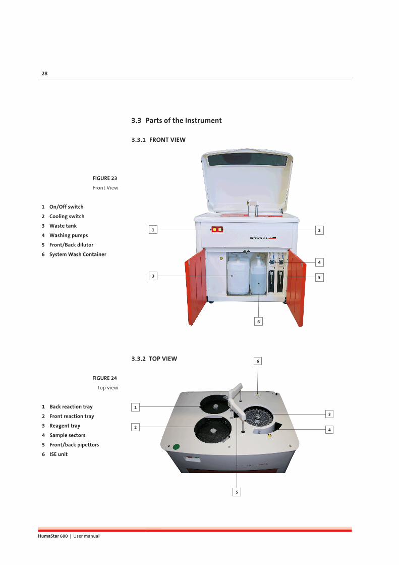
3.3 Parts of the Instrument
3.3.1 FRONT VIEW
1
3
6
5
4
2
3.3.2 TOP VIEW
2
5
1
4
3
6
1 On/Off switch
2 Cooling switch
3 Waste tank
4 Washing pumps
5 Front/Back dilutor
6 System Wash Container
FIGURE 23
Front View
1 Back reaction tray
2 Front reaction tray
3 Reagent tray
4 Sample sectors
5 Front/back pipettors
6 ISE unit
FIGURE 24
Top view

SyStem deScrIptIon 29
3.3.3 LEFT SIDE
1
2
3.3.4 SAMPLES AND SAMPLE SECTORS
Samples are loaded in a 19 positions sample sector. Continuous processing is
possible by the use of different bar-coded sample sectors, which the user can
insert or remove from sample tray during analysis. After loading the sector,
samples are immediately identified by direct barcode reading together with
sample sector type recognition. Five segments can be present simultaneously
in the sample tray, while up to 99 external (out of tray) sectors can be handled
by the system. STAT samples can be loaded in special high priority sectors to be
processed. Standard sector holds 19 bar-coded primary tubes or 19 non bar-cod-
ed cups and primary tubes. Special sector for 16 mm external diameter tubes is
available upon request.
Sectors can hold:
- micro cup: 0.5 ml
- standard cup: 1.5 ml
- primary tube: 5 ml (13 x 75 mm) 7 ml (13 x 100 mm) 10 ml (16 x 100 mm)
1 Service door for lamp
2 Electronics
FIGURE 25
FIGURE 26
Standard 19 positions
bar-coded sector

HumaStar 600 | User manual
30
3.3.5 REAGENTS
This HumaStar 600 has a cooled reagent tray where 25ml and 70ml containers
can be placed. The reagent tray includes integrated barcode reader for 24 inner
and 24 outer positions. Sample Diluent as well as cleaning solutions are also
placed in the reagent tray.
2
1
3.3.6 BARCODES
Maximum length for samples and reagents bar-codes, length is up to 20 alphanumeric characters. For details on labeling position, see figure (Data expressed in mm).Available codes for both sample barcodes or rea-gent barcodes, are Code 128 (NCCLS recommend-ed), UPC/EAN, Code 39, PARAF, Tri-Optic, 2 of 5 Codes, Codabar, Code 93, Code 11, MSI Plessey and Telepen.
3.3.7 CUVETTES
Samples and reagents are dispensed into a multiple cuvette strip. Each strip has
5 cuvettes. Reaction trays hold 16 cuvettes strips each, having the system a total
of 160 cuvettes.
FIGURE 27
Reagent tray and different
containers positions
1 Inner position
2 Outer position
FIGURE 28
Cuvettes strips

SyStem deScrIptIon 31
3.4 Software functions overviewThe software offers complete functionality to control the instrument and mon-
itor the overall operation which includes: samples and patients management,
control reagents, program tests, calibration of methods, perform QC tasks, reac-
tions follow up, statistic on results, among others.
3.4.1 LEVELS OF ACCESS
System has different levels of access depending of the type of user:
- Normal user
- Power user
- Supervisor
- Service
Select in main menu:
Select Power User, Supervisor or Service and introduce corresponding Password.
Normal User is the default operator, which can only operate the system. Power
User can define control sets and calibration sets. Several actions described in the
present manual will be available to Supervisor only. They will be indicated with
the symbol:
FIGURE 29
HumaStar 600 | User manual
32
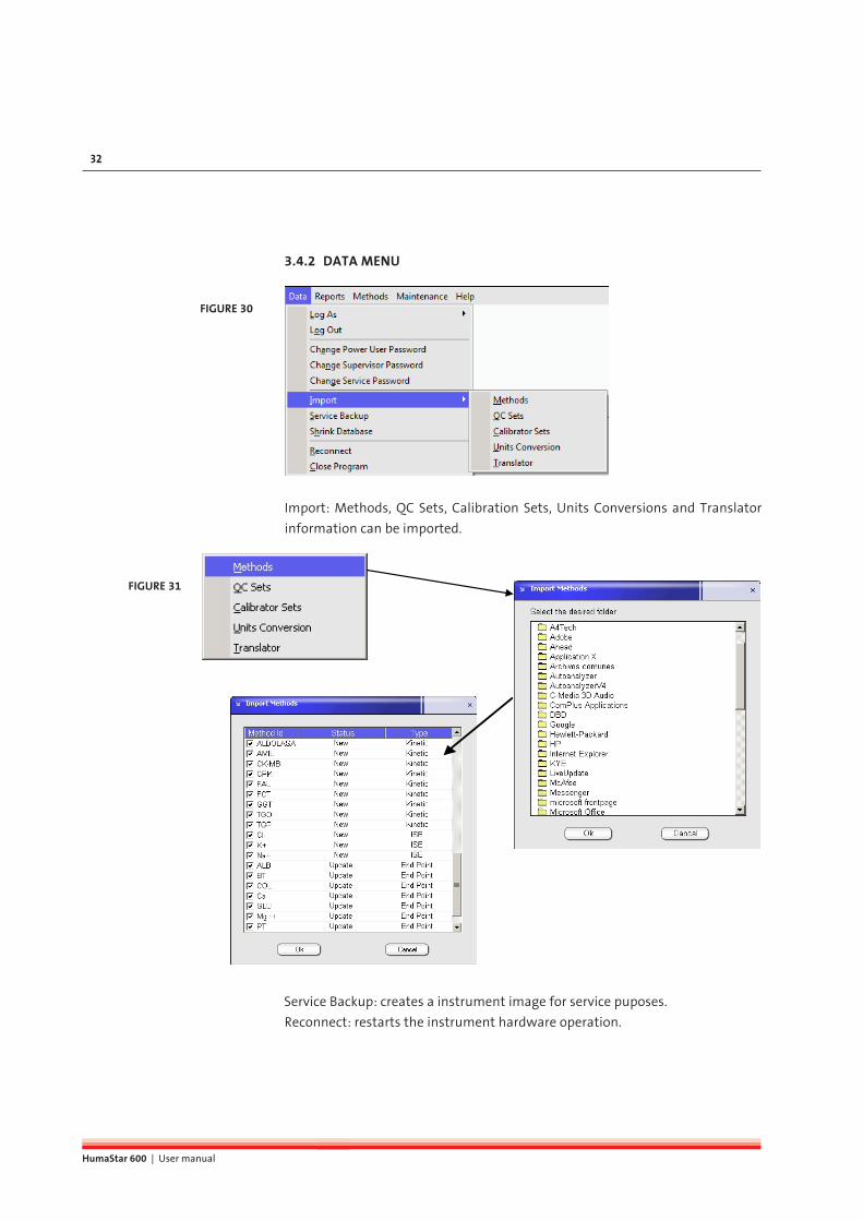
3.4.2 DATA MENU
Import: Methods, QC Sets, Calibration Sets, Units Conversions and Translator
information can be imported.
Service Backup: creates a instrument image for service puposes.
Reconnect: restarts the instrument hardware operation.
FIGURE 30
FIGURE 31

SyStem deScrIptIon 33
3.4.3 MAIN SCREEN
Main screen combines the information required for instrument operation, al-lowing user to check for instrument status and intervention (when required) at a glance.
1. Quick keys menu provide direct access to the major program functions.
Mainreview the information about current run.
Patientsset demographic data and relevant information.
Samplesdefine and order chemistry, ISE, coagulation and calculated tests.Testsreview pending reactions and analysis results.
Reagent traygraphically insert or remove reagents in tray.
Sample tray load new samples and graphically insert or remove sample sectors in tray.
FIGURE 32
Main Screen
1 Menu & Quick keys
2 Control bar
3 Running options
4 Operator request
5 System information
6 System messages
7 Transmission and operating
status
8 Calibration and reagent
status
9 Tests in progress
10 Current activities
11 Eventlog
12 ISE eventlog
TABLE 3

HumaStar 600 | User manual
34
Reactionsgraphically review cuvette usage and change cuvettes.
Calibrations request or browse pending acceptance, historic and in use calibrations.Blanksdefinition, review and acceptance of reagent blanks.
Quality Controlrequest or browse QC and handle statistical functions.
Methodsbrowse and edit definitions of methods.
2. Control bar gives control over mayor automatic routine operation.
Initializeinitialize all instrument units to home positions.
Startbegin the routine operation.
Stopstop the routine operation.
Suspend and restart dilutions.Allows to momentarily stopping dilutions for sample and STAT load.
3. Running options can be selected by operator according requirements which
depend on the moment and opportunity.
Non-stop operation: when this option is selected, the automatic cycle does not
finish and after sample process instrument is in stand-by condition. This option
is recommended when additional samples for processing are expected soon.
For daily work end, deselect the option.
Process ISE assays: disable if ISE samples are not expected for the day. This
option will not be shown if ISE module is not enabled.
Process Coagulation assays: disable if coagulation samples are not expect-
ed for the day. This option will not be shown, if coagulation assays are not
enabled.
TABLE 4

SyStem deScrIptIon 35
4. Operation request bar provides actions requested from instrument to com-
plete some operation such as confirmation of calibrations, confirmation on
sample results outside reference class limits, etc.
5. System information indicates the status of the system such as maintenance
tasks, system alerts and system logs.
6. System messages registers most relevant notes and warnings the instru-
ment operation can generate such as running out of sample and reagent or
qc results out of range.
7. Transmission and operating status displays communication condition be-
tween the computer and the instrument (Connecting, Online or Offline and
Operating) phase of operation (pre automatic, automatic and post automat-
ic) and LIS communication status.
8. Calibration and reagent status shows required reagent volumes to accom-
plish the processing of the on-tray samples as well as reagent availability.
With right click in mouse, options about operations are shown. In addition
Information on missing or expired reagents or calibrations are included.
9. Test in progress provide the list of pending tests.
10. Current activity and summary contain relevant information about the es-
timated time to complete the analysis, in progress, tests, next dispensing /
reading operation and remaining readings and dispenses as well as approx-
imate time of completion. The ISE status is displayed including reagent pack
content.
11. Eventlog views the current operation status and the details (initialization,
warming up, photometer calibration, cuvette check, cuvette blank, clot cali-
bration, cuvette washing, tip cleaning, system flush, intensive cuvette clean-
ing and intensive washer cleaning).
12. ISE eventlog views the current operation status of ISE (calibration, cleaning
and sample analysis) and the content of the reagent pack in percentage.

HumaStar 600 | User manual
36
3.4.4 QUICK KEY MENUS
Patients Menu:Data such as patient name, sample type, MD, diagnostic can be included. Also, the assignment of samples to each patient is performed.For calculated methods, if more than one sample is involved, all must be as-signed to the patient.The patients window can also be ac-cessed directly from samples window.
Samples Menu:Data from samples are added to this identification screen: Id, type, collec-tion date. Also, tests and number of replicates are incorporated.This load can be performed method by method or with the aid quick load and Profile screens.Patients can be defined with button located to the left of Patient Id.
Tests Menu:In this menu flagged and calculated results can be validated and/or re-peated.Test results can be printed or exported. Data storage of sample is unlimited.External results can be imported, to complete reports and calculated methods.
FIGURE 33
FIGURE 34
FIGURE 35

SyStem deScrIptIon 37
Reagent Tray Menu:From main menu it is possible to access the reagent tray programming to place or remove reagent or solutions.The second reagent of a given double re-agent method will be marked with a dot.Slide mouse over a reagent on the tray to obtain details on the right panel regard-ing reagent usage, available volume and pending reactions.Alternative views on reagents and cali-bration status are available Click apply to place vials in the tray.
Sample Tray Menu: A sample tray consists of five sectors 19 samples each.User can prepare and load additional sectors while instrument is operating. Primary tubes (light edging) and sec-ondary cups (bold edging) are available. Indication of colors: green - patient, or-ange - calibrator and purple - QC. Pos-tion strikethrough - no test requisition.
Reaction Tray Menu:Two buttons may be used to force a manual wash of the cuvettes or assert the replacement with new ones.When this operation is performed mo-tors are disengaged for easier operation and reconnected when done.
FIGURE 36
FIGURE 37
FIGURE 38

HumaStar 600 | User manual
38
Calibration Menu: Calibrations (single and multi-point) can be defined, performed and re-quested in this menu. A calibration set is a group of data de-fining tests, standard solutions and concentrations, allowing any combi-nation of multi-point and multi-cali-brators.Once defined, user can confirm pend-ing acceptance and browse in use or historic calibrations.
Reagent Blank Menu:Reagent blanks can be programmed in this menu.If they are within the automatic set up limits, they can be viewed and validat-ed.Historical results can be viewed and asessed in order to help reagent per-formance troubleshooting.
Quality Control Menu: QC material can be defined, performed, requested and validated in this menu.Levy-Jennings plot and Westgard mul-ti-rules are integrated to facilitate QC analysis.Twin QC is designed to relate high and low controls and get an accurate sta-tistical picture.Scheduler is designed to program con-trols at pre-set dates.
FIGURE 39
FIGURE 40
FIGURE 41

SyStem deScrIptIon 39
Method Definition Menu:New methods for the open channels can be set up by the supervisor.For the closed channels the limits and reference classes can be set.
FIGURE 42

HumaStar 600 | User manual
40

Get ready for operatIon 41
4 GET READY FOR OPERATIONComplete all the steps pointed out in the preceding chapter before continuing.
After verifying correct voltage settings, connect instrument and computer to
mains. The suggested startup sequence is:
Turn on instrument by pressing the red button on the front (see Figure 23).
Turn printer on.
Turn monitor on.
Turn computer on.
Turn reagent cooling system on by pressing green button lateral on the front
panel.
Once operating system is ready, activate the desktop‘s program icon to open the
HumaStar 600 program.
Accept the startup offered by the program, wait until operation finishes and
checks there are no visible warning messages on the screen. Otherwise, refer to
the troubleshooting chapter in this manual (see chapter 9 “Troubleshooting”).
4.1 Automatic operationLoad of method definitions, samples, analysis, profiles, etc. will be described in
detail in the next chapters. Here, the automatic measuring procedure will out-
lined.
Once samples and reagents are loaded, main window will show pending anal-
ysis, present and required reagents, and any other flagged condition. If one or
more samples are not listed, verify that samples are already positioned in sam-
ple tray and have been assigned.
Press the startup (key) button.The sytem conditions will be tested (system wash solution, Dilu-ent, clot detector, drain, pump tubing, syringes and blocks cycles). If any failure is detected, a warning will be issued at this time.Addional warning messages will be issued if maintenance pro-cedures have not been performed, if reagent blanks and calibra-tions are not valid and reagent volumes are to low or missing.
There are three cycles (shown in the transmission and operating status):
- Pre-automatic
- Automatic
- Post-automatic
Indication of operation in progress is shown in the screen in green color.
Pre-automatic cycle includes initialization, warming up and cuvette testing. Sys-
tem stops if more than 15 cuvettes are dirty in any tray and a warning is issued.
Do not change the computer
date or time during opera-
tion. The current operation will be
aborted and all in-progress reac-
tions will be lost.
Pending samples are shown
when samples are loaded on
tray and tray is already positioned
in instrument.

HumaStar 600 | User manual
42
No new sample entries are allowed in this period. A warning is issued if cooling
system is off or defective.
Automatic cycle includes reagent testing, integrity check, test analysis and cal-
culations. Also printouts can be generated in this period.
Post-automatic includes cuvette washing, probe cleaning and conditioning and
remaining printout.
If “Non Stop operation” has been selected, instrument remains idle until new
samples are introduced or the check box gets deselected.
4.1.1 CLOT DETECTOR
System counts with two clot detectors, one in each probe. They operate based
on a differential pressure principle.
Clot detector is installed in
Maintenance > Service > Parameters > Instrumentals > Others
Detectors automatically calibrated when automatic cycle starts. Several work-
ing conditions can be adjusted. They are defined in section 3.2.6.1:
Maintenance > Parameters > General
and modified with Supervisor privileges.
Operation of clot detectors can be enabled or disabled; if clot is detected, then
sample can be repeated or not.
The clot condition will be posted in the details of the sample result.
If sample is discarded, it will continue as in process and a message will be shown
in the window of messages in main menu. Clot detector version is posted in the
ErrorsLog.txt file.
routIne taSKS 43
5 ROUTINE TASKS
5.1 Reagents
5.1.1 REAGENT TRAY
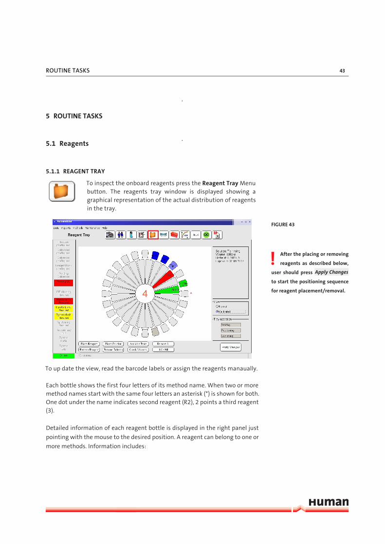
To inspect the onboard reagents press the Reagent Tray Menu button. The reagents tray window is displayed showing a graphical representation of the actual distribution of reagents in the tray.
To up date the view, read the barcode labels or assign the reagents manaually.
Each bottle shows the first four letters of its method name. When two or more method names start with the same four letters an asterisk (*) is shown for both. One dot under the name indicates second reagent (R2), 2 points a third reagent (3).
Detailed information of each reagent bottle is displayed in the right panel just
pointing with the mouse to the desired position. A reagent can belong to one or
more methods. Information includes:
After the placing or removing
reagents as described below,
user should press Apply Changes
to start the positioning sequence
for reagent placement/removal.
FIGURE 43

HumaStar 600 | User manual
44
- Method name
- Reagent number
- Lot number
- Bottle number
- Expiration date
- Available test number
- Available volume
- Pending tests
- Date reagent was placed onboard
- Expired date
It can be defined morethan one vial for each method.
If the first bottle is empty, the system will automatically switch to the next
bootle. The + in the right field indicates the second bottle. Multiple lots of the
same reagent can also be placed simutaneously on the reagent tray and sepa-
rately calibrated.
The colors used for positions allow to easily distinguishing as follows:
Green Reagent in position and in use (programmed samples)
Red Reagent not calibrated (only shown if “Calibrated” on the “View” is selected)
Blue Tip cleaning solutions, diluents and C-Clean
Yellow Reagent not in use
Light Gray Free position
Dark Gray Reagent not in use or removed
5.1.2 LOADING BARCODED REAGENTS, DILUENT AND CLEANING SOLUTIONS
Barcoded reagents, diluent and cleaning solutions can be randomly placed
into the reagent tray and will be checked and identified by pressing BCR All
button. To load barcoded reagents on a single position right click a suitable posi-
tion and pick Change & BCR check. A question mark symbol will be issued at the
specified position. Place the reagent on this position and press Apply Changes
to start the positioning sequence for reagent loading into the tray and barcode
reading. When a reagent is not included in the table of methods in use but its
code detected as located in the tray, it is automatically included in the methods
in use. If a reagent barcode label cannot be read a window will open and the
barcode can be insert manually.
TABLE 5

routIne taSKS 45
5.1.3 LOADING NON BARCODED REAGENTS AND SOLUTIONS
To define a reagent into the tray, press Place Reagent , then from the win-
dow select the reagent and desired position and press Ok or press Cancel or Esc
key to abort. Defined reagent position will exhibit dark gray color.
To define a diluent or cleaning solution into the tray press Place Solution and
proceed as above.
It is also possible to click on a position in the reagent tray display, right click
and pick Place Reagent, Place Diluent Solution, Place Cleaning Solution options.
Select the desired reagent or solution and press Ok when done or Cancel to
abort.
Press Apply Changes and the reagent tray turn the selected position to the
bottle insert/remove area. Message will be: Put CREA-1 in position 2.
Open the cover, insert the reagent or solution bottle and close the cover.
Then press Ok to confirm the operation.
If more than one reagent is loaded, several messages will be shown in sequence.
5.1.4 REMOVING REAGENTS AND SOLUTIONS
To remove reagent/s from the tray, press Remove Reagent , select one or
more reagent/s or desired positions. Press Ok when done or Cancel to abort.
After the placing or removing
reagents as described below,
press Apply Changes to start the
positioning sequence for vial
placement/removal.
FIGURE 44
If Apply Changes is not
pressed, selected positions
will remain in dark gray color and
cannot be used.
HumaStar 600 | User manual
46
5.1.5 REFILLING REAGENT BOTTLES (ONLY FOR OPEN CHANNELS)
When pressing right button over a given reagent, menu will include a Refill
option. Once the Apply Changes button is pressed, tray will move in the desired
reagent position.
Several reagent vials can be refilled with this procedure: when Apply Changes
is pressed tray will sequentially position in all the defined refilling reagents. The
dilution restart is automatic.
5.1.6 METHOD ASSIGNMENT TO TRAYS
Methods can be assigned for processing either in the front or back reaction tray.
Only those methods defined as Methods in Use can be assigned to a tray. De-
fault assignment is to the front tray if not otherweise specified at the applica-
tion protocol of the method.
For tray assignment, follow:
There is a unique feature consisting an automatic reassignment of methods to
the trays, according historic statistics and with the criterion of minimum total
analysis time. Automatic reassignment does not include interfering or inter-
fered methods. Interfered methods are posted in red color and consecutive use
is avoided either at the arm or cuvette sequence level. To apply it, first Refresh
the desired period for statistical analysis and then press the Automatic button.
Moved methods will be indicated with an X. Press Apply to save the changes.
5.2 SamplesSamples can be loaded directly or associated to patients. Tests and calculated
methods (which including a chemistry measurement) are assigned to samples
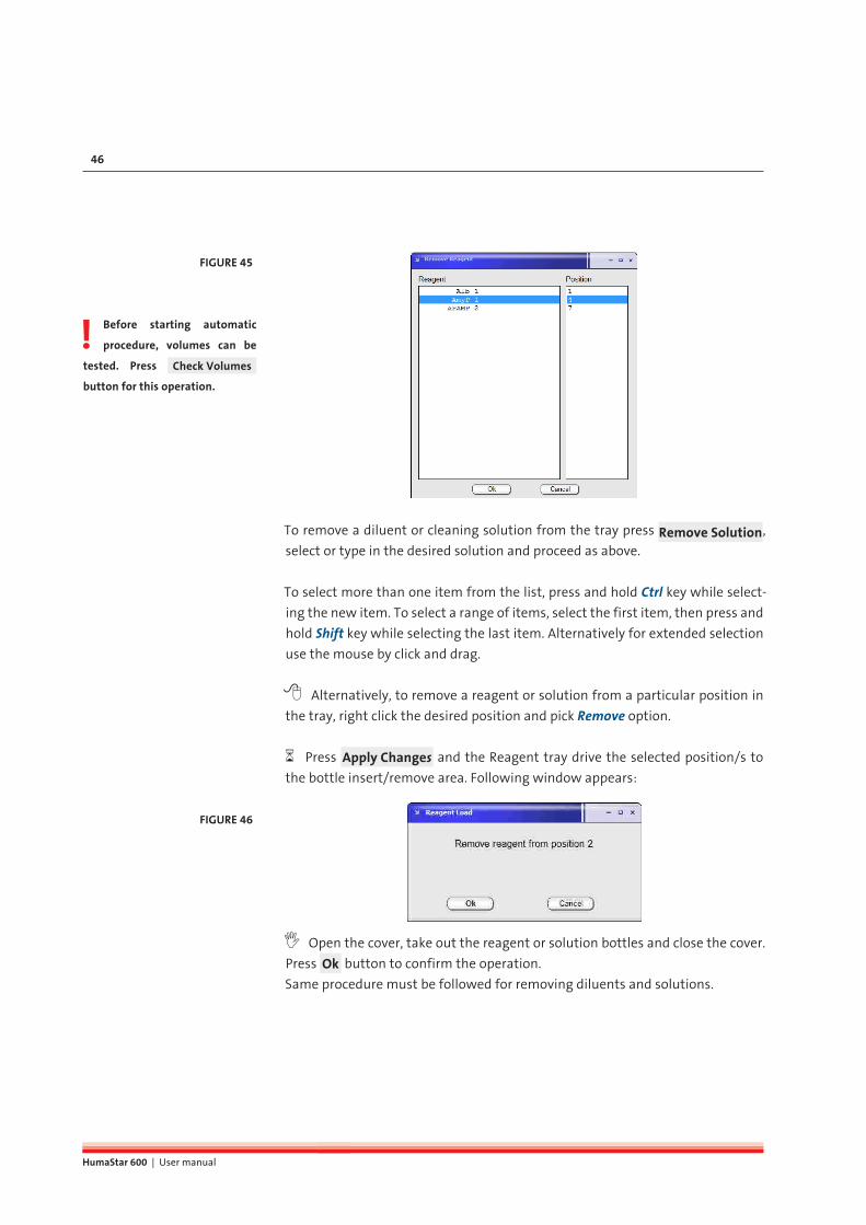
Before starting automatic
procedure, volumes can be
tested. Press Check Volumes
button for this operation.
FIGURE 47
To remove a diluent or cleaning solution from the tray press Remove Solution,
select or type in the desired solution and proceed as above.
To select more than one item from the list, press and hold Ctrl key while select-
ing the new item. To select a range of items, select the first item, then press and
hold Shift key while selecting the last item. Alternatively for extended selection
use the mouse by click and drag.
Alternatively, to remove a reagent or solution from a particular position in
the tray, right click the desired position and pick Remove option.
Press Apply Changes and the Reagent tray drive the selected position/s to
the bottle insert/remove area. Following window appears:
Open the cover, take out the reagent or solution bottles and close the cover.
Press Ok button to confirm the operation.
Same procedure must be followed for removing diluents and solutions.
FIGURE 45
FIGURE 46

routIne taSKS 47
5.1.5 REFILLING REAGENT BOTTLES (ONLY FOR OPEN CHANNELS)
When pressing right button over a given reagent, menu will include a Refill
option. Once the Apply Changes button is pressed, tray will move in the desired
reagent position.
Several reagent vials can be refilled with this procedure: when Apply Changes
is pressed tray will sequentially position in all the defined refilling reagents. The
dilution restart is automatic.
5.1.6 METHOD ASSIGNMENT TO TRAYS
Methods can be assigned for processing either in the front or back reaction tray.
Only those methods defined as Methods in Use can be assigned to a tray. De-
fault assignment is to the front tray if not otherweise specified at the applica-
tion protocol of the method.
For tray assignment, follow:
There is a unique feature consisting an automatic reassignment of methods to
the trays, according historic statistics and with the criterion of minimum total
analysis time. Automatic reassignment does not include interfering or inter-
fered methods. Interfered methods are posted in red color and consecutive use
is avoided either at the arm or cuvette sequence level. To apply it, first Refresh
the desired period for statistical analysis and then press the Automatic button.
Moved methods will be indicated with an X. Press Apply to save the changes.
5.2 SamplesSamples can be loaded directly or associated to patients. Tests and calculated
methods (which including a chemistry measurement) are assigned to samples
Before starting automatic
procedure, volumes can be
tested. Press Check Volumes
button for this operation.
FIGURE 47

HumaStar 600 | User manual
48
and not directly to patients. External methods and calculated methods are al-
ways assigned to patients.
5.2.1 WORKING WITH PATIENTS
To create or work with patients press the Patient Menu button.
1. Patient Information are shown at the Patient report. All fields are automat-
ically confirmed and only the Patient Id is mandatory. Patient Id cannot be
modified, only option is to delete the entry.
2. Display of all defined patients.
3. Display of all samples defined for the patient Id shown above.
4. Display of all tests defined for the patient Id shown above.
FIGURE 48

routIne taSKS 49
5.2.2 DEFINING SAMPLE DATA AND TESTS
To define new samples or request tests for a given sample, press the Samples Menu button.
In this menu it is possible to add, edit, delete and copy samples and correspond-
ing tests.
1. Sample Information including Id, type, reference class, collection date, pri-
ority (STAT), Patient Id (can be predefined in the patient menu or generated
directly using the the button next to the patient Id field) and the manuall
dilution factor.
2. Programmed tests for the sample Id shown above.
3. Quick load to add tests.
4. Predefined profiles to add multiple tests. To define a profile see section 5.9.1.
5. Samples can be placed immediatley on a sector.
6. Display of all programmed samples.
To edit information for an already defined sample, select the sample from
the list on the right and press Edit button, add or change information and then
press Browse (depending on the mode the function of the F8 button is Edit or
Browse) to switch to navigation mode.
Press New button to define a new sample. Sample ID number will be counted
up automatically, but can also be changed manually. To generate a patient di-
FIGURE 49

HumaStar 600 | User manual
50
rectly from this side, press the button located right of the patient Id. Input all
necessary information and then press Browse to switch to the navigation mode.
To request new tests for a sample, first select the sample from the list on the
right window and then either:
Press Add Test to choose a single test from the window (shown below).
Alternatively, double click on the desired methods or profiles, in Quick load
panel or Profiles panel.
When replicates of the same sample are required, use the Add Test button or
press method ID several times in the Quick load window.
Without requiring its introduction in a STAT sector, any sample can be defined
as STAT at all times by checking Stat Sample . This will enhance its priority over
other samples. To place samples directly in a sector, select the sample number
and press Place . A new window opens, select the sector and position number
and press Ok to save or Cancel to abort.
5.2.3 REMOVING A SAMPLE
To remove a sample from the list press Delete :
FIGURE 50
FIGURE 51

routIne taSKS 51
Then press Yes to confirm or No to abort.
Delete All button will remove all samples from the window on the right side.
5.2.4 REMOVING TESTS
To remove tests from a sample, first select the sample from the list on the
right window and then press Delete Test . Select tests to remove from the list.
Press Ok when done or Cancel to abort.
5.2.5 COPY DATA
New samples can be generated by copying data from another sample. Press
Copy button and a window will open for selection of number of replicates.
New ID numbers will be correlative to the original one. If alphabetic characters
are present in the ID, new digits are added.
FIGURE 52

HumaStar 600 | User manual
52
5.2.6 LOADING SAMPLES
To manage samples and sample sectors press the Sample Tray button.
To review a sample sector content, just point the mouse over the desired
sector on the tray. The complete list of samples will be displayed on the right
panel.
To review a sector which is not placed in the tray, select the sector number
on the left side. The selected sector will be displayed in the lower panel. Point
the mouse over the desired position and all sample/test information will be dis-
played on the right panel.
Data are also available for printout in
Reports > Input Tray
5.2.6.1 Loading barcoded samples
Be sure that barcode reading is enabled. Access for enabling is in
Maintenance > Parameters > Software (Supervisor only)
Use Secondary to set a given
sector for use with cups vials,
press Primary to return to prima-
ry vial mode or press right mouse
button on a given position.
Use Data > Log as supervisor
and then Maintenance >
Parameters > Use to set the sec-
ondary sample vial section before
using this option.
FIGURE 53

routIne taSKS 53
Once a sector is loaded, codes are read for all samples, if samples are not present,
reader will reach code located on the rear of sector. Its reading is equivalent to
“sample is not present”.
When Sample ID is recognized, vial position will match defined sample. If sam-
ple ID was not defined in advance, new sample entry is created with recognized
ID but user will have to complete data.
If one or more codes are not read by the barcode, samples still can be measured;
a window will open containing the detected non coded samples and operator
can accept or reject them.
5.2.6.2 Loading non barcoded samples, calibrators and controls
To place a sample, calibrator or control in a sector, first click in a sector ID
from the list of sectors and then press Place Sample . Chose from Samples, Cali-
brators or Controls tab, and select the desired sample and sector position. Press
Place to confirm selection, and then repeat the operation or press Exit to re-
turn. Press Place All to fill all the free positions in sector with available samples
in a sequential order.
5.2.7 REMOVING A SAMPLE
To remove samples from a sector, first click on a sector ID from the list of
sectors and then press Remove Sample . Select the sample IDs or sector posi-
tions to remove. Press Ok when done or Cancel to abort.
To select more than one item from the list, press and hold Ctrl key while select-
ing the new item. To select a range of items, select the first item, then press and
hold Shift key while selecting the last item. Alternatively, to extend the selection
use the mouse to click and drag.
5.2.8 PLACING A SECTOR ON THE TRAY
To place a sector on the tray, first click on a sector ID from the sectors list,
then press Load Sector .
The sample tray drives the first available sector position to the sample sector
insertion/removal area.
Remove the old sector if any, place the new one.
Note that non barcoded sam-
ples have to be assigned to a
sector position before inserted to
a sample tray.
To allow samples to be added
or removed the sector must
be out of the tray. No samples can
be added to or removed from an
on-tray sector.
When sectors are coded for
BCR reading, it is not neces-
sary to declare the sector number,
user will be prompted to put any
sector in the first available posi-
tion. If sector is not coded user
must specify any non-used sector
position.

HumaStar 600 | User manual
54
When done press Ok button to confirm the operation. Don’t press Ok before
you have pyhsically placed the sector in the sample tray. Right after the Ok click,
the tray will start to move.
5.2.9 REMOVING A SECTOR
To remove a sector from the tray, first click on the sector ID from the list of
sectors or click on an on-tray sector, and then press Remove Sector .
The sample tray drives the selected sector position to the sample sector in-
sertion/removal area.
Remove the sector.
When done press Ok button to confirm the operation.
5.2.10 LOADING A STAT
A STAT sample placed on a STAT sector or STAT position has priority over all oth-
er samples. For sector definition, select
Data > Log as supervisor and then Maintenance > Parameters > Sector definition
Define a new sector with a number and assign the STAT condition. Be sure that
number is not already defined in the column to the right. If so, first delete defi-
nition and then re-enter new definition, including STAT condition. To give a
sample a STAT priority on a routine sector, select the Stat Sample option in the
Sample menu.
routIne taSKS 55
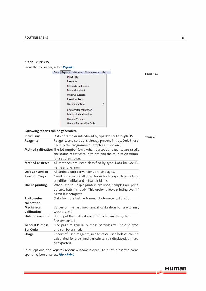
5.2.11 REPORTS
From the menu bar, select Reports.
Following reports can be generated:
Input Tray Data of samples introduced by operator or through LIS.Reagents Reagents and solutions already present in tray. Only those
used by the programmed samples are shown.Method calibration The lot number (only when barcoded reagents are used),
the status of active calibrations and the calibration formu-la used are shown.
Method abstract All methods are listed classified by type. Data include ID, name and version.
Unit Conversion All defined unit conversions are displayed.Reaction Trays Cuvette status for all cuvettes in both trays. Data include
condition, initial and actual air blank.Online printing When laser or inkjet printers are used, samples are print-
ed once batch is ready. This option allows printing even if batch is incomplete.
Photometer calibration
Data from the last performed photometer calibration.
Mechanical Calibration
Values of the last mechanical calibration for trays, arm, washers, etc.
Historic versions History of the method versions loaded on the system.See section 6.1.
General Purpose Bar Code
One page of general purpose barcodes will be displayed and can be printed.
Usage Report of used reagents, run tests or used bottles can be calculated for a defined periode can be displayed, printed or exported.
In all options, the Report Preview window is open. To print, press the corre-sponding icon or select File > Print.
FIGURE 54
TABLE 6

HumaStar 600 | User manual
56
5.3 Test results
To inspect sample results press the Test Menu button.
In the Tests Menu following options are available:
Pending All non-processed and in-process tests are shown.Pending Acceptance Results can be accepted, rejected or a rerun can be trig-
gered (normal or diluted).External Values from another source, usually required for a calcu-
lated test, can be insert.Calculated Calculated results can be checked and confirmed.Done Results can be reviewed sorted by last name, sample Id
or patient Id. Using the Print button results and patient reports can be printed (refer to section 5.3.3).Press Export and results will be exported to a csv file which can be imported to excel. To see the detail infor-mation of a result (raw data) select a result and press Detail.
Cumulative Historic Results can be stored permanently in folders named with year and month. The button Cuvettes is for Service use only.
FIGURE 55
TABLE 7

routIne taSKS 57
5.3.1 ACCEPTANCE OF RESULTS
To confirm the result for a given test open the Pending Acceptance Menu
, then select the desired sample test from the list and then press Accept . Press
Reject to reject the test result. To reprocess the reaction just press Rerun or
Diluted Replicate if additional dilution could be useful for confirmation of result.
A dilution factor can be introduced.
5.3.2 REFLEX TESTS
Reflex tests are those automatically launched when a given test is out of deter-
mined limits. Condition for the reflex test launch can be relative to fixed values
or to a reference class.
5.3.3 PRINTOUT OF RESULTS
Results can be printed in different ways and operator has full control on the
display of the results. This is a post run operation and is not related to the online
printing controlled by
Maintenance > Parameter > Software.
Press the Print button from Test Menu Done screen and following submenu opens:
Printing can be performed on all samples, some filtered or selected. Se-
lection can be made by pressing Ctrl Key while pointer is pressed on selected
samples. A range is selected by pressing mouse on the first and then pressing
Shift key and pointing to the last one of the desired ranges.
There are three types of reports: Continuous - samples are printed out one after
the other; 3 per page - according a fixed report format; Custom - according re-
port made by use of the Report Format Generator, refer to section 3.2.7.2 Modify
reports.
5.3.4 CUVETTE
Report use for service engineers only.
FIGURE 56

HumaStar 600 | User manual
58
5.4 Calibration
To enter a new calibration or define a calibrator set, press Calibration Menu button.
In the Calibration Menu following options are available:
Calibration New calibrations can be requested or requested calibrations can be deleted.
Pending All non-processed and in-process calibrations are shown.Pending Acceptance
In case the manual acceptance is programmed and/or the reac-tion is flagged the calibration has to be manually accepted. Use the reject function to rerun the calibration and Detail to see the reaction measurements.
In Use Actual calibrations can be reviewed, deleted or printedHistoric Former calibrations can be reviewed or reactivated for the ac-
tual use. The calibration is shown in the In Use screen with a warning and the results should be flagged (function “Check Re-used Calibration” in Maintenance>Parameters>Software>Gen-eral has to be enabled). WARNING this funtion must be cau-tiously used, never mix calibrations and actual reagent lots.
ISE Actual and historic ISE calibrations can be reviewed.Automatic calibration
Calibrator Lot numbers can be defined for the use in the next automatic calibration, this can be in advance.
Calibrator Set Single and Multipoint calibrators can be set up, modified or deleted.
FIGURE 57
TABLE 8

routIne taSKS 59
5.4.1 CALIBRATOR SETS
Calibrators for single or mutipoint calibrations are defined for methods. This
calibrators can contain a single- or multiple methods. Following information are
included in the sets: calibrator set Id, Lot number, number of vials, tests, mean
values and automatic dilution if necessary. Once the calibrator sets are created
it is easy to request calibrations in routine. Only Supervisor and Power user can
define a new calibrator set.
5.4.1.1 Defining a calibrator set
Open the Calibration Menu and select on the left side the Calibrator Set
Submenu.
To edit the definition of an already defined calibrator set, first select the
calibrator set from the list on the right and then press Edit .
To enter or define a new calibrator set, press New . Assign a calibrator Set Id and
the corresponding lot number of the calibrator. In case of a multipoint calibra-
tion insert the number of vials, default it is on 1 for a single point calibration. To
add a new test to the calibrator set press Add Test .
FIGURE 58

HumaStar 600 | User manual
60
Select the method from the list or type in the method Id. Select the calibrator
vial number, concentration and the number of replicates and press Add . It is
recommended to use at least 2 replicates for each calibration point.
Press Ok when done or Cancel to abort. For a multi calibrator repeat this steps
for each test/method.
To remove a method from the calibrator set, select the test and press Delete Test .
Once no further modifications are required for the calibrator set, press Ok to
finish or Cancel to abort.
Once tests are loaded in the grid, concentration values can be edited at all times.
5.4.1.2 Removing a calibrator set
To remove a calibrator set from the list, select the calibrator set from the list
on the right and press Delete . Press Yes to confirm or No to abort.
5.4.1.3 Automatic Dilutions
It is possible to dilute a single calibrator for a multi point calibration. When
Add Test is pressed, the following screen will show up:
FIGURE 59

routIne taSKS 61
The window for automatic Dilutions will show the number of points that inte-
grate the curve. The Serial factor indicates the dilution factor: a factor of 2 will
define the concentration as 1/2, 1/4, 1/8, etc.; a factor of 3 will define concen-
trations as 1/3; 1/9; 1/27; etc. The set optionally can include the mother solu-
tion (1:1) and the blank. If included, they are within the defined number (i.e. Di-
lution # of 6 it is 1:1, 1:2, 1:4, 1:8, 1:16 and blank). The concentration of mother
solution is defined in the Vial sector. A minimum of 2 standards and a maximum
of 10 standards are accepted.
5.4.2 REQUESTING A CALIBRATION
Open the Calibration Menu and select on the left side the Calibration Submenu.
FIGURE 60
The instrument will automat-
ically adjust the number of
times this procedure is repeated
for completing all requested cali-
brators and replicates.

HumaStar 600 | User manual
62
To request a new calibration based on a calibrator set, press New .
Select or type in the desired calibrator set. Edit the calibration ID if necessary
and check at least one test you want the calibration to take into account.
Press Ok when done or Cancel to abort.
To request at a later time another method from the calibrator set, select the cali-
bration from the list on the right and press Add Test . Check one or more tests
you want to add. Define the number of replicates. They can be equal or different
for different tests. Press Ok when done or Cancel to abort.
FIGURE 61
FIGURE 62

routIne taSKS 63
5.4.3 ORDERING A CALIBRATION
To load the calibrator‘s cups on the instrument sample tray refer to section 5.2.6.
5.4.4 CALIBRATION ACCEPTANCE
Open the Calibration Menu and select on the left side the Pending Accept-
ance Submenu. Following window will be displayed:
To confirm a calibration test result, select the desired method and the calibra-
tion curve including replicates will be displayed.
Before acceptance of a calibration indivdual replicates can be disabled. Unselect
the box in front of a replicate which should be excluded from the calibration
curve calculation.
Column to the right of each function will show the least squares adjusting val-
ue. Select function with minimum value unless some special feature is required.
Experiment deselecting one or more standards and observe recalculated values.
Press Accept once the calibration curve and values are as desired. In this case,
at least one value for each vial must be selected.
Press Reject to mark the calibration as unusable.
5.4.4.1 Flagged results
Press Detail to expand the detailed area for the selected reaction. This
panel points out active flags. Results may be flagged if validity limits, duplica-
FIGURE 63

HumaStar 600 | User manual
64
tion limits or reference class limits and so on are exceeded. Both low and high
limits can be set independently (see chapter 6.2.4 for details).
5.4.4.2 Calculations
For the calibration curve calculation following formulas are available:
Linear Abs = Ax + B
Multilinear Cx = C1s+(C2s-C1s)*(Sx-S1s)/(S2s-S1s) linear interpolation between consecutive standards
Spline C = a*A3 + b*A2 + c*A + d where consecutive 3d degree polynomials joining consecutive data
Sigmoid Abs = L + ((H – L)/(1 + exp(-(Conc – a)/b)))where H, L , a and b are automatic adjusting parameters
Logit4 Abs = R + (K/(1 + exp(-(a+b*ln(Conc))))) where K, a,b are automatic adjusting parameters
Logit5 Abs = R + (K/(1 + exp(-(a+b*ln(Conc) + c* Conc)))) where K, a,b,c are automatic adjusting parameters
Calibration fit parameter is shown in all cases.
If curve is forced to pass through zero, functions logit 4 and logit 5 will diverge
because of the logarithm function and will not be shown.
Logit5 requires a minimum of 5 standards; logit4 requires a minimum of 4 stand-
ards; sigmoid and multi linear functions require a minimum of 3 standards.
5.4.5 AUTOMATIC CALIBRATION
It is possible to define for each method, which Calibrator Set will be used in
the next calibration, once the present one is expired, deleted or a lot number
changed. This set can also be “Run in advance” and be ready several hours be-
fore the present calibration expires. Open the Calibration Menu and select on
the left side the Automatic Calibration Submenu.
TABLE 9

routIne taSKS 65
Select from the right window the desired Method-Calibration Set combination
and press the Add button. With the corresponding button the Run in ad-
vance interval is also fixed. This interval is checked every 15 minutes when the
system is running, it is in the “don’t stop” mode or during start operation.
5.5 Reagent Blank
Reagent Blank can be measured in the automatic procedure or directly from the Reagent Blank Menu.
When the automatic measurement starts, blanks are requested for the follow-
ing reasons:
1. No reagent blank available
2. It expired
3. Reagent was removed, refilled or changed
4. A new reagent lot was introduced
In that case, a window opens with the list of required blanks. User can include
the number of required replicates.
FIGURE 64

HumaStar 600 | User manual
66
In the Reagent Blank Menu following options are available:
Blanks New reagent blank can be requested or requested reagent blanks can be deleted.
Pending Acceptance
In case the manual acceptance is programmed and/or the reac-tion is flagged the reagent blank has to be manually accepted. When replicates are taken, they can be accepted or reject indi-vidually. The final result is the average of all accepted values. Use the reject function to rerun the reagent blank.
In Use Actual reagent blanks can be reviewed, deleted or printed.
Historic Former reagent blanks can be reviewed or printed.
FIGURE 65

routIne taSKS 67
To request a reagent blank press the New button in the Blanks Submenu.
Table shows last measured absorbance and its date. By checking and adding the
number of replicates, blanks can be measured.
5.6 Quality controlQuality control system is based on the use of Control Sets. A control set is a vial
of a given brand and lot containing all the desired analytes with their respective
admissible ranges. Control sets from different brands and levels can be defined.
Once the Control Set is defined, it is daily used by defining a Control and select-
ing from the set the desired analytes and number of replicates. New Control
Sets must be defined when a new lot is available and new admissible ranges
are defined.
FIGURE 66

HumaStar 600 | User manual
68
To add, edit or request a quality control, press the Quality Control Menu button.
In the Quality Control Menu following options are available:
Controls New control for specific tests can be requested or requested controls/tests can be deleted.
Pending All non-processed and in-process controls are shown.
Statistics A statistic of QC samples of a special period can be dis-played or printed.
Done Controls mesured in a specific time frame can be dis-played. Tests can be deleted (only out of the statistics), a rerun can be requested, statistics can be displayed and the results can be printed or exported.
Cumulative Historic Archived QC results can be reviewed.
Twin QC Quality control results will be displayed in a Youden Plot.
Scheduler QC actions can be programmed in advance for the com-plete week.
Control Set Single and Multi controls can be set up, modified or deleted.
FIGURE 67

routIne taSKS 69
5.6.1 CREATING A CONTROL SET
Open the Quality Control Menu and select on the left side the Control Set
Submenu.
To define a new control set, press New .
FIGURE 68
FIGURE 69

HumaStar 600 | User manual
70
Define control set id, introduce lot number and expiration date for traceability
purposes and filtering options.
To edit the definition of a already defined control set and select the control set
from the list on the right and then press Edit .
To add a new test to the control set press Add Test and select or type in the
method ID. Then type in the concentration range for that method and press
Ok to add the test or Cancel to abort. To remove a method from the control
set, press Delete Test .
Define the number of default Replicas for each test within each control set.
This number will be used every time the control set is used or scheduled.
Repeat this operation for each required test on the profile. Then press Ok to
finish or Cancel to abort.
Alternatively, double click on the Quick load list to add tests in the control set
and type the values in the corresponding fields. Mean values are calculated
automatically.
Once tests are loaded in the grid, concentration limits can be edited at all times.
To remove a control set from the list, first select the control profile from the
list on the right and then press Delete . Press Yes to confirm or No to abort.
Delete All button will remove all control sets.

routIne taSKS 71
5.6.2 REQUESTING A CONTROL
Open the Quality Control Menu and select on the left side the Submenu
Controls.
To request a control based on a control set press New .
Select the desired control set in the list on the left side. Tick at least one box in
front of a test name to select them and enter the number of replicates. Repli-
cates can be set individually per test with a maximum value of 10. Push the blue
box above in order to select or deselect all tests. Control Id is automatically gen-
FIGURE 70
FIGURE 71

HumaStar 600 | User manual
72
erated by using the Control Set Name. This Id can be modified at the moment of
generation but not at a later time.
New tests included in the Control Set can be added later using the Control sub-
menu: Select the control from the list on the right and press Add Test . Check
one or more tests that you want to add. Press Ok when done or Cancel to
abort.
To remove a test from the control press Delete Test . Select one or more tests
from the list. Press Ok to confirm or Cancel to abort.
5.6.3 PROCESSING A CONTROL
Once the control has been requested, load it in a vial and place in the instrument
as indicated in 5.2.6.
If the barcode reading procedure is performed and a control set is recognized, it
will be associated with any pending action already defined in the scheduler. If
not programmed in scheduler, no action will be taken on the control.
Use the Pending Submenu tests to review non-processed (idle) or in-progress
control tests.
User must consider that test results may stay idle if the system operation runs
out of reagent or control sample.
Use the Cumulative Historic Submenu to review data already stored in previous
runs. They will be organized in directories, where results of each month are au-
tomatically stored.
5.6.4 PROCESSED CONTROLS
To display processed Controls, open the Quality Control Menu and select on the
left side the Submenu Done.

routIne taSKS 73
In the upper section following filter options are available to display the desired
data:
Date (From - To)
Index (From - To)
Test Id
Lot Number
Control Id
Last (number of displayed results)
Date selectors show calendar for simple selection. All results are indexed and in-
dex is shown at the beginning of each column. Selectors can be used separately
or together. Selectors act as logical AND which allows refining the selection. The
result are dislayed including the low and high limits and they are marked in the
last column by an X when they are out of range.
Select a result and press the Details >> button to show extended information.
The raw data curve is displayed including the information about dilution factor,
reagent- and calibrator lot numbers. Press the << Plot button to display the re-
sults in a graph.
FIGURE 72

HumaStar 600 | User manual
74
Select a single result and press Rerun test to repeat the measurement. Press
the Print button to print the displayed results or Export to export the dis-
played results into a csv file.
Press the Statistics button to display a Levy-Jennings graph with relvant statis-
tical data and the Westgard rules violations, as shown below.
To print the displayed data, press the Print button. Before the print will be
displayed an opportunity to enter comments is given.
To exclude results from the statistics press the Results button. Press Close to
get back to the main window.
To view additional statistic press the Statistics Submenu button on the left side.
FIGURE 73
FIGURE 74

routIne taSKS 75
The results of the day will be displayed including the Westgard rules violation,
the assigned- and cumulative values. CV and SD are calculated if multiple meas-
urements are available.
Press Detail to display the single measurements. To exclude a results form
the statistics, select a result in the table on the left side, press Exclude and
insert a reason. The point will be removed from the graph and the calulation on
the main screen will be recalculated. The result is not deleted it can be included
again. To get back to the main screen, press Details again.
The red color indicates that the results are out of the assigned range or out of
WR (Westgardrules), green they are inside the assigned range. Additionaly, su-
pervisor can define which Westgard Rule will be applicable to this window from
Maintenance > Parameters > Software > OC tab.
5.7 Twin QCTwin QC operates on quality controls already performed and its purpose is re-
lating high and low controls and getting Youden plots and correlated Levy-Jen-
nings plots.
Youden Plot is a bi-dimensional plot where correlated data for two-level systems
or normal/abnormal data, taken in the same run are represented.
To display Twin QC , open the Quality Control Menu and select on the left side
the Submenu Twin QC.
FIGURE 75

HumaStar 600 | User manual
76
For operation, proceed as follows:
1. Define a Twin set. Press the Twin definition tab:
- Define a name which defines a given set of controls.
- Select the prefix for the high and low (or normal/abnormal) levels. It is im-
portant that they must coincide with the Control Vial Id (given in the Control
Set).
2. Link the samples. Press the Link Samples tab:
- Select the Twin Id.
- Press the Refresh Lists button to display all controls which correspond to
high and low level.
- Select for each level a control and press Link .
FIGURE 76
Coupled quality control is a
useful tool if both controls of
each pair are taken in similar
conditions. Observe index num-
ber, date, time and lot number
and verify that data were taken in
close conditions.
FIGURE 77

routIne taSKS 77
3. To display the linked Twin QC press Statistics tab.
- Linked entries will appear in the upper (Linked) window. For identification
purposes entries will be shown in alternate colors yellow and white. Every
entry can be unlinked by selecting one of both components and pressing the
Unlink button.
- Select the desired method, and the initial and final date for the study.
- Press the Youden Plot button to display the plot.
FIGURE 78
FIGURE 79

HumaStar 600 | User manual
78
- This statistical technique involves both normal and abnormal controls and
graphically helps to differentiate between systematic and random errors.
The square represents +/- 3 standard deviations for both controls. Red circle
represents SQR(SD12 + SD22) = 2. The two median lines (vertical and horizon-
tal axis) represent zero error normal and abnormal controls, respectively. The
intersection of both median lines is called the Manhattan Median. The dia-
gonal through the Manhattan Medial is the ideal location, high correlation
position for the pairs. Points near the line but outside the 2SD circle indicate
a systematic error. Points that lie far from the 45-degree reference line indi-
cate a random error.
- Press the Levey-Jennings Plot button and follwing graph will be displa-
yed:
5.7.1 QC SCHEDULER
To display and program the QC Scheduler, open the Quality Control Menu and
select on the left side the Submenu Scheduler.
FIGURE 80

routIne taSKS 79
QC scheduler allows programming in advance all the QC actions on a weekly
basis.
The defined controls are shown in the lower part of the screen. They must be
dragged and dropped in the desired hour and day and then saved by pressing
the Save button. They are immediately in the Pending QC status shown in red
in the left side of the screen. They can be removed by dragging and dropping on
the trash symbol.
They remain as pending until they are in the list of programmed samples and all
the included reactions are processed. The Activity shows the next programmed
action on each control, but they are due immediately after programming. If only
some test are pending, warning flag will be in yellow color.
FIGURE 81
FIGURE 82

HumaStar 600 | User manual
80
5.8 Working with LISThe use of information management systems is widespread in hospitals and
health centres where data must be collected from different kinds of instru-
ments. The LIS (or LIMS) capability provides a reliable way for information inter-
change through ASTM E1381 and E1394 standards.
Refer to the LIS integration guide for more information.
5.9 Definition and use of sample profilesSample profiles are useful for ordering predefined patterns of tests.
5.9.1 DEFINING A SAMPLE PROFILE
To define a new sample profile, press New .
Enter a Profile Id and use the Quick load to add test by double click the test
name. Tests can also be added or deleted using the Add Test or Delete Test
button.
To edit a existing profile, select the name from the list on the right side and press
Edit . Tests can be added or deleted as described above.
Repeat this operation for each required test on the profile. Then press Ok to
finish or Cancel to abort.
5.9.1.1 Removing a sample profileTo remove a sample profile from the list, first select the sample profile from the list on the right and then press Delete . Press Yes to confirm or No to abort.
FIGURE 83

defInItIon of metHodS 81
6 DEFINITION OF METHODS
For open channels only!
There are four mayor types of methods or procedures in clinical chemistry analy-
sis results. Photometric methods control the way the reactions take place. Their
definitions include the volumes of reagent and sample, the times when the ab-
sorbance measurements shall be taken by the photometer and the calculations
to obtain the final result. ISE methods define the ion selective electrode meas-
urements only. Calculated and external methods are used to compute a new
result with the results of other methods and/or externally added values.
6.1 Method Types and Calculations
To work with methods press the Method Definition Menu
button.
FIGURE 84

HumaStar 600 | User manual
82
6.1.1 ENDPOINT
6.1.1.1 Single point end point
Readings
A single absorbance reading (A1) is taken at specified time after reagent addition.
Other absorbance reading (Ae1) may be taken immediately after the first read-
ing for extra precision.
Measurement
M = A1 - B.
where B is the measurement of the reagent blank if required, otherwise set to 0.
The reagent blank determination is analogous to sample reaction.
If extra precision is required, measurement is computed as the average of the
first and extra precision readings as
M = ((A1 + Ae
1) / 2) - B
Limitations
Reagent times for R2/R3 (if any) shall be 0.
6.1.1.2 Two point end point
Readings
The first absorbance reading (A1) is taken just before last reagent addition. The
second absorbance reading (A2) is taken at specified time after last reagent ad-
dition.
Measurement
The measurement is calculated as
M= (A2-F*A
1) – B
Where F is a Volume Factor Correction given by
F= (V1 + Vs ) / (V1 + V2 + Vs)
With V1: first reagent volume
V2: second reagent volume
Vs: sample volume

defInItIon of metHodS 83
If no correction is applied, formula becomes
M = (A2 - A
1) - B.
where B is the measurement of the reagent blank if required, otherwise set to 0.
The reagent blank determination is analogous to sample reaction.
If extra precision is required, readings are computed as the average of the first
and extra precision readings as
M = ((A2 + Ae
2) / 2 - (A
1 + Ae
1) / 2) - B.
Limitations
Reagent times for R2/R3 shall be greater than 0.
Extra precision
Other absorbance readings (Ae1 and Ae
2) may be taken immediately after each
reading.
6.1.2 FIXED POINT
Readings
The first and second absorbance readings (A1 and A
2) are taken at specified times
(NT1 and NT2) after last reagent addition. Real reading times in seconds since
last reagent addition are observed (RT1 and RT
2).
Measurement
The measurement is calculated as
M = ((A2 - A
1) · (NT
2 - NT
1) / (RT
2 - RT
1)) - B.
where B is the measurement of the reagent blank if required, otherwise set to 0.
The reagent blank determination is analogous to sample reaction.
If extra precision is required, absorbance readings are interpolated from Aei at
RTei and A
i at RT
i as
AIi = Ae
i + (A
i - Ae
i) / (RT
i - RTe
i) · (NT
i - RTe
i)
and measurement is calculated as
M = (AI2 - AI
1) - B.
Extra precision
Absorbance readings (Ae1 and Ae
2) are taken 6 seconds before NT
1 and NT
2. Real
reading times since last reagent addition are observed (RTe1 and RTe
2).

HumaStar 600 | User manual
84
6.1.3 KINETICS
Readings
Absorbance readings (Ac1
and Ac2
) for rate evaluation (consumption) are taken
at specified times (NTc1
and NTc2
, with values of 30 and 45 s) after last reagent
addition. Real reading times in seconds since last reagent addition are observed
(RTc1
and RTc2
).
Absorbance readings (A1 to A
n) are taken at specified times (NT
1 to NT
n, equally
time spaced) after last reagent addition. Real reading times in seconds since last
reagent addition are observed (RT1 to RT
n). The number of readings is n = 10 in
normal conditions.
Once the 10 readings are taken, the linear correlation coefficient is estimated;
also, correlation is estimated but excluding all 10 points, one by one. System will
select the condition of best correlation, excluding the worst point, if necessary.
Measurement
Consumption evaluation is calculated per 1 minute as
C = (Ac2
- Ac1
) / (RTc2
- RTc1
) · (60 s).
The measurement is calculated as
M = b(Ai, RT
i) · (60 s) - B
where B is the measurement of the reagent blank if required, otherwise set to 0.
The reagent blank determination is analogous to sample reaction.
With i from 1 to n, where b(y,x) function returns the slope of the linear cor-
relation of absorbance against time pairs of values as shown in the following
equation:
where x is the represents the time and y the absorbance.
6.2 Method parametersSeveral sections can be accessed in the method definition window.
6.2.1 COMMON PARAMETERS
The common parameters are available for following methods: Endpoint, Fixed
Point, Kinetics, Calculated and External.
FIGURE 85
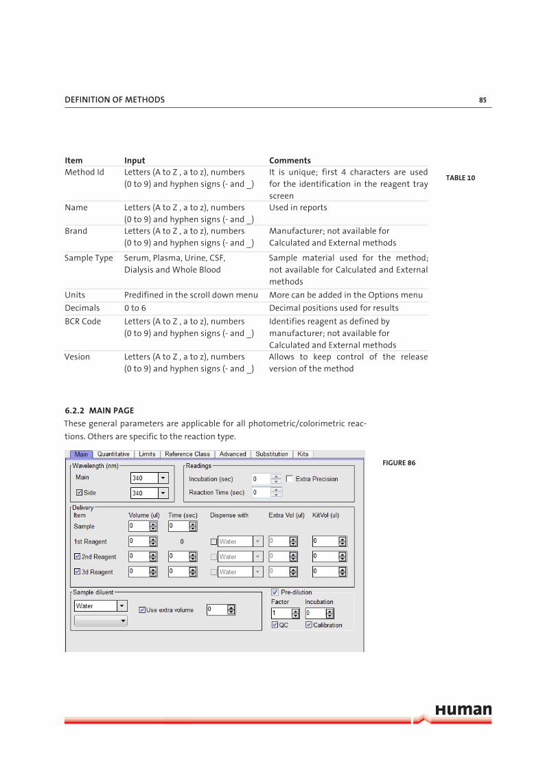
defInItIon of metHodS 85
Item Input CommentsMethod Id Letters (A to Z , a to z), numbers
(0 to 9) and hyphen signs (- and _)It is unique; first 4 characters are used for the identification in the reagent tray screen
Name Letters (A to Z , a to z), numbers (0 to 9) and hyphen signs (- and _)
Used in reports
Brand Letters (A to Z , a to z), numbers (0 to 9) and hyphen signs (- and _)
Manufacturer; not available for Calculated and External methods
Sample Type Serum, Plasma, Urine, CSF, Dialysis and Whole Blood
Sample material used for the method; not available for Calculated and External methods
Units Predifined in the scroll down menu More can be added in the Options menu
Decimals 0 to 6 Decimal positions used for results
BCR Code Letters (A to Z , a to z), numbers (0 to 9) and hyphen signs (- and _)
Identifies reagent as defined by manufacturer; not available for Calculated and External methods
Vesion Letters (A to Z , a to z), numbers (0 to 9) and hyphen signs (- and _)
Allows to keep control of the release version of the method
6.2.2 MAIN PAGE
These general parameters are applicable for all photometric/colorimetric reac-
tions. Others are specific to the reaction type.
TABLE 10
FIGURE 86

HumaStar 600 | User manual
86
Item Input CommentsWavelength (nm) Mono- or bichromatic measurement; 12 WL
(340 - 800 nm) Main Select from drop down menu Choose a WL from the installed filters
Side Check and select from drop down menu or No Check
Check to enable a second WL and choose a WL from the installed filters
Readings
Incubation (sec) 1 to 1500 Only for Fixed Point and Kinetics; time be-tween the last dispensing and the first reading
(Reaction) Time (sec) 1 to 1500 Reading time is counted after the addition of the last fluid
Extra Precision Check / No Check Enpoint (two consecutive readings are averged; Fixed Point each value is the line-ar interpolation of two readings, one before and one after the specified time
Delivery
Volume (µl) Max volume per pipetting 470 µl; Min/Max reaction volume 180/650 µl
Sample 2 to 100 µl Set in increments of 1 µl1st Reagnet 5 to 500 µl Set in increments of 1 µl2nd Reagent Check or No Check;
5 to 500 µlCheck the box to use a second reagent; Set in increments of 1 µl
3nd Reagent Check or No Check; 5 to 500 µl
Check the box to use a third reagent; Set in increments of 1 µl
Time (sec) 1 to 1500 R1 is dispensed at time 0; S, R2 or R3 can be set variable by insert a different time
Dispense with Check / No Check Check and the drop down menu will be available
Water / Extra Reagent Water will be added to the reaction/ extra reagent will be discarded
Extra volume (µl) Max total per dispensing 470 µlKit Vol (µl) Reagent volume in the bottle (excluding the
dead volume)Sample diluent Used to pre or post dilute a sample/QC/CalFirst drop-down Water/Diluent/Reagent Select from the drop-downSecond drop - down Select from the drop-down According to the above decision, different
diluents (defined in Solutions menu) and the reagents of this test are availble
Use extra volume Check / No Check Check and the defined extra volume of the sample diluent will be used and after dis-pensing discarded
TABLE 11

defInItIon of metHodS 87
Predilution Check / No Check Check to enable the sample predilution function
Factor 1 to 100 Dilution will be done in an extra cuvette; di-lution volume 300 µl (factor 10 -> 30 µl sam-ple + 270 µl sample diluent)
QC Check / No Check Check and QC samples will be pre dilutedCalibration Check / No Check Check and Calibration samples will be
prediluted
6.2.2.1 Specific data
End point
Readings. Measuring time starting when last reagent was added if more than
one or when sample was added if only one reagent is present. When Extra Preci-
sion is used (recommended), two consecutive readings are averaged.
Fixed Point
Readings. Incubation is the time interval between addition of last reagent and
the first reading. Reaction time is the time interval between two readings. When
Extra Precision is used (recommended), each value is the linear interpolation of
two readings, one before and one after the specified time.
Kinetics
Readings. Incubation is the time interval between addition of last reagent and
the first reading. Reaction time is the time interval in which 10 readings are per-
formed. These 10 readings define the slope for the concentration calculation (in
some cases, only 9 points are considered; see section 6.1.3.

HumaStar 600 | User manual
88
6.2.3 QUANTITATIVE
Calibration, reagent blank and reaction specific parameters are set up in the
Quantitative tab.
Item Input CommentsMethod Correlation The concentration value (X) will be corrected
with the equation Y=AX + BSlope -999999 to 999999 Slope = AOffset -999999 to 999999 Offset = B
Direction Reaction direction according the methodDirection Ascending or Decreasing Select from drop down menü
Direction CheckCheck / No Check
Direction will be checked and result will be flagged if direction is wrong and the result has to be manually accepted
Calibration typeCurve / Linear Check / No Check Check if one or more calibrators should be
usedValidity time (days) Check / No Check;
1 to 999999Check and insert the number of days, if the calibration stability should be checked; after the number of days or if a new reagent lot is on board, the calibration curve expires and a new calibration will be requested.
Fixed Check / No Check; 1 to 20 Check and insert the number of points used in the calibration; If this option is not select-ed, the user can define a calibrator set with any number of points.
FIGURE 87
TABLE 12

defInItIon of metHodS 89
Mandatory formula
None, Linear, MultLinear, Sigmoidea, Logit4, Logit5 or Spline.
Select from dop down menu if a special for-mula should be used; if none is used the for-mula can be manually modified in the Cali-bration>Pending Acceptance window
Factor -999999 to 999999 Insert the factorUse from thismethod
Check / No Check Check if the calibration curve from different method should be used and select the meth-od from the drop down menu
Reagent blankEnabled Check / No Check Check if a reagent blank should be used in
the calculation of the resultSample replacement with
Diluent/Reagent Select which solution should be used
Diluent Drop down menu All diluents defined in Method Definition > Solutions are available
Reagent Drop down menu All reagents defined in the Main tab are available
Validty time 1,3,6 or 12 hours; 1 to 120 days
New reagent blank will be requested if the defined time expires or a reagent lot or bot-tle number is modified
Default replicates 1 to 10
Automaticallyperformed
Check / No Check Check if the reagent blank should be per-formed automatically
6.2.4 LIMITS
Checks and automatic acceptance ranges are set up in the Limits tab.
FIGURE 88

HumaStar 600 | User manual
90
Item Input CommentsConcentrationvalidity limit
Linearity range check
Low -999999 to 999999 Insert the low linearity limit according the method IFU
Not rerun, Rerun, More Sample
Select from drop down menu; result can be flagged, repeated as original run or repeated with more sample volume
High -999999 to 999999 Insert the high linearity limit according the method IFU
Not rerun, Predilution, Less Sample
Select from drop down menu; results can be flagged, repeated with a predilution (the predilution factor is established automat-ically (taking in account low and high lim-it and calculates the dilution factor for the measured absorbance to get readings in the middle) or repeated with less sample volume
Integrity check absorbance limit
Reagent integrity (quality) check; only reagent will be dispensed into a cuvette and measured each morning
Low limit -999999 to 999999 Insert a low absorbance limitHigh limit -999999 to 999999 Insert a low absorbance limitConcentration duplication limit
Result verification check; normal repetion can be triggered according to each laboratory need
Low limit -999999 to 999999 Insert a low absorbance limitHigh limit -999999 to 999999 Insert a low absorbance limitReagent blank automatic acceptance
If automatic acceptance is enabled, reagent blank results within the specified limits will not appear on the Pending Acceptance window of blanks, they show up directly in the In Use window of blanks
Low limit -999999 to 999999 Insert a low absorbance limitHigh limit -999999 to 999999 Insert a high absorbance limitCalibrationfactor automatic acceptance
If automatic acceptance is enabled, calibration factors within the specified limits will not ap-pear on the Pending Acceptance window of calibration, they show up directly in the In Use window of calibrations
Low limit -999999 to 999999 Insert a low factor limitHigh limit -999999 to 999999 Insert a high factor limitChange in % Check / No Check;
-999999 to 999999Check if the deviation from the previous valid (in use) calibration should be checked and in-sert the allowable percentage
TABLE 13
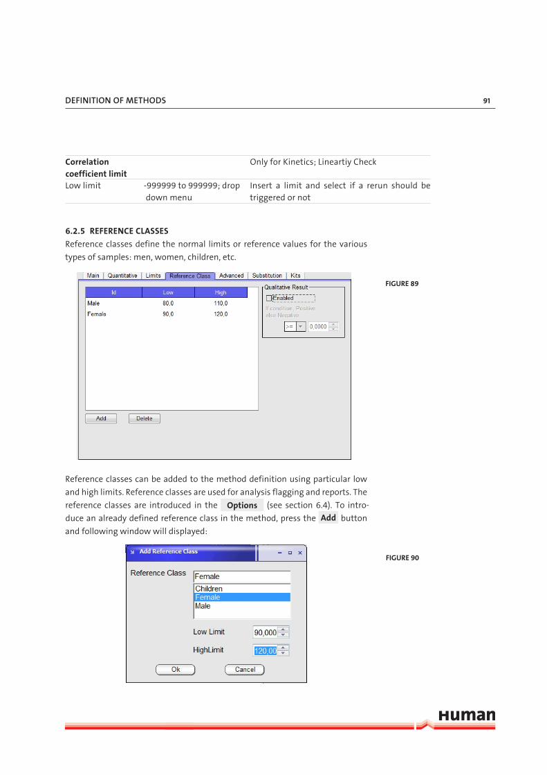
defInItIon of metHodS 91
Correlation coefficient limit
Only for Kinetics; Lineartiy Check
Low limit -999999 to 999999; drop down menu
Insert a limit and select if a rerun should be triggered or not
6.2.5 REFERENCE CLASSES
Reference classes define the normal limits or reference values for the various
types of samples: men, women, children, etc.
Reference classes can be added to the method definition using particular low
and high limits. Reference classes are used for analysis flagging and reports. The
reference classes are introduced in the Options (see section 6.4). To intro-
duce an already defined reference class in the method, press the Add button
and following window will displayed:
FIGURE 89
FIGURE 90

HumaStar 600 | User manual
92
Select the reference class and insert the Low and High Limit. Press Ok to con-
firm or Cancel to abort.
To Delete a reference classe, selecte the line in the table and press Delete .
Qualitative Result can be evaluated using the option on the right side of the
screen.
Check the box and the results can be reported as positive or negative instead of
a numerical value.
Insert the function (>=, >, < or <=) and the value for the decision between posi-
tive and negative.
6.2.6 ADVANCED FEATURES
Advanced features include procedures to avoid contamination, shaking behav-
iour and on board stability.
Item Input CommentsTip post wash Check / No Check Check to enable always an extra probe wash
after dispensing to the cuvetteWater Check / No Check Check to use water for the extra washSolution Check / No Check,
drop down menuCheck and select the solution which should used for the extra post wash
FIGURE 91
TABLE 14

defInItIon of metHodS 93
Tip pre wash Check / No Check Check to enable an extra probe wash before aspirating the reagent
Water Check / No Check Check to use water for the extra washSolution Check / No Check,
drop down menuCheck and select the solution which should used for the extra wash
Reagent Check / No Check, drop down menu
Check and select the reagent which should used for the extra wash
When Always / After interf. methods
Usage always or only when a defined interfer-ing mehtod was used before the method
Cuvette post wash Check / No Check Check to enable the addition of a solution to the reaction cuvette before washing
Solution Drop down menu Select the solution to be usedVol (µl) 0 to 50 Insert the volume to be usedTime (sec) 0 to 60 Insert the time the added solution should be
incubated together with the reaction liquidAfter sample tip wash Check / No Check Check to enable an external tip wash after aspi-
ration of the sample (to improve the lineartiy in methods with very low absorbances)
Interfering methods Add or delete methods which interfer the existing method
Sample Acceptance Manual/Automatic Manual to send all results to the Pending Ac-ceptance tab in the Tests Menu; automatic to send all results without flag to the Done tab in the Tests Menu (flagged results will all the time be show up in the Pending Acceptance)
Arm selection Select the arm which should be used (important to take contamination avoidance and speed in consideration)
Front Check / No Check Check if the front arm should be usedBack Check / No Check Check if the back arm should be usedShake Off / Normal / x2 / x3/
x4Adjust the shaking during the tip cleaning, in-termediate wash, reaction cuvette and pre dilu-tion mixing. Normal (centrifugal) mixing dura-tion is 500 msec
Viscouse reagent Check / No Check Check if the reagent has a sticky cosistensy and the dilutor speed will be slowed down
On board stabilityTime 1,3,6 or 12 hours;
1 to 120 days Select the on board stability given by the man-ufacturer
Keep using Check / No Check Check to enable the reagent longer then the on board stability (a warning will be issued)

HumaStar 600 | User manual
94
6.2.7 CONSUMPTION
This section applies to kinetic methods only.
Item Input CommentsConsumption check Check / No Check Check to enable substrate depletion check; reaction
curve will be checked for a excessive initial substrate consumption
Limit (Abs/min) -999999 to 999999 Given by the manufactorer (approx. Abs/min of the lin-erarity limit at the point of interest)
First and second point Check / No Check Check and evaluation is performed between the two first reading points
Time and first point Check / No Check Check and the evaluation is performed before the read-ing is started
Time before first (sec) 0 to ... Define the time when the check should take place (rec-ommendation: incubation < 60 sec set to 15; incubation > 60 sec set to 30)
BehaviourConservative Check / No Check Check and during the reading time the system perform
10 readingsAdaptative Check / No Check Check and the system will automatically increase the to-
tal reaction time and the interval between the readings if the consumption rate is low to optimze precision and decrease the total reading interval if the consumption rate is high to preserve linearity; recommended
Initial absorbance limit
-999999 to 999999 Insert the OD limit; if absorbance is below limit in a de-creasing reaction or above limit in increasing reaction the sample will be prediluted
Dilution factor 1 to 120 Insert a dilution factor
FIGURE 92
TABLE 15

defInItIon of metHodS 95
6.2.8 REAGENT SUBSTITUTION
Two or more methods can share the same reagent. Or a defined diluent can be
used as a reagent.
Item Input Comments1st Reagent Check / No Check Check to apply a reagent or diluent for reagent 1
drop down menu Choose “Use Method” for a reagent of a different method or a predifined diluent
drop down menu If “Use Method” is chosen, select the method (this method belongs to R2 and R3
2nd Reagent Check / No Ceck Check to apply a reagent or diluent for reagent 2drop down menu Choose “Use Method” for a reagent of a different method
or a predifined diluent3rd Reagent Check / No Check Check to apply a reagent or diluent for reagent 3
drop down menu Choose “Use Method” for a reagent of a different method or a predifined diluent
FIGURE 93
TABLE 16

HumaStar 600 | User manual
96
6.2.9 KITS
Kits
For barcoded reagents different kit sizes can be used.
The information of the first kit are automatically insert from the Main and Ad-
vanced tab. If a second Kit size should be used insert the BCR code, the on board
stability and the Kit Volume in µl.
FIGURE 94

defInItIon of metHodS 97
6.3 SolutionsTo set up Solutions press the Method Definition Menu button and select the Submenu Solution.
Two categories of solutions are available:
Fixed in the system Solutions which are fixed in the system and can not be modified Solution Ref BCR Code UsageTip Clean 16663/25 900 Clean the probe after “Start” and
before going to “Standby” Tip Rinse 16663/25 901 Rinse the probe after Tip CleanISE solutions described in the ISE User Guide
User defined Generic and specific dilutents required in some methodsSolution Ref BCR Code UsageDiluent (DIL) 16663/10 910 Diluent: pre- and post dilution of
serum samples; reagent blankDiluent 2 (DIL2) 16663/11 911 Diluent: pre- and post dilution of
urin samplesCuvette Clean 16663/20 902 Cleaning: tip pre- and post wash;
cuvette post wash; maintenance (refer to chapter 8.2.2 and 6.2.6)
FIGURE 95
TABLE 17
TABLE 18

HumaStar 600 | User manual
98
To add more solutions or dilutents press the New button.
Insert a ID and a BCR code (if barcoded), Select the Type and press Ok to con-
firm or Cancel to abort.
Once the solution is set up only BCR code is possible to change.
To delete a solution, select the solution in the table and press Delete .
6.4 OptionsTo add or delete Reference Classes or Measurement Units press the Method
Definition Menu button and select Submenu Options.
FIGURE 96
FIGURE 97
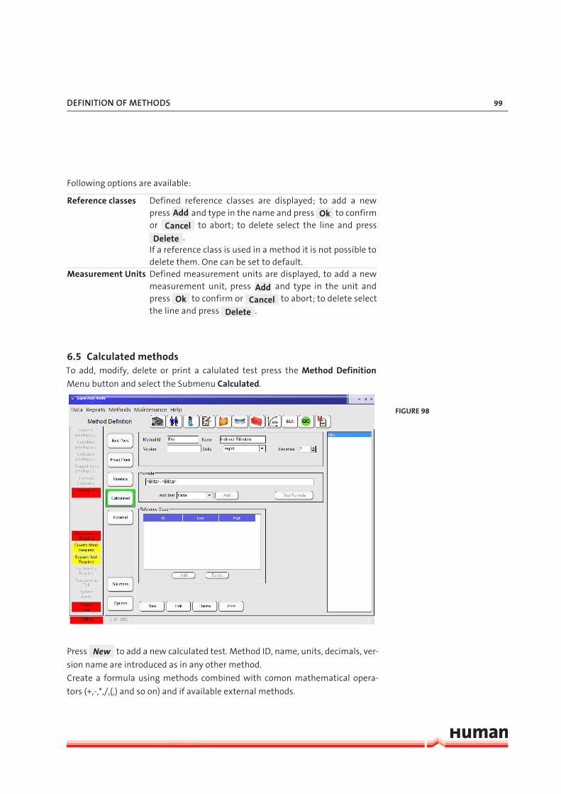
defInItIon of metHodS 99
Following options are available:
Reference classes Defined reference classes are displayed; to add a new press Add and type in the name and press Ok to confirm or Cancel to abort; to delete select the line and press
Delete . If a reference class is used in a method it is not possible to delete them. One can be set to default.
Measurement Units Defined measurement units are displayed, to add a new measurement unit, press Add and type in the unit and press Ok to confirm or Cancel to abort; to delete select the line and press Delete .
6.5 Calculated methodsTo add, modify, delete or print a calulated test press the Method Definition
Menu button and select the Submenu Calculated.
Press New to add a new calculated test. Method ID, name, units, decimals, ver-
sion name are introduced as in any other method.
Create a formula using methods combined with comon mathematical opera-
tors (+,-,*,/,(,) and so on) and if available external methods.
FIGURE 98

HumaStar 600 | User manual
100
To insert a method select the name on the drop down menu below and press
Add . The method name will be insert on the point the cursor is placed in the
formula. Press Test Formula to check the formula’s consistency.
External methods can be used in formula if previously stored in memory.
Methods may correspond to different samples if samples are assigned to the
same patient. To add a reference class to the calculated formula, press Add
and select the class and insert the low and high limit. Press Ok to confirm or
Cancel to abort.
6.6 External MethodsTo add, modify, delete or print an external method press the Method Definition
Menu button and select the Submenu External.
External methods are printed out together with those calculated by the instru-
ment.
They are useful for the introduction of constants in the calculated methods.
Such constants are, for instance “Creatinine clearance”, “24-hour volume”, etc.
Method ID, name, units, decimals, external names are introduced as usual.
To add a reference class to the external method, press Add and select the class
and insert the low and high limit. Press Ok to confirm or Cancel to abort.
FIGURE 99

defInItIon of metHodS 101
6.7 Units and LimitsUnits and limits can be modified from the menu of methods without direct ac-
cess to a given method in particular. This feature is used to set lab specific limits
or checks to closed methods.
In brief, the method ID and measuring units can be modified. Method correla-
tion, concentration duplication limits and reagent blank and calibration auto-
matic acceptance limits can be set. Reference classes can be modified, deleted or
added. Additionally sample acceptance can be assigned as manual or automatic
and on board stability can be extended by checking the Keep Using button.
6.8 Developement of a Method
FIGURE 100
FIGURE 101

HumaStar 600 | User manual
102
The option gives access to review in real time any reaction. This method does not
run with others as part of the automatic cycle. It is used alone, sample by sample
and its purpose is to study slope, end point, optimum range, incubation period,
etc. of individual reactions.
In Options, basic method parameters are defined: wavelengths, number of
reagents, volumes, total measuring time. In Calibration page, analysis type is
defined and fit formula calculated. In Results, measurements can be viewed
graphically and Time 1 and Time 2 can be adjusted in order to focus on required
time interval. This funtion is mostly used for research and development projects
as well as method optimization.
FIGURE 102

ISe module cat.-no. 16663-03 103
7 ISE MODULE CAT.-NO. 16663-03See HumaStar 600 ISE MODULE User Manual, 16663/1.

HumaStar 600 | User manual
104

maIntenance 105
8 MAINTENANCEA regular maintenance is necessary, to keep the system in good operating con-
dition. The scheduler will help to manage the daily, weekly and monthly main-
tenance. From time to time it’s also necessary to do some maintenance on de-
mand i.e. Cuvette change.
A recommended summary of tasks for daily, weekly and monthly maintenance
is presented in the table below:
Frequency Task Daily Inspection and Cleaning of Probes
Check and Replace System SolutionsEmpty Waste BottleHydraulic Testing - System Flush
Weekly Intensive Cuvette CleaningCuvette Water BlankService Backup
Monthly Photometer CalibrationWasher Volume CalibrationClean System BottlesIntensive Washer Cleaning
On Demand Cuvette ChangeLamp ReplacementPump Tube Replacement
8.1 SchedulerMaintenance Scheduler can be accessed either from the warnings bar (if a warn-
ing is yellow or red, click on it) on the system information field at the main win-
dow or from main menu:
FIGURE 103
FIGURE 104

HumaStar 600 | User manual
106
The scheduler window is further divided into two tabs which are the Status and
Schedule. Both windows are analytically presented at next sections. Red color
indicates that one or more of the scheduled tasks has not been completed.
8.1.1 SCHEDULE
To schedule the alerts for the maintenance tasks a number of parameters which
involve daily lab routine operation are edited in this screen in order to set the
preferred times for maintenance tasks.
Item Input CommentsDay start at 0 to 24 o’clock Set the time of routine startDay Ends at 0 to 24 o’clock Set the time of routine stopsService Backup at
0 to 24 o’clock Set the time when the Backup should take place
Change Select the folder to store the service back up (recommended to an external MD)
Default Press to use the default folderWeekly Maintenance
Monday to Sunday
Select the day the weekly maintenance should take place
0 to 24 o’clock Set the time when the weekly maintenance should take place
Monthly Maintenance
Monday to Sunday
Select the day the monthly maintenance should take place
0 to 24 o’clock Set the time when the alert should take place
FIGURE 105
TABLE 19

maIntenance 107
Service Bakup
Daily Check / No Check Check for a daily backup
Weekly Check / No Check Check for a weekly backup
Cuvette Water Blank
Daily Check / No Check Check for a daily cuvette water
blank
Weekly Check / No Check Check for a weekly cuvette water
blank
Start of the day Check / No Check Check, if the maintenance should
be done on the start of the day
End of the day Check / No Check Check, if the maintenance should
be done on the end of the day
Press Apply changes to save the modifications.
8.1.2 STATUS
A list of maintenance tasks is presented in this window with the dates and times
that were last executed as well as the times that are next scheduled for. The ac-
tivities are mainly separated into Daily, Weekly, Monthly and On Demand main-
tenance routines and can be performed directly from this screen by pressing the
corresponding Perform button which will either initialize the task directly or will
transfer to the corresponding screen of the software.
If the “Next scheduled” time is reached an alert will be shown on the main
screen in the system information field. Additional details for some of the tasks
can be found in separate sections of the maintenance chapter.

HumaStar 600 | User manual
108
8.2 Daily MaintenanceRecommended operations should be performed at the start of every run or on
demand.
8.2.1 INSPECTION AND CLEANING OF PROBES
The probes are a delicate part of the instrument. Precision of results is essentially
dependent on how well the probes are maintained. Probe tip must be kept clean.
1. Inspect if the probes are not bent or damaged. If a probe is defective contact
your technical support.
2. Inspect the probes for debris and clean them if contaminated.
3. Open the Maintenance scheduler status screen and press Perform behind
the Clean needle function.
4. Gently remove protein deposits or solids from tip with a cotton swab soaked
in 70% Alkohol. Dry with lint-free tissue.
5. Press Ok when done. The scheduler will be updated automatically.
6. After Cleaning the probes, flush the system.
8.2.2 CHECK AND REPLACE SYSTEM SOLUTIONS
System wash solution and cleaning solutions are necessary to run the system.
Provide all solutions to avoid interruption during the run.
System Wash Solution: The system washes the probes between sample aspira-
tions, requiring approximately 4 mL of wash solution for each performed test
in case of single reagent tests. The washing solution is pumped up from its res-
ervoir and is disposed into the waste reservoir, both reservoirs have electronic
level sensors. If volume is not sufficient, a message will warn after initialization.
FIGURE 106

maIntenance 109
The Tip clean and Tip rinse solutions are needed to clean and rinse the probes
after measurement, before the system stops and should be replaced (if not used
up) all three months.
The Cuvette Clean is used during run for tip pre/post wash- and cuvette post
wash and should be replaced (if not used up) all three months.
The Diluent is used for sample/calibrator pre- and post dilution and for blank
measurements and should be replaced (if not used up) once a month.
1. Check the system wash solution behind the front door, if necessary prepare
new, for details refer to the IFU of Wash Add Ref 18971. After replacement
flush the system. Don’t top up to avoid contamination and bacterial grow.
2. Check the Tip Clean and - Rinse (Ref 16663/25) in the reagent tray, replace
if necessary.
3. Check the Cuvette Clean (Ref. 16663/20) in the reagent tray, replace if nec-
essary.
4. Check the Diluent (Ref. 16663/10) in the reagent tray, replace if necessary.
8.2.3 EMPTY WASTE BOTTLE
The waste bottle is placed on a scale and if the bottle is full, the system will show
an alarm. Open the front door, empty the waste bottle and put it back into the
system.
8.2.4 HYDRAULIC TESTING – SYSTEM FLUSH
System flush is required at least once per day and can be set to be automatically
performed during analyzer start up at the beginning of the day. In case that
analyzer has stayed operational and has not been switched off then the system
flush warning will come up at the specified time. Air gaps and bubbles should
be flushed, if present, particularly after the filling operation of system bottles or
after cleaning the probes.
1. Open the Maintenance scheduler status screen and press Perform behind
the System Flush function.
2. During process look for:
- Presence of bubbles or air gaps in system
- Leakage in peristaltic pump
- Constant and uniform flow from probe tip
- No droplets hanging on probe tip
- In case new bubbles generate in the process, Refer to chapter 9 “Trouble-
shooting”.
3. The scheduler will be updated automatically.

HumaStar 600 | User manual
110
8.3 Weekly MaintenanceProceed to the daily maintenance routine.
8.3.1 INTENSIVE CUVETTE CLEANING
Intensive cuvette cleaning should be done at least weekly. In case of an intense
contamination of the cuvettes (i.e. high usage of Latex reagents) it may be nec-
essary to clean the cuvettes more often. The system checks the cuvettes before
each run and if cuvettes get’s unusable in a short time, it is a sign to clean them
more often. Place neat Cuvette Clean Solution (Ref 16663/20) on the reagent
tray. Approximately 25 min are needed to clean all cuvettes.
1. Open the Maintenance scheduler status screen and press Perform behind
the Intensive Cuvette Cleaning function.
2. Check the box for Front and Back on the “Intensive cuvette cleaning” section.
3. Select the C-Clean as solution to use.
4. Select the volume to 300 µl of C-Clean to be dispensed to the cuvettes.
5. Set the time to 1 min (increase the time by an intense contamination).
6. Check if enough C-Clean is placed on the reagent tray (160 x the volume set
above).
7. Press to start the cleaning.
8. After the cuvette cleaning finished the scheduler will be updated automat-
ically. It is mandatory to perform a Cuvette Water Blank after the cleaning.
FIGURE 107

maIntenance 111
8.3.2 CUVETTE WATER BLANK
Cuvette water blank should be done weekly and after each intensive cuvette
cleaning.
Washers are dispensing system wash in all cuvettes and photometer records
the background measurement of each cuvette at all 12 filters. The process takes
places into two parts; at first system wash is dispensed to the first 40 cuvettes,
absorbances are read, cuvettes are then dried and then the other half of the
cuvette tray is filled and read. Process takes approximately 15 min and if accept-
ance criteria are fulfilled, cuvettes are considered clean.
1. Open the Maintenance scheduler status screen and press Perform behind
the Cuvette Water Blank function.
2. The cuvette water blank starts automatically.
3. After the cuvette water blank finished the scheduler will be updated auto-
matically. The actual and the previous results are displayed on the screen.
8.3.3 SERVICE BACKUP
Perform the backup at least once per week to save all necessary information
needed to reinstall the system and retrieve data in an emergency.
Save the Backup on an external memory device. Duration can vary from a few
seconds up to a couple of minutes, depending on the size of the database.
FIGURE 108

HumaStar 600 | User manual
112
1. Open the Maintenance scheduler status screen and press Perform behind
the Service Backup function.
2. The Backup starts automatically and a pop up window appears when it fin-
ished.
3. Press Ok and the scheduler will be updated.
8.4 Monthly MaintenanceProceed to the weekly maintenance routine.
8.4.1 PHOTOMETER CALIBRATION
This calibration will determine the optimum reading position in the middle of
each cuvette.
Please perform this maintenance directly after intensive cuvette clean and cu-
vette water blank to ensure the cuvettes in Pos 1 are clean. The calibration will
take approximately 10 minutes.
1. Open the Maintenance scheduler status screen and press Perform behind
the Photometer Calibration function and a pop up window will appear. If the
cuvette is clean, a new placement is not necessary.
2. Press Ok and the calibration will start automatically.
3. When finished refer to the summarize tab and following window will be dis-
played:

maIntenance 113
Check following values:
Front and Back Gain ≤ 8
Ref Gain ≤ 16
4. If the gains are over the limit, refer to chapter 9 “Troubleshooting”.
8.4.2 WASHER VOLUME CALIBRATION
The washer volume should be between 500 and 700 µl. The calibration will take
approximately 3 minutes. The screen will show the pump steps settings and
new pump steps required for system delivery in all four wash steps.
1. Perform a System Flush (refer to 8.2.4).
2. Open the Maintenance scheduler status screen and press Perform behind
the Washer Calibration function.
3. The Calibration will start automatically and a pop up window will appear
when it finished.
4. Press Ok to get the screen, displayed below:
FIGURE 109

HumaStar 600 | User manual
114
5. If the new values are around 650 press Save new values to save them.
8.4.3 CLEAN SYSTEM BOTTLES
The system wash- and waste bottles need to be cleaned manually once per
month. This is not controlled by analyzer software. Build of dirt and potential
biological contamination within the containers could seriously influence perfor-
mance of the analyzer. To clean the bottles follow the below instructions.
1. Open the Maintenance scheduler status screen and press Perform behind
the Clean System Bottles function.
2. Take out and empty the system wash bottle.
3. Clean with dilute hypochlorite (1 %) and rinse several times with water and
at the end with deionized water.
4. Refill with wash solution (for more information read the IFU of Wash Add
Ref 18971).
5. Take out and empty the waste bottle.
6. Clean with dilute hypochlorite (1 %) and rinse once with water.
7. Press Ok when finished, the scheduler will be updated.
8. Flush the System.
FIGURE 110

maIntenance 115
8.4.4 INTENSIVE WASHER CLEANING
To provide a good cuvette cleaning the wash station should be cleaned at least
monthly using the instructions below. The procedure will take approximately
5 min. To open the Operation menu select:
1. Check the box for Front and Back in the “Intensive washer cleaning” section.
2. Select the C-Clean for the Solution to use.
3. Check if C-Clean (Ref 16663/20) is placed on the reagent tray.
4. Press to start the washer cleaning. At the end of the cleaning the sys-
tem starts a normal wash and drying cycle to clean the used cuvettes. The
scheduler will be updated automatically.
FIGURE 111
FIGURE 112

HumaStar 600 | User manual
116
8.5 Maintenance on DemandThe tasks below should be performed when instrument indicates the need of
corrective action, or when operation anomalies are encountered.
8.5.1 CUVETTE CHANGE
Before starting every automatic cycle, the instrument will check the cuvette
status. When following circumstances occur the system stops and the cuvettes
have to be changed:
A. When more than 15 cuvettes are out of the absorbance limit (given by the
manufacturer)
B. When the usage value of 25.000 is reached (Maintenance>Operations>Wear)
All cuvettes should be changed at the same time. To change cuvettes open the
Reaction Tray Menu.
1. Press Change and a following pop up window will be displayed:
“Check the Front- and Back Tray box and press Ok .”
2. Remove the red and black covers from the front- and back reaction tray.
3. The reaction tray can be turned with the hand to remove all cuvettes.
4. Place new cuvettes and replace the black and the red cover.
5. When finished press Ok .
6. The cuvette water blank will be automatically started, when the tempera-
ture in the reaction try is reached. The number in the counter table (Wear)
will be reset to Zero.
FIGURE 113

maIntenance 117
8.5.2 LAMP REPLACEMENT
When required, lamp replacement can be easily performed by user following
these instructions:
1. Turn off and unplug instrument from Main Plug and wait 10 min in order to
let the lamp cool down.
2. Remove lamp cover from left side of instrument, lamp will be visible.
3. Press lever on lamp socket to remove burnout lamp.
4. Insert new lamp in place securely. There is only one possible position due to
different size of connecting pins.
5. Lamp is pre-focused, does not require other handling.
6. Reinstall cover, tighten screws.
7. Wait approximately 20 minutes and then start a cuvette water blank.
8.5.3 PUMP TUBE REPLACEMENT
The pump tubing has a useful life given by a pre-fixed number of work cycles.
When that number is surpassed, instrument will show a message for tubing
replacement. At the earliest opportunity the replacement must be done (it is not
necessary to stop the system during work).
1. Pull fittings up and out of bracket.
2. Pull tube out of its lodging rotating by hand the pump rotor if necessary.
3. Insert new tube on the fittings.
4. Install in inverse order.
5. Turn slowly rotor by hand until tubing is properly lodged.
6. Reset the cycle counter on the Wear screen (see below).
7. Proceed at least 3 system flushes.
8.6 Counters Some of the parts in the system needs to be tracked how often they are used.
The display about the actual numbers will be find in:
Do not touch lamp bulb with
bare hands, only with gloves.
If touched accidentally, clean
with lint-free cloth or tissue pa-
per and alcohol.
FIGURE 114

HumaStar 600 | User manual
118
Open the Wear tab:
Table includes actual readings, limits and latest replacement dates.
When a limit is reached, the system issues a warning. The maintenance should
be done as soon as possible, but there is no need to interrupt routine work.
When a replacement is done, the reset button should be pressed to reset the
actual number to zero.
Check regularly this table and be sure to have spares for all elements.
FIGURE 115

troubleSHootInG 119
9 TROUBLESHOOTINGInstrument related problems can be classified into three groups:
1. Operation malfunctions with visual, acoustic or printed warnings.
2. Visible faults or problems.
3. Measurement inconsistencies (for example: GOT method with high disper-
sion).
9.1 Messages and WarningsSelf-explanatory messages are not included in the present listing.
Message Cause Action
Change reaction cuvettes.
All 160 cuvettes are dirty. Replace reaction cuvettes.
Front / Back syringe exceeded.
Preset limit is surpassed. Replace at the earliest op-portunity.
Front / Back pump turns exceeded
Preset limit is surpassed. Replace at the earliest op-portunity.
There is no enough cleaning solution.
Cleaning or rinsing solutions are missing.
Replace required System Wash Solution.
9.2 Visible faults
9.2.1 GENERAL FAULTS
Symptom Corrective Action
Drops on probe tip after dis-pensing
Verify hydraulic system in accordance to user’s manual.Clean probe tip by submerging in Solution 1 for 5 minutes.
Drops on tip after wash cycle. Verify hydraulic system for leaks or obstructions.
Abnormal noises. Defective fans.Moving parts blocked or frozen. Contact Technical Support.
TABLE 20
TABLE 21

HumaStar 600 | User manual
120
Temperature in reaction tray is too high. (Do not be con-cerned about arm probe temperature)
Room temperature too high, (should always be at least 4°C lower than selected working tem-perature).Example: For 37°C incubation temperature, Room temperature should not exceed 33°C.If Room temperature is within limits, and prob-lem persists, call Technical Support.
Temperature in reaction tray is too low. (Do not be concerned about arm probe temperature)
Room temperature excessively low. Verify in-strument operating range, and adequate the room temperature.If room temperature is within specified range and problem persists, call Technical Support.
9.2.2 MEASUREMENT INCONSISTENCIES
Consider storage and handling of reagents, standards and controls:
1. Verify expiration date, storage temperatures on and off analyzer.
2. Check that reagent was not frozen. Check color changes, sediments, turbid-
ity, no foam.
3. Check for mixed reagents from different lots or re-use of reagent bottles.
All methods
1. Verify cuvettes for dirt or scratching.
2. Verify there are no bubbles or droplet.
3. Verify there are no obstructions on probe, check for non constant or regular
flow.
4. Recalibrate photometer.
Colorimetrics with high dispersion
1. Replace sample by a standard and verify dispersion.
2. Perform hydraulic verification.
3. Check for sample centrifugation, increase time and speed.
4. Perform energy, noise photometric stability and dilution tests.
Colorimetrics with proper dispersion but values too high or low
1. Verify standard, compare calculated factor with stored (historic) factors, and
recalibrate method. If problem persists, replace standard and/or reagent.
2. Clean probe and check for cross contamination by changing the order of dis-
pensing (“Time priority for reagents” parameter). Check proper probe wash-
ing/clean probe.

troubleSHootInG 121
3. Check for exceeded method linear range; compare method definition with
reagent specification.
4. Verify sample volume is not excessive.
5. Perform stray light verification, high range and low range linearity test, and
dilution test.
Kinetics with high dispersion or low linearity
1. Verify if incubation time is too short or heaters are not working properly.
2. Verify for abnormally high initial absorbance for decreasing kinetics (prob-
lems with reagent preparation) or too low on increasing kinetics. Replace reagents and compare results.
3. Check lamp for stability.
4. Use new cuvettes and test again, check cuvettes for dirt or scratching.
5. Perform noise and photometric stability tests, clean filters.
6. For some kinetics: verify if sample volume is too low.
7. For some kinetics: verify centrifugation (increase time and speed).
Kinetics with normal values too high
1. Perform energy, noise and photometric stability.
2. Perform temperature verification.
3. Some kinetics: incorrect factor for selected temperature and volume.
4. Replace lamp, clean filters.
Kinetics with normal and pathological values too high
1. Verify incubation time and temperature. Perform temperature test.
2. Verify if factor matches selected temperature. Remember selected temper-
ature is usually 37°C.
Kinetics with normal and pathological values too low
1. Check for short incubation time or low temperature.
2. Verify if factor matches selected temperature. Remember selected temper-
ature is usually 37°C.
Kinetics with values too low or too high on the whole range
Verify if factor matches selected temperature. Remember selected temperature
is usually 37°C.

HumaStar 600 | User manual
122
Two point kinetics (high dispersion)
1. Verify if standard absorbance is too low (verify data provided by standard
manufacturer).
2. Verify initial consumption is too high (verify data provided reagent manu-
facturer).
3. Perform energy tests.
4. Verify reagent handling and storage.
5. Check method parameter for reagent, low sample volume or too short inter-
val times.
6. Check time table for dispersion on first measurement.
Two point kinetics (high dispersion)
Verify factor, standard and method for reagent.
Repetition or dilution (colorimetric or non linear kinetics)
1. Verify if sample volume is too high, check reagent linear limit.
2. Replace reagent and compare.
Repetition or dilution (two point kinetics)
This is not actually an error; it is because volume / absorbance change relation-
ship is not linear, and so it is necessary to dilute standard and compare.
Reactions (general comparison between reactions)
1. Control quality of water.
2. Verify proper usage of solutions (System Wash Solution, rinse solution, etc).
3. Use uric acid to check water quality.
4. Verify for frosted cuvettes (presence of salts).
5. Verify scratching or old reactions residues (not enough washing).
6. Perform instrument validation tests.
“Standard absorbance error” message
1. Check/replace standard.
2. Replace standard by a known concentration sample.
3. Decrease parameter “minimal standard absorbance”.
“Doubtful” flagged reaction
This message appears when concentration after dilution is lower than meas-
ured before dilution; it could be due a bubble, dirty probe or problem in reagent.

appendIx 123
10 APPENDIX
10.1 Technical Specification
ThroughputUp to 600 test/hr with 1 shot assays; Typical 450 tests/hr with 2 shot assays; plus 120 test/hr ISE (optional).
Analysis Modes End point with sample or reagent blank.Factor or standard.Priority selection by sample (profile) or by reagent (batch).Calibration curve with any number of standards. Auto-matic curve fit, multipoint, logit 4/5, etc.Turbidimetry.Fast and two-point kinetics (zero and first order).Routine, batch, STAT procedures, profiles.Enzymes. Drugs.Automatic sample dilution on abnormal levels, exces-sive substrate consumption and/ or lack of linearity. Au-tomated reflex testing.Full quality control: Levy-Jennings and Twin plots, Westgard rules.Import/export data, methods and historic files.Automatic backup procedure.Test selection, automatic calibration, calibration curve multipoint calibration, polygonal.Sample blank compensation, calculated tests, Quality control, auto re-run, record of calibration, data storage (historic results).Automatic pre-dilution and post-dilution (ratio 1:2 to 1:100)Stat: Highest priority in operation.Continuous sample load.Decontaminating post wash.
Samples Sample volume: 2 to 100 µL/test (in increments of 1.0 µL.Sample Tray: 95 (5 racks x 19 positions) ID bar code equipped positions for routine, stat and control sam-ples and standard solutions.Primary tube (length up to 100 mm), Pediatric vial
TABLE 22

HumaStar 600 | User manual
124
Reagents Maximum number of simultaneous tests: 24 double to 48 single reagent tests + 3 with optional ISE unit.1 to 3 reagents, 5 to 500 µL/test each (in increments of 1 µL), final total solution volume 180 to 500 µL/testReagent bottles capacities: 25 and 70.Reagent cooling compartment: 48 cooled positions. Multiple vials per test.Reagent temperature 9°C+/-2°C for room temperature between 15 and 30°C.
Reaction Water consumption: 5 L / hour.Warm air incubator: 37°C.Reaction cuvette: re-usable plastic 6 mm light path with 6-stage washingReaction time: 0 to 10 min.Reaction temperature: 37°C ± 0.1°C.Stirring: After dispensing each reagent.
Optics Double beamPhotometric Range: -0.1 to 3.6 A.Measuring wavelength: 340 to 800 nm (selectable among 12 wavelengths). Photometry: Single or Dou-ble-wavelength simultaneous reading.
ISE Unit Na+, K+ and Cl- measurements. Samples: serum or urine.
Data Management WindowsTM based Software. Interface LIS: bi-directional RC 232 C, according to ASTM 1394 requirements.
Printout Customer’s optimized (Analysis result, work list, list of samples, QualityControl, Calibration curves, etc.)
Environmental conditions Transportation and storage: 10 to 40°C, humidity 30 to 90%, pressure 600 to 1050 hPa.Use: 15 to 30 °C, humidity 40 to 80%, pressure 600 to 1050 hPa.
Power Requirements 110/220V, 50/60 Hz, 1,4 kVADimensions (WxDxH): Instrument without
any components:100 x 74 x 113 cm
Space required for routine use:
162 x 128 x 160 cm
Packaging: 135 x 86 x 135 cmWeight: Gross: 250 kg, Net: 180 kg.

125

HumaStar 600 | User manual
126


HUMAN
Gesellschaft für Biochemica und Diagnostica mbH
Max-Planck-Ring 21 • 65205 Wiesbaden • Germany
Tel.: +49 6122/9988 0 • Fax: +49 6122/9988 100
eMail: [email protected] • www.human.de