600 Series - Featured Video
40
600 Series 600 Series Prior to Serial #1810000 Prior to Serial #1810000 © SUB-ZERO FREEZER COMPANY INC. 2006 ALL RIGHTS RESERVED JOB AID #3756270 (Revision B. - January, 2006) Technical Service Manual Downloaded from www.Manualslib.com manuals search engine
-
Upload
khangminh22 -
Category
Documents
-
view
2 -
download
0
Transcript of 600 Series - Featured Video

600 Series600 SeriesPrior to Serial #1810000Prior to Serial #1810000
© SUB-ZERO FREEZER COMPANY INC. 2006 ALL RIGHTS RESERVED JOB AID #3756270 (Revision B. - January, 2006)
TTeecchhnniiccaall
SSeerrvviiccee MMaannuuaall
Downloaded from www.Manualslib.com manuals search engine

General Information600 Series (Prior to #1810000)
1-1 #3756270 - Revision B - January, 2006
SECTION 1
GENERAL
INFORMATION
Downloaded from www.Manualslib.com manuals search engine

General Information 600 Series (Prior to #1810000)
1-2#3756270 - Revision B - January, 2006
TECHNICAL ASSISTANCE
If you should have any questions regarding a 700-3
Base Unit and/or this manual, please contact:
Sub-Zero Freezer Company, Inc.ATTN: Service Department
P.O. Box 44988Madison, WI 53744 - 4988
Customer Service & Parts / Warranty ClaimsPhone #: (800) 222 - 7820
Technical AssistancePhone #: (800) 919 - 8324
Customer Service & Technical AssistanceFacsimile #: (608) 441 - 5887
Parts / Warranty ClaimsFacsimile #: (608) 441 - 5886
Service Department E-Mail Address:[email protected]
Office Hours:7:00 AM to 7:00 PM Central Time
Monday through Friday
This manual is designed to be used by Authorized Service Personnel only. Sub-Zero Freezer Co., Inc.
assumes no responsibility for any repairs made on Sub-Zero refrigeration units by anyone other than
Authorized Service Technicians.
IMPORTANT SAFETY INFORMATION
Below are the Product Safety Labels used in this manu-
al. The "Signal Words" used are WARNING or CAU-
TION.
When reviewing this manual, please note these differ-
ent Product Safety Labels placed at the beginning of
certain sections of this manual. You must follow the
instructions given in the boxes below the Product
Safety Labels in order to avoid personal injury and/or
product damage.
The sample Product Safety Labels below illustrate the
precautions that should be taken when the signal word
is observed.
INTRODUCTION
This 600 Series Base Unit Technical Service Manual, Part #3756270, has been compiled to provide the most recent
information on safety, installation, set-up, design, operation, features, troubleshooting, wiring diagrams, and repair
procedures of the 600 Series, prior to Serial #1810000. This information will enable the service technician to trou-
bleshoot and diagnose malfunctions, perform necessary repairs, and return a 600 Series unit, prior to Serial
#18101000 to proper operational status.
The service technician should read the complete instructions contained in this service manual before initiating any
repairs on a 600 Series unit.
INDICATES THAT HAZARDOUS OR UNSAFE PRAC-
TICES COULD RESULT IN SEVERE PERSONAL
INJURY OR DEATH
Indicates that hazardous or unsafe practices could
result in minor personal injury or product and/or
property damage
In addition, please pay attention to the signal word
“NOTE”, which highlights information that is especially
important for the topic being covered.
The information and images contained in this manual are the copyright property of Sub-Zero Freezer Company, Inc.
Neither this manual nor any information or images contained herein may be copied or used in whole or in part with-
out the express written consent of Sub-Zero Freezer Company, Inc. © all rights reserved.
Downloaded from www.Manualslib.com manuals search engine

General Information600 Series (Prior to #1810000)
1-3 #3756270 - Revision B - January, 2006
Section 1 - General Information 1-1
Introduction .......................................................................... 1-2Technical Assistance ........................................................... 1-2Important Safety Information ............................................... 1-2Warranty Information .......................................................... 1-5Model Description ............................................................... 1-6
Section 2 - Installation Information 2-1
Installation Considerations ................................................. 2-2Unit Leveling (All Models) ............................................. 2-2Door Adjustment (All Models) ....................................... 2-2Special Side-by-side Door Adjustment ......................... 2-3Freezer Drawer Adjustment (Models 611, 650) ........... 2-4Door Panel Installation .................................................. 2-590° Door Stop (Models 632, 642, 690) ........................ 2-690° Door Stop (Models 601R, 601F) ............................ 2-6
Section 3 - Electronic Control System Information 3-1
Electronic Control Terminology ........................................... 3-2Basic Electronic Control System......................................... 3-3Control Board Summary / Layout ....................................... 3-4Basic Input Operations ....................................................... 3-5
Power On/Off ................................................................. 3-5Temperature Adjustment (Adjusting Setpoint) ............... 3-5Icemaker System On/Off ............................................... 3-5
Unique Input Operations .................................................... 3-6Show Room Mode ........................................................ 3-6Sabbath Mode ............................................................... 3-6
Functions of Electronic Control System ............................. 3-7Supply Power to the Lighting System ........................... 3-7Control Condenser Operation (All Except 601R/601F) . 3-8Monitor, Display, Regulate Temperatures .................... 3-9Monitor and Control Off-Cycle Defrost ........................ 3-10Monitor and Control “Adaptive Defrost” ....................... 3-10
Initiating Manual Defrost ........................................ 3-10Monitor Icemaker, Display if Service is Needed .......... 3-11Monitor Compressor Run, Displays if Service or Condenser Cleaning is Needed .................................. 3-12
Possible Error Displays .................................................... 3-13Diagnostic Procedures ...................................................... 3-14
Thermistor Error .......................................................... 3-16Diagnostic Mode Sequence ........................................ 3-16
Using Temperatures to Troubleshoot Sealed System....... 3-18
Section 4 - Sealed System Information 4-1
HFC-134a Refrigerant Service Information ........................ 4-2General Rules for Working With 134a Refrigerant ....... 4-2
Sealed System Repair Procedures .................................... 4-3Sealed System Operation .................................................. 4-4Refrigerant Flow Diagrams ................................................. 4-6
Section 5 - Air Flow & Fan Blade Spacing 5-1
Model 601R ........................................................................ 5-2Model 601F ........................................................................ 5-2Models 611, 650 ................................................................. 5-3Model 632, 642 .................................................................. 5-3Model 690 .......................................................................... 5-4
TABLE OF CONTENTSPage #
Section 6 - Icemaker Information 6-1
Icemaker Information .......................................................... 6-2Icemaker Components ........................................................ 6-2Icemaker Operation ............................................................ 6-3Manually Stopping Ice Production ...................................... 6-8Manually Starting Icemaker ................................................ 6-9Adjusting Water Fill Level ................................................... 6-9
Section 7 - Component Access and Removal 7-1
Section Table of Contents ................................................... 7-2Warnings and Cautions ...................................................... 7-2Primary Parts .................................................................... 7-3
Upper Light Diffuser ...................................................... 7-3Light Bulbs .................................................................... 7-3Door Shelf / Dairy Compartment Assemblies ............... 7-3Compartment Shelves ................................................... 7-4Utility Basket .................................................................. 7-4Crisper Glass Shelf ....................................................... 7-4Large High Humidity Drawer ........................................ 7-4Humidity Drawer Carriage Assembly ............................ 7-5Small Storage Drawer ................................................... 7-5Freezer Basket (Models 601F, 632, 642, 690) .............. 7-5Freezer Glass Shelf (Model 601F) ................................ 7-6Ice Bucket (Model 601F) ............................................... 7-6Ice Bucket Assy. (Models 632, 642) ............................. 7-6Juice Can Rack (Model 690) ........................................ 7-6Ice Bucket Assy. (Model 690) ....................................... 7-7Standard Louvered Grille (Models 601R, 601F) ........... 7-7Stainless Steel Grille (Models 601R/S, 601F/S) ........... 7-7Drain Pan (Models 601R, 601F) ................................... 7-8Louvered & SS Grille Assy’s (All Except 601R/601F) .. 7-8Panel Grille Assembly (All Except 601R/601F) ............ 7-8Kickplate ........................................................................ 7-9Drain Pan (All Except 601R/601F) ................................ 7-9
Refrigerator Mechanical & Electrical Components ..... 7-10Control Board (All Except 690) .................................... 7-10Control Panel (All Except 690) ................................... 7-10Refrigerator Evaporator Cover (All Except 690) ......... 7-11Refrigerator Evaporator Cover (Model 690) ................ 7-11Refrigerator Evaporator Fan Shroud ........................... 7-11Refrigerator Evaporator Fan Assembly ........................ 7-11Refrigerator Compartment Thermistor ........................ 7-12Refrigerator Evaporator Thermistor ............................. 7-12Water Reservoir Tank Cover (Model 690) ................... 7-12Control Board (Model 690) .......................................... 7-13Vertical Control Panel (Model 690) .............................. 7-13Water Reservoir Tank (Model 690) .............................. 7-14Ice Chute Component (Model 690) ............................. 7-14
Page #
Downloaded from www.Manualslib.com manuals search engine

General Information 600 Series (Prior to #1810000)
1-4#3756270 - Revision B - January, 2006
Freezer Mechanical & Electrical Components ............. 7-15Control Board (Model 601F) ........................................ 7-15Control Panel (Model 601F) ........................................ 7-15Freezer Evaporator Cover (Model 601F) .................... 7-16Evaporator Fan Shroud Assy. (Model 601F) ............... 7-16Freezer Evaporator Fan Assy. (Model 601F) .............. 7-16Freezer Evaporator Thermistor (Model 601F) ............. 7-17Defrost Terminator (Model 601F) ................................ 7-17Defrost Heater (Model 601F) ....................................... 7-17Icemaker Assy. (Model 601F) ...................................... 7-18Fill Tube Heater (Model 601F) .................................... 7-18Drain Trough Enclosure (Model 601F) ........................ 7-18Freezer Compartment Thermistor (Model 601F) ........ 7-18Drain Tube Heater (Model 601F) ................................ 7-19Drain Trough Heater (Model 601F) ............................. 7-19Freezer Light Bulbs (Models 611, 650) ....................... 7-20Icemaker Assy. (Models 611, 650) .............................. 7-20Icemaker Fill Tube Heater (Models 611, 650) ............. 7-20Light, Fan & Icemaker Switches (Models 611, 650) .... 7-21Compartment Thermistor (Models 611, 650) .............. 7-21Freezer Air Duct (Models 611, 650) ............................ 7-21Freezer Evaporator Cover (Models 611, 650) ............. 7-22Freezer Evaporator Fan Assy. (Models 611, 650) ....... 7-22Freezer Evaporator Thermistor (Models 611, 650) ..... 7-23Defrost Thermistor (Models 611, 650) ......................... 7-23Defrost Heater (Models 611, 650) ............................... 7-23Lower Light Diffuser (Models 632, 642) ...................... 7-24Freezer Compartment Thermistor (Models 632, 642) . 7-24Freezer Duct/Shelf Assy. (Models 632, 642) ............... 7-24Icemaker (Models 632, 642) ....................................... 7-25Fill Tube Heater (Models 632, 642) ............................ 7-25Evaporator Fan Assembly (Models 632, 642) ............ 7-25Defrost Terminator (Models 632, 642) ......................... 7-26Ice Bucket Carriage Assy. (Models 632, 642) ............. 7-26Freezer Evaporator Cover (Models 632, 642) ............ 7-26Defrost Heater (Models 632, 642) .............................. 7-26Freezer Drain Tube Heater (Models 632, 642) ........... 7-26Evaporator Thermistor (Models 632, 642) .................. 7-27Light Bulbs (Model 690) .............................................. 7-27Upper Front Panel (Model 690) .................................. 7-27Ice Auger Motor Assy. (Model 690) ............................. 7-27Evaporator Front Cover (Model 690) .......................... 7-27Evaporator Fan Assembly (Model 690) ...................... 7-28Compartment Thermistor (Model 690) ....................... 7-28Evaporator Thermistor (Model 690) ............................ 7-28Lower Light Diffuser (Model 690) ................................ 7-28Rear Duct Removal (Model 690) ................................ 7-28Lower Evaporator Cover Assy. (Model 690) ............... 7-29Icemaker Carriage Assembly (Model 690) .................. 7-29Icemaker (Model 690) .................................................. 7-29Fill Tube Heater (Model 690) ....................................... 7-30Drain Tube Heater (Model 690) ................................... 7-30Evaporator Defrost Heater (Model 690) ...................... 7-31Defrost Terminator (Model 690) ................................... 7-31
Lower Compressor Area Mechanical &Electrical Components ...................................................... 7-32
Light and Fan Switches (Models 601R, 601F) ............ 7-32Water Valve (Model 601F) ........................................... 7-32Condenser Fan (Models 601R, 601F) ......................... 7-33
Upper Compressor Area Mechanical &Electrical Components ...................................................... 7-33
Light and Fan Switch (All Except 601R/601F) ............. 7-33Dual Water Valve (Model 690) ..................................... 7-34Condenser Fan (All Except 601R/601F) ..................... 7-34
Drain Pan Area ................................................................. 7-35Water Valve (Models 611, 632, 642, 650) ................... 7-35
Sealed System Components ......................................... 7-36Filter-Drier (Models 601R, 601F) ............................... 7-36Compressor (Models 601R, 601F) ............................. 7-37Drain Pan Condensate Heater Loop (Model 601R) .... 7-37Condenser (Models 601R, 601F) ................................ 7-37Evaporator (Models 601R, 601F) ................................ 7-38Heat Exchanger (Models 601R, 601F) ........................ 7-38Filter-Drier (All Except 601R/601F) ............................ 7-39Compressor (All Except 601R/601F) ........................... 7-39Condenser (All Except 601R/601F) ........................... 7-39Refrigerator Evaporator (All Except 601R) .................. 7-40Refrigerator Heat Exchanger (All Except 601R) .......... 7-40Freezer Evaporator (Models 611, 650) ....................... 7-41Freezer Heat Exchanger (Models 611, 650) ............... 7-41Freezer Evaporator (Models 632, 642) ....................... 7-42Freezer Heat Exchanger (Models 632, 642) ............... 7-42Freezer Evaporator (Model 690) 7-43Freezer Heat Exchanger (Model 690) 7-43
Section 8 - Troubleshooting Guides 8-1
Troubleshooting Guide Table of Contents .......................... 8-2How to Use the Troubleshooting Guide......................... 8-2General Troubleshooting Guide .................................... 8-3
Sealed System Troubleshooting Information .................... 8-14Sealed System Repair Procedures ................................... 8-15Membrane Switch/Ribbon Cable Tests ............................. 8-16
Section 9 - Technical Data 9-1
Model 601R ......................................................................... 9-2Model 601F ......................................................................... 9-3Model 611 ........................................................................... 9-4Model 632 ........................................................................... 9-5Model 642 ........................................................................... 9-6Model 650 ........................................................................... 9-7Model 690 ........................................................................... 9-8
Section 10 - Wiring Diagrams 10-1
Wiring Diagram Model 601R ............................................. 10-2Wiring Schematic Model 601R .................................... 10-3
Wiring Diagram Model 601F ............................................. 10-4Wiring Schematic Model 601F ..................................... 10-5
Wiring Diagram Models 611 & 650 ................................... 10-6Wiring Schematic Model 611 & 650 ............................ 10-7
Wiring Diagram Model 632 & 642 ..................................... 10-8Wiring Schematic Model 632 & 642 ............................ 10-9
Wiring Diagram Model 690 ............................................. 10-10Wiring Schematic Model 690 ..................................... 10-11
Page # Page #
Downloaded from www.Manualslib.com manuals search engine

General Information600 Series (Prior to #1810000)
1-5 #3756270 - Revision B - January, 2006
WARRANTY INFORMATION
This page summarizes the 2, 5 & 12 Year Warrantysupplied with every unit, as well as the two special war-
ranties: The Non-Residential Warranty which applies to
units installed in non-residential applications, and the
Display/Model Home Warranty which applies to distribu-
tor or dealer’s display units and units in model homes,
sold three years after date of manufacture. The last
entries on this page are details and notes about the
warranties.
TWO, FIVE & TWELVE YEAR Warranty Summary• Two year TOTAL PRODUCT warranty, *parts and
labor.
• Five Year SEALED SYSTEM warranty, **parts and
labor.
• Sixth through Twelfth year LIMITED SEALED SYS-
TEM warranty, sealed system **parts only.
ONE & FIVE YEAR Non-Residential Warranty
Summary (Example: Office, Yacht, etc.)
• One Year TOTAL PRODUCT warranty, *parts and
labor.
• Five year LIMITED SEALED SYSTEM warranty,
sealed system **parts only.
ONE & FIVE YEAR Display/Model Home Warranty
Summary (Display units sold three years after date
of manufacture)
• One Year TOTAL PRODUCT warranty, *parts and
labor.
• Five year LIMITED SEALED SYSTEM warranty,
sealed system **parts only.
Warranty Details:
• * Total Product Parts includes, but is not limited to the following:Electronic Control System Components, Fan & LightSwitches, Fan Motors & Blades, Defrost & DrainHeaters, Defrost Terminators, Drain Pans, Drain Tubes,Wiring, Light sockets & bulbs, Icemakers, WaterValves, Door hinges, Door closers & Cams,Compressor Electricals, etc. . .
• ** Sealed System Parts include the following:Compressors, Condensers, Evaporators, Filter-Driers,Heat-exchangers, All Tubing That Carries the Freon.NOTE: Condenser Fan Motors, Freon, Solder andcompressor electricals are NOT considered sealedsystem parts.
Warranty Notes:
• All warranties begin at the time of the unit's initialinstallation.
• All Warranty and Service information collected by Sub-Zero is arranged and stored under the unit serial num-ber. This information is now also stored under the cus-tomer's last name.NOTE: Sub-Zero still requests that you have themodel and serial number available whenever contact-ing the factory or parts distributor.
• The serial number tag for the SIDE-BY-SIDE models
is located by the top door hinge of the freezer section.
• The serial number tag for the OVER-AND-UNDER
models is located by the top door hinge of the refrig-
erator section.
• The serial number tag for the ALL-REFRIGERATOR
and ALL-FREEZER models is located by the top door
hinge of the refrigeration compartment.
• “M”-Preceding the Serial # = Madison Production
• “P”-Preceding the Serial # = Phoenix Production.
Figure 1-1. Serial Tag Layout (Layout Reference Only)
632 000000010.0 9.0 2.0 R-12
Jul 99
Model Number Serial Number Manufacture Date
Refrigerant Charge Total Amps Refrigerant Type
REFRIGERATOR FREEZER TOTAL AMPS REFRIGERANT
Downloaded from www.Manualslib.com manuals search engine

General Information 600 Series (Prior to #1810000)
1-6#3756270 - Revision B - January, 2006
NOTE: Functional parts are common to each modelconfiguration, meaning the models 601R/F, 601R/O and601R/S will utilize common functional parts, just as themodels 601F/F, 601F/O and 601F/S will utilize commonfunctional parts, and so on... For this reason, the back-ward slash and letter at the end of the alpha-numericmodel number will be used in this manual only whennecessary.
Listed below are the twenty model numbers with a brief
description of that model.
MODEL DESCRIPTIONS
This section briefly describes the models covered in this
600 Series Service Manual. Though there are twenty
models, there are only seven basic model configura-
tions (Models 601R, 601F, 611, 632, 642, 650, 690).
The reason for twenty different model numbers is the
three esthetic variations to the exterior components.
The letter after the backward slash in the alpha-numeric
model number indicates the exterior cosmetic variation.
(“/F” indicates a Framed look with the door trim visible,
“/O” indicates that it is intended for the unit’s door pan-
els to Overlay the door trim, and “/S” indicates that the
unit is Stainless Steel.)
MODEL DESCRIPTION
601R/F 36” Wide, All-Refrigerator, Framed Door with handle, Louver Grille
601R/O 36” Wide, All-Refrigerator, Overlay Door Trim without handle, Louver Grille
601R/S 36” Wide, All-Refrigerator, Stainless Steel Door and Grille
601F/F 36” Wide, All-Freezer, Framed Door Trim with handle, Louver Grille
601F/O 36” Wide, All-Freezer, Overlay Door Trim without handle, Louver Grille
601F/S 36” Wide, All-Freezer, Stainless Steel Door and Grille
611/F 30” Wide, Over-and-Under, Framed Door Trim with handle, Louver Grille (Standard)
611/O 30” Wide, Over-and-Under, Overlay Door Trim without handle, Panel Grille (Standard)
611/S 30” Wide, Over-and-Under, Stainless Steel Doors and Grille
632/F 48” Wide, Side-by-Side, Framed Door Trim with handle, Louver Grille (Standard)
632/O 48” Wide, Side-by-Side, Overlay Door Trim without handle, Panel Grille (Standard)
632/S 48” Wide, Side-by-Side, Stainless Steel Doors and Grille
642/F 42” Wide, Side-by-Side, Framed Door Trim with handle, Louver Grille (Standard)
642/O 42” Wide, Side-by-Side, Overlay Door Trim without handle, Panel Grille (Standard)
642/S 42” Wide, Side-by-Side, Stainless Steel Doors and Grille
650/F 36” Wide, Over-and-Under, Framed Door Trim with handle, Louver Grille (Standard)
650/O 36” Wide, Over-and-Under, Overlay Door Trim without handle, Panel Grille (Standard)
650/S 36” Wide, Over-and-Under, Stainless Steel Doors and Grille
690/F 48” Wide, Side-by-Side, Ice & Water Dispenser, Framed Door Trim with handle,
Louver Grille, (Standard)
690/S 48” Wide, Side-by-Side with Ice & Water Dispenser, Stainless Steel Doors and Grille
NOTE: There is no overlay variation for the model 690, but an optional panel grille is available.
Downloaded from www.Manualslib.com manuals search engine

Installation Information600 Series (Prior to #1810000)
2-1 #3756270 - Revision B - January, 2006
SECTION 2
INSTALLATION
INFORMATION
Downloaded from www.Manualslib.com manuals search engine

Installation Information 600 Series (Prior to #1810000)
2-2#3756270 - Revision B - January, 2006
INSTALLATION CONSIDERATIONS
This section covers common installation issues seen by Service Technicians. Improper installation, though not a
valid service issue, has the potential to lead to a call for service. Installation related complaints could include, but
are not limited to: Unit leveling, unit movement, door misalignment, improper door and drawer sealing, internal frost
or condensation, exterior condensation, warm compartment temperatures, etc.
NOTE: If additional installation information is needed, refer to the complete Installation Manual, or contact Sub-ZeroService Department.
Unit Leveling (All Models)
NOTE: Unit must be installed before leveling (SeeWARNING above). If unit is anchored to cabinets,remove anchor screws before leveling, reinstalled after.
To level a unit, first remove kickplate (See Figure 2-1).
Then, to raise unit front, turn front leveler legs counter-
clockwise, clockwise to lower (See Figure 2-2).
At front of unit base is an adjusting screw that reaches
to rear leveler/roller assembly. To raise unit rear, use
5/16” socket wrench to turn adjusting screw clockwise
to raise, counterclockwise to lower (See Figure 2-2).
NOTE: Level is best checked at top & side mainframe.
Door Adjustment (All Models)
NOTE: Unit must be level before adjusting doors.
If unit is properly installed, blocked and leveled, it may
still be necessary to adjust door(s) left to right and/or in
and out. Adjustments are performed at top and/or bot-
tom door hinge(s). Two small Phillips head shipping
screws in each door hinge must be removed and dis-
carded before attempting adjustments. Then, working
on only one hinge at a time, loosen and re-snug door
hinge mounting screws, allowing door adjustment (See
Figure 2-3). After adjusting door, tighten door hinge
mounting screws and check for proper door seal.
NOTE: If one door on a side-by-side unit sits higherthan the other, bottom hinge spacer (part #0183100) isavailable. To install spacer, remove shipping screwsfrom bottom door hinge, then loosen hinge mountingscrews. Insert spacer(s) between bottom door hingeand bottom door trim. Adjust door accordingly andretighten door hinge screws. (See Figure 2-4.)
Figure 2-2. Unit Leveling
Turn front levelers
counterclockwise
to raise front.
Turn adjusting
screw clockwise
to raise rear.
Unit Base
UNIT COULD TIP UNDER CERTAIN LOAD CONDI-
TIONS. FAILURE TO INSTALL ANTI-TIP COMPO-
NENTS AND EXTEND LEVELERS TO FLOOR
ACCORDING TO INSTALLATION MANUAL COULD
RESULT IN SERIOUS INJURY OR DEATH.
Figure 2-3. Top Door Hinge & Screws
Top door
hinge
Loosen & re-snug
door hinge mounting
screws to allow door
adjustment
Discard shipping
screws
Kickplate
Figure 2-1. Kickplate Removal
Figure 2-4. Bottom Hinge Shim Installation
Hinge Shim
Part #0183100
Downloaded from www.Manualslib.com manuals search engine

Installation Information600 Series (Prior to #1810000)
2-3 #3756270 - Revision B - January, 2006
Special Side-by-Side Door Adjustment
Occasionally after a side-by-side unit is properly installed, blocked and leveled, the refrigerator door top may stick
out farther then the freezer door top, even though the bottom of each door is flush. The adjustment procedure listed
below explains how to correct this. (For video showing this procedure, order part #3756530)
NOTE: Unit must be level before adjusting doors.
Special Side-by-Side Door Adjustment Procedure:
1. First - Adjust Refrigerator Door Bottom Hinge OUT:
a. Extract shipping screws from refrigerator door bottom hinge. Then, loosen & re-snug bottom hinge mounting
screws.
b. Pull refrigerator door bottom hinge corner out to outer most limit & tighten hinge mounting screws.
NOTE: Check door gasket seal by refrigerator door bottom hinge. If gasket is not sealing, loosen & re-snugmounting screws, and push refrigerator door bottom hinge corner in slightly until gasket seals.
c. Check door alignment. If refrigerator door top still sticks out farther then freezer door, perform second adjust-
ment.
2. Second - Adjust Refrigerator Door Top Hinge IN:
a. With a pencil, trace location of refrigerator door top hinge for reference. Extract shipping screws from refrigera-
tor door top hinge, then loosen & re-snug top door hinge mounting screws.
b. Push refrigerator door top hinge corner in to inner most limit & tighten hinge mounting screws.
NOTE: Check door gasket seal around refrigeratordoor. If gasket is not sealing, adjust accordingly.
c. Check door alignment. If refrigerator door top still sticks
out farther then freezer door, perform third adjustment.
3. Third - Adjust Freezer Door Top Hinge OUT:
a With a pencil, trace location of freezer door top hinge
for reference. Extract shipping screws from freezer
door top hinge, then loosen & re-snug top door hinge
mounting screws.
b. Pull freezer door top hinge corner out to outer most limit
& tighten hinge mounting screws.
NOTE: Check door gasket seal by freezer door tophinge. If gasket is not sealing, loosen & re-snug mount-ing screws, and push freezer door top hinge corner inslightly until gasket seals.
c. Check door alignment. If refrigerator door top still sticks
out farther then freezer door, perform fourth adjustment.
4. Fourth - Adjust Freezer Door Bottom Hinge IN:
a. Extract Phillips head shipping screws from freezer door
bottom hinge. Then, loosen & re-snug bottom door
hinge mounting screws.
b. Push freezer door bottom hinge corner in to inner most
limit & tighten hinge mounting screws.
NOTE: Check door gasket seal around freezer door. Ifgasket is not sealing, adjust accordingly.
c. Check door alignment. Minor adjustments may still be
needed at this point, adjust accordingly.
1 - OUT
2 - IN3 - OUT
4 - IN
Figure 2-5. Special Side-by-Side Door Adjustment
Downloaded from www.Manualslib.com manuals search engine

Installation Information 600 Series (Prior to #1810000)
2-4#3756270 - Revision B - January, 2006
Freezer Drawer Adjustments
(Models 611 & 650)
NOTE: Before attempting freezer drawer adjustment,remove freezer drawer assembly. Pull drawer assem-bly out, then lift at front while holding upper freezer bas-ket in place. (See Figure 2-6)
Vertical Freezer Drawer Adjustment:
a. Loosen two screws towards rear of each cabinet
drawer slide, and extract screw at slide front. (See
Figure 2-7)
b. Relocate front screw to desired position in drawer
slide insulator grommet (See Figure 2-7).
c. After adjustment, tighten all screws, reinstall drawer
assembly, then check door seal for proper gasket
seating.
Freezer Drawer Front Pitch Adjustment:
a. Remove two 3/4” white plastic plugs from each side
of plastic drawer liner. (See Figure 2-8)
b. With 3/8” socket, loosen bolts, then adjust drawer
front pitch accordingly. (See Figure 2-8).
c. After adjustment, tighten bolts and check door seal
for proper gasket seating.
NOTE: If freezer drawer assembly has too much playfrom side-to-side, freezer drawer slide shims (part #0232300 - front, part # 0232310 - rear) are available.
Figure 2-6. Drawer Assembly Removal
Figure 2-7. Vertical Freezer Drawer Adjustment
Rear Screws
Front Screw
Adjust slide front up
or down as required
Figure 2-8. Drawer Front Pitch Adjustment
Downloaded from www.Manualslib.com manuals search engine

Installation Information600 Series (Prior to #1810000)
2-5 #3756270 - Revision B - January, 2006
Door Panel Installation (All Models)
a. Using piece of tape stuck to magnetic trim molding center, pull trim molding out at midpoint to expose
handle/trim mounting screws (See Figure 2-9).
b. Extract mounting screws and handle/trim from door (See Figure 2-10).
c. Slide door panel into door frame (See Figure 2-11), then reinstalling handle/trim and magnetic trim molding.
NOTE: If door panel is less than 1/4” thick, a filler panel must be installed behind door panel.
NOTE: On Model 690, the handle inserts, trim fillers, vertical trim strip and glass well bezel will need to also beremoved from door before sliding door panel into door frame.
Figure 2-9. Molding Removal
DoorPanel
Door
Door
Stick tape to
center of
trim molding
and pull
Extract screws and
handle/trim from door
Slide door panel into
door frame
Figure 2-10. Handle/Trim Removal Figure 2-11. Door Panel Install
Downloaded from www.Manualslib.com manuals search engine

Installation Information 600 Series (Prior to #1810000)
2-6#3756270 - Revision B - January, 2006
90° Door Stop Cam Installation (Models 601R, 601F)
Optional 90° door stop cam (part # DS90) and 105° door stop cam (part
# DS105) are available at no charge from Authorized Parts Distributors
and Product Distributors. To install (See Figure 2-13):
a With door closed, extract bolts, stiffener plate and bushing from
lower cabinet hinge.
b. Place door stop cam up over hinge pin, making sure stub on cam
fits into hole in lower cabinet hinge.
c. Reinstall bushing, stiffener plate and bolts onto lower cabinet hinge.
90° DOOR
STOP CAM
HINGE PIN
STIFFENER
PLATE
BUSHING
Figure 2-13. 90° Stop Cam
90° DOOR
STOP CAM
E-RING
HINGE PIN
Figure 2-12. 90° Stop Cam
90° Door Stop Cam Installation (Models 632, 642, 690)
Optional 90° door stop cam (part # DS90) and 105° door stop cam (part
# DS105) are available at no charge from Authorized Parts Distributors
and Product Distributors. To install (See Figure 2-12):
a With door closed, place door stop cam up over hinge pin, making
sure stub on cam fits into hole in lower cabinet hinge.
b. Secure door stop cam by pushing E-ring into groove at end of hinge
pin.
Downloaded from www.Manualslib.com manuals search engine

Electronic Control System600 Series (Prior to #1810000)
3-1 #3756270 - Revision B - January, 2006
SECTION 3
ELECTRONIC CONTROL
SYSTEM INFORMATION
Downloaded from www.Manualslib.com manuals search engine

Electronic Control System 600 Series (Prior to #1810000)
3-2#3756270 - Revision B - January, 2006
ELECTRONIC CONTROL TERMINOLOGY & COMPONENT DESCRIPTIONS
All 600 Series units utilize an electronic control system. The electronic control system monitors, regulates and con-
trols a variety of functions, as well as displaying temperatures and possible problems with the unit. In this section,
some basic electronic control system terminology is defined, and electronic control components described. An
understanding of the following information is needed in order to comprehend the electronic control system.
TERM / COMPONENT DEFINITION / DESCRIPTION
Control Board The electronic board which contains the microprocessor, relays, electrical connec-
tions and LCD. The electrical hub of the electronic control system.
NOTE: See "Control Board Summary / Layout" in following section.
Microprocessor An electrical component on the control board which receives electrical signals from
other components in the electronic control system, processes that information, and
then sends an electrical signal to the relays instructing them to open or close, and
other electronic components to switch on or off.
Relay The electrical components on the control board which, when closed, allow power to
the appropriate components.
LCD (Liquid Crystal Display) That part of the control board seen at the control panel which displays compartment
temperatures, service indicators, etc...
Control Panel The information input and read-out area of the electronic control system. The LCD
is visible through a window on the control panel.
Membrane Switch That part of the upper control panel where all input functions are performed.
Keys Buttons on the Membrane switch used for input functions.
Indicators The words that are displayed on the LCD.
Set-Point The desired compartment temperature. This is the approximate average of the high
offset and the low offset.
High Offset The maximum compartment air temperature the electronic control system will allow.
When the high offset is reached, power is supplied to the compressor to run.
Low Offset The minimum compartment air temperature the electronic control system will allow.
When the Low Offset is reached, power to the compressor is interrupted.
Offset Temperature Range The difference between the low offset and the high offset.
Thermistor A resistor with which resistance changes as the temperature around it changes. For
electronic control system purposes, the microprocessor deciphers this resistance
signal as temperature.(Temperature Sensor)
Downloaded from www.Manualslib.com manuals search engine

Electronic Control System600 Series (Prior to #1810000)
3-3 #3756270 - Revision B - January, 2006
BASIC ELECTRONIC CONTROL SYSTEM
Input operations for the electronic control system are performed at the control panel, with monitoring, regulating and
controlling functions taking place at the control board. Temperatures and possible problems with the unit are illumi-
nated on the LCD. This page illustrates a basic electronic control system (See Figure 3-1).
Figure 3-1. Basic Electronic Control System
Downloaded from www.Manualslib.com manuals search engine

Electronic Control System 600 Series (Prior to #1810000)
3-4#3756270 - Revision B - January, 2006
Control Board Summary / Layout
The electrical connection points on the control board are labeled, indicating which components are connected at
which connection points. Below is a layout diagram of the control board, followed by a summary table.
NOTE: All components on the control board are non-replaceable.
Figure 3-2. Control Board Diagram
Figure 3-3. Control Board Summary Table
Downloaded from www.Manualslib.com manuals search engine

Electronic Control System600 Series (Prior to #1810000)
3-5 #3756270 - Revision B - January, 2006
Figure 3-5. Temperature Adjustment
OFF
Figure 3-4. Unit Power ON/OFF
When in OFF mode, 115 Volts are still present at the control board.
Basic Input Operations
This section illustrates the basic input operations performed at the control panel. Switching the unit on & off, tem-
perature adjustment, and switching the icemaker system on & off will be explained.
POWER ON/OFF
All 600 Series units arrive in Off Mode, and “OFF” is visible on the LCD. By pressing the UNIT ON/OFF key at this
time (See Figure 3-4.), “OFF” disappears from the LCD as power is allowed past the control board to the rest of the
unit, and the compartment temperatures are displayed.
NOTE: Whenever the last stroke of the UNIT ON/OFF key is off, “OFF” will be visible on the LCD.
TEMPERATURE ADJUSTMENT (ADJUSTING SET-POINT)
To adjust the compartment temperature, press the WARMER or COLDER keys on the control panel in multiple key
strokes until the desired set-point is achieved. One key stroke equals a 1° F change. (See Figure 3-5.)
NOTE: Freezer temperature range is -5° F to +5° F, with an initial Set Point of 0° F; Refrigerator temperature rangeis 34° F to 45° F, with an initial Set Point of 38° F.
NOTE: Set-point will be displayed for 10 seconds after the last WARMER or COLDER key stroke, then the compart-ment temperature will appear. As the compartment temperature changes, the temperature displayed on the LCD willchange, by no more than 1° F per minute.
Icemaker System ON/OFF
All 600 Series units arrive with the icemaker system off. By pressing the ICE ON/OFF key at this time, power is
allowed to the icemaker system, and “ICE” is displayed on the LCD. (See Figure 3-6.)
NOTE: Also see “Sabbath Mode” in UNIQUE INPUT OPERATIONS section.
ICE
Figure 3-6. Icemaker System ON/OFF
Downloaded from www.Manualslib.com manuals search engine

Electronic Control System 600 Series (Prior to #1810000)
3-6#3756270 - Revision B - January, 2006
UNIQUE INPUT OPERATIONS
This section illustrates electronic control input operations not associated with typical unit function.
Show Room Mode
Showroom Mode was incorporated into the electronic control system so these appliances could be displayed in a
showroom setting. With power to the unit, initiate showroom mode by pressing the UNIT ON/OFF key so that “OFF”
is appears on the LCD. With “OFF” displayed, press and hold the WARMER, COLDER keys, then the UNIT
ON/OFF key (See Figure 3-7). This disables all but the lighting system. To return to normal operating condition,
repeat the above steps.
NOTE: Always recheck set-points after returning unit to normal operating condition.
OFF
Figure 3-7. Show Room Mode - Press UNIT ON/OFF Key.
Then, Press and Hold WARMER, COLDER Keys, then Press the UNIT ON/OFF Key.
Sabbath Mode
Sabbath Mode was incorporated into the electronic control sysyem for the observence of certain religeous days.
Sabbath Mode disables the lights and icemaker switches. With the unit on, initiate Sabbath Mode by pressing the
UNIT ON/OFF key so that OFF is displayed on the LCD. Then press and hold the UNIT ON/OFF key for 10 sec-
onds (See Figure 3-8). To return unit to normal operating condition, press and release the UNIT ON/OFF key.
OFF
Figure 3-8. Sabbath Mode - Press and Hold for 10 Seconds
Downloaded from www.Manualslib.com manuals search engine

Electronic Control System600 Series (Prior to #1810000)
3-7 #3756270 - Revision B - January, 2006
Figure 3-9. Lighting System Signal Trace
When in OFF mode, 115 Volts are still present at the control board.
FUNCTIONS OF ELECTRONIC CONTROL SYSTEM
This section covers the monitoring, regulating and controlling functions of the electronic control system.
NOTE: All electronic control system functions described in this section are normal operation only. Malfunctions willbe covered in later sections.
Supply Power to the Lighting System
115 Volts is supplied to the lighting system through the control board. (See Figure 3-9)
NOTE: Disabling the lighting system (Sabbath Mode) is covered in the UNIQUE INPUT OPERATIONS section.
Downloaded from www.Manualslib.com manuals search engine

Electronic Control System 600 Series (Prior to #1810000)
3-8#3756270 - Revision B - January, 2006
Figure 3-10. Condenser Fan Power Signal Trace
Control Condenser Fan Operation (Models 611, 632, 642, 650, 690)
NOTE: Power to the condenser fan on models 601R and 601F is supplied direct from the compressor.The microprocessor senses the 115 volt output supplied to both compressors. If either compressor is running, a sig-
nal is sent to the condenser fan relay on the control board to close, supplying power to the condenser fan. If both
compressors are off, the condenser fan is off. (See Figure 3-10)
NOTE: The condenser fan will run 100% if the VACUUM CONDENSER indicator is activated, This will be discussed inMONITORS COMPRESSOR RUN DURATION.
Downloaded from www.Manualslib.com manuals search engine

Electronic Control System600 Series (Prior to #1810000)
3-9 #3756270 - Revision B - January, 2006
Figure 3-12. Compressor Power Signal Trace
Figure 3-11. Temperature Display
Monitor, Display and Regulate Temperatures
The temperature signal from the thermistor in the refrigerator and/or freezer compartment is monitored by the micro-
processor, and displayed on the LCD. Though the compartment air temperature does fluctuate, the LCD displays
the average temperature. (See Figure 3-11) When the compartment temperature reaches high offset, the signal is
sent to the compressor relay on the control board to close. This allows power to be supplied to the compressor and
evaporator fan, which cycle on. (See Figure 3-12) As the compressor and evaporator fan run, the compartment tem-
perature drops. When the compartment temperature reaches low offset, the signal is sent to the compressor relay
on the control board to open. This interrupts power to the compressor and evaporator fan, cycling them off.
NOTE: If the compartment temperature should ever exceed either the high offset or low offset (for example: when adoor is left open), the temperature displayed on the LCD will change by one degree per minute.
Downloaded from www.Manualslib.com manuals search engine
Electronic Control System 600 Series (Prior to #1810000)
3-10#3756270 - Revision B - January, 2006
Figure 3-13. Refrigerator Compressor OFF
Figure 3-14. Defrost Heater Signal Trace
Monitor and Control Rerigerator Off-cycle Defrost
Temperature signals from the refrigerator compartment
thermistor and evaporator thermistor are monitored by
the microprocessor. If the compartment temperature
reaches high offset before the evaporator rises to 38°F,
the command to start the compressor will wait, allowing
the evaporator to fully defrost before the compressor is
energized. (See Figure 3-13)
Monitor and Control Freezer “Adaptive Defrost”
Initially the freezer compressor in a 600 Series unit will
cycle-run for 12 hours, after which the microprocessor
sends the signal to the defrost relay on the control
board to close. This supplies power to the defrost
heater, and the compressor is switched off. (See
Figure 3-14) With the “Adaptive Defrost” technique, the
length of time that the heater actually stays on to
defrost the evaporator and satisfy the defrost terminator
is observed by the microprocessor. The microproces-
sor then determines the number of hours before the
next defrost. If the heater stays on for a shorter time
than specified, the microprocessor increases the next
defrost interval. If the heater stays on longer than spec-
ified, the electronic control decreases the next defrost
interval. This is an ongoing process whereby the
defrost time and the defrost interval will vary by unit
use.
NOTE: A five (5) minute delay/dwell follows all defrosts.
NOTE: Minimum defrost interval = six (6) hours;Maximum defrost duration = twenty-five (25) minutes.
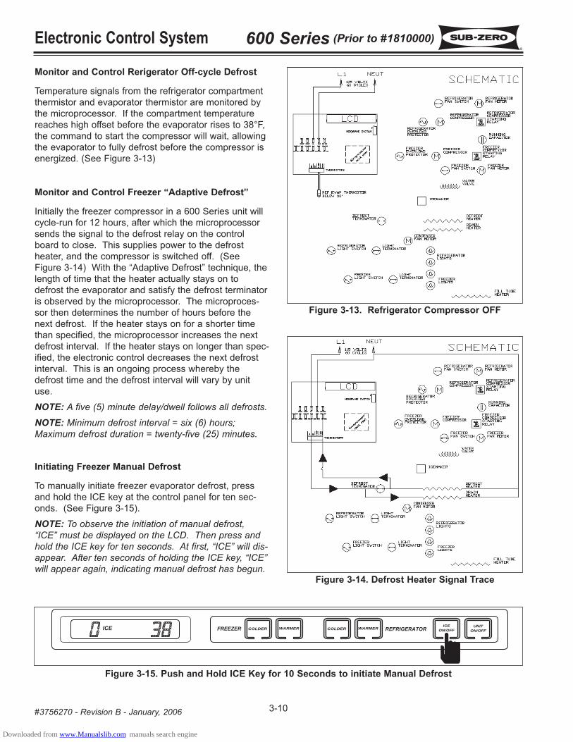
Initiating Freezer Manual Defrost
To manually initiate freezer evaporator defrost, press
and hold the ICE key at the control panel for ten sec-
onds. (See Figure 3-15).
NOTE: To observe the initiation of manual defrost,“ICE” must be displayed on the LCD. Then press andhold the ICE key for ten seconds. At first, “ICE” will dis-appear. After ten seconds of holding the ICE key, “ICE”will appear again, indicating manual defrost has begun.
ICE
Figure 3-15. Push and Hold ICE Key for 10 Seconds to initiate Manual Defrost
Downloaded from www.Manualslib.com manuals search engine

Electronic Control System600 Series (Prior to #1810000)
3-11 #3756270 - Revision B - January, 2006
Figure 3-16. Water Valve Monitored.
ICESERVICE
Figure 3-17. ICE and SERVICE Indicators Flashing = Water Valve Energized Too Long
Monitor Icemaker System and Display If Service Is Needed.
The microprocessor monitors the voltage supplied to the icemaker water valve (See Figure 3-16). If the water valve
is energized for more than fifteen (15) seconds, power to the icemaker system is interupted, and a signal is sent to
the SERVICE and ICE indicators on the LCD to flash (See Figure 3-17).
NOTE: To allow ice to freeze fully and reduce effects of low water pressure, the electronic control system disablesthe icemaker system for 45 minutes after each ice harvest.
Downloaded from www.Manualslib.com manuals search engine
Electronic Control System 600 Series (Prior to #1810000)
3-12#3756270 - Revision B - January, 2006
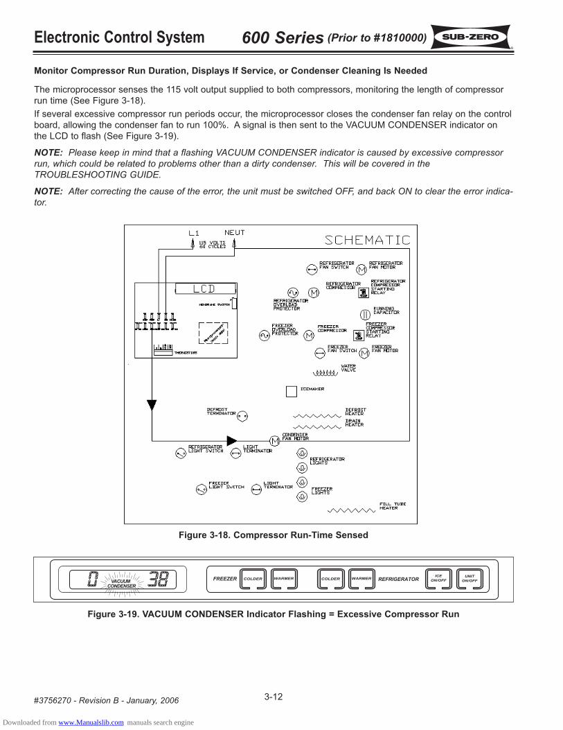
Monitor Compressor Run Duration, Displays If Service, or Condenser Cleaning Is Needed
The microprocessor senses the 115 volt output supplied to both compressors, monitoring the length of compressor
run time (See Figure 3-18).
If several excessive compressor run periods occur, the microprocessor closes the condenser fan relay on the control
board, allowing the condenser fan to run 100%. A signal is then sent to the VACUUM CONDENSER indicator on
the LCD to flash (See Figure 3-19).
NOTE: Please keep in mind that a flashing VACUUM CONDENSER indicator is caused by excessive compressorrun, which could be related to problems other than a dirty condenser. This will be covered in theTROUBLESHOOTING GUIDE.
NOTE: After correcting the cause of the error, the unit must be switched OFF, and back ON to clear the error indica-tor.
Figure 3-18. Compressor Run-Time Sensed
Figure 3-19. VACUUM CONDENSER Indicator Flashing = Excessive Compressor Run
VACUUMCONDENSER
Downloaded from www.Manualslib.com manuals search engine

Electronic Control System600 Series (Prior to #1810000)
3-13 #3756270 - Revision B - January, 2006
SERVICE
Figure 3-20. “EE” Displayed for Freezer Temp. with “SERVICE”
Flashing = Freezer Compartment Thermistor Faulty
SERVICE
Figure 3-21. “EE” Displayed for Refrigerator Temp. with “SERVICE”
Flashing = Refrigerator Compartment Thermistor Faulty
SERVICE
Figure 3-22. Freezer and Refrigerator Temps OK with “SERVICE”
Flashing = Refrigerator Evaporator Thermistor Faulty or Line Separated
POSSIBLE ERROR DISPLAYS
The diagrams below illustrate what a customer may see on the LCD if there is a problem/error with the unit. Below
each diagram is a description of what could be causing the error indicator. (See Figures 3-20 through 3-24.)
NOTE: “EE” indicates a thermistor error.
NOTE: To clear an error display, the cause must be corrected, then the unit switched off and back on with the UNITON/OFF key.
ICESERVICE
Figure 3-23. Freezer and Refrigerator Temps OK with “SERVICE” and “ICE”
Flashing = Water Valve Energized Too Long
VACUUMCONDENSER
Figure 3-24. “VACUUM CONDENSER” Flashing = Excessive Compressor Run, Possible Condenser Cleaning
Needed, but Could Be a Result of Other Problems Which Cause Excessive Compressor Run
NOTE: To clear error indicators, the cause must be corrected and the unit must be switched off, then back on usingthe UNIT ON/OFF key.
Downloaded from www.Manualslib.com manuals search engine

Electronic Control System 600 Series (Prior to #1810000)
3-14#3756270 - Revision B - January, 2006
DIAGNOSTIC MODE PROCEDURES
Diagnostic Mode was incorporated into the electronic control system to help troubleshoot various electrical, mechan-
ical and sealed system components. This section explains Diagnostic Mode and illustrates the operations performed
at the control panel for troubleshooting purposes.
Follow the steps below to initiate and use the Diagnostic Mode.
1. To initiate diagnostic mode, press and hold either COLDER key, then press the UNIT ON/OFF key. All indicators
on the LCD will light-up, indicating diagnostic mode is now active. Thehe first reading on the LCD will be the
freezer compartment temperature (See Figure 3-25).
ICESERVICE
OFFVACUUM
CONDENSER
Figure 3-25. Initiating Diagnostic Mode - Press Either COLDER Key and UNIT ON/OFF Key simultaneously
ICESERVICE
OFFVACUUM
CONDENSER
Figure 3-26. Press UNIT ON/OFF Key to Display Location of Thermistor
2. Press the UNIT ON/OFF key at this time to display the location of the thermistor being read, “F” represents the
freezer compartment (See Figure 3-26).
ICESERVICE
OFFVACUUM
CONDENSER
Figure 3-27. Press COLDER Key to Display Temperature Reading
ICESERVICE
OFFVACUUM
CONDENSER
Figure 3-28. Press UNIT ON/OFF Key to Display Location of Thermistor
ICESERVICE
OFFVACUUM
CONDENSER
Figure 3-29. Press COLDER Key to Display Temperature Reading
3. Press the COLDER key now to display the second reading, the refrigerator compartment temperature (See
Figure 3-27).
4. Press the UNIT ON/OFF key at this time to display the location of the thermistor being read, “r” represents the
refrigerator compartment (See Figure 3-28).
5. Press the COLDER key now to display the third reading, which will be the refrigerator evaporator temperature
(See Figure 3-31).
Downloaded from www.Manualslib.com manuals search engine

Electronic Control System600 Series (Prior to #1810000)
3-15 #3756270 - Revision B - January, 2006
6. Press the UNIT ON/OFF key at this time to display the location of the thermistor being read, “rE” represents the
refrigerator evaporator temperature (See Figure 3-30).
ICESERVICE
OFFVACUUM
CONDENSER
Figure 3-34. Press UNIT ON/OFF Key to Display Inactive Line
ICESERVICE
OFFVACUUM
CONDENSER
Figure 3-31. Press COLDER Key to Display Temperature Reading
ICESERVICE
OFFVACUUM
CONDENSER
Figure 3-30. Press UNIT ON/OFF Key to Display Location of Thermistor
ICESERVICE
OFFVACUUM
CONDENSER
Figure 3-32. Press UNIT ON/OFF Key to Display Location of Thermistor
ICESERVICE
OFFVACUUM
CONDENSER
Figure 3-33. Press COLDER Key to Display Last Reading
7. Press the COLDER key now to display the fourth reading, which will be the freezer evaporator temperature (See
Figure 3-31).
8. Press the UNIT ON/OFF key at this time to display the location of the thermistor being read, “FE” represents the
freezer evaporator (See Figure 3-32).
9. Press the COLDER key now to display the fifth reading. This fifth reading should be “00” because it is inactive. This
area of the electronic control system is intended for possible future use (See Figure 3-33).
10. Pressing the UNIT ON/OFF key at this time should display “IL” representing the inactive line (See Figure 3-34).
Downloaded from www.Manualslib.com manuals search engine

Electronic Control System 600 Series (Prior to #1810000)
3-16#3756270 - Revision B - January, 2006
DIAGNOSTIC MODE SEQUENCE
For the models 611, 632, 642, 650 and 690, the diagnostic mode sequence is:
First: (“F”) Freezer CompartmentSecond: (“r”) Refrigerator Compartment
Third: (“rE”) Refrigerator EvaporatorFourth: (“FE”) Freezer Evaporator
Fifth: (“IL”) Inactive Line
For the model 601R, the diagnostic mode sequence is:
First: (“r”) Refrigerator CompartmentSecond: (“rE”) Refrigerator Evaporator
For the model 601F, the diagnostic mode sequence is:
First: (“F”) Freezer CompartmentSecond: (“FE”) Freezer Evaporator
Third: (“IL”) Inactive Line
Keeping these sequences in mind, it is not necessary to press the UNIT ON/OFF key to display the location each
time after a COLDER key stroke. Pressing the COLDER key successively will display the readings in sequence,
bypassing location display. Then, if location is unknown, press the UNIT ON/OFF key.
NOTE: The electronic control will exit diagnostic mode ten seconds after the last key stroke.
NOTE: Always recheck set-points after performing diagnostic mode procedures.
ICESERVICE
OFFVACUUM
CONDENSER
Figure 3-35. While in Diagnostic Mode Press COLDER Key
ICESERVICE
OFFVACUUM
CONDENSER
Figure 3-36. Press UNIT ON/OFF Key to Display Location of Thermistor
Thermistor Error Indicator
1. While in diagnostic mode, If “EE” is displayed in place of a temperature reading, the thermistor in that location is
either faulty or the electrical line is separated. (In this example, the refrigerator evaporator thermistor is faulty.)
(See Figure 3-35)
2. Press the UNIT ON/OFF key at this time to determine which thermistor is faulty or line separated. ( In thisexample, the refrigerator evaporator thermistor is faulty.) (See Figure 3-36)
NOTE: The electronic control will exit diagnostic mode ten (10) seconds after the last key stroke.
Downloaded from www.Manualslib.com manuals search engine

Electronic Control System600 Series (Prior to #1810000)
3-17 #3756270 - Revision B - January, 2006
Figure 3-37. Evaporator Temp, Compartment Air Temp. and Sealed System Pressure vs. Temp. set-point
During Normal Cycle of Operation
Using Temperatures To Troubleshoot Sealed System
To give the 600 Series a true “Sealed System”, the compressor process stub is soldered shut at the factory after the
sealed system is charged. Troubleshooting the sealed system is possible without a process valve because of the
600 Series Electronic Control System. Since the evaporator temperature, compartment air temperature and sealed
system pressure fluctuate harmoniously around the set-point during normal cycle of operation, troubleshooting the
sealed system is accomplished by observing the evaporator temperature reading in Diagnostic Mode.
Following is a chart illustrating how evaporator temperature and compartment air temperature fluctuate harmoniously
around the set-point during normal cycle of operation. Using temperatures to diagnose sealed system problems will
be detailed in the TROUBLESHOOTING GUIDE.
Downloaded from www.Manualslib.com manuals search engine

Electronic Control System 600 Series (Prior to #1810000)
3-18#3756270 - Revision B - January, 2006
Downloaded from www.Manualslib.com manuals search engine

Sealed System Information600 Series (Prior to #1810000)
4-1 #3756270 - Revision B - January, 2006
SECTION 4
SEALED SYSTEM
INFORMATION
Downloaded from www.Manualslib.com manuals search engine

Sealed System Information 600 Series (Prior to #1810000)
4-2#3756270 - Revision B - January, 2006
HFC-134a REFRIGERANT SERVICE INFORMATION
The 600 Series sealed systems contain HFC-134a refrigerant. This section provides general rules for working with
134a, and explains procedures to be followed while servicing the sealed system. This is followed by diagrams which
illustrate sealed system operation, then model-specific refrigerant flow diagrams.
134a refrigerant requires Synthetic Ester oil in the compressor, and does not tolerate contamination from
other refrigerants, moisture, petroleum-based lubricants, silicone lubricants, cleaning compounds, rust
inhibitors, leak detection dyes, or any other type of additive.
General Rules for Working with 134a Refrigerant
• Use equipment dedicated to 134a sealed system service only.
• Use only 134a refrigerant for back-flushing and sweep charging.
• Always replace the filter-drier when servicing the sealed system.
• The filter-drier must be cut from the sealed system. Never un-braze the drier as the heat will drive moisture
back into the sealed system.
• Do not leave sealed system nor replacement compressor open to the atmosphere for more than 10 minutes.
• When the rubber plugs are pulled from the service compressor, a release of pressure should be heard. If no
release of pressure is heard, do not use the compressor.
• Use ONLY virgin 134a refrigerant when recharging the sealed system.
Downloaded from www.Manualslib.com manuals search engine

Sealed System Information600 Series (Prior to #1810000)
4-3 #3756270 - Revision B - January, 2006
600 SERIES SEALED SYSTEM REPAIR PROCEDURES
Service Procedures
a. Capture refrigerant
b. Replace Compressor
c. Replace filter-drier
d. Evacuate or sweep charge system
e. Recharge system with Virgin 134a refrigerant.
NOTE: To check for a non-operating compressor, a hard start kit can be used.
a. Capture refrigerant.
b. Repair leak.
c. Replace filter-drier.
d. Evacuate or sweep charge system.
e. Recharge system with Virgin 134a refrigerant.
a. Capture refrigerant.
b. Repair leak (if at solder joint) or replace part.
c. Back flush high side of sealed system.
d. If all refrigerant has escaped & system is in vacuum, replace compressor
e. Replace filter-drier.
f. Evacuate or sweep charge system.
g. Recharge system with Virgin 134a refrigerant.
a. Capture refrigerant.
b. Repair leak (if at solder joint) or replace part.
c. Back flush high side of sealed system.
d. Replace compressor.
e. Replace filter-drier.
f. Replace heat exchanger if cap tube is clogged.
g. Install a low side drier on suction line.
h. Evacuate or sweep charge sealed system.
i. Recharge with Virgin 134a refrigerant.
a. Capture refrigerant.
b. Locate and remove restriction or locate and replace part.
c. Back flush high side of sealed system.
d. Replace filter-drier.
e. Evacuate or sweep charge system.
f Recharge system with Virgin 134a refrigerant.
a. Capture refrigerant.
b. Replace filter-drier.
c. Evacuate or sweep charge system.
d. Recharge system with Virgin 134a refrigerant.
.
Problem
Non-Operating, Inefficient,
Noisy Compressor
High Side leak
Low Side Leak
Contaminated Sealed System
Examples:> Burned out compressor> Excessive moisture from
leak in condensate loop or inlow side
> Plugged capillary tube
Restriction
NOTE: If restriction is due tosealed system being contami-nated, see ContaminatedSealed System above.
Overcharge
Downloaded from www.Manualslib.com manuals search engine

Sealed System Information 600 Series (Prior to #1810000)
4-4#3756270 - Revision B - January, 2006
Figure 4-1. Compressor
1
3
Figure 4-2. Condenser
2
SEALED SYSTEM OPERATION
The following six diagrams illustrate a basic sealed sys-
tem. The components are listed in order of refrigerant
flow, with an explanation of their fundamental role as part
of a sealed system. NOTE: These illustrations do notrepresent any specific 600 Series sealed system.
Compressor (Figure 4-1)
The compressor creates a high side and low side pres-
sure difference in the sealed system by compressing the
refrigerant gas, thus raising the pressure and tempera-
ture. The compressor pushes this high-pressure/high-
heat gas through the door gasket seat heater loop to pre-
vent sweating (on most units the gas also travels through
drain pan heater tubing to help evaporate water in the
drain pan). The high-pressure/high-heat gas then travels
to the condenser.
Condenser (Figure 4-2)
The high-pressure/high-heat gas travels through the con-
denser, where the heat is dissipated by cooler air being
drawn over the condenser tubing by the condenser fan.
This changes the gas into a high-pressure/warm liquid
that then enters the high-side filter-drier.
High-Side Filter-Drier (Figure 4-3)
The high-pressure/warm liquid travels through the high-
side filter-drier, which removes moisture from the refriger-
ant before it enters the capillary tube.
Compressor
Drain Pan
Heater Tubing
Door Gasket
Seat Heater
Loop
Condenser High-Side Filter-Drier
Figure 4-3. High-Side Filter-Drier
Downloaded from www.Manualslib.com manuals search engine

Sealed System Information600 Series (Prior to #1810000)
4-5 #3756270 - Revision B - January, 2006
Capillary Tube (Part of Heat Exchanger) (Figure 4-4)
The high-pressure/warm liquid refrigerant travels through
the long skinny capillary tube which is attached to the
suction line. (These two tubes soldered together create
the heat exchanger.) As the high-pressure/warm liquid
refrigerant travels through the capillary tube it gives up
heat to the cool refrigerant gas traveling through the suc-
tion line and the pressure drops, so it is a low-
pressure/cool liquid before it enters the evaporator.
Evaporator (Figure 4-5)
As the low-pressure/cool liquid refrigerant enters the
evaporator, it vaporizes. This is caused by a dramatic
pressure change which occurs when the refrigerant
enters the larger diameter evaporator tubing from the
smaller diameter capillary tubing. This vapor travels
through the evaporator absorbing heat from the compart-
ment, gradually converting it to a cool gas. This cool gas
then enters the suction line.
Suction Line (& Heat Exchanger) (Figure 4-6)
The cool gas travels through the suction line which is
attached to the capillary tube. (As mentioned earlier,
these two tubes soldered together create the heat
exchanger.) As this cool refrigerant gas travels through
the suction line it absorbs heat from the warm liquid
refrigerant traveling through the capillary tube, making it a
luke warm gas. The lukewarm refrigerant gas returns to
the compressor where the process begins again. Figure 4-4. Capillary Tube (Part of Heat Exchanger)
4
Figure 4-6. Suction Line (Part of Heat Exchanger)
6
Figure 4-5. Evaporator
5
Capillary Tube
Evaporator Accumulator
Suction Line
Heat
Exchanger
Downloaded from www.Manualslib.com manuals search engine

Sealed System Information 600 Series (Prior to #1810000)
4-6#3756270 - Revision B - January, 2006
Figure 4-7. Models 601R Refrigerant Flow
Figure 4-8. Model 601F Refrigerant Flow
Freezer Compressor
Refrigerator Compressor
Refrigerator Evaporator
Freezer Evaporator
Heater Loop
Drain Pan Heater
Heat Exchanger
Condenser
Condenser
High-Side Filter Drier
High-Side Filter Drier
Heat Exchanger
Downloaded from www.Manualslib.com manuals search engine

Sealed System Information600 Series (Prior to #1810000)
4-7 #3756270 - Revision B - January, 2006
Figure 4-9. Models 611, 650 Refrigerant Flow
Figure 4-10. Models 632, 642, 690 Refrigerant Flow
Freezer Compressor
Freezer Drier
Freezer Heat Exchanger
Drain Pan Heater
Freezer Heater Loop
Freezer Evaporator
Refrigerator Evaporator
Refrigerator Heater Loop
Refrigerator Heat Exchanger
Refrigerator Drier
Refrigerator Compressor
Dual Condenser
Drain Pan Heater
Freezer Heat Exchanger
Freezer Compressor
Freezer Heater Loop
Freezer Evaporator
Freezer Drier
Refrigerator
Drier
Refrigerator Heater Loop
Refrigerator
Evaporator
Dual Condenser
Refrigerator Compressor
Refrigerator
Heat Exchanger
Downloaded from www.Manualslib.com manuals search engine

Sealed System Information 600 Series (Prior to #1810000)
4-8#3756270 - Revision B - January, 2006
Downloaded from www.Manualslib.com manuals search engine