3002018310NP, "BWRVIP-25, Revision 1-A: BWR Vessel and ...
277
t=~1211 ELECTRIC POWER -=,1- RESEARCH INSTITUTE 2020 TECHNICAL REPORT BWRVIP-25NP, Revision l-A: BWR Vessel and Internals Project BWR Core Plate Inspection and Flaw Evaluation Guidelines NOTICE: THIS REPORT CONTAINS THE NONPROPRIETARY INFORMATION INCLUDED IN THE PROPRIETARY VERSION OF THIS REPORT. THE PROPRIETARY VERSION OF THIS REPORT CONTAINS PROPRIETARY INFORMATION THAT IS THE INTELLECTUAL PROPERTY OF EPRI. ACCORDINGLY, THE PROPRIETARY REPORT IS AVAILABLE ONLY UNDER LICENSE FROM EPRI AND MAY NOT BE REPRODUCED OR DISCLOSED, WHOLLY OR IN PART, BY ANY LICENSEE TO ANY OTHER PERSON OR ORGANIZATION.
-
Upload
khangminh22 -
Category
Documents
-
view
0 -
download
0
Transcript of 3002018310NP, "BWRVIP-25, Revision 1-A: BWR Vessel and ...
t=~1211 ELECTRIC POWER -=,1- RESEARCH INSTITUTE 2020 TECHNICAL REPORT
BWRVIP-25NP, Revision l-A: BWR Vessel and Internals Project BWR Core Plate Inspection and Flaw Evaluation Guidelines
NOTICE: THIS REPORT CONTAINS THE NONPROPRIETARY INFORMATION INCLUDED IN THE PROPRIETARY VERSION OF THIS REPORT. THE PROPRIETARY VERSION OF THIS REPORT CONTAINS PROPRIETARY INFORMATION THAT IS THE INTELLECTUAL PROPERTY OF EPRI. ACCORDINGLY, THE PROPRIETARY REPORT IS AVAILABLE ONLY UNDER LICENSE FROM EPRI AND MAY NOT BE REPRODUCED OR DISCLOSED, WHOLLY OR IN PART, BY ANY LICENSEE TO ANY OTHER PERSON OR ORGANIZATION.
BWRVIP-25NP, Revision 1-A: BWR Vessel and Internals Project BWR Core Plate Inspection and Flaw Evaluation Guidelines
3002018310NP
Final Report, September 2020
EPRI Project Manager R. Carter
All or a portion of the requirements of the EPRI Nuclear Quality Assurance Program apply to this product.
'NO ELECTRIC POWER RESEARCH INSTITUTE
3420 Hillview Avenue, Palo Alto, California 94304-1338 • PO Box 10412, Palo Alto, California 94303-0813 • USA 800.313.3774 • 650.855.2121 • [email protected] • www.epri.com

DISCLAIMER OF WARRANTIES AND LIMITATION OF LIABILITIES
THIS DOCUMENT WAS PREPARED BY THE ORGANIZATION(S) NAMED BELOW AS AN ACCOUNT OF WORK SPONSORED OR COSPONSORED BY THE ELECTRIC POWER RESEARCH INSTITUTE, INC. (EPRI). NEITHER EPRI, ANY MEMBER OF EPRI, ANY COSPONSOR, THE ORGANIZATION(S) BELOW, NOR ANY PERSON ACTING ON BEHALF OF ANY OF THEM:
(A) MAKES ANY WARRANTY OR REPRESENTATION WHATSOEVER, EXPRESS OR IMPLIED, (I) WITH RESPECT TO THE USE OF ANY INFORMATION, APPARATUS, METHOD, PROCESS, OR SIMILAR ITEM DISCLOSED IN THIS DOCUMENT, INCLUDING MERCHANTABILITY AND FITNESS FOR A PARTICULAR PURPOSE, OR (II) THAT SUCH USE DOES NOT INFRINGE ON OR INTERFERE WITH PRIVATELY OWNED RIGHTS, INCLUDING ANY PARTY'S INTELLECTUAL PROPERTY, OR (Ill) THAT THIS DOCUMENT IS SUITABLE TO ANY PARTICULAR USER'S CIRCUMSTANCE; OR
(B) ASSUMES RESPONSIBILITY FOR ANY DAMAGES OR OTHER LIABILITY WHATSOEVER (INCLUDING ANY CONSEQUENTIAL DAMAGES, EVEN IF EPRI OR ANY EPRI REPRESENTATIVE HAS BEEN ADVISED OF THE POSSIBILITY OF SUCH DAMAGES) RESULTING FROM YOUR SELECTION OR USE OF THIS DOCUMENT OR ANY INFORMATION, APPARATUS, METHOD, PROCESS, OR SIMILAR ITEM DISCLOSED IN THIS DOCUMENT.
REFERENCE HEREIN TO ANY SPECIFIC COMMERCIAL PRODUCT, PROCESS, OR SERVICE BY ITS TRADE NAME, TRADEMARK, MANUFACTURER, OR OTHERWISE, DOES NOT NECESSARILY CONSTITUTE OR IMPLY ITS ENDORSEMENT, RECOMMENDATION, OR FAVORING BY EPRI.
THE ELECTRIC POWER RESEARCH INSTITUTE (EPRI) PREPARED THIS REPORT.
NOTICE: THIS REPORT CONTAINS THE NONPROPRIETARY INFORMATION INCLUDED IN THE PROPRIETARY VERSION OF THIS REPORT. THE PROPRIETARY VERSION OF THIS REPORT CONTAINS PROPRIETARY INFORMATION THAT IS THE INTELLECTUAL PROPERTY OF EPRI. ACCORDINGLY, THE PROPRIETARY REPORT IS AVAILABLE ONLY UNDER LICENSE FROM EPRI AND MAY NOT BE REPRODUCED OR DISCLOSED, WHOLLY OR IN PART, BY ANY LICENSEE TO ANY OTHER PERSON
THE TECHNICAL CONTENTS OF THIS PRODUCT WERE PREPARED IN ACCORDANCE WITH THE EPRI QUALITY PROGRAM MANUAL THAT FULFILLS THE REQUIREMENTS OF 10 CFR 50 APPENDIX B. THIS PRODUCT IS SUBJECT TO THE REQUIREMENTS OF 10 CFR PART 21. CERTIFICATION OF CONFORMANCE CAN BE OBTAINED FROM EPRI.
NOTE
For further information about EPRI, call the EPRI Customer Assistance Center at 800.313.3774 or e-mail [email protected].
Electric Power Research Institute, EPRI, and TOGETHER. .. SHAPING THE FUTURE OF ELECTRICITY are registered service marks of the Electric Power Research Institute, Inc.
Copyright© 2020 Electric Power Research Institute, Inc. All rights reserved.
NRC SAFETY EVALUATION
In accordance with an NRC request, the NRC Safety Evaluation immediately follows this page. Other pertinent NRC and BWRVIP correspondence are included in appendices.
111
IV
BWRVIP 2020-021; Attachment 1
UNITED STATES NUCLEAR REGULATORY COMMISSION
WASHINGTON, D.C. 20555-0001
Mr, Tim Hanley, Chairman ATTN:. Qebb.ie Ro~se BWR Vessel and Internals Project
tv!arch 23, 2020
1300_West W.T . ...._rri_s Boul~vard (Building 1) Charlotte, NC 28262
SµBJECT: ANAL PROPRIETARY SAFETY EVALUATION FOR aBWRVIP-25, REVISION 1: BWRVESSEL AND INTERNALS PROJECT, BWR CORE PLATE INSPECTION AND Fl.AWEVAL.UATIONGUIDELINES.(CAC NO. MF4887; EPID L~2014-TOP-OQ08)
Dear Mr. Hanley:
By letter dated ~eptember 26, 201.6 (Agencywide Documents Access and M~agement System Accession No. ML.16273A474), the Boiling Water Reactor (BWR) Vessel and Internals Project (BWRVlf') subm!l!ed for U.S. Nu~lear Regulatory"Cominjssion (I\IRC) staff review Topical Report (TR) .BWR\liP.;,25, Revision 1: BWRVessel and liliemals P.roject, BWR.Core Plate Inspection and Flaw. Evaluation Guidelines.· By letter daf.ed September 10, 2019; the NRC staff issued .its draft safety eval~atipn (SE) (ADAMS Accession No. ML 19007A012). .
The BWRVIP provided commenls on the draft SE via letter.dated October 15, 2019 (ADAMS Accession No. ML 19290D822). The comments addressed inconsistencies, typographical errors, and identified proprietary information.
In response to the BWRVIP comments, the NRC staff issued a revised draft SE via email dated February 3, 2020 (ADAMS Accession No. ML20030A002). By letter dated February 28, 2020 (ADAMS Accession No. ML20063J233), the BWRVIP provided additional comments. The comments centered on the additional plant-specific actions that w.ere in the revised draft SE.
The NRC staff has found that BWRVIP-25 is acceptable for referencing in licensing applications for nuclear power plants to the extent specified and under the limitations delineated in the TR and in the enclosed final SE. The final SE defines the basis for our acceptance of the TR
NOTICE: The enclosure transmitted herewith contains Proprietary Information. When separated from enclosure, this transmittal document is decontrolled.
T_ Hanley -2-
Our acceptance applies only to material provided in the subject TR We do not intend ~o ~peat our review of the acceptable material described in the TR When the TR appears as a reference in license applications. our review will ensure that the material presented applies to the specific plant involved_ License amendment requests that deviate from this TR will be. subject to a plant-specific review in accordance with applicable review standards_
In accordance with the guidance provided on the NRC website, we request that ~e BWR'{IP publish accepted versions of BWRVIP-25-P and -NP, within six months of receipt ofthis ietter, The accepted versions shall incorporate this letter and the enclosed final SE after th~ tit{e page, For -NP versions. the BWRVIP shall strike the proprietary information markings on this;letler and make the appropriate redactions and adjustments to document security classifiCcltions to the attached SE including striking the header and footerforthe-NP version of the SE
Also, the accepted versions must contain historical review information, including NRC requests for additional information (RAls) and responses_ The accepted versions shall includea·•~m (designating approved) following the TR identification symbol_ ·
As an alternative to including the RAls and RAI responses behind the title page, if changes_ to the TRs provided to the NRC staff to support the resolution of RAI responses, and the NRC staff reviewed and approved those changes as described in the RAI responses. there are two ways· that the accepted version can capture the RAls:
1 _ The RAls and RAI responses can be included as an Appendix to the accepted version_ 2_ The RAls and RAI responses can be captured in the form of a table (inserted after the fin~
SE) which summarizes the changes as shown in the accepted version of the TR The.table should reference the specific RAls and RAJ responses which resulted in any changes, as shown in the accepted version of the TR_ ·
If future changes to the NRC's regulatory requirements affect the acceptability of this -m,; the BWRVIP will be expected to revise the TR appropriately_ Licensees referencing this:~ would be expected to justify its continued applicability or evaluate their plant usin9, the revised TR
If you l'lave.any questions, p1ease·contactJh~·Project M~ager fortl!e review, Joseph J_ t-ioionich at 301415-7297 or via electronic mail at josephJ-loionic~~rirc:H()V_
Docket No_.:, 99902016
Enclosure: Final SE
Sincerely,
/RN
Den.nis More.y, Chief l,..iceilsing Processes Branch Divlsion of Operating Reactor Licensing Qffi~ of Nuclear Rt?actor R~Lilation
V

Vl
T. Hanley -3-
SUBJECT: FINAL PROPRIETARY SAFETY EVALUATION FOR ·ewRVJP-25. REVISION 1: BWR VESSEL AND INTERNALS PROJECT. BWR CORE PLATE INSPECTION AND FLAW EVALUATION GUIDELINES• (CAC NO. MF4:887; EPID L-2014-TOP-0008) DATED MARCH 23, 2020
DISTRIBUTION: PUBLIC (Letter) NON-PUBLIC (Rnal SE) RidsNrrLADHanison RidsResOd RidsNnOorl RidsNnOorlUpb RidsOgcMwlCenter RidsNrrDe RidsNrrDeWmib RidsACRS_MailCTR !Tseng, NRR RidsNnDnlr RidsNnDnlrMVib JMedoff, NRR GCheruvenki. NRR CSyndor. NRR JHolonich. NRR
ADAMS Accession Nos.: ML 19290G703 (LettertPublic}; ML 19290G733 (SE/NonPublic}; ML19290G755 (Package} *via e-mail;
OFFICE NRR/DORULLPB/PM NRR/DORL/LLPB/LA* NRR/DNLR/MVIB/BC* NAME JHolatich DHarrisoo* HGonzalez DAlE 03/23/2020 03/23/2020 03/03/2020 OFFICE NRR/DEIWMIB/ABC* NRR/DORL/LLPB/BC* NAME TScarbrough DMorey DAlE 03/15/2020 03/23/2020
OFRCIAL RECORD COPY
. . _ UNiTEb STATES _ . _ NUCLEAR REGULATORY COMMISSION
WAsHiNGToN; o.c. 2qi;ss:0001.
U.S. NUCLEAR REGULATORY COMMISSION
SAFETY EVALUATION BY THE OFRCEOF NUCLEAR REACTOR REGULATION
•eWRVIP-25, REVISION 1: BWRVESSEL AND INTERNALS PROJECT
BWR CORE PLATE INSPECTION AND Fl.AW EVALUATION GUIDELINES•
1.0 INTRODUCTION
1.1 Background Information
By letter dat~ ,5ep~eniber ,2ij, .201,6 (Ref. 1 ) •. as supp!~me~ed by letters dated .~ber 12, 2018 (Ref. 2).- and June 20, 2019 (Ref. 19), Jhe Bectrical Power Research Institute (EPRI) Boiling Wener Reactor (BWR) Vessel an~ Internals Proj¢ct ~VIP)submitted proprietary EPRI Tec~nical Report No. 30Q20QSQ94, -eWRViP-25, Reyision 1 :. B~ V~ and internals Project; BWR Core Plate Inspection and Raw .Evaluation Guidelines"' (Ret .3, referred to herein as the ~pica! report pr TR)tothe U.S: ~ucJear Rajlll~ory ~rr,iin.~9n (NRC). ·~ pLibliclyavailaple, non-proprietary version of the report.(BWR.VIP-25NP. Revision 1) is available for review by members of the general public ~ef. 4). This report.provides a set of augmented !ilspectior;i and evaluation (!&E) criteria that. may be used to either inspect or evaluate the reactor vessel internal (RVI) core plate (CP) assemblies that are present in BWR plant d~igns. The TR represents an update ofthe previous l&E guidelines for these assemblies in proprietary EPRI Technical Report No. 107281 ·BWR Vessel and Internals Project, BWR Core Plate Inspection and Raw Evaluation Guidelines (BWRVIP-25t (Ref. 5), which was approved for implementation in a staff-issued safety evaluation (SE) dated December 19, 1999 (Ref: 6).
1.2 Summary of Changes in the TR Relative to BWRVIP-25
The updated methodology in the TR is based on a proprietary l&E methodology for the, inspection, monitoring, and evaluation of BWR CP assembly designs. These include the.CPs and any components in the assembly designs that may be used to secure the platesfn place and protect against either lateral or vertical movements during design basis loading conditions. including those that may occur during normal, upset, emergency, or faulted loading conditions. This includes wedges or CP rim hold-0own bolts that may be used to ensure the structurai integrity of the CP assemblies and restrain the CPs from lateral displacements under i:ippli£i:!j loading conditions. A summary of the major differences in the TR from the previous methodology in BWRVIP-25 is given in the next paragraph.
Enclosure
Vll
vm
-2-
The most significant change to the TR relative to BWRVIP-25 is the addition of Appendix I, aEvaluation to Justify Core Plate ~olt Inspection Bimination; which contains a generic evaluation intended to justify performing no examinations of the CP hold-down bolts. A license renewal appendix was also added in Appendix B; however, 'this appendix wil not be included in the final version of the TR The LR appendix was originally provided to the NRC in a separate letter and was never included in BWRVIP-25, Rev .0. As explained in the October 12, 2018, RAI response, Appendix B to the TR was intended to be historical. The BWRVIP is generally removing or no longer including license renewal appendixes in its l&E guidelines due to inclusion of adequate guidance for operation beyond 40 years in the main body of the reports. Therefore, the BWRVIP stated in the RAI respon~ that it would remove Appendix B in the next revision of the TR The staff notes that although a 60-year fluence value was used to calculate stress relaxation of the CP bolts in Appendix I, the TR does not include an applicability limit based on calendar years, nor was it the intent of the staff to impose such a limit
2.0 REGULATORY EVALUATION
2.1 Applicable Requirements- License Renewal
The NRC regulations for submitting license renewal applications (LRAs) or subsequent license renewal applications (SLRAs) of U.S. light water reactors are given in the Title 10 of the Code of Federal Regulations (1 O CFR) Part 54, "Requirements for Renewal of Operating Licenses for Nuclear Power Plants· (Ref. 7, the LR Rule). The LR Rule includes (in part) requirements on the following topics: ·
□ 10 CFR 54.3(a)- "Definitions,· including the six criteria that must be met to define a given analysis, calculation, evaluation, or assessment as a time-limited aging analysis (TLAA)
□ 1 O CFR 54.4- scoping of systems, structures. and components (SSCs)
□ 1() CFR 54.21 (aX1 )- performance of an integrated plant assessment (IPA) and determination of SSCs subject to an aging management review (AMR)
D 1 O CFR 54.21 (aX3)- management of applicable aging effects
□ 1 O CFR 54.21 (c)(1 )- identification of applicable analyses that conform to the definition of a TLAA in 10 CFR 54.3(a)
□ 10 CFR54.21(d)-final safety analysis report (FSAR), updated final safety analysis report, or updated safety analysis report supplement summary descriptions for each aging management plan (AMP) and TLAA that is included in an LRA or subsequent LRA (SLRA).
Applicable NRC and Industry Guidelines for Aging Management
The NRC staff recommended guidelines for developing AMPs are given in Sections A.1.2.2 and A.1.2.3 of NUREG-1.800, Revision 2, ·standard Review Plan for Review of License Renewal Applications for Nuclear Power Plants· (Ref. 8, SRP-LR). Appendix A.1. • Aging Management Review - Generic (Branch Technical Position (BTP) RLSB-1 r (Ref. 9). The AMPs provided in
-3-
Chapter XI of NUREG-1801, Revision 2, "Generic Aging Lessons Learned (GALL) Report" (Ref. 10), or in subsequently issued interim staff guide documents. represent a set of generic staff-approved AMPs that may be adopted for aging management objectives in an LRA. These AMPs are based on the ten generic program elements recommended for AMPs in BTP RLSB-1. as defined in Section A 12_3 of SRP-LR. Appendix A_ 1 _
Adadional Guidance Used.or Referenced in Initial llcense Renewal Applications The current NRC staff AMP that is recommended for aging management of BWR RVI components in an initial, 60-year LRA is given in Chapter XtM9, "BWR Vessel lnternals,R of the GALL Report (Le_, GALL AMP XLM9), The program in GALL AMP XLM9 defines a set of generic program element criteria that, if implemented, should be acceptable to manage age-related degradation BWR RVI components_ The ·scope of Program· element in GALL AMP XLM9 references the methodology in BWRVIP-25 as a valicl EPRI BWRVIP l&E basis for managing age-related degradation that may develop in BWR CP assembly components. The NRC staff accepted EP~I TR No_ BWRVIP-25 for implementation for the initial plant operating license period in a SE elated December 19, 1999 (Ret 6)_ By letter dated July 17, 1Q97, EPRI submitted Appendix B to BWRVIP-25 documenting compliance with the LR Rule (Ref. 11 )_ The NRC staff issued a supplementary SE documenting its acceptance of BWRVIP-25 for referencing in LRAs ori December 7, 2000 (Ref. 12)_
Additional Guidance Used or Referenced in Subsequent license Renewal Applications For SLRAs. the staff addressed aging management criteria for BWR RVI components in Section 3_ 1 _22_ 12, "Cracking Due to Irradiation-Assisted Stress Corrosion Cracking," Section 3_ 1_22_ 13, "Loss of Fracture Toughness Due to Neutron Irradiation or Thermal Aging Embritllement, • and Section 3_ 1.22_ 14, "Loss of Preload Dueto Thermal or IrradiationEnhanced Stress Relaxation; of NUREG-2192, "Standard Review Plan for Review of Subsequent License Renewal Applications for Nuclear Power PlantsR (Ret 13, SRP-SLR report) and in GALL-SLR AMP XLM9, "BWR Vessel Internals,. contained in NUREG-2191, "Generic Aging Lesson Learned for Subsequent License Renewal Report,R Volumes 1 and 2 (Ref_ 14, GALL-SLR)_ The SRP.:..SLR contains additional evaluation criteria to ensure that the effects of increases in neutron .fluence for 80 years versus 60 years are considered_
Therefore, GALL-SLR AMP XLM9, as subject to the additional further evaluation criteria in SRP-SLR Section 3_ 1 _22_ 14, now addresses how the BWRVIP-25 report may be used as the basis for managing age-related effects in BWR CP assembly components during a proposed subsequent period of extended operation (PEO)_
3.0 TECHNICAL EVALUATION
3_ 1 Summary of Contents ofTopical Report
Section 1_0 contains the introduction and background_ Section 2_0 contains a description of the various CP subcomponents, and a summary of the BWRVIP's evaluation of the applicable aging effects and the consequences of failure_ Section 3_0 summarizes the recommended inspections of the.various CP subcomponents, incl1,1ding schedule, scope, and ihe nondestructive examination methodologies_ The only subcomponents with any recommended inspections are the CP rim hold down bolts, for plants that do not have wedges installed, or plants not meeting the criteria of TR Appendix L Section 4_0 describes the loads and stresses that should be · considered, should a plant perform a plant-specific evaluation to justify not inspecting the CP
lX
X
-4-
bolts. _App~di}C A ce>l'Jtains ~ example plant-specifi<: 1:1rtalysis Qf CP b<Jlts and.is not ch~ged from BWRVIP.::25 (Ref. 5), Appen<iix B is the~ appendix. It is ~ritiaDy the same as the LR appendix transmitted via BWRVIP ietter 97-634. The intent of the appendix is to demonstrate tiow_BWRVl~:..25 c<>mp!i~ with 1,h~t~hnicaI·in{omurticm requirements <>.fthe LR Rul~ (1Q' CFR 54.21). Page Be tof the TR slatElS that the information iii Appendix B Vias ~viewed and confirmed to remain applicabletothe TR However. the BWRVIP indicated in a RAI response that Apperidix !3 would b¢ removed in the final versitw of the'TR -ApJien~ices'C through Hcoritain correspondence reiai.edto the review:of BWRVIP-25and its LR supplement. inch.idirig the initial arid firiaJ NRC SEs, and supplemental LR SE. These apperidices ·are tiistoricaliri nf!lb-1~- Appendix! contains~ generjc ~aliliitlon to jl!stify elimination· of CP bolt inspections and is new. AJ>pendix J contains a reco~ of r:evisions.
3.2 Recommended Inspections
The ~ommended insp~ioris for the varjous GP subc::C>111p<>.nents have not changed in the TR relcltivete> B\IVRVIP-25 (Ref. 5). Per TR-Section 3:2.2; based _Qn structural analyses ij~ribed in TR.Section 4 and safely consequence analyses; the CP bolts are the only CP location.which n_eeds to be add~_\!ith· a plant-specific inspection ~Y- The IB specifies_ inspection of the CP b(:11~ to ensure an adequate number are intact to prevent lateral displacement of the CP. However. additional altemalivesto:examination have.been added.
Based on the statements in BWRVIP-25. ~evisjon 1, Section 3.1.1, page 3:-3,.the NRC staff has inferrecf that some BWR plants have been able to perform visual inspections (VT-1 )\ enhanced visual techniqu_e (EYT-"1 )2. or modified visual t¢chnique (MVT-1) of the CP bolts. Many BWR plants have been able to pertorm VT-33 visual exams of the bolls. In addition. quring the LRA reviews, some BWR;renewed license holders made commitments to perform analytical evaluatic,ns for dem9nsti:atirig that the integri!Y ~d functionality of CP ~sserribly would be maintained during the PEO.
These LR commitments. which oft~n w~ inc_orporated into.the FSAR. specifieci tti_at a plant-specific ~ ana,ysis of the CP assembly would be performed. The analysis takes into consideration the loss-of-bolt preioad due to stress relaxation from irradiation ancft:hermal e~. ~swE?D ltle potential for bolt cracking durtng l!le PEQ. The anitlysis would be _submitted to.the NRC stafffor review. Th~ugh its review of these plant-specific analyses, the NRC staff
1 The TR _s~es, that VT-1 is d_efiiled in Americail Sot::iety of Mechanical Engineeis (ASME) Section XI. Sub~graph 'IW A- 2211 (b), 1989 Edition. No Addenda, as "the'visual testing method capable of resdvin'g a 1/32inc_h blackliileon 18~ neu~ gray ca~. Later Editions oflheASNiEcix!e can be used.
2 The TR states.that EVT-1 is defined in the latest revision of BWRVIP--03. BWRVIP--03 Rev. 18 (Ref. 16) states that EVT-1 as used in this dcicunieiit is a visual inspection inethod where the equipment and em,irorimental conditions are such that they· can ailecjuately resolve the.ASME Code Section XI VT-1 O:C)44 inch characters. Note: This definition supersedes EVT-1 definitions foilnd iii 'other BWRVIP gUidarice docu"'ents, EVT-.1 examinations perfonned to ttiepreviolis ievis(ons (if BWR'(IP~03 ri!quired a sensitivrty, resolution; and contrast standard providing.½ niil resolution and are considered acceptable. FutureEVf~1 e~ainitjationswll requi~ dei.ionstrating resolution oftheASMECodeSection XI VT-1 0.044 incti c,h~cters.
3 Th!!:TR $rt~ that VT-3 as used in .this document is a visual inspection method for assessing general mechan1~ and structural conditions. ·

-5-
h~ requested that licen~ commit to performing VT-3 visual examination of a 50 peite~t sample of the CP bolts during PEOs. ~ese examinations provide reasonable assurance.that the bolts and their locking devices remain in place during the PEO.
Some BWR licensees have committed to performing the VT-3 exams as ~n aging management activity. These regular commitments were made during the NRCstaffreview of the plant-specific CP analytical evaluations for dosure of the original LR/FSAR commitnlents. Based on the above-<:ited past experience and precedent for performing visual examination of accessible CP bolts fotthe detection of significant degradation, the NRC staff requested in· MVIB Operating Plants Request for Additional Information (RAl)-1 that EPRI provideJhe following information regarding the future CP bolt inspection criteria (including inspec;tion method, frequency, and sample size) that will be applied during the PEOs for the following categories of BWR plants:
1. Applies to those plants that satisfy the evaluation criteria specified in BWRVIP-25, Revision 1, Appendix I, Section 9:7 for eliminatjon of CP bolt inspections. Specifically, for these plants. please discuss whether any in-vessel visual inspections wouid be · conducted to provide reasonable assurance that the bolls and their locking devjces are remaining in place during PEOs. Please revise and/or supplement Append ix I to · . address performance of these core bolt inspections for BWRs seeking to implement the Appendix I methodology.
2. For those plants that do not satisfy the evaluation criteria specified in Appendix I; please address how the plant-specific CP bolt inspection criteria will be determined based c:,n the results of this plant-specific analysis. Please revise and/or supplement BV'yRVl~-25, Revision 1, Appendix A to address the determination of core bolt inspection criteriafor BWRs that need to perform this plant-specific analysis.
3. For those plants that do not satisfy the Appendix I evaluation criteria, and for which a plant-sp~ifi_~ stress ancllysis. does npt demonstrate.c;tc:ceptaj,le margins, per the example p~vided il!..A~~ndiJ!f\. pl~JdEll!t!fV.:.W:b~er f!l~plants would be -~quired
_ to J!.erfotrri....,Content Deleted - Ef.'_'1!._Pro~_~?,!_ry Information· . , __ J ~------- ~ p!~~rev.is¢1ind/o[siJpple.menttheJ3~VIP-2,5; Rev_ision 1 to address performance of these CP.bolt inspections.
{n its October 12, 2018, response to MVIB Operating Plants RAl-1, Request 1, EPRrstatE!d that in-.vessei visuai inspections of CP bolting can only provide assurance that the core bolts are p,:esent,arJ_d thl:!-1 ad~jtion~ inspect.ions.!'1011ld npt p·~vid_e a,ny ri~ relevant informaliori,. EPRI stated that visual ex~inatiori cannot interrogate the th!l!iided region of the bolts wh_e,e intergranularstress corrosion cracking (IGSCC)would:occurwithoui bolt removal. and that any .tracking would be.obscured by the nut. EPRI stated that since·coinplete boltfailure·is riot a lik~y ·~vefit; visual _exami'mitions of any kictd .EUe judg~ to be 1ovi value. . EP~ stated ~at itt the CP boll location., the risk ofJGSCCis minimal, as discussed in Section 4 of-Appendix I, and that Appe11dilc I pr.qvides stJfficiEmtju~catiQn fornc> inspections being p~rformefat the c;p bolt l~Qns.
Th_e Octob_er 12, ~01~; ~~lJn,se to RAl-1, Request 2 ~ed that if a plant perform_s a plant-specific analysis of CP bolting to demonstrate that the horizontal displacement remilins acceptable. even with the ioss of some boltin$J, no.inspections would be required. EPRI further
Xl

Xll
-6-
referredtqther~on~toRequ~ 1 forMVIBQperating PlantsRAl-1 forju~cation ofthe elimination of inspections..
In its Octqb~ 12, 2018, _response ~i:(RAl-1, ijequ~ 3, EPR! state;d ttii;n if the ApIfendix I ev~uationcritena ~not be satisfied, a plantv.,ould need to address _it through their.corrective action program. EPRI further,stated that remedial actions, such as additional analysis, i,nspetjjon~.ari~r plam lll~ifitjmoils, \YOUl~)e. iniplemerited ac; necessary 19-~fy . _ programmatic requirements. EPRI indicated that Sections 3.2.2:fill.d 3:2.2:3 ~rovide acceptable _!iltemativesti:> AP.P.!:?ftdix I, i.e., . . . , , . . . . . · _. ;
:content Del~ted - E:PR~ Proprietary Information] T~e st.tff rev:iewed l;PR!'s ~011seto MVll~,Op¢rating Plants !t-\1-1 and fi_nds th.-, Vf-3 examination ·of the CP bolts from above the CP would provide little orno vaiue, Since.it cannot ~etemiine ifth~ bolt shan!ai !ire crack¢d, Tile bolt ke¢penvoul~ !1;ilitin the bol_t h$ids even in the ei,erit of a compleieshank fi:l~qre, making VT~ examinations frpin above Qt li!:Hevalue, Visual:examinations from below the;CP could verify that the bolUs·present but could not det~i'Tlli_ne ifth.e bolt.was parfially cra~ed,. This argutn~would apply to plants iti the {irsttwo categqrfes.' The staff also fdund EPRl's resporisetoJiAI-\ R,equest:2 acceptable ~ause It clarifies that a. plant-specific.analysis-may be used as the basis for not .performing CP bolt examinations for plants that canri~t meet th,e generic cnte,ia irr TR.Appendix I · With respect k> RAI.:1, Request 3, ttie use of the correiclive action prrigranHb determine actions in the event that the plant is not bounded .bvct.\.nnendix I and ,cannot qualify the CP via a plart-s~ific arialys~ is [email protected]~~I , , . , ., , , iwould iik~y nQt b¢ the option chosen since L . ...:-~~ __ :c:._ _ __:_ _____ ..,: ____ -isJri:-eftective .. J:orJhesec~._theJicensee_-would: need to assess whettier Tmpiementation of I Content De_leted - EPRI Proprietary Information :
I . i_s the 1>iQper cqurse of!lctionto ~sure the · structural integrity_ ofttieir CP il$emblies. MVIB Operating Plants RAl-1 is thus resolved.
TRSectic5ri.:~-1.1 identifies that most plants· im::liJ!fe iriservic~ irispei:tion (ISi) of the CP under theASME Code, SectiC>n XI, Examination Category B-N-2,,ltem No, B13.4Q for weld~ .core supportsfructures(CSSs). ThisSectlon XI item requiresVT-3visual examinations of ·accessible· surfacet of weldectcsss. TR Section 3: 1.1 further states that ·accessible surfaces" is:clarifiedJomean those~ "made:accessible for exaniinali_on by remov,al of components·during narmai refuelmg outages" [emphasis adciedJ, and that shuffling of fuel bumfles do¢sn.<$t allov(acc~ti:>the CP- The'TRfLi~her:states,that_forthi!il'eclspii, most plants consider CP subcomponents inaccessibie for examination based on the ASME.Code, S~oii XI, Examination Category B-N-2 ISi require"'enb;_
The NRC.staffwas.concemed that the above staiements are net consisientwlth the later BWRVIP-25,.Revision 1, Section~ •. 1.1 statemeritthal;,based on the information iriT : - · · ' i , ,· , ' ', , . , , , ,, ; , ... , ' , ,, , , , , , ! 1Content Deleted - EPRI Proprietary Information: ; . . .
Th_~ref<>re,_in· t,,ty!B Op~rating Pl~,S RAl-2, thestaff~uested thatEPRI: 1).~qncil~the contra~nctory.$teme~ regarding tt:ie 1:1ccessibility of.the CP bolts-for visual examinatiori, and 2) address vihettier plants. implementing .the TR methodology will ensure compliance with

either the ASMECode -Section XI Examination cat o · B-N--2 ,. Uirerrientfor VF3' exariiinEitii!fr.9t~e -~~'.~in~~'~ i:>f::pi~~sp~fic:~J'ativ~Jwt/:qni~'.bj ttfoir,.aR<t~1f . pursuant to 1 o CFR50'.55a(~}(1) for implementation oMheTRguidelines. in lieu of the ASME · ~-~teqiJirE!rll~nts, JI\ ~QgQbE!r 12. 20JjJ, respon~JQ MyiBOp~ng ~~ct§~ ~1;~. R~u~ 1, EPRI state:d :that tti~iirtentoftheTRisto supers_edeSIL·~; Re11ision 1, !'hith was 1SSi.iecfbased on non-Generai Electricoperatlngexpenerice·involvihg top·guideand CP rim cracking:arid thus y,,as not_relatooto CP-bi:ilt faiiures ataIL EPRI statedthe recomineridatioo iri the:Siltoperlorm: Content Deleted- EPRI PropJj_etary Information iisnot appropriat'e, and that astatemenhvill beadded ,to TR Section a:1.1 to: indicate that theTR su ei'Seded° tti"i:frecoriimendation in SIL 588 Revision 1. - .P ........ ·- .· -· .. -- - - - - ...• --·- .-. - -
In response:to MVIB,Operating Reactors RAi•.:Z. Request :;t EPRI ~eltlle'-t'R does noi: obviate:or.chari · e ari _ of the ASME Code section XI examination · uirements associated with _._ -.,- ... ••-----·-·- ... •.9·.·· .... Y ............ •.·-·---· .......... -.. , .. ., ... ,._. _ ....... -· ~·--·•---··. -· .... ,, ... -., .. · - · Category ~~2'for other areas ofthe cor:e plat~. and that. each licensee.is.responsible for erisurjr;igtti~ tl)e requi~rriertts0Ut1~ A~ME c»de. SectiqiJ XI :iii"e·met.:
Toe stafffindsthat.-EPRI has reconciled the confficting;siatements. Ttte·siaft also finds that EPRI clarified that. the TR'does not'chari e ari .ASMECode Section XI. .. uiren'lents~ MVIB op~~ng R~(;Jors--~~2 ls~tti4~"'.reso1~l. v · ·· · -- · ·· -· ·· -- · ~ · · ··. ·. · · •. · · · ·
.3.3 IGSCC Mitigation and Evaluation of IGSCC.and Fatiguecracking
lhe.condusions of TR Appemfoc .I.state that f) the TR documents a .comprehensive evaiuation · rovidiri · ·ustification forth,felimiriatiofrofCP bolt ins "ections for · Iants. meetin · the P ... ·,· .. ·91 ................. - __ ............ _ .. ,P ......... .. P .. ....... .. 9 .. applicab,ilify requirements of~on:9.I;.2) this ev~L.1atior:i cov:ers 2s: Q\NR.s•th~ do not ha1t~ CP wedges installed; and 3) the evaluation·:is vaiid for a SO:-yearlife. The TR sfatesthai the ~v:~U:~tjn.~d~~Jh~.Iµ~·~u~~P~.bilif.Y, ~tth,e ~ t>:olts afid.'l~_.qf' p_i"el~qJli~ ril~y .. occur in the bolts as a·result of thermal or:irradiation induced mechanisms: ·Toe TR also.states that a.margin a~rrientwiis"perlo1111ed to sti()W the nuintier.0{6o1ts required tor ~arious ioad ~ev~&u<:tf:t!l.~!fie h<>r:ii~~ dJsp!~c¢11:i.¢~tv,~s mi!iii@~~ l>ijQ!I a!.f.il~~I~ •~vfl! aj:id A~ME'.Code allowabl~.$ess limits.we~ met.. The evid1,1ation;condudesthat c~cking d4e tQ IGSCC'fo the CP bdls rs very l.1illikeiy. This is supported by:anassessment oHhe material typ~; fl!~ritjitiofi; ~-r·i:g i'i:ii;ithtni,•19 prrx~)i~d corrtn:il~; me: TR ~J11~:~Q$1 ptal)ts..~· mitigatelf by ~ydrogen water ~hemisby (HWC). an_d nobl~. meud ~h~!fllslry ~ddition '.(NMCA}. although this is not-a requirement for use of th1S' evaluation; and that fieiit"ex:perieni::e iias shown no faih.ires:m Tpe.304:stain1ess:s1ee1 tfotts in eWRstodate. TR Appendix 1. Seclioo 4.3 states -- -- ... r --- .Y --------· . ---- ·---~-----------·- --=-=c-=-==. .~ -·---·- ------· -----· . . rthat 1 Content o·eleted- EPRI Proprietary Information f1c;u~the
. A :'."C,eridix:Tmethodol" .. ·in .BWRVIP,:25 'Revision 1 forsthictiirafariaf sis'ofthe.,..CPbolts~ . . . PP ... OQY .-, ... ,,•.·· .. ·---• .......... Y. ... ,.••.· .. . furthermorei,sinceCP'bolts in U.S. BWRs have not been volumetrically examined in accordance with the original BWRVIP'-25insp~on-gliidelines; the NRC staffconsiden; the e'>.cliint oft.~~king in tti"~ ce t>Cll_tsi<> ·~ _yn!ciiown. . .. . . -. , ... .. . .. . . . .. - ..
tioWev~, ttieAp~endiic J ril~tt_i:tl<l~OQV for~~~ an~y~i$ Qf tile ~~~,!H9.b~ ~~jc~~ Qritfie·~!iS!imptionJhin GP !:!blt.c~cki11g.),lile toJG~~-wtjµld nQt.~~µf;.~sed ¢~¢:I_µ~Eily on . an evaiuaiiorri>t:the:bolttabrication method, which•is.discussedin Section 4 ofAppendix 1;,bolt fabrication rnethoct aione'.Woold not tota11 · · · reciude 1Gscc in· a sufficieritt ioxidiiin · · · .. _ _ ... - .... __ ........ YP .. .. . . .......... Y ...... 9 ~nvironmenl
xiii
XlV
-8-
The NRC staff was concerned that it did not have adequate assu~ncethat the CP bolts would be resistant to IGSCC and fatigue cracking_ Accordingly, the NRC staff could not evaluate the validity of the TR Appendix I methoddogy as a basis for aging management for ensuring the structural integrity and functionality of the CP bqlfs, consistent with current licen:sing basis (CLB) requirements in General Design Criterion (GDC) 1 and GDC 2 during PEOs, without an evaluation of either: 1) ha.v the loss of CP bolt functionality as a result of IGSCC and fatigue cracking is considered as a specific input into the Appendix I structural analysis; or 2). how IGSCC and fatigue cracking would be specifically considered later by plants seeking to use the Appendix I structural analysis methodology to demonstrate acceptable structural margins_
Therefore, in MVIB and ESEB Operating Reactors RAl--3, the staff requested the following information:
1 _ For normal water chemistry (Le_, no credit for i-lwc and NMCNOLNC), please address ha.v the loss of CP bolt functionality as a result of IGSCC and fatigue cracking is evaluated for determining a bounding number and distribution (Le_, clustering) of failed bolts for the BWRVIP-25, Revision 1, Appendix I structural analysis_
2_ For plants with normal water chemistry (no credit for HWC and NMCA/OLNC), if the effects of IGSCC and fatigue were not already considered for the Appendix I structural analysis, please revise and supplement BWRVIP-25, Revision 1, Appendix I to address ha.v applicable plants using theAppendix I, Section 9evaluation process will specifically determine whether they have an acceptable number and distribution of intact bolts to satisfy the structural-acceptance criteria, based on a conservative plant-specific calculation of a certain number of non-functional bolts due to IGSCC and fatigue cracking_
EPRl's October 12, 2018, response to RAl--3, request 1 provided the following information in support of the CP bolts resistance to IGSCC:
□ Final surface finish of the CP bolt assembly was controlled-through a dry or liquid honing process which improv~ the surface finish of the threads, removed surface defects, and re!iL!lted in a uniform m!ltte finish. -
□ Upper ri~ threads were el~yzed which pu_ts a chrome ~ing on the sµrface that reduces the potential for galling, reduces friction, and minimizes general corrosion_
□ It is.impossible for actual tllread forms to have a "theoretically sharp· mot, which reduces the stress concentration of,the root
□ -Operating experience has identified no anomalous conditions for either the CP bolts or simil11r stainless-$l~ fa~ners in BWRservice_
□ The CP bolt hardriesswas limited tor---_-_ --7 as noted in the response to MVIB Operating Plants RAI~, . _ ___,
D Even in the case of welded stainless-steel locali<>ns With known IGSCC susceptibility in .BWRs, the occurrence rate 1n BWR.s is.very ·1a.v. - EPRi cited jet pump weid data from B~V!P-266 which i_ndicated an overall occurrence rate Qf IGSCC of< 0_5%_ This is
-9-
more than an order of magnitude less than the occurrence rate allowed by the analysis in Appendix I of the TR
EPRI indicated that based on fabrication related factors and operating experience and.the current state of knowledge regarding IGSCC occurrence in BWR internals, any IGSCC of CP bolting is considered improbable. EPRI further stated that, given that IGSCC of any single CP bolt is considered improbable, a scenario in which multiple CP bolt failures occur dueto IGSCC is not considered credible.
EPRI also stated that the structural analysis supporting Appendix I was performed by determining the limiting CP bolt with regards to the maximum bolt stress and CP displacement For each case; the resulting limiting bolt was removed forthe next iteration of the analysis. Resulls indicate that limiting bolts occur in clusters (i.e.,. near each other). Hence, the CP bolts were removed in dusters (i.e. one at a time but near each other), rather than randomly. The evaluation represents the worst-case scenario of non-functional bolts. EPRI finally stated that based on the forgoing discussion, it is the BWRVIP position that uncertainties regarding the extent and distribution of IGSCC in CP bolts need not be considered further.
With respect to fatigue, EPRl's response to RAl-3, Request 1 states that known fatigue mechanisms affecting BWR internals include system cyding thermal fatigue. load cyding fatigue; and flow induced vibration (FIV) fatigue. Normal operation is not expected to contribute to CP bolt thermal fatigue as reactor startup and shutdONn evenJs occur under quasi-uniform heating and cooling. with transients of 100"F/h or less. and the CP bolts. CP. and shroud are comprised of similar material types.
EPRI further stated that normal load fatigue is not relevant as steady-state load fluctuations are insignificant and the flanged members. acting in series with the CP bolts, transfer the bulk of external loads. Off-normal operating conditions could possibly induce load cycling on the CP bolts, but the effect is insignificant due to the limited number of such cycles. Historically, FN _indllced fatigu~ is _not <=onsidered tc;>r CP bolts.as #)e bol~ joJnt is, d~ign~ with sufficient preload ~o resist p~re d iffereritial loads across the CP. Thi~ condition .inhibits_ leakage flow through the bolt holes which could cause FIV and consequent fretting wear or fatigue ac<:uniLilati.:>n. Duetqlhe !0!' p~ability qfsignif~ant fiitigu:e loading/qicliilg, cra¢king due to fatigue is not considered to be a relevant degradation. mechanism for the CP bolts:
The !ilaff re)4ewed EPRI'!; r:esportselo MVl~ Operatirig R.eaqors RAl:'3. Bequ~ 1. and finds that the factors cited by EPRI should reduce IGSCC susceptibility of the CP bolis, or in the case of the operatiJig experience (induding .the jet pump weld IGSCC i_ncidente), i_ndi~tes that IGSCC should not b~ cCllilmori in the CP b~: The staff also finds EP~ has provided an acceptable explanation for not consjdering fatigue expliciily in the TR Appen~i>c J.iinalysis. The staff notes that a quantitative basis for estimating the number of CP bolts with IGSCC in a given reactor is lacking.
l:fowevet. the staff notes that; for the most l[initii:fg ca~ in App~dix I of the TR. generally at ieast;Li of the tob!I nunjber of bolts can be completely faiied. excepHor one case. The operatina,experlence and jet pump weld data seems to support a rate of IGSCC of much less tha_ri L __ J. Furtherm9~. th~-~taff fiilds thcd: •~cc should not be common iri t,i.e CP bolls. With EPRl's ,description of how limiting bolls. w~re c~n for each ite~on ofthe analysis resulting in CP bolls·being removed in clusters, the siaffissatisfied that the moments and
xv

XVI
-10-
stress conditions generated by asymmetrical or eccentric clustering of non-functional bolts are minor, arid thus were sufficiently considered. Therefore, the staff finds that EPRI has provided reasonable assurance that the cases in TR Appendix I should be bounding for the BWRs within scope of Appendix I.
In response to MVIB Operating Reactors RAl-3, Request 2, EPRI stated that the structural analysis of Appendix I addressing CP bolts does conservatively include consideration of bolt degradation since the acceptance criteria are based on the presumption of complete loss of functionality of a percentage of the CP bolts.
The staff finds EPRl's response to MVIB Operating Reactors RAl-3, Request 2, to not be responsive to the request because the request specifically asked for plant-specific determination of whether the plant has an adequate number and distribution Qf function~ bolts, considering the possibility IGSCC and fatigue cracking. However, EPRl's response to MVIB Operating Reactors RAl-3, Request 1 implies that a plant-specific calculation of the number of non-functional bdts would not be necessary due to the very low iikelihood of IGSCC and fatigue in the CP bolts. MVIB Operating Reactors RAl-3, Requests 1 and 2 are thus resolved.
The staff notes that MVIB License Renewal RAl-4 addresses a similar theme to MVIB Operating Reactors RAl-3. In MVIB License Renewal RAl-4, the staff requested that EPRI: 1) clarify whether use of the methodology in Appendix I is predicated on an assumption that there has been no past operating experience (OE) with cracking in BWR CP bolts, or that the amount of cracking is minimal; 2) provide the CP bolt inspection data that supports this conclusion; 3) if there is no supporting inspection data, justify why it would be permissible for a BWR license renewal applicant to use the methodology in Appendix I as a basis for eliminating future inspections of its BWR CP bolts; and 4) justify why BWRVIP-25, Revision 1, Section B.3(c) does not address this possibility as a specified alternative to the performance of UT or enhance visual inspections of the CP bolts.
In its October 12, 2018, response to MVIB License Renewal RAl-4, EPRI indicated that data supporting the conclusion that cracking of CP bolts is unlikely is partially based on the lack of any evidence of CP bolt cracking in service. EPRI also provided for comparison OE related to shroud head bolts in BWRs, which EPRI argued should bound the CP bolts with respect to IGSCC susceptibility, and which have e~perienced no IGSCC in the Type 304 stainless steel portion of the boll EPRI indicated that the shroud head bolts are re-tensioned during each refueling outage and are in an area of the RVI that cannot be mitigated by .-.we. By contrast, the CP boils stresses are relaxed by irradiation-assisted stress relaxation and are in a region of the RVI mitigated by HWC.
EPRI also provided several examples of other cases in BWRs where locations of interest are uninspectable and NRC accepts inspection of a similar population. EPRI stated that in similar fashion. trending of shroud head bolt performance provides data that are rel.evant to CP bolt performance.
The staff reviewed the information provided by EPRI in response to MVIB License. Renewal RAl-4 and finds that EPRI has provided sufficient justification based on OE with both CP bolts and other BWR internals, that IGSCC in the CP bolts is unlikely. In response to item 4 of MVIB License Renewal RAl-4, EPRI stated that Appendix B will be removed in its entirety in the riext revision of BWRVIP-25. Therefore, the staff finds it is irrelevant whether Appendix B addresses
-11 -
~i.miri~oh of GP bolt eX@Rlinatic>n!i ~a~ _on QE ~B Qpe_rating Rt$ctQ~ ~1-4 is thu~ 1$o!ve~j,
lJt~ ~ff act:epted son:ie tR <:ol!imi@Emts k>,_ p~rfQm'fVf-:3 exainjfiatiqns <>f GP b()lts asOar:i aging management ac;tiv.ity. with the use of VT-:3 p~i~,on ·a ~emonstration J>y the· licensees that the CP bolts wouid have low susceptibility to IGSCC, including lack of sensitization and lowlevels hf cold work. BWRVIP:..2s. Revision 1. 1\J>peridix 1. Section_~4=_2_~ r~ ttiafairf.-.~. - · =--=·-- • _ . · · _ . . . ____ · __ ~-.-~---- -- · --;--. -_ ·· ~, · • . l 1:· ·. ·- · -, _ ; : _;_!}yYRVIP-2!?,Revision:1,.A~i!.~'Ldix_l;_~iori_~-2alsostatestha1 ;·- ~~cc--·
1 _ Content Deleted:- EPRI Propqet~ry lnform~t10n ··:] , Therefore, in MVIB Operating Plants RAl'.:s: the staff re(fuested thafEPRI identify: -1 )whether th_e origitja! b~ prpc1:1~ent !ipec_i~~atiqr!$p~ifjca,Qf requi~ t:tte b~ rp~eri~ !9 b~ SCJ!11tie>ri heatlreated following the cold roll threading process; and 2)vihetherthe original'bolt P!l>CUrntrler:itsp~ifici:rt,ion limit~ th~ as:-;fabricated ni~er_LaL~JJJ:faC~ ~~!'!~-'° ~~ belaw a certain value in ordertolirrirt the amount:of. . · _· _- . ." _ J introduced.@~ part orthe ---~-1 . . . ~
----~--, EPRl's October 12; 2918; ~on~·to MV!BOpe_rating Plari~ RAH>. ~eqQesttstated _that the core structure purchase specification put iimits on• surface_ hardness. of the as-fabricated hardware; and that a typical bolt purchase drawir:ig did iriciudt! a limit of[--:-·-c --:-----:·· ~,7 <>fthe finished part and required annealing prior't<>'machinihg}as necessaryJo achi~ve the final hardness. EPRi stated that as suchJt wouid have been difficult io 'form the threads by cold fqrrriing ijrid conform t9 the specified tiardil~ requi~e~. EPRI stated_ th~ the pun:hase specification also .required annealing for material that was cold wqrked, otherthan bending to large radii; and that the purchase specifications apply to aD planls induded in .Appendix t · T~le}-j. --
EPRl's response.to MVIB Operating Plants RAl-5 Request 2 stated that the core structilre puJthas¢ s~ificaji_'?-11Jridi!9.~_~/~1Jinlirrie,nt tliaj the, l:i~~ricafe:d stru¢t!Jre, shaD hctv~;a surface l'lardness of!\ • . - · _ · ·, . ! or less, an~ .that this requirement was in1plementedfor CP hotts by limiting the hardness offfieas received materiai toF }or less~ EPRI ~ed ttte purch'i:!,se;sj>ecificatie>ns apply t9 all plants_ !rit:lµd~ in.APpeiid~J •. Jable-~t
Based on EPRi"s response'to MVIB Operating Piants RAr.:5, the staff-understands that the. pu~hiise .specificatioii fequi~ ~ririealin,g .a,s rjec~J<>~~-bi~V§_the 'final. requi~. su.rfa~e hardness, and the surface ·hardness requirement ot! .- · . . · .. for lesswouid have dictated th~ annealing was performeg on the CP bolts as nee~ to ,meetthe requi~ final h~pess
lm~:Aitti~~~~=~~!f:t:i~~kf~o~~~~~11~lC:,~t~rx_i in~icatesrat[] 1, _ _ -_ , I The stal'f finds EP~·s~pon_se to MVIB Op~rating Pli:lnb; ~1-:5 ai;teptable because it confirm~ that p!Jrt:hase sp~ifications :w<>uld tiave controlled the haniness of the GP bolts to mitigate.sec susceptibmty, MVIB Operatin~ Plants RAl.:Sis thus resolved.
xvn
xvm
- 12-
Corisideiitf · EPRl's;res · onses to MVIB o ·eratirf ·. Plairts RAl-3 and RAl-5 arid MVIB license ~~neWi11'rl!i4:tt1,:sfa;fi@~.·iii.~•·~pm:·~~iB~f1~~tidet1Ji~~ju~~~~6iiifiat.ije;i!~~,~&id of a·sigpificantnumber().f CP .bolHatlures due:to IGSCC.or fatigue is low: SupportingJaclors, iru;:Jiid~: ·
□. •qp~fig}~lCJ1e,n~f¢;}Y!lfiJirgile,_(j;v~4,;il.'~~~m~91!$t>f91?.~(?lt,s,:Whic:J1 hji!ffoµnd·nq •e5tide!'ic.~,sugg~ng IG~}
0 ·;~~fu9.~;t~i!;:~t~~~N\•i~{R!~~ti~;~J~lj=• D Effectivemitigcltion:oUGSCCinthe"CP region by HWC;.NMCA,orOLNC;;and □ .Maiiufactunri, s ecificaooriszthatoontro11M surlace·firilsh arid matefiai tensilEt ro erties . .. ._ ...... , . _9. IL ........ " ...... ·.• ·•"···· ..... " ····" _ .. .. . . . .... . . .. . . P .P. _
Jo minimize:ffie:matenarsusceptibilitfloSCC, ·· .-.
rW!t~:'r:eoamJoeffernve:111~1fafioitJhe staff;~~•tfiat:}11tt!qi:fa~ TR Appendix 1 !itat~ that LCor:itent J;;>e1$tep •- ·1:t PHI Pro,grie~ Information jTR'.Section 2A.1 states ttiat the
·iij.~t>i~1~~=~;::::==~~i1~0J~~~~t~r:~~!:tber ctassit,NMCAor oLNc:·andlhat radiolysis:model calculations; validated ~t electrochemical
~~;r~~ft~~~~~~~~~l~~J~[~~~«:~r3ri,~~~H~r ~~i~~n",\iin~ states:that;. the,potential for IGSCC:.at the:.CP location,.:including crevices. is rnuch·reduced ~~!Jip~ ti> norm~ W~rttie,,rijstr,y·g'>ndJtioli~: . . ·.
ffie:staff therefore finds itis acceptable thahhe'methodoiogy of'.Appendix i to tfie'TR. makes the inherentassum uorithatthe numbers.of CR bolts that'ai:e non-fifrictiona1 doetci 1GSCC is .... ,c•••, .. , ....... •., ... JL ...... ".•-• ....... , ................ , ..................... , ........... , ... _. ......... ,. ,, .......... , , .. , .. small,: and,bpunded ,by the num ben,:Qf bolts assumed to be;non~funclional ·inthe str:uctural Mmy~JcirtJ:!~,ViitjOlli;Jllj;l)lt~~~r,iE!S:
3>4 :ofherissues ReiatecHo.fhe Generic CP BbltAnaiysis,
Itie.·TR.id~tifi~t~~Q~m~~ij~o@!!:~tPl!l~!rg~f¢>nri~op.gi:ieJom~~aii!~~.~~iat~•w1tl! thermal creep would.restiltin. aL,:_:c:,;, .. ::'.:J reduction in bolt p~oad- TIJe basisJor the.values is
;.:;~~p~:;;i,~:1nw:t1!1~i:f1;;i~z~:~1i;r:~@W~.m~1-tJ~ Plants, ,In its ,October 12; 2018,Jesponseto MVIB•Operating;Plants RAl-6,;,EPRtstated that the
,it~i~Jf~i~:ft~!~~~~I:t~~jt~{:~~:Nfi\~t},n~·:w~~ heatedto.•55Q·~F; aload applied; and .the amount of.creep'wasmeasured after::--,:50 hours of eicj>~~ffl- 'ER~(~~ pi~t~~g ~~W~.ifiJ;:a,!!Y'P~rftJrfil~!~Htd.~~~~.@~~orfof · ~~~ j~,nt!.,i!l e~;appli~a.ti9ni.; in~µ~·i"!l prii'rl1ffY:ttle!J11al•.c;~p,flt .l?P~ra..ting;t~!D~rat,ure. EPRl·slated the:valutfis bounding, for all· plantsJotthree,reasons~ 1;)'.the:material tested (st@li'l!~,~~);!Stti~,li.~,e, ~~lfl~~~l<f fc;Wij~~tti~ GP ?gis;J~> tt:i~J;p@gp~pri 9fJII~ ... CP,b(_)lµ;!§sill,ID,arforth.epl~hi,i!JI~lea;.1;·~d(3)the.9p~ratii1g.c.onqitions(i.e,,temp~R:!) is.simffarfor:.alltheJ>laritsin Table~1. · ·· · · ·
Jhe,~ff~n1pa~ EfRl's J>ll>J>~ .• ~~c;tion. i!J p~98(1 .dHeW;th«:!~al creep.iii_ fh~.tRi .to thermal stress relaxation information iil EPRI .- Materia1s,Relia:bffity0Prqgram: PWR'lntemals M~iia!.'A!llrig .QeQ~o~iQr:i:M~ijr:iJ~ $c@~irjg ·~ct·Ttt~~?Jlg:y~iJ~.·:(t.1BP::11_~,
-13-
Reyi~9ri n:(~ef. 15). ~nci findsth~-~~~ctiQn jil l>r:el<>;ad ofL~~--· __ · J~ue't9,the.rmal creep is ri!a~ri:abl¢)vfien comp~toth~l\4RP-i175~ Revisiori 1 data forType3CJ4$iini¢ss steel. The TR provides a projected amountofloss ofpreioad due to irradiation-assisted. stress r:el~cltiori •. biJf d~:not pi:oyid~ t;t ~e~il~ ~dil~ti_or'i Qf tllis·v~ue 9f de.iriqil~ethat it is bounding :for all B~ plantsli~ iii T~ble.3'-1 ofTRl).ppertdix I. Jherefore,in MVIB Operating Plants RA1.:.t the staff requested EPRI to, 1) discuss hmthe projected stress reiaxation values d.u¢ to !1~tr:on. ini!diatiqrj,Yierft:alculate<f ar:i.~ a~dres,s how tlley are· bouri~irig ftjr'illl Appendix I, Table~1 BWR pl~. taking into consideration the differences in plant'-specific:CP·bolt configuration and geometry; aria 2) address how the Appendix I, Section 6.3 neutron fluence ~aluesthat w~re use.cf~s the biisisfq(dErterminiilg prq¢cied0d~$se ir:i CP l:loll preload due to irradiall9n~ohanced:~;relaxation Y1ere det~rmined to be t>oundlng fqrthe.BWR plants in Appendix I, Table·3:,t taking into consideration any variations in neutron flux as afunction of bqll: azi_m_µtfl~ !gcclti9ij. ~urfd _:the perpllery Qf t11e .cp ~!!d ~ny di,@re11~~ ln ttie plant-specific neutron ffuence exposuresfor the bolts ..
!;:PRl)i ()ct~en?:,291Jt ~oii_seto MVI~ OR~ratirig Reactofs. ffl\lc.7, Request 1 stated that fluence for the. CP bolt location was calculated 'along the length of the bolt at..intervals of approximately 0:4 inches; arui that th~ fluence values,were no~alized to a' p~ value of E ·-:-"~-7at the top of ttie :boil EPRI further stated tt\aijtiis ~~eri~~ was considered representative and assumed to be bounding for 60 years of operation, but could certainly, be greater titan sq )'ei'llS based Ql'I plant~speclfic ch~qeristics 'such a~ BWR type, anniili.t'!idirnen~ons3uei design,. etc. '~PRI alsostat~that.8srioted111°Sedion 6~~ of Appendix I, the top and bottom.ofthe bolt were:not induded in the calculation since.these regions do not proliideariy'load tarrying c:apafity.
EPRI. then ·described the two different methods of calculating stress relaxation due to irradiation a~fQIIQVis: ·
□ Average. ffiJerice method: In this'citse, the fliience values· along the load ¢ar:rying portion ofJh~, l>olt w~-ilV~~ged t.Q a sing!e fiuenc:~ ~alu,e. This, single fluence value was used ,with .the polynomial .fit shown in flgiJre 64 of Appendix I to determine. a relaxation value for the boll . '
□ Av:erag¢ R!laxati~rj: i:tie· f!uenccfvalue at each inc:rernent ali:mg the load carrying portion of the· bdt\.Yas used to.calculate a relaxation value at each iricreriierit using the pdynomial fl1fiom Rgure64. ttieserelaxationvaiueswerethen averaged fo determine the ~!D(alior:i v~uejd~irtifiEld in Table 6-2<>fAppendix. t ·
EPRI then stated that considering the differences in plaht-specifid;p boll configuration and geometry, these values'are r,epresentative'sincea plant must confimi that its.plant-specific flue,iic~~ihe:peak ·~~tiori_ik.~u.afo:i j).rlessthari r·:-;--: , •. ·· .. · , ' , , ;al.the.top of the bolt;_as described·in Table~ of Appendix I, and. that; sincelhe ffuence was calculated at the siJ[fac~ of the bolt th.e actual :diarn$r.of the bolt doesJ1otaffect the rel~ion perc:entage c!ilci.ii~oiL ·· · · · · ·· · · · · · · · ·· · · · · · ·· · · · · ·
Hi' res· onse to: R ·· · iJesf2 :of MVIB o eratiri ·· Plants RAl-7 EPRl'stated that A ridix I rovides . . ... P . .. . . , eq .. ,.. . .. p g . . . . ·' .. ·. ·•. . . ppe . . p c1 justifigm9n for the eliminatiori of CP ~(?It ir:i!;pections f9r plants meeting,the req~irements of Appendiic:I Section 9:7: EPRI further stated that-as part ofthe .. Section 9.7criteria, each plant ITiii!:il confimt the IQads 9fl"a!>l~ H t>oung its,plant:-specifit .load~. :arid that per TEll:!le ~. the
XIX
xx
-14-
ITl~ll(Lim_fluooj::~-~.u~p_g~_bJt~ppendix•I fi>,r ,,ill bolts, reg,:1",iles::s 9f azi~Jtthaflgcatjon, and all pfi'jlnts~[_:_:__~ ·'. : -_--• l. EPRI furthe(stated tha(lti~cri~on·~_emJ>ha~ized in the example for a.category 1 plant.in 5ection9 of Appendix I; which states ~e plant has ensured theitplant:-s~ific load~ (including pealfCP boltfltience)are bounded by,those'used in this report (See Till>le' 8"-3). ~ EPRI stateci' It is the responsibillty of the user fo ensu~ its plant meets this Criterion, ·
The staff finds that EPRi provided _an acceptable d~ription of how.the projected stress relaxation values-due to irradiation were calculated. The-staff".also understands that each lic~ri~ ~pplyi!Jg _ the ~Pi>fffldix I m~Qgology mlil:il v~fy the plant.,sp~ifi~ cp l>oll peak flu~nce is b<>1mded by the yaluein'Table~ ofAppendix I. the staff notes that although Table 8"3 of TR Appendix I :does provide t11e·peak 1iuence value~ the TRdoes not specifically ~e that lii:eJl~ mu!il: v~!ify its, plant:spec:ific ~P b<>,!f. fli.ie~¢e i!i bc>urid~ bY, ttl~ peak fluence value. To.address this.issue, in.Comment No.-15 forthe contents of the draft final SE, EPRI co111m~.to perfor_ming a revisiqnj>f S~O!l 9.7 in .t\pp~n,di~ I of.tt:ie !3~VIP-:25,,Revision 1 r¢p~r(an~·tQiri~iiujEfa,i applican~i~.nsee needed actl_ori'ttic1fwiD c~I fo(the lie~~ or applicantto confirm that (a)the limiting neutrpn flueqce expOSl_l_re for the core plate rim holddow,n b~ts is bo1Jn!f~_ by m.~ i,~Ju~ric~ ofL. ·'7;-~ :~ _ . :,?' J~mf!d_ iri Appendix I of the_ B\/fflVIP-25,. ije\tision 1 reptjr:t, and.(b)if.!li'Caverage.t,~flLien,ce isLised'.as.an input to thelicensee's or·applicanfs stress relaxat1ori modeling basis, the ave~ge fluence (as averaged for'~ortioils oftt:ie,.b'~th~-i(lcyrti,~ bCJ!tstress loads) would be withirt th~~blished in the bolt flilence attenuation fig).1re providec;t in the report Q.e:, in Appendix I, Rgure 6-3 of the report).
This:c::,ohfirmatory.action iS!ilie is ~ved as EPR! will 1,mu~nd the repc,rt to include a aNeeded~ confirmatory action on verificatiqn of CP bolt fluences.
l"tl~ staff was. coricem~.;th~Jhe neutron fluE?nc::,e, "'~hodd_ogi~ used t() ge,ne~e the neutron fluence, valuesJor tt:ie CP t,~ are approve_d _only.for r:eactor pressure vessel_ IBPV) integrity evaluations. Therefore,.in MVIBOperating Plants RAl-8, the staff requested EPRI address how these methodologies Were validateo forcalculating the specific neutron fluelice values identified in TR Appendix I Section 6.3, taking into consideration any benchmarking of the calculations (based on measured neutron activation of material samples) for application to CP bolting.
The response to MVIB Operating Plants ~1-8 indicates that the fiuence evaluation supporting BWRVIP-25, Revision 1, was performed using the RAMA methodology described in Reference. 17. This method has ~n approved by the NRC staff for use in determining RPV fluence in support of generation of RPV pressure--temperature limils and for calculations supporting RPVsurveiUance requirements. The NRC approval establishes that the method used a compLifational approach and is qualified, through appropriate benchmarking, to provide accurate RPV fluence estimates.
In its response to MVIB Operating Plant RAl-8, EPRI BWRVIP provided additional bases to justify use of the BWRVIP RAMA Code for performance of neutron fluence estimates. Rrst, the methodology has been qualified for use in calculating fluence on other RPV internal components, as noted in Reference 18. Second, theangularquadraturewasjustified by a sensitivity study showing that the S10 quadrature used in the analysis, and intended for use in plant-s~ific evaluations, produced a conservative estimate in comparison to increased orders of angular quadrature approaching 5 32 quadrature. The staff noted that the RAI response demonstrates that approaching the 5 32 solution results in a nearly asymptotic solution, meaning
that higher resolution would not produce· a different neutron fluence estiniate for.the same pro~lem: Ela~ on thi~acjdrtion~ evidifrice, th~ NRC staff determined that the ~pplication of RAMA is acceptable for CP bolt fluence estimates for the purposes set forth in Appendix I to BWR\IIP.:.25,.~evi~iqrt·1 . . _, .. . · .. ,,--"7,-..,-,-----
The_Ta Aooendix.LSection_B.3.states.thatf · . . [ _ _ .• · _ Content Oeleted - EPRI Proprietary Information
' _ _____;The.staff.identified that.the weld qualityJactor.of 1._Jilsed in.the analysiswas inappropriate· for the reported pedigree of the welds; and .that sufficient technical justification was not provided t9·justify its use. The ~ngth 9f i.ntniodeled welds carmot be credited or exchanged for an in_~se in weld quality.fclctor. Th_erefore, in ESEB Operating)>.iar¢. RAJ:-.!, the staff requested that EPRI either reanalyze using the appropriate weld quality factor of C provide~ desciiptiori of the modeled •vieldsthat deinonstrates the pecfigr:ee required tor the use ottlie specified weld quaiity, factor, or.revise the model to include unniodeted weids as needed to.provide suflicient·mmgin.
The June 20, 201 g; revised. response to ESEB Operating Plants RAl-1 (Ref. 19) states that
.forcqmptit~na/ e[fic;ien~y,.ciJre plate ef,g~(btoqkw~ were nqt m~ as elements in. the CO~-plate Rnite Bement Analysis (FEA)'of AppenalX I. Instead of modeling tlle welds,. equilialer,t ~~ldsttesses were,~utated with, -sirjjjghifolV(aid closijiJ form formulas (i.e., PiA, 'Mc/1).btised upon!iJcal FEA reactions. For simplicity, Appemla I weld stress.ca/culations usedon/y a portion · of the weldprofiles defined iii the design.drawings; ~ effective weld throat atearmerlia was reduced by oniilling a portion of the weld.
111e weld sfr!;~,w(!re_Ifi:c~k:iJ/a,tec:t.~ the weld profiles ba~ c,_n de§ign drawing:$ wil/J a weld quafdy factor t;>f L~=lfor com~ to the weld~ calculated in the Appendix-l·anafyski1he revised weld stress ratios (cak;u/ated I (weld faa:p;-fJllf,_wab~)J were_cle,termineq to~ lower than _fhe ~luesppo,;tecf.iil Appencfix I, Therefore, the nef result of using;J weld quality facta; of jf_J in Appendix I remains conserva'tive and bounding when compared to modeling all ~-w~ P~tifrJ an.fl Lll!ilJ!1 a weld'qualityfacto_r ot). ~-
The staff finds that -because a reanalysis was performed and shC7Ned that the weld stresses wheri n:i®eling tile parti!:11. vielg~ an_d using a_ weld qualify fac:t9r Qt:[_7 , as usecf in the oiigirial Appendix I study, remains conservative and boundingwhencompared to the weld stresses. v,l'len modeling the. entire WE!ld profile and using a Weld quality factor ofL__j the staff considers this iSS:ue resol\l'~ ~nd finds this ai;:ceptabltt . . ' ' ' ' ' ' . . '
3.5 License Renewal-Considerations
3:5.1 Reference of BWRviP.,.25, Revision 1 in LRAs or SLRAs
f\ppen_cfix B in BWRVIP~25, Reyision 1, proviges EPRl's niethodology for addtessing how use of the BWRVIP;.25, Revision 1 ; report may be used as part of the. basis' for complying wiih ~Liiri;mlents in 10 CFR P~ 54. .
XXI

XXll
-16-
However, EPRI indicated in the introductory section to its response to the MVIB License Renewal RAls that Appendix B was included for historical purposes only, and would be removed in its entirety in the next version of the TR (either BWRVIP-25, Revision 1-A or BWRVIP-25, Revision 2, whichever is published first). to avoid the potential for conflicting language and confusion with the main body of the TR. EPRI indicated that the removal of TR Appendix B resolves several RAI questions.
3.52 Description of the BWR Core Plate and Intended Functions
MVIB Lic~nse Renewal RAl-1 asked whether certain CP subcomponents are within scope of LR EPRl's response indicated its position is that LR scoping determinations are a plantspecific determination, thus is outside the scope of the TR The staff finds this response acceptable, and MVIB License Renewal RAl-1 is thus resolved.
3.5.3 Management of Aging Effects
The staff was concerned that EPRl's aging effect requiring management (AERM) determination may have been non-conservative relative to the types of AERMs that may need to be identified in future BWR LRA or SLRA submittals. Therefore, in MVIB License Renewal RAl-2. the staff asked EPRI to: 1) justify why the TR methodology limits structures or components (SC) subject to AMR only to those that have applicable aging effects; 2) justify why loss of preload due to stress relaxation or irradiation-assisted creep is not identified as an AERM for the CP bolts; and 3) provide the basis for why the TR does not identify cumulative fatigue damage or cracking due to fatigue or cydic loading as an applicable AERM for BWR CP assemblies and assembly components.
In its October 12, 2018, response to MVIB License Renewal RAl-2. Request 1, EPRI stated that all CP assembly components were considered in the set of components subject to an AMR EPRI also stated that although not described as such, TR Section 2.2 is essentially a presenl:iltion of AMR results for the CP assembly, and that the entire CP assembly is included in this evaluation.
In response to MVIB License Renewal RAl-2, Request 2, EPRI stated that TR Section 2.2 would be enhanced to clearly identify loss of preload due to irradiation-enhanced stress relaxation as an AERM for the CP bolts. with reference to Appendix I for additional detail.
In response to MVIB License Renewal RAl-2. Request 3, EPRI stated cracking due to fatigue was considered by the BWRVIP iri assessing CP assembly aging management requirements and was determined not to be an aging effect requiring management for at least three reasons:
1. CP fatigue is not significanL In response to staff RAI 3 on the initial version of BWRVIP-25, the BWRVIP noted that
Fatigue was considered, but since 1) there is no thermal gradient on the core plate, and the only /oacf,ng on the core plate O(:CUts during startup and shutdown, there are too few cycles for fatigue to be a significant degradation mechanism for the core plate.
See BWRVIP-25, Revision 1, Appendix D, pages D-2 and D-3.

-17-
2. Cracking due to sec is the limiting cracking mechanism of concern. Shoul~ fatigue cracking occur, the CP is subject to minimal thermal cycling during operation. such that fatigue crack gr'a.vth occurs only during significant transients. primanly startups and shutdowns. Given that.even during these events. the .thermal stresses imposed on the CP are not significant, it can be concluded that fatigue crack growth would !>e insignificant ii) comparison with the potential for growth of SCC cracks alona weld HAZs.
3. Evaluation of the CP indicates that the CP is a highly redundant structure that can perform its intended function even in the case of significant cracking. A~ a result, the assessments in Section 22 conclude that the CP structure need not be inspected to manage cracking, whether occurring due to sec or to fatigue.
EPRI stated that TR Section 2 would be enhanced to include BWRVIP conclusions that cracking due to fatigue is not an AERM. and that any consistency issues associated with appendix wording would be resolved through removal of the LR appendix in the next revision of the TR.
The staff finds EPRl's response to MVIB License Renewal RAl-2 acceptable because it clarified that CP subcomponents are sulJiect to AMR regardless of whether there are applicable AERMs. clarified that loss of preload is an AERM. and provided adequate justification that, in general, cumulative fatigue damage or cracking due to fatigue or cyclic loading is not an AERM for CP subcomponents. and because enhanced language regarding loss of preload and fatigue.will be added to the body of the TR.
The staff observed that the scope of the TR does not include any generic technical stress evaluation of CP assemblies that utilize wedge assemblies ·as the main restraining basis such that the upper bound limits on the stress loadings for the wedge assemblies would be firmly established in the TR.
Therefore. in MVIB License Renewal RAl-3, the staff asked EPRI to:
1. Justify the basis for omitting a structural analysis report appendix in BWRVIP-25, Revision 1, for those CP designs that are restrained with wedge assemblies and why report does not firmly establish the upper bound limits for stresses. loads, or stress intensities associated with the design basis loading conditions applicable to the CP wedge assembly designs;
2. aarify whether there could be any AERMs in the wedge assemblies. or components if the stress loads associated with the components were to exceed the upper bound stress or stress intensity limits set in the stress analysis for the wedge assembly designs. and if so, identify the wedge assembly components and aging effects associated with those components that may need to be managed during the PEO {including subsequent periods of operation for SLRAs); ·
3. If there are AERMs, define and justify the corrective actions a BWR applicant would take under its BWRVIP to manage the AERMs that may be manifested, should the maximum allowable stress levels or stress intensity factors for the wedge assembly components be exceeded; and
XXlll
XXIV
-18-
4. Justify why the action requesting verification of the structural analysis has not been identified as an applicable applicant/licensee action item (A/LAI) for the BWRVIP-25. Revision 1 methodology.
In its October 12. 2018. response to MVIB License Renewal RAl-3, EPRI indicated that it does not consider the CP wedge analysis to be a TLAA. Rather, EPRl's position is that a simple verification that the wedge design is adequate to carry CP lateral displacement loads, assuming loss of integrity of the CP bolts. is all that is recommended by the LR Appendix. EPRI also indicated that there~ noAERMs for the CP wedges. thus there is no need to revisit structural analyses confirming wedge load bearing capability. Further detail provided by EPRI supporting its conclusion of no AERMs in(:ludes the following:
As described in BWRVIP-25. Revision 1, Section 2.2.8; "The wedges are machined pads which are retained in position by keepers; these keepers are retained by bolts tack welded to prevent back-off.• Although tack weld cracking is known to occur. it is the BWRVIP position that cracking of a tack weld does not prevent it from performing its intended function. So long as sufficient weld metal remains to prevent rotation of the keeper bolt. the intended function is retained. Although instances of tack weld cracking have been observed in various locations in the BWR internals, there have been no instances where a loss of tack weld anti-rotation function was reported.
EPRI also stated that it does not have tun knowledge of the structural evaluations that may be in plant CLBs and as such. cautioned licensees that existing structural analyses should be reviewed. EPRI stated that the intent was simply to identify to licensees that these analyses should be reviewed to confirm they do not represent Tl.AAs. EPRI acknowledged that the wording in Section B.3 does not make this position clear. but that this ambiguity wiD be resolved by removing TR Appendix B.
EPRl's response.to MVIB License Renewal RAl-3 implies that no material degradation has been observed in wedges other that tack weld cracking, which does not prevent the intended functions from being performed. The staff finds that EPRI has provided sufficient justification that there are no AERMs applicable to CP wedges. EPRl's response also clarified that CP wedge analyses should be reviewed on a plant-specific basis to ensure these analyses are not TLAAs. EPRl's response does not answer the q ueslion of why guidance for CP wedge analyses is not induded in the TR However, the staff notes that these structural analyses have historicaUy been plant-specific, and no generic guidance for CP wedge analyses was induded in BWRVIP-25. CP wedge analyses must be consistent with each plant's design and licensing basis.
The NRC staff AMP for inspecting CP bolts is provided in AMP XI.M9. -SWR Vessel Internals; as induded in NUREG~1801, Revision 2 (i.e., the GALL Report)forLRAs, or NUREG-2191, Voiume 2 (GALL-SLR) for SLRAs. For aging management of BWR CP assemblies, the AMP invokes the inspection methods previously approved for these types of assemblies in BWRVIP-25.
~ince AMP Xl .. t.49 has.yet to ~ference µse of BWRVIP-25, R¢Y~ion. 1, the AMP dQeS not identify that use of the .evaluation methodology in BWRVIP'..25, Revision ·1, Appendi~ I is an acceptable altemativeto the performance of augmented inspections ofcp· bolts,
Therefore, 1n MYJB Llcen~ Renew~· RAl-5, the staff ~uested EPRI to clarify :the c1dditiQnal criteria and justifications a BWR applicant will need to identify and incorporate into.the.BWR Vessel lntemalsPmgrani of its LRA or'SLRA in Ql:derto ju~ useqfthe BVVRVIP-25. Rev1Sion 1 report as the basis for managing c1ging in the CP assembly and .CP assembiy components of its reactor design; and to include all inspection'-based or analytically-basea !)ptions that LR.A c,r SJ.RA applicani may use t<> manage th~ eff~ of c1ging ttiat c1re c1pplicable to passive, long-lrved components in the. CP assemblies.
EPRl'.s OctobE!r 1~. 2018; ~onse to MVIB Ljcense R.e.hewal RAl-:5 ~ed that BV'/R'(IP-25, Revision f provldes four options for managing aging ofCP boits1n Section 3; and thatthese options are described within Table &2; ·sµmm.i!fY of Results and· lrJspection Recommeiid~o.ns; and iri
0
Sectiori a:2:2, "ln.spection Rec;omm~ndations or Alternatives.• EPRI stated thatthese options inciude:
r .- - - , -··---··-- .. ·- .;. ·.··- ·- ··········-. - .,, .. ··-··· --·. ·-·. < .• -·---.- -·---- . -- : - . 1. I . · , ' ! 2
· i Content Deleted - EPRI Proprietary 1.nformation · .. 3. l 4. i ----
EPRl.staled Optiqns 1 through 3 c1re consistent with the initial version Qf avvR\flP:::Z5. EPRI further staled that with regard to the generic evaluation method (Option 4). BWRVIP-25, Reyision 1. Appendix 1. ~or(!J..7dearly specifi~ the conditions for'a planttq credit the gen~nc evaluation, d~ribed jn Appendix U:o manage aging <{CP bolts.. and that the . engineering-based criteria referenced· in Appendix• 1; Section 9, 7 are applicable; regardless of plant licensing_ opei:citing life e>r LRA/ s.LRJ\ subrli!tial §Ullu!>, EP~. ~ed that. !:iO'l<,:ing as these. c:;riteria are satisfied, the p!an.t prog~m i~ in c<>nf<>~ance wittr BWRVIP guidanc~~ _ EPRI stated that a separate issue raised by the RAI request regards the information a BWR applicantv(ou!d 11eed foid~i:rtjfy arj1f incQi"po~einto the BWR V~. lnten1als. i\r,IIP ~fits LRA, or SLRA in o!'.(ferto'justify use of the BWRVIP-25; Revision 1 report Thi~ is_. Uc:;ensing decision that is owned by the licensee and is outside the control of the BWRVIP. EPRI stated that each lic.ensee is responsibl~ to ensure thatJRAs/~l,RAs n1eet the intehtof the stii11d!ll'ds prest:ribed by L.Rguidance.NUREGs'.
The staff notesthat EPRI ti~s clarified that the: first three options.for nianagerilEmt of.aging of CP bolts are consistent with the initial version of BWRVIP-25: EPRl's response implies'that the fourth option (use of TR Appendix I) would constitute an exception fo the GALL, but that is cQnsidereg by EPRI fo be ali~erisee-specificdecision .that is outside the_ S::ope <>f.the. TR The staff finds that how to incorporate the use:ot the TR into an LRA or:sLRA (until the GALL is updated to ref~rence the TR)js an individual lic~nsee decisioru oi.ltside th~ sc:;ope of the TR MVIB Licen~ Re.naval RAi-$ isthlJ~ ~V~-. .- . . . . . . .
The staff nofe9 tht:rt ternlin $item~ in TR Appemfix A and TR Appe.ndix !l, cor)ffi~ with respect to what types oO:in:um,stanceswoul~ necessitate a plant-,-specific an.c:dysis in . accordance with TR Appendix A. Therefore( in MVIB License Renewal RAl-6, the staff
XXV
XXVI
-20-
requested that EPRI identify and clarify (with appropriate justification~) all circumstances that would call for a BWR LR applicant to perform a plant-specific bolt.stress analysi$ con~istent with the methodology in BWRVIP-25, Revision 1, Appendix A, and to factor this into a revision of Appendix A of the report as apprqpriate. For ~xample, a plant could possibly find it feasible to perform the recommended examination of CP bolls, rather than perform a plant-specific analysis per AppendixA
In its October 12, 2018, response to MVIB License Renewal RAl-6, EPRI stated that plant-specific analysis is a method that may be used to justify an alternative strategy for-aging management of CP bolls. As such, ~ analysis is needed only if the plant does not ~isfy the criteria for other options provided in BWRVIP-25, Revision 1, Section 3, EPRI stated that inconsistencies between the text in Appendix B and other portions of BWRVIP-25 will be resolved by the removal of Appendix B in its entirety in the next revisi1;m of BWRVIP-25, with only a cover page remaining to document removal.
Regarding Appendix A, EPRI stat~ the applicability of this appendix will be clarified through modification of the first sentence in the Appendix, as shown by the markup below:
This Appendix is an example for:-the plant-specific core plate bolt stress analysis. Such an analysis may be used as a means of developing a plant-specif"ic aging management strategy for the coi"e plate bolts if a plant fails to meet any of the other options for core plate aging management described in Section 3 application criter:ia to eliminate the requl!eJRents of the inspection of
- the co,e plate bolls specified in Appendix I. (Original markings)
The staff finds that EPRI has clarified when a plant-specific CP bolt stress analysis may be needed.
3.5.4 Time-Limited Aging Analyses
The staff notes that per the criteria in 10 CFR 54.3(a). the stress relaxation analysis in BWRVIP-25 • Revision 1, Appendix I appears to be based on several different time-dependent assumptions that may be defined by current operating term: 1) the time period associated with the assessment of thermally-influenced preload l<>SS, 2) the time period associated with the assessment of preload loss that is influenced by neutron radiation exposure o.e. neutron fluence exposure), and (c) the time frame for the neutron fluence assessmentthat factors into the assessment of neutron irradiation-influenced preload loss.
The staff was concerned that the preload relaxation calculation forthe CP bolts in Appendix I may constitute a TLAA as defined by 10 CFR 54.21 (a)(3). which would need to be identified in an LRA or SLRA in as required by 10CFR54.21(c)(1). However, the TR Appendix I does not identify the time period associated with the fluence assessment In addition, the TR fails to include any guidance in Appendices Band I of the report that a plant-specific stress relaxation analysis performed in accordance with the methodology in Appendix I of the report may need to be identified as a plant-specific TLAA for an LRA or SLRA.
Therefore, in MVIB License Renewal RAl-7, the staff requested that EPRI: 1) justify why Appendix I does not define the bounding time frame that was used for the neutron fluence assessment in the bolt preload relaxation analysis, consistent with the manner that the EPRI

-21 -
BWRVJP defined thetime-frameforthis parameter in Section B.4 of Appendix Bin the BWRVJP-25, Revision 1 report; and 2) clarify and justify whether an applicant, that has performed a BWRViP-25, Revision 1, Appendix I analysis as part of its .CLB, will need to identify the ~ relaxation analysis as a TLAA for its SLRA.
In its October 12, 2018, response to MVIB License Renewal RAl-7, EPRI stated that identification of a bounding time frame is not necessary because the BWRVIP-25, Revision 1, Appendix I analysis methodology clearly specifies applicab~ity of the stress relaxation portion of the analysis in terms of accumulated fast neutron fluence. EPRI further stated that its position is that plants may rely on the generic analysis as a means of ensuring the CP assembly wm perform its intended function so long as the requirements for using the analysis (specified in the TR, Appendix I, Section 9. 7) remain satisfied, regardless of plant licensing basis. EPRI stated that this approach is not only technically sound since it is based on engineering values and not an arbitrary time period, it is also expedient for applicant use since plant years of operation is an owner decision and not all plants will operate for either a 60-year or 80-year period. EPRI stated Jhat similar fluence based limitations have been previously accepted by NRC in BWRVJP-234-A (Ref. 20).
Regarding the identification ofTlAAs, EPRI stated that it agrees with the staff that CP bolt fluence calculations used as a basis for demonstrating applicability of the TR, Appendix I evaluation method generally meets the definition of a TlAA. EPRI further stated that, this determination is ultimately the responsibility of a LR/SLR applicant consistent with the requirements of 10 CFR 54. Further, EPRI stated that how a licensee chooses to address such a TLAA in an LRA orSLRA isa licensing decision owned by the licensee, not the BWRVIP. Finally, EPRI stated that the content contained in Appendix B presents a prior approach which did not specify a fluence-based criterion, instead choosing to use a bounding approach that was based oil years of operation. EPRI stated that to reduce the potential for future confusion, Appendix B will be removed in its entirety in the next revision of BWRVIP-25, with only a cover page remaining to document removal.
The staff notes that TR Appendix I Section 2.1.4 indicates that the 60-year neutron fluence is used to. determine the loss of preload. However, the staff understands from EPRl's response to MVIB License Renewal RAl-7 that any pl~nt bounded by the neutron fluence value given in TR Appendix I Table 8-3, regardless of EFPY. could apply the TR Appendix I analysis. The staff finds this acceptable since the TR is clear with respect to the bounding neutron ffuence value. Based on EPRl's response MVIB License Renewal RAl-7, the staff understands that it is EPRl's position that identification of TLAAs, induding loss of preload of the CP bolls, is a plant-specific determination to be made by licensees applying for LR or SLR The staff finds this position acceptable because 10 CFR 54 clearly provides the six criteria for TLAAs and requires LR applicants to screen all analyses to determine if they are TLAAs.
The TR states that crack initiation and growth are the only aging effect for the CP that requires aging management review for LRAs. In past LRAs for BWR designed plants, many appiicants have identified that cumulative fatigue damage or cracking due to fatigue or cyclic loading is an aging effect requiring management for the CP assemblies. They have dispositioned this aging effect citing their metal fatigue TLAAs (Le,, cumulative usage factor (CUF) analyses) for the CPs. as given and evaluated in Chapter 4.3 of their LRAs.
xxvn
xxvm
-22-
The assessment in TR Appendix B. ·0emonstration of Compliance with the Technical lnformi:llion Requirements of the License Renewal Rule (10 CFR 5421),0 does not identify that metal fatigue analyses for the CP assemblies or specific CP assembly components may conformtQthedefinition of a TL.AA in 10 CFR 54.3(a) and may need to be identified and evaluated as TLAAs 1n accordance with the requirements in 1 O CFR 54.21(c)(I).
Therefore, in MVIB License Renewal RAl-8. the staff requested that EPRI: 1) identify all BWR CP assembly components that have been identified as.being within the scope and the subject of an ASME Section Ill CUF analysis; and 2) justify why TR Appendix B does not identify that metal fatigue analyses for CP assemblies or specific CP assembly components may need to be identified as applicable TLAAs for LRAs or for subsequent LRAs..
In its Oclober 12. 201 s. response to MVIB License Renewal RAl-8. EPRI stated that some BWRs have ASME Section Ill CUF analyses for the CP, but other plants do not. EPRI further stated that each licensee is responsible for maintaining the plant CLB. The BWRVIP does not collect detaDed information regarding plant design code information and therefore cannot provide an answer to this request
In its response to the second part of MVIB License Renewal RAl-8. EPRI stated its position on metal fatigue of the CP assembly is discussed in the response to MVIB License Renewai RAl-2. EPRI stated that TL.AA identification and disposition is an applicant responsibility required by 10 CFR Part 54. whether or not BWRVIP guidance suggests potential TLAAs that may exist. EPRI also stated that finally. as discussed in responses to other RAls. the intent was to make Appendix B historical in BWRVIP-25. Revision 1. To further prevent any confusion arising from inconsistencies between Appendix B and other portions ofthe guideline, Appendix B wiU be removed in its entirety in the next revision of BWRVIP-25, with only a cover page remaining to documerit removal.
The staff finds EPRl's response to MVIB License Renewal RAl-8 to be acceptable because it clarifies that identification of CP components within the scope of a CUF analysis is plant-specific. and because removal of TR Appendix B will address the fact that Appendix B does not identify fatigue analyses for CP components as potential TL.AAs.
4.0 USE AND REFERENCING OF THE TOPICAL REPORT
LR or SLR applicants for BWR facmties that confirm that the BWRVIP-25, Revision 1 report is applicable to the design of their BWR CP assembly components may use the report as the basis for managing age-related degradation in the components during the PEO or subsequent PEO. In this case. the applicant may reference the BWRVIP-25. Revision 1 report as part of the BWR RVI AMP that will be used to demonstrate compliance with Section 54.21 of the LR Rule.
5.0 LIMITATIONSANDCONDITIONS
None.
-23-
6.0 .CONCLUSION
The NRC staff finds that the TR, subject to the identified limitation, is acceptabie for use with respect to the proposed inspections and flaw evaluation guidelines for the CP components. The TR is considered by the NRC staff to be acceptable for use during either a facility current operating term, the PEO, or the subsequent PEO.
7.0 REFERENCES
1. EPRI, Transmittal ot •BWRVIP-25, Revision 1: BWR Vessel and Internals Project, BWR Core Plate Inspection and Flaw Evaluation Guidelines,• September 26, 2016 (ADAMS Accession No, ML16273A474).
2. EPRI, BWRVIP Response to RAls on BWRVIP-25, Revision 1 to NRC, October 12, 2018 (ADAMSAcc~on No, ML18295A325).
3. EPRI, Proprietary Technical Report No. 3002005594, "BWRVIP-25, Revision 1: BWR Vessel and lntem~s Project; BWR Core Plate Inspection and Raw Evaluation Guidelines: July 2016, (ADAMS Accession No. ML 16273A476). 4
4. EPRI, BWR Vessel and Internals Project, BWR Core Plate Inspection and Raw Evaluation Guidelines: July 2016. BWRVIP-25NP, Revision 1) July 2016 (ADAMS Accession No. ML 16273A475).
5. •eWR Vessel & Internals Prqect: BWR Core Plate lnsp & Flaw Evaluation Guidelines (BWRVIP-25NP)-■ ERPI TR-107284NP, April 30, 1999 (ADAMS Legacy Accession No. ~140153).
6. Safety Evaluation of BWRVIP Vessel and Internals Project, "BWR Vessel and Internals Project. BWR Core Plate Inspection and Raw Evaluation Guidelin~ (BWRVIP-25), • EPRI Report TR-107284, dated December 1996 (ADAMS Accession No. ML993620274).
7. Title 10, Code of Feqera/Regu/atioils (10 CFR). Part 54, "Requirements for Renewal of Operating Licen~ for Nucl~r Power Plants.·
8. NUREG-1800, Revision 2, ·standard Review Plan for Review of License Renewal Applications for Nuclear Power Plants.· December 2010 (ADAMS Accession No. ML103490036).
9. NUREG-1800. Revision 2,AppendixA.1. "Aging Management Review-Generic (Branch Technical Position RLSB-1); December2010 (ADAMS Accession No. ML103490036).
10. NUREG-1801, Revision 2, "Generic Aging Lessons Learned (GALL) Report; December 2010 (ADAMS Accession No.ML103490041).
4 Henceforth, any ADAMS accession numbers in 1his raferance list will be listed sdely by 1heir ML designalians.
XXIX

XXX
-24-
11. Proprietuy App B to TR-107284, •sWR Vessel & Internals Project, BWR Core Plate lnsp & Raw Evaluation Guideline (BWRVIP-25),■ Wrthholding, July 17, 1997 (ADAMS legacy Accession No. 9707230325).
12. Safety Evaluation for Referencing of BWR Vessel and Internals Project,. BWR Core Plate Inspection and Raw Evaluation Guidelines (BWRVIP-25) Report for Compliance with the License.Renewal Rule (10 pFR Part 54) and Appendix B, BWR Core Plate Demonstration of Compliance with the Technical Information Requirements of the License Renewal Rule (10 CFR 54.21), December 7, 2000 (ADAMSAccession No. ML003775989).
13. NUREG~2192, astandard Review Plan for Review of Subsequent License Renewal Applications for Nuclear Power Plants.a July 31, 2017, (ADAMS Accession No. ML17188A158).
14. NUREG-2191, Volumes 1 and 2, "Generic Aging Lessons Learned for Subsequent License Renev,al (GALL-SLR) Report, a July 31, 2017, (ADAMS Accession Nos. ML 17187A031 and ML 17187A204).
15. EPRI - Materials Reliability Program: PWR Internals Material Aging Degradation Mechanism Screening and Threshold Values (MRP-175, Revision I), October 30, 2017 (ADAMS Accession No. ML17361A190).
16. TR-105696~R18 (BWRVIP-03) Revision 18: BWRVessel and Internals Project, Reactor Pressu~ Vessel and Internals Examination Guidelines, April 30, 2016 (ADAMS Accession No. ML16161A471).
17. EPRI. aBWR Vessel and Internals Project, RAMA Fluence Methodology Theory Manual.a Proprietary Report BWRVIP-114-A, June 2009 and Non-Proprietary Report BWRVIP-114NP-A, June 2009 (ADAMS Accession Nos. ML092650377 and ML092650376).
18. EPRI, "BWR Vessel and Internals Project, Evaluation of Susquehanna Unit 2 Top Guide and Core Shroud Material Samples Using RAMA Ruence methodology.a EPRI Lett.er 2010-017, Prqprietary Report BWRVIP-145-A, and Non-Proprietary Report BWRVIP-145NP-A, January 22, 2010 (ADAMS Package Accession No. ML 100260996).
19. EPRI, "Revised B~VIP Response for ESEB RAl-1 to NRC Request for Additional Information on BWRVIP-25, Revision 1,= June 20, 2019 (ADAMS Accession No. ML 19175A072).
20. EPRI Proprietary Technical Report No. 3002010550, "BWRVIP-234-A: BWR Vessel and Internals Project, Thermal Aging and Neutron Embritllement of cast Austenitic Stainless Steels for BWR Internals, a November 2017.
Principal Contributor:
James Medoff NRR/QNLRJNVIB
Date: March 23, 2020
Chris Sydnor, NRR NRR/t.lNLR/NVIB
-25-
Dr. Ian Tseng, NRR NRR/DEX/EMIB
XX.XI

ACKNOWLEDGMENTS
This report was prepared by
Electric Power Research Institute (EPRI) 3420 Hillview A venue Palo Alto, CA 94304
This report describes research sponsored by EPRI and its BWRVIP participating members.
This report is based on the following previously published reports:
BWR Vessel and Internals Project, BWR Core Plate Inspection and Flaw Evaluation Guidelines (BWRVIP-25). EPRI. Palo Alto, CA: 1996. TR-107284.
BWRVIP-25, Revision I: BWR Vessel and Internals Project, BWR Core Plate Inspection and Flaw Evaluation Guidelines. EPRI, Palo Alto, CA: 3002005594.
This publication is a corporate document that should be cited in the literature in the following manner:
BWRVJP-25NP, Revision I-A: BWR Vessel and Internals Project, BWR Core Plate Inspection and Flaw Evaluation Guidelines. EPRI, Palo Alto, CA: 2020. 3002018310NP.
XXXlll
ABSTRACT
Most plants include the examination of the core plate under ASME Section XI, Examination Category B-N-2, "Integrally Welded Core Support Structures." The first instance of core plate cracking was detected in a non-GE boiling water reactor (BWR) located outside the United States. The inspections were performed by visual methods, and cracking in the core plate was observed in the rim near the welds of the rim to the plate after 13 online years of operation. Similar welds exist in GE BWRs. Therefore, it is possible to expect that similar cracking may occur in GE BWRs that have 304 or 304L stainless steel reactor vessel internals, as well as a similar amount of hot operating time. The BWR Vessel and Internals Project (BWRVIP) prepared BWRVIP-06, Safety Assessment ofBWR Reactor Internals, which established the importance of the core plate safety functions in ensuring safe shutdown of the reactor. It was clear that inspections are an important part of ensuring core plate safety function integrity.
This inspection and evaluation (l&E) guideline provides information on potential failure locations in the BWR/2 through BWR/6 core plate assemblies. It also provides a discussion of susceptibility considerations, which concludes that all core plate subcomponents may be subject to cracking. The guideline is intended to present the appropriate inspection recommendations to ensure safety function integrity (that is, economic and normal operational consequences of cracking are not factored into the recommendations). In keeping with this approach, the l&E guideline presents a conservative and representative structural analysis of the core plate to determine which core plate locations require inspection to ensure the performance of core plate safety functions. The load magnitudes at various locations in the core plate were determined through finite element analysis. The finite element model consists of the core plate, which includes stiffener beam, stabilizer beams, and rim. For some cases, wedges were added to the model. The core plate evaluation was broken into several parts by investigating stiffener beam separation, core plate bolts restraining the core plate, and wedges restraining the core plate.
Revision 0 of this report (TR-107284) documents the core plate designs, the susceptibility factors for the occurrence of intergranular stress corrosion cracking (IGSCC) for the core plate, and the potential core plate failure locations for BWR/2-6 designs. Revision 1 (3002005594) provides a summary of the inspection history and results. It also updates the inspection recommendations for the core plate bolting, and the definitions of various loads applicable for the core plate. This report (300201830) incorporates changes requested by the NRC Safety Evaluation of Revision 1.
Keywords
Boiling water reactor Flaw evaluation Stress corrosion cracking
Core plate Inspection strategy Vessel and internals
XXXV

~~~,-1 ELECTRIC POWER ~-~~~ .. . RE$EARCH INSTITUTE EXECUTIVE SUMMARY
Deliverable Number: 3002018310NP
Product Type: Technical Report
Product Title: BWRVIP-25NP, Revision 1-A: BWR Vessel and Internals Project, BWR Core Plate Inspection and Flaw Evaluation Guidelines
PRIMARY AUDIENCE: Boiling Water Reactor Ve_ssel Internals Project (BWRVIP) program owners
SECONDARY AUDIENCE: Utility in-vessel inspection staff
KEY RESEARCH QUESTION
Based on industry inspection experience and a safety assessment completed by the BWRVIP ( Safety Assessment of BWR Reactor Internals (BWRVIP-06-Revision 1-A, EPRI report 1019058)), it has been determined that inspection and evaluation (l&E) procedures play a role in ensuring the long-term integrity of the core plate safety functions, and maintaining the design basis of the core plate assembly. This report was developed and is maintained to present appropriate inspection recommendations to assure safety function integrity.
RESEARCH OVERVIEW
This inspection and evaluation (l&E) guideline provides information on potential failure locations in the BWR/2 through BWR/6 core plate assemblies. This guideline also provides a discussion of susceptibility considerations, which concludes that all core plate subcomponents may be subject to cracking. The susceptibility trends may, as further inspection data accumulates, provide a basis to revise the recommended reinspection frequencies. The guideline is intended to present the appropriate inspection recommendations to ensure safety function integrity (that is, economic and normal operational consequences of cracking are not factored into the recommendations).
KEY FINDINGS
• Revision 0 of this report (TR-107284) documents the core plate designs, the susceptibility factors for the occurrence of intergranular stress corrosion cracking (IGSCC) for the core plate, and the potential core plate failure locations for BWR/2-6 des.igns.
• Revision 1 (3002005594) of this report provides a summary of the inspection history and results. Most noteworthy is that this revision provides the evaluation of the justification to eliminate the inspection requirement of the core plate bolts, contained in Appendix I. If a plant meets the application criteria in Appendix I of this report, the inspection of the core plate bolts for the plant is not required. If the application criteria in Appendix I cannot be met, a plant-specific core plate bolt analysis is required as discussed in Section 4.0 and Appendix A.
• This report (300201830NP) incorporates changes requested by the NRC Safety Evaluation of Revision 1.
WHY THIS MATTERS • The BWRVIP undertook an extensive program to develop and maintain a comprehensive set of
guidelines that will provide every member utility with the necessary information to make cost-effective decisions on degradation management for key plant components. This series of l&E guidelines provides BWR owners with NRG-approved tools to answer questions on what needs to be inspected, when it needs to be inspected, and the technical basis for run-repair decisions when degradation is observed.
XXXVll
~----- -----
IEFJell ELECTRIC POWER RESEARCH INSTITUTE
HOW TO APPLY RESULTS
EXECUTIVE SUMMARY
Utilities should incorporate the inspection and flaw evaluation guidance provided in this guideline into their plant-specific BWR vessel internals inspection program. Utility implementation of these guidelines for safetycritical BWR internals will ensure that components have not approached safety limits, thus confirming their serviceability.
LEARNING AND ENGAGEMENT OPPORTUNITIES
• BWR Vessel and Internals Project
EPRI CONTACTS: Robert G. Carter, Technical Executive, [email protected]
PROGRAM: BWR Vessel and Internals Project (BWRVIP), 41.01.03
IMPLEMENTATION CATEGORY: Regulatory
Together ... Shaping the Future of Electricity®
Electric Power Research Institute 3420 Hillview Avenue, Palo Alto, California 94304-1338 • PO Box 10412, Palo Alto, California 94303-0813 USA
800.313.3774 • 650.855.2121 • [email protected] • www.epri.com © 2020 Electric Power Research Institute (EPRI), Inc. All rights reserved. Electric Power Research Institute, EPRI, and
TOGETHER. .. SHAPING THE FUTURE OF ELECTRICITY are registered service marks of the Electric Power Research Institute, Inc.
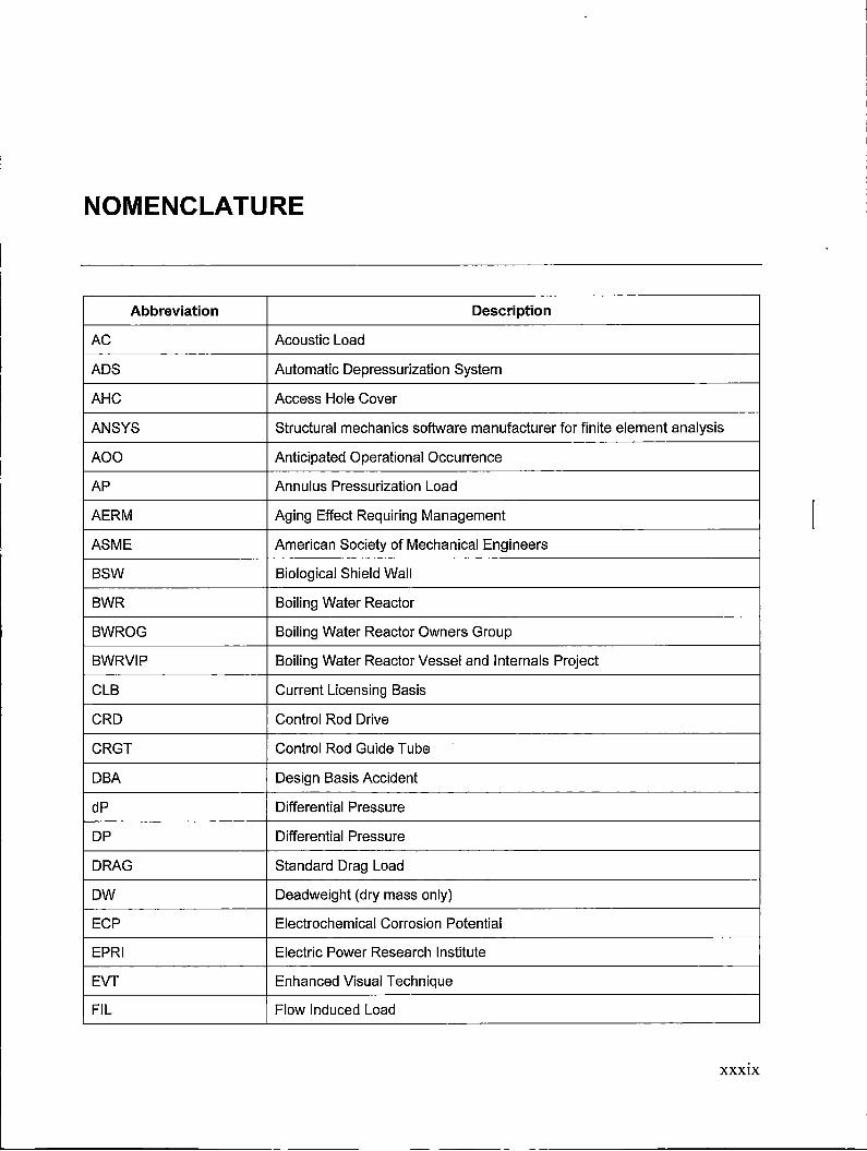
NOMENCLATURE
Abbreviation Description
AC Acoustic Load
ADS Automatic Depressurization System
AHC Access Hole Cover
ANSYS Structural mechanics software manufacturer for finite element analysis
AOO Anticipated Operational Occurrence
AP Annulus Pressurization Load
AERM Aging Effect Requiring Management
ASME American Society of Mechanical Engineers
BSW Biological Shield Wall
BWR Boiling Water Reactor
BWROG Boiling Water Reactor Owners Group
BWRVIP Boiling Water Reactor Vessel and Internals Project
CLB Current Licensing Basis
CRD Control Rod Drive
CRGT Control Rod Guide Tube
OBA Design Basis Accident
dP Differential Pressure
DP Differential Pressure
DRAG Standard Drag Load
ow Deadweight (dry mass only)
ECP Electrochemical Corrosion Potential
EPRI Electric Power Research Institute
EVT Enhanced Visual Technique
FIL Flow Induced Load
XXXIX

Abbreviation Description
FL Fuel Lift Load
FIV Flow Induced Vibration Load
FSAR Final Safety Analysis Report
GE General Electric
GEH GE Hitachi Nuclear Energy
GENE Document classification for GE (General Electric Nuclear Energy)
HAZ Heat Affected Zone
HWC Hydrogen Water Chemistry
IBA Intermediate Break Accident
ID Inner Diameter
l&E Inspection and Evaluation
IGSCC lntergranular Stress Corrosion Cracking
IPA Integrated Plant Assessment
ISi In-Service Inspection
IWI In Vessel Visual Inspection
JR Jet Reaction
LOCA Loss of Coolant Accident
MOC Method of Characteristics
MSLB Main Steam Line Break
MVT Modified Visual Technique
NEI Nuclear Energy Institute
NRC Nuclear Regulatory Commission
NSSS Nuclear Steam Supply System
OBE Operational Basis Earthquake
OD Outer Diameter
OFS Orificed Fuel Support
OLNC On-line NobleChem TM
Pb Primary bending stress intensity
Pm Primary membrane stress intensity
PWR Pressurized Water Reactor
RICSIL Rapid Information Communication Services Information Letter
xl
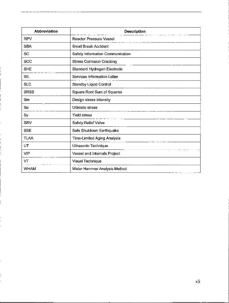
Abbreviation Description
RPV Reactor Pressure Vessel
SBA Small Break Accident
SC Safety Information Communication
sec Stress Corrosion Cracking
SHE Standard Hydrogen Electrode
SIL Services Information Letter
SLC Standby Liquid Control
SRSS Square Root Sum of Squares
Sm Design stress intensity
Su Ultimate stress
Sy Yield stress
SRV Safety Relief Valve
SSE Safe Shutdown Earthquake
TLAA Time-Limited Aging Analysis
UT Ultrasonic Technique
VIP Vessel and Internals Project
VT Visual Technique
WHAM Water Hammer Analysis Method
xli
CONVERSION FACTORS
1 inch= 25.4 mm
1 psi= .001 ksi
1 ksi = 6.895 MPa
1 lbm/in3 = 27,679.9 kg/m3
1 ft-lb= 1.356 Nm
1 °F = -17.2°C
xliii
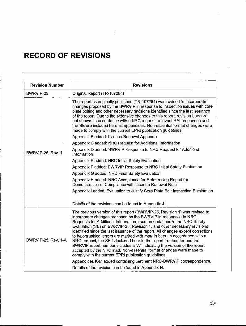
RECORD OF REVISIONS
Revision Number Revisions
BWRVIP-25 Original Report (TR-107284)
The report as originally published (TR-107284) was revised to incorporate changes proposed by the BWRVIP in response to inspection issues with core plate bolting and other necessary revisions identified since the last issuance of the report. Due to the extensive changes to this report, revision bars are not shown. In accordance with a NRC request, relevant RAI responses and the SE are included here as appendices. Non-essential format changes were made to comply with the current EPRI publication guidelines.
Appendix B added: License Renewal Appendix
Appendix C added: NRC Request for Additional Information
BWRVIP-25, Rev. 1 Appendix D added: BWRVIP Response to NRC Request for Additional Information
Appendix E added: NRC Initial Safety Evaluation
Appendix F added: BWRVIP Response to NRC Initial Safety Evaluation
Appendix G added: NRC Final Safety Evaluation
Appendix H added: NRC Acceptance for Referencing Report for Demonstration of Compliance with License Renewal Rule
Appendix I added: Evaluation to Justify Core Plate Bolt Inspection Elimination
Details of the revisions can be found in Appendix J.
The previous version of this report (BWRVIP-25, Revision 1) was revised to incorporate changes proposed by the BWRVIP in responses to NRC Requests for Additional Information, recommendations in the NRC Safety Evaluation (SE) on BWRVIP-25, Revision 1, and other necessary revisions identified since the last issuance of the report. All changes except corrections to typographical errors are marked with margin bars. In accordance with a
BWRVIP-25, Rev. 1-A NRC request, the SE is included here in the report frontmatter and the BWRVIP report number includes a "A" indicating the version of the report accepted by the NRC staff. Non-essential format changes were made to comply with the current EPRI publication guidelines.
Appendices K-M added containing pertinent NRC-BWRVIP correspondence.
Details of the revision can be found in Appendix N.
xiv
CONTENTS
NRC SAFETY EVALUATION OF BWRVIP-25, REVISION 1 .................................................... iii
ABSTRACT .......................................................................................................................... xxxv
EXECUTIVE SUMMARY .................................................................................................... xxxvii
NOMENCLATURE .............................................................................................................. xxxix
CONVERSION FACTORS ...................................................................................................... xliii
RECORD OF REVISIONS ....................................................................................................... xiv
1 INTRODUCTION .................................................................................................................. 1-1
1.1 Background ................................................................................................................... 1-1
1.2 Objectives and Scope .................................................................................................... 1-1
1.3 Implementation Guidelines ............................................................................................ 1-2
2 CORE PLATE DESIGN AND SUSCEPTIBILITY INFORMATION ........................................ 2-1
2.1 Susceptibility Factor ...................................................................................................... 2-2
2.1.1 Environment. .......................................................................................................... 2-2
2.1.2 Materials ................................................................................................................ 2-3
2.1.3 Stress State ........................................................................................................... 2-3
2.1.4 Fatigue ................................................................................................................... 2-4
2.2 Design of Typical Core Plate Assemblies ...................................................................... 2-4
2.2.1 Location 1 - Stiffener Beam to Core Plate Weld .................................................... 2-4
2.2.2 Location 2 - Peripheral Fuel Support to Core Plate Weld ...................................... 2-5
2.2.3 Locations 3a, 3b - Stiffener Beam and Stabilizer Beam to Rim Welds .................. .2-5
2.2.4 Location 4, 5 - Stiffener Beam to Stabilizer Beam Welds ....................................... 2-5
2.2.5 Location 6 - In-core Guide Tube Support to Stabilizer Beam Weld ........................ 2-5
2.2.6 Location 7 - Core Plate to Rim Weld ..................................................................... 2-6
xlvii
2.2.7 Location 8-Aligner Pin and Socket to Rim Welds ................................................. 2-6
2.2.8 Location 9 - Core Plate Wedge Retainer ............................................................... 2-6
2.2.9 Location 10- Core Plate Bolts ............................................................................... 2-6
2.2.10 Location 11 - Rim Fabrication Weld ..................................................................... 2-7
2.2.11 Location 12 - Core Plate Fabrication Welds ........................................................ 2-7
2.2.12 Location 13-Core Plate Plug .............................................................................. 2-8
2.3 Conclusion ..................................................................................................................... 2-8
3 INSPECTION STRATEGY .................................................................................................... 3-1
3.1 Background ................................................................................................................... 3-1
3.1.1 Core Plate Inspection History ................................................................................. 3-1
3.1.2 Examination Methods ............................................................................................ 3-3
3.2 Inspection Recommendations or Alternatives ................................................................ 3-3
3.2.1 Plant Categories .................................................................................................... 3-3
3.2.2 Inspection Recommendation or Alternatives .......................................................... 3-3
3.2.2.1 Installation of Wedges .................................................................................... 3-4
3.2.2.2 Inspection of Core Plate Bolts ........................................................................ 3-4
3.2.2.3 Application Criteria for Eliminating Inspection of Core Plate Bolts .................. 3-5
3.3 Reporting of Inspection Results ..................................................................................... 3-6
4 LOADING ............................................................................................................................. 4-1
4.1 Significant Loads ........................................................................................................... 4-1
4.1.1 Deadweight (OW) ................................................................................................... 4-2
4.1.2 Seismic Induced Loads .......................................................................................... 4-2
4.1.3 ~p Loads ............................................................................................................... 4-2
4.1.4 SRV Loads ............................................................................................................. 4-2
4.1.5 Loss-of-Coolant Accident (LOCA) Loads .............................................................. .4-3
4.1.6 AP Loads ............................................................................................................... 4-3
4.1. 7 Fuel Lift (FL) Loads ............................................................................................... .4-4
4.1.8 Applicability of Hydrodynamic Loads ..................................................................... .4-4
4.2 Load Combinations ........................................................................................................ 4-5
4.3 Example Stress Analysis .............................................................................................. .4-6
4.3.1 Stiffener Beam Separation .................................................................................... .4-6
4.3.2 Core Plate Bolts Restraining the Core Plate .......................................................... .4-7
4.3.3 Wedges Restraining Core Plate ............................................................................ .4-7
xlviii
4.4 Review of Applicability of SCs for Core Plate ................................................................ .4-7
5 REFERENCES ..................................................................................................................... 5-1
A EXAMPLE CORE PLATE BOLT ANALYSIS ...................................................................... A-1
A.1 Example Core Plate Bolt Analysis ................................................................................ A-1
A.1.1 Loadings ............................................................................................................... A-1
A.1.2 Calculated Stresses on the Core Plate Bolts ........................................................ A-3
8 LICENSE RENEWAL APPENDIX ....................................................................................... 8-1
C NRC REQUEST FOR ADDITIONAL INFORMATION (97-268A/588) ................................. C-1
D BWRVIP RESPONSE TO NRC REQUEST FOR ADDITIONAL INFORMATION (97-937) ........................................................................................................................................ D-1
E NRC INITIAL SAFETY EVALUATION (99-1598) ............................................................... E-1
F BWRVIP RESPONSE TO NRC INITIAL SAFETY EVALUATION (99-403) ......................... F-1
G NRC FINAL SAFETY EVALUATION (99-524A) ................................................................. G-1
H NRC ACCEPTANCE FOR REFERENCING REPORT FOR DEMONSTRATION OF COMPLIANCE WITH LICENSE RENEWAL RULE (2001-006) .............................................. H-1
/ EVALUATION TO JUSTIFY CORE PLATE BOLT INSPECTION ELIMINATION .................. I-1
Abstract ............................................................................................................................... 1-1
Nomenclature ...................................................................................................................... 1-2
Section 1: Background ........................................................................................................ 1-4
1.1 Core Plate Cracking Concerns .................................................................................. 1-4
1.2 Inspection Difficulties ............................................................................................... 1-5
Section 2: Scope ................................................................................................................. 1-6
2.1 Introduction .............................................................................................................. 1-6
2.1.1 Determination of Plant Core Plate Bolt Categories ............................................. 1-6
2.1.2 Review of Core Plate Bolt Material and Fabrication Design Data ....................... 1-6
2.1.3 IGSCC Susceptibility Evaluation ........................................................................ 1-6
2.1.4 Develop Methodology for Determination of Core Plate Bolt Stress ...................... 1-6
2.1.5 Core Plate Bolt Mechanical Analysis .................................................................. 1-7
Section 3: Plant Configuration Summary ............................................................................. 1-7
xlix

Section 4: IGSCC Resistance ............................................................................................. I-10
4.1 lntroduction .............................................................................................................. I-10
4.2 Stress Corrosion Resistance of Core Plate Bolts ..................................................... 1-10
4.3 Residual Effects of Bolt Thread Manufacturing Processes ....................................... I-10
4.4 Aligner Pins .............................................................................................................. I-13
Section 5: Field Experience ................................................................................................ I-14
Section 6: Stress Relaxation Evaluation ............................................................................. 1-14
6.1 Thermal Loosening .................................................................................................. 1-15
6.2 Primary Thermal Creep ............................................................................................ I-15
6.3 Stress Relaxation Due to Fluence ............................................................................ I-15
Section 7: Structural Analysis Methodology ........................................................................ I-20
7.1 Choice of Categories ............................................................................................... I-20
7.1.1 Category 1 Plants: 34 Inboard Bolts, Vertical Aligner Pins ................................ 1-20
7.1.2 Category 2 Plant: Laguna Verde ....................................................................... I-21
7.1.3 Category 3 Plant: Duane Arnold ....................................................................... 1-21
7.1.4 Category 4 Plant: Vermont Yankee ................................................................... I-21
7 .1.5 Category 5 Plant: Monticello ............................................................................. 1-21
7.1.6 Category 6 Plants: 72 Outboard Bolts, Horizontal Aligner Pins .......................... I-21
7.2 Failure Mechanisms and Displacement Limit ........................................................... 1-22
Section 8: Structural Analysis ............................................................................................. 1-23
8.1 Structural Design Features ...................................................................................... 1-23
8.1.1 Components ..................................................................................................... I-23
8.1.2 Bolt and Aligner Pin Configurations .................................................................. 1-24
8.2 Material Properties ................................................................................................... 1-24
8.2.1 Plasticity ........................................................................................................... 1-25
8.3 Structural Acceptance Criteria ................................................................................. 1-25
8.4 Loads and Load Combinations ................................................................................ 1-26
8.4.1 Horizontal Combined Loads .............................................................................. I-28
8.4.2 Vertical Combined Loads .................................................................................. 1-29
8.4.3 Core Plate Pressure Differential. ....................................................................... I-29
8.4.4 Deadweight Loads ............................................................................................ I-29
8.4.5 Peripheral Fuel Weight and Core Plate Buoyancy ............................................ 1-29
8.4.6 Preload ............................................................................................................. I-29
8.4.7 Friction ............................................................................................................. 1-30
8.5 Assumptions and Conservatisms ............................................................................ 1-30

8.5.1 Assumptions ..................................................................................................... I-31
8.5.2 Conservatisms .................................................................................................. I-31
8.6 Elements and Mesh ................................................................................................ 1-31
8.7 Boundary Conditions ............................................................................................... I-32
8.7.1 Friction ............................................................................................................. 1-33
8.7.2 Bolts ................................................................................................................. 1-33
8.7.3 Vertical Aligner Pins: Categories 1-5 ................................................................. l-34
8.7.4 Horizontal Aligner Pins: Category 6 .................................................................. 1-35
8.8 Finite Element Analysis ........................................................................................... 1-36
8.8.1 Preload Application Verification ........................................................................ 1-36
8.8.2 Load Application ............................................................................................... 1-36
8.8.3 Worst Bolt. ........................................................................................................ I-37
8.8.4 Core Plate Horizontal Displacement ................................................................. 1-37
Section 9: Analysis Results ................................................................................................ 1-38
9.1 Category 1 ............................................................................................................... 1-38
9.2 Category2 .............................................................................................................. 1-41
9.3 Category 3 .............................................................................................................. 1-43
9.4 Category 4 ............................................................................................................... 1-44
9.5 Category 5 ............................................................................................................... 1-45
9.6 Category 6 ............................................................................................................... 1-46
9.7 Application of Analysis Results ................................................................................ 1-47
Section 10: Conclusions ..................................................................................................... 1-48
Section 11: References ...................................................................................................... 1-48
J RECORD OF REVISIONS (BWRVIP-25, REV. 1) ................................................................ J-1
K NRC REQUEST FOR ADDITIONAL INFORMATION ON BWRVIP-25, REVISION 1 ......... K-1
L BWRVIP RESPONSE TO REQUEST FOR ADDITIONAL INFORMATION ON BWRVIP-25, REVISION 1 ...................................................................................................... L-1
M REVISED BWRVIP RESPONSE FOR ESEB RAl-1 TO REQUEST FOR ADDITIONAL INFORMATION ON BWRVIP-25, REVISION 1 ................................................ M-1
N RECORD OF REVISIONS FOR BWRVIP-25, REVISION 1-A ............................................. N-1
LIST OF FIGURES
Figure 2-1 BWR Core Plate ...................................................................................................... 2-9
Figure 2-2 BWR/2 Core Plate ................................................................................................. 2-10
Figure 2-3 BWR/3 Core Plate Assembly ................................................................................ 2-11
Figure 2-4 BWR/4 Core Plate Type l ...................................................................................... 2-12
Figure 2-5 BWR/4 Core Plate Type II ..................................................................................... 2-13
Figure 2-6 BWR/4 Core Plate Type Ill .................................................................................... 2-14
Figure 2-7 BWR/5 Core Plate Assembly ................................................................................ 2-15
Figure 2-8 BWR/6 Core Plate Assembly ................................................................................ 2-16
Figure 2-9 Peripheral Fuel Support to Core Plate Weld .......................................................... 2-17
Figure 2-10 Stiffener Beam to Rim Weld ................................................................................ 2-18
Figure 2-11 In-Core Guide Tube Support to Stabilizer Beam Weld ........................................ 2-19
Figure 2-12 Aligner Pin to Socket and Socket to Rim Welds .................................................. 2-20
Figure 2-13 Core Plate Wedge Restrainer ............................................................................. 2-21
Figure 2-14 BWR/2-5 Core Plate Bolt .................................................................................... 2-22
Figure 2-15 BWR/6 Core Plate Bolt. ....................................................................................... 2-23
Figure 2-16 Core Plate Plug ................................................................................................... 2-24
Figure A-1 Finite Element Model of Core Plate ....................................................................... A-6
Figure A-2 Finite Element Model Showing Core Plate Bolt and Beam Element.. ..................... A-7
Figure A-3 Vertical Force Acting on Core Plate Bolts Around Core Circumference ................. A-7
Figure A-4 Horizontal Forces Acting on Core Plate Bolt Around Core Plate Circumference ................................................................................................................. A-8
Appendix I Figures:
Figure 4-1 Relationship of Hardness to sec Susceptibility [7] ............................................ 1-11
Figure 4-2 The Relationship of Austenitic Stainless Steel Mechanical Properties to Hardness [8] ................................................................................................................ 1-12
Figure 4-3 Example of the Predicted Plastic Strain as a Function of Depth in the Vicinity of a Stainless Steel Thread Radius ................................................................. 1-13
Figure 6-1 Top View of Core Plate Bolts ............................................................................. 1-17
Figure 6-2 Bottom View of Core Plate Bolts ........................................................................ 1-18
Figure 6-3 Fluence at Varying Core Plate Bolt Locations .................................................... 1-18
Figure 6-4 Predicted Relaxation of Irradiated Austenitic Steels versus Existing Stainless Steel Relaxation Data [16-20) ....................................................................... l-19
Figure 6-5 Relaxation Predictions versus Core Plate Bolt Elevation .................................... 1-19

Figure 8-1 Components of a Generic Core Plate Assembly ................................................ 1-23
Figure 8-2 Category 1-5 Core Plate Bolt and Vertical Aligner Pin Configuration (Generic) ..................................................................................................................... 1-24
Figure 8-3 Category 6 Core Plate Bolt and Horizontal Aligner Pin Configuration (Generic) ..................................................................................................................... 1-24
Figure 8-4 Example Finite Element Mesh ............................................................................ I-32
Figure 8-5 Example Friction Boundary Conditions (24 of 34 bolts ....................................... 1-33
Figure 8-6 Example Vertical Aligner Pin Boundary Conditions (24 of 34 bolts) .................... I-34
Figure 8-7 Example Horizontal Aligner Pin Boundary Conditions (52 of 72 bolts) ................ I-35
Figure 8-8 Example Preload Application (24 of 34 bolts) ..................................................... I-36
Figure 8-9 Example Horizontal Displacement Plot (24 of 34 bolts ....................................... 1-37
Figure 9-1 Category 1 Results (Not Including Fuel Lift) ....................................................... 1-39
Figure 9-2 Category 1 Results (Including Fuel Lift) .............................................................. I-40
Figure 9-3 Category 2 Results (Not Including Fuel Lift) ....................................................... 1-41
Figure 9-4 Category 2 Results (Including Fuel Lift) .............................................................. I-42
Figure 9-5 Category 3 Results ............................................................................................. I-43
Figure 9-6 Category 4 Results ............................................................................................. I-44
Figure 9-7 Category 5 Results ............................................................................................. I-45
Figure 9-8 Category 6 Results ............................................................................................. I-46
Figure 9-9 Applicability Flow Chart ...................................................................................... I-47

LIST OF TABLES
Table 2-1 Potential Core Plate Failure Location ....................................................................... 2-8
Table 3-1 Core Plate Cracking Experience .............................................................................. 3-6
Table 3-2 Summary of Results and Inspection Recommendations ........................................... 3-7
Table 4-1 Typical BWR Load Definitions for Reactor Internals ................................................. 4-8
Table 4-2 Reactor Internal Load Applicability for Core Plate .................................................. 4-10
Table 4-3 AP and LOCA Loads for Fuel Lift ........................................................................... 4-10
Table 4-4 AP and LOCA Loads for RPV and RPV Internals .................................................. .4-11
Table 4-5 Core Plate Loads ................................................................................................... 4-11
Table 4-6 Review of Applicability of GEH's SCs for Core Plate ............................................. .4-14
Table A-1 Summary of Results for Core Plate Analyses ......................................................... A-5
Appendix I Tables:
Table 3-1 Plants without Wedges (Analyzed) ....................................................................... 1-8
Table 6-1 Summary of Relaxation Amounts ........................................................................ 1-15
Table 6-2 Core Plate Relaxation Predictions after Thermal Creep and Irradiation Relaxation Due to Fluence .......................................................................................... 1-17
Table 8-1 Type 304 Stainless Steel Material Properties Used in Finite Element Model (at 550°F) .................................................................................................................... 1-25
Table 8-2 ASME Code Allowable Limits [23] ....................................................................... 1-26
Table 8-3 Loads Requiring Bounding Verification ................................................................ I-27
Table 8-4 Finite Element Types ........................................................................................... 1-32
Table 9-1 Category 1 Results (Not Including Fuel Lift) ........................................................ 1-39
Table 9-2 Category 1 Results (Including Fuel Lift) ............................................................... I-40
Table 9-3 Category 2 Results (Not Including Fuel Lift) ........................................................ 1-41
Table 9-4 Category 2 Results (Including Fuel Lift) ............................................................... I-42
Table 9-5 Category 3 Results .............................................................................................. I-43
Table 9-6 Category 4 Results .............................................................................................. I-44
Table 9-7 Category 5 Results .............................................................................................. I-45
Table 9-8 Category 6 Results .............................................................................................. I-46
Table J-1 Details of Revisions .................................................................................................. J-2
Table N-1 Details of Revisions ................................................................................................ N-2
Iv
1 INTRODUCTION
1.1 Background
The BWR Vessel and Internals Project (BWRVIP) prepared a safety assessment of Boiling Water Reactor (BWR) internals as a follow-on to the activities completed for core shroud cracking. In the evaluation of the core plate and the consequences of core plate cracking, it has been determined that inspection is an important part of ensuring the integrity of core plate safety functions, and therefore the ability to achieve safe shutdown for the most limiting accident scenarios. As a result, the BWRVIP made development of the core plate inspection and evaluation guidelines a high priority for 1996.
Actually it is difficult to perform an inspection on the core plate bolt. Alternately to eliminate the requirements of the inspection of the core plate bolts, a set of application criteria are developed in Appendix I in Revision 1 of this report.
1.2 Objectives and Scope
The core plate Inspection and Evaluation (l&E) guideline is a generic guideline intended to present the appropriate inspection recommendations to ensure safety function integrity (i.e., economic and normal operational consequences of cracking are not factored into the recommendations). It is the intent that, for BWRVIP members, this guideline can be followed in the place of prior GE SILs (Services Information Letters) to ensure the essential safety functions of the core plate. The guideline addresses the following specific issues:
• Locations within the core plate assembly for which inspection is recommended
• Categories of plants for which inspection needs differ
• Extent of inspection for each location
The l&E guideline provides design information on the core plate geometries and weld locations for several categories of plants. The guideline scope addresses all weld and bolted locations identified from design drawings of the core plate stiffener beams, stabilizer beams, aligner pins, core plate bolts, and wedges. In addition, shroud repair was considered in the guideline development, and it was determined that the core plate l&E guideline is applicable whether or not a shroud repair has been installed. Typical core plate configurations are shown schematically in Section 2; these figures identify the welded and bolted locations for each configuration, with the identifiers used in this guideline for each location.
This guideline also contains a discussion of susceptibility considerations which concludes that all core plate subcomponents may be subject to cracking. The susceptibility trends may, as further inspection data accumulates, provide a basis to revise the recommended reinspection frequencies.
1-1
Introduction
In addition, the I&E guideline presents a conservative representative structural analysis of the core plate in order to determine which core plate locations require inspection. The load magnitudes at various locations in the core plate were determined through finite element analysis (See Section 4.0). The finite element model consists of the core plate, including stiffener beam, stabilizer beams and rim. For some cases, wedges also were added to the model.
The core plate evaluation was broken into several parts by investigating the following scenarios:
• stiffener beam separation
• core plate bolts restraining the core plate
• wedges restraining the core plate
In Section 4, loading combination recommendations are provided. Methodology is provided to take stresses from finite element analysis of the core plate under these loading combinations and perform limit load flaw evaluation at each weld. The limit load methodology is demonstrated in an example analysis (See Appendix A).
In Revision 1 of this report, Appendix I is included to provide the application criteria to eliminate the requirement of the inspection of the core plate bolts. The technical justification is also based on finite element analyses, which are different from the one presented in Section 4.0.
The guideline presents the inspections that each plant will perform for the core plate components. Reinspection approaches are presented which vary depending on the type of plant and the outcome of the previous inspections.
1.3 Implementation Guidelines
In accordance with the implementation requirements of Nuclear Energy Institute (NEI) 03-08, Guideline for the Management of Materials Issues, Sections 3, 4 and Appendix I are "needed" and the remainder of the report is provided for information only. Utilities should also consult the updated load and load combinations in BWRVIP-303 [28] for the core plate.
1-2
2 CORE PLATE DESIGN AND SUSCEPTIBILITY INFORMATION
The core plate assembly provides lateral support for the fuel bundles, control rod guide tubes, and in-core instrumentation during seismic events, and provides vertical support for the peripheral fuel assemblies. The typical core plate assembly (Figure 2-1) consists of a perforated stainless steel plate reinforced by stiffener beams and supported on the perimeter by a circular rim. The core plate rim is bolted to a ledge on the core shroud by stainless steel studs which prevent vertical movement.
Stiffener beams are welded to the core plate to carry the pressure loads following design basis Loss of Coolant Accident (LOCA) events. Because peak pressure loads place the lower edges of the beams in compression, cross ties between the beams are required for stabilization. The stabilizer beams or rods prevent flange buckling by providing lateral support. These beams or rods also provide support for in-core housing monitors.
There are slight design differences between core plates; general core plate configurations can be classified as follows:
• BWR/2
• BWR/3
• BWR/4 - 3 types
• BWR/5
• BWR/6
Schematics of each configuration are given in Figure 2-2 through Figure 2-8.
Core plates are positioned on the shroud ledge by four vertical or horizontal aligner pins (not applicable to BWR/6 plants), which vary in configuration from plant to plant. The pin assembly engages bosses or sockets which are welded to both the core plate and the shroud. For BWR/2 through BWR/5 plants, seismic and other dynamic loads are shared between the friction load of the shroud to rim bolt connection, and the shear resistance of the aligner pins. BWR/6 plants were designed to be restrained by wedges and studs between the core plate rim and the shroud.
Table 2-1 summarizes the potential failure locations. These failure locations are illustrated in Figure 2-1 through Figure 2-16. The figures detail the locations of the welds in the assemblies, with weld identifications which are used throughout this report, and which correspond to the weld identifications used in the BWRVIP Safety Assessment Report [1]. While the entire assembly is generally similar, there are several differences in design and fabrication conditions that exist in the different types ofBWR, as well as between plants of the same BWR type. Some of these differences potentially affect the susceptibility oflocations on the core plate assembly.
2-1

Core Plate Design and Susceptibility Information
Design and fabrication differences may include the following:
• Core plate material (304 vs. 304L stainless steels 1)
• Material condition ( annealed vs. welded vs. cold worked)
• Core plate assembly dimensions
• Weld design ( creviced vs. non-creviced)
• Type of weld (fillet vs. groove vs. partial penetration)
The ways in which some of these characteristics play a role in core plate cracking susceptibility are discussed in Sections 2.1 and 2.2.
2.1 Susceptibility Factor
The occurrence of intergranular stress corrosion cracking (IGSCC) requires the combined presence of an aggressive environment, a susceptible material and a tensile stress. These specific factors are discussed for the core plate assembly in more detail below.
Another important consideration in evaluating IGSCC susceptibility, because of the variability of the phenomenon, is the cracking history. A discussion of cracking history is presented in Section 3 as part of the background discussion on inspection.
2. 1. 1 Environment
High electrochemical corrosion potential (ECP) is considered one of the key factors in promoting IGSCC in austenitic stainless steel components when combined with adverse material microstructures and imposed residual and fit-up stresses. IGSCC is considered mitigated when the local (ECP) is reduced below -230 mV(SHE). Additionally tight crevices can, in some cases, promote crack initiation and crack growth due to the tendency for crevices to concentrate ionic species that aggravate IGSCC. For these locations, the tight crevice increases the likelihood of multiple crack initiation sites with the possibility of extensive cracking in the crevice before any cracks grow through-thickness. The behavior of creviced 304 and creviced 304L has been shown in the laboratory to be similar, with 316L performing somewhat, but not significantly, better. It must be noted, however, that stress corrosion cracking (SCC) initiation requires both a tensile stress and a susceptible material in addition to an aggressive environment. Therefore, crevices which are subject to higher stresses ( e.g., crevices created by welding with high weld residual stresses remaining) in a susceptible material (sensitized and/or cold worked) would be expected to initiate cracks sooner than crevices with relatively low stresses ( e.g. crevices created by bolting) in nonsensitized material.
Regardless, the United States-based BWR fleet is now operating with an effective HWC core environment in the core plate region. Most plants also implement NobleChem ™ mitigation, either Classic NMCA or On-line NobleChem TM (OLNC). Radiolysis model calculations, validated by ECP measurements at several internal locations, predict that the environment in contact with core plate assembly will have ECP values below -230 m V (SHE). Thus, the potential for IGSCC at
1 XM-19 stainless steel is also used as an alternate material for BWR/6 core plate bolt.
2-2

Core Plate Design and Susceptibility Information
the core plate location, including crevices, is much reduced compared to normal water chemistry conditions.
2.1.2 Materials
The core plate assembly is either 304 or 304L austenitic stainless steel. GE required all austenitic stainless steel plates to be supplied in the solution heat treated condition. However, those full penetration fabrication welds which were made following delivery of the material as part of the core plate assembly process contain an as-welded heat affected zone (RAZ) that is a susceptible location for IGSCC. Assembly welds were typically performed in the shop, and the welding process used varied depending upon the manufacturing sequence. These weld locations may require inspection, depending on the role a particular location has in core plate function.
In terms of IGSCC susceptibility, higher strength ( or higher hardness) materials are in general ~ore susceptible than.the same materials with lower strength (or _lower hardnesstC:- 7-. ___
7
f ~J ~ - . . . I l ' Content DeletE)d ~ EPRI f'rOprietary lnformatiOn . " . s During installation of the core plate assembly there may have been installation steps that introduced localized regions of susceptibility. Along the curved surfaces such as the rim, there may also be localized regions that received more cold work from bending. If cracking were to initiate at such localized regions, it is not certain that through-thickness cracks would result. Even then, such cracks would be limited to the length of the cold- worked region.
Therefore, core plate materials can be susceptible to IGSCC at locations where a heat affected zone or excessive cold work exists.
2.1.3 Stress State
During normal operation, no components of the core plate are highly stressed; however, residual stresses due to welding and fit-up can be significant. All weld locations that were not solution annealed are characterized by tensile residual stresses. In general, the welds in the core plate assembly are similar enough that the residual stresses would not provide a means to differentiate by location or plant type.
The welding process introduces residual stress in the material. The level of this residual stress and the location of the tensile component vary with geometry and the welding process used. Experience and analysis verifies the presence of residual stress in all welds that are not subiected
j --to annealing. · · > :- · · · ; - ' · · · . · -- · . · · · ·• . - ·. · . ·• · · · -i r-- . a·, . . -- .. , . . . . t I - - ·)
f ContentDelete_d -.EPRi _Proprietary-informatiqn_ -- a 11
;t\J§Q,J_J.:i_e stress state of the core plate bolts needs to be considered. f - · · i
i _· - · Cont~nt Deleted ; EPRI Propriet~ry- _Information · · · :, , , r----_. j L__;_ ~~--~----------~------~I
2-3
Core Plate Design and Susceptibility Information
~- -~ 1 Content Deleted - ·EPRI Proprietary Information· c-J
L _____________ :----------~--------· _! __ --.__;!
Consequently, significant tensile stresses, the third requirement for IGSCC, may exist at weld locations in the core plate.
2. 1.4 Fatigue
Known fatigue mechanisms affecting boiling water reactor (BWR) internals include system cycling thermal fatigue, load cycling fatigue, and flow-induced vibration (FIV) fatigue. Normal operation is not expected to contribute to core plate bolt thermal fatigue as reactor startup and shutdown events occur under quasi-uniform heating and cooling, with transients of 100°F/hr or less, and the core plate bolts, core plate, and shroud are comprised of similar material types. Normal load fatigue is not relevant as steady-state load fluctuations are insignificant and the flanged members, acting in series with the core plate bolts, transfer the bulk of external loads. Off-normal operating conditions could possibly induce load cycling on the core plate bolts, but the effect is insignificant due to the limited number of such cycles. Historically, FIV induced fatigue is not considered for core plate bolts as the bolted joint is designed with sufficient preload to resist pressure differential loads across the core plate. This condition inhibits leakage flow through the bolt holes which could cause FIV and consequent fretting wear or fatigue accumulation. Due to the low probability of significant fatigue loading/cycling, cracking due to fatigue is not considered to be a relevant degradation mechanism for the core plate bolts. Consequently, cracking due to fatigue is not an aging effect requiring management (AERM).
2.2 Design of Typical Core Plate Assemblies
The core plate assembly contains welds that can be divided into either creviced locations or noncreviced locations. Many of the welds in the core plate assembly are creviced due to the presence of a fillet weld or a partial penetration weld. The regions with the highest expected crack susceptibility are the creviced locations, especially those creviced regions subject to high weld residual stresses. Each specific weld region is discussed in this section.
2.2.1 Location 1 - Stiffener Beam to Core Plate Weld
Stiffener beams are either continuous or intermittent fillet welded on both sides to the bottom of the core plate as shown in Figure 2-1; since these beams are fillet welded, a creviced condition exists whether the weld is continuous or intermittent. Failure of these welds would have no impact on core plate function because the pressure load is transferred to the guide tubes, as discussed below.
·• "·
Content Deleted -:- EF>~I Propri~tary Information
2-4
r--·-' l
,--~ ! __
]'

Core Plate Design and Susceptibility Information
Under transient and accident conditions, a small tensile stress in a guide tube tab could be generated for a short period of time (refer to Table 3-2 for analysis results). Also, the effect of failure of all of these welds on the peripheral fuel supports was analyzed; Table 3-2 discusses a very small rotation of the fuel support casting which would not affect control blade insertion.
2.2.2 Location 2 - Peripheral Fuel Support to Core Plate Weld
The peripheral fuel support to core plate weld is an all-around fillet weld which attaches the support to the top of the core plate (Figure 2-1 and Figure 2-9). Figure 2-9 shows the configurations for two types of supports, typical BWR/2-3 and typical BWR/4-6. For both configuration types, the peripheral fuel support to core plate weld is the same configuration. Since the weld was made on one side of the core plate, this is a creviced condition. If this weld failed, differential pressure or seismic loading would have no adverse safety consequences because the fuel support weld is compressed by the weight of the fuel. Therefore, fuel alignment is maintained under all conditions, so there are no safety consequences.
2.2.3 Locations 3a, 3b - Stiffener Beam and Stabilizer Beam to Rim Welds
The stiffener beams and stabilizer beams are first groove welded and then fillet welded to the rim; the number of beams and the number of welds per stiffener vary by plant. Figure 2-10 shows details of stiffener beam and stabilizer beam to rim welds. Since these welds are not seal welds, a creviced condition exists. Failure of these welds would change the stresses and deflections in the core plate and possibly redistribute loading in the rim hold- down bolts. The impact on the core plate from this failure is bounded by a failure at Location 1. The impact on the core plate bolts from this failure is bounded by the core plate bolt failure scenario presented in Section 2.2.9. The failure scenarios at Locations 1 and 10 have acceptable safety consequences. Therefore, there is no safety consequence of failure at this location.
2.2.4 Location 4, 5 - Stiffener Beam to Stabilizer Beam Welds
In addition to each being welded to the core plate, the stiffener beams and stabilizer beams are either continuous or intermittent fillet welded on both sides as shown in Figure 2-1; since the weld may be intermittent, this location is treated as a crevice. Failure of one or several of these welds may affect the stability of the stiffener beams. However, as discussed in Section 2.2.1, the stiffener beams are not required for acceptable core plate safety function, so failure of the stiffener beam to stabilizer beam welds is not a safety concern.
2.2.5 Location 6 - In-core Guide Tube Support to Stabilizer Beam Weld
The in-core guide tube support is fillet welded all around to the stabilizer beam, and typical views of this connection are shown in Figure 2-1 and Figure 2-11. Since this joint is not welded on both sides, it is creviced. The failure of an in-core guide tube support to stabilizer beam weld has no adverse impact on the safety function of the core plate. These welds to the in-core guide tubes limit the motion of the guide tubes caused by flow-induced vibration. The failure of one of these welds would increase flow-induced vibrations to some extent and could potentially cause the failure of the affected in-core instrument. There would be no safety consequence to the failure of an in-core instrument since individual failures only affect one instrument string at a
2-5
Core Plate Design and Susceptibility Information
time and would be detectable by operational surveillance of the detectors or by the plant leak detection system.
2.2.6 Location 7- Core Plate to Rim Weld
Around its entire circumference, the bottom side of the core plate is first continuously groove welded on the outer diameter (OD) and then continuously fillet welded on the inner diameter (ID) (Figure 2-3 through Figure 2-7). Since both the ID and OD welds are continuous, this location is uncreviced. The failure of this weld has no adverse safety consequence because the core plate bolts (Location 10) compress the core plate against the shroud flange and keep these welds in compression. The failure of the weld would not result in loss of compression or shear load path because the interlocking grooves of a postulated crack would prevent relative movement between the rim and cover plate.
Some plants have the core plate bolts outside of the rim. Failure of Location 7 in this configuration could affect the preload of the bolt if the stiffening effect of the rim were lost. However, even if enough preload were lost to allow horizontal displacement, the presence of the bolts outside the rim and the aligner pins hardware would limit core plate horizontal displacements to acceptable values [3].
2.2.7 Location 8 -Aligner Pin and Socket to Rim Welds
The aligner pin to socket welds are fillet welds as shown in Figure 2-12; this configuration is creviced and is typical for BWR/2 through 5's with vertical aligners. The socket to rim welds are typically first groove welded and then fillet welded; since the welds were not specified as continuous, this joint is also creviced.
Movement of the core plate during a seismic event in such a way as to interfere with control rod insertion is not an issue for plants with restraining wedges and requires multiple failures of the core plate bolts (Location 10) for those plants without restraining wedges. The aligner pin assemblies are redundant to both the core plate bolts and/or the wedges. For plants without wedges, as long as the critical number of bolts remains intact, lateral support for the core plate assembly is ensured. For plants with wedges, the wedges ensure lateral support, and there is no concern of wedge failure. Therefore, there are no safety consequences of failure at Location 8.
2.2.8 Location 9 - Core Plate Wedge Retainer
BWR/6 plants contain wedges which restrict lateral movement to less than about 0.5 inch. The wedges are machined parts which are retained in position by keepers; these keepers are retained by bolts tack welded to prevent back-off (Figure 2-13). Tack bolts create a creviced geometry, but even if the tack weld and/or bolt failed, the wedges would remain in approximately their designed location and would perform their intended function.
2.2.9 Location 10- Core Plate Bolts
The core plate bolts connect the core plate to the core shroud. The bolts are subjected to moderate tensile stress and have threaded regions where stress concentrations occur, and where creviced water chemistry conditions may exist. Additionally, the bolts accumulate fluence during plant operation which results in irradiation-enhanced stress relaxation and is an AERM. This is
2-6

Core Plate Design and Susceptibility Information
discussed in more detail in Appendix I, Section 6.3. The bolt material is not sensitized, a fact which makes the SCC susceptibility lower. To date, there have been no instances of core plate bolt cracking in the field. Two of the BWR/3's have different configurations. An additional shroud flange is used to bolt the core plate to the shroud at a higher elevation. Since in both of these BWR/3's the bolts are located close to the active fuel region, irradiation induced relaxation of bolt stress can be significant over the life of the plant. However, the bolts in these two plants are in compression, reducing the likelihood of SCC.
Content. Deleted· - 'EPRI Proprietc:lry Information . .
. r~~ ----~---~~-_,_____,___, -~----~~------'
. ·. ~Content _De.lated ~ EPRI P~(?pri~tary lnform_ation
2.2.10 Location 11- Rim Fabrication Weld
The rim fabrication welds are those full penetration welds which is made when forming the rim, and an example is shown in Figure 2-1. The total number of rim fabrication welds varies by plant, but since solution annealing was not required of the manufacturer, these welds are in the as-welded condition. The failure of rim fabrication welds has no adverse safety consequences because it has little effect on the compression created by the hold- down bolts, which prevents lateral movement.
2.2.11 Location 12- Core Plate Fabrication Welds
The core plate fabrication welds are those full penetration welds that connect the plates from which the core plate is machined; they are not shown in a figure since the number and position of these welds vary by plant. Similar to the rim fabrication weld (Location 11), these welds remain in the as-welded condition as solution annealing treatments were not required by the manufacturer. There are no adverse safety consequences from weld failure because assuming:
• a failure of fabrication welds, and
• at least partial integrity of the beam to rim and beam to core plate welds,
2-7

Core Plate Design and Susceptibility Information
The pressure loads would be redistributed between the stiffener beams, or, if beams are cracked, on the guide tubes.
2.2.12 Location 13- Core Plate Plug
BWR/2 and BWR/3s had holes in the core plate to ensure sufficient core bypass flow to prevent boiling in th~ space be_tween fuel channels. Bo~lil}g~!YQ_uld reduce instrumentation accuracy~nd nuclear effic1en07. · '. · · · · · •. ,, , · .·· .: · · ' · ·! , . l
; t ..... --l
Content D_eleted - EPRI Proprietary lnform~tiori ••. I
2.3 Conclusion
For most locations on the core plate, failure does not result in unacceptable safety consequences. While cracking may or may not occur, the extent of cracking need not be determined. This conclusion is reflected in the inspection guidelines in Section 3.
Table 2-1 Potential Core Plate Failure Location
I
·---~-; '' '
I ~ . r . I
j i
, l j I
I , - . . . . I
Coritenf Delete_·d -. EPRI ·Proprietary·lnformation;
2-8
. . ' . I ,, ' ' . ' j
'i !
. ·i ;
'i
i I i
I ','' i
-~-~~~-]
Core Plate Design and Susceptibility Information
': j I
. . . . . , , , . , l
1content Deleted - l::PRI Proprietc1ry Information !
I I•, i
Figure 2-1 BWR Core Plate
l I
i I ,\
i ,I !
2-9
Core Plate Design and Susceptibility Information
Content Deleted EPRI Proprietary Information
. . -~- --------·-----------,---------------- --------~-- --- -- -- -- - -- ----------- ---
Figure 2-2 BWR/2 Core Plate
2-10

Core Plate Design and Susceptibility Information ------ ----------·7
. . I
I I I
t l
_Content Deleted - EPRI -Propr_i~tary :Information
t 1-----··---------Figure 2-3 BWR/3 Core Plate Assembly
I .I I I
-i ·1 i ________________ __j
2-11

Core Plate Design and Susceptibility Information .---...... --- ---------- --------- ---·-·-- --- ----- -- -- ------------ - -- - - -- - - ---- --- -- ., --- ------ - -- --- ---- -- -- -- ---- - ·- -, 1 i
:ContentD.eleted - EPRI Proprietary Information:
Figure 2-4 BWR/4 Core Plate Type I
2-12
1-- ------- -----1 .
!
I I I I
l I . . Content Deleted -.
i !
Figure 2-5 BWR/4 Core Plate Type II
Core Plate Design and Susceptibility Information ,••-,
! I I I I
· 1
EPRI Proprietary· 18formationi
I
2-13
- -- --- ---- ---------------------------
Core Plate Design and Susceptibility Information
Content Deleted -- EPRI Propri.etary Information
Figure 2-6 BWR/4 Core Plate Type Ill
2-14
Core Plate Design and Susceptibility Information
1Content Deleted - EPRI Proprietary Information!
Figure 2-7 BWR/5 Core Plate Assembly
2-15

Core Plate Design and Susceptibility Information r-· ----~ --------- -------~--------- - ---- -- -·- ----.. ---·- - -~-----·--------·- ---·-' !
I . ..
;content Deleted ·EPRI Proprietary lnformatron
Figure 2-8 BWR/6 Core Plate Assembly
2-16
Core Plate Design and Susceptibility Information
Figure 2-9 Peripheral Fuel Support to Core Plate Weld
2-17
Core Plate Design and Susceptibility Information
r
--. ------- --· ---, -----· ---·----, ·" '
'
.....,_ , • • • w , - -- _,..~~----- --:--·-- -~--~-- 7
'. , > !
. I I
I
I. I
i
Content Deleted· - EPRI Proprieta_ry Information· _'. - - - - .,, l
, l
i '
··'
1
• I I
-~----·-----••----•- - ''-•--' _....., _____ ,••~••••••-~ -----~---•- --•--- • •-·----K~-•••-•-•"'"" • ~----•••••--•----~.-..,,~--'
Figure 2-10 Stiffener Beam to Rim Weld
2-18
Ii.: -I -I ·-· I
I •
Core Plate Design and Susceptibility Information
-~-~-.. ~-- . -- ·1 ! I
I · l
.-1 . l
l !
. Cont~ntDeleted. - EP_RI _ Propri~_tary tnforrnation
I.
I
I
. ' l -------- ---------"'· , - , ______ _ Figure 2-11 In-Core Guide Tube Support to Stabilizer Beam Weld
2-19
Core Plate Design and Susceptibility Information
j
"J -:1 . ,· ; · ... .:·., .. · ' . . . ·.. ',. . '._ .. ,/•·.'.·. <." ' ,.·. ,, .·: '" . .l
- EP~I. Pro,prietary lpfotm:_ati.,9nl
Figu~e- 2~12'"i.c:..--C.,.• ~-~"--l-..'..
' '. '.- : '• '".~ ' :, ,/ ' ,, '- ',.. _'--:>, ' . .• -· ,·_'.: ' ' ,' , , .\' ; •' ·i ·J i
.J !
Aligner Pin to Socket and Socket to Rim Welds
2-20
Figure 2-13 Core Plate Wedge Restrainer
Core Plate Design and Susceptibility Information
: I
l
l ' '.j
I , 1
! l l
:JJ··.-· '' . . .· : ','' .· . ;·,·
2-21
Core Plate Design and Susceptibility Information
,----- ---- -- - --- --- ---- -- ---- --------- -
i I
! ; .
' '
\Content Deleted - EPRI Proprietary Information:
Figure 2-14 BWR/2-5 Core Plate Bolt
2-22
Core Plate Design and Susceptibility Information
Content Deleted - EPRI Proprietary Information j
Figure 2-15 BWR/6 Core Plate Bolt
2-23
Core Plate Design and Susceptibility Information
Figure 2-16 Core Plate Plug
2-24
7 . I

3 INSPECTION STRATEGY
3.1 Background
3. 1. 1 Core Plate Inspection History
Most plants include the examination of the core plate under ASME Section XI, Examination Category B-N-2, "Integrally Welded Core Support Structures" Specifically for BWRs, Examination Category B-N-2, Item No. B13.40 (86 edition), Core Support Structures, addresses the examination of accessible surfaces by the VT-3 visual examination method.
There are variations in the interpretation of the examination category B-N-2. Some plants list the core plate structure as a single component for examination, whereas other plants itemize the core plate subcomponents into core plate and hardware ( e.g., core plate bolts, fuel support castings). Most plants list the examination requirement as VT-3, but some plants may require a VT-1 examination of any core plate welds ( e.g., core plate bolts keeper tack welds).
The key element in the performance of core plate exams is accessibility. The code examination requirement specifies "accessible surfaces". The code attempts to clarify "accessible" as those areas "made accessible for examination by removal of components during normal refueling outages". During a typical refueling outage, the shuffling of fuel bundles does not allow access to the core plate. For this reason, most plants consider core plate subcomponents inaccessible for examination.
Some reactor maintenance activities like control rod blade changeout require the complete disassembly of a fuel cell. This disassembly requires the removal of all four ( 4) fuel bundles and the fuel support casting. This disassembly permits access to some areas of the core plate for inspection, but disassembly of peripheral fuel cells would be required to access the core ajate core plate bolts for examination. j · ! r---- . . ~-- -I ______________ ___ r-
l ;.
--- .. I
i I
,J c.J I I -~-;
·, I !
Go'n~ent Deleted ~ EPRI Proprietary' Information -r-~J
l I i I I . i
I L-.._ ___________________ J
. L __ j !
\ r·
.._;____~--~----------------__J
3-1
Inspection Strategy
'·. ',,:,
[~_______.__~ ... __ __,___ __ ~--------~
'l __ ,
) ~-----· . ' -- ·-- ' --~-~-----'-__ .......,,_ __ ·c._c.•____,_-~~~~-.:_: ~---..:_.:.I I; '.: ..
'--~---~~-~
n ~,_:·. -.,..--,,--,-,~\"";·--~-.,.,._.....,..--.....,. ,. . ~
u
I I
l f
. . . '--'"'--'~ ~----""'---.Lo--'----~
,:,
~~~~=' . . . . . - ·.• .
·, .. >'<\
I -.·- ·r ·- .;·._·\L e,_j .. _ .. I
·,,,' r---...l
.,. _: >---~·rJ . -~
C; :,/_;j
Inspection recommendations or alternatives for the core plate bolts are found in Section 3.2.2. Seventy-one core plate bolt inspection evolutions have been performed at 21 plants, including BWR/2-5s. Fourteen plants performed 16 inspection evolutions prior to the publication of BWRVIP-25, with some of these inspections occurring prior to the issuance of SIL 588. Some inspections were performed on a 100% basis, while others were performed on a percentage or an as-accessible basis. Fifteen of the inspections were performed using VT-1, EVT-1, or MVT-1 methods, 51 were performed using the VT-3 method, and five were performed by confirming the presence of bolts using UT methods on adjoining structures. Three inspection evolutions are reported to have included the bottom of the bolts. One inspection from below was performed using EVT-1 methods, and two inspection evolutions were performed of the bottoms of the bolts
3-2
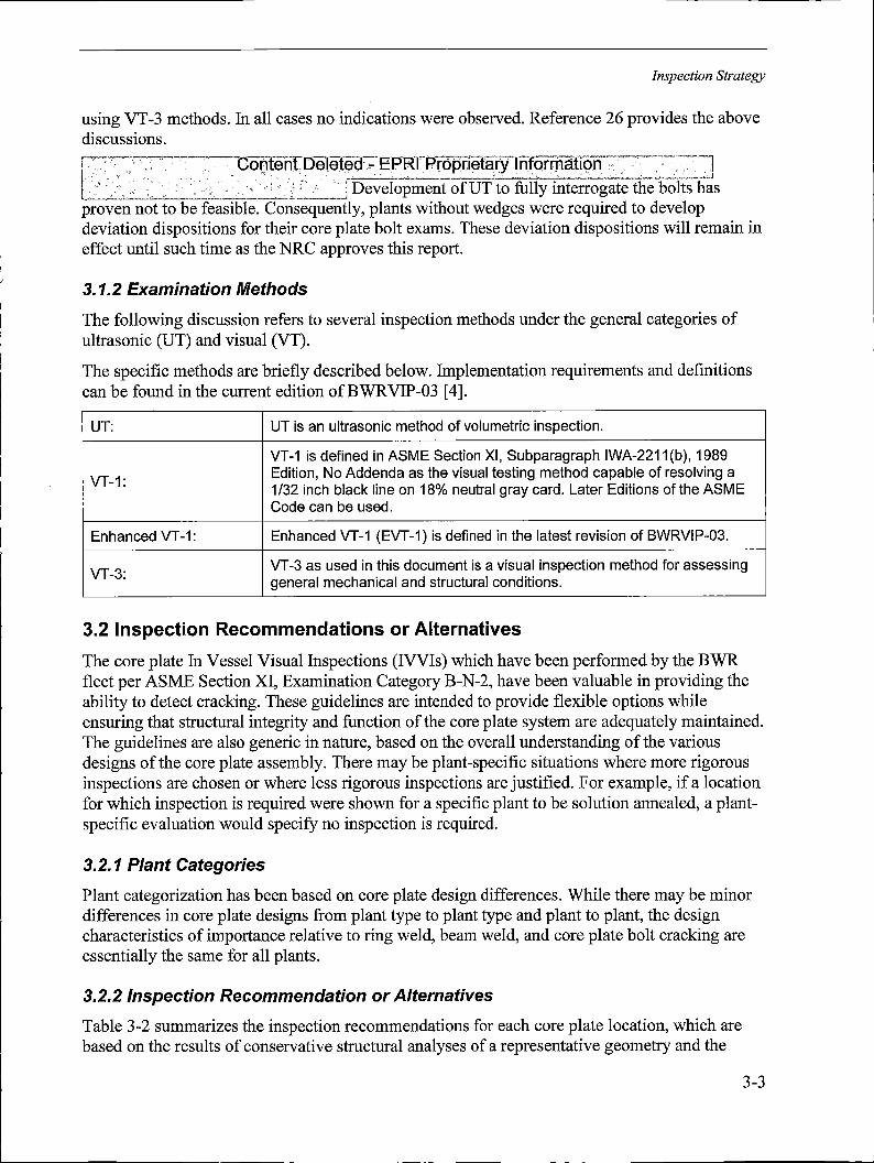
Inspection Strategy
using VT-3 methods. In all cases no indications were observed. Reference 26 provides the above discussions.
1, . , , Cor:iteht, Delet~d,,... EPRIPropr:ieta,ry lnforrfiati9n _ ,· , -]
t ' · . . · · ·· · ,. · i Development of UT to fully interrogate the bolts has proven not to be feasible. Consequently, plants without wedges were required to develop deviation dispositions for their core plate bolt exams. These deviation dispositions will remain in effect until such time as the NRC approves this report.
3.1.2 Examination Methods
The following discussion refi ers to several inspection methods under the general categories of VT). ultrasonic (UT) and visual (
The specific methods are bri efly described below. Implementation requirements and definitions dition ofBWRVIP-03 [4]. can be found in the current e
UT:
VT-1:
Enhanced VT-1:
VT-3:
u T is an ultrasonic method of volumetric inspection.
E VT-1 is defined in ASME Section XI, Subparagraph IWA-2211 (b), 1989
dition, No Addenda as the visual testing method capable of resolving a 32 inch black line on 18% neutral gray card. Later Editions of the ASME ode can be used.
1/ C
E nhanced VT-1 (EVT-1) is defined in the latest revision of BWRVIP-03.
VT-3 as used in this document is a visual inspection method for assessing neral mechanical and structural conditions. ge
3.2 Inspection Recom mendations or Alternatives
The core plate In Vessel Vis fleet per ASME Section XI,
ual Inspections (IVVIs) which have been performed by the BWR Examination Category B-N-2, have been valuable in providing the ese guidelines are intended to provide flexible options while ability to detect cracking. Th
ensuring that structural inte The guidelines are also gene
grity and function of the core plate system are adequately maintained. ric in nature, based on the overall understanding of the various mbly. There may be plant-specific situations where more rigorous ere less rigorous inspections are justified. For example, if a location red were shown for a specific plant to be solution annealed, a plantecify no inspection is required.
designs of the core plate asse inspections are chosen or wh for which inspection is requi specific evaluation would sp
3.2.1 Plant Categories
Plant categorization has been based on core plate design differences. While there may be minor gns from plant type to plant type and plant to plant, the design relative to ring weld, beam weld, and core plate bolt cracking are ants.
differences in core plate desi characteristics of importance essentially the same for all pl
3.2.2 Inspection Recom mendation or Alternatives
Table 3-2 summarizes the in spection recommendations for each core plate location, which are rvative structural analyses of a representative geometry and the based on the results of conse
3-3

Inspection Strategy
safety consequences of component failure. Refer to Section 4 for details of the structural analyses. The table also provides the option of reduced inspection for plants that have done or may consider plant-specific analyses and/or repair modifications.
Based on these analyses, the core plate bolts are the only core plate location which needs to be addressed with a plant-specific inspection strategy. Inspect the core plate bolts to ensure an adequate number are intact to prevent lateral displacement of the core plate.
ft;\·~'_.,::': : ~ - ~ " ~· ·, ~~~~--:--=;•~~'.:~~.:-:T·--::--:;:\-. · ~~~ ~-T~~:-:1 ,~~~<:::·::.31;~,~r~\O,~l,~tep,>~,~-~~;-!?r~grietaryt~f~r:rt)ation~-::_~c~-C~~-~--~----J
Each of these options is discussed below.
3.2.2.1 Installation of Wedges
3.2.2.2 Inspection of Core Plate Bolts
3-4
----- --------
Inspection Strategy
r - ..,....,_ .... ~- -~ · l
l l I
Content Deleted - EPRI Proprietary Information
l . , . -- < i I - - - --------- --- --- ----------------- -- -- --· -- - ------ ·- --- ----
l_. ---
I
r
- ' '
I .--------·-- ------ --'------------ -- ---- ---- -------------- ··---- ------ ---- - --- -- - -- ---------- - - --- ------ - ___ : i---i I L - J
i -
I I
Content Deleted - EPRI Proprietary Information
-•- -~-• -•-•-•- --•- -- ~----------,.•-- -- -~----- •• ••---- - H----•~---- -••----•-•- - --~· - -•~ -----• •--~--' ' I '
L ·--~-----·- --·
3.2.2.3 Application Criteria for Eliminating Inspection of Core Plate Bolts
I
I ,__ ___ _
1
--- ------------- -._ ----------------------- ---- ------------- ---- -- -- - - ----------- ---------- --- ------------------------
' - Content Deleted - EPRI Proprietary Information
I
. ------- ------- ---··· ------ --------------------- ---- ----·· ··•·- ---------------- ----- ____ -_ -- -------------------·-J
3-5
Inspection Strategy
,/,-.·
. Contenr Deleted.;. EP.Rt Proprietary Information '•-'• , •' •, • C < \ -' ,., - ,•., ! '\. ' ,-• ' > '•: .... , ,' J O • •' • ~ ' ••
.1
~~------~-~~~~--~---~~--___ j
3.3 Reporting of Inspection Results
.. I
'"'•'7._, i ·----~-~
Table 3-1 Core Plate Cracking Experience
';,:i
·o.~ntent·Peletep; ~---EPJ~i. prbpri.et~cyjbtq'rni_?tion • • ·~ '.; ' • - .-.,: • ;;, - • • ' ,:' ._ • • • • ~· ·\ -. <f • ~ ·, •
3-6
Inspection Strategy
Table 3-2 Summary of Results and Inspection Recommendations ~------~-- =·•-·-·-------~~~-.. -,----~-~-~-- . --------- ,------- ,----------·- - --~- -- .- - - . - -·- •· -·- ... _ --- -- - -~- --- - - -------------~-----.-~,.~---~ ~--~- ~~~----
Content :Deleted - ·EPRI Proprietary 'Information
L -- -- - ' --... ~------ - . -- __ ., __ ,, ____ ., ----· ,_,.,., -··-•·-----·-- -~---'· _ _,, _________ ----·-- --· ~------~- -·-
3-7
Inspection Strategy
Table 3-2 (continued)
3-8
Table 3-2 (continued) Summary of Results and Inspection Recommendations
I··,-•, .•. '
I I I I I
Inspection Strategy
I
' >
(. OY---•' •' •,•
3-9
Inspection Strategy
Table 3-2 (continued) Summary of Results and Inspection Recommendations ~-
I . Co:ntent _Deleted::~ EPRI .. Prqpri.~tary· Information . . . ~ . - .
3-10

I
I_. I -,! 1-
1 I f
Inspection Strategy
Table 3-2 (continued) Summary of Results and Inspection Recommendations
·- .
. Content Deleted EPRI' Proprietary lnformaUon
!_ ___ . - -~ -·- - . •·-•··- ·- .. _ - ' --·-----.. ··---~ -... ., ___ , ...... ,..;_.,,. - ____ .. ___ , __ . -- . ___ .. ____ . ---- -·-•------•·-----·-·--- -··- . . - . __ .. --· ------ ---- ~ -~---- --·-•-·-·-----------·
3-11
4 LOADING
This section provides the load term definitions, load combinations and the methodology of a plant-specific core plate bolt stress analysis that is related to an example in Appendix A.
In the event that plant-specific analyses are required, loads, load combinations and key analyses must be defined. Sections 4.1 and 4.2 describe the details of the various loadings and the load combinations that need to be considered to determine the primary and secondary stress levels appropriate for various operating conditions. A finite element model is typically used to determine the stresses once the appropriate loads are determined and combined. Section 4.3 provides information on a conservative example core plate analysis. The results of this example case provide the basis for many of the inspection recommendations in Section 3. Section 4.4 provides a review of applicability of GEH' s Safety Information Communications (SCs) related to acoustic (AC) load and annulus pressurization (AP) load for the core plate stress analysis.
4.1 Significant Loads ~· .
;" ~
..:.--c..-c---~ J
n .-~·---~-----~ U 1· , · .· ... j n LJ L~_•·-•·l..:'..:..-";-·_~-~
f] L---~~-0 I ·_:..._•'--·":. ~-~------~J
i.< .:-:c-:,~:J .·;_---'--~-'-'
fl - . ,,~ u L·· .. · . , L..-:~ .
[: ~ : Content oe,etEld ··" ·(=:PRI . Proprietary iiifohn8tion :, : :,. ' ,- ' ~ '' , .-; . ,, -- -~ -" \ -· ', ' ' ,, ;.,. - ~.' ' . -. , .•; .. , .; -:•' ' -
~---.. ,......,.. .. ~, • .. · .1
4-1
Loading
Each of these applied loads is discussed below.
4. 1. 1 Deadweight (DW)
4. 1.2 Seismic Induced Loads
4. 1.3 11P Loads
l '/ ·. . Co~len~ 6eiite~ -EPRi Pr-opri~tary lnfofm8tion ... ~7
,~.,~ 1·":··:.'::·.:,,:' ,,_ . · ,·.• · · · .. · f.........,,c_ ________ ·. · ·. -:':. ·. ~~~-~'~;·;_.j
4. 1.4 SRV Loads
4-2
Loading
4.1.5 Loss-of-Coolant Accident (LOCA) Loads
4.1.6 AP Loads
4-3

Loading
4. 1. 7 Fuel Lift (FL) Loads
4. 1.8 Applicability of Hydrodynamic Loads
4-4

Loading
4.2 Load Combinations
The typical faulted load combinations for Mark I, II and III with the FL load on the core plate are summarized as follows: ·
4-5
Loading
4.3 Example Stress Analysis
fl u '7 lJ n u
4.3. 1 Stiffener Beam Separation
4-6

Loading
4.3.2 Core Plate Bolts Restraining the Core Plate
. ·: __ Content Deleted - i=PRIPrbprietary ,·nform,atjoh·· ··,; .. ·- ·•'.'
.··-::1-1 .-r~-
1 ,----1 ,._i--;
J
j
·._ X
-7 ---~- .•• ·: <'~---~-""-''-"----~~' j
4.3.3 Wedges Restraining Core Plate
· .Gonten(beleted .- l=PRI. P,rOpriet~ry 'lnfortn~tiQ.n -.·. . " " - . . . ,· ' . '
.. -~--~- ,_,-..;,,,,_.._...,.............,~-~~
--~-'j
4.4 Review of Applicability of SCs for Core Plate r ~·, "• ~ . I
=·-,,-1 ' I ~
·.· J l L ... ..,...,,
i 1
··-o:._r'
4-7
Loading
Table 4-1 Typical BWR Load Definitions for Reactor Internals
iContentDeleted.- EPRl Proprietary IDforrnationl I I !
4-8
Loading
Table 4-1 {continued) Typical BWR Load Definitions for Reactor Internals
j
Content Deleted - . EPRI Proprietary 1ntormation
i . , . ·. l_ ._ ._· ______ ... _____ _._ -·--·· ---- - -- . ··---·- -----------··---- --- -·
4-9
Loading
Table 4-2 Reactor Internal Load Applicability for Core Plate
--~T '. ·, :-, ,- •.
. --
·c•;<; • ,• • ·,
Table 4-3 AP and LOCA Loads for Fuel Lift
'i 1
I I
. ' (
f ·- .... <.:·:\~ f. ·<·.'· - l I .-l
1 . - , . . ;, J 1 · -· ·•· . . .-__ .. ." . > . . . , . . . . . ;
:conter1t D9Ief9d ,. EPRI pr,ppr:i9tacy 111fofrn-atid~1
I . . - _- - .- - - - _--: __ -- -· - - _- - . I -I I . . .< . • . : -- j
l, __ -_· .. ,1, - , ·,''
.,___:_~
4-10

Loading
Ai~rd:Pti~{~fY•f ~tqrrn,ti'.aQi ,f'.I
Table 4-5 Core Plate Loads
; ! ~-;:' '
kt)· I, 1 ._' . ~-'-• ~-<,..,_~;..._,._..-1-~.
.•:;tf;;,j .~~~~-~~-~-:i<·i,,,/j
4-11
Loading
Table 4-5 (continued) Core Plate Loads
4-12

Table 4-5 (continued) Core Plate Loads
[' ·'., ... ',:-•,,, r,,.
(,·.
[\·· :, -/./;': c' --- :· >:r;i, ,::- .- -;::·'> ....... . -_: ••_:. ., ~>-: .. \: p~nt~"Ol;Q~leteg:;JJ~_fRJ.::et8Pfi~tqf¥·l_nfqrrnij{ioQ !-""·
IL:· _0 -
•.
:'~ f':
[
Loading
4-13

Loading
Table 4-6 Review of Applicability of GEH's SCs for Core Plate - -- 7
. ~ I -.J
4-14
5 REFERENCES
1. BWRVIP-06-A: BWR Vessel and Internals Project, Safety Assessment ofBWR Reactor Internals, EPRI, Palo Alto, CA: 2002. 1006598.
2. Letter, dated 7/11/96, V.L. McCarthy, GENE to T.A. Caine, GENE, "Core Plate Bolt Relaxation Calculations".
3. "Final Test Report, CRD Performance Evaluation Testing with Drive Line Misalignment," NEDC-32406, September 1994.
4. "BWR Vessel and Internals Project, Reactor Pressure Vessel and Internals Examination Guidelines (BWRVIP-03)," EPRI Report TR-105696, October 1995.
5. "Evaluation of Acoustic Pressure Loads on BWR/6 Internal Components," NEDO-24048, September 1978.
6. "Technical Description and Work Scope NSSS Design Adequacy Evaluation-New Loads," NEDO-24547, December 1978.
7. "BWR Internal Component Loading Following Hypothetical Loss of Coolant," APED-5580, January 1968.
8. "Asymmetric Blowdown Loads on PWR Primary Systems, Resolution of Generic Task Action Plan A-2," NUREG-0609, January 1981.
9 .. "BWR Owner's Group Sub-compartment (Annulus) Pressurization Loads Evaluation Methodology Review," NEDC-33637P, Rev.0, May 2013.
10. "Annulus Pressurization Loads Evaluation," GE Hitachi Nuclear Energy SC 09-01, Rev.0, June 8, 2009.
11. "Shroud Screening Criteria Reports," GE Hitachi Nuclear Energy SC 09-03, Rev.I, June 10, 2013.
12. "Impact of Inertial Loading and Potential New Load Combination from Recirculation Suction Line Break Acoustic Loads," GE Hitachi Nuclear Energy SC 11-07, Rev.0, June 10, 2013.
13. "Impact of Plant Changes on Bio-Shield Wall Doors," GE Hitachi Nuclear Energy SC 12-08, Rev.0, April 2, 2012.
14. "Error in Method of Characteristics Boundary Conditions Affecting Acoustic Loads Analyses," GE Hitachi Nuclear Energy SC 12-20, Rev.I, December 8, 2014.
15. "Shroud Support Plate-to-Vessel Evaluation for AC Loads," GE Hitachi Nuclear Energy SC 13-08, Rev.0, December 15, 2014.
16. "Non-conservatism Acoustic Load Calculated by WHAM," GE Hitachi Nuclear Energy SC 14-01, Rev.0, to be issued.
5-1
References
17. "Acoustic Load and Flow-induced Load on Jet Pump," GE Hitachi Nuclear Energy SC 14-02, Rev.0, to be issued.
18. "Acoustic Load Pressure Difference on Access Hole Cover," GE Hitachi Nuclear Energy SC 14-03, Rev.0, May 18, 2015.
19. "BWR Fuel Assembly Evaluation of Combined Safe Shutdown (SSE) and Loss-of-Coolant Accident (LOCA) Loading (Amendment No. 3)," NEDE-21175-3-P-A, October 1984.
20. "Reactor Vessel," GEH Drawing 237E434, Revision 5, January 6, 1966 (BWR/2).
21. "Reactor Vessel," GEH Drawing 886D482, Revision 5, November 22, 1967 (BWR/3).
22. "Reactor Vessel," GEH Drawing 886D499, Revision 12, November 30, 1970 (BWR/4).
23. "Reactor Vessel Loading," GEH Drawing 761E512, Revision 7, November 5, 1982 (BWR/5).
24. "Reactor Vessel Loadings" GEH Drawing 213A5458B, Revision 7, May 4, 1978 (BWR/6).
25. "Core Plate Bolt Relaxation," GEH Design Basis Specification Design Note, DBR-0002568, October 15, 2014.
26. "BWRVIP-25 Inspection Recommendations," GEH Design Basis Specification Design Note, DBR-0003433, November 13, 2014.
27. "Failure to Include Seismic Input in Channel-Control Blade Interference Customer Guidance," GE Hitachi Nuclear Energy SC 11-05, Rev.2, December 16, 2013.
28. BWRVIP-303: "BWR Vessel and Internals Project, Load Definitions and Combinations for Use in BWR Internals and Repair/Replacement and Flaw Evaluations. EPRI, Palo Alto, CA: 2019.
5-2

A EXAMPLE CORE PLATE BOLT ANALYSIS
This Appendix is an example plant-specific core plate bolt stress analysis. Such an analysis may be used as a means of developing a plant-specific aging management strategy for the core plate bolts if a plant fails to meet any of the other options for core plate aging management in Section 3.
The loads and the resultant stresses presented in this Appendix A are an example; are not intended to be bounding. For a plant-specific analysis, the plant-specific loads should be used since the applicable loads and load combinations for the plants vary (See Section 4.0).
A.1 Example Core Plate Bolt Analysis
' ____ j
i ' ·1
i i --------------~-------------- ·----' ! , I
l-•-----~ ! ---------------------·----------------- -----, ---- . - ---- I
r----_1 I
I I I I
I ; -
Content Deleted"- EPRI Proprietary Information
L ------------·---
t_ ___ ,_,
1
i
.. i~---_J . t ----~------
A. 1. 1 Loadings ,----.----,.----,• ---••--- h
Deadweight (DW) loading consists of the weight of the core plate. 1 i
J I Li •.---· . ---,----c -· . --
1 -~----~ L.:. _________ _
Seismic Inertia loading consists of horizontal and vertical inertia forces acting on the entire core plate due to seismic excitation of the core plate. These loads are considered for both the OBE and SSE cases. These loads can be divided into two categories: acceleration loads due to the seismic inertia of the core plate, and the loads due to fuel shear. These loads were applied to the model as follows:
A-1
Example Core Plate Bolt Analysis i--~ ------------------ ,---·--1 I . I.
7
I l i
I .- . -
Content Deleted -- . .· . . . . . , - _. l
EPRI Proprietary lnfotmation·: ' - ' - i
I
I
SRV loads are induced by actuations which produce oscillating pressures on the suppression pool boundary. These pressures impart structural motions which may cause dynamic excitations of the structure and contained equipment. These loads can be divided into two categories: loads due to the effect of SRV loading of the core plate and loads due to the effect of SRV loading on fuel shear. These loads were applied as follows in this evaluation:
I ----.- . . . . , . ~.. , -- - - , .· ' , . . . --,
I . I I ' ' ' ' ' '' ' ' - ' ' " ' '' ,' .. ' -, ' - ' -' ' .. : - I
;Content Deleted ·- E.PRI Proprietary. l.r1form~tton·i I - - . . . _. . . . . . . _, _- : .: - . . . '. I ·_ I ,
I . l_-' __ _ - 1
·----~--- ' _ _j
Annulus Pressurization loads are due to the loading on the biological shield and the reactor vessel following a postulated break of the vessel nozzle safe end to pipe weld. This rupture allows a rapid mass and energy release into the small annular region between the biological shield and the RPV. Annulus pressurization leads to interactions between the shield wall, reactor vessel, and the reactor pedestal, with loads transmitted to the vessel internals. These loads can be divided into two categories: loads due to the effect of AP loading of the core plate and loads due to the effect of AP loading on fuel shear. These loads are applied to the model as follows:
.---. ,,,-,---.~!
I . . .
Content Deleted -I ·,. I
I ~ I [ __
A-2

Example Core Plate Bolt Analysis
LOCA conditions which are postulated to occur are SBA, IBA, and DBA LOCA. These loads can be divided into two categories: loads due to the effect ofLOCA on the core plate and loads due to the effect ofLOCA on fuel shear. These loads are applied to the model as follows:
- -~ ----l 'I ; !
Content Deleted -· EPRI Proprietary Jnformation! . . ' . . ' . - ' . ' . . . ; :_ : . . .. ,· . . . ' ·.. . . ' !
Fuel Lift loads are postulated to occur if, under postulated dynamic conditions, a fuel bundle could move relative to its support, unseat and reseat on the fuel support, and impart loads on the core plate. Loading for both OBE and SSE conditions is considered. These loads are applied to the model as follows: r~- - ----------,
I J
iConte11t Deleted - EPRI PrDprietary lnformatio~ ., I
·, I
-~--------____:_J Pressure loads are those delta-P's which act across the core plate; this load acts in the vertical direction only and varies with Normal, Upset, or Faulted conditions. These loads are applied to the model as follows:
j . . !
EPRI :Propri.etary Jnforrnation Content Deleted -i .
. . ' . ' J
L _______ _ ! I
' i ----- ---·~-- -·---------·------- _____ t
A.1.2 Calculated Stresses on the Core Plate Bolts -------:·;~l
,J __ J
. . . . - I
Content Pel.eted·::-- EPRI Proprietary. Information ·-L.1
- . . . . I ,· . 1-·---•"-"
I ·---, __,
A-3

Example Core Plate Bolt Analysis
r- --- --- ----·-----~-------------- --- -----·-- --
Content Deleted EPRI Proprietary Information I ______ _,,
____ -J
I ________ ,_-----
A-4
Table A-1 Summary of Results for Core Plate Analyses
Example Core Plate Bolt Analysis
! I
I i
. I
I l I i
• I
' '• ' ' . . . ' ! Content· Deleted· - EPRI Proprietary I nformationj
, I
I j I I !
. ! .i
i
I
A-5
Example Core Plate Bolt Analysis
Figure A-1 Finite Element Model of Core Plate
A-6
Example Core Plate Bolt Analysis
Figure Finite Element Model Showing Core Plate Bolt and Beam Element
Figure A-3 Vertical Force Acting on Core Plate Bolts Around Core Circumference2
2 Vertical lines in figure denote position of beams.
A-7
Example Core Plate Bolt Analysis
Figure A-4 Horizontal Forces Acting on Core Plate Bolt Around Core Plate Circumference
A-8

B LICENSE RENEWAL APPENDIX
The demonstration of compliance with the technical information requirements of the License Renewal Rule (10 CFR 54.21) previously contained in this appendix was developed based on "BWR Vessel and Internal Project, BWR Core Plate Inspection and Flaw Evaluation Guidelines (BWRVIP-25)," EPRI Report TR-107284. The content of this appendix is now considered historical and has been removed from this report to eliminate any potential for conflicting language or misuse. The prior content can be found in Appendix B of BWRVIP-25, Rev. 1. Subsequent revisions to BWRVIP-25 have been reviewed with regard to ensuring that the guideline remains adequate to meet the technical information requirements of the License Renewal Rule and to ensure that the applicable effects of aging are identified and adequately addressed by the l&E guidance provided in this report.
B-1
C NRC REQUEST FOR ADDITIONAL INFORMATION (97-268A/588)
: . - -- - --- \
' '
I
. '
i
:content Deleted - EPRI Proprietary Information
C-1

' I r
NRC Request for Additional Information (97-268A/58B)
I
l 'I
I
Content 'Deleted: ... EPRI. Pf9~pri~tc,1ry'.:lnfo_[f!1~!i9n 1. - ' ·' ,. ' < - • '
·~ ,, ,; - ·_, ":-:-' .'1; ,1~" -· '
' ,, ~ ---~--~-~-----__ , ·----~~-~---~-~-~-----~-----~
C-2

NRC Request for Additional Information (97-268A/58B)
-1-PROPRIETARY ---,-.,,--7
l
C-3
NRC Request for Additional Information (97-268A/58B)
-2-
PROPRIETARY
C-4

NRC Request for Additional Information (97-268A/58B)
. . . . . . :. . . . ·. .. . .' . : . . . . ·. . .-.. ·. ·. . . : . I
· · Content Deleted - ·E·PRI ·Proprietary lnform·ation 1 · .
' ·I
! l I 1
.. ·1 , I . I
_:' ,,
-----~~~------------- ----- :-·---~--~--·"·_. _, 1
PRO?RIETARY
C-5
NRC Request for Additional Information (97-268A/58B)
-4-r-- ------ - ---- - - ______________________ ________ PROPRIETARY __ ----- - - ---·---------- ------·--·· ----·--··--
! i I
i
Content Deleted EPRI Proprietary Information
' ·---------------- --------- --· - ------------·-"-·-----~--- - -~---------------, ..
PROPRIETARY
C-6
NRC Request for Additional Information (97-268A/58B)
-5-PROPRIETARY
PROPRJITARY
C-7

D BWRVIP RESPONSE TO NRC REQUEST FOR ADDITIONAL INFORMATION (97-937)
PROPRIETARY REQUEST FOR ADDITIONAL INFORMATION REGARDING EPRI REPORT TR-107284
1.
"BWR VESSEL AND INTERNALS PROJECT, CORE PLATE INSPECTION AND FLAW EVALUATION GUIDELINES
(BWRVIP-25)"
Content Deleted - EPRI Proprietary Information_ , .
BWRVIP-06, "Safety Assessment of BWR Reactor Internals", contains a safety assessment of internals components for BWR/2 through BWR/6 product lines. The purpose of this evaluation was to determine the short-term and long-term actions which would be appropriate to assure the continuing operation given the possibility of cracking in those components.
i . - . . .
· Content Deleted - EPRI Proprietary Information ' t ...... , - ' r----_.· __ ~_J
I ·_ r --------,
L _________ ~ ______ J
c~ Content Deleted - EPRI Proprietary lnform_a_ti_o_n ____ --~ D-1
BWRVIP Response to NRC Request for Additional Information (97-937)
----- ·-- --- ---~~------- ---~---------- ~--- ------ ---- ----. ' !
Content Deleted - EPRI proprietary Information ·
i
,------ ------------- cl
r----- ·----- -- ----------------- -.------ - - ----- -------~---------- ----- -----~- -------- ··t I
l.. - \
I
As stated in Question 1, the effects of loose parts on the safety consequences of failure for the core plate locations discussed in BWRVIP-25 have been addressed in BWRVIP-06, ____ _ Section 4.0. ! · : 1- -- --- - ------.
I -
I __ ,
I .
Content Deleted - EPRI Proprjetary Information· i .
-------·---~! r ·------------------------· ------------------------------------- -------- --------- -. I
I !. I ~---' • ---- --- • ----- ----- -------------------- ----- -·-! I L________________...J
r·· -·-·--------- ---------------~---~-------------- -------. - - -------·---·-- -------------- ----~ --------- - --\ ' I i ____ l ,
(
D-2
BWRVIP Response to NRC Request for Additional Information (97-937)
1____,, . i
-'--'--~--~---'---------~-~-~~--.:_,_]
D-3
BWRVIP Response to NRC Request for Additional Information (97-937)
1- ·------ ·-----------
'
I
' S <>~----k- ---.-~------¥- . -~,------------;--- ~---~ ·---:--~ ~--------- ------·-··- -----,-~--,.--·-----------~,----·--! l
l .,
Content Deleted - EPRI Proprietary l,nforni:atiori~~----; . . ' . ' . " . ·' . . ·' ,. --~-~->__:-~----~.:
,.J
, ,l
D-4
BWRVIP Response to NRG Request for Additional Information (97-937)
D-5
BWRVIP Response to NRC Request for Additional Information (97-937)
The timing of the implementation of the BWRVIP I&E Guidelines is currently being discussed by the NRC and the BWRVIP Executive Committee. It is generally agreed that utilities should implement the Guidelines as soon as practical after the NR.C hasissued a safoty evaluation. TheJ~recist: timin~ is being. discu,ssed: J:-•::. : .. · ·,:\,•',. -:_ ;,· \ > ( : <:":.- ;] r;_::'···"• ·:: ·.-;c:·, -- -- -- .,,.·•:-- --- -_,· ·-:··•,-• -- i .. ---·--·•·•" < - .,_,._,"·•·.::-,)1
I~--~ \-~ , ' ·:' '"·'•,1 L ·"· . r---;,J
r.· -._,.·---~----- _ ~""; ~5oe--- --'---~.J > ~"~ -~- •'
•'
--~~-"---:,J
D-6

BWRVIP Response to NRC Request for Additional Information (97-937)
L __ l .. , Content Deleted - EPRI Proprietary Information
L~ ,--·-~---~ r ! l
! L
D-7

E NRC INITIAL SAFETY EVALUATION (99-159B)
UNITED STATES NUCLEAR REGULATORY COMMISSION
WASHINGTON, b.C. 2'1555-0001
April 28 •. 1999 FILE COPY
earl Teny, BWRVIP Chairman Niagara Mohawk Power Company Post Office Box 63 Lycoming. NY 13093
SUBJECT: SAFElY EVALUATION OF THE "BWRVIP VESSEL AND INTERNALS PROJECT, "BWR VESSEL AND IITTERNALS PROJECT, BWR CORE Pl.ATE INSPECTION AND A.AW EVALUATION GUIDELINE (BWRVIP•25),"' EPRI REPORT TR-107284, DECEMBER 1996 (TAC NO. M97802}
Dear.Mr. Teny,
The NAC staff has completed its review of the Electric Power Research tnstltute (EPRJ) J)ropnetary report TR•107284, "'BWR Vessel and Internals Project, BWR Core Plate Inspection and Flaw Evaluation Guideline (BWRVlP-25)." December 1996. This report was submitted by letter dated DecC3mber 27, 1996, and supplemented by a letter dated December 19, 1997, which was in response to the staff's request for additional Information, dated March 14, 1997.
The BWRVlP-25 report provides generic guidelines intended to present the appropriate Inspection recommendations to assure safety function Integrity of the subject safety.related RPV intemat components. It also provides design information on the core plate, geometries, weld locatlons, and potential failure locattons for the sevemt categories of bolling water reactors (BWRf2 through BWR/6)'.
The NRC staff has reviewed the BWRVlP-25 report and finds, in the endosed Safety Eva!uatlon (SE}. that the guidance of the 8WRVIP•25 report fs acceptable for tnspection and flaw evaluation cf the subject safety&related RPV Internal components, except where the staff's conclusions dffler from the BWRVIP's, as discussed In the enclosed SE. The staff has concluded that ricensee Implementation of the guidertnos in the BWAVl?-25 report wm provide an acceptable level of quanty tor inspection and flaw evaluaUon, with mocfrfications to address the staffs conclusions in the enclosed SE, of the safety~retated components addressed.
The staff requests that the BWRVlP review and resolve the Issues raised in the enclosed SE, and incorporate the staffs conclusions into the revised BWRVIP-25 report ?lease mfonn the staff within 90 days of the date of this letter as to your proposed actions and sChedule for such revisions. ·
E-1
NRC Initial Safety Evaluation (99-l 59B)
E-2
Carl Terry
Please cont.act C. E. (Gene) Carpenter. Jr., of my staff at (301} 415•2:169 if you have any further questions regarding this subject.
Enclosure: As stated
cc: See next page
Sincerely,
--°-J ffe~u·Jat ~ck R. Strosnider. Director
DMsfon of Engineering Offiee of Nuclear Reactor Regulation
cc:.
Kari W. Singer. Executive Chair BWRVIP Assessment Task
Tennessee Valley Authority PO Box2000 Deca!tur, AL 35602-2000
sm Eaton. Executwe Chair Inspection Committee
Entergy Operations, Inc. PO Box 756, Waterloo Rd Port Gibson, MS 39150-0756
H. Lewis Sumner, Executive Chairman BWAVIP Mitigation Task
Southern Nuclear Operating Co. MI'S 'IN 8051, ?O Box 1295 40 Inverness Center Parkway Blrmingham, AL 35201
Harry P, Salmon, Executive Chahman BWAVIP lntogmllon Task
New York Power Authority 123 Main St. MIS 11 D White Plains, NY 10601-3104
George T. Jones, Executive Chair BWRVIP Repair Task
PennsyJvanla Power & Light. Inc. MfSGENA61 2N 9"S1reet Allentown, PA 18101~1139
Robert Carter. EPRI BWRVIP Assessment Manager
EPRI NOE Center -P.O. Box217097 1300 W. T. Harns Blvd. Charlotte. NC 28221
Greg Selby, EPRI BWRVIP Inspection Manage-r
EPAI NOE Center P.O. Box217097 1300 W, T. Harris BIVd, Charlotte, NC 28221
Joe Hagan, BWRVI? Vice Chairman PEPCO Energy Co. MC62C-3 965 Chesterbrook Blvd Wayne, PA 19807~5691
NRC Initial Safety Evaluation (99-159B)
Stave Lewis, Technfcal Chafrman BWRVIP Assessment Task
Entergy P.O. Box756 Waterloo Road Port Gibson, MS 39150
cart Lan!en, Technical Chairman BWRVIP Inspection Task
Yankee Atomto 580 Main Street Bolton, MA 01740
John Wilson, Technical Chairman BWRVIP Mitigation Task
CUnton Power Statton, MIC T•31C P.O. Box678 Clinton, tl 61727
Vaughn Wagoner, Technical Chairman BWRVIP Integration Task
Caronna Power & Light Company One Hannover Square 9C1 P .o. Box 1551 Raleigh. NC 27612
Bruce Mcleod. Technical Chaltman BWRVIP Repair Task
Soo:them Nuclear Operating Co. Post Office Box 1295 40 Inverness Center Parkway Birmingham, AL 35201
Warren Bilanin, EPRI BWRVIP tntegration Manager
Raj ?athanfa, EPRI BWRVIP Mltigation Manager
Ken Wotfa, EPRI BWRVIP Repair Manager
Electric Power Research Institute P. 0. Box 10412 3412 Hillview Ave. Palo Alto, CA 94303
James P. Pelletier, BWRVIP Liaison to EPRI Nuclear Power Council
Nebraska Public Power District 1200 Prospect Avenue fl0Box98 Brownville, NE 68321-0098
E-3
NRC Initial Safety Evaluation (99-159B)
U.S. NUCLEAB REGULATORY COMMISSION
OFFICE OF NUCLEAR REACTOR REGULATION_SAFElY fiY:ALUATION OF
"BWRVIP VESSEL AND INTERNALS PROJECT. SWR PORE P~TE INSPECTION
AND FLAW EVALUATION GUfOELINi; (§WB:¥1e-25), ..
EPRI REPORT IB-107284, DECEMBER 1996
1.0 INTRODUCTION
1.1 Background
Sy letter dated December 27, 1996, the Bolling Water Reactor Vessel and Internals Project (BWRVIP) submitted the E1ecmc Power Research !:nstitUte (EPRI) proprieta!y Reports TR-107284. '"BWRVessel and Intern.a.ls ProJect. BWR Core Plate tnspection and Flaw Evaluation Guideline (BWRVIP-25)." De¢ember 1996. ThiS report was supplemented by a letter dated December 19, 19:)7. whlch was in response to the staff's request for additional information {RAJ), dated March 14, 1997.
The BWRVIP·25 report provides generic guidelines intended to present the appropriate inspection recommendations to assure safety function integrity of the subject safety ... reJate-d reactor pressure vessel (RPV} intemaJ components. It aJso provides design infonnation on the core plate. geometries, weld locations. and potential failure locations for the several categories of bolling water reactors {BWR/2 through BWR/6).
1.2 Purpose
The staff reviewed the BWRVIP-25 report to detennine whether its guidance will provide acceptable levels of quaaty for inspection and flaw evaluation of the subject safety-related RPV internal compenents. The review considered the consequences of component faflures, potential degradation mechanisms and past seivlce experience, and the abilfty of the proposed inspections to detect degradation in a timely rnanrnn.
1.3 Organization of this Report
Because the BWRVl?-25 report Is proprietary. this SE was written so as not to repeat fnfonnation contained in the report. The staff does not discuss in any detail the provfsions of the guidelines nor the parts of the guidellnes it finds acceptable. A brief summa,y of the contenlS of the BWRVIP-25 report is given in Section 2 of this SE. with a detailed evaluation in Section 3. The conc~uslons are summarized in Section 4. Th-e presentation of the evaluation is structured according to the organization of the BWRVIP-25 report.
ENCLOSURE
E-4
-- I

NRC Initial Safety Evaluation (99-159B)
2
2.0 SUMMARY Or BWRVIP~25 REPORT
The BWRVIPM25 re-port addresses the following topics:
• SusooptibiHty Factors - The various types of material degradation mechanisms (e.g., fatigue, stress corrosion cracklng, age embrittlement) that oould impact the core plate ate characterized. Materials, stress, and environmental factors are described In general tenns. followed by specific references to locaUzed regions relative to plant operating experience for particular mechanisms and components. ·
• Component Description and Function - The various core plate components are described in considerable detail by a series of iltustrations along wlth brief descnptlons of each oomponenfs function and materials/welding characterlstlcs. Differences among the various models of BWRs (BWR/2, BWR•S.5, and BWR/6} are identified.
• Potential Failura Loe.at Jns aod Safety Conseguencm - Each of the core plate components are addressed from the standpoint of inspection hEstory. future susceptibility to degradation, and consequences of failures in terms of component functions and plant safety. Based in these qualitative conslderations, the BWAVIP~25 report makes recommendations as to the need for inspections for each of the lower plenum components.
• Background and ln~on Histo£i - Data on serviee related failures of components are summarized. The major sources of such data are the various GE Slls and Rapid Information Communication Service Information Letters (RICSILs).
• BWBVIP Inspection Guidelines - The guidelines recommend the specific 1ocaUons, NOE methods, and inspection frequencies for examinations of core plate components.
• Loads - This section defines the loacmg to be used in fracrum mechanics evaluations to address the effects of detected flaws on structural integrity. and is based on the plant design and licensing basis. The various types of loads (e.g., pressures, seismic, etc.) of concem are listed.
3.0 STAFF EVALUATION
With the exception of issues described below, this review finds that the guidance provided In the subject report to be acceptable.
Item 3. rnspectlon Strategy
The BWRVIP .. 25 report presents a conservative representative structural analysls of the core plate m order to determine which core p!ate locations require inspection to assure perlom1ance of core plate safety functions. The load magni1udes at various tocatlons In the core plate were determined through finite element analysis. I _ · . . • . . · · · l r- . - . 1
i Content Deleted - EPRI Proprietary lnfqrmation -~----~--J
E-5
NRC Initial Safety Evaluation (99-159B)
3 ----------------------- ------~------- - I
l
:Content Deleted_ - EPRI Proprietary lnforma~ion l -__ :· . -• -· :_ _: .. . ._ . . , , -·_:.. . .. . . . . .. ;
The BWRVIP•25 repon presents a "baseline" approach for the first inspections perfonned, Acceptable altematives to inspection to new BW RVl? requirements for the core plate are also presented for plants to consider. speclfically involving plant-specif!o analysis or repalis and/or
1_.ro_o_di[~ti.o.ns..;_! • . . -.. ·; , _'. .. · .. ·--_, ... ---~-: -· · · . . . . .. · · \ i . . . i I - - . ·1 i • • 0 r •• • , , • !
1
conJent:_pe1§te_d -:.: EPRI Proprl~tary._ I nfqrm_a,tion;
i L
E-6
,. I I I I I I
. . I . i
I
I
-~---~--------------· 4' .. · _._,,., "'I
Item 3.1.8 Location 8 - Aligner Pin Socket to Rfm Welds
I . ; /.,; \ . . . .· . ' ' ! I . . . . ,
~ontent Deleted,~: EPRI. Propr,ietanr I nformation.l i . ' . . ' ; .. ' ' ' ' ' ' . . . . . -:
i I
. ,\ i
NRC Initial Safety Evaluation (99-159B)
4 r··- - _:---::~---:-.-:.. - ._ - ·- - ft· - • • , - - •• _• • • •• - - , •• --: - • _ .. - - _~1
~C?Jltenf D~letE3d·r··EPRl•·Propriet~ry;Jr,fqrmati~n\ L.,.,.._,,_~~------.,....J: . " < - • • ' ' , " •• - " • --~..!I
4.0 CONCLUSIONS
The staff has revlewed the BWRVIP-25 report and finijS that the guidance of the report iS acceptable for inspection and flaw evaluation of the subject safety~related core Internal components, exoopt where the staff's oonclusions differ from the proposed guJdance. as discussed above. The staff requests that the BWRVIP review and resolve the issues raised above, and incorporate the staff's conclusions into revised BWRVJP·:25 report. Please infonn the staff In writing as to this resolution.
5,0 REFERENCES
1. Can Terry. BWRVIP, to USNRC, "BWR Vessel and Internals Project, Core Plate Inspection and Flaw Evaluation Guidelines (BWF .VIP-25}." EPRI Report TA .. 107284, December 1996, dated December 27. 1998.
2. Cari Teny. BWRVIP. to USNRC, "BWR Vessel and Internals Project, Top Gulde lnspectlon and Flaw Eva!uation Guidelines (BWRVIP-25)," EPRI Report if\.107285, December 1996, dated December 27, 1998.
3. c. E. Carpenter. USNRC. to Carl Teny, BWRVIP. *Propfieta;y Request for Ad<fmonal Information ... Review of BWR Vessel and lmemats Project RepQrts, 'BWR Core Plate Inspection and Raw Evaluation Guidelines {SWRVIP•25).' and 'Top Guide Inspection and Flaw Evaluation Guidelines (BWRVIP-26): (TAC Nos. M97802 and M97803)," dated March 14. 1997.
4. Vaughn Wagoner, BWRVIP, to USNRC, ·awRVIP Response to NRC Request for Additional Information on BWRVIP-25 and 8WRVIP•26," dated Oecember19.1997.
Principa1 Contributors: C. E. Carpenter K. A. Kavanagh J. R. Rajan

F BWRVIP RESPONSE TO NRC INITIAL SAFETY EVALUATION (99-403)
BWRVIP Response to NRC Safety Evaluation ofBWRVIP-25, "Core Plate Inspection and Evaluation Guidelines" (SE Dated 4/28/99)
Item 3 Inspection Strategy r--- ---" ----~------~ ··-··-·-----. --------,-------7 I ' ,.......,.;.. ______ _,
'
f: Content Deleted - EPRI Pro;r~eta~-lnformatiO~~-; ~ .-l r-~----· -----
L · ·-------------------- . - -----,
. I
f•------c-.;.--.~--- • i, >, ' J I
----·-··--------- -- ] f..,:,
• I
L_~c-_____ _____________,-~-----~-~ __ .L,_L,
F-1
BWRVIP Response to NRC Initial Safety Evaluation (99-403)
BWRVIP Response to Item 3
· ... :I '"--:----~
: . I
. ' ' ' ' . . ' . ' . '· ' ' . ,•·: < ' .. ·,· :~.c-J
Cont$nt D_e!ete.d-~· EPRI Pr9prietaty lnfor·mation • . : ·. L, ,'', ,,',, :/:,,,',,,,', ,''',',:':''·,,:',··,'",,.,,,,,Cl
:.~ "
--- ~--·---"-= .' .. - . l
f.cj
.. ·· .. r~-~ . ·: ~---~-71
'i~ "". · '. " •. ~ -----~··_ .· ~~J
. ' ,~\;., ~ ·'-'.'' :~"-''"'-' ~----'~• .. ';_' ·:··.:
••••1•-in,.~ .........
Item 3.1.8 Location 8 -Aligner Pin Socket to Rim Welds
.::~: ·. · .'. < .:~ t\' .. :: . -·:>·:··· ·.:?-} ,: : ·-s~·:·: ,, __ : i;0e:-~ :~--•\ . - /:,,_. - L~
ContentDelet~d - EPRJ P~bprietary f nf9rm~t1pn . · · ·r-3 •. ' ' .. . .::,·_:._ .. ;,,, . . '' ·'• ' ' : " ' . ';. ·',___j
... ,' ·' -~~-- ' ~-~~J
' ---7~-0·1 ' \
BWRVIP Response to Item 3.1.8
The BWRVIP will provide a response to the staffs comment at a later date.
Item 3.1.9 Location 9 - Core Plate Wedge Retainer -,, '.----·,
: cdntent [)e1~tir(f- E~RI, p(Qpritfafi1nforhl~tlon . ,',: >~ e C '• •• .'" • .,:, •. • • • , • ,-....J
<· \ .,. '
BWRVIP Response to Item 3.1.9
[ •. • , Content oelet~d - ~PRI P~opriet~ry lnf~rma~ ~]
F-2
BWRVIP Response to NRC Initial Safety Evaluation (99-403)
I ; .l
_.,_]
. I __:_J
. Content Deleted -- _EPR! · Proprietary Information ·- 1-7 -----'
I ,-........-~--------~--~
F-3

G NRC FINAL SAFETY EVALUATION (99-524A)
UNJTEO STATES NUCLEAR REGULATORY COMMISSION
Gari Terry, SWRVIP Chairman · Niagara Mohawk Power Compar.y
Post OfflCe Box 63 Lycor.,ing, NY 13093
WASHIMQTON, D.C. 20$$S-CIOQ1
December 19, 1999
99-524A
- r • ,·
SU9JECT: FINAL SAFErY EVALUATION OF BWRVIP VESSEL AND INTERNAL.S PROJECT, "BWR VESSEL AND INTERNALS PROJECT, BWR CORE PLATE INSPECTION ANO FLAW EVALUATION GUIDELINE (BWRVIP-25)," EPRI REPOATTR-107284, DECEMBER 1996 (TAC NO. M97B02)
Dear Mr. Terry:
The NRC staff has completed its review of the proposed revisions to proprietary report TR-107284 "BWR VesseJ and Internals Project, BWR Core Plate lnspectron and Flaw Evaluation Guidelines (BWRVIP-25); dated December 1996. This report was si.:bmitted by the Electric Power Research Institute (EPRI} by letter dated December 27, 1996, and supplemented by a letter dated December 19, 1997, in response to lhe staff's re<;tuest tor additional infonnation (RAI}, dated Marcf'l 14, 1997. The BWRVIP-.25 report provides generic guideUnes intended to present the appropriate inspection recommendations to assure safety function integrity of the subject safety-related RPV internal components. It also provides desfgn information on the core plate, geometries, weld locations, and potential failure locations for the several categories of boiling water reactors {BWR/2 through BWR/6).
The NRC staff completed its initial review of the BWRVIP-25 report and transmitted a Safety Evaluation {SE) with several open items to you by letter dated April 28. 1999. By letter dated October 6, 1999, the BWRVIP responded to the open items in the staff's initial SE. The NRC staff has reviewed the pro-posed revisions to the SWRVlP-25 report and fmds, in the endosed final SE, that the revised guidance of the BWRVIP-25 repon ls accep!abTe for inspectk>n of the subject safety-related RPV internal components. Thls finding is based on information submitted by the above cited letters.
Regarding Issue 3.1.8, Location 8 • Aligner Pin Socket to Rim Welds, you stated in your October 6, 1999, response that H[t]he BWRVlP wm provide a response to the staff's comment at a later date." The staff understands from discussions with the BWAVIP that an expanded technical basis for this assumption Is being developed, and wil I be provided in the near future for staff review. Until such time as an adequate, expanded technical basis for not inspecting is approved by the staff. licensees should continue to perform inspections of the hold-down bolts, except for those plants that have Installed core plate wedges to structurally replace the lateral load resistance provided by the rim hold-down bolts, in which case no inspections are required. Per the staffs cfJSCUSSions with the BWRVIP, the staff understands that the BWRVIP agrees to incorporate inspections of the hold-down bolts Into a revised BWRVIP-25 report. This lssue will be re-considered when the BWRVIP provides an expanded technical basis for the assumption in the BWRVIP-25 report.
G-1
NRC Final Safety Evaluation (99-524A)
G-2
carJTeny
The staff has concluded that licensee implementatlon of the guidelines in BWRVIP-25. as amended. will provide an acceptable level o1 quality for e·xamlnation of the safety .. related components addressed in the BWRVlP-25 document.
Please contact C. E. (Gene) Carpenter, Jr .• of my staff at (301) 415-2169, if you have any further questions regarding this subject.
Enclosure: As stated
cc: See next page
Sincerely,
~Oa~ffi~4, u;ck R, Str<lsnlder, Director Dlvlsfon of Engineering Office of Nuclear Reactor Aegutation
cc:
em Eaton. Exea.mve Ohair Inspection Committee
Ente:rgy Operations. Inc. PO 8ox 756, Waterloo Rd P.ort Gibson. MS 39150-0756
H. Lewis Svmner. Executive Chairman BWRVIP Mitigation Task
Southern Nuclear Operating Co. MIS BIN 80S1, PO Box 1295 4-0 lnvemess Center Park.way Birmingham, Al 35201
Harry P. Salmon, Executive Chairman BWRVIP Integration Task
New York Power Authority 123 Main St., WS 11 D . White Plains, NY 10601-3104
George T. JonesT Exectll1ive Chair BWfMP Repair Task
Pennsytvania Power & Light, Inc. MISGENA61 .2 N gm Street Allentown. PA 18101 .. 1139
Robert Carter. EPA! BWRV1P Assessment Manager
Greg Selby, EPFU BWRVl•P rnspection Manager
EPRI NOE Center P. 0. Box 217097 1300 W. T. Harris IBM:f. Charlotte. NC 28221
Joe Hagan. BWRVIP Vice Chairman PEPCO Energy Co. MC62C-3 . 955 Chesterbrook. Blvd Wayne. PA 19807-5691
Steve lewis, Technical Chairmen BWRVIP Assessment Task Entergy P. 0. Box 756 Waterloo Road Pert Gibson, MS 39150
NRC Final Safety Evaluation (99-524A)
Cart Larsen, Technical Chairman BWRV!P Inspection Task.
P.O. Box 157 Vemon. VT 05354
John Wltson, Technical Chairman BWRVIP MJtlgatfon Task
Clinton Power Statton, MIC T"31C P.O. Box678 CUl'lton. JL 81727
Vaughn Wag.oner, Technjcal Chairman BWRVf P Integration Task
carolina Power & Light Company One Han,nover Square 9C1 P.O. Box 1551 Raletgh, NO 2'7612
Bruce McLeod,; TechnJcal Chairman SWRVtP AepaJr Task
Southern Nuclear Operating Co. Post Office Box 1295 40 lnvemess Center Parkway BJrmingham, .AL 35201
Tom Mulford, EPFU BWRVIP Integration Manager
Raj Pathania, EPRI BWRVlP Mitigation Manager
Ken Woffe, EPAt BWAVIP Repair Manager
Electric Power Research lnstiwm P.O. Box 10412 3412 HilMew Ave, Palo Alto. CA 94303
James P. Pelletier, BWRVIP Liaison to EPRt Nuclew- Power Council Nebraska Public Power District 1200 Prospect Avenue PO Box98 Brownvme, NE 68321 .,ooga
G-3
NRC Final Safety Evaluation (99-524A)
u~s. N!JQ.LEAR REGULATO,,BVJJOMMISSION
QFFIQE OF NUCLEAR REACTOR REGULAT10N§6EJ!!'LsYAWAmN O_F
swevte VESSl:l Af!4_0 ll:frsB~6b$~BQJECT. BWRCORE ,Pl,ATE
INSPEQJION ANO ELAW EY~Wtf.IJON GUtQeLtNES [i!W..Bl£1E+?5) EPRI REE'ORTIB•l9n?a4, DECEMBER 1996
1.•0 lNTRODUCTION
1.1 Background
By retter dated December 27. 1996, as supplemented by letter dated December 19, 1997, tile Boiling Water Reactor Vessel and lntemals Prqect (BWRVIP) :submitted the Ek!dric Power Research Institute (EPRI} proprietary report Tfl .. 107284, "BWR Vesset and Internals Project .. BWR Core Plate lnspection end Flaw Evaluation Guidel[nes (BWRVIPw25)," December 1996. for NRC staff review. The supplemental information was in response to the staff's req1,1est for additional information (AAI), dated March 14, 1997. The BWAVIP .. 25 report provides generic gukfelines intended to present the apprq:i,rlate inspection recommendations to assure safety function integrity of the subjed eafety .. related reader pressure vessel (RPV) lntemat components. It also provides design inf'Offllation on the top guide, geometries. weld locations, an,ct potential failure locations for the several categories of boiling water reactors (BWR/2 through SWFVG).
By tetter dated April 28. 1999. the staff forwarded tts cnltial safety evaluation (SE) of the BWRVIP.,25 repon to the BWRVIP. This SE had several open items. repeated below, and requested 1hat the BWRVJP address these issues In a timely manner, By fetter dated October 6, 1999, the BWRVIP responded to the open. items in the staff's inltial SE.
1.2 Purpose
The staff reviewed the BWRVIP•25 report, as suppJemented, to determine whether its revised guidance addressed the open items in the staff's initial SE, and if it wm provide acceptable levels of quality for inspection and flaw evaluation (I&E) 0f the subject safety-refated reactor pressure vessel (RPV) intemal ccmponents. The review COflSidered the consequences of component faitu res, potential degradation mechanisms and past service experience, end the abillty of the proposed inspections to detect degradation in a timefy manner.
1.3 Qr91omon of this B@ggn
Because the BWRvtP-25 report, as revised. is proprietary. this SE was written so as net to repeat proprietary informafion contained In the report or its revision. The staff does n1)t d!Gcuss in any detail the provisions of the guidefrnes oor Che parts of the guidelines it fcnds acceptable.
A brlef summary of the coritems of the BWR~·25 report is given in Section 2.0 of this SE, with a detailed evaluation m Section 3.0. The conclusion is summarized m Section 4.0. The presentation of this evaluation is structured according to the crgaruzaticm of the BWRVIP~25 report.
ENCLOSURE
G-4

NRC Final Safety Evaluation (99-524A)
2.0 SUMMARY OF BWRVIP-25
The BWRVIP-25 report addresses the fo!lowing topics in the fo11owlng order:
o Susceptibility Facto!§ - The various types of materlad degradatlon mechanisms (e.g .• fatigue. stress corrosion cracking, age embrittlement) that could impact the core plate are characterized. Materials, stress. and environmentat factors are described in general . terms, foHqwed by specific references to !ocaftzed regions rerattve to plant operating experience for particular mechanisms and components.
o · Qomp~:ment_Descriptlon and Function - The various core plate components are described In conslderab!e detail by a series of mustrations along with brief descriptions of each component's function and materials/welding characteristrcs. Differences among the various models of BWRs (BWR/2, BWR-3-5, and BWR/6) are identified.
o Potential FailureJ-_ggt;ons-and Safety Conswuences - Each of the core plate components are addressed from the standpoint of inspection history, Mure susceptibility to degradation, and consequences of failures in terms of component functions and plant safety. Based on these qualltative consideratiohs, the BWRVlP--25 report makes recommendations as to the need for inspections for each of the lower plenum components.
o Background and Inspection HlstQrv- Data on service related faJlures of components are summarized. The major sources of such data are the varJous GE Sll.s and Rapid Information Communication Service Jnformaoon Letters (RICSlls).
o BWRVlP lns~tian Guideli!)ll§ - The guidelines recommend the spee1fI0 locations, NDE methods, and inspection frequem::ies for examinations .of core plate components.
o ~-This section dfrilnes the loading to be used in fracture mechanics evaluations to address the effects of detected flaws on structural integrity. and is based on the plant design and licensing basis. The vari01JS types of toads (e.g., pressures, seismic, etc.) of concern are listed.
3.0 NRC STAFF EVALUATION
The staffs April 28, 1999, initial SE provided three open Items. The BWRVlP, in its letter of October 6, 1999, addressed these Items, which are discussed beiow.
3.1 Inspection Slrategy
The s1aff's April 28. 1999, initial SE stated:
The BWRVIP,25 report presents a conservative representative structural anafysls of the oore plate in order to detennine which core plate locations require inspection to assure performance of core pfate safety functions. The load magnitudes at various locations in the core pr.ate were determined through finite element ana.lysls. The finite element model co-nsists of the core plate, including stiffener beam. stabilizer beams and rim and, in some cases, wedges. The core plate evaluation was broken imo several parts by investfgatfng the following scenarlos:
2
G-5

NRC Final Safety Evaluation (99-524A)
G-6
o stiffener beam separation
o rim hold-down bolts restraining the core plate
o wedges restrainmg the core plate
_. '',, ' ,,:,c,·: '.; ,·~·,;:,/:';:,,_~·-:,--.• ~;::\t:~:\:,,}::: .::•, :, ',,'~ .ry. f,''./';'}i·;\';' Jl " -· ' ' ~-"' ? ' "- ' . ~-'. ~,,. ,,_" - ~ .. ::
' o ~-; 'c }>< > C
The BWRViP-25 report presents a "'baseline'" approach for the first inspections performed. Acceptable altema1ives to inspection to new BWRVIP requirements for the core plate are also presented fer plants to consider, speciflcally tnvoMng plant.,spec{fic analysis or repairs and/or modifications. Relnspecticn scopa and frequency have not been determfned. but will be devetof:H!d later based on "baserine" fnspection results.
The staff believes that an initial baseline inspection should be comprehensive, and include all components that are practicable tc inSJMct, based on toollng available. Fut1her. 1he staff believes that a re-inspection schedule and scope, based on the performance and results of the ln!tlal basellne inspectlons, should be addressed. The staff requests that the BWRVIP address these In a revision to tho BWAVlP·26 report.
BWRVIP's October 6, 1999, Response:
In deVeloping inspeetion recommendations tor the core plate (and all other intema1 components), 1he BW RVIP fltst evaluated whether the failure of a pardcu1$r location (e.g., weld, bolted connection, etc.) could cause a degradation fn plant safety. If the failure affects the ability of the plant to safely shut down, an inspection of that location is required. If not, no inspection is required. This strategy is adequate to ensure plant safety. Perionning a baseline inspection of locations which, If falled, have no affect on plant safety, would require an uMecessary increase m outage time in addition to the cost associated with devetoping and qualifying additional inspection tooling. Consequently, the BWRVIP does not agree wlth the NAC suggestfcn that aB locatiOns on the core plate be
Staff's Evaluation:
The staff flnds that the BWRVIP's response adequately addressed this Item.

NRC Final Safety Evaluation (99-524A)
Issue 3.1.8 Location 8 ~ Afigner Pin Socket to Rim Wefds
The staffs AprH 28, 1999, !nitral SE stated: r-v 'i
' ;•"1
.I . . ' ' . .
! I
_ 1Coritent Deleted . - ·.. - ·- . "· - -_ .. _ ·:·· ... '-1 EPRI Proprietary- lnformatioq ' - ' 'i
- -I
... 1 . l
:··•.:1 ·-1
'------'----~---~-------- '. • __ . ------~ _____ c.__ ____ .J
BWRVIP's October 6, 1999. Response:
The BWRVIP will provide a response to the staff's comment at a lator date.
Staffs Evaluation:
The staff understands from discussions with the BWRVIP that an expanded technical, basis for this assumption is being developed, and will be provided In the near future for staff review. Based on this, until such time as an adequate, expanded technical basis for ~t inspecting is approv_ad by the staff. licensees should con1inue to perform ina-pactians of the hofd-down bol1s, except for those plants that have installed core plate wedges to structurally replace the tatE;!ral load resistance provided by the rim hold-down bolts, In whfch case no inspections are required. Per the staff's discussions with the BWRVIP, the staff understands that the-BWRVIP agrees to lneorporate inspections of the hold-down bolts fnto a revised BWRVIP-25 report. This issue wm be re-consldered when the BWRVIP provides an expanded technical basis for the assumption in the BWRVIP-25 report.
Item 3.1.9 Location 9 - Core Plate Wedge Retainer
The staff's April 28, 1999, initial SE stated:
The BWRVIP's technical basis for its assumption that the BWR/6 core plate wedge retainers "'would remain in approximately their designed location and would perfonn their intended function," even It the tack-welded bolts used to retain the keepers failed, should be expanded upon for accident and upset conditions. where it Is assumed that the wedges are no longer restrained by bolts.
BWRVIP's October 6, 1999, Response: r- ---- ,-t . ' . _;_ : .. · - .. _, " : . : ,-- . ;: . ' . -, ' . .- ·,' ·. . ;·· ' / .... por,tenf De:leted - ·l;PRI ._Ploprietary -1 nform~tion i
f -.. ~~ ·- -_;___:,_;;__~- - . . . . <· ._._.- ·---- .~~. ----. -~ _____ J 4
G-7
NRC Final Safety Evaluation (99-524A)
. ''
. I ,,
I .,
l ! !
Staffs Evaluation:
The staff finds that the BWAVIP's response adequately addressed thrs item.
4.0 CONCLUSIONS
The staff has completed its review of the BWRVIP-25 report, as revised, and finds that the llcensee's impl~entation of the revlsed guidelines as discussed and modified above, wiO provide an acceptable level of quality for examination of the safety.rerated components addressed in the BWRVIP-25 document
5.0 REFERENCES
1. Carl Terry, BWRVIP, to USNRC, "BWR Vessel and Internals Project, Core Plate tnspecliOn and Raw Evafuation Guidelines {BWAVIPQ25)," EPRI Report TR-107284. December 1996, dated December 27. 1996.
2. Carl Terry, BWRVI?. to USNRC, ''BWR Vessel and Cntemals Project, Top Gulde Inspection and Aaw Evafuation Guidelines (BWRVIP-25),'" EPA! Report TR~107285, December 1996, dated December 27, 1996.
3. C. E. Garpenter. USNRC. to can Terry, BWRVlP, "Proprietary Request for Additional Information - Review of BWR Vessel and Internal$ Project Reports, 'BWR Core Plate lrn;peclion and Flaw Evaluation Guidelines {BWRVIP•25),' and "Top Guide lnspec:ticn and Flaw &aluation Guidelines (BWRVIP-26),' (TAC Nos. Nl97802 and M97803}," dated March 14, 1997.
4. Vaughn Wagener. BWRVIP. to USNRC, "-BWAVIP Response to NRC Request for Additional Information on BWRVIP-25 and BWRVl?~26," dated December 19. 1997.
G-8
5. Jack Strosnider. USNRC, 10 earl Teny. BWRVIP, •Safety Evaluation of the BWRVIP Vessel and Internals Project, 'BWR Vessel and lntemats Project, BWR Core Plate Inspection and Flaw Evaluation Guideline (BWRVIP-25)/ EPRI Report TR~107284, December 1996 (TAC NO. M97802};" dated April 28, 1999
5
I
NRC Final Safety Evaluation (99-524A)
6. earl Terry, BWRVIP, to USNRC. '"BWRVlP Response to NRC Evaluation of BWRVlP-25,'" dated Odobar G. 1999.
Prin-cipal Com:nbutor: C. E. carpenter
6
G-9
H NRC ACCEPTANCE FOR REFERENCING REPORT FOR DEMONSTRATION OF COMPLIANCE WITH LICENSE RENEWAL RULE (2001-006)
BWRVIPsWRvesse1&mtenwsProject. ________ 2oouJ06
January S. 2001
TO:
FROM:
All BWRVJP Commiuee Members
VIIU@lm Wa@DIKr/Tom Malfonl -;r.-.,. P • ~ SUBJECT; NRC A~ce of BWRVJP•l8. BWRVJP-2.5. BWRVlP-26 andBWRVJP..47 for
Rdmncing in Uce:ns= Renewal Applications
Endosed is one copy of each of the foHowmg NRC lcttcra and Safety EvalualiOM mu lcccpl the idl:mified BWR.VlP reporu for referencing in license renewal applicati~
1. .. Ac:ccpcancc for Rcfetmcing of BWR Vessel and lntemAII Project, BWR Core Spray lntemab lmpcc:uon and flaw EvalwUion Guidelines (BWRVIP-18) Rq,ort for Compliance with die License Renewal Rule (1 OCFR Pan 54)," letter from Christopher L Grimes (NRC) to Cad Tmy (BWRVJP Chairman) dated December 7. 2000, .
2. "Safety Evaluation for Refenmcing of BWR Vessel and Internals Project. BWR Cote Plate lns~lion and Flaw Evaluation Guidelines (BWRVIP-25) Report for-Comptiancc with the Licensa Renewal Ruic (l OCFR Pan 54) and AppendiJt B. BWR Con= Plate Demonsnrion of Compliance wim the Technical Information Requirements of the License Renewal Rule C10CFRS4.21)." letter from Christopher I. Grimes (NRC) to Carl Terry (BWRVIP Cminnan) daEed December 7. 2000.
3. -Acceprani:e for Refcmicing of BWR Vessel and Internals Projc-e:c. BWR Top Guide hi$pection and flaw Evaluation Guidelines (BWRVIP•26) Report for Compliam::e with lhe License Renewal Ruic ( l OCFR Pan 34) • .., letter from Chrisropher I. Grimes (NRC) to Carl T~ (BWRVIP Cbainnan) dated December 7. 2000.
4. .. Aa:eptancc for Referencing of Report, BWR VcsscJ and Jntcmals Projec:L BWR. Lower Plenum Inspection and flaw Evaluation Guidelines (BWllVlP-47), for Compliance with the Ucense Renewal Rule (10eR Pan 54) (TAC NO. MA07970).'' lettcr from Christopher I. Grimes (NRC) to Carl Terry (BWRVIP Chainnan) dated December 7. 2000.
We expect NRC approval of additional BWRVIP reports for referencing in BWR licmse renewal appHr;ations in the near future.
If you have any questions on this subject please coruact Tom Mulford at EPRI by tek=pbone w: 650.855.2766 or by e-mail a [email protected]
H-1
NRC Acceptance for Referencing Report for Demonstration of Compliance with License Renewal Rule (2001 -006)
H-2
UNrrED STATES NUCLEAR REGULATORY COMMISSION
WASHlNGTOM. D.C. :ztb-ss.oool
{/MIS
Mr. Carl Terry, BWRVlP Chairman Niagara Mohawk Power Company Post Office Box 63 Lycoming, NY 13093
Oecember i, 2000
SUBJECT: SAFETY EVALUATION FOR Ra=ER!NCING OF BWR VESSEL AND INTERNALS PROJECT, BWR CORE PLATE INSPECTION AND FLAW EVALUATION GUIDELINES (BWRVIP-25) REPORT FOR COMPLIANCE WITH -me LICENSE RENEWAC RUlE (10 CFR PART MrAND APPENDIX 8, BWR CORE PLATE DEMONSTRATION OF COMPLIANCE WITH THE lECHNICAL INFORMATION REQUIREMENTS OF THE LICENSE RENEWAL RULE (10 CFR 54.21)
Dear Mr. Terry.
By letter dated Oecember 27, 1996, as supplemented and modffled by letters dated December 19, 1997, and October 15, 1999, the eamng Water Reactor Vesset and lmema!s Project (BWRVIP) :submitted the Eledrle Pcwer Research fndtute (EPRI) proprietary Resx,rt TR .. 107284, ·ewR Vessel and Internals Project, BWR Core Plate Inspection lillld Flaw Evaluation Guidelines (BWRVIP•25),■ December 1996, for U.S. Nuclear Regulatory Catnmlssion (NRC) staff review. In response to the staffs request for additional infonnl!ltiDn (RA.I), dated March 14, 1997, the BWRVIP provided supplernen1a1 Information by letter dated December 19, 1997. The NRC staff Issued Its Initial safety evaluation rer,art (SER), with open items, by letter dated April 28, 1999. The BWRVIP responded to these open items by letter date<1 Octc!Jer 15, 1899, modifying the 8WRVIP4:5 repert. The staff Issued a final SER (FSER) by letter dated Oecember 19, 1999, which found the BWRVIP~25 report, as supp1emented and modified, acceptable for the current operating period of BWRs.
Sy letter dated July 17, 1997, the BWRVIP submitted ''Appendix B, BWR Core Plate Demonstration of Complfar,ice with the Technical Information Requirements cf the Ucense Renewal Rule (10 CFR 54.21), • for NRC staff revt&w. The BWRVlP submitted a nonpro.prtetary version of the BWRVfp .. 25 repcrt, TR .. 1Q7284NP, en April 9, 1999.
As doeumented In the attached license renewal {LR) SER, the NRC staff has completed Hs revi!!W of Appendix B to the BWRVIP,25 report. As discussed, the staff found the BWRVIP-25 re;:iort to be acceptable fer licensees participating In the BWRVIP to reference in a LR a.pplicatlon to the extent specified and under the llmitatkms delineated In the LR SER. In order for licensees participating in the· BWRVI P to reference the report, they must commit to the accepted aging management programs defined therein, gnd complete the action items described in the LR SER.
NRC Acceptance for Referencing Report for Demonstration of Compliance with License Renewal Rule (2001-006)
-2-
By referencing the BWRVIP-25 repcn, as supplemented and modified, and meeting these limi1atlcns. an applicant will provtde suffici_ent information that the staff will be able to make a finding that theta is reasonable assurance that the applicant wiil adequately manage the effects of aging so 'that the intended functions of the reactor vessel internal components covered by the scope of the repon will be maintained consistent wi'lh the current licensing basis during the period of ~ncled operation.
The staff does not intend to repeat Its review of the matters described in the report and found acceptable in the LR SER wtien the repon appears as a reference in LR applications, except to ensure that the material presented. applies to the specified plant
In accordance with the procedures established in NUREG-0390, "Tcpical Report Review Status,., the staff requests that BWRVIP publish the accepted version Of the SWRVIP-25 report Within 90 days after receiving this tetter. In addition, the published version shaU incorporate th!$ fetter and the enclosed LR SER, as wen as the staff'S initial SER and FSER, between the titte page and theab5tract.
To identify the version of the report that was found accepted by the Slaff, the staff requests that lhe B\NRVIP inctude PA" foUowing the topical report number (e.g., BWRVlP-25-A).
Project No. 704
EncJosure: Final Safety Evaluation Ref!lort
ce w/end: See next page
Sincerely,
CIC:51,.. :_~ Christopher t. Grimes, Branch Chief License Renewal and Standardization Branch Division of Regulato.-y tmprovement Programs Office of Nudear Reactor Regulation
H-3
NRC Acceptance for Referencing Report for Demonstration of Compliance with License Renewal Rule (2001-006)
H-4
Ce! Karl W. Singer, Executive Chair BWRVIP Assessment Task Tennessee Valtey Authority PO8ox2000 Deeattur. AL 35602·2000
Bill Eaton, Executive Chair lnspectton Committee Entergy Operations, Inc. PO Box 156, W;terloo Rd Port Glbson, MS 39150~756
H. Lewis Sumner, Executive Chainnan BWRVIP MJtigation Task Southern Nuclear Operating Ca. MIS BIN 8051, PC Box 129S 40 lnvemeu Center Parkway Birmingham, AL ~201
Harry?. Salmon, Executive Chairman BWRVIP Integration Task New York Fowef Autfionty · 123 Mafn St., MIS 11 D White Plains, NY 10601-3104
George T. Jones, Executive Chatr BWRVIP Repair Task Pennsytvama Power & Light rnc. M/SGENA61 2 N r Street Allentown. PA 18101-1139
Robert Carter, EPRI BWRVIP Assessment Manager EPRI NOE Center P. 0. Box 217097 1300 w. T. Hams Blvd. CharlQtte, NC 28221
Greg Selby, EPRI BWRVfP Inspection Manager EPRI NOE Center P. 0. Box 217097 1300W. T. Hams Blvd, Charlotte, NC 28221
Joe Hagan, BWRVIP Vloe Chairman PECO Energy Co. MC62C-3 965 Chesterbrock Blvd Wayne, PA 19807 .. 6691
Steve Lewis, Technical Chairman BWRV1P Assessment Task Entergy P, O.Box756 Waterloo Read Port Gibson, MS 39150
Carl t.ansen. Technical C-h.a.innan BWRVIP Inspection Task Yankee Atomic 580 Main Street Botten, MA 01740
John w~ TedmicaJ Chairman SWRVIP Mitigation Task Canton Power Staticn. WC T -31C P.O. Box678 . Cfimon. IL 61727
Vaughn Wagoner. Technical Chairman BWRVIP Integration Task Cirotina Power & light Company One Hannover Square 9C1 P.O. Bax 1551 Raleigh. NC 27612
Bruce Md.ecd, Technical Chairman BWRVIP Repair Task Southern Nuclear Operating Co. Post Office Bax 1295 40 Inverness Center Parkway Birmingham. AL 35201
Tom Mulford, EPRI BWRVIP Integration Manager Raj Pathanfa, EPRI BWRVIP Mitigation Manager Ken Wolfe, EPRI BWRVIP Repair Manager . Sectric Power Research institute P. 0. Sox 10412 3412 Hfilview Ave. Palo Alto, CA 94303
James P. Pelletier, BWRVIP Liaison to EPRI Nuclear Power Council Nebraska Publlc Power DI.strict. 1200 Prospect Avenue PO Bex 988rownviBe, NE 683210098
NRC Acceptance for Referencing Report for Demonstration of Compliance with License Renewal Rule (2001-006)
FINAL UQENSE RENEWA~ $AEnX EVALUATION REPORT av THE OFFlCE OF NUCLEAR REACJ:QRREGUl,ATION
.EQB
•SWB..V'l;SS'EL AND INTERNALS PROJECT, BWB QQBEJ!LALQ INSPECTION AND FLAW EVALUATION_ GY!Pl;UNES ce.wBYJP-2~r
FOR COMPLIANCE WITH TH§ LICE~SE RENEWAL RULE no CFR PART 54l
1.0 INTRODUCTION
1.1 Background
By tatter dated December 2.7, 1996. as supplemented and mcdiliad by letters dated December 19, 1997, and October 1~, 1999, the Boiling Water Raactor Vessel and Internals Project (BWRVIP) swmitted the Eectric Power Research Institute (EPRI) proprietary Report TR-107284, "BWR Vessel and Internals Project, BWR Core Pfate Inspection and Flaw Evaluation Guidefines (BWAViP-25)." December 1996, for U.S. Nuclear Regwatary Ccmmfssion (NRC) staff review. The BWRVJp .. 25 repcrt provides generic guldellnes intended to present the appropriate inspection recommendati0ns to assure safety function lntegrily ot the subject safety-related reactor presEWre vessel (RPV} internal components. It also pn:widn design infonnation on the core plate, geometries, weld !ocatfons. and potential failure locaUons for the several categories of boiling water reactors (BWR/2 through BWRl6). The BWRVlP submitted a non-proprietary versian of the BWAVIP-25 rep0rt TR-107284-N P, on Apli1 9. 1999.
l:n response to the staffs request for additional information (RAJ}, dated March 14,.1997, the SWRVIP provided supplemental information by letter dated December 19, ·1997. The NRC staff issued its initial safety evaluation report (SER), with open itemsi by letter dated April 28, 1999. Toe BWRVIP responcled to these open items by letter dated October 15, 1999, modifying the BWfMp .. 25 report.
The staff issued a final SEA (FSER) by Jetter dated December 19. 1999. which found the BWAVIP-25 report, as supplemented and modified, acceptable for the current operating paJiod of BWRs.
1.2 Ueense Renewal Appendix
By letter dated July 17. 1997, the BWRVIP submitted "Appendix B, BWR Core Plate Demonstration of Compfiance with the Technical Information Requfrements of thu License Renewal Rule {10 CFR 5421)." tor NRC staff review in accordance with the License RenewaJ (LR) Rule (10 CFR Part 54).
Section 54.21 of the LA RuJe requires, in part, that each application for flcense renewal contain an integrated plant assessment (I PA) and an e"8Jue.tion of tim~imited aging analyses (TI.AA.). The IPA must identify ancl list those structures and components subject to an aging management review and demonstrate that the effects of aging 'WilI be aaeqllJatety managed so that their mtended functions will be maintained consistent with the current ftcensing basis (CLB)
ATTACHMENT
H-5

NRC Acceptance for Referencing Report for Demonstration of Compliance with License Renewal Rule (2001-006)
H-6
for the period of extended operation, In addition, 10 CFR 54.22 requires that each application include any technical specification changes or additions necessary to manage the effecm cf aging during the period of extended operation as part of the renewal appl[oation.
If an LA applicant participating in the BWRVIP confirms that the BWRVIP•25 report applies to its facility and that the results of the Append!x B tPA and TI.AA evaluation are in effect at tts plant, lhen no further review by the NRC staff of the issues described fn the documents is necessary, except as specifically identified by the staff belqw. With this exception. such an applicant may rely on the BWRVIP•25 report for the demonstration required by Section 54,21(a)(3) wilh respect to the components and structures within the scope cf the report. Under S1Jch circumstances. the NAC staff intends to rely on the evaluation In this LR SE to make the findings required by 1 o CFR 54.29 with respect to a particular appiicatiori.
1.2 Pur;:,ose.....-
The staff reviewed the BWRVIP•25 report and its Appendix B to determine whether its guidance will provide acceptable levels of quality for inspection and flaw evaluation of the subject safetyrelated RPV fntemal components during the period of extended operation. The review also considered compliance with the LA Aule ln order to allow applicants the option ef inccrporatfng the BWRVIP-25 guidelines by reference in a pfant-speclfic IPA and associated Tt.AAs..
1.3 Organlzatlon of BWRVIP-25 Report
Because the BWRVIP-25 report. as supplemented and mccfflied.. is proprietary. this SER was written so as not to repeat information contained in the propriety portions of the report. The staff does not discuss in any detail the provis;ons of the guidelines nor the parts of the guidelines it finds acceptable. A brief summary of the contenlS of the 6WRVIP-25 report is given in Section 2.0 of this SER. with the NAC staff's evaluation presented in Section 3.0. The conclusions are summarized in Section 4.0. The presentation of the evaluation is structured according to the organization of the BWRViP-25 report.
2.0 SUMMARY OF BWRVIP-25 REPORT
The BWRVlP-25 rePQrt and its Appendix B contain a generic evaluatiQn of the management of the effects on aging on the subject safety•related RPV internal components so 1hat their intended functions will be maintained consistent with the CL8 for the period of extended operation. This evaluation applies to SWR applicants Who have committed to implementing the BWRVIP•2S report and want to incorporate the report and Appendix B by reference into a plantspecific lPA and associated TLAAs.
The SWAVI P-25 report addresses the following toi:,ics: · - -
• Susceptibility Factors - The various types of material degradation mechanisms (e.g., fatigue, stress corrosion cracking. age embrittlement) that could impact the core plate are characterized. Materials. stress, and environmental factors are described in general terms. followed by specific references to locallzed regions relative to plant operating experience for particular mechanisms and components.
2
NRC Acceptance for Referencing Report for Demonstration of Compliance with License Renewal Rule (2001-006)
• Comoomun pescrjpt[on and Fynctfon - The various e0re plate componerrts are descnbed in considerable detaU by a ser[es of illustrations along with brief descl'lptions of each component's fundlon and materials/welding characteristics. Differences among the various models of BWAs {BWR/2,. BWR•3-5, and SWR/6) are identified.
• Pot@nti~J Fai!ure Locations and Safety Copsequences ~ Each of the core plate components is addressed f ram the standpoint of inspect!Qn history, future susceptibility 10 degradation, and consequences of failures In terms of component functicns ana plant safety. Based on these qualitative considerations, the BWRVlP-25 report makes recommendations as to the need for mspection ot the eore plate components.
~ B,e!ssu;cund and ln~o.oJ:lfs.to,a ... Data on servtce-related failures cf components me summarized. Most ptants Include the examfna.Uon of the core plate under the .ASM£ Code, Section XI, Examination Category B-N-2, "Integrally Welded Core Support Structures, i. which addresses the-Code examination requlremem-foF-"accessible surfaces" by the VT--3 visual examination method. While the Code defines "aeeessible surm.c:a- as those areas ~ade accessible for examtnatlon by removaJ of components during normal refueling outages/' during a typic;:al refueling ouiage. the shuffling of fuel bundes does not aUow n<;cass to the core plate. With the accessibifity fimitations. few exam!nations have actually been performed to data. and ther& Is lltUe inspection history on the care plate components, However. no Instances of crackfng have b.een identified during the Cede inspections performed domesticalty. The major sources of data on cracking detected outafde 1he U.S. are the various General Electric (GE) Service Jnformaticn Letters (stls} and Rapid Information Communication SILs (RICSILs}. It is expected. as licenseel Implement the BWRVIP-25 Inspection Guidelines. that the mspectiOn histmywiJl lnaease.
• BWBYJP 1psoeetion Gulde!Jne,s -The guidelines recommend the specific locations, NOE methods, and inspection frequencies for examinations of core plate components.
• ~ - Thls section defines the toacfmg to be used in fracture mechanics evaluations to acfdrees the effects of detected flaws on structural integrity. and fS based on the plant design and llcensfng basis. The various types cf loa.dS {e.g., pressures. seismic. etc.) of concern are listed.
Apriencllx B discusses the following topics:
2.1 Identification of Structures and Components Subject to an Aging Management Review
1 O CFR 54.21 (a){1) requires that the IPA identify ancl list those structures and components within the scope of license renewal that are subject to an aging management review (AMR). Structures and components subject to an AMA will encompass those structures and components that (1) perform an intended function, as descnbed in 1 o CFA 54.4, without moving parts or without a change in the configuration or properties. and (2) are not subject to replacement based on a qualified life or specified time period. These structures and components are also referred to as "passive" and •tong..tived" structures and components. respectively.
3
H-7
NRC Acceptance for Referencing Report for Demonstration of Compliance with License Renewal Rule (2001-006)
H-8
In Sectlon 2.0 cf the BWRVIP-25 report, the BWAVIP describes the intended function of the core plate assembly. The functions a.re to: (1) provide lateral suPJ)Ort for the fuel bundles, control rod gulde tubes. and in-core instrumentation during seismic e·vents. and (2) provide vertlca! support for the peripheral fuel assambUes.
in Appenoix B. the BWRVIP identified the passive and long-tived components a, required by 1 o CFR 54.21 (a)(1 ). The BWRVI P noted that the complete ex>re plate asGembly Is subjuct to AMR.
2.2 Effects cf Agf.ng
The BWRVIP identified the aging mechanisms and aglng effects for the core plate using the gwdanee from NUMARC 90-02. •awR Reae10r Pressure Veesel Lieense Aenewat lnduatry
_Aepgrt.• Revisicn...1, dated August 1992....The.BWRVIP also..used.NUREG•1551. •summmyof Technical Information and Agreements from Nuclear Manage-ment and Reaovreer. Council Industry Reports Addressing LJcense Renewal,• dated October 1998. to correlate 1he agnng effects and their associated aglng mechanisms. Using these reports, the SW~VIP determinecl that stress corrosion crack initiation and growth ts the only aging effect that requtres AMR fer the~ plate assembly.
In Section 2.0 of the BWRVJP-25 report, the BWRVIP dfscussed the causes of crack initiation and growth and provtded a susceptibility assessment, and also discussed the susceptibmty factors of environment. materials, and stress s1a1e. The BWRVf P's review of tha degradation history Is presented in Section 3.0. The assessment detenruned that:
1. AR locations on the core plate are subjected to an aggressive environment and within a region of high electrochemlcal corr0$10n potentia• (ECP).
2. Core plate materials at loc:atlons where a heaHllffected zone (HAZ) or excessive colt:J work exists may be susceptfble.
3. The cracking history suggests that aa core plate components. regard! ess of the grade cf stmnless steel material, are susceptible.
4. Regions wm, the highest expected crack susceptibUity are the aeviced locations. especially those creviced regions subject to high weld residual stresses.
2.3 Aging Management Programs
10 CFR 54.21 {a)(3) requires that the eppllcant demonstrate. for each c:cmponent identified, that the effects of aging WiU bia adequately managed so that the intended function wm be maintained consistent with th:e CLB for the period of extended operation.
In Section 3.0 of the BWRVIP·2S report, the BWRVIP discussed the plant-specific inspeeticn strategy (i.e •• ptant•specific analysis and relnspecticn sche<fuie) to be used for ensuring that cracks that might occur in the core plate are detected in a timely manner. The inspection methods and implementation guidance address the:
4
NRC Acceptance for Referencing Report for Demonstration of Compliance with License Renewal Rule (2001-006)
• COre plate loeatlon (rim Hold down bolts) 1ha.t requires inspection •
Extent of Inspection for each location.
Analysts methods to determfne the need for eorre-ctlve action and establish a relnspectlon schecfute.
The SWRVIP concluded that both its inspection program and plant-specifl.c considerations will result In veriflcatton of the structural integrity. consistent with the CL.a. for the subject safety,, related RPV Internal components. ·
2..4 11nte•Umited Aging Analyses
10 CFR 54,21 (1}(c) requires that each application for license renewal contain an evaluation of TLAAs as defin-ed In 1 o CFR 54.3., and that the applicant shall demommate that:
(i) The analyses remain valid for the period of extended operation;
(fl) The enalyses have been projected to the end of the period of wctended operation; or
(ID) The effeets oi aging on the intended function(s) will be adequately managed for the period of extended operation.
The TI.AA& considered in 1he BWAVIP-2Sreport are tttose ricensee caJculations and analyses that
(1) involve the core plate withfn ttle scope cf iicense renewal;
(2) constder the effects cf aging;
(3) 1nvolve time-limited assumptions defined by the current opera.ting term;
( 4) were determined to be relevant by the licensee in making a safety determination;
(5) invelve conclusions or provide the basis for conctu:i;ions related to the c:apa,billty of the eore ptate to perform its intended function: and
(6) are contained or incorporated by reference in the CLB.
With respect to the SW RVlP-25 report. If a plant-specific analysis. as Identified by an appDcant. meets a.II six of the above criteria, the analysfs wm be considered a TLAA for llcense renewal and needs to be evaluated by the appHeant on a plant•spec:ffic basiS.
The susceptlbnity cf the· rim hold'..down bolts to stress relaxation results in a potential nAA issue. The 6WRVIP evaluated this issue under 1 o CFR 54.21 (c)(1) (ii) by projecting the anah'"'IB - 1·h• ........ - .... - - ........... of ...,. -"""d. no ..... ..:on Th. e muRVIP -fo••nd"' st-ut....-- .■7g __ ~.., uvll!YUI r.n8p8Muu t='Alenuc: 01"-""lal + .. PIii' . ____ .., _,.. -1:;1'"'._,,, reduction In the stress state during an extended 60--year period of operation; haw&ver. even in the most severe cue, some tensile pte--load remained. The stress relaxation is duo to the close proximity of the rim hold-tlow:n bolts to the a.ewe fuel region resulting In irnu:fiation induced relaxation oi the bolt S1tess over the life of the plant.
H-9

NRC Acceptance for Referencing Report for Demonstration of Compliance with License Renewal Rule (2001-006)
H-10
3.0 STAFFEVALUATION
The staff reviewed the BWRVIP-25 report to determine ff it demonstrated that the effects ot aging on the reactor vessel components wjtnfn the seope of the report will be adequately managed so that the cornpon.ents' intended tunenons will be maintained eorn;istent wtth tne CLB for the period d extended operation, in aecordance with 10 CFR 54.21(a)(3). This Is the last step in the IPA desoribed in 10 CFR 54.21(a).
Besides the IPA. Part:54 requires an evaluaficn of TLMs fn aca:m!ance with 10 CFR 54.21(c). The staff reviewed the BWRVIP-25 report to detennme if the 11.AAs cowted by the report wem ewiuated for license renewal in aec:ctdance with 10 CFR. 54.21 (e)(1).
3.1 Structures anti Componems SubJed to Agmg Management Review
The staff agrees 1hat the core plate ccmponems are subject to AWi because they perform intended fundians wilhout moving parts OJI' Wffhout a change in the configuraticn or prcp.U.. ihe staff condudes that BWR appUcants fer ficense renewal must identify the appmpnme u·ect ~~---~v ~---• ... -~ ~-.1o.1 .. - to AMR t · meet m '"'"-·""'-1 --r.•"'- nr UllmHGI! ccrn,..... .......... as - - . D . . .... e up.,.._.....,. requiremerns ot 10 CFR 54.2.1(a)(1).
3.2 Intended Functions
The staff agrees that the intended functions of the core plate assembly are as stated. The functicn is to s,rovfde lateral support for the fuel bundles. control rod gulde tul:)es. and in-care instnlmel.'lfation during seismlc events. and amo 1D provide vertical support for lhe peripheral fuel assemblies. --.,,,.,,,,, .....
3.3 Effects of Aging
Tile information necessary to demonstrate compliance with the requirements of the ficense renewal rule. 1 O CFR 54.21. is pto\lided in Appendix B of the SWAVl? .. 25 report. The BWR Reaetor Pressure Vesse-1 Industry Report, NUMARC 90-02, Revision 1, dated August 1992. and the iresofution to the NRC•s questions on that industry report were used to identify the aging mechanisms for the core plate. If Ute indu51ry report conctuded that the aging mirohanism i5 signiffcant then the aging mechanism was included in the AMR. Using this meth0dolagy. It wu determined 1hal crack inltiaticn and growth are the oniy aging effects that required AMR.
3.4 Aging Management Programs
The staff evafuated. the BWRVIP~s aging management program (AMP) to determine lf it contains the following 1 o ~lements constitUling an adequate AMP for license renewal:
(1) Sccpe of Pn:mmm: The program is focused en managing the effects af crack initiation and growth due to stress corrosion cracking (SCC). The program contains preventive measures to mitigate stress corrosion cracking; inservlce Inspection (ISi) 10 monitor the effects of sec on the intended function of the components. and repair and/or replacement as needed to maintain the ability to perform 1he intended function.
6
NRC Acceptance for Referencing Report for Dem~nstration of Compliance with License Renewal Rule (2001-006)
(2) ?reyentiye Actions: Coolant water chem!stry is monitored and maintruned in acccrdance wi!h EPRI guidelines. Maintaining high water purity reduces susceptibility to sec. For those plants using hydragen water chemistry (HWC) or noble chemistry chemical add'mon (NMCA), hydrogen additions are effecliVe In roduc:lng electrochemical (corrosion) potentials in the recirct.llation pfping systemt but are less effective In the core region. NMCA. through a catalytic action, appears to Increase the effectiveness of hydrcgen additions in the core region.
(3) Parameters Mopitored or ln.s,ected: The AMP monitors the effe~ of SCC _on the intended function by detection and sizing of cracks by lnservlce Inspection. Table IW~2500 category B--N..-2 specmes visual VT-3 examtnatlon of all acce1SSible surfac:es o1 the core support structure. Inspection and flaw evaluation are perf0m1ed m accordance with the 6WAVIP•25 guidelines. which specifies ultrasonic or visual examfnations (EVr-1 }. as approved by the NRC.
(4) Pltf Ptlon gt Aglog Effects: Inspection in accordance with BWRVIP guidelines assures that degradation due to sec ls detected before any !oss of the intended function of the core plate components.
(S) Mqnttoring @Od Tw,ding: The inspection sehedula is in accordance with applicatlle approved BWAVIP guidelines and is adequate for limely d1tedlon of cracks. ~ of examination expansion and re-inspection beyond the basetine inspection are requil"Bd if 11aws are detected.
(6) Aq;eptanet., Criteria: Any degradation is evaluated rn accordance with: ASME Code Section xt or other acceptable flaw evaluaUcn criteria, !uch as the appt!cab!e ndf. appl'QV8d BWRvtP-25 guidelines..
(7) Correcttye Actions: Repair and replacement procedures are equivalent to those requirements In the ASME: Code, Section XI.
(8) & (9) Conffrmatign Process and Administrative Cgntro[s: Site QA procedures, review and approval precesses and administrative controls are Implemented in accordance with the requirements o1 Appendix B to 1 o CFR 50.
(10) Op.mating Experience: Cracking of the core plate ltsel1 ln C:leneral Electric 6WRs has not been reported, but the creviced regions beneath the pla1o are difficult to inspect. NRC lntonnation Notice (IN) SS.17 dlscu!iSes cracking in core plates cf the U.S. and overseas BWRs. Related experience In other components ta reviewed In NRC Generic Letter (GL) 94-03 and NUREG-1544.
The staffs FSER of the BW RVIP•25 report for the current operating term was transmitted by letter dated December 19, 1999, to Carl Terry, BWRVIP Chairman. In it. the staff concluded that the Inspection strategy and evaluation methodologies disa.issed in the BWRVIP•25 report. as supplemented and modified, will provide an acceptable level of q~tyfor e~ of the subje-ct safety.related RPV Internal components fo:r the current operating period o1 BWAs. Further, based on the licensee's imptementati0n of the BWAVIP•25 inspection program. as supplemented and modified, the staff ffnds that there is reasonable assurance that ctac:k initiation and growth will be adequatety managed such that the intended functions of the subject safety-related RPV intemal components wit! be maintained consistent with the CLB for the period of extended operation.
7
H-11
NRC Acceptance/or Referencing Report/or Demonstration of Compliance with License Renewal Rule (2001-006)
H-12
3.5 11me Limited Aging Analyses
The susceptibmty of the rim hold-down bolts to stress relaxation resuits in a potential Time Limffing Analysis Agfng (TLAA) issue. The rim hold-down bolts connect the core plate to the core shroud. Toe BWRVIP evaluated thfs issue under 10 CFR 54.21(c){1)(ii) by projecting the analysis to the and of the period of extended operation. The stress state analyses, calm.dated for a 60-year plant life. indicated that all but two BWR/3s wowd undergo a five to 19 percent reduction tn stress (e.g., loss of preload). However. two BWRl3s with core plate bolts positicned closer to the active fuel would snow a 54 to 74 percent stress reduction. The staff agrees that stress relaxation in the rim hold..clown belts is a TI.AA issue and must be identified and evaluated by individual a.ppHcants considering license renewat.
4.0 CONCLUSIONS -~~- - ..
The staff has reviewed the BWRVIP--:25 report submitted by the BWAVIP. On the basis of Its review, as set forth above, the staff cencludes that the BWRVIP.25 report provides an acceptable demonstratiOn that BWRVIP member utilities referencing this topical report will adequately manage the aging effects of reactor vessel components within the $001)8 of the report, with thill! exception of the noted renewal applicant acticn items set forth in Section 4.1 below, so that there is 1&aSOnable assurance that the core plate compc;lnents wm peffonn their intended functions in accordance-with the Ct.S-during·the period of extended operation..
Aey BWRVIP member utility may reference this report in a license renewal application (LAA) 1o satisfy the requirements of (1) 10.CEB 54.2:l(a)(S) for.demonstrating that the effects of a;tng on the reactor vessel tomJ)Onents within the scope ot this topical repon wm be adequately managed, and (2) 1 O CFR 54.21 (c)(1}. fer demonstrating the appropriate findings regarding evatuation of TLAAs for the core plate for the period of extended operation. The staff also ccnciudes that, upon ccmpletfon cf the renewal ar,pl!cant actfon Items set forth in Seclicn 4.1 below, referencing this topical report in an LAA and summarizing fn an FSAR supplement the AMPs and the Tl.AA evaluations contained fn this topical rei,ort WiU prOVlide the staff wtth sufficient information to make the findfngs required by Sections 54.29'(a){1) and (a}{2) for components within the scope of this topical report.
4.1 Renewal Applicant Action Items
The follOWing are ltcense renewal applicant acti.on items to be addressed in the plant-specffic LAA when incorporating the BWRVIP·25 report in a renewal application:
(1) The license renewal applicant is to verify that its plant is bounded by the BWRVlP•25 report. Funtler, the renewal applicant is to commit to programs described as necessary
-· . - -- in the SWAVIP,25 report to manage the-effects of aging-on the functicnatity ef the core plate assembly during the period of extended operation. AppUcants for license renewal wm be responsible for describing any such commitments and identifying how such commitments wm be controlled. Any deviations trom the AMPs within the BWRvtP-25 report described as necessary to manage die effects of aging during the period of extended operation and to maintain the functionality of the reactor vessel components or
8
NRC Acceptance for Referencing Report for Demonstration of Compliance with License Renewal Rule (2001-006)
other information presented in the repon, such as materials of construction, will have to be identified by the renewal applicant and evaluated on a pfant-specific basis in accordance with 10 CFR 54.21(a}(3) and (c)(1).
(2) 10 CFR 54.21(d) requires that an FSAR supplement for the facHity contain a summary description of the programs and a.ctMtfes for managing the effects of aging and the evaluation at TLAAs for the period of extended operation. These appHcants for rr.cense renev.al referencing the BWRVIP•25· report for the core plate will ensure that the programs and actMties specified as necessa,y in the BWFMP-2.5 report are 8Ummarily described In the FSAR supplement.
(3) 10 CFR 54.22 requires that ea.ch applicatfon for license renewal Include any technical specification changes (and the justification for the changes) or additions nece&eary to manage the effects cf aging during the period of extended operation as part of the renewal appHcation. In Its Append:bc B to the BWRV1P .. 25 report. the BWRVIP stated that there are no generic changes or addltions to teehnlca.l specifications assaciated with the c:ore plate as a result 0f its AMA and that the applicant wiU provide the justification for plant-specific changes or additions. Those apptlcrurts fer ifcenae renawal referenctng the BWRVIP-25 report for 1he core plate will ensure that the inspection strategy described tn the BWAVIP•25 report does not conflict with or result fn any changes to their tedmical specifications (TS). If TS changes do result. then tho applicani must ensure that those changes are Included In its application for lfeensa renewal.
(4) Due to susceptibmty of the rim hold-down bolts to stress relaxation, appticants referencing 1he BWRVIP-25 repon for llc.ense renewel shou~ identify and evaluate the projected stress relaxation as a potential TlAA issue.
(5) Until such time as an expanded technical basis for not inspecting the rim hold-cfclwn bolts is approved by the staff. applicants referencing the BWAV1P•25 report f01 license renews) should continue to perform inspections of tho rim hold-down bolts.
9
H-13
NRC Acceptance for Referencing Report for Demonstration of Compliance with License Renewal Rule (2001-006)
5.0 REFERENCES
1. NUREG-1557, Summmy of Technical Information and Agreements from NucJear Management and Resources CQunet! Industry Reports Addressing License Renewal. October 1.996.
2. Carl Terry, BWRViP: to USNRC. "BWR Vessel ano Internals Project, BWR Core Plate Inspection and Raw Evaluation Guidelines {BWRVIP-25)."' EPAt Report TR-107284. dated December 1997.
3. C. E. Csrpenter. USNRC. to Cart Terry. BWRVIP. "Propriety Request fer Additional Information • Review of SWR Vessel and lntemats Project Report. SWR Core Plate Inspection and Flaw Evaluation Gufdetines (BWAV1P-2S) ... dated March 14, 1997.
- 4. car1 Terry, BWRVIP • to USNRC, "SWRVIP Response to NRC Request for Additk>nal fnformation on BWRVIP-25," December 19, 1997.
H-14
5. J. R. Strosnider. USNRC. to cart Terry. BWRVtP, •Safety Evaluation of SWR Vessel and Internals Project Repon. BWR Core Ptate Inspection and Flaw Evaluation GuideUnes (SWRVSP-25),• dated December 19, 1999.
--- ·- __ ._.,,. .... ..,,..,. -- ---
I EVALUATION TO JUSTIFY CORE PLATE BOLT INSPECTION ELIMINATION
BWRVIP-25, Revision 1-A, Appendix I was originally published as deliverable BWRVIP-276: Evaluation to Justify Core Plate Bolt Inspection Elimination (3002000688). BWRVIP-25, Revision 1-A, Appendix I supersedes BWRVIP-276. The section, table, and figure numbers from BWRVIP-276 were maintained in the transition to BWRVIP-25, Revision 1-A, Appendix I and are reflected in the BWRVIP-25, Revision 1-A Table of Contents to ensure that references in program and regulatory correspondence remain consistent."
Abstract
This report documents a comprehensive evaluation providing justification for the elimination of periodic core plate bolt inspections for many boiling water reactors. The evaluation presented here covers 26 Boiling Water Reactors (BWRs) divided into six subsets ofBWRs without core plate wedges. Utilities that meet the applicability requirements in this evaluation may use it to show that inspections of core plate bolts are no longer required. Specifically, the support for IGSCC resistance is based on material data and fabrication methods. Positive field experience is based on Type 304 stainless steel bolting used in BWR internal components. The comprehensive evaluation of the bolts needed for core plate restraint provides a margin assessment. It is based on a series of detailed Finite Element Analyses (FEA) for the different plant subsets. The models incorporate plasticity and compare stresses in the bolts, aligner pins, and aligner block welds to the ASME Boiler and Pressure Vessel Code ("ASME Code") allowable limits. In addition, the analyses were characterized to ensure that core plate horizontal displacements that could inhibit control rod insertion did not occur. The analyses establish that there is significant structural margin that does not depend on bolt inspections. To conclude, inspections of core plate bolts for the plants meeting the applicability requirements described in this report are no longer required because of the intergranular stress corrosion cracking (IGSCC) resistance of the bolts, excellent field experience, and a margin assessment on the number of bolts required to meet allowable limits.
I-1
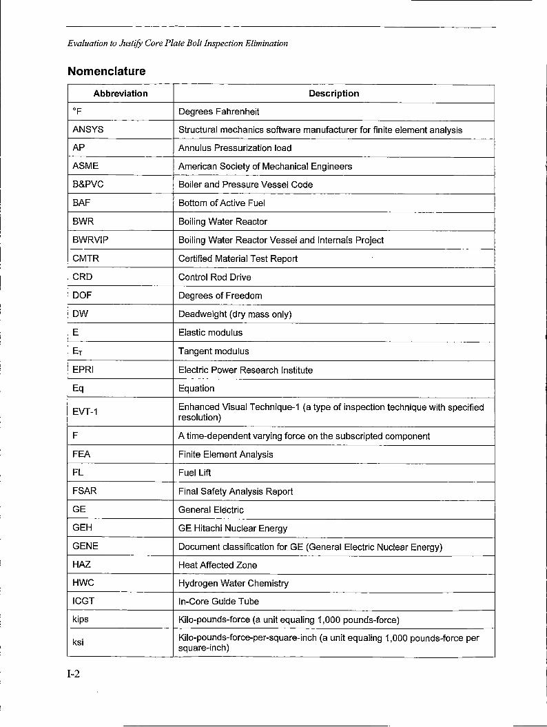
Evaluation to Justify Core Plate Bolt Inspection Elimination
Nomenclature
Abbreviation Description
OF Degrees Fahrenheit
ANSYS Structural mechanics software manufacturer for finite element analysis
AP Annulus Pressurization load
ASME American Society of Mechanical Engineers
B&PVC Boiler and Pressure Vessel Code
BAF Bottom of Active Fuel
BWR Boiling Water Reactor
BWRVIP Boiling Water Reactor Vessel and Internals Project
CMTR Certified Material Test Report
CRD Control Rod Drive
DOF Degrees of Freedom
DW Deadweight (dry mass only)
E Elastic modulus
ET Tangent modulus
EPRI Electric Power Research Institute
Eq Equation
EVT-1 Enhanced Visual Technique-1 (a type of inspection technique with specified resolution)
F A time-dependent varying force on the subscripted component
FEA Finite Element Analysis
FL Fuel Lift
FSAR Final Safety Analysis Report
GE General Electric
GEH GE Hitachi Nuclear Energy
GENE Document classification for GE (General Electric Nuclear Energy)
HAZ Heat Affected Zone
HWC Hydrogen Water Chemistry
ICGT In-Core Guide Tube
kips Kilo-pounds-force (a unit equaling 1,000 pounds-force)
ksi Kilo-pounds-force-per-square-inch (a unit equaling 1,000 pounds-force per square-inch)
1-2
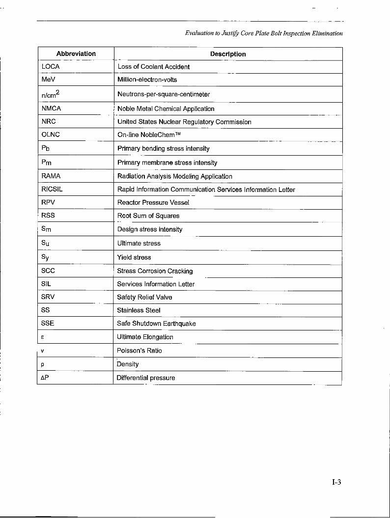
Evaluation to Justify Core Plate Bolt Inspection Elimination
Abbreviation Description
LOCA Loss of Coolant Accident
MeV Million-electron-volts
n/cm2 Neutrons-per-square-centimeter
NMCA Noble Metal Chemical Application
NRC United States Nuclear Regulatory Commission
OLNC On-line NobleChem TM
Pb Primary bending stress intensity
Pm Primary membrane stress intensity
RAMA Radiation Analysis Modeling Application
RICSIL Rapid Information Communication Services Information Letter
RPV Reactor Pressure Vessel
RSS Root Sum of Squares
Sm Design stress intensity
Su Ultimate stress
Sy Yield stress
sec Stress Corrosion Cracking
SIL Services Information Letter
SRV Safety Relief Valve
ss Stainless Steel
SSE Safe Shutdown Earthquake
E Ultimate Elongation
V Poisson's Ratio
p Density
LlP Differential pressure
1-3
Evaluation to Justify Core Plate Bolt Inspection Elimination
Section 1: Background
Intergranular stress corrosion cracking (IGSCC) has been observed in a number of internal components in boiling water reactors (BWRs ). Concerns related to core plate subcomponent cracking began in 1994. This report provides a methodology that utilities can use to ensure safe and reliable performance of the core plate bolts. It also serves as an aging management tool that can be used in license renewal applications. This report justifies the elimination of core plate bolt3 inspections for the plants that meet the applicability requirements of Section 9. 7.
1. 1 Core Plate Cracking Concerns
The first Reactor Pressure Vessel (RPV) internal component finding occurred at Wuergassen ( a BWR in Germany) in September 1994 after 13 years of operation. Cracking in both the top guide and core plate were detected using visual inspection methods; this is discussed in Rapid Information Communication Services Information Letter RICSIL-071 [l]. The component designs were similar to the component designs employed in other BWRs. It should be noted, however, that the Wuergassen material was Type 347 stainless steel (SS) and was subjected to a potentially sensitizing stress relief heat treatment during fabrication. Welded 347 SS has a susceptibility to IGSCC that is equivalent to 304L SS when not sensitized, and equivalent to high carbon 304 SS when sensitized [2].
In February 1995, GE issued Services Information Letter SIL 588 Revision O [2] to provide an update on the top guide and core plate cracking condition identified in RICSIL-071. It included an assessment of the significance of the findings and it provided recommended actions for owners of GE BWRs. The recommendation related to the core plate assembly was to inspect the core plate bolts to ensure they are in place during the next refueling outage.
Subsequently, SIL 588 Revision 1 [2], dated May 18, 1995, provided an update and clarification of SIL 588 Revision O based on feedback from BWR owners who implemented the original recommendations provided in the SIL. The updated recommendations were as follows: for plants with core plate wedges and for BWR/6s, no core plate inspection was recommended; for BWRs without core plate wedges, visually (VT-3) inspect the core plate bolts to ensure that their locking devices are in place. A sampling inspection was considered adequate, and the inspection could be performed over the next two refueling outages. Examining the bolts that become available for inspection during normal refueling activities was considered an adequate sampling.
It should be noted that BWRVIP-25, Rev. 1-A supersedes the recommendations in SIL 588, Revision O and Revision 1.
The Electric Power Research Institute (EPRI) Boiling Water Reactor Vessel and Internals Project (BWRVIP) made development of a core plate inspection and evaluation guideline a high priority in 1996. BWRVIP-06, Revision 1-A [3] "Safety Assessment ofBWR Reactor Internals" established that the integrity of the core plate safety functions is important in ensuring the ability for safe shutdown of the reactor. This assessment mentions that there is margin in the number of intact bolts required to prevent lateral displacement of the core plate during a seismic event and
3 Technically the "bolts" are "studs" with a nut on either end. Also, the "core plate" is technically the "core support." Nevertheless, these terms are used interchangeably in this report.
1-4

Evaluation to Justify Core Plate Bolt Inspection Elimination
that the possibility of multiple bolt failures and the occurrence of a seismic event is not considered credible. The BWRVIP elaborated on these findings in Section 2.
Cracking of another core plate subcomponent was next detected at Edwin I. Hatch Unit 1 after 15 online years of operation. The defect was in a creviced location-a locating-pin-to-core-plate weld heat affected zone (HAZ).
In December 1996, EPRI issued Revision O of this report. It postulated that similar cracking may occur in GE BWRs with 304 or 304L stainless steel RPV internals. Along with the inspection and flaw evaluation guidelines, the document provided information on potential failure locations in the BWR/2 through BWR/6 core plate assemblies and a discussion of susceptibility considerations. It stated that all core plate locations may be subject to cracking. The analysis performed in support of Revision O of this report concluded that the core plate bolts are the only core plate components which needed to be addressed with a plant-specific inspection strategy. Two solution options presented in Revision O of this report were either to inspect the core plate bolts (to ensure an adequate number are intact to prevent horizontal displacement of the core plate) or to install core plate wedges. Revision O of this report also stated that a plant-specific analysis or a repair/modification as an alternative to inspection is acceptable.
1.2 Inspection Difficulties
The key element in the performance of core plate exams is accessibility. The ASME Code examination requirement specifies "accessible surfaces." The ASME Code attempts to clarify "accessible" as those areas "made accessible for examination by removal of components during normal refueling outages." During a typical refueling outage, the shuffling of fuel bundles does not allow access to the core plate. For this reason, most plants consider core plate subcomponents inaccessible for examination. Some reactor maintenance activities, like control rod blade changeout, require the complete disassembly of a fuel cell. This disassembly requires the removal of all four fuel bundles and the fuel support casting. This disassembly permits access to some areas of the core plate for inspection, but disassembly of peripheral fuel cells would be required to access the core plate bolts for examination. With the accessibility limitations, BWRVIP noted in 1996 that few examinations had actually been performed, and there is little inspection history on the core plate components. However, no instances of core plate bolt cracking have been identified to date during these ASME Code inspections.
Section 1 (Page 1-1) stated "the susceptibility trends may, as further inspection data accumulates, provide a basis to revise the recommended reinspection :frequencies." Section 3.2.2.2 (Page 3-5) it also stated, "good inspection results combined with the good operating experience of BWR bolts and the degree of redundancy of the core plate bolts may justify elimination of any reinspection." The evaluation documented here provides justification for the elimination of inspection of the core plate bolts if the plant meets the applicability requirements of Section 9. 7.
1-5
Evaluation to Justify Core Plate Bolt Inspection Elimination
Section 2: Scope
2. 1 Introduction
The objective of this study is to justify that it is safe to eliminate the current requirement in Section 3.2 of this report to inspect core plate bolts. This objective is achieved in three main parts:
~..:===================---_-_-_-_-_-_-_··_-_-_---,------------• Content De:1eted - EPRI Proprietary Information_
l ----~- .. -:----1 '
I l '-'---
2.1.1 Determination of Plant Core Plate Bolt Categories
2.1.2 Review of Core Plate Bolt Material and Fabrication Design Data 0 I
I ! . I
II, . , Content Deleted- EpRI Proprietary-lnforma\i9n
'-1 _J
I ~----~ I ' I L ~----~--~-~--~----- ---~----•·~,
2.1.3 IGSCC Susceptibility Evaluation r---- .·----~-----/ I,
t
Conter:,t Deleted - EPRI Proprietary. lnformat!on
2.1.4 Develop Methodology for Determination of Core Plate Bolt Stress
r . Content Deleted -- EPRI · Propri~tary lnforrjlatiori
I
I-6
I
J' j
i --~
,-·1
I
Evaluation to Justify Core Plate Bolt Inspection Elimination
2.1.5 Core Plate Bolt Mechanical Analysis
Six structural finite element analyses were conducted,._!,·; :. ·: · ··, ,
[: ~· ",. _- _- .. ,:,~. -~ 7,_,_-:'. --··. -~- _,' :::·-, -: -.. ~~-- ~' -~ ._ -'""-"-~
Section 3: Plant Configuration Summary
The following table provides information regarding plant configuration for the plants without t~1;~~~:t;~{f11;;;fs.•,-, -~-~- -,-,,::-_ ·: '.: ·_-;--_~·-- -s~·_::?;:ll
1-7
-----------------------------------· -- -
Evaluation to Justify Core Plate Bolt Inspection Elimination
Table 3-1 Plants without Wedges (Analyzed)
r-~..,-:;---- ,
I -. ·---. ---···· -- . -- .. -- .. ~----1
• I
·j • I
I !
i
l .I
:1 i
l I .I l
Content Deleted - EPRI · Proprietary 1l1formatio~ . - . I
,i
! . [_,, __ , .' ,,. ,h -••• • ,,,.,.._, __ ,,__._:. •~•----••••---------• ,,, '·"·•--•· .• •, •,._,,_,_ • ~-••-••--, .. ~••--••• _ _.,~., • ,. ·,.,.,.,_,,_.,,_.,,_,_,,,.,,_ • ,_,_,_,. ''" • •• •·•-• ·. • ,.· _,,,,,.,_,._" •·~· ---
I-8
Evaluation to Justify Core Plate Bolt Inspection Elimination
Table 3-1 (continued) Plants without Wedges (Analyzed)
t . . . . ·. ,. . . : . ■ ; ' ' . ■ ' \
Cont_ent Detete.d -._EPRI Pro.pr1etary lnform.at1on
I I • • '-- ·-----·~-· '---------~----------------..---------·-· ---·
l ___ J
1-9

Evaluation to Justify Core Plate Bolt Inspection Elimination
Section 4: IGSCC Resistance
4. 1 Introduction
Three concurrent factors are required for IGSCC: susceptible material, applied stress, and an ~ggressive environm_ent. r---, . . . . . . i. . . .· :, ·. . ·. -~-._-... ---. ---~ I . . . , . ,, . . . \ 1
· · CoAten't Del~ted ~ EPRI Proprietary 1ntormatiori · · Li (
J . ! ~---- -------~---J
4.2 Stress Corrosion Resistance of Core Plate Bolts
The history of non-welded Type 304 stainless steel material in the solution annealed condition has been excellent with no reported incidences of cracking, substantiat~ngjts high resista!\ce to IGSCC initiation in BWR a12_plications. I:· · · · · · [ ____ " __
'.' .• - - . ·,
. ·. :Content Deleted: EPRI- Proprietc,3ry Information 1-'
-~--~-~---~---~---- . ,-·._ , ___ , _, __ J . I
4.3 Residual Effects of Bolt Thread Manufacturing Processes . · ... ·_ .. · l_,
I i .
l ! . r-•----•
7-~-1
. ,I . i_____J ---1
'
· _- Content Deleted ~-,EPRI Propr~etary. lnformation. \~--i 1
l '-~
I__J
. : 1_-:-1 I
.. r-·--' _J
~
Evaluation to Justify Core Plate Bolt Inspection Elimination
Figure 4-1
k, f Ontent :Del_~ted:_~ EPRI Pr9pri~ta7~: r:form,jtioR
r 1:_:_ t,,~. ( .. i:--__ -,_
t· I
i ~1·~~----- ~~~-~~~~-
Relationship of Hardness to sec Susceptibility [7]
I-11
Evaluation to Justify Core Plate Bolt Inspection Elimination
I I. . r
i ! I i
I r
r---- ----------·····----·---·-·•-·----·-- __ .. _____ -. --·-· -----1
!
{ , • ; ' • •' ', V • ,, ' ' • • : '> '> < : ~: > ' ,, > •,
Gontent Deleted·~ EPRI ._Proprietary. I nfqrrn,•atiQn i . . .. . .
I
Figure 4-2 The Relationship of Austenitic Stainless Steel Mechanical Properties to Hardness [8]
Content b·eleted: "". EPRI Proprietary·· l_nformation - . , '• ' ' .'
l-~'-·-"-~-~ ~--·----~---~---~-----~~--· ---~J
I-12
Evaluation to Justify Core Plate Bolt Inspection Elimination .~--- "·-··"-----~.--------.. •··-----<---·-···~- ·----- -- ~-- ~---- --·----~~¼-··~---------~-~---~ -~--~-~-' .. I
~Content Qeleted - EPRI Proprietary ·lnformationj I I I - · 1 '. I
Figure 4-3
I -1 I i
i I ! . ,
Example of the Predicted Plastic Strain as a Function of Depth in the Vicinity of a Stainless Steel Thread Radius
- . - . - - . . . . " ' . . }
· Content o·eleted - EPRI Proprietary Information •
4.4 Aligner Pins
Content Deleted ~ EPRI Proprietary Information
I-13

Evaluation to Justify Core Plate Bolt Inspection Elimination
Section 5: Field Experience
Section 6: Stress Relaxation Evaluation
In this analysis, three factors resist horizontal motion of the core plate: friction between the core plate rim and shroud ledge, aligner pin assemblies, and the core plate bolts themselves. Frictional resistance is the main factor to resist horizontal motion when all bolts are intact and preloaded. The available frictional resistance will be reduced if the preload is lower or if the bolts are assumed to be cracked (removed from the finite element model for margin analysis purposes). Because friction is the key contributor to resisting horizontal motion, accounting for stress relaxation in the bolts must be included in the evaluation. This section discusses the mechanisms of stress relaxation and the corresponding reduction in bolt preload.
4 It should be noted that shroud head bolts have exhibited cracking in the creviced region of the Alloy 600, but no cracking has been found in the threaded portion of the stainless steel. See GE Services Information Letter (SIL) SIL-433.
1-14
Evaluation to Justify Core Plate Bolt Inspection Elimination
Table 6-1 Summary of Relaxation Amounts
- - . 7 . -- I
- - - . -- I -- -- -_ -__ . --_ . - -- - -I
po~tent Deleted - EPRI Proprietary lnformatio~\
I - I l ! i · · -1 L __ _
6.1 Thermal Loosening
Content Deleted - EPRI Proprietary lnfo'rmation
I . l
_J . . r
Content Deleted -. . . ,_ j
EPRI Proprietary Information l~, . J
I I.
c~, '·.
I
I [ ___ _ i ·--'
6.2 Primary Thermal Creep
I '7
r-1 -~ I ,
~----~---~- ...J
Once at operating temperature, the pre-loaded stainless steel bolts will also undergo small amounts of permanent deformation due to stage I creep. This creep, which is material and temperature-dependent, is known to occur in Type 304 stainless steel, even though th,~stress is ~low the yiaj_d strength of the material. ~ · · _ · -, . · _ · _ - · · I I . . r---' I - -· -· 1·7
I _ Content Deleted_- EPRI Ptoprietary Information · 1
1
I ---~--- I 6.3 Stress Relaxation Due to Fluence
High-energy radiation produces a number of simultaneous effects in materials, primarily originating with the displacement of atoms from their original lattice position to relatively distant locations, usually as an interstitial. The interstitial atoms and the associated vacancies group into
I-15
Evaluation to Justify Core Plate Bolt Inspection Elimination
interstitial and vacancy clusters (hardening), migrate to grain boundaries, and relax constant displacement stresses due to the resulting interaction with dislocations [13].
This irradiation causes the preload in the bolts to reduce over time. Because fluence is dependent on the distance from the active fuel and because of the length of the bolt, radiation-induced relaxation will vary along the length of the bolt. ~igur~ 6-1 and Figure 6-2 provide a generic visual renresentation ofBWR/4 core plate bolts.: · · · . ,---- ---
1 1
Content Deleted·-- EPRI Proprietary Information·
i
Over the plant lifetime the bolts are irradiated, causing a decrease in clamping force between the core plate and shroud flange. The amount of bolt stress relaxation in the material is directly ___ _ related to the amount of irradiation (fluence) along the length of the bolt. : · · · ! 1 · · r·--1" i
' I i I I ,
I I
I I
r·-·
I I
l----= ~ --.. -~ - -- -----
_j
I----,,-------,------- -------·--- ----- ... --·-------------~~~--~·----; : L__..,
!
I f
i I,
I l L ______ ~· --
1-16
Content Deleted·- EPRI Proprietary Jnformation
r- ------------~------------~------- -- -----~ ---------__ ._.J
f I
.---------'
I __ \ ____ :
I -1 i
. ~ -------------·
I I
Evaluation to Justify Core Plate Bolt Inspection Elimination
" - . "
Content Delete~ - EPRI Proprietary Information
J Table 6-2 Core Plate Relaxation Predictions after Thermal Creep and Irradiation Relaxation Due to Fluence ' . ------·- . ---~---~!
_i ~· ~--_c_o_nt_e_n_t o_e,_e_te_d_--_-E~.P-R~I_P_r_o_pr_i·e_t_ary_l_ni __ o_rrn_: _at-io~n- J
Figure 6-1
[ ,
I
t , 'i
! " j I ' .
pontent Deleted - EPRI Proprietary Information'. ' '
I .
I i
/· i
l .. I
l I I !
Top View of Core Plate Bolts
1-17
Evaluation to Justify Core Plate Bolt Inspection Elimination
.--------1
i I
i , . , . - , I
;content-D~leted -EPRI Proprietary Information) I , )
\ l
I ! ., l . i i
! ·~~-~"----·-
Figure 6-2 Bottom View of Core Plate Bolts
. l , I .i
I ____ -:..;_ __ , ___ ,
-------- --~--------- -~----, 't
I • I i
' ' . ' ' ' . ' '' i Content .Deleted-. EPRI Propri~tary lnformation
1
,. t
I 1----~-
Figure 6-3 Fluence at Varying Core Plate Bolt Locations
I-18
i
' i

Evaluation to Justify Core Plate Bolt Inspection Elimination
I . . . . . .· · · . l Content Deleted - EPRI Proprietary ·lnformat1on1
Figure 6-4 Predicted Relaxation of Irradiated Austenitic Steels versus Existing Stainless Steel Relaxation Data [15-19]
I I
I .. . . . . . .· . . . " . 11 . . .
Content Deleted·~ EPRI. Proprietary lnformati~n1
Figure 6-5 Relaxation Predictions versus Core Plate Bolt Elevation
I I I i I
. j !
_J
I-19
Evaluation to Justify Core Plate Bolt Inspection Elimination
Section 7: Structural Analysis Methodology
This section describes the structural analysis methodology used to obtain margin on the number of bolts required to meet allowable core plate horizontal displacement limits and stress limits.
___ _I
r---------·- ----- --- --.---------------- ------ ~ --·- --------- -- -·------ --- -- ----- ·------· ·-- ----· .. .,. ___ -------- ----- ·---- -- -- ----·. I ' '
Content Deleted - EPRI Proprietary I nformatioti
r---- ----·-----·----------'
r- ---------- --
' ' ------------·--· ------------~ -· ------·---·- ----------- ------~----·-----~--.. ----J •---- - .... _ ·-·------~---·----- ·-·-·--- ... ---------------·--~ -·-- -·--·-•--- --~- -----------·-------- .--· --------------·- -- --··--------- -!
I I ____ _,
!
i ----------------- ------------------·---•-' I
·- r----------- ----- -- ----· ---. ---- -'--· '-~~-- --------------·- ·------------ ----- -------- ----------- ---~j
7. 1 Choice of Categories
7.1.1 Category 1 Plants: 34 Inboard Bolts, Vertical Aligner Pins
I
I
Content Deleted :.. EPRI Proprietary Information
I--------------•- ' . --- ------ - ------ ·---- -J•--- --~·- ·--~-- - ------~-- ----~---------------~------~---J ----· -- --- ~------·•
1-20
Evaluation to Justify Core Plate Bolt Inspection Elimination
I: . Cqnte'nt P~leted ~· EPRI _ Proprielcary. I nforn:,atiqi:, · .:
7.1.2 Category 2 Plant: Laguna Verde
--Content Deleted·- _EPRI J>rop'rietary Information
__ _j
7 .1.3 Category 3 Plant: Duane Arnold
Conte.nt Deleted ~- E,PR_I Propri_etary Information_·_
7.1.4 Category 4 Plant: Vermont Yankee ,--
_ ·cpntent D~leteg - EPRI P,roprietary lnforrnatiori : - • ." ' ' ·_ s -. • ' - s - ",' ' -~ - - •
7 .1.5 Category 5 Plant: Monticello
I _ Content Delet~d - ~PRI Proprietar:y-, lrfformatipn: _• .• -- ' . ·•. "' . . . . . :" '. -
I 7.1.6 Category 6 Plants: 72 Outboard Bolts, Horizontal Aligner Pins
. -- C~nt~nf Del~ted __ :,EPRl'-PrOp~ie·tary. lriforn1ati~n:: --: - ·,•, -
--~
l . l
-~
. -'l
~ .. l
_J
I
I-21

Evaluation to Justify Core Plate Bolt Inspection Elimination
7.2 Failure Mechanisms and Displacement Limit
I . ~ .· l
.1 s I~
·'-=-:Z....:"'---'-'--'---..;......;.:__--"
, ..
Content :bel~ted _.·gPRrProprielary ln'fotmatioh
!·
I
I-22
j
I l,
~J L,_l
' ' ~~_J
:~!'7
i _ ___J i
·.-·:-~;1 • l
·', ·ct \
. I
.,·•.'l ',j ·'J
_J
,.L ·" ,, ! ,,,,,-,;
.r l
l : i -~-~·-,

Evaluation to Justify Core Plate Bolt Inspection Elimination
Section 8: Structural Analysis
8.1 Structural Design Features
8.1 .1 Components
Figure 8-1 Components of a Generic Core Plate Assembly
77 - 1
i · 1
"I
1-23

Evaluation to Justify Core Plate Bolt Inspection Elimination
8.1.2 Bolt and Aligner Pin Configurations r-: ~~~------,---~-----~
I
Figure a=-2 _____ _ _J
Category 1-5 Core Plate Bolt and Vertical Aligner Pin Configuration (Generic)
1Content Deleted - EPR-1 Pr_oprie_tary I nf9hnat~on
! I
I :l
Figure 8-3 Category 6 Core Plate Bolt and Horizontal Aligner Pin Configuration (Generic)
8.2 Material Properties
Content Deleted~ EPRI Proprietary Information_
1-24

Evaluation to Justify Core Plate Bolt Inspection Elimination
,--- --------·---------------- ------- -- -------------------------·-- -------~------ ----·-----------:----1 l , !
-·'
I
Content Deleted - EPRI Proprietary Information : __ _J
i ··-·- --· -- ---·- - -------- _________ _J
I '
L •. -·-·----· ----·-·---··· -- - . - ·•-· - ·- ··-----------·---,
Table 8-1 Type 304 Stainless Steel Material Properties Used in Finite Element Model (at 550°F)
:------------- ------ -- ------ -~-- ·-- - -- -- ---- -~- ------ - -----··- - ~----- ---- ---- -- - - -----~- ---· I
' '
! I
pontent Deleted - EPRI Proprietary lnformationj !
! I
i - --· -------- -- ·---- --- ----- • -- -- --- • - -- - -~ - -- -- -----···· - - -·------ -- • - ---- ----- __ _j
8.2.1 Plasticity r·· -------- -----~----------- ----- ------- -- ---------- ·----- __________________ ., ------ ----- -·----·7 i I l.----.
Content Deleted - EPRI Proprietary Information I
.J I I
!
_ _r
. ---------- ·--,
I --- _ _____j I
[_ ___________ - --------------- ------ ------·---- - ----- ----,·-•·-- ------------ -- --- -- ------------· -------- -·--- --·-------~
8.3 Structural Acceptance Criteria
Content Deleted - EPRI Proprietary Information
: [ ______ _, __________ - --------·· J
i !
Content Deleted - EPRI Proprietary Information
! I
-· J
.'--------- -, • I
I ;
!
L -----------·- ~- ----- -------- - - -- - --·- -- --- ----- .. --------- ---- ------- -- - --------~-----------· __________________ r
1-25
I
I
Evaluation to Justify Core Plate Bolt Inspection Elimination
r----1
------- ------- --- -- ·-- --- -- - --- - -----·· ·-- ··-· -- --~-------- ----·- --- --- ---·----- ---· --·-- . ..,
I
I I ! I
i · Content Deleted - EPRI Proprietary Information
Table 8-2 ASME Code Allowable Limits [22]
I
1------
: -- - -i
i
J ! _______ j
I
L. _______________________ -------, ---- ------~·-·--·------ -~--- -------- -- ---- --------- -- --------·--------·---
I I ! !-
Content Deleted - EPRI Proprietary Information ;
i I~
' -I
l ------------·------ --- ·- --------~--J L ___ . ------------ -----------------
I -------- __ -____ -_J
r---- ------------- - ---- - - --·--- -- -------- ----_ ·---------~-~---~- -- --- - -------------- --- - ----------- ··1 - 1
I ---------·, ·, _,
j - .. -- ---~-- - . - - --·-- ----------- -~'> --~-- ----· ~- -- ..... -~--------- - ---- ·...._-~ L ____ -- ------------ __ J ______ --------
a.4 Loads and Load Combinations
I !
Content Deleted - EPRI Proprietary Information
i. _____ --~- - ---,
1--------------------·----------~ ~--- --- ~ ----·-----------~--- ---------- --·---- --~···-~·--·----~---- - ----
1-26
Evaluation to Justify Core Plate Bolt Inspection Elimination
r------------ ------------------
i 1 I
------- _____________ ,,___.
[ _________ - ------- -•·---··--------------------···- ------ -------- __ :
Content Deleted - EPRI Proprietary·lnformation :--- ~ ----- --- ______________ J
I L ___ _ r---------- ---~--- - ---- -- ----- ------~- - ---------~- -- -------------- ------- ---- - -- - - --- -·-- - ------ :i
I - . ____ ----· - --- ---------- ~- ----- --·----------~ I : L ________ - --- ------------ ---·--- ·------- ------- --- - --- I ,- --------------------------- ---·-•·--·· ----- ----·- -·-····-·--- -----·--·-······------------ --- ... --------------
! __ J
i . l , · l L...__ _____ ------ ----~---·•-------------- ----~- ----~---. - ---~--- -· ----------------------·'/
Table 8-3 Loads Requiring Bounding Verification
! . Content Deleted - EPRI Proprietary Information; i ! ' !
I ,------------ --------------------------------------------------- -- -------.------ ----- - ------- -
I Content Deleted - EPRI Proprietary Information : - -- ··7 L - ------------------- ---·-·- -- ----·--·------ - ---------·---- -----··· -·- ·------------- ---- ·--· -- ·- ----------- _/
1-27

Evaluation to Justify Core Plate Bolt Inspection Elimination
--------~------~------------------------ ___ ,. __ - ------------------·-- -·--- ---------- -- ------- -- ----,
' i --------- - -- ------- - - -- - --- ------ - -· ---- - _____ I
~------------------------~---- --
8.4.1 Horizontal Combined Loads
! I I.
' I l r--·-----: ____ · ________ J
Content Deleted EPRI Proprietary Information
-~--------~---------------- -- ---- ---- ----- -- ·---·--~---- --- -~-.--- ----~ -- -- - '
',
__________ \
---- - ------------------~ --------- ------ --- --------- ------------- ----- ------- --- ------1 I ·-•·-1
r- -- - ------------ -------~-------·----· ----------- - ----------. -------------- ---- --- -· I I
' ' ---- ------------·---~- ------- ---·· = --~-~- ... _ -~ ---- --· -------- --·------· ---
-- j
L ___________________ -------------------- --------------------------- -------- _----. ---1
~ ,-------- -------- ----------------~I : '_,
------~----• • -• •- -~---•••------•--••-••--•-••--•-••-•• R••-• -~-~-•----~-----1 I ! •-·------- ----------------------------·------· --- _____________ J
1-28
Evaluation to Justify Core Plate Bolt Inspection Elimination
Content Deleted - EPRI Proprietary Information
8.4.2 Vertical Combined Loads
Content Deleted~ EPRI Proprietary Information.
8.4.3 Core Plate Pressure Differential
Conient Deleted - EPRI Proprietary lnformatiC?n
8.4.4 Deadweight Loads -, ----~--------~-
,-J ,. I -l
-----·-·, rJ I
- .-----' j
l_-___ c_o_n_te-n~t Deleted- EPR_I Proprietary lnformatio_n __ ~-. c--:7 8.4.5 Peripheral Fuel Weight and Core Plate Buoyancy
r I
•-·-------··-··- ------7
I· i
Content D~leted··_ EPRI Proprietary Information. · 1J ' - - ~ • , J
8.4.6 Preload
. co·ntent Del.eted - EPRI. Proprietary Information . ' ;_ . -".,-. , ' ' ; .. ,, ,
□ I , • r. --j ___ ~
l
I ------:-, l
---·----- 'j
I-29
Evaluation to Justify Core Plate Bolt Inspection Elimination
Content Deleted - EPRI Proprietary Information ,
l ----·-------------------------- --------·- ______ --- · ____________________ I
8.4.7 Friction
~- ~- --- -- -· 1
L _· - - -- - ---- - ---- -
' i ! -
Content Deleted -EPRI Prop~ietary Information
i - ------ • -- --··---- -- --···--------- --- ----------- -----·- - .. --· ·-I > '---- -----~ c- ---------------··
! . f
t
I r------L.._ ---- ----- j
8.5 Assumptions and Conservatisms . - - l
Content Deleted - EPRI Proprietary Information ~----~------------------ ---=-··---- ---- ---~-i
----·-----·----·--------•,;,.---•------·----- _____ J
1-30
I !

Evaluation to Justify Core Plate Bolt Inspection Elimination
8.5.1 Assumptions
8.5.2 Conservatisms
8.6 Elements and Mesh
1-31

Evaluation to Justify Core Plate Bolt Inspection Elimination
Table 8-4 Finite Element Types
I~----------,--------,---.---~
Figure 8-4
I I I . i I
1 ./ , I
-: l I
I . . . bon_tent Deleted- EPRI Proprietary Information ! . .,: ' ,, ,, ' '.' . < ' ,: .- • •. '
! I I, I ,
i. I
l_~-~-__J
Content De{'eted - EPRI Proprieta'ry Information i ' _.., ' ' . : ' ' ' ,,, ' '· ,, . ' I i
Example Finite Element Mesh
8. 7 Boundary Conditions r-- --~---! ' .. . ,', '.' . ' :· . ' ::, ' ' ' ' ' . ' : cc ' • ••, ,. ',,·
1Content Deleted -: EPRI Proprieta,ry lnforn:iatior:, . . I . . . . ,--·
1-32
·---
7 r
Evaluation to Justify Core Plate Bolt Inspection Elimination
8.7.1 Friction
. . ~
Content Dele~_~d - EP.RI Prbprieta"ry Information' . ' -; . . ', ' - . ' . - '.,,
,. J
Figure 8-5 Example Friction Boundary Conditions (24 of 34 bolts
8.7.2 Bolts
1-33

Evaluation to Justify Core Plate Bolt Inspection Elimination
·)Cont!3·nt Deleted·"". §P RI p/opri.etary Olnformation'
'•
.-_:~/ ··.:
8.7.3 Vertical Aligner Pins: Categories 1-5 ' 'I
l~, . r=-±1
. '? ·: .·. :l
Content DeJeted -'EPRrProp_rietary Information · .. '·. •, ' .: . "' . . ' ' ... · . . .. ·'
~_J
~,!=i•~·. ~-=----'·~·. -···-· -•·.,:_.,~-.~· ~·--·- 1~---'---'----'"----------'------'---'-'---'---' "J
Figure 8-6 Example Vertical Aligner Pin Boundary Conditions (24 of 34 bolts)
1-34
Evaluation to Justify Core Plate Bolt Inspection Elimination
8. 7.4 Horizontal Aligner Pins: Category 6
._ Content Deleted - EPRI Propriet_ary Information
'~_:,]
-c~·:1 ~---·
I I
. i
l j
1 !
-- I J
. I I
·I . , ,. I
CqntentDeleteq-·EpRI_ Propriet_ary lnformationj ' , - • - ' • • • • • a • , '-" ~, a 1 - • •
Figure 8-7 '---~---Example Horizontal Aligner Pin Boundary Conditions (52 of 72 bolts)
1-35
Evaluation to Justify Core Plate Bolt Inspection Elimination
8.8 Finite Element Analysis
.Co,ntent ·□eleted - EPRI. Proprietary Information
·---'------=-----"----J -----8.8.1 Preload Application Verification
. Content Deleted ~ EPRI; Pro·ptietary Information
,.... I
I 1- _.-i -
r------ . --' '
_, ' ,
- ~-' . : ', . '
-------~---, . ' , -i ·-'---""-_.c.__~-- __,
7
I - I
I
. j : I
l
Content Deleted·~ EPRI Pr6prieta~ ln~ormati~d
Figure 8-8 Example Preload Application (24 of 34 bolts)
8.8.2 Load Application
1-36
. I I
- i -1 I I I
'
Evaluation to Justify Core Plate Bolt Inspection Elimination
8.8.3 Worst Bolt l
Content Deleted ~ EPRI Proprietary _Information · r··-~ _____ . __ J
8.8.4 Core Plate Horizontal Displacement
I I I
i I i I
I i
. . L. l Content. Deleted - EPRI Proprietary Information
--~---r
I l
I: I l f
! f.
I
----1 , I
l . I
I
Content Deleted - EPRI ·Proprietary lnformatiori ' . . , . . i I I·: I I· [
I
! < .j
I ' i
I. I \ I
I·. ,i .· i
1 I I . I
I !
· I I . I I , j
I l !
I 1 I .I ~I ______________ :._: ____________________ _J
Figure 8-9 Example Horizontal Displacement Plot (24 of 34 bolts
L,
I J
1-37
Evaluation to Justify Core Plate Bolt Inspection Elimination
Section 9: Analysis Results
l f !, ~t -~----'-"--·:J
Cqntent [)elijteQ ~);P_Ri Pro'prietary IOform.atiori ,, ' -
•,
, '~;-~-:/'-•,a;'--.~.,_ ··-·
9. 1 Category 1
I
-L_ .. ~~~~~··.::..~L.~": ___ ~~-· '4,,L,.,,i~~-~·:{.:.1
1-38
·t : I
r-J .-l -'--1
I "·=·--7
... l . ·l
.,,rJ ·:--.-,
·--'·I
' 7 " ;: ~~ > !
i I I : I I
I I
I I_
Evaluation to Justify Core Plate Bolt Inspection Elimination
Table 9-1 Category 1 Results (Not Including Fuel Lift) -------~------- 7
' I I
Co'ntent Deleted - EPRI Proprietary ln'formation I , . . . . . . , - .. l I
I -------,---------~--------~---' _J
I . .
:content Deleted ~. EPRI Proprietary :Information! I I ' I
i i .. I __ _
Figure 9-1 Category 1 Results (Not Including Fuel Lift)
1 ' I i i I
' , I
l
1-39
Evaluation to Justify Core Plate Bolt Inspection Elimination
Table 9-2 Category 1 Results (Including Fuel Lift)
i
L_ ........ ·---.c.....--~-----'------'-'--'-'--~----'"-'--'-'-'----'"------"----'-'-----'-----'
'1
I
• • ~ : ".-' <:<. - ~ - ·i ._ - -o,..,• : -- ')
•,'° .. :,_c- ' . _,. ,. ':: .·• . ' ":, . _·, .. ',' '.'' , , - ,·. . ·, . '; C •.'· •:· .• :-. • j
pontent · D_el~tectt<~PRI :;Proprietary Jnf,orfnqtio~j l - . ·, •' .. . ' < -- • I t : i I., ,· '1
r t t· ! L
i ·) ·j )
'i I I
---· - _J
Figure 9-2 Category 1 Results (Including Fuel Lift)
1-40
Evaluation to Justify Core Plate Bolt Inspection Elimination
9.2 Category 2
I ' .
Conte~t Del~ted ~: Ep~L Proprieta~y IJlformation .·
Table 9-3 Category 2 Results (Not Including Fuel Lift)
' 1 - ' j
r-- -~~----~---. I
-:----1
- I I l
. ·I
I
Content Oeleted -- EPRI Proprietary: IDforrnation ' ,, . '" ' .
I - . I
i I
Figure 9-3 Category 2 Results (Not Including Fuel Lift)
1-41
Evaluation to Justify Core Plate Bolt Inspection Elimination
Table 9-4 Category 2 Results (Including Fuel Lift)
i I
I pontent Deleted_ - EPRI Proprietary- lnfor~ation-
,----------------------------------, l --i 1-!
f -· ' . --· -· . ; f . . - , ~ ' . - - . - ■ - - - ~ ' • • L ' l :content Deleted - EPRI Propnetary· 1nformat1on1 I . - . . . - . . . ! , ' I I I \
! • 1
I
-'; • I
I I l i ---'"- -·'- __ -_---..;..._ __ .:..,
Figure 9-4 Category 2 Results (Including Fuel Lift)
I-42
-1 I I l
.. i I .....

Evaluation to Justify Core Plate Bolt Inspection Elimination
9.3 Category 3
Table 9-5 Category 3 Results
~9Wjent;~e'iytij~,/Ef ~!i:~t~,~l~t~o/it~.f Gt~'~tl~j1
l;,-,:d:/:-•·· ~. .~. ~ •.•:',:;;_J Figure 9-5 Category 3 Results
1-43
Evaluation to Justify Core Plate Bolt Inspection Elimination
9.4 Category 4
Table 9-6 Category 4 Results
Figure 9-6 Category 4 Results
1-44
Evaluation to Justify Core Plate Bolt Inspection Elimination
9.5 Category 5
__,
Content Deleted . .:. .EPRI Proprietary Information L_,
~ . I
.-----------'
Table 9-7 Category 5 Results
I I I
I • I
I. . , . -·. ., · ·• · ·, -. -· - . l Content Deleted - EPRI Proprietary lnformatiOni
!
II
L~_· -----;========::::=========--=================================:::::=:::========::::--~' l
• I
!
- j
. l i - . - • I
p,C?nt~nt D_eleted. -- EPRI. Prqprietary lnfo.r~aUon1
I - - I I . I I
I -!
Figure 9-7 Category 5 Results
I l I I I
1-45

Evaluation to Justify Core Plate Bolt Inspection Elimination
9. 6 Category 6
I , .· ... . •. ' ~~ ' '
..
Table 9-8 Category 6 Results
I
I
I· . Figure 9-8 Category 6 Results
I-46
J
Evaluation to Justify Core Plate Bolt Inspection Elimination
9. 7 Application of Analysis Results
L ~8(1J$rjt~~Iit~~\~·l;PRl,Propri~ta,rJ lnfe;>tm,atign····
"'--'"-~~'----"-'-•· ............. · ~.;}~; . "'·. .. ~~~.:;·, ·.j
~-.·-.-~---" .~-u~~~j
Figure 9-9 Applicability Flow Chart
I-47

Evaluation to Justify Core Plate Bolt Inspection Elimination
Section 10: Conclusions
This report documents a comprehensive evaluation providing justification for the elimination of core plate bolt inspections for plants meeting the applicability requirements of Section 9. 7. This evaluation covers 26 BWRs that do not have core plate wedges installed and is valid for a 60-year life. The evaluation addressed the IGSCC susceptibility of the core plate bolts, the loss of preload due to heat-up to operating temperature, thermal creep, and irradiation. A margin assessment was performed to show the number of bolts required for various load levels such that the horizontal displacement was maintained below an acceptable level and ASME Code allowable stress limits were met.
The evaluation concludes that cracking due to IGSCC in the core plate bolts is very unlikely. This is supported by an assessment of the material type, fabrication and machining processes and controls. Most plants are mitigated by HWC and NMCA too, although this is not a requirement for use of this evaluation. Furthermore, field experience has shown no failures of Type 304 stainless steel bolts in BWRs to date.
In addition to the reasons above, the results of structural analyses demonstrate that the 26 plants need only a portion of the installed core plate bolts to ensure that the allowable displacement and stress limits are not exceeded. This is based on meeting the ASME Code allowable limits for the Service Level D (Faulted) condition and allowable limits established by GEH for maximum core plate horizontal displacement for control rod insertion. The exact amount of margin is plantspecific. Regardless, there is sufficient margin under expected loading conditions for all plants herein such that inspections of core plate bolts are not required. Utilities must confirm that they meet the application criteria described in this report to show that inspections of their core plate bolts are no longer required.
If a plant meets the requirements in Appendix I and the plant can demonstrate the acceptability of at least one (1) missing bolt, then sufficient justification ( considering the other conservatisms in the analysis) exists for the elimination of core plate bolt inspections.
Section 11 : References
1. General Electric Company, "Top Guide and Core Plate Cracking", RICSIL No. 071. November 22, 1994.
2. General Electric Company, SIL No. 588. "Top guide and core plate cracking." Revision 0 (February 1995) and Revision 1 (May 1995).
3. BWR Vessel and Internals Project, "Safety Assessment ofBWR Reactor Internals" (BWRVIP-06 Revision 1-A). EPRI Technical Report 1019058. December 2009.
4. Deleted.
5. NEI 03-08 Rev 2. "Guideline for the Management of Materials Issues." January 2010.
6. BWR Vessel and Internals Project, "Guidelines for Selection and Use of Materials for Repairs to BWR Internal Components" (BWRVIP-84), EPRI, Palo Alto, CA. 2000. 1000248.
7. Y. Kanazawa and M. Tsubota, "Stress Corrosion Cracking of Cold Worked Stainless Steel in High Temperature Water," Paper 237, Corrosion 1994.
8. B.M. Gordon: "Corrosion Control in BWRs," NEDE-30637. December 1984.
1-48
Evaluation to Justify Core Plate Bolt Inspection Elimination
9. Richard Budynas and Keith Nisbett. Shigley's Mechanical Engineering Design. Eighth Edition.
10. 2004 ASME Boiler and Pressure Vessel Code. Section II "Materials."
11. Materials Reliability Program: "PWR Internals Material Aging Degradation Mechanism Screening and Threshold Values" (MRP- 175), 1012081, Topical Report, December 2005.
12. NEDE 13334. A Study of Stress Relaxation in AISI 304 Stainless Steel. R.G. Sim and A. J. Giannuzzi. April 1973.
13. BWR Vessel and Internals Project, "Crack Growth Rates in Irradiated Stainless Steel in BWR Internal Components" (BWRVIP-99-A). EPRI Technical Report 1016566. November 2008.
14. Letter from William H. Bateman (NRC) to Bill Eaton (BWRVIP Chairman), Safety Evaluation of Proprietary EPRI Reports, "BWR Vessel and Internals Project, RAMA Fluence Methodology Manual (BWRVIP-114)," "RAMA Fluence Methodology Benchmark Manual- Evaluation of Regulatory Guide 1.190 Benchmark Problems (BWRVIP- 115),"" RAMA Fluence Methodology- Susquehanna Unit 2 Surveillance Capsule Fluence Evaluation for Cycles 1-5 (BWRVIP- 117)," and "RAMA Fluence Methodology Procedures Manual (BWRVIP-121)," and "Hope Creek Flux Wire Dosimeter Activation Evaluation for Cycle 1 (TWE-PSE-001-R-001)" (TAC NO. MB9765) dated May 13, 2005 (BWRVIP Correspondence File Number 2005-308).
15. "Final Report On IFA-586, 605; Water Chemistry and Crack Behavior", Proprietary Final Report HWR-473, Halden, April 1996.
16. B. Z. Hyatt, WAPO-TM-881(L), Degradation of the Stress Relaxation Properties of Selected Reactor Materials in a Fast Neutron Flux, March 1973.
17. C. Leitz, H. Strobel, "Influence of Neutron Irradiation on the Strength Properties and on the Relaxation of High-Strength Austenitic Steels and Nickel Alloys for Connection Elements of the Core Structure of Water Cooled Reactors," KWU Final Report RE23/023/77, April 1977.
18. J.P. Foster, "Analysis of In-Reactor Stress Relaxation Using Irradiation Creep Models", Proc. Irradiation Effects on the Microstructure and Properties of Metals, ASM STP611, p.32, 1976.
19. E. Gilbert and L. Blackbum, "Irradiation Induced Creep in Austenitic Stainless Steels", Second International Conference On The Strength of Metals and Alloys, ASM, Metals Pk., 1970, 2, 773-777.
20. GENE-771-44-0894 Rev 2. "Justification of Allowable Displacements of the Core Plate and Top Guide-Shroud Repair." November 16, 1994.
21. GE Hitachi Safety Communication SC 11-05, "Failure to Include Seismic Input in ChannelControl Blade Interference Customer Guidance." September 2011.
22. 2004 ASME Boiler and Pressure Vessel Code. Section III "Rules for Construction of Nuclear Facility Components." Subsection NG- Core Support Structures.
23. "Investigation of the Sliding Behavior of a Number of Alloys Under Dry and Water Lubricated Conditions." R.E. Lee, Jr. January 22, 1960. Report Number 60GL20.
24. Core Support Structure Design Specification. 22A4052. June 26, 1979.
1-49

Evaluation to Justify Core Plate Bolt Inspection Elimination
25. BWR Vessel and Internals Project, "Jet Pump Repair Design Criteria" (BWRVIP-51-A). EPRI Technical Report 1012116. September 2005.
26. BWRVIP Letter 2020-035, "BWRVIP Inquiry 2020-001 Resolution," May 5, 2020.
1-50
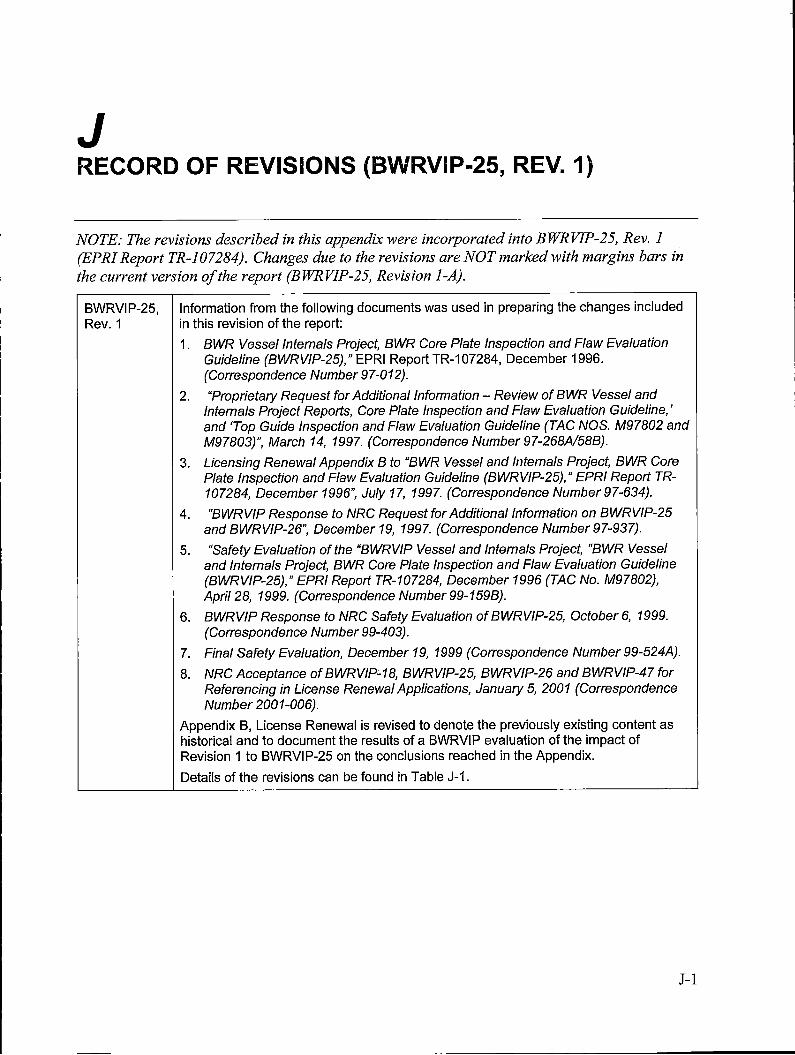
J RECORD OF REVISIONS (BWRVIP-25, REV. 1)
NOTE: The revisions described in this appendix were incorporated into BWRVIP-25, Rev. 1 (EPRI Report TR-107284). Changes due to the revisions are NOT marked with margins bars in the current version of the report (BWRVJP-25, Revision 1-A).
BWRVIP-25, Information from the following documents was used in preparing the changes included Rev. 1 in this revision of the report:
1. BWR Vessel Internals Project, BWR Core Plate Inspection and Flaw Evaluation Guideline (BWRVIP-25)," EPRI Report TR-107284, December 1996. (Correspondence Number 97-012).
2. "Proprietary Request for Additional Information - Review of BWR Vessel and Internals Project Reports, Core Plate Inspection and Flaw Evaluation Guideline,' and 'Top Guide Inspection and Flaw Evaluation Guideline (TAC NOS. M97802 and M97803}", March 14, 1997. (Correspondence Number 97-268A/58B).
3. Licensing Renewal Appendix B to "BWR Vessel and Internals Project, BWR Core Plate Inspection and Flaw Evaluation Guideline (BWRVIP-25)," EPRI Report TR-107284, December 1996", July 17, 1997. (Correspondence Number 97-634).
4. "BWRVIP Response to NRG Request for Additional Information on BWRVIP-25 and BWRVIP-26", December 19, 1997. (Correspondence Number 97-937).
5. "Safety Evaluation of the "BWRVI P Vessel and Internals Project, "BWR Vessel and Internals Project, BWR Core Plate Inspection and Flaw Evaluation Guideline (BWRVIP-25)," EPRI Report TR-107284, December 1996 (TAC No. M97802), April 28, 1999. (Correspondence Number 99-1598).
6. BWRVIP Response to NRG Safety Evaluation of BWRVIP-25, October 6, 1999. (Correspondence Number 99-403).
7. Final Safety Evaluation, December 19, 1999 (Correspondence Number 99-524A).
8. NRG Acceptance of BWRVIP~18, BWRVIP-25, BWRVIP-26 and BWRVIP-47 for Referencing in License Renewal Applications, January 5, 2001 (Correspondence Number 2001-006).
Appendix B, License Renewal is revised to denote the previously existing content as historical and to document the results of a BWRVIP evaluation of the impact of Revision 1 to BWRVIP-25 on the conclusions reached in the Appendix.
Details of the revisions can be found in Table J-1.
J-1
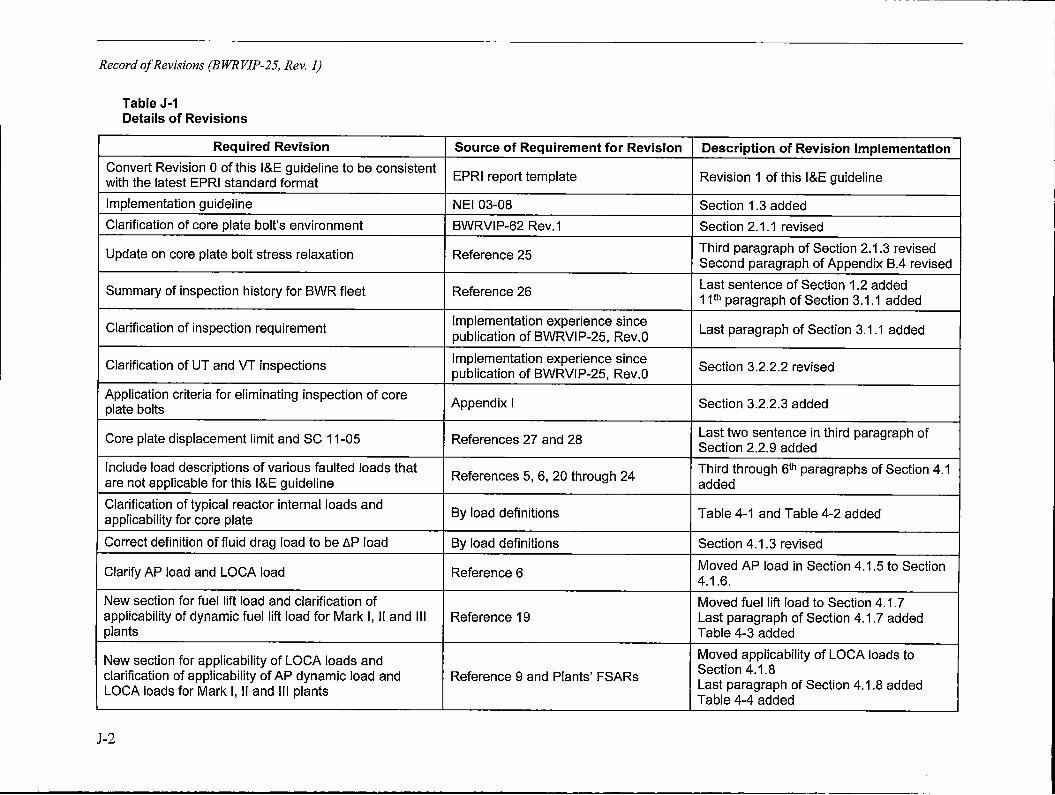
Record of Revisions (BWRVIP-25, Rev. 1)
Table J-1 Details of Revisions
Required Revision Source of Requirement for Revision Description of Revision Implementation Convert Revision O of this l&E guideline to be consistent
EPRI report template Revision 1 of this l&E guideline with the latest EPRI standard format
Implementation guideline NEI 03-08 Section 1 .3 added
Clarification of core plate bolt's environment BWRVIP-62 Rev.1 Section 2.1.1 revised
Update on core plate bolt stress relaxation Reference 25 Third paragraph of Section 2.1.3 revised Second paragraph of Appendix B.4 revised
Summary of inspection history for BWR fleet Reference 26 Last sentence of Section 1.2 added 11 th paragraph of Section 3.1.1 added
Clarification of inspection requirement Implementation experience since
Last paragraph of Section 3.1.1 added publication of BWRVIP-25, Rev.a
Clarification of UT and VT inspections Implementation experience since
Section 3.2.2.2 revised publication of BWRVIP-25, Rev.a
Application criteria for eliminating inspection of core Appendix I Section 3.2.2.3 added plate bolts
Core plate displacement limit and SC 11-05 References 27 and 28 Last two sentence in third paragraph of Section 2.2.9 added
Include load descriptions of various faulted loads that References 5, 6, 20 through 24
Third through 6th paragraphs of Section 4.1 are not applicable for this l&E guideline added
Clarification of typical reactor internal loads and By load definitions Table 4-1 and Table 4-2 added applicability for core plate
Correct definition of fluid drag load to be LlP load By load definitions Section 4.1.3 revised
Clarify AP load and LOCA load Reference 6 Moved AP load in Section 4.1.5 to Section 4.1.6.
New section for fuel lift load and clarification of Moved fuel lift load to Section 4.1.7 applicability of dynamic fuel lift load for Mark I, II and Ill Reference 19 Last paragraph of Section 4.1.7 added plants Table 4-3 added
New section for applicability of LOCA loads and Moved applicability of LOCA loads to Section 4.1.8 clarification of applicability of AP dynamic load and Reference 9 and Plants' FSARs Last paragraph of Section 4.1.8 added LOCA loads for Mark I, II and Ill plants Table 4-4 added
J-2
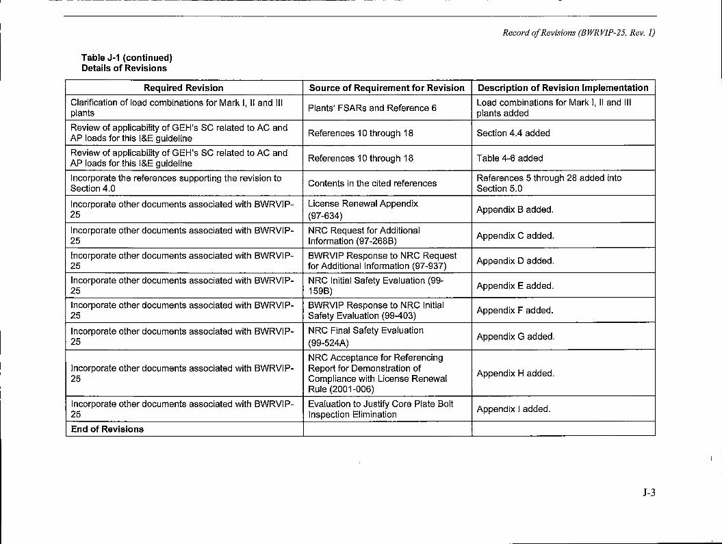
Table J-1 (continued) Details of Revisions
Required Revision
Clarification of load combinations for Mark I, II and Ill plants
Review of applicability of GEH's SC related to AC and AP loads for this l&E guideline
Review of applicability of GEH's SC related to AC and AP loads for this l&E guideline
Incorporate the references supporting the revision to Section 4.0
Incorporate other documents associated with BWRVIP-25
Incorporate other documents associated with BWRVIP-25
Incorporate other documents associated with BWRVIP-25
Incorporate other documents associated with BWRVIP-25
Incorporate other documents associated with BWRVIP-25
Incorporate other documents associated with BWRVIP-25
Incorporate other documents associated with BWRVIP-25
Incorporate other documents associated with BWRVIP-25
End of Revisions
Record of Revisions (BWRVIP-25, Rev. 1)
Source of Requirement for Revision Description of Revision Implementation
Plants' FSARs and Reference 6 Load combinations for Mark I, II and Ill plants added
References 10 through 18 Section 4.4 added
References 10 through 18 Table 4-6 added
Contents in the cited references References 5 through 28 added into Section 5.0
License Renewal Appendix Appendix B added.
(97-634)
NRC Request for Additional Appendix C added. Information (97 -268 B)
BWRVIP Response to NRC Request Appendix D added. for Additional Information (97-937)
NRC Initial Safety Evaluation (99- Appendix E added. 159B)
BWRVIP Response to NRC Initial Appendix F added. Safety Evaluation (99-403)
NRC Final Safety Evaluation Appendix G added.
(99-524A)
NRC Acceptance for Referencing Report for Demonstration of Appendix H added. Compliance with License Renewal Rule (2001-006)
Evaluation to Justify Core Plate Bolt Appendix I added.
Inspection Elimination
J-3
K NRC REQUEST FOR ADDITIONAL INFORMATION ON BWRVIP-25, REVISION 1
K-1
NRC Request for Additional Information on BWRVIP-25, Revision 1
K-2
OFFICIAL USE ONLY-PROPRIETARY INFORMATION UNITED STATES
NUCLEAR REGULATORY COMMISSION WASHtNGfON, O.c. 2l)5~5-D001
July 24, 2017
Tim Hanley Chairman, BWR Vessel and lntemals Project 1300 West W.T. Harris Boulevard (Bldg 1) Charlotte, NC 28262 ATTN: Debbie Rouse
SUBJECT: REQUEST FOR ADD!TIONAL INFORMATION FOR REPORT "BWRVIP~25, REVISION 1: BWR VESSEL AND INTERNALS PROJECT, BWR CORE PLATE INSPECTION AND FLAW EVALUATION GUIDELINES" (TAC NO. MF8863)
Dear Mr. Hanley:
By letter dated S,eptember 26, 2016 (Agencywide Documents Access and Management System Accession No. ML 16273A474), the Boiling Water Reactor {BWR) Vessel and Internals Project {BWRVIP) submitted for U.S. Nuclear Regulatory Commission (NRC) staff review Topical Report "BWRVDP~25, Revision 1: BWR Vessel And Internals Project. BWR Core Plate Inspection And Flaw Evaluatio.n Guidlellnes." Upon review of the information provided, the NRC staff has detemilned that additlonal Information ts needed to complete the review. The request for additional information (RAls) questions are provided in the enclosure to U1is letter.
In an email exchange between Mr. Chuck Wirtz representing EPRI and myself, we agreed that the NRC staff will receive your response to the enclosed RAI by January 30, 2018.. If you have any questions regarding the enclosed RAI questions, please contact me at 301e415•7297 or [email protected].
Project No. 704
Enclosures: 1. RA! questions (nonproprietary) 2. RAI questions (proprietary)
Sincerely,
Joseph J. Holonich, Senior Project Manager licensing Processes Branch Division of Policy and Rulemakl11g Office of Nuclear Reactor Regulation
NOTJCE: Enetet$Ure 1 transmitted herewith c:ontains ProprietS1ry lnformalion. When se,parated from Enclosure 2, this transml1tal d1lcument is decontrnlled.
OFFICIAL USIE ONLY - PROPRIETARY INFORMATION
NRG Request for Additional Information on BWRVIP-25, Revision 1
OFFICIAL USE ONLY - PROPRIETARY INFORMATION
Request for Additional Information . EPRI Technical Report No. 3002005594, BWRVIP-25, Revision 11
~BWR Core Plate Inspection and Flaw Evaluation Guidelines"
By letter dated September 26, 2016 (Agencywide Documents Access and Management System (ADAMS) Accession No. ML 16273A4741), the Electrical Power Research Institute (EPRI) Boiling Water Reactor (BWR) Vessel and Internals Project (BWRVIP) submitted EPRI Techni,cal Report No. 3002005594, ~BWRVIP-25, Revision 1: BWR Vessel and Internals Project, BWR Core Plate Inspection and Flaw Evaluation Guidelines," for U.S. Nuclear Regulatory Commission (NRC} staff review. BWRVIP-25, Revlslon (Rev.) 1 provides a set of augmented inspection and evaluation (l&E) criteria that may be used to either inspect or evaluate the reactor vessel intemal core plate assemblies that are present in BWR plant designs. BWRVIP-25 represents an update of the previous l&E guidelines for the core plate assemblies in EPRI Topical Report (TR) No. 107284, "BWRVIP Vessel and Internals Project, BWR Core Plate Inspection and Flaw Evaluation Guidelines (BWRVIP-25)," which was accepted for use In an NRC staff-issued safety evaluation (SE) dated December 19, 1999 {ML993620274).
Based on n:s review of BWRVIP-25, Rev. 1, the NRC staff has determined that additional lnformatlon Is needed to complete lts review. The NRG staffs request for additional information (RAI) is provided below. This NRC RAI contai.!_l~,l'!t<?.~~~!l~r-.!~~U~-~~~lcf~~t.e~~p~~t~-~~Y .. _ EPRI. All EPRI proprietary text Is marked In [[b(ild::;uitdenlne-;,&ellow~tiighllglitiwlthY"doubre iira'6k'era'n.
MVIB Operating Plants RAJ-1: Perfonnance of Core Plate Bolt Inspections for BWR Plants during Periods of Extended Operation
Background: For all operating U.S. BWR plants that do not have lateral restraint wedges, Section 3.2.2 of the original BWRVIP-25 rePOrt (BWRVIP-25, Rev. o. December 1996) identifies that the core plate bolts • · · · " · · -r-. '. ,-r - • . . •
f . . . : In the course Its review of BWR plants license· renewal {LR) applications (LRAs) for 20.-year extended license terms (periods of extended operation {PEOs)), the NRG staff has approved BWR renewed lrcense holders use of the ori!:iinal BWRVIP-25 rePOrt as a basis for
~~l!!~}!'~~i~~~t~f!':!:.-~r.~J~l,1:i~t~, ~!~J!l~L~-~~~f ·· . · . . : . :.- . 7 l_ Content-Deleted .-·EPRI Proprietary·lnformation .. ·.1
Renewed licenses were generally conditioned to require Implementation of aging management activities that are described in the Final Safety Analysis Report (FSAR) sections for LR (includ~!l BWRVIP l&E ~uldellnes for the 13WR internals) during PEOs. However. for all BWR plants r : · . · . . • . . . . --:=J it was established that implementation of the l' . : · · • :· - · · · is not feasible for inspecting the core plate bolts and therefore, BWR plants [_ _ __ . _. ___ -··-• ____ - ____ : __ ·required a deviation from the BWRVIP-25 Inspection guidelines. Thesej3WRVIP•25 dev,iatlon rettrrs included some limited justification fornot perfonning the I ·.. . . · .·· ·· . ,and were submitted to the NR.C for Information only, without any regulatory requirement for NRC staff review.
1 Henceforth, documents ttiat are identified in 1hie. report anti 1racked ln the statr:s ADAMS will be designated solely by their accession oumber designations.
OFFICIAL USE ONLY - PROPRIETARY INFORMATION Enclosure 2
K-3
NRC Request for Additional Information on BWRVIP-25, Revision 1
OFFICIAL USE ONLY-PROPRIETARY INFORMATION -2-
BWRV!P-25, Rev. 1, Section 3.1.1, page 3-3 states that 71 core plate bolt inspection evolutions have been perfonned at 21 plants that are General Electric {GE) Type 2 through 5 BWR containments (BWR/2-5s). Some inspections were performed on a 100-P5rce11t basis, while others were performed on a percentage or an as-accessible basis. Specifically, "fifteen of the inspectlons were performed using Visual Testing (VT)-1, Enhanced Visual Testlng (EVT)-1, or Modlfied Visual Testing (MVT)-1 methods, 51 were performed using the VT-3 method, and five were performed by confirming the presence of bolts using UT methods on adjoining structures ... In all cases no Indications were observed." The TR identifies that r L._
1- ... Con.tent Deleted·~ EPRI· Proprietary Jnformc1tion . ' l ~----------------------------
Issue: Based on the statements provided ln BWRVlP-25, Rev. _1, Section 3.1.1, page 3-3, the NRC staff has inferred that some BWR plants have been able to perform either, VT-1, EVT-1, or MVT-1 examinations of the core~p!ate (CP} bolts, and many BWR plants have been abfe to perform VT-3 exams of the bolts. In addition, during the LRA reviews; some BWR renewed license holders had made commitments for LR to perform analytfcal evatuatlons ror demonstrating that the integrity and functionallty of CP assembly would ba maintained during PEOs.
These LR commitments, which often got lncorpcrated Into the FSAR, specified that a plantspecific stress analysis of the CP assembly would be performed, taking into consideration the loss-of-bolt pre-load due to stress relaxation from Irradiation and thermal effects, as well the po~entlal for bolt cracking durlng the PEO. The analysis would lbe submitted to the NRC staff for review. Through its review of these plant-specific analyses, the NRC staff has requested that licensees commit to performing VT-3 vfsuaf examination of a 50 percent sample of the CP bolts during PEOs in order to provide reasonable assurance that the bolts and their locking devices are remaining In place during the PEO.
Some BWR licensees have committed to perfonnlng the VT-3 exams as an aging management activity. These regular commitments were made during the course of the NRC staff review of the plant-specific CP analytfcal evaluations for closure of the original LRIFSAR commitments. For an example, please see the October 2013 supplemental RAI response provided by Nebraska Publtc Power District for Cooper Nuclear Station at ML 13283A01 o.
Request: Based on the above-.cited past experience and precedent for performing visual examination of accesslple CP bolts for the detection of significant degradation, please provide the foUowlng informat!on regarding future CP bolt lnsp~ctlon criteria, to Include Inspection method, frequency, and inspection sample size, that will be conducted during PEOs for the following categories of BWR plants:
K-4
1. Those plants that satisfy the evaluation criteria specified in BWRVI P-25, Rev. 1, Appendix I, Section 9.7_ for elimination of CP bolt inspections. Spedfically, for these plants, please discuss whether any in-vessel visual inspections would be conducted to provide reasonable assurance that the bolts and their locking devices are remaining in place during PEOs. Please revise and/or supplement Appendix I to address performance of these core bolt inspections for BWRs seeking to implement the Appendix I methodology, ·
2. Those plants that do not satisfy the evaluation criteria specified in Appendix I shall require a plant-specific justification and/or alternative, as specified in Section 9.7.
OFFICIAL USE ONLY -PROPRIETARY INFORMATION
NRC Request for Additional Information on BWRVIP-25, Revision 1
OFFICIAL USE ONLY-PROPRIETARY INFORMATION -3-
BWRVIP-25, Rev. 1, Appendix A provides an example for a plant-specific OP bolt stress analysis that would need to be performed if the plant f::i.if.:,._tn_m,...,.t_tb.::._i,;v~•• 1~fll"ll'.'.l_erit~r.i"'
7 Jr.i_~or,iendhcLS~l'."Jion_Q_L~nMndix.AJrl~otifiP.sJb:id . . · · .· · . · · . <; . . l.., l . · Content Deleted -· EPRI Proprjetaryy,forrilation _____ :, .J ~ · .. ·. · .·· .· rPlease address how the plant-specific CP .bolt inspection criteria will i,e C1eterm1neel Dased on the results of this plant-specific analysis. Please revise and/or supplement BWRVI P~25, Rev. 1, Appendix A to address the determination of core bolt inspection criteria for BWRs that need to perform this plant-specffic analysis.
3. For those plants that do not satisfy the Appendix I evaluation criteria, and for which a plant"speciffc stress analysis does not demonstrate acceptable margins, per the example provicted in A.Qpendix A._please identiN whether these r:ilants would be @<!Ulred to performJ Content Deleted- EPRI Proprietary Information ·. " · · . 7 L · . . · .. • · . ·• .. • jPlease revise and/or supplement the BWRVf p:2~--;-Rev. 1 ft> address performance of these CP bolt [nspectf ons.
MVIB Operating Plants RA1•2: lnservice Inspection (ISi) of the Core Plate, per the American Society of Mechanical Engineers (ASME) Code, Section XI, Examination Category B~N•2
Background: The first paragraph of BWRVIP-25, Rev. 1, Section 3.1.1 Identifies that most plants include inservlce examination of the CP under the ASME Code, Section XI, Examination Category B-N-2, Item No. B13.40 for welded core support structures (CSSs). Examination Category B-N-2 of the ASME Code, Section XI requires VT-3 exams or "accessible surfaces" of welded CSSs. The third paragraph of Section 3.1.1 states that the ASME Code, Section XI, Examination Category B-N-2, Item No. 813.40 "accessible surfaces" phrase is clarified to be those areas '"made accessible for examination by removal of components during no11T1al · refueling outagesd [emphasis added]. This third paragraph further states that during a typical refueling outage, "the shuffling of fuel bundles does not allow access to the core plate," and for this reason, "most plants consider core plate subcomponents inaccessible for examination," based on the ASME Code, Section XI, Examination Category B-N-2 ISi requirements.
Issue: The NRC staff identified that the above statements are not consistent with the later BWRVIP-25, Rev. 1, Section 3.1.1 statements addressing_performance of visual exams. Specifically, Section 3.1.1, page 3-2 states that · · · · · · · · · · · · /
f·content Deleted - ·EP.RI Proprietary lnformaJio~·.·1
!Page 3-2 of TR, ---- -, Section 3.1.1 then indicates that SIL 588, Rev. 1 recommended that
r~~ll','7":R'":!°'~-.,:,.t•:•;n•.!o~~.:..,.~~f'"!.)'"~~·J:"'":J'~.r--,•~,.,....,...,~.:-~:"""7,~••-rr;;!~•:•t~•••~:;-<:v~;:r,,,_..,~,_~'l1',,_'.':<:f,Jt.~,:;:..,..,J:.':;'t~;"-:,•r .. J.:;'\!?,.lY'" ~JJ,--:J",
' . G--------w..-~-~---"-~-'--~'--'-~----'-·--~-
.j i J
·-~-~--~~--· j
Reguest:
1. Please reconcile the above two contradictory statements regarding the accessibility of the CP bolls for VT-3 visual examination.
2. The NRC staff notes that VT-3 examination of "accessible surfaces" of the CP once every 10~year ISi interval is required by the ASME Code, Seciion XI, Examination Category B-N-2. Based on the above BWRVIP-25, Rev. 1, Section 3 statement, it is
OFFICIAL USE ONLY - PROPRIETARY INFORMATION
K-5
NRC Request for Additional Information on BWRVIP-25, Revision I
OFFICIAL USE ONLY - PROPRIETARY INFORMATION . -4 -
unclear how plants proposing to implement the new guidelines will perform the ASME Code, Section XI ISi of the core plate in accordance with Title 1 O of the Code af Federal Regulations (10 CFR), Part 50, Section 50.55a. Please address whether plants proposing to implement this BWRVIP-25, Rev. 1, methodology will ensure compliance with either (i) the ASME Code, Section XI, Examination Category B-N-2 requirement for VT-3 examination of accessible surfaces of the core plate durlng refueling and/or maintenance activities; or {ii) plant-specific altemalives authorized by the NRC staff pursuant to 10 CFR 50.55a(z)(1) for implementation of BWRVIP-25 guidelines in lieu of tha ASME Code, Section XI, Examlnation Category B-N-2 VT-3 examinations.
MVJB and ESEB Operating Plants RAl-3: IGSCC Mitigation and Evaluation oflGSCC & Fatigue Cracking for the Core Plate Bolt Structural Analysis in TR Appendix I
Bacl,sground: 10 CFR Part 50, Appendix A, General Design Criterion (Gbc) 1, .,.Quality standards and records,• requires structures, systems, and components be designed, fabricated, erected, and tested to quality standards commensurate with the fmportanoe of the safety functions to be perfonned. Where generally recognlzed codes and standards are used, they shall be Identified and evaluated to determine their applicabilii)1, adequacy, and sufflcfency and shall be supptemented or modified as necessary to assure a quality product in keeping with the required safety function. GDC 2, "Design bases for protection against natural phenomena," requires structures, systems, and components important to safety to be designed to withstand the effects of natural phenomena, such as earthqua~es, without loss of capability to perform their safety functions. In accordance with 1 0 CFR 54.21 (a}(3}, aging management programs are specifically requfred to ensure that the effects of aging on structures and components will be ad'\'=lquately managed during PEOs so that intended functions are maintained consistent with the current licensing basis (CLB), whlch includes GDCs. Renewed licenses were generally conditioned to require implementation of aging management activitles that are described in the plants' FSAR sections for LR (including BWRVIP l&E guidelines for the BWR internals) during PEOs In order to ensure that safety functions are maintained consistent with CLB requirements.
Issue: BWRVIP-25._Rev:. t. A~p_endix I. Section 4.3 states that L___ 7Hydrogen Water . Chemistry (HWqJ . - · · ' - 7Noble Metat Chemical Addition (NMCA)!·. · ·. J [ · Content Del~ted ~ l;PRI Proprietary Information - ._Jin order to use the Appendix I methodology for structural analysis of the CP bolts. Furthermore. since CP bolts in U.S. BWRs
• have not been volumetrically examined in accordance with the original BWRVIP-25 inspection guidelines, the NRC staff considers the extent of cracking in the CP bolts to be unknown. However, the Appendix I methodology for structural analysts of the bolts seems to be predicated on the assumption that core plate bolt cracking (due to intergranulair stress corrosion cracking (IGSCC}) would not occur, based exclusively on an evaluation of the bolt fabrication method, which is discussed in Section 4 of Appendix ; bolt fabrication method alone would not totally preclude IGSCC in a sufficiently oxidizing environment. Additionally, BWRVIP-25, Rev. 1 is silent on the potential for CP bolt cracking due to other aging mechanisms, IU<e fatigue.
Therefore, the NRC staff determined that it currently does not have adequate a$surance that the CP bolts would be resistant to IGSCC and fatigue cracking. Accordingly, the NRC staff cannot evaluate the vandity of the BWRVIP-25, Rev. 1, Appendix I rnethodofogy as a basis for aging management for ensuring the structural Integrity and functionality of the CP bolts, consistent with CLB requirements in GDC 1 and GDC 2 during PE.Os. without an evaluation of either: {1} how the loss of CP bolt functionallty as a result of IGSCC and fatigue cracking is considered as a specific input into the Appendix I structural analysis; or (2) how IGSCC and fatigue cracking
OFFICIAL USE ONLY - PROPRIETARY INFORMATION
K-6
NRC Request for Additional Information on BWRVIP-25, Revision 1
OFFICIAL USE ONLY- PROPRIETARY INFORMATION -5-
would be specifically considered later by plants seeking to use the Appendix I structural analysis methodology to demonstrate acceptable structural margins.
Request:
1. For normal water chemistry (i.e., no credit for HWC and NMCA/OLNC), please address how the loss of CP boll functionality as a result of IGSCC and fatigue cracking is evaluated for determining a bounding number and distribution (i.e., clustering) of failed bolts for the BWRVIP-25, Rev. 1, Appendix I structural analysis. Thfs technlcal justification should specifically address how the following attributes are incorporated into the Appendix I structural analysis to determine the minimum number and bounding distribution of intact (crack free) bolts that are necessary to satisfy the structural acceptance criteria: (1) the extent of IGSCC in the bolts; (2) the distribution of IGSCC in the bolts (i.e., randomness or clustering of cracking in various locations); (3) the effects of fatigue cracking on the bolts; and (4) the effects of potential clustering of cracked and non-functional bolts on the stress analysis and worst-bolt determination used tn the parametric study, including a consideration of moments and stress conditions generated by asymmetrical or eccentric clustering of non-functional bolts.
2. Plant-specific appli~ation of the BWRVI P-25, Rev. 1, Appendix I structuraf analysis must provide reasonable assurance that the CP bolls will maintain their functionality to ensure safe-shutdown capability under seismic and loss-of-coolant accident (LOCA) loadings during PEOs, specifically considering the potential for a bounding number and distribution (i.e., clustering) of cracked and non-functional bolts, based on the occurrence of IGSCC and fatigue. Therefore, for plants with normal water chemistry (no credlt for HWC and NMCNOLNC), if the effects of IGSCC and fatigue were not already considered for the Appendix I structural analysis, please ,evfse and/supplement BWRVIP-25, Rev. 1, Appendix I to address how appficable plants usi11g the Appendix I, Section 9 evaluation process will specifically determine whether they have an acceptable number and distribution of intact bolts to satisfy the structural-acceptance criteria, based on a conservative plant-specific calculation of a certain number of raon-functfonal bolts due to lGSCC and fatigue cracking.
MVIB Operating Plants RAl-4: BWRVlP-25, Rev. 1, Appendix A - Consideration of Core Plate Bolt Aging Effects
Background/lssue: BWRVIP-25, Rev. 1, Appendix A provides an example for the CP bolt stress analysis lf a plant falls to meet the Appendix I evaluation appllcability criteria. Appendix A addresses determination of loadings and the calculation of stresses on the CP bolts. However it does not specify how reduction in bolt pre!oad due to stress relaxation (per the mechanisms identified In AppendJx I) and the potential for bolt cracking would be accounted for in a plantspeclflc analysis.
Request Please revise and/or supplement BWRVIP-25, Rev. 1, Appendix A to address the effects of stress relaxation and cracking for the core plate bolts.
MVIB Operating Plants RAl•5: IGSCC Susceptibility Based on Core Plate Bolt Fabrication and Procurement Specification
Background: As disC1.1ssed above, the NRC staff has previously reviewed licensee submittals in fulffilment of LR/FSAR commitments for demonstrating CP bolt functionality during PEOs. · As
OFFICIAL USE ONLY - PROPRIETARY INFORMATION
K-7

NRC Request for Additional Information on BWRVIP-25, Revision 1
K-8
OFFICIAL USE ONLY - PROPRIETARY INFORMATION -6-
discussed above, certain licensees made regular commitments for perform VT-3 exams of the bolts as an aging management activity. These commitments were made as part of the staff's review of the CP bolt analytical evaluations for demonstrating CP bolt functionality. The NRC staff identified that its approval of these ptant-specffic CP bolt analyses and associated commitments to perform VT9 3 exams was based, in part, on its determination that the licensees adequately demonstrated that their CP bolts would have a tow susceptibility to IGSCC. These NRC staff findings are documented In the following correspondence:
• Section 3.2.2 of the March 28, 2012, SE for the Vermont Yankee (VY) CP hold-down bolt inspection plan and stress analysis for closure of a LR Commitment (ML 120760152);
• Section 3.2.3 of the July 25, 2014, SE for the Cooper CP hold-down bolt inspection plan · and stress analysis for closure of a LR Commitment (ML 14190A004).
The NRC staff's determination regarding the low IGSCC susceptibility for the CP hold-down bolts at VY and Cooper were basecl on the fact that the VY and Cooper CP bolts are not sensitized. The bolts were procured to a specification prohibiting cold forming operations after solutron heat treatment, and there were no known instanoes of stress corrosion cracking (SCC) in these bolts in the BWR fleet at that time.
rlssue: BWRVIP-25, Rev. 1,~QR$:ndlx I, Section 4.2 states that all[~-.· -: --: ~-- -_-y-'l I . . , .. _. : ··. • . .. . , . . ·' •· . -~
BWRV!P-25, Rev. 1, Appendix I, Section 4.2 also states that! . j . " ' , - _; -- !
Conte_nt Delete~ - EPRI Proprietary lhformatiori , ;--· --J
R~uest:
1. For all plants listed in Table 3-1 of BWRVtP-25, Rev. 1, Appendix I, please identify ~!!..~b_er the original bolt procurement specification specifically required the c=J [~~.bolt material lo be solution heat treated following the cold roll threading · process,
2. In addition, for all plants listed in Table 3-1 of Appendix l, please tdenUfy whether the original bolt procurement specification also limited the as-fabricatecl material surface hardness to be below a certain value in order to limit the amount of ·· -. ·· · 1cold work introduced as part of thee . . ' _;_-_·.:_ -~~ _J ' . .
MVIB Operating Pf ants RAt-6: Thermal Stress Relaxation for Core Plate Bolting
BWRVIP-25, Rev, 1, Appendix I, Section 6.2 identifies that small anJounts of plastic deformation due to mechanisms associated with thermal creep would result in a1
· •· · • -;,reduction in bolt preload. The basfs ror this value is References 11 and 12 of the BWRVIP:25: Rev. 1. PJease discuss how this value was calculated and address how tt is bounding for all Appendix I, Table 3-1 BWR plants.
MVIB Operating Plants RAl-7: Irradiation-Enhanced Stress Relaxation and Neutron F luence Evaluation for Core Plate Bolting
OFFICIAL USE ONLY - PROPR[ETARY INFORMATION
NRC Request for Additional Information on BWRVIP-25, Revision 1
OFFICIAL USE ONLY-PROPRIETARY INFORMATION • 7 -
Background/Issue: Based on the stress relaxation evaluation described in BWRV1P-25, Rev. 1, Appendix I, Section 6.3, the NRC staff identified that the amount of Q.i:QJected stress relaxat!!;>n
~ to neutron irras~~t~~tr B'Uefe1{i ~t~~rtl1~'V~~riefary.Tr,f61-mat16n~--- ·-~----·-_J l However, the BWRVIP-25, Rev. 1 does not provide detailed carculations of these values for demonstrating that they are bounding for all BWR plants listed in Table 3--1 of BWRVIP~25, Rev. 1, Appendix I. Nor does it address how the neutron fluence values that were used to calculate the projected stress relaxation due to irradiation were detennrned to be bounding for all BWR plants listed in Table 3-1.
Request:
1. Please discuss how the projected stress relaxation values due to neutron irradiation were calculated and address how they are bounding for all Appendix I, Table 3-1 BWR plan.ts, taking into consideration the differences in plant-speclflc CP bolt configuration and geometry.
2. Please address how the Appendix I, Section 6.3 neutron fluence values that were used as the basrs for determining projected decrease rn CP bolt preload due to irradiation~ enhanced stress relaxation were determined to be bound! ng for the BWR plants in AppendiX I, Table 3·1, taking into consideration variation in neutron flux as a function of bolt azimuthal location around the perlphery of the core plate and differences in plantspecific neutron fluence for the bolts_
MVIB Operating Plants RAl-8: Neutron Fluence Methodologies for Core Plate Bolting
Backaround: BWRVIP-25. _ _Rey. 1. Aortendi:x I. Section 6_3 references !
Content Deleted - EPRI Propri~tary I riformation -1 _J
Issue: The NRC staff identified that these neutron fluence methodologies were approved by the NRC staff only for the specific applications identified therein - specifically, reactor-pressure vessel (RPV} integrity evaluations.
Request: Please address how these methodologies were validated for calculating the specific neutron fluence values identified in Section 6.3, taking into consideration any benchmarktng of the calculations {based on measured neutron activation of material samples) for application to core plate bolting_
ESEB Operating Plants RAl-1: Appendix I Structural Analysis
Background: GDC 1 requires structures, systems, and components be designed, fabricated, erected, and tested to quality standards commensurate with the !mportance of the safety functions to be performed. Where generally recognized codes and standards are used, they shall be identified and evaluated to detelTTline their applicability, adequacy, and sufficiency and shall be supplemented or modified as necessary to assure a quality product in keeping wtth the required safety function. GDC 2 requires structures, systems, and components Important to safety to be designed to \\tithstand the effects of natural phenomena, such as earthquakes, without toss of capability to perform their safety functions. ASME Code Section Ill,
'OFFICIAL USE ONLY- PROPRIETARY INFORMATION
K-9
NRC Request for Additional Information on BWRVIP-25, Revision 1
OFFICIAL USE ONLY - PROPRIETARY INFORMATION -8-
Subsection NG, Table NG-3352-1 provides the a tabulation of appropriate weld quality factors based on the type of welded joint, and the type of examinatlon(s) performed.
l~ue: BWRVIP-25. Rev. 1. Appendlx I, Section 8.3 states that! · · ------1 1.· - . -. Content.Deleted - EPRI ProorietarvJnfoi:matLon ________ . _ J ! -~- · ' -· ._· L Sufficient technical justification is not -provwecno1usmytrren:rs1nm;FWe10-qoalitfta·ctor·oTL -• _]as the strength of unmodeled welds cannot be cr-Eldited or exchanged for an increase in welci quality factor.
Request: Please either reduce the specified weld quality factor to E:...=---:or provide a description of the modeled welds that demonstrates the pedigree required for the use of the specified weld quality factor, or revise the model to include unmode!ed welds as needed to provide sufficient margin. MVIB License Renewat RAl-1
Background: BWRVlP-25, Revision 1, Appendlx 8, Section B.1 identifies ttiat BWR core plates wm need to be within the scope of an LRA or a subsequent LRA (SLRA) because they serve intended functions n:eeded to either: (a} shut down the reactor and maintain It in a safeshutdown condition, as defined in 10 CFR 54.21 (a)_(1 ){]i), or (b) prevent or mitigate the consequences of design basis accidents, as defined in 10 CFR 54.21 (a}(1)(Hi).
Issue: BWRVIP-25, Revfsfon 1, Appendix B, Section 8.1 does not indicate whether the core plate i'lm hold-down bolts or CP wedge restrainers (as appUcab[e and relied on for protecting the core plates against lateral movements) wm need to be included in the scope of an LRA or SLRA, as required by either 10 CFR 54A(a)(1 )(ii) or (iii), or in accordance with 10 CFR 54.4(a)(2), which applies to the scopjng of non-safety related components whose failures could impact the intended funciion(s) of a safety-related structure or component serving a reactor coolant pressure boundary, safe shutdovm, or accident mitigation intended function.
Reguest Clarify whether BWR CP rim hold-down bofts or core plate wedge restrainers will need to be included in the scope of an LRA or SLRA under the requirements of 1 0 CFR 54.21(a}(1 )Oi) or (iii) or in accordance wlth the scoping requirements for non-safety related components in 10 CFR (a)(2). Justify the basis for your response.
MVJB License Renewal -RAl~2
Backgrguad: BWRVIP-25, Revision 1, Includes Appendix B, ~Demonstration of Compliance with the Technical Information Requirements of the License Renewal Rule {10 CFR 5421)." On page B-4 of the report, EPRI states that crack initiation and growth is the only aging effect for the core plate that requires an aging management review (AMR) for license renewal.
~: 1_ EPRl's statement implies that the need for subjecting a structure or component (SC} to an AMR is limited only ~o those components that have one or more aging effects requiring management (AERMs). This is not consistent with the requirements !n 10 CFR 54.21 (a){1) -(a)(3}. The rule requires a given SC to be the subject of an AMR if they are not active or involve moving parts or configuration and if they are not subject to replacement based on a qualified life or specified time frame o.e., p~ssive. !ong~lived SCs). For those SCs that are determined to be passive, long-lived SCs, the requirements in 10 CFR 54.21 (a)(1) would require a given SC to be subject to an AMR even if there were no AERMs attributed to the material-environmental combination for the SC.
OFFICWAL USE ONLY - PROPRIETARY INFORMATION
K-10

NRC Request for Additional Information on BWRVIP-25, Revision 1
OFFICIAL USE ONLY- PROPRIETARY INFORMATION -9-
2. Many past LRAs for BWR facilities h_ave identified loss of preload due to thermal or Irradiation-enhanced stress relaxation as an AERM for their BWR core plate rim hold-dmvn bolts. To be consistent vmh past practices, the NRC staff identified this AERM in AMR line item IV.81 .R-420 of Table IV.B1 in the GALL-SLR report {i.e., Table IV.81 in NUREG-2191, Volume 1).
3. In some past LRAs for BWR plants, the LRAs identified that cumulative fatigue damage or . cracking due to fatigue or cyc□c loading is an AERM for CP assemblies or specific CP assembly
components that were within the scope of the LRAs.
Requests:
1. Justify why the report's methodology limits SCs subject to AMR only to those that have applicable aging effects.
2. Justify why loss of preload due to stress relaxation or trradiation assisted creep is not identified as an AERM for the core plate rim hold-down bolts.
3. Provide the basis why BWRVIP-25, Rev. 1 does not identify cumulative fatigue damage or cracking due to fatigue or cyclic loading as an applicable AERM for BWR core prate assemblies and assembly components.
MVlB License Renewal RAl~3
Background: BWRVIP-25, Rev 1, Appendix B, Section B.3 identifies that some CP assemblies are designed wlth wedge restrainers in the assembly deslgn. EPRI made the following proprietary statement with respect to these types of CP e.ssem blies:
,.·.· :.•· ·-7
·. Cont~nt Del~ted ~ EPRl prgpriet,ary.Jriforrn~ttOri . . i . . . . ·, ·1
/··, ,, ·. "·: l .. , l
Issue: EPRl's·inspection basis for CP assembly designs that rely on wedge assemblies to secure the core plates was consistent with the CLBs for past BWR LRAs whose epce_oJat~
ra~s.emb.lie.s_w.eJJ?J~~taioed_wifb_w..e..d!'.le_S.c __ ge81~~-s_t§!t!;!Jlle..OH~Q.q,V.~U~av~s-~f . : . _. _! ~ . Content [)eleted ::: EPRI Propnet;:iry:I nformat10n -· · .. _ · . , ·. j This type of AMR basis creates a regulatory issue for core plate assembly designs that are secured with wedge restrainers because it may imply that the wedges may not be reliable for restraining the core plates if the loadings on the wedge assemblies were to exceec;i upper bound acceptance lim[ts on design basis stress levels or stre~s intensity values.
However, the scope of BWRVIP~25, Rev. 1 does not include any generic technlcal stress evaluation appendix for CP assembly designs that utllfze wedge restrainers, such that the upper bound limits on the allowable stress loadings or stress intensify factors for the wedge restrainers would be firmly established in the BWRVIP-25, Rev. 1 report. Thus, the NRC staff questions how an applicant for a LRA or SLRA would be capable o.f performing this type of confirmatory action when BWRVIP-25, Rev. 1 fails to include any bounding generic stress analysis for assembly designs that utilize and rely on wedge restrainers as the basis for securing the core plates during design basis loading conditions. ·
OFFICIAL USE ONLY - PROPRIETARY INFORMATION
K-11
NRC Request for Additional Information on BWRVIP-25, Revision 1
OFFICIAL USE ONLY-PROPRIETARY INFORMATION -10·
Request Justffy the basis for omitting a structural analysis report appendix in BWRVIP-25, Rev. 1, for those core plate designs that are restrained with v11edges and why the report qoes not firmly establish the upper bound timits for stresses, toads, or stress intensities associated with the design basis loading conditions of the wedge restrainers In the core plate assembly . designs. Clarify whether there could be any AERMs in the wedge restrainers if the stress toads associated with the components were to exceed the upper bound stress or stress intensity limits set in the stress analysis for the wedge restrainers. If so, identify the AERMs associated with those components that may need to be managed during the period of extended operation (inciudfng subsequent periods of operation for proposed SLRAs}.
If there are AERMs, define and justify the corrective actions a BWR would take under its BWR Vessel Internals Program to manage the AERMs that may be manifested if the max[mum allowable stress levels or stress intensity factors for the wedge restrainers were to be exceeded. lastly, Justify why the action requestin9 verification of the structural analysis has not been identified as an applicable Ucense renewal applicant act.ion Item for the BWRV!P-25, Rev. 1 methodology,
MVfB License Renewal RAl-4
Background: BWRVIP~25, Rev. 1, Section B.3(c) states that crack init1ation and growth wfli°be managed by an inspection program that incorporates the inspection guidance provided 1n Seotlon 3.0, However, BWRVIP~25, Rev. 1, Appendix I provides a general, time--dependent bolt stress relaxation methodology that may be used as an alternative to the criteria for inspecting BWR core plate rim hofo-down b-olts (CPRH-DBs}. BWRVIP~25, Rev. 1, Section 3.2.2.2 and Appendix I, Section 1.1._2 state that '"good inspection results combined with the good operating experience of BWR bolts and the degree of redundancy of the core plate bolts may justify elimination of any reinspection. >'2 Section l.1,2 further states-that the evaluation in Appendix t .. provides justification for the elimination of inspection of CPRH~DBs if the plant meets the minimum acceptability requirements of Section 9.7" of Appendix I.
!s$ue: EPRI 's basis for altowi ng use of ttie Appendix I methodology appears to rely on the general assumptron that there has not ~n any operating experlence (OpE) with cracking of US. BWR CPRH~DBs to date, or if it has occurred, that the amount and extent of cracking in the bolts is minimal: EPRI does not define which type of bolting is being referenced in the terminology "good operating experience with BWR bolling," and what EPRI means by the statement "good operating experience." Even if there has been good OpE with other types of BWR bolting, the OpE may not be indicative and representative of the material cor,idition In BWR CPRH-DBs, at least not without citing and summarizing appropriate baseline inspection results of BWR CPRH-DBs to support such a concluslon. ·
As a minimum, baseline Inspection results from a reasonable sample of past inspections performed on U.S. BWR CPRH•DBs would be needed to support a conclusion that, rn all probability, cracking has not occurring in a ~ant's CPRH~DBs or is minimal. Yet many past BWR LRA applicants have identified in their previous LRAs that they cannot perform the BWRVIP-defined inspections of their CPRH-DBs due to accessibility issues with the configurattons of the core plate assemblies: at their facilities. Also EPRI has yet to provide any past CF'RH~DB inspection data to support its assumptt-ons on this matter. In addition, BWRVIP-25, Rev. 1, Appendix B, Section B.3.{c) fails to include any statement that the alternative stress relaxation analysis methodology in BWRVIP-25, Rev. 1, Appendix I may be
OFFICIAL USE ONLY - PROPRIETARY INFORMATION
K-12
NRC Request for Additional Information on BWRVIP-25, Revision 1
OFFICIAL USE ONLY - PROPRIETARY INFORMATION - 11 -
used to eliminate future inspections of BWR CPRH-DBs. Thus, additional information is need to resolve these Issues.
Request Clarify whether use of the methodology in Appendix I is predicated on an assumption that there has been no past OpE wlth cracking in BWR CPRH-OBs, or that the amount of cracking is minimal. Provide the CPRH~DB inspection data that supports this conclusion. If there is no supporting inspectio11 data, justify why it would ba pemi issible for a BWR llcense renewal appllcant to use the methodology in Appendix I as a basis for eliminating future inspections of its BWR CPRH-DBs. Justify why BWRVIP-25, Rev. 1, Section B.3(c) does not address this possibility as a specified alternative to the performance of UT or enhance visual inspections of the CPRH-DBs.
MVIB License Renewal RAl-5
Background: BWRVIP-25, Rev. 1, Appendix B establishes how the BWRVIP-25, Rev. 1 may be used to comply With requirements in 1 O CFR Part 54, "Requ[rements for Renewal of Operating Licenses for Nuclear Power Plants." BWRVIP-25, Rev. 1, Appendix I provides a generic evaluation methodology that may be used as an altemative to the criteria for inspecting BWR CPRH-DBs in BWRVIP-25, Rev. 1, Section 3. Specifically, Appendix I, Section 9.7 provides the criteria that need to be met to justify use of the appendix for elimination of the inspection protocols for the assemblies.
The NRC staff's aging management program {AMP) for inspecting BWR CPRH-DBs is provided in AMP XI.M9, ~BWR Vessel Internals,~ as in-Olucled in NUREG-1801, Revision 2 (i.e., the Generic Aging Lessons Learned [GALL] Report) for LRA$, or NUREG-2191, Volume 2 {GALL-SLR) for SLRAs. For aging management of BWR CP assemblies, the AMP invokes the inspection methods previously approved for these types of assemblies in BWRVIP-25.
The NRC staff-endorsed guidance in the Nuclear Energy Institute {NEJ) guidance NEl-95-10, Revision 6, "Industry Guidelines for Implementing the Requirements of 10 CFR Part 54-The License Renewal Rure," (ML051860406), provides the Industry's main guidance methodology for the format and contents of LRAs that are required to be submitted in accordance with the 10 CFR Part 54 rule. NE! 17-01, "'Industry Guidance for Implementing the Requirements of 10 CFR Part 54 for Subsequent License Renewal," provides the analogous criteria for SLRAs. The NEI guidance documents define when alternative aging management criteria proposed by license renewal applicants woukl need to be ldentlfied as exceptions to the stated program element criteria in GALL-based or GALL.SLR-based AMPs.
Issue: Since AMP XI.M9 has yet to reference use of BWRVIP•25, Rev. 1, the AMP does not identify that use of the evaluation methodology In BWRVIP~25, Rev. 1, Appendix I is an acceptable alternative to the performance of augmented inspections of BWR CPRH-DBs.
Request Clarify the additional criteria and justifications a BWR applicant will need to identify and incorporate into the BWR Vessel Internals Program of Its LRA or SLRA in order to justify use of the BWRVIP-25, Rev. 1 report as the basis for managing aging in the CP assembly and CP assembly components of its reactor design. Include an inspection-based or analytical--based options that LRA or SLRA applicant may use to manage the effects of aging that are applicable to passive, long~lived components in the core plate assemblies.
OFFICIAL USE ONLY - PROPRIETARY INFORMATION
K-13
NRC Request for Additional Information on BWRVIP-25, Revision I
OFFIClAL USE ONLY- PROPRIETARY INFORMATION -12 •
MVIB License Renewal RAl-6
Background: The BWRVIP·25, Rev. 1 report includes Appendix A, "Example Core Plate Bolt Analysis." For BWR plants relying on bolts for the Integrity of their core plates, Appendix A indicates that it is provide<! as "an example for the plant-specific core plate bolt stress analysis If a plant fails to meet the application criteria to eliminate the requirements of the inspection of the of the core plate bolts specified in Append1x r of the report.
In contrast, BWRVIP-25, Rev. 1, Appendix B makes the following proprietary statement regarding inspection strategies for C?RH-OBs and the Implementation of plant-specific stress analyses for the bolts:
. . .
Conteht ·(2?eleted: ~\EPR1j:)rQ(Drietary:lr,f9rniation I , ,.";; • ', ·- ·. . . ; ' . '-_,-: : ,, . . . ·; . . .. ' ,;··. · .. ,~:: ·,, . •· .'·:/l
. j _, ~
Issue: The various statements referenced in the background section above create confusion on the specific types of circumstances that would prompt a BWR license renewal applicant to perform a plant-specific bolt stress ana[ysis in accordance with the methodology In BWRVIP-25, Rev. 1, Appendix A. The statement in Appendix A implies that a plant-specific bolt stress analysis ·would only need to be performed if a BWR license renewal applicant had performed a plant-specific stress relaxation analysis assessment of the bolts in accordance with . methodology in Appendix I and had failed to meet the acceptance criteria of the evaluation basis in Appendix I. Yet, for those license renewal applicants that may find the inspection bases in BWRVIP-25, Rev. 1, Section 3 feasible for implementation, the statement in Appendix B Implies that the licensee or applicant would also need to perform the Appendix A bolt stress analysis in
2rcrerto establisf!rt · · ... , ,• •._ ·. . _ i ..• · .· _: ,; _ - •• · · :.'.•/ ::,;'; ,:\:: ; l
1ContenJ. D~Jet~9· ~-:l~P~I ·_Proprj~!~ty:_t.hf~rr11~tio~-Reguest: Identify and clarify (with appropriate justifications) all circumstances that would catl for a BWR license renewal applicant to perform a plant-specific bolt stress analysis consistent with the methodology rn BWRVI P-25, Rev. 1, Appendix A. Factor this into a revision of Appendix A of the report as appropriate.
MVIB License Renewal RAl-7
Background: BWRVI P-25, Rev. 1, Appendix I provides a generic stress relaxation analysis methodofogy that may be adopted and used to justify elimination of BWRVIP-defined augmented inspections for BWR core plate rim hold-clown bolts. Section 6 of Appendix I summarizes the core plate rim hold-down mechanical analysis. The appendix identifies that the
OFFICIAL USE ONLY - PROPRIETARY INFORMATION
K-14
NRC Request for Additional Information on BWRVIP-25, Revision 1
OFFtCIAL USE ONLY- PROPRlETARY INFORMATION ~ 13·
analysis involves an assessment of[~,_::_, . , · •·. ,:_-_-Jthatwas based on an a..,;;sessmeotof_rn:slaadJoss_oyer_ai_cur:nul,:1tivs_~v.ear_liceos.ad,nlanUi(e __ lo,fluer:ices_of~---,,--__,,, I ; , -: . : _ Content Deleted -: EPRI Proprietary_ lr:iformation , , .. · .·. ··. · _: , ',: I (' · !for the bolts were assessed In Appendix -i.
The regulation in 1 0 CFR 54.21 (c)(1) requires llcense renewal applicants to identify all analyses or evaluations that conform to the definition of a time--limlted aging analysis (TLAA) in 1 O CFR 54.3(a). In Section 4.1 of NUREGm2192, the NRC staff proVided additional clarifications on this matter. The NRC staff identified that analyses; calculations, or evaluations based on 60..year time dependent assumptions would nee-ct to be identified as TI..AAs in a SLRA if they were determined to conform to the other five criteria for defining TLAAs in 1 0 CFR 64.3(a).
Issue: Per the criteria In 10 CFR 54.3(a}, the stress relaxation analysis in BWRVIP-25, Rev. 1, Appendix I appears to be based on several different time-dependent assumptions that may be .defined by current operating term: (a) the time period associated with the assessment of thermally-influenced pre!oad loss, (b) the time period associated with the assessment of preload loss that is Influenced by neutron radiation exposure (i.e. neutron fluence exposure), and (c) the time frame for the neutron fiuence assessment that factors into the assessment of neutron irradiation-influenced preload ross.
Any BWR ricensea performing a plant-speclflc 6O-year Appendix I-based bolt stress relaxation analysis as part of their ClB and intending to use this basis as part the 10 CFR 54.21(a)(3} required basis for managing rim hold-down bolt preload losses fn a SlRA, would need to identify and evaluate the analysis as a TLAA for its incoming SLRA, as required by 1 o CFR 54.21 (c)(1) and use the TlAA as the basis for managing 1he aging effect under the requirements in 10 CFR 54.21 (a)(3). The same concept is vatid for those licensees or applicants that have yet to submit a LRA for their BWRs, but had performed an Appendix Ibased stress relaxation analysis of the rim hold-down bolts based on a cumulative 40-year plant life.
r'(.~tBW8Y.f ~2JiJ~e:v~.-t. Appendix I does not Identify the ~ntent Deleted.~ EPRI Proprie.tary Iriformatjon; 1 .• · • : . ·· • • ·. ·· · • .' ,· ·• - •, I In addition, BWRVl P-25, Rev. 1, fails to include any guidance in Appendices B and I of the report that a plant-specific stress relaxation analysis performed! in accordance with the methodology r.n Appendix I of the report may need to be ic(entified as a plant-specifrc T~ for an LRA or SLRA. ·
Request: Justifv whv Aooendix I does not define the boundinQ time frame that was used for the C~nte~tDeleted.-:,EPRIPropriet9cry,lnfo,rmation:,~Jconsistentwiththe manner that the EPRI BWRVIP defined the time-frame for this pa~meter in Section 8.4 of Appendix 6 In the BWRVIP-25. Rev. 1 report. Clarify and justify whether an app!icant, that has performed a BWRVIP-25, Rev. 1, Appendix I analysis as part of its CLB, will need to identify the
· stress relaxation analysis as a TLAA for its SLRA
MVIB License Renewal RAf-S
Background: BWRVf P-25, Rev. 1, states trnit crack Initiation and growth is the only aging effect for the core plate that requires aging management review for LRAs In past LRAs for BWRdesigned plants, many appffcants have Identified that cumulative fatigue damage or cracking due to fatigue or cyclic loading is an aging effect requiring management for the CP assembties and have dispositfoned this aging effect citing their metal fatigue TLAAs (i.e., cumulative usage factor (CUF) analyses) for the core plates, as given and evaluated in Chapter 4.3 of their LRAs.
OFFICIAL USE ONLY - PROPRIETARY INFORMATION
K-15
NRC Request for Additional Information on BWRVIP-25, Revision I
OFFICIAL USE ONLY - PROPRIETARY INFORMATION -14 ~
12sue: The assessment fn BWRVIP-25, Rev. 1, Appendix B, "Demonstration of Compliance with the Technical Information Requirements of the License Renewal Rule (10 CFR 54.21).~ does not identify that metal fatigue analyses for the CP assembDes or specific CP assembly components may conform to the definition of a TLAA in 10 CFR 54.3(a) and may need to Identified and evaluated as TL.AAs in accordance v,.rith the requirements in 10 CFR 54.21{c)(1),
Request
K-16
1. Identify all BWR core plate assembly components that hav~ been identified as being within the scope andl the subject of an ASME Section Ill CUF analysis.
2. Justify why BWRVIP-25, Rev. 1, Appendix B does not identify that metal fatigue analyses for core plate assemblies or specific core ptate assembly components may need to be fdentifled as applrcable Tl.AA$ for LRAs or for subsequent lrcense renewal applications_
OFFICIAL USE ONLY - PROPRIETARY INFORMATION
L BWRVIP RESPONSE TO REQUEST FOR ADDITIONAL INFORMATION ON BWRVIP-25, REVISION 1
L-1
BWRVIP Response to Request for Additional Information on BWRVIP-25, Revision 1
L-2
E r.=,~11 ELECTRIC POWER 1-1~ RESEARCH INSTITUTE
2018-126, ________________ -----'BWR Vessel & lnlEmals Project (BWRVIP)
October 12. 2018
Document Control Desk U.S. Nuclear Regu]atoty Commission 11555 Rockville Pike Rock:ville. MN 20852
Attention: JosephHolonich
Snl!iect Docket No. 99902016-BWRVIPResponsetoRAJs onBWRVJP-25,Rev. l toNRC
References: 1. BWRVIP Letter 2017-89A: Request for Additional lnfunnat:ion for Report "BWRVJP-25, Revision 1: BWR Vessel and Internals Prqect, BWR Cce Plate Jnspection and Flaw Evalwdion Guidelines" dated (TAC NO. MF8863)
Enclosed are two (2) cq,ies of the BWRVJP proprietary respome to the NRC Request for Additional Jnfonnat:ion(RAI) ontheBWRVJP report enlided "BWRVIP-25, Revision 1, BWR Core Plate Inspection and Flaw Evaluation Guidelines"
Pleasenotethattheenclosedrespomecontainsproprietuyinfunnat:ion.Aletterrequestingtbattherespome be withheld ftom public disclosure and an affidavit describing the basis for withholding this infonnat:ion are provided as Attacbment 1. Therespcmse includes yellow shading and b.rackets to indicate the proprietary infonnat:ion. The pages that conlainproplietuy infmmationare also IDlllked with the lettem "TS" indicating the infoanation is clIISidered trade secrets in accon:Jance with 10CFR2390.
Two (2) copies of a non-pmprietuy veision of the BWRVIP respome to the RAI are also ern:lcsed. 'Ibis non-proprietuy response is identical to the enclosed proprietary respome except that the proprietary infonnat:ionhas been deleted.
If you have any comments or questions please cmlact Bob Carter at (704) 595-2519 or by email at [email protected]
Sincerely,
/~~ Andrew McGehee, EPRI. BWRVJP Program Manager Tim Hanley, Exelon, BWRVIP CbaiIInan
c: BWRVJP Technical ChaiIS BWRVJP EPRI TaskManagem
Together ... Shaping the Future of Electricity
PALO ALTO OFFICE 3420 Hillview Avenue, Palo Aho, CA 94304-1338 USA• 650,855.2000 • Customer Service 800.313.3774 • www.epri.com
BWRVIP Response to Request for Additional Information on BWRVIP-25, Revision 1
E r.::::1~1 I ELECTRIC POWER 1-11.; RESEARCH INSTITUTE
Ref. EPRI Docket No. 99902016
October 12, 2018
Document Control Desk Office of Nuclear Reactor Regulation U.S. Nuclear Regulatory Commission Washington, DC 20555-0001
BWRVIP 2018-126, Attachment 1
NEIL WILMSHURST Vice President and Chief Nudeo~ Officer
Subject: Request for Withholding of the following Proprietary Information Included in:
BWRVIP Responses to NRC Requests for Additional Information (RAJ) on "BWRVIP-25., Revision 1, BWR Vessel and Internals Project, BWR Core Plate
Inspection and Flaw Evaluation Guidelines"
To Whom It May Concern:
This is a request under 10 C.F.R. §2.390(a)(4} that the U.S. Nuclear Regulatory Commission ("NRC"} withhold from public disclosure the report identified in the enclosed Affidavit consisting of the proprietary information owned by Electric Power Research .Institute, Inc. ("EPRI") identified in the attached report. Proprietary and non-proprietary versions of the Responses and the Affidavit in support of this request are enclosed.
EPRI desires to disclose the Proprietary Information in confidence as a means of exchanging technical information with the NRC. The Proprietary Information is not to be divulged to anyone outside of the NRC or to any of its contractors, nor shall any copies be made of the Proprietary lnfomation provided herein. EPRI welcomes any discussions and/or questions relating to the information enclosed.
If you have any questions about the legal aspects of this request for withholding, pfease do not hesitate to contact me at {704) 595-2732. Questions on the content of the Report should be directed to Andy McGehee of EPRI at (704) 502-6440.
Attachment(s)
Together ... Shaping the Future of Electricity
1300 West W.T. Harris Boulevard, Charlotte, NC 28262·8550 USA• 704.595.2732 • Mobile 704.490.2653 • [email protected]
L-3
BWRVIP Response to Request/or Additional Information on BWRVIP-25, Revision 1
L-4
r.!!!~~, , ELECTRIC POWER t,;;;;1-11;;. . RESEARCH INSTITUTE
AFFIDAVIT
RE: Request for Withholding of the Following Proprietary Information Included In:
BWRVIP Responses to NRC Requests for Additional Information (RAI) on "BWRVIP-25, Revision 1, BWR Vessel and Internals Project, BWR Core Plate
Inspection and Flaw Evaluation Guidelines"
I, Neil Wilmshurst, being duly sworn, depose and state as follows:
I am the Vice President and Chief Nuclear Officer at Electric Power Research Institute, Inc. whose principal office is located at 3420 Hillview Avenue, Palo Alto, California ("EPRI:') and I have been specifically delegated responsibrlity for the above-listed response that contains EPRI Proprietary Information that is sought under this Affidavit to be withheld "Proprietary Information·. I am authorized to apply to the U.S. Nuclear Regulatory Commission ("NRC") for the withholding of the Proprietary Information on behalf of EPRI.
EPRI Proprietary Information is identified in the above referenced response by highlighted text and double brackets. Example of such identification is as follows:
[[fhis sentence if an ex~bleTI, Tables, figures, or graphics containing EPRI Proprietary Information are identified with double
brackets before and after the object. In each case this affidavit is the basis for the proprietary determination.
EPRI requests that the Proprietary Information be withheld from the public on the following bases:
Withholding Based Upon Privileged And Confidential Trade Secrets Or Commercial Or Financial Information {see e.g. 10 C.F.R. §2.390fa){4))::
a. The Proprietary Information is owned by EPRI and has been held in confidence by EPRI. All entities accepting copies of the Proprietary Information do so subject to written agreements imposing an obligation upon the recipient to maintain the confidentiality of the Proprietary Information. The Proprietary Information is disclosed only to parties who agree, in writing, to preserve the confidentiality thereof.
b. EPRI considers the Proprietary information contained therein to constitute trade secrets of EPRI. As such, EPRI holds the Information in confidence and disclosure thereof is strictly limited to individuals and entities who have agreed, in writing, to maintain the confidentiality of the Information.
c. The information sought to be withheld is considered to be proprietary for the following reasons. EPRI made a substantial economic investment lo develop the Proprietary Information, and, by prohibiting public disclosure, EPRI derives an economic benefit in the form of licensing royalties and other additional fees from the confidential nature of the Proprietary Information. if the Proprietary Information were publicly available to consultants and/or other businesses providing services in the electric and/or
BWRVIP Response to Request for Additional Information on BWRVIP-25, Revision 1
nuclear power industry, !hey would be able to use the Proprietary Information for their own commercial benefit and profit and without expending the substantial economic resources required of EPRI to develop the Proprietary Information.
d. EPRl's classification of the Proprietary Information as trade secrets is justified by the Uniform Trade Secrets Act which California adopted in 1984 and a version of which has been adopted by over forty states. The California Uniform Trade Secrets Act, California Civil Code §§3426 - 3426.11, defines a "trade secret" as follows:
"'Trade secret' means information, including a formula, pattern, compilation, program device, method, technique, or process, that:
(1) Derives independent economic value, actual or potential, from not being generally known to the public or to other persons who can obtain economic value from its disclosure or use; and
(2) Is the subject of efforts that are reasonable under the circumstances to maintain its secrecy.•
e. The Proprietary lnformation contained therein are not generally known or available to the public. EPRI developed the Information only after making a determination that the Proprietary Information was not available from public sources. EPRI made a substantial investment of both money and employee hours in the development of the Proprietary Information. EPRI was required to devote these resources and effort to derive the Proprietary Information. As a result of such effort and cost, both in terms of dollars spent and dedicated employee time, the Proprietary Information is highly valuable to EPRI.
f. A public disclosure of the Proprtetary Information would be highly likely to cause substantial harm to EPRl's competitive position and the abiltty of EPRI to license the Proprietary Information both domestically and internationally. The Proprietary Information can only be acquired and/or duplicated by others using an equivalent investment of time and effort.
I have read the foregoing and the matters stated herein are true and correct to the best of iny knowledge, information and belief. I make this affidavit under penalty of perjury under the laws of the United States of America and under the laws of the State of California. Executed at 1300 W WT Harris Blvd, Charlotte, NC being the premises and place of business of Electric Power Research Institute, Inc.
Neil Wilrnshurst
L-5

BWRVIP Response to Request for Additional Information on BWRVIP-25, Revision J
L-6
{State of North Carotina) (County of Mecklenburg)
Subsc~ibed~~~d swpm to (or affirmed) before me on this /;l..~y of o& , 20 fl, by ...:il!iJ. I.J.J~ , proved to me on the basis of satisfactory evidence to be the person{s} who appeared before me.
Signature /)d;«al, i/ ~ (Seal)
My Commission Expires ~~ay of td , 20J./
BWRVIP Response to Request for Additional Information on BWRVIP-25, Revision 1
BWRVIP 2018-127, Attachment
Request for Additional Information onBWRVIP-25, Rev. 1: BWR Vessel and Internals Project, BWR Core Plate Inspection and Flaw Evaluation Guidelines (TAC No. MF8863)
Each item frlBll the NRC Request for Additional InfCIIIllation (RAI) :from the Vessel Internals Bmncb. (MVIB) and Slmctmal Engineering Br.mch (ESEB) is repeated below verbatim followed bytheBWRVIP response to that item. All EPRlproprietuytextis mlllkedin [[bold, underline! ;yellow-highlight, with double bracketsl].
MVIB Operating Plants RAI-1: Pedormance of Core Plate Bolt Inspections for BWR Plants during Periods of Extended Operation
Background: For all operating U.S. BWR plants that do not have lateral restraint wedges, Section 3.2.2 of the original BWR.VIP-=25_reDDrtJRWRVIP~'.l5._Rey._0.J)ecember_l~9.6) __
identifies that the cor~_nlatehnlt,i.J Content Deleted - EPRI Proprietary· Information i ( . I
i . In the comse its review ofBWR plants license renewal (LR) applications (LRAs) for 20-year extended license terms (periods of extended operation (PEOs)), the NRC staffhas approvedBWRrenewedlicense holders use ofthe o~lrinal_B.m~..::25_r~_ort_as_~ basis for aging management of the core plate, which includes I J ~Content Deleted-=-E-F>RI-Proprietary I nforma~ion ·1 L ___ . --·--------------- . . _J
Renewed licenses were generally conditioned to require implementation of aging management activities that are described in the Final Safety Analysis Report (FSAR) sections for LR (including BWRVIP I&E ggidelines for the BWR iotemals) during PEOs. However, for all BWR J]lants L .... _ ... . .. . ~: _ J it was established that implementation of the ~- · · · l.i"-nnt_f"P.""i~IP_for.im,pecting the core plate bolts and therefore, BWR plants · . . • · · · · ,I required a deviation from the BWRVIP-25 inspection guidelines.r.'.l'.h~.,,._1;t~.VW-?~'·"'!Vi..ti,...J'!ffP.IS included some limited justification for not performing the . _ · . . . . . · . ~and were submitted to the NRC for information only, without any regnlatory requirement for NRC staff review.
BWRVIP-25, Rev. 1, Section 3.1.1, page 3-3 states that 71 core plate bolt inspection evolutions have been performed at 21 plants that are General Elecbic (GE) Type 2 through 5 BWR containments (BWR/2-5s). Some inspections were performed on a 100-percent basis, while others were performed on a pereentage or an as-accessible basis. Specifically, «fifteen of the inspections were performed using Visual Testing (VT)-1,Enhanced Visual Testing (EVT}-1, or Modified Visnal Testing (MVT)-1 methods, 51 were performed using the VT-3 method, and five were performed by confirming 1he presence of bolts using UT methods on aLljoi_Qi_lll!: ____ ~ structmes ... In all cases no indications were observed." The TR identifies that [ .. , . j I · Content Deleted •--EPRI Proprietary Information 1 ~-----· ------- • J
Issue: Based on the statements provided inBWRVIP-25, Rev. 1, Section3.l.l, page 3-3, the NRC staff has inferred that some BWRplants have been able to perform either, VT-I, EVT-1, or MVT-1 examinations of the core-plate (CP) bolts, and many BWR plants have been able to
I
TS
L-7
BWRVIP Response to Request for Additional Information on BWRVIP-25, Revision I
L-8
perrOIID VT-3 exams of the bolts_ In addition, during the LRA reviews, some BWR renewed license holders bad made commitments for LR to perfonn analytical evaluations for demonstrating that the integrity and fimctiooality of CP assembly would be maintained during PEOs.
These LR commitments, which often got incoiporated into the FSAR, specified that a plantspecific stress analysis of the CP assembly would be performed, taking into consideration the loss-of-bolt preload due to stress relaxation from inadiation and thennal effects, as well the potential for bolt cracking during the PEO. The analysis would be submitted to the NRC staff for review. Through its review of these plant-specific analyses, the NRC staff has requested that licensees commit to perfm:ming VT-3 visual examination of a 50 peroent sample of the CP bolts during PEOs in order to provide reasonable assurance that the bolts and their locking devices are remaining in place during the PEO.
Some BWR licensees have committed to perfonniog the VT-3 exams as an aging management activity. These regular commitments were made during the comse of the NRC staff review of the plant-specific CP analytical evaluations for closure of the original LR/FSAR commitments. For an example, please see the October 2013 supplemental RAI response provided by Nelnska Public Power District for Cooper Nuclear Station at ML13283A0IO.
~ Based on the above-cited past experience and precedent for perfonning visual examination of accessible CP bolts for the detection of significant degradation, please provide the following infonnation regarding future CP bolt inspection criteria, to include inspection method, frequency, and inspection sample size, that will be conducted during PEOs for the following categories ofBWR plants:
1. Those plants that satisfy the evaluation criteria specifiedinBWRVIP-25, Rev. I, Appendix I, Section 9. 7 for elimination of CP bolt inspections_ Specifically, for these plants, please discuss whether any in-vessel visual inspections would be cooducted to provide reasooa.ble assurance that the bolts and their locking devices are remaining in place during PEOs. Please revise and/or supplement Appendix I to address perfonnance of these core bolt inspections for BWRs seeking to implement the Appendix I methodology.
2_ Those plants that do not satisfy the evaluation criteria specified in Appendix I shall require a plant-specific justification and/or alternative, as specified in Section 9.7. BWRVIP-25, Rev. I, Appendix A provides an example for a plant-specific CP bolt stress analysis that would need to be performed if the plant fails to meet the evaluation criteria ~pendixl, Section9.7. Ap~ndixAideotifiesthatr • - · · i
I . · . . ContentDeleted - EPRI Proprietary l,nformation 1-' .---· · ·-'iPI~ address how the plant-specific CP bolt inspection criteria will
be detennioed based on the results of this plant-specific analysis. Please revise and/or sopplementBWRVIP-25, Rev. l,AppeodixA to address the determination of core bolt inspection criteria for BWRs that need to perfonn this plant-specific analysis_
2
TS
BWRVIP Response to Request for Additional Information on BWRVIP-25, Revision I
3. For those plants that do not satisfy the Appendix I evaluation criteria, and for which a plant-specific stress analysis does not demonstrate acceptable maigins, per the example provided in_Aol)Clldix.A_olease_ideotifv_ whetherJh~_olants_w.:ould_be_r~jo J~d9@.{ _ Content Deleted - EPRI Proprietary lnformationl L . . . . _JPieasereviseand/orsupplementtheBWRVIP-25,Rev. l to address perfoDDance of these CP bolt inspections.
BWRVIP Response to MVIB Operating Plants RAI-1
Response to Request 1:
In-vessel visual inspections of core plate bolting can only provide assurance that the core bolts are present. Additional inspections would not provide any new relevant infoDDation. Visual examination cannot interrogate the threaded region of the bolts where intergranular stress corrosion cracking (IGSCC) would occur without bolt removal Any cracking would be obscmed by the nut Since complete bolt failure is not a likely event, visual examinations of any kind are judged to be low value. For1unately, at the core plate bolt location, the risk of intergranular stress corrosion cracking (IGSCC) is minimal, as discussed in Section 4 of Appendix l Appendix I provides sufficient justification for no inspections beiog perfoDDed at the core plate bolt locations.
Response to Request 2:
If a plant perfonns a plant-specific analysis of care plate bolting to demonstrate that the horizontal displacement remains acceptable, even with the loss of some bolting, no inspeaions would be required See response #I for justification of the elimination of inspections.
Response to Request 3:
If the Appendix I evaluation criteria cannot be satisfied, a plant would need to address it through their corrective action program. Remedial actions, such as additional analysis, inspections and/or plant modifications, would be implemented as necessaey to satisfy progr.unmaticreouirements, Sections 3.2.2 and 3.2.23 provides a~ble alternatives to Appendig i.e.,) ; '- . . -- ---, '1
p_ontent Deleted --EPRI Propri~~ry- lnformatio~
MVIB Opemling Plants RAI-2: lnseIVice Inspection QSD of the Core Plate. per the American Society of Mechanical Engineers (ASME) Code. Section XL Examination CategozyB-N-2
Background: The first pamgraph of BWR VIP-25, Rev. 1, Section 3. 1.1 identifies that most plants include inseivice examination of the CP under the ASME Code, Section XI, Examination Category B-N-2, Item No. B 13.40 for welded care support structures (CSSs). Examination CategoryB-N-2 oftheASME Code, SectionXIrequires VT-3 exams of"accessible surfaces" of welded CSSs. The third paragraph of Section 3.1. l states that the ASME Code, Section XI,
3
TS
L-9
BWRVIP Response to Request for Additional Information on BWRVIP-25, Revision I
L-10
Examination Categocy B-N-2, Item No. Bl3.40 "accessible surfaces" phrase is clarified to be those areas "made accessible for examination by removal of components during normal rtefueling outages" [emphasis added]. This third paragraph further states that during a typical refueling outage. "the shuffling of fuel bundles does not allow access to the core plate," and for this reason, "most plants consider core plate subcomponents inaccessible for examination," based on the ASME Code, Section XI, Examination Categocy B-N-2 ISi requirements. Issue: The NRC staff identified that the above statements are not consistent with the later BWRVIP-25, Rev. 1, Section 3.1.1 statements addressiggJ>erfollllance of visual exams. ~~ificallY., Section 3.1.1,~e 3-2 states that! . . ____ _
[ ' ' . ' '·.' . ' . ' ' ·. '
r_,Conte·nt _Deleted - EPRI Proorietijry lnforma~iqn; ~ 3.Ll'th~-~c~ ~ SIL 5°il8, Rev. 1 rt:eo~~~ that I . I_Pa1>.e
3,,?..nU:R.Sectinn ____ .j
I ' f
I t.__,__ ________ _ ------------------~------~
1. Please reconcile the almve two contradictocy statements regarding the accessibility of the CP bolts for VT-3 visual examination.
2. The NRC staff notes that VT-3 examination of"accessible smfaces" of the CP once evecy 10-year ISi interval is required by the ASME Code, Section XI, Examination Categocy B-N-2. Based on the above BWRVIP-25, Rev. 1, Section 3 statement, it is unclear how plants proposing to implement the new guidelines will penollll the ASME Code, SectionXI ISi of the core plate in accordance with Title 10 of the Code of Federal R£gulatwns (IO CFR), Part 50, Section 50.55a. Please address whether plants proposing to implement this BWRVIP-25, Rev. I, methodology will ensure compliance with either (i) the ASME Code, Section XI, Examination Categocy B-N-2 requirement for Vf-3 examination of accessible surfaces of the core plate during refueling and/or maintenance activities; or (Ii) plant-specific alternatives authorized by the NRC staff pmsuant to 10 CFR50.55a(z)(l) for implementation ofBWRVIP-25 guidelines in lieu of the ASME Code. SectionXI,ExaminationCategocyB-N-2 VT-3 examinations.
BWRVIP Response to MVIB Operating Plants RAl-2
Response to Request 1:
The intent ofBWRVIP-25, Rev. 1 is to supersede SIL 588, Rev. 1. SIL 588, Rev. 1 was issued based on non-GE operating experience involving top guide and core plate rim cracking and thus was not related to core plate bolt :firilures or cracking at all. The recommendations in the SIL to penm:m Vf-3 of core plate bolting in non-wedge plants are not appropriate. A statement will be added to Section 3.1.1 to indicate tbatBWRVIP-25, Rev. I supersedes the recommendations in SIL 588, Rev. I.
4
TS
BWRVIP Response to Request for Additional Information on BWRVIP-25, Revision I
Response to Request 2:
BWRVIP-25, Rev. I does not obviate or change anyoftheASME Code Section XI examination requirements associated with Category B-N-2 for other areas of the core plate. Each licensee is responsible foc ensuring that the requirements of ASME Code, Section XI are mel
MVIB andESEB Operating Plants RAl-3: IGSCC Mi1igationandEvalua1ion ofIGSCC & Fatigue Cracking for the Core Plate Bolt Structnral Analysis in TR Appendix I
Background: IO CFR Part 50, Appendix A, General Design Criterion (GDC) I, •'Quality standards andrecocds," requires structures, systems, and components be designed, fabricated, erected, and tested to quality standards commensurate with the importance of the safety functioos to be performed. Where generally recognized codes and standards are used, they shall be identified and evaluated to detennine their applicability, adequacy, and sufficiency and shall be supplemented or modified as necessary to assure a quality product in keeping with the reqnired safety function. GDC 2, •'Design bases foc protection against natural phenomena," requires structures, systems, and components important to safety to be designed to withstand the effects of natural phenomena, such as earthquakes, without loss of capability to perfonn their safety functions. In accocdance with IO CFR 54.2l(a)(3), aging mauagemeut programs are specifically required to ensure that the effects of aging on structures and components will be adequately managed during PEOs so that intended fimctioos are maintained coosistent with the cmreut licensing basis (CLB), which includes GDCs. Renewed licenses were generally conditioned to require implemeota1ion of aging managemeut activities that are described in the plants' FSAR sections for LR (including BWRVIP l&E gnidelines for the BWR internals) during PEOs in order to ensure that safety fimc1ions are maintained coosistent with CLB requirements.
L~•.~~Y¥,1~~5,!t:y:J,A~~¼~~~.~!1.4}_~s~tJ , . . ~ I =.o ----CC , -= Content Deleted.-- EP_RI Pmpriet~ry_l nfor~~~l:rto use the Appendix I
'methodology for stroctural analysis offue CP bolts. --Furthemore, since CP bolts in U.S. BWRs have not been volumetrically examined in accordance with the original BWRVIP-25 inspection guidelines, the NRC staff considers the extent of cracking in the CP bolts to be unknown. However, the Appendix I methodology for stmctural analysis of the bolts seems to be predicated on the assmnption that core plate bolt cracking ( due to inteigmnular stress corrosion cracking (IGSCC)) wonld not occur, based exclusively on an evaluation of the bolt fabrication method, which is discussed in Section 4 of Appendix I; bolt fabrication method alone would not totally preclude IGSCC in a snfficieutly oxidizing environment. Additionally, BWRVIP-25, Rev. I is silent on the potential for CP bolt cracking due to other aging mechanisms, like fatigne.
Therefore, the NRC staff determined that it currently does not have adequate assurance that the CP bolts would be resistant to IGSCC and fatigue cracking. Accordingly, the NRC staff cannot evalnate the validity of the BWRVIP-25, Rev. I, Appendix I methodology as a basis for aging managemeut for ensuring the stmcturaI integrity and fimctionality of the CP bolts, coosistent with CLB requirements in GDC I and GDC 2 during PEOs, without an evaluation of either. (I) how the loss of CP bolt fimctionality as a resnlt ofIGSCC and fatigue cracking is cODSidered as
5
TS
L-11

BWRVIP Response to Request for Additional Information on BWRVIP-25, Revision 1
L-12
a specific input into the Appendix I structmal analysis; or (2) how IGSCC and fatigue cracking would be specifically considered later by plants seeking to use the Appendix I structmal analysis methodology to demonstrate acceptable stmctmal margins.
I. For normal water chemistry (i.e., no credit for HWC and NMCA/OLNC), please address how the loss of CP bolt :functionality as a result of IGSCC and fatigue cracking is evaluated for determining a. bounding number and distribution (i.e., clustering) of failed bolts for the BWRVIP-25, Rev. 1, Appendix I stroctmal analysis. This technical justification should specifically address how the following attributes are incorporated into the Appendix I stroctmal analysis to detennine the minimum oomber and bounding distributionofiotact(cxackfree) bolts that are necessary to satisfy the stroctmal acceptance criteria: (I) the extent ofIGSCC in the bolts; (2) the distribution ofIGSCC in the bolts (i.e., randomness or clustering of cracking in various locations); (3) the effects of fatigue cracking on the bolts; and ( 4) the effects of potential clustering of cracked and non-functional bolts on the stress analysis and worst-bolt detenoinati on used in the parametric study, including a consideration of moments and stress conditions generated by asymmetrical or eccentric clustering of non-functional bolts.
2. Plant-specific application oftheBWRVIP-25, Rev. l,Appendixl structmal analysis must provide reasonable assurance that the CP bolts will maintain their :functionality to ensme safe-shutdown capability ooder seismic and loss-of-coolant accident (LOCA) loadings during PEOs, specifically considering the potential for a bounding oomber and distribution (i.e., clustering) of cracked and non-functional bolts, based on the occurrence of IGSCC and fatigue. Therefore, for plants with normal water chemistry (no credit for HWC andNMCA/OLNC), if the effects ofIGSCC and fatigue were not already considered for the Appendix I stroctmaI analysis, please revise and/supplement BWRVIP-25, Rev. I, Appendix I to address how applicable plants using the Appendix I, Section 9 evaluation process will specifically determine whether they have an acceptable oomber and distribution of intact bolts to satisfy the stmctmal-acceptance criteria, based on a coOSCIVative plant-specific calculation of a certain oomber of non-functional bolts due to IGSCC and fatigue cracking.
BWR.VIP Response to MVIB andESEB Opera.ting Plants RAI-3
Response to Request I:
Known fatigue mechanisms affecting boiling water reactor (BWR.) iotemals include system cycling thermal fatigue, load cycling fatigue, and flow induced vibration (FIV) fatigue. Normal operation is not expected to contribute to core plate bolt thermal fatigue as reactor startup and shutdown events occur under quasi-uniform heating and cooling, with transients of I 00°F /hr or less, and the core plate bolts, core plate, and shroud are comprised of similar material fypes. Normal load fatigue is not relevant as steady-state load fluctuations are insignificant and the flanged membeIS, acting in series with the core plate bolts, transfer the bulk of external loads. Off-oomial operating conditions could possibly induce load cycling on the core plate bolts, but the effect is insignificant doe to the limited number of such cycles. Historically, FIV induced
6
BWRVIP Response to Request for Additional Information on BWRVIP-25, Revision 1
fatigue is not considered for core plate bolts as the bolted joint is designed with sufficient preload to resist pressure differential loads across the core plate. This condition inhibits leakage flow through the bolt holes which could cause FIV and consequent :fretting wear or fatigue accumulation. Due to the low probability of significant fatigue loading/cycling, cracking due to fafigue is not considered to be a relevant degradation mechanism for the core plate bolts.
In theory, care plate bolts are susceptible to intergranular stress corrosion cradcing (IGSCC) from the presence of a moderate tensile stress and localized cold work from fabrication. However, the presence of IGSCC is ve:cy unlikely as the bolt material is free of sensitization and bulk cold won:, was pmchased to specifications requiring solntio,1 annealing following cold work and a smooth surface :finisb._As_note.d.in r~ponse to MVIB Operating Plants RAl-5 below, bolt hardness was limited tol . . . , Additionally, the final surface finish of the core plate bolt assembly was controlled through a d:cy or liquid honing process. This honing process improved the surface finish of the threads, removed surface defec1s, machining marks and buns on the threaded smface, and resulted in a unifonn matte finish. The upper not threads were also electrolyzed which pots a chrome coating on the surface that reduces the potential for galling, reduces friction and minimizes general corrosion. It should also be noted that no thread fonn features an actnal "theoretically sbiu:p" thread root, as it is physically impossible for the tooling to create such a configuration. All thread fonns include a slight "flat" at the root, which is also usually rounded to blend into the thread angle, thereby reducing the stress concentration at the root. Wrth regard to operating experience, although the care plate bolts cannot be readily examined, to date there have been no anomalous conditions identified for either the core plate bolts themselves or far other similar stainless steel fastener materials inBWR. service. Were IGSCC occurring in a significant percentage of these fasteners, it is anticipated that some anomalous condition such as cocked bolt beads, missing parts or evidence of loose part damage would have been reported after over 40 yeBIS of BWR. fleet operations. Finally, even in the case of welded stainless steel locations with known susceptibility to IGSCC, the IGSCC occmrence rates remain ve:cy low for most locafions. For example, data presented in BWRVIP-266 [I] indicate that the overall rate ofIGSCC occunence in jet pump welds is less than 0.5%. This occunence rate is mare than an order of magnitnde less than the occmrence rate allowed by the analyses containedinBWR.VIP-25, Rev. I, Appendixl A further conservatism in the stmctmal analysis contained in Appendix I is that it does not credit partial functionality of any care plate bolts, but instead assumes complete loss of bolt function.
Based on the fabrication-related factors !mllllTlarized above, the lack of any reports of anomalous conditions associated with stainless steel fasteners and the cunent state of knowledge regarding IGSCC occmrence inBWR. internals, any IGSCC of core plate bolting is considered to be improbable. Given that IGSCC of any single core plate bolt is considered to be improbable, a scenario in which multiple care plate bolt failures dne to IGSCC is assumed is not credible.
Finally, the stmctmal analysis supporting Appendix I was performed by determining the limiting core plate bolt with regards to the maximum bolt stress and core plate displacement. For each case, the resulting limiting bolt was removed for the next iteration of the analysis. Results indicate that limiting bolts occm in clusters (i.e., near each other). Hence, the care plate bolts were removed in clusters (i.e. one at a time but near each other), rather than randomly. The evaluation represents the worst-case scenario of non-functional bolts.
Based on the foregoing discussion, it is the BWR.VIP position that uncertainties regarding the TS
7
L-13
BWRVIP Response to Request for Additional Information on BWRVIP-25, Revision 1
L-14
extent and distribution of IGSCC in core plate bolts need not be considered further.
Reference:
I. BWRVIP-266: BWR Vessel and lntemalsPraject, Technical Bases for Revision of the BWRVIP-41 Jet Pump Inspection Program, EPRI Technical Report 1025140. (ADAMS Package Accession No. ML14343A098)
Response to Request 2:
The stroctmal analysis of Appendix I addressing core plate bolts does conservatively include consideration of bolt degradation since the acceptaoce criteria are based on presmnption of complete loss offimctionality ofa percentage of the core plate bolts.
MVIB Operating Plants RAl-4: BWRVIP-25, Rev. 1, AooendixA - Consideration of Core Plate Bolt Aging Effects
Background/Issue: BWRVIP-25, Rev. l,AppendixA provides an example for the CP bolt stress analysis if a plant fails to meet the Appendix I evaluation applicability criteria. Appendix A addresses deteunioation of loadings and the calculation of stresses on the CP bolts. However it does not specify how reduction in bolt preload due to stress relaxation (per the mechanisms identified in Appendix I) and the potential for bolt cracking would be accounted for in a plantspecific analysis.
Request Pleasereviseand/orsupplementBWRVIP-25,Rev. l,Appendix.A to address the effects of stress relaxation and cracking for the core plate bolts.
BWRVIP Response to MVIB QPerating Plants RAl-4
If a stmcturaI analysis in accordance with Appendix A is required, cOl"e plate bolt degradation is addressed by conservatively omitting the functionality of any bolt with assumed cracking. As the process assumes complete bolt failure, it is not necesS31Y to evaluate the extent OI" distribution of potential bolt cracking.
The applied core plate preload of! , ... , · ,' -'Jin the example analysis of Appendix A, is the effective bolt preload. The ensuing passage from Appendix A Section 1.2 will be revised for clarity.
Existing text r·--·,,_..-___..,,
«A core plate bolt preload ofL~-~.:,is assumed."'
Proposed revision:
"An effective cOl"e plate bolt preload of[· :· ,-,~is assmned; and accounts fOI" stress relaxations from thennal loosening ( changes in elasbc inodoi~ with temperature), pimacy thermal creep, and inadiation-induced relaxation as a function of time.""
8
TS

BWRVIP Response to Request for Additional Information on BWRVIP-25, Revision I
MVIB Operating Plants RAI-5: IGSCC SusceptibilityBasedonCorePlateBoltFabrica1ionand Procurement Specification
Background: As discussed above, the NRC staff bas previously reviewed licensee submittals in fulfillment of LR/FSAR commitments for demonstrating CP bolt functionality during PEOs. As discussed above, cer1ain licensees made regular commitments for perfOIIll VT-3 exams of the bolts as an aging management activity. These commitments were made as part of the staff's review of the CP bolt analytical evaluations for demonstrating CP bolt functionality. The NRC staff identified that its approval of these plant-specific CP bolt analyses and associated commitments to perform VT-3 exams was based, in part, on its dr.teanioation 1hatthe licensees adequately demonstrated that their CP bolts would have a low susceptibility to IGSCC. These NRC staff findings are documented in the following correspondence:
• Sec1ion3.2.2 of the Mareh 28, 2012, SE for the Vermont Yankee (VY) CP hold-down bolt inspection plan and stress analysis for closure of a LR Commitment (ML120760152);
• Section 3.2.3 of the July 25, 2014, SE for the Cooper CP hold-down bolt inspection plan and stress analysis for closure of a LR Commitment (MLl 4190A004).
The NRC staff's determination regarding the low IGSCC susceptibility for the CP hold-down bolts at VY and Cooper were based on the fact that the VY and Cooper CP bolts are not sensitized. The bolts were procured to a specification prohibiting cold fonning operations after solution heat treatment, and there were no known instances of stress corrosion cracking (SCC) in these bolts in the BWR fleet at that time.
Issue: BWRVIP-25, Rev. l,Appendixl, Section4.2 states 1hata11 I C .'.- -- .. ·· BWRVIP-25, Rev. l,Appendixl, Section4.2 also states that! L Conte~t D~leted ~ EPf{! P .. ropri~tary)nformation
~
I. For all plants listed in Table 3-1 ofBWRVIP-25, Rev. 1, Appendix I, pleaselidentify_ whether the original bolt procurement specification specifically required the ! [=)oltmaterial to be solution heat treated following the cold roll threadirig _ _____, process.
2. In addition, for all plants listed in Table 3-1 of Appendix I, please identify whether the original bolt procurement specification also limited the as-fabricated material surface hardness to be below a certain value in order to limit the amount of
~--~t:old work introduced as part of the ~L_.·._. _· ·------~
9
TS
L-15
BWRVIP Response to Request for Additional Information on BWRVIP-25, Revision I
L-16
BWRVIP Response to MVIB Operating Plants RAI-5
Response to Request 1:
The core strnctme purchase specification put limits on surface hardness of the as-fabricated hardware. A typical bolt pumbase drawing did include a limit of . : • · · of the finished part, and required annealing prior to machining as necessary to achieve the final hardness. As such. it would have been difficult to fomi the threads by cold fonniug and confoDD to the specified hardness requirements. The purchase specification also required annealing for material that was cold wmked, other than bending to large radii. The pumbase specifications apply to all plants included in Appendix I, Table 3-1
Response to Request 2:
The core strnctme purchase s~ification included a requiremeut that the as-fabricated strnctme shall have a surface hardness of, • ·. . . . . or less. This require.IIW-nt_wa~,imnlen:,enf~ for core plate bolts by limiting the hardness of theas received material to I . . . . .. ·.. ; , lor less. The purchase specifications apply to all plants included in Appendix I, Table 3-1
MVIB Operating Plants RAI-6: TheDDal Stress Relaxation for Core Plate Bolting
BWRVIP-25, Rev. 1, Appendix I, Section 62 identifies that small amounts of plastic defonnation due to mechanisms associated with theanal creep would result in a[-~--·] reduction in bolt preload. The basis for this value is References 11 and 12 of the BWRVIP-25, Rev. I. Please discuss how this value was calculated and address how it is bounding for all Appendix!, Table3-l BWRplants.
BWRVIP Response to MVIB Operating Plants RAI-6
The primary thennal creep value of 7% was obtained from test data, which is documented in Reference 12 of Appendix I ofBWRVIP-25, Rev. I. Three beats ofType 304 material were heated to 550°F, a load applied, and the amount of creep was measured after -50 hours of exposure. The testing was specifically perfoDDed to address stress relaxation of bolted joints in BWR applications, including primary theonal creep at operating temperature (-5500F).
The value is bounding for all plauts for three reasons: (1) the material tested ( stainless steel) is the same as the core plate bolts; (2) the configuration of the core plate bolts is similar for the plants in Table 3-1; and (3) the operating conditions (i.e., temperature) is similar for all the plants in Table 3-1.
MVIB Operating Plants RAI-7: Irradiation-Enhanced Stress Relaxation and Neutron Fluence Evaluation for Core Plate Bolting
Backgroundflssue: Based on the stress relaxalionevaloationdescribedinBWRVIP-25, Rev. 1, Appendix I, Section 6.3, the NRC staff identified that the amount of projected stress relaxation TS
IO
BWRVIP Response to Request for Additional Information on BWRVIP-25, Revision 1
'. . . . , . ·I
~-m~nf~~·=~f:If:i~1~tr~~t~P~iti~~etary 1nrorn1atior1. ··: However, the BWR VIP-25, Rev. 1 does not provide detailed calculaticms of these values for demonstrating that they are boumling for all BWR plants listed in Table 3-1 ofBWRVIP-25, Rev. 1, Appendix l Nor does it address how the neutron ffoence values that were used to calculate the projected stress relaxation due to inadia1ion were detennined to be bounding for all BWR plants listed in Table 3-1.
~
1. Please discuss how the projected stress relaxation values due to neutron irradiation were calculated and address how they are b01mding for all Appendix I, Table 3-1 BWRplants, taking into ccmsideration the differences in plant-specific CP bolt configuration and geomeby.
2. Please address how the Appendix. I, Section 63 neutron ffuence values that were used as the basis for detennining projected decrease in CP bolt preloaddue to irradiationenhanced stress relaxation were determined to be bounding for the BWR plants in Appendix I, Table 3-1, taking into consideration variation in neutron flux as a function of bolt azimuthal location around the periphery of the coce plate and differences in plantspecific neutron fluence for the bolts.
BWRVJP Response to MVIB Operating Plants RAI-7
Response to Request 1:
Floence foc the core plate bolt location was calculated along the length of the bolt ,at_irden,als_of., raQmoximately 0.4 inches. These ffoence values were nnnnalized to a peak value of! · • :; ' ··• · '·' ,' j [__., _·_: .. ,_· -~ ~at the top of the bolt. This fluence was considered representative and assumed. to be bounding for 60 years of operation bot could certainly be greater than 60 years based on plant specific characteristics such as BWR type, annulus dimensions, fuel design, etc. As noted in Section 63 of Appendix I, the top and bottom of the bolt were not inclnded in the calculation since these regions do not provide any load cauying capacity. The two methods are described as follows:
Average floence method: In this case, the floence values along the load carrying portion of the bolt were averaged to a single ffuence value. This single floence value was used with the polynomial fit shown in Figure 6-4 of Appendix I to detennine a relaxation value foc the bolt.
Average relaxation: The ffueoce value at each iru:rement along the load carrying portion of the bolt was used to calculate a relaxation value at each iru:rement using the polynomial fit from Figure 6-4. These relaxation values were then averaged to determine the relaxation value identified in Table 6-2.
Considering the differences in plant-specific CP bolt configuration and geome1Iy, these values are representative since a.plant must confirm that its plant-specific fluence at the peak location is equaltoorlessthanr : •. .-·. · .. :. . •, · ;atthetopofthebolt,asdescribedinTable8-3 of Appendix l Since the flueoce was calculated at the smface of the bolt, the actual diameter of the bolt does not affect the relaxation pereeotage calculaticm. TS
11
L-17

BWRVIP Response to Request for Additional Information on BWRVIP-25, Revision I
L-18
Response to Request 2:
Appendix I provides justification for the elimination of cme plate bolt inspections fm plants meeting the requirements of Appendix I Section 9. 7. As part of the Section 9 .7 criteria, each plantmnstconfionthe loads of Table 8-3 bound their plant-specific loads. Per Table 8-3, the maximUD1.fl~~-sunuortedJw_~ onendix I for all bolts, regardless of azimuthal location, and all plants is h~ .,;:_{·, ·"· · ;~~'.> ~"...: ..... ::c: ;Furthermore, the criterion is emphasized in the example for a category 1 plant in Section 9 of Appendix I; which states "The plant has ensured their plantspecific loads (including peak core plate bolt fluence) are bounded by those used in this report (see Table 8-3)." Itis the responsibility of the user to ensmetheir plantmeets this criterion.
MVIB Operating Plants RAI-8: Neutron Fluence Methodologies for Core Plate Bolting
~-~!!!ound: BWRVIP-25~ Rev. 1-: ~ I, Secti~n 6.3 ref~es PT~ . : , •, ·. ;·< · :: , · ;]
po?t~~t,D~j~t~~-~{E~~:t rrop~i~~~~{t nf~m}~~iO~I Issue: The NRC staff identified that these neutron tluence methodologies were approved by the NRC staff only for the specific applications identified therein-specifically, reactor-pressure vessel (RPV) integrity evaluations.
Request Please address how these methodologies were validated for calculating the specific neutron fluence values identified in Section 6.3, taking into consideration any benchmarking of the calculations (based on measured neutron activation of material samples) for application to core plate bolting.
BWRVIP Response to MVIB Operating Plants RAI-8
Upon further review, it has been discovered that the GEH tluence methodology was not used to calculate the core plate bolt fluence values found in Section 6.3 of Appendix I ofBWRVIP-25, Rev. 1. The tluence values in Figure 6-3 cmrently labeled as based on the GEH tluence methodology were calculated using fluence data obtained by the RAMA me1hodology. All references to the GEH tluence methodology in Section 6.3 of Appendix. I ofBWRVIP-25, Rev. 1 will be removed
Figure 6-3, "Fluence at Varying Core Plat,e Bolt Locations", of Appendix I inBWRVIP-25, Revision 1, provides attenuation curves showing the fast neutron fluence in core plate bolts as a function of axial length. The curve identified as being generated by the "RAMA Code" is based on the RAMA Fluence Methodology. The •RAMA Code' curve is derived from a plant-specific best-estimate RPV /RVI fluence model with determined conservatisms in the modeling process and the computational methods used to solve the neutronics problem.
The geometry models used to detennine the core plate bolt fluence is based on combinatorial
12
TS
BWRVIP Response to Request for Additional Information on BWRVIP-25, Revision 1
geometcy modeling techniques identical to that used in Moote Carlo methods. The geometcy model accm:ately npresents the irradiation environment for the core plate bolts. This includes cmrect representations of the neutron source, lower fuel assembly parts, fuel supports, core support plate, core plate rim, core plate rim bolts, core shroud, and lower shroud flange. The water/coolant conditions used in the analysis are detennined from heat balance and core flow conditions for the reactor assuming rated power and flow conditions.
The RAMA Fluence Methodology is based on a deterministic transport method [1] and therefore employs meshing schemes and numerical integration parameters to attain detailed flueoce profiles throughout the reactor fluence model. It is demonstrated through meshing and nmnerical paramebic studies that the tendency of the methodology is to generate conseIVative fast neutron flux: when meshing and integration paxameteis are coarsely defined. It is further demonstrated in the meshing and parametric studies that the methodology is capable of approaching measured values as the meshing is refined to an analylically-detennined asymptotic solution.. Paramebic studies that test the numerical integration parameters affecting the transport solution also show conseIVatism. The primary parameter affecting transport solution is the angular quadrature used in the analysis. It is demonstrated that an angular quadrature approaching S32 achieves a computational asymptotic solution.. Due to limitations in computational time, TraosW are uses an S10 angular quadrature set which shows conservative results on the order of a few percent for extended regions away from the neutron somce. By design criteria and testing for each plantspecific model, evaluated components are not allowed to be non-conservative relative to a reference analytical solution.. Specific studies that demonstrate this approach include evaluations of numerous vessel and top guide sm:veillance capsule flax: wires [2], cavity dosimetcy [3], and irradiated shroud and top guide samples [4, 5].
By extrapolation of the modeling approach and obselved characteristics of the transport methodology, it is reasonable to assume that the computed attenuated core plate bolt fluence presented in Figure 6-3 is conseIVative without bias conectioo.. The degree of conseIVatism will only be detenninable when measurements for below-core dosimeuy or vessel internals are available for benchmarking.
References:
I. BWRVIP-114-A.: BWR Vessel and Internals Project, RA.MA Fluence Methodology Theory Manual, EPRI, Palo Alto, CA: 2009. 1019049.
2. BWRVIP-189: BWR Vessel and Internals Project, Evaluation of RA.MA. Fluence Methodology Calculational Uncertainty, EPR.I, Palo Alto, CA: 2008. 1016938.
3. BWRVIP-115: BWR Vessel and Internals Project, RAMA. Fluence Methodology Benchmark Manual- Evaluation of Regulatory Guide 1.190 Benchmark Problems, EPR.I, PaloAlto,CA2003.1008063.
4. BWRVIP-145-A.: BWR Vessel and Internals Project, Evaluation of Susquehanna Unit 2 Top Guide and Core Shroud Material Samples Using RA.MA Fluence Methodology, EPR.I, Palo Alto, CA 2016. EPR.I,PaloAlto, CA 2009.1019053.
5. BWRVIP-297: BWR Vessel and Internals Prqject, Fart Neutron Fluence and Activation A.nalysisofHatch Unit 1 ShroudBoatSample,EPR.I, Palo Alto, CA 2009. 1019053.
13
L-19
BWRVIP Response to Request for Additional Information on BWRVIP-25, Revision 1
L-20
ESEB Operating Plants RAl-1: Appendix I Structural Analysis
Background: GDC I requires stiuctores, systems, and components be designed, fabricated, erected, and tested to qualify standards commensurate with the importance of the safety functions to be penoimed. Where generally recognized codes and standards are used, they shall be identified and evaluated to deteDDin.e their applicability, adequacy, and sufficiency and shall be supplemented or modified as necessary to assure a qualify product in keeping with the required safety function. GDC 2 requires structures, systems, and components important to safety to be designed to withstand the effects of oatoral phenomena, such as earthquakes, without loss of capability to perform their safety functions. ASME Code Section III, Subsection NG, Table NG-3352-1 provides the a tabulation of appropriate weld quality factoIS based on the type of welded joint, and the type of examination(s) performed
1Iss~;~~~~~;Rey._l,;.A.~n!lixJ.$e,~oR83_.~tl:~tt~,:+~;.,.~~;::;~J~-~l,.;;:;~i.,~},
},--"\ _.. •J :9011te,_ritQ9:let~d-·:.:..Ef:>Rl:P,c.Qor_~tarv~tntq:rn;tat1~:m: ,.:: : : · r ' / ' " '' :, ' ' ' : ' ' '' ; : ' ' ·/ : ' ' '' ' '. SoffiCient technical justification IS not ~proVI<icif'w]usmj'ilie"uie--o~·aweia•quiu1iy:racli:ir·of ~Jas the strength ofunmodeled welds cannot be credited or exchanged for an increase in weld quality factor.
Request Please either rednce the specified weld quality factor to F"'.'.r~77or provide a description of the modeled welds that demonstrates the pedigree required for the use of the specified weld quality factor, or revise the model to include munodeled welds as needed to provide sufficient .margin.
BWRVIP Response to ESEB Operating Plants RAl-1
For computational efficiency, core plate aligner block welds were not modeled as elements in the core plate Finite Element Analysis (FEA) of Appendix L Instead of modeling the welds, equivalent weld stresses were calculated with straight forward closed-foIID formulas (i.e. PIA, Mc/I) based upon local FEA reactions. For simplicity, weld stress calculations considered ouly a po:rtion of the total weld length. The effective weld throat area/ine:rtia was rednced by omitting a po:rtion of the weld The conservatism results in increased stress valnes which are greater than the difference in effectively increasing the weld qualify factor from [~ :'>' >;' ,' : ! The ensuing passage from Appendix I Section 8.3 will be revised for clarity.
Existing text
.. All we~ds use a weld quality factor %1:/ ; "f23l ~ ~ li~d_penetrant ins~~~ ~s w~ 1 chosenmsteadofthelowervalneofjl.. ,- ... ·· ,.•: •. . ,,· J · ·, , :;:·· •:. <·:. ,,.:1 0~(for simplicity). The netreimt is co~ati.ve.» "--· ·,c.,--.:.~~~~--1.....,_,.
Proposed revision:
"A weld qualify factor of ['~=.:_J23] is applicable for all welds, based on liquid penetrant
t:Jt .. n~:~R-~~;nf_tht>~nril!i~a:~i'.aht:tQ~,~~~~f:'"~r,n~,f~~t•~latin~tti'?~ti,:c;ls a realistic
rjZ~!:fc~~..-::::z.: ,. 14
BWRVIP Response to Request for Additional Information on BWRVIP-25, Revision 1
.--·--1 using a weld quality factor of ii · ,_ ..___,
TS
15
L-21
BWRVIP Response to Request for Additional Information on BWRVIP-25, Revision 1
L-22
BWR VIP Responses to NRC MVIB License Renewal RAis on BWR VIP-25, Rev_ I
NOTE: This docmnent contains an iotroductoxy section describing the BWRVIP position on LR appendices, followed by responses to each of the eight LR RAls onBWRVIP-25, Rev_ L For each RAJ, the RAI as provided by NRC is repeated, followed by the BWRVIP response_
BWRVIP POSITION ON LICENSE RENEW AL APPENDICES
Background
The original intent oflicense renewal appendices was to provide BWRVIP member ntilities with an option to incoq>orate BWRVIP reports by reference into plant-specific integrated plant assessments (IP As) 8IHl time-limited aging analysis (f LAA) evaluations_ The intended result was a reduction in the level of effort required for both licensee preparation and NRC review of individual plant IP A infonnationregarding the adequacy of the BWRVIP program by eliminating the need for each element of the AMP to be described in detail by the applicant and reviewed in detail on a plant-specific basis by NRC_
Subsequently, this original purpose was effectively replaced by the availability of generic aging lessons learned NUREGs, both for an initial license renewal [I] and, more recently, for second license renewal (SLR) [21- All LRAs submitted since completion of the initial version of NUREG-1801 and development of a standard LRA format (described in guidance provided by NEI [3], [4D have addressed aging management on the basis of comparison to the applicable generic aging lessons learned NUREG document. Such an approach is consistent with NRC expectations as described in the Standard Review Plans for both initial LR [ 5] 8IHl SLR [ 6)- The following content, exceipted from the SRP-SLR highlight the NRC staff's expectation for AMP reviews:
From bottom of page 1-2-4 and first line of page 1-2-5: As part of the development of the SLRA, the applicant should assess the AMPs in the GALL-SLR Report. The applicant may choose to use an AMP that is consistent with the GALL-SLR. Report AMP, or may choose a plant-specific AMP_ An applicant may reference the GA.LL-SLR Report in an SLR.A. to designate which programs at the applicant's facility will be used to manage the effecu of aging/or specific structures or componenu, and how those programs correspond to the A.MPs reviewed and approved in the GA.LL-SLR Report_
From page 1-2-5: For the programs submitted in the SLRA that the applicant claims are consistent with the GALL-SLR Report, the NRC staff will verify that the applicant's programs are consistent with those described in the GA.LL-SLR. Report and/or with plant conditions and OE during the performance of an.A.MP audit and review_
Based on this fact, the BWRVIP mdertook an assessment of existing guidance with the regard to the burdenrequired to maintain the LR appendices associated with eachBWRVIP l&E guideline_ In all cases, it was concluded that the essential elements of the license renewal appendix could be captmed within the main body of the guideline and the appendix itself made historical_ This approach would reduce burden on both indostxy 8IHl NRC throogh elimination of
16
BWRVIP Response to Request for Additional Information on BWRVJP-25, Revision 1
the need to maintain these appendices and, by extension, the need to obtain NRC review and acceptance of these appendices.
The essential elements of the appendix include only the appropriate identification of all the aging effects requiring management and addressing all of time dependencies associated with these aging effects. To accomplish this o~ective, the BWRVIP is in the process of revising guidance to eliminate reference to opemling time periods. referring instead to the underlying technical bases for program implementation. The primacy example is reference to fluence-based limitations in lieu of citing 40, 60 or 80-year "bounding" evaluations. Other content. including generic statements regarding LR scoping and potential TLAAs is not essential. Applicants have always explicitly met the requirements of l O CFR 54 through identification of the SCs included in the scope of LR as well as applicable TLAAs based on the plant-specific CLB.
At this point in time. the BWRVIP has already made the license renewal appendices of smne guideline documents historical, including smne I&E guidelines that have been reviewed and accepted by NRC via safety evaluation ( e.g .• BWRVIP-18. Rev. 2-A). The intent for BWRVIP-25, Rev. l was to similarly make the LRappendix(AppendixB inBWRVIP-25, Rev. 1) historical. As in prior cases. the BWRVIP did this through the addition of a cover page that denotes the appendix as historical. but re1aioed the appendix content. Given that some confusion has been created by this approach, the BWRVIP proposes to modify its approach going forward. lnstead of retaining the LR Appendix, the content of the appendix will be removed. In its place. a summary statement will be provided. The example shown below is written to communicate the removal the LR appendix contained in BWRVIP-25, Rev. I. AppendixB:
The demonstration of compliance with the technical information requirement.r of the, L'iL:ense Renewal Rule (JO CFR 54.21) previously contained in this appendiJC war developed bared on "BWR Vessel and Internal Project, BWR Core Plate Inspection and Flaw Evaluation Guidelines (BWRVIP-25, Revision I},,. EPRJReport TR-107284. The content of this appendix is now considered historical and has been removed from this report to eliminate any potential for co,,P'iL:ting language or misuse. The prior content can be found in Appendix B ofBWRVIP-25, Rev. I. Subsequent revisions to BWRVIP-25 have been reviewed with regard to ensuring that the guideline remains adequate to meet the technical i,formation requirements of the L'iL:ense Renewal Rule and to ensure that the appl'iL:able reflects of aging are identified and adequately addressed by the l&E guidance provided in this report.
This change will be made in the next revision ofBWRVIP-25. either inBWRVIP-25. Rev. 1-A or inBWRVIP-25, Revision 2; whichever is published first
The BWRVIP intends to continue to make LR appendices historical whenever guidance documents containing LR appendices are revised for another reason.
Wrth Regard to LR Appendix Treatment for BWRVIP-25. Rev. l
An issue potentially creating some confusion with regard to the LR appendix in BWRVIP-25. Rev. I was that the pior ven;ion ofB WR VIP-25 did not include the LR appendix. Revision I to BWRVIP-25 both added the LR appendix (based on BWRVIP letter 97-635) and added a cover page cmnmuoicaling the appendix as historical. This is different :frmn other instances where the LR appendix was already included in the pior revision of the document.
Given that the BWRVIP intended to malre this appendix historical, the RAis generated by the NRC staff were not anticipated. Since the LR appendix will be removed in its entirety in the next
17
L-23
BWRVIP Response to Request for Additional Information on BWRVIP-25, Revision 1
L-24
revision ofBWRVIP-25, the BWRVIP believes that RAls associated with inconsistencies betweenAppendixB and other sections ofBWRVIP-25, Rev. 1 will be resolved by this action. Nonetheless, the following pages provide BWRVIP responses to each RAI in an effort to reduce the potential for miscommtmication on this topic.
References:
1. NUREG-1801, Rev. 2, "Generic Aging Lessons Learned (GALL) Report", Revision 2, Vols. 1 and 2, December 2010.
2. NUREG-2191, .. Generic Aging Lessons Learned for Subsequent License Renewal (GALL-SLR) Report", Volumes 1 and 2, July 2017.
3. NEI 95-10, Rev. 6, Industry Gnidelines For Implementing The Requirements oflO CFR Part 54 - The License Renewal Rule, JUDe 2005.
4. NEI 17--01, Industry Gnideline for Implementing the Requirements of 10 CFR Part 54 for Subsequent License Renewal, Mareh, 2017.
5. NUREG-1800, Rev. 2, "Standard Review Plan for Review of License Renewal Applications for Nuclear Power Plants", December 2010.
6. NUREG-2192, .. Standard Review Plan for Review of Subsequent License Renewal Applications for Nuclear Power Plants", July 2017.
MVIB License Renewal RAI-1
Background: BWRVIP-25, Revision 1, AppendixB, SectionB.l identifies thatBWR core plates will need to be within the scope of an LRA or a subsequent LRA (SLRA) because they serve intended functions needed to either. (a) shut down the reactor andmaiutain it in a safeshutdown condition, as defined in 10 CFR 54.2l(a)(1Xii), or (b) preveut or mitigate the consequences of design basis accidents, as defined in 10 CFR 54.2l(aXl)(iii).
Issue: BWRVIP-25, Revision l,AppendixB, SectionB.l doesnotindicatewhetherthecore plate rim hold-down bolts or CP wedge resbaineIS (as applicable and relied on for protecting the core plates against lateral movements) will need to be included in the scope of anLRA or SLRA, as required by either 10 CFR 54.4(aXl )(ri.) or (iii), or in accordance with 10 CFR 54.4(a)(2), which applies to the scoping of non-safety related components whose fuil.mes could impact the intended function(s) of a safety-related structure or componeut serving a reactor coolant pressure boundary, safe shutdown, or accideut mitigation intended function.
Request Clarify whether BWR CP rim hold-down bolts or core plate wedge restrainers will need to be included in the scope of an LRA or SLRA under the requirements of 10 CFR 54.2l(a)(l )(ii) or (iii) or in accordance with the scoping requirements for non-safety related components in 10 CFR (a)(2). Justify the basis for yom: response.
BWRVIPResponsetoMVIB License Renewal RAl-1
The BWRVIP position is that license renewal scoping detem:iinations regarding whether BWR core plate holddown bolts or core plate wedge restraineIS are within the scope of LR is a plant-
18
BWRVIP Response to Request for Additional Information on BWRVIP-25, Revision I
specific deteoniua1ion that is the responsibility oftbe licensee applying for a renewed operating license. As is the case for all scoping determinations, each licensee must make this detennioati on based on its plant-specific CLB.
Additionally, as described in the license renewal appendix backgromd iofonoation provided above, the intent of the cover page added to Appendix B was to make the license renewal appendix historical in Revision L To prevent potential future misinterpretation, the BWRVIP intends to remove the ccmtent of the LR appendix entirely and amend the appendix cover page text This change will be made in the next revision ofBWRVIP-25, either inBWRVIP-25, Rev. 1-A or in BWRVIP-25, Revision 2; whichever is published first
MVIB License Renewal RAI-2
Background: BWRVIP-25, Revision 1, includes AppendixB, "Demonstration of Compliance with the Technical Information Requirements of the License Renewal Rule (10 CFR 54.21)." On page B-4 of the report, EPRI states that crack ini1ia1ion and growth is the only aging effect for the core plate that requires that an aging management review (AMR) for license renewal.
Issues: 1. EPRl's statement implies that the need for subjecting a structure or component (SC) to an AMR is limited only to those components that have one or more aging effects requiring management (AERMs). This is not consistent with the requirements in 10 CFR 54.21(aX1)(aX3 ). The role requires a given SC to be the suiject of an AMR if they are not active or involve moving parts or configuration and if they are not stqect to replacement based on a qualified life or specified time frame (i.e., passive, long-lived SCs). For those SCs that are detennined to be passive, long-lived SCs, the requirements in 10 CFR 54.21(a)(l) would require a given SC to be s1qect to an AMR even if there were no AERMs attributed to the material-environmental combination for the SC.
2. Many past LRAs for BWR facilities have identified loss of preload due to thenoal or irradiation-enhanced stress relaxation as anAERM for their BWR core plate rim hold-down bolts. To be consistent with past practices, the NRC staff identified this AERM in AMR line itemN.Bl.R-420 ofTable N.Bl intheGALL-SLRreport(i.e., TableN.Bl inNUREG-2191, Volumel).
3. In some past LRAs for BWR plants, the LRAs identified that cumulative fatigue damage or cracking due to fatigue or cyclic loading is anAERM for CP assemblies or specific CP assembly components that were within the scope of the LRAs.
Requests:
1. Justify why the report's methodology limits SCs subject to AMR only to those that have applicable aging effects.
2. Justify why loss of preload due to stress relaxation or irradiation assisted creep is not identified as an AERM for the core plate rim hold-down bolts.
19
L-25

BWRVIP Response to Request for Additional Information on BWRVIP-25, Revision I
L-26
3_ Provide the basis why BWRVIP-25, Rev_ l does not identify cumulative fatigue damage or cracking doe to fatigue or cyclic loading as an applicable AERM for BWR core plate assemblies and assembly components_
BWRVIP Response to MVIB license Renewal RAl-2
Response to Request l:
Regardless of the wording identified on page B-4 implying a limitation on the components subject to AMR, all coce plate assembly components were considered in the set of components subject to an.AMR. This is stated directly in SectionB..2 (pageB-3) of the LR appendix:
All of the components in the core plate assembly are parsive and lonY,lived Therefore, the complete core plate assembly (see Figures 2-1 through 2-8) is subject to aging management review_
Although not described as such, Section 2..2 ofBWRVIP-25, Rev_ I is essentially a presentation of AMR results for the coce plate assembly_ The entire coce plate assembly, including coce plate holddown bolts and wedge restrainer assemblies is included in this evaluation.
Finally, as described in the license renewal appendix. background infoaoation provided above, the BWR VIP intends to make the license renewal appendix historical by removing the cootent of the LR appendix. entirely and amending the appendix. cover page text This change will be made in the oextrevisionofBWRVIP-25, eitherinBWRVIP-25, Rev_ 1-A orinBWRVIP-25, Revision 2; whichever is published :first. By making this change, the wording on page B-4 of the LR appendix will be removed
Response to Request 2:
Although the topic of stress relaxation is noted, the BWRVIP agrees that loss of preload due to irradiation-enhanced stress relaxation is not explicitly identified as an aging effect requiring management (AERM) in either the LR appendix or in Section 2 ofBWRVIP-25, Rev_ l_ Given the current state ofknowledge, the BWRVIP agrees that inadiatioo-enhanced stress relaxatioo of core plate holddown bolts should be identified as anAERM witbinBWRVIP-25_
With regard to such identification within Appendix B, there are no actions needed This appendix was intended to be retained as histocical inBWRVIP-25, Rev_ L To reduce the potential for future confusion, Appendix B will be removed in its entirety in the next revision of BWR VIP-25, with only a cover page remaining to document removal_
Wrth regard to consideration in the coce plate assembly AMR, although indirectly mentioned in Section 2, this aging effect is addressed in detail within Appendix I. To ensure that management of irradiation-enhanced stress relaxation is given appropriate visibility in the main body of the report, Section 2..2 ofBWRVIP-25, Rev_ l will be enhanced to clearly identify loss of preload due to irradiation-enhanced stress relaxation as an AERM for the core plate holddown bolts, with reference to Appendix I for additional detail_
Response to Request 3:
Craclring doe to fatigue was considered by the BWRVIP in assessing core plate assembly aging management requirements and was detennined not to be an aging effect requiring management foc at least three reasons:
20
BWRVIP Response to Request for Additional Information on BWRVIP-25, Revision I
1) Core plate fatigue is not significant.. In response to staff RAI 3 on the initial version of BWRVIP-25, the BWRVIP noted that
Fatigue was considered, but since I) there is no thermal gradient on the core plate, and 2) the only loading on the core plate occurs during startup and shutdown, there are too few cycles for fatigue to be a significant degradation mechanism for the core plate.
See BWRVIP-25, Rev. 1, Appendix D-pages D-2 and D-3.
2) Cracking due to sec is the limiting cracking mechanism of concern.. Should fatigue cracking occm. the core plate is ~ect to minimal thermal cycling during operation. such that fatigue crack growth occurs only during significant transients, primarily startups and shutdowns. Given that even during these events, the thennal stresses imposed on the core plate are not significant, it can be concluded that fatigue crack growth would be insignificant in comparison with the potential for growth of sec cracks along weld HAZs.
3) Evaluation of the core plate indicates that the core plate is a highly redundant slructure that is capable of perfonning its intended function even in the case of significant cracking. As a result, the assessments in Section 2.2 conclude that the core plate structure need not be inspected to manage cracking. whe1her occmring due to sec or to fatigue.
Based on these factors. the BWRVJP concludes that cracking due to fatigue or cyclic loading is not anAERM for the core plate assembly.
However, this conclusion is not intended to supersede the licensee responsibilify to address TLAAs. For the core plate. some BWRs have CUF calculations that may be TLAAs. Disposition of these TLAAs is the responsibility of the licensee. Although the conclusions reached by the BWRVIP above suggest that licensees have alternatives for disposition of core plate fatigue usage TLAAs. such dispositions are the responsibility of the licensee and cannot be generically dispositioned bythe BWRVJP.
To ensure that the conclusions regarding cracking due to fatigue are given appropriate visibility. Section 2 will be enhanced to include BWRVIP conclusions that cracking due to fatigue is not an aging effect requiring management. Finally, any consistency issues associated with Appendix B wording will be resolved through removal of this LR appendix in the next revision of BWRVIP-25, either in BWRVIP-25, Rev. 1-A or in BWRVIP-25, Revision 2; whichever is published first
MVIB License Renewal RAI-3
Background: BWRVIP-25. Rev 1, Appendix:B. Section B.3 identifies that some CP assemblies are designed with wedge restrainers in the assembly design. EPRI made the following proprietacy statement with respect to these types of CP assemblies:
21
L-27

BWRVIP Response to Request for Additional Information on BWRVIP-25, Revision 1
L-28
bo~tenfDeleted-' ERR! Pf0~i~tary h1formatioJ l::~~,, ~-:- _::~~-'- . _,.• : -.. ___ ·_c:: .. ~- : ~ -~J Issue: EPRI's inspection basis for CP assembly designs that rely on wedge assemblies to secme the core plates was consistent with the CLBs for pastBWR LRAs whose core plate assemblies
[w~{:~~e~,with~~:s·::~eiµ:s~~~ntJa~~e,!:~~~esJr _(:~<;;~Ji~s-~: ~f ~l basis creates a regulatozy issue for core plate assembly designs that are secured with wedge restraineIS because it may imply that the wedges may not be reliable for restraining the core plates if the loadings on the wedge assemblies were to exceed upper bomul acceptance limits on design basis stress levels or stress intensity values.
However, the scope ofBWRVIP-25, Rev. I does not include any generic technical stress evaluation appendix for CP assembly designs that utilize wedge restrainers, such that the upper bomid limits on the allowable stress loadings or stress intensity factors for the wedge restrainers would be fumly established in the BWRVIP-25, Rev. I report Thus, the NRC staff questions how an applicant for a LRA or SLRA would be capable of peifonning this type of coofionatoi:y action whenBWRVIP-25, Rev. I fails to include any bomuling generic stress analysis for assembly designs that utilize and rely on wedge restrainers as the basis for securing the core plates during design basis loading conditions.
Reguest Justify the basis for omitting a stmctoral analysis report appendix inBWR VIP-25, Rev. I, for those core plate designs that are restrained with wedges and why the report does not fumly establish the upper bound limits for stresses, loads, or stress intensities associated with the design basis loading conditions of the wedge restrainers in the core plate assembly designs. Clarify whether there could be any AERMs in the wedge restrainers if the stress loads associated with the components were to exceed the upper bound stress or stress intensity limits set in the stress analysis for the wedge restraineIS. If so, identifythe AERMs associated with those components that may need to be managed during the period of extended operation (including subsequent periods of operation for proposed SLRAs).
If there are AERMs, define and justify the corrective actions a BWR would take under its BWR Vessel Internals Program to manage the AERMs that may be manifested if the maximum allowable stress levels or stress intensity factors for the wedge restrainers were to be exceeded. Lastly,jostify why the actionreqnes1ing verification of the stroctoral analysis has not been identified as an applicable license renewal applicant action item for the BWRVIP-25, Rev. I methodology.
BWRVIP Response to MVIB License Renewal RAI-3
The BWRVIP believes the wording in the LR appendix, although suggestive ofa required analysis that may be a TLAA, corresponds to a simple verification that the wedge design is adequate to cany core plate lateral displacement loads, assuming loss of integrity of the core plate holddown bolts. It is the BWRVIP conclusion that there are no AERMs for core plate wedges and wedge
22
TS
BWRVIP Response to Request for Additional Information on BWRVIP-25, Revision 1
retainers. As described in BWRVIP-25, Rev. 1, Section 2.2.8; "The wedges are machined parts which are retained in position by keepers; these keepers are retained by bolts tack welded to prevent back-off-" Although tack weld cracking is known to occur, it is the BWRVIP position that cracking of a tack weld does not prevent it :from perfonning its intended function. So long as sufficient weld metal remains to prevent rotation of the keeper bolt, the intended function is retained. Although instances of tack weld cracking have been observed in various locations in the BWR internals, there have been no instances where a loss of tack weld anti-rotation function was reported.
Therefore. since there are no aging effec1s requiring management for core plate wedges. there is no need to revisit stmctoral analyses confinning wedge load bearing capability. However. the BWRVIP does not have full knowledge of the structural evaluations that may be in plant CLBs and as such. cantioned licensees that existing structural analyses shoold be reviewed. The intent was simply to identify to licensees that these analyses should be reviewed to confirm that they do notrepresent TLAAs. TheBWRVIP acknowledges that the wording in SectionB3 does not.make this position clear. However, since the LR appendix. is being removed, this ambiguity will be resolved in future revisions of BWRVIP-25. Any "stmctural analyses" in a plant's CLB must be evaluated bythe licensee ona plant-specific basis to deteunine if the analysis is a TLAA as defined by 10 CFR 543. If dete1D1ined to be a TLAA. such an analysis must be dispositioned on a plantspecific basis.
MVIB License Renewal RAI-4
Background: BWRVIP-25,Rev. l, SectionB3(c) statestbatcrackinitiationaodgrowthwill be managed by an inspection program that incoxporates the inspection guidance provided in Section 3.0. However. BWRVIP-25, Rev. 1, Appendix I provides a geneml. tim~dent bolt stress relaxation methodology that may be used as an alternative to the criteria for inspecting BWR core plate rim hold-down bolts (CPRH-DBs). BWRVIP-25. Rev. 1, Section3.2.2.2 and Appendix I. Section Ll.2 state that "good inspection results combined with the good operating experience ofBWR bolts and the degree of redundancy of the core plate bolts may justify elimination of any reinspection. "2 Section LI .2 further states that the evaluation in Appendix I «provides justification for the elimination of inspection of CPRH-DBs if the plant meets the minimum acceptability requirements of Section 9.7" of Appendix L
Issue: EPRl's basis for allowing use of the Appendix I methodology appears to rely on the general assmnption that there bas not been any operating experience (OpE) with cracking of US. BWR CPRH-DBs to date, or if it has occmred, that the amount and extent of cracking in the bolts is minimal. EPRI does not define which type of bolting is being referenced in the terminology "good operating experiencewithBWR bolting," and whatEPRlmeans by the statement "good operating experience." Even if there has been good OpE with other types of BWR bolting. the OpE may not be indicative andrepresentative of the material condition in BWR CPRH-DBs. at least not without citing and summarizing appropriate baseline inspection results ofBWR CPRH-DBs to support such a conclusion.
23
L-29
BWRVIP Response to Request for Additional Information on BWRVIP-25, Revision 1
L-30
As a minimum. baseline inspection results from a reasonable sample of past inspectioos perfOlllled on U.S. BWR CPRH-DBs would be needed to support a conclusion that, in all probability, cracking bas not occmring in a plant's CPRH-DBs or is minimal. Yet many past BWR LRA applicants have identified in their previous LRAs that they cannot perfOllll the BWRVIP-definedinspections of their CPRH-DBs due to accessibility issues with the configurations of the core plate assemblies at their facilities. Also EPRI bas yet to provide any past CPRH-DB inspection data to support its assmnptions on this matter. In addition, BWRVIP-25, Rev. 1, AppendixB, SectionB3.(c) fails to include any statement that the alternative stress relaxation analysis methodology inBWRVlP-25, Rev. 1, Appendix I maybe used to eliminate futme inspectioos ofBWR CPRH-DBs. Thus, additional infoDDation is need to resolve these issues.
~ Clarify whether use of the methodology in Appendix I is predicated on an assumption that there has been no past OpE with cracking inBWR CPRH-DBs, or that the amount of cracking is minimal. Provide the CPRH-DB inspection data that supports this conclusion. If there is no supporting inspection data, justify why it would be peDDissible for a BWR license renewal applicant to use the methodology in Appendix I as a basis for eliminating future inspections ofitsBWR CPRH-DBs. JnstifywhyBWRVlP-25, Rev. 1, SectionB3(c) does not address this possibility as a specified alternative to the perfOllllance of UT or enhance visual inspections of the CPRH-DBs.
BWRVIP Response to MVIB License Renewal RAI-4
Data supporting the conclusion that cracking of core plate holddown bolts is unlikely is panially based on the lack of any evidence of core plate holddown bolt cracking in seIVice. Inspections of rim holddown bolting from above the core plate have not identified anomalous conditions that could indicate significant degradation or failme of a bolt ( e.g., missing or displaced bolt heads). There have been no reports of damage to lower plenum components due to impacts from loose parts, potentially from severed core plate holddown bolts. Inspections and maintenance activities condncted to clear blocked RPV bottom bead drains have not identified any evidence of core plate holddown bolt failure.
It is acknowledged that these data are anecdotal. However, when combined with the infonoa.tion presented in Sections 4 and5 ofBWRVlP-25, Rev. 1, Appendix I, these anecdotal data provide a reasonable basis to conclude that IGSCC of core plate holddown bolts is unlikely. Section 5 describes the observed perfoDDance of similar bolting used in BWR reactor internals seIVice. One example cited in Appendix I, Section 5 is shroud head bolting. The performance of these bolts are anticipated to bound that of core plate holddown bolting for several reasons. These bolts are snbject to an environment more conducive to IGSCC since they are located in a region of the reactor vessel that cannot be protected by HWC technologies (i.e., moderate HWC, NMCA or 01..NC). In contrast, the core plate holddown bolts are located in a region of the reactor vessel subject to reducing water chemistry conditions established by use ofHWC technologies. Second, the shroud head bolt stresses are re-established at each refueling outage and there is insufficient neutron fluence to result in imuliation-i:llmlllced stress relaxation. The tensile stresses in the shroud head bolts during operation are sufficiently high to initiate IGSCC in the creviced Alloy 600 portion of the bolt. In contrast, the core plate holddown bolt stresses are slowly reduced over time through irradiation-enhanced stress relaxation aud not re-established by re-tensioning. Finally, the shroud
24
BWRVIP Response to Request for Additional Information on BWRVIP-25, Revision 1
head bolts are subject to potential handling damage daring removal and reiostallation. Such damage which could increase the potential for IGSCC is not possible for core plate holddown bolts.
Depending on model, eachBWR was designed with a range of 36 to 48 shroud head bolts. While many plants have implemented a shroud head bolt reduction program, the overall population of bolts in service is substantial, with many of these bolts having been in service for many years and for which there have been zero reported instances ofIGSCC occuning in the 304SS portion of the bolt assembly.
Finally, the BWRVIP notes that other cases exist where locations of interest are uninspectable and NRC accepts inspection of a similar population. For example, bidden theunal sleeve welds associated with core spray piping,jet pump, and LPCI coupling assemblies are uninspectable. The BWRVIP guidance for each of these assemblies allows for inspection of a population of similar welds as indication of perfonnaoce of the hidden welds. Such gnidance bas already been approved by NRC for both core spray (BWRVIP-18, Rev. 2-A) and LPCI coupling (BWRVIP-42, Rev. IA), and is in the process ofbeing approvedbythe NRC staffforjetpumps(BWRVIP-41, Rev. 4, which was under review by NRC at the time this RAI response was developed). In a similar fashion, trending of shroud head bolt ped'onnance provides data that are relevant to core plate holddown bolt perfonnaoce.
Therefore, based on the enlire1y of the data available (including what is known from laboratory study, the capability of HWC technologies to mitigate IGSCC, as well as the exemplaiy performance of annealed SS bolting in shroud head bolts), the BWRVIP asserts that a reasonable assessment of core plate holddown bolt ped'onnaoce can be made, regardless of the lack of detailed core plate holddown bolt inspection data.
Finally, as stated above in the response to RAI-2, Request #2, Appendix B will be removed in its entire1y in the next revision ofBWRVIP-25, with ooly a cover page remaining to document removal.
MVIB License Renewal RAI-5
Background: BWRVIP-25; Rev. 1, Appendix B establishes bow the BWRVIP-25, Rev. I may be used to comply with reqnirements in IO CFR Part 54, "Requirements for Renewal of Operating Licenses for Nuclear Power Plants." BWRVIP-25, Rev. 1, Appendix I provides a generic evaluation methodology that may be used as an alternative to the criteria for inspecting BWRCPRH-DBsinBWRVIP-25,Rev. l, Section 3. Specifically,AppendixI, Section9.7 provides the criteria that need to be met to justify use of the appendix for elimination of the inspection protocols for the assemblies.
The NRC staff's aging management program (AMP) for inspectingBWR CPRH-DBs is provided in AMP XLM9, •"BWR Vessel Internals,"" as included in NUREG-1801, Revision 2 (i.e., the Generic Aging Lessons Learned [GALL] Report) for LRAs, or NUREG-2191, Volume 2 (GALL-SLR) for SLRAs. For aging management ofBWR CP assemblies, the AMP invokes the inspection methods previously approved for these 1ypes of assemblies inBWRVIP-25.
The NRC staff-endorsed guidance in the NuclearEnergyJnstitute (NEI) guidance NEI-95-10,
25
L-31

BWRVIP Response to Request for Additional Information on BWRVIP-25, Revision I
L-32
Revision 6, "Industry Guidelines for Implementing the Requirements of IO CFR Part 54 - The License Renewal Rule," (ML051860406), provides the industry's main guidance methodology for the foDDat and contents of LRAs that are required to be submitted in accordance with the 10 CFR Part 54 role. NEI 17--01, "Industry Guidance for Implementing the Requirements of 10 CFR Part 54 for Subsequent License Renewal," provides the analogous criteria for SLRAs. The NEI guidance documents define when alternative aging mmagement criteria proposed by license renewal applicants would need to be identified as exceptions to the stated program element criteria in GALL-based or GALL--SLR-based.AMPs.
Issue: Since AMP XI.M9 bas yet to reference use ofBWRVIP-25, Rev. I, the AMP does not ideotifythatuse oftheevaluationmethodologyinBWRVIP-25, Rev. l,Appeodixl is an acceptable alternative to the performance of augmented inspections ofBWR CPRH-DBs.
~ Clarify the additional criteria and justifications a BWR applicant will need to identify and incoiporate into the BWR Vessel Internals Program of its LRA or SLRA in order to justify use of the BWRVIP-25, Rev. 1 report as the basis for managing aging in the CP assembly and CP assembly components of its reactor design_ Include all inspection-based or analytical-based options that LRA or SLRA applicant may use to mmage the effects of aging that are,applicable to passive, long-lived components in the core plate assemblies.
BWRVIP Response to MVlB License Renewal RAI-5
BWRVIP-25, Rev. 1 provides fom options for managing aging of core plate holddown bolts in Section 3. These options are described within Table 3-2, SummaIY of Results and Inspection Recommendations, and in Section 3.2.2, Inspection Recommendations or Alternatives. These options include:
' I i ;ca,ntent _Qelete9 -
.- " . • ' . ' ■ ·1
EPRI Proprietary lnfprmat1on; I - . .. . . . . ·., .. . j
I·
I Options 1 thm 3 are consistent with the initial version ofBWRVIP-25. With regard to the generic evaluationmethod(oplion4), BWRVIP-25, Rev. l,Appeodixl, Section 9.7 clearly specifies the conditions for a plant to credit the generic evaluation described in Appendix I to manage aging of core plate holddown bolts. The engineering-based criteria referenced in Appendix I, Section 9. 7 are applicable, regardless of plant licensing operating life or LRA / SLRA submittal status. So long as these criteria are satisfied, the plant program is in confoDDance with BWRVIP guidance.
A separate issue raised by the RAI request regards the infoDDation a BWR applicant would need to identify and inco:rporate into the BWR Vessel Internals Program of its LRA or SLRA in order to justify use of the BWRVIP-25, Rev. I repoil This is a licensing decision that is owned by the licensee aodis outside the control of the BWRVIP. Each licensee is responsible to ensmethat LRAs / SLRAs meet the intent ofNEI guidance documents regarding LRA / SLRA content as
26
TS
BWRVIP Response to Request for Additional Information on BWRVIP-25, Revision 1
well as the standards prescribed by license renewal guidance NUREGs.
MVIB License Renewal RAI-6
Background: The BWRVIP-25, Rev. I report includes Appendix A, "Example Core Plate Bolt Analysis." For BWR plants relying on bolts for the in1egrity of their core pla1es, Appendix A indicates that it is provided as "'an example for the plant-specific core pla1e bolt stress aoalysis if a plant fails to meet the application criteria to eliminate the requirements of the inspection of the ofthe core pla1e bolts specified in Appendix f' oftherepoil
In contrast, BWRVIP-25, Rev. I, AppendixB makes the following propriefaly statement regarding inspection strategies for CPRH-DBs and the implementation of plant-specific stress analyses for the bolts:
,,· i ~--~-------'------~-'--------'--~--~---~-'----'---'---- cJ
Issue: The various statements referenced in the background section above create coofusion on the specific types of circumstances that would prompt a BWR license renewal applicant to perform a plant-specific bolt stress analysis in accordance with the methodology in BWRVIP-25, Rev. 1, Appendix A. The statement in Appendix A implies that a plant-specific bolt stress analysis would only need to be perfonned if a BWR license renewal applicant had perfooned a plant-specific stress relaxation analysis assessment of the bolts in accordance with methodology in Appendix I and had failed to meet the acceptance criteria of the evalwdion basis in Appendix 1 Yet, for those license renewal applicants that may find the inspection bases in BWRVIP-25, Rev. I, Section 3 feasible for implementation, the statement inAppendixB implies that the licensee or aoolicaot would also need to oerform the .AJJvendix A bolt stress aoalvsis in order to
r-~~~Cqnt~ritJJei~t~ct·-· 'E PRCProprieta'tyd nform~ti~Hl i',',",'·.·.· .. ,,.;·.······· ... ·.,:./.· ~· ... -• .. ,: .... ;• .. ·.·.·,·.· .. .-,·.·__J
~ Identify and clarify (with appropriate justifications) all circmnstances that would call for a BWR license renewal applicant to perform a plant-specific bolt stress aoalysis consistent with the methodology inBWRVIP-25, Rev. 1, Appendix A Factor this into a revision of Appendix A of the report as appropriate.
27
TS
L-33
BWRVIP Response to Request for Additional Information on BWRVIP-25, Revision 1
L-34
BWR.VIP Response to MVIB License Renewal RAI--6
Plant-specific analysis is a method that may be used to justify an alternative strategy for aging management of core plate holddown bolts. Such an analysis is needed only if the plant does not satisfy the criteria for other options provided inBWR.VIP-25, Rev. 1, Section 3. Inconsistencies between text inAppendixB and other portions ofBWR. VIP-25 will be resolved by the removal of AppendixB in its entirety in the next revision ofBWR.VIP-25, with only a cover page remaining to document removal.
Wrth regard to Appendix A, the applicability of this appendix will be clarified through modification of the first sentence in the Appendix, shown below:
This Appendix is an example fm--the plant-specific core plate bolt stress analysis. Such an analysis may be used as a means of developing a plant-specific aging management strategy for the core plate bolts if a plant fails to meet any of the other options for core plate aging management described in Section 3 appliGidi8D. Gliteria ta dimieam 111.G requirements af:lh.G iespooti91l ef:lh.G GBH plate halts speGifiecl in 1'\ppeeltix l
MVIB License Renewal RAl-7
Background: BWRVIP-25, Rev. 1, Appendix I provides a generic stress relaxation analysis methodology that may be adopted and used to justify elimination ofBWR.VIP-defined augmented inspections for BWR. core plate rim hold-down bolts. Section 6 of Appendix I summarizes the core plate rim hol~wnmech;igi~.awdY1!is,, The appendix. identifies that the analysis involves an assessment off. · · • .· • . · • · ,. : · ". . · · ·: ·.··••'that was based.on.an.~11sessm~
of or~,oad loss over a ~umulajiyf 6J):):earJi~pl~ fife)pfluences oflf: > ··.; :~~-J l ~ . Conte□tD:el~tecj.,..; El?RLProRrietary lr:ifomiation,. },L.forthe bolts were assessed in Appendix L
The regulation in 10 CFR 542l(c)(l) requires license renewal applicants to identify all analyses or evaluations that confoIDl to the definition of a time-limited aging analysis (TLAA) in l O CFR 54.3(a). In Section 4.1 ofNUREG-2192, the NRC staff provided additional clarifications on this matter. The NRC staff identified that analyses, calculations, or evaluations based on 60-year time dependent assumptions would need to be identified as TLAAs in a SLRA if they were determined to conform to the other five criteria for defining TLAAs in l O CFR 543(a).
Issue: Perthe criteria in 10 CFR543(a), the stress relaxation analysis inBWR.VIP-25, Rev. 1, Appendix I appears to be based on several different time-dependent assumptions that may be defined by current opemting tenn: (a) the time period associated with the assessment of thermally-influenced preload loss, (b) the time period associated with the asse~ent of preload loss that is influenced by neulron radiation exposure (i.e. neulron fluence exposure), and ( c) the time frame for the neulron fluence assessment that factors into the assessment of neulron irradiation-influenced preload loss.
Any BWR. licensee performing a plant-specific 60-year Appendix I-based bolt stress relaxation analysis as part of their CLB and intending to use this basis as part the 10 CFR 542l(aX3) required basis for managing rim hold-down bolt preload losses in a SLRA, would need to TS
28
BWRVIP Response to Request for Additional Information on BWRVIP-25, Revision I
iden1ify and evaluate the analysis as a TLAA for its incoming SLRA, as required by 10 CFR 54.2l(cXl) and use the TLAA as the basis for managing the aging effect under the requirements in 10 CFR 54.2l(aX3). The same concept is valid for those licensees or applicants that have yet to submit a LRA for their BWRs. but had perfolilled an Appendix I-based stress relaxation analysis of the rim hold-down bolts based on a cumulative 40-year plant life.
YetBWRVJP-25, Rev. l,Appendixldoesnotideotifythe . · ·.. ..·· . I f · . ;2_ In addition, BWRVJP-25, Rev. 1, fails fi> include any guidan~ in Appendices B and I of the report that a plant-specific stress relaxation analysis perfolilled in accordance with the methodology in Appendix I of the report may need to be identified as a plant-specific TLAA for an LRA or SLRA.
~ Justify why Appendix I does not define the bo~ time fi:ame that was used for the I · · Content 013letea-=-EPRI Proprietary lnforr:nat1on ·. •· . ·I consistent with the manner that the EPRI BWR VIP defined the time-fi:ame for1his parameter in SectionB.4 of Appendix B in the BWRVJP-25, Rev. 1 report aarify and justify whether an applicant, that bas perfDIIlled a BWRVIP-25, Rev. 1, Appendix I analysis as part ofits CLB, will need to iden1ify the stress relaxation analysis as a TLAA for its SLRA.
BWRVJP Response to MVIB License Renewal RAl-7
Identification of a bounding time frame is not oecesS31Y because the BWRVJP-25 Rev. 1, Appendix I analysis methodology clearly specifies applicability of the stress relaxation portion of the analysis in teuns of accumulated Jilst neutron fluence. The BWRVJP position is that plants may rely on the generic analysis as a means of ensuring the core plate assembly will perfolill its intended fimction so long as the requirements for using the analysis (specified in BWRVJP-25, Rev. l,Appendixl, Section9.7)remainsatisfied,regardless of plant licensing basis. This approach is not onlytechuically sound since it is based on engineering values and not arbitrary time period, it is also expedient for applicant use since plant years of operation is an owner decision and not all plants will operate for either a 60- or 80-year period. The BWRVIP notes that similar flueucebased limitations have been previously accepted by NRC (e.g., use of a similar fluence-based criterion foc screening of CASS BWR reactor internals adopted by the NRC staff within the SE foc BWRVJP-234).
With regard to identification of TLAAs, the BWRVJP agrees with the staff that core plate holddown bolt fluence calculations used as a basis for demonstrating applicability of the BWRVJP-25, Rev. 1, Appendix I evaluation method generally meets the definition of a Tl.AA. However, this detennination is ultimately the responsibility of a LR / SLR applicant consistent with the requirements of 10 CFR 54. Further, the BWRVIP notes that how a licensee chooses to address such a TLAA in a LRA or SLRA is a licensing decision owned by the licensee, not the BWRVJP.
Finally, the content contained in Appendix B presents a prior approach which did not specify a flueuce-based criterion, instead choosing to use a bounding approach that was based on years of operation. As discussed in other RAI responses, the BWRVJP intent was to make Appendix B historical. As such, this content in Appendix B, although now out of date, was not modified. To reduce the potential foc future confusion, Appendix B will be removed in its entirety in the next revision ofBWRVIP-25, with only a cover page remaining to docmneotremoval. TS
29
L-35
BWRVIP Response to Request for Additional Information on BWRVIP-25, Revision 1
L-36
MVIB License Renewal RAI-8
Background: BWRVIP-25, Rev. 1, states that crack initiation and growth is the only aging effect forthe core plate thatrequires aging managementreviewforLRAs. lnpastLRAsforBWRdesigned plants, many applicants have identified that cumulative fatigue damage or cracking due to fatigue or cyclic loading is an aging effect requiring management for the CP assemblies and have dispositioned this aging effect citing their metal fatigue TLAAs (i.e., cmnulative usage factor (CUF) analyses) for the core plates, as given and evaluated in Chapter 4.3 of their LRAs.
Issue: The assessment inBWRVIP-25, Rev. 1, Appendix. B, "Demonstration of Compliance with the Technical Infonnation Requirements of the License Renewal Rule (10 CFR 54.21)," does not identify that metal fatigue analyses for the CP assemblies or specific CP assembly components may confonn to the definition ofa TLAA in 10 CFR 54.J(a) and may need to identified and evaluated as TLAAs in accordance with the requirements in 10 CFR 54.2l(cXl).
L Identify all BWR core plate assembly components that have been identified as being within the scope and the subject of an ASME Section ID CUF analysis.
2. JustifywbyBWRVIP-25, Rev. l,Appendix.B doesnotidentifythatmeta.l fatigue analyses for core plate assemblies or specific core plate assembly components may need to be identified as applicable TLAAs for LRAs or for subsequent license renewal applications. ·
BWRVIPResponsetoMVIB License Renewal RAI-8
Response to Request 1:
Some BWRs have ASME Section ID CUF analyses for the core plate, but other plants do not Each licensee is responsible for maintaining 1he plant CLB. The BWRVIP does not collect detailed information regarding plant design code infonnation and therefore cannot provide an answer to this request
Response to Request 2:
The BWRVIP's position on metal fatigue of the core plate assembly is discnssed in the response to MVIB License Renewal RAI-2. TLAA identification and disposition is an applicant responsibility required by 10 CFR 54, whether or not BWRVIP gnidance suggests potential TLAAs that may exist.
Finally, as discussed in responses to other RAis, the intent was to make Appendix B historical in BWRVIP-25, Rev. L To further prevent any confusion arising from inconsistencies between AppendixB and o1her portions of the gnideline, AppendixB will be removed in its entirety in the next revision ofBWRVIP-25, with only a cover page remaining to document removal.
30
M REVISED BWRVIP RESPONSE FOR ESEB RAl-1 TO REQUEST FOR ADDITIONAL INFORMATION ON BWRVIP-25, REVISION 1
M-1

Revised BWRVIP Response for ESEB RAJ-I to Request for Additional Information on BWRVIP-25, Revision 1
M-2
-=~1211 ELECTRIC POWER -.=1- RESEARCH INSTITUTE
2019-063 ______________ BWR Vessel & IntemalsProject (BWRVJP)
Jone 20, 2019
Document Control Desk U.S. Nuclear Regolatoi:y Commission 11555 Rockville Pike Rockville, MN 20852
Attention: JosephHolonich
Subject Doclret No. 99902016 - RevisedBWR.VIP Response for ESEB RAI-1 to NR.C Request for Additioual Information onBWRVIP-25, Revision 1
References: L BWRVIP Lettec- 2017-89A: Request for Additional Ioformation for Report "BWRVIP-25, Revision 1: BWR Vessel and Internals Project, BWR Core Plate Inspection and Flaw Evaluation Guidelines" dated (fAC NO. MF8863) 2. BWRVIP Lettec-2018-126, ''JJockd No. 99902016-BWRVIP Respwseto RAis onBWRVIP-25, Rev. 1 to NRC," October 12, 2018
Enclosed are two (2) cq1ies of a revision to the BWR.VIP proprietary response for ESEB RAI-1 previously submitted via Reference 2.
Please note that the enclosed response contains proprietary information. A letter requesting that the response be withheld from public disclosure and an affidavit describing the basis for withholding this information are provided as Attaclunent 1. The response includes ydlow shading and brackets to indicate the prq>rietmy information. The pages that amain proprietuy information are also marked with the letters "TS" indicating the information is considered trade secrets in accoroance with 10CFR2390.
Two (2) copies of anon-proprietuyvemonoftheBWR.VIP responsetotheRAI are also enclosed. This non-proprietuy response is identical to the enclosed proprietary respoose except that the proprietmy information has been deleted.
If you have any comments or questions, please contact Bob Carter at (704) 595-2519 or by email at!bcam:[email protected]
Together ... Shaping the Future of Electricity
PALO ALTO OFFICE 3-420 Hillview Avenue, Palo Aho, CA 9.430.4-1338 USA • 650.855.2000 • Customer Service 800.313.377 -4 • www.epri.com
Revised BWRVIP Response for ESEB RAJ-] to Request for Additional Information on BWRVIP-25, Revision 1
BWRVIP 2fil9--063 June 20, 2019 Page2
Sincerely,
/~~· Andrew McGehee, EPRI, BWRVIP Program Manager Tim Hanley, Exelon, BWRVIP Chainnan
c: BWRVIPTedmical Chairs BWRVIPEPRI TaskManagecs
M-3
Revised BWRVIP Response for ESEB RAJ-I to Request for Additional Information on BWRVIP-25, Revision 1
M-4
~~~11 ELECTRIC POWE!! t.::-1-lfi.iiiiiii, RESEARCH INSitnHE
Ref. EPRJ BWRVIP Docket No. 99U02016
June 20, 2019
Document Control Desk Office of Nuclear Reactor Regulation U.S. Nuclaar R$gulatory Commission Washinf!ton, DC 20555-0001
BWRVIP 2019-063, Attachment 1
Nllll WILMSHURST Vk~ Pre;fd,,,nt end Chief Nudoor Offi«.r
Subject Request for Withholding of the followfng Proprietary lnforma5on Included in:
Revised BVYRVIP Responses for ESEB RAl-1 to NRC Request for Additional lnfumiation (RAI) on "BWRVIP-25, Revision 1, BWR Vessel and Internals
Project, BWR Core Plate [nspection and Flaw Evaluation Gufdelines'"
To Whom It May Concem:
This is a request under 10 C.F.R. §2.390(a){4) that the U.S. Nuclear Regulatory Commission {"NRC:') withhold from pubUc disclosure the revised response for ESEB RA[-1 identified In lhe enclosed Affidavit consisttng of fhe proprietary information owned by Electric Power Research lnslitute, Inc. ("EPRI") identified In the subject report. Proprietary and non-proprietary versions of ttie Responses and lhe Affidavit in support of this request are ermlosed.
EPRI desires to disclose ihe Proprietary Information in confidence as a means of exchanging technica:l fnfonnatlon wl!h the NRC. The Proprietary Information ls not to be divulged to anyone outside of the NRC or to any of its contractors, nor shall any copies be made of the Proprietary lnfoma1ion provided herein. EPRI welcomes any discussions and/or questions relating to the information enclosed.
If you have any questions a.bout the legal aspects of this request for withholding, please do not hesitate to contact me at (704) 595-2732. Questions an the content of the Report should be directed to Andy McGehee ofEPRI at(704) 502·6440,
Slncerely,
lbuv Attachmenl(s)
Together ... Shaping the Future of Electtidty
1 JOO W~$t W.T. H«:irri• !!oulevard, Ch.crtcllle, NC 28262•85SO USA • i'OIJ.595.2732 • Mchils 7O4,490.265:l • nwi1m1h11r,[email protected]
Revised BWRVIP Response for ESEB RAJ-] to Request for Additional Information on BWRVIP-25, Revision 1
~,=-~, 1 ELECHU•:: POWER t=l-1~ RESEARCH INHIWH
AFFIDAVIT
RE: Request for Wilhholdlng of the Fo□owing Proprietary Information Included In:
Revised BWRVIP Responses for ESEB RAl-1 to NRC Request for Additional [nformation (RAI} on "BWRVIP-25, Revision 1, BWR Vessel and lntemals
Project, BWR Core Plate Inspection and Flaw Evaluation Guidelfnes~
I, Neil Wilmshurst, being duly sworn, depose and state as follows:
I am the Vice President and Chief Nuclear Officer at 8ectric Power Research Institute, Inc. whose principal office is located at 3420 H□lview Avenue, Palo Alto, Califomta ("EPRf) and I have been specifical[y delegated responslbi!lty for the above-fisted response that contains EPRI Proprietary Information that is sought under this Affidavit to be withheld "Proprietary Information". I am authorized to apply lo the U.S. Nuclear Regulatory Comrrusston ("NRC") for the withholding of the Proprietary lnformatlon on behalf of EPRI.
EPRI Proprietary Information is identified in the above referenced response by highlighted text and double brackets. Example of such identification is as fo□ows:
[[This sentence'i"s an exampfe]l
Tables, figures, or graphics containing EPRf Proprietary Information are identified with double brackets before and after the object. In each case this affidavit is the basts for the proprietary dete1TT1ination.
EPRI requests that lhe Proprietary Information be wilhheld from !he pubnc on ttie fonowlng bases:
W"rthholdlng Based Upon Privileged And Confidential Trade Secrets Or Commercial Or financial Information (see e.g. 10 C.F.R. §2.300(a}{4)}::
a. The Proprietary Information is owned by EPRI and has been held ln confidence by EPRI. All entities accepfing copies of the Proprietary Information do so subject to written agreements imposing an obligation upon the recipient to maintain the confidentiality of the Proprietary Information. The Proprietary Information is disclosed only to parties who agree, In writing, to preserve the conficlentianty thereof.
b. EPRI considers the Prnprtetmy informatton contained therein to constitute trade secrets of EPRI. As such, EPRI hards the lnfonnation In confidence and disclosure thereof is strlcUy limited to lndlvfduals and entitles who have agreed, in writing, to maintain the confidentiality of 1he tnformation.
c. The Information sought to be withheld is considered to be proprietary for the following reasons. EPRI made a substantial economic investment to develop the Proprielaly Information, and, by prohibiting ptiblic dlsdosure, EPRI derives an economic benefit in the form of licensing royalties and otiler additional fees from the confidential nature of the Proprietary Information. If lhe Proprietary lnfonnation were publicly available to consultants and/or □lher businesses provtdlng servfces in the e[ectric and/or
M-5

Revised BWRVIP Response for ESEB RAJ-I to Request for Additional Information on BWRVIP-25, Revision I
nuclear power imlustly, they would be able to use the Proprietary Information fur their own commercial benefit and profit and without expending the substanlial economic resources required of EPRI to develop the Propri-etruy Information.
d. EPRl's classffication of the Proprietary Information as trade secrets is justified by the Unifonn Trade Secrets Act which Calif omia adopted in 1984 and a version of which has been adopted by over forty states. The Calrromia Uniform Trade Secrets Act California CMI Code §§3426 - 3426.11, defines a "trade secrer as follows:
"'Trade secret' means information, including a formula, pattem, compfflatlon, program device, method. technfq;ue, or process, that:
(1) Derives independent economic value, actual or potenllal, from not being generally known to the public or to other persons who can obtain economfc value from its disclosure or use; and
(2) Is !he subject of efforts that are reasonable under Ille circumstances to maintain ils secrecy."
e. The Proprietary Information contained therein are not generally known or available to the public. EPRI developed the Information only after making a determination that Oie Propnetary Information was not available from pubDc sources. EPRI made a substantial investment of both money and employee hours in the development of the Proprietary lnformalf on. EPRl was required to devote these resources and effort to derive the Proprietary Information. As a result of such effort and cost, both In terms of dollars spent and dedicated employee time, the Proprietary Information is highly valuable to EPRL
f. A public disclosure of the Proprietary lnfomiation would be highly likely to cause substantial hann to EPRl's competitive position and the abiflty of EPRI to license U,e Proprietary Information both domestically and internationally. The Proprietary Information can only be acquired and/or duplicated by others using an equivalent investment of time ancl effort.
I have read lhe f oregomg and the matters stated herein are true and correct to the best of my knowledge, information and belief. I make this affidavit under penalty of petjury under the laws of the UnHed States of America and under the laws of the State of California. Executed at 1300 W WT Harris Btvd. Charlotte, NC being lhe premises and pla.ce of business of Electric Power Research Institute, Inc.
Neil Wltmsimrst
M-6

Revised BWRVIP Response for ESEB RAl-1 to Request for Additional Information on BWRVIP-25, Revision 1
(State of Nolth Carolrna) {County of Mecklenburg)
Subscrfb..ed an~r affirmed) . before.. me on this ;l.,P~ of . ~ , ?(Jl!l. by 17if IJ~ . . . . , proved to me on ttie basis££ satisfactory evidence to
be the person(s) who appeared befote me.
My commission Expires f).._~Y of~-20P!,
M-7
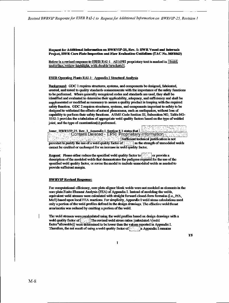
Revised BWRVIP Response for ESEB RAJ-I to Request for Additional Information on BWRVIP-25, Revision 1
M-8
Request for Additional.Information on BWRVIP-25, Rev. 1: BWR Vessel and Internals Project, BWR Core Plate lmpedion and Flaw Evaluation GuidelilHs (IAC No. MFSS63)
Bdow is a revised~ to ESEB RAI~l-. All EPRI propriebuy text is marked in [[boicij iuideriine,:yellow~highlight;;withdoulile·brackets)).
ESEB Oj>eraling PlantsRAl-1: Appendix I Structural Analysis
Background: GDC I requires sfrnctures, systems, and components be designed, fabricated, erected, and tested to qualify standards commemorate with the impommce of the safety functions to be ped"ormed. Where generally recognized codes and standards are used, they shall be identified and evaluated to detennine their applicability, adequacy, and sufficiency and shall be supplemented or modified as necessary to assure a quality product in keeping with the required safety function. GDC 2 requires structures, systems, and components impommt to safety to be designed to withstand the effects of natural phenomena, such as eanhquakes, without loss of capability to perform their safety fimctims. ASME Code Section III, Subsection NG, Table NG-3352-1 provides the a tabulation of appropriate weld quality factors based on the type ofwdded joint, and the type of examioation(s) pedooned.
[ftc0:Tcf~t1!~~0W~~!!;~~~~7D~"c•~ provided to justify the use of a weld quality factor of I , , ; J, as the strength ofmunodeled wdds cannot be credited or excbaoged for an increase in wd.d qiiality factor.
~ Please either reduce the specified wdd quality factorto [':T-~-l or provide a desaiptionofthemodeled wdds that demonstrates the pedigreerequiredfortheuse of the specified wdd quality factor, or revise the model to include unmodeled welds as needed to provide sufficient margin.
BWRVIP Revised Response:
For compulational efficiency, core plate aligner block wdds were not modeled as elements in the core plate Finite Elemwt Analysis (FEA) of Appendix I. Instead of modeling the welds, equivalwt weld stresses were calcolated with straight forw.ml closed-foon foonulas (i.e., P/A, Mc/I) based upon local FEA reactims. For simplicity, Appendix I weld stress calcolatims used only a portion of the weld profiles defined in the design drawings. The effective wdd throat area/inertia was reduced by omitting a portion of the weld.
The weld stresses werev1·eca1:?1ated using the wdd profiles based on design drawings with a wdd quality factor of lL~ The revised wdd stress ratios [calcolated/ (weld facto~allowable)] were deleimined to be lower than the values !Cl)Orted in Appendix I. Therefore, the net result of using a wdd quality factor off~ Appendix I remains
-·-,,~
I
TS
Revised BWRVIP Response for ESEB RAJ-] to Request for Additional Information on BWRVIP-25, Revision 1
conservative and ho~ when compared to modeling all 1he weld profile and using a weld quality factor of il
1-,.,._... _ _..-1
The ensuing passages from Appendix I, Sections 83 and 85 2 are proposed to be revised for clarity.
Existing text in Section 83:
•~1 welds use a weld qualify factor ~!.!7[23] due to )iquid penetrant inspection. This was choseninsteadof1helowervalueof,Content Deleted - EPRI Proprietary Information' ~~--(for simplicity). The net result is conservative.''
Proposed revision to Section 83:
"A weld quality factor of 1-----,,[23] is applicable for all welds, based on liquid penetrant inspection as part of ~!ig~ fabrication. However-, all welds in the stmctural analysis use a weld qoali1y factor of[_· _·_J For compotmiooal efficiency, core plate aligner- block welds were not modeled as elements in the core plate Finite Bement Analysis (FEA) of Appendix I. Instead of modeling 1he welds, equivalent weld stresses were calculated with straightforward closedfonn foonulas (i.e., PIA, Mdl) based upon local FEA reactions. Forsimplicity, Appendix I weld stress calculations used only a ponion of the weld profiles defined in the design drawings. The effective weld throat area/"mema was reduced by omitting a pomonoftheweld.Following publication ofBWR.VIP-25, Rev. I, the weld stresses~~ ~aluated using the weld profiles based on design drawings with a weld qualify factor ofc=for comparison to the weld stresses calculated in the Appendix I analysis. The revised weld stress ratios [calculated I (weld facto~allowable)] were detennined to be lower than the values reported inAp~dix I of BWR.V1:P-2S, R~. I. Therefo~, the net~ of using a weld quality fac!or of~in Appendix I remams conservative ~JJO!!l]ding when compared to modeling an-me weld profile and using a weld quality factor ofL.J
Existing teKt in Section 8.S.2:
''9.~tent.Deleted - EPRI Proprietary lnformationi · 1qualityfactorisusedinsteadofa
C ' I quality factor~ perfomung stress calculations for liquid-penetrant-inspected welds. TIie result is conseIVative."
Proposed revision to Section 852:
''9.AsstatedinSection83,thenetresultofusingaweldqualifyfactorof]1-..,,mdonlyapomon of the aligner block weld profile is consecvative and bounding when compared to modeling all the weld profile and using a weld quality factor of r- ·· ·]
2
TS
M-9
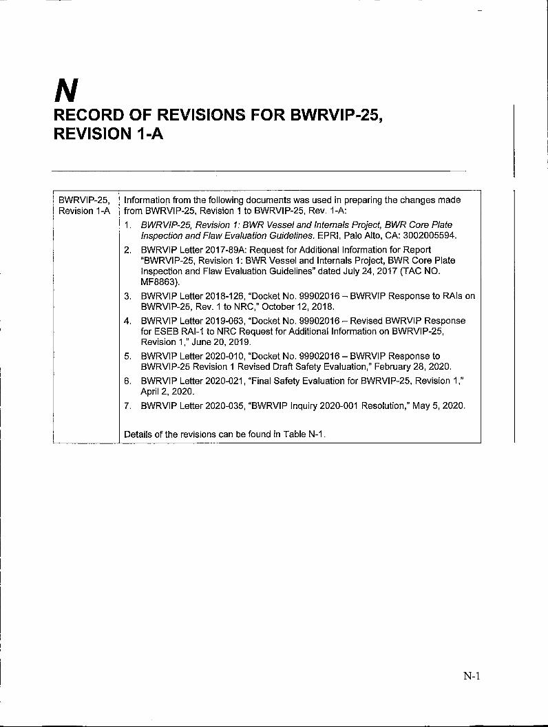
N RECORD OF REVISIONS FOR BWRVIP-25, REVISION 1-A
BWRVIP-25, Information from the following documents was used in preparing the changes made Revision 1-A from BWRVIP-25, Revision 1 to BWRVIP-25, Rev. 1-A:
1. BWRVIP-25, Revision 1: BWR Vessel and Internals Project, BWR Core Plate Inspection and Flaw Evaluation Guidelines. EPRI, Palo Alto, CA: 3002005594.
2. BWRVIP Letter 2017-89A: Request for Additional Information for Report "BWRVIP-25, Revision 1: BWR Vessel and Internals Project, BWR Core Plate Inspection and Flaw Evaluation Guidelines" dated July 24, 2017 (TAC NO. MF8863).
3. BWRVIP Letter 2018-126, "Docket No. 99902016 - BWRVIP Response to RAls on BWRVIP-25, Rev. 1 to NRC," October 12, 2018.
4. BWRVIP Letter 2019-063, "Docket No. 99902016 - Revised BWRVIP Response for ESEB RAl-1 to NRC Request for Additional Information on BWRVIP-25, Revision 1," June 20, 2019.
5. BWRVIP Letter 2020-010, "Docket No. 99902016 - BWRVIP Response to BWRVIP-25 Revision 1 Revised Draft Safety Evaluation," February 28, 2020.
6. BWRVIP Letter 2020-021, "Final Safety Evaluation for BWRVIP-25, Revision 1," April 2, 2020.
7. BWRVIP Letter 2020-035, "BWRVIP Inquiry 2020-001 Resolution," May 5, 2020.
Details of the revisions can be found in Table N-1.
N-1
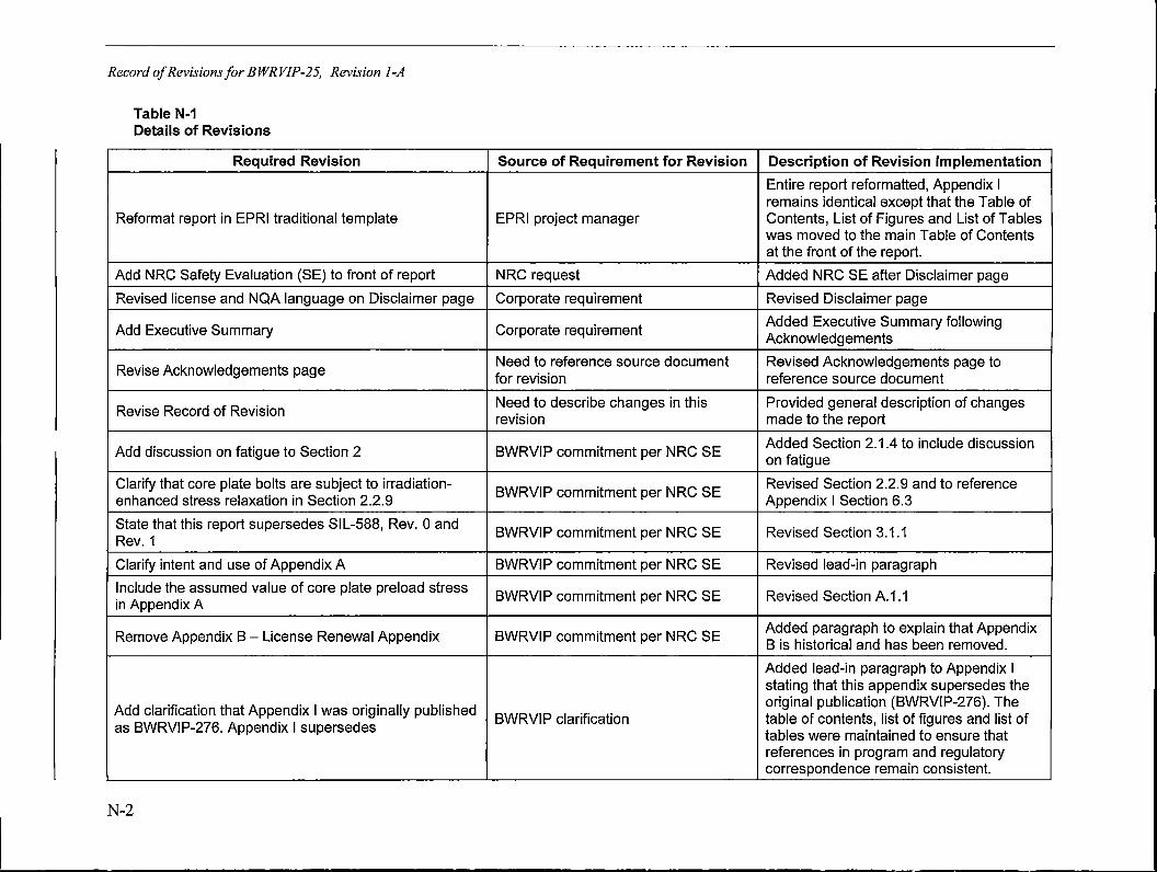
Record of Revisions for BWRVIP-25, Revision 1-A
Table N-1 Details of Revisions
Required Revision Source of Requirement for Revision Description of Revision Implementation
Entire report reformatted, Appendix I remains identical except that the Table of
Reformat report in EPRI traditional template EPRI project manager Contents, List of Figures and List of Tables was moved to the main Table of Contents at the front of the report.
Add NRC Safety Evaluation (SE) to front of report NRC request Added NRC SE after Disclaimer page
Revised license and NQA language on Disclaimer page Corporate requirement Revised Disclaimer page
Add Executive Summary Corporate requirement Added Executive Summary following Acknowledgements
Revise Acknowledgements page Need to reference source document Revised Acknowledgements page to for revision reference source document
Revise Record of Revision Need to describe changes in this Provided general description of changes revision made to the report
Add discussion on fatigue to Section 2 BWRVIP commitment per NRC SE Added Section 2.1.4 to include discussion on fatigue
Clarify that core plate bolts are subject to irradiation-BWRVIP commitment per NRC SE
Revised Section 2.2.9 and to reference enhanced stress relaxation in Section 2.2.9 Appendix I Section 6.3
State that this report supersedes SIL-588, Rev. 0 and BWRVIP commitment per NRC SE Revised Section 3.1.1
Rev. 1
Clarify intent and use of Appendix A BWRVIP commitment per NRC SE Revised lead-in paragraph
Include the assumed value of core plate preload stress BWRVIP commitment per NRC SE Revised Section A.1 .1
in Appendix A
Remove Appendix 8 - License Renewal Appendix BWRVIP commitment per NRC SE Added paragraph to explain that Appendix 8 is historical and has been removed.
Added lead-in paragraph to Appendix I stating that this appendix supersedes the
Add clarification that Appendix I was originally published original publication (BWRVIP-276). The
as BWRVIP-276. Appendix I supersedes BWRVIP clarification table of contents, list of figures and list of
tables were maintained to ensure that references in program and regulatory correspondence remain consistent.
N-2

Table N-1 {continued) Details of Revisions
Required Revision
Appendix I - State that this report supersedes SIL-588, Rev. 0 and Rev. 1
Clarify that assumed core plate bolt fluence can correspond to greater than 60 years of operation
Revise Appendix I, Figure 6-3 and associated description in report
Revise Appendix I, Section 7.2 to clarify conditions to meet SC 11-05
Revise Appendix I, Section 8.3 regarding weld quality factor
Revise Appendix I, Table 8.3 footnotes
Revise Appendix I, Section 8.5.2 regarding weld quality factor
Revise Appendix I, Section 9.7 regarding core plate bolt fluence calculations
Updated Appendix I, Figure 9-9
Add NRC Request for Additional Information (RAI) on BWRVIP-25, Rev. 1
Add BWRVIP response to RAI on BWRVIP-25, Rev. 1
Source of Requirement for Revision
BWRVIP commitment per NRC SE
BWRVI P clarification
BWRVIP commitment per NRC SE
Inquiry 2020-001
BWRVIP commitment per NRC SE
General
BWRVIP commitment per NRC SE
BWRVIP commitment per NRC SE
General
NRC request
NRC request
Record of Revisions/or BWRVIP-25, Revision 1-A
Description of Revision Implementation
Revised Appendix I, Section 1.1
Added sentence to Apper_,dix I, Section 2.1.4
Revised Figure 6-3 to remove GE fluence calculation as this was erroneously placed on graph. Revised sentence in Section 6.3 to remove mention of GE fluence calculation. Deleted Reference 15 and renumbered all remaining references.
Added footnote 5 and reference 26 to Section 7 .2 and Section 11 of Appendix I
The discussion on weld quality factor was revised following Table 8-2 to state that weld stresses were reevaluated using a weld quality factor of 0.6 and were determined to remain conservative.
Revised Table 8.3 footnotes to be consistent with revisions to Section 9.7, item 5
Revised item 9 in Section 8.5.2 to state that using weld quality factor of 0.8 versus 0.6 remains conservative and bounding
Added item 5 to Section 9.7 requiring plants to confirm that the neutron fluence of the core plate bolts is bounded by the assumed peak fluence of 5E20 n/cm2.
Revised Figure 9-9 in Appendix I to be consistent with the revisions in Section 9. 7
Added Appendix K
Added Appendix L
N-3
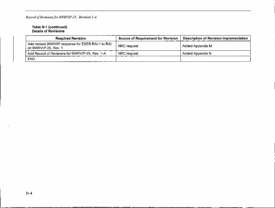
Record of Revisions for BWRVIP-25, Revision 1-A
Table N-1 (continued) Details of Revisions
Required Revision
Add revised BWRVIP response for ESEB RAl-1 to RAI on BWRVIP-25, Rev. 1
Add Record of Revisions for BWRVIP-25, Rev. 1-A
END
N-4
Source of Requirement for Revision Description of Revision Implementation
NRG request Added Appendix M
NRG request Added Appendix N

The Electric Power Research Institute, Inc. (EPRl, www.epri.com)
conducts research and development relating to the generation, delivery.
and use of electricity for the benefit of the public. An independent,:
nonprofit organization, EPRl brings together its scientists and engineersi
as well as experts from academia and industry to help address
challenges in electricity, including reliability, efficiency, affordability,
health, safety and the environment. EPRl also provides technology, policy
and economic analyses to drive long-range research and development
planning, and supports research in emerging technologies. EPRl
members represent 90% of the electricity generated and delivered in
the United States with international participation extending to nearly
40 countries. EPRl's principal offices and laboratories are located in
Palo Alto, Calif.; Charlotte, N.C.; Knoxville, Tenn.; Dallas, Texas; Lenox,
Mass.; .and Washington, D.C.
Together ... Shaping the Future of Electricity
Program:
BWR Vessel and Internals Project
© 2020 Electric Power Research Institute [EPRI), Inc. All rights reserved. Electric Power Research Institute, EPRI, and TOGETHER ... SHAPING THE FUTURE OF ELECTRICITY are registered service marks of the Electric Power Research Institute, Inc.
3002018310
Electric Power Research Institute 3420 Hillview Avenue, Palo Alto, California 94304-1338 • PO Box 10412, Palo Alto, California 94303-0813 USA
800.313.3774 • 650.855.2121 • [email protected] • www.epri.com