2M DIY kit build manual - Version 2.0 - Transient Modules
6
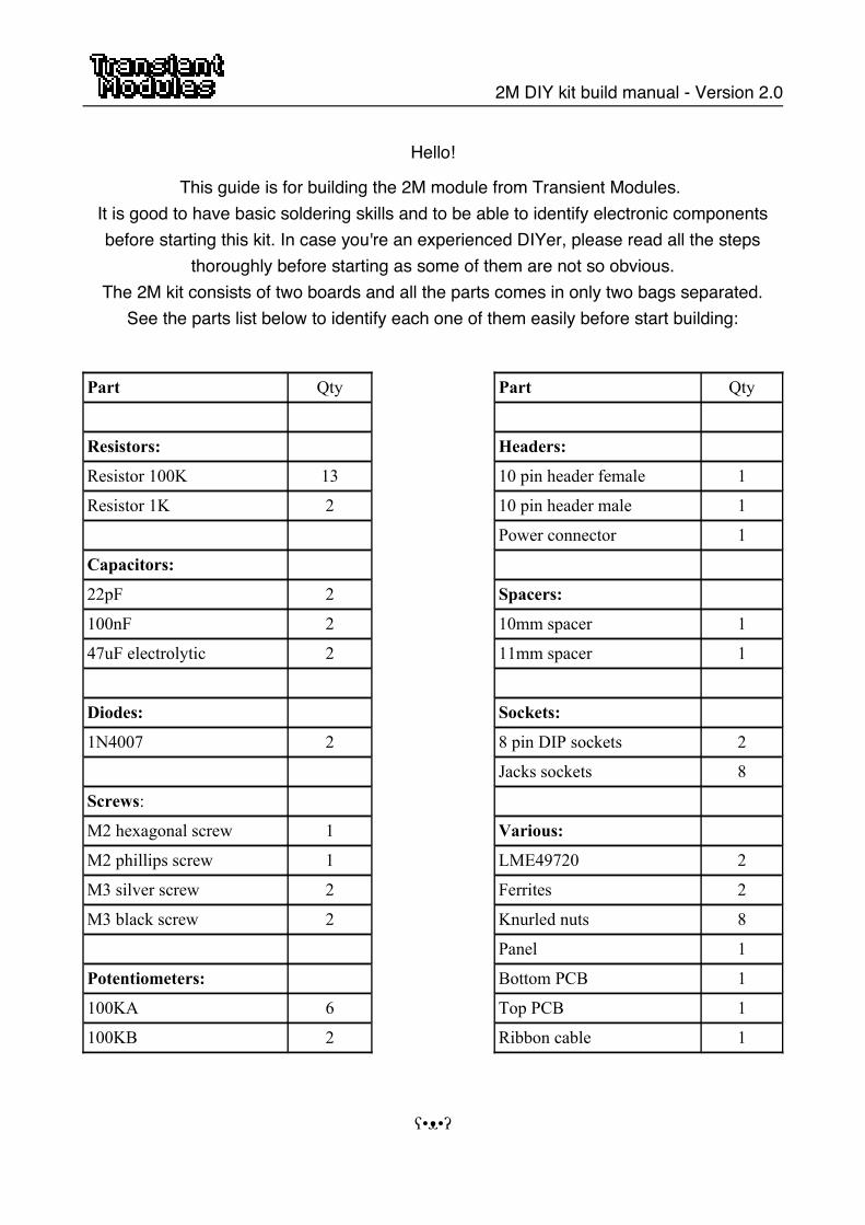
2M DIY kit build manual - Version 2.0 Hello! This guide is for building the 2M module from Transient Modules. It is good to have basic soldering skills and to be able to identify electronic components before starting this kit. In case you're an experienced DIYer, please read all the steps thoroughly before starting as some of them are not so obvious. The 2M kit consists of two boards and all the parts comes in only two bags separated. See the parts list below to identify each one of them easily before start building: Part Qty Part Qty Resistors: Headers: Resistor 100K 13 10 pin header female 1 Resistor 1K 2 10 pin header male 1 Power connector 1 Capacitors: 22pF 2 Spacers: 100nF 2 10mm spacer 1 47uF electrolytic 2 11mm spacer 1 Diodes: Sockets: 1N4007 2 8 pin DIP sockets 2 Jacks sockets 8 Screws: M2 hexagonal screw 1 Various: M2 phillips screw 1 LME49720 2 M3 silver screw 2 Ferrites 2 M3 black screw 2 Knurled nuts 8 Panel 1 Potentiometers: Bottom PCB 1 100KA 6 Top PCB 1 100KB 2 Ribbon cable 1 ʕ•ᴥ•ʔ
-
Upload
khangminh22 -
Category
Documents
-
view
0 -
download
0
Transcript of 2M DIY kit build manual - Version 2.0 - Transient Modules
2M DIY kit build manual - Version 2.0
Hello!
This guide is for building the 2M module from Transient Modules. It is good to have basic soldering skills and to be able to identify electronic componentsbefore starting this kit. In case you're an experienced DIYer, please read all the steps
thoroughly before starting as some of them are not so obvious.The 2M kit consists of two boards and all the parts comes in only two bags separated.
See the parts list below to identify each one of them easily before start building:
Part Qty Part Qty
Resistors: Headers:
Resistor 100K 13 10 pin header female 1
Resistor 1K 2 10 pin header male 1
Power connector 1
Capacitors:
22pF 2 Spacers:
100nF 2 10mm spacer 1
47uF electrolytic 2 11mm spacer 1
Diodes: Sockets:
1N4007 2 8 pin DIP sockets 2
Jacks sockets 8
Screws:
M2 hexagonal screw 1 Various:
M2 phillips screw 1 LME49720 2
M3 silver screw 2 Ferrites 2
M3 black screw 2 Knurled nuts 8
Panel 1
Potentiometers: Bottom PCB 1
100KA 6 Top PCB 1
100KB 2 Ribbon cable 1
ʕ•ᴥ•ʔ
2M DIY kit build manual - Version 2.0
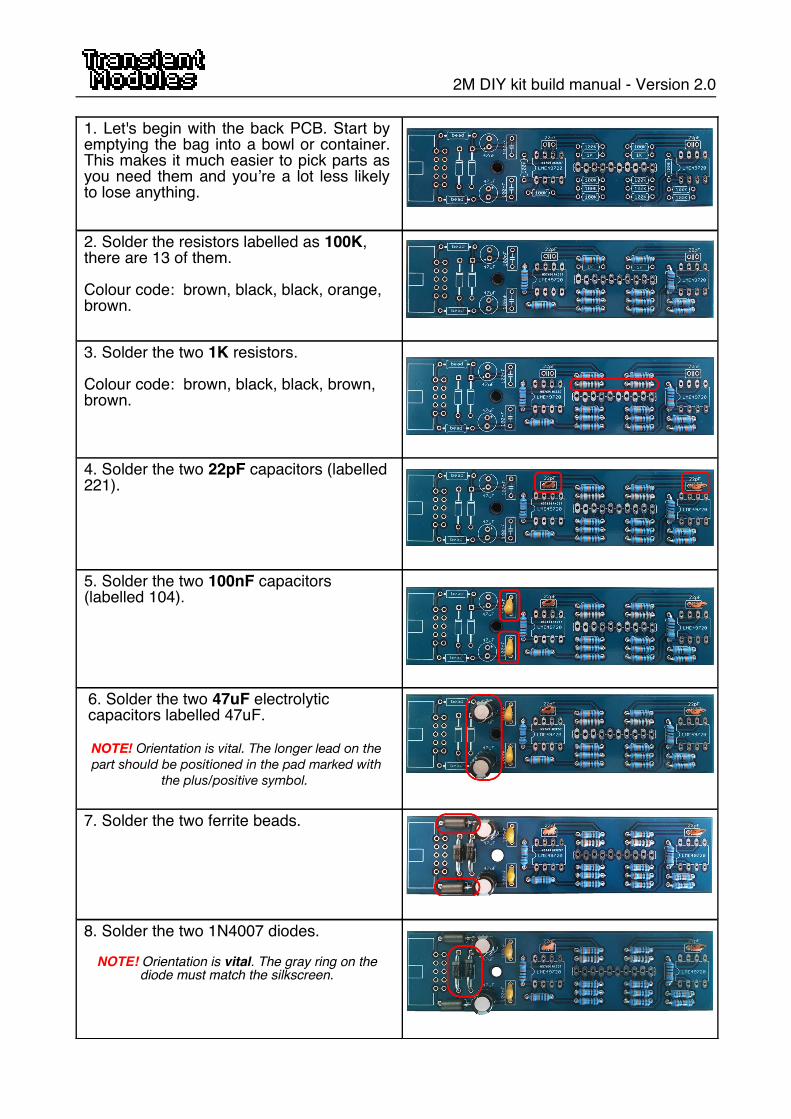
1. Let's begin with the back PCB. Start byemptying the bag into a bowl or container.This makes it much easier to pick parts asyou need them and you’re a lot less likelyto lose anything.
2. Solder the resistors labelled as 100K, there are 13 of them.
Colour code: brown, black, black, orange, brown.
3. Solder the two 1K resistors.
Colour code: brown, black, black, brown, brown.
4. Solder the two 22pF capacitors (labelled221).
5. Solder the two 100nF capacitors (labelled 104).
6. Solder the two 47uF electrolytic capacitors labelled 47uF.
NOTE! Orientation is vital. The longer lead on the
part should be positioned in the pad marked with
the plus/positive symbol.
7. Solder the two ferrite beads.
8. Solder the two 1N4007 diodes.
NOTE! Orientation is vital. The gray ring on thediode must match the silkscreen.
2M DIY kit build manual - Version 2.0
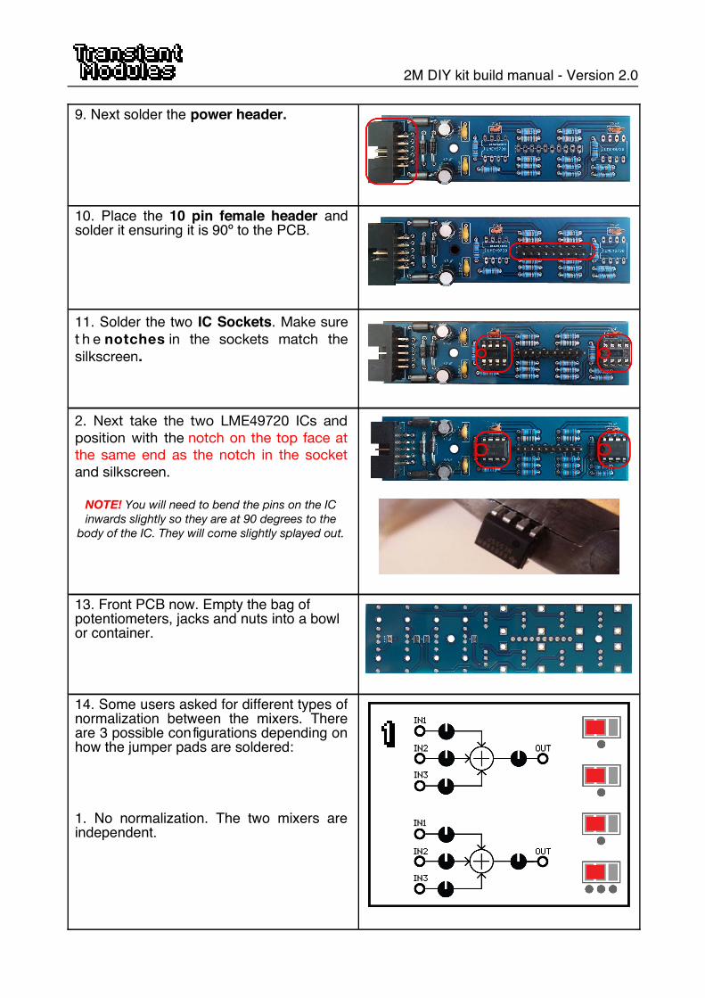
9. Next solder the power header.
10. Place the 10 pin female header andsolder it ensuring it is 90º to the PCB.
11. Solder the two IC Sockets. Make sure
t h e notches in the sockets match the
silkscreen.
2. Next take the two LME49720 ICs and
position with the notch on the top face at
the same end as the notch in the socket
and silkscreen.
NOTE! You will need to bend the pins on the IC
inwards slightly so they are at 90 degrees to the
body of the IC. They will come slightly splayed out.
13. Front PCB now. Empty the bag of potentiometers, jacks and nuts into a bowl or container.
14. Some users asked for different types ofnormalization between the mixers. Thereare 3 possible configurations depending onhow the jumper pads are soldered:
1. No normalization. The two mixers areindependent.

2M DIY kit build manual - Version 2.0
2. When no cable is connected at theoutput jack of the mixer on the left, itsoutput is summed to the inputs of the mixeron the right. This normalization may beuseful if you want to mix 6 drum sounds toone output. Note that the normalization ismade after the output potentiometer, sothere is a 'submix' control between the twomixers.
3. The inputs of the mixer on the left arenormalled to the inputs of the mixer on theright. This setting is useful when the mixeris used for obtaining a L/R signal. This wayis possible to patch 3 mono signals andobtain a (even panned) L/R signal at theoutput.
Example of how must look the smd jumper soldered pads. (Normalization 3 on the image)
15. Solder the 10 pin female headerensuring it's 90º to the PCB.
NOTE! This part is placed at the bottom of the PCBand soldered from the top, as shown on the image.
16. Next, place the 2x 100KB potentiometers (labelled B104) and the 6x 100KA potentiometers (labelled A104) into their position but DO NOT SOLDER yet. Make sure they're 90º to the PCB and fully inserted.
2M DIY kit build manual - Version 2.0
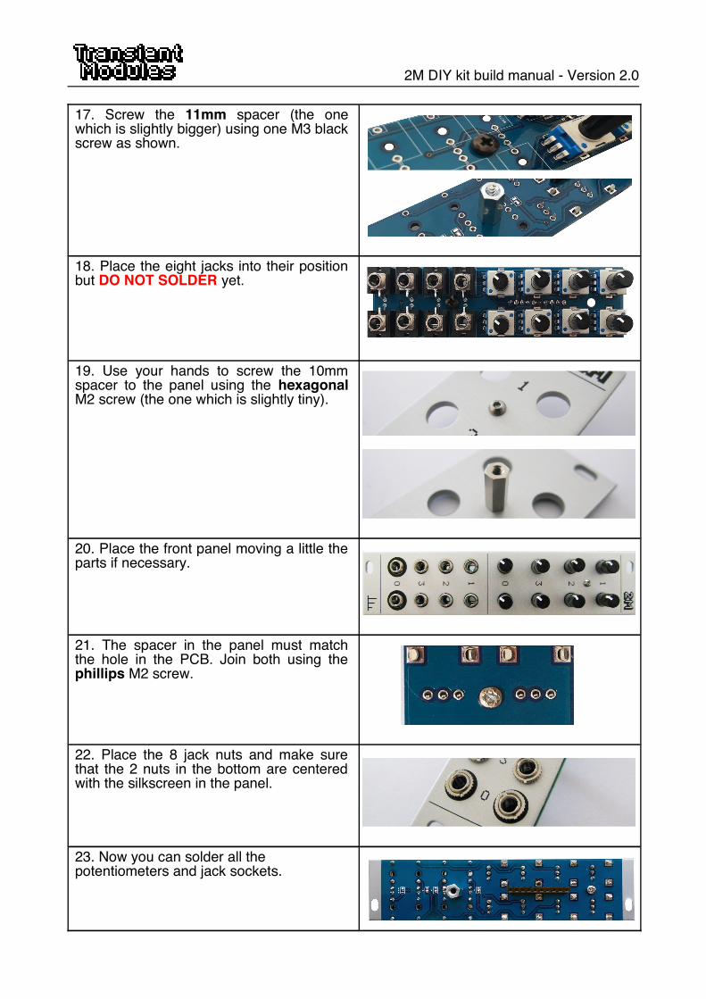
17. Screw the 11mm spacer (the onewhich is slightly bigger) using one M3 blackscrew as shown.
18. Place the eight jacks into their positionbut DO NOT SOLDER yet.
19. Use your hands to screw the 10mmspacer to the panel using the hexagonalM2 screw (the one which is slightly tiny).
20. Place the front panel moving a little theparts if necessary.
21. The spacer in the panel must matchthe hole in the PCB. Join both using thephillips M2 screw.
22. Place the 8 jack nuts and make surethat the 2 nuts in the bottom are centeredwith the silkscreen in the panel.
23. Now you can solder all the potentiometers and jack sockets.
2M DIY kit build manual - Version 2.0
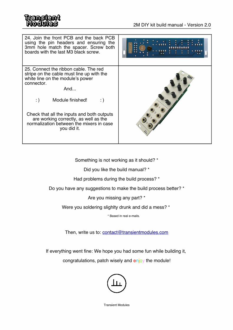
24. Join the front PCB and the back PCBusing the pin headers and ensuring the3mm hole match the spacer. Screw bothboards with the last M3 black screw.
25. Connect the ribbon cable. The red stripe on the cable must line up with the white line on the module’s power connector.
And...
: ) Module fnished! : )
Check that all the inputs and both outputsare working correctly, as well as the
normalization between the mixers in caseyou did it.
Something is not working as it should? *
Did you like the build manual? *
Had problems during the build process? *
Do you have any suggestions to make the build process better? *
Are you missing any part? *
Were you soldering slighlty drunk and did a mess? * * Based in real e-mails.
Then, write us to: [email protected]
If everything went fine: We hope you had some fun while building it,
congratulations, patch wisely and enjoy the module!
Transient Modules