Preparation of Supported Pd Catalysts: From the Pd Precursor Solution to the Deposited Pd 2+ Phase
Upload
khangminh22Category
view
2download
0
HAL Id: hal-02151239https://hal.archives-ouvertes.fr/hal-02151239
Submitted on 25 Oct 2021
HAL is a multi-disciplinary open accessarchive for the deposit and dissemination of sci-entific research documents, whether they are pub-lished or not. The documents may come fromteaching and research institutions in France orabroad, or from public or private research centers.
L’archive ouverte pluridisciplinaire HAL, estdestinée au dépôt et à la diffusion de documentsscientifiques de niveau recherche, publiés ou non,émanant des établissements d’enseignement et derecherche français ou étrangers, des laboratoirespublics ou privés.
Distributed under a Creative Commons Attribution - NonCommercial| 4.0 InternationalLicense
2D & 3D in situ study of the calcination of Pdnanocatalysts supported on delta-Alumina in an
Environmental Transmission Electron MicroscopeThierry Epicier, Siddardha Koneti, Priscilla Avenier, Amandine Cabiac,
Anne-Sophie Gay, Lucian Roiban
To cite this version:Thierry Epicier, Siddardha Koneti, Priscilla Avenier, Amandine Cabiac, Anne-Sophie Gay, et al.. 2D &3D in situ study of the calcination of Pd nanocatalysts supported on delta-Alumina in an Environmen-tal Transmission Electron Microscope. Catalysis Today, Elsevier, 2019, �10.1016/j.cattod.2019.01.061�.�hal-02151239�

2D & 3D in situ study of the calcination of Pd nanocatalysts supported on delta-Alumina in an Environmental Transmission Electron Microscope
Thierry Epicier1, Siddardha Koneti1, Priscilla Avenier2, Amandine Cabiac2, Anne-Sophie Gay2, Lucian Roiban1
1Univ Lyon, INSA-Lyon, Université Claude Bernard Lyon 1, MATEIS, UMR 5510, CNRS, 69621 Villeurbanne Cedex, France.
2 IFP Energies Nouvelles – Rond-point de l’échangeur de Solaize, BP 3, 69360 Solaize, France.
Abstract
The quality of metallic nanoparticles (NPs) used in heterogeneous catalysis relies through many aspects on their small size, on the homogeneity of their spatial distribution on their supports and on their ability to resist to sintering or coalescence. It is thus very important to quantify these parameters and understand the mechanisms controlling the growth of NPs during the genesis process of the catalyst. Whereas conventional Transmission Electron Microscopy (TEM) is currently used for these purposes, it most frequently remains a ‘static’ method where results are obtained in high vacuum and post mortem, i.e. after the typical drying, calcination and reduction steps without the possibility to follow directly the evolution of both NPs and supports during those treatments. Environmental TEM (ETEM) unlocks this blocking and allows elementary mechanisms, such as Ostwald Ripening (OR) and coalescence to be unravelled through direct in situ observations. We report here an ETEM study of the preparation of Pd-based narrow NPs, less than 5 nm in
size, deposited on a δ-alumina support. We focused on 3 main objectives: (i) quantifying
the sizes of NPs at each preparation step performed in situ under environmental (i.e. respectively oxygen or air and hydrogen atmospheres at working temperatures) and comparing them to post mortem measurements; (ii) identify the oxidation state of the NPs through an in situ High Resolution imaging study of their crystallographic structure; (iii) explore the possibilities of environmental tri-dimensional (3D) studies by tilt series based Electron Tomography. This last item represents a challenging breakthrough in the characterization of nanocatalysts; it will be demonstrated that the use of modern
© 2019 published by Elsevier. This manuscript is made available under the CC BY NC user licensehttps://creativecommons.org/licenses/by-nc/4.0/
Version of Record: https://www.sciencedirect.com/science/article/pii/S0920586118310599Manuscript_c42fd7fbc9174b1a7bd0b56d319d447c
instruments (microscope and accessories) allows tomographic acquisitions to be performed very fast, within a few minutes and even seconds, which opens the way to the 3D tracking of microstructures almost in real time during their evolution under gas and at high temperature.
Key words: Pd calcination, Delta alumina support, ETEM, In-situ TEM, Fast Environmental tomography, Pd/Delta alumina catalytic system.
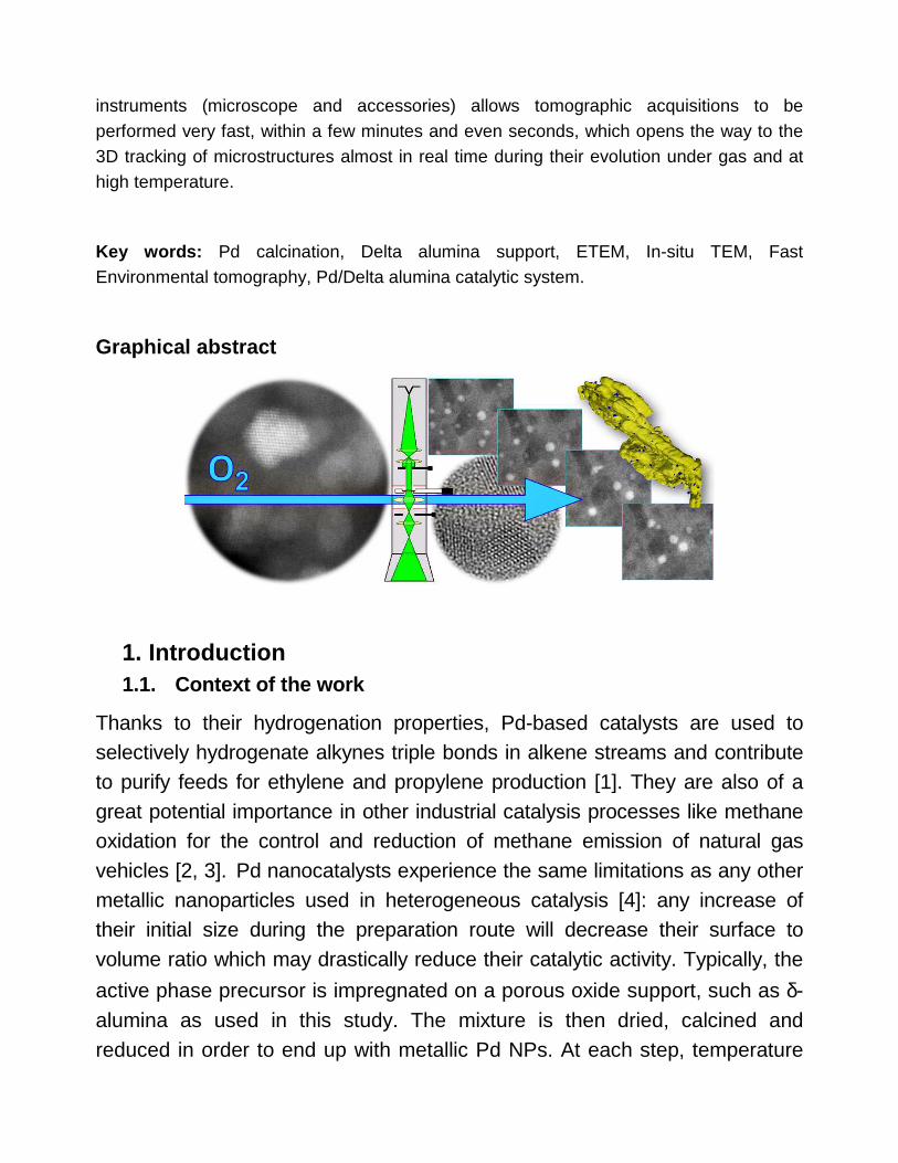
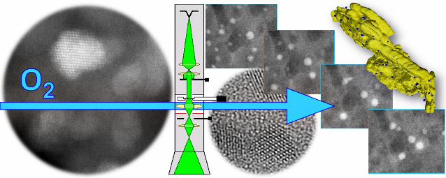
Graphical abstract
1. Introduction 1.1. Context of the work
Thanks to their hydrogenation properties, Pd-based catalysts are used to selectively hydrogenate alkynes triple bonds in alkene streams and contribute to purify feeds for ethylene and propylene production [1]. They are also of a great potential importance in other industrial catalysis processes like methane oxidation for the control and reduction of methane emission of natural gas vehicles [2, 3]. Pd nanocatalysts experience the same limitations as any other metallic nanoparticles used in heterogeneous catalysis [4]: any increase of their initial size during the preparation route will decrease their surface to volume ratio which may drastically reduce their catalytic activity. Typically, the
active phase precursor is impregnated on a porous oxide support, such as δ-alumina as used in this study. The mixture is then dried, calcined and reduced in order to end up with metallic Pd NPs. At each step, temperature

and gas pressure are varied and therefore diffusion, coalescence, interaction with the support (such as anchoring effects) can affect the quality of the final catalyst system by changing shape, distribution and chemical nature (i.e. oxidation state) of the NPs. Quantifying the evolution of the NPs during the whole process is then needed and this can be efficiently performed using Transmission Electron Microscopy (TEM). Among the available methods to characterize NPs (see for example [5]), TEM and associated techniques1 constitute today a broad spectrum of very well adapted approaches to study and quantify accurately supported (collections of) NPs [6,7] and their interaction with their support in the context of catalysis [8]. However, usual studies in a conventional, i.e. high vacuum microscope suffer a severe limitation: they do only inform about the evolution of NPs after heat treatments and exposure to gas. Although delicate, a comparison of results before and after such treatments is possible and such specific studies have been conducted in some particular cases, such as the 3D view of a porous silica zeolite at different stages of calcination [9], the electrochemical ageing of Pt−Co Fuel Cell nano-catalysts [10], a 3D ageing study of Pt-Pd nanocatalysts [11] or the evolution of Pd-Pt catalysts in low-temperature wet methane combustion [12]. Such ‘before and after’ studies may rely on statistics accounting for large numbers of NPs, which remains a difficult goal to achieve in TEM, or on the same object(s) as performed in the so-called “identical location” approach in TEM experiments [13], where the same Region of Interest (ROI) is studied ‘before’ and ‘after’ a solicitation (heat treatment, oxidation, reduction, exposure to gas) performed outside the microscope. Though valuable, ‘before and after’ studies cannot compete with the potential interest of ‘during’ studies where the system of interest is followed in situ in the microscope without the risk of an accidental exposure to an unwanted atmosphere during any in/out transfer. This approach is now possible in Environmental Transmission Electron Microscopy (ETEM), where gas (in the present context of catalysis) can be introduced around the sample
1 Electron diffraction, Scanning TEM (TEM), spectroscopic analyses and imaging based on Energy-Dispersive X-ray (EDX) and Electron Energy-Loss Spectroscopy (EELS), tomography, Environmental TEM (ETEM).

during the observation, enabling to study its evolution in real time and during heat treatments owing to dedicated heating holders (see [14] and references within for a large overview). Not only adopting the “identical location” strategy is the implicit way to perform in situ experiments since the same ROI can be analysed in its starting and final states, but NPs can easily be tracked at any stage during their dynamic evolution which is of the greatest importance to study mechanisms controlling catalysts sintering [15].
1.2. Objectives
In this work, we studied in situ in the ETEM the genesis on Pd-based catalysts, consisting of sub 5 nm Pd nanoparticles prepared by colloidal
synthesis, supported on mesoporous δ (delta) alumina. We focused on
studying size evolution of NP especially during the calcination step, performed under low oxygen pressure and at temperature up to 450°C, mimicking calcination performed in lab conditions. The present observations
were undertaken in the frame of a larger study aiming at comparing α and δ
alumina supports [16], as it is well-known that the nature of support influences the behaviour of the NPs [17,18,19].
A first objective is to compare size evolution as they can be measured in a TEM on samples after either ex situ or in situ heat treatments. Ex situ, or post mortem treatments are calcination under oxygen or air and reduction under hydrogen performed in an industrial context, e.g. on ‘bulk’ alumina pellets impregnated with Pd salts and treated at ambient pressure. In situ means experiments performed in an ETEM under lower partial pressure. As already mentioned, growth of NPs is unwanted since it will degrade the catalytic performances of the system. Several TEM or ETEM works have already been devoted to the Pd-Al2O3 system, although in general for a significantly larger initial NP size as compared to the present study (about 2 nm [20] as it will be seen later): more than 20 nm [17], 10 to 30 nm [18], about 8 nm [21], 34 nm [22] and 2.4 nm [23]. These studies can be briefly summarized as follows regarding the size evolution of NPs during a calcination step: the growth of
Pd nanoparticles on a δ-Al2O3 support can happen, due to Ostwald ripening

and coalescence mechanisms at 700°C [21]. A similar result was obtained in the case of small Pd NPs deposited on an amorphous Al2O3 film and experiencing an Ostwald ripening induced growth at 650°C under 10 mbar of air pressure during a direct in situ ETEM experiment where no significant NP mobility was observed [23].
A second objective is to follow the structural evolution of Pd-based NPs. Table 1 documents Pd and PdOx phases. In one of the pioneer ETEM experiments, Rodriguez and co-workers have shown that Pd NPs deposited
on γ-alumina get oxidized at temperatures above 325°C when heated in
presence of oxygen at about 0.25 mbar in a modified commercial TEM [29]. A similar transformation into tetragonal PdO (P42/mmc, see Table 1) was confirmed by High Resolution TEM after oxidation of Pd NPs deposited on a silica film in pure oxygen at atmospheric pressure above 350°C [30].
Table 1: crystallographic structures of palladium and palladium oxides.
Compound Space group Parameters Ref. Pd Cubic Fm-3m (225) a = 3.9 Å [24] PdO Tetragonal P4/m a = 3.0 Å, c = 5.2 Å [25] PdO Tetragonal P42/mmc a = 3.02 Å, c = 5.31 Å [26] Pd3O4 Cubic Pm-3n (223) a = 5.756 Å [27] Pd2O Cubic Pn-3m (224) a = 4.28 Å [28]
The oxidation proceeds by a mechanism where dissociated oxygen chemisorbs first at the Pd surface then dissolves into the metal lattice up to formation of the oxide phase as demonstrated by Han et al. [31] who studied a single crystal of Pd in a low pressure atmosphere (1 - 150 Torr) between 327 and 507°C using surface science characterization and spectroscopic techniques. Figure 1 reports their proposed phase diagram in the Pd-O system as a function of the oxygen pressure in contact with a (111)-Pd surface; these evolutions are in qualitative agreement with all previous results.
In situ ETEM reduction of PdO into Pd proceeds easily in hydrogen at temperatures as low as 150 to 200°C; a spontaneous reduction under high vacuum in the range of 10-6 mbar is also observed [34], as it can be

suggested by the diagram of Figure 1 (instability of the ‘bulk’ oxide phase at low pressure).
Figure 1: experimentally observed stability of the different Pd oxide structures in a pressure - temperature space [32] (reproduced from [33]; the dark line crossing the diagram delineates the upper domains related to oxygen chemisorption and the lower domains corresponding to an increasing surface then bulk oxidation).
A third objective is to evaluate the possibility of characterizing the population of Pd NPs in 3D during environmental in situ experiments. Tomography experiments are now classically conducted in TEM and especially in the field of catalysis [35, 36, 37]. They mostly consist in a post mortem 3D characterization at an intermediate or at the final step of the genesis process as performed on the Pd-alumina system [22], or via a ‘before and after’ approach as previously mentioned in section 1.1 [9,10,11]. We aim here at following the tri-dimensional evolution of the catalytic system during the in situ calcination in the ETEM. When in situ tomography of nanomaterials during heating has already been performed using adapted sample holders [38, 39],

there is, to the best of our knowledge, no such approach under environmental conditions apart the recent strategy we have developed in a dedicated ETEM [40].
2. Materials and Methods 2.1. Chemical synthesis
Pd supported catalyst is prepared by colloidal synthesis. The detailed protocol has been previously described [20, 41]. An aqueous acid Pd solution (Pd(NO3)2 solution provided by HERAUS with 8.22 wt. % Pd concentration, pH of 1) is stabilized with sodium nitrite (0.4 mol NaNO2 by 1 mol of Pd). Further NaOH addition by pH adjustment to 2 allows to obtaining the colloidal Pd solution. Initial mean particle sizes of 1.7 nm (for a similar acid PH) and around 2 nm were respectively measured in previous works [41, 20]. After 5 minutes maturation, the solution is used for dry impregnation of an alumina
support consisting in 2-4 mm beads (mesoporous δ-Al2O3, SBET = 70 m2/g).
The Pd concentration of the catalyst extrudates is 0.3 wt. %, however since Pd NPs are located in a shell of few hundred of µm thickness the resulting Pd concentration in such a shell is significantly larger than 0.3 wt. %. After completion of this process called ‘impregnation’, the material is dried at 120°C under ambient air and calcined at 425°C for 2 h. The final reduction to insure the metallic state of Pd NPs is performed under hydrogen at atmospheric pressure during 2 h at 150°C. The whole synthesis process is depicted in Figure 2. Microstructures of the impregnated, calcined and reduced states (respectively designated as IMPR, CALC and REDU) will be considered in the following. The intermediate dried (DRIE) state will be less documented.

Figure 2 : synthesis of Pd nanocatalysts grafted on δ-alumina.
2.2. TEM work
2.2.1. Sample preparation and high vacuum observations
In a first step post mortem observations after each IMPR, CALC and REDU steps were performed in a JEOL2010F Transmission Electron Microscope operating at 200 keV and under usual high vacuum conditions, with some occasional observations in the aberration-corrected High Resolution FEI-TITAN ETEM operated at 300 kV.
According to the preparation routes, Pd-based NPs are essentially anchored at the surface of the alumina aggregates, therefore samples for TEM were prepared by peeling them with a sharp blade; the obtained residues were then dispersed in ethanol and a drop of this solution ultrasonically stirred was deposited on classical holey carbon grids for the high vacuum observations.
Both STEM-HAADF (High Angular Annular Dark Field) and TEM-BF (TEM - Bright Field) imaging modes were used to characterize the Pd NPs anchored on their support. HRTEM was also used to determine the crystallography of these nanoparticles which appeared to be too small (see below) for a meaningful diffraction analysis. EELS (Gatan Imaging Filter - GIF - ERs) and EDX (X-max SDD detector from Oxford Instruments) analysis and mapping was performed from time to time to confirm that analysed NPs are Pd-based (see Supplementary Information SI-1 ).

2.2.2. In situ ETEM observations
In situ experiments under gas in temperature were performed in a dedicated ETEM instrument using a single-tilt Wildfire heating holder (DENSsolutions) capable of a tilt amplitude of 144° (±72°) in the pole pieces of the microscope. The Pd-Al2O3 dispersed powder was deposited on specific Si/SiNx MEMS-based chips which were cleaned 15 seconds in an O2-Argon plasma (Gala Instrument) beforehand. High vacuum observations were performed in the ‘environmental’ mode of the microscope under a pressure of typically 10-6 mbar. True environmental observations were performed under pure H2, O2 or air atmospheres (using gas cylinders from Air Liquid connected to a home-made mixing unit provided by the Serv’Instrumentation Company); pressures were varied between 0.2 to 15 mbar and temperature between 150 and 450°C (drying was performed at a temperature varying between 120 and 200°C, calcination at 425 or 450°C and reduction at 200°C). Both low and high magnification imaging was performed in STEM and TEM modes in order to analyse the Pd population from a crystallographic and from a size point of view respectively (see SI-1). Great care was taken to avoid significant electron beam induced irradiation effects which are known to damage both the PdOx particles [20] (see SI-2) and the alumina support. This can be especially sensitive at high temperatures where dissociation of gas molecules might be favoured by the energetic 300 kV electrons, which promotes gas-solid interactions [16]. In particular, most of the long-term annealing treatments were performed ‘beam off’ to minimize the total electron dose received by the sample (see e.g. SI-3).
2.2.3. Tomography and fast tomography
The flowchart for electron tomography in the TEM is presented in [40] and briefly summarized in SI-4. Basically, it consists in acquiring a so-called tilt series of 2D projections over a large angular range with a variable incremental tilting step of up to 1 or 2° typically. The series is then carefully aligned post-mortem before a tomogram is produced using dedicated algorithms enabling the volume of the sample to be reconstructed.
Details are given in SI-4 on how the classical step-by-step tilting procedure has been optimized to allow acquisitions fast enough to capture snapshots of
the 3D microstructure of a Pd / δ-Al2O3 agglomerate during its evolution from the IMPR to the CALC states.
3. Results 3.1. Post-mortem microstructures
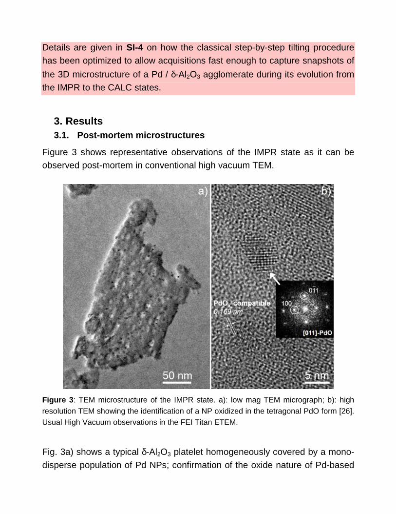
Figure 3 shows representative observations of the IMPR state as it can be observed post-mortem in conventional high vacuum TEM.
Figure 3 : TEM microstructure of the IMPR state. a): low mag TEM micrograph; b): high resolution TEM showing the identification of a NP oxidized in the tetragonal PdO form [26]. Usual High Vacuum observations in the FEI Titan ETEM.
Fig. 3a) shows a typical δ-Al2O3 platelet homogeneously covered by a mono-disperse population of Pd NPs; confirmation of the oxide nature of Pd-based
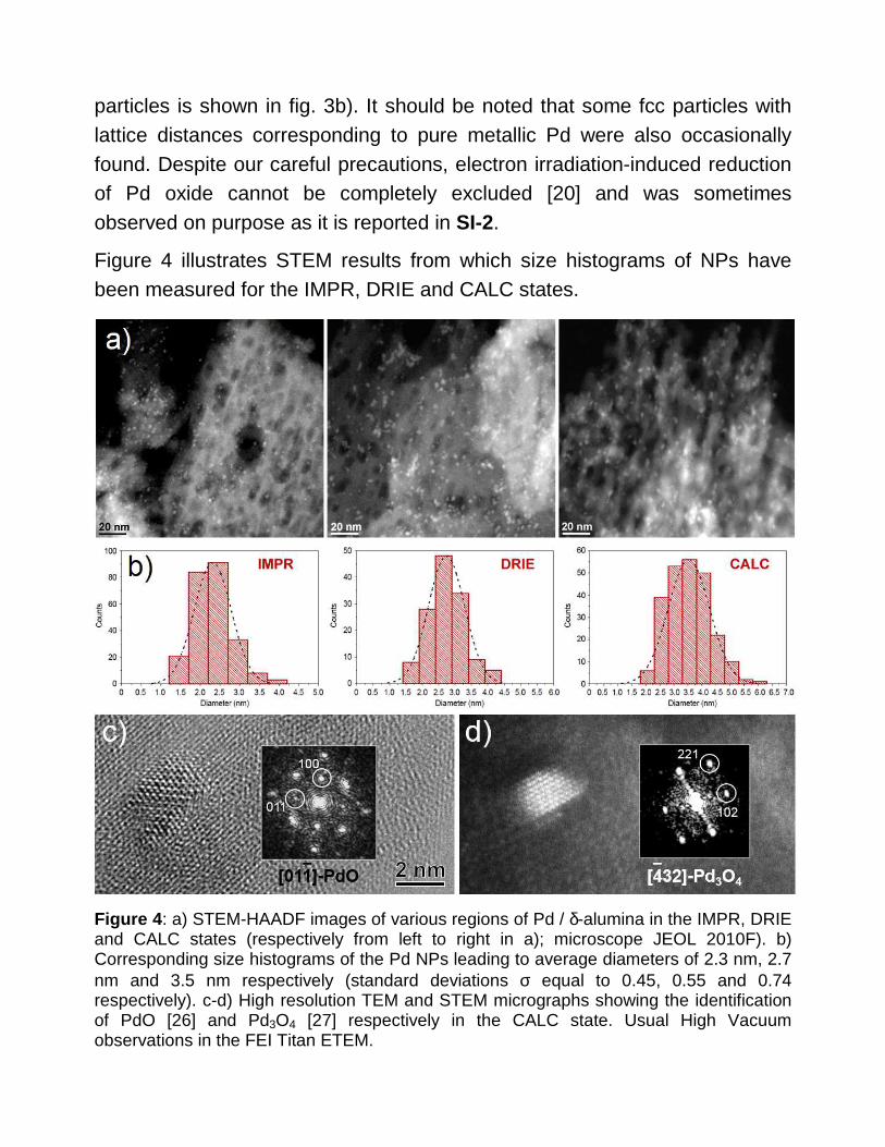
particles is shown in fig. 3b). It should be noted that some fcc particles with lattice distances corresponding to pure metallic Pd were also occasionally found. Despite our careful precautions, electron irradiation-induced reduction of Pd oxide cannot be completely excluded [20] and was sometimes observed on purpose as it is reported in SI-2.
Figure 4 illustrates STEM results from which size histograms of NPs have been measured for the IMPR, DRIE and CALC states.
Figure 4 : a) STEM-HAADF images of various regions of Pd / δ-alumina in the IMPR, DRIE and CALC states (respectively from left to right in a); microscope JEOL 2010F). b) Corresponding size histograms of the Pd NPs leading to average diameters of 2.3 nm, 2.7 nm and 3.5 nm respectively (standard deviations σ equal to 0.45, 0.55 and 0.74 respectively). c-d) High resolution TEM and STEM micrographs showing the identification of PdO [26] and Pd3O4 [27] respectively in the CALC state. Usual High Vacuum observations in the FEI Titan ETEM.

The increase from the IMPR to the CALC state is significant although the particles remain rather small after the calcination, 3.5 nm in average. As expected after a treatment in ambient air at 450°C, palladium should stay oxidized (Fig. 4c-d) although some fcc NPs were again found. At this stage one can argue that such small PdOx NPs could be unstable under high vacuum according to the diagram presented in Figure 1. This experimental feature should merit further investigation; however we will see that pure metallic Pd particles are confirmed after the reduction treatment as expected.
3.2. In situ calcination and reduction in ETEM
The global evolution of the Pd / δ-Al2O3 system is illustrated in Figure 5 which
reports experiments performed with a pressure of about 11 mbar.
Figure 5: Pd / δ-Al2O3 STEM microstructures in the DRIE, CALC and REDU states (a) to c) respectively) after heat treatments performed in the ETEM at 11.8 mbar of oxygen (a-b) and 11 mbar of hydrogen during 2 hours (c). d): other grain in the REDU state with more

sparse NPs; e): enlargement of dotted frame in d): HRSTEM identification of the fcc structure of Pd NPs (the one in the dotted frame is enlarged in f) where the diffractogram allows to identify the fcc [1-10] zone-axis). In d), the arrow points out a possible coalescence event. Microscope FEI Titan ETEM.
According to the heavier risk of irradiation damage in the BF TEM mode where the sample is constantly illuminated by the electron beam when acquiring micrographs, most of measurements were performed in the STEM mode where only a very small region of the sample is illuminated at once when the electron is scanned over the area of interest.
A small size decrease can be observed between the CALC and the REDU states as well evidenced in areas 1 and 2 in fig. 5b-c), which is qualitatively consistent with the reduction of an oxidized phase2. STEM images such as shown in Figure 5 a-c) were used to measure the NPs sizes in the DRIE and CALC states under various oxygen pressures.
Results are summarized in Figure 6 which also reports the measurements performed during the post mortem observations. All measurements reveal a comparable evolution of the NP size although the experiments performed in situ with the higher pressure (15 mbar in air - O2 partial pressure 3 mbar -) show larger values, but already in the starting IMPR state. The average behaviour (yellow bold line in fig. 6) is an increase by almost 33% from the IMPR state (2.57 nm) to the CALC state (3.41 nm).
Dedicated in situ experiments have thus been implemented to check whether growth occurs via Ostwald Ripening and or coalescence.
2 As a representative oxide structure, the PdO tetragonal cell reported in Table 1 contains
2PdO units in a cell volume of 0.0484 nm3, which corresponds to a Pd atomic density ρ(Pd|PdO) equal to 41.3 atoms/nm3. The transformation into metallic Pd during reduction should be accompanied by a size reduction equal to (ρ(Pd|Pd) / ρ(Pd|PdO))1/3, where ρ(Pd|Pd) is the Pd atomic density in the fcc cell of Pd equal to 67.4 atoms/nm3 (4 Pd atoms in the cell volume of 0.059 nm3), i.e. about 15 %. The observed reduction in size could be quite different from this value according to the exact morphology and structure of particles.
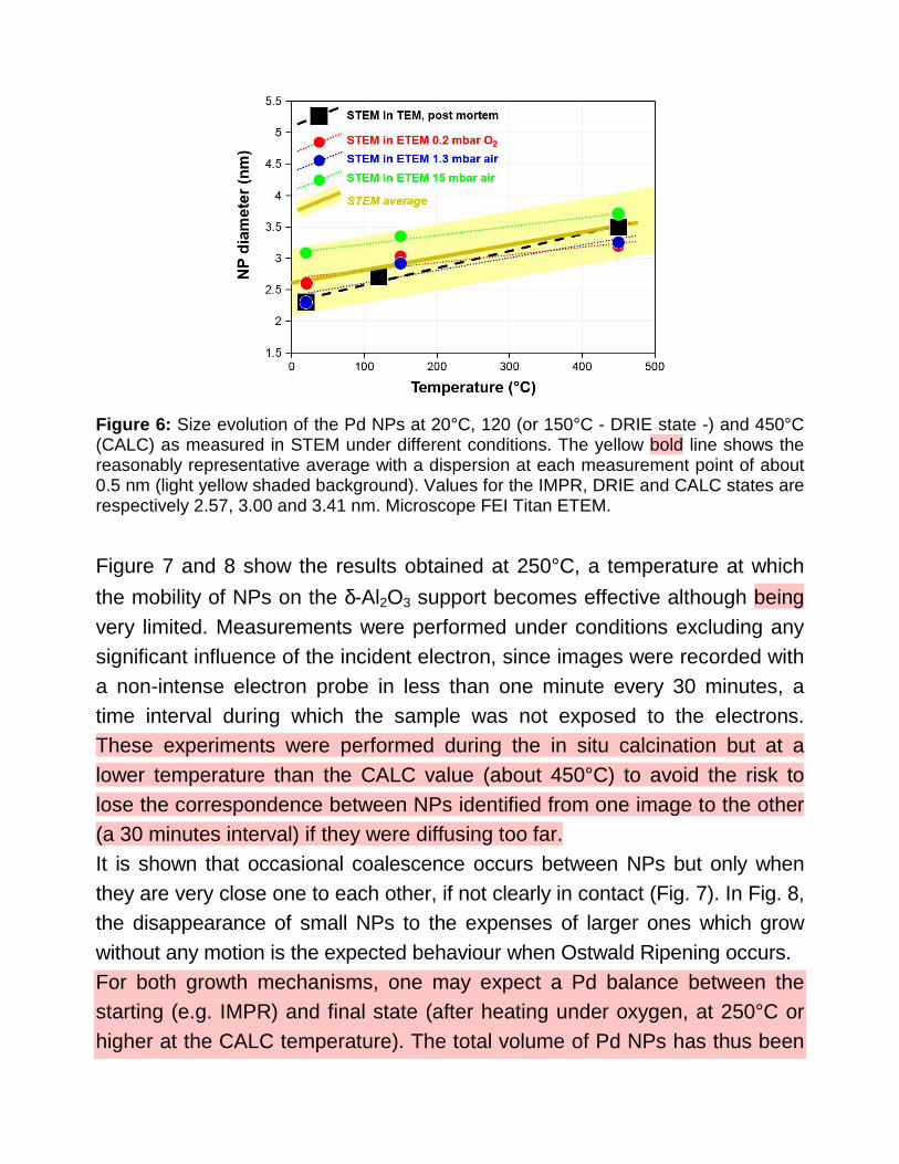
Figure 6: Size evolution of the Pd NPs at 20°C, 120 (or 150°C - DRIE state -) and 450°C (CALC) as measured in STEM under different conditions. The yellow bold line shows the reasonably representative average with a dispersion at each measurement point of about 0.5 nm (light yellow shaded background). Values for the IMPR, DRIE and CALC states are respectively 2.57, 3.00 and 3.41 nm. Microscope FEI Titan ETEM.
Figure 7 and 8 show the results obtained at 250°C, a temperature at which
the mobility of NPs on the δ-Al2O3 support becomes effective although being very limited. Measurements were performed under conditions excluding any significant influence of the incident electron, since images were recorded with a non-intense electron probe in less than one minute every 30 minutes, a time interval during which the sample was not exposed to the electrons. These experiments were performed during the in situ calcination but at a lower temperature than the CALC value (about 450°C) to avoid the risk to lose the correspondence between NPs identified from one image to the other (a 30 minutes interval) if they were diffusing too far. It is shown that occasional coalescence occurs between NPs but only when they are very close one to each other, if not clearly in contact (Fig. 7). In Fig. 8, the disappearance of small NPs to the expenses of larger ones which grow without any motion is the expected behaviour when Ostwald Ripening occurs. For both growth mechanisms, one may expect a Pd balance between the starting (e.g. IMPR) and final state (after heating under oxygen, at 250°C or higher at the CALC temperature). The total volume of Pd NPs has thus been

analysed in several areas have been measured and results are reported in Table 2 and SI-4 where the data were further analysed with the method developed by Treacy and Rice [42] to test the chemical homogeneity of the population of NPs. It is shown that the final states after heating in oxygen always correspond to higher Pd content. This means that either Pd diffuses towards the region of interest from outside the field of view, or the Pd increase is due to some ‘invisible’ Pd objects (very small NPs and/or atomically dispersed Pd atoms) not resolved in the images of the IMPR state. While it is difficult to rule out the first hypothesis, 3D observations reported in the next sub-section (3.3) bring some credence to the second one.
Figure 7: In situ tracking of the evolution of Pd NPs on δ-Al2O3 at 250°C under 2.2 mbar of oxygen in the ETEM. STEM images a) to d) have been taken every 30 minutes while keeping the beam “OFF” in between (images at 90 and 120 minutes are shown in Fig. 8). The arrow points out a group of very close NPs which coalesce in less than one hour; the dotted frame shows a region where significant changes occur (see Fig. 8).

Figure 8: detailed analysis of the framed area in Fig. 7; small vertical arrows indicate NPs that have disappeared and larger horizontal arrows point out NPs to which they have diffused (on the basis on the intensity increase, more sensitive in STEM-HAADF than the size increase).
Table 2: evolution of the total volume of Pd NPs during ETEM in situ heat treatments under oxygen. Note that the ‘Treacy-Rice’ analysis [42] reported in SI-4 indicates that the volume changes should not be attributed to possible changes in the atomic density of the NP phase as it could have occurred in the case of a transition Pd / PdOx.
Area Total volume of Pd NPs (nm 3) IMPR state After 150°C at 250°C Relative variation (%)
1 (189 NPs) 839 1202 +45 % 2 (77 NPs) 364 526 +43 %
Indeed, tomography is needed: if the low magnification micrographs presented above attest of a reasonably homogeneous distribution of NPs on their support in all stages, they remain only 2D projections which obviously introduces a bias in the evaluation of this dispersion.
3.3. Tomography and ‘fast’ tomography under environ mental condition in ETEM
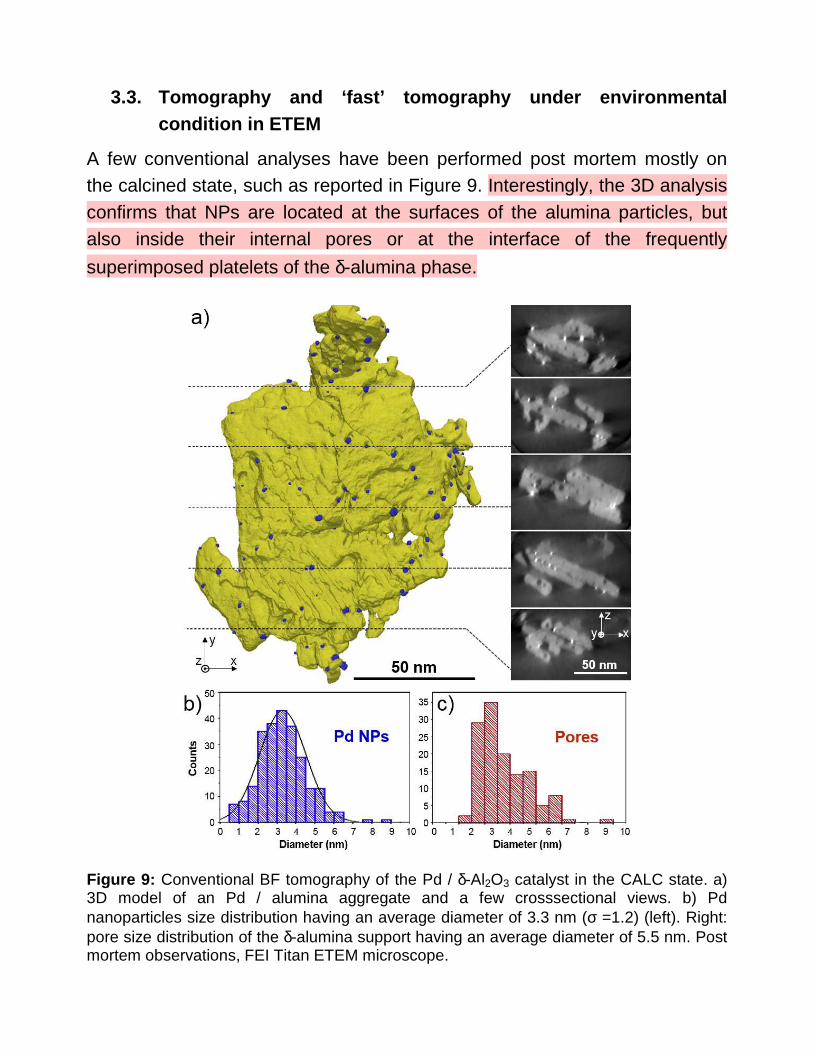
A few conventional analyses have been performed post mortem mostly on the calcined state, such as reported in Figure 9. Interestingly, the 3D analysis confirms that NPs are located at the surfaces of the alumina particles, but also inside their internal pores or at the interface of the frequently
superimposed platelets of the δ-alumina phase.
Figure 9: Conventional BF tomography of the Pd / δ-Al2O3 catalyst in the CALC state. a) 3D model of an Pd / alumina aggregate and a few crosssectional views. b) Pd nanoparticles size distribution having an average diameter of 3.3 nm (σ =1.2) (left). Right: pore size distribution of the δ-alumina support having an average diameter of 5.5 nm. Post mortem observations, FEI Titan ETEM microscope.

However, standard tomography as performed in the STEM-HAADF imaging mode does not allow the tilt series to be acquired sufficiently rapidly to perform a 3D in situ investigation of the sample during its evolution under environmental conditions (see the brief discussion in SI-4). We have applied a fast acquisition scheme in BF (details are given in SI-4) to follow the evolution of a Pd/alumina agglomerate in the course of an in situ calcination in the ETEM. Figure 10a) shows 2D images of a Pd / alumina aggregate on which a first fast tomographic acquisition was performed under high vacuum at 20°C on the IMPR state. Our objective was to follow the sample in 3D during calcination in the ETEM (here under 2.6 mbar of oxygen), and a fast acquisition was thus recommended to preserve its integrity.
Figure 10: 3D tracking of the evolution of the Pd / δ-Al2O3 catalyst during ETEM in situ calcination. a) IMPR state under High Vacuum at 20°C: BF image at zero tilt of the region of interest, showing a poor contrast and very few Pd NPs images as small dark dots (this micrograph is an average of 2 frames corresponding to the fast tomographic acquisition - see text -). b) Same configuration at 350°C after 60 minutes under 2.6 mbar of oxygen. c) Same configuration observed in STEM-HAADF under similar conditions at 20°C under High Vacuum but after 60 minutes at 350°C under 2.6 mbar of oxygen. The STEM micrograph presents a better contrast and more NPs are resolved (white dots); a few of them seem to have been already identified in a) and/or b).
According to changes suspected when controlling the sample after 60 minutes at 350°C (Figure 10b), it was decided to perform a second fast acquisition exactly in the same conditions than the first one. After this acquisition the sample was cooled down very rapidly in less than half a second according to the very negligible thermal inertia of the heating SiNx

chips. A last tomography sequence was then re-acquired at room temperature but still under O2; in this case, we performed a conventional STEM acquisition (Figure 10c) to serve as a reference to the previous fast procedures, expecting that the rapid cooling had frozen the 350°C microstructure. Both fast acquisitions were performed in 162 seconds whereas the STEM acquisition took about 90 minutes.
Because of the low SNR of the tilt series acquired in the fast tomographic approach, the segmentation of the tomograms appeared to be very tedious and 3D models such as shown in Figure 9 were not calculated. The reconstructed volumes were nevertheless of a sufficient quality to quantify the populations of Pd NPs in the 3 states, i.e. initially at 20°C, after 60 minutes at 350°C under O2 and back to 20°C. A semi-automatic home-made treatment (briefly described in SI-4 c) was performed, consisting in labelling and measuring the NPs slice by slice along the z direction in the tomograms. A typical (x,y) projection of a few such slices binned together near the top surface of the supporting grain is shown in Figure 11.
Figure 11: identical slabs close to a (x,y) δ-surface made of the grouping of 36 over 284 elementary slices from the reconstructed tomograms from the object shown in Figure 9: a) at 20° under vacuum, b) at 350°C after 60 minutes under 2.6 mbar of oxygen, c) back at 20° after a rapid cooling from 350°C (this last projection from the STEM tomogram is displayed in reverse contrast for a better visual comparison). The colour code at the bottom gives information about the way the NPs evolve. Note that the correspondence between NPs from one stage to another is not strictly measured but proposed on the basis of their similar positions.

It should be mentioned that differences in the pore arrangement between fig. 11a) and b) especially visible in the top-left part of the d-alumina platelet is due to a slight deformation of the SiNx supporting membrane giving rise to a minor 3° rotation of the sample during the heating sequence as it has been verified after the tomographic reconstructions.
As compared to Figure 10, it is clearly evidenced than these reconstructed slabs exhibit a much better SNR than simple 2D projections, as expected for such polytropic montages [43]. Furthermore, they strongly suggest that the density of NPs increases significantly from 20°C to 350°C. Regarding quantitative results, histograms counting the total numbers of NPs in each volume are reported in Figure 12 which confirm the visual analysis of Figure 11:
(i) There is a little evolution in size of the NPs during the whole process. (ii) Some particles disappear from one state to the other, or move too much
to allow re-identifying them (see the colour coding in Fig. 11). (iii) As expected, the quenched state resembles strongly to the high
temperature state, which validates the fast tomography procedure. However, some minor differences exist which are certainly meaningful.
(iv) Knowing the position of NPs in 3D, the inter-particles distances can be measured to quantify their repartition, and we consistently see that these distances decrease when the number of particles increases, although the decrease seems to be small in comparison with the increase of the NPs number.
These findings will be discussed in the following section.
4. Discussion and conclusions
4.1. Size evolution A first objective of the present study was to measure the size evolution essentially during the calcination step when performed under normal

industrial conditions and under a lower oxygen pressure in an environmental microscope.
Figure 12: Quantitative analysis of the Pd NPs population analysed during the 3D environmental study reported in Figure 9 and 10. a-b) Size histograms of the initial IMPR state (a) and after one hour at 350°C (b); this last diagram shows the excellent agreement with the quenched state (STEM results). c-d): First neighbours distance measured for the room temperature initial state and at 350°C. STEM images have allowed to deduce an evolution which appears to be consistent when comparing both approaches. It consists in a regular increase from the IMPR, DRIE and CALC states. Consequently we have to consider Ostwald Ripening (OR) or coalescence of NPs to explain this evolution [15]. Figures 7 and 8 support the idea that Ostwald Ripening (OR) is the essential mechanism occurring as relatively low temperature, i.e. 250°C. Although some coalescence is evidenced, many observations demonstrate that it remains limited to group of particles very close to each other if not simply in contact. OR is strongly suggested by the analysis presented in Figure 8,

where smaller particles disappear when larger ones increase in size without any significant motion. Tracking experiments (i.e. figures in SI-3) performed in situ at 250 and 450°C (the calcination temperature) under 10 mbar of oxygen demonstrate that the mobility of NPs is always very low, confirming that coalescence is limited to very close particles. It must be concluded here that the size increase between 150 and 450°C (see Fig. 6), although relatively small, is sufficient to decrease considerably the mobility of Pd NPs. Clearly,
the topography of δ-alumina grains also provides numerous potential
anchorage sites on their surfaces [22], such as pores or interfaces between
superimposed δ-platelets (see the tomography study illustrated by Figure 9) which must significantly contribute to the reduction of NP diffusion. The 3D sequence reported in Figure 10-12 provides further information on the evolution of the Pd-based NPs. From the initial IMPR state to the temperature of the experiment, i.e. 350°C in between the drying and calcination temperatures, the NP size increases slightly from 2.6 to 2.8 nm, a 7.6% increase roughly consistent with previous sizes measured for the DRIE and CALC states although probably outside the real accuracy of the 3D measurements. But more importantly the number of detected NP increases from 91 to 171 (a 88% increase). It must be concluded from these data that pre-existing small particles not detected in the initial IMPR state because of the non-ideal operating conditions for fast tomography, or possible atomically dispersed Pd atoms as suggested in [20], form new particles or ripen with pre-existing ones as expected by the OR mechanism leading to a little increase of the NP size. Attempts to confirm the existence of atomically dispersed Pd species on impregnated samples were undertaken in both High Resolution TEM and STEM modes. No satisfactory observation could be performed in HRTEM due to the diffraction contrast of the support. However, and despite strong contamination effects (probably due to residues of solvent in the IMPR state) when using the smallest and focused STEM probe for High Resolution imaging, we were able to detect small objects, i.e. Pd clusters or patches with sizes ranging between 0.6 and 1 nm typically, as reported in SI-

5. Such small objects were not included in the size measurements since they do not correspond to the population of initial colloidal particles. Note however that STEM tomography allows the detection of some sub-nanometric objects (Fig. 12b). Although the final size of NPs after reduction has not been statistically measured, we may anticipate from the very little coalescence efficiency discussed above that it remains smaller than that of the CALC state, i.e. around or below 3.4 ± 0.5 nm in average (cf. Figure 6).
4.2. Crystallographic structure of particles during calcination Initially found under the form of an oxide phase [20, 41], the NPs population is easily reduced after 2 hours under 11 mbar of hydrogen during the in situ treatment (Figure 5). It should be reminded that we experienced some difficulties in observing the NPs in their native state, i.e. unreduced PdOx. Whereas we believe irradiation-induced reduction can be ruled out in most cases, these observations suggest a lack of stability of the very small oxidized NPs under low pressures as previously evidenced on another support (silica) [34]. Some further work would be worth to quantify this effect as a function of size and of the atmosphere partial pressure inside the ETEM.
4.3. Environmental tomography The last objective of this study was to attempt to follow the 3D organisation of NPs in real or pseudo real-time during in situ observations. As quoted in SI-4, this requires a fast procedure in order to grab realistic configurations during the acquisition of the series of projections in ‘tilted’ electron tomography. It has been shown in Figure 10-12 that such rapid acquisitions are possible in the bright field mode at the level of a few minutes (162 seconds in the present case, to be compared to 90 minutes for a classical STEM tomography). Despite the unavoidable variation of contrast due to changes in diffraction conditions during the tilt series, it should be emphasized here that such an in situ 3D analysis provides very valuable information, especially regarding the distribution and location of NPs on their supporting media. Considering histograms in Figure 12 c) and d), one may find counter-intuitive that the
number of NPs increases by such a significant amount without a significant decrease of the first neighbours inter-particle distance (40 nm at 20°C and 47
at 350°C). According to the high specific surface of δ-alumina and the low density of Pd NPs, it is highly probable that newly formed NPs from the invisible reservoir in the IMPR state easily disperse on the alumina surfaces and within the open porosity without significantly affecting the mean inter-
particle distance. Orientating the reconstructed volumes to visualize the δ-
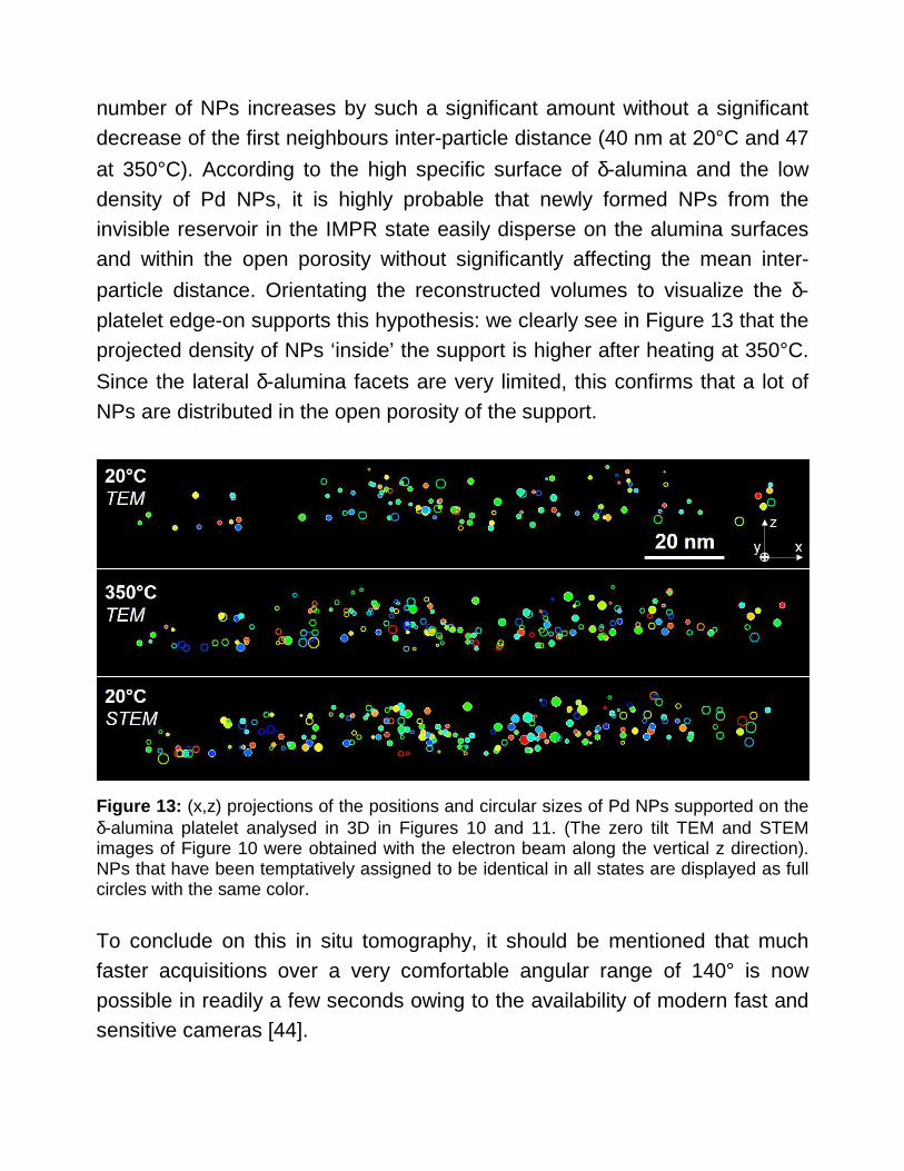
platelet edge-on supports this hypothesis: we clearly see in Figure 13 that the projected density of NPs ‘inside’ the support is higher after heating at 350°C.
Since the lateral δ-alumina facets are very limited, this confirms that a lot of NPs are distributed in the open porosity of the support.
Figure 13: (x,z) projections of the positions and circular sizes of Pd NPs supported on the δ-alumina platelet analysed in 3D in Figures 10 and 11. (The zero tilt TEM and STEM images of Figure 10 were obtained with the electron beam along the vertical z direction). NPs that have been temptatively assigned to be identical in all states are displayed as full circles with the same color. To conclude on this in situ tomography, it should be mentioned that much faster acquisitions over a very comfortable angular range of 140° is now possible in readily a few seconds owing to the availability of modern fast and sensitive cameras [44].

5. Conclusions
The present work was undertaken in the course of a general characterisation of Pd nanocatalysts synthetized under a colloidal oxidized form and
impregnated on δ-alumina platelets. It was shown that the use of an Environmental Transmission Electron Microscope enables to measure in situ the evolution of sizes during the drying, calcination and reduction steps with a good correspondence with what can be measured in a conventional high vacuum microscope after ex-situ treatments. ETEM further enables to follow directly some interesting features of specific interest for the final distribution of NPs on their supporting media. A great advantage of in situ ETEM experiments is morever that the evolution of the sample can be followed continuously through the analysis of the same areas (easily identified) under various environmental conditions, i.e. gas and temperature, without back-and-forth manipulations between the ex situ reactor and the high vacuum of the electron microscope. Tracking experiments support the conclusion that the size increase is mainly due to Ostwald Ripening, as frequently observed in similar systems [15], although occasional direct coalescence has been evidenced for some groups of very close particles. All these results show that the system studied here presents nice characteristics (small size - Figure 6 -, reasonable homogeneous spatial distribution - Figure 12 c-d) -, metallic form - Figure 5e) -) for a potential good catalytic activity (which was not investigated here).
One very important finding of this study is also that 3D experiments are possible under environmental conditions, as far as fast acquisition of tilt series necessary for electron tomography is possible. This essentially requires a high speed, high sensitivity recording camera and a heating specimen holder compatible with a large tilt amplitude (at least around 140° as shown here). In particular, it was possible to show on the same object that generation of new particles occur during the course of the in situ calcination under oxygen in the microscope. This represents a great progress as

compared to delicate and limited ‘before and after’ investigations introduced in section 1.1.
It might be anticipated that, as quoted in previous works [37], following important phenomena related to catalysis, such as sintering, faceting, deactivation of nanocatalysts [4] will become possible in 3D on the same ROI with very fast acquisition in a few seconds as it has been shown to be feasible in this study in the continuity of previous works [16, 40, 44].
Acknowledgements
The authors are grateful to CLYM (www.clym.fr) for the access to the FEI 80-300 keV ETEM microscope. Gatan is acknowledged for his interest in the development of fast environmental tomography. Thanks are due to referees for their pertinent comments and questions on the initially submitted manuscript.
Funding: This work was financially supported by IFP Energies Nouvelles, the INSA BQR program (project Spee3D 2015-0020) and the ‘3Dclean’ ANR-15-CE09-0009 project granted by The French National Research Agency (ANR). It was also partly funded by the LABEX iMUST (ANR-10-LABX-0064) of Université de Lyon, within the program "Investissements d'Avenir" (ANR-11-IDEX-0007) operated by the French National Research Agency. S.K. thanks the French Ministry of Higher Education and Research for his PhD grant. Part of this study was performed in the frame of the French CNRS and CEA ‘METSA’ network (FR3507 CNRS www.metsa.fr) which has supported experiments at the CLYM platform.

References
[1] D. Teschner, Z. Revay, J. Borsodi, M. Haevecker, A. Knop-Gericke, R. Schloegl, D. Milroy, S. D. Jackson, D. Torres, P. Sautet, Angew. Chem. Int. Ed., 47 (2008) 9274-9278.
[2] P. Gélin, M. Primet, Appl. Catal. B: Environmental 39 (2002) 1-37.
[3] D. Ciuparu, M.R. Lyubovsky, E. Altman, L.D. Pfefferle, A. Datye, Catal. Reviews, 44 (2002) 593-649.
[4] P. Munnik, P.E. de Jongh, K.P. de Jong, Chem. Rev., 115 (2015) 6687-6718.
[5] A.H. Singh, Experimental Methodologies for the Characterization of Nanoparticles, in: Engineered Nanoparticles, Elsevier Inc., 2016, pp 125-170.
[6] M. López‐Haro, J.J. Delgado, J.C. Hernández‐Garrido, J. de Dios López‐Castro, C.M. Susana Trasobares, A.B. Hungría, J.A. Pérez‐Omil, J.J. Calvino, Nanoparticles, in Ed. G. Van Tendeloo, D. Van Dyck, S.J. Pennycook, , Handbook of Nanoscopy, Wiley‐VCH Verlag GmbH & Co, 2012, pp. 877-960.
[7] L.D. Marks, L. Peng, J. Phys.: Condens. Matter, 28 (2016) 053001.
[8] P.L. Gai, E.D. Boyes, Electron Microscopy in Heterogeneous Catalysis, 2003, CRC Press, Taylor & Francis Group, London, 2003.
[9] I. Arslan, E. Stach, Nat. Mater., 11 (2012) 911-912.
[10] Y. Yu, H. l. Xin, R. Hovden, D. Wang, E. Rus, J. Mundy, D. Muller, H. Abruña, Nano Lett., 12 (2012) 4417-4423.
[11] T. Nilsson Pingel, S. Fouladvand, M. Heggen, R.E. Dunin-Borkowski, W Jäger, P. Westenberger, D. Phifer, J. McNeil, M. Skoglundh, H. Grönbeck, E. Olsson, Chem. Cat. Chem 9 (2017) 3544-3553.
[12] H. Nassiri, R. E. Hayes, N. Semagina, Chem. Eng. Science (2018), doi: https://doi.org/10.1016/j.ces.2018.04.028
[13] K. J. J. Mayrhofer, J. C. Meier, S. J. Ashton, G. K. H. Wiberg, F. Kraus, M. Hanzlik, M. Arenz, Chem. Comm., 10 (2008) 1144-1147.
[14] T.W. Hansen, J.B. Wagner, Controlled Atmosphere Transmission Electron Microscopy, Springer, New York, 2016.
[15] A.T. DeLaRiva, T.W. Hansen, S.R. Challa, A.K. Datye, In situ Transmission Electron Microscopy of catalyst sintering. J. of Catalysis, 308 (2013) 291-305.
[16] S. Koneti, In situ and 3D Environmental Transmission Electron Microscopy of Pd-Al2O3 nanocatalysts: fast tomography with applications to other catalytic systems in operando conditions and to electron beam sensitive nanomaterials. PhD thesis, 2017LYSEI123, INSA Lyon, (2017).

[17] R. J. Farrauto, J. K. Lampert, M. C. Hobson, E. M Waterman, Appl. Catal. B: Environmental, 6 (1995) 263-270.
[18] S. Colussi, A. Trovarelli, E. Vesselli, A. Baraldi, G. Comelli,G. Groppi, J. Llorca, Appl. Catal. A: Gen., 390 (2010) 1-10.
[19] J.B. Miller, M. Malatpure, Appl. Catal. A: Gen., 495 (2015) 54–62.
[20] M. Ramos-Fernandez, L. Normand, L. Sorbier, Oil & Gas Science and Technology, 62 (2007) 101-113.
[21] R. J. Liu, P. A. Crozier, C. M. Smith, D. A. Hucul, J. Blackson, G. Salaita, Appl. Catal. A: Gen., 282 (2005) 111-121.
[22] L. Roiban, L. Sorbier, C. Pichon, C. Pham-Huu, M. Drillon, O. Ersen, Nanoscale, 4 (2012) 946-954.
[23] S. B. Simonsen, I. Chorkendorff, S. Dahl, M. Skoglundh, S. Helveg, Surf. Science, 648 (2016) 278-283.
[24] J. Häglund, A. F. Guillermet, G. Grimvall, M. Körling, Physical Review B, 48 (1993) 11685.
[25] G. R. Levi, C. Fontana, Gazzetta Chimica Italiana, 56 (1926) 388-396.
[26] W. J Moore, L. Pauling J. Am. Chem.Soc., 63 (1941) 1392-1394.
[27] H. J. Meyer, H. Müller-Buschbaum, Zeitschrift für Naturforschung B, 34 (1979) 1661-1662.
[28] J. Kumar, R. Saxena, J. Less Common Metals, 147 (1989) 59-71.
[29] N. M. Rodriguez, S. G. Oh, R. A. Dallabetta, R. T. K. Baker, J. Catal., 157 (1995) 676-686.
[30] S. Penner, D. Wang, B. Jenewein, H. Gabasch, B. Klötzer, A. Knop-Gericke, R. Schlögl, K. Hayek, J. Chem. Phys. 125 (2006) 094703.
[31] J. Han, D. Y. Zemlyanov, F. H. Ribeiro, Surf. Science, 600 (2006) 2752-2761.
[32] G. Ketteler, D. F. Ogletree, H. Bluhm, H. Liu, E. L. Hebenstreit, M. Salmeron, J. Am. Chem. Soc., 127 (2005) 18269-18273.
[33] F. F. Tao, M. Salmeron, Science, 331 (2011) 171-174.
[34] P. A. Crozier, R. Sharma, A. K. Datye, Microscopy and microanalysis, 4 (1998) 278-285.
[35] M. Weyland, Topics in Catal., 21 (2002) 175-183.
[36] O. Ersen, C. Hirlimann, M. Drillon, J. Werckmann, F. Tihay, C. Pham-Huu, C. Crucifix, P. Schultz, Solid State Sciences, 9 (2007) 1088-1098.

[37] J. Zecevic, K.P. de Jong, P.E. de Jongh, Curr. Opin. Solid State Mater. Science, 17 (2013) 115-125.
[38] S.K. Malladi, Q. Xu, M.A. van Huis, F.D. Tichelaar, K.J. Batenburg, E. Yücelen, B. Dubiel,A. Czyrska-Filemonowicz, H.W. Zandbergen, Nano Lett., 14 (2014) 384−389.
[39] L.C. Gontard, R.E. Dunin-Brokowski, A. Fernandez, D. Ozkaya, T. Kasama, Micro. and Microanal., 20 (2014) 982-990.
[40] L. Roiban, S. Li, M. Aouine, A. Tuel, D. Farrusseng, T. Epicier, J. of Microscopy, 269 (2018), 117-126.
[41] B. Didillon, E. Merlen, T. Pagès, D. Uzio, Stud. Surf. Science and Catal., 118 (1998) 41-54.
[42] M.M.J. Treacy, S.B. Rice, J. of Microscopy, 156 (1989) 211-234.
[43] Hart, R. G. Science, 159 3822 (1968) 1464-1467.
[44] H. Banjak, T. Grenier, T. Epicier, S. Koneti, L. Roiban, A-S. Gay, I. Magnin, F. Peyrin, V. Maxim, Ultramicroscopy, 189 (2018) 109-123.
Copyright © 2022 FDOKUMEN