
20th Tube Licensee Meeting Proceedings, Nov. 1995 - Galfan ...
60
GTC 95028 20th GALFAN TUBE LICENSEE MEETING PROCEEDINGS Holiday Inn, Auburn Hills, Michigan USA November 28,1995 Sponsored by International Lead Zinc Research Organization, Inc. Galfan Technology Centre Research Triangle Park, NC USA I
-
Upload
khangminh22 -
Category
Documents
-
view
0 -
download
0
Transcript of 20th Tube Licensee Meeting Proceedings, Nov. 1995 - Galfan ...
GTC 95028
20th GALFAN TUBE LICENSEE MEETING
PROCEEDINGS
Holiday Inn, Auburn Hills, Michigan USA
November 28,1995
Sponsored by International Lead Zinc Research Organization, Inc.
Galfan Technology Centre Research Triangle Park, NC USA I

TUBE LICENSEES MEETING PROCEEDINGS
TABLE OF CONTENTS
Minutes of the Meeting . . . . . . . . . . . . . . . . . . . . . . . . . . . . . . . . . . . . . . . . . . . . . . . . . . . . . . . . . . . . . . . . . . . . . . . . . . . . . . . . . . . . . . . . . . 1
Positioning Galfan@ for Future Requirements of Automotive Tubing Protection, r)y J.L. Hostetler, GTC . . . . . . . . . . . . . . . . . . . . . . . . . . . . . . . . . . . 7
Metal Yield-Dross Management, /7!/ J. Malmgrcen, Eastern Alhys . . . . . . . . . . . . . . . . . . 17
Improved Corrosion Resistance for Small Diameter Automotive and Refrigeration Steel Tubing, [J~J J.D. Hostetler, Decktec, 1~. . . . . . . . . . . . . . . . . . . . . . . . . . . . 21
Product Literature: Fischerscope MMS 33 . . . . . . . . . . . . . . . . . . . . . . . . . . . . . . . . . . . . . . . . . . . . . . . . . . . . . . . . . . ..~
The Delot Process: A New Technology for Automotive Tube Galvanizing (with Galfan), b!/ Victor Dorsfen, Delot Process, N.A. . . . . . . . . . . . . . . 47
Product Literature: Meseran Residue Analyzer . . . . . . . . . . . . . . . . . . . . . . . . . . . . . . . . . . . . . . . . . . . . 57

Galfan@ Tubing Licensee Meeting held at
Holiday Inn, Auburn Hills, Michigan
On
November 28,199s
LICENSEES IN ATTENDANCE:
Name Company Adkins, Del Bundy Corporation Anderson, G.N. Cominco-Product Technology Centre Emmons, Charley Pilot Industries Eschenburg, Mark Bundy Corporation-Marysville Everett, Jerry ITT Archbold Fleeman, Larry Pilot Industries Gibbs, Glen ITT-Automotive Hostetler, John GTC Kejriwal, Ranjan ITT-Automotive-Newlex Kreiman, Dan Handy & Harman Auto. Kreis, Al Markin Tubing Leupold, Conrad Pilot Industries Malmgreen, John Eastern Alloys McDaniel, Jim ITT Automotive Patel, R.D. Form-Rite Ruebsam, Keith Form-Rite Schwiebert, Tim ITT Archbold Skubick, Skip Eastern Alloys Vlahakis, Paul Pilot Industries
MEETING CONVENED:
John Hostetler, Director, Galfan Technology Centre (GTC) declared the meeting
in session at 9:00 a.m. Those present introduced themselves with a brief description of
their involvement with Galfan.

Minutes of the Galfan Tube Licensees Meeting (cont’d.) 28 November 1995 2
GALFAN STATUS REPORT
Table One, showing the number of licensed production lines by region and by
category, was discussed. The addition of several new sheet licensees should be of
interest to tubing licensees because it enables the Research Committee to commit
significant funds to Galfan research.
This also makes evident the importance of tube licensees purchasing GTC
unitshares so that tube licensees have representation in determining where the research
money is allocated.
The addition of three small parts licensees is also important to tube licensees
because all three are research licenses to develop and commercialize processes to use
Galfan for spin-galvanizing small parts such as those used with automotive tubing.
Mr. Hostetler reported that Southeast Asia and to a lesser degree, Mexico, are
regions that show great interest in Galfan for sheet, wire and tube.
GTC estimates that nearly 4,000,OOO metric tons of steel will have been Galfan-
covered by the end of 1995. This includes about one billion feet of tubing in North
America.
Each Galfan category (sheet, wire and tube) is becoming more dissimilar in terms
of issues, marketing and production technology. This has led to separate meetings in
1995 and we expect this will be the standard format for the next few years. The sheet
licensees met in September 1995 in Chicago, the tube licensees are in session now
the wire licensees will meet in Dusseldorf, Germany in April 1996.
and
The first year of GTC is nearing its end with good results. ILZRO owners and
members, after spending nearly $2,000,000 for Galfan research from 1980 through 1993,
stopped any further direct support to the Galfan program. GTRC was self-supporting
in 1994 but did not sponsor any significant research. GTC will finish the year as a self-
supporting department with commitment to substantial Galfan research.
All active licensees are encouraged to purchase a GTC unitshare to support the
GTC operating budget. Research funds are derived from new license fees that come
from GTC’s efforts
2
Minutes of the Galfan Tube Licensees Meeting (cont’d.) 28 November 1995 3
Mr. Gibbs raised the question regarding the status of the Galfan patents and their
relationship to the Galfan license. Mr. Hostetler responded by saying the patents in
most of the industrialized countries will expire in the years 2000 or 2001 and that all
licenses granted prior to 1994 will terminate on the patent expiration date. ILZRO will,
however, offer to convert any older license to the new agreement during the year 1996
at no charge or fee. The new agreement grants license rights for ten (10) years with an
automatic five (5) year renewal if not canceled in writing by either party. Full details
will be distributed in early 1996.
Mr. Hostetler then presented the paper, “Positioning Galfan for Future
Requirements for Automotive Tubing Protection. N A copy of the paper is attached as GTC
Document 95-025.
John Malmgreen, Eastern Alloys, presented the paper, “Metal Yield - Dross
Management. ” Dross generation in the tubing line baths is much greater than for wire or
sheet and is a problem common to all licensees. A copy of the paper is attached.
The discussion that followed Mr. Malmgreen’s presentation reported that
attempts to shroud the bath in nitrogen did not significantly reduce the dross
generation. There was
Malmgreen volunteered
where copper is present.
also discussion concerning the presence of copper. Mr.
to analyze simultaneous samples of bath, dross and coating
Mr. Hostetler announced GTC’s plans to produce and publish an 80-100 page
book called “Galfan Anti-Corrosion Systems for Automotive Tubing.” It is in response to
the fast-growing interest from automakers and refrigeration manufacturers throughout
the world.
The book shall be divided into five parts:
(2) Characteristics of Galfan Systems
(2) Production Processes
(3) Process Control
(4) Specifications and Testing
(5) Engineering Addendum
3

Minutes of the Galfan Tube Licensees Meeting (cont’d.) 28 November 1995 4
GTC welcomes black and white photographs of tube-making, coating lines,
testing and final fabrications and assemblies from licensees. One or more color
photographs suitable for use on the cover are especially solicited.
A preliminary outline of the manuscript is enclosed. Licensees are urged to
comment on it - any input will be very useful and greatly appreciated. The
manuscript is scheduled for completion by February 15,1996 with publication by June
1996.
A paper recently presented at Tube China ‘95 is included with
although it was not presented or discussed at the meeting. It is
document No. 95-021.
these proceedings
available as GTC
GALFAN CONSTANT IMPROVEMENT PROGRAM
GTC will customize the Galfan Constant Improvement Program to apply
specifically to automotive tubing. It shall feature a manual available by June 1996 to all
licensees as GTC Document 96-002.
The program starts with the recognition that Galfan tube-coating lines are a
sequential series of industrial processes. It accepts the premise that if the processes
operate within appropriate limits, the final coating specifications and performance will
consistently be within limits. Reducing the process variations will improve the coating’s
consistency and performance by reducing its variability.
The document includes analytical and evaluation techniques and devices based
on the Automotive Industry Action Group’s (AIAG) publications Potential Failure
Mode and Effects Analysis (FMEA) and Advanced Product Quality Planning and
Control Plan (APQP) as well as other statistical techniques.
This Galfan Constant Improvement Program (GCIP) will include comprehensive
data for both type production lines now in use: Type 1: Cold chemical and Type 2: Hot
chemical. It shows how to develop a specific Production Control Plan using an analysis
and evaluation of each process. The user must thorougNy know or learn the following
about each process:
l What is the process meant to do?
4

Minutes of the Galfan Tube Licensees Meeting Ccont’d.) 28 November 1995
l How will the eflect of the process be measured?
5
l What are the process variables?
l How is each process variable controlled?
l How do the processes interact?
l What are the potential defects?
l What are the eficts of each defect?
GTC will also offer a comprehensive training program to teach the principles of
each process, how to test and/or measure the processes, how to control the processes
and how to collect the data and present it in statistical form. Training can be done at
GTC’s Training Center or at the licensee’s site. More details including registration fees
and schedules will be announced later.
Jodie Yannick, Fischer Technologies, presented information and demonstrated
how to measure thicknesses of Galfan and various top-coats using the model MMS
Fischerscope. A product brochure is included in these proceedings.
The MMS is able to use various type probes to match the type and thickness of
coating and, of particular interest, the duplex probe which can measure a top-coat and
Galfan simultaneously.
Victor Dorsten, Galvacor, Inc., presented the Delot Process as it will be used for
applying Galfan to tubing in either a horizontal or vertical passline. The system
features mechanical abrasion to clean and de-oxidize the tube surface, then heats the
tube as it passes through an electric induction coil around a nitrogen/hydrogen
atmosphere. The tubing then passes through a “bubble” of Galfan after which it is
quenched in water mist. The Galfan bubble is contained in a very small vessel that is
still protected by the N2/H2 atmosphere. Galfan is contained within the vessel by
electromagnetic seals and is circulated from a holding pot by a magnetic induction
pump.
The original installation is being re-installed in another location in France and a
new line with a vertical passline is being installed in Quebec City. The line in France is
scheduled for commissioning in February, the Canadian line in June or July 1996.
5
Minutes of the Galfan Tube Licensees Meeting (cont’d.) 28 November 1995 6
A more detailed description is included in the proceedings.
Jack Anderson and Mark Benkovich, ERA Systems explained and demonstrated
the principles used in measuring the clean-ness of steel tubing surfaces using the new
Meseran. Limits of organic contamination on steel to be single-dip Galfan coated have
been set at 0.3 pg/cm2 which is well below the normal detection levels for water-break
or white cloth smudging. The Meseran is the only reliable, accurate and practical
method known for making this measurement.
A description of this instrument is included in the proceedings.
12/5/95
6
GTC DOCUMENT
95-025 . . . . . . .
POSITIONING GALFAN FOR FLJTURE REQUIREMENTS OF
ALJTOMOTIVE TUBING PROTECTION
GALFAN LICENSEES MEETING
NOVEMBER 28,1995
BY
JOHN L. HOSTETLER, DIRECTOR
GALFAN TECHNOLOGY CENTRE
BACKGROUND
When the GalfanB/Al-Rich Epoxy (ARE) duplex system for coating small-diameter
automotive tubing was introduced in 1990, its performance compared to super-terne
coatings in the corrosion tests then specified was so much better that it quickly became
very popular with the automotive industry.
A dozen new continuous hot-dip Galfan coating lines were built incorporating few
changes from 1980’s technology. These lines, with minor improvements since 1990
have, however, successfully coated more than one billion feet of tubing.
Simple salt spray tests (SST) at that time required 1,000 hours before 5% red rust in
ASTM B117 conditions. This requirement was easily surpassed by Galfan/ARE
coatings produced on these lines. The only control specification for the Galfan coating
was that its average mass be no less than 0.16 oz/ft2, an easily-achieved process
requirement. Results exceeded performance requirements.
The first complaint brought to our attention came from Ford Motor Company. A small
but statistically significant number of the Galfan/ARE systems were failing prematurely
in Ford’s cyclical Arizona Proving Ground (APG) tests. Even though the system was
consistent in its performance in SST, it was inconsistent in CCT.
Galfan Technical Resource Center (GTRC) had production samples from several
producers evaluated and found the average coating weights to be well above the
0.16 oz/ft2 (50 g/m2) but when measuring thicknesses around the tube’s circumference,
7

Galfan for Future Automotive Tubing GTC Paper 95-025
2
both the Galfan and the ARE showed very high standard deviations (SD) with many
locations showing zero thickness.
Most producers made minor improvements to various processes in their coating line
resulting in some reduction in the SD but performance was still short of the bogeys. A
few of the producers changed to another top-coat but this is an expensive effort to treat
the symptom rather than the problem.
The challenge facing the Galfan licensees is, “How can we meet the increasingly more
demanding requirements with statistically acceptable performance without increasing costs to
non-competitive levels? ”
There are three improvements that can be made to help meet the requirements now
under consideration.
1. The coating’s corrosion resistance can be optimized by producing a fully eutectic microstructure.
2. The average weight of the Galfan coating can be 0.33 oz/ft2 (100 g/m2).
increased to
3. Thickness SD should be no more than 30% of the average thickness. Average thickness based on average weight = 15 pm so SD should not exceed 4.5 pm.
OPTIMIZINGTHEGALFANMICROSTRUCTURE
Galfan is generally described as Zn-5% Al but is well-known as a eutectic alloy. Galfan
coatings are, however, found to be hypo-eutectic, eutectic or hyper-eutectic
microstructures.
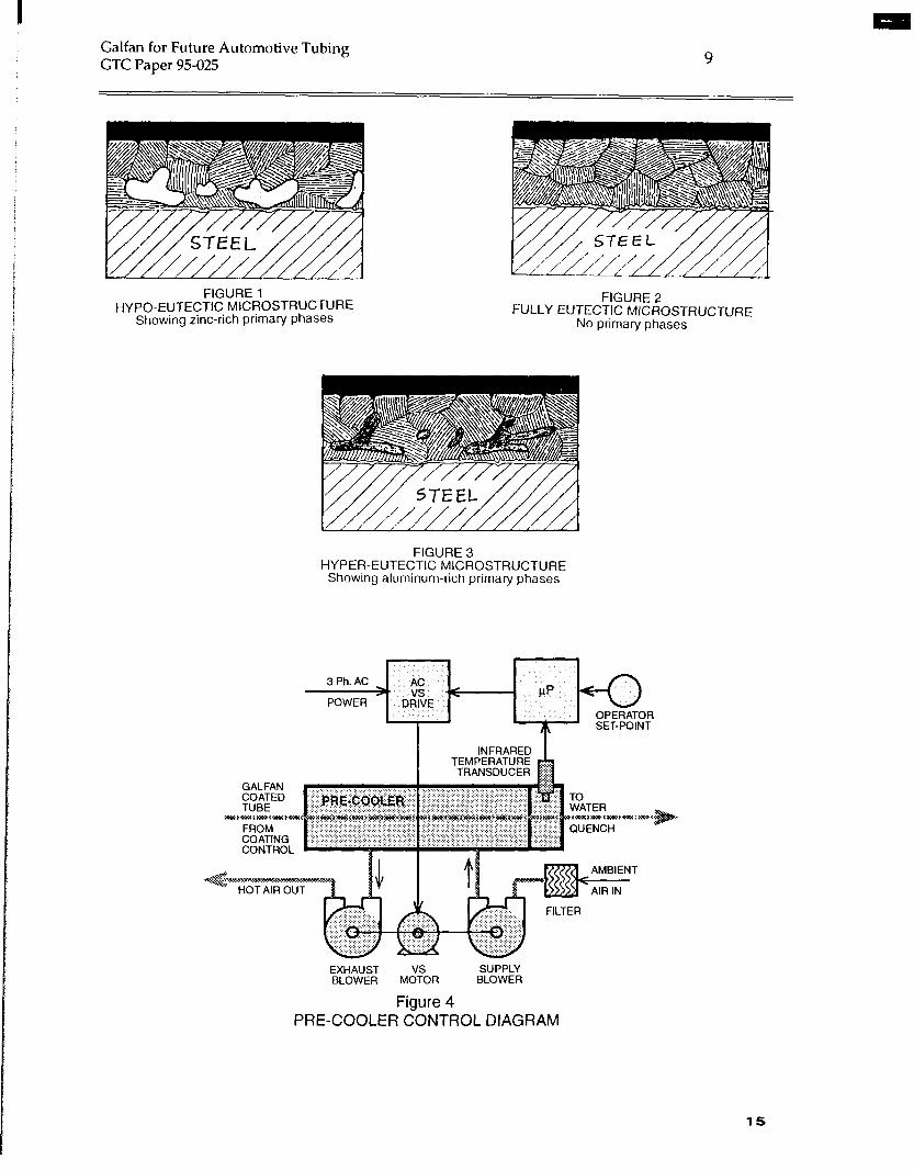
Hype-eutectic microstructures are those that contain some primary Zn-rich phases in a
eutectic matrix. (See Figure 1)
A eutectic microstructure is one that is homogeneous from interface to surface with no
primary phases or other multi-phase characteristics. (See Figure 2)
8

I Galfan for Future Automotive Tubing GTC Paper 95425
3
Hyper-eutectic microstructures are those that contain primary Al-rich phases surrounded
by a eutectic matrix. (See Figure 3)
The microstructure of the Galfan coating has a significant influence on its corrosion
resistance. The eutectic microstructure provides maximum resistance to atmospheric corrosion.
Fully eutectic microstructures can be achieved by controlling the Galfan bath
composition and the rate of cooling during the coating’s solidification. Other
production line variables have a lesser influence but cannot be totally ignored. The
main ones are bath temperature and incoming tube temperature.
The microstructure’s effect on the coating’s corrosion resistnace has been known for
more than ten years. Akira Yasuda etal., Kawasaki Steel Corporation, first reported this
in a ppaer at the Galfan Licensee Meeting November 8,1984 and a follow-up report at
the licensee meeting December 5,1985.
Why then is not every Galfan coating fully eutectic?
There are at least two answers:
(1) It is normal for the bath to lose about 10% of its original and make-up
aluminum composition because a greater percentage of aluminum is lost
to Fe reactions in the bath and to top scum and oxides that are removed
from the bath. If the producer uses Zn-5% Al alloy as the initial melt and
subsequent make-up, the steady-state bath will probably assay at 4.5% to
4.7% Al.
The aluminum composition of the initial charge and the make-up alloy must
therefore begreater than the controlled Galfizn bath Al composition.
(2) Some producers intentionally compromise a fully eutectic microstructure
in order to optimize another characteristic. For example, some licensees
applying Galfan for pre-painted sheet often choose lower aluminum
compositions to reduce the depth of shrinkage dents at cell boundaries.
This results in a hypo-eutectic microstructure.
9

I Galfan for Future Automotive Tubing GTC Paper 95-025
4
BATHCOMPOSITION
A eutectic microstructure is mainly the result of two process controls, the bath
composition and the rate of cooling through the coating’s solidification process. The
kind of eutectic microstructure, whether rod type or lamellar, is largely dependent upon
the cooling. Most Galfan eutectic microstructures are lamellar.
The Galfan bath composition should be maintained near the eutectic point. The eutectic
point may be shifted slightly by the composition of elements other than zinc and
aluminum but will be between 5.2% and 5.4% Al. If the Al composition is higher, the
microstructure will be hypereutectic, if lower, the microstructure will be hypoeutectic.
Aluminum composition of the tube-coating Galfizn bath should be maintained at 5.2% zuitlz
LCL = 5.1% and UCL = 5.3%.
If the baths present Al composition is below this range, make-up alloy with Al-7%
composition may be used in some ratio with Al-5% bars to bring the bath’s Al
composition within the control range as follows:
When Bath Composition Is:
Add 7% Bars
With 5% Bars
Result Make-Up %
4.5 - 4.69 10 0 7.0
4.7 - 4.89 8 2 6.6
4.9 - 5.09 6 4 6.2
5.1 - 5.29 *4 *6 5.8
*After the baths Al composition is inside the control range, the make-up ratio to keep it
there must be carefully determined. This involves frequent bath assays and monitoring
both the amount and composition of the skimmings removed from the bath.
Note: The actual composition of the higher Al% bar may vary. The selected Al %
ordered must consider that the higher the Al composition, the higher the temperature
required
10
Galfan for Future Automotive Tubing GTC Paper 95-025
5
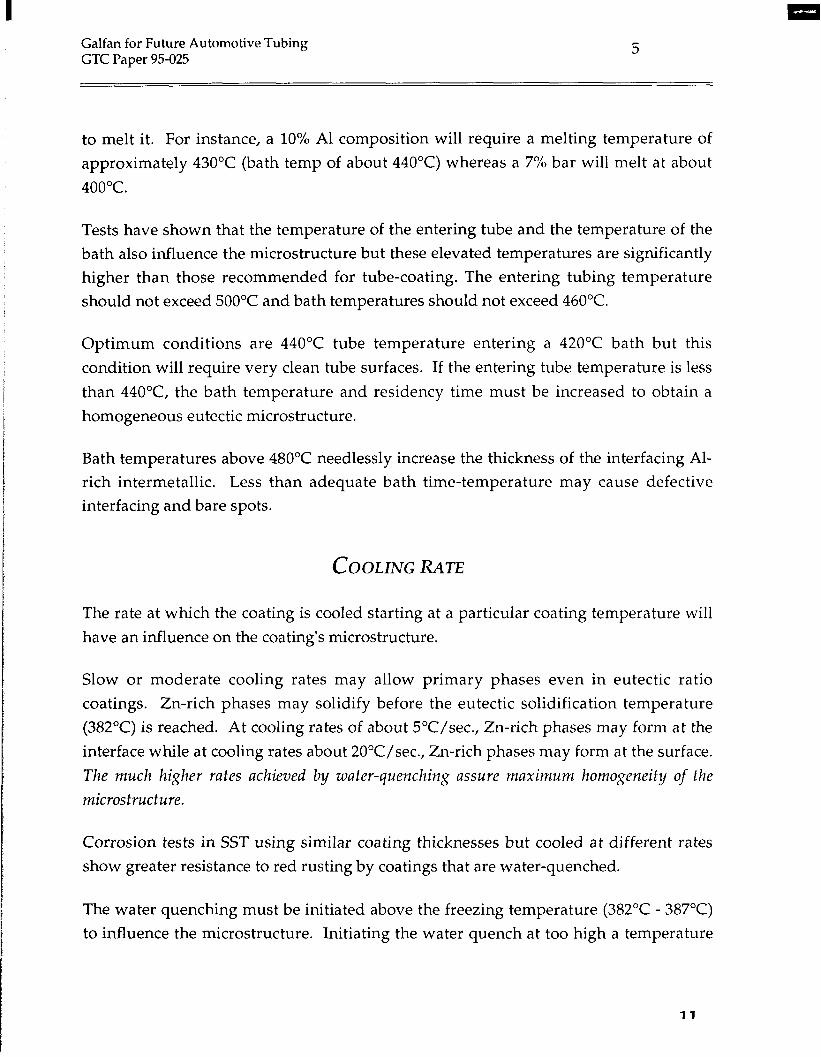
to melt it. For instance, a 10% Al composition will require a melting temperature of
approximately 430°C (bath temp of about 440°C) whereas a 7% bar will melt at about
400°C.
Tests have shown that the temperature of the entering tube and the temperature of the
bath also influence the microstructure but these elevated temperatures are significantly
higher than those recommended for tube-coating. The entering tubing temperature
should not exceed 500°C and bath temperatures should not exceed 460°C.
Optimum conditions are 440°C tube temperature entering a 420°C bath but this
condition will require very clean tube surfaces. If the entering tube temperature is less
than 44O”C, the bath temperature and residency time must be increased to obtain a
homogeneous eutectic microstructure.
Bath temperatures above 480°C needlessly increase the thickness of the interfacing Al-
rich intermetallic. Less than adequate bath time-temperature may cause defective
interfacing and bare spots.
COOLINGRATE
The rate at which the coating is cooled starting at a particular coating temperature will
have an influence on the coating’s microstructure.
Slow or moderate cooling rates may allow primary phases even in eutectic ratio
coatings. Zn-rich phases may solidify before the eutectic solidification temperature
(382°C) is reached. At cooling rates of about 5OC/sec., Zn-rich phases may form at the
interface while at cooling rates about 20”C/sec., Zn-rich phases may form at the surface.
The much higher rates achieved by water-quenching assure maximum homogeneity of the
microstructure.
Corrosion tests in SST using similar coating thicknesses but cooled at different rates
show greater resistance to red rusting by coatings that are water-quenched.
The water quenching must be initiated above the freezing temperature (382°C - 387°C)
to influence the microstructure. Initiating the water quench at too high a temperature
11

Galfan for Future Automotive Tubing GTC Paper 95-025
6
however, may unacceptably roughen the coating’s surface. The water quench should
therefore, be initiated between 395°C and 387°C.
COOLINGCONTROL
The preceding information suggest the use of a pre:cooler to reduce the tubing
temperature to f: 390°C immediately before it enters a water quench.
If the tube temperature entering the quench water is constant, the microstructure and
surface aspects of the coating should also be constant. Temperature of the quench water
may however, need to be a process control variable.
The pre-cool process must have adjustable cooling capacity because the heat removal
load will vary by the following:
a) tubing O.D. and wall thickness
b) line speed
c) bath tempera t we
d) wiping gas temperature
e) temperature drop of tubing before entering pre-cooler.
Typical conditions on a modern high-speed tube-coating line will create a heat load
beyond the capability of typical impingement type air coolers within a reasonable
distance. Higher efficiency methods for cooling with ambient air are being developed
specifically for tubing applications. A suggested control scheme of the cooling process
is shown in Figure 4.
INCREASINGTHEGALFANCOATINGTHICKNESSAND IMPROWNGITSUNIFORMITY
The final amount of Galfan on the tubing is the result of the amount of coating drag-out
12

I Galfan for Future Automotive Tubing GTC Paper 95-025
7
from the Galfan bath less the amount removed by a coating control system as:
where:
Cf = the final coating (thickness or mass)
cdo = coating drag-out from the bath
Cr = coating removed
Coating drag-out is the result of several variables including:
(1) line speed (2) coating fluidity (3) smoothness of tube surface
Change in the coating mass drag-out is approximately
line speed.
a square root relationship to the
where:
c2 = coating mass at line speed N2
Cl = coating mass at line speed N1
Nl = line speed at known coating mass
N2 = new line speed.
Examble: If a line speed of 150 fpm drags out 60 g/m2, a line speed of 250 fpm will
drag out about 75 g/m2.
Galfan’s fluidity is a function of its Al composition and temperature. Generally, the
greater the Al composition, the more fluid the alloy becomes, but it appears to be
minimized at the eutectic ratio.
13

Galfan for Future Automotive Tubing GTC Paper 95-025
8
Galfan’s fluidity also is a function of its temperature, it decreases with decrease in bath
temperature. Thus the coating drag-out can be maximized by maintaining the bath at 5.2% Al
and the lowest possible temperature.
The tube’s surface smoothness also affects the drag-out. Typical surface smoothness of
the steel strip at the entry to the tube mill is 50 to 70 micro-inches but the tube mill
processes typically reduce the smoothness to 8-32 micro-inches. GTC conducted hand-
dip proof-of-principle experiments that showed an 80% increase in drag-out when
abrading a typical 3/8 OD tube surface to 52 micro-inches. The thickness variance
coefficient was also reduced by 50%.
Most of the production lines rely on gas knives to control the coating mass and
uniformity but gas knives are most effective when they remove 25% to 50% of the drag-
out coating. Thus, if the final coating is to be 100 g/m 2, the drag-out should be at least
133 g/m2 (20 pm). The desired thickness SD may require a drag-out of 150 g/m2
(23 Pm)*
CONCLUSIONS
A totally eutectic microstructure corrodes uniformly whereas hypo-eutectic
microstructures may corrode more rapidly at Zn-rich primary phases. Hypo-eutectic
coatings also show greater edge creep both in painted and unpainted applications.
Homogeneous eutectic microstructures provide maximum corrosion resistance, both in
terms of general rate of corrosion and in uniformity of corrosion.
Thicker Galfan coatings and improved unformity can only be achieved if the coating
drag-out from the bath is increased so that the gas wipe coating control can be more
effective by removing a larger percentage of the drag-out.
l bbbebbbbbbbobbbb*bb
14
Galfan for Future Automotive Tubing GTC Paper 95-025 9
FIGURE 1 HYPO-EUTECTIC MlCROSTRUCTURE
FIGURE 2
Showing zinc-rich primary phases FULLY EUTECTIC MICROSTRUCTURE
No primary phases
FIGURE 3 HYPER-EUTECTIC MICROSTRUCTURE
Showing aluminum-rich primary phases
EXHAUST SUPPLY BLOWER MoVTSoR BLOWER
Figure 4 PRE-COOLER CONTROL DIAGRAM
15

16

METAL YIELD - DROSS MANAGEMENT
John Malmgreen
Presented to the
Galfan Tube Licensee Meeting Holiday Inn, Auburn Hills, MI
November 28,1995
Metal yield is best defined as the amount of metal put into product versus the total amount of metal used in the process. Relating this to the GALFANIZING process: Alloy is melted and held as a reservoir of molten metal. The alloy is removed from the bath as coating and dross. The less dross generated and removed from the bath, the greater the amount used as product, and therefore, the greater the yield.
One might be inclined to dismiss the cost associated with dross formation since it can be sold. However, the loss involves more than just the cost of lost metal. Energy is required to melt the extra metal needed to compensate for the lost metal. Dross production of 20% requires that much extra energy. Labor cost must also be considered since extra time and labor is required to skim the bath. Dross management is the key to reducing these costs. In order to manage a dross problem, one needs to know what dross is, and why excess dross forms.
WHAT IS DROSS?
Dross is the generic name for the scoria that is removed from molten metal. It is comprised of metal salts, intermetallics, oxides, and bath metal.
Excess flux or water carried over to the coating bath can react to form metal salts. Salts
Intermetallics Zinc, aluminum and iron can react to form a high melting compound that will eventually float to the bath surface.
Oxides Zinc alloys will react with air to form oxides.
17

Malmgreen Presentation at Galfan Tube Licensee Meeting (cant ‘d.)
28 November 1995 2
The metal salts, intermetallics, and oxides are less dense than zinc. They will accumulate at the surface and bind bath metal into a mass that can vary from thick flowing soup to whipped cream in consistency.
SKIMMING PRACTICES
Dross needs to be removed from the bath to prevent it from getting on the product and to allow the addition of fresh alloy. What is skimmed from the bath can contain from 60% to 80% bath metal. Using good metal handling practices can help to minimize dross loss.
Don’t Overskim - Skimming the metal clean will expose a fresh surface. As mentioned above, the alloy will react with air and oxidize to form more dross. A thin layer of dross will help protect the surface from further oxidation. So don’t overskim; Skim regularly, but not too often.
Skim Carefullv - Use a perforated tool and do not dig too deep - try not to disturb the surface. Shake the tool; this allows the denser bath metal to flow back through the perforations into the bath.
Contain the Dross - If certain areas in your bath are more prone to dross formation, baffle and contain it in these areas. Concentrate on these areas when skimming. Extra heat onto the surface in these areas and letting the dross form longer may result in some separation and therefore remove less bath metal.
The best solution is to not create dross. If there are areas of the operation or metal handling techniques that create dross, eliminate or change them.
DROSS FORMATION
One thing that can lead to dross formation is poor upstream process control; “How you prepare the tube and present it to the bath”. It is important to remove all scale and organic contaminants. These can lead to dross formation. Avoid drag over of excess flux and water. They can contribute to the dross layer and even react with the bath metal to form salts and oxides.
One major component of dross is metal oxide. Operating conditions can contribute to the formation of oxides and therefore dross. Here are things to avoid:
18

I Malmgreen Presentation at
Galfan Tube Licensee Meeting (con t ‘d.) 28 November 199.5 3
Overheating - Oxidation will increase as temperature of the bath increases. Top-fired furnaces create more dross. Poorly adjusted burners can lead to hot spots and localized overheating. The preferred furnace is refractory lined with an immersion tube burner or an induction melter.
Exposing fresh metal to air - As mentioned previously, this will allow it to oxidize and form dross. This can be caused by excessive skimming and turbulence.
Turbulence - Turbulence is the most likely cause of excessive dross formation in a coating bath. It can be created by mixing too fast and causing a vortex that sucks metal and air into the bath. This will form a whipped airy dross. Turbulence can also be caused by metal freely cascading into the bath.
i
SUMMARY
Dross management is an important tool for reducing costs. The best solution is to not make dross. Skim properly. Avoid conditions that will cause oxidation. Minimize turbulent conditions where metal is exposed to air, such as cascading metal.
19

I
20
Improved Corrosion Automotive and
Resistance for Small Diameter Refrigeration Steel Tubing
bY
John D. Hostetler, John L. Hostetler, P.E., Chief Engineer Director,
Decktec, Inc. Galfan Technology Centre
Canton, OH, USA Research Triangle Park, NC, USA
for presentation to
Tube China ‘95 Beijing, China
Nov. 16,1995
Abstract
Zn-Al alloys, as compared to tin, terne or regular galvanize coatings, provide an improved anti-corrosion coating for steel. This paper reviews the development of Galfan@, one such alloy that has become popular in North American automotive applications. The paper discusses the development of Galfan, its characterization and the technology currently in use on 15 pro- duction lines.
Researchers have published much information relating to Galfan’s composition and its use as a galvanizing alloy for steel sheet and wire but very little is available relating to its use on tubing. This is partially true because nearly all tubing production has been used by the North American automotive industry in applications covered by the manufacturer’s propri- etary specifications.
North American car makers have already used more than 50,000 metric tons of tubing coated with a duplex system consisting of Galfan with an Al-rich epoxy top- coat that typically survives more than 4,000 hours in an ASTM B117 salt spray before the appearance of 5% red rust.
Total production of Galfan-galvanized automotive tubing is estimated at over 300 million meters, most of it produced in the last two years. International Lead Zinc Re- search Organization (ILZRO), owner of the Galfan patents has now licensed fifteen production lines to galvanize tubing with Galfan in North America. Its Galfan Tech- nology Centre (GTC) provides technology and technical assistance to new licensees.
Considerable interest for Galfan coated tubing in similar sizes and specifications in various refrigeration applications is now developing in other parts of the world as well.
21

I
Characteristics of Galfan
GALFAN is a eutectic. A etrtectic represents a unique temperature-composition point for a system of two or more elements. Lowering the temperature below the eutectic temperuttrre, causes a reaction that completely freezes the liquid mixture solid as one phase with no gross segregation of the elements as is the case at non-eutectic points.
Typically, the eutectic composition is that ratio of the elements having the lowest melting temperature and is located at the intersection of the elements’ liquidus curves. Figure 1 shows an Aluminum-Zinc Equilibrium Phase Diagram. It shows the melting temperature of the eutectic Zn5%AI to be 382°C. The eutectic characteristics give Galfan a corrosion mechanism that is different from zinc, aluminum or any other ratio of zinc and aluminum.
“C 700
12ca F
600
Al-Zn Aluminum-Zinc Nomic Percentage Zinc
5 10 15 20 30 40 50 60 70 80 90
300 FIGURE 1 5c.JF
Binary Al-Zn Phase Diagram showing Eutectic
Point at Zn-5% Al
L.A.W. Weight Percentage Zinc
GALFAN is formable. A hot-dip regular gal- vanizing coating interfaces with the steel tubing surface by reacting with the iron to form Fe-Zn alloy layers such as seen in Figure 2a. This alloy layer is about 3 pm thick and limits the formabil- ity of the tubing because it is very brittle. Galfan’s interface shown in Figure 2b is a barely percep- tible Al,-Fe,-ZnX intermetallic that is even more ductile than the steel, thus does not limit the tube’s formability.
FIGURE 2b steel
22

GALFAN is paintable. Its surface is easily passivated and converted with standard pre-treatments to bond to many standard primers and different top coat systems. Ad- hesion characteristics meet all specifications normally associated with automotive, re- frigeration and appliance specifications. The fabricator may choose from a broad range of top-coats to match the particular application requirements with one universal anti- corrosion coating.
GALFAN is synergistic. All zinc coatings are synergistic when used in a duplex system but Galfan provides a higher synergism. Figure 3 shows the synergism of a typical Galfan duplex system using an Al-rich epoxy top-coat.
COATING TYPE
GALFAN (chromated) AI-RICH EPOXY COMBINED TOTAL
GALFAN + AI-RICH EPOXY
SYNERGISM FACTOR
Thickness, Hours, microns SST
8 360 5 1 200
13 +ifi FIGURE 3
13 3,000 Synergism from Galfan Duplex System on Steel Tubing B117
1.90 Salt Spray Test (SST)
GALFAN is solderable. It is soldered or brazed as easily as regular galvanizing with low-melt solders or high-melt braze. Tin-free solders should be used.
Corrosion Mechanisms
Every metallic coating has a mechanism by which it corrodes. The mechanism af- fects the rate at which the coating corrodes and determines whether the corrosion is uniform or non-uniform and other characteristics.
Corrodents in the atmosphere or test environment dissolve metal(s) from the coat- ing that precipitate as oxides of the metal, then dehydrate as hydroxides, after which they combine with elements of the corrodent to form the corrosion products - usually salts or carbonates of the metal.
A single-phase coating such as regular galvanized has one corrosion mechanism but in a non-eutectic alloy coating, each element may behave independently according to its particular reactivity.
The exact corrosion products are dependent upon the coating metal and the corrodent. Industrial atmospheres produce sulfur salts whereas marine environments produce mainly chlorine salts of the metal. The process continues at a near linear rate dependent upon the coating metal’s reactivity, the corrodents and cyclical influences such as temperature, humidity, exposure to sunlight, washing, drying, etc.
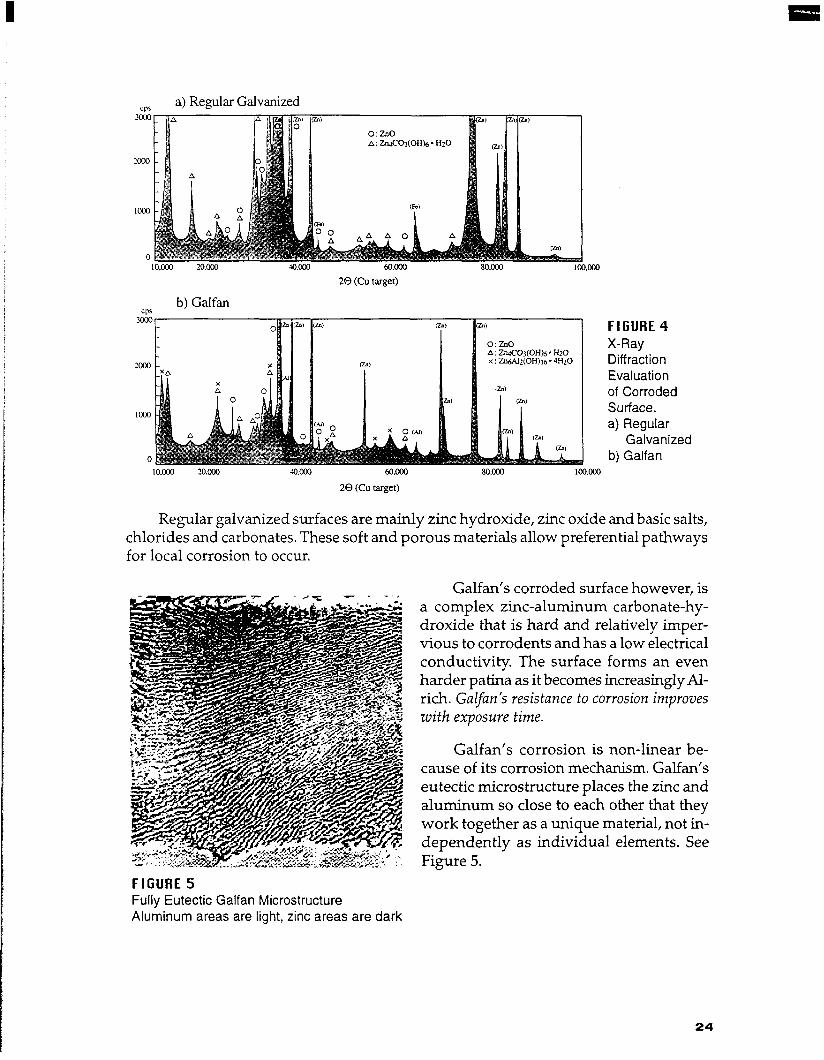
X-ray Diffraction (XRD) evaluations can be used to determine the composition of the corroded coating’s surface. XRD’s in Figure 4 compare Galfan and regular galva- nized surfaces corroded by the same marine environment for seven years. The corro- sion products are seen to be quite different.
23
I
a) Regular Galvanized
20 (Cu target)
b) Galfan
, IO.oM 2O.ooO
A: ZtuC03(0H)6 * Hz0 x : Z.~U2(0H)l6 - 4H20
60.m
20 (Cu target)
IcQ.oco
FIGURE 4 X-Ray Diffraction Evaluation of Corroded Surface. a) Regular
Galvanized b) Galfan
Regular galvanized surfaces are mainly zinc hydroxide, zinc oxide and basic salts, chlorides and carbonates. These soft and porous materials allow preferential pathways for local corrosion to occur.
Galfan’s corroded surface however, is a complex zinc-aluminum carbonate-hy- droxide that is hard and relatively imper- vious to corrodents and has a low electrical conductivity. The surface forms an even harder patina as it becomes increasingly Al- rich. Galfan’s resistance to corrosion improves zuith exposure time.
Galfan’s corrosion is non-linear be- cause of its corrosion mechanism. Galfan’s eutectic microstructure places the zinc and aluminum so close to each other that they work together as a unique material, not in- dependently as individual elements. See Figure 5.
FIGURE 5 Fully Eutectic Galfan Microstructure Aluminum areas are light, zinc areas are dark
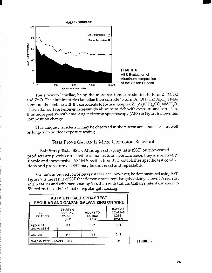
GALFAN SURFACE
100
After Corrosion 0
Before Corrosion 0
FIGURE 6 AES Evaluation of Aluminum composition
IO of the Galfan Surface
Sputter time (seconds)
The zinc-rich lamellae, being the more reactive, corrode first to form Zn(OH)2 and ZnO. The aluminum-rich lamellae then corrode to form Al(OH) and AJO,. These compounds combine with the corrodents to form a complex Zn,Al,(OH),,CO, and H,O. The Galfan surface becomes increasingly aluminum-rich with exposure and corrosion, thus more passive with time. Auger electron spectroscopy (AES) in Figure 6 shows this composition change.
This unique characteristic may be observed in short-term accelerated tests as well as long-term outdoor exposure testing.
Tests Prove GALFAN is More Corrosion Resistant
Salt Spray Tests (SST). Although salt spray tests (SST) on zinc-coated products are poorly correlated to actual outdoor performance, they are relatively simple and inexpensive. ASTM Specification B117 establishes specific test condi- tions and procedures so SST may be universal and repeatable.
Galfan’s improved corrosion resistance can, however, be demonstrated using SST. Figure 7 is the result of SST that demonstrates regular galvanizing shows 5% red rust much earlier and with more coating loss than with Galfan. Galfan’s rate of corrosion to 5% red rust is only l/5 that of reg;lar galvanizing.
ASTM 8117 SALT SPRAY TEST REGULAR AND GALFAN GALVANIZING ON WIRE
TYPE COATING
REGULAR GALVANIZING
STARTING COATING WEIGHT
g/m2
162
HOURS TO 5% RED
RUST
192
RATE OF COATING
LOSS, gim2lhr
0.94
GALFAN 144 768 , 0.19
GALFAN PERFORMANCE RATIO 51 FIGURE 7
25

Kestemich Tests. The SO, Kestemich test correlates better to outdoor exposure in industrial environments than SST. Figure 8 shows results of a Kesternich cyclical cor- rosion test (CCT) in which each cycle consists of two phases:
8 hours in chamber @ 4O”C, 200% RH, 11 SO, 16 hours in chamber @ 25”C, 75% RH, no SO,after water rinsing
The test is ended when the test specimen shows 5% red rust. This test shows Galfan to be 3.2 times more resistant to CCT corrosion than regular galvanizing.
KESTERNICH SO2 CYCLICAL TEST
REGULAR AND GALFAN GALVANIZING ON 4mm WIRE
TYPE COATING
REGULAR GALVANIZING
STARTING RATE OF COATING CYCLES COATING WEIGHT TO 5% LOSS,
4/m2 RED RUST g/m2/cyc
550 15 36.7
GALFAN 275 24 11.4
GALFAN PERFORMANCE RATIO 3.2:1 1 1 FIGURE 8
Electra-chemical Tests. Electra-chemical evaluation is an even better correlation to the actual corrosion in an outdoor environment. This test finds the corrosion poten- tial and corrosion currentj7ow of a specimen in a specified corrosion media by measur- ing the electrical potential and the current flow between a standard calometric elec- trode (SCE) and the test specimen.
Figure 9 shows the corrosion potential of regular galvanized and GALFAN are simi- lar in oxygen-flushed seawater as an electrolyte, about -1.035 volts.
-1 .oal
g (I)
1 I:Zr &&P-7-@ d
8 -1.060 - 5 l Galfan .-
g 0 Regular Galvanized
s -1.080 -
-1.100 I I I I I I I I
0 loo 2ocl 300 400
Xme (min)
FIGURE 9 Comparing the Corrosion Potential of Regular Galvanized Wire and Galfan Galvanized Wire in Oxygen-flushed Seawater.
26

A big difference is seen however, when series-connecting a galvanometer and potentiostat between the SCE and the test specimen to measure corrosion current. Higher current flow indicates a faster rate of corrosion. Figure 10 shows that the corro- sion current flow for regular galvanizing is more than six times that of Galfan.
160 - FIGURE 10
l Galfan Comparing the 120 - Corrosion Current of
0 Regular Galvanized
1:: \.,.
Regular Galvanized Wire and Galfan Galvanized Wire in Oxygen-flushed
0 I I I I I I I I Seawater. 0 100 200 300 400
Time (min)
Outdoor Exposure Tests. The most reliable and accurate tests are long-term expo- sures of test panels in outdoor environments because these are better simulations of what the product will experience in the real world.
Figure 11 shows actual data from tests exposing panels for ten years in an indus- trial atmosphere. The actual ten-year results are extrapolated to thirty years. Because of Galfan’s parabolic behavior, it can be seen that Galfan’s performance ratio as com- pared to regular galvanized improves with time. It is slightly more than 2:l at the end of ten years, but will be 3:l at thirty years.
60 UJ
5 t 50 .-
E cri
40
: 30
$ 20
i= $ 10
0 0
FIGURE 11 Regular Galvanizing and Galfan Coating Loss on Sheets in Industrial Atmosphere.
10th to 30th years extrapolated
0 10 20 30
EXPOSURE TIME, years
40
27

Galf an’s Formability
Formability is a non-dimensional term used to indicate a material’s overall ability to form or be deformed without compromising its properties by combining several measurable characteristics. Figure 12 shows several characteristics for different metal coatings. The lower the coefficient of friction and draw load, the more easily formed. Higher lifting dome heights mean a greater resistance to cracking when the part is stretched.
The absence of the hard brittle Fe-Zn alloys at the interface makes Galfan more ductile than the steel substrate. Thus Galfan does not limit the deformation of the coated tube.
Bending, swaging, stretching, crimping and other forming operations with Galfan can be done to limits beyond those of other metallic coatings. Figure 13 shows that Galfan maintains its corrosion resistance advantage in the deformed conditions.
FIGURE 12 r
FORMABILITY TEST RESULTS
FORMING PARAMETER
THICKNESS: Coating pm
THICKNESS: STEEL, mm
COEFFICIENT OF FRICTION’
LIFTING DOME HEIGHT l *
DRAW LOAD, kN”’
SPECIMEN: Coating Type
ELECTRO REG GALV GALV
EG 2185
9
0.84
0.010
39.0
80
15
0.69
0.020
39.0
70
-
L
L
GALV- ANNEAL
A120
7
0.79
0.025
80
COLD ROLLED
AKQD
0
GALFAN ZA185
10
0.84 0.74
0.015
38.5 42.0
84
* Steel beads, dry film lubricant
** Hardened steel punch, dry film lubricant
l ** Hardened steel die, dry film lubricant
Production Technology
The Process Section of a production line built for coating tubing with Galfan is similar to other continuous hot-dip coating line designs. It includes three sub-sections; namely,
(1) Steel surface preparation section (2) Hot-dip coating section (3) Coated surface finishing section
28

100
90
80
70 1
I I
I
I
Galfan 1CQ
90
80
70
60
50
I
Regular Galvanized
%e,
FIGURE 13 Form Limit Diagrams for Regular Galvanizing and Galfan Showing Effect of
Major/Minor Strain (el/e2) on Hours to Red Rust in Salt Spray Tests.
There are three basic methods (although many variations of each) for the steel surface preparation section in a hot-dip coating line. These can be identified as:
*Type1 Cold Chemical l Type2 Hot Chemical *Type3 Hot Mechanical
The final coating characteristics will be similar. The choice of line type is mainly one of cost, convenience, experience or versatility. Figure 14 shows the three basic types in diagram form.
Steel Clean-ness. The steel surface must be cleaner for Galfan coating than for most other hot-dip coatings. If the tubing is contaminated with more than 0.4 pg/cm2 of dirt and soil, a rough and non-uniform Galfan coating may result.
This requires that the tubing be cleaned in an alkaline solution and thoroughly water-rinsed before any other surface preparation can be effective. Lines operating faster than 60 mpm must use an electrolytic alkaline cleaner and, depending upon the incoming surface contamination, may require a pre-cleaner ahead of the electrolytic cleaner.
Scale and oxides of iron are removed by chemical dissolution with a solution of hydrochloric acid (type 1 line) or by a reducing gas such as hydrogen at an elevated temperature (type 2 line) in a low dew-point atmosphere. Alternatively, a type 3 line replaces both the soils and oxide removal processes with one that mechanically abrades the tubing surface until clean new metal is exposed.
29

Air Blow-off (typical) 7
Gas Wipe Coaling Control
7
Electrolytic Alkaline Cleaner and Hot Water Rinse
Electrolytic Electroflux Pre-heater Galfan Bath Pre-Cooler
2 PicWe
and Coating Trough
Hot Water Rinse
GALFAN TUBE-COATING PRODUCTION LINE Type 1: Cold Chemical (Flux)
Water Quench
Section or Tube Mill
Air
Gas Wipe
Air Blow-off .-.-.- >
To Top-Coat Application or Exit Section
//j////~~~j~/~~/~~/~~-(~jjjj~j~~.j.~~~~~~~~~~~~jj~~~~~~~j~~~
Electrolytic Reducing Atmosphere Galfan Bath Forced Water
Alkaline Furnace in Ceramic Air Cleaner or Stainless Pre- %Zh
and Steel Pot Cooler Hot Water Rinse
GALFAN TUBE-COATING PRODUCTION LINE Type 2: Hot Chemical Line
Section or - Application or
Tube Mill Extt Section
///////////////////////////////////~//~/~~~///~///~////~
Mechanical Induction Coil Galfan Pre-Cooler Water Quench
(Abrasive) Heated Oven Reactor Cleaner and with Reducing De-scaler Gas
GALFAN TUBE-COATING PRODUCTION LINE Type 3: Hot Mechanical
30

I
If the tubing must enter the Galfan bath below the bath temperature, it must be fluxed with an aqueous ZnCl solution and additionally, if it enters below 3OO”C, the Galfan will have difficulty wetting the steel. The ElectrofluxrM method may be used to electro-deposit a thin layer of zinc on the tubing surface as it passes through the flux solution so the Galfan bath need only wet the zinc.
Most lines use a coating bath arrangement that allows the tubing passline to remain horizontal. Some lines that coat thin-wall small diameter tubing immerse the tubing into the bath by deflecting it downward between entry and exit deflector rolls.
Conclusions
Galfan is an improved galvanizing system including a patented alloy of Zn5%Al- MM used as a hot-dip coating in a continuous galvanizing line. Although the pro- cesses for preparing the steel for hot-dipping are conventional, they must be better controlled than minimal requirements for other coatings.
The major improvements for application on steel tubing include greater corrosion resistance, better formability, better paintability and low cost. Many different top-coat systems are used successfully to form duplex or triplex systems with Galfan as the anti-corrosion sacrificial coating between the top coat and the steel tube.
Galfan has been proven in extensive testing as well as in the use of nearly 4,000,OOO metric tons of steel in sheet, wire and tube applications.
References
Much of the material used in this paper is taken from reports by Galfan licensees presented to regular Galfan licensee meetings. Special recognition is given for the use of data and figures as follows:
Figs. 2 and 3: Decktec, Inc. Figs. 4 and 11: Nisshin Steel Corp. Figs. 6 - 10: N. V. Bekaert Co. Fig. 12 Hoesch Stahl
31

32

I
33

A compact and extremely ver- satile desktop multi-function measuring system for non-de- structive measurement, data archiving and measurement data processing applications. The ooerator can
0 measure coating thick- nesses and other material properties according to different non-destructive test methods;
0 document, manage and evaluate data according customer specifications
rest methods
iardware design
vleasurement orobes
‘eripheral nstruments
‘ower supply
Dimensions
Weight
Software design
Data entry
Display
Measurement presentation choices
Measurement capture
Data evaluation:
Measurement data memory
Calibration
Documentation
and quality system require- capabilities of the MMS Soft- ments; ware provide for the evalu-
0 define control charts and ation of a few single measure- evaluate measurement ments or series of thousands data using modern SPC/ of measurements according SQC methods; to user defined criteria.
0 organize collected meas- The MMS system is frequentlv urement data.
The extensive capabilities of this instrument make it one of a kind -worldwide. Automation of measurement orocesses and monitorina
to production are other uses’of the MMS. The full statistical
used for full control and’ moni’- toring of round the clock pro- duction processes. Millions of measurements have already been evaluated by users of the MMS system.
magnetic induction, Hall effect, Eddy current, and Beta backscatter test methods for coating thickness measurement and the measurement of electrical conductivity and delta ferrite content in weld metal or duolex steels.
Ergonomic and attractive housing; modular design concept for different test method module installation; the MMS can easily be retrofitted with different modules as requirements change.
All FISCHER magnetic induction, Hall effect and Eddy current smart probes, Beta backscatter measuring tables and hand probes can be connected to the base unit. A maximum of 5 probes can be connected simultaneously.
RS232 and parallel ports to connect a computer or printer Connector for external start switch and control sianal outouts for soecification limit monitorina. Contact closures with external adaoter.
AC 11 V / 0.8 A from external A/C line adapter.
WxHxD: 350 x 140 x 190 mm (13.8” x 5.5” x 7.5”)
3 kg (6.6 Ibs) when fully equipped.
User friendly menu driven interactive dialogue concept.
Clear functional keyboard design for numeric entries and pre-programmed functions; 5 softkeys with menu-sensitive functions, alpha-numeric character entry from character matrix for application and feature descriptions. Security mode available.
Large high-contrast flat screen LCD display (126 x 70 mm - 5.0” x 2.75”). Alphanumeric display to indicate active measurement module, active probe, date and time, measurement data, name of aoolication. and selected feature.
Large numeric display of the current reading plus window showing the previous 4 measurements with consecutive measurement number, or graphic presentation of measurements within defined specification limits, or SPC control chart display, or difference measurement display (for measurement of specimens with multi-layered coatings). Unit of measurement selectable depending on the application: metric or U.S. units, Ferrite % or WRC-FN; Celsius or Fahrenheit; %IACS or MS/m conductivity units.
Automatic measurement capture with acoustic signal after probe placement, external start, continuous data display mode or automatic periodic capture after probe placement with selectable time intervals. Deletion of current or preceding measurement / measurement group. Corrective remeasure possible. Automatic data capture after n measurements possible. Abilitv to enter offset value to be added or subtracted from current reading.
Full statistical evaluation of measurement series with mean value, standard deviation, coefficient of variation, maximum and minimum, number of measurements, statistics for single readings and groups; calculation of the process capability indices Cp and Cpk; Skewness; Kurtosis; outlier (freak measurement) rejection; histogram; normal probability chart with test for normal distribution; automatic arouoina after n measurements and/or automatic final evaluation after N croups; group evaluation accdrdiig to group numbers or features.
_ _
Dynamically allocated data memory for a total of 20,000 measurements that can be distributed into a maximum of 50 aoolication memories: alohanumeric apolication names, aroup identification bv feature, operator, order number, part number and time/date.
_
Normalization (analogous to a zero correction using the bare substrate material only), corrective cali- bration using one or two thickness standards (foils), calibration using coated part (when bare substrate is not available). Normalization and corrective calibration saved in current application memory. Master calibration with 4 standards to generate a new master probe characteristic for storage in the memorv chio of the active smart orobe (does not aoolv to olua-in testing module BETASCOPE?.
Printout of single readings, block results and cumulative final results: specification limits, SPC control charts, histogram, normal probability chart, customer specific print form with selection of the data to be printed can be generated and downloaded to the MMS with separate PC Software. Ability to store up to 5 different print form templates; application-related on-line/off-line output of the measurement data via RS232 to external computer.
34
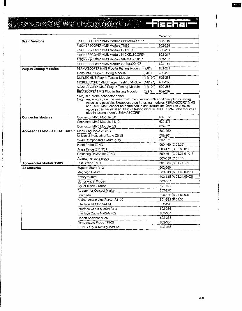
basic Versions FISCHERSCOPEmMMS Module PERMASCOPE*
FISCHERSCOPEQMMS Module TM85
Order no.
602-l 10
602-269
FISCHERSCOPE’MMS Module DUPLEX 602-251
FISCHERSCOPE*MMS Module NICKELSCOPEQ 602-217
slug-in Testing Modules
FISCHERSCOPEOMMS Module SIGMASCOPE* 602-l 56
FISCHERSCOPE’MMS Module BETASCOPE’ 602-155
PERMASCOPE* MMS Plug-in Testing Module (8/8’) 602-264
TM85 MMS Plug-in Testing Module (8/a’) 602-263
DUPLEX MMS Plug-in Testing Module (14/19’) 602-268
NICKELSCOPEB MMS Plua-in Testina Module (14/19’) 602-265
:onnector Modules
SIGMASCOPE* MMS Plug-in Testing Module (14/19’) 602-266
BETASCOPE@ MMS Plug-in Testing Module (5/2’) 602-267
l required probe connector panel Note: Any up-grade of the basic instrument version with additional plug-in testing
modules is possible. Exception: plug-in testing modules PERMASCOPE’MMS and TM85 MMS cannot be combined in one instrument. Only one of these modules can be installed. Plug-in testing module DUPLEX MMS also requires a plug-in testing module SIGMASCOPE’.
Connector MMS Module 818 602-272
Connector MMS Module 14/19 602-273
kcessories Module BETASCOPE’
Connector MMS Module 5/2 602-271 I.
Adapter for Contact Marker
Footpedal
Alohanumeric Line Printer F3100
Interface MMS/PC-AT SET
Interface Cable MMS/MP3-4
Interface Cable MMS/MPOS
602-270
600-152 (A 03.88.03)
601-962 (P 01.06)
602-220
602-386
602-387 I
Report Software MMS 602-388
Temperature Probe TFlOO 602-365
TFlOO Plug-in Testing Module 602-366
35
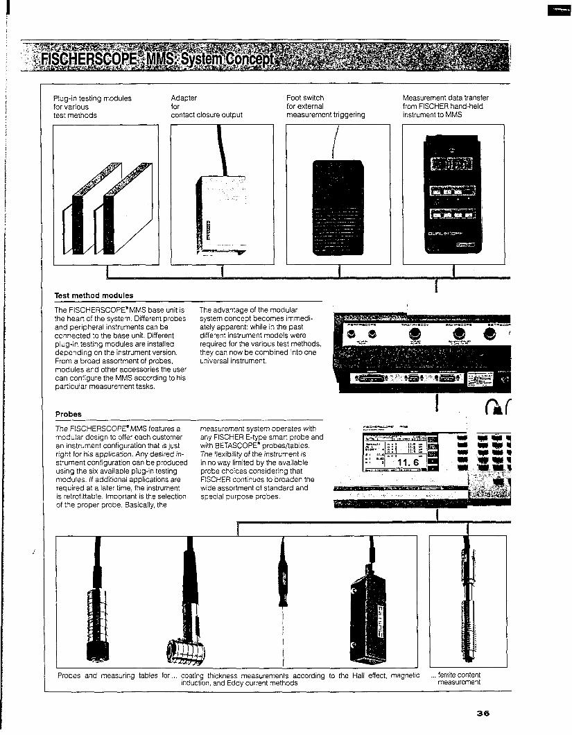
f-in testing modules marious methods
Adapter for contact closure output
Foot switch for external measurement triggering
The the and con
PIus deF Fror mot can
pan
Pro
Measurement data transfer from FISCHER hand-held instrument to MMS
Tes t method modules
FISCHERSCOPE”MMS base unit is heart of the system. Different probes peripheral instruments can be
netted to the base unit. Different a-in testing modules are installed lending on the instrument version. n a broad assortment of probes, jules and other accessories the user configure the MMS according to his
titular measurement tasks.
1be.s
The advantage of the modular system concept becomes immedi- ately apparent: while in the past different instrument models were required for the various test methods, they can now be combined into one universal instrument.
The FISCHERSCOPEaMMS features a mot War design to offer each customer an i nstrument configuration that is just rigr it for his application. Any desired in- stn rment configuration can be produced usir Jg the six available plug-in testing mol dules. If additional applications are
req uired at a later time, the instrument is r( strofittable. Important is the selection of tl he proper probe. Basically, the
measurement system operates with any FISCHER E-type smart probe and with BETASCOPE” probes/tables. The flexibility of the instrument is in no way limited by the available probe choices considering that FISCHER continues to broaden the wide assortment of standard and special purpose probes.
roes and measuring tables for coating thickness measurements according to the Hall effect, magnetic ,.. ferrite content induction, and Eddy current methods measurement
36

I
Use external personal computer for: 0 Data evaluation and storage 0 Print form template design
Use a printer to document the measurement results
Documentation
Every FISCHERSCOPE’MMS features Therefore measurements taken on the interface(s) necessary to transfer site with the hand-held instrument data to a printer, PC or other data can be transferred to the collecting device. Even data transfer FISCHERSCOPE* MMS using the to the MMS from FISCHER hand-held instrument’s data management and instruments is possible. evaluation capabilities,
electrical conductivity measurement
. coating thickness measurement according to the Beta backscatter method
The MMS measuring system is universal
Different probes can be connected to one and the same base unit: all FISCHER E-types smart probes-magnetic, magnetic induction, and Eddy current probes (even future models). In addition: Beta backscatter transducers and probes to measure the electrical conductivity and the ferrite content.
The MMS measuring system is flexible
In its most simple version, the MMS is an instrument for magnetic induction and Eddy current coating thickness measure- ment (PERMASCOPF). In a fully equipped version the MMS combines five instruments in one. Between these two extremes are numerous other possible instrument configurations which can be expanded at any time to meet the needs of the user.
The MMS measuring system is easy to operate
The instrument features a high contrast large area LCD display and a tactile feedback keyboard. The operator can handle all measurement, storage, evalu- ation, and documentation tasks through an interactive dialogue with the system. Operation is simple, easy to learn, and uniform for all test methods.
37

A broad spectrum of test methods
Different applications require different test methods. The FISCHERSCOPE”
MMS can combine the most commonly used non-destructive test methods in one measuring system. The measuring system operates according to the
required test method by using specific probes and corresponding testing modules.
vlagnetic induction method
Fddv current method
Magnetic method
leta backscatter method
Magnetic induction method (DIN 50981, ASTM 8499, IS0 2178) used to measure 0 non-magnetic coatings on ferro-
magnetic substrates such as zinc, chromium, copper, tin, or paint, plastic, enamel on steel;
0 delta ferrite content in austenitic weld metal or duplex stainless steel.
Eddy current method (DIN 50984, ASTM 8244, IS0 2360) used to measure 0 electrically non-conductive coatings
on non-ferrous metals such as paint, powder coatings, plastics on alumi- num, brass, or zinc and anodized coatings on aluminum;
0 poorly conductive non-ferrous coat- ings on electrically good conducting non-ferrous metals, such as chro- mium, or electroless nickel on cop- per, aluminum, or brass.
Modified Eddy current method used to measure: 0 metallic coatings on electrically non-
conductive or ferromagnetic sub- strates, e.g.. copper on epoxy, zinc on steel and nickel on steel;
0 the electrical conductivity of non-fer- rous metals.
Magnetic method (Hall effect) (DIN 50981) to measure l electroplated nickel coatings deposit-
ed on el. non-conductive or non-fer- rous substrates:
0 non-ferrous metal coatings, e.g.. copper, aluminum, or lead coatings on steel (advantage: no Eddy current errors when measuring thick non-fer- rous coatings.
Beta backscatter method (DIN 50983, IS0 3543, ASTM 8567, BS5411) This test method offers a great deal of versatility and can be used to measure: 0 paint, plastic, enamel, ceramic and
phosphate coatings on metals and some non-metals;
0 metal coatings on other metals and non-metals, including some coatings too thick for the X-ray test method.
Test method basics Contacting test method. A low frequency AC excitation current generates a low fre- quency magnetic field. The magnetic flux density depends on the distance between the measurement probe and the ferromag- netic substrate. A probe output signal is generated by means of a pick-up coil. In the instrument, the measurement signal is translated to coating thickness based on the probe characteristic and a suitable mathematical conversion model.
Test method basics Contacting test method. A high-fre- quency magnetic field induces Eddy currents in the conductive substrate material. The magnitude of these Eddy currents depends on the distance between the probe coil and the sub- strate material. The measurement signal is derived from the reflected impedance change in the probe coil as a function of the Eddy currents generated in the substrate material.
Test method basics Contact-free test method. The magnitude and direction (phase angle) of the Eddy current probe signal is evaluated to meas- ure the coating thickness, The method provides for probe ,,lift - off” compensa- tion, which allows contact free measure- ment applications. The test method is particularly useful to measure contact free on rough surfaces. The method also can be used to measure the electrical conductivity of non-ferrous metals be- cause it is inherently sensitive to changes in the electrical conductivity.
Test method basics Contacting test method. A permanent magnet generates a constant magnetic field. The field strength will depend on the thickness of the nickel coating to be measured. When measuring non-ferrous coatings on steel, the field strength will be proportional to the distance between the probe tip and the steel substrate. The magnetic field strength is measured with a Hall effect sensor, from this signal the coating thickness is calculated.
Test method basics This test method uses a beta particle (electron) emitting isotope, an aperture and Geiger Miiller tube detector. The iso- tope is located so that a collimated beam of beta particles is directed through the aperture onto the coated test specimen. A portion of these particles is ,,back- scattered” through the aperture to pen- etrate the window of the GM tube. The coating thickness is proportional to the rate of backscattered particles.
38

Interactive dialog with the operator
The FISCHERSCOPE’MMS includes powerful but easy to operate Software. The software enables the MMS to:
0 inform and guide the operator by means of a large flat screen LCD display and the keypad;
0 process measurement data effi- It is important that the operation of the ciently, save data in a particular unit is independent of the test method order, evaluate the data according to in use. No matter which test method is certain criteria or transfer the data; employed, the user interface remains
0 integrate the measurement system the same. in a higher flow of information, e.g., as part of a complex quality man- agement system.
Ergonomic aspects are very important for the operator of the instrument, the easy to read data display allows the operator to discern important informa- tion immediately, positive avoidance of errors . . . . all these aspects have been taken into consideration during the design of the instrument. The large numeric display mode allows reading of the measurements even from a distance.
Data presentation in the form of quality control charts can be used to monitor and control production processes (e.g., coating processes). The FISCHER- SCOPE’MMS evaluation software pro- vides full SPC/SQC support capability.
A histogram with automatic selection of class limits and normal probability chart can be displayed and printed with the push of a button. This presen- tation allows for a quick visual evalu- ation of the process, particularly useful to see if measurements follow a normal distribution.
The specification limits are freely select- able to allow for control of the process to be monitored using the control chart display. Measurement subgroups are separated by vertical bars.
In today’s quality conscious environ- ment, user or customer specific docu- mentation of the measurement result is a service the customer expects from his supplier. Often, documentation of the coating thickness and of other material properties is a stipulation.
Only the information necessary for the measurement process is displayed. The last or selected measurement is enlarged allowing for clear readability.
The operator is presented with a real time control chart just by making a sim- ple presentation mode selection. The chart appears as a graphics display on the screen while measurement are made. The control chart can be printed if required. Process capability indices Cp and Cpk as well as Kurtosis and Skewness which are important to evalu- ate the process quantitatively, are cal- culated continuously.
If the distribution is not normal, either the number of samples measured must be increased, or the process is not under statistical control, or the process is not normally distributed by nature. Suitable measures must be taken to eliminate possible assignable causes still present. Only when the measurements show nor- mal distribution can the usual known rules for a capability evaluation be applied.
When a subgroup of measurements is finished, the subgroup evaluation data is displayed at the push of a button. The result includes number and per- centage of measurements that violate the upper and lower specification limits.
In addition to the standard print form template included, a separate PC based program allows the creation and downloading of up to five customer specific print form templates. They are stored in the FISCHERSCOPE’MMS and are readily accessible for final and batch results evaluation.
Large numeric display mode
, 1
F lea/ time control chart display mode
, ?obabi/ity chart display mode
4q.q ,___L__L__L__L__L__I ,
or.1 ?:wlNmE 2 IN-tot: 1R
Specification limit display mode
Example for a customer specific print form
39

With its broad range of applications, the available to the MMS. From a total the system can be retrofitted with other
FISCHERSCOPE’MMS replaces all pre- of 6 different modules, the operator can modules at any time.
ceding FISCHER bench top instruments select the right one(s) for his appli-
which were based on the test methods cation. If the application changes,
Examples of test specimens
FISCHERSCOPE”MMS Module PERMASCOPE”
Test method 0 Magnetic induction method.
All type EG...; EK...; VlE...; V6E... probes can be connected
0 Eddy current method. All type ET...; EA... probes can be connected.
Application 0 High volume electroplating 0 Automotive industry 0 Paint production and application 0 Aerospace industry, metal industry 0 Chemical industry 0 Etc.
FISCHERSCOPE” MMS Module TM85
Test method Application 0 Magnetic induction method. 0 Coating thickness measurement on
All type EG...; EK...; VlE...; V6E... the inside and outside of cylindrical
probes can be connected tubes and beverage containers 0 Eddy current method. Only the F/B made of aluminum. The system can
container measuring system TM65 also be used to measure coatings on can be connected. flat material.
Note: cannot be combined with the PERMASCOPEQmodule.
l Thickness of thin plastic foils
FISCHERSCOPE”MMS.Module DUPLEX
Measurement method 0 Combination of magnetic induction
and Eddy current method. The type ESG2 probe can be con- netted.
Application 0 One-step measurement of the indivi-
dual thicknesses of a paint/zinc coat- ing system (duplex coating) on steel, e.g.. in galvanizing plants,
. Measurement of zinc coatings
Note: only in combination with the SIGMASCOPE”module.
in the aitomot?ve supply industries, in metal industries
Measurement of anodized coatinas
Measurement of an enamel coating
FISCHERSCOPE” MMS Module NICKELSCOPE”
Measurement method Application 0 Magnetic method (Hall effect). 0 Electroplating plants
The type EN3 and ENW3 probes can 0 Automotive supply industries
be connected.
FISCHERSCOPE” MMS Module SIGMASCOPE”
Measurement method Application 0 Modified Eddy current method. 0 Electrical and electronics industries
All type ES... probes can be connec- 0 Plating shops
ted. 0 Metal industries 0 Aerospace and other industries
FISCHERSCOPE”MMS Module BETASCOPE”
Measurement method 0 Beta backscatter method.
All BETASCOPE” measuring tables and hand held probes combined with suitable isotopes and platen aperture rings can be connected.
Application 0 PC-board and electronics industries 0 Automotive industry 0 Consumer products industry
and others
40

A measurement system that allows a SCOPE” MMS. The system is ideally suit- low volume measurement tasks and sin- variety of measurement tasks to be ed for high volume measurement appli- gle measurements are performed just as performed using a single instrument is cations due to its powerful software and easily. A few application examples shall the primary feature of the FISCHER- high degree of automation - however, illustrate the operation of the instrument.
The NSCHERSCOPE” MMS is used for high volume measurements of motor safty parts. Every month, hundreds of thousands of parts are measured In round the clock operations.
Application example Electroplating industry
In a plating shop, coating thickness measurements are performed for vari- ous customers on parts with different shapes, sizes and material combina- tions. The FISCHERSCOPEQMMS Module PERMASCOPE@ is the optimal instrument for this application. In this case, the MMS can be equipped with 0 probes suitable for the respective
applications; 0 suitable supports fixtures and a
measuring stand to assure precise positioning of small test specimen, such as fasteners, stampings, etc;
0 a personal computer for data acqui- sition to satisfy networking require- ments or data analysis using third party software.
In the case of repetitive measurement tasks involving the same products, the proper application is retrieved at the push of a button which loads all appli- cation-specific calibration parameters. The measurement is performed in dia- log with the measuring system. The operator can evaluate the measure- ments immediately or store the data in one of 50 application memories for later evaluation. When the measurement task is finished, a customer-specific measurement report can be printed. The print form template for this report is also saved in the specific application memory. The operator can focus on the task of measuring; the instrument per- forms all other functions.
Aluminum rims are safty parts.
Application example Performance critical aluminum alloy components
Some aluminum alloy components used in the aerospace or automotive indus- tries have a clearly defined spectrum of physical properties. Non-destructive measurement of the performance re- lated structural condition of the com- ponent is required as part of a quality assurance program. Additionally, these components often receive some form of surface treatment decorative finishes or anodic coatings (alloy wheels), hard anodizing (ma- chine parts, extrusions), or electroplat- ed finishes for certain applications. The FISCHERSCOPE’MMS with the PERMASCOPE’ and SIGMASCOPE” modules is ideal to control the quality of these coatings. 0 The PERMASCOPE’module is used
to measure the thickness of ano- dized and other nonconductive coatings.
0 The SIGMASCOPE’ module is used to measure the electrical conductivi- ty, which is closely related to the structural condition and can be used as a correlating parameter. Addition- ally, this module can be used to measure chromium coatings on alu- minum.
The versatility and measurement accu- racy of the instrument make the FISCHERSCOPE’MMS the ideal inspection tool for the quality control of many other performance critical coating applications.
The simple and fast measurement of the copper thickness in through holes of printed circuit boards, using the ESLOBA probe immediate/y foilowing reinforce- ment by electroplating, improves the quality and avoIds out/iers.
Application example Printed circuit board manufacturing
Aside from the X-ray fluorescence method, electromagnetic methods and the Beta backscatter method can be used to measure the coating thickness in the PC-board manufacturing proc- ess Measurements based on these test methods can be performed with a FISCHERSCOPE” MMS equipped with the modules NICKELSCOPE*, SIGMA- SCOPE”, and BETASCOPEQ. 0 The nickel coating, which is depos-
ited under the gold coating as a dif- fusion barrier, is measured according to the magnetic (Hall effect) method (NICKELSCOPEa).
0 Surface copper cladding thickness and copper plating thickness in through holes is measured using the Eddy current method (SIGMASCOPE’).
0 The gold coatings on contacts, tin- lead alloy coatings on solder oads and traces, and photo resist &at: ings are measured using the Beta backscatter method (BETASCOPE’).
A centralized measurement system can perform all of these measurement tasks by simply selecting the proper applica- tion. Uniformity of operation regardless of the test method selected keeps op- erator activities to a minimum. The meas- urement data can be stored, evaluated, printed or downloaded to an external computer. The FlSCHERSCOPE*MMS equipped with the NICKELSCOPE*, SIGMASCOPE’ and BETASCOPE’ modules offers the PC board manufac- turer an economic method to efficiently measure all his applications.
41
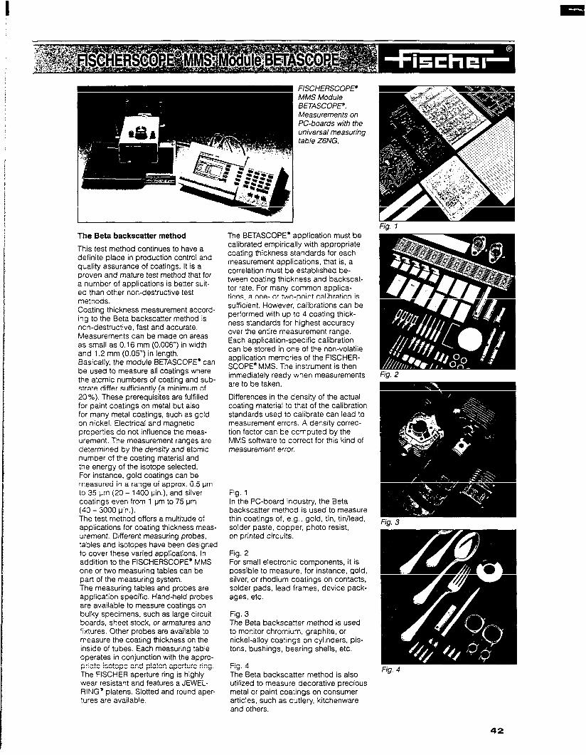
The Beta backscatter method
This test method continues to have a definite place in production control and quality assurance of coatings. It is a proven and mature test method that for a number of applications is better suit- ed than other non-destructive test methods. Coating thickness measurement accord- ing to the Beta backscatter method is non-destructive, fast and accurate. Measurements can be made on areas as small as 0.16 mm (0.006”) in width and 1.2 mm (0.05”) in length. Basically, the module BETASCOPE’ can be used to measure all coatings where the atomic numbers of coating and sub- strate differ sufficiently (a minimum of 20%). These prerequisites are fulfilled for paint coatings on metal but also for many metal coatings, such as gold on nickel. Electrical and magnetic properties do not influence the meas- urement. The measurement ranges are determined by the density and atomic number of the coating material and the energy of the isotope selected. For instance, gold coatings can be measured in a range of approx. 0.5 urn to 35 urn (20 - 1400 pin.), and silver coatings even from 1 urn to 75 urn (40 - 3000 pin.). The test method offers a multitude of applications for coating thickness meas- urement. Different measuring probes, tables and isotopes have been designed to cover these varied applications. In addition to the FISCHERSCOPE@ MMS one or two measuring tables can be part of the measuring system. The measuring tables and probes are application specific. Hand-held probes are available to measure coatings on bulky specimens, such as large circuit boards, sheet stock, or armatures and fixtures. Other probes are available to measure the coating thickness on the inside of tubes. Each measuring table operates in conjunction with the appro- priate isotope and platen aperture ring. The FISCHER aperture ring is highly wear resistant and features a JEWEL- RING* platens. Slotted and round aper- tures are available.
The BETASCOPE” application must be calibrated empirically with appropriate coating thickness standards for each measurement applications, that is, a correlation must be established be- tween coating thickness and backscat- ter rate. For many common applica- tions, a one- or two-point calibration is sufficient. However, calibrations can be performed with up to 4 coating thick- ness standards for highest accuracy over the entire measurement range. Each application-specific calibration can be stored in one of the non-volatile application memories of the FISCHER- SCOPE”MMS. The instrument is then immediately ready when measurements are to be taken.
Differences in the density of the actual coating material to that of the calibration standards used to calibrate can lead to measurement errors. A density correc- tion factor can be computed by the MMS software to correct for this kind of measurement error.
Fig. 1 In the PC-board industry, the Beta backscatter method is used to measure thin coatings of, e.g.. gold, tin, tin/lead, solder paste, copper, photo resist, on printed circuits.
Fig. 2 For small electronic components, it is possible to measure, for instance, gold, silver, or rhodium coatings on contacts, solder pads, lead frames, device pack- ages, etc.
Fig. 3 The Beta backscatter method is used to monitor chromium, graphite, or nickel-alloy coatings on cylinders, pis- tons, bushings, bearing shells, etc.
Fig. 4 The Beta backscatter method is also utilized to measure decorative precious metal or paint coatings on consumer articles, such as cutlery, kitchenware and others.
Fig. 1
42

Beta isotopes
Isotopes of different energies and aper- tures with different openings (see figure below) are available.
The table below contains all standard isotopes, others are available on request.
JUWELRINGg platens
Measurement ranges
The measurement range of the Beta backscatter method is generally deter- mined by the energy of the isotope and the density of the coating material. In the table on the right, suitable isotopes and measurement ranges are listed for typical coating/substrate combinations. The measurement ranges refer to the so-called logarithmic range of the cor- responding isotope, which is the range where the best measurement precision is obtained.
Universal measuring table ZGNG with small parts accessory kit and weight pin
Measurement table Z14NG to measure the coating thickness on small
parts with universal weight pin
The angle probe Zl 1NG 1 in combination with support stand V72 in used to measure the coating thickness in bushings, pipes, bearing shells, etc. with diameters of 32 mm (7 l/4”) and up
Hand probe ZSNG to measure the coating thickness of, e.g.,
armatures, printed circuit boards, sheet metal, etc.
43
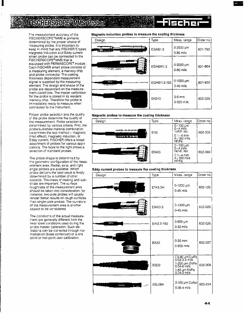
Magnetic induction probes to measure the coating thickness
[ De&n Type Meas. range
The measurement accuracy of the FISCHERSCOPEQMMS is primarily determined by the proper choice of measuring probe. It is important to keep in mind that any FISCHER E-types magnetic induction and Eddy current smart probe can be connected to the FlSCHERSCOPE*MMS that is equipped with PERMASCOPE’ module. Each FISCHER smart probe consists of a measuring element, a memory chip and probe connector. The coating thickness dependent measurement signal is supplied by the measuring element. The design and shape of the probe are dependent on the measure- ment conditions. The master calibration for the probe is stored in its resident memory chip. Therefore the probe is immediately ready to measure when connected to the instrument.
Proper probe selection and the quality of the probe determine the quality of the measurement. Probe selection is determined by various criteria. First, the probe/substrate material combination determines the test method - magnetic (Hall effect), magnetic induction, or Eddy current. FISCHER offers a broad assortment of probes for various appli- cations The table to the right shows a selection of standard probes.
The probe shape is determined by the geometric configuration of the meas- urement area. Radial, axial, and right angle probes are available. Which probe delivers the best result is finally determined by a number of other aspects. Thickness of coating and sub- strate are important. The surface roughness of the measurement area should be taken into consideration; for instance, two-pole probes will usually render better results on rough surfaces than single-pole probes. The curvature of the measurement area is another aspect to be considered.
The conditions of the actual measure- ment are generally different from the near ideal conditions used during the probe master calibration. Such de- viations can be corrected through nor- malization (base correction) or a one point or two point user calibration.
Irder no
O-2000 urn
O-80 mils EGABl.3 601-793
O-2000 urn
O-80 mils EGABW1.3 601-964
O-1000 pm
O-40 mils 601-932 EGABl1.3-150
EKBlO O-8 mm
O-320 mils 602-225
Magnetic probes to measure the coating thickness
1 Design Type Meas. range
tIA”ii s” r Ni/NF, Iso
0.1-4 mm &%t mils
O-100 m O-4 mi s Y NVNF, Iso
0.1-4 mm 4- 160 mils NF/Fe
Irder no
EN3 602-305
ENWB 602-380
Eddy current probes to measure the coating thickness
Desion Meas. range Order no.
O-1200 pm 602-l 28
O-4.5 mils
O-l 200 urn 602-025
O-45 mils
O-800 urn 602-026
O-32 mils
ETA3.3H
EAW3.3
EAl3.3-150
EA30 O-20 mm
O-800 mils 602-027
ESD2
2-100 urn Cu/lso 602_224
0.08-4 mils ESL08A

The operator can correct for differences in magnetic properties (permeability) or in the electrical conductivity, and for specimen shape related geometric influences through a simplified user calibration. In most cases, only one calibration standard and the bare sub- strate need to be measured. In extreme cases, where highly unusual material property or geometric effects are encountered, a two-point or even a master calibration can be performed.
Eddy current probes to measure the electrical conductivitv
Meas. range Irder no Type
O-65 MS/m O-112% IACS
ESlA 602-222
O-65 MS/m O-112% IACS
ES2 602-222
Application-specific user calibration parameters are stored in the applica- tion memory of the measurement system, thus avoiding the need for user calibrations when switching applica- tions. Even measurements made at dif- ferent times will, therefore, correlate well because the same calibration settings are used by the instrument when the application is retrieved. Automatic loading of the application specific parameters avoids mistakes and assures the highest measurement accuracy.
Magnetic induction probes to measure the ferrite content
I Design Type ( Order no Meas. range
O-80 % Ferrite O-110 WRC ferrite numbers
O-80% Ferrite o-1 10 WRC ferrite numbers
EGAB1.3-Fe
EGABW1.3-Fe
602-221
602-304
For special applications, measurement aids such as placement fixtures, probe stands and other attachments are avail- able to complement the broad variety of probes that can be used with the FISCHERSCOPE”MMS. These accesso- ries may be used when, for instance, 0 standard probes can not be used at
all, 0 the measurement accuracy can be
improved with the aid of such an accessory,
0 manual probe positioning is not pos- sible.
FISCHER has developed a number of such measurement aids and special attachments. Here are some examples (the number increases continuously): 0 Support stand V12 with mounting
adapter for various probes (shown: inside probe EGAB1.3-150).
0 Piston ring measuring table V4EKB4 to measure chromium coatings on piston rings and oil rings.
0 Food/beverage container measuring system TM85 to measure the coating thickness on the inside and outside of aluminum containers.
0 Probe positioning system to control the probe placement for automatic high volume measurement applica- tions, or automatic measurements on strip, sheet, etc., or to avoid indenta- tion errors on very soft coatings.
Piston ring measurement table V4EKB4 Measurement stand V12 with mounted inside measurement probe EGAi31.3-150
Probe placement system assures in- dentation free probe positioning for auto- matic rn~2w~mrn~nt nnnlicntions
F/B measurement system TM85
45

NSCHERSCOPE@ X-RAY to measure the coating thickness according to the X-ray fluorescence method
The high quality standard of FISCHER instruments is the result of our efforts to provide the very best instrumentation to our customers.
Micro-hardness measuring instrument FISCHERSCOPE* HlOO
FISCHER is a reliable and competent Today, FISCHER instruments are used
partner, offering expert advice, extensive successfully in all technological fields of
service, and user training seminars. industry and research.
I I
DUALSCOPE MP4C with magnetic induction probe for zinc coating on iron
0 HELMUT FISCHER GMBH +CO 1995 Subject to change 902-050 Printed in Germany 07195
b#=j=d i;6i;;bgosrrach ELEKTRONIK UN0 MESSTECHNIK AG
Tel. (042) 366626, ax (042) 362440
FISCHER INSTRUMENTATION (G.B.) LTD. Hannah Way. Gordleton lndustnal Parks Pennmgton. Lymin IonlHants. England Tel. (0590) 66366 s , Fax (0590) 663640 Telex 477727 fibnlg
HELMUT FISCHER S.R.L. TECNICA DI MISURA
HELMUT FISCHER GMBH+CO HELMUT FISCHER MEETTECHNIEK B.V. Via Columella 40. I-20126 MllanO
Tarasconweg 10. NL-5627 GB Eindhoven Tel. (02) 2552626. Fax (02) 2570039
lnstitut fur Elektronik und MeOtechnik Postbus 1626, NL-5602 CA Emdhoven FISCHER INSTRUMENTS S.A.
IndustriestraOe 21 Tel. (040) 462255, Fax (040) 426665 c/Alma Avers 157 3a Planta
E.060198 Barcelona
D-71069 Sindelfingen (Maichingen). Germany FISCHER INSTRUMENTATION ELECTRONIQUE Part d’Activit&s Nord du Pas du Lac
Tel. (03) 3097916, Fax (03) 4650594
Postfach 600161. D-71050 Sindelfingen Tel. (07031) 303-0, Fax (07031) 30379
5. Rue Michael Faraday FISCHER INSTRUMENTATION (FAR EAST LTD.)
F-76160 Monti Telex 7265769 ficod Tel. (01) 3056 8
ny le Bretonneux Unit 1706, Metroplaza Tower ll
056. Fax (01) 34601070 223 Hing Fon New Terntory 8i
Road. Kwai Chung ongkong
FISCHER TECHNOLOGY, INC. Tel. (02) 4201100. Fax (02) 4670216
750 Marshall Phelps Road FISCHER INSTRUMENTS K.K. Wmdsor, Ct. 06095 USA ShInmel 2-3-5. Souka-Sh! Tel. (203) 663-0761, Fax (203) 666-6496 Sa!tama.Ken 340/Japan
x a
Watts 600-243-6417. Telex 6906062 Tel. (0469) 323621, Fax (0469) 323616
46

THE DELOT PROCESS
Presented to
GAL&W TUBE LICENSEES
at
AUBURN HILLS, MICHIGM
November 28,1995
By Victor Do&en Delot Process NA
47

Control and management
Induction heating
Surface Galfan” coating unit with
preparation electromagnetic devices
48
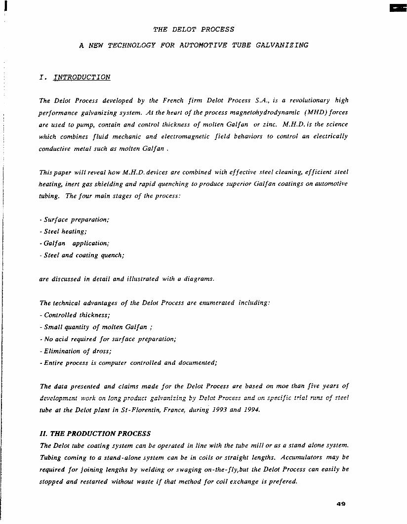
I.
THE DELOT PROCESS
A NEW TECHNOLOGY FOR AUTOMOTIVE TUBE GALVANIZING
INTRODUCTION
The Delot Process developed by the French firm Delot Process S.A., is a revolutionary high
performance galvanizing system. At the heart of the process magnetohydrodynamic (MHD) forces
are used to pump, contain and control thickness of molten Galfan or zinc. M.H.D. is the science
which combines fluid mechanic and electromagnetic field behaviors to control an electrically
conductive metal such as molten Galfan .
This paper will reveal how M.H.D. devices are combined with effective steel cleaning, efficient steel
heating, inert gas shielding and rapid quenching to produce superior Galfan coatings on automotive
tubing. The four main stages of the process:
- Surf ace preparation;
- Steel heating;
- Gulf an application;
- Steel and coating quench;
are discussed in detail and illustrated with a diagrams.
The technical advantages of the Delot Process are enumerated including:
- Controlled thickness;
- Small quantity of molten Galfan ;
- No acid required for surface preparation;
-Elimination of dross;
-Entire process is computer controlled and documented;
The data presented and claims made for the Delot Process are based on moe than five years of
development work on long product galvanizing by Delot Process and on specific trial runs of steel
tube at the Delot plant in St -Florentin, France, during 1993 and 1994.
II. THE PRODUCTION PROCESS
The Delot tube coating system can be operated in line with the tube mill or as a stand alone system.
Tubing coming to a stand-alone system can be in coils or straight lengths. Accumulators may be
required for joining lengths by welding or swaging on- the-fly, but the Delot Process can easily be
stopped and restarted without waste if that method for coil exchange is prefered.
49

I
The process should receive tube which is free of contaminants such as oil, carbonaceous smut, and
moisture. Limited mill scale and other oxides are acceptable. The input tube temperature should
not exceed 300” F and in higher than room temperature cases an additional radiation thermometer
may be added to the heat control circuit.
-2 -
Processing speeds may be controlled from I5 to 120 m lm, for tube diameter from 3 to I5 mm.
A) STEEL PREPARATION
The Delot Process employs the widely used rotoblast wheel method of shot blasting to clean and
profile the tube surface. The shot blaster consists of (3) rotoblast wheels arranged at 120” angles
around the horizontal tube centerline. Concentrator plates are used to focus the blast pattern on the
tube surface for greater efficiency. An abrasive cleaning, recycling and replenishing network
maintain uniform shot characteristics and provide machine ventilation and dust control.
The blast cleaned tube exits the 10’ blast cabinet through an air ring which blows any residual metal
fines back into the vestibule.
The tube now enters a low pressure inert gas shield ( 95% Nitrogen and 5% Hydrogen) which is
maintained through the rest of the process up to quenching. Next the tube passes a two plane laser
micrometer (No. 1) which sends diameter data to the process controller.
At this point in the process the large or small tubes may continue on a horizontal path, or the small
tubes may be directed to a vertical-up path. The &oice will be discussed later in this section. In
either case, the tube will enter induction heating coils of 3 to 6 feet in length. Here the power from
a 40 to 60 kw power supply will efficiently raise the tube to Galfan application temperature or
higher.
Process diagram
A Induction heating
Surface pregxration
Galfan* coating unit ~5th elecuomagnetic devices
50

-3 -
B) COATING
Upon leaving the induction heating coils the hot tube, still shielded in nitrogen, passes a radiation
thermometer for non-contact verification of correct temperature. The hot tube now enters the Delot
reactor.
The reactor is a cylindrical containment about one liter in volume and sealed at both ends by
magnetic fields which permit entry and exit of the passing tube, but contain the molten Galfan.
Within the reactor the Al-Fe- Zn intermetallic forms on the tube surface and pure Galfan wets the
alloy layer.
Exposure time in the reactor is adjustable from 0.1 to 0.4 seconds depending on line speed and coil
separation selected.
Further the exit field force is regulated to control the coating thickness as the tube exits. Thickness
of coating can be controlled from (5) to (50) microns.
C) SUPPLY CRUCIBLE
Molten Galfan alloy is supplied to the reactor via a recirculating loop from and back to the crucible.
The crucible is housed in a nitrogen blanketed electric furnace and contains only one metric ton
of Galfan. Melting of ingots is controlled to achieve a constant melt level and temperature.
Galfan is pumped from the crucible to reactor by a sealed MHD pump with no moving parts. The
entire network of crucible, recirculation loop and reactor is temperature controlled to assure
uniform temperatures, even if the system is not operating.
D) RAPID QUENCH
The exit of the Delot reactor is nitrogen covered to prevent oxidation as the tube passes into the
rapid quench stage. In the case of the horizontal reactor, a classic water flooded trough of
controlled temperature is used to freeze the coating.
51

-4 -
In the case of the vertical reactor, a specially engineered water quench system:
- quickly freezes the coating in only 1.3 seconds;
- does not distort the molten Galfan or
-allow coolant leakage into the reactor below and
- reacts to emergency stops without damaging the product or equipment
E) THICKNESS CONTROL
Immediately following quench, the tube passes through laser micrometer No. 2 which sends the two
plane coated tube diameter measurement to the process controller. With diameter
measurements before and after coating, Galfan thickness is computed and compared to the desired
value. A P.I.D. function control then makes adjustments, if required, to the exit coil power on
the Delot reactor.
F) HORIZONTAL OR VERTICAL DELOT REACTOR
When considering the orientation of a Delot reactor, several factors will influence the decision:
- the ratio of coating thickness to product diameter;
- the range of product diameter to be processed on the given Delot reactor;
- the allowable tolerance for coating eccentricity;
- and the combination of product diameter and tensile strength as they influence difficulty in
redirecting the tube around transport sheaves.
In general, large diameters (7.0 to 12 mm) with coatings of 8 to 25 microns are best for the
horizontal reactor and small diameters (4.0 to 6.0 mm) with coatings of 25 to 50 microns are best
for the vertical reactor. The vertical reactor is not sensitive to the effects of gravity in so far as
eccentric coating is concerned.
52
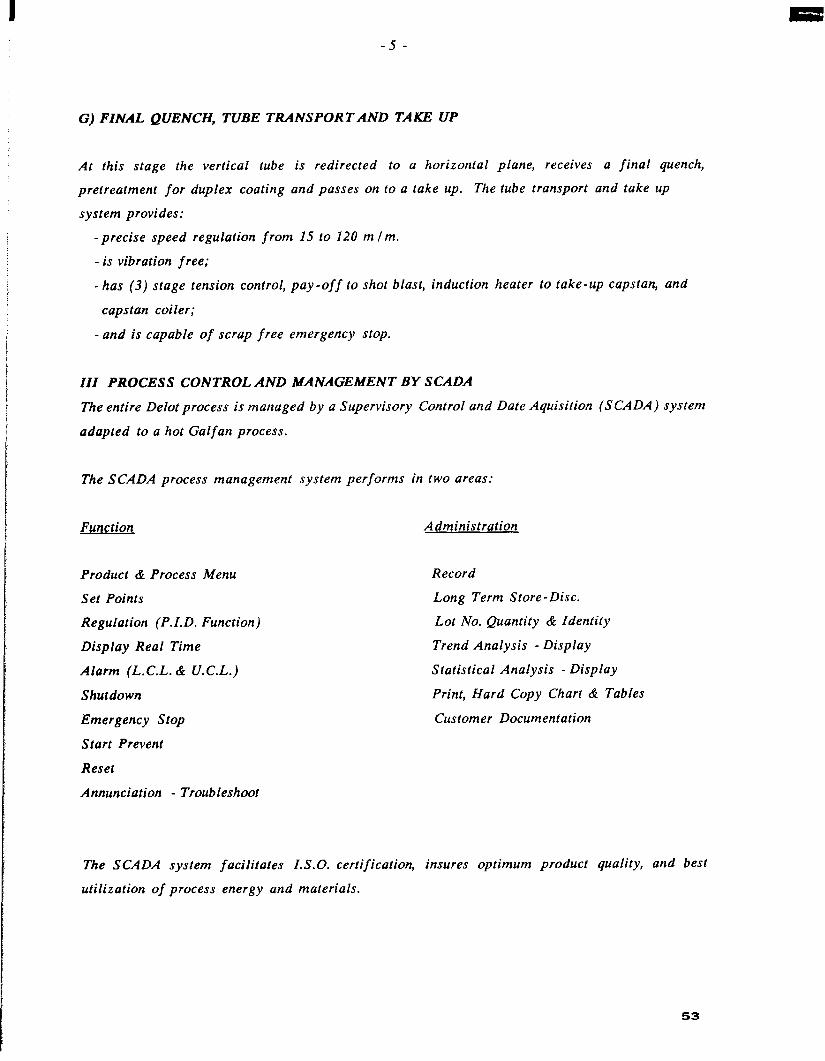
-5 -
G) FINAL QUENCH, TUBE TRANSPORT AND TAKE UP
At this stage the vertical tube is redirected to a horizontal plane, receives a final quench,
pretreatment for duplex coating and passes on to a take up. The tube transport and take up
system provides:
-precise speed regulation from 15 to 120 m lm.
- is vibration free;
-has (3) stage tension control, pay-off to shot blast, induction heater to take-up capstan, and
capstan toiler;
- and is capable of scrap free emergency stop.
III PROCESS CONTROL AND MANAGEMENT BY SCADA
The entire Delot process is managed by a Supervisory Control and Date Aquisition (SCADA) system
adapted to a hot Galfan process.
The SCADA process management system performs in two areas:
Function Administration
Product & Process Menu
Set Points
Regulation (P.I.D. Function)
Display Real Time
Alarm (L.C.L. & U.C.L.)
Shutdown
Emergency Stop
Start Prevent
Reset
Annunciation - Troubleshoot
Record
Long Term Store-Disc.
Lot No. Quantity & Identity
Trend Analysis - Display
Statistical Analysis - Display
Print, Hard Copy Chart & Tables
Customer Documentation
The SCADA system facilitates I.S.O. certification, insures optimum product quality, and best
utilization of process energy and materials.
53

-6 -
IV) PROCESS CONTROL PARAMETERS
This section will discuss the primary process parameters controlled with the Delot tube coating
system. When the Delot SCADA system is given the tube diameter, wall thickness and desired Galfan
thickness, the menu of process set points is automatically selected. They include:
1. TUBE PAY OFF - Speed signal from digital tach on motor - Tension as measured by motor armature
Current
2. SHOT BLASTER - (3) rotoblast wheel motor currents Shot flow control valve position Shot replenishment valve position
3. INDUCTION HEATING - Laser micrometer #I
4. DELOT REACTOR
5. SUPPLY CRUCIBLE
6. RAPID QUENCH - Water temp., pressure and flow -Laser micrometer #2 - Final quench temp. and flow
7. POST GALFAN - T.B.D.
8. TARE UP COILER - Speed signal from digital tach - Tension, as motor current
- Inert gas flow #I - Induction voltage, frequency and power - Radiation camera, tube temperature
-Entry coil V and i -Exit coil Vand i - E. M. pump Vand i - Reactor & conduit thermocouples - Inert gas flow #2
- Supply side T-Couple - Return side T-Couple - Inert gas flow #3 - Heater current - Load cell, crucible Wt. loss rate
54

-7-
The total process sequence for coating tubing is summarized below:
transport
2. Shot blast cleaning steel High speed, pollution free,
3. Steel heating and precise temperature control
4. Inert gas protection for steel and Delot Reactor
5. Delot Reactor, Galfan application
Energy efficient, duplex tern - perature capability
No polluting flux required, reduced dross and oxides
M.H.D. technology: - small molten mass - efficient alloy heating -high speed capability
6. Rapid quench horizontal or vertical
High speed, short distance, distortion free, instant start I stop, no leakage
7. Galfan thickness control
Precision, high speed
8. Final quench, horizontal
9. Take up speed regulation to coil or straight
10. SCADA System management
High speed, vibration free
Computer managed process control and data administra-
55

-8 -
V COSTAND QUALITYADVANTAGES
The Delot Process for tubes we’ve described is revolutionary in two significant ways. They are not
only cost advantages of the process, but product quality is superior to classical hot dip methods.
The Delot Process is operator friendly, it offers easy, scrap free start and stop, no drossing required,
maintenance free Galfan pumping, and no wipe maintenance. The process is environment friendly,
it requires no chemical cleaning or rinse treatments, no flux, no acids, and the small molten mass
consumes less fuel. In fact Delot Process was honored with the ” Clean Technology “Award by the
French Ministry of the Environment.
The tube quality produced with this process is enhanced by the very short residence time of the hot
steel in the reactor compared to classical methods. The result is a thinner Fe-Galfan intermetallic
layer. Even after bending and the resultant cracks in the intermetallic layer, the very ductile coating
exhibits no cracks or embrittlement.
And this ductile coating is uniform and precise thanks to M.H.D. wiping technology. The quality
approaches electroplated.
56


![L-nnn-yy-[LICENSEE]-ELPAC-VVV AMBER Sensitive information ...](https://static.fdokumen.com/doc/165x107/6326029f6d480576770c9276/l-nnn-yy-licensee-elpac-vvv-amber-sensitive-information-.jpg)