2013 facilities master plan - Solano Community College
289
2013 FACILITIES MASTER PLAN BOARD APPROVED APRIL 2, 2014 SOLANO COMMUNITY COLLEGE DISTRICT BOOK 2: DISTRICT STANDARDS PUBLISHED MAY 30, 2014 REVISED PER BOARD APPROVED REVISIONS FEBRUARY 15, 2015 MARCH 16, 2016, FEBRUARY 21, 2018 AND APRIL 3, 2019
-
Upload
khangminh22 -
Category
Documents
-
view
2 -
download
0
Transcript of 2013 facilities master plan - Solano Community College

2013 FACILITIES MASTER PLAN
BOARD APPROVED APRIL 2, 2014
SOLANO COMMUNITY COLLEGE DISTRICT
BOOK 2: DISTRICT STANDARDS
PUBLISHED MAY 30, 2014REVISED PER BOARD APPROVED REVISIONS FEBRUARY 15, 2015 MARCH 16, 2016, FEBRUARY 21, 2018 AND APRIL 3, 2019
SOLANO COMMUNITY COLLEGE 2013 FACILITIES MASTER PLAN
Image DisclaimerThis document contains images obtained from the world wide web that are from organizations and companies not associated with Solano Community College District or STV|vbn. These images are provided solely for the purpose of providing diverse visual examples for the written content, and do not represent any endorsement of organizations, companies, their services or products, or their views.
Furthermore, the authors of this document have attempted to ascertain the origin and credit for the images to the best of their abilities and can not guarantee the accuracy or completeness of the image source provided.

3
SOLANO COMMUNITY COLLEGE 2013 FACILITIES MASTER PLANSOLANO COMMUNITY COLLEGE 2013 FACILITIES MASTER PLAN
Emergency Response Related 67Exterior Paint 69Flagpoles 74Flooring 74Glazing 76Interior Paint 77Restrooms 79Vending Spaces 82Wall & Corner Protection 83White Boards 84Window Treatment 84Thermoplastic Single-Ply Roofing 86
FIRE PROTECTION STANDARDS21 00 00 Basic Fire Protection System Design 88
PLUMBING STANDARDS22 00 00 Basic Plumbing System Design 8922 05 12 Plumbing Pipe and Fittings 9322 05 13 Common Motor Requirements for Plumbing Equipment 9522 05 23 General Duty Valves for Plumbing 9622 05 29 Hangers and Supports for Plumbing Piping & Equipment 9722 05 48 Vibration and Seismic Controls for Plumbing Piping and Equipment 9922 05 53 Identification for Plumbing Piping & Equipment 10022 07 00 Insulation for Plumbing Piping and Equipment 10222 11 13 General Plumbing Piping Systems 103
PART III: THE STANDARDS
Table of Contents 3Overview 5Design Standards Process 6
LANDSCAPE STANDARDSBenches 7Bike Racks and Bike Locks 9Bollards 11Decomposed Granite Pathways 12Irrigation 13Site Lighting (Refer to Electrical Standards 265000 Lighting) 19Pedestrian Asphalt Paving 20Pedestrian Concrete Paving 22Pedestrian Pavers 23Planting 26Tables and Chairs 36Trash and Recycling Receptacles 37Tree Grates 39
ARCHITECTURAL STANDARDSAcoustical Panel Ceilings 40 Casework 41Custodial Spaces 43Designations - Bldg, Floor, Room etc. 45Door Hardware 46Doors and Door Frames 61Elevators 63
22 30 00 Plumbing Equipment 10422 40 00 Plumbing Fixtures 106
MECHANICAL STANDARDS23 00 00 Basic HVAC System Design 11823 05 10 HVAC Piping 12323 05 13 Common Motor Requirements HVAC Equipment 12623 05 23 General Duty Valves for HVAC 12723 05 29 Hangers and Supports for HVAC Piping & Equipment 12923 05 48 Vibration and Seismic Controls for HVAC Piping, Ductwork & Equipment 13123 05 53 Identification for HVAC Piping, Ductwork & Equipment 13223 05 93 Testing, Adjusting and Balancing 13423 07 00 HVAC Insulation 13523 09 13 Variable Frequency Drives 13623 11 23 Facility Natural Gas Systems 13723 21 05 Hydronic Piping Systems 13923 21 10 Heating Water Systems 14323 21 15 Chilled Water Systems 14523 21 20 Hydronic Pumps 14623 31 00 Ductwork 14823 33 00 Ductwork Accessories 15023 34 00 Fans 15123 36 00 Air Terminal Units 15323 37 00 Air Outlets and Inlets 15423 52 00 Heating Boilers and Accessories 15523 62 00 Refrigeration 15623 74 00 Packaged Air Conditioning Units 15823 75 00 Air Handling Units 159
Table of Contents:

4
SOLANO COMMUNITY COLLEGE 2013 FACILITIES MASTER PLAN
23 81 46 Water-to-Air Heat Pumps 16023 83 15 Hydronic Floor Heating & Cooling System 161
ELECTRICAL STANDARDS26 00 00 Basic Electrical System Design 16326 05 13 Medium Voltage Cables 16726 05 19 Wires Cables Connectors 16826 05 26 Grounding 17026 05 33 Raceways 17226 05 34 Boxes 17526 05 48 Supporting Devices 17726 05 53 Electrical Identification 17826 08 05 Electrical Acceptance Testing 18026 09 21 Occupancy Sensors 18226 09 23 Daylighting Controls 18326 12 00 Liquid-Type Transformers 18426 22 00 Dry-Type Transformers 18626 24 00 Switchboards and Distribution Panel Boards 18826 24 19 Motor Control Centers 19126 27 26 Wiring Devices 19526 28 00 Overcurrent Protective Devices 19626 28 19 Circuit and Motor Disconnects 19726 50 00 Lighting 199
CIVIL SITE STANDARDS DETAILSStreets and Hardscapes 203Sanitary Sewer and Storm Drainage 207Water 212Electrical 217
Miscellaneous 219
CIVIL STANDARDS SPECIFICATIONS31 00 00 Earthwork and Grading 22031 10 00 Site Preparation 22631 23 33 Trenching, Backfilling and Compacting 22932 10 00 Demolition 23332 12 33 Paving and Surfacing 23532 17 23 Pavement Marking 23832 32 13 Portland Cement Concrete Retaining Walls 23932 50 00 Restoration of Surfaces 24633 10 00 Water Systems 24733 30 00 Sanitary Sewer 26033 40 00 Storm Drainage 26633 50 00 Natural Gas Distribution Piping 269
TELECOMMUNICATIONS STANDARDS27 00 00 Telecommunications 271
AUDIO VISUAL STANDARDS27 00 00 Audiovisual Systems 275Clocks 280Assistive Listening System 280
SECURITY STANDARDSElectronic Safety and Security 282Security System Ownership 282
Electronic Access Control System (EACS) 283Video Management System (VMS) 284Intrusion Detection System (IDS) 285Emergency Mass Notification Systems (EMNS) 286Crime Prevention through Environmental Design (CPTED) 286
FIRE ALARM STANDARDS28 00 00 Fire Alarm Systems 288

5
SOLANO COMMUNITY COLLEGE 2013 FACILITIES MASTER PLANSOLANO COMMUNITY COLLEGE 2013 FACILITIES MASTER PLAN
Durability,Ease of
Maintenance & Sustainability
OverviewSCCD has established standards for design and construction to ensure equity and consistency in facilities and for efficiency in operations and maintenance. The Standards consist of Design Standards that are directives and information that Design Consultants should incorporate into their contract documents (drawings and specifications). A few disciplines have also provided Construction Specifications and Typical Details, which should be customized to the design project.
These Standards were developed by the District, with intensive input from District Facilities, Maintenance and Operations personnel, in addition to IT personnel and the Security shared governance Committee for relevant sections. The Standards are based on prior experience at the District and the best practices from other California Community Colleges, and the products selected were carefully evaluated based on criteria that included aesthetics & user comfort, durability, ease of maintenance, sustainable properties/practices and cost.
PART IIIDISTRICTSTANDARDS

6
SOLANO COMMUNITY COLLEGE 2013 FACILITIES MASTER PLAN
as documentation of any approved deviations or variances to the Design Standards early in the design process.
Approved deviations and variances from the Design Standards should be conscious and justifiable, provide a solution for a site-specific need or replace outdated/obsolete requirements, and be compatible with other Design Standards. Proposed deviations shall be submitted to SCCD in writing for review and approval prior to incorporation into the project. Approved deviations may be project-specific or permanent; if an approved deviation or variance is intended to be permanent the change should be reflected in the associated Design Standard.
Review and ApprovalReview and approval by SCCD is required at the conclusion of each of the design phases listed below prior to progressing to the next phase. Documentation required for review includes project drawings and specifications; manufacturer cutsheets, diagrams, and other product data; associated progress cost estimates and written identification of deviations/variances from District Standards Not all projects will include all phases.
Schematic DesignDesign professionals should become familiar with the Architectural, Landscape, Sustainability and other Guidelines (found in Book 1 of the Facilities Master Plan) and the District Standards (found in this Book 2 and the Facilities Website) prior to initiating the design process. While most of the specifics within the District Standards will be reflected in future design phases, there are some aspects reflected in the District Standards that require consideration from the onset of the design process. If any deviations/variations are apparent at this early phase, bring them to District attention for consideration.
Deliverables of this phase are as stipulated in the Contract with the District. In addition for system designs such as Electronic Security and Safety, Fire Alarm etc. provide the following: a written design narrative which describes planned system elements by function and overall design. The narrative should include conceptual device and system floor plan, site layout drawings and functional/operational project planning.
These Design Standards are a tool to clarify direction and streamline project execution for design professionals, construction managers and other participants in capital improvement projects. They represent the District’s “strong preference” and should be applied, when possible, without compromising the creativity of the overall design. Final disposition, color, size, product choice etc. should conform to the best extent possible where equivalent substitutes are allowed in the Design Standard. If equivalent substitutes are allowed only “if performance and quality equivalency can be evidenced” or the consultant wishes to deviate from the written design standards for other reasons, then the consultant needs to provide evidence/justification and seek District approval as outlined below.
In all cases the written design standards do not diminish or eliminate the standard of care owed by the consultant to SCCD or relieve, in any manner whatsoever, a consultant from any professional responsibility, duty or due diligence required toward that work.
These Design Standards should be incorporated into all Solano Community College (“SCC”, the “College”) projects. Projects include but are not limited to new construction, Tenant Improvements (TI) projects, remodels, and renovations. It is understood that the College could not attempt to upgrade and retrofit all campus facilities in a single massive construction project; such a process would be prohibitively costly and disruptive. Rather, the strategy is for installations to be implemented continually and concurrently in a phased manner, over time and as funding allows, toward a goal of all campuses and campus buildings eventually meeting the same consistent Design Standards.
Design Standards Process:The following Design Standards Process Guidelines incorporation and approval process provides procedural guidelines to ensure that project-specific design and contractor teams submit and receive approval by authorized SCCD departmental and administrator personnel at defined milestones. This allows for SCCD review, input, and approval as well
Design DevelopmentThis is the phase where the specifics within the Design Standards will need to be reflected and coordinated within the specific project, and any required deviations/variances should be apparent during this phase. Bring all deviations/variances to District attention, in written format, for evaluation and action as soon as they are determined. Do not assume deviations/variations will be apparent to District personnel during their documentation review towards the end of this phase.
Deliverables of this phase are as stipulated in the Contract with the District. In addition for system designs such as Electronic Security and Safety, Fire Alarm etc. provide the following: refinement of schematic design conceptual elements to provide a greater level of detail of system floor plan, functional/operational project planning and site layout drawings as well as required supporting components such as physical, electrical, MEP, data network, etc.
Construction DocumentsBy this phase the deviations/variances should have already been resolved. If coordination and detailing efforts during this phase require previously unknown deviations/variances from District Standards, bring them to District attention, via written format, for evaluation and action as soon as they are determined.
Deliverables of this phase are as stipulated in the Contract with the District. In addition for system designs such as Electronic Security and Safety, Fire Alarm etc. provide the following: design drawings indicating location, installation details, cabling and interfaces for elements approved in the schematic design and design development phases. This phase includes written device and systems specifications in the current MasterFormat edition as issued by the Construction Specifications Institute. These specifications should clearly describe interfaces between systems or assemblies and interfaces to any other equipment and systems under other Design Standards.
Project Close-OutDeliverables of this phase are as stipulated in the Contract with the District. District should endeavor to update District Standards for any deviations or variances that were approved as permanent during that particular project.
Standards Process

7
SOLANO COMMUNITY COLLEGE 2013 FACILITIES MASTER PLAN
DESIGN STANDARD Solano Community College District Division 12 93 00
1 01.16.2014
DESIGN STANDARD for Benches Purpose:
The purpose of this document is to standardize the benches used throughout the campus. This design standard achieves the purpose of ensuring the quality of maintenance, reliability, and aesthetic value of these objects on campus.
Design Standard:
Set back at least 24” from pedestrian walkway
Place by other amenities such as bus shelters, kiosks, newsstands, waste receptacles, etc.
Place along pedestrian walkways
Should be located to give people a choice between sun and shade, and protected from elements like wind
Use backless benches in park‐like areas individually or in clusters
Use benches with back in lower traffic areas along primary and secondary pedestrian routes, plazas and main building entryways
Benches should be located on concrete paving, interlocking pavers, or asphalt
Approved Manufacturers:
Landscape Forms.
o Model: 72” Scarborough Bench, Horizontal Strap with Back or 72” Scarborough Bench, Horizontal Strap Backless.
o Color: Powdercoated stormcloud
o Mounting: Surface mounted
o Phone: (269) 381‐0396
o Web: Landscapeforms.com
DESIGN STANDARD Solano Community College District Division 12 93 00
2 01.16.2014
Substitutes Allowed:
Approved manufacturer or approved equal.
Associated Design Standards and Construction Specifications
Install per manufacturer’s specifications.
Landscape Standards

8
SOLANO COMMUNITY COLLEGE 2013 FACILITIES MASTER PLAN
DESIGN STANDARD Solano Community College District Division 12 93 00
3 01.16.2014
DESIGN STANDARD Solano Community College District Division 12 93 00
4 01.16.2014

9
SOLANO COMMUNITY COLLEGE 2013 FACILITIES MASTER PLAN
DESIGN STANDARD Solano Community College District Division 12 93 00
1 01.16.2014
DESIGN STANDARD for Bike Racks & Bike Lockers Purpose:
The purpose of this document is to standardize the benches used throughout the campus. This design standard achieves the purpose of ensuring the quality of maintenance, reliability, and aesthetic value of these objects on campus.
Design Standard:
Place near building entrances along bike paths
At least 5’ from crosswalk or fire hydrant
Minimum 2’ from curb
Minimum 3’ from street furniture, light poles, parking meters, trees, and other objects
3’ from wall if perpendicular to wall
3’ from wall if parallel to wall
Single loop or five loop racks recommended
Install number of bike racks and lockers per CalGreen Standards
Approved Manufacturers:
Bike Lockers
o Manufacturer: Dura Bike Locker, durabikelocker.com
o Phone: (916) 488‐7026
o Model: DBLP Pie Shaped Bicycle Locker
o Color: Galvanized steel, powder coat graphite with bike symbol wall perforation
o Mount: In ground
Bike Lockers
o Manufacturer: Bikeparking.com
o Phone: (415) 333‐6428
DESIGN STANDARD Solano Community College District Division 12 93 00
2 01.16.2014
o Style: Welle Multiple Bend Round Pipe
o Color: Powder coat silver metallic
o Mount: In ground
Substitutes Allowed:
Approved manufacturer or approved equal
Associated Design Standards and Construction Specifications
Install per manufacturer’s specifications

10
SOLANO COMMUNITY COLLEGE 2013 FACILITIES MASTER PLAN
DESIGN STANDARD Solano Community College District Division 12 93 00
3 01.16.2014
DESIGN STANDARD
Solano Community College District Division 12 93 00
4 01.16.2014

11
SOLANO COMMUNITY COLLEGE 2013 FACILITIES MASTER PLAN
DESIGN STANDARD Solano Community College District Division 12 93 00
5 01.16.2014
DESIGN STANDARD Solano Community College District Division 12 93 00
1 01.16.2014
DESIGN STANDARD for Bollards Purpose:
The purpose of this document is to standardize the use of bollards used on campus. This design standard achieves the purpose of ensuring the quality of maintenance, reliability, and value of these objects on campus.
Design Standard:
Maximum spacing 8’ on center, minimum 4’ on center
Permanent bollards are used to restrict vehicular access at gates and entryways
Removable bollards may be installed where occasional vehicle access is required, such as service roads
Should be used anywhere pedestrian pathways meet vehicular traffic
Approved Manufacturers:
Reliance Foundry Co., LTD.
Model: R-7902 Removal Steel Bollard
Color: Bengal Silver
Mounting: Embedded receiving with lids
Phone: (604)592-4333
Website: Reliance-foundry.com
Substitutes Allowed:
Approved manufacturer or approved equal.
Associated Design Standards and Construction Specifications
Install per manufacturer specifications.

12
SOLANO COMMUNITY COLLEGE 2013 FACILITIES MASTER PLAN
DESIGN STANDARD Solano Community College District Division 12 93 00
2 01.16.2014
DESIGN STANDARD Solano Community College District Division 32 15 40
1 01.06.2014
DESIGN STANDARD for Decomposed Granite Pathways Purpose:
The purpose of this document is to standardize paths made of decomposed granite. This design standard achieves the purpose of ensuring the quality of maintenance, reliability, and aesthetic value of these paths on campus.
Design Standard:
Install with commercial binder
Install away from entry doors to prevent spread of fines into buildings and classrooms
Do not use on paths adjacent to buildings or lawns where materials can migrate onto lawns or building entry systems
Approved Manufacturers:
Colors: California Gold and Graphite Grey only
Stabilizer: Technisoil G3 commercial
Associated Design Standards and Construction Specifications
See decomposed granite detail.

13
SOLANO COMMUNITY COLLEGE 2013 FACILITIES MASTER PLAN
5
SOLANO COMMUNITY COLLEGE 2013 FACILITIES MASTER PLAN
DESIGN STANDARD Solano Community College District Division 32 15 40
2 01.06.2014
DESIGN STANDARD Solano Community College District Division 32 84 00
1 01.16.2014
DESIGN STANDARD for Irrigation
Purpose:
The purpose of this document is to standardize the irrigation procedures and design on campus. This design standard achieves the purpose of ensuring the quality of maintenance, reliability, and efficiency of these systems on campus
Design Standard:
• Irrigation systems shall be designed to prevent runoff, low head drainage, overspray or other similar conditions.
• All irrigation systems should be designed, managed and maintained to meet or exceed 70%efficiency.
• Sprinklers, drip irrigation and bubblers must be on separate valves. Overhead sprinkler irrigation should only be used for turf areas.
• Subsurface or low volume irrigation must be used when turf is be planted on slopes greater than 25% or in areas that are less than 8’ wide
• Controllers must use evapotranspiration or soil moisture data
• Overhead irrigation is not permitted within 24” of non‐permeable surfaces unless there is an alternate design or technology to prevent runoff or unless the overspray runoff flows into landscaping
• See Irrigation Notes
• Note that Fairfield Campus and Vacaville Center use non potable water supplied by the Solano Irrigation District (SID) unfiltered. For the Fairfield Campus, there is a filtration system at the pump station. At the Vacaville Center, there is an in-line filter. City water is utilized for irrigation at Vallejo Center.
Approved Manufacturers: • See Irrigation Legend
Substitutes Allowed:
None
Associated Design Standards and Construction Specifications
Model Water Efficient Landscape Ordinance AB 1881

14
SOLANO COMMUNITY COLLEGE 2013 FACILITIES MASTER PLAN
6
SOLANO COMMUNITY COLLEGE 2013 FACILITIES MASTER PLAN
DESIGN STANDARD Solano Community College District Division 32 84 00
2 01.16.2014
DESIGN STANDARD Solano Community College District Division 32 84 00
2 01.16.2014
DESIGN STANDARD Solano Community College District Division 32 84 00
2 01.16.2014
DESIGN STANDARD Solano Community College District Division 32 84 00
2 01.16.2014
AT THE VACAVILLE CENTER, 2-WIRE CABLE BETWEEN CONTROLLER AND DECODERS SHALL BE PAIGE P7350D 14 AWG SOLID COPPER JACKETED 2-CONDUCTOR DIRECT BURIAL CABLE. 2-WIRE CABLE BETWEEN DECODERS AND SOLENOIDS SHALL BE PAIGE P7351D DTS 14 AWG SOLID COPPER JACKETED 2-CONDUCTOR DIRECT BURIAL CABLE.
SPRINKLERS WHERE LOW HEAD DRAINAGE WILL CAUSE EROSION AND EXCESS WATER USE A POP-UP BODY WITH INTEGRAL CHECK VALVE.THE SPRINKLER SYSTEM DESIGN IS BASED ON THE NORMAL OPERATION PRESSURE SHOWN ON THE IRRIGATION DRAWINGS. THE IRRIGATION CONTRACTOR SHALL VERIFY WATER PRESSURE PRIOR TO CONSTRUCTION. REPORT ANY DIFFERENCE BETWEEN THE WATER PRESSURE INDICATED ON THE DRAWINGS AND THE ACTUAL PRESSURE READING AT THE IRRIGATION POINT OF CONNECTION TO THE OWNER’S AUTHORIZED REPRESENTATIVE. TEST USING MAXICOM CENTRAL CONTROLS AT EACH SITE.
STATIC PRESSURE AT POINT OF CONNECTION IS ALL DEPENDENT UPON LOCATION. TEST AND VERIFY.
ALL IRRIGATION VALVE BOXES SHALL BE PURPLE FOR USE WITH RECYCLED WATER AND LOCATED WITHIN GROUNDCOVER AREAS ONLY. DO NOT LOCATE VALVES AT PEDESTRIAN ENTRY POINTS OR AT PEDESTRIAN CHANGE OF DIRECTION.
ALSO CALL DISTRICT STAFF PERSON KELLY TRUJILLO, (707) 580-6598).
SPLICING OF 24 VOLT WIRE WILL NOT BE PERMITTED EXCEPT IN VALVE BOXES. LEAVE A 36 INCH COIL OF EXCESS WIRE AT EACH SPLICE AND 100 FEET ON CENTER ALONG WIRE RUN
WIRE CONNECTION: 3M DBR/Y-6 DIRECT BURWIREY SPLICE KIT

15
SOLANO COMMUNITY COLLEGE 2013 FACILITIES MASTER PLAN
7
SOLANO COMMUNITY COLLEGE 2013 FACILITIES MASTER PLAN
DESIGN STANDARD Solano Community College District Division 32 84 00
4 01.16.2014
DESIGN STANDARD Solano Community College District Division 32 84 00
5 01.16.2014
(PEDESTAL ALSO ALLOWED)
7
SOLANO COMMUNITY COLLEGE 2013 FACILITIES MASTER PLAN
DESIGN STANDARD Solano Community College District Division 32 84 00
4 01.16.2014
DESIGN STANDARD Solano Community College District Division 32 84 00
5 01.16.2014
(PEDESTAL ALSO ALLOWED)

16
SOLANO COMMUNITY COLLEGE 2013 FACILITIES MASTER PLAN
8
SOLANO COMMUNITY COLLEGE 2013 FACILITIES MASTER PLAN
DESIGN STANDARD Solano Community College District Division 32 84 00
8 01.16.2014
DESIGN STANDARD Solano Community College District Division 32 84 00
10 01.16.2014
DESIGN STANDARD Solano Community College District Division 32 84 00
10 01.16.2014
43
VALVE LID SHALL BE PERMANENTLY INSCRIBED “CONTROL VALVE” AND WITH THE CONTROLLER STATION NUMBER, AND BE PURPLE IN COLOR WHERE NON-POTABLE WATER IS USED.
PROVIDE ISOLATION BRONZE GATE VALVE WITH GROSS HANDLE ON LIVE SIDE OF REMOTE CONTROL VALVE (NOT SHOWN IN DETAIL)
8
SOLANO COMMUNITY COLLEGE 2013 FACILITIES MASTER PLAN
DESIGN STANDARD Solano Community College District Division 32 84 00
8 01.16.2014
DESIGN STANDARD Solano Community College District Division 32 84 00
10 01.16.2014
DESIGN STANDARD Solano Community College District Division 32 84 00
10 01.16.2014
43
VALVE LID SHALL BE PERMANENTLY INSCRIBED “CONTROL VALVE” AND WITH THE CONTROLLER STATION NUMBER, AND BE PURPLE IN COLOR WHERE NON-POTABLE WATER IS USED.
PROVIDE ISOLATION BRONZE GATE VALVE WITH GROSS HANDLE ON LIVE SIDE OF REMOTE CONTROL VALVE (NOT SHOWN IN DETAIL)PROVIDE ISOLATION BRASS GATE VALVE WITH GROSS HANDLE LIVE
SIDE OF REMOTE CONTROL VALVE (SHOWN IN DETAIL)
24 VOLT WIRE - PROVIDE 3M DBR/Y-6 SPLICE KIT WIRE CONNECTORS AT ALL SPLICES AND 36 INCHES OF EXCESS WIRE

17
SOLANO COMMUNITY COLLEGE 2013 FACILITIES MASTER PLAN
9
SOLANO COMMUNITY COLLEGE 2013 FACILITIES MASTER PLAN
DESIGN STANDARD Solano Community College District Division 32 84 00
11 01.16.2014
5
DESIGN STANDARD Solano Community College District Division 32 84 00
13 01.16.2014
6
NOTE: PLACE CONTROL WIRE BUNDLE ON TOP OF MAIN LINE PIPE, NOT AS SHOWN IN DRAWING.

18
SOLANO COMMUNITY COLLEGE 2013 FACILITIES MASTER PLAN
10
SOLANO COMMUNITY COLLEGE 2013 FACILITIES MASTER PLAN
DESIGN STANDARD Solano Community College District Division 32 84 00
14 01.16.2014
DESIGN STANDARD Solano Community College District Division 32 84 00
15 01.16.2014
7 8
10
SOLANO COMMUNITY COLLEGE 2013 FACILITIES MASTER PLAN
DESIGN STANDARD Solano Community College District Division 32 84 00
14 01.16.2014
DESIGN STANDARD Solano Community College District Division 32 84 00
15 01.16.2014
7 8

19
SOLANO COMMUNITY COLLEGE 2013 FACILITIES MASTER PLAN
DESIGN STANDARD Solano Community College District Division 26 56 00
1 01.16.2014
DESIGN STANDARD for Site Lighting Purpose:
The purpose of this document is to standardize vehicular and pedestrian lighting on campus. This design standard achieves the purpose of ensuring the quality of maintenance, reliability, and safety of these objects on campus.
Design Standard:
Parking lots, major walkways, pathways, stairs, and intersections should be sufficiently lit to meet safety standards
State minimum photometric foot candles for various areas must be met
Provide adequate lighting for safety without over lighting
Night sky friendly
Approved Manufacturers:
Vehicular Lighting:
Vehicular Lighting
o Manufacturer: Lumec
o Model: 20’pole with double and single luminaire, MPTCRC,
o Base: P805AE
o Bracket: CR double banner bracket
o Color: GR sandtext
o Phone: (510) 638‐3800
Pedestrian Lighting:
o Manufacturer: Lumec
o Model: 15’ tapered pole, with luminaire MPTCRC
o Base: TM6V
Refer to Electrical Standards 265000 Lighting

20
SOLANO COMMUNITY COLLEGE 2013 FACILITIES MASTER PLAN
DESIGN STANDARD Solano Community College District Division 32 12 16
1 01.16.2014
DESIGN STANDARD for Pedestrian Asphalt Paving
Purpose:
The purpose of this document is to standardize asphalt paving in pedestrian areas. This design standard achieves the purpose of ensuring the quality of maintenance, reliability, and safety of paving on campus.
Design Standard:
To be used for secondary, tertiary or service paths and roads
All asphaltic concrete to be restrained with metal header or min. 6” concrete mowband
Associated Design Standards and Construction Specifications
• Asphaltic concrete to be 1/4 in. maximum aggregate, minimum course thickness: 2 in.
• Aggregate base to be Class 2 aggregate base 3/4 in. maximum aggregate size
• Nails shall be hot dipped galvanized
• Paving and base section to be designed to allow for light vehicular traffic where path/road is wider than six feet.
DESIGN STANDARD Solano Community College District Division 32 12 16
2 01.16.2014

21
SOLANO COMMUNITY COLLEGE 2013 FACILITIES MASTER PLAN
DESIGN STANDARD Solano Community College District Division 32 12 16
3 01.16.2014
DESIGN STANDARD Solano Community College District Division 32 12 16
4 01.16.2014

22
SOLANO COMMUNITY COLLEGE 2013 FACILITIES MASTER PLAN
DESIGN STANDARD Solano Community College District Division 03 30 00
1 01.16.2014
DESIGN STANDARD for Pedestrian Concrete Paving Purpose:
The purpose of this document is to standardize concrete paving in pedestrian areas. This design standard achieves the purpose of ensuring the quality of maintenance, reliability, and safety of paving on campus.
Design Standard:
4” thick for Standard Pathways with rebar reinforcement
#3 at 16” thick for paths with occasional vehicular traffic
#4 @ 12” thick for fire truck access
Poured‐in‐place concrete
SRI Reflectance rating 0.3 minimum
Approved Manufacturers:
L.M. Scofield Co. Chromix Admixture
o Medium broom with 1 ½” troweled edge
o No color specified
o Phone: (800) 800‐9900
Portland Cement. ASTM C150, Type 1, natural color
Specialty finishes: exposed aggregate, stamped concrete
Substitutes Allowed:
Approved manufacturer or approved equal
DESIGN STANDARD Solano Community College District Division 03 30 00
2 01.16.2014
Associated Design Standards and Construction Specifications
1. American Society of Testing and Materials, (ASTM).
2. American Concrete Institute, (ACI).
3. California Building Code (CBC)
4. State Standard Specifications, California Department of Transportation.
5. American National Standards Institute, (ANSI).
6. Bay Area Air Quality Management District, Sandblasting Guidelines.

23
SOLANO COMMUNITY COLLEGE 2013 FACILITIES MASTER PLAN
DESIGN STANDARD Solano Community College District Division 03 30 00
3 01.16.2014
DESIGN STANDARD Solano Community College District Division 32 14 13
1 01.16.2014
DESIGN STANDARD for Pavers Purpose:
The purpose of this document is to standardize the use of pavers in pedestrian areas. This design standard ensures the quality of maintenance, reliability, and safety of pavers on campus.
Design Standard:
Pavers to be used in specialty spaces for a decorative element
Approved Manufacturers:
Pavers
Manufacturer: Basalite, basalite.com
Phone: (707) 678‐1901
Model: Cityscape Series
Davis Color Options: Dune, Pebble, Taupe and Pewter
Permeable Paver
Manufacturer: Basalite, basalite.com
Phone: (707) 678‐1901
Model: SF Rima Series
Davis Color Options: Dune, Pebble, Taupe and Pewter
Edge Restraint – provide edge restraints installed around the perimeter of all interlocking concrete paving unit areas
Manufacturer: Snap Edge Corporation supplied by Genest Concrete Works, Inc.
Phone: (800) 932‐3343
Model: Snap Edge

24
SOLANO COMMUNITY COLLEGE 2013 FACILITIES MASTER PLAN
DESIGN STANDARD Solano Community College District Division 32 14 13
2 01.16.2014
Substitutes Allowed:
Approved manufacturer or approved equal
Associated Design Standards and Construction Specifications
a. American Society for Testing and Materials (ASTM): 1) ASTM C 33, Standard Specification for Concrete Aggregates. 2) C 67, Standard Test Methods for Sampling and Testing Brick and Structural Clay Tile,
Section 8, Freezing and Thawing. 3) ASTM C 136, Standard Test Method for Sieve Analysis of Fine and Coarse Aggregates. 4) ASTM C 140, Standard Test Methods for Sampling and Testing Concrete Masonry Units
and Related Units. 5) ASTM C 144, Standard Specification for Aggregate for Masonry Mortar. 6) ASTM C 936, Standard Specification for Solid Concrete Interlocking Paving Units. 7) ASTM C 979, Standard Specification for Pigments for Integrally Colored Concrete. 8) ASTM D 698, Standard Test Method for Laboratory Compaction Characteristics of Soil
Using Standard Effort (12,000 ft‐lbf/ft3 (600 kN‐m/m3)). 9) ASTM D 1557, Test Method for Laboratory Compaction Characteristics of Soil Using
Modified Effort (56,000 ft‐lbf/ft3 (2,700 kN‐m/m3)). 10) ASTM D 2940, Specification for Graded Aggregate Material for Bases or Subbases for
Highways or Airports.
b. Interlocking Concrete Pavement Institute (ICPI): 1) ICPI Tech Spec Technical Bulletins
Install per manufacturers specifications.
DESIGN STANDARD Solano Community College District Division 32 14 13
3 01.16.2014

25
SOLANO COMMUNITY COLLEGE 2013 FACILITIES MASTER PLAN
DESIGN STANDARD Solano Community College District Division 32 14 13
4 01.16.2014
26
SOLANO COMMUNITY COLLEGE 2013 FACILITIES MASTER PLAN
11
SOLANO COMMUNITY COLLEGE 2013 FACILITIES MASTER PLAN
DESIGN STANDARDSolano Community College District 32 90 00
TREE PALETTESTANDARD for DESIGN Plan ng
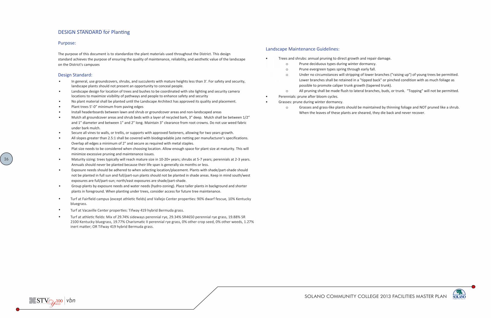
Purpose:
The purpose of this document is to standardize the plant materials used throughout the District. This design standard achieves the purpose of ensuring the quality of maintenance, reliability, and aesthe c value of the landscape on the District's campuses
Design Standard:• In general, use groundcovers, shrubs, and succulents with mature heights less than 3'. For safety and security,
landscape plants should not present an opportunity to conceal people.• Landscape design for location of trees and bushes to be coordinated with site lighting and security camera
locations to maximize visibility of pathways and people to enhance safety and security• No plant material shall be planted un l the Landscape Architect has approved its quality and placement.• Plant trees 5’-0” minimum from paving edges• Install headerboards between lawn and shrub or groundcover areas and non-landscaped areas• Mulch all groundcover areas and shrub beds with a layer of recycled bark, 3” deep. Mulch shall be between 1/2”
and 1” diameter and between 1” and 2” long. Maintain 3" clearance from root crowns. Do not use weed fabric under bark mulch.
• Secure all vines to walls, or trellis, or supports with approved fasteners, allowing for two years growth.• All slopes greater than 2.5:1 shall be covered with biodegradable jute netting per manufacturer's specifications.
Overlap all edges a minimum of 2" and secure as required with metal staples.• Plat size needs to be considered when choosing location. Allow enough space for plant size at maturity. This will
minimize excessive pruning and maintenance issues.• Maturity sizing: trees typically will reach mature size in 10-20+ years; shrubs at 5-7 years; perennials at 2-3 years.
Annuals should never be planted because their life span is generally six months or less.• Exposure needs should be adhered to when selecting location/placement. Plants with shade/part-shade should
not be planted in full sun and full/part-sun plants should not be planted in shade areas. Keep in mind south/west exposures are full/part-sun; north/east exposures are shade/part-shade.
• Group plants by exposure needs and water needs (hydro-zoning). Place taller plants in background and shorter plants in foreground. When planting under trees, consider access for future tree maintenance.
DESIGN STANDARDSolano Community College District 32 90 00
1 01.16.2014
Landscape Maintenance Guidelines:
• Trees and shrubs: annual pruning to direct growth and repair damage.o Prune deciduous types during winter dormancy.o Prune evergreen types spring through early fall.o Under no circumstances will stripping of lower branches ("raising up") of young trees be permitted.
Lower branches shall be retained in a "tipped back" or pinched condition with as much foliage aspossible to promote caliper trunk growth (tapered trunk).
o All pruning shall be made flush to lateral branches, buds, or trunk. "Topping" will not be permitted.• Perennials: prune after bloom cycles.• Grasses: prune during winter dormancy.
o Grasses and grass-like plants should be maintained by thinning foliage and NOT pruned like a shrub.When the leaves of these plants are sheared, they die back and never recover.
11
SOLANO COMMUNITY COLLEGE 2013 FACILITIES MASTER PLAN
DESIGN STANDARDSolano Community College District 32 90 00
TREE PALETTESTANDARD for DESIGN Plan ng
Purpose:
The purpose of this document is to standardize the plant materials used throughout the District. This design standard achieves the purpose of ensuring the quality of maintenance, reliability, and aesthe c value of the landscape on the District's campuses
Design Standard:• In general, use groundcovers, shrubs, and succulents with mature heights less than 3'. For safety and security,
landscape plants should not present an opportunity to conceal people.• Landscape design for location of trees and bushes to be coordinated with site lighting and security camera
locations to maximize visibility of pathways and people to enhance safety and security• No plant material shall be planted un l the Landscape Architect has approved its quality and placement.• Plant trees 5’-0” minimum from paving edges• Install headerboards between lawn and shrub or groundcover areas and non-landscaped areas• Mulch all groundcover areas and shrub beds with a layer of recycled bark, 3” deep. Mulch shall be between 1/2”
and 1” diameter and between 1” and 2” long. Maintain 3" clearance from root crowns. Do not use weed fabric under bark mulch.
• Secure all vines to walls, or trellis, or supports with approved fasteners, allowing for two years growth.• All slopes greater than 2.5:1 shall be covered with biodegradable jute netting per manufacturer's specifications.
Overlap all edges a minimum of 2" and secure as required with metal staples.• Plat size needs to be considered when choosing location. Allow enough space for plant size at maturity. This will
minimize excessive pruning and maintenance issues.• Maturity sizing: trees typically will reach mature size in 10-20+ years; shrubs at 5-7 years; perennials at 2-3 years.
Annuals should never be planted because their life span is generally six months or less.• Exposure needs should be adhered to when selecting location/placement. Plants with shade/part-shade should
not be planted in full sun and full/part-sun plants should not be planted in shade areas. Keep in mind south/west exposures are full/part-sun; north/east exposures are shade/part-shade.
• Group plants by exposure needs and water needs (hydro-zoning). Place taller plants in background and shorter plants in foreground. When planting under trees, consider access for future tree maintenance.
DESIGN STANDARDSolano Community College District 32 90 00
1 01.16.2014
Landscape Maintenance Guidelines:
• Trees and shrubs: annual pruning to direct growth and repair damage.o Prune deciduous types during winter dormancy.o Prune evergreen types spring through early fall.o Under no circumstances will stripping of lower branches ("raising up") of young trees be permitted.
Lower branches shall be retained in a "tipped back" or pinched condition with as much foliage aspossible to promote caliper trunk growth (tapered trunk).
o All pruning shall be made flush to lateral branches, buds, or trunk. "Topping" will not be permitted.• Perennials: prune after bloom cycles.• Grasses: prune during winter dormancy.
o Grasses and grass-like plants should be maintained by thinning foliage and NOT pruned like a shrub.When the leaves of these plants are sheared, they die back and never recover.
Turf at Fairfield campus (except athletic fields) and Vallejo Center properties: 90% dwarf fescue, 10% Kentucky bluegrass.
Turf at Vacaville Center properties: Tifway 419 hybrid Bermuda grass.
Turf at athletic fields: Mix of 29.74% sideways perennial rye, 29.34% SR4650 perennial rye grass, 19.88% SR 2100 Kentucky bluegrass, 19.77% Charismatic II perennial rye grass, 0% other crop seed, 0% other weeds, 1.27% inert matter; OR Tifway 419 hybrid Bermuda grass.

27
SOLANO COMMUNITY COLLEGE 2013 FACILITIES MASTER PLAN
Acer Rubrum ‘New World’New World Red MapleLocation: Secondary SpinesHeight: 30’Spread: 15’Deciduous
Carpinus betulus ‘Frans Fontaine’Columnar HornbeamLocation: Primary SpinesHeight: 35’Spread: 15’Deciduous
TREE PALETTE
Spine & Bosque Trees
LEGENDSUN/SHADE REQUIREMENTS
FULL SUN
PARTIAL SUN
SHADE
CALIFORNIA NATIVE
WATER REQUIREMENTS
VERY LOW
LOW
MODERATE
REGULAR
Zelkova serrata ‘Musashino’ZelkovaLocation: Tertiary SpinesHeight: 40’Spread: 15’Deciduous
Canopy/Shade Trees
Celtis sinensisChinese HackberryHeight: 35’Spread: 35’Deciduous
Ulmus parvifoliaChinese ElmHeight: 50’Spread: 60’Deciduous
Prunus serrulata ‘Amanogawa’Amanogawa Japanese Flowering CherryHeight: 25’Spread: 4’ to 8’Deciduous
Prunus x yedoensisAkebono CherryHeight: 25’Spread: 25’Deciduous
Quecus rubra ‘Fastigiata’Columnar English OakHeight: 50’Spread: 15’Deciduous

28
SOLANO COMMUNITY COLLEGE 2013 FACILITIES MASTER PLAN
Parking Lot/Shade Trees
Pistacia chinensisChinese PistacheHeight: 30’ to 60’Spread: 30’ to 60’Deciduous
Platanus x hispanica ‘Columbia’London Plane TreeHeight: 50’Spread: 30’Deciduous
Quercus VirginianaSouthern Live OakHeight: 40’ to 60’Spread: 40’ to 60’Evergreen
Parking Lot/Shade Trees
Orchard Trees
Chitalpa tashkenensisChitalpaHeight: 25’Spread: 20’ to 30’Deciduous
Lagerstroemia indicaCrape MyrtleHeight: 25’Spread: 25’Deciduous
Malus spp.CrabappleHeight: 25’Spread: 25’Deciduous
Screen Trees
Elaeocarpus decipiensJapanese BlueberryHeight: 50’Spread: 25’Evergreen
Laurus nobilis ‘Saratoga’Sweet BayHeight: 30’Spread: 30’Evergreen
Podocarpus gracilior ‘Icee Blue’Blue Ice Yellow-WoodHeight: 20’Spread: 20’Evergreen

29
SOLANO COMMUNITY COLLEGE 2013 FACILITIES MASTER PLAN
Trees
Acacia baileyanaBailey AcaciaHeight: 20’ to 30’Spread: 20’ to 40’Evergreen
Arbutus ‘Marina’Marina MadroneHeight: 25’ to 30’Spread: 20’ to 25’Evergreen
Cotinues coggygria ‘Royal Purple’Royal Purple Smoke BushHeight: 10’ to 15’Spread: 10’ to 15’Deciduous
Feijoa sellowianaPineapple GuavaHeight: 15’ to 20’Spread: 15’ to 20’Evergreen
Fraxinus angustifolia ‘Raywood’Raywood AshHeight: 40’ to 50’Spread: 25’ to 35’Deciduous
Geijera parvifoliaAustralian WillowHeight: 25’ to 30’Spread: 20’ to 25’Evergreen
Ginkgo biloba ‘Autumn Gold’Autumn Gold Maidenhair TreeHeight: 40’ to 45’Spread: 30’ to 35’Deciduous
Rhus lanceaAfrican SumacHeight: 20’ to 30’Spread: 20’ to 30’Evergreen
Vitex agnus-castusChaste TreeHeight: 10’ to 15’Spread: 10’ to 15’Deciduous

30
SOLANO COMMUNITY COLLEGE 2013 FACILITIES MASTER PLAN
PLANTING PALETTESee legend above for sun/shade & water requirements
Groundcovers & Vines
Acacia redolensProstrate WattleHeight: 3’ to 6’Spread: 6’ to 12’Evergreen
Arctostaphylos uva-ursiKinnikinnick ManzanitaHeight: 6” to 1’Spread: 6” to 1’Evergreen
Bergenia crassifoliaWinter Blooming BergeniaHeight: 1’Spread: 2’Evergreen
Carex pansaDune SedgeHeight: 10” Spread: 1’Evergreen
Ceanothus griseus horizontalis ‘Yankee Point’CeanothusHeight: 2’ to 3’Spread: 8’ to 10’Evergreen
Cistus salviifolius ‘Prostratus’Sageleaf RockroseHeight: 2’ to 3’Spread: 5’ to 6’Evergreen
Cotoneaster dammeri ‘Lowfast’Lowfast BearberryHeight: 1’ to 2’Spread: 6’ to 8’Deciduous
Erigeron karvinskianusSanta Barbara DaisyHeight: 18’Spread: 2’Evergreen
Ficus pumilaCreeping FigFast GrowerEvergreen
Gazania hybridsGazaniaHeight: 6” to 1’Spread: 2’ to 4’Evergreen
Geranium ‘Rozanne’Rozane CranesbillHeight: 1’ to 2’Spread: 2’ to 3’Evergreen
Hypericum calycinumSt. John’s WartHeight: 1’Spread: 2’ to 4’Evergreen
Lantana montevidensisLantanaHeight: 2’ to 3’Spread: 2’ to 4’Semi-Evergreen
Leymus condensatus ‘Canyon Prince’Giant Wild RyeHeight: 2’Spread: 2’Evergreen

31
SOLANO COMMUNITY COLLEGE 2013 FACILITIES MASTER PLAN
Penstemon heterophyllusFoothill PenstemonHeight: 1’ to 2’Spread: 2’ to 3’Semi-Evergreen
Rosa x NoatraumFlower Carpet Pink Groundcover RoseHeight: 2’Spread: 3’Deciduous
Rosmarinus offi cinalis ‘Prostratus’RosemaryHeight: 2’Spread: 3’ to 4’Evergreen
Salivia ‘Bee’s Bliss’Bee’s Bliss SageHeight:1’ to 2’Spread: 4’ to 6’Evergreen
Salvia sonomensisSonoma SageHeight: 1’Spread: 3’ to 4’Evergreen
Teucrium x lucidrysProstrate GermanderHeight: 1’Spread: 2’Evergreen
Trachelospermum jasminoidesStar JasmineHeight: 2’Spread: 4’Evergreen
Veronica prostrataProstrate SpeedwillHeight: 1’Spread: 2’Evergreen
Succulents
Agave AttenuataFox Tail AgaveHeight: 2’ to 3’Spread: 4’ to 6’Evergreen
Aloe ArborescensTorch AloeHeight: 3’ to 4’Spread: 3’ to 4’Evergreen
Aloe ‘Johnson Hybrid’Johnson’s AloeHeight: 1’ to 2’Spread: 1’ to 2’Evergreen
Aloe saponariaSoap AloeHeight: 12” to 18”Spread: 2’ to 3’Evergreen
Echeveria secundaHens & ChicksHeight: 6” to 9”Spread: 1’ to 2’Evergreen
Sedum ‘Autumn Joy’Autumn Joy Stone CropHeight: 1’ to 2’Spread: 2’ to 3’Deciduous
Sempervivum tectorumHouseleekHeight: 6” to 12”Spread: 1’ to 2’Evergreen

32
SOLANO COMMUNITY COLLEGE 2013 FACILITIES MASTER PLAN
Senecio mandraliscaeChalksticksHeight: 12” to 18”Spread: 2’ to 3’Evergreen
Yucca pallidarSoapweed YuccaHeight: 1’ to 2’Spread: 3’ to 4’Evergreen
Low Shrubs
Achillea millefolium ‘Island Pink’Island Pink YarrowHeight: 1’Spread: 2’Semi-Evergreen
Bergenia cordifoliaBergeniaHeight: 1’ to 2’Spread: 1.5’ to 2.5’Evergreen
Carex divulsaSedgeHeight: 1’ to 1.5’Spread: 1’ to 2.5’Evergreen
Coleonema pulchrum ‘Sunset Gold’Breath of HeavenHeight: 1.5’ to 2.5’Spread: 2.5’ to 4’Evergreen
Coprosma kirkii ‘Variegata’CoprosmaHeight: 1’ to 3’Spread: 5’Evergreen
Euonymus fortunei ‘Emerald n Gold’Emerald n Gold Winter CreeperHeight: 2’Spread: 4’ to 5’Evergreen
Euonymus fortunei ‘Ivory Jade’Ivory Jade Winter CreeperHeight: 2’Spread: 4’ to 5’Evergreen
Festuca glaucaBlue FescueHeight: 6” to 1’Spread: 10” to 1’Evergreen
Helictotrichon sempervirensBlue Oat GrassHeight: 2’ to 3’Spread: 2’ to 3’Evergreen
Helleborus argutifoliusCorsican HelleboreHeight: 2’ to 3’Spread: 2’ to 3’Evergreen
Heuchera maximaIsland Alum RootHeight: 1’ to 2’Spread: 2’ to 3’Evergreen
Leptospermum scoparium ‘Pink Cascade’Pink Cascade ManukaHeight: 1’Spread: 3’ to 4’Evergreen
Liriope muscariLilyturfHeight: 6” to 1’Spread: 1’ to 1.5’Evergreen

33
SOLANO COMMUNITY COLLEGE 2013 FACILITIES MASTER PLAN
Intermediate Shrubs
Santolina chamaecyparissus cvs.Lavendar CottonHeight: 1’ to 2’Spread: 2’ to 3’Evergreen
Sarcococca hookeriana humilisSweet BoxHeight: 1’ to 2’Spread: 5’ to 6’Evergreen
Tulbaghia violacea ‘Silver lace’Society GarlicHeight: 18”Spread: 2’Evergreen
Abelia grandiflora ‘Kaleidoscope’ also ‘Confetti’ & ‘Mardi Gras’Kaleidoscope AbeliaHeight: 2’ to 3’Spread: 3’ to 4’Evergreen
Berberis thunbergii atropurpurea ‘Crimson Pygmy’ & ‘Golden Ring’BarberryHeight: 2’ to 3’Spread: 3’Deciduous
Calamagrostis acutiflora ‘Karl Foerster’Karl FoersterHeight: 2’ to 3’Spread: 2’ to 3’Evergreen
Callistemon viminalis ‘Little John’BottlebrushHeight: 2.5’ to 3’Spread: 3’ to 3.5’Evergreen
Cistis x pulverulentus ‘Sunset’Sunset RockroseHeight: 2’ to 3’Spread: 5’ to 7’Evergreen
Cistis x skanbergiiSkanbergii RockroseHeight: 3’Spread: 6’ to 8’Evergreen
Correa pulchella ‘Mission Bells’Mission Bells Australian FuchsiaHeight: 2’ to 3’Spread: 4’ to 6’Evergreen
Euonymus fortunei ‘Canadale Gold’ also ‘Ivory Jade’ & ‘Emerald Gaiety’”Canadale Gold WintercreeperHeight: 3’ to 4’Spread: 3’ to 3.5’Evergreen
Euphorbia amygdaloides ‘Purpurea’Purpurea SageHeight: 2’ to 3’Spread: 2’Evergreen
Euphorbia x martiniMartin SpurgeHeight: 2’ to 3’Spread: 2’ to 3’Evergreen
Hemerocallis hybrids (evergreen)DaylilyHeight: 2’ to 3’Spread: 2’ to 3’Evergreen
Hesperaloe parvifoliaRed YuccaHeight: 2’ to 3’Spread: 3’ to 4’Evergreen
34
SOLANO COMMUNITY COLLEGE 2013 FACILITIES MASTER PLAN
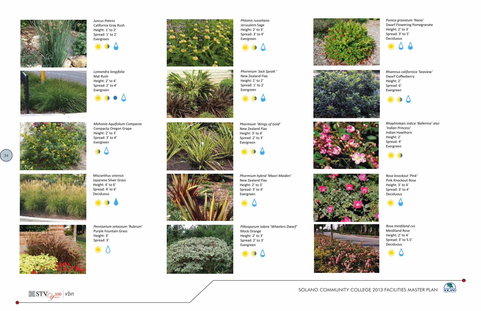
Juncus PatensCalifornia Gray RushHeight: 1’ to 2’Spread: 1’ to 2’Evergreen
Lomandra longifoliaMat RushHeight: 2’ to 4’Spread: 2’ to 4’Evergreen
Mahonia Aquifolium CompactaCompacta Oregon GrapeHeight: 2’ to 3’Spread: 3’ to 4’Evergreen
Miscanthus sinensisJapanese Silver GrassHeight: 4’ to 6’Spread: 4’ to 6’Deciduous
Pennisetum setaceum ‘Rubrum’Purple Fountain GrassHeight: 3’Spread: 3’
Phlomis russelianaJerusalem SageHeight: 2’ to 3’Spread: 3’ to 4’Evergreen
Phormium ‘Jack Spratt ’New Zealand FlaxHeight: 1’ to 2’Spread: 1’ to 2’Evergreen
Phormium ‘Wings of Gold’New Zealand FlaxHeight: 3’ to 4’Spread: 2’ to 3’Evergreen
Phormium hybrid ‘Maori Maiden’New Zealand FlaxHeight: 2’ to 3’Spread: 3’ to 4’Evergreen
Pittosporum tobira ‘Wheelers Dwarf’Mock OrangeHeight: 2’ to 3’Spread: 2’ to 3’Evergreen
Punica granatum ‘Nana’Dwarf Flowering PomegranateHeight: 2’ to 3’Spread: 3’ to 5’Deciduous
Rhamnus californica ‘Seaview’Dwarf CoffeeberryHeight: 2’Spread: 6’Evergreen
Rhaphiolepis indica ‘Ballerina’ also ‘Indian Princess’Indian HawthornHeight: 2’Spread: 4’Evergreen
Rosa knockout ‘Pink’Pink Knockout RoseHeight: 3’ to 4’Spread: 3’ to 4’Deciduous
Rosa meidiland cvsMeidiland RoseHeight: 2’ to 4’Spread: 3’ to 5.5’Deciduous
35
SOLANO COMMUNITY COLLEGE 2013 FACILITIES MASTER PLAN
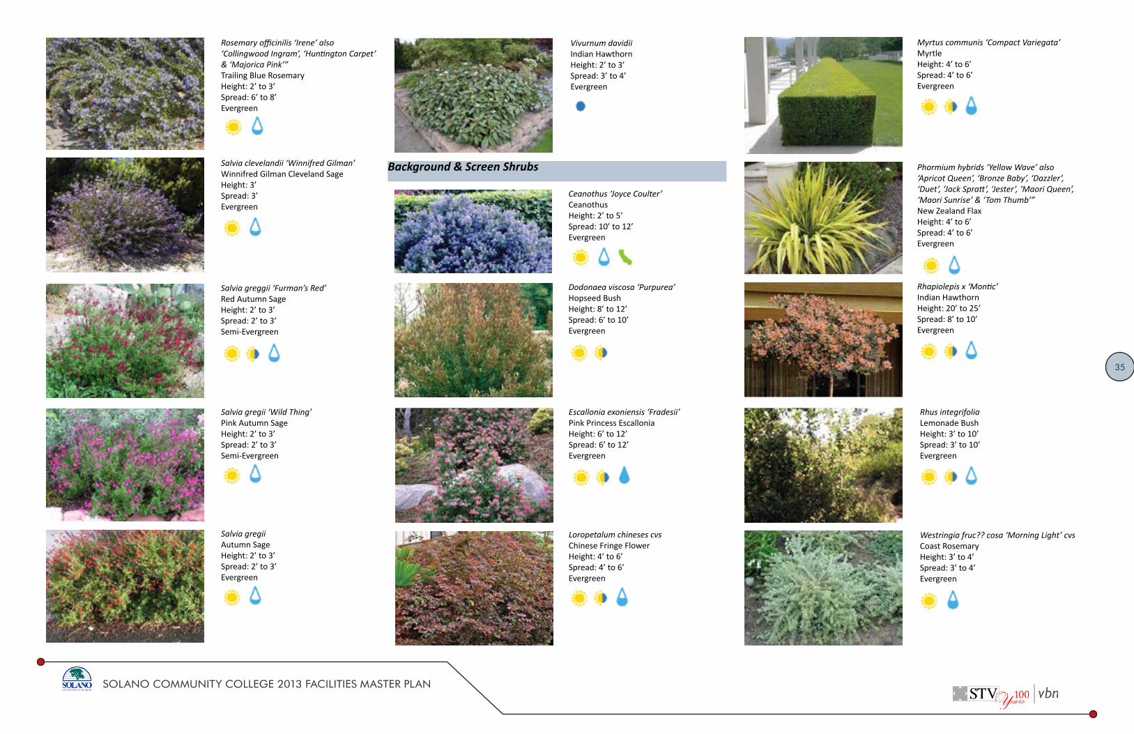
Rosemary officinilis ‘Irene’ also ‘Collingwood Ingram’, ‘Huntington Carpet’ & ‘Majorica Pink’”Trailing Blue RosemaryHeight: 2’ to 3’Spread: 6’ to 8’Evergreen
Salvia clevelandii ‘Winnifred Gilman’Winnifred Gilman Cleveland SageHeight: 3’Spread: 3’Evergreen
Salvia greggii ‘Furman’s Red’Red Autumn SageHeight: 2’ to 3’Spread: 2’ to 3’Semi-Evergreen
Salvia gregii ‘Wild Thing’Pink Autumn SageHeight: 2’ to 3’Spread: 2’ to 3’Semi-Evergreen
Salvia gregiiAutumn SageHeight: 2’ to 3’Spread: 2’ to 3’Evergreen
Vivurnum davidiiIndian HawthornHeight: 2’ to 3’Spread: 3’ to 4’Evergreen
Background & Screen Shrubs
Ceanothus ‘Joyce Coulter’CeanothusHeight: 2’ to 5’Spread: 10’ to 12’Evergreen
Dodonaea viscosa ‘Purpurea’Hopseed BushHeight: 8’ to 12’Spread: 6’ to 10’Evergreen
Escallonia exoniensis ‘Fradesii’Pink Princess EscalloniaHeight: 6’ to 12’Spread: 6’ to 12’Evergreen
Loropetalum chineses cvsChinese Fringe FlowerHeight: 4’ to 6’Spread: 4’ to 6’Evergreen
Myrtus communis ‘Compact Variegata’MyrtleHeight: 4’ to 6’Spread: 4’ to 6’Evergreen
Phormium hybrids ‘Yellow Wave’ also ‘Apricot Queen’, ‘Bronze Baby’, ‘Dazzler’, ‘Duet’, ‘Jack Spratt’, ‘Jester’, ‘Maori Queen’, ‘Maori Sunrise’ & ‘Tom Thumb’”New Zealand FlaxHeight: 4’ to 6’Spread: 4’ to 6’Evergreen
Rhapiolepis x ‘Montic’Indian HawthornHeight: 20’ to 25’Spread: 8’ to 10’Evergreen
Rhus integrifoliaLemonade BushHeight: 3’ to 10’Spread: 3’ to 10’Evergreen
Westringia fruc?? cosa ‘Morning Light’ cvsCoast RosemaryHeight: 3’ to 4’Spread: 3’ to 4’Evergreen

36
SOLANO COMMUNITY COLLEGE 2013 FACILITIES MASTER PLAN
DESIGN STANDARD Solano Community College District Division 12 93 00
1 01.16.2014
DESIGN STANDARD for Tables and Chairs Purpose:
The purpose of this document is to standardize the tables and chairs used for group seating. This design standard ensures the quality of maintenance, reliability, and safety of tables and chairs on campus.
Design Standard:
Must allow clearance for pedestrian movement around tables and chairs
Should be placed in a variety of settings, with some shade
Must be ADA compliant
Approved Manufacturers:
Victor Stanley; FBF‐56 Streetsites Series, 8’ Steel Table and (2) 6’ Benches
o Color: Powder coat grey
o Mount: In‐Ground
Victor Stanley; A‐I‐424 Anthrosites Series, all metal
o Color: Powder coat grey
o Mount: In‐Ground
Substitutes Allowed:
Approved manufacturer or approved equal
Associated Design Standards and Construction Specifications
Install per manufacturer’s specifications.
DESIGN STANDARD Solano Community College District Division 12 93 00
2 01.16.2014

37
SOLANO COMMUNITY COLLEGE 2013 FACILITIES MASTER PLAN
DESIGN STANDARD Solano Community College District Division 12 93 00
3 01.16.2014
DESIGN STANDARD Solano Community College District Division 12 93 00
1 01.16.2014
DESIGN STANDARD for Trash and Recycling Receptacles
Purpose:
The purpose of this document is to standardize the trash, waste, and recycling receptacles used throughout all the campuses.
Design Standard:
Trash and recycling should be placed together
Place at main entrances to buildings, plazas, and pedestrian walkways
Place with other site furniture for functional and organized gathering areas
Approved Manufacturers:
Landscape Forms: Scarborough Litter Receptacle with 30-gallon side opening, Vertical strap, with Lock
o Finish: Pangard II® polyester
o Color: powder coat Stormcloud for trash receptacles; powder coat Bluebell for recycling receptacles
Landscape Forms: Scarborough Receptacle with 30-gallon side opening, Vertical strap, dual use
o Finish: Pangard II® polyester
o Color: powder coat Stormcloud for trash receptacles; powder coat Bluebell for recycling receptacles
Substitutes Allowed:
Approved manufacturer or approved equal.
Associated Design Standards and Construction Specifications
Install per manufacturer’s specifications

38
SOLANO COMMUNITY COLLEGE 2013 FACILITIES MASTER PLAN
DESIGN STANDARD Solano Community College District Division 12 93 00
2 01.16.2014
DESIGN STANDARD Solano Community College District Division 12 93 00
3 01.16.2014

39
SOLANO COMMUNITY COLLEGE 2013 FACILITIES MASTER PLAN
DESIGN STANDARD Solano Community College District Division 12 93 00
1 10.7.2013
DESIGN STANDARD for Tree Grates Purpose:
The purpose of this document is to standardize the tree grates used throughout the campus. This design standard achieves the purpose of ensuring the quality of maintenance, reliability, and aesthetic value of these objects on campus.
Design Standard:
Can be used in high traffic areas or where space is limited
Approved Manufacturers:
IronSmith. Metro Tree Grate, ½” slots, with anti‐theft hardware
o Material: Cast aluminum
o Finish: Brushed
Substitutes Allowed:
Ironsmith Metro Tree Grate or approved equal
Associated Design Standards and Construction Specifications
Install per manufacturer specifications
DESIGN STANDARD Solano Community College District Division 12 93 00
2 10.7.2013

40
SOLANO COMMUNITY COLLEGE 2013 FACILITIES MASTER PLAN
Architectural Standards
DESIGN STANDARD Solano Community College District Acoustical Panel Ceilings
For Standard Typical Applications: 1. Lowest Grade of Acoustic Ceiling Panel: use only when acoustic criteria, light
reflectance, recycled content and humidity resistance are not of high priority and the space is temporary or of utility use only.
o Size: 2’ x 4’ x 5/8” Flat Panel o Color: White o Style: Square Lay‐in o NRC Rating: 0.55 o CAC Rating: 0.35 o LR Rating: 0.80 o Recycled Content: not less than 40% o Cost Rating: $ o Product: USG Radar #2315 or equivalent in performance criteria above.
2. Highest Grade of Acoustic Ceiling Panel: for normal occupied classroom, corridor and office spaces. This panel has the “second look” in that it is a 2’ x 4’ panel with a tegular 2’ x 2’ appearance, which adds textural richness to the ceiling plane while still using the economical and easily accessible larger grid spacing.
o Size: 2’ x 4’ x 5/8” Flat Panel o Color: White o Style: Angled Tegular o NRC Rating: 0.70 o CAC Rating: 0.35 or higher o LR Rating: 0.85 o Recycled Content: no less than 40% o Cost Rating: $$ o Product: USG Millennia Clima Plus, Illusion Two/24 Panels, SLT Edge detail,
Panel #78780, or equivalent as long as “second look” aesthetic and performance criteria as noted above are met.
3. Special Grade of Acoustic Ceiling Panel: for applications such as computer and control rooms, kitchens/food prep areas (specify Class 100 panels) and laboratories that may require this level of cleanability.
o Size: 2’ x 4’ x 3/4” Flat Panel o Class: 10M‐100M Panels typical, Class 100 panels for Kitchen/Prep Areas. o Color: White o Style: Square o NRC Rating: 0.55 o CAC Rating: 0.35 o LR Rating: 0.79 o Recycled Content: no less than 40% o Cost Rating: $$$ o Product: USG Clean Room ClimaPlus, 10M‐100M Panels, Panel # 56090 or
equivalent as long as performance criteria as noted above are met. Suspended Grid System: USG Donn/DX series, white.
Page 2 of 3 4.9.2014
Page 1 of 3 4.9.2014
DESIGN STANDARD Solano Community College District Acoustical Panel Ceilings
DESIGN STANDARD for Acoustical Panel Ceilings Purpose:
The purpose of this design standard is to achieve the following performance and sustainability criteria for acoustical ceiling panels installed at the Solano Community College District sites:
High noise reduction and CAC coefficients Good light reflectance to conserve energy associated with mechanical lighting Product using recycled content High humidity resistance to prevent sagging
Note: these Design Standards are a tool to clarify direction and streamline project execution for design professionals, construction managers and other participants in capital improvement projects. They represent the District’s “strong preference” and should be applied, when possible, without compromising the creativity of the overall design. Final disposition, color, size, product choice etc. should conform to the best extent possible where equivalent substitutes are allowed in the Design Standard. If equivalent substitutes are allowed only “if performance and quality equivalency can be evidenced” or the consultant wishes to deviate from the written design standards for other reasons, then the consultant needs to provide evidence/justification and seek District approval as outlined in the Open this Document First: Standards Process.pdf. In all cases the written design standards do not diminish or eliminate the standard of care owed by the consultant to SCCD or relieve, in any manner whatsoever, a consultant from any professional responsibility, duty or due diligence required toward that work.
Design Standard:
Solano College’s preference is to simplify design, construction and maintenance by limiting panels to one type (and standard sizes) in any given project, unless programmatic requirements call for specialized/unusual sized panels in certain areas.
Specialized/unusual size panels have to be reviewed and approved by the Director of Facilities. Larger size panels are harder to remove and replace so factors contributing to approval are the location of panels with respect to items above ceilings that need to be maintained/serviced.
Design Professionals should specify that contractor is to provide 10% attic stock for all panel types used on this project.
o This attic stock will be stored in the Custodial Main Storage Room within the same building (see Design Standard for Custodial Spaces). Doing so avoids confusion with which panels belong to which buildings and reduces maintenance time associated with locating extra stock and replacing panels.

41
SOLANO COMMUNITY COLLEGE 2013 FACILITIES MASTER PLAN
Page 3 of 3 4.9.2014
DESIGN STANDARD Solano Community College District Acoustical Panel Ceilings
Approved Manufacturers:
As noted in this Standard. Substitutes Allowed:
As noted in this Standard.
Associated Design Standards and Construction Specifications
Design Standard for Custodial Spaces.
End of Document
Page 1 of 4 4.9.2014
DESIGN STANDARD Solano Community College District Casework
DESIGN STANDARD for Casework Purpose:
The purpose of this design standard is to create a consistent standard for the quality, reliability and ease of maintenance for casework throughout the Solano Community College District. Casework must be designed and installed with the understanding that it will be subject to decades of use, abuse and continually changing applications. Casework should be simple and intuitive to use. Surface materials should hide dirt and wear, while being aesthetically pleasing.
Note: these Design Standards are a tool to clarify direction and streamline project execution for design professionals, construction managers and other participants in capital improvement projects. They represent the District’s “strong preference” and should be applied, when possible, without compromising the creativity of the overall design. Final disposition, color, size, product choice etc. should conform to the best extent possible where equivalent substitutes are allowed in the Design Standard. If equivalent substitutes are allowed only “if performance and quality equivalency can be evidenced” or the consultant wishes to deviate from the written design standards for other reasons, then the consultant needs to provide evidence/justification and seek District approval as outlined in the Open this Document First: Standards Process.pdf. In all cases the written design standards do not diminish or eliminate the standard of care owed by the consultant to SCCD or relieve, in any manner whatsoever, a consultant from any professional responsibility, duty or due diligence required toward that work.
Design Standard:
1. Countertops Science or Vocational laboratory countertops shall be cast of epoxy resin for the following
reasons:
o Solid materials, such as epoxy resin, do not delaminate, nor do they contain off‐ gassing glues/binders; therefore, the quality of indoor air is healthier.
o Epoxy resin does not depend on a surface coating for chemical resistance. o Molded construction allows for integral back‐splashes and marine edges. o A non‐glare matte finish is attractive and easy to maintain. o Plastic Laminates are not permitted for Science or Vocational Laboratory countertops.
SCCD’s preference for other countertops is natural stone such as slab granite, recycled
glass material Terrazo, composite engineered stone, or a solid material such as epoxy resin for the following reasons:
o These materials does not contain off‐gassing glues/binders; therefore they contribute to healthier indoor air quality, and they do not have the de‐lamination issues associated with plastic laminates.

42
SOLANO COMMUNITY COLLEGE 2013 FACILITIES MASTER PLAN
Page 2 of 4 4.9.2014
DESIGN STANDARD Solano Community College District Casework
For non‐wet conditions alternate materials will be considered. Design professionals are
encouraged to consider sustainable products such as wood and bamboo, 9‐ply plywood and other similar sustainably produced products that do not contain off‐gassing glues/binders. Plastic laminates are discouraged due to the de‐lamination issues, but may be permitted on a case by case basis.
For countertops with sinks: locate sink faucets so that outlet is well over sink to prevent water splashing onto counter top.
o Sinks shall be fabricated of a material equal to or better than counter top material. Verify required size and depth of sinks with User.
All edges shall have fused edging, such as 3MM PVC, and backer sheet. Self‐edges, T‐mold or bull‐nosed laminate edges are unacceptable.
2. Casework: Casework shall be WIC Certified. The use of the WIC Manual of Millwork as a standard of performance is acceptable
provided the specific grades which are applicable are specified. o Minimum quality for casework shall be WIC Custom Grade. o Science and vocational laboratory casework shall be WIC Laboratory quality.
Include in construction specifications the requirement for contractor to arrange for and pay costs of WIC inspections, and obtain WIC Certified Compliance Label on each unit of casework indicating grade specified. In order to allow non‐WIC licensed millwork contractors to bid on SCCD projects, include the following provision in construction specifications:
“Millwork specified shall be manufactured in accordance with the standards established in the Manual of Millwork of the Woodwork Institute of California, current edition, in the grade or grades hereinafter specified or as shown on the drawings. If the manufacturer of millwork is not a WIC licensee, Contractor shall furnish to Architect, prior to installation, a Certificate of Re‐inspection by the WIC indicating that the millwork in question meets the requirements of the WIC grade specified. If the manufacturer of millwork is a WIC licensee, each unit of millwork shall bear the WIC Certified Compliance grade stamp indicating the grade specified, and by the completion of the job WIC Certified Compliance Certificates shall be provided indicating the grade specified. The foregoing shall not be construed to limit the power and authority of Architect to reject millwork which does not, in Architect's opinion, meet with any one or more of the specifications of the contract.”
Page 3 of 4 4.9.2014
DESIGN STANDARD Solano Community College District Casework
• Casework Design Guidelineso Casework is to be of modular design (4'‐ 0" lengths) for ease of access to building site
and possible reuse in future remodeling work.o Design drawers and shelves for heavy loading; use metal standards/rests and/or guides
only with a minimum load carrying capacity of 125 pounds.o Specify adequate backing in stud walls for attachment of casework, and detail same on
Drawings.o Verify if User requires locks for casework doors and/or drawers. If locks are required,
verify keying requirements with User. Comply with Design Standard for Door Hardware.
o Verify if User requires glazed or full glass casework doors.o Where plastic laminate is used for casework cabinet bodies, verify with User whether
chemical resistant type is required. If wood is used for casework bodies, verify with User whether finish must be chemical resistant.
o Design of shelving span shall be verified with User, since they may load same with heavy equipment, etc.
o All edges shall have fused edging, such as 3mm PVC, and backer sheet. Self‐edges, T‐mold or bull‐nosed laminate edges are unacceptable.
o Design minimal design details (nooks, crannies, edges in millwork) which require additional time or labor for cleaning.
o Specify standard rubber base around exposed bases of casework, to create a unified appearance at the base of walls and casework. Direct contractor to run a bead of silicone caulk where casework base meets floor, prior to installation of rubber base, to ensure that floor cleaning activities do not damage the structural integrity of the casework base. Comply with Design Standard for Flooring for rubber base specification.
o Design sloped wall cabinet tops, to discourage storage of items which is a safety hazard and a cleaning burden.
o Casework must be adjustable over time to accommodate new contents, changes in teaching styles and technology. Ensure that such flexibility is achievable by non‐tradespersons; i.e., design such flexibility into the initial design of the casework.
o Specify adjustable metal shelf standards and rests.o Drawer and door pulls shall be 4” metal wire pull type, in stainless steel or satin nickel.o Cabinet locks: comply with requirements stated Design Standard for Door Hardware.o Drawer Slides: full extension steel slides, white epoxy coated, with steel bearing rollers
and integral positive stops, anti-slamming. Static load carrying capacity of minimum 125 pounds.
o Concealed hinges, Grade 2 European Style, 170 degree opening, all steel construction, self‐closing.
o Catch: magnetic catch with plastic housing.
3. Color/Finishes: The casework materials for any given project should be designed in consultation with the
furniture consultant or furniture coordinator, since the architectural and furniture finisheswill be experienced holistically by the building’s end users.

43
SOLANO COMMUNITY COLLEGE 2013 FACILITIES MASTER PLAN
Page 4 of 4 4.9.2014
DESIGN STANDARD Solano Community College District Casework
Approved Manufacturers:
The fabricator shall be equipped for and experienced in doing work, including fabricating, finishing, and installing, equal to standards specified, and be able to provide evidence of such experience to the Architect's and District’s satisfaction. Failure to meet these qualifications may be sufficient cause for rejection.
Substitutes Allowed:
Not Applicable. Associated Design Standards and Construction Specifications
Design Standard for Door Hardware Design Standard for Flooring
End of Document
Page 1 of 4 4.9.2014
DESIGN STANDARD Solano Community College District Custodial Spaces
DESIGN STANDARD for Custodial Spaces
Purpose:
Custodial spaces include Custodial Closets and Facilities Main Storage Rooms. Adequate sized and placed custodial closets are essential for productive and efficient maintenance of a facility. Too small of a closet and too few closets add unproductive labor hours spent going back and forth to closets or other floors to gather custodial supplies and equipment. Similarly, every building must have adequate custodial storage space to store bulk supplies and equipment. The following guidelines will lower the long‐term cost of maintaining a facility with increased productivity and efficiency of the custodial crew.
Note: these Design Standards are a tool to clarify direction and streamline project execution for design professionals, construction managers and other participants in capital improvement projects. They represent the District’s “strong preference” and should be applied, when possible, without compromising the creativity of the overall design. Final disposition, color, size, product choice etc. should conform to the best extent possible where equivalent substitutes are allowed in the Design Standard. If equivalent substitutes are allowed only “if performance and quality equivalency can be evidenced” or the consultant wishes to deviate from the written design standards for other reasons, then the consultant needs to provide evidence/justification and seek District approval as outlined in the Open this Document First: Standards Process.pdf. In all cases the written design standards do not diminish or eliminate the standard of care owed by the consultant to SCCD or relieve, in any manner whatsoever, a consultant from any professional responsibility, duty or due diligence required toward that work.
Design Standard:
A. Custodial Closets:
Closet locations: Placed on every floor with not more than 150 feet between closets. Foreach 15,000 to 18,000 square feet of building floor space, provide a minimum of onecloset. Locate closets adjacent to, or between, restrooms, for economics of plumbing.Alternate preferred location is close to an elevator. Do not locate closets in stairwaylandings or under stairways.
Do not locate electrical panels, elevator controls, telephone equipment, roof hatches andplumbing items inside the closets.
Closet size: should be 8’ x 8’ (64 sq. ft.) minimum. Shelving: Shelving at eye level with a minimum of two 24” deep shelves. Wooden shelves
are more practical than steel because of the corrosion that can occur with chemicals. Forgallon size chemicals a minimum of 18 inches between shelving is required.
Provide adequate ventilation with an exhaust grill in the upper wall or ceiling.

44
SOLANO COMMUNITY COLLEGE 2013 FACILITIES MASTER PLAN
DESIGN STANDARD Solano Community College District Custodial Spaces
• Electrical: Minimum one GFCI (ground fault circuit interrupter) outlet. • Lighting: Provide at least 50 to 75 foot candles of illumination or a minimum two
fluorescent tube ceiling light with a safety guard to protect breaking of tubes. Install a motion light sensor to conserve energy.
B. Facilities Main Storage Room:
• The Facilities Main Storage Room will store bulk supplies and equipment for building
maintenance purposes and it will also store building replacement materials for that particular building (e.g. extra stock for ceiling panels, carpet tiles etc.).
• The Facilities Main Storage Room should not include boilers, water heaters, electrical panels, similar mechanical or electrical equipment, or roof access.
• Facilities Main Storage Room Size: should be 10’ x 20’ (200 sq. ft.) minimum. • The Facilities Main Storage does not replace a Custodial Closet for that particular
floor/area. The Facilities Main Storage is in addition to the Custodial Closet requirements. Should the layout of the Building require these to be combined for a particular floor/area, the size of the combined room shall be 264 sq. ft. minimum.
• Storage location: Near an elevator and normally placed in the lower levels of the facility. • Shelving: Reinforced shelving that is wall mounted along one entire wall. • Provide adequate ventilation with an exhaust grill in the upper wall or ceiling. • Electrical: Several GFCI outlets to charge battery‐operated equipment. • Lighting: Install two sets of two fluorescent tube‐ceiling lights.
C. Doors:
• Comply with Design Standard for Door Hardware. • Door Swing and Space Implications: doors should open outward to gain maximum square
footage. Doors to Custodial and Facilities Main Storage Room spaces to swing outward. If this cannot be accomplished, the size of the room shall be increased by ten square feet.
• Door Size: Custodial Closet: Door should be 36 inches minimum. Facilities Main Storage: Door should be 42 inches minimum.
• Provide Hollow Metal door and door frames per Design Standard for Doors and Door Frames. Door should have a vent and a Stainless Steel armor plate and kick plate on push side of door.
• Door Signage: Provide Room Sign for all Custodial and Facilities Main Storage Room Spaces on wall side adjacent to door lever.
D. Custodial Floor Finish:
• Flooring in Custodial Closets and Facilities Main Storage Room to be smooth concrete with clear
coating. • Product: Rust‐Oleum’s Easyclear® Epoxy Maintenance Floor Coating. No substitutions allowed. • See Design Standard for Flooring for more information.
DESIGN STANDARD Solano Community College District Custodial Spaces
E. Wall Finish:
• At the floor mounted service sink: provide Rigid Sheet Vinyl Material on the wall sides of service sink. Rigid Sheet Vinyl Material Thickness no less than 0.040” and to a height of 48 inches Above Finish Floor. Product: InPro Corp. Wall Protection, Standard Color: Antique White.
• Rest of the Walls 1st Choice: Provide FRP (fiberglass reinforced panel) to a height of four‐feet (4’‐0”) above finish floor on all walls. Provide semi‐gloss, water based epoxy paint at gypsum board above FRP, color: District Standard Navajo White.
• 2nd Choice: concrete block sealed with an epoxy resin similar to Rust‐Oleum® Wet Look Concrete Sealer or equivalent.
• See Design Standard for Interior Paint for more information.
F. Plumbing Fixtures:
• Comply with Design Standard for Plumbing Fixtures for plumbing fixtures, hose bibs and floor drains in each custodial closet and custodial main storage room.
• Service Sink: Floor mounted (24” x 24” x 10”), with a chemical impervious surface and a stainless steel collar.
• Sink faucet: Bibb‐type faucet with hose tread and backflow preventer installed. Install shut off values for the faucets.
• Sink Essentials: Install a mop grip‐all, preferably on the wall without the faucet. Leave space on the faucet‐side wall to install a chemical dilution system.
• Provide one Floor Drain with waterless trap guard per custodial closet/main storage room: nickel bronze drain with trap primer.
Approved Manufacturers:
Per above and referenced Design Standards.
Substitutes Allowed:
As noted within the standard.
Associated Design Standards and Construction Specifications
Design Standard for Door Hardware Design Standard for Doors and Door Frames Design Standard for Interior Paint Design Standard for Plumbing Fixtures
End of Document

45
SOLANO COMMUNITY COLLEGE 2013 FACILITIES MASTER PLAN
4.9.2014
DESIGN STANDARD Solano Community College District Designations
DESIGN STANDARD for Building, Floor, Room, Stairway & Elevator
Purpose:
Designations of buildings, floors, rooms, stairways and elevators are important elements in way‐finding for all on a college campus. SCCD’s goal is to establish naming and numbering protocols that are consistent and naturally intuitive for all end‐users including students, faculty, staff, visitors and maintenance staff.
Design Standard:
1. Campus Designations
The following campus designations for the Solano Community College District are the first characters for all buildings:
FF Fairfield VJ Vallejo VV Vacaville NT Nut Tree
2. Building Designations
The buildings on the Fairfield Campus are identified by number and name. The building number is the most widely recognized identification and is used in class schedules. On all other District sites the buildings are to be identified name.
Page 1 of 3
DESIGN STANDARD Solano Community College District Designations
4. Floor Designations
o Floor numbering will begin with the floor accessed at the main grade as “first floor” andwill be designated with a “1.”
o One floor above will be “second floor” and will be designated with a “2.”o The next floor above that will be “third floor” and will be designated with a “3” if occupied and
accessed by students and faculty. If this floor is a roof it will be called “roof” and designated with a “R.”
o If the Building has a basement that floor will be called “Basement” and designated with a“B.”
5. Room Numbering
o Basement rooms will be designated with two‐digit room numbers (e.g. 01, 02, etc.)o In buildings identified by name (all sites except Fairfield Campus), first floor room numbers will
be the 1000 series; second floor rooms will be the 2000 series, etc.o At the Fairfield campus, where buildings are identified by number, begin numbering of spaces at
the entry to the building with the first space (or corridor) being the building number. Begin upper floor room numbering with a decade number. For example Building 100: second floor room numbers might start at 130, third floor numbers might start at 170." At 5th bullet starting with "Begin", replace "for" with "or" and add a comma after "floor".
o Millennium numbers (1000, 2000, etc.) should be used for main lobbies/main circulation only.o Begin numbering of spaces at the entry to the building for floor turning to the right
and sequencing counterclockwise.o Century or decade numbers may be assigned to departments or functional areas if it is logical to
facilitate wayfinding,o Assign alpha suffixes to rooms whose sole access is from within a room (e.g., if there are rooms
within room 1010, the inner rooms shall be designated room 1010a, 1010b, etc.).Skip letters “I” and “O”.
o Create number intervals to allow future assignments should subdivision occur.o Assign numbers in sequence.o In general, keep even numbered rooms on one side of each corridor, and odd numbered rooms
on the opposite side.o For rooms accessed only from the building exterior, once all interior first floor rooms have been
assigned a number and starting from the building main entry door, move counterclockwise about the exterior of the building and continue the first floor numbering sequence to designate numbers for any rooms which are accessed only from the exteriorof the building.
3.
4.
46
SOLANO COMMUNITY COLLEGE 2013 FACILITIES MASTER PLAN
Page 3 of 3 4.9.2014
DESIGN STANDARD Solano Community College District Designations
6. Stairway Designations o Stairways should be identified by building two‐letter abbreviation or building number and the
predominant cardinal direction (North, South, East and West) of its placement in the building. For example the VV101‐North Stair is the Stair in the Vacaville Center on the North Side.
7. Elevator Designations
o Elevators should be identified by building two‐letter abbreviation or building number and the
predominant cardinal direction (North, South, East and West) of its placement in the building. For example FF400‐East Elevator is the Elevator in Building 400 on the Fairfield Campus located on the East side of the Building.
8. Equipment Designations
o Equipment such as Mechanical and Electrical equipment should be identified using the
building number (or two letter abbreviation for future naming), hyphen, floor number, hyphen, two‐three letter (common) abbreviation for equipment item, hyphen and number 1, 2,3 etc. For example 200‐R‐EF‐3 is the exhaust fan (EF) #3 on the Roof of Building 200.
9. Outlet Designations o Outlets should be identified using the building number (or two letter abbreviation for future
naming), hyphen, floor number, hyphen, “EO” for electrical outlet and “DO” for data outlet, hyphen and number 1, 2, 3 etc.
Approved Manufacturers:
Not Applicable Substitutes Allowed:
Not Applicable Associated Design Standards and Construction Specifications
Not Applicable
End of Document
Page 1 of 6 4.9.2014
DESIGN STANDARD Solano Community College District Door Hardware
DESIGN STANDARD for Door Hardware Purpose:
Door hardware across District sites must be consistent to facilitate the logistics of keying locks and to assist in the efficiency of door maintenance. Pursuant to Public Contract Code Section 3400, the following particular products are designated by brand name in order to match other products in use on a particular public improvement (facilities on all District sites) either completed or in the course of completion. No substitutions will be accepted for these products, unless otherwise indicated.
Coordinate all hardware requirements with the Electronic Access Control System (EACS) and other requirements in the District Standard for Electronic Safety and Security.
Note: these Design Standards are a tool to clarify direction and streamline project execution for design professionals, construction managers and other participants in capital improvement projects. Given the logistical, and compatibility requirements with the Electronic Access Control System, all door hardware selected by consultant must be reviewed by the Director of Facilities and equivalent products (only where allowed) have to be approved as outlined in the Open this Document First: Standards Process.pdf. In all cases the written design standards do not diminish or eliminate the standard of care owed by the consultant to SCCD or relieve, in any manner whatsoever, a consultant from any professional responsibility, duty or due diligence required toward that work.
Design Standard:
A. Exterior Door Hardware
1) Preferred Choice for Main Entrance to Buildings: Automatic Sliding Doors. See details in District Standard on Doors and Door Frames.
Hardware provided by Automatic Sliding Door Manufacturer, except for Electronic Access Control System (EACS), see District Standard for Electronic Safety and Security.
2) Alternate Choice for Main Entrance to Buildings: Aluminum Entrance Doors with Automatic Door Operators.
These Doors shall have the following features: o Operators shall be furnished with three‐position rocker switches (on/off/hold
open). o Hardwire all Door Operators. Radio‐controlled receivers are acceptable for retrofit
installations only. o Provide motion sensor activation system in addition to push plate activation.
5.
6.

47
SOLANO COMMUNITY COLLEGE 2013 FACILITIES MASTER PLAN
DESIGN STANDARD Solano Community College District Door Hardware
o Door & Frame per Exterior Aluminum Entrance in District Standard for Doors and Door Frames.
o Glazing per District Standard for Glazing. o Interlock the power assist’s actuators with the EACS, see District Standard for
Electronic Safety and Security. • Product: Stanley Access Technologies Magic Access (Low Energy). No substitutions
allowed.
3) In new buildings with more than one major entry, provide at least one Automatic Sliding Door entry and Aluminum Entrance Doors with Automatic Door Operators at all other locations.
4) In retrofits all major entries can be Aluminum Entrance Doors with Automatic Door
Operators if it is not feasible to make one of them an Automatic Sliding Door entry.
5) All other exterior doors:
• For type see District Standard for Doors and Door Frames. For Glazing see District Standard for Glazing.
• Hinges: Heavy Duty Ball Bearing Hinges with non‐removable pins. o Finish to be non‐ferrous and to match adjacent door frame. o Identify appropriate substrate for application; ensure substrate provides for structural
integrity for support of door frame and door. • Continuous hinges are permitted as long as backing in the jamb is provided.
6) For double doors that do not have automatic openers for both leafs, door hardware to have vertical rods; all metal and aluminum fore front doors to have concealed vertical rods.
B. Interior Doors
For Door material/finish see District Standard for Doors and Door Frames.
C. Locks
All doors (including doors with EACS) must have mechanical lock mechanisms, and must be keyed to the College’s master key system. This protocol facilitates emergency response, ease of use, departmental control, protection of SCCD assets, and the safety and security of faculty, staff and students. No exceptions to this protocol are allowed.
1) The mechanical key system installed at SCCD is Stanley Security System’s BEST
Interchangeable Core (IC). No substitutions allowed. Contact campus locksmith for keying on all projects.
• Locksets: ANSI A156.2, Series 4000, Grade 1 UL Listed, Extra Heavy‐Duty cylindrical type.
• Interchangeable core 7‐pin: District is moving to COREMAXTM Patented Keying System. • Series: 9K. • Lever Style: 15D.
DESIGN STANDARD Solano Community College District Door Hardware
• Lockset Finish: o Fairfield Campus Exterior Finish: US10B (613) Dark Oxidized Satin Bronze, Oil
Rubbed. o Vacaville/Vallejo Exterior Finish: US26 A M (626 A M) Satin Chrome plated with
UltraShield antimicrobial Finish. o All Interior Finish: US26 A M (626 A M) Satin Chrome plated with UltraShield
antimicrobial Finish. • Keys:
o Best Standard 7‐pin, District is moving COREMAXTM Patented Keying System. o All new keys will be given to the College’s Locksmith in the form of blanks. No exceptions.
• Implementation: o All permanent cylinders and keys are to be furnished directly to the College’s
Locksmith for keying. o Specify the use of construction cores and keys for doors requiring locking during
construction. Construction control and operating keys and cores are not part of permanent keying system or furnished on same keyway (or key section) as permanent keying system. Remove temporary inserts immediately prior to SCCD occupancy and return to Stanley/BEST.
• Warranty: 7 years.
2) Electronic Control Access System including Keypads, Proximity Cards etc. see District Standard for Electronic Safety and Security.
3) Electrified Locking:
• All electronically access controlled doors require electrified locksets. o Depending on application this may require a door core and an electric transfer
hinge, or an electric transfer door loop for door‐mounted locksets or exit devices. o If a door core is performed on a rated opening in the field the work should be
performed by a NRTL‐certified contractor so that the opening may be re‐labeled in the field. (NRTL = Nationally Recognized Testing Laboratory such as UL or Intertek).
o Lockset per this Standard shown in item #1. o Coordinate lockset requirements with District Standard for Electronic Safety and
Security. • Request‐To‐Exit (REX):
o Electrified door locks and exit devices must be ordered with a request‐to‐exit (REX) microswitch in the door lock.
o At pairs of doors, each door lock or exit device requires this integral request‐to‐exit (REX) microswitch and electric transfer hinge – even if only one of the two door leafs will be powered and operated by the Electronic Access Control System (EACS).
o REX does not control nor operate the door lock in any way – it only shunts (temporarily disables) the “door forced” alarm in the access control system when someone exits through the door. All doors have free egress in the egress direction with no special effort or knowledge required.
Page 3 of 6 4.9.2014

48
SOLANO COMMUNITY COLLEGE 2013 FACILITIES MASTER PLAN
Page 4 of 6 4.9.2014
DESIGN STANDARD Solano Community College District Door Hardware
Electric Transfer Hinge: o BEST Cylindrical Locks require an electric transfer hinge. o Exit devices require an electric transfer hinge. o Pairs of doors require an electric transfer hinge for each door leaf for the REX as
previously noted. (Exception at pair with Interchangeable Core lockset in active leaf and the inactive leaf pinned with head/foot bolts.)
Exit Device (Panic Hardware) Local Door Power Supply: o Where exit devices (panic/crash bars) are scheduled with local door power
supplies they shall be provided by the Door Hardware Contractor; low‐voltage cabling terminations by Security Contractor; and installed with 120VAC high‐voltage power by Electrical Contractor.
o 120VAC high‐voltage power is required to the local power supply at the door location. Local power supply shall be installed within 50 feet of the door location.
o Low‐voltage cabling from the local power supply to the electrified exit devices (panic/crash bars) shall be in flex conduit from the local power supply to the electric transfer hinges.
o Local door power supplies are required where specified for the exit devices (panic/crash bars), such as when scheduled with Electric Latch Retraction function. This is due to the 16A in‐rush on unlocking.
o Typically, few doors should require the Electric Latch Retraction function, such as the main front lobby doors. Electric Latch Retraction function would also be required where doors are scheduled with Auto Door Operators typically associated with ADA accessible openings.
o All other exit devices (panic/crash bars) should be scheduled with Electric Unlock Only which is solenoid operated and consumes less than an amp in‐rush on unlocking. These exit devices (panic/crash bars) shall be powered by low‐voltage power supply provided and installed in a centralized location by the Security Contractor.
o All exit devices should also have cylindrical dogging as a secondary system. Coordinate width of door stile (where applicable) to accommodate exit device with cylindrical dogging system integrated.
o BEST Cylindrical locksets shall also be powered by low‐voltage power supply provided and installed in a centralized location by the Security Contractor.
4) Padlocks will be keyed to the College’s Master Key System, as such Stanley BEST 3 Series Heavy Duty Padlocks (similar to 41B/42B series), with Best Interchangeable Cores and COREMAXTM Patented Keying System should be specified.
5) Furniture & Casework that house materials that need to be secured (as determined by the District) should be provided with Interchangeable Cores Cabinet Locks, and keyed to the College’s Master Key System. Locks shall fit flush to the cabinetry surface. Product: Stanley BEST Cabinet Locks.
6) Other Furniture & Casework that do NOT house materials that need to be secured specify: Olympus Locks with Small Format BEST Interchangeable Cores or equivalent.
DESIGN STANDARD Solano Community College District Door Hardware
D. Other Hardware
All hardware to be 626 Satin Chrome finish or 630 Satin Stainless Steel finish unless otherwise noted.
1) Hinges: ANSI Heavy Duty Ball Bearing Hinges with non‐rising pin (NRP).
• Stainless Steel (630) typical interior and exterior, except at Fairfield Campus exterior locations where Brass, Antique Bronze, Oiled (613) should be used.
• Unless otherwise specified, the size of the butts will be determined by the following table:o Doors 1‐3/8 inch thick to have 3‐1/2 inch.o Doors 1‐3/8 inch thick and up to 41 inch wide to have 4‐1/2 inch.o Doors 1‐3/4 inch thick, 42 inch to 48 inch wide, to have 4‐1/2 inch extra heavy.o Doors 2 inches thick and over 48 inches wide to have 5 inch extra heavy.
• Provide widths sufficient to clear trim projection when door swings 180 degrees.• Provide 2 hinges to 60 inches high, 3 hinges to 90 inches high, 4 hinges to 120 inches
high for each door leaf.• Products: Hager BB 1199 NRP or equivalent.• Full height metal hinges not allowed, including at storefront doors.
2) Exit Devices to be touch bar design, rim and concealed rod types.
• Use key removable and rim devices at pairs of doors.• Use Interchangeable Cylindrical Cores at panic devices.• All exit devices at non‐rated doors to have Cylinder dogging (CD).• All exit devices at fire‐rated doors to have double cylinder (BEST Intruder Function).• Products: Stanley Precision Hardware Apex 2000 Series Exit Device, select specific exit
device appropriate for specific application. No Substitutions allowed. This product has been selected because it integrates with District Locksets and District Electronic Access Control System.
3) Surface Closers to be heavy‐duty, for institutional use.
• Non‐handed for ease of maintenance/re‐installation by maintenance staff.• Must comply with Building Code requirements for opening force.• Provide hold‐open arm for non‐rated conditions.• Product: Exterior Doors - Stanley Door Closers D-4550/D-4551 Series selected as
appropriate for specific application. Interior Doors - Stanley Door Closers D-3550/D-3551 Series selected as appropriate for specific application. No Substitutions allowed.
4) Floor Closers: District preference is to not use Floor Closers. Exceptions need to be approved by Director of Facilities for Solano CCD.
5) Flush Bolts:
• Manual Flush Bolts typical.• Auto Flush Bolts at Fire Doors with Panic Hardware and I.T. Rooms.• Product: IVES: FB 30,40,50, 60 Series or equivalent.

49
SOLANO COMMUNITY COLLEGE 2013 FACILITIES MASTER PLAN
6) Pivots shall be in ground, 3/4" offset, and stainless steel finish. Ives 7215 series or equivalent.
7) Stops:
• Wall Stops are preferred. Ives WS443 or equivalent.• Avoid Floor Stops to best extent possible.• Overhead Stops: use only where wall or floor stops are inadvisable, and must be approved by Director of Facilities
for Solano CCD. Use in coordination with extra heavy duty hinges.• Automatic Door Holder/Stop where required: Ives WS45 or equivalent.
8) Seals shall be adjustable screw type with silicone underneath, no adhesive types allowed. Pemko, National Guard Products or equivalent.
9) Thresholds to be coordinated with project conditions. Aluminum typical finish, except at Fairfield Exterior locations where Bronze should be specified. Pemko or equivalent.
10) Door Plates:
• Provide Stainless Steel Kick Plates 10” high x Door Width minus 2 inches at all Restrooms and High Use Rooms.• Provide 30” high Stainless Steel Armor Plates at push side of Custodial Closets and Main Storage Rooms.• Ives, Pemko or equivalent.
11) Vertical Rods:
• Provide vertical rods for all double doors.• Metal and aluminum storefront double doors to have concealed vertical rods.
12) ADA Access Touch Panels and Bollard Posts:
• Provide 36" ADA access wall-mounted touch panel where possible.
• Touch panel: Security Door Controls, Model #482AA36 Touch panel 36", finish 628 Aluminum, blue infill, DPDT.
• Bollard Post (where cannot use wall-mounted touch panel): Security Door Controls, Model #BRSG6 54" In-Ground, 6" square post, 628 Aluminum finish; with 36" touch panel.
• Wireless transmitter and receiver if needed.
Approved Manufacturers:
As noted within this standard.
Substitutes Allowed:
As noted within this standard.
Associated Design Standards and Construction Specifications
Design Standard on Electronic Safety and Security Standards. Design Standard on Doors and Door Frames. Design Standard on Glazing.
Cutsheet Attachments: Stanley Security Solutions, BEST 9K Series Heavy Duty Locks‐Levers Partial Stanley Security Solutions 3 Series Padlocks Partial Stanley Security Solutions Door Closers D‐4550‐D‐4551 Partial Stanley Security Solutions Exit Devices Apex 2000 Series

50
SOLANO COMMUNITY COLLEGE 2013 FACILITIES MASTER PLAN

51
SOLANO COMMUNITY COLLEGE 2013 FACILITIES MASTER PLAN

52
SOLANO COMMUNITY COLLEGE 2013 FACILITIES MASTER PLAN
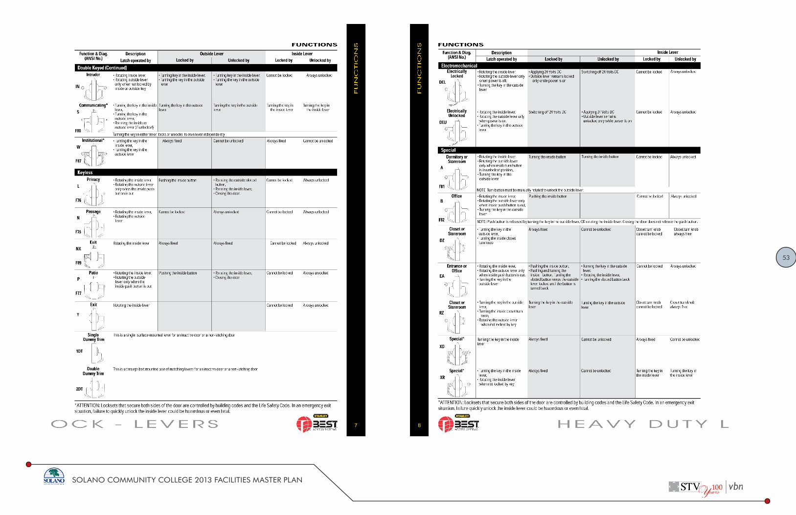
53
SOLANO COMMUNITY COLLEGE 2013 FACILITIES MASTER PLAN

54
SOLANO COMMUNITY COLLEGE 2013 FACILITIES MASTER PLAN

55
SOLANO COMMUNITY COLLEGE 2013 FACILITIES MASTER PLAN

56
SOLANO COMMUNITY COLLEGE 2013 FACILITIES MASTER PLAN

57
SOLANO COMMUNITY COLLEGE 2013 FACILITIES MASTER PLAN
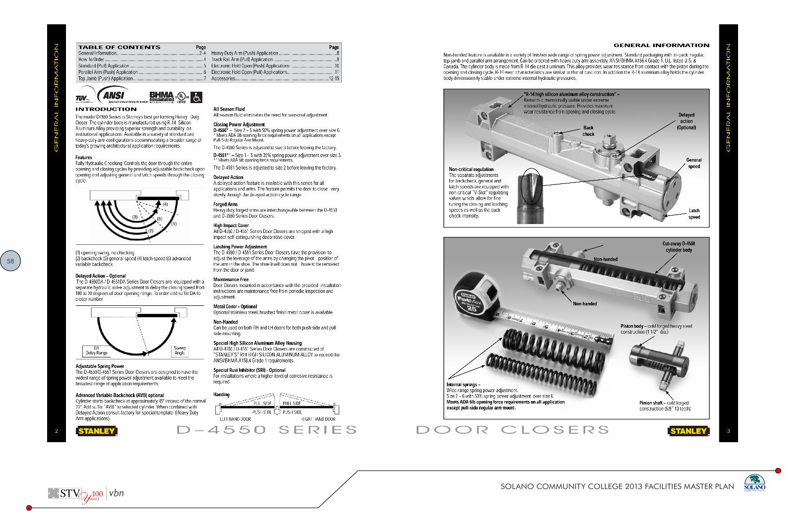
58
SOLANO COMMUNITY COLLEGE 2013 FACILITIES MASTER PLAN

59
SOLANO COMMUNITY COLLEGE 2013 FACILITIES MASTER PLAN

60
SOLANO COMMUNITY COLLEGE 2013 FACILITIES MASTER PLAN

61
SOLANO COMMUNITY COLLEGE 2013 FACILITIES MASTER PLAN
Page 1 of 4 4.9.2014
DESIGN STANDARD Solano Community College District Doors and Door Frames
DESIGN STANDARD for Doors and Door Frames Purpose:
Doors are an important part in the user’s experience, and are perhaps the most intimately experienced element of the built environment, because they are used daily to enter and exit the building and the rooms and spaces within. Doors should be inviting, easy to find, easy to use, durable and maintainable, add aesthetic value, and allow authorized entries while restricting unauthorized entries. The door design standards cited herein are intended to establish and maintain a minimum level of door quality in the educational and work facilities of SCCD buildings.
Note: these Design Standards are a tool to clarify direction and streamline project execution for design professionals, construction managers and other participants in capital improvement projects. Given the compatibility requirements with the Electronic Access Control System, all doors and door frames selected by consultant must be reviewed by the Director of Facilities and equivalent products (only where allowed) have to be approved as outlined in the Open this Document First: Standards Process.pdf. In all cases the written design standards do not diminish or eliminate the standard of care owed by the consultant to SCCD or relieve, in any manner whatsoever, a consultant from any professional responsibility, duty or due diligence required toward that work.
Design Standard:
A. Exterior Doors and Frames (For Main Entry):
Given the windy conditions on all District Sites, which create challenges for the disabled community access, the District Standard for Exterior Doors is as follows:
1) Preferred Choice for Main Entrance to Buildings: Automatic Sliding Doors.
These Doors shall have the following features: o Continually monitor door position with microprocessor controller. o Provide smooth, trouble‐free operation with long‐lasting load‐bearing wheels. o Prevent slippage and uneven closing with anti‐riser wheels. o Provide complete threshold protection at all times with self‐contained sensors. o Emergency Breakaway Capability: power‐operated automatic sliding doors may be
used as emergency egress doors because they “break‐out” in the direction of egress.
o Glazing: Standard 1/4” tempered to match Glazing in Design Standard for Glazing. o Door & Frame Finish to match Exterior Aluminum Entrance in item B that follows. o Access Control Locking with recessed panic hardware: coordinate stile width to
accept EACS (Electronic Access Control System), see Design Standard for Electronic Safety and Security. Door hardware must be compatible with EACS.
o Battery Back‐Up.

62
SOLANO COMMUNITY COLLEGE 2013 FACILITIES MASTER PLAN
Page 2 of 4 4.9.2014
DESIGN STANDARD Solano Community College District Doors and Door Frames
o Control Switch: Auto‐Close‐Open.• Product: Stanley Access Technologies Dura‐Glide 2000/3000. No substitutions
allowed.
2) Alternate Choice for Main Entrance to Buildings: Aluminum Entrance Doors per item Bbelow.
Provide hardware as identified in Design Standard for Door Hardware, item A2.
B. Exterior Doors and Frames (All other Entries and Public Access Spaces):
Aluminum Entrances such as Kawneer 350 Heavy Wall Entrance, Vistawall 375 orequivalent.
Aluminum Storefront such as Kawneer Trifab®400 or equivalent. Entrance, Frame and Storefront Finish:
o Fairfield: Kawneer Finish No. 40 Dark Bronze Anodized Aluminum, AluminumAssociation Specification # AA‐M10C22A44.
o Vallejo and Vacaville Centers: Kawneer Finish No. 14 Clear Anodized Aluminum,Aluminum Association Specification # AA‐M10C22A41.
Coordinate Stile Width with door hardware, see Electronic Access Control System inDesign Standard on Electronic Security and Safety and Design Standard on DoorHardware.
Glazing per Design Standard on Glazing.
C. Exterior Doors and Frames (All others):
Shall be Aluminum Entrance if they occur in Aluminum Storefront. For finish, see itemB above. For Glazing see Design Standard on Glazing.
Shall be Hollow Metal Doors and Frames all other instances:o Insulated Exterior Flush Doors: ANSI 250.8, Level 4 Maximum Duty, Model 2
Seamless Construction, 14 gauge thick galvanized metal. Reinforce door lock edgewith one‐piece full height 14 ga channel; reinforce hinge edge with one‐piece fullheight 12 ga channel.
o Exterior Door Frames: full profile welded, ANSI 250.8, Level 4 Maximum Duty ,12 gauge thick material, 2‐inch core with 1 ½” flashing fin.
o Hollow Metal Door and Frame Finish:o Paint grade hollow metal doors and frames shall be painted the same color as
the surrounding wall finish, to allow the doors to visually “disappear” toreinforce that the doors are not for public access.
o Exceptions: if appropriate to Exterior Color Scheme hollow metal door framesshould be painted to match finish identified in item B above (Entrance, Frameand Storefront Finish), and hollow metal doors should be painted per ExteriorColor Scheme.
o Suggested Manufacturers: Amweld, Curries or equivalent.
Page 3 of 4 4.9.2014
DESIGN STANDARD Solano Community College District Doors and Door Frames
D. Interior Doors (Public Spaces):
Stained wood veneer solid core doors are to be used for all public space types, such as classrooms, offices, labs, meeting rooms, break rooms, restrooms, and corridor separation doors. o Flush Interior Doors: 1‐3/4 inches thick; WI Premium Grade; solid core; 5 ply
construction; “A” grade veneer per ANSI/WDMA I.S.1A, White Birch, Plain‐Sliced. Preferred Finish Option
Basis of Design: Marshfield DoorSystems® Signature Series Wood Veneer Doors, White Birch, Plain‐Sliced, Honey 26‐95 Finish with Enviroclad UVTM
Alternate Finish Option subject to approval by District Basis of Design: Marshfield DoorSystems® Signature Series Wood Veneer Doors, White Birch, Plain‐Sliced, Wine 38‐95 with Enviroclad UVTM
o Materials subject to compliance with LEED Green Building Rating System Credit Requirements.
o Suggested Manufacturers: Marshfield Door Systems; Algoma Hardwoods inc or equivalent.
Exceptions: if appropriate to design and use, public space doors can be glazed aluminum storefront doors. Finish: Clear Anodized Aluminum.
E. Interior Doors (Non‐Public Spaces):
Painted hollow metal doors are to be used for non‐public type spaces, such as utility rooms, maintenance shops, warehouses, and theatrical back‐of‐house areas such as oversized scene shop doors.
Hollow Metal Flush Doors shall be: o Steel Sheet material in accordance to ANSI A250. o ANSI 250.8, Level 3 Extra Heavy Duty, Model 2 Seamless Construction o 14 gauge thick metal. o Reinforce door lock edge with one‐piece full height 14 ga channel; reinforce hinge
edge with one‐piece full height 12 ga channel. o Paint grade doors shall be painted the same color as the surrounding wall finish, to
allow the doors to visually “disappear” to reinforce that the doors are not for public access.
Suggested Manufacturers: Amweld, Curries or equivalent. F. Interior Door Frames:
Shall be (Hollow Metal) Steel Sheet material in accordance to ANSI A250: o Full profile welded, ANSI 250.8, Level 4 Maximum Duty , 12 gauge thick material, 2‐
inch core with 1 ½” flashing fin. o Frame Finish:
o At Public Space Types: paint grade hollow metal frames shall be painted to visually match the Clear Anodized Aluminum.
o At Non‐Public Space Types: paint grade hollow metal frames shall be painted the same color as the surrounding wall finish, to allow the frames to visually “disappear” to reinforce that the doors are not for public access.
63
SOLANO COMMUNITY COLLEGE 2013 FACILITIES MASTER PLAN
Page 4 of 4 4.9.2014
DESIGN STANDARD Solano Community College District Doors and Door Frames
Suggested Manufacturers: Amweld, Curries or equivalent. Approved Manufacturers:
As noted in this Standard. Substitutes Allowed:
Not Applicable. Associated Design Standards and Construction Specifications
Design Standard on Electronic Safety and Security Standards. Design Standard on Doors Hardware. Design Standard on Glazing.
End of Document
Page 1 of 8 4.9.2014
DESIGN STANDARD Solano Community College District Elevators
DESIGN STANDARD for Elevators Purpose:
When required elevators are a critical component in the building. They provide access to the disabled community, transport supplies and equipment vertically through a building, and provide convenience to the general public. Given tight maintenance budgets, new and renovated elevators must achieve reliable performance and ride quality, as well as the level of aesthetic quality, operability and maintainability suggested by this design standard.
Note: these Design Standards are a tool to clarify direction and streamline project execution for design professionals, construction managers and other participants in capital improvement projects. They represent the District’s “strong preference” and should be applied, when possible, without compromising the creativity of the overall design. Final disposition, color, size, product choice etc. should conform to the best extent possible where equivalent substitutes are allowed in the Design Standard. If equivalent substitutes are allowed only “if performance and quality equivalency can be evidenced” or the consultant wishes to deviate from the written design standards for other reasons, then the consultant needs to provide evidence/justification and seek District approval as outlined in the Open this Document First: Standards Process.pdf. In all cases the written design standards do not diminish or eliminate the standard of care owed by the consultant to SCCD or relieve, in any manner whatsoever, a consultant from any professional responsibility, duty or due diligence required toward that work.
Design Standard:
1. Elevator Installer and Maintenance Qualifications
Installer must be a licensed Elevator Contractor in the State of California and must:
Show evidence of successful experience in complete installation and maintenance of proposed manufacturer’s elevator equipment.
Directly employ sufficient competent personnel within 50 miles of Fairfield, California to handle both construction and maintenance duties.
Maintain local stock of parts adequate for replacement on permanent or emergency basis.
Respond to trouble calls within one hour.
2. Elevator Types and Stops
Given the height of buildings proposed (two to three stories) and the existing precedent on campus, hydraulic elevators are the preferred elevator type at SCCD.

64
SOLANO COMMUNITY COLLEGE 2013 FACILITIES MASTER PLAN
Page 2 of 8 4.9.2014
DESIGN STANDARD Solano Community College District Elevators
Provide at least one elevator that serves all floors, including Basement (where it exists) and Roof Level.
3. Controllers
Elevators shall use standard, non‐proprietary controllers. This allows SCCD to have many
choices of service providers, rather than being locked into one sole source provider. Acceptable controllers include MotionControl Engineering, or an equivalent controller that can be easily and economically serviced by an elevator service company other than the installing company.
All diagnostic tools and equipment required for adjusting and troubleshooting shall be an integral / “on‐board” feature of the microprocessor controller, and shall not require recharging, reprogramming or be of the automatic destruct type.
4. Battery Emergency Operation
Battery back‐up is required to prevent entrapment during power outages. In the event of a power outage, the battery power lowers the elevator to the main exit floor and the doors open to allow anyone who would otherwise be entrapped to exit safely.
Battery backup should operate as follows:
Provide a battery driven unit that will initiate operation of the protective circuits in case of a power failure.
Arrange circuitry so that, if the mainline switch is open when the power transfer takes place, the elevator will not respond to the operation of the protective circuit.
In case of normal power failure, arrange the elevator system to lower from a battery emergency supply. The emergency power supply shall consist of battery and battery chargers.
Upon the failure of normal power, lower the elevator to the main exit floor. Upon arrival at the main exit landing, the elevator doors shall open automatically and remain open until regular door time has expired. The elevator shall then become inactivated.
Automatically resume normal operation on restoration of normal power supply to the building.
5. Double‐Bottom Cylinders with Sealed PVC Casings
To enhance passenger safety and reduce the risk of environmental contamination, SCCD requires new hydraulic elevators to have a double‐bottom cylinder (in order to control the descending speed of the car as the hydraulic oil passes through a relief orifice should the bottom plate fail). SCCD also requires new hydraulic elevators to have a sealed PVC casing (to surround the entire cylinder and provide additional protection to the double‐bottom cylinder investment and against environmental contamination).
Page 3 of 8 4.9.2014
DESIGN STANDARD Solano Community College District Elevators
6. Performance, Operating Qualities, Vibration Control and Sound Control
Performance:
Contract Speed: Maximum ten percent (10%) speed variation under any loading condition in either direction.
Hydraulic Pressure: Hydraulic components shall be factory tested for 600 PSI. Maximum operating pressure shall be 425 PSI.
Door Open Times: 2.3 ‐ 2.5 Seconds. Door Close Times: 3.0 Seconds or minimum without exceeding kinetic energy and closing
force allowed by code. Door Dwell Times: Separate adjustable timers with initial settings at 5.0 seconds for both
car and hall calls. Door dwell times shall be canceled by registration of car calls or by pressing the “door close” button.
Leveling: Within three‐eighths (3/8) inch under any loading condition. Level into floor at all times, do not overrun floor and level back.
Operating Qualities:
Transition: Starting and stopping shall be smooth and comfortable. Slowdown, stopping and leveling shall be without jars or bumps. Full Speed: Riding shall be free from vibration and sway.
Vibration Control:
Specify effective sound isolation materials to isolate pumping plant from building structure to prevent objectionable noise and vibration transmission to occupied building spaces.
Sound Control:
Maximum acoustical output level shall not exceed: 80 dBA measured 3 feet from any piece of equipment in machine room. 50 dBA measured in center of elevator cars and 5 feet above the cab floor during all
sequences of operation. 45 dBA measured in elevator lobbies 10 feet from the elevator doors.
7. Finishes
SCCD’s preferred finishes include:
No. 4 Satin Stainless Steel for interior doors, exterior doors, and for door jambs. Interior cab walls wear best with textured, rigidized stainless steel, with its increased
impact resistance, graffiti resistance, and reflection control that hides scratches and

65
SOLANO COMMUNITY COLLEGE 2013 FACILITIES MASTER PLAN
Page 4 of 8 4.9.2014
DESIGN STANDARD Solano Community College District Elevators
eliminates oil‐canning. Rigidized Metals Corporation’s 5.WL is an acceptable textured stainless steel; equivalent textured stainless steel (e.g., 6.WL, 1.NA, 2.WL, 1.CS, and 1.HM) are also acceptable.
Designers should plan on replacing existing cab finishes that do not conform to these design standards, except in the case of freight‐only elevators.
Stainless Steel grab bars, no aluminum or brass. The sill shall be extruded aluminum, recessed to allow for finished floor. The finished flooring shall be the same resilient flooring as adjacent spaces.
8. Signage
Permit holder shall be displayed within the elevator. The hallway signage warning occupants to use the stairway for exit in case of fire should
be combined with the hall call button, in one brushed metal plaquard.
9. Key Switches
Key switches shall be keyed to the College’s master key system. This requirement ensures that operating personnel do not have to carry or duplicate additional keys, and emergency response personnel (particularly fire responders) have the appropriate keys. Each function and/or lock shall be keyed alike.
Coordinate the design of the elevator controls key switches with the work of the security system designer and hardware specifier. Note that the appropriately pinned cylinders will be provided to the elevator contractor for installation.
10. Ceilings and Lighting
SCCD goal for elevator lighting includes an evenly and adequately lit cab using energy efficient lamps with long service lives. To that end, designers should specify any of the following lighting options:
Suspended opaque acrylic ceiling grills, acting as lighting diffusers to the fluorescent strip lights above that include electronic ballasts and four foot T8 lamps
Suspended silver parabolic lenses, acting as lighting diffusers to the fluorescent strip lights above that include electronic ballasts and four foot T8 lamps
No. 4 Stainless steel panels with recessed, fluorescent down cans
Emergency Lighting:
Specify a battery driven and self‐recharging emergency car lighting unit, mounted on top of car, with sufficient capacity to operate emergency lights in continuous operation for four hours and the alarm bell for one hour.
Page 5 of 8 4.9.2014
DESIGN STANDARD Solano Community College District Elevators
Within 5 seconds of loss of normal power activate two lamps as part of normal cab lighting. Surface mounted lights are not acceptable.
Specify a test button in service cabinet.
11. Telephone Specify a complete system consisting of a telephone and automatic dialer and push button to activate system. The telephone shall not be on the District’s VOIP internal communications system, because category 6 cabling has a bending radius constraint inconsistent with the requirements of the elevator shaft; specify a POTS line. Mount behind a pattern of holes as an integral part of car operating panel. The automatic dialer shall be programmed to call the elevator contractor’s telephone monitoring service (see Section 14 Warranty and Service, below).
12. Card Readers
Elevators with exterior access shall be tied to the College’s Electronic Access Control System (EACS), for after‐hours access. See Design Standard for Electronic Safety and Security. The EACS shall also be used if floors or areas of the building are to be isolated from each other during or after hours.
Coordinate the design of the elevator controls with the work of the security system designer. Specify that the elevator contractor is to include required wiring from the cab and elevator lobbies to the machine room, and that the final connections of the card readers shall be made by the security system integrator.
13. Protective Pads
Each cab must have its own set of pads provided in a heavy duty duffle bag with handles. This requirement ensures that each cab can be protected even during concurrent furniture/fixture/occupant moving operations, that maintenance personnel can handily carry the pads from the storage location to the cab for ease of installation, and that the pads are protected during periods of storage.
Pads shall cover all walls with cutout sections for car operating panels. Specify heavy duty stainless steel buttons attached to cab panels for hanging.
14. Permits
Specify that contractor is responsible for arranging and paying for inspections by governing authorities and obtaining operating permits.
The operating permit shall list as the owner: Solano Community College District, 4000 Suisun Valley Road, Fairfield, CA 94534.

66
SOLANO COMMUNITY COLLEGE 2013 FACILITIES MASTER PLAN
Page 6 of 8 4.9.2014
DESIGN STANDARD Solano Community College District Elevators
15. Warranty and Service
The elevator contractor shall warrant the new or renovated elevator for a period of 12 months following substantial completion of the general contractor’s contract. Under no circumstances shall the elevator warranty period commence prior to the governing authority issuing an operating permit for the elevator.
SCCD typically uses one elevator service company to perform all its elevator service on existing elevators, including telephone monitoring service, monthly preventive maintenance service, callback repairs, entrapment rescues and 5‐year load testing. However, we require new or renovated elevators to be fully serviced for the first 12 month period by the same elevator contractor who installed and is warranting the unit, and this requirement should be specified in the construction specifications.
Specify the following activities and criteria to be included as part of this requirement:
Prior to commencing the 12 month maintenance service period, execute a standard elevator maintenance service agreement with the Solano Community College District, through the office of the Director of Facilities.
Provide complete monthly maintenance on entire elevator system for a period of 12 months. This shall minimally include: Examination: Include systematic examination with monthly adjustment and
lubrication of elevator equipment. Whenever required provide replacement of defective parts with parts of same manufacture as required for proper operation. Contractor is not responsible for repairs to car enclosures, door panels, frames, sills or platform flooring resulting from normal usage or misuse, accidents and negligence.
Testing: Include any testing required by Code authorities including monthly testing of Firefighters’ Service.
Performance Standards: Maintain smooth starting, stopping, ride qualities and accurate leveling at all times.
Call‐Backs: Provide 24 hour emergency call‐back service at no additional cost to Owner. Emergency call‐back includes trapped passengers and incidents where serious equipment or building damage may occur. Respond to trouble calls within one hour.
Telephone Monitoring: The automatic dialer shall be programmed to call the elevator contractor’s telephone monitoring service. Coordinate through the District’s Office of the Vice Chancellor of Facilities for the College’s callback notification protocol.
Final Service and Inspection: Two weeks before expiration of the year’s maintenance, the equipment shall be lubricated, fully serviced, adjusted to the standards designated and emergency service operation devices shall be checked. A representative of the District will make a complete inspection.
Page 7 of 8 4.9.2014
DESIGN STANDARD Solano Community College District Elevators
Elevator Shutdowns: Should the elevator become inoperative, repair or replace minor components within
24 hours of notification of failure and return to service. Complete service and repairs of major components within 72 hours.
The District may order the work done by other contractors at the Contractor’s expense for failure to comply with the requirements noted above.
Extend maintenance and responsibility for correct operation to devices repaired or replaced by others under these circumstances.
Follow‐Up Tests: Test all safety devices and emergency operations at 6 month intervals or sooner and submit written report on each test. Perform tests at times that do not interfere with College operations.
Maintenance Tool and Software Manuals: Provide maintenance tools, supporting software, instruction manuals and all documentation required for maintenance of the entire system including trouble shooting, diagnostics and adjusting. All diagnostic tools and equipment required for adjusting and troubleshooting shall be an integral / “on‐board” feature of the microprocessor controller, and shall not require recharging, reprogramming or be of the automatic destruct type.
Maintenance Materials: The elevator service contractor shall provide a metal cabinet in the machine room containing a reasonable supply of expendable parts required for prompt replacement. Replenish parts used for routine maintenance to ensure an adequate supply is available. Cabinet and all contents shall become property of SCCD and shall not be removed upon expiration of maintenance period.
Approved Manufacturers:
o Elevator Manufacturers
ThyssenKrupp Elevator Corp. Schindler Elevator Co. Otis Elevator Co.
o Microprocessor Controllers
MotionControl Engineering Or equivalent nonproprietary
o Cab and Entrance Manufacturers
Elevator manufacturer Tyler Elevator Products H & B Elevators Sterling Corporation Swiss Dane

67
SOLANO COMMUNITY COLLEGE 2013 FACILITIES MASTER PLAN
Page 8 of 8 4.9.2014
DESIGN STANDARD Solano Community College District Elevators
Substitutes Allowed:
Yes, if performance and quality equivalency can be evidenced.
Associated Design Standards and Construction Specifications
Design Standard on Building, Floor, Room, Stair, Elevator, Equipment and Outlets Designation. Design Standard on Electronic Safety and Security.
End of Document
Page 1 of 4 4.9.2014
DESIGN STANDARD Solano Community College District Emergency Response Related
DESIGN STANDARD for Emergency Response Related Purpose:
The purpose of this design standard is to help ensure that emergency response vehicles and personnel have quick, clear, and easy access to all areas of any District campus in the event of an emergency.
SCCD is committed to working with local agencies to insure that safety standards and access for emergency vehicles and other devices as discussed in the District’s “PACEP” Safety Committee will meet best practices of the industry.
Design Standard:
Fire department service areas Fairfield Campus is served primarily by the Cordilia Fire Department.
Vacaville Campus is served primarily by City of Vacaville Fire Department. Vallejo Campus is served primarily by City of Vallejo Fire Department.
General Site Access
It is important that emergency vehicles have driving access close to all campus buildings, central campus areas and exterior plaza areas; a good goal is to provide EVA access to within 150 feet of all exterior portions of each building.
Provide a minimum 20‐foot width on all Emergency Vehicle Access (EVA) lanes, to allow adequate space for two emergency vehicles to pass each other going in opposite directions. Where this cannot be provided for the entire length of the EVA lanes (due to existing structural or landscape feature), a passing lane or other accommodation will be reviewed by SCCD and the appropriate emergency response agencies.
The EVA lanes must have a minimum 13‟ canopy clearance for emergency response vehicles.
Paving for EVA lanes must be capable of supporting fire trucks (60,000 pound minimum loading requirement, subject to review and acceptance by the respective emergency response agencies).
Ideally EVA lanes should be “looped” to allow alternate means to access central and critical areas of the campus. Where this cannot be provided, hammer‐head turnarounds will be required (subject to the acceptance of the respective emergency response agencies).
Fire trucks require a 52’ outside diameter turning circle, if this is not feasible, confirm with the fire department if they will accept a 3‐point turning configuration.
Knox Boxes and Padlocks
The fire department prefers that Knox boxes are placed throughout the campus, for easy and multiple key set access.
SCCD has standardized on Knox‐Box 3200 Series for fire department key storage.
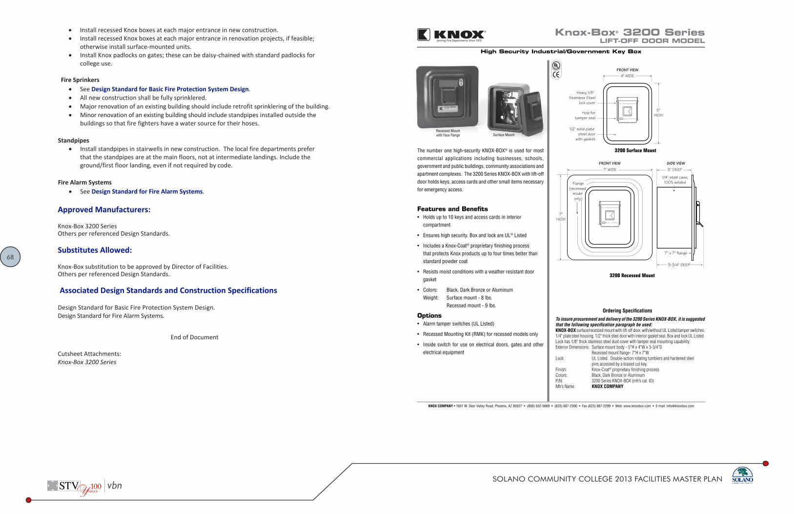
68
SOLANO COMMUNITY COLLEGE 2013 FACILITIES MASTER PLAN
Page 2 of 4 4.9.2014
DESIGN STANDARD Solano Community College District Emergency Response Related
Install recessed Knox boxes at each major entrance in new construction. Install recessed Knox boxes at each major entrance in renovation projects, if feasible;
otherwise install surface‐mounted units. Install Knox padlocks on gates; these can be daisy‐chained with standard padlocks for
college use. Fire Sprinkers
See Design Standard for Basic Fire Protection System Design. All new construction shall be fully sprinklered. Major renovation of an existing building should include retrofit sprinklering of the building. Minor renovation of an existing building should include standpipes installed outside the
buildings so that fire fighters have a water source for their hoses. Standpipes
Install standpipes in stairwells in new construction. The local fire departments prefer that the standpipes are at the main floors, not at intermediate landings. Include the ground/first floor landing, even if not required by code.
Fire Alarm Systems
See Design Standard for Fire Alarm Systems. Approved Manufacturers:
Knox‐Box 3200 Series Others per referenced Design Standards. Substitutes Allowed:
Knox‐Box substitution to be approved by Director of Facilities. Others per referenced Design Standards. Associated Design Standards and Construction Specifications
Design Standard for Basic Fire Protection System Design. Design Standard for Fire Alarm Systems.
End of Document
Cutsheet Attachments: Knox‐Box 3200 Series
7" HIGH
7" WIDE FRONT VIEW
Flange (recessed
model only)
SIDE VIEW
1/4" steel case,100% welded
3" DEEP
3-3/4" DEEP
7" x 7" flange
Knox-Box® 3200 SeriesLIFT-OFF DOOR MODEL
High Security Industrial/Government Key Box
Recessed Mountwith Face Flange Surface Mount
Ordering Specifications
To insure procurement and delivery of the 3200 Series KNOX-BOX, it is suggested that the following specification paragraph be used:KNOX-BOX surface/recessed mount with lift-off door, with/without UL Listed tamper switches. 1/4" plate steel housing, 1/2" thick steel door with interior gasket seal. Box and lock UL Listed. Lock has 1/8" thick stainless steel dust cover with tamper seal mounting capability.Exterior Dimensions: Surface mount body - 5"H x 4"W x 3-3/4"D Recessed mount flange- 7"H x 7"WLock: UL Listed. Double-action rotating tumblers and hardened steel pins accessed by a biased cut key.Finish: Knox-Coat® proprietary finishing processColors: Black, Dark Bronze or AluminumP/N: 3200 Series KNOX-BOX (mfr’s cat. ID)Mfr’s Name: KNOX COMPANY
KNOX COMPANY • 1601 W. Deer Valley Road, Phoenix, AZ 85027 • (800) 552-5669 • (623) 687-2300 • Fax (623) 687-2299 • Web: www.knoxbox.com • E-mail: [email protected]
3200 Surface Mount
3200 Recessed Mount
5"HIGH
4" WIDEFRONT VIEW
Heavy 1/8" Stainless Steel
lock cover
Hole fortamper seal
1/2" solid plate steel door
with gasket
The number one high-security KNOX-BOX® is used for most commercial applications including businesses, schools, government and public buildings, community associations and apartment complexes. The 3200 Series KNOX-BOX with lift-off door holds keys, access cards and other small items necessary for emergency access.
Features and Benefits• Holds up to 10 keys and access cards in interior
compartment
• Ensures high security. Box and lock are UL® Listed
• Includes a Knox-Coat® proprietary finishing process that protects Knox products up to four times better than standard powder coat
• Resists moist conditions with a weather resistant door gasket
• Colors: Black, Dark Bronze or Aluminum Weight: Surface mount - 8 lbs. Recessed mount - 9 lbs.
Options• Alarm tamper switches (UL Listed)
• Recessed Mounting Kit (RMK) for recessed models only
• Inside switch for use on electrical doors, gates and other electrical equipment

69
SOLANO COMMUNITY COLLEGE 2013 FACILITIES MASTER PLAN
Knox-Box® 3200 SeriesLIFT-OFF DOOR MODEL - MOUNTING DIAGRAM
KNOX COMPANY • 1601 W. Deer Valley Road, Phoenix, AZ 85027 • (800) 552-5669 • (623) 687-2300 • Fax (623) 687-2299 • Web: www.knoxbox.com • E-mail: [email protected]
MKT-KBSPEC-0020-C© Copyright 2008. Knox Company
Recessed Mounting Kit
The 3200 Recessed Mounting Kit (RMK) is used for recessed models only. It contains a shell housing and mounting hardware to be cast-in-place in new concrete or masonry construction. After construction is completed, the KNOX-BOX mounts inside the recessed shell housing. The RMK may only be used in new concrete or masonry construction.
Installation In Cast ConcreteThe optional Recessed Mounting Kit is for use in new concrete or masonry construction only. The kit includes a shell housing and mounting hardware to be cast-in-place. The KNOX-BOX is mounted into the shell housing after construction is completed.
DimensionsRough-in Dimensions: 6-1/2"H x 6-1/2"W x 5"D
IMPORTANT: Care should be taken to insure that the front of the RMK shell housing, including the cover plate and screw heads, is flush with the finish wall. The RMK must be plumbed to insure vertical alignment of the vault.
Knox® Rapid Entry SystemThe Knox Company manufacturers a complete line of high security products including Knox-Box key boxes, key vaults, cabinets, key switches, padlocks, locking FDC caps, plugs and electronic master key security systems. For more information or technical assistance, please call Customer Service at 1-800-552-5669.
Door
3/8" Grade 5 or Grade 8 Fasteners
Flange
Large Thick Steel
Washer
To building alarm system
3200 Series Lift-off Door Surface Mount
3200 Series Lift-off DoorRecessed Mount
Suggested minimum mounting height6 feet above ground
Solid concrete wall Solid concrete wall
To buildingalarm system
OptionalDoor Tamper
Switch
5"HIGH
3-1/4"
7/8"
7/8"
3/4"
3/4"
All mountingholes are 7/16"
diameter
Inside View
2-1/16"
Rear TamperSwitch
Mounting Holes
Rear TamperSwitch Hole
Alarm wire exit opening
Holes marked "x" areused for mounting with
at least 3/8" Grade 5 or Grade 8 fasteners
4" WIDE7/8"2-5/16"
1-1/8"
1-5/16"1-5/16"Key Hooks Mounting Holes
x x
x xx
Attention: KNOX-BOX® is a very strong device that MUST be mounted properly to ensure maximum security and resist physical attack.
6" H
6" W4 " D
KNOX-BOX® mounts inside
RMK shell after completion ofconstruction
RecessedFlange
Mounting studs provided inside RMK shell
to accommodate KNOX-BOX®
RMK shell is mounted in wall during new construction
Knockouts for alarm wire conduit
Concrete or masonry wall construction
Recessed Mounting UsingRecessed Mounting Kit (RMK)
Trim rebar for tie-in to wall if necessary
Page 1 of 4 4.9.2014
DESIGN STANDARD Solano Community College District Exterior Paint
DESIGN STANDARD for Exterior Paint Purpose:
This design standard has the purpose of creating a consistent application of painting requirements throughout the Solano Community College District. The intent is to create a standard of quality for maintenance and reliability throughout all renovation and new building projects.
Note: these Design Standards are a tool to clarify direction and streamline project execution for design professionals, construction managers and other participants in capital improvement projects. They represent the District’s “strong preference” and should be applied, when possible, without compromising the creativity of the overall design. Final disposition, color, size, product choice etc. should conform to the best extent possible where equivalent substitutes are allowed in the Design Standard. If equivalent substitutes are allowed only “if performance and quality equivalency can be evidenced” or the consultant wishes to deviate from the written design standards for other reasons, then the consultant needs to provide evidence/justification and seek District approval as outlined in the Open this Document First: Standards Process.pdf. In all cases the written design standards do not diminish or eliminate the standard of care owed by the consultant to SCCD or relieve, in any manner whatsoever, a consultant from any professional responsibility, duty or due diligence required toward that work.
Design Standard:
1. Exterior Paint SCCD has standardized on latex (water based) paints for the outdoor environment for the
following reasons: o Water‐based paints are the safest option for the people who handle them and the
environment. o Latex paints have a less objectionable odor, which makes them good for repaints and
painting in occupied areas, where solvent odor is an issue. o They clean up with soap and water; there's no need to work with hazardous and/or
flammable solvents, and no used solvent to dispose of afterwards. o Latex paints dry faster, and can be recoated sooner; this makes them a good choice for
painting in occupied areas, where someone might touch or brush up against the freshly painted surface.
o Latex paint binders hold up better in sun‐exposed areas, because they're more resistant to UV (ultraviolet) radiation.
o Latex paint films are less prone to yellowing over time, especially with white, light off‐white and pastel colors.
o Latex paint films are more breathable; they allow small amounts of water vapor to pass through the film, so the chance of blistering is reduced. This is especially important when the surface being painted is slightly damp.

70
SOLANO COMMUNITY COLLEGE 2013 FACILITIES MASTER PLAN
C. Latex paint films have better gloss and color retention, so they'll keep a 'like‐new'appearance longer.
2. Exterior Color Palette
• Each of the campuses has an exterior color palette that creates continuity across the District sites but also addresses each campus’ uniqueness. See Attachments for Campus Color Palettes. Note Trespa Panel Colors have been used as a basis for some of the colors provided because in some instances buildings may introduce colors through building panel materials in lieu of paint, and there is a desire to match the quality of color saturation provided by these panels should they be introduced via painting.o All Campuses Field Colors:
Color similar to Kelly Moore Apple White, KM_OW206‐1 Color similar to Sherwin Williams Eider White, SW 7014 Color similar to Trespa Stonebeige, A0511
o All Campuses Exterior Columns: Exposed Concrete, Sandblasted, Smooth Finish or Color similar to Sherwin Williams Extra White, SW 7006
o Accent Colors for Fairfield and Vacaville: the intent is for buildings to opt for only one to two accent colors out of these pair of choices: Color similar to Trespa Pacific Board, NW04 or Trespa Sienna Brown, A10.4.5 Color similar to the range provided by Trespa Dark Mahogany, NW19 Color similar to Trespa Ocean Grey, A22.3.1 or Trespa Powder Blue, A22.2.4 Color similar to Trespa Sun Yellow, A05.1.4 or Trespa Gold Yellow, A04.1.7 Color similar to Trespa Spring Green, A37.2.3 or Trespa Forest Green, A34.8.1 Neverfade Solano Blue P – 6726, semi‐gloss
o Accent Colors for Vallejo: the intent is for buildings to opt for only one to two accent colors out of these pair of choices: Color similar to Trespa Pacific Board, NW04 or Trespa Sienna Brown, A10.4.5 Color similar to the range provided by Trespa Dark Mahogany, NW19 Color similar to Trespa Ocean Grey, A22.3.1 or Trespa Steel Blue, A24.4.1 Neverfade Solano Blue P – 6726, semi‐gloss
o Non‐Public/Utility Buildings on any campus have the option of being painted to match Trespa Mid Beige A08.2.1.
o Exterior Mullions for Fairfield: Kawneer Finish No. 40 Dark Bronze Anodized Aluminum, Aluminum Association Specification # AA‐M10C22A44. See Design Standard on Doors and Door Frames.
o Exterior Glazing for Fairfield: to match Viracon VE1‐2M, see Design Standard on Glazing for exceptions.
o Exterior Mullions for Vallejo and Vacaville Centers: Kawneer Finish No. 14 Clear Anodized Aluminum, Aluminum Association Specification # AA‐M10C22A41. See Design Standard on Doors and Door Frames.
o Exterior Glazing for Vallejo and Vacaville Centers: to match PPG Industries, Inc. Solargray with Solarban 60, see Design Standard on Glazing for exceptions.
Approved Manufacturers:
Latex Paint: Sherwin Williams.
Page 3 of 4 4.9.2014
DESIGN STANDARD Exterior Paint
Solano Community College District
Substitutes Allowed:
No substitutions allowed.
Associated Design Standards and Construction Specifications:
Design Standard for Interior Paint
End of Document
Attachments: Fairfield Exterior Color Palette, Vacaville Exterior Color Palette, Vallejo Exterior Color Palette
Fairfield Exterior Color Palette:

71
SOLANO COMMUNITY COLLEGE 2013 FACILITIES MASTER PLAN
DESIGN STANDARD Solano Community College District Exterior Paint
Fairfield Exterior Color Palette:
Sandblasted Concrete
Sherwin Williams Extra White SW7006
Trespa Powder Blue, A22.2.4
Trespa Ocean Grey, A22.3.1
Sherwin Williams, Elder White, SW 714
Trespa Stonebeige, A0511
Trespa Gold Yellow A04.1.7
Trespa Sun Yellow, A05.1.4
Kelly Moore Apple White, KM_OW206-1
White Birch
Trespa Pacific Board, NW04
Trespa Sienna Brown, A10.4.5
Medium Grey
Trespa Dark Mahogany, NW19
Trespa Light Mahogany, NW19
Anodized Clear Aluminum
Trespa Forest Green, A34.8.1
Trespa Spring Green, A37.2.3
Kawneer 40Dark BronzeAnodizedAluminum
Trespa Natural Greige, A06.7.1
Trespa Mid Beige, A08.2.1
ViraconVE1-2MGlazing
Neverfade Solano Blue, P-6726

72
SOLANO COMMUNITY COLLEGE 2013 FACILITIES MASTER PLAN
DESIGN STANDARD Solano Community College District Exterior Paint
Vacaville Exterior Color Palette:
Sandblasted Concrete
Sherwin Williams Extra White SW7006
Trespa Powder Blue, A22.2.4
Trespa Ocean Grey, A22.3.1
Sherwin Williams, Elder White, SW 714
Trespa Stonebeige, A0511
Trespa Gold Yellow A04.1.7
Trespa Sun Yellow, A05.1.4
Kelly Moore Apple White, KM_OW206-1
White Birch
Trespa Pacific Board, NW04
Trespa Sienna Brown, A10.4.5
Medium Grey
Trespa Dark Mahogany, NW19
Trespa Light Mahogany, NW19
Anodized Clear Aluminum
Trespa Forest Green, A34.8.1
Trespa Spring Green, A37.2.3
Trespa Natural Greige, A06.7.1
Trespa Mid Beige, A08.2.1
PPGSolargray
withSolarban 60
Neverfade Solano Blue, P-6726

73
SOLANO COMMUNITY COLLEGE 2013 FACILITIES MASTER PLAN
DESIGN STANDARD Solano Community College District Exterior Paint
Vallejo Exterior Color Palette:
Sherwin Williams, Elder White, SW 714
Trespa Stonebeige, A0511
Trespa Ocean Grey, A22.3.1
Kelly Moore Apple White, KM_OW206-1
White Birch
Trespa Pacific Board, NW04
Trespa Sienna Brown, A10.4.5
Medium Grey
Trespa Dark Mahogany, NW19
Trespa Light Mahogany, NW19
Anodized Clear Aluminum
Trespa Steel Blue, A24.4.1 Trespa Mid Beige, A08.2.1
PPGSolargray
withSolarban 60
Neverfade Solano Blue, P-6726

74
SOLANO COMMUNITY COLLEGE 2013 FACILITIES MASTER PLAN
DESIGN STANDARD
Solano Community College District Flagpoles
DESIGN STANDARD for Flagpoles Purpose:
The purpose of this design standard is to ensure consistency in the provision of flagpoles at each campus, which are functionally appropriate to each college’s environment.
Design Standard:
Flagpoles shall be aluminum, unpainted. Flagpole heights shall be appropriate to the site. Flagpoles shall have a round gold finial at the top. Flagpoles shall have LED light fixtures at the base, for nighttime illumination. This ensures that
the flags can be displayed at night, negating the need for staff to raise and lower the flags on a daily basis.
Flags shall be weatherproof material, appropriate for 24/7/365 exposure. Comply with rules for use and display of the flag (36 United States Code 173‐178)
Substitutes Allowed:
Not applicable.
Associated Design Standards and Construction Specifications
Not applicable.
End of Document
Page 1 of 1 4.9.2014 Page 1 of 4 4.9.2014
DESIGN STANDARD Solano Community College District Flooring
DESIGN STANDARD for Flooring Purpose:
The purpose of this Standard is to standardize the Flooring for District sites based on the following criteria:
Durability Ease of Maintenance Aesthetics Sustainability: products that reduce water and energy consumption, are sustainably
produced, and assist with quality of indoor air. Acoustics Cost (initial and total cost)
Note: these Design Standards are a tool to clarify direction and streamline project execution for design professionals, construction managers and other participants in capital improvement projects. They represent the District’s “strong preference” and should be applied, when possible, without compromising the creativity of the overall design. Final disposition, color, size, product choice etc. should conform to the best extent possible where equivalent substitutes are allowed in the Design Standard. If equivalent substitutes are allowed only “if performance and quality equivalency can be evidenced” or the consultant wishes to deviate from the written design standards for other reasons, then the consultant needs to provide evidence/justification and seek District approval as outlined in the Open this Document First: Standards Process.pdf. In all cases the written design standards do not diminish or eliminate the standard of care owed by the consultant to SCCD or relieve, in any manner whatsoever, a consultant from any professional responsibility, duty or due diligence required toward that work.
Design Standard:
1. Flooring Recommendations by Room Type:
See Table on the next page.

75
SOLANO COMMUNITY COLLEGE 2013 FACILITIES MASTER PLAN
DESIGN STANDARD Solano Community College District Flooring
Flooring Recommendations by Room Type:
Room Use 1st Choice 2nd Choice 3rd Choice Lobby/Entries Stained Concrete with
transparent sealer appropriate for use
Carpet with built-in Walk-Off Mat
Door Entrance Area Built-in Walk-Off Mat Do not specify Aluminum Grate Walkway
Public Hallways/Corridors Stained concrete with transparent sealer appropriate for use
Carpet Linoleum
Classrooms Carpet Linoleum Stained Concrete with transparent sealer appropriate for use
Laboratories/ Kitchen Areas Stained Concrete sealed with transparent sealer specific to Laboratory use. No exception except where required by code.
Offices and Office Areas Carpet Restrooms Ceramic Tile Study Areas, Lounges etc. Carpet with linoleum at
areas with sinks
Service Areas and Service Hallways
Concrete with transparent sealer specific to use. No exceptions except where required by code
Vinyl Sheet Flooring with welded seams and integral coves where chemicals are a concern
Custodial Spaces Concrete with transparent sealer specific to maintenance use. No exceptions.
Concrete with transparent sealer specific to maintenance use
2. Flooring Specifics:
A. Concrete with Transparent Sealer appropriate for specific use, Stained in Public Areas: One sustainable approach to buildings is to use less building materials. In rooms and hallway/corridors where acoustics are less of a concern (or handled by other finish materials) the concrete used in the floor slab can be utilized as the floor finish, as long as it is sealed with a sealer appropriate for the room/space use. In public areas, the concrete should be stained to provide visual interest.
o With new buildings, design professionals should review concrete specification to ensure best staining results and review concrete joint locations to enhance the visual appearance of the floor.
o Sealers should address appropriate use (for example expected chemicals, moisture, cleanability performance) as well as code requirements for anti-slip etc.
o Example sealers are sealers from Rustoleum. o Locations: see Table under item #1.
Page 2 of 4 4.9.2014
DESIGN STANDARD Solano Community College District Flooring
B. Linoleum Flooring:Sheet Linoleum is an extremely durable product made of natural materials that are naturally anti‐bacterial and biodegradable, yet very resistant to water, easy to clean, relatively low maintenance, aesthetically pleasing, and cost effective. Since it is easy to cut, it can be combined into different colors and patterns.
o The product does require experienced installers, and specifications should list criteria for ensuring adequate experience.
o Heat‐Welded Seams.o Specify Low Maintenance Coating (such as Armstrong NATURCote UV‐cured
coating).o Product: Armstrong Commercial Flooring Linoleum.o Locations: see Table under item #1.
C. Vinyl Sheet Flooring:In certain laboratory classrooms, kitchen areas and service areas it might be necessary to specify vinyl sheet flooring with heat‐welded seams and integral cove base due to the chemicals or activities in the room that require specialized clean up/containment. Vinyl Sheet Flooring is not a sustainable/green product and should not be used for any other application.
o Material: heavy‐duty resilient sheet flooring.o Thickness: 0.10”o Locations: only at laboratories and service areas that warrant this flooring.o Products: Armstrong Sheet Vinyl or Altro High Performance Safety Flooring.
D. Carpet:SCCD selected the Tarkett Company, Tandus Carpets as the District Standard because of the ease of installation (and replacement by maintenance personnel), its environmental benefits (including cradle to grave, high recycled content, virtually zero VOCs), elegant aesthetics, use of no wet adhesives (avoids offgasses), static control and its affordability. Products are available both as rolled and modular tile, and logos can be cut into the carpet.
o Rolled Goods: 6’ or 12’ wide. Not preferred; avoid if possible.o Modular Goods: 24” x 24”.o Backing: Flex‐Aire Cushion Modularo Product: Tandus Carpets.o Style: Choose from most popular styles (to ensure manufacturer continuity with
providing that particular style), such as Aftermath II, Longitude, Monumento and Ratio.
o Non‐directional pattern preferred.o Peel and stick, or corner tabs.

76
SOLANO COMMUNITY COLLEGE 2013 FACILITIES MASTER PLAN
DESIGN STANDARD Solano Community College District Flooring
E. Rubber Base: Rubber is the preferred (sustainable) base material, that is also durable:
o 4” Topset rubber cove base. o Long rolls to minimize seams. o Minimize joints o No joints in corners. o Score corners. o No pieces less than 24” o Use full length sections around columns and appurtenances. o Roll out base during installation. o Product: BurkeMercer, Type TS.
F. Ceramic Tile:
As described in the Design Standard for Restrooms: o Provide ceramic mosaic tile in minimum 6” x 6” size for restrooms. o Provide ceramic tile in colors that camouflage dirt and stains. o Number of colors not to exceed 5 different colors for restrooms, 1 for custodial. o Provide a 12‐inch wide darker color border on floor, in a color that has a
matching cove tile base at restrooms only. o Pattern within border can be random (makes for easier replacement), at
restrooms only. o Select grout color to minimize appearance of stains. o Provide same colored grout for both floors and walls, this will allow installer to
complete installation in a single installation, thereby reducing cost to District. o Products: Dal Tile or American Olean.
3. Flooring Colors:
• Design Teams should provide District with at least (2) choices for Color Palettes that
encompass all finish materials, including flooring finishes. District may opt to adopt a particular palette as a District Standard for that campus in the future.
Approved Manufacturers:
Per above.
Substitutes Allowed:
Yes, if performance and quality equivalency can be evidenced.
Associated Design Standards and Construction Specifications
Design Standard for Restrooms Design Standard for Custodial Spaces
Page 4 of 4 4.9.2014
Page 1 of 2 4.9.2014
DESIGN STANDARD Solano Community College District Glazing
DESIGN STANDARD for Glazing Purpose:
The purpose of this Standard is to standardize the glazing on each District Site for the architectural cohesiveness of each campus, while ensuring that the visibility requirements, the energy performance requirements and the quality criteria are met.
The desire is to move away from the existing dark glazing on the Fairfield campus to a more visible glazing that allows inside activities to be showcased. A glazing with a “greenish” look is the preferred color due to its compatibility with the rest of the Fairfield exterior color palette for Fairfield (see Design Guidelines). For the Vallejo and Vacaville sites, the preference is to replicate the existing “greyish” look that already exists at the recently built Centers. District understands that glazing choices are affected by many considerations, including energy performance for the project, which is why deviations from the preferred colors will be considered on a project basis.
Note: these Design Standards are a tool to clarify direction and streamline project execution for design professionals, construction managers and other participants in capital improvement projects. They represent the District’s “strong preference” and should be applied, when possible, without compromising the creativity of the overall design. Final disposition, color, size, product choice etc. should conform to the best extent possible where equivalent substitutes are allowed in the Design Standard. If equivalent substitutes are allowed only “if performance and quality equivalency can be evidenced” or the consultant wishes to deviate from the written design standards for other reasons, then the consultant needs to provide evidence/justification and seek District approval as outlined in the Open this Document First: Standards Process.pdf. In all cases the written design standards do not diminish or eliminate the standard of care owed by the consultant to SCCD or relieve, in any manner whatsoever, a consultant from any professional responsibility, duty or due diligence required toward that work.
Design Standard:
1. Exterior Fairfield Campus:
Tinted Low‐E Glass Units: ASTM E774, Class A; double pane with dual silicone sealed edge; 1 inch overall thickness.
Properties: o Visible Light Transmittance: 70 percent o Shading Coefficient: 0.44 o Solar Heat Gain Coefficient: 0.38 o U‐Value: 0.29 Winter/0.26 Summer o Preferred Glass Color: per Viracon VE1‐2M
Product: Viracon VE1‐2M. Silkscreens: permitted, review with District’s Project Manager.

77
SOLANO COMMUNITY COLLEGE 2013 FACILITIES MASTER PLAN
Page 2 of 2 4.9.2014
DESIGN STANDARD Solano Community College District Glazing
2. Exterior Vacaville and Vallejo Campus:
Tinted Low‐E Glass Units: ASTM E774, Class A; double pane with dual silicone sealed edge; 1 inch overall thickness.
Properties: o Visible Light Transmittance: 35 percent o Shading Coefficient: 0.32 o Solar Heat Gain Coefficient: 0.28 o U‐Value: 0.29 Winter/0.27 Summer o Preferred Glass Color: per PPG Industries, Inc. Solargray with Solarban 60 o Silkscreens: permitted, review with District’s Project Manager.
Product: PPG Industries, Inc. Solargray with Solarban 60. Silkscreens: permitted, review with District’s Project Manager.
3. Interior Glazing (All Sites):
Clear, 1/4" tempered glazing, unless otherwise required by Fire‐rated or Code conditions. Silkscreens: permitted and encouraged for interior conditions where some privacy is
required, review selection with District’s Project Manager. Approved Manufacturers:
Per above.
Substitutes Allowed:
For Exterior Glazing: glazing color deviations will be considered on a project by project basis, regardless glazing must perform to these minimum requirements: visible transmittance is no lower than 35%, and energy performance criteria satisfies energy targets for particular project.
Associated Design Standards and Construction Specifications
Design Standard for Doors and Door Frames.
End of Document
Page 1 of 3 4.9.2014
DESIGN STANDARD Solano Community College District Interior Paint
DESIGN STANDARD for Interior Paint Purpose:
The purpose of this design standard is to create a standard for the quality, maintenance, reliability, and indoor air quality of Interior Paint throughout all renovation and new building projects.
The District is limiting the number of paint colors within buildings for both sustainability reasons and maintenance reasons. For regular maintenance, Districts require extra paint to perform touch ups etc. and having numerous paint colors means that multiple cans of extra paint have to be stored, correctly identified and used. If the District is out of that particular color, and the paint is no longer available from the manufacturer, that paint color has to be matched. All of these tasks require extra maintenance hours that having one or two colors of paint would not require. Unfortunately, paint also has a limited shelf life (typically only 3 years in the right conditions), and countless numbers of unused extra paint cans get disposed each year by institutions as large as SCCD. This is not environmentally sound. Limiting the District paint colors to one classic color that is less likely to be discontinued by the manufacturer means that less paint has to be stored and fewer maintenance hours are needed. Color richness in buildings should be achieved through other materials such as flooring, wall coverings/wall paneling, ceilings, furniture etc. However, should cost prohibit the use of materials that can provide color interest, the District will permit the limited use of feature painted walls in certain instances to create visual interest within a room or space.
Note: these Design Standards are a tool to clarify direction and streamline project execution for design professionals, construction managers and other participants in capital improvement projects. They represent the District’s “strong preference” and should be applied, when possible, without compromising the creativity of the overall design. Final disposition, color, size, product choice etc. should conform to the best extent possible where equivalent substitutes are allowed in the Design Standard. If equivalent substitutes are allowed only “if performance and quality equivalency can be evidenced” or the consultant wishes to deviate from the written design standards for other reasons, then the consultant needs to provide evidence/justification and seek District approval as outlined in the Open this Document First: Standards Process.pdf. In all cases the written design standards do not diminish or eliminate the standard of care owed by the consultant to SCCD or relieve, in any manner whatsoever, a consultant from any professional responsibility, duty or due diligence required toward that work.
Design Standard:
1. Typical Interior Paint SCCD has standardized on latex (water based) paints for the indoor environment for the
following reasons:

78
SOLANO COMMUNITY COLLEGE 2013 FACILITIES MASTER PLAN
DESIGN STANDARD
Solano Community College District Interior Paint
o Water‐based paints are the safest option for the people who handle them and the environment (Zero to Low VOC).
o Latex paints have a less objectionable odor, which makes them good for repaints and painting in occupied areas, where solvent odor is an issue.
o They clean up with soap and water; there's no need to work with hazardous and/or flammable solvents, and no used solvent to dispose of afterwards.
o Latex paints dry faster, and can be recoated sooner; this makes them a good choice for painting in occupied areas, where someone might touch or brush up against the freshly painted surface.
o Latex paint binders hold up better in sun‐exposed areas, because they're more resistant to UV (ultraviolet) radiation.
o Latex paint films are less prone to yellowing over time, especially with white, light off‐ white and pastel colors.
o Latex paint films are more breathable; they allow small amounts of water vapor to pass through the film, so the chance of blistering is reduced. This is especially important when the surface being painted is slightly damp.
o Latex paint films have better gloss and color retention, so they'll keep a 'like‐new' appearance longer.
o Latex paint films are more elastic, so they can expand and contract with the substrate better; this means they’ll be less likely to crack and peel over time.
SCCD has standardized on one color: Sherwin Williams, Navajo White, Zero VOC. A very limited quantity of interior accent color walls may be permitted upon District approval, and
color must be from the palette of approved exterior colors. 2. Whiteboard Paint for Teaching Walls
While white boards are the District standard for teaching walls, wall painted with high
performance dryerase formula paint may be approved by the District for special locations. If approved, provide per the following: o Product: IdeaPaint Pro or demonstrated equivalent. o Field applied, durable dry erase coating. o LEED compliant (Low VOC). o Color: White. o Substrate: Gypsum Board Level 5 finish. o Application: HVLP Spray application per professional installer, final finish to be
smooth and free of texture. o Warranty: 10 years. o Location: one wall in room (certain room types may require more than one), from
base to ceiling level. o Special Considerations: do not locate any wall‐mounted items such as strobes, fire
alarm pull stations, phones on this wall, unless they have been specifically approved by end users. Outlets should be located no higher than 18” above finish floor, unless approved by end users.
o Manufacturer Qualifications: minimum of 3 years manufacturing dry‐erase coatings. Approved Manufacturers:
Latex Paint: Sherwin Williams. Whiteboard Paint: IdeaPaint.
Page 3 of 3 4.9.2014
DESIGN STANDARD Interior Paint Solano Community College District
Substitutes Allowed:
No substitutions allowed.
Associated Design Standards and Construction Specifications:
Design Standard for Exterior Paint
End of Document

79
SOLANO COMMUNITY COLLEGE 2013 FACILITIES MASTER PLAN
Page 1 of 8 4.9.2014
DESIGN STANDARD Solano Community College District Restrooms
DESIGN STANDARD for Restrooms Purpose:
Restrooms should be consistent throughout Solano Community College District (SCCD) to provide aesthetically pleasing, clean, well lit restrooms with durable fixtures, fittings and finishes that are cost effective to maintain.
Products should be selected based on the following criteria: Durability Ease of Maintenance (including availability of parts) Ease of Operation Anti Graffiti Properties Aesthetics Sustainability: products that reduce water and energy consumption, are sustainably
produced, and assist with quality of indoor air.
Note: these Design Standards are a tool to clarify direction and streamline project execution for design professionals, construction managers and other participants in capital improvement projects. They represent the District’s “strong preference” and should be applied, when possible, without compromising the creativity of the overall design. Final disposition, color, size, product choice etc. should conform to the best extent possible where equivalent substitutes are allowed in the Design Standard. If equivalent substitutes are allowed only “if performance and quality equivalency can be evidenced” or the consultant wishes to deviate from the written design standards for other reasons, then the consultant needs to provide evidence/justification and seek District approval as outlined in the Open this Document First: Standards Process.pdf. In all cases the written design standards do not diminish or eliminate the standard of care owed by the consultant to SCCD or relieve, in any manner whatsoever, a consultant from any professional responsibility, duty or due diligence required toward that work.
Design Standard:
A. Entries and Signage: 1) Entries to restrooms should be well‐signed and easily located.
a) If the entry is hidden in an alcove, provide a double‐sided flag‐type sign (one perpendicular to the wall plane) that clearly marks the restroom location in the hallway leading to the alcove.
b) Unless approved by Director of Facilities, restrooms must have entry doors.
DESIGN STANDARD Solano Community College District Restrooms
c) Per the discretion of the Director of Facilities, high‐use restrooms in new buildings may consider door‐less restrooms with privacy wall entries. This will facilitate entry/exit traffic into these high‐use restrooms. Note: door‐less restrooms must provide more stringent negative air pressurization to eliminate odor pollution in adjacent areas.
d) Regardless of whether it has a door or not, each restroom should be numbered and clearly signed, so that the room can be easily found and matched with the SCCD space inventory. See Design Standard on Building, Floor, Room, Stair, Elevator, Equipment and Outlets Designation.
B. Door Related:
1) Comply with Design Standard for Door Hardware and provide:
a) Public multi‐stall restrooms remain unlocked except when locked by maintenance/security personnel.
b) Public single stall restrooms remain unlocked except when locked by maintenance/ security personnel.
c) Staff single stall restrooms remain locked at all times and indicate clearly when the room is occupied.
d) All restroom entry doors require a kick plate to protect door from custodial carts.
2) Provide Wood door per Design Standard for Doors and Door Frames.
3) Provide Hollow Metal door frames per Design Standard for Doors and Door Frames.
4) Provide Door Thresholds as follows: a) Provide a light‐colored marble threshold, size to match width of door jamb, to
transition between restroom ceramic tile and hallway finish. Height of threshold should comply with CBC Code requirements for Accessibility.
b) Provide SchluterTM Schiene or SchluterTM Deco transition piece to separate finishes between restroom and adjacent hallway at cased opening/jamb.
C. Restroom Finishes
1) These standards apply to New Buildings and Major Renovations. When renovating
restrooms that are more than 20 years old, gut and replace everything down to the original wall studs. For restrooms that have been built or remodeled in the last 20 years, replace those items that are feasible and cost effective to match these standards.
2) The SCCD standard for Restroom Floors is as follows:
a) Provide ceramic mosaic tile in minimum 6” x 6” size. b) Provide ceramic tile in colors that camouflage dirt and stains. c) Number of colors not to exceed 5 different colors. d) Provide a 12‐inch wide darker color border on floor, in a color that has a matching
cove tile base. e) Pattern within border can be random (makes for easier replacement). f) Select grout color to minimize appearance of stains.
Page 2 of 8 4.9.2014

80
SOLANO COMMUNITY COLLEGE 2013 FACILITIES MASTER PLAN
Page 3 of 8 4.9.2014
DESIGN STANDARD Solano Community College District Restrooms
g) Provide same colored grout for both floors and walls, this will allow installer to complete installation in a single installation, thereby reducing cost to District.
3) The SCCD standard for Restroom Walls is as follows:
a) Provide ceramic tile to start above built‐up cove tile base (6” tall in total) to approximately 6 inches below the ceiling. Exact height should be determined by full tile heights. Providing this gap at ceiling avoids the cost of scribing the wall tile to an imperfect ceiling line.
b) Provide ceramic tile in a 6” x 6” size, semi‐gloss finish. c) Provide one predominant light colored tile for majority of wall. d) Provide bull‐nose version of this tile for the top row. e) Provide a wall tile accent band in one of the floor tile colors at a visually appealing
height (about two‐thirds of total wall tile height measured from the floor). f) District currently applies 286 wipe epoxy graffiti sealant on wall tile. In the event that
tile companies start to provide built‐in anti‐graffiti coatings on their tile products, design teams should bring these tile products to District Facilities attention for evaluation.
g) Use same grout color as floor grout (see above).
4) The SCCD standard for Restroom Ceilings and 6” Band at Top of Wall is as follows: a) Provide gypsum board painted District Standard White Color in semi‐gloss finish. Refer
to Design Standard for Interior Paint. D. Toilet Compartments and Urinal Screens 1) Basis of Design: Bobrick Washroom Equipment, Inc; Sierra Series Toilet Partitions and
Urinal Privacy Screens, gap‐free and vandal resistant. Color: SC02 Desert Beige. District chooses this manufacturer because it meets the District criteria for performance, sustainability and maintenance. District preference for one color is to enhance the ability to quickly repair/replace these as needed by stocking components from this one manufacturer in one color.
2) Toilet Compartments should perform to the following criteria: a) Material: all Stiles, Panels, Doors and Screens shall be Solid Color Reinforced
Composite material and edges of material shall be the same color as the surface. Toilet partitions constructed of High Density Polyethylene (HDPE) or High Density Polypropylene will not be acceptable.
b) Design: interlocking design with no sight lines between Doors and Stiles. c) Material shall have a non‐ghosting, graffiti‐resistant surface integrally bonded to
core through a series of manufacturing steps requiring thermal and mechanical pressure.
d) Stiles and doors shall be 3/4" (19 mm); Panels shall be 1/2" (13mm). e) Graffiti Resistance (ASTM D 6578): Passed cleanability test; 5 staining agents. f) Scratch Resistance (ASTM D 2197): Maximum load value exceeds 10 kilograms. g) Impact Resistance (ASTM D 2794): Maximum impact force exceeds 30 inch‐pounds. h) Smoke Developed Index (ASTM E 84): Less than 450. i) Flame Spread Index (ASTM E 84): Less than 75.
Page 4 of 8 4.9.2014
DESIGN STANDARD Solano Community College District Restrooms
j) Sustainability Contribution: partition material shall contribute to the following sustainability goals (per USGBC’s LEED credits):
• Materials and Resource Credits MR5.1 and MR5.2 – Regional Materials; submit manufacturer’s calculation of value of recycled content for specified products, calculated in accordance with USGBC LEED certification requirements.
• Materials and Resource Credit MR7‐ Certified Wood; submit manufacturers certification that a minimum of 50% of wood based materials are certified in accordance with Forest Stewardship Council (FSC) Guidelines.
• Indoor Environmental Quality Credit IEQ 4 ‐ No Added Urea Formaldehyde; submit manufacturer’s certification that composite and agrifiber products contain no added urea‐formaldehyde resins and that laminating used to fabricate on‐site and shop‐applied composite wood and agrifiber contain no added urea‐formaldehyde resins.
k) Hardware:• Compliance: Operable with one hand, without tight grasping, pinching, or
twisting of the wrist, and force to operate does not exceed five pounds.• Emergency Access: Hinges, latch allow door to be lifted over keeper from
outside compartment on in‐swing doors.• Materials: 18‐8, Type 304, heavy‐gauge stainless steel with satin finish. Chrome‐
plated “Zamak”, aluminum, or extruded plastic hardware not acceptable.• Fastening: Hardware secured to door and stile by through‐bolted, theft‐
resistant, pin‐in‐head Torx stainless steel machine screws into factory‐installed, threaded brass inserts. Fasteners secured directly into core not acceptable. Threaded Brass Inserts: Factory‐installed; withstand direct pull force
exceeding 1500 Ib (680 kg) per insert.• Hardware Type: Institutional Hardware (.67).
Latching: 14 gauge (2 mm) sliding door latch, 11 gauge (3.2mm) keeper; latch slides on a shock‐resistant nylon track. Twist‐style door latch operation not acceptable.
Hinges: 16‐gauge (1.6 mm) stainless steel, self‐closing, 3 section hinges.o Product: Bobrick commercial grade, self-closing. No substitutions.
Mounting Brackets: 18 gauge (1.2mm) stainless steel and extend full height of panel.
o U‐Channels: Secure panels to stileso Angle Brackets: Secure stiles‐to‐walls and panels‐to‐walls.
l) Compartment Hooks: In each toilet compartment, furnish and install a Bobrick B212 Clothes Hook and Bumper at 38 to 40” AFF for a barrier‐free installation. Utilize through‐bolted, stainless steel, pin‐in‐head Torx sex bolt fasteners.
m) Stiles: Floor‐Anchored stiles furnished with expansion shields and threaded rods. Leveling Devices: 7 gauge, 3/16 inches (5 mm) thick, corrosion‐resistant,
chromate‐treated, double zinc‐plated steel angle leveling bar bolted to stile;furnished with 3/8 inch (10 mm) diameter threaded rods, hex nuts, lock washers,flat washers, spacer sleeves, expansion anchors, and shoe retainers.

81
SOLANO COMMUNITY COLLEGE 2013 FACILITIES MASTER PLAN
DESIGN STANDARD
Solano Community College District Restrooms
Stile Shoes: One‐piece, 22 gauge (0.8 mm), 18‐8, Type 304 stainless steel, 4 inch (102 mm) height; tops with 90 degree return to stile. One‐piece shoe capable of adapting to 3/4 inch (19 mm) or 1 inch (25 mm) stile thickness and capable of being fastened (by clip) to stiles starting at wall line.
n) Wall Posts: Pre‐drilled for door hardware, 18‐8, Type 304, 16 gauge (1.6 mm) stainless steel with satin finish; 1 inch (25 mm) x 1‐1/2 inches (38 mm) x 58 inches high (1473 mm).
o) Anchors: Expansion shields and threaded rods at floor connections as applicable. Threaded rods secured to supports above ceiling as applicable. Supports above ceiling furnished and installed as Work of Section 055000.
p) Overhead Braced Headrail: shall be satin finish, extruded anodized aluminum headrails, 0.065 inch (1.65 mm) thick with anti‐grip profile.
q) Warranty: furnish 10 year limited warranty for panels, doors, and stiles against breakage, corrosion, de‐lamination, and defects in factory workmanship. Furnish 1 year guarantee against defects in material and workmanship for stainless steel door hardware and mounting brackets.
E. Lighting
1) Lighting should be designed to provide consistent and adequate lighting
throughout the restroom. 2) Design lighting at and around the mirror to ensure that glare is minimized. 3) Provide appropriate placement and access of light fixtures for quick and easy
maintenance removal or replacement of lamps and ballasts. Consider what is involved for someone to access a fixture to change a lamp or ballast. a) Lighting should be placed on the ceiling in an open space, in the middle of the
restroom to ensure quick and easy access to the fixture. Lighting should illuminate the stalls as well as the circulation area.
Do not place light fixtures over toilets or inside partitioned areas. Access is too difficult and time consuming for maintenance and lamp/ballast removal and replacement.
b) Select equipment that can be easily maintained by one person using only their hands.
Do not specify light fixtures that require tools to remove/replace the lenses and lamps.
c) Install motion sensors for restroom lighting control to save energy and provide flexibility for restroom use after hours.
Specify a style that will be able to “see” motion in as many areas of the room as possible, including to the extent possible the areas within the toilet partitions; this is likely to be a ceiling‐mounted sensor (or 2) in multi‐stall restrooms.
A wall switch/sensor combination may suffice in a single stall restroom. Specify a time delay on the motion sensor of 30 minutes.
F. Plumbing Fixtures:
1) Comply with Design Standard for Plumbing Fixtures for plumbing fixtures, hose
bibs and floor drains in each restroom. Page 5 of 8 4.9.2014
DESIGN STANDARD
Solano Community College District Restrooms
G. Plumbing Isolation Valves
1) Plumbing isolation valves shall be installed for each restroom, to be located in an access panel of no less than 8” x 8” clear for ease of access, and preferably inside the restroom itself.
H. Accessories
1) Mount Accessories to comply with accessibility requirements per most recent Building Codes.
Where “ADA Compliant Height” is used in this Standard it refers to both the clearances around that item that are required, as well as the height of whatever component of that item that needs to be located per ADA code requirements.
2) Basis of Design: Bobrick Washroom Equipment, Inc.
a) Toilet Tissue and Seat Cover Dispensers/Napkin Disposals i) Bobrick B‐357 Classic Series for all multi‐stall restrooms. This unit mounts centered
through the toilet partition, can be used from both sides and is services from one side. Capacity: 0.8 gal. (3.0L). Holds 1000 toilet seat covers and four rolls of tissue, two for each compartment. It also features theft‐resistant spindles.
ii) Bobrick B‐3571 or 3574 as needed to achieve accessible clearances within stalls. iii) In wall conditions where a recessed unit is not physically possible, specify Bobrick B‐
4288 ConturaSeries® surface‐mounted multi‐roll toilet tissue dispenser, Bobrick B‐4221 ConturaSeries® surface‐mounted seat‐cover dispenser, and Bobrick B‐270 ConturaSeries® surface‐mounted sanitary napkin disposal.
b) Towel Dispensers and Waste Containers i) Bobrick B‐3944 : provide combination unit multi‐fold towel dispenser/semi‐
recessed waste containers placed near the sinks and toward the door. Note waste can depth has to be 8” for anything less does not accommodate the waste produced.
In Multi‐Stall Restrooms provide one B‐3944 at ADA compliant height and one B‐3944 at standard height.
In all other restrooms where only one B‐3944 is required mount it at ADA compliant height.
ii) Restrooms should be designed to accommodate an additional free‐standing waste cans area of four (4)‐square feet near the door, inside the restroom. This waste cans area should not interfere with required clearances at or around the door.
iii) In layout of interior wall elevations, provide space for District’s vendor paper towel dispenser. Dispensers mounting is allowable on ceramic tile or mirror surfaces.
c) Mirrors, Shelves and Hooks i) Multi‐Stall Restrooms:
Individual mirror over each sink. Avoid one continuous mirror over muti‐sink area. One full‐length mirror, Bobrick B165 2460. One 2’ Stainless Steel Shelf, Bobrick B‐298x24, in close proximity of mirror
and within view of mirror reflection, mounted at ADA compliant height. Two wall‐mounted hooks, Bobrick B6707, in close proximity of mirror and
within view of mirror reflection, mounted at ADA compliant height.
Page 6 of 8 4.9.2014

82
SOLANO COMMUNITY COLLEGE 2013 FACILITIES MASTER PLAN
DESIGN STANDARD Solano Community College District Restrooms
ii) Single Restrooms: Single‐sized mirror over each sink, with a shelf for all other restrooms.
Bobrick B166 1836. One wall‐mounted hook, Bobrick B6707, in close proximity of mirror and
within view of mirror reflection, mounted at ADA compliant height.iii) All Restrooms:
Provide Graffiti‐film on mirrors that do not change mirror reflectiveproperties including color.
d) Soap Dispensersi) Wall‐mounted on wing (return) walls where mirror is continuous, at ADA compliant
heights.ii) Wall‐mounted between mirrors, at ADA compliant heights, at all other restrooms.iii) Dispensers shall be mechanically fastened, tape mounted installation is prohibited.iv) Dispensers to be foam soap type, District vendor provided, contractor installed.
e) Diaper Changing Stationsi) Provide in both male and female multi‐stall restrooms in community‐use facilities
such as Student Centers, Student Services, Library Learning Resource Center,Gymnasiums and Theaters.
ii) If a unisex family single stall restroom is provided in the facility, locate the BabyChanging Station in that restroom in lieu of locating in male and female multi‐stallrestrooms.
iii) Provide Bobrick (Koala Bear) KB110‐SSRE, Horizontal, Recessed Mounted BabyChanging Station, mounted at ADA compliant height.
iv) Locate in an area where the use of the Baby Changing Station will not interfere withaccess requirements for the restroom. Do not locate Baby Changing Stations installs.
v) Provide Signage indicating “Baby Changing Station” on restroom doors where aBaby Changing Station is provided.
Approved Manufacturers: o Ceramic Tile: Daltile, American Olean or Equivalent.o Toilet Partitions: Bobrick Washroom Equipment, Inc; Sierra Series Toilet Partitions or
Demonstrated equivalent if approved in writing by Director of Facilities.o Toilet Accessories: Bobrick Washroom Equipment, Inc or Equivalent.
Substitutes Allowed:
Yes, if performance and quality equivalency can be evidenced.
Associated Design Standards and Construction Specifications
Design Standard on Building, Floor, Room, Stair, Elevator, Equipment and Outlets Designation. Design Standard on Door Hardware. Design Standard on Doors and Door Frames. Design Standard on Interior Painting. Design Standard for Plumbing Fixtures
Page 7 of 8
4.9.2014 End of Document
Page 8 of 8 4.9.2014
DESIGN STANDARD Restrooms
DESIGN STANDARD for Vending Spaces
Purpose:
The purpose of this design standard is to ensure consistency in the provision of vending spaces at each campus, in a manner that is aesthetically pleasing to the environment, yet convenient for all users.
Design Standard: • Vending machines should be installed at high traffic locations around each campus, for the
convenience of students, staff and visitors. Machines shall vend beverages and snacks.• Design professionals shall inquire during the design phase as to whether vending machines are
desired in the facility, as well as quantities and locations.• Wherever possible, create vending rooms (with open doorways, no doors) off the entrance
lobby for vending machines, so that the machines are accessible without visually detractingfrom an orderly and aesthetically pleasing instructional environment. Provide glazing into thevending machine area from adjacent traffic area, if an as needed to enhance security.
• Where vending rooms are not possible, create recessed alcoves for vending machines.• Where vending machines are to be installed at an exterior location, plan for extra security
measures against vandalism. These measures will be provided by Vending Provider but DesignProfessionals should be aware of them: Machines to be caged and lockable. A minimum of 3/8” wedge anchor into concrete, minimum 3” embed. Identify trip hazards. Flooring under vending machines to be sealed concrete if possible. In no case shall it
be carpet.• SCCD is currently under contract with Pepsi for beverage and Canteen for snack vending
machine sales, respectively.
Substitutes Allowed:
Not applicable.
Associated Design Standards and Construction Specifications
Not applicable.
End of Document

83
SOLANO COMMUNITY COLLEGE 2013 FACILITIES MASTER PLAN
Page 1 of 1 4.9.2014
DESIGN STANDARD Solano Community College District Vending Spaces
End of Document
DESIGN STANDARD for Wall and Corner Protection
Purpose:
The purpose of this design standard it to protect interior surfaces that are vulnerable to excessive wear and tear due to high volumes of traffic, movement of furniture and custodial/supply carts. The need to maintain a neat and orderly appearance, while prolonging the life of interior finishes, needs to be balanced with the College aesthetic values in appearing welcoming but not overly institutional.
Note: these Design Standards are a tool to clarify direction and streamline project execution for design professionals, construction managers and other participants in capital improvement projects. They represent the District’s “strong preference” and should be applied, when possible, without compromising the creativity of the overall design. Final disposition, color, size, product choice etc. should conform to the best extent possible where equivalent substitutes are allowed in the Design Standard. If equivalent substitutes are allowed only “if performance and quality equivalency can be evidenced” or the consultant wishes to deviate from the written design standards for other reasons, then the consultant needs to provide evidence/justification and seek District approval as outlined in the Open this Document First: Standards Process.pdf. In all cases the written design standards do not diminish or eliminate the standard of care owed by the consultant to SCCD or relieve, in any manner whatsoever, a consultant from any professional responsibility, duty or due diligence required toward that work.
Design Standard:
Corner Protection
• Corners need to be protected by full‐height surface mounted corner guards in high volumeareas like Elevator Lobbies, Restrooms and Service Areas.
• At aesthetically important areas such as building lobbies consider Flush Mounted CornerGuards.
• Other Hallway/Corridor corners should be protected by a 5’ high corner guard.• Products: Stainless Steel if appropriate or InPro Corp, Aluminum Surface Mount Corner
Guards in Antique White.
Wall Protection: Classrooms
In classrooms with moveable furniture provide a Chair Rail to protect wall surfaces andfurniture from furniture dents caused by furniture scraping wall surfaces.o Simple profile Wood chair rails, 2” to 3” tall are preferred. Wood finish to
match/coordinate with other interior finishes/colors.
Page 1 of 2 4.9.2014
DESIGN STANDARD Solano Community College District Wall and Corner Protection
Wall Protection: Corridors/Hallways In Corridors/Hallways with high traffic provide a Chair Rail to protect wall finishes from
custodial and supply carts.o Simple profile Wood chair rails, 2” to 3” tall are preferred. Wood finish to
match/coordinate with other interior finishes/colors. Given the propensity to post multiple notices in these types of hallways/corridors, design
professionals should provide areas within these corridors/hallways where these noticeswould be posted. To help hide the multiple pinpricks from notice posting, design teamsshould specify:o Wallcoverings similar to Carnegie’s Xorel Wallcoverings with X‐Protect Wall backing.
These wallcoverings are sustainably produced and are free of PVC, chlorine,plasticizers, heavy metals and ozone depleting chemicals, making them extremely lowVOC. They are also easily cleaned with water based solvents and bleach.
o Wallcoverings should be either full height or above chair rail to ceiling.
Wall Protection: Custodial Service Sinks and similar service areas Service areas that accommodate supply carts or experience intensive activity that may
damage wall surfaces should be specified with Rigid Sheet Wall protection similar to thewall area around the Custodial Service Sink (see Design Standard for Custodial Spaces) andper below:
o Material: Rigid Sheet Vinyl Materialo Thickness: no less than 0.040”o Height: 48 inches Above Finish Floor.o Product: InPro Corp. Wall Protectiono Standard Color: Antique White
Approved Manufacturers:
Per above.
Substitutes Allowed:
Yes, if performance and quality equivalency can be evidenced.
Associated Design Standards and Construction Specifications
Not Applicable
End of Document

84
SOLANO COMMUNITY COLLEGE 2013 FACILITIES MASTER PLAN
4.9.2014
DESIGN STANDARD Solano Community College District Window Treatments
DESIGN STANDARD for White Boards
Purpose:
The purpose of this document is to standardize whiteboards used throughout the District's facilities. This design standard achieved the purpose of consistency, maintenance, and aesthetic qualities of this equipment throughout the District.
Design Standard:
• Provide and install in each classroom, lab or teaching space. Install as needed in other offices or spaces in District facilities. • Size: Standard dimensions of whiteboards: 8’0”w x 4’0”h. Other dimensions may be allowed for special conditions if and as approved by the District.• Color: White.• Material: Whiteboards to be provided with anodized aluminum frames, continuous anodized aluminum marker/eraser tray at bottom edge, cork strop, map clips, and flag holder at top edge. • Location: teaching walls – minimum 16 lineal feet, other areas as needed.• Whiteboards to be mechanically anchored to the wall; adhesive not allowed.• Special Considerations: do not locate any wall-mounted items such as strobes, fire alarm pull- stations, phones, on the area of the whiteboards.
Approved Manufacturers:
• Claridge.
Substitutes Allowed:
Yes, if performance and quality equivalency can be evidenced.
Associated Design Standards and Construction Specifications
Install per manufacturer's specifications.
Page 1 of 3
Page 1 of 3 4.9.2014
DESIGN STANDARD Solano Community College District Window Treatments
DESIGN STANDARD for Window Treatments Purpose:
Indoor spaces at SCCD should be naturally daylight to the best extent possible for numerous health, well‐being and sustainability reasons. However, window shading may be required for solar shading, black‐out and provision of privacy at different times of the day. The District wishes to standardize the treatment of windows to provide a consistent aesthetic look to the campus and to implement solutions that are cost effective to maintain.
Note: these Design Standards are a tool to clarify direction and streamline project execution for design professionals, construction managers and other participants in capital improvement projects. They represent the District’s “strong preference” and should be applied, when possible, without compromising the creativity of the overall design. Final disposition, color, size, product choice etc. should conform to the best extent possible where equivalent substitutes are allowed in the Design Standard. If equivalent substitutes are allowed only “if performance and quality equivalency can be evidenced” or the consultant wishes to deviate from the written design standards for other reasons, then the consultant needs to provide evidence/justification and seek District approval as outlined in the Open this Document First: Standards Process.pdf. In all cases the written design standards do not diminish or eliminate the standard of care owed by the consultant to SCCD or relieve, in any manner whatsoever, a consultant from any professional responsibility, duty or due diligence required toward that work.
Design Standard:
Each building should have one consistent treatment for all exterior windows that need shading. In other words do not provide some windows with vertical blinds and others with roller shades. The decision on which of the following treatments should be provided should be based on the predominant use of the building. For example a predominantly public or classroom building should provide Solar Roller Shades while a predominantly office building should provide vertical blinds.
1. Public and High Use Spaces: Solar Roller Shades For buildings with many public spaces like lobbies, lounges, meeting rooms and high use areas like classrooms, laboratories etc, provide Solar Roller Shades. These offer the following performance and maintenance features: The shade cloth filters the sunlight, lowers solar heat gain, and improves occupant comfort
by reducing eye strain due to glare. The shade cloth is an open weave and therefore allows some transparency that affords a
visual connection to the exterior environment. During daylight hours, this also provides some degree of privacy. (For security reasons, it should be understood that at night, however, the situation is reversed, and the view to the outside is obscured, but the view to the interior is unimpeded).

85
SOLANO COMMUNITY COLLEGE 2013 FACILITIES MASTER PLAN
Page 2 of 3 4.9.2014
DESIGN STANDARD Solano Community College District Window Treatments
The flat surface and washable fabric is easy to clean. This ease of maintenance allows for easy and regular cleaning by our custodial crews, limiting dust in the indoor environment and improving indoor air quality.
Damaged fabric can be easily replaced by local staff, reducing the life‐cycle cost of ownership.
Manufacturer offers 25 year on‐site parts warranty on all products, further reducing SCCD’s life cycle cost of ownership.
Installation technicians are manufacturer‐certified, ensuring quality in installation.
Guidelines for application:
Shades shall be single layer installations. o In special circumstances where a room has a programmatic requirement of
complete black out capability a simple and economical black out curtain using a rod and ring system should be designed.
Side channels shall not to be used. Cord‐stays shall be specified for all manually‐operated shades. Metal on metal gearing mechanism, and metal chains for operation shall be specified. This
configuration provides a higher ratio of pull action to shade movement. Shades covering heights of over 15 feet shall be motorized, to prevent possible operator
injury from heavy lifting. The shade fabric shall be a maximum of 8 ft in width, to prevent possible operator injury
from heavy lifting. Shade widths should be equally spaced across an opening if longer than 8’‐0” in width.
Where mullions occur within the opening, matching the mullion spacing is preferred. Minimum allowable shade width shall be governed by the actual size of the opening, or the condition where if the width were added to the next adjacent opening, the combined width would result in a shade greater than 8 feet.
When multiple shades are to be operated in unison (e.g., a forum‐sized lecture room, a library, a large conference room or event space), the shades shall be motorized and have ganged controls.
Where the top rail will be visible, specify a metal fascia to match the color of the shade. Specify the longest possible lengths for fascias, for the best aesthetic effect.
When possible, specify inside mounting.
MechoShade Systems is the preferred manufacturer of solar roller shades, approved products:
1000 Series Dense Vertical Weave with 2‐3% Openness Factor provides a uniform color on either side of the window. This is the preferred product, as it provides an acceptable level of solar control while also offering transparency. Note that darker colored shade cloth affords greater transparency and enhanced views to the outside environment. Color: 1004 Black/Brown.
Page 3 of 3 4.9.2014
DESIGN STANDARD Solano Community College District Window Treatments
0700 Series Blackout ShadeCloths are an opaque vinyl/fiberglass/vinyl laminated shadecloth that is appropriate for multi‐media area functions. 0700 Series provides insulation and opacity at the window wall. If installing blackout shades in combination with solar shades, place blackout shade at plane closest to the window. Color: 0706 Oyster.
2. Other Areas: Vertical Shades For buildings with predominantly offices and lower use areas provide Vertical Blinds. The following is based on Levelor Vertical Blinds: Vinyl Vertical Blinds with curved vanes Vane Color: Brushed Aluminum. Vanes to stack to one side. Cordless Wand Control. Where possible, specify inside mounting. Where rail is visible, provide a Valance: DesignLine – Tailored, color coordinated with Vane
Color.
3. Glazing within Doors Glazing in Doors should be specified with fritted screens integral in the glazing or should have coatings applied to the glazing surface. Do not specify blinds (either integral or surface mounted) for glazing in doors.
Approved Manufacturers:
Mechoshade Levelor
Substitutes Allowed:
No substitutes allowed.
Associated Design Standards and Construction Specifications
Not Applicable.
End of Document

86
SOLANO COMMUNITY COLLEGE 2013 FACILITIES MASTER PLAN
DESIGN STANDARD
Solano Community College District Thermoplastic Single-Ply Roofing
DESIGN STANDARD for Thermoplastic Single-Ply Roofing
Purpose:
Thermoplastic single-ply roofing shall be the District Standard for roofing. The purpose of this design standard is to achieve the following performance and sustainability criteria for thermoplastic single-ply roofing installed at the Solano Community College District sites:
• Heat-reflective and energy efficient roofing system
• Exceptional resistance to ultraviolet, ozone and chemical exposure
Note: These Design Standards are a tool to clarify direction and streamline project execution for design professionals, construction managers and other participants in capital improvement projects. They represent the District’s “strong preference” and should be applied, when possible, without compromising the creativity of the overall design. Final disposition, color, size, product choice etc. should conform to the best extent possible where equivalent substitutes are allowed in the Design Standard. If equivalent substitutes are allowed only “if performance and quality equivalency can be evidenced” or the consultant wishes to deviate from the written design standards for other reasons, then the consultant needs to provide evidence/justification and seek District approval as outlined in the Open this Document First: Standards Process.pdf. In all cases the written design standards do not diminish or eliminate the standard of care owed by the consultant to SCCD or relieve, in any manner whatsoever, a consultant from any professional responsibility, duty or due diligence required toward that work.
Design Standard:
• Basis of Design: 80-mil.
Membrane thickness over the reinforcing scrim (top-ply thickness) shall be nominal 23 mil thick or greater.
Face Color: White, Grey, Tan
• Provide an installed roofing membrane and base flashing system that does not permit the passage of water, and will withstand the design pressures determined in FM Global's Loss Prevention Data Sheet 1-28, to meet a 1-90 wind uplift rating.
• Installer shall provide all primary roofing materials that are physically and chemically compatible when installed in accordance with manufacturers current application requirements.
• Roofing System Design: Provide a membrane roofing system that is identical to systems that have been successfully tested by a qualified testing and inspection agency to resist uplift pressure calculated according to ASCE 7-10.
• Fire-Test-Response Characteristics: Provide membrane roofing materials with the fire-test-response characteristics indicated as determined by testing identical products per test method below by UL, FMG, or another testing and inspection agency acceptable to authorities having jurisdiction. Material shall be identified with appropriate markings of applicable testing and inspecting agency.
- Exterior Fire-Test Exposure: Class A; ASTM E 108, for application and roof slopes indicated.
- Fire-Resistance Ratings: ASTM E 119, for fire-resistance-rated roof assemblies of which the roofing system is a part.
• FMG Listing: provide roofing membrane, base flashings, and component materials that comply with requirements in FMG 4450 and FMG 4470 as part of a membrane roofing system and that are listed in FMG's Approval Guide for Class 1 or noncombustible construction, as applicable. Identify material with FMG markings.
- Fire/Windstorm Classification: Class 1 A-90
- Hail Resistance: MH
- Wind uplift: FM I-90
• Thermoplastic surface layer to meet the following criteria:
- Minimum solar reflectance of .63
- Minimum thermal emittance of .75 or a minimum SRI of 75.
• Installer's Qualifications:
- Certificates: Signed by roofing system manufacturer certifying that installer is approved, authorized, or licensed by manufacturer to install roofing system.
- Installer shall have a formalized Safety Program, a copy of the parameters of which will be provided to the Owner for his review and acceptance. Safety Program will include formal scheduled meetings and an outline of procedures to be used for each roofing project. Include a written Fall Protection Plan.
- Must have installed a minimum of five (5) similar installations.

87
SOLANO COMMUNITY COLLEGE 2013 FACILITIES MASTER PLAN
• Source Limitations: All components listed in this section shall be provided by a single manufacturer or approved by the primary roofing manufacturer.
• Final Inspection: Upon completion of the roofing installation, the applicator shall arrange for an inspection to be made by a non-sales technical representative from the manufacturer to provide and document a comprehensive final inspection and determine any corrective work required before a warranty will be issued.
• Installer Warranty: Provide a 2-year installer warranty in conformance with State of California regulations for roofing system.
• Manufacturer's Warranty: Provide a 20 year non-prorated Unlimited Warranty for Thermoplastic Roof Systems.
• Ensure that all existing mechanical equipment curbs are raised to meet current code and manufacturer’s requirements if new insulation changes the height between top of roofing and top of equipment curb.
• Ensure that all new walk path materials fully encircle mechanical equipment on the roof for servicing.
• Ensure that walk path materials are provided to ensure that every pathway requirement is met for safe foot travel on the roof (design to be reviewed and signed off on by SCCD Facilities staff.)
• Ensure that existing ladders and access hatches are reviewed and modified or replaced if necessary to comply with current code and safety regulations.
Approved Manufacturers:
o Approved Manufacturers:
• Firestone Building Products – Ultra Ply TPO
• Johns Manville – TPO Membrane
• Carlisle SynTec Systems, Inc. – Sure Weld TPO
o Materials:
• Unless otherwise approved by the specifier, all materials and products (including adhesive, sealant, insulation, fasteners, fastening plates and edgings) to be provided by the roofing system manufacturer and covered by warranty.
• Flashing: Nominal 80-mil membrane shall be used for all flashing requirements to match the field membrane and warranty expectations selected for the roofing system.
• Bonding Adhesive: Low VOC adhesive for bonding roofing membrane and sheet flashings to substrates and projection, per manufacturer.
• Flashing Metal: Coated metal sheets made from 24 gauge galvanized steel with a minimum 0.035” thick non-reinforced white TPO laminate. Factory supplied in sheets and required for fabrication into metal base and curb flashings, sealant pans, and scupper sleeves.
• Pre-Moulded Flashings: Injection molded vent stack and inside/outside corner flashing.
• Termination Bars: Manufacturer's standard predrilled stainless-steel or aluminum bars, 1" x 1/8" thickness, with anchors.
• Miscellaneous Accessories: provide pourable sealers, counter flashing, reglets, cover strip and other accessories.
• Cover Board: 1/2" min. thickness fibrous glass faced water resistant gypsum core cover board such as DensDeck Prime from G-P Gypsum or Securock from USG. Board size to be 4' x 4' for adhered applications. Manufactured to conform to ASTM C 1177.
• Walkpads and Walkway Roll: Protective surface for roof traffic shall be Sure-Weld TPO Walkway Rolls with deep-embossed anti-slip tread surface.
• Metal Edging: All metal edging shall be tested and meet ANSI/SPRI ES-1 standards and comply with Building Code.
• Caulking: Provide caulking and sealant per TPO manufacturer.
Substitutes Allowed:
As noted in this Standard.
Associated Design Standards and Construction Specifications
As noted in this Standard.

88
SOLANO COMMUNITY COLLEGE 2013 FACILITIES MASTER PLAN
DESIGN STANDARD Solano Community College District Division 21 00 00
1 02.2014
DESIGN STANDARD for Basic Fire Protection System Design
Purpose:
The purpose of this document is to standardize the basic elements of the Fire Protection system design process. This design standard has the purpose of creating a consistent application of Fire Protection system design throughout the Solano Community College District therefore achieving a standard of quality for maintenance and reliability throughout all renovation and new building projects.
Design Standard:
Codes and Standards
California Fire Code
NFPA 13, Installation of Sprinkler Systems.
NFPA 14, Standard for the Installation of Standpipe and Hose Systems
NFPA, Automatic Sprinkler System Handbook.
Underwriters Laboratories Fire Protection Equipment Directory.
Factory Mutual Approval Guide.
Local Fire Marshall
All new structures and structures receiving a major modernization will be protected by an approved wet pipe hydraulically calculated automatic fire sprinkler system designed, installed, and tested in accordance with NFPA 13, CCR Title 19, the California Fire Code and local Fire Marshal requirements. The fire sprinkler water connection will be connected to the site fire water service. The design and installation of wet sprinkler system will be by a Design/Build Fire Protection Contractor.
The Contractor is responsible for all hydraulic calculations, stamping of drawings by a California Licensed Engineer in conformance with all the jurisdictions requirements for submittal to local agencies for building permit, coordination with Architect, and getting approval from the AHJ.
Design and furnish all materials, labor and equipment necessary for installation of the hydraulically designed Automatic Wet Sprinkler System throughout the building as generally outlined herein:
Service main from connection to campus water main to building entrance riser valve assembly (with post indicator shut off valve, back flow preventer and fire department hose connection).
DESIGN STANDARD Solano Community College District Division 21 00 00
2 02.2014
Required zone control valve assemblies, drain valves, pressure gauges and signs to identify all valves.
Provide a stock of each type of sprinkler head in a locked box near the main fire riser of each building.
Water flow and valve supervisory switches with alarm signals to building fire alarm system.
All piping shall be concealed except in equipment type rooms that have no ceilings. In retrofit project, discuss merits of concealing pipes with the District.
Design based on flow and residual water pressure tests and submit to local and state Fire Marshal for approval prior to installation.
Sprinkler Head Use:
Exposed, Upright – Mechanical Rooms without ceilings, Equipment Rooms without ceilings, Utilitarian Mechanical Type Shops, Electrical Rooms without ceiling, Telecom Rooms without ceilings.
Semi-recessed – All removable tile ceilings and hard lid ceilings.
Concealed – Only in architecturally sensitive locations to match architectural design intent.
High Temperature – Utilize in all Mechanical Rooms, Electrical Rooms, Telecom Rooms or othere areas where high temperatures may be experienced.
Sprinkler head Guard - Utilize in all Mechanical Rooms, Electrical Rooms, Telecom Rooms or other areas where damage to heads could easily result.
See sprinkler layout detailed below. In corridors, sprinkler heads are ideally located along the centerline. However priority is given to the location of the light fixtures. In general, the District standards for the suspended acoustical tile ceilings includes a 2’x4’ tile with a routed groove which simulates a 2’x2’ tile. The sprinkler head layout should avoid placing heads over the routed groove, or within 6” of any tee.
Pre-Action Systems:
Provide in all locations where damage due to water is deemed catastrophic (i.e. data centers). Determination of rooms requiring such shall be made by Solano Community College District as part of a risk mitigation consideration.
Determine best application of single or double interlock as required and coordinate use with clean agent extinguishing system if required. Use clean agents that match existing inventories. Complete system parameters and design intent shall be coordinated with the Solano
Fire Protection Standards

89
SOLANO COMMUNITY COLLEGE 2013 FACILITIES MASTER PLAN
DESIGN STANDARD
Solano Community College District Division 21 00 00 Community College District project manager for risk assessment including use of cross zoned detection, VEDA systems, etc.
All dry sprinkler piping shall be galvanized steel.
Fire Extinguisher Equipment in Sensitive Areas:
Where fire extinguishers required in rooms primarily housing electronic equipment such as MDF. IDF, server rooms, and computer labs, use Ansul Cleanguard clean agent fire extinguishers that are corrosion‐resistant with a clean agent that is electronically nonconductive and will not cause thermal shock damage, leaves no residue, and requires no clean up after discharge.
Minimum UL and VLC rated. Code compliant.
May also be appropriate for other sensitive areas.
Approved Manufacturers:
Extinguishers in Sensitive Areas: Ansul
Substitutes Allowed:
Yes, if performance and quality equivalency can be evidenced.
Associated Design Standards and Specifications
All Division 21 Design Standards and Construction Specifications
3 02.2014
Plumbing Standards DESIGN STANDARD Solano Community College District Division 22 00 00
1 02.2014
DESIGN STANDARD for Basic Plumbing System Design
Purpose:
The purpose of this document is to standardize the basic elements of the Plumbing system design process. This design standard has the purpose of creating a consistent application of Plumbing system design throughout the Solano Community College District therefore achieving a standard of quality for maintenance, energy efficiency, and reliability throughout all renovation and new building projects.
Design Standard:
Codes – Systems will be designed in accordance with the latest edition of the following codes:
Uniform Building Code; California Building Code.
Uniform Mechanical Code; California Mechanical Code.
Uniform Plumbing Code; California Plumbing Code.
Uniform Fire Code; California Fire Code.
National Electrical Code; California Electrical Code.
State of California Code of Regulations (CCR).
Energy Efficiency Standards and Title 24 Regulations.
Local City of Newark Amendments and Regulations.
DSA – Department of the State Architect.
Standards – The following reference standards shall be used for the design:
ANSI – American National Standards Institute.
ASME – American Society of Mechanical Engineers.
ASSE – American Society of Sanitary Engineering.
ASTM – American Society for Testing and Materials.
AWS – American Welding Society.
AWWA – American Water Work Association.

90
SOLANO COMMUNITY COLLEGE 2013 FACILITIES MASTER PLAN
DESIGN STANDARD Solano Community College District Division 22 00 00
2 02.2014
CISPI – Cast Iron Soil Pipe Institute.
CS – Commercial Standards.
EPA – Environmental Protection Agency.
NEMA – National Electrical Manufacturer’s Association.
NFPA – National Fire Protection Association.
NFPA 10 – Portable Fire Extinguishers.
NFPA 101 – Life Safety Code
NSF – National Sanitation Foundation.
PDI – Plumbing and Drainage Institute.
UL – Underwriters’ Laboratory.
LEED – U.S. Green Building Council
Water Piping:
Determine cold water service and building domestic hot and cold water demands for major buildings by the fixture unit method as outlined in the California Plumbing Code.
Add known continuous demands to the total estimated demand.
Size water piping with velocities not exceeding 7.5' per second and minimum of 35 pounds per square inch residual pressure at the highest, or last, fixture or hose rack. For copper pipe, size with velocities of 5' to 8' per second
Take particular care in designing and sizing of cold water piping to any shower, or shower room, where the use of adjacent flush valve fixtures could affect the pressure and cause excessive temperature fluctuations. Consider the use of a pressure balancing valve between hot and cold water supplies, or separate line from a point that would not be affected by flushing of fixtures.
Soil and Waste, and Vent Piping
Size soil and waste piping by the fixture unit method as outlined in the California Plumbing Code (CPC).
Grade interior piping, above grade, at 1/4" per foot minimum; 1/8" is acceptable if the pipe size is increased to compensate for the 1% slope as required by California Plumbing Code (CPC)
Vent all sanitary fixtures as required by code.
DESIGN STANDARD Solano Community College District Division 22 00 00
3 02.2014
Kitchen or Food Service Waste System: Design a separate waste system for any kitchen or food service and discharge through a grease trap/interceptor. Keep this system separate and connect at a point in the building sanitary sewer system where a stoppage below the connection will not back sewage up to kitchen or food service floor drains or sinks.
Use corrosive-resistant pipe in any location where the waste may contain corrosives. Keep such waste and vent system separate from the building plumbing soil, waste and vent systems to a point outside the building. In buildings with minor isolated points of corrosive use, discuss the method of handling Solano Community College District.
Use gravity flow for all building drainage systems. Where this appears to be impractical, discuss installation of pumps with Solano Community College District and obtain approval before proceeding with design.
Storm Piping
Rainwater Leaders and Storm Drains: Compute rainwater quantity on the basis of 1.5" rainfall per hour minimum (.935 gallons per hour/square foot horizontal drainage area). Size all piping per CPC
Grade interior piping, above grade, at 1/4" per foot minimum as required by California Plumbing Code (CPC)
Insulate underbodies and horizontal mains.
Industrial Water Systems
The industrial water system shall serve all points of water use that could cause contamination by their backflow into the domestic water system.
Where an industrial water system is selected for a project, protect the domestic water system by installation of two approved reduced pressure backflow prevention devices in parallel at the point of connection.
Detail the installation of the devices in an accessible location with the lower a minimum of 1' above the floor and the upper a maximum of 5'. Provide adequate drainage below the devices for testing or malfunction, via floor drains.
Each outlet or connection to the industrial water system shall be posted with a sign reading Industrial Water - Do Not Drink. These may be waterproof clothtape with printing protected by clear vinyl and self-adhesive back; 1/4" high, black letters on yellow background.

91
SOLANO COMMUNITY COLLEGE 2013 FACILITIES MASTER PLAN
DESIGN STANDARD Solano Community College District Division 22 00 00
4 02.2014
Connections to Kitchen Equipment
Kitchen equipment is normally furnished under the specification section for kitchen equipment
Include a schedule in the plumbing drawings for the rough-in and final connections to all kitchen equipment
Coordinate the furnishing of all equipment trim, such as traps, faucets and valves, with the kitchen equipment drawings and specifications
Provide a pressure regulating valve, pressure gauge, pressure relief valve, thermometer and shock absorber in the 180° rinse line to the dishwasher connection
Back Flow Prevention
The proper design, selection, installation and maintenance of cross-connection control devices is imperative for the protection of potable drinking water and distribution systems. Appropriate backflow prevention assemblies shall be selected.
Provide backflow protection at any building water system where there are connections, actual or potential, to a contaminating liquid. Examples include connection from domestic system to HHW makeup and cooling towers
Backflow may be prevented by installing a backflow prevention device at each individual point of possible contamination, where devices such as vacuum breakers or air gaps may be employed, or at a single point where an industrial water piping system takes off from the domestic water piping.
Roof, Floor, and Areaway Drains
Include provisions in the design for coordination of drain and clean-out elevations and other work such as concrete and waterproofing
Locate toilet room floor drains out of foot traffic below water closet partitions or between urinals
Where floor drains are roughed in for future use, cover with a flush plate and gasket for protection against fume leakage
Provide trap primers to retain trap seals on floor drains installed in areas where floors are not washed periodically or there is no regularly used water outlet to replenish trap seal.
All floor drains to have 3" or larger traps plus trap primers
All horizontal drain runs to have cleanouts on the end of the run on every floor
DESIGN STANDARD Solano Community College District Division 22 00 00
5 02.2014
Main drain stacks must have cleanouts installed on each floor
Hose Bibbs and Landscape Irrigation Service
Provide keyless hose bibbs at important outside entrances to a building along each side of the building and never more than 50’ from a paved entrance for washing down purposes. Locate these as inconspicuously as possible consistent with accessibility. Provide a ground level hose bibb for wash-down at all large concrete areaways or shafts. Hose bibbs shall be supplied from an industrial water system or have separate RP device or vacuum breaker and backflow preventer on each hose bibb
Disinfection Of Water Systems
Clean and disinfect the domestic hot and cold water systems, including fire systems connected to the domestic water systems, in accordance with the generally accepted standards and Codes. For remodeling work, modify the procedure as required to accommodate the occupants
Plumbing Isolating Valves
Show all valves on drawings.
Arrange and valve all utility services so that, as a minimum, each floor may be isolated
Arrange and valve domestic hot and cold water piping so that toilet rooms can be isolated without interrupting service to other parts of the building
Show sectionalizing valves in top center and bottom of risers in hot water supply and return systems
Place valves on each side of backflow or check valve to permit servicing
Show valves on all services left for future connections (tees, stubs, etc.) unless they are in a valved zone, or isolated by other valves, that permits only a minor loss of pipe contents when opened
Pipe Installation
Specify a proper corrosion preventive wrapping for any black steel piping installed below grade (bituminous and paper wrapping or extruded plastic).
Provide water hammer arrestors in water lines to equipment or fixtures having quick closing or flush valves and any equipment that might produce water hammer. Water hammer arrestors shall be certified by the Plumbing and Drainage Institute (PDI). Show location and size of all water hammer arrestors on plans and access for maintenance or replacement. Provide access panels if required.

92
SOLANO COMMUNITY COLLEGE 2013 FACILITIES MASTER PLAN
DESIGN STANDARD Solano Community College District Division 22 00 00
6 02.2014
Show clean-outs in sewer lines as required by code. In addition, vertical to horizontal changes in main risers that occur above furred ceilings shall have a clean-out extended from the base to a floor clean-out or a wall clean-out above the change in direction
Do not embed piping in concrete.
Kitchen Grease, Plaster, Sediment and Sand Traps
In general, grease traps should be avoided except where required by code or other regulations. If required, locate for easy access and servicing, preferably outside, with proper venting
Provide a sand and oil interceptor where required for separation of solids from the sanitary sewer system.
Fixtures, General
Specify fixtures using a minimum of water consistent with fixture application. Install flow control devices to limit water use, except in tank and flushometer water closets and urinals.
Vitreous ware shall be institutional quality
Design cast iron enameled ware with acid-resisting enamel
Design fixtures complete with trims, where applicable. Exposed trims shall be coordinated with finish of plumbing fittings
Provide accessible fixtures per Architectural documentation.
Provide stops in hot and cold water lines serving all fixtures, including hose bibs
Fixture Connections
Exposed water supply pipe, tubing and waste piping connections shall be chrome-plated brass
Fit supply pipe, tubing, and other connections with chrome-plated brass escutcheons at walls
Cover exposed bolt heads in floor flanges of any fixture, in the back of any fixture, or in the fixture itself, with porcelain bolt caps securely held in place with putty
Fit fixtures tight to walls and seal joint. Coordinate sealant with architectural
Specify red brass for all nipples from copper water lines to fixture stops. Do not allow galvanized nipples
DESIGN STANDARD Solano Community College District Division 22 00 00
7 02.2014
Sustainable Design Practices
The Solano Community College District has a desire to build buildings utilizing sustainable design techniques. As part of the Plumbing Design Standards, sample sustainable design opportunities are provided in the table located in Sustainability Section of the Solano Community College District Standards. Each strategy needs to be integrated appropriately into their respective projects. Development of design strategies for each item is beyond the scope of this Design Standard and requires careful consideration for proper application. See table on following pages. The District will select on a case by case basis, which projects will be LEED Certified and to what level.
Approved Manufacturers:
Not Applicable
Substitutes Allowed:
Not Applicable
Associated Design Standards and Specifications
All Division 22 Design Standards and Construction Specifications

93
SOLANO COMMUNITY COLLEGE 2013 FACILITIES MASTER PLAN
DESIGN STANDARD Solano Community College District Division 22 05 12
1 02.2014
DESIGN STANDARD for Plumbing Pipe and Fittings
Purpose:
The plumbing piping materials are an essential element of the plumbing systems. This design standard has the purpose of creating a consistent application of plumbing piping material requirements throughout the Solano Community College District therefore achieving a standard of quality for maintenance, reliability, and energy efficiency throughout all renovation and new building projects.
Design Standard:
Work Included: Materials, installation and testing of pipe, tubing and fittings for complete and operable systems.
General Electrical Equipment Clearances: Do not route piping through electrical rooms, transformer vaults, elevator equipment rooms, and other electrical or electronic equipment spaces and enclosures. Within mechanical or plumbing equipment rooms, provide minimum 3 feet lateral clearance from sides of electric switchgear panels, MCC’s, etc. Do not route piping above any electric power or lighting panel, switchgear, or similar electric device. Coordinate with electrical and coordinate exact pipe routing to provide proper clearance with such items.
Welding Qualification: Qualify welding procedures, welders and operators in accordance with ANSI B31.9 for shop and project site welding of piping work.
All piping shall meet the piping material requirements set forth:
Equipment: Provide pipe, tube and fittings of the type, fitting requirements, grade, class, size and weight indicated or required for each service, as indicated in other Division 22 Specifications.
Piping: Piping shall conform to ASTM or ANSI Standards and be approved by the governing Code for the application intended.
Excavation: Perform necessary excavation and backfill required for the installation of the plumbing work.
Tests: Test piping according to the requirements of Plumbing Code and submit "Certificate of Accessibility" to Owner. Test water piping at 150 PSIG for a period of 2 hours with no loss in pressure.
DESIGN STANDARD Solano Community College District Division 22 05 12
2 02.2014
Steel Pipe:
ASTM A-53-84a, Electric Resistance Welded or Seamless, Grade B: Black, unless otherwise indicated, Schedule as specified.
ASTM A-135-84, Grade B: Black, unless otherwise indicated, Schedule as specified.
Copper Tube:
Temper: Provide hard drawn temper.
Water Service: ASTM B-88, type as indicated for each service.
Drain, Waste, and Vent (DWV): ASTM B-306.
Cast Iron Pipe:
ASTM A74, Hub-and-Spigot, service weight.
CISPI 301-75 Hubless (No-Hub), including coupling assembly.
Insulating (Dielectric) Unions: Standard units recommended by manufacturer for use in the service indicated, which isolate ferrous from nonferrous piping, and prevent galvanic corrosion action. Minimum rated "flashover" voltage: 600 volts. Watts 3000 Series. Provide insulated flanges for flanged piping system connection to dissimilar metals.
Welding Materials: Comply with Section 2-C of ASME Boiler Code, as applicable.
Tin-Antimony Soldering Materials: ASTM B13.
Copper-Brazed: Make brazed joints for copper tubing and fittings with code approved brazing filler alloys meeting ASTM and AWS standards and listings. Filler alloys of BCuP2 classification (e.g., "Phos-O" or "Fos-Copper") may not be used to make joints between copper tubing and cast brass or bronze fittings. Installations conform to accepted published procedures, i.e., CPC Installation Standard 3-75 and CDA Publications. Use of steel wool for cleaning tube and fittings is prohibited.
Unions: Provide unions at all threaded connections to equipment, regulators, and controls that may have to be removed or replaced and at all points where necessary for the disassembly of piping for maintenance. Detail piping and unions to allow removal of equipment without springing pipe.
Steel Pipe Union: 150 PSI malleable iron, brass to iron seat, ground joint, black or galvanized to match pipe

94
SOLANO COMMUNITY COLLEGE 2013 FACILITIES MASTER PLAN
DESIGN STANDARD Solano Community College District Division 22 05 12
3 02.2014
Copper Pipe Union: 200 PSI working pressure. Bronze body, solder or grooved ends. Pipes 2 inches and under use ground joint, pipes 2-1/2 inches and larger use flanged face or grooved ends
Insulating Unions: 250 PSI working pressure. Pipe ends and material to match piping. Electric current below 1 percent of galvanic current. Gasket material as recommended by manufacturer. Epco or approved
Escutcheons:
Brass material, chrome plated finish. Size sufficient to cover pipe openings through wall, floor or ceiling. Set screw or spring to secure to pipe. Coordinate opening sizes
Sleeves: Provide sleeves on pipes passing through concrete or masonry construction. Extend sleeve 1 inch above finished floor. Caulk pipes passing through floor with non-shrinking grout or approved caulking compound. Provide "Link-Seal" sleeve sealing system for slab on grade or exterior wall penetrations. Caulk/seal piping and ductwork passing through fire rated building assembly with UL rated assemblies. Provide fire-rated assemblies per local AHJ requirements.
Corrosion Control: Underground Steel Piping Corrosion Protection: Factory wrap un-insulated underground steel piping systems with protective coating composed of a coal-tar saturated wrapping tape over a 20 mil thick coal-tar epoxy coating, equivalent to "Republic X-Tru-Coat." Wrap joints spirally with a minimum overlap of 1/2 tape width. Extend wrap not less than 3 inches above grade. . Provide cathodic protection to meet requirements of NACE Standard RP0169-2002.
Pipe Tests:
Make test before pipes are concealed
Fill system and remove air from system at least 24 hours before test begins
Correct leaks in screwed fittings by remaking the joint. Cut out leaks in welded joints and reweld; caulking is not permitted
Apply test pressure of 125 PSI and maintain for 1 hour with no visible leaks and no appreciable drop after the test pump has been disconnected
Approved Manufacturers:
Not Applicable
DESIGN STANDARD Solano Community College District Division 22 05 12
4 02.2014
Substitutes Allowed:
Not Applicable
Associated Design Standards and Specifications
22 05 29 - HANGERS AND SUPPORTS FOR PLUMBING PIPING AND EQUIPMENT
22 05 53 - IDENTIFICATION FOR PLUMBING PIPING AND EQUIPMENT
22 11 13 – GENERAL PLUMBING PIPING SYSTEMS

95
SOLANO COMMUNITY COLLEGE 2013 FACILITIES MASTER PLAN
DESIGN STANDARD Solano Community College District Division 22 05 13
1 02.2014
DESIGN STANDARD for Common Motor Requirements for Plumbing Equipment
Purpose:
The motor requirements for plumbing equipment are an essential element of the plumbing systems. This design standard has the purpose of creating a consistent application of plumbing equipment motor requirements throughout the Solano Community College District therefore achieving a standard of quality for maintenance, reliability, and energy efficiency throughout all renovation and new building projects.
Design Standard:
Work Included: Materials, installation and testing for complete and operable motors and starters for plumbing equipment. These Design Standards are inclusive of motors that are field installed as well as integral to mechanical equipment.
All motors to meet the following requirements based on Code requirements and industry standard of care:
Energy efficient, suitable for non-overloading operation, and capable of continuous operation atfull nameplate rating. Motors 1 HP and larger must meet Energy Policy act of 1992. Motors tomeet or exceed California Energy Commission Title 24 requirements.
Take NEMA standards as minimum requirements for motor design and performance. Motorssuitable for load, duty, voltage, frequency, hazard, and for service and location intended.
For consistency and economy, motors, unless specified otherwise, to be general purpose opendrip-proof type, ball bearing equipped, 40°C temperature rise, and rated for continuous dutyunder full load.
To avoid unnecessary maintenance costs and early failure of equipment, all motors locatedoutdoors to be TEFC motors (totally enclosed, fan cooled).
Due to the harsh weather environment at Solano College, all motors exposed to the outside airstream (whether inside or outside of equipment) to be TEFC motors (totally enclosed, fancooled).
DESIGN STANDARD Solano Community College District Division 22 05 13
2 02.2014
Motors smaller than 1/2 horsepower, 1 phase; and motors 1/2 horsepower and larger, 3 phase and voltage as indicated on Drawings. Maximum motor speed of 1750 RPM, unless otherwise noted. One phase motors to have internal thermal overload protection with automatic reset.
Motors for belt drive to have adjustable bases with set screw to maintain belt tension.
Provide inverter rated motors per NEMA MG1-31 where variable frequency drives are applied or where soft start starters are utilized.
For consistency, all starters to be specified by Division 26.
For consistency, all disconnects to be specified by Division 26.
Motors to have name plate giving manufacturer's name, shop number, HP, RPM and current characteristics.
Motor mounting to provide for anti-vibration isolation in order to minimize vibration for ceiling-mounted projectors.
Approved Manufacturers:
General Electric
Westinghouse
Baldor
Reliance
Substitutes Allowed:
Yes, if performance and quality equivalency can be evidenced.
Associated Design Standards and Specifications
22 05 48 - VIBRATION AND SEISMIC CONTROLS FOR PLUMBING PIPING AND EQUIPMENT
22 05 53 - IDENTIFICATION FOR PLUMBING PIPING AND EQUIPMENT
23 09 13 - VARIABLE FREQUENCY DRIVES

96
SOLANO COMMUNITY COLLEGE 2013 FACILITIES MASTER PLAN
DESIGN STANDARD Solano Community College District Division22 05 23
1 02.2014
DESIGN STANDARD for General Duty Valves for Plumbing
Purpose:
The plumbing valves are an essential element of the plumbing systems. This design standard has the purpose of creating a consistent application of plumbing valve requirements throughout the Solano Community College District therefore achieving a standard of quality for maintenance and reliability throughout all renovation and new building projects.
Design Standard:
Work Included: Materials, installation and testing of valves for a complete and operable systems.
All valves of a particular type and size range on any one project shall be the product of one manufacturer.
Valves shall be designed to be installed with the valve bonnet in an upright position to prevent deterioration or corrosion of the bonnet and packing.
Valve body materials shall be compatible with piping system materials.
A valve drain shall be provided at the base of each water piping riser and manual air vents shall be provided at the top of each riser and at the high point of the system.
All valves shall be provided with reusable strap-on insulation covers.
All exposed valves in finished areas shall be chrome-plated.
Insulation: Where insulation is indicated, install extended stem valves, arranged in proper manner to receive insulation
Design access panels, where a removal type ceiling is not planned, into the project so all valves are accessible
Locate isolation valves so that it is possible to isolate separate floors, separate wings, machinery rooms and other natural subdivisions of the building. Design isolation valves on each side of equipment to permit servicing or removal without draining system. Design valves at all services left for future connections (tees, stubs, etc.,) unless they are in a valved zone, or can be isolated by existing valves with minor loss of pipe contents when opened
DESIGN STANDARD Solano Community College District Division22 05 23
2 02.2014
All general duty plumbing valves shall meet the requirements set forth:
Ball Valves
System supply and return piping shut-off and isolation valves for application in piping system up to and including 2-1/2” in diameter
Class 125, bronze body, screw-in bonnet, integral seat, renewable disc, straight body
Butterfly Valves
System supply and return piping shut-off and isolation valves for application in piping system over 2-1/2” in diameter
6 Inches and Smaller: 200 PSI, ductile iron body, extended neck, aluminum bronze disc, reinforced resilient EDPM seat, manual lever and lock
8 Inches and Larger: 200 PSI, ductile iron body, extended neck, aluminum bronze disc, reinforced resilient EDPM seat, gear operator
Globe Valves
Design for modulating services
2 Inches and Smaller: Class 125, bronze body, screw-in bonnet, integral seat, renewable disc, straight body
2-1/2 Inches and Larger: Class 125, iron body, bolted bonnet, flanged ends, renewable seat and disc, bronze mounted
Balancing Valves
Provide balancing valves as required for proper balance and to maintain balance at part and full load conditions
Bronze with a machined orifice flow restriction, multi-turn globe type valve, internal O-rings, rated working pressure of at least 240 PSIG (175 PSI iron construction, 2-1/2 inches and larger), flow setting indicating pointer and calibrated nameplate, memory stops, and pressure readout port with integral check valve on each side of the orifice
Check Valves
Where check valves are required, they shall be installed on the equipment side of all shutoff valves to facilitate servicing of the check valve

97
SOLANO COMMUNITY COLLEGE 2013 FACILITIES MASTER PLAN
DESIGN STANDARD Solano Community College District Division22 05 23
3 02.2014
2 Inches and Smaller: Class 125, bronze body, horizontal swing, regrinding type, Y-pattern, renewable disc
2-1/2 Inches and Larger: Class 125, iron body, bolted bonnet, horizontal swing, renewable seat and disc, flanged ends
Drain Valves
Class 125, bronze body, screw-in bonnet, rising stem, composition disc, 3/4-inch hose outlet
Approved Manufacturers:
Ball, Butterfly, Globe Valves, Check Valves, Drain Valves
Nibco
Crane
Milwaukee
Balancing Valves
Bell & Gossett
Armstrong
Nibco
Wheatley
Tour & Anderson
Substitutes Allowed:
Yes, if performance and quality equivalency can be evidenced.
Associated Design Standards and Specifications
22 05 53 - IDENTIFICATION FOR PLUMBING PIPING AND EQUIPMENT
DESIGN STANDARD Solano Community College District Division 22 05 29
1 02.2014
DESIGN STANDARD for Hangers and Supports for Plumbing Piping and Equipment
Purpose:
The plumbing piping and equipment hangers are an essential element of the plumbing systems. This design standard has the purpose of creating a consistent application of plumbing piping and equipment hanger requirements throughout the Solano Community College District therefore achieving a standard of quality for maintenance, reliability throughout all renovation and new building projects.
Design Standard:
Work Included: Material and installation of supports, anchors and sleeves including: horizontal piping hangers and supports; vertical piping clamps; hanger rod attachments; building attachments; saddles and shields; miscellaneous metals, miscellaneous materials; roof equipment supports; anchors; equipment supports; wall and floor sleeves; and escutcheon plates for a complete and operable systems.
Design pipe hangers and supports whose materials, design and manufacture comply with MSS SP-58, "Pipe Hangers and Supports - Materials, Design and Manufacture," latest edition.
Select and apply pipe hangers and supports complying with MSS SP-69, "Pipe Hangers and Supports - Selection and Application," latest edition. Use only one type by one manufacturer for each piping service. Select size of hangers and supports to exactly fit pipe size for bare piping, and to exactly fit around piping insulation with saddle or shield for insulated piping. Provide copper-plated hangers and supports for un-insulated copper piping systems.
Pipe Hangers Size 2 Inches and Smaller: Adjustable swivel ring hanger, UL listed
Pipe Hangers Size 2-1/2 Inches and Larger: Adjustable clevis type, UL listed
The use of pipe hooks, chains, plumbers tape, or perforated iron for pipe supports is not acceptable
All piping shall be designed to maintain the required pitch and shall provide for proper expansion and contraction
Vertical runs of pipe shall be supported with steel, UL listed riser clamps made specifically for pipe or for tubing

98
SOLANO COMMUNITY COLLEGE 2013 FACILITIES MASTER PLAN
DESIGN STANDARD Solano Community College District Division 22 05 29
2 02.2014
Due to the harsh outdoor environment at Solano College, all piping supports at Solano College that are in contact with the outdoor air shall be protected against corrosion.
Piping supports shall be designed to withstand seismic forces.
Roof equipment supports: Coordinate the location and type of each roof equipment support with the roofing system supplier. Coordinate systems to maintain roof warranty. Due to Solano College’s harsh outdoor environment all exposed equipment supports or equipment supports in mechanical rooms with contact to the outdoor air shall be protected against corrosion.
Compensate for slope in roof so top of support is level
Construct curb to withstand seismic forces
Roof Pipe Supports: Support piping on roof with polyethylene high-density U.V. resistant quick "pipe" block with foam pad. Recommended installation is for quick "pipe" blocks to be freestanding. Piping 3 inch and larger mounted on roller hangers. Wood block supports are not acceptable due to increased maintenance and low reliability.
Escutcheon Plates: Design around horizontal and vertical piping at visible penetrations through walls, partitions, floors, or ceilings, including penetrations through closets, through below ceiling corridor walls, and through equipment room walls and floors.
Approved Manufacturers:
Pipe Hanger Supports
B-Line
Michigan
Superstrut
Unistrut
Roof Equipment Supports
Pate ES
Custom Curb
Vibrex
Thycurb
DESIGN STANDARD Solano Community College District Division 22 05 29
3 02.2014
Roof Pipe Supports
Erico Pipe Piers
Nelson-Olsen Inc.
Substitutes Allowed:
Yes, if performance and quality equivalency can be evidenced.
Associated Design Standards and Specifications
22 11 13 – GENERAL PLUMBING PIPING SYSTEMS

99
SOLANO COMMUNITY COLLEGE 2013 FACILITIES MASTER PLAN
DESIGN STANDARD Solano Community College District Division 22 05 48
1 02.2014
DESIGN STANDARD for Vibration and Seismic Controls for Plumbing Piping, and Equipment
Purpose:
The vibration and seismic controls for plumbing piping and equipment is an essential element of the plumbing systems. This design standard has the purpose of creating a consistent application of vibration and seismic control requirements throughout the Solano Community College District therefore achieving a standard of quality for maintenance and reliability throughout all renovation and new building projects.
Design Standard:
Work Included: Materials and installation of seismic restraint devices, vibration isolation systems, and related items for complete and operable systems.
Vibration Control
Mechanical and electrical equipment and associated piping shall be mounted by vibration isolators as required to minimize transmission of vibrations and noise to building structures or spaces.
Selection of isolator type shall be as given in Table 42, Selection Guide for Vibration Isolation, Chapter 47, “Sound and Vibration Control,” of the latest edition of the ASHRAE Applications Handbook.
All rotating equipment shall be balanced both statically and dynamically. Vibration shall not exceed the guidelines given in Table 42, Selection Guide for Vibration Isolation, Chapter 47, “Sound and Vibration Control,” of the latest edition of the ASHRAE Applications Handbook.
To minimize alignment problems, all motors over 5 hp must be designed to be solidly attached to a common base with the driven unit.
In order to minimize vibration, solid sheaves and band belts shall be designed to be used in multiple V-belt driven equipment over 15 hp.
DESIGN STANDARD Solano Community College District Division 22 05 48
2 02.2014
Isolation Equipment
Isolation shall be designed to be stable during starting and stopping of equipment without any transverse and eccentric movement of equipment that would damage or adversely affect operation of the equipment or appurtenances.
Isolation shall be designed for the operating speed of the equipment.
Isolators, including springs, exposed to the weather shall be hot dipped galvanized after fabrication. Hot dipped zinc coating shall comply with ASTM Method A-123 and shall not be less than 2 oz per square foot. Isolators at the Solano campus shall not be designed to be exposed to the environment, if absolutely impossible; the isolators will be required to have extra corrosion protection. A request to install isolators exposed to the elements shall be submitted to Solano Community College District.
Isolators shall be selected and located to produce uniform loading and deflection even when equipment weight is not evenly distributed.
Isolation equipment includes: neoprene pads, hanger spring and neoprene, travel limited floor spring and neoprene, inertia base, flexible pipe connections, thrust limits, grommets, and snubbers.
Seismic Control and Restraint
Brace or anchor plumbing equipment to resist horizontal forces acting in any direction using the CBC latest edition.
Provide factory fabricated seismic restrained vibration isolating components. Earthquake resistant designs for equipment to conform to the regulations of the CBC, latest edition. It is the Districts desire to use standard factory fabricated components, if they are not available, provide properly designed custom components which meet the requirements herein.
Design shall include earthquake bumpers to prevent excessive motion during starting and stopping of equipment and for earthquake bracing. Install bumpers after equipment is in operation to allow proper placement and alignment and ensure that bumpers are not engaged during normal system operation
Design the seismic bracing and anchorage of piping per Section 22 05 29
Design piping and ductwork seismic restraints using the document "Seismic Restraints Manual Guidelines for Mechanical Systems." Secure piping, ductwork, and the like to withstand a force in any direction.

100
SOLANO COMMUNITY COLLEGE 2013 FACILITIES MASTER PLAN
DESIGN STANDARD Solano Community College District Division 22 05 48
3 02.2014
Design restraints to meet CBC Seismic Restraint requirements. Provide structural engineering calculations sealed by a professional engineer registered in state of California.
Seismic Pipe Loops and Pipe Expansion
The design shall examine the piping system and shall design expansion compensation into the system by use of expansion loops, flexible connectors or, where space is limited, self-aligning bellows-type expansion joints.
The design shall design all anchors and guide supports as needed.
Seismic connectors for straight pipe runs to be designed with sufficient live length on each flexible leg to provide the minimum movement in directions as required by movement allowed at joint. Verify with structural total movement required in planes.
Approved Manufacturers:
Isolation Equipment
Amber Booth
Mason
Vibrex
Seismic Pipe Loops and Expansion Joints
Amber Booth
Mason
Metraflex
Vibrex
Substitutes Allowed:
Yes, if performance and quality equivalency can be evidenced.
Associated Design Standards and Specifications
22 05 29 - HANGERS AND SUPPORTS FOR PLUMBING PIPING AND EQUIPMENT
DESIGN STANDARD Solano Community College District Division 22 05 53
1 02.2014
DESIGN STANDARD for Identification of Plumbing Piping and Equipment
Purpose:
The identification of plumbing piping equipment is an essential element of the plumbing systems. This design standard has the purpose of creating a consistent application of systems identification requirements throughout the Solano Community College District therefore achieving a standard of quality for maintenance and reliability throughout all renovation and new building projects.
Design Standard:
Work Included: Materials and installation of mechanical systems identification for complete and operable systems.
General: Adhere to ANSI A-13.1
Piping
Wrap around plastic identification. Include arrows to show normal direction of flow. For hot non-insulated pipes, install a segment of pipe insulation with appropriate piping identification.
Locate identification as follows wherever piping is exposed to view in occupied spaces, machine rooms, accessible maintenance spaces (above removable ceilings and the like) and exterior non-concealed locations.
Near each valve and control device.
Near each branch, excluding short take-offs for fixtures and terminal units; mark each pipe at branch, where there could be question of flow pattern.
At locations where pipes pass through walls, floors, ceilings, or enter non-accessible enclosures.
At access doors, manholes and similar access points which permit view of concealed piping.
At major equipment items and other points of origination and termination.

101
SOLANO COMMUNITY COLLEGE 2013 FACILITIES MASTER PLAN
DESIGN STANDARD Solano Community College District Division 22 05 53
2 02.2014
Spaced intermediately at maximum spacing of 20’ in spaces with removable ceilings and at each access door in spaces with hard ceilings.
Identify non potable piping and outlets.
Color code piping: Fire protection – red; Gas – yellow; All others – white with appropriate identification.
Valve Identification
Provide for brass valve tags on every valve cock and control device in each piping system; exclude check valves, valves within factory-fabricated equipment units, plumbing fixture faucets, convenience and lawn-watering hose bibs, and shut-off valves at plumbing fixtures. Rough-in connections of end-use fixtures and units. List each tagged valve in a valve schedule for each piping system.
Plumbing Equipment Identification
Provide for engraved plastic laminate sign on or near each major item of plumbing equipment and each operational device. Provide signs for the following general categories of equipment and operational devices:
Main control and operating valves, including safety devices.
Meters, gauges, thermometers and similar units.
Fuel-burning units including boilers, furnaces, and heaters.
Pumps, compressors, chillers, condensers and similar motor-driven units.
Heat exchangers, coils, evaporators, cooling towers, heat recovery units and similar equipment.
Fans, blowers, primary balancing dampers and VAV boxes.
HVAC central-station and zone-type units.
Tanks and pressure vessels.
Air conditioning indoor and outdoor units.
AFD's and transmitters and Control Boxes.
DESIGN STANDARD Solano Community College District Division 22 05 53
3 02.2014
Approved Manufacturers:
Seton
Brady
Substitutes Allowed:
Yes, if performance and quality equivalency can be evidenced.
Associated Design Standards and Specifications
22 05 29 - HANGERS AND SUPPORTS FOR PLUMBING PIPING AND EQUIPMENT

102
SOLANO COMMUNITY COLLEGE 2013 FACILITIES MASTER PLAN
DESIGN STANDARD Solano Community College District Division 22 07 00
1 02.2014
DESIGN STANDARD for Insulation of Plumbing Piping and Equipment
Purpose:
The plumbing systems insulation is an essential element of the plumbing systems. This design standard has the purpose of creating a consistent application of insulation requirements throughout the Solano Community College District therefore achieving a standard of quality for maintenance, energy efficiency, and reliability throughout all renovation and new building projects.
Design Standard:
Work Included: Materials and installation of insulation, jackets and accessories for a complete and operable system.
General:
Adhere to the requirements of the California Energy Code – Title 24, latest edition.
Insulation shall be applied on clean, dry surfaces and only after tests and approvals required by the specifications have been completed.
All pipe insulation on piping operating below ambient temperature shall be continuous through wall and ceiling openings and sleeves.
Insulation on all cold surfaces must be applied with a continuous, unbroken vapor seal. Hangers, supports, anchors, etc., that are secured directly to cold surfaces shall be adequately insulated and vapor sealed to prevent condensation.
Specified adhesives, mastics, and coatings shall be applied at the manufacturer’s recommended minimum coverage per gallon.
Edges of vapor barrier insulation at valve stems, instrument wells, unions, and other raw edges shall be sealed adequately to prevent moisture from penetrating the insulation.
Fire Hazard Ratings: All insulation shall have composite (insulation jacket and adhesive used to adhere the jacket to the insulation) Fire and Smoke Hazard ratings as tested under procedure ASTM E 84, NFPA 225, and UL 723.
Insulation Protection Shields
To prevent crushing of insulation, insulation protection shields shall be installed at all pipe hangers and supports. Shields shall span an arc of 180°. Provide full size diameter
DESIGN STANDARD Solano Community College District Division 22 07 00
2 02.2014
hangers and shields (18 gauge minimum) for piping. Provide 18-inch long, non-compressible insulation section at insulation shields for lines 2 inches and larger.
Insulation Jacketing
Provide aluminum jacketing for all piping located aboveground, outdoors.
Piping
In general, piping systems shall be insulated with fiberglass piping insulation with an all-purpose jacket. Fittings, flanges, and valves shall be insulated with fiberglass inserts and premolded polyvinyl or PVC jackets.
Calcium silicate or high-temperature fiberglass shall be used in high temperature applications.
Special insulation protection shall be considered for areas subject to abuse and moisture, such as outside areas, washdown areas, public areas, and classrooms.
Removable insulated jackets shall be provided on all valves.
Equipment: At a minimum, the following equipment shall be provided with insulation:
Hot water storage tanks
Heat exchangers
Flue pipe
Approved Manufacturers:
Armacell LLC Armaflex
Certainteed
Johns Manville
Knauf
Owens-Corning Brady

103
SOLANO COMMUNITY COLLEGE 2013 FACILITIES MASTER PLAN
DESIGN STANDARD Solano Community College District Division 22 07 00
3 02.2014
Substitutes Allowed:
Yes, if performance and quality equivalency can be evidenced.
Associated Design Standards and Specifications
22 05 12 - PLUMBING PIPE AND FITTINGS
DESIGN STANDARD Solano Community College District Division 22 11 13
1 02.2014
DESIGN STANDARD for General Plumbing Piping Systems
Purpose:
The plumbing piping materials are an essential element of the plumbing systems. This design standard has the purpose of creating a consistent application of plumbing piping material requirements throughout the Solano Community College District therefore achieving a standard of quality for maintenance, reliability, and energy efficiency throughout all renovation and new building projects.
Design Standard:
Work Included: Materials, installation and testing of pipe, tubing and fittings for complete and operable systems.
Above ground soil, waste and vent piping within buildings, including soil stacks, vent stacks, horizontal branches, traps, and connections to fixtures and drains.
Underground building drain piping including mains, branches, traps, connections to fixtures and drains, and connections to stacks, terminating at connection to sanitary sewers 5 feet outside foundation wall.
Storm building drain piping from conductor piping and area drains to storm sewers 5 feet outside inner face of foundation wall.
Domestic cold water piping.
Domestic hot water piping.
Domestic re-circulating water piping.
Schedules:
Pipe Service Location Material
Potable hot, cold and hot recirculation water.
Above ground Copper: L
Potable hot, cold, and hot recirculation water
Below ground Copper: K

104
SOLANO COMMUNITY COLLEGE 2013 FACILITIES MASTER PLAN
DESIGN STANDARD Solano Community College District Division 22 11 13
2 02.2014
Pipe Service Location Material
Soil and waste, drainage Above ground CISP: No hub or service weight
Soil and waste, drainage Below ground CISP: No hub or service weight
Vents Above and below ground
CISP: No hub
Storm drains Above ground CISP: No hub or service weight
Storm drains Below ground CISP: No hub or service weight
Approved Manufacturers:
Not Applicable
Substitutes Allowed:
Not Applicable
Associated Design Standards and Specifications
22 05 29 - HANGERS AND SUPPORTS FOR PLUMBING PIPING AND EQUIPMENT
22 05 53 - IDENTIFICATION FOR PLUMBING PIPING AND EQUIPMENT
22 05 12 – PLUMBING PIPE AND FITTINGS
DESIGN STANDARD Solano Community College District Division 22 30 00
DESIGN STANDARD for Plumbing Equipment
Purpose:
The plumbing equipment is an essential element of the plumbing systems. This design standard has the purpose of creating a consistent application of plumbing equipment requirements throughout the Solano Community College District therefore achieving a standard of quality for maintenance, water efficiency, and reliability throughout all renovation and new building projects.
Design Standard:
Work Included: Materials and installation of water heaters, circulation pumps, storage tanks, sump pumps, grease interceptors, and accessories for a complete and operable system.
• Pumps: Design, manufacture and install pumps in accordance with HI (Hydraulic Institute Standards).
• Water Heaters: Electric, Commercial type, with minimum 5 year commercial warranty.
• Circulation Pumps: Provide in‐line factory tested pumps, cleaned, and painted with enamel prior to shipment. Provide pumps of same type by same manufacturer.
• Sump Pumps: Submersible, heavy duty cast iron, float operated, visual/audible alarm/control panel.
• Grease Interceptors:
Prefabricated reinforced concrete grease interceptor structure in accordance with state and local agency code standards.
Coated cast iron grease interceptor with coated steel extension. Gasketed nonskid locking cover.
Storage Tanks: Factory fabricated steel, glass lined, vertical tank with mounting supports.
1 02.2014

105
SOLANO COMMUNITY COLLEGE 2013 FACILITIES MASTER PLAN
DESIGN STANDARD Solano Community College District Division 22 30 00
2 02.2014
Approved Manufacturers:
Water Heaters (Gas, Storage)
Rheem, Ruud
A. O. Smith
State
Bradford-White
PVI
Water Heaters (Gas, Instantaneous)
Takagi
A.O. Smith
Aerco
Circulation Pumps
Amtrol
Armstrong
Bell & Gossett
Grundfos
Paco
Taco
Sump Pumps
Paco
Hydromatic
Aurora
Grundfos
Peerless
DESIGN STANDARD Solano Community College District Division 22 30 00
3 02.2014
Substitutes Allowed:
Yes, if performance and quality equivalency can be evidenced.
Associated Design Standards and Specifications
22 05 12 - PLUMBING PIPE AND FITTINGS
22 11 13 - GENERAL PLUMBING PIPING SYSTEMS
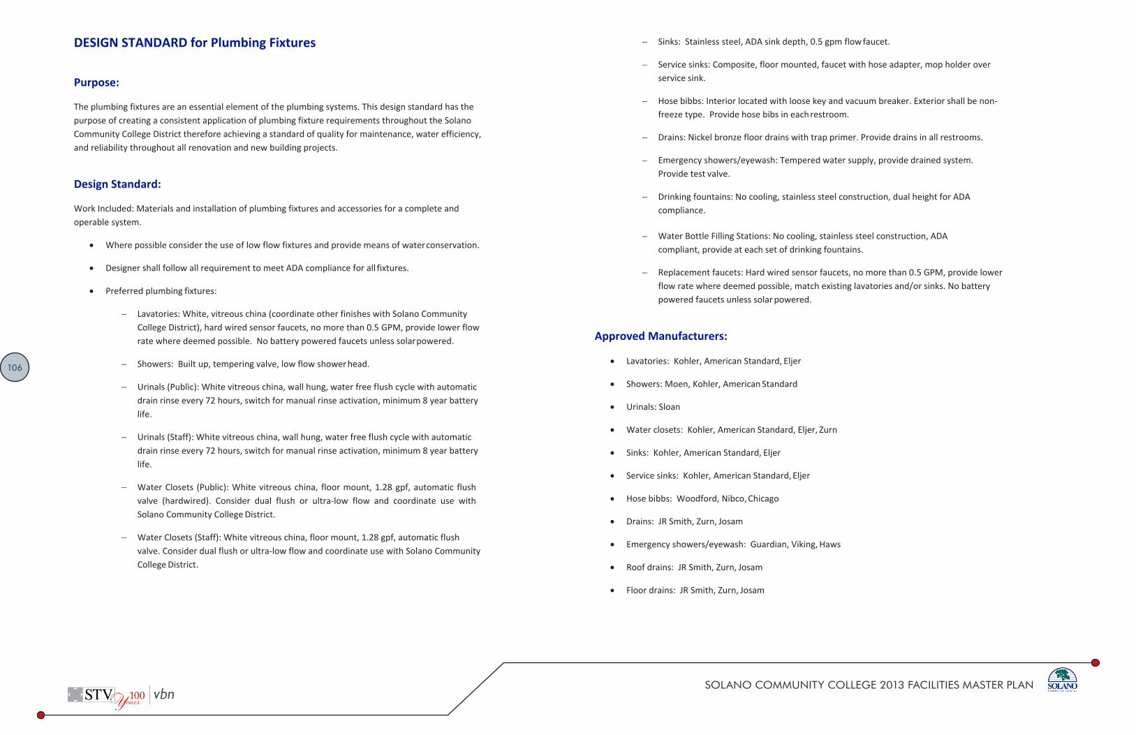
106
SOLANO COMMUNITY COLLEGE 2013 FACILITIES MASTER PLAN
DESIGN STANDARD Solano Community College District Division 22 40 00
DESIGN STANDARD for Plumbing Fixtures
Purpose:
The plumbing fixtures are an essential element of the plumbing systems. This design standard has the purpose of creating a consistent application of plumbing fixture requirements throughout the Solano Community College District therefore achieving a standard of quality for maintenance, water efficiency, and reliability throughout all renovation and new building projects.
Design Standard:
Work Included: Materials and installation of plumbing fixtures and accessories for a complete and operable system.
Where possible consider the use of low flow fixtures and provide means of water conservation.
Designer shall follow all requirement to meet ADA compliance for all fixtures.
Preferred plumbing fixtures:
Lavatories: White, vitreous china (coordinate other finishes with Solano Community College District), hard wired sensor faucets, no more than 0.5 GPM, provide lower flow rate where deemed possible. No battery powered faucets unless solar powered.
Showers: Built up, tempering valve, low flow shower head.
Urinals (Public): White vitreous china, wall hung, water free flush cycle with automatic drain rinse every 72 hours, switch for manual rinse activation, minimum 8 year battery life.
Urinals (Staff): White vitreous china, wall hung, water free flush cycle with automatic drain rinse every 72 hours, switch for manual rinse activation, minimum 8 year battery life.
Water Closets (Public): White vitreous china, floor mount, 1.28 gpf, automatic flush valve (hardwired). Consider dual flush or ultra‐low flow and coordinate use with Solano Community College District.
Water Closets (Staff): White vitreous china, floor mount, 1.28 gpf, automatic flush valve. Consider dual flush or ultra‐low flow and coordinate use with Solano Community College District.
1 02.2014
DESIGN STANDARD Solano Community College District Division 22 40 00
Sinks: Stainless steel, ADA sink depth, 0.5 gpm flow faucet.
Service sinks: Composite, floor mounted, faucet with hose adapter, mop holder over service sink.
Hose bibbs: Interior located with loose key and vacuum breaker. Exterior shall be non‐ freeze type. Provide hose bibs in each restroom.
Drains: Nickel bronze floor drains with trap primer. Provide drains in all restrooms.
Emergency showers/eyewash: Tempered water supply, provide drained system. Provide test valve.
Drinking fountains: No cooling, stainless steel construction, dual height for ADA compliance.
Water Bottle Filling Stations: No cooling, stainless steel construction, ADA compliant, provide at each set of drinking fountains.
Replacement faucets: Hard wired sensor faucets, no more than 0.5 GPM, provide lower flow rate where deemed possible, match existing lavatories and/or sinks. No battery powered faucets unless solar powered.
Approved Manufacturers:
Lavatories: Kohler, American Standard, Eljer
Showers: Moen, Kohler, American Standard
Urinals: Sloan
Water closets: Kohler, American Standard, Eljer, Zurn
Sinks: Kohler, American Standard, Eljer
Service sinks: Kohler, American Standard, Eljer
Hose bibbs: Woodford, Nibco, Chicago
Drains: JR Smith, Zurn, Josam
Emergency showers/eyewash: Guardian, Viking, Haws
Roof drains: JR Smith, Zurn, Josam
Floor drains: JR Smith, Zurn, Josam

107
SOLANO COMMUNITY COLLEGE 2013 FACILITIES MASTER PLAN
DESIGN STANDARD Solano Community College District Division 22 40 00
• Floor Sinks: JR Smith, Zurn, Josam
• Drinking Fountains: Elkay
• Water Bottle Filling Stations: Elkay
• Automatic Valves: Sloan
• Lav Faucets: Speakman
• Sink Faucets: Chicago
Substitutes Allowed:
Yes, if performance and quality equivalency can be evidenced.
Associated Design Standards and Specifications
22 11 13 ‐ GENERAL PLUMBING PIPING SYSTEMS
22 00 00 ‐ BASIC PLUMBING SYSTEM DESIGN
End of Document
Plumbing Fixtures
L-1: Lavatory: American Standard Declyn Model 0321, 18-1/2" wide x 17" long, white vitreouschina, wall mount lavatory with perforated grid drain and tailpiece for ADA compliance and Speakman model S-8801 hard wired sensor faucet, lead free, 0.50 gpm.
SK-I: Sink: Just Model SL-ADA-1921-A-GR, 19" wide x 21" long x 5-1/2" deep, stainless steel, counter mount sink with J-ADA-35 crumb cup strainer and tailpiece for ADA compliance and Chicago model 786-E2805-5ABCP gooseneck faucet with wrist blade handles, lead free, 0.5 gpm.
WC-I: Water closet: American Standard Model Madera 3461.712, white vitreous china, siphon jet, elongated-bowl;-floor-mount;-Flus!Tvalvewith-hard-wire·d-infrared-sensor-C-l.28-gallons·per flush),
white open front seat (less cover), ADA compliant, water hammer arrestor.
UR-I: Urinal: Sloan Hybrid (HYB-1000), white vitreous china, wall mount, automatic drain rinse, ADA compliant
SH- I: Shower: Moen model T8346EP15 Chrome plated single handle posi-temp handheld shower system with Moen model 8371 mixing valve (l .5 gpm). ADA compliant.
MSK-1: Mop Sink: Stern Williams Corlow model SBC-1700 24"x24"x12" with 6" drop front corner, stainless steel cap on threshold, cast brass drain with stainless steel strainer, mop hanger and Chicago model 897-CP faucet with integral stops, top brace,%" hose thread on spout with pail hook, vacuum breaker, 832-AA 30 inch long, heavy duty 5/8" cloth reinforced rubber hose and 18 gauge 304 stainless steel hose bracket with rubber grip.
FS-1: Floor sink: Zurn model ZI 900 12"xl 2"x6" with acid resistant coating, flange strainer & trap primer.
FD-I: Floor drain: Zurn model FD-23215 2" cast iron body, adjustable bronze strainer head & trap primer.
SHD-1: Shower Drain: Zurn model FD225 l-CI 2" cast iron body, strainer and trap primer.
DF-1 and WBF-1: Water Bottle Filling Station and Bi-Level Drinking Fountain: Elkay model LZSTLDDWSSK, light gray granite finish, filter certified to NSF42 and 53 for lead, class 1 particulate, chlorine, taste and odor reduction, Green Ticker, hands-free, laminar flow for minimal splash, real drain, ADA complaint.
SAMPLE STANDARD PLUMBING FIXTURES - SOLANO COMMUNITY COLLEGE DISTRICT

108
SOLANO COMMUNITY COLLEGE 2013 FACILITIES MASTER PLAN

109
SOLANO COMMUNITY COLLEGE 2013 FACILITIES MASTER PLAN

110
SOLANO COMMUNITY COLLEGE 2013 FACILITIES MASTER PLAN

111
SOLANO COMMUNITY COLLEGE 2013 FACILITIES MASTER PLAN

112
SOLANO COMMUNITY COLLEGE 2013 FACILITIES MASTER PLAN
►► Code NumberCode Number
1001020
►► DescriptionDescription
Complete Vitreous China Hybrid Urinal with automatic drain rinse.
►► Flush CycleFlush Cycle
Waterfree operation
►► SpecificationsSpecifications
● ● Urinal Assembly
● ● Complete mounting kit included
● ● Jetrinse™ Assembly
Patented housing and drain line rinsing
Automatic activation injects 1 gallon of water through housing and
drain line every 72 hours to prevent struvite build-up and clogs
IR switch for manual rinse activation
Long life lithium battery provides at least 8 years of service
● ● Cartridge Assembly*
Enhance patented design maximizes operational life, prevents
accidental sealant loss and virtually eliminates odor
Biodegradable sealant liquid
Vandal resistant locking design
20% less plastic than previous designs
Provides average of 7,000 uses that saves up to 40,000 gallons of
water each year
* Replacement cartridges sold separately
►► FeaturesFeatures
● ● Patented drain rinsing assembly
Minimizes cleaning effort
Virtually eliminates odor
● ● Touch-free hygenic operation
● ● Earns maximum LEED credits
● ● Up to 5 times cleaner than conventional flush urinals
● ● Best in class odor control
►► Compliance & CertificationsCompliance & Certifications
This space for Architect/Engineer Approval
Sloan Standard Urinal
Model HYB-1000
2017-02-06 Page 1 of 2
SLOAN 10500 SEYMOUR AVE. ● FRANKLIN PARK, ● IL. SLOAN 10500 SEYMOUR AVE. ● FRANKLIN PARK, ● IL. 60131 60131
Ph: 1-800-9-VALVE-9 or 1-847-671-4300 ● Fax: 1-800-447-8329 or 1-847-671-4380 ● http://www.sloan.com
Sloan Standard Urinal
Model HYB-1000
2017-02-06 Page 2 of 2
SLOAN 10500 SEYMOUR AVE. ● FRANKLIN PARK, ● IL. SLOAN 10500 SEYMOUR AVE. ● FRANKLIN PARK, ● IL. 60131 60131
Ph: 1-800-9-VALVE-9 or 1-847-671-4300 ● Fax: 1-800-447-8329 or 1-847-671-4380 ● http://www.sloan.com

113
SOLANO COMMUNITY COLLEGE 2013 FACILITIES MASTER PLAN
SPECIFICATIONS
Elkay EZH2O Bottle Filling Station & Versatile Bi-Level ADA Cooler Filtered Non-Refrigerated Stainless
Model LZSTLDDWSSK
In keeping with our policy of continuing product improvement, Elkay reserves the right to change product specifications without notice. Please visit elkay.com for the most current version of Elkay product specification sheets. This specification describes an Elkay product with design, quality, and functional benefits to the user. When making a comparison of other producers’ offerings, be certain these features are not overlooked.
Elkay REV 03012019 2222 Camden Court © 2019 Page 1 LZSTLDDWSSK Oak Brook, IL 60523 LZSTLDDWSSK_spec.pdf
PRODUCT SPECIFICATIONS Elkay ezH2O® Bottle Filling Station & Versatile Bi-Level ADA Cooler, Filtered Non-Refrigerated Stainless. Features shall include Hands Free, Visual Filter Monitor, Filtered, Green Ticker™, Laminar Flow, Antimicrobial, Real Drain. Furnished with Flexi-Guard ® Safety Bubbler. Electronic Bottle Filler Sensor With Electronic Front And Side Bubbler Pushbar activation. Product shall be Wall Mount (On Wall), for Indoor applications, serving 2 station(s). Unit shall be certified to UL 399 and CAN/CSA C22.2 No. 120. Unit shall be lead-free design which is certified to NSF/ANSI 61 & 372 (lead free) and meets Federal and State low-lead requirements.
Special Features: Hands Free, Visual Filter Monitor, Filtered, Green Ticker™, Laminar Flow, Antimicrobial, Real Drain
Finish: Stainless Steel Power: 115V/60Hz Bubbler Style: Flexi-Guard ® Safety Bubbler Activation by: Electronic Bottle Filler Sensor With
Electronic Front And Side Bubbler Pushbar
Mounting Type: Wall Mount (On Wall) Chilling Option: Non-refrigerated Full Load Amps 1.1 Rated Watts: 15 Dimensions (L x W x H): 36-3/4" x 19" x 39-1/16" Approx. Shipping Weight: 82 lbs. Installation Location: Indoor No. of Stations Served: 2 Special Note: *Coming soon: The Elkay ezH2O you know and love is getting a fresh look, as shown here. In stock models may have prior logo design.
Visual Filter Monitor: LED Filter Status Indicator for when filter change is necessary. Filter is certified to NSF 42 and 53 for lead, particulate, chlorine, taste and odor reduction. 3,000 gal. capacity.
Green Ticker: Informs user of number of 20 oz. plastic water bottles saved from waste.
Laminar flow provides clean fill with minimal splash. Silver Ion Antimicrobial protection on key plastic components to inhibit the growth of mold and mildew. Real Drain System eliminates standing water.
AMERICAN PRIDE. A LIFETIME TRADITION. Like your family, the Elkay family has values and traditions that endure. For almost a century, Elkay has been a family-owned and operated company, providing thousands of jobs that support our families and communities. Included with Product: Water Cooler (LZSTLDDWSSC),
Bottle Filler (LZWSR), Filter
Ships in multiple boxes. PRODUCT COMPLIANCE ADA & ICC A117.1 Buy American Act CAN/CSA C22.2 No. 120 GreenSpec® NSF/ANSI 42, 53, 61, & 372 (lead free) UL 399
Complies with ADA & ICC A117.1 accessibility requirements when installed according to the requirements outlined in these standards. Installation may require additional components and/or construction features to be fully compliant. Consult the local Authority Having Jurisdiction if necessary.
Installation Instructions (PDF) Electrical components and water system are warranted for 12 months from date of installation. Warranty pertains to drinking water applications only. Non-drinking water applications are not covered under warranty. Warranty (PDF)
OPTIONAL ACCESSORIES 51300C - WaterSentry Plus Replacement Filter (Bottle Fillers) LKAPREZL - Elkay Cane Apron for EZ Gray MLP200 - Accessory - In Wall Carrier (Bi-Level) for bi-level EZ, LZ, EMABF, LMABF, VRC, LVRC models 98568C - WaterSentry Filter Mounting Cover (Stainless Steel)
PART:________________________________QTY: _____________
PROJECT:______________________________________________
CONTACT:______________________________________________
DATE:__________________________________________________
NOTES:_________________________________________________
APPROVAL:_____________________________________________

114
SOLANO COMMUNITY COLLEGE 2013 FACILITIES MASTER PLAN

115
SOLANO COMMUNITY COLLEGE 2013 FACILITIES MASTER PLAN

116
SOLANO COMMUNITY COLLEGE 2013 FACILITIES MASTER PLAN

117
SOLANO COMMUNITY COLLEGE 2013 FACILITIES MASTER PLAN

118
SOLANO COMMUNITY COLLEGE 2013 FACILITIES MASTER PLAN
DESIGN STANDARD Solano Community College District Division 23 00 00
1 02.2014
DESIGN STANDARD for Basic HVAC System Design
Purpose:
The purpose of this document is to standardize the basic elements of the HVAC system design process. This design standard has the purpose of creating a consistent application of HVAC system design throughout the Solano Community College District therefore achieving a standard of quality for maintenance, energy efficiency, and reliability throughout all renovation and new building projects.
Design Standard:
Codes – Systems will be designed in accordance with the latest edition of the following codes:
California Building Code.
California Mechanical Code.
California Plumbing Code.
California Fire Code.
National Electrical Code; California Electrical Code.
State of California Code of Regulations (CCR).
Energy Efficiency Standards and Title 24 Regulations.
Local City Amendments and Regulations.
DSA – Department of the State Architect.
Standards – The following reference standards will be used for the design:
AMCA – Air Movement and Control Association International, Inc.
ANSI – American National Standards Institute.
ARI – Air Conditioning and Refrigeration Institute.
ASHRAE – American Society of Heating, Refrigeration, and Air Conditioning Engineers.
SMACNA – Fire and Smoke Damper Installation Guide.
DESIGN STANDARD Solano Community College District Division 23 00 00
2 02.2014
SMACNA – Guidelines for Seismic Restraints of Mechanical Systems.
SMACNA – Standards for Duct Construction.
EPA – Environmental Protection Agency.
NEMA – National Electrical Manufacturer’s Association.
UL – Underwriters’ Laboratories.
NFPA - National Fire Protection Association.
NFPA 90A – Air Conditioning and Ventilating Systems.
NFPA 101 – Life Safety Code.
LEED – U.S. Green Building Council.
HVAC Calculation
Utilize the following outside air temperatures in calculating HVAC system capacities:
Solano College (Fairfield, Vallejo, Vacaville - Climate Zone 3, CEC T-24 0.5%):
Lighting Loads: Lighting loads shall be calculated at CEC T-24 Watt per square foot values during preliminary design. Engineers shall execute final calculations upon selection of final lighting fixture selections.
Equipment Loads: Equipment loads are variable and should be based on actual equipment to be installed in each location. Engineer shall apply diversity factors so as not to oversize central HVAC systems.
Thermal Mass: Thermal mass shall be considered during calculations as a method to offset cooling loads.
U-Values for Walls and Roofs: Loads shall be calculated at CEC T-24 allowances during preliminary design. Engineers shall execute final calculations upon selection of final building façade materials.
U-Values for Solar Heat gain Factors for Windows: Loads shall be calculated at CEC T-24 allowances during preliminary design. Engineers shall execute final calculations upon selection of final building façade materials.
Cooling system pick-up capacity: 10% of total load
Heating system pick-up capacity: 25% of total load
Mechanical Standards

119
SOLANO COMMUNITY COLLEGE 2013 FACILITIES MASTER PLAN
DESIGN STANDARD Solano Community College District Division 23 00 00
3 02.2014
All calculations shall be completed utilizing DOE approved calculation software.
Pipe sizing calculations: 4.0’/100’HD for main piping; 3.5’/100’ HD for branch piping; 7 fps maximum velocity in occupied spaces.
Duct sizing calculations: equal friction method - 0.1”/100’ for main ductwork (never exceed 2,000 feet per minute); 0.08”/100’ for low pressure branch ductwork (never exceed 800 feet per minute). Lower velocities may be needed for acoustical purposes.
Return air systems – Return air ducts shall be sized on the equal friction method at 0.08”/100’ (never exceed 1,500 feet per minute). Design plenum return air systems for low pressure drops. Design transfer air systems at 250 feet per minute to minimize pressure drop.
Interior temperature requirements:
General conditions
Summer time cooling design 73°F +/- 3°F, no RH control (no cooling control except through ventilation for buildings deemed not to have cooling systems)
Winter time heating design: 70°F +/- 3°F, no RH control
Acoustical and Vibration Calculations:
Acoustical calculations shall be completed by a professional specializing in the science of sound transmission, acoustics, and vibration.
Design shall conform to ASHRAE Chapter “Sound and Vibration Control”, latest edition and the Solano Community College District Acoustical Design Standards.
Outside Air Make-up and Ventilation
Utilize CEC T-24 and/or ASHRAE Standard 62 (whichever is most stringent), latest edition, to determine outside air ventilation flow rates. Indicate quantities of minimum outside air on all equipment schedules.
Outside air for ventilation and make-up shall be brought from a fresh source of air. Outside air openings and operable building systems shall be located at a minimum of 15-0” from any permanent or temporary points of:
Boiler exhaust
Kilns
exhaust air
DESIGN STANDARD Solano Community College District Division 23 00 00
4 02.2014
plumbing vents
areas of objectionable odor
locate away from loading docks, parking lots, adjacent roadways, etc.
30’-0” separation from non-environmental exhaust systems (as defined by the CMC) such as kitchen exhaust, lab fume hood exhaust, garage exhaust, etc. Increase separation where openings are downwind from sources listed above.
Design outside air intakes to eliminate the possibility of water carry over. Always utilize drainable weatherproof type louvers at intakes.
Provide CO2 monitoring to accommodate demand based ventilation to reduce energy use. Monitors shall be connected to the BMS. Consider for large occupancy areas such as:
Classrooms
Gymnasiums
Theatres
Lecture halls
Auditoriums
Lobbies
Cafeterias
Meeting rooms
Conference rooms
Determine if natural ventilation can be utilized for comfort cooling either by itself or as part of a mixed-mode system. Prior to locating intakes, consider:
pollution sources
acoustical interferences
security
airflow patterns via CFD modeling

120
SOLANO COMMUNITY COLLEGE 2013 FACILITIES MASTER PLAN
DESIGN STANDARD Solano Community College District Division 23 00 00
5 02.2014
Consider the use of ultraviolet lamps at AHU outside air coils to kill bacteria and mold that may grow in air handling units. Ultraviolet lamps will not only kill bacteria and mold but also have the advantage of reducing maintenance for coil cleaning.
Equipment Selection
HVAC Systems: Specific system types are either addressed in the program or where a system is not indicated shall be addressed by the engineer of record for the project based on:
Lifecycle cost analysis to include first cost, operating cost, maintenance cost, energy cost
Reliability
Temperature control
Noise level
System complexity
Life expectancy – Minimum life expectancy for equipment shall be 25 years
Susceptibility to vandalism
Equipment General:
Provide an integrated design so that each element of the building is carefully considered. Produce a holistic solution.
Utilize shading, landscape, canopies, blinds, building thermal mass, etc. to reduce heating and cooling loads and minimize equipments sizes.
Fans:
Fans shall be selected on a stable point of operation of the fan curve. Fan selection shall be based on methods in the ASHRAE Handbook, most recent edition.
Select Motor sizes and speed should provide a 15% safety factor for deviation in fan static pressure and future airflow increases.
Static pressure of fans shall be determined from pressure drop calculations (based on the most hydraulically remote location) including:
ductwork
fittings
diffusers/grilles
DESIGN STANDARD Solano Community College District Division 23 00 00
6 02.2014
ductwork accessories
system effects
specialties and appurtenances
discharge velocity pressure
Select fan noise sound and pressure levels to assure quite operation per acoustical requirements above.
Kitchen Grease Exhaust: Fans shall be UL listed for such service. Provide with drain. Consider location of kitchen smoke exhaust with regards to campus views, deterioration of building façade, and odors.
Fume Hood Exhaust Fans: Fans shall be UL listed for such service. Provide explosion proof systems with appropriate coatings to prevent chemical action on fan housing.
Cooling Coils
Design direct expansion and chilled water coils on basis of a nominal 400-500 foot per minute face velocity.
All cooling coils shall be pipe counterflow of refrigerant against airflow.
Select the Cv of each coil control valve at design conditions.
Design with upward flow through coil and air vents at all high points of coils to eliminate trapped air.
At a minimum design with isolation valves on supply and return, two or three way control valve based on pumping system design, drain, flexible connections, and temperature gage.
Heating Coils
Design heating water coils on basis of a nominal 600 foot per minute face velocity.
All heating coils shall be pipe counterflow of refrigerant against airflow.
Select the Cv of each coil control valve at design conditions.
Design with upward flow through coil and air vents at all high points of coils to eliminate trapped air.

121
SOLANO COMMUNITY COLLEGE 2013 FACILITIES MASTER PLAN
DESIGN STANDARD Solano Community College District Division 23 00 00
7 02.2014
At a minimum design with isolation valves on supply and return, two or three way control valve based on pumping system design, drain, flexible connections, and temperature gage.
Air Distribution Devices
Supply Diffusers:
Preferred method of air distribution due to aspiration and entrainment of room air (reduction of drafts and more even room temperature profiles) as well as the ability to distribute air in many different directions.
Supply air grilles shall be sized based on manufacture’s airflow, noise criteria, mounting height, and pressure drop data.
Supply Grilles:
Avoid wall grilles where possible. Wall grilles have a lack of aspirating qualities and when discharging in cooling can create a perceived feeling of drafts. Where designed, use care. Utilizes a larger width to height aspect ratio for maximum induction of room air. Utilize double deflection type grilles to maximize adjustability. Do not throw air longer than 15-20 feet in rooms with low ceilings (below 9 feet).
Supply air grilles shall be sized based on manufacture’s airflow, noise criteria, mounting height, and pressure drop data. Do not exceed 500 feet per minute.
Return Air Grilles
Locate to aid in contaminant displacement.
Design for low pressure loss in return plenum systems to assure that rooms do not get over-pressurized.
Return air grilles shall be sized based on manufacture’s airflow, noise criteria, mounting height, and pressure drop data. Do not exceed 400 feet per minute for ducted systems and 250 feet per minute for plenum return systems.
Sound Attenuation and Vibration Control
Where required utilize sound traps or acoustical duct lining to mitigate noise attributable to HVAC equipment.
Size of sound traps and length to be provided by an acoustical engineer after completion of calculations.
DESIGN STANDARD
Solano Community College District Division 23 00 00 Length of acoustical lining to be provided by an acoustical engineer after completion of
calculations.
Provide vibration isolation devices as required to meet ASHRAE recommendations for vibration transmission.
Pumps
Select systems with two pumps. Deliver 100% capacity with both pumps operating in parallel. When one pump shuts down, a single pump shall be capable of providing 75‐ 80% of the total capacity. Due to cost considerations standby pumps are not required unless there is a specific concern for redundancy.
For economical design and energy efficiency, end suction, base mounted pumps and in‐ line pumps should be used for most systems except when the systems become very large.
Dynamic head of pumps shall be determined from pressure drop calculations (based on the most hydraulically remote location) including:
piping
fittings
valves
coils
system effects
specialties and appurtenances
Pumps shall be capable of being removed for maintenance without having to drain the entire system.
Temperature Control and Zoning
All buildings shall be connected to the campus wide DDC control network (Delta controls system). See DDC Controls Design Standards and Standard Specifications for additional criteria.
Individual temperature controls will be based on function, exposure, and Owner request.
Each corner exposure (NE, NW, SE, and SW) shall be on a separate temperature control zone.
8 02.2014

122
SOLANO COMMUNITY COLLEGE 2013 FACILITIES MASTER PLAN
DESIGN STANDARD Solano Community College District Division 23 00 00
9 02.2014
Each conference room, lobby, classroom, lecture hall, break area shall be on a separate temperature control zone.
Perimeter closed offices will be provided with no more than three to five offices per group of offices along the same orientation. This requirement may be relaxed when utilizing variable volume diffusers and terminal units are used primarily as a means of pressure control and reheat, however, group variable volume diffusers along the same orientation.
Large group spaces shall allow user-adjustable controls restricted to +/- 2°F with a time-out after 2 hours.
Specialty Considerations
Central Plants
The purpose of a central plant is to reduce overall energy costs, limit noise and vibration to occupied spaces, reduce maintenance to a single location for boilers, chiller, and pumps, increase the aesthetic nature for the remainder of the campus.
All campuses that have existing central plants for heating and/or cooling shall have new and/or modernized buildings connected to the central plant. Exceptions will be made based on project budget and other factors.
Equipment selection for new central plants should be industrial commercial grade.
Systems should be easy to maintain and operate.
Consideration should be given for expansion.
Sequences shall be determined to minimize energy use and take advantage of low part-load conditions that occur frequently at the campuses.
Specialty Pressure Requirements and Exhaust Systems
Specific rooms shall be designed to be at a negative pressure to adjoining spaces and to be exhausted 100%. These rooms include but are not limited to: restrooms, certain labs (confirm with activity and use), certain science classrooms (confirm with activity and use), kitchens, janitor closets, copy rooms, food service rooms, loading docks, locker rooms, shower facilities, photograph rooms and dark rooms, art classrooms (confirm with activity and use), refrigeration machinery rooms, boiler rooms, etc.
DESIGN STANDARD Solano Community College District Division 23 00 00
10 02.2014
Areas with products of combustion need removal of the products and a source of combustion air.
Food Service Facilities
The kitchen shall be designed with separate exhaust systems for each hood allowing each hood to be separately controlled. Fans shall be at the end of the exhaust system and located in the exhaust duct. Exhaust airflow shall be at a rate of 1500 feet per minute minimum to create a capture velocity. No duct accessories are allowed in the kitchen exhaust system.
Provide separate exhaust systems for dishwashing. Ductwork shall be non-corrosive stainless steel and pitched for drainage. A duct drain shall be provided at the low point of the ductwork. Do not trap water in the duct.
Exhaust ductwork shall be specifically designed of materials compatible for kitchen grease exhaust
Make up air can either be provided from make-up air handlers or by transfer of air from adjoining spaces, Code permitting.
The make-up air and exhaust air systems shall be interlocked.
Sustainable Design Practices
The Solano Community College District has a desire to build buildings utilizing sustainable design techniques. As part of the Mechanical Design Standards, sample sustainable design opportunities are provided in a table in the sustainability section of the Solano Community College District standards. Each strategy needs to be integrated appropriately into their respective projects. Development of design strategies for each item is beyond the scope of this Design Standard and requires careful consideration for proper application. The District will select on a case by case basis, which projects will be LEED Certified and to what level.
Approved Manufacturers:
Not Applicable
Substitutes Allowed:
Not Applicable

123
SOLANO COMMUNITY COLLEGE 2013 FACILITIES MASTER PLAN
DESIGN STANDARD Solano Community College District Division 23 00 00
11 02.2014
Associated Design Standards and Specifications
All Division 23 Design Standards and Construction Specifications
DESIGN STANDARD Solano Community College District Division 23 05 10
1 02.2014
DESIGN STANDARD for HVAC Piping
Purpose:
The heating, ventilating, and air‐conditioning piping materials are an essential element of the mechanical systems. This design standard has the purpose of creating a consistent application of heating, ventilating, and air‐conditioning piping material requirements throughout the Solano Community College District therefore achieving a standard of quality for maintenance, reliability, and energy efficiency throughout all renovation and new building projects.
Design Standard:
Work Included: Materials, installation and testing of pipe, tubing and fittings for complete and operable systems.
General Electrical Equipment Clearances: Do not route piping through electrical rooms, transformer vaults, elevator equipment rooms, and other electrical or electronic equipment spaces and enclosures. Within mechanical or plumbing equipment rooms, provide minimum 3 feet lateral clearance from sides of electric switchgear panels, MCC’s, etc. Do not route piping above any electric power or lighting panel, switchgear, or similar electric device. Coordinate with electrical and coordinate exact pipe routing to provide proper clearance with such items.
Welding Qualification: Qualify welding procedures, welders and operators in accordance with ANSI B31.9 for shop and project site welding of piping work.
All piping shall meet the piping material requirements set forth:
Steel pipe:
ASTM A53, Hot Dipped, Zinc Coated Welded or Seamless, Grade B: Black
Copper tube:
Temper: Annealed (hard drawn)
Pre‐insulated underground piping systems:
Factory pre‐insulated piping system, consisting of an inner media carrier pipe, insulation around the carrier pipe, and a water/vapor seal jacket over the insulation
Carrier Pipe Material: Schedule 40 black steel pipe with 150 PSI malleable screwed fittings

124
SOLANO COMMUNITY COLLEGE 2013 FACILITIES MASTER PLAN
DESIGN STANDARD Solano Community College District Division 23 05 10
2 02.2014
Insulation: Rigid closed cell polyurethane, average density of at least 2 lb./ft.3, conforming to ASTM C552, Type II, Class 1, K factor of not more than 0.14 (BTU/in)/(hr/sq.ft./deg. F) at 50F
Outer Casing: PVC pipe of minimum 60 mils thickness. Each factory prefabricated section provides complete sealing of the insulation at each end of the conduit section. Provide permanent water and vapor seal. Carry over the outer casing and extend it to the carrier pipe. Use prefabricated caps specifically designed for end seal of prefabricated insulation systems. Fabricate caps of the same material as the outer casing
Includes: Expansion loops, Ells, Welded fitting and elbows, Moisture barrier and end seals, Anchors, Thrust Blocks.
After anchor blocks are poured and cured, a hydrostatic test of 150 PSIG or 1‐1/2 times operating pressure, whichever is greater, required for a period of 4 hours
Fittings for steel pipe:
Flanges, fittings, unions and other products, mark in accordance with MSS SP‐25
Welding Fittings: Wrought carbon steel fittings, ASTM A234, ANSI B16.9, B16.28. Butt‐welding type unless otherwise indicated to be socket welding type
Branch Connections: From mains or headers 2‐1/2 inches or larger, welded tees or forged welding outlets
Welding Outlets: "Weldolets" or "Threadolets" equivalent to Bonney Forge. Use forged welding outlets wherever branch line is at least 1 nominal pipe size smaller than local main or header
Threaded Fittings: ANSI B2.1, ASTM A47, 150 PSI rating, except where otherwise specified, prevailing codes or requirements or Specifications dictate use of 300 PSI rating. Fabricate from standard malleable iron with dimensions conforming to ANSI B16.3
Flanges: Carbon steel conforming to ASTM A105, ANSI B16.5, and factory forged in the USA. Flanges which have been machined, remade, painted, or are of non‐domestic origin are not acceptable. Provide raised or full face ends wherever indicated or required
Unions: ANSI B16.39, ASTM A47, and be fabricated from malleable iron with bronze‐to‐iron ground joints rated at 150 percent design operating pressure. Threads: ANSI B2.1
DESIGN STANDARD Solano Community College District Division 23 05 10
3 02.2014
Fasteners: Semi‐finished carbon steel bolts and hex nuts conforming to ASTM A307. Threads and Dimensions: ANSI B1.1 and B18.2
Threaded Pipe Plugs: ANSI B16.14
Provide thread lubricant
Designers can use mechanical couplings for pipe systems identified in Design Standard 23 21 05 if there is a cost benefit in doing so. The increased cost of mechanical couplings shall be weighed against the ease of installation and reduced installation time. The Design Standard recommends that designers allow the contractor to decide if they will or will not use mechanical couplings on systems allowing such. Mechanical couplings for steel pipe:
Coupling Housings: Malleable iron ASTM A47 or ductile iron ASTM A536
Coupling Housing Description: Grooved or rolled mechanical type, which engages grooved or rolled shouldered pipe ends, encasing an elastomeric gasket which bridges pipe ends to create seal. Cast in two or more parts, secured together during assembly with nuts and bolts. Permit degree of contraction and expansion as specified in manufacturer's published literature
Gaskets: Mechanical grooved or rolled coupling design, pressure responsive so that internal pressure serves to increase seal's tightness, constructed of elastomers having properties as designated by ASTM D2000. Water Services: EDPM Grade E, with green color code identification
Bolts and Nuts: Heat treated carbon steel, ASTM A183, minimum tensile 110,000 PSI
Branch Stub‐Ins: Upper housing with full locating collar for rigid positioning engaging machine‐cut hole in pipe, encasing elastomeric gasket conforming to pipe outside diameter around hole, and lower housing with positioning lugs, secured together during assembly with nuts and bolts
Fittings: Grooved or rolled shouldered end design to accept grooved or rolled mechanical couplings: Malleable Iron: ASTM A47, Ductile Iron: ASTM A536; Fabricated Steel: ASTM A53, Type F for 3/4 to 1‐1/2 inches, Type E or S, Grade B for 2 to 20 inches; Steel: ASTM A234
Flanges: Class 125 cast iron and Class 150 steel bolt hole alignment: Malleable Iron: ASTM A47, Ductile Iron: ASTM A536
Pipe/Grooved: Carbon steel, A‐53B/A‐106B/A135 Schedule 40. Roll or cut grooved‐ends as appropriate to pipe material, wall thickness, pressures, size and method of

125
SOLANO COMMUNITY COLLEGE 2013 FACILITIES MASTER PLAN
DESIGN STANDARD Solano Community College District Division 23 05 10
4 02.2014
joining. Pipe ends to be grooved or rolled in accordance with current listed standards conforming to ANSI/AWWA C‐606
Fittings for copper tubing: Wrought copper/bronze solder joint fittings complying with ANSI B16.22.
Insulating (Dielectric) Unions: Standard units recommended by manufacturer for use in the service indicated, which isolate ferrous from nonferrous piping, and prevent galvanic corrosion action. Minimum rated "flashover" voltage: 600 volts. Watts 3000 Series. Provide insulated flanges for flanged piping system connection to dissimilar metals.
Welding Materials: Comply with Section 2‐C of ASME Boiler Code, as applicable.
Tin‐Antimony Soldering Materials: ASTM B13.
Gaskets for Flanged Joints: ANSI B16.12; full faced for cast iron flanges; raised face for steel flanges, unless otherwise indicated or recommended by manufacturer. Gaskets: Minimum 1/8‐inch thick fabricated from non‐asbestos bases.
Copper‐Brazed: Make brazed joints for copper tubing and fittings with code approved brazing filler alloys meeting ASTM and AWS standards and listings. Filler alloys of BCuP2 classification (e.g., "Phos‐O" or "Fos‐Copper") may not be used to make joints between copper tubing and cast brass or bronze fittings. Installations conform to accepted published procedures, i.e., CPC Installation Standard 3‐75 and CDA Publications. Use of steel wool for cleaning tube and fittings is prohibited.
Unions: Provide unions at all threaded connections to equipment, regulators, and controls that may have to be removed or replaced and at all points where necessary for the disassembly of piping for maintenance. Detail piping and unions to allow removal of equipment without springing pipe.
Steel Pipe Union: 150 PSI malleable iron, brass to iron seat, ground joint, black or galvanized to match pipe
Copper Pipe Union: 200 PSI working pressure. Bronze body, solder or grooved ends. Pipes 2 inches and under use ground joint, pipes 2‐1/2 inches and larger use flanged face or grooved ends
Insulating Unions: 250 PSI working pressure. Pipe ends and material to match piping. Electric current below 1 percent of galvanic current. Gasket material as recommended by manufacturer. Epco or approved
DESIGN STANDARD Solano Community College District Division 23 05 10
5 02.2014
Escutcheons:
Brass material, chrome plated finish. Size sufficient to cover pipe openings through wall, floor or ceiling. Set screw or spring to secure to pipe. Coordinate opening sizes
Sleeves: Provide sleeves on pipes passing through concrete or masonry construction. Extend sleeve 1 inch above finished floor. Caulk pipes passing through floor with non‐shrinking grout or approved caulking compound. Provide "Link‐Seal" sleeve sealing system for slab on grade or exterior wall penetrations. Caulk/seal piping and ductwork passing through fire rated building assembly with UL rated assemblies. Provide fire‐rated assemblies per local AHJ requirements.
Corrosion Control: Underground Steel Piping Corrosion Protection: Factory wrap un‐insulated underground steel piping systems with protective coating composed of a coal‐tar saturated wrapping tape over a 20 mil thick coal‐tar epoxy coating, equivalent to "Republic X‐Tru‐Coat." Wrap joints spirally with a minimum overlap of 1/2 tape width. Extend wrap not less than 3 inches above grade. . Provide cathodic protection to meet requirements of NACE Standard RP0169‐2002.
Pipe Tests:
Make test before pipes are concealed
Fill system and remove air from system at least 24 hours before test begins
Correct leaks in screwed fittings by remaking the joint. Cut out leaks in welded joints and reweld; caulking is not permitted
Apply test pressure of 125 PSI and maintain for 1 hour with no visible leaks and no appreciable drop after the test pump has been disconnected
Approved Manufacturers:
Pre‐insulated underground piping systems Rovanco
Thermacore
PERMA‐PIPE
Mechanical Couplings
Victaulic
Gruvlok

126
SOLANO COMMUNITY COLLEGE 2013 FACILITIES MASTER PLAN
DESIGN STANDARD Solano Community College District Division 23 05 10
6 02.2014
Substitutes Allowed:
Yes, if performance and quality equivalency can be evidenced.
Associated Design Standards and Specifications
23 05 29 ‐ HANGERS AND SUPPORTS FOR HVAC PIPING AND EQUIPMENT
23 05 53 ‐ IDENTIFICATION FOR HVAC PIPING AND EQUIPMENT
23 21 05 ‐ HYDRONIC PIPING SYSTEMS
DESIGN STANDARD Solano Community College District Division 23 05 13
1 02.2014
DESIGN STANDARD for Common Motor Requirements for HVAC Equipment
Purpose:
The motor requirements for heating, ventilating, and air-conditioning equipment are an essential element of the mechanical systems. This design standard has the purpose of creating a consistent application of heating, ventilating, and air-conditioning equipment motor requirements throughout the Solano Community College District therefore achieving a standard of quality for maintenance, reliability, and energy efficiency throughout all renovation and new building projects.
Design Standard:
Work Included: Materials, installation and testing for complete and operable motors and starters for heating, ventilating, and air-conditioning equipment. These Design Standards are inclusive of motors that are field installed as well as integral to mechanical equipment.
All motors to meet the following requirements based on Code requirements and industry standard of care:
Energy efficient, suitable for non-overloading operation, and capable of continuous operation at full nameplate rating. Motors 1 HP and larger must meet Energy Policy act of 1992. Motors to meet or exceed California Energy Commission Title 24 requirements.
Take NEMA standards as minimum requirements for motor design and performance. Motors suitable for load, duty, voltage, frequency, hazard, and for service and location intended.
For consistency and economy, motors, unless specified otherwise, to be general purpose open drip-proof type, ball bearing equipped, 40°C temperature rise, and rated for continuous duty under full load.
To avoid unnecessary maintenance costs and early failure of equipment, all motors located outdoors to be TEFC motors (totally enclosed, fan cooled).
Due to the harsh weather environment at Solano College, all motors exposed to the outside air stream (whether inside or outside of equipment) to be TEFC motors (totally enclosed, fan cooled).
Motors smaller than 1/2 horsepower, 1 phase; and motors 1/2 horsepower and larger, 3 phase and voltage as indicated on Drawings. Maximum motor speed of 1750 RPM, unless otherwise noted. One phase motors to have internal thermal overload protection with automatic reset.

127
SOLANO COMMUNITY COLLEGE 2013 FACILITIES MASTER PLAN
DESIGN STANDARD Solano Community College District Division 23 05 13
2 02.2014
Motors for belt drive to have adjustable bases with set screw to maintain belt tension.
Provide inverter rated motors per NEMA MG1-31 where variable frequency drives are applied or where soft start starters are utilized.
For consistency, all starters to be specified by Division 26.
For consistency, all disconnects to be specified by Division 26.
Motors to have name plate giving manufacturer's name, shop number, HP, RPM and current characteristics.
Approved Manufacturers:
General Electric
Westinghouse
Baldor
Reliance
Substitutes Allowed:
Yes, if performance and quality equivalency can be evidenced.
Associated Design Standards and Specifications
23 05 48 - VIBRATION AND SEISMIC CONTROLS FOR HVAC PIPING AND EQUIPMENT
23 05 53 - IDENTIFICATION FOR HVAC PIPING AND EQUIPMENT
23 09 13 - VARIABLE FREQUENCY DRIVES
DESIGN STANDARD Solano Community College District Division 23 05 23
1 02.2014
DESIGN STANDARD for General Duty Valves for HVAC
Purpose:
The heating, ventilating, and air-conditioning valves are an essential element of the mechanical systems. This design standard has the purpose of creating a consistent application of heating, ventilating, and air-conditioning valve requirements throughout the Solano Community College District therefore achieving a standard of quality for maintenance, reliability, and energy efficiency throughout all renovation and new building projects.
Design Standard:
Work Included: Materials, installation and testing of valves for a complete and operable systems.
All valves of a particular type and size range on any one project shall be the product of one manufacturer.
Valves shall be designed to be installed with the valve bonnet in an upright position to prevent deterioration or corrosion of the bonnet and packing.
Valve body materials shall be compatible with piping system materials.
A valve drain shall be provided at the base of each water piping riser and manual air vents shall be provided at the top of each riser and at the high point of the system.
All valves shall be provided with reusable strap-on insulation covers.
All exposed valves in finished areas shall be chrome-plated.
Insulation: Where insulation is indicated, install extended stem valves, arranged in proper manner to receive insulation
Design access panels, where a removal type ceiling is not planned, into the project so all valves are accessible
Locate isolation valves so that it is possible to isolate separate floors, separate wings, machinery rooms and other natural subdivisions of the building. Design isolation valves on each side of equipment to permit servicing or removal without draining system. Design valves at all services left for future connections (tees, stubs, etc.,) unless they are in a valved zone, or can be isolated by existing valves with minor loss of pipe contents when opened

128
SOLANO COMMUNITY COLLEGE 2013 FACILITIES MASTER PLAN
DESIGN STANDARD Solano Community College District Division 23 05 23
2 02.2014
All general duty HVAC valves shall meet the requirements set forth:
Ball Valves
System supply and return piping shut-off and isolation valves for application in piping system up to and including 2-1/2” in diameter
Class 125, bronze body, screw-in bonnet, integral seat, renewable disc, straight body
Butterfly Valves
System supply and return piping shut-off and isolation valves for application in piping system over 2-1/2” in diameter
6 Inches and Smaller: 200 PSI, ductile iron body, extended neck, aluminum bronze disc, reinforced resilient EDPM seat, manual lever and lock
8 Inches and Larger: 200 PSI, ductile iron body, extended neck, aluminum bronze disc, reinforced resilient EDPM seat, gear operator
Globe Valves
Design for modulating services
2 Inches and Smaller: Class 125, bronze body, screw-in bonnet, integral seat, renewable disc, straight body
2-1/2 Inches and Larger: Class 125, iron body, bolted bonnet, flanged ends, renewable seat and disc, bronze mounted
Balancing Valves
Provide balancing valves as required for proper balance and to maintain balance at part and full load conditions
Bronze with a machined orifice flow restriction, multi-turn globe type valve, internal O-rings, rated working pressure of at least 240 PSIG (175 PSI iron construction, 2-1/2 inches and larger), flow setting indicating pointer and calibrated nameplate, memory stops, and pressure readout port with integral check valve on each side of the orifice
Check Valves
Where check valves are required, they shall be installed on the equipment side of all shutoff valves to facilitate servicing of the check valve
DESIGN STANDARD Solano Community College District Division 23 05 23
3 02.2014
2 Inches and Smaller: Class 125, bronze body, horizontal swing, regrinding type, Y-pattern, renewable disc
2-1/2 Inches and Larger: Class 125, iron body, bolted bonnet, horizontal swing, renewable seat and disc, flanged ends
Drain Valves
Class 125, bronze body, screw-in bonnet, rising stem, composition disc, 3/4-inch hose outlet
Control Valves
The design documents shall include a valve schedule for all ATC valves. The schedule shall indicate service, flow, CV, and pressure drop
Control valves shall be closely coordinated with Division 25 requirements
2-Inch or Less Two-Way Valves: Pressure independent, ball valve with forged brass nickel plated bodies and female NPT threads. Valves shall have blowout-proof stem design. Rate chrome plated ball and stem at a minimum of 400 psi water service with equal percentage characteristics from characterizing disc. Provide valves with reinforced Teflon seats. Minimum 200 psi close-off rating. Stainless steel, flow-limiting spring. 0-50 psi differential pressure operating range.
2-Inch or Less Three-way Valves: Ball valve with forged brass nickel plated body and female NPT threads. Blow-out proof stem design. Rate stainless steel ball and stem at a minimum of 400 PSI water service with equal percentage characteristics from characterizing disc. Provide reinforced teflon seats.
2-1/2 Inch to 6-Inch Modulating Control Valves: Iron body, globe valve, with flanged ends, bronze seat, and 316 stainless steel stem. TFE V-ring packing. Maximum 25 PSI differential pressure.
Two-Way and Three-Way Butterfly Control Valve: Valve body shall be of the full lug wafer style. Flanges shall meet ANSI 125 and 150 standards. Valves shall feature a single, through-shaft design for high-strength and positive disc control. The seat shall be made of heavy-duty, molded-in O-rings creating a positive seal between flange face and valve body. The seat shall provide positive bubble-tight close off.

129
SOLANO COMMUNITY COLLEGE 2013 FACILITIES MASTER PLAN
DESIGN STANDARD Solano Community College District Division 23 05 23
4 02.2014
Approved Manufacturers:
Ball, Butterfly, Globe Valves, Check Valves, Drain Valves
Nibco
Crane
Milwaukee
Balancing Valves
Bell & Gossett
Armstrong
Nibco
Wheatley
Tour & Anderson
Control Valves
Belimo
Griswold
Substitutes Allowed:
No substitutions allowed on control valves and balancing valves.
Associated Design Standards and Specifications
23 05 53 - IDENTIFICATION FOR HVAC PIPING AND EQUIPMENT
25 55 00 – BUILDING MANAGEMENT SYSTEM
DESIGN STANDARD Solano Community College District Division 23 05 29
1 02.2014
DESIGN STANDARD for Hangers and Supports HVAC and Piping and Equipment
Purpose:
The heating, ventilating, and air-conditioning piping and equipment hangers are an essential element of the mechanical systems. This design standard has the purpose of creating a consistent application of heating, ventilating, and air-conditioning piping and equipment hanger requirements throughout the Solano Community College District therefore achieving a standard of quality for maintenance, reliability throughout all renovation and new building projects.
Design Standard:
Work Included: Material and installation of supports, anchors and sleeves including: horizontal piping hangers and supports; vertical piping clamps; hanger rod attachments; building attachments; saddles and shields; miscellaneous metals, miscellaneous materials; roof equipment supports; anchors; equipment supports; wall and floor sleeves; and escutcheon plates for a complete and operable systems.
Design pipe hangers and supports whose materials, design and manufacture comply with MSS SP-58, "Pipe Hangers and Supports - Materials, Design and Manufacture," latest edition.
Select and apply pipe hangers and supports complying with MSS SP-69, "Pipe Hangers and Supports - Selection and Application," latest edition. Use only one type by one manufacturer for each piping service. Select size of hangers and supports to exactly fit pipe size for bare piping, and to exactly fit around piping insulation with saddle or shield for insulated piping. Provide copper-plated hangers and supports for un-insulated copper piping systems.
Pipe Hangers Size 2 Inches and Smaller: Adjustable swivel ring hanger, UL listed
Pipe Hangers Size 2-1/2 Inches and Larger: Adjustable clevis type, UL listed
The use of pipe hooks, chains, plumbers tape, or perforated iron for pipe supports is not acceptable
All piping shall be designed to maintain the required pitch and shall provide for proper expansion and contraction
Vertical runs of pipe shall be supported with steel, UL listed riser clamps made specifically for pipe or for tubing

130
SOLANO COMMUNITY COLLEGE 2013 FACILITIES MASTER PLAN
DESIGN STANDARD Solano Community College District Division 23 05 29
2 02.2014
Due to the harsh outdoor environment at Solano College, all piping supports at Solano College that are in contact with the outdoor air shall be protected against corrosion.
Piping supports shall be designed to withstand seismic forces.
Roof equipment supports: Coordinate the location and type of each roof equipment support with the roofing system supplier. Coordinate systems to maintain roof warranty. Due to Solano College’s harsh outdoor environment all exposed equipment supports or equipment supports in mechanical rooms with contact to the outdoor air shall be protected against corrosion.
Compensate for slope in roof so top of support is level
Construct curb to withstand seismic forces
Roof Pipe Supports: Support piping on roof with polyethylene high-density U.V. resistant quick "pipe" block with foam pad. Recommended installation is for quick "pipe" blocks to be freestanding. Piping 3 inch and larger mounted on roller hangers. Wood block supports are not acceptable due to increased maintenance and low reliability.
Escutcheon Plates: Design around horizontal and vertical piping at visible penetrations through walls, partitions, floors, or ceilings, including penetrations through closets, through below ceiling corridor walls, and through equipment room walls and floors.
Approved Manufacturers:
Pipe Hanger Supports
B-Line
Michigan
Superstrut
Unistrut
Roof Equipment Supports
Pate ES
Custom Curb
Vibrex
Thycurb
DESIGN STANDARD Solano Community College District Division 23 05 29
3 02.2014
Roof Pipe Supports
Erico Pipe Piers
Nelson-Olsen Inc.
Substitutes Allowed:
Yes, if performance and quality equivalency can be evidenced.
Associated Design Standards and Specifications
23 21 05 - HYDRONIC PIPING SYSTEMS

131
SOLANO COMMUNITY COLLEGE 2013 FACILITIES MASTER PLAN
DESIGN STANDARDSolano Community College District Division23 05 48
1 02.2014
DESIGN STANDARD for Vibration and Seismic Controls for HVAC Piping, Ductwork, and Equipment
Purpose:
The vibration and seismic controls for heating, ventilating, and air-conditioning piping and equipment is an essential element of the mechanical systems. This design standard has the purpose of creating a consistent application of vibration and seismic control requirements throughout the Solano Community College District therefore achieving a standard of quality for maintenance and reliability throughout all renovation and new building projects.
Design Standard:
Work Included: Materials and installation of seismic restraint devices, vibration isolation systems, and related items for complete and operable systems.
Vibration Control
Mechanical and electrical equipment and associated piping and duct work shall bemounted by vibration isolators as required to minimize transmission of vibrations andnoise to building structures or spaces.
Selection of isolator type shall be as given in Table 42, Selection Guide for VibrationIsolation, Chapter 47, “Sound and Vibration Control,” of the latest edition of the ASHRAEApplications Handbook.
All rotating equipment shall be balanced both statically and dynamically. Vibration shallnot exceed the guidelines given in Table 42, Selection Guide for Vibration Isolation,Chapter 47, “Sound and Vibration Control,” of the latest edition of the ASHRAEApplications Handbook.
To minimize alignment problems, all motors over 5 hp must be designed to be solidlyattached to a common base with the driven unit.
In order to minimize vibration, solid sheaves and band belts shall be designed to be usedin multiple V-belt driven equipment over 15 hp.
DESIGN STANDARDSolano Community College District Division23 05 48
2 02.2014
Isolation Equipment
Isolation shall be designed to be stable during starting and stopping of equipmentwithout any transverse and eccentric movement of equipment that would damage oradversely affect operation of the equipment or appurtenances.
Isolation shall be designed for the operating speed of the equipment.
Isolators, including springs, exposed to the weather shall be hot dipped galvanized after fabrication. Hot dipped zinc coating shall comply with ASTM Method A-123 and shall not be less than 2 oz per square foot.
Isolators shall be selected and located to produce uniform loading and deflection even when equipment weight is not evenly distributed.
Isolation equipment includes: neoprene pads, hanger spring and neoprene, travel limited floor spring and neoprene, inertia base, flexible duct connections, flexible pipe connections, thrust limits, grommets, and snubbers.
Seismic Control and Restraint
Brace or anchor mechanical equipment to resist horizontal forces acting in any directionusing the CBC latest edition.
Provide factory fabricated seismic restrained vibration isolating components.Earthquake resistant designs for equipment, i.e., air handling units, blowers, motors,ductwork, and mechanical piping, to conform to the regulations of the CBC, latestedition. It is the Districts desire to use standard factory fabricated components, if theyare not available, provide properly designed custom components which meet therequirements herein.
Design shall include earthquake bumpers to prevent excessive motion during startingand stopping of equipment and for earthquake bracing. Install bumpers afterequipment is in operation to allow proper placement and alignment and ensure thatbumpers are not engaged during normal system operation
Design the seismic bracing and anchorage of piping per Section 23 05 29
Design piping and ductwork seismic restraints using the document "Seismic RestraintsManual Guidelines for Mechanical Systems." Secure piping, ductwork, and the like towithstand a force in any direction.

132
SOLANO COMMUNITY COLLEGE 2013 FACILITIES MASTER PLAN
DESIGN STANDARD Solano Community College District Division23 05 48
3 02.2014
Design restraints to meet CBC Seismic Restraint requirements. Provide structural engineering calculations sealed by a professional engineer registered in state of California.
Seismic Pipe Loops and Pipe Expansion
The design shall examine the piping system and shall design expansion compensation into the system by use of expansion loops, flexible connectors or, where space is limited, self-aligning bellows-type expansion joints.
The design shall design all anchors and guide supports as needed.
Seismic connectors for straight pipe runs to be designed with sufficient live length on each flexible leg to provide the minimum movement in directions as required by movement allowed at joint. Verify with structural total movement required in planes.
Approved Manufacturers:
Isolation Equipment
Amber Booth
Mason
Vibrex
Seismic Pipe Loops and Expansion Joints
Amber Booth
Mason
Metraflex
Vibrex
Substitutes Allowed:
Yes, if performance and quality equivalency can be evidenced.
Associated Design Standards and Specifications
23 05 29 - HANGERS AND SUPPORTS FOR HVAC PIPING AND EQUIPMENT
DESIGN STANDARD Solano Community College District Division 23 05 53
1 02.2014
DESIGN STANDARD for Identification of HVAC Piping, Ductwork, and Equipment
Purpose:
The identification of heating, ventilating, and air-conditioning piping, ductwork, and equipment is an essential element of the mechanical systems. This design standard has the purpose of creating a consistent application of systems identification requirements throughout the Solano Community College District therefore achieving a standard of quality for maintenance and reliability throughout all renovation and new building projects.
Design Standard:
Work Included: Materials and installation of mechanical systems identification for complete and operable systems.
General: Adhere to ANSI A-13.1
Ductwork
General: Provide for identification of air supply, return, exhaust, intake, and relief ductwork with stenciled signs and arrows, showing ductwork service and direction of flow, in black and white.
Locations: Ductwork shall be identified every 20’ in spaces with removable ceilings and at each access door in spaces with hard ceilings. Exposed ductwork shall be identified every 20’ in mechanical rooms. As described above, ductwork shall be labeled on both sides of floor and wall penetrations.
Access Doors: Provide engraved plastic-laminate signs on each access door in ductwork and housings, indicating purpose of access (to what equipment) and other maintenance and operating instructions, and appropriate and procedural information.
Piping
Wrap around plastic identification. Include arrows to show normal direction of flow. For hot non-insulated pipes, install a segment of pipe insulation with appropriate piping identification.

133
SOLANO COMMUNITY COLLEGE 2013 FACILITIES MASTER PLAN
DESIGN STANDARD Solano Community College District Division 23 05 53
2 02.2014
Locate identification as follows wherever piping is exposed to view in occupied spaces, machine rooms, accessible maintenance spaces (above removable ceilings and the like) and exterior non-concealed locations.
Near each valve and control device.
Near each branch, excluding short take-offs for fixtures and terminal units; mark each pipe at branch, where there could be question of flow pattern.
At locations where pipes pass through walls, floors, ceilings, or enter non-accessible enclosures.
At access doors, manholes and similar access points which permit view of concealed piping.
At major equipment items and other points of origination and termination.
Spaced intermediately at maximum spacing of 20’ in spaces with removable ceilings and at each access door in spaces with hard ceilings.
Identify non potable piping and outlets.
Color code piping: Fire protection – red; Gas – yellow; All others – white with appropriate identification.
Valve Identification
Provide for brass valve tags on every valve cock and control device in each piping system; exclude check valves, valves within factory-fabricated equipment units, plumbing fixture faucets, convenience and lawn-watering hose bibs, and shut-off valves at plumbing fixtures. HVAC terminal devices and similar rough-in connections of end-use fixtures and units. List each tagged valve in a valve schedule for each piping system.
Mechanical Equipment Identification
Provide for engraved plastic laminate sign on or near each major item of mechanical equipment and each operational device. Provide signs for the following general categories of equipment and operational devices:
Main control and operating valves, including safety devices.
Meters, gauges, thermometers and similar units.
Fuel-burning units including boilers, furnaces, and heaters.
Pumps, compressors, chillers, condensers and similar motor-driven units.
DESIGN STANDARD Solano Community College District Division 23 05 53
3 02.2014
Heat exchangers, coils, evaporators, cooling towers, heat recovery units and similar equipment.
Fans, blowers, primary balancing dampers and VAV boxes.
HVAC central-station and zone-type units.
Tanks and pressure vessels.
Air conditioning indoor and outdoor units.
AFD's and transmitters and Control Boxes.
Approved Manufacturers:
Seton
Brady
Substitutes Allowed:
Yes, if performance and quality equivalency can be evidenced.
Associated Design Standards and Specifications
23 05 29 - HANGERS AND SUPPORTS FOR HVAC PIPING AND EQUIPMENT

134
SOLANO COMMUNITY COLLEGE 2013 FACILITIES MASTER PLAN
DESIGN STANDARD Solano Community College District Division 23 05 93
1 02.2014
DESIGN STANDARD for Testing, Adjusting, and Balancing
Purpose:
The testing, adjusting, and balancing (TAB) of heating, ventilating, and air-conditioning systems is an essential element of the mechanical system turnover to the District. This design standard has the purpose of creating a consistent application of TAB requirements throughout the Solano Community College District therefore achieving a standard of quality for maintenance and reliability throughout all renovation and new building projects.
Design Standard:
Work Included: Materials, equipment and labor required for testing, adjusting, and balancing work required by this Standard, including air, hydronic systems, and associated equipment and apparatus. The work consists of setting speed and volume (flow) adjustments, recording data, conducting tests, preparing and submitting reports, and recommending modifications to work as required for complete and operable systems.
All testing, adjusting, and balancing (TAB) shall be done in accordance with the National Environmental Balancing Bureau (NEBB) or Associated Air Balance Council (AABC).
Environmental systems, including all equipment, apparatus, and distribution systems, shall be tested and balanced in accordance with the AABC or NEBB procedural standards. Fume hood testing shall be in accordance with the procedure outlined in the AABC manual.
All instruments used for measurements shall be accurate, and calibration histories for each instrument shall be available for examination. Calibration and maintenance of all instruments shall be in accordance with the requirements of AABC or NEBB.
Accuracy of measurements shall be in accordance with AABC or NEBB standards.
In order to verify field capacities of plants, during the operating tests of the chilled water system and/or heating water system, the Contractor shall provide a false load equal to full capacity on the chiller plant/boiler plant and submit data on gpm flow, pressure drop, inlet and outlet temperatures of chilled water/hot water, amperage of chiller, capacity of gas load, and ambient air temperature at condenser.
In addition, the Contractor shall check the operation of all automatic temperature control equipment; verify all thermostat, aquastat, airstat, etc., set-points and operations; and enlist the aid of the control subcontractor to make necessary adjustment where required.
DESIGN STANDARD Solano Community College District Division 23 05 93
2 02.2014
Reports:
Three copies of the final reports shall be submitted on applicable AABC or NEBB Reporting Forms for review and approval by the Design Consultant and the District.
Each individual final reporting form submitted shall bear the signature of the person who recorded the data and the signature of the testing and balancing supervisor of the performing firm.
If more than one certified firm performs the TAB work, all final reports shall be submitted by that certified firm having managerial responsibility.
Identification of all types of instruments used and their last dates of calibration shall be submitted with the final report.
The final test report shall include appropriate reference to all problems regarding the system(s) encountered prior to, during, and after testing and what action was taken to correct the problem(s), including noise and vibration problems.
Each report shall include a print (or sketch) reduced in size, showing all supply, return, and exhaust air outlets for easy reference to report data.
An approved copy of the balancing report shall be included in the maintenance manual submittal.
Approved Manufacturers:
Section not applicable
Substitutes Allowed:
Section not applicable
Associated Design Standards and Specifications
All Division 23 Design Standards and Construction Specifications

135
SOLANO COMMUNITY COLLEGE 2013 FACILITIES MASTER PLAN
DESIGN STANDARD Solano Community College District Division 23 07 00
1 02.2014
DESIGN STANDARD for HVAC Insulation
Purpose:
The heating, ventilating, and air-conditioning insulation is an essential element of the mechanical systems. This design standard has the purpose of creating a consistent application of insulation requirements throughout the Solano Community College District therefore achieving a standard of quality for maintenance, energy efficiency, and reliability throughout all renovation and new building projects.
Design Standard:
Work Included: Materials and installation of insulation, jackets and accessories for a complete and operable system.
General:
Adhere to the requirements of the California Energy Code – Title 24, latest edition.
Insulation shall be applied on clean, dry surfaces and only after tests and approvals required by the specifications have been completed.
All pipe insulation on piping operating below ambient temperature shall be continuous through wall and ceiling openings and sleeves.
Insulation on all cold surfaces must be applied with a continuous, unbroken vapor seal. Hangers, supports, anchors, etc., that are secured directly to cold surfaces shall be adequately insulated and vapor sealed to prevent condensation.
Specified adhesives, mastics, and coatings shall be applied at the manufacturer’s recommended minimum coverage per gallon.
Edges of vapor barrier insulation at valve stems, instrument wells, unions, and other raw edges shall be sealed adequately to prevent moisture from penetrating the insulation.
Fire Hazard Ratings: All insulation shall have composite (insulation jacket and adhesive used to adhere the jacket to the insulation) Fire and Smoke Hazard ratings as tested under procedure ASTM E 84, NFPA 225, and UL 723.
DESIGN STANDARD Solano Community College District Division 23 07 00
2 02.2014
Insulation Protection Shields
To prevent crushing of insulation, insulation protection shields shall be installed at all pipe hangers and supports. Shields shall span an arc of 180°. Provide full size diameter hangers and shields (18 gauge minimum) for piping. Provide 18-inch long, non-compressible insulation section at insulation shields for lines 2 inches and larger.
Insulation Jacketing
Provide aluminum jacketing for all piping located aboveground, outdoors.
Ductwork
In general, duct system shall be insulated with fiberglass blanket. Insulation on all cold surfaces shall be provided with a vapor barrier jacket.
Ductwork requiring sound attenuation my utilize duct lining with mold, humidity, and erosion resistant surfaces compliant to UL 181.
Piping
In general, piping systems shall be insulated with fiberglass piping insulation with an all-purpose jacket. Fittings, flanges, and valves shall be insulated with fiberglass inserts and premolded polyvinyl or PVC jackets.
Refrigerant piping systems shall be insulated with elastromeric pipe insulation.
Calcium silicate or high-temperature fiberglass shall be used in high temperature applications.
Special insulation protection shall be considered for areas subject to abuse and moisture, such as outside areas, washdown areas, public areas, and classrooms.
Removable insulated jackets shall be provided on all valves.
Equipment: At a minimum, the following equipment shall be provided with insulation:
Air eliminators
Boilers
Chilled water pump bodies
Hot water storage tanks
Heat exchangers

136
SOLANO COMMUNITY COLLEGE 2013 FACILITIES MASTER PLAN
DESIGN STANDARD Solano Community College District Division 23 07 00
3 02.2014
Cold surfaces of chillers
Flue pipe
Engine exhaust
Approved Manufacturers:
Armacell LLC Armaflex
Certainteed
Johns Manville
Knauf
Owens-Corning Brady
Substitutes Allowed:
Yes, if performance and quality equivalency can be evidenced.
Associated Design Standards and Specifications
All Division 23 Design Standards and Construction Specifications
DESIGN STANDARD Solano Community College District Division 23 09 13
1 02.2014
DESIGN STANDARD for Variable Frequency Drives
Purpose:
The variable frequency drive is an essential element of variable flow mechanical systems. This design standard has the purpose of creating a consistent application of variable frequency drives throughout the Solano Community College District therefore achieving a standard of quality for maintenance, energy efficiency, and reliability throughout all renovation and new building projects.
Design Standard:
Work Included: Materials and installation for a complete adjustable frequency motor drive consisting of a pulse width modulated (PWM) inverter for use on a standard NEMA Design B induction motor. Design drive specifically for variable torque applications.
Drives to be UL Listed.
Solid state, with a Pulse Width Modulated (PWM) output waveform enclosed in a NEMA 1 enclosure (provide other NEMA enclosures as required for application), completely assembled and tested by manufacturer. Employ a full wave rectifier (to prevent input line notching), DC Line Reactor, capacitors, and Insulated Gate Bipolar Transistors (IGBTs) as the output switching.
Device drive efficiency: 97 percent or better at full speed and full load.
Fundamental power factor: 0.98 at all speeds and loads.
Door interlocked thermal magnetic circuit breaker disconnect handle, through-the-door type, and pad-lockable in the "Off" position.
Provide all VFDs with the same customer interface, including digital display, keypad and customer connections; regardless of horsepower rating. The keypad is to be used for local control (start/stop, forward/reverse, and speed adjust), for setting all parameters, and for stepping through the displays and menus
Approved Manufacturers:
ABB
Siemens

137
SOLANO COMMUNITY COLLEGE 2013 FACILITIES MASTER PLAN
DESIGN STANDARD Solano Community College District Division 23 09 13
2 02.2014
General Electric
Danfoss
Yaskawa
Mitsubishi
Substitutes Allowed:
Yes, if performance and quality equivalency can be evidenced.
Associated Design Standards and Specifications
23 05 13 - COMMON MOTOR REQUIREMENTS FOR HVAC EQUIPMENT
DESIGN STANDARD Solano Community College District Division 23 11 23
1 02.2014
DESIGN STANDARD for Facility Natural Gas Systems
Purpose:
The natural gas systems are an essential element of the mechanical heating and domestic water heating systems. This design standard has the purpose of creating a consistent application of natural gas system requirements throughout the Solano Community College District therefore achieving a standard of quality for maintenance and reliability throughout all renovation and new building projects.
Design Standard:
Work Included: Materials, installation, and testing of piping, valves, and appurtenances for natural gas systems for a complete and operable system.
Gas meter to be installed at each new building, and at each existing building with first major renovation. This is to allow the District to monitor gas flow/consumption per building.
Size gas piping for estimated maximum demand flow in CFH (using 1000 BTU per cubic foot) per code requirements.
Steel Pipe (Above Grade Installation):
2 Inches and Smaller: Schedule 40, A53 black steel pipe and threaded black malleable threaded fittings.
2-1/2 Inches and Larger: Schedule 40, A53 black pipe with Schedule 40 butt weld fittings.
ASTM A53, electric-resistance welded (Type E) or seamless (Type S), Grade B, black, Schedule 40 pipe, manufactured for threaded or welded pipe connections.
Steel Pipe (Exterior of Building Below Grade Installations)
2 Inches and Smaller: Schedule 40, A53 black steel pipe and threaded black malleable threaded fittings.
2-1/2 Inches and Larger: Schedule 40, A53 black pipe with butt weld fittings.
ASTM A53, electric-resistance welded (Type E) or seamless (Type S), Grade B, black, Schedule 40 pipe, manufactured for threaded or welded pipe connections.
Underground Steel Piping Corrosion Protection: Factory wrap un-insulated underground steel piping systems with protective coating composed of a coal-tar saturated wrapping tape over a 20 mil thick coal-tar epoxy coating, equivalent to"Republic X-Tru-Coat." Wrap joints spirally with a minimum overlap of 1/2 tape width.

138
SOLANO COMMUNITY COLLEGE 2013 FACILITIES MASTER PLAN
DESIGN STANDARD Solano Community College District Division 23 11 23
2 02.2014
Extend wrap not less than 3 inches above grade. Provide tinker test to check for holidays. Provide cathodic protection to meet requirements of NACE Standard RP0169-2002
Polyethylene Pipe (Below Grade Installations at 30 psig and Less Only)
Polyethylene pipe, tubing and fittings furnished under this Specification shall conform to applicable provisions and requirements of the latest revision of the US Department of Transportation Pipeline Safety Regulations (CFR) Title 49, Part 192, "Transportation of Natural or Other Gases by Pipeline: Minimum Federal Safety Standards," and, by inclusion, appropriate standards referenced therein.
Piping shall be easily traced.
Natural Gas Valves:
2 Inches and Smaller: Ball valves. UL listed, two-piece construction, threaded, bronze body, conventional port, 250 PSI WOG working pressure
2-1/2 Inches and Larger: 100 to 125 PSI rated, all bronze or iron body/bronze trimmed plug cock type, square head or tee/lever handle operation. CSA approved
Natural Gas Pressure Regulators: Diaphragm and spring actuated type, with vented relief feature. Construction, pressure range and venting features suitable for intended service. Regulator to meet code and serving utility requirements. Pipe vented type to atmosphere in approved location.
Provide shutoff valves, pressure regulators and unions at connections to gas-fired equipment. Provide dirt legs at low points.
Approved Manufacturers:
Valves
Apollo
Jenkins Bros.
Lunkenheimer Co.
Nibco
Watts
DESIGN STANDARD Solano Community College District Division 23 11 23
3 02.2014
Substitutes Allowed:
Yes, if performance and quality equivalency can be evidenced.
Associated Design Standards and Specifications
22 00 00 - BASIC PLUMBING SYSTEM DESIGN
22 11 13 - GENERAL PLUMBING PIPING SYSTEMS
22 05 12 - PLUMBING PIPE AND FITTINGS

139
SOLANO COMMUNITY COLLEGE 2013 FACILITIES MASTER PLAN
DESIGN STANDARD Solano Community College District Division 23 21 05
1 02.2014
DESIGN STANDARD for Hydronic Piping Systems
Purpose:
The hydronic piping systems are an essential element of the mechanical heating and cooling systems. This design standard has the purpose of creating a consistent application of hydronic piping system requirements throughout the Solano Community College District therefore achieving a standard of quality for maintenance and reliability throughout all renovation and new building projects.
Design Standard:
Work Included: Materials, installation, and testing of pipes and pipe fittings for cooling tower water, chilled water, building heating water, make-up and drain, and valves for a complete and operable system.
Manual vents are standard but automatic vents can be considered in special situations. Where vent location is high or otherwise inaccessible, the following procedure can be followed: Install valve at vent chamber, then extend 0.375-in. tubing to the nearest janitor sink or mechanical room floor drain and terminate with a ball valve. Use automatic water feed set to maintain proper system pressure. Add cold water makeup at the air vent line above an air-eliminating device.
Glycol systems shall be equipped with a mix-and-fill tank with manual fill capabilities, hose bib from domestic water for tank filling, and tank level alarm. Direct-connect city makeup lines to glycol systems are NOT permitted.
Provisions shall be made for draining and air venting of all water coils.
Closed Loop Water Treatment: All new hot water and chilled water systems that are independent of the central systems shall be arranged for shot feed chemical treatment. In each such system, the equivalent of one Calgon 100L Mircomet pot feeder shall be provided, including pressure gage and flow indicator. The pot feeder to the system shall be hard-piped; using a hose is NOT acceptable.
Open Tower Water Treatment: All new open loop cooling tower systems shall be provided with a non-chemical treatment system similar to the EnviroTower system.
DESIGN STANDARD Solano Community College District Division 23 21 05
2 02.2014
After all items of equipment have been connected to the system, the hot and chilled water system shall be chemically cleaned as follows:
Drain and refill the system using trisodium phosphate, 1 lb for every 50 gal in the system.
Fill, vent, and circulate the system with this solution, allowing it to reach design or operating temperatures.
After circulating a few hours, the system should be drained completely, strainers removed and cleaned, dirt legs and pockets opened and cleaned, and then refilled with fresh water.
Reduced pressure principal backflow preventers shall be installed on all make-up water lines. Drains shall be piped to the nearest floor drain
Chilled Water:
Pipe Sizes 2-1/2 Inches and Larger: Steel, Schedule 40 with welded or mechanical coupling fittings, copper tubing, type L.
Pipe Sizes, 2 Inches and Smaller: Steel, Schedule 40 with threaded fittings, copper tubing, type L.
Drain Pipe: Steel, Schedule 40, threaded fittings; copper tubing, type M, soldered fittings
Heating Water:
Pipe Sizes 2-1/2 Inches and Larger: Steel, Schedule 40 with welded fittings, copper tubing, type L.
Pipe Sizes, 2 Inches and Smaller: Steel, Schedule 40 with threaded fittings, copper tubing, type L.
Drain Pipe: Steel, Schedule 40, threaded fittings; copper tubing, type M, soldered fittings
Cooling Tower:
Pipe Sizes 2-1/2 Inches and Larger: Steel, Schedule 40 with welded, flanged or mechanical coupling fittings.
Pipe Sizes, 2 Inches and Smaller: Steel, Schedule 40 with threaded fittings, copper tubing, type L.

140
SOLANO COMMUNITY COLLEGE 2013 FACILITIES MASTER PLAN
DESIGN STANDARD Solano Community College District Division 23 21 05
3 02.2014
Pressurized Steel Pipe:
ASTM A-53-84a, Electric Resistance Welded or Seamless, Grade B: Black, unless otherwise indicated, schedule as specified.
ASTM A-135-84, Schedule B: Black unless otherwise specified, schedule as specified
Manual air vent valves.
Operated manually with screwdriver or thumbscrew, 1/8-inch NPS or 1/4-inch NPS connection as require
Automatic air vent valves.
Float type with pressure rating equal to or greater than the system in which it is installed
Automatic flow control valves.
General: Pressure independent design, constructed to provide constant flow over a range of differential pressures, with field adjustable control point.
Accuracy: Plus or minus 5 percent.
Flow Characteristic. Smooth, continuous curve, void of abrupt changes over the entire range of operation.
Construction: Brass body, EPDM O-ring seals, abrasion resistant and non-corrosive thermoplastic cartridge, 1/8-inch pressure ports.
Flow adjustment: External adjustment via removable key and numeric dial indicator. Indicator reading to match manufacturer's data chart for calibration and flow reading
Pressure/Temperature Rating: 230 PSIG/248F
Strainers
Full line size strainers with ends matching connecting piping materials, machined screen seats, gasketed cap, blow off outlet, minimum 2-1/2 to 1 open area ratio, and Type 304 stainless steel screens with 1/16-inch diameter holes
Air separators.
Line size, pressure rated for 125 PSI. Construct sizes 1-1/2 inches and smaller of cast iron, and sizes 2 inches and larger of steel complying with ASME Boiler and Pressure Code and stamped with the "U" symbol
DESIGN STANDARD Solano Community College District Division 23 21 05
4 02.2014
Expansion tanks.
Welded steel, constructed, tested and stamped in accordance with Section VIII of ASME Boiler and Pressure Vessel Code for working pressure of 125 PSI. Furnish National Board Form U-1 denoting compliance. Support vertical tanks with steel legs or base. Provide single flexible diaphragm securely sealed into tank to separate air charge from system water, to maintain design expansion capacity. Provide pressure gauge and air-charging fitting, and drain fitting. Diaphragm: Removable and replaceable in line
Liquid flow switches.
Brass for all wetted parts, with packless construction, paddle with removable segments for pipe size and flow velocity, vaporproof electrical compartment for switches mounted on cold hydronic piping systems, switches for 115V, 60 Hz, 1-phase with 7.4A rating
Water pressure relief valves.
Size and capacity as selected by installer for proper relieving capacity, in accordance with ASME Boiler and Pressure Vessel Code.
Combined Pressure-Temperature Relief Valves: Bronze body, test lever, thermostat, complying with ANSI Z21.22 listing requirements for temperature discharge capacity. Provide temperature relief at 210F, and pressure relief at 125 PSI.
Pressure Relief Valves: Bronze body, test lever, ASME rated. Provide pressure relief at 30 PSI
Water pressure reducing valves.
Cast iron or brass body, inlet check valves, inlet strainer removable without system shut down, non-corrosive valve seat and stem factory set at operating pressure required
Thermometers
3-inch diameter bimetal dial thermometer, stainless steel case, white dial, black numbers, 4-inch stainless steel stem, brass separable socket. Back or bottom connections as required.
Service Range
Heating Water 50 to 300F
Chilled Water 0 to 120F
Condenser Water 50 to 150F

141
SOLANO COMMUNITY COLLEGE 2013 FACILITIES MASTER PLAN
DESIGN STANDARD Solano Community College District Division 23 21 05
5 02.2014
Thermometer wells
Brass or stainless steel, pressure rated to match piping system design pressure. Provide extensions for insulated piping of length required to extend above insulation used at each location. Provide cap nut with chain fastened permanently to thermometer well
Pressure gages
Type: General use, 1 percent accuracy, ANSI B40.1, Grade A, phosphor bronze bourdon type, bottom connection.
Case: Drawn steel or brass, glass lens, 4-1/2-inch diameter.
Connector: Brass with 1/4-inch male NPT.
Scale: White coated aluminum, with permanently etched markings.
Range:
Pump Suctions: 30-inch Hg - 60 PSI.
Water: 0 - 100 PSI.
Differential Pressure Switches
Sensing Range: 0- to 1.0-inch water column. Diaphragm operated with switching accomplished by photocell controlled relays, adjustable switch setpoints that close contacts on the relay if the differential pressure sensed raised above the setpoint, incorporate a pointer type gauge with divisions of 0.02-inch W.C.
Instrument probe fittings
Brass or stainless steel body and cap, high pressure rated, valve material neoprene, Nordal or Viton to suit temperature range, 1/4 inch or 1/2-inch NPT tailpiece.
Expansion joints
Furnish and install controlled flexing expansion joints where shown or required. Expansion Joints: Minimum of 150 PSI working pressure.
For copper piping, 3/4 inch through 3 inches, use Type HB, 1-3/4-inch traverse two-ply stainless steel bellows, traveling nipple extended through bellows and guided each end, integral shroud, screwed steel ends.
DESIGN STANDARD Solano Community College District Division 23 21 05
6 02.2014
For steel piping, 1-1/2 inches through 8 inches externally pressurized. 4-inch traverse, 150 PSI working pressure, stainless steel bellows, 150 PSI flanged ends, furnish insulation shroud
Pipe guides
Install where using expansion joints to avoid pipe buckling
Pipe anchors
Install where using expansion joints to avoid pipe displacement
Approved Manufacturers:
Manual air vent valves.
Armstrong
Bell & Gossett
Hoffman
Spirax
Sarco
Automatic air vent valves.
Taco
Bell & Gossett
Hoffman
Automatic flow control valves.
Griswold
Taco
Bell & Gossett
Strainers
Mueller
Armstrong
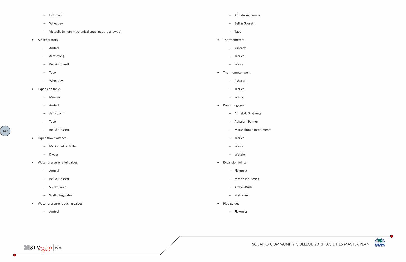
142
SOLANO COMMUNITY COLLEGE 2013 FACILITIES MASTER PLAN
DESIGN STANDARD Solano Community College District Division 23 21 05
7 02.2014
Hoffman
Wheatley
Victaulic (where mechanical couplings are allowed)
Air separators.
Amtrol
Armstrong
Bell & Gossett
Taco
Wheatley
Expansion tanks.
Mueller
Amtrol
Armstrong
Taco
Bell & Gossett
Liquid flow switches.
McDonnell & Miller
Dwyer
Water pressure relief valves.
Amtrol
Bell & Gossett
Spirax Sarco
Watts Regulator
Water pressure reducing valves.
Amtrol
DESIGN STANDARD Solano Community College District Division 23 21 05
8 02.2014
Armstrong Pumps
Bell & Gossett
Taco
Thermometers
Ashcroft
Trerice
Weiss
Thermometer wells
Ashcroft
Trerice
Weiss
Pressure gages
Amtek/U.S. Gauge
Ashcroft, Palmer
Marshaltown Instruments
Trerice
Weiss
Weksler
Expansion joints
Flexonics
Mason Industries
Amber-Bush
Metraflex
Pipe guides
Flexonics

143
SOLANO COMMUNITY COLLEGE 2013 FACILITIES MASTER PLAN
DESIGN STANDARD Solano Community College District Division 23 21 05
9 02.2014
Mason Industries
Amber-Bush
Metraflex
Pipe anchors
Flexonics
Mason Industries
Amber-Bush
Metraflex
Substitutes Allowed:
Approved manufacturer or approved equal
Associated Design Standards and Specifications
23 05 10 – HVAC PIPING
23 05 29 - HANGERS AND SUPPORTS FOR HVAC PIPING AND EQUIPMENT
23 05 53 - IDENTIFICATION FOR HVAC PIPING AND EQUIPMENT
DESIGN STANDARD Solano Community College District Division 23 21 10
1 02.2014
DESIGN STANDARD for Heating Water Systems
Purpose:
The heating water systems are an essential element of the mechanical space heating systems. This design standard has the purpose of creating a consistent application of heating water system requirements throughout the Solano Community College District therefore achieving a standard of quality for maintenance, energy efficiency, and reliability throughout all renovation and new building projects.
Design Standard:
Work Included: Materials, installation, and testing of heating water system for a complete and operable system.
Radiant Ceiling Panels
Design complete radiant heating/cooling ceiling system. The radiant panels consist of 0.040-inch aluminum faceplate, 1/2-inch ID copper serpentine coil metallurgically bonded to face plate, with a 1-1/2-inch thick, 3/4 lb. density glass fiber acoustic pad installed over panels. Panel interconnecting piping to be Type "L," soft copper, with wrought bronze or hard temper connection to valved outlets in the radiant panel circulating system. Panel finished with baked enamel finish
Panels to be designed as an installed system with the supplier providing interconnecting piping and the pipe between the panel system and the control valve
Hot water heating coils:
Designed to be counter-flow
Coil construction (downstream of air handlers): copper coils, aluminum fins
Coil construction (inside of air handlers): copper coils, aluminum fins
Coil construction (Solano, exposed to outdoor air): copper coils, copper fins
Horizontal hydronic unit heaters
Blow through unit with heating water coil, propeller fans with motor, three-speed switch, 18 gauge galvanized steel casing, fan guard, adjustable discharge louvers

144
SOLANO COMMUNITY COLLEGE 2013 FACILITIES MASTER PLAN
DESIGN STANDARD Solano Community College District Division 23 21 10
2 02.2014
Coils: 1/2-inch OD copper tubes with aluminum fins mechanically bonded to the tubes, 5/8-inch OD male sweat fittings. Coils are leak tested at 350 PSIG minimum air pressure, suitable for working pressures up to 250 PSIG with air vents
Motors: Permanent split capacitor type with built-in thermal overload protection
Cabinet Heaters:
Blow-through design with direct drive motor and forward curved double inlet fans in the airstream below the coil. Internal surfaces are either painted or are constructed of galvanized steel. Baked enamel finish on cabinet
Heating water constructed of copper tubing mechanically expanded into aluminum fins. Joints are brazed with high temperature silver alloy
Hot Water Convectors
Partially or fully recessed cabinet constructed of 16 gauge steel. Fasteners to be tamperproof Allen-Head machine screws. Access doors flush mounted with tamperproof latches. Exposed corners to have formed 1-inch radius cabinet to be phosphatized and painted inside and out with baked on primer and baked enamel finish
Grilles to be die-cast formed with directional louvers
Heating element to consist of 1/2-inch OD copper tube and aluminum fins and 1-1/4-inch steel headers. Test heating element at 200 PSI hydrostatic pressure
Finned Tube Radiator
Copper Aluminum Elements: Manufacture copper aluminum heating elements of seamless copper tube permanently bonded to aluminum fins by a mechanical process
Provide enclosure
Heat Exchangers
Plate and Frame Exchanger: Pressure plate and frame supporting heat transfer plates to be carbon steel. Heat transfer surfaces to be corrugated Type 304 stainless steel. Piping connections to be ANSI flanges. Minimum 150 PSIG working pressure to conform to ASME rules for pressure vessels. Install as recommended by manufacturer and provide adequate clearance for cleaning
DESIGN STANDARD Solano Community College District Division 23 21 10
Approved Manufacturers:
Radiant Ceiling Panels
Airtex Corporation
TROX
Hot water heating coils
Trane
Horizontal hydronic unit heaters
Trane
Cabinet Heaters
Trane
Carrier
Hot Water Convectors
Trane
Finned Tube Radiator
Trane
Heat Exchangers
Bell & Gossett
Taco
Substitutes Allowed:
Approved manufacturer or approved equal
Associated Design Standards and Specifications
23 05 10 – HVAC PIPING
23 05 53 ‐ IDENTIFICATION FOR HVAC PIPING AND EQUIPMENT
23 21 05 ‐ HYDRONIC PIPING SYSTEMS

145
SOLANO COMMUNITY COLLEGE 2013 FACILITIES MASTER PLAN
DESIGN STANDARD Solano Community College District Division 23 21 15
2 02.2014
Water-Cooled Chiller:
Water cooled, centrifugal type, assembled at the factory on a steel base. Individual performance test at full and part load conditions. Units to be leak tested and provided with a full operating charge of refrigerant
Locate indoors in a refrigeration machinery rooms
Design with variable frequency drive
Design with integral touch screen control panel
Design with integration to campus wide control system
Induced Draft Counterflow Cooling Tower:
Factory assembled, sectional, counterflow, induced draft design. Fan assemblies built completely into the pan with moving parts factory mounted and aligned.
All steel components: Hot-dip galvanized steel with cut edges given a protective coat of zinc-rich compound, with a final coating of zinc chromatized aluminum.
Stainless steel sumps.
Ice Storage Systems:
Installed in manufacturers steel tanks or underground insulated concrete tanks.
Contained within the tank shall be a steel heat exchanger that is constructed of 1.05" O.D., all prime surface serpentine steel tubing encased in a steel framework. The coil, which is hot-dip galvanized after fabrication, shall be pneumatically tested at 190 psig and rated for 150 psig operating pressure. The coil circuits are configured to provide maximum storage capacity. The coil connections on the unit are galvanized steel and are grooved for mechanical coupling.
Heat Exchangers
Plate and Frame Exchanger: Pressure plate and frame supporting heat transfer plates to be carbon steel. Heat transfer surfaces to be corrugated Type 304 stainless steel. Piping connections to be ANSI flanges. Minimum 150 PSIG working pressure to conform to ASME rules for pressure vessels. Install as recommended by manufacturer and provide adequate clearance for cleaning
DESIGN STANDARD Solano Community College District Division 23 21 15
1 02.2014
DESIGN STANDARD for Chilled Water Systems
Purpose:
The chilled water systems are an essential element of the mechanical space cooling systems. This design standard has the purpose of creating a consistent application of chilled water system requirements throughout the Solano Community College District therefore achieving a standard of quality for maintenance, energy efficiency, and reliability throughout all renovation and new building projects.
Design Standard:
Work Included: Materials, installation, and testing of chillers and cooling towers for building cooling and associated accessories for a complete and operable system.
All chilled water systems shall have refrigerant systems that meet all LEED requirements for refrigerant use with regards to ozone depletion and global warming.
Air-Cooled Chiller:
Air-cooled, reciprocating or screw type, dual independent refrigerant circuits with lead-lag switch, assembled at the factory on a steel base. Individual performance test at full and part load conditions. Units to be leak tested and provided with a full operating charge of refrigerant
Design on Solano campus shall provide casing and all components in contact with the outdoor environments to be corrosion resistant
Design with integration to campus wide control system
Evap-Cooled Chiller:
Evap-cooled, reciprocating or screw type, dual independent refrigerant circuits with lead-lag switch, assembled at the factory on a steel base. Individual performance test at full and part load conditions. Units to be leak tested and provided with a full operating charge of refrigerant
Design on Solano campus shall provide casing and all components in contact with the outdoor environments to be corrosion resistant
Design with integration to campus wide control system

146
SOLANO COMMUNITY COLLEGE 2013 FACILITIES MASTER PLAN
DESIGN STANDARD Solano Community College District Division 23 21 15
Approved Manufacturers:
• Air-Cooled Chiller:
− Trane
− Carrier
− York
• Evap-Cooled Chiller:
− Governair
• Water-Cooled Chiller:
− Trane
− Carrier
− York
• Induced Draft Counterflow Cooling Tower:
− BAC
• Ice Storage Systems:
− BAC
• Heat Exchangers
− Bell & Gossett
− Taco
Substitutes Allowed:
Air-Cooled Chiller and Water-Cooled Chiller: No substitutes allowed.
Other items: Approved manufacturer or approved equal.
Associated Design Standards and Specifications
• 23 05 10 – HVAC PIPING
• 23 05 53 – IDENTIFICATION FOR HVAC PIPING AND EQUIPMENT
• 23 21 05 – HYDRONIC PIPING SYSTEMS
DESIGN STANDARD Solano Community College District Division 23 21 20
1 02.2014
DESIGN STANDARD for Hydronic Pumps
Purpose:
The hydronic pumps are an essential element of the mechanical space cooling and heating systems. This design standard has the purpose of creating a consistent application of hydronic pump requirements throughout the Solano Community College District therefore achieving a standard of quality for maintenance, energy efficiency, and reliability throughout all renovation and new building projects.
Design Standard:
Work Included: Materials, installation and testing of pumps for a complete and operable system.
General:
Factory-tested pumps cleaned and painted with enamel prior to shipment. Do not install any pumps at Solano College in contact with the outdoor environment.
All pumps shall have bronze impellers.
A single gage shall be connected to the discharge and suction side of each pump and across the strainer so that the differential pressure can be observed.
Pumps – Closed Coupled
Closed-coupled pumps are not permitted over 0.5 hp.
Pumps – Base Mounted, End Suction
Pumps shall be electric-motor-driven, centrifugal, single-suction, single-stage pumps. Pumps shall be bronze fitted, with bronze impeller, with close-grained semi-steel vertically split casing (125 psi), provided with mechanical seals designed for the operating conditions shown on the plans. Pumps shall be provided with sleeve bearings and an oil reservoir. A drop-out coupling shall be provided.
Pumps shall have a sleeve bearing, specially selected for quiet operation at 1750 rpm. The motor size shown on the drawing shall be the minimum acceptable. A pump motor should operate within the service factor of the motor, providing that the service factor is acceptable to the pump manufacturer. The motor shall not exceed the nominal hp at the specified delivery and head.

147
SOLANO COMMUNITY COLLEGE 2013 FACILITIES MASTER PLAN
DESIGN STANDARD Solano Community College District Division 23 21 20
2 02.2014
Discharge increasers shall be concentric and located at the pump discharge nozzle. Suction pipe reducers shall be eccentric, located at the pump suction nozzle and at least five diameters of straight pipe shall be installed before the inlet or along the sweep elbow. (Suction diffusers in lieu of straight pipe section may be used.) A 0.75-in. drain shall be provided from each base plate to the nearest floor drain.
Pumps shall be selected so that the ratio of impeller diameter to the maximum diameter possible in the casing shall not exceed 0.85. A purge cock shall be provided in the casing and gage tappings shall be provided in pump suction and discharge.
All piping connections to pumps shall be supported independently so that no strain is imposed on the pump casing.
Pumps installed on “slab-on grade” shall be mounted on a 6-in. high concrete pad with anchor bolts. The space between pad and base shall be grouted to eliminate all voids.
Pumps shall have rear pull-out design for removal of the impeller without disturbing the motor alignment or piping.
Pumps installed on supported slabs shall be provided with concrete inertia subbases with spring isolators.
In-Line Pumps
Pumps shall be centrifugal and single-stage, complete with motor, mechanical seals, bronze fittings, bronze impellers, and a flexible coupler with safety guard. The pumps shall also be dynamically and hydraulically balanced.
The pump motor shall be supported independently.
Approved Manufacturers:
Pumps – Base Mounted, End Suction
Bell & Gossett
Taco
Paco
In-Line Pumps
Bell & Gossett
Taco
DESIGN STANDARD Solano Community College District Division 23 21 20
3 02.2014
Paco
Substitutes Allowed:
Approved manufacturer or approved equal.
Associated Design Standards and Specifications
23 05 10 – HVAC PIPING
23 05 53 - IDENTIFICATION FOR HVAC PIPING AND EQUIPMENT
23 21 05 - HYDRONIC PIPING SYSTEMS

148
SOLANO COMMUNITY COLLEGE 2013 FACILITIES MASTER PLAN
DESIGN STANDARD Solano Community College District Division 23 31 00
1 02.2014
DESIGN STANDARD for Ductwork
Purpose:
Ductwork is an essential element of the mechanical space cooling and heating systems. This design standard has the purpose of creating a consistent application of ductwork requirements throughout the Solano Community College District therefore achieving a standard of quality for maintenance, energy efficiency, and reliability throughout all renovation and new building projects.
Design Standard:
Work Included: Materials, installation and testing of HVAC ductwork and accessories, including the following:
» Heating and air conditioning supply and return systems
» Outside air systems
» Exhaust systems
» Ductwork hangers
» Plenums
» Gas vents
Galvanized Steel Ductwork: Carbon steel, lock-forming quality, hot-dip galvanized, with spangle-type zinc coating, double seam without showing fracture. Conform to ASTM A525 and A527.
ASHRAE and/or SMACNA shall be used as a guide.
Design medium pressure ductwork at 0.1”/100’ pressure drop
Design low pressure ductwork at 0.08”/100’Pressure classification shall be specified on the drawings.
All metal ductwork shall be crossbroke to ensure rigidity.
Inlet and discharge ductwork configuration shall conform to the SMACNA HVAC Duct Design Manual.
Seismic restraints shall be designed per SMACNA requirements
DESIGN STANDARD Solano Community College District Division 23 31 00
2 02.2014
All ductwork located outdoors shall be designed to be waterproof and sloped for water run-off
Flexible ducts:
Standard factory fabricated product, construct an inner wall of impervious vinyl or chlorinated polyethylene, permanently bonded to a vinyl or zinc-coated spring steel helix. Cover the assembly with fiberglass blanket insulation covered by an outer wall of vinyl or fiberglass-reinforced metalized vapor barrier. UL 181 listed Class 1 flexible air duct material. Overall thermal transmission no more than 0.25 (BTU/in)/(hr/sq.ft./deg. F) at 75F differential, per ASTM C335. Vapor transmission value no more than 0.10 perm, per ASTM E96. Rated for a minimum of 4-inch w.g. positive pressure and 1-inch w.g. negative pressure. Air friction correction factor of 1.3 maximum at 1000 FPM. Working air velocity of at least 2000 FPM. Flame spread rating no more than 25. Smoke development rating no more than 50 as tested per ASTM E84. Must have cataloged data on insertion loss characteristics, minimum attenuation of 29 DB for 10-foot straight length at 8-inch diameter and 500 Hz.
Install flexible duct with bend radius equal to 1.5 times the diameter. Minimum length 2 feet. Maximum length 5 feet.
Provide round neck grilles/diffusers or square-to-round transitions. No flex duct connections directly to square neck allowed.
Flex duct allowed only for vertical drops to diffusers. Maximum offset angle from vertical: 30 degrees.
Approved for use on supply ducts only; not allowed for return or exhaust.
Flex duct allowed in concealed spaces above lay-in ceilings only
Positive pressure gas vents:
Doublewalled insulated piping system. Construct the inner wall of at least 0.035-inch-thick Type 304 stainless steel. Construct the outer wall of at least 0.025-inch-thick aluminized steel. Fabricate duct to provide space between the inner and outer walls of at least 1 inch. List system by UL as 1400F Factory Built Chimneys with 2-inch clearance to combustibles for use with No. 2 fuel oil-fired equipment. Join sections by means of a system, capable of sealing gastight to pressure up to at least 60-inch w.g. for temperatures up to 600F. Fittings of the same manufacture and construction as the straight sections
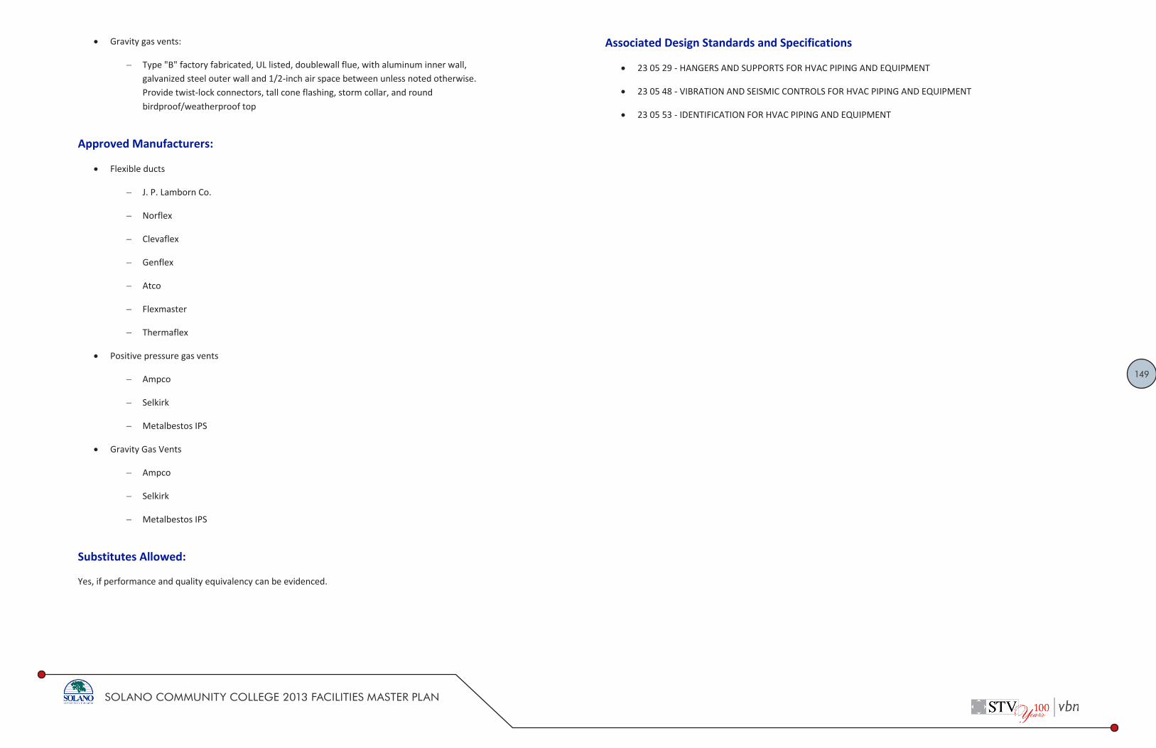
149
SOLANO COMMUNITY COLLEGE 2013 FACILITIES MASTER PLAN
DESIGN STANDARDSolano Community College District Division 23 31 00
3 02.2014
Gravity gas vents:
Type "B" factory fabricated, UL listed, doublewall flue, with aluminum inner wall,galvanized steel outer wall and 1/2-inch air space between unless noted otherwise.Provide twist-lock connectors, tall cone flashing, storm collar, and roundbirdproof/weatherproof top
Approved Manufacturers:
Flexible ducts
J. P. Lamborn Co.
Norflex
Clevaflex
Genflex
Atco
Flexmaster
Thermaflex
Positive pressure gas vents
Ampco
Selkirk
Metalbestos IPS
Gravity Gas Vents
Ampco
Selkirk
Metalbestos IPS
Substitutes Allowed:
Yes, if performance and quality equivalency can be evidenced.
DESIGN STANDARDSolano Community College District Division 23 31 00
4 02.2014
Associated Design Standards and Specifications
23 05 29 - HANGERS AND SUPPORTS FOR HVAC PIPING AND EQUIPMENT
23 05 48 - VIBRATION AND SEISMIC CONTROLS FOR HVAC PIPING AND EQUIPMENT
23 05 53 - IDENTIFICATION FOR HVAC PIPING AND EQUIPMENT

150
SOLANO COMMUNITY COLLEGE 2013 FACILITIES MASTER PLAN
DESIGN STANDARDSolano Community College District Division 23 33 00
1 02.2014
DESIGN STANDARD for Ductwork Accessories
Purpose:
Ductwork is an essential element of the mechanical space cooling and heating systems. This design standard has the purpose of creating a consistent application of ductwork requirements throughout the Solano Community College District therefore achieving a standard of quality for maintenance, energy efficiency, and reliability throughout all renovation and new building projects.
Design Standard:
Work Included: Materials, installation, and testing of HVAC duct accessories such as volume dampers, splitter dampers, adjustable deflectors, duct access doors, backdraft dampers, fire dampers, duct silencers, spin-in fittings, and smoke dampers
Volume Dampers
Construct of galvanized sheets not lighter than 18 gauge, reinforced to preventvibration, equipped at both ends with brass bearing mounts and of sufficient length toprovide a complete shutoff of the duct
Provide each damper with an adjustment and locking quadrant device for accessiblelocations, or remote type for non-accessible locations. Provide operating rod andattaching devices as required. Provide raised platform for insulated duct
Barometric Dampers (Large): Frame and blades fabricated from 0.063 mill finish aluminum.Blades have polyurethane edge seals. 1/2-inch diameter aluminum blade shafts with bronzebearings. Adjustable counterweight. Blades start to open at 0.05-inch APD - 55 FPM. Bladesfully open at 0.06-inch APD - 680 FPM.
Backdraft Dampers (small): All welded 14 gauge aluminum, with blades pivoting off center,double crimped front and rear, polyurethane seals. Link blades to work in unison, pivoting inball bearings, and provide adjustable counterweights attached to the blades. . Blades start toopen at 0.05-inch APD - 55 FPM. Blades fully open at 0.06-inch APD - 680 FPM. Frames:Channel type with flanges to facilitate mounting.
Control Dampers: Provide automatic control dampers as indicated. Airfoil, multiblade type,maximum blade length of 48 inches. Provide parallel blades for positive or modulating mixing
DESIGN STANDARDSolano Community College District Division 23 33 00
2 02.2014
service and opposed blades for throttling service. Blades to be interlocking, minimum 16 gauge galvanized steel. Damper blades reinforced, have continuous full length axle shafts and/or operating jackshafts as required to provide coordinated tracking of blades. Dampers over 25 sq.ft. in area to be in two or more sections, with interconnecting blades. Dampers to have a maximum air leakage of 15 CFM psf at 4-inch w.g. pressure. Provide automatic dampers except those specified with units.
Fire smoke damper: Motorized fire/smoke damper with motor. 22 gauge roll from galvanizedsteel with a 120VAC motor for motorized operation. Standard UL 212F fusible link. Providesmoke detector at each damper per code. Dynamic type. The fire dampers to be U.S. standardfor 1-1/2 hour listing. Motors to be UL listed. Provide the thermal protection via the fusiblelink. Damper to be normally closed. Minimum leakage Class II damper. Provide with automaticreset. Damper to fail closed when power is interrupted to actuator.
Filters: Provide minimum Merv-13 filters for LEED projects. Size for maximum velocity of 500feet per minute. Filters shall be standard dimensions.
Moisture eliminators: stainless steel moisture eliminator media, contained in an all stainlesssteel frame. Provide at all outside air intakes for equipment at Solano College.
Approved Manufacturers:
Volume dampers
Ruskin
Greenheck
Penn
Nailor
Cesco
Backdraft dampers
Ruskin
Greenheck
Cesco
Louvers & Dampers
Prefco

151
SOLANO COMMUNITY COLLEGE 2013 FACILITIES MASTER PLAN
DESIGN STANDARDSolano Community College District Division 23 33 00
3 02.2014
Control dampers
Ruskin
Greenheck
Louvers & Dampers
Prefco
Cesco
Fire Smoke Dampers
Ruskin
Greenheck
Penn
Nailor
Cesco
Filters
American Air Filter
Substitutes Allowed:
Approved manufacturer or approved equal.
Associated Design Standards and Specifications
23 31 00 - DUCTWORK
• Control Damper Actuators- Belimo- Delta
DESIGN STANDARDSolano Community College District Division 23 34 00
1 02.2014
DESIGN STANDARD for Fans
Purpose:
Fans are an essential element of the mechanical space ventilation, cooling, and heating systems. This design standard has the purpose of creating a consistent application of fan requirements throughout the Solano Community College District therefore achieving a standard of quality for maintenance, energy efficiency, and reliability throughout all renovation and new building projects.
Design Standard:
Work Included: Materials, installation, and testing of fans used for ventilation and exhaust service for a complete and operating system
Fans shall be AMCA rated for sound and air performance.
All fans shall be statically and dynamically balanced and test run at the factory.
The motor horsepower shall not be less than 120% of fan bhp, non-overloading.
Where variable speed drives are utilized, consider use of direct drive fans to reducemaintenance for belts. Consider fan’s critical speed in selection of direct drive fans with variablespeed operation.
Fan types shall include but not be limited to:
Sidewall exhaust fans
Centrifugal belt drive roof exhaust fans
Utility sets
Inline cabinet fans
Plug fans
Wall propeller exhaust fans
Transfer filter fans
Duct mounted inline fans
Air curtains

152
SOLANO COMMUNITY COLLEGE 2013 FACILITIES MASTER PLAN
DESIGN STANDARDSolano Community College District Division 23 34 00
2 02.2014
Dust Collectors
Design with material handling exhaust fan, heavy duty cotton sateen filters, explosionvent, (top mounted discharge silencer if required for acoustical attenuation) duststorage hopper. Housing of 14 gauge hot rolled steel base with extended legs providing42 inch clearance below hopper. Paint Finishes: One coat zinc chrome primer oninterior and one coat grey machinery enamel on exterior.
Heavy duty industrial type material handing direct drive exhaust fan.
Filters: High efficient cotton sateen fabric with an efficiency rating of 99.9 percent byweight, allowing recirculation of the air. The filter pockets must have a metal insert toprevent the filter from collapsing and to maintain a positive connection to the filtershaker during the cleaning cycle. Foam inserts will not be allowed.
Motorized shaker complete with motor. Solid state field adjustable controller governingshaking cycle duration, automatically actuated at each fan shutdown. Shaker must behigh frequency type for maximum cleaning.
Factory mounted and wired NEMA 4 control panel including magnetic starters withheaters for the blower motor and shaker motor. Single point electrical connection,provide for field wiring required for internally mounted start/stop station supplied byfactory.
Explosion vent designed for vacuum service to be supplied with the dust collector forfield installation. The explosion vent is to be the same diameter as the main duct andinstalled in "T" connection at the highest point prior to entering the dust collector.
Energy Recovery Units
General: Outdoor heat recovery ventilator designed for rooftop or indoor mountingwith separate supply and exhaust blowers.
Weatherproof, galvanized steel frame and panels, with 18 gauge steel where panels areexposed to the weather. Overlapping top seams. If used at Solano College, casing shallbe corrosion resistant.
Provide moisture eliminator testing in accordance with AMCA Standard 500-L to preventwater penetration up to 3 inches per hour at 29 miles per hour.
Insulation: 1-inch fiberglass, meeting UL 181 erosion requirements.
Energy Recovery Wheel: Silica gel enthalpy type and ARA certified to Standard 1060.Polymer media construction. Drive Belt: High strength urethane.
DESIGN STANDARDSolano Community College District Division 23 34 00
3 02.2014
Access Doors: Removable for servicing components.
Roof Curb: Weathertight with gasket and designed to carry gravity and seismic loads.
Approved Manufacturers:
Fans
Greenheck
Cook
Penn
Twin Cities
Air curtains
Mars
Dravo Corporation
Berner International
Dust collectors
Sternvent
Torit
American Air Filter
Energy recovery units
Greenheck
Innovent
Aaon
Haakon

153
SOLANO COMMUNITY COLLEGE 2013 FACILITIES MASTER PLAN
DESIGN STANDARDSolano Community College District Division 23 34 00
4 02.2014
Substitutes Allowed:
Yes, if performance and quality equivalency can be evidenced.
Associated Design Standards and Specifications
23 05 29 - HANGERS AND SUPPORTS FOR HVAC PIPING AND EQUIPMENT
23 05 48 - VIBRATION AND SEISMIC CONTROLS FOR HVAC PIPING AND EQUIPMENT
23 05 53 - IDENTIFICATION FOR HVAC PIPING AND EQUIPMENT
23 05 93 - TESTING, ADJUSTING AND BALANCING
23 31 00 - DUCTWORK
DESIGN STANDARDSolano Community College District Division 23 36 00
1 02.2014
DESIGN STANDARD for Air Terminal Units
Purpose:
Air terminal units are an essential element of the mechanical space ventilation, cooling, and heating systems. This design standard has the purpose of creating a consistent application of air terminal unit requirements throughout the Solano Community College District therefore achieving a standard of quality for maintenance, energy efficiency, and reliability throughout all renovation and new building projects.
Design Standard:
Work Included: Materials, installation and testing for variable air volume terminal units, including reheat central air terminals for a complete and operating system
Variable air volume (VAV) systems shall typically be zoned so that three to five offices areganged on a temperature sensor. Offices grouped together shall be ganged in a logical manner,such as having the same floor area, building face exposure, and similar internal loads. Cornerzones shall always be an independent zone not connected to any other rooms.
VAV boxes shall have a minimum position setting for ventilation air requirements.
Use of reheat coils shall be limited to hot water reheat coils. Utilize two row coils only wherenecessary to meet space temperature loads. 5/8-inch OD seamless copper tubes mechanicallyexpanded to aluminum fins. 150 PSIG working pressure. Sweat connections.
VAV boxes with perimeter radiation shall be sequenced from the same room temperaturesensor to ensure that the systems do not “fight” each other.
VAV boxes that are DDC type shall have factory-installed controls. Controls are to be furnishedby the controls contractor.
When multiple boxes are used to serve a single zone, all shall be controlled from a singlethermostat.
Location of all boxes shall be accessible for maintenance.
Box controls shall be pressure independent.

154
SOLANO COMMUNITY COLLEGE 2013 FACILITIES MASTER PLAN
DESIGN STANDARD Solano Community College District Division 23 36 00
2 02.2014
Approved Manufacturers:
Air terminal units
Trane
Titus
Tuttle & Bailey
Krueger
Price
Carnes
Nailor
Substitutes Allowed:
Approved manufacturer or approved equal.
Associated Design Standards and Specifications
23 05 29 - HANGERS AND SUPPORTS FOR HVAC PIPING AND EQUIPMENT
23 05 53 - IDENTIFICATION FOR HVAC PIPING AND EQUIPMENT
23 05 93 - TESTING, ADJUSTING AND BALANCING
23 31 00 – DUCTWORK
DESIGN STANDARD Solano Community College District Division 23 37 00
1 02.2014
DESIGN STANDARD for Air Outlets and Inlets
Purpose:
Air outlets and inlets are an essential element of the mechanical space ventilation, cooling, and heating systems. This design standard has the purpose of creating a consistent application of air outlets and inlets throughout the Solano Community College District therefore achieving a standard of quality for maintenance and reliability throughout all renovation and new building projects.
Design Standard:
Work Included: Materials, installation, and testing of HVAC outlets and inlets for a complete and operating system
Where possible, balancing dampers shall be located at the branch take-off instead of at the diffuser to reduce air noise. Where this is not possible, the damper at the diffuser shall be screwdriver operated
Grilles, registers, and diffusers:
Indicate 1-, 2-, 3-, or 4-way deflection so as to reduce chances of drafts
Coordinate mounting frames with construction types per finish schedule
Provide components that have velocity, throw and drop, and noise criteria ratings for each size device as listed in manufacturer's current standard literature, which are plus or minus 10 percent of the components as listed in the Diffuser, Register and Grille Schedule, or as specified herein
Gravity intake and relief penthouses:
Stormproof, gravity type. Penthouse: Aluminum or fiberglass. Cover: Removable and lined with fiberglass insulation to prevent condensation. Provide birdscreen, roof curb, and anti-condensation coating
Approved Manufacturers:
Grilles, registers, and diffusers:
Titus

155
SOLANO COMMUNITY COLLEGE 2013 FACILITIES MASTER PLAN
DESIGN STANDARD Solano Community College District Division 23 37 00
2 02.2014
Tuttle & Bailey
Krueger
Price
Carnes
Nailor
Gravity intake and relief penthouses
Acme
Breidert
Carnes
Greenheck
JencoFan
ILG
Cook
Penn
Substitutes Allowed:
Yes, if performance and quality equivalency can be evidenced.
Associated Design Standards and Specifications
23 05 93 - TESTING, ADJUSTING AND BALANCING
23 31 00 – DUCTWORK
DESIGN STANDARD Solano Community College District Division 23 52 00
1 02.2014
DESIGN STANDARD for Heating Boilers and Accessories
Purpose:
The boiler systems are an essential element of the mechanical space heating systems. This design standard has the purpose of creating a consistent application of boiler requirements throughout the Solano Community College District therefore achieving a standard of quality for maintenance, energy efficiency, and reliability throughout all renovation and new building projects.
Design Standard:
Work Included: Materials, installation, and testing of hot water boilers for building heating, and associated accessories for a complete and operable system.
Boilers shall be located under cover for protection from tree debris and rain. It is preferable for all boilers to be located indoors.
Boilers shall be located at grade level at a point accessible by hand truck from a service vehicle.
Condensing boilers are not acceptable due to high maintenance cost.
Furnish with trim per California Fired Pressure Vessel Safety Order (Title 17) including dual low water cut outs, dual gas valves.
Automatic reset low water cut out shall include automatic feed for increased safety (McDonald-Miller or equal).
Provide line pressure manual quick fill valve.
Boilers 100,000 BTUH and smaller.
Cast iron or steel tube with atmospheric burners.
80% minimum thermal efficiency
Boilers 100,000 BTUH to 2,000,000 BTUH
Copper fin or steel tube with atmospheric burners
80% minimum thermal efficiency
Access required to fire box, control panel, Low Water Cut Outs.

156
SOLANO COMMUNITY COLLEGE 2013 FACILITIES MASTER PLAN
DESIGN STANDARD Solano Community College District Division 23 52 00
2 02.2014
Boilers 2,000,000 BTUH and Greater
Boiler permit required from air pollution control district as required.
Provide Powered Burners If low NOX is required.
Provide Best Available Control Technology (BACT) for NOX emissions.
Steel or fire tube design acceptable.
80% minimum thermal efficiency
Approved Manufacturers:
Boilers
Clever Brooks
Kawahnee
Ajax
Rite
Lochinvar
Raypack
Substitutes Allowed:
Approved manufacturer or approved equal.
Associated Design Standards and Specifications
23 05 10 – HVAC PIPING
23 05 53 - IDENTIFICATION FOR HVAC PIPING AND EQUIPMENT
23 21 05 - HYDRONIC PIPING SYSTEMS
DESIGN STANDARD Solano Community College District Division 23 62 00
1 02.2014
DESIGN STANDARD for Refrigeration
Purpose:
The refrigeration systems are an essential element of the mechanical cooling systems. This design standard has the purpose of creating a consistent application of refrigerant system requirements throughout the Solano Community College District therefore achieving a standard of quality for maintenance and reliability throughout all renovation and new building projects.
Design Standard:
Work Included: Materials, installation and testing of refrigeration devices for air conditioning applications for a complete and operable system.
All refrigerant systems shall have refrigerant systems that meet all LEED requirements for refrigerant use with regards to ozone depletion and global warming.
Refrigerant liquid and suction piping shall be type L, hard drawn ACRS tubing.
A nitrogen purge shall be maintained when soldering all joints. Copper-to-copper joints shall be made with a brazing alloy similar to Sil-Fos. Copper-to-brass joints shall be made with silver solder.
Main piping fittings for dryers, sight glasses, expansion valves, and controls shall be flare or compression-type fittings.
Prior to being charged with refrigerant, the system shall be evacuated to 500 microns and held for at least 24 hours under this vacuum.
Double-suction risers shall be employed on systems with capacity reduction and where required by lift.
Precharged lines are not acceptable.
Isolation valves shall be provided at all specialties.
Installations shall be complete with dryers, sight glass, and thermostatically-controlled solenoid valves for pump down operations.
Where defrost units are required, they shall be operated electrically with adequate space provided to replace defrost elements. Defrost shall not be limited to electrical units. In larger installations, hot gas defrost is preferred.

157
SOLANO COMMUNITY COLLEGE 2013 FACILITIES MASTER PLAN
DESIGN STANDARD Solano Community College District Division 23 62 00
2 02.2014
Installations shall be provided with necessary protective devices including, but not limited to,electric overload devices, low-suction pressure cutouts (manual reset), high head pressurecutouts (manual reset), low-lube oil pressure cutouts (manual reset), oil traps, crankcaseheaters, and antirecycling.
Condensing systems shall be designed for low ambient conditions, using variable-frequency fansor fan staging when required for 24/7 cooling.
Condensing systems shall be provided for corrosion resistant when installed at Solano College
Approved Manufacturers:
Condensing Units.
Carrier
Trane
Mini Split Systems
Carrier
Friedrich
Mitsubishi
Sanyo
Daiken
Computer Room Units
Liebert
Stulz
APC
DESIGN STANDARD Division 23 62 00
3 02.2014
Solano Community College District
Substitutes Allowed:
Approved manufacturer or approved equal.
Associated Design Standards and Specifications
23 05 10 – HVAC PIPING
23 05 29 - HANGERS AND SUPPORTS FOR HVAC PIPING AND EQUIPMENT
23 05 53 - IDENTIFICATION FOR HVAC PIPING AND EQUIPMENT

158
SOLANO COMMUNITY COLLEGE 2013 FACILITIES MASTER PLAN
DESIGN STANDARD Solano Community College District Division 23 74 00
1 02.2014
DESIGN STANDARD for Packaged Air Conditioning Units
Purpose:
Packaged air conditioning units are an essential element of the mechanical space ventilation, cooling, and heating systems. This design standard has the purpose of creating a consistent application of packaged air conditioning unit requirements throughout the Solano Community College District therefore achieving a standard of quality for maintenance, energy efficiency, and reliability throughout all renovation and new building projects.
Design Standard:
Work Included: Materials, installation, and testing of fans used for ventilation and exhaust service for a complete and operating system
On campuses where a central chilled water system is available, package A/C units are not preferable due to higher energy consumption and increased maintenance costs.
Air-cooled packaged air conditioning equipment shall be equipped with low ambient cooling if systems are not provided with economizers or if systems serve a 24/7 load.
All units shall have a dedicated set of minimum outside air dampers for ventilation requirements. The dampers shall be two-position, and a second set of modulating outside air dampers shall be provided, as required, for economizer operation or tracking with exhaust air.
Rooftop package air conditioners 5 ton and larger shall be mounted on structural steel channel curbs with curb vibration isolation rails. Smaller units may be mounted on the manufacturer’s prefabricated curbs. Units located outdoors at Solano College shall be corrosion proof, including their steel supports.
Where hot water is not available, a gas-fired heat exchanger shall be used. (An electric heating coil is NOT acceptable.)
Casings shall be double-walled, with hinged access doors where available as an option.
Approved Manufacturers:
Light Commercial Package A/C Units
Carrier
DESIGN STANDARD Solano Community College District Division 23 74 00
2 02.2014
York
McQuay
Trane
Commercial Package A/C Units
Mammoth
Governair
Petra
Mini Split Systems
Carrier
Friedrich
Mitsubishi
Sanyo
Daiken
Computer Room Units
Liebert
Stulz
APC
Substitutes Allowed:
Approved manufacturer or approved equal.
Associated Design Standards and Specifications
23 05 29 - HANGERS AND SUPPORTS FOR HVAC PIPING AND EQUIPMENT
23 05 48 - VIBRATION AND SEISMIC CONTROLS FOR HVAC PIPING AND EQUIPMENT
23 05 53 - IDENTIFICATION FOR HVAC PIPING AND EQUIPMENT

159
SOLANO COMMUNITY COLLEGE 2013 FACILITIES MASTER PLAN
DESIGN STANDARD Solano Community College District Division 23 74 00
3 02.2014
23 05 93 - TESTING, ADJUSTING AND BALANCING
23 31 00 – DUCTWORK
23 62 00 - REFRIGERATION
DESIGN STANDARD Solano Community College District Division 23 75 00
1 02.2014
DESIGN STANDARD for Air Handling Units
Purpose:
Air handling units are an essential element of the mechanical space ventilation, cooling, and heating systems. This design standard has the purpose of creating a consistent application of air handling unit requirements throughout the Solano Community College District therefore achieving a standard of quality for maintenance, energy efficiency, and reliability throughout all renovation and new building projects.
Design Standard:
Work Included: Materials, installation and testing of central station air handling unit for a complete and operating system
All air handling units shall have, at minimum, a dedicated set of two-position outside air dampers for ventilation requirements plus a second set of modulating outside air dampers, as required, for economizer operation or tracking with exhaust air.
A full coil section width casing with access door shall be used to separate the chilled and heating coils.
Coils shall be copper coils with aluminum fins except at Solano College where all coils shall be copper coils with copper fins due to the harsh environment.
Insulated casings and plenums shall be specified for all units, including those serving heat and vent applications. Provide double wall casings at all locations.
Casings for heat and vent applications shall have space for installation of future cooling coil.
Units shall be installed to allow removal of all coils and filters. Clearance equal to full-finned width of coil shall be provided to facilitate removal.
Units shall be mounted on internal vibration isolators and concrete housekeeping pads.
Units shall have a mixing box and filter box or a combination filter/mixing box properly sized so as not to exceed the filter manufacturer’s recommended face velocities. Low leakage dampers (2%) shall be provided for mixing box dampers.
All cooling coil drain pans shall be stainless steel.
Variable speed drives shall be installed on the air handlers in a separate conditioned vestibule.
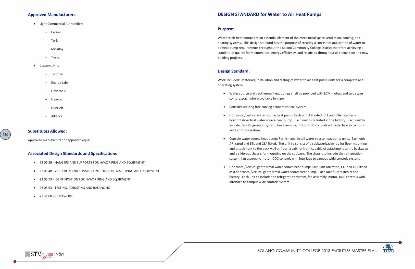
160
SOLANO COMMUNITY COLLEGE 2013 FACILITIES MASTER PLAN
DESIGN STANDARD Solano Community College District Division 23 75 00
2 02.2014
Approved Manufacturers:
Light Commercial Air Handlers
Carrier
York
McQuay
Trane
Custom Units
Temtrol
Energy Labs
Governair
Haakon
Hunt Air
Alliance
Substitutes Allowed:
Approved manufacturer or approved equal.
Associated Design Standards and Specifications
23 05 29 - HANGERS AND SUPPORTS FOR HVAC PIPING AND EQUIPMENT
23 05 48 - VIBRATION AND SEISMIC CONTROLS FOR HVAC PIPING AND EQUIPMENT
23 05 53 - IDENTIFICATION FOR HVAC PIPING AND EQUIPMENT
23 05 93 - TESTING, ADJUSTING AND BALANCING
23 31 00 – DUCTWORK
DESIGN STANDARD Solano Community College District Division 23 81 46
1 02.2014
DESIGN STANDARD for Water to Air Heat Pumps
Purpose:
Water to air heat pumps are an essential element of the mechanical space ventilation, cooling, and heating systems. This design standard has the purpose of creating a consistent application of water to air heat pump requirements throughout the Solano Community College District therefore achieving a standard of quality for maintenance, energy efficiency, and reliability throughout all renovation and new building projects.
Design Standard:
Work Included: Materials, installation and testing of water to air heat pump units for a complete and operating system
Water source and geothermal heat pumps shall be provided with ECM motors and two stage compressors (where available by size).
Consider utilizing free cooling economizer coil system.
Horizontal/vertical water source heat pump: Each unit ARI rated, ETL and CSA listed as a horizontal/vertical water source heat pump. Each unit fully tested at the factory. Each unit to include the refrigeration system, fan assembly, motor, DDC controls with interface to campus wide controls system.
Console water source heat pump: Furnish and install water source heat pump units. Each unit ARI rated and ETL and CSA listed. The unit to consist of a subbase/backwrap for floor mounting and attachment to the back wall or floor, a cabinet front capable of attachment to the backwrap and a slide-out chassis for mounting on the subbase. The chassis to include the refrigeration system, fan assembly, motor, DDC controls with interface to campus wide controls system.
Horizontal/vertical geothermal water source heat pump: Each unit ARI rated, ETL and CSA listed as a horizontal/vertical geothermal water source heat pump. Each unit fully tested at the factory. Each unit to include the refrigeration system, fan assembly, motor, DDC controls with interface to campus wide controls system

161
SOLANO COMMUNITY COLLEGE 2013 FACILITIES MASTER PLAN
DESIGN STANDARD Solano Community College District Division 23 81 46
2 02.2014
Approved Manufacturers:
Water Source Heat Pumps
Carrier
Climate Master
Florida Heat Pump
Trane
McQuay
Geothermal Water Source Heat Pumps
Climate Master
Florida Heat Pump
Waterfurnace
Substitutes Allowed:
Yes, if performance and quality equivalency can be evidenced.
Associated Design Standards and Specifications
23 05 29 - HANGERS AND SUPPORTS FOR HVAC PIPING AND EQUIPMENT
23 05 48 - VIBRATION AND SEISMIC CONTROLS FOR HVAC PIPING AND EQUIPMENT
23 05 53 - IDENTIFICATION FOR HVAC PIPING AND EQUIPMENT
23 05 93 - TESTING, ADJUSTING AND BALANCING
23 31 00 - DUCTWORK
23 62 00 - REFRIGERATION
DESIGN STANDARD Solano Community College District Division 23 83 15
1 02.2014
DESIGN STANDARD for Hydronic Floor Heating and Cooling System
Purpose:
Hydronic floor heating and cooling systems are an essential element of the mechanical cooling and heating systems. This design standard has the purpose of creating a consistent application of hydronic floor heating and cooling requirements throughout the Solano Community College District therefore achieving a standard of quality for maintenance, energy efficiency, and reliability throughout all renovation and new building projects.
Design Standard:
Work Included: Materials, installation and testing of hydronic floor heating and cooling systems for a complete and operating system
Design system to assure there will not be any condensation during cooling mode (if cooling is used).
Tubing: Flexible single pipe energy transfer hose which is oil resistant and is not degradable by continuous exposure to sunlight. System/tubing shall have an oxygen diffusion barrier. System capable of withstanding temperatures of minus 50F and plus 200F, and provide a commercial warranty of 20 years. Tubing capable of 180 degree change of direction without cracking or collapsing. Burst pressure not less than 800 PSI at 70F installation to meet requirements of manufacturer. Tubing installation and layout as directed and required by manufacturer. Lay out system with separate zones and controls.
Supply and return manifold piping to energy transfer tubing to be Type "K" copper with brass fittings for transition to tubing
During the installation, cap tubing on each end to prevent foreign materials from entering the tubing. Check tubing for abrasions prior to installation. Install tubing embedded in the floor without joints or splices, the cold bending radius of the tubing in accordance with Paragraph X2.3.6 of ASTM F877. Install tubing in such a manner as to effectively address the heat loss of the space. Do not place tubing near heat sensitive materials. The manifold and fittings accessible for maintenance. After the system is filled with water/glycol mix, vent air vented from the system. After the system is allowed to stabilize at the operating temperature of the heating fluid, vent the system again. Properly pressure test PEX system in accordance with the tubing manufacturer's guidelines, prior to burial below grade or in concrete. The tubing shall maintain a pressure test of 100 psi for a period of 24 hours prior to such covering. Keep tubing under constant pressure during installation of covering or backfill
162
SOLANO COMMUNITY COLLEGE 2013 FACILITIES MASTER PLAN
DESIGN STANDARD Solano Community College District Division 23 83 15
2 02.2014
Concrete Slab Construction: Fasten tubing to a flat mesh or reinforcing bar (or othermanufacturer-approved device) in accordance with the tubing manufacturers designrecommendations.
Apply test pressure of 125 PSI and maintain for one hour with no visible leaks and noappreciable drop after the test pump has been disconnected
Approved Manufacturers:
Heatway
Uponor HE PEX
Substitutes Allowed:
Approved manufacturer or approved equal.
Associated Design Standards and Specifications
23 05 29 - HANGERS AND SUPPORTS FOR HVAC PIPING AND EQUIPMENT
23 05 48 - VIBRATION AND SEISMIC CONTROLS FOR HVAC PIPING AND EQUIPMENT
23 05 53 - IDENTIFICATION FOR HVAC PIPING AND EQUIPMENT
23 05 93 - TESTING, ADJUSTING AND BALANCING

163
SOLANO COMMUNITY COLLEGE 2013 FACILITIES MASTER PLAN
DESIGN STANDARD Solano Community College District Division 26 00 00
1 02.2014
DESIGN STANDARD for Basic Electrical Systems Design
Purpose:
This design standard has the purpose of maintaining a consistent application of the basic electrical requirements of the electrical systems throughout the Solano Community College District therefore achieving a standard of quality for maintenance, reliability, and operation throughout all renovation and new building projects.
Design Standard:
Electrical systems required for this work includes labor, materials, equipment, and services necessary to complete installation of electrical work specified herein or required for a complete operable facility and not specifically described in other Sections of these Standards.
Following is a list of abbreviations generally used in Division 26:
ADA Americans With Disabilities Act
AHJ Authority Having Jurisdiction
ANSI American National Standards Institute
APWA American Public Works Association
ASTM American Society for Testing and Materials
CBC California Building Code
CEC California Electrical Code
CFC California Fire Code
FCC Federal Communications Commission
HVAC Heating, Ventilating and Air Conditioning
IEC International Electrotechnical Commission
DESIGN STANDARD Solano Community College District Division 26 00 00
2 02.2014
IEEE Institute of Electrical and Electronics Engineers.
IETA International Electrical Testing Association
FM FM Global
NEMA National Electrical Manufacturers Association
NFPA National Fire Protection Association
OSHA Occupational Safety and Health Administration
UL Underwriters Laboratories Inc.
Conform to requirements of the CEC, latest adopted version with amendments by local AHJs.
Conform to latest adopted version of the CBC with amendments by local AHJs.
Obtain and pay for electrical permits, plan review, and inspections from local AHJs.
Furnish products listed by UL or other testing firm acceptable to AHJ.
Conform to requirements of the serving electric, telephone, and cable television utilities.
Provide like items from one manufacturer, such as luminaire types, switches, receptacles, breakers, panels, and the like.
All materials to meet the following requirements based on Code requirements and industry standard of design and care:
Provide new electrical materials of the type and quality, listed by UL, bearing their label wherever standards have been established. Indicated brand names and catalog numbers are used to establish standards of performance and quality. The description of materials listed herein governs in the event that catalog numbers do not correspond to materials described herein.
Provide material and equipment that is acceptable to AHJ as suitable for the use. For example, provide wet labeled equipment in locations that are wet.
Provide incidentals not specifically mentioned herein, but needed to complete the system, in a safe and satisfactory working condition.
All documents to meet the following requirements based on District requirements and industry standard of design and care:
Prepare and submit layout drawings to coordinate installation and location of lighting, electrical and signal systems. Prepare composite drawings showing all equipment on a single sheet. The
Electrical Standards

164
SOLANO COMMUNITY COLLEGE 2013 FACILITIES MASTER PLAN
DESIGN STANDARD Solano Community College District Division 26 00 00
3 02.2014
architectural floor plans, reflected ceiling plans, and access floor layout plan shall form the base for the coordination drawings. Prior to completion of Drawings, coordinate proposed installation with the Architect, structural requirements, and other trades (including HVAC, plumbing, fire protection, ceiling systems, and raised floor system), and provide required maintenance access. Systems shall include, although not limited to, the following:
- Luminaires.
- Occupancy sensors.
- Wiring devices.
- Electrical equipment enclosures.
- Control equipment enclosures.
- Route of feeders 100A and larger.
- Route of cable tray systems.
- Surface metal raceways.
- Conduit rack supports.
- Transformers and supports.
- Standby engine generator.
- Fire alarm devices, annunciators and control panel.
- Outlet boxes and raceway system for security system alarm devices and control panel.
- Outlet boxes and raceway system for telephone, data and CATV raceways 2 inches and larger.
Prepare Drawings as follows:
- Prepare Drawings, to accurate scale, in latest AutoCAD graphics format printed to media as directed by District.
- Distribute plans to all trades and provide additional coordination as needed.
Advise Architect, in event a conflict occurs in location of equipment. Bear all costs for relocation of equipment, resulting from failure to properly coordinate installation or failure to advise Architect of conflict.
DESIGN STANDARD Solano Community College District Division 26 00 00
4 02.2014
Provide means of access to all junction and pull boxes and concealed equipment which may require access, adjustment or servicing.
Final coordination drawings, with as-constructed information added, are to be submitted as record drawings at completion of project. Plans are to incorporate all addenda items and change orders.
All installation methods to meet the following requirements based on district requirements and industry standard of design and care:
Install electrical equipment complete as directed by manufacturer’s installation instructions. Obtain installation instructions from manufacturer prior to rough-in of the electrical equipment, examine the instructions thoroughly. When requirements of the installation instructions conflict with the Contract Documents, request clarification from Architect prior to proceeding with the installation.
Do not install electrical equipment in obvious passages, doorways, scuttles or crawl spaces which would impede or block the area passage's intended usage.
Earthwork:
- Refer to Division 31, Section "Earthwork."
- Perform excavation and backfill required for the installation of electrical work.
Noise Control:
- Do not install outlet boxes back to back. Do not use straight through boxes.
- Do not place contactors, transformers, starters and similar noise producing devices on walls which are common to occupied spaces unless specifically directed by the District. Where such devices must be mounted on walls common to occupied spaces, mount or isolate in such a manner as to effectively prevent the transmission of their inherent noise to the occupied space.
Firestopping:
- Coordinate with the Drawings the location of fire rated walls, ceilings, floors and the like. When these assemblies are penetrated by electrical equipment, seal around the equipment with approved firestopping material.
- Install firestopping material complete as directed per the manufacturer’s installation instructions.

165
SOLANO COMMUNITY COLLEGE 2013 FACILITIES MASTER PLAN
DESIGN STANDARD Solano Community College District Division 26 00 00
5 02.2014
All field quality control methods to meet the following requirements based on Code requirements and industry standard of design and care:
Tests:
- Conduct tests of equipment and systems to demonstrate compliance with requirements specified in Division 26. Refer to individual Specification Sections for required tests. Document tests and include in Closeout Documents.
- During site evaluations by the Inspector of Record (IOR), provide an electrician with tools to remove and replace trims, covers, devices, and the like, so that a proper evaluation of the installation can be performed.
Testing shall include:
- Daylight automatic controls.
- Occupant sensing automatic controls.
- Automatic time and override controls for interior lighting.
- Automatic time and photo controls for exterior lighting.
- Lighting system control testing and commissioning:
Test lighting controls to ensure that control devices, components, equipment and systems are calibrated, adjusted and operate in accordance with Drawings and Specifications. Provide functional testing of sequences of operation to ensure operation in accordance with Drawings and Specifications. Provide complete report of test procedures and results to engineer and insert approved copy into project closeout documents.
All cleaning methods to meet the following requirements based on district requirements and industry standard of design and care:
Remove dirt and debris caused by the execution of the electrical work.
Leave the entire electrical system installed under this Contract in clean, dust-free and proper working order.
Vacuum clean interiors of all new and modified electrical signal and communication equipment enclosures.
DESIGN STANDARD Solano Community College District Division 26 00 00
6 02.2014
For renovations requiring demolition, all demolition methods to meet the following requirements based on district requirements and industry standard of design and care:
Coordinate with District so that work can be scheduled not to interrupt operations, normal activities, building access, access to different areas. The District will cooperate to the best of their ability to assist in a coordinated schedule, but will remain the final authority as to time of work permitted.
Examination: Determine the exact location of existing utilities and equipment before commencing work, compensate the District for damages caused by the failure to locate and preserve utilities. Replace damaged items with new material to match existing.
Promptly notify District if utilities are found which are not shown on record Drawings.
Execution:
- Remove existing luminaires, switches, receptacles, and other electrical equipment and devices and associated wiring from walls, ceilings, floors, and other surfaces scheduled for remodeling, relocation, or demolition.
- Maintain electrical continuity of existing systems. Remove or relocate electrical boxes, conduit, wiring, equipment, luminaires, and the like, as encountered in removed or remodeled areas in the existing construction affected by this work.
- Remove and restore wiring which serves usable existing outlets clear of the construction or demolition
- If existing junction boxes will be made inaccessible, or if abandoned outlets serve as feed through boxes for other existing electrical equipment which is being retained, provide new conduit and wire to bypass the abandoned outlets.
- If existing conduits pass through partitions or ceiling which are being removed or remodeled, provide new conduit and wire to reroute clear of the construction or demolition and maintain service to the existing load.
- Extend circuiting and devices in existing walls to be furred out.
- Remove abandoned wiring to leave site clean.
- If existing lighting which is to remain or be relocated is to be relamped, reballasted and cleaned, notify architect and/or District. Leave all luminaires in proper working order.
- If existing electrical equipment contains PCBs (polychlorinated biphenyl), replace with new. Dispose of material containing PCBs as required by federal and local regulations.
- Repair adjacent construction and finishes damaged during demolition work.

166
SOLANO COMMUNITY COLLEGE 2013 FACILITIES MASTER PLAN
DESIGN STANDARD Solano Community College District Division 26 00 00
7 02.2014
- Maintain access to existing electrical installations which remain active. Modify installation or provide access panel as appropriate.
For renovations requiring demolition, all methods for salvaged equipment and recycled material shall meet the following requirements based on District requirements and industry standard of design and care:
Salvage the following equipment not being reused and return to District (as applicable):
- Luminaires
- Panelboards
- Breakers
- Transformers
Salvage the following equipment not being reused and sell/give to electrical salvage company (as applicable):
- Luminaires
- Panelboards
- Breakers
- Transformers
Electrical equipment that cannot be salvaged for reuse, sell/give to recycling company. Recycle the following excess, removed, or demolished electrical material (as applicable):
- Copper or aluminum conductors, buses, motor/transformer windings, and the like.
- Steel and aluminum from raceways, boxes, enclosures, housings and the like.
- Acrylic and glass from luminaire lenses/refractors.
Provide separate on-site storage space for recycled and salvaged material. Clearly label space for intended use.
For renovations requiring demolition, all systems requiring continuity of service shall meet the following requirements based on District requirements and industry standard of design and care:
No interruption of services to any part of existing facilities will be permitted without express permission in each instance from the District. Requests for outages shall state the specific dates and hours and the maximum durations, with the outages kept to these specific dates and hours
DESIGN STANDARD Solano Community College District Division 26 00 00
8 02.2014
and the maximum durations. Obtain written permission from the District for any interruption of power, lighting or signal circuits and systems.
If overtime is necessary, there will be no allowance made by District for extra expense for such overtime or shift work, due to maintaining continuity of service herein required.
Organize work to minimize duration of power interruption.
Operation and Maintenance Documentation: Provide copies of certificates of code authority acceptance, test data, product data, guarantees, warranties, and the like.
Closeout Documentation: Submit electrical code authority certification of inspection. Include documentation of on-site electrical testing that was performed.
Sustainable Design Practices
The Solano Community College District has a desire to build buildings utilizing sustainable design techniques. As part of the Electrical Design Standards, sample sustainable design opportunities are provided in a table in the Sustainability Section of the Solano Community College District standards. Each strategy needs to be integrated appropriately into their respective projects. Development of design strategies for each item is beyond the scope of this Design Standard and requires careful consideration for proper application. The District will select on a case by case basis, which projects will be LEED Certified and to what level.
Approved Manufacturers:
Refer to individual standards.
Substitutes Allowed:
Yes, if performance and quality equivalency can be evidenced.
Associated Design Standards and Specifications:
Division 22 Plumbing
Division 23 Heating Ventilation and Air Conditioning
Division 27 Communications

167
SOLANO COMMUNITY COLLEGE 2013 FACILITIES MASTER PLAN
DESIGN STANDARD Solano Community College District Division 26 05 13
1 02.2014
DESIGN STANDARD for Medium Voltage Cables
Purpose:
This design standard has the purpose of creating a consistent application of medium voltage cables throughout the Solano Community College District therefore achieving a standard of maintenance, reliability and quality throughout all renovation and new building projects.
Design Standard:
Provide installation of medium voltage cable, terminations, and splicing, as required by code and detailed in the Contract Documents.
Medium voltage cables include the following but not limited to:
Cables.
Terminations.
All medium voltage cables to meet the following requirements based on Code requirements and industry standard of care:
Regulatory Requirements:
- UL 1072.
- NEMA-WC7.
- ICEA Standards S-68-516 and CS6-79.
All cables to meet the following requirements based on code requirements and industry standard of care:
Type MV-90, 133 percent insulation, single uncoated annealed copper conductor with Class B stranding, with strippable extruded conductor shielding around the conductors.
Conductor screen consists of an extruded layer of semiconducting compound with a volume resistivity not exceeding 50,000 ohms-cm at 90C and a minimum average thickness of 22 mils.
Provide flexible thermosetting dielectric based insulation on an ethylene-propylene elastomer (APPEAR).
DESIGN STANDARD Solano Community College District Division 26 05 13
2 02.2014
Provide insulation screen with an extruded semi-conduction compound with a volume resistivity not exceeding 50,000 ohms-cm at 90C.
Provide extruded insulation screen shielded with a nonmagnetic 5 mil thick copper tape.
The overall jacket is polyvinyl chloride, 80 mils thick.
Cable has continuous factory printed identification on the outer jacket for the full length of the cable indicating manufacture's name, trade name of cable, voltage, wire size, and type of insulation. Deliver cables to the site on factory reels properly identified with the certified test report and marked or tagged to indicate the month and year of manufacturer of the cable. Provide cable from the same manufacturer.
All terminations and splices to meet the following requirements based on code requirements and industry standard of care:
Provide terminations in weatherproof enclosures with preformed stress cones rated for the system voltage, phase-to-phase with a corona extinction level for the system voltage. Use a stress cone designed specifically to terminate the cable on which it is used, and which provides a watertight seal to the cable insulation. Incorporate a grounding eye, eliminating the need for a metal ground clamp to the cable shield.
Provide terminations exposed to the weather with a preformed stress cone, as described in preceding paragraph, with the appropriate number of rain shields required for the system voltage.
Protect terminations of insulated cables from accidental contact, deterioration of covering, and moisture by the use of terminating devices and material. Install terminations in accordance with the kit and cable manufacturer's instructions.
Provide splicing and terminating materials compatible with the cable supplied. Submit proof of acceptability by cable manufacturer of splicing and terminating materials.
When installing medium voltage cables:
- Protect conductors from mechanical and physical abuse, and from exposure to the atmospheric elements. Do not bend cable to less than 12 times the outer diameter of the cable.
- Provide terminations and splices performed by skilled high voltage personnel. Submit record of experience for personnel performing splices and terminations. Provide the services of a field engineer of the cable manufacturer to supervise and certify terminations and splices.
- Install cables in conduit.

168
SOLANO COMMUNITY COLLEGE 2013 FACILITIES MASTER PLAN
DESIGN STANDARD Solano Community College District Division 26 05 13
3 02.2014
For quality control of medium voltage cables:
- Provide field insulation tests on conductors as recommended by ANSI/IEEE 141. Test under DC voltage conditions recommended by cable manufacturer warranty constraints.
- Provide tests performed by a testing agency with 5 years documentable experience testing medium and high voltage cables.
- Complete tests with terminal equipment disconnected.
- Provide written final report and test results to the District.
Approved Manufacturers:
Cable:
- General Electric
- General Cable
- Rome
- Okonite
Terminations and Splices:
- 3M
- Elastimold
- Cable Manufacturer
Substitutes Allowed:
Yes, if performance and quality equivalency can be evidenced.
Associated Design Standards and Specifications:
26 00 00 - Basic Electrical Requirements
DESIGN STANDARD Solano Community College District Division 26 05 19
1 02.2014
DESIGN STANDARD for Wires, Cables and Connectors
Purpose:
Provide wires, cables, connectors, lugs, and the like for a complete and operational electrical system. This design standard has the purpose of creating a consistent application for the installation of wires, cables, and connectors throughout the Solano Community College District therefore achieving a standard of quality for maintenance, reliability, and operation throughout all renovation and new building projects.
Design Standard:
Wiring shall be copper, 600 volt rated throughout.
- Conductors #10 and smaller shall be solid,
- #8 and larger shall be stranded, 90°c rated.
- Conductors 3 AWG and larger, minimum insulation rating of 75C.
- Insulation types THWN, THHN or XHHW. Minimum insulation rating of 90C for branch circuits.
MC Cable:
- High strength galvanized steel flexible armor.
- Full length minimum size No. 12 copper ground wire, THHN 90C conductors, full length tape marker. Overall PVC or nylon cable tape.
- Short circuit throat insulators, mechanical compression termination.
- MC Cable is allowed for the following conditions. Installations not meeting these conditions will be removed and replaced at installer's own expense.
20 and 30 amp branch circuiting where following conditions apply:
o Where there is a suspended ceiling with accessible space above (example: suspended acoustic ceiling tile).
o Do not use for homeruns from branch circuit to first device or luminaire in circuit.

169
SOLANO COMMUNITY COLLEGE 2013 FACILITIES MASTER PLAN
DESIGN STANDARD Solano Community College District Division 26 05 19
2 02.2014
o For drops to ceiling-mounted luminaires in areas with accessible ceiling space.
The electrical design engineer must provide for the possible effects of harmonics on the neutral wire and the transformer.
Phase color to be consistent at feeder terminations; A-B-C, top to bottom, left to right, front to back.
Color Code Conductors as Follows:
PHASE 208 VOLT WYE 240 VOLT DELTA 480 VOLT
A Black Black Brown
B Red Orange (High Leg) Orange
C Blue Blue Yellow
Neutral White White Or White w/ colored strip
Ground Green Green Green
Isolated Ground Green w/yellow trace N/A N/A
Connectors types shall have the following characteristics:
- Copper Pads: Drilled and tapped for multiple conductor terminals.
- Lugs: Indent/compression type for use with stranded branch circuit or control conductors. Manufacturers: Anderson, Ilsco, Panduit, Thomas & Betts, 3M, or approved.
- Conductor Branch Circuits: Wire nuts with integral spring connectors for conductors 18 through 8AWG. Push-in type connectors where conductors are not required to be twisted together are not acceptable. Manufacturers: 3M, Ideal, or approved.
DESIGN STANDARD Solano Community College District Division 26 05 19
3 02.2014
Conductor Installation:
- Install conductors in raceways having adequate, code size cross-sectional area for wires indicated.
- Install conductors with care to avoid damage to insulation.
- Do not apply greater tension on conductors than recommended by manufacturer during installation.
- Use of pulling compounds is permitted. Clean residue from exposed conductors and raceway entrances after conductor installation. Do not use pulling compounds for installation of conductors connected to GFCI circuit breakers or GFCI receptacles.
Conductor Size and Quantity:
- Install no conductors smaller than 12AWG.
- Provide required conductors for a fully operable system.
Provide dedicated neutrals (one neutral conductor for each phase conductor).
Provide dedicated circuits for refrigerators, microwaves, copiers, large printers, portable heaters, and the like.
Provide a dedicated computer circuit for every three offices.
Provide a dedicated convenience circuit for every four offices.
Conductors in Cabinets:
- Cable and tree wires in panels and cabinets for power and control. Use plastic ties in panels and cabinets.
- Tie and bundle feeder conductors in wireways of panelboards.
- Hold conductors away from sharp metal edges.
Test conductor insulation on feeders of 100 amps and greater for conformity with 1000 volt megohmmeter. Use Insulated Cable Engineers Association testing procedures. Minimum insulation resistance acceptable is 1 megohm for systems 600 volts and below. Notify District if insulation resistance is less than 1 megohm.

170
SOLANO COMMUNITY COLLEGE 2013 FACILITIES MASTER PLAN
DESIGN STANDARD Solano Community College District Division 26 05 19
4 02.2014
Approved Manufacturers:
General Cable
Southwire
Carol
Substitutes Allowed:
Yes, if performance and quality equivalency can be evidenced.
Associated Design Standards and Specifications:
26 05 26 - GROUNDING
26 05 33 – RACEWAYS
26 05 48 – SUPPORTING DEVICES
26 05 53 – IDENTIFICATION
DESIGN STANDARD Solano Community College District Division 26 05 26
1 02.2014
DESIGN STANDARD for Grounding
Purpose:
Provide grounding and bonding of electrical service, circuits, equipment, signal and communications systems. This design standard has the purpose of creating a consistent application of the electrical system requirements throughout the Solano Community College District therefore achieving a standard of quality for maintenance, reliability, and operation throughout all renovation and new building projects.
Design Standard:
Install equipment grounding such that metallic structures, enclosures, raceways, junction boxes, outlet boxes, cabinets, machine frames, portable equipment and other conductive items in close proximity with electrical circuits operate continuously at ground potential and provide a low impedance path for possible ground fault currents. Grounding Electrode Conductor shall be a bare copper stranded conductor.
Supplement the grounded neutral of the secondary distribution system with an equipment grounding system to properly safeguard the equipment and personnel.
The grounding system shall meet the following installation requirements based on Code requirements and standard industry practices:
Concrete Encased Ground Electrode (“Ufer ground”):
- From the service equipment ground bus install grounding electrode conductor to footing/foundation rebar.
- Bond the grounding electrode conductor to independent steel rebars.
- Protect grounding electrode conductor extension from footing/foundation to service equipment with rigid PVC conduit. Do not use metal conduit for grounding electrode conductor protection.
Ground Rod Electrode:
- Coordinate placement of ground rods and interconnecting conductor in base of building concrete footing prior to placement of concrete.

171
SOLANO COMMUNITY COLLEGE 2013 FACILITIES MASTER PLAN
DESIGN STANDARD Solano Community College District Division 26 05 26
2 02.2014
- Install stranded bare copper conductor in base of perimeter concrete footing, minimum gauge: #3/0.
- Layout conductor to provide maximum exposure to earth in the perimeter footing. Do not fold conductor.
- Bond to driven ground rods.
- Tap at center ground rod and extend ground electrode conductor to service ground bus. Install grounding electrode conductor extension in rigid PVC conduit for physical protection. Do not use metal conduit for grounding electrode conductor protection.
Water Service Grounding: Bond building ground electrode and water service pipe to service ground bus. Connect to water pipe on utility side of isolating fittings or meters, bond across water meters.
Other Piping Systems: Bond gas piping system, fire sprinkler piping system and other metal piping systems to service equipment ground bus.
Raceways:
- Ground metallic raceway systems. Bond to ground terminal with code size jumper except where code size or larger grounding conductor is included with circuit, use grounding bushing with lay-in lug.
- Connect metal raceways, which terminate within an enclosure but without mechanical connection to the enclosure, by grounding bushings and ground wire to the grounding bus.
- Where equipment supply conductors are in flexible metallic conduit, install stranded copper equipment grounding conductor from outlet box to equipment frame.
- Install equipment grounding conductor, code size minimum in raceway systems.
Feeders and Branch Conduits:
- Install continuous insulated equipment copper ground conductors within the following circuits; feeders, circuits for computer systems and other circuits as required.
- Where installed in a continuous solid metallic raceway system and larger sizes are not detailed, provide insulated equipment ground conductors for feeders and branch circuits sized in accordance with Table 250-122.
DESIGN STANDARD Solano Community College District Division 26 05 26
3 02.2014
- Install isolated ground conductors for electrically sensitive equipment. Install isolated grounding conductors isolated from the equipment ground system except at the common ground connection at the service equipment. Provide isolated ground bus in panelboards isolated from the equipment ground system.
Boxes, Cabinets, Enclosures and Panelboards:
- Bond grounding conductors to enclosure with specified conductors and lugs. Install lugs only on thoroughly cleaned contact surfaces.
- Bond sections of service equipment enclosure to service ground bus.
Motors, Equipment and Appliances: Install code size equipment grounding conductor from outlet box to (motor) equipment frame or manufacturer's designated ground terminal.
Receptacles: Connect ground terminal of receptacle to equipment ground system by No. 12 conductor bolted to outlet box except isolated grounds where noted. Self grounding nature of receptacle devices does not eliminate conductor bolted to outlet box.
Telecommunications Grounding System: Mount telecommunications main grounding busbar (TMGB) in each MDF. Mount a telecommunications grounding busbar (TGB) in each IDF. Install main telecommunications bonding backbone (TBB) conductor continuous from the MDF to every IDF. Bond the TMGB to the main building electrical grounding system and the nearest acceptable structural ground with a 3/0 AWG copper equipment grounding conductor.
Separately Derived Systems: Ground each separately derived system.
Approved Manufacturers:
Ground Rods
- Weaver
- Thomas & Betts
- Talley
Grounding Connectors
- Burndy Hyground Compression Systems
- Erico/Cadweld
- Amp Ampact Grounding System

172
SOLANO COMMUNITY COLLEGE 2013 FACILITIES MASTER PLAN
DESIGN STANDARD Solano Community College District Division 26 05 26
4 02.2014
Pipe Grounding Clamps
- Burndy GAR Series
- O-Z Gedney
- Thomas & Betts
Telecommunication Grounding Bus Bar
- Chatsworth
- Erico
- Square D
- Panduit
Substitutes Allowed:
Upon review and approval.
Associated Design Standards and Specifications:
26 24 00 - Switchboards and Distribution Panelboards
26 05 34 - Boxes
DESIGN STANDARD Solano Community College District Division 26 05 33
1 02.2014
DESIGN STANDARD for Raceways
Purpose:
Provide raceways, wires, cables, connector, boxes, devices, finish plates and the like for a complete and operational electrical system. This design standard has the purpose of creating a consistent application for the installation of raceways throughout the Solano Community College District therefore achieving a standard of quality for maintenance, reliability, and operation throughout all renovation and new building projects.
Design Standard:
Sequencing and Scheduling: Raceway System is Defined as Consisting of: Conduit, tubing or duct and fittings including but not limited to connectors, couplings, offsets, elbows, bushings, expansion and deflection fittings and other components and accessories. Complete electrical raceway installation before starting the installation of conductors and cables.
Conduits:
- Galvanized Rigid Steel Conduit (GRC):
Hot-dip galvanized after thread cutting.
Manufacture in conformance with Federal Specification WWC-581 and ANSI C80.1.
Uniform finish coat with chromate for added protection.
- Rigid Aluminum Conduit: Alloy 6063, threaded at each connection.
- Intermediate Metal Conduit (IMC):
Hot-dip galvanized after thread cutting.
Manufacture in conformance with Federal Specification WWC-581.
Uniform finish coat with chromate for added protection.
- Electrical Metallic Tubing (EMT):
Hot-dip galvanized and chromate coated.

173
SOLANO COMMUNITY COLLEGE 2013 FACILITIES MASTER PLAN
DESIGN STANDARD Solano Community College District Division 26 05 33
2 02.2014
Manufacture in conformance with Federal Specification WWC-563 and ANSI C80.3.
- Flexible Conduit:
Reduced wall flexible steel conduit.
Hot-dip galvanize steel strip prior to forming and joining.
Manufacture in conformance with Federal Specification WWC-566.
- Flexible Conduit, PVC Coated:
Hot-dip galvanize steel strip prior to forming and joining.
PVC chemical resistant jacket extruded to core, up to 1 inch trade size.
PVC chemical resistant jacket, tubed over core, up to 4 inch trade size.
- PVC:
Class 40 heavy wall rigid PVC.
Rated for use with 90C conductors.
Manufacture in conformance with Federal Specification WC1094A and NEMA TC-2.
Conduit Fittings:
- Bushings:
Insulated Type for Threaded Rigid, IMC Conduit or Raceway Connectors without Factory Installed Plastic Throat Conductor Protection: Thomas & Betts 1222 Series or O-Z Gedney B Series.
Insulated Grounding Type for Threaded Rigid, IMC Conduit and Conduit Connectors: O-Z Gedney BLG Series.
- Raceway Connectors and EMT Couplings:
Steel conductor and coupling bodies, with zinc electroplate or hot-dip galvanizing.
Connector locknuts are steel, with threading meeting ASTM tolerances. Locknuts are zinc electroplated or hot-dip galvanized.
DESIGN STANDARD Solano Community College District Division 26 05 33
3 02.2014
Connector throats (EMT, flexible conduit, metal clad cable and cordset connectors) have factory installed plastic inserts permanently installed. For normal cable or conductor exiting angles from the raceway, the cable jacket or conductor insulation bears only on the plastic throat insert.
Steel gland, Tomic or Breagle connectors and couplings are recognized for this Contract as having acceptable raceway to fitting electrical conductance.
Set screw connectors and couplings, without integral compression glands, are recognized for this Contract as not having acceptable raceway to fitting electrical conductance. A ground conductor sized per this Specification must be included and bonded within a raceway assembly utilizing this type connector or coupling.
- Expansion/Deflection Fittings:
EMT, O-Z Gedney Type TX.
RMC, O-Z Gedney Type AX, DX and AXDX, Crouse & Hinds XD.
Conduit Joints: Assemble conduits continuous and secure to boxes, panels, luminaires and equipment with fittings to maintain continuity. Provide watertight joints where embedded in concrete, below grade or in damp locations. Seal PVC conduit joints with solvent cement and metal conduit with metal thread primer. Rigid conduit connections to be threaded, clean and tight (metal to metal). Threadless connections are not permitted for GRC and IMC.
Conduit Placement:
- Install continuous conduit and raceways for electrical power wiring and signal systems wiring.
- Conceal conduits. Exposed conduits are permitted only in the following areas:
Mechanical rooms, electrical rooms or spaces where walls, ceilings and floors will not be covered with finished materials.
Existing walls that are concrete or block construction.
Where exposed conduits are permitted install parallel or at right angles to building lines, tight to finished surfaces and neatly offset into boxes.
- Do not install conduits or other electrical equipment in obvious passages, doorways, scuttles or crawl spaces which would impede or block the area passage's intended usage.

174
SOLANO COMMUNITY COLLEGE 2013 FACILITIES MASTER PLAN
DESIGN STANDARD Solano Community College District Division 26 05 33
4 02.2014
- Do not install conduits on surface of building exterior, across roof, on top of parapet walls, or across floors.
- Route raceway at least 6 inches from hot surfaces above 120F, including noninsulated steam lines, heat ducts, and the like.
Below Grade Conduit and Cables:
- Place a minimum 3 inch cover of sand or clean earth fill around the cable or conduit on a leveled trench bottom. Lay conduit on a smooth level trench bottom, so that contact is made for its entire length.
- Remove water from trench before electrical conduit is installed.
- When three or more conduits are in a single trench, use conduit spacers that will maintain 3 inch spacing between the conduits. Provide spacers on 5 foot centers.
Maximum Bends: Install code sized pull boxes to restrict maximum bends in a run of conduit to 270 degrees.
Conduit Terminations: Provide conduits shown on Drawings which terminate without box, panel, cabinet or conduit fitting with not less than five full threads. Bushings and metal washer type sealer between bushing and conduit end.
Flexible Conduit: Install 12 inch minimum slack loop on flexible metallic conduit and PVC coated flexible metallic conduit.
Conduit Size: Provide conduit in minimum code permitted size for THW conductors of quantity shown. Minimum trade size 1/2 inch.
Conduit Use Locations:
- Underground: PVC.
- Wet Locations, Classified Locations, and Subject to Mechanical Damage: GRC, IMC.
- Damp Locations and Locations Exposed to Rain: GRC, IMC, and EMT up to 2 inches in diameter.
- Cast-In-Place Concrete and Masonry: GRC, IMC, and PVC. Horizontal runs of conduit in poured-in-place concrete slabs.
- Dry, Protected: GRC, IMC, EMT.
- Sharp Bends and Elbows: GRC, EMT use factory elbows.
DESIGN STANDARD Solano Community College District Division 26 05 33
5 02.2014
Install pull wire or nylon cord in empty raceways provided for other systems. Secure wire or cord at each end.
Elbow for Low Energy Signal Systems: Use long radius factory ells where linking sections of raceway for installation of signal cable.
Motors, recessed luminaires and equipment connections subject to movement or vibration, use flexible metallic conduit.
Motors and equipment connections subject to movement or vibration and subjected to any of the following conditions; exterior location, moist or humid atmosphere, water spray, oil or grease use PVC coated liquid tight flexible metallic conduit.
Branch Circuits: Do not change the intent of the branch circuit or controls without approval. Homeruns for 20 amp branch circuits may be combined to a maximum of six conductors in a homerun. Apply derating factors. Increase conductor size as needed.
Feeders: Do not combine or change feeder runs.
Unless otherwise indicated, provide raceway systems for lighting, power and Class 1 remote-control and signaling circuits and Class 2 and 3 remote-control signaling and communication circuits.
Conduit Fittings:
- Use set screw type fittings only in dry locations. When set screw fittings are utilized provide insulated continuous equipment ground conductor in conduit, from over current protection device to outlet.
- Use compression fittings in dry locations, damp and rain-exposed locations. Maximum size permitted in damp locations and locations exposed to rain is 2 inches in diameter.
- Use threaded type fittings in wet locations, hazardous locations, and damp or rain-exposed locations where conduit size is greater than 2 inches.
- Use PVC coated rigid steel conduit ells for underground power and telephone service entrance conduits. Use 36-inch radius ells for power service conduits and 48-inch radius ells for telephone service conduits.
- Use insulated type bushings with ground provision at switchboards, panelboards, safety disconnect switches, junction boxes and the like that have feeders 60 amperes and greater.
- Provide bushing or EMT connector for conduits that do not terminate in box, enclosure, or the like.

175
SOLANO COMMUNITY COLLEGE 2013 FACILITIES MASTER PLAN
DESIGN STANDARD Solano Community College District Division 26 05 33
6 02.2014
- Provide conduit expansion fittings at building expansion joints and at locations where conduit is exposed to thermal expansion and contraction.
- Condulets and Conduit Bodies: Do not use condulets and conduit bodies in conduits for signal wiring and in feeders 100 amp and larger.
Sleeves and Chases - Floor, Ceiling and Wall Penetrations: Provide necessary rigid conduit sleeves, openings and chases where conduits or cables are required to pass through floors, ceiling or walls.
Conduit crossing building seismic joints:
- Provide box on either side of joint and flexible conduit between the box.
- Coordinate with structural engineer and/or architect to determine movement at the seismic joint.
- Rigid conduit crossings at seismic joints are not acceptable.
Approved Manufacturers:
Allied Steel
Certainteed
Jones & Laughlin
Carlon
Kraloy
Substitutes Allowed:
Yes, if performance and quality equivalency can be evidenced.
Associated Design Standards and Specifications:
26 05 26 – GROUNDING
26 05 34 – BOXES
DESIGN STANDARD Solano Community College District Division 26 05 34
1 02.2014
DESIGN STANDARD for Boxes
Purpose:
This design standard has the purpose of creating a consistent application for the installation of electrical boxes throughout the Solano Community College District therefore achieving a standard of quality for maintenance, reliability, and operation throughout all renovation and new building projects.
Design Standard:
Provide electrical boxes and fittings for a complete installation. Include but not limited to outlet boxes, junction boxes, pull boxes, bushings, locknuts, and other necessary components.
Locate boxes and conduit bodies so as to ensure accessibility of electrical wiring.
Avoid using round boxes where conduit must enter through side of box, which would result in a difficult and insecure connection with a locknut or bushing on the rounded surface.
Secure boxes rigidly to the substrate upon which they are being mounted, or solidly embed boxes in concrete or masonry.
Provide weatherproof outlets for locations exposed to weather or moisture.
Provide knockout closures to cap unused knockout holes where blanks have been removed.
Mount center of outlet boxes, unless otherwise required by ADA, the following distances above the floor:
- Control Switches: 46 inches.
- Receptacles: 18 inches.
- Telecom Outlets: 18 inches.
- Other Outlets: As indicated in other sections of specifications or as detailed on drawings.
Coordinate electrical device locations (switches, receptacles, and the like) with architectural elevations to prevent mounting devices in mirrors, back splashes, behind cabinets, and the like.

176
SOLANO COMMUNITY COLLEGE 2013 FACILITIES MASTER PLAN
DESIGN STANDARD Solano Community College District Division 26 05 34
2 02.2014
All outlet boxes to meet the following requirements based on Code requirements and industry standard of care:
Luminaire Outlet: 4-inch octagonal box, 1-1/2 inches deep with 3/8-inch luminaire stud if required. Provide raised covers on bracket outlets and on ceiling outlets.
Device Outlet: Installation of one or two devices at common location, minimum 4 inches square, minimum 1-1/2 inches deep. Single- or two-gang flush device raised covers. Hubbell.
Signal and communications systems outlet: 4-inches square,minimum 2-1/8 inches deep. One- or two- gang raised device cover. Hubbell.
Multiple Devices: Three or more devices at common location. Install one-piece gang boxes with one-piece device cover. Install one device per gang.
Masonry Boxes: Outlets in concrete, Hubbell.
Construction: Provide galvanized steel interior outlet wiring boxes, of the type, shape and size, including depth of box, to suit each respective location and installation; constructed with stamped knockouts in back and sides, and with threaded holes with screws for securing box covers or wiring devices.
Accessories: Provide outlet box accessories for each installation, including mounting brackets, wallboard hangers, extension rings, luminaire studs, cable clamps and metal straps for supporting outlet boxes, compatible with outlet boxes being used and meeting requirements of individual wiring situations.
For weatherproof outlet boxes, provide corrosion-resistant cast metal weatherproof outlet wiring boxes, of the type, shape and size, including depth of box, with threaded conduit ends, cast metal face plate with spring-hinged waterproof cap suitably configured for each application, including face plate gasket, blank plugs and corrosionproof fasteners. Weatherproof boxes to be constructed to have smooth sides, gray finish.
For junction and pull boxes, provide ANSI 49 gray enamel painted sheet steel junction and pull boxes, with screw-on covers; of the type shape and size, to suit each respective location and installation; with welded seams and equipped with steel nuts, bolts, screws and washers.
- Install junction boxes above accessible ceilings for drops into walls for receptacle outlets from overhead.
- Install junction boxes and pull boxes to facilitate the installation of conductors and limiting the accumulated angular sum of bends between boxes, cabinets and appliances to 270 degrees.
DESIGN STANDARD Solano Community College District Division 26 05 34
3 02.2014
Provide diecast aluminum box extension adapters as necessary and install over flush wall outletboxes to permit flexible raceway extension from flush outlet to fixed or movable equipment.Bell 940 Series, Red Dot IHE4 Series.
For conduit fittings, provide corrosion-resistant punched-steel box knockout closures, conduitlocknuts and plastic conduit bushings of the type and size to suit each respective use andinstallation.
In general, avoid use of floor boxes. If floor boxes must be used, carpet flooring is preferred. If floor boxes and poke-thrus must be used, meet the following requirements based on Code requirements and industry standard of care (device numbers noted are Wiremold. Provide equivalent as noted under approved manufacturers):
Multi-Gang Box, Slab on Grade: Wiremold RFB4-CI series cast iron housing with S36CCTC series,steel flanged activation for use with matching carpet or tile insert. Rubber gasket protectsinterior from water and debris. Provide with two duplex receptacles and blank inserts for twofuture data outlets.
Multi-Gang Box, Slab above Grade: Wiremold RFB4 series steel housing with S36CCTC series,steel flanged activation for use with matching carpet or tile insert. Rubber gasket protectsinterior from water and debris. Provide with two duplex receptacles and blank inserts for twofuture data outlets.
Multi-Gang Box, Concrete Finish Floor: Same as above, except use Wiremold S36BBTC series,steel flanged activation.
Single Gang Box, Slab on Grade: Wiremold 880CM (cast-iron) series with 817 series flangesuitable for both carpet and tile floors, and 828GFI cover plate insert.
Single Gang Box, Slab above Grade: Wiremold 880S (stamped steel) series with 817 series flangesuitable for both carpet and tile floors, and 828GFI cover plate insert.
Poke-Thrus: Fire rated for 4 hour, dual service, flush brass cover and service fitting prewiredspecification grade receptacle, voice/data jacks, Hubbell PT7 Series, or approved.
Provide floor boxes sized minimum 3-7 /16 inches deep with 1-inch factory knockouts.
Brass or Aluminum finish for flanges will be determined per specific installation and as directedby the architect.
Approved Manufacturers:
Outlet Boxes:
- Bowers DESIGN STANDARD
Solano Community College District Division 26 05 34
4 02.2014
- Hubbell
Weatherproof Outlet Boxes and Box Extension Adapters:
- Bell
- Red Dot
- Carlon
Junction and Pull Boxes:
- Circle AW
- Hoffman
Conduit Fittings:
- O-Z Gedney
- Thomas & Betts, or approved.
Floor Boxes:
- Wiremold/Walker
- Hubbell
Substitutes Allowed:
Yes, if performance and quality equivalency can be evidenced.
Associated Design Standards and Specifications:
26 05 26 – GROUNDING
26 05 34 – BOXES

177
SOLANO COMMUNITY COLLEGE 2013 FACILITIES MASTER PLAN
DESIGN STANDARD Solano Community College District Division 26 05 34
4 02.2014
- Hubbell
Weatherproof Outlet Boxes and Box Extension Adapters:
- Bell
- Red Dot
- Carlon
Junction and Pull Boxes:
- Circle AW
- Hoffman
Conduit Fittings:
- O-Z Gedney
- Thomas & Betts, or approved.
Floor Boxes:
- Wiremold/Walker
- Hubbell
Substitutes Allowed:
Yes, if performance and quality equivalency can be evidenced.
Associated Design Standards and Specifications:
26 05 26 – GROUNDING
26 05 34 – BOXES
DESIGN STANDARD Solano Community College District Division 26 05 48
1 02.2014
DESIGN STANDARD for Supporting Devices
Purpose:
This design standard has the purpose of creating a consistent application for the installation of supporting devices throughout the Solano Community College District therefore achieving a standard of quality for maintenance, reliability, and operation throughout all renovation and new building projects.
Design Standard:
Supporting devices shall have a safety factor of 4 required for every fastening device or support for electrical equipment installed. Supporting devices are to withstand four times the weight of equipment it supports. Bracing shall comply with Seismic Zone 4 requirements.
Provide electrical equipment supports.
Verify mounting height of luminaires or items prior to installation of supporting devices when heights are not detailed.
Install vertical support members for equipment and luminaires, straight and parallel to building walls.
Provide independent supports to structural member for electrical luminaires, materials, or equipment installed in or on ceiling, walls or in void spaces or over furred or suspended ceilings.
Do not use other trade's fastening devices as supporting means for electrical equipment materials or fixtures.
Do not use supports or fastening devices to support more than one particular item.
Support conduits within 18 inches of outlets, boxes, panels, cabinets and deflections.
Maximum distance between supports not to exceed 8 foot spacing.
Securely suspend junction boxes, pull boxes or other conduit terminating housings located above suspended ceiling from the floor above or roof structure to prevent sagging and swaying.
Provide seismic bracing per CBC requirements.

178
SOLANO COMMUNITY COLLEGE 2013 FACILITIES MASTER PLAN
DESIGN STANDARD Solano Community College District Division 26 05 48
2 02.2014
Approved Manufacturers:
Substitutes Allowed:
Yes, if performance and quality equivalency can be evidenced.
Associated Design Standards and Specifications:
26 05 34 – BOXES
DESIGN STANDARD Solano Community College District Division 26 05 53
1 02.2014
DESIGN STANDARD for Electrical Identification
Purpose:
This design standard has the purpose of creating a consistent application for the identification of electrical equipment and devices throughout the Solano Community College District therefore achieving a standard of quality throughout all renovation and new building projects.
Design Standard:
All identification material and methods to meet the following requirements based on Code requirements and industry standard of care:
Coordinate names, abbreviations and other designations with equipment specified in this or other Divisions of the Specification or identified by the District.
Fasten labels to equipment in a secure and permanent manner.
Mark underground utilities in conformance with APWA.
Conform to requirements of the CEC, latest adopted version with amendments by local AHJs.
Furnish products listed by UL or other testing firm acceptable to AHJ.
Where signs are to be applied to surfaces which require finish, install identification after completion of painting.
All engraved labels to meet the following requirements based on Code requirements and industry standard of care:
Melamine plastic laminate, white with black core, 1/16-inch thick.
Engravers standard letter style, minimum 3/16-inch high capital letters.
Drill or punch labels for mechanical fastening except where adhesive mounting is necessary because of substrate. Use self tapping stainless steel screws.
Dymo tape labels are not acceptable.

179
SOLANO COMMUNITY COLLEGE 2013 FACILITIES MASTER PLAN
DESIGN STANDARD Solano Community College District Division 26 05 53
2 02.2014
Install an engraved label on each major unit of electrical equipment indicating both equipmentname and circuit serving equipment (e.g. "EF-1, CKT. 2P1-1,3,5), including but not limited to thefollowing items:
- Disconnect switches, identify item of equipment controlled.
- Relays.
- Contactors.
- Time switches.
- Override switches.
- Service disconnect and distribution switches, identify connected load.
- Branch circuit panelboards.
- Central or master unit of each electrical system including communication/signal systems, unless the unit incorporates its own self-explanatory identification.
Install engraved on the inside of flush panels, visible when door is opened. Install label on outside of surface panel.
All conductor numbers to meet the following requirements based on Code requirements and industry standard of care:
Manufacturers standard vinyl-cloth self-adhesive cable and conductor markers of the wraparound type. Preprinted black numbers on yellow field.
Apply markers on each conductor for power, control, signaling and communications circuits where wires of more than one circuit are present.
Match conductor identification used in panelboards, shop drawings, contact documents and similar previously established identification for division 26 work.
Label faceplates of electrical outlets and lighting switches with electrical panel number and breaker/circuit number. Label to be white vinyl cloth self adhesive or other if approved by District.
All branch circuit schedules to meet the following requirements based on Code requirements and industry standard of care:
Provide branch circuit identification schedules, typewritten, clearly filled out, to identify loadconnected to each circuit and location of load. Numbers to correspond to numbers assigned toeach circuit breaker pole position.
Provide two columns, odd numbers in left column, even numbers in right column, with 3-inch-wide line for typing connected load information.
DESIGN STANDARD Solano Community College District Division 26 05 53
3 02.2014
All relay panel schedules to meet the following requirements based on Code requirements and industry standard of care:
Provide typewritten schedule to identify the incoming circuit, the controlled load, and the controlling devices for each relay.
All identification for circuit breakers to meet the following requirements based on Code requirements and industry standard of care:
Provide permanent identification number in or on panelboard dead-front adjacent to each circuit breaker pole position. Square D adhesive is approved, other adhesives by specific prior approval only.
Horizontal centerline of engraved numbers to correspond with centerline of circuit breaker pole position.
Provide underground utility markers to meet the following requirements based on Code requirements and industry standard of care:
Inert polyethylene plastic ribbon, 6-inch wide by 4 mil thick.
Color code as recommended by APWA. Safety Red for electric power distribution. Safety Alert Orange for telephone, signal, data and cable TV.
Imprint over entire length of ribbon in permanent black letters, the system description, selected from manufacturer's standard legend which most accurately identifies the subgrade system.
Install continuous tape, 6 to 8 inches below finish grade, for each exterior underground raceway.
Where multiple small lines are buried in a common trench and do not exceed an overall width of 16 inches, install a single marker. Over 16 inch width of lines, install multiple tapes not over 10 inches apart (edge to edge) over the entire group of lines.
Approved Manufacturers:
Engraved Labels: Lamicoid
Conductor Numbers: Brady
Underground Utilities Ribbon: Allen Systems, Inc.
180
SOLANO COMMUNITY COLLEGE 2013 FACILITIES MASTER PLAN
DESIGN STANDARD Solano Community College District Division 26 05 53
4 02.2014
Substitutes Allowed:
Yes, if performance and quality equivalency can be evidenced.
Associated Design Standards and Specifications:
26 05 26 – Grounding
26 05 34 - Boxes
DESIGN STANDARD Solano Community College District Division 26 08 05
1 02.2014
DESIGN STANDARD for Electrical Acceptance Testing
Purpose:
Provide testing, evaluation and calibration of equipment provided, installed and connected in Division 1. This design standard has the purpose of maintaining a consistent method for electrical acceptance testing throughout all renovation and new building projects for the Solano Community College District.
Design Standard:
Acceptance Testing Criteria: Latest edition of Acceptance Testing Specifications for Electrical Power Distribution Equipment and Systems, published by IETA.
System Description:
- Performance Requirements:
Retain the services of a recognized independent testing firm for the purpose of performing inspections and tests as specified herein.
Independent test firm providing report direct to Architect.
Material, equipment, labor and technical supervision to perform tests and inspections provided by testing firm.
It is the intent of these tests to assure that electrical equipment, Contractor or Owner supplied, is operational within industry and manufacturer's tolerances and is installed in accordance with design Specifications.
Tests and inspections determine suitability for energization.
Supply to the independent testing organization complete sets of approved shop drawings, coordination study (provided by Contractor's equipment supplier under Contractor's direction, setting of adjustable devices and other information requested by testing agency).
- Scope of Testing, Evaluation and Calibration:
Power transformers.
Distribution transformers.
Low voltage circuit breakers (greater than 100 amp).

181
SOLANO COMMUNITY COLLEGE 2013 FACILITIES MASTER PLAN
DESIGN STANDARD Solano Community College District Division 26 08 05
2 02.2014
Medium voltage circuit breakers.
Metal enclosed switchgear.
Switchboards.
Ground fault protective signaling.
Protective relays and associated instrument transformers.
Medium voltage cables.
Bus duct.
Grounding systems.
Motor control centers.
Generators.
Automatic transfer switches.
- Test Reports:
Maintain written record of tests.
At completion of project, assemble and certify a final test report. Submit report to Architect prior to final acceptance to include:
o Summary of project.
o Description of equipment tested.
o Visual inspection report.
o Description of tests.
o Test results.
o Conclusions and recommendations.
Qualifications of Testing Firm:
- Corporately independent testing organization which can function as an unbiased testing authority, professionally independent of the manufacturers, suppliers and installers of equipment or systems evaluated by testing firms.
- Independent organization as defined by OSHA Title 29, Part 1936 and IETA.
DESIGN STANDARD Solano Community College District Division 26 08 05
3 02.2014
- Regularly engaged in the testing of electrical materials, devices, appliances, electrical installations and systems for the purpose of preventing injury to persons or damage to property and other equipment.
- Engaged in testing practices for minimum of 2 years.
- Use only full-time technicians, regularly employed by firm for testing services. Electrically unskilled employees are not permitted to perform testing or assistance of any kind. Electricians and line workers may assist, but may not perform testing or inspection services.
- Submit proof of above qualifications with Bid Documents.
The following tests are required for field quality control based on industry standard of care:
Contractor's Responsibilities:
- Perform routine insulation resistance, continuity and rotation tests for distribution and utilization equipment prior to and in addition to tests performed by testing firm.
- Notify the testing firm when equipment becomes available for acceptance tests. Coordinate work to expedite project scheduling.
Testing Firm’s Responsibilities:
- Notify District prior to commencement of any testing.
- Report directly to District any systems, material or installation found defective on the basis of acceptance tests.
- Provide auxiliary portable power supply necessary for conducting tests.
Associated Design Standards and Specifications:
26 05 26 - GROUNDING
26 05 33 – RACEWAYS
26 05 48 – SUPPORTING DEVICES
26 05 53 – IDENTIFICATION

182
SOLANO COMMUNITY COLLEGE 2013 FACILITIES MASTER PLAN
DESIGN STANDARD Solano Community College District Division 26 09 21
1 02.2014
DESIGN STANDARD for Occupancy Sensors Standards
Purpose:
Provide occupancy sensors, combined occupancy sensors/wall switches, and/or automatic switches to sense the presence of human activity within the desired space and enable or disable the on/off manual lighting control function provided by local switches. This design standard has the purpose of creating a consistent application of the lighting control requirements throughout the Solano Community College District therefore achieving a standard of quality for maintenance, reliability, and operation throughout all renovation and new building projects.
Design Standard:
Occupancy Sensors
- Passive Infrared Sensors:
Sensor Function: Detects human presence in the floor area being controlled by detecting changes in the Infrared energy. Sensor detects small movements, i.e., when a person is writing while seated at a desk.
i) Ultrasonic Occupancy Sensors: Sensor Function: Detects human presence in the controlled floor area by
detecting Doppler shifts in 40kHz ultrasound created by sensor.
- Dual Technology Sensors:
General: Sensor has combined capability of passive infrared and ultrasonic sensors as described above.
Combined Occupancy Sensor/Wall Switches (“Sensor Switches”):
- Completely self-contained sensor system that fits into a standard single gang box. Internal transformer power supply, latching dry contact relay switching mechanism compatible with electronic ballasts, compact fluorescent, and inductive loads. Triac and other harmonic generating devices are not allowed.
Upon detection of human activity by the detector, sensor initiates a time delay to maintain the lights on for a preset period of time. The detector shall have field adjustable time delay settings from 30 seconds to 30 minutes.
Factory set sensors for maximum sensitivity.
DESIGN STANDARD Solano Community College District Division 26 09 21
2 02.2014
LED lamp built into sensor indicates when occupant is detected.
Provide zero cross relay control with sensors and sensor/switches; relay contacts close and openwhen AC voltage signal is at zero.
Where line voltage sensors and sensor/switches are used, provide to match voltage ofcontrolled circuit.
Install occupancy sensors as directed by manufacturer's instructions. Provide connections tocontrol circuits, occupancy sensors, power supply pack and low voltage wiring.
Provide power packs for the sensor to control the number of circuits and/or switch legs withinits area of coverage.
Field adjust each sensor to maximize its coverage of the room space.
Relocate sensors with ultrasonic technology to avoid being closer to HVAC diffusers and powerpacks than recommended by manufacturer.
Field set time delay for each device as noted below:
- Classrooms and Conference Rooms: 30 minutes.
- Restrooms: 15minutes. 30 minutes if interlocked with the exhaust fan.
- Storage Rooms, Janitor's Closets, Unisex Restrooms: 5 minutes.
- All Other Spaces: 15 minutes.
- Timer Switches: 2 hours.
Prior to applying dimming controls, maintain fluorescent lighting at full output for minimum of 100 hours. If this is not done, replace lamps and ballasts of affected luminaires at no cost to Owner.
Parking lot lighting controlled by occupancy sensor: Provide two occupancy sensors per pole for360-degree coverage at each pole. Mount sensors at 10 to 15 feet above grade (minimum 5 feet below pole lighting). Provide controller for each luminaire, mounting controller to adjoin luminaire and securing to pole arm. Provide liquid-tight, flexible metallic conduit and raintight junction box as needed to splice wiring between occupancy sensor and HID bi-level controller per manufacturer's installation instructions, and as allowed by luminaire manufacturer. Paint exposed conduit and junction box to match pole finish.

183
SOLANO COMMUNITY COLLEGE 2013 FACILITIES MASTER PLAN
DESIGN STANDARD Solano Community College District Division 26 09 21
3 02.2014
Approved Manufacturers:
WattStopper
Substitutes Allowed:
Yes, if performance and quality equivalency can be evidenced.
Associated Design Standards and Specifications:
26 50 00 - LIGHTING
DESIGN STANDARD Solano Community College District Division 26 09 23
1 02.2014
DESIGN STANDARD for Daylighting Controls
Purpose:
This design standard has the purpose of creating a consistent application of daylighting controls for the Solano Community College District therefore achieving a standard of operation, reliability and quality throughout all renovation and new building projects.
Design Standard:
Daylighting control systems include the following but not limited to:
Continuous Dimming Daylighting Controller: Provide dimming control systems capable of controlling 10VDC control input fluorescent dimming ballasts in three output zones via one photocell, with system adjustments capable of being made at control module instead of remote photocell.
Switched Daylighting Controller: Provide switched control systems capable of controlling three output zones via one photocell with system adjustments capable of being made at control module instead of remote photocell.
Local Continuous Dimming Photocell: Provide local daylighting photocell capable of directly controlling up to fifty 10VDC control input fluorescent dimming ballasts.
Local Switched Photocell: interfaces with room occupancy sensor power pack, where available.
HID High/Low Ballast Switching: Provide HID bi-level HID controller for each HID luminaire in switched daylighting control area. Controller to contain both capacitor and control module, allowing HID ballast to be switched to 50 percent of full power output based on 24VDC control signal.
Daylighting controls to be UL listed and carry factory warranty for minimum 5-year duration.
All daylighting controls to meet the following requirements based on Code requirements and industry standard of care:
Continuous Dimming Daylight Controller:
- Provide dimming control of interior lights in response to light level data, compatible with 0 to 10VDC dimming ballasts. Control system to be open loop, and will provide three output control zones consisting of a 0 to 10VDC signal compatible with fluorescent
184
SOLANO COMMUNITY COLLEGE 2013 FACILITIES MASTER PLAN
DESIGN STANDARD Solano Community College District Division 26 09 23
2 02.2014
dimmable ballasts. Control system includes three relay outputs capable of switching each of the three output zones off after an adjustable time delay when a given channel is fully dimmed.
Installation
- Install photocells as directed by manufacturer’s instructions. Complete connections to control circuits, photocells, control modules, power supply pack and low voltage wiring.
- Verify with manufacturer’s representative that the sensors and photocells are laid out in compliance to manufacturer’s published sensing distribution. Provide additional sensors for complete coverage of the space being served.
Approved Manufacturers:
Wattstopper
Substitutes Allowed:
Yes, if performance and quality equivalency can be evidenced.
Associated Design Standards and Specifications:
26 50 00 – LIGHTING
DESIGN STANDARD Solano Community College District Division 26 12 00
1 02.2014
DESIGN STANDARD for Liquid-Type Transformers
Purpose:
Provide liquid-type transformers to step-down high voltage power for exterior installations. This design standard has the purpose of providing liquid-type transformers with a level of quality which meets the requirements throughout the Solano Community College District for all renovation and new building projects.
Design Standard:
The liquid-type transformers shall have the following characteristics based on Code requirements and standard industry practices:
Provide compartmental type, self cooled, tamperproof and weatherproof with pad mounting provisions. Comply within the latest applicable standards of NEMA and ANSI. Provide transformer with no exposed screws, bolts or other fastening devices which are externally removable.
Voltage: Unless otherwise indicated on Drawings, operate transformers at 3 phase, nominal delta primary to 3 phase wye secondary. Provide standard NEMA, ANSI 3 phase primary taps; that is, 10 percent range of tap voltage adjustment for transformers smaller than 30KVA and 15 percent range tap voltage adjustment for 30KVA and larger.
Rating: Unless otherwise indicated on Drawings, provide transformer ratings continuous, with an average temperature rise, by resistance, not to exceed 65C in a 30C ambient with 100 percent of rated nameplate load connected to the secondary.
Provide sealed tank construction of sufficient strength to withstand a pressure of 7 psi without permanent distortion. Provide welded cover with the fastening tamperproof. Provide exterior cooling panels, lifting eyes, jacking pads, and welded cover.
Provide core and coil assembly core type with aluminum windings. Where wye wye is specified or required provide triplex or 5 legged core design.
Provide tap changing mechanism for deenergized operation only and externally operable with two 2.5 percent full capacity taps above and two 2.5 percent full capacity taps below normal rated primary voltage.
Provide high and low voltage compartments located side-by-side separated by a steel barrier. Provide full height air filled terminal compartments with individual doors. Provide high voltage

185
SOLANO COMMUNITY COLLEGE 2013 FACILITIES MASTER PLAN
DESIGN STANDARD Solano Community College District Division 26 12 00
2 02.2014
door fastenings which are not accessible until the low voltage door has been opened. Provide the low voltage door with a three point latching mechanism with vault type handle having provisions for a single padlock. Provide doors with lift off type stainless steel hinges and door stops. Provide removable front sills and ANSI tank grounding provisions in each compartment.
Provide dead front construction with load break gang operated immersed switch with switch hand located in the high voltage compartment for operating with distribution hot stick. Provide 2 position on-off for radial feed unless loop feed is indicated on Drawings. If loop feed is indicated provide 4 position switch. Provide dry well canister mounted current limiting fuses externally replaceable with distribution hot stick. Size fuses to manufacturer's recommendation to final design load. Provide Series NX Arc-Strangler fuses. Provide distribution class lighting arrester mounted in the high voltage compartment.
Provide low voltage bushings, 6 hole spade, molded epoxy with blade type spade terminals for NEMA standard hole spacing arranged for vertical take-off. Provide low voltage neutral with insulated busing grounded to the transformer tank by removable grounding strap. Wye-wye connected transformers are provided with the high and low voltage neutrals internally tied with a removable link for testing.
Provide the following accessories:
- 1 inch drain valve/sampling device
- Dial type thermometer
- Magnetic liquid level gauge
- Pressure/vacuum gauge
- Pressure relief valve
- 1000KVA and larger provide sudden pressure relay
Provide transformer coils of continuous wire wound construction.
Provide each coil layer with end fillers or tie-downs to provide maximum mechanical strength. Braze tap terminations directly to bus stubs or lugs firmly mounted.
Provide windings continuous from start to finish. Splicing is unacceptable. Materials incorporated must have at least a minimum of 1 year of proven field usage. Accelerated laboratory test not acceptable.
Degrease, clean, phosphatize, prime and finish enclosures with a gray, baked enamel. Visibly ground the core of the transformer to this enclosure by means of a flexible ground strap.
DESIGN STANDARD Solano Community College District Division 26 12 00
3 02.2014
Mount transformers core and coil on vibration mounting pads designed to suppress transmission of 120 cycle frequencies and harmonics thereof. Arrange and select pads in consideration of core and coil weight. Provide additional noise suppressing mountings external to transformers where transformers are located in mechanical spaces.
Sound levels guaranteed by manufacturer, 45dB through 150KVA and 50dB through 300KVA.
Liquid-type transformers shall meet the following installation requirements based on Code and standard industry practices:
Provide transformers with a concrete reinforced pad.
Mount transformers not closer to combustible materials than allowed by CEC and NFPA. Provide adequate ventilation, mount transformers away from structure as recommended by manufacturer and power utility.
Provide transformers with 8 inch round by 24 inch (above and below grade) concrete and steel bollards where subject to vehicular traffic.
Where transformers are grouped exterior together or with switchgear, refinish transformer or switchgear resulting in transformers and switchgear finishes matching in color and type.
For field quality control:
- Check for damage and tight connections prior to energizing transformers.
- Measure primary and secondary voltages and make appropriate tap adjustments.
- Revise the installation of noisy units to achieve an acceptable noise level or replace with a new unit with an acceptable sound level.
Approved Manufacturers:
Square D
General Electric
Cutler-Hammer
Substitutes Allowed:
Upon review and approval.

186
SOLANO COMMUNITY COLLEGE 2013 FACILITIES MASTER PLAN
DESIGN STANDARD Solano Community College District Division 26 12 00
4 02.2014
Associated Design Standards and Specifications:
26 00 00 – Basic Electrical Requirements
DESIGN STANDARD Solano Community College District Division 26 22 00
1 02.2014
DESIGN STANDARD for Dry‐Type Transformers
Purpose:
Provide dry‐type transformers to step‐down high voltage power to end‐user voltages (ex. 277V for lighting, 120V for convenience receptacles). This design standard has the purpose of providing dry‐type transformers with a level of quality which meets the requirements throughout the Solano Community College District for all renovation and new building projects.
Design Standard:
Provide transformer coils of the continuous wire wound construction and impregnate with nonhygroscopic, thermosetting varnish prior to baking.
Maximum temperature rise at full load: 150 degrees above 40C ambient temperature. NEMA TP‐1 compliant.
Provide windings continuous from start to finish. Splicing is unacceptable. Materials incorporated must have at least a minimum of 1 year of proven field usage. Accelerated laboratory test not acceptable.
All cores manufactured from a high‐grade, nonaging silicon steel with high magnetic permeability, low hysteresis and eddy current losses. Magnetic flux densities are kept well below saturation to allow for a minimum of 10 percent over‐voltage excitation.
Ventilated openings must be designed in a manner as to prevent accidental access to live parts.
Transformers shall be dry‐type, with copper windings.
In locations where the transformer serves computer classrooms, the transformer shall at the least be “K13” rated. Due to code requirements for California, all transformers shall be energy efficient and be rated, TP‐1.
Mount all transformers, core and coil, on vibration mounting pads designed to suppress transmission of 120 cycle frequencies and harmonics thereof. Arrange and select pads in consideration of core and coil weight. Provide additional noise suppressing mountings external to transformers where transformers are located in mechanical spaces.
Maximum case temperature, 35C above ambient.
Sound levels guaranteed by manufacturer, 45dB through 150KVA and 50dB through 300KVA.

187
SOLANO COMMUNITY COLLEGE 2013 FACILITIES MASTER PLAN
DESIGN STANDARD Solano Community College District Division 26 22 00
2 02.2014
Winding Taps:
- Less than 15KVA: 4‐2‐1/2 percent FCBN, FCAN.
- 15KVA and Larger: 4‐2‐1/2 percent‐2+2‐.
Where possible; all transformers shall be placed within the building or below grade.
- Only under special circumstances and as approved by the District, shall a transformer be allowed to be exterior pad mounted. If the design team provides an exterior yard for equipment, pad mounted transformers may be considered.
- Provide weather resistant enclosure and factory rating for exterior where shown at exterior locations.
- Provide transformers with 8‐inch round by 24‐inch (above and below grade) concrete and steel bollards where subject to vehicular traffic.
Transformers up to 45KVA may be floor mounted, wall mounted or suspended. Floor mount all transformers above 45KVA rating.
Transformer Supports: Provide additional vibration isolation hangers and pads, brackets and supports as may be required for a complete installation.
Provide transformers with concrete working or housekeeping pad minimum 8 inches larger than transformer and minimum 3 inches above finish grade. Install plumb and level. Provide exterior pads of 2500 to 3000 psi concrete reinforced with 8 gauge wire fabric or No. 6 reinforcing bars on 12‐inch centers. Provide 10‐inch thick base of gravel below pad for support. Pad extends 6 inches on all sides from the exterior most prominent dimension. Provide 3/4‐inch by 10‐foot ground rod at each corner thermally bonded to No. 2 copper ground conductor, bonded to transformer, and concrete reinforcement.
Do not mount transformers closer to combustible materials than allowed by CEC.
Provide adequate ventilation, mount transformers away from adjacent surfaces as recommended by manufacturer.
Use flexible conduit, 18 inches minimum length, for connections to transformer case. Make connections to side panel or bottom of enclosure. Include ground conductor in flex.
Mount wall mounted transformers with a minimum of 6'‐6" headroom below unit.
Provide seismic restraints per local requirements.
DESIGN STANDARD Solano Community College District Division 26 22 00
3 02.2014
Approved Manufacturers:
Square D
General Electric
Cutler‐Hammer
Substitutes Allowed:
Upon review and approval.
Associated Design Standards and Specifications:
26 00 00 – Basic Electrical Requirements

188
SOLANO COMMUNITY COLLEGE 2013 FACILITIES MASTER PLAN
DESIGN STANDARD Solano Community College District Division 26 24 00
1 02.2014
DESIGN STANDARD for Switchboards and Distribution Panelboards
Purpose:
Provide switchboards, distribution panelboards, and branch panelboards for all power and lighting distribution sources to individual buildings and facilities requiring voltages under 600V. This design standard has the purpose of providing switchboards and distribution panels with a level of quality which meets the requirements throughout the Solano College District for all renovation and new building projects.
Design Standard:
All switchboards to meet the following requirements based on Code requirements and industry standard of design and care:
Install equipment in conformance with work space requirements of CEC.
Locate equipment in rooms or spaces dedicated to such equipment.
Enclosures:
- Free standing, dead front with front accessibility.
- Framework constructed of formed, code gauge steel, rigidly welded and bolted together to support coverplates, bussing, and component devices during shipment and installation. Bolt steel base channels to the frame to rigidly support the entire shipping section for moving on rollers and floor mounting.
- Provide each section with individually removable top plate and open bottom to permit installation and termination of service and feeder raceways.
- Removable Front Covers: Screw attached.
- Provide removable hinge pins on hinged doors.
- Paint interior and exterior surfaces. Medium light gray finish, applied by electro-deposition process over an iron phosphate pretreatment.
- All panel boards, switchboards, motor control centers and other components of electrical systems shall be Nema 1 when enclosed within a building. Except when subjected to moisture, the housing shall be Nema 3R.
DESIGN STANDARD Solano Community College District Division 26 24 00
2 02.2014
- All floor standing equipment shall be mounted on a minimum 6” reinforced concrete pad. All panelboards shall be provided with a minimum of 30% expansion capacity.
Bussing:
- Material: Plated copper.
- Ground Bus: Full length of switchboard, 50 percent of phase bus capacity.
- Neutral Bus: 100 percent rated, full length of switchboard.
Provide fully rated integrated equipment rating greater than the available fault current. Series rated switchboards are not acceptable. Coordinate with serving electric utility.
Lugs: Compression type rated for both aluminum and copper conductors.
Molded Case Circuit Breakers are to be NEMA AB 1, with standard frame sizes, trip ratings, and number of poles, and interrupting capacity to meet available fault currents. Molded-case circuit breakers are also identified as:
- Thermal-Magnetic Circuit Breakers: Inverse time-current element for low-level overloads, and instantaneous magnetic trip element for short circuits. Adjustable magnetic trip setting for circuit-breaker frame sizes 250A and larger.
- Adjustable Instantaneous-Trip Circuit Breakers: Magnetic trip element with front-mounted, field-adjustable trip setting.
- Electronic Trip Unit Circuit Breakers: RMS sensing; field-replaceable rating plug; with the following field-adjustable settings:
Instantaneous trip.
Long- and short-time pickup levels.
Long- and short-time adjustments.
Ground-fault pickup level, time delay, and I2t response.
- Current-Limiting Circuit Breakers: Frame sizes 400A and smaller; let-through ratings less than NEMA FU 1, RK-5.
- Integrally Fused Circuit Breakers: Thermal-magnetic trip element with integral limiter-style fuse listed for use with circuit breaker; trip activation on fuse opening or on opening of fuse compartment door.
Enclosed, Insulated-Case Circuit Breaker: Fixed mounting, manually closed, fully rated, encased-power circuit breaker with interrupting capacity rating to meet available fault current.
189
SOLANO COMMUNITY COLLEGE 2013 FACILITIES MASTER PLAN
DESIGN STANDARD Solano Community College District Division 26 24 00
3 02.2014
- Two-step, stored energy closing.
- Microprocessor-based trip units with interchangeable rating plug, LED trip indicators, and the following field-adjustable settings:
Instantaneous trip.
Long- and short-time pickup levels.
Long- and short-time adjustments.
Ground-fault pickup level, time delay, and I2t response.
- Remote trip indication and control capability.
- Key Interlock Kit: Externally mounted to prohibit circuit-breaker operation; key shall be removable only when circuit breaker is in off position.
- Zone-Selective Interlocking: Integral with electronic trip unit; for interlocking ground-fault protection function.
All lighting and appliance branch panelboards to meet the following requirements based on Code requirements and industry standard of design and care:
Enclosures:
- Flush Panelboards Rated 400 Amp or Less: Maximum enclosure depth, 5-3/4-inches.
- Wiring Gutter Size: 5 inches at sides, 6 inches top and bottom.
- Finish: Galvanized steel constructed in accordance with UL 50 requirements. Front shall have ANSI 49 gray enamel electrodeposited over cleaned phosphatized steel.
- Hinged door with door-in-door construction, flush lift latch and lock, two keys per panel. Key panelboards alike.
Interior:
- Copper bar with suitable electroplating (tin) for corrosion control at connection.
- Provide copper ground bar to accommodate specified terminal lugs.
- Predrill bus for bolt-on type circuit breakers.
- Provide double lugs or landing pads for feed through feeders.
- Provide feed through feeder lugs for field connection of multi-section flush panel sections, where applicable.
DESIGN STANDARD Solano Community College District Division 26 24 00
4 02.2014
- When distribution panel is feeding isolated ground circuits, provide isolated ground bar, insulated from panelboard enclosure, to accommodate specified terminal lugs.
- Provide fully rated rated integrated equipment rating greater than the available fault current. Coordinate available fault current with serving electric utility. Minimum rating is 10,000 amps.
- Lugs: Compression type rated for both aluminum and copper conductors.
- Provide interior wiring diagram, neutral wiring diagram, UL listed label and short circuit current rating on the interior or in a booklet format inserted in a sleeve inside the panel cover.
Main Circuit Breaker, Where Applicable:
- UL listed to accept solid or stranded, aluminum or copper conductors. Lugs: suitable for 90C rated wire sized according to the 75C temperature rating per CEC.
Branch Circuit Breakers:
- Bolt-on type bus connectors.
- UL listed to accept solid or stranded, aluminum or copper conductors. Lugs: suitable for 90C rated wire sized according to the 75C temperature rating per CEC.
- UL listed for use with the following factory installed accessories: shunt trip, auxiliary switch and alarm switch.
- UL listed with the following ratings:
- 15 to 125 amp breakers: Heating, Air Conditioning, and Refrigeration (HACR).
- 15 to 30 amp breakers: High Intensity Discharge (HID) lighting.
- 15 to 20 amp breakers: Switch Duty (SWD).
- When indicated on drawings, provide 200 percent rated copper neutral assembly.
- When indicated on drawings, provide an isolated ground bus in addition to the equipment ground bus.
All power distribution panelboards to meet the following requirements based on Code requirements and industry standard of design and care:
Enclosures:

190
SOLANO COMMUNITY COLLEGE 2013 FACILITIES MASTER PLAN
DESIGN STANDARD Solano Community College District Division 26 24 00
5 02.2014
- Provide boxes with removable blank end walls and interior mounting studs. Provide interior support bracket for ease of interior installation.
- Finish: Galvanized steel constructed in accordance with UL 50 requirements. Front shall have ANSI 49 gray enamel electrodeposited over cleaned phosphatized steel.
- Hinged door with door-in-door construction, flush lift latch and lock, two keys per panel. Key panelboards alike.
Interior:
- Copper bar with suitable electroplating (tin) for corrosion control at connection.
- Provide copper ground bar to accommodate specified terminal lugs.
- Panelboard interior: three flat bus bars stacked and aligned vertically with glass reinforced polyester insulators laminated between phases. Molded polyester insulators shall support and provide phase isolation to entire length of bus.
- Predrill bus for bolt-on type circuit breakers.
- Provide double lugs or landing pads for feed through feeders.
- Provide feed through feeder lugs for field connection of multi-section flush panel sections.
- When distribution panel is feeding isolated ground circuits, provide isolated ground bar, insulated from panelboard enclosure, to accommodate specified terminal lugs.
- Fully equip unused spaces for future devices, including manufacturer required connectors and mounting hardware.
- Provide fully rated integrated equipment rating greater than the available fault current. See drawings for available fault current. Coordinate available fault current with serving electric utility. Minimum rating is 10,000 amps.
- Lugs: Compression type rated for both aluminum and copper conductors.
- Provide interior wiring diagram, neutral wiring diagram, UL listed label and short circuit current rating on the interior or in a booklet format inserted in a sleeve inside the panel cover.
- When indicated on drawings, provide 200 percent rated copper neutral assembly.
- When applicable, provide an isolated ground bus in addition to the equipment ground bus.
DESIGN STANDARD Solano Community College District Division 26 24 00
6 02.2014
All instrumentation equipment to meet the following requirements based on Code requirements and industry standard of design and care:
Multifunction Digital-Metering Monitor: Microprocessor-based unit suitable for three- or four-wire systems and with the following features:
Switch-selectable digital display of the following values with maximum accuracy tolerances asindicated:
- Phase Currents, Each Phase: Plus or minus 1 percent.
- Phase-to-Phase Voltages, Three Phase: Plus or minus 1 percent.
- Phase-to Neutral Voltages, Three Phase: Plus or minus 1 percent.
- Megawatts: Plus or minus 2 percent.
- Megavars: Plus or minus 2 percent.
- Power Factor: Plus or minus 2 percent.
- Frequency: Plus or minus 0.5 percent.
- Megawatt Demand: Plus or minus 2 percent; demand interval programmable from 5 to 60 minutes.
- Accumulated Energy, Megawatt Hours: Plus or minus 2 percent. Accumulated values unaffected by power outages up to 72 hours.
Approved Manufacturers:
Square D
General Electric
Cutler-Hammer
Eaton
Substitutes Allowed:
Upon review and approval.
Associated Design Standards and Specifications:
26 00 00 – Electrical Basic Requirements

191
SOLANO COMMUNITY COLLEGE 2013 FACILITIES MASTER PLAN
DESIGN STANDARD Solano Community College District Division 26 24 19
1 02.2014
DESIGN STANDARD for Motor Control Centers
Purpose:
This design standard has the purpose of creating a consistent application of motor control centers throughout the Solano Community College District therefore achieving a standard of maintenance, reliability and quality throughout all renovation and new building projects.
Design Standard:
All motor control centers to meet the following requirements based on Code requirements and industry standard of care:
Regulatory Requirements: The MCC must conform to Underwriters Laboratory (UL) 845, current revision, CSA, EEMAC, NEMA ICS-2, the latest version of the National Electrical Code. The MCC must be manufactured in an ISO 9001 certified facility.
Do not place motor control centers in hazardous locations. The area chosen shall be well ventilated and totally free from humidity, dust and dirt. The temperature of the area shall be no less than 32F and no greater than 104F. For indoor locations, protection must be provided to prevent moisture entering the enclosure.
Locate motor control centers in an area which allow a minimum of 3 feet of free space in front of front-of-board construction. An additional 3 feet should be allowed in the rear of back-to-back construction. This free space will give adequate room to remove and install units. Provide a minimum of 0.5-inch space between the back of front-of-board MCCs and a wall (6 inches required for damp locations).
Assemble the MCCs in the factory on a smooth level surface so that sections are properly aligned. Provide a similar smooth and level surface for installation. The surface under a MCC shall be of a noncombustible material unless bottom plates are installed in each vertical section.
Motor control centers shall include and have the following characteristics but not limited to:
Materials:
- Each MCC shall consist of one or more vertical sections of heavy gauge steel bolted together to form a rigid, free-standing assembly. Mount a removable 7 gauge structural steel lifting angle full width of the MCC lineup at the top. Mount removable 7 gauge bottom channel sills underneath front and rear of the vertical sections extending the full width of the lineup. Vertical sections made of welded side-frame assembly formed from
DESIGN STANDARD Solano Community College District Division 26 24 19
2 02.2014
a minimum of 12 gauge steel. Internal reinforcement structural parts shall be of 11 gauge steel to provide a strong, rigid assembly. Construct and package the entire assembly to withstand stresses included in transit and during installation.
MCC Finish:
- Provide steel parts with UL and CSA listed acrylic/alkyd baked enamel paint finish, except plated parts used for ground connections. Painted parts shall undergo a multi-stage treatment process, followed by the finishing paint coat.
- Pretreatment shall include:
Hot alkaline cleaner to remove grease and oil.
Iron phosphate treatment to improve adhesion and corrosion resistance.
- Apply paint using an electrodeposition process to ensure a uniform paint coat with high adhesion.
- Test the standard paint finish to UL 50 per ASTM B117 with no greater than 0.125 in loss of paint from a scribed line.
- Paint Color: No. 49 medium light gray per ANSI standard Z55.1-967 on surfaces unless specified otherwise.
Structures:
- Totally enclose structures, dead-front, free-standing assemblies. Structures capable of being bolted together to form a single assembly.
- The overall height of the MCC shall not exceed 90 inches (not including base channel). Base channels, of 1.5 inches in height, shall be removable. The total width of one section shall be 20 inches.
- Structures: NEMA/EEMAC 1 general purpose, 12 (industrial duty), or 3R non-walk-in (rainproof) depending on installation.
- Each 20-inch wide standard section shall have the necessary hardware and bussing for modular plug-in units to be added and moved around. Cover unused space with hinged blank doors and equipped to accept future units. Cover vertical bus openings with manual bus shutters.
- Each section shall include a top plate. NEMA/EEMAC 12 shall also include a bottom plate. Top and bottom plates removable for ease in cutting conduit entry openings.

192
SOLANO COMMUNITY COLLEGE 2013 FACILITIES MASTER PLAN
DESIGN STANDARD Solano Community College District Division 26 24 19
3 02.2014
Wireways:
- Structures shall contain a minimum 12-inch high horizontal wireway at the top of each section and a minimum 6-inch high horizontal wireway at the bottom of each section. These wireways shall run the full length of MCC to allow room for power and control cable to connect between units in different sections.
- Provide a full-depth vertical wireway in each MCC section that accepts modular plug-in units. The vertical wireway shall connect with both the top and bottom horizontal wireway and isolated from unit interiors by a full height barrier. The vertical wireway 4 inches wide minimum with a separate hinged door. There should be a minimum of 4,000 in3 of cabling space available. Access to the wireways shall not require opening control unit doors. Structures that house a single, full section control unit are not required to have vertical wireways. Those control units must open directly into the MCC horizontal wireways.
Barriers:
- Isolate power bussing and splice connections from the unit compartments and the wireways. Mount the horizontal bus onto a glass filled polyester support assembly that braces the bus against the forces generated during a short circuit. Isolate the horizontal bus from the top horizontal wireway by a two-piece grounded steel barrier. Provide removable barrier to allow access to the bus and connections for maintenance.
- House the vertical bus in a molded glass-filled polyester support that provides bus insulation and braces the bus against the forces generated during a short circuit. These supports shall have openings every 3 inches for unit stab-on connections. Provide each opening with a manual shutter to close off the stab opening. Attach these shutters to the structure so that when they are removed they are retained in the structure and are readily accessible for use should a plug-in unit be removed from the MCC.
- Provide barriers in the vertical structure and unit designs to prevent the contact of any energized bus or terminal by a fishtape inserted through the conduit or wireway areas.
Bussing:
- Bussing and Connectors: Tin-plated or silver-plated copper.
- Main Horizontal Bus: Rated at 600A, 800A, 1200A, 1600A, or 2000A continuous and shall extend the full length of the MCC. Base bus ratings on 65C maximum temperature rise in a 40C ambient. Provide provisions for splicing additional sections onto either end of the MCC.
DESIGN STANDARD Solano Community College District Division 26 24 19
4 02.2014
- Horizontal Bus Splice Bars: Preassembled into a captive bus stack. This bus stack is installed into the end of the MCC power bus to allow the installation of additional sections. The main bus splice shall utilize four bolts, two on each side of the bus split, for each phase. Additional bolts must not be required when splicing higher amperage bus. The splice bolts shall secure to self clenching nuts installed in the bus assembly. It shall be possible to maintain any bus connection with a single tool. "Nut and bolt" bus connections to the power bus shall not be permitted.
- Provide each section that accepts plug-in units with a vertical bus for distributing power from the main bus to the individual plug-in starter units. This bus shall be of the same material and plating as the main bus, and rated at 300A or 600A continuous. Connect the vertical bus directly to the horizontal bus stack without the use of risers or other intervening connectors. It shall be possible to maintain the vertical to horizontal bus connection with a single tool. "Nut and bolt" bus connections to the power bus are not permitted. When a back-to-back unit arrangement is utilized, provide separate vertical bus for both the front and rear units.
- Provide a tin-plated copper ground bus that runs the entire length of the MCC. Ground bus: 0.25 by 1 inch and rated for 300 amps. Provide a compression lug in the MCC for a 4/0-250 kcmil ground cable. Provide the ground bus with six 0.38-inch holes for each vertical section to accept customer-supplied ground lugs for any loads requiring a ground conductor.
- Each vertical section shall have a copper vertical ground bus that is connected to the horizontal ground bus. Install this vertical ground bus so that the plug-in units engage the ground bus prior to engagement of the power stabs and shall disengage only after the power stabs are disconnected upon removal of the plug-in unit.
- Brace the power bus system for a short circuit capacity as determined by information from the utility and a short circuit study.
Unit Construction:
- Units with circuit breaker disconnects through 250A frame, and fusible switch disconnects through 200A, shall connect to the vertical bus through a spring reinforced stab-on connector. Connect units with larger disconnects directly to the main horizontal bus with appropriately sized cable or riser bus. Stabs on plug-in units shall be solidly bussed to the unit disconnect. Cabled stab assemblies are not permitted.
- Conducting parts on the line side of the unit disconnect shrouded by a suitable insulating material to prevent accidental contact with those parts.
- Unit mounting shelves shall include hanger brackets to support the unit weight during installation and removal. Plug-on units shall use a twin-handle camming lever located at

193
SOLANO COMMUNITY COLLEGE 2013 FACILITIES MASTER PLAN
DESIGN STANDARD Solano Community College District Division 26 24 19
5 02.2014
the top of the bucket to rack in and out the plug‐on unit. The cam lever shall work in conjunction with the hanger brackets to ensure positive stab alignment.
- A cast metal handle operator must be provided on each disconnect. With the unit stabs engaged into the vertical phase bus and the unit door closed, the handle mechanism shall allow complete ON/OFF control of the unit disconnect with clear indication of the disconnects status. Circuit breaker operators shall include a separate TRIPPED position to clearly indicate a circuit breaker trip condition. It shall be possible to reset a tripped circuit breaker without opening the control unit door.
- A mechanical interlock shall prevent the operator from opening the unit door when the disconnect is in the ON position. Another mechanical interlock shall prevent the operator from placing the disconnect in the ON position while the unit door is open. It shall be possible for authorized personnel to defeat these interlocks.
- Provide a nondefeatable interlock between the handle operator and the cam lever to prevent installing or removing a plug‐on unit unless the disconnect is in the OFF position.
- The plug‐in unit shall have a grounded stab‐on connector which engages the vertical ground bus prior to, and releases after, the power bus stab‐on connectors.
- Provide provisions for locking disconnects in the OFF position with up to three padlocks.
- Locate handle mechanisms on the left side to encourage operators to stand to the left of the unit being switched.
- Unit construction shall combine with the vertical wireway isolation barrier to provide a fully compartmentalized design.
High Density Unit Construction:
- Units with circuit breaker disconnects through 100 A frame, and fusible switch disconnects through 100 A, shall connect to the vertical through a spring‐reinforced stab‐on connector. Cable connect stabs on plug‐on units to the unit disconnect. High density units shall accept Class J fuses only and to be rated for 100,000 AIR (amperes interrupting rating) at 600 volts. Rate high density units with breakers for 65,000 AIR at 480 volts.
- Conducting parts on the line side of the unit disconnect be shrouded by a suitable insulating material.
- Unit mounting shelves shall include hanger brackets to support the unit weight during installation and removal. High density units installable without the assistance of a camming device so as to allow maximum accessibility with the unit installed.
DESIGN STANDARD Solano Community College District Division 26 24 19
6 02.2014
- Provide a cast metal handle operator on each disconnect. With the unit stabs engaged into the vertical phase bus and the unit door closed, the handle mechanism shall allow complete ON/OFF control of the unit disconnect with clear indication of the disconnects status. Circuit breaker operators shall include a separate TRIPPED position to clearly indicate a circuit breaker trip condition. It shall be possible to reset a tripped circuit breaker without opening the control unit door.
A mechanical interlock shall prevent an operator from opening the unit door when the disconnect is in the ON position. Another mechanical interlock shall prevent an operator from placing the disconnect in the ON position while the door is open. It shall be possible for authorized personnel to defeat these interlocks.
Provide a nondefeatable interlock between the handle operator and the structure to prevent installing or removing a plug‐on unit unless the disconnect is in the OFF position. The plug‐on unit shall have a grounded stab‐on connector which engages the vertical ground bus prior to, and releases after, the power bus stab‐on connectors.
- Provide provisions for locking disconnects in the OFF position with up to three padlocks.
- Locate handle mechanisms on the bottom left side of the unit and operate horizontally to encourage operators to stand to the left of the unit being switched.
- Unit construction shall combine with the vertical wireway isolation barrier to provide a fully‐compartmentalized design.
- Up to a maximum of 12 high‐density units can be installed per vertical section without placement restrictions in new or existing applications.
Components:
- Combination Starters:
Combination starters shall utilize a unit disconnect as specified in the previous article. Furnish magnetic starters in combination starter units. Starters shall utilize NEMA/EEMAC rated contactors. Provide starters with a 3 pole, external manual reset, overload relay for thermal overload units.
When provided, control circuit transformers shall include internal primary protection 208V to 480V (separate primary fuse on 600V) and one secondary fuse (in the nonground secondary conductor). Size the transformer to accommodate the contactor(s) and connected control circuit loads. The transformer rating fully visible from the front when the unit door is opened.

194
SOLANO COMMUNITY COLLEGE 2013 FACILITIES MASTER PLAN
DESIGN STANDARD Solano Community College District Division 26 24 19
7 02.2014
When a unit control circuit transformer is not provided, the disconnect shall include an electrical interlock for disconnection of externally powered control circuits.
Provide auxiliary control circuit interlocks where indicated. Auxiliary interlocks field convertible to normally open or normally closed operation.
Mount NEMA/EEMAC Size 1‐4 starters directly adjacent to the wireway so that power wiring (motor leads) shall connect directly to the starter terminals without the use of interposing terminals. Arrange larger starters so that power wiring may exit through the bottom of the starter cubical without entering the vertical wireway.
- Terminal Blocks:
Provide Type B wiring. Provide starter units with unit control terminal blocks.
Terminal Blocks: Pull‐apart type 600 volt and rated at 25 amps. Tin plate current carrying parts. Terminals accessible from inside the unit when the unit door is opened. Terminal blocks shall be DIN rail mounted with the stationary portion of the block secured to the unit bottom plate. Use the stationary portion for factory connections, and shall remain attached to the unit when removed. The terminals used for field connections shall face forward so they can be wired without removing the unit or any of its components.
When Type C wiring is specified, provide starter units with unit control terminal blocks as described for Type B wiring. Provide an additional set of identical terminal blocks in a terminal compartment located in each section. Prewire these terminal blocks to the unit terminals so that field control connections can be made at the terminal compartments.
Components For High Density Units:
- High Density Combination Starters:
High density combination starters shall use a unit disconnect as specified in the previous article. NEMA rated units shall use magnetic starters and furnished in high density combination starter units. Starters shall use NEMA/EEMAC‐rated contactors. Provide starter units with a 3 pole, external manual reset, overload relay for motor overload protection.
When provided, control circuit transformers shall include internal primary protection 280V to 480V, and one secondary fuse (in the nonground secondary
DESIGN STANDARD Solano Community College District Division 26 24 19
8 02.2014
conductor.) Size the transformer to accommodate the contactor(s) and connected control circuit loads.
When a unit control circuit transformer is not provided, the disconnect shall include an electrical interlock for disconnection of externally powered control circuits.
Provide auxiliary control circuit interlocks. For NEMA rated starters, auxiliary interlocks field convertible to normally open or normally closed operation.
Mount NEMA/EEMAC size 1 starters directly adjacent to the wireway so that power wiring (motor leads) will connect directly to the starter terminals.
- Terminal Blocks for High Density Units
Provide starter units with unit control terminal blocks.
Terminal Blocks: Pull‐apart type, 250V, and rated for 10 amperes. Tin plate current‐carrying parts. Terminals accessible from inside the unit when the unit door is opened. Use the stationary portion of the terminal block for factory connections and will remain attached to the unit when the portion used for field connections is removed. The terminals used for field connections accessible so they can be wired without removing the unit or any of its components.
- Pilot Device Control Panel: Provide each unit with a control panel for up to a maximum of four pilot devices. Control panel to be removable by loosening two semi‐captive fasteners for customer access.
Approved Manufacturers:
Square D
General Electric
Cutler‐Hammer
Substitutes Allowed:
Yes, if performance and quality equivalency can be evidenced.
Associated Design Standards and Specifications:
26 00 00 – Electrical Basic Requirements

195
SOLANO COMMUNITY COLLEGE 2013 FACILITIES MASTER PLAN
DESIGN STANDARD Solano Community College District Division 26 27 26
1 02.2014
DESIGN STANDARD for Wiring Devices
Purpose:
This design standard has the purpose of creating a consistent application of wiring devices throughout the Solano Community College District therefore achieving a standard of maintenance, reliability and quality throughout all renovation and new building projects.
Design Standard:
Wiring devices are identified as the following but not limited to:
Wall Switches:
- Toggle type
- Pilot light toggle type (handle is on when load is energized)
- Lighted handle toggle type (handle is on when load is not energized)
- Key switches
Receptacles:
- Duplex receptacles
- Isolated ground receptacles
- Ground Fault Circuit Interrupter (GFCI) receptacles
- Tamper Resistant receptacles
- Special Purpose Receptacles (NEMA type as applicable)
Wall Dimmers
All wiring devices to meet the following requirements based on Code requirements and industry standard of care:
For Wall Switches:
- Characteristics: Toggle type, quiet acting, 20 amp, 120/277 volt, UL listed for motor loads up to 80 percent of rated amperage.
DESIGN STANDARD Solano Community College District Division 26 27 26
2 02.2014
- Pilot Light Switches: Lighted handle, toggle type, red unless noted otherwise, neon pilot lamp. Pilot lamp energized when load is energized.
- Lighted Handle Switches: Lighted handle, quiet acting, 20 amp, 120/277 volt, toggle type, red unless noted otherwise, neon lamp. Lamp energized when load is not energized.
- Key Switches: 20 amp/120-277 volt, black key guide.
- Finish: As selected by District. Provide District with optional colors for selection prior to ordering.
- Appearance: Provide lighting switches and receptacles of common manufacturer and appearance.
For Receptacles:
- Commercial Grade: Riveted. Brass ground contact on steel mounting strap. 20 amp.
- Decorative Type: Back and side wired. 20 amp.
- Isolated Ground Receptacle: Isolated ground "delta" on receptacle face, same finish as standard duplex receptacles, 20 amp.
- Ground Fault Circuit Interrupter (GFCI) Receptacle: Meets or exceeds UL943 (Class A GFCI), UL498. Feed through type, back-and-side wired, 20 amp, 125VAC.
- Tamper-Resistant Receptacle: 20 amp, 125VAC, complies with CEC requirements for tamper-resistant outlets in areas where children are cared for.
- UL Wet-Listed Covers While-In-Use: NEMA 3R when closed over energized plug. Vertical mount for duplex receptacle. Provide continuous use cover with cover capable of closing over energized cord cap with bottom aperture for cord exit.
Coverplates shall be nylon thermoplastic.
For Wall Dimmers, size dimmers to accept connected load. Do not cut fins. Where dimmers are ganged together, provide a single multigang coverplate.
Conform to requirements of the CEC, latest adopted version with amendments by local AHJs.
Furnish products listed by UL or other testing firm acceptable to AHJ.
Federal Specification Compliance: Comply with Federal Specification WS896 and WC596 for switches and receptacles respectively.

196
SOLANO COMMUNITY COLLEGE 2013 FACILITIES MASTER PLAN
DESIGN STANDARD Solano Community College District Division 26 27 26
3 02.2014
NEMA Configuration: Comply with NEMA configurations and standards for general and special purpose wiring devices.
Orientation:
- Wall-Mounted Receptacles: Install with long dimension oriented vertically at centerline height shown on Drawings or specified herein.
- Vertical Alignment: When more than one outlet is shown on Drawings in close proximity to each other, but at different elevations, align the outlets on a common vertical center line for best appearance. Verify with Architect.
Locate receptacles in convenient locations for the users. Do not locate receptacles where they will be inaccessible or inconvenient to the users.
For quality control, provide testing of wiring devices to ensure electrical continuity of grounding connections, and after energizing circuitry, to demonstrate compliance with requirements. Test receptacles for line to neutral, line to ground and neutral to ground faults. Contractor to correct any defective wiring.
Approved Manufacturers:
Cooper
Hubbell
Leviton
Pass & Seymour
Substitutes Allowed:
Yes, if performance and quality equivalency can be evidenced.
Associated Design Standards and Specifications:
26 05 34 - BOXES
DESIGN STANDARD Solano Community College District Division 26 28 00
1 02.2014
DESIGN STANDARD for Overcurrent Protective Devices
Purpose:
This design standard has the purpose of creating a consistent application of overcurrent protective devices throughout the Solano Community College District therefore achieving a standard of maintenance, reliability and quality throughout all renovation and new building projects.
Design Standard:
Overcurrent protective devices are identified as the following but not limited to:
Fusible switches.
Fuses.
Circuit breakers.
Fuse cabinet.
All overcurrent protective devices to meet the following requirements based on Code requirements and industry standard of care:
For each class and ampere rating of fuse installed, provide the following quantities of spares for quantity of fuses installed:
- 0 to 24: Provide 6 spare.
- 25 to 48: Provide 9 spare.
- 49 and Above: Provide 12 spare.
Provide testing of ground fault interrupting breakers.
Provide circuit breakers for installation in panelboards, individual enclosures or combination motor starters.
Provide ground fault interrupter circuit breakers for equipment in damp or wet locations.
Provide device on handle to lock breaker in "ON" position for breakers feeding time switches, night lights and similar circuits required to be continuously energized.

197
SOLANO COMMUNITY COLLEGE 2013 FACILITIES MASTER PLAN
DESIGN STANDARD Solano Community College District Division 26 28 00
2 02.2014
Approved Manufacturers:
Fuses:
- Bussmann Division
- McGraw-Edison
- Shawmut Division
- Gould Electronic
- Littelfuse
Circuit Breakers and Fusible Switches:
- Eaton Electrical
- General Electric
- Siemens
- Square D
Fuse Cabinet:
- Bussmann
- Circle AW
- Ferraz-Shawmut
- Littelfuse
- Siemens
- Square D
Substitutes Allowed:
Yes, if performance and quality equivalency can be evidenced.
Associated Design Standards and Specifications:
26 00 00 – Basic Electrical Requirements
DESIGN STANDARD Solano Community College District Division 26 28 19
1 02.2014
DESIGN STANDARD for Circuit and Motor Disconnects
Purpose:
This design standard has the purpose of creating a consistent application of circuit and motor disconnects throughout the Solano Community College District therefore achieving a standard of maintenance, reliability and quality throughout all renovation and new building projects.
Design Standard:
Circuit and motor disconnects are identified as the following but not limited to:
Toggle type disconnect switches.
Manual motor starters.
Safety switches.
All circuit and motor disconnects to meet the following requirements based on Code requirements and industry standard of care:
Provide disconnect switch in sight of each motor location unless otherwise noted.
Motors within sight of and not more than 20 feet from motor branch circuit device do no require a disconnect switch at the motor. Provide locking device on circuit protective device.
Provide disconnect switch in site of each motor controller. Motor controller disconnect equipped with lock-out/tag-out padlock provisions do not require a disconnect switch at the controlled motor location.
Recessed fractional horsepower exhaust ceiling or wall fan units; no disconnect switch required at motor if unit is recessed.
Switches disconnect phase legs.
Coordinate fuse ampere rating with installed equipment. Fuse ampere rating variance between original design information and installed equipment, size in accordance with Bussmann Fusetron 40C recommendations. Do not provide fuses of lower ampere rating than motor starter thermal units.

198
SOLANO COMMUNITY COLLEGE 2013 FACILITIES MASTER PLAN
DESIGN STANDARD Solano Community College District Division 26 28 19
2 02.2014
For toggle type disconnect switches:
- Rating: 120 volt, 1 pole, 20 amp, 1 HP maximum.
- Enclosure: NEMA 1 indoors, NEMA 3R raintight outdoors.
For manual motor starters:
- Characteristics:
Quick-make, quick-break.
Thermal overload protection.
Clearly label device for maximum voltage, current and horsepower.
Square D, Class 2510.
- Enclosure: NEMA 1 indoors, NEMA 3R raintight outdoors.
For safety switches:
- Heavy duty, fused type, dual rated, quick-make, quick-break with fuse rejection feature for use with Class R fuses only, unless other fuse type is specifically noted.
- Enclosures: NEMA 1 indoors, NEMA 3R raintight outdoors.
- Switches clearly marked for maximum voltage, current and horsepower.
- Equip enclosure with defeatable cover interlock.
- Switches rated for maximum available fault current.
For combination starters:
- Heavy duty, fused type, dual rated, quick-make, quick-break with fuse rejection feature for use with Class R fuses only, unless other fuse type is specifically noted.
- Enclosures: NEMA 1 indoors, NEMA 3R raintight outdoors.
- Clearly mark switches for maximum voltage, current and horsepower.
- Provide coil voltage coordinated with control requirements.
- Provide thermal overload units sized to equipment nameplate rating.
- Provide one N.C. and one N.O. auxiliary contacts.
- Provide prewired hand/off/auto switch and start button.
DESIGN STANDARD Solano Community College District Division 26 28 19
3 02.2014
Approved Manufacturers:
Toggle Type Disconnect Switches:
- Cooper
- Hubbell
- Leviton
- Pass & Seymour
- Slater
Manual Motor Starters:
- Eaton Electrical
- Siemens
- Square D
Safety Switches:
- Eaton Electrical
- General Electric
- Siemens
- Square D
Substitutes Allowed:
Yes, if performance and quality equivalency can be evidenced.
Associated Design Standards and Specifications:
26 00 00 – Basic Electrical Requirements

199
SOLANO COMMUNITY COLLEGE 2013 FACILITIES MASTER PLAN
Page 1
DESIGN STANDARD for Lighting
Purpose:
This design standard has the purpose of specifying complete luminaires with a level of quality which meets the requirements throughout the Solano Community College District for all renovation and new building projects.
Design Standard:
• All lighting shall be designed per the latest edition of the California Electrical Code, California Energy Code, and California Green Energy standards.
• Comply with the recommendations of the Illuminating Engineering Society (IES).
• Comply with applicable ANSI standards pertaining to lamp materials, lamp ballasts, drivers, transformers, and luminaire.
• Comply with applicable NEMA standards pertaining to lighting equipment.
• Comply with fallout and retention requirements of CBC for diffusers, baffles, louvers, and the like.
• Provide all structural and seismic supports as required by the California Building Code and approved by DSA.
• All lighting fixtures, and their placement in the building, shall be selected with future maintenance in mind.
- No fixture shall be selected or mounted that will require more than one person to service the fixture.
- Nor shall they be located where a 6-10 foot ladder cannot readily access the fixture for re-lamping or other maintenance.
• Provide luminaires and lamp holders which comply with UL standards and have been UL listed and labeled for location and use indicated.
• Fixtures shall have a minimum 5-year warranty from the manufacturer.
• Provide spares as noted:
- Furnish 2 percent extra lens or louvers for each size and type of luminaire.
- Furnish 5 percent extra drivers for each size and type of fixture.
- Furnish 10% extra lamps for each site and type installed.
• Light Emitting Diode (LED) technical requirements:
Page 2
- Luminaire manufactures shall have a minimum of five (5) years’ experience in the manufacture and design of LED products. All LED sources shall be of proven quality from established and reputable LED manufacturers. Acceptable LED manufactures unless otherwise noted are:
Cree, Inc.
Philips Lighting
Osram Optronic Semiconductors.
Nichia
GE Lumination
- LED luminaires and components shall be UL listed.
- LEDs shall have a rated source life of 50,000 hours under normal operating conditions. LED “rated source life” is defined as the time when a minimum of 70% initial lumen output remains.
- LED’s shall be adequately protected from moisture or dust in interior applications.
- Luminaire assembly shall include a method of dissipating heat so as to not degrade life of source, electronic equipment, or lenses. LED luminaire housing shall be designed to transfer heat from the LED board to the outside environment. Thermal management shall be passive design. The use of fans or other mechanical equipment is not allowed.
- LED drivers shall have reverse polarity protection, open circuit protection and a minimum 80 percent efficiency. Class A noise rating.
- LED fixtures shall be capable of full and continuous dimming. There shall be no visible flicker to the unaided eye over the dimming range.
- Photometry shall comply with IESNA LM-79 “Electrical and photometric measurements of solid state lighting products”
- Luminaires shall be constructed such that LED modules may be replaced or repaired without the replacement of the whole fixture.
- The LED arrays shall be constructed such that a failure of an individual LED will not result in the loss of the entire array.
Interior lighting shall be designed with the following considerations:
• Interior lighting shall be LED based. The use of non-LED fixtures is not allowed without the approval of the district on a case by case basis.
• Where lighting control systems are required per Title 24, the system shall include lighting relay control panels, daylight harvesting, motion sensors, switch inputs, and connections to other building systems (fire alarm, security and energy management systems for HVAC.)

200
SOLANO COMMUNITY COLLEGE 2013 FACILITIES MASTER PLAN
Page 3
• For classrooms supporting AV presentations:
- Provide multi-level switching and/or dimming to switch front of class to support AV presentations while allowing some light in the student area for note taking.
- Provide a lighting control location at front of class for easy control by instructor.
• Restroom lighting is recommended to be specified with lenses for ease of cleaning. Avoid installation of lighting over stalls (hard to maintain).
• Consider the high surface brightness of LEDs and specify downlights with diffusing lenses or recessed LED arrays within the fixtures to minimize glare.
• Under cabinet lighting shall be low profile and easily integrate into the furniture.
• Non-electric supplied exit signs shall be non-radioactive photoluminescent signs. Tritium powered (radioactive) exit signs are prohibited for installation on campus.
• Each luminaire shall consist of an assembly that utilizes LEDs as the light source. In addition, a complete luminaire shall consist of a housing, LED array, and electronic driver.
• Luminaire shall be high efficacy with a minimum of 60 lumens per watt.
• Where recessed luminaires are installed in cavities intended to be insulated, provide IC rated luminaire or other code approved installation.
• Recessed 2’x4’ luminaires shall employ concealed LED’s with a center panel.
• Luminaires installed under canopies, roof or open porches, and similar damp or wet locations, shall be UL listed for damp or wet locations.
• Recessed luminaires shall have the frame compatible with ceiling material installed at particular location. Provide proper factory trim and frame to fit location and ceiling material.
• Finishes:
- Manufacturer’s standard finish (unless otherwise indicated) over a corrosion resistant primer.
- Interior Light Reflecting Finishes: White or specular finish with not less than 85 percent reflectance.
• Light Transmitting Components:
- Plastic diffusers, molded or extruded of 100 percent virgin acrylic.
- Prismatic acrylic, extruded, flat diffusers, 0.125 inch overall thickness, unless otherwise noted
Page 4
Exterior Lighting shall be designed with the following considerations:
• Confirm the color kelvin temperature rating with respect to security, proximity to observatories, and as directed by District. For example, the International Dark-Sky Association recommends a warmer 3000K rating or lower for minimizing light pollution and visual comfort. However, parking areas and higher security locations may consider a cooler 5000K rating or higher for increased visibility.
• There is a need to connect exterior fixtures to on site lighting circuits, some on night lighting circuits. Verify requirements for each of the campuses or as directed by the District.
• Provide accent lighting for building (i.e. entrances.) Entrance lighting is important as there are as many night school students as day.
• Provide for art and accent landscape lighting to surrounding area from any renovation, remodel or new construction including, but not limited to controls of lighting and point of connection.
• Coordinate placement of fixture with landscape plan to ensure trees and brush do not conflict with lights.
• Parking lots, major walkways, pathways, stairs, and intersections should be sufficiently lit to meet safety standards. Provide adequate lighting for safety without over lighting.
• Lights must have cut-offs to cover intended area but no more. Comply with Title 24 and consider minimizing light pollution.
• State of California minimum photometric foot candles for various areas must be met.
• Upon written approval of the District, in areas where electrical power is not readily available, a solar LED fixture head may be provided. Solar panel and battery to be built into the head.
Approved Manufacturers:
Interior Lighting
• Recessed 2’ x 4’ LED Troffer
- Manufacturer: Lithonia Lighting
- Model: 2VTL
Exterior Lighting
• Building Overhangs (Entries)
- Manufacturer: Alumen8e
- Model: E-CF-LED
- Surface mount, vandal resistant
• Parking Lot Lighting

201
SOLANO COMMUNITY COLLEGE 2013 FACILITIES MASTER PLAN
Page 5
- Manufacturer: McGraw-Edison
- Model: 20’ pole with double and single LED luminaire - GLEON.
- Color: AP Gray
• Parking Lots Vallejo Center
- Manufacturer: RAB
- Model: Tapered pole with LED luminaire – ALED5T52N
- Color:
• Pedestrian Walkway
- Manufacturer: RAB
- Model: 15’ tapered pole, with luminaire - ALED5T52N.
- Color: Custom Sandtext.
• Pathway LED Lighting
- Manufacturer: Landscape Forms, Inc., Hawthorne.
- Model: Hawthorne.
- Color: Stormcloud.
- Mount: Surface.
• On Property Roadway Lighting
- Manufacturer: GE Lighting Solutions
- Model: Evolve LED Roadway Lighting – ERX1 (without photo sensor)
- Color: Gray
• Site Light Poles LED Solar Head (if approved by District) - Manufacturer:RemPhos, - Model: 1166022 or 1166027
• Finishes:
- Verify pole and fixture colors with District. Finishes shall be highly durable.
Substitutions Allowed
• No substitutions allowed on parking lot, pedestrian and pathway, and roadway lighting fixtures
Associated Design Standards and Specifications:
• 26 05 19 – Wires, Cables and Connectors
• 26 05 48 – Supporting Devices
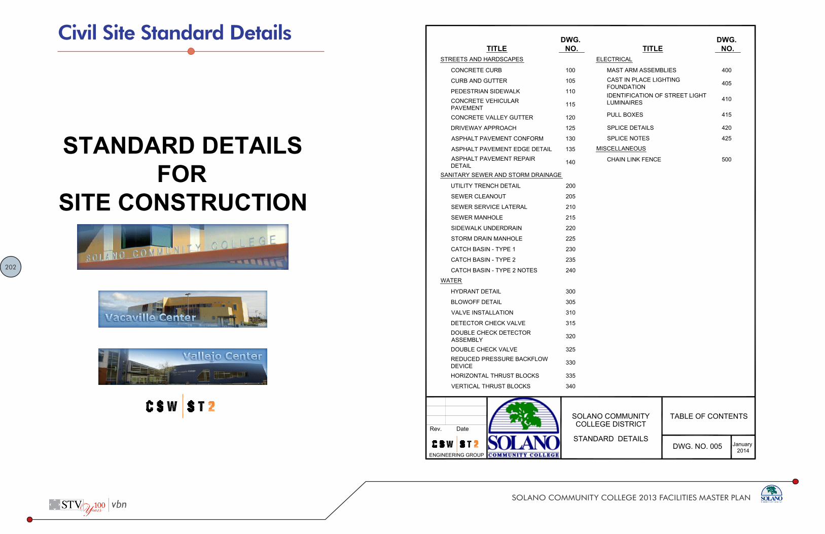
202
SOLANO COMMUNITY COLLEGE 2013 FACILITIES MASTER PLAN
STANDARD DETAILSFOR
SITE CONSTRUCTION
ADOPTED JANUARY, 2014
TITLEDWG. NO.
STREETS AND HARDSCAPES
CONCRETE CURB 100
CURB AND GUTTER 105
PEDESTRIAN SIDEWALK 110CONCRETE VEHICULARPAVEMENT 115
CONCRETE VALLEY GUTTER 120
DRIVEWAY APPROACH 125
ASPHALT PAVEMENT CONFORM 130
ASPHALT PAVEMENT EDGE DETAIL 135ASPHALT PAVEMENT REPAIRDETAIL 140
SANITARY SEWER AND STORM DRAINAGE
UTILITY TRENCH DETAIL 200
SEWER CLEANOUT 205
SEWER SERVICE LATERAL 210
SEWER MANHOLE 215
SIDEWALK UNDERDRAIN 220
STORM DRAIN MANHOLE 225
CATCH BASIN TYPE 1 230
CATCH BASIN TYPE 2 235
CATCH BASIN TYPE 2 NOTES 240
WATER
HYDRANT DETAIL 300
BLOWOFF DETAIL 305
VALVE INSTALLATION 310
DETECTOR CHECK VALVE 315DOUBLE CHECK DETECTORASSEMBLY 320
DOUBLE CHECK VALVE 325REDUCED PRESSURE BACKFLOWDEVICE 330
HORIZONTAL THRUST BLOCKS 335
VERTICAL THRUST BLOCKS 340
TITLEDWG. NO.
ELECTRICAL
MAST ARM ASSEMBLIES 400CAST IN PLACE LIGHTINGFOUNDATION 405
IDENTIFICATION OF STREET LIGHTLUMINAIRES 410
PULL BOXES 415
SPLICE DETAILS 420
SPLICE NOTES 425
MISCELLANEOUS
CHAIN LINK FENCE 500
DWG. NO. 0052014
January
TABLE OF CONTENTSSOLANO COMMUNITYRev. Date
P:\04\4116402\DWG\Standard Details\TOC.dwg 12/17/2013 04:41 PM salsa 1:1
COLLEGE DISTRICT
STANDARD DETAILS
ENGINEERING GROUP
Civil Site Standard Details

203
SOLANO COMMUNITY COLLEGE 2013 FACILITIES MASTER PLAN
CURB
LINE
HARDSCAPE SURFACEWHERE APPLICABLE
LANDSCAPE SURFACEWHERE APPLICABLE
R=1/2"
1:4 BATTERCURB FACE
APPLY TACK COATIF ADJACENT TOASPHALT
PAVEMENT SECTIONPER PLAN
NOTES:1. WHERE CONCRETE WALK IS ADJACENT TO CURB, PROVIDE ISOLATION JOINT
BETWEEN WALK AND BACK OF CURB.2. CONTROL JOINTS CONSISTING OF 1" DEEP SCORES SHALL BE PLACED AT 10'
INTERVALS O.C. ALL SIDES EXCEPT BOTTOM.3. WHERE WALK IS ADJACENT TO CURB, THE JOINTS SHALL ALIGN WITH THE
JOINTS IN THE CURB.
SCARIFY AND RECOMPACT 6"OF SUBGRADE TO 92% R.C. ORAS DIRECTED BY GEOTECHNICALENGINEER.
6"
10" M
IN.
VARIES
6"1"
CLASS II A.B. COMPACTEDTO 95% R.C.
4"
DWG. NO. 100
CONCRETE CURB
2014January
SOLANO COMMUNITYRev. Date
P:\04\4116402\DWG\Standard Details\DWG 100Curb Detail.dwg 12/17/2013 04:41 PM salsa 1:1
COLLEGE DISTRICT
STANDARD DETAILS
ENGINEERING GROUP
CURB
LINE
HARDSCAPE SURFACEWHERE APPLICABLE
LANDSCAPE SURFACEWHERE APPLICABLE 6"
R=1/2"
R=1"
1:6 BATTERCURB FACE
APPLY TACK COATIF ADJACENT TOASPHALT
PAVEMENT SECTIONPER PLAN
SCARIFY AND RECOMPACT 6" OFSUBGRADE TO 92% R.C. OR ASDIRECTED BY GEOTECHNICAL
ENGINEER.
NOTES:1. WHERE CONCRETE WALK IS ADJACENT TO CURB, PROVIDE ISOLATION JOINT
BETWEEN WALK AND BACK OF CURB.2. CONTROL JOINTS CONSISTING OF 1" DEEP SCORES SHALL BE PLACED AT 10'
INTERVALS O.C. ALL SIDES EXCEPT BOTTOM.3. WHERE WALK IS ADJACENT TO CURB, THE JOINTS SHALL ALIGN WITH THE
JOINTS IN THE CURB.
6" 1.5"
6"
2'
6.25%
4"
CLASS II A.B. COMPACTEDTO 95% R.C.
DWG. NO. 105
CONCRETE CURBAND GUTTER
2014January
SOLANO COMMUNITYRev. Date
P:\04\4116402\DWG\Standard Details\DWG 105Curb and Gutter Detail.dwg 12/17/2013 04:41 PM salsa 1:1
COLLEGE DISTRICT
STANDARD DETAILS
ENGINEERING GROUP

204
SOLANO COMMUNITY COLLEGE 2013 FACILITIES MASTER PLAN
PORTLAND CEMENTCONCRETE
LANDSCAPEFINISH SURFACEWHERE APPLICABLE
R = 1/2"1"
6"
6"
4"
HARDSCAPEFINISH SURFACE
WHERE APPLICABLE
INCLUDE THICKENEDEDGE WHERE ADJACENT
TO LANDSCAPINGCLASS II AGGREGATE BASECOMPACTED TO 95% R.C.
SCARIFY AND RECOMPACTSUBGRADE TO 90% R.C. ORAS DIRECTED BY GEOTECHNICALENGINEER.
NOTES:1. ALL TREAD SURFACES SHALL BE SLIP RESISTANT.2. REFER TO PROJECT CONSTRUCTION DRAWINGS/ SPECIFICATIONS FOR COLOR, PATTERN, TEXTURE , FINISH, AND
LOCATION OF JOINTS.3. REFER TO GEOTECHNICAL REPORT FOR SUBGRADE PREPARATION.
6"4"
DWG. NO. 110
CONCRETE PEDESTRIANWALKWAY
2014January
SOLANO COMMUNITYRev. Date
P:\04\4116402\DWG\Standard Details\DWG 110Pedestrian Sidewalk Detail.dwg 12/17/2013 04:41 PM salsa 1:1
COLLEGE DISTRICT
STANDARD DETAILS
ENGINEERING GROUP
NOTES:1. PAVEMENT SECTION SHOWN ABOVE ARE MINIMUM VALUES. REFER TO PROJECT
GEOTECHNICAL REPORT FOR ACTUAL VALUES.2. REFER TO ARCHITECTURAL PLANS FOR CONCRETE COLOR, PATTERN, TEXTURE
AND FINISH.3. SEE PROJECT CONSTRUCTION DOCUMENTS FOR DETAILS AND LOCATIONS OF
CONTROL JOINTS AND EXPANSION JOINTS.4. REFER TO GEOTECHNICAL REPORT FOR SUBGRADE PREPARATION.5. CONCRETE COMPRESSIVE STRENGTH TO BE 4 000 PSI OR GREATER.
9"
6"5"
6"
2, #4 BARS3" CLEAR
#4 BARS @ 18"BOTH WAYS
CONCRETEPAVEMENT
SCARIFY AND RECOMPACT SUBGRADE TO 90% R.C.OR AS DIRECTED BY GEOTECHNICAL ENGINEER.
CLASS II AB COMPACTEDTO 95% R.C.
3'
DWG. NO. 115
CONCRETE VEHICULARPAVEMENT
2014January
SOLANO COMMUNITYRev. Date
P:\04\4116402\DWG\Standard Details\DWG 115Concrete vehicular pavement Detail.dwg 12/17/2013 04:41 PM salsa 1:1
COLLEGE DISTRICT
STANDARD DETAILS
ENGINEERING GROUP

205
SOLANO COMMUNITY COLLEGE 2013 FACILITIES MASTER PLAN
4'0"
1/2" BATTER20"
NOTES:1. CONCRETE SHALL BE CLASS "B" (5 SACK) WITH 1" AGGREGATE.2. NO CONCRETE SHALL BE PLACED PRIOR TO FORM INSPECTION .3. ASPHALT CONCRETE SHALL BE 1/4" HIGH AT EDGE OF CONCRETE.4. CONTROL JOINTS SHALL BE PLACED AT 8' INTERVALS.5. EXPANSION JOINTS SHALL BE PLACED AT 16' INTERVALS.
1" DEPRESSION
6" THICK CONCRETE APRONWITH 6x6x10 GA. W.W.M.1" DEPRESSION
5" CLASS IIAGGREGATE BASE COMPACTEDTO 95% R.C.
6" RECOMPACTED SUBGRADECOMPACTED TO 90% R.C.
DWG. NO. 120
CONCRETE VALLEYGUTTER
2014January
SOLANO COMMUNITYRev. Date
P:\04\4116402\DWG\Standard Details\DWG 120Concrete Valley Gutter Detail.dwg 12/17/2013 04:41 PM salsa 1:1
COLLEGE DISTRICT
STANDARD DETAILS
ENGINEERING GROUP
SIDEWALK
ROUNDED
10% MAX **
LIP AT BOTTOM OFDRIVEWAY RAMP,1" ABOVEGUTTER GRADE
SECTION VIEW
* TYPE 3 DRIVEWAY
2% MAX
DRIVEWAY
48" MIN.
48" MIN.
SLOPE 1:50 MAX
1:12MA
X
1:12
MAX
SIDEW
ALK
48" MIN.
48" MIN.
SIDEW
ALK
SLOPE 1:50 MAX
DRIVE
WAY
SLOPE 1:50 MAX
SLOPE 1:50 MAX
1:50 MAX
48" MIN.
SIDEW
ALK
SLOPE 1:50 MAX
DRIVEWAY
TYPE 1
TYPE 2 TYPE 3
2% MAX *
** TYPE 1 and 2 DRIVEWAY
3'
3'
WIDTH AS SHOWN ON PLANS
WIDTH AS SHOWN ON PLANS
WIDTH AS SHOWN ON PLANS
#4 @ 4' O.C.#4 @ 2' O.C.
5" CLASS II ABCOMPACTED TO 95% R.C.
SUBGRADE COMPACTED TO 92%OR AS DIRECTED BY GEOTECH.
DWG. NO. 125
DRIVEWAY APPROACH
2014January
SOLANO COMMUNITYRev. Date
P:\04\4116402\DWG\Standard Details\DWG 125Driveway Approach Detail.dwg 12/17/2013 04:41 PM salsa 1:1
COLLEGE DISTRICT
STANDARD DETAILS
ENGINEERING GROUP

206
SOLANO COMMUNITY COLLEGE 2013 FACILITIES MASTER PLAN
EXISTING PAVING
12" MIN.OVERLAP
SAWCUT FULL DEPTHPROTECT EDGE
BITUMINOUSTACK COATNEW ASPHALT
SURFACE
11
NEW AGGREGATEBASE COURSE
EXISTING AGGREGATE BASE COURSE TOBE PROTECTED AND REMAIN UNDISTURBEDTO PREVENT LOSS OF DENSITY AND SUPPORTUNDER EXISTING PAVEMENT
NOTE:1. REFER TO PROJECT CONSTRUCTION DOCUMENTS FOR ASPHALT
PAVEMENT SECTION , SUBGRADE PREPARATION AND OTHERREQUIREMENTS.
DWG. NO. 130
ASPHALT PAVEMENTCONFORM
2014January
SOLANO COMMUNITYRev. Date
P:\04\4116402\DWG\Standard Details\DWG 130Asphalt Pavement Conform Detail.dwg 12/17/2013 04:42 PM salsa 1:1
COLLEGE DISTRICT
STANDARD DETAILS
ENGINEERING GROUP
90% COMPACTED EARTH,PLANTED AREA OR NATURALGROUND
2" X 6" PT REDWOODHEADER
ASPHALT CONCRETEPAVEMENT SECTION
PER PLAN
2" X 4" X 2'0" LONG PTREDWOOD STAKE AT 5' O.C.
NOTE:1. REFER TO PROJECT CONSTRUCTION DOCUMENTS FOR ASPHALT
PAVEMENT SECTION , SUBGRADE PREPARATION AND OTHERREQUIREMENTS.
DWG. NO. 135
ASPHALT PAVEMENTEDGE DETAIL
2014January
SOLANO COMMUNITYRev. Date
P:\04\4116402\DWG\Standard Details\DWG 135Asphalt Pavement Edge Detail.dwg 12/17/2013 04:42 PM salsa 1:1
COLLEGE DISTRICT
STANDARD DETAILS
ENGINEERING GROUP

207
SOLANO COMMUNITY COLLEGE 2013 FACILITIES MASTER PLAN
WIDTH OF SAWCUT
ACT
B
T+1"
MIN
TRENCHWIDTH
NOTES:1. DURING EXCAVATION AND SUBGRADE PREPARATION, THE CONTRACTOR SHALL
TAKE ALL NECESSARY STEPS TO ENSURE THE PROTECTION OF ALLIMPROVEMENTS, WHETHER PUBLIC OR PRIVATE, INCLUDING UTILITIES ANDTHEIR SERVICES FROM ANY DAMAGE THAT COULD OCCUR DUE TOCONTRACTORS CONSTRUCTION ACTIVITY.
2. IF NOT OTHERWISE SPECIFIED, TRENCH BACKFILL SHALL BE DENSIFIED TO AMINIMUM OF 90% R.C.
3. TEMPORARY PAVEMENT RESURFACING SHALL BE PLACED AT THECONTRACTORS EXPENSE. IT SHALL BE PLACED LEVEL WITH THE EXISTINGPAVEMENT ON COMPACTED TRENCH BACKFILL AND SHALL BE A MINIMUM OF 2"THICK.
4. PERMANENT PAVEMENT RESURFACING SHALL BE DONE WITHIN TWO (2) WEEKSAFTER BACKFILL OF TRENCHES HAS BEEN COMPLETED, ONLY AFTERSETTLEMENT HAS TAKEN PLACE AND THE FILL SURFACE HAS SUFFICIENTLYDRIED. ALL CUTS SHALL BE GROOMED CLEAN AND STRAIGHT.
5. CONTACT SURFACES OF EXISTING PAVEMENT MANHOLE FRAMES AND SHAFTSAND CONCRETE SURFACES SHALL HAVE A TACK COATING APPLIED BEFOREPERMANENT ASPHALT RESURFACING IS PLACED.
6. ASPHALT CONCRETE PAVEMENT SHALL BE AS SPECIFIED.
B+6"
MIN.
ASPHALT SEAL TACK COAT (TYP.)
EX. AC PAVEMENT
6"MIN.
6"MIN.
DWG. NO. 140
ASPHALT PAVEMENTREPAIR at UTILITY TRENCH
2014January
SOLANO COMMUNITYRev. Date
P:\04\4116402\DWG\Standard Details\DWG 140Asphalt Pavement Repair Detail.dwg 12/17/2013 04:42 PM salsa 1:1
COLLEGE DISTRICT
STANDARD DETAILS
ENGINEERING GROUP
FINISHED GRADE OR PAVEMENTPER PLANS
BACKFILL COMPACTEDTO 90% R.C. EXCEPT UPPER 12"BELOW PAVEMENT SUBGRADEWHERE COMPACTED TO 95% R.C.
COVER(SEE NOTE 3)
BEDDING(SEE NOTE 3)
4"
PIPE
DIA.
12"
SCARIFY AND COMPACT 12"OF SUBGRADE TO 90% R.C.SEE NOTE 8
6" WIDE METALLIC BURIAL TAPEMARKED WITH UTILITY TYPE (I.E.SANITARY SEWER, STORMDRAIN, GAS, ELECT., ETC.)PLACED 12" TO 18" ABOVE PIPE.TAPE TO BE DETECTABLE WITHUTILITY DETECTION EQUIPMENTAT GROUND SURFACE
NOTES:1. UTILITY TRENCH CONSTRUCTION
SHALL CONFORM TO THERECOMMENDATIONS OF THEGEOTECHNICAL REPORT.
2. EXCAVATE FOR BELLS OR HUBS SOFULL LOAD IS CARRIED BY PIPEBARRELS.
3. BEDDING AND COVER: SAND ORFINE GRAVEL WITH LESS THAN 10%FINES.
4. BEDDING SHALL BE PLACED IN AMANNER SUCH AS SLICING,SHOVELSPADING, OR SHOVELRODDING TO ENSURE COMPLETEFILLING OF THE "HAUNCH AREAS"BELOW THE PIPE. JETTING IS NOTPERMITTED
5. SUBGRADE TO BE FREE OFPROTRUDING OBJECTS.
6. BACKFILL MAY BE NATIVE SOILTHAT MEETS THE CRITERIA FORFILL AS DESCRIBED IN THEGEOTECHNICAL REPORT.
7. WHERE LESS THAN 18" BETWEENBOTTOM OF PAVING SECTION (I.E.BOTTOM OF A.B.) AND TOP OF PIPE,BACKFILL TO BE CONTROLLEDDENSITY FILL (CDF)
8. TRENCH SUBGRADE SHALL BEPREPARED IN ACCORDANCE WITHTHE GEOTECHNICAL REPORT.
PIPE SIZE AND TYPEPER PLANS AND SPECS.
D/2(4" MIN.)
DWG. NO. 200
UTILITY TRENCH
2014January
SOLANO COMMUNITYRev. Date
P:\04\4116402\DWG\Standard Details\DWG 200UtilityTrench Detail.dwg 12/17/2013 04:42 PM salsa 1:1
COLLEGE DISTRICT
STANDARD DETAILS
ENGINEERING GROUP

208
SOLANO COMMUNITY COLLEGE 2013 FACILITIES MASTER PLAN
PAVEMENT PER PLANCONCRETE SUPPORT
MAY BE LOWERED
CAST IRON FRAME & COVER MARKED WITHUTILITY TYPE (E.G. "SANITARY SEWER",STORM DRAIN", ETC.)
FINISH GRADE(FULL HEIGHTSUPPORT)
CONC. WALL SUPPORTFOR TRAFFIC LOAD
CONDITION
OPTIONAL CONSTRUCTION JOINT
1/8 BEND
INSTALL CAP & MORTAR IFTERMINAL CLEANOUT.INSTALL PIPE IF INLINECLEANOUT
UNDISTURBED EARTH
4"±
12"MIN.
TOP ELEVATIONPER PLAN
4" MIN.
4" MIN.
2" MIN.
2" MIN.
INVERT ELEV.PER PLAN
FLOW
MAIN PIPE13"
WYE
11
3/4"
18" M
AX.
12" M
IN.
RISER SHALL BE THE SAMEAS MAIN PIPE DIAMETERBUT NOT LARGER THAN 6"
CONC. COLLAR MAYBE SQUARE
OR CIRCULAR
PROVIDE CLEANOUT PLUG AND ADAPTOR
13"
MIN.
13"
MIN.
26" M
IN.
9"MIN.
9"MIN.
18" MIN.CONCRETE WALLSUPPORT FORTRAFFIC LOAD
CONDITIONS
CONCRETEBASE
SECTION B
SECTION A
S
12"
MIN.
12"
MIN.
24" M
IN.
CONCRETECOLLAR MAY BE
SQUARE ORCIRCULAR
FRAMECOVER
PLAN
NOTES:1. SEE PROJECT PLANS FOR INVERT ELEVATION.2. PIPE AND FITTINGS, EXCEPT AS OTHERWISE SHOWN HEREON,
SHALL BE OF THE SAME MATERIAL AS THE SEWER, UNLESSAPPROVED ADAPTERS ARE UTILIZED.
3. PIPE AND FITTINGS SHALL BE PROPERLY ALIGNED ANDMAINTAINED WHILE CONCRETE IS BEING PLACED ANDALLOWED TO HARDEN. JOINTS FOR PIPES AND FITTINGSSHALL BE MADE PRIOR TO PLACING CONCRETE. CONCRETEFOR BEDDING, ENCASEMENT, AND FITTINGS SHALL BE PLACEDUNIFORMLY AROUND THE PIPE AND FITTINGS AS SHOWNHEREON TO MAINTAIN PROPER ALIGNMENT.
4. THE ACCESS FRAME, COVER AND CAP SHALL BE CAST IRON.5. THE CONTRACTOR, AT HIS OPTION, MAY PLACE EITHER
CIRCULAR OR SQUARE CONCRETE PIPE WALL SUPPORTS ASSHOWN HEREON.
CONC. BASE(FULL WIDTH OF TRENCH)
FOR TRAFFIC LOAD CONDITIONS
A-
B-
DWG. NO. 205
SEWER CLEANOUT
2014January
SOLANO COMMUNITYRev. Date
P:\04\4116402\DWG\Standard Details\DWG 205Sewer Cleanout Detail.dwg 12/17/2013 04:42 PM salsa 1:1
COLLEGE DISTRICT
STANDARD DETAILS
ENGINEERING GROUP
SEWER LINE INVERTELEVATION PER PLAN
CENTER LINESEWER MAIN
LENGTH A
PROPOSEDBUILDING LINE
FINISHEDSURFACE
FINISHEDFLOOR ELEV.
Y
S=0.02 MIN.
BRANCH
ELEVATION FJOIN ELEV. PER
PROJECT PLANS
CAP ( SEE NOTE 4 )
SEWER LINE INVERTELEVATION PER PLAN
CENTER LINESEWER MAIN
PROPOSEDBUILDING LINE
FINISHEDSURFACE
FINISHEDFLOOR ELEV.
Y
S=0.02 MIN.
BRANCH
ELEVATION FJOIN ELEV. PER
PROJECT PLANS
CAP ( SEE NOTE 4 )
45°
1/8 OR 1/16 BENDAS NEEDED
ELEVATION E
SEWER LINE INVERTELEVATION PER PLAN
CENTER LINESEWER MAIN
LENGTH A
PROPOSEDBUILDING LINE
FINISHEDSURFACE
FINISHEDFLOOR ELEV.
Y
S= 0.02 MIN.
BRANCH
ELEVATION FJOIN ELEV. PER
PROJECT PLANS
CAP ( SEE NOTE 4 )
45°
MAX
.
1/8 OR 1/16 BENDAS NEEDED
LENGTH B
NOTES:1. EXCEPT AS OTHERWISE INDICATED ON THE PROJECT PLANS, ALL SEWERS
SHALL BE TYPE "A" AND SHALL BE CONSTRUCTED ON STRAIGHT LINES ANDGRADES BETWEEN CONTROL POINTS AND ELEVATIONS.
2. DIMENSIONS: Y = VARIES JOIN ELEVATION PER PROJECT PLANS LENGTHS "A" AND "B" SEE PROJECT PLANS ELEVATION "E" SEE PROJECT PLANS ELEVATION "F" SEE PROJECT PLANS3. ALL CONNECTION SEWER PIPE SHALL BE 6 INCH UNLESS OTHERWISE
INDICATED.4. IF NOT CONNECTED TO BUILDING SEWER AT TIME OF INSTALLATION, THE
UPPER END OF THE SEWER CONNECTION SHALL BE SEALED BY INSTALLINGA CAP AND SEALING THE CAP WITH 1" THICK TYPE "F" MORTAR AROUND THECIRCUMFERENCE OF THE CAP . THE SEAL SHALL BE REMOVED PRIOR TOCONNECTION WITH BUILDING SEWER.
5. EXCEPT AS CONTROLLED BY ELEVATIONS INDICATED ON THE PROJECTPLANS, THE MINIMUM SLOPE FOR ALL PIPES SHALL BE 2.0 PERCENT ( S=0.020MIN.).
6. BRANCHES SHALL BE EITHER TEES OR WYES AND SHALL BE ROTATEDUPWARD FROM THE HORIZONTAL TO AN ANGLE OF 221/2 DEGRESS TO 45DEGRESS WHEN TEES ARE USED. BENDS ARE NOT REQUIRED BUT MAY BEUSED AT THE OPTION OF THE CONTRACTOR. WHEN THE BRANCH ROTATIONDOES NOT CONFORM THE THE SLOPE OF THE BUILDING CONNECTIONSEWER, PULLED JOINTS MAY BE USED FOR ADJUSTMENT.
7. CONNECTION OF A BUILDING SEWER SMALLER THAN 6 INCHES TO A 6 INCHCONNECTION SEWER SHALL BE MADE USING AN APPROVED INCREASER TEE OR AN INCREASER FOLLOWED BY A TEE.
PROFILETYPE A PROFILE
TYPE B
PROFILETYPE C
5'
5' LENGTH A
ELEVATION E
5'
LENGTH B
DWG. NO. 210
SEWER SERVICE
2014January
SOLANO COMMUNITYRev. Date
P:\04\4116402\DWG\Standard Details\DWG 210Sewer Service Detail.dwg 12/17/2013 04:42 PM salsa 1:1
COLLEGE DISTRICT
STANDARD DETAILS
ENGINEERING GROUP

209
SOLANO COMMUNITY COLLEGE 2013 FACILITIES MASTER PLAN
1"
6"6'0" MIN.
1'0"
2'0"
7"
2'6"MAX.
4'0"
3" MIN.18" MAX.
3'0"
VAR
IABL
E4"
MIN
.
"A" "A"
SEWER MANHOLE
3'0"
2'0"
4'0" 4'0
" MAX
.
"B""B"
SHALLOW SEWER MANHOLE
4"
2'6"
4"
SECTION "BB"SECTION "AA"
NOTES:1. MANHOLE FRAME AND COVER SHALL BE PINKERTON A640, D & LA1024 OR APPROVED EQUAL
MARKED "SANITARY SEWER".2. POURED CONCRETE BASE SHALL BE 4,000 PSI OR APPROVED PRECAST BASE.3. ALL JOINTS SHALL BE SEALED WITH APPROVED FLEXIBLE JOINT SEALANT.4. PLACE STEPS ON DOWNSTREAM SIDE OF MANHOLE.5. LATERALS INTO MANHOLES SHALL HAVE A JOINT AT 2'6" FROM OUTSIDE WALL.
SEE DETAIL AON STANDARDDETAIL #225
3,000 P.S.I. P.C.C.
DWG. NO. 2152014
January
SEWER MANHOLESOLANO COMMUNITYRev. Date
P:\04\4116402\DWG\Standard Details\DWG 215Sewer Manhole.dwg 12/17/2013 04:42 PM salsa 1:1
COLLEGE DISTRICT
STANDARD DETAILS
ENGINEERING GROUP
24"
4" 6" 12"
2" MIN.
6"
12"
4"
3"
2" TO REBAR
T.C.
F.L.
24"LIMITS OF REMOVAL 3"
3"
6"3"
2"
F.L.
T.C.
SCORE LINELIMIT OF REMOVAL
WEAKENED PLANE JOINT1/8" WIDE x 11/4" DEEP *4x4 10 GA. WIRE MESH
BETWEEN SCORE LINESSCORE LINELIMIT OF REMOVAL
21/2" MAX. PIPE
#4 DOWELED REBAR
2#4 DOWELS
* WEAKENED PLANE JOINT TO BE LOCATED MIDWAY BETWEEN OUTSIDE PIPES.
NOTES:1. OWNER SHALL BE RESPONSIBLE FOR CLEANING AND MAINTAINING PIPE.2. MINIMUM CROSSSLOPE TO BE 1% FOR DRAIN PIPE.3. PLACE 4X4 WIRE MESH FULL LENGTH 24" ON EACH SIDE OF PIPE.4. UNDER SIDEWALK DRAINS TO BE USED ONLY BY APPROVAL OF CITY ENGINEER WHERE A STORM
DRAIN DOSE NOT EXIST, OR EXTENSION OF AN EXISTING STORM DRAIN IS IMPRACTICAL.
DWG. NO. 2202014
January
COMMERCIALMULTIPLE UNDERSIDEWALK DRAINS
SOLANO COMMUNITYRev. Date
P:\04\4116402\DWG\Standard Details\DWG 220Commercial Multiple Under Sidewalk Drains.dwg 12/17/2013 04:43 PM salsa 1:1
COLLEGE DISTRICT
STANDARD DETAILS
ENGINEERING GROUP

210
SOLANO COMMUNITY COLLEGE 2013 FACILITIES MASTER PLAN
DIAMETER 48"84"VARIABLE
6" 6"
8"
112"
8" MIN.
2"
6"VAR
IABL
E3'0"
24"3" MIN.18" MAX.
412"
48"
A
STORM DRAIN MANHOLE(CASTINPLACE PIPE)
DETAIL A
PINKERTON A640, D & L A1024 OR APPROVEDEQUAL LABELED STORM SEWER
3,000 P.S.I. P.C.C.
STANDARD 24" DIAMETERMANHOLE SHAFT
STANDARD 48" ECCENTRICMANHOLE REDUCER CONE
FINISH GRADE
STANDARD 48" DIAMETERMANHOLE SHAFT
NOTES:1. FOR STORM DRAIN LESS THAN 4 FT. DIAMETER
OR LESS THAN 4 FT. BELOW STREET GRADE,SEE SEWER MANHOLE DETAIL.
2. CONSTRUCT MANHOLE WITHOUT DROP STEPS.3. GROUT ALL JOINTS.
2" MIN. 4" MAX.
CEMENT MORTAR
#4 REINFORCING BARAT 6" O.C. EACH WAY
EXTEND REBAR 15"MIN. ALL SIDES
BOX STRUCTURE
4,000 P.S.I. P.C.C.
DWG. NO. 2252014
January
STORM DRAINMANHOLESOLANO COMMUNITY
Rev. Date
P:\04\4116402\DWG\Standard Details\DWG 225Storm Drain Manhole.dwg 12/17/2013 04:43 PM salsa 1:1
COLLEGE DISTRICT
STANDARD DETAILS
ENGINEERING GROUP
6" 36" 6"
8"
2' M
IN.
24"41/2" 2"
6"
VAR
IES
6"18"
VARIES 8" MIN.
6"
2'0"
8' CURB HEIGHT VARIES FROM 6" TO 8" ONA STRAIGHT GRADE, BOTH SIDES OF CATCH BASIN.
PLAN
CROSS SECTIONALVIEWS
WEAKEN PLANEJOINT
NOTES:1. CONCRETE FOR STRUCTURE SHALL HAVE A MINIMUM 28 DAY COMPRESSIVE STRENGTH OF
3,000 P.S.I.2. ALL STRUCTURES SHALL BE GROUTED AND SACKED.3. NOSING SHALL BE 2 1/2"X2 1/2"X1/4"X4' GALVANIZED ANGLE WITH THREE 6" TIE BARS.4. FOR STORM DRAIN PIPES LARGER THAN 36", USE STORM DRAIN MANHOLE DETAIL FOR BOX
STRUCTURE.
CURB FACE
SIDEWALK
CURB RETURN
FRAME & GRATE SHALL BEPHOENIX IRON WORKS P6301HYDROCONDUIT OR APPROVEDEQUAL.
SEE NOTE 3
#4 REINFORCING BARSAT 12 INCHES O.C.EACH WAY
C.B. WALL WILL MEETINSIDE WALL OF CONDUITCHANNELIZE TOCONFORM TO CONDUIT
CONST. JOINT (TYP)FOR CASTINPLACE
DWG. NO. 2302014
January
CATCH BASIN TYPE 1SOLANO COMMUNITYRev. Date
P:\04\4116402\DWG\Standard Details\DWG 230Catch Basin Type 1.dwg 12/17/2013 04:43 PM salsa 1:1
COLLEGE DISTRICT
STANDARD DETAILS
ENGINEERING GROUP

211
SOLANO COMMUNITY COLLEGE 2013 FACILITIES MASTER PLAN
36"
48" OR 36"FOR 3' TO 6' DEPTH
6"
3"
3"
TRANSITION TRANSITION
6"8"
6"
DEPRESSED GUTTER
6" *
6"
DEPRESS DEPRESS
2 NO.4 BARSALL AROUNDTOP
BACK OF ADJACENTSIDEWALK
NO. 4 BARSAT 6" O.C.BOTH WAYS
BACKOFCURB
NO. 4 TRIMBARS AROUNDMANHOLE
4" RADIUS ON CORNERS
2 NO. 4 BARS X 8'
DEP
TH V
ARIE
S
SLOPE 2% (1:50)
NORMAL GUTTER LINE
4" RADIUS
#4 BARS @ 12" O.C.HORIZ. & VERT. (TYP)
EPOXY STEPS INPLACE STEPS TO BESTEEL REINFORCEDPOLYPROPYLENE PLASTIC
NOTES:1. SEE STANDARD DETAIL #240 FOR GENERAL
NOTES.2. TOP SHALL BE CAST IN PLACE.3. ADJACENT SIDEWALK SHALL BE POURED
MONOLITHIC WITH TOP.* 8" WALL FOR DEPTHS GREATER THAN 8'
PLAN
GUTTER ELEVATION
SECTION
SIDEWALKMANHOLE,
FRAME ANDCOVER
9'0"(8'0" FOR 4' TO 6' DEPTH)
12" MAX.(TYP.)
DWG. NO. 2352014
January
CATCH BASIN TYPE 2SOLANO COMMUNITYRev. Date
P:\04\4116402\DWG\Standard Details\DWG 235Catch Basin Type 2.dwg 12/17/2013 04:43 PM salsa 1:1
COLLEGE DISTRICT
STANDARD DETAILS
ENGINEERING GROUP
NOTES:
1. CONCRETE SHALL BE CLASS "A" (6 SACK MIX) UNLESS OTHERWISE NOTED. STRUCTURE TOPS CAST WITH ADJACENT CURB/SIDEWALK MAY BE CLASS "B" CONCRETE.
2. BASE SHALL BE PLACED AGAINST UNDISTURBED EARTH, SIDES MAY BE FORMED OR PLACED AGAINST UNDISTURBED EARTH.
3. WHERE CONDUITS ARE ENCOUNTERED THAT ARE LARGER IN DIAMETER THAN THE WIDTH OF THE WALL THROUGH WHICH THEY PASS, THE INSIDE DIMENSION OF THE WALLS PERPENDICULAR TO THE DIRECTION OF THE PIPE SHALL BE INCREASED TO 12" WIDER THAN THE OUTSIDE DIAMETER OF THE PIPE.
4. EXPANSION JOINTS SHALL BE PLACED THROUGH CURB AND SIDEWALK AT BOTH SIDES OF CATCH BASINS AND SHALL BE LIMIT OF PAYMENT FOR CURB AND GUTTER. UNIT PRICES FOR DRAINAGE STRUCTURES SHALL INCLUDE CURB, GUTTER AND SIDEWALK POURED WITH DRAINAGE STRUCTURE.
5. NO CONCRETE SHALL BE PLACED PRIOR TO FORM AND STEEL APPROVAL BY THE AGENCY ENGINEER.
6. WALL THICKNESS, REINFORCING, AND STEP (AS REQUIRED BY AGENCY ENGINEER) REQUIREMENTS SHALL BE IN ACCORDANCE WITH THE TABLE BELOW, UNLESS OTHERWISE INDICATED BY THE PROJECT PLANS OR DIRECTED BY THE AGENCY ENGINEER.
7. PLACE 2" WEEPHOLES AS REQUIRED BY THE AGENCY ENGINEER.8. EQUIVALENT PRECAST STRUCTURES MAY BE SUBSTITUTED AS APPROVED BY THE AGENCY
ENGINEER.9. WALL THICKNESS SHALL NOT EXCEED 10" ON ANY STRUCTURE.10. PRECAST INLETS AND MANHOLES SHALL HAVE A MINIMUM COMPRESSIVE STRENGTH OF 4000 PSI AT
28 DAYS AND BE DESIGNED TO WITHSTAND H20 LOADING.11. PROVIDE FOR SECURITY FASTENERS FOR MANHOLE COVER.
DEPTHWALL THICKNESS(SEE NOTE #11) WALL REINFORCEMENT STEPS REQUIRED
LESS THAN 3' 6" NO. 4 AT 12" BOTH WAYS NO
LESS THAN 3' 8"NONE OUTSIDE ROADWAY.
NO. 4 AT 12" BOTH WAYSWITHIN OR ADJACENT TO ROAD.
NO
3' TO 8' 6" NO. 4 AT 12" BOTH WAYS AS REQUIRED BY THEAGENCY ENGINEER
OVER 8' 8" NO. 4 AT 12" BOTH WAYS AS REQUIRED BY THEAGENCY ENGINEER
DWG. NO. 2402014
January
CATCH BASINTYPE 2 NOTESSOLANO COMMUNITY
Rev. Date
P:\04\4116402\DWG\Standard Details\DWG 240Catch Basin Type 2 Notes.dwg 12/17/2013 04:43 PM salsa 1:1
COLLEGE DISTRICT
STANDARD DETAILS
ENGINEERING GROUP

212
SOLANO COMMUNITY COLLEGE 2013 FACILITIES MASTER PLAN
VARIES(SEE PLANS FOR LENGTH)
NOTES:1. HYDRANT LOCATION IN RELATION TO THE CURB AND SIDEWALK
MUST BE DETERMINED BY THE CONTROLLING FIRE MARSHALL.2. PRIME AND WRAP ALL BARE METAL INCLUDING HYDRANT BURY
AND RISER UP TO BOTTOM OF HYDRANT FLANGES.3. FIRE HYDRANT SHALL BE INSTALLED PER LOCAL FIRE
DEPARTMENT REQUIREMENTS.
2' TYP. FIRE HYDRANT BODYPER LOCAL ADMINISTRATIVEAUTHORITY
RISER BREAK AWAY
NUTS UNDER RISERFLANGE EXCEPT FORONE WITH DOUBLE NUT
4" MIN. TO FINISH GRADE
BAC
K O
F S
IDEW
ALK
BREAK OFF CHECK VALVE,CLOW VALVE CO. MODELLBI 400A OR EQUIVALENT
D.I.P. FLG BURY
CONC. THRUSTBLOCK
SO FLG
32# ANODE
F.E.GATE VALVE
WSP RUN
LIP OF GUTTER
VALVE BOX.CHRISTY CONCRETE
PRODUCTS NO. G5OR EQUAL.
8" DIA. WHITE PVC.DEPTH EXTENSION
SO FLG
CONC.THRUSTBLOCK
[X"] X 6"TEE
FLANGE INSULATION KIT(NOT REQ'D FOR WSP
OR NON-METALLIC MAINS)
DWG. NO. 300
FIRE HYDRANT
2014January
SOLANO COMMUNITYRev. Date
P:\04\4116402\DWG\Standard Details\DWG 300Hydrant Detail.dwg 12/17/2013 04:43 PM salsa 1:1
COLLEGE DISTRICT
STANDARD DETAILS
ENGINEERING GROUP
FINISH GRADE,WHERE SHOWN
(SEE PLANS)
METER BOXw/ CAST IRONTRAFFIC COVER
2" CAP HANDTIGHT
2" GALV. PIPE
2" M
IN.
18" M
IN.USE OPERATING
VALVE NUT2" BRONZE
GATE VALVE(OFF)
2" GALV. NIPPLELENGTH AS REQ'D
TEEMJxFLG, BLIND FLGTAPPED 2" I.P.T. AND
THRUST BLOCK ORSADDLE TAP w/ I.P.T.
2" X 6" GALV. NIPPLE
2" GALV.90° ELBOW
THRUST BLOCK
DRAIN ROCK 4" ABOVEAND BELOW CL OF PIPE
DRILL (3)1/8"WEEP HOLES
PAVEMENT,WHERE SHOWN(SEE PLANS)
DWG. NO. 305
BLOW OFF
2014January
SOLANO COMMUNITYRev. Date
P:\04\4116402\DWG\Standard Details\DWG 305Blowoff Detail.dwg 12/17/2013 04:43 PM salsa 1:1
COLLEGE DISTRICT
STANDARD DETAILS
ENGINEERING GROUP

213
SOLANO COMMUNITY COLLEGE 2013 FACILITIES MASTER PLAN
8"
1038" CHRISTY
8"±
*48"
4" MIN.VAR.
4" MIN.
1'6
" MIN
.
TYPICAL SECTIONGREATER THAN 12" VALVE
1
TYPICAL SECTION12" VALVE AND SMALLER
AREA BEARING AGAINSTUNDISTURBED EARTHSHALL BE A MIN. OF 9'SQUARE
NOTES:1. VALVE BOX AND COVER SHALL BE CHRISTY CONCRETE PRODUCTS NO. G5 OR EQUAL, WITH DEPTH
EXTENSIONS AS REQUIRED.2. ALL VALVES SHALL HAVE FLANGED CONNECTIONS AT ALL TEES AND CROSSES.3. ALL VALVES SHALL BE SEPARATED FROM JOINTS WITH A 3' TO 6' SECTION OF PIPE.4. VALVE SHALL BE RESILIENT SEAT GATE (12" OR LESS) OR BUTTERFLY (GREATER THAN 12") PER CITY
SPECIFICATION.
34"Ø S.S.
RODVALVE BOXAND COVER
3,000 P.S.I. CONCRETE
CHRISTY
2'6" DIAMETER MINIMUMENCASEMENT 3,000 P.S.I.CONCRETE
WHITE PVC DEPTHEXTENSION
MASONRY BLOCK
* IF GREATER THAN 48",VALVE NUT EXTENSIONSHALL BE REQUIRED.
DWG. NO. 3102014
January
VALVE INSTALLATIONSOLANO COMMUNITYRev. Date
P:\04\4116402\DWG\Standard Details\DWG 310Valve Installation.dwg 12/17/2013 04:43 PM salsa 1:1
COLLEGE DISTRICT
STANDARD DETAILS
ENGINEERING GROUP
NOTES:1. BYPASS METER SHALL BE A SENSUS. FOR 4" AND 6" VALVES USE 3/4" SR METER. FOR 8" VALVES USE
1" SR METER FOR 10" VALVES USE 11/2" SR METER. METERS SHALL READ IN CUBIC FEET.2. VAULT BOX TO BE APPROVED BY THE CITY ENGINEER.3. DETECTOR CHECK VALVE SHALL HAVE AN INTEGRAL BYPASS AND WEIGHTED CLAPPER AND BELL &
FM LISTED.4. READING LID TO BE INSTALLED OVER METER.5. FIRE SERVICE LINE MATERIALS AND INSTALLATION FROM THE WATER MAIN SHALL CONFORM TO
STANDARD DETAIL FOR 3" AND LARGER WATER SERVICE INSTALLATION.6. DETECTOR CHECK VALVE EXTERIOR FINISH SHALL BE HOT DIPPED GALVANIZED OR PAINTED RED.7. ALL PIPES AND FITTINGS FROM MECHANICAL JOINT TO DETECTOR CHECK SHALL BE DUCTILE IRON.
BYPASS SHALL BE COPPER OR BRASS.
6"6"
MAX
.
6" M
AX.
12" MIN24" MAX
END VIEW
DETECTOR CHECK UNIT
VAR
IES
BRICK AS REQD.FOR STABILITY (TYP.)
112" DRAIN ROCK
BACK OF CURBOR S/W
MECH. JOINTOR FLANGEBY RINGTITE
BRICK AS REQD. FOR STABILITY (TYP.)
FLANGE BY SPIGOT PIECE WITH STAINLESSSTEEL AND THREAD TIE BACK FOR GRADEADJUSTMENT OR FLANGE BY FLANGETHRUST BLOCK
1
2
1
3
FLOW
KEYNOTESTHREADED CURB STOP VALVE
ROCKWELL METER
FORD HS11 CHECK VALVE TOMATCH METER SIZE OR EQUAL.
DWG. NO. 3152014
January
DETECTORCHECK VALVESOLANO COMMUNITY
Rev. Date
P:\04\4116402\DWG\Standard Details\DWG 315Detector Check Valve.dwg 12/17/2013 04:44 PM salsa 1:1
COLLEGE DISTRICT
STANDARD DETAILS
ENGINEERING GROUP

214
SOLANO COMMUNITY COLLEGE 2013 FACILITIES MASTER PLAN
NOTES:1. DOUBLE CHECK DETECTOR ASSEMBLY SHALL BE ON THE MOST RECENT LIST APPROVED BY THE
CALIFORNIA DEPARTMENT OF HEALTH SERVICES. SHUTOFF VALVES SHALL BE O, S, & Y TYPE(RESILIENT SEAT GATES). UL LISTED FOR FIRELINE SERVICE.
2. THE DOUBLE CHECK DETECTOR ASSEMBLY SHALL BE DELIVERED TO THE PROJECT SITE AS A UNITASSEMBLED BY THE MANUFACTURER INCLUDING THE SENSUS SR BYPASS METER.
6" MIN.8" MAX.
6" MIN.8" MAX.
12" MIN.18" MAX.
FROM MAIN
PROFILEPER LOCAL CODE
M
FROM MAIN
PLAN VIEW
DUCTILE IRONOR BRASS
PIPE SUPPORTS
4" PCC MAINTENANCE PAD
90% COMPACTION
FINISH GRADE
THRUST BLOCK
DUCTILE IRON,BRASS OR COPPER
DUCTILE IRON,BRASS ORCOPPER
1" GAP AND WRAPWITH FELT (TYP.)
TO FIRE SERVICE
BYPASS DOUBLE CHECKBYPASS METERSENSUSSR (READING IN CF)
MAINLINE DOUBLE CHECK
SUPPLY
DWG. NO. 3202014
January
DOUBLE CHECKDETECTOR ASSEMBLYSOLANO COMMUNITY
Rev. Date
P:\04\4116402\DWG\Standard Details\DWG 320Double Check Detector Assembly.dwg 12/17/2013 04:44 PM salsa 1:1
COLLEGE DISTRICT
STANDARD DETAILS
ENGINEERING GROUP
NOTES:1. ALL DOUBLE CHECK VALVE ASSEMBLIES AND REDUCED PRESSURE BACKFLOW PREVENTION
DEVICES SHALL BE ON THE MOST RECENT LIST OF APPROVED BACKFLOW PREVENTION DEVICES ASPUBLISHED BY THE CALIFORNIA DEPARTMENT OF HEALTH SERVICES. VALVE ASSEMBLY SHALL BEDELIVERED TO THE PROJECT SITE AS A UNIT ASSEMBLED BY THE MANUFACTURER.
2. CITY MAY REQUIRE TWO BACKFLOW PREVENTION DEVICES ON DOMESTIC SERVICE, WITH ONE TOSERVE AS A BYPASS FOR TESTING PURPOSES, IF WATER SERVICE CAN NOT BE SHUT OFF FORMAINTENANCE OR IF TOXIC CHEMICALS ARE INVOLVED.
3. BACKFLOW PREVENTION DEVICES SHALL BE ONLY REDUCED PRESSURE TYPES FOR ALL LANDSCAPEIRRIGATION APPLICATIONS.
4. COPPER CONNECTIONS SHALL BE COMPRESSION FITTINGS OR SILVER SOLDER (MINIMUM 15%SILVER CONTENT). ALL COPPER SHALL BE RIGID TYPE K.
5. PIPE SUPPORTS SHOULD BE USED IF THE PIPE IS 3" OR LARGER.6. THE DIAGRAMS DEPICT DOUBLE CHECK/REDUCED PRESSURE ASSEMBLIES LARGER THAN 1 INCH.
COMPONENTS SHOWN ARE FOR INFORMATION ONLY.
6" MIN.8" MAX.
3"
4" (TYP.)
A
6" MIN.12" MAX.
12" M
IN.
18" M
AX.
DOUBLE CHECK VALVE ASSEMBLY
SECTION AA
BRASS UNION (TYP.)OR FLANGED
ISOLATIONVALVES
CHECKVALVES
FINISHGRADE
1" GAP AND WRAPWITH FELT
FROMCITY MAIN
DUCTILE IRON,BRASS OR COPPER ON SITE PRESSURE
LINE PER LOCAL CODETHRUST BLOCK ONLYREQUIRED FOR 3" ANDLARGER
1" GAP AND WRAPWITH FELT (TYP.)
4" P.C.C.MAINTENANCE PAD
90% COMPACTION
WATERMETER
SEE NOTE 5
A
DUCTILE IRON, BRASS OR COPPER
DWG. NO. 3252014
January
DOUBLE CHECK VALVESOLANO COMMUNITYRev. Date
P:\04\4116402\DWG\Standard Details\DWG 325Double Check Valve.dwg 12/17/2013 04:44 PM salsa 1:1
COLLEGE DISTRICT
STANDARD DETAILS
ENGINEERING GROUP

215
SOLANO COMMUNITY COLLEGE 2013 FACILITIES MASTER PLAN
NOTES:1. ALL DOUBLE CHECK VALVE ASSEMBLIES AND REDUCED PRESSURE BACKFLOW PREVENTION
DEVICES SHALL BE ON THE MOST RECENT LIST OF APPROVED BACKFLOW PREVENTION DEVICES ASPUBLISHED BY THE CALIFORNIA DEPARTMENT OF HEALTH SERVICES. VALVE ASSEMBLY SHALL BEDELIVERED TO THE PROJECT SITE AS A UNIT ASSEMBLED BY THE MANUFACTURER.
2. CITY MAY REQUIRE TWO BACKFLOW PREVENTION DEVICES ON DOMESTIC SERVICE, WITH ONE TOSERVE AS A BYPASS FOR TESTING PURPOSES, IF WATER SERVICE CAN NOT BE SHUT OFF FORMAINTENANCE OR IF TOXIC CHEMICALS ARE INVOLVED.
3. BACKFLOW PREVENTION DEVICES SHALL BE ONLY REDUCED PRESSURE TYPES FOR ALL LANDSCAPEIRRIGATION APPLICATIONS.
4. COPPER CONNECTIONS SHALL BE COMPRESSION FITTINGS OR SILVER SOLDER (MINIMUM 15%SILVER CONTENT). ALL COPPER SHALL BE RIGID TYPE K.
5. PIPE SUPPORTS SHOULD BE USED IF THE PIPE IS 3" OR LARGER.6. THE DIAGRAMS DEPICT DOUBLE CHECK/REDUCED PRESSURE ASSEMBLIES LARGER THAN 1 INCH.
COMPONENTS SHOWN ARE FOR INFORMATION ONLY.
6" MIN.12" MAX.
12" MIN.18" MAX.
6" MIN.8" MAX.
BACKFLOW PREVENTION DEVICEREDUCED PRESSURE
WATER METER
BRASS UNION (TYP.)OR FLANGED
FINISHGRADE
4" P.C.C.MAINTENANCE PAD
PRESSURE LINE ASPER LOCAL CODE
1" GAP AND WRAPWITH FELT
DUCTILE IRON,BRASS OR COPPER
THRUST BLOCK ONLYREQUIRED FOR 3" ANDLARGER
90% COMPACTION
SEE NOTE 5
DWG. NO. 3302014
January
REDUCED PRESSUREBACKFLOW DEVICESSOLANO COMMUNITY
Rev. Date
P:\04\4116402\DWG\Standard Details\DWG 330RPBD.dwg 12/17/2013 04:44 PM salsa 1:1
COLLEGE DISTRICT
STANDARD DETAILS
ENGINEERING GROUP
NOTES:1. THRUST BLOCKS TO BE CONSTRUCTED OF 3000 PSI CONCRETE.2. BLOCKS TO BE POURED AGAINST UNDISTURBED SOIL.3. THRUST BLOCKS SHALL HAVE CONTACT WITH FITTINGS ONLY AND
REMAIN CLEAR OF PIPE AND JOINTS.4. ALL FITTINGS TO BE SEPARATED FROM JOINTS BY A 3' TO 6'
LENGTH OR PIPE.
FITTING TYPE 45° BEND 90° BEND 221/2°BEND
TEE ORDEAD END
TEE W/PLUG
CROSSW/PLUG
TYPICALINSTALLATION
PIP
E SI
ZE
4" 1 2 1 2 2 2
6" 2 4 1 3 4 4
8" 5 8 3 6 8 8
10" 7 14 4 10 14 14
12" 11 18 6 14 18 18
16" 19 34 10 23 34 34
24" 45 83 23 59 83 83
REQUIRED BEARING AREATOTAL SQUARE FEET
DWG. NO. 3352014
January
HORIZONTALTHRUST BLOCKSSOLANO COMMUNITY
Rev. Date
P:\04\4116402\DWG\Standard Details\DWG 335Horizontal Thrust Valves.dwg 12/17/2013 04:44 PM salsa 1:1
COLLEGE DISTRICT
STANDARD DETAILS
ENGINEERING GROUP

216
SOLANO COMMUNITY COLLEGE 2013 FACILITIES MASTER PLAN
NOTES:1. THRUST BLOCKS TO BE CONSTRUCTED OF 3000 PSI CONCRETE.2. BLOCKS TO BE POURED AGAINST UNDISTURBED SOIL.3. THRUST BLOCKS SHALL HAVE CONTACT WITH FITTINGS ONLY AND
REMAIN CLEAR OF PIPE AND JOINTS.4. ALL FITTINGS TO BE SEPARATED FROM JOINTS BY A 3' TO 6'
LENGTH OR PIPE.
FITTING TYPE 221/2°BEND 45° BEND 90° BEND
TYPICALINSTALLATION
PIP
E SI
ZE
4" 8 27 40
6" 19 34 60
8" 31 56 100
10" 48 89 160
12" 62 120 220
16" 121 225 400
24" 270 530 970
REQUIRED TIE DOWNCUBIC FEET OF CONCRETE
DWG. NO. 3402014
January
VERTICALTHRUST BLOCKSSOLANO COMMUNITY
Rev. Date
P:\04\4116402\DWG\Standard Details\DWG 340Vertical Thrust Blocks.dwg 12/17/2013 04:44 PM salsa 1:1
COLLEGE DISTRICT
STANDARD DETAILS
ENGINEERING GROUP
NOTES:A. POLES SHALL BE IN ACCORDANCE WITH APPLICABLE REQUIREMENTS OF EEINEMA STANDARDS FOR
STREET LIGHTING POLES, EET PUBLICATION ON. TDJ 135.B. ALL STEEL POLES TO HAVE 1/2" SQUARE GROUNDING OR NUT HOLDER IN THE POLE, DIRECTLY
OPPOSITE THE HANDHOLE.C. ALL STEEL POLES TO BE FURNISHED GALVANIZED. GALVANIZED STEEL POLES AND ANCHOR BOLTS
TO BE HOT DIP GALVANIZED PER LATEST REVISION OF ASTM SPEC. A153.D. ALL STEEL POLES TO BE FURNISHED WITH HANDHOLE AND HANDHOLE COVER.E. POLES TO BE FURNISHED WITH POLE BASE COVERS.F. SHIPPING INSTRUCTIONS: SHIP ALL LOOSE PARTS FOR ONE POLE IN ONE PACKAGE.
TABLE 1 SINGLEARM STEEL POLES
MOUNTINGHEIGHT
ARMCODE GAUGE
AMERON POLE PRODUCTS
LENGTH/RISE SHAFT SIZE CAT. NO.
27'6" 4' 1'6" 357119
1O OR 11
7.5'x3.8"X26'6"
PL264
28'0" 6' 2'0" 357170 PL266
28'0" 8' 2'0" 357252 PL268
32'6" 6' 2'0" 3571208.0"x3.7"x31'0"
PL316
32'6" 8 2'0" 357230 PL318
35'0" 6' 2'0" 3571228.0"x3.4"x33'6"
PL336
35'0" 8' 2'0" 3571254 PL338
SINGLE ARM POLE
6"ARM LENGTH
RISE MOUNTINGHEIGHT
DWG. NO. 4002014
January
MAST ARMASSEMBLIESSOLANO COMMUNITY
Rev. Date
P:\04\4116402\DWG\Standard Details\DWG 400Mast Arm Assemblies.dwg 12/17/2013 04:44 PM salsa 1:1
COLLEGE DISTRICT
STANDARD DETAILS
ENGINEERING GROUP
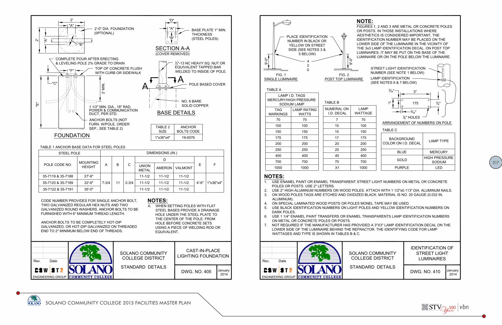
217
SOLANO COMMUNITY COLLEGE 2013 FACILITIES MASTER PLAN
NOTES:A. WHEN SETTING POLES WITH FLAT
STEEL BASES PROVIDE A DRAINAGEHOLE UNDER THE STEEL PLATE TOTHE CENTER OF THE POLE. FROMHOLE BEFORE CONCRETE SETSUSING A PIECE OF WELDING ROD OREQUIVALENT.
TABLE 1 ANCHOR BASE DATA FOR STEEL POLES
STEEL POLE DIMENSIONS (IN.)
POLE CODE NO. MOUNTINGHEIGHT A B C
DE FUNION
METAL AMERON VALMONT
357119 & 357188 27'6"
73/4 11 23/4
111/2 111/2 111/2
4'6" 1"x36"x4"357120 & 357189 32'6" 111/2 111/2 111/2
357122 & 357191 35'0" 111/2 111/2 111/2
BASE DETAILS
"A"
"A"
"A"
2'
2'
"B"
"D"
"B"
SECTION AA(COVER REMOVED)
FOUNDATION
2' M
IN."C"
"E"
"F"
1 1/2" MIN. DIA., 18" RAD.POWER & COMMUNICATIONDUCT, PER STD.
A
BASE PLATE 1" MIN.THICKNESS(STEEL POLES)
2'0" DIA. FOUNDATION(0PTIONAL)
12"13 NC HEAVY SQ. NUT OR
EQUIVALENT TAPPED BARWELDED TO INSIDE OF POLE.
POLE BASED COVER
NO. 6 BARESOLID COPPER
A
ANCHOR BOLTS (NOTFURN. W/POLE, ORDERSEP., SEE TABLE 2)
TOP OF CONCRETE FLUSHWITH CURB OR SIDEWALK
COMPLETE POUR AFTER ERECTING& LEVELING POLE 2% GRADE TO DRAIN
CODE NUMBER PROVIDES FOR SINGLE ANCHOR BOLT,TWO GALVANIZED REGULAR HEX NUTS AND TWOGALVANIZED ROUND WASHERS. ANCHOR BOLTS TO BEFURNISHED WITH 6" MINIMUM THREAD LENGTH.
ANCHOR BOLTS TO BE COMPLETELY HOTDIPGALVANIZED, OR HOTDIP GALVANIZED ON THREADEDEND TO 2" MINIMUM BELOW END OF THREADS.
TABLE 2SIZE
ANCHORBOLTS CODE
1"x36"x4" 190076
DWG. NO. 4052014
January
CASTINPLACELIGHTING FOUNDATIONSOLANO COMMUNITY
Rev. Date
P:\04\4116402\DWG\Standard Details\DWG 405Cast in Place Lighting Foundation.dwg 12/17/2013 04:45 PM salsa 1:1
COLLEGE DISTRICT
STANDARD DETAILS
ENGINEERING GROUP
NOTES:1. USE ENAMEL PAINT OR ENAMEL TRANSPARENT STREET LIGHT NUMBERS ON METAL OR CONCRETE
POLES OR POSTS. USE 2" LETTERS.2. USE 2" HIGH ALUMINUM NUMBERS ON WOOD POLES. ATTACH WITH 1 1/2"x0.113" DIA. ALUMINUM NAILS.3. ON WOOD POLES TAGS ARE ETCHED AND OXIDIZED BLACK. MATERIAL IS NO. 20 GAUGE (0.032 IN.
ALUMINUM).4. ON SPECIAL LAMINATED WOOD POSTS OR POLES MONEL TAPE MAY BE USED.5. USE BLACK IDENTIFICATION NUMBERS ON LIGHT POLES AND YELLOW IDENTIFICATION NUMBERS ON
DARK POLES.6. USE 1 1/4" ENAMEL PAINT TRANSFERS OR ENAMEL TRANSPARENTS LAMP IDENTIFICATION NUMBERS
ON METAL OR CONCRETE POLES OR POSTS.7. NOT REQUIRED IF THE MANUFACTURER HAS PROVIDED A 3"X3" LAMP IDENTIFICATION DECAL ON THE
LOWER SIDE OF THE LUMINAIRE BEHIND THE REFRACTOR. THE IDENTIFYING CODE FOR LAMPWATTAGES AND TYPE IS SHOWN IN TABLES B & C.
TABLE ALAMP I.D. TAGS
MERCURY/HIGH PRESSURESODIUM LAMP
TAGMARKINGS
LAMP RATINGWATTS
70 70
100 100
150 150
175 175
200 200
250 250
400 400
700 700
1000 1000
FIG. 1SINGLE LUMINAIRE
ARRANGEMENT OF NUMBERS ON POLE
400
C123
316" 3"
34"
316"
1" 175
9'0"
9'0"
TABLE C
BACKGROUNDCOLOR ON I.D. DECAL LAMP TYPE
BLUE MERCURY
GOLD HIGH PRESSURESODIUM
PURPLE LED
TABLE B
NUMERAL ON I.D. DECAL
LAMPWATTAGE
7 70
10 100
15 150
17 175
20 200
25 250
40 400
70 700
X1 1000
NOTE:FIGURES 1, 2 AND 3 ARE METAL OR CONCRETE POLESOR POSTS. IN THOSE INSTALLATIONS WHEREAESTHETICS IS CONSIDERED IMPORTANT, THEIDENTIFICATION NUMBER MAY BE PLACED ON THELOWER SIDE OF THE LUMINAIRE IN THE VICINITY OFTHE 3x3 LAMP IDENTIFICATION DECAL. ON POST TOPLUMINAIRES, IT MAY BE PUT ON THE BASE OF THELUMINAIRE OR ON THE POLE BELOW THE LUMINAIRE.
PLACE IDENTIFICATIONNUMBER IN BLACK ORYELLOW ON STREETSIDE (SEE NOTES 3 &
5 BELOW)
FIG. 2POST TOP LUMINAIRE
420
18" HOLES
STREET LIGHT IDENTIFICATIONNUMBER (SEE NOTE 1 BELOW)LAMP IDENTIFICATION(SEE NOTES 6 & 7 BELOW)
DWG. NO. 4102014
January
IDENTIFICATION OFSTREET LIGHTLUMINAIRES
SOLANO COMMUNITYRev. Date
P:\04\4116402\DWG\Standard Details\DWG 410Identification of Street Light Luminaires.dwg 12/17/2013 04:45 PM salsa 1:1
COLLEGE DISTRICT
STANDARD DETAILS
ENGINEERING GROUP

218
SOLANO COMMUNITY COLLEGE 2013 FACILITIES MASTER PLAN
NOTES:1. USE STEEL COVER AND SPECIAL CONCRETE FOOTING, SHOWN, WHEN PULL BOX IS TO BE INSTALLED
WHERE SUBJECT TO VEHICULAR TRAFFIC LOADING. STEEL COVER SHALL HAVE EMBOSSED NONSKIDPATTERN.
2. TOP OF PULL BOXES SHALL BE FLUSH WITH ADJACENT GRADE, SIDEWALK, CURB, OR OTHERSTRUCTURE.
3. CONDUIT SHALL NOT EXTEND MORE THAN 3" INTO PULL BOX.4. PULL BOX COVERS SHALL BE MARKED AS FOLLOWS:
A. "SIGNAL" FOR TRAFFIC SIGNAL CIRCUITRYB. "STREET LIGHTS" FOR STREET LIGHT CIRCUITRYC. "SPRINKLERCONTR." FOR SPRINKLER CONTROL CIRCUITRY
5. BONDING JUMPER FOR METAL COVERS SHALL BE 36" LONG, MINIMUM.6. PULL BOXES SHALL NOT BE LOCATED IN HANDICAPPED RAMP AREAS OR IN DRIVEWAYS.
DIMENSION TABLECONCRETE BOX PLASTIC BOX CONCRETE OR PLASTIC COVERS
PULLBOX
MIN. **THICKNESS
MIN. DEPTHBOX AND
EXTENSION
MIN. **THICKNESS
MIN. DEPTHBOX AND
EXTENSIONL*** W*** R EDGE
THICKNESSEDGETAPER
NO. 312" 1" NO EXTENSION 5
16" NO EXTENSION 15 3 8" 10 18" 1 18" 1 3 4" 18"
NO. 5 1" 22" 516" 20" 23 14" 13 3 4" 1 14" 2" 1
8"
NO. 6 1 12" 24" 38" 20" 30 5 8" 17 5 8" 1 14" 2" 1
8"
NO. 6T 2" 11" DOES NOT APPLY 33"± * 20"± * 0" 14" NONE
* STEEL COVER ** EXCLUDING CONDUIT WEB *** TOP DIMENSION
2"
2"
3" MIN.L
1/3L
12" M
IN.
6" M
IN.
NO. 3 1/2(T) & NO.5(T) TRAFFIC PULL BOX(CONCRETE BOX ONLY)
COVER SHALL COVERENTIRE TOP OF BOX1
2" DIA. LIFT HOLE
BOLT HOLE SHALL MATCH STANDARDSTUD BOLTS. RECESS IN COVER FOR NUT
SEE NOTE 41
4" STEEL PLATE COVER,GALVANIZED AFTER FABRICATION
112"x112"x316" MIN.BEVEL ENDS TO FIT LIP OF BOX
TOP OF COVER FLUSH WITHSIDEWALK OR PAVEMENT GRADE
PRECAST REINF.CONC. BOXGROUNDING BUSHING
POUR IN FIELD
3" MIN. ALL AROUNDCLEAN CRUSHED ROCK SUMP
13 4"x13 4"x316" MIN.
BONDING JUMPER
3" MIN. PCC ONALL SIDES OF BOX
DWG. NO. 4152014
January
PULL BOXESSOLANO COMMUNITYRev. Date
P:\04\4116402\DWG\Standard Details\DWG 415Pull Boxes.dwg 12/17/2013 04:45 PM salsa 1:1
COLLEGE DISTRICT
STANDARD DETAILS
ENGINEERING GROUP
34"
2" 34"
2"
2"
2" 34"2"3
4"
2"
34"
2" 34"2"3
4"2" 34"2"3
4"
2"
34"
TYPE "T" SPLICE(FOR 3 FREEENDS)
TYPE "ST" SPLICE(FOR SIGNAL CONDUCTORS)
TYPE "C" SPLICE(BETWEEN I FREEEND AND I THROUGH CONDUCTOR) TYPE "S" SPLICE
(BETWEEN 2 FREEENDS)
PVC TAPE
PENCILING (TYP.) 14" MIN.
PVC TAPE
"C" SHAPED COMPRESSIONCONNECTOR
FOR LOW VOLTAGE CIRCUITSELECTRICAL FILTER COMPOUND,INSULATING PAD OR RUBBERTAPE.
FOR HIGH VOLTAGE CIRCUITS:HIGH VOLTAGE TAPE
FOR LOW VOLTAGE CIRCUITS:ELECTRICAL FILTERCOMPOUND, INSULATINGPAD OR RUBBER TAPE
SLEEVE TYPE PRESSURECONNECTOR
PENCILING (TYP.) 14" MIN.
"C" SHAPED COMPRESSIONCONNECTOR
PENCILING (TYP.) 1
4" MIN.
FOR LOW VOLTAGE CIRCUITSELECTRICAL FILTER COMPOUND,INSULATING PAD OR RUBBERTAPE.
SLEEVE TYPE PRESSURECONNECTOR (SIZE TOACCOMMODATE MIN. OF2 #14 CONDUCTORS)
DWG. NO. 4202014
January
SPLICE DETAILSSOLANO COMMUNITYRev. Date
P:\04\4116402\DWG\Standard Details\DWG 420Splice Details.dwg 12/17/2013 04:45 PM salsa 1:1
COLLEGE DISTRICT
STANDARD DETAILS
ENGINEERING GROUP

219
SOLANO COMMUNITY COLLEGE 2013 FACILITIES MASTER PLAN
NOTES:
1. ALL DIMENSIONS ARE MINIMAL.
2. RUBBER TAPES SHALL BE ROLLED AFTER APPLICATION.
3. WHEN PVC TAPE IS USED AS FINAL LAYER, PAINT FINISHED SPLICE WITH ELECTRICALINSULATING COATING.
INSULATING METHODS:LOW VOLTAGE CIRCUITS (0600 VOLTS)
1. COMPLETELY COVER THE SPLICE AREA WITH AN ELECTRICAL INSULATING COATING AND ALLOWTO DRY.
2. APPLY 2 LAYERS OF ELECTRICAL INSULATING PAD WITH MINIMUM THICKNESS OF 1/8" EACHLAYERS OR 2 LAYERS, HALF LAPPED, SYNTHETIC OIL RESISTANT, SELF FUSING RUBBER TAPE.
3. APPLY 3 LAYERS HALF LAPPED PVC TAPE.
TABLE 1. HORIZONTALLY MOUNTED HIGH PRESSURE SODIUM VAPOR LUMINAIRES
LUMINAIRE DESCRIPTION LUMINAIRES APPROVED FOR PURCHASE ARE GE OR EQUAL
LAMPSIZE
(WATT)
BALLAST TWISTLOCKRCPT.
GENERAL ELECTRICCATALOG NUMBERTYPE RATING
VOLTS
70 REGULATOR 120 YES M2AR07SIN2AMS22
100 REGULATOR 120 YES M2AR10SIN2AMS22
200 REGULATOR 120 YES M2AR20SIN2AMS22
DWG. NO. 4252014
January
SPLICE NOTESSOLANO COMMUNITYRev. Date
P:\04\4116402\DWG\Standard Details\DWG 425Splice Notes.dwg 12/17/2013 04:45 PM salsa 1:1
COLLEGE DISTRICT
STANDARD DETAILS
ENGINEERING GROUP
NOTES:1. FABRIC SHALL BE 9 GAUGE 3 1/2"x5 1/2" MESH WITH PLASTIC PICKETS 2 1/2"x3/8" ATTACHED TO
FABRIC USING TWO GALVANIZED STAPLES (CRIMPED ON BACK SIDE). TOP & BOTTOMSELVAGES TO BE KNUCKLED. PLACE FABRIC ON PUBLIC SIDE.
2. FABRIC TO BE ATTACHED TO END & CORNER POSTS USING 1/4"x3/4" STRETCHER BARS.3. BOTTOM TENSION WIRE SHALL BE 7 GAUGE GALVANIZED STEEL COIL SPRING WIRE. FABRIC
TO BE ATTACHED TO TENSION WIRE USING 9 GAUGE HOG RINGS AT 18" SPACING.4. FABRIC TIES(a) TO POST USE 6 GAUGE STEEL POST CLIPS OR 9 GAUGE GALVANIZED STEEL
WIRE TIES AT 14" SPACING (b) TO TOP RAIL USE 9 GAUGE GALVANIZED STEEL WIRE TIES AT 14"MAX. SPACING.
5. TRUSS RODS SHALL BE ADJUSTABLE 3/8" GALVANIZED STEEL RODS.
6' CHAIN LINK FENCE
3.5'
3'
3.5'
18"
1'
18"
2"12"
9"
10'0" MAX
12'0"
END ORCORNER POST
HORIZONTAL BRACELINE POST
38" ADJUSTABLE
TRUSS ROD
TRUSS ROD
TYPICAL MEMBER DIMENSIONS
LINE POSTS CORNER GATE ENDPOSTS TOP RAIL & BRACES
ROUND ROLLFORM ROUND ROUND
238" O.D.
3.65 #/FT2.25"x1.7"2.64 #/FT
278" O.D.
5.79 #/FT31
2"x312"5.14 #/FT 3"x3" 15
8" O.D.2.27 #/FT
114" x 15
8"1.35 #/FT
DWG. NO. 5002014
January
CHAIN LINK FENCESOLANO COMMUNITYRev. Date
P:\04\4116402\DWG\Standard Details\DWG 500Chain Link Fence.dwg 12/17/2013 04:45 PM salsa 1:1
COLLEGE DISTRICT
STANDARD DETAILS
ENGINEERING GROUP

220
SOLANO COMMUNITY COLLEGE 2013 FACILITIES MASTER PLAN
Civil Standard Specifications

221
SOLANO COMMUNITY COLLEGE 2013 FACILITIES MASTER PLAN

222
SOLANO COMMUNITY COLLEGE 2013 FACILITIES MASTER PLAN

223
SOLANO COMMUNITY COLLEGE 2013 FACILITIES MASTER PLAN

224
SOLANO COMMUNITY COLLEGE 2013 FACILITIES MASTER PLAN

225
SOLANO COMMUNITY COLLEGE 2013 FACILITIES MASTER PLAN

226
SOLANO COMMUNITY COLLEGE 2013 FACILITIES MASTER PLAN

227
SOLANO COMMUNITY COLLEGE 2013 FACILITIES MASTER PLAN

228
SOLANO COMMUNITY COLLEGE 2013 FACILITIES MASTER PLAN
Solano Community College District Site Preparation
Month Day, Year 31 10 00 Page 4 of 5 Bid No. XXXXX V.[X] Name of Project
3.2 PREPARATION
A. Verify that the area to be demolished or removed has been vacated, or adequate space made available to perform the work.
B. Arrange for, and verify termination of utility services to include removing meters
and capping of lines. C. Lay out cutting work at Job Site and coordinate with related work for which
cutting is required. 3.3 DEMOLITION
A. If confirmed or suspected hazardous materials are encountered during operations, stop operations immediately and notify the Project Manager.
B. Perform work in accordance with ANSI A10.61969 unless otherwise noted. C. Provide noise and dust abatement as required to prevent contamination of
adjacent areas. 1. Remove all materials not designated as salvage, in their entirety. 2. Remove building foundations in their entirety, unless otherwise indicated on the plans.
D. Fill voids in the land left by the removal of existing structures as follows:
1. In accordance with the requirements of Section 31 00 00 – EARTHWORK AND GRADING. Grade finished remaining surface to the contours shown, or if not shown, to match the existing natural contours.
E. Lower, or remove, heavy structural framing members by hoist or crane. F. Concrete and Masonry:
1. Demolish concrete and masonry in sections, less than 3 feet in any direction. 2. Method of cutting shall be limited to saw cutting and torch.
3.4 CUTTING
A. Make new openings neat. B. Do not cut or alter structural members and any utilities including appurtenances
unless indicated to do so in the Construction Documents, or written approval is received from the Project Manager.
C. Take care not to damage reinforcing or structural steel scheduled to remain in
place. D. Concrete: Cut new openings in concrete by coring and saw cutting. Saw runbys
will not be permitted.
Solano Community College District Site Preparation
Month Day, Year 31 10 00 Page 5 of 5 Bid No. XXXXX V.[X] Name of Project
3.5 PREPARATION FOR NEW FINISH WORK
A. Where demolished surfaces are scheduled to receive new finishes, Contractor shall restore such substrate to a condition ready to receive the scheduled new finishes, including grinding or leveling.
3.6 DISPOSAL OF DEMOLISHED MATERIALS
A. Promptly dispose of demolished materials. Do not allow demolished materials to accumulate onsite.
B. Burning of demolished materials off District’s property in a legal manner.
3.7 FIELD QUALITY CONTROL
A. The Project Manager will accompany the Contractor before and after performance of work to observe physical condition of existing structures or improvements involved.
End of Document

229
SOLANO COMMUNITY COLLEGE 2013 FACILITIES MASTER PLAN
Solano Community College District Trenching, Backfilling and Compacting
Month Day, Year 31 23 33 Page 1 of 9 Bid No.XXXXX V.1 Name of Project
Section 31 23 33 TRENCHING, BACKFILLING AND COMPACTING
PART 1 – GENERAL
1.1 SUMMARY A. Provide labor, material, equipment, and services necessary to complete the backfilling and
compacting as necessary for this project. Section includes, but is not limited to: 1. Select Backfill Material. 2. Aggregate Base. 3. Detectable Tape. 4. Trench Excavation. 5. Pipe Bedding. 6. Trench Backfill. 7. Trench Surfacing.
B. Work specified in Related Sections:
1. Section 31 10 00 – SITE PREPARATION 2. Section 31 00 00 – EARTHWORK AND GRADING 3. Section 33 10 00 – WATER SYSTEMS 4. Section 33 30 00 – SANITARY SEWER 5. Section 33 40 00 – STORM DRAINAGE
1.2 DEFINITIONS A. Engineered Fill:
1. Soil or soilrock material approved by the Project Manager and transported to the site by the Contractor in order to raise grades or to backfill excavations.
2. Contractor shall provide sufficient tests, and a written statement that all materials brought onto the project site comply with specification requirements.
B. Excavation: Consists of the removal of material encountered to subgrade elevations. C. Subgrade: The uppermost surface of an excavation or the top surface of a fill or backfill
immediately below base. D. Base: The layer placed between the subgrade and surface pavement in a paving system. E. Relative Compaction: Inplace dry density of soil expressed as percentage of maximum dry
density of same materials, as determined by laboratory test procedure American Society for Testing and Materials (ASTM) D1557.
1.3 SYSTEM DESCRIPTION
A. Requirements:
1. Comply with the recommendations of the Geotechnical Engineer . 2. Protect existing trees to remain. No grading is permitted under the drip line of protected
trees. 3. Excavations for appurtenant structures, such as, but not limited to, manholes, transition
structures, junction structure, vaults, valve boxes, catch basins, thrust blocks, and boring pits, shall be deemed to be in the category of trench excavation.
4. Unless otherwise indicated in the Plans, all excavation for pipelines shall be open cut.
Solano Community College District Trenching, Backfilling and Compacting
Month Day, Year 31 23 33 Page 2 of 9 Bid No.XXXXX V.1 Name of Project
1.4 SUBMITTALS A. Comply with provisions of Section 01 32 19 – SUBMITTAL PROCEDURES. B. Test Reports: Submit the following report for import material directly to the Project Manager from
the Contractor’s testing services: 1. Compaction test reports for aggregate base.
C. Submit description of compactors proposed for use when requesting placement of base material.
1.5 QUALITY ASSURANCE
A. Requirements of Regulatory Agencies:
1. Comply with State of California Business and Transportation Agency, Department of Transportation (Caltrans) latest edition of “Standard Specifications.” (CSS).
2. Comply with State of California Code of Regulations (CCR). 3. Comply with State of California Construction Safety Orders, Latest Edition (CAL/OSHA).
B. Soil Testing:
1. District to engage a geotechnical testing agency, to include compaction testing and for quality control testing during fill operations.
2. Test results will be submitted to the Project Manager. C. Codes and Standards:
1. Perform excavation work in compliance with applicable requirements of authorities having jurisdiction.
2. California Department of Transportation (CDT): a. Section 19: Earthwork. b. Standard Test Methods: No. 202.
3. American Society for Testing and Materials (ASTM): a. D1556: Density of Soil by the Sand Cone Method. b. D1557: Moisture Density Relations of Soils and SoilAggregate Mixtures
1.6 DELIVERY, STORAGE AND HANDLING
A. Protect materials before, during and after installation. B. Comply with provisions of Section 01 51 00 TEMPORARY FACILITIES AND CONTROLS
where necessary to control dust and noise on and near the work caused by operations during construction activities.
1.7 PROJECT CONDITIONS
A. Environmental Requirements:
1. Protect existing storm drainage system from silt and debris resulting from construction activities. If contamination occurs, remove contamination at no cost to the District.
2. Protect existing streams, ditches and storm drain inlets during work on this project. B. Barricade open excavations and post with warning lights.
1. Comply with requirements of Section 01 51 00 TEMPORARY FACILITIES AND CONTROLS.
2. Operate warning lights and barricades as required. 3. Protect structures, utilities, sidewalks, pavements, and other facilities immediately adjacent

230
SOLANO COMMUNITY COLLEGE 2013 FACILITIES MASTER PLAN
Solano Community College District Trenching, Backfilling and Compacting
Month Day, Year 31 23 33 Page 3 of 9 Bid No.XXXXX V.1 Name of Project
to excavations, from damages caused by settlement, lateral movement, undermining, washout, and other hazards.
C. Protection of Subgrade: Do not allow equipment to pump or rut subgrade, stripped areas, footing
excavations, or other areas prepared for project. D. Transport all excess soils materials by legally approved methods to disposal areas.
1. Coordinate with the Project Manager. 2. Any additional fill requirements shall be the responsibility of the Contractor.
1.8 EXISTING UTILITIES
A. Locate existing underground utilities in the areas of work. For utilities that are to remain in place, provide adequate means of protection during excavation operations. 1. Locating of existing underground utilities shall include but not be limited to potholing prior
to the start of construction. B. Should uncharted or incorrectly charted piping or other utilities be encountered during excavation,
consult Project Manager, Facilities, and/or utility agency immediately for directions. 1. Cooperate with the Project Manager and public and private utility companies in keeping
their respective services and facilities in operation. 2. Repair damaged utilities to the satisfaction of the agency with jurisdiction.
C. Do not interrupt existing utilities serving facilities occupied and used by the District or others,
except when permitted in writing by the Project Manager and then only after acceptable temporary utility services have been provided.
1.9 SEQUENCING AND SCHEDULING
A. The sequence of operations shall be reviewed by the Project Manager prior to commencement of any work.
PART 2 – PRODUCTS 2.1 MATERIALS
A. General: 1. Import materials will be subject to approval of the Geotechnical Engineer. 2. For approval of imported fill material, notify the Project Manager at least 7 days in advance
of intention to import material. B. Select backfill material shall be gravel, free of clay or organic matter and shall conform to the
following gradation:
Sieve Size Percentage Passing 1 inch 100 ¾ inch 90 – 100 No. 4 35 – 60 No. 200 2 9
C. For gas pipe and fuel piping select backfill shall be clean, graded building sand conforming to the
following gradation:
Sieve Size Percentage Passing No. 4 100 No. 200 0 5
Solano Community College District Trenching, Backfilling and Compacting
Month Day, Year 31 23 33 Page 4 of 9 Bid No.XXXXX V.1 Name of Project
D. Water: Clean and free from deleterious amounts of acids, alkalis, salts and organic matter.
2.2 BURIED WARNING AND IDENTIFICATION TAPE
A. Polyethylene plastic and metallic core or metallicfaced, acid and alkaliresistant, polyethylene plastic warning tape manufactured specifically for warning and identification of buried utility lines. Provide tape on rolls, 75 mm 3 inch minimum width, color coded as specified below for the intended utility with warning and identification imprinted in bold black letters continuously over the entire tape length. Warning and identification to read, "CAUTION, BURIED (intended service) LINE BELOW" or similar wording. Color and printing shall be permanent, unaffected by moisture or soil. 1. Warning Tape Color Codes. Red: Electric. Yellow: Gas, Oil; Dangerous Materials. Orange: Telephone and Other Communications. Blue: Water Systems. Green: Sewer Systems. White: Steam Systems. Gray: Compressed Air. 2. Warning Tape for Metallic Piping: Acid and alkaliresistant polyethylene plastic tape
conforming to the width, color, and printing requirements specified above. Minimum thickness of tape shall be 0.003 inch. Tape shall have a minimum strength of 1500 psi lengthwise, and 1250 psi crosswise, with a maximum 350 percent elongation.
3. Detectable Warning Tape for NonMetallic Piping: Polyethylene plastic tape conforming to the width, color, and printing requirements specified above. Minimum thickness of the tape shall be 0.004 inch. Tape shall have a minimum strength of 1500 psi lengthwise and 1250 psi crosswise. Tape shall be manufactured with integral wires, foil backing, or other means of enabling detection by a metal detector when tape is buried up to 920 mm 3 feet deep. Encase metallic element of the tape in a protective jacket or provide with other means of corrosion protection.
2.3 DETECTION WIRE FOR NONMETALLIC PIPING
A. Detection wire shall be insulated single strand, solid copper with a minimum of 12 AWG.
PART 3 – EXECUTION 3.1 GENERAL
A. Prior to commencement of work, become thoroughly familiar with site conditions. B. In the event discrepancies are found, immediately notify the Project Manager in writing, indicating
the nature and extent of differing conditions. C. Backfill excavations as promptly as work permits. D. Do not place Engineered fill or backfill until rubbish and deleterious materials have been removed
and areas have been approved by the Project Manager. E. Place acceptable soil material in layers to required subgrade elevations, for each area classification
listed below. F. In excavations, use satisfactory excavated or borrow material.

231
SOLANO COMMUNITY COLLEGE 2013 FACILITIES MASTER PLAN
Solano Community College District Trenching, Backfilling and Compacting
Month Day, Year 31 23 33 Page 5 of 9 Bid No.XXXXX V.1 Name of Project
G. Under grassed areas, use satisfactory excavated or borrow material.
3.2 COMPACTING
A. Compact by power tamping, rolling or combinations thereof. 1. Where impractical to use rollers in close proximity to walls, stairs, etc., compact by
mechanical tamping. 2. Scarify and recompact any layer not attaining compaction until required density is obtained.
3.3 SITE PREPARATION
A. Protect structures, utilities, sidewalks, pavements, and other facilities, which are to remain, from damage caused by settlement, lateral movement, undermining, washout, and other hazards created by earthwork operations.
B. Protect existing storm drainage system from silt and debris resulting from construction activities.
If contamination occurs, remove contamination at no cost to the District.
3.4 EXISTING UTILITIES
A. Identity the location of existing utilities. 1. Prior to trenching, the Contractor shall excavate at locations specifically indicated on the
Plans, if any, and where new lines cross other utilities of uncertain depth and determine the elevation of the utility in question to ensure that the new line will clear the potential obstruction.
2. The Contractor shall contact Underground Service Alert (USA) at 18002272600 for assistance in locating existing utilities.
3. If, after the excavation, a crossing utility does present an obstruction, then the line and grade of the new line will be adjusted as directed by the Project Manager to clear the utility.
B. Protect all existing utilities to remain in operation. C. Movement of construction machinery and equipment over existing pipes and utilities during
construction shall be at Contractor’s risk. E. Excavation made with powerdriven equipment is not permitted within 2 feet of any known utility
or subsurface structure. 1. Use hand or light equipment for excavating immediately adjacent to known utilities or for
excavations exposing a utility or buried structure. 2. Start hand or light equipment excavation on each side of the indicated obstruction and
continue until the obstruction is uncovered or until clearance for the new grade is assured. 3. Support uncovered lines or other existing work affected by excavation until approval for
backfill is obtained. 4. Report damage of utility line or subsurface structures immediately to the Project Manager.
F. Backfill trenches resulting from utility removal in lifts of 8 inches maximum.
3.5 TRENCH EXCAVATION
A. General
1. Excavation shall include removal of all water and materials that interfere with construction. The Contractor shall remove any water which may be encountered in the trench by pumping or other methods during the pipe laying, bedding and backfill operations. Material shall be sufficiently dry to permit approved jointing.
2. Excavation shall include the construction and maintenance of bridges required for vehicular and pedestrian traffic, support for adjoining utilities.
Solano Community College District Trenching, Backfilling and Compacting
Month Day, Year 31 23 33 Page 6 of 9 Bid No.XXXXX V.1 Name of Project
3. The Contractor shall be responsible to safely direct vehicular and pedestrian traffic through or around his/her work area at all times.
4. The Contractor shall relocate, reconstruct, replace or repair, at his/her own expense, all improvements which are in the line of construction or which may be damaged, removed, disrupted or otherwise disturbed by the Contractor.
B. Existing Paving and Concrete:
1. Existing pavement over trench shall be sawcut, removed, and hauled away from the job. Existing pavement shall be neatly sawcut along the limits of excavations.
2. Existing concrete over the trench shall be sawcut to a full depth in straight lines either parallel to the curb or a right angles to the alignment of the sidewalk.
3. Boards or other suitable material shall be placed under equipment outrigging to prevent damage to paved surfaces.
C. Trench Width:
1. The maximum allowable trench widths at the top of the pipe shall be as follows: Pipe Type Trench Width (Maximum) Copper Outside diameter of barrel plus 18 inches Plastic " Vitrified Clay " DuctileIron " Reinforced Concrete "
a. The maximum trench width shall be inclusive of all shoring. b. If the maximum trench width is exceeded, the State’s representative may direct the
Contractor to encase or cradle the pipe in concrete at no additional charge. 2. For pipes 3 inch diameter and larger, the free working space on each side of the pipe barrel
shall not be less than 6 inches.
D. Open Trench: 1. The maximum length of open trench shall be 300 feet or the distance necessary to
accommodate the amount of pipe installed in a single day, whichever is greater. No trench shall be left open at the end of the day.
2. Provisions for trench crossings and free access shall be made at all street crossings, driveways, water gate valves, and fire hydrants.
E. Excavation Bracing:
1. The excavation shall be supported and excavation operations shall be conducted in accordance with the California Industrial Accident Commission and CAL/OSHA.
2. The Contractor shall, at his/her own expense, furnish, put in place, and maintain such sheeting and bracing as may be required to support the sides of all excavations (whether above or below the pipe grade), and to prevent any movement which could in any way diminish the required trench section or otherwise injure or delay the work. The sheeting and bracing shall be withdrawn in a manner such as to prevent any earth movement that might overload the pipe.
F. Excavated Material:
1. All excavated material not required for backfill shall be immediately removed and properly disposed of in a legal manner by the Contractor.
2. Material excavated in streets and roadways shall be laid alongside the trench no closer than 2 feet from the trench edge and kept trimmed to minimize inconvenience to public traffic.
3. Provisions shall be made whereby all storm and wastewater can flow uninterrupted in gutters or drainage channels.
3.6 PIPE BEDDING
A. Bedding Excavation: The trench shall be excavated below the grade of the pipe bottom to the
following minimum depths:

232
SOLANO COMMUNITY COLLEGE 2013 FACILITIES MASTER PLAN
Solano Community College District Trenching, Backfilling and Compacting
Month Day, Year 31 23 33 Page 7 of 9 Bid No.XXXXX V.1 Name of Project
Pipe Type Depth Copper 6 inch Reinforced Concrete 6 inch Plastic: 2 inch diameter and smaller 6 inch Plastic: over 2 inch diameter 6 inch Ductile Iron 6 inch
1. Stabilization of Trench Bottom: When the trench bottom is unstable due to wet or spongy foundation, trench bottom shall be stabilized with gravel or crushed rock. The State’s inspector will determine the suitability of the trench bottom and the amount of gravel or crushed rock needed to stabilize a soft foundation. Soft material shall be removed and replaced with gravel or crushed rock as necessary.
2. Placement of Bedding Material: The trench bottom shall be cleaned to remove all loose native material prior to placing select backfill material. Sufficient select backfill material shall be placed in trench and tamped to bring trench bottom up to grade of the bottom of pipe. The relative compaction of tamped material shall be not less than 90 percent. It is the intention of these requirements to provide uniform bearing under the full length of pipe to a minimum width of 60 percent of the external diameter.
3.7 TRENCH BACKFILL
A. Initial Backfill:
1. Prior to trench backfill, the condition of the trench and laying of pipe must be inspected and approved by the Inspector of Record.
2. Select backfill material shall be used for initial backfill. After the pipe has been properly laid and inspected, select backfill material shall be placed on both sides of the pipe and compacted to final depth as follows:
Pipe Type Depth Copper 12 inches above top of pipe Plastic: less than 3 inches diameter 12 inches above top of pipe Plastic: 3 inches diameter and larger 12 inches above top of pipe Ductile Iron 12 inches above top of pipe Reinforced Concrete 12 inches above top of pipe
3. Compaction: Initial backfill compaction shall be by mechanical means. The initial backfill
material shall be hand tamped in layers not exceeding 4 inches in uncompacted depth and shall be brought up uniformly on both sides of the pipe to avoid bending or distortional stress. After hand tamping, the relative compaction of the initial backfill material shall be not less than 90 percent.
4. Pipe Detection: In trenches containing pressurized plastic pipes, tracer wire shall be placed directly above the pipe and shall be connected to all valves, existing exposed tracer wires, and other appurtenances as appropriate.
B. Subsequent Backfill:
1. Above the level of initial backfill, the trench shall be backfilled with nonexpansive native material from trench excavation or with imported select backfill material (Contractor’s option). Subsequent backfill shall be free of vegetable matter, stones or lumps exceeding 3 inches in greatest dimension, and other unsatisfactory material. The Inspector of Record shall approve the backfill material prior to placement.
2. Subsequent backfill compaction shall be by mechanical means with backfill material placed in layers not exceeding 8 inches in loose depth. Each layer shall be thoroughly compacted before succeeding layers are placed. The use of machine tampers, except manually held types, shall not be permitted.
Solano Community College District Trenching, Backfilling and Compacting
Month Day, Year 31 23 33 Page 8 of 9 Bid No.XXXXX V.1 Name of Project
3. Subsequent backfill shall be compacted to a relative compaction of not less than 90 percent except the relative compaction shall not be less than 95 percent within 21/2 feet of finished permanent surface grade or 11/2 feet below the finished subgrade, whichever is greater.
C. Jetting and Ponding:
1. Jetting of trench backfill is not permitted. D. Compaction Testing:
1. Compaction testing shall be in accordance with California Test Method ASTM D1556 or D1557.
3.8 TRENCH SURFACING
A. Unpaved Areas:
1. In unimproved areas, the trench surface shall be restored to its original condition. No mounds of earth shall be left along the trench. Repair and reestablish grades in settled, eroded, and rutted areas to specified tolerances.
2. Where completed compacted areas are disturbed by subsequent construction operation or adverse weather, scarify surface, reshape, compact to required density and provide other corrective work, including retesting, prior to further construction.
B. Temporary Surfacing:
1. Temporary surfacing shall be a minimum of 2 inches of cutback asphalt on 10 inches of Class 2 aggregate base and shall be placed at all trench locations subject to vehicular or pedestrian traffic.
2. Temporary surfacing shall be laid within one day after backfilling (except where the Contractor elects to place permanent surfacing within this time period).
3. Before the trenching area is opened for traffic, all excess dirt, rock, and debris shall be removed, the street surface shall be swept clean and the pavement shall be washed down with a water truck and pressure nozzle.
4. Temporary surfacing shall be maintained to prevent the occurrence of mudholes and prevent the surface from settling below 1 inch or rising more than 1 inch from the existing pavement grade.
3.9 FILL AND COMPACTING
A. General Requirements: 1. Backfill excavations as promptly as work permits. 2. Do not place Engineered fill or backfill until rubbish and deleterious materials have been
removed and areas have been approved by the Project Manager. 3. Place acceptable soil material in layers to required subgrade elevations, for each area
classification listed below. 4. In excavations, use satisfactory excavated or borrow material. 5. Under grassed areas, use satisfactory excavated or borrow material.
B. After subgrade compaction has been approved by the Geotechnical Engineer , spread the Engineered fill materials in 6 to 8 inch loose lifts and uniformly mixed during the spreading operation. 1. Bring nonexpansive fill materials to or slightly above the optimum moisture content and
compacted to at least 85 percent of the maximum laboratory dry density, pert ASTM D1557. 2. Bring nonexpansive aggregate fill materials to or slightly above the optimum moisture
content and compacted to at least 95 percent of the maximum laboratory dry density, pert ASTM D1557.
3. Do not compact the top 12 inches of soil in the planting areas. 4. Fill sections greater than 5 feet in depth shall be compacted to at least 95 percent.
C. Repeat compaction procedure until proper grade is attained.

233
SOLANO COMMUNITY COLLEGE 2013 FACILITIES MASTER PLAN
Solano Community College District Trenching, Backfilling and Compacting
Month Day, Year 31 23 33 Page 9 of 9 Bid No.XXXXX V.1 Name of Project
D. Rocks generated during site earthwork may be used in fill when conforming to material
specifications. 3.10 MOISTURE CONTROL
A. Do not resume operations until moisture content and fill density are satisfactory to the Inspector.
3.11 DISPOSAL OF EXCESS AND WASTE MATERIALS
A. Testing Services: Allow testing agency to test each backfill layer. Do not proceed until test results for previously completed work verify compliance with requirements.
B. When testing agency reports that backfills are below specified density, scarify and moisten or
aerate, or remove and replace soil to the depth required, recompact and retest until required density is obtained.
3.12 PROTECTION
A. Repair and reestablish grades in settled, eroded, and rutted areas to specified tolerances. B. Where completed compacted areas are disturbed by subsequent construction operation or adverse
weather, scarify surface, reshape, compact to required density and provide other corrective work, including retesting, prior to further construction.
3.13 CLEANUP
A. Remove all debris, equipment, tools and materials upon completion prior to final inspections to
the satisfactions of the Project Manager. B. In unpaved areas without landscaping, cover with straw erosion control blanket. Follow
manufacturer’s recommendations for installation. Provide and place straw wattles or biodegradable fiber logs across the slope at the midpoint and along the downhill edge of site. No soil is to be left uncovered at the completion of construction.
End of Document
Solano Community College District Demolition
Month Day, Year 31 10 00 Page 1 of 4 Bid No. XXXXX V.[X] Name of Project
Section 32 10 00 DEMOLITION
PART 1 – GENERAL
1.1 SUMMARY
A. Provide labor, material, and equipment required for demolishing, cutting, removing and disposing of existing construction as designated or required to provide for new work.
B. Coordinate all work with capping or sealing of existing utilities. C. Related Sections:
1. Section 31 10 00 SITE PREPARATION 2. Section 31 00 00 EARTHWORK AND GRADING 3. Section 31 23 33 TRENCHING, BACKFILLING, AND COMPACTING
1.2 SUBMITTALS
A. Comply with requirements of the SUBMITTAL PROCEDURES and GENERAL CONDITIONS.
1.3 QUALITY ASSURANCE
A. Comply with the following Standards: American National Standards Institute, Inc. “American National Standard Safety Requirements for Demolition” (ANSI A10.6 and A10.8).
B. Regulatory Agencies:
1. Comply with rules and regulations of State of California, California Code of Regulations, Title 8, Industrial Relations, Chapter 4, Subchapter 4, “Construction Safety Order.”
2. Comply with applicable local and state agencies having jurisdiction. 3. Comply with governing EPA notification regulations. 4. Comply with applicable state and local regulations regarding dust and noise
mitigation during construction.
C. Secure all required Permits or Certificates for demolition prior to beginning the work.
1.4 PROJECT CONDITIONS
A. District assumes no responsibility for actual condition of the site to be altered. 1. Conditions existing at time of inspection for bidding purpose will be maintained
by District as far as practical. B. Disposal of Existing Improvements:
1. All materials removed shall become the property of the Contractor; dispose of these materials outside the project site. a. Do not dispose of removed materials to the general public by sale, gift
or in any other manner at the project site. b. These provisions shall not be construed as limiting or prohibiting sale
or disposal of such materials at the Site to duly licensed Contractors or material suppliers, provided materials are removed from construction site by the Contractor.
2. All removal of debris from the site, including removal of inventory to site of storage, is part of this Contract and shall be done by Contractor’s employees and

234
SOLANO COMMUNITY COLLEGE 2013 FACILITIES MASTER PLAN
Solano Community College District Demolition
Month Day, Year 31 10 00 Page 2 of 4 Bid No. XXXXX V.[X] Name of Project
no others.
C. Salvage: 1. Recycle AC pavement and Class II AB where practical. 2. Recycle concrete where practical. 3. Items indicated to be salvaged shall be removed carefully, cleaned, and returned
to the District. Coordinate with the Project Manager.
D. Protection: 1. Erect and maintain temporary bracing, shoring, lights, barricades, except
construction barricades for subsequent new construction, warning signs, and guards necessary to protect public, the District’s employees, adjacent improvements to remain, and adjoining property from damage, all in accordance with applicable regulations.
2. Wet down areas affected by this work as required to prevent dust and dirt from rising.
E. Scheduling:
1. Coordinate with the Project Manager in scheduling noisy or dirty work. 2. The Project Manager will supply a schedule of days on which no construction
will be allowed. 3. Contractor shall take College schedule into consideration during construction. 4. Coordinate and schedule temporary water shutdowns and temporary water
service with the Project Manager, Facilities, and the Water Department, and the Fire Department.
F. Traffic Circulations: Ensure minimum interference with roads, streets, driveways,
sidewalks, and adjacent facilities. 1. Minimize obstruction to thoroughfares by first obtaining the required approval
or permission of the responsible jurisdiction. 2. Where closing of a vehicular traffic circulation route is necessary, provide
adequate directional signs to minimize the potential for confusion. Provide access at all times for emergency vehicles.
G. Safety:
1. The Contractor shall take all necessary precautions to eliminate the exposure of workers, students, staff, and the public to asbestos fibers, including but not limited to: dust control measures and measures included in Sections 93106 and 93105 of California Code of Regulations, Title 17.
PART 2 – PRODUCTS Not Used
PART 3 – EXECUTION
3. 1 EXAMINATION:
A. Where existing conditions conflict with representations of the Construction Documents, notify the Project Manager and obtain clarifications. Do not perform work affecting the conflicting conditions until clarification of the conflict is received.
3.2 PREPARATION
A. Verify that the area to be demolished or removed has been vacated, and adequate space
has been made available to perform the work.
Solano Community College District Demolition
Month Day, Year 31 10 00 Page 3 of 4 Bid No. XXXXX V.[X] Name of Project
B. Lay out saw cutting and coordinate with related work for which saw cutting is required. C. Contractor shall coordinate and arrange the shut down of utilities serving the site with
Facilities, the Fire Department, and the Project Manager. 3.3 DEMOLITION
A. If known or suspected hazardous materials are encountered during operations, stop operations immediately and notify the Project Manager.
B. Perform work in accordance with ANSI A10.61969 unless otherwise noted. C. Provide noise and dust abatement as required to prevent contamination of adjacent areas. D. Remove all materials not designated as salvage, in their entirety. E. If unknown items such as human remains are encountered during operations, stop
operations immediately and notify the Project Manager. F. The Project Manager will provide a list of any items to be stockpiled for future use.
Stockpile location will be a site on campus determined by the Project Manager.
3.4 DEMOLITION AND REMOVAL OF AC PAVEMENT:
A. Sawcut pavement at edge of demolition area. B. Break pavement and remove. C. Remove any base material, gravel, and/or or any other nonnative soil.
3.5 SAW CUTTING:
A. Make new openings neat.
B. Take care not to damage existing AC pavement to remain in place.
3.6 UTILITY REMOVAL:
A. Where utility removal is shown on the plans or required for construction, excavate to
expose existing utility, demolish and remove the section of pipe or conduit. Cap section of pipe or conduit to remain. Mark end of utility with 12” piece of #4 rebar.
B. Included in demolition are any appurtenances, including but not limited to valves, valve
boxes, and irrigation system components.
C. Backfill trench in accordance with requirements of Section 31 23 33 – TRENCHING, BACKFILLING, AND COMPACTING.
3.7 DISPOSAL OF DEMOLISHED MATERIALS:
A. Promptly dispose of demolished materials. Do not allow demolished materials to
accumulate onsite. B. Burning of demolished materials is prohibited.

235
SOLANO COMMUNITY COLLEGE 2013 FACILITIES MASTER PLAN
Solano Community College District Demolition
Month Day, Year 31 10 00 Page 4 of 4 Bid No. XXXXX V.[X] Name of Project
3.8 FIELD QUALITY CONTROL:
A. The Project Manager will accompany the Contractor before and after performance of
work to observe physical condition of existing structures or improvements involved.
End of Document
Solano Community College District Paving and Surfacing
Month Day, Year 32 12 33 Page 1 of 5 Bid No. XXXXX V.[X] Name of Project
Section 32 12 33 PAVING AND SURFACING
PART 1 GENERAL 1.1 SUMMARY
A. Section Includes (but is not necessarily limited to): 1. Asphalt Concrete Paving. 2. Concrete Paving. 3. Liquid Asphalt and Asphalt Emulsion. 4. Aggregate Base.
B. Related work furnished under other sections but conforming to the provisions of this section: 1. Subgrade preparation. 2. Aggregate Base installation.
C. Related Sections:
1. Section 32 00 00 DEMOLITION 2. Section 31 17 23 PAVEMENT MARKING.
1.2 REFERENCES
A. American Society for Testing and Materials (ASTM): 1. A615: Deformed and Plain BilletSteel Bars for Concrete Reinforcement. 2. C150: Portland Cement. 3. D1557: Moisture Unit Weight Relations of Soils and Aggregate Mixtures Using a 10 lb (4.5
kg) Rammer and 18 in. (457 mm) Drop. 4. D1682: Breaking Loads and Elongation of Textile Fabrics.
B. California Code of Regulations (CCR): Title 24, Chapter 271, Site development Requirements
for Handicapped Accessibility.
C. California Department of Transportation (C.D.T.): 1. Standard Specifications:
a. Section 26 Aggregate Bases. b. Section 37 Bituminous Seals. c. Section 39 Asphalt Concrete. d. Section 51 Concrete Structures. e. Section 52 Reinforcement. f. Section 73 Concrete Curbs and Sidewalks. g. Section 90 Portland Cement Concrete. i. Section 92 Asphalts. j. Section 93 Liquid Asphalts. k. Section 94 Asphaltic Emulsions.
2. Traffic Manual. 3. Highway Design.
D. Institute of Transportation Engineers: Transportation and Traffic Engineering Handbook.
1.3 SUBMITTALS
A. Requirements: Refer to Section SUBMITTAL PROCEDURES.
B. Asphalt Concrete Paving:

236
SOLANO COMMUNITY COLLEGE 2013 FACILITIES MASTER PLAN
Solano Community College District Paving and Surfacing
Month Day, Year 32 12 33 Page 2 of 5 Bid No. XXXXX V.[X] Name of Project
1. Provide two copies of material certificates signed by the material producer and the Contractor, certifying that each material item complies with or exceeds specified requirements.
2. The Contractor shall furnish a certified weight or load slip for each load of material used in the construction of the asphalt concrete pavement.
C. Concrete Paving: The Contractor shall furnish mill test reports on the cement, reinforcement bars,
and aggregates, showing compliance with the respective specifications. The Testing Engineer may make concrete test cylinders and slump tests as deemed necessary to determine compliance with the Specifications.
D. Liquid Asphalt.
E. Pavement Reinforcement Fabric.
F. Tack Coat.
G. Pavement Reinforcement Mesh.
H. Structural Geotextile Fabric.
1.4 PROJECT CONDITIONS
A. Liquid Asphalt and Asphalt Emulsion: 1. Prime coat, seal coat, and paint binder shall be applied only when the ambient temperature is
above 50° Fahrenheit and when temperature has not been below 35° Fahrenheit for 12 hours immediately prior to application.
2. Prime coat, fog coat, seal coat, and paint binder shall not be applied when base or surfaces are wet or contain excess moisture.
B. Asphalt Concrete Paving: Asphalt concrete surfaces shall be constructed only when ambient
temperature is above 50° Fahrenheit and when base is dry. 1.5 GENERAL DESIGN CRITERIA
A. Services Areas: Approach ramps, driveways, and paved work areas in excess of 4 percent slope shall be provided with a rough texture for nonskid surface.
B. Walks and Paths: Concrete exterior slabs (walks, terraces, etc.) shall have a pitch of at least 1
percent.
C. Pavement Markings: All traffic control striping and pavement markings shall conform to the standards illustrated in the C.D.T. Standard Plans Book issued May 2006, General Road Work Section.
PART 2 PRODUCTS 2.1 PAVING MATERIALS
A. Aggregate Base: Aggregate base shall conform to Caltrans Class 2 (R value 78 min) aggregate base, 3/4" maximum size, as specified in Section 26 of the C.D.T. Standard Specifications.
B. Asphalt Concrete Paving:
1. Paving asphalt to be mixed with aggregate shall be steamrefined asphalt, AR4000, conforming to Section 92 of the C.D.T. Standard Specifications.
Solano Community College District Paving and Surfacing
Month Day, Year 32 12 33 Page 3 of 5 Bid No. XXXXX V.[X] Name of Project
2. Mineral aggregate shall be Type B mineral aggregate as specified in Section 39 of the C.D.T. Standard Specifications.
3. Maximum aggregate size shall be as follows: A.C. Thickness Max. Ag.
a. ¾” 1½ 1/2" b. 2 & 2½" 1/2" c. 3” & 4” 3/4"
4. Liquid asphalt for prime coat shall be Grade SC70 in conformance with Section 93 of the C.D.T. Standard Specifications.
5. Asphaltic emulsion for paint binder, fog coat, and seal coat shall be emulsified asphalt, Type SS1h, conforming to Section 94 of the C.D.T. Standard Specifications.
C. Portland Cement Concrete:
1. Concrete shall be Class A concrete conforming to Section 90 of the C.D.T. Standard Specifications.
2. Cement shall be Type II cement conforming to ASTM C150 as modified by Section 90 of the C.D.T. Standard Specifications.
3. Aggregate shall be 3/4inch maximum size conforming to Section 90 of the C.D.T. Standard Specifications.
4. Water shall be potable and free of organic matter and injurious amounts of oil, acid, alkali, or other deleterious substances.
5. Reinforcing bars shall be deformed and shall conform to ASTM A615. 6. Filled joints, unless noted otherwise on the Drawings, shall be 1/4inch thick, the full
depth of the concrete section and conforming to Section 51 of the C.D.T. Standard Specifications.
7. Joint filler shall conform to Section 51 of the C.D.T. Standard Specifications for premolded expansion joint filler and expanded polystyrene joint filler.
8. No admixtures will be allowed without prior approval of the Project Manager.
D. Pavement Reinforcement Fabric: Pavement reinforcement fabric shall meet Caltrans Section 881.02, BP Petromat or approved equivalent.
E. Crack Sealant:
1. Crack sealant shall be rubberized hotpour type and shall meet ASTM D 3405, Husky 1611 or approved equivalent.
2. Blotting Agent shall be one of: Screened sand, cement, or fly ash.
F. Tack coat: Tack coat shall meet Caltrans Section 394.02. G. Pavement reinforcement mesh: Pavement reinforcement mesh for use in Type 2 Overlay
shall be Glasgrid Model 8501 or approved equivalent.
H. Structural geotextile fabric: Structural geotextile fabric shall be Mirafi 500X or approved equivalent.
PART 3 EXECUTION
3.1 PREPARATION
A. Subgrade and Aggregate Base: 1. Prepare a subgrade and over excavation paragraph reference 3.4 of Section 31 00 00
EARTHWORK AND GRADING.

237
SOLANO COMMUNITY COLLEGE 2013 FACILITIES MASTER PLAN
Solano Community College District Paving and Surfacing
Month Day, Year 32 12 33 Page 4 of 5 Bid No. XXXXX V.[X] Name of Project
2. Aggregate base shall be compacted to 95 percent ASTM D1557. Sections 261.04B and 261.05 of the C.D.T. Standard Specifications shall apply.
3. Soil sterilant shall be applied to prepared subgrade or after installation of rock or aggregate base uniformly at the rate recommended by the manufacturer. B. Crack Sealing:
1. Before sealing, cracks shall be cleared of dirt, dust, and all other deleterious materials to a depth of 1/4inch to 1/2inch.
2. Cracks 1/8inch in width and greater shall be sealed. 3. Application of crack sealer shall be in accordance with the manufacturer's recommendations
unless otherwise directed. 3.2 ASPHALT CONCRETE PAVING
A. General: 1. Asphalt concrete shall be proportioned, mixed, placed, spread, and compacted in conformance
with Section 39 of the C.D.T. Standard Specifications. 2. Before placing asphalt concrete on untreated base, a liquid asphalt prime coat shall be applied
to the base course in conformance with Section 39 of the C.D.T. Standard Specifications. Prime coat shall be applied at the rate of 0.25 gallons per square yard.
3. Before placing asphalt concrete, an asphalt emulsion tack coat shall be applied to all vertical surfaces of existing pavement, curbs, gutters, construction joints, and all existing pavement to be surfaced, in conformance with Section 39 of the C.D.T. Standard Specifications.
4. Spreading and compacting asphalt concrete shall be performed in accordance with Section 39 of the C.D.T. Standard Specifications.
5. Fog seal shall be applied to all finished surfaces of asphalt concrete pavement at a rate of 0.05 gallons per square yard, in accordance with Section 37 of the C.D.T. Standard Specifications.
6. After fog seal has been applied, ample time shall be allowed for drying before traffic is allowed on the pavement or paint striping is applied.
3.3 CONCRETE CONSTRUCTION
A. General: 1. All concrete shall be mixed in accordance with applicable provisions of Section 90 of the
C.D.T. Standards Specifications. 2. Construction of concrete substructures shall conform to applicable provisions of Section 51 of
the C.D.T. Standard Specifications. Unless noted otherwise in the Specifications, all exposed surfaces of structure shall have Class 1 surface finish or finished to match existing adjacent paving.
5. No pigment shall be used in curing compounds for construction of concrete curbs, gutters, and structures.
6. All work shall be subject to field inspection. No concrete shall be placed until the Project Manager has approved the forms and reinforcement.
7. Expansion joints on curbs and gutters shall be placed 20 feet on centers, adjacent to structures, and at all returns, and shall be filled with joint filler. Control joints shall be formed 10 feet on centers. The score shall 1inch deep minimum.
8. Concrete shall not be dropped freely where reinforcing bars will cause segregation, nor shall it be dropped freely more than 6 feet. Spouts, elephant trunks, or other approved means shall be used to prevent segregation.
3.4 FIELD QUALITY CONTROL
A. Asphalt Concrete Paving: 1. The specified thickness of the finished pavement shall be the minimum acceptable. 2. Conforms shall form a smooth, pondfree transition between existing and new pavement. 3. Depressions in paving between high spots are not to exceed 1/8inch when measured below a
Solano Community College District Paving and Surfacing
Month Day, Year 32 12 33 Page 5 of 5 Bid No. XXXXX V.[X] Name of Project
10 feet long straight edged placed anywhere on surface in any direction. 4. The finished asphalt pavement shall have positive drainage without ponding.
3.6 CLEANUP
A. General:
1. Surplus material remaining upon completion of paving operations shall become the property of the Contractor, to be removed from the work site and disposed of in a lawful manner.
2. Surfaces shall be left in a clean, neat, and workmanlike condition, and all construction waste,
rubbish, and debris shall be removed from the work site and disposed of in a lawful manner.
End of Document

238
SOLANO COMMUNITY COLLEGE 2013 FACILITIES MASTER PLAN
Solano Community College Pavement Marking
Month Day, Year 31 17 23 Page 1 of 2 Bid No. XXXXX V.[X] Name of Project
Section 32 17 23 PAVEMENT MARKING
PART 1 – GENERAL 1.1 SUMMARY: A. Provide requirements for materials, fabrications, and installation of traffic control and pavement
markings. 1.2 SUBMITTALS:
A. Submit manufacturer’s product data describing application of products and compliance with VOC requirements.
B. Shop Drawings: Show complete layout and location of pavement markings prior to demolition or
obliteration of the existing markings. C. Submit samples as follows:
1. Traffic paint. 2. Pavement markers and adhesives. 3. Reflectorized markers and posts.
1.3 DELIVERY, STORAGE AND HANDLING:
A. Comply with Division 1 requirements, specifications, and the Project Manager. B. Deliver and store packaged products in original containers with seals unbroken and labels intact
until time of installation.
C. Provide proper facilities for handling and storage of products to prevent damage. Where necessary, stack products off ground on level platform, fully protected from weather.
PART 2 – PRODUCTS 2.1 MATERIALS:
A. Traffic Marking and Symbol Paint: WaterBorn, FastDry, Traffic Paint distributed by FullerO’Brien Corp. D.J. Simpson (#108273, White); (#108280, Blue); or approved equivalent.
B. Handicapped Symbol Background Paint: Blue Color. Glidden Co. “GlidGuard Lifemaster Finish
No. 5200 /series, Color 1/M 79", or approved equivalent.
C. Thermoplastic Stripes and Markings: 4. Thermoplastic stripes and makings shall be hot applied conforming to CSS Section 84 and
shall be CataphoteCatatherm brand, Pavemark thermoplastic brand, or approved equal. 5. Thermoplastic stripes and markings shall have a minimum skid friction value of BPN 35.
D. Pavement Markers and Adhesives: 6. Fire hydrant pavement markers shall be twoway retroflective “Blue” markers and shall
conform to the applicable requirements of CSS Section 85. 7. Adhesive for pavement markers shall be standard set epoxy adhesive conforming to the
requirements of CSS Section 952.05. PART 3 EXECUTION
Solano Community College Pavement Marking
Month Day, Year 31 17 23 Page 2 of 2 Bid No. XXXXX V.[X] Name of Project
3.1 INSPECTION:
A. Examine receiving surfaces and verify that surfaces are clean and proper for installation. B. Do not start work until unsatisfactory conditions have been corrected.
3.2. APPLICATION: A. Preparation:
1. Clean and prepare surfaces to receive traffic paint in accordance with CSS Section 843.05 and these special provisions. Where required, remove existing striping and markings by wet blasting or equivalent method. Do not use dry sandblasting or other dust producing methods.
B. Traffic Paint:
1. Traffic paint shall be machine applied in accordance with CSS Section 843.04.
C. Striping Layout: 1. Traffic stripe shall be single and double, solid and broken, and of the color to match existing
conditions. 2. Traffic striping shall be placed in patterns to match existing conditions, contractor shall
document.
D. Thermoplastic Stripes and Markings: 1. Thermoplastic stripes and markings shall be applied hot in conformance with manufacturer’s
recommended instructions and the applicable requirements of CSS Section 842.06.
E. Pavement Markers: 1. Blue pavement markers shall be installed to delineate the location of fire hydrants along
campus roads or as shown on plans. No markers shall be installed until the surface has been approved by the Project Manager and until at least 10 days after the slurry seal on asphalt concrete has been placed. Place markers in accordance with CSS Section 851.06.
F. Apply marking paint in accordance with approved manufacturer’s recommendations. G. Density of paint coverage shall hide color and texture of substate. H. Parking Stripes: Paint four inches wide unless otherwise noted.
I. Symbol Marking: Paint to match existing conditions.
3.3 CLEANING AND PROTECTION:
A. Comply with requirements of Section CLEANING. B. Upon completion of work, remove surplus materials and rubbish and clean off spilled or splattered
paint resulting from this work.
C. Permit no surface traffic until pavement and symbol marking has dried thoroughly.
End of Document

239
SOLANO COMMUNITY COLLEGE 2013 FACILITIES MASTER PLAN
Solano Community College District Portland Cement Concrete Retaining Walls
Month Day, Year 32 32 13 Page 1 of 15 Bid No. XXXXX V.1 Name of Project
SECTION 32 32 13
PORTLAND CEMENT CONCRETE RETAINING WALLS PART 1 GENERAL 1.1 SUMMARY
A. This section describes general requirements, products, and methods of execution relating to onsite Portland Cement Concrete Retaining Walls, unless otherwise noted:
1. Concrete mix design. 2. Formwork. 3. Reinforcement. 4. Removal of unused concrete and materials.
B. Contractor shall provide all labor, equipment, materials, and testing services unless
otherwise noted.
C. Related Sections:
1. Section 31 10 00 SITE PREPARATION. 2. Section 31 23 33 – TRENCHING, BACKFILLING, & COMPACTING.
1.2 SUBMITTALS
A. Comply with requirements of Section 01 33 00 SUBMITTALS. B. Submit product data for proprietary materials and items, admixtures, joint systems, curing
compounds, dryshake finish materials, and others if requested by District. C. Submit design mixes for each class of concrete. Include revised mix proportions when
characteristics of materials, project conditions, weather, test results, or other circumstances warrant adjustments.
D. Submit laboratory test reports for evaluation of concrete materials and mix design tests. E. Provide material certificates in lieu of material laboratory test reports when permitted by
Architect.
1. Provide material certificates signed by manufacturer and Contractor certifying that each material item complies with or exceeds requirements.
2. Provide certification from admixture manufacturers that chloride content complies with requirements.
F. Shop Drawings: Submit shop drawings showing elevations, control joint layout, finish,
and rebar schedule.
Solano Community College District Portland Cement Concrete Retaining Walls
Month Day, Year 32 32 13 Page 2 of 15 Bid No. XXXXX V.1 Name of Project
1.3 QUALITY ASSURANCE
A. Comply with latest edition of the following standards and regulations:
1. American Society for Testing and Materials (ASTM). 2. California Department of Transportation (CALTRANS) Standard Plans (CSP)
and Standard Specifications (CSS). 3. American Concrete Institute (ACI). 4. Local requirements where they are applicable.
B. Prevent damage to adjacent concrete curbs, walks, utilities, walls, etc., during installation.
1. Repair any damage to concrete edges or breaks in concrete at no cost to the District, by removal and replacement of complete sections.
2. Patching will not be acceptable.
C. The sequence of operations shall be reviewed by the District’s Representative prior to commencement of any work.
1.4 SITE CONDITIONS
A. Submit to District in writing any discrepancy between existing conditions and the Contract
Documents. B. Commencement of any part of the work shall constitute acceptance of existing site
conditions as satisfactory. C. Provide protection of materials if required by weather conditions so as not to compromise
the quality of work. D. Provide protection of surfaces adjacent to work. E. Traffic Control: Maintain access for vehicular and pedestrian traffic as required by
District.
PART 2 PRODUCTS 2.1 CONCRETE
A. Provide concrete materials conforming to the applicable requirements for Portland Cement Concrete as specified in CSS Section 90 Portland Cement Concrete (P.C.C.) for ASTM Type II P.C.C., Class 1 Concrete.
1. Concrete shall not contain less than 675 lb of Portland cement per cubic yard. 2. Concrete shall have a 4000 psi, 28day compressive strength. 3. Concrete shall have a watercement ratio of 0.44 maximum (nonairentrained), or
0.35 maximum (airentrained). 4. Mix design adjustments may be requested when materials, job conditions,

240
SOLANO COMMUNITY COLLEGE 2013 FACILITIES MASTER PLAN
Solano Community College District Portland Cement Concrete Retaining Walls
Month Day, Year 32 32 13 Page 3 of 15 Bid No. XXXXX V.1 Name of Project
weather, test results, or other circumstances warrant adjustment. Laboratory tests must be submitted to and accepted by the District’s representative before using in work.
B. Aggregate for normal weight concrete shall be free of deleterious material and conform to
CSS Section 903.04, 1 inch maximum grading.
1. Coarse Aggregate shall conform to CSS Section 902.02A. 2. Fine Aggregate shall conform to CSS Section 902.02B.
C. Water: Water shall be clean and potable. D. Admixtures: Admixtures may be used with approval of the Engineer. If more than one
admixture is used, Contractor shall certify that all admixtures are compatible. Admixtures shall conform to CSS Section 904.
E. Slump Limit: Slump shall be not less than 1 inch and not more than 4 inches. F. Patching Mortar: Mortar shall conform to CSS Section 511.135. Color shall match
surrounding concrete. G. Grout: Non Shrink Grout shall be factory premixed conforming to ASTM C1107, Grade
B, capable of developing 2400 psi in 48 hours, 7000 psi in 28 days. 2.2 FORMS
A. General: Provide forms of wood or steel, straight and of sufficient strength and stiffness to resist springing during depositing and consolidating concrete, of a height equal to the full depth of the finished concrete, and conforming to CSS Section 51.105 Forms, unless otherwise specified.
B. Wood forms:
1. Use minimum 5/8inch thick plywood complying with U.S. Product Standard PS 1 for s for Concrete Form plywood for exposed surfaces.
2. Wood forms for exposed surfaces shall be straight and free from warp, twist, loose knots, splits or other defects.
3. Wood forms for unexposed surfaces shall be of sufficient strength and stiffness to hold concrete properly in place.
C. Steel forms:
1. Provide channelformed sections with a flat top surface and with welded braces at
each end and at not less than 2 intermediate points. 2. Form ends shall be interlocked and selfaligning. 3. Forms shall include flexible forms for radius forming, corner forms, form
spreaders, and fillers. 4. Stake pins shall be solid steel rods with chamfered heads and pointed tips,
designed for use with steel forms.
Solano Community College District Portland Cement Concrete Retaining Walls
Month Day, Year 32 32 13 Page 4 of 15 Bid No. XXXXX V.1 Name of Project
D. Form ties: Form ties shall be snapoff metal of fixed length, leaving no metal within 11/2
inch of surface and no fractures or other surface defects larger than 1 inch in diameter. Manufactured by Burke, Dayton, or approved equivalent.
E. Chamfer strips: Chamfer strips shall be rigid PVC, 3/4 inch x 3/4 inch or 1 inch x 1 inch
size, as indicated on the Plans. F. Form release agent: Form release agent shall be a colorless, nonstaining agent, free from
oils, that shall not impair bonding of paint or other coatings.
2.3 OTHER MATERIALS
A. Concrete Curing Material:
1. Burlap: Conforming to AASHTO M182 with a weight of 14 ounces or more per square yard when dry.
2. Impervious Sheeting: Comply with ASTM C171. 3. Liquid Membrane Curing Compound: Comply with ASTM C309. Provide curing
compound free of paraffin or petroleum.
B Expansion Joint Fillers: Comply with ASTM D1751 or provide a resinimpregnated fiberboard conforming to the physical requirements of ASTM D1752.
C. Reinforcement: Provide dowels, reinforcement bars and welded wire mesh conforming to
the requirements in CSS Section 52, Reinforcement, as required in the Plans.
PART 3 EXECUTION 3.1 EXAMINATION
A. Examine the surfaces and areas at the locations for the retaining walls to establish acceptable conditions.
1. Examine areas where formwork will be constructed and verify that:
a. The excavations are sufficient to permit placement, inspection, and removal of forms.
b. The excavations for earth forms have been neatly and accurately cut. c. Conditions are otherwise proper for formwork construction.
2. Verify that formwork is complete. 3. Verify that the excavation is free of debris and excess water.
B. Coordinate size and location of openings and penetrations in the concrete. C. Coordinate location of items to be embedded into the concrete. D. If unsuitable conditions are found, immediately notify the District’s Representative in
writing, indicating the nature and extent of the unsuitable conditions.

241
SOLANO COMMUNITY COLLEGE 2013 FACILITIES MASTER PLAN
Solano Community College District Portland Cement Concrete Retaining Walls
Month Day, Year 32 32 13 Page 5 of 15 Bid No. XXXXX V.1 Name of Project
E. Do not begin installation until defects have been corrected.
3.2 SUBGRADE PREPARATION
A. Remove material deflecting more than 1/2 inch under the roller to a depth of 4 inches. below subgrade elevation and replace with an approved granular material.
1. Compact new material as specified in Section 31 23 33 – TRENCHING,
BACKFILLING, & COMPACTING, or as shown in the Construction Documents.
2. Test completed subgrade for grade and cross section with a template extending the full width of the footing and supported between side forms.
3. Provide subgrade of materials equal in bearing quality to the subgrade under the adjacent pavement.
4. Place and compact additional subgrade material as needed.
B. Maintenance of Subgrade:
1. Maintain subgrade in a smooth, compacted condition, in conformity with the required section until the concrete is placed.
2. Prepare and protect subgrade so as to produce a subgrade free from frost and excessive moisture when the concrete is deposited.
3.3 FORM SETTING
A. Construct formwork to produce concrete surfaces to the tolerances of ACI 301. B. Provide temporary ports in formwork to facilitate cleaning and inspections. Locate
openings at the bottom or forms to allow flushing water to drain. Close ports with tightfitting panels, flush with the inside face of the forms, neatly fitted so that joints will not be apparent in exposed concrete surfaces.
C. Provide chamfer strips on external corners of walls. D. At exposed surfaces, keep the number of panel joints to a practical minimum. Insure
vertical joints are plumb and horizontal joints are level. E. After forms are set, check grade and alignment with a 10foot straightedge.
1. Forms shall conform to line and grade with an allowable tolerance of 1/4 inch in
any 10foot long section. 2. Forms shall have a transverse slope with the low side adjacent to the roadway
unless otherwise indicated on Drawings.
F. Form release agent:
1. Apply a coating of form release agent immediately before use, but prior to installation of reinforcing steel and embedded items.
2. Do not apply agent where concrete surfaces are scheduled to receive special
Solano Community College District Portland Cement Concrete Retaining Walls
Month Day, Year 32 32 13 Page 6 of 15 Bid No. XXXXX V.1 Name of Project
finishes which may be affected by the agent. 3. Soak contact surfaces of untreated forms with clean water.
G. Embedded parts and openings:
1. Provide formed openings for work passing through concrete where indicated on
Electrical drawings. 2. Do not install sleeves or openings, except as indicated on the Plans, without
approval of the Engineer. 3. Properly locate and place inserts and embedded items required by work prior to
casting concrete.
H. Expansion Joints: 1. Provide expansion joints and isolation joints where shown or noted on the Plans. 2. Provide sealed joints where concrete surface remains exposed to view or at
conditions with nonbituminous or liquid waterproofing, unless otherwise shown or noted.
3. Place joint filler in straight line with edge held back to specified dimension from finish surface and secure to formwork or previously placed construction.
4. Use fiber type joints typically and hold edge back 1/4 inch from concrete surface. 5. Use cork type joint fillers at sealed joints and hold edge back 1/2 inch. 6. After curing concrete, carefully clean, prime and fill joints with sealant to 1/4 inch
from the finished surface in accordance with manufacturer’s recommendations. I. Do not remove side forms within 12 hours after finishing has been completed.
3.4 EARTH FORMS
A. Footing forms may be omitted and foundation concrete may be placed directly into neatly and accurately cut excavations, provided that the walls are stable as determined by the Geotechnical Engineer, subject to approval by the Engineer.
B. Where sides are deemed unstable or excavations are not accurately cut to tolerances of
ACI 301, construct forms to the extent required. C. Remove loose dirt prior to placing concrete.
3.5 FORM REMOVAL
A. Do not remove forms until concrete has hardened and attained sufficient strength to permit safe removal and adequate support of adjacent loads.
B. Remove forms carefully to avoid damaging corners and edges of exposed concrete.
Prying against the face of concrete is not allowed. C. Curing, where forms are removed in less than 14 days, shall be continued as follows:
1. Wet down concrete immediately after stripping.

242
SOLANO COMMUNITY COLLEGE 2013 FACILITIES MASTER PLAN
Solano Community College District Portland Cement Concrete Retaining Walls
Month Day, Year 32 32 13 Page 7 of 15 Bid No. XXXXX V.1 Name of Project
2. Apply curing compound as soon as areas are surface dry.
D. After concrete is placed, forms and shores shall remain in place for not less than 7 days for wall forms and 3 days for side forms of slabs and foundations.
3.6 REUSE OF FORMS
A. The District’s Representative will approve reuse of forms. Forms shall be straight, clean, free from nails, hardened concrete, and other deleterious matter. Edges and surfaces should be in good condition.
B. Clean and repair all damage caused by placing, removal, or storage. Reuse of formwork
with patches or repairs that could affect the exposed concrete finish will not be permitted. C. Forms shall not be reused for Architectural Concrete if there is any evidence of surface
damage or defect which could affect the quality of the surface. D. Reseal form faces as required to achieve concrete of specified quality.
3.7 REINFORCEMENT PLACEMENT
A. Place bars at locations shown on the Plans, maintaining minimum cover, to the following tolerances:
1. Clear distance to formed surfaces: Plus or minus 1/4 inch. 2. Top bars in slabs 8 inches deep or less: Plus or minus 1/4 inch. 3. Tops bars in beams and slabs over 8 inches deep: Plus 1/4 inch and minus 1/2
inch. 4. Bar Spacing: Plus or minus one inch, but not less than minimum spacing. 5. Ends of Bars: Plus or minus 2 inches, except plus or minus 1/2 inch at
discontinuous ends.
B. Comply with Concrete Reinforcing Steel Institute's recommended practice for "Placing Reinforcing Bars," for details and methods of reinforcement placement and supports, and as herein specified.
C. Clean reinforcement of loose rust and mill scale, earth, ice, and other bondreducing
materials.
D. Locate and support reinforcing by metal chairs, runners, bolsters, spacers, and hangers.
E. Accurately position, support and secure reinforcement against displacement by formwork, construction, or concrete placement operations.
F. Place reinforcement to obtain at least minimum coverage for concrete protection.
1. Arrange, space and securely tie bars and bar supports to hold reinforcement in position during concrete placement operations.
Solano Community College District Portland Cement Concrete Retaining Walls
Month Day, Year 32 32 13 Page 8 of 15 Bid No. XXXXX V.1 Name of Project
2. Set wire ties so ends are directed into concrete, not toward exposed concrete surfaces.
G. Reinforcement to be welded shall conform to requirement of American Welding Society
Specifications, AWS D12.1.
1. If mill test reports are not available, chemical analysis shall be made of bars representative of the bars to be welded.
2. ASTM A706 bars may be assumed to have a carbon equivalent (C.E.) not exceeding 0.55. Bars with a C.E. above 0.75 shall not be welded.
3. Welding shall not be done on or within two bar diameters of any bent portion of a bar which has been bent cold.
4. Welding of crossing bars shall not be permitted for assembly of reinforcement unless authorized by the Structural Engineer of Record and approved by the Inspector of Record.
5. Welding is not permitted unless specifically detailed on plans or approved by Architect.
H. Splicing: Make splices only at those locations shown on the Plans or as accepted by the
Owner’s Representative. Stagger splices in adjacent bars wherever possible. I. Dowels: Dowels shall be tied securely in place before concrete is deposited. In the event
there are no bars in position to which dowel may be tied, No. 3 bars (minimum) shall be added to provide proper support and anchorage.
J. Install deformed bar anchors in accordance with the manufacturer’s recommendations. K. Install mechanical splices and reinforcing couplers in accordance with manufacturer’s
recommendations. L. Reinforcement shall not be bent after being embedded in hardened concrete. M. Protection Against Rust
1. Where there is danger of rust staining adjacent surfaces, wrap reinforcement with
impervious tape or otherwise prevent rust staining. 2. Remove protective materials and clean reinforcement as required before
proceeding with concrete placement. 3.8 CONCRETE PLACEMENT
A. Placing Record: Record time, date and location of concrete placement; maintain record open to inspection by the InspectorofRecord.
B. Place concrete in accordance with ACI 301, or CSS Section 511.09 Placing Concrete. C. Convey concrete as rapidly and directly as practicable to preserve quality and to prevent
separation.

243
SOLANO COMMUNITY COLLEGE 2013 FACILITIES MASTER PLAN
Solano Community College District Portland Cement Concrete Retaining Walls
Month Day, Year 32 32 13 Page 9 of 15 Bid No. XXXXX V.1 Name of Project
1. Do not deposit concrete which has initially set. 2. Retempering of concrete which has partially set will not be permitted.
D. The free vertical drop of the concrete deposited at any point in forms during conveying
shall not exceed 3 feet. Chutes may be issued only where they discharge into a hopper before distribution.
E. Deposit concrete in a continuous operation to permit proper and thorough integration.
1. Carry work started in a section continuously to construction joint. 2. Place concrete at rate and in such manner that concrete surfaces not carried to
joint levels will not attain initial set before additional concrete is placed. 3. Use equipment that will permit the concrete to be placed in a manner that will
prevent segregation and accumulations or hardened concrete above the level of the concrete.
F. Keep forms and reinforcement clean above pour line by removing clinging concrete.
G. Cold Weather Placement: Protect concrete work from physical damage or reduced
strength which could be caused by frost, freezing, or low temperatures, in compliance with ACI 306 and as herein specified.
1. When air temperature has fallen to or is expected to generally fall below
40 degrees F (4 degrees C), uniformly heat water and aggregates before mixing to obtain a concrete mixture temperature of not less than 50 degrees F (10 degrees C), and not more than 80 degrees F (27 degrees C) at point of placement.
2. Thin upper level slabs should obtain a concrete mixture temperature of not less than 55 degrees F (13 degrees C).
3. Do not use frozen materials or materials containing ice or snow. 4. Do not place concrete on frozen subgrade or on subgrade containing frozen
materials. 5. Do not use calcium chloride, salt and other mineral containing antifreeze agents
or chemical accelerators, unless otherwise accepted by Architect.
H. Hot Weather Placement: When hot weather conditions exist that would seriously impair quality and strength of concrete, place concrete in compliance with ACI 305 and as herein specified.
1. Cool ingredients before mixing to maintain concrete temperature at time of
placement below 90 degrees F (32 degrees C). Mixing water may be chilled, or chopped ice may be used to control concrete temperature provided water equivalent of ice is calculated to total amount of mixing water.
2. Place concrete immediately upon delivery. Keep exposed concrete surfaces, and formed shaft extensions, moist by fog sprays, wet burlap or other effective means.
3. Do not use retarding admixtures without acceptance of Architect.
I. Consolidation:
Solano Community College District Portland Cement Concrete Retaining Walls
Month Day, Year 32 32 13 Page 10 of 15 Bid No. XXXXX V.1 Name of Project
1. Use internal vibrators for thorough consolidation of all concrete, in compliance with ACI 309 and as herein specified. Use largest size and most powerful vibrators that can be accommodated in the work.
2. Do not place vibrators against reinforcement, attach to forms, or use to spread concrete.
3. Exposed Concrete: Vibrate with rubber type heads and spade along forms with flat strap or plate.
4. Architectural Concrete: a. Proper placement and thorough compaction of architectural concrete are
critical. b. Place vibrators in the concrete rapidly to minimize entrapped air between
the concrete and the form and to blend the two layers. c. Insert vibrators in accordance with manufacturer's recommended radius of
influence. d. Use a minimum of three 180cycle motorinhead vibrators for concrete
placing. Minimum frequency 9,000 impulses per minute, minimum head diameter 11/2 inches.
5. Keep vibrator heads a minimum of 21/2 inches from the architectural concrete face.
6. If, during the placing operation, there is any delay of more than 15 minutes, the previous lift will be manipulated with the vibrators just prior to the placement of fresh concrete.
3.9 FINISHING
A. Finish of formed surfaces to be smooth and free of fins, honeycomb, or segregation. When defects occur, they are to be remedied by chipping cavities and patching, or by other methods approved by Owner.
B. Exposed surfaces to be “sacked” by rubbing cement mortar into voids with burlap or canvas.
Fins to be ground smooth and loose mortar to be removed. C. Vertical edges of the walls to have 3/4inch chamfer. D. Horizontal edges of the walls to have ½inch chamfer. E. Unformed surfaces to be steel troweled to a smooth dense finish. After the trowel finish has
sufficiently hardened, walking surfaces of the entire surface to be given a medium broom finish perpendicular to the direction of travel. The broom finish to be applied just prior to the application of the curing compound/sealer.
3.10 CURING AND PROTECTION
A. General: Protect freshly placed concrete from premature drying and excessive cold or hot temperature in accordance with ACI 308 and as specified herein.
1. Start initial curing as soon as free water has disappeared from concrete surface
after placing and finishing concrete. Weather permitting, keep continuously moist for not less than 7 days.

244
SOLANO COMMUNITY COLLEGE 2013 FACILITIES MASTER PLAN
Solano Community College District Portland Cement Concrete Retaining Walls
Month Day, Year 32 32 13 Page 11 of 15 Bid No. XXXXX V.1 Name of Project
2. Begin final curing procedures immediately following initial curing and before concrete has dried.
3. Continue final curing for at least 7 days in accordance with ACI 301 procedures. 4. Avoid rapid drying at end of final curing period.
B. Curing Methods: Perform curing of concrete by moist curing (Mat Method), by moisture
retaining cover curing (Impervious Sheeting Method), by curing compound (Membrane Curing Method), or by combinations thereof.
1. Mat Method: Provide moist curing by any of the following methods to keep
concrete surface continuously wet:
C. Cover concrete continuously with water. D. Provide a continuous water fog spray. E. Cover concrete with a saturated absorptive mat. Prior to placing mats on concrete surface,
thoroughly wet the exposed surface with water. Cover the entire exposed surface with 2 or more layers of burlap. Mats shall overlap each other at least 6 inches. Continuously keep mats in a saturated condition and in intimate contact with concrete for not less than 7 days.
F. Impervious Sheeting Method: Provide moisturecover curing as follows:
1. Wet the entire exposed surface with a fine spray of water and then cover with
impervious sheeting material. 2. Lay sheets directly on the concrete surface, placed in widest practicable width
with sides and ends lapped at least 12 inches when a continuous sheet is not used. 3. Provide impervious sheeting at least 18 inches wider than the concrete surface to
be cured. 4. Securely weigh sheeting down with heavy wood planks, or by placing a bank of
moist earth along edges and laps in the sheets, or by sealing with waterproof tape or adhesive.
5. Immediately repair any holes or tears in cover during curing period using cover material and waterproof tape.
6. Sheets shall be satisfactorily repaired or replaced if torn or otherwise damaged during curing. a. The curing sheet shall remain on the concrete surface to be cured for not
less than 7 days.
G. Membrane Curing Method: Provide curing compound to slabs as follows:
1. Cover the entire exposed surface with a membraneforming curing compound. 2. Apply specified curing and sealing compound as soon as final finishing operations
are complete (within 2 hours). 3. Apply uniformly in continuous operation by powerspray or roller in accordance
with manufacturer's directions, or apply in 2 coats by handoperated pressure sprayers as recommended by the manufacturer.
4. Apply an additional coat to all surfaces showing discontinuity, pinholes or other defects.
Solano Community College District Portland Cement Concrete Retaining Walls
Month Day, Year 32 32 13 Page 12 of 15 Bid No. XXXXX V.1 Name of Project
5. Recoat areas subjected to heavy rainfall within 3 hours after initial application. 6. Maintain continuity of coating and repair damage during curing period. 7. Protect concrete surfaces to which membranecuring compounds have been
applied. 8. Any area covered with curing compound and damaged by subsequent construction
operations within the 7day curing period shall be resprayed.
H. Do not use membrane curing compounds on concrete surfaces which are to be covered with material applied directly to concrete, such as liquid floor hardener, waterproofing, dampproofing, membrane roofing, flooring, painting, and other coatings and finish materials, unless otherwise acceptable to Engineer.
3.11 CONSTRUCTION JOINTS
A. General: Construction joints shall conform to typical details and be located where shown on the Plans or where approved by the Engineer. Locate joints to minimize impairment to the strength of the structure.
B. Place construction joints perpendicular to the main reinforcement. Continue
reinforcement across construction joints.
C. Walls: To assure a level and straight joint in exposed vertical surfaces, tack a 3/4 inch x 11/4 inch strip of dressed lumber to exposed face form at construction joint.
1. Place concrete 1 inch above underside of strip. 2. During stripping, carefully remove tack strip to prevent chipping or spalling. 3. Maximum spacing between vertical construction joints shall be 60 feet.
D. Provide keyways at least 1½inches deep in construction joints in walls and slabs, unless
shown otherwise. Bulkheads designed for this purpose may be used for slabs if approved by Architect.
3.12 CONTRACTION (CONTROL) JOINTS
A. Provide joints of size and at locations specified below:
1. Provide ¾” Chamfer joints at 20 feet maximum spacing in each direction, unless otherwise shown or noted.
B. Sawcut as soon as concrete has hardened sufficiently to prevent aggregates being
dislodged by saw. Complete sawcutting operations within 24 hours of the introduction of water to the mix.

245
SOLANO COMMUNITY COLLEGE 2013 FACILITIES MASTER PLAN
Solano Community College District Portland Cement Concrete Retaining Walls
Month Day, Year 32 32 13 Page 13 of 15 Bid No. XXXXX V.1 Name of Project
3.14 REPAIR OF DEFECTIVE WORK
A. Where concrete is under strength, out of line, level or plumb, or shows objectionable cracks, honeycombing, rock pockets, voids, spalling, exposed reinforcement, or is otherwise defective, and in the Engineers's judgment, these defects impair the proper strength or appearance of the work, the Engineer will require its removal and replacement at the Contractor's expense.
B. Immediately after stripping and before concrete is thoroughly dry, patch minor defects,
formtie holes, honeycombed areas with patches that match finish of adjacent surface.
1. Tie holes shall be filled solid with patching mortar. 2. Cut out honeycombed or otherwise defective areas to solid concrete to a depth of
not less than 1 inch. 3. The edges of the cut shall be perpendicular to the surface of the concrete. 4. Saturate the area to be patched and at least 6 inches adjacent thereto with water
before placing the mortar. 5. Mix the mortar approximately 1 hour before placing and remix occasionally
during this period with a trowel without the addition of water. 6. A grout of cement and water mixed to the consistency of paint shall then be
brushed on to the surfaces to which the mortar is to be bonded. 7. Compact the mortar into place and screed slightly higher than the surrounding
surface. 8. Finish patches on exposed surfaces to match the adjoining surfaces, after they
have set for an hour or more. 9. Cure patches as specified for the concrete.
C. The specified patching mortar may be used in lieu of the above method when color match
of the adjacent concrete is not required. Prior approval by the Engineer is required. D. All structural repairs shall be made with prior approval of the Engineer of Record, as to
method and procedure, using the specified epoxy adhesive and/or epoxy mortar. Where epoxy injection procedures must be used, an approved low viscosity epoxy made by the manufacturers previously specified shall be used.
3.15 FIELD QUALITY CONTROL
A. Comply with requirements of Section 01 45 23 TESTING AND INSPECTION SERVICES.
B. The Owner's Testing Agency will:
1. Provide full time special inspection for concrete placement. 2. Inspect concrete placement for conformance with the Contract Documents in
accordance with the California Building Code.
C. Sampling Fresh Concrete: Samples for strength tests shall be taken in accordance with ASTM C172. Cylinders and cores for acceptance shall be made, cured and tested in accordance with ASTM C31 and ASTM C39.
Solano Community College District Portland Cement Concrete Retaining Walls
Month Day, Year 32 32 13 Page 14 of 15 Bid No. XXXXX V.1 Name of Project
1. Slump: ASTM C 143; one test for each concrete load at point of discharge; and
one test for each set of compressive strength test specimens. 2. Air Content: Air content tests shall be made each time compressive strength
cylinders are taken of concrete required to be air entrained. 3. Compression Test Specimen: One set of 4 standard cylinders for each
compressive strength test, unless otherwise directed. Mold and store cylinders for laboratory cured test specimens except when fieldcure test specimens are required.
4. Compressive Strength Tests: One set for each 10 cubic yards or fraction thereof, of each concrete type and strength placed in any one day, 1 specimen tested at 7 days, 2 specimens tested at 28 days, and 1 specimen retained in reserve for later testing if required. Compressive strength tests are not required for exterior concrete paving.
5. When frequency of testing will provide less than 5 tests for a given type and strength of concrete, conduct testing from at least 5 randomly selected batches or from each batch if fewer than 5 are used.
6. When strength of fieldcured cylinders is less than 85 percent of companion laboratorycured cylinders, evaluate current operations and provide corrective procedures for protecting and curing the inplace concrete.
7. Strength level of concrete will be considered satisfactory if averages of sets of two consecutive strength test results equal or exceed specified compressive strength, and no individual strength test result falls below specified 28 day compressive strength by more than 500 psi.
D. Structural Grout for Horizontal Joints: Verify that required mixing procedures are taken.
One set of four samples will be taken for compression tests for each day grouting takes place. Observe initial grout placement and conduct periodic visual inspections of inplace work.
E. Additional Tests: The testing agency will make additional tests of inplace concrete when
test results indicate specified concrete strengths and other characteristics have not been attained in the structure, as directed by Engineer.
1. Testing agency may conduct tests to determine adequacy of concrete by cored
cylinders complying with ASTM C 42, or by other methods as directed. 2. Owner shall back charge the Contractor for such tests conducted, and any other
additional testing as may be required, when unacceptable concrete is verified. 3.16 BACKFILL
A. After curing, remove debris; backfill, grade and compact the area adjoining the concrete to conform to the surrounding area in accordance with lines and grades indicated.
3.17 CLEANING
A. Comply with requirements of Section 01 71 00 CLEANING. B. Protect completed concrete from damage until accepted.

246
SOLANO COMMUNITY COLLEGE 2013 FACILITIES MASTER PLAN
Solano Community College District Portland Cement Concrete Retaining Walls
Month Day, Year 32 32 13 Page 15 of 15 Bid No. XXXXX V.1 Name of Project
C. Repair damaged concrete and clean concrete discolored during construction.
1. Concrete that is damaged shall be removed and reconstructed for the entire length
between regularly scheduled joints. 2. Refinishing the damaged portion will not be acceptable. 3. Remove damaged portions and dispose of as directed.
D. Ensure removal of bituminous materials, form release agents, bond breakers, curing
compounds or other materials employed in work of concreting which would otherwise prevent proper application of sealants, liquid waterproofing, or other delayed finishes or treatments.
E. Where cleaning is required, take care not to damage surrounding surfaces or leave residue
from cleaning agents.
END OF SECTION
Solano Community College District Restoration of Surfaces
Month Day, Year 32 50 00 Page 1 of 2 Bid No. XXXXX V.[X] Name of Project
Section 32 50 00 RESTORATION OF SURFACES
PART 1 GENERAL 1.1 SUMMARY
A. Section includes but is not limited to:
1. General surface restoration. 2. Asphalt concrete surface restoration. 3. Concrete surface restoration. 4. Pavement Marking 5. Landscape/Planting restoration.
B. Related Sections:
1. Section 02315 TRENCHING, BACKFILLING & COMPACTING. 2. Section 02750 PAVING AND SURFACING. 3. Section 02780 – PAVEMENT MARKING.
PART 2 PRODUCTS 2.1 MATERIALS A. Refer to Section 31 23 33 TRENCHING, BACKFILLING & COMPACTING.
Refer to Section 31 12 23 PAVING AND SURFACING. Refer to Section 32 17 23 – PAVEMENT MARKING.
PART 3 EXECUTION 3.1 GENERAL
A. Surface restoration shall be in kind or better. 3.2 ASPHALT CONCRETE SURFACE RESTORATION
A. The base course for permanent asphalt concrete surface restoration shall be Class II Aggregate Base, equal in depth to the existing pavement structural section, but not less than 8 inches in depth.
B. The wearing surface for permanent surface restoration on improved streets shall be asphalt concrete
equal in thickness to the existing pavement, but not less than 3 inches in depth. The asphalt concrete shall be Type B Asphalt Concrete, in accordance with Section 32 12 23 PAVING AND SURFACING.
3.3 CONCRETE SURFACE RESTORATION
A. The base for permanent concrete surface restoration shall be Class II Aggregate base, equal in depth to the existing section, but not less than 6 inches in depth.
B. The weaving surface for permanent concrete surface restoration shall be concrete equal in thickness to the existing concrete section, but not less than 4 inches in depth for Pedestrian Areas and not less than 6 inches in depth for Vehicular areas. The concrete shall be 6sack concrete, in accordance with Section 32 12 33 – PAVING AND SURFACING.

247
SOLANO COMMUNITY COLLEGE 2013 FACILITIES MASTER PLAN
Solano Community College District Restoration of Surfaces
Month Day, Year 32 50 00 Page 2 of 2 Bid No. XXXXX V.[X] Name of Project
3.4 PAVEMENT MARKING RESTORATION
A. Replace pavement marking disturbed by construction operations/activity to the satisfaction of the Project Manager in kind in accordance with Section 31 17 23 – PAVEMENT MARKING.
3.5 LANDSCAPE RESTORATION
A. Replace landscaping, planting, trees, shrubs, ground cover, irrigations systems disturbed by construction operations/activity to the satisfaction of the Project Manager in kind or better.
B. Disturbed lawn areas shall be replace with Sod in kind or better to the satisfaction of the Project
Manager.
END OF SECTION
Solano Community College District Water Systems
Month Day, Year 33 10 00 Page 1 of 26 Bid No. XXXXX V.[X] Name of Project
Section 33 10 00 WATER SYSTEMS
PART 1 GENERAL 1.1 SUMMARY
A. This section describes general requirements, products, and methods of execution relating to onsite domestic water and fire water systems serving all buildings and appurtenances. Unless otherwise noted, this section does not apply to irrigation water systems and water systems inside and within 5 feet of buildings. This section applies to:
1. Domestic water distribution and services. 2. Fire water distribution and services. 3. Water storage tanks. 4. Booster pumps.
B. Contractor shall provide all labor, equipment, materials, and testing services unless otherwise noted.
C. Related Sections:
1. Section 31 23 33 – TRENCHING, BACKFILLING AND COMPACTING.
1.2 SUBMITTALS
A. Comply with requirements of Section 01330 – SUBMITTAL PROCEDURES.
B. Product Data: Manufacturer’s literature and data, including, where
applicable, sizes, pressure rating, rated capacity, listing/approval stamps, labels, or other marking on equipment made to the specified standards for materials, and settings of selected models, for the following: 1. Piping and fittings. 2. Gaskets, couplings, sleeves, and assembly bolts and nuts. 3. Gate valves and ball valves. 4. Blowoff valves, air release and vacuum valves, and combination
air valves. 5. Check valves. 6. Pressure reducing valves. 7. Backflow preventers. 8. Post indicators. 9. Fire department connections and wet stand pipes. 10. Fire hydrants. 11. Thrust block concrete mix and/or restrained joints and fittings.

248
SOLANO COMMUNITY COLLEGE 2013 FACILITIES MASTER PLAN
Solano Community College District Water Systems
Month Day, Year 33 10 00 Page 2 of 26 Bid No. XXXXX V.[X] Name of Project
12. Tapping sleeves and tapping valves. 13. Service saddles and corporation stops. 14. Identification materials and devices.
C. Shop Plans and Calculations: Where an onsite fire water system is required, Contractor shall provide shop plans for Program Manager and agency approval prior to construction. Coordinate with the Construction Documents and identify any proposed modifications or deviations. Shop Plans and Calculations shall be stamped and signed by a registered Fire Protection Engineer licensed by the State of California as required.
1. Include the following information:
a. Design assumptions. b. Thrust block sizing and calculations. c. Materials to be used. d. Available water pressure. e. Required water pressure.
2. The review of fire system components constitutes only a portion of the review and approval required. A copy of the fire system component submittal package shall be forwarded to the local fire marshal for further review and approval.
D. Test Reports:
1. Water Pressure Report: At the conclusion of work, the Contractor shall engage a qualified testing service to conduct a flow test of the existing campus main(providing flow test data for all mains and at least six (6) hydrants). Provide date and location of test, type and method of test performed, static pressure and residual pressure in psig, observed flow in gpm, and orifice size.
E. Samples: None specified. Provide as necessary.
1.3 QUALITY ASSURANCE
A. Comply with the latest edition of the following Standards and Regulations:
1. American Water Works Association (AWWA) and American National Standards Institute (ANSI):
a. C104/A21.4 ANSI Standard for CementMortar Lining for DuctileIron Pipe and Fittings for Water.
b. C105/A21.5 ANSI Standard for Polyethylene Encasement for DuctileIron Pipe Systems.
c. C110/A21.10 ANSI Standard for DuctileIron and GrayIron Fittings, 3 inch 48 inch for Water.
d. C111/A21.11 ANSI Standard for RubberGasket Joints for DuctileIron Pressure Pipe and Fittings.
e. C115/A21.15 ANSI Standard for Flanged DuctileIron Pipe with DuctileIron or GrayIron Threaded Flanges.
Solano Community College District Water Systems
Month Day, Year 33 10 00 Page 3 of 26 Bid No. XXXXX V.[X] Name of Project
f. C116/A21.16 ANSI Standard for Protective FusionBonded Epoxy Coatings Interior & Exterior Surfaces for DuctileIron and GrayIron Fittings.
g. C150/A21.50 ANSI Standard for Thickness Design of DuctileIron Pipe.
h. C151/A21.51 ANSI Standard for DuctileIron Pipe, Centrifugally Cast, for Water.
i. C153/A21.53 ANSI Standard for DuctileIron Compact Fittings for Water Service.
j. C500 MetalSeated Gate Valves for Water Supply Service. k. C502 DryBarrel Fire Hydrants. l. C503 WetBarrel Fire Hydrants. m. C504 RubberSeated Butterfly Valves. n. C507 Ball Valves, 6 inches 48 inches. o. C508 SwingCheck Valves for Waterworks Service, 2
inches 24 inches NPS. p. C509 ResilientSeated Gate Valves for Water Supply
Service. q. C510 Double Check Valve Backflow Prevention
Assembly. r. C511 ReducedPressure Principle Backflow Prevention
Assembly. s. C512 Air Release, Air/Vacuum, and Combination Air
Valves for Waterworks Service. t. C550 Protective Epoxy Interior Coating for valves and
Hydrants. u. C600 Installation of DuctileIron Water Mains and their
Appurtenances. v. C602 Cement Mortar Living of water Piplines in place 4
inches and larger. w. C605 Underground Installation of Polyvinyl Chloride
(PVC) Pressure Pipe and Fittings for Water. x. C651 Disinfecting Water Mains y. C652 Disinfection of WaterStorage Facilities z. C800 Underground Service Line Valves and Fittings for
1/2 inches 2 inches. aa. C900 Polyvinyl Chloride (PVC) Pressure Pipe, and
Fabricated Fittings, 4 inches 12 inches, for Water Distribution.
bb. C901 Polyethylene (PE) Pressure Pipe and Tubing, 1/2 inches through 3 inches, for Water Service.
cc. C905 Polyvinyl Chloride (PVC) Pressure Pipe and Fabricated Fittings, 14 inches 48 inches.
dd. C906 Polyethylene (PE) Pressure Pipe and Fittings, 4 inches 63 inches, for Water Distribution and Transmission.
ee. C907 Polyvinyl Chloride (PVC) Pressure Fittings for Water, 4 inches 8 inches.
ff. C908 PVC SelfTapping Saddle Tees for Use on PVC

249
SOLANO COMMUNITY COLLEGE 2013 FACILITIES MASTER PLAN
Solano Community College District Water Systems
Month Day, Year 33 10 00 Page 4 of 26 Bid No. XXXXX V.[X] Name of Project
Pipe. gg. D103 FactoryCoated Bolted steel Tanks for water
Storage.
2. National Fire Protection Association (NFPA): a. NFPA 13 Standard for the Installation of Sprinkler
Systems. b. NFPA 14 Standard for the Installation of Standpipe,
Private Hydrants, and Hose Systems. c. NFPA 20 Standard for the Installation of Stationary Pumps
for Fire Protection. d. NFPA 22 Standard for Water Tanks for Private Fire
Protection. e. NFPA 24 Private Service Mains and their Appurtenances. f. NFPA 25 Standard for the Inspection, Testing, and
Maintenance of WaterBased Fire Protection Systems.
3. UniBell Plastic Pipe Association (UNI). a. PUB 3 PVC Pipe – Technology Serving the Water
Industry. b. PUB 7 External Corrosion of Underground Water
Distribution Piping Systems. c. PUB 8 Tapping Guide for AWWA C900 Pressure Pipe. d. PUB 9 Installation Guide for PVC Pressure Pipe. e. B8 Recommended Practice for the Direct Tapping of
Polyvinyl Chloride (PVC) Pressure Water Pipe (Nominal Diameters 612 inch).
4. American Society of Testing and Materials (ASTM).
a. ASTM A536 Standard Specification for Ductile Iron Castings.
b. ASTM A674 Standard Practice for Polyethylene Encasement for Ductile Iron Pipe for Water or Other Liquids.
c. ASTM D1785 Standard Specification for Poly (Vinyl Chloride) (PVC) Plastic Pipe, Schedules 40, 80, and 120.
d. ASTM D2241 Standard Specification for Poly (Vinyl Chloride) (PVC) PressureRated Pipe.
e. ASTM D2466 Standard Specification for Poly (Vinyl Chloride) (PVC) Plastic Pipe Fittings, Schedule 40.
f. ASTM D2564 Standard Specification for Solvent Cements for Poly (Vinyl Chloride) (PVC) Plastic Piping Systems.
g. ASTM D2683 Standard Specification for SocketType Polyethylene Fittings for Outside DiameterControlled Polyethylene Pipe and Tubing.
h. ASTM D3139 Standard Specification for Joints for Plastic Pressure Pipes Using Flexible Elastomeric Seals.
Solano Community College District Water Systems
Month Day, Year 33 10 00 Page 5 of 26 Bid No. XXXXX V.[X] Name of Project
i. ASTM D3261 Standard Specification for Butt Heat Fusion Polyethylene (PE) Plastic Fittings for Polyethylene (PE) Plastic Pipe and Tubing.
j. ASTM D3350 Standard Specification for Polyethylene Plastics Pipe and Fittings Materials.
k. ASTM F477 Standard Specification for Elastomeric Seals (Gaskets) for Joining Plastic Pipe.
l. ASTM F1055 Standard Specification for Electrofusion Type Polyethylene Fittings for Outside Diameter Controlled Polyethylene Pipe and Tubing.
m. ASTM F1056 Standard Specification for Socket Fusion Tools for Use in Socket Fusion Joining Polyethylene Pipe or Tubing and Fittings.
n. ASTM A53/A53M Standard Specification for Pipe, Steel, Black and HotDipped, ZincCoated, Welded and Seamless.
o. ASTM A795 Standard Specification for Black and HotDipped ZincCoated (Galvanized) Welded and Seamless Steel Pipe for Fire Protection Use.
p. ASTM A865 Standard Specification for Threaded Couplings, Steel, Black or ZincCoated (Galvanized) Welded or Seamless, for Use in Steel Pipe Joints.
q. ASTM B88 Standard Specification for Seamless Copper Water Tube.
5. American Society of Mechanical Engineers (ASME).
a. ASME B16 series for valves, fittings, flanges, and gaskets applicable for use in water systems.
b. ASME B1.20.1 American Standard Tapered Pipe Threads for factorythreaded pipe and pipe fittings.
6. National Sanitation Foundation (NSF).
a. NSF/ANSI 14 Plastics Piping System Components and Related Materials.
b. NSF/ANSI 61 Standard for Drinking Water Systems Components – Health Effects.
7. Underwriters Laboratories, Inc. (UL).
a. UL 157 Standard for Safety for Gaskets and Seals. b. UL 194 Standard for Safety for Gasketed Joints for
DuctileIron Pipe and Fittings for Fire Protection Service. c. UL 213 Rubber Gasketed Fittings for FireProtection
Service. d. UL 246 Standard for Safety for Hydrants for Fire
Protection Service. e. UL 262 Standard for Safety for Gate Valves for Fire
Protection Service. f. UL 312 Standard for Safety for Check Valves for Fire
Protection Service.

250
SOLANO COMMUNITY COLLEGE 2013 FACILITIES MASTER PLAN
Solano Community College District Water Systems
Month Day, Year 33 10 00 Page 6 of 26 Bid No. XXXXX V.[X] Name of Project
g. UL 405 Standard for Safety for Fire Department Connections.
h. UL 448 Standard for Safety for Pumps for FireProtection Service.
i. UL 789 Standard for Safety for Indicator Posts for FireProtection Service.
j. UL 860 Pipe Unions for Flammable and Combustible Fluids and FireProtection Service.
k. UL 1091 Standard for Safety for Butterfly Valves for FireProtection Service.
l. UL 1285 Pipe and Couplings, Polyvinyl Chloride (PVC), for Underground Fire Service.
m. UL 1468 Direct Acting Pressure Reducing and Pressure Restricting Valves.
n. UL 1478 Standard for Safety for Fire Pump Relief Valves.
8. FM Global (FM). a. FM 1020 Automatic Water Control Valves. b. FM 1045 Waterflow Detector Check Valves. c. FM 1110 Indicator Posts. d. FM 1111 PostIndicatorValveAssembly. e. FM 1112 Indicating Butterfly Valves. f. FM 1120 and FM 1130 Fire Service Water Control Valves
(OS&Y and NRS Type Gate Valves). g. FM 1210 Swing Check Valves. h. FM 1221 Backflow Preventers (Reduced Pressure
Principle and Double Check Valve Types). i. FM 1311 Centrifugal Fire Pumps (Horizontal, SplitCase
Type). j. FM 1312 Centrifugal Fire Pumps (VerticalShaft, Turbine
Type). k. FM 1319 Centrifugal Fire Pumps (Horizontal, End Suction
Type). l. FM 1361 Water Pressure Relief Valve. m. FM 1362 Pressure Reducing Valves. n. FM 1371 Centrifugal Fire Pumps (InLine Type). o. FM 1510 Fire Hydrants (Dry Barrel Type) for Private Fire
Service. p. FM 1511 Fire Hydrants (Wet Barrel Type) for Private Fire
Service. q. FM 1530 Fire Department Connections. r. FM 1610 Plastic Pipe & Fittings for Underground Fire
Protection Service. s. FM 1620 Pipe Joints & Anchor Fittings for Underground
Fire Service Mains.
9. Plastics Pipe Institute (PPI). a. Underground Installation of Polyethylene Pipe. b. Polyethylene Joining Procedures.
Solano Community College District Water Systems
Month Day, Year 33 10 00 Page 7 of 26 Bid No. XXXXX V.[X] Name of Project
c. Inspections, Test and Safety Considerations.
10. American Association of State Highway and Transportation Officials (AASHTO) for H20 Loading.
11. American Concrete Institute (ACI).
a. ACI 348 Meter Pit Construction.
12. Local Water District Standard Specifications and Details. 13. Local Office of the Fire Marshal Regulations. 14. Other authorities having jurisdiction.
B. System Description: Grades and elevations are to be established with benchmarks referenced on Plans.
C. Comply with authorities having jurisdiction for the installation and testing
of potable water piping and fire protection systems. D. All testing of systems specified in this section shall be witnessed by
representatives of the local water department or local authority. Provide at least 7 days notice.
E. The Contractor shall prepare shop plans and calculations, and obtain all
required approvals for the fire water system of the proposed project. Contractor shall have shop plans and calculations stamped and signed by a Fire Protection Engineer, licensed by the State of California, as required by the local jurisdiction.
PART 2 PRODUCTS 2.1 PIPING
A. Water Distribution Main (pipe size 4 inches and larger).
1. Ductile Iron Pipe (DIP): Pressure Class 350 pipe conforming to AWWA/ANSI C151/A21.5, cementmortar lining conforming to AWWA/ANSI C104/A21.4, with standard thickness per AWWA/ANSI C150/A21.50. U.S. Pipe, American Cast Iron Pipe Company (ACIPCO), or approved equivalent.
a. Flanged ends shall conform to AWWA/ANSI C115/A21.15.
b. Rubbergasket joints shall conform to AWWA/ANSI C111/A21.11.
2. Polyvinyl Chloride Pipe (PVC): Pressure Class 200, DR 14, spigot and gasket bell end, conforming to AWWA C900 or AWWA C905, with equivalent castiron pipe outer diameter (O.D.). JM Manufacturing, PW Pipe, North American Pipe Company, or approved equivalent.

251
SOLANO COMMUNITY COLLEGE 2013 FACILITIES MASTER PLAN
Solano Community College District Water Systems
Month Day, Year 33 10 00 Page 8 of 26 Bid No. XXXXX V.[X] Name of Project
B. Water Service Line (pipe size 3 inches and smaller)
1. Copper (Cu): Provide Type K soft or hard copper pipe conforming to ASTM B88.
2. For pipe size 1 inches and smaller High Density Polyethylene Pipe (HDPE): PE3408, Pressure Class 200, DR 9 conforming to AWWA C901. PWPIPE or approved equivalent.
2.2 FITTINGS, GASKETS, COUPLINGS, SLEEVES, AND ASSEMBLY
BOLTS AND NUTS
A. For DIP: Provide fittings with pressure rating greater than or equal to that of the pipe. Provide flanged joints, mechanical joints, pushon joints, and insulating joints where indicated. Fittings with pushon joint ends shall conform to the same requirements as fittings with mechanicaljoint ends. Provide mechanically coupled type joints using a sleevetype mechanical coupling where indicated. Provide ends of pipe and fittings suitable for the specified joints. Fittings shall have cementmortar lining conforming to AWWA/ANSI C104/A21.4.
1. Flanged Joints: Provide bolts, nuts, and gaskets in conformance
with AWWA/ANSI C115/A21.15. Flanged fittings shall conform to AWWA/ANSI C110/A21.10 or C153/A21.53. a. Provide flange for setscrewed flanges of ductile iron,
ASTM A536, Grade 654512, and conform to the applicable requirements of ASME B16.1, Class 250.
b. Provide setscrews for setscrewed flanges of 190,000 psi tensile strength, heat treated and zinccoated steel.
c. Gaskets for setscrewed flanges shall conform to the applicable requirements for mechanicaljoint gaskets specified in AWWA/ANSI C111/A21.11.
d. Design of setscrewed gaskets shall provide for confinement and compression of gasket when joint to adjoining flange is made.
e. Unless otherwise required, above ground flange assembly bolts shall be standard hexhead, cadmium plated machine bolts with American Standard Heavy, hotpressed, cadmium plated hexagonal nuts. Buried flange nuts and bolts shall be as above except they shall be of Type 304 stainless steel.
2. Mechanical Joints: Dimensional and material requirements for pipe ends, glands, bolts and nuts, and gaskets shall conform to AWWA/ANSI C111/A21.11.
3. Pushon Joints: Provide shape of pipe ends and fitting ends, gaskets, and lubricant for joint assembly conforming to AWWA/ANSI C111/A21.11. Modify bell design fittings, as approved.
Solano Community College District Water Systems
Month Day, Year 33 10 00 Page 9 of 26 Bid No. XXXXX V.[X] Name of Project
4. Insulating Joints: Provide a rubbergasketed or other suitable approved type of insulating joint or dielectric coupling which will effectively prevent metaltometal contact at the joint between adjacent sections of dissimilar metals. a. Provide joint of the flanged type with insulating gasket,
insulating bolt sleeves, and insulating washers. b. Provide gasket of the dielectric type, full face, as
recommended in AWWA/ANSI C115/A21.15. c. Provide bolts and nuts as recommended in AWWA/ANSI
C115/A21.15.
B. For PVC: Fittings shall be DIP.
1. DIP fittings: Provide grayiron or ductileiron conforming to AWWA/ANSI C110/A21.10, with cementmortar lining conforming to AWWA/ANSI C104/A21.4, and standard thickness, with equivalent castiron pipe O.D. a. Fittings with pushon joint ends shall conform to the same
requirements as fittings with mechanicaljoint ends, except the bell design shall be modified, as approved, for pushon joint suitable for use with PVC plastic pipe.
b. Provide pushon joints, compression joints and mechanical joints where indicated between pipe and fittings, valves, and other accessories.
c. Mechanical joints, glands, bolts and nuts, and gaskets shall conform to AWWA/ANSI C111/A21.11.
d. All fittings shall be epoxycoated, 10mil thickness conforming to AWWA C550.
C. For Cu:
1. Cast copper alloy solderjoint pressure fittings shall conform to ASME B16.18.
2. Wrought copper solderjoint pressure fittings or wrought copper alloy unions shall conform to ASME B16.22
3. Cast copper alloy flare fittings shall conform to ASME B16.26. 4. Wrought copper alloy body, hexagonal stock, metaltometal
seating surfaces, and solderjoint threaded ends shall conform to ASME B1.20.1.
5. Compression connections shall be Mueller 110, Ford or approved equivalent.
D. For PE:
1. Cast Copper Fittings shall conform to ASME B16.18. 2. Cast Copper Compression Fittings and connections shall be
Mueller 110 Ford or approved equivalent. 2.3 GATE VALVES AND BALL VALVES

252
SOLANO COMMUNITY COLLEGE 2013 FACILITIES MASTER PLAN
Solano Community College District Water Systems
Month Day, Year 33 10 00 Page 10 of 26 Bid No. XXXXX V.[X] Name of Project
A. Gate Valves: Valves shall open by counterclockwise rotation of the valve
stem. Provide valves with ends as appropriate for the adjoining pipe. 1. Stuffing boxes shall have Oring stem seals. Provide stuffing
boxes bolted and constructed so as to permit easy removal of parts for repair.
2. Valves (21/2 inches and larger): a. Provide valves conforming to AWWA C500 or AWWA
C509 and of one manufacturer. Valves shall have a nonrising stem, a 2inch square nut, and doubledisc gates. Valves shall be rated for 250 psi maximum working pressure. Mueller 2360 series, ACIPCO, or approved equivalent.
b. For the domestic water system, valves shall also conform to ANSI/NSF 61.
c. For the fire water system, valves 2 inches through 16 inches in size shall also conform to UL 262 and FM 1120 or FM 1130 to a working pressure of 200 psi.
3. Where a post indicator is shown, provide valve with an indicator post flange.
B. Ball Valves: Valves shall open by counterclockwise rotation of the valve
stem. Provide valves with ends as appropriate for the adjoining pipe. 1. Valves (2inches and smaller):
a. Provide valves conforming to AWWA C800 and of one manufacturer. Mueller 300 Series, Ford, or approved equivalent.
2. Provide valve with lockable operating nut or handle as shown on the Construction Documents.
2.4 BLOWOFF VALVES, AIR RELEASE AND VACUUM VALVES,
AND COMBINATION AIR VALVES
A. Blowoff valves: Provide valve and service size as shown in the Construction Documents. Provide 2inch valves at low points of the piping system, and 4inch valves at deadends of the piping system, unless otherwise directed by the Program Manager.
1. 2inch blowoff shall have a 2inch vertical female iron pipe (FIP) inlet
and a 2inch normal pressure and temperature (NPT) nozzle outlet with cap. Valve shall open by counterclockwise rotation of a topmounted 9/16inch square operating nut. All working parts shall be serviceable without excavation. Kupferle/Truflo Model TF550, or approved equivalent.
2. 4inch blowoff shall have a 4inch vertical FIP inlet and a 4inch male iron pipe (MIP) outlet with cap. Valve shall open by counterclockwise rotation of a topmounted 9/16inch square operating nut. All working
Solano Community College District Water Systems
Month Day, Year 33 10 00 Page 11 of 26 Bid No. XXXXX V.[X] Name of Project
parts shall be serviceable without excavation. Kupferle/Truflo Model TF800, or approved equivalent.
B. Air release and vacuum valves: Provide valve and service size as shown
on the Construction Documents, and where there is an increase in the downward slope or a decrease in the upward slope of the piping system. Valve shall have castiron single valve body, and shall conform to AWWA C512. A compound lever system shall have a maximum operating pressure of 300psi. Provide a protective cap for the outlet of the valve. Provide universal airvacuum type valves, Crispin Model UL, Apco, or approved equivalent.
C. Combination air valves: Provide valve and service size as shown on the
Construction Documents, and at high points and sharp changes in gradient of the pipe system. Valve shall have castiron single valve or double valve body, and shall conform to AWWA C512. A simple or compound lever system shall have a maximum operating pressure of 300psi. Provide a protective cap for the outlet of the valve. Crispin Model C, Apco, or approved equivalent.
2.5 CHECK VALVES
A. Check Valves: Valves shall have clear port opening and a castiron body.
Provide springloaded or weightloaded valves where indicated on the Construction Documents.
1. For the domestic water system, provide swingcheck type valves
conforming to AWWA C508. Provide valves of one manufacturer. Mueller, Apco, or approved equivalent.
2. For the fire water system, provide swingcheck type valves conforming to FM 1210 and UL 312. Mueller, Watts, or approved equivalent.
2.6 PRESSURE REDUCING VALVES
A. Pressure Reducing Valves: Valves shall have a castiron body, conforming to ASTM A536, with epoxy interior coating conforming to AWWA, and rated to pressure class 300. ClaVal Model 9001, Singer, or approved equivalent.
1. Valves shall have flanged ends. 2. Valves sized 3inches or smaller may have screwed ends.
2.7 POST INDICATORS
A. Posts Indicators shall withstand up to 900 ftlbs of operating torque, be freestanding, and tamperproof.
B. Post Indicators shall conform to UL 789 and FM 1110. Mueller,
ACIPCO, or approved equivalent.

253
SOLANO COMMUNITY COLLEGE 2013 FACILITIES MASTER PLAN
Solano Community College District Water Systems
Month Day, Year 33 10 00 Page 12 of 26 Bid No. XXXXX V.[X] Name of Project
2.8 VALVE BOXES, METER BOXES, FRAMES AND COVERS
A. Water Valve Box: Provide precast concrete valve box for each buried
valve. Provide box with steel or cast iron traffic cover marked “WATER”. Christy Model G5 with G5C cover or approved equivalent.
B. Valve or Meter Boxes: Contractor shall verify box size required for water
system appurtenances as shown in the Construction Documents. Provide a precast concrete utility box for each buried appurtenance. Provide a trafficrated lid for H20 loading. A nontraffic rated lid may be used for boxes located in landscape areas. Christy, or approved equivalent.
2.9 BACKFLOW PREVENTERS
A. Provide backflow preventers as shown on the Construction Documents. Subject to District’s approval. Backflow preventers on the fire water system shall be subject to approval by the local office of the fire marshal.
B. Reduced Pressure Principle Assemblies (RPPA): Provide a castiron body
RPPA consisting of two independently operating check valves with a pressure differential relief valve located between the two check valves, two shutoff valves and four test cocks. RPPA shall be tamperproof and conform to AWWA C511. Febco 860, Watts, or approved equivalent.
C. Double Check Detector Assemblies (DCDA): Provide a castiron body
DCDA consisting of mainline double check assemblies in parallel with a bypass double check and meter assembly, two shutoff valves and four test cocks. DCDA shall be tamperproof and conform to AWWA C510. Febco 806, Watts, or approved equivalent.
2.10 FIRE DEPARTMENT CONNECTIONS AND WET STAND PIPES
A. Fire Department Connections (FDC): Provide FDC’s with 21/2 inch female hose connections, sidewalk or freestanding type. Number of inlets shall be as shown on the Construction Documents. Clapper and spring check inlets shall each have a minimum capacity of 250 gpm, and be furnished with a cap and chain. Outlet shall be sized for simultaneous use of all inlets. Connection shall be branded “Building XX”.
1. 2Way FDC: Connection shall conform to UL 405 or FM 1530.
Elkhart, Croker, or approved equivalent. 2. 3Way FDC: Connection shall be subject to approval by the local
water department or fire marshal. Elkhart, Croker, PotterRoemer or approved equivalent.
3. 4Way FDC: Connection shall conform to UL 405. PotterRoemer, Croker, or approved equivalent.
Solano Community College District Water Systems
Month Day, Year 33 10 00 Page 13 of 26 Bid No. XXXXX V.[X] Name of Project
4. 6Way FDC: Connection shall be subject to approval by the local water department or fire marshal. Croker, PotterRoemer or approved equivalent.
2.11 FIRE HYDRANTS
A. Provide two 21/2 inch and one 41/2 inch outlets, with a 6inch nominal inside diameter inlet and breakaway type bolts. Hydrant shall have a working pressure of 250 psi and shall conform to AWWA C502 or C503, and be UL listed and FM approved. Provide hydrants of one manufacturer. Clow model 960 series or approved equivalent, subject to approval of the District and fire marshal.
2.12 THRUST BLOCKS AND PIPE RESTRAINTS
A. Thrust Blocks: Provide thrust blocks in accordance with NFPA 24 Standards. Use concrete conforming to ASTM C94 having a minimum compressive strength of 2,500 psi at 28 days; or use concrete of a mix not leaner than one part cement, 21/2 parts sand, and 5 parts gravel, having the same minimum compressive strength.
B. Pipe Restraints: Provide thrust restraint systems for fittings and joints as
indicated on the Plans. Restrained lengths for onsite fire system will be as indicated on the Plans.
1. For mechanical joint fittings and joints: Pipe restraints shall be
“MegaLug” pipe restraint system by EBBA Iron, Inc., or approved equivalent.
2. For pushon joint fittings and joints: Pipe restraints shall be
“FieldLok” gaskets by U.S. Pipe, or approved equivalent.
C. Thrust blocks or mechanical pipe restraints may be used at Contractor’s option, unless otherwise indicated on the Plans.
D. Provide thrust blocks or mechanical pipe restraints at all fittings and
changes in angle, alignment or elevation. E. Where depth or location of existing structures prohibit the use of standard
thrust blocks, gravity blocks may be used. Conform to NFPA 24 Standards.
2.13 TAPPING SLEEVES AND TAPPING VALVES
A. Tapping sleeves shall be epoxy coated and furnished with stainless steel washers, nuts and bolts. Mueller H615 and H619, Ford, or approved equivalent.

254
SOLANO COMMUNITY COLLEGE 2013 FACILITIES MASTER PLAN
Solano Community College District Water Systems
Month Day, Year 33 10 00 Page 14 of 26 Bid No. XXXXX V.[X] Name of Project
B. Tapping valves shall have flanged inlet, Class 125, conforming to ASME B16.1 and furnished with stainless steel washers, nuts and bolts. Tapping valves shall be constructed with a mechanical joint outlet. Mueller T687, T642, T681, or approved equivalent.
2.14 SERVICE SADDLES AND CORPORATION STOPS
A. Service Saddles: Saddles shall conform to AWWA C800 and NSF 61.
1. For DIP: Provide bronze or stainless steel body, double strap type with a 200 psi maximum working pressure. Mueller BR2 Series, Ford, or approved equivalent.
2. For PVC: Provide bronze body, wide strap type. Mueller H13000 Series, Ford, or approved equivalent.
3. For PE: Per manufacturer’s recommendations. B. Corporation Stops: Provide ground key type; bronze conforming to
ASTM B61 or ASTM B62, for a working pressure of 100 psi. and suitable for the working pressure of the system.
1. Ends shall be suitable for adjoining pipe and connections, solder
joint, or flared tube compression type joint. 2. Threaded ends shall conform to AWWA C800. 3 Coupling nut for connection to flared copper tubing shall conform
to ASME B16.26. 4. Mueller H15000 Series with “CC” threads and a copper flare
straight connection outlet, Ford, or approved equivalent.
2.15 IDENTIFICATION MATERIALS AND DEVICES
A. Marker Tape: Provide marker tape consisting of metallic foil bonded to plastic film not less than 2inches wide. Film shall be inert polyethylene plastic. Film and foil shall each not be less than 1mil. thick. The tape shall be identified with lettering, not less than 3/4inch high, “CAUTION: WATER MAIN BELOW”, repeated at approximately 24inch intervals.
B. Tracer Wire for Nonmetallic Piping: Provide 12 gage, coated copper or
aluminum wire not less than 0.10 inch in diameter in sufficient length to be continuous over each separate run of nonmetallic pipe. Wire shall be tied in at all valves.
PART 3 EXECUTION 3.1 EXAMINATION
A. Examine surfaces and areas for suitable conditions where water service is being installed.
Solano Community College District Water Systems
Month Day, Year 33 10 00 Page 15 of 26 Bid No. XXXXX V.[X] Name of Project
B. Do not begin installation until unsatisfactory conditions have been corrected.
3.2 LOCATION OF WATER LINES
A. Where the location of the water line is not clearly defined by dimensions on the Plans, do not lay water line closer than 10 feet horizontally from any sewer line.
B. Where water lines cross under gravity sewer lines, encase sewer line in
concrete for a distance of at least 10 feet on each side of the crossing, unless sewer line is made of pressure pipe with rubbergasketed joints and no joint is located within 3 feet horizontally of the crossing.
C. Where water lines cross sewer force mains and inverted siphons, install
water line at least 2 feet above these sewer lines. D When joints in the sewer line are closer than 3 feet horizontally from the
water line, encase sewer line joints in concrete. E. Do not lay water lines in the same trench with other utilities. F. Install water lines at 3'0" minimum depth or as detailed on Plans.
3.3 INSTALLATION OF PIPING
A Inspection:
1. Before placing in position, inspect pipe for noticeable defects. Clean the inside and outside of the pipe, fittings, valves, and accessories, and maintain in a clean condition.
2. Remove fins and burrs from pipe and fittings.
B. Pipe laying and jointing:
1. Provide proper facilities for lowering sections of pipe into trenches.
2. Do not drop or dump pipe, fittings, valves, or any other water line material into trenches.
3. Cut pipe accurately to length established at the site and work into place without springing or forcing. Replace any pipe or fitting that does not allow sufficient space for proper installation of jointing material.
4. Blocking or wedging between bells and spigots will not be permitted. Lay bellandspigot pipe with the bell end pointing in the direction of laying.
5. Grade the pipeline in straight lines; avoid the formation of dips and low points.
6. Support pipe at proper elevation and grade.

255
SOLANO COMMUNITY COLLEGE 2013 FACILITIES MASTER PLAN
Solano Community College District Water Systems
Month Day, Year 33 10 00 Page 16 of 26 Bid No. XXXXX V.[X] Name of Project
7. Provide secure firm, uniform support. Wood support blocking will not be permitted.
8. Lay pipe so that the full length of each section of pipe and each fitting rests solidly on the pipe bedding; excavate recesses to accommodate bells, joints, and couplings.
9. Provide anchors and supports where indicated and where necessary for fastening work into place.
10. Make proper provision for expansion and contraction of pipelines. 11. Keep trenches free of water until joints have been properly made. 12. Do not lay pipe when conditions of trench or weather prevent
proper installation. 13. All fittings shall be blocked with appropriately sized thrust blocks
as shown in the Construction Documents.
C. Installation of Tracer Wire:
1. Install a continuous length of tracer wire for the full length of each run of nonmetallic pipe.
2. Attach wire to top of pipe in such manner that it will not be displaced during construction operations.
D. Connections to Existing Lines:
1. Make connections to existing water lines after approval is obtained and with a minimum interruption of service on the existing line.
2. Make connections to existing lines under pressure in accordance with the recommended procedures of a manufacturer of pipe of which the line being tapped is made.
E. At the end of each work day, close open ends of pipe temporarily with
wood blocks or bulkheads to keep out debris and contamination.
3.4. INSTALLATION OF DUCTILEIRON PIPING
A. Install pipe and fittings in accordance with requirements of AWWA C600 for pipe installation, joint assembly, valveandfitting installation, and thrust restraint.
B. Jointing:
1. Provide pushon joints with the gaskets and lubricant specified for this type joint; assemble in accordance with the applicable requirements of AWWA C600 for joint assembly.
2. Provide mechanical joints with the gaskets, glands, bolts, and nuts specified for this type joint; assemble in accordance with the applicable requirements of AWWA C600 for joint assembly and with the recommendations of AWWA C111.
3. Provide flanged joints with the gaskets, bolts, and nuts specified for this type joint.
Solano Community College District Water Systems
Month Day, Year 33 10 00 Page 17 of 26 Bid No. XXXXX V.[X] Name of Project
a. Install flanged joints up tight; avoid undue strain on flanges, fittings, valves, and other equipment and accessories.
b. Align bolt holes for each flanged joint. c. Use full size bolts for the bolt holes; use of undersized bolts
to make up for misalignment of bolt holes or for any other purpose will not be permitted.
d. Do not allow adjoining flange faces to be out of parallel to such degree that the flanged joint cannot be made watertight without over straining the flange.
e. Where flanged pipe and fitting have dimensions that do not allow the installation of a proper flanged joint as specified, replace it by one of proper dimensions.
f. Use setscrewed flanges to make flanged joints where conditions prevent the use of fulllength flanged pipe. Assemble in accordance with the recommendations of the setscrewed flange manufacturer.
3. Provide insulating joints with the gaskets, sleeves, washers, bolts,
and nuts previously specified for this type joint. Assemble insulating joints as specified for flanged joints. Bolts for insulating sleeves shall be full size for the bolt holes.
4. Ensure that there is no metaltometal contact between dissimilar metals after the joint has been assembled.
C. Exterior Protection: Completely encase buried ductile iron pipelines and
underground appurtenances with polyethylene wrap. Install 8mil linear lowdensity polyethylene (LLD) film or 4mil highdensity crosslaminated (HDCL) film per manufacturer’s recommendations and in accordance with AWWA/ANSI C105/A21.5 and ASTM A674.
D. Pipe Anchorage:
1. Provide concrete thrust blocks or restrained joints for pipe anchorage, except where metal harness is indicated on the Construction Documents.
2. Pipe anchorage shall be in accordance with NFPA 24 Standards.
3.5 INSTALLATION OF POLYVINYL CHLORIDE PIPING
A. Install pipe and fittings in accordance with the requirements of UNI B3 for the following:
1. The laying of pipe, joining PVC pipe to fittings and accessories. 2. The setting of hydrants, valves, and fittings.
B. Comply with the recommendations for pipe joint assembly and
appurtenance installation in AWWA Manual M23, Chapter 7, “Installation”.

256
SOLANO COMMUNITY COLLEGE 2013 FACILITIES MASTER PLAN
Solano Community College District Water Systems
Month Day, Year 33 10 00 Page 18 of 26 Bid No. XXXXX V.[X] Name of Project
C. Comply with the applicable requirements of AWWA C600 for joint
assembly, and with the recommendations of Appendix A to AWWA C111.
D. Jointing:
1. Provide pushon joints with the elastomeric gaskets specified for this type joint, using either elastomericgasket bellend pipe or elastomericgasket couplings.
2. For pipetopipe pushon joint connections, use only pipe with pushon joint ends having factorymade bevel.
3. For pushon joint connections to metal fittings, valves, and other accessories, cut spigot end of pipe off square and rebevel pipe end to a bevel approximately the same as that on ductileiron pipe used for the same type of joint.
4. Use an approved lubricant recommended by the pipe manufacturer for pushon joints.
5. Assemble pushon joints for connection to fittings, valves, and other accessories in accordance with the requirements of UNI B3 for joining PVC pipe to fittings and accessories and with the applicable requirements of AWWA C600 for joint assembly.
6. Make compressiontype joints/mechanicaljoints with the gaskets, glands, bolts, nuts, and internal stiffeners previously specified for this type joint. Cut off spigot end of pipe for compressiontype joint or mechanicaljoint connections and do not rebevel.
7. Assemble joints made with sleevetype mechanical couplings in accordance with the recommendations of the coupling manufacturer using internal stiffeners as previously specified for compressiontype joints.
E. Pipe Anchorage:
1. Provide concrete thrust blocks or restrained joints for pipe anchorage, except where metal harness is indicated on the Construction Documents.
Solano Community College District Water Systems
Month Day, Year 33 10 00 Page 19 of 26 Bid No. XXXXX V.[X] Name of Project
2. Anchorage shall be in accordance with the requirements of UNI B3 and in accordance with NFPA 24 Standards for reaction or thrust blocking and plugging of dead ends, except that size and positioning of thrust blocks shall be as indicated on the Construction Documents.
3.6 INSTALLATION OF POLYETHYLENE PIPING
A. Install pipe, fittings, and appurtenances in accordance with PPI and
Manufacturer’s Recommendations. B. Jointing:
1. Provide mechanical joints, compression fittings, or flanges as recommended by the manufacturer.
2. Jointing shall be performed using proper equipment and machinery by trained and certified personnel.
3. Joints, fittings and tools shall be clean and free of burrs, oil, and dirt.
4. Butt fusion: a. Pipe ends shall be faced to establish clean, parallel mating
surfaces. b. Align and securely fasten the components to be joined
squarely between the jaws of the joining machine. c. Heat the ends of the pipe to the pipe manufacturer’s
recommended temperature interface pressure and time duration. A pyrometer or other surface temperature measuring device should be used to insure proper temperature of the heating tool. Temperature indicating crayons shall not be used on a surface which will come into contact with the pipe or fitting.
d. Prevent molten plastic from sticking to the heater faces. Molten plastic on the heater faces shall be removed immediately according to the tool manufacturer’s instructions.
e. Bring the molten ends together with sufficient pressure to properly mix the pipe materials and form a homogeneous joint. Hold the molten joint under pressure until cooled adequately to develop strength. Refer to the Manufacturer’s recommendations for temperature, pressure, holding, and cooling times.
f. Remove the inside bead from the fusion process using Manufacturer’s recommended procedure.
5. Socket fusion: a. Mixing manufacturers’ heating tools and depth gages will
not be allowed unless the tools conform to ASTM F1056. b. Pipe ends shall be faced square to establish clean, parallel
mating surfaces.

257
SOLANO COMMUNITY COLLEGE 2013 FACILITIES MASTER PLAN
Solano Community College District Water Systems
Month Day, Year 33 10 00 Page 20 of 26 Bid No. XXXXX V.[X] Name of Project
c. Clamp the cold ring on the pipe at the proper position using a depth gauge.
d. Heat the tool to the pipe manufacturer’s recommended temperature. A pyrometer or other surface temperature measuring device should be used to insure proper temperature. Temperature indicating crayons shall not be used on a surface which will come into contact with the pipe or fitting.
e. Follow manufacturer’s recommendations for bringing the hot tool faces into contact with the outside surface of the end of the pipe and the inside surface of the socket fitting.
f. Simultaneously remove the pipe and fitting from the tool. g. Inspect the melt pattern for uniformity and immediately
insert the pipe squarely and fully into the socket of the fitting until the fitting contacts the cold ring. Do not twist the pipe or fitting during or after the insertion.
h. Hold or block the pipe in place during cooling. 6. Electrofusion:
a. Unless the operation is for a saddletype electrofusion joint, pipe ends shall be faced square to establish clean, parallel mating surfaces.
b. Clamp the pipe and fitting at the proper position in the fixture.
c. Connect the electrofusion control box to the fitting and to the power source. Apply the electric current using manufacturer’s instructions.
d. Allow the joint to cool before removing the clamping fixtures.
3.7 INSTALLATION OF VALVES
A. Install gate valves conforming to AWWA C500 and UL 262 in accordance with the requirements of AWWA C600 for valveandfitting installation and with the recommendations of the Appendix (Installation, operation, and Maintenance of Gate Valves) to AWWA C509.
B. Install gate valves conforming to AWWA C509 in accordance with the
requirements of AWWA C600 for valveandfitting installation and with the recommendations of the Appendix (Installation, Operation, and Maintenance of Gate Valves) to AWWA C509.
C. Install gate valves on PVC water mains in addition in accordance with the
recommendations for appurtenance installation in AWWA Manual M23, Chapter 7, “Installation.”
D. Install check valves in accordance with the applicable requirements of
AWWA C600 for valveandfitting installation, except as otherwise indicated.
Solano Community College District Water Systems
Month Day, Year 33 10 00 Page 21 of 26 Bid No. XXXXX V.[X] Name of Project
E. Provide and assemble joints to gate valves and check valves as specified for making and assembling the same type joints between pipe and fittings.
3.8 INSTALLATION OF VALVE AND METER BOXES
A. Boxes shall be centered over the appurtenance so as not to transmit shock or stress. Covers shall be set flush with the surface of the finished pavement, or as shown in the Construction Documents. Backfill shall be placed around the boxes and compacted to the specified level in a manner that will not damage or displace the box from proper alignment or grade. Misaligned boxed shall be excavated, plumbed, and backfilled at no additional cost to the District.
3.9 INSTALLATION OF HYDRANTS
A. Install hydrants, except for metal harness, plumbed vertical, in accordance with AWWA C600 for hydrant installation and as indicated.
B. Provide and assemble joints as specified for making and assembling the
same type joints between pipe and fittings. Hydrants shall be set so that mounting bolts clear the top of finished grade by three inches so bolts may be easily replace if needed.
C. Provide metal harness as specified under pipe anchorage requirements for
the respective pipeline material to which hydrant is attached.
3.10 SERVICE LINE CONNECTIONS TO WATER MAINS
A. Connect service lines of size shown on plans to the main with a rigid connection or a corporation stop and gooseneck. Install a gate valve on the service line.
B. Connect service lines to ductileiron water mains in accordance with
AWWA C600 for service taps. C. Connect service lines to PVC plastic water mains in accordance with UNI
B8 and the recommendations of AWWA Manual M231, Chapter 9, “Service Connections.”

258
SOLANO COMMUNITY COLLEGE 2013 FACILITIES MASTER PLAN
Solano Community College District Water Systems
Month Day, Year 33 10 00 Page 22 of 26 Bid No. XXXXX V.[X] Name of Project
3.11 INSTALLATION OF BACKFLOW PREVENTERS
A. Backflow devices shall be installed horizontal and level, with three feet minimum clearances from obstructions.
3.12 HYDROSTATIC PIPELINE TESTING
A. Requirements:
1. After the pipe has been laid and backfilled, perform hydrostatic pressure tests.
2. Do not conduct tests until at least 12 hours have elapsed since pipe laying and at least 5 days have elapsed since placing of concrete thrust blocks.
3. Fill the pipe with water which shall remain without external application of pressure for 24 hours before tests are conducted.
4. Prior to hydrostatic testing, flush pipe system with fresh water until piping is free of dirt and foreign matter.
5. Apply pressure by a pump and measured by a test gage. All necessary apparatus and labor for conducting the pressure and leakage tests shall be furnished by the Contractor.
6. Ensure the release of air from the line during filling, and prevent collapse due to vacuum when dewatering the line.
7. For pressure test, use a hydrostatic pressure not less than 200 psi. The duration of the test shall not be less than 4 hours with the variation in pressure of not more than 5 psi for the duration of the test.
B. Leakage Tests:
1. Perform tests at the same time as pressure tests. 2. Leakage rate shall be measured for at least 4 hours with a certified
water meter, or other approved method. If requested, meter certification shall be submitted to the District for approval prior to testing.
3. Leakage shall not be measured by a drop in pressure in a test section over a period of time.
4. Leakage at mechanical couplings and joints, tapping sleeves, saddles, flanged joints, and copper piping will not be accepted. Correct any visible leaks.
5. Pushon joints: Test ductile iron pipe for leakage in accordance with AWWA C600 as shown in the following table:
TABLE 1 Allowable Leakage per 1000 feet of DIP Pipeline (Gal/Hr) Average Test Pressure
Nominal Pipe Diameter Inches
Solano Community College District Water Systems
Month Day, Year 33 10 00 Page 23 of 26 Bid No. XXXXX V.[X] Name of Project
Average Test Pressure
Nominal Pipe Diameter Inches
(psi)
3
4
6
8
10
12
14
16
18
20
300
0.39
0.52
0.78
1.04
1.30
1.56
1.82
2.08
2.34
2.60
275
0.37
0.50
0.75
1.00
.124
1.49
1.74
1.99
2.24
2.49
250
0.36
0.47
0.71
0.95
1.19
1.42
1.66
1.90
2.14
2.37
225
0.34
0.45
0.68
0.90
1.13
1.35
1.58
1.80
2.03
2.25
200
0.32
0.43
0.64
0.85
1.06
1.28
1.48
1.70
1.91
2.12
6. When the pipeline under test contains sections of various
diameters, the allowable leakage will be the sum of the computed leakage for each size.
7. Test polyvinyl chloride pipe for leakage in accordance with the recommendations of the UniBell Plastic Pipe Association (UNI) as shown in the following table:
TABLE 2
Allowable Leakage per 1000 feet or 50 joints of PVC Pipeline (Gal/Hr) Nominal Pipe Size (inches)
Average Test Pressure in Line (psi.)
200 250 4 0.38 0.43 6 0.57 0.64 8 0.76 0.85 10 0.96 1.07 12 1.15 1.28 14 1.34 1.50 16 1.53 1.71 18 1.72 1.92 20 1.91 2.14
8. Should any section of new pipe fail to pass either test, locate and
repair the defective pipe and repeat the test.
3.13 STERILIZATION AND FLUSHING
A. General:
1. Disinfect domestic water lines, mains, and branches by chlorination in accordance with AWWA C601 and as herein specified.
B. Sterilization Methods:

259
SOLANO COMMUNITY COLLEGE 2013 FACILITIES MASTER PLAN
Solano Community College District Water Systems
Month Day, Year 33 10 00 Page 24 of 26 Bid No. XXXXX V.[X] Name of Project
1. Liquid Chlorine Solution Method:
a. Flush all foreign matter from mains, branch runs, hydrant runs, and installed services.
b. Introduce liquid chlorine solution at appropriate locations to assure uniform distribution through the facilities at the proper concentration.
c. Do not use installed copper service lines to convey the concentrated chlorine solution to the mains.
d. The sanitizing solution shall be retained in the facilities for a period of 24 hours after which each service, hydrant run, branch run and dead end shall be flushed until: i. Residual chlorine is less than 1 part per million. ii. Residual chlorine is no greater than the
concentration of chlorine in the water supplied for flushing.
e. Chlorine shall be a 1 percent solution (containing 10,000 parts per million available chlorine) or shall be obtained by use of dry chlorine in tablet form firmly attached to inside tope of the pipe.
f. The required concentration of chlorine in the pipe is 50 parts per million. This concentration may be attained by adding 5 gallons of the chlorine solution to 1,000 gallons of water.
g. The weight of chlorine or chlorine compound required to make a 1 percent chlorine solution is as follows:
TABLE 3 OnePercent Chlorine Solution Mix
AMOUNT OF PRODUCT COMPOUND QUANTITY OF WATER
(in gallons) HighTest Calcium
Hypochlorite (6570% Cl)
1 pound
7.50
Chlorinated Lime (3235% Cl)
2 pounds
7.50
Liquid Laundry Bleach (5.25% Cl)
1 gallon
4.25
Liquid Chlorine
(100% available chlorine)
0.62 pounds
7.50
2. HTH Tablet Method:
a. The required concentration of chlorine in the mains may be obtained by the use of HTH tablets as produced by Olin Mathieson in the following quantities or approved equivalent:
Solano Community College District Water Systems
Month Day, Year 33 10 00 Page 25 of 26 Bid No. XXXXX V.[X] Name of Project
TABLE 4 HTH Tablet (70%) Dosage Number of Tablets Per Length of Pipe
Length of Section
DIAMETER OF PIPE
4 inches 6 inches 8 inches 10 inches 12 inches 13 feet or less
1 2 3 4 6
18 feet 1 2 3 5 6 20 feet 1 2 3 5 7 30 feet 2 3 5 7 10 36 feet 2 3 5 8 12 40 feet 2 4 6 9 14 100 feet 4 9 15 23 30
b. Tablets are to be fastened to the inside top surface of each
length of pipe using “Permatex No. 1" no earlier than the day pipe is laid.
c. Tablets shall not be installed in the pipe and left overnight before laying and shall not be accessible at any time for casual pilferage by the general public or by children. Tablets shall be stored in a hermetically sealed container.
d. The new water lines are to be slowly filled with water. Air is to be exhausted from each dead end, branch run, hydrant run, and installed service.
e. Water shall be retained for a period of 24 hours, after which each service, hydrant run, branch run and dead end shall be thoroughly flushed to clear foreign matter and until: i. Residual chlorine concentration is less than 1 part
per million ii. Residual chlorine is no greater than the
concentration of chlorine in the water supplied for flushing.
B. Bacteriological Testing:
1. Samples shall be gathered and tests conducted at the expense of the Contractor by a laboratory approved by the District.
2. Samples are to be taken at representative points not less than one test per every 500 feet of pipe, plus one test at each end of the pipe; or as required by the District and inspector having jurisdiction.
3. The new water lines shall remain isolated and out of service until satisfactory test results have been obtained that: a. All samples shall be tested and show the absence of
Coliform Organisms, the presence of free chlorine residual (and shall equal to that of source water). Turbidity, PH and
260
SOLANO COMMUNITY COLLEGE 2013 FACILITIES MASTER PLAN
Solano Community College District Water Systems
Month Day, Year 33 10 00 Page 26 of 26 Bid No. XXXXX V.[X] Name of Project
Heterotrophic Plate Count shall also match that of the source water.
b. District has accepted the results as indicative of the bacteriological condition of the facilities.
c. If unsatisfactory or doubtful results are obtained from the initial sampling, repeat the chlorination process until acceptable test results are reported.
d. Source water shall be that of the campus.
END OF SECTION
Solano Community College District Sanitary Sewer
Month Day,Year 33 30 00 Page 1 of 11 Bid No. XXXXX V.[X] Name of Project
Section 33 30 00 SANITARY SEWER
PART 1 – GENERAL 1.1 SUMMARY
A. This section describes general requirements, products, and methods of execution relating to onsite sanitary sewerage excluding portions within five feet of buildings unless otherwise noted. Any work within the public rightofway shall be constructed to the standards of the local sanitation district, which would include one of the following: City of Fairfield; City of Vacaville; Vallejo Sanitation and Flood Control Department; and the State of California Department of Transportation.
1. Sanitary Sewer System, including piping and structures.
B. Contractor shall provide all labor, equipment, and materials, unless otherwise noted.
C. Related Sections:
1. Section 31 23 33 – TRENCHING, BACKFILLING, AND COMPACTING.
1.2 SUBMITTALS
A. Comply with the requirements of Section SUBMITTAL PROCEDURES.
B. Product Data: Manufacturer’s literature and data, including, where applicable, pressure rating, capacity, labels, or other markings on equipment made to the specified standards for materials, for the following:
1. Piping and fittings. 2. Jointing material. 3. Gaskets, couplings, and sleeves. 4. Precast concrete structures, including manholes. 5. Concrete mix design for sanitary structures. 6. Manhole lids and frames. 7. Steps. 8. Pipe to Structure Connection Seal 9. Cleanout boxes. 10. Lift Station Vault. 11. Pump Data.
1.3 QUALITY ASSURANCE
A. Comply with the latest editions of the following Standards and Regulations:
1. American Concrete Pipe Association (ACPA). a. ACPA 01102 (1988) Concrete Pipe Handbook. b. ACPA 01103 (1995) Concrete Pipe Installation Manual.
2. American National Standards Institute (ANSI). a. ANSI B18.5.2.1M (1981; R 1995) Metric Round Head Short Square Neck Bolts.
3. American Railway Engineering & MaintenanceofWay Association (AREMA). a. AREMA 15 (2001) Pipelines.
4. American Society for Testing and Materials (ASTM). a. A 123/A 123M (2001a) Zinc (HotDip Galvanized) Coatings on Iron
and Steel Products.

261
SOLANO COMMUNITY COLLEGE 2013 FACILITIES MASTER PLAN
Solano Community College District Sanitary Sewer
Month Day,Year 33 30 00 Page 2 of 11 Bid No. XXXXX V.[X] Name of Project
b. A 307 (2000) Carbon Steel Bolts and Studs, 60 000 PSI Tensile Strength.
c. A 47 (1999) Ferritic Malleable Iron Castings. d. A 47M (1990; R 1996) Ferritic Malleable Iron Castings (Metric). e. A 48 (1994ae1) Gray Iron Castings. f. A 48M (1994e1) Gray Iron Castings (Metric). g. A 536 (1984; R 1999e1) Ductile Iron Castings. h. A 563 (2000) Carbon and Alloy Steel Nuts. i. A 563M (2001) Carbon and Alloy Steel Nuts (Metric). j. A 74 (1998) Cast Iron Soil Pipe and Fittings. k. A 746 (1999) Ductile Iron Gravity Sewer Pipe. l. C 12 (2002) Installing Vitrified Clay Pipe Lines. m. C 14 (1999) Concrete Sewer, Storm Drain, and Culvert Pipe. n. C 14M (1999) Concrete Sewer, Storm Drain, and Culvert Pipe
(Metric). o. C 150 (2002) Portland Cement. p. C 260 (2001) AirEntraining Admixtures for Concrete. p. C 270 (2001a) Mortar for Unit Masonry. q. C 301 (1998) Vitrified Clay Pipe. r. C 33 (2001a) Concrete Aggregates. s. C 361 (1999) Reinforced Concrete LowHead Pressure Pipe. t. C 361M (1999) Reinforced Concrete LowHead Pressure (Metric). u. C 425 (2002) Compression Joints for Vitrified Clay Pipe and Fittings. v. C 443 (2001) Joints for Circular Concrete Sewer and Culvert Pipe,
Using Rubber Gaskets. w. C 443M (2001) Joints for Circular Concrete Sewer and Culvert Pipe,
Using Rubber Gaskets (Metric). x. C 478 (1997) Precast Reinforced Concrete Manhole Sections. y. C 478M (1997) Precast Reinforced Concrete Manhole Sections
(Metric). z. C 494 Chemical Admixtures for Concrete. aa. C 564 (1997) Rubber Gaskets for Cast Iron Soil Pipe and Fittings. ab. C 700 (2002) Vitrified Clay Pipe, Extra Strength, Standard Strength,
and Perforated. ac. C 76 (2000) Reinforced Concrete Culvert, Storm Drain, and Sewer
Pipe. ad. C 76M (2000) Reinforced Concrete Culvert, Storm Drain, and Sewer
Pipe (Metric). ae. C 828 (2001) LowPressure Air Test of Vitrified Clay Pipe Lines. af. C 920 (2002) Elastomeric Joint Sealants. ag. C 923 (2000) Resilient Connectors Between Reinforced Concrete
Manhole Structures, Pipes and Laterals. ah. C 923M (1998) Resilient Connectors Between Reinforced Concrete
Manhole Structures, Pipes and Laterals (Metric). ai. C 924 (1989; R 1997) Testing Concrete Pipe Sewer Lines by Low
Pressure Air Test Method. aj. C 924M (1989; R 1998) Testing Concrete Pipe Sewer Liner by Low
Pressure Air Test Method (Metric). ak. C 94 (1994) ReadyMixed Concrete. al. C 94/C 94M (2000e2) ReadyMixed Concrete. am. C 969 (2000) Infiltration and Exfiltration Acceptance Testing of
Installed Precast Concrete Pipe Sewer Lines. an. C 969M (2000) Infiltration and Exfiltration Acceptance Testing of
Installed Precast Concrete Pipe Sewer Lines (Metric). ao. C 972 (2000) CompressionRecovery of Tape Sealant. ap. C 990 (2001a) Joints for Concrete Pipe, Manholes, and Precast Box
Sections Using Preformed Flexible Joint Sealers.
Solano Community College District Sanitary Sewer
Month Day,Year 33 30 00 Page 3 of 11 Bid No. XXXXX V.[X] Name of Project
aq. C 990M (2001a) Joints for Concrete Pipe, Manholes, and Precast Box Sections Using Preformed Flexible Joint Sealants (Metric).
ar. D 1784 (1999a) Rigid Poly(Vinyl Chloride) (PVC) Compounds and Chlorinated Poly(Vinyl Chloride) (CPVC) Compounds.
as. D 1785 (1999) Poly(Vinyl Chloride)(PVC) Plastic Pipe, Schedules 40, 80, and 120.
at. D 2235 (2001) Solvent Cement for AcrylonitrileButadieneStyrene (ABS) Plastic Pipe and Fittings.
au. D 2241 (2000) Poly(Vinyl Chloride) (PVC) PressureRated Pipe (SDR Series).
av. D 2321 (2000) Underground Installation of Thermoplastic Pipe for Sewers and Other GravityFlow Applications.
aw. D 2412 (1996a) Determination of External Loading Characteristics of Plastic Pipe by ParallelPlate Loading.
ax. D 2464 (1999) Threaded Poly(Vinyl Chloride) (PVC) Plastic Pipe Fittings, Schedule 80.
ay. D 2466 (2001) Poly(Vinyl Chloride)(PVC) Plastic Pipe Fittings, Schedule 40.
az. D 2467 (2001) Poly(Vinyl Chloride) (PVC) Plastic Pipe Fittings, Schedule 80.
ba. D 2680 (2001) AcrylonitrileButadieneStyrene (ABS) and Poly(Vinyl Chloride) (PVC) Composite Sewer Piping.
bb. D 2751 (1996a) AcrylonitrileButadieneStyrene (ABS) Sewer Pipe and Fittings.
bc. D 2996 (2001) FilamentWound "Fiberglass" (GlassFiberReinforced ThermosettingResin) Pipe.
bd. D 2997 (2001) Centrifugally Cast "Fiberglass" (GlassFiberReinforced ThermosettingResin) Pipe.
be. D 3034 (2000) Type PSM Poly(Vinyl Chloride) (PVC) Sewer Pipe and Fittings.
bf. D 3139 (1998) Joints for Plastic Pressure Pipes Using Flexible Elastomeric Seals.
bg. D 3212 (1996a) Joints for Drain and Sewer Plastic Pipes Using Flexible Elastomeric Seals.
bh. D 3262 (2002) "Fiberglass" (GlassFiberReinforced ThermosettingResin) Sewer Pipe.
bi. D 3350 (2002) Polyethylene Plastics Pipe and Fittings Materials. bj. D 3753 (1999)GlassFiberReinforced Manholes. bk. D 3840 (2001) "Fiberglass" (GlassFiberReinforced Thermosetting
Resin) Pipe Fittings for Nonpressure Applications. bl. D 4101 (2002) Propylene Injection and Extrusion Materials. bm. D 412 (1998a) Vulcanized Rubber and Thermoplastic Rubbers and
Thermoplastic Elastomers – Tension. bn. D 4161 (2001) "Fiberglass" (GlassFiberReinforced Thermosetting
Resin) Pipe Joints Using Flexible Elastomeric Seals. bo. D 624 (2000) Tear Strength of Conventional Vulcanized Rubber and
Thermoplastic Elastomers. bp. F 1336 (2002) Poly(Vinyl Chloride) (PVC) Gasketed Sewer Fittings. bq. F 402 (1993; R 1999) Safe Handling of Solvent Cements, Primers, and
Cleaners Used for Joining Thermoplastic Pipe and Fittings. br. F 405 (1997) Corrugated Polyethylene (PE) Tubing and Fittings. bs. F 477 (1999) Elastomeric Seals (Gaskets) for Joining Plastic Pipe. bt. F 714 (2001) Polyethylene (PE) Plastic Pipe (SDRPR) Based on
Outside Diameter. bu. F 758 (1995; R 2000) SmoothWall Poly(Vinyl Chloride) (PVC)
Plastic Underdrain Systems for Highway, Airport, and Similar Drainage.
262
SOLANO COMMUNITY COLLEGE 2013 FACILITIES MASTER PLAN
Solano Community College District Sanitary Sewer
Month Day,Year 33 30 00 Page 4 of 11 Bid No. XXXXX V.[X] Name of Project
bv. F 794 (1999) Poly(Vinyl Chloride) (PVC) Profile Gravity Sewer Pipe and Fittings Based on Controlled Inside Diameter.
bw. F 894 (1998a) Polyethylene (PE) Large Diameter Profile Wall Sewer and Drain Pipe.
bx. F 949 (2001a) Poly(Vinyl Chloride) (PVC) Corrugated Sewer Pipe with a Smooth Interior and Fittings.
5. ASME International (ASME). a. B1.20.1 (1983; R 2001) Pipe Threads, General Purpose, Inch. b. B16.1 (1998) Cast Iron Pipe Flanges and Flanged Fittings. c. B18.2.2 (1987; R 1999) Square and Hex Nuts. d. B18.5.2.2M (1982; R 2000) Metric Round Head Square Neck Bolts.
6. American Water Works Association (AWWA). a. C104 (1995) CementMortar Lining for DuctileIron Pipe and Fittings
for Water. b. C105 (1999) Polyethylene Encasement for DuctileIron Pipe Systems. c. C110 (1998) DuctileIron and GrayIron Fittings, 3 In. Through 48 In.
(76 mm through 1219 mm), for Water. d. C111 (2000) RubberGasket Joints for DuctileIron Pressure Pipe and
Fittings. e. C115 (1999) Flanged DuctileIron Pipe With DuctileIron or GrayIron
Threaded Flanges. f. C151 (1996) DuctileIron Pipe, Centrifugally Cast, for Water. g. C153 (2000) DuctileIron Compact Fittings for Water Service. h. C302 (1995) Reinforced Concrete Pressure Pipe, Noncylinder Type. i. C600 (1999) Installation of DuctileIron Water Mains and Their
Appurtenances. j. C606 (1997) Grooved and Shouldered Joints. k. C900 (1997) Polyvinyl Chloride (PVC) Pressure Pipe, and Fabricated
Fittings, 4 In. Through 12 In. (100 mm Through 300 mm), for Water Distribution.
l. M23 (1980) Manual: PVC Pipe Design and Installation. m. M9 (1995) Manual: Concrete Pressure Pipe.
7. California Department of Transportation (CDT): Standard Specifications: a. Section 55: b. Section 70: c. Section 75:
8. Cast Iron Soil Pipe Institute (CISPI). a. 301 (2000) Hubless Cast Iron Soil Pipe and Fittings for Sanitary and
Storm Drain, Waste, and Vent Piping Applications. b. 310 (1997) Coupling for Use in Connection with Hubless Cast Iron
Soil Pipe and Fittings for Sanitary and Storm Drain, Waste, and Vent Piping Applications.
9. UniBell PVC Pipe Association (UBPPA). a. UNIB3 (1992) Recommended Practice for the Installation of
Polyvinyl Chloride (PVC) Pressure Pipe (Nominal Diameters 436 Inch).
b. UNIB6 (1990) Recommended Practice for the LowPressure Air Testing of Installed Sewer Pipe.
10 City of Fairfield Standard Plans and Specifications. 11. City of Vacaville Standard Plans and Specifications. 12. Vallejo Sanitation and Flood Control District Standard Plans and Specifications. 13. American Association of State Highway and Transportation Officials
(AASHTO) for H20 Loading. 14. American Concrete Institute (ACI). 15. Other authorities having jurisdiction.
Solano Community College District Sanitary Sewer
Month Day,Year 33 30 00 Page 5 of 11 Bid No. XXXXX V.[X] Name of Project
B. System Description: Grades and elevations are to be established with reference to the benchmarks referenced on the Plans.
1.4 DELIVERY, STORAGE, AND HANDLING
A. Delivery and Storage
1. Piping: Inspect materials delivered to site for damage; store with minimum of
handling. Store materials on site in enclosures or under protective coverings. Store plastic piping and jointing materials and rubber gaskets under cover out of direct sunlight. Do not store materials directly on the ground. Keep inside of pipes and fittings free of dirt and debris.
2. Metal Items: Check upon arrival; identify and segregate as to types, functions, and sizes. Store off the ground in a manner affording easy accessibility and not causing excessive rusting or coating with grease or other objectionable materials.
B Handling
1. Handle pipe, fittings, and other accessories in such manner as to ensure delivery to the trench in sound undamaged condition. When handling lined pipe, take special care not to damage linings of pipe and fittings; if lining is damaged, make satisfactory repairs. Carry, do not drag, pipe to trench.
PART 2 – PRODUCTS 2.1 PIPING
A. Polyvinyl Chloride (PVC) Pipe: PVC pipe conforming to ASTM D3034, SDR 26 with bellandspigot type of rubber gasket joints. Bells shall be integral with pipe. Spigot end pipe with separate double hub couplings is not acceptable.
B. Vitrified Clay Pipe (VCP): VCP and fitting shall conform to ASTM C700, Extra
Strength. 2.2 MANHOLES
A. Manholes shall be precast concrete of the size and shape shown on the Plans and shall conform to Sections 701.02H of the CDT Standard Specifications and to ASTM C478. Equivalent pouredinplace structures may be used at the Contractor’s option. Concrete shall consist of Caltrans Type I/II cement.
B. Frames and covers shall be cast iron conforming to Section 552.03 and 751.02 of the
CDT Standard Specifications. Manhole covers shall have the words “SANITARY SEWER” in letters not less than 2 inches cast into the cover. The clear opening for all manhole covers shall be 24 inches.
C. All interior concrete surfaces shall be coated with “Xypex Crystalline” or approved
equivalent. Use of a waterresistant admix is acceptable, at contractor option. D. Frames and lids for manholes shall be matchmarked in pairs before delivery to the job
site. The lids shall fit into their frames without rocking. E. Reinforcing Bars: Reinforcing bars shall be of intermediate grade billet steel conforming
to ASTM A615 and shall be of the size shown on the Standard Details or in the Plans. Bars shall be of the round deformed type, free from injurious seams, flaws, or cracks, and shall be cleaned of all rust, dirt, grease and loose scales.

263
SOLANO COMMUNITY COLLEGE 2013 FACILITIES MASTER PLAN
Solano Community College District Sanitary Sewer
Month Day,Year 33 30 00 Page 6 of 11 Bid No. XXXXX V.[X] Name of Project
F. Portland Cement Concrete: Concrete for manhole bases, inlets, and other concrete
structures shall conform to the requirements of CDT Section 90 and as herein specified. The concrete shall be Class “A” containing six (6) sacks of Portland Cement per cubic yard of concrete. The grading of the combined aggregate shall conform with the CDT requirements of the threequarter inch maximum. The consistency of the fresh aggregate shall be such that the slump does not exceed four inches, as determined by Test Method No. Calif. 520. The concrete shall have a minimum design compressive strength of 3,000 psi after 28 days.
2.3 CLEANOUTS
A. Where cleanouts are located in landscaping, a box shall be provided for each cleanout. Boxes shall be precast concrete with cast iron frame and cover marked “SAN SEWER”; Christy G5 with G5C lid or approved equivalent. Where cleanouts are in hardscape, minimize the aesthetic impact of the cleanout by eliminating the concrete box (cleanout cover flush with hardscape).
2.4 PIPE TO STRUCTURE CONNECTOR/SEAL
A. A flexible pipe to manhole connector shall be used for all pipe penetrations to precast and/or castinplace concrete structures.
1. The seal shall provide a flexible, positive, watertight connection between pipe and
concrete wastewater structures. The connector shall assure that a seal is made between (1) the connector and the structure wall, and (2) between the connector and the pipe. The seal between the connector and the manhole wall shall be made by casting the connector integrally with the structure wall during the manufacturing process in such a manner that it will not pull out during coupling. The seal between connector and pipe will be made by way of a stainless steel take down band compressing the gasket against the outside diameter of the pipe.
The connector shall be molded from materials whose physical/chemical properties
meet or exceed the physical/chemical resistant properties outlined in ASTM C923. The connector and stainless steel hardware shall meet or exceed the performance requirements proscribed in ASTM C923.
The connector shall be of size specifically designed for the pipe material being used
and shall be installed in accordance with recommendations of the manufacturer. 2. Connectors shall be ZLOK or G3 connectors manufactured by ALOK Products Inc.
or approved equivalent. PART 3 – EXECUTION 3.1 PIPE INSTALLATION
A. Pipe shall be installed in conformance with Section 31 23 33 – TRENCHING, BACKFILLING AND COMPACTING, and manufacturer’s recommendations.
B. Pipe laying:
1. No pipe shall be laid until the Geotechnical Project Manager inspects and approves the conditions of the bottom of the trench.
2. Pipe laying shall proceed “up grade” with the spigot section of the bellandspigot pipe pointing in the direction of the flow.
Solano Community College District Sanitary Sewer
Month Day,Year 33 30 00 Page 7 of 11 Bid No. XXXXX V.[X] Name of Project
3. Each section of pipe shall be laid true to line and grade and in such a manner as to form a close concentric joint with the adjoining pipe and to prevent sudden offsets in the flow line.
4. Pipe shall not be laid when the condition of the trench or the weather is unsuitable.
C. Debris Control:
1. The interior of the sewer pipe shall be kept clean of dirt and debris at all times. When work is not in progress, open ends of pipe and fittings shall be plugged.
2. Where clearing after laying is difficult because of small pipe size, a suitable swab or squeegee shall be kept in the pipe and bulled forward past every joint immediately after joining has been completed.
3.2 POUREDINPLACE CONCRETE
A. Concrete shall be mixed in accordance with applicable provisions of Section 90 of the CDT Standard Specifications.
B. Construction of concrete structures shall conform to applicable provisions of Section 51
of the CDT Standards Specifications. Unless otherwise noted herein or in the Plans, exposed surfaces of structures shall be Class 1 surface finish.
C. Curing shall conform to applicable portions in Section 90 of CDT Standard
Specifications. No pigment shall be used in curing compounds. All work shall be subject to inspection. No concrete shall be placed until the Project Manager has approved the forms and reinforcement.
D. Concrete shall not be cropped freely where reinforcing bars will cause segregation, nor
shall it be dropped freely more than six feet. Spouts, elephant trunks, or other approved means shall be used to prevent segregation.
3.3 PIPELINE AIR TESTING AND FLUSHING
A. All new sections of sanitary sewer shall be tested using the following procedures:
1. Test is conducted between two consecutive manholes, or as directed by the Project Manager.
2. The test section of the sewer shall be plugged at each end. One of the plugs used at the manhole shall be tapped and equipped for the air inlet connection for filling the line from an air compressor.
3. All service laterals, stubs, and fittings into the sewer test section shall be properly capped or plugged and carefully braced against the internal pressure to prevent air leakage by slippage and blowout.
4. Connect air hose to tapped plug selected for the air inlet. Connect the other end of the air hose to the portable air control equipment, which consists of valves and pressure gauges used to control the air entry rate into the sewer test section, and to monitor the air pressure in the pipeline. More specifically, the air control equipment includes a shutoff valve, pressure regulating valve, pressure reduction valve, and a monitoring pressure gauge having a pressure range from 05 psi. The gauge shall have minimum divisions of 0.10 psi and an accuracy of 0.40 psi.
5. Connect another air hose between the air compressor (or other source of compressed air) and the air control equipment. This completes the test equipment setup. Test operations may commence.
6. Supply air to the test section slowly, filling the pipeline until a constant pressure of 3.5 psig is maintained. The air pressure must be regulated to prevent the pressure inside the pipe from exceeding 5.0 psig.
7. When constant pressure of 3.5 psig is reached, throttle the air supply to maintain the internal pressure above 3.0 psig for at least 5 minutes. This time permits the

264
SOLANO COMMUNITY COLLEGE 2013 FACILITIES MASTER PLAN
Solano Community College District Sanitary Sewer
Month Day,Year 33 30 00 Page 8 of 11 Bid No. XXXXX V.[X] Name of Project
temperature of the entering air to equalize with the temperature of the pipe wall. During this stabilization period, it is advisable to check all capped and plugged fittings with a soap solution to detect any leakage at these connections. If leakage is detected at any cap plug, release the pressure in the line and tighten all leaky caps and plugs. Start the test operation again by supplying air. When it is necessary to bleed off the air to tighten or repair a faulty plug, a new 5minute interval must be allowed after the pipeline has been refilled.
8. After the stabilization period, adjust the air pressure to 3.5 psig and shutoff or disconnect the air supply. Observe the gauge until the air pressure reached 3.0 psig. At 3.0 psig, commence timing with a stopwatch until the pressure drops to 2.5 psig, at which time the stop watch is stopped. The time required, as shown on the stopwatch, for a pressure loss of 0.5 psig is used to compute the air loss.
9. If the time, in minutes and seconds, for the air pressure drop from 3.0 to 2.5 psi is greater than that shown in the following table for the designated pipe size, the section undergoing test shall have passed and shall be presumed to be free of defects. The test may be discontinued at any time.
10. If the time, in minutes and seconds, for the 0.5 psig drop is less than that shown in the following table for the designated pipe size, the section of the pipe shall not have passed the test; therefore, adequate repairs must be made and the line retested. Requirements for Air Testing Pipe Size Time (in inches) Minutes Seconds 4 2 32 6 3 50 8 5 6 10 6 22 12 7 39 14 8 56 15 9 35 16 10 12 18 11 34 20 12 30 (For larger diameter pipe use the following: Minimum time in seconds = 462 X pipe diameter in feet).
11. For 8 inch and smaller pipe, only: if, during the 5 minute saturation period, pressure drops less than 0.5 psig after the initial pressurization and air is not added, the pipe section undergoing test shall have passed.
12. Multipipe sizes: when the sewer line undergoing test is 8 inch or larger diameter pipe and includes 4 inch or 6 inch laterals, the figures in the table for uniform sewer main sizes will not give reliable or accurate criteria for the test. Where multipipe sizes are to undergo the air test, the Project Manager can compute the “average” size in inches which is then multiplied by 38.2 seconds. The results will give the minimum time in seconds acceptable for a pressure drop of 0.5 psig for the “averaged” diameter pipe.
13. Adjustment Required for Groundwater: a. An air pressure correction is required when the ground water table is above the sewer
line being tested. Under this condition, the air test pressure must be increased .433 psi for each foot the ground water level is above the invert of the pipe.
b. Where ground water is encountered or is anticipated to be above the sewer pipe before the air testing will be conducted, the following procedure shall be implemented at the time the sewer main and manholes are constructed.
i. Install a ½ inch diameter pipe nipple (threaded one or both ends, approximately 10 inch long) through the manhole wall directly on top of one of the sewer pipes entering the manhole with threaded end of nipple extending inside the manhole.
Solano Community College District Sanitary Sewer
Month Day,Year 33 30 00 Page 9 of 11 Bid No. XXXXX V.[X] Name of Project
ii. Seal pipe nipple with a threaded ½ inch cap. iii. Immediately before air testing, determine the ground water level by removing the
threaded cap from the nipple, blowing air through the pipe nipple to remove any obstruction, and then connecting a clear plastic tube to the pipe nipple.
iv. Hold plastic tube vertically permitting water to rise in it to the groundwater level. v. After water level has stabilized in plastic tube, measure vertical height of water, in
feet, above invert of sewer pipe. vi. Determine air pressure correction, which must be added to the 3.0 psig normal
starting pressure of test, by dividing the vertical height in feet by 2.31. The result gives the air pressure correction in pounds per square inch to be added.
Example: if the vertical height of water from the sewer invert to the top of the water column measures 11.55 feet, the additional air pressure required would be:
(11.55) = 5.0 psig (2.31)
Therefore, the starting pressure of the test would be 3.0 plus 5 or 8.0 psig, and the ½ pound drop becomes 7.5 psig. There is no change in the allowable drop (0.5 psig) or in the time requirements established for the basic air test.
B. After the line has passed the air test, it shall be balled and flushed with water to clean. A
metal screen shall be used downstream at the point of connection to the existing system to collect and remove any rock or other debris that is flushed out during cleaning.
3.4 DEFLECTION TESTING
A. Upon completion of work, perform a deflection test on entire length of installed plastic
pipeline. Completed work includes superimposed loads adjacent to and over the pipeline, such as compacted backfill and earthwork, and does not include paving, concrete curbs and gutters, sidewalks, walkways, and landscaping.
B. Under external loads, deflection of pipe in the installed pipeline shall not exceed 4.5
percent of the average inside diameter of pipe. C. Determine whether the allowable deflection has been exceeded by use of a pullthrough
device or a deflectionmeasuring device. D. PullThrough Device:
1. Provide a spherical, spheroidal, or elliptical ball, a cylinder, or circular sections
fused to a common shaft. a. Circular sections shall be so spaced on the shaft that distance from
external faces of front and back sections will equal or exceed diameter of the circular section.
b. Pullthrough device may also be of a design approved by the UniBell Plastic Pipe Association, provided that the device meets the applicable requirements specified in this paragraph, including those for diameter of the device.
2. Ball, cylinder, or circular sections shall conform to the following: a. A diameter, or minor diameter as applicable, of 95 percent of the
average inside diameter of the pipe; tolerance of plus 0.5 percent will be permitted.
b. A homogeneous material throughout, with a density greater than 1.0 as related to water at 39.2 degrees F, and a surface Brinell hardness of not less than 150.

265
SOLANO COMMUNITY COLLEGE 2013 FACILITIES MASTER PLAN
Solano Community College District Sanitary Sewer
Month Day,Year 33 30 00 Page 10 of 11 Bid No. XXXXX V.[X] Name of Project
c. Center bored and through bolted with a ¼ inch minimum diameter steel shaft having a yield strength of not less than 70,000 pounds per square inch, with eyes or loops at each end for attaching pulling cables.
d. Each eye or loop shall be suitably backed with a flange or heavy washer such that a pull exerted on opposite end of shaft will produce compression throughout remote end.
3. PullThrough Device: a. Pass the pullthrough device through each run of pipe, either by pulling
it through or flushing it through with water. b. If the device fails to pass freely through a pipe run, replace pipe which
has the excessive deflection and completely retest in same manner and under same conditions as specified.
E. Deflection measuring Device:
1. Sensitive to 1.0 percent of the diameter of the pipe being tested and accurate to 1.0 percent of the indicated dimension.
2. Obtain approval of deflection measuring device prior to use.
F. Deflection Measuring Device Procedure: 1. Measure deflections through each run of installed pipe. 2. If deflection readings in excess of 4.5 percent of average inside diameter of pipe
are obtained, retest pipe by a run from the opposite direction. 3. If retest continues to show a deflection in excess of 4.5 percent of average inside
diameter of pipe, remove pipe which has excessive deflections, replace with new pipe, and completely retest in same manner and under same conditions.
G. Warranty Period Test: Pipe found to have a deflection of greater than 5 percent of
average inside diameter when deflection test is performed just prior to end of 1 year warranty period shall be replaced with new pipe and tested as specified for leakage and deflection.
3.5 CLEANING
A. Thoroughly clean storm drain lines, manholes, catch basins, field inlets, culverts, and
similar structures, of dirt, debris, and obstructions of any kind.
3.6 TELEVISION INSPECTION A. After completion of the pipe installation, service connections, flushing and cleaning, and
prior to placement of pavement, the sewer line shall be televised with a color closedcircuit television with tilthead camera recorded in VHS format. The original videotape and log sheets shall be provided to the Project Manager for review.
1. The following observations from television inspections will be considered
defects in the construction of sewer pipelines and will require correction prior to placement of pavement: a. Low spot (1 inch or greater mainlines only). b. Joint separations (3/4 inch or greater opening between pipe sections). c. Cocked joints present in straight runs or on the wrong side of pipe
curves. d. Chips in pipe ends. e. Cracked or damaged pipe. f. Dropped joints. g. Infiltration. h. Debris or other foreign objects. i. Other obvious deficiencies.
Solano Community College District Sanitary Sewer
Month Day,Year 33 30 00 Page 11 of 11 Bid No. XXXXX V.[X] Name of Project
j. Irregular condition without logical explanation
End of Document

266
SOLANO COMMUNITY COLLEGE 2013 FACILITIES MASTER PLAN
Solano Community College District Storm Drainage
Month Day, Year 33 40 00 Page 1 of 6 Bid No. XXXXX V.[X] Name of Project
Section 33 40 00 STORM DRAINAGE
PART 1 – GENERAL 1.1 SUMMARY
A. This section describes general requirements, products, and methods of execution relating to onsite storm drainage excluding portions within five feet of buildings unless otherwise noted. Any work within the public rightofway shall be constructed to the standards of the local Jurisdiction, which would include one of the following: City of Fairfield; City of Vacaville; City of Vallejo; and the State of California Department of Transportation.
B. State of California Department of Transportation.
1. Storm drain piping. 2. Storm drain structures including curb inlets, catch basins, area drains, and
manholes. 3. Storm drain outfalls. 4. Culverts and headwalls. 5. Storm drain pump station.
C. Contractor shall provide all labor, equipment, and materials, unless otherwise noted.
D. Related Sections:
1. Section 02315 – TRENCHING, BACKFILLING, AND COMPACTING.
1.2 SUBMITTALS
A. Comply with the requirements of Section 01330 – SUBMITTAL PROCEDURES.
B. Product Data: Manufacturer’s literature and data, including, where applicable, pressure rating, capacity, labels, or other markings on equipment made to the specified standards for materials, for the following:
1. Piping and fittings. 2. Jointing material. 3. Gaskets, couplings, and sleeves. 4. Precast concrete structures, including manholes and drainage inlets. 5. Concrete mix design for precast and castinplace structures. 6. Manhole lids and frames. 7. Manhole steps. 8. Pipe to Structure Connection Seal 9. Drainage inlet and area drain grates and frames. 10. Pump station vaults. 11. Pump data.
1.3 QUALITY ASSURANCE
A. Comply with the latest editions of the following Standards and Regulations:
1. American Society for Testing and Materials (ASTM). a. A74: Cast Iron Soil Pipe and Fittings. b. A615: Deformed and Plain BilletSteel Bars for Reinforcement. c. B32: Solder Metal. d. C76: Reinforced Concrete Culvert, Storm Drain, and Sewer
Pipe.
Solano Community College District Storm Drainage
Month Day, Year 33 40 00 Page 2 of 6 Bid No. XXXXX V.[X] Name of Project
e. C150: Portland Cement. f. C478: Precast Reinforced Concrete Manhole Sections. g. C494: Chemical Admixtures for Concrete. h. C92002: Elastomeric Joint Sealants. i. D224100: Poly (Vinyl Chloride) (PVC) PressureRated Pipe (SDR
Series). j. D268001 AcrilonitrileButadieneStyrene (ABS) and Poly (Vinyl
Chloride) (PVC) Composite Sewer Piping. k. D2729: Perforated PVC Drain Pipe. l. D303400: Type PSM Polyvinyl Chloride (PVC) Sewer pipe and
Fittings. m. F133602: Poly(Vinyl Chloride) (PVC) Gasketed Sewer Fittings.
2. California Department of Transportation (CDT): Standard Specifications: a. Section 51: Concrete Structures b. Section 52: Reinforcement c. Section 55: Steel Structures d. Section 66: Corrugated Facilities e. Section 70: Miscellaneous Metal f. Section 72: Slope Protection g. Section 75: Miscellaneous Metal h. Section 90: Portland Cement Concrete
3. City of Fairfield Standard Plans and Specifications. 4. City of Vacaville Standard Plans and Specifications. 5. City of Vallejo Standard Plans and Specifications. 6. American Association of State Highway and Transportation Officials
(AASHTO) for H20 Loading. 7. American Concrete Institute (ACI). 8. Other authorities having jurisdiction.
B. System Description: Grades and elevations are to be established with reference to the
benchmarks referenced on the Plans.
PART 2 – PRODUCTS 2.1 PIPING
A. Polyvinyl Chloride (PVC) Pipe: PVC pipe conforming to ASTM D3034, SDR 35 with bellandspigot type of rubber gasket joints. Bells shall be integral with pipe. Spigot end pipe with separate double hub couplings is not acceptable.
B. Reinforced Concrete Pipe (RCP): RCP shall conform to ASTM C76 with tongueand
groove or bellandspigot joints. Unless indicated otherwise on the plans, all reinforced concrete pipe shall be Class III, 1350D pipe.
C. HighDensity Polyethylene (HDPE) Pipe: HDPE pipe conforming to ASTM D3212, or
ASTM 1417 for pipe sizes four inch 60 inch (ADS N12 1B WT pipe or equivalent). 2.2 MANHOLES
A. Manholes shall be precast concrete of the size and shape shown on the Drawings and shall conform to Sections 701.02H of the CDT Standard Specifications and to ASTM C478. Equivalent pouredinplace structures may be used at the Contractor’s option. Concrete shall consist of Caltrans Type I/II cement.
B. Frames and covers shall be cast iron conforming to Section 552.03 and 751.02 of the
CDT Standard Specifications. Manhole covers shall have the words “STORM DRAIN” in letters not less than 2inches cast into the cover. The clear opening for all manhole covers shall be 24 inches.

267
SOLANO COMMUNITY COLLEGE 2013 FACILITIES MASTER PLAN
Solano Community College District Storm Drainage
Month Day, Year 33 40 00 Page 3 of 6 Bid No. XXXXX V.[X] Name of Project
C. All interior concrete surfaces shall be coated with “Xypex Crystalline” or equal. Use of a
waterresistant admix is acceptable, at Contractor option. D. Frames and grates for manholes and catch basins shall be matchmarked in pairs before
delivery to the job site. The grates shall fit into their frames without rocking. Grates shall have a maximum opening of onehalf inch between bars, unless otherwise noted in the Plans.
E. Reinforcing Bars: Reinforcing bars shall be of intermediate grade billet steel conforming
to ASTM A615 and shall be of the size shown on the Standard Details or in the Drawings. Bars shall be of the round deformed type, free from injurious seams, flaws, or cracks, and shall be cleaned of all rust, dirt, grease and loose scales.
F. Portland Cement Concrete: Concrete for manhole bases, inlets, and other concrete
structures shall conform to the requirements of CDT Section 90 and as herein specified. The concrete shall be Class “2” containing at least six (6) sacks of Portland Cement per cubic yard of concrete. The grading of the combined aggregate shall conform with the CDT requirements of the threequarter inch maximum. The consistency of the fresh aggregate shall be such that the slump does not exceed four inches, as determined by Test Method No. Calif. 520. The concrete shall have a minimum design compressive strength of 3,000 psi after 28 days.
2.3 PIPE TO STRUCTURE CONNECTOR/SEAL
A. A flexible pipe to manhole connector shall be used for all pipe penetrations and/or castinplace concrete structures.
1. The seal shall provide a flexible, positive, watertight connection between pipe
and concrete wastewater structures. The connector shall assure that a seal is made between (1) the connector and the structure wall, and (2) between the connector and the pipe. The seal between the connector and the manhole wall shall be made by casting the connector integrally with the structure wall during the manufacturing process in such a manner that it will not pull out during coupling. The seal between connector and pipe will be made by way of a stainless steel take down band compressing the gasket against the outside diameter of the pipe.
a. The connector shall be molded from materials whose physical/chemical
properties meet or exceed the physical/chemical resistant properties outlined in ASTM C923. The connector and stainless steel hardware shall meet or exceed the performance requirements proscribed in ASTM C923.
b. The connector shall be of size specifically designed for the pipe
material being used and shall be installed in accordance with recommendations of the manufacturer.
2. Connectors shall be ZLOK or G3 connectors manufactured by ALOK Products
Inc. or approved equivalent.
2.4 AREA DRAINS
A. Grate and Riser: Area drain shall be ADS model 2718 AG or approved equal. Riser shall be constructed of 6inch PVC SDR 35 piping per paragraph 2.1(A) of this section and connected to area drain by a gasket joint. Riser shall be vertical except as otherwise noted in the plans. Riser may include a reducer if necessary to make connection to the storm drain line.
Solano Community College District Storm Drainage
Month Day, Year 33 40 00 Page 4 of 6 Bid No. XXXXX V.[X] Name of Project
B. Elevation and Grading: Area Drain rim elevation shall be set and area around area drain
shall be graded to drain away from any adjacent structures, walks, or roadways and towards area drain.
2.5 CLEANOUTS
A. A valve box shall be provided for each cleanout. Boxes shall be precast concrete with cast iron frame and cover marked “STORM DRAIN”; Christy G5 with G5C lid or approved equivalent.
2.6 CULVERT AND OUTFALL HEADWALLS
A. All headwalls shall be constructed in conformance with CDT Standard Plans as indicated. PART 3 – EXECUTION 3.1 PIPE INSTALLATION
A. Pipe shall be installed in conformance with Section 02315, and manufacturer’s recommendations.
B. Pipe laying:
1. No pipe shall be laid until the Geotechnical Engineer inspects and approves the conditions of the bottom of the trench.
2. Pipe laying shall proceed “up grade” with the spigot section of the bellandspigot pipe pointing in the direction of the flow.
3. Each section of pipe shall be laid true to line and grade and in such a manner as to form an close concentric joint with the adjoining pipe and to prevent sudden offsets in the flow line.
4. Pipe shall not be laid when the condition of the trench or the weather is unsuitable.
C. Debris Control:
1. The interior of the storm pipe shall be kept clean of dirt and debris at all times. When
work is not in progress, open ends of pipe and fittings shall be plugged. 2. Where clearing after laying is difficult because of small pipe size, a suitable
swab or squeegee shall be kept in the pipe and pulled forward past every joint immediately after joining has been completed.
3.2 POUREDINPLACE CONCRETE
A. Concrete shall be mixed in accordance with applicable provisions of Section 90 of the CDT Standard Specifications. Concrete shall consist of Type I/II cement.
B. Construction of concrete structures shall conform to applicable provisions of Section 51
of the CDT Standards Specifications. Unless otherwise noted herein or in the Drawings, exposed surfaces of structures shall be Class 1 surface finish.
C. Curing shall conform to applicable portions in Section 90 of CDT Standard
Specifications. No pigment shall be used in curing compounds. All work shall be subject to inspection. No concrete shall be placed until the Project Manager has approved the forms and reinforcement.

268
SOLANO COMMUNITY COLLEGE 2013 FACILITIES MASTER PLAN
Solano Community College District Storm Drainage
Month Day, Year 33 40 00 Page 5 of 6 Bid No. XXXXX V.[X] Name of Project
D. Concrete shall not be cropped freely where reinforcing bars will cause segregation, nor shall it be dropped freely more than six feet. Spouts, elephant trunks, or other approved means shall be used to prevent segregation.
3.3 PIPELINE FLUSHING
A. Newly constructed storm drain pipes shall be flushed with water to clean. A metal screen
shall be used to collect and remove any rock, silt and other debris that is flushed out during cleaning.
3.4 DEFLECTION TESTING
A. Upon completion of work, perform a deflection test on entire length of installed plastic
pipeline. Completed work includes superimposed loads adjacent to and over the pipeline, such as compacted backfill and earthwork, and does not include paving, concrete curbs and gutters, sidewalks, walkways, and landscaping.
B. Under external loads, deflection of pipe in the installed pipeline shall not exceed 4.5
percent of the average inside diameter of pipe. C. Determine whether the allowable deflection has been exceeded by use of a pullthrough
device or a deflectionmeasuring device. D. PullThrough Device:
1. Provide a spherical, spheroidal, or elliptical ball, a cylinder, or circular sections
fused to a common shaft. a. Circular sections shall be so spaced on the shaft that distance from
external faces of front and back sections will equal or exceed diameter of the circular section.
b. Pullthrough device may also be of a design approved by the UniBell Plastic Pipe Association, provided that the device meets the applicable requirements specified in this paragraph, including those for diameter of the device.
2. Ball, cylinder, or circular sections shall conform to the following: a. A diameter, or minor diameter as applicable, of 95 percent of the
average inside diameter of the pipe; tolerance of plus 0.5 percent will be permitted.
b. A homogeneous material throughout, with a density greater than 1.0 as related to water at 39.2 degrees F, and a surface Brinell hardness of not less than 150.
c. Center bored and through bolted with a ¼ inch minimum diameter steel shaft having a yield strength of not less than 70,000 pounds per square inch, with eyes or loops at each end for attaching pulling cables.
d. Each eye or loop shall be suitably backed with a flange or heavy washer such that a pull exerted on opposite end of shaft will produce compression throughout remote end.
3. PullThrough Device: a. Pass the pullthrough device through each run of pipe, either by pulling
it through or flushing it through with water. b. If the device fails to pass freely through a pipe run, replace pipe which
has the excessive deflection and completely retest in same manner and under same conditions as specified.
E. Deflection measuring Device:
1. Sensitive to 1.0 percent of the diameter of the pipe being tested and accurate to 1.0 percent of the indicated dimension.
Solano Community College District Storm Drainage
Month Day, Year 33 40 00 Page 6 of 6 Bid No. XXXXX V.[X] Name of Project
2. Obtain approval of deflection measuring device prior to use.
F. Deflection Measuring Device Procedure: 1. Measure deflections through each run of installed pipe. 2. If deflection readings in excess of 4.5 percent of average inside diameter of pipe
are obtained, retest pipe by a run from the opposite direction. 3. If retest continues to show a deflection in excess of 4.5 percent of average inside
diameter of pipe, remove pipe which has excessive deflections, replace with new pipe, and completely retest in same manner and under same conditions.
G. Warranty Period Test: Pipe found to have a deflection of greater than 5 percent of
average inside diameter when deflection test is performed just prior to end of 1 year warranty period shall be replaced with new pipe and tested as specified for leakage and deflection.
3.5 CLEANING
A. Thoroughly clean storm drain lines, manholes, catch basins, field inlets, culverts, and
similar structures, of dirt, debris, and obstructions of any kind.
3.6 TELEVISION INSPECTION A. After completion of the pipe installation, service connections, flushing and cleaning, and
prior to placement of pavement, the storm drainage line shall be televised with a color closedcircuit television with tilthead camera recorded in VHS format. The original videotape and log sheets shall be provided to the District.
1. The following observations from television inspections will be considered
defects in the construction of sewer pipelines and will require correction prior to placement of pavement: a. Low spot (1 inch or greater mainlines only). b. Joint separations (3/4 inch or greater opening between pipe sections). c. Cocked joints present in straight runs or on the wrong side of pipe
curves. d. Chips in pipe ends. e. Cracked or damaged pipe. f. Dropped joints. g. Infiltration. h. Debris or other foreign objects. i. Other obvious deficiencies. j. Irregular condition without logical explanation.
End of Document
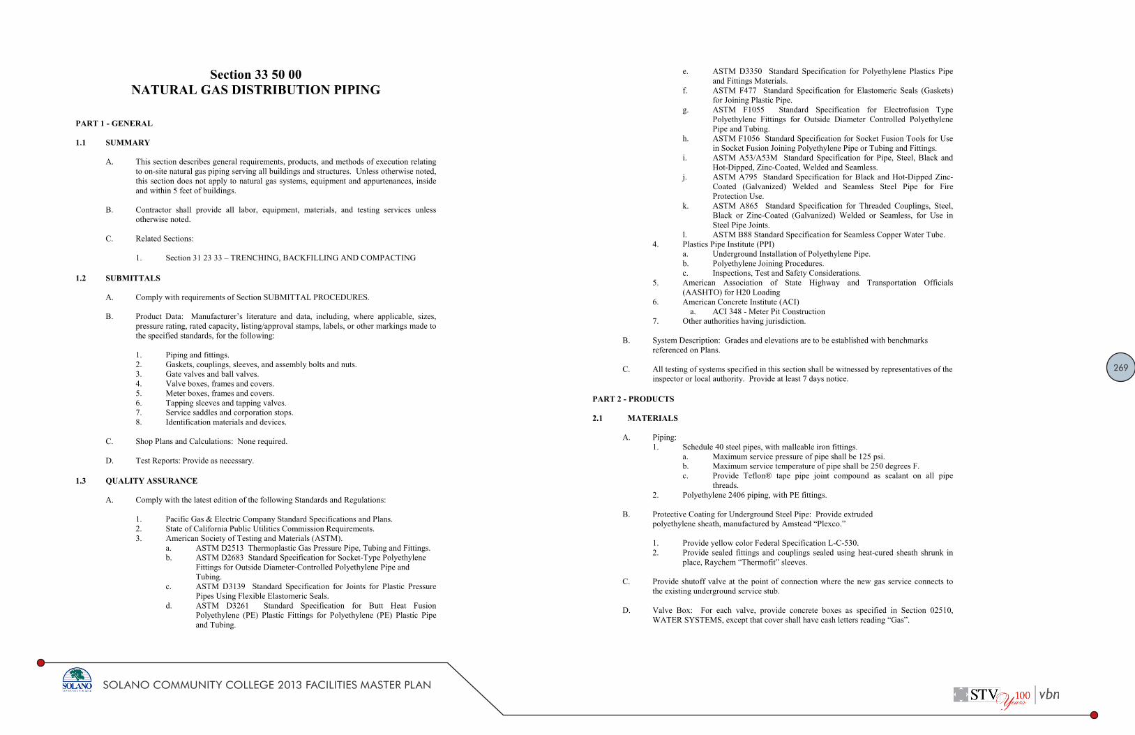
269
SOLANO COMMUNITY COLLEGE 2013 FACILITIES MASTER PLAN
Solano Community College District Natural Gas Distribution Piping
Month Day, Year 33 50 00 Page 1 of 4 Bid No. XXXXX V.[X] Name of Project
Section 33 50 00 NATURAL GAS DISTRIBUTION PIPING
PART 1 GENERAL 1.1 SUMMARY
A. This section describes general requirements, products, and methods of execution relating to onsite natural gas piping serving all buildings and structures. Unless otherwise noted, this section does not apply to natural gas systems, equipment and appurtenances, inside and within 5 feet of buildings.
B. Contractor shall provide all labor, equipment, materials, and testing services unless otherwise noted.
C. Related Sections:
1. Section 31 23 33 – TRENCHING, BACKFILLING AND COMPACTING
1.2 SUBMITTALS
A. Comply with requirements of Section SUBMITTAL PROCEDURES. B. Product Data: Manufacturer’s literature and data, including, where applicable, sizes,
pressure rating, rated capacity, listing/approval stamps, labels, or other markings made to the specified standards, for the following:
1. Piping and fittings. 2. Gaskets, couplings, sleeves, and assembly bolts and nuts. 3. Gate valves and ball valves. 4. Valve boxes, frames and covers. 5. Meter boxes, frames and covers. 6. Tapping sleeves and tapping valves. 7. Service saddles and corporation stops. 8. Identification materials and devices.
C. Shop Plans and Calculations: None required. D. Test Reports: Provide as necessary.
1.3 QUALITY ASSURANCE
A. Comply with the latest edition of the following Standards and Regulations:
1. Pacific Gas & Electric Company Standard Specifications and Plans. 2. State of California Public Utilities Commission Requirements. 3. American Society of Testing and Materials (ASTM). a. ASTM D2513 Thermoplastic Gas Pressure Pipe, Tubing and Fittings.
b. ASTM D2683 Standard Specification for SocketType Polyethylene Fittings for Outside DiameterControlled Polyethylene Pipe and Tubing.
c. ASTM D3139 Standard Specification for Joints for Plastic Pressure Pipes Using Flexible Elastomeric Seals.
d. ASTM D3261 Standard Specification for Butt Heat Fusion Polyethylene (PE) Plastic Fittings for Polyethylene (PE) Plastic Pipe and Tubing.
Solano Community College District Natural Gas Distribution Piping
Month Day, Year 33 50 00 Page 2 of 4 Bid No. XXXXX V.[X] Name of Project
e. ASTM D3350 Standard Specification for Polyethylene Plastics Pipe and Fittings Materials.
f. ASTM F477 Standard Specification for Elastomeric Seals (Gaskets) for Joining Plastic Pipe.
g. ASTM F1055 Standard Specification for Electrofusion Type Polyethylene Fittings for Outside Diameter Controlled Polyethylene Pipe and Tubing.
h. ASTM F1056 Standard Specification for Socket Fusion Tools for Use in Socket Fusion Joining Polyethylene Pipe or Tubing and Fittings.
i. ASTM A53/A53M Standard Specification for Pipe, Steel, Black and HotDipped, ZincCoated, Welded and Seamless.
j. ASTM A795 Standard Specification for Black and HotDipped ZincCoated (Galvanized) Welded and Seamless Steel Pipe for Fire Protection Use.
k. ASTM A865 Standard Specification for Threaded Couplings, Steel, Black or ZincCoated (Galvanized) Welded or Seamless, for Use in Steel Pipe Joints.
l. ASTM B88 Standard Specification for Seamless Copper Water Tube. 4. Plastics Pipe Institute (PPI)
a. Underground Installation of Polyethylene Pipe. b. Polyethylene Joining Procedures. c. Inspections, Test and Safety Considerations.
5. American Association of State Highway and Transportation Officials (AASHTO) for H20 Loading
6. American Concrete Institute (ACI) a. ACI 348 Meter Pit Construction
7. Other authorities having jurisdiction.
B. System Description: Grades and elevations are to be established with benchmarks referenced on Plans.
C. All testing of systems specified in this section shall be witnessed by representatives of the
inspector or local authority. Provide at least 7 days notice.
PART 2 PRODUCTS 2.1 MATERIALS A. Piping:
1. Schedule 40 steel pipes, with malleable iron fittings. a. Maximum service pressure of pipe shall be 125 psi. b. Maximum service temperature of pipe shall be 250 degrees F. c. Provide Teflon® tape pipe joint compound as sealant on all pipe
threads. 2. Polyethylene 2406 piping, with PE fittings.
B. Protective Coating for Underground Steel Pipe: Provide extruded polyethylene sheath, manufactured by Amstead “Plexco.”
1. Provide yellow color Federal Specification LC530. 2. Provide sealed fittings and couplings sealed using heatcured sheath shrunk in
place, Raychem “Thermofit” sleeves.
C. Provide shutoff valve at the point of connection where the new gas service connects to the existing underground service stub.
D. Valve Box: For each valve, provide concrete boxes as specified in Section 02510,
WATER SYSTEMS, except that cover shall have cash letters reading “Gas”.

270
SOLANO COMMUNITY COLLEGE 2013 FACILITIES MASTER PLAN
Solano Community College District Natural Gas Distribution Piping
Month Day, Year 33 50 00 Page 3 of 4 Bid No. XXXXX V.[X] Name of Project
E. Valves: Provide UL approved and listed ball valves with threaded ends and level handle.
1. Acceptable manufacturers: Worcester “EconoMiser” or HillsMcCanna. 2. Equivalent products will be considered when submitted in accordance with
“Substitutions” as specified in Section 01600 PRODUCT REQUIREMENTS.
F. Provide 2inch wide yellow warning tape reading “Caution Medium Pressure Gas Buried Below”.
2.2 MATERIALS
A. Polyethylene (PE) Pipe: All plastic pipe installed shall be medium density PE 2406 TR
418 “GAS” pipe manufactured in accordance with the latest listed edition of ASTM D2513. All pipes will be supplied in straight 40 feet lengths. All PEtoPE connections shall be Butt Fusion Type made in the presence of a qualified inspector.
B. Polyethylene (PE) Fittings: All plastic fittings shall be medium density PE 2406, TR418
“GAS” fittings manufactured in accordance with the latest listed edition of ASTM D2513 and ASTM D3261. All fittings shall have Butt End outlets.
C. Polyethylene (PE) Valves: All plastic valves shall be medium density PE 2406, TR418
“GAS” valves manufactured in accordance with the latest listed edition of ASTM D2513 and ASTM D3261. All valves shall have Butt End outlets.
D. Pipe Scratches or Cuts: Pipe that has scratches, notches, cuts or any other abrasions that
exceed 10% of the pipe wall thickness shall not be used on the project and shall be disposed of. The Contractor shall inspect all pipes and reject any pipe that has scratches exceeding 10% of the pipe wall thickness. The Contractor will be responsible for the cost of all defective or damaged pipe that he accepts, costs will be deducted from payments. The Contractor shall use pipe stands, spooling devices, or other means to avoid damaging the pipe during installation. The Contractor shall observe the pipe during installation for scratches, gouges or other defects. If defects are present, the Contractor shall remove and discard the damaged section of pipe.
E. Minimum Bending Radius: The minimum bend radius for plastic pipe is twenty times
the outer diameter. The Contractor shall not bend plastic pipe to a radius less than twenty times the outside diameter of the pipe. Fittings shall not be installed in pipe that is bent or curved to conform to trench dimensions.
F. Tracer Wire: Tracer wire shall be attached to the pipe with all nonmetallic electric tape
at intervals not exceeding 3 feet. All connections between tracer wires shall be made with the split bolt connectors and wrapped with electric tape. See Section 02315 for specifications of tracer wire.
PART 3 EXECUTION 3.1 EXAMINATION
A. Examine surfaces of site and work area for suitable conditions where gas service is be installed.
B. Do not begin installation until unsatisfactory conditions have been corrected.
Solano Community College District Natural Gas Distribution Piping
Month Day, Year 33 50 00 Page 4 of 4 Bid No. XXXXX V.[X] Name of Project
3.2 ABANDONMENT OF EXISTING UNDERGROUND PIPE
A. Existing gas pipe to be abandoned in place shall be capped at each end, evacuated of all natural gas, pressure tested per section 2.4B, and pressurized with nitrogen gas to a pressure not less than 5 PSIG.
3.3 INSTALLATION A. Provide protective covers having an extruded polyvinyl chloride outer coating
for underground pipe and fittings. 1. Provide “Thermofit” fitting sleeves shrunk in place over joints and fittings after
welding and testing of piping. 2. As an option, provide 2layer wrap of 3M No. 53, 10mil thickness tape.
B. Depth of Cover for Underground Piping: 2foot, 6inches minimum. C. Sand Encasement:
1. For protectivecoated pipe, provide 3inch minimum thickness of clean, washed and graded building sand.
2. Apply after all coatings have been finished. D. Installation shall conform to ANSI B31.8. E. Location of Service Piping: Service pipe shall enter building wall in areaway or
above ground. F. Provide backfill and compaction of trenches as specified in Section 02300
EARTHWORK AND GRADING. 3.4 FIELD QUALITY CONTROL A. Blowing Out Piping:
1. Blow out piping with air immediately prior to pressure testing. 2. The flow shall be a velocity of at least 100 feet per second. 3. Blow out piping for at least 20 minutes and continue until the effluent is clear
and contains no visible particulate matter. B. Field Tests:
1. Tests shall conform to requirements in ANSI B31.8; conduct tests prior to backfilling.
2. Air pressure test shall be at a pressure of 100 psig, duration 30 minutes minimum.
3. The Inspector of Record shall witness all field tests. 4. Conduct tests, providing labor, equipment and incidentals required for testing.
If any failure occurs during testing, provide replacements as directed by the Project Manager and repeat tests until satisfactory installation and operation are achieved.
C. May conduct and provide report of 12,000V Tinker Riser Test.
End of Document

271
SOLANO COMMUNITY COLLEGE 2013 FACILITIES MASTER PLAN
DESIGN STANDARD Solano Community College District Division 27 00 00
1 1.31.2014
DESIGN STANDARD FOR TELECOMMUNICATIONS Purpose:
The purpose of this document is to standardize the basic elements of the telecommunications systems design process. The design standard has the purpose of creating a consistent application of telecommunications systems design throughout the Solano Community College (SCC) District, therefore achieving a standard of quality for maintenance and reliability throughout all renovation and new building projects. This standard serves as a supporting document part of the overall Solano Community College Technology Plan (2013‐2015). Deviations from this standard shall be approved by SCC.
Telecommunications Systems‐Related Support Staff and Committees: Chief Technology Officer Director, Technology Services & Support Desktop Services Network Services The Strategic Technology Advisory Committee (STAC) Design Standard:
I. TELECOM IDF/MDF ROOMS
A. Minimum size of the IDF is to be 8’ x 9’.
B. Minimum size of the MDF is to be 10’ x 13’ and shall not be co‐located with electrical equipment due to EMI‐mechanical noise transmitted from the electrical equipment.
C. IDF should have a hard ceiling for security purposes.
D. IDF/MDF rooms should not have any water sprinklers in the room.
E. Room must be well lit. Lighting fixtures shall be coordinated with any horizontal cable tray or other ceiling mounted equipment.
F. No equipment other than that related to the voice/data network should be located in the IDF’s/MDF’s. This includes but not limited to FACP, lighting control equipment, electrical panels, EMS, etc.
G. Regular 110v receptacles should be located at standard locations around the room.
DESIGN STANDARD Solano Community College District Division 27 00 00
2 1.31.2014
H. Some form of standalone air conditioning must be provided to adequately cool the space when fully equipped. Cooling capacity shall be calculated taking into account all equipment planned for the room. Rooms should not be on building Air system. Wall or floor mounted AC equipment preferred. In no case shall AC equipment be located above IT equipment racks. Roof mounted package units are also acceptable for single story buildings or IDF Rooms located on the top floor of a multi-storied building.
I. There should be 3’ of clear space on all 4 sides of the 2’ x 3.25’ cabinet. If necessary for placement of an additional cabinet or future placement of an additional cabinet this requirement can be modified to 3’ of clear space in the front, rear and one side of the cabinet.
J. Access to IDF/MDF to be by electronic key card or keypad, and only Technology Services & Support staff is to be issued access cards or codes. In cases where an IDF is shared with Maintenance & Operation (M&O), only essential M&O staff is to have access to the IDF/MDF (i.e. Engineers, Director, and Assistant Director). Before issuing an access card or code to anyone for any IDF/MDF the Director of Technology Services & Support must be consulted.
K. Where possible, doors to the IDF/MDF should not have windows or signage other than room numbers (for security purposes). If IDF/MDF doors must have windows, windows are to be blacked out.
L. A phone is to be located on one wall of the IDF/MDF room, typically on the door wall.
II. CABINETS
A. Refer to the document SCC – TSS Telecommunications Cabling Materials List for standard cabinet models and accessories (fan kit).
B. Secure cabinet(s) to floor utilizing CPI brackets and drop‐in anchors.
C. Secure top of cabinet(s) utilizing appropriate size ladder rack attached to cabinet with CPI elevation kits.
D. Install CPI vertical wire managers and fan‐kits to cabinet. Fans shall be connected to power and operational.
E. Install cabinet provided vertical wire management @ rear of cabinet.
F. Install square punched rails in cabinet; contractor to provide necessary cage nuts and mounting screws for all equipment being installed in rack.
G. Install hardware in cabinet based on 1. = top U holes:
1. Fiber LIU (with single‐mode fiber terminated first left to right and then followed by MM). LIU shall be installed in the top 1U of the cabinet
2. Wire management shall be installed on the sides of the patch panels as well as between each Data/Voice patch panel
Telecomm Standards

272
SOLANO COMMUNITY COLLEGE 2013 FACILITIES MASTER PLAN
DESIGN STANDARD Solano Community College District Division 27 00 00
3 1.31.2014
3. Data patch panel(s) shall be KRONE CAT 6 and 568B compliant
4. Copper cable (CAT3) terminated on patch panel. All data patch panels shall be terminatedfirst, and then the CAT 3 cable shall be terminated on a voice patch panel at the end of thedata patch panel sequence. There shall be one pair per port (termination on the White/Bluepair for voice) with the Violet/Slate pair un‐terminated and left as a spare.
5. District supplied network switches
6. District supplied UPS
7. District supplied PDU (extra outlets for equipment)
H. Two dedicated electrical outlets (30 amp w/L5-30R receptacles) to be installed inside the top of each rack, near the back.
I. Customer provided UPS power cord will be run from UPS on floor of cabinet through rear vertical wire manager to electrical outlet.
III. BACKBOARD LAY‐OUT
A. Refer to the document SCC – TSS Telecommunications Cabling Materials List for standardcabling materials.
B. Backboard: 4’ X 8’ X 3/4” plywood should be installed on only one wall (to be determined bycabinet position)
C. Backboard shall be installed starting 4” above the finished floor, shall be fire‐rated plywoodpainted white. Fire rated sticker shall not be painted over.
D. Copper feed cable is to be terminated in appropriate sized protected terminal (50pr, 100pr etc.).Terminal is to be grounded to bus bar.
E. CAT3 copper cable to be terminated on “out” of protected terminal to patch panel in cabinet.(routed overhead on ladder rack)
IV. CABLING & CABLE ROUTING
A. Refer to the document SCC – TSS Telecommunications Cabling Materials List for standardcabling materials.
B. All drop cables routed into MDF/IDF to be installed through appropriate sized sleeves withbushings.
C. All drop cables to be “split out” by number (ie; 1‐12, 13‐24) and brought into cabinet onopposing sides of patch panel.
DESIGN STANDARD Solano Community College District Division 27 00 00
4 1.31.2014
D. All cables will be tested for compliance (using MicroTek or similar device) with results provided to district in printed and in an electronic form acceptable to the district.
E. All ladder rack to be grounded to provided bus bar.
F. Labeling standard is Room#‐drop (i.e. 128‐10) number starting in left corner of room and moving clockwise around room. Drops number are sequential from room to room (i.e. 128‐20, 129‐21, etc.).
G. All cables to be terminated 568B.
H. All phone connectivity is to be VOIP with all cables to be ADC blue CAT6.
I. Customer/Architect to determine PVC vs. plenum rated cable.
J. ADC faceplate and jack insert color is typically Ivory.
K. Cable numbering to be determined by sequence: floor, closet #, drop number. Two drop locations to be labeled 1/2 and three plus drop locations to be labeled 1‐3. Example: 1st floor closet # 1 would read: 1.1.1/2 or 1.1.1‐3.
L. All fiber required to be extended shall match existing hybrid fiber count.
M. All fiber will be tested using OTDR with results provided to district in printed and in an electronic form acceptable to the district.
N. Extended fiber shall be fusion spliced in approved fiber splice case.
O. Single mode patch cords are to be installed from fiber LIU to fire panel. Alarm vendor will plug in @ panel.
P. Copper cable required to be extended can “splice thru” on A110 blocks.
Q. All cabling should be routed according to industry standards and supported in cable hangers or cable trays.
R. Cable hangers will not be attached to ceiling tie wires. The first choice by cabling vendor will be to install their own wires or wall mount hangers. Where this is not possible due to existing conditions, there may be existing wires that are unattached to the grid or utilized for other mechanical support that can be utilized.
S. Industry standards apply to fire stop installation and will be dictated by field conditions.
T. Phones are to be co‐located with data and terminated on patch panel in cabinet

273
SOLANO COMMUNITY COLLEGE 2013 FACILITIES MASTER PLAN
DESIGN STANDARD Solano Community College District Division 27 00 00
5 1.31.2014
U. Need data runs for HVAC (copper) and fire alarms (fiber). A cat 6 drop must be placed near the HVAC controller. A fiber patch cable must be run in conduit from the FACP location to the IDF.
V. Standard is Cat6 cabling
W. Cabinet as well as station patch cords are to be provided by contractor in lengths and quantities as specified by customer (usually the number of ports terminated for cabinet quantity– 3’& 7’ lengths).
X. Standard drop count for an employee work location is 3 drops. Standard drop count for a student station is 1 drop plus 1 printer drop for every 20 computers.
Y. Standard materials are to be used as listed on the Solano Community College ‐ Technology Services & Support Telecommunications Cabling Materials List.
Z. All building projects must include above ceiling cabling for installation of PoE wireless access points.
AA. Electronic and printed forms of as built drawings must be provided to IT.
BB. All newly installed cabling must be tested and performance test results shall be submitted to SCC IT.
V. WIRELESS NETWORK
A. All building projects must include installation of wireless access points to cover the interior of the building (location diagram will be supplied by district).
B. All interior wireless access points are Power over Ethernet (PoE) and therefore DO NOT require a power receptacle to be placed near the access point device.
C. All exterior wireless access points have an external antenna and the device MAY REQUIRE a power receptacle to be located in close proximity to the device. Coordinate requirements with SCC IT.
D. Wireless access points require a Cat6 cable terminated with an RJ45 connector in a biscuit box to be located per the district supplied drawings and routed to the IDF/MDF. Every effort should be made to keep the wireless access point cables to be terminated in a group on the patch panel and clearly identified. Cabling and termination is vendor supplied (i.e. patch panels, biscuit box, etc.).
E. Access points are to be mounted per manufacturer supplied instructions and are generally surface mounted on the ceiling at district specified locations. Actual placement can vary slightly depending on conditions at the specified locations.
DESIGN STANDARD Solano Community College District Division 27 00 00
6 1.31.2014
F. All cabling to access points are to be tested per industry standards.
G. All wireless access points are district supplied/contractor installed.
VI. PHONES
A. All phones are to be VoIP phones except where analog lines are necessary (i.e. emergency phones, fax lines, etc.).
B. District standard VoIP phones are CISCO brand.
C. All VoIP phones plug into CISCO PoE (Power over Ethernet) switches.
D. Lines for emergency equipment (emergency phones, fire alarms, security alarms, etc.) are to be 1MB’s provided by the district’s Telco carrier and NOT part of the district phone system.
E. Each building is to have wall mounted courtesy/emergency phones in each hallway.
VII. ACCESS TO TELECOM SPACES
A. Contractors shall contact SCC IT for proper badging and access to telecom spaces. Request for access shall be submitted in writing and follow the District’s guidelines and procedures.
Typical IDF Room Layout

274
SOLANO COMMUNITY COLLEGE 2013 FACILITIES MASTER PLAN
DESIGN STANDARD Solano Community College District Division 27 00 00
7 1.31.2014
Approved Manufacturers:
Equipment Racks and Cabinets:
1. Middle Atlantic Products
2. CPI – Chatsworth Products
3. Panduit
Wireless Access Points:
1. Refer to SCC IT for list of approved manufacturers
Copper Patch Panels:
1. Panduit
2. Siemen
Fiber Patch Panels:
1. Panduit
2. Siemen
Category Cable / Patch Cords:
1. General Cable
2. Mohawk
3. Berk‐Tek
Fiber Cable / Patch Chords:
1. General Cable
2. Mohawk
3. Berk‐Tek
Wire Managers:
1. Middle Atlantic Products
2. CPI – Chatsworth Products
DESIGN STANDARD Solano Community College District Division 27 00 00
8 1.31.2014
3. Panduit
Ladder Rack / Cable Tray:
2. Refer to SCC IT for list of approved manufacturers
Substitutes Allowed:
All substitutions must be approved by SCC IT. Requests for substitutions must be submitted in writing prior to design, purchase, and installation.
Associated Design Standards and Construction Specifications
Standards EIA/TIA‐568 Commercial Building Telecommunications Wiring Standard TIA‐569 Telecommunications Pathways and Spaces TIA‐607 Generic Telecommunications Bonding and Grounding for Customer Premises TIA‐942 Telecommunications Infrastructure Standard for Data Centers ANSI/NECA/BICSO‐56‐2006 Standard for Installing Commercial Building Telecommunications Cabling ANSI/NECA/BISCI‐607 Telecommunications Bonding and grounding Planning and Installation Methods for Commercial Buildings ANSI/BICSI‐002 Data Center Design Standard and Recommended Practices Specifications 270500 COMMON WORK RESULTS FOR COMMUNICATIONS 271100 COMMUNICATIONS EQUIPMENT ROOM FITTINGS 271300 COMMUNICATIONS BACKBONE CABLING 271500 COMMUNICATIONS HORIZONTAL CABLING

275
SOLANO COMMUNITY COLLEGE 2013 FACILITIES MASTER PLAN
DESIGN STANDARD Solano Community College District Division 27 00 00
1 1.17.2018
DESIGN STANDARD FOR AUDIOVISUAL SYSTEMS General:
Solano Community College (SCC) is intent on moving to 21st century unified communications and data systems, consistent with industry standards and best practices as they evolve. To that end all SCC Audio/Visual (AV) will be digital (unless laws or codes specify otherwise) and/or will be digitally controlled through an enterprise management system, and be tightly integrated into the data components of the SCC Technology plan.
Purpose:
The purpose of this document is to standardize the basic elements of the audiovisual systems design process, and to guide AV to the integrated solutions envisioned above. This Design Standard has the purpose of creating a consistent application of AV systems design throughout the Solano Community College District, therefore achieving a standard of quality for maintenance and reliability throughout all renovation and new building projects. This standard serves as a supporting document to the Solano Community College Technology Plan. Any deviations from this standard must be approved by SCC Information Technology (IT) Management.
Background of Audiovisual Systems within the District:
Audiovisual Systems cover both instructional and informational AV technology. Instructional AV technology covers systems that support teaching, learning, and research. Students and staff members use this technology in pursuit of the College’s educational goals. Informational AV technology covers the digital signage systems deployed around the College. Students and staff members use this technology to share content with the different audiences that may occupy the spaces within the College.
For the purposes of this document the instructional AV technology will be referred to as AUDIOVISUAL SYSTEMS. Informational AV technology will be referred to as DIGITAL SIGNAGE SYSTEMS.
Audiovisual Systems‐Related Support Staff and Committees: Chief Technology Officer Director, Technology Services & Support Desktop Services Network Services Strategic Technology Advisory Committee (STAC)
DESIGN STANDARD Solano Community College District Division 27 00 00
2 1.17.2018
Design Standard: Smart Classroom General Descriptions Audio/Video (A/V) Cabinet:
Located next to wall adjacent to teaching wall 5' from teaching wall corner. 2” Conduit from ceiling to a recessed A/V wall plate behind A/V cabinet location. Refer to Page 4 of this document for conceptual drawing In certain situations, the room configuration may dictate the elimination or repositioning of the A/V
Cabinet. Elimination/Repositioning of cabinet must be coordinated with SCC IT Management. Equipment purchase, cabinet construction and installation to be accomplished by SCC IT.
Lighting:
Shall be coordinated for appropriate levels related to room functions. Lighting controls, if control system is installed, can be controlled via the District’s A/V control system. Lighting controls must be configured so that lights directly over the teaching wall can be dimmed or
turned off independently of the other lights in the room for maximum viewing capability. Industry standards and guidelines shall be followed. Refer to Codes & Standards section of this document for a list of related standards.
Power requirements:
(1) Single gang dual power outlet above the ceiling at the projector location or behind TV in a recessed box.
(2) Single gang dual power outlets at the A/V cabinet. (1) to be at the table top height of Cabinet and (1) below/behind cabinet, within a recessed box.
Refer to Page 4 of this document for conceptual drawing Data requirements:
(1) 4‐port wall jack, in a recessed box, below/behind cabinet next the single gang power outlet noted above.
Data cables to be run to IDF/MDF within the building Data ports should be labeled as per the District labeling standard detailed in the SCC Telecom
Standards Guideline. (2) Cat 6 (shielded) to be run and terminated from a wall jack, within a recessed box, located next to the 4‐
port data plate at the smart cabinet location to the Projector/TV location. Refer to Page 4 of this document for conceptual drawing.
Audio requirements:
(2) Audio wires (proper gauge for installed speakers) to be run from AV wall plate, within a recessed box, at the smart cabinet location to the speaker locations within the room. Consult with district IT for location of speakers. Note: Audio terminations at wall plate to be coordinated with District IT.
Refer to Page 4 of this document for conceptual drawing
Audio Visual Standards

276
SOLANO COMMUNITY COLLEGE 2013 FACILITIES MASTER PLAN
DESIGN STANDARD Solano Community College District Division 27 00 00
3 1.17.2018
Projection screens:
May be motorized or manual roll up and shall be sized appropriately for the room size and desired coverage areas.
Motorized screens shall be used in areas in which the screen sizes are larger than 12 ft., typically Large Lecture, Multipurpose rooms and Cafeterias.
Motorized screens to be programmed and controlled via the A/V control console if possible. Smaller screens shall be manual roll up. Screens are to be centered on teaching wall mounted no more than 6” below the ceiling (in rooms with
normal ceiling heights). Screens to be purchased by District IT and installed by A/V contractors.
Screen mounts:
Must have backing of sufficient size to support size of screen. Mounts to be purchased by District IT and installed by A/V contractors.
Projectors:
Shall be industry standard High Definition, with HDMI and Internet Protocol (IP) input, native 16:9 format. Mounted at an appropriate distance from screen so as to take up as much screen space as possible.
Coordinate with District IT prior to mounting. Projector mount may have to be offset 3.5” right of screen as viewed from the screen location to
accommodate for the offset of the projector lens (If Lens is not center of projector). Coordinate with District IT prior to installation.
Care should be taken to NOT place anything in the projection path (i.e. lights, art work hangers etc.) Projectors to be purchased by District IT and installed by A/V contractors.
Television: Industry standards should be followed when determining the correct size of the room. The chart below
can assist with determining screen size. A/V Consultant in conjunction with District IT will determine appropriate size for room.
DESIGN STANDARD Solano Community College District Division 27 00 00
4 1.17.2018
Television: (cont) Proper backing for the TV must be installed for TV locations. TV’s should at a minimum have (3) HDMI and (1) RS‐232 connections. Power and Data locations to be within a recessed box and above TV Mount and behind TV. Consult with
District IT on location. Tilted Mounts shall be installed as to allow easy access to TV Inputs and Controls. TV’s and Mounts to be purchased by District IT and installed by A/V contractors.
Visual Layout of Smart Classroom
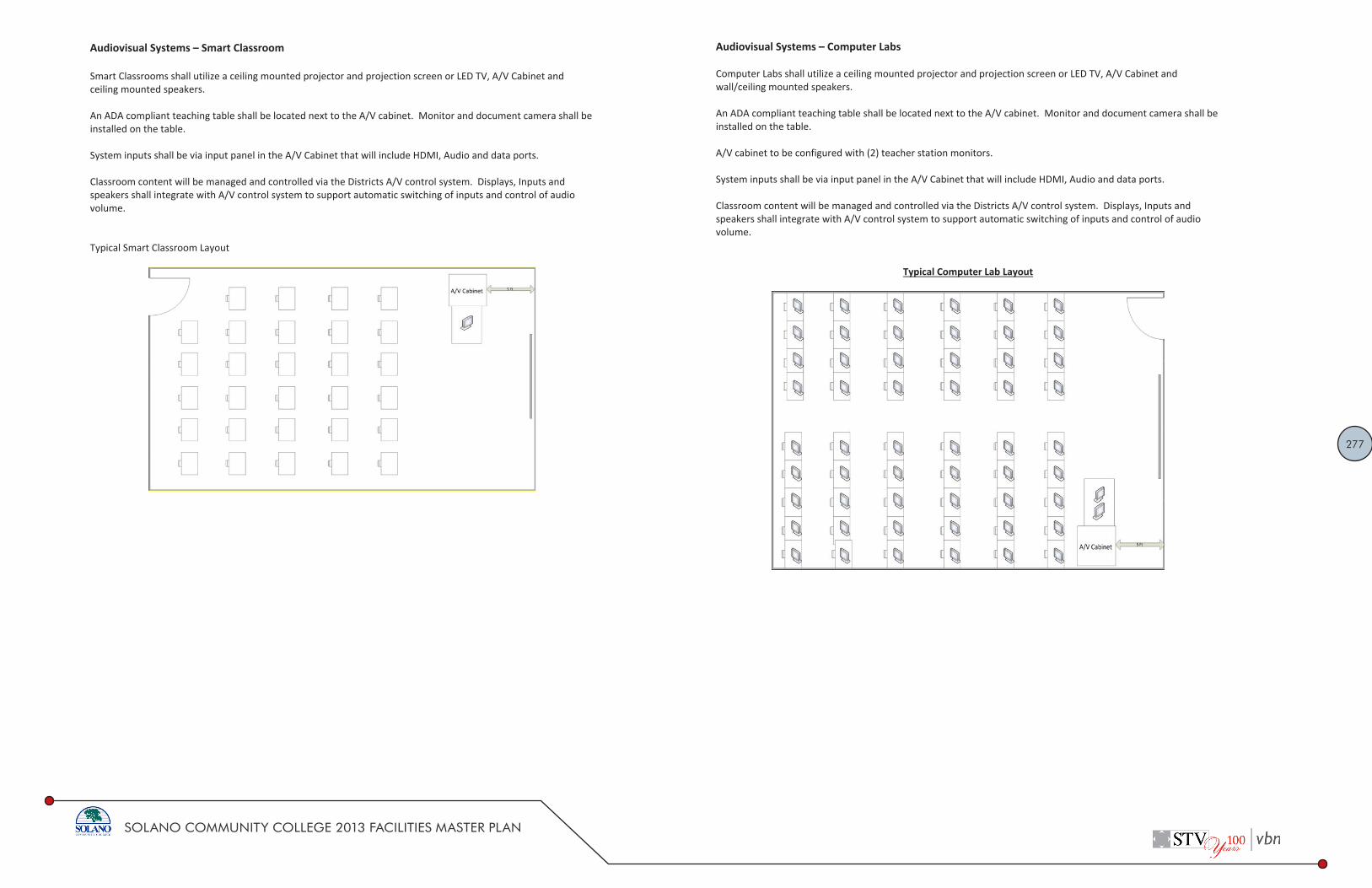
277
SOLANO COMMUNITY COLLEGE 2013 FACILITIES MASTER PLAN
DESIGN STANDARD Solano Community College District Division 27 00 00
5 1.17.2018
Audiovisual Systems – Smart Classroom Smart Classrooms shall utilize a ceiling mounted projector and projection screen or LED TV, A/V Cabinet and ceiling mounted speakers. An ADA compliant teaching table shall be located next to the A/V cabinet. Monitor and document camera shall be installed on the table. System inputs shall be via input panel in the A/V Cabinet that will include HDMI, Audio and data ports. Classroom content will be managed and controlled via the Districts A/V control system. Displays, Inputs and speakers shall integrate with A/V control system to support automatic switching of inputs and control of audio volume. Typical Smart Classroom Layout
DESIGN STANDARD Solano Community College District Division 27 00 00
6 1.17.2018
Audiovisual Systems – Computer Labs Computer Labs shall utilize a ceiling mounted projector and projection screen or LED TV, A/V Cabinet and wall/ceiling mounted speakers. An ADA compliant teaching table shall be located next to the A/V cabinet. Monitor and document camera shall be installed on the table. A/V cabinet to be configured with (2) teacher station monitors. System inputs shall be via input panel in the A/V Cabinet that will include HDMI, Audio and data ports. Classroom content will be managed and controlled via the Districts A/V control system. Displays, Inputs and speakers shall integrate with A/V control system to support automatic switching of inputs and control of audio volume.
Typical Computer Lab Layout

278
SOLANO COMMUNITY COLLEGE 2013 FACILITIES MASTER PLAN
DESIGN STANDARD Solano Community College District Division 27 00 00
7 1.17.2018
Audiovisual Systems – Conference Rooms Conference Rooms shall utilize single wall mounted LED flat panel display sized accordingly for video content presentation. Size of flat panel display shall be determined by using the minimum display dimension formulas illustrated in Figure 1.
Figure 1: Minimum display dimensions shall be calculated using the coverage area formulas represented above. Acceptable coverage area begins at the green dashed circle, which is calculated by obtaining the height of the display and multiplying it by 1.5. Alternatively, one could obtain the desired minimum coverage area and divide this by 1.5. Similarly, the blue and red dashed circles represent the optimal coverage areas for text and video images, respectively.
Power requirements: (1) Single gang dual power outlet, within recessed box, to be installed above TV mount/behind the LED
display. Data requirements:
(1) 2‐port wall jack, within recessed box, behind LED display. (1) 2‐Port data jack to be installed within the cable cubby or input panel on display wall.
Data cables to be run to IDF/MDF within the building Data ports should be labeled as per the District labeling standard detailed in the SCC Telecom
Standards Guideline.
DESIGN STANDARD Solano Community College District Division 27 00 00
8 1.17.2018
Audio/Video requirements:
(2) HDMI Cables run from Input Panels (either Cable cubby or Display Wall) to TV‐HDMI inputs. Ceiling mounted speakers may be installed to provide the best sound throughout the conference room.
Coordinate with District IT to determine if speakers are needed. Tilted Mount shall be installed to provide easy access to display inputs and controls wherever possible
Lighting shall be coordinated for appropriate levels related to room functions. Industry standards and guidelines shall be followed. Refer to Codes & Standards section of this document for a list of related standards.
Typical Conference Room Layout
Note: Larger conference rooms may require the addition of multiple cable cubbies to provide Data and Power outlets only. Coordinate number and location of additional cubbies with SCC IT.

279
SOLANO COMMUNITY COLLEGE 2013 FACILITIES MASTER PLAN
DESIGN STANDARD Solano Community College District Division 27 00 00
9 1.17.2018
Digital Signage Systems Digital signage content shall be displayed via LED flat panel displays sized accordingly for this application. Size of flat panel display shall be determined by using the minimum display dimension formulas illustrated in Figure 1. Digital signage is found typically in Lounges and public spaces, but may be required in specialty areas as well. Power requirements: (1) Single gang dual power outlet, within recessed box, installed above TV mount/behind the LED display.
Data requirements:
(1) 2‐port wall jack, within recessed box, installed above TV mount/behind LED display. Data cables to be run to IDF/MDF within the building Data ports should be labeled as per the District labeling standard detailed in the SCC Telecom
Standards Guideline.
Audio/Video requirements: Tilted Mount shall be installed to provide easy access to display inputs and controls wherever possible TV should be mounted on wall so as to permit optimal viewing and is to be secured to the mount to
prevent easy theft. If deployed in outdoor or unmonitored public areas consideration should be given to anti‐vandalism
measures including cabinets with toughened Macaralon type screen protection. Content will be managed and controlled by the districts content management system
Coordinate all power/data and installation requirements with SCC IT prior to installing. Refer to Codes & Standards section of this document for a list of related standards.
DESIGN STANDARD Solano Community College District Division 27 00 00
10 1.17.2018
Preferred Manufacturers: LED Flat Panel Displays:
1. Samsung 2. Sharp 3. NEC 4. Other as approved by IT
Video Projectors:
1. Panasonic 2. Hitachi 3. Epson 4. Other as approved by IT
Equipment purchases will be by District IT department. Certain circumstances may dictate vendor purchase (specialty/Nonstandard classroom equipment) If contractor purchased, a complete Equipment lists/Bill of Materials must be approved by SCC Technology Services Management prior to purchase. Purchases must follow the Technology Purchases policy of Solano Community College. Substitutes Allowed:
All substitutions must be approved by SCC IT Management. Requests for substitutions must be submitted in writing prior to design, purchase, and installation. Associated Design Standards and Construction Specifications Codes and Standards: ANSI/INFOCOMM 1M‐2009 Audio Coverage Uniformity in Enclosed Listener Areas ANSI/INFOCOMM 2M‐2010 Standard Guide for Audiovisual Systems Design and Coordination Processes ANSI/INFOCOMM 3M‐2011 Projected Image System Contrast Ratio
Construction Specifications: 274100 Audiovisual Systems 274200 Digital Signage Systems

280
SOLANO COMMUNITY COLLEGE 2013 FACILITIES MASTER PLAN
DESIGN STANDARD Solano Community College District Division 27 00 00
DESIGN STANDARD FOR CLOCKS Purpose:
The purpose of this design standard is to standardize the clocks and clock systems used through-out the District's facilities, ensuring synchronized time, reliability, and consistent maintenance requirements and aesthetic qualities through-out the District.
Design Standard:
• Provide and install in each classroom, lab or teaching space. Install as needed in other offices or spaces in District facilities.
• Clocks to be battery model with remote antenna, wireless, draw time from GPS satellite, automatically adjust for Daylight Savings Time.
• Clocks to be 12.5” diameter, easy to read white clock face, with durable black frame and clear lens.
• Transmitters to be 1‐watt, 5‐watt, or 30‐watt with internal or external antenna as needed; utilize 72MHz frequency: preferably installed indoors.
Approved Manufacturers:
Primex; clock model 14244.
Substitutions Allowed:
None.
Associated Design Standards and Construction Specifications:
Install per manufacturer’s specifications. .
1 1.17.2018
DESIGN STANDARD FOR ASSISTIVE LISTENING SYSTEM Purpose: The purpose of this Standard is to ensure consistency in the provision of assistive listening devices through‐out the District for convenience of users, and service/maintenance by the District.
Design Standard: The assisted listening system shall be a Frequency Modulated Radio Transmission system assigned by the FCC exclusively for low power assistive listening systems. The system shall consist of rack‐mounted transmitter, portable receivers, antenna and earphones. All equipment shall be standard catalogued products of a single manufacturer. System and components shall comply with CBC code requirements for same. Stationary Transmitter
Stationary FM transmitter capable of broadcasting on 57 channels SNR of 80 dB or greater Output power adjustable to quarter, half, or full Channel tuning capable of being locked Capable of broadcasting o both wide and narrow band channels Audio frequency responses of 50 Hz to 15k Hz, + 3 dB at 72 MHz; or of 50 Hz to 10k Hz, + dB at
72 MHz Two mixing audio inputs. Audio processor that is capable of automatic gain control and limiting. Listen Technologies model LT‐800‐072‐01; or Williams Sound model T45 Rack mount kit: Listen Technologies model LA‐326; or Williams Sound model RPK 005
Portable Receivers
Capable of receiving on 57 wide band channels with a SNR of 80dB or greater Capable of being locked on a single channel Capable of seeking channels Adjustable squelch Audio frequency response of 50 Hz to 15 KHz, + 3 dB Stereo headset jack that allows user to plug in either a mono or stereo headset LCD display that indicates channel, battery level, low battery, battery charging, and RF signal
strength Function in both DX and Local mode Operate off of 2 AA batteries. Include automatic battery charging circuitry for recharging of
NiMH batteries. Listen Technologies model LR‐400‐072; or Williams Sound model R38
Receiver Accessories

281
SOLANO COMMUNITY COLLEGE 2013 FACILITIES MASTER PLAN
Charging carrying case for up to 8 units: Listen Technologies model LA‐324; or Williams Sound model CHG 3512 PRO
Ear speakers (per receiver): Listen Technologies model LA‐164; or Williams Sound model EAR 022
Neck loop that wirelessly connects to hearing aids equipped with a “T” coil: Listen Technologies LA‐166; or Williams Sound model NKL 001
NiMH rechargeable batteries: Listen Technologies model LA‐362; or Williams Sound model BAT 026‐2
Remote Antenna
Able to transmit signals at 72 Mhz Mounted to a BNC wall plate: Listen Technologies LA‐123; or Williams Sound model ANT 028 RG58 coax cables with BNC connectors, length as required
Wall Plaque
Sign(s) indicating equipment available for the hearing impaired per ADA requirements. May be provided by signage Vendor or equipment Vendor.
Listen Technologies LA‐304 ADA Access Compliance signage kit; or Williams Sounds IDP 008
Approved Manufacturers: Listen Technologies Williams Sound
Substitutes Allowed: No substitutions allowed. (Reviewers, confirm this is College DSTM standard).
Associated Design Standards and Construction Specifications: End of Document

282
SOLANO COMMUNITY COLLEGE 2013 FACILITIES MASTER PLAN
Electronic Safety & Security StandardsDESIGN STANDARD Solano Community College District Division 28 00 00
1 1.31.2014
DESIGN STANDARD FOR ELECTRONIC SAFETY AND SECURITY
Purpose
The purpose of this document is to standardize the basic elements of the Electronic Safety and Security systems design process. The Design Standard has the purpose of creating a consistent application of Electronic Safety and Security systems design throughout the Solano Community College (SCC) District, therefore achieving a standard of quality for maintenance and reliability throughout all renovation and new building projects. Deviations from this standard shall be approved by SCC.
Abbreviations
• SSA – Security Sensitive Areas
• P&P’s – Policies & Procedures
• LED – Light Emitting Diode (type of lighting with preferable heat generation and energyconsumption characteristics over traditional incandescent luminaires)
• PV – Photovoltaic (solar panels)
• EMNS – Emergency Mass Notification Systems
• PA – Public Address (overhead speakers)
• AV – Audiovisual
• LAN – Local Area Network (IP network based Ethernet data network)
• IDS – Intrusion Detection System (burglar alarm)
• PIN code – Personal Identification Number (numerical code entered on arming station keypad toarm or disarm an Intrusion Detection System)
• ARM – arming station keypad used to arm or disarm an Intrusion Detection System
• MD – Motion Detector (intrusion detection sensor)
• EACS – Electronic Access Control System
• ACP – Access Control Panel
• CCTV – Closed Circuit Television (older, traditional term for analog video surveillance system)
• VMS – Video Management System (newer term for IP network based video surveillance system)
• NVR – Network Video Recorder
• PTZ – Pan Tilt Zoom video surveillance camera (remotely operable in lieu of fixed)
DESIGN STANDARD Solano Community College District Division 28 00 00
4 1.31.2014
Design Standard—Security Systems Ownership An effective security program requires comprehensive administrative and operational planning, direction, oversight, and control. With regard to security electronics systems – including electronic access control, video surveillance, intrusion detection, and emergency communications – the “ownership” of the security systems by various associated parties must be clarified, codified in policy, assigned, and accepted.
There are 4 primary parties that must be assigned and must accept responsibility and accountability for various functions of service and maintenance as well as daily operation of the security systems. Importantly, such accountability cannot be reasonably and successfully assigned unless the associated party is also granted the authority, staffing, and funding to carry out the responsibility.
SCC Executive Leadership
1. Provides the authority, authorization, oversight, and funding for systems deployment and use, unless otherwise specified in the Standards.
2. Issues Policies & Procedures.
3. Determines the appropriate end-users of the system from both law enforcement professional security personnel and departmental staff personnel.
4. Coordinates the functional and operational system requirements between Academic and departmental representatives.
SCC IT
1. Provides network connectivity and support.
2. May provide computing hardware such as servers and computer workstations for use by theSecurity Systems Contractor/Integrator.
3. Ensures appropriate network security, firewalls, and encryption issues are addressed anddocumented.
4. Maintains scheduled maintenance of security systems software versions, licenses, and firmware(when such activities are not outsourced to the Security Systems Contractor/Integrator).
5. Maintains scheduled maintenance of security systems hardware operating system, antivirussoftware, utilities, and system activity logs.
6. Coordinates authorized login UserID and passwords with the network domain identity structure.

283
SOLANO COMMUNITY COLLEGE 2013 FACILITIES MASTER PLAN
DESIGN STANDARD Solano Community College District Division 28 00 00
5 1.31.2014
Security Systems Contractor/Integrator
1. Provides, installs, programs, configures, and tests the security systems hardware and software.
2. Warrants the installation for one year from date of project substantial completion.
3. May be engaged under contract to provide extended warranty including work order service andpreventative maintenance beyond the one year project warranty.
4. This role may be filled by one or more contractors.
SCC Engineering & Plant Ops
1. Provides, installs, programs, configures, and tests the security systems hardware and softwareas needed above and beyond the scope of the Security Systems Contractor/Integrator and whenthe Security Systems Contractor/Integrator is no longer under contract.
2. Provides, installs, and maintains door/frame assemblies and electrified locking door hardware.
3. Maintains traditional physical keying system with documented issuance and retrieval audit logs.
4. Provides the lead role in coordinating the efforts of the Security Systems Contractor/Integratorwith SCC Executive Leadership, IT, project design team, and the work of other trades andcontractors.
Design Standard—Electronic Access Control System (EACS) Refer to Addendum ‘A’ at the end of this document for the Electronic Access Control System Standard.
Design standards ensure that Electronic Access Control System installations, retrofits, replacements, and upgrades maintain system consistency and compatibility – regardless of project timing or funding source. These EACS Standards also support a single system database to avoid redundancy, duplication, and error, facilitate system administrator training and back-up, facilitate service and maintenance, and act as a record document that can be periodically updated to reflect new developments and requirements.
System Criteria
1. SCC will deploy a single standardized, centralized, and compatible Electronic Access Control System at all campuses
2. System will primarily consist of card readers, keypads, electrified locking door hardware, alarm contacts, request-to-exit (REX) sensors and access control server hardware/software
3. System will secondarily consist of wireless locksets which communicate with the centralized access control server hardware/software
4. Electrified locking door hardware should be hardwired for low-voltage power
Design Standard – Electronic Access Control System (EACS) and Door Lock-Down Design Standards ensure that Electronic Access Control System and Door Lock-Down installations, retrofits, replacements, and upgrades maintain system consistency and compatibility – regardless of project timing or funding source. These Standards also support a single system database to avoid redundancy, duplication, and error, facilitate system administrator training and back-up, facilitate service and maintenance, and act as a record document that can be periodically updated to reflect new developments and requirements. The District has established Stanley WI-Q/Omni Wireless Access Control System as the District Standard for door access and lock-down, and utilizes it at all District campuses and facilities.
• Include electronic door control in the door hardware specification and procure under the door hardware trade. If separate control system sub-contractor, they should be under door hardware vendor/contractor.
o Installers must be certified in the WI-Q/Omni System
• Provide an Omni wireless access controller installed to control a specific proximity device that will lock down all electronic locks in the building. Provide two of these proximity devices in each building. Locate the proximity devices:
o One at each end of the building o In corridor where easily accessible o Within 10’ – 20’ from the exterior door, but not at the exterior door
• Provide electronically controlled door locks at the following locations:
o Exterior doors, except emergency exit-only doors with no exterior trim o Doors to Smart Classrooms o Doors to computer labs o Doors to any rooms with wall mounted flat screens o Doors to conference rooms o Doors to suites of offices o Doors to MDF and IDF rooms o Doors to Lost & Found or other asset storage areas o Doors to common areas where people might congregate such as mail rooms and copy
areas o Security sensitive areas, as may be approved by the Superintendent President
• Door locks to operate with key, keypad, and proximity device.
• Interior door locks to be Best Dorma Kaba.
• Exterior doors will be on the Omni programmable access system wireless access controller.
Provide Precision MLR panic hardware with Best mortised IC lock.
• Portal Gateways: o Design should establish redundancy in signal strength o Each floor of a building to have its own signal system o Prior to installation, provide a survey by Dorma Kaba to confirm locations of portal
gateways o Following installation, perform another test to verify signal strength to each device
complies with design and is adequate o Each portal gateway to include two ceiling mount antennas o Install two spare drops of Cat6 cable with thirty feet coil above ceiling at each floor for
potential future need
• Graphics to emulate format and characteristics of that of the rest of the buildings on campus, and utilize the same terminology.
• Attic Stock: provide two spares of the following: o WACs o Gateway portals o Door locks.
The following doors have access control considerations other than the electronic access control with electrified door hardware:
• Emergency exit only doors shall have no exterior trim (no exterior lockset knobs/lever handles or key cylinders) unless required by SCC or DSA. These doors shall be used for exiting only and should not be used as entry doors into the building.
o These exit-only doors may be locally alarmed with door prop alarms to indicate that the door has been left open. These locations shall be determined on a project-specific case by case basis.
o Where door prop alarms are used, hardwire for low-voltage power and support by appropriate signage.

284
SOLANO COMMUNITY COLLEGE 2013 FACILITIES MASTER PLAN
DESIGN STANDARD Solano Community College District Division 28 00 00
7 1.31.2014
2. Building interior additional doors shall be installed with electronic access control devicespending confirmation by Solano Community College on a project-specific case-by-case basis incoordination with the project teams:
a. MDF/IDF data network equipment closets
b. Computer labs
c. Smart classrooms
d. Lost & Found or other asset storage areas
e. Security Sensitive Areas
The following doors have access control considerations other than electronic access control with electrified locking door hardware:
1. Emergency exit only doors shall have no exterior trim (no exterior lockset knobs/lever handlesor key cylinders) unless required by SCC or the Authority Having Jurisdiction. These doors shallbe used for exiting only and should not be used as entry doors into the building.
a. They may be locally alarmed with door prop alarms to indicate that the door has beenleft open, these locations shall be determined on a project-specific case by case basis.
b. Where door prop alarms are used they should be hardwired for low-voltage power andsupported by appropriate signage.
Design Standard—Video Management System (VMS)
System Criteria
1. SCC will deploy a single standardized, centralized, and compatible video surveillance system at all campuses
2. System will consist of cameras, cabling, Power-Over-Ethernet (PoE) data network switches, and Video Management System video recorder/software.
3. System shall be IP network (Ethernet) based; no analog cameras or other system components shall be specified, provided, or installed.
4. Cameras shall primarily be homerun hardwired with cabling. Cabling shall be completed by the data cabling vendor for the project and follow Design Standard, Division 27 00 00 (Design Standard for Telecommunications), using a single CAT6 cable for each camera.
5. The Video Management System that records the camera images is used for system management, command and control, and incident investigation purposes. The District Standard for Video Management System in Genetec. All cameras and system components shall be fully compatible with the Genetec software.
DESIGN STANDARD Solano Community College District Division 28 00 00
8 1.31.2014
5.
6. All models of cameras shall be Axis, each camera type to be appropriate for the specific location and functionality needed (indoor/outdoor, fixed view, PTZ, etc.) and vandal resistant.
7. Security camera locations and type must be approved by SCC Campus Security, Facilities and IT departments. Camera Locations:• Entries and exits of buildings• Corridors in buildings• Not in the classrooms• Parking lots• Entry/exit driveways to parking lots (license plate views)• Other locations may be recommended or requested if approved by SCC.
8. Cameras are to be procured, installed, and software configured by SCC IT and/or IT's security camera contractor, unless otherwise specified in project contract documents.
9. SCC will purchase all security camera software and licenses.
10. Storage shall have capacity to store the video images for 30 days. Servers and storage will be purchased and installed by SCC IT department.
Camera Application Criteria
Video surveillance cameras shall be designed, provided, and installed at the following areas in the following order of priority; camera placements shall be coordinated with projects that are pending in the SCC Master Plan so that projects are not installing cameras that will subsequently be removed:
1. Primary campus vehicular entry/exit lanes; though these cameras are not intended to besoftware-based “License Plate Recognition (LPR)” cameras they should be mounted low with IRilluminators in order to provide views of vehicles and license plates. These installations typicallyleverage an available local power source such as a light-pole and may utilize undergroundconduit runs or wireless point-to-point to send the video signal to a building where therecording equipment is installed.
2. Parking lots general views as confirmed in design projects by SCC; coordinated withobstructions, trees/landscaping, and PV panels; may include bus stop and drop-off/pick-up curbs
3. Building primary pedestrian entry/exit doors associated with electronic access controlled doors
4. Building secondary pedestrian entry/exit and emergency exit only doors
5. Building second floors points of vertical transportation and corridors
6. Quad (clock tower)
7. Cafeteria
• Exterior doors will be on the Omni programmable access system wireless access controller. Provide Precision MLR panic hardware with Best mortised IC lock.
• Portal Gateways: o Design should establish redundancy in signal strength o Each floor of a building to have its own signal system o Prior to installation, provide a survey by Dorma Kaba to confirm locations of portal
gateways o Following installation, perform another test to verify signal strength to each device
complies with design and is adequate o Each portal gateway to include two ceiling mount antennas o Install two spare drops of Cat6 cable with thirty feet coil above ceiling at each floor for
potential future need
• Graphics to emulate format and characteristics of that of the rest of the buildings on campus, and utilize the same terminology.
• Attic Stock: provide two spares of the following: o WACs o Gateway portals o Door locks.
The following doors have access control considerations other than the electronic access control with electrified door hardware:
• Emergency exit only doors shall have no exterior trim (no exterior lockset knobs/lever handles or key cylinders) unless required by SCC or DSA. These doors shall be used for exiting only and should not be used as entry doors into the building.
o These exit-only doors may be locally alarmed with door prop alarms to indicate that the door has been left open. These locations shall be determined on a project-specific case by case basis.
o Where door prop alarms are used, hardwire for low-voltage power and support by appropriate signage.

285
SOLANO COMMUNITY COLLEGE 2013 FACILITIES MASTER PLAN
DESIGN STANDARD Solano Community College District Division 28 00 00
9 1.31.2014
8. Building Security Sensitive Areas (SSA) doors such as IDF’s, computer labs, and asset/equipment storage closets associated with electronic access controlled doors, specifically including but not limited to any associated money handling areas
9. Specific areas where past incidents have occurred and/or future incidents are anticipated to occur, specifically including but not limited to Financial Aid, Check Cashing, Veterans, and Counseling
10. Child care center
Design Standard—Intrusion Detection System (IDS)
System Criteria
1. SCC will deploy industry standard intrusion alarm panels at designated campuses buildings ordesignated high-value rooms within buildings for the detection and monitoring of unauthorizedentry
2. Intrusion alarm panels do not have to be of a single consistent type, this equipment is essentiallya commodity and the functionality between various products is similar. However, from thepoint of view of contractor support and SCC service and maintenance the College shouldconsider standardizing on a single product type
3. Intrusion detection system alarm control panels shall be installed in a locked enclosure with alocked room
4. PIN-code arming/disarming keypad station shall be installed just inside the main authorized userentry door
a. The keypad station should not be visible from the exterior of the building or room to beprotected
b. The main authorized user entry door associated with the keypad station shall beprogrammed as an entry/exit delay in the system in order to give the authorized usertime to enter and disarm, or exit after arming, the system
c. Do not install a motion detection sensor that covers the area of the keypad station, orthe authorized user will not be able to enter and disarm the system without activatingthe alarm, and they will not be able to arm the system without generating a system fault
5. Primary alarm signal communication shall be via a telephone line dialer module
a. SCC shall contract monitoring service for each alarm panel from a UL-Listed 3rd partycommercial Central Station monitoring service
DESIGN STANDARD Solano Community College District Division 28 00 00
10 1.31.2014
b. Alarm signal communication telephone line shall be a supervised circuit to produce a ‘trouble’ or ‘comm loss’ alarm signal on disruption or loss of the alarm signal communication telephone line
c. Each alarm panel shall require a dedicated analog telephone line (outside service line, not an analog line out from a digital PBX)
6. Each authorized user shall have their own unique PIN-code for arming and disarming of the system
a. PIN-codes shall be maintained in a centrally controlled list and changed periodically (minimum annually)
b. PIN-codes shall be removed from the system on turnover of a previously authorized user; this step should be included in the termination or exit interview HR processes along with retrieving any traditional door lock keys and access control card badge credentials
c. Alarm panels may be programmed to arm and disarm on schedule in addition to a manual process
Intrusion Detection System Application Criteria
Intrusion Detection System equipment, cabling, and sensor devices shall be designed, provided, and installed on the following doors, windows, and rooms for an entire building or a specific interior area to be monitored:
1. Exterior doors leading into the building or area: door position switch alarm contacts
a. Mounted concealed in the door and frame header rabbet
b. On certain existing doors surface-mounted door position switch alarm contacts may need to be installed on the interior door and frame header face; installation shall limit the amount of exposed cabling and wiring by using armored flex conduit to a junction box
2. Exterior windows leading into the building or area: glass break detection sensors
a. Ceiling mounted or wall-mounted
3. Interior rooms and corridors: motion detection sensors
a. Ceiling mounted or wall-mounted
b. Motion detection sensors shall be dual-technology type to minimize false alarms: passive infrared (PIR) and microwave (Doppler effect)

286
SOLANO COMMUNITY COLLEGE 2013 FACILITIES MASTER PLAN
DESIGN STANDARD Solano Community College District Division 28 00 00
11 1.31.2014
Design Standard—Emergency Mass Notification Systems Emergency Mass Notification shall be provided, installed, and utilized on SCC campuses in accordance with the communication goals of the President’s Advisory Council on Emergency Preparedness (PACEP).
The District utilized an electronic automated notification message broadcasting service over SMS text/email/phone call trees. Secondary announcements may be made over indoor public address or outdoor public address systems if they exist, but adding these types of systems to buildings is not a District Standard.
Automated Notification Message Broadcasting Service
Refer to AlertU website https://www.alertu.org/ for more information regarding this hosted service.
Refer to SCC website http://www.solano.edu/ for enrollment information.
DESIGN STANDARD Solano Community College District Division 28 00 00
12 1.31.2014
Outdoor “Blue Tower” Emergency Telephones
Outdoor 2‐way emergency communication is produced through exterior mounted “Blue Tower” Emergency Telephones. These Emergency Telephones should be installed throughout the campus grounds based on a campus‐wide strategic layout though they may be installed as part of specific projects.
Outdoor “Blue Tower” Emergency Telephones shall be: Talk‐A‐Phone WEBS multi‐layer hardware and software mass notification platform. Platform components include: outdoor tower units or wall‐mount units. The tower hardware units can be configured to support strobes, cameras, and light fixtures. Tower hardware units shall be provided with supervised communication links and call source announcement capability. The outdoor public address loudspeakers shall be integrated into the Talk‐A‐Phone WEBS mass notification platform.
Design Standard— Crime Prevention through Environmental Design (CPTED) Crime Prevention through Environmental Design (CPTED) is a design perspective which leverages physical and environmental aspects to incorporate security within a campus.

287
SOLANO COMMUNITY COLLEGE 2013 FACILITIES MASTER PLAN
DESIGN STANDARD Solano Community College District Division 28 00 00
13 1.31.2014
The four principles of CPTED are:
Natural Surveillance
Natural Access Control
Territorial Reinforcement
Maintenance and Management
From a high‐level perspective, Natural Surveillance would be ensuring that sight lines are open and trees and bushes aren’t obstructing views in strategic areas that could encourage crime or vandalism. The intent of natural surveillance is to increase the perception of observation, which can affect and alter the decision‐making process with regard to inappropriate and unauthorized behavior.
Natural Access Control would be the thoughtful application of environmental designs (plants, trees, or benches) used to “control” or “funnel” access to certain areas. For example, properly located entrances, exits, fencing, landscaping and lighting can subtly direct both foot and vehicular traffic in ways that decreases criminal opportunities.
The last two principals – Territorial Reinforcement and Maintenance and Management – are related to invoking a sense of pride and investment within the campus so people feel this campus is their own, which naturally encourages them to protect the space. This is known to be related to reduction in opportunities for aberrant or criminal behavior such as vandalism.
Approved Manufacturers Stanley Security Solutions / BEST Access Systems (EACS)
Genetec Video Management System (VMS)
DSC MaxSys (IDS)
Talk‐A‐Phone WEBS (EMNS)
Substitutes Allowed No substitutions allowed.
Associated Design Standards and Construction Specifications Associated Design Standards:
None noted.
DESIGN STANDARD Solano Community College District Division 28 00 00 Construction Specifications:
28 10 00 Electronic Access Control and Intrusion Detection
28 13 00 Access Control
28 16 00 Intrusion Detection
28 20 00 Electronic Surveillance
28 23 00 Video Surveillance
Addendum ‘A’
ElectronicAccessControlSystemStandard
Solano Community College understands that there are advantages, efficiencies, and cost savings to be realized with the adoption and ongoing commitment to facilities Standards. In pursuit of these benefits Solano Community College is currently pursuing an initiative for the creation, development, and adoption of Standards. Electronic security systems—including an Electronic Access Control System—are an important part of such Standards.
Standards ensure that Electronic Access Control System installations, retrofits, replacements, and upgrades maintain system consistency and compatibility – regardless of project timing or funding source. Standards also support a single system database to avoid redundancy, duplication, and error, facilitate system administrator training and back‐up, facilitate service and maintenance, and act as a record document that can be periodically updated to reflect new developments and requirements.
Ongoing and future renovation projects require timely direction with regard to the selection of the Standard for an Electronic Access Control System. The selected Electronic Access Control System should be purpose‐built for access control functionality, support wireless and hardwired access control locking door hardware, support integration with software for the maintenance of the traditional “hard key” Keying System, supported by numerous local competitive contractors, and should not require recurring licensing fees.
Solano Community College hereby selects BEST Access Systems “Stanley WI‐Q Technology Wireless Access Management System” including associated system software, equipment components, and electronic locking door hardware as the Standard Electronic Access Control System.
Electronic access control devices shall be installed on all exterior building doors, with the exception of emergency exit only doors with no exterior trim (no exterior lockset knobs/lever handles or key cylinders). These electronic access control devices shall provide wireless or hardwired communication to the standardized centralized access control system software platform. Additional interior doors may be installed with electronic access control devices at the discretion of Solano Community College (such as at MDF/IDF equipment closets, computer labs, classrooms, etc.). System shall support both cardreaders and keypads located at each controlled door.
This direction applies to the following facilities: FAIRFIELD CAMPUS | 4000 Suisun Valley Road, Fairfield, CA 94534 VACAVILLE CENTER | 2001 North Village Parkway, Vacaville, CA 95688 VALLEJO CENTER | 545 Columbus Parkway, Vallejo, CA 94591 Any future SCC campuses or properties.

288
SOLANO COMMUNITY COLLEGE 2013 FACILITIES MASTER PLAN
DESIGN STANDARD Solano Community College District Division 28 00 00
1 1.31.2014
DESIGN STANDARD FOR FIRE ALARM SYSTEMS Purpose
The purpose of this document is to standardize the basic elements of the Fire Alarm system design process. The Design Standard has the purpose of creating a consistent application of Fire Alarm system design throughout the Solano Community College (SCC) District, therefore achieving a standard of quality for maintenance and reliability throughout all renovation and new building projects. Deviations from this standard shall be approved by SCC.
Design Standard— Fire Alarm Systems (FAS) Design standards ensure that the Fire Alarm System installations, retrofits, replacements, and upgrades maintain system consistency and compatibility – regardless of project timing or funding source. These EACS Standards require use of a specific brand (manufacturer) of the FAS, including control panels, alarm initiating devices, and alarm notification devices, to ensure uniformity in alarm reporting, and compatibility with the existing FAS in use on the SCCD campus. The standards will also facilitate service and maintenance, and act as a record document that can be periodically updated to reflect new developments and requirements.
Fire Alarm System Criteria
1. SCCD will continue to utilize a standardized Fire Alarm System at all campus locations, compatible with the existing Fire Alarm systems.
2. For new construction, the contractor shall provide a new Fire Alarm Control Panel (FACP), GE model EST3. The FACP shall be connected to the campus‐wide Fire Alarm system network via fiber optic cable using a multi‐priority peer‐to‐peer token ring protocol.
3. The FACP will be programmed to display system status and all alarms at the FACP, and on the existing Fireworks graphics workstations using the EST3 Life Safety Network.
4. All alarms and trouble conditions will also report to the UL‐approved 24 hour central station service (Sacramento Valley Alarm) via the existing Digital Alarm Communicator Transmitter (DACT) located inside the Building 1800B FACP.
5. For retrofit/remodel projects, the contractor shall utilize the existing GE EST3 FACP found in each of the existing buildings. All alarm initiating devices and alarm notification devices shall be connected to the FACP in the affected building.
6. For buildings not located on the main SCCD campus, the FACP shall include a DACT connected via phone line to the UL‐approved 24 hour central station monitoring service.
Fire Alarm Standards DESIGN STANDARD
Solano Community College District Division 28 00 00
2 1.31.2014
7. Consideration should be given to potential future integration of the FAS with the Emergency Mass Notification System (EMNS) when an EMNS is designed and put into place on the SCCD campus.
Fire Alarm System Design Criteria
1. All Fire Alarm System (FAS) alarm initiation devices shall be intelligent addressable type, and shall display specific device ID, type, and location on the FACP, and on the FireWorks graphic workstation annunciator.
2. All alarms and trouble conditions will report to the UL‐approved 24 hour central station service (Sacramento Valley Alarm) via the existing system dialer located in Building 1800B.
3. The FAS design shall include intelligent manual pull stations at all building exits.
4. The FAS design shall include intelligent photoelectric smoke detectors at all Code required locations.
5. The FAS design shall include intelligent heat detectors at all Code required locations.
6. The FAS design shall include intelligent photoelectric duct‐mounted smoke detectors for all supply fans > 2,000 CFM. Provide NEMA‐3R enclosures for all duct smoke detectors mounted in exterior and/or exposed locations. Provide fan shutdown upon alarm of the associated duct smoke detector.
7. The FAS shall monitor fire protection (sprinkler) system water flow alarm and valve tamper switches.
8. The FAS shall monitor all auxiliary alarm systems (fire suppression, etc.) as required by Code.
9. The FAS shall provide audible and visual alarm notification throughout the affected building in the event of an alarm. All strobe alarm lights shall be synchronized, and installed in compliance with ADA regulations.
10. All alarms and trouble conditions will report to the UL‐approved 24 hour central station service (Sacramento Valley Alarm) via the existing system dialer located in Building 1800B.
11. The Fire Alarm contractor shall be responsible for all required permits.
12. The Fire Alarm contractor shall provide complete system documentation, including product data, associated CSFM listing sheets, and installation shop drawings, and shall submit documentation and obtain approval from the Division of the State Architect prior to the start of construction.

289
SOLANO COMMUNITY COLLEGE 2013 FACILITIES MASTER PLAN
DESIGN STANDARD Solano Community College District Division 28 00 00
3 1.31.2014
13. The Fire Alarm contractor shall conduct a test and commissioning of the installed system, andshall obtain approval from the Authority Having Jurisdiction (AHJ) prior to building occupancy.
14. The Fire Alarm Contractor and manufacturer guarantee installation, equipment, software,software support and all parts and labor for one year from written notification of acceptance bythe Owner.
15. The Fire Alarm contractor shall provide record drawings showing the as‐built condition/locationof all equipment, devices, and wiring installed on the project.
Approved Manufacturers
GE EST3 Fire Alarm Control Panel
Edwards Intelligent Addressable Alarm Devices
Edwards Alarm Notification Devices
System Sensor Alarm Notification devices
Substitutes Allowed No substitutions allowed.
Associated Code References and Construction Specifications Associated Code References (current approved issue):
ADA – Title 3 of the Americans with Disabilities Act CCR – Titles 19 and 24 of the California Code of Regulations CBC – 2012 International Building Code with 2013 CA Amendments CEC – 2011 National Electrical Code with 2013 CA Amendments CFC – 2012 International Fire Code with 2013 CA Amendments CMC – 2012 International Mechanical Code with 2013 CA Amendments NEMA – National Electrical Manufacturers' Association NFPA 72 – 2010 National Fire Protection Association Standards UL – Underwriters Laboratories, Inc.
Construction Specifications:
28 31 00 Fire Alarm Systems