20 Using Scripts - PRO-FACE
174
20-1 20 Using Scripts (Programming without Parts) This chapter explains how you can use GP-Pro EX to "Program without Parts" and how to create scripts. Please start by reading "20.1 Settings Menu" (page 20-2) and then turn to the corresponding page. 20.1 Settings Menu ............................................................................................... 20-2 20.2 Conditional Operations.................................................................................. 20-5 20.3 Copying Data in Blocks ............................................................................... 20-12 20.4 Displaying an Alarm When an Error Occurs ............................................... 20-17 20.5 Communicating with Unsupported Peripheral Devices ............................... 20-21 20.6 Procedure for Creating Scripts .................................................................... 20-39 20.7 Triggered Condition Setup .......................................................................... 20-44 20.8 Settings Guide............................................................................................. 20-51 20.9 Restrictions ................................................................................................. 20-57 20.10 Program Instructions/Conditional Expressions ........................................... 20-66
-
Upload
khangminh22 -
Category
Documents
-
view
3 -
download
0
Transcript of 20 Using Scripts - PRO-FACE

20-1
20 Using Scripts (Programming without Parts)
This chapter explains how you can use GP-Pro EX to "Program without Parts" and how to create scripts.Please start by reading "20.1 Settings Menu" (page 20-2) and then turn to the corresponding page.
20.1 Settings Menu ...............................................................................................20-220.2 Conditional Operations..................................................................................20-520.3 Copying Data in Blocks ...............................................................................20-1220.4 Displaying an Alarm When an Error Occurs ...............................................20-1720.5 Communicating with Unsupported Peripheral Devices ...............................20-2120.6 Procedure for Creating Scripts....................................................................20-3920.7 Triggered Condition Setup ..........................................................................20-4420.8 Settings Guide.............................................................................................20-5120.9 Restrictions .................................................................................................20-5720.10 Program Instructions/Conditional Expressions ...........................................20-66

Settings Menu
GP-Pro EX Reference Manual 20-2
20.1 Settings Menu
You can use D-Scripts to create simple programs. Using this feature, you can perform operations on the GP or communicate between the GP and unsupported peripheral devices.
Be sure to not use D-Scripts/Global D-Scripts to control systems that can cause life-threatening or serious injury.
• D-Scripts are set up on a Base Screen. That Base Screen looks at the conditions while it is displayed and executes the script.
• When the GP is running, a Global D-Script runs based on the trigger, regardless of the screen displayed.
• Extended Scripts should be used for high-level communication programs.• In addition to scripts, you can use logic programs for control applications.
"27.1 Setup Menu" (page 27-2)
Settings Menu
GP-Pro EX Reference Manual 20-3
Conditional Operations
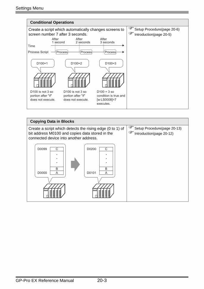
Create a script which automatically changes screens to screen number 7 after 3 seconds.
Setup Procedure(page 20-6)Introduction(page 20-5)
Copying Data in Blocks
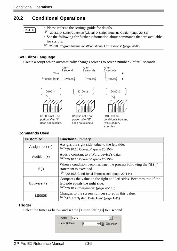
Create a script which detects the rising edge (0 to 1) of bit address M0100 and copies data stored in the connected device into another address.
Setup Procedure(page 20-13)Introduction(page 20-12)
D100=1 D100=2 D100=3
Process Process Process
Time
Process Script
After 1 second
After 2 seconds
After 3 seconds
D100 is not 3 so portion after "if" does not execute.
D100 is not 3 so portion after "if" does not execute.
D100 = 3 so condition is true and [w:LS0008]=7 executes.
D0099
D0000
C
BA
D0200
D0101
C
BA

Settings Menu
GP-Pro EX Reference Manual 20-4
Displaying an Alarm When an Error Occurs
The temperature management system detects an error bit from the connected device and displays alarm messages when the temperature information storage address (D200) rises to 70 degrees C or higher, or falls to 30 degrees C or lower. Also, this script counts the number of detected errors.
Setup Procedure(page 20-18)Introduction(page 20-17)
Communicating with Unsupported Peripheral Devices
Create an extended script to read data from a bar code connected to the USB port and output the data to a serial printer connected to COM1.
Setup Procedure(page 20-34)Introduction(page 20-21)
Screen 1
Tank temperature Temperature is too high!!
Temperature is too low.
Screen 2
Screen 3
D200 50
D200≥70
D200≤30
Read "Product Name" and "Price" information from barcode.
Product Name: Pro-face Price: 1234 Yen Product Name: ABC Price: 567 Yen Product Name: DEF Price: 89 Yen
GP
Product Name and Price printer output
Product Name (1000)
Start
Pro-face
Price (0500)
Print Start Button (005000)
Yen 12345
ON
Conditional Operations
GP-Pro EX Reference Manual 20-5
20.2 Conditional Operations
Set Editor LanguageCreate a script which automatically changes screens to screen number 7 after 3 seconds.
Commands Used
TriggerSelect the timer as below and set the [Timer Settings] to 1 second.
• Please refer to the settings guide for details."20.8.1 D-Script/Common [Global D-Script] Settings Guide" (page 20-51)
• See the following for further information about commands that are available for scripts.
"20.10 Program Instructions/Conditional Expressions" (page 20-66)
Customize Function Summary
Assignment (=) Assigns the right side value to the left side."20.10.10 Operator" (page 20-150)
Addition (+) Adds a constant to a Word device's data."20.10.10 Operator" (page 20-150)
if ( )When a condition becomes true, the process following the "if ( )" statement is executed.
"20.10.8 Conditional Expressions" (page 20-144)
Equivalent (==)Compares the value on the right and left sides. Becomes true if the left side equals the right side.
"20.10.9 Comparison" (page 20-148)
LS0008 Changes to the screen number stored in this value."A.1.4.2 System Data Area" (page A-11)
D100=1 D100=2 D100=3
Process Process Process
After 1 second
After 2 seconds
After 3 seconds
D100 is not 3 so portion after "if" does not execute.
D100 is not 3 so portion after "if" does not execute.
D100 = 3 so condition is true and [w:LS0008]=7 executes.
Time
Process Script

Conditional Operations
GP-Pro EX Reference Manual 20-6
Completed Script
Creation Procedure1 From the [Common Settings (R)] menu, select [Global D-Script (L)].
2 Click [Create]. To view an existing script, select the ID number and click [Edit], or double-click the ID number row.

Conditional Operations
GP-Pro EX Reference Manual 20-7
3 The [Global D-Script] dialog box is displayed.
4 In [Trigger], select [Timer] and specify the [Timer Settings] as 1 second.

Conditional Operations
GP-Pro EX Reference Manual 20-8
5 Click the [Tool Box] tab. The toolbox allows you to easily place a command to use in the script.
6 Create the first line of script. If you specify the D00100 default value as 0, the first line operation is a count operation that increases and stores the count every time a process completes. Click and select [Word Address], click .
7 Input D00100, and click [ENT].
00

Conditional Operations
GP-Pro EX Reference Manual 20-9
8 Click [Assignment (=)] in the Toolbox.
9 Place D00100 in the same way as steps 6-7.
10 Click [Addition (+)] and type "1". The first row is now complete.
11 Create the second row of the script. In the second row, when a condition becomes true, the process following the "if ( )" statement is executed. Click [if - endif].
12 Create the condition expression inside the brackets "( )" following "if". The condition expression compares the value stored in D00100 to "3", and turns true if they are equal. Place the cursor inside the brackets "( )" and repeat steps 6 to 7 to place another D00100.

Conditional Operations
GP-Pro EX Reference Manual 20-10
13 Click [Equivalent (==)] and input "3". The second row is now complete.
14 Place the cursor inside the "{ }" brackets and press Enter. Repeat steps 6 to 7 to place another LS0008.
15 Click [Assignment (=)] and input "7".

Conditional Operations
GP-Pro EX Reference Manual 20-11
16 The script is now complete.
• When selecting text, press the [Ctrl] key + the [Shift] key + the [Right Arrow] key/[Left Arrow] key to select an entire block of text.
• Press the [Ctrl] key + the [F4] key to close the currently selected screen.• Press the [Esc] key to overwrite and save the script or to delete it and exit.

Copying Data in Blocks
GP-Pro EX Reference Manual 20-12
20.3 Copying Data in Blocks
Set Editor LanguageCreate a script which detects the rising edge (0 to 1) of bit address M0100 and copies data stored in the connected device into another address.
Commands Used
TriggerIn [Trigger], select [Bit ON], and set the [Bit Address] to M000100.
Completed Script
• Please refer to the settings guide for details."20.8.1 D-Script/Common [Global D-Script] Settings Guide" (page 20-51)
• See the following for further information about commands that are available for scripts.
"20.10 Program Instructions/Conditional Expressions" (page 20-66)
Customize Function Summary
Copy Memorymemcpy ( )
Copies a stored value into a device in one operation.Data for the number of Addresses will be copied to the copy destination Word Addresses beginning from the source data's first Word Address.[Format]memcpy ([Copy To Address], [Copy From Address], Words)
"20.10.3 Memory Operation" (page 20-76)
D0099
D0000
C
BA
D0200
D0101
C
BA

Copying Data in Blocks
GP-Pro EX Reference Manual 20-13
Creation Procedure1 From the [Part (P)] menu, select [D-Script (R)] or click from the toolbar.
2 Click [Create]. The IDs for existing scripts are displayed in the [D-Script List].

Copying Data in Blocks
GP-Pro EX Reference Manual 20-14
3 The [D-Script] dialog box is displayed.
4 Select [Bit ON] in [Trigger] and specify M000100 as [Bit Address].

Copying Data in Blocks
GP-Pro EX Reference Manual 20-15
5 Click the [Function] tab. The built-in functions allow you to easily place a command to use in the script.
6 From [Built-in Function (Instruction)], select [Memory Operation].
7 Double-click [Copy Memory]. Click .

Copying Data in Blocks
GP-Pro EX Reference Manual 20-16
8 For [Parameter 1], enter D00101, and click [ENT].
9 For [Parameter 2] enter D00000, and click [OK].
10 The script is now complete.

Displaying an Alarm When an Error Occurs
GP-Pro EX Reference Manual 20-17
20.4 Displaying an Alarm When an Error Occurs
Set Editor LanguageThe temperature management system detects an error bit from the connected device and displays alarm messages when the temperature information storage address (D200) rises to 70 degrees C or higher, or falls to 30 degrees C or lower. Also, this script counts the number of detected errors.
The address that counts each time D200 rises to 70 degrees C or higher and stores the number of times: LS0300The address that counts each time D200 falls to 30 degrees C or lower and stores the number of times: LS0301Address that stores the alarm screen number: LS0008
Commands Used
• Please refer to the settings guide for details."20.8.1 D-Script/Common [Global D-Script] Settings Guide" (page 20-51)
• See the following for further information about commands that are available for scripts.
"20.10 Program Instructions/Conditional Expressions" (page 20-66)
Customize Function Summary
if ( ) When the "if" condition, enclosed in brackets "( )", is true, the expression following the "if ( )" statement is run.
"20.10.8 Conditional Expressions" (page 20-144)
greater than or equal to (>=)
True if N1 is more than or equal to N2 (N1 >= N2)."20.10.9 Comparison" (page 20-148)
Assignment (=) Assigns the right side value to the left side."20.10.10 Operator" (page 20-150)
Addition (+) Adds a constant to a Word device's data."20.10.10 Operator" (page 20-150)
less than or equal to (<=)
True if N1 is less than or equal to N2 (N1 <= N2)."20.10.9 Comparison" (page 20-148)
Screen 1
Tank temperature Temperature is too high!!
Temperature is too low.
Screen 2
Screen 3
D200 50
D200≥70
D200≤30

Displaying an Alarm When an Error Occurs
GP-Pro EX Reference Manual 20-18
TriggerIn [Trigger], select [Bit ON], and set the [Bit Address] to M000100.
Completed Script
Creation Procedure1 From the [Parts] menu click [D-Script (R)] or click .

Displaying an Alarm When an Error Occurs
GP-Pro EX Reference Manual 20-19
2 Click [Create]. The IDs for existing scripts are displayed in the [D-Script List].
3 The [D-Script] dialog box is displayed.
4 In [Comment], enter "Alarm Display".
Displaying an Alarm When an Error Occurs
GP-Pro EX Reference Manual 20-20
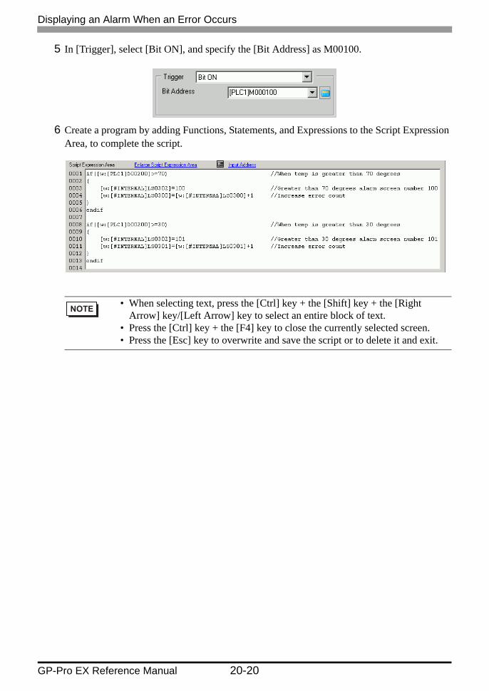
5 In [Trigger], select [Bit ON], and specify the [Bit Address] as M00100.
6 Create a program by adding Functions, Statements, and Expressions to the Script Expression Area, to complete the script.
• When selecting text, press the [Ctrl] key + the [Shift] key + the [Right Arrow] key/[Left Arrow] key to select an entire block of text.
• Press the [Ctrl] key + the [F4] key to close the currently selected screen.• Press the [Esc] key to overwrite and save the script or to delete it and exit.

Communicating with Unsupported Peripheral Devices
GP-Pro EX Reference Manual 20-21
20.5 Communicating with Unsupported Peripheral Devices
ActionThis example creates an extended script to output the data read from a bar code connected to the USB to a serial printer connected to COM1.
• Please refer to the settings guide for details."20.8.1 D-Script/Common [Global D-Script] Settings Guide" (page 20-51)
• See the following for further information about commands that are available for scripts.
"20.10 Program Instructions/Conditional Expressions" (page 20-66)
Read "Product Name" and "Price" information from barcode.
Product Name: Pro-face Price: 1234 Yen Product Name: ABC Price: 567 Yen Product Name: DEF Price: 89 Yen
GP
Product Name and Price printer output
Product Name (1000)
Start
Pro-face
Price (0500)
Print Start Button (005000)
Yen 12345
ON

Communicating with Unsupported Peripheral Devices
GP-Pro EX Reference Manual 20-22
Extended Script StructureExtended Scripts are scripts used for communicating between the GP internal Serial Port and connected input/output devices.For Extended Script data management, as shown in the following picture, data is stored in databuf0 to databuf3 via the Send/Receive Buffer. Databuf is not divided by address, so store the data in internal memory before editing the data on the device/PLC.
Receive Buffer/Send BufferFor communication with the device/PLC, this acts as a bit memory space which distinguish sent and received data in real time.
databuf0 - databuf3These are byte (8-bit) memory spaces used for data storage. The buffer size is 1 KB.
Extended Script Device/PLC
databuf0 Receive Buffer databuf1
databuf2 databuf3
Send Buffer
LS Area, USR, etc.
Buffer
GP
Internal Memory

Communicating with Unsupported Peripheral Devices
GP-Pro EX Reference Manual 20-23
Procedure to Create Scripts
Decides whether or not to start the printing when the Printer Start Button turns ON.
Main function
Configures the Send Buffer, Receive Buffer, and Error initialization.
INIT (User Defined Function)
Initializes the printer. PINIT (User Defined Function)
Changes the data format in order to transfer print data to the printer.
Strset (User Defined Function)
Appends a “line feed” to allow for continuous printer output, and transfers print data to the printer.
Print (User Defined Function)

Communicating with Unsupported Peripheral Devices
GP-Pro EX Reference Manual 20-24
Flow Chart(1) Main Process
Main Process
Communication Start Bit ON
Receive Data Exist
Extended SIO Initialization
Printer Initialization
Execution of Data Transmission
Communication Start BitOFF
Yes
No
Yes
No
(2) Initialization Function (INT)
Initialization
Clear Send Buffer
Clear Receive Buffer
Clear Error
Finish

Communicating with Unsupported Peripheral Devices
GP-Pro EX Reference Manual 20-25
(3) Printer Initialization Function (PINIT)
Printer Initialization
(4) String Function (Strset)
Send
Set the header string to the data buffer
Set the printer initialization data to the data buffer
Send the Data
Finish
Convert the data set to the address from binary values to ASCII codes
30 characters of data converted?
Loop 1
Loop 1
Set the footer string to the data buffer
Finish

Communicating with Unsupported Peripheral Devices
GP-Pro EX Reference Manual 20-26
(5) Send Function (Print)
Send
Call Send Data
Set new-line data to the data buffer
Send the Data
Finish

Communicating with Unsupported Peripheral Devices
GP-Pro EX Reference Manual 20-27
Script Function Summary
Main FunctionCompleted Script
Function SummaryWhen the Printer Start Button (internal memory 005000) turns ON, the script decides whether or not to start printing from the 1st byte of Print Permit data.The Print Permit data performs the following actions as an example of the printer specifications.
Print Preparation OK: Send 0x31 (ASCII code "1") to the device/PLC.Print Preparation Invalid: Send 0x30 (ASCII code "0") to the device/PLC.
The GP receives the Print Permit data in databuf0 and this data is moved to accessible internal memory 100 with the following script handling.

Communicating with Unsupported Peripheral Devices
GP-Pro EX Reference Manual 20-28
When internal memory 100 = 0x31 (ASCII code for the value "1"), printing starts. When internal memory is 0x30 (ASCII code for "0"), the GP returns to the beginning of the script and repeats this process until it receives the 0x31 data.
INIT (User Defined Function)Completed Script
Function SummaryConfigure the Send Buffer, Receive Buffer, and Error initialization.
PINIT (User Defined Function)Completed Script
Created Screen
Product Name and Price printer output
Product Name (1000)
Start
Pro-face
1 (ASCII)
1 (ASCII)
Price (0500)
Print Start Button (005000)
Yen 12345
ON or
1 databuf0
1 Internal Memory 100

Communicating with Unsupported Peripheral Devices
GP-Pro EX Reference Manual 20-29
Function SummaryInitializes the printer. Send the ESC/P command "ESC+@" to the printer.
GP
“ESC+@”
databuf0 0x1B
( “ESC”)
1 databuf1
0x40 ( “@”)
2
databuf0
( “ESC+@”)
3

Communicating with Unsupported Peripheral Devices
GP-Pro EX Reference Manual 20-30
Strset (User Defined Function)Completed Script
Function Summary1 Append the text “Price:” and “Yen” to the price data stored internal memory 0500.
GP
databuf0
Price:
1databuf1 2
databuf0
Price(0500)
From screen
XXX Yen
3
GP
Changes text and stores it in databuf1.
databuf0 databuf1
Yen
databuf0
Price: Yen
3 4
5
Price:
Price:

Product Name (1000)
From screen
Stores data in byte units.
Internal Memory (16 bit)
databuf2 (8 bit)
Pro-face
2000 2001 2002 2003 2004 2005 2006 2007 2008 2030
0 P 0 r 0 o 0 - 0 f 0 a 0 c 0 e 0 0 : : 0 0
databuf2[0] databuf2[1] databuf2[2] databuf2[3] databuf2[4] databuf2[5] databuf2[6] databuf2[7] databuf2[8]
databuf2[30]
P r o - f a c e 0 : 0
Stores the low order byte to databuf 2.
Communicating with Unsupported Peripheral Devices
GP-Pro EX Reference Manual 20-31
2 Change the data format in order to send print data to the printer. Divide the string data (Product Name) stored sequentially in internal memory 1000 into byte units, and store into internal memory 2000 to 2030 as low order byte string data. Use the function _ldcopy and store the data in databuf2 in order of the consecutive word address's lowest byte.
3 Append the text "Product Name:" and "Price" to databuf2.
• The _ldcopy function takes data stored as Words, and stores only the lower order bytes in the buffer, while higher order byte data is ignored.
GP
databuf1
Product Name:
1 databuf2
Pro-face
2
databuf1
Product Name: Pro-face
3
GP
databuf1
Product Name: Pro-face
databuf0
Price: XXX Yen
databuf1
Product Name: Pro-face Price: XXX Yen
3 4
5

Communicating with Unsupported Peripheral Devices
GP-Pro EX Reference Manual 20-32
Print (User Defined Function)Completed Script
Function Summary1 Append a "line feed" to allow for continuous printer output.
GP
databuf1 Product Name: Pro-face Price: XXX Yen
1 databuf0
0x0d ("CR")
2
databuf1
Product Name: Pro-face Price: XXX Yen "CR"
3
GP
databuf1 Product Name: Pro-face Price: XXX Yen "CR"
3 databuf0
0x0a ("LF")
4
databuf1
Product Name: Pro-face Price: XXX Yen "CR" "LF"
5

Communicating with Unsupported Peripheral Devices
GP-Pro EX Reference Manual 20-33
2 Set the print data to the printer.
Commands UsedCustomize Function Summaryif ( ) When the "if" condition, enclosed in brackets "( )", is true, the
expression following the "if ( )" statement is run."20.10.8 Conditional Expressions" (page 20-144)
Label Settings[r:EXT_SIO_RECV]
Shows the quantity of data (number of bytes) received at that time. The received data size is read-only.
"20.10.4 SIO Port Operation" (page 20-97)Equivalent (==) True if N1 is equal to N2 (N1 = N2).
"20.10.9 Comparison" (page 20-148)Text Settings (_strset) Stores a fixed string in the data buffer.
"20.10.11 Text Operation" (page 20-154)Extended Receive (IO_READ_EX)
Receives data of the size indicated in Received Data Size (bytes) from the Extended SIO and stores it in the data buffer.
"20.10.4 SIO Port Operation" (page 20-97)From Data Buffer to Internal Device (_dlcopy)
Each byte of string data stored in the offset of the data buffer is copied to the LS area according to the number of strings.
"20.10.11 Text Operation" (page 20-154)Label Settings [c:EXT_SIO_CTRL **]
This control variable is used to clear the Send buffer, Receive buffer, and error status.
"20.10.8 Conditional Expressions" (page 20-144)Connect Text (_strcat) Concatenates a character string or character code with the text
buffer."20.10.11 Text Operation" (page 20-154)
Text Length (_strlen) Obtains the length of the stored string."20.10.11 Text Operation" (page 20-154)
Extended Send (IO_WRITE_EX)
Sends the data in the data buffer with Extended SIO according to the size of Number of Send Bytes.
"20.10.4 SIO Port Operation" (page 20-97)Assignment (=) Assigns the right side value to the left side.
"20.10.10 Operator" (page 20-150)Continued
Created Screen
Product Name and Price printer output
Product Name (1000)
Start
Pro-face
Product Name: Pro-face Price: XXX Yen "CR" "LF"
Price (0500)
Print Start Button (005000)
Yen 12345
ON

Communicating with Unsupported Peripheral Devices
GP-Pro EX Reference Manual 20-34
Creation Procedure1 Set up the script settings to use Extended Script to communicate. From the [Project (F)]
menu, point to [System Settings (C)] and select [Script I/O Settings]. Make sure to set the [Type] to [Extended Script].
There are two tabs for the script settings.Set the [Port] to COM1 or COM2. Set the [Communication Settings] to match the Extended SIO.
Addition (+) Adds a constant to a Word device's data."20.10.10 Operator" (page 20-150)
Numeric Value Decimal String Conversion (_bin2decasc)
This function is used to convert an integer to a decimal string."20.10.11 Text Operation" (page 20-154)
From Internal Device To Data Buffer (_ ldcopy)
The data of the string stored in the LS area is copied to the data buffer according to the number of strings in a byte-by-byte transfer.
"20.10.11 Text Operation" (page 20-154)
Customize Function Summary

Communicating with Unsupported Peripheral Devices
GP-Pro EX Reference Manual 20-35
2 From the [Common Settings (R)] menu, select [Extended Script (E)].
3 Register "INIT" as a User-Defined Function. Click the [Function] tab and click the user-defined function frame's [Create] button.

Communicating with Unsupported Peripheral Devices
GP-Pro EX Reference Manual 20-36
4 Input [INIT] as the function name, click [OK]. The following screen appears.
5 Create a script in the Execution Expression with Commands, Statements, and Constant input.
6 In the same manner, register "PINIT" as a User-Defined Function. Enter [PINIT] as the function name and create the following script in Execution Expression.

Communicating with Unsupported Peripheral Devices
GP-Pro EX Reference Manual 20-37
7 In the same manner, register "Strset" as a User-Defined Function. Enter [Strset] as the function name and create the following script in Execution Expression.
8 In the same manner, register "Print" as a User-Defined Function. Enter [Print] as the function name and create the following script in Execution Expression.
(2)
(1)
(3)

Communicating with Unsupported Peripheral Devices
GP-Pro EX Reference Manual 20-38
9 Create the main script. Create the following script in Execution Expression to complete the script.
• When placing the user-defined functions created in steps 3 to 9 into the main script, select the function to be placed and click [Call] on the [Function] tab. The function will be placed using "Call Function Name".
• When selecting text, press the [Ctrl] key + the [Shift] key + the [Right Arrow] key/[Left Arrow] key to select an entire block of text.
• Press the [Ctrl] key + the [F4] key to close the currently selected screen.• Press the [Esc] key to overwrite and save the script or to delete it and exit.

Procedure for Creating Scripts
GP-Pro EX Reference Manual 20-39
20.6 Procedure for Creating Scripts
20.6.1 Procedure for Creating D-Scripts/Global D-Scripts
From the [Part (P)] menu, select [D-Script (R)].
From the [Common Settings (R)] menu, select [Global D-Script (L)].
Click [Create]. To view an existing script, select the ID number and click [Edit], or double-click the ID Number row.
Click [Create]. To view an existing script, select the ID number and click [Edit], or double-click the ID Number row.
Set the trigger condition that causes the script to run. For more information about this function, please refer to "20.7 Triggered Condition Setup" (page 20-44).
Create the script (Execution Expression). For more information about commands and functions, please refer to "20.10 Program Instructions/Conditional Expressions" (page 20-66).

Procedure for Creating Scripts
GP-Pro EX Reference Manual 20-40
• The component tray displays registered D-script parts in the order they are created. To change the order of D-script parts in the component tray, change the ID number for registered parts, then from the [Edit] menu select [Auto-Align Trays]. You can change ID settings by double-clicking parts in the component tray to display the edit dialog box.

Procedure for Creating Scripts
GP-Pro EX Reference Manual 20-41
20.6.2 Procedure for Creating Extended Scripts
From the [Project (F)] menu, select [System Settings (C)]. Click [Script I/O Settings] to display the following dialog box.When using an extended script, set [Type] to [Extended Script] and select the appropriate [Port].
From the [Common Settings (R)] menu, select [Extended Script (E)].
Create the script (Execution Expression). For more information about commands and functions, please refer to "20.10 Program Instructions/Conditional Expressions" (page 20-66).

Procedure for Creating Scripts
GP-Pro EX Reference Manual 20-42
20.6.3 Setting Up User-Defined Functions
Register an existing script as a user-defined function so you can use it within other scripts. The registered function can be used by a D-Script, Global D-Script, or Extended Script.
Setting Procedure
When creating a new User-Defined FunctionClick on [Create]. The User-Defined Function dialog box appears.
When editing a previously registered User-Defined FunctionSelect the User-Defined Function you want to modify and click [Edit]. The User-Defined Function dialog box appears.
Enter the function name and create the script in the Execution field. Click [OK] to save the user-defined function.
• Restrictions apply to Function Names. For more information, see "20.9.3 Restrictions on User-Defined Functions" (page 20-63).

Procedure for Creating Scripts
GP-Pro EX Reference Manual 20-43
Select the user-defined function to call, click [Call] and "Call Function Name" will be placed in the Execution field.
• When a user-defined function calls another script, it cannot use functions created in an Extended Script in D-Scripts or Global D-Scripts.

Triggered Condition Setup
GP-Pro EX Reference Manual 20-44
20.7 Triggered Condition Setup
A created script can use any of the following 7 types of trigger conditions.
20.7.1 Continuous Action
Executes each display scan time.
20.7.2 Timer
TimerEach time the designated time elapses, the script is executed one time. The timer duration can be set from 1 to 32,767 seconds.
Setting DescriptionContinuous Action The script is triggered regularly.Timer The script is triggered after a designated time elapses.Bit Bit ON When the GP detects the designated bit rise from 0 to 1, the
script is triggered.Bit OFF When the GP detects the defined bit falling from 1 to 0, the
script is triggered.Bit Change When the GP detects the designated bit rise from 0 to 1 or
fall from 1 to 0, the script is triggered.Condition Expression
When Condition is True
When the GP detects true for a designated expression, the script is triggered.
When Condition is False
When the GP detects false for a designated expression, the script is triggered.
• When setting the timer function's time, the time value includes the set time + display scan time error. Also, depending on the time taken to draw a screen item or to printout data, the timer function may be slowed. For more information about the Display Scan Time, please refer to " Restrictions on the Triggered Bit" (page 20-48).
• When using D-Script, switching the screen causes the timer function to restart counting from 0.
Script processed Script processed
t [sec.]
t seconds t seconds

Triggered Condition Setup
GP-Pro EX Reference Manual 20-45
20.7.3 Bit
Bit ONWhen the GP detects the designated bit address (trigger bit) rise from 0 to 1, the script is triggered.
Bit OFFWhen the GP detects the designated bit address (trigger bit) fall from 1 to 0, the script is triggered.
Bit ChangeWhen the GP detects the designated bit address (trigger bit) rise from 0 to 1 or fall from 1 to 0, the script is triggered.
• For the trigger bit's ON/OFF, make sure to leave an interval longer than the communication cycle time or display scan time, whichever is longer. For more information about this function, please refer to |" Restrictions on the Triggered Bit" (page 20-48).
• For the trigger bit's ON/OFF, make sure to leave an interval longer than the communication cycle time or display scan time, whichever is longer. For more information about this function, please refer to " Restrictions on the Triggered Bit" (page 20-48).
• For the trigger bit's ON/OFF, make sure to leave an interval longer than the communication cycle time or display scan time, whichever is longer. For more information about this function, please refer to " Restrictions on the Triggered Bit" (page 20-48).
Script processed Script processed
Triggered bit
Script processed Script processed
Triggered bit
Script processed Script processed
Triggered bit

Triggered Condition Setup
GP-Pro EX Reference Manual 20-46
20.7.4 Condition Expression
When Condition is TrueWhen the GP evaluates the trigger condition as true, the script runs one time.For example, when the Triggered Condition is 100>[D100]>50, the script will run with the following timing. [False] → [True] is detected, the script executes, and 70 is assigned to D100. The script does not execute when [True] → [True].
• For the Triggered Condition, leave an interval longer than the communication cycle time or display scan time, whichever is longer. For more information about this function, please refer to " Restrictions on the Triggered Bit" (page 20-48).

Triggered Condition Setup
GP-Pro EX Reference Manual 20-47
When Condition is not SatisfiedWhen the GP detects false for a designated expression in a triggering program, the script is executed once.When the Triggered Condition is set to 100>[D100]>50, the script will execute with the following timing. [True]->[False] is detected, the script executes, and 20 is assigned to D100 The script does not execute when [False]->[False].
• For the Triggered Condition, leave an interval longer than the communication cycle time or display scan time, whichever is longer. For more information about this function, please refer to " Restrictions on the Triggered Bit" (page 20-48).

Triggered Condition Setup
GP-Pro EX Reference Manual 20-48
Restrictions on the Triggered Bit
• Make sure to leave an interval longer than the communication cycle time for executing write operations onto the connected device. When write operations onto the connected device are executed frequently by using the scan counter of GP internal special relay, communication errors or system errors may result.
• When the bit used for the D-Script Triggered Condition is set for "touch" and that bit turns OFF during D-Script processing, the timing used when pressing the touch area repeatedly can prevent the detection of the bit's rise. The D-Script trigger compares the previously read out value to the currently read out value to determine if the trigger is now "True". However, during a single scan, the value that is stored in the bit address used during the Triggered operation is kept the same, even if the value is changed during execution. The new value is read out only after the next scan begins.
Communication Cycle Time:
The communication cycle time is the time it takes to request and take in data from the GP unit to the PLC. It is stored in the internal device LS2037 as binary data. The unit is milliseconds (ms). There is an error of +/-10 ms.
Display Scan Time: The display scan time is the time it takes to display/calculate 1 screen. It is stored in the internal device LS2036 as binary data. The unit is milliseconds (ms). There is an error of +/-10 ms.
For example, When Touch is used to turn ON the trigger bit (LS010000), and D-Script turns the value OFF:
Triggered Condition: Bit ON [#INTERNAL] LS010000Execution Expression: clear ([b:[#INTERNAL] LS010000])

Triggered Condition Setup
GP-Pro EX Reference Manual 20-49
D-Script Processing Timing Chart
For example, if the D-Script touch timing is not used, and only detection is performed, the processing is as follows.
Using an if ( ) statement to detect a trigger:Use an if statement to determine if a touch operation sets the bit. Each time the if () statement runs, it reads the value and runs a comparison check.
Triggered Condition: Bit ON ([#INTERNAL]LS203800 *1)Execution Expression: if ([b:[#INTERNAL]LS010000]==1){clear ([b:[#INTERNAL]LS010000])::
GP internal counter. The counter increments each time the Part set on the display screen processes.
When using the previous D-script, even if you input consecutive touches, the script is run only if the condition matches. As shown in the following timing chart, every display scan the value is read and checked for a match, and if there is a match, regardless of the previous value, the script is run.
Read out [b:LS010000] and store value of "1"
Detect Trigger Detect Trigger Cannot Detect Trigger
Read out [b:LS010000] and store value of "0"
Read out [b:LS010000] and store value of "1" Read out
[b:LS010000] and store value of "1"
LS010000 Condition
Value stored during Triggered operation
Detects that bit address value changes from 0 to 1 (OFF to ON)
Detects that bit address value stayed from 1 to 1 (ON to ON), cannot detect bit rise

Triggered Condition Setup
GP-Pro EX Reference Manual 20-50
D-Script Processing Timing Chart
[b:LS010000] Read out value is "1"Condition is Satisfied(Execute)
LS203800 Condition
if ( ) statement trigger condition
LS010000 Condition
[b:LS010000] Read out value is "1"Condition is Satisfied(Execute)
[b:LS010000] Read out value is "0"Condition is not Satisfied(Do not execute)
[b:LS010000] Read out value is "0"Condition is not Satisfied(Do not execute)
[b:LS010000] Read out value is "1"Condition is Satisfied(Execute)
Settings Guide
GP-Pro EX Reference Manual 20-51
20.8 Settings Guide
20.8.1 D-Script/Common [Global D-Script] Settings Guide
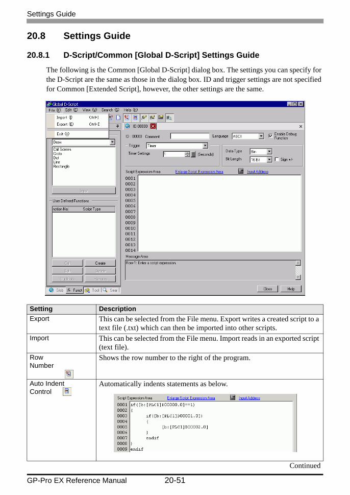
The following is the Common [Global D-Script] dialog box. The settings you can specify for the D-Script are the same as those in the dialog box. ID and trigger settings are not specified for Common [Extended Script], however, the other settings are the same.
Setting DescriptionExport This can be selected from the File menu. Export writes a created script to a
text file (.txt) which can then be imported into other scripts.Import This can be selected from the File menu. Import reads in an exported script
(text file).Row Number
Shows the row number to the right of the program.
Auto Indent Control
Automatically indents statements as below.
Continued

Settings Guide
GP-Pro EX Reference Manual 20-52
Function Input Assistance
When the function and the initial bracket "(" are inputted as below, the function's format gets displayed.
Auto Syntax Completion
When "if" or "loop" is entered from the keypad, the remaining syntax is automatically placed.
Setting Description

Settings Guide
GP-Pro EX Reference Manual 20-53
Address Input
When creating a script, enter a left square bracket ( [ ) to display the [Input Address] dialog box.
Select the address type from [Bit Address], [Word Address], [Temporary Address].• Bit Address
You can specify the Device/PLC address, GP Internal Device and Bit Variable.
• Word AddressYou can specify the Device/PLC address, GP Internal Device and Integer Variable.
• Temporary AddressThis address can only be used for scripts.
Refer to the following for details on the internal device."A.1.2 Communicating with a Device/PLC Using the Direct Access Method" (page A-4)"A.1.3 Using the Memory Link Method with Unsupported Devices/PLCs" (page A-7)
• In the scripts, please do NOT set any passwords, and so on, that begin with "0". All numeric values beginning with "0" will be processed as Oct (base-8) data.
• How to describe different input data formatsFor example,
• Example of operation with different data formats using the AND operator (Hex and BCD)
Continued
Setting Description
DEC (Base-10) : Non-zero starting value For example, 100
HEX (Base-16) : Value starting with 0x For example, 0x100
OCT (Base-8) : Value starting with 0xFor example, 0100
Hex only0x270F & 0xFF00 Result: 0x2700
BCD and Hex9999 & 0xFF00 Result: 0x9900

Settings Guide
GP-Pro EX Reference Manual 20-54
Auto Syntax Analysis
Checks the syntax during script creation. The check results will be displayed in the bottom portion of the window.
ID Scripts are managed by an ID number.When creating multiple scripts with different trigger conditions, set a value from 0 to 65,535.
Comment Input a comment for the script.Language Choose a language from the drop-down list: [ASCII], [Japanese], [Chinese
(Traditional)], [Chinese (Simplified)], or [Korean].Enable Debug Function
Set whether or not to enable the debug function. If the _debug function exists in the body of the script, the _debug function will execute.For more information about this function, please refer to" Debug Function" (page 20-139).
Trigger Set the trigger condition that causes the script to execute. For more information about this function, please refer to "20.7 Triggered Condition Setup" (page 20-44).Extended scripts do not have the trigger condition setting.
Data Type Set the data format for the script to Bin or BCD.For Extended Scripts, Bin is fixed.
Bit Length Set the data length for the script to 16 bit or 32 bit.Sign +/- Select this when you want to insert negative numbers.
This can only be set when the data type is Bin.Execution Expression
The contents of the script.
Built-in Function (Instruction)
From the toolbar, select commands and functions to more easily add them to the script.For more information about available commands and functions that can be used, see
"20.10 Program Instructions/Conditional Expressions" (page 20-66)Built-in Functions
Continued
Setting Description
Select a category from [Built-In Function (Instruction)]. The related functions appear in the bottom area.Select the function and click [Input]. The corresponding settings dialog box appears.

Settings Guide
GP-Pro EX Reference Manual 20-55
User Defined Function
Register a script as a user-defined function and it can be used by other scripts.
• For more details about user-defined functions, see "20.8.2 User-Defined Functions Settings Guide" (page 20-56).
Tool Box As a shortcut, select commands from the Toolbox to use in the script.Also, you can select commands such as search and position text used in scripts.For more information about available commands, see "20.10 Program Instructions/Conditional Expressions" (page 20-66).
Setting Description

Settings Guide
GP-Pro EX Reference Manual 20-56
20.8.2 User-Defined Functions Settings Guide
Setting DescriptionCall Call a created function. Select the function to call, click [Call] and "Call
Function Name" is placed in the Execution field.Create Create a new function. Click on [Create]. The [Function Name] dialog box
appears.Edit Edit an existing function. Select the function to edit, click on [Edit]. The
[D-Script Function] dialog box appears.Delete Delete an existing function. Select the function to delete and click
[Delete].Duplicate Copy an existing function. Select the function to copy and click [Copy] to
display the dialog box to create the name of the copy of the function.Rename Change the name of an existing function. Click on [Rename]. The Rename
Function dialog box appears.

Restrictions
GP-Pro EX Reference Manual 20-57
20.9 Restrictions
20.9.1 D-Script/Global D-Script Restrictions
• In D-Script programming, three addresses occupy the same amount of memory as one Part. The maximum number of addresses available for a D-Script is 255*1. Use the fewest possible addresses, since the more devices that are used, the slower the response.
• D-Script cannot run calculations on floating point values (Float Variables or Real Variables) or structure variables. However, you can run calculations on individual elements from structure variables.
• The size of a D-Script affects the Display Scan Time. Note that using a large number of addresses may significantly degrade the program performance.
• Do not specify [Continuous Action] in the Trigger Conditions for the script to write to device/PLC addresses. An error will be displayed because the communication processing cannot keep up with the large amount of write instructions. To enable [Continuous Action], use the GP internal device or temporary address.
• When calling a function within a function, the maximum number of nested levels is 9. Do NOT create more than 9 levels.
• Up to 9 levels of nested calls can be created.• Up to 254 Functions can be created.
Depending on the devices specified for trigger conditions, the D-script operations activated by a trigger after the screen changes are as follows:
O: Operation is performed immediately after the screen is changed, or the power is turned ON.X: Operation is not performed immediately after the screen is changed, or the power is turned ON.
• When the timer is operating, the timer starts counting immediately after the screen changes.
• When using Global D-Script, the operations mentioned above are performed only when the GP power is turned ON. When the GP screen changes, however, the operation
*1 Total number of devices used in trigger expressions and script programs.
Triggered Condition
Any Connected Device other than [#MEMLINK] [#MEMLINK]
Current Value or Condition
Bit "0" Bit "1" Condition is not Satisfied
Condition is Satisfied
Bit "0" Bit "1" Condition is not Satisfied
Condition is Satisfied
Leading edge of bit
X O − − X X − −
Falling edge of bit O X − − X X − −Bit Change O O − − X X − −Timer setting X X X X X X X XDetecting true − − X O − − X ODetecting false − − O X − − O X

Restrictions
GP-Pro EX Reference Manual 20-58
mentioned above is not performed and the monitor operates using the trigger conditions that have been set.
• When a Global D-Script includes a timer, the timer starts counting immediately after the GP power is turned ON.
When a value is assigned to an address for switching screens while a D-Script command is being executed, the screen switching operation is processed after all D-Scripts have been processedFor example:
ID 00000Data Type Bin Data Length 16 Bit Sign +/− NoneTrigger Leading Bit([b:M0000])[w:[PLC1]D0100]=0 // (1)[w:[#INTERNAL]LS0008]=30// (2) Switches to Base screen Number 30[w:[PLC1]D0101]=1 // (3)[w:[PLC1]D0102]=2 // (4)When the above D-Script is executed, processing of the screen switch is performed after (3) and (4) have been processed.
When data used in a D-Script is set up with a GP touch operation, make sure the data write operation is complete before running the D-script.
Restrictions Specific to Global D-Script• When the GP power is turned ON, the actions shown in the table on the previous page are
performed. At the screen change, the above table is not applied, and the trigger conditions are continuously monitored.
• Global D-Script operation is suspended during screen changes or other GP operations.• After the GP power is turned ON, Global D-Script actions are not performed until all data
reads are completed for the initial screen. After the initial screen changes, Global D-Script actions may be performed before the data reads are completed.
• The maximum number of devices in Global D-Scripts is 255*1. When this number is exceeded, the D-Script does not function. Since these devices always read data regardless of the screens, be sure to use only the minimum number of device settings in your D-Script. Otherwise, operation performance can be degraded.
• The maximum number of Global D-Scripts available is 32. The currently used function also counts as one Global D-Script. When the number of the Global D-Scripts reaches 32, any subsequent Global D-Scripts are ignored.
• Do not use the touch panel key to set the trigger bit or to operate the start bit in a program. The timing of the touch input may not be correct, resulting in the bit being improperly entered.
*1 Total number of devices used in trigger expressions and script programs.

Restrictions
GP-Pro EX Reference Manual 20-59
Restrictions for SIO Port Operations• Addresses designated in the Send/Receive functions are not added to the D-Script address
count.• The Control is a write-only variable, while Status and Received Data are read-only
variables. Reading the Control variable or writing data to the Status variable causes the operation to fail.
• Create independent D-Scripts (or functions) for Send and Receive operations. For more information about the flow charts of data transfers, see
" Flow Chart" (page 20-24)• The User area in the LS device (LS20 to LS2031 and LS2096 to LS8191) can store data
for Send/Receive functions.• In the [System Settings] workspace [Script I/O Settings] page, when the [Type] is not set
to [D-Script/Global D-Script], the 13th bit in address LS2032 turns ON when the [D-Script/Global D-Script] runs the [SIO Port Operation]'s Label Settings functions (Send, Receive, Control, Read Status, and Receive Data Size).For information about special relays:
"A.1.4.3 Special Relay" (page A-23)• When using the Send/Receive functions, set the bit length of the D-Script to 16 bits. Note
that the operation fails if the bit length is set to 32 bits.• The size of the Send buffer is 2048 bytes, while the Receive buffer is 8192 bytes. The ER
signal (output) RS signal (output) is turned OFF after at least 80% of the Receive buffer is full of received data.
Limitations on BCD Format OperationsIf a value which cannot be converted into BCD format is found during operation, the program stops running.These values include A to F in hexadecimal format. Do not use such values.If the program stops due to non- BCD values, bit 7 in common relay information (LS2032) in the GP turns ON. This bit does not turn OFF until the GP is turned OFF or goes offline.For example:
[w:[PLC1]D0200]=([w:[PLC1]D0300]<<2)+80If D300 is 3, shifting two bits to the left results in 0x000C, which cannot be converted into BCD format, and interrupts program execution.
[w:[PLC1]D0200]=[w:[PLC1]D0300]<<2If D300 is 3, shifting two bits to the left results in 0x000C. Unlike the above example, 0x000C is the result of the operation to be stored in the memory, and does not cause the program to stop.
Limitations of Zero OperationsIf you divide by zero in division (/) and remainder (%) operations, execution will stop. Do not divide by zero.If the program stops due to non- BCD values, bit 8 in common relay information (LS2032) in the GP turns ON. This bit does not turn OFF until the GP is turned OFF or goes offline.

Restrictions
GP-Pro EX Reference Manual 20-60
Notes on Delay During Assign OperationUsing a device address in an assign operation may cause write delay because the GP has to read the address data from the connected device. Consider the following:For example:
[w:[PLC1]D0200]=([w:[PLC1]D0300]+1 ... (1)[w:[PLC1]D0201]=([w:[PLC1]D0200]+1 ... (2)
Statement (1) assigns (D0300+1) into D0200. However, in statement (2), the result of statement (1) has not been assigned in D0200 because of time-consuming communication with the device/PLC. In such cases, program so that the result of statement (1) is stored in the LS area before it is executed, as shown below.
[w:[#INTERNAL]LS0100]=[w:[PLC1]D0300]+1[w:[PLC1]D0200]=[w:[#INTERNAL]LS0100][w:[PLC1]D0201]=[w:[#INTERNAL]LS0100]+1
Notes on dealing with negative numbersFor functions where a negative number is entered for an argument that does not accept negative numbers*1 the entered number operates as unsigned*2.
*1 For example, "the number of bytes" of the _CF_read () argument cannot accept negative numbers because it is the size of data to be read.
*2 For example, −1 is handled as 65535 for 16 Bit, and 4294967295 for 32 Bit.

Restrictions
GP-Pro EX Reference Manual 20-61
20.9.2 Extended Script Restrictions
• For Device Addresses, only the LS Area and USR Area (Extended User Area) can be used.
• The temporary addresses of D-Scripts and Global D-Scripts are managed independently from the temporary address of Extended Scripts. Therefore, changes made to the temporary addresses of D-Scripts and Global D-Scripts are not reflected in the temporary address of Extended Scripts.
• You can call user-defined functions created with D-Script/Global D-Script, but if you access a device address outside the range of the internal device in the function, it may not operate normally. Also, when transferred (during the creation of data for the GP), user-defined functions are created independently for D-Scripts, Global D-Scripts, and Extended Scripts.
• When calling a function from a function, the maximum number of nested levels is 9.• Up to 254 functions can be called. (The number of functions available with "Call" is 254.)• Extended Script does not affect the tag count.• Functions supported only by Extended Script, for example string operations, do not
function if called with D-Script or Global D-Script.• The available data format is Bin. BCD data format is disabled.• The size of the Send buffer is 2048 bytes, while the Receive buffer is 8192 bytes. The
CTS line is turned OFF after at least 80% of the Receive buffer is full of received data.• D-Script/Global D-Script and Extended Script cannot be selected simultaneously. Note
the combinations listed in the table below.
• Notational conventions for the character string setting
When using character strings with "_strset ( )" and other functions, enclose the character string in double quotation marks ("). To display double quotation marks in the character strings, append the "\" symbol and express as [\"]. There is no way to represent a single "\" symbol. When necessary, use the character code format setting (_strset (databuf0, 92).For example:
"ABC\"DEF"→ ABC"DEF"ABC\DEF"→ ABC\DEF"ABC\\"DEF"→ ABC\"DEF"ABC\\DEF" → ABC\\DEF
• For functions where a negative number is entered for an argument that does not accept negative numbers *1, the entered number operates as unsigned *2.
*1 For example, "the number of bytes" of the _CF_read () argument cannot accept negative numbers because it is the size of data to be read.
*2 For example, −1 is handled as 65535 for 16 Bit, and 4294967295 for 32 Bit.
Extended SIO Setting D-Script/ Global D-ScriptExtended SIO function for Extended Script
Extended SIO function for Extended Script
D-Script/Global D-Script OK: Operation enabled Invalid: Operation disabled
Extended Script Invalid: Operation disabled OK: Operation enabled

Restrictions
GP-Pro EX Reference Manual 20-62
The following table shows the sizes of the dedicated buffers for Extended SIO, databuf0, databuf1, databuf2, and databuf3.
Buffer Buffer Name Size
Data Buffer 0 databuf0 1 KB
Data Buffer 1 databuf1 1 KB
Data Buffer 2 databuf2 1 KB
Data buffer 3 databuf3 1 KB

Restrictions
GP-Pro EX Reference Manual 20-63
20.9.3 Restrictions on User-Defined Functions
• Portions of the commands that can be used differ with each script. When using
commands, please refer to "20.10 Program Instructions/Conditional Expressions" (page
20-66).
• For the function name, you may use any English letters or the underscore character "_."
(However, the function name must begin with an alphanumeric character.)
• Do not use the following as Function Names.
and b_call Bcall _bin2hexasc break Call
_CF_delete _CF_dir _CF_read _CF_read_csv _CF_rename _CF_write
_USB_delete _USB_dir _USB_read _USB_read_csv _USB_rename _USB_write
clear databuf0 databuf1 databuf2 databuf3 _decasc2bin
_dlcopy dsp_arc dsp_circle dsp_dot dsp_line dsp_rectangle
else endif fall _hexasc2bin if IO_READ
IO_READ_EX IO_READ_WAIT IO_WRITE IO_WRITE_EX loop _memcmp
memcpy _memcpy_EX memring _memsearch memset _memset_EX
_memshift not or return rise rise_expr
set _strcat _strlen _strmid _strset timer
toggle _wait

Restrictions
GP-Pro EX Reference Manual 20-64
20.9.4 Notes on Operation Results
Overflowing DigitsOverflowing digits resulting from operations are rounded.When performing an operation on unsigned 16-bit data:• 65535 + 1 = 0 (Produces overflowing digits)
• (65534 ∗ 2) / 2 = 32766 (Produces overflowing digits)
• (65534 / 2) ∗ 2 = 65534 (Does not produce overflowing digits)
Difference of Residual ProcessingThe result of a residual processing depends on whether the left and right sides are signed or unsigned.• −9 % 5 = −4
• 9 % −5 = 4
Rounded Decimal PlacesDecimal places resulting from a division are rounded.• 10 / 3 ∗ 3 = 9
• 10 ∗ 3 / 3 = 10
Notes on Operating BCD DataA BCD-data operation which produces overflowing digits does not give the correct result.

Restrictions
GP-Pro EX Reference Manual 20-65
20.9.5 Errors
The following error message is displayed when a Script is configured incorrectly. The error will be displayed on the bottom of the GP screen.Error codes are written to the LS91XX addresses. The number written in the error code area will be the number portion following RAAA in the table below. (For example, when error RAAA130 occurs, '130' will be written.)
List of Script Error Codes
D-Script(Error Address=LS9120)
Global D-Script(Error Address=LS9110)
Extended Script(Error Address=LS9100)
- RAAA130 RAAA140
Unused Global D-Script Error. (The Total Number of Global D-Scripts exceeds the maximum of 32.)
Extended D-Script Error (The total no. of functions exceeds the maximum of 255.)
- RAAA131 -
Unused Global D-Script Error. (The total no. of devices exceeds the maximum of 255*1.)
*1 Total number of devices used in trigger expressions and script programs.
Unused
RAAA120 RAAA132 RAAA141
D-Script Error (The specified function does not exist or the function has an error.)
Global D-Script Error (The specified function does not exist or the function has an error.)
Extended D-Script Error (The specified function does not exist or the function has an error.)
RAAA121 RAAA133 RAAA142
D-Script Error (These functions are nested to 10 levels or more.)
Global D-Script Error (These functions are nested to 10 levels or more.)
Extended D-Script Error (These functions are nested to 10 levels or more.)
RAAA122 RAAA134 RAAA143
D-Script Error (An expression exists, that is not supported by this version.)
Global D-Script Error (An expression exists, that is not supported by this version.)
Extended D-Script Error (An expression exists, that is not supported by this version.)
RAAA123 RAAA135 RAAA144
D-Script Error (The SIO operation function is used in a condition where no device/PLC has been set.)
Global D-Script Error (The SIO operation function is used in a condition where no device/PLC has been set.)
Extended D-Script Error (The SIO operation function is used in a condition where no device/PLC has been set.)
RAAA124 RAAA136 RAAA145
The D-Script has an error. The Global D-script has an error.
The Extended D-Script has an error.

Program Instructions/Conditional Expressions
GP-Pro EX Reference Manual 20-66
20.10 Program Instructions/Conditional Expressions
InstructionsFunction Command/Function D-Script/Global D-
ScriptExtended Script
Data Type Bin, BCD O Bin onlyBit Length 16 bit, 32 bit O OSigned/ Unsigned O OTrigger Timer setting O X
Leading edge of bit O XFalling edge of bit O XToggle bit O XExpression is true O XExpression is false O X
Draw Load Screen O XDot O OLine O OCircle O ORectangle O O
Operator Addition (+) O OSubtraction (−) O OModulus (%) O OMultiplication (∗) O ODivision (/) O OAssignment (=) O O
Comparison Logical AND O OLogical OR O ONegation (NOT) O OLess than (<) O OLess than or equal to (<=) O ONot equal to (<>) O OGreater than (>) O OGreater than or equal to (>=) O OEquals (==) O O
Continued
Program Instructions/Conditional Expressions
GP-Pro EX Reference Manual 20-67
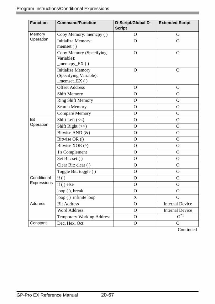
Memory Operation
Copy Memory: memcpy ( ) O OInitialize Memory: memset ( )
O O
Copy Memory (Specifying Variable): _memcpy_EX ( )
O O
Initialize Memory (Specifying Variable): _memset_EX ( )
O O
Offset Address O OShift Memory O ORing Shift Memory O OSearch Memory O OCompare Memory O O
Bit Operation
Shift Left (<<) O OShift Right (>>) O OBitwise AND (&) O OBitwise OR (|) O OBitwise XOR (^) O O1's Complement O OSet Bit: set ( ) O OClear Bit: clear ( ) O OToggle Bit: toggle ( ) O O
Conditional Expressions
if ( ) O Oif ( ) else O Oloop ( ), break O Oloop ( ) infinite loop X O
Address Bit Address O Internal DeviceWord Address O Internal DeviceTemporary Working Address O O*1
Constant Dec, Hex, Oct O OContinued
Function Command/Function D-Script/Global D-Script
Extended Script
Program Instructions/Conditional Expressions
GP-Pro EX Reference Manual 20-68
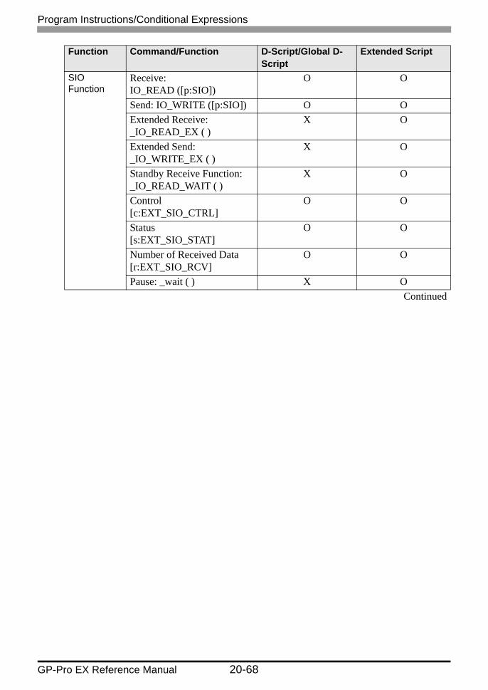
SIO Function
Receive: IO_READ ([p:SIO])
O O
Send: IO_WRITE ([p:SIO]) O OExtended Receive: _IO_READ_EX ( )
X O
Extended Send: _IO_WRITE_EX ( )
X O
Standby Receive Function: _IO_READ_WAIT ( )
X O
Control [c:EXT_SIO_CTRL]
O O
Status [s:EXT_SIO_STAT]
O O
Number of Received Data [r:EXT_SIO_RCV]
O O
Pause: _wait ( ) X OContinued
Function Command/Function D-Script/Global D-Script
Extended Script
Program Instructions/Conditional Expressions
GP-Pro EX Reference Manual 20-69
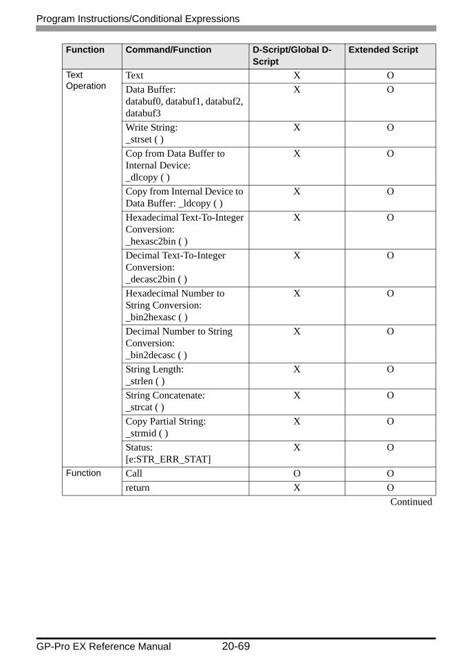
Text Operation
Text X OData Buffer: databuf0, databuf1, databuf2, databuf3
X O
Write String: _strset ( )
X O
Cop from Data Buffer to Internal Device: _dlcopy ( )
X O
Copy from Internal Device to Data Buffer: _ldcopy ( )
X O
Hexadecimal Text-To-Integer Conversion: _hexasc2bin ( )
X O
Decimal Text-To-Integer Conversion: _decasc2bin ( )
X O
Hexadecimal Number to String Conversion: _bin2hexasc ( )
X O
Decimal Number to String Conversion: _bin2decasc ( )
X O
String Length: _strlen ( )
X O
String Concatenate: _strcat ( )
X O
Copy Partial String: _strmid ( )
X O
Status: [e:STR_ERR_STAT]
X O
Function Call O Oreturn X O
Continued
Function Command/Function D-Script/Global D-Script
Extended Script

Program Instructions/Conditional Expressions
GP-Pro EX Reference Manual 20-70
CF File Operation
Read CSV File O OOutput File List: _CF_dir ( )
O O
Read File: _CF_read ( )
O O
Read CSV File CF_read_csv ( )
O O
Write File: _CF_write ( )
O O
Delete File: _CF_delete ( )
O O
Edit File Name: _CF_rename ( )
O O
USB File Operation
USB Read File O OOutput File List _USB_dir ( )
O O
Read File _USB_read ( )
O O
Read CSV File USB_read_csv ( )
O O
Write File _USB_write ( )
O O
Delete File _USB_delete ( )
O O
Change File Name _USB_rename ( )
O O
Printer Operation
Output COM Port: IO_WRITE ([p:PRN])
O O
Debug: _debug ( ) O O*1 The temporary address exists separate from the D-script and global D-script.
Function Command/Function D-Script/Global D-Script
Extended Script

Program Instructions/Conditional Expressions
GP-Pro EX Reference Manual 20-71
20.10.1 Bit Operation
Bit Settings
Example expression:set ([b:[#INTERNAL]LS010000])
In the above example, the 00th bit of LS0100 is changed from 0 → 1.
Clear Bit
Example expression:clear ([b:[#INTERNAL]LS010000])
In the above example, the 00th bit of LS0100 is changed from 1 → 0.
Bit Toggle
Example expression:toggle([b:[#INTERNAL]LS010000])
In the above example, the 00th bit of LS0100 is changed from 1 → 0 or from 0 → 1.
Bit Operation Function Summary
Bit Settings" Bit Settings" (page 20-71)
Changes the specified bit address from 0 → 1.
Clear Bit" Clear Bit" (page 20-71)
Changes the specified bit address from 1 → 0.
Bit Toggle" Bit Toggle" (page 20-71)
Changes the specified bit address from 1 → 0 or from 0 → 1.
Function Description
Summary Changes the specified bit address from 0 → 1.
Format set( )
Function Description
Summary Changes the specified bit address from 1 → 0.
Format clear()
Function Description
Summary Changes the specified bit address from 1 → 0 or from 0 → 1.
Format toggle ( )
Program Instructions/Conditional Expressions
GP-Pro EX Reference Manual 20-72
20.10.2 Draw
Call Screen
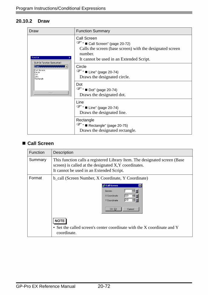
Draw Function Summary
Call Screen" Call Screen" (page 20-72)
Calls the screen (base screen) with the designated screen number.It cannot be used in an Extended Script.
Circle" Line" (page 20-74)
Draws the designated circle.
Dot" Dot" (page 20-74)
Draws the designated dot.
Line" Line" (page 20-74)
Draws the designated line.
Rectangle" Rectangle" (page 20-75)
Draws the designated rectangle.
Function Description
Summary This function calls a registered Library Item. The designated screen (Base screen) is called at the designated X,Y coordinates.It cannot be used in an Extended Script.
Format b_call (Screen Number, X Coordinate, Y Coordinate)
• Set the called screen's center coordinate with the X coordinate and Y coordinate.

Program Instructions/Conditional Expressions
GP-Pro EX Reference Manual 20-73
Coordinate Position
Circle
Function Description
Summary Draws a circle at the designated point. When you select the [Pattern] check box, a filled circle is drawn. Select and enter the line type (or fill pattern when selecting a pattern), color attributes, center coordinates, and radius value. Center coordinates and radius can be set indirectly.
Format dsp_circle (X Coordinate, Y Coordinate, Radius, Display Color Blink + Display Color, Background Color Blink + Background Color, Line Type)
• When both black and Blink are set, the background color becomes transparent.
Portrait type
(0, 0)
(639, 399)
X, Y coordinates
Y
X
Designate this coordinate.
Landscape type
(0, 0)
(639, 399)X, Y coordinates
X
Y
Designate this coordinate.

Program Instructions/Conditional Expressions
GP-Pro EX Reference Manual 20-74
Dot
Line
Function Description
Summary Draws a dot at the designated point. Set the X,Y coordinates, and display color.
Format dsp_dot (X Coordinate, Y Coordinate, Blink + Display Color)
• When both black and Blink are set, the background color becomes transparent.
Function Description
Summary Draws a line at the designated position. Set the line type, color attributes, and start and end coordinates.
Format dsp_line (Start Point X Coordinate, Start Point Y Coordinate, End Point X Coordinate, End Point Y Coordinate, Display Color Blink + Display Color, Background Color Blink + Background Color, Line Type and Arrow)
• When both black and Blink are set, the background color becomes transparent.

Program Instructions/Conditional Expressions
GP-Pro EX Reference Manual 20-75
Rectangle
Function Description
Summary Draws a rectangle at the designated position. When you select the [Pattern] check box, draws a filled rectangle.Select and enter the line type (or fill pattern when selecting a pattern), color attributes, and start and end coordinates.
Format dsp_rectangle (Start Point X Coordinate, Start Point Y Coordinate, End Point X Coordinate, End Point Y Coordinate, Display Color Blink + Display Color, Background Color Blink + Background Color, Pattern and Line Type)
• When both black and Blink are set, the background color becomes transparent.
• When color-coding the draw functions, set the color codes from 0 to 255. If you set E1 to E12 and save the script, an error occurs.

Program Instructions/Conditional Expressions
GP-Pro EX Reference Manual 20-76
20.10.3 Memory Operation
Memory Operation Function Summary
Offset Address" Offset Address" (page 20-77)
Sets an address offset.
Compare Memory" Compare Memory" (page 20-79)
Compares two blocks of data at the specified positions (offset), and writes the comparison result to the storage address.
Copy Memory" Copy Memory" (page 20-82)
Copies device memory in one operation.
Copy Memory (Variable Specification)" Copy Memory (Variable)" (page 20-85)
Copies device memory in one operation. The source (copy from) address, destination (copy to) address, and number of addresses can be modified.
Ring Shift Memory" Memory Ring" (page 20-86)
Ring-shifts the data in memory by the designated number of word blocks.
Search Memory" Search Memory" (page 20-88)
Performs a data search in block units, and returns (saves) the search result to the specified storage address.
Initialize Memory" Initialize Memory" (page 20-92)
Initializes all devices at once.
Initialize Memory (Variable Specification)" Initialize Memory (Variable)" (page 20-93)
Initializes all devices at once. The top address, set data, and number of addresses can be modified.
Shift Memory" Shift Memory" (page 20-94)
Shifts block units up.

Program Instructions/Conditional Expressions
GP-Pro EX Reference Manual 20-77
Offset Address
Example expression 1:[w:[PLC1]D0200]=[w:[PLC1]D0100]#[t:0000]In the above example, when [t:0000]'s value is 2, the value stored in D0102 are offset to D0200.
Example expression 2:[w:[PLC1]D0100]#[t:0000]=30In the above example, when [t:0000]'s value is 8, 30 is offset to D0108.
Function Description
Summary Offset Addresses can be designated. Only temporary Word Addresses can be designated for offset value storage Addresses.
Format [Device Address] # [Offset Address]
Constant Input Ranges
Data Type Constant InputMin Max
Bin16 0 65535Bin32 0 4294967295Bin16+/− −32768 32767Bin32+/− −2147483648 2147483647BCD16 0 9999BCD32 0 99999999

Program Instructions/Conditional Expressions
GP-Pro EX Reference Manual 20-78
• Word Addresses used in the offset address format are not counted as D-Script Addresses.
• Data from a device designated by an offset address is not continuously read from the connected device. It is read when the D-Script is run. When an error occurs during the readout, the read-out value is treated as "0". Also, Bit 12 of the display unit internal special relay LS2032 turns ON. When data read is completed normally, Bit 12 turns OFF.
• If the address offset result exceeds 16 bits (maximum value: 65535), bits up to bit 15 are valid, and bits 16 and higher are discarded.
• When defining a variable as the address, specify an integer array. Make sure the integer array is large enough to house all the consecutive addresses. Operations will be invalid if the array is not large enough to store consecutive addresses. Operations will also be invalid if the integer variable is not an array.

Program Instructions/Conditional Expressions
GP-Pro EX Reference Manual 20-79
Compare Memory
Example expression 1:_memcmp ([w:[#INTERNAL]LS1000], [w:[#INTERNAL]LS1005],
[w:[#INTERNAL]LS0100], 0, 1, 5)
Function Description
Summary Compares two blocks of data at the specified positions (offset), and writes the comparison result to the storage address.The following values are stored as the comparison result: When the values are equal: "0". When the target data is larger than the original data: "1". When the target data is smaller than the original data: "2". When an error occurs, the error status value is written to LS9152.
Format _memcmp ([Compared block Address], [Compare To Block Address], [Comparison Result Storage Address], Offset from Start of Block, Number of Compared Words, Words in 1 Block)
Parameter 1: Internal DeviceParameter 2: Internal DeviceParameter 3: Internal DeviceParameter 4: Numeric Value (0 to 639), Internal Device, Temporary variableParameter 5: Numeric Value (1 to 640)Parameter 6: Numeric Value (1 to 640)
Data to be stored0: Match1: Source is smaller than Target (Source < Target)2: Source is larger than Target (Source > Target)

Program Instructions/Conditional Expressions
GP-Pro EX Reference Manual 20-80
(Compares one word from Block 1 and Block 2 (starting from offset 0) and saves the comparison result in LS0100).
Since the source value is smaller than the target value, the comparison result "2" is stored in LS0100.
Example expression 2: _memcmp ([w:[#INTERNAL]LS1000], [w:[#INTERNAL]LS1010],
[w:[#INTERNAL]LS0100], 2, 3, 5)(Compares three words from Block 1 and Block 3 (starting from offset 2), and saves the comparison result in LS0100).
Since the values of the original and target data match, the comparison result "0" is stored in LS0100.
LS1000+1+2+3+4
LS1005+1+2+3+4
LS1010+1+2+3+4
16 bitAA00hBB01hCC02hCC03hCC04hBB00hBB01hBB02hBB03hBB04hCC00hCC01hCC02hCC03hCC04h
Block 1
Block 2
Block 3
Compares one word from Block 1 and Block 2(starting from offset 0).
LS0100 2
LS1000+1+2+3+4
LS1005+1+2+3+4
LS1010+1+2+3+4
16 bitAA00hBB01hCC02hCC03hCC04hBB00hBB01hBB02hBB03hBB04hCC00hCC01hCC02hCC03hCC04h
Block 1
Block 2
Block 3
Compares three words from Block 1 and Block 3 (starting from offset 2).
LS0100 0

Program Instructions/Conditional Expressions
GP-Pro EX Reference Manual 20-81
Error Status
Editor Function Name
LS Area Error Status Cause
_memcmp ( ) LS9152 0000h Completed Successfully
0001h Parameter error
0003h Write/Read error
• The effective LS device range that can be specified is limited to the designated user area (LS20 to LS2031 and LS2096 to LS8191).
• When you specify a value that is larger than the number of words in one block to the offset of a block, this feature does not work.
• When the number of words to compare is larger than one block, this feature does not work.
LS9152
LS Area

Program Instructions/Conditional Expressions
GP-Pro EX Reference Manual 20-82
Copy Memory
Example expression:memcpy ([w:[PLC1]D0200], [w:[PLC1]D0100], 10)
In the above example, data is copied from D0100 to D0109 to D0200 to D0209.
Function Description
Summary Copies device memory in one operation. Data for the number of Addresses is copied to the copy destination Word Addresses beginning from the source data's first Word Address. The number of addresses that can be used is from 1 to 640.
Format memcpy ([Copy To Address], [Copy From Address], Words)
• Source copy data is read from the connected device only once, when required. If a communication error occurs during data read, the display unit's internal special relay LS2032’s Bit 12 is turned ON. When data read is completed normally, Bit 12 is OFF.
• Reading from the source copy data and writing the data to the destination is performed in one operation, or it is accomplished by dividing the data into several items equivalent to the number of Addresses used for the source copy data. If a communication error occurs during data read, the result of the data copy varies as follows, depending on whether the data was processed in one operation or in several items: (Result of data copy OK: Properly copied, x: No data copied)
• As the number of Addresses increases, more time is required for writing data to the PLC. Depending on the number of Addresses, it may take from 20 seconds to several minutes.
Continued
(Copy by dividing data)
(Copy in one operation)
Source copy data Data copySuccessful communicationSuccessful communicationCommunication ErrorCommunication Error
OKOK××
×Source copy data Data copy
Communication error
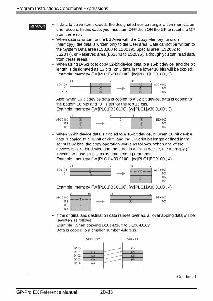
• If data to be written exceeds the designated device range, a communication error occurs. In this case, you must turn OFF then ON the GP to reset the GP from the error.
• When data is written to the LS Area with the Copy Memory function (memcpy), the data is written only to the User area. Data cannot be written to the System Data area (LS0000 to LS0019), Special area (LS2032 to LS2047), or Reserved area (LS2048 to LS2095), although you can read data from these areas.
• When using D-Script to copy 32-bit device data to a 16-bit device, and the bit length is designated as 16 bits, only data in the lower 16 bits will be copied.Example: memcpy ([w:[PLC1]w30.0100], [w:[PLC1]BD0100], 3)
31 150BD0100
101102
w30.0100101102
0
Also, when 16 bit device data is copied to a 32 bit device, data is copied to the bottom 16 bits and "0" is set for the top 16 bits.Example: memcpy ([w:[PLC1]BD0100], [w:[PLC1]w30.0100], 3)
031 0BD0100
101102
w30.0100101102
000
15
• When 32-bit device data is copied to a 16-bit device, or when 16-bit device data is copied to a 32-bit device, and the D-Script bit length defined in the script is 32 bits, the copy operation works as follows. When one of the devices is a 32-bit device and the other is a 16-bit device, the memcpy ( ) function will use 16 bits as its data length parameter.Example: memcpy ([w:[PLC1]w30.0100], [w:[PLC1]BD0100], 4)
31 150BD0100
101w30.0100
101102103
0
Example: memcpy ([w:[PLC1]BD0100], [w:[PLC1]w30.0100], 4)310 0
BD0100101
w30.0100101102103
15
• If the original and destination data ranges overlap, all overlapping data will be rewritten as follows:Example: When copying D101-D104 to D100-D103Data is copied to a smaller number Address.
Copy From Copy To
D100D101D102D103D104
(1)(2)(3)(4)
(1)(2)(3)(4)
Program Instructions/Conditional Expressions
GP-Pro EX Reference Manual 20-83
Continued

Example: When copying D100-D103 to D101-D104Data is copied to a larger number Address.
Copy From Copy To
D100D101D102D103D104
(1)(2)(3)(4)
(1)(2)(3)(4)
• Although this example's function designates 2 Addresses, these Addresses will not be counted as D-Script Addresses.
• When using a device address for assignment, communication with the device/PLC causes a slight delay in assigning the value.
Program Instructions/Conditional Expressions
GP-Pro EX Reference Manual 20-84

Program Instructions/Conditional Expressions
GP-Pro EX Reference Manual 20-85
Copy Memory (Variable)
Example expression: [t:0000]=10, [t:0001]=20_memcpy_EX ([w:[#INTERNAL]LS 0100]#[t:0000], [w:[PLC1]D0100]#[t:0001], 5)
In the example above, five words of data are read out from D0120 and written into LS0110 to LS0114.
Function Description
Summary Copies device memory in one operation. The data of addresses specified with Parameter 3 are copied from the source word address specified with Parameter 2 to the destination word address specified with Parameter 1.The number of addresses that can be used is from 1 to 640. With the "_memcpy_EX" function, the source address, destination address, and number of addresses can be designated indirectly.
Format _memcpy_EX ([Copy To Address], [Copy From Address], Words)Parameter 1: Device address + Temporary addressParameter 2: Device address + Temporary addressParameter 3: Numeric Value, Internal Device, Temporary address (The valid range for
Parameter 3 is from 1 to 640.)
• If the original and destination data ranges overlap, all overlapping data will be rewritten as follows:Example: When copying LS101-LS104 to LS100-LS103Data is copied to a smaller number Address.
Example: When copying LS100-LS103 to LS101-LS104Data is copied to a larger number Address.
LS100101102103104
(1)(2)(3)(4)
(1)(2)(3)(4)
Copy From Copy To
LS100101102103104
(1)(2)(3)(4)
(1)(2)(3)(4)
Copy From Copy To

Program Instructions/Conditional Expressions
GP-Pro EX Reference Manual 20-86
Memory Ring
Example expression 1:memring ([w:[#INTERNAL]LS1000], [w:[#INTERNAL]LS1030], 10)
(When Parameter 1 is smaller than Parameter 2 (P1 < P2))
Data moves upward in 10-word block units.
Function Description
Summary Ring-shifts the data in memory in blocks.Performs ring-shift between the start and ending addresses in block units (by the specified number of words). When an error occurs, the error status is written to LS9150.
Format memring ([Start Address], [End Address], Words in 1 Block)
Parameter 1: Internal DeviceParameter 2: Internal DeviceParameter 3: Numeric Value (1 to 640)- When Parameter 1 is smaller than Parameter 2 (P1 < P2), the block data is shifted upward.- When Parameter 1 is larger than Parameter 2 (P1 > P2), the block data is shifted downward.
• Make sure that the Start Address and End Address are set to the same type of device (LS or USR).
LS1000
LS1010
LS1020
LS1030
(1)
(2)
(3)
LS1000
LS1010
LS1020
LS1030
(2)
(3)
(1)

Program Instructions/Conditional Expressions
GP-Pro EX Reference Manual 20-87
Example expression 2:memring ([w:[#INTERNAL]LS1030], [w:[#INTERNAL]LS1000], 10)
(When Parameter 1 is greater than Parameter 2 (P1 > P2))
Data moves downward in 10-word block units.
Example expression 3:memring ([w:[#INTERNAL]LS1000], [w:[#INTERNAL]LS1050], 10)
(When the range contains a block where all words are "0".)
Data moves upward in 10-word block units only, from the starting block to the block with "0" data. If data exists after the block with "0" data, the data is ignored.
Example expression 4:memring ([w:[#INTERNAL]LS1050], [w:[#INTERNAL]LS1000], 10)
(When a block with "0" data exists within the range.)
Data moves downward in 10-word block units only, from the starting block to the block with "0" data. If data exists after the block with "0" data, the data is ignored.
LS1000
LS1010
LS1020
LS1030
(1)
(2)
(3)
LS1000
LS1010
LS1020
LS1030
(3)
(1)
(2)
LS1000
LS1010
LS1020
LS1030
LS1040
LS1050
(1)
(2)
(3)
(4)
"0" is stored in all 10 words.
LS1000
LS1010
LS1020
LS1030
LS1040
LS1050
(2)
(3)
(1)
(4)
"0" is stored in all 10 words.
LS1000
LS1010
LS1020
LS1030
LS1040
LS1050
(1)
(2)
(3)
(4)
"0" is stored in all 10 words.
LS1000
LS1010
LS1020
LS1030
LS1040
LS1050
(3)
(1)
(2)
(4)
"0" is stored in all 10 words.

Program Instructions/Conditional Expressions
GP-Pro EX Reference Manual 20-88
Error Status
Search Memory
Editor Function Name
LS Area Error Status Cause
memring ( ) LS9150 0000h Completed Successfully
0001h Parameter error
0003h Write/Read error
• The processing time required is proportional to the range designated by the start and end addresses. The larger the designated range, the longer the processing time becomes. The Part is not refreshed until processing is completed.
• The effective LS device range that can be specified is limited to the designated user area (LS20 to LS2031 and LS2096 to LS8191).
Function Description
Summary Performs a data search in block units, starting from the first item in the specified range. Compares data blocks, starting from the specified (offset) blocks and returns (saves) the search result to the specified storage address. When a matching block is found, the offset value of the block (1 or higher) is saved. When no matching block is found, "FFFFh" is saved. When an error occurs, the error status value is written to LS9153.
LS9150
LS Area

Program Instructions/Conditional Expressions
GP-Pro EX Reference Manual 20-89
Format _memsearch ([Searched Block Address], [Search Start Address], [Search End Address], [Search Result Storage Address], Offset from Start Block, Number of Compared Words, Words in 1 Block)
Parameter 1: Internal DeviceParameter 2: Internal DeviceParameter 3: Internal DeviceParameter 4: Internal DeviceParameter 5: Numeric Value (0 to 639), Internal Device, Temporary variableParameter 6: Numeric Value (1 to 640)Parameter 7: Numeric Value (1 to 640)
Data to be writtenWhen there are matching blocks: The block's offset value ("1" or higher)When there are no matching blocks: "FFFFh"
• Make sure that the search start address and search ending address are set to the same type of device (LS or USR). However, the [Searched Block Address] and [Search Result Storage Address] can be set to the Internal Device.
• Be sure that [Parameter 2] is smaller than [Parameter 3] (Parameter 2 < Parameter 3). Otherwise, an error occurs.

Program Instructions/Conditional Expressions
GP-Pro EX Reference Manual 20-90
Example expression 1:_memsearch ([w:[#INTERNAL]LS1000], [w:[#INTERNAL]LS1005],
[w:[#INTERNAL]LS1025],[w:[#INTERNAL]LS0100], 0, 1, 5)(Searches from LS1005 to LS1025 for a block with the same value. Starts from offset 0 of the source search block, and stores the result in LS0100.)
In this case, the value of "Block 1" matches the value of "the source search block"; As a result the search result "1" is stored in LS0100.
LS1000+1+2+3+4
LS1005+1+2+3+4
LS1010+1+2+3+4
LS1015+1+2+3+4
LS1020+1+2+3+4
LS1025
16 bitBB00hCC01hDD02hEE03hEE04hBB00hBB01hBB02hBB03hBB04hCC00hCC01hCC02hCC03hCC04hDD00hDD01hDD02hDD03hDD04hEE00hEE01hEE02hEE03hEE04h
Block 1
Block 2
Block 3
Block 4
Compares the value in one word (offset 0) of "the source search block" with "Block 1" in the search area.
Source search block
LS0100 1

Program Instructions/Conditional Expressions
GP-Pro EX Reference Manual 20-91
Example expression 2:_memsearch ([w:[#INTERNAL]LS1000], [w:[#INTERNAL]LS1005],
[w:[#INTERNAL]LS1025], [w:[#INTERNAL]LS0100], 3, 2, 5)
(Searches from LS1005 to LS1025 for a block with the same value. Uses two words, starting from an offset of 3, and stores the result in LS0100.)
In this case, the value of "Block 4" matches the value of "the source search block". As a result the search result "4" is stored in LS0100.
Error Status
Editor Function Name
LS Area Error Status Cause
_memsearch ( ) LS9153 0000h Completed Successfully
0001h Parameter error
0003h Write/Read error
LS1000+1+2+3+4
LS1005+1+2+3+4
LS1010+1+2+3+4
LS1015+1+2+3+4
LS1020+1+2+3+4
LS1025
16 bitBB00hCC01hDD02hEE03hEE04hBB00hBB01hBB02hBB03hBB04hCC00hCC01hCC02hCC03hCC04hDD00hDD01hDD02hDD03hDD04hEE00hEE01hEE02hEE03hEE04h
Block 1
Block 2
Block 3
Block 4
Compares the values stored in two words (offset of 3 from "source search block") with the data in the search area, starting from "Block 1".
Source search block
LS0100 4
LS9153
LS Area

• As the number of Addresses increases, more time is required for writing data to the PLC. Depending on the number of Addresses, it may take from 20 seconds to several minutes.
• If data to be written exceeds the designated device range, a communication error occurs. In this case, you must turn OFF then ON the GP to reset the GP from the error.
• Although this function designates addresses, they are not counted as D-Script addresses.
• When writing data to the LS Area with the Memory Reset (memset) function, the data can be written only into the User area. Data cannot be written into the System Data area (LS0000 to LS0019), Special area (LS2032 to S2047), or Reserved area (LS2048 to LS2095).
• When using device addresses for the Assign operation, the write values are not assigned immediately, due to the GP to PLC transmission time.For example:
memset ([w:[PLC1]D0100], 0, 10)Initialize //D100 to D109 to 0[ w:[PLC1]D200]=[w:[PLC1]D100]Substitute //D100 to D200In this case, the value 0 is written to D100 as the operation result has not
been assigned to D200 yet.
Program Instructions/Conditional Expressions
GP-Pro EX Reference Manual 20-92
Initialize Memory
Example expression:memset ([w:[PLC 1]D0100], 0, 10)
In the above example, "0" is set for the addresses D0100 to D0109.
• The processing time required is proportional to the range designated by the start and end addresses. The larger the designated range, the longer the processing time becomes. The Part is not refreshed until processing is completed.
• The effective LS device range that can be specified is limited to the designated user area (LS20 to LS2031 and LS2096 to LS8191).
Function Description
Summary Initializes all devices at once. Setting data for the number of Addresses is taken from the Set Word Address. The valid range for the number of addresses is from 1 to 640.
Format memset ([Write-To Address], Write Data, Words)

Program Instructions/Conditional Expressions
GP-Pro EX Reference Manual 20-93
Initialize Memory (Variable)
Example expression:[t:0000]=10[ w:[#INTERNAL]LS0050]=0[ w:[#INTERNAL]LS0051]=5_memset_EX ([w:[#INTERNAL]LS0100]#[t:0000], [w:[#INTERNAL]LS0050],
[w:[#INTERNAL]LS0051])In the example above, "0" will be written into the five words from LS0100 to LS0114.
Function Description
Summary Initializes all devices at once. The Set data specified with Parameter 2 are set from the Set Word Address specified with Parameter 1 into the addresses specified with Parameter 3. The valid range for the number of addresses is from 1 to 640. The Write-To Address, Write Data, and number of addresses can each be designated indirectly.
Format _memset_EX ([Write-To Address], Write Data, Words)
Parameter 1: Device address + Temporary addressParameter 2: Numeric Value, Internal Device, Temporary address (The valid range for
Parameter 2 is from 0 to 65535 for Dec, and from 0 to FFFF for Hex.)Parameter 3: Numeric Value, Internal Device, Temporary address (The valid range for
Parameter 3 is from 1 to 640.)

Program Instructions/Conditional Expressions
GP-Pro EX Reference Manual 20-94
Shift Memory
Function Description
Summary Deletes the specified block and moves the following data blocks upward. The block to be deleted is designated using an offset. When an error occurs, the error status is written to LS9151.
Format _memshift ([Start Address], [End Address], Offset of Block to Delete, Words in 1 Block)
Parameter 1: Internal DeviceParameter 2: Internal DeviceParameter 3: Numeric Value (1 to 65,535), Internal Device, Temporary variableParameter 4: Numeric Value (1 to 640)
• Make sure that the Start Address and End Address are set to the same type of device (LS or USR).
• Be sure that [Parameter 1] is smaller than [Parameter 2] (Parameter 1 < Parameter 2). Otherwise, an error occurs.

Program Instructions/Conditional Expressions
GP-Pro EX Reference Manual 20-95
Example expression 1:_memshift ([w:[#INTERNAL]LS1000], [w:[#INTERNAL]LS1030], 1, 10)
Data moves upward in block units (1 block = 10 words), and the last block (10 words) is cleared to zero.
Example expression 2:_memshift ([w:[#INTERNAL]LS 1000], [w:[#INTERNAL]LS1030], 2, 10)
The data moves upward in block units (1 block = 10 words) starting from the offset 2 position, and the last block (10 words) is cleared to zero.
Error Status
Editor Function Name
LS Area Error Status Cause
_memshift ( ) LS9151 0000h Completed Successfully
0001h Parameter error
0003h Write/Read error
LS1000
LS1010
LS1020
LS1030
(1)
(2)
(3)
LS1000
LS1010
LS1020
LS1030
(2)
(3)
Deletes Block (1) and moves the following data upward.
10 words are cleared and "0" is stored.
LS1000
LS1010
LS1020
LS1030
(1)
(2)
(3)
LS1000
LS1010
LS1020
LS1030
(1)
(3)
Deletes Block (2) and moves the following data upward.
10 words are cleared and "0" is stored.
LS9151
LS Area

Program Instructions/Conditional Expressions
GP-Pro EX Reference Manual 20-96
• The processing time required is proportional to the range designated by the start and end addresses. The larger the designated range, the longer the processing time becomes. The Part is not refreshed until processing is completed.
• When a value exceeding the range specified for the start and end addresses is designated as the offset of the block to delete, this feature does not operate correctly.
• The effective LS device range that can be specified is limited to the designated user area (LS20 to LS2031 and LS2096 to LS8191).

Program Instructions/Conditional Expressions
GP-Pro EX Reference Manual 20-97
20.10.4 SIO Port Operation
SIO Port Operation Function Summary
Label Settings" Label Settings" (page 20-99)
Set from the Control, Status, Receive Data Count, Receive Function, and Send Function.
Receive" Receive" (page 20-101)
Reads received data from the designated serial port (COM1 or COM2).
Send" Send" (page 20-102)
Writes to the designated serial port (COM1 or COM2).
Extended Receive" Extended Receive" (page 20-103)
Reads received data from the designated serial port (COM1 or COM2).It can only be used in an Extended Script.
Extended Send" Extended Send" (page 20-104)
Writes to the designated serial port (COM1 or COM2).It can only be used in an Extended Script.
Standby Reception Function" Standby Receive Function" (page 20-105)
Stays in standby receive mode until it receives specified strings.It can only be used in an Extended Script.
Standby Function" Standby Function" (page 20-106)
The system waits (suspends operation) for the specified period of time until it executes the process.It can only be used in an Extended Script.

• Label Settings, Send, and Receive can be easily included in a D-Script/Global D-Script.
• To communicate with D-Scripts/Global D-Scripts, set the following script settings. If script settings are not designated, they cannot execute.
[D-Script/Global D-Script I/O Procedure]In the [System Settings] [Script I/O Settings] page, set the [Type] to [D-Script/Global D-Script].
There are 2 tabs in the Script I/O. "Script 1" is shown above.Set the [Port] to COM1 or COM2, and set the [Communication Settings] to match the Extended SIO.
• When creating a communication program with more advanced functionality than the SIO port operation, it is recommended to use an [Extended Script]. For examples on how to use extended scripts, see "20.5 Communicating with Unsupported Peripheral Devices" (page 20-21)
Program Instructions/Conditional Expressions
GP-Pro EX Reference Manual 20-98

Program Instructions/Conditional Expressions
GP-Pro EX Reference Manual 20-99
Label SettingsControl
Example expression:When designating the bit: [c:EXT_SIO_CTRL00] = 1When designating the word: [c:EXT_SIO_CTRL] = 0x0007
EXT_SIO_CTRL
Status
Example expression:When designating the bit: if ([s:EXT_SIO_STAT 00] == 1)When designating the word: if ( ( [s:EXT_SIO_STAT] & 0x0001) <> 0)
Function Description
Summary This control variable is used to clear the Send buffer, Receive buffer, and error status. This control variable is write-only.
Format When designating the bit: [c:EXT_SIO_CTRL∗∗] (∗∗: 00 to 15)When designating the word: [c:EXT_SIO_CTRL]
• When a word is designated (when two or more bits are set simultaneously), the processing is executed in the following order: Clear Error → Clear Receive Buffer → Clear Send Buffer
Function Description
Summary Status includes the following information.This status variable is write-only.
Format When designating the bit: [s:EXT_SIO_STAT∗∗] (∗∗ : 00 to 15)When designating the word: [s:EXT_SIO_STAT]
15 14 13 12 11 10 9 8 7 6 5 4 3 2 1 0
Bit1514131211109876543210
Content
Reserved
1: Clear Receive timeout1: Clear error1: Clear Receive buffer1: Clear Send buffer

Program Instructions/Conditional Expressions
GP-Pro EX Reference Manual 20-100
Contents of EXT_SIO_STAT
Received Data Size
• The reserved bits may be assigned in the future. Therefore, be sure to check only the necessary bits.
• Two types of transmission errors exist: the transmission timeout error and the transmission buffer-full error. When either of the two errors occurs, the transmission error bit turns ON. The transmission timeout period is five seconds.
• There are four types of receive errors: parity error, overrun error, framing error, and overflow. When one of these four errors occurs, the bit for the receive error turns ON.
• If a transmission error is detected, the send data remains in the transmission buffer. If a transmission error cannot be detected, the send data is sent from the transmission buffer.
• When using the serial interface COM2, which is RS-422, the CS (CTS) signal cannot be detected. As a result, disconnection of a cable cannot be detected.
Function Description
Summary Shows the quantity of data (number of bytes) received at that time. The received data size is read-only.
Format [r:EXT_SIO_RECV]
15 14 13 12 11 10 9 8 7 6 5 4 3 2 1 0
Bit15
14
13121110987654
3
2
1
0
Content0: No D-Script/Global D-Script1: D-Script/Global D-Script exists0: No extended script1: Extended script exists
Reserved
0: Normal1: Receive timeout0: Normal1: Receive error0: No receive data1: Receive data exists0: Normal1: Send error0: Data exists in Send buffer1: Send buffer is empty

Program Instructions/Conditional Expressions
GP-Pro EX Reference Manual 20-101
Receive
Example expression:IO_READ ([p:EXT_SIO], [w:[#INTERNAL]LS0100], 10)
In the above example, the number of bytes received is stored in LS0100. 10 bytes of data is stored starting from LS0101. The following image shows the stored received data.
• Label name of the Number of Received Data (number of bytes)With GP-PRO/PB III V.6.0 and earlier versions, the Label name designated for the received data size is [r: EXT_SIO_RCV]. However, you are not required to revise the description because the function is the same whether [r: EXT_SIO_RCV] or [r: EXT_SIO_RECV] expression is selected.
Function Description
Summary Write the statement as follows when reading out the received data from the Extended SIO.
Format IO_READ ([p:EXT_SIO], Data Storage Address, Number of Receive Bytes)
Parameter 1: EXT_SIOParameter 2: Internal DeviceParameter 3: Numeric Value
• The maximum number of transfer bytes during data reception is 2,011. The data is written to each word address in units of 1 byte.
LS0100LS0101LS0102LS0103LS0104LS0105LS0106LS0107LS0108LS0109LS0110
00000000000000000000
Byte 1Byte 2Byte 3Byte 4Byte 5Byte 6Byte 7Byte 8Byte 9
Byte 10
Received Data Size
Received Data Storage Method
... 10 bytes

Program Instructions/Conditional Expressions
GP-Pro EX Reference Manual 20-102
Send
Example expression:IO_WRITE ([p:EXT_SIO], [w:[#INTERNAL]LS0100], 10)
In the above example, 10 bytes of data starting from LS0100 are sent. The following image shows the stored sent data.
Function Description
Summary Write the statement as follows when writing data to the Extended SIO.
Format IO_WRITE ([p:EXT_SIO], Data Storage Address, Number of Send Bytes)
Parameter 1: EXT_SIOParameter 2: Internal DeviceParameter 3: Numeric Value
• The maximum number of transfer bytes when receiving data is 2,012.• As the LS device for the Send buffer, write the data in single bytes to each
word address.
LS0100LS0101LS0102LS0103LS0104LS0105LS0106LS0107LS0108LS0109
00000000000000000000
Byte 1Byte 2Byte 3Byte 4Byte 5Byte 6Byte 7Byte 8Byte 9
Byte 10
Sent Data Storage Method

Program Instructions/Conditional Expressions
GP-Pro EX Reference Manual 20-103
Extended Receive
Example expression:IO_READ_EX ([p:EXT_SIO], databuf 1, 10)
In the above example, 10 bytes of data in the data received by the Extended SIO are received and stored in "databuf1".
Function Description
Summary Receives data of the size indicated in Received Data Size (bytes) from the Extended SIO and stores it in the data buffer. The number of bytes specified with Parameter 3 is received from the Extended SIO and stored in the data buffer specified with Parameter 2.It can only be used in an Extended Script.
Format IO_READ_EX ([p:EXT_SIO], Data Buffer, Number of Receive Bytes)
Parameter 1: [p:EXT_SIO]Parameter 2: Data BufferParameter 3: Numeric Value, Internal Device, Temporary address (The valid range for
Parameter 3 is from 1 to 1,024.)

Program Instructions/Conditional Expressions
GP-Pro EX Reference Manual 20-104
Extended Send
Example expression:IO_WRITE_EX ([p:EXT_SIO], databuf 0, 10)
In the example above, 10 bytes of data in "databuf0" are sent from Extended SIO.
Function Description
Summary Sends the data in the data buffer with Extended SIO according to the size of Number of Send Bytes. The contents of the data buffer specified with Parameter 2 are sent from Extended SIO by the length specified with Parameter 3.It can only be used in an Extended Script.
Format IO_WRITE_EX ([p:EXT_SIO], Data Buffer, Number of Send Bytes)
Parameter 1: [p:EXT_SIO]Parameter 2: Data BufferParameter 3: Numeric Value, Internal Device, Temporary address (The valid range for
Parameter 3 is from 1 to 1,024.)

Program Instructions/Conditional Expressions
GP-Pro EX Reference Manual 20-105
Standby Receive Function
Function Description
Summary Stays in standby receive mode until it receives specified text. After the timeout period has expired, Bit 4 (Receive time-out error) of Status [s: EXT_SIO_STAT] is set. The timeout duration can be set in 100 ms increments.The system is in standby receive mode until it receives the character string or character code specified with Parameter 2. Configure the timeout duration with Parameter 3.It can only be used in an Extended Script.
Format IO_READ_WAIT([p:EXT_SIO], Text, Time-out)
Parameter 1: [p:EXT_IO]Parameter 2: Numeric Value, Text, Data BufferParameter 3: Numeric Value, Internal Device, Temporary address (The valid range for
Parameter 3 is from 1 to 600.)
• The received data cannot be used until the specified text is received. (Otherwise, the data are abandoned.)
• Up to 128 characters (bytes) can be specified. Note that the standby receive operation cannot be performed successfully when strings exceeding the limit are specified.

Program Instructions/Conditional Expressions
GP-Pro EX Reference Manual 20-106
Standby Function
Example expression:_wait ( 10)
In the example above, the system waits one second.
Function Description
Summary The system waits for the specified period of time. The time can be configured in 100 ms increments.It can only be used in an Extended Script.
Format _wait (Wait Time)
Parameter 1: Internal Device, Temporary address, Numeric Value (The valid range for Parameter 1 is from 1 to 600.)

Program Instructions/Conditional Expressions
GP-Pro EX Reference Manual 20-107
20.10.5 CF File Operation/USB File Operation
Operate CF File Function Summary
Label Settings" Label Settings" (page 20-108)
Set from the Number of Files Listed, Number of Read Bytes, and CF Card/USB Storage Error Status.
Write File" Write File" (page 20-118)
Writes the specified number of bytes of data from the source address to the specified file.
Change File Name" Change File Name" (page 20-122)
Modifies the file name.
Read CSV File" Read CSV FileRead" (page 20-124)
Reads data in cell units from a CSV file and writes it to a word address.
Read File" Read File" (page 20-127)
Reads the specified number of bytes of data in the file after the specified offset and writes it in the destination address.
Output File List" Output File List" (page 20-129)
The list of files that exist in the specified folder is written in the Internal Device.
Delete File" Delete File" (page 20-131)
Deletes the file.

Program Instructions/Conditional Expressions
GP-Pro EX Reference Manual 20-108
Label SettingsThe following are possible status values for CF Card/USB Storage Status.
Listed FilesWhen the File List Output function "_CF_dir ( )" ( ) or "_USB_dir" ( ) is executed, the number of file lists that are actually written in the LS Area is stored in "Listed Files [s:CF_FILELIST_NUM]/[s:USB_FILELIST_NUM]".
Usage example_CF_dir ("\DATA\∗.∗", [w:[#INTERNAL]LS0100], 10, 0)[w:LS0200] = [s:CF_FILELIST_NUM]
When obtaining a file list of the 10 files and the specified folder contains only five files, "5" is stored in [s:CF_FILELIST_NUM].
Number of Read BytesWhen the File Read function "_CF_read ( )" ( ) or "_USB_read" ( ) is executed, the number of bytes actually read out is stored in "Readout Bytes [s:CF_READ_NUM] / [s:USB_READ_NUM].
Usage example_CF_read ("\DATA", "DATA0001.BIN", [w:[#INTERNAL]LS0100], 16, 16)[w:[#INTERNAL]LS0200] = [s:CF_READ_NUM]
When an attempt is made to read 16 bytes but only 12 bytes are read successfully,"12" is stored in [s:CF_READ_NUM].
Status name Label name Description
Listed Files [s:CF_FILELIST_NUM][s:USB_FILELIST_NUM]
Stores the number of files actually listed when the File List Output function "_CF_dir ( )" or "_USB _dir ( )" is executed.
Number of Read Bytes [s:CF_READ_NUM][s:USB_READ_NUM]
Stores the number of bytes that can actually be read out when the File Read function "_CF_read ( )" or "_USB_read ( )" is executed.
CF Card/USB Storage Error Status
[s:CF_ERR_STAT][s:USB_ERR_STAT]
Stores the error status generated when the CF Card or USB Storage is accessed.
• When no files are written, the total number of files contained in the specified folder is written in [s:CF_FILELIST_NUM].
\DATA DATA0000.BINDATA0001.BINDATA02.BINDATA003.BINDATA0004.BIN

Program Instructions/Conditional Expressions
GP-Pro EX Reference Manual 20-109
CF Card/USB Storage Error StatusStores the error status generated when the CF Card or USB Storage is accessed.
Bit Position
Error Name Description
15 Reserved Reserved
14
13
12
11
10
9
8
7
6 File rename error • CF Card/USB Storage is removed during execution.
• Specified file does not exist.
5 File delete error • CF Card/USB Storage is removed during execution.
• Specified file does not exist.• An attempt was made to delete a file with a read-
only attribute.
4 File write error • CF Card/USB Storage is removed during execution.
• Free space of CF Card/USB Storage capacity exceeded.
• An attempt was made to write data to a file with a read-only attribute.
• An attempt was made to "overwrite" a file that does not exist.
3 File read error • CF Card/USB Storage is removed during execution.
• Specified file does not exist.
2 File list error • CF Card/USB Storage is removed during execution.
• Specified folder does not exist.
1 CF/USB Storage Card Error
• CF Card/USB Storage is invalid.• The media inserted is not a CF Card.
0 CF/USB No storage card
• CF Card/USB storage is not inserted.• Cover is open.

Program Instructions/Conditional Expressions
GP-Pro EX Reference Manual 20-110
• Even when a CF Card/USB storage Error occurs, processing will continue. Be sure to write the script so that it checks for errors when you use the file operation functions of a CF Card/USB storage. For example:
_CF_dir ("\DATA\∗.∗", [w:[#INTERNAL]LS0100], 2, 1) Outputs a file list.if ([s:CF_ERR_STAT02] <> 0) // Checks the error status.{
set ([b:[#INTERNAL]LS 005000]) // Sets the bit address for error display.}endif
CF Card/USB storage Error Detail Status Storage AreaEach Bit will be set when an error occurs. You can check what factors lead to the error by setting Detail Status. In each function, Detail Status is stored in LS9132 to LS9137 for Extend System Area (LS9138 to LS9143 for USB storage). These areas are only for Read-in.
LS0000:
LS9132LS9133LS9134LS9135LS9136LS9137
:LS9999
CF List StatusCF Read StatusCF Write StatusCF Delete StatusCF Rename StatusCF CSV Read Status
LS AreaLS0000
:LS9138LS9139LS9140LS9141LS9142LS9143
:LS9999
USB List StatusUSB Read StatusUSB Write StatusUSB Delete StatusUSB Rename StatusUSB CSV Read Status
LS Area

Program Instructions/Conditional Expressions
GP-Pro EX Reference Manual 20-111
Error list for each function
Editor Function Name
Error Status Cause
_CF_dir ( ) LS9132 0010h Invalid D-Script data (Error in retrieving folder name specified with fixed string)
0012h File name (path name) error
0018h LS Area writing range error
0020h No CF Card
0021h Invalid CF Card
0100h Directory open error
_CF_read ( ) LS9133 0010h Invalid D-Script data (Error in retrieving folder name/file name specified with fixed string)
0011h LS Area reading range error
0010002h File name (path name) error
0018h LS Area writing range error
0020h No CF Card
0021h Invalid CF Card
0101h File seek error (Offset error)
0102h Number of readout bytes error
0110h File creation (open) error
_CF_write ( ) LS9134 0010h Invalid D-Script data (Error in retrieving folder name/file name specified with fixed string)
0011h LS Area reading range error
0010002h File name (path name) error
0020h No CF Card
0021h Invalid CF Card
0101h File seek error (Offset error)
0104h Folder creation error
0108h Write mode error
0110h File creation (open) error
0111h File write error (Example Insufficient space on CF Card)
Continued

Program Instructions/Conditional Expressions
GP-Pro EX Reference Manual 20-112
Editor Function Name
Error Status Cause
_CF_delete ( ) LS9135 0010h Invalid D-Script data (Error in retrieving folder name/file name specified with fixed string)
0011h LS Area reading range error
0010002h File name (path name) error
0020h No CF Card
0021h Invalid CF Card
0112h File delete error (Example Specified file does not exist. Specified file is read-only.)
_CF_rename ( ) LS9136 0010h Invalid D-Script data (Error in retrieving folder name/file name specified with fixed string)
0011h LS Area reading range error
0010002h File name (path name) error
0020h No CF Card
0021h Invalid CF Card
0114h File rename error (Specified file does not exist. File name already exists.)
_CF_read_csv ( ) LS9137 0001h Parameter error
0002h CF Card error (No CF Card, Open file error, File read error)
0003h Write Error
Continued

Program Instructions/Conditional Expressions
GP-Pro EX Reference Manual 20-113
Editor Function Name Error Status Cause
_USB_dir ( ) LS9138 0010h Invalid D-Script data (Error in retrieving folder name specified with fixed string)
0010002h File name (path name) error
0018h LS Area writing range error
0020h No USB storage
0021h Invalid USB storage
0100h Directory open error
_USB_read ( ) LS9139 0010h Invalid D-Script data (Error in retrieving folder name/file name specified with fixed string)
0011h LS Area reading range error
0010002h File name (path name) error
0018h LS Area writing range error
0020h No USB storage
0021h Invalid USB storage
0101h File seek error (Offset error)
0102h Number of readout bytes error
0110h File creation (open) error
_USB_write ( ) LS9140 0010h Invalid D-Script data (Error in retrieving folder name/file name specified with fixed string)
0011h LS Area reading range error
0010002h File name (path name) error
0020h No USB storage
0021h Invalid USB storage
0101h File seek error (Offset error)
0104h Folder creation error
0108h Write mode error
0110h File creation (open) error
0111h File write error (Example: Insufficient space on USB storage)
Continued

Program Instructions/Conditional Expressions
GP-Pro EX Reference Manual 20-114
_USB_delete ( ) LS9141 0010h Invalid D-Script data (Error in retrieving folder name/file name specified with fixed string)
0011h LS Area reading range error
0010002h File name (path name) error
0020h No USB storage
0021h Invalid USB storage
0112h File delete error (Example Specified file does not exist. Specified file is read-only.)
_USB_rename ( ) LS9142 0010h Invalid D-Script data (Error in retrieving folder name/file name specified with fixed string)
0011h LS Area reading range error
0010002h File name (path name) error
0020h No USB storage
0021h Invalid USB storage
0114h File rename error (Example Specified file does not exist. File name already exists.)
_USB_read_csv ( ) LS9143 0001h Parameter error
0002h USB storage error (No USB storage, File open error, File read error)
0003h Write Error
Editor Function Name Error Status Cause
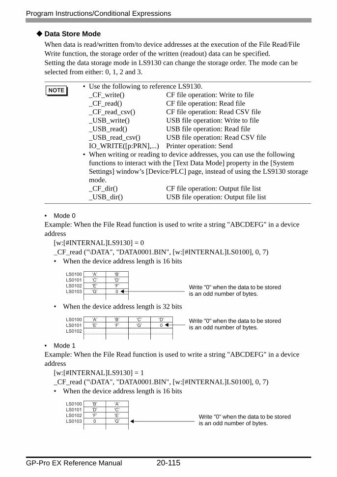
Program Instructions/Conditional Expressions
GP-Pro EX Reference Manual 20-115
Data Store ModeWhen data is read/written from/to device addresses at the execution of the File Read/File Write function, the storage order of the written (readout) data can be specified.Setting the data storage mode in LS9130 can change the storage order. The mode can be selected from either: 0, 1, 2 and 3.
• Mode 0Example: When the File Read function is used to write a string "ABCDEFG" in a device address
[w:[#INTERNAL]LS9130] = 0_CF_read ("\DATA", "DATA0001.BIN", [w:[#INTERNAL]LS0100], 0, 7)• When the device address length is 16 bits
• When the device address length is 32 bits
• Mode 1Example: When the File Read function is used to write a string "ABCDEFG" in a device address
[w:[#INTERNAL]LS9130] = 1_CF_read ("\DATA", "DATA0001.BIN", [w:[#INTERNAL]LS0100], 0, 7)• When the device address length is 16 bits
• Use the following to reference LS9130. _CF_write() CF file operation: Write to file _CF_read() CF file operation: Read file _CF_read_csv() CF file operation: Read CSV file _USB_write() USB file operation: Write to file _USB_read() USB file operation: Read file _USB_read_csv() USB file operation: Read CSV file IO_WRITE([p:PRN],...) Printer operation: Send
• When writing or reading to device addresses, you can use the following functions to interact with the [Text Data Mode] property in the [System Settings] window’s [Device/PLC] page, instead of using the LS9130 storage mode. _CF_dir() CF file operation: Output file list _USB_dir() USB file operation: Output file list
LS0100 LS0101 LS0102 LS0103
‘A’ ‘C’ ‘E’ ‘G’
‘B’ ‘D’ ‘F’ 0
Write "0" when the data to be stored is an odd number of bytes.
LS0100 LS0101 LS0102
‘A’ ‘E’
‘B’ ‘F’
‘C’ ‘G’
‘D’ 0
Write "0" when the data to be stored is an odd number of bytes.
LS0100 LS0101 LS0102 LS0103
‘B’ ‘D’ ‘F’ 0
‘A’ ‘C’ ‘E’ ‘G’
Write "0" when the data to be stored is an odd number of bytes.

Program Instructions/Conditional Expressions
GP-Pro EX Reference Manual 20-116
• When the device address length is 32 bits
• Mode 2Example: When the File Read function is used to write a string "ABCDEFG" in a device address
[w:[#INTERNAL]LS9130] = 2_CF_read ("\DATA", "DATA0001.BIN", [w:[#INTERNAL]LS0100], 0, 7)• When the device address length is 16 bits
• When the device address length is 32 bits
• Mode 3Example: When the File Read function is used to write a string "ABCDEFG" in a device address
[w:[#INTERNAL]LS9130] = 3_CF_read ("\DATA", "DATA0001.BIN", [w:[#INTERNAL]LS0100], 0, 7)• When the device address length is 16 bits
• When the device address length is 32 bits
LS0100LS0101LS0102
‘B’‘F’
‘A’‘E’
‘D’0
‘C’‘G’
Write "0" when the data to be stored is an odd number of bytes.
LS0100LS0101LS0102LS0103
‘C’‘A’‘G’‘E’
‘D’‘B’0‘F’
Write "0" when the data to be stored is an odd number of bytes.
LS0100LS0101LS0102
‘C’0
‘D’‘G’
‘A’‘E’
‘B’‘F’
Write "0" when the data to be stored is an odd number of bytes.
LS0100LS0101LS0102LS0103
‘D’‘B’0‘F’
‘C’‘A’‘G’‘E’
Write "0" when the data to be stored is an odd number of bytes.
LS0100LS0101LS0102
‘D’0
‘C’‘G’
‘B’‘F’
‘A’‘E’
Write "0" when the data to be stored is an odd number of bytes.

• The data storage mode is not the same as the string data mode in the system setting. The relationship with the string data mode is shown in the following table.
Data Device Storage Order
Bytes in Word LH/HL Storage Order
LH/HL Storage Order In Double Word
D-Script data storage mode
Text Data Mode
Store from Start Data
HL Order HL Order 0 1
LH Order 1 2
HL Order LH Order 2 5
LH Order 3 4
Store from Last Data
HL Order HL Order - 3
LH Order - 7
HL Order LH Order - 8
LH Order - 6
• There is a limit to the frequency that data can be rewritten to the CF Card. Therefore, be sure to backup all CF Card data regularly to another storage media. Assuming that 500 KB of DOS format data is overwritten, the limit is 100,000 times.
• If an error occurs during CF Card/USB storage processing, the error is written to the CF Card Error/USB storage error status [s:CF_ERR_STAT]/[s:USB_ERR_STAT]. For more details, see " CF Card/USB Storage Error Status" (page 20-109).
• The following symbols and characters cannot be used in folder names or file names. Use of these symbols and characters in a folder name or file name will generate an error.
: , = + / " [
] | < > (space) ?
• To specify a root folder (directory), specify " " (empty string) as the folder name.
Program Instructions/Conditional Expressions
GP-Pro EX Reference Manual 20-117
Continued

Program Instructions/Conditional Expressions
GP-Pro EX Reference Manual 20-118
Write File
Function Description
Summary Writes the specified number of bytes of data from the source address to the specified file. Any one of three modes can be selected: "New", "Add" or "Overwrite". See the "Data Storage Mode" section below for more details about data storage order.
Format _CF_write/_USB_write (folder names, file names, read from addresses, offset, the number of bytes, mode)
Parameter1Folder name: Fixed string (Maximum length: 32 single-byte characters)
Parameter 2File name: Fixed string, Internal Device (Maximum length: 32 single-byte
characters), Internal Device + Temporary addressParameter 3
Read From Address: Device address, Device address + Temporary addressParameter 4
Offset: Numeric Value, Device address, Temporary address (Maximum number that can be specified: 65,535 for 16-bit length, 4,294,967,295 for 32-bit length)
Parameter 5Number of bytes: Numeric Value, Device address, Temporary address (Maximum length: 1280)
Parameter 6Mode: Numeric Value, Device address, Temporary address (Available values: 0,1,2)

Program Instructions/Conditional Expressions
GP-Pro EX Reference Manual 20-119
Storage Format Overview
Example expression:[w:[#INTERNAL]LS0200] = 0//Offset ("0" when the mode is "New")[w:[#INTERNAL]LS0202] = 100 // Number of Bytes (100 bytes)[w:[#INTERNAL]LS0204] = 0//Mode (New)_CF_write ("\DATA", "DATA0001.BIN", [w:[#INTERNAL]LS0100],
[w:[#INTERNAL]LS0200], [w:[#INTERNAL]LS0202], [w:[#INTERNAL]:LS0204])
In the previous example, 100 bytes of data is read from LS0100 and stored in the \DATA folder as DATA0001.BIN. You can indirectly define the byte count and mode by defining the offset, byte count, and mode with internal devices.
Mode Name Description
0 New Create a new file. If a file with the same name exists, it is deleted.
1 Add Add the data to a specified file. If the specified file does not exist, a new file is created.
2 Overwrite Overwrite part of the file. If the specified offset is larger than the file size, the surplus area is filled with 0s and the data is written after the area. If the offset is specified at the end of the file data, the operation is equivalent to adding the data to the file. If the file does not exist, an error occurs. For more information about this error, please see " CF Card/USB Storage Error Status" (page 20-109).
• The offset setting is effective only in "Overwrite" mode. The offset setting is disabled in "New" and "Add" modes. Set the offset value to "0" in modes other than "Overwrite" mode.
• When "New" mode is specified and a file with the same name already exists, it is overwritten.
• When the LS Area is specified for "File name", "Read From Address" is not counted as a D-Script address.
• When a PLC device is defined as the "Read From Address", data is read from the PLC only once when the function is executed. If an error occurs during data read, it results in a CF Card or USB storage read error: [s:CF_ERR_STAT] or [s:<USB_ERR_STAT]. The error is cleared when the data read is successfully completed.
• The data is divided into items and read from the source, although this depends on the number of bytes to be read. Therefore, even if a communication error occurs during data read, the data may have been partially written to the specified file.
• To specify a full path for a file name, specify "“∗”" (asterisk) as the folder name.For example: _CF_read ("∗", "\DATA\DATA0001.BIN", [w:[#INTERNAL]LS0100], 0, 10)

Program Instructions/Conditional Expressions
GP-Pro EX Reference Manual 20-120
Storage format example expression
When "New" mode is specified
In the example above, 100 bytes of data are read from LS0100 and the DATA0001.BIN file is newly created in the \DATA folder.
When "Add" mode is specified
If the specified file (DATA0001.BIN in the example) already exists and the statement above is executed, 100 bytes of data are read from LS0100 and following areas and added to the DATA0001.BIN file in the \DATA folder.
When "Overwrite" mode is specified (1)
If the specified file (DATA0001.BIN in the example) already exists and the above statement is executed, 10 bytes of data stored in LS0100 and following areas are read and overwritten over the 10 bytes of data stored in the 17th and following bytes after the offset in the DATA0001.BIN file in the \DATA folder.
When "Overwrite" mode is specified (2)(The file to be overwritten is less than the sum of the offset value and number of added bytes.)
• Only the 8.3 format (a maximum of 12 characters, with 8 characters for the file name, the period, and 3 characters for the extension) can be used for the file name. A file name longer than this format cannot be used.
Folder name File Name Read from address
OffsetNumber of bytes
Mode_CF_write ("\DATA", "DATA0001.BIN", [w:[#INTERNAL]LS0100], 0, 100, 0 )
_CF_write ("\DATA", "DATA0001.BIN", [w:[#INTERNAL]LS0100], 0, 100, 1 )
Folder name File Name Read from addressOffsetNumber of bytes
Mode
_CF_write ("\DATA", "DATA0001.BIN", [w:[#INTERNAL]LS0100], 16, 10, 2 )
Folder name File Name Read from addressOffset
Number of bytesMode
_CF_write ("\DATA", "DATA0001.BIN", [w:[#INTERNAL]LS0100], 96, 10, 2 )
Folder name File Name Read from addressOffset
Number of bytesMode

• The maximum allowable number of characters for the first parameter (Folder name) and the second parameter (File name) is 32 single-byte characters.
• An Internal Device can be specified for the second parameter (File name). Specifying the Internal Device allows indirect addressing of a file name. Also, up to 32 single-byte characters can be used to specify a file name.For example: _CF_write ("\DATA", [w:[#INTERNAL]LS0100], [w:[#INTERNAL]LS0200], 0, 100, 0)Storing a file name in LS0100 allows indirect addressing of a file name. In this example, a file name is stored in LS0100 through LS0106 as follows.
LS0100LS0101LS0102LS0103LS0104LS0105LS0106
‘D’‘T’‘0’‘0’‘.’‘I’
‘\0’
‘A’‘A’‘0’‘1’‘B’‘N’‘\0’
16 bit
:
The end of the file name must be a NULL character. The display device recognizes the data before the NULL character as the file name.
In the example above, 100 bytes of data are read from LS0200 and following areas and a new file, "\DATA\DATA0001.BIN", is created for storing the data.
• As for the file name, only the "8.3 format" (a maximum of 12 characters, with 8 characters for the file name, the period, and 3 characters for the extension) may be used. Long file names cannot be used.
Program Instructions/Conditional Expressions
GP-Pro EX Reference Manual 20-121
The specified file (DATA0001.BIN in the example) already exists and the file size is 100 bytes. When the offset is set to 96 bytes and the number of bytes is set to 10 bytes for the overwrite operation, 10 bytes of data stored in LS0100 and following areas are read. Then, the first 4 bytes of readout data overwrite the 4 bytes of data stored in the 97th and following bytes in the file, and the remaining 6 bytes of data are added to the end of the file data. The resulting file contains 106 bytes of data.
When "Overwrite" mode is specified (3)(The file to be overwritten is smaller than the offset value.)
The specified file (DATA0001.BIN in the example) already exists and the file size is 100 bytes. When the offset is set to 110 bytes and the number of bytes is set to 10 bytes for the overwrite operation, the area between the 101st byte and 110th bytes is filled with 0s and the 10 bytes of data read from LS0100 and following areas are written in the 111th and following bytes. The resulting file contains 120 bytes of data.
_CF_write ("\DATA", "DATA0001.BIN", [w:[#INTERNAL]LS0100], 110, 10, 2 )
Folder name File Name Read from addressOffset
Number of bytesMode

Program Instructions/Conditional Expressions
GP-Pro EX Reference Manual 20-122
Change File Name
Function Description
Summary Modifies the file name. Parameter 1 designates the CF Card data folder. Parameter 2 designates the original file name. Parameter 3 designates the new name.
Format _CF_rename/_USB_rename (folder names, file names, changed file names)The file name can also be designated indirectly with the LS Address.
Parameter1Folder name: Fixed text
Parameter 2File name: Fixed text, Internal device, Internal device + Temporary address
Parameter 3File name: Fixed text, Internal device, Internal device + Temporary address

• As for the file name, only the "8.3 format" (a maximum of 12 characters, with 8 characters for the file name, the period, and 3 characters for the extension) may be used. Long file names cannot be used.
• The maximum allowable number of characters for the first parameter (Folder name) and the second parameter (File name) is 32 single-byte characters.
• An Internal Device can be specified for the second and third parameters (File names). Specifying the Internal Device allows indirect addressing of a file name. Also, up to 32 single-byte characters can be used to specify a file name.Example
_CF_rename ("\DATA", [w:[#INTERNAL]LS0100], [w:[#INTERNAL]LS0200])Storing the file name in LS0100 and LS0200 enables indirect addressing of the file name.
• Store the file names in LS0100 through LS0106 as follows:
LS0100LS0101LS0102LS0103LS0104LS0105LS0106
‘D’‘T’‘0’‘0’‘.’‘I’
‘\0’
‘A’‘A’‘0’‘1’‘B’‘N’‘\0’
16 bit
:
LS0200LS0201LS0202LS0203LS0204LS0205LS0206
‘D’‘T’‘1’‘3’‘.’‘I’
‘\0’
‘A’‘A’‘2’‘4’‘B’‘N’‘\0’
16 bit
:
The end of the file name must be a NULL character. The GP recognizes the data before the NULL character as the file name.
In the statement above, the “\DATA\DATA0001.BIN” file is renamed the “\DATA\DATA1234.BIN” file.
• When the LS Area is specified for "File name", it is not counted as a D-Script Address.
• To specify a root folder (directory), specify " " (empty string) as the folder name.
• To specify a full path for a file name, specify "“∗”" (asterisk) as the folder name.
Program Instructions/Conditional Expressions
GP-Pro EX Reference Manual 20-123
Example expression:_CF_rename ("\DATA","DATA0001.BIN","DATA1234.BIN")
In the example above, change to "\DATA\DATA0001.BIN" File Name "\DATA\DATA1234.BIN".

Program Instructions/Conditional Expressions
GP-Pro EX Reference Manual 20-124
Read CSV FileRead
Example expression:_CF_read_csv ("\CSV", "SAMPLE.CSV", [w:[#INTERNAL]LS1000], 1, 2)
(When reading two lines of data, starting from the first line of the [ \CSV\SAMPLE.CSV] file in the CF memory card using the "_CF_read_csv ( )" function.)
Function Description
Summary Reads data in cell units from a CSV file (constructed from a cell image delimited with ","), and writes it to a word address.
Format _CF_read_csv/_USB_read_csv (folder names, file names, save in addresses, start line, the number of lines read)
Parameter 1: Text (Up to 32 single-byte characters)Parameter 2: Text (Up to 32 single-byte characters), Internal Device, Internal Device +
Temporary addressParameter 3: Internal Device, Internal Device designated with offsetParameter 4: Numeric Value (1 to 65,535), Internal Device, Temporary variableParameter 5: Numeric Value (1 to 65,535), Internal Device, Temporary variable
LS1000+1+2+3+4+5+6+7+8+9
LS1010+1+2+3+4+5+6+7+8+9
‘D’‘T’‘1’‘0’
00h‘D’‘T’‘1’‘2’‘’
‘D’‘T’‘2’‘0’
00h‘D’‘T’‘2’‘2’
‘A’‘0’‘-’‘1’
00h‘A’‘0’‘-’
00h
‘A’‘0’‘-’‘1’
00h‘A’‘0’‘-’
00h
16 bit1
2
When the Data Storage Mode is 0
SAMPLE.CSV001, "DAT01-01", "DAT01-2"002, "DAT02-01", "DAT02-2"
Reads two lines of data, starting from the first line of the CSV file. When the first character is a numerical value ("0" to "9" or "−"), the data is stored as a numerical value. When the first character is ["], the data is treated as a character and "00h" is stored at the end of the text string. For example, when storing "”DAT01-01” " the data size is 8 characters, which is an even number, and a total of five words are used: Four words are used for storing the text string, and one word is used for storing "00h" at the end. For example, when storing "”DAT01-2”" the data size is 7 characters, which is an odd number, and a total of 4 words are used to store the text, with "00h" stored at the end.

Program Instructions/Conditional Expressions
GP-Pro EX Reference Manual 20-125
Error Status
• When the first character in the cell is a numerical value ("0" to "9", "−"), it converts the value to numerical data and then writes the data to the LS device. The allowed range is from −32,768 to 32,767.
• When the first character in the cell is ["], it writes the range with ["] to the LS device as text string data. When the size of the text string data is an odd number of bytes, "0x00" is appended to the end. When the size of the text data is an even number of bytes, "0x0000" is written to the address following the last address. Up to 32 single-byte characters can be entered in one cell.
• When a CSV file has two or more lines of data, the desired number of lines can be read out starting from the specified line. Up to 200 single-byte characters can be entered in a line, and up to 65,535 lines can be entered in a CSV file.
• When an error occurs, the error status is written in LS9137 (LS9143 for USB storage).
• When writing CSV file text data to the LS device, the data storage order depends on the data storage mode.
Editor Function Name
LS Area Error Status Cause
_CF_read_csv ( )/_USB_read_csv ( )
LS9137/LS9143
0000h Completed Successfully
0001h Parameter error
0002h CF Card/USB storage error(No CF Card(USB storage)/File open error/File read error
0003h Write/Read error
LS9137
LS Area
LS9143
LS Area

Program Instructions/Conditional Expressions
GP-Pro EX Reference Manual 20-126
• When " ∗ " is specified for the folder name, the full path can be designated for the file name.
• Only the 8.3 format (a maximum of 12 characters, with 8 characters for the file name, the period, and 3 characters for the extension) can be used for the file name. A file name longer than this format cannot be used.
• The effective LS device area for storing data imported from a CSV file is limited to the designated user area (LS20 to LS2031 and LS2096 to LS8191).
• The processing time required for importing data is proportional to the data volume of the CSV file to be read out. Parts are not refreshed until processing is complete. (It takes approximately 10 seconds to read the data from the first to the 100th line of a CSV file containing 100 lines, with 40 characters per line.)
• Unlike the "_CF_read()/_USB_read()" function, the status is not saved to [s:CF_ERR_STAT]/[s:USB_ERR_STAT] immediately after the function is executed. (In some cases, undefined values may be stored.)
• Be sure to insert ["] at the beginning and end of text strings that start with a numeral.For example:
[ 123, 2-D4EA ] [ 123, "2-D4EA" ]X O

Program Instructions/Conditional Expressions
GP-Pro EX Reference Manual 20-127
Read File
Example expression:To read 16 bytes of data in the specified file when the offset is 16:
_CF_read ("\DATA", "DATA0001.BIN", [w:[#INTERNAL]LS0100], 16, 16)In the example above, the 16 bytes of data starting from the 17th byte in the "\DATA\DATA0001.BIN" file are written to the area starting from LS0100.
Function Description
Summary Reads the specified number of bytes of data in the file after the specified offset and writes it in the destination address. See the "Data Storage Mode" section below for more details about data storage order.
Format _CF_read/_USB_read (folder names, file names, save in addresses, offset, the number of bytes)
Parameter1Folder name: Fixed string (Maximum length: 32 single-byte characters)
Parameter 2File name: Fixed string, Internal Device, Internal Device + Temporary
address (Maximum length: 32 single-byte characters)Parameter 3
Write-To Address: Device Address, Device Address + Temporary address
Parameter 4Offset: Numeric Value, Device address, Temporary address
(Maximum number that can be specified: 65,535 for 16-bit length, 4,294,967,295 for 32-bit length)
Parameter 5Number of bytes: Numeric Value, Device address, Temporary address
(Maximum length: 1280)

Program Instructions/Conditional Expressions
GP-Pro EX Reference Manual 20-128
Continued
• As for the file name, only the "8.3 format" (a maximum of 12 characters, with 8 characters for the file name, the period, and 3 characters for the extension) may be used. Long file names cannot be used.
• The maximum allowable number of characters for the first parameter (Folder name) and the second parameter (File name) is 32 single-byte characters.
• An Internal Device can be specified for the second parameter (File name). Specifying the Internal Device allows indirect addressing of a file name. Also, up to 32 single-byte characters can be used to specify a file name.Example
To read 10 bytes of data stored in a file when the file is specified in LS0100 and later and the offset is 0:_CF_read ("\DATA", [w:LS0100], [w:LS0200], 0, 10)Storing a file name in LS0100 allows indirect addressing of a file name. In this example, a file name is stored in LS0100 through LS0106 as follows.
In the example above, the 10 bytes of data at the beginning of the "\DATA\DATA0001.BIN" file are read and written into the area starting from LS0200.
• The number of bytes that are successfully read is written in CF Card/USB storage Readout Bytes [s:CF_READ_NUM]/[s:USB_READ_NUM]. For more details, see "20.10.5 CF File Operation/USB File Operation CF Card/USB Storage Error Status" (page 20-109) .
• The internal device designated in "File Name" and the "Write-To Address" are not counted as D-Script Addresses.
• When a PLC device is specified for the Write-To Address, more time is required for writing data to the PLC as the number of words (bytes) increases. Several seconds may be required, depending on the number of words.
• If the data read out from the file exceeds the designated device range of the PLC, a communication error occurs. In this case, you must turn the power to the PLC OFF and ON once to reset the PLC from the error.
LS0100LS0101LS0102LS0103LS0104LS0105LS0106
‘D’‘T’‘0’‘0’‘.’‘I’
‘\0’
‘A’‘A’‘0’‘1’‘B’‘N’‘\0’
16 bit
:
The end of the file name must be a NULL character. The display device recognizes the data before the NULL character as the file name.

• When a PLC device is specified as a destination, the values are not written immediately due to the GP to PLC transmission time.Example
In the script below, statement (1) reads 10 bytes of data from the file and writes the data into [w:D0100]. The data, however, has not yet been written into [ w:[PLC1]D0100 ] at the execution of statement (2) due to the transmission time._CF_read ("\DATA", "DATA0001.BIN", [w:[PLC1]D0100], 0, 10) ........ (1)[w:[PLC1]D0200] = [w:[PLC1]D0100] + 1 ............................................ (2)
In such a case, store the data once in the LS Area and then execute the second statement, as follows._CF_read ("\DATA", "DATA0001.BIN", [w:[PLC1]D0100], 0, 10)memcpy ([w:[#INTERNAL]LS0100], [w:[PLC1]D0100], 10)[w:[PLC1]D0200] = [w:[#INTERNAL]LS0100] + 1
Program Instructions/Conditional Expressions
GP-Pro EX Reference Manual 20-129
Output File List
Function Description
Summary The list of files that exist in the specified folder is written in the Internal Device. Parameter 1 indicates the CF Card data folder. Parameter 4 indicates the offset used to select a file/files within that folder. Parameter 3 indicates the number of files selected within that folder. Parameter 2 specifies the LS Area into which the files will be written. When the offset is specified as "0," the list starts from the first file.
Format _CF_dir/_USB_dir (folder names, save in addresses, the number of files, offset)
Parameter1Folder name: Fixed text (Maximum length: 32 single-byte characters)
Parameter 2Write-To Address: Internal Device, Internal Device designated with offset
Parameter 3Number of files: Numeric Value, Device address, Temporary address (Maximum length: 32)
Parameter 4Offset: Numeric Value, Device address, Temporary address

• When the offset is specified as "0", the list starts from the first (starting) file.• As for the file name, only the "8.3 format" (a maximum of 12 characters, with
8 characters for the file name, the period, and 3 characters for the extension) may be used. Long file names cannot be used.
• If the specified folder does not have enough files as specified, the remaining LS Area is filled with NULL characters ('\0').
• If a file name has fewer than 12 characters, the empty positions are filled with NULL characters ('\0').
• To specify a folder name, be sure to add "∗.∗" (Example "“\DATA\∗*.∗”")."∗.∗" means to list all files.
• The number of files actually listed is written in CF Card/USB Storage Listed Files [s:CF_FILELIST_NUM]/[s:USB_FILELIST_NUM]. For more details, see " CF Card/USB Storage Error Status" (page 20-109).
• Write-To LS Addresses are not counted as D-Script Addresses.• The file names are not sorted when they are written into the LS Area. They
are written in order of creation (the order of FAT entry).• You can create the list by specifying a file extension. To list files with a certain
extension, use a format such as "“\DATA\∗.BIN”". However, you cannot use "∗" within a file name.
Program Instructions/Conditional Expressions
GP-Pro EX Reference Manual 20-130
Example expression:To output a file list containing two files when the offset is 1 (second file):
_CF_dir ("\DATA\∗.∗", [w:[#INTERNAL]LS0100], 2, 1)When the statement above is executed while the following files exist in the DATA folder, file names "DATA0001.BIN" and "DATA02.BIN" are written to LS0100 and later areas.
LS0100LS0101LS0102LS0103LS0104LS0105LS0106LS0107LS0108LS0109LS0110LS0111LS0112LS0113
‘D’‘T’‘0’‘0’‘.’‘I’
‘\0’‘D’‘T’‘0’‘.’‘I’
‘\0’‘\0’
16 bit(Contents of LS Area)(Contents of folder)
7 words are used.
7 words are used.
/DATA DATA0000.BINDATA0001.BINDATA02.BINDATA003.BINDATA0004.BIN
‘A’‘A’‘0’‘1’‘B’‘N’‘\0’‘A’‘A’‘2’‘B’‘N’‘\0’‘\0’

Program Instructions/Conditional Expressions
GP-Pro EX Reference Manual 20-131
Delete File
Example expression:_CF_delete ("\DATA", "DATA0001.BIN")
The above example deletes the "“\DATA\DATA0001.BIN”" file.
Function Description
Summary Deletes the specified file from the CF Card. Parameter 1 indicates the CF Card data folder. Parameter 2 indicates the name of the file to be deleted.
Format _CF_delete/_USB_delete (folder names, file names)The file name can also be designated indirectly with the LS Address.
Parameter1Folder name: Fixed text
Parameter 2File name: Fixed text, Internal device, Internal device + Temporary
address

• As for the file name, only the "8.3 format" (a maximum of 12 characters, with 8 characters for the file name, the period, and 3 characters for the extension) may be used. Long file names cannot be used.
• The maximum allowable number of characters for the first parameter (Folder name) and the second parameter (File name) is 32 single-byte characters.
• An Internal Device can be specified for the second parameter (File name). Specifying the Internal Device allows indirect addressing of a file name. Also, up to 32 single-byte characters can be used to specify a file name.
In this example, a file name is stored in LS0100 through LS0106 as follows.
LS0100LS0101LS0102LS0103LS0104LS0105LS0106
‘D’‘T’‘0’‘0’‘.’‘I’
‘\0’
‘A’‘A’‘0’‘1’‘B’‘N’‘\0’
16 bit
:
The end of the file name must be a NULL character. The display device recognizes the data before the NULL character as the file name.
In the example above, the "“\DATA\DATA0001.BIN”" file is deleted.• To specify a root folder (directory), specify " " (empty string) as the folder
name.• When the LS Area is specified for "File name", "Write-To Addresses" are not
counted as D-Script Addresses.• To specify a full path for a file name, specify "“∗”" (asterisk) as the folder
name.
Program Instructions/Conditional Expressions
GP-Pro EX Reference Manual 20-132

Program Instructions/Conditional Expressions
GP-Pro EX Reference Manual 20-133
20.10.6 Printer Operation
Label SettingsControl
Control (PRN_CTRL) is a variable to clear the Send Buffer and the Error Status. This variable is write-only.• Control (PRN_CTRL) Summary
Printer Operation Function Summary
Label Settings" Label Settings" (page 20-133)
Designated from the Control and Status variables.
Send" Send" (page 20-135)
Outputs the designated number of bytes to the COM port.
• COM1 or USB/PIO (USB-PIO) are ports which can be used as a Printer Operation Function.
• When a word is selected, and two or more bits are set simultaneously, the processing is executed in the following order:
Clear errorto
Clear send buffer• Do not use reserved bits. Set only the bits that are required.
15 14 13 12 11 10 9 8 7 6 5 4 3 2 1 0
Bit1514131211109876543210
Content
Reserved
1: Clear errorReserved1: Clear Send buffer

Program Instructions/Conditional Expressions
GP-Pro EX Reference Manual 20-134
StatusThe status variable (PRN_STAT) is used in order to check for the presence/absence of data in the Send Buffer and to get the Error Status. This status variable is write-only.• Contents of Status Variable (PRN_STAT)
• If the Send buffer overflows, an error occurs. When this error occurs, the transmission error bit turns ON.
• The Send buffer is 8,192 bytes.• The reserved bits may be assigned in the future. Therefore, be sure to check
only the necessary bits.
15 14 13 12 11 10 9 8 7 6 5 4 3 2 1 0
Bit1514
13
12
1110987654321
0
ContentReservedThe status of the Printer I/F ERROR signalPrinter Error (Input):0: Error1: NormalThe status of the Printer I/F SLCT signalSelect (Input):0: Offline1: OnlineThe status of the Printer I/F PE signalPaper Empty (Input):0: Normal1: Paper Empty
Reserved
0: Normal1: Send error0: Data exists in Send buffer1: Send buffer is empty

Program Instructions/Conditional Expressions
GP-Pro EX Reference Manual 20-135
Send
Example expression 1:IO_WRITE ([p:PRN], [w:[#INTERNAL]LS1000], 10)
In the example above, 10 bytes of data stored in LS1000 and later areas are output from the COM port.
Example expression 2:IO_WRITE ([p:PRN], [w:[#INTERNAL]LS1000], [w:[#INTERNAL]LS0800])
In the example above, the data stored in LS1000 and later areas are output from the COM port. The number of bytes is that same as that written in LS0800.
Example expression 3:IO_WRITE ([p:PRN], [w:[#INTERNAL]LS 1000], [t:0010])
In the example above, the data stored in LS1000 and later areas are output from the COM port. The number of bytes is that same as that written in the Temporary address [t:0010].
Function Description
Summary Outputs the designated number of bytes to the COM port. The data is output regardless of the printer type specified.
Format IO_WRITE ([p:PRN], Output Data Storage Address, Number of Output Bytes)
Parameter 1: [p:PRN]Parameter 2: Internal DeviceParameter 3: Integer value, Device address, Temporary address
• The maximum numerical value that can be specified for Parameter 3 is 1024. Even when values larger than 1024 are specified, only 1024 bytes of data are output from the COM port.

Program Instructions/Conditional Expressions
GP-Pro EX Reference Manual 20-136
Data Storage ModeWhen data is read from device addresses upon execution of the COM Port Operation function, you can specify the storage order of the readout data.Setting the data storage mode in LS9130 can change the storage order.The mode can be selected from four options: 0, 1, 2 or 3.
Mode 0For example, When the COM Port Operation function is used to read the string "ABCDEFG" from a device address
[w:[#INTERNAL]LS9130] = 0IO_WRITE ([p:PRN], [w:[#INTERNAL]LS1000], 7)• When the device address length is 16 bits
• When the device address length is 32 bits
Mode 1For example, When the COM Port Operation function is used to read the string "ABCDEFG" from a device address
[w:[#INTERNAL]LS9130] = 1IO_WRITE ([p:PRN], [w:[#INTERNAL]LS1000], 7)• When the device address length is 16 bits
• When the device address length is 32 bits
LS0100LS0101LS0102LS0103
‘A’‘C’‘E’‘G’
‘B’‘D’‘F’0
Write "0" when the data to be stored is an odd number of bytes.
LS0100LS0101LS0102
‘A’‘E’
‘B’‘F’
‘C’‘G’
‘D’0 Write "0" when the data to be stored
is an odd number of bytes.
LS0100LS0101LS0102LS0103
‘B’‘D’‘F’0
‘A’‘C’‘E’‘G’
Write "0" when the data to be stored is an odd number of bytes.
LS0100LS0101LS0102
‘B’‘F’
‘A’‘E’
‘D’0
‘C’‘G’ Write "0" when the data to be stored
is an odd number of bytes.

Program Instructions/Conditional Expressions
GP-Pro EX Reference Manual 20-137
Mode 2For example, When the COM Port Operation function is used to read the string "ABCDEFG" from a device address
[w:[#INTERNAL]LS9130] = 2IO_WRITE ([p:PRN], [w:[#INTERNAL]LS1000], 7)• When the device address length is 16 bits
• When the device address length is 32 bits
Mode 3For example, When the COM Port Operation function is used to read the string "ABCDEFG" from a device address
[w:[#INTERNAL]LS9130] = 3IO_WRITE ([p:PRN], [w:[#INTERNAL]LS1000], 7)• When the device address length is 16 bits
LS0100LS0101LS0102LS0103
‘C’‘A’‘G’‘E’
‘D’‘B’0‘F’
Write "0" when the data to be stored is an odd number of bytes.
LS0100LS0101LS0102
‘C’0
‘D’‘G’
‘A’‘E’
‘B’‘F’ Write "0" when the data to be stored
is an odd number of bytes.
LS0100LS0101LS0102LS0103
‘D’‘B’0‘F’
‘C’‘A’‘G’‘E’
Write "0" when the data to be stored is an odd number of bytes.

Program Instructions/Conditional Expressions
GP-Pro EX Reference Manual 20-138
• When the device address length is 32 bits
• The data storage mode is not the same as the string data mode in the system setting. The relationship with the string data mode is shown in the following table.
LS0100LS0101LS0102
‘D’0
‘C’‘G’
‘B’‘F’
‘A’‘E’ Write "0" when the data to be stored
is an odd number of bytes.
Data Device Storage Order
Bytes in Word LH/HL Storage Order
LH/HL Storage Order In Double Word
D-Script data storage mode
Text Data Mode
Store from Start Data
HL Order HL Order 0 1
LH Order 1 2
HL Order LH Order 2 5
LH Order 3 4
Store from Last Data
HL Order HL Order - 3
LH Order - 7
HL Order LH Order - 8
LH Order - 6

Program Instructions/Conditional Expressions
GP-Pro EX Reference Manual 20-139
20.10.7 Others
Debug Function
Others Function Summary
Debug Function" Debug Function" (page 20-139)
Displays the designated address or text on the screen to debug it.
Start Application" Triggering Application" (page 20-141)
Runs the specified range and start the application.
Exit WinGP" Exit WinGP" (page 20-143)
Exits WinGP.
Function Description
Summary Displays the designated address or text on the screen to debug it.After you finish debugging and you clear the script editor's [Enable Debug Function] check box, none of the scripts are deleted. Only the debug screen does not appear.
Format _debug (Parameter 1)
Parameter 1: Text (Up to 32 single-byte, 16 double-byte characters)

Program Instructions/Conditional Expressions
GP-Pro EX Reference Manual 20-140
Contents of Parameter 1
Example expression 1:The following script displays the value of the Word Address.
[w:[#INTERNAL]LS0100]=100_debug
([w:[#INTERNAL]LS0100])_debug (_CRLF)[w:[#INTERNAL]LS0100]=50_debug ([w:[#INTERNAL]LS0100])
Example expression 2:The following script displays a line feed and text.
_debug ("Test1")_debug (_CRLF)_debug ("Test2")
Parameter1 Format DescriptionText _debug ("ABC") Displays the text inside " ". The text can be up to
32 single-byte characters.Word Address or Temporary Address
_debug (w:[PLC1]D1000)
Displays the value of the set Word Address or Temporary Address.
Line Feed _debug (_CRLF) Moves the cursor to the start of the next line.Carriage Return _debug (_CR) Moves the cursor to the start of the same line.
100(64h)50(32h)
The display is in the following format.∗∗∗∗∗∗∗ (∗∗∗h) | |Decimal Hexadecimal
Test1Test2
Drop down a line and display "Test 2".

Program Instructions/Conditional Expressions
GP-Pro EX Reference Manual 20-141
Triggering ApplicationThis feature does not function on models other than the IPC Series.
Function Description
Summary Runs the specified range and start the application.You can specify settings such as the startup parameters and the watch on multiplex start.
Format Exec Process (Parameter 1, Parameter 2, Parameter 3, Parameter 4)
Parameter1EXE path:Input the absolute path of the executable file (.exe) for the
application you want to start. You can input up to 255 characters.
Parameter 2Parameter:Input the startup argument of the executable file. You can
input up to 255 characters.Parameter 3
Window Title:If you do not want to allow multiple instances, select "Do not allow multiple instances" and input the [Window Title]. You can input up to 63 characters.The application cannot start if another window with the same title as [Window Title] is found. Multiple instances are allowed if you select [Allow multiple instances] or if [Window Title] is not specified.
Parameter 4Find whole window titles only:
Enabled only when you select the Parameter3 - "Do not allow multiple instances".When "0: Partial Words" is selected, the specified application is not executed if a window is found with a title partially the same as that in [Window Title]. When "1: Whole Words Only" is selected, the specified application is not executed if a window is found with a title completely the same as that in [Window Title].
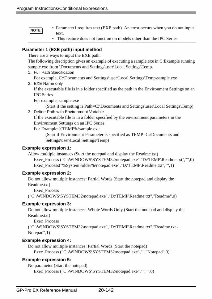
Program Instructions/Conditional Expressions
GP-Pro EX Reference Manual 20-142
Parameter 1 (EXE path) input methodThere are 3 ways to input the EXE path:The following description gives an example of executing a sample.exe in C:Example running sample.exe from \Documents and Settings\user\Local Settings\Temp.1. Full Path Specification
For example, C:\Documents and Settings\user\Local Settings\Temp\sample.exe2. EXE Name only
If the executable file is in a folder specified as the path in the Environment Settings on an IPC Series.For example, sample.exe
(Start if the setting is Path=C:\Documents and Settings\user\Local Settings\Temp)3. Define Path with Environment Variable
If the executable file is in a folder specified by the environment parameters in the Environment Settings on an IPC Series.For Example:%TEMP%\sample.exe
(Start if Environment Parameter is specified as TEMP=C:\Documents and Settings\user\Local Settings\Temp)
Example expression 1:Allow multiple instances (Start the notepad and display the Readme.txt)
Exec_Process ("C:\WINDOWS\SYSTEM32\notepad.exe","D:\TEMP\Readme.txt","",0)Exec_Process("%SystemFolder%\notepad.exe","D:\TEMP\Readme.txt","",1)
Example expression 2:Do not allow multiple instances: Partial Words (Start the notepad and display the Readme.txt)
Exec_Process ("C:\WINDOWS\SYSTEM32\notepad.exe","D:\TEMP\Readme.txt","Readme",0)
Example expression 3:Do not allow multiple instances: Whole Words Only (Start the notepad and display the Readme.txt)
Exec_Process ("C:\WINDOWS\SYSTEM32\notepad.exe","D:\TEMP\Readme.txt","Readme.txt - Notepad",1)
Example expression 4:Do not allow multiple instances: Partial Words (Start the notepad)
Exec_Process ("C:\WINDOWS\SYSTEM32\notepad.exe","","Notepad",0)
Example expression 5:No parameter (Start the notepad)
Exec_Process ("C:\WINDOWS\SYSTEM32\notepad.exe","","",0)
• Parameter1 requires text (EXE path). An error occurs when you do not input text.
• This feature does not function on models other than the IPC Series.

Program Instructions/Conditional Expressions
GP-Pro EX Reference Manual 20-143
Example expression 6:Multiple Parameter (Start the sample.exe)
Exec_Process ("C:\WINDOWS\SYSTEM32\sample.exe","/v /a/s","",1)
Exit WinGPThis feature does not function on models other than the IPC Series.
Example expression:Displaying an acknowledgment message when exiting WinGP.
Exit_WinGP(1)
Function Description
Summary Exit WinGP. You can display an acknowledgment message upon exiting.
Format Exit_WinGP(Parameter1)
Parameter1Folder Name: Select "0: Do not Confirm" or "1: Confirm".
• Parameter1 requires text (EXE path). An error occurs when you do not input text.
• The feature does not operate when you transfer the "Exit WinGP" script to a non-IPC Series models.

Program Instructions/Conditional Expressions
GP-Pro EX Reference Manual 20-144
20.10.8 Conditional Expressions
if - endifWhen the "if" condition, enclosed in brackets "( )", is true, the expression following the "if ( )" statement is run.
if - else - endifWhen the "if" condition, enclosed with brackets "( )", is true, the expression following the "if ( )" statement is run. When the condition is false, the "else" expression is run.
Conditional Expressions Function Summary
if - endif" if - endif" (page 20-144)
When the "if" condition, enclosed in brackets "( )", is true, the expression following the "if ( )" statement is run.
if - else - endif" if - else - endif" (page 20-144)
When the "if" condition, enclosed with brackets "( )", is true, the expression following the "if ( )" statement is run. When the condition is false, the "else" expression is run.
loop - endloop" loop - endloop" (page 20-145)
Loop processing is repeated according to the number stored in the temporary Addresses designated in the brackets "( )" following "loop".
break" break" (page 20-147)
Halts loop operation while the loop ( ) equation is being executed.
return" return" (page 20-147)
Executes again from the beginning.It can only be used in an Extended Script.
• The Assign "=" character cannot be used in a conditional expression.
• The Assign "=" character cannot be used in a conditional expression.

Program Instructions/Conditional Expressions
GP-Pro EX Reference Manual 20-145
loop - endloopLoop processing is repeated according to the number stored in the temporary Addresses designated in the brackets "( )" following "loop".
Infinite LoopThe loop is infinite when there is no statement in the loop brackets ( ).You can use infinite loops in Extended Scripts.
Example expression:loop ( ){
[w:[#INTERNAL]LS0100]=[w:[#INTERNAL]LS0100]+1if ( [w:[#INTERNAL]LS0100] >10){
break}endif
}endloop
• The loop ( ) format is as follows:For example:
loop (number of loops)<= Defines the temporary Address that stores the number of loops.
{Action equationbreak <= Use to exit the loop part way through (optional)
} endloop <= Defines the end of the loop• Only a temporary Word Address can be entered in the parentheses.
(Example: loop ([t:000]))• "loop ( )" cannot be used for a trigger equation.• The temporary Word Address value used to define the number of loops
decreases for every loop. When the value changes to 0, the loop operation ends. If the temporary Word Address value defined for the number of loops is modified, the loop could become endless. The temporary Word Address used is designated as Global. Therefore, simultaneously using this temporary Word Address for other purposes could result in an infinite loop.
• Until a loop operation completes, screen displays of Parts and so on are not updated or refreshed.

Program Instructions/Conditional Expressions
GP-Pro EX Reference Manual 20-146
• loop ( ) can also be nested. When it is nested, the innermost loop ( ) is skipped via the "break" command.
• If loop operation is finished without using the escape command, the temporary Word Address value becomes 0.
• The range available for the temporary Word Address value differs depending on the data format (Bin, BCD), bit length, and code +/− used. If code +/- has been set and the temporary Word Address becomes a negative value, the condition is judged at the beginning of the loop and the loop processing stops.
• DO NOT use a PLC device in the loop formula. Instead, use the display unit internal LS area user area address or a temporary Word Address. For example, the following description performs data write to the PLC many times in a short period (100 times in the following example). This can cause a system error since communication processing (the time required to write to the PLC) cannot be performed at this speed.For example,
Please change as follows:
• Using "loop" or "break" as a function name for a D-Script function causes an error.
loop ([t:0000])// loop 1{
loop ([t:0001]) // loop 2{
break // Escape from loop 2}endloop
break // Escape from loop1}endloop
[t:0000] = 100 // Loop Count:loop ([t:0000]){
[w:[PLC1]D0200] = [w:[#INTERNAL]LS0100] // Write to D0200[w:[#INTERNAL]LS0100] = [w:[#INTERNAL]LS0100]+1 // Increment LS0100
}endloop
[t:0000] = 100 // Loop Count:loop ([t:0000]){
[w:[#INTERNAL]LS0200] = [w:[#INTERNAL]LS0100]
// Write to D0200
[w:[#INTERNAL]LS0100] = [w:[#INTERNAL]LS0100] + 1 // Increment LS0100}endloop

Program Instructions/Conditional Expressions
GP-Pro EX Reference Manual 20-147
breakHalts loop operation while the loop ( ) equation is being executed.
returnWhen the "User Defined Function" includes "return"The processing of the Function is terminated and the control returns to the caller of the Function.
When Execution (main Function) includes "return"The processing of the main Function is momentarily aborted, and is restarted from the start of the main Function.
Example expression:[w:[#INTERNAL]LS0100]=([w:[#INTERNAL]LS0200]>> 8) & 0xFFif ([w:[#INTERNAL]LS0100]==0) // When LS0100 is "0", processing is no longer
executed{
set([b:[#INTERNAL]LS005000]) // Sets the bit address for error displayreturn //End
}endif
• The "break" command can be used only in the { } section of loop ( ).• Scripts will not operate properly if you use the "break" command in if {}
expressions.
• The Assign "=" character cannot be used in a conditional expression.

Program Instructions/Conditional Expressions
GP-Pro EX Reference Manual 20-148
20.10.9 Comparison
Logical AND (AND)ANDs the right and left sides. Value 0 (zero) is regarded as OFF, and other values as ON.N1 and N2: True if both N1 and N2 are ON. Otherwise false.
Logical OR (OR)ORs the right and left sides. Value 0 (zero) is regarded as OFF, and other values as ON.N1 or N2: True if either N1 and N2 are ON. Otherwise false.
Negation (not)Inverts the value. 0 (zero) is regarded as 1, and other values as 0.not N1: Becomes 0 if N1 is 1, and 1 if N1 is 0.
Less than (<)Compares the data in two word addresses, or the data in a word address and a constant.
Comparison Function Summary
Logical AND (AND)" Logical AND (AND)" (page 20-148)
N1 and N2: True if both N1 and N2 are ON.
Logical OR (OR)" Logical OR (OR)" (page 20-148)
N1 or N2: True if either N1 and N2 are ON.
Negation (not)" Negation (not)" (page 20-148)
not N1: Becomes 0 if N1 is 1, and 1 if N1 is 0.
Less than (<)" Less than (<)" (page 20-148)
True if N1 is less than N2 (N1 < N2).
Less than or equal to ( =)" Less than or equal to (<=)" (page 20-149)
True if N1 is less than or equal to N2 (N1 <= N2).
Not equal to (<>)" Not equal to (<>)" (page 20-149)
True if N1 is not equal to N2 (N1 <> N2).
Greater than (>)" Greater than (>)" (page 20-149)
True if N1 is greater than N2 (N1 > N2).
Greater than or equal to (>=)" Greater than or equal to (>=)" (page 20-149)
True if N1 is greater than or equal to N2 (N1 >= N2).
Equivalent (==)" Equal to (==)" (page 20-149)
True if N1 is equal to N2 (N1 = N2).

Program Instructions/Conditional Expressions
GP-Pro EX Reference Manual 20-149
True if N1 is less than N2 (N1 < N2).
Less than or equal to (<=)Compares the data in two word addresses, or the data in a word address and a constant.True if N1 is less than or equal to N2 (N1 <= N2).
Not equal to (<>)Compares the data in two word addresses, or the data in a word address and a constant.True if N1 is not equal to N2 (N1 <> N2).
Greater than (>)Compares the data in two word addresses, or the data in a word address and a constant.True if N1 is greater than N2 (N1 > N2).
Greater than or equal to (>=)Compares the data in two word addresses, or the data in a word address and a constant.True if N1 is greater than or equal to N2 (N1 >= N2).
Equal to (==)Compares the data in two word addresses, or the data in a word address and a constant.True if N1 is equal to N2 (N1 = N2).
Command For example
Conjunction and if ((Operation) and (Operation))
Disjunction or if ((Operation) or (Operation))
Negation not if (not (Operation))
Less than < (Term 1) < (Term 2)
Less than or equal to <= (Term 1) <= (Term 2)
Not equal to <> (Term 1) <> (Term 2)
Greater than > (Term 1) > (Term 2)
Greater than or equal to >= (Term 1) >= (Term 2)
Equivalent == (Term 1) == (Term 2)

Program Instructions/Conditional Expressions
GP-Pro EX Reference Manual 20-150
20.10.10 Operator
Operator Function Summary
Addition (+)" Addition (+)" (page 20-151)
Adds the data in two word addresses, or the data in a word address and a constant.
Subtraction (−)" Subtraction (−)" (page 20-151)
Subtracts the data in two word addresses, or the data in a word address and a constant.
Margin (%)" Margin (%)" (page 20-151)
Detects a remainder of a division performed on the data in two word addresses, or the data in a word address and a constant.
Multiplication (∗)" Multiplication (∗)" (page 20-151)
Multiplies the data in two word addresses, or the data in a word address and a constant.
Division (/)" Division (/)" (page 20-151)
Performs division the data in two word addresses, or the data in a word address and a constant.
Assignment (=)" Assignment (=)" (page 20-151)
Assigns the right side value to the left side.
Left Shift (<<)" Shift Left (<<)" (page 20-151)
Shifts the data on the left side to the left by the number on the right side.
Right Shift (>>)" Right Shift (>>)" (page 20-152)
Shifts the data on the left side to the right by the number on the right side.
Bit Operator Logical AND (&)" Bitwise AND (&)" (page 20-152)
Performs logical AND of data between word devices, or between word device data and constant.
Bit Operator Logical OR (|)" Bitwise OR (|)" (page 20-152)
Performs logical OR of data between word devices, or between word device data and constant.
Continued

Program Instructions/Conditional Expressions
GP-Pro EX Reference Manual 20-151
Addition (+)Adds the data in two word addresses, or the data in a word address and a constant. Any overflowing digits resulting from the operation are rounded.
Subtraction (−)Subtracts the data in two word addresses, or the data in a word address and a constant. Any overflowing digits resulting from the operation are rounded.
Margin (%)Detects a remainder of a division performed on the data in two word addresses, or the data in a word address and a constant. The operation result may depend on the sign of the left and right sides.
Multiplication (∗)Multiplies the data in two word addresses, or the data in a word address and a constant. Any overflowing digits resulting from the operation are rounded.
Division (/)Divides the data in two word addresses, or the data in a word address, by a constant. Fractional values resulting from the operation are truncated. Any overflowing digits resulting from the operation are truncated.
Assignment (=)Assign the value on the right hand side to the left hand side. Only devices can be specified on the left side. Devises and Constants can be described on the right side. When the results of computing overflow, figures are truncated.
Shift Left (<<)Shifts the data on the left side to the left by the number on the right side. This feature supports logical shifts only.
Bit Operator Exclusive OR (^)" Bitwise Exclusive OR (^)" (page 20-152)
Performs exclusive OR of data between word devices, or between word device data and constant.
Bit Operator 1's Complement (~)" Bitwise 1's Complement (~)" (page 20-152)
Inverts the bits.
Operator Function Summary

Program Instructions/Conditional Expressions
GP-Pro EX Reference Manual 20-152
For example, Left Shift operation (Shifts to the left by one bit.)
Right Shift (>>)Shifts the data on the left side to the right by the number on the right side. This feature supports logical shifts only.
Bitwise AND (&)Performs logical AND of data between word devices, or between word device data and constant. Used to extract a specific bit or to mask a specific string of bits.
Bitwise OR (|)Performs logical OR of data between word devices, or between word device data and constant. Used to turn ON a specific bit.
Bitwise Exclusive OR (^)Performs exclusive OR of data between word devices, or between word device data and constant.
Bitwise 1's Complement (~)Inverts the bits.
• For information about rounding decimal numbers or overflowing digit caused by operation results, see
"20.9.4 Notes on Operation Results" (page 20-64)
1 0 1 0 1 0 1 0 1 0 1 0 1 0 1 0
Before the shift
0 1 0 1 0 1 0 1 0 1 0 1 0 1 0 0
After the shift
0"1" is rounded off.

Program Instructions/Conditional Expressions
GP-Pro EX Reference Manual 20-153
Priority and AssociativityThe following table shows the priority of the trigger conditions. If two or more operators have the same priority, follow the direction shown by the associativity.
Priority Operator Associativity
High ( ) →
not ~ ←
∗ / % →
+ − →
<< >> →
< <= > >= →
== <> →
& ^ | →
and or →
Low = ♦

Program Instructions/Conditional Expressions
GP-Pro EX Reference Manual 20-154
20.10.11 Text Operation
Text Operation functions can only be used in an Extended Script.
Text Operation Function Summary
Decimal Text-To-Integer Conversion" Decimal Text-To-Integer Conversion" (page 20-155)
This function is used to convert decimal text to integers.
Hexadecimal Text-To-Integer Conversion" Hexadecimal Text-To-Integer Conversion" (page 20-157)
This function converts hexadecimal text to integers.
From Internal Device To Data Buffer" Internal Device To Data Buffer" (page 20-159)
The data of the string stored in the Internal Device is copied to the data buffer.
From Data Buffer to Internal Device" Data Buffer To Internal Device" (page 20-161)
The data of the string stored in the data buffer is copied to the Internal Device.
Status" Text Operation Error Status" (page 20-163)
Stores any error that has occurred.
Numeric Value Decimal String Conversion" Numeric Value Decimal String Conversion" (page 20-164)
This function is used to convert an integer to a decimal string.
Numeric Value Hexadecimal String Conversion" Numeric Value Hexadecimal String Conversion" (page 20-165)
This function is used to convert binary data into a hexadecimal string.
Partial Text Function" Partial Text" (page 20-166)
Data are retrieved from the specified offset of the string according to the length of the string and stored in another data buffer.
Text Settings" Text Settings" (page 20-167)
Stores a fixed string in the data buffer.
Get Text Length" Text Length" (page 20-168)
Obtains the length of the stored string.
Connect Text" Connect Text" (page 20-169)
Concatenates a character string or character code with the text buffer.

Program Instructions/Conditional Expressions
GP-Pro EX Reference Manual 20-155
Decimal Text-To-Integer Conversion
Example expression 1 (When the data length is 16 bits)_decasc2bin ([w:[#INTERNAL]LS0100], databuf0)
The content of "databuf0" is as follows:
The above data are converted as follows.
Function Description
Summary This function is used to convert a decimal string to integers. Convert the decimal integer text in Parameter 2 (Convert-From Data Buffer) into an integer, and store it in Parameter 1 (Convert-To Address).
Format _decasc2bin ([Convert-To Address], [Convert-From Data Buffer])
Parameter 1: Internal Device, Temporary addressParameter 2: Data Buffer
databuf0[0]databuf0[1]databuf0[2]databuf0[3]databuf0[4]
31h32h33h34h00h
8 bit‘1’‘2’‘3’‘4’NULL
LS0100
16 bit
1234

Program Instructions/Conditional Expressions
GP-Pro EX Reference Manual 20-156
Example expression 2 (When the data length is 32 bits)_decasc2bin ([w:[#INTERNAL]LS0100], databuf0)
The content of "databuf0" is as follows:
The above data is converted as follows.
• An error occurs when the converted bit length is greater than the bit length of the D-Script Editor.For example, When the bit length of the script is 16 bits:
_strset (databuf 0, " 123456") // When a 6-digit decimal string is set accidentally
_decasc2bin ([w:[#INTERNAL]LS0100], databuf0)When the above expression is executed, Error Number 2 (string conversion error) of the String error status [e: STR_ERR_STAT] is triggered. However, the bit returns to the beginning of the Main function when an error occurs. Therefore, you cannot reference other functions directly after _decasc2bin executes. (If the command comes while a function is running, it returns to the line that called that function.)
• An error occurs during conversion of a string of data containing characters other than "0" to "9".For example, When the bit length of the script is 16 bits:
_strset (databuf0, "12AB") // When a non-decimal string is set accidentally
_decasc2bin ([w:[#INTERNAL]LS0100], databuf0)When the above expression is executed, Error Number 2 (string conversion error) of the String error status [e: STR_ERR_STAT] is triggered. However, the bit returns to the beginning of the Main function when an error occurs. Therefore, you cannot reference other functions directly after _decasc2bin executes. (If the command comes while a function is running, it returns to the line that called that function.)
• The processing is terminated when an error occurs and returns to the beginning of the Main function. (If the command comes while a function is running, it returns to the line that called that function.)
databuf0[0]databuf0[1]databuf0[2]databuf0[3]databuf0[4]databuf0[5]databuf0[6]databuf0[7]databuf0[8]
31h32h33h34h35h36h37h38h00h
8 bit‘1’‘2’‘3’‘4’‘5’‘6’‘7’‘8’NULL
LS0100LS0102
32 bit
12345678

Program Instructions/Conditional Expressions
GP-Pro EX Reference Manual 20-157
Hexadecimal Text-To-Integer Conversion
Example expression 1 (When the data length is 16 bits)_hexasc2bin ([w:[#INTERNAL]LS0100], databuf0)
The content of "databuf0" is as follows:
The above data are converted as follows.
Function Description
Summary This function converts a hexadecimal string to binary data. Convert the hexadecimal integer text in Parameter 2 (Convert-From Data Buffer) into an integer, and store it in Parameter 1(Convert-To Address).
Format _hexasc2bin ([Convert-To Address], [Convert-From Data Buffer])
Parameter 1: Internal Device, Temporary addressParameter 2: Data Buffer
databuf0[0]databuf0[1]databuf0[2]databuf0[3]databuf0[4]
31h32h33h34h00h
8 bit‘1’‘2’‘3’‘4’NULL
LS0100
16 bit
1234h

Program Instructions/Conditional Expressions
GP-Pro EX Reference Manual 20-158
Example expression 2 (When the data length is 32 bits)_hexasc2bin ([w:[#INTERNAL]LS0100], databuf0)
The content of "databuf0" is as follows:
The above data are converted as follows.
• An error occurs when the converted string is greater than 16 bits or 32 bits.For example, When the bit length of the script is 16 bits:
_strset (databuf0, "123456")_hexasc2bin ([w:[#INTERNAL]LS0100], databuf0)
When the above expression is executed, Error Number 2 (string conversion error) of the String error status [e: STR_ERR_STAT] is triggered.
• An error occurs during conversion of a string of data containing characters other than "0" to "9", "A" to "F", or "a" to "f".For example, When the bit length of the script is 16 bits:
_strset (databuf 0, "123G")_hexasc2bin ([w:[#INTERNAL]LS0100], databuf0)
When the above expression is executed, Error Number 2 (string conversion error) of the String error status [e: STR_ERR_STAT] is triggered.
• The processing is terminated when an error occurs and returns to the beginning of the Main function. (If the command comes while a function is running, it returns to the line that called that function.)
databuf0[0]databuf0[1]databuf0[2]databuf0[3]databuf0[4]databuf0[5]databuf0[6]databuf0[7]databuf0[8]
31h32h33h34h35h36h37h38h00h
8 bit‘1’‘2’‘3’‘4’‘5’‘6’‘7’‘8’NULL
LS0100LS0102
32 bit
12345678h

Program Instructions/Conditional Expressions
GP-Pro EX Reference Manual 20-159
Internal Device To Data Buffer
Example expression 1:_ldcopy (databuf0, [w:[#INTERNAL]LS0100], 4)
The data in LS0100 to LS0103 is written into the 4 bytes of the data buffer sequentially starting from "databuf0" The LS area is read in each byte (the lowest bits).
Function Description
Summary The data of the string stored in the LS area is copied to the data buffer according to the number of strings in a byte-by-byte transfer. Store the Parameter 3 (Words) words of data from Parameter 2 (Copy-From Address) in Parameter 1 (Copy-To Data Buffer) as a text.
Format _ldcopy (Copy-To Data Buffer, [Copy-From Address], Words)
Parameter 1: Data BufferParameter 2: Internal DeviceParameter 3: Integer value, Internal Device, Temporary address (The valid range for
Parameter 3 is from 1 to 1,024.)
LS0100LS0101LS0102LS0103
16 bit
31h32h33h34h
databuf0[0]databuf0[1]databuf0[2]databuf0[3]databuf0[4]
31h32h33h34h00h
8 bit‘1’‘2’‘3’‘4’NULL

• The low 1 byte of the LS area is read out and the specified quantity of data is written into the data buffer.
• The maximum value that can be assigned for Parameter 3 is 1,024. When a value exceeding the limit is set, Error Number 1 (string overflow) of the String error status [e: STR_ERR_STAT] is triggered.
• Even when there is data in the upper byte of the internal device, only data from the bottom byte is read.
• The processing is terminated when an error occurs and returns to the beginning of the Main function. (If the command comes while a function is running, it returns to the line that called that function.)
_ldcopy (databuf0, [w:[#INTERNAL]LS0100], 4)
LS0100LS0101LS0102LS0103
16 bit
3132h3334h3536h3738h
When data is stored as illustrated above, data from the bottom byte is read and written to the data buffer.
databuf0[0]databuf0[1]databuf0[2]databuf0[3]databuf0[4]
32h34h36h38h00h
8 bit‘2’‘4’‘6’‘8’NULL
Program Instructions/Conditional Expressions
GP-Pro EX Reference Manual 20-160

Program Instructions/Conditional Expressions
GP-Pro EX Reference Manual 20-161
Data Buffer To Internal Device
Example expression 1:_dlcopy ([w:[#INTERNAL]LS0100], databuf0, 2, 4)
4 bytes of data retrieved from "offset 2" of "databuf0" are written into LS0100 to LS0103. The data are written into the LS area in units of 1 byte.
Function Description
Summary Each byte of string data stored in the offset of the data buffer is copied to the LS area according to the number of strings.Stores Parameter 4 (Characters to Copy) characters of data from Parameter 3 (Copy-From Offset Value) of the contents of Parameter 2 (Copy-From Data Buffer) in Parameter 1 (Copy-To Address).
Format _dlcopy ([Copy-To Address], Copy-From Data Buffer, Copy-From Offset Value, Number of Copied Characters)
Parameter 1: Internal DeviceParameter 2: Data BufferParameter 3: Numeric Value, Internal Device, Temporary address (The valid range for
Parameter 3 is from 0 to 1,024.)Parameter 4: Numeric Value, Internal Device, Temporary address (The valid range for
Parameter 4 is from 1 to 1,024.)
databuf0[0]databuf0[1]databuf0[2]databuf0[3]databuf0[4]databuf0[5]databuf0[6]databuf0[7]
31h32h33h34h35h36h37h38h
8 bit‘1’‘2’‘3’‘4’‘5’‘6’‘7’‘8’
LS0100LS0101LS0102LS0103
16 bit
33h34h35h36h

• 1 byte of data is read out from the data buffer and written into the LS area. That means only the lowest 8 bits (1 byte) of the LS area will be used. The significant 8 bits (1 byte) will be cleared with "0".
• When the specified value [source offset value + number of characters to be copied] is greater than the data buffer size, error Number 3 (string extraction error) of the string error status [e: STR_ERR_STAT] is issued.
• The processing is terminated when an error occurs and returns to the beginning of the Main function. (If the command comes while a function is running, it returns to the line that called that function.)
Program Instructions/Conditional Expressions
GP-Pro EX Reference Manual 20-162

Program Instructions/Conditional Expressions
GP-Pro EX Reference Manual 20-163
Text Operation Error StatusWhen an error occurs during execution of text operation, an error is set to the Text Operation Error Status [e: STR_ERR_STAT]. "0" in [e: STR_ERR_STAT] indicates a normal condition, and values other than "0" stored in [e: STR_ERR_STAT] indicate error states. The most recent error is stored in the Text Operation Error Status [e: STR_ERR_STAT]. The Text Operation Error Status can be set up with [SIO Port Operation/Label Settings] under the D-Script Toolbox menu. The following table lists the text operation errors.
The String Control Error Status cannot be used with D-Scripts and Global D-Scripts. If it is read out accidentally, "0" will be loaded.It is stored in the Error Status during execution of each function.To check the error [e: STR_ERR_STAT], write the following statements. You can confirm the error with the following expression.
Error Number
Error Message Description
0 Normal No error
1 Text overflow A string of at least 256 bytes is directly included in the argument for the following Functions: _strset ( ), _strlen ( ), _strcat ( ), _strmid ( ), and IO_READ_WAIT ( ).Or, a string exceeding the data buffer size is created during execution of the _strcat ( ) or _ldcopy ( ) function.For example:
_strcat (databuf0, databuf1) The above function is executed when a string of 1,020 bytes is stored in databuf0, and a string of 60 bytes is stored in databuf 1. (A string exceeding 1,024 bytes, the size of the data buffer, results in an error status.)
2 String conversion error
Invalid character code is given to the _hexasc2bin ( ) or _decasc2bin ( ) Function.For example:
A character code other than "0" to "9", "A" to "F", or "a" to "f" is included in the second argument of _hexasc2bin ( ).
3 String retrieval error Retrieval of a character string longer than the character string specified with the "_strmid ( )" Function is attempted. Or, an offset value greater than the specified string is designated.For example:
_strmid (databuf0, "12345678", 2, 8) Retrieval of an 8-character string from offset 2 is attempted.

Program Instructions/Conditional Expressions
GP-Pro EX Reference Manual 20-164
Example expression:if ([e:STR_ERR_STAT] <> 0) // Checks the error status.{
set([b:[#INTERNAL]LS005000]) // Sets bit on Error Display Lamp}endif
Numeric Value Decimal String Conversion
Example expression 1 (When the data length is 16 bits)_bin2decasc (databuf0, [w:[#INTERNAL]LS0100])
The above data are converted as follows: Note that "NULL (0x00)" is added.
• The processing is terminated when an error occurs and returns to the beginning of the Main function. (If the command comes while a function is running, it returns to the line that called that function.)
Function Description
Summary This function is used to convert an integer to a decimal string. Convert the integer in Parameter 2 (Convert-From Address) into a decimal integer text, and store it in Parameter 1 (Convert-To Data Buffer).
Format _bin2decasc(Conversion result address, Conversion source buffer)
Parameter 1: Data BufferParameter 2: Internal Device, Temporary address
LS0100
16 bit
1234
databuf0[0]databuf0[1]databuf0[2]databuf0[3]databuf0[4]
31h32h33h34h00h
8 bit‘1’‘2’‘3’‘4’NULL

Program Instructions/Conditional Expressions
GP-Pro EX Reference Manual 20-165
Example expression 2 (When the data length is 32 bits)_bin2decasc (databuf0, [w:[#INTERNAL]LS0100])
The above data are converted as follows.
Numeric Value Hexadecimal String Conversion
Example expression 1 (When the data length is 16 bits)_bin2hexasc (databuf0, [w:[#INTERNAL]LS0100])
The above data are converted as follows: Note that "NULL (0x00)" is added.
Function Description
Summary This function is used to convert binary data into a hexadecimal string. Convert the integer in Parameter 2 (Convert-From Address) into a hexadecimal integer text, and store it in Parameter 1 (Convert-To Data Buffer).
Format _bin2hexasc (Convert-To Data Buffer, [Convert-From Address])
Parameter 1: Data BufferParameter 2: Internal Device, Temporary address
LS0100LS0102
32 bit
12345678
databuf0[0]databuf0[1]databuf0[2]databuf0[3]databuf0[4]databuf0[5]databuf0[6]databuf0[7]databuf0[8]
31h32h33h34h35h36h37h38h00h
8 bit‘1’‘2’‘3’‘4’‘5’‘6’‘7’‘8’NULL
LS0100
16 bit
1234h
databuf0[0]databuf0[1]databuf0[2]databuf0[3]databuf0[4]
31h32h33h34h00h
8 bit‘1’‘2’‘3’‘4’NULL

Program Instructions/Conditional Expressions
GP-Pro EX Reference Manual 20-166
Example expression 2 (When the data length is 32 bits)_bin2hexasc (databuf0, [w:[#INTERNAL]LS0100])
The above data are converted as follows.
Partial Text
Example expression:_strmid (databuf0, "12345678", 2, 4)
4 bytes of data retrieved from offset 2 of string "12345678" are stored in "databuf0".
Function Description
Summary Data are retrieved from the specified offset of the string according to the length of the string and stored in another data buffer. Store Parameter 4 (Text Length) from Parameter 3 (Text Offset) of Parameter 2 (Text) in Parameter 1 (Write-To Data Buffer).
Format _strmid (Write-To Data Buffer, Text, Text Offset, Text Length)
Parameter 1: Data BufferParameter 2: String, Data BufferParameter 3: Numeric Value, Internal Device, Temporary address (The valid range for
Parameter 3 is from 0 to 1024.)Parameter 4: Numeric Value, Internal Device, Temporary address (The valid range for
Parameter 4 is from 1 to 1024.)
LS0100LS0102
32 bit
12345678h
databuf0[0]databuf0[1]databuf0[2]databuf0[3]databuf0[4]databuf0[5]databuf0[6]databuf0[7]databuf0[8]
31h32h33h34h35h36h37h38h00h
8 bit‘1’‘2’‘3’‘4’‘5’‘6’‘7’‘8’NULL
databuf0[0]databuf0[1]databuf0[2]databuf0[3]databuf0[4]
33h34h35h36h00h
8 bit‘3’‘4’‘5’‘6’NULL

Program Instructions/Conditional Expressions
GP-Pro EX Reference Manual 20-167
Text Settings
Example expression:_strset (databuf0, "ABCD")
The string is stored in the data buffer as illustrated below:
• When attempting to retrieve a string longer than the string specified with the "strmid ( )" function, or when specifying an offset value greater than the specified string, error Number 3 (string extraction error) of the string error status [e: STR_ERR_STAT] is issued.
• The processing is terminated when an error occurs and returns to the beginning of the Main function. (If the command comes while a function is running, it returns to the line that called that function.)
Function Description
Summary A fixed string is stored in the data buffer. Stores the data of Parameter 2 (Text) in Parameter 1 (Write-To Data Buffer).
Format _strset(Write destination buffer, String)
Parameter 1: Data BufferParameter 2: Text, Numeric Value (Text Code) (The valid range for Parameter 2 is 0
and from 1 to 255.)
• A string of up to 255 characters can be specified. To create strings longer than this limit, store the string in another buffer and concatenate the strings with the string-concatenating function (_strcat).
• To clear the data buffer, create an empty string "î Example)_strset (databuf0,"")_strset (databuf0,0)
databuf0[0]databuf0[1]databuf0[2]databuf0[3]databuf0[4]
41h42h43h44h00h
8 bit‘A’‘B’‘C’‘D’NULL

Program Instructions/Conditional Expressions
GP-Pro EX Reference Manual 20-168
Text Length
Example expression 1:_strlen ([w:[#INTERNAL]LS0100], "ABCD")
When the above statement is executed, the length of the string is written into LS0100 as illustrated below.
Example expression 2:_strlen ([t:0000], databuf0)
The content of "databuf0" is as follows:
When the above statement is executed, the length of the string is written into [t: 0000] as illustrated below.
Function Description
Summary Obtains the length of the stored string. Stores the length of Parameter 2 (Text) in Parameter 1 (Text Length Write-To Address). (The NULL character is not included.)
Format _strlen (Destination address, String)
Parameter 1: Internal Device, Temporary addressParameter 2: String, Data Buffer
LS0100 4
databuf0[0]databuf0[1]databuf0[2]databuf0[3]databuf0[4]
31h32h33h34h00h
8 bit‘1’‘2’‘3’‘4’NULL
t0000 4

Program Instructions/Conditional Expressions
GP-Pro EX Reference Manual 20-169
Connect Text
Example expression 1:_strcat (databuf0, "ABCD")
When "ABCD" is concatenated according to the above, the result is as follows. Note that "NULL (0x00)" is added.
Function Description
Summary A character string or character code is concatenated with the text buffer. Adds the data of Parameter 2 (Text) to the last of the contents of Parameter 1 (Contact Data Buffer).
Format _strcat(String data buffer, String)
Parameter 1: Data BufferParameter 2: Text, Numeric Value (Text Code), Data Buffer (The valid range for
Parameter 2 is 0 and from 1 to 255.)
• A string of up to 255 characters can be specified.• If you set an empty string for the numeric value 0 to Parameter 2, Parameter
1’s data buffer does not change.Example:_strcat (databuf0,"")_strcat (databuf0,0)
databuf0[0]databuf0[1]databuf0[2]databuf0[3]databuf0[4]
31h32h33h34h00h
8 bit‘1’‘2’‘3’‘4’NULL
databuf0[0]databuf0[1]databuf0[2]databuf0[3]databuf0[4]databuf0[5]databuf0[6]databuf0[7]databuf0[8]
31h32h33h34h41h42h43h44h00h
8 bit‘1’‘2’‘3’‘4’‘A’‘B’‘C’‘D’NULL
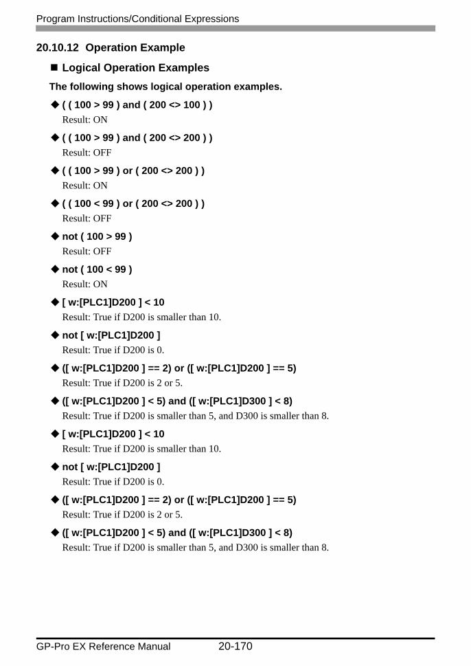
Program Instructions/Conditional Expressions
GP-Pro EX Reference Manual 20-170
20.10.12 Operation Example
Logical Operation ExamplesThe following shows logical operation examples.
( ( 100 > 99 ) and ( 200 <> 100 ) )Result: ON
( ( 100 > 99 ) and ( 200 <> 200 ) )Result: OFF
( ( 100 > 99 ) or ( 200 <> 200 ) )Result: ON
( ( 100 < 99 ) or ( 200 <> 200 ) )Result: OFF
not ( 100 > 99 )Result: OFF
not ( 100 < 99 )Result: ON
[ w:[PLC1]D200 ] < 10Result: True if D200 is smaller than 10.
not [ w:[PLC1]D200 ]Result: True if D200 is 0.
([ w:[PLC1]D200 ] == 2) or ([ w:[PLC1]D200 ] == 5)Result: True if D200 is 2 or 5.
([ w:[PLC1]D200 ] < 5) and ([ w:[PLC1]D300 ] < 8)Result: True if D200 is smaller than 5, and D300 is smaller than 8.

Program Instructions/Conditional Expressions
GP-Pro EX Reference Manual 20-171
Bit Operation ExamplesThe following shows bit operation examples.
[ w:[PLC1]D200 ] << 4Result: The data in D200 is shifted 4 bits to the left.
[ w:[PLC1]D200 ] >> 4Result: The data in D200 is shifted 4 bits to the right.
12(0000Ch) is stored in D301, using the BIN format.[ w:[PLC1]D200 ] = [ w:[PLC1]D300 ] >> [ w:[PLC1]D301 ]Result: The data in D300 is shifted 12 bits to the right and assigned to D200.
[ w:[PLC1]D200 ] << 4Result: The data in D200 is shifted 4 bits to the left.
[ w:[PLC1]D200 ] >> 4Result: The data in D200 is shifted 4 bits to the right.
12(0000Ch) is stored in D310, using the BIN format.[ w:[PLC1]D200 ] = [ w:[PLC1]D300 ] >> [ w:[PLC1]D310 ]Result: The data in D300 is shifted 12 bits to the right and assigned to D200.
Bitwise AND0 & 0 Result: 00 & 1 Result: 01 & 1 Result: 10x1234 & 0xF0F0 Result: 0x1030
Bitwise OR0 | 0 Result: 00 | 1 Result: 11 | 1 Result: 10x1234 | 0x9999 Result: 0x9BBD
Bitwise XOR0 ^ 0 Result: 00 ^ 1 Result: 11 ^ 1 Result: 0
Bitwise 1's Complement (When the Data Format is BIN16+)~ 0 Result: 0xFFFF~ 1 Result: 0xFFFE

Program Instructions/Conditional Expressions
GP-Pro EX Reference Manual 20-172
Conditional Branch Usage Calculation ExamplesControl program flow using "if-endif" and "if-else-endif"
if-endifif (condition){Process 1}endif
If the condition is true, Process 1 is run. If false, skips Process 1.
For example:if ( [ w:[PLC1]D200 ] < 5 ){
[ w:[PLC1]D100 ] = 1}endif
If data in D200 is less than 5, then assigns 1 to D100.
if-else-endifif (condition){Process 1}else{Process 2}endif
If the condition is true, runs Process 1. If false, runs Process 2.
For example:if ( [ w:[PLC1]D200 ] < 5 ){
[ w:[PLC1]D100 ] = 1}else{
[ w:[PLC1]D100 ] = 0}endif
If the value in D200 is less than 5, assigns 1 to D100. Otherwise, assigns 0.

Program Instructions/Conditional Expressions
GP-Pro EX Reference Manual 20-173
Offset Address Usage Calculation ExamplesOffset Specification: Special Calculation Examples Using [w:D00100]#[t:0000].
Script I/O: 16 bit unsigned, [t:0000]= 65526, the resulting address is [w:[PLC1]D00090].100 + 65526 = 64(Hex) + FFF6(Hex) = 1005A(Hex) --> 005A(Hex) = 90 | Bottom 16 bits are valid
Script I/O: 16 bit signed, [t:0000]= -10, the resulting address is [w:[PLC1]D00090].100 + (-10) = 64(Hex) + FFF6(Hex) = 1005A(Hex) --> 005A(Hex) = 90 | Bottom 16 bits are valid
Script I/O: 32 bit unsigned, [t:0000]= 4294901840, the resulting address is [w:[PLC1]D00180].100 + 4294901840 = 64(Hex) + FFFF0050(Hex) = FFFF 00B4(Hex) --> 00B4(Hex) = 180 | Bottom 16 bits are valid
Script I/O: 32 bit signed, [t:0000]= -65456, the resulting address is [w:[PLC1]D00180].100 + (-65456) = 64(Hex) + FFFF0050(Hex) = FFFF 00B4(Hex) --> 00B4(Hex) = 180 | Bottom 16 bits are valid
• Offset addresses are always treated as 16 bit Bin values, regardless of the script's Bit Length and Data Type settings. If the result exceeds 16 bits (Maximum Value: 65535), Bits 0 to 15 are treated as the valid bits, and bits 16 and higher are ignored.

Program Instructions/Conditional Expressions
GP-Pro EX Reference Manual 20-174