
JTEKT Corporation:TOYOPUC CMP-LINK SIO - PRO-FACE
116
1 JTEKT Corporation TOYOPUC CMP-LINK SIO Driver 1 System Configuration ....................................................................................................... 3 2 Selection of External Device ............................................................................................ 8 3 Example of Communication Setting ................................................................................. 9 4 Setup Items .................................................................................................................... 27 5 Cable Diagram ............................................................................................................... 32 6 Supported Device......................................................................................................... 101 7 Device Code and Address Code .................................................................................. 110 8 Error Messages ............................................................................................................ 116
-
Upload
khangminh22 -
Category
Documents
-
view
0 -
download
0
Transcript of JTEKT Corporation:TOYOPUC CMP-LINK SIO - PRO-FACE

1
JTEKT Corporation
TOYOPUC CMP-LINK SIO Driver
1 System Configuration....................................................................................................... 3
2 Selection of External Device ............................................................................................ 8
3 Example of Communication Setting ................................................................................. 9
4 Setup Items .................................................................................................................... 27
5 Cable Diagram ............................................................................................................... 32
6 Supported Device......................................................................................................... 101
7 Device Code and Address Code.................................................................................. 110
8 Error Messages............................................................................................................ 116

TOYOPUC CMP-LINK SIO Driver
GP-Pro EX Device/PLC Connection Manual 2
Introduction
This manual describes how to connect the Display and the External Device (target PLC).
In this manual, the connection procedure will be described by following the below sections:
1 System Configuration
This section shows the types of External
Devices which can be connected and SIO
type.
"1 System Configuration" (page 3)
2 Selection of External Device
Select a model (series) of External Device
to be connected and connection method.
"2 Selection of External Device" (page 8)
3 Example of Communication Settings
This section shows setting examples for
communicating between the Display and
the External Device.
"3 Example of Communication Setting" (page 9)
4 Communication Settings
Perform the communication settings
between the Display and the External
Device.
Set communication settings of the Display
with GP-Pro EX or in offline mode.
"4 Setup Items" (page 27)
5 Cable Diagram
This section shows cables and adapters
for connecting the Display and the
External Device.
"5 Cable Diagram" (page 32)
Operation

TOYOPUC CMP-LINK SIO Driver
GP-Pro EX Device/PLC Connection Manual 3
1 System Configuration
The system configuration in the case when the External Device of JTEKT Corporation and the Display are connected
is shown.
Series CPU Link I/FSIO
TypeSetting Example Cable Diagram
TOYOPUC-PC2
PC2L2
THU-2652 (computer link module)
RS422 (2wire)
Setting Example 1 (page 9)
Cable Diagram 1 (page 32)
PC2J THU-2755 (PC/CMP-LINK)RS422 (2wire)
Setting Example 2 (page 11)
Cable Diagram 1 (page 32)
TOYOPUC-PC3J
PC3J
Link I/F on the CPU unit (L1 or L2 terminal block)
RS422 (2wire)
Setting Example 3 (page 13)
Cable Diagram 2 (page 45)
Link I/F on the CPU unit (L1 terminal block)
RS422 (4wire)
Setting Example 4 (page 15)
Cable Diagram 3 (page 58)
THU-2755 (PC/CMP-LINK)RS422 (2wire)
Setting Example 5 (page 17)
Cable Diagram 4 (page 67)
PC3JDPC3JG
Link I/F on the CPU unit (L1 terminal block)
RS422 (2wire)
Setting Example 3 (page 13)
Cable Diagram 1 (page 32)
THU-2755 (PC/CMP-LINK)*1
*1 When using PC/CMP-LINK (THU-2755) with PC3J command, the link unit in ver. 5.00 or higher is required. Also, the link unit does not have the settings of PC2J or PC3J selection switch (SW) etc. Error occurs when sending PC3J command to the link unit in less than ver. 5.00.
RS422 (2wire)
Setting Example 5 (page 17)
Cable Diagram 1 (page 32)
TOYOPUC-
PC3JTPC3JT
Communication connector (L1 for operation board) on CPU Unit
RS422 (2wire)
Setting Example 6 (page 19)
Cable Diagram 5 (page 80)
Link communication connector(L2) on CPU Unit
RS422 (2wire)
Setting Example 7 (page 21)
Cable Diagram 6 (page 88)
TOYOPUC-
PC10GPC10G
Link I/F on the CPU unit (L3 terminal block)
RS422 (2wire)
Setting Example 8 (page 23)
Cable Diagram 1 (page 32)
THU-2755 (PC/CMP-LINK)*2
*2 To connect to GM, GC, GY, or EB devices, PC/CMP-LINK(THU-2755) Ver.6 or later is required.
RS422 (2wire)
Setting Example 9 (page 25)
Cable Diagram 1 (page 32)
TOYOPUC CMP-LINK SIO Driver
GP-Pro EX Device/PLC Connection Manual 4
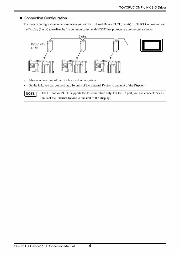
Connection Configuration
The system configuration in the case when you use the External Device PC2J (n units) of JTEKT Corporation and
the Display (1 unit) to realize the 1:n communication with HOST link protocol are connected is shown.
• Always set one unit of the Display used in the system.
• On the link, you can connect max 16 units of the External Device to one unit of the Display.
• The L1 port on PC3JT supports the 1:1 connection only. For the L2 port, you can connect max 16
units of the External Device to one unit of the Display.

TOYOPUC CMP-LINK SIO Driver
GP-Pro EX Device/PLC Connection Manual 5
IPC COM Port
When connecting IPC with an External Device, the COM port used depends on the series and SIO type. Please
refer to the IPC manual for details.
Usable port
SeriesUsable Port
RS-232C RS-422/485(4 wire) RS-422/485(2 wire)
PS-2000BCOM1*1 , COM2, COM3*1, COM4
*1 The RI/5V can be switched. Use the IPC’s switch to change if necessary.
- -
PS-3450A, PS-3451A,PS3000-BA, PS3001-BD
COM1, COM2*1*2 COM2*1*2 COM2*1*2
PS-3650A (T41 model),PS-3651A (T41 model)
COM1*1 - -
PS-3650A (T42 model),PS-3651A (T42 model)
COM1*1*2, COM2 COM1*1*2 COM1*1*2
PS-3700A (Pentium®4-M)PS-3710A
COM1*1, COM2*1, COM3*2 , COM4
*2 Set up the SIO type with the DIP Switch. Please set up as follows according to SIO type to be used.
COM3*2 COM3*2
PS-3711A COM1*1, COM2*2 COM2*2 COM2*2
PS4000*3
*3 When making communication between an External Device and COM port on the Expansion slot, only RS-232C is supported. However, ER (DTR/CTS) control cannot be executed because of the specification of COM port.For connection with External Device, use user-created cables and disable Pin Nos. 1, 4, 6 and 9.Please refer to the IPC manual for details of pin layout.
COM1, COM2 - -
PL3000COM1*1*2, COM2*1, COM3, COM4
COM1*1*2 COM1*1*2
PE-4000B Atom N270 COM1, COM2 - -
PE-4000B Atom N2600 COM1, COM2COM3*4 , COM4*4, COM5*4, COM6*4
*4 Set up the SIO type with the BIOS. Please refer to the IPC manual for details of BIOS.
COM3*4, COM4*4, COM5*4, COM6*4
PS5000 (Slim Panel Type Core i3 Model) *5 *6 COM1, COM2*4 COM2*4 COM2*4
PS5000 (Slim Panel Type Atom Model) *5 *6
COM1, COM2*7 COM2*7 COM2*7
PS5000 (Enclosed Panel Type)*8 COM1 - -
PS5000 (Modular Type PFXPU/PFXPP)*5 *6
PS5000 (Modular Type PFXPL2B5-6)
COM1*7 COM1*7 COM1*7
PS5000 (Modular Type PFXPL2B1-4)
COM1, COM2*7 COM2*7 COM2*7
TOYOPUC CMP-LINK SIO Driver
GP-Pro EX Device/PLC Connection Manual 6
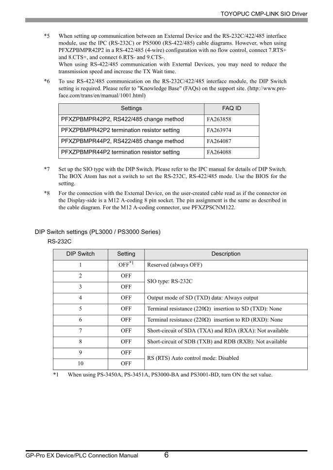
DIP Switch settings (PL3000 / PS3000 Series)
RS-232C
*5 When setting up communication between an External Device and the RS-232C/422/485 interface module, use the IPC (RS-232C) or PS5000 (RS-422/485) cable diagrams. However, when using PFXZPBMPR42P2 in a RS-422/485 (4-wire) configuration with no flow control, connect 7.RTS+ and 8.CTS+, and connect 6.RTS- and 9.CTS-.When using RS-422/485 communication with External Devices, you may need to reduce the transmission speed and increase the TX Wait time.
*6 To use RS-422/485 communication on the RS-232C/422/485 interface module, the DIP Switch setting is required. Please refer to "Knowledge Base" (FAQs) on the support site. (http://www.pro- face.com/trans/en/manual/1001.html)
*7 Set up the SIO type with the DIP Switch. Please refer to the IPC manual for details of DIP Switch.The BOX Atom has not a switch to set the RS-232C, RS-422/485 mode. Use the BIOS for the setting.
*8 For the connection with the External Device, on the user-created cable read as if the connector on the Display-side is a M12 A-coding 8 pin socket. The pin assignment is the same as described in the cable diagram. For the M12 A-coding connector, use PFXZPSCNM122.
DIP Switch Setting Description
1 OFF*1
*1 When using PS-3450A, PS-3451A, PS3000-BA and PS3001-BD, turn ON the set value.
Reserved (always OFF)
2 OFFSIO type: RS-232C
3 OFF
4 OFF Output mode of SD (TXD) data: Always output
5 OFF Terminal resistance (220) insertion to SD (TXD): None
6 OFF Terminal resistance (220) insertion to RD (RXD): None
7 OFF Short-circuit of SDA (TXA) and RDA (RXA): Not available
8 OFF Short-circuit of SDB (TXB) and RDB (RXB): Not available
9 OFFRS (RTS) Auto control mode: Disabled
10 OFF
Settings FAQ ID
PFXZPBMPR42P2, RS422/485 change method FA263858
PFXZPBMPR42P2 termination resistor setting FA263974
PFXZPBMPR44P2, RS422/485 change method FA264087
PFXZPBMPR44P2 termination resistor setting FA264088

TOYOPUC CMP-LINK SIO Driver
GP-Pro EX Device/PLC Connection Manual 7
RS-422/485 (4 wire)
RS-422/485 (2 wire)
DIP Switch Setting Description
1 OFF Reserved (always OFF)
2 ONSIO type: RS-422/485
3 ON
4 OFF Output mode of SD (TXD) data: Always output
5 OFF Terminal resistance (220) insertion to SD (TXD): None
6 OFF Terminal resistance (220) insertion to RD (RXD): None
7 OFF Short-circuit of SDA (TXA) and RDA (RXA): Not available
8 OFF Short-circuit of SDB (TXB) and RDB (RXB): Not available
9 OFFRS (RTS) Auto control mode: Disabled
10 OFF
DIP Switch Setting Description
1 OFF Reserved (always OFF)
2 ONSIO type: RS-422/485
3 ON
4 OFF Output mode of SD (TXD) data: Always output
5 OFF Terminal resistance (220) insertion to SD (TXD): None
6 OFF Terminal resistance (220) insertion to RD (RXD): None
7 ON Short-circuit of SDA (TXA) and RDA (RXA): Available
8 ON Short-circuit of SDB (TXB) and RDB (RXB): Available
9 ONRS (RTS) Auto control mode: Enabled
10 ON

TOYOPUC CMP-LINK SIO Driver
GP-Pro EX Device/PLC Connection Manual 8
2 Selection of External Device
Select the External Device to be connected to the Display.
Setup Items Setup Description
Number of Devices/PLCs
Enter an integer from 1 to 4 to define the number of Devices/PLCs to connect to the display.
Manufacturer Select the manufacturer of the External Device to connect. Select "JTEKT Corporation".
Driver
Select the External Device model (series) and the connection method. Select "TOYOPUC CMP-LINK SIO".In System configuration, make sure the External Device you are connecting is supported by "TOYOPUC CMP-LINK SIO".
"1 System Configuration" (page 3)
Port Select the Display port to be connected to the External Device.
Use System Area
Check this option to synchronize the system data area of the Display and the device (memory) of the External Device. When synchronized, you can use the External Device’s ladder program to switch the display or display the window on the Display.
Cf. GP-Pro EX Reference Manual "LS Area (Direct Access Method Area)"This feature can also be set in GP-Pro EX or in the Display's offline mode.
Cf. GP-Pro EX Reference Manual "System Settings [Display Unit] - [System Area] Settings Guide"
Cf. Maintenance/Troubleshooting Guide "Main Unit - System Area Settings"

TOYOPUC CMP-LINK SIO Driver
GP-Pro EX Device/PLC Connection Manual 9
3 Example of Communication Setting
Examples of communication settings of the Display and the External Device, recommended by Pro-face, are
shown.
When you use the TOYOPUC Series, use GP-Pro EX and the ladder software to set as below.
3.1 Setting Example 1
Setting of GP-Pro EX
Communication Settings
To display the setup screen, from the [Project] menu, point to [System Settings] and select [Device/PLC].

TOYOPUC CMP-LINK SIO Driver
GP-Pro EX Device/PLC Connection Manual 10
Device Setting
To display the [Individual Device Settings] dialog box, from [Device-Specific Settings] in the [Device/PLC]
window, select the external device and click [Settings] .
To connect multiple External Devices, from [Device-Specific Settings] in the [Device/PLC] window, click [Add
Device] to add another External Device.
Setting of External Device
Set the computer link module as below.
Please refer to the manual of the External Device for more details on settings.
Setup Items Settings
Speed 19200bps
Data Bit 8bit
Stop Bit 1bit
Parity Bit Even
Card Type CMP link
SET5 Watchdog timer ON
Station No. 0

TOYOPUC CMP-LINK SIO Driver
GP-Pro EX Device/PLC Connection Manual 11
3.2 Setting Example 2
Setting of GP-Pro EX
Communication Settings
To display the setup screen, from the [Project] menu, point to [System Settings] and select [Device/PLC].
Device Setting
To display the [Individual Device Settings] dialog box, from [Device-Specific Settings] in the [Device/PLC]
window, select the external device and click [Settings] .
To connect multiple External Devices, from [Device-Specific Settings] in the [Device/PLC] window, click [Add
Device] to add another External Device.

TOYOPUC CMP-LINK SIO Driver
GP-Pro EX Device/PLC Connection Manual 12
Setting of External Device
Set the computer link module as below.
Please refer to the manual of the External Device for more details on settings.
Setup Items Settings
Speed 19200bps
Data Bit 8bit
Stop Bit 1bit
Parity Bit Even
Internal SwitchSW4-1 OFFSW4-2 ON
Station No. 1

TOYOPUC CMP-LINK SIO Driver
GP-Pro EX Device/PLC Connection Manual 13
3.3 Setting Example 3
Setting of GP-Pro EX
Communication Settings
To display the setup screen, from the [Project] menu, point to [System Settings] and select [Device/PLC].
Device Setting
To display the [Individual Device Settings] dialog box, from [Device-Specific Settings] in the [Device/PLC]
window, select the external device and click [Settings] .
To connect multiple External Devices, from [Device-Specific Settings] in the [Device/PLC] window, click [Add
Device] to add another External Device.

TOYOPUC CMP-LINK SIO Driver
GP-Pro EX Device/PLC Connection Manual 14
Setting of External Device
Set the computer link module as below.
Please refer to the manual of the External Device for more details on settings.
Setup Items Settings
Speed 19200bps
Data Bit 8bit
Stop Bit 1bit
Parity Bit Even
RS422
Connecting Port2wire
STATION No. 0

TOYOPUC CMP-LINK SIO Driver
GP-Pro EX Device/PLC Connection Manual 15
3.4 Setting Example 4
Setting of GP-Pro EX
Communication Settings
To display the setup screen, from the [Project] menu, point to [System Settings] and select [Device/PLC].
Device Setting
To display the [Individual Device Settings] dialog box, from [Device-Specific Settings] in the [Device/PLC]
window, select the external device and click [Settings] .
To connect multiple External Devices, from [Device-Specific Settings] in the [Device/PLC] window, click [Add
Device] to add another External Device.

TOYOPUC CMP-LINK SIO Driver
GP-Pro EX Device/PLC Connection Manual 16
Setting of External Device
Set the computer link module as below.
Please refer to the manual of the External Device for more details on settings.
Setup Items Settings
Speed 19200bps
Data Bit 8bit
Stop Bit 1bit
Parity Bit Even
RS422
Connecting Port4wire
STATION No. 0
TOYOPUC CMP-LINK SIO Driver
GP-Pro EX Device/PLC Connection Manual 17
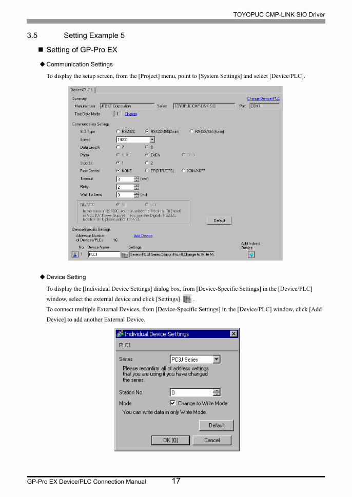
3.5 Setting Example 5
Setting of GP-Pro EX
Communication Settings
To display the setup screen, from the [Project] menu, point to [System Settings] and select [Device/PLC].
Device Setting
To display the [Individual Device Settings] dialog box, from [Device-Specific Settings] in the [Device/PLC]
window, select the external device and click [Settings] .
To connect multiple External Devices, from [Device-Specific Settings] in the [Device/PLC] window, click [Add
Device] to add another External Device.

TOYOPUC CMP-LINK SIO Driver
GP-Pro EX Device/PLC Connection Manual 18
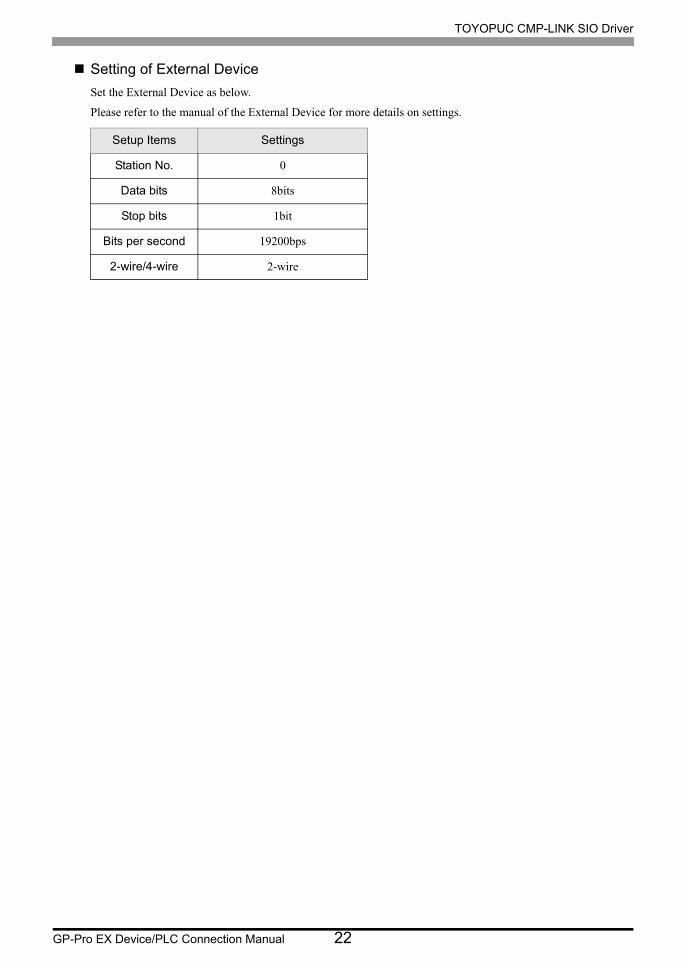
Setting of External Device
Set the computer link module as below.
Please refer to the manual of the External Device for more details on settings.
Setup Items Settings
Speed 19200bps
Data Bit 8bit
Stop Bit 1bit
Parity Bit Even
RS422
Connecting
Port*1
*1 When using PC/CMP-LINK (THU-2755), only 2-wire type is available to use. In addition, when using PC3J command, the link unit in ver. 5.00 or higher is required.
2wire
STATION No. 0

TOYOPUC CMP-LINK SIO Driver
GP-Pro EX Device/PLC Connection Manual 19
3.6 Setting Example 6
Setting of GP-Pro EX
Communication Settings
To display the setup screen, from the [Project] menu, point to [System Settings] and select [Device/PLC].
Device Setting
To display the [Individual Device Settings] dialog box, from [Device-Specific Settings] in the [Device/PLC]
window, select the external device and click [Settings] .
To connect multiple External Devices, from [Device-Specific Settings] in the [Device/PLC] window, click [Add
Device] to add another External Device.

TOYOPUC CMP-LINK SIO Driver
GP-Pro EX Device/PLC Connection Manual 20
Setting of External Device
Use the DIP Switch of the External Device for communication settings of the External Device.
Please refer to the manual of the External Device for more details on settings.
• DIP Switch (SW5)
DIP Switches Setting Value Setup Description
1 ON RS422
2 ON CMP (computer link)
3 OFF Turning off always
4 ON 115.2 Kbps
5 OFF Turning off always
6 OFF Output OFF
7 OFF RUN continuance
8 OFF The scanning is asynchronous.
• The following items are fixed.
Setup Items Setting Value
Data Length 8 bit
Stop 1 bit
Parity Even
Station Number 0

TOYOPUC CMP-LINK SIO Driver
GP-Pro EX Device/PLC Connection Manual 21
3.7 Setting Example 7
Setting of GP-Pro EX
Communication Settings
To display the setup screen, from the [Project] menu, point to [System Settings] and select [Device/PLC].
Device Setting
To display the [Individual Device Settings] dialog box, from [Device-Specific Settings] in the [Device/PLC]
window, select the external device and click [Settings] .
To connect multiple External Devices, from [Device-Specific Settings] in the [Device/PLC] window, click [Add
Device] to add another External Device.
Note
When you use an L2 port on PC3JT, select [PC3J Series] from the [Series] list.
TOYOPUC CMP-LINK SIO Driver
GP-Pro EX Device/PLC Connection Manual 22
Setting of External Device
Set the External Device as below.
Please refer to the manual of the External Device for more details on settings.
Setup Items Settings
Station No. 0
Data bits 8bits
Stop bits 1bit
Bits per second 19200bps
2-wire/4-wire 2-wire
TOYOPUC CMP-LINK SIO Driver
GP-Pro EX Device/PLC Connection Manual 23
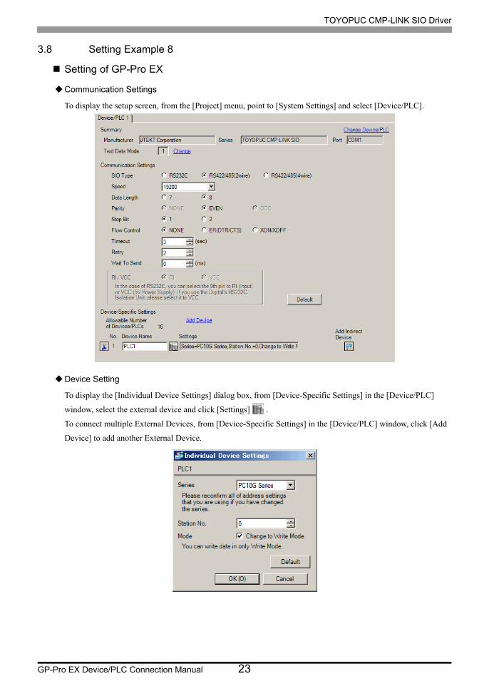
3.8 Setting Example 8
Setting of GP-Pro EX
Communication Settings
To display the setup screen, from the [Project] menu, point to [System Settings] and select [Device/PLC].
Device Setting
To display the [Individual Device Settings] dialog box, from [Device-Specific Settings] in the [Device/PLC]
window, select the external device and click [Settings] .
To connect multiple External Devices, from [Device-Specific Settings] in the [Device/PLC] window, click [Add
Device] to add another External Device.
TOYOPUC CMP-LINK SIO Driver
GP-Pro EX Device/PLC Connection Manual 24
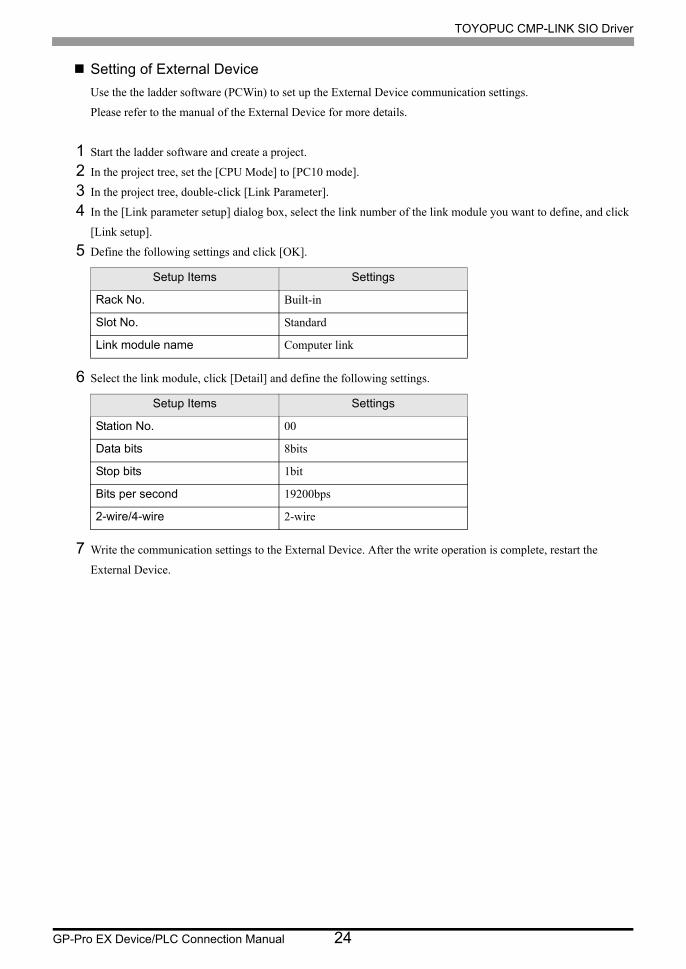
Setting of External Device
Use the the ladder software (PCWin) to set up the External Device communication settings.
Please refer to the manual of the External Device for more details.
1 Start the ladder software and create a project.
2 In the project tree, set the [CPU Mode] to [PC10 mode].
3 In the project tree, double-click [Link Parameter].
4 In the [Link parameter setup] dialog box, select the link number of the link module you want to define, and click
[Link setup].
5 Define the following settings and click [OK].
6 Select the link module, click [Detail] and define the following settings.
7 Write the communication settings to the External Device. After the write operation is complete, restart the
External Device.
Setup Items Settings
Rack No. Built-in
Slot No. Standard
Link module name Computer link
Setup Items Settings
Station No. 00
Data bits 8bits
Stop bits 1bit
Bits per second 19200bps
2-wire/4-wire 2-wire

TOYOPUC CMP-LINK SIO Driver
GP-Pro EX Device/PLC Connection Manual 25
3.9 Setting Example 9
Setting of GP-Pro EX
Communication Settings
To display the setup screen, from the [Project] menu, point to [System Settings] and select [Device/PLC].
Device Setting
To display the [Individual Device Settings] dialog box, from [Device-Specific Settings] in the [Device/PLC]
window, select the external device and click [Settings] .
To connect multiple External Devices, from [Device-Specific Settings] in the [Device/PLC] window, click [Add
Device] to add another External Device.

TOYOPUC CMP-LINK SIO Driver
GP-Pro EX Device/PLC Connection Manual 26
Setting of External Device
On the front of the link interface, use the rotary switch and dip switch to define the External Device
communication settings.
Please refer to the manual of the External Device for more details.
• Rotary Switch
• Dip Switch
Rotary Switch Setup Value Description
SW1 0 Station No. (ten's digit)
SW2 0 Station No. (one's digit)
SW3 1 19200bps
Dip Switch Setup Value Description
SW4-4 OFF Data bits: 8bits
SW4-3 ON Stop bits: 1bit
SW4-2 ON Computer link
SW4-1 OFF 2-wire (fixed)

TOYOPUC CMP-LINK SIO Driver
GP-Pro EX Device/PLC Connection Manual 27
4 Setup Items
Set communication settings of the Display with GP-Pro EX or in offline mode of the Display.
The setting of each parameter must be identical to that of External Device.
"3 Example of Communication Setting" (page 9)
4.1 Setup Items in GP-Pro EX
Communication Settings
To display the setup screen, from the [Project] menu, point to [System Settings] and select [Device/PLC].
Setup Items Setup Description
SIO Type Select the SIO type to communicate with the External Device.
Speed Select speed between the External Device and the Display.
Data Length Select data length.
Parity Select how to check parity.
Stop Bit Select stop bit length.
Flow ControlSelect the communication control method to prevent overflow of transmission and reception data.
TimeoutUse an integer from 1 to 127 to enter the time (s) for which the Display waits for the response from the External Device.
RetryIn case of no response from the External Device, use an integer from 0 to 255 to enter how many times the Display retransmits the command.
continued to next page

TOYOPUC CMP-LINK SIO Driver
GP-Pro EX Device/PLC Connection Manual 28
Device Setting
To display the [Individual Device Settings] dialog box, from [Device-Specific Settings] in the [Device/PLC]
window, select the external device and click [Settings] .
To connect multiple External Devices, from [Device-Specific Settings] in the [Device/PLC] window, click [Add
Device] to add another External Device.
Wait To SendUse an integer from 0 to 255 to enter standby time (ms) for the Display from receiving packets to transmitting next commands.
RI/VCCYou can switch RI/VCC of the 9th pin when you select RS232C for SIO type.It is necessary to change RI/5V by changeover switch of IPC when connect with IPC. Please refer to the manual of the IPC for more detail.
• Refer to the GP-Pro EX Reference Manual for Indirect Device.
Cf. GP-Pro EX Reference Manual "Changing the Device/PLC at Runtime (Indirect Device)"
Setup Items Setup Description
Series Select either " PC3J Series" or "PC2 Series" for the driver series name.
Station No. Use an integer from 0 to 31 (octal) to enter the station No.
ModeWhen receiving write request from GP-Pro EX, check "ON" to change the External Device to the write mode.
• The External Device does not receive write from the Display in operation mode. When the "operation mode" is enabled, the External Device will be changed to the monitor mode at startup, which allows you to write to the External Device.
Setup Items Setup Description

TOYOPUC CMP-LINK SIO Driver
GP-Pro EX Device/PLC Connection Manual 29
4.2 Setup Items in Offline Mode
Communication Settings
To display the setting screen, touch [Device/PLC Settings] from [Peripheral Settings] in the offline mode. Touch
the External Device you want to set from the displayed list.
• Refer to the Maintenance/Troubleshooting guide for information on how to enter offline mode or
about the operation.
Cf. Maintenance/Troubleshooting Guide "Offline Mode"
• The number of the setup items to be displayed for 1 page in the offline mode depends on the
Display in use. Please refer to the Reference manual for details.
Setup Items Setup Description
SIO Type
Select the SIO type to communicate with the External Device.
To make the communication settings correctly, confirm the serial interface specifications of Display unit for [SIO Type].We cannot guarantee the operation if a communication type that the serial interface does not support is specified.For details concerning the serial interface specifications, refer to the manual for Display unit.
Speed Select speed between the External Device and the Display.
Data Length Select data length.
Parity Select how to check parity.
Stop Bit Select stop bit length.
Flow ControlSelect the communication control method to prevent overflow of transmission and reception data.
TimeoutUse an integer from 1 to 127 to enter the time (s) for which the Display waits for the response from the External Device.
Continues to the next page.

TOYOPUC CMP-LINK SIO Driver
GP-Pro EX Device/PLC Connection Manual 30
Device Setting
To display the setting screen, touch [Device/PLC Settings] from [Peripheral Settings] in the offline mode. Touch
the External Device you want to set from the displayed list, and touch [Device].
RetryIn case of no response from the External Device, use an integer from 0 to 255 to enter how many times the Display retransmits the command.
Wait To SendUse an integer from 0 to 255 to enter standby time (ms) for the Display from receiving packets to transmitting next commands.
Setup Items Setup Description
Device/PLC NameSelect the External Device for device setting. Device name is a title of External Device set with GP-Pro EX.(Initial value [PLC1])
Series Displays the series name of the External Device.
Station No. Use an integer from 0 to 31 (octal) to enter the station No.
Write CommandWhen receiving write request from GP-Pro EX, check "Enable" to change the External Device to the write mode.
Setup Items Setup Description

TOYOPUC CMP-LINK SIO Driver
GP-Pro EX Device/PLC Connection Manual 31
Option
To display the setting screen, touch [Device/PLC Settings] from [Peripheral Settings]. Touch the External Device
you want to set from the displayed list, and touch [Option].
• GP-4100 series, GP-4*01TM, GP-Rear Module, LT-4*01TM and LT-Rear Module do not
have the [Option] setting in the offline mode.
TOYOPUC CMP-LINK SIO Driver
GP-Pro EX Device/PLC Connection Manual 32
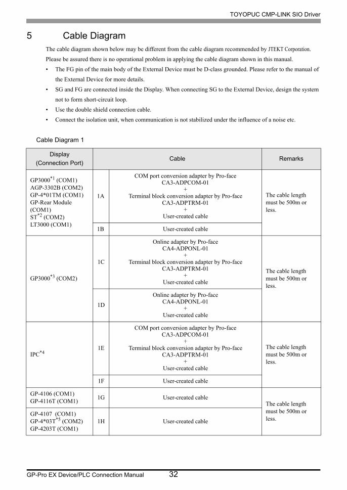
5 Cable DiagramThe cable diagram shown below may be different from the cable diagram recommended by JTEKT Corporation.
Please be assured there is no operational problem in applying the cable diagram shown in this manual.
• The FG pin of the main body of the External Device must be D-class grounded. Please refer to the manual of
the External Device for more details.
• SG and FG are connected inside the Display. When connecting SG to the External Device, design the system
not to form short-circuit loop.
• Use the double shield connection cable.
• Connect the isolation unit, when communication is not stabilized under the influence of a noise etc.
Cable Diagram 1
Display
(Connection Port)Cable Remarks
GP3000*1 (COM1)AGP-3302B (COM2)GP-4*01TM (COM1)GP-Rear Module (COM1)ST*2 (COM2)LT3000 (COM1)
1A
COM port conversion adapter by Pro-faceCA3-ADPCOM-01
+Terminal block conversion adapter by Pro-face
CA3-ADPTRM-01+
User-created cable
The cable length must be 500m or less.
1B User-created cable
GP3000*3 (COM2)
1C
Online adapter by Pro-faceCA4-ADPONL-01
+Terminal block conversion adapter by Pro-face
CA3-ADPTRM-01+
User-created cable
The cable length must be 500m or less.
1D
Online adapter by Pro-faceCA4-ADPONL-01
+User-created cable
IPC*41E
COM port conversion adapter by Pro-faceCA3-ADPCOM-01
+Terminal block conversion adapter by Pro-face
CA3-ADPTRM-01+
User-created cable
The cable length must be 500m or less.
1F User-created cable
GP-4106 (COM1)GP-4116T (COM1)
1G User-created cableThe cable length must be 500m or less.
GP-4107 (COM1)GP-4*03T*5 (COM2)GP-4203T (COM1)
1H User-created cable

TOYOPUC CMP-LINK SIO Driver
GP-Pro EX Device/PLC Connection Manual 33
GP4000*6 (COM2)GP-4201T (COM1)SP5000*7 (COM1/2)SP-5B00 (COM2)
1I
RS-422 Terminal Block Conversion Adapter by Pro-facePFXZCBADTM1*8
+User-created cable
The cable length must be 500m or less.
1B User-created cable
LT-4*01TM (COM1)LT-Rear Module (COM1)
1JRJ45 RS-485 Cable (5m) by Pro-face
PFXZLMCBRJR81The cable length must be 200m or less.
PE-4000B*9
PS5000*9 1K User-created cableThe cable length must be 500m or less.
*1 All GP3000 models except AGP-3302B
*2 All ST models except AST-3211A and AST-3302B
*3 All GP3000 models except GP-3200 series and AGP-3302B
*4 Only the COM port which can communicate by RS-422/485 (2 wire) can be used. (Except PE-4000B, PS5000)
IPC COM Port (page 5)
*5 Except GP-4203T
*6 All GP4000 models except GP-4100 Series, GP-4*01TM, GP-Rear Module, GP-4201T and GP-4*03T
*7 Except SP-5B00
*8 When using a Terminal Block Conversion Adapter (CA3-ADPTRM-01) instead of the RS-422 Terminal Block Conversion Adapter, refer to Cable Diagram 1A.
*9 Only the COM port which can communicate by RS-422/485 (2 wire) can be used.
IPC COM Port (page 5)
• For connection cable, we recommend the double shield 0-VCTF-SS 2C*0.75mm2 by Chugoku
Electric Wire & Cable Co., Ltd., the double shield UL2464-DSS 2C x 20AWG by Chugoku
Electric Wire & Cable Co., Ltd. and UL2464-2SB 2 x 20AWG by Kuramo Electric Co., Ltd.
• The FG pin of the main body of the External Device must be D-class grounded.
• Select either on the External Device or on the Display depending on installation environment to
connect FG to the shield cable.
• Please be sure to connect signal ground (SG) when connecting the communication cable.
• In RS422 connection, please refer to the manual of JTEKT Corporation for the cable length.
Display
(Connection Port)Cable Remarks

TOYOPUC CMP-LINK SIO Driver
GP-Pro EX Device/PLC Connection Manual 34
1A)
• 1:1 Connection
• 1:n Connection
CA3-ADPTRM-01
RDA
RDB
SDA
SDB
SG
L +
L -
0V
G
CA3-ADPCOM-01Display
External Device4 pin terminal block
Terminal blockSignalname
Signalname
TERM
Terminationresistance1/4W or 1/2W330Ω
Terminationresistance1/4W or 1/2W330Ω
User-created cable
Double Shield
CA3-ADPTRM-01
No. 0RDA
RDB
SDA
SDB
SG
L +
L -
0V
G
CA3-ADPCOM-01
No. 1
L +
L -
0V
G
No. n
L +
L -
0V
GTERM
External Device External Device External Device
Terminal block
Double Shield
Double Shield Double Shield
4pin terminal block4pin terminal block4pin terminal block
Signalname
Signalname
Signalname
SignalnameDisplay
Terminationresistance1/4W or 1/2W330Ω
Terminationresistance1/4W or 1/2W330Ω
User-created cable

TOYOPUC CMP-LINK SIO Driver
GP-Pro EX Device/PLC Connection Manual 35
1B)
• 1:1 Connection
• 1:n Connection
FGShell
RDA
RDB
SDA
SDB
SG
L +
L -
0V
G
1
2
3
7
5
CSB
ERB
CSA
ERA
6
9
8
4
External Device4 pin terminal block
Double ShieldD-sub 9 pin (socket)
Pin Signalname
SignalnameDisplay
Terminationresistance1/4W or 1/2W330Ω
Terminationresistance1/4W or 1/2W330Ω
RDA
RDB
SDA
SDB
SG
FG
L +
L -
0V
G
1
2
3
7
5
CSB
ERB
CSA
ERA
6
9
8
4
No. nNo. 0
L +
L -
0V
G
No. 1
L +
L -
0V
G
External DeviceDouble Shield External DeviceDouble Shield External DeviceDouble ShieldD-sub 9 pin (socket)
Pin Signalname
Signalname
Signalname
Signalname
Display
4pin terminal block4pin terminal block4pin terminal block
Terminationresistance1/4W or 1/2W330Ω
Terminationresistance1/4W or 1/2W330Ω

TOYOPUC CMP-LINK SIO Driver
GP-Pro EX Device/PLC Connection Manual 36
1C)
• 1:1 Connection
• 1:n connection
CA3-ADPTRM- 01
RDA
RDB
SDA
SDB
TERM
SG
L +
L -
0V
G
CA4-ADPONL- 01
Signalname
Signalname
External Device4 pin terminal block
Terminal block
Display
Terminationresistance1/4W or 1/2W330Ω
Terminationresistance1/4W or 1/2W330Ω
Double Shield
User-created cable
CA3-ADPTRM- 01
No. 0RDA
RDB
SDA
SDB
SG
TERM
L +
No. 1 No. n
L -
0V
G
L +
L -
0V
G
L +
L -
0V
G
CA4-ADPONL- 01
External Device External Device External Device
Terminal block
Double Shield Double Shield Double Shield
Signalname
Signalname
Signalname
Signalname
4 pin terminal block4 pin terminal block 4 pin terminal block
Display
Terminationresistance1/4W or 1/2W330Ω
Terminationresistance1/4W or 1/2W330Ω
User-created cable

TOYOPUC CMP-LINK SIO Driver
GP-Pro EX Device/PLC Connection Manual 37
1D)
• 1:1 Connection
• 1:n Connection
FGShell
RDA
RDB
SDA
SDB
SG
2
7
3
8
5
TERM1
RTS4
VCC6
TERM9
CA4-ADPONL-01 L +
L -
0V
G
Pin Signalname
Signalname
External Device4 pin terminal block
Double Shield
D-sub 9 pin (plug)
Display
Terminationresistance1/4W or 1/2W330Ω
Terminationresistance1/4W or 1/2W330Ω
User-created cable
FGShell
No. 0RDA
RDB
SDA
SDB
SG
L +
L -
0V
G
2
7
3
8
5
TERM1
RTS4
VCC6
TERM9
No. n
L +
L -
0V
G
No. 1
L +
L -
0V
G
External DeviceDouble Shield
External DeviceDouble Shield
External DeviceDouble Shield
D-sub 9 pin (plug)
Pin Signalname
Signalname
Signalname
Signalname
Display
CA4-ADPONL-01 4 pin terminal block
4 pin terminal block
4 pin terminal block
Terminationresistance1/4W or 1/2W330Ω
Terminationresistance1/4W or 1/2W330Ω
User-created cable
TOYOPUC CMP-LINK SIO Driver
GP-Pro EX Device/PLC Connection Manual 38
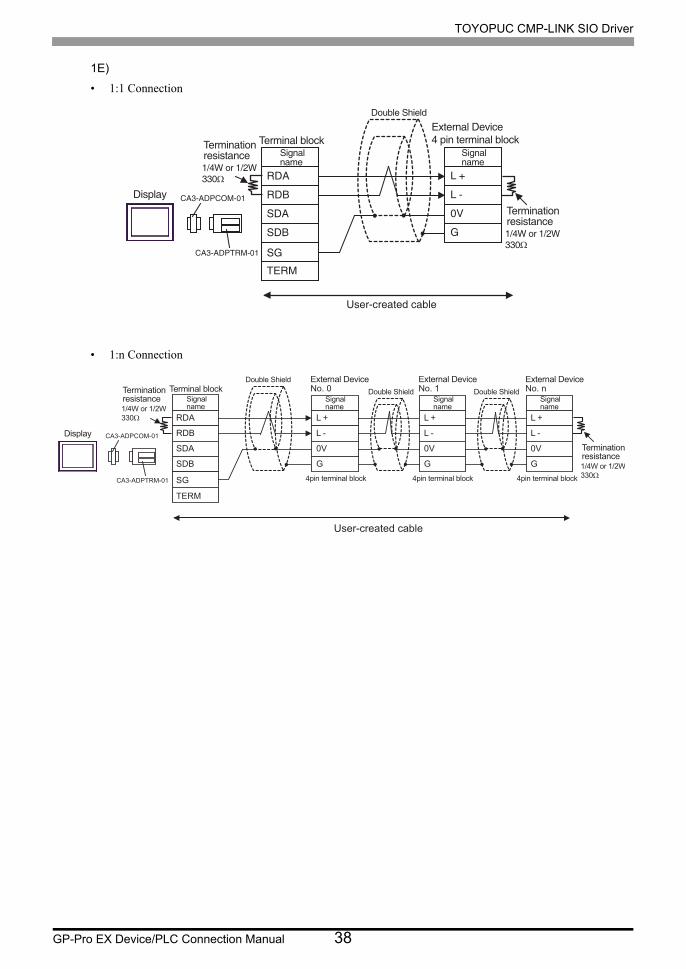
1E)
• 1:1 Connection
• 1:n Connection
CA3-ADPTRM-01
RDA
RDB
SDA
SDB
SG
L +
L -
0V
G
CA3-ADPCOM-01Display
External Device4 pin terminal blockTerminal block
Signalname
Signalname
TERM
Terminationresistance1/4W or 1/2W330Ω
Terminationresistance1/4W or 1/2W330Ω
Double Shield
User-created cable
CA3-ADPTRM-01
RDA
RDB
SDA
SDB
SG
CA3-ADPCOM-01
TERM
Terminal blockSignalname
Display
Terminationresistance1/4W or 1/2W330Ω
No. 0
L +
L -
0V
G
No. 1
L +
L -
0V
G
No. n
L +
L -
0V
G
External Device External Device External DeviceDouble Shield
Double Shield Double Shield
4pin terminal block4pin terminal block4pin terminal block
Signalname
Signalname
Signalname
Terminationresistance1/4W or 1/2W330Ω
User-created cable

TOYOPUC CMP-LINK SIO Driver
GP-Pro EX Device/PLC Connection Manual 39
1F)
• 1:1 Connection
• 1:n Connection
FGShell
DATA+
DATA-
NC
NC
GND(SG)
L +
L -
0V
G
1
2
3
7
5
CSB
ERB
CSA
ERA
6
9
8
4
External Device4 pin terminal block
Double ShieldD-sub 9 pin (socket)
Pin Signalname
Signalname
Display
Terminationresistance1/4W or 1/2W330Ω
Terminationresistance1/4W or 1/2W330Ω
DATA+
DATA-
NC
NC
GND(SG)
FG
L +
L -
0V
G
1
2
3
7
5
CSB
ERB
CSA
ERA
6
9
8
4
No. nNo. 0
L +
L -
0V
G
No. 1
L +
L -
0V
G
External DeviceDouble Shield External DeviceDouble Shield External DeviceDouble Shield
D-sub 9 pin (socket)
Pin Signalname
Signalname
Signalname
Signalname
Display
4pin terminal block4pin terminal block4pin terminal block
Terminationresistance1/4W or 1/2W330Ω
Terminationresistance1/4W or 1/2W330Ω

TOYOPUC CMP-LINK SIO Driver
GP-Pro EX Device/PLC Connection Manual 40
1G)
• 1:1 Connection
• 1:n Connection
*1 The resistance in the Display is used as the termination resistance. Set the value of the DIP Switch on the rear of the Display as shown in the table below.
DIP Switch No. Set Value
1 OFF
2 OFF
3 ON
4 OFF
RDA
RDB
SDA
SDB
SG
L +
L -
0V
GCSB
ERB
CSA
ERA
External Device4 pin terminal block
Double ShieldSignalname
SignalnameDisplay
Terminationresistance*1
Terminationresistance1/4W or 1/2W330Ω
Display side Terminal block
RDA
RDB
SDA
SDB
SG
L +
L -
0V
GCSB
ERB
CSA
ERA
No. nNo. 0
L +
L -
0V
G
No. 1
L +
L -
0V
G
External DeviceDouble Shield External DeviceDouble Shield External DeviceDouble ShieldSignalname
Signalname
Signalname
Signalname
Display
4pin terminal block4pin terminal block4pin terminal block
Terminationresistance1/4W or 1/2W330Ω
Terminationresistance*1
Display side Terminal block

TOYOPUC CMP-LINK SIO Driver
GP-Pro EX Device/PLC Connection Manual 41
1H)
• 1:1 Connection
• 1:n Connection
• The 5V output (Pin #6) on the Display is the power for the Siemens AG’s PROFIBUS
connector. Do not use it for other devices.
• In COM on the GP-4107, the SG and FG terminals are isolated.
L +
L -
0V
G
External Device4 pin terminal block
Double Shield
Signalname
Display
Terminationresistance1/4W or 1/2W330Ω
Terminationresistance1/4W or 1/2W330Ω
Pin Signal name
NC
NC
GND(SG)
RS(RTS)
5V
NC
NC
FG
LINE(+)
LINE(-)
3
8
1
2
5
4
6
7
9
Shell
Display sideD-Sub 9pin (plug)
L +
L -
0V
G
No. nNo. 0
L +
L -
0V
G
No. 1
L +
L -
0V
G
External DeviceDouble Shield External DeviceDouble Shield External DeviceDouble Shield
Signalname
Signalname
Signalname
Display
4pin terminal block4pin terminal block4pin terminal block
Terminationresistance1/4W or 1/2W330Ω
Terminationresistance1/4W or 1/2W330Ω
Pin Signal name
NC
NC
GND(SG)
RS(RTS)
5V
NC
NC
FG
LINE(+)
LINE(-)
3
8
1
2
5
4
6
7
9
Shell
Display sideD-Sub 9pin (plug)

TOYOPUC CMP-LINK SIO Driver
GP-Pro EX Device/PLC Connection Manual 42
1I)
• 1:1 Connection
• 1:n Connection
PFXZCBADTM1
RDA
RDB
SDA
SDB
SG
L +
L -
0V
G
01Display
External Device4 pin terminal block
Terminal blockSignalname
Signalname
TERM
Terminationresistance1/4W or 1/2W330Ω
Terminationresistance1/4W or 1/2W330Ω
User-created cable
Double Shield
No. 0RDA
RDB
SDA
SDB
SG
L +
L -
0V
G
No. 1
L +
L -
0V
G
No. n
L +
L -
0V
GTERM
External Device External Device External Device
Terminal block
Double Shield
Double Shield Double Shield
4pin terminal block4pin terminal block4pin terminal block
Signalname
Signalname
Signalname
SignalnameDisplay
Terminationresistance1/4W or 1/2W330Ω
Terminationresistance1/4W or 1/2W330Ω
User-created cable
PFXZCBADTM1

TOYOPUC CMP-LINK SIO Driver
GP-Pro EX Device/PLC Connection Manual 43
1J)
• 1:1 Connection
• 1:n Connection
Number Name Notes
(1)RJ45 RS-485 Cable (5m) by Pro-face
PFXZLMCBRJR81
L +
L -
0 V
G
External Device 4 pin terminal block
Signal name
Termination resistance 1/4W or 1/2W 330Ω
Display
GND
D0D1
(1)
L +
L -
0 V
G
No. n No. 0
L +
L -
0 V
G
No. 1
L +
L -
0 V
G
External Device External Device Double Shield External Device Double Shield
Signal name
Signal name
Signal name
4pin terminal block 4pin terminal block 4pin terminal block
Termination resistance 1/4W or 1/2W 330Ω
Terminationresistance1/4W or 1/2W330Ω
Display
GND
D0
D1
(1)
User-created Cable

TOYOPUC CMP-LINK SIO Driver
GP-Pro EX Device/PLC Connection Manual 44
1K)
• 1:1 Connection
• 1:n Connection
FG Shell
DATA+
DATA-
NC
NC
NC
NC
NC
NC
GND
L +
L -
0 V
G
2
1
3
7
5
6
9
8
4
External Device 4 pin terminal block
Double Shield D-sub 9 pin (socket)
Pin Signal name
Signal name
Display
Termination resistance 1/4W or 1/2W 330Ω
Termination resistance 1/4W or 1/2W 330Ω
DATA+
DATA-
NC
NC
NC
NC
NC
NC
GND
FG
L +
L -
0 V
G
2
1
3
7
5
6
9
8
4
No. n No. 0
L +
L -
0 V
G
No. 1
L +
L -
0 V
G
External Device Double Shield External Device Double Shield External Device Double Shield
D-sub 9 pin (socket)
Pin Signal name
Signal name
Signal name
Signal name
Display
4pin terminal block 4pin terminal block 4pin terminal block
Termination resistance 1/4W or 1/2W 330Ω
Termination resistance 1/4W or 1/2W 330Ω

TOYOPUC CMP-LINK SIO Driver
GP-Pro EX Device/PLC Connection Manual 45
Cable Diagram 2
Display
(Connection Port)Cable Remarks
GP3000*1 (COM1)AGP-3302B (COM2)GP-4*01TM (COM1)GP-Rear Module (COM1)ST*2 (COM2)LT3000 (COM1)
2A
COM port conversion adapter by Pro-faceCA3-ADPCOM-01
+Terminal block conversion adapter by Pro-face
CA3-ADPTRM-01+
User-created cable
The cable length must be 500m or less.
2B User-created cable
GP3000*3 (COM2)
2C
Online adapter by Pro-faceCA4-ADPONL-01
+Terminal block conversion adapter by Pro-face
CA3-ADPTRM-01+
User-created cable
The cable length must be 500m or less.
2D
Online adapter by Pro-faceCA4-ADPONL-01
+User-created cable
IPC*42E
COM port conversion adapter by Pro-faceCA3-ADPCOM-01
+Terminal block conversion adapter by Pro-face
CA3-ADPTRM-01+
User-created cable
The cable length must be 500m or less.
2F User-created cable
GP-4106 (COM1)GP-4116T (COM1)
2G User-created cableThe cable length must be 500m or less.
GP-4107 (COM1)GP-4*03T*5 (COM2)GP-4203T (COM1)
2H User-created cable
GP4000*6 (COM2)GP-4201T (COM1)SP5000*7 (COM1/2)SP-5B00 (COM2)
2I
RS-422 Terminal Block Conversion Adapter by Pro-facePFXZCBADTM1*8
+User-created cable
The cable length must be 500m or less.
2B User-created cable
LT-4*01TM (COM1)LT-Rear Module (COM1)
2JRJ45 RS-485 Cable (5m) by Pro-face
PFXZLMCBRJR81The cable length must be 200m or less.
PE-4000B*9
PS5000*9 2K User-created cableThe cable length must be 500m or less.

TOYOPUC CMP-LINK SIO Driver
GP-Pro EX Device/PLC Connection Manual 46
*1 All GP3000 models except AGP-3302B
*2 All ST models except AST-3211A and AST-3302B
*3 All GP3000 models except GP-3200 series and AGP-3302B
*4 Only the COM port which can communicate by RS-422/485 (2 wire) can be used. (Except PE-4000B, PS5000)
IPC COM Port (page 5)
*5 Except GP-4203T
*6 All GP4000 models except GP-4100 Series, GP-4*01TM, GP-Rear Module, GP-4201T and GP-4*03T
*7 Except SP-5B00
*8 When using a Terminal Block Conversion Adapter (CA3-ADPTRM-01) instead of the RS-422 Terminal Block Conversion Adapter, refer to Cable Diagram 2A.
*9 Only the COM port which can communicate by RS-422/485 (2 wire) can be used.
IPC COM Port (page 5)
• For connection cable, we recommend the double shield 0-VCTF-SS 2C*0.75mm2 by Chugoku
Electric Wire & Cable Co., Ltd., the double shield UL2464-DSS 2C x 20AWG by Chugoku
Electric Wire & Cable Co., Ltd. and UL2464-2SB 2 x 20AWG by Kuramo Electric Co., Ltd.
• The FG pin of the main body of the External Device must be D-class grounded.
• Select either on the External Device or on the Display depending on installation environment to
connect FG to the shield cable.
• Please be sure to connect signal ground (SG) when connecting the communication cable.
• In RS422 connection, please refer to the manual of JTEKT Corporation for the cable length.

TOYOPUC CMP-LINK SIO Driver
GP-Pro EX Device/PLC Connection Manual 47
2A)
• 1:1 Connection
• 1:n Connection
CA3-ADPTRM-01
RDA
RDB
SDA
SDB
TERM
SG
L2 +
L2 -
L1 +
L1 -
0V
FG
0V
FG
CA3-ADPCOM-01Display
External Device8 pin terminal blockTerminal block
Double ShieldSignalname
Signalname
Terminationresistance
Terminationresistance
User-created cable
CA3-ADPTRM-01
RDA
RDB
SDA
SDB
TERM
SG
L2 +
L2 -
L1 +
L1 -
0V
FG
0V
FG
CA3-ADPCOM-01
No. 0
L2 +
L2 -
L1 +
L1 -
0V
FG
0V
FG
No. 1 No. n
L2 +
L2 -
L1 +
L1 -
0V
FG
0V
FG
External Device
Terminal blockDouble Shield
External Device
Double Shield
External Device
Double ShieldSignalname
Signalname
Signalname
Signalname
8 pin terminal block8 pin terminal block 8 pin terminal block
Display
Terminationresistance1/4W or 1/2W330Ω
Terminationresistance1/4W or 1/2W330Ω
User-created cable

TOYOPUC CMP-LINK SIO Driver
GP-Pro EX Device/PLC Connection Manual 48
2B)
• 1:1 Connection
• 1:n Connection
FGShell
RDA
RDB
SDA
SDB
SG
L2 +
L2 -
L1 +
L1 -
0V
FG
0V
FG
1
2
3
7
5
CSB
ERB
CSA
ERA
6
9
8
4
External Device8 pin terminal block
Display
Double ShieldPin Signalname
Signalname
D-sub 9 pin (socket)Terminationresistance1/4W or 1/2W330Ω
Terminationresistance1/4W or 1/2W330Ω
FGShell
RDA
RDB
SDA
SDB
SG
L2 +
L2 -
L1 +
L1 -
0V
FG
0V
FG
1
2
3
7
5
CSB
ERB
CSA
ERA
6
9
8
4
L2 +
L2 -
L1 +
L1 -
0V
FG
0V
FG
L2 +
L2 -
L1 +
L1 -
0V
FG
0V
FG
D-sub 9 pin (socket)
Double Shield Double Shield Double ShieldPin Signalname
Signalname
Signalname
Signalname
No. 0 No. 1 No. nExternal Device External Device External Device
8 pin terminal block8 pin terminal block 8 pin terminal block
Display
Terminationresistance1/4W or 1/2W330Ω
Terminationresistance1/4W or 1/2W330Ω

TOYOPUC CMP-LINK SIO Driver
GP-Pro EX Device/PLC Connection Manual 49
2C)
• 1:1 Connection
• 1:n Connection
CA3-ADPTRM-01
RDA
RDB
SDA
SDB
TERM
SG
L2 +
L2 -
L1 +
L1 -
0V
FG
0V
FG
CA4-ADPONL-01Display
External Device8 pin terminal blockTerminal block
Double ShieldSignalname
Signalname
Terminationresistance
Terminationresistance
User-created cable
CA3-ADPTRM-01
RDA
RDB
SDA
SDB
TERM
SG
L2 +
L2 -
L1 +
L1 -
0V
FG
0V
FG
CA4-ADPONL-01
L2 +
L2 -
L1 +
L1 -
0V
FG
0V
FG
L2 +
L2 -
L1 +
L1 -
0V
FG
0V
FG
Terminal block Double ShieldSignalname
Signalname
Signalname
Signalname
Display
No. 0 No. 1 No. nExternal Device External Device External Device
8 pin terminal block8 pin terminal block 8 pin terminal block
Terminationresistance1/4W or 1/2W330Ω
Terminationresistance1/4W or 1/2W330Ω
User-created cable

TOYOPUC CMP-LINK SIO Driver
GP-Pro EX Device/PLC Connection Manual 50
2D)
• 1:1 Connection
• 1:n Connection
FGShell
RDA
RDB
SDA
SDB
SG
L2 +
L2 -
L1 +
L1 -
0V
FG
0V
FG
2
7
3
8
5
TERM1
RTS4
VCC6
TERM9
CA4-ADPONL-01
External Device8 pin terminal block
Display
D-sub 9 pin (plug)
Double Shield
Pin Signalname
Signalname
Terminationresistance1/4W or 1/2W330Ω
Terminationresistance1/4W or 1/2W330Ω
User-created cable
FGShell
RDA
RDB
SDA
SDB
SG
L2 +
L2 -
L1 +
L1 -
0V
FG
0V
FG
2
7
3
8
5
TERM1
RTS4
VCC6
TERM9
CA4-ADPONL-01
L2 +
L2 -
L1 +
L1 -
0V
FG
0V
FG
L2 +
L2 -
L1 +
L1 -
0V
FG
0V
FG
D-sub 9 pin (plug)
Double Shield Double Shield Double Shield
Pin Signalname
Signalname
Signalname
Signalname
Display
No. 0 No. 1 No. nExternal Device External Device External Device
8 pin terminal block8 pin terminal block 8 pin terminal block
Terminationresistance1/4W or 1/2W330Ω
Terminationresistance1/4W or 1/2W330Ω
User-created cable

TOYOPUC CMP-LINK SIO Driver
GP-Pro EX Device/PLC Connection Manual 51
2E)
• 1:1 Connection
• 1:n Connection
CA3-ADPTRM-01
RDA
RDB
SDA
SDB
TERM
SG
L2 +
L2 -
L1 +
L1 -
0V
FG
0V
FG
CA3-ADPCOM-01Display
External Device8 pin terminal block
Terminal block
Double Shield
Signalname
Signalname
Terminationresistance
Terminationresistance
User-created cable
CA3-ADPTRM-01
RDA
RDB
SDA
SDB
TERM
SG
L2 +
L2 -
L1 +
L1 -
0V
FG
0V
FG
CA3-ADPCOM-01
No. 0
L2 +
L2 -
L1 +
L1 -
0V
FG
0V
FG
No. 1 No. n
L2 +
L2 -
L1 +
L1 -
0V
FG
0V
FG
External Device
Terminal block
Double Shield
External Device
Double Shield
External Device
Double Shield
Signalname
Signalname
Signalname
Signalname
8 pin terminal block8 pin terminal block 8 pin terminal block
DisplayTerminationresistance1/4W or 1/2W
Terminationresistance1/4W or 1/2W
User-created cable

TOYOPUC CMP-LINK SIO Driver
GP-Pro EX Device/PLC Connection Manual 52
2F)
• 1:1 Connection
• 1:n Connection
FGShell
DATA+
DATA-
NC
NC
GND(SG)
L2 +
L2 -
L1 +
L1 -
0V
FG
0V
FG
1
2
3
7
5
CSB
ERB
CSA
ERA
6
9
8
4
External Device8 pin terminal block
Display
Double Shield
Pin Signalname
Signalname
D-sub 9 pin (socket)Terminationresistance1/4W or 1/2W330Ω
Terminationresistance1/4W or 1/2W330Ω
FGShell
DATA+
DATA-
NC
NC
GND(SG)
L2 +
L2 -
L1 +
L1 -
0V
FG
0V
FG
1
2
3
7
5
CSB
ERB
CSA
ERA
6
9
8
4
L2 +
L2 -
L1 +
L1 -
0V
FG
0V
FG
L2 +
L2 -
L1 +
L1 -
0V
FG
0V
FG
D-sub 9 pin (socket)Double Shield Double Shield Double Shield
Pin Signalname
Signalname
Signalname
Signalname
No. 0 No. 1 No. nExternal Device External Device External Device
8 pin terminal block8 pin terminal block 8 pin terminal block
DisplayTerminationresistance1/4W or 1/2W330Ω
Terminationresistance1/4W or 1/2W330Ω

TOYOPUC CMP-LINK SIO Driver
GP-Pro EX Device/PLC Connection Manual 53
2G)
• 1:1 Connection
• 1:n Connection
*1 The resistance in the Display is used as the termination resistance. Set the value of the DIP Switch on the rear of the Display as shown in the table below.
DIP Switch No. Set Value
1 OFF
2 OFF
3 ON
4 OFF
RDA
RDB
SDA
SDB
SG
L2 +
L2 -
L1 +
L1 -
0V
FG
0V
FG
CSB
ERB
CSA
ERA
External Device8 pin terminal block
Display
Double ShieldSignalname
SignalnameTermination
resistance*1
Terminationresistance1/4W or 1/2W330Ω
Display side Terminal block
RDA
RDB
SDA
SDB
SG
L2 +
L2 -
L1 +
L1 -
0V
FG
0V
FG
CSB
ERB
CSA
ERA
L2 +
L2 -
L1 +
L1 -
0V
FG
0V
FG
L2 +
L2 -
L1 +
L1 -
0V
FG
0V
FG
Double Shield Double Shield Double ShieldSignalname
Signalname
Signalname
Signalname
No. 0 No. 1 No. nExternal Device External Device External Device
8 pin terminal block8 pin terminal block 8 pin terminal block
Display
Terminationresistance1/4W or 1/2W330Ω
Terminationresistance*1
Display side Terminal block
TOYOPUC CMP-LINK SIO Driver
GP-Pro EX Device/PLC Connection Manual 54
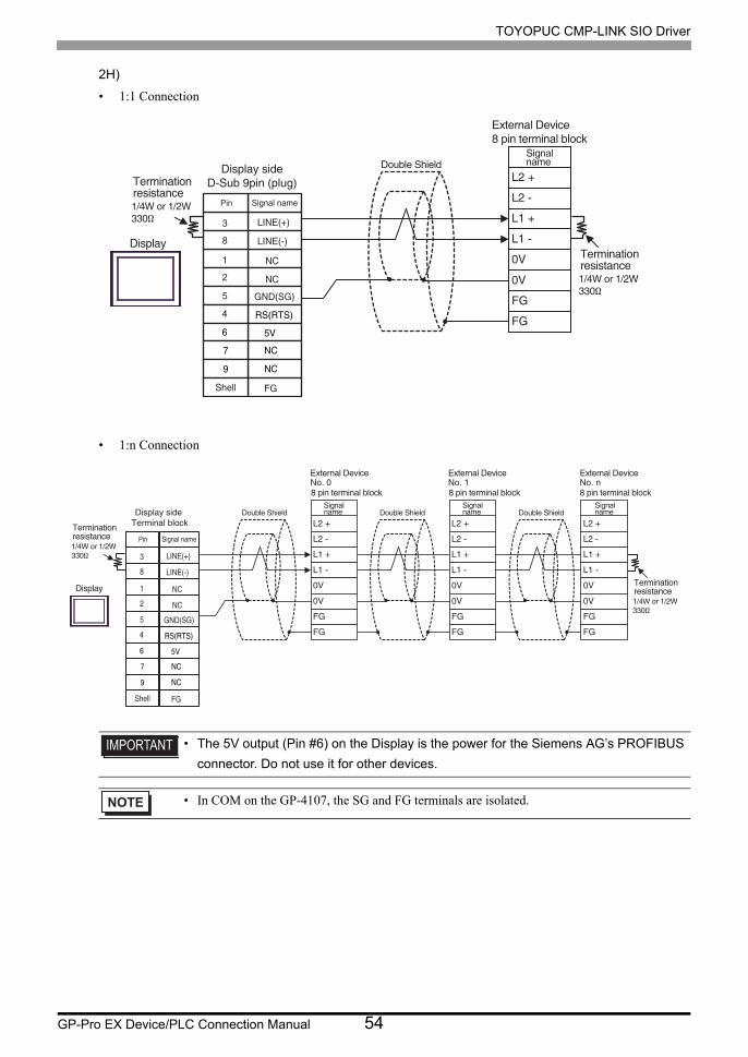
2H)
• 1:1 Connection
• 1:n Connection
• The 5V output (Pin #6) on the Display is the power for the Siemens AG’s PROFIBUS
connector. Do not use it for other devices.
• In COM on the GP-4107, the SG and FG terminals are isolated.
L2 +
L2 -
L1 +
L1 -
0V
FG
0V
FG
External Device8 pin terminal block
Display
Double ShieldSignalname
Terminationresistance1/4W or 1/2W330Ω
Terminationresistance1/4W or 1/2W330Ω
Pin Signal name
NC
NC
GND(SG)
RS(RTS)
5V
NC
NC
FG
LINE(+)
LINE(-)
3
8
1
2
5
4
6
7
9
Shell
Display sideD-Sub 9pin (plug)
L2 +
L2 -
L1 +
L1 -
0V
FG
0V
FG
L2 +
L2 -
L1 +
L1 -
0V
FG
0V
FG
L2 +
L2 -
L1 +
L1 -
0V
FG
0V
FG
Double Shield Double Shield Double ShieldSignalname
Signalname
Signalname
No. 0 No. 1 No. nExternal Device External Device External Device
8 pin terminal block8 pin terminal block 8 pin terminal block
DisplayTerminationresistance1/4W or 1/2W330Ω
Terminationresistance1/4W or 1/2W330Ω
Pin Signal name
NC
NC
GND(SG)
RS(RTS)
5V
NC
NC
FG
LINE(+)
LINE(-)
3
8
1
2
5
4
6
7
9
Shell
Display side Terminal block

TOYOPUC CMP-LINK SIO Driver
GP-Pro EX Device/PLC Connection Manual 55
2I)
• 1:1 Connection
• 1:n Connection
PFXZCBADTM1
RDA
RDB
SDA
SDB
TERM
SG
L2 +
L2 -
L1 +
L1 -
0V
FG
0V
FG
Display
External Device8 pin terminal blockTerminal block
Double ShieldSignalname
Signalname
Terminationresistance
Terminationresistance
User-created cable
RDA
RDB
SDA
SDB
TERM
SG
L2 +
L2 -
L1 +
L1 -
0V
FG
0V
FG
No. 0
L2 +
L2 -
L1 +
L1 -
0V
FG
0V
FG
No. 1 No. n
L2 +
L2 -
L1 +
L1 -
0V
FG
0V
FG
External Device
Terminal blockDouble Shield
External Device
Double Shield
External Device
Double ShieldSignalname
Signalname
Signalname
Signalname
8 pin terminal block8 pin terminal block 8 pin terminal block
Display
Terminationresistance1/4W or 1/2W330Ω
Terminationresistance1/4W or 1/2W330Ω
User-created cable
PFXZCBADTM1

TOYOPUC CMP-LINK SIO Driver
GP-Pro EX Device/PLC Connection Manual 56
2J)
• 1:1 Connection
• 1:n Connection
Number Name Notes
(1)RJ45 RS-485 Cable (5m) by Pro-face
PFXZLMCBRJR81
L 2 +
L 2 -
L 1 +
L 1 -
0 V
FG
0 V
FG
External Device 8 pin terminal block
Signal name
Termination resistance 1/4W or 1/2W 330Ω
Display
GND
D0
D1
(1)
L 2 +
L 2 -
L 1 +
L 1 -
0 V
FG
0 V
FG
L 2 +
L 2 -
L 1 +
L 1 -
0 V
FG
0 V
FG
L 2 +
L 2 -
L 1 +
L 1 -
0 V
FG
0 V
FG
Double Shield Double Shield Signal name
Signal name
Signal name
No. 0 No. 1 No. n External Device External Device External Device
8 pin terminal block 8 pin terminal block 8 pin terminal block
Termination resistance 1/4W or 1/2W 330Ω
Terminationresistance1/4W or 1/2W330Ω
User-created Cable
Display
GND
D0
D1
(1)

TOYOPUC CMP-LINK SIO Driver
GP-Pro EX Device/PLC Connection Manual 57
2K)
• 1:1 Connection
• 1:n Connection
FG Shell
DATA+
DATA-
NC
NC
NC
NC
NC
NC
GND
L 2 +
L 2 -
L 1 +
L 1 -
0 V
FG
0 V
FG
2
1
3
7
5
6
9
8
4
External Device 8 pin terminal block
Display
Double Shield
Pin Signal name
Signal name
D-sub 9 pin (socket) Termination resistance 1/4W or 1/2W 330Ω
Termination resistance 1/4W or 1/2W 330Ω
FG Shell
DATA+
DATA-
NC
NC
NC
NC
NC
NC
GND
L 2 +
L 2 -
L 1 +
L 1 -
0 V
FG
0 V
FG
2
1
3
7
5
6
9
8
4
L 2 +
L 2 -
L 1 +
L 1 -
0 V
FG
0 V
FG
L 2 +
L 2 -
L 1 +
L 1 -
0 V
FG
0 V
FG
D-sub 9 pin (socket) Double Shield Double Shield Double Shield
Pin Signal name
Signal name
Signal name
Signal name
No. 0 No. 1 No. n External Device External Device External Device
8 pin terminal block 8 pin terminal block 8 pin terminal block
Display Termination resistance 1/4W or 1/2W 330Ω
Termination resistance 1/4W or 1/2W 330Ω

TOYOPUC CMP-LINK SIO Driver
GP-Pro EX Device/PLC Connection Manual 58
Cable Diagram 3
Display
(Connection Port)Cable Remarks
GP3000*1 (COM1)AGP-3302B (COM2)GP-4*01TM (COM1)GP-Rear Module (COM1)ST*2 (COM2)LT3000 (COM1)IPC*3
*1 All GP3000 models except AGP-3302B
*2 All ST models except AST-3211A and AST-3302B
*3 Only the COM port which can communicate by RS-422/485 (4 wire) can be used. (Except PE-4000B, PS5000)
IPC COM Port (page 5)
3A
COM port conversion adapter (for COM1) by Pro-faceCA3-ADPCOM-01
+Terminal block conversion adapter by Pro-face
CA3-ADPTRM-01+
User-created cable
The cable length must be 500m or less.
3B User-created cable
GP3000*4 (COM2)
*4 All GP3000 models except GP-3200 series and AGP-3302B
3C
Online adapter by Pro-faceCA4-ADPONL-01
+Terminal block conversion adapter by Pro-face
CA3-ADPTRM-01+
User-created cable
The cable length must be 500m or less.
3D
Online adapter by Pro-faceCA4-ADPONL-01
+User-created cable
GP-4106 (COM1)GP-4116T (COM1)
3E User-created cableThe cable length must be 500m or less.
GP4000*5 (COM2)GP-4201T (COM1)SP5000*6 (COM1/2)SP-5B00 (COM2)
*5 All GP4000 models except GP-4100 Series, GP-4*01TM, GP-Rear Module, GP-4201T and GP-4*03T
*6 Except SP-5B00
3F
RS-422 Terminal Block Conversion Adapter by Pro-facePFXZCBADTM1*7
+User-created cable
*7 When using a Terminal Block Conversion Adapter (CA3-ADPTRM-01) instead of the RS-422 Terminal Block Conversion Adapter, refer to Cable Diagram 3A.
The cable length must be 500m or less.
3B User-created cable
PE-4000B*8
PS5000*8
*8 Only the COM port which can communicate by RS-422/485 (4 wire) can be used.
IPC COM Port (page 5)
3G User-created cableThe cable length must be 500m or less.

TOYOPUC CMP-LINK SIO Driver
GP-Pro EX Device/PLC Connection Manual 59
• For connection cable, we recommend the double shield 0-VCTF-SS 2C*0.75mm2 by Chugoku
Electric Wire & Cable Co., Ltd., the double shield UL2464-DSS 2C x 20AWG by Chugoku
Electric Wire & Cable Co., Ltd. and UL2464-2SB 2 x 20AWG by Kuramo Electric Co., Ltd.
• The FG pin of the main body of the External Device must be D-class grounded.
• Select either on the External Device or on the Display depending on installation environment to
connect FG to the shield cable.
• Please be sure to connect signal ground (SG) when connecting the communication cable.
• In RS422 connection, please refer to the manual of JTEKT Corporation for the cable length.

TOYOPUC CMP-LINK SIO Driver
GP-Pro EX Device/PLC Connection Manual 60
3A)
• 1:1 Connection
• 1:n Connection
CA3-ADPTRM-01
RDA
RDB
SDA
SDB
TERM
SG
L1 S+
L1 S-
0V
FG
0V
FG
CA3-ADPCOM-01
L1 R+
L1 R-
Display
Signalname
Signalname
External Device8 pin terminal blockTerminal block Double ShieldTermination
resistance
Terminationresistance
User-created cable
CA3-ADPTRM-01
RDA
RDB
SDA
SDB
TERM
SG
L1 S+
L1 S-
0V
FG
0V
FG
No. 0
CA3-ADPCOM-01
L1 R+
L1 R-
L1 S+
L1 S-
0V
FG
0V
FG
No. 1
L1 R+
L1 R-
L1 S+
L1 S-
0V
FG
0V
FG
No. n
L1 R+
L1 R-
Double Shield Double Shield Double Shield
Signalname
Signalname
Signalname
Signalname
External Device External Device External DeviceTerminal block
8 pin terminal block8 pin terminal block 8 pin terminal block
Display
Terminationresistance1/4W or 1/2W330Ω
Terminationresistance1/4W or 1/2W330Ω
User-created cable
TOYOPUC CMP-LINK SIO Driver
GP-Pro EX Device/PLC Connection Manual 61
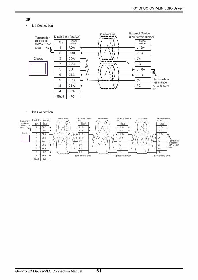
3B)
• 1:1 Connection
• 1:n Connection
RDA
RDB
SDA
SDB
SG
FG
L1 S+
L1 S-
0V
FG
0V
FG
1
2
3
7
5
CSB
ERB
CSA
ERA
6
9
8
4
L1 R+
L1 R-
External Device8 pin terminal block
Display
D-sub 9 pin (socket)Double Shield
Pin Signalname
Signalname
Shell
Terminationresistance
Terminationresistance
RDA
RDB
SDA
SDB
SG
L1 S+
L1 S-
L1 R+
L1 R-
0V
FG
0V
FG
1
2
3
7
5
CSB
ERB
CSA
ERA
6
9
8
4
No. 0 No. 1 No. n
L1 S+
L1 S-
L1 R+
L1 R-
0V
FG
0V
FG
L1 S+
L1 S-
L1 R+
L1 R-
0V
FG
0V
FG
FG
External Device External Device External DeviceD-sub 9 pin (socket)
Double Shield Double Shield Double Shield
Pin Signalname
Signalname
Signalname
Signalname
Shell
Display
8 pin terminal block8 pin terminal block 8 pin terminal block
Terminationresistance1/4W or 1/2W330Ω
Terminationresistance1/4W or 1/2W330Ω

TOYOPUC CMP-LINK SIO Driver
GP-Pro EX Device/PLC Connection Manual 62
3C)
• 1:1 Connection
• 1:n Connection
CA3-ADPTRM-01
RDA
RDB
SDA
SDB
TERM
SG
L1 S+
L1 S-
0V
FG
0V
FG
CA4-ADPONL-01
L1 R+
L1 R-
External Device8 pin terminal blockTerminal block
Display
Double Shield
Signalname
Signalname
Terminationresistance
Terminationresistance
User-created cable
CA3-ADPTRM-01
RDA
RDB
SDA
SDB
TERM
SG
L1 S+
L1 S-
0V
FG
0V
FG
No. 0
CA4-ADPONL-01
L1 R+
L1 R-
L1 S+
L1 S-
0V
FG
0V
FG
No. 1
L1 R+
L1 R-
L1 S+
L1 S-
0V
FG
0V
FG
No. n
L1 R+
L1 R-
Double Shield Double Shield Double ShieldExternal Device External Device External Device
Terminal blockSignalname
Signalname
Signalname
Signalname
8 pin terminal block8 pin terminal block 8 pin terminal block
Display
Terminationresistance1/4W or 1/2W330Ω
Terminationresistance1/4W or 1/2W330Ω
User-created cable
TOYOPUC CMP-LINK SIO Driver
GP-Pro EX Device/PLC Connection Manual 63
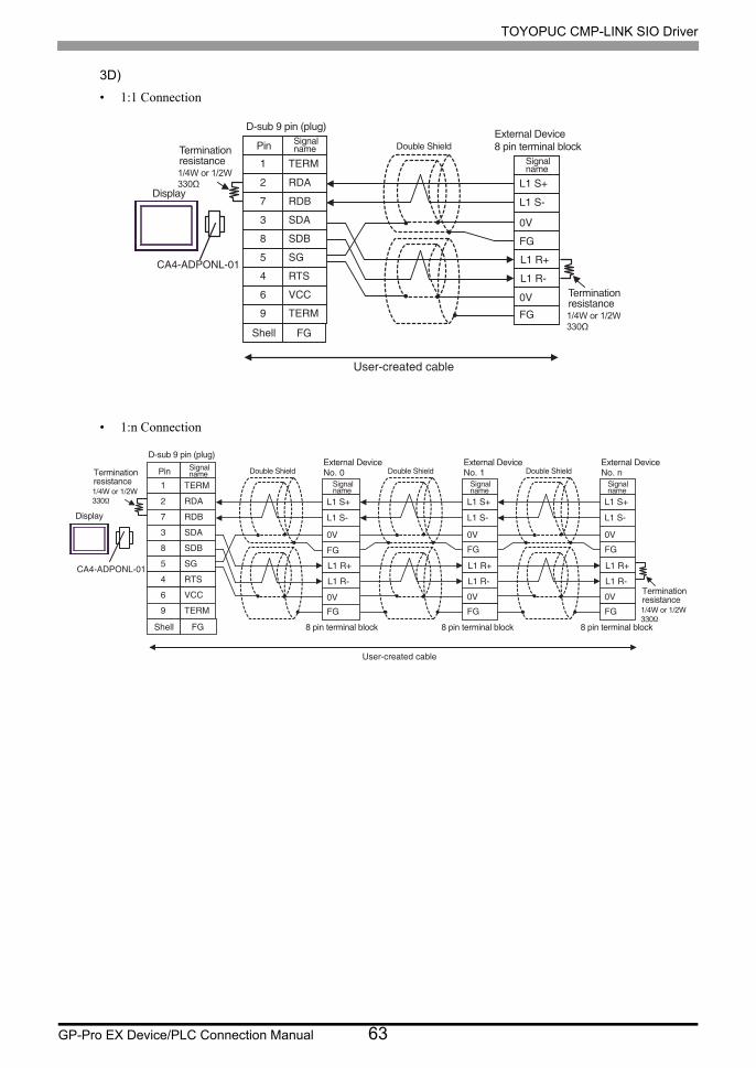
3D)
• 1:1 Connection
• 1:n Connection
TERM
RDA
RDB
SDA
SDB
SG
1
2
7
3
8
5
RTS4
VCC6
TERM9
L1 S+
L1 S-
0V
FG
0V
FG
L1 R+
L1 R-CA4-ADPONL-01
FG
Display
External Device8 pin terminal block
D-sub 9 pin (plug)
Double ShieldPin Signalname
Signalname
Shell
Terminationresistance
Terminationresistance
User-created cable
TERM
RDA
RDB
SDA
SDB
SG
1
2
7
3
8
5
RTS4
VCC6
TERM9
L1 S+
L1 S-
0V
FG
0V
FG
No. 0
L1 R+
L1 R-
L1 S+
L1 S-
0V
FG
0V
FG
No. 1
L1 R+
L1 R-
L1 S+
L1 S-
0V
FG
0V
FG
No. n
L1 R+
L1 R-CA4-ADPONL-01
FG
Pin Signalname
Signalname
Signalname
Signalname
External Device External Device External DeviceD-sub 9 pin (plug)
Double Shield Double Shield Double Shield
Shell
Display
8 pin terminal block8 pin terminal block 8 pin terminal block
Terminationresistance1/4W or 1/2W330Ω
Terminationresistance1/4W or 1/2W330Ω
User-created cable

TOYOPUC CMP-LINK SIO Driver
GP-Pro EX Device/PLC Connection Manual 64
3E)
• 1:1 Connection
• 1:n Connection
*1 The resistance in the Display is used as the termination resistance. Set the value of the DIP Switch on the rear of the Display as shown in the table below.
DIP Switch No. Set Value
1 OFF
2 OFF
3 ON
4 OFF
RDA
RDB
SDA
SDB
SG
L1 S+
L1 S-
0V
FG
0V
FG
CSB
ERB
CSA
ERA
L1 R+
L1 R-
External Device8 pin terminal block
Display
Double Shield
Signalname
Signalname
Terminationresistance*1
Terminationresistance
Display side Terminal block
RDA
RDB
SDA
SDB
SG
L1 S+
L1 S-
L1 R+
L1 R-
0V
FG
0V
FG
CSB
ERB
CSA
ERA
No. 0 No. 1 No. n
L1 S+
L1 S-
L1 R+
L1 R-
0V
FG
0V
FG
L1 S+
L1 S-
L1 R+
L1 R-
0V
FG
0V
FG
External Device External Device External DeviceDouble Shield Double Shield Double Shield
Signalname
Signalname
Signalname
Signalname
Display
8 pin terminal block8 pin terminal block 8 pin terminal block
Terminationresistance1/4W or 1/2W330Ω
Terminationresistance*1
Display side Terminal block

TOYOPUC CMP-LINK SIO Driver
GP-Pro EX Device/PLC Connection Manual 65
3F)
• 1:1 Connection
• 1:n Connection
RDA
RDB
SDA
SDB
TERM
SG
L1 S+
L1 S-
0V
FG
0V
FG
L1 R+
L1 R-
Display
Signalname
Signalname
External Device8 pin terminal blockTerminal block Double ShieldTermination
resistance
Terminationresistance
User-created cable
PFXZCBADTM1
RDA
RDB
SDA
SDB
TERM
SG
L1 S+
L1 S-
0V
FG
0V
FG
No. 0
L1 R+
L1 R-
L1 S+
L1 S-
0V
FG
0V
FG
No. 1
L1 R+
L1 R-
L1 S+
L1 S-
0V
FG
0V
FG
No. n
L1 R+
L1 R-
Double Shield Double Shield Double Shield
Signalname
Signalname
Signalname
Signalname
External Device External Device External DeviceTerminal block
8 pin terminal block8 pin terminal block 8 pin terminal block
Display
Terminationresistance1/4W or 1/2W330Ω
Terminationresistance1/4W or 1/2W330Ω
User-created cable
PFXZCBADTM1

TOYOPUC CMP-LINK SIO Driver
GP-Pro EX Device/PLC Connection Manual 66
3G)
• 1:1 Connection
• 1:n Connection
Signalname
Rx+
Rx-
Tx+
Tx-
GND
NC
NC
NC
NC
FG
L1 S+
L1 S-
0V
FG
0V
FG
3
4
2
1
5
6
9
8
7
L1 R+
L1 R-
External Device8 pin terminal block
Display
D-sub 9 pin (socket)Double Shield
Pin Signalname
Shell
Terminationresistance
Terminationresistance
Rx+
Rx-
Tx+
Tx-
GND
L 1 S+
L 1 S-
L 1 R+
L 1 R-
0 V
FG
0 V
FG
3
4
2
1
5
NC
NC
NC
NC
6
9
8
7
No. 0 No. 1 No. n
L 1 S+
L 1 S-
L 1 R+
L 1 R-
0 V
FG
0 V
FG
L 1 S+
L 1 S-
L 1 R+
L 1 R-
0 V
FG
0 V
FG
FG
External Device External Device External Device D-sub 9 pin (socket)
Double Shield Double Shield Double Shield
Pin Signal name
Signal name
Signal name
Signal name
Shell
Display
8 pin terminal block 8 pin terminal block 8 pin terminal block
Termination resistance 1/4W or 1/2W 330Ω
Termination resistance 1/4W or 1/2W 330Ω

TOYOPUC CMP-LINK SIO Driver
GP-Pro EX Device/PLC Connection Manual 67
Cable Diagram 4
Display
(Connection Port)Cable Remarks
GP3000*1 (COM1)AGP-3302B (COM2)GP-4*01TM (COM1)GP-Rear Module (COM1)ST*2 (COM2)LT3000 (COM1)
4A
COM port conversion adapter by Pro-faceCA3-ADPCOM-01
+Terminal block conversion adapter
by Pro-faceCA3-ADPTRM-01
+User-created cable
The cable length must be 500m or less.
4B User-created cable
GP3000*3 (COM2)
4C
Online adapter by Pro-faceCA4-ADPONL-01
+Terminal block conversion adapter
by Pro-faceCA3-ADPTRM-01
+User-created cable
The cable length must be 500m or less.
4D
Online adapter by Pro-faceCA4-ADPONL-01
+User-created cable
IPC*44E
COM port conversion adapter by Pro-faceCA3-ADPCOM-01
+Terminal block conversion adapter
by Pro-faceCA3-ADPTRM-01
+User-created cable
The cable length must be 500m or less.
4F User-created cable
GP-4106 (COM1)GP-4116T (COM1)
4G User-created cableThe cable length must be 500m or less.
GP-4107 (COM1)GP-4*03T*5 (COM2)GP-4203T (COM1)
4H User-created cableThe cable length must be 500m or less.
GP4000*6 (COM2)GP-4201T (COM1)SP5000*7 (COM1/2)SP-5B00 (COM2)
4I
RS-422 Terminal Block Conversion Adapter by Pro-facePFXZCBADTM1*8
+User-created cable
The cable length must be 500m or less.
4B User-created cable
LT-4*01TM (COM1)LT-Rear Module (COM1)
4JRJ45 RS-485 Cable (5m) by Pro-face
PFXZLMCBRJR81The cable length must be 200m or less.
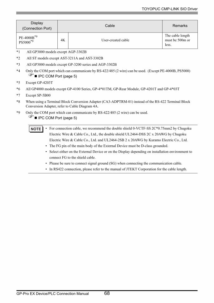
TOYOPUC CMP-LINK SIO Driver
GP-Pro EX Device/PLC Connection Manual 68
PE-4000B*9
PS5000*9 4K User-created cableThe cable length must be 500m or less.
*1 All GP3000 models except AGP-3302B
*2 All ST models except AST-3211A and AST-3302B
*3 All GP3000 models except GP-3200 series and AGP-3302B
*4 Only the COM port which can communicate by RS-422/485 (2 wire) can be used. (Except PE-4000B, PS5000)
IPC COM Port (page 5)
*5 Except GP-4203T
*6 All GP4000 models except GP-4100 Series, GP-4*01TM, GP-Rear Module, GP-4201T and GP-4*03T
*7 Except SP-5B00
*8 When using a Terminal Block Conversion Adapter (CA3-ADPTRM-01) instead of the RS-422 Terminal Block Conversion Adapter, refer to Cable Diagram 4A.
*9 Only the COM port which can communicate by RS-422/485 (2 wire) can be used.
IPC COM Port (page 5)
• For connection cable, we recommend the double shield 0-VCTF-SS 2C*0.75mm2 by Chugoku
Electric Wire & Cable Co., Ltd., the double shield UL2464-DSS 2C x 20AWG by Chugoku
Electric Wire & Cable Co., Ltd. and UL2464-2SB 2 x 20AWG by Kuramo Electric Co., Ltd.
• The FG pin of the main body of the External Device must be D-class grounded.
• Select either on the External Device or on the Display depending on installation environment to
connect FG to the shield cable.
• Please be sure to connect signal ground (SG) when connecting the communication cable.
• In RS422 connection, please refer to the manual of JTEKT Corporation for the cable length.
Display
(Connection Port)Cable Remarks
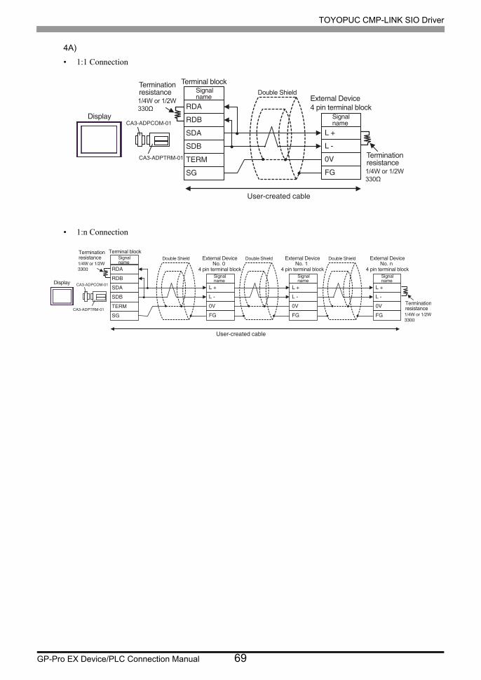
TOYOPUC CMP-LINK SIO Driver
GP-Pro EX Device/PLC Connection Manual 69
4A)
• 1:1 Connection
• 1:n Connection
CA3-ADPTRM-01
CA3-ADPCOM-01
RDA
RDB
SDA
SDB
TERM
SG
L +
L -
0V
FG
Display
Double ShieldExternal Device4 pin terminal block
Terminal blockSignalname
Signalname
Terminationresistance
Terminationresistance
User-created cable
CA3-ADPTRM-01
CA3-ADPCOM-01
RDA
RDB
SDA
SDB
TERM
SG
L +
L -
0V
FG
No. 0
L +
L -
0V
FG
No. 1
L +
L -
0V
FG
No. nSignalname
Signalname
Signalname
Signalname
Terminal block
4 pin terminal block 4 pin terminal block 4 pin terminal block
External Device External Device External DeviceDouble Shield Double Shield Double Shield
Display
Terminationresistance1/4W or 1/2W330Ω
Terminationresistance1/4W or 1/2W330Ω
User-created cable

TOYOPUC CMP-LINK SIO Driver
GP-Pro EX Device/PLC Connection Manual 70
4B)
• 1:1 Connection
• 1:n Connection
1
2
3
7
5
L +
L -
0V
FG
RDA
RDB
SDA
SDB
SG
6
9
8
4
CSB
ERB
CSA
ERA
FG
External Device4 pin terminal block
Display
D-sub 9 pin (socket)
Double ShieldPin Signalname
Signalname
Shell
Terminationresistance
Terminationresistance
4 pin terminal blockNo. 0 No. 1 No. n
4 pin terminal block 4 pin terminal block
External Device External Device External Device
1
2
3
7
5
L +
L -
0V
FG
RDA
RDB
SDA
SDB
SG
6
9
8
4
CSB
ERB
CSA
ERA
L +
L -
0V
FG
L +
L -
0V
FG
FG
Pin Signalname
Signalname
Signalname
Signalname
D-sub 9 pin (socket)
Double Shield Double Shield Double Shield
Shell
Display
Terminationresistance1/4W or 1/2W330Ω
Terminationresistance1/4W or 1/2W330Ω

TOYOPUC CMP-LINK SIO Driver
GP-Pro EX Device/PLC Connection Manual 71
4C)
• 1:1 Connection
• 1:n Connection
CA3-ADPTRM-01
RDA
RDB
SDA
SDB
TERM
SG
L +
L -
0V
FG
CA4-ADPONL-01Display
External Device4 pin terminal block
Double ShieldSignalname
Signalname
Terminal blockTerminationresistance
Terminationresistance
User-created cable
CA3-ADPTRM-01
RDA
RDB
SDA
SDB
TERM
SG
L +
L -
0V
FG
No. 0
CA4-ADPONL-01 L +
L -
0V
FG
No. 1
L +
L -
0V
FG
No. n
Terminal blockSignalname
Signalname
Signalname
Signalname
External Device External Device External DeviceDouble Shield
Double Shield Double Shield
Display
4 pin terminal block 4 pin terminal block 4 pin terminal block
Terminationresistance1/4W or 1/2W330Ω
Terminationresistance1/4W or 1/2W330Ω
User-created cable

TOYOPUC CMP-LINK SIO Driver
GP-Pro EX Device/PLC Connection Manual 72
4D)
• 1:1 Connection
• 1:n Connection
FGShell
RDA
RDB
SDA
SDB
SG
L +
L -
0V
FG
2
7
3
8
5
TERM1
RTS4
VCC6
TERM9
CA4-ADPONL-01
External Device4 pin terminal block
Display
D-sub 9 pin (plug)
Double ShieldPin Signal
name
Signalname
Terminationresistance1/4W or 1/2W330Ω
Terminationresistance1/4W or 1/2W330Ω
User-created cable
FGShell
RDA
RDB
SDA
SDB
SG
L +
L -
0V
FG
2
7
3
8
5
TERM1
RTS4
VCC6
TERM9
No. 0
L +
L -
0V
FG
No. 1
CA4-ADPONL-01
L +
L -
0V
FG
No. n
Pin Signalname
Signalname
Signalname
Signalname
External Device External Device External Device
D-sub 9 pin (plug)
Double Shield Double Shield Double Shield
Display
4 pin terminal block 4 pin terminal block 4 pin terminal block
Terminationresistance1/4W or 1/2W330Ω
Terminationresistance1/4W or 1/2W330Ω
User-created cable

TOYOPUC CMP-LINK SIO Driver
GP-Pro EX Device/PLC Connection Manual 73
4E)
• 1:1 Connection
• 1:n Connection
CA3-ADPTRM-01
CA3-ADPCOM-01
RDA
RDB
SDA
SDB
TERM
SG
L +
L -
0V
FG
Display
Double ShieldExternal Device4 pin terminal blockTerminal block
Signalname
Signalname
Terminationresistance
Terminationresistance
User-created cable
CA3-ADPTRM-01
CA3-ADPCOM-01
RDA
RDB
SDA
SDB
TERM
SG
L +
L -
0V
FG
No. 0
L +
L -
0V
FG
No. 1
L +
L -
0V
FG
No. n
Signalname
Signalname
Signalname
Signalname
Terminal block 4 pin terminal block 4 pin terminal block 4 pin terminal block
External Device External Device External DeviceDouble Shield Double Shield Double Shield
Display Terminationresistance1/4W or 1/2W330Ω
Terminationresistance1/4W or 1/2W330Ω
User-created cable

TOYOPUC CMP-LINK SIO Driver
GP-Pro EX Device/PLC Connection Manual 74
4F)
• 1:1 Connection
• 1:n Connection
1
2
3
7
5
L +
L -
0V
FG
DATA+
DATA-
NC
NC
GND(SG)
6
9
8
4
CSB
ERB
CSA
ERA
FG
External Device4 pin terminal block
Display
D-sub 9 pin (socket)
Double Shield
Pin Signalname
Signalname
Shell
Terminationresistance
Terminationresistance
4 pin terminal blockNo. 0 No. 1 No. n
4 pin terminal block 4 pin terminal block
External Device External Device External Device
1
2
3
7
5
L +
L -
0V
FG
DATA+
DATA-
NC
NC
GND(SG)
6
9
8
4
CSB
ERB
CSA
ERA
L +
L -
0V
FG
L +
L -
0V
FG
FG
Pin Signalname
Signalname
Signalname
Signalname
D-sub 9 pin (socket)
Double Shield Double Shield Double Shield
Shell
Display Terminationresistance1/4W or 1/2W330Ω
Terminationresistance1/4W or 1/2W330Ω

TOYOPUC CMP-LINK SIO Driver
GP-Pro EX Device/PLC Connection Manual 75
4G)
• 1:1 Connection
• 1:n Connection
*1 The resistance in the Display is used as the termination resistance. Set the value of the DIP Switch on the rear of the Display as shown in the table below.
DIP Switch No. Set Value
1 OFF
2 OFF
3 ON
4 OFF
L +
L -
0V
FG
RDA
RDB
SDA
SDB
SG
CSB
ERB
CSA
ERA
External Device4 pin terminal block
Display
Double ShieldSignalname
Signalname
Terminationresistance*1
Terminationresistance
Display side Terminal block
4 pin terminal blockNo. 0 No. 1 No. n
4 pin terminal block 4 pin terminal block
External Device External Device External Device
L +
L -
0V
FG
RDA
RDB
SDA
SDB
SG
CSB
ERB
CSA
ERA
L +
L -
0V
FG
L +
L -
0V
FG
Signalname
Signalname
Signalname
Signalname
Double Shield Double Shield Double Shield
Display
Terminationresistance1/4W or 1/2W330Ω
Terminationresistance*1
Display side Terminal block

TOYOPUC CMP-LINK SIO Driver
GP-Pro EX Device/PLC Connection Manual 76
4H)
• 1:1 Connection
• 1:n Connection
• The 5V output (Pin #6) on the Display is the power for the Siemens AG’s PROFIBUS
connector. Do not use it for other devices.
• In COM on the GP-4107, the SG and FG terminals are isolated.
L +
L -
0V
FG
External Device4 pin terminal block
Display
Double Shield
Signalname
Terminationresistance
Terminationresistance
Pin Signal name
NC
NC
GND(SG)
RS(RTS)
5V
NC
NC
FG
LINE(+)
LINE(-)
3
8
1
2
5
4
6
7
9
Shell
Display sideD-Sub 9pin (plug)
4 pin terminal blockNo. 0 No. 1 No. n
4 pin terminal block 4 pin terminal block
External Device External Device External Device
L +
L -
0V
FG
L +
L -
0V
FG
L +
L -
0V
FG
Signalname
Signalname
Signalname
Double Shield Double Shield Double Shield
Display Terminationresistance1/4W or 1/2W330Ω
Terminationresistance1/4W or 1/2W330Ω
Pin Signal name
NC
NC
GND(SG)
RS(RTS)
5V
NC
NC
FG
LINE(+)
LINE(-)
3
8
1
2
5
4
6
7
9
Shell
Display sideD-Sub 9pin (plug)

TOYOPUC CMP-LINK SIO Driver
GP-Pro EX Device/PLC Connection Manual 77
4I)
• 1:1 Connection
• 1:n Connection
RDA
RDB
SDA
SDB
TERM
SG
L +
L -
0V
FG
Display
Double ShieldExternal Device4 pin terminal block
Terminal blockSignalname
Signalname
Terminationresistance
Terminationresistance
User-created cable
PFXZCBADTM1
RDA
RDB
SDA
SDB
TERM
SG
L +
L -
0V
FG
No. 0
L +
L -
0V
FG
No. 1
L +
L -
0V
FG
No. nSignalname
Signalname
Signalname
Signalname
Terminal block
4 pin terminal block 4 pin terminal block 4 pin terminal block
External Device External Device External DeviceDouble Shield Double Shield Double Shield
Display
Terminationresistance1/4W or 1/2W330Ω
Terminationresistance1/4W or 1/2W330Ω
User-created cable
PFXZCBADTM1
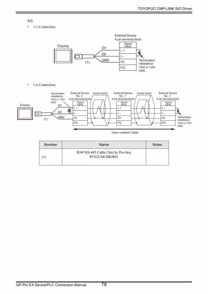
TOYOPUC CMP-LINK SIO Driver
GP-Pro EX Device/PLC Connection Manual 78
4J)
• 1:1 Connection
• 1:n Connection
Number Name Notes
(1)RJ45 RS-485 Cable (5m) by Pro-face
PFXZLMCBRJR81
L +
L -
0V
FG
External Device4 pin terminal block
Signalname
Terminationresistance
Display
GND
D0
D1
(1)
4 pin terminal block No. 0 No. 1 No. n
4 pin terminal block 4 pin terminal block
External Device External Device External Device
L +
L -
0 V
FG
L +
L -
0 V
FG
L +
L -
0 V
FG
Signal name
Signal name
Signal name
Double Shield Double Shield
Termination resistance 1/4W or 1/2W 330Ω
Terminationresistance1/4W or 1/2W330Ω
Display
GND
D0
D1
(1)
User-created Cable

TOYOPUC CMP-LINK SIO Driver
GP-Pro EX Device/PLC Connection Manual 79
4K)
• 1:1 Connection
• 1:n Connection
2
1
3
7
5
L +
L -
0V
FG
DATA+
DATA-
NC
NC
GND
6
9
8
4
FG
External Device4 pin terminal block
Display
D-sub 9 pin (socket)
Double Shield
Pin Signalname
Signalname
Shell
Terminationresistance
Terminationresistance
NC
NC
NC
NC
4 pin terminal block No. 0 No. 1 No. n
4 pin terminal block 4 pin terminal block
External Device External Device External Device
2
1
3
7
5
L +
L -
0 V
FG
DATA+
DATA-
NC
NC
GND
6
9
8
4
L +
L -
0 V
FG
L +
L -
0 V
FG
FG
Pin Signal name
Signal name
Signal name
Signal name
D-sub 9 pin (socket)
Double Shield Double Shield Double Shield
Shell
Display Termination resistance 1/4W or 1/2W 330Ω
Termination resistance 1/4W or 1/2W 330Ω
NC
NC
NC
NC

TOYOPUC CMP-LINK SIO Driver
GP-Pro EX Device/PLC Connection Manual 80
Cable Diagram 5
Display
(Connection Port)Cable Remarks
GP3000*1 (COM1)AGP-3302B (COM2)GP-4*01TM (COM1)GP-Rear Module (COM1)ST*2 (COM2)LT3000 (COM1)
5A
COM port conversion adapter by Pro-faceCA3-ADPCOM-01
+Terminal block conversion adapter
by Pro-faceCA3-ADPTRM-01
+User-created cable
The cable length must be 1000m or less.
5B User-created cable
GP3000*3 (COM2)
5C
Online adapter by Pro-faceCA4-ADPONL-01
+Terminal block conversion adapter
by Pro-faceCA3-ADPTRM-01
+User-created cable
The cable length must be 1000m or less.
5D
Online adapter by Pro-faceCA4-ADPONL-01
+User-created cable
IPC*45E
COM port conversion adapter by Pro-faceCA3-ADPCOM-01
+Terminal block conversion adapter
by Pro-faceCA3-ADPTRM-01
+User-created cable
The cable length must be 1000m or less.
5F User-created cable
GP-4106 (COM1)GP-4116T (COM1)
5G User-created cableThe cable length must be 1000m or less.
GP-4107 (COM1)GP-4*03T*5 (COM2)GP-4203T (COM1)
5H User-created cableThe cable length must be 1000m or less.
GP4000*6 (COM2)GP-4201T (COM1)SP5000*7 (COM1/2)SP-5B00 (COM2)
5I
RS-422 Terminal Block Conversion Adapter by Pro-facePFXZCBADTM1*8
+User-created cable
The cable length must be 1000m or less.
5B User-created cable
LT-4*01TM (COM1)LT-Rear Module (COM1)
5JRJ45 RS-485 Cable (5m) by Pro-face
PFXZLMCBRJR81The cable length must be 200m or less.

TOYOPUC CMP-LINK SIO Driver
GP-Pro EX Device/PLC Connection Manual 81
PE-4000B*9
PS5000*9 5K User-created cableThe cable length must be 1000m or less.
*1 All GP3000 models except AGP-3302B
*2 All ST models except AST-3211A and AST-3302B
*3 All GP3000 models except GP-3200 series and AGP-3302B
*4 Only the COM port which can communicate by RS-422/485 (2 wire) can be used. (Except PE-4000B, PS5000)
IPC COM Port (page 5)
*5 Except GP-4203T
*6 All GP4000 models except GP-4100 Series, GP-4*01TM, GP-Rear Module, GP-4201T and GP-4*03T
*7 Except SP-5B00
*8 When using a Terminal Block Conversion Adapter (CA3-ADPTRM-01) instead of the RS-422 Terminal Block Conversion Adapter, refer to Cable Diagram 5A.
*9 Only the COM port which can communicate by RS-422/485 (2 wire) can be used.
IPC COM Port (page 5)
• For connection cable, we recommend the double shield 0-VCTF-SS 2C*0.75mm2 by Chugoku
Electric Wire & Cable Co., Ltd., the double shield UL2464-DSS 2C x 20AWG by Chugoku
Electric Wire & Cable Co., Ltd. and UL2464-2SB 2 x 20AWG by Kuramo Electric Co., Ltd.
• The FG pin of the main body of the External Device must be D-class grounded.
• Select either on the External Device or on the Display depending on installation environment to
connect FG to the shield cable.
• Please be sure to connect signal ground (SG) when connecting the communication cable.
• In RS422 connection, please refer to the manual of JTEKT Corporation for the cable length.
Display
(Connection Port)Cable Remarks

TOYOPUC CMP-LINK SIO Driver
GP-Pro EX Device/PLC Connection Manual 82
5A)
• 1:1 Connection
5B)
• 1:1 Connection
CA3-ADPTRM-01
RDA
RDB
SDA
SDB
TERM
SG
L1 +
L1 -
0V
TXD
FG
RXD
CA3-ADPCOM-01Display
External Device178289-3 by AMP
Terminal blockDouble ShieldSignal
name
Signalname
Terminationresistance
Terminationresistance
User-created cable
FGShell
RDA
RDB
SDA
SDB
SG
L1 +
L1 -
0V
TXD
FG
RXD
1
2
3
7
5
CSB
ERB
CSA
ERA
6
9
8
4
External Device178289-3 by AMP
Display
Double ShieldPin Signalname
Signalname
D-sub 9 pin (socket)Terminationresistance1/4W or 1/2W330Ω
Terminationresistance1/4W or 1/2W330Ω

TOYOPUC CMP-LINK SIO Driver
GP-Pro EX Device/PLC Connection Manual 83
5C)
• 1:1 Connection
5D)
• 1:1 Connection
CA3-ADPTRM-01
RDA
RDB
SDA
SDB
TERM
SG
L1 +
L1 -
0V
TXD
FG
RXD
CA4-ADPONL-01Display
External Device178289-3 by AMP
Terminal blockDouble Shield
Signalname
Signalname
Terminationresistance
Terminationresistance
User-created cable
FGShell
RDA
RDB
SDA
SDB
SG
L1 +
L1 -
0V
TXD
FG
RXD
2
7
3
8
5
TERM1
RTS4
VCC6
TERM9
CA4-ADPONL-01
External Device178289-3 by AMP
Display
D-sub 9 pin (plug)
Double Shield
Pin Signalname
Signalname
Terminationresistance1/4W or 1/2W330Ω
Terminationresistance1/4W or 1/2W330Ω
User-created cable
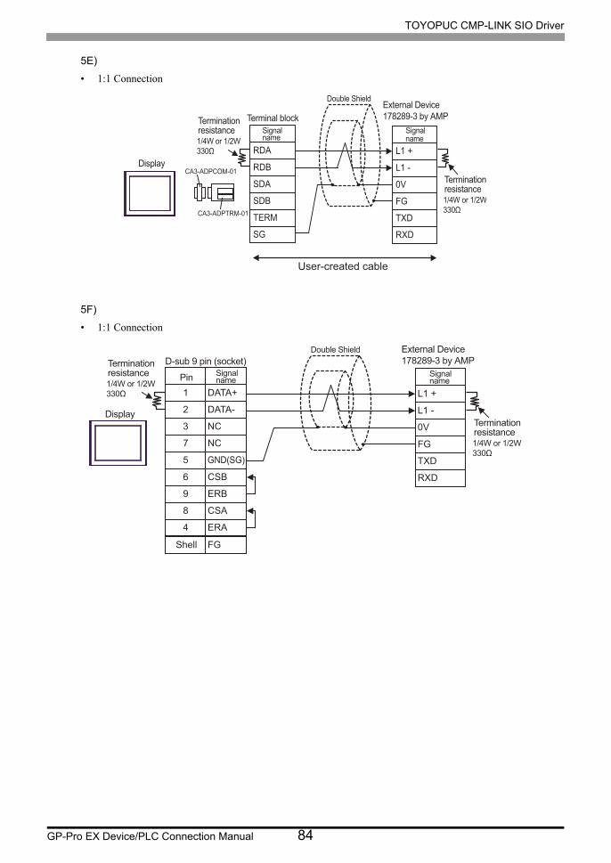
TOYOPUC CMP-LINK SIO Driver
GP-Pro EX Device/PLC Connection Manual 84
5E)
• 1:1 Connection
5F)
• 1:1 Connection
CA3-ADPTRM-01
RDA
RDB
SDA
SDB
TERM
SG
L1 +
L1 -
0V
TXD
FG
RXD
CA3-ADPCOM-01Display
External Device178289-3 by AMPTerminal block
Double Shield
Signalname
Signalname
Terminationresistance
Terminationresistance
User-created cable
FGShell
DATA+
DATA-
NC
NC
GND(SG)
L1 +
L1 -
0V
TXD
FG
RXD
1
2
3
7
5
CSB
ERB
CSA
ERA
6
9
8
4
External Device178289-3 by AMP
Display
Double Shield
Pin Signalname
Signalname
D-sub 9 pin (socket)Terminationresistance1/4W or 1/2W330Ω
Terminationresistance1/4W or 1/2W330Ω
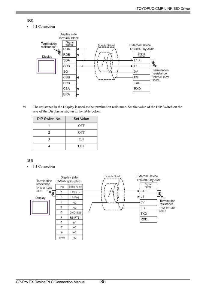
TOYOPUC CMP-LINK SIO Driver
GP-Pro EX Device/PLC Connection Manual 85
5G)
• 1:1 Connection
*1 The resistance in the Display is used as the termination resistance. Set the value of the DIP Switch on the rear of the Display as shown in the table below.
5H)
• 1:1 Connection
DIP Switch No. Set Value
1 OFF
2 OFF
3 ON
4 OFF
RDA
RDB
SDA
SDB
SG
L1 +
L1 -
0V
TXD
FG
RXD
CSB
ERB
CSA
ERA
Display
Double ShieldSignalname
Signalname
Terminationresistance*1
Terminationresistance1/4W or 1/2W330Ω
Display side Terminal block
External Device178289-3 by AMP
L1 +
L1 -
0V
TXD
FG
RXD
Display
Double Shield
Signalname
Terminationresistance1/4W or 1/2W330Ω
Terminationresistance1/4W or 1/2W330Ω
Pin Signal name
NC
NC
GND(SG)
RS(RTS)
5V
NC
NC
FG
LINE(+)
LINE(-)
3
8
1
2
5
4
6
7
9
Shell
Display sideD-Sub 9pin (plug)
External Device178289-3 by AMP

TOYOPUC CMP-LINK SIO Driver
GP-Pro EX Device/PLC Connection Manual 86
5I)
• 1:1 Connection
5J)
• 1:1 Connection
Number Name Notes
(1)RJ45 RS-485 Cable (5m) by Pro-face
PFXZLMCBRJR81
PFXZCBADTM1
RDA
RDB
SDA
SDB
TERM
SG
L1 +
L1 -
0V
TXD
FG
RXD
Display
External Device178289-3 by AMP
Terminal blockDouble ShieldSignal
name
Signalname
Terminationresistance
Terminationresistance
User-created cable
L 1 +
L 1 -
0 V
TXD
FG
RXD
External Device 178289-3 by AMP
Signal name
Termination resistance 1/4W or 1/2W 330Ω
Display
GND
D0
D1
(1)
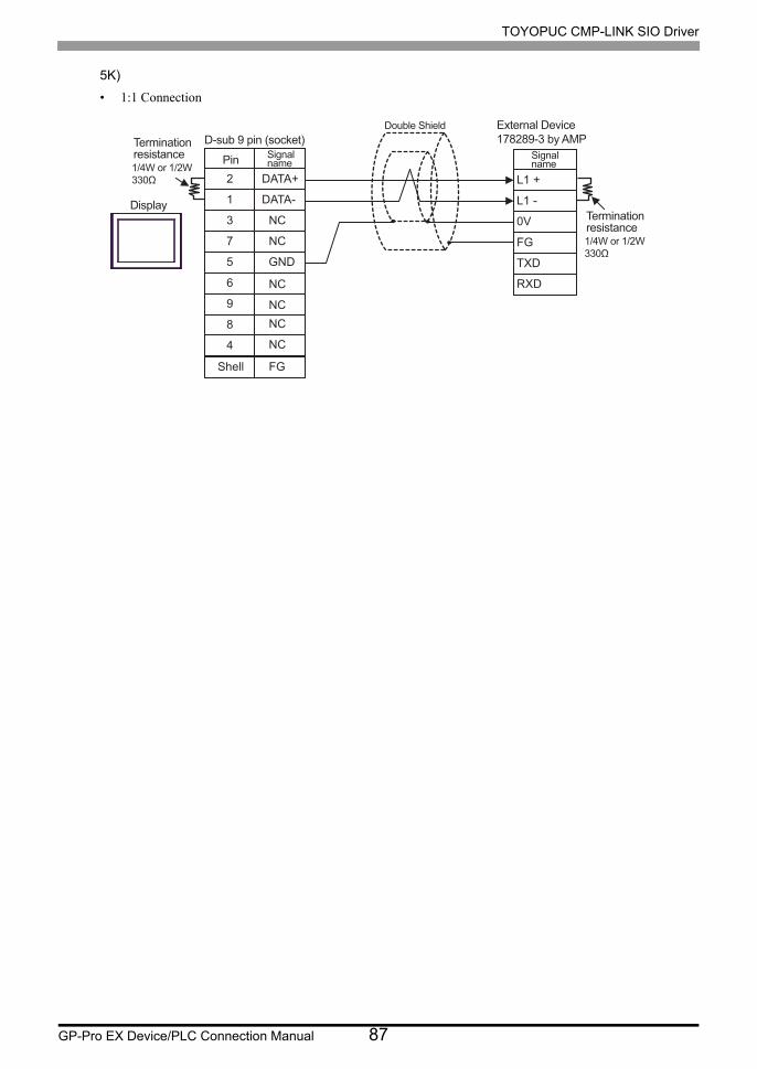
TOYOPUC CMP-LINK SIO Driver
GP-Pro EX Device/PLC Connection Manual 87
5K)
• 1:1 Connection
FGShell
DATA+
DATA-
NC
NC
GND
L 1 +
L 1 -
0 V
TXD
FG
RXD
2
1
3
7
5
6
9
8
4
External Device 178289-3 by AMP
Display
Double Shield
Pin Signal name
Signal name
D-sub 9 pin (socket) Termination resistance 1/4W or 1/2W 330Ω
Termination resistance 1/4W or 1/2W 330Ω
NC
NC
NC
NC

TOYOPUC CMP-LINK SIO Driver
GP-Pro EX Device/PLC Connection Manual 88
Cable Diagram 6
Display
(Connection Port)Cable Remarks
GP3000*1 (COM1)AGP-3302B (COM2)GP-4*01TM (COM1)GP-Rear Module (COM1)ST*2 (COM2)LT3000 (COM1)
*1 All GP3000 models except AGP-3302B
6A
COM port conversion adapter by Pro-faceCA3-ADPCOM-01
+Terminal block conversion adapter by Pro-face
CA3-ADPTRM-01+
User-created cable
The cable length must be 1000m or less.
6B User-created cable
GP3000*3 (COM2)
6C
Online adapter by Pro-faceCA4-ADPONL-01
+Terminal block conversion adapter by Pro-face
CA3-ADPTRM-01+
User-created cable
The cable length must be 1000m or less.
6D
Online adapter by Pro-faceCA4-ADPONL-01
+User-created cable
IPC*46E
COM port conversion adapter by Pro-faceCA3-ADPCOM-01
+Terminal block conversion adapter by Pro-face
CA3-ADPTRM-01+
User-created cable
The cable length must be 1000m or less.
6F User-created cable
GP-4106 (COM1)GP-4116T (COM1)
6G User-created cableThe cable length must be 1000m or less.
GP-4107 (COM1)GP-4*03T*5 (COM2)GP-4203T (COM1)
6H User-created cableThe cable length must be 1000m or less.
GP4000*6 (COM2)GP-4201T (COM1)SP5000*7 (COM1/2)SP-5B00 (COM2)
6I
RS-422 Terminal Block Conversion Adapter by Pro-facePFXZCBADTM1*8
+User-created cable
The cable length must be 1000m or less.
6B User-created cable
LT-4*01TM (COM1)LT-Rear Module (COM1)
6JRJ45 RS-485 Cable (5m) by Pro-face
PFXZLMCBRJR81The cable length must be 200m or less.
PE-4000B*9
PS5000*9 6K User-created cableThe cable length must be 1000m or less.

TOYOPUC CMP-LINK SIO Driver
GP-Pro EX Device/PLC Connection Manual 89
*2 All ST models except AST-3211A and AST-3302B
*3 All GP3000 models except GP-3200 series and AGP-3302B
*4 Only the COM port which can communicate by RS-422/485 (2 wire) can be used. (Except PE-4000B, PS5000)
IPC COM Port (page 5)
*5 Except GP-4203T
*6 All GP4000 models except GP-4100 Series, GP-4*01TM, GP-Rear Module, GP-4201T and GP-4*03T
*7 Except SP-5B00
*8 When using a Terminal Block Conversion Adapter (CA3-ADPTRM-01) instead of the RS-422 Terminal Block Conversion Adapter, refer to Cable Diagram 6A.
*9 Only the COM port which can communicate by RS-422/485 (2 wire) can be used.
IPC COM Port (page 5)
• For connection cable, we recommend the double shield 0-VCTF-SS 2C*0.75mm2 by Chugoku
Electric Wire & Cable Co., Ltd., the double shield UL2464-DSS 2C x 20AWG by Chugoku
Electric Wire & Cable Co., Ltd. and UL2464-2SB 2 x 20AWG by Kuramo Electric Co., Ltd.
• The FG pin of the main body of the External Device must be D-class grounded.
• Select either on the External Device or on the Display depending on installation environment to
connect FG to the shield cable.
• Please be sure to connect signal ground (SG) when connecting the communication cable.
• In RS422 connection, please refer to the manual of JTEKT Corporation for the cable length.

TOYOPUC CMP-LINK SIO Driver
GP-Pro EX Device/PLC Connection Manual 90
6A)
• 1:1 Connection
• 1:n Connection
CA3-ADPTRM-01
RDA
RDB
SDA
SDB
SG
L2 +
L2 -
0V
FG
CA3-ADPCOM-01Display
Terminal blockSignalname
Signalname
TERM
Terminationresistance1/4W or 1/2W330Ω
Terminationresistance1/4W or 1/2W330Ω
User-created cable
External Device1-178288-4 by AMP
Double Shield
CA3-ADPTRM-01
No. 0RDA
RDB
SDA
SDB
SG
L2 +
L2 -
0V
FG
CA3-ADPCOM-01
No. 1
L2 +
L2 -
0V
FG
No. n
L2 +
L2 -
0V
FGTERM
External Device External Device External Device
Terminal block
Double Shield
Double Shield Double Shield
Signalname
Signalname
Signalname
SignalnameDisplay
Terminationresistance1/4W or 1/2W330Ω
Terminationresistance1/4W or 1/2W330Ω
User-created cable
1-178288-4 by AMP 1-178288-4 by AMP 1-178288-4 by AMP

TOYOPUC CMP-LINK SIO Driver
GP-Pro EX Device/PLC Connection Manual 91
6B)
• 1:1 Connection
• 1:n Connection
FGShell
RDA
RDB
SDA
SDB
SG
L2 +
L2 -
0V
FG
1
2
3
7
5
CSB
ERB
CSA
ERA
6
9
8
4
Double ShieldD-sub 9 pin (socket)
Pin Signalname
SignalnameDisplay
Terminationresistance1/4W or 1/2W330Ω
Terminationresistance1/4W or 1/2W330Ω
External Device1-178288-4 by AMP
RDA
RDB
SDA
SDB
SG
FG
L2 +
L2 -
0V
FG
1
2
3
7
5
CSB
ERB
CSA
ERA
6
9
8
4
No. nNo. 0
L2 +
L2 -
0V
FG
No. 1
L2 +
L2 -
0V
FG
External DeviceDouble Shield External DeviceDouble Shield External DeviceDouble ShieldD-sub 9 pin (socket)
Pin Signalname
Signalname
Signalname
Signalname
Display
Terminationresistance1/4W or 1/2W330Ω
Terminationresistance1/4W or 1/2W330Ω
1-178288-4 by AMP 1-178288-4 by AMP 1-178288-4 by AMP
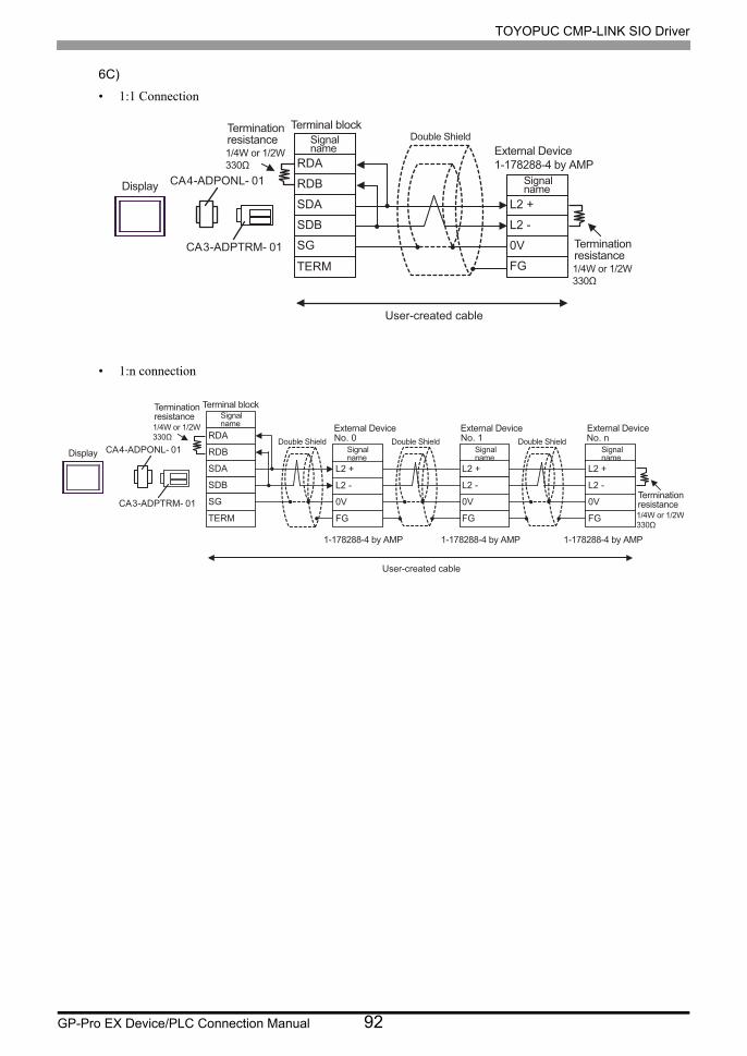
TOYOPUC CMP-LINK SIO Driver
GP-Pro EX Device/PLC Connection Manual 92
6C)
• 1:1 Connection
• 1:n connection
CA3-ADPTRM- 01
RDA
RDB
SDA
SDB
TERM
SG
L2 +
L2 -
0V
FG
CA4-ADPONL- 01
Signalname
Signalname
Terminal block
Display
Terminationresistance1/4W or 1/2W330Ω
Terminationresistance1/4W or 1/2W330Ω
Double Shield
User-created cable
External Device1-178288-4 by AMP
CA3-ADPTRM- 01
No. 0RDA
RDB
SDA
SDB
SG
TERM
L2 +
No. 1 No. n
L2 -
0V
FG
L2 +
L2 -
0V
FG
L2 +
L2 -
0V
FG
CA4-ADPONL- 01
External Device External Device External Device
Terminal block
Double Shield Double Shield Double Shield
Signalname
Signalname
Signalname
SignalnameDisplay
Terminationresistance1/4W or 1/2W330Ω
Terminationresistance1/4W or 1/2W330Ω
User-created cable
1-178288-4 by AMP 1-178288-4 by AMP 1-178288-4 by AMP

TOYOPUC CMP-LINK SIO Driver
GP-Pro EX Device/PLC Connection Manual 93
6D)
• 1:1 Connection
• 1:n Connection
FGShell
RDA
RDB
SDA
SDB
SG
2
7
3
8
5
TERM1
RTS4
VCC6
TERM9
CA4-ADPONL-01 L2 +
L2 -
0V
FG
Pin Signalname
Signalname
Double Shield
D-sub 9 pin (plug)
Display
Terminationresistance1/4W or 1/2W330Ω
Terminationresistance1/4W or 1/2W330Ω
User-created cable
External Device1-178288-4 by AMP
FGShell
No. 0RDA
RDB
SDA
SDB
SG
L2 +
L2 -
0V
FG
2
7
3
8
5
TERM1
RTS4
VCC6
TERM9
No. n
L2 +
L2 -
0V
FG
No. 1
L2 +
L2 -
0V
FG
External DeviceDouble Shield
External DeviceDouble Shield
External DeviceDouble Shield
D-sub 9 pin (plug)
Pin Signalname
Signalname
Signalname
Signalname
Display
CA4-ADPONL-01
Terminationresistance1/4W or 1/2W330Ω
Terminationresistance1/4W or 1/2W330Ω
User-created cable
1-178288-4 by AMP 1-178288-4 by AMP 1-178288-4 by AMP

TOYOPUC CMP-LINK SIO Driver
GP-Pro EX Device/PLC Connection Manual 94
6E)
• 1:1 Connection
• 1:n Connection
CA3-ADPTRM-01
RDA
RDB
SDA
SDB
SG
L2 +
L2 -
0V
FG
CA3-ADPCOM-01Display
Terminal blockSignalname
Signalname
TERM
Terminationresistance1/4W or 1/2W330Ω
Terminationresistance1/4W or 1/2W330Ω
Double Shield
User-created cable
External Device1-178288-4 by AMP
CA3-ADPTRM-01
RDA
RDB
SDA
SDB
SG
CA3-ADPCOM-01
TERM
Terminal blockSignalname
Display
Terminationresistance1/4W or 1/2W330Ω
No. 0
L2 +
L2 -
0V
FG
No. 1
L2 +
L2 -
0V
FG
No. n
L2 +
L2 -
0V
FG
External Device External Device External DeviceDouble Shield
Double Shield Double ShieldSignalname
Signalname
Signalname
Terminationresistance1/4W or 1/2W330Ω
User-created cable
1-178288-4 by AMP 1-178288-4 by AMP 1-178288-4 by AMP
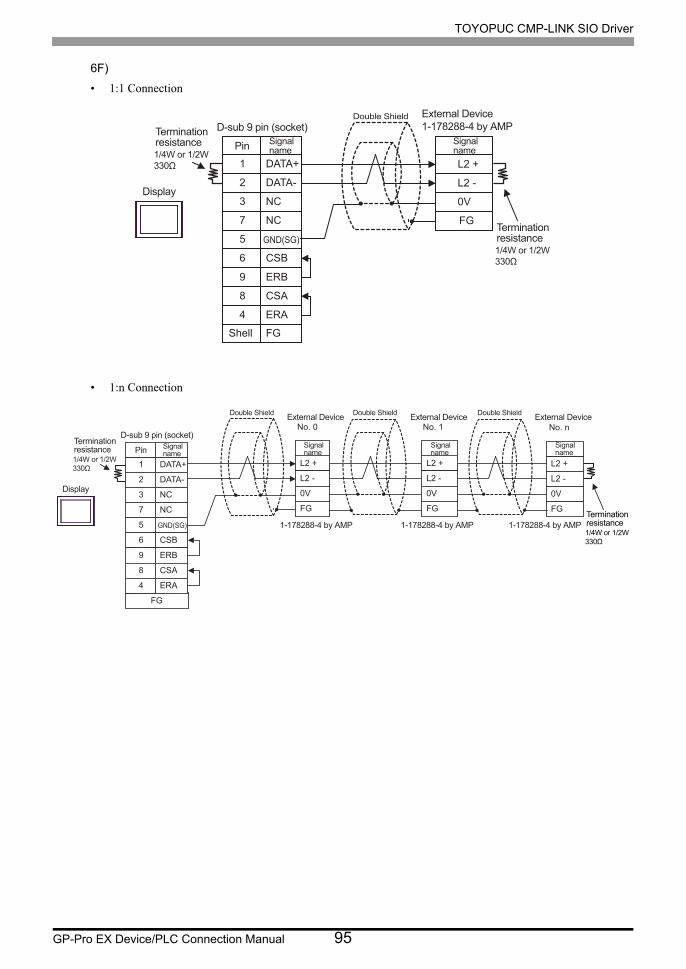
TOYOPUC CMP-LINK SIO Driver
GP-Pro EX Device/PLC Connection Manual 95
6F)
• 1:1 Connection
• 1:n Connection
FGShell
DATA+
DATA-
NC
NC
GND(SG)
L2 +
L2 -
0V
FG
1
2
3
7
5
CSB
ERB
CSA
ERA
6
9
8
4
Double ShieldD-sub 9 pin (socket)
Pin Signalname
Signalname
Display
Terminationresistance1/4W or 1/2W330Ω
Terminationresistance1/4W or 1/2W330Ω
External Device1-178288-4 by AMP
DATA+
DATA-
NC
NC
GND(SG)
FG
L2 +
L2 -
0V
FG
1
2
3
7
5
CSB
ERB
CSA
ERA
6
9
8
4
No. nNo. 0
L2 +
L2 -
0V
FG
No. 1
L2 +
L2 -
0V
FG
External DeviceDouble Shield External DeviceDouble Shield External DeviceDouble Shield
D-sub 9 pin (socket)
Pin Signalname
Signalname
Signalname
Signalname
Display
Terminationresistance1/4W or 1/2W330Ω
Terminationresistance1/4W or 1/2W330Ω
1-178288-4 by AMP1-178288-4 by AMP1-178288-4 by AMP
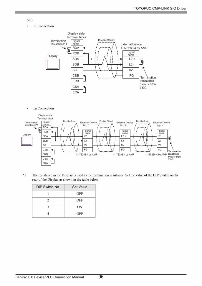
TOYOPUC CMP-LINK SIO Driver
GP-Pro EX Device/PLC Connection Manual 96
6G)
• 1:1 Connection
• 1:n Connection
*1 The resistance in the Display is used as the termination resistance. Set the value of the DIP Switch on the rear of the Display as shown in the table below.
DIP Switch No. Set Value
1 OFF
2 OFF
3 ON
4 OFF
RDA
RDB
SDA
SDB
SG
L2 +
L2 -
0V
FGCSB
ERB
CSA
ERA
Double ShieldSignalname
SignalnameDisplay
Terminationresistance*1
Terminationresistance1/4W or 1/2W330Ω
Display side Terminal block
External Device1-178288-4 by AMP
RDA
RDB
SDA
SDB
SG
L2 +
L2 -
0V
FGCSB
ERB
CSA
ERA
No. nNo. 0
L2 +
L2 -
0V
FG
No. 1
L2 +
L2 -
0V
FG
External DeviceDouble Shield External DeviceDouble Shield External DeviceDouble ShieldSignalname
Signalname
Signalname
Signalname
Display
Terminationresistance1/4W or 1/2W330Ω
Terminationresistance*1
Display side Terminal block
1-178288-4 by AMP1-178288-4 by AMP1-178288-4 by AMP

TOYOPUC CMP-LINK SIO Driver
GP-Pro EX Device/PLC Connection Manual 97
6H)
• 1:1 Connection
• 1:n Connection
• The 5V output (Pin #6) on the Display is the power for the Siemens AG’s PROFIBUS
connector. Do not use it for other devices.
• In COM on the GP-4107, the SG and FG terminals are isolated.
L2 +
L2 -
0V
FG
Double Shield
Signalname
Display
Terminationresistance1/4W or 1/2W330Ω
Terminationresistance1/4W or 1/2W330Ω
Pin Signal name
NC
NC
GND(SG)
RS(RTS)
5V
NC
NC
FG
LINE(+)
LINE(-)
3
8
1
2
5
4
6
7
9
Shell
Display sideD-Sub 9pin (plug)
External Device1-178288-4 by AMP
L2 +
L2 -
0V
FG
No. nNo. 0
L2 +
L2 -
0V
FG
No. 1
L2 +
L2 -
0V
FG
External DeviceDouble Shield External DeviceDouble Shield External DeviceDouble Shield
Signalname
Signalname
Signalname
Display
Terminationresistance1/4W or 1/2W330Ω
Terminationresistance1/4W or 1/2W330Ω
Pin Signal name
NC
NC
GND(SG)
RS(RTS)
5V
NC
NC
FG
LINE(+)
LINE(-)
3
8
1
2
5
4
6
7
9
Shell
Display sideD-Sub 9pin (plug)
1-178288-4 by AMP 1-178288-4 by AMP 1-178288-4 by AMP

TOYOPUC CMP-LINK SIO Driver
GP-Pro EX Device/PLC Connection Manual 98
6I)
• 1:1 Connection
• 1:n Connection
PFXZCBADTM1
RDA
RDB
SDA
SDB
SG
L2 +
L2 -
0V
FG
01Display
Terminal blockSignalname
Signalname
TERM
Terminationresistance1/4W or 1/2W330Ω
Terminationresistance1/4W or 1/2W330Ω
User-created cable
External Device1-178288-4 by AMP
Double Shield
No. 0RDA
RDB
SDA
SDB
SG
L2 +
L2 -
0V
FG
No. 1
L2 +
L2 -
0V
FG
No. n
L2 +
L2 -
0V
FGTERM
External Device External Device External Device
Terminal block
Double Shield
Double Shield Double Shield
Signalname
Signalname
Signalname
SignalnameDisplay
Terminationresistance1/4W or 1/2W330Ω
Terminationresistance1/4W or 1/2W330Ω
User-created cable
PFXZCBADTM1
1-178288-4 by AMP 1-178288-4 by AMP 1-178288-4 by AMP

TOYOPUC CMP-LINK SIO Driver
GP-Pro EX Device/PLC Connection Manual 99
6J)
• 1:1 Connection
• 1:n Connection
Number Name Notes
(1)RJ45 RS-485 Cable (5m) by Pro-face
PFXZLMCBRJR81
L2 +
L2 -
0 V
FG
Signal name
Termination resistance 1/4W or 1/2W 330Ω
External Device 1-178288-4 by AMP
Display
GND
D0
D1
(1)
L2 +
L2 -
0 V
FG
No. n No. 0
L2 +
L2 -
0 V
FG
No. 1
L2 +
L2 -
0 V
FG
External Device External Device Double Shield External Device Double Shield
Signal name
Signal name
Signal name
Termination resistance 1/4W or 1/2W 330Ω
Terminationresistance1/4W or 1/2W330Ω
1-178288-4 by AMP 1-178288-4 by AMP 1-178288-4 by AMP
Display
GND
D0
D1
(1)
User-created Cable

TOYOPUC CMP-LINK SIO Driver
GP-Pro EX Device/PLC Connection Manual 100
6K)
• 1:1 Connection
• 1:n Connection
FGShell
DATA+
DATA-
NC
NC
GND
L2 +
L2 -
0 V
FG
2
1
3
7
5
6
9
8
4
Double Shield D-sub 9 pin (socket)
Pin Signal name
Signal name
Display
Termination resistance 1/4W or 1/2W 330Ω
Termination resistance 1/4W or 1/2W 330Ω
External Device 1-178288-4 by AMP
NC
NC
NC
NC
DATA+
DATA-
NC
NC
GND
FG
L2 +
L2 -
0 V
FG
2
1
3
7
5
6
9
8
4
No. n No. 0
L2 +
L2 -
0 V
FG
No. 1
L2 +
L2 -
0 V
FG
External Device Double Shield External Device Double Shield External Device Double Shield
D-sub 9 pin (socket)
Pin Signal name
Signal name
Signal name
Signal name
Display
Termination resistance 1/4W or 1/2W 330Ω
Termination resistance 1/4W or 1/2W 330Ω
1-178288-4 by AMP 1-178288-4 by AMP 1-178288-4 by AMP
NC
NC
NC
NC

TOYOPUC CMP-LINK SIO Driver
GP-Pro EX Device/PLC Connection Manual 101
6 Supported Device
Range of supported device address is shown in the table below. Please note that the actually supported range of
the devices varies depending on the External Device to be used. Please check the actual range in the manual of
your External Device.
6.1 PC2 Series
This address can be specified as system data area.
Device Bit Address Word Address 32bits Remarks*1
*1 You can connect maximum 16 units of External Device.
Input Relay X0000 - X07FF X000 - X07F *2
*2 You cannot set the duplicate address for X and Y, T and C.
(Setting such address as X000/Y000, EX000/EY000, T000/C000, ET000/EC000 is wrong.)
Output Relay Y0000 - Y07FF Y000 - Y07F *2
Internal Relay M0000 - M07FF M000 - M07F
Keep Relay K0000 - K02FF K000 - K02F
Link Relay L0000 - L07FF L000 - L07F
Special Relay V0000 - V00FF V000 - V00F
Edge Detection P0000 - P01FF ------
Timer (Contact) T0000 - T01FF T000 - T01F *2
Counter (Contact) C0000 - C01FF C000 - C01F *2
Present Value Register N0000-0 - N01FF-F N0000 - N01FF *3
*3 When you write the bit address, the Display reads the word address corresponding to that of the External Device first. Then, it changes the target bit address among the word data once read and returns the word data to the External Device. Note that the correct data may not be written if you change the word address value in the ladder program while the Display reads the data of the External Device and returns it to the External Device.
Data Register D0000-0 - D2FFF-F D0000 - D2FFF *3
Link Register R0000-0 - R07FF-F R0000 - R07FF *3
File Register B0000-0 - B1FFF-F B0000 - B1FFF *3 *4
*4 The PC2J does not support the File Register.
Special Register S0000-0 - S03FF-F S0000 - S03FF *3
Watch Time Register ------ WT0 - WT6 *5 *6
*5 When you write "Watch Time Register", the Display reads all addresses of "Watch Time Register" in the External Device. Then the Display writes all addresses of "Watch Time Register" after the Display changes the data of your requested address. Note that the correct data may not be written if you change the word address using the ladder program while the Display reads data from the External Device and returns it.
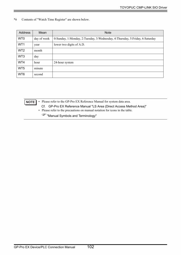
TOYOPUC CMP-LINK SIO Driver
GP-Pro EX Device/PLC Connection Manual 102
*6 Contents of "Watch Time Register" are shown below.
• Please refer to the GP-Pro EX Reference Manual for system data area.
Cf. GP-Pro EX Reference Manual "LS Area (Direct Access Method Area)"• Please refer to the precautions on manual notation for icons in the table.
"Manual Symbols and Terminology"
Address Mean Note
WT0 day of week 0:Sunday, 1:Monday, 2:Tuesday, 3:Wednesday, 4:Thursday, 5:Friday, 6:Saturday
WT1 year lower two digits of A.D.
WT2 month
WT3 day
WT4 hour 24-hour system
WT5 minute
WT6 second

TOYOPUC CMP-LINK SIO Driver
GP-Pro EX Device/PLC Connection Manual 103
6.2 PC3J, PC3JD, PC3JG, PC3JT
This address can be specified as system data area.
Device Bit Address Word Address 32bits Remarks*1
Input Relay
1X0000 - 1X07FF 1X000W - 1X07FW
*2 *32X0000 - 2X07FF 2X000W - 2X07FW
3X0000 - 3X07FF 3X000W - 3X07FW
Output Relay
1Y0000 - 1Y07FF 1Y000W - 1Y07FW
*2 *32Y0000 - 2Y07FF 2Y000W - 2Y07FW
3Y0000 - 3Y07FF 3Y000W - 3Y07FW
Internal Relay
1M0000 - 1M07FF 1M000W - 1M07FW
*22M0000 - 2M07FF 2M000W - 2M07FW
3M0000 - 3M07FF 3M000W - 3M07FW
Keep Relay
1K0000 - 1K02FF 1K000W - 1K02FW
*22K0000 - 2K02FF 2K000W - 2K02FW
3K0000 - 3K02FF 3K000W - 3K02FW
Link Relay
1L0000 - 1L07FF 1L000W - 1L07FW
*22L0000 - 2L07FF 2L000W - 2L07FW
3L0000 - 3L07FF 3L000W - 3L07FW
Special Relay
1V0000 - 1V00FF 1V000W - 1V00FW
*22V0000 - 2V00FF 2V000W - 2V00FW
3V0000 - 3V00FF 3V000W - 3V00FW
Edge Detection
1P0000 - 1P01FF ------
2P0000 - 2P01FF ------
3P0000 - 3P01FF ------
Timer (Contact)
1T0000 - 1T01FF 1T000W - 1T01FW
*2 *32T0000 - 2T01FF 2T000W - 2T01FW
3T0000 - 3T01FF 3T000W - 3T01FW
Counter (Contact)
1C0000 - 1C01FF 1C000W - 1C01FW
*2 *32C0000 - 2C01FF 2C000W - 2C01FW
3C0000 - 3C01FF 3C000W - 3C01FW
Present Value Register
1N0000-0 - 1N01FF-F 1N0000 - 1N01FF
*42N0000-0 - 2N01FF-F 2N0000 - 2N01FF
3N0000-0 - 3N01FF-F 3N0000 - 3N01FF

TOYOPUC CMP-LINK SIO Driver
GP-Pro EX Device/PLC Connection Manual 104
Data Register
1D0000-0 - 1D2FFF-F 1D0000 - 1D2FFF *5
*42D0000-0 - 2D2FFF-F 2D0000 - 2D2FFF *5
3D0000-0 - 3D2FFF-F 3D0000 - 3D2FFF*5
Link Register
1R0000-0 - 1R07FF-F 1R0000 - 1R07FF
*42R0000-0 - 2R07FF-F 2R0000 - 2R07FF
3R0000-0 - 3R07FF-F 3R0000 - 3R07FF
Special Register
1S0000-0 - 1S03FF-F 1S0000 - 1S03FF
*42S0000-0 - 2S03FF-F 2S0000 - 2S03FF
3S0000-0 - 3S03FF-F 3S0000 - 3S03FF
File Register B0000-0 - B1FFF-F B0000 - B1FFF *4
Extension Input EX0000 - EX07FF EX000W - EX07FW *2 *3
Extension Output EY0000 - EY07FF EX000W - EY07FW *2 *3
Extension Internal Relay EM0000 - EM1FFF EM000W - EM1FFW *2
Extension Special Relay EV0000 - EV0FFF EV000W - EV0FFW *2
Extension Keep Relay EK0000 - EK0FFF EK000W - EK0FFW *2
Extension Edge Detection
EP0000 - EP0FFF ------
Extension Timer ET0000 - ET07FF ET000W - ET07FW *2 *3
Extension Counter EC0000 - EC07FF EC000W - EC07FW *2 *3
Extension Link Relay EL0000 - EL1FFF EL000W - EL1FFW *2
Extension 2 Input GX0000 - GXFFFF GX000W - GXFFFW *2 *3 *6
Extension 2 Output GY0000 - GYFFFF GY000W - GYFFFW *2 *3 *6
Extension 2 Internal Relay
GM0000 - GMFFFF GM000W - GMFFFW *2 *6
Extension Data Register U0000-0 - U7FFF-F U0000 - U7FFF *4
Extension Setting Value Register
H0000-0 - H07FF-F H0000 - H07FF *4
Extension Special Register
ES0000-0 - ES07FF-F ES0000 - ES07FF *4
Extension Current Value Register
EN0000-0 - EN07FF-F EN0000 - EN07FF *4
Watch Time Register ------ WT0 - WT6 *7 *8
Extended buffer register EB00000-0 - EB1FFFF-F EB00000 - EB1FFFF *4
*1 You can connect maximum 16 units of External Device.
Device Bit Address Word Address 32bits Remarks*1

TOYOPUC CMP-LINK SIO Driver
GP-Pro EX Device/PLC Connection Manual 105
*2 For word description of BitDevice, add "W" to the last of the word address. Example) When the address is 0 in M device, describe "M0000W".
*3 You cannot set the duplicate address for X and Y (EX, EY, GX, GY), T and C (ET, EC). (Setting such address as X000/Y000, EX000/EY000, T000/C000, ET000/EC000 is wrong.)
*4 For bit description of WordDevice, describe "-" following the word address and the bit position next. Example) When the address is 0 and the bit is 5 in D device, describe "D0000-5".
*5 Maximum address value of PC3J and PC3JT is 2FFF, and of PC3JD and PC3JG is 0FFF.
*6 Supported by Link I/F on the CPU of PC3JG.
*7 When you write "Watch Time Register", the Display reads all addresses of "Watch Time Register" in the External Device. Then the Display writes all addresses of "Watch Time Register" after the Display changes the data of your requested address. Note that the correct data may not be written if you change the word address using the ladder program while the Display reads data from the External Device and returns it.
*8 Contents of "Watch Time Register" are shown below.
• Please refer to the GP-Pro EX Reference Manual for system data area.
Cf. GP-Pro EX Reference Manual "LS Area (Direct Access Method Area)"• Please refer to the precautions on manual notation for icons in the table.
"Manual Symbols and Terminology"
Address Mean Note
WT0 day of week 0:Sunday, 1:Monday, 2:Tuesday, 3:Wednesday, 4:Thursday, 5:Friday, 6:Saturday
WT1 year lower two digits of A.D.
WT2 month
WT3 day
WT4 hour 24-hour system
WT5 minute
WT6 second

TOYOPUC CMP-LINK SIO Driver
GP-Pro EX Device/PLC Connection Manual 106
6.3 PC10G Series
This address can be specified as system data area.
Device Bit Address Word Address 32bits Remarks
Input
1X000 - 1X7FF 1X00W - 1X7FW
*1 *22X000 - 2X7FF 2X00W - 2X7FW
3X000 - 3X7FF 3X00W - 3X7FW
Output
1Y000 - 1Y7FF 1Y00W - 1Y7FW
*1 *22Y000 - 2Y7FF 2Y00W - 2Y7FW
3Y000 - 3Y7FF 3Y00W - 3Y7FW
Internal relay
1M000 - 1M7FF 1M00W - 1M7FW
*1
2M000 - 2M7FF 2M00W - 2M7FW
3M000 - 3M7FF 3M00W - 3M7FW
1M1000 - 1M17FF 1M100W - 1M17FW
2M1000 - 2M17FF 2M100W - 2M17FW
3M1000 - 3M17FF 3M100W - 3M17FW
Keep-relay
1K000 - 1K2FF 1K00W - 1K2FW
*12K000 - 2K2FF 2K00W - 2K2FW
3K000 - 3K2FF 3K00W - 3K2FW
Link relay
1L000 - 1L7FF 1L00W - 1L7FW
*1
2L000 - 2L7FF 2L00W - 2L7FW
3L000 - 3L7FF 3L00W - 3L7FW
1L1000 - 1L2FFF 1L100W - 1L2FFW
2L1000 - 2L2FFF 2L100W - 2L2FFW
3L1000 - 3L2FFF 3L100W - 3L2FFW
Special relay
1V00 - 1VFF 1V0W - 1VFW
*1
2V00 - 2VFF 2V0W - 2VFW
3V00 - 3VFF 3V0W - 3VFW
1V1000 - 1V17FF 1V100W - 1V17FW
2V1000 - 2V17FF 2V100W - 2V17FW
3V1000 - 3V17FF 3V100W - 3V17FW

TOYOPUC CMP-LINK SIO Driver
GP-Pro EX Device/PLC Connection Manual 107
Edge detection
1P0000 - 1P01FF ----------
2P0000 - 2P01FF ----------
3P0000 - 3P01FF ----------
1P1000 - 1P17FF ----------
2P1000 - 2P17FF ----------
3P1000 - 3P17FF ----------
Timer(Contact)
1T000 - 1T1FF 1T00W - 1T1FW
*1 *2
2T000 - 2T1FF 2T00W - 2T1FW
3T000 - 3T1FF 3T00W - 3T1FW
1T1000 - 1T17FF 1T100W - 1T17FW
2T1000 - 2T17FF 2T100W - 2T17FW
3T1000 - 3T17FF 3T100W - 3T17FW
Counter(Contact)
1C000 - 1C1FF 1C00W - 1C1FW
*1 *2
2C000 - 2C1FF 2C00W - 2C1FW
3C000 - 3C1FF 3C00W - 3C1FW
1C1000 - 1C17FF 1C100W - 1C17FW
2C1000 - 2C17FF 2C100W - 2C17FW
3C1000 - 3C17FF 3C100W - 3C17FW
Present value register
1N000-0 - 1N1FF-F 1N000 - 1N1FF
*3
2N000-0 - 2N1FF-F 2N000 - 2N1FF
3N000-0 - 3N1FF-F 3N000 - 3N1FF
1N1000-0 - 1N17FF-F 1N1000 - 1N17FF
2N1000-0 - 2N17FF-F 2N1000 - 2N17FF
3N1000-0 - 3N17FF-F 3N1000 - 3N17FF
Data register
1D0000-0 - 1D2FFF-F 1D0000 - 1D2FFF
*32D0000-0 - 2D2FFF-F 2D0000 - 2D2FFF
3D0000-0 - 3D2FFF-F 3D0000 - 3D2FFF
Link register
1R000-0 - 1R7FF-F 1R000 - 1R7FF
*32R000-0 - 2R7FF-F 2R000 - 2R7FF
3R000-0 - 3R7FF-F 3R000 - 3R7FF
Device Bit Address Word Address 32bits Remarks
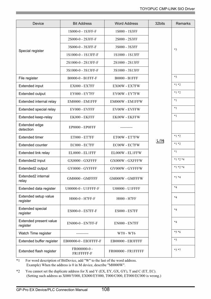
TOYOPUC CMP-LINK SIO Driver
GP-Pro EX Device/PLC Connection Manual 108
Special register
1S000-0 - 1S3FF-F 1S000 - 1S3FF
*3
2S000-0 - 2S3FF-F 2S000 - 2S3FF
3S000-0 - 3S3FF-F 3S000 - 3S3FF
1S1000-0 - 1S13FF-F 1S1000 - 1S13FF
2S1000-0 - 2S13FF-F 2S1000 - 2S13FF
3S1000-0 - 3S13FF-F 3S1000 - 3S13FF
File register B0000-0 - B1FFF-F B0000 - B1FFF *3
Extended input EX000 - EX7FF EX00W - EX7FW *1 *2
Extended output EY000 - EY7FF EY00W - EY7FW *1 *2
Extended internal relay EM0000 - EM1FFF EM000W - EM1FFW *1
Extended special relay EV000 - EVFFF EV00W - EVFFW *1
Extended keep-relay EK000 - EKFFF EK00W - EKFFW *1
Extended edge detection
EP0000 - EP0FFF ----------
Extended timer ET000 - ET7FF ET00W - ET7FW *1 *2
Extended counter EC000 - EC7FF EC00W - EC7FW *1 *2
Extended link relay EL0000 - EL1FFF EL000W - EL1FFW *1
Extended2 input GX0000 - GXFFFF GX000W - GXFFFW *1 *2 *4
Extended2 output GY0000 - GYFFFF GY000W - GYFFFW *1 *2 *4
Extended2 internal relay
GM0000 - GMFFFF GM000W - GMFFFW *1 *4
Extended data register U00000-0 - U1FFFF-F U00000 - U1FFFF *4
Extended setup value register
H000-0 - H7FF-F H000 - H7FF *4
Extended special register
ES000-0 - ES7FF-F ES000 - ES7FF *4
Extended present value register
EN000-0 - EN7FF-F EN000 - EN7FF *4
Watch Time register ---------- WT0 - WT6 *5 *6
Extended buffer register EB00000-0 - EB3FFFF-F EB00000 - EB3FFFF *3
Extended flash registerFR000000-0 - FR1FFFFF-F
FR000000 - FR1FFFFF *3 *7
*1 For word description of BitDevice, add "W" to the last of the word address. Example) When the address is 0 in M device, describe "M0000W".
*2 You cannot set the duplicate address for X and Y (EX, EY, GX, GY), T and C (ET, EC). (Setting such address as X000/Y000, EX000/EY000, T000/C000, ET000/EC000 is wrong.)
Device Bit Address Word Address 32bits Remarks

TOYOPUC CMP-LINK SIO Driver
GP-Pro EX Device/PLC Connection Manual 109
*3 For bit description of WordDevice, describe "-" following the word address and the bit position next. Example) When the address is 0 and the bit is 5 in D device, describe "D0000-5".
*4 Supported by Link I/F on the PC10G CPU only.
*5 When you write "Watch Time Register", the Display reads all addresses of "Watch Time Register" in the Ex- ternal Device. Then the Display writes all addresses of "Watch Time Register" after the Display changes the data of your requested address. Note that the correct data may not be written if you change the word address using the ladder program while the Display reads data from the External Device and returns it.
*6 Contents of "Watch Time Register" are shown below.
*7 You can read from and write to the extended flash register. However, you cannot write values to flash memory. Use the ladder software to write values to flash memory.
• Please refer to the GP-Pro EX Reference Manual for system data area.
Cf. GP-Pro EX Reference Manual "LS Area (Direct Access Method Area)"• Please refer to the precautions on manual notation for icons in the table.
"Manual Symbols and Terminology"
Address Mean Note
WT0 day of week 0:Sunday, 1:Monday, 2:Tuesday, 3:Wednesday, 4:Thursday, 5:Friday, 6:Saturday
WT1 year lower two digits of A.D.
WT2 month
WT3 day
WT4 hour 24-hour system
WT5 minute
WT6 second

TOYOPUC CMP-LINK SIO Driver
GP-Pro EX Device/PLC Connection Manual 110
7 Device Code and Address Code
Use device code and address code when you select "Device Type & Address" for the address type in data displays.
7.1 PC2 Series
Device Device Name Device Code (HEX) Address Code
Input Relay X 0080 Word Address
Output Relay Y 0081 Word Address
Internal Relay M 0082 Word Address
Keep Relay K 0084 Word Address
Link Relay L 0088 Word Address
Special Relay V 0083 Word Address
Timer (Contact) T 0086 Word Address
Counter (Contact) C 0087 Word Address
Special Register S 0001 Word Address
Present Value Register N 0003 Word Address
Data Register D 0000 Word Address
Link Register R 0002 Word Address
File Register B 0004 Word Address
Watch Time Register WT 0007 Word Address

TOYOPUC CMP-LINK SIO Driver
GP-Pro EX Device/PLC Connection Manual 111
7.2 PC3J, PC3JD, PC3JG, PC3JT
Device Device Name Device Code (HEX) Address Code
Input Relay
1X 0080 Word Address
2X 0180 Word Address
3X 0280 Word Address
Output Relay
1Y 0081 Word Address
2Y 0181 Word Address
3Y 0281 Word Address
Internal Relay
1M 0082 Word Address
2M 0182 Word Address
3M 0282 Word Address
Keep Relay
1K 0084 Word Address
2K 0184 Word Address
3K 0284 Word Address
Link Relay
1L 0088 Word Address
2L 0188 Word Address
3L 0288 Word Address
Special Relay
1V 0083 Word Address
2V 0183 Word Address
3V 0283 Word Address
Timer (Contact)
1T 0086 Word Address
2T 0186 Word Address
3T 0286 Word Address
Counter (Contact)
1C 0087 Word Address
2C 0187 Word Address
3C 0287 Word Address
Special Register
1S 0001 Word Address
2S 0101 Word Address
3S 0201 Word Address
Present Value Register
1N 0003 Word Address
2N 0103 Word Address
3N 0203 Word Address

TOYOPUC CMP-LINK SIO Driver
GP-Pro EX Device/PLC Connection Manual 112
Data Register
1D 0000 Word Address
2D 0100 Word Address
3D 0200 Word Address
Link Register
1R 0002 Word Address
2R 0102 Word Address
3R 0202 Word Address
File Register B 0004 Word Address
Extension Setting Value Register
H 0006 Word Address
Extension Data Register U 0005 Word Address
Extension Input EX 0090 Word Address
Extension Output EY 0091 Word Address
Extension Internal Relay EM 0092 Word Address
Extension Keep Relay EK 0094 Word Address
Extension Link Relay EL 0098 Word Address
Extension Special Relay EV 0093 Word Address
Extension Timer (Contact)
ET 0096 Word Address
Extension Counter (Contact)
EC 0097 Word Address
Extension Special Register
ES 0011 Word Address
Extension Current Value Register
EN 0013 Word Address
Extension 2 Input GX 00A0 Word Address
Extension 2 Output GY 00A1 Word Address
Extension 2 Internal Relay
GM 00A2 Word Address
Watch Time Register WT 0007 Word Address
Extended Buffer Register EB 0014 Word Address
Device Device Name Device Code (HEX) Address Code
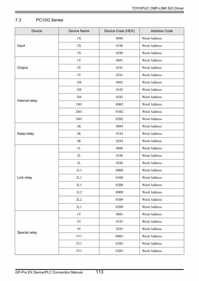
TOYOPUC CMP-LINK SIO Driver
GP-Pro EX Device/PLC Connection Manual 113
7.3 PC10G Series
Device Device Name Device Code (HEX) Address Code
Input
1X 0080 Word Address
2X 0180 Word Address
3X 0280 Word Address
Output
1Y 0081 Word Address
2Y 0181 Word Address
3Y 0281 Word Address
Internal relay
1M 0082 Word Address
2M 0182 Word Address
3M 0282 Word Address
1M1 00B2 Word Address
2M1 01B2 Word Address
3M1 02B2 Word Address
Keep-relay
1K 0084 Word Address
2K 0184 Word Address
3K 0284 Word Address
Link relay
1L 0088 Word Address
2L 0188 Word Address
3L 0288 Word Address
1L1 00B8 Word Address
2L1 01B8 Word Address
3L1 02B8 Word Address
1L2 00B9 Word Address
2L2 01B9 Word Address
3L1 02B9 Word Address
Special relay
1V 0083 Word Address
2V 0183 Word Address
3V 0283 Word Address
1V1 00B3 Word Address
2V1 01B3 Word Address
3V1 02B3 Word Address

TOYOPUC CMP-LINK SIO Driver
GP-Pro EX Device/PLC Connection Manual 114
Timer(Contact)
1T 0086 Word Address
2T 0186 Word Address
3T 0286 Word Address
1T1 00B6 Word Address
2T1 01B6 Word Address
3T1 02B6 Word Address
Counter(Contact)
1C 0087 Word Address
2C 0187 Word Address
3C 0287 Word Address
1C1 00B7 Word Address
2C1 01B7 Word Address
3C1 02B7 Word Address
Special register
1S 0001 Word Address
2S 0101 Word Address
3S 0201 Word Address
1S1 0031 Word Address
2S1 0131 Word Address
3S1 0231 Word Address
Present value register
1N 0003 Word Address
2N 0103 Word Address
3N 0203 Word Address
1N1 0033 Word Address
2N1 0133 Word Address
3N1 0233 Word Address
Data register
1D 0000 Word Address
2D 0100 Word Address
3D 0200 Word Address
Link register
1R 0002 Word Address
2R 0102 Word Address
3R 0202 Word Address
File register B 0004 Word Address
Extended setup value register
H 0006 Word Address
Device Device Name Device Code (HEX) Address Code

TOYOPUC CMP-LINK SIO Driver
GP-Pro EX Device/PLC Connection Manual 115
Extended data register U 0005 Word Address
Extended input EX 0090 Word Address
Extended output EY 0091 Word Address
Extended internal relay EM 0092 Word Address
Extended keep-relay EK 0094 Word Address
Extended link relay EL 0098 Word Address
Extended special relay EV 0093 Word Address
Extended timer ET 0096 Word Address
Extended counter EC 0097 Word Address
Extended special register ES 0011 Word Address
Extended present value register
EN 0013 Word Address
Extended2 input GX 00A0 Word Address
Extended2 output GY 00A1 Word Address
Extended2 internal relay GM 00A2 Word Address
Watch Time register WT 0007 Word Address
Extended buffer register EB 0014 Word Address
Extended flash register FR 0018 Word Address
Device Device Name Device Code (HEX) Address Code

TOYOPUC CMP-LINK SIO Driver
GP-Pro EX Device/PLC Connection Manual 116
8 Error Messages
Error messages are displayed on the Display screen as follows: "No.: Device Name: Error Message (Error
Occurrence Area)". Each description is shown below.
Display Examples of Error Messages
"RHAA035: PLC1: Error has been responded for device write command (Error Code: 2 [02H])"
Error Messages Unique to External Device
Item Description
No. Error No.
Device NameName of the External Device where error occurs. Device name is a title of the External Device set with GP-Pro EX. (Initial value [PLC1])
Error Message Displays messages related to the error which occurs.
Error Occurrence Area
Displays IP address or device address of the External Device where error occurs, or error codes received from the External Device.
• IP address is displayed such as "IP address(Decimal): MAC address( Hex)".• Device address is diplayed such as "Address: Device address".• Received error codes are displayed such as "Decimal[Hex]".
• Refer to your External Device manual for details on received error codes.
• Refer to "Display-related errors" in "Maintenance/Troubleshooting Guide" for details on the error
messages common to the driver.
Error No. Error Message Description
RHxx128[Node Name]: It failed in the writing mode setting.
Please check the connection.