
Q/QnA Serial Communication Driver - Pro-face
100
1 Mitsubishi Electric Corporation Q/QnA Serial Communication Driver 1 System Configuration ....................................................................................................... 3 2 Selection of External Device .......................................................................................... 12 3 Example of Communication Setting ............................................................................... 13 4 Setup Items .................................................................................................................... 46 5 Cable Diagram ............................................................................................................... 53 6 Range of Supported Device Address ............................................................................. 81 7 Device Code and Address Code .................................................................................... 91 8 Error Messages .............................................................................................................. 99
-
Upload
khangminh22 -
Category
Documents
-
view
2 -
download
0
Transcript of Q/QnA Serial Communication Driver - Pro-face

1
Mitsubishi Electric Corporation
Q/QnA Serial Communication Driver
1 System Configuration....................................................................................................... 3
2 Selection of External Device .......................................................................................... 12
3 Example of Communication Setting ............................................................................... 13
4 Setup Items .................................................................................................................... 46
5 Cable Diagram ............................................................................................................... 53
6 Range of Supported Device Address............................................................................. 81
7 Device Code and Address Code.................................................................................... 91
8 Error Messages.............................................................................................................. 99
Q/QnA Serial Communication Driver
GP-Pro EX Device/PLC Connection Manual 2
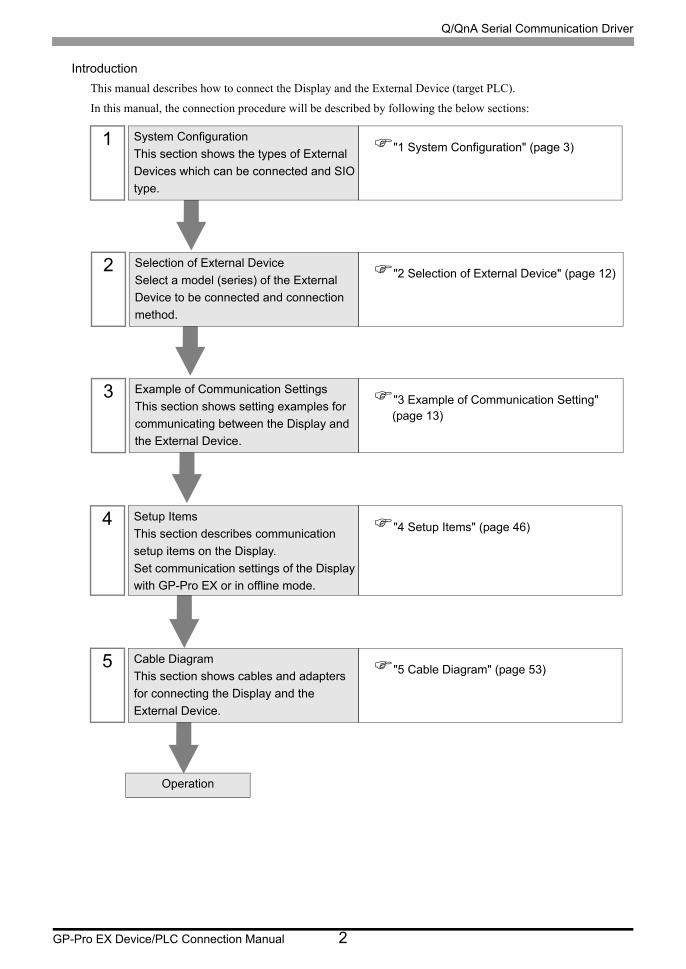
Introduction
This manual describes how to connect the Display and the External Device (target PLC).
In this manual, the connection procedure will be described by following the below sections:
1 System Configuration
This section shows the types of External
Devices which can be connected and SIO
type.
"1 System Configuration" (page 3)
2 Selection of External Device
Select a model (series) of the External
Device to be connected and connection
method.
"2 Selection of External Device" (page 12)
3 Example of Communication Settings
This section shows setting examples for
communicating between the Display and
the External Device.
"3 Example of Communication Setting" (page 13)
4 Setup Items
This section describes communication
setup items on the Display.
Set communication settings of the Display
with GP-Pro EX or in offline mode.
"4 Setup Items" (page 46)
5 Cable Diagram
This section shows cables and adapters
for connecting the Display and the
External Device.
"5 Cable Diagram" (page 53)
Operation
Q/QnA Serial Communication Driver
GP-Pro EX Device/PLC Connection Manual 3
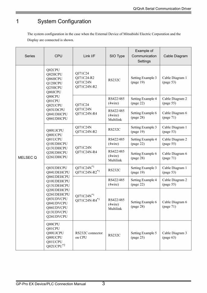
1 System Configuration
The system configuration in the case when the External Device of Mitsubishi Electric Corporation and the
Display are connected is shown.
Series CPU Link I/F SIO Type
Example of
Communication
Settings
Cable Diagram
MELSEC Q
Q02CPUQ02HCPUQ06HCPUQ12HCPUQ25HCPUQ00JCPUQ00CPUQ01CPUQ02UCPUQ03UDCPUQ04UDHCPUQ06UDHCPU
QJ71C24QJ71C24-R2QJ71C24NQJ71C24N-R2
RS232CSetting Example 3 (page 19)
Cable Diagram 1 (page 53)
QJ71C24QJ71C24NQJ71C24N-R4
RS422/485 (4wire)
Setting Example 4 (page 22)
Cable Diagram 2 (page 55)
RS422/485 (4wire)Multilink
Setting Example 6 (page 28)
Cable Diagram 6 (page 71)
Q00UJCPUQ00UCPUQ01UCPUQ10UDHCPUQ13UDHCPUQ20UDHCPUQ26UDHCPU
QJ71C24NQJ71C24N-R2
RS232CSetting Example 3 (page 19)
Cable Diagram 1 (page 53)
QJ71C24NQJ71C24N-R4
RS422/485 (4wire)
Setting Example 4 (page 22)
Cable Diagram 2 (page 55)
RS422/485 (4wire)Multilink
Setting Example 6 (page 28)
Cable Diagram 6 (page 71)
Q03UDECPUQ04UDEHCPUQ06UDEHCPUQ10UDEHCPUQ13UDEHCPUQ20UDEHCPUQ26UDEHCPUQ03UDVCPUQ04UDVCPUQ06UDVCPUQ13UDVCPUQ26UDVCPU
QJ71C24N*1
QJ71C24N-R2*1 RS232CSetting Example 3 (page 19)
Cable Diagram 1 (page 53)
QJ71C24N*1
QJ71C24N-R4*1
RS422/485 (4wire)
Setting Example 4 (page 22)
Cable Diagram 2 (page 55)
RS422/485 (4wire)Multilink
Setting Example 6 (page 28)
Cable Diagram 6 (page 71)
Q00CPUQ01CPUQ00UJCPUQ00UCPUQ01UCPUQ02UCPU*2
RS232C connector on CPU
RS232CSetting Example 5 (page 25)
Cable Diagram 3 (page 63)
Q/QnA Serial Communication Driver
GP-Pro EX Device/PLC Connection Manual 4
MELSEC QnA
Q2ASCPUQ2ASCPU-S1Q2ASHCPUQ2ASHCPU-S1
A1SJ71QC24A1SJ71QC24NA1SJ71QC24-R2A1SJ71QC24N-R2
RS232CSetting Example 1 (page 13)
Cable Diagram 1 (page 53)
A1SJ71QC24A1SJ71QC24N
RS422/485 (4wire)
Setting Example 2 (page 16)
Cable Diagram 2 (page 55)
RS422/485 (4wire)Multilink
Setting Example 7 (page 31)
Cable Diagram 6 (page 71)
Q2ACPUQ2ACPU-S1Q3ACPUQ4ACPUQ4ARCPU
AJ71QC24AJ71QC24NAJ71QC24-R2AJ71QC24N-R2
RS232CSetting Example 1 (page 13)
Cable Diagram 4 (page 64)
AJ71QC24AJ71QC24N
RS422/485 (4wire)
Setting Example 2 (page 16)
Cable Diagram 2 (page 55)
RS422/485 (4wire)Multilink
Setting Example 7 (page 31)
Cable Diagram 6 (page 71)
AJ71QC24-R4AJ71QC24N-R4
RS422/485 (4wire) (when using CH1)
Setting Example 2 (page 16)
Cable Diagram 5 (page 66)
RS422/485 (4wire) (when using CH2)
Setting Example 2 (page 16)
Cable Diagram 2 (page 55)
RS422/485 (4wire) (when using CH2)Multilink
Setting Example 7 (page 31)
Cable Diagram 6 (page 71)
MELSEC LL02CPUL26CPU-BT
LJ71C24LJ71C24-R2
RS232CSetting Example 3 (page 19)
Cable Diagram 1 (page 53)
LJ71C24
RS422/485 (4wire) (when using CH2)
Setting Example 4 (page 22)
Cable Diagram 2 (page 55)
RS422/485 (4wire) (when using CH2)Multilink
Setting Example 6 (page 28)
Cable Diagram 6 (page 71)
Series CPU Link I/F SIO Type
Example of
Communication
Settings
Cable Diagram
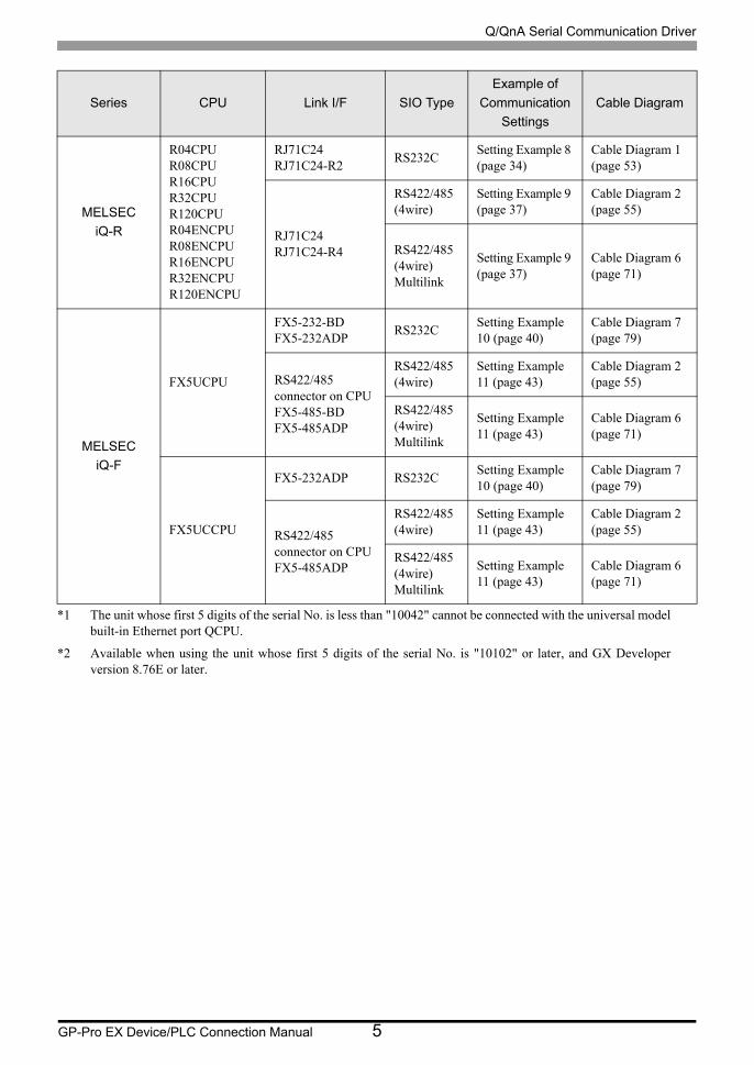
Q/QnA Serial Communication Driver
GP-Pro EX Device/PLC Connection Manual 5
MELSEC
iQ-R
R04CPUR08CPUR16CPUR32CPUR120CPUR04ENCPUR08ENCPUR16ENCPUR32ENCPUR120ENCPU
RJ71C24RJ71C24-R2
RS232CSetting Example 8 (page 34)
Cable Diagram 1 (page 53)
RJ71C24RJ71C24-R4
RS422/485 (4wire)
Setting Example 9 (page 37)
Cable Diagram 2 (page 55)
RS422/485 (4wire)Multilink
Setting Example 9 (page 37)
Cable Diagram 6 (page 71)
MELSEC
iQ-F
FX5UCPU
FX5-232-BDFX5-232ADP
RS232CSetting Example 10 (page 40)
Cable Diagram 7 (page 79)
RS422/485 connector on CPUFX5-485-BDFX5-485ADP
RS422/485 (4wire)
Setting Example 11 (page 43)
Cable Diagram 2 (page 55)
RS422/485 (4wire)Multilink
Setting Example 11 (page 43)
Cable Diagram 6 (page 71)
FX5UCCPU
FX5-232ADP RS232CSetting Example 10 (page 40)
Cable Diagram 7 (page 79)
RS422/485 connector on CPUFX5-485ADP
RS422/485 (4wire)
Setting Example 11 (page 43)
Cable Diagram 2 (page 55)
RS422/485 (4wire)Multilink
Setting Example 11 (page 43)
Cable Diagram 6 (page 71)
*1 The unit whose first 5 digits of the serial No. is less than "10042" cannot be connected with the universal model built-in Ethernet port QCPU.
*2 Available when using the unit whose first 5 digits of the serial No. is "10102" or later, and GX Developer version 8.76E or later.
Series CPU Link I/F SIO Type
Example of
Communication
Settings
Cable Diagram
Q/QnA Serial Communication Driver
GP-Pro EX Device/PLC Connection Manual 6
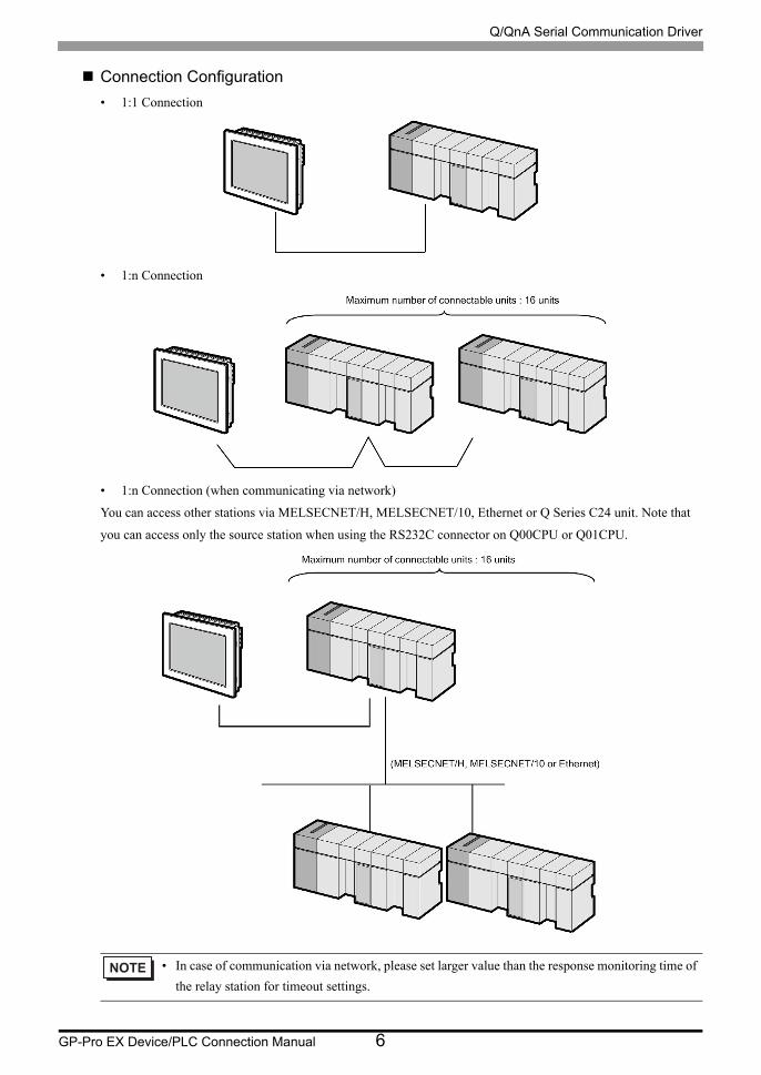
Connection Configuration
• 1:1 Connection
• 1:n Connection
• 1:n Connection (when communicating via network)
You can access other stations via MELSECNET/H, MELSECNET/10, Ethernet or Q Series C24 unit. Note that
you can access only the source station when using the RS232C connector on Q00CPU or Q01CPU.
• In case of communication via network, please set larger value than the response monitoring time of
the relay station for timeout settings.

Q/QnA Serial Communication Driver
GP-Pro EX Device/PLC Connection Manual 7
Setting examples for access beyond the network are shown below. Check the details of the setup items in
"Setup Item."
"4 Setup Items" (page 46)
External
Device to be
Accessed
Port No. Station No. Network No. PC No.
Request
destination
module
I/O No.
Request
destination
module
Station No.
External Device 1
1025 5 0 255 1023 0
External Device 11
1026 5 1 6 1023 0
External Device 22
1027 5 2 8 32 15
Q/QnA Serial Communication Driver
GP-Pro EX Device/PLC Connection Manual 8
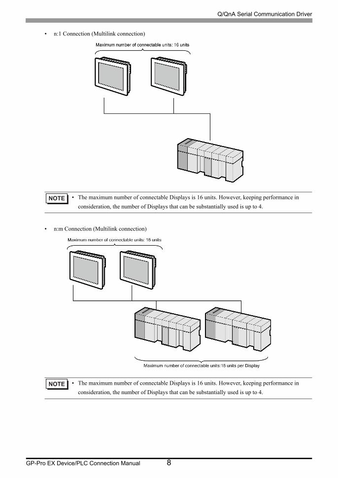
• n:1 Connection (Multilink connection)
• n:m Connection (Multilink connection)
• The maximum number of connectable Displays is 16 units. However, keeping performance in
consideration, the number of Displays that can be substantially used is up to 4.
• The maximum number of connectable Displays is 16 units. However, keeping performance in
consideration, the number of Displays that can be substantially used is up to 4.
Q/QnA Serial Communication Driver
GP-Pro EX Device/PLC Connection Manual 9
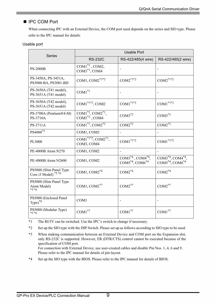
IPC COM Port
When connecting IPC with an External Device, the COM port used depends on the series and SIO type. Please
refer to the IPC manual for details.
Usable port
SeriesUsable Port
RS-232C RS-422/485(4 wire) RS-422/485(2 wire)
PS-2000BCOM1*1 , COM2, COM3*1, COM4
*1 The RI/5V can be switched. Use the IPC’s switch to change if necessary.
- -
PS-3450A, PS-3451A,PS3000-BA, PS3001-BD
COM1, COM2*1*2 COM2*1*2 COM2*1*2
PS-3650A (T41 model),PS-3651A (T41 model)
COM1*1 - -
PS-3650A (T42 model),PS-3651A (T42 model)
COM1*1*2, COM2 COM1*1*2 COM1*1*2
PS-3700A (Pentium®4-M)PS-3710A
COM1*1, COM2*1, COM3*2 , COM4
*2 Set up the SIO type with the DIP Switch. Please set up as follows according to SIO type to be used.
COM3*2 COM3*2
PS-3711A COM1*1, COM2*2 COM2*2 COM2*2
PS4000*3
*3 When making communication between an External Device and COM port on the Expansion slot, only RS-232C is supported. However, ER (DTR/CTS) control cannot be executed because of the specification of COM port.For connection with External Device, use user-created cables and disable Pin Nos. 1, 4, 6 and 9.Please refer to the IPC manual for details of pin layout.
COM1, COM2 - -
PL3000COM1*1*2, COM2*1, COM3, COM4
COM1*1*2 COM1*1*2
PE-4000B Atom N270 COM1, COM2 - -
PE-4000B Atom N2600 COM1, COM2COM3*4 , COM4*4, COM5*4, COM6*4
*4 Set up the SIO type with the BIOS. Please refer to the IPC manual for details of BIOS.
COM3*4, COM4*4, COM5*4, COM6*4
PS5000 (Slim Panel Type Core i3 Model) *5 *6 COM1, COM2*4 COM2*4 COM2*4
PS5000 (Slim Panel Type Atom Model) *5 *6
COM1, COM2*7 COM2*7 COM2*7
PS5000 (Enclosed Panel Type)*8 COM1 - -
PS5000 (Modular Type) *5 *6 COM1*7 COM1*7 COM1*7
Q/QnA Serial Communication Driver
GP-Pro EX Device/PLC Connection Manual 10
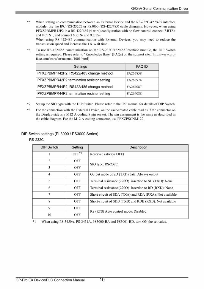
DIP Switch settings (PL3000 / PS3000 Series)
RS-232C
*5 When setting up communication between an External Device and the RS-232C/422/485 interface module, use the IPC (RS-232C) or PS5000 (RS-422/485) cable diagrams. However, when using PFXZPBMPR42P2 in a RS-422/485 (4-wire) configuration with no flow control, connect 7.RTS+ and 8.CTS+, and connect 6.RTS- and 9.CTS-.When using RS-422/485 communication with External Devices, you may need to reduce the transmission speed and increase the TX Wait time.
*6 To use RS-422/485 communication on the RS-232C/422/485 interface module, the DIP Switch setting is required. Please refer to "Knowledge Base" (FAQs) on the support site. (http://www.pro- face.com/trans/en/manual/1001.html)
*7 Set up the SIO type with the DIP Switch. Please refer to the IPC manual for details of DIP Switch.
*8 For the connection with the External Device, on the user-created cable read as if the connector on the Display-side is a M12 A-coding 8 pin socket. The pin assignment is the same as described in the cable diagram. For the M12 A-coding connector, use PFXZPSCNM122.
DIP Switch Setting Description
1 OFF*1
*1 When using PS-3450A, PS-3451A, PS3000-BA and PS3001-BD, turn ON the set value.
Reserved (always OFF)
2 OFFSIO type: RS-232C
3 OFF
4 OFF Output mode of SD (TXD) data: Always output
5 OFF Terminal resistance (220) insertion to SD (TXD): None
6 OFF Terminal resistance (220) insertion to RD (RXD): None
7 OFF Short-circuit of SDA (TXA) and RDA (RXA): Not available
8 OFF Short-circuit of SDB (TXB) and RDB (RXB): Not available
9 OFFRS (RTS) Auto control mode: Disabled
10 OFF
Settings FAQ ID
PFXZPBMPR42P2, RS422/485 change method FA263858
PFXZPBMPR42P2 termination resistor setting FA263974
PFXZPBMPR44P2, RS422/485 change method FA264087
PFXZPBMPR44P2 termination resistor setting FA264088
Q/QnA Serial Communication Driver
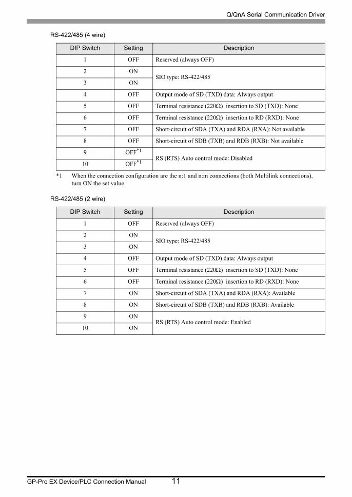
GP-Pro EX Device/PLC Connection Manual 11
RS-422/485 (4 wire)
RS-422/485 (2 wire)
DIP Switch Setting Description
1 OFF Reserved (always OFF)
2 ONSIO type: RS-422/485
3 ON
4 OFF Output mode of SD (TXD) data: Always output
5 OFF Terminal resistance (220) insertion to SD (TXD): None
6 OFF Terminal resistance (220) insertion to RD (RXD): None
7 OFF Short-circuit of SDA (TXA) and RDA (RXA): Not available
8 OFF Short-circuit of SDB (TXB) and RDB (RXB): Not available
9 OFF*1
*1 When the connection configuration are the n:1 and n:m connections (both Multilink connections), turn ON the set value.
RS (RTS) Auto control mode: Disabled10 OFF*1
DIP Switch Setting Description
1 OFF Reserved (always OFF)
2 ONSIO type: RS-422/485
3 ON
4 OFF Output mode of SD (TXD) data: Always output
5 OFF Terminal resistance (220) insertion to SD (TXD): None
6 OFF Terminal resistance (220) insertion to RD (RXD): None
7 ON Short-circuit of SDA (TXA) and RDA (RXA): Available
8 ON Short-circuit of SDB (TXB) and RDB (RXB): Available
9 ONRS (RTS) Auto control mode: Enabled
10 ON
Q/QnA Serial Communication Driver
GP-Pro EX Device/PLC Connection Manual 12
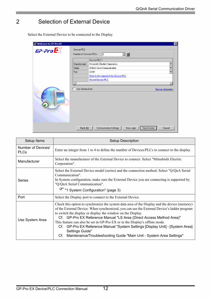
2 Selection of External Device
Select the External Device to be connected to the Display.
Setup Items Setup Description
Number of Devices/PLCs
Enter an integer from 1 to 4 to define the number of Devices/PLCs to connect to the display.
ManufacturerSelect the manufacturer of the External Device to connect. Select "Mitsubishi Electric Corporation".
Series
Select the External Device model (series) and the connection method. Select "Q/QnA Serial Communication".In System configuration, make sure the External Device you are connecting is supported by "Q/QnA Serial Communication".
"1 System Configuration" (page 3)
Port Select the Display port to connect to the External Device.
Use System Area
Check this option to synchronize the system data area of the Display and the device (memory) of the External Device. When synchronized, you can use the External Device’s ladder program to switch the display or display the window on the Display.
Cf. GP-Pro EX Reference Manual "LS Area (Direct Access Method Area)"This feature can also be set in GP-Pro EX or in the Display's offline mode.
Cf. GP-Pro EX Reference Manual "System Settings [Display Unit] - [System Area] Settings Guide"
Cf. Maintenance/Troubleshooting Guide "Main Unit - System Area Settings"

Q/QnA Serial Communication Driver
GP-Pro EX Device/PLC Connection Manual 13
3 Example of Communication Setting
Examples of communication settings of the Display and the External Device, recommended by Pro-face, are
shown.
3.1 Setting Example 1
Setting of GP-Pro EX
Communication Settings
To display the setup screen, from the [Project] menu, point to [System Settings] and select [Device/PLC].
• When using A1SJ71QC24N, A1SJ71QC24N-R2, AJ71QC24N or AJ71QC24N-R2, you can set
the "Speed" up to 115200.
Q/QnA Serial Communication Driver
GP-Pro EX Device/PLC Connection Manual 14
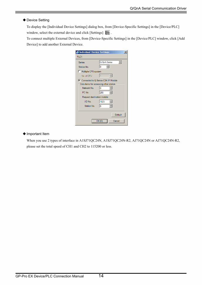
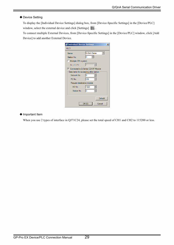
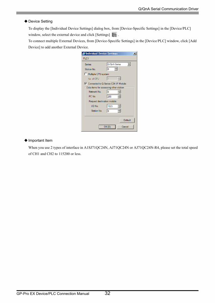
Device Setting
To display the [Individual Device Settings] dialog box, from [Device-Specific Settings] in the [Device/PLC]
window, select the external device and click [Settings] .
To connect multiple External Devices, from [Device-Specific Settings] in the [Device/PLC] window, click [Add
Device] to add another External Device.
Important Item
When you use 2 types of interface in A1SJ71QC24N, A1SJ71QC24N-R2, AJ71QC24N or AJ71QC24N-R2,
please set the total speed of CH1 and CH2 to 115200 or less.
Q/QnA Serial Communication Driver
GP-Pro EX Device/PLC Connection Manual 15
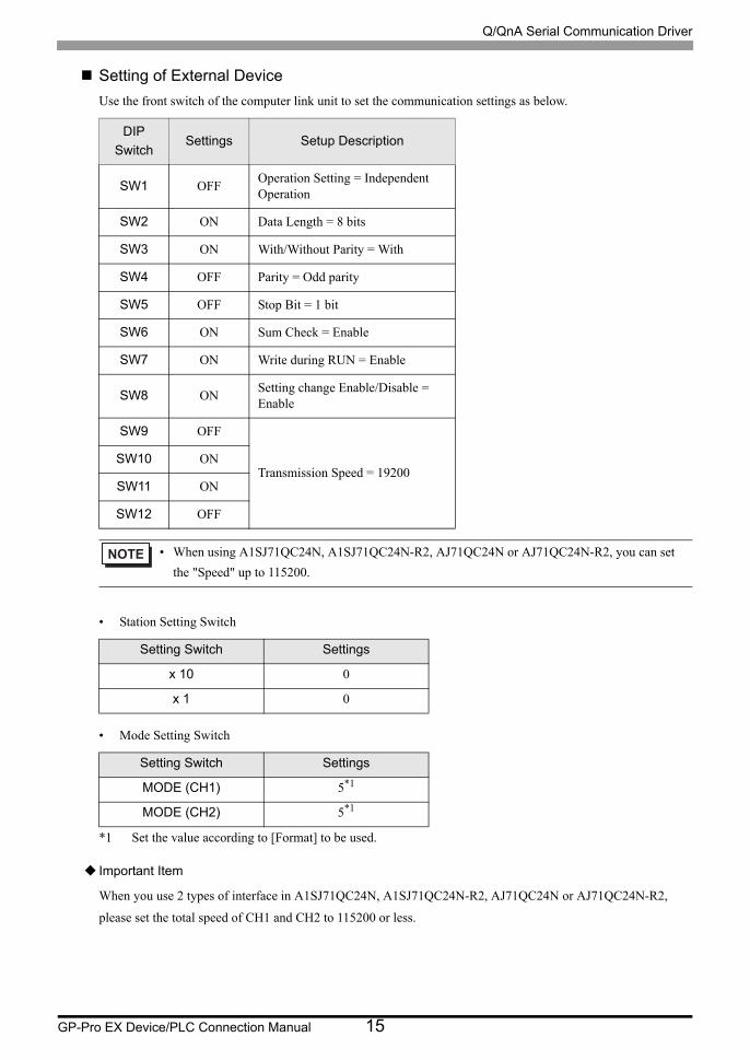
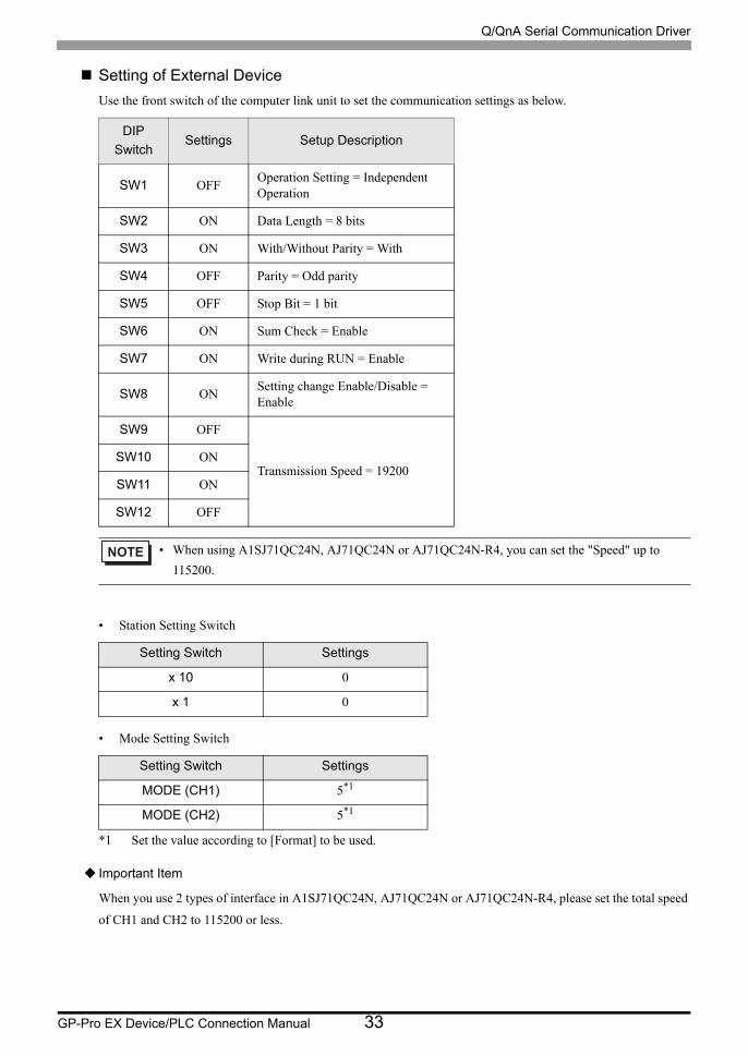
Setting of External Device
Use the front switch of the computer link unit to set the communication settings as below.
• Station Setting Switch
• Mode Setting Switch
Important Item
When you use 2 types of interface in A1SJ71QC24N, A1SJ71QC24N-R2, AJ71QC24N or AJ71QC24N-R2,
please set the total speed of CH1 and CH2 to 115200 or less.
DIP
SwitchSettings Setup Description
SW1 OFFOperation Setting = Independent Operation
SW2 ON Data Length = 8 bits
SW3 ON With/Without Parity = With
SW4 OFF Parity = Odd parity
SW5 OFF Stop Bit = 1 bit
SW6 ON Sum Check = Enable
SW7 ON Write during RUN = Enable
SW8 ONSetting change Enable/Disable = Enable
SW9 OFF
Transmission Speed = 19200SW10 ON
SW11 ON
SW12 OFF
• When using A1SJ71QC24N, A1SJ71QC24N-R2, AJ71QC24N or AJ71QC24N-R2, you can set
the "Speed" up to 115200.
Setting Switch Settings
x 10 0
x 1 0
Setting Switch Settings
MODE (CH1) 5*1
*1 Set the value according to [Format] to be used.
MODE (CH2) 5*1
Q/QnA Serial Communication Driver
GP-Pro EX Device/PLC Connection Manual 16
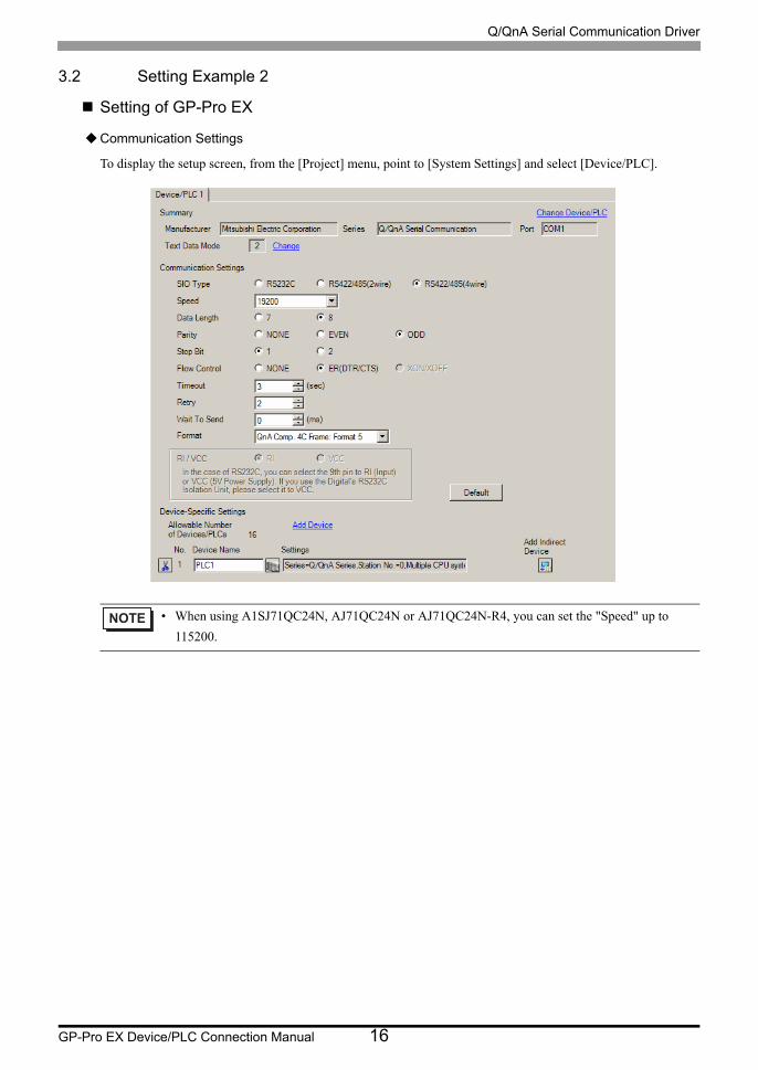
3.2 Setting Example 2
Setting of GP-Pro EX
Communication Settings
To display the setup screen, from the [Project] menu, point to [System Settings] and select [Device/PLC].
• When using A1SJ71QC24N, AJ71QC24N or AJ71QC24N-R4, you can set the "Speed" up to
115200.
Q/QnA Serial Communication Driver
GP-Pro EX Device/PLC Connection Manual 17
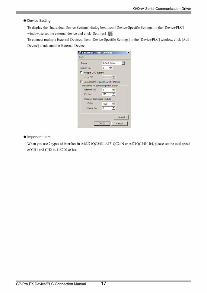
Device Setting
To display the [Individual Device Settings] dialog box, from [Device-Specific Settings] in the [Device/PLC]
window, select the external device and click [Settings] .
To connect multiple External Devices, from [Device-Specific Settings] in the [Device/PLC] window, click [Add
Device] to add another External Device.
Important Item
When you use 2 types of interface in A1SJ71QC24N, AJ71QC24N or AJ71QC24N-R4, please set the total speed
of CH1 and CH2 to 115200 or less.

Q/QnA Serial Communication Driver
GP-Pro EX Device/PLC Connection Manual 18
Setting of External Device
Use the front switch of the computer link unit to set the communication settings as below.
• Station Setting Switch
• Mode Setting Switch
Important Item
When you use 2 types of interface in A1SJ71QC24N, AJ71QC24N or AJ71QC24N-R4, please set the total speed
of CH1 and CH2 to 115200 or less.
DIP
SwitchSettings Setup Description
SW1 OFFOperation Setting = Independent Operation
SW2 ON Data Length = 8 bits
SW3 ON With/Without Parity = With
SW4 OFF Parity = Odd parity
SW5 OFF Stop Bit = 1 bit
SW6 ON Sum Check = Enable
SW7 ON Write during RUN = Enable
SW8 ONSetting change Enable/Disable = Enable
SW9 OFF
Transmission Speed = 19200SW10 ON
SW11 ON
SW12 OFF
• When using A1SJ71QC24N, AJ71QC24N or AJ71QC24N-R4, you can set the "Speed" up to
115200.
Setting Switch Settings
x 10 0
x 1 0
Setting Switch Settings
MODE (CH1) 5*1
*1 Set the value according to [Format] to be used.
MODE (CH2) 5*1

Q/QnA Serial Communication Driver
GP-Pro EX Device/PLC Connection Manual 19
3.3 Setting Example 3
Setting of GP-Pro EX
Communication Settings
To display the setup screen, from the [Project] menu, point to [System Settings] and select [Device/PLC].
Q/QnA Serial Communication Driver
GP-Pro EX Device/PLC Connection Manual 20
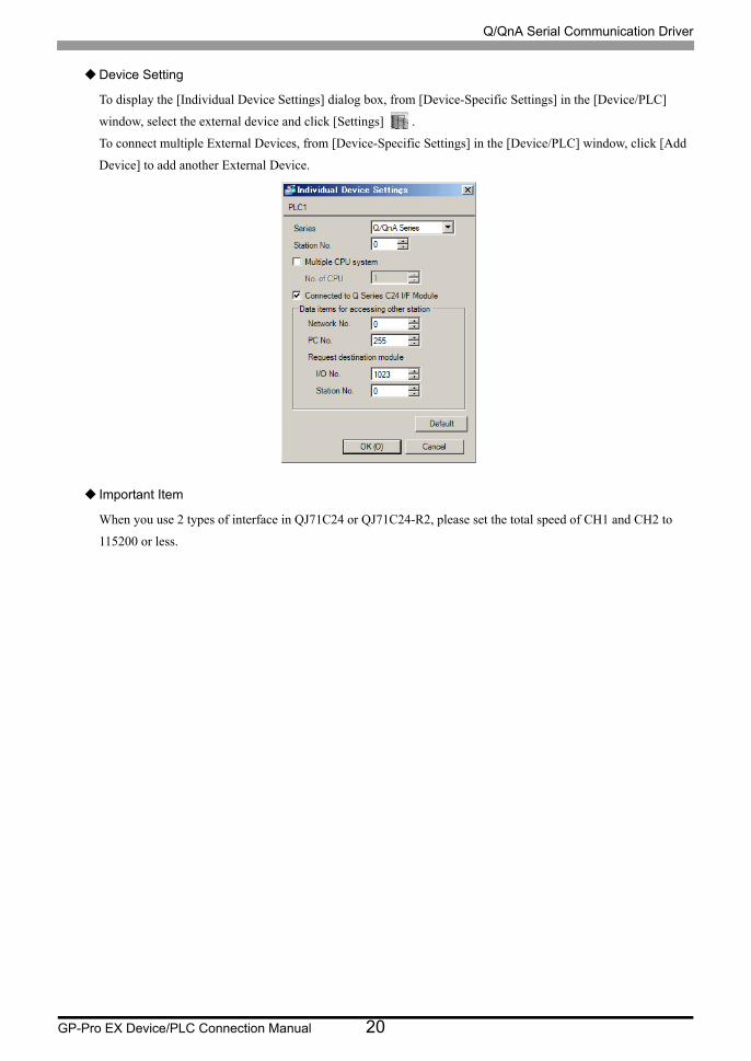
Device Setting
To display the [Individual Device Settings] dialog box, from [Device-Specific Settings] in the [Device/PLC]
window, select the external device and click [Settings] .
To connect multiple External Devices, from [Device-Specific Settings] in the [Device/PLC] window, click [Add
Device] to add another External Device.
Important Item
When you use 2 types of interface in QJ71C24 or QJ71C24-R2, please set the total speed of CH1 and CH2 to
115200 or less.
Q/QnA Serial Communication Driver
GP-Pro EX Device/PLC Connection Manual 21
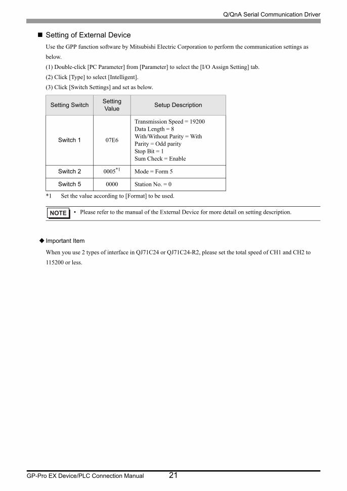
Setting of External Device
Use the GPP function software by Mitsubishi Electric Corporation to perform the communication settings as
below.
(1) Double-click [PC Parameter] from [Parameter] to select the [I/O Assign Setting] tab.
(2) Click [Type] to select [Intelligent].
(3) Click [Switch Settings] and set as below.
Important Item
When you use 2 types of interface in QJ71C24 or QJ71C24-R2, please set the total speed of CH1 and CH2 to
115200 or less.
Setting SwitchSetting Value
Setup Description
Switch 1 07E6
Transmission Speed = 19200Data Length = 8With/Without Parity = WithParity = Odd parityStop Bit = 1Sum Check = Enable
Switch 2 0005*1
*1 Set the value according to [Format] to be used.
Mode = Form 5
Switch 5 0000 Station No. = 0
• Please refer to the manual of the External Device for more detail on setting description.
Q/QnA Serial Communication Driver
GP-Pro EX Device/PLC Connection Manual 22
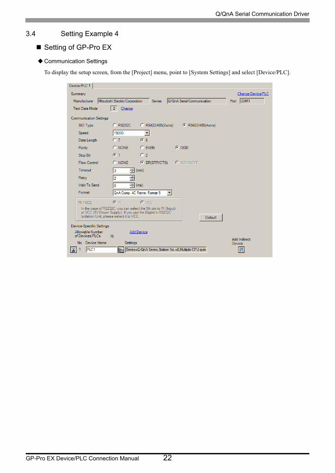
3.4 Setting Example 4
Setting of GP-Pro EX
Communication Settings
To display the setup screen, from the [Project] menu, point to [System Settings] and select [Device/PLC].
Q/QnA Serial Communication Driver
GP-Pro EX Device/PLC Connection Manual 23
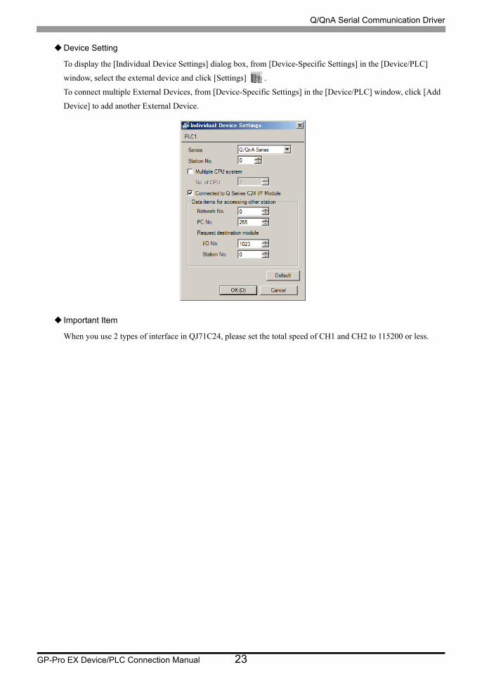
Device Setting
To display the [Individual Device Settings] dialog box, from [Device-Specific Settings] in the [Device/PLC]
window, select the external device and click [Settings] .
To connect multiple External Devices, from [Device-Specific Settings] in the [Device/PLC] window, click [Add
Device] to add another External Device.
Important Item
When you use 2 types of interface in QJ71C24, please set the total speed of CH1 and CH2 to 115200 or less.
Q/QnA Serial Communication Driver
GP-Pro EX Device/PLC Connection Manual 24
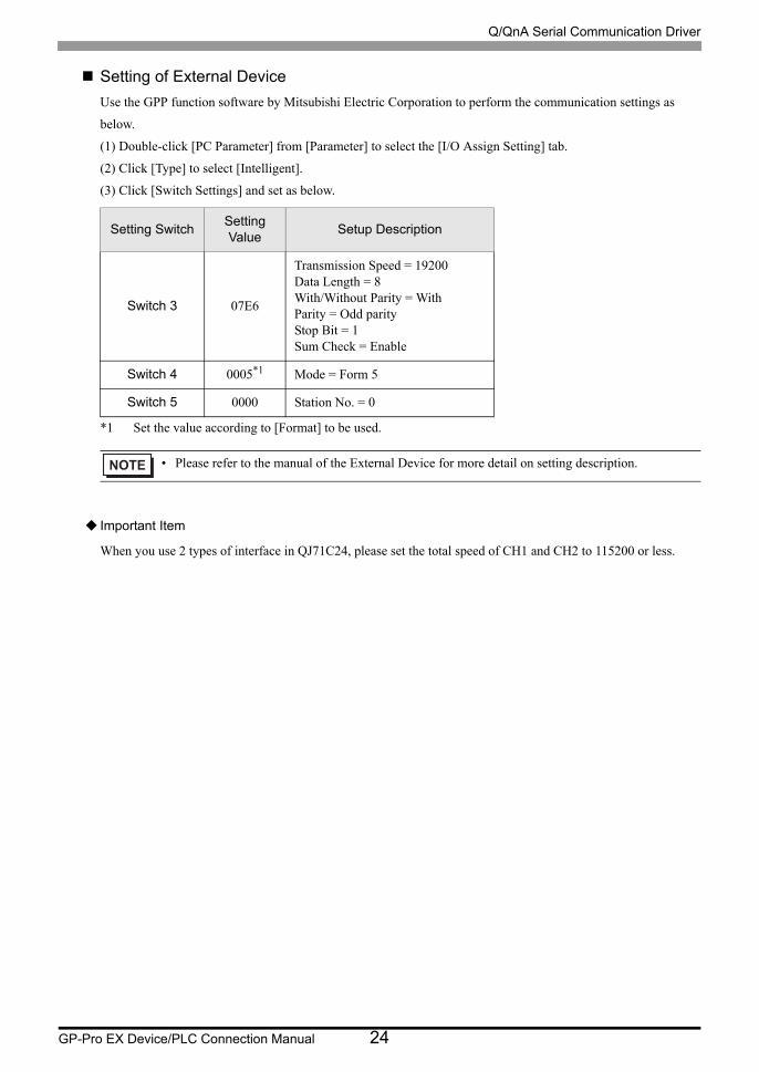
Setting of External Device
Use the GPP function software by Mitsubishi Electric Corporation to perform the communication settings as
below.
(1) Double-click [PC Parameter] from [Parameter] to select the [I/O Assign Setting] tab.
(2) Click [Type] to select [Intelligent].
(3) Click [Switch Settings] and set as below.
Important Item
When you use 2 types of interface in QJ71C24, please set the total speed of CH1 and CH2 to 115200 or less.
Setting SwitchSetting Value
Setup Description
Switch 3 07E6
Transmission Speed = 19200Data Length = 8With/Without Parity = WithParity = Odd parityStop Bit = 1Sum Check = Enable
Switch 4 0005*1
*1 Set the value according to [Format] to be used.
Mode = Form 5
Switch 5 0000 Station No. = 0
• Please refer to the manual of the External Device for more detail on setting description.

Q/QnA Serial Communication Driver
GP-Pro EX Device/PLC Connection Manual 25
3.5 Setting Example 5
Setting of GP-Pro EX
Communication Settings
To display the setup screen, from the [Project] menu, point to [System Settings] and select [Device/PLC].
Q/QnA Serial Communication Driver
GP-Pro EX Device/PLC Connection Manual 26
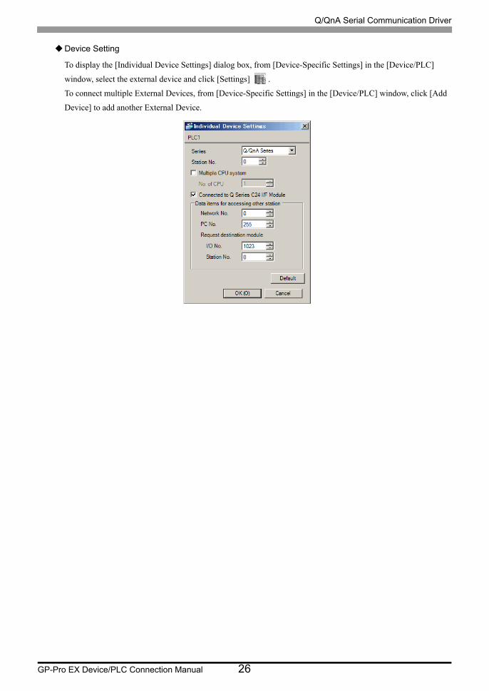
Device Setting
To display the [Individual Device Settings] dialog box, from [Device-Specific Settings] in the [Device/PLC]
window, select the external device and click [Settings] .
To connect multiple External Devices, from [Device-Specific Settings] in the [Device/PLC] window, click [Add
Device] to add another External Device.
Q/QnA Serial Communication Driver
GP-Pro EX Device/PLC Connection Manual 27
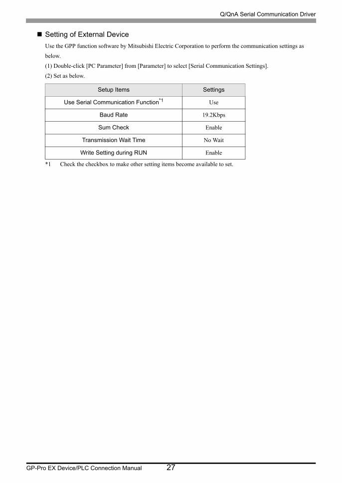
Setting of External Device
Use the GPP function software by Mitsubishi Electric Corporation to perform the communication settings as
below.
(1) Double-click [PC Parameter] from [Parameter] to select [Serial Communication Settings].
(2) Set as below.
Setup Items Settings
Use Serial Communication Function*1
*1 Check the checkbox to make other setting items become available to set.
Use
Baud Rate 19.2Kbps
Sum Check Enable
Transmission Wait Time No Wait
Write Setting during RUN Enable
Q/QnA Serial Communication Driver
GP-Pro EX Device/PLC Connection Manual 28
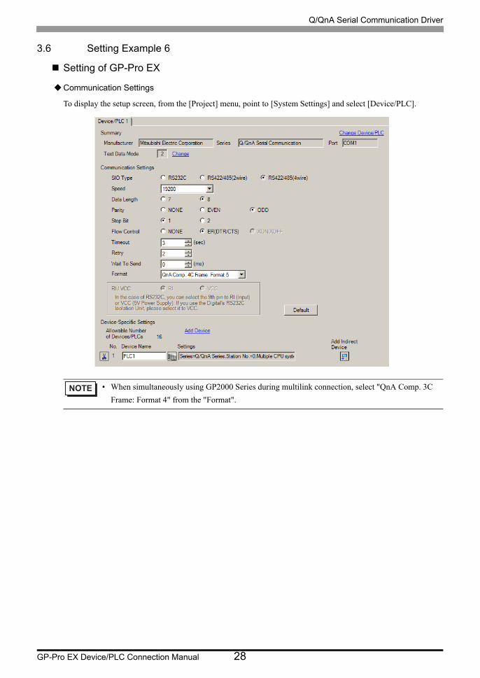
3.6 Setting Example 6
Setting of GP-Pro EX
Communication Settings
To display the setup screen, from the [Project] menu, point to [System Settings] and select [Device/PLC].
• When simultaneously using GP2000 Series during multilink connection, select "QnA Comp. 3C
Frame: Format 4" from the "Format".
Q/QnA Serial Communication Driver
GP-Pro EX Device/PLC Connection Manual 29
Device Setting
To display the [Individual Device Settings] dialog box, from [Device-Specific Settings] in the [Device/PLC]
window, select the external device and click [Settings] .
To connect multiple External Devices, from [Device-Specific Settings] in the [Device/PLC] window, click [Add
Device] to add another External Device.
Important Item
When you use 2 types of interface in QJ71C24, please set the total speed of CH1 and CH2 to 115200 or less.

Q/QnA Serial Communication Driver
GP-Pro EX Device/PLC Connection Manual 30
Setting of External Device
Use the GPP function software by Mitsubishi Electric Corporation to perform the communication settings as
below.
(1) Double-click [PC Parameter] from [Parameter] to select the [I/O Assign Setting] tab.
(2) Click [Type] to select [Intelligent].
(3) Click [Switch Settings] and set as below.
Important Item
When you use 2 types of interface in QJ71C24, please set the total speed of CH1 and CH2 to 115200 or less.
Setting SwitchSetting Value
Setup Description
Switch 3 07E6
Transmission Speed = 19200Data Length = 8With/Without Parity = WithParity = Odd parityStop Bit = 1Sum Check = Enable
Switch 4 0005*1
*1 Set the value according to [Format] to be used.
Mode = Form 5
Switch 5 0000 Station No. = 0
• Please refer to the manual of the External Device for more detail on setting description.
Q/QnA Serial Communication Driver
GP-Pro EX Device/PLC Connection Manual 31
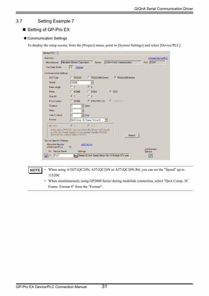
3.7 Setting Example 7
Setting of GP-Pro EX
Communication Settings
To display the setup screen, from the [Project] menu, point to [System Settings] and select [Device/PLC].
• When using A1SJ71QC24N, AJ71QC24N or AJ71QC24N-R4, you can set the "Speed" up to
115200.
• When simultaneously using GP2000 Series during multilink connection, select "QnA Comp. 3C
Frame: Format 4" from the "Format".
Q/QnA Serial Communication Driver
GP-Pro EX Device/PLC Connection Manual 32
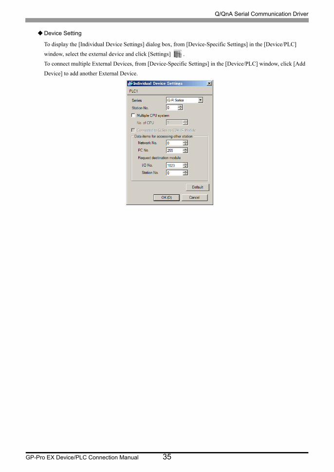
Device Setting
To display the [Individual Device Settings] dialog box, from [Device-Specific Settings] in the [Device/PLC]
window, select the external device and click [Settings] .
To connect multiple External Devices, from [Device-Specific Settings] in the [Device/PLC] window, click [Add
Device] to add another External Device.
Important Item
When you use 2 types of interface in A1SJ71QC24N, AJ71QC24N or AJ71QC24N-R4, please set the total speed
of CH1 and CH2 to 115200 or less.
Q/QnA Serial Communication Driver
GP-Pro EX Device/PLC Connection Manual 33
Setting of External Device
Use the front switch of the computer link unit to set the communication settings as below.
• Station Setting Switch
• Mode Setting Switch
Important Item
When you use 2 types of interface in A1SJ71QC24N, AJ71QC24N or AJ71QC24N-R4, please set the total speed
of CH1 and CH2 to 115200 or less.
DIP
SwitchSettings Setup Description
SW1 OFFOperation Setting = Independent Operation
SW2 ON Data Length = 8 bits
SW3 ON With/Without Parity = With
SW4 OFF Parity = Odd parity
SW5 OFF Stop Bit = 1 bit
SW6 ON Sum Check = Enable
SW7 ON Write during RUN = Enable
SW8 ONSetting change Enable/Disable = Enable
SW9 OFF
Transmission Speed = 19200SW10 ON
SW11 ON
SW12 OFF
• When using A1SJ71QC24N, AJ71QC24N or AJ71QC24N-R4, you can set the "Speed" up to
115200.
Setting Switch Settings
x 10 0
x 1 0
Setting Switch Settings
MODE (CH1) 5*1
*1 Set the value according to [Format] to be used.
MODE (CH2) 5*1

Q/QnA Serial Communication Driver
GP-Pro EX Device/PLC Connection Manual 34
3.8 Setting Example 8
Setting of GP-Pro EX
Communication Settings
To display the setup screen, from the [Project] menu, point to [System Settings] and select [Device/PLC].
• When simultaneously using GP2000 Series during multilink connection, select "QnA Comp. 3C
Frame: Format 4" from the "Format".
Q/QnA Serial Communication Driver
GP-Pro EX Device/PLC Connection Manual 35
Device Setting
To display the [Individual Device Settings] dialog box, from [Device-Specific Settings] in the [Device/PLC]
window, select the external device and click [Settings] .
To connect multiple External Devices, from [Device-Specific Settings] in the [Device/PLC] window, click [Add
Device] to add another External Device.

Q/QnA Serial Communication Driver
GP-Pro EX Device/PLC Connection Manual 36
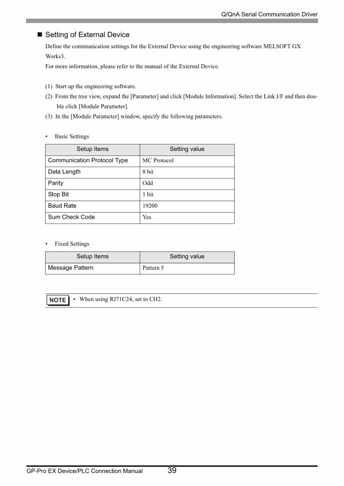
Setting of External Device
Define the communication settings for the External Device using the engineering software MELSOFT GX
Works3.
For more information, please refer to the manual of the External Device.
(1) Start up the engineering software.
(2) From the tree view, expand the [Parameter] and click [Module Information]. Select the Link I/F and then dou-
ble click [Module Parameter].
(3) In the [Module Parameter] window, specify the following parameters.
• Basic Settings
• Fixed Settings
Setup Items Setting value
Communication Protocol Type MC Protocol
Data Length 8 bit
Parity Odd
Stop Bit 1 bit
Baud Rate 19200
Sum Check Code Yes
Setup Items Setting value
Message Pattern Pattern 5
• When using RJ71C24, set to CH1.

Q/QnA Serial Communication Driver
GP-Pro EX Device/PLC Connection Manual 37
3.9 Setting Example 9
Setting of GP-Pro EX
Communication Settings
To display the setup screen, from the [Project] menu, point to [System Settings] and select [Device/PLC].
• When simultaneously using GP2000 Series during multilink connection, select "QnA Comp. 3C
Frame: Format 4" from the "Format".

Q/QnA Serial Communication Driver
GP-Pro EX Device/PLC Connection Manual 38
Device Setting
To display the [Individual Device Settings] dialog box, from [Device-Specific Settings] in the [Device/PLC]
window, select the external device and click [Settings] .
To connect multiple External Devices, from [Device-Specific Settings] in the [Device/PLC] window, click [Add
Device] to add another External Device.
Q/QnA Serial Communication Driver
GP-Pro EX Device/PLC Connection Manual 39
Setting of External Device
Define the communication settings for the External Device using the engineering software MELSOFT GX
Works3.
For more information, please refer to the manual of the External Device.
(1) Start up the engineering software.
(2) From the tree view, expand the [Parameter] and click [Module Information]. Select the Link I/F and then dou-
ble click [Module Parameter].
(3) In the [Module Parameter] window, specify the following parameters.
• Basic Settings
• Fixed Settings
Setup Items Setting value
Communication Protocol Type MC Protocol
Data Length 8 bit
Parity Odd
Stop Bit 1 bit
Baud Rate 19200
Sum Check Code Yes
Setup Items Setting value
Message Pattern Pattern 5
• When using RJ71C24, set to CH2.
Q/QnA Serial Communication Driver
GP-Pro EX Device/PLC Connection Manual 40
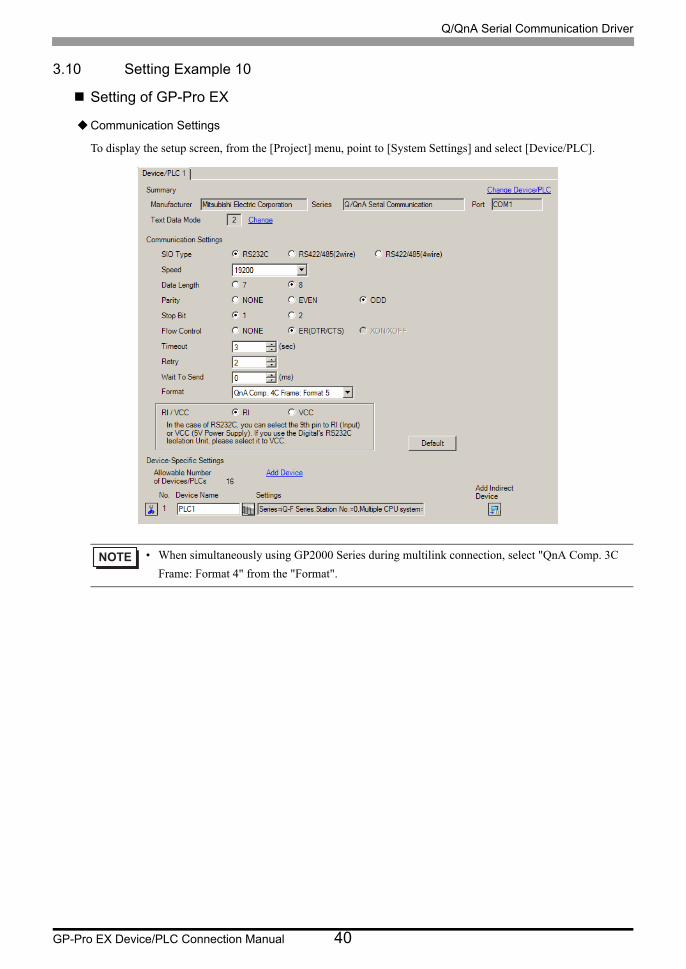
3.10 Setting Example 10
Setting of GP-Pro EX
Communication Settings
To display the setup screen, from the [Project] menu, point to [System Settings] and select [Device/PLC].
• When simultaneously using GP2000 Series during multilink connection, select "QnA Comp. 3C
Frame: Format 4" from the "Format".
Q/QnA Serial Communication Driver
GP-Pro EX Device/PLC Connection Manual 41
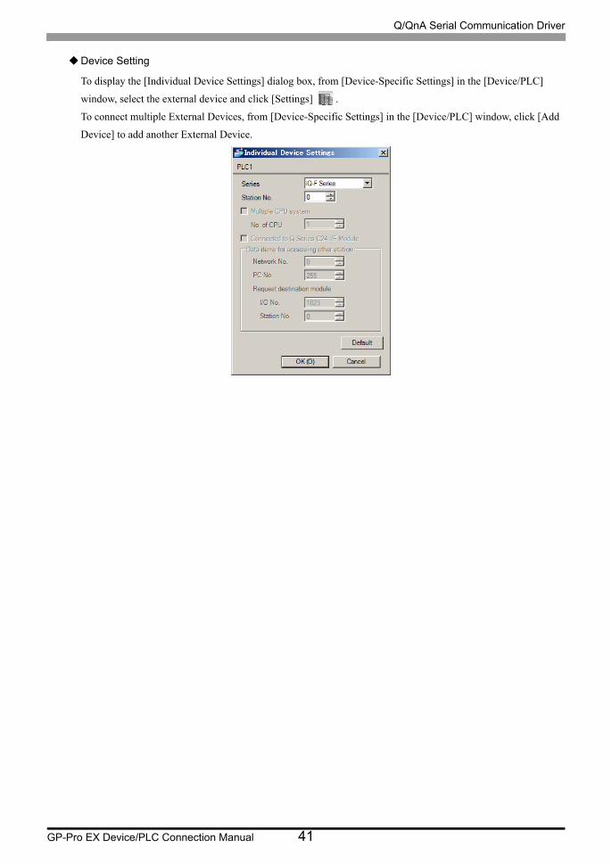
Device Setting
To display the [Individual Device Settings] dialog box, from [Device-Specific Settings] in the [Device/PLC]
window, select the external device and click [Settings] .
To connect multiple External Devices, from [Device-Specific Settings] in the [Device/PLC] window, click [Add
Device] to add another External Device.

Q/QnA Serial Communication Driver
GP-Pro EX Device/PLC Connection Manual 42
Setting of External Device
Define the communication settings for the External Device using the engineering software MELSOFT GX
Works3.
For more information, please refer to the manual of the External Device.
(1) Start up the engineering software.
(2) From the tree view, expand the [Parameter] and click [Module Information]. Select the Link I/F and then dou-
ble click [Module Parameter].
(3) In the [Module Parameter] window, specify the following parameters.
• Basic Settings
• Fixed Settings
Setup Items Setting value
Communication Protocol Type MC Protocol
Data Length 8 bit
Parity Odd
Stop Bit 1 bit
Baud Rate 19200
Sum Check Code Yes
Setup Items Setting value
Message Pattern Pattern 5
Q/QnA Serial Communication Driver
GP-Pro EX Device/PLC Connection Manual 43
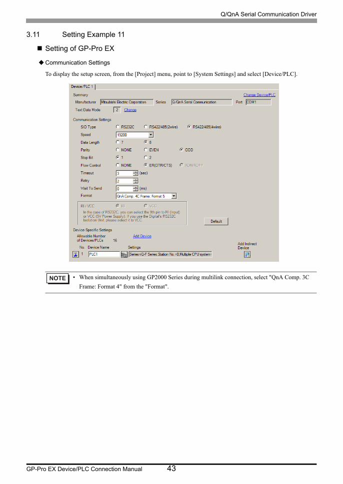
3.11 Setting Example 11
Setting of GP-Pro EX
Communication Settings
To display the setup screen, from the [Project] menu, point to [System Settings] and select [Device/PLC].
• When simultaneously using GP2000 Series during multilink connection, select "QnA Comp. 3C
Frame: Format 4" from the "Format".

Q/QnA Serial Communication Driver
GP-Pro EX Device/PLC Connection Manual 44
Device Setting
To display the [Individual Device Settings] dialog box, from [Device-Specific Settings] in the [Device/PLC]
window, select the external device and click [Settings] .
To connect multiple External Devices, from [Device-Specific Settings] in the [Device/PLC] window, click [Add
Device] to add another External Device.
Q/QnA Serial Communication Driver
GP-Pro EX Device/PLC Connection Manual 45
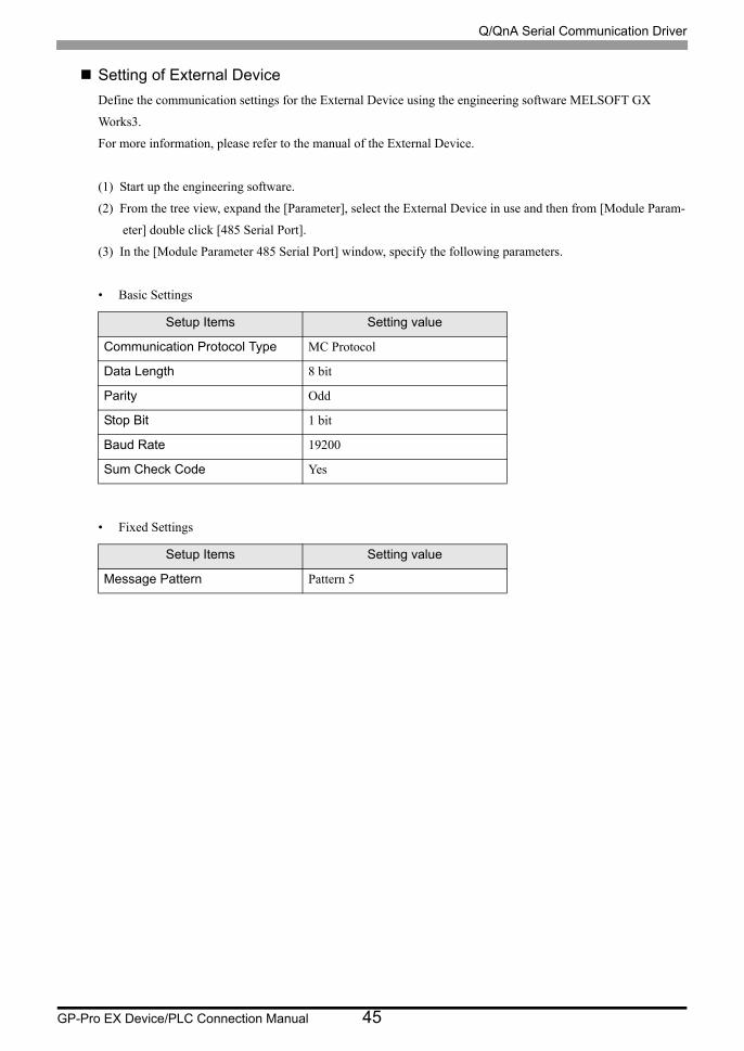
Setting of External Device
Define the communication settings for the External Device using the engineering software MELSOFT GX
Works3.
For more information, please refer to the manual of the External Device.
(1) Start up the engineering software.
(2) From the tree view, expand the [Parameter], select the External Device in use and then from [Module Param-
eter] double click [485 Serial Port].
(3) In the [Module Parameter 485 Serial Port] window, specify the following parameters.
• Basic Settings
• Fixed Settings
Setup Items Setting value
Communication Protocol Type MC Protocol
Data Length 8 bit
Parity Odd
Stop Bit 1 bit
Baud Rate 19200
Sum Check Code Yes
Setup Items Setting value
Message Pattern Pattern 5
Q/QnA Serial Communication Driver
GP-Pro EX Device/PLC Connection Manual 46
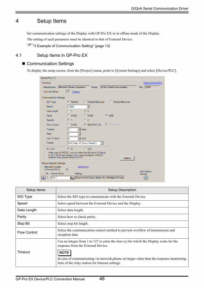
4 Setup Items
Set communication settings of the Display with GP-Pro EX or in offline mode of the Display.
The setting of each parameter must be identical to that of External Device.
"3 Example of Communication Setting" (page 13)
4.1 Setup Items in GP-Pro EX
Communication Settings
To display the setup screen, from the [Project] menu, point to [System Settings] and select [Device/PLC].
Setup Items Setup Description
SIO Type Select the SIO type to communicate with the External Device.
Speed Select speed between the External Device and the Display.
Data Length Select data length.
Parity Select how to check parity.
Stop Bit Select stop bit length.
Flow ControlSelect the communication control method to prevent overflow of transmission and reception data.
Timeout
Use an integer from 1 to 127 to enter the time (s) for which the Display waits for the response from the External Device.
In case of communicating via network,please set larger value than the response monitoring time of the relay station for timeout settings.

Q/QnA Serial Communication Driver
GP-Pro EX Device/PLC Connection Manual 47
RetryIn case of no response from the External Device, use an integer from 0 to 255 to enter how many times the Display retransmits the command.
Wait To SendUse an integer from 0 to 255 to enter standby time (ms) for the Display from receiving packets to transmitting next commands.
Format
Select the communication frame for the use of MELSEC communication protocol, from "QnA Comp. 3C Frame: Format 4" or "QnA Comp. 4C Frame: Format 5".
When simultaneously using GP2000 Series during multilink connection, select "QnA Comp. 3C Frame: Format 4"
RI/VCCYou can switch RI/VCC of the 9th pin when you select RS232C for SIO type.It is necessary to change RI/5V by changeover switch of IPC when connect with IPC. Please refer to the manual of the IPC for more detail.
• Refer to the GP-Pro EX Reference Manual for Indirect Device.
Cf. GP-Pro EX Reference Manual "Changing the Device/PLC at Runtime (Indirect Device)"
Setup Items Setup Description
Q/QnA Serial Communication Driver
GP-Pro EX Device/PLC Connection Manual 48
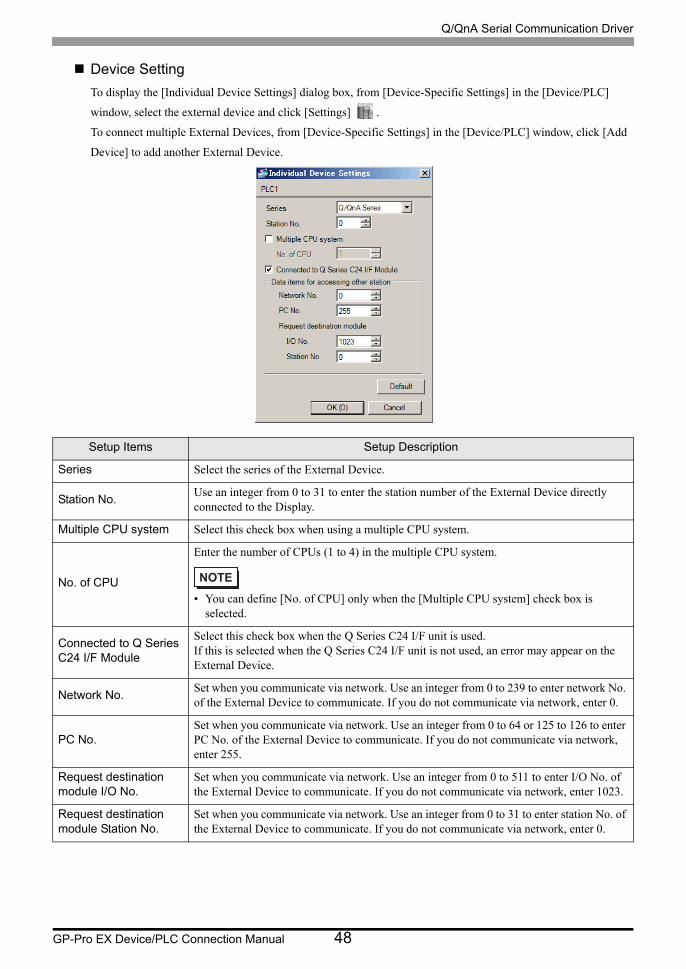
Device Setting
To display the [Individual Device Settings] dialog box, from [Device-Specific Settings] in the [Device/PLC]
window, select the external device and click [Settings] .
To connect multiple External Devices, from [Device-Specific Settings] in the [Device/PLC] window, click [Add
Device] to add another External Device.
Setup Items Setup Description
Series Select the series of the External Device.
Station No.Use an integer from 0 to 31 to enter the station number of the External Device directly connected to the Display.
Multiple CPU system Select this check box when using a multiple CPU system.
No. of CPU
Enter the number of CPUs (1 to 4) in the multiple CPU system.
• You can define [No. of CPU] only when the [Multiple CPU system] check box is selected.
Connected to Q Series C24 I/F Module
Select this check box when the Q Series C24 I/F unit is used. If this is selected when the Q Series C24 I/F unit is not used, an error may appear on the External Device.
Network No.Set when you communicate via network. Use an integer from 0 to 239 to enter network No. of the External Device to communicate. If you do not communicate via network, enter 0.
PC No.Set when you communicate via network. Use an integer from 0 to 64 or 125 to 126 to enter PC No. of the External Device to communicate. If you do not communicate via network, enter 255.
Request destination module I/O No.
Set when you communicate via network. Use an integer from 0 to 511 to enter I/O No. of the External Device to communicate. If you do not communicate via network, enter 1023.
Request destination module Station No.
Set when you communicate via network. Use an integer from 0 to 31 to enter station No. of the External Device to communicate. If you do not communicate via network, enter 0.

Q/QnA Serial Communication Driver
GP-Pro EX Device/PLC Connection Manual 49
4.2 Setup Items in Offline Mode
Communication Settings
To display the setting screen, touch [Device/PLC Settings] from [Peripheral Settings] in offline mode. Touch the
External Device you want to set from the displayed list.
• Refer to the Maintenance/Troubleshooting guide for information on how to enter offline mode or
about the operation.
Cf. Maintenance/Troubleshooting Guide "Offline Mode"
• The number of the setup items to be displayed for 1 page in the offline mode depends on the
Display in use. Please refer to the Reference manual for details.
Setup Items Setup Description
SIO Type
Select the SIO type to communicate with the External Device.
To make the communication settings correctly, confirm the serial interface specifications of Display unit for [SIO Type].We cannot guarantee the operation if a communication type that the serial interface does not support is specified.For details concerning the serial interface specifications, refer to the manual for Display unit.
Speed Select speed between the External Device and the Display.
Data Length Select data length.
Parity Select how to check parity.
Stop Bit Select stop bit length.
Flow ControlSelect the communication control method to prevent overflow of transmission and reception data.
Q/QnA Serial Communication Driver
GP-Pro EX Device/PLC Connection Manual 50
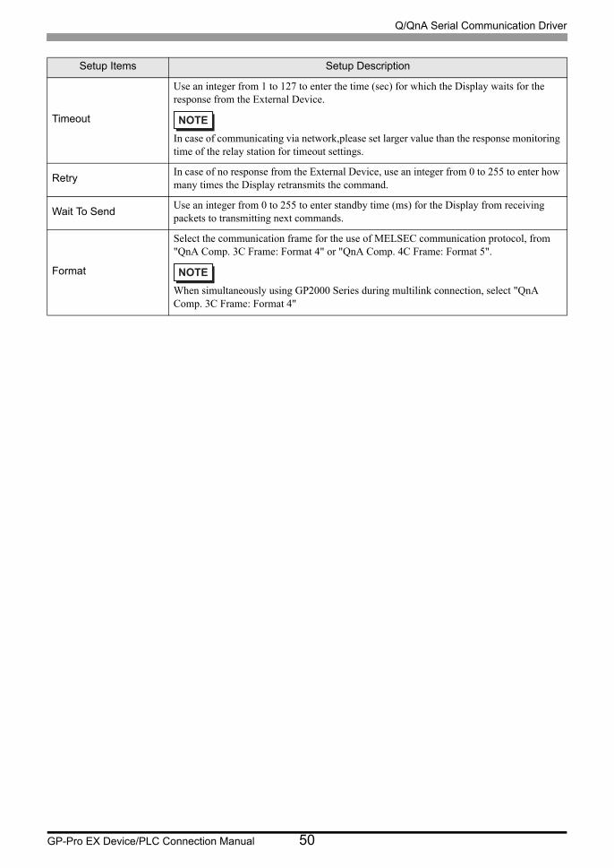
Timeout
Use an integer from 1 to 127 to enter the time (sec) for which the Display waits for the response from the External Device.
In case of communicating via network,please set larger value than the response monitoring time of the relay station for timeout settings.
RetryIn case of no response from the External Device, use an integer from 0 to 255 to enter how many times the Display retransmits the command.
Wait To SendUse an integer from 0 to 255 to enter standby time (ms) for the Display from receiving packets to transmitting next commands.
Format
Select the communication frame for the use of MELSEC communication protocol, from "QnA Comp. 3C Frame: Format 4" or "QnA Comp. 4C Frame: Format 5".
When simultaneously using GP2000 Series during multilink connection, select "QnA Comp. 3C Frame: Format 4"
Setup Items Setup Description
Q/QnA Serial Communication Driver
GP-Pro EX Device/PLC Connection Manual 51
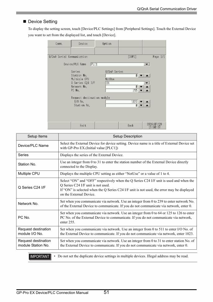
Device Setting
To display the setting screen, touch [Device/PLC Settings] from [Peripheral Settings]. Touch the External Device
you want to set from the displayed list, and touch [Device].
Setup Items Setup Description
Device/PLC NameSelect the External Device for device setting. Device name is a title of External Device set with GP-Pro EX.(Initial value [PLC1])
Series Displays the series of the External Device.
Station No.Use an integer from 0 to 31 to enter the station number of the External Device directly connected to the Display.
Multiple CPU Displays the multiple CPU setting as either “NotUse” or a value of 1 to 4.
Q Series C24 I/F
Select “ON” and “OFF” respectively when the Q Series C24 I/F unit is used and when the Q Series C24 I/F unit is not used.If “ON” is selected when the Q Series C24 I/F unit is not used, the error may be displayed on the External Device.
Network No.Set when you communicate via network. Use an integer from 0 to 239 to enter network No. of the External Device to communicate. If you do not communicate via network, enter 0.
PC No.Set when you communicate via network. Use an integer from 0 to 64 or 125 to 126 to enter PC No. of the External Device to communicate. If you do not communicate via network, enter 255.
Request destination module I/O No.
Set when you communicate via network. Use an integer from 0 to 511 to enter I/O No. of the External Device to communicate. If you do not communicate via network, enter 1023.
Request destination module Station No.
Set when you communicate via network. Use an integer from 0 to 31 to enter station No. of the External Device to communicate. If you do not communicate via network, enter 0.
• Do not set the duplicate device settings in multiple devices. Illegal address may be read.
Q/QnA Serial Communication Driver
GP-Pro EX Device/PLC Connection Manual 52
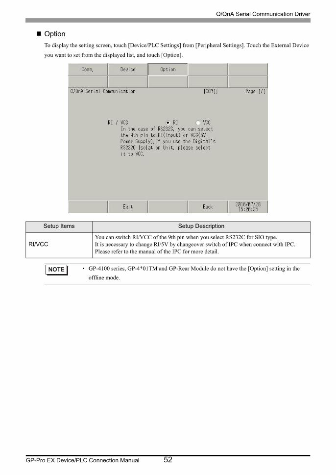
Option
To display the setting screen, touch [Device/PLC Settings] from [Peripheral Settings]. Touch the External Device
you want to set from the displayed list, and touch [Option].
Setup Items Setup Description
RI/VCCYou can switch RI/VCC of the 9th pin when you select RS232C for SIO type.It is necessary to change RI/5V by changeover switch of IPC when connect with IPC. Please refer to the manual of the IPC for more detail.
• GP-4100 series, GP-4*01TM and GP-Rear Module do not have the [Option] setting in the
offline mode.
Q/QnA Serial Communication Driver
GP-Pro EX Device/PLC Connection Manual 53
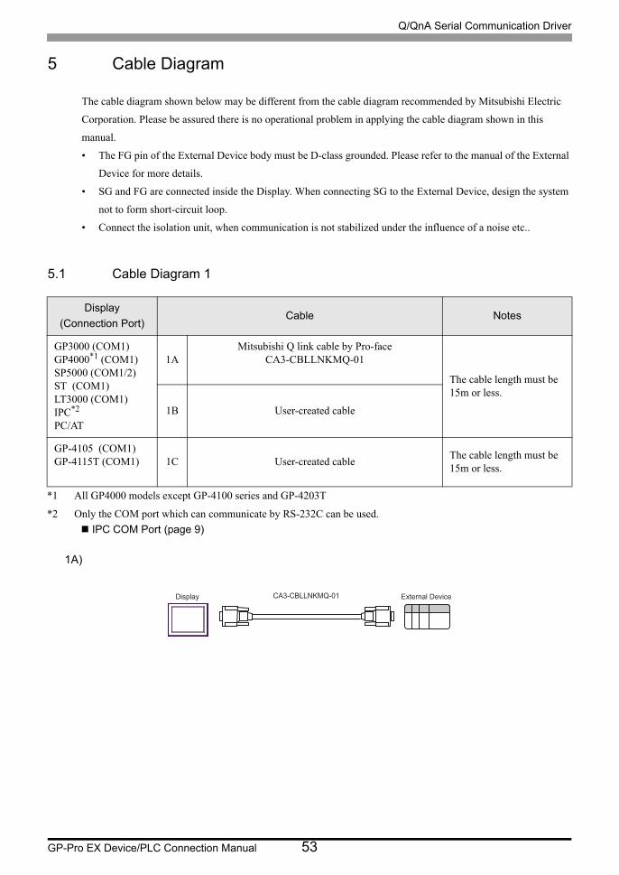
5 Cable Diagram
The cable diagram shown below may be different from the cable diagram recommended by Mitsubishi Electric
Corporation. Please be assured there is no operational problem in applying the cable diagram shown in this
manual.
• The FG pin of the External Device body must be D-class grounded. Please refer to the manual of the External
Device for more details.
• SG and FG are connected inside the Display. When connecting SG to the External Device, design the system
not to form short-circuit loop.
• Connect the isolation unit, when communication is not stabilized under the influence of a noise etc..
5.1 Cable Diagram 1
1A)
Display
(Connection Port)Cable Notes
GP3000 (COM1)GP4000*1 (COM1)SP5000 (COM1/2)ST (COM1)LT3000 (COM1)IPC*2
PC/AT
*1 All GP4000 models except GP-4100 series and GP-4203T
*2 Only the COM port which can communicate by RS-232C can be used.
IPC COM Port (page 9)
1AMitsubishi Q link cable by Pro-face
CA3-CBLLNKMQ-01
The cable length must be 15m or less.
1B User-created cable
GP-4105 (COM1)GP-4115T (COM1) 1C User-created cable
The cable length must be 15m or less.
CA3-CBLLNKMQ-01Display External Device
Q/QnA Serial Communication Driver
GP-Pro EX Device/PLC Connection Manual 54
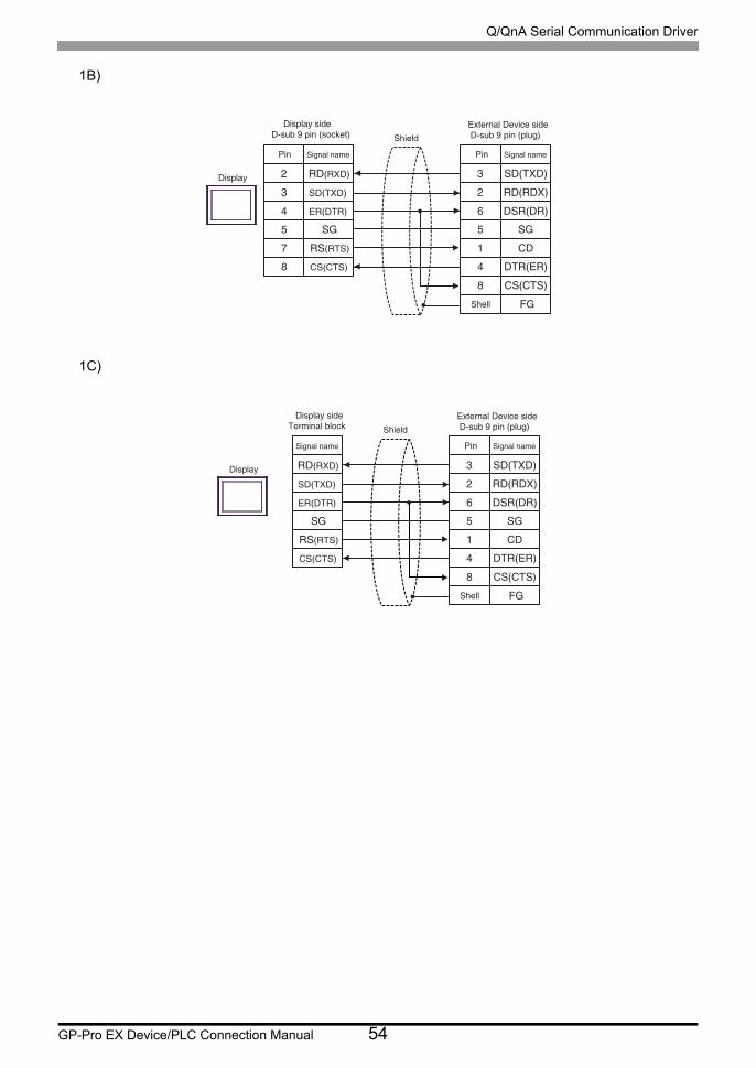
1B)
1C)
3
2
6
5
1
SD(TXD)
RD(RDX)
DSR(DR)
SG
CD
4 DTR(ER)
8 CS(CTS)
FG
2
3
4
5
7
RD(RXD)
SD(TXD)
ER(DTR)
SG
RS(RTS)
8 CS(CTS)
Display
Pin Signal name
ShieldExternal Device sideD-sub 9 pin (plug)D-sub 9 pin (socket)
Pin Signal name
Shell
Display side
3
2
6
5
1
SD(TXD)
RD(RDX)
DSR(DR)
SG
CD
4 DTR(ER)
8 CS(CTS)
FG
RD(RXD)
SD(TXD)
ER(DTR)
SG
RS(RTS)
CS(CTS)
Display
Signal name
ShieldExternal Device sideD-sub 9 pin (plug) Terminal block
Pin Signal name
Shell
Display side

Q/QnA Serial Communication Driver
GP-Pro EX Device/PLC Connection Manual 55
5.2 Cable Diagram 2
Display
(Connection Port)Cable Notes
GP3000*1 (COM1)AGP-3302B (COM2)GP-4*01TM (COM1)GP-Rear Module (COM1)ST*2 (COM2)LT3000 (COM1)IPC*3
*1 All GP3000 models except AGP-3302B
*2 All ST models except AST-3211A and AST-3302B
*3 Only the COM port which can communicate by RS-422/485 (4 wire) can be used. (Except PE-4000B, PS5000)
IPC COM Port (page 9)
2A
COM Port Conversion Adapter by Pro-faceCA3-ADPCOM-01
+Terminal Block Conversion Adapter by Pro-face
CA3-ADPTRM-01+
User-created cable
The cable length must be 500m or less.
2B User-created cable
GP3000*4 (COM2)
*4 All GP3000 models except GP-3200 series and AGP-3302B
2C
Online Adapter by Pro-faceCA4-ADPONL-01
+Terminal Block Conversion Adapter by Pro-face
CA3-ADPTRM-01+
User-created cable
The cable length must be 500m or less.
2D
Online Adapter by Pro-faceCA4-ADPONL-01
+User-created cable
GP-4106 (COM1)GP-4116T (COM1) 2E User-created cable
The cable length must be 500m or less.
GP4000*5 (COM2)GP-4201T (COM1)SP5000 (COM1/2)
*5 All GP4000 models except GP-4100 series, GP-4*01TM, GP-Rear Module, GP-4201T and GP-4*03T
2F
RS-422 terminal block conversion adapter by Pro-facePFXZCBADTM1*6
+User-created cable
*6 When using a Terminal Block Conversion Adapter (CA3-ADPTRM-01) instead of the RS-422 Terminal Block Conversion Adapter, refer to Cable Diagram 2A.
The cable length must be 500m or less.
2B User-created cable
PE-4000B*7
PS5000*7
*7 Only the COM port which can communicate by RS-422/485 (4 wire) can be used.
IPC COM Port (page 9)
2G User-created cableThe cable length must be 500m or less.
Q/QnA Serial Communication Driver
GP-Pro EX Device/PLC Connection Manual 56
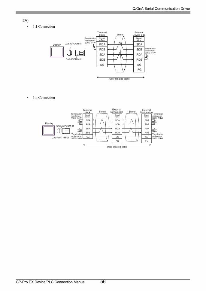
2A)
• 1:1 Connection
• 1:n Connection
QC@
QCA
RC@
RCA
RF
RC@
RCA
QC@
QCA
RF
Chrok`x B@2,@COBNL,/0
B@2,@COSQL,/0
Rhfm`km`ld
RghdkcRhfm`km`ld
EF
Sdqlhm`shnmqdrhrs`mbd22/Ω�0.3V
Sdqlhm`shnmqdrhrs`mbd22/Ω�0.3V
Trdq,bqd`sdc�b`akd
Sdqlhm`kaknbj
Dwsdqm`kCduhbd�rhcd
B@2,@COBNL,/0
B@2,@COSQL,/0
QC@
QCA
RC@
RCA
RF
RC@
RCA
QC@
QCA
RF
EF
RC@
RCA
QC@
QCA
RF
EF
Chrok`x
Rhfm`km`ld
RghdkcRhfm`km`ld
RghdkcRhfm`km`ld
Sdqlhm`shnmqdrhrs`mbd22/Ω�0.3V
Sdqlhm`shnmqdrhrs`mbd22/Ω�0.3V
Sdqlhm`shnmqdrhrs`mbd22/Ω�0.3V
Sdqlhm`shnmqdrhrs`mbd22/Ω�0.3V
Trdq,bqd`sdc�b`akd
Sdqlhm`kaknbj
Dwsdqm`kCduhbd�rhcd
Dwsdqm`kCduhbd�rhcd
Q/QnA Serial Communication Driver
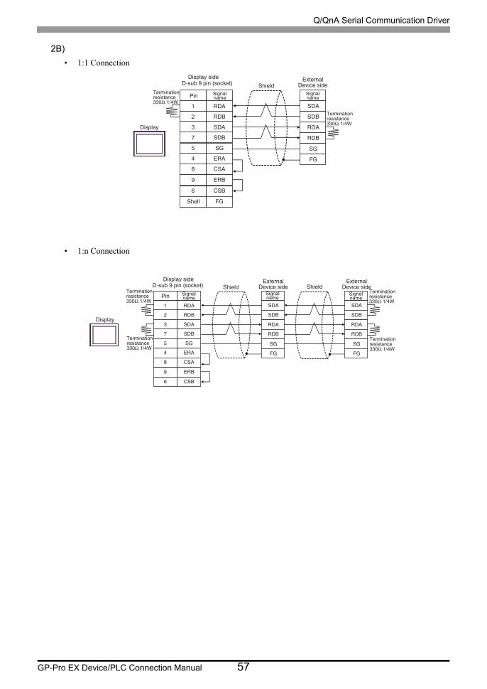
GP-Pro EX Device/PLC Connection Manual 57
2B)
• 1:1 Connection
• 1:n Connection
0
1
2
6
4
3
7
RC@
RCA
QC@
QCA
RF
EF
QC@
QCA
RC@
RCA
RF
DQ@
BR@
8 DQA
5 BRA
EF
Chrok`x
Ohm Rhfm`km`ld
Rghdkc
Rgdkk
C,rta�8�ohm�'rnbjds(
Rhfm`km`ld
Sdqlhm`shnmqdrhrs`mbd22/Ω�0.3V
Sdqlhm`shnmqdrhrs`mbd22/Ω�0.3V
Dwsdqm`kCduhbd�rhcd
Chrok`x�rhcd
0
1
2
6
4
3
7
RC@
RCA
QC@
QCA
RF
EF
QC@
QCA
RC@
RCA
RF
DQ@
BR@
8 DQA
5 BRA
RC@
RCA
QC@
QCA
RF
EF
Chrok`x
Ohm Rhfm`km`ld
Rghdkc RghdkcC,rta�8�ohm�'rnbjds(Rhfm`km`ld
Rhfm`km`ld
Dwsdqm`kCduhbd�rhcd
Sdqlhm`shnmqdrhrs`mbd22/Ω�0.3V
Sdqlhm`shnmqdrhrs`mbd22/Ω�0.3V
Sdqlhm`shnmqdrhrs`mbd22/Ω�0.3V
Sdqlhm`shnmqdrhrs`mbd22/Ω�0.3V
Dwsdqm`kCduhbd�rhcd
Chrok`x�rhcd
Q/QnA Serial Communication Driver
GP-Pro EX Device/PLC Connection Manual 58
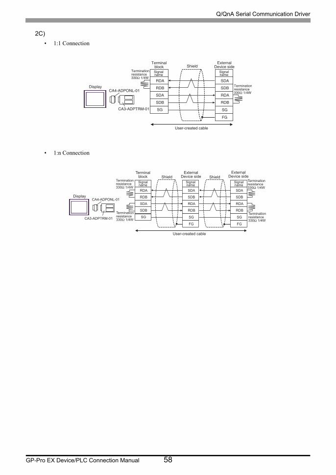
2C)
• 1:1 Connection
• 1:n Connection
B@3,@CONMK,/0
B@2,@COSQL,/0
QC@
QCA
RC@
RCA
RF
RC@
RCA
QC@
QCA
RF
EF
Chrok`x
Rhfm`km`ld
RghdkcDwsdqm`k
Cduhbd�rhcdRhfm`km`ld
Sdqlhm`shnmqdrhrs`mbd22/Ω�0.3V
Sdqlhm`shnmqdrhrs`mbd22/Ω�0.3V
Trdq,bqd`sdc�b`akd
Sdqlhm`kaknbj
CA4-ADPONL-01
CA3-ADPTRM-01
RDA
RDB
SDA
SDB
SG
SDA
SDB
RDA
RDB
SG
FG
SDA
SDB
RDA
RDB
SG
FG
Display
TerminalblockSignalname
ShieldExternal
Device sideExternal
Device sideSignalname
Signalname
ShieldTerminationresistance330Ω 1/4W
Terminationresistance330Ω 1/4W
Terminationresistance330Ω 1/4W
Terminationresistance330Ω 1/4W
User-created cable
Q/QnA Serial Communication Driver
GP-Pro EX Device/PLC Connection Manual 59
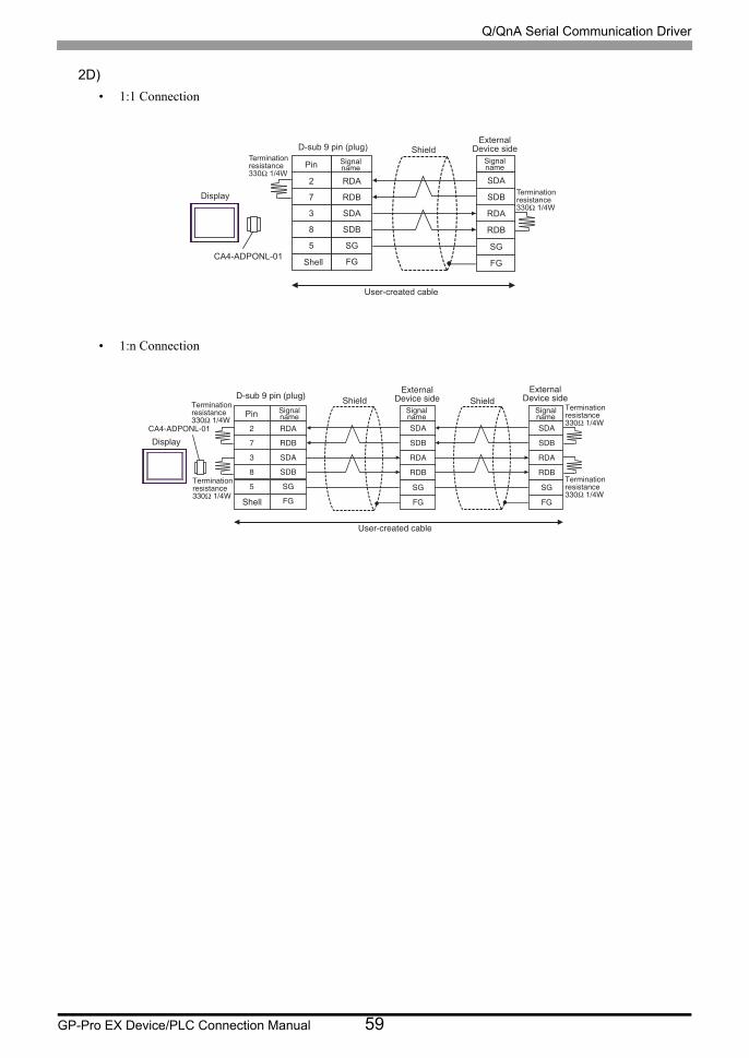
2D)
• 1:1 Connection
• 1:n Connection
2
7
3
8
5
SDA
SDB
RDA
RDB
SG
FG
RDA
RDB
SDA
SDB
SG
FGCA4-ADPONL-01
Display
Pin Signalname
Shell
ShieldExternal
Device sideD-sub 9 pin (plug)Signalname
Terminationresistance330Ω 1/4W
Terminationresistance330Ω 1/4W
User-created cable
1
6
2
7
4
RC@
RCA
QC@
QCA
RF
EF
QC@
QCA
RC@
RCA
RF
EF
RC@
RCA
QC@
QCA
RF
EF
B@3,@CONMK,/0
Chrok`x
Ohm Rhfm`km`ld
Rgdkk
Rghdkc RghdkcDwsdqm`k
Cduhbd�rhcdC,rta�8�ohm�'oktf(Rhfm`km`ld
Dwsdqm`kCduhbd�rhcd
Rhfm`km`ld
Sdqlhm`shnmqdrhrs`mbd22/Ω�0.3V
Sdqlhm`shnmqdrhrs`mbd22/Ω�0.3V
Sdqlhm`shnmqdrhrs`mbd22/Ω�0.3V
Sdqlhm`shnmqdrhrs`mbd22/Ω�0.3V
Trdq,bqd`sdc�b`akd
Q/QnA Serial Communication Driver
GP-Pro EX Device/PLC Connection Manual 60
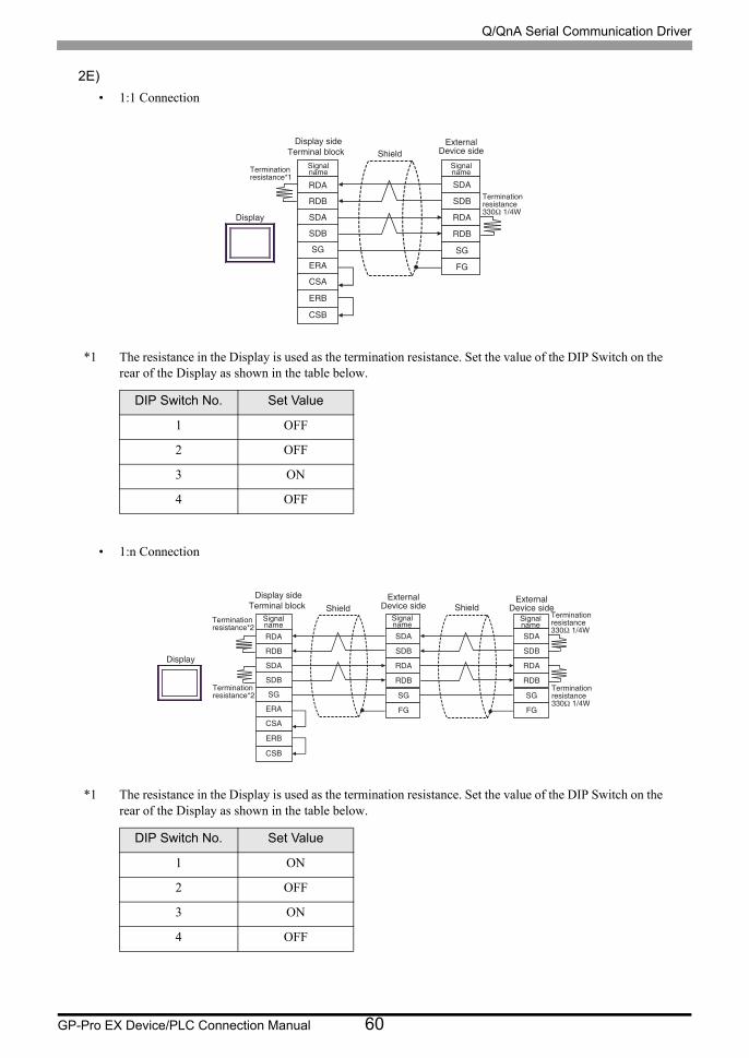
2E)
• 1:1 Connection
*1 The resistance in the Display is used as the termination resistance. Set the value of the DIP Switch on the rear of the Display as shown in the table below.
• 1:n Connection
*1 The resistance in the Display is used as the termination resistance. Set the value of the DIP Switch on the rear of the Display as shown in the table below.
DIP Switch No. Set Value
1 OFF
2 OFF
3 ON
4 OFF
DIP Switch No. Set Value
1 ON
2 OFF
3 ON
4 OFF
SDA
SDB
RDA
RDB
SG
FG
RDA
RDB
SDA
SDB
SG
ERA
CSA
ERB
CSB
Display
Signalname
ShieldSignalnameTermination
resistance*1
Terminationresistance330Ω 1/4W
ExternalDevice side Terminal block
Display side
SDA
SDB
RDA
RDB
SG
FG
RDA
RDB
SDA
SDB
SG
ERA
CSA
ERB
CSB
SDA
SDB
RDA
RDB
SG
FG
Display
Signalname
Shield ShieldSignalname
Signalname
ExternalDevice side
Terminationresistance*2
Terminationresistance*2
Terminationresistance330Ω 1/4W
Terminationresistance330Ω 1/4W
ExternalDevice side Terminal block
Display side
Q/QnA Serial Communication Driver
GP-Pro EX Device/PLC Connection Manual 61
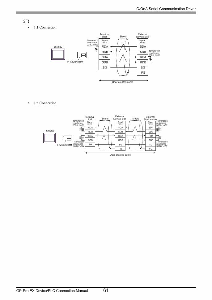
2F)
• 1:1 Connection
• 1:n Connection
RDA
RDB
SDA
SDB
SG
SDA
SDB
RDA
RDB
SG
Display
PFXZCBADTM1
Signalname
ShieldSignalname
FG
Terminationresistance330Ω 1/4W
Terminationresistance330Ω 1/4W
User-created cable
Terminalblock
ExternalDevice side
PFXZCBADTM1
RDA
RDB
SDA
SDB
SG
SDA
SDB
RDA
RDB
SG
FG
SDA
SDB
RDA
RDB
SG
FG
Display
Signalname
ShieldSignalname
ShieldSignalname
Terminationresistance330Ω 1/4W
Terminationresistance330Ω 1/4W
Terminationresistance330Ω 1/4W
Terminationresistance330Ω 1/4W
User-created cable
Terminalblock
ExternalDevice side
ExternalDevice side
Q/QnA Serial Communication Driver
GP-Pro EX Device/PLC Connection Manual 62
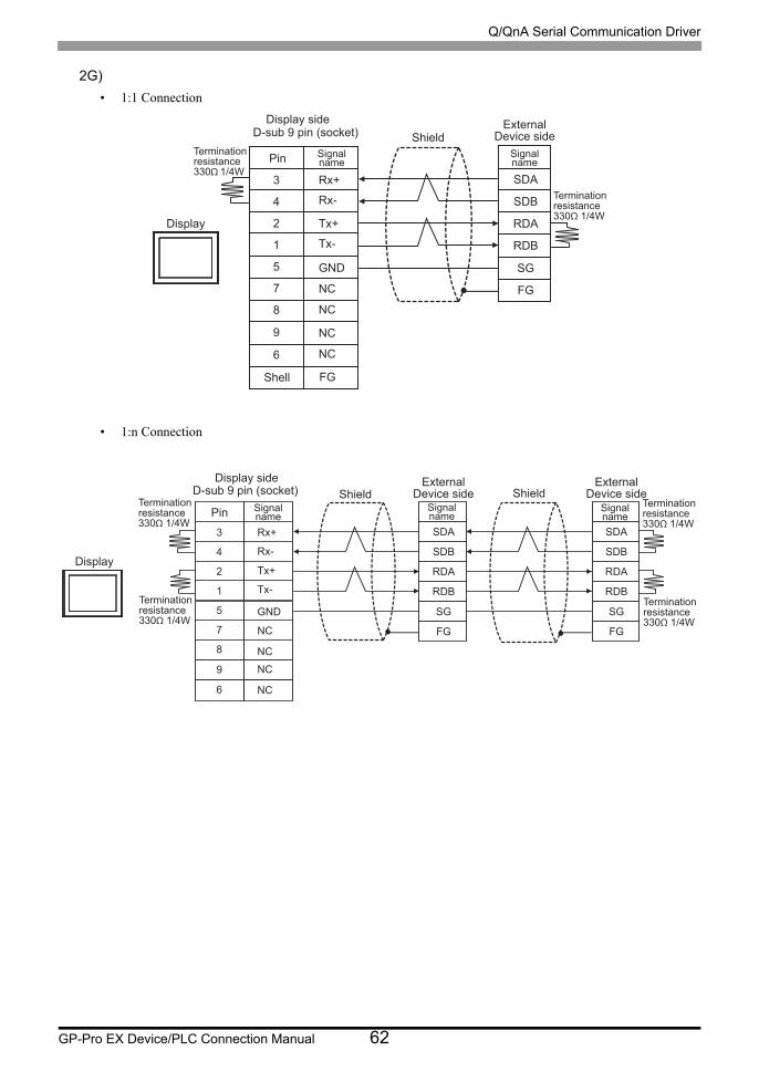
2G)
• 1:1 Connection
• 1:n Connection
3
4
2
1
5
7
8
SDA
SDB
RDA
RDB
SG
FG
Rx+
Rx-
Tx+
Tx-
GND
NC
NC
NC
NC
9
6
FG
Display
Pin Signalname
Shield
Shell
D-sub 9 pin (socket)
Signalname
Terminationresistance330Ω 1/4W
Terminationresistance330Ω 1/4W
ExternalDevice side
Display side
3
4
2
1
5
7
8
SDA
SDB
RDA
RDB
SG
FG
Rx+
Rx-
Tx+
Tx-
GND
NC
NC
NC
NC
9
6
SDA
SDB
RDA
RDB
SG
FG
Display
Pin Signalname
Shield ShieldD-sub 9 pin (socket)Signalname
Signalname
ExternalDevice side
Terminationresistance330Ω 1/4W
Terminationresistance330Ω 1/4W
Terminationresistance330Ω 1/4W
Terminationresistance330Ω 1/4W
ExternalDevice side
Display side
Q/QnA Serial Communication Driver
GP-Pro EX Device/PLC Connection Manual 63
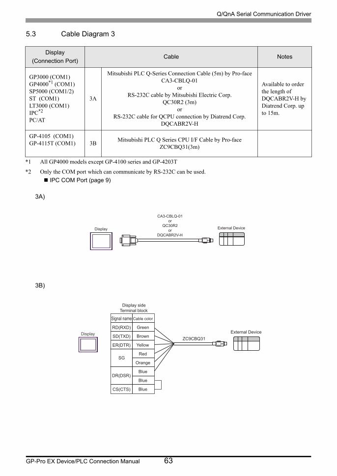
5.3 Cable Diagram 3
3A)
3B)
Display
(Connection Port)Cable Notes
GP3000 (COM1)GP4000*1 (COM1)SP5000 (COM1/2)ST (COM1)LT3000 (COM1)IPC*2
PC/AT
*1 All GP4000 models except GP-4100 series and GP-4203T
*2 Only the COM port which can communicate by RS-232C can be used.
IPC COM Port (page 9)
3A
Mitsubishi PLC Q-Series Connection Cable (5m) by Pro-faceCA3-CBLQ-01
orRS-232C cable by Mitsubishi Electric Corp.
QC30R2 (3m)or
RS-232C cable for QCPU connection by Diatrend Corp.DQCABR2V-H
Available to order the length of DQCABR2V-H by Diatrend Corp. up to 15m.
GP-4105 (COM1)GP-4115T (COM1) 3B
Mitsubishi PLC Q Series CPU I/F Cable by Pro-faceZC9CBQ31(3m)
CA3-CBLQ-01or
QC30R2or
DQCABR2V-HDisplay External Device
Signal name
RD(RXD)
SD(TXD)
ER(DTR)
CS(CTS)
SG
DR(DSR)
Cable color
Green
Brown
Yellow
Red
Orange
Blue
Blue
Blue
Display
Display sideTerminal block
External DeviceZC9CBQ31
Q/QnA Serial Communication Driver
GP-Pro EX Device/PLC Connection Manual 64
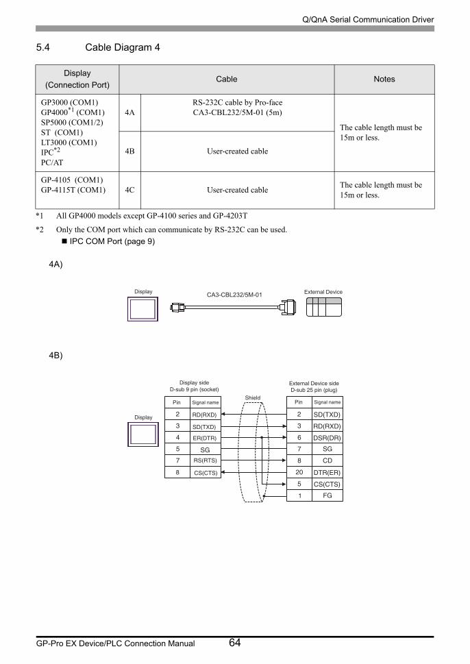
5.4 Cable Diagram 4
4A)
4B)
Display
(Connection Port)Cable Notes
GP3000 (COM1)GP4000*1 (COM1)SP5000 (COM1/2)ST (COM1)LT3000 (COM1)IPC*2
PC/AT
*1 All GP4000 models except GP-4100 series and GP-4203T
*2 Only the COM port which can communicate by RS-232C can be used.
IPC COM Port (page 9)
4ARS-232C cable by Pro-faceCA3-CBL232/5M-01 (5m)
The cable length must be 15m or less.
4B User-created cable
GP-4105 (COM1)GP-4115T (COM1) 4C User-created cable
The cable length must be 15m or less.
CA3-CBL232/5M-01Display External Device
2
3
4
5
7
2
3
6
7
8
SD(TXD)
RD(RXD)
DSR(DR)SG
CD
20 DTR(ER)
5 CS(CTS)
FG
Display
Pin Signal nameShield
External Device sideD-sub 25 pin (plug)D-sub 9 pin (socket)
Pin Signal name
1
8
Display side
SD(TXD)
ER(DTR)
SG
RD(RXD)
CS(CTS)
RS(RTS)
Q/QnA Serial Communication Driver
GP-Pro EX Device/PLC Connection Manual 65
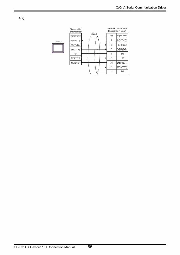
4C)
2
3
6
7
8
SD(TXD)
RD(RXD)
DSR(DR)SG
CD
20 DTR(ER)
5 CS(CTS)
FG
Display
Signal nameShield
External Device sideD-sub 25 pin (plug)
Pin Signal name
1
SD(TXD)
ER(DTR)
SG
RD(RXD)
CS(CTS)
RS(RTS)
Terminal blockDisplay side
Q/QnA Serial Communication Driver
GP-Pro EX Device/PLC Connection Manual 66
5.5 Cable Diagram 5
Display
(Connection Port)Cable Notes
GP3000*1 (COM1)AGP-3302B (COM2)GP-4*01TM (COM1)GP-Rear Module (COM1)ST*2 (COM2)LT3000 (COM1)IPC*3
*1 All GP3000 models except AGP-3302B
*2 All ST models except AST-3211A and AST-3302B
*3 Only the COM port which can communicate by RS-422/485 (4 wire) can be used. (Except PE-4000B, PS5000)
IPC COM Port (page 9)
5A
COM Port Conversion Adapter by Pro-faceCA3-ADPCOM-01
+Terminal Block Conversion Adapter by Pro-face
CA3-ADPTRM-01+
User-created cable
The cable length must be 500m or less.
5B User-created cable
GP3000*4 (COM2)
*4 All GP3000 models except GP-3200 series and AGP-3302B
5C
Online Adapter by Pro-faceCA4-ADPONL-01
+Terminal Block Conversion Adapter by Pro-face
CA3-ADPTRM-01+
User-created cable
The cable length must be 500m or less.
5D
Online Adapter by Pro-faceCA4-ADPONL-01
+User-created cable
GP-4106 (COM1)GP-4116T (COM1) 5E User-created cable
The cable length must be 500m or less.
GP4000*5 (COM2)GP-4201T (COM1)SP5000 (COM1/2)
*5 All GP4000 models except GP-4100 series, GP-4*01TM, GP-Rear Module, GP-4201T and GP-4*03T
5F
RS-422 terminal block conversion adapter by Pro-facePFXZCBADTM1*6
+User-created cable
*6 When using a Terminal Block Conversion Adapter (CA3-ADPTRM-01) instead of the RS-422 Terminal Block Conversion Adapter, refer to Cable Diagram 5A.
The cable length must be 500m or less.
5B User-created cable
PE-4000B*7
PS5000*7
*7 Only the COM port which can communicate by RS-422/485 (4 wire) can be used.
IPC COM Port (page 9)
5G User-created cableThe cable length must be 500m or less.
Q/QnA Serial Communication Driver
GP-Pro EX Device/PLC Connection Manual 67
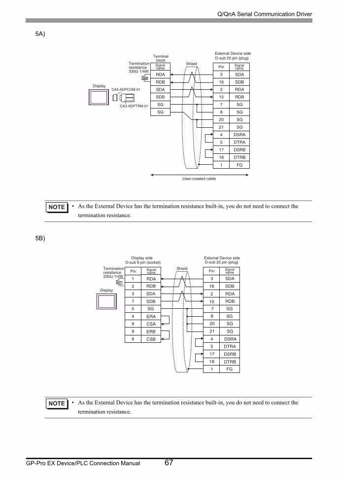
5A)
5B)
• As the External Device has the termination resistance built-in, you do not need to connect the
termination resistance.
• As the External Device has the termination resistance built-in, you do not need to connect the
termination resistance.
QC@
QCA
RC@
RCA
RF
RF
0
2
05
1
04
EF
RC@
RCA
QC@
QCA
6 RF
7 RF
1/ RF
10 RF
3 CRQ@
4 CSQ@
06 CRQA
07 CSQA
B@2,@COBNL,/0
B@2,@COSQL,/0
Chrok`x
Rhfm`km`ld
Rghdkc
Dwsdqm`k�Cduhbd�rhcdC,rta�14�ohm�'oktf(
Ohm Rhfm`km`ld
Sdqlhm`kaknbj
Sdqlhm`shnmqdrhrs`mbd22/Ω�0.3V
Trdq,bqd`sdc�b`akd
0
1
2
6
4
3
7
8
5
Chrok`x
C,rta�8�ohm�'rnbjds(
Ohm Rhfm`km`ld
Rghdkc
Dwsdqm`k�Cduhbd�rhcdC,rta�14�ohm�'oktf(
Ohm Rhfm`km`ld
Sdqlhm`shnmqdrhrs`mbd22/Ω�0.3V QC@
QCA
RC@
RCARF
DQ@
BR@
DQA
BRA
2
05
1
0467
1/
10
34
06
07
0
RC@
RCA
QC@
QCA
RF
RF
RF
RF
CRQ@
CSQ@
CRQA
CSQAEF
Chrok`x�rhcd
Q/QnA Serial Communication Driver
GP-Pro EX Device/PLC Connection Manual 68
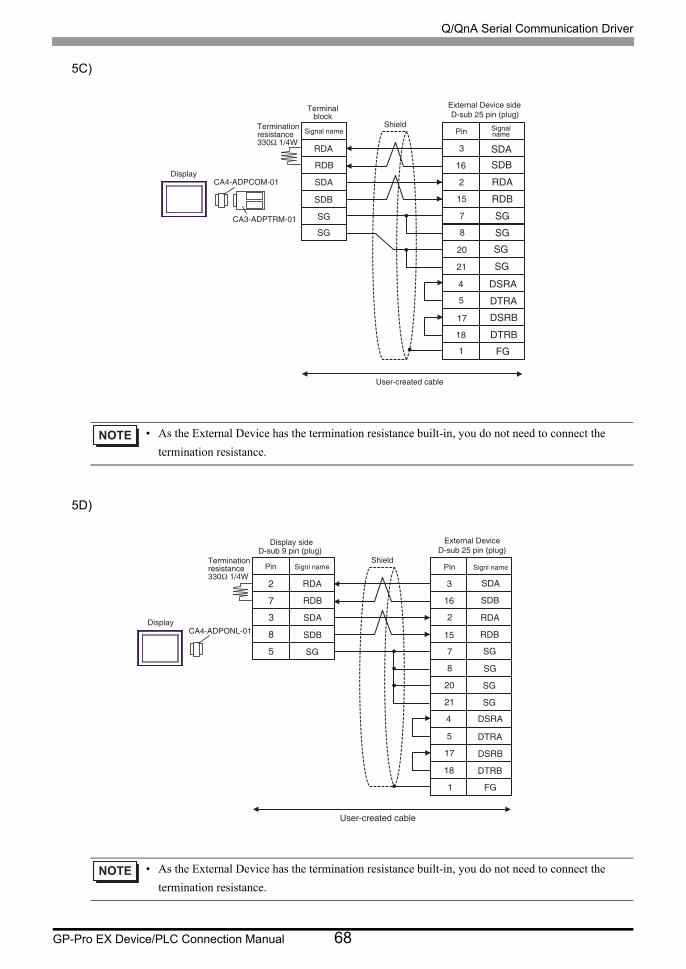
5C)
5D)
• As the External Device has the termination resistance built-in, you do not need to connect the
termination resistance.
• As the External Device has the termination resistance built-in, you do not need to connect the
termination resistance.
B@3,@COBNL,/0
B@2,@COSQL,/0
Chrok`x
Rhfm`k�m`ldRghdkc
Dwsdqm`k�Cduhbd�rhcdC,rta�14�ohm�'oktf(
Ohm Rhfm`km`ld
Sdqlhm`shnmqdrhrs`mbd22/Ω�0.3V
Sdqlhm`kaknbj
QC@
QCA
RC@
RCA
RF
RF
2
05
1
04
6
7
1/
3
4
06
07
0
10
RC@RCA
QC@
QCA
RF
RFRF
RF
CRQ@
CSQ@
CRQA
CSQA
EF
Trdq,bqd`sdc�b`akd
2
7
3
8
5
CA4-ADPONL-01Display
Pin Signl nameShield
External DeviceD-sub 25 pin (plug)D-sub 9 pin (plug)
Pin Signl nameTerminationresistance330Ω 1/4W
RDA
RDB
SDA
SDB
SG
3
16
2
15
7
8
20
21
4
5
17
18
1
SDA
SDB
RDA
RDB
SG
SG
SG
SG
DSRA
DTRA
DSRB
DTRB
FG
User-created cable
Display side
Q/QnA Serial Communication Driver
GP-Pro EX Device/PLC Connection Manual 69
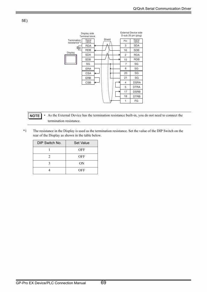
5E)
*1 The resistance in the Display is used as the termination resistance. Set the value of the DIP Switch on the rear of the Display as shown in the table below.
• As the External Device has the termination resistance built-in, you do not need to connect the
termination resistance.
DIP Switch No. Set Value
1 OFF
2 OFF
3 ON
4 OFF
Display
Signalname
Shield
External Device sideD-sub 25 pin (plug)
Pin SignalnameTermination
resistance*1RDARDB
SDA
SDBSG
ERA
CSA
ERB
CSB
3
16
2
1578
20
21
45
17
18
1
SDA
SDB
RDA
RDB
SG
SG
SG
SG
DSRA
DTRA
DSRB
DTRBFG
Terminal blockDisplay side
Q/QnA Serial Communication Driver
GP-Pro EX Device/PLC Connection Manual 70
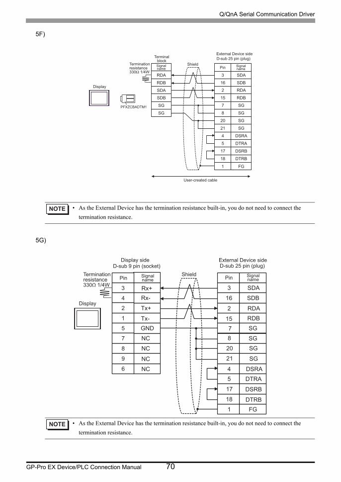
5F)
5G)
• As the External Device has the termination resistance built-in, you do not need to connect the
termination resistance.
• As the External Device has the termination resistance built-in, you do not need to connect the
termination resistance.
RDA
RDB
SDA
SDB
SG
SG
1
3
16
2
15
FG
SDA
SDB
RDA
RDB
7 SG
8 SG
20 SG
21 SG
4 DSRA
5 DTRA
17 DSRB
18 DTRB
PFXZCBADTM1
Display
Signalname
Shield
External Device sideD-sub 25 pin (plug)
Pin Signalname
Terminalblock
Terminationresistance330Ω 1/4W
User-created cable
3
4
2
1
5
7
8
9
6
Display
D-sub 9 pin (socket)
Pin Signalname
Shield
External Device sideD-sub 25 pin (plug)
Pin Signalname
Terminationresistance330Ω 1/4W Rx+
Rx-
Tx+
Tx-GND
NC
NC
NC
NC
3
16
2
1578
20
21
45
17
18
1
SDA
SDB
RDA
RDB
SG
SG
SG
SG
DSRA
DTRA
DSRB
DTRBFG
Display side

Q/QnA Serial Communication Driver
GP-Pro EX Device/PLC Connection Manual 71
5.6 Cable Diagram 6
Display
(Connection Port)Cable Notes
GP3000*1 (COM1)AGP-3302B (COM2)GP-4*01TM (COM1)GP-Rear Module (COM1)ST*2 (COM2)LT3000 (COM1)IPC*3
6A
COM port conversion adapter by Pro-face
CA3-ADPCOM-01+
Connector terminal block conversion adapter by Pro-face
CA3-ADPTRM-01+
User-created cableThe cable length must be 1200m or less.
6B
COM port conversion adapter by Pro-face
CA3-ADPCOM-01+
Multilink cable by Pro-face CA3-CBLMLT-01
+User-created cable
6C User-created cable
GP3000*4 (COM2)
6D
Online adapter by Pro-faceCA4-ADPONL-01
+Connector terminal block conversion adapter
by Pro-faceCA3-ADPTRM-01
+User-created cable
The cable length must be 1200m or less.
6E
Online adapter by Pro-faceCA4-ADPONL-01
+Multilink cable by Pro-face
CA3-CBLMLT-01+
User-created cable
6F
Online adapter by Pro-faceCA4-ADPONL-01
+User-created cable
GP-4106 (COM1)GP-4116T (COM1) 6G User-created cable
The cable length must be 1200m or less.
Q/QnA Serial Communication Driver
GP-Pro EX Device/PLC Connection Manual 72
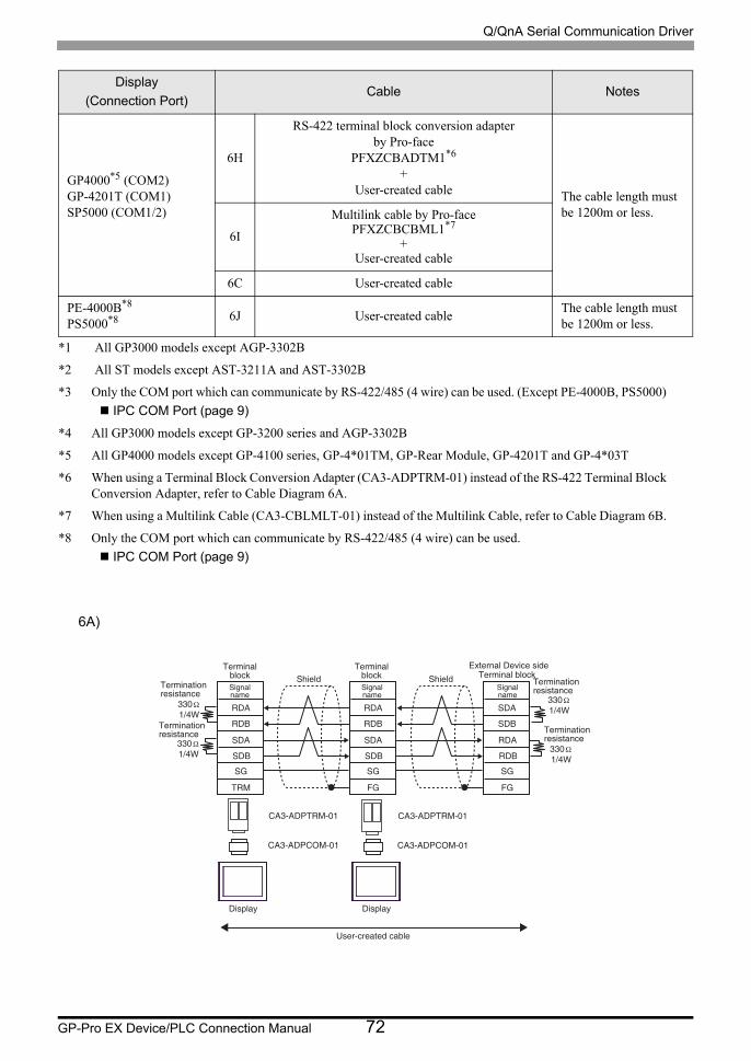
6A)
GP4000*5 (COM2)GP-4201T (COM1)SP5000 (COM1/2)
6H
RS-422 terminal block conversion adapter by Pro-face
PFXZCBADTM1*6
+User-created cable The cable length must
be 1200m or less.
6I
Multilink cable by Pro-facePFXZCBCBML1*7
+User-created cable
6C User-created cable
PE-4000B*8
PS5000*8 6J User-created cableThe cable length must be 1200m or less.
*1 All GP3000 models except AGP-3302B
*2 All ST models except AST-3211A and AST-3302B
*3 Only the COM port which can communicate by RS-422/485 (4 wire) can be used. (Except PE-4000B, PS5000)
IPC COM Port (page 9)
*4 All GP3000 models except GP-3200 series and AGP-3302B
*5 All GP4000 models except GP-4100 series, GP-4*01TM, GP-Rear Module, GP-4201T and GP-4*03T
*6 When using a Terminal Block Conversion Adapter (CA3-ADPTRM-01) instead of the RS-422 Terminal Block Conversion Adapter, refer to Cable Diagram 6A.
*7 When using a Multilink Cable (CA3-CBLMLT-01) instead of the Multilink Cable, refer to Cable Diagram 6B.
*8 Only the COM port which can communicate by RS-422/485 (4 wire) can be used.
IPC COM Port (page 9)
Display
(Connection Port)Cable Notes
Terminationresistance
330Ω1/4W
CA3-ADPTRM-01
CA3-ADPCOM-01
CA3-ADPTRM-01
CA3-ADPCOM-01
RDA
RDB
SDA
SDB
SG
TRM
RDA
RDB
SDA
SDB
SG
FG
SDA
SDB
RDA
RDB
SG
FG
330Ω1/4W
330Ω1/4W
330Ω1/4W
Terminationresistance
Signalname
Signalname
Signalname
Terminalblock
Terminalblock
External Device sideTerminal blockShield Shield Termination
resistance
Terminationresistance
Display Display
User-created cable
Q/QnA Serial Communication Driver
GP-Pro EX Device/PLC Connection Manual 73
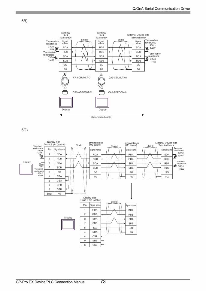
6B)
6C)
22/Ω0.3V
B@2,@COBNL,/0 B@2,@COBNL,/0
QC@
QCA
RC@
RCA
RF
EF
QC@
QCA
RC@
RCA
RF
EF
RC@
RCA
QC@
QCA
RF
EF
22/Ω0.3V
22/Ω0.3V
22/Ω0.3V
B@2,BAKLKS,/0 B@2,BAKLKS,/0
Sdqlhm`shnmqdrhrs`mbd
Sdqlhm`kaknbj
'L2�rbqdv(Dwsdqm`k�Cduhbd�rhcd
Rghdkc
Chrok`x
Trdq,bqd`sdc�b`akd
Chrok`x
Sdqlhm`kaknbj
'L2�rbqdv(Rhfm`km`ld
Rhfm`km`ld
Rhfm`km`ld
Sdqlhm`k�aknbj
Sdqlhm`shnmqdrhrs`mbd
Sdqlhm`shnmqdrhrs`mbd
Sdqlhm`shnmqdrhrs`mbd
Rghdkc
QC@
QCA
BR@
RC@
RCA
RF
DQ@
4
1
0
7
6
2
3
8
5
DQA
BRA
EF
22/Ω0.3V
QC@
QCA
RC@
RCA
EF
RF
QC@
QCA
RC@
RCA
EF
RF
QC@
QCA
BR@
RC@
RCA
RF
DQ@
4
1
0
7
6
2
3
8
5
DQA
BRA
QC@
QCA
RC@
RCA
EF
RF
22/Ω0.3V
22/Ω0.3V
22/Ω0.3V
RC@
RCA
QC@
QCA
EF
RF
C,rta�8�ohm�'rnbjds(
Ohm Rhfm`k�m`ld
Rgdkk
Sdqlhm`kqdrhrs`mbd
Sdqlhm`kqdrhrs`mbd
Chrok`x
RghdkcSdqlhm`k�aknbj
'L2�rbqdv(Sdqlhm`k�aknbj
'L2�rbqdv(RghdkcRhfm`k�m`ld Rhfm`k�m`ld
RghdkcDwsdqm`k�Cduhbd�rhcd
Sdqlhm`k�aknbj
Rhfm`k�m`ldSdqlhm`kqdrhrs`mbd
Sdqlhm`kqdrhrs`mbd
C,rta�8�ohm�'rnbjds(
Ohm Rhfm`k�m`ld
Chrok`x
RghdkcRhfm`k�m`ld
Chrok`x�rhcd
Chrok`x�rhcd
Q/QnA Serial Communication Driver
GP-Pro EX Device/PLC Connection Manual 74
6D)
6E)
330 Ω1/4W
CA3-ADPTRM-01
CA4-ADPONL-01
CA3-ADPTRM-01
CA4-ADPONL-01
RDA
RDB
SDA
SDB
SG
TRM
RDA
RDB
SDA
SDB
SG
FG
SDA
SDB
RDA
RDB
SG
FG
330 Ω1/4W
330 Ω1/4W
330 Ω1/4W
Terminationresistance
Terminationresistance
Signalname
Terminalblock
External Device sideTerminal block
Shield
Display
User-created cable
TerminalblockShield
Display
Signalname
Signalname
Terminationresistance
Terminationresistance
22/Ω0.3V
B@3,@CONMK,/0 B@3,@CONMK,/0
QC@
QCA
RC@
RCA
RF
EF
QC@
QCA
RC@
RCA
RF
EF
RC@
RCA
QC@
QCA
RF
EF
22/Ω0.3V
22/Ω0.3V
22/Ω0.3V
B@2,BAKLKS,/0 B@2,BAKLKS,/0
Sdqlhm`shnmqdrhrs`mbd
Sdqlhm`shnmqdrhrs`mbd
Rhfm`km`ld
Sdqlhm`kaknbj
'L2�rbqdv(Dwsdqm`k�Cduhbd�rhcd
Sdqlhm`k�aknbjRghdkc
Chrok`x
Trdq,bqd`sdc�b`akd
Sdqlhm`kaknbj
'L2�rbqdv( Rghdkc Sdqlhm`shnmqdrhrs`mbd
Sdqlhm`shnmqdrhrs`mbd
Chrok`x
Rhfm`km`ld
Rhfm`km`ld

Q/QnA Serial Communication Driver
GP-Pro EX Device/PLC Connection Manual 75
6F)
QC@
QCA
RC@
RCA
RF4
6
1
7
2
EF
22/Ω0.3V
QC@
QCA
RC@
RCA
EF
RF
QC@
QCA
RC@
RCA
EF
RF
QC@
QCA
RC@
RCA
RF4
6
1
7
2
QC@
QCA
RC@
RCA
EF
RF
22/Ω0.3V
22/Ω0.3V
22/Ω0.3V
RC@
RCA
QC@
QCA
EF
RFB@3,@CONMK,/0
B@3,@CONMK,/0
C,rta�8�ohm�'oktf(
Ohm Rhfm`k�m`ld
Rgdkk
Sdqlhm`kqdrhrs`mbd
Sdqlhm`kqdrhrs`mbd
Chrok`x
RghdkcSdqlhm`k�aknbj
'L2�rbqdv(Sdqlhm`k�aknbj
'L2�rbqdv(RghdkcRhfm`k�m`ld Rhfm`k�m`ld
RghdkcDwsdqm`k�Cduhbd�rhcd
Sdqlhm`k�aknbj
Rhfm`k�m`ld
C,rta�8�ohm�'oktf(
Ohm Rhfm`k�m`ldChrok`x
RghdkcRhfm`k�m`ld
Sdqlhm`kqdrhrs`mbd
Sdqlhm`kqdrhrs`mbd
Q/QnA Serial Communication Driver
GP-Pro EX Device/PLC Connection Manual 76
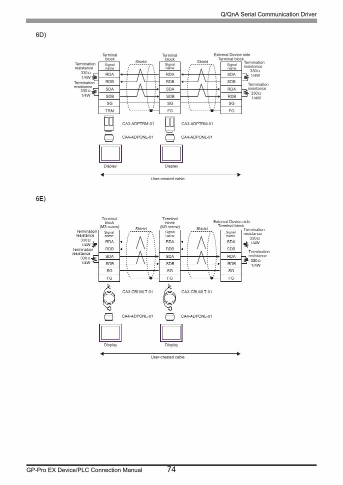
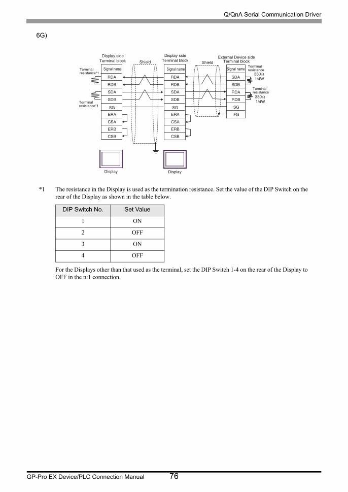
6G)
*1 The resistance in the Display is used as the termination resistance. Set the value of the DIP Switch on the rear of the Display as shown in the table below.
For the Displays other than that used as the terminal, set the DIP Switch 1-4 on the rear of the Display to OFF in the n:1 connection.
DIP Switch No. Set Value
1 ON
2 OFF
3 ON
4 OFF
RDA
RDB
CSA
SDA
SDB
SG
ERA
ERB
CSB
RDA
RDB
CSA
SDA
SDB
SG
ERA
ERB
CSB
330Ω1/4W
330Ω1/4W
SDA
SDB
RDA
RDB
FG
SG
Signal nameTerminalresistance*1
Terminalresistance*1
Shield ShieldExternal Device side
Terminal block
Signal nameTerminalresistance
Terminalresistance
Signal name
Display
Terminal blockDisplay side
Terminal blockDisplay side
Display

Q/QnA Serial Communication Driver
GP-Pro EX Device/PLC Connection Manual 77
6H)
6I)
Terminationresistance
330 Ω1/4W
PFXZCBADTM1 PFXZCBADTM1
RDA
RDB
SDA
SDB
SG
TRM
RDA
RDB
SDA
SDB
SG
FG
SDA
SDB
RDA
RDB
SG
FG
330 Ω1/4W
330 Ω1/4W
330 Ω1/4W
Terminationresistance
Signalname
Signalname
Signalname
Terminalblock
Terminalblock
External Device sideTerminal blockShield Shield Termination
resistance
Terminationresistance
Display Display
User-created cable
330 Ω1/4W
RDA
RDB
SDA
SDB
SG
FG
RDA
RDB
SDA
SDB
SG
FG
SDA
SDB
RDA
RDB
SG
FG
330 Ω1/4W
330 Ω1/4W
330 Ω1/4W
PFXZCBCBML1 PFXZCBCBML1
Terminationresistance
Terminalblock
(M3 screw)External Device side
Shield
Display
User-created cable
Display
Terminalblock
(M3 screw)Signalname
Signalname
Signalname
Terminal block
Terminationresistance
Terminationresistance
Terminationresistance
Shield
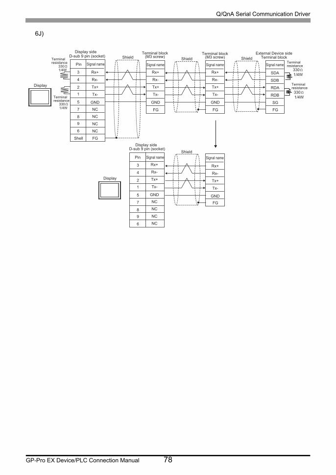
Q/QnA Serial Communication Driver
GP-Pro EX Device/PLC Connection Manual 78
6J)
Rx+
Rx-
Tx+
Tx-
NC
NC
NC
NC
GND
Rx+
Rx-
Tx+
Tx-
NC
NC
NC
NC
GND
Rx+
Rx-
Tx+
Tx-
GND
Rx+
Rx-
Tx+
Tx-
GND
Rx+
Rx-
Tx+
Tx-
GND
5
4
3
8
1
2
7
9
6
FG
330 Ω1/4W
FG FG
5
4
3
8
1
2
7
9
6
FG
330 Ω1/4W
330 Ω1/4W
330 Ω1/4W
SDA
SDB
RDA
RDB
FG
SG
D-sub 9 pin (socket)
Pin Signal name
Shell
Terminalresistance
Terminalresistance
Display
ShieldTerminal block
(M3 screw)Terminal block
(M3 screw)ShieldSignal name Signal name
ShieldExternal Device side
Terminal block
Signal nameTerminalresistance
Terminalresistance
D-sub 9 pin (socket)
Pin Signal name
Display
ShieldSignal name
Display side
Display side
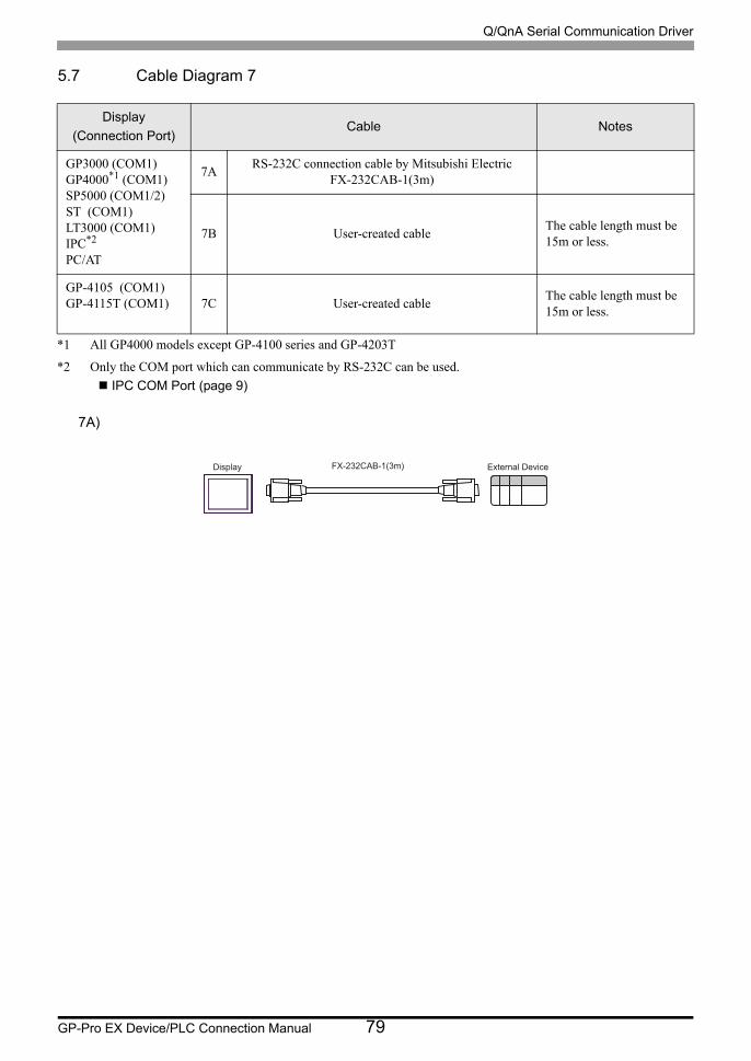
Q/QnA Serial Communication Driver
GP-Pro EX Device/PLC Connection Manual 79
5.7 Cable Diagram 7
7A)
Display
(Connection Port)Cable Notes
GP3000 (COM1)GP4000*1 (COM1)SP5000 (COM1/2)ST (COM1)LT3000 (COM1)IPC*2
PC/AT
*1 All GP4000 models except GP-4100 series and GP-4203T
*2 Only the COM port which can communicate by RS-232C can be used.
IPC COM Port (page 9)
7ARS-232C connection cable by Mitsubishi Electric
FX-232CAB-1(3m)
7B User-created cableThe cable length must be 15m or less.
GP-4105 (COM1)GP-4115T (COM1) 7C User-created cable
The cable length must be 15m or less.
FX-232CAB-1(3m)Display External Device
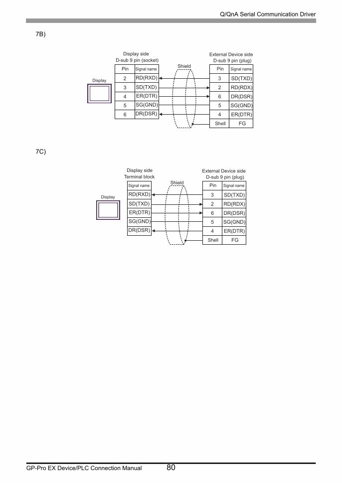
Q/QnA Serial Communication Driver
GP-Pro EX Device/PLC Connection Manual 80
7B)
7C)
3
2
6
5
4
SD(TXD)
RD(RDX)
DR(DSR)
SG(GND)
ER(DTR)
FG
2
3
4
5
6
SD(TXD)
ER(DTR)
SG(GND)
RD(RXD)
DR(DSR)
Shield
External Device sideD-sub 9 pin (plug)D-sub 9 pin (socket)
Display side
Display
Pin Signal name Pin Signal name
Shell
3
2
6
5
4
SD(TXD)
RD(RDX)
DR(DSR)
SG(GND)
ER(DTR)
FG
SD(TXD)
ER(DTR)
SG(GND)
RD(RXD)
DR(DSR)
Shield
External Device sideD-sub 9 pin (plug)Terminal block
Display side
Display
Signal name Pin Signal name
Shell
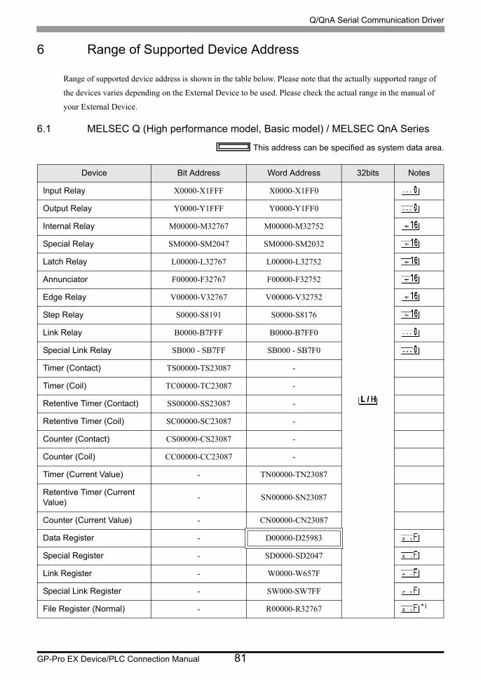
Q/QnA Serial Communication Driver
GP-Pro EX Device/PLC Connection Manual 81
6 Range of Supported Device Address
Range of supported device address is shown in the table below. Please note that the actually supported range of
the devices varies depending on the External Device to be used. Please check the actual range in the manual of
your External Device.
6.1 MELSEC Q (High performance model, Basic model) / MELSEC QnA Series
This address can be specified as system data area.
Device Bit Address Word Address 32bits Notes
Input Relay X0000-X1FFF X0000-X1FF0
Output Relay Y0000-Y1FFF Y0000-Y1FF0
Internal Relay M00000-M32767 M00000-M32752
Special Relay SM0000-SM2047 SM0000-SM2032
Latch Relay L00000-L32767 L00000-L32752
Annunciator F00000-F32767 F00000-F32752
Edge Relay V00000-V32767 V00000-V32752
Step Relay S0000-S8191 S0000-S8176
Link Relay B0000-B7FFF B0000-B7FF0
Special Link Relay SB000 - SB7FF SB000 - SB7F0
Timer (Contact) TS00000-TS23087 -
Timer (Coil) TC00000-TC23087 -
Retentive Timer (Contact) SS00000-SS23087 -
Retentive Timer (Coil) SC00000-SC23087 -
Counter (Contact) CS00000-CS23087 -
Counter (Coil) CC00000-CC23087 -
Timer (Current Value) - TN00000-TN23087
Retentive Timer (Current Value)
- SN00000-SN23087
Counter (Current Value) - CN00000-CN23087
Data Register - D00000-D25983
Special Register - SD0000-SD2047
Link Register - W0000-W657F
Special Link Register - SW000-SW7FF
File Register (Normal) - R00000-R32767 *1
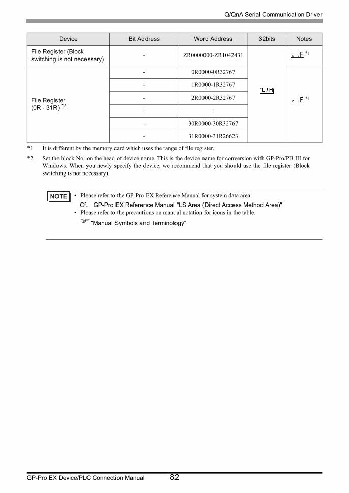
Q/QnA Serial Communication Driver
GP-Pro EX Device/PLC Connection Manual 82
File Register (Block switching is not necessary)
- ZR0000000-ZR1042431 *1
File Register(0R - 31R) *2
- 0R0000-0R32767
*1
- 1R0000-1R32767
- 2R0000-2R32767
: :
- 30R0000-30R32767
- 31R0000-31R26623
*1 It is different by the memory card which uses the range of file register.
*2 Set the block No. on the head of device name. This is the device name for conversion with GP-Pro/PB III for Windows. When you newly specify the device, we recommend that you should use the file register (Block switching is not necessary).
• Please refer to the GP-Pro EX Reference Manual for system data area.
Cf. GP-Pro EX Reference Manual "LS Area (Direct Access Method Area)"• Please refer to the precautions on manual notation for icons in the table.
"Manual Symbols and Terminology"
Device Bit Address Word Address 32bits Notes
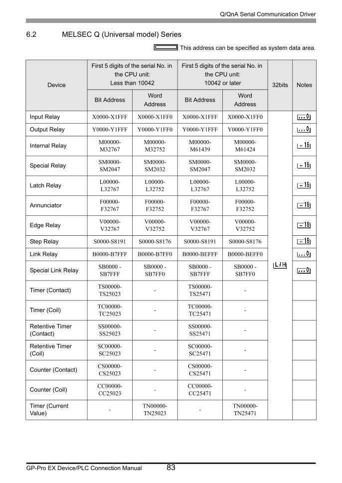
Q/QnA Serial Communication Driver
GP-Pro EX Device/PLC Connection Manual 83
6.2 MELSEC Q (Universal model) Series
This address can be specified as system data area.
Device
First 5 digits of the serial No. in
the CPU unit:
Less than 10042
First 5 digits of the serial No. in
the CPU unit:
10042 or later 32bits Notes
Bit AddressWord
AddressBit Address
Word
Address
Input Relay X0000-X1FFF X0000-X1FF0 X0000-X1FFF X0000-X1FF0
Output Relay Y0000-Y1FFF Y0000-Y1FF0 Y0000-Y1FFF Y0000-Y1FF0
Internal RelayM00000-M32767
M00000-M32752
M00000-M61439
M00000-M61424
Special RelaySM0000-SM2047
SM0000-SM2032
SM0000-SM2047
SM0000-SM2032
Latch RelayL00000-L32767
L00000-L32752
L00000-L32767
L00000-L32752
AnnunciatorF00000-F32767
F00000-F32752
F00000-F32767
F00000-F32752
Edge RelayV00000-V32767
V00000-V32752
V00000-V32767
V00000-V32752
Step Relay S0000-S8191 S0000-S8176 S0000-S8191 S0000-S8176
Link Relay B0000-B7FFF B0000-B7FF0 B0000-BEFFF B0000-BEFF0
Special Link RelaySB0000 - SB7FFF
SB0000 - SB7FF0
SB0000 - SB7FFF
SB0000 - SB7FF0
Timer (Contact)TS00000-TS25023
-TS00000-TS25471
-
Timer (Coil)TC00000-TC25023
-TC00000-TC25471
-
Retentive Timer (Contact)
SS00000-SS25023
-SS00000-SS25471
-
Retentive Timer (Coil)
SC00000-SC25023
-SC00000-SC25471
-
Counter (Contact)CS00000-CS25023
-CS00000-CS25471
-
Counter (Coil)CC00000-CC25023
-CC00000-CC25471
-
Timer (Current Value)
-TN00000-TN25023
-TN00000-TN25471

Q/QnA Serial Communication Driver
GP-Pro EX Device/PLC Connection Manual 84
Retentive Timer (Current Value)
-SN00000-SN25023
-SN00000-SN25471
Counter (Current Value)
-CN00000-CN25023
-CN00000-CN25471
Data Register/External Data Register *1
-D00000-D28159
-D0000000-
D4910079 *2
Special Register -SD0000-SD2047
-SD0000-SD2047
Link Register/External Link Register *3
-W0000-W6DEF
-W000000-
W4AEBFF *2
Special Link Register
-SW0000-SW6DFF
-SW0000-SW6FFF
File Register (Normal)
-R00000-R32767
-R00000-R32767 *4
File Register (Block switching is not necessary)
-ZR0000000-ZR4184063
-ZR0000000-ZR4849663 *4
File Register(0R - 31R) *5
-0R0000-0R32767
-0R0000-0R32767
*4
-1R0000-1R32767
-1R0000-1R32767
-2R0000-2R32767
-2R0000-2R32767
: : : :
-30R0000-30R32767
-30R0000-30R32767
-31R0000-31R26623
-31R0000-31R26623
*1 External Data Register can be used in the CPU of which first 5 digits of serial No. is 09042 or later.
*2 To use addresses D0065536 or higher, or addresses W010000 or higher, the Serial Communication unit must meet the following requirements:
- The first 5 digits of the serial number are 09043 or later.
- The function version is B or later.
*3 External Link Register can be used in the CPU of which first 5 digits of serial No. is 09042 or later.
*4 It is different by the memory card which uses the range of file register.
Device
First 5 digits of the serial No. in
the CPU unit:
Less than 10042
First 5 digits of the serial No. in
the CPU unit:
10042 or later 32bits Notes
Bit AddressWord
AddressBit Address
Word
Address
Q/QnA Serial Communication Driver
GP-Pro EX Device/PLC Connection Manual 85
*5 Set the block No. on the head of device name. This is the device name for conversion with GP-Pro/PB III for Windows. When you newly specify the device, we recommend that you should use the file register (Block switching is not necessary).
• Please refer to the GP-Pro EX Reference Manual for system data area.
Cf. GP-Pro EX Reference Manual "LS Area (Direct Access Method Area)"• Please refer to the precautions on manual notation for icons in the table.
"Manual Symbols and Terminology"

Q/QnA Serial Communication Driver
GP-Pro EX Device/PLC Connection Manual 86
6.3 MELSEC L Series
This address can be specified as system data area.
Device Bit Address Word Address 32bits Notes
Input Relay X0000-X1FFF X0000-X1FF0
Output Relay Y0000-Y1FFF Y0000-Y1FF0
Internal Relay M00000-M61439 M00000-M61424
Special Relay SM0000-SM2047 SM0000-SM2032
Latch Relay L00000-L32767 L00000-L32752
Annunciator F00000-F32767 F00000-F32752
Edge Relay V00000-V32767 V00000-V32752
Step Relay S0000-S8191 S0000-S8176
Link Relay B0000-BEFFF B0000-BEFF0
Special Link Relay SB0000 - SB7FFF SB0000 - SB7FF0
Timer (Contact) TS00000-TS25471 -
Timer (Coil) TC00000-TC25471 -
Retentive Timer (Contact) SS00000-SS25471 -
Retentive Timer (Coil) SC00000-SC25471 -
Counter (Contact) CS00000-CS25471 -
Counter (Coil) CC00000-CC25471 -
Timer (Current Value) - TN00000-TN25471
Retentive Timer (Current Value)
- SN00000-SN25471
Counter (Current Value) - CN00000-CN25471
Data Register - D000000-D421887
Special Register - SD0000-SD2047
Link Register - W00000-W66FFF
Special Link Register - SW0000-SW6FFF
File Register (Normal) - R00000-R32767 *1
File Register (Block switching is not necessary)
- ZR000000-ZR393215 *1
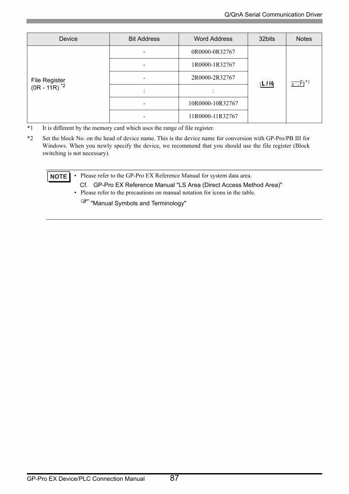
Q/QnA Serial Communication Driver
GP-Pro EX Device/PLC Connection Manual 87
File Register(0R - 11R) *2
- 0R0000-0R32767
*1
- 1R0000-1R32767
- 2R0000-2R32767
: :
- 10R0000-10R32767
- 11R0000-11R32767
*1 It is different by the memory card which uses the range of file register.
*2 Set the block No. on the head of device name. This is the device name for conversion with GP-Pro/PB III for Windows. When you newly specify the device, we recommend that you should use the file register (Block switching is not necessary).
• Please refer to the GP-Pro EX Reference Manual for system data area.
Cf. GP-Pro EX Reference Manual "LS Area (Direct Access Method Area)"• Please refer to the precautions on manual notation for icons in the table.
"Manual Symbols and Terminology"
Device Bit Address Word Address 32bits Notes
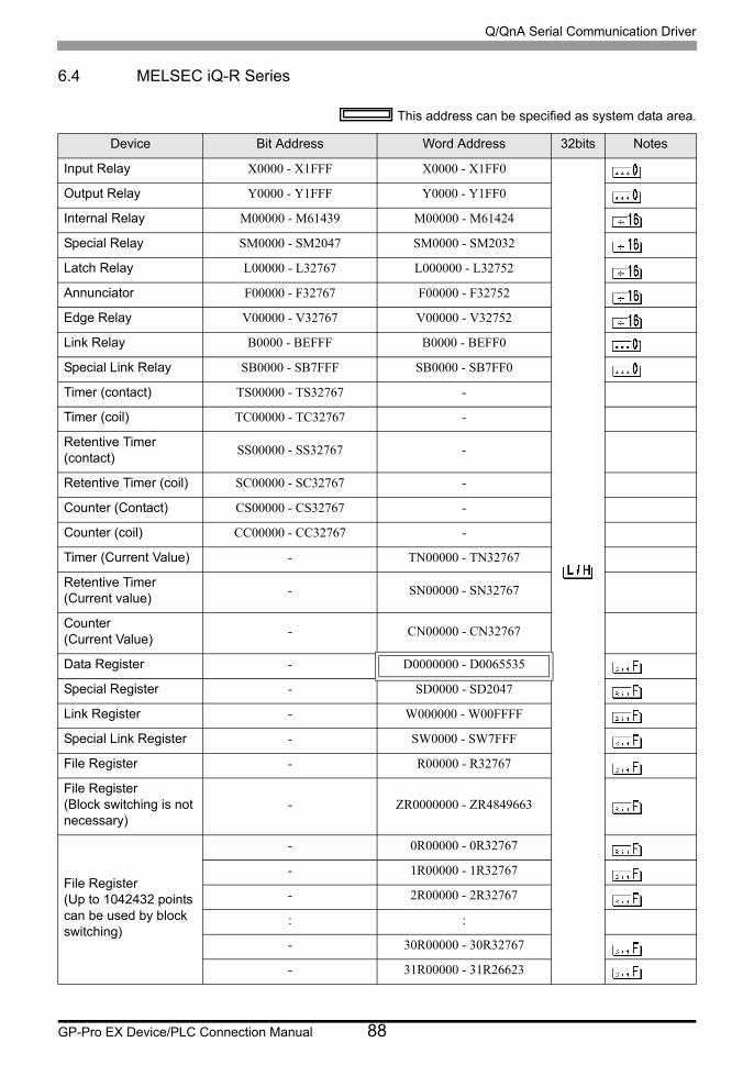
Q/QnA Serial Communication Driver
GP-Pro EX Device/PLC Connection Manual 88
6.4 MELSEC iQ-R Series
This address can be specified as system data area.
Device Bit Address Word Address 32bits Notes
Input Relay X0000 - X1FFF X0000 - X1FF0
Output Relay Y0000 - Y1FFF Y0000 - Y1FF0
Internal Relay M00000 - M61439 M00000 - M61424
Special Relay SM0000 - SM2047 SM0000 - SM2032
Latch Relay L00000 - L32767 L000000 - L32752
Annunciator F00000 - F32767 F00000 - F32752
Edge Relay V00000 - V32767 V00000 - V32752
Link Relay B0000 - BEFFF B0000 - BEFF0
Special Link Relay SB0000 - SB7FFF SB0000 - SB7FF0
Timer (contact) TS00000 - TS32767 -
Timer (coil) TC00000 - TC32767 -
Retentive Timer (contact)
SS00000 - SS32767 -
Retentive Timer (coil) SC00000 - SC32767 -
Counter (Contact) CS00000 - CS32767 -
Counter (coil) CC00000 - CC32767 -
Timer (Current Value) - TN00000 - TN32767
Retentive Timer (Current value)
- SN00000 - SN32767
Counter (Current Value)
- CN00000 - CN32767
Data Register - D0000000 - D0065535
Special Register - SD0000 - SD2047
Link Register - W000000 - W00FFFF
Special Link Register - SW0000 - SW7FFF
File Register - R00000 - R32767
File Register (Block switching is not necessary)
- ZR0000000 - ZR4849663
File Register (Up to 1042432 points can be used by block switching)
- 0R00000 - 0R32767
- 1R00000 - 1R32767
- 2R00000 - 2R32767
: :
- 30R00000 - 30R32767
- 31R00000 - 31R26623

Q/QnA Serial Communication Driver
GP-Pro EX Device/PLC Connection Manual 89
• Please refer to the GP-Pro EX Reference Manual for system data area.
Cf. GP-Pro EX Reference Manual "LS Area (Direct Access Method Area)"• Please refer to the precautions on manual notation for icons in the table.
"Manual Symbols and Terminology"
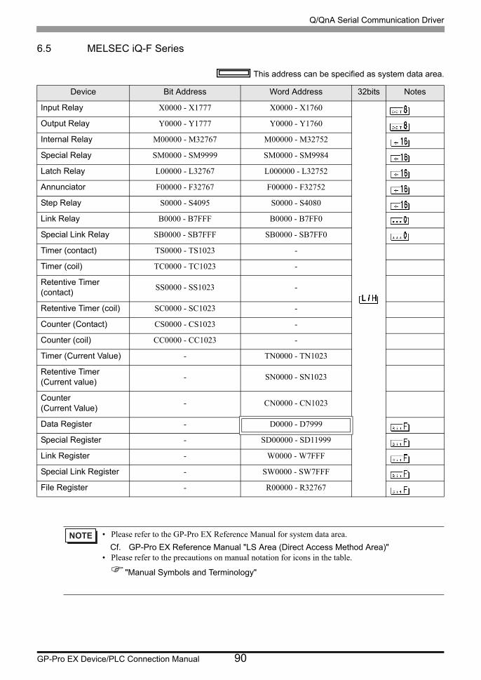
Q/QnA Serial Communication Driver
GP-Pro EX Device/PLC Connection Manual 90
6.5 MELSEC iQ-F Series
This address can be specified as system data area.
Device Bit Address Word Address 32bits Notes
Input Relay X0000 - X1777 X0000 - X1760
Output Relay Y0000 - Y1777 Y0000 - Y1760
Internal Relay M00000 - M32767 M00000 - M32752
Special Relay SM0000 - SM9999 SM0000 - SM9984
Latch Relay L00000 - L32767 L000000 - L32752
Annunciator F00000 - F32767 F00000 - F32752
Step Relay S0000 - S4095 S0000 - S4080
Link Relay B0000 - B7FFF B0000 - B7FF0
Special Link Relay SB0000 - SB7FFF SB0000 - SB7FF0
Timer (contact) TS0000 - TS1023 -
Timer (coil) TC0000 - TC1023 -
Retentive Timer (contact)
SS0000 - SS1023 -
Retentive Timer (coil) SC0000 - SC1023 -
Counter (Contact) CS0000 - CS1023 -
Counter (coil) CC0000 - CC1023 -
Timer (Current Value) - TN0000 - TN1023
Retentive Timer (Current value)
- SN0000 - SN1023
Counter (Current Value)
- CN0000 - CN1023
Data Register - D0000 - D7999
Special Register - SD00000 - SD11999
Link Register - W0000 - W7FFF
Special Link Register - SW0000 - SW7FFF
File Register - R00000 - R32767
• Please refer to the GP-Pro EX Reference Manual for system data area.
Cf. GP-Pro EX Reference Manual "LS Area (Direct Access Method Area)"• Please refer to the precautions on manual notation for icons in the table.
"Manual Symbols and Terminology"
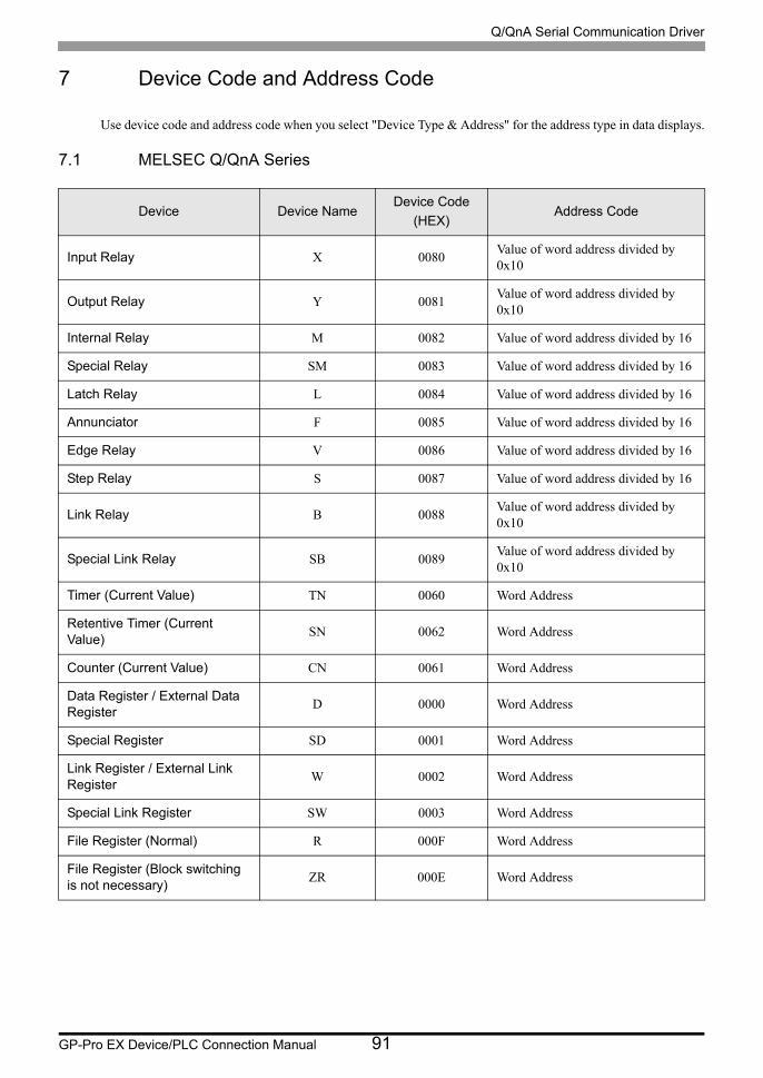
Q/QnA Serial Communication Driver
GP-Pro EX Device/PLC Connection Manual 91
7 Device Code and Address Code
Use device code and address code when you select "Device Type & Address" for the address type in data displays.
7.1 MELSEC Q/QnA Series
Device Device NameDevice Code
(HEX)Address Code
Input Relay X 0080Value of word address divided by 0x10
Output Relay Y 0081Value of word address divided by 0x10
Internal Relay M 0082 Value of word address divided by 16
Special Relay SM 0083 Value of word address divided by 16
Latch Relay L 0084 Value of word address divided by 16
Annunciator F 0085 Value of word address divided by 16
Edge Relay V 0086 Value of word address divided by 16
Step Relay S 0087 Value of word address divided by 16
Link Relay B 0088Value of word address divided by 0x10
Special Link Relay SB 0089Value of word address divided by 0x10
Timer (Current Value) TN 0060 Word Address
Retentive Timer (Current Value)
SN 0062 Word Address
Counter (Current Value) CN 0061 Word Address
Data Register / External Data Register
D 0000 Word Address
Special Register SD 0001 Word Address
Link Register / External Link Register
W 0002 Word Address
Special Link Register SW 0003 Word Address
File Register (Normal) R 000F Word Address
File Register (Block switching is not necessary)
ZR 000E Word Address
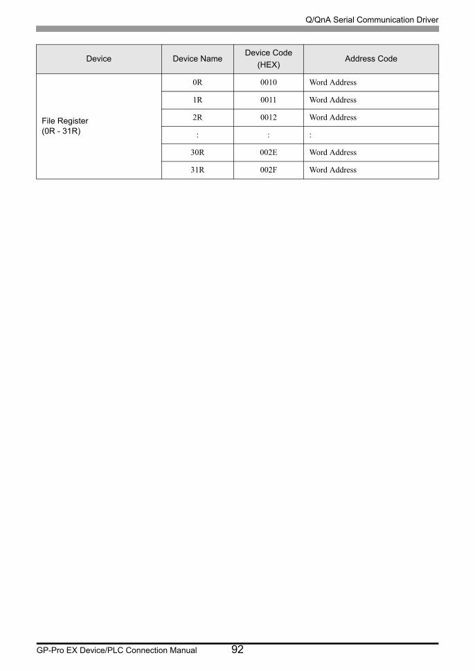
Q/QnA Serial Communication Driver
GP-Pro EX Device/PLC Connection Manual 92
File Register(0R - 31R)
0R 0010 Word Address
1R 0011 Word Address
2R 0012 Word Address
: : :
30R 002E Word Address
31R 002F Word Address
Device Device NameDevice Code
(HEX)Address Code

Q/QnA Serial Communication Driver
GP-Pro EX Device/PLC Connection Manual 93
7.2 MELSEC L Series
Device Device NameDevice Code
(HEX)Address Code
Input Relay X 0080Value of word address divided by 0x10
Output Relay Y 0081Value of word address divided by 0x10
Internal Relay M 0082 Value of word address divided by 16
Special Relay SM 0083 Value of word address divided by 16
Latch Relay L 0084 Value of word address divided by 16
Annunciator F 0085 Value of word address divided by 16
Edge Relay V 0086 Value of word address divided by 16
Step Relay S 0087 Value of word address divided by 16
Link Relay B 0088Value of word address divided by 0x10
Special Link Relay SB 0089Value of word address divided by 0x10
Timer (Current Value) TN 0060 Word Address
Retentive Timer (Current Value)
SN 0062 Word Address
Counter (Current Value) CN 0061 Word Address
Data Register D 0000 Word Address
Special Register SD 0001 Word Address
Link Register W 0002 Word Address
Special Link Register SW 0003 Word Address
File Register (Normal) R 000F Word Address
File Register (Block switching is not necessary)
ZR 000E Word Address
File Register(0R - 11R)
0R 0010 Word Address
1R 0011 Word Address
2R 0012 Word Address
: : :
10R 001A Word Address
11R 001B Word Address

Q/QnA Serial Communication Driver
GP-Pro EX Device/PLC Connection Manual 94
7.3 MELSEC iQ-R Series
Device Device NameDevice Code
(HEX)Address Code
Input Relay
X 0080
Value of word address divided by 0x10
1/X 0180
2/X 0280
3/X 0380
4/X 0480
Output Relay
Y 0081
Value of word address divided by 0x10
1/Y 0181
2/Y 0281
3/Y 0381
4/Y 0481
Internal Relay
M 0082
Value of word address divided by 16
1/M 0182
2/M 0282
3/M 0382
4/M 0482
Special Relay
SM 0083
Value of word address divided by 16
1/SM 0183
2/SM 0283
3/SM 0383
4/SM 0483
Latch Relay
L 0084
Value of word address divided by 16
1/L 0184
2/L 0284
3/L 0384
4/L 0484
Annunciator
F 0085
Value of word address divided by 16
1/F 0185
2/F 0285
3/F 0385
4/F 0485
Edge Relay
V 0086
Value of word address divided by 16
1/V 0186
2/V 0286
3/V 0386
4/V 0486
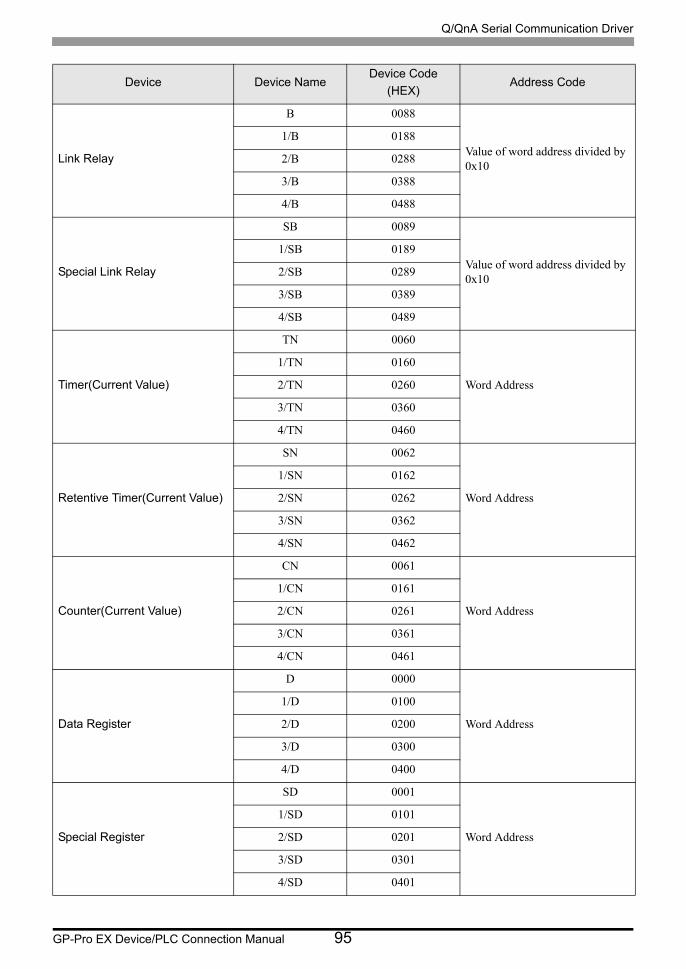
Q/QnA Serial Communication Driver
GP-Pro EX Device/PLC Connection Manual 95
Link Relay
B 0088
Value of word address divided by 0x10
1/B 0188
2/B 0288
3/B 0388
4/B 0488
Special Link Relay
SB 0089
Value of word address divided by 0x10
1/SB 0189
2/SB 0289
3/SB 0389
4/SB 0489
Timer(Current Value)
TN 0060
Word Address
1/TN 0160
2/TN 0260
3/TN 0360
4/TN 0460
Retentive Timer(Current Value)
SN 0062
Word Address
1/SN 0162
2/SN 0262
3/SN 0362
4/SN 0462
Counter(Current Value)
CN 0061
Word Address
1/CN 0161
2/CN 0261
3/CN 0361
4/CN 0461
Data Register
D 0000
Word Address
1/D 0100
2/D 0200
3/D 0300
4/D 0400
Special Register
SD 0001
Word Address
1/SD 0101
2/SD 0201
3/SD 0301
4/SD 0401
Device Device NameDevice Code
(HEX)Address Code
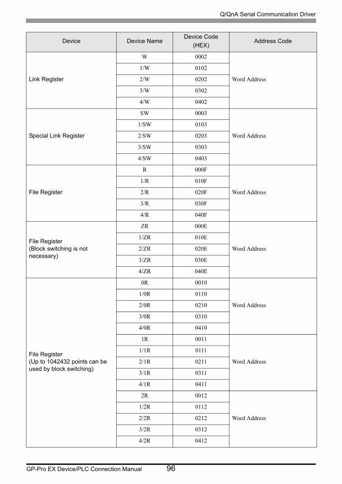
Q/QnA Serial Communication Driver
GP-Pro EX Device/PLC Connection Manual 96
Link Register
W 0002
Word Address
1/W 0102
2/W 0202
3/W 0302
4/W 0402
Special Link Register
SW 0003
Word Address
1/SW 0103
2/SW 0203
3/SW 0303
4/SW 0403
File Register
R 000F
Word Address
1/R 010F
2/R 020F
3/R 030F
4/R 040F
File Register (Block switching is not necessary)
ZR 000E
Word Address
1/ZR 010E
2/ZR 020E
3/ZR 030E
4/ZR 040E
File Register (Up to 1042432 points can be used by block switching)
0R 0010
Word Address
1/0R 0110
2/0R 0210
3/0R 0310
4/0R 0410
1R 0011
Word Address
1/1R 0111
2/1R 0211
3/1R 0311
4/1R 0411
2R 0012
Word Address
1/2R 0112
2/2R 0212
3/2R 0312
4/2R 0412
Device Device NameDevice Code
(HEX)Address Code
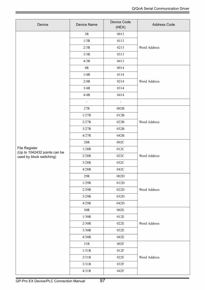
Q/QnA Serial Communication Driver
GP-Pro EX Device/PLC Connection Manual 97
File Register (Up to 1042432 points can be used by block switching)
3R 0013
Word Address
1/3R 0113
2/3R 0213
3/3R 0313
4/3R 0413
4R 0014
Word Address
1/4R 0114
2/4R 0214
3/4R 0314
4/4R 0414
: :
27R 002B
Word Address
1/27R 012B
2/27R 022B
3/27R 032B
4/27R 042B
28R 002C
Word Address
1/28R 012C
2/28R 022C
3/28R 032C
4/28R 042C
29R 002D
Word Address
1/29R 012D
2/29R 022D
3/29R 032D
4/29R 042D
30R 002E
Word Address
1/30R 012E
2/30R 022E
3/30R 032E
4/30R 042E
31R 002F
Word Address
1/31R 012F
2/31R 022F
3/31R 032F
4/31R 042F
Device Device NameDevice Code
(HEX)Address Code
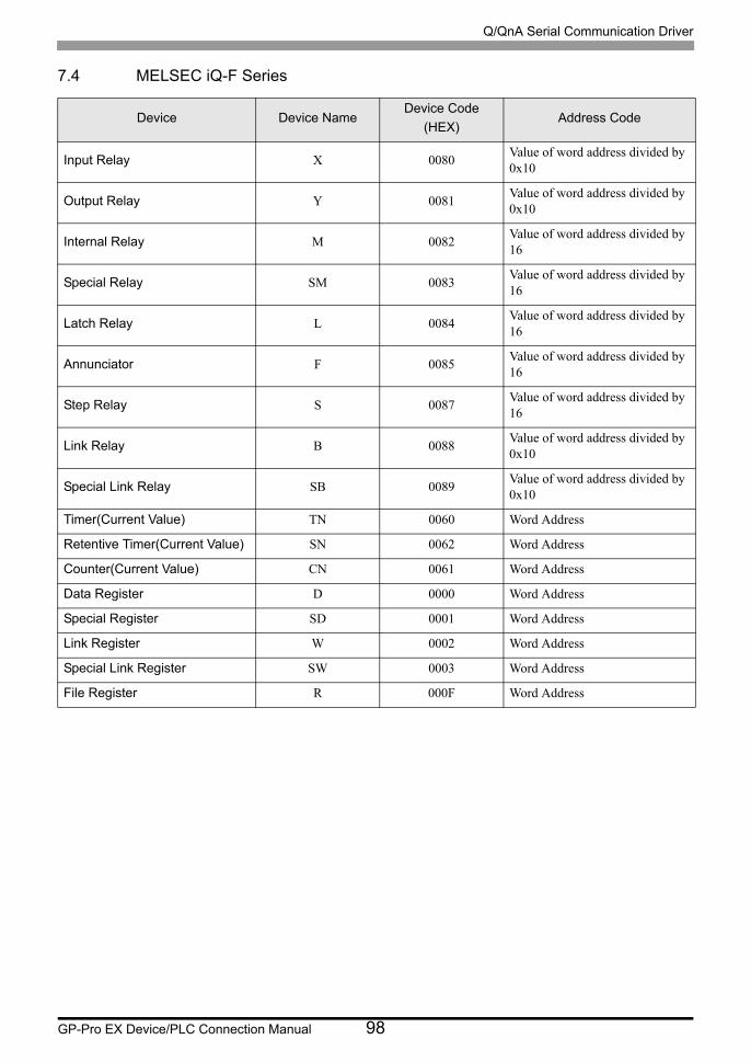
Q/QnA Serial Communication Driver
GP-Pro EX Device/PLC Connection Manual 98
7.4 MELSEC iQ-F Series
Device Device NameDevice Code
(HEX)Address Code
Input Relay X 0080Value of word address divided by 0x10
Output Relay Y 0081Value of word address divided by 0x10
Internal Relay M 0082Value of word address divided by 16
Special Relay SM 0083Value of word address divided by 16
Latch Relay L 0084Value of word address divided by 16
Annunciator F 0085Value of word address divided by 16
Step Relay S 0087Value of word address divided by 16
Link Relay B 0088Value of word address divided by 0x10
Special Link Relay SB 0089Value of word address divided by 0x10
Timer(Current Value) TN 0060 Word Address
Retentive Timer(Current Value) SN 0062 Word Address
Counter(Current Value) CN 0061 Word Address
Data Register D 0000 Word Address
Special Register SD 0001 Word Address
Link Register W 0002 Word Address
Special Link Register SW 0003 Word Address
File Register R 000F Word Address
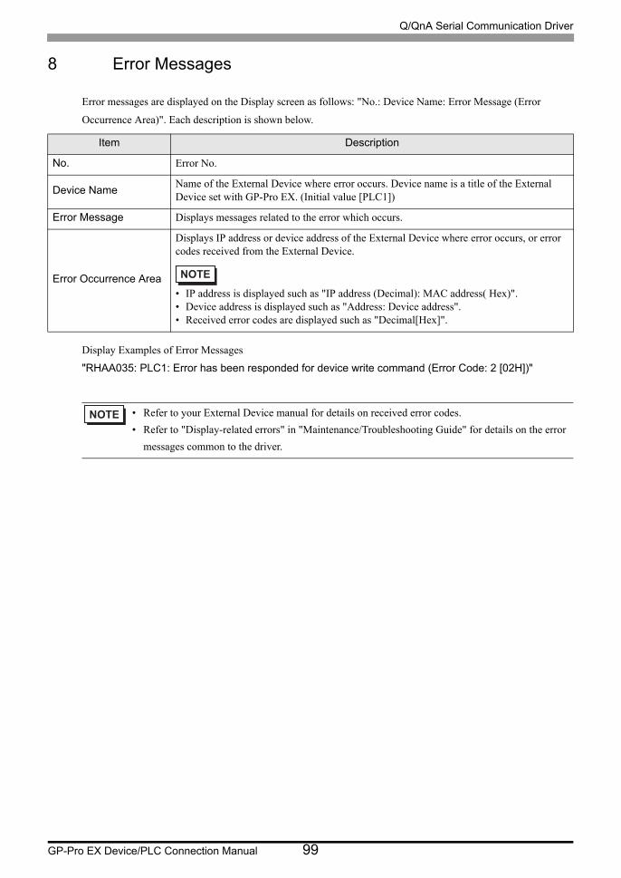
Q/QnA Serial Communication Driver
GP-Pro EX Device/PLC Connection Manual 99
8 Error Messages
Error messages are displayed on the Display screen as follows: "No.: Device Name: Error Message (Error
Occurrence Area)". Each description is shown below.
Display Examples of Error Messages
"RHAA035: PLC1: Error has been responded for device write command (Error Code: 2 [02H])"
Item Description
No. Error No.
Device NameName of the External Device where error occurs. Device name is a title of the External Device set with GP-Pro EX. (Initial value [PLC1])
Error Message Displays messages related to the error which occurs.
Error Occurrence Area
Displays IP address or device address of the External Device where error occurs, or error codes received from the External Device.
• IP address is displayed such as "IP address (Decimal): MAC address( Hex)".• Device address is displayed such as "Address: Device address".• Received error codes are displayed such as "Decimal[Hex]".
• Refer to your External Device manual for details on received error codes.
• Refer to "Display-related errors" in "Maintenance/Troubleshooting Guide" for details on the error
messages common to the driver.

Q/QnA Serial Communication Driver
GP-Pro EX Device/PLC Connection Manual 100


![North Carolina register [serial] - NC.gov](https://static.fdokumen.com/doc/165x107/6327f539e491bcb36c0b8a23/north-carolina-register-serial-ncgov.jpg)
![The Rhododendron [serial] - Internet Archive](https://static.fdokumen.com/doc/165x107/63237b81117b4414ec0c57ee/the-rhododendron-serial-internet-archive.jpg)