1/86 Approved consolidated baseline methodology ACM0008 ...
86
UNFCCC/CCNUCC CDM – Executive Board ACM0008 / Version 04 Sectoral Scope: 08 and 10 EB 35 1/86 Approved consolidated baseline methodology ACM0008 “Consolidated baseline methodology for coal bed methane, coal mine methane and ventilation air methane capture and use for power (electrical or motive) and heat and/or destruction by flaring or catalytic oxidation” I. SOURCE, DEFINITIONS AND APPLICABILITY Sources This consolidated baseline methodology is based on elements from the following methodologies: • NM0066 “Baseline methodology for grid-connected coalmine methane power generation at an active coal mine with existing methane extraction and partial utilization,” submitted by Hegang Coal Industry Group Limited • NM0075 “Baseline methodology for coal mine methane (CMM) utilization and destruction at a working coal mine,” prepared by IT Power • NM0093 “Baseline methodology for methane utilization and destruction project activities at working coal mines where both coal mine methane (drained from within the mine) and coal bed methane (drained from the surface within the coal mining concession area) is used and/or destroyed,” prepared by Westlake Associates, Ltd and Asian Development Bank • NM0094 “Baseline methodology for coal mine methane recovery and utilization at active coal mines,” prepared by Millennium Capital Services, Co. • NM0102 “Generalised baseline methodology for coal mine methane (CMM) power generation,” prepared by the Prototype Carbon Fund For more information regarding the proposals and their consideration by the Executive Board please refer to http://cdm.unfccc.int/goto/MPappmeth . This methodology also refers to the “Tool for calculation of emission factor for electricity systems”, the latest version of the “Tool for the demonstration and assessment of additionality” and the latest version of the “Tool to determine project emissions from flaring gases containing Methane 1 ”. Selected approach from paragraph 48 of the CDM modalities and procedures “Existing actual or historical emissions, as applicable” Definitions Coalbed methane (CBM) - a generic term (USA) for the methane originating in coal seams that is drained from surface boreholes before mining takes place. Coal mine methane (CMM) – methane component of gases captured in a working mine by methane drainage techniques. Goaf - collapsed area of strata produced by the removal of coal and artificial supports behind a working coalface. Strata above and below the goaf is de-stressed and fractured by the mining activity. Methane released from this disturbed zone is available for Post mining CMM Extraction through either surface goaf wells or underground boreholes or drainage galleries. 1 Please refer to http://cdm.unfccc.int/goto/MPappmeth
-
Upload
khangminh22 -
Category
Documents
-
view
1 -
download
0
Transcript of 1/86 Approved consolidated baseline methodology ACM0008 ...

UNFCCC/CCNUCC CDM – Executive Board ACM0008 / Version 04 Sectoral Scope: 08 and 10 EB 35
1/86
Approved consolidated baseline methodology ACM0008
“Consolidated baseline methodology for coal bed methane, coal mine methane and ventilation air methane capture and use for power (electrical or motive) and heat and/or destruction by flaring
or catalytic oxidation”
I. SOURCE, DEFINITIONS AND APPLICABILITY Sources This consolidated baseline methodology is based on elements from the following methodologies: • NM0066 “Baseline methodology for grid-connected coalmine methane power generation at an
active coal mine with existing methane extraction and partial utilization,” submitted by Hegang Coal Industry Group Limited
• NM0075 “Baseline methodology for coal mine methane (CMM) utilization and destruction at a working coal mine,” prepared by IT Power
• NM0093 “Baseline methodology for methane utilization and destruction project activities at working coal mines where both coal mine methane (drained from within the mine) and coal bed methane (drained from the surface within the coal mining concession area) is used and/or destroyed,” prepared by Westlake Associates, Ltd and Asian Development Bank
• NM0094 “Baseline methodology for coal mine methane recovery and utilization at active coal mines,” prepared by Millennium Capital Services, Co.
• NM0102 “Generalised baseline methodology for coal mine methane (CMM) power generation,” prepared by the Prototype Carbon Fund
For more information regarding the proposals and their consideration by the Executive Board please refer to http://cdm.unfccc.int/goto/MPappmeth. This methodology also refers to the “Tool for calculation of emission factor for electricity systems”, the latest version of the “Tool for the demonstration and assessment of additionality” and the latest version of the “Tool to determine project emissions from flaring gases containing Methane1”.
Selected approach from paragraph 48 of the CDM modalities and procedures
“Existing actual or historical emissions, as applicable” Definitions Coalbed methane (CBM) - a generic term (USA) for the methane originating in coal seams that is drained from surface boreholes before mining takes place. Coal mine methane (CMM) – methane component of gases captured in a working mine by methane drainage techniques. Goaf - collapsed area of strata produced by the removal of coal and artificial supports behind a working coalface. Strata above and below the goaf is de-stressed and fractured by the mining activity. Methane released from this disturbed zone is available for Post mining CMM Extraction through either surface goaf wells or underground boreholes or drainage galleries. 1 Please refer to http://cdm.unfccc.int/goto/MPappmeth
UNFCCC/CCNUCC CDM – Executive Board ACM0008 / Version 04 Sectoral Scope: 08 and 10 EB 35
2/86
Ventilation air methane (VAM) – methane mixed with the ventilation air in the mine that is circulated in sufficient quantity to dilute the methane to low concentrations for safety reasons. Pre mining CMM (also known as pre drainage) – methane extraction prior to the mining process from underground boreholes in the mine (for safety reasons). Post mining CMM (also known as post drainage) – methane extraction after completion of the mining process from vertical surface goaf wells, underground inclined or horizontal boreholes, gas drainage galleries or other goaf gas capture techniques, including drainage of sealed areas, in the mine (for safety reasons). Mining Activities – working of an area, or panel, of coal that has been developed and equipped to facilitate coal extraction and is shown on a mining plan. Applicability This methodology applies to project activities that involve the use of any of the following extraction activities: • Surface drainage wells to capture CBM associated with mining activities; • Underground boreholes in the mine to capture pre mining CMM ; • Surface goaf wells, underground boreholes, gas drainage galleries or other goaf gas capture
techniques, including gas from sealed areas, to capture post mining CMM; • Ventilation air methaneCMM that would normally be vented. This methodology applies to CMM and VAM capture, utilisation and destruction project activities at a working coal mine, where the baseline is the partial or total atmospheric release of the methane and the project activities include the following method to treat the gas captured: • The methane is captured and destroyed through flaring; and/or • The methane is captured and destroyed through catalytic oxidation with or without utilisation of the
thermal energy; and/or • The methane is captured and destroyed through utilisation to produce electricity, motive power
and/or thermal energy; emission reductions may or may not be claimed for displacing or avoiding energy from other sources;
• The remaining share of the methane, to be diluted for safety reason, may still be vented; • All the CBM or CMM captured by the project should either be used or destroyed, and cannot be
vented. Project participants must be able to supply the necessary to data for ex-ante projections of methane demand as described in sections Baseline Emissions and Leakage to use this methodology. The methodology applies to both new and existing mining activities. The methodology does not apply to project activities with any of the following features:
• Operate in open cast mines; • Capture methane from abandoned/decommissioned coalmines; • Capture/use of virgin coal-bed methane, e.g. methane of high quality extracted from coal seams
independently of any mining activities; • Use CO2 or any other fluid/gas to enhance CBM drainage before mining takes place.

UNFCCC/CCNUCC CDM – Executive Board ACM0008 / Version 04 Sectoral Scope: 08 and 10 EB 35
3/86
This baseline methodology shall be used in conjunction with the approved consolidated monitoring methodology for “Consolidated monitoring methodology for coal bed methane and coal mine methane capture and use for power (electrical or motive) and heat and/or destruction by flaring” (ACM0008).
II. BASELINE METHODOLOGY PROCEDURE Project boundary For the purpose of determining project activity emissions, project participants shall include:
• CO2 emissions from the combustion of methane in a flare, engine, power plant or heat generation plant;
• CO2 emissions from the oxidation of methane in a catalytic oxidation unit; • CO2 emissions from the combustion of non methane hydrocarbons (NMHCs), if they represent
more than 1% by volume of the extracted coal mine gas; • CO2 emissions from on-site fuel consumption due to the project activity, including transport of the
fuel; • Fugitive emissions from unburned methane For the purpose of determining baseline emissions, project participants shall include the following emission sources:
• CH4 emissions as a result of venting gas that would be captured in the project scenario; • CO2 emissions from the destruction of methane in the baseline scenario; • CO2 emissions from the production of heat and power (motive and electrical) that is replaced by the
project activity. The spatial extent of the project boundary comprises:
• All equipment installed and used as part of the project activity for the extraction, compression, and storage of CMM and CBM at the project site, and transport to an off-site user.
• Flaring, catalytic oxidation, captive power and heat generation facilities installed and used as part of the project activity.
• Power plants connected to the electricity grid, where the project activity exports power to the grid, as per the definition of project electricity system and connected electricity system given in “Tool for calculation of emission factor for electricity systems”2.
Table 1 illustrates which emissions sources are included and which are excluded from the project boundary for determination of both baseline and project emissions.
2 Please refer to: http://cdm.unfccc.int/goto/MPappmeth

UNFCCC/CCNUCC CDM – Executive Board ACM0008 / Version 04 Sectoral Scope: 08 and 10 EB 35
4/86
Table 1: Overview on emissions sources included in or excluded from the project boundary
Source Gas Justification / Explanation Emissions of methane as a result of venting
CH4 Included ・ Main emission source. However, certain sources of methane may not be included, as noted in the applicability conditions.
・ Recovery of methane from coal seams will be taken into account only when the particular seams are mined through or disturbed by the mining activity.
・ Recovery of methane from abandoned coalmines will not be included.
・ The amount of methane to be released depends on the amount used (for local consumption, gas sales, etc) in the baseline.
CO2 Included ・ Considers any flaring or use for heat and power in the baseline scenario.
CH4 Excluded ・ Excluded for simplification. This is conservative.
Emissions from destruction of methane in the baseline
N2O Excluded ・ Excluded for simplification. This is conservative.
Grid electricity generation (electricity provided to the grid)
CO2 Included ・ Only CO2 emissions associated to the same quantity of electricity than electricity generated as a result of the use of methane included as baseline emission will be counted.
・ Use of combined margin method as described in “Tool for calculation of emission factor for electricity systems” should be made.
CH4 Excluded ・ Excluded for simplification. This is conservative.
N2O Excluded ・ Excluded for simplification. This is conservative.
Captive power and/or heat, and vehicle fuel use
CO2 Included ・ Only when the baseline scenario involves such usage.
CH4 Excluded ・ Excluded for simplification. This is conservative.
Bas
elin
e Em
issi
ons
N2O Excluded ・ Excluded for simplification. This is conservative.
Emissions of methane as a result of continued venting
CH4 Excluded ・ Only the change in CMM/CBM/VAM emissions release will be taken into account, by monitoring the methane used or destroyed by the project activity.
Proj
ect E
mis
sion
s
On-site fuel consumption due to the project activity, including transport of the gas
CO2 Included ・ If additional equipment such as compressors or fans are required on top of what is required for purely drainage, energy consumption from such equipment should be accounted for.

UNFCCC/CCNUCC CDM – Executive Board ACM0008 / Version 04 Sectoral Scope: 08 and 10 EB 35
5/86
CH4 Excluded ・ Excluded for simplification. This emission source is assumed to be very small.
N2O Excluded ・ Excluded for simplification. This emission source is assumed to be very small.
Emissions from methane destruction
CO2 Included ・ From the combustion of methane in a flare, catalytic oxidation, or heat/power generation.
Emissions from NMHC destruction
CO2 Included ・ From the combustion of NMHC in a flare or catalytic oxidizer, or heat/power generation, if NMHC accounts for more than 1% by volume of extracted coal mine gas.
Fugitive emissions of unburned methane
CH4 Included ・ Small amounts of methane will remain unburned in flares, catalytic oxidizers or heat/power generation.
Fugitive methane emissions from on-site equipment
CH4 Excluded ・ Excluded for simplification. This emission source is assumed to be very small.
Fugitive methane emissions from gas supply pipeline or in relation to use in vehicles
CH4 Excluded ・ Excluded for simplification. However taken into account among other potential leakage effects (see leakage section).
Accidental methane release CH4 Excluded ・ Excluded for simplification. This emission source is assumed to be very small.
Identification of the baseline scenario Step 1. Identify technically feasible options for capturing and/or using CBM or CMM or VAM Step 1a. Options for CBM and CMM or VAM extraction The baseline scenario alternatives should include all possible options that are technically feasible to handle CBM, and CMM or VAM to comply with safety regulations. These options could include:
A.Ventilation air methane; A. B. Pre mining CMM extraction including CBM to Goaf drainage and/or Indirect CBM to Goaf
only; B. C. Post mining CMM extraction; C. D. Possible combinations of options A, B and C, with the relative shares of gas specified.
These options should include the CDM project activity not implemented as a CDM project. Step 1b. Options for extracted CBM and CMM or VAM treatment The baseline scenario alternatives should include all possible options that are technically feasible to use CBM and CMM or VAM. These options could include:
i. Venting; ii. Using/destroying ventilation air methane rather than venting it; iii. Flaring of CBM/CMM; iv. Use for additional grid power generation;

UNFCCC/CCNUCC CDM – Executive Board ACM0008 / Version 04 Sectoral Scope: 08 and 10 EB 35
6/86
v. Use for additional captive power generation; vi. Use for additional heat generation; vii. Feed into gas pipeline (to be used as fuel for vehicles or heat/power generation); viii. Possible combinations of options i to vii with the relative shares of gas treated under each
option specified. These options should include the proposed project activity not implemented as a CDM project. Step 1c. Options for energy production The baseline scenario alternatives should include all possible options to generate electricity (grid, captive power plant using CBM/CMM/VAM or other fuels) and/or heat (using CBM/CMM/VAM or another fuel) and/or to fuel vehicles. These options should include the proposed project activity that has however not been implemented as a CDM project activity. Step 2. Eliminate baseline options that do not comply with legal or regulatory requirements Any options for CBM/CMM/VAM management and use that do not meet with local legal or regulatory requirements should be eliminated. The project participants shall provide evidence and supporting documents to exclude baseline options that meet the above-mentioned criteria. Step 3. Formulate baseline scenario alternatives On the basis of the options that are technically feasible and comply with all legal and regulatory requirements, the project participants should construct coherent and comprehensive baseline scenario alternative(s). One of these alternative(s) shall be the CDM project activity not being registered as a CDM project. All alternative(s) shall be in compliance with all applicable legal and regulatory requirements, even if these laws and regulations have objectives other than GHG reductions, e.g. to mitigate local air pollution. This does not consider national and local policies that do not have legally-binding status. If an alternative does not comply with all applicable legislation and regulations, then show that, based on an examination of current practice in the country or region in which the law or regulation applies, those applicable legal or regulatory requirements are systematically not enforced and that non-compliance with those requirements is widespread in the country. If this cannot be shown, then eliminate the alternative from further consideration. The baseline scenario alternatives should clearly identify what share or volumes of potential CBM, CMM and VAM would be managed according to the different technology options, and what share or volumes of CBM/CMM/VAM would be used for which end-uses, where appropriate (including flaring and catalytic oxidation if applicable). The baseline scenario alternatives should also identify whether the power used at the coalmine would be from the grid, from captive power, or a combination of the two.

UNFCCC/CCNUCC CDM – Executive Board ACM0008 / Version 04 Sectoral Scope: 08 and 10 EB 35
7/86
Step 4. Eliminate baseline scenario alternatives that face prohibitive barriers Establish a complete list of barriers that would prevent identified baseline scenario alternatives to occur in the absence of the CDM. Such barriers may include, among others:
Investment barriers inter alia:
- Debt funding is not available for this type of innovative project activity; - Neither access to international capital markets due to real or perceived risks associated
with domestic or foreign direct investment in the country where the project activity is to be implemented, nor sufficient ODA can be allocated to finance the considered project alternatives.
Technological barriers, inter alia:
- Skilled and/or properly trained labour to operate and maintain the technology is not available and no education/training institution in the host country provides the needed skill, leading to equipment disrepair and malfunctioning;
- Lack of infrastructure for implementation of the technology.
Barriers due to prevailing practice, inter alia:
- The project activity is the “first of its kind”: No project activity of this type is currently operational in the host country or region.
Provide transparent and documented evidence, and offer conservative interpretations of this documented evidence, as to how it demonstrates the existence and significance of the identified barriers. Anecdotal evidence can be included, but alone is not sufficient proof of barriers. The type of evidence to be provided may include:
(a) Relevant legislation, regulatory information or industry norms; (b) Relevant (sectoral) studies or surveys (e.g. market surveys, technology studies, etc)
undertaken by universities, research institutions, industry associations, companies, bilateral/multilateral institutions, etc;
(c) Relevant statistical data from national or international statistics; (d) Documentation of relevant market data (e.g. market prices, tariffs, rules); (e) Written documentation from the company or institution developing or implementing
the CDM project activity or the CDM project developer, such as minutes from Board meetings, correspondence, feasibility studies, financial or budgetary information, etc;
(f) Documents prepared by the project developer, contractors or project partners in the context of the proposed project activity or similar previous project implementations;
(g) Written documentation of independent expert judgements from industry, educational institutions (e.g. universities, technical schools, training centres), industry associations and others.
The baseline scenario alternatives that face barriers that would prohibit them from being implemented should be eliminated. If all project alternatives are prevented by at least one barrier, either the proposed CDM project is itself the baseline, or the set of project alternatives has to be completed to include the potential baseline. If there are several potential baseline scenario candidates that do not face barriers:

UNFCCC/CCNUCC CDM – Executive Board ACM0008 / Version 04 Sectoral Scope: 08 and 10 EB 35
8/86
1. Either choose the most conservative (results in least emissions) alternative as the baseline scenario, or
2. Go to step 5, and choose the economically most viable scenario as the baseline scenario.
Step 5. Identify most economically attractive baseline scenario alternative (optional) Determine which of the remaining baseline scenario alternatives not prevented by any barrier is the most economically or financially attractive, and, therefore, is a possible baseline scenario. To conduct the investment analysis, use the following sub-steps: If one or more baseline scenario alternatives under consideration generate financial or economic benefits, then the simple cost analysis cannot be used to select the baseline scenario. If so, go to Step 5b Sub-step 5a. – Option I. Apply simple cost analysis Document the costs associated with alternatives to the CDM project activity and demonstrate that the corresponding activities produce no financial or economic benefits. → The least costly alternative among the baseline scenario alternatives under consideration is the baseline scenario. Sub-step 5b. – Option II. Apply investment comparison analysis Identify the financial indicator, such as IRR3, NPV, cost benefit ratio, or unit cost of service (e.g., levelized cost of electricity production in $/kWh or levelized cost of delivered heat in $/GJ) most suitable for the project type and decision-making context. Calculate the suitable financial indicator for each of the project alternatives that have not been eliminated in step 4 and include all relevant costs (including, for example, the investment cost, the operations and maintenance costs, financial costs, etc.), and revenues (including subsidies/fiscal incentives4, ODA, etc. where applicable), and, as appropriate, non-market cost and benefits in the case of public investors. Present the investment analysis in a transparent manner and provide all the relevant assumptions in the CDM-PDD, so that a reader can reproduce the analysis and obtain the same results. Clearly present critical techno-economic parameters and assumptions (such as capital costs, fuel prices, lifetimes, and discount rate or cost of capital). Justify and/or cite assumptions in a manner that can be validated by the DOE. In calculating the financial indicator, the project’s risks can be included through the cash flow pattern, subject to project-specific expectations and assumptions (e.g. insurance premiums can be used in the calculation to reflect specific risk equivalents).
3 For the investment comparison analysis, IRRs can be calculated either as project IRRs or as equity IRRs. Project IRRs calculate a return based on project cash outflows and cash inflows only, irrespective of the source of financing. Equity IRRs calculate a return to equity investors and therefore also consider amount and costs of available debt financing. The decision to proceed with an investment is based on returns to the investors, so equity IRR will be more appropriate in many cases. However, there will also be cases where a project IRR may be appropriate. 4 This provision may be further elaborated depending on deliberations by the Board on national and sectoral policies.

UNFCCC/CCNUCC CDM – Executive Board ACM0008 / Version 04 Sectoral Scope: 08 and 10 EB 35
9/86
Assumptions and input data for the investment analysis shall not differ across the project activity and its alternatives, unless differences can be well substantiated. Present in the CDM-PDD submitted for validation a clear comparison of the financial indicator for the proposed project alternatives. The alternative that has the best indicator (e.g. highest IRR) can be identified as the baseline scenario candidate. Perform Step 5.c to confirm the results of this step. Step 5.c shall be performed for all baseline scenario alternatives that have not been eliminated in step 4. Sub-step 5c. Sensitivity analysis: Include a sensitivity analysis that shows whether the conclusion regarding the financial attractiveness is robust to reasonable variations in the critical assumptions. The investment analysis provides a valid argument in selecting the baseline only if it consistently supports (for a realistic range of assumptions) the conclusion that the identified baseline scenario is likely to remain the most financially and/or economically attractive. In case the sensitivity analysis is not fully conclusive, select the baseline scenario alternative with least emissions among the baseline scenario alternatives that are the most financially and/or economically attractive according to both steps 5.b and the sensitivity analysis in this step 5.c. Additionality The additionality of the project activity shall be demonstrated and assessed using the latest version of the “Tool for the demonstration and assessment of additionality” agreed by the Executive Board5. This section elaborates on the use of the tool, and in particular how it relates to the selection of the baseline scenario. Because of the similarity of both approaches used to determine the baseline scenario and the additionality tool, step 1 of the tool for the demonstration and assessment of additionality can be ignored. Consistency shall be ensured between baseline scenario determination and additionality demonstration. The baseline scenario alternative selected in the previous section shall be used when applying steps 2 (or 3) to 5 of the tool for the demonstration and assessment of additionality. The investment analysis approach, if used, should identify whether the baseline scenario selected above is economically and/or financially more attractive than the CDM project activity if not registered as a CDM project. Project Emissions Project emissions are defined by the following equation: PEy = PEME + PEMD + PEUM (1) Where: PEy Project emissions in year y (tCO2e) PEME Project emissions from energy use to capture and use methane (tCO2e) PEMD Project emissions from methane destroyed (tCO2e)
5 Please refer to: <http://cdm.unfccc.int/methodologies/PAmethodologies/approved.html>
UNFCCC/CCNUCC CDM – Executive Board ACM0008 / Version 04 Sectoral Scope: 08 and 10 EB 35
10/86
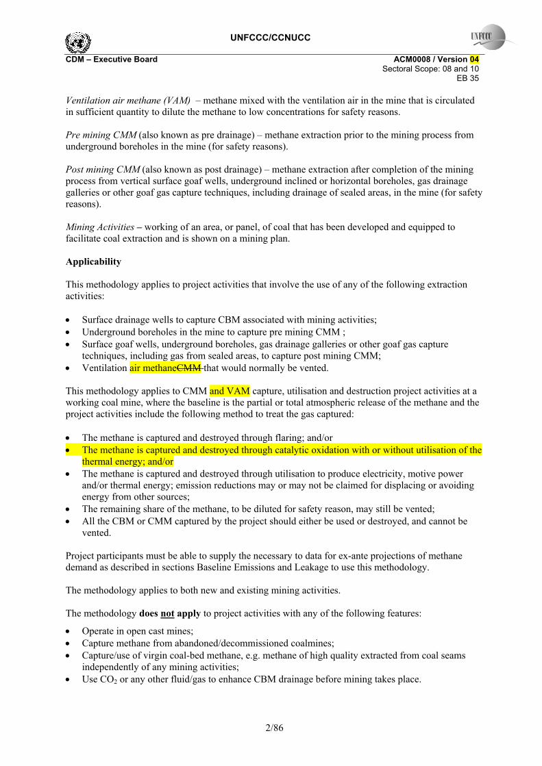
PEUM Project emissions from un-combusted methane (tCO2e)
Combustion emissions from additional energy required for CBM/CMM/VAM capture and use Additional energy may be used for the capture, transport, compression and use or destruction of for CBM/CMM/VAM. Emissions from this energy use should be included as project emissions. PEME = CONSELEC,PJ x CEFELEC + CONSHEAT,PJ x CEFHEAT + CONSFoss Fuel,PJ x CEFFoss Fuel (2) PEME Project emissions from energy use to capture and use or destroy methane (tCO2e) CONSELEC,PJ Additional electricity consumption for capture and use or destruction of methane, if
any (MWh)6 CEFELEC Carbon emissions factor of electricity used by coal mine (tCO2/MWh) CONSHEAT,PJ Additional heat consumption for capture and use or destruction of methane, if any
(GJ) CEFHEAT Carbon emissions factor of heat used by coal mine (tCO2e/GJ) CONSFossFuel,PJ Additional fossil fuel consumption for capture and use or destruction of methane, if
any (GJ) 7 CEFFossFuel Carbon emissions factor of fossil fuel used by coal mine (tCO2/GJ) For electricity emissions factor, the same formulae are used as in the calculations of baseline emissions. In other words, if the source of power for the coalmine is the grid, then the formulae from “Tool for calculation of emission factor for electricity systems” for calculating the combined margin emissions factor are used. If the source of power for the coalmine is captive power generation, then the emissions factor is calculated based on the emission factor for the fuel used and the efficiency of the captive power plant. For the heat generation emission factor, the same formulae are used as in the calculations of baseline emissions. In other words, the boiler efficiency and the emission factor for the fuel used are the basis of the emissions factor.
Combustion emissions from use of captured methane When the captured methane is burned in a flare, heat or power plant, or oxidized in a catalytic oxidation unit, combustion emissions are released. In addition, if NMHC account for more than 1% by volume of the extracted coal mine gas CMM/CBM or for more than 0.1% by volume of the extracted VAM, combustion emission from these gases should also be included. PEMD = (MDFL + MDOX + MDELEC + MDHEAT + MDGAS) x (CEFCH4 + r x CEFNMHC ) (3) PEMD = (MDFL + MDELEC + MDHEAT + MDGAS) x (CEFCH4 + r x CEFNMHC ) (3) with: r = PCNMHC / PCCH4 (4)
6 For instance, VAM units will consume electricity in fan motors, which are required to push the VAM through the unit without creating any back-pressure on the existing mine ventilation systems. 7 Pre-heating of VAM units prior to start-up will utilize some form of heat, most likely bottled butane or propane. Emissions from this source will be counted as CONSFossFuel,PJ

UNFCCC/CCNUCC CDM – Executive Board ACM0008 / Version 04 Sectoral Scope: 08 and 10 EB 35
11/86
Where:8 PEMD Project emissions from CMM/CBM destroyed (tCO2e) MDFL Methane destroyed through flaring (tCH4) MDOX Methane destroyed through catalytic oxidation (tCH4) MDELEC Methane destroyed through power generation (tCH4) MDHEAT Methane destroyed through heat generation (tCH4) MDGAS Methane destroyed after being supplied to gas grid or for vehicle use (tCH4) CEFCH4 Carbon emission factor for combusted methane (2.75 tCO2/tCH4) CEFNMHC
Carbon emission factor for combusted non methane hydrocarbons (the concentration varies and, therefore, to be obtained through periodical analysis of captured methane) (tCO2/tNMHC)
r Relative proportion of NMHC compared to methane PCCH4 Concentration (in mass) of methane in extracted gas (%), measured on wet basis PCNMHC NMHC concentration (in mass) in extracted gas (%) In each end-use, the amount of gas destroyed depends on the efficiency of combustion of each end use. MDFL = MMFL - (PEflare/GWPCH4) (5) Where: MDFL Methane destroyed through flaring (tCH4) MMFL Methane measured sent to flare (tCH4) PEflare Project emissions of non-combusted CH4, expressed in terms of CO2e, from flaring of the
residual gas stream (tCO2e) GWPCH4 Global warming potential of methane (21 tCO2e/tCH4) The project emissions of non-combusted CH4 expressed in terms of CO2e from flaring of the residual gas stream project emissions from flaring of the residual gas stream (PEflare) shall be calculated following the procedures described in the “Tool to determine project emissions from flaring gases containing Methane”. PEflare can be calculated on an annual basis or for the required period of time using this tool. MDOX = MMOX - PEOX (6) Where: MDOX Methane destroyed through catalytic oxidation (tCH4) MMOX Methane measured sent to catalytic oxidizer (tCH4) PEOX Project emissions of non oxidized CH4 from catalytic oxidation of the VAM stream
(tCH4) And where: MMOX = VAMflow.rate,y * timey * PCCH4.VAM * DCH4,corr inflow (6a) Where: VAMflow.rate,y Average flow rate of VAM entering the oxidation unit during period y (m3/s) timey Time during which VAM unit is operational during period y (s)
8 Note that throughout this baseline methodology, it is assumed that measured quantities of coal mine gas are converted to tonnes of methane using the measured methane concentration of the coal mine gas and the density of methane.

UNFCCC/CCNUCC CDM – Executive Board ACM0008 / Version 04 Sectoral Scope: 08 and 10 EB 35
12/86
PCCH4.VAM Concentration of methane in the VAM entering the oxidation unit (m3/m3) DCH4,corr inflow Density of methane entering the catalytic oxidation unit corrected for pressure and
temperature (PVAMinflow and TVAMinflow respectively) (tCH4/m3) And PEOX = VAMflow.rate,y * timey * PCCH4.exhaust * DCH4,corr exh (6b) Where: PCCH4exhaust Concentration of methane in the VAM exhaust (m3/m3) DCH4,corr exh Density of methane corrected for pressure and temperature in the exhaust gases
(PVAMexhaust and TVAMexhaust respectively) (tCH4/m3) For ex ante projections, the efficiency of destruction of methane in the VAM may be assumed to be 90%. MDELEC = MMELEC x EffELEC (7) Where: MDELEC Methane destroyed through power generation (tCH4) MMELEC Methane measured sent to power plant (tCH4) EffELEC Efficiency of methane destruction/oxidation in power plant (taken as 99.5% from IPCC) MDHEAT = MMHEAT x EffHEAT (8) Where: MDHEAT Methane destroyed through heat generation (tCH4) MMHEAT Methane measured sent to heat plant (tCH4) EffHEAT Efficiency of methane destruction/oxidation in heat plant (taken as 99.5% from IPCC) MDGAS = MMGAS x EffGAS (9) Where: MDGAS Methane destroyed after being supplied to gas grid (tCH4) MMGAS Methane measured supplied to gas grid for vehicle use or heat/power generation off-site
(tCH4) EffGAS Overall efficiency of methane destruction/oxidation through gas grid to various
combustion end uses, combining fugitive emissions from the gas grid and combustion efficiency at end user (taken as 98.5% from IPCC)9
9The Revised 1996 IPCC Guidelines for National Greenhouse Gas Inventories gives a standard value for the fraction of carbon oxidised for gas combustion of 99.5% (Reference Manual, Table 1.6, page 1.29). It also gives a value for emissions from processing, transmission and distribution of gas which would be a very conservative estimate for losses in the grid and for leakage at the end user (Reference Manual, Table 1.58, page 1.121). These emissions are given as 118,000kgCH4/PJ on the basis of gas consumption, which is 0.6%. Leakage in the residential and commercial sectors is given as 0 to 87,000kgCH4/PJ, which is 0.4%, or in industrial plants and power station the losses are 0 to 175,000kg/CH4/PJ, which is 0.8%. These leakage estimates are additive. EffGAS can now be calculated as the product of these three efficiency factors, giving a total efficiency of (99.5% * 99.4% * 99.6%) 98.5% for residential and commercial sector users, and (99.5% * 99.4% * 99.2%) 98.1% for industrial plants and power stations.

UNFCCC/CCNUCC CDM – Executive Board ACM0008 / Version 04 Sectoral Scope: 08 and 10 EB 35
13/86
Un-combusted methane from project activityflaring and end uses Not all of the methane sent to the flare, to the catalytic oxidizer or used to generate power and heat will be combusted, so a small amount will escape to the atmosphere. These emissions are calculated using the following:
( ) 44 ]1[ CHOXflarei
iiCHUM GWPPEPEEffMMGWPPE ×++−××= ∑ (10)
Where: PEUM Project emissions from un-combusted methane (tCO2e) GWPCH4 Global warming potential of methane (21 tCO2e/tCH4) i Use of methane (power generation, heat generation, supply to gas grid to various
combustion end uses) MMi Methane measured sent to use i (tCH4) Effi Efficiency of methane destruction in use i (%) PEflare Project emissions of non-combusted CH4 expressed in terms of CO2e from flaring of the
residual gas stream (tCO2e) PEOX Project emissions of non oxidized CH4 from catalytic oxidation of the VAM stream
(tCH4) The project emissions from flaring of the residual gas stream (PEflare) shall be calculated following the procedures described in the “Tool to determine project emissions from flaring gases containing Methane”. PEflare can be calculated on an annual basis or for the required period of time using this tool. Baseline Emissions Baseline emissions are given by the following equation: BEy = BEMD,y + BEMR,y + BEUse,y (11) BEy Baseline emissions in year y (tCO2e) BEMD,y Baseline emissions from destruction of methane in the baseline scenario in year y
(tCO2e) BEMR,y Baseline emissions from release of methane into the atmosphere in year y that is avoided
by the project activity (tCO2e) BEUse,y Baseline emissions from the production of power, heat or supply to gas grid replaced by
the project activity in year y (tCO2e)
Methane destruction in the baseline Depending on the nature of the activities in the baseline scenario, CBM/CMM can be removed at three four different stages – (1) as coal bed methane from a CBM to goaf wells prior to mining, or from underground pre-mining CMM drainage; (2) during the mining process using surface or underground post mining CMM drainage techniques, (3) during the mining process using ventilation air or (4) after the mining process by drainage from sealed goafs but before the mine is closed. Depending on the baseline scenario, part of this methane may be destroyed in the baseline scenario through flaring, catalytic oxidation, power generation, heat generation, supply to gas grid to various combustion end uses. Baseline emissions should account for the CO2 emissions resulting from the destruction of that methane.

UNFCCC/CCNUCC CDM – Executive Board ACM0008 / Version 04 Sectoral Scope: 08 and 10 EB 35
14/86
∑ ++××+=i
yiBLyBLiyBLiNMHCCHMDy PMMCMMCBMCEFrCEFBE )()( ,,,4
∑ +++××+=i
yiBLyiBLyiBLyiBLNMHCCHMDy PMMCMMVAMCBMCEFrCEFBE )()( ,,,,,,,,4 (12)
Where: BEMD,y Baseline emissions from destruction of methane in the baseline scenario in year y
(tCO2e) i Use of methane (flaring, power generation, heat generation, supply to gas grid to various
combustion end uses) CBMBL,i,y CBM that would have been captured, sent to and destroyed by use i in the baseline
scenario in the year y (expressed in tCH4) VAMBLi,,y VAM that would have been captured, sent to and destroyed by use i in the baseline
scenario in the year y (expressed in tCH4) CMMBL,i,y Pre-mining CMM that would have been captured, sent to and destroyed by use i in the
baseline scenario in year y (expressed in tCH4) PMMBL,i,y post-mining CMM that would have been captured, sent to and destroyed by use i in the
baseline scenario in year y (tCH4) CEFCH4 Carbon emission factor for combusted methane (2.75 tCO2e/tCH4) CEFNMHC Carbon emission factor for combusted non methane hydrocarbons (various. To be
obtained through periodical analysis of captured methane) (tCO2eq/tNMHC) r Relative proportion of NMHC compared to methane with : r = PCNMHC / PCCH4 PCCH4 Concentration (in mass) of methane in extracted gas (%), to be measured on wet basis. PCNMHC NMHC concentration (in mass) in extracted gas (%) Note that to estimate conservatively methane destruction in the baseline over time, it is important to understand the characteristics of any ex ante thermal demand for methane in the baseline scenario. As stated in the applicability conditions of this methodology, project participants must be able to supply the necessary to data for ex-ante projections of methane demand in order to use this methodology.
Calculation of the mean annual demand (Thy) for each year of the crediting period For thermal demand, which includes on-site heat generation and supply to the gas grid for various combustion end uses, demand can vary within the year. More importantly, this section presumes that such power generation (or other uses) projects are designed to primarily (or exclusively) use extracted CMMVAM/CMM that would not be used for baseline thermal energy and would otherwise be emitted to the atmosphere. Figures 1 and 2 indicate the disposition of methane under the baseline and project scenarios for this type of project.
UNFCCC/CCNUCC CDM – Executive Board ACM0008 / Version 04 Sectoral Scope: 08 and 10 EB 35
15/86
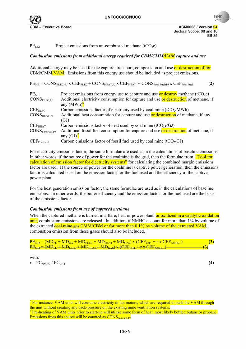
Figure 1. Baseline Disposition of CMMVAM/CMM/CBM Figure 2. Project Case Disposition of CMMVAM/CMM/CBM
For applicable projects, some or all of the CMMVAM/CMM/CBM used to generate electricity would be emitted to the atmosphere under the baseline (Figure 1). Appropriate CMMVAM/CMM/CBM flow and concentration meters should directly measure the amount of methane delivered to the project electric generator. Under some circumstances, some portion of the CMMVAM/CMM/CBM used by a project for power generation might otherwise have gone to produce thermal energy under the baseline. This situation is shown in Figure 3, indicating an
“overlap” between CMMVAM/CMM/CBM used for power and baseline use of CMMVAM/CMM for heating/cooking. This overlap may occur if CMMVAM/CMM flows fall below expected levels (left column at bottom of Figure 3), or if baseline thermal energy demand exceeds expected levels (right column at bottom of Figure 3). Such overlaps may occur even where total annual CMMVAM/CMM/CBM volumes are more than enough to cover annual thermal energy and power requirements (as in Figure 3). This methodology provides for conservatively estimating what amount of methane – if any – used for power production would have been used for thermal energy in the baseline. Emissions from the project are reduced only to the extent that the power generation uses methane that would have been emitted in the baseline (i.e., “emitted to atmosphere” in Figure 1).
Coalmine CH4
Atmosphere
Heating/CookingFuel
To Atmosphere
For Heating/ Cooking
Coalmine CH4
Atmosphere
Heating/CookingFuel
Power Generation
UNFCCC/CCNUCC CDM – Executive Board ACM0008 / Version 04 Sectoral Scope: 08 and 10 EB 35
16/86
∑=
=+++365
1,,,,,,,,, )(
kkBLythBLythBLythBLythBL THPMMCMMCBMVAM
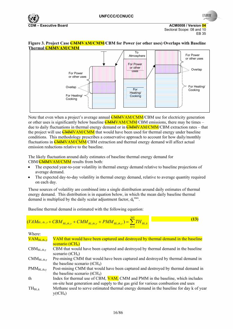
Figure 3. Project Case CMMVAM/CMM/CBM for Power (or other uses) Overlaps with Baseline Thermal CMMVAM/CMM
Note that even when a project’s average annual CMMVAM/CMM/CBM use for electricity generation or other uses is significantly below baseline CMMVAM/CMM/CBM emissions, there may be times – due to daily fluctuations in thermal energy demand or in CMMVAM/CMM/CBM extraction rates – that the project will use CMMVAM/CMM that would have been used for thermal energy under baseline conditions. This methodology prescribes a conservative approach to account for how daily/monthly fluctuations in CMMVAM/CMM/CBM extraction and thermal energy demand will affect actual emission reductions relative to the baseline. The likely fluctuation around daily estimates of baseline thermal energy demand for CBM/CMMVAM/CMM results from both: • The expected year-to-year volatility in thermal energy demand relative to baseline projections of
average demand. • The expected day-to-day volatility in thermal energy demand, relative to average quantity required
on each day.
These sources of volatility are combined into a single distribution around daily estimates of thermal energy demand. This distribution is in equation below, in which the mean daily baseline thermal demand is multiplied by the daily scalar adjustment factor, dk
max. Baseline thermal demand is estimated with the following equation:
(13)
Where: VAMBL,th,,y VAM that would have been captured and destroyed by thermal demand in the baseline
scenario (tCH4) CBMBL,th,y CBM that would have been captured and destroyed by thermal demand in the baseline
scenario (tCH4) CMMBL,th,y Pre-mining CMM that would have been captured and destroyed by thermal demand in
the baseline scenario (tCH4) PMMBL,th,y Post-mining CMM that would have been captured and destroyed by thermal demand in
the baseline scenario (tCH4) th Index for thermal use of CBM, VAM, CMM and PMM in the baseline, which includes
on-site heat generation and supply to the gas grid for various combustion end uses THBL,k Methane used to serve estimated thermal energy demand in the baseline for day k of year
y(tCH4)
To Atmosphere
For Heating/Cooking
For Power
or other uses
For Heating/ Cooking
For Power or other uses
For Power or other uses
For Heating/Cooking
Over lap
Overlap

UNFCCC/CCNUCC CDM – Executive Board ACM0008 / Version 04 Sectoral Scope: 08 and 10 EB 35
17/86
The quantity THBL,k should be determined for each day k of the annual reporting period. For each day k, in a future year y the formula is:
max,, 365 k
yBLkBL d
THTH ×= (14)
Where: THBL,k Methane used to serve estimated thermal energy demand in the baseline for day k in
year y (tCH4) THBL,y Projected annual baseline thermal demand for year y (tCH4) dk scalar adjustment factor for day k to reflect seasonal variations, such that Σdk=365 dmax
k maximum scalar adjustment factor for day k over the 5 years prior to the start of the project activity (i.e. Σdmax
k>365) The scalar adjustment factor for the day k of a year prior to the commencement of the project activity is the ratio between the demand for that day k and the mean daily demand for that year. For the past 5 years before the starting date of the proposed project activity, dk is calculated using real measured data. For each year y of the crediting period, dk takes the highest value observed during the 5 years before the starting date of the proposed project activity (i.e. dmax
k). If daily data are not available for estimating the scalar factor dk, then monthly data may be used. The source of data for mean annual baseline thermal energy demand should be provided on an ex ante projection basis by local CMMVAM/CMM / CBM distribution system operators, supported by a detailed description of the drivers of, and constraints on, future CMMVAM/CMM / CBM thermal energy demand. The project participants will use the methods below to project thermal energy demand. If using approach (b) project proponents must document why (a) cannot be used. If using approach (c) project proponents must document why neither (a) or (b) can be used.
a) Engineering/economic study of thermal energy demand. Ideally, projections should be based on a detailed description of the existing CMMVAM/CMM / CBM distribution system for thermal energy, how and why it was constructed, and what the primary drivers are behind thermal energy demand on the system. Based on this description, project proponents should describe how thermal energy demand is expected to change in the future in the absence of the project. Key points to address include: • Who the users of CMMVAM/CMM for thermal energy are, by quantity and type (e.g.,
residential, commercial, industrial); • What service agreements are in place with these end users; • Average CMMVAM/CMM/thermal energy consumption rates for each type of end user; • The number of end users serviced by the distribution system relative to the total pool of
possible end users, given infrastructure constraints; • How quickly the total pool of possible end users is expected to grow, if at all; • Whether official plans exist to expand the CMMVAM/CMM / CBM thermal energy system; • The cost/benefits of expanding the CMMVAM/CMM / CBM delivery system to additional end
users; • The type and cost of alternative fuels for potential or existing CMMVAM/CMM / CBM
thermal energy customers, compared to the cost of delivering CMMVAM/CMM / CBM; • Any other variables relevant to the particular thermal energy CMMVAM/CMM / CBM
distribution system associated with the project. Project proponents should explain how any assumptions used in this analysis are conservative.

UNFCCC/CCNUCC CDM – Executive Board ACM0008 / Version 04 Sectoral Scope: 08 and 10 EB 35
18/86
b) Statistical projection. If detailed information on thermal energy demand or the existing
CMMVAM/CMM distribution system is not available, project proponents may use a statistical projection based on CMMVAM/CMM / CBM availability and thermal energy CMMVAM/CMM / CBM usage rates over at least the past five years. If the latter approach is used, proponents must explain why such a statistical projection is reasonable, and should supplement any projection with as much engineering/economic information as possible.
c) Maximum throughput on the distribution system. Failing sufficient data for an
engineering/economic assessment or a statistical projection (e.g., if less than five years of data are available), prospective thermal energy demand in the absence of the project may be estimated from the maximum amount of CMMVAM/CMM / CBM that could be delivered to end users through existing pipelines. To be conservative, this approach should assume that thermal energy demand for CMMVAM/CMM / CBM in all future years will be equal to the maximum amount of CMMVAM/CMM / CBM that can be delivered. Maximum throughput estimates should be based on a detailed engineering description of the existing pipeline infrastructure. This analysis may also inform the analysis for (a) and (b), above.
1.1 Methane released into the atmosphere Depending on the nature of the project activity, CBM/CMMVAM/CMM can be removed at three four different stages – (1) as coal bed methane from a CBM wells prior to mining, or from underground pre-mining CMM drainage; (2) during the mining process using surface or underground post mining CMM drainage techniques; (3) during the mining process using ventilation air or (4) after the mining process by drainage from sealed goafs but before the mine is closed. This methane would have been emitted to the atmosphere in the baseline scenario, unless some capture and use activities form part of the baseline:
])()(
)()([
,,,,
,,,,4
∑∑
∑∑−+−
+−+−×=
iyiBLyPJi
iyiBLyPJi
iyiBLyPJi
iyiBLyiCHMRy
VAMVAMPMMPMM
CMMCMMCBMCBMeGWPBE
])(
)()([
,,
,,,,4
∑
∑∑−
+−+−×=
iyiBLyPJi
iyiBLyPJi
iyiBLyiCHMRy
PMMPMM
CMMCMMCBMCBMeGWPBE (15)
Where: BEMR,y Baseline emissions from release of methane into the atmosphere in year y that is avoided
by the project activity (tCO2e) i Use of methane (flaring, power generation, heat generation, supply to gas grid to various
combustion end uses) CBMei,.y Eligible CBM captured, sent to and destroyed by use i in the project for year y (expressed
in tCH4) CBMBLi,,y CBM that would have been captured, sent to and destroyed by use i in the baseline
scenario in the year y (expressed in tCH4) CMMPJ,i,y Pre-mining CMM captured, sent to and destroyed by use i in the project activity in year y
(expressed in tCH4) CMMBL,i,y Pre-mining CMM that would have been captured, sent to and destroyed by use i in the

UNFCCC/CCNUCC CDM – Executive Board ACM0008 / Version 04 Sectoral Scope: 08 and 10 EB 35
19/86
baseline scenario in year y (expressed in tCH4) PMMPJ,i,y Post-mining CMM captured, sent to and destroyed by use i in the project activity in year
y (tCH4) PMMBLi,,y Post-mining CMM that would have been captured, sent to and destroyed by use i in the
baseline scenario in year y (tCH4) VAMPJ,i,y VAM sent to and destroyed by use i in the project activity in year y (tCH4). In the case
of catalytic oxidation, VAMPJ,i,y is equivalent to MDOX defined previously. VAMBLi,,y VAM that would have been captured, sent to and destroyed by use i in the baseline
scenario in year y (tCH4). GWPCH4 Global warming potential of methane (21 tCO2e/tCH4) CEFCH4 Carbon emission factor for combusted methane (2.75 tCO2e/tCH4) CEFNMHC Carbon emission factor for combusted non methane hydrocarbons (various. To be
obtained through periodical analysis of captured methane) (tCO2eq/tNMHC) r Relative proportion of NMHC compared to methane with: r = PCNMHC / PCCH4 PCCH4 Concentration (in mass) of methane in extracted gas (%) PCNMHC NMHC concentration (in mass) in extracted gas (%) The methane that is still vented in the project scenario is not accounted for in the project emissions or in the baseline emissions, since it is vented in both scenarios. For CBM captured, the avoided emissions should only be credited in the year in which the seam is mined through the CBM well influence zone, as explained in the next section. Eligible CBM The approach to quantify the eligible CBM is to identify the zone of influence of CBM wells, and when these are impacted by mining activities. Step 1. Identify relevant wells The first step is to identify the drilling plan and the wells that will be intersected by mining or are likely to extract methane from an area that will overlap with future coal extraction : The location of CBM wells in relation to the mine concession area and mining plan during the initial crediting period is estimated using the latest mine plan information, and a map should be included in the Project Design Document. An indicative mining map showing relevant CBM wells and their zones of influence is shown in Figure 3. Note: Wells that extract virgin coal bed methane, i.e. from areas that would not be mined and would not influence eventual CMM emissions in mined areas, are out of the boundary of both the baseline and the project. Any activity intending to extract and use such virgin coal bed methane should refer to another methodology.

UNFCCC/CCNUCC CDM – Executive Board ACM0008 / Version 04 Sectoral Scope: 08 and 10 EB 35
20/86
Figure 3. Indicative Figure Showing Mining Plan, relevant CBM wells and their zones of influence
Start Date: e.g. 1H08
Roadway
Roadway
AccessRoad
Direction of mining
Start Date: e.g. 2H09
Roadway
Roadway
130m
60m
Direction of principal stress 1200m
Seam Thickness = 6m
Start Date: e.g. 1H08
Roadway
Roadway
AccessRoad
Direction of mining
Start Date: e.g. 2H09
Roadway
Roadway
130m
60m
Direction of principal stress 1200m
Seam Thickness = 6m
Step 2. Estimation of the Zone of Influence of a CBM Well and eligible methane This methodology estimates the overlap between a cylindrical gas drainage zone around a production well with the zone of disturbance around a longwall panel, from which gas is emitted into the mine. A generalised zone or radius of influence, R, for a particular well can be estimated at any time during the pre drainage process based on either (i) the cumulative flow measured at the well Vw or (ii) on the total cumulative gas drained from all the wells measured at the centralised monitoring station Vc. Idealised uniform degassing is assumed within a cylindrical zone centred on the borehole and a constant production flow. (i) Using cumulative flow at an individual well: R = ((Vw)/(π x T x ρcoal x gcoal))0.5 (16) Where: R Cumulative radius of zone of influence (m) Vw Cumulative flow measured at an individual well (m3) T Total thickness of coal in section accessed by well (m) ρcoal Density of locally mined coal (t/m3)– default value 1.4 t/m3 gcoal Gas content of the coal (m3 CH4/tonne coal) (ii) Using cumulative flow from a number of wells R = ((n x Va )/(π x T x ρcoal x gcoal))0.5 (17) Where: R Cumulative radius of zone of influence (m) n Number of days the selected wells are operational Va Average flow per day across all wells (m3/d)

UNFCCC/CCNUCC CDM – Executive Board ACM0008 / Version 04 Sectoral Scope: 08 and 10 EB 35
21/86
T Total thickness of coal in section accessed by well (m) ρcoal Density of locally mined coal – default value 1.4 t/m3 gcoal Gas content of the coal (tCH4/tonne coal) and
N∑== w
ca
V N / V V (18)
Where: Va Average flow per day (m3/d) Vc Total cumulative gas drained from all the wells measured at the centralised monitoring
station (m3) Vw Cumulative flow measured at an individual well (m3) N Sum of days that all wells have been operational (days) As an example, taking the density of coal as 1.4 tonne per m3, the gas in coal to be 12 m3 per tonne, the thickness of the section to be 40 metres and the flow rate to be 2400m3/day, then the radius of zone of influence will increase by 20 m per year. Therefore, if the number pre-drainage years are ‘n’ the corresponding radius of zone of influence will be n x20 m. The Project Design Document should elaborate the project specific values for the zone of influence. Area of Overlap Once the zone of influence for a well in a given year overlaps the longwall panel to be mined, then the gas from the well is considered to be eligible CBM. To estimate portion of CBM that would have been released from mining activities, a geometric approach in the horizontal plane and the vertical plane is used where the area of overlap between the defined zones of influence for each well and the longwall panel to be mined (“Area of Overlap”) is used as well as the de-stressing zone above and below the seam to be mined.

UNFCCC/CCNUCC CDM – Executive Board ACM0008 / Version 04 Sectoral Scope: 08 and 10 EB 35
22/86
Horizontal plane: The ratio of the Area of Overlap to the total area of the zones of influence of the wells considered is calculated and used to identify the appropriate share of gas counted as eligible CBM. The equations for this are:
Where: ESh Eligible share of CBM based on the horizontal plane overlap (%) AOw Area of overlap of well w with the longwall mining panel (m2) ATw Total zone of influence of well w (m2) w CBM wells with zones of influence that overlap with mining activity Note that for CBM wells which will be physically intersected by mining, ESh is unity by definition. In other words, all of the CBM drained from this type of well is eligible, unless there is gas coming from seams beyond the de-stressing zone. Vertical plane: The de-stressing zone typically extends upwards 140 m and downwards 40 metres. If cased boreholes are used and the seams are fractured within the de-stressing zone, then all the gas entering the CBM well is gas that would have appeared as methane in ventilation air and CMM during and after mining. If other seams outside of the de-stressed zone are fractured, then this gas must be excluded from the eligible CBM. The eligible share is defined as follows:
Where: ESv Eligible share of CBM based on the vertical plane overlap (%) t Thickness of coal which lies within the longwall emission zone (m) T Total thickness of coal that is producing gas in the production well (m) The value for ESv would be 1 for cased boreholes where fraccing is only done in the seams of relevance. A mine cross section should be included in the PDD together and supporting documentation on the well drilling process should be supplied to the Validator to justify the ratio of t/T. Eligible CBM: Summarising the eligible contribution of CBM in the horizontal and vertical planes gives the final ratio of eligible CBM: ESt = ESh x ESv (21) Where: ESt Total eligible share of CBM (%) ESh Eligible share of CBM based on the horizontal plane overlap (%) ESv Eligible share of CBM based on the vertical plane overlap (%)
∑∑
=
ww
ww
h AT
AOES
TtESv =
(19)
(20)

UNFCCC/CCNUCC CDM – Executive Board ACM0008 / Version 04 Sectoral Scope: 08 and 10 EB 35
23/86
CO2 emissions from use or destruction of CBM: Note that while only the eligible CBM should be accounted to calculate the volume of methane emissions avoided by the project, the totality of the CO2 resulting from the use or the destruction of all the CBM extracted should be accounted as project emissions. Note that once a CBM well has been mined through, then the well acts in the same manner as conventional underground post mining CMM drainage (surface goaf well) and therefore all of the methane that is drained through this type of well is eligible, irrespective of whether the well is drilled off-centre to the longwall panel and some of the area of influence is outside the area of the longwall panel. The Project Design Document should contain the relevant project specific data in order to calculate an ex-ante estimate of the above. Furthermore this will be updated ex-post using mining plans and accurate measurements of the locations of the actually drilled wells, as the final location of the relevant CBM wells will be determined after proper risk assessments and taking into account local conditions for drilling. If any CBM wells that were planned to be intersected by mining, or their zones of influence overlap with mining, are not reached by the mining activities, then corresponding methane extracted should not be taken into account in the emission reduction calculation. Step 3. Temporal adjustments for baseline emissions within a defined crediting period No emission reductions from CBM utilization and or destruction can be claimed until the mining activity enters the zone of influence of the well. At that time the emission reductions from the share of eligible pre-drainage and subsequent post-drainage methane can be claimed. This is calculated as follows:
Where: CBMe.y Eligible CBM captured by the project for year y (tCH4) ESt total eligible share of CBM (%) Vw,y-m Volume of methane captured from well w in year y-m (tCH4) Vw,y Volume of methane captured from well w in year y (tCH4) W Number of wells where mining reached the zone of influence in year y b Initial year of crediting period Note that the first term covers the sum of all the methane drained from each new well for which mining has actually entered the zone of influence during a given year y, from the start of the crediting period to the end of the previous year (i.e. end of year y-1). The second term covers the sum of all methane drained from each well for which mining has entered the zone of influence for the year y. For example, at a mine in which 5 CBM wells had been drilled, if mining entered the zone of influence of all five wells in year 4, then in years 1 to 3 the eligible CBM would be zero. In year 4 it would be the cumulative volume for the previous 3 years plus the volume extracted in year 4. In year 5 it would only be the volume extracted in year 5.
×+
×= ∑∑∑
−
=−
wywt
w
by
mmywtye VESVESCBM ,
1,,
(22)

UNFCCC/CCNUCC CDM – Executive Board ACM0008 / Version 04 Sectoral Scope: 08 and 10 EB 35
24/86
Pre-mining and post-mining CMM extraction and VAM Both CMMPJ,y, PMMPJ,y and VAM are directly monitored as part of the project activity. In all threeboth cases, the avoided methane equals the amount captured, less any that would have been captured in the baseline. The amount captured in the baseline may be defined as an absolute amount, or as a share of the amount captured in the project activity. In either each case, these assumptions must be justified by the project participants.
Emissions from power/heat generation and vehicle fuel replaced by project For emissions from displacing other energy forms, it is necessary to distinguish between emissions reductions derived from the use of CBM versus CMM, because CBM emissions reductions should only be credited once the mining area has intersected the zone of influence of the CBM well. BEUse,y = EDCBMw,y + EDCBMz,y + EDCPMM,y (23) BEUse,y Total baseline emissions from the production of power or heat replaced by the project
activity in year y (tCO2) EDCBMw,y Emissions from displacement of end uses by use of coal bed methane captured from
wells where the mining area intersected the zone of influence in year y (tCO2) EDCBMz,y Emissions from displacement of end uses by use of coal bed methane captured from
wells where the mining area intersected the zone of influence prior to year y (tCO2) EDCPMM,y Emissions from displacement of end uses by use of coal mine methane, VAM and post-
mining methane (tCO2) The total methane captured during year y can be described as follows: CBMMtot,y = CBMw,y + CBMz,y + CBMx,y + CMMPJ,y + PMMPJ,y + VAM PJ,y (24) CBMMtot,y Total CBM, CMM and VAM captured and utilised by the project activity (tCH4) CBMw,.y CBM captured from wells where the mining area intersected the zone of influence in
year y (tCH4) CBMz,.y CBM captured from wells where the mining area intersected the zone of influence prior
to year y (tCH4) CBMx,.y CBM captured from wells where the mining area has not yet intersected the zone of
influence in year y (tCH4) CMMPJ,i,y Pre-mining CMM captured by the project activity in year y (tCH4) PMMPJ,i,y Post-mining CMM captured by the project activity in year y (tCH4) VAM PJ,y VAM captured by the project activity year y (tCH4) The total potential emissions reductions from displacement of power/heat generation and vehicle fuels are given by the following equation: PBEUse,y = GEN,y x EFELEC+ HEATy x EFHEAT + VFUELy x EFV (25) Where: PBEUse,y Potential total baseline emissions from the production of power or heat replaced by the
project activity in year y (tCO2e) GENy Electricity generated by project activity in year y (MWh), including through the use of
CBM EFELEC Emissions factor of electricity (grid, captive or a combination) replaced by project
(tCO2/MWh) HEATy Heat generation by project activity in year y (GJ), including through the use of CBM

UNFCCC/CCNUCC CDM – Executive Board ACM0008 / Version 04 Sectoral Scope: 08 and 10 EB 35
25/86
EFHEAT Emissions factor for heat production replaced by project activity (tCO2/GJ) VFUELy Vehicle fuel provided by the project activity in year y (GJ), including through the use of
CBM EFV Emissions factor for vehicle operation replaced by project activity (tCO2/GJ) To identify the CBM/CMM that should receive credits in the year during which the gas is captured and used, the following formulae are used, assuming that CMM and CBM are used for various end uses in the same proportions as the overall supply for that year of different gas sources:
yUseytot
yzyCBMz PBE
CBMMCBM
ED ,,
,, ×= (26)
Where: EDCBMz,y Emissions from displacement of end uses by use of coal bed methane captured from
wells where the mining area intersected the zone of influence prior to year y (tCO2e) CBMz,.y CBM captured from wells where the mining area intersected the zone of influence prior
to year y (tCH4) CBMMtot,y Total CBM, CMM and VAM captured and utilised by the project activity in year y
(tCH4) PBEUse,y Potential total baseline emissions from the production of power or heat replaced by the
project activity in year y (tCO2e)
yUseytot
yPJyPJyPJyCPMM PBE
CBMMVAMPMMCMM
ED ,,
,,,, ×
++= (27)
yUseytot
yPJyPJyCPMM PBE
CBMMPMMCMM
ED ,,
,,, ×
+=
Where: EDCPMM,y Emissions from displacement of end uses by use of coal mine methane and post-mining
methane (tCO2e) CMMPJ,i,y Pre-mining CMM captured by the project activity in year y (tCH4) PMMPJ,i,y Post-mining CMM captured by the project activity in year y (tCH4) VAMPJ,y VAM captured by the project activity in year y (tCH4) CBMMtot,y Total CBM CMM and VAM captured and utilised by the project activity in year y (tCH4)PBEUse,y Potential total baseline emissions from the production of power or heat replaced by the
project activity in year y (tCO2e)
∑−
=−
−
−
×=
by
mmy
mytot
mywyCBMw PBE
CBMMCBM
ED0 ,
,, (28)
Where: EDCBMw,y Emissions from displacement of end uses by use of coal bed methane captured from
wells where the mining area intersects the zone of influence in year y (tCO2e) CBMw,.y-m CBM captured in the year y-m from wells where the mining area intersected the zone of
influence in year y (tCH4) CBMMtot,y-m Total CBM, CMM and VAM captured and utilised by the project activity in year y-m
(tCH4) PBEUse,y-m Potential total baseline emissions from the production of power or heat replaced by the
project activity in year y-m (tCO2e)

UNFCCC/CCNUCC CDM – Executive Board ACM0008 / Version 04 Sectoral Scope: 08 and 10 EB 35
26/86
b initial year of crediting period
Note that no emissions reductions are associated with CBMx,y, so the actual baseline emissions in each year will vary from the potential baseline emissions. Grid power emission factor If the baseline scenario includes grid power supply that would be replaced by the project activity, the Emissions Factor for displaced electricity is calculated as per “Tool for calculation of emission factor for electricity systems”.
Captive power emissions factor If the baseline scenario includes captive power generation (either existing or new) that would be replaced by the project activity, the Emissions Factor for displaced electricity is calculated as follows: Where:
EFcaptive,y Emissions factor for captive power generation (tCO2/MWh) EFCO2,i CO2 emissions factor of fuel used in captive power generation (tC/TJ) Effcaptive Efficiency of the captive power generation (%) 44/12 Carbon to Carbon Dioxide conversion factor 3.6/1000 TJ to MWh conversion factor Combination of grid power and captive power emissions factor If the baseline scenario selection determines that both captive and grid power would be used, then the emissions factor for the baseline is the weighted average of the emissions factor for grid power and captive power.
ycaptivecaptiveygridgridyELEC EFsEFsEF ,,, ⋅+⋅= (30) Where: EFELEC.,y
CO2 baseline emission factor for the electricity displaced due to the project activity during the year y (tCO2/MWh).
EFgrid,y CO2 baseline emission factor for the grid electricity displaced due to the project activity during the year y (tCO2/MWh).
EFcaptive,y CO2 baseline emission factor for the captive electricity displaced due to the project activity during the year y (tCO2/MWh).
sgrid Share of facility electricity demand supplied by grid imports over the last 3 years (%)10 scaptive Share of facility electricity demand supplied by captive power over the last 3 years (%)2 10 If the facility is a new facility, then the share of grid versus import power determined to be the most likely baseline scenario should be used.
MWhTJ
EffEF
EFcaptive
iCOycaptive 1000
6.31244,2
, ××=(29)

UNFCCC/CCNUCC CDM – Executive Board ACM0008 / Version 04 Sectoral Scope: 08 and 10 EB 35
27/86
Heat generation emissions factor If the baseline scenario includes heat generation (either existing or new) that is replaced by the project
activity, the Emissions Factor for displaced heat generation is calculated as follows: Where: EFheat,y Emissions factor for heat generation (tCO2/GJ) EFCO2,i CO2 emissions factor of fuel used in heat generation (tC/TJ) Effheat Boiler efficiency of the heat generation (%) 44/12 Carbon to Carbon Dioxide conversion factor 1/1000 TJ to GJ conversion factor To estimate boiler efficiency, project participants may choose between the following two options:
Option A Use the highest value among the following three values as a conservative approach: • Measured efficiency prior to project implementation; • Measured efficiency during monitoring; • Manufacturer nameplate data for efficiency of the existing boilers. Option B Assume a boiler efficiency of 100% based on the net calorific values as a conservative approach.
Vehicle fuel use emissions factor If the baseline scenario includes vehicle operation that will be fuelled by gas produced by the project activity, the Emissions Factor for displaced vehicle fuel use is calculated as follows:
Where: EFV Emissions factor for vehicle operation replaced by project activity (tCO2/GJ) EFCO2,i CO2 emissions factor of fuel used for vehicle operation (tC/TJ) EffV Vehicle engine efficiency (%) 44/12 Carbon to Carbon Dioxide conversion factor 1/1000 TJ to GJ conversion factor To estimate vehicle engine efficiency, project participants should select the highest value among the following three values as a conservative approach: • Measured fuel efficiency prior to project implementation; • Measured fuel efficiency during monitoring; • Manufacturer reported data for efficiency for vehicle.
GJTJ
EffEF
EFheat
iCOyheat 1000
11244,2
, ××=
GJTJ
EffEF
EFV
iCOV 1000
11244,2 ××=
(31)
(32)

UNFCCC/CCNUCC CDM – Executive Board ACM0008 / Version 04 Sectoral Scope: 08 and 10 EB 35
28/86
Leakage The formula for leakage is given as follows LEy = LEd,y + LEo,y (33) Where: LEy Leakage emissions in year y (tCO2e) LEd,y Leakage emissions due to displacement of other baseline thermal energy uses of methane
in year y (tCO2e) LEo,y Leakage emissions due to other uncertainties in year y (tCO2e) Displacement of baseline thermal energy uses Leakage may occur if the project activity prevents CMM/CBM from being used to meet baseline thermal energy demand, whether as a result of physical constraints on delivery, or price changes. Where regulations require that local thermal demand is met before all other uses, which is common in many jurisdictions, then this leakage can be ignored. If displacement does occur, the project activity may cause increased emissions outside the project boundary associated with meeting thermal energy demand with other fuels. Because of likely day-to-day fluctuations in CMM extraction rates, to ensure a conservative result, CERs should not be calculated solely from annual data. Any CERs generated from methane destruction should be calculated using daily logs, or monthly logs if daily data is not available, of project-case demand for CMM for non-thermal uses compared against estimates of baseline CMM demand for thermal uses. For each day (or month) of the crediting period, this form of leakage must be calculated if:
kkHEATkELECk THMMMMME <+− )( ,, (34)
with:
max
365 kBL
k dTH
TH ×= (35)
Where: MEk Methane extracted on day k (tCH4) MMELEC,k Methane measured sent to power plant on day k (tCH4) MMHEAT,k Methane measured sent to new heat generation uses on day k in the Project Scenario that
would not have been sent in the Baseline Scenario on day k (tCH4) THk Methane used to serve thermal energy demand in the baseline for day k (tCH4) THBL Average annual thermal demand over the past 5 years (tCH4) dk scalar adjustment factor for day k to reflect seasonal variations such that Σdk=365 dmax
k Maximum scalar adjustment factor for day k over the past 5 years (i.e. Σdmaxk>365)
Under this condition, some portion of CMM/VAM that would have gone to meet thermal energy demand in the baseline scenario is instead used by the project. A corresponding amount of thermal energy demand in the project scenario will have to be met by an alternative fuel, leading to possible increased emissions. To calculate such emissions, the following approach should be used.

UNFCCC/CCNUCC CDM – Executive Board ACM0008 / Version 04 Sectoral Scope: 08 and 10 EB 35
29/86
The amount of thermal energy from CMM/VAM diverted from thermal uses existing in the baseline diverted to other uses by the project should be calculated on a daily basis, and then summed up for each year y: EDth,y = Σ(EDth,k) =Σ[max (0, (THk – (MEk – (MMELEC,k + MMHEAT,k))) x NCVCH4 ] (36) Where: EDth,y Quantity of thermal energy displaced by the project activity in year y (GJ) EDth,k Quantity of thermal energy displaced by the project activity on day k (GJ) MEk Total methane extracted on day k (tCH4) MMELEC,k Methane measured sent to power plant on day k (tCH4) MMHEAT,k Methane measured sent to new heat generation uses on day k in the Project Scenario that
would not have been sent in the Baseline Scenario on day k (tCH4) NCVCH4 Net calorific value for methane (GJ/tCH4) Project participants must describe and justify what alternative fuel(s) is (are) used to provide thermal energy in the area when VAM/CMM is not available. They must then calculate the amount of alternative fuel required to provide the same heat output as the VAM/CMM. QAF,y = EDth,y / NCVAF (37) Where: QAF,y Quantity of alternative fuels displaced by the project activity in year y (tonnes or m3) EDth,y Quantity of thermal energy displaced by the project activity in year y (GJ) NCVAF Net calorific value for alternative fuels (GJ/tonne or m3) Emissions from the use of alternative fuels are calculated as follows: LEd,y = QAF x NCVAF x EFAF x OXID (38) Where: LEd,y Leakage emissions in year y (tCO2e) QAF,y Quantity of alternative fuels displaced by the project activity in year y (tonnes or m3) NCVAF Net calorific value for alternative fuels (GJ/tonne or m3) EFAF Emissions factor for alternative fuel (tCO2/GJ), sourced from IPCC OXID Oxidation efficiency of combustion (%), sourced from IPCC CBM drainage from outside the de-stressed zone Surface CBM drainage wells can in some cases drain gas from seams that are outside the de-stressed zone for 140m specified in this methodology, or could extract from an area larger than the circular zone of influence used in this methodology. The vertical leakage would only occur if the surface wells were not cased. Similarly, if there is surface CBM extraction in the baseline, then the gas drawn from other seams would be the same in the baseline and project scenario. Therefore, in cases where:
1. Surface boreholes drilled in the project activity are not cased, AND 2. There are no surface boreholes for CBM draining present in the baseline scenario

UNFCCC/CCNUCC CDM – Executive Board ACM0008 / Version 04 Sectoral Scope: 08 and 10 EB 35
30/86
Project participants should discount the total emissions reductions achieved. The amount of discount should be based on:
Option 1: a comparison of ex-ante engineering estimates of CBM production from surface boreholes versus actual project activity CBM production Option 2: a standard discount factor of 10% Impact of CDM project activity on coal production The additional CBM/CMM extraction from the CDM project activity could in some cases release certain constraints that currently limit mining operations. In cases of gassy mines where production is constrained by gas drainage capacity (i.e. too high concentration requires temporary interruption of mining operation), CER value can cover both the cost of CMM/CBM destruction and increase of extraction capacity to release the concentration constraint, then allowing increased coal production. This will only be the case, however, when no CBM/CMM extraction is present in the baseline scenario (i.e. the baseline scenario is ventilation of mine gas only). If the project activity is CBM/CMM extraction and the baseline scenario is ventilation only, project participants should: Option 1: calculate the extra coal production likely by the relaxing of the production constraint. The emission reductions claimed by the project should then be discounted so that CBM/CMM capture from the additional coal production is not included. Option 2: apply a standard discount factor of 10%. Note that for projects using CBM this leakage is to be calculated in addition to leakage described in section “CBM drainage from outside the de-stressed zone” above. Impact of CDM project activity on coal prices and market dynamics Depending on relative market price of coal and the value of CERs for the CDM project activity, the new carbon revenue could theoretically eventually induce a decrease in coal prices and, as a result, lead to an increase of coal demand (i.e. a rebound effect). The share of coal in national energy demand could therefore increase, leading to higher emissions that could offset emission reduction achieved through CMM/CBM destruction. While this impact is theoretically possible, reliable scientific information is not currently available to assess this risk and check if the phenomenon would be negligible or not. Moreover, it is difficult to assess ex-ante the contribution of any particular project given the dynamic nature of local and global coal markets.11 Emission Reductions The emission reduction ERy by the project activity during a given year y is the difference between the baseline emissions (BEy) and project emissions (PEy), as follows:
yyyy LEPEBEER −−= (39)
11 The Meth Panel recommends that the EB further investigate and monitor this issue after approving this methodology and considers to decide after 2-3 years of projects being implemented using this methodology, whether it should be revised to reflect price and market impacts.
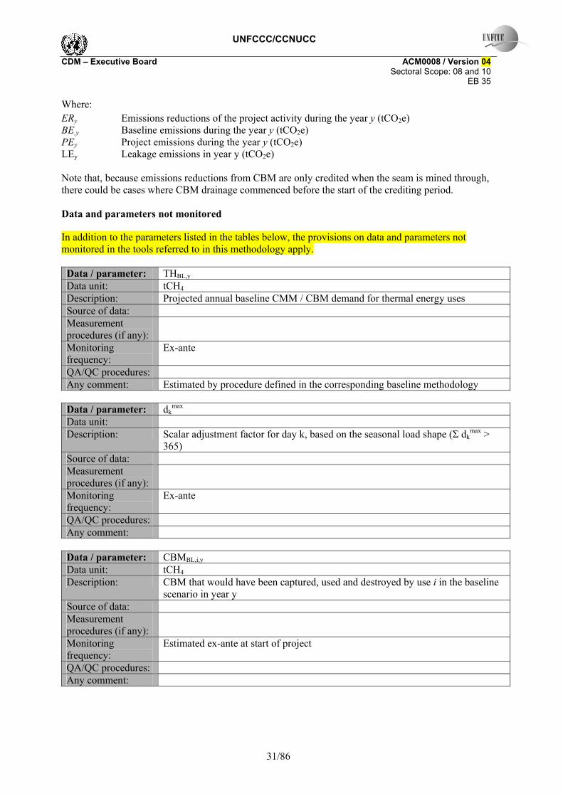
UNFCCC/CCNUCC CDM – Executive Board ACM0008 / Version 04 Sectoral Scope: 08 and 10 EB 35
31/86
Where: ERy Emissions reductions of the project activity during the year y (tCO2e) BE,y Baseline emissions during the year y (tCO2e) PEy Project emissions during the year y (tCO2e) LEy Leakage emissions in year y (tCO2e) Note that, because emissions reductions from CBM are only credited when the seam is mined through, there could be cases where CBM drainage commenced before the start of the crediting period. Data and parameters not monitored
In addition to the parameters listed in the tables below, the provisions on data and parameters not monitored in the tools referred to in this methodology apply. Data / parameter: THBL,y Data unit: tCH4 Description: Projected annual baseline CMM / CBM demand for thermal energy uses Source of data: Measurement procedures (if any):
Monitoring frequency:
Ex-ante
QA/QC procedures: Any comment: Estimated by procedure defined in the corresponding baseline methodology
Data / parameter: dk
max Data unit: Description: Scalar adjustment factor for day k, based on the seasonal load shape (Σ dk
max > 365)
Source of data: Measurement procedures (if any):
Monitoring frequency:
Ex-ante
QA/QC procedures: Any comment:
Data / parameter: CBMBL,i,y Data unit: tCH4 Description: CBM that would have been captured, used and destroyed by use i in the baseline
scenario in year y Source of data: Measurement procedures (if any):
Monitoring frequency:
Estimated ex-ante at start of project
QA/QC procedures: Any comment:

UNFCCC/CCNUCC CDM – Executive Board ACM0008 / Version 04 Sectoral Scope: 08 and 10 EB 35
32/86
Data / parameter: CMMBL,i Data unit: tCH4 Description: CMM that would have been captured, used and destroyed by use i in the baseline
scenario in year y Source of data: Measurement procedures (if any):
Monitoring frequency:
Estimated ex-ante at start of project
QA/QC procedures: Any comment:
Data / parameter: PMMBL,i Data unit: tCH4 Description: PMM that would have been captured, used and destroyed by use i in the baseline
scenario in year y Source of data: Measurement procedures (if any):
Monitoring frequency:
Estimated ex-ante at start of project
QA/QC procedures: Any comment:
Data / parameter: VAMBLi,y Data unit: tCH4 Description: VAM that would have been captured, used and destroyed by use i in the baseline
scenario in year y Source of data: Measurement procedures (if any):
Monitoring frequency:
Estimated ex-ante at start of project
QA/QC procedures: Any comment:
Data / parameter: CBMei,.y Data unit: tCH4 Description: Eligible CBM captured, sent to and destroyed by use i in the project for year y Source of data: Measurement procedures (if any):
Monitoring frequency:
Yearly
QA/QC procedures: Any comment:

UNFCCC/CCNUCC CDM – Executive Board ACM0008 / Version 04 Sectoral Scope: 08 and 10 EB 35
33/86
Data / parameter: CBMBL,i,y Data unit: tCH4 Description: CBM that would have been captured , sent to and destroyed by use i in the
baseline scenario Source of data: Measurement procedures (if any):
Monitoring frequency:
Ex ante
QA/QC procedures: Any comment:
Data / parameter: CMMBL, i,y Data unit: tCH4 Description: Pre-mining CMM that would have been captured , sent to and destroyed by use i
in the baseline scenario in year y Source of data: Measurement procedures (if any):
Monitoring frequency:
Ex ante
QA/QC procedures: Any comment:
Data / parameter: VAMBL, i,y Data unit: tCH4 Description: VAM that would have been captured , sent to and destroyed by use i in the
baseline scenario in year y Source of data: Measurement procedures (if any):
Monitoring frequency:
Ex ante
QA/QC procedures: Any comment:
Data / parameter: PMMBL, i,y Data unit: tCH4 Description: post-mining CMM that would have been captured , sent to and destroyed by use i
in the baseline scenario in year y Source of data: Measurement procedures (if any):
Monitoring frequency:
Ex ante
QA/QC procedures: Any comment:

UNFCCC/CCNUCC CDM – Executive Board ACM0008 / Version 04 Sectoral Scope: 08 and 10 EB 35
34/86
III. MONITORING METHODOLOGY
All data collected as part of monitoring should be archived electronically and be kept at least for 2 years after the end of the last crediting period. 100% of the data should be monitored if not indicated otherwise in the tables below. All measurements should be conducted with calibrated measurement equipment according to relevant industry standards.
In addition, the monitoring provisions in the tools referred to in this methodology apply. Methane collected and flared: The amount of methane actually flared will be determined by monitoring the: • Amount of CMM/CBM/VAM gas collected, using a continuous flow meter and monitoring of
temperature and pressure; • Percentage of CMM/CBM/VAM gas that is methane (%v/v), measured using a continuous
analyser or alternatively, with periodical measurements, at a 95% confidence level, using calibrated portable gas meters and taking a statistically valid number of samples;
• The parameters used for determining the project emissions from flaring of the residual gas stream (PEflare) or catalytic oxidation of the VAM stream (PEOX) should be monitored as per the “Tool to determine project emissions from flaring gases containing Methane”.
Temperature (T) and pressure (P) of the CMM/CBM/VAM gas are required to determine the density of methane in the CMM/CBM/VAM gas. Methane in ventilation air destroyed by catalytic oxidation: A catalytic oxidation unit differs both from a thermal oxidation unit and a flare in that methane destruction takes place at a substantially lower temperature and also from a flare in that it is a closed system with no additional gas flow inputs (or emissions) between the input and exhaust methane measurement points. The amount of methane entering the reaction chamber will be determined by monitoring the total inlet flow using a continuous flow meter and monitoring temperature and pressure to determine gas density. The amount of VAM that is methane (%v/v) will be measured using a continuous analyser and for mine safety and regulatory reasons this is unlikely to exceed 1%. Project emissions from a VAM unit will be measured by continuous measurement of methane concentration, pressure and temperature of the exhaust gas stream. Data and parameters monitored In addition to the parameters listed in the tables below, the provisions on data and parameters not monitored in the tools referred to in this methodology apply.

UNFCCC/CCNUCC CDM – Executive Board ACM0008 / Version 04 Sectoral Scope: 08 and 10 EB 35
35/86
Data / parameter: CONSELEC,PJ Data unit: MWh Description: Additional electricity consumption for capture and use or destruction of methane,
if any Source of data: Project site Measurement procedures (if any):
Monitoring frequency:
Continuous
QA/QC procedures: Any comment:
Data / parameter: CONSHEAT,PJ Data unit: GJ Description: Additional heat consumption for capture and use or destruction of methane Source of data: Project site Measurement procedures (if any):
Monitoring frequency:
Continuous
QA/QC procedures: Any comment:
Data / parameter: CONSFossFuel,PJ Data unit: GJ Description: Additional fossil fuel consumption for capture and use or destruction of methane Source of data: Project site Measurement procedures (if any):
Monitoring frequency:
Continuous
QA/QC procedures: Any comment:
Data / parameter: CEFELEC Data unit: tCO2/MWh Description: Carbon emissions factor of electricity used by coal mine Source of data: Measurement procedures (if any):
Monitoring frequency:
Ex ante
QA/QC procedures: Any comment:

UNFCCC/CCNUCC CDM – Executive Board ACM0008 / Version 04 Sectoral Scope: 08 and 10 EB 35
36/86
Data / parameter: CEFHEAT Data unit: tCO2/ GJ Description: Carbon emissions factor of heat used by coal mine Source of data: Measurement procedures (if any):
Monitoring frequency:
Ex ante
QA/QC procedures: Any comment:
Data / parameter: CEFFossFuel Data unit: tCO2/GJ Description: Carbon emissions factor of fossil fuel used by coal mine Source of data: Measurement procedures (if any):
Monitoring frequency:
Ex ante
QA/QC procedures: Any comment: Use of IPCC default or national values would suffice
Data / parameter: MMFL Data unit: tCH4 Description: Methane measured sent to flare Source of data: Measurement procedures (if any):
Monitoring frequency:
Continuous
QA/QC procedures: Any comment: Flow meters will record gas volumes, pressure and temperature. Density of
methane under normal conditions of temperature and pressure is 0.67kg/m3 (Revised 1996 IPCC Reference Manual p 1.24 and 1.16)
Data / parameter: VAMflow.rate,y Data unit: m3/s Description: Average flow rate of VAM entering the oxidation unit during period y Source of data: Measurement procedures (if any):
Monitoring frequency:
Continuous
QA/QC procedures: Any comment: Readings taken every two minutes to calculate average hourly flow, or more
frequently.

UNFCCC/CCNUCC CDM – Executive Board ACM0008 / Version 04 Sectoral Scope: 08 and 10 EB 35
37/86
Data / parameter: timey Data unit: s Description: Time during which VAM unit is operational during period y Source of data: Measurement procedures (if any):
Monitoring frequency:
Continuous
QA/QC procedures: Any comment: Readings taken every two minutes to calculate average hourly flow, or more
frequently. Data / parameter: DCH4,corr inflow Data unit: tCH4/m3 Description: Density of methane entering the catalytic oxidation unit corrected for pressure
and temperature (PVAMinflow and TVAMinflow respectively) Source of data: Measurement procedures (if any):
Monitoring frequency:
Continuous
QA/QC procedures: Any comment:
Data / parameter: DCH4,corr exh Data unit: tCH4/m3 Description: Density of methane corrected for pressure and temperature in the exhaust gases
(PVAMexhaust and TVAMexhaust respectively) Source of data: Measurement procedures (if any):
Monitoring frequency:
Continuous
QA/QC procedures: Any comment:
Data / parameter: PVAMinflow Data unit: bar Description: Pressure of VAM entering the oxidation unit Source of data: Ppressure transducer Measurement procedures (if any):
Monitoring frequency:
Continuous
QA/QC procedures: Any comment: Readings taken every hour or more frequently to calculate hourly pressure

UNFCCC/CCNUCC CDM – Executive Board ACM0008 / Version 04 Sectoral Scope: 08 and 10 EB 35
38/86
Data / parameter: TVAMinflow Data unit: Kelvin Description: Temperature of VAM entering the oxidation unit Source of data: Thermocouple Measurement procedures (if any):
Monitoring frequency:
Continuous
QA/QC procedures: Any comment: Readings taken every hour or more frequently to calculate hourly temperature
Data / parameter: PVAMexhaust Data unit: bar Description: Pressure of exhaust gases exiting the oxidation unit Source of data: M (pressure transducer) Measurement procedures (if any):
Monitoring frequency:
Continuous
QA/QC procedures: Any comment: Readings taken every hour or more frequently to calculate hourly pressure
Data / parameter: TVAMexhaust Data unit: Kelvin Description: Temperature of exhaust gases exiting the oxidation unit Source of data: Thermocouple Measurement procedures (if any):
Monitoring frequency:
Continuous
QA/QC procedures: Any comment: Readings taken every hour or more frequently to calculate hourly temperature
Data / parameter: MMELEC Data unit: tCH4 Description: Methane sent to power plant Source of data: m Measurement procedures (if any):
Monitoring frequency:
Continuous
QA/QC procedures: Any comment: Flow meters will record gas volumes, pressure and temperature. Density of
methane under normal conditions of temperature and pressure is 0.67kg/m3 (Revised 1996 IPCC Reference Manual p 1.24 and 1.16)
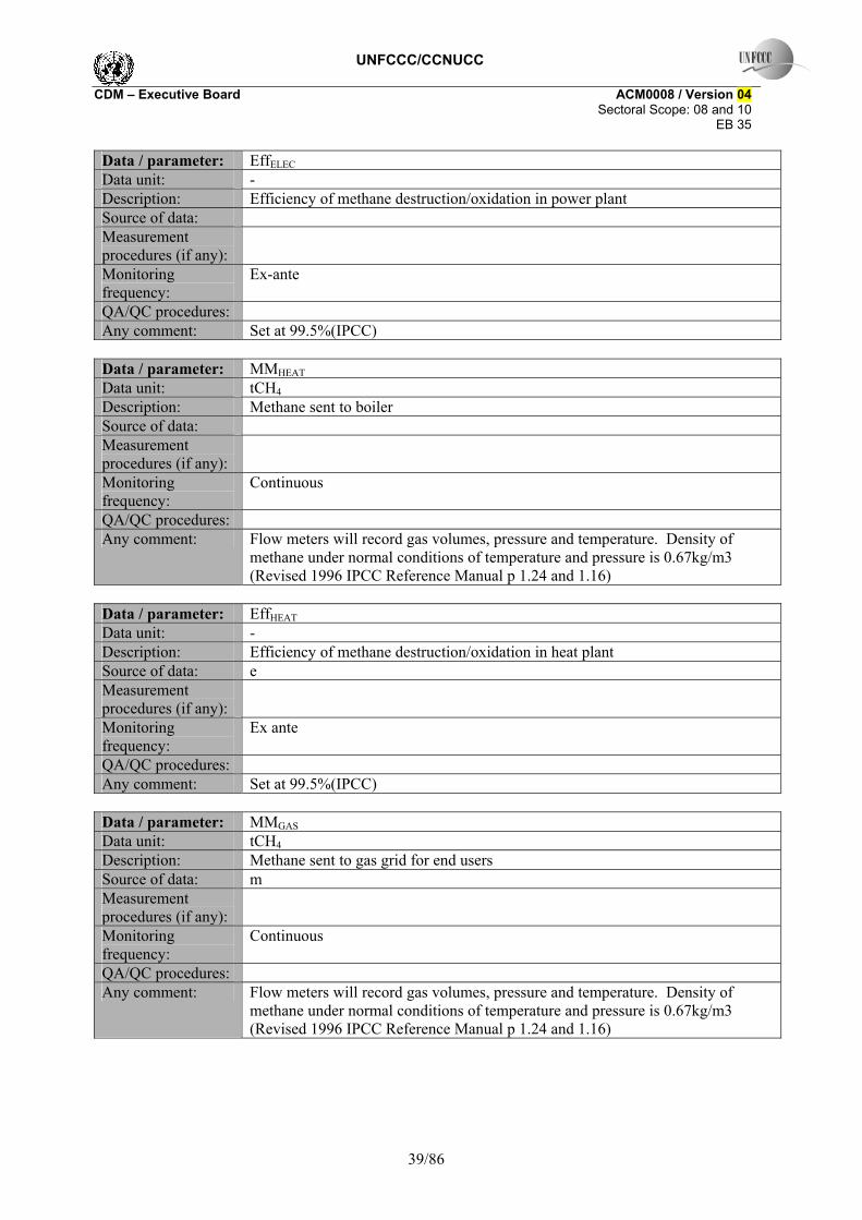
UNFCCC/CCNUCC CDM – Executive Board ACM0008 / Version 04 Sectoral Scope: 08 and 10 EB 35
39/86
Data / parameter: EffELEC Data unit: - Description: Efficiency of methane destruction/oxidation in power plant Source of data: Measurement procedures (if any):
Monitoring frequency:
Ex-ante
QA/QC procedures: Any comment: Set at 99.5%(IPCC)
Data / parameter: MMHEAT Data unit: tCH4 Description: Methane sent to boiler Source of data: Measurement procedures (if any):
Monitoring frequency:
Continuous
QA/QC procedures: Any comment: Flow meters will record gas volumes, pressure and temperature. Density of
methane under normal conditions of temperature and pressure is 0.67kg/m3 (Revised 1996 IPCC Reference Manual p 1.24 and 1.16)
Data / parameter: EffHEAT Data unit: - Description: Efficiency of methane destruction/oxidation in heat plant Source of data: e Measurement procedures (if any):
Monitoring frequency:
Ex ante
QA/QC procedures: Any comment: Set at 99.5%(IPCC)
Data / parameter: MMGAS Data unit: tCH4 Description: Methane sent to gas grid for end users Source of data: m Measurement procedures (if any):
Monitoring frequency:
Continuous
QA/QC procedures: Any comment: Flow meters will record gas volumes, pressure and temperature. Density of
methane under normal conditions of temperature and pressure is 0.67kg/m3 (Revised 1996 IPCC Reference Manual p 1.24 and 1.16)

UNFCCC/CCNUCC CDM – Executive Board ACM0008 / Version 04 Sectoral Scope: 08 and 10 EB 35
40/86
Data / parameter: EffGAS Data unit: - Description: Overall efficiency of methane destruction / oxidation through gas grid Source of data: e Measurement procedures (if any):
Monitoring frequency:
Ex ante
QA/QC procedures: Any comment: Set at 98.5% (IPCC)
Data / parameter: CEFNMHC Data unit: Description: Carbon emission factor for combusted non methane hydrocarbons (various) Source of data: Measurement procedures (if any):
Monitoring frequency:
QA/QC procedures: Any comment: To be obtained through periodical analysis of the fractional composition of
captured Data / parameter: PCCH4 Data unit: % Description: Concentration (in mass) of methane in extracted gas (%), measured on wet basis Source of data: Concentration meters, optical and calorific Measurement procedures (if any):
Monitoring frequency:
Hourly/Daily
QA/QC procedures: Any comment: To be measured on wet basis.
Data / parameter: PCNMHC Data unit: % Description: NMHC concentration (in mass) in extracted gas Source of data: Concentration meters, optical and calorific Measurement procedures (if any):
Monitoring frequency:
Annually
QA/QC procedures: Any comment:

UNFCCC/CCNUCC CDM – Executive Board ACM0008 / Version 04 Sectoral Scope: 08 and 10 EB 35
41/86
Data / parameter: PCCH4,VAM Data unit: m3/m3 Description: Concentration of methane in the VAM entering the oxidation unit Source of data: On line, low reading methanometer Measurement procedures (if any):
Monitoring frequency:
Continuous
QA/QC procedures: Any comment: Readings taken at least every two minutes and used to calculate average methane
concentration per hour or more frequently. Data / parameter: PCCH4,exhaust Data unit: % Description: Concentration of methane in exhaust gas from catalytic oxidation unit Source of data: M (online low reading methanometer) Measurement procedures (if any):
Monitoring frequency:
Continuous
QA/QC procedures: Any comment: Readings taken at least every two minutes and used to calculate average methane
concentration per hour or more frequently. Data / parameter: MMi Data unit: tCH4 Description: Methane measured sent to use i Source of data: Measurement procedures (if any):
Monitoring frequency:
Continuous
QA/QC procedures: Any comment: Flow meters will record gas volumes, pressure and temperature.
Data / parameter: Effi Data unit: - Description: Efficiency of methane destruction / oxidation through use i (power generation,
heat generation, supply to gas grid to various combustion end uses) Source of data: Measurement procedures (if any):
Monitoring frequency:
Ex ante or ex post
QA/QC procedures: Any comment:

UNFCCC/CCNUCC CDM – Executive Board ACM0008 / Version 04 Sectoral Scope: 08 and 10 EB 35
42/86
Data / parameter: PEMvent Data unit: tCH4 Description: Emissions of methane vented to atmosphere during the project activity Source of data: Measurement procedures (if any):
Monitoring frequency:
Continuous
QA/QC procedures: Any comment: This parameter is to include any methane vented to atmosphere through flares, in
ventilation air methane as well as direct emissions through vents Data / parameter: CBMei,.y Data unit: tCH4 Description: Eligible CBM captured, sent to and destroyed by use i in the project for year y Source of data: Measurement procedures (if any):
Monitoring frequency:
Yearly
QA/QC procedures: Any comment:
Data / parameter: CMMPJ, i,y Data unit: tCH4 Description: Pre-mining CMM captured, sent to and destroyed by use i in the project activity
in year y Source of data: Measurement procedures (if any):
Monitoring frequency:
Continuous
QA/QC procedures: Any comment:
Data / parameter: VAMPJ, i,y Data unit: tCH4 Description: VAM captured, sent to and destroyed by use i in the project activity in year y Source of data: Measurement procedures (if any):
Monitoring frequency:
continuous
QA/QC procedures: Any comment:

UNFCCC/CCNUCC CDM – Executive Board ACM0008 / Version 04 Sectoral Scope: 08 and 10 EB 35
43/86
Data / parameter: PMMPJ, i,y Data unit: tCH4 Description: Post-mining CMM captured, sent to and destroyed by use i in the project activity
in year y Source of data: Measurement procedures (if any):
Monitoring frequency:
Continuous
QA/QC procedures: Any comment:
Data / parameter: GWPCH4 Data unit: tCO2e/ tCH4 Description: Global warming potential of methane Source of data: Measurement procedures (if any):
Monitoring frequency:
Ex ante
QA/QC procedures: Any comment: 21 tCO2e/tCH4
Data / parameter: CEFCH4 Data unit: tCO2e/tCH4 Description: Carbon emission factor for combusted methane Source of data: Measurement procedures (if any):
Monitoring frequency:
Ex ante
QA/QC procedures: Any comment: 44/16 = 2.75 tCO2e/tCH4
Data / parameter: R Data unit: m Description: Cumulative radius of zone of influence Source of data: c Measurement procedures (if any):
Monitoring frequency:
Annually
QA/QC procedures: Any comment:

UNFCCC/CCNUCC CDM – Executive Board ACM0008 / Version 04 Sectoral Scope: 08 and 10 EB 35
44/86
Data / parameter: Vw Data unit: m3 Description: Cumulative flow at well Source of data: Measurement procedures (if any):
Monitoring frequency:
QA/QC procedures: Any comment: Monitoring at each well should record gas flow, methane concentration, pressure,
and temperature Data / parameter: T Data unit: m coal Description: Thickness of all coal accessed by wells Source of data: Measurement procedures (if any):
Monitoring frequency:
Annually
QA/QC procedures: Any comment: Depth of fractures into respective seams and casing used should be recorded at
time of drilling Data / parameter: ρcoal Data unit: t/m3 Description: Density of locally mined coal Source of data: Measurement procedures (if any):
Monitoring frequency:
At start of each crediting period
QA/QC procedures: Any comment: Default value is 1.4
Data / parameter: gcoal Data unit: m3CH4/t coal Description: Gas content of coal Source of data: Measurement procedures (if any):
Monitoring frequency:
At start of each crediting period
QA/QC procedures: Any comment:

UNFCCC/CCNUCC CDM – Executive Board ACM0008 / Version 04 Sectoral Scope: 08 and 10 EB 35
45/86
Data / parameter: n Data unit: Days Description: Number of days the selected well is operational Source of data: Measurement procedures (if any):
Monitoring frequency:
QA/QC procedures: Any comment:
Data / parameter: Va Data unit: m3/day Description: Average flow per day Source of data: Measurement procedures (if any):
Monitoring frequency:
QA/QC procedures: Any comment:
Data / parameter: Vc Data unit: m3/day Description: Cumulative flow from all wells Source of data: Measurement procedures (if any):
Monitoring frequency:
QA/QC procedures: Any comment: Total flow from all boreholes measured at collection manifold using automatic
remote monitoring of gas flow, methane concentration, pressure and temperature Data / parameter: N Data unit: Days Description: Sum of days all wells operational Source of data: Measurement procedures (if any):
Monitoring frequency:
QA/QC procedures: Any comment:

UNFCCC/CCNUCC CDM – Executive Board ACM0008 / Version 04 Sectoral Scope: 08 and 10 EB 35
46/86
Data / parameter: Data unit: Coordinates Description: Position of wells relative to mining plan Source of data: Measurement procedures (if any):
Monitoring frequency:
Annually
QA/QC procedures: Any comment: Recorded in PDD ex-ante. New drawing produced each year.
Data / parameter: Data unit: Coordinates Description: Well profile Source of data: Measurement procedures (if any):
Monitoring frequency:
Annually
QA/QC procedures: Any comment: Shows each well and zone of influence against latest mining plan
Data / parameter: Data unit: m Description: Well depth Source of data: Measurement procedures (if any):
Monitoring frequency:
At time of drilling
QA/QC procedures: Any comment: Based on actual drilling records
Data / parameter: t Data unit: m Description: Total thickness of coal in longwall emission zone Source of data: Measurement procedures (if any):
Monitoring frequency:
At start of each crediting period
QA/QC procedures: Any comment: From geology report and drilling records
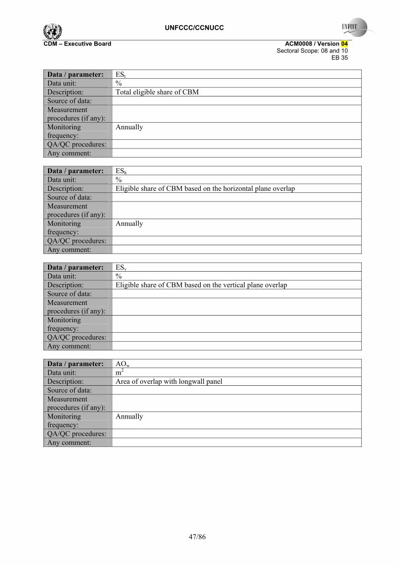
UNFCCC/CCNUCC CDM – Executive Board ACM0008 / Version 04 Sectoral Scope: 08 and 10 EB 35
47/86
Data / parameter: ESt Data unit: % Description: Total eligible share of CBM Source of data: Measurement procedures (if any):
Monitoring frequency:
Annually
QA/QC procedures: Any comment:
Data / parameter: ESh Data unit: % Description: Eligible share of CBM based on the horizontal plane overlap Source of data: Measurement procedures (if any):
Monitoring frequency:
Annually
QA/QC procedures: Any comment:
Data / parameter: ESv Data unit: % Description: Eligible share of CBM based on the vertical plane overlap Source of data: Measurement procedures (if any):
Monitoring frequency:
QA/QC procedures: Any comment:
Data / parameter: AOw Data unit: m2 Description: Area of overlap with longwall panel Source of data: Measurement procedures (if any):
Monitoring frequency:
Annually
QA/QC procedures: Any comment:

UNFCCC/CCNUCC CDM – Executive Board ACM0008 / Version 04 Sectoral Scope: 08 and 10 EB 35
48/86
Data / parameter: ATw Data unit: m2 Description: Total zone of influence Source of data: Measurement procedures (if any):
Monitoring frequency:
Annually
QA/QC procedures: Any comment:
Data / parameter: w Data unit: Description: Wells Source of data: Measurement procedures (if any):
Monitoring frequency:
QA/QC procedures: Any comment:
Data / parameter: EDCBMw,y Data unit: tCO2 Description: Avoided emissions related to CBM wells intersected by mine in year y Source of data: Measurement procedures (if any):
Monitoring frequency:
Annually
QA/QC procedures: Any comment:
Data / parameter: EDCBMz,y Data unit: tCO2 Description: Avoided emissions related to CBM wells intersected before year y Source of data: Measurement procedures (if any):
Monitoring frequency:
Annually
QA/QC procedures: Any comment:

UNFCCC/CCNUCC CDM – Executive Board ACM0008 / Version 04 Sectoral Scope: 08 and 10 EB 35
49/86
Data / parameter: EDCPMM,y Data unit: tCO2 Description: Avoided emissions related to CMM and PMM Source of data: Measurement procedures (if any):
Monitoring frequency:
Annually
QA/QC procedures: Any comment:
Data / parameter: CBMw,y Data unit: tCH4 Description: CBM captured from well intersected in yr y Source of data: Measurement procedures (if any):
Monitoring frequency:
Continuous
QA/QC procedures: Any comment: Monitor each well separately
Data / parameter: CBMz,y Data unit: tCH4 Description: CBM captured from well intersected before year y Source of data: Measurement procedures (if any):
Monitoring frequency:
Continuous
QA/QC procedures: Any comment: Monitor each well separately
Data / parameter: CBMx.y Data unit: tCH4 Description: CBM captured from well not yet intersected in yr y Source of data: Measurement procedures (if any):
Monitoring frequency:
Continuous
QA/QC procedures: Any comment: Monitor each well separately

UNFCCC/CCNUCC CDM – Executive Board ACM0008 / Version 04 Sectoral Scope: 08 and 10 EB 35
50/86
Data / parameter: PBEUse,y Data unit: tCO2e Description: Potential baseline emissions from displacement fuels Source of data: Measurement procedures (if any):
Monitoring frequency:
Annually
QA/QC procedures: Any comment:
Data / parameter: GENy Data unit: MWh Description: Electricity generation by project Source of data: Measurement procedures (if any):
Monitoring frequency:
Continuous
QA/QC procedures: Any comment:
Data / parameter: HEATy Data unit: GJ Description: Heat generation by project Source of data: Measurement procedures (if any):
Monitoring frequency:
Continuous
QA/QC procedures: Any comment:
Data / parameter: VFUELy Data unit: GJ Description: Vehicle power supplied by project Source of data: Measurement procedures (if any):
Monitoring frequency:
Continuous
QA/QC procedures: Any comment:

UNFCCC/CCNUCC CDM – Executive Board ACM0008 / Version 04 Sectoral Scope: 08 and 10 EB 35
51/86
Data / parameter: EFELEC Data unit: tCO2 /MWh Description: CO2 emission factor of the grid Source of data: Measurement procedures (if any):
Monitoring frequency:
Annually
QA/QC procedures: Any comment: Calculated as per “Tool for calculation of emission factor for electricity systems”.
Data / parameter: EFOM,y Data unit: tCO2 /MWh Description: CO2 Operating Margin emission factor of the grid Source of data: Measurement procedures (if any):
Monitoring frequency:
Annually or ex ante
QA/QC procedures: Any comment: Calculated as per “Tool for calculation of emission factor for electricity systems”.
Data / parameter: EFBM,y Data unit: tCO2 /MWh Description: CO2 Build Margin emission factor of the grid Source of data: Measurement procedures (if any):
Monitoring frequency:
Annually or ex ante
QA/QC procedures: Any comment: Calculated as per “Tool for calculation of emission factor for electricity systems”.
Data / parameter: Fi,j,y Data unit: t or m3/yr Description: Amount of each fossil fuel consumed by each power source / plant Source of data: Measurement procedures (if any):
Monitoring frequency:
Annually or ex ante
QA/QC procedures: Any comment: Obtained from the power producers, dispatch centers or latest local statistics,.

UNFCCC/CCNUCC CDM – Executive Board ACM0008 / Version 04 Sectoral Scope: 08 and 10 EB 35
52/86
Data / parameter: COEFi,k Data unit: tCO2 / t or m3 Description: CO2 emission coefficient of each fuel type and each power source / plant Source of data: Measurement procedures (if any):
Monitoring frequency:
Annually
QA/QC procedures: Any comment: Plant or country-specific values to calculate COEF are preferred to IPCC default
values, in case of obtaining EFOM ex post. Data / parameter: GENj,y Data unit: MWh/yr Description: Electricity generation of each power source / plant Source of data: Measurement procedures (if any):
Monitoring frequency:
Annually or ex ante
QA/QC procedures: Any comment: Obtained from the power producers, dispatch centers or latest local statistics..
Data / parameter: EFCO2,i Data unit: tC/TJ Description: CO2 emission factor of fuel used for captive power or heat Source of data: Measurement procedures (if any):
Monitoring frequency:
Annually or ex ante
QA/QC procedures: Any comment: National sources or IPCC defaults
Data / parameter: Effcaptive Data unit: % Description: Energy efficiency of captive power plant Source of data: Measurement procedures (if any):
Monitoring frequency:
Annually
QA/QC procedures: Any comment: Depending on option chosen in baseline, measured before or after project
implementation

UNFCCC/CCNUCC CDM – Executive Board ACM0008 / Version 04 Sectoral Scope: 08 and 10 EB 35
53/86
Data / parameter: Effheat Data unit: % Description: Energy efficiency of heat plant Source of data: Measurement procedures (if any):
Monitoring frequency:
Annually
QA/QC procedures: Any comment:
Data / parameter: EffV Data unit: % Description: Efficiency of vehicle engine Source of data: Measurement procedures (if any):
Monitoring frequency:
Annually
QA/QC procedures: Any comment:
Data / parameter: MEk Data unit: tCH4 Description: Methane extracted on day k Source of data: Measurement procedures (if any):
Monitoring frequency:
Daily/continuous
QA/QC procedures: Any comment:
Data / parameter: MMELEC,k Data unit: tCH4 Description: Methane measured for power generation on day k Source of data: Measurement procedures (if any):
Monitoring frequency:
Daily/continuous
QA/QC procedures: Any comment:

UNFCCC/CCNUCC CDM – Executive Board ACM0008 / Version 04 Sectoral Scope: 08 and 10 EB 35
54/86
Data / parameter: MMHEAT,k Data unit: tCH4 Description: Methane measured for new heat generation on day k Source of data: Measurement procedures (if any):
Monitoring frequency:
Daily/continuous
QA/QC procedures: Any comment:
Data / parameter: MMFL,k Data unit: tCH4 Description: Methane measured sent flare on day k Source of data: Measurement procedures (if any):
Monitoring frequency:
Daily/continuous
QA/QC procedures: Any comment:
Revision to the approved consolidated monitoring methodology ACM0008
“Consolidated monitoring methodology for virgin coal bed methane and coal mine methane capture and use for power (electrical or motive) and heat and/or destruction by flaring and or catalytic oxidation”
Sources
This consolidated monitoring methodology is based on elements from the following methodologies:
NM0066 “Monitoring methodology for grid-connected coalmine methane power generation at an active coal mine with existing methane extraction and partial utilization,” submitted by Hegang Coal Industry
Group Limited NM0075 “ Monitoring methodology for coal mine methane (CMM) utilization and destruction at a
working coal mine,” prepared by IT Power NM0093 “Monitoring methodology for methane utilization and destruction project activities at working
coal mines where both coal mine methane (drained from within the mine) and coal bed methane (drained from the surface within the coal mining concession area) is used and/or destroyed,” prepared
by Westlake Associates, Ltd and Asian Development Bank NM0094 “Monitoring methodology for coal mine methane recovery and utilization at active coal
mines,” prepared by Millennium Capital Services, Co. NM0102 “Generalised monitoring methodology for coal mine methane (CMM) power generation,”
prepared by the Prototype Carbon Fund
For more information regarding the proposals and their consideration by the Executive Board please refer to http://cdm.unfccc.int/methodologies/approved. This methodology also refers to the

UNFCCC/CCNUCC CDM – Executive Board ACM0008 / Version 04 Sectoral Scope: 08 and 10 EB 35
55/86
“Consolidated monitoring methodology for grid-connected electricity generation from renewable sources” (ACM0002), the “Tool for the demonstration and assessment of additionality” and the latest
version of the “Tool to determine project emissions from flaring gases containing Methane12”.
Applicability
This methodology applies to project activities that: Use surface drainage wells to capture CBM;
Use underground boreholes in the mine to capture pre mining CMM ; Use surface goaf wells, underground boreholes, gas drainage galleries or other goaf gas capture
techniques to capture post mining CMM; Use ventilation CMM air methane that would normally be vented.
This methodology applies to CMM and/or VAM capture, utilisation and destruction project activities at a working coal mine, where the baseline is the partial or total atmospheric release of the methane and
the project activities include the following situations: The methane is captured and destroyed through flaring; and/or
The methane is captured and destroyed through catalytic oxidation with or without utilisation of the thermal energy; and/or
The methane is captured and destroyed through utilisation to produce electricity, motive power and/or thermal energy; emission reductions may or may not be claimed for displacing or avoiding energy from
other sources.
The methodology applies to both new and existing mining activities.
The methodology does not apply to project activities that: Capture methane from abandoned/decommissioned coal mines;
Are not able to monitor the necessary parameters, as indicated in the relevant monitoring methodology, to provide a conservative and transparent estimate of emissions reductions achieved
Operate in opencast mines.
This monitoring methodology shall be used in conjunction with the approved consolidated baseline methodology for “Consolidated baseline methodology for coal bed methane and coal mine methane capture and use for power (electrical or motive) and heat and/or destruction by flaring”(ACM0008). Project participants must be able to supply the necessary to data for ex-ante projections of methane
demand as described in sections Baseline Emissions and Leakage of the baseline methodology to use this methodology.
Methane collected and flared: The amount of methane actually flared will be determined by monitoring
the: Aamount of CMM/CBM/VAM gas collected, using a continuous flow meter and monitoring of
temperature and pressure Ppercentage of CMM/CBM/VAM gas that is methane (%v/v ), measured using a continuous analyser
The fraction of methane in the CMM/CBM/VAM gas should be measured with a continuous analyzer or, alternatively, with periodical measurements, at a 95% confidence level , using calibrated portable
gas meters and taking a statistically valid number of samples.
12 Please refer to < http://cdm.unfccc.int/methodologies/PAmethodologies/approved.html >

UNFCCC/CCNUCC CDM – Executive Board ACM0008 / Version 04 Sectoral Scope: 08 and 10 EB 35
56/86
The parameters used for determining the project emissions from flaring of the residual gas stream (PEflare) or catalytic oxidation of the VAM stream (PEOX) should be monitored as per the “Tool to
determine project emissions from flaring gases containing Methane”.

UNFCCC/CCNUCC CDM – Executive Board ACM0008 / Version 04 Sectoral Scope: 08 and 10 EB 35
57/86
Temperature (T) and pressure (P) of the CMM/CBM/VAM gas are required to determine the density of methane in the CMM/CBM/VAM gas. 1. Project Emissions
Overall
ID no
Symbol Data variable Data
unit
Measured (m),
calculated (c) or estimated
(e)
Recording frequency
Proportion of data to
be monitored
How will the data be
archived? (electronic/
paper)
For how long is archived data to be
kept?
Comment
P1 PEy Project emissions
in year y tCO2e c Monthly 100% Electronic Crediting
period + 2 yrs
P2 PEME
Project emissions from energy use to capture and use methane
tCO2e c Monthly 100% Electronic Crediting
period + 2 yrs
P3 PEMD Project emissions
from methane destroyed
tCO2e c Monthly 100% Electronic Crediting
period + 2 yrs
P4 PEUM
Project emissions from un-
combusted methane
tCO2e c Monthly 100% Electronic Crediting
period + 2 yrs
Project emissions are defined by the following equation
PEy = PEME + PEMD + PEUM (1)
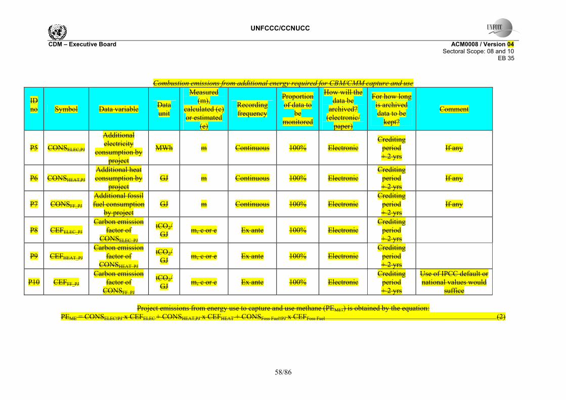
UNFCCC/CCNUCC CDM – Executive Board ACM0008 / Version 04 Sectoral Scope: 08 and 10 EB 35
58/86
Combustion emissions from additional energy required for CBM/CMM capture and use
ID no
Symbol Data variable Data
unit
Measured (m),
calculated (c) or estimated
(e)
Recording frequency
Proportion of data to
be monitored
How will the data be
archived? (electronic/
paper)
For how long is archived data to be
kept?
Comment
P5 CONSELEC,PJ
Additional electricity
consumption by project
MWh m Continuous 100% Electronic Crediting
period + 2 yrs
If any
P6 CONSHEAT,PJ
Additional heat consumption by
project GJ m Continuous 100% Electronic
Crediting period + 2 yrs
If any
P7 CONSFF_PJ Additional fossil fuel consumption
by project GJ m Continuous 100% Electronic
Crediting period + 2 yrs
If any
P8 CEFELEC_PJ Carbon emission
factor of CONSELEC_PJ
tCO2/ GJ m, c or e Ex ante 100% Electronic
Crediting period + 2 yrs
P9 CEFHEAT_PJ Carbon emission
factor of CONSHEAT_PJ
tCO2/ GJ m, c or e Ex ante 100% Electronic
Crediting period + 2 yrs
P10 CEFFF_PJ Carbon emission
factor of CONSFF_PJ
tCO2/ GJ m, c or e Ex ante 100% Electronic
Crediting period + 2 yrs
Use of IPCC default or national values would
suffice
Project emissions from energy use to capture and use methane (PEME,) is obtained by the equation: PEME = CONSELEC,PJ x CEFELEC + CONSHEAT,PJ x CEFHEAT + CONSFoss Fuel,PJ x CEFFoss Fuel (2)

UNFCCC/CCNUCC CDM – Executive Board ACM0008 / Version 04 Sectoral Scope: 08 and 10 EB 35
59/86
Combustion emissions from use of captured methane
ID no
Symbol Data variable Data
unit
Measured (m),
calculated (c) or estimated
(e)
Recording frequency
Proportion of data to
be monitored
How will the data be
archived? (electronic/
paper)
For how long is
archived data to be
kept?
Comment
P11 MDFL Methane destroyed by flare tCH4 c Calculated
monthly 100% Electronic Crediting
period + 2 yrs
P12 MMFL Methane sent to flare tCH4 m Continuous 100% Electronic
Crediting period + 2 yrs
Flow meters will record gas volumes, pressure and
temperature. Density of methane under normal
conditions of temperature and pressure is 0.67kg/m3
(Revised 1996 IPCC Reference Manual p 1.24
and 1.16)
P13 PEflare Project emissions from flaring of the residual gas stream
tCO2e m / c See comments n/a Electronic
During the crediting
period and two years
after
The parameters used for determining the project
emissions from flaring of the residual gas stream
(PEflare) should be monitored as per the “Tool to determine
project emissions from flaring gases containing
Methane”.
P14 MDOX Methane destroyed by Oxidizer tCH4 c Continuous 100% electronic
Crediting period + 2 yrs
By subtraction of P16 from P15

UNFCCC/CCNUCC CDM – Executive Board ACM0008 / Version 04 Sectoral Scope: 08 and 10 EB 35
60/86
ID no
Symbol Data variable Data
unit
Measured (m),
calculated (c) or estimated
(e)
Recording frequency
Proportion of data to
be monitored
How will the data be
archived? (electronic/
paper)
For how long is
archived data to be
kept?
Comment
P15 MMOX Methane sent to oxidizer tCH4 C Continuous 100%
Crediting period + 2 yrs
Flow meters will record gas volumes, pressure and
temperature. On-line analyzer will determine methane concentration.
Density of methane under normal conditions of
temperature and pressure is 0.67kg/m3 (Revised 1996 IPCC Reference
Manual p 1.24 and 1.16)
P16 VAMflowrat
e
Volume of VAM entering the
oxidation unit M3/sec M Continuous 100%
Crediting period + 2 yrs
Readings taken every two minutes to calculate
average hourly flow, or more frequently.
P17 Time,y
Number of second that the oxidation unit runs during
period y
sec M Continuous 100% Crediting period + 2
years
Readings taken every two minutes to calculate
average hourly flow, or more frequently.
P18 PCH4VAMinfl
ow
Pressure of VAM entering the
oxidation unit Bar M (pressure
transducer) Continuous 100% Crediting
period + 2 yrs
Readings taken every hour or more frequently to calculate hourly pressure,
or more frequently.
P19 TCH4VAMinf
low
Temperature of VAM entering the
oxidation unit Kelvin
M (thermocoupl
e) Continuous 100%
Crediting period + 2
years
Readings taken every hour or more frequently to
calculate hourly temperature, or more

UNFCCC/CCNUCC CDM – Executive Board ACM0008 / Version 04 Sectoral Scope: 08 and 10 EB 35
61/86
ID no
Symbol Data variable Data
unit
Measured (m),
calculated (c) or estimated
(e)
Recording frequency
Proportion of data to
be monitored
How will the data be
archived? (electronic/
paper)
For how long is
archived data to be
kept?
Comment
frequently.
P20 MEOX Methane emitted in
exhaust from oxidizer
tCH4 C Continuous 100% Crediting
period + 2 yrs
Closed system so inlet flow equals exhaust flow at standard conditions.
Flow mMeters will record gas volumes, pressure and
temperature. On-line analyzer will determine methane concentration.
Density of methane under normal conditions of
temperature and pressure is 0.67kg/m3 (Revised 1996 IPCC Reference
Manual p 1.24 and 1.16)
P21 PCH4exhaust Pressure of exhaust
gases exiting the oxidation unit
Bar M (pressure transducer) Continuous 100%
Crediting period + 2 yrs
Readings taken every hour or more frequently to calculate hourly pressure,
or more frequently.
P22 TCH4exhaust
Temperature of exhaust gases
exiting the oxidation unit
Kelvin M
(thermocouple)
Continuous 100% Crediting period + 2
years
Readings taken every hour or more frequently to
calculate hourly temperature, or more
frequently. P2314 MDELEC Methane destroyed
by power tCH4 c Calculated monthly 100% Electronic Crediting
period

UNFCCC/CCNUCC CDM – Executive Board ACM0008 / Version 04 Sectoral Scope: 08 and 10 EB 35
62/86
ID no
Symbol Data variable Data
unit
Measured (m),
calculated (c) or estimated
(e)
Recording frequency
Proportion of data to
be monitored
How will the data be
archived? (electronic/
paper)
For how long is
archived data to be
kept?
Comment
generation + 2 yrs
P2415 MMELEC Methane sent to
power plant tCH4 m Continuous 100% Electronic Crediting
period + 2 yrs
Flow meters will record gas volumes, pressure and
temperature. Density of methane under normal
conditions of temperature and pressure is 0.67kg/m3
(Revised 1996 IPCC Reference Manual p 1.24
and 1.16)
P2516 EffELEC
Efficiency of methane
destruction/oxidation in power plant
- e Ex-ante set at 99.5%(IPCC)
P2617 MDHEAT Methane destroyed
by heat generation tCH4 c Calculated monthly 100% Electronic
Crediting period + 2 yrs
P2718 MMHEAT Methane sent to
boiler tCH4 m Eontinuous 100% Electronic Crediting
period + 2 yrs
Flow meters will record gas volumes, pressure and
temperature. Density of methane under normal
conditions of temperature and pressure is 0.67kg/m3
(Revised 1996 IPCC Reference Manual p 1.24
and 1.16)

UNFCCC/CCNUCC CDM – Executive Board ACM0008 / Version 04 Sectoral Scope: 08 and 10 EB 35
63/86
ID no
Symbol Data variable Data
unit
Measured (m),
calculated (c) or estimated
(e)
Recording frequency
Proportion of data to
be monitored
How will the data be
archived? (electronic/
paper)
For how long is
archived data to be
kept?
Comment
P2819 EffHEAT
Efficiency of methane
destruction/oxidation in heat plant
- e Ex ante set at 99.5%(IPCC)
P290 MDGAS
Methane destroyed by gas grid end-
users tCH4 c 100% Eelectronic
Crediting period + 2 yrs
P3021 MMGAS Methane sent to gas
grid for end users tCH4 m Continuous 100% Electronic Crediting
period + 2 yrs
Flow meters will record gas volumes, pressure and
temperature. Density of methane under normal
conditions of temperature and pressure is 0.67kg/m3
(Revised 1996 IPCC Reference Manual p 1.24
and 1.16)
P3122 EffGAS
Overall efficiency of methane
destruction / oxidation through
gas grid
- e Ex ante set at 98.5% (IPCC)
P3223
CEFCH4 Carbon emission factor for
combusted methane set at 2.75 tCO2e/tCH4

UNFCCC/CCNUCC CDM – Executive Board ACM0008 / Version 04 Sectoral Scope: 08 and 10 EB 35
64/86
ID no
Symbol Data variable Data
unit
Measured (m),
calculated (c) or estimated
(e)
Recording frequency
Proportion of data to
be monitored
How will the data be
archived? (electronic/
paper)
For how long is
archived data to be
kept?
Comment
P3324
CEFNMHC Carbon emission factor for
combusted non methane
hydrocarbons (various)
To be obtained through periodical analysis of the fractional composition of
captured
P3425 PCCH4
Concentration of methane in
extracted gas
% m (concentratio
n meters, optical and calorific)
Hourly/Daily 100% Electronic Crediting period + 2 yrs
To be measured on wet basis.
P35 PCNMHC NMHC
concentration in coal mine gas
%
m (concentratio
n meters, optical and calorific)
Annually 100% Crediting
period + 2 yrs
Used to check if more than 1% of emissions and
to calculate r
P36 PCCH4VAM Concentration of methane in VAM %
M (on line, low reading
methanometer)
Continuous 100%
Crediting period + 2 yrs
readings taken at least every two minutes and
used to calculate average methane concentration
per hour or more frequently.
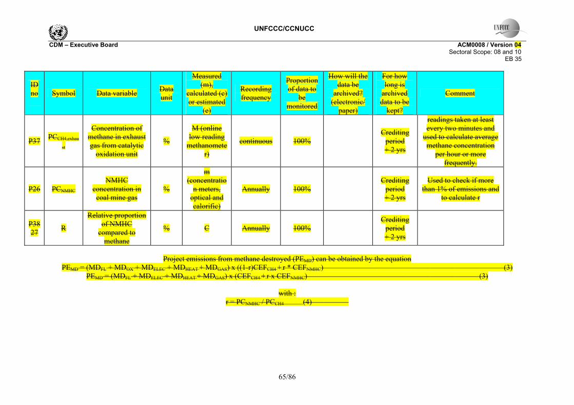
UNFCCC/CCNUCC CDM – Executive Board ACM0008 / Version 04 Sectoral Scope: 08 and 10 EB 35
65/86
ID no
Symbol Data variable Data
unit
Measured (m),
calculated (c) or estimated
(e)
Recording frequency
Proportion of data to
be monitored
How will the data be
archived? (electronic/
paper)
For how long is
archived data to be
kept?
Comment
P37 PCCH4,exhau
st
Concentration of methane in exhaust gas from catalytic
oxidation unit
%
M (online low reading
methanometer)
continuous 100% Crediting
period + 2 yrs
readings taken at least every two minutes and
used to calculate average methane concentration
per hour or more frequently.
P26 PCNMHC NMHC
concentration in coal mine gas
%
m (concentratio
n meters, optical and calorific)
Annually 100% Crediting
period + 2 yrs
Used to check if more than 1% of emissions and
to calculate r
P3827 R
Relative proportion of NMHC
compared to methane
% C Annually 100% Crediting
period + 2 yrs
Project emissions from methane destroyed (PEMD) can be obtained by the equation
PEMD = (MDFL + MDOX + MDELEC + MDHEAT + MDGAS) x ((1-r)CEFCH4 + r * CEFNMHC) (3) PEMD = (MDFL + MDELEC + MDHEAT + MDGAS) x (CEFCH4 + r x CEFNMHC) (3)
with :
r = PCNMHC / PCCH4 (4)

UNFCCC/CCNUCC CDM – Executive Board ACM0008 / Version 04 Sectoral Scope: 08 and 10 EB 35
66/86
Where::13 PEMD Project emissions from CMM/CBM destroyed (tCO2e) MDFL Methane destroyed through flaring (tCH4) MDOX Methane destroyed by oxidation (tCH4)
MDELEC Methane destroyed through power generation (tCH4) MDHEAT Methane destroyed through heat generation (tCH4) MDGAS Methane destroyed after being supplied to gas grid or for vehicle use (tCH4) CEFCH4 Carbon emission factor for combusted methane (2.75 tCO2e/tCH4)
CEFNMHC Carbon emission factor for combusted non methane hydrocarbons (various) (tCO2eq/tNMHC)
R Relative proportion of NMHC compared to methane PcCH4 Concentration (in mass) of methane in extracted gas (%)
PcNMHC NMHC concentration (in mass) in extracted gas (%)
In each end-use, the amount of gas destroyed depends on the efficiency of combustion of each end use.
13 Note that throughout this monitoring methodology, it is assumed that measured quantities of coal mine gas are converted to tonnes of methane using the measured methane concentration of the coal mine gas or VAM and the density of methane.

UNFCCC/CCNUCC CDM – Executive Board ACM0008 / Version 04 Sectoral Scope: 08 and 10 EB 35
67/86
Un-combusted methane from the project activity, flaring, catalytic oxidationg and end uses
ID no
Symbol Data variable Data
unit
Measured (m),
calculated (c) or estimated
(e)
Recording frequency
Proportion of data to
be monitored
How will the data be
archived? (electronic/
paper)
For how long is archived data to be
kept?
Comment
P3928 GWPCH4
Global warming potential of
methane - e Ex ante set at 21
P4029 MMi
Methane measured sent to
use i tCH4 m Continuous 100% Electronic
Crediting period + 2 yrs
Flow meters will record gas volumes,
pressure and temperature.
P4130 Effi
Efficiency of methane
destruction / oxidation
through use i (power
generation, heat generation,
supply to gas grid to various
combustion end uses)
- m, c, or e Ex ante or ex post 100% Electronic
Crediting period + 2 yrs
P4231 PEflare
Project emissions from flaring of the residual gas
stream
tCO2e m / c See comments n/a Electronic
During the crediting
period and two years
after
The parameters used for determining the
project emissions from flaring of the residual
gas stream (PEflare) should be monitored as

UNFCCC/CCNUCC CDM – Executive Board ACM0008 / Version 04 Sectoral Scope: 08 and 10 EB 35
68/86
per the “Tool to determine project
emissions from flaring gases containing
Methane”.
P43 PEOX
Project emissions from the catalytic
oxidation of VAM
tCO2e m / c See comments n/a Electronic
During the crediting
period and two years
after
Meters will record methanegas
concentration, pressure and temperature. Flow
measured at inlet. Density of methane
under normal conditions of
temperature and pressure is 0.67kg/m3 (Revised 1996 IPCC Reference Manual p
1.24 and 1.16)
P44 PEMvent
Emissions of methane vented to atmosphere
during the project activity
tCH4 m Continuous 100% Electronic
During the crediting
period and two years
after
This parameter is to include any methane vented to atmosphere
through flares, in ventilation air methane
as well as direct emissions through
vents
Uncombusted methane from flaring and end uses (PEUM) can be obtained through the equation:

UNFCCC/CCNUCC CDM – Executive Board ACM0008 / Version 04 Sectoral Scope: 08 and 10 EB 35
69/86
( ) oxflarei
iiCHUM PEPEEffMMGWPPE ++−××= ∑ ]1[ 4
(109)

UNFCCC/CCNUCC CDM – Executive Board ACM0008 / Version 04 Sectoral Scope: 08 and 10 EB 35
70/86
2. Baseline emissions Overall
ID no Symbol Data
variable Data unit
Measured (m)
calculated (c)
estimated (e)
Recording frequency
Proportion of data
monitored
How will data be
archived? (electronic/
paper)
For how long is archived data
kept? Comment
B1 BEy Baseline emissions in
year y tCO2 c Yearly 100% Electronic Crediting
period + 2 yrs
B2
BEMD,y Baseline emissions from destruction of
methane in the baseline scenario in
year y
tCO2 c Yearly 100% Electronic Crediting
period + 2 yrs
B3
BEMR,y Baseline emissions from release of
methane into the atmosphere in year y that is avoided by the
project activity
tCO2 c Yearly 100% Electronic Crediting
period + 2 yrs
B4
BEUse,y Baseline emissions from the production
of power, heat or supply to gas grid
replaced by the project activity in
year y
tCO2 c Yearly 100% Electronic Crediting
period + 2 yrs
Baseline emissions are given by the following equation: BEy = BEMD,y + BEMR,y + BEUse,y (110)

UNFCCC/CCNUCC CDM – Executive Board ACM0008 / Version 04 Sectoral Scope: 08 and 10 EB 35
71/86
Methane destruction due to thermal demand in the baseline
ID no Symbol Data
variable Data unit
Measured (m)
calculated (c)
estimated (e)
Recording frequency
Proportion of data
monitored
How will data be
archived? (electronic/
paper)
For how long is archived data
kept? Comment
B5
CBMBL,i,y CBM that would have been captured, used and
destroyed by use i in the baseline scenario in year y
tCH4 e
Estimated ex-ante at
start of project
100% Eelectronic Crediting period + 2 yrs
B6
CMMBL,i CMM that would have been captured, used and
destroyed by use i in the baseline scenario in year y
tCH4 e
Estimated ex-ante at
start of project
100% Electronic Crediting period + 2 yrs
B7
PMMBL,i PMM that would have been captured, used and
destroyed by use i in the baseline scenario in year y
tCH4 e
Estimated ex-ante at
start of project
100% Electronic Crediting period + 2 yrs
B8
VAMBLi,y VAM that would have been captured, used and
destroyed by use i in the baseline scenario in year y
tCH4 e
estimated ex-ante at
start of project
100% electronic crediting period + 2 yrs
B9
THBL,y Projected annual baseline CMM / CBM demand for
thermal energy uses tCH4 e Ex-ante 100% Electronic Crediting period + 2yrs
estimated by procedure defined in
the corresponding baseline
methodology
B10 CEFCH4 Carbon emission factor for methane
tCO2e/ tCH4
e Ex-ante 100% 2.75 tCO2e/tCH4

UNFCCC/CCNUCC CDM – Executive Board ACM0008 / Version 04 Sectoral Scope: 08 and 10 EB 35
72/86
ID no Symbol Data
variable Data unit
Measured (m)
calculated (c)
estimated (e)
Recording frequency
Proportion of data
monitored
How will data be
archived? (electronic/
paper)
For how long is archived data
kept? Comment
B11 dk
max scalar adjustment factor for day k, based on the seasonal load shape (Σ dk
max > 365) - c Ex-ante 100% Electronic Crediting
period+2yrs
Methane destruction due to thermal demand in the baseline (BEMD,y) is obtained by the equation:
∑ +++××+−=i
yBLiyiBLyBLiyBLiNMHCCHMRy VAMPMMCMMCBMCEFrCEFrBE )())1(( ,,,,4 (12)
∑ ++××+=i
yiBLyBLiyBLiNMHCCHMRy PMMCMMCBMCEFrCEFBE )()( ,,,4 (11)
where:
BEMD,y Baseline emissions from destruction of methane in the baseline scenario in year y (tCO2e)
i Use of methane (flaring, power generation, heat generation, supply to gas grid to various combustion end uses)
CBMBLi,,y CBM that would have been captured, sent to and destroyed by use i in the baseline scenario in the year y (expressed in tCH4)
CMMBL,i,y Pre-mining CMM that would have been captured, sent to and destroyed by use i in the baseline scenario in year y (expressed in tCH4)
PMMBLi,,y post-mining CMM that would have been captured, sent to and destroyed by use i in the baseline scenario in year y (tCH4)
VAMBLi,,y VAM that would have been captured, sent to and destroyed by use i in the baseline scenario in year y (tCH4)
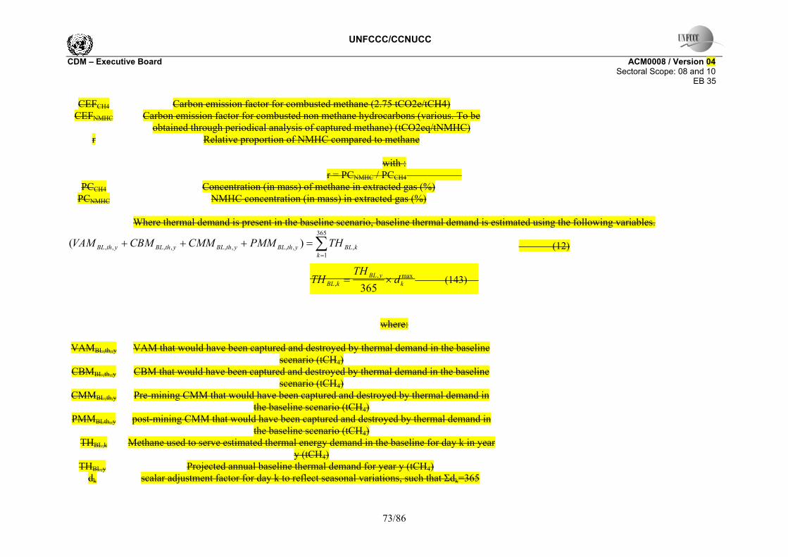
UNFCCC/CCNUCC CDM – Executive Board ACM0008 / Version 04 Sectoral Scope: 08 and 10 EB 35
73/86
∑=
=+++365
1,,,,,,,,, )(
kkBLythBLythBLythBLythBL THPMMCMMCBMVAM
CEFCH4 Carbon emission factor for combusted methane (2.75 tCO2e/tCH4) CEFNMHC Carbon emission factor for combusted non methane hydrocarbons (various. To be
obtained through periodical analysis of captured methane) (tCO2eq/tNMHC) r Relative proportion of NMHC compared to methane
with :
r = PCNMHC / PCCH4 PCCH4 Concentration (in mass) of methane in extracted gas (%)
PCNMHC NMHC concentration (in mass) in extracted gas (%)
Where thermal demand is present in the baseline scenario, baseline thermal demand is estimated using the following variables.
(12)
max,, 365 k
yBLkBL d
THTH ×= (143)
where:
VAMBL,th,,y VAM that would have been captured and destroyed by thermal demand in the baseline scenario (tCH4)
CBMBL,th,,y CBM that would have been captured and destroyed by thermal demand in the baseline scenario (tCH4)
CMMBL,th,y Pre-mining CMM that would have been captured and destroyed by thermal demand in the baseline scenario (tCH4)
PMMBLth,,y post-mining CMM that would have been captured and destroyed by thermal demand in the baseline scenario (tCH4)
THBL,k Methane used to serve estimated thermal energy demand in the baseline for day k in year y (tCH4)
THBL,y Projected annual baseline thermal demand for year y (tCH4) dk scalar adjustment factor for day k to reflect seasonal variations, such that Σdk=365

UNFCCC/CCNUCC CDM – Executive Board ACM0008 / Version 04 Sectoral Scope: 08 and 10 EB 35
74/86
dmaxk maximum scalar adjustment factor for day k over the 5 years prior to the start of the
project activity (i.e. Σdmaxk>365)
Baseline emissions from methane released into the atmosphere
i. Overall
ID number Symbol Data
variable Data unit
Measured (m)
calculated (c)
estimated (e)
Recording frequency
Proportion of data
monitored
How will data be archived? (electronic/
paper)
For how long is archived data kept?
Comment
B12 CBMei,.y
Eligible CBM captured, sent
to and destroyed by use i in the project for
year y
tCH4 c Yearly 100% Electronic Crediting
period + 2 yrs
B13 CBMBL,i,y
CBM that would have
been captured , sent to and
destroyed by use i in the
baseline scenario
tCH4 c,e Ex ante 100% Electronic Crediting
period + 2 yrs

UNFCCC/CCNUCC CDM – Executive Board ACM0008 / Version 04 Sectoral Scope: 08 and 10 EB 35
75/86
ID number Symbol Data
variable Data unit
Measured (m)
calculated (c)
estimated (e)
Recording frequency
Proportion of data
monitored
How will data be archived? (electronic/
paper)
For how long is archived data kept?
Comment
B14 CMMPJ, i,y
Pre-mining CMM
captured, sent to and
destroyed by use i in the
project activity in year y
tCH4 m Continuous 100% Electronic Crediting
period + 2 yrs
B15 CMMBL, i,y
Pre-mining CMM that would have
been captured , sent to and
destroyed by use i in the
baseline scenario in
year y
tCH4 c,e Ex ante 100% Electronic Crediting
period + 2 yrs
B16 VAMPJ, i,y
VAM captured, sent
to and destroyed by use i in the
project activity in year y
tCH4 m continuous 100% electronic & Paper
Crediting period + 2 yrs

UNFCCC/CCNUCC CDM – Executive Board ACM0008 / Version 04 Sectoral Scope: 08 and 10 EB 35
76/86
ID number Symbol Data
variable Data unit
Measured (m)
calculated (c)
estimated (e)
Recording frequency
Proportion of data
monitored
How will data be archived? (electronic/
paper)
For how long is archived data kept?
Comment
B17 VAMBL, i,y
VAM that would have
been captured , sent to and
destroyed by use i in the
baseline scenario in
year y
tCH4 c,e ex ante 100% electronic Crediting
period + 2 yrs
B186 PMMPJ, i,y
post-mining CMM
captured, sent to and
destroyed by use i in the
project activity in year y
tCH4 m Continuous 100% Electronic & Paper
Crediting period + 2 yrs

UNFCCC/CCNUCC CDM – Executive Board ACM0008 / Version 04 Sectoral Scope: 08 and 10 EB 35
77/86
ID number Symbol Data
variable Data unit
Measured (m)
calculated (c)
estimated (e)
Recording frequency
Proportion of data
monitored
How will data be archived? (electronic/
paper)
For how long is archived data kept?
Comment
B197 PMMBL, i,y
post-mining CMM that would have
been captured , sent to and
destroyed by use i in the
baseline scenario in
year y
tCH4 c,e Ex ante 100% Electronic Crediting
period + 2 yrs
B2018 GWPCH4
Global warming
potential of methane
tCO2e/ tCH4
e Ex ante 21 tCO2e/tCH4
B1219 CEFCH4
Carbon emission factor for
combusted methane
tCO2e/tCH4
e Ex ante 44/16 = 2.75 tCO2e/tCH4
The baseline emissions from release of methane into the atmosphere in the year y (BEMR,y) is obtained by the following equation:
BEMR,y = [(CBMe,y – CBMBL,y)+ (CMMPJ,y - CMMBL,y)+ (VAMPJ,y - VAMBL,y)+ (PMMPJ,y - PMMBL,y)] x GWPCH4 BEMR,y = [(CBMe,y – CBMBL,y)+ (CMMPJ,y - CMMBL,y)+ (PMMPJ,y - PMMBL,y)] x GWPCH4 (154)

UNFCCC/CCNUCC CDM – Executive Board ACM0008 / Version 04 Sectoral Scope: 08 and 10 EB 35
78/86
ii. Estimation of eligible CBM
ID number Symbol Data
variable Data unit
Measured (m)
calculated (c)
estimated (e)
Recording frequency
Proportion of data
monitored
How will data be archived? (electronic/
paper)
For how long is archived data kept?
Comment
B220 R Cumulative
radius of zone of influence
m c Annually 100% Electronic Crediting
period + 2 yrs
B231 Vw Cumulative flow at well m3 m/c 100% Electronic &
Paper
Crediting period + 2 yrs
Monitoring at each well should record gas flow, methane concentration,
pressure, and temperature
B242 T Thickness of all coal accessed by
wells m coal m Annually 100% Paper/Electro
nic
Crediting period + 2 yrs
Depth of fractures into respective seams and casing used should be
recorded at time of drilling
B253 ρcoal density of locally
mined coal t/m3 m
At start of each
crediting period
Sample Electronic & Paper
Crediting period + 2 yrs
default value is 1.4
B264 gcoal gas content of
coal m3CH4/t coal m
At start of each
crediting period
Sample Electronic & Paper
Crediting period + 2 yrs
B275 n number of days the selected well
is operational days m Electronic &
Paper
Crediting period + 2 yrs

UNFCCC/CCNUCC CDM – Executive Board ACM0008 / Version 04 Sectoral Scope: 08 and 10 EB 35
79/86
ID number Symbol Data
variable Data unit
Measured (m)
calculated (c)
estimated (e)
Recording frequency
Proportion of data
monitored
How will data be archived? (electronic/
paper)
For how long is archived data kept?
Comment
B286 Va Average flow per
day m3/day c 100% Electronic & Paper
Crediting period + 2 yrs
B297 Vc Cumulative flow
from all wells m3/day m 100% Electronic & Paper
Crediting period + 2 yrs
Total flow from all boreholes measured at
collection manifold using automatic remote monitoring of gas flow, methane concentration,
pressure and temperature
B3028 N sum of days all wells operational days c Electronic &
Paper
Crediting period + 2 yrs
B3129 Position of wells
relative to mining plan
coordi-nates m annually 100% Paper/
Electronic
Crediting period + 2 yrs
Recorded in PDD ex-ante. New drawing produced each year.
B320
Well profile coordi-nates m annually 100% Paper/
Electronic
Crediting period + 2 yrs
Shows each well and zone of influence
against latest mining plan
B331
Well depth m m at time of drilling 100% Paper/
Electronic
Crediting period + 2 yrs
Based on actual drilling records

UNFCCC/CCNUCC CDM – Executive Board ACM0008 / Version 04 Sectoral Scope: 08 and 10 EB 35
80/86
ID number Symbol Data
variable Data unit
Measured (m)
calculated (c)
estimated (e)
Recording frequency
Proportion of data
monitored
How will data be archived? (electronic/
paper)
For how long is archived data kept?
Comment
B342 t Total thickness of coal in longwall emission zone
m m
at start of each
crediting period
Paper/ Electronic
Crediting period + 2 yrs
From geology report and drilling records
B353 ESt total eligible share of CBM % c annually 100%? Electronic Crediting
period +2yrs
B364
ESh eligible share of CBM based on the horizontal plane overlap
% c Annually 100%? Electronic Crediting period +2yrs
B375
ESv eligible share of CBM based on
the vertical plane overlap
% c Annually 100%? Electronic Crediting
period +2yrs
B386 AOw Area of overlap with longwall
panel m2 e Annually 100%? Electronic &
Paper
Crediting period + 2 yrs
B397 ATw Total zone of influence m2 c Annually 100%? Electronic &
Paper
Crediting period + 2 yrs
B4038 w wells

UNFCCC/CCNUCC CDM – Executive Board ACM0008 / Version 04 Sectoral Scope: 08 and 10 EB 35
81/86
Baseline emissions from power/heat generation and vehicle replaced by project
ID No Symbol Data
variable Data unit
Measured (m)
calculated (c)
estimated (e)
Recording frequency
Proportion of data
monitored
How will data be
archived? (electronic/
paper)
For how long is archived data
kept? Comment
B4139 EDCBMw,y
Avoided emissions related to CBM wells intersected by mine in year y
tCO2 c Annually 100% Electronic Crediting period + 2 yrs
B420 EDCBMz,y
Avoided emissions related to CBM wells intersected
before year y
tCO2 c Annually 100% Electronic Crediting period + 2 yrs
B431 EDCPMM,y Avoided emissions
related to CMM and PMM
tCO2 c Annually 100% Electronic Crediting period + 2 yrs
B442 CBMw,y CBM captured
from well intersected in yr y
tCH4 m Continuous 100% Electronic Crediting period + 2 yrs
Monitor each well separately
B453 CBMz,y
CBM captured from well
intersected before year y
tCH4 m Continuous 100% Electronic Crediting period + 2 yrs
Monitor each well separately
B464 CBMx.y CBM captured
from well not yet intersected in yr y
tCH4 m Continuous 100% Electronic Crediting period + 2 yrs
Monitor each well separately
B475 PBEUse,y Potential baseline emissions from
displacement fuelstCO2e c Annually 100% Electronic Crediting
period + 2 yrs
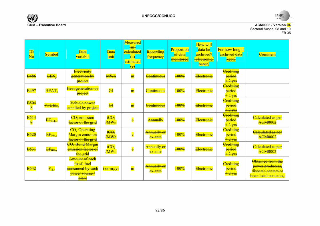
UNFCCC/CCNUCC CDM – Executive Board ACM0008 / Version 04 Sectoral Scope: 08 and 10 EB 35
82/86
ID No Symbol Data
variable Data unit
Measured (m)
calculated (c)
estimated (e)
Recording frequency
Proportion of data
monitored
How will data be
archived? (electronic/
paper)
For how long is archived data
kept? Comment
B486 GENy Electricity
generation by project
MWh m Continuous 100% Electronic Crediting
period + 2 yrs
B497 HEATy Heat generation by
project GJ m Continuous 100% Electronic Crediting
period + 2 yrs
B5048 VFUELy
Vehicle power supplied by project GJ m Continuous 100% Electronic
Crediting period + 2 yrs
B5149 EFELEC CO2 emission
factor of the grid tCO2
/MWh c Annually 100% Electronic Crediting
period + 2 yrs
Calculated as per ACM0002
B520 EFOM,y CO2 Operating
Margin emission factor of the grid
tCO2 /MWh c Annually or
ex ante 100% Electronic Crediting
period + 2 yrs
Calculated as per ACM0002
B531 EFBM,y CO2 Build Margin emission factor of
the grid
tCO2 /MWh c Annually or
ex ante 100% Electronic Crediting
period + 2 yrs
Calculated as per ACM0002
B542 Fi,j,y
Amount of each fossil fuel
consumed by each power source /
plant
t or m3/yr m Annually or ex ante 100% Electronic
Crediting period + 2 yrs
Obtained from the power producers,
dispatch centers or latest local statistics,.
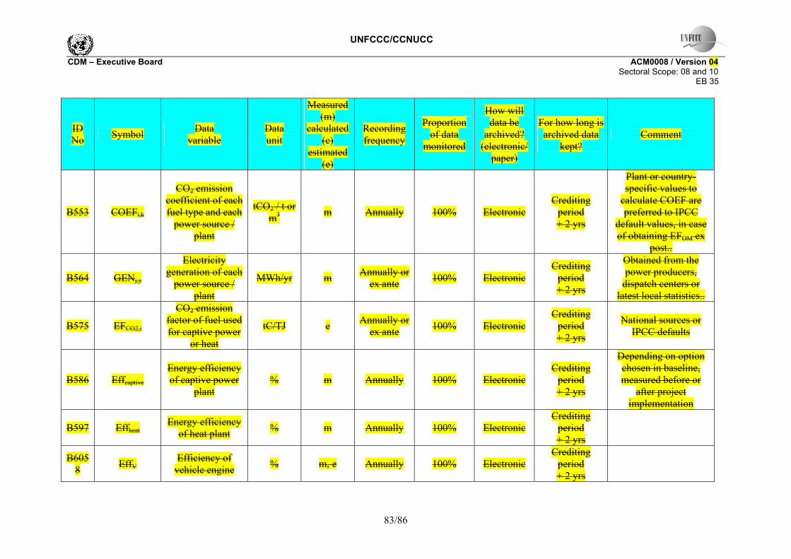
UNFCCC/CCNUCC CDM – Executive Board ACM0008 / Version 04 Sectoral Scope: 08 and 10 EB 35
83/86
ID No Symbol Data
variable Data unit
Measured (m)
calculated (c)
estimated (e)
Recording frequency
Proportion of data
monitored
How will data be
archived? (electronic/
paper)
For how long is archived data
kept? Comment
B553 COEFi,k
CO2 emission coefficient of each fuel type and each
power source / plant
tCO2 / t or m3 m Annually 100% Electronic
Crediting period + 2 yrs
Plant or country-specific values to
calculate COEF are preferred to IPCC
default values, in case of obtaining EFOM ex
post..
B564 GENj,y
Electricity generation of each
power source / plant
MWh/yr m Annually or ex ante 100% Electronic
Crediting period + 2 yrs
Obtained from the power producers,
dispatch centers or latest local statistics..
B575 EFCO2,i
CO2 emission factor of fuel used for captive power
or heat
tC/TJ e Annually or ex ante 100% Electronic
Crediting period + 2 yrs
National sources or IPCC defaults
B586 Effcaptive Energy efficiency of captive power
plant % m Annually 100% Electronic
Crediting period + 2 yrs
Depending on option chosen in baseline, measured before or
after project implementation
B597 Effheat Energy efficiency
of heat plant % m Annually 100% Electronic Crediting
period + 2 yrs
B6058 EffV Efficiency of
vehicle engine % m, e Annually 100% Electronic Crediting
period + 2 yrs

UNFCCC/CCNUCC CDM – Executive Board ACM0008 / Version 04 Sectoral Scope: 08 and 10 EB 35
84/86
BEUse,y = EDCBMw,y + EDCBMz,y + EDCPMM,y (232)
BEUse,y Total baseline emissions from the production of power or heat replaced by the project activity in year y (tCO2)
EDCBMw,y Emissions from displacement of end uses by use of coal bed methane captured from wells where the mining area intersected the zone of influence in year y (tCO2)
EDCBMz,y Emissions from displacement of end uses by use of coal bed methane captured from wells where the mining area intersected the zone of influence prior to year y (tCO2)
EDCPMM,y Emissions from displacement of end uses by use of coal mine methane and post-mining methane and VAM (tCO2)
The total methane captured during year y can be described as follows:
CBMMtot,y = CBMw,y + CBMz,y + CBMx,y + CMMPJ,y + PMMPJ,y + VAMPJ,y (23)
CBMMtot,y = CBMw,y + CBMz,y + CBMx,y + CMMPJ,y + PMMPJ,y (23)
CBMMtot,y Total CBM, and CMM and VAM captured and utilised by the project activity (tCH4) CBMw,.y CBM captured from wells where the mining area intersected the zone of influence in
year y (tCH4) CBMz,.y CBM captured from wells where the mining area intersected the zone of influence prior
to year y (tCH4) CBMx,.y CBM captured from wells where the mining area has not yet intersected the zone of
influence in year y (tCH4) CMMPJ,i,y Pre-mining CMM captured by the project activity in year y (tCH4) PMMPJ,i,y Post-mining CMM captured by the project activity in year y (tCH4) VAMPJ,i,y VAM captured by the project activity in year y (tCH4)
The total potential emissions reductions from displacement of power/heat generation and vehicle fuels are given by the following equation:

UNFCCC/CCNUCC CDM – Executive Board ACM0008 / Version 04 Sectoral Scope: 08 and 10 EB 35
85/86
PBEUse,y = GEN,y x EFELEC+ HEATy x EFHEAT + VFUELy x EFV (254)
Where, PBEUse,y Potential total baseline emissions from the production of power or heat replaced by the
project activity in year y (tCO2e) GENy Electricity generated by project activity in year y (MWh), including through the use of
CBM EFELEC Emissions factor of electricity (grid, captive or a combination) replaced by project
(tCO2/MWh) HEATy Heat generation by project activity in year y (GJ), including through the use of CBM EFHEAT Emissions factor for heat production replaced by project activity (tCO2/GJ)
VFUELy Vehicle fuel provided by the project activity in year y (GJ), including through the use of CBM
EFV Emissions factor for vehicle operation replaced by project activity (tCO2/GJ)
Leakage emissions from displacement of baseline thermal energy uses
ID no. Symbol Data
variable Data unit
Measured (m)
calculated (c)
estimated (e)
Recording frequency
Proportion of data
monitored
How will data be
archived? (electronic/
paper)
For how long is archived data
kept? Comment
L1 MEk Methane extracted
on day k tCH4 m daily/continuous? 100% electronic
Crediting period + 2 yrs
L2 MMELEC,k
Methane measured for power
generation on day k
tCH4 m daily/continuous? 100% electronic
Crediting period + 2 yrs

UNFCCC/CCNUCC CDM – Executive Board ACM0008 / Version 04 Sectoral Scope: 08 and 10 EB 35
86/86
ID no. Symbol Data
variable Data unit
Measured (m)
calculated (c)
estimated (e)
Recording frequency
Proportion of data
monitored
How will data be
archived? (electronic/
paper)
For how long is archived data
kept? Comment
L3 MMHEAT,k
Methane measured for new heat
generation on day k
tCH4 m daily/continuous? 100% electronic
Crediting period + 2 yrs
L4 MMFL,k Methane measured sent flare on day k tCH4 m daily/contin
uous? 100% electronic Crediting
period + 2 yrs
The other factors used for calculating baseline thermal demand are described under B9 and B11.
- - - - -