iRMX™86 INTRODUCTION AND OPERATOR'S
403
intel ® iRMX™86 INTRODUCTION AND OPERATOR'S REFERENCE MANUAL For Release 6 Copyright ® 1984, Intel Corporation Intel Corporation, 3065 Bowers Avenue, Santa Clara, California 95051 Order Number: 1 461 94-001
-
Upload
khangminh22 -
Category
Documents
-
view
2 -
download
0
Transcript of iRMX™86 INTRODUCTION AND OPERATOR'S

intel®
iRMX™86INTRODUCTION AND OPERATOR'S
REFERENCE MANUALFor Release 6
Copyright ® 1984, Intel Corporation
Intel Corporation, 3065 Bowers Avenue, Santa Clara, California 95051Order Number: 1 461 94-001


ASSEMBLY INSTRUCTIONS
Volume: iRMXw 86 INTRODUCTION AND OPERATORS REFERENCE MANUALOrder No: 146194
INTRODUCTION
This sheet describes how to assemble this iRMX 86 literature packet. Theassembly is simple and takes less than 5 minutes.
This literature packet contains:
• The literature in the volume, including this instruction sheetand these manuals:
- INTRODUCTION TO THE iRMX 86 OPERATING SYSTEM- iRMX 86 OPERATOR'S MANUAL- iRMX 86 DISK VERIFICATION UTILITY REFERENCE MANUAL
• The first of two cardboard separators.
• Three divider tabs, one for each manual.
• The bottom cardboard separator.
If your literature packet is missing one or more of these items, contactIntel immediately.
ASSEMBLY
Assembling the volume involves inserting the literature packet into athree-ring binder and placing an appropriately labeled divider tab at thefront of each manual in the volume.
At this point you have torn open the shrink wrapping, removed the entireliterature packet, and extracted this sheet from the packet. Set thissheet aside. You will be referring to it as you go.
To put the volume together, follow these steps:
1. Separate the divider tabs from the rest of the literature packet.Tear off the shrink wrapping. Discard the cardboard. The dividertabs have these labels and match these manuals:
Label Manual
Introduction INTRODUCTION TO THE iRMX 86 OPERATING SYSTEMOperator iRMX 86 OPERATOR'S MANUALDisk Verify iRMX 86 DISK VERIFICATION UTILITY REFERENCE MANUAL
(over)

ASSEMBLY INSTRUCTIONS (continued)
2. Find Page ix, which is at the end of the Volume Contents. Open the
binder rings and insert the Front Cover up to and including Page ix
into the left side of the open rings. The top page of the literature
packet is now the "Introduction" title page, which looks like this:
INTRODUCTION TO THEIRMX'"86
OPERATING SYSiTEM
3. Insert the divider tab labeled "Introduction" into the left side of
the open rings.
4. Insert the text of the Introduction manual into the left side of the
binder rings. The last page of the Introduction manual is
"Introduction Index-4." The top page of the literature packet should
now be the title page of the Operator's manual.
5.N
Repeat the process for the remaining manuals, matching divider tabs
with manuals.
6. Close the binder rings. Discard the shrink wrapping and this
instruction sheet.
***

iRMX™ 86INTRODUCTION AND OPERATOR'S
REFERENCE MANUALFor Release 6
Order Number: 146194-001
Copyright ® 1 984, Intel CorporationIntel Corporation, 3065 Bowers Avenue, Santa Clara, California 95051

Additional copies of this manual or other Intel literature may be obtained from:
Literature DepartmentIntel Corporation
3065 Bowers AvenueSanta Clara, CA 95051
The information in this document is subject to change without notice.
Intel Corporation makes no warranty of any kind with regard to this material, including, but not limit-
ed to, the implied warranties of merchantability and fitness for a particular purpose. Intel Corporation
assumes no responsibility for any errors that may appear in this document. Intel Corporation makes
no commitment to update nor to keep current the information contained in this document.
Intel Corporation assumes no responsibility for the use of any circuitry other than circuitry embodied
in an Intel product. No other circuit patent licenses are implied.
Intel software products are copyrighted by and shall remain the property of Intel Corporation. Use,
duplication or disclosure is subject to restrictions stated in Intel's software license, or as defined in
ASPR7-104.9(a)(9).
No part of this document may be copied or reproduced in any form or by any means without prior writ-
ten consent of Intel Corporation.
Intel Corporation makes no warranty for the use of its products and assumes no responsibility for any
errors which may appear in this document nor does it make a commitment to update the information
contained herein.
Intel retains the right to make changes to these specifications at any time, without notice.
Contact your local sales office to obtain the latest specifications before placing your order.
The following are trademarks of Intel Corporation and its affiliates and may be used only to identify
Intel products:
BITBUSCOMMputerCREDITData Pipeline
GENIUSA
I2ICEICEiCS
iDBPiDIS
MDS is an ordering code only and is not used as a product name or trademark. MDS® is a registered
trademark ofMohawk Data Sciences Corporation.
MULTIBUS is a patented Intel bus.
Copyright® 1983, Intel Corporation
iLBX iPDS Plug-A-Bubble
im iRMX PROMPTiMMX iSBC Promware
Insite iSBX QUEXIntel iSDM QUESTintel iSXM Ripplemode
intelBOS Library Manager RMX/80Intelevision MCS RUPI
inteligent Identifier Megachassis Seamless
inteligent Programming MICROMAINFRAME SOLOIntellec MULTIBUS SYSTEM 2000
Intellink MULTICHANNEL UPI
iOSP MULTIMODULE

REV. REVISION HISTORY DATE-001 Original Issue. Supplies and updates information
formerly contained in the Introduction to the
iRMX 86 Operating System, the iRMX 86 Opera-tor's Manual, and the iRMX 86 Disk Verification
Reference Manual.
3/84
iii/iv


VOLUME PREFACE
This volume, the iRMX 86 INTRODUCTION AND OPERATOR'S REFERENCE MANUAL,
contains introductory and operating information about the iRMX 86Operating System.
MANUALS IN THIS VOLUME
This section briefly describes each iRMX 86 manual in the order theyappear in this volume.
INTRODUCTION TO THE iRMX™ 86 OPERATING SYSTEM
Tab Label: Introduction
This manual is designed to introduce engineers and managers to the
iRMX 86 Operating System. This manual describes in general terms themost important characteristics of the iRMX 86 Operating System.
iRMX™ 86 OPERATOR'S MANUAL
Tab Label: Operator
This manual describes the iRMX 86 Operating System commands.Introductory material discusses command line editing, iRMX 86 pathnames,wild cards, and other material necessary to use commands from a keyboardterminal. Also, the manual describes how to use the Files Utility.
iRMX™ DISK VERIFICATION UTILITY REFERENCE MANUAL
Tab Label: Disk Verify
This manual documents the iRMX 86 Disk Verification Utility, which can be
used to check the file structure of an iRMX 86 volume. The manual also
contains a detailed description of the iRMX 86 file structure.
iRMX™ 86 PUBLICATIONS
Because the iRMX 86 documentation set is packaged in bound volumes, youcan no longer order manuals individually. Instead, you must order acomplete volume of text to get a manual contained in that volume.
(Individual manuals no longer have order numbers.)

VOLUME PREFACE(continued)
When ordering individual volumes, you can order the binder, spine card,
and literature packet together as a unit or separately. If you wish to
order a volume as a unit, use the "order" number that appears on the
spine of the binder. This number is also provided in the followinglist. If you wish to order separate pieces of the volume (e.g., the
literature packet only), use the "part" number as labeled on the piece.If you don't know the part number, consult the Intel Literature Guide.
The following list shows volume titles, order numbers, and individualmanuals in each of the volumes. Manuals are listed in the order they
appear in the volumes. This volume is indicated by boldface type.
1. iRMXw 86 INTRODUCTION AND OPERATOR'S REFERENCE MANUALOrder Number: 146545
• Introduction to the iRMX™ 86 Operating System• iRMX* 86 Operator's Manual• iRMX1" 86 Disk Verification Utility Reference Manual
2. iRMX™ 86 PROGRAMMER'S REFERENCE MVNUAL, PART I
Order Number: 146546
• iRMX™ 86 Nucleus Reference Manual• iRMX™ 86 Basic I/O System Reference .Manual
• iRMX™ 86 Extended I/O System Reference Manual
3. iRMX™ 86 PROGRAMMER'S REFERENCE MANUAL, PART II
Order Number: 146547
iRMX™ 86 Application Loader Reference ManualiRMX™ 86 Human Interface Reference ManualiRMX™ 86 Universal Development Interface Reference ManualGuide to Writing Device Drivers for the iRMX 1" 86 and
IRMX 1" 88 I/O SystemsiRMX™ 86 Programming TechniquesiRMX™ 86 Terminal Handler Reference ManualiRMX 1" 86 Debugger Reference ManualiRMX™ 86 Crash Analyzer Reference ManualiRMX™ 86 System Debugger Reference ManualiRMX™ 86 Bootstrap Loader Reference Manual
4. iRMX™ 86 INSTALLATION AND CONFIGURATION GUIDEOrder Number: 146548
• iRMX™ 86 Installation Guide• iRMX™ 86 Configuration Guide• Master Index for Release 6 of the iRMX™ 86 Operating System
vi

VOLUME PREFACE(continued)
RELATED PUBLICATIONS
• iAPX 86,88 Family Utilities User's Guide, Order Number: 121616
• iMMX™ 800 MULTIBUS® Message Exchange Reference Manual, OrderNumber: 144912
vii

viii

VOLUME CONTENTS
INTRODUCTION: INTRODUCTION TO THE iRMX™ 86 OPERATING SYSTEM
CHAPTER 1
CHAPTER 2
CHAPTER 3
CHAPTER 4
CHAPTER 5
CHAPTER 6
Overview of the iRMX"1
86 Operating System
Considerations Relating to Real-Time SoftwareBenefits of the iRMX
IH86 Operating System
Features of the iRMX™ 86 Operating SystemA Hypothetical SystemiRMX™ 86 Literature
OPERATOR: iRMX™ 86 OPERATOR'S REFERENCE MANUAL
CHAPTERCHAPTERCHAPTERCHAPTERCHAPTERCHAPTER
Line Editing and Control Characters
Using the Human InterfaceHuman Interface CommandsHuman Interface ExamplesPatching UtilityFiles Utility System
APPENDIX A: Condition Codes Summary
DISK VERIFY: IRMX™ 86 DISK VERIFICATION UTILITY REFERENCE MANUAL
CHAPTER 1: Invoking the Disk Verification Utility
CHAPTER 2: DISKVERIFY CommandsAPPENDIX A: Structure of iRMX™ 86 Named Volumes
ix


INTRODUCTION TO THEiRMX™ 86
OPERATING SYSTEM


PREFACE
If you are looking for a high-level introduction to the iRMX 86 OperatingSystem, this manual will satisfy you. By reading this manual, you willacquire sufficient knowledge of the iRMX 86 Operating System to:
• See how the iRMX 86 Operating System can help you develop yourapplication system in less time and at less expense.
• Begin reading the more detailed iRMX 86 manuals.
This manual, which is written for engineers and managers, is designed to
be read completely in one or two sittings. It presents informationstarting with the most general and familiar terms, then uses these termsto define specific and new terms.
Throughout this manual, the expression "iAPX 86,88, 186, 188, 286-basedmicrocomputer" is used to refer to any microcomputer that uses the InteliAPX 86, 88, 186, 188, or 286 microprocessor as its central processingunit.
ORGANIZATION OF THIS MANUAL
This manual is divided into six chapters. Some of the chapters are
designed for managers, some for engineers, and others for both. The
following paragraphs identify the audience and purpose of each chapter,
Chapter 1 - Overview of the iRMX 86 Operating System
Chapter 1 provides managers and engineers with a very brief
introduction to the iRMX 86 Operating System, and defines terms
used in later chapters.
Chapter 2 - Considerations Relating to Real-Time Software
Chapter 2 introduces engineers to some of the obstacles that theiRMX 86 Operating System can eliminate. Managers who have hadprogramming experience may want to read this short chapter.
Chapter 3 - Benefits of the iRMX 86 Operating System
Chapter 3 provides managers with a discussion of the economicbenefits of using the iRMX 86 Operating System. Interestedengineers may also want to read this short chapter.
Introduction iii

PREFACE(continued)
Chapter 4 - Features of the iRMX 86 Operating System
Chapter 4 is a tutorial for engineers. It discusses the featuresof the iRMX 86 Operating System and, at the same time, it definesthe vocabulary used in the other IRMX 86 manuals. Engineers whoare already proficient at real-time, multitasking programmingneed only skim this chapter to ascertain the features of theiRMX 86 Operating System.
Chapter 5 - A Hypothetical System
Chapter 5 is designed primarily for engineers. It describes arelatively simple application system. The purpose of thischapter is to illustrate the use of the features discussed inChapter 4.
Chapter 6 - iRMX 86 Literature
Chapter 6 contains a description of the other manuals associatedwith the iRMX 86 Operating System,.
Introduction iv

CONTENTS
PAGE
CHAPTER 1
OVERVIEW OF THE iRMX™ 86 OPERATING SYSTEMMajor Characteristics of the iRMX™ 86 System 1-1
Customers of the iRMX™ 86 Operating System 1-1
Commonly Used iRMX™ 86 Terminology 1-2
Purpose of the iRMX™ 86 Operating System 1-3
CHAPTER 2
CONSIDERATIONS RELATING TO REAL-TIME SOFTWAREEvent Detection 2-1
Scheduling of Processing .,2-1
Error Processing ,
2-1
Device Sensitivity 2-2
Mass Storage File Allocation Tradeoffs 2-2Unneeded Features 2-2
Multiple Applications .
2-2
Memory Requirements 2-2
Files and Multiple Users. 2-3
Human Engineering 2-3
Application Development.
.
2-3
Debugging 2-3
Chapter Perspective ,
2-4
CHAPTER 3
BENEFITS OF THE iRMX™ 86 OPERATING SYSTEMDevelopment Time 3-1
Cost of Implementation ,3-2
Costs After Development. ...» 3-2
Chapter Perspective 3-2
CHAPTER 4
FEATURES OF THE iRMX™ 86 OPERATING SYSTEMArchitectural Features ,
4-2Object-Oriented Architecture 4-3
Multitasking 4-4Interrupt Processing 4-4
Preemptive Priority-Based Scheduling » 4-5
Multiprogramming ,4-6
Intertask Coordination. 4-7
Exchanging Information.
,
4-8Mu tual Exclus ion 4-9
Synchronization 4-10Extendibility ,
4-11
Introduction v

CONTENTS(continued)
PAGE
CHAPTER 4 (continued)
Debugging Support 4-11
Processor Selectivity 4-12
Input/Output Features. 4-12
Choice of I/O Systems 4-13
Basic I/O System 4-13
Extended I/O System 4-14
Device-Independent Input and Output 4-15
Hierarchical Naming of Mass Storage Files 4-16
File Access Control 4-19
Control Over File Fragmentation 4-19
Selection of Device Drivers 4-20
Terminal Support Code 4-21
Editing and Controlling Input to a Terminal 4-21
Type-Ahead 4-21
Controlling Output to a Terminal 4-22
Translation 4-22
Customizing Features 4-23
Custom Interactive Commands 4-23
Custom Commands = Programs 4-23
Command Line Parsing. 4-24
Application Loading. 4-24
Load-Time Location 4-25
Overlay Loading 4-25
Simultaneous Multiple Terminal Support 4-25
Multi-Access Human Interface 4-26
Multiple Terminal Support with I/O Programs 4-26
Run-Time Binding 4-27
Binding Objects to Tasks 4-28
Binding of Files and Devices to Tasks 4-28
Binding of Application Software to Operating System 4-29
Error Handling 4-29
Dynamic Memory Allocation 4-30
Software Interface 4-31
Bootstrap Loading 4-31
Tools 4-32
Object-Oriented Dynamic Debugger 4-32
Sys tem Debugger <4-33
Crash Analyzer 4-34
Installation Systems. 4-35
On-Target Program Development 4-35
Interactive Configurability 4-36
Configuration is Making Choices 4-37
Configuration is Interactive «,4-37
Parts of the iRMXIH
86 Operating System 4-37
File Maintenance Programs 4-40
Chapter Perspective «
.
4-41
Introduction vi

CONTENTS(continued)
PAGE
CHAPTER 5
A HYPOTHETICAL SYSTEMInterrupt Processing 5-3
Human Interface • 5-4
Multitasking 5-4
Intertask Coordination 5-4
Multiprogramming . 5-4
Run-Time Binding 5-5
Mass Storage Files . 5-5
Device Independence 5-6
Chapter Perspective. .
.
5-6
CHAPTER 6
iRMX 86 LITERATURE
Reading Tips . 6-3
iRMX™ 86 Introduction and Operator's Reference Manual For Release 6 6-3
Introduction to the iRMX™ 86 Operating System 6-3
iRMX™ 86 Operator' s Manual 6-3
iRMX™ 86 Disk Verification Utility Reference Manual 6-4
iRMX™ 86 Programmer's Reference Manual For Release 6, Part 1 6-4
iRMX™ 86 Nucleus Reference Manual 6-4
iRMX™ 86 Basic I/O System Reference Manua] 6-5
iRMX™ 86 Extended I/O System Reference Manual 6-5
iRMX™ 86 Programmer's Reference Manual For Release 6, Part II 6-5
iRMX™ 86 Application Loader Reference Manual 6-6
iRMX™ 86 Human Interface Reference Manual .,6-6
iRMX™ 86 Universal Development Interface Reference Manual 6-7
Guide to Writing Device Drivers for the iRMX™ 86 and iRMX™ 88
I/O Sys terns 6-7
iRMX™ 86 Programming Techniques 6-7
iRMX™ 86 Terminal Handler Reference Manual 6-7
iRMX™ 86 Debugger Reference Manual .6-7
iRMX™ 86 System Debugger Reference Manual., 6-7
iRMX™ 86 Crash Analyzer Reference Manual. 6-8
iRMX™ 86 Bootstrap Loader Reference Manual 6-8
iRMX™ 86 Installation and Configuration Guide For Release 6 6-8
iRMX™ 86 Installation Guide. 6-8
iRMX™ 86 Configuration Guide. .,6-9
Master Index For Release 6 of the iRMX™ 86 Operating System 6-9
TABLE
6-1. Correlation of Manuals and Features, 6-10
Introduction vii

FIGURES
PAGE
FIGURES
1-1. The iRMX1" 86 Foundation For Application Systems 1-2
3-1. The iRMXTH
86 System Provides Economic Benefits 3-1
4-1. Features of the iRMX™ 86 Operating System 4-1
4-2. An Engineering Directory 4-174-3
.
A Marke ting Direc tory 4-1
7
4-4. Hierarchical Naming of Files 4-184-5. Configuration of an iRMX™ 86 System 4-385-1. The Hardware of the Dialysis Application System 5-2
Introduction viii

CHAPTER 1
OVERVIEW OF THE iRMX™ 86OPERATING SYSTEM
The iRMX 86 Operating System is a software package designed for use withIntel's iSBC 86,88,186,188,286 Single Board Computers and with otheriAPX 86,88, 186, 188, 286-based microcomputers. The Operating System isdifferent from many other operating systems in that it is specificallydesigned to be incorporated in the products that you build.
The iRMX 86 Operating System consists of a collection of subsystems, eachof which provides one or more features that can be used in your product.Based on the features that you need to build your product, you decidewhich subsystems you want. You then combine these subsystems to form atailored operating system that precisely meets your needs.
MAJOR CHARACTERISTICS OF THE iRMX"1 86 SYSTEM
The iRMX 86 Operating System exhibits the following characteristics:
• It can simultaneously monitor and control unrelated eventsoccurring outside the single board computer.
• It can communicate with a wide variety of input, output, and massstorage devices.
• It can execute on all members of the iAPX 86,88,186,188,286microprocessor family.
• It provides a powerful and flexible means for an operator toobserve and modify the behavior of the system.
• It provides a base upon which to run a number of languages andother software tools.
These characteristics (especially when combined with features discussedin Chapter 4) make the iRMX 86 Operating System an excellent foundationfor your software-based products (Figure 1-1).
CUSTOMERS OF THE iRMX™ 86 OPERATING SYSTEM
The iRMX 86 Operating System is designed for two types of customers:Original Equipment Manufacturers (OEMs) and Volume End Users (VEUs).OEMs are companies that build products for resale. VEUs are companiesthat build products for use within their organization. Both types ofcustomers can produce products more quickly and at less expense by usingthe iRMX 86 Operating System.
Introduction 1-1

OVERVIEW OF THE iRMXw 86 OPERATING SYSTEM
Application System
Figure 1-1. The iRMX™ 86 Foundation for Application Systems
COMMONLY USED iRMX™ 86 TERMINOLOGY
The following terms are used frequently in this book:
Application
Application System
Application Software
User
^ application is the problem that you solvewith your product.
^n application system is the product thatsatisfies the requirements of theapplication (Figure 1-1).
^ne application software is all the softwareyou must add to the iRMX 86 Operating Systemin order to complete your application system(Figure 1-1).
The user is the individual or organizationwho uses your application system.
Introduction 1-2

OVERVIEW OF THE iRMX™ 86 OPERATING SYSTEM
PURPOSE OF THE iRMX™ 86 OPERATING SYSTEM
The iRMX 86 Operating System is your shortcut to the marketplace. By
supplying you with features that can be used in a large number of
application systems, the iRMX 86 Operating System allows you to focus
your attention on the specialized application software. Since you spendless time and effort developing sophisticated system software, you can
bring your application system to market faster and at a lower price.
***
Introduction 1-3


CHAPTER 2CONSIDERATIONS RELATING TO
REAL-TIME SOFTWARE
The difficulties encountered in real-time programming differ from thosefound in other types of programming. This chapter briefly introducessome of the problems that face designers of real-time systems.
This chapter only poses questions — it provides no answers. You canfind the answers in the discussion of iRMX 86 features in Chapter 4 ofthis manual.
EVENT DETECTION
Real-time application systems monitor events in the real world. Theseevents occur asynchronously, that is, at seemingly random intervals.When an event occurs, the system could be in the midst of processinginformation associated with a previous event. Even so, the system mustbe able to detect and record the occurrence of the second event withoutaffecting the previous event.
SCHEDULING OF PROCESSING
Assuming that the system can detect and record the occurrence of anevent, it still must decide in what order to process recorded events.For that matter, when the system is processing a relatively unimportantevent and a critical event occurs, the system must be able to respondcorrectly. It must be able to postpone processing of the lesssignificant event until the more important one has been processed. Then,after the higher-priority processing, the system must resume where it
left off.
ERROR PROCESSING
Suppose that during the processing of real-time events, an error is
detected. How can the error be corrected, or how can its impact belimited, without adversely affecting the system? The whole system, for
instance, should not be shut down merely because an error is detected;it should be able to recover from these errors and continue processing.
Introduction 2-1

CONSIDERATIONS RELATING TO REAL-TIME SOFTWARE
DEVICE SENSITIVITY
Many real-time applications use one or more input or output devices. And
sometimes the devices associated with an application system must be
changed. By allowing devices to be changed without requiringrecompilation, the operating system can save much time and effort.
MASS STORAGE FILE ALLOCATION TRADEOFFS
In any real-time system, file allocation performance is an important
consideration. One factor that relates directly to mass storage fileallocation performance is the size of each contiguous chunk of data
written to and read from a file (the file's "granularity"). In some
applications, large granularity results in much faster retrieval. In
other applications, large granularity does, not improve performance, but
does waste space on the device. The operating system must contend with
the trade-off between performance and optimal use of space on the device
UNNEEDED FEATURES
Some OEM and VEU applications require features that other applications do
not. An operating system should provide a means of selecting required
features and eliminating unneeded features. Because operating systems
are complex, the method used to select features should be "humanengineered," so that the process is efficient and relatively easy to
understand.
MULTIPLE APPLICATIONS
Sometimes there is a need to run more than one application on the same
computer. Several applications might need to share some resources, suchas hardware and perhaps some files, while reserving other resources for
themselves
.
MEMORY REQUIREMENTS
The memory requirements of some applications change according to the
events that occur in the real world. If a system can share memorybetween applications, then the total amount of memory required for the
system might be less than the sum of the maximum amounts required by eachapplication.
Introduction 2-2

CONSIDERATIONS RELATING TO REAL-TIME SOFTWARE
FILES AND MULTIPLE USERS
Some applications, such as data-entry and database-management systems,support more than one user at a time. In such systems, three majorproblems must be dealt with.
The first problem pertains to file naming. Users must be able to namefiles without concern for duplicate names. If they cannot, each user maybe forced to guess at names that have not yet been coined by other users.
The second problem deals with selective sharing of files. Multi-usersystems often must be able to share and protect files. For instance, in
a data-entry system, one operator may be entering data while anothersimultaneously verifies the entered data. This illustrates the need forfile sharing. Now suppose that the file contains confidentialinformation. Once verified, the file must be protected againstunauthorized reading and writing. This illustrates the need forrestricting access. The system must provide for both sharing andrestricted access.
The third problem is that the Operating System must be able to respondsimultaneously to more than one terminal. The system must respondquickly to each terminal, and must be able to keep track of tasks and
other resources associated with a particular terminal.
HUMAN ENGINEERING
Applications must be controlled by people. Systems often containcritical processes that operators must control with a minimum chance of
error. An application system should provide an easily-understood set of
interactive commands and messages by which operators may use the system.
APPLICATION DEVELOPMENT
Frequently the hardware on which an application system will be installedincludes mass storage devices and file structures. If possible, theoperating system should allow application system development using
existing hardware. This means that you should be able to use languageprocessors (such as assemblers, compilers, and run-time support systems),linking utilities, editors, and file maintenance utilities. Programmersshould be able to install such development tools on the operating systemquickly and easily.
DEBUGGING
Real-time application systems require real-time debugging support.Often, logic errors or "bugs" in real-time systems are dependent uponevents in the real world (outside of the computer). In order to detectsome real-time logic errors, the system should continue to run while youdebug it. This type of debugging is called "dynamic" debugging.
Introduction 2-3

CONSIDERATIONS RELATING TO REAL-TIME SOFTWARE
If the system crashes, programmers must be able to gather enoughinformation to analyze the cause of the crash. In addition, sometimes it
is useful for programmers to "freeze" the system and examine its state.This type of debugging is called "static" debugging.
CHAPTER PERSPECTIVE
If the foregoing considerations pertain to your application, then the
iRMX 86 Operating System can save you an enormous amount of effort. To
see how the iRMX 86 System resolves these and other similar problems,read Chapter 4.
***
Introduction 2-4

CHAPTER 3BENEFITS OF THE iRMX™ 86
OPERATING SYSTEM
You are reading this manual because you are planning to develop areal-time application system. As an OEM manager, you are interested indeveloping your application system quickly using the latest Very LargeScale Integration (VLSI) technology, while still holding down the cost ofdevelopment. Furthermore, you want to minimize your costs afterdevelopment. By serving as a foundation for your application software(Figure 3-1), the iRMX 86 Operating System can help you meet yourobjectives
.
REDUCED DEVELOPMENTCOSTS
SHORTER DEVELOPMENTCYCLE
Figure 3-1. The iRMX™ 86 System Provides Economic Benefits
DEVELOPMENT TIME
The iRMX 86 Operating System helps you develop real-time applicationsystems quickly. Acting as the foundation for your specializedapplication software, the iRMX 86 Operating System provides services thatare required by many real-time applications. Since these services aresupplied by the iRMX 86 Operating System, your application engineersspend no time writing software to manage multitasking, dynamic memoryallocation, and other functions vital to many real-time applications.Rather, your engineers concentrate their efforts on the software thatrelates specifically to the application being solved. This greatlyreduces the time needed to develop your application system.
Introduction 3-1

BENEFITS OF THE iRMX™ 86 OPERATING SYSTEM
COST OF IMPLEMENTATION
The iRMX 86 Operating System helps reduce the cost of implementation in
the following ways:
• By supplying the general services required by many real-time
applications, the iRMX 86 System reduces your manpowerrequirements.
• Industry-standard languages are available for use with the
iRMX 86 Operating System. These languages are the same ones used
on your Intellec Microcomputer Development System.
• The features of the Operating System simplify the process of
development. These features, such as object-oriented
architecture and device independence, are discussed in Chapter 4.
• Support for VLSI devices is available now , which results in
immediate improvements in speed and performance.
COSTS AFTER DEVELOPMENT
After your application system is developed, your major expense is
maintenance — the process of correcting logic errors, making changes,
and adding features . The iRMX 86 Operating System helps minimize these
costs in the following ways:
• A number of features of the iRMX 86 Operating System smooth the
process of system design, reducing the probability of major
design errors. These features, which include multitasking and
multiprogramming, are described in Chapter 4.
• When errors do reveal the presence of bugs in your application
software, the iRMX 86 System provides tools to help find the
errors. These tools include error handlers, an on-line dynamic
debugger, a static system debugger, and a crash analyzer. These
tools are described in Chapter 4.
• The modularity provided by multiple jobs and tasks lets you make
changes and additions without severely affecting the system's
overall design.
CHAPTER PERSPECTIVE
The iRMX 86 Operating System is your economic ally. It helps you put
your real-time application system in the hands of your users in less time
and at less expense. It also allows you to use the latest improvements
in VLSI technology while reducing your maintenance costs after your
system is developed.
***
Introduction 3-2

CHAPTER 4FEATURES OF THE iRMX™ 86
OPERATING SYSTEM
This chapter provides you with moderately detailed descriptions of thefeatures of the iRMX 86 Operating System (see Figure 4-1).
Figure 4-1. Features of the iRMX™ 86 Operating System
The features described in this chapter are:
ARCHITECTURAL FEATURES
Object-Oriented ArchitectureMultitaskingInterrupt ProcessingPreemptive Priority-Based SchedulingMultiprogrammingIntertask CoordinationExtendibilityDebugging SupportProcessor Selectivity
Introduction 4-1

FEATURES OF THE iRMX™ 86 OPERATING SYSTEM
INPUT/OUTPUT FEATURES
Choice of I/O SystemsDevice-Independent Input and OutputHierarchical Naming of Mass Storage FilesFile Access ControlControl over File FragmentationSelection of Device DriversTerminal Support Code
CUSTOMIZING FEATURES
Custom Interactive CommandsApplication LoadingRun-Time BindingSimultaneous Multiple Terminal SupportError HandlingDynamic Memory AllocationSoftware InterfaceBootstrap Loading
TOOLS
Object-Oriented Dynamic DebuggerSystem DebuggerCrash AnalyzerInstallation SystemsOn-Target DevelopmentInteractive Configuration Utility (ICU)
File Maintenance Programs
Because you may be familiar with some features, each section is organizedfor easy skimming as follows:
1. A brief introduction to the feature (in this typeface).
2. A detailed and more technical explanation of the feature.
3. The advantages of the feature (in this typeface).
ARCHITECTURAL FEATURES
When Intel software engineers designed the iRMX 86 Operating System, theyspecified the basic processes and data structures of the system,including such characteristics as the partitioning of programs into
"tasks," task scheduling, and task communication. These characteristicsare referred to as the "architecture" of the system. The importantarchitectural features of the Operating System are described here.
Introduction 4-2

FEATURES OF THE iRMX™ 86 OPERATING SYSTEM
OBJECT-ORIENTED ARCHITECTURE
The iRMX 86 Operating System uses an object-oriented architecturebecause it makes the Operating System easy to understand and use.
An operating system is a collection of software that is meant to be usedby software engineers. Man)r non-object-oriented operating systems areoverly complex and difficult to understand. In contrast, systemsexhibiting object-oriented architectures are easier to understand. Theirmechanisms are well defined, and they demonstrate a consistency thatmakes the operating system less intimidating.
In other words, an object-oriented architecture is a means of humanizingan operating system. It uses a collection of building blocks that aremanipulated by operators. Let's look at a "typed" architecture that youmight be familiar with FORTRAN.
FORTRAN exhibits a typed architecture. Its building blocks are variablesof several types. For instance, it has integers, real numbers,double-precision real numbers, etc. It also has operators (+, -, *, /,
**, and others) that act on variables to produce understandable results.
The building blocks of the iRMX 86 Operating System are called objects
and, as with FORTRAN variables, objects are of several types. There aretasks, jobs, mailboxes, semaphores, segments, and connections. There arealso other types of objects, but we already have enough for anintroduction.
Just as the variables in a FORTRAN program are acted upon by operators,
the objects in an iRMX 86-based application system are acted upon bysystem calls. In other words, your application software uses system
calls to manipulate the objects in your application system. Forinstance, the CREATE MAILBOX and DELETE MAILBOX system calls do preciselywhat their names suggest.
How does an object-oriented architecture make a system easier to learnand use? By taking advantage of useful classification. To illustratethis, let's return to FORTRAN. The variables of FORTRAN are classifiedinto types because each type exhibits certain characteristics. Forinstance, all integer variables are somewhat similar, even though they
can take on different values. Once you learn the characteristics of aninteger variable, you feel comfortable with every integer variable. This
similarity makes FORTRAN easy to master.
For the same reasons, the objects of the iRMX 86 Operating System are
classified into types. Each object type (such as a semaphore) has a
specific set of attributes. Once you become familiar with the attributes
of a semaphore, you are familiar with all. semaphores. There are nospecial cases. Also, each type of iRMX 86 object has an associated set
of system calls. These calls cannot be used to manipulate objects ofanother type without causing an error.
Introduction 4-3

FEATURES OF THE iRMXw 86 OPERATING SYSTEM
The advantages of an object-oriented architecture depend upon your pointof view. If you are an engineer, the advantage is that you can masterthe Operating System in a very short time. You can also focus yourlearning on the objects you plan to use. If you only need a few objecttypes, you can ignore the others.
If you are a manager, you reap economic benefits. Because engineers canquickly become familiar with the iRMX 86 Operating System, you can trimlarge amounts of time out of your system's; development cycle. Yoursystem reaches your users far sooner and at far less cost than it couldwithout object-oriented architecture.
MULTITASKING
The iRMX 86 Operating System uses multitasking to simplify thedevelopment of applications that process real-time events.
The essence of real-time application systems is the ability to processnumerous events occurring at seemingly random times. These events areasynchronous because they can occur at any time, and they are potentiallyconcurrent because one event might occur while another is being processed.
Any single program that attempts to process multiple, concurrent,asynchronous events is bound to be complex. The program must performseveral functions. It must process the events. It must remember whichevents have occurred and the order in which they occurred. It mustremember which events have occurred but have not been processed. Thecomplexity obviously grows greater as the system monitors more events.
Multitasking is a technique that unwinds this confusion. Rather thanwriting a single program to process N events, you can write N programs,each of which processes a single event. This technique eliminates theneed to monitor the order in which events occur.
Each of these N programs forms an iRMX 86 task , one of the types of
objects mentioned in "Object-Oriented Architecture." Tasks are the onlyactive objects in the iRMX 86 Operating System, as only tasks can issuesystem calls.
Multitasking simplifies the process of building an application system.This allows you to build your system faster and at less expense.Furthermore, because of the one-to-one relationship between events andtasks, your system's code is less complex and easier to maintain.
INTERRUPT PROCESSING
The iRMX 86 Operating System is an interrupt processor. When aninterrupt occurs, the iRMX 86 Operating System schedules a task toprocess the interrupt. This method of event detection improves theperformance of your application system.
Introduction 4-4

FEATURES OF THE iRMX™ 86 OPERATING SYSTEM
There are two ways that computer systems can schedule processingassociated with detecting and controlling events in the real world —polling and interrupt processing. Polling is implemented by having thesoftware periodically check to see if certain events have occurred. Anexample of polling from a human perspective can be created using a classof students and a teacher. If, rather than spotting raised hands, theinstructor specifically asks each student: in the class if the student hasany questions, then the instructor is polling the students.
Polling has a major shortcoming. A significant amount of the processor'stime is spent testing to see if events have occurred. If events have notoccurred, the processor's time has been wasted.
The second method of controlling processing is interrupt processing.When an event occurs the processor is literally interrupted. Rather thanexecuting the next sequential instruction, the processor begins to
execute a task associated specifically with the detected event.
The classroom example used earlier to portray a polling situation canalso be used to illustrate interrupt processing. If a student has a
question, he raises his hand and speaks the instructor's name. Theinstructor, interpreting this as an interrupt, finishes his sentence anddeals immediately with the student's question. Once the instructor hasanswered the student's question, he returns to what he was doing beforehe was interrupted.
Interrupt processing of external events provides your application systemwith three benefits.
• Better Performance . Interrupt processing allows your system to
spend all of its time running the tasks that process events,rather than executing a polling loop to see if events haveoccurred.
• More Flexibility . Because of the direct correlation betweeninterrupts and tasks, your system can easily be modified toprocess different events. All you need to do is write the tasksto process the new interrupts.
• Economic Benefits . Because interrupt processing allows yoursystem to respond to events by means of modularly coded tasks,your system's code is more structured and easier to understandthan monolithic code. Modular code is less costly to develop andmaintain, and it can be developed more quickly than monolithiccode.
PREEMPTIVE PRIORITY-BASED SCHEDULING
The iRMX 86 Operating System uses preemptive, priority-based schedulingto decide which task runs at any instant. This technique ensures that if
a more important task becomes ready while a less important task isrunning, the more important task begins execution immediately.
Introduction 4-5

FEATURES OF THE iRMXw 86 OPERATING SYSTEM
In multitasking systems, there are two common techniques for decidingwhich task is to be run at any given moment. Time slicing, where tasksare run in rotation, is the technique used in time-sharing systems. Thesecond technique, priority-based scheduling, uses assigned priorities todecide which task is to be run.
Within priority-based scheduling, there are two approaches.Non-preemptive scheduling allows a task to run until it relinquishes theprocessor. Even if a higher-priority task becomes ready for execution,the original task continues to run until it explicitly surrenders theprocessor.
The second approach to priority-based scheduling is preemptive. Insystems using preemptive scheduling, the system always executes thehighest priority task that is ready to run. In other words, if therunning task or an interrupt causes a higher-priority task to becomeready, the operating system switches the processor to the higher-prioritytask.
Preemptive, priority-based scheduling goes hand-in-hand with theinterrupt processing discussed earlier. The priorities of tasks can betied to the relative importance of the events that they process. Thisenables the processing of more-important events to preempt the processingof less-important events without abandoning the less-important events.
MULTIPROGRAMMING
Multiprogramming provides your system with the ability to run more thanone application on a single iAPX 86,88, 186, 188, 286-based microcomputer.This helps reduce hardware costs.
Multiprogramming is a technique used to run several applications on a
single application system. By using this technique, the hardware is usedmore fully. More processing is squeezed out of each hardware dollar.
In order to take full advantage of multiprogramming, you must provideeach application with a separate environment; that is, separate memory,files and objects. The reason for the isolation is to preventindependently developed applications from causing problems for each other.
For instance, suppose that two unrelated applications share a temporaryfile on a disk. If Application 1 writes information to the file andApplication 2 writes over the file, Application 1 has problems. The onlyway to avoid this kind of problem with shared files is to create someform of mutual exclusion. But if the two applications must interact evento the point of excluding each other, they cannot be developedindependently. The two engineers creating the applications mustcoordinate with each other and spend valuable time that could be usedwithin, rather than between, applications. The only alternative is toavoid sharing the file.
Introduction 4-6

FEATURES OF THE iRMX™ 86 OPERATING SYSTEM
The iRMX 86 Operating System provides a type of object that can be usedto obtain this kind of isolation. The object is called a job, and it hasthe following characteristics:
• Unlike tasks, jobs are passive. They cannot invoke system calls.
• Each job includes a collection of tasks and resources needed bythose tasks.
• Jobs serve as useful boundaries for dynamically allocatingmemory. When two tasks of one job request memory, they share thememory associated with their job. Two tasks in different jobs donot directly compete for memory.
• An application consists of one or more jobs.
• Each job serves as an error boundary. When the applicationdetects an error, or when the operator decides to abort anapplication, a job is a convenient object to delete.
Multiprogramming provides your application system with two benefits:
• Multiprogramming increases the amount of work your system cando. By utilizing your hardware more fully, your system can runseveral applications rather than one. This reduces the hardwarecost of implementation.
• Because of the correspondence between jobs and applications, newjobs can be added to your system (or old jobs removed) withoutaffecting other jobs. This makes your system much easier andfaster to modify.
INTERTASK COORDINATION
The iRMX 86 Operating System provides simple techniques for tasks to
coordinate with one another. These techniques allow tasks in amultitasking system to mutually exclude, synchronize, and communicatewith each other.
As we have already seen, multitasking is a technique used to simplify thedesigning of real-time application systems that monitor multiple,concurrent, asynchronous events. Multitasking allows engineers to focustheir attention on the processing of a single event rather than having tocontend with numerous other events occurring in an unpredictable order.
However, the processing of several events may be related. For instance,the task processing Event A may need to know how many times Event B hasoccurred since Event A last occurred. This kind of processing requiresthat tasks be able to coordinate with each other. The iRMX 86 OperatingSystem provides for this coordination.
Introduction 4-7

FEATURES OF THE iRMX1" 86 OPERATING SYSTEM
Tasks can interact with each other in three ways. They can exchangeinformation, mutually exclude each other, and synchronize each otherWe'll now examine each of these.
Exchanging Information
Tasks exchange information for two purposes. One purpose is to pass datafrom one task to another. For instance, suppose that one taskaccumulates keystrokes from a terminal until a carriage return isencountered. It then passes the entire line of text to another task,which is responsible for decoding commands
.
The second reason for passing data is to draw attention to a specificobject in the application system. In effect, one task says to another,"I am talking about that object."
The iRMX 86 System facilitates intertask communication by supplyingobjects called "mailboxes" along with system calls to manipulatemailboxes. The system calls associated with mailboxes are CREATEMAILBOX, DELETE MAILBOX, SEND MESSAGE, and RECEIVE MESSAGE. Tasks usethe first two system calls to build and eradicate a particular mailbox.They use the second two calls to communicate with each other.
Let's see how tasks can use a mailbox for drawing attention and forsending information. If Task A wants Task B to become aware of aparticular object, Task A uses the SEND MESSAGE system call to mail theobject to the mailbox. Task B uses the RECEIVE MESSAGE system call toget the object from the mailbox.
NOTE
The foregoing example, along with allof the examples in this section, issomewhat simplified in order to serveas an introduction. If you wantdetailed information, refer to theiRMX 86 NUCLEUS REFERENCE MANUAL.
As mentioned previously, tasks can use mailboxes to send information toeach other. This is accomplished by putting the information into asegment (an iRMX 86 object consisting of a contiguous block of memory)and using the SEND MESSAGE system call to mail the reference to thesegment. The other task invokes the RECEIVE MESSAGE system call to getaccess to the segment containing the message.
Why don't tasks just send messages directly between each other, ratherthan through mailboxes? Tasks are asynchronous — they run inunpredictable order.
Introduction 4-8

FEATURES OF THE iRMX™ 86 OPERATING SYSTEM
If two tasks want to communicate with each other, they need a place tostore messages and to wait for messages. If the receiver uses theRECEIVE MESSAGE system call before the message has been sent, thereceiver waits at the mailbox until a message arrives. Similarly, if thesender uses the SEND MESSAGE system call before the receiver is ready toreceive, the message is held at the mailbox until a task requests amessage from the mailbox. In other words, mailboxes allow tasks tocommunicate with each other even though tasks are asynchronous.
Mutual Exclusion
Occasionally, when tasks are running concurrently, the following kind ofsituation arises:
1. Task A is in the process of reading information from a segment.
2. An interrupt occurs and Task B, which has higher priority thanTask A, preempts Task A.
3. Task B modifies the contents of the segment that Task A was inthe midst of reading.
4. Task B finishes processing its event and surrenders the processor
5. Task A resumes reading the segment.
The problem is that Task A might have information that is completelyinvalid. For instance, suppose the application is air traffic control.Task A is responsible for detecting potential collisions, and Task B isresponsible for updating the Plane Location Table with the new X- andY-coordinates of each plane's location. Unless Task A can obtainexclusive use of the Plane Location Table, Task B can make Task A fail tospot a collision.
Here's how it could happen. Task A reads the X-coordinate of the plane'slocation and is preempted by Task B. Task B updates the entry that TaskA was reading, changing both the X- and Y-coordinates of the plane'slocation. Task B finishes its function and surrenders the processor.Task A resumes execution and reads the new Y-coordinate of the plane'slocation. As a direct result of Task B changing the Plane Location Tablewhile Task A was reading it, Task A thinks the plane is at old X and newY. This misinformation could easily lead to disaster. This problem canbe avoided by mutual exclusion. If Task A can prevent Task B frommodifying the table until after A has finished using it, Task A can beassured of valid information. Somehow, Task A must obtain exclusive useof the table.
The iRMX 86 Operating System provides two types of objects that can beused to provide mutual exclusion — the semaphore and the region. Asemaphore is an integer counter that tasks can manipulate using foursystem calls: CREATE SEMAPHORE, DELETE SEMAPHORE, SEND UNITS and RECEIVEUNITS. The creation and deletion system, calls are used to build anderadicate semaphores. The send and receive system calls can be used toachieve mutual exclusion.
Introduction 4-9

FEATURES OF THE iRMX™ 86 OPERATING SYSTEM
Regions allow tasks to share data. Mutual exclusion is achieved becauseonly one task may access a region at a time. The use of regions shouldbe restricted to programmers who have a firm understanding of the iRMX 86Operating System. For more information on regions, see the iRMX 86NUCLEUS REFERENCE MANUAL.
Before discussing how semaphores can provide exclusion, we must examinetheir properties. As mentioned above, a semaphore is a counter. It cantake on only nonnegative integer values. Tasks can modify a semaphore'svalue by using the SEND UNITS or RECEIVE UNITS system calls. When a tasksends N units (must be zero or greater) to a semaphore, the value of thecounter is increased by N. When a task uses the RECEIVE UNITS systemcall to request M units (must be zero or greater) from a semaphore, oneof two things happens:
• If the semaphore's counter is greater than or equal to M, theOperating System reduces the counter by M and continues toexecute the task.
• Otherwise, the Operating System begins running the task havingthe next highest priority, and the requesting task waits at thesemaphore until the counter reaches M or greater.
How can tasks use a semaphore to achieve mutual exclusion? Easy! Createa semaphore with an initial value of 1. Before any task uses the sharedresource, it must receive one unit from the semaphore. Also, as soon asa task finishes using the resource, it must send one unit to thesemaphore. This technique ensures the following behavior. At any givenmoment, no more than one task can use the resource, and any other tasksthat want to use it await their turn at the semaphore.
Semaphores allow mutual exclusion; they don't enforce it. All tasks(there can be more than two) sharing the resource must receive one unitfrom the semaphore before using the resource. If one task fails to dothis, mutual exclusion is not achieved. Also, each task must send a unitto the semaphore when the resource is no longer needed. Failure to dothis can permanently lock all tasks out of the resource.
Synchronization
As mentioned earlier, tasks are asynchronous. Nonetheless, occasionallya task must know that a certain event has occurred before the task startsrunning. For instance, suppose that a particular application systemrequires that Task A cannot run until after Task B has run. This kind ofrequirement calls for synchronizing Task A with Task B.
Your application system can achieve synchronization by using semaphores.Before executing either Task A or Task B, create a semaphore with aninitial value of zero. Then have Task A issue RECEIVE UNITS requestingone unit from the semaphore. Task A is forced to wait at the semaphoreuntil Task B sends a unit. This achieves the desired synchronization.
Introduction 4-10

FEATURES OF THE iRMX1" 86 OPERATING SYSTEM
Every real-time multitasking system must provide for intertaskcoordination, so this coordination cannot be billed as an advantage. Thetrue advantage arises from the flexible means that the iRMX 86 Systemprovides for accomplishing coordination.
The intertask coordination supplied by the iRMX 86 Operating System isflexible and simple to use« Semaphores and mailboxes can accommodate awide variety of situations • And your application system is not limitedto some arbitrary number of mailboxes or semaphores. It can create asmany as it needs.
EXTENDIBILITY
The iRMX 86 Operating System is extendible. It allows you to createyour own object types and to add system calls to the Operating System.
Something is extendible if you can add to it, and the iRMX 86 OperatingSystem is extendible. Your system programming engineers can build theirown types of objects and the system calls to manipulate those objects.These custom features become a part of the Operating System. From thepoint of view of the application programming engineer, there is no way to
distinguish your custom objects from those supplied by Intel.
The advantage of extendibility is that you can add your features to theiRMX 86 Operating System and obtain the same benefits as supplied by itsobject-oriented architecture. These benefits include the ability to send
your custom-made objects to mailboxes and the ability to put them inobject directories. Additionally, your application engineers can morequickly become familiar with your custom features. This shrinks yourdevelopment time and costs, and it allows you to bring your applicationsystem to your users sooner.
DEBUGGING SUPPORT
The iRMX 86 Operating System provides object-oriented debugging
facilities.
Intel provides three object-oriented debugging aids for use with the
iRMX 86 Operating System: the on-line Dynamic Debugger (or simply the
"Debugger"), the System Debugger (SDB), and the Crash Analyzer. You can
include these tools during development of your application system, thenremove them from your application when it has stabilized, thus reducing
the size of the application system.
All three tools are attuned to IRMX 86 objects (tasks, mailboxes, etc.).
This eases the debugging of iRMX 86 applications. These tools arediscussed in greater detail later in this chapter.
Introduction 4-11

FEATURES OF THE IRMX1" 86 OPERATING SYSTEM
Because the Dynamic Debugger, System Debugger, and Crash Analyzer are
"sensitive" to iRMX 86 objects, you can fully debug your applicationsystem, including the interaction between tasks. The Dynamic Debuggerallows you to debug individual tasks while the remainder of the job
continues to execute. The System Debugger and Crash Analyzer allow youto "freeze" the entire system and examine the contents of memory and CPU
registers, and the state of each object :Ln use at the time.
Using the iRMX 86 debugging tools, you can reduce development time, time
to market, and the cost of implementing and maintaining your applicationsystems.
PROCESSOR SELECTIVITY
The iRMX 86 Operating System supports a number of Intel microprocessorboards. During configuration you select the processor to match yoursystem.
In addition to supporting the iAPX 86,88 microprocessors, the
IRMX 86 Operating System can be configured to execute on other iAPXfamily members, including the iAPX 186, L88, and 286 processors. These
processors have a higher level of integration and faster execution timesthan the iAPX 86, 88 processors.
On the iAPX 186,188 processors, the iRMX 86 Operating System executes in
iRMX compatibility mode. On the iAPX 286 processor, the Operating Systemexecutes in real address mode. Applications written for iAPX 86,88-basedmicrocomputers will run in real address mode or in IRMX compatibilitymode without modification or relinking.
The ability to tailor the Operating System to match your processor meansyou can upgrade your system to a higher level of integration without the
need to modify or relink your application systems to run on the newprocessor. This provides flexibility in the development of yourapplication systems as well as faster execution times for applicationsrunning on the more highly integrated processors.
INPUT/OUTPUT FEATURES
The iRMX 86 Operating System offers the power and flexibility of a
general-purpose operating system. Input and output operations will be alarge part of most applications, so the Operating System offers a
collection of I/O features to speed development of application systems,and to make the I/O of those systems efficient.
Introduction 4-12

FEATURES OF THE iRMX™ 86 OPERATING SYSTEM
CHOICE OF I/O SYSTEMS
To meet the I/O needs of a wide variety of applications, the iRMX 86
Operating System provides two I/O systems: the Basic I/O System and theExtended I/O System. You can use the Basic I/O System only, or you cancombine the two I/O systems.
Many features of the iRMX 86 Operating System are useful in mostapplications, but not all applications. This is especially true offeatures relating to input and output. The iRMX 86 Operating Systemprovides two I/O systems: the Basic I/O System and the Extended I/OSystem.
Basic I/O System
For some applications the performance or flexibility of the system is
more critical than the time necessary to produce the system. For theseapplications, the iRMX 86 Operating System provides the Basic I/O System.
The Basic I/O System is the more flexible of the two I/O systems. It
provides very powerful capabilities, and it makes few assumptions about
the. requirements of your application. The following features illustratethe flexibility of the Basic I/O System:
ALLOWS YOU TO DESIGN YOUR OWN BUFFERING ALGORITHM . Rather than
automatically providing a buffering algorithm, the Basic I/O Systemallows you to design and implement your own buffering technique. Usingthe Basic I/O System, you control the synchronization between I/O andprocessing.
APPROPRIATE FOR RANDOM I/O OPERATIONS . Perhaps the I/O in yourapplication is random access. This means that rather than reading or
writing data in sequential blocks, the application accesses data in
blocks that are not adjacent to each other. The Basic I/O System is moreappropriate for these operations because of the explicit control the
programmer has over I/O operations.
GIVES YOUR TASK CONTROL OF DETAILS . The system calls of the Basic I/OSystem often have many parameters. Using these parameters, your taskscan closely tailor the behavior of each system call to match theperformance requirements of your application system.
Introduction 4-13

FEATURES OF THE iRMX™ 86 OPERATING SYSTEM
The Basic I/O System emphasizes flexibility rather than ease of use. TheBasic I/O System provides I/O features that are useful in time-criticalor memory-critical applications, and allows the performance of a systemto be optimized.
Extended I/O System
The Extended I/O System is designed to be easy to use, and to beefficient for sequential I/O. The important features of the Extended I/OSystem are described below.
AUTOMATIC BUFFERING OF I/O OPERATIONS . If you want to usemultiple-buffered I/O, but do not want to be burdened with writingcomplex code to check and switch buffers, you can use iRMX 86 ExtendedI/O System calls. When the application program issues a system call toperform an I/O operation, the iRMX 86 Operating System performs the inputor output and returns control to the user program after the data transferis completed. But before returning control to the user program, theiRMX 86 Operating System starts reading or writing the next block.
For example, if the application is reading a file from disk, thefollowing sequence will occur:
1. When the application program opens a file using an Extended I/OSystem call, the Operating System starts reading the first blockof the file ("initiates" the input).
2. The Operating System returns control to the application program.
3. Later the program requests an Extended I/O System Read. TheOperating System has already started reading this data. When theinput is complete, the Operating System initiates a read of thenext block of the file (called "reading ahead"), and returnscontrol to the calling program.
In this way, whenever the user requests an Extended I/O System Read, thedata is either immediately available, or is in the process of being read.
The equivalent output process is performed by "writing behind." When anapplication program requests an Extended I/O System Write, the iRMX 86Operating System copies the data to a buffer maintained by the ExtendedI/O System, and returns to the calling program. Whenever this buffer isfilled, the system initiates an output operation.
Introduction 4-14

FEATURES OF THE iRMX 1" 86 OPERATING SYSTEM
EFFICIENT SEQUENTIAL I/O OPERATIONS . Another characteristic of theExtended I/O System is that when it does a "read ahead" operation, theOperating System assumes that a series of sequential reads are to beperformed. For example, the Operating System will read data from diskaddress 23, then from disk address 24, and so on. So when your I/O is
mostly sequential, (for example, when examining consecutive records of a
file) Extended I/O System calls are particularly efficient. Though lessefficient, it is still possible to perform random access of a file withthe Extended I/O System by preceding operations with a Seek callspecifying the offset into the file.
FREE OF TEDIOUS DETAILS . The system calls of the Extended I/O Systemhave relatively few parameters and are easy to code. In many cases a
single Extended I/O call will serve the purpose of several Basic I/OSystem calls. This simplifies your application system, which reducesdevelopment time and reduces costs.
The iRMX 86 Operating System allows you to select the features youwant. The Basic I/O System gives maximum control of I/O operations forapplications requiring finely tuned performance, especially while doingrandom-access I/O. The Extended I/O System is easy to use. It savesdevelopment costs and development time, especially in applications thatuse sequential I/O.
Finally, remember that you can use both I/O systems when your applicationsystem uses I/O for several purposes, some of which are best accomplishedby the Basic I/O System, and some of which are best accomplished by theExtended I/O System.
DEVICE-INDEPENDENT INPUT AND OUTPUT
The input and output capabilities of the iRMX 86 Operating System aredevice independent. This adds flexibility to your system by allowing youto easily reroute input or output to different devices.
A system provides device-independent I/O if it has one set of systemcalls for communicating with all I/O devices. The alternative to deviceindependence is to provide different calls for each type of device.Let's first examine the alternative and then move on to deviceindependence. Consider an operating system that does not provide deviceindependence. The system calls controlling input and output operationsare explicitly related to the I/O devices being used. For instance, the
system call for writing to the line printer might be PRINT, while thesystem call for writing to the terminal might be TYPE. Once you havewritten a procedure in such a system, the procedure is locked into aparticular combination of devices. The only way you can reroute input oroutput is to edit the source code and recompile.
Introduction 4-15

FEATURES OF THE iRMX'" 86 OPERATING SYSTEM
Now consider an operating system that is device independent: the iRMX 86Operating System. Because the iRMX 86 System supports device-independentI/O, the system calls are not device dependent. The READ system call isalways used for input, and the WRITE system call is always used foroutput. The device is specified by a parameter of the system call.Consequently, by using a variable as the parameter that selects the
device, you can create I/O procedures that are completely independent ofthe devices they use.
Device independence makes your application system very flexible. If youwrite a procedure to log events on a line printer, you can use the sameprocedure to log events on a terminal or, for that matter, on a disk.You need not recompile or otherwise modify your system.
HIERARCHICAL NAMING OF MASS STORAGE FILES
The iRMX 86 Operating System supports hierarchical naming of files onmass storage devices. This naming technique provides your applicationsystems with additional flexibility by simplifying the process oforganizing and naming files.
Hierarchical naming is one of three common techniques used to name fileson mass storage devices such as disks, bubble memories, or drums. Theother two techniques are called simple naming and directory naming. Theadvantages of hierarchical naming become clear when that technique iscompared to the other two. First we'll look at simple naming.
Simple naming allows you to provide files with a descriptive name. Forinstance, you might decide to name files ACCOUNTS PAYABLE, ACCOUNTSRECEIVABLE, TRANSACTIONS, and INVENTORY. These names are certainlydescriptive, but what happens when a different application running in thesame system also decides to use one of these names? This question isavoided by using a more powerful naming technique: directory naming.
Directory naming allows different applications (or different applicationengineers, for that matter) to use the same file name. Each application(or engineer) is given one special-purpose file, called a directory.This directory contains only file names; it does not contain data.Figures 4-2 and 4-3 provide examples of directories. When applicationsoftware refers to a specific file, It first names the directory and thennames the file. For instance, in Figure 4-2, the TRANSACTIONS fileassociated with Engineering would be designatedENGINEERING/TRANSACTIONS. The comparable file for Marketing, in Figure4-3, would be designated MARKETING/TRANSACTIONS.
The advantage of directory naming over simple naming is that directorynaming allows the file names to reflect the relationships between files.In Figure 4-2, all the files pertaining to Engineering are in thedirectory called ENGINEERING. This grouping of related files is notsupported by simple naming.
Introduction 4-16

FEATURES OF THE iRMXw 86 OPERATING SYSTEM
ENGINEERINGACCOUNTSPAYABLE
ACCOUNTSRECEIVABLE
TRANSACTIONS
INVENTORY
DIRECTORYFILE
Figure 4-2. An Engineering Directory
MARKETINGACCOUNTSPAYABLE
ACCOUNTSRECEIVABLE
TRANSACTIONS
INVENTORY
DIRECTORYFILE
Figure 4-3. A Marketing Directory
What about situations in which more than one level of directory is
required? This situation is illustrated in Figure 4-4. This figurediffers from 4-3 only in that a second level of grouping has beenincluded.
Introduction 4-17

FEATURES OF THE iRMX 1" 86 OPERATING SYSTEM
MARKETINGACCOUNTSPAYABLE
ACCOUNTSRECEIVABLE
TRANSACTIONSINVENTORY
CAPITALEQUIPMENT
NONCAPITALEQUIPMENT
m 552
SShS
H><0
BOOKINGS
BILLINGS
TRILOBITEMEMORIES
PLEISTOCENEELECTRONICS
ACESTATIONARY
SMITHADVERTISING
SMUDGEPENCILS
m =5ooI>
5 r § i NAMES50
DATAFILES
DIRECTORYFILES
Figure 4-4. Hierarchical Naming of Files
Just as Figure 4-4 shows that single-level directory naming is notsufficient for all collections of files, another figure could beconstructed to show that two-level directory naming is not alwayssufficient. Consequently, the iRMX 86 Operating System supports anynumber of levels of directories. This n-level directory naming is calledhierarchical naming of files.
Hierarchical naming of files simplifies the process of adding newapplications to your system* One concern about expanding your system isthe naming of mass storage files associated with a new application.Names of new files must differ from names of existing files. If yoursystem uses only a few mass storage files, you can expect littledifficulty in assigning unique file names. But if your system uses alarge number of files, the problem of ensuring uniqueness becomes moresignificant.
This uniqueness problem becomes particularly difficult if file names areassigned by an operator in a system having more than one operator.Hierarchical file naming eliminates the problem. Whenever you add a newapplication to your system, you can assign it a directory. The newapplication can then use this directory to provide unique names to anynumber of files. Also, each operator can be assigned a unique directorywhich can then be used to provide unique names.
Introduction 4-18

FEATURES OF THE iRMX™ 86 OPERATING SYSTEM
FILE ACCESS CONTROL
The iRMX 86 Operating System allows your application system to controlaccess to hierarchically named files. This facilitates file sharingwhile still preventing valuable data from being copied, modified, ordestroyed by unauthorized users.
In the multiprogramming environment provided by the iRMX 86 OperatingSystem, the sharing of files can be useful. But the job that owns a filemay wish to share it with only certain other jobs rather than all otherjobs. Furthermore, the job owning a file may wish to restrict the natureof the shared access. For example, the owning job may wish to allow aparticular file to be read but not written. The ability to specify howand with whom a file is shared is called file access control.
The iRMX 86 Operating System provides powerful file access control byallowing the owner of a file to specify who can use the file and how theycan use it. In fact, a file's owner can even grant differentcombinations of access (reading only, writing only, reading and writing,etc.) to each user of a file.
By controlling who can access a file and how they can access it, yoursystem becomes more reliable and secure. There is less chance for anunauthorized task to accidentally modify a valuable file, and there isless opportunity for an unauthorized task to read a confidential file.
Your application software can, in fact, expand file access protectioninto a file security system. For instance, suppose that your applicationinvolves several operators accessing files on disk. By providing eachoperator with a password, so an individual's identity can be verified,your application software can strictly control which operators haveaccess to which files.
CONTROL OVER FILE FRAGMENTATION
The iRMX 86 Operating System allows you to specify the granularity ofeach mass storage file. This lets you trade faster I/O for moreefficient use of space on the mass storage device.
When information is stored on a mass storage device, space is allocatedin chunks rather than one byte at a time. These chunks, called granules ,
can be large or small, but all granules within one file must be the samesize. This size is called the file granularity , and it is specified bythe engineer who creates the file.
A file's granularity affects the use of a storage device in three ways.
• Data Transfer Rate . The granularity directly affects the speedat which the Operating System can transfer information to or fromthe storage device. The larger the granularity, the faster theOperating System transfers data.
Introduction 4-19

FEATURES OF THE iRMX™ 86 OPERATING SYSTEM
• Access Time . The smaller the granules, the more time is required
to access a series of random locations in the file. Largergranules reduce access time.
• Wasted Device Space . The file granularity directly affects theamount of wasted space on the device. More device space iswasted with larger granularity.
Here's an example. (For the sake of simplicity, we will ignore
any information stored on the device on behalf of the OperatingSystem.) Consider a file containing 20010 bytes. If the
granularity is 10000 bytes, the file occupies three granules,
each of which is 10000 bytes long. The first two granules are
full and the third contains only 10 useful bytes. This file
wastes almost 10000 bytes of storage space.
If we change the file granularity to 200 bytes, the file occupies
101 granules. Each of the first 100 granules is full and the
last granule contains only 10 useful bytes. The file now wastes
only 190 bytes of storage space.
By allowing you to control granularity, the iRMX 86 Operating System
lets you trade device space for performance. If your application has
many mass storage units and space is readily available, you can specify a
large file granularity. This provides you with faster average transfer
rates and shorter access times, but it wastes some of your device space.
If, on the other hand, you have only one small mass storage unit, you
might want to sacrifice some performance for better use of space. This
trade would be particularly desirable if you do not use the device often
enough to be concerned with the rate of data transfer.
SELECTION OF DEVICE DRIVERS
The iRMX 86 Operating System offers you your choice of Intel-supplied
device drivers. It also allows you to write your own drivers.
A device driver is a software module that serves as the interface between
a device's controller (which is hardware) and the iRMX 86 Basic 1/0
System. The purpose of the driver is to make all devices look alike to
the Basic 1/0 System. In effect, the driver hides the idiosyncrasies of
a device from the Basic 1/0 System.
By selecting and creating device drivers, you can attach any device to
your application system. This means that you are not limited to a few
specific devices. You can select devices on any basis at all
performance, cost, reliability, availability, whatever. The choice is
yours .
Introduction 4-20

FEATURES OF THE iRMX™ 86 OPERATING SYSTEM
TERMINAL SUPPORT CODE
Many brands and types of keyboard terminals are available in themarketplace. The iRMX 86 Terminal Support Code allows you to use nearlyany terminal regardless of its individual characteristics. TerminalSupport Code also allows programmers or terminal operators to specify avariety of special terminal modes and operations.
Every terminal connected to an iRMX 86 application system communicateswith the system via one of two software packages: the iRMX 86 TerminalHandler or the iRMX 86 Terminal Support Code. (The Terminal Handler isdescribed in a later section, "Interactive Configurability.") TerminalSupport Code is software that acts as a programmable interface between aterminal driver and the Basic I/O System.
This section describes these major capabilities of the Terminal SupportCode:
• Editing and controlling terminal input.
• Type-ahead.
• Controlling terminal output.
• Terminal characterization.
Editing and Controlling Input to a Terminal
A terminal operator has available a set of characters that control andedit terminal input. For example, an operator can:
• Use the RUBOUT key to delete the previous character in an inputline. The Terminal Support Code can be set to handle the RUBOUTcharacter differently for a video terminal than it does for ahard-copy terminal.
• Reprint the line to show editing already performed.
• Discard the current: input line and start typing a new line.
The Terminal Support Code allows you to replace default controlcharacters with different characters. You can also switch a terminal to"transparent mode," so that editing and control characters have no effectand are not removed from the line of text.
Type-Ahead
If an operator types faster than the Operating System can read,interpret, and respond to input, the Terminal Support Code sends thefirst line to the I/O System for processing, and saves additional data ina type-ahead buffer.
Introduction 4-21

FEATURES OF THE iRMX"1
86 OPERATING SYSTEM
After the Operating System finishes with the first line, the TerminalSupport Code sends additional input data.
Controlling Output to a Terminal
When sending output to a terminal, the Terminal Support Code alwaysoperates in one of four modes. An operator can dynamically switch from
one output mode to another by entering output control characters. The
output modes and their characteristics are as follows:
Normal The Terminal Support Code accepts output from the
application system and immediately passes output to the
terminal for display.
Stopped The Terminal Support Code accepts output from the
application system, but it queues the output rather than
passing it immediately to the terminal.
Scrolling The Terminal Support Code accepts output from the
application system, and it queues the output as in the
stopped mode. However, rather than completely preventing
output from reaching the terminal, it sends a
predetermined number of lines to the terminal whenever
the operator enters a certain character at the terminal.
Discarding Data sent to the terminal is effectively lost; it is
neither displayed nor queued.
Translation
The Terminal Support Code accepts escape sequences (characters preceded
by an ESC character) to define characteristics of a terminal. This
powerful feature allows you to "characterize" terminals so that the I/O
system can use standard control codes and sequences of codes for all
terminals. This process is called translation .
Here is how translation works. The Basic I/O System sends standard codes
to the Terminal Support Code to, for example, move the video cursor. The
Terminal Support Code converts the standard codes into codes recognized
by a particular terminal, and sends out these terminal-specific codes.
Besides translation, escape sequences are used to set terminal variables,
such as how many lines are displayed when in Scrolling mode. Escape
sequences can be sent either from the terminal, or from a program. That
is, you can change terminal behavior by keying in escape sequences or by
running a program.
Some of the advantages to including the Terminal Support Code in yourapplication are:
Introduction 4-22

FEATURES OF THE iRMX™ 86 OPERATING SYSTEM
You can use virtually any ASCII keyboard terminal that can beconnected to your hardware.
Your application can include convenient line-editing and
output-control functions.
You can define unique characteristics for each terminal in amultiple- terminal system.
You can define new characteristics either from programs or fromterminals.
CUSTOMIZING FEATURES
The iRMX 86 Operating System is designed specifically for OEM and VEU
applications. For this reason the application system as a whole canappear unique to the user. Certain features of the Operating Systemallow an application to be customized in its capabilities and in how itappears to the end user. Let's look at these features.
CUSTOM INTERACTIVE COMMANDS
People interact with your applications by entering commands andreceiving information at terminals. The iRMX 86 Operating System allowsyou to define commands that are appropriate to the application and aremeaningful to the operator.. This command facility is called the HumanInterface.
By designing commands which are appropriate to the type of people who use
a system, you can control the human-to-application interface. This canmake a system appear "friendly," it can give the application a uniquecharacter, and it can reduce operator errors.
Custom Commands = Programs
Because the first word in a command is the name of an executable programfile on a mass storage device such as a disk, you are given greatflexibility in defining commands. When someone types a command at the
terminal, the program having the command name is loaded from the
secondary storage and is run by the Operating System. This means:
• You may add or modify commands simply by writing new programs.
• The number of custom commands for a system is not limited by the
amount of dynamic memory.
• You do not have to "rebuild" the system to change commands.
• Programs that are used infrequently do not take up memory space
when they aren' t being run.
Introduction 4-23

FEATURES OF THE iRMX™ 86 OPERATING SYSTEM
Command Line Parsing
System calls are available for retrieving and interpreting parameters ofa command. This process is called "parsing a command line."
Consider an application that monitors toxins in the blood of hospitalpatients. An operator (perhaps a nurse or doctor) can run a task thatdisplays the toxin level of an individual patient, or of all patientsbeing monitored.
One approach would be to have the operator run the task with a command:
RUN TOXIN. V3
The program might prompt with:
Display of which units? —A more "friendly" approach allows a person to use commands that areoriented to the application and to his or her skills, rather than to usecomputer-oriented commands. In the example, a better command is:
TOXIN of John Doe
The program TOXIN issues a system call to receive the parameter "JohnDoe". Because file names frequently are parameters for commands,specialized system calls are also available to interpret file nameparameters.
The iRMX 86 Operating System makes it easy to design commands foroperators who are not particularly familiar with computers. The abilityto define commands enables you to create an application that is easy touse, easy to understand, and resistant to operator errors. New commandsmay be added by simply writing new programs, rather than making expensivechanges to the system.
APPLICATION LOADING
The iRMX 86 Operating System allows your application to read programsfrom disk into memory and to run them. (This capability is brieflydescribed under Custom Interactive Commands in this section.) Also, theOperating System allows a program to be broken into segments calledoverlays, so that the entire program does not have to be in memory at onetime.
Introduction 4-24

FEATURES OF THE iRMXm
86 OPERATING SYSTEM
Load-Time Location
The explanation of Custom Interactive Commands mentioned that programscan be loaded from a mass storage device like a disk or bubble memory.The iRMX 86 Application Loader is designed so that programs may be loadedanywhere in available memory. The loader will modify the appropriateaddresses in the program at the time the program is loaded . Thiscapability, Load-Time Location , offers great flexibility in the design ofapplication systems. As new programs are added, existing programs do nothave to be rebuilt ("linked") in order to run together. Or if morememory is added to the system, the memory can be readily used.
Overlay Loading
Occasionally a program is large enough that it is necessary to break it
into pieces called overlays . Each overlay runs at a different time, andoccupies the same area of memory. A program containing overlays consists
of a "root" that is always present while the program is running, and of
two or more overlays. The overlays are loaded by system calls issued
from the root.
An overlay facility allows programs to be run even if the programs are
too large to fit in memory* Naturally, some care must be exercised to
ensure that functions performed by separate overlays do not have to run
simultaneously. Also, a program with overlays will execute somewhatslower than one that does not contain overlays.
The iRMX 86 Application Loader gives a programmer great flexibility in
the way programs use memory. The system can load programs anywhere in
available memory, and programs can execute even though they are actually
larger than the memory available.
SIMULTANEOUS MULTIPLE TERMINAL SUPPORT
Operating systems are characterized as either single-terminal ormulti- terminal systems. The iRMX 86 Operating System, being a
multi- terminal system, can be accessed by more than one terminal at the
same time .
The iRMX 86 Operating System offers two ways that you can implementmulti-terminal support:
• Multi-access Human Interface (both standard multi-access andmodified multi-access).
• Simultaneous Multiple Terminal Support with I/O Programs.
This section explains both approaches.
Introduction 4-25

FEATURES OF THE iRMX™ 86 OPERATING SYSTEM
Multi-Access Human Interface
The iRMX 86 Operating System can communicate with multiple terminalssimultaneously. The Human Interface part of the Operating Systemprovides multi-access , which is high-level support for thiscommunication. From a terminal in a multi-access system an operator canexecute commands, run development programs (like editors, compilers, andso on), and run other application programs. Here is how multi-accessworks.
The Operating System detects when a terminal is turned on and assigns anoperating environment for the terminal. This environment consists of anidentifier (ID), an area of memory in which programs can run, and apriority at which the programs run. The Operating System then starts aprogram called the initial program . (This is true even if you have onlyone terminal.)
If the initial program is the one that comes with the Human Interface, wecall this standard multi-access . But you can replace the Intel-suppliedinitial program with one of your own; we call this modified multi-access .
STANDARD MULTI-ACCESS . With standard multi-access, the initial programis an Intel-supplied Command Line Interpreter, (CLI, for short). A CLIis a program that parses commands an operator enters. As each command isentered the CLI divides it into a program name and parameters, runs theprogram indicated by the command, and passes the parameters to theprogram.
MODIFIED MULTI-ACCESS . You have the option of providing your own initialprogram. This initial program might be a CLI of your own design, or itmight be a completely different kind of program. For example, you canwrite a Command Line Interpreter that checks a password before allowingthe user to access the system. Or if you want a particular terminal tobe used only for BASIC-language programs, a BASIC interpreter might bethe initial program.
Multi-access is particularly versatile because you can select, on aterminal-by- terminal basis, what initial program runs. For example, oneterminal might run the Intel CLI, another run a special CLI, and a thirdterminal might always run a word-processing program.
Multiple Terminal Support with I/O Programs
You can implement multiple terminal support with your own programs. Thatis, you can replace the iRMX 86 multi-access mechanism just describedwith programs that you write.
Introduction 4-26

FEATURES OF THE iRMX™ 86 OPERATING SYSTEM
In this case, your programs communicate with terminals through I/O systemcalls. You might do this if you need to implement functions notavailable with multi-access, or if you want to leave out the HumanInterface layer. (A later section, "Interactive Configurability,"describes how you can include and exclude parts of the iRMX 86 OperatingSystem.
)
The obvious advantage of this feature is that the your system can beaccessed by more than one person at a time, which enables you to buildsystems that are more cost-effective and more powerful thansingle-terminal systems.
Because of the variety of ways that the Operating System supportsmultiple terminals, you can build specialized systems, you can make yourapplication system easy to use, and you can protect data from accidentalchanges .
RUN-TIME BINDING
The iRMX 86 Operating System uses "run-time binding," the process of
linking objects, files and devices with the tasks that use them. Thisprovides your system with three kinds of flexibility. It allows tasks indifferent jobs to share objects; it lets your procedures use logicalnames for files and devices; and it simplifies the process of attachingyour application software to the iRMX 86 Operating System.
Before we look into run-time binding, let's consider binding as it
relates to a program.. Binding is the process of letting each programknow the locations of the variables and procedures that it uses.
Binding can be performed several times during the development andexecution of a program. Some binding takes place during the process of
compilation. As a program is being compiled, its references to variablesand procedures are resolved (that is, converted into machine language)whenever the compiler has sufficient information. Sometimes, however, a
program refers to variables or procedures that are part of a separateprogram. When this happens, the compiler cannot resolve the reference,and binding must be delayed.
Some binding also takes place during linking. Linking is the process ofcombining several programs that are compiled separately. The purpose oflinking is to allow a program to refer to variables and proceduresdefined in a different program. (Such references are called externalreferences because they refer to information outside of the program underconsideration.) When the linking process resolves an external reference,it performs binding that cannot be completed during compilation.
Introduction 4-27

FEATURES OF THE iRMX™ 86 OPERATING SYSTEM
Run-time binding means binding while the system is actually running. TheiRMX 86 Operating System provides three kinds of run-time binding:
• Binding objects to tasks.
• Binding files and devices to tasks.
• Binding your application software to the Operating System.
The first two kinds of run-time binding are based on the use of objectdirectories. An object directory is an attribute of a job that allowstasks to provide ASCII names for objects. Tasks use the CATALOG OBJECT,LOOKUP OBJECT, and UNCATALOG OBJECT system calls to define, lookup, ordelete the name of an object. In each case, the task using the systemcall must specify the job whose object directory is to be accessed.
Let's look more closely at each type of run-time binding.
Binding Objects to Tasks
When two tasks use a mailbox to pass information, they obviously mustboth access the same mailbox. But if the programs for the two tasks arecompiled and linked independently of one another (as they probably wouldbe if they are in separate jobs), the tasks must use run-time binding toaccess the same mailbox.
The run-time binding of objects to tasks is accomplished as follows.
When a task creates an object that it wishes to share with other tasks,the creator task catalogs the object in an object directory. Other taskscan then access the cataloged object if they know its ASCII name and itsobject directory.
Engineers can control the sharing of objects by selectively broadcastingobject names. If two engineers wish to share an object, they must agreeon both the name and the object directory that is to contain the name.One task then creates the object and the other accesses it through theobject directory.
Binding of Files and Devices to Tasks
Suppose you wish to code an application utility program that takes inputfrom any supported input device or from a disk file. Run-time bindingcan help accomplish this. The utility program can be coded to lookup aninput connection under a particular name. Then any program that needs
the utility program can create the input connection, catalog it under the
agreed-upon name, and invoke the utility program. In effect, the ASCIIname in the object directory is the logical name of the input file.
Introduction 4-28

FEATURES OF THE iRMXw 86 OPERATING SYSTEM
Binding of Application Software to Operating System
The iRMX 86 Operating System uses a third type of run-time binding toallow your application software to communicate with the OperatingSystem. Whenever your application software invokes a system call, anIntel-supplied interface routine converts the call into a
software-generated interrupt. This interrupt causes control to betransferred to a procedure within the iRMX 86 Operating System that
performs the desired function. In other words, the software interruptsbind the system calls of your application software to the iRMX 86
procedures.
Run-time binding provides your application system with flexibility. Byallowing your system to name objects, the iRMX 86 Operating Systemprovides a means of sharing dynamically created objects between jobs* Bysupporting logical names for files and devices, the iRMX 86 System allowstasks to work with any combination of files and devices rather than witha single, fixed combination. By using software interrupts to bind yourapplication software to the Operating System, you can reconfigure the
Operating System without having to recompile or relink your applicationsoftware.
ERROR HANDLING
The iRMX 86 Operating System allows your application system to specifyan error handling procedure for each task.
Error handling is the process of detecting and reacting to unexpectedconditions. The iRMX. 86 Operating System supports error handling bydoing a substantial amount of validity testing and condition checkingwithin system calls, but it cannot detect every error.
Nonetheless, the iRMX 86 Operating System does protect your system frommost types of errors. The concepts involved in the iRMX 86 errorhandling scheme are condition or exception codes, and exceptionhandlers. We'll look, at these one at a time.
• Condition Codes . Whenever a task invokes a system call, theiRMX 86 Operating System attempts to perform the requestedfunction. Whether or not the attempt is successful the OperatingSystem generates a condition code . This code indicates twothings. First, it shows whether the system call succeeded or
failed. Second, in the case of failure, it is called anexception code and shows which unexpected condition preventedsuccessful completion.
• Exception Handlers . An exception handler is a procedure that theOperating System can invoke when a task receives a condition codeindicating failure of the function requested. As each task is
created, it is assigned an exception handler; either one writtenby the programmer, or a default exception handler provided by theOperating System.
Introduction 4-29

FEATURES OF THE iRMXT" 86 OPERATING SYSTEM
The alternative to using exception handlers is to process
exception codes in the procedure that issued the system call.
Because you can write the exception handler, you can control the
behavior of an application when it receives an exception code.The handler can recover from the error, delete the taskcontaining the error, warn the operator of the error, or ignorethe error altogether. The choice is yours.
In summary, exception handling works as follows. The Operating System
generates a condition code for each system call. If the code indicatessuccessful completion, the Operating System detected no problems. If the
code indicates an exceptional condition, the exceptional code can beprocessed either of two ways: within the procedure that used the systemcall, or by an exception handler invoked by the Operating System. Thetechnique used is a characteristic of a task, and is established when the
task is incorporated into the system.
Error handling provides your application system with several methods forreacting to unusual conditions. One of these methods, having theOperating System automatically invoke your task's error handlingprocedure, greatly simplifies error processing. The other method,dealing with some or all unusual conditions within your application task,
allows you to provide special processing for unusual circumstances. TheiRMX 86 Operating System allows your application system to use bothmethods.
DYNAMIC MEMORY ALLOCATION
The iRMX 86 Operating System supports dynamic allocation of memory.
This allows you to reduce your implementation costs by building systemsin which applications share memory. It also allows your applications to
change the amount of memory they use as their needs change.
Although there are numerous techniques for assigning memory to jobs, each
technique falls into one of two classes: static allocation or dynamicallocation. Let's look briefly at static allocation first.
Static memory allocation entails assigning memory to jobs when the systemis starting up. Once the memory is allocated, it cannot be freed to beused by other jobs. Consequently, the total memory requirements of the
system is always the sum of the memory requirements of each job.
Dynamic memory allocation, on the other hand, allows jobs to sharememory. Memory is allocated to jobs only when tasks request it. Andwhen a job no longer needs the memory, one of its tasks can free thememory for use by other jobs.
Dynamic allocation also is useful within a job. Some tasks can use
additional memory to improve efficiency. An example of this is a taskthat allocates large buffers to speed up input and output operations.
Introduction 4-30

FEATURES OF THE iRMX™ 86 OPERATING SYSTEM
The dynamic allocation of memory provides your application system withreduced implementation costs. If your application system runs more thanone application, chances are fair that memory demands for various jobswill be out of phase. That is, one job will be freeing memory whileanother needs more. Dynamic memory allocation allows jobs to takeadvantage of this. Consequently, your application system requires lessmemory than it would using static allocation.
SOFTWARE INTERFACE
The iRMX 86 Operating System may be used to run various languagetranslators (PASCAL, FORTRAN, PL/M-86, ASM86 Macro Assembler, etc.). Astandard, flexible protocol, the Universal Development Interface (UDI),allows language translators, language run-time packages, and othersoftware development tools to run on the iRMX 86 Operating System.
The UDI protocol consists of a set of system calls by which languagesoftware uses the Operating System. (Language processors might becompilers, interpreters, assemblers, or run-time systems.) Any languagemay be run on the iRMX 86 Operating System if the language processor usesthe UDI standard system calls. In addition, the same language processorcan, without modification, be run on any other operating system whichincludes the UDI system calls. (Intel markets a variety of operatingsystems which use UDI for language support.)
There are at least two major advantages to the UDI software interface:
• A language processor can use well-defined, appropriate, standardcalls to communicate with the iRMX 86 Operating System. Existinglanguages can be adapted easily to run on the Operating System.
• Any language processor or software tool using UDI system callscan run on several Intel operating systems. This feature iscommonly termed "portability," and is becoming a majorconsideration in software design because of obvious economicbenefits.
BOOTSTRAP LOADING
The iRMX 86 Operating System contains a bootstrap loader that allowsyour application system to reside on disk and be loaded into RAM(random-access memory).
A bootstrap loader is a program that resides in ROM on your applicationhardware. When your system's microprocessor is reset, the bootstraploader receives control and loads the rest of the software, including theiRMX 86 Operating System and the application software, into RAM.
Introduction 4-31

FEATURES OF THE iRMX™ 86 OPERATING SYSTEM
The iRMX 86 Bootstrap Loader provides your application system with twomajor advantages:
• By placing the iRMX 86 Bootstrap Loader in ROM, you can shift therest of your application system to RAM. Since the rest of yoursystem is probably one or two orders of magnitude larger than theBootstrap Loader, this displacement substantially decreases theamount of ROM required to implement your application.
This decrease in the amount of ROM required for your applicationleads directly to reduced manufacturing costs. ROM, unlike RAM,requires that information be "burned" or masked into memory. Bydecreasing the amount of ROM in your system, the Bootstrap Loaderreduces your masking or "burning"' expenses.
• The iRMX 86 Bootstrap Loader simplifies the process of providingupdated software to your customers. Rather than shipping ROMscontaining the modified software, you can ship diskettes. Thisgreatly reduces the cost of updating your software.
TOOLS
Along with the iRMX 86 Operating System, Intel provides software tools to
help you develop an application system. Sometimes you use the featureslisted in this section as part of your system, and sometimes you use themonly while developing the system. But each feature simplifies theprocess of developing a complex system.
OBJECT-ORIENTED DYNAMIC DEBUGGER
The iRMX 86 Operating System provides a special dynamic debugger that isattuned to iRMX 86 objects. This debugger simplifies the process ofremoving the bugs in the Interaction between tasks of the applicationsystem. It also facilitates debugging in a real-time environment.
We have already discussed the object-oriented architecture of the iRMX 86Operating System. Reviewing briefly, each iRMX 86 job is a community oftasks, and each task can manipulate objects. A special set of objects(mailboxes and semaphores) provides a means for tasks to coordinate withone another.
The iRMX 86 Dynamic Debugger (or simply the "Debugger") has twocapabilities that greatly simplify the process of debugging in amultitasking environment. First, the Debugger allows you to debugseveral tasks while the balance of the application system continues to
run in real time. Second, the debugger lets you see which tasks orobjects are queued at mailboxes and semaphores.
These two capabilities help you debug your application system at twolevels. You can look into the behavior of an individual task, and youcan examine the interaction between tasks. Both levels must bethoroughly debugged before your system is fully implemented.
Introduction 4-32

FEATURES OF THE iRMX™ 86 OPERATING SYSTEM
The object-oriented Debugger gives your application system flexibility
while simultaneously providing economic benefits.
By allowing you to debug several tasks while the system continues to runin real time, the Debugger lets you check out new tasks in a runningsystem. This simplifies the process of adding new tasks to an existingapplication system.
By simplifying the process of debugging interaction between tasks, the
Debugger lessens the amount of time needed to debug your applicationsystem. This directly reduces the time to market, the cost of
implementation, and the cost of maintenance.
SYSTEM DEBUGGER
The iRMX 86 Operating System includes a System Debugger (SDB), which
extends the capabilities of your system monitor. The System Debugger
provides "static" debugging facilities for those times when the system
hangs or crashes, when the Nucleus is inadvertently overwritten or
destroyed, when you wish to "freeze" the system and examine it, or whensynchronization requirements preclude the debugging of selected tasks.
As we saw earlier, the Dynamic Debugger lets you debug one or more tasks
while the rest of the application system continues to run.
In contrast, the System Debugger stops the system (if it's not already
stopped) and allows you to examine the state of the system at that very
instant in time. If possible, after examining the state of the system
you can continue execution from where it stopped.
The SDB extends the capabilities of the iSDM 86,286 System Debug Monitor
(which you must purchase separately) or the iSBC 957B Monitor (which you
may already have) by allowing you to:
• Identify and interpret iRMX 86 system calls.
• Display information about iRMX 86 objects.
• Examine a task's stack to determine system call history.
The System Debugger provides the facilities necessary for diagnosing
system crashes. By stopping the system, the SDB provides a global viewof the system, which can help you find errors not easily found with the
Dynamic Debugger. Development time and costs are reduced because you can
track down and fix errors in a more timely manner.
Introduction 4-33

FEATURES OF THE iRMX1" 86 OPERATING SYSTEM
CRASH ANALYZER
The iRMX 86 Operating System includes a Crash Analyzer that dumps thecontents of memory to a file, and then formats the information fordisplay or printing.
When your system crashes -- as any system might during development — theCrash Analyzer provides a "snapshot" of the contents of memory. After asystem crash (or whenever you want to "freeze" the system) the Dumperportion of the iRMX 86 Crash Analyzer writes the contents of selectedmemory to a file on an Intellec Microcomputer Development System. TheAnalyzer portion then reads the file and produces a formatted print filethat includes:
• Every iRMX 86 object.
• The state of each object; for example, how many units are in asemaphore, whether a task is ready or suspended or asleep, theobjects queued at a mailbox, the size of memory segments.
• The state of the hardware, including the contents of registers.
In short, the Crash Analyzer is oriented to the characteristics of theiRMX 86 Operating System. Therefore an iRMX 86 memory dump doesn't showjust the usual raw data; it formats the data according to iRMX 86 datatypes.
Having a memory dump facility helps to solve difficult and sometimesobscure problems in your application system. There are four majoradvantages to using the Crash Analyzer:
• It is a "smart" analysis utility that knows about the IRMX 86system and environment, so it can save programmers laborioussearches through raw memory data. The result is an applicationsystem that can be debugged and refined quickly, and a systemthat you know is working according to design.
• A system failure does not have to be debugged at the time itoccurs. The problem can be handled later, perhaps by anotherperson, and perhaps at a different site.
• The Analyzer finds and identifies probable errors, such aslinked-lists that are broken, and stack overflow.
• Crash Analyzer software is divided between a relatively smallDumper program that is part of the application system, and anAnalyzer program that runs on the host development system.Therefore you can use the Crash Analyzer with little loss ofapplication system memory.
Introduction 4-34

FEATURES OF THE iRMX™ 86 OPERATING SYSTEM
INSTALLATION SYSTEMS
The iRMX 86 release package contains two systems that are ready to beused. These ready- to-run systems are referred to as installationsystems.
The iRMX 86 Operating System is a "building block" operating system, withpieces you can put together to create your system. The release diskettescontain two installation systems, built and ready to run. Intel providesone installation system for iAPX 86-based computers and one foriAPX 286-based computers. Also on the release diskettes are thedefinition files that were used to create these installation systems aswell as definition files that you can use to create systems for the iAPX186/03, 186/51, and 188/48 processor boards, with little or nomodification.
The installation-system concept provides these specific advantages:
• The installation systems may be used as-is on Intel's IntegratedSystems such as the iSYS 86/310, iSYS 86/330A, iSYS 86/380,iSYS 286/310 and iSYS 286/380 systems. No hardware or softwarechanges are required to install iRMX 86 on these systems.
• You can become familiar with the Operating System immediately,and perhaps even run your application software without rebuildingthe Operating System.
• The installation systems have commands to perform common fileoperations. (See "File Maintenance Programs" later in thischapter.) These commands can be used in developing yourapplication, and may themselves be Included in your application.
• The actual files used to create the installation systems providean example of how to put together an iRMX 86 system, and may bebe used as a starting point for creating your own system.
ON-TARGET PROGRAM DEVELOPMENT
You may develop an iRMX 86 application system on a "host" computersystem, and then transfer the system to a "target" computer. Analternative is to develop programs on the target computer. With certainhardware and software options, the iRMX 86 Operating System can providean ideal program development environment. Although program developmenton a target system is not practical for all applications, for someapplications it is very worthwhile.
The emphasis of most of this chapter has been on building a specializedsoftware product using the iRMX 86 Operating System as a basis for theapplication.
Introduction 4-35

FEATURES OF THE iRMXT" 86 OPERATING SYSTEM
Typically the programs you write are developed on an IntellecMicrocomputer Development System, and the application system is then,,migrated ,,
onto an iSBC 86,88,186,188,286 board (the target computer).
In contrast, you can develop programs directly on the target computer byusing certain capabilities of the iRMX 86 Operating System. Each of
these features has already been described, and here is how they combineto provide a program development system.
• File support . The iRMX 86 file system supports creation ofsource, object, and loadable files. Many programmers can use the
same disk because of the hierarchical structure and protectionmechanisms of the iRMX 86 file system.
• Languages and software tools . The Universal DevelopmentInterface makes it easy to support language processors andrun-time support systems. You can perform all phases of programdevelopment using editors, linkers, and other tools of the
programming trade; these software tools are available from Inteland run on the iRMX 86 Operating System.
• Convenience . The Application Loader makes it easy to load andexecute software. Also, the Human Interface provides a powerfulfacility for parsing the names of files that are used by languageprocessors, editors, and linkers.
• Debugging . Programs developed on an iRMX 86 Operating System canbe debugged using the iRMX 86 object-oriented Dynamic Debuggerand the static System Debugger.
On-target program development using the iRMX 86 Operating System is
useful for these reasons:
• If your application system has spare resources (processing time,memory, mass-storage space) you can use the system moreefficiently.
• Programmers can make changes on-site, which has economic andscheduling advantages.
INTERACTIVE CONFIGURABILITY
The iRMX 86 Operating System is configurable. By selecting only theparts of the Operating System that you need, you can reduce the amount ofmemory required for your application system. The configuration processis straightforward and certain because Intel provides the InteractiveConfiguration Utility (ICU), a utility that guides you through theprocess.
Introduction 4-36

FEATURES OF THE iRMX™ 86 OPERATING SYSTEM
A system is configurable if you can select the pieces of it that you wantand discard the pieces that you don't want. During the process ofconfiguration, you select the desired parts and combine them to form thesystem.
Configuration is Making Choices
To configure an application system based on the iRMX 86 Operating System,
you first select the parts of the Operating System that your applicationsystem requires, as shown in Figure 4-5. (You also specify importantcharacteristics of each module, such as memory requirements.) Then youcombine Operating System modules with your application software, withIntel-supplied software and with software from vendors. This forms thecomplete application system. Finally you install the application systemon the target hardware.
Configuration is Interactive
The iRMX 86 Operating System includes the Interactive ConfigurationUtility (ICU), which guides you through the configuration process bydisplaying a series of "menus." Each menu describes a number offeatures, and then allows you to accept or change an existing (ordefault) value for each feature. Also, the ICU allows you to save theresults of a previous configuration, so that you can make a small changequickly without re-answering all of the questions.
Parts of the iRMXTH
86 Operating System
The iRMX 86 Operating System consists of a number of major subsystems,
also called layers . During the process of configuration you specifywhich of these subsystems, shown in Figure 4-5, to include in yourapplication system. The functions of these layers are:
• The Nucleus . The Nucleus is the heart of the iRMX 86 OperatingSystem. All other pieces of the Operating System use theNucleus, so it must be included in every application system builtupon the iRMX 86 Operating System.
With Intel's iOSP 86 Support Package, supplied on release
diskette, you can replace approximately two-thirds of the Nucleuswith the code contained in the 80130 Operating System Firmwarecomponent. This device decreases the number of hardwarecomponents required for your system.
Introduction 4-37

FEATURES OF THE iRMX™ 86 OPERATING SYSTEM
PARTS OF iRMX ,M86OPERATING SYSTEM
NEXTCOMBINE APPLICATIONSOFTWARE WITH iRMX 86OPERATING SYSTEM TO FORMAPPLICATION SYSTEM
FIRST TMSELECT PARTS OF iRMX™86OPERATING SYSTEMREQUIRED BYAPPLICATION SOFTWARE
Figure 4-5. Configuration of an iRMX™ 86 System
Introduction 4-38

FEATURES OF THE iRMX1" 86 OPERATING SYSTEM
The I/O Systems . The I/O Systems (Basic and Extended) providefile management and the device-independent interface to input andoutput devices. The I/O Systems are optional components of theiRMX 86 Operating System, so they can be excluded from theOperating System if they are not needed. The user may includethe Basic I/O System without including the Extended I/O System.The Extended I/O System requires the Basic I/O System.
Device Drivers . Device drivers are the interface between anapplication and the I/O devices connected to the application.Any device drivers selected during configuration (includingterminal drivers and Terminal Support Code) become part of theBasic I/O System.
The Human Interface . The Human Interface may control theapplication system with commands entered at a terminal. TheHuman Interface includes a set of commands for commonly usedoperations. You can also create your own commands. Like the I/OSystems, the Human Interface is an optional component and can beleft out of the Operating System if it is not required. If theHuman Interface is included, it requires all other system layers.
The Application Loader . The Application Loader allows yourapplication to load programs and overlays from disk into mainmemory. The Application Loader is an optional part of a system,but if included requires the I/O Systems.
The Dynamic Debugger . The Dynamic Debugger is also an optionalcomponent of the iRMX 86 Operating System. While the applicationsystem is being developed, the Debugger is a very useful tool.By including it in your system during the development period, youcan take advantage of its powerful capabilities. Then, oncedevelopment is completed, you can remove the Debugger and reducethe size of your finished application system.
The System Debugger . The System Debugger (SDB), also optional,extends the capabilities of the iSDM 86, 286 System DebugMonitors by supplying "static" debugging information about the
system after a crash or at any time you need to freeze andexamine the system. As with the Dynamic Debugger, you caninclude the SDB in your system during development, then remove itto reduce the size of your finished application system.
Terminal Handler . The Terminal Handler, another optional pieceof software, allows you to use a terminal without using the I/O
System or Human interface. It is possible to configure theterminal so that it is only an output device.
The Crash Analyzer . The Crash Analyzer, an optional component,produces a post-mortem dump of memory. It allows a user to dumpmemory to a file, and later format and print the file, showingeach iRMX 86 object. The program to dump memory to a filebecomes part of the application system; formatting and printingis done with your development system.
Introduction 4-39

FEATURES OF THE iRMX1" 86 OPERATING SYSTEM
The Universal Development Interface (UDI) . The UniversalDevelopment Interface is a software interface that allowslanguage translators and other software development tools to
access the facilities of the iRMX 86 Operating System. The UDIis the outermost layer of any application system but may be
excluded if not needed. However, if it is included it requiresthe Human Interface and all other system layers.
Figure 4-5 illustrates the advantage of a configurable OperatingSystem. An iRMX 86 Operating System — consisting of the Nucleus, BasicI/O System, and Application Loader — is being combined with applicationsoftware. By excluding unnecessary subsystems of the Operating System,you reduce the amount of memory needed by your system.
Two advantages to using Intel's interactive utility for configurationare:
Configuration of application systems, even complex systems, is
relatively easy.
Choices you make during the configuration process are saved in a
file, and you can make changes to this file and re-use it. Thismeans that having once configured your application system, it is
easy to make changes to the configuration.
FILE MAINTENANCE PROGRAMS
The iRMX 86 Operating System is delivered with programs which allow youto manipulate iRMX 86 files.
As you develop an application, you need to work with files. You canwrite programs to perform these operations. But the Operating Systemalready has programs to perform operations that are usually necessary indeveloping an application system. (These programs operate as commands tothe system, as explained in the earlier section "Custom InteractiveCommands.")
Here is a sample of some of the programs supplied with the OperatingSystem:
• COPY, which copies or creates files.
• FORMAT, which formats an iRMX 86 secondary storage device such asa disk or diskette.
• DIR, which displays a directory of the files on an iRMX 86 device,
• DOWNCOPY and UPCOPY, which are used to move files betweenIntellec development system devices and iRMX 86 devices.
Introduction 4-40

FEATURES OF THE iRMX™ 86 OPERATING SYSTEM
• RENAME, which allows you to rename files.
• CREATEDIR, which allows you to create a new file directory.
• SUBMIT, which automatically executes commands contained in aniRMX 86 file.
• BACKUP and RESTORE for saving all of the files on a device.
The most important advantage of these programs is that you will save
time and money in developing your application system, because you alreadyhave the software tools necessary to manipulate files during thedevelopment process. In addition, the file maintenance programs may beincluded as part of your application system if this is appropriate.
CHAPTER PERSPECTIVE
In this chapter we discussed some features of the iRMX 86 OperatingSystem. We also saw some of the advantages that each feature lends yourapplication system. Next we'll see how some of these features worktogether.
ftic-k
Introduction 4-41


CHAPTER 5A HYPOTHETICAL SYSTEM
In the previous chapter, you were shown some of the features of theiRMX 86 Operating System. The features were discussed individually.This chapter revisits some of these features using a hypothetical systemto show you how features combine to form a powerful environment for yourapplication software.
During the following discussion, a hypothetical application system is
used to illustrate the relationship between your application software andthe iRMX 86 Operating System. The system monitors and controls kidneymachines in a hospital. These machines remove toxins from the blood ofpatients whose kidneys are not functioning correctly.
The system, which is portrayed in Figure 5-1, consists of three mainhardware components
.
Intel iSBC 86 Single Board Computer
The single board computer provides the intelligence for the
entire system. It contains the software to monitor and controlthe machines in the system.
Bedside Units
One of these units is located at the side of each patient's bed.
Connected by cable to the iSBC 86 Single Board Computer, each ofthese units performs four functions:
Measuring the level of toxins in the blood as the bloodenters the unit.
- Displaying information so medical personnel at the bedsidecan monitor the dialysis process.
- Accepting commands from the bedside personnel.
- Removing toxins from the blood.
Each bedside unit performs these functions under the control of
the single board computer. That is, commands and measurementsare sent to the single board computer which then adjusts the rateof dialysis and generates the bedside display.
Introduction 5-1

A HYPOTHETICAL SYSTEM
Master Control Unit
The system's Master Control Unit (MCU) consists of a terminalwith a screen and a keyboard. This terminal, which operatesunder control of the single board computer, allows one individualto monitor and control the entire system.
BEDSIDEwy UNIT
BEDSIDEy^UNIT
iSBC™ 86
SINGLE BOARDCOMPUTER IS
IN HERE.
BEDSIDEUNIT
Figure 5-1. The Hardware Of The Dialysis Application System
In summary, the system consists of one Master Control Unit and a variablenumber of bedside units, all operating under control of the softwarewithin an Intel iSBC 86 Single Board Computer. Now let's look at thesoftware.
The application software controls the dialysis process. In order to dothis, the software must:
• Obtain commands from the Master Control Unit.
• Obtain commands (if there are any) from each of the activebedside units.
• Reconcile the commands from the MCU and the commands of theactive bedside units.
• Obtain a toxicity level from each of the active bedside units.
Introduction 5-2

A HYPOTHETICAL SYSTEM
• Create a display at each active bedside unit.
• Create a display at the MCU.
• Control the rate of dialysis at each of the active bedside units.
Now that we have roughly examined the nature of the system, let's
investigate how the iRMX 86 Operating System fits in. Let's start withinterrupt processing.
INTERRUPT PROCESSING
Two kinds of information flow from the bedside units to the single board
computer — commands and toxicity levels.. Before we delve into the
technique used to process this information, we must know more about the
form of the information.
The toxicity levels, measured as the blood enters the bedside unit, are
not subject to violent change. The machine slowly removes toxins fromthe blood while the patient's body, even more slowly, puts toxins back
in. The result is a steadily declining toxicity level.
This means that toxicity levels must be monitored regularly, but not too
frequently. Let's suppose that each bedside unit computes the toxicitylevels once every ten seconds and sends a signal when the computation is
complete. When the signal line goes high, the levels are available until
the signal line goes low and then high again for the next computation.
The command information changes less predictably than the toxicity
levels. Persons at the patient's bedside can enter commands through the
bedside unit. Let's suppose that after encoding the information they
press a button labeled ENTER, and that this button sets a line high.
When the line goes high, the command information is available until the
ENTER button is pressed for the next command.
Now let's see how the interrupt processing of the iRMX 86 Operating
System fields the commands. (The toxicity levels can be fielded in
precisely the same manner, so, for the sake of brevity, they are not
discussed.) By attaching all the signal lines to a MULTIBUS interrupt
line, we convert the signal into an interrupt level. Each interruptlevel has an interrupt task that is executed when the level goes high.
So, when the ENTER line from any bedside unit goes high, the interrupt
task for bedside commands begins running.
You must write the interrupt tasks for your system's custom devices, so
the bedside-command task may serve as an example for you. In brief, the
task performs the following steps.
• It determines which bedside unit received the command.
• It puts the command information, along with the number of the
bedside unit that received the command, into a message.
Introduction 5-3

A HYPOTHETICAL SYSTEM
• It sends the message to a predetermined mailbox. The only taskthat waits at this mailbox is the task that reconciles bedsidecommands with the commands from the Master Control Unit.
• It surrenders the processor to the iRMX 86 Operating System.
One advantage of interrupt processing now becomes clear. Instead ofwasting time polling the bedside units to see if a command has beenissued, the application system can do other things until interrupted byone of the units. When an interrupt (an event) does occur, it is quicklyconverted into a message and is placed into a mailbox for processing by atask. The system then returns to its normal priority-based, preemptivescheduling. This technique enables your system to deliver morethroughput.
Interrupt processing also provides the application system withflexibility. For instance, you can add more bedside units withoutmodifying the system's software at all.
HUMAN INTERFACE
Interaction between medical personnel and the system can be "humanengineered." Information can be requested and displayed in a form thatis meaningful to the operators of the system. Also, new capabilities maybe added to the system by simply adding new programs.
MULTITASKING
The entire application system is based on the multitasking capability ofthe iRMX 86 Operating System. Tasks are run using the preemptive,priority-based, scheduling that was discussed in Chapter 4. This allowsthe more important tasks (such as those controlling the bedside units) topreempt lower priority tasks (such as those of the Terminal Handler).
INTERTASK COORDINATION
The only form of intertask coordination used in our hypothetical dialysissystem is intertask communication. The system uses a number of mailboxesto send information from one task to another. The simplicity ofmailboxes allows engineers to divide the system into tasks on the basisof modularity, rather than on the basis of minimizing intertaskcommunication.
MULTIPROGRAMMING
Although multiprogramming has not yet been of use in our hypotheticalexample, its potential is high.
Introduction 5-4

A HYPOTHETICAL SYSTEM
Suppose that we extend the example to include cardiac monitoring inaddition to dialysis. The two functions could advantageously beperformed in different jobs. Why? Because they need share very fewresources.
If the cardiac application has very little to do with the kidneyapplication, there is no need for them to share mailboxes, tasks, or anyother objects. By splitting them into two different jobs, there is less
chance that one application can affect the environment of the other.
But what happens if the two applications need to share only a littleinformation? How can the shared data be passed from one job to anotherwithout losing the benefits of isolation? The iRMX 86 Operating Systemprovides for this contingency in its implementation of run-time binding.
RUN-TIME BINDING
As mentioned earlier in this manual, run-time binding provides a means
for tasks of different jobs to share objects. As tasks create objects to
be shared, the tasks catalog the objects in an object directory. Thenthe tasks that need the objects can look them up by using their catalogednames
.
Run-time binding also allows you to change the configuration of theiRMX 86 Operating System without recompiling or relinking yourapplication software. For instance, suppose you have been including theiRMX 86 Debugger in systems delivered to your customers. The advantagein doing this is that it allows some debugging on systems as they arebeing used. But now, a year or so after you started delivering systems,your product has stabilized. Virtually no new bugs are being found. If
you delete the Debugger from your system, you can reduce the amount of
memory required in any new systems you sell. The run-time binding of thesystem to your application software allows you to remove the Debuggerfrom your system without making any changes to your application software.
MASS STORAGE FILES
As specified, the hypothetical system does not require mass storagefiles. However, a very reasonable extension of the current specificationcould include recording information about: patients.
The iRMX 86 I/O System allows you to record information in files onflexible and hard disks. The system provides device handlers, diskformatting and allocating, and provides a way to move information betweenmain memory and the disk. Your application software need not includecode to perform these functions.
If mass storage devices were added to the system, it would be possible todo program development on the system, so that new programs could bewritten and tested at the site. This is a powerful addition to a system,although it is not appropriate for every application.
Introduction 5-5

A HYPOTHETICAL SYSTEM
DEVICE INDEPENDENCE
Even if the application system uses mass storage devices, deviceindependence is not necessarily required. But, if the application isextended to allow the operator at the MCU to send recorded data to any ofseveral devices (say teletypewriter, line printer, magnetic tape ordisk), device independence becomes more important. Thedevice-independent I/O System lets you implement recording without addingcode specific to each possible device.
CHAPTER PERSPECTIVE
In this and the previous chapters, you were introduced to some of thefeatures and benefits associated with the iRMX 86 Operating System. Ifyou want more detailed information, you will find the next chapter very
useful. It contains descriptions of the iRMX 86 technical manuals.
***
Introduction 5-6

CHAPTER 6iRMX™ 86 LITERATURE
This chapter describes the iRMX 86 Operating System documentation set.
This chapter lists the four volumes and the manuals contained therein,
describes the technical content and audience level of each manual, andcorrelates individual manuals with the features described in previouschapters.
The iRMX 86 documentation set consists of four bound volumes organized
into these functional categories: introductory and operationalinformation, programming information (two volumes), and installation and
configuration instructions. Each volume contains two or more iRMX 86
manuals that conform to the volume's functional theme.
Because the iRMX 86 documentation set is packaged in bound volumes, you
can no longer order manuals individually. Instead, you must order a
complete volume of text to get a manual contained in that volume.
(Individual manuals no longer have order numbers.)
When ordering individual volumes, you can order the binder, spine card,
and literature packet together as a unit or separately. If you wish to
order a volume as a unit, use the "order" number that appears on the
spine of the binder. This number is also provided in the following
list. If you wish to order separate pieces of the volume (e.g., the
literature packet only), use the "part" number as labeled on the piece.
If you don't know the part number, consult the Intel Literature Guide.
The following list shows volume titles, order numbers, and individual
manuals in each of the volumes. Manuals are listed in the order they
appear in the volumes.
1. iRMX1- 86 INTRODUCTION AND OPERATOR'S REFERENCE MANUAL
Order Number: 146545
• Introduction to the iRMX™ 86 Operating System
• iRMX™ 86 Operator's Manual• iRMX™ 86 Disk Verification Utility Reference Manual
2. iRMX1" 86 PROGRAMMER'S REFERENCE MANUAL, PART I
Order Number: 146546
•
iRMX™ 86 Nucleus Reference ManualiRMX™ 86 Basic I/O System Reference Manual
• iRMX™ 86 Extended I/O System Reference Manual
Introduction 6-1

iRMX™ 86 LITERATURE
3. iRMX™ 86 PROGRAMMER'S REFERENCE MANUAL, PART II
Order Number: 146547
iRMX™ 86 Application Loader Reference ManualiRMX™ 86 Human Interface Reference ManualiRMX™ 86 Universal Development Interface Reference ManualGuide to Writing Device Drivers for the iRMX™ 86 and
iRMX™ 88 I/O SystemsiRMX™ 86 Programming TechniquesiRMX™ 86 Terminal Handler Reference ManualiRMX™ 86 Debugger Reference; ManualiRMX™ 86 Crash Analyzer Reference ManualiRMX™ 86 System Debugger Reference ManualiRMX™ 86 Bootstrap Loader Reference Manual
4. iRMX™ 86 INSTALLATION AND CONFIGURATION GUIDEOrder Number: 146548
• iRMX™ 86 Installation Guide• iRMX™ 86 Configuration Guide• Master Index for Release 6 of the iRMX™ 86 Operating
System
Each of these volumes (and the manuals contained in each) serves a
well-defined set of readers. For each volume, this chapter describes thegeneral content of the volume and the content, purpose and intendedreadership of each manual in that volume. (Table 6-1 correlates featureswith manuals.) Also, the chapter provides some time-saving tips to bearin mind as you read the documentation.
The following descriptions deal with engineers in two classes — systemprogrammers, and application programmers. System programmers areresponsible for configuring the system, extending the Operating System,writing interrupt handlers, and performing other functions that affectthe entire application system. Application programmers, on the otherhand, are responsible for writing application software. This distinctionis drawn because the actions of the system programmer have a more globaleffect.
Specifically, some system calls can, if used improperly, cause problemsfor all the tasks in your system; other system calls can affect only thetask invoking the call. As a matter of policy, the more powerful systemcalls should be used only by system programmers and, even then, onlywithin Operating System extensions. To emphasize this distinction, themore powerful system calls are identified, in whatever manual they aredescribed, by a caution regarding their effect.
Introduction 6-2

iRMX,H
86 LITERATURE
READING TIPS
The following pointers can save you a substantial amount of time:
• No one individual need become intimately familiar with all of the
documents associated with the iRMX 86 Operating System. Readonly the documents that relate to your responsibilities.
• Before reading one of the documents, read its preface and scan
its table of contents to see if the manual contains the kind ofinformation you seek.
• Read the Introductory Manual (this manual) before reading any ofthe others.
By following these tips, you can quickly focus your attention on the
information that is of most value to you.
iRMX™ 86 INTRODUCTION AND OPERATOR'S REFERENCE MANUAL
This volume contains introductory and operations-specific informationabout the iRMX 86 Operating System. The information in this volume is
designed for first- time users of the system.
INTRODUCTION TO THE iRMX™ 86 OPERATING SYSTEM
This manual, the one you are presently reading, is aimed at a widervariety of readers than any of the other iRMX 86 manuals. Being anintroduction, it can be understood by anyone who has some experienceprogramming or managing programming projects. It is designed tointroduce managers and engineers to the iRMX 86 Operating System.
iRMX™ 86 OPERATOR'S MANUAL
This manual describes the Human Interface commands. For example, theHuman Interface provides commands:
• To copy, delete, and otherwise manage files.
• To display directories.
• To format and verify mass storage volumes.
The manual also describes:
• File pathnames and other file information necessary to usecommand s
.
• Standard logical names.
Introduction 6-3

iRMX™ 86 LITERATURE
• The Multi-Access Human Interface.
• The iRMX 86 Files Utility.
If you intend to include the iRMX 86 Human Interface in your system, you
will be interested in this manual.
iRMX™ 86 DISK VERIFICATION UTILITY REFERENCE MANUAL
This manual documents the Disk Verification Utility, a software tool that
runs as a Human Interface command, verifying and modifying the data
structures of iRMX 86 disk structures (files, directories, and physicalvolumes). The manual describes how to invoke the utility and contains
detailed descriptions of all utility commands. Because users of the DiskVerification Utility must be familiar with the structure of iRMX 86
volumes in order to use the utility intelligently, the manual describesin detail the structure of iRMX 86 file and directory structures.
You will use this manual to maintain disk file volumes, and perhaps to
recover files that are "lost" or corrupted.
iRMX™ 86 PROGRAMMER'S REFERENCE MANUAL, PART I
This volume contains detailed information about the iRMX 86 Nucleus and
Basic and Extended I/O systems. The information in this volume is
intended for system and application programmers.
iRMX™ 86 NUCLEUS REFERENCE MANUAL
This reference manual is written for engineers planning to use the
iRMX 86 Operating System. It is the information warehouse for the
Nucleus. It contains concise but detailed discussions of these topics:
The nature of objects in general and of tasks, jobs, semaphores,
mailboxes, and segments in particular.
Error processing.
Interrupt processing.
The creation and deletion of extensions to the Operating System.
Region exchanges.
Enabling and disabling the delation of objects.
Adding new types of objects to the Operating System.
Introduction 6-4

iRMXTH
86 LITERATURE
The heart of the iRMX 86 NUCLEUS REFERENCE MANUAL is a chapter describingall the information necessary to use each system call relating to theNucleus, including:
• the calling sequence,
• a description of parameters,
• an explanation of exception codes that may be returned by eachcall, and
• a sample program showing its usage.
iRMXIH
86 BASIC I/O SYSTEM REFERENCE MANUAL
This manual describes the iRMX 86 Basic I/O System. The manual containsdescriptions ofs
File directories, and the types of files supported ( named ,
stream , and physical )
.
User objects, and access rights associated with user objects.
I/O operations a programmer may use with the iRMX 86 OperatingSystem.
Attaching and detaching devices.
System calls a programmer may use in accessing the facilities ofthe Basic I/O System.
Terminal Support Code.
iRMXIH
86 EXTENDED I/O SYSTEM REFERENCE MANUAL
This manual describes the iRMX 86 Extended I/O System, the easier-to-useI/O system. It includes descriptions of the types of iRMX 86 files, anda general description of the Extended I/O System. The most useful partof the manual is a chapter describing all the information necessary to
use each Extended I/O System call.
The Extended I/O System unburdens programmers from details of I/O
operations. In particular, Extended I/O data transfers are synchronous ,
meaning that the operating system performs multiple-buffering operations,
automatically synchronizing I/O operations with processing.
Introduction 6-5

iRMX™ 36 LITERATURE
iRMX™ 86 PROGRAMMER'S REFERENCE MANUAL, PART II
This volume contains detailed information about the iRMX 86 programming
utilities and advanced programming techniques for writing application and
system programs. The information in this volume is intended for systemand application programmers.
iRMX™ 86 APPLICATION LOADER REFERENCE MANUAL
This manual describes the Application Loader. The Application Loader is
used for two purposes:
• To load and run programs that reside on secondary storage. These
programs are invoked by Human Interface commands.
• To load overlays by invoking system calls.
The manual describes the types of code that can be loaded by the
Application Loader (absolute, position-independent, and load-time
loca table). The manual also provides detailed descriptions of the
Application Loader system calls.
If your application uses the Application Loader (chances are that it
will), then you will want to use this manual.
iRMX"1
86 HUMAN INTERFACE REFERENCE MANUAL
The iRMX 86 Human Interface is an optional layer of the iRMX 86 OperatingSystem. The Human Interface allows operators to load and run programs
from a console terminal, and provides facilities for custom commands. In
addition, the Human Interface has a number of commands (COPY, FORMAT,
RENAME, etc.) that are documented in the iRMX 86 OPERATOR'S MANUAL.
If you want to use the powerful facilities provided by the HumanInterface, the manual provides information you need, such as:
• Descriptions of Human Interface system calls. These system calls
are used to parse custom commands, to control programs run by theHuman Interface, to send and receive messages, and generally to
control command functions.
• An explanation of the Multi-Access Human Interface, which allows
the Operating System to communicate with many terminalssimultaneously.
• Instructions for building command programs.
Introduction 6-6

iRMX™ 86 LITERATURE
iRMX™ 86 UNIVERSAL DEVELOPMENT INTERFACE REFERENCE MANUAL
Designed for system and application programmers, this manual outlinesgeneral programming considerations for using the Universal DevelopmentInterface (UDI). The UDI is a software interface that allows languagetranslators and other software development tools to access the facilitiesof the iRMX 86 Operating System. The manual describes in detail the UDIsystem calls that provide this access.
You will be interested in this manual if you need a general introductionto the application development process and to the use of the UDI.
GUIDE TO WRITING DEVICE DRIVERS FOR THE iRMX™ 86 AND iRMX1" 88 I/O SYSTEMS
This manual gives detailed instructions for writing a device driver thatis compatible with both the iRMX 86 I/O System and the iRMX 88 I/OSystem. System programmers can use this manual to add new devices to
application systems. Readers of this manual must be very familiar withthe I/O System and the Nucleus.
iRMXm
86 PROGRAMMING TECHNIQUES
This manual provides system and application programmers with techniquesthat can save time and avoid mistakes during system development.
IRMX™ 86 TERMINAL HANDLER REFERENCE MANUAL
If you wish to use the iRMX 86 Operating System without using the iRMX 86I/O System, you might need software to communicate with a terminal. Thisis the function of the Terminal Handler. The iRMX 86 Terminal Handlerprovides basic character echoing and line editing functions. The manualalso describes an optional form of the software called the Output-OnlyTerminal Handler.
If your application is not using the I/O System or Human Interface to
communicate with terminals, you will be interested in the information inthis manual.
iRMXIH
86 DEBUGGER REFERENCE MANUAL
This manual describes the Dynamic Debugger (or simply the "Debugger"), aninteractive debugging tool used with the iRMX 86 Operating System. TheDebugger is especially useful because it is "sensitive" to iRMX 86
objects and it lets you debug one or more tasks while the rest of thesystem continues to run. This manual includes descriptions of iRMX 86Dynamic Debugger commands.
Introduction 6-7

iRMX1" 86 LITERATURE
iRMX1" 86 SYSTEM DEBUGGER REFERENCE MANUAL
This manual describes the System Debugger, a static debugging tool that
is useful in diagnosing system crashes and other "freeze" situations.The System Debugger, like the Dynamic Debugger, is attuned to iRMX 86
objects. The System Debugger is an extension of the iSDM 86 or 286System Debug Monitor. This manual includes descriptions of SystemDebugger commands.
iRMX™ 86 CRASH ANALYZER REFERENCE MANUAL
This manual describes the iRMX 86 Crash Analyzer, a utility used to
produce post-mortem memory dumps, and to print a formatted display thatdescribes iRMX 86 objects (memory segmemts, tasks, jobs, etc.) along withthe state of each object at the time the system failed.
Because the Crash Analyzer is such a useful tool for development, youwill probably want to include it in the early stages of your developmentcycle. The reference manual describes everything that you need to knowabout hardware requirements, operating the Crash Analyzer, andinterpreting the formatted output.
iRMXrM
86 BOOTSTRAP LOADER REFERENCE MANUAL
This manual describes the Bootstrap Loader. The Bootstrap Loader is usedto start a system running by loading the Operating System from a
secondary storage device, and transferring control to the OperatingSystem. The Bootstrap Loader is usually in the computer ROM.
If your application uses the Bootstrap Loader, you will want to use thismanual
.
iRMXTH
86 INSTALLATION AND CONFIGURATION GUIDE
This volume describes how to get your IRMX 86 Operating System up andrunning on your hardware. The information in this volume is designed forsystem managers and/or engineers.
This volume also contains the Master Index for the iRMX 86 documentationset, which is useful to any user of the system.
iRMXTH
86 INSTALLATION GUIDE
The INTELLEC Microcomputer Development System is a general purpose tool
for programming microcomputers. When you purchase the iRMX 86 OperatingSystem, you receive the iRMX 86 software on several flexible disks andyou receive the iSDM 86,286 System Debug Monitor, depending on yourhardware.
Introduction 6-8

iRMX™ 86 LITERATURE
The iRMX 86 INSTALLATION GUIDE tells you how to use the iRMX 86 software
and the iSDM package in conjunction with your Intellec MicrocomputerDevelopment System and any Intel single board computer.
The manual describes everything necessary to get the installation systems
running. This includes instructions for installing wire jumpers on anIntel Single Board Computers, loading and running an installation system,and using the Human Interface commands included in the installationsystems. If you are familiar with the Intellec Microcomputer DevelopmentSystem, this manual will prove very useful.
iRMX™ 86 CONFIGURATION GUIDE
As you build an application system upon the iRMX 86 Operating System, you
must decide which optional IRMX 86 features you want in your system.Once you have made these decisions and have written your application
software, you can configure your system. Configuration is the process of
building a complete system from the iRMX 86 Nucleus, your applicationsoftware, and iRMX 86 options that you have selected.
The iRMX 86 CONFIGURATION GUIDE describes the iRMX 86 Interactive
Configuration Utility (ICU). The ICU leads a system programmer throughthe process of configuration by displaying a logical series of "menus"
that describe each choice he or she must make. Each menu then allows a
default answer, or allows the programmer to change the default. The ICU,
using these answers, creates a file that automatically links and locatesthe application system software.
MASTER INDEX FOR RELEASE 6 OF THE iRMX™ 86 OPERATING SYSTEM
The Master Index is your road map to the four-volume iRMX 86
documentation set. It is intended for all levels of users.
Introduction 6-9

iRMX™ 86 LITERATURE
Table 6-1. Correlation of Manuals and Features
Title
IRMX 86 Nucleus
Reference Manual
IRMX 86 Basic I/O System
Reference Manual and
IRMX 86 Extended I/O System
Reference Manual
IRMX 86 Human Interface
Reference Manual
IRMX 86 Operator's Manual
IRMX 86 Bootstrap Loader
Reference Manual
IRMX 86 Application Loader
Reference Manual
IRMX 86 Instal I at ion Guide
IRMX 86 Configuration Guide
IRMX 86 Debugger Reference
Manual
IRMX 86 System Debugger
Reference Manual
IRMX 86 Crash Analyzer
Reference Manual
Guide to Writing Device Drivers for
the iRMX 86 and iRMX 88 I/O Systems
IRMX 86 Universal Development
Interface Reference Manual
Feature
Object-Oriented Architecture
Multiprogramming
Multitasking
Interrupt Processing
Preemptive, Priority-based SchedulingError Hand 1 1 ng
Dynamic Memory Allocation
Intertask Coordination
Run-Time Binding
Extendi bi I ity
Processor Selectivity
Choice of I/O Systems
Hierarchical Naming of Mass Storage FilesFile Access Control
Control of File Fragmentation
Device- Independent I/O
Terminal Support Code
Custom Interactive Commands
Multi-Access Human Interface
File Maintenance Commands
Multi-Access Human Interface
Bootstrap Load I ng
Appl I cation Loading
Installation Systems
Interactive Configuration
Object-Oriented Dynamic Debugger
Debugging Support
System Debugging (static)
Debugging Support
Crash Analysis
Debugging Support
Selection of Device Drivers
Dev I ce- I ndependent I/O
Software Interface
Introduction 6-10

Primary references are underscored
80130 Operating System Component 4-38
access control 4-19
access time 4-20
application 1-2
Application Loader and application loading 4-24, 4-39, 6-6application software 1-2
application system 1-2
architectural features 4-2ASM86 4-31
assemblers 4-31
asynchronous events 4-4automatic 1/0 buffering 4-14
BACKUP command 4-41
Basic I/O System 4-13 , 4-39, 6-5binding 4-27
Bootstrap Loader and bootstrap loading 4-31 , 6-8
buffering 4-14
cataloging objects 4-28choice of I/O systems 4-13
Command Line Interpreter (CLI) 4-26commands 4-23compilers 4-31
concurrent events 4-4
condition codes 4-29configuration and the configuration utility 4-36, 6-9
controller (device) 4-21
COPY command 4-40costs 3-1
Crash Analyzer 4-39 , 6-8CREATEDIR command 4-41custom commands 4-23
custom interactive commands 4-23customizing features 4-23
data transfer rate 4-19
debugging 2-3, 4-11Dynamic Debugger 4-11, 4-32, 4-39, 6-7
System Debugger 4-11, 4-33, 4-39, 6-8development costs 3-1
development software and utilities 2-3, 4-31, 4-36
Introduction Index-1

INDEX (continued)
device controller 4-20
device drivers 4-20 , 4-39, 6-7
device-independent I/O 4-15 ,5-6
device sensitivity 2-2
DIR command 4-40
directories 4-16
Disk Verification Utility 6-4
documentation 6-1ordering of 6-1
DOWNCOPY command 4-40
dynamic debugging 2-3
dynamic memory allocation 4-7, 4-30
error processing 2-1, 4-29
escape sequences ( terminal) 4-22
event detection 2-1
exception codes 4-29exception handlers 4-29
Extended I/O System 4-14 , 4-39, 6-5
extensions to Operating System 4-11external references 4-27
file access control 4-19
file maintenance programs 4-40
file types 6-5
files 4-16 , 4-36, 4-40FORMAT command 4-40
FORTRAN 4-3, 4-31
fragmentation (of files) 4-19
granules and granularity 2-2, 4-19
hierarchical file structure 4-16
host computer system 4-35
human engineering 2-3, 4-23 ,5-4
Human Interface 4-23 , 4-39, 5-4, 6-6
multi-access 4-26
hypothetical system 5-1
I/O buffering 4-14
iAPX 36,88, 186, 188, 286-based computers lii, 1-1
input/output features 4-12
installation systems 4-35, 6-6
Interactive Configuration Utility (ICU) 4-36interpreters 4-31
interrupts and interrupt processing 4-4, 5-3
intertask coordination 4-7, 5-4
iOSP 86 Support Package 4-38
iRMX compatibility mode 4-12iSBC 86,88,186,188,286 boards 4-36iSBC 957B Monitor 4-33
iSDM 86,286 System Debug Monitors 4-33
job 4-7
Introduction Index-
2

INDEX (continued)
languages and language translators 4-31, 4-36linking 4-25Load-Time Location 4-25
loading (program and overlay) 4-25application 4-25, 4-39bootstrap 4-31
mailbox 4-8
maintenance of software 3-2
manuals 6-1
ordering of 6-1
mass storage device 4-20mass storage file allocation 2-2, 5-5
master index 6-9
memory allocation 2-2, 4-6, 4-19
memory dump 4-34 , 6-8
messages between tasks 4-8
multi-access Human Interface 4-26multiple terminal support 4-26
multiple users 2-2
multiple-buffered I/O 4-14multiprogramming 4-6, 5-4
multitasking 4-4, 5-4mutual exclusion 4-9
Nucleus 4-37 , 6-4
object directory 4-28object-oriented architecture 4-3objects 4-3, 4-32
on- target program development 4-35operating information 6-3Original Equipment Manufacturer (OEM) 1-1
overlays 4-25owner (of file) 4-19
parsing of command lines 4-24PASCAL 4-31PL/M-86 4-31
polling 4-5portability 4-31preemptive priority-based scheduling 4-5
priority 4-6
processor selectivity 4-12program environment 4-6 , 4-26
protection (files) 4-19
random I/O operations 4-14
reading ahead (file operation) 4-15
real-time events, software 2-1 , 4-4real address mode 4-12
region 4-10RENAME command 4-41RESTORE command 4-41
root (of overlaid program) 4-25
Introduction Index-3

INDEX (continued)
RUBOUT key 4-21
run- time binding 4-27, 5-5
scheduling 2-1, 4-6
scrolling 4-22security (files) 4-19
segment 4-9
selection of device drivers 4-20semaphore 4-3, 4-10
sequential I/O operations 4-15
shared data regions 4-10simultaneous multiple terminal support 4-25
software interface 4-31
see also: Universal Development Interfacestart-up systems, see: installation systemsstatic debugging 2-4
see also: System DebuggerSUBMIT command 4-41
synchronization 4-10, 6-5
system calls 6-5, 6-6, 6-7System Debugger 4-33 , 4-39, 6-8
target computer system 4-36
tasks and task scheduling 4-4Terminal Handler 4-21, 4-39
Terminal Support Code 4-21
terminals (keyboard) 4-21
time-slicing, time-sharing 4-6tools (for developing applications) 4-32translation (Terminal Support Code) 4-22
type-ahead 4-22typed architecture 4-3
units (semaphore) 4-10
Universal Development Interface (UDI) 4-31, 4-40, 6-7
UPCOPY command 4-40
user 1-2
Volume End User (VEU) 1-1
writing behind (file operation) 4-14
***
Introduction Index-4

iRMX™86OPERATOR'S MANUAL


PREFACE
This manual is the primary reference for operators who access the iRMX 86
Operating System through a terminal using Human Interface commands. Inaddition to Human Interface commands, this manual also discusses theline-editing and control characters supported by the iRMX 86 OperatingSystem and two utilities available to iRMX 86 operators: the PatchingUtility and the Files Utility.
The manual is divided into the following chapters:
Chapter 1 discusses the Line-editing and control characters availableto terminals that access the iRMX 86 Operating System. This chapterapplies to all application systems, regardless of whether theyinclude the Human Interface.
Chapters 2 through 4 discuss the Human Interface. Chapter 2
introduces the operator to the Human Interface and describes thegeneral process of using it. Chapter 3 provides a detaileddescription of Human Interface commands in alphabetical order.Chapter 4 contains examples of Human Interface operations.
Chapter 5 discusses the Patching Utility, a utility that runs on bothiRMX 86-based systems and Series III Microcomputer DevelopmentSystems.
Chapter 6 discusses the Files Utility, an iRMX 86 application systemthat you can use to format and maintain iRMX 86 secondary storagevolumes.
Appendix A contains a list of iRMX 86 condition codes with shortdescriptions of the codes.
NOTATIONAL CONVENTIONS
This manual uses the following notational conventions to illustratesyntax:
UPPERCASE In examples of command syntax, uppercase informationmust be entered exactly as shown. You can, however,enter this information in uppercase or lowercasecharacters.
lowercase In examples of command syntax, lowercase fieldsindicate information to be supplied by the user,must enter the appropriate value or symbol forlowercase fields.
You
Operator iii

PREFACE (continued)
underscore In examples of dialog at the terminal, user input is
underscored to distinguish it from system output.
< > Angle brackets surround variable fields in messagesdisplayed by the Human Interface commands and by the
utilities. This information can vary from message to
message.
All numbers, unless otherwise noted, are assumed to be decimal.Hexadecimal numbers include the "h" radix character (for example OFFh).
Operator :Lv

CONTENTS
PAGE
CHAPTER 1
LINE EDITING AND CONTROL CHARACTERSType-Ahead .
1""1
Controlling Input to a Terminal 1~2
Controlling Output to a Terminal 1-3
Escape Sequences.. I"""
CHAPTER 2
USING THE HUMAN INTERFACERequirement s 2-1
iRMX® 86 Layers.. 2-1
Hardware Requirements 2-2
Configurable Features of the Human Interface 2-2
Loading the Operating System 2-3
Loading the Operating System on an OEM System 2-4
Loading the Operating System on Intel Integrated Systems 2-4
Loading the Operating System Without a Resident Monitor 2-5
Loading From a PROM-Based Operating System 2-5
Accessing the Human Interface 2-6
File Structure 2-9
Types of Files 2-9
Named File Hierarchy. 2-9
Pathnames 2-11
Logical Names 2-14
Logical Names for Devices 2-15
Logical Names for Files 2-15
Where Logical Names are Stored 2-16
Logical Names Created by the Operating System 2-17
Removing Volumes from Devices • 2-19
Wild Cards 2-19
Devices 2-22
Automatic Device Characteristics Recognition 2-22
How Automatic Device Characteristics Recognition Works 2-22
Commands That Cannot Recognize Device Characteristics 2-24
Operational Considerations for iSBC® 215/iSBX™ 218 Devices 2-25
Command Syntax « 2-25
Command Name •2-27
Prepositions » 2-28
One-for-One Match. 2-30
Concatenate 2-30
Error Conditions • • 2-30
Other Parameters 2-31
System Manager 2-32
Operator v

CONTENTS (continued)
PAGE
CHAPTER 3
HUMAN INTERFACE COMMANDSError Messages • . 3-1Command Syntax Schematics 3-3
ATTACHDEVICE 3-7
ATTACHFILE 3-13BACKUP 3-16COPY 3-24
CREATEDIR 3-28DATE 3-29
DEBUG 3-31
DELETE 3-33DETACHDEVICE 3-35
DETACHFILE 3-38
DIR 3-40
DISKVERIFY 3-48
DOWNCOPY 3-53
FORMAT 3-56
INITSTATUS 3-67
JOBDELETE 3-69
LOCDATA 3-71
LOCK 3-75
LOGICALNAMES 3-77
MEMORY 3-80
PATH 3-81
PERMIT 3-83RENAME 3-88
RESTORE 3-91
SUBMIT 3-98
SUPER 3-102
TIME 3-105UPCOPY 3-107
VERSION 3-110
WHOAMI 3-112
CHAPTER 4
HUMAN INTERFACE EXAMPLESCommand Examples Format. 4-1
How to Begin a Console Session 4-1
How to Create a Simple Data File 4-2
How to Copy Files 4-3
How to Copy to New Files 4-4
How to Display the Contents of Files 4-5
How to Replace Existing Files 4-5
How to Concatenate Files 4-6
Operator vi

CONTENTS (continued)
PAGE
CHAPTER 4 (continued)How to Delete Files 4-8
How to Use Directories 4-9
How to Create a New Directory 4-9
How to Refer to a Directory 4-10
How to Add New Entries to a Directory 4-11
How to Create a Directory Within a Directory 4-12
How to List Directories 4-13
How to Move Files Between Directories 4-14
How to Delete a Directory 4-14
How to Change Your Default Directory 4-15
How to Rename Files and Directories 4-16
How to Rename Files 4-16
How to Rename Directories 4-18
How to Move Files Across Volume Boundaries 4-19
How to Format a New Volume 4-20
Diskette Switching Procedures 4-22
CHAPTER 5
PATCHING UTILITYTypes of Patches 5-1
Kinds of Codes That Can Be Patched 5-2
Versions of the Patching Utility 5-2
Invoking the Patching Utility 5-2
Error Messages ,
5-4
Patching Procedures
.
5-5
Jump Instruction Patch. 5-6
In-Place Patch. 5-7
Listing Translator Header Records 5-7
CHAPTER 6
FILES UTILITY SYSTEMHardware Required 6-1
Starting the Files Utility. 6-2
Using the Files Utility. . • 6-3
Changing Diskettes »6-3
Commands 6-3
ATTACHDEV (AD) 6-3
BREAK (BR) 6-4
CREATEDIR (CD) 6-4
DELETE (DE) 6-5
DETACH (DT) 6-5
DIR (DI) 6-5
Operator vii

CONTENTS (continued)
PAGE
CHAPTER 6 (continued)DOWNCOPY (DC) 6-6
FORMAT (FO) , 6-6HELP (HE) 6-9
UPCOPY (UC) . 6-9
Error Messages 6-9
APPENDIX ACONDITION CODES SUMMARY . A-l
TABLES
1-1. Overview of Default Input Control Characters 1-5
2-1. Input Pathname And Output Pathname Combinations 2-29
3-1. Human Interface Command Dictionary 3-5
3-2. Suggested Physical Device Names 3-9
3-3. Controllers Connected to the iSBC® 186/03SASI/SCSI Interface 3-11
3-4. Directory Listing Headings 3-453-5. Optimal Interleave Factor for Hard Disk Controllers 3-63
3-6. Flexible Disk Controllers (using 8" Disks) 3-64
A-l . iRMXw 86 Codition Codes A-l
FIGURES
2-1. Example Output of a System 86/300 SCT (Terse Mode) 2-6
2-2. Example of a Named-File Tree 2-102-3. File Structure on an Intel Supplied Start-up System 2-12
3-1. Sample DEBUG Display 3-323-2. FAST Directory Listing Example (Default Listing Format).... 3-433-3. SHORT Directory Listing Example 3-433-4
.
LONG Directory Listing Example 3-443-5. EXTENDED Directory Listing Example 3-443-6
.
INITSTATUS Display 3-67
***
Operator viii

CHAPTER 1
LINE EDITING AND CONTROL CHARACTERS
Every terminal connected to an iRMX 86 application system communicates
with the system via one of two software packages: the iRMX 86 Terminal
Handler or the Terminal Support Code feature of the Basic I/O System.
The Terminal Handler is an independent layer of the Operating System that
provides terminal I/O facilities for application systems that do notinclude the Basic I/O System. Because this manual assumes you are using
an application system that includes the Basic I/O System, it does not
discuss how to communicate with an application system via the Terminal
Handler. Refer to the iRMX 86 TERMINAL HANDLER REFERENCE MANUAL for
information about the line-editing and control characters available withthe Terminal Handler.
The Terminal Support Code is a software package that interfaces to
terminal device drivers to provide terminal communication for systems
that include the Basic I/O System. This manual assumes that yourterminal communicates with the iRMX 86 application system via the
Terminal Support Code.
The Terminal Support Code provides a set of line-editing and controlcharacters that give you the basic editing and control functions you need
when entering text at a terminal. You can use these characters in
addition to the Human Interface commands described later in this manual.
This chapter discusses, along with the terminal support code, the line
editing features and control characters which are available. However,
the Terminal Support Code contains many features other than those
discussed in this chapter. Refer to the iRMX 86 BASIC I/O SYSTEM
REFERENCE MANUAL for a complete description of the Terminal Support Code.
TYPE-AHEAD
When you enter characters at the terminal, you can use the type-ahead
feature to enter a number of lines at one time. The Terminal SupportCode sends the first line to the Operating System for processing and
stores additional lines in a type-ahead buffer. It sends the next line
in the buffer to the Operating System after the Operating System finishes
with the first line. If the type-ahead buffer becomes full, the Terminal
Support Code sounds the terminal bell and refuses to accept input.
Operator 1-1

LINE EDITING AND CONTROL CHARACTERS
CONTROLLING INPUT TO A TERMINAL
The Terminal Support Code provides several characters that you can enterto control and edit terminal input. Some of these characters correspondto single keys on your terminal (such as carriage return or rubout). Forothers, called control characters , you must press the CTRL key, and whileholding it down, also press an alphabetical key. This manual designatescontrol characters as follows:
CTRL/character
The editing and control characters are processed by the Terminal SupportCode. With the exception of the line terminator, they are not normallyincluded in the input line that is sent to the Operating System.
The control characters listed in this section are the defaultcharacters. Each can be replaced with a different character by means ofa selection procedure described in the iRMX 86 BASIC I/O SYSTEM REFERENCEMANUAL. The default editing and control characters for terminal inputinclude:
CARRIAGE RETURNor
LINE FEED
RUBOUT
CTRL/p
Terminates the current line and positions thecursor at the beginning of the next line.Entering either of these characters adds acarriage return/line feed pair to the input line.
Deletes (or rubs out) the previous character inthe input line. In response to the RUBOUT, yourterminal display changes in one of two ways,depending on the configuration of the TerminalSupport Code. In one configuration, each RUBOUTremoves a character from the screen and moves thecursor back to that character position. In theother configuration, each RUBOUT echoes thedeleted character back to the terminal. In thesecond configuration, also called hard-copy mode ,
the Terminal Support Code surrounds the echoedcharacters with the "#" character to distinguishthe echoed characters from the surrounding text.
A "quoting" character, which removes, from thecharacter that follows it, any meaning that isspecial to the Terminal Support Code. Itliteralizes the next character, causing it to besent on to the Operating System, even if it is acontrol character that the Terminal Support Codeunderstands. All control characters (except foroutput control characters) sent to the OperatingSystem in this manner are not processed ascontrol characters. Output control characters(such as CTRL/s and CTRL/q) perform their specialfunctions even if preceded by a CTRL/p. TheCTRL/p does not echo at the terminal.
Operator 1-2

LINE EDITING AND CONTROL CHARACTERS
CTRL/r
CTRL/u
CTRL/x
CTRL/z
If the current input line is not empty, this
character reprints the line with editing alreadyperformed. This control character enables you to
see the effects of the editing characters enteredsince the most recent line terminator. If the
current line is empty, this character reprints
the previous line, up to the point of the line
terminator. Additional CTRL/r characters displayprevious lines, until there are no more lines in
the type-ahead buffer. Subsequent CTRL/rcharacters display the last line found.
Discards the entire contents of the type-aheadbuffer.
Discards the current input line. This character
echoes the "#" character, followed by a carriagereturn/line feed, at the terminal.
If entered as the only character in a line, this
character specifies an end-of-file, terminating a
read from the terminal. If entered on a
non-empty line, it terminates the line without
appending a carriage return/ line feed pair to the
line.
CONTROLLING OUTPUT TO A TERMINAL
When sending output to a terminal, the Terminal Support Code always
operates in one of four modes. You can switch the current output mode
dynamically to any of the other output modes by entering output control
characters. The output modes and their characteristics are as follows:
Normal The Terminal Support Code accepts output from the
application system and immediately passes the output
to the terminal for display.
Stopped The Terminal Support Code accepts output from the
application system, but it queues the output rather
than immediately passing it to the terminal.
Scrolling The Terminal Support Code accepts output from the
application system, and it queues the output as in the
stopped mode. However, rather than completelypreventing output from reaching the terminal, it sends
a predetermined number of lines (called the scrolling
count ) to the terminal whenever the operator enters a
"control character at the terminal.
Discarding The Terminal Support Code discards output from the
application system without displaying or queuing the
output
«
Operator 1-3

LINE EDITING AND CONTROL CHARACTERS
The following control characters, when entered at the terminal, changethe output mode for the terminal. Like the input control characters,these are defaults. They can be changed by a selection process describedin the iRMX 86 BASIC I/O SYSTEM REFERENCE MANUAL.
CTRL/o Places the terminal in discarding mode if the terminalis in a mode other than discarding mode. If theterminal is already in discarding mode, the CTRL/ocharacter returns the terminal to its previous outputmode.
CTRL/q
CTRL/s
CTRL/t
CTRL/w
Resumes previous output mode. If you enter thischaracter after stopping output with the CTRL/scharacter, output continues in the same manner asbefore you entered the CTRL/s (that is, if yourterminal was in scrolling mode before you enteredCTRL/s, output resumes in scrolling mode). EnteringCTRL/q at any other time places your terminal innormal mode (that is, all output is displayed at theterminal without waiting for permission to continue).Therefore, you can use CTRL/q to reverse the effect ofa CTRL/w and get your terminal out of scrolling mode.
Places the terminal in stopped mode (stops output).You can resume output without loss of data by enteringthe CTRL/q character. If the terminal is indiscarding mode (as a result of a CTRL/o character),the CTRL/s character has no effect on output.
Places the terminal in scrolling mode and sets thescroll count to one. This means that you must enteranother CTRL/t character after each displayed line inorder to continue the display.
Places the terminal in scrolling mode. In this mode,the terminal displays output several lines at a time(usually, enough lines to fill the screen) and thenwaits for user input to continue. When you enteranother CTRL/w character, the terminal displays thenext screen of information. The scrolling count isselectable; refer to the iRMX 86 BASIC I/O SYSTEMREFERENCE MANUAL for more information.
Entering the CTRL/w character while the terminal isscrolling increments the scrolling count by theoriginal scrolling count value. Therefore, you canuse CTRL/w to increase the number of lines theterminal displays before stopping. Entering an inputline resets the scroll count to its original value.
An additional control character is supported which, although it doesn'taffect the output mode of the terminal, can affect output to theterminal. This character is:
Operator 1-4

LINE EDITING AND CONTROL CHARACTERS
CTRL/c Deletes the type-ahead buffer and causes the OperatingSystem to abort the currently-executing program. If
you enter a Human Interface command to initiate a
program, you can enter CTRL/c to stop it.
For an overview of the control characters see Table 1-1 and Table 1-2.
Table 1-1. Overview of Default Control Characters
Characters Results
Default Input Control Characters
carriage returnline feed
or terminates current line and putscursor at start of next line
rubout deletes single character
CRTL/p removes any meaning special to
terminal support code
CRTL/r reprints line
CRTL/u discards type-ahead buffer
CRTL/x discards current input line
CRTL/z specifies an end of file
DefauIt Output Control Characters
CRTL/o places terminal in discarding mode
CRTL/q resumes output mode
CRTL/s stops output
CRTL/t scrolls output one line at a time
CRTL/w scrolls output
CRTL/c aborts currently executing program
Operator 1-5

LINE EDITING AND CONTROL CHARACTERS
ESCAPE SEQUENCES
The Terminal Support Code also accepts escape characters that you canenter to further define your terminal. (For example, you could set thescroll count or switch your terminal into transparent mode so thatcontrol characters have no effect.) You can enter these escapecharacters from the terminal, or you can write them to the terminal froma program. Refer to the iRMX 86 BASIC I/O SYSTEM REFERENCE MANUAL formore information about these escape characters.
***
Operator 1-6

CHAPTER 2
USING THE HUMAN INTERFACE
This chapter discusses how to use the Human Interface. It doesn'tprovide detailed descriptions of individual commands. These descriptionsare in Chapter 3. However, it does address the following topics:
Requirements for including the Human Interface in your system.
Configurable features of the Human Interface.
The process of loading and accessing the Human Interface.
The iRMX 86 file structure and file-naming conventions (includingwild cards)..
Devices supported by the Human Interface.
Automatic Device Recognition.
The general syntax of a command.
The system manager.
REQUIREMENTS
This section explains the basic software and hardware requirements forrunning the Human Interface.
iRMX 1" 86 LAYERS
The Human Interface is a layer of the iRMX 86 Operating System. To
include the Human Interface in your application system, you must alsoinclude the following additional layers:
• Nucleus
• Basic I/O System
• Extended I/O System
• Application Loader
During command execution, the Human Interface invokes the services of
these other iRMX 86 layers in a way that is transparent to the operator.
Operator 2-1

USING THE HUMAN INTERFACE
Therefore, an operator needs little or no knowledge of operating systemstructures to load and execute programs from the console keyboard. Formore information about iRMX 86 configuration, refer to the iRMX 86
CONFIGURATION GUIDE.
HARDWARE REQUIREMENTS
You can implement the iRMX 86 operating system on five different Intelmicroprocessors. These CPUs are the iAPX 86, iAPX 88, iAPX 186, iAPX188, and the iAPX 286 microprocessors. The iRMX 86 INSTALLATION GUIDEexplains how to install the Operating System on boards containing each ofthe microprocessors.
Although you can use different Intel microprocessors to run the iRMX 86operating system, the Human Interface does not change its appearance to
the user. Every command in this manual retains the format you seedescribed regardless of the microprocessor you use.
CONFIGURABLE FEATURES OF THE HUMAN INTERFACE
The Human Interface, like the other layers of the iRMX 86 OperatingSystem, is configurable. Thus, any description of how to use the HumanInterface depends a great deal on its configuration. This manualdescribes several features of the Human Interface that may be different(or not present at all) in your system. The configurable items that are
the most visible to the operator include:
• Multi-access . If your Human Interface is configured for
multi-access, several users can access the Human Interface atonce via separate terminals. One of the users, the systemmanager, has more capabilities than other users and is
responsible for managing system resources and controlling who canuse the system. Users of a multi-access Human Interface areconcerned about user IDs, access rights to files, and attachingand detaching devices — all in relation to the other users ofthe system.
However, if your Human Interface is configured for single access,
you are less interested in much of this information. You are theonly user accessing the system; therefore you are not as
interested in user IDs and the system manager. You have no greatconcern about file access rights since all the files on thesystem are yours.
This manual attempts to satisfy both users. It explains all theinformation that the user of a multi-access Human Interfaceneeds, but it also points out cases where information does notapply to users of single-access systems. In all cases, theinformation required by a user of a single-access Human Interfaceis a subset of the information required by a user of a
multi-access system.
Operator 2-2

USING THE HUMAN INTERFACE
• Initial program . During initialization, the Human Interfacestarts an initial program for each terminal. This initialprogram is a Command Line Interpreter (CLI), a program that readscommands and starts those programs running.
This manual assumes that the initial program for all users is theCLI supplied by the Human Interface. If your Human Interface isconfigured with a different initial program, the information inthis manual might not describe your Human Interface accurately.The system prompts might be different, the command syntax mightbe different, or you might be restricted to using a specialprogram such as an interpreter or a transaction processor. If
you suspect that your initial program is not the standard CLI,contact the person who configured your system to determine thedifferences..
• RAM Disk . The RAM Driver treats a reserved area of RAM as if
that area of RAM were a physical device. Reserving RAM for theRAM Driver occurs at system configuration time. Once you haveallocated an area of memory for the RAM Driver, you can use suchcommands as FORMAT and ATTACHDEVICE to manipulate the contents ofof the reserved memory.
There are other configuration options that affect how the system appearsto a user. When describing these items, this manual points out theirconfigurable nature and urges you to consult the iRMX 86 CONFIGURATIONGUIDE. If you are not involved in iRMX 86 configuration, contact theperson who configured your system to obtain more information.
LOADING THE OPERATING SYSTEM
Before you can access the Human Interface, someone must first load theOperating System into the memory of your iRMX 86 system and start itrunning. This process can vary from system to system (depending on suchthings as the monitor you use), but generally it involves one of thefollowing procedures:
• Connecting the target system (the iRMX 86 system) to an IntelMicrocomputer Development System and using the iSDM 86 or iSDM286 package to load the Operating System from development systemfiles to memory in the iRMX 86 system. This procedure is
normally done during the development phase of an applicationsystem, when some of the system elements are still undergoingdevelopment,. Refer to the iSDM 86 SYSTEM DEBUG MONITOR REFERENCEMANUAL and the iSDM 286 SYSTEM DEBUG MONITOR REFERENCE MANUAL formore information.
• Using the iRMX 86 Bootstrap Loader to load the Operating Systemfrom iRMX 86 files to memory.
Operator 2-3

USING THE HUMAN INTERFACE
LOADING THE OPERATING SYSTEM ON AN OEM SYSTEM
On systems which are not part of Intel's family of integrated systems,such as the System 86/310, you must verify that the device contains thecorrect volume and then perform the following steps:
1. Reset the system; usually, reset involves pressing a RESET buttonon the system chassis. A series of characters (usuallyasterisks) should appear at the system terminal (the oneconnected to the processor board). If you have an iSDM 286monitor, no characters appear on the screen; you simply go tostep 2.
2. Type an uppercase U at the system terminal. This procedureaccesses the resident monitor. The monitor displays thefollowing information:
iSDM xxx MONITOR Vx.yCOPYRIGHT <year> INTEL CORPORATION
The period (.) is the monitor prompt. iSDM xxx indicates whichmonitor you are using and Vx.y which version of the monitor youare using.
3. Use the monitor's B command to bootstrap load the OperatingSystem. In most cases you do this by entering:
.B
For the default configuration of the Bootstrap Loader, this command loadsa file with pathname SYSTEM/RMX86 from the first available device. If
your Operating System resides on a file with a different pathname, youmust specify that pathname in the B command. Refer to the iRMX 86 LOADERREFERENCE MANUAL, and the iRMX 86 CONFIGURATION GUIDE.
LOADING THE OPERATING SYSTEM ON INTEL INTEGRATED SYSTEMS
On Intel integrated systems (such as the System 86/310), you must verifythat the device contains the correct volume and then perform thefollowing steps:
1. Turn on the power to the terminals and to the system. If yoursystem contains multiple chassis (such as the 86/380Microcomputer System), turn on the power to the PERIPHERALchassis before turning on the power to the PROCESSOR chassis.
Operator 2-4

USING THE HUMAN INTERFACE
2. Within a few seconds, the terminal connected to the system'sprocessor board (Jl connector) should begin displaying a seriesof asterisks if the microprocessor is an iAPX 86 CPU. If the
microprocessor running the system is an iAPX 286 CPU, the displaywill show only one astrisk. In either case, the system requiresno further input from you to load the Operating System from yourhard disk. In approximately 12 seconds, the System ConfidenceTest (SCT), a diagnostic program residing in PROM which performsan initial check of your hardware, begins to run automatically.The SCT executes in its Terse Mode output (a short version of theoriginal SCT's output). If your want to run other modes of the
SCT, consult the SYSTEM x86/300 SERIES DIAGNOSTIC MAINTENANCEMANUAL for more information. The system assumes a baud rate of9600 for your terminal.
3. When the SCT successfully completes its check of the system, youwill see a display which is similar to Figure 2-1. Figure 2-1
shows the display you would see if your microcomputer was a
member of the System 286/300 series. But every display which theSCT shows in its Terse Mode contains the same type of information.
4. When the SCT is successful, it invokes the Bootstrap Loader,which attempts to load a file with the pathname /SYSTEM/RMX86.The Bootstrap Loader, along with the SCT, resides in PROM.
5. If the SCT encounters a problem, it transfers control to themonitor. Refer to the SYSTEM 86/300 SERIES DIAGNOSTICMAINTENANCE MANUAL if the Operating System fails to load. Whenthe Bootstrap Loader completes loading, you can access the HumanInteface from any terminal, as described in the next section.
LOADING THE OPERATING SYSTEM WITHOUT A RESIDENT MONITOR
For some custom systems which do not include one of the monitors, yousimply ensure that an iRMX 86-formatted volume containing the OperatingSystem resides in the proper device and reset the system.
LOADING FROM A PROM-BASED OPERATING SYSTEM
Some systems contain the entire Operating System in PROM and do not
require you to load additional information from secondary storage. Theusual process for starting these systems is simply to reset the system.If you were not involved in the configuration of your system and areunsure about how to load and start the Operating System, contact the
person who configured your system.
Operator 2-5

USING THE HUMAN INTERFACE
Figure 2-1. Example Output of a System 86/300 SCT (Terse Mode)
ACCESSING THE HUMAN INTERFACE
Assuming that the Operating System software is loaded into the system,
you access the Human Interface by powering on your terminal. If yourapplication system is configured for automatic baud rate recognition, youmust also enter the following character at the keyboard:
U (uppercase U)
This character allows the Operating System to determine the baud rate of
your terminal.
Operator 2-6

USING THE HUMAN INTERFACE
When the Human Interface starts running,, it creates an environment foryou to enter commands. This environment is an iRMX 86 job, which thismanual refers to as an interactive job .
As part of creating this interactive job, the Human Interface assigns youa user ID. This user ID is your "identity" in the system. It determinesyour access to files and devices. Whenever you create files, the HumanInterface assigns your user ID as the owner ID of the file. Being the
owner of a file gives you complete control over the file; you can read
it, delete it, write it, update it, and select the access that you wishto grant to other users. Your own ability to access files created byother users depends on the access they grant you.
Once the interactive job has been created by the Operating System, aninitial program begins execution. The initial program that runs in yourinteractive job (at your terminal) may be different from one that runs atanother terminal. (A configuration option specifies which initialprograms are associated with which user IDs.) Initial programs arecommand line interpreters (CLIs), which read and parse command input andstart programs running based on that input. The Human Interface suppliesa standard CLI, which this manual assumes you are using. The standardCLI begins running by displaying the following (configurable) headermessage and prompt:
iRMX 86 HI CLI, V<x.y>: user = <user ID>Copyright <year> Intel Corporation
where:
V<x.y> The version number of the Human Interface.
user = user ID A display of your user ID. The Human Interfaceuses this ID to determine the type of access youhave to files and devices. Most single-accesssystems are set up to give you an ID of WORLD(65535 decimal), but some may differ. The user ID
WORLD is compatible with multi-access systems (if
transferring files is necessary), because everymulti-access user has read and write access tofiles created by WORLD.
- (hyphen) The Human Interface prompt. This prompt impliesthat the CLI is ready to accept command input.
If the information that appears at your terminal is different from this,contact the person who configured your iRMX 86 Operating System to
determine the differences between your initial program and the standardCLI.
Next, the standard CLI searches for the logon file, a file whose pathnameis :PROG:R?LOGON (later sections of this chapter discuss pathnames offiles). There can be a file with this name for each user of the system.
Operator 2-7

USING THE HUMAN INTERFACE
The CLI expects to find command invocation lines in this file. When it
finds this file, the CLI automatically invokes the SUBMIT command to
process all the commands in the file (refer to Chapter 3 for more
information about SUBMIT). You can modify the information in your: PROG :R? LOGON file to change the amount of processing that occurs
automatically when the Operating System recognizes your terminal. The
Operating System does not have a default R7L0G0N file. If the HumanInterface does not find a R7L0G0N file, it returns an error message. Youcan ignore the error message.
As supplied with the Start-Up versions of the Operating System, the
R7L0G0N file for each user contains the DATE and TIME commands which ask
you for the correct date and time as follows:
-date query
DATE:
In response, enter the date. Any of the following formats is acceptable:
5/13/831 OCT 83
25 OCTOBER 83
If you use an improper format, the DATE discards your entry and prompts
you for another date. For more information, refer to the description of
the DATE command in Chapter 3. After you enter the date correctly, DATE
responds by displaying the date. Then the following display occurs:
-time query
TIME:
In response, enter the correct time in the format:
hours : minutes : seconds
You can omit the last field or the last two fields. TIME sets the
omitted fields to zero. The following are all valid times:
13:02:458:3417
For more information, refer to the description of the TIME command in
Chapter 3. TIME responds by displaying the date and time.
After processing all the commands in the logon file, the CLI issues its
prompt (-) and returns control to you. At this point you can enter HumanInterface commands and invoke programs.
Operator 2-8

USING THE HUMAN INTERFACE
FILE STRUCTURE
One of the primary uses of Human Interface commands is manipulatingfiles. Before you can use the Human Interface commands described in
Chapter 3, you should have an understanding of the kinds of files thatexist in an iRMX 86 environment and how to access those files.
TYPES OF FILES
There are three basic types of files in an iRMX 86 environment: named
files, physical files, and stream files. These files are used as follows:
Named files
Physical files
Stream files
Named files divide the data on mass storage devicesinto individually-accessible units. Users andprograms refer to these files by name when they wantto access information stored in them. Terminaloperators access named files more often than anyother file type.
Physical files are mechanisms by which the OperatingSystem can access an entire I/O device as a singlefile. The Human Interface accesses backup volumesand devices such as line printers and terminals inthis manner. It also accesses secondary storagedevices (such as disk drives) as physical deviceswhen formatting them. When terminal operatorsaccess physical files, it is usually in a mannerthat is transparent to them (such as copying a namedfile to the line printer or formatting a disk).
Stream files are mechanisms for communicatingbetween programs. Two programs can use a streamfile for communication if one program writesinformation to the stream file while another programreads the information. Terminal operators seldomuse stream files directly.
When manipulating data with Human Interface commands, you are most oftendealing with named files. Therefore it is important that you know aboutthe hierarchy of named files and file-naming conventions. The nextsections discuss these topics in detail.
NAMED FILE HIERARCHY
The iRMX 86 Operating System allows you to organize named files into
structures called file trees , as shown in Figure 2-2. Figure 2-3 shows
the actual file structure you recieve in a Start-Up system. The file
structure in Figure 2-3 is what you would see if you kept the originalfile hierarchy intact in your system.
Operator 2-9

USING THE HUMAN INTERFACE
BILLTOM
SIM-SOURCESIM-OBJECT
TEST- DATATEST-OBJECT
AASIM-SOURCE SIM-OBJECT
DEPT1DEPT2DEPT3
I
DEPT2
GEORGEHARRYSAM
I
GEORGE HARRY
J
DEPT3
]SUEBILL
SAM SUE BILL
I
ATEST-OBJECT
BATCH -1
BATCH-2
AABATCH-1 BATCH-2
A= DIRECTORY
= DATA FILE
Figure 2-2. Example of a Named-File Tree
As you can see from the figure, there are two kinds of files in the file
tree: data files and directories. Data files , (shown as triangles in
Figure 2-2) contain the information that you manipulate in the course of
your terminal session (for example, inventory, accounts payable, text,
source code, and object code). Directories (shown as rectangles in
Figure 2-2) contain only pointers to other files (either named files or
directories). The iRMX 86 Operating System allows you to have multipledirectories in a hierarchical structure so that instead of having a
single directory containing an enormous number of files, you can organizeyour files into logical groupings under several directories. You candisplay the list of files in any directory by invoking the DIR commandfor that directory (refer to Chapter 3 for more information).
Operator 2-10

USING THE HUMAN INTERFACE
Another advantage of hierarchical file structure is that duplicate file
names are permitted unless the files reside in the same directory.Notice in Figure 2-2 that the file tree contains two directories named
BILL. (These directories are on the extreme left and extreme right of
the figure.) However, the Operating System recognizes them as unique
files because each resides in a different directory.
Each file tree resides on a secondary storage volume — the storage
medium that contains the data. Examples of volumes include flexiblediskettes, hard disks, and bubble memories. Before you can place named
files on a volume, you must format the volume to accept named files. Theformatting process writes a number of data structures on the volume to
aid the Operating System in creating and maintaining files. You can usethe FORMAT command (described in Chapter 3) to format your volumes.
The uppermost point of each file tree is a directory called the root
directory . When formatted for named files, each secondary storage volume
has one and only one root directory. For these reasons:
• There can be only one file tree per secondary storage volume.
• A file tree cannot extend to more than one volume.
PATHNAMES
This section describes how to specify a particular file in a named-filetree. For simplification, it assumes that all files reside in the same
file tree, and thus in the same volume. To identify the volume as well
as the file, you must include a logical name for the device as the firstportion of the file specification. Refer to the "Logical Names" section,
later in this chapter, for more information about logical names.
In a file tree, each file (data or directory) has a unique shortest path
connecting it to the root directory. For example, in Figure 2-2, the
shortest path from the root directory to file BATCH-2 goes throughdirectory DEPTl, through directory TOM, through directory TEST-DATA, and
finally stops at data file BATCH-2. When you want to perform anoperation on a file (for example, using the COPY command to copy one fileto another), you must specify not only the file's name, but the path
through the file tree to the file. This description is called the file'spathname . For file BATCH-2 in Figure 2-2, the pathname is:
DEPTl /TOM/TEST-DATA/BATCH-2
Operator 2-11

oopi
rtO
ro
OPC
<T>
S3I
^
cortncortcft
O
DJ
COc
H«
COrt
l-{
rtI
a*a
wCO
rtfl>
B
= Attaching User \
= ownerWORLD = L
Human InterfaceCommands10 = owner 1
t = R/VWORLD =
RMX86(0 = ownerWORLD =
iRMX™86 Librariesand Configuration Files
ownerWORLD(0 = owner \WORLD = R/
Include Files
/ = owner \\W0RLD = R^
NDP87(0 = owner \WORLD = L/
nMAOO(0 = owner \WORLD = L/
= owner \WORLD = L/
(ri_moo= owner 1
WORLD = L/
Kl LI
= owner \WORLD = L/
/ = owner \Iuiori n = R J
(0 = owner \WORLD = R/
WORLD(WORLD = owner)
PROG(WORLD = owner)
Kl 1iRMX'"86 Interface Libraries and Language Libraries
/ = owner \\WORLD = R/
R7LOGON(WORLD = owner)
| |= directory
A = data file
L = list access
R = read access
N = no access
DLAC = all access

USING THE HUMAN INTERFACE
This pathname consists of the names of files (in uppercase or lowercase
characters; the Operating System treats them as the same) and
separators. In this case, slashes (/) separate the individual components
of the pathname and tell the Operating System that the next component
resides down one level in the file tree. You can use another separator,
the circumflex or up-arrow ("), btween path components. Each circumflex
tells the Operating System that the next path component resides up one
level in the file tree. The following pathname, although not the
shortest possible pathname, indicates another path to file BATCH-2:
DEPT1/BILITT0M/TEST-DATA/BATCH-2
If you always start at the root directory, the circumflex separator is
not very useful, since you usually want to traverse down the file tree.
However, in some systems, your starting point in the file tree may be a
directory other than the root directory. In such cases the circumflex
separator is useful in accessing files in other branches of the file
tree. Your default prefix (discussed later in the "Logical Names"
section of this chapter) determines your starting point in the file tree.
For example, suppose your starting point in the file tree is the
directory TOM shown in Figure 2-2. In order for you to access a file in
directory BILL from this starting point, you must use the circumflex in
the pathname. To indicate file SIM-SOURCE in directory BILL, you could
enter the pathname:
"BILL/SIM-SOURCE
This path tells the Operating System to go up one level in the file tree
from the starting point (to directory DEPTl from directory TOM), search
in that directory for directory BILL, and search in directory BILL for
file SIM-SOURCE.
More than one circumflex allows you to go up any number of levels within
the file structrue. For example, if your starting point is TOM, then you
can go up to the root directory by using two circumflexes.
Another way to specify files in different branches of the file tree is by
including the slash separator as the first character in the pathname.
The slash tells the Operating System to ignore your normal starting point
and begin the path from the root directory. Using the previous example
where the starting point is directory TOM, another way to specify
SIM-SOURCE is with the pathname:
/DEPTl /BILL/SIM-SOURCE
The initial slash causes the Operating System to search in the root
directory for directory DEPTl instead of in the normal starting directory
(TOM).
Operator 2-13

USING THE HUMAN INTERFACE
LOGICAL NAMES
Although the Operating System allows you to use pathnames to refer tofiles, it also allows you to create symbolic names that correspond tofiles or devices. These symbolic names are called logical names . Youcan create logical names that represent devices, data files, ordirectories. After creating a logical name, you can refer to the entityit represents by specifying the logical name. The rules for logicalnames are:
• Each logical name must contain 1 to 12 ASCII characters.
• The hexadecimal representation of each character must be between02 lh and 07 Fh inclusive (printable characters).
• The logical name cannot include the characters colon (:), slash(/), up-arrow or circumflex (~), asterisk (*), and question mark
• When you specify a logical name, you must surround it with colons.
When referring to logical names, this manual always lists the surroundingcolons.
For an example of how to use logical names, refer again to Figure 2-2.
Suppose you have created a logical name called :ME: that represents thepathname DEPT1/ TOM/ TEST-DATA (a later paragraph in this section discusseshow to create this logical name). If you want to refer to the directoryTEST-DATA, you can either specify its pathname as before, or you canspecify the logical name :ME:. If you want to refer to the file BATCH-1under directory TEST-DATA, you can do this in either of the followingways:
DEPTl/TOM/TEST-DATA/BATCH-1
or
: ME: BATCH-1
The second line shows that you can use a logical name as a beginningportion (or prefix ) of a pathname. The logical name tells the OperatingSystem where to begin in its search for the file. However, you cannotuse a logical name in the middle or at the end of a pathname. If you usea logical name, you must specify it at the beginning.
Notice that you must not include a slash or circumflex between thelogical name and the next path component if you want the Operating Systemto search down one level. If you include the slash, the Operating Systemignores the normal starting point (the directory TEST-DATA) and searchesfor the file BATCH-1 in the root directory of the volume. If you includethe circumflex, the Operating System searches up one level from thestarting point.
Operator 2--14

USING THE HUMAN INTERFACE
As a Human Interface* user, you deal with two general classes of logical
names: logical names for devices and logical names for files.
Logical Names for Devices
Device logical names allow you to refer to specific devices by name. The
Operating System can establish logical names for devices during system
initialization. You can establish other logical names for new or
existing devices by invoking the ATTACHDEVICE command (see Chapter 3 for
details).
By using device logical names as the prefix portion of your pathname
specifications, you can refer to any file on any device. For example,
suppose your system contains two flexible disk drives for which you have
established logical names :F0: and :F1:. (You used the ATTACHDEVICEcommand to attach the devices as :F0: and :F1:.) If you have a diskette
containing the file DEPT2/HARRY, you could place the diskette in drive
:F0: and access the file with the pathname:
:F0:DEPT2/HARRY
If you put the same diskette in drive :F1:, you could access the file by
specifying the pathname:
:F1:DEPT2/HARRY
You can see that for devices containing named files, the device logical
name is actually a logical name for the root directory on that device.
If you enter the DIR command (described in Chapter 3) to list the
directory of device :F1:, as follows:
DIR :F1:
Logical Names for Files
A logical name for a file provides a shorthand way of accessing that
file. For example, suppose you have a file that resides several levels
down in the file tree, such as:
:F1 :DEPTl/T0M/TEST-DATA/BATCH-2
where :F1: is logical name for the device that contains the file. After
entering this pathname a few times, you might find it inconvenient to
continually enter so many characters. If so, you can establish a logical
name for this pathname, such as : BATCH : . (You could also say that you
attached the file with the logical name : BATCH:.) Then, whenever you
want to refer to the file in a command, you can specify the logical name
instead of the pathname.
Operator 2-15

USING THE HUMAN INTERFACE
If your logical names refer to directories instead of data files, you canuse the logical names in the prefix portion of a pathname. For example,consider the same pathname:
:Fl:DEPTl/T0M/TEST-DATA/BATCH-2
Suppose you have attached the pathname :F1 :DEPT1/TOM/TEST-DATA as logicalname :TEST:; therefore it is a logical name for the directory TEST-DATA.To refer to file BATCH-2, you could enter:
:TEST:BATCH-2
Logical names for files come into existence in two ways. One way is foryou to invoke the ATTACHFILE command (refer to Chapter 3 for details).The other way is for the Operating System to create them. The OperatingSystem establishes a number of logical names for files during systeminitialization. A later section lists these logical names.
Where Logical Names are Stored
When the Operating System creates logical names, at initialization timeor as a result of ATTACHFILE or ATTACHDEVICE commands, it does so byplacing the logical name, along with a token for a connection to the fileor device, into an object directory. This process is referred to ascataloging the logical name (refer to the iRMX 86 EXTENDED I/O SYSTEMREFERENCE MANUAL for more information about this process). The objectdirectory that receives this information determines the scope of thelogical name (that is, who can use the logical name). There are threepossibilities:
Root object directory
Global object directory
Logical Names cataloged in the objectdirectory of the root job can be accessed byevery user. When you use ATTACHDEVICE to
create logical names for devices, theOperating System catalogs the logical namesin the root directory.
Logical names cataloged in the root objectdirectory remain valid until deleted oruntil the system is reinitialized.
Logical names can be cataloged in the objectdirectory of a job that is designated as aglobal job (refer to the iRMX 86 EXTENDEDI/O SYSTEM REFERENCE MANUAL for moreinformation about global jobs). Eachinteractive job (user session) is a globaljob. When you use ATTACHFILE to createlogical names for files, the OperatingSystem catalogs the logical names in yourglobal job. Likewise, if you invoke anycommands that issue ATTACHFILE commands
Operator 2-16

USING THE HUMAN INTERFACE
(such as a SUBMIT command), the OperatingSystem catalogs the logical names in your
global job. You (and any commands that youinvoke) can use the logical names catalogedin your interactive job. However, otherusers have no access to these logical names.
Logical names cataloged in your interactive
job remain valid for the life of yourinteractive job or until deleted.
Local object directory Logical names can be cataloged in the object
directory of the job itself. When youinvoke a command (such as DIR), the
Operating System creates a job for thatcommand and catalogs certain objects in its
object directory. A command that you createand invoke might also use iRMX 86 systemcalls to catalog logical names in its ownobject directory.
Logical names cataloged in a local job
remain valid only for the life of the job or
until deleted.
Whenever you (or one of the commands you invoke) use a logical name, the
Operating System searches for that logical name in as many as three
different object didirectory. If thethe global object d
rectories. It first looks in the local objectlogical name is not defined there, it next looks in
irectory and finally, if necessary, the root object
directory. It uses the first such logical name it finds.
Because of this order of search, you can override the system logical
names (those cataloged in the root object directory) by cataloging the
same logical names (but representing different files or devices) in the
object directory of your interactive job. For example, suppose you used
the ATTACHFILE command to attach a file with the logical name : SYSTEM:.
Then, whenever you specify : SYSTEM:, the Operating System refers to your
file and not the one represented by the same logical name in the root
object directory.
Logical Names Created by the Operating System
The Operating System establishes several logical names that you can use
without first having to create them. It catalogs some of these logical
names in the root object directory (where they are available to all
users). It catalogs others in global object directories (these are
specific to each interactive job). It catalogs others in local object
directories (these are specific to each interactive job and to each
command invoked )
.
Operator 2-17

USING THE HUMAN INTERFACE
The Human Interface catalogs system-wide logical names in the root objectdirectory. These logical names are available to all users and theyrepresent the same file or device for all users. The number of logicalnames created and their identities depend on the configuration of yourOperating System. However, the following logical names are available onmost systems.
BB:
:LANG:
SD:
: STREAM:
: SYSTEM:
:UTILS:
A device that is treated as an infinite sink (bytebucket). Anything written to :BB: disappears, andanything read from :BB: returns an end-of-file.
A directory used to store language products, such asassemblers, compilers, and linkers.
The system device. If you used the Bootstrap Loaderto load your system, this logical name refers to thedevice from which the Bootstrap Loader read theOperating System file.
The prototype stream file connection. To create a
connection to a stream file, you must use this logicalname as the prefix portion of the pathname.
The directory containing the Human Interface commands.
A directory used to store utility programs created byusers.
:WORK: A directory that Intel language translators andutilities use to store their temporary and work files
The following logical names are cataloged in each user's global objectdirectory. Although each user has access to these names, the namesrepresent different files or devices for each user.
$:
HOME:
;PROG:
Your default prefix. This is the path to your defaultdirectory. If you do not specify a logical name (aprefix) at the beginning of a pathname, the OperatingSystem automatically uses :$: as the prefix. In thiscase, the Operating System assumes that the fileresides in the directory corresponding to :$:. Duringan interactive session, you can use the ATTACHFILEcommand to change the directory corresponding to :$:.
Your default prefix when you first start using theHuman Interface. Initially, :HOME: and :$: representthe same directory. This logical name provides youwith the ability to re-establish your original :$:logical name if you become lost in the hierarchicalfile structure. You should not use ATTACHFILE tochange the directory corresponding to :HOME:.
A directory in which to store your programs.
Operator 2--18

USING THE HUMAN INTERFACE
The following logical names are cataloged in the local object directoryof each user and each command that a user invokes. These logical namescan have different meanings for each user and each command.
:CI: The terminal keyboard (or command input). As the nameimplies, each user's :CI: refers to the terminalassociated with that user.
:C0: The terminal screen (or command output). As the nameimplies, each user's :C0: refers to the terminalassociated with that user.
Upon initialization, your Human Interface may create additional logicalnames. These logical names are configuration parameters. Contact the
person who configured your system for more information about the logicalnames initially available to you. The iRMX 86 CONFIGURATION GUIDEdiscusses this subject in more detail.
Removing Volumes from Devices
Removing volumes from devices (such as removing flexible diskettes fromdrives) destroys any connections that may have existed to files on that
device. Therefore, any logical names that represent files on the volumeare no longer valid once you remove the volume. The names remaincataloged in the directories, but they do not represent validconnections. Therefore, before removing volumes, you should invokeDETACHFILE commands to detach the files.
WILD CARDS
Wild cards provide a shorthand notation for specifying several files in a
single reference when entering commands. You can use either of twospecial wild card characters in the last component of a pathname to
replace some or all characters in that component. The wild cardcharacters are:
? The question mark matches any single character. The HumanInterface allows any character to appear in that characterposition. It selects every file that meets thisrequirement. For example, the name "FILE?" could imply allof the following files:
FILE1FILE 2
FILEA
* The asterisk matches any number of characters (including zerocharacters). The Human Interface allows any number of
characters to appear in that character position. It selectsevery file that meets this requirement. For example, thename "FILE*" could imply all of the following files:
Operator 2-19

USING THE HUMAN INTERFACE
FILE1FILE.OBJFILEFILECHANGE
You can use multiple wild cards in a single pathname. For example, thename:
?PIF?.*
matches every file whose second through fourth characters are "PIF" andwhose sixth character is a period. These files could include all of the
following names (or more):
RPIFC.LIBEPIFL.TXTHPIFC
.
You can use wild cards in both input pathnames (files that commands readfor information) and output pathnames (files into which commands writeinformation). For example, in the command:
COPY A* TO B*
the A* represents the input pathname and B* represents the outputpathname. In this command (which copies information from one file toanother), the Human Interface searches the appropriate directory for all
files that begin with the "A" character. Then it copies each file to a
file of the same name, but beginning with the "B" character. If the
directory contains the files:
ALPHAA112A
the previous command would copy files in the following manner:
ALPHA TO BLPHAA112 TO B112A TO B
There are several operational characteristics that you should be aware of
when using wild cards:
• Wild cards are valid in the last component of the pathname only.Therefore, :F1: SYSTEM/APP1/FILE* is a valid pathname, but:F1: SYSTEM/APP*/FILE1 is not valid.
• You can negate the meaning of a wild card character by enclosingit in quotes, either single (') or double ("). For example, if
you have a file named F*123, you can refer to it alone in a
command by specifying F'*'123 or 'F*123 f.
Operator 2-20

USING THE HUMAN INTERFACE
• When you specify input and output pathnames in commands, you can
specify lists of pathnames, separated by commas. For example:
COPY A,B,C TO D,E,F
copies A to D, B to E, and C to F. If you use a wild cards in
any one of the output pathnames, you must use the same wild cardsin the same order in the corresponding input pathname. The term
"same order" means that if you use both the "*" and the "?"
characters, their ordering must be the same in both the input and
output pathnames. For example, the following is valid:
COPY A*B?C* TO *DE?FGH*I
However, the following is invalid because the wild cards are out
of order:
COPY A*B?C* TO *DE*FGH?I
• If you use wild cards in an input pathname, you can omit all wildcards from the corresponding output pathname to cause the HumanInterface to perform file concatenation. For example, suppose a
directory contains files Al, Bl, and CI. The following commandis valid:
COPY *1 TO X
It copies files in the following manner:
Al TO X
Bl AFTER XCI AFTER X
But if X is a directory, concatenation is not performed by thisseries of commands. Instead, the Human Interface copies eachfile over to the new directory. Refer to the "Command Syntax"section later in this chapter for more information about theprepositions TO and AFTER.
• The "*" character matches as close to the end of the pathname as
possible. For example, suppose the directory contains the file"ABXCDEFXGH" , and you enter the command:
COPY *X* TO *1*
This command copies:
ABXCDEFXGH TO ABXCDEF1GH
The first asterisk matches the characters "ABXCDEF", and the
second asterisk matches the characters "GH".
Operator 2-21

USING THE HUMAN INTERFACE
• You can also use wild cards for finding invisible files. Aninvisible file is a file which will not appear in any normaldirectory listing. Thus, the file is "invisible" to the user.The name of any invisible file must begin with the prefix R?.Since the wildcard function does not automatically matchinvisible files, you must explicitly state the R? prefix. You dothis procedure by using quotes. Thus to find all the invisiblefiles within a directory, you use the format "r 1
?1 *". You need
to include the quotes so that "?" is not interpreted as awildcard symbol.
DEVICES
The iRMX 86 Operating System allows you to communicate with various typesof devices (disks, terminals, etc.). Each device supports one or moretypes of files (named or physical). The following paragraphs identify,in general, the kinds of devices with which you can communicate and thetypes of files supported on those devices.
Terminals An operator needs the terminal to communicate with theHuman Interface. You can also write programs thatread from and write to terminals.
Disks Disks provide permanent storage for programs anddata. The Operating System allows you to communicatewith a variety of disk devices: Winchester disks,other hard disks, and flexible diskettes.
Bubble Memory You can reconfigure the Operating System to includesupport Bubble Memory. Once you have done this, youcan treat the bubble memory as a physical device, oryou can use it to store named files.
AUTOMATIC DEVICE CHARACTERISTICS RECOGNITION
Automatic device recognition gives the Operating System the ability torecognize and access named disks of different formats without requiringyou to reattach the device. This feature does not work with physicalfiles. Refer to the iRMX 86 CONFIGURATION GUIDE for more information onautomatic device characteristics recognition.
HOW AUTOMATIC DEVICE CHARACTERISTICS RECOGNITION WORKS
The Basic I/O System, the Extended I/O System, and the formatting utility(either the FORMAT command or the Files Utility) combine to provide theautomatic device characteristics recognition feature. They do thisprocedure as follows:
Operator 2-22

USING THE HUMAN INTERFACE
1. When the formatting utility formats a disk as a named volume, it
formats with the same characteristics you specified when you usedATTACHDEVICE to attach the device. However, it formats trackwith a fixed density (single density) and a fixed sector size(128 bytes) regardless of the way it formats the rest of thedisk. On track 0, the formatting program places the iRMX 86volume label, a table that describes the characteristics of theremainder of the volume (granularity, density, number of sides,
etc.). Refer to the iRMX 86 DISK VERIFICATION UTILITY REFERENCEMANUAL for a description of the iRMX 86 volume label.
Because track is formatted the same way for all named disks,the Basic I/O System can access the information on trackwithout knowing the format of the remainder of the disk.
2. When you attach a device to the system as a named device (usingthe ATTACHDEVICE command), you specify the name of a DUIB(device-unit information block) as one of the ATTACHDEVICEparameters. The DUIB names you can use are the ones that youspecified as input: to the "Device-Unit Information" screen of theICU.
The DUIB tells the Basic I/O System which device-unit (diskdrive) to attach and which characteristics (granularity, density,number of sides, etc.) to assume about the disk drive.
3. During the attach process, the Basic I/O System reads the
information from track (the volume label) and compares it withthe information in the DUIB you specified when attaching thedevice. If the information does not match, the Basic I/O Systemperforms the following operations:
a. It compares the information in the volume label with all the
other DUIBs defined for that device-unit. If it finds a
match, it "switches" DUIBs and uses the matching one as thecurrent DUIB.
b. If none of the DUIBs defined for that device-unit match the
information in the volume label, the Basic I/O System createsa temporary DUIB that does match. It uses the informationfrom the DUIB that you specified when attaching the deviceand modifies it with information from the volume label. As a
name for the temporary DUIB, the Basic I/O System appends a
question mark (?) to the beginning of the old DUIB name.
4. Whenever you remove a disk from a drive, the Operating Systemautomatically detaches the device. If it was accessing the
device through a temporary DUIB (as opposed to the one youspecified as an ATTACHDEVICE parameter), it destroys the DUIB.
However, it remembers the name of the DUIB that you specified asinput to ATTACHDEVICE.
Operator 2-23

USING THE HUMAN INTERFACE
5. When you insert a new disk into the drive and attempt to access
it as a named volume (by invoking the DIR command, for example),
the Operating System automatically reattaches the device usingthe same process listed in step 3.
From these steps, you can see that you can continue to change diskettes
without having to detach and reattach the device. The Operating Systemdoes this change for you automatically. However, this process occursonly for named-file operations. Whenever the Operating System performs
physical-file operations, it cannot use the temporary or "switched"
DUIBs. Instead, it must use the DUIB you specified as a parameter to
ATTACHDEVICE.
COMMANDS THAT CANNOT RECOGNIZE DEVICE CHARACTERISTICS
Because the automatic device characteristics recognition feature does not
apply to physical-file operations, some Human Interface commands cannotmake use of this feature. They are:
FORMATBACKUPRESTOREDISKVERIFY
Each of these commands must detach the device and re-attach it again as a
physical device. This process cancels the ability of the Basic I/O
System to recognize the characteristics of the volume. Therefore, these
commands assume that the device characteristics are those listed in the
DUIB you specified as an ATTACHDEVICE parameter. Consequently, if you do
not include, for example, a DUIB for a double-sided, double-densitydiskette in your configuration, you cannot format such a diskette.
Neither can you create a backup volume in this format nor restoreinformation from one.
If you plan to use one of these commands and you are not sure how your
device was attached, use DETACHDEVICE and ATTACHDEVICE to reattach the
device with the characteristics you require.
OPERATIONAL CONSIDERATIONS FOR iSBC® 215/iSBX™ 218 DEVICES
If your system contains an iSBC 215/iSBX 218 controller, you may receiveerror messages that are not appropriate when switching diskettes. Forexample, if you attach your device as a double-sided/double-densitydevice and insert a single-sided/single-density diskette, you willreceive an I/O error message when attempting an I/O operation. In thissituation, the message does not indicate a problem. If you try the I/O
operation again, it will usually succeed.
Operator 2-24

USING THE HUMAN INTERFACE
COMMAND SYNTAX
This section describes the general syntax rules that apply when enteringHuman Interface commands at a terminal. These rules apply equally toboth the supplied Human Interface commands and any user-created commandsthat may have been added to your system. The individual commanddescriptions in Chapter 3 contain additional and more specificinformation about each supplied Human Interface command.
The elements that form a standard command entry include a command name,required input parameters (if any), and optional parameters. The generalstructure of a command line is as follows (brackets [] indicate optionalportions)
:
command-name [inpath-list [preposition outpath-list]] [parameters] cr
where:
command-name
inpath-list
preposition
outpath-list
Pathname of the file containing the command'sexecutable object code.
One or more pathnames, separated by commas, of filesto be read as input during command execution.
A word that tells the executing command how to handlethe output. The four prepositions used inIntel-supplied commands are TO, OVER, AFTER, and AS.
One or more pathnames, separated by commas, of filesthat are to receive the output during commandexecution.
parameters Parameters that cause the command to performadditional or extended services during commandexecution.
cr A line terminator character. This characterterminates the current line and causes the cursor togo to a new line. This character also causes a
command to be loaded and executed if the cr characteris not preceded by the ampersand (&) symbol. TheRETURN (or CARRIAGE RETURN) key and NEW LINE (or LINEFEED) key are both line terminators.
You can enter all elements of a command line in uppercase characters,lowercase characters, or a mix of both. The Human Interface makes nodistinction between cases when it reads command line items. In addition,you can include the following optional command line entries:
continuationmark
An ampersand character (&) indicates that the commandcontinues on the next line. When you include theampersand character, the Human Interface displays twoasterisks (**) on the next line to prompt for thecontinuation line. All characters appearing after thecontinuation mark but before the line terminator areinterpreted as comments.
Operator 2-25

USING THE HUMAN INTERFACE
Within available memory limits, you can use as many
continuation lines for a given command as you desire.
After you enter the line terminator without a
preceding ampersand character, the invoked command
receives the entire command string as a single command.
comment A semicolon (;) character indicates that all text
character following it on the current line is a non-executablecomment. You can also enter comments after a
continuation mark (&) but before the line terminator.
A common use of comments in commands is in a SUBMIT
file list of commands (see the SUBMIT command in
Chapter 3).
quoting Two single-quote (') or double-quote (") characters
characters remove the semantics of special characters they
surround. For example, if you surround an ampersand
character (&) with single quotes, the ampersand is not
recognized as a continuation character. The same
holds for other characters such as asterisk (*),
question mark (?), equals (=), semicolon (;), and
others. The only special characters not affected by
the quoting characters are the pathname separators,
semicolon (;), and dollar sign ($).
Although you can use either single quotes or double quotes as
quoting characters, you must use the same quoting character at
the beginning and at the end of your quoted string. If you want
to include the quoting character inside your quoted string, you
must specify the character twice. For example:
' can ''t
'
You can accomplish the same effect by using the other quoting
character, for example:
"can't"
Although the Human Interface places no restriction on the number of
characters in a command, each terminal line can have a maximum of 255
characters, including any punctuation, embedded blanks, continuation
mark, non-executable comments, and carriage return. If your command
requires more characters, use continuation lines.
The following sections discuss the individual elements of the command
syntax in more detail.
Operator 2-26

USING THE HUMAN INTERFACE
COMMAND NAME
Each Human Interface command is a file of executable code that resides in
secondary storage. When you specify a command name, you actually specify
the name of the file containing the command's code. If you write your
own command (refer to the iRMX 86 HUMAN INTERFACE REFERENCE MANUAL for
information), you invoke it by entering the name of the file that
contains it. After you invoke a command, the Operating System loads it
from secondary storage into memory and executes it in conformance with
parameters you specify.
When you enter a command name, you can enter the complete pathname of the
command, or, in many cases, you can enter just the last component of the
pathname
.
• If you enter the complete pathname of the command (that is, if
you include a logical name as the prefix portion of the
pathname), the Operating System searches only the device and
directory you specify for the command. If it cannot find the
command there, it returns an error message.
• If you enter only the last component of the pathname (such as
COPY instead of :F1 : SYSTEM/COPY) , the Operating Systemautomatically searches a certain number of directories for the
command. It does not return an error message until it has
searched each of the directories. The number of directoriessearched and the order of search are Human Interfaceconfiguration parameters. However, in the default case, the
Operating System searches the following directories, in order,
for commands:
: PROG
:
:UTILS:: SYSTEM::LANG::$:
When writing your own commands, you can take advantage of the order in
which the Operating System searches directories. For example, suppose
you write your own copy command, one that provides more or different
functions than the Human Interface COPY command. If you want to invoke
your own program whenever you type the command "COPY", you can simply
place your copy program in a file called COPY in your :PROG: directory.
Since the Operating System searches the :PROG: directory before searching
the : SYSTEM: directory (the directory that normally contains Human
Interface commands), it will invoke your copy program when you enter the
command "COPY".
If you still want to be able to invoke the Human Interface COPY command,
you can do so by entering its complete pathname, that is, by entering the
following:
: SYSTEM: COPY
Operator 2-27

USING THE HUMAN INTERFACE
PREPOSITIONS
Preposition parameters in a command line tell the command how you want itto process the output file or files. The Human Interface commandsusually provide three options in the choice of a preposition: TO, OVER,and AFTER. The preposition AS is also available for use in theATTACHDEVICE and ATTACHFILE commands. The TO preposition and :C0:(console screen) will be used by default if you do not specify apreposition and an output file. The prepositions have the followingmeaning:
TO Causes the command to send the processed output to new files;that is, to files that do not already exist in the givendirectory. If a listed output file already exists, thecommand displays the following query at the console screen:
<pathname>, already exists, OVERWRITE?
Enter a Y or y if you wish to write over the existing file.Enter any other character if you do not wish the file to beoverwritten. In the latter case, the command does notprocess the corresponding input file but rather goes to thenext input file in the command line. Commands process inputfiles and write to output files on a one-for-one basis. Forexample:
COPY A,B TO C,D
copies file A to file C and file B to file D.
OVER Causes the command to write your input files to the outputfiles in sequence, destroying any information currentlycontained in the output files. It creates new output filesif they do not exist already. For example:
COPY SAMP1,SAMP2 OVER 0UTl,0UT2
copies the data from file SAMP1 over the present contents offile 0UT1, and copies the data of SAMP2 over the contents offile 0UT2.
AFTER Causes the command to append the contents of one or morefiles to the end of one or more new or existing files (fileconcatenation). For example:
COPY IN1,IN2 AFTER DESTl,DEST2
appends the contents of file INI to the the end of fileDEST1, and appends the contents of IN2 to the end of DEST2.
AS A special preposition used with the ATTACHDEVICE andATTACHFILE commands. When you use the AS preposition, theOperating System does not assume that the command containsinput pathnames and output pathnames. Rather, it sees the
Operator 2-28

USING THE HUMAN INTERFACE
parameters as entities that: it must associate (for example,ATTACHFILE associates a pathname with a logicalname).INPATH-LIST AND OUTPATH-LIST
An inpath-list specifies the files on which a command is to operate. Anoutpath-list defines the destination or destinations of the processedoutput. Each inpath-list or outpath-list consists of a pathname (orlogical name) or list of pathnames. If you specify multiple pathnames,you must separate the individual pathnames with commas. Embedded blanksbetween pathnames are optional. You can also use wild cards to indicatemultiple pathnames (refer to the "Wild Cards" section of this chapter).Usually when you specify multiple pathnames, each pathname in theinpath-list has a corresponding pathname in the outpath-list. Forexample, the command:
COPY A, B TO C, D
copies file A to file C and also copies file B to file D. Therefore, Aand C are corresponding pathnames, and so are B and D. However, thereare some instances when the number of input pathnames you enter differsfrom the number of output pathnames. The validity of the operationdepends on whether the pathname lists contain single pathnames,
Table 2-1. Input Pathname and Output Pathname Combinations
Human InterfaceInpath-list Outpath-list Action
single pathname single pathname one-for-one matchsingle pathname list of pathnames errorsingle pathname wild-card pathname errorsingle pathname list of wild cards errorsingle pathname pathname to directory one-for-one match
list of pathnames single pathname concatenatelist of pathnames list of pathnames one-for-one matchlist of pathnames wild-card pathname errorlist of pathnames list of wild cards errorlist of pathnames pathname to directory one-for-one match
wild-card pathname single pathname concatenatewild-card pathname list of pathnames errorwild-card pathname wild-card pathname one-for-one matchwild-card pathname pathname to directory one-for-one matchwild-card pathname list of wild cards error
list of wild cards single pathname concatenatelist of wild cards list of pathnames concatenatelist of wild cards wild-card pathname concatenatelist of wild cards list of wild cards one-for-one matchlist of wild cards pathname to directory one-for-one match
Operator 2-29

USING THE HUMAN INTERFACE
lists of pathnames, a wild-card pathname, or lists of wild-cardpathnames. Table 2-1 lists the possibilities and describes the HumanInterface's action in each instance. The following sections discuss the
Human Interface's actions in more detail.
One-For-One Match
The combinations in Table 2-1 that are marked "one-for-one match" are
those in which each element in the inpath-list is matched with an elementof the outpath-list. An example of this is the command:
COPY A*, B* TO C*, D*
In this case, the Human Interface copies all files beginning with thecharacter "A" to corresponding files beginning with the character "C"
.
When it finishes this operation, it advances past the comma to the nextset of pathnames (copies all files beginning with "B" to correspondingfiles beginning with "D" ).
Concatenate
The combinations in Table 2-1 that are marked "concatenate" are those inwhich there are multiple input pathnames that correspond to a singleoutput pathname. In this situation, the Operating System automaticallyappends the remaining input files to the end of the specified outputfile, regardless of the preposition you specify.
This allows you to combine one-for-one file operations (as in TO or OVERpreposition) with file concatenation (as in the AFTER preposition) in a
single command, and thus avoid entering an extra command to perform a
separate concatenation operation. The following example explains thissituation.
Assume that in a COPY command, you use the TO preposition and specify thefollowing Input and output pathnames:
COPY A,B,C TO D
When the Human Interface processes the command line, it copies file "A"
to file "D" and appends files "B" and "C" to the end of file "D" asfollows:
A TO DB AFTER D
C AFTER D
Notice that this concatenation occurs only when there are multipleelements in the inpath-list that correspond to a single element of theoutpath-list. This means that the following commands are invalid:
Operator 2-30

USING THE HUMAN INTERFACE
COPY A, B, C TO D, E ; INVALID COMMAND
COPY A*, B*, C* TO D*, E* ; INVALID COMMAND
Error Conditions
The combinations in Table 2-1 that are marked "error" indicate invalid
operations. For these combinations, the Human Interface returns an error
message without performing the requested operation.
OTHER PARAMETERS
Most commands allow you to enter parameters other than inpath-lists,
outpath-lists, and prepositions. These other parameters are known as
keyword parameters, because you must enter a particular word, called a
keyword, to obtain the additional or extended services provided by the
parameter.
For example, the DIR command (described in Chapter 3) lists the contents
of a directory. You can enter several different keyword parameters to
specify the amount of information displayed and the format of the
display. A command such as:
DIR : SYSTEM: EXTENDED
displays the contents of the : SYSTEM: directory in extended format. You
could substitute other keywords such as SHORT or LONG to obtain different
formats.
The command descriptions in Chapter 3 list the keyword parameters
available with each command. However, the descriptions list the complete
names for the keywords. When you use keywords, you can enter their
complete names or you can enter only as many characters as are necessary
to uniquely identify the keyword. For example, you could enter the
previous command as:
DIR : SYSTEM: E
For the DIR command, the character E uniquely identifies the EXTENDED
parameter. Other keywords might require additional characters to make
them unique.
Some keyword parameters also require an associated value. An example of
this is the FORMAT command (described in Chapter 3), which prepares
secondary storage volumes for iRMX 86 use. A command such as:
FORMAT :F1:TEST FILES = 60
Operator 2-31

USING THE HUMAN INTERFACE
formats a volume on device :F1: and sets up the volume to contain at most60 files. The keyword in this command (FILES) has an associated value(60). Although this example and the descriptions in Chapter 3 use theequal sign (=) to associate keywords and values, there are actually twoways to do this. They are:
keyword = valuekeyword (value)
The blanks are optional. You can use either method when entering HumanInterface commands.
SYSTEM MANAGER
The multi-access Human Interface supports a user called the systemmanager . The system manager's primary purpose is to maintain themulti-access configuration files. The system manager can modify thesefiles to add or delete user IDs, add or delete terminals, and changeterminal or user characteristics (refer to the iRMX 86 CONFIGURATIONGUIDE for more information). For security reasons, no user other thanthe system manager can access these files.
In addition, the system manager has a special user ID which gives thatuser privileges that other users do not have. The system manager:
• Has read access to all data files and list access to alldirectories.
• Can change the access rights of any file, regardless of thefile's owner.
• Can detach devices attached by any user.
• Can delete any user from the system.
Any operator can become the system manager by invoking a Human Interfacecommand called SUPER. This command (which requires entering a password)changes the operator's user ID from its normal value to that of thesystem manager. Once an operator invokes SUPER, that operator has allthe powers of the system manager. Refer to Chapter 3 for moreinformation about the SUPER command.
***
Operator 2-32

CHAPTER 3
HUMAN INTERFACE COMMANDS
This chapter presents the commands in alphabetical sequence without
regard for functional organization. The Human Interface Command
Dictionary (Table 3-1) also lists a functional grouping of the commands
for fast reference.
The commands described in this chapter are supplied by Intel for iRMX 86
Operating Systems that are configured with the Human Interface. If you
are a new user of the Human Interface, it is suggested that you review
the information on file-naming conventions and invocation considerations
in Chapter 2 before reading this chapter.
This chapter does not describe how to specify the names of the devices
and directories that contain the Human Interface commands. This is
because during the Human Interface configuration process you can specify
a number of directories that the Human Interface automatically searches
for commands. If you place your Human Interface commands in one of these
directories (normally the : SYSTEM: directory), you can invoke the
commands by entering only their names. However, if your commands reside
in a directory that the Human Interface does not search automatically, or
if you have multiple commands with the same name in different
directories, you can use the complete pathname for the command. For
example, if the DIR command resides in directory COMMANDS on device :F6:
(a directory not normally searched by the Human Interface), you can
invoke the command by entering:
:F6: COMMANDS /DIR
Refer to the iRMX 86 CONFIGURATION GUIDE for more information about Human
Interface Configuration.
ERROR MESSAGES
Each command can generate a number of error messages which indicate
errors in the way you specified the command. The messages that apply to
a specific command are listed with that command. However, the following
are general error messages that can appear with many of the commands:
• command not found
There is no file whose pathname is the same as the command name
you specified, nor can the Human Interface find the file in any
of the directories it automatically searches.
Operator 3-1

HUMAN INTERFACE COMMANDS
• <logical name>, device does not belong to you
The device you specified was originally attached by a user otherthan WORLD or you.
• <pathnarae>, file does not exist
The pathname you specified does not represent an existing file.
• <pathname>, invalid file type
You specified a data file for an operation that required a
directory, or vice versa.
• <logical name) , invalid logical name
The logical name you specified contains unmatched colons, is
longer than 12 characters, or contains invalid characters.
• <pathname>, invalid pathname
The pathname you specified contains invalid characters or a
component of the pathname (other than the last one) does notexist or does not represent a directory.
• <logical name>, is not a device connection
The logical name you specified does not represent a connection to
a physical device.
• <logical name>, logical name does not exist
The logical name you specified does not exist.
• parameters required
The command you specified cannot be entered without parameters.
• program version incompatible with system
The command and the Operating System are not compatible. The
command expects to obtain information from internal tables thatare not present. Therefore the command cannot run successfully.
• <control>, unrecognized control
The parameter you entered is not valid for the specified command.
Operator 3-2

HUMAN INTERFACE COMMANDS
<exception value> : <exception mnemonic>, while loading command
The Operating System encountered an exceptional condition while
attempting to load the command into memory from secondary
storage. The message lists the. exception code encountered.
<exception value> : <exception mnemonic>
An operational error occurred during the execution of the
command. The <exception value> and <exception mnemonic> portions
of the message indicate the exception code encountered.
<parameter>, <exception value> : <exception mnemonic>
The command encountered an exceptional condition while attempting
to process the <parameter> portion of the command. The
<exception value> and <exception mnemonic> portions of the
message indicate the exception code encountered.
COMMAND SYNTAX SCHEMATICS
The syntax for each command described in this chapter is presented by
means of a "railroad track" schematic, with syntactic elements scattered
along the track. Your entrance to any given schematic is always from
left to right, beginning with some command name entry.
Elements shown in uppercase characters must be typed in a command line
exactly as shown in the command schematics except that you can type them
either in uppercase or lowercase characters; the Human Interface makes no
distinction between cases in alphabetic characters. Syntactic elements
shown in lowercase characters are generic terms, which means that you
supply the specific item, such as the pathname for a file.
The vertical dotted line separates the position-dependent parameters from
those that are position-independent. Parameters to the left of the
dotted line must be entered in the order listed (from left to right).
Parameters to the right of the dotted line can be entered in any order
(as long as they obey the rest of the syntax).
The example that follows shows all the possible paths through a railroad
track schematic. Notice that the main track goes through required
elements in a given command.
"Railroad sidings" go through optional parameter elements. In some
cases, you have a choice of going through one of several possible sidings
before returning to the main track. In still other cases, the main track
itself diverges into two separate tracks, which means that you must
select one parameter or the other but not both.
Operator 3-3

(START) 0—
In this example:
A is a required element. It is position-dependent; it must beentered first.
Either B or C is required but not both. These elements are alsoposition-dependent. Whichever element you enter must follow Aimmediately.
D, E, or F are all optional but only one can be selected. Theseare position-independent elements. If you select one of theseelements, you can enter it before or after G.
G is required. It is a position-independent parameter. You canenter it before or after D, E, or F.
Operator 3-4

Table 3-1. Human Interface Command Dictionary
Command Synopsis Page
File Management Commands
ATTACHFILE Associates a logical name with an existing file. 13
COPY Creates new data files, or copies files to
other pathnames. 24
CREATEDIR Creates one or more new directories. 28
DELETE Deletes data files and empty directories from a
volume on secondary storage. 33
DETACHFILE Removes the association of a logical name witha file. 38
DIR Lists a directory's filenames (and optionally,file attributes). 40
DOWNCOPY Copies files and directories from an iRMX 86
volume mounted on a secondary storage device toan ISIS-II secondary storage device. 53
PERMIT Grants or rescinds user access to a file. 83
RENAME Renames files or directories. 88
UPCOPY Copies files and directories from an ISIS-IIsecondary storage device to an iRMX 86 volumemounted on a secondary storage device. 107
Volume Management Commands
ATTACHDEVICE Attaches a new physical device to the systemand catalogs its logical name in the rootjob's object directory. 7
BACKUP Copies named files to a backup volume. 16
DETACHDEVICE Removes a physical device from system use and
deletes its logical name from the root job'sobject directory. 35
DISKVERIFY Verifies the data structures of named andphysical volumes. 48
FORMAT
._ .
Formats an iRMX 86 volume. 56
Operator 3-5

Table 3-1. Human Interface Command Dictionary (continued)
Command Synopsis Page
Volume Management Commands (continued)
LOCDATA Puts relocatable programs in absolute locations. 71
RESTORE Copies files from a backup volume to a namedvolume. 91
Multi-Access Commands
INITSTATUS Displays the initialization status of HumanInterface terminals. 67
JOBDELETE Deletes a running interactive job. 69
LOCK Prevents the Human Interface from automaticallycreating an interactive job. 75
SUPER Changes the operator's user ID into that of
the system manager (user ID 0). 102
General Utility Commands
DATE Sets or resets the system date, or displaysthe current date. 29
DEBUG Transfers control to the iSDM 86 or iSDM 286
monitor to debug an iRMX 86 application program. 31
LOGICALNAMES Lists all the logical names within the system 77
MEMORY Displays the memory available to the user. 80
PATH Shows the pathname for a file. 81
SUBMIT Reads, loads, and executes a string of commandsfrom secondary storage instead of the keyboard. 98
TIME Sets or resets the system clock, or displaysthe current system time. 105
VERSION Displays the version numbers of commands. 110
WHOAMI Displays the current ID associated with the user. 112
Operator 2»-6

ATTACH DEVIC
ATTACHDEVICE
This command attaches a physical device to the Operating System andassociates a logical name with the device. The command catalogs thelogical name in the root object directory, making the logical nameaccessible to all users. The format of the command is as follows:
INPUT PARAMETERS
physical name
AS
: logical name
Physical device name of the device to be attachedto the system. This name must be the name used inone of the Basic I/O System's Device UnitInformation Blocks (DUIB), as defined at systemconfiguration time (see Table 3-2).
Preposition; required for the command.
A 1- to 12-character name, that represents thelogical name to be associated with the device.Colons surrounding the logical name are optional;however, if you use colons, you must use matchingcolons.
NAMED
PHYSICAL
Specifies that the volume mounted on the device isalready formatted for NAMED files. Examples ofvolumes that can contain named files are diskettesor hard disk platters. If neither NAMED norPHYSICAL are specified, NAMED is the default. Seethe FORMAT command in this chapter for a furtherdescription of NAMED files.
Specifies that the volume mounted on the logicaldevice is considered to be a single, large file.Examples include line printers and terminals. Seethe FORMAT command in this chapter for a furtherdescription of PHYSICAL volumes.
Operator 3-7

ATTACH DEVICE
WORLD Specifies that user ID WORLD (65535 decimal) is the
owner of the device. This implies that any user can
detach the device. If you omit this parameter, your
user ID is listed as the owner of the device. In this
case, only you and the system manager can detach the
device.
DESCRIPTION
ATTACHDEVICE attaches a device to the system and catalogs a logical name
for it in the root job's object directory. The logical name is the means
by which all users can access the device. Devices must have their
characteristics listed in the Basic I/O System's Device Unit Information
Block (DUIB) at configuration time before they can be attached with the
ATTACHDEVICE command.
Table 3-2A and Table 3-3B list the physical device names normally used
with the Basic I/O System. Your system might support a subset of these
devices or it might support devices not listed. If it supports the
devices listed, it might support them under different names. Therefore,
consult the person who configured your system to determine the correct
device names for your system.
One frequent use of the ATTACHDEVICE command is to attach a new device,
such as a new disk drive or a line printer, without having to reconfigure
portions of the Operating System. (See the DETACHDEVICE command in this
chapter for a description of how to detach a device from the system
without reconfiguring.)
Unless you have a user ID of WORLD (65525) or specify the WORLD
parameter, once you attach a device, only you and the system manager can
detach the device. This limitation prevents users from detaching devices
belonging to other users and prevents you from accidentally detaching
system volumes. However, if you have a user ID of WORLD or specify the
WORLD parameter, any device that you attach can be detached by any other
user. Refer to the DETACHDEVICE command for more information.
When the device attachment is completed, the ATTACHDEVICE command
displays the following message:
<physical name), attached as <logical name>, id = <user id>
where <physical name) and <logical name> are as specified in the
ATTACHDEVICE command and <user id> is your user ID (or WORLD, if you
specify the WORLD parameter).
Operator 3-8

ATTACH DEVICE
Table 3-2. Suggested Physical Device Names
PhysicalDevice Device Unit Bytes perNames Controller Type Number Sides Density Sector
Flexible Disk Drives: 8 Inch Drives
FO 204 Shugart SA800 1 Single 128Fl 204 Shugart SA800 1 1 Single 128
FXO 204 Shugart SA800 1 Single 512FX1 204 Shugart SA800 1 1 Single 512
AFO 208 Shugart SA800 1 Single 128
AF1 208 Shugart SA800 1 1 Single 128
AFDO 208 Shugart SA800 1 Double 256AFD1 208 Shugart SA800 1 1 Double 256
AMFO 208 Shugart SA410 1 Double 256
AMF1 208 Shugart SA410 1 1 Double 256
AFDDO 208 Shugart SA850/SA851 2 Double 256
AFDD1 208 Shugart SA850/SA851 1 2 Double 256
AFDXO 208 Shugart SA850/SA851 2 Double 1024AFDX1 208 Shugart SA850/SA851 1 2 Double 1024
WFO 218(A) Shugart SA800 1 Single 128WF1 218(A) Shugart SA800 1 1 Single 128WFDO 218(A) Shugart SA800 1 Double 256WFD1 218(A) Shugart SA800 1 1 Double 256WMFO 218(A) Shugart SA410 1 Double 256WMF1 218(A) Shugart SA410 1 1 Double 256
WFDDO 218(A) Shugart SA850/SA851 2 Double 256WFDD1 218(A) Shugart SA850/SA851 1 2 Double 256
WFDXO 218(A) Shugart SA850/SA.851 2 Double 1024WFDX1 218(A) Shugart SA850/SA851 1 2 Double 1024
Flexible Disk Drives:: 5 1/4 Inch Drives
AMFDXO 208 Shugart 450 2 Double 512
AMFDX1 208 Shugart 450 1 2 Double 512AMFDYO 208 Shugart 460 2 Double 512
AMFDY1 208 Shugart 460 1 2 Double 512PMFO* 218A Shugart 460 2 Double 512
PMFDXO* 218A Shugart 450 2 Double 512
PMFDX1* 21 8A Shugart 450 1 2 Double 512
PMFYO* 218A Shugart 460 2 Double 512
PMFY1* 21 8A Shugart 460 1 2 Double 512
WMFDXO 218(A) Shugart 450 2 Double 512WMFDX1 218(A) Shugart 450 1 2 Double 512
WMFDYO 218(A) Shugart 460 2 Double 512
WMFDY1 218(A) Shugart 460 1 2 Double 512
* Mounte d on processor board. (A) = either 218 or 218A controllerr
.
Operator 3-9

ATTACH DEVICE
Table 3-2. Suggested Physical Device Names (continued)
PhysicalDeviceNames Controller Device Type Unit Number
Bytes perSector
Hard Disk Drives
DODl
DSODS1
206206
206206
1
1
512512128
128
Winchester Disk Drives
WOWlIWOMWOPWOSWOCMOCMlCMBOCMBl
215215215215215215215215215215
generic drivegeneric drivePriam 3450 (8")
Memorex 101 (8")
Pertec D8000 (8")
Shugart SA1002 (8")
CMl 5412 (5 1/4")
CMl 5412 (5 1/4")
CMl 5419 (5 1/4")
CMl 5419 (5 1/4")
1
1
1
1024102410241024102410241024102410241024
Storage Module Disk (SMD) Drives
SMDOSMD1
220220 1
10241024
Bubble Memory Device
BXOBO
251
254
256256
Others
BBSTREAMT(n)*LP
Byte bucket (already attached)Stream file device (already attacterminalline printer
hed)
* Physicfollow
al device namered by a single
s for terminals begin with the letterdigit.
°T° and are
Operator 3-10

ATTACH DEVICE
Table 3-3. Controllers Connected to the iSBC® 186/03SASI/SCSI Interface
Device Manufacturer Unit Bytes PerName And Model Number Sector
SAO * generic controller 512
SCO * generic controller 512
ATSO ** Adaptec ACB-4000 512
XESO ** Xebec S1410 512
FJSO Fujitsu M2312K 512
SHSO ** Shugart SA1610-2 512
* SAO is the SASI generic device name. SCO is the SCSI generic devicename.
** These controllers support the ST506 Winchester Interface.
ERROR MESSAGES
• <device name) , cannot attach device
There is a hardware problem or for SCSI an incorrectconfiguration.
• <device name) , cannot be ATTACHED as <type> device
The device specified by <device name) cannot support the type of
files specified by <type> (NAMED or PHYSICAL). ATTACHDEVICE does
not attach the device. For example, the NAMED option is notvalid for a device such as a line printer.
• <device name), device already attached
The specified device has already been attached. ATTACHDEVICEdoes not attach the device.
• <device name), device does not exist
The physical device name you specified does not correspond to a
name the Basic I/O System recognizes. That is, the person whoconfigured your application system did not specify <device name)as the name of a device-unit during configuration of the BasicI/O System. ATTACHDEVICE does not attach the device.
Operator 3-11

ATTACH DEVICE
<logical name>, logical name already exists
The specified logical name is already cataloged in the root job's
object directory. ATTACHDEVICE does not attach the device.
0085 : E$LIST, too many device names
You tried to attach more than one physical device with a singleATTACHDEVICE command. ATTACHDEVICE does not attach more than onedevice.
<logical name>, volume is not a NAMED volume
ATTACHDEVICE attempted to attach a device as a named device and
discovered a physical volume on the device. However,ATTACHDEVICE does attach the device. You can use the deviceafter formatting the volume as a named volume or after insertinga named volume in the device.
<logical name) , volume not formatted
<logical name>, <exception value> : <exception mnemonic)
ATTACHDEVICE attempted to attach a device as a named device and
encountered an I/O error while searching for the volume's rootdirectory. This usually indicates that the volume is notformatted. However, ATTACHDEVICE does attach the device.
<logical name>, volume not mounted
The specified device does not contain a volume. However,ATTACHDEVICE does attach the device.
• <exception value> : <exception mnemonic), while collecting devicename
ATTACHDEVICE encountered an exceptional condition while parsingthe device name from the command line. This message lists theresulting exception code. ATTACHDEVICE does not attach thedevice.
<exception value) : <exception mnemonic), while collectinglogical name
ATTACHDEVICE encountered an exceptional condition while parsingthe logical name from the command line. This message lists theresulting exception code.
Operator 3-12

ATTACHFIL
ATTACHFILE
This command allows you to associate a logical name with an existingfile. The command catalogs the logical name in your global objectdirectory. The format of this command is as follows:
INPUT PARAMETERS
pathname Pathname of the file to which the Human Interfaceassociates a logical name.
: logical name: 1- to 12-character name that represents thelogical name to be associated with the file.Colons surrounding the logical name are optional;however, if you use colons, you must use matchingcolons. If you omit this parameter, the defaultlogical name is :$:.
If you enter the ATTACHFILE command without parameters, the default is:
ATTACHFILE .-HOME: AS :$:
DESCRIPTION
The ATTACHFILE command allows you to associate a logical name with anexisting file. After making this association, you can use the logicalname, instead of the entire pathname, to refer to the file.
When the attachment is complete, ATTACHFILE displays the followingmessage:
<pathname>, attached AS <logical name)
where <pathname> and <logical name) are as specified in the ATTACHFILEcommand
.
ATTACHFILE makes the association between a file and a logical name by
cataloging a connection to the file in your global object directory (thisis normally the object directory of your interactive job). It catalogsthe connection under the name specified as the logical name. If there is
another connection cataloged in the object directory under the same
logical name, ATTACHFILE uncatalogs and deletes the previous connectionbefore cataloging the new one. If an object other than a connection
Operator 3-13

ATTACHFILE
is cataloged in the directory under the specified logical name,
ATTACHFILE leaves the previous object as is, does not catalog the newconnection, and displays an error message to describe the situation.
Because ATTACHFILE catalogs the connection in your global objectdirectory, the logical name has effect only within your interactive job.
Therefore, several users can specify the same logical name withoutaffecting the others.
If you specify a pathname for a file but omit the logical name,
ATTACHFILE attaches the file as :$:. This allows you to change yourdefault prefix. Changing your default prefix can be useful when you want
to manipulate files that reside in a directory other than the one
specified by your original default prefix. For example, suppose you have
a file that you normally refer to as:
:PROG: SOURCE/PLM/ INTERRUPT/TEST. P86
You can change your default prefix with the command:
ATTACHFILE SOURCE/PLM/ INTERRUPT
Then, you can refer to the file as simply:
TEST.P86
When you finish using the files in directory : PROG: SOURCE /PLM/ INTERRUPT,
you can return your default prefix to its original setting by entering:
ATTACHFILE
This is the same as entering:
ATTACHFILE :HOME: AS :$:
:HOME: is a logical name that refers to the same directory as youroriginal default prefix. Therefore, you can change your default prefixas much as you like with ATTACHFILE and return to the original setting by
making reference to :HOME:. However, you cannot use ATTACHFILE to changethe meaning of :HOME:. (Also, you cannot use ATTACHFILE to change the
meaning of :CI: and :C0:.)
The logical name created with ATTACHFILE remains valid until one of the
following situations occur:
• A DETACHFILE command (described later in this chapter) dissolvesthe association between file and logical name.
• The interactive session that specified the ATTACHFILE commandterminates processing. This event occurs when a user, in
response to the Human Interface prompt, enters a Control-Zcharacter to reinitialize the interactive job. In this case, theOperating System deletes the interactive job and then recreatesit.
Operator 3-14

ATTACH DEVICE
• A task deletes the connection to the file via a Basic I/O System
or Extended I/O System call (refer to the iRMX 86 BASIC I/O
SYSTEM REFERENCE MANUAL or the iRMX 86 EXTENDED I/O SYSTEM
REFERENCE MANUAL for more information about connections). In
this instance, the. logical name remains cataloged in the global
directory, but the connection to which it refers does not exist.
• A user forcibly detaches the volume containing the file via the
DETACHDEVICE command (described later in this chapter).
• A user removes the volume from the drive.
ERROR MESSAGES
• <logical name), list of logical names not allowed
You entered more than one logical name as input to ATTACHFILE.
• <pathname>, list of pathnames not allowed
You entered more than one pathname as input to ATTACHFILE.
• <logical name>, logical name not allowed
You attempted to attach a file using a logical name :HOME:, :CI:,
or :C0:. You cannot change the meaning of these logical names.
• <logical name>, not a file connection
The logical name you specified, <logical name>, is already
cataloged in object directory of the session and does not
represent a connection object.
• <pathname>, not allowed as default prefix
You attempted to attach a physical or stream file as your default
prefix (:$:). Only named files are valid.
• <logical name>, too many logical names
Your global object directory is full. Therefore ATTACHFILE is
unable to catalog the file's name in the object directory.
Operator 3-15

BACKUP
BACKUP
This command saves files on a named volume by copying them to a physicalvolume which serves as a backup storage device. This command provides away of saving a large volume (a Winchester disk, for example) onto anumber of smaller volumes such as diskettes or onto another mass storagedevice such as a tape drive. Later, you can use the RESTORE command(described later in this chapter) to retrieve these files and copy themto a named volume.
TO
TIMEhh:mm:ss
INPUT PARAMETERS
pathname
DATE
mm/dd/yy
DATEmm/dd/yy FORMAT QUERY
x-667
Pathname of a file on the source volume. BACKUPsaves all the files starting from this point onthe file tree. If you specify the logical name ofthe device only, BACKUP saves all files in thevolume, beginning with the root directory. If youspecify a file and not a directory, then only thespecified file is saved.
BACKUP saves all files created or modified on orafter the date and time specified with theDATE/TIME parameters. If the DATE parameter isomitted, the date defaults to the current systemdate. If both date and time parameters areomitted (DATE/TIME), then the date and timedefault to 1/1/78 and 00:00:00.
Form used to specify the DATE
mm Numerical designation for the month. (Forexample: 1 represents January, 2 representsFebruary, etc.). Must be a digit.
dd Numerical designation for the day of themonth. Value must be in digits.
year Designation for the year. You enter thisas a two digit number, as follows:
Operator 3--16

entered year actual year
TIME
hh:ram: ss
<name>=name
FORMAT
through 77
78 through 99
100 through 1977
1978 through 20992100 and up
2000 through 2077
1978 through 1999
error1978 through 2099
error
TIME is used in conjunction with the DATE
parameter to determine which files to
save. If TIME is omitted, the default is
00:00:00. BACKUP saves only those filesmodified since the specified date or time,
Format for TIME parameter:
hh Hours specified as 0-24
mm Minutes specified as 0-59
ss Seconds specified as 0-59
Name that is given to the backup volume.
If you have a set of physical volumes,
this name applies to the set as a whole.
Causes BACKUP to format each volume
before writing to it. Interleave is set
to one. FORMAT should be insertedwhenever a new volume is used.
QUERY Causes the Human Interface to prompt for
permission to save each file. The HumanInterface prompts with one of the
following queries:
pathname, BACKUP Data File?or
pathname, BACKUP Directory?
Enter one of the following responses to
the query:
ENTRY
Y or y
E or e
Action
Save the file.
Exit from BACKUP.
R or r
N or n
Operator 3-17
Continue saving files
without further query.
If data file, do not savethe file; if directorydo not save the
directory or any file inin that part of thedirectory tree. Query forthe next file, if any.

BACKUP
Other
OUTPUT PARAMETERS
TO
OVER
AFTER
: backup device;
Error message andreprompt.
Causes BACKUP to send the processedoutput to new backup volume. Thispreposition also causes BACKUP to readthe volume label from each newly mountedphysical volume in an attempt todetermine the volume type. This is anattempt to ensure that the volume iscompatible with any previously mountedvolumes in the backup set.
Causes BACKUP to begin writing on eachfresh volume without checking the labelfor compatibility. BACKUP writes overany previous files or directories on thebackup volume.
Causes BACKUP to search the mountedvolume looking for the end of a previousbackup operation. BACKUP then appendsthe file or directory after the previousbackup operation. If more volumes areneeded to complete the backup operation,then BACKUP behaves as if the TOpreposition had been specified forsubsequent volumes. If FORMAT wasspecified, BACKUP formats any new volumesrequired to finish the backup operation.
The logical name of the device to whichBACKUP copies the files.
DESCRIPTION
BACKUP is a utility which saves named files on backup volumes such astapes or diskettes. For BACKUP to save files from a named volume, youmust have read access to the files and to the directories that containthem.
BACKUP saves the following information for each file:
File name
Access list, including owner
Extension data
File granularity
Contents of the file
Operator 3--18

BACKUP
When you enter BACKUP, the command displays the following sign-on message:
iRMX 86 BACKUP, Vx.yCopyright <year> Intel Corporation
where Vx.y is the version number of the utility.
Once the command line has been scanned the following message is displayed
to indicate what TIME and DATE has been used to save files:
All Files Modified After <date> , <time> Will Be Saved
where <date> and <time> are the values you specified in the date and time
parameters (or defaults). BACKUP then prompts you to mount the backupvolume.
When you use the BACKUP command, you do not have to format a volume
previous to issuing the command. BACKUP has a FORMAT parameter which youcan use to format any volume while a backup operation is occurring.
Whenever BACKUP requires a new backup volume, the command displays the
following message:
<device>, Mount Backup Volume [(name) #<nn>] , Enter Y to Continue:
where <device> is the logical name of the backup device, (name) is the
name of the physical volume set, and nn is the identifying number of the
requested volume. In response to this message, you place a volume in thebackup device and enter one of the following responses:
Entry Action
Y, y, R or r Continue the backup process.
E or e Exit from the BACKUP command.
Any other Invalid entry; reprompt for entry,character
BACKUP continues prompting for a backup volume until you supply one that
it can access.
If BACKUP detects that a volume cannot be read, that a volume is namedvolume, or that the volume is a physical volume containing data, the
command informs you with one the following messages:
<device>, Recognized Volume<device>, Volume Not Correctly Formatted<device>. Backup Volume <name> #<nn>, <date>, <time> Mounted<device>, Named Volume, <name> Mounted
where <device> is the logical name of the backup device, <name> is the
Operator 3-19

BACKUP
volume name as recorded in the label, <nn> Is the volume number of the
backup volume, and <date> and <time> are the date and times when the lastbackup operation was performed. If the situation is appropriate, thenthe command may prompt you by a request to FORMAT or to OVERWRITE themounted volume in the following way:
<device>, Enter Y to Overwrite /Format:
In response to this prompt, you enter one of the following:
Entry Action
Y or y Use the volume as a backup volume.
R or r Use the volume and do not query for permissionagain. This is equivalent to specifying 'OVER'on the command line for the rest of the BACKUPoperation.
E or e Exit from the BACKUP command.
N or n Reprompt for another volume.
Other Invalid Response—reprompt for entry.
When BACKUP has finished has finished a backup routine, the commandprints the following message:
Physical Volume (name), #nn, Complete
After the backup operation is complete, the number of data files anddirectories which were saved are displayed for you in the followingformat
:
nn Data File[s] Savednn Director [y] [ies] Saved
BACKUP [Not] Complete
ERROR MESSAGES
If the error message requires a response, enter one of the following:
Entry Action
Y, y, R or r Continue the backup process.
E or e Exit from the BACKUP command.
Any other Invalid entry; reprompt for entry,character
Operator 3-20

BACKUP
<backup dev:Lce>, backup operation not completed
When BACKUP requested a new backup volume, you specified an "E"
to exit BACKUP. This message is a reminder that the backupoperation is not complete. The last file on the last backupvolume may be incomplete.
• <backup device>, backup volume #<nn>, <date>, <time>, mounted<backup device>, enter Y to overwrite:
The backup volume you supplied already contains backupinformation. BACKUP lists the logical name of the backup device,the volume number, and the date on which the original backupoccurred. It overwrites this volume if you enter Y, y, R, or r.
• <backup device>, cannot attach volume<backup device>, <exception value> : <exception mnemonic><backup device>, mount backup volume #<nn>, enter Y to continue:
BACKUP cannot access the backup volume. This could be because
there is no volume in the backup device or because of a hardwareproblem with the device. The second line of the messageindicates the iRMX 86 exception code encountered. BACKUPcontinues to issue this message until you supply a volume thatBACKUP can access.
• <pathname>, <exception value> : <exception mnemonic>, cannot backup file
For some reason BACKUP could not copy a file from the namedvolume, possibly because you do not have read access to the fileor because there is a faulty area on the named volume. Themessage lists the pathname of the file and the exception codeencountered. BACKUP copies as much of the file as possible andcontinues with the next file.
<backup device>, device in use
<backup device>, <exception value> : <exception mnemonic>
The device you specified for the backup device is the same devicethat contains your input pathname. Continuing would result indamage to the files on the input volume.
<backup device>, error writing volume label
<backup device>, <exception value> : <exception mnemonic>
Operator 3-21

BACKUP
<backup device>, input and output are on same device
The device you specified for the backup device is the same device
that contains your input pathname. Continuing would result in
damage to the files on the input volume.
<backup device>, invalid backup device
The logical name you specified for the backup device was not a
logical name for a device. Examples of invalid names are :CI:,
: CO : , and : HOME :
.
<exception value> : <exception mnemonic>, invalid DATE or TIME
For either the DATE or TIME parameter, you entered a value that
is out of range (such as 31/02/81 or 26:03:62). The messagelists the exception code encountered as a result of this entry.
invalid output specification
You did not supply the logical name of the backup device when youentered the BACKUP command.
<backup device>, mount backup volume #<nn>, enter Y to continue:
When BACKUP attempted to write a label on the backup volume, it
encountered an error condition, possibly because of a faulty areaon the volume, or because the volume is write-proteeted. Thesecond line of the message indicates the IRMX 86 exception code
encountered. BACKUP reprompts for a different backup volume.
• <backup device>, named volume, <volume name>, enter Y to
overwrite:
The backup volume you supplied is a named volume. BACKUP liststhe logical name of the device containing the volume and the
volume name. It overwrites this volume if you enter Y, y, R, orr.
• <backup device> not correctly formatted, enter Y to format:
The backup volume was not correctly formatted.
• <exception value> : <exception m.nemonic>, requested date/timelater than system date/ time
Either the date and time you specified in the BACKUP command are
in error or you did not set the system date and time.
Operator 3-22

BACKUP
<pathname>, too many input pathnames
You attempted to enter a list of pathnames or use a wild-cardedpathname as the input pathname. You can enter only one pathnameper invocation of BACKUP.
<pathname>, too many output pathnames
You attempted to enter a list of logical names for the backupdevice. You can enter only one output logical name perinvocation of BACKUP.
<pathname>, unable to complete directory
BACKUP encountered an error when accessing a file in the
<pathname> directory. It skips the rest of the files in the
directory and goes on to the next directory. This error couldoccur if you do not have list access to the directory.
<backup device>, unrecognized volume, enter Y to overwrite:
The backup volume you supplied is a formatted volume, but it has
a label that is not readable. BACKUP will overwrite this volumeif you enter Y, y, R, or r.
<backup device>, volume not formatted
<backup device>, mount backup volume #<nn>, enter Y to continue:
The backup volume you supplied was not formatted. BACKUP
continues to issue this message until you supply a formattedbackup volume.
• <backup device>, write error on backup volume<backup device>, <exception value> : <exception mnemonic>
BACKUP encountered an error condition when writing information to
the backup volume. The second line of the message lists the
exception code encountered. This error is probably the result of
a faulty area on the volume.
Operator 3-23

COPY
COPY
This command reads data from the specified input source or sources and
writes the output to the specified destination file or files.
The format of the command is as follows:
INPUT PARAMETERS
inpath-list
QUERY
One or more pathnames for the files to be copied.
Multiple pathnames must be separated by commas.
Separating blanks are optional. To copy files on
a one-for-one basis, you must specify the same
number of files in the inpath-list as in the
outpath-list.
Causes the Human Interface to prompt for
permission to copy each file. Depending on the
specified preposition (TO, OVER, or AFTER), the
Human Interface prompts with one of the followingqueries
:
<pathname>, copy TO <out-pathname>?
<pathnarae>, copy OVER <out-pathname>?
<pathname>, copy AFTER <out-pathname>?
Enter one of the following (followed by a carriagereturn) in response to the query:
Entry ActionY or y Copy the file.E or e Exit from COPY command.
R or r Continue copying files withoutfurther query.
Any other Do not copy this file; go to the
character next file in the input list.
Operator 3-24

OUTPUT PARAMETERS
TO
OVER
AFTER
outpath-list
Writes the listed input files to named newoutput files. The specified output file or
files should not already exist. If they do,
COPY displays the following message:
<pathname>, already exists, OVERWRITE?
Enter Y, y, R, or r if you wish to write over
the existing file. Enter an "N" (upper or lower
case) or a carriage return alone if you do notwish to overwrite the existing file. In the
latter case, the COPY command will pass over the
corresponding input file without copying it, andwill attempt to copy the next input file to its
corresponding output file.
If you specify multiple input files and a single
output file, COPY appends the remaining input
files to the end of the output file.
Writes the input files over (replaces) the
existing output files on a one-for-one basis,
regardless of file size. If an output file does
not already exist, its corresponding input fileis written to a new file with the correspondingoutput file name. If you specify multiple inputfiles and a single output file, COPY appends
the remaining input files to the end of the
output file.
Appends the input file or files to the current
data in the existing output file or files. If
the output file does not already exist, all
listed input files will be concatenated into a
new file with the listed output file name.
One or more pathnames for the output files.
Multiple pathnames must be separated by commas.
Separating blanks are optional. If you omit the
preposition and outpath-list parameters, COPY
displays the output at your console screen (TO
:C0:).
DESCRIPTION
The COPY command can be used to perform several different operations.
Some of these include:
Operator 3-25

COPY
Creating new files (TO preposition).
Copying over existing files or creating new files (OVERpreposition).
Adding data to the end of existing files (AFTER preposition).
Copying a list of files to another list of files on a
one-for-one basis.
Concatenating two or more files into a single output file.
As each file is copied, the COPY command displays one of the followingmessages:
<pathname>, copied TO <out-pathname>
<pathname>, copied OVER <out-pathname>
<pathname>, copied AFTER <out-pathname>
When you copy files, the number of input pathnames you specify mustequal the number of output pathnames, unless you specify only one
output pathname. In the latter case, COPY appends the remainder of theinput files to the end of the ouput file. As each file is appended,the following message is displayed on the console screen:
<pathname>, copied AFTER <output-file>
If you specify multiple output files, and there are more input filesthan output files, or if you specify fewer input files than outputfiles, COPY returns an error message.
Also, if you specify a wild-card character in an output pathname, youmust specify the same wild-card character in the corresponding inputpathname. Other combinations result in error conditions.
You cannot successfully use COPY to copy a directory to a data file or
to another directory. Although a directory can be copied, theattributes of the directory are lost. That is, the directory can nolonger be used as a directory. However, a file listed under onedirectory can be copied to another directory. For example:
COPY SAMP/TEST/A TO :Fl : /ALPHA/BETA
This would copy the A data file to a different volume, directory, andfilename, where the new file's pathname would be :Fl: /ALPHA/BETA.
The user ID of the user who invokes the COPY command is considered the
owner of new files created by COPY. Only the owner can change the
access rights associated with the file (refer to the PERMIT commandlater in this chapter).
Operator 3-26

COPY
When COPY creates new files, it sets the access rights and list of
accessors as follows:
• It sets the file for ALL access (delete, read, append, and
change)
.
• It sets the owner as the only accessor to the file.
Refer to the PERMIT command for more information about access rights
and the list of accessors.
ERROR MESSAGES
• <pathname>, output file same as input file
You attempted to copy a file to itself.
• <pathname>, UPDATE or ADD access required
Either you cannot overwrite the information in a file because
you do not have update access to it, or you cannot copy
information to a new file because you do not have add entry
access to the file's parent directory.
Operator 3-27

CREATEDIR
CREATEDIR
This command creates one or more iRMX 86 user directories,
as follows:
The format is
INPUT PARAMETER
inpath-list One or more pathnames of the iRMX 86 directories
to be created. Multiple pathnames must be
separated by commas. Embedded blanks betweencommas and pathnames are optional.
DESCRIPTION
CREATEDIR creates a directory with all access rights available to you,
the owner. That is, you can delete, list, add, and change the contentsof the directory you created with CREATEDIR. Other users (except the
system manager) have no access to the directory unless you use the PERMITcommand (described later in this chapter) to change the access rights andlist of accessors.
The following message is displayed if a directory is successfully created:
<directory-name>, directory created
You can create new directories that are subordinate to other directories.
For example:
CREATEDIR AB/DC/EF/GH
causes the newly-created directory GH to be nested within existingdirectory EF, which in turn, is nested within directory DC, and so on.
The directories AB, DC, and EF must already exist before entering this
command.
You can check the contents of the directory at any time by using the DIRcommand to list the directory (see the DIR command in this chapter).
ERROR MESSAGE
• <directory-name>, file already exists
The pathname of the directory to be created already exists
Operator 3-28

DATE
This command sets a new system date or displays the current date,
format is as follows:
The
-^ dd month year
mm/dd/year
QUERY
INPUT PARAMETERS
dd
month
mm
year
QUERY
Two-digit number that specifies the day of the
month. Both digits are not required to set this
parameter.
Designation for the month. You can enter the whole
name (such as AUGUST) or enough characters to
distinguish one month from another (for example, AU,
to distinguish AUGUST from APRIL). You can use this
form for specifying the month only when using the
"dd month year" format.
Numerical designation for the month (for example: 1
represents January, 2 represents February, etc.).
You can use this form for specifying the month only
when using the "mm/dd/year" format. Both digits are
not required to set this parameter.
Designation for the year. You can enter this as a
two- or four-digit number, as follows:
entered year
through 77
78 through 99
100 through 19771978 through 20992100 and up
actual year
2000 through 2077
1978 through 1999error1978 through 2099error
Causes DATE to prompt for the date by issuing the
following message:
DATE:
DATE continues to issue this prompt until you enter
a valid date.
Operator 3-29

DATE
DESCRIPTION
If you set one date parameter, you must set all three; there are no
default settings for individual date parameters. You must separate the
dd, month, and year entries with single blanks.
If you omit the date parameters, DATE displays the current date and time
in the following form:
dd mm yy, hh:mm:ss
When the Operating System displays the date, it displays only the first
three characters of the month and the last two digits of the year. It
separates the hours, minutes, and seconds of the time with colons.
When you start up or reset the Operating System, the date is automatically
set to the last time you accessed the : SYSTEM: directory. You may then
reset the DATE setting to any acceptable value.
ERROR MESSAGES
• <date>, invalid date
You entered an invalid date. This error could result from
specifying a day that is invalid for the month you specified (such
as 31 FEB 82), entering characters for the year parameter that do
not fall into the legitimate ranges listed under the yearparameter, entering a month parameter that does not uniquelyidentify the month, or entering invalid characters.
• <parameter>, invalid syntax
You specified both a date and the QUERY parameter in the DATE
command.
Operator 3-30

DEBUG
This command allows you to debug your iRMX 86 application jobs if yoursystem is configured with the iSDM 86, iSDM 286, or iSBC 957B monitors.
INPUT PARAMETERS
pathname
parameter- string
Pathname of the file containing the applicationprogram to be debugged.
String of required, optional, and defaultparameters that can be used in the command line toload and execute the application program.
DESCRIPTION
DEBUG loads your specified application program into main memory andtransfers control to the system monitor. You can then use the monitor tosingle-step, display registers, and set breakpoints within the program.Refer to the iSDM 86 SYSTEM DEBUG MONITOR REFERENCE MANUAL and the iSDM286 SYSTEM DEBUG MONITOR REFERENCE MANUAL for more information.
When you invoke the DEBUG command, it displays the following message:
DEBUG file, <pathname>
where <pathname> is the pathname of the file containing the applicationjob to debug. Then DEBUG loads the application job and displaysinformation about the location of the job's segments and groups. Figure3-1 shows an example of this output.
As Figure 3-1 shows, the first line of the display lists the token forthe job that was created. The remaining lines list the base portions ofall segments and groups assigned by LINK86 when the code was linked. TheS(n) and G(n) values are the same as those that appear on the link map.Therefore, you can match the base values shown in this display with theoffset values shown in the link map to determine the exact location of a
symbol listed in the link map. Refer to the iAPX 86, 88 FAMILY UTILITIESUSER'S GUIDE for information about LINK86 and the link map.
Operator 3-31

DEBUG
SEGMENT AND GROUP MAP FOR JOB: A88F
NAME BASE NAME BASE NAME BASE NAME BASE NAME BASE
S(l) 9E4E S(2) 9E32 S(3) 9CFF S(5) 9CEC S(6) A863
S(7) A229 S(8) A84D S(9) A152 S(13) 9C91 S(15) 9C85
S(17) 9C67 S(18) 9C5C
G(l) A229 G(2) A152
Figure 3-1. Sample DEBUG Display
When DEBUG executes, the monitor in your system disables interrupts.
This causes the time-keeping function to stop when code is not
executing. This slowing of the timing function:
• Affects the ability of the Nucleus to execute time-out tasks that
have provided time limits to system calls, such as RECEIVE$UNITSand RECEIVE $MESSAGE.
• Affects the ability of the Basic. I/O System to keep track of the
tirae-of-day and write its data structures to secondary storage.
Unless you use the monitor's NQ command to single-step through code, the
system monitor cannot tolerate interrupts while single-stepping. The NQ
command disables interrupts while single-stepping, allowing you to
single-step through code without being interrupted by the system clock.
When DEBUG is invoked to debug an application program, it loads the
application program into its own dynamic, memory. As a result of thisprocess, the application program obtains dynamic memory from the memorypool of DEBUG, not from the memory pool of the user session. BecauseDEBUG uses a different set of default values than the CLI, it is possible
that the program may behave differently than when it is run independently,
ERROR MESSAGE
• <exception value> : <exception mnemonic> command aborted by EH
While processing, the DEBUG command encountered an exceptionalcondition. Therefore, the Human Interface's exception handler
aborted the command. The message lists the exception code thatoccurred.
Operator 3-32

DELETE
DELETE
This command removes data files and empty directories from secondary
storage. The format is as follows:
INPUT PARAMETERS
inpath-list
QUERY
One or more pathnames for the named data files or
empty directories to be deleted. Multiple
pathname entries must be separated by commas.
Separating blanks are optional.
Causes the DELETE command to ask for your
permission to delete each file in the list. Prior
to deleting a file, the DELETE command displays
the following query:
<pathname>, DELETE?
Enter one of the following (followed by a carriage
return) in response to the query:
Entry Action
Y or y Delete the file.
E or e Exit from DELETE command.
R or r Continue deleting without further
query.
Any other Do not delete file; query for next
character file in sequence.
DESCRIPTION
The DELETE command allows you to release unused secondary storage space
for new uses by removing empty directories and unneeded data files. To
delete a file, you need not be the owner of the file; however you must
have delete access to the file. If a user or program is accessing the
file (has a connection to the file) when you enter the DELETE command,
DELETE marks the file for deletion and deletes it when all connections to
the file are gone.
Operator 3-33

DELETE
Non-empty directories cannot be deleted. If you wish to delete a
directory that contains files, you must first delete all its contents.For example, if you wish to delete a directory named ALPHA whose entirecontents consist of a directory BETA containing a data file SAMP, youwould enter the following command:
DELETE ALPHA/BETA/ SAMP, ALPHA/BETA, ALPHA
This command sequence would delete all the files contained under ALPHAbefore deleting the directory itself.
DELETE displays the following message as it deletes each file or marksthe file for deletion:
<pathname>, DELETED
ERROR MESSAGE
• <pathname>, DELETE access required
You do not have permission to delete the specified file.
Operator 3-34

DETACHDEVICE
DETACHDEVICE
This command detaches the specified devices and deletes their logical
names from the root job's object directory. The format of this commandis as follows:
INPUT PARAMETER
logical-name-list One or more logical names of the physical devicesthat are to be detached. Colons surrounding each
logical name are optional; however, if you usecolons, you must use matching colons. Multiplelogical names must be separated by commas.
FORCE Causes DETACHDEVICE to detach the device even if
connections to files on the device currently exist
DESCRIPTION
The DETACHDEVICE command allows you to detach a device without having to
reconfigure the system. After a device is detached, no volume mounted on
that device is accessible for system use.
Unless you are the system manager (user ID 0), you can detach only the
following devices:
• Devices that are configured with your user ID as the owner ID
• Devices you originally attached using the ATTACHDEVICE command
• Devices originally attached using the WORLD parameter of
ATTACHDEVICE
• Devices originally attached by user WORLD (user ID 65535)
DETACHDEVICE returns an error message if you attempt to detach devices
originally attached by other users. This error prevents users from
detaching devices belonging to other users and from accidentallydetaching system volumes. However, the system manager can detach all
devices.
Operator 3-35

DETACH DEVICE
Unless you specify the FORCE parameter, you cannot detach a device if any
connections exist to files on the device (that is, if other users are
currently accessing the device). However, the FORCE parameter causes
DETACHDEVICE to delete all connections to files on the device before
detaching the device.
After detaching the device and deleting its logical name from the root
job's object directory, the DETACHDEVICE command displays the followingmessage:
<logical-name>, detached
NOTE
Using the DETACHDEVICE command to
detach the device containing your HumanInterface commands causes loss of
access to Human Interface functions
until the system is restarted.
ERROR MESSAGES
• <logical narae>, can't detach device<logical name>, <exception value> : <exception mnemonic>
An exceptional condition occurred which prevented DETACHDEVICEfrom detaching the device. This message lists the resultingexception code.
• <logical name>, device does not belong to you
The device was originally attached by a user other than WORLD or
you. Thus you cannot detach the device.
• <logical name>, device has outstanding file connections
There are existing connections to files on the device. Because
you did not specify the FORCE parameter, DETACHDEVICE does notdetach the device.
<logical name>, device is in use
Another user or program is accessing the device (has a connection
to a file). Therefore, you must specify the FORCE parameter in
order to detach the device.
Operator 3-36

DETACH DEVICE
• <logical name>, outstanding connections to device have beendeleted
There were outstanding connections to files on the volume.
However, because you specified the FORCE parameter, DETACHDEVICEdeleted those connections. This is a warning message that does
not prevent DETACHDEVICE from detaching the device.
Operator 3-37

DETACH FILE
DETACHFILE
This command allows you to terminate the association of a logical namewith a file. The format of this command is as follows:
PARAMETERS
logical-name-list List of logical names, separated by commas, thatrepresent the files to be detached. Each logicalname must be contain 1 to 12 characters. Colonssurrounding each logical name are optional;however, if you use colons, you must use matchingcolons.
DESCRIPTION
You establish an association between a file and a logical name byentering the ATTACHFILE command. DETACHFILE breaks this association. Itdoes this by uncataloging the logical name from your interactive job'sglobal object directory. When DETACHFILE detaches a file in this manner,it displays the following message:
<logical name>, detached
where <logical name) is the name you specified.
You cannot use DETACHFILE to detach logical names that do not representfiles. DETACHFILE returns an error message if you make such an attempt.In particular, you cannot use DETACHFILE to detach devices.
You cannot use DETACHFILE to detach logical names originally created byother users. DETACHFILE searches for logical names in the global objectdirectory of your interactive job only. It does not search the rootjob's object directory nor the object directories of any otherinteractive jobs.
Operator 3-38

DETACH FILE
ERROR MESSAGES
• <exception value> : <exception mnemonic> invalid global job
The Human Interface encountered an internal system problem whenit attempted to remove the logical name from the global job'sobject directory. The message lists the resulting exception code.
<logical name) , logical name does not exist
The logical name is not cataloged in the global object directoryof your interactive job.
<logical name>, logical name not allowed
The logical name you specified was either :$:, :HOME:, :CI: , or
:C0:. You cannot detach the files associated with these logicalnames.
<logical name) , not a file connection
The logical name you specified is cataloged in the global object
directory of your interactive job, but it is not the logical nameof a file.
Operator 3-39

DIR
This command lists the names and attributes of the data and directory
files contained in a given directory. The format of the command is as
follows:
INPUT PARAMETERS
inpath-list
FAST
SHORT
ONE
One or more pathnames of the directories to be
listed (the pathnames can represent data files if
the PARENT parameter is also specified). Multipledirectory pathname entries must be separated bycommas. Separating blanks are optional. If no
pathname is specified, the user's defaultdirectory is listed.
Lists only the filenames and directory names in
the directory. The output format contains fivecolumns of filenames unless you also specify the
ONE parameter (see Figure 3-2 at the end of thiscommand description). FAST is the default if youomit the listing format.
Lists the file information in a two-column format
(see Figure 3-3 at the end of this commanddescription)
.
Lists the output of a FAST or SHORT listing in
single-column format. ONE is the default numberof columns for EXTENDED or LONG listings.
Operator 3-40

LONG
EXTENDED
FREE
INVISIBLE
Lists file information in a one-line format (seeFigure 3-4 at the end of this command description).
Lists all available information for each data fileor directory file in the directory. The firstline for each file is the same as for the LONGform. The second line contains the last accessdate, creation date, and the accessor list. Thelisting is in a double-column format (see Figure3-5 at the end of this command description).
Lists the amount, of free space available on the
volume containing the given directory. Thelisting shows the number of free files, freevolume blocks, and free bytes.
Lists the invisible files (those beginning withthe characters "R?" or "r?") in addition to the
rest of the files in the directory. If you omit
this parameter, DIR does not display invisiblefiles.
PARENT
QUERY
Causes DIR to display an entry for the directory
specified in the inpath-list in addition to the
files contained in the directory. This parameteris useful for obtaining information about the rootdirectory of a volume when using the LONG orEXTENDED parameters.
Causes the DIR command to prompt you for
permission to list a directory by issuing the
following message:
<pathname>, DIR?
Enter one of the following (followed by a carriagereturn) in response to the query:
Entry
Y or y
Action
List the directory,
E or e Exit from DIR command.
R or r
Any othercharacter
Continue listing directories withoutfurther query.
Do not list directory; query for the
next directory, if any.
FOR Selects only those files within a specificdirectory in the path-list. FOR can be used withwildcard file designators.
Operator 3-41

OUTPUT PARAMETERS
TO Copies the directory listing to the specified
destination data file. If the destination file
already exists, DIR displays the followinginformation:
<pathname>, already exists, OVERWRITE?
OVER
AFTER
Enter Y, y, R, or r if you wish to delete the
existing file. Enter any other character if youdo not wish to delete the file.
If you omit the TO/OVER/AFTER preposition and the
output pathname, TO :C0: is the default.
Copies the directory listing to the specifiedoutput file and writes over (replaces) the
previous contents.
Appends the directory listing to the current
contents of the specified output file.
outpath-list One or more pathnames of the files to receive the
directory listing. Multiple pathname entries mustbe separated by commas. Separating blanks are
optional. If you omit the preposition and the
outpath-list, the default destination is the
user's console screen (TO :C0:).
DESCRIPTION
You do not need to be the owner of a directory to list its contents with
DIR; however, you must have list access to the directory.
The amount of information listed for each file depends upon what listing
format you specify (FAST, SHORT, LONG, or EXTENDED). The end of the
SHORT, LONG, and EXTENDED DIR listings show the amount of space used(first line) by the files and the amount of free space left over (secondline)
.
An example of each type of listing format is provided at the end of the
DIR command description in Figures 3-2 through 3-5 respectively. Table3-3, which follows the figures, provides an explanation of theillustrated headings.
If you want to list the default user directory but also wish to specify a
listing format other than FAST, use the default directory name
explicitly. For example:
Operator 3-42

DIR
DIR :$: EXTENDED
displays a listing of the default directory in the EXTENDED format. Notethat the identity of your default directory is a configuration option.
Figures 3-2, 3-3, 3-4, and 3-5 show output examples for FAST, SHORT,
LONG, and EXTENDED listing formats respectively. Table 3-3 defines thedisplayed column headings.
If a file name begins with the characters "R?" or "r?", it is an
invisible file. Normally DIR does not display invisible files. However,
you can specify the INVISIBLE parameter to display these files.
-DIR alpha
03 MAR 82 04:25:40DIRECTORY OF alpha ON mvol
fnamel fname2 fnarae3 fname4 fname
5
fname6 fname7 fname8 fname9 fnamelOfname 11 . . .
Figure 3-2. FAST Directory Listing Example (Default Listing Format)
-DIR mydirectory2 S
03 MAR 82 21:55:24DIRECTORY OF mydirectory2 ON myvol
NAME AT ACCappend -R
—
REFERENCE DR -L~LEMONADEIT DRAUtime DRAUtest -R
—
testprog.a86 -RA-EXPERIMENTAL DR -LAC
BLKS LENGTH NAME02 1425 alpha. obj1 10 DATA
123456789 1234567896 5374 detachdevice5 4415 schedule
DATABASE. LSTBACKUP
2 20401 20
AT ACC BLKS LENGTHDRAU 3 2871
DR DLAC 1 4
DRAUU
-RAUDR DLAC
34146976
11 103361 10
13 FILES33 FILES
44 BLOCKS3,000 BLOCKS
36895 BYTES3,072,000 BYTES FREE
Figure 3-3. SHORT Directory Listing Example
Operator 3-43

DIR
-DIR mydirectoryl L
03 MAR 82 21:55:24DIRECTORY OF mydirectoryl ON myvol
NAMEed
programsfmat-.
OBJFILEALPHA1.P86ALPHA1.MP1manuals
AT ACC-R—
DR DL—DRAU
UDLACDLAC
DR -L—
BLKS11
301
3
2
6
1
GRANLENGTH VOL FIL OWNER
1057 1024 1 # 47
30185 1024 1 # 47
39 1024 1 # 6555352895 1024 1 # 47
1304 1024 1 # 505397 1024 1 # 50
304 1024 1 # 47
LAST MOD02 MAR 82
03 MAR 82
08 NOV 81
18 DEC 81
22 OCT 81
22 OCT 81
02 JUL 80
7 FILES33 FILES
54 BLOCKS3,000 BLOCKS
41181 BYTES3,072,000 BYTES FREE
Figure 3-4. LONG Directory Listing Example
-DIR mydir E
03 MAR 82 21:55:24DIRECTORY OF mydir ON myvol
GRANNAME AT ACC BLKS LENGTH VOL FIL OWNER LAST MOD
programs DR DL— 30 :30185 1024 1 # 47 03 MAR 82CREATION: 01 JAN 81 04:05:44 ACCESSORS ACCLAST ACC: 03 MAR 82 05:52:33 # 47 DL—LAST MOD: 03 MAR 82 05:52:33 # 50
# 82-LA--L—
ed -R— 11 1057 1024 1 # 47 02 MAR 82CREATION: 11 NOV 81 12:24:05 ACCESSORS ACCLAST ACC: 02 MAR 82 14:22:16 # 47 -R—LAST MOD: 02 MAR 82 14:22:16
fmat DRAU 1 39 1024 1 # 65535 08 NOV 81CREATION: 01 NOV 81 08:54:39 ACCESSORS ACCLAST ACC: 03 MAR 82 14:56:59 # 65535 DRAULAST MOD: 08 NOV 81 20:44:01
testdir DR DLAC 1 32 1024 1 # 47 01 MAR 82CREATION: 02 FEB 82 15:02:42 ACCESSORS ACCLAST ACC: 03 MAR 82 09:32:53 # 47 DLACLAST MOD: 01 MAR 82 13:13:07 # 50
# 65535-LA--L—
4 FILES 43 BLOCKS 32213 BYTES33 FILES 3,000 BLOCKS 3,072,000 BYTES FREE
Figure 3-5. EXTENDED Directory Listing Example
Operator 3-44

Table 3-4. Directory Listing Headings
Heading Meaning
NAME
AT
ACC
14-character file name.
File attribute, where:DR = DirectoryMP = Bit map fileblank = Data file
File access rights of the user who entered the DIR command,
where:
BLKS
LENGTH
VOL
FIL
OWNER
LAST MOD
LAST ACC
CREATION
Directories:
Data Files:
DeleteListAdd
I |Change
DLAC
DRAUI
I UpdateI Append
ReadDelete
Nine-digit number (five digits on SHORT listing) giving the
volume-granularity units allocated to the file. On the
SHORT display, if the number of digits exceeds five, DIRdisplays the file in the nine-digit form (see the
LEMONADEIT file in Figure 3-5).
10-digit number (7 digits on SHORT listing) giving the
length of the file in bytes. On the SHORT form, if the
number of digits exceeds 7, the file is displayed in the
10-digit form (see the LEMONADIT file in Figure 3-5).
Five-digit number giving the volume granularity in bytes.
Three-digit number giving the granularity of the file in
multiples of volume granularity.
14-character, alphanumeric owner name.
Date of last file modification.
Date of last file access.
Date of file creation.
Operator 3-45

Table 3-4. Directory Listing Headings (continued)
Heading Meaning
ACCESSORS User IDs of users who have access to the file.
ACC Access rights of the corresponding user. The format ofthis field is identical to ACC as described previously.
ERROR MESSAGES
• no directory files found
None of the files you specified were directories.
• <pathname>, READ access required
You do not have read (list) access to the directory.
• <pathname>, UPDATE or ADD access required
Either you cannot overwrite the information in a file because youdo not have update access to it, or you cannot copy informationto a new file because you do not have add entry access to thefile's parent directory. The oul:path-list is most likely to beat fault.
EXAMPLES
The examples that follow show how a directory's files are listed when youuse your default prefix in a directory's pathname. In the examples,directory names are enclosed in triangles; data file names are enclosedin rectangles.
Assume you have the following directory structure for your files:
Operator 3-46

DIR
Example 1
:
Suppose your default prefix is :F0:Q. This example shows the filesthat would be listed in response to various DIR commands. It showsthe pathnames that you could enter and the resulting files that DIRwould list.
Pathname
omittedf
AA/dA/CBA/CB/e
Files Listed
A, f
not allowed because f is a data filebb, CB, d
not allowed because d is a data filee, f
not allowed because e is a data file
Example 2:
Suppose your default prefix is :F0:Q/A. This example also shows the
files that would be listed in response to various DIR commands.
Pathname Files Listed
omittedA
CB
bb, CB, d
not allowed because directory A does notcontain an entry Ae, f
Operator 3-47

DISKVERIFY
DISKVERIFY
This command invokes the disk verification utility which verifies thedata structures of iRMX 86 physical and named volumes. This utility canalso be used to reconstruct portions of the volume and perform absoluteediting on the volume. The format of the DISKVERIFY command is asfollows:
DISKVERIFYJ-T :logicalname: \r
{PHYSICAL}
INPUT PARAMETERS
: logical-name: Logical name of the secondary storage devicecontaining the volume.
DISK Displays the attributes of the volume (such as type ofvolume, device granularity, block size, number ofblocks, interleave factor, extension size, volumesize, and number of fnodes) and returns control to youat the Human Interface level. You can then enter anyHuman Interface command.
If you omit this parameter (and the VERIFY parameter),the utility displays a sign-on message and the utilityprompt (*). You can then enter individual diskverification commands. These commands are describedin the iRMX 86 DISK VERIFICATION UTILITY REFERENCEMANUAL.
Operator 3-48

DISKVERIFY
VERIFY or V Performs a verification of the volume. If you
specify this parameter and omit the options, the
utility performs the NAMED verification.
If you specify this parameter, the utilityperforms the verification function and returnscontrol to you at the Human Interface level. Youcan then enter any Human Interface command.
If you omit this parameter (and the DISKparameter), the utility displays a sign-on messageand the utility prompt (*). You can then enterindividual disk verification commands. Thesecommands are described in the iRMX 86 DISKVERIFICATION UTILITY REFERENCE MANUAL.
NAMED1 or Nl VERIFY option that applies to named volumes only.
This option checks the fnodes of the volume to
ensure that they match the directories in terms offile type and file hierarchy. (Refer to the
description of the FORMAT command for moreinformation about fnodes.) This option also
checks the information in each fnode to ensurethat it is consistent. As a result of thisoption, DISKVERIFY displays a list of all files on
the volume that are in error, with informationabout each file. Refer to the iRMX 86 DISKVERIFICATION UTILITY REFERENCE MANUAL for moreinformation.
NAMED or N
ALL
NAMED2 or N2
VERIFY option that performs both the NAMEDl and
NAMED2 verification functions on a named volume.If you omit the VERIFY option, NAMED is thedefault option.
VERIFY option that applies to both named andphysical volumes. For named volumes, this optionperforms both the NAMED and PHYSICAL verificationfunctions. For physical volumes, this optionperforms only the PHYSICAL verification function.
VERIFY option that applies to named volumes only.
This option checks the allocation of fnodes on thevolume, checks the allocation of space on the
volume, and verifies that the fnodes point to the
correct locations on the volume. Refer to the
iRMX 86 DISK VERIFICATION UTILITY REFERENCE MANUALfor more information.
PHYSICAL VERIFY option that applies to both named and
physical volumes. This option reads all blocks onthe volume and checks for I/O errors.
Operator 3-49

DISKVERIFY
LIST VERIFY option that you can use with other VERIFYoptions that, either explicitly or implicitly,specify the NAMED1 option. When you use thisoption, the file information generated by VERIFYis displayed for every file on the volume, even ifthe file contains no errors. Refer to the iRMX 86DISK VERIFICATION UTILITY REFERENCE MANUAL formore information.
OUTPUT PARAMETERS
TO Copies the output from the disk verificationutility to the specified file. If the filealready exists, DISKVERIFY displays the followinginformation:
<pathname>, already exists, OVERWRITE?
Enter Y, y, R, or r to write over the existingfile. Enter any other character if you do notwish to overwrite the file.
If no preposition is specified, TO :C0: is thedefault.
OVER
AFTER
outpath
Copies the output from the disk verificationutility over the specified file.
Appends the output from the disk verificationutility to the end of the specified file.
Pathname of the file to receive the output fromthe disk verification utility. If you omit thisparameter and the TO/OVER/AFTER preposition, theutility copies the output to the console screen(TO :C0:). You cannot direct the output to a fileon the volume being verified. If you attemptthis, the utility returns an E$NOT_CONNECTED errormessage.
DESCRIPTION
When you enter the DISKVERIFY command, the utility responds by displayingthe following line:
iRMX 86 DISK VERIFY UTILITY, Vx.yCopyright <year> Intel Corporation
where Vx.y is the version number of the utility. If you specify theVERIFY or DISK parameter in the DISKVERIFY command, the utility performsthe operation specified in the parameter and copies the output to theconsole (or to the file specified by the outpath parameter).
Operator 3-50

DISKVERIFY
Refer to the iRMX 86 DISK VERIFICATION UTILITY REFERENCE MANUAL for a
description of the output. After generating the output, the utilityreturns control to the Human Interface, which prompts you for more HumanInterface commands. The following is an example of a DISKVERIFY commandthat uses the VERIFY option:
-DISKVERIFY ;F1; VERIFY NAMED2iRMX 86 DISK VERIFY UTILITY , Vx.yCopyright <year> Intel CorporationDEVICE NAME = Fl : DEVICE SIZE = 0003E900 : BLOCK SIZE = 0080
f NAMED2 ' VERIFICATIONBIT MAPS O.K.
The following is an example of a DISKVERIFY command that uses the DISKoption:
-DISKVERIFY :F2: DISKiRMX 86 DISK VERIFY UTILITY, Vx.yCopyright <year> Intel Corporation
Device name = WFO
Named disk, Volume name = UTILSDevice gran = 0080Block size = 0080
No of blocks = 0000072D : No of Free blocks - 00000408Volume size = 0003E900Interleave = 0005
Extension size = 03
No of fnodes = 0038 : No of Free fnodes = 0022
However, if you omit the VERIFY and DISK parameters from the DISKVERIFYcommand, the utility does not return control to the Human Interface.Instead, it issues an asterisk (*) as a prompt and waits for you to enter
individual DISKVERIFY commands. The following is an example of such a
DISKVERIFY command:
-DISKVERIFY :Fl:
iRMX 86 DISK VERIFY UTILITY, Vx.yCopyright <year> Intel Corporation
After you receive the asterisk prompt, you can enter any of the
DISKVERIFY commands listed in the iRMX 86 DISK VERIFICATION UTILITYREFERENCE MANUAL.
ERROR MESSAGES
• argument error
The VERIFY option you specified is not valid,
Operator 3-51

DISKVERIFY
command syntax error
You made a syntax error when entering the command,
• device size inconsistent
size in volume label = <valuel> : computed size = <value2>
When the disk verification utility computed the size of the
volume, the size it computed did not match the informationrecorded in the iRMX 86 volume label. It is likely that the
volume label contains invalid or corrupted information. This
error is not a fatal error, but it is an indication that further
error conditions may result during the verification session. You
may have to reformat the volume or use the disk verificationutility to modify the volume label. Refer to the iRMX 86 DISKVERIFICATION UTILITY REFERENCE MANUAL for more information about
the disk verification utility commands.
• not a named disk
You tried to perform a NAMED, NAMED1, or NAMED2 verification on a
physical volume.
The NAMED1, NAMED2, and PHYSICAL verification options can also produce
error messages. Refer to the iRMX 86 DISK VERIFICATION UTILITY REFERENCE
MANUAL for more information about these messages.
EXAMPLE
The following command performs both named and physical verification of a
named volume.
-DISKVERIFY :F1: VERIFY ALL
iRMX 86 DISK VERIFY UTILITY, Vx.yCopyright <year> Intel Corporation
DEVICE NAME = Fl : DEVICE SIZE = 0003E900 : BLK SIZE = 0080
'NAMED1 1 VERIFICATION
'NAMED2' VERIFICATIONBIT MAPS O.K.
'PHYSICAL' VERIFICATIONNO ERRORS
Operator 3-52

DOWNCOPY
DOWNCOPY
This command copies files from a volume on an iRMX 86 secondary storage
device to a volume on an ISIS-II secondary storage device via the
monitor. The format: is as follows:
INPUT PARAMETERS
inpath-list
QUERY
One or more iRMX 86 pathnames for files, separated
by commas, that are to be copied to ISIS-II
secondary storage. Separating blanks between
pathnames are optional. The files may be copied
in the listed sequence either on a one-for-one
basis or concatenated into one or more files.
Causes the Human Interface to prompt for
permission to copy each iRMX 86 file to the listedISIS-II destination file. Depending on whichpreposition you specify (TO, OVER, or AFTER), the
Human Interface prompts with one of the following
queries:
<pathname>, copy down TO <outfile>?
<pathname>, copy down OVER <outfile>?
<pathname>, copy down AFTER <outfile>?
Enter one of the following in response to the
query
:
Entry Action
Y or y Copy the file.
E or e Exit from the DOWNCOPY command.
R or r Continue copying files withoutfurther query.
Any other Do not copy this file; query
character for the next file in sequence.
Operator 3-53

DOWNCOPY
OUTPUT PARAMETERS
TO
OVER
AFTER
outfile-list
Reads iRMX 86 files and copies them TO new ISIS-IIfiles in the listed sequence. If the specifiedoutput files already exist in the ISIS-IIdirectory when the TO parameter is used, DOWNCOPYdisplays the following message:
<filenarae>, already exists, OVERWRITE?
Enter Y, y, R, or r if you wish to delete the
existing file. E'.nter any other character if youdo not wish the €'.xisting file to be deleted.
If no preposition is specified, TO :C0: (ISIS-II
console screen) is the default. If more inputfiles than output: files are specified, theremaining input files are appended to the end ofthe last-specified ISIS-II file.
Copies the iRMX 86 input files OVER the existingISIS-II destination files in the specifiedsequence. If you specify multiple input files andone output file, DOWNCOPY appends the remaininginput files to the end of the output file.
Copies the iRMX 86 input files, in sequence, AFTERthe end of data on the existing ISIS-IIdestination files.
One or more ISIS-II filenames for the outputfiles. Multiple filenames must be separated bycommas. Separating blanks are optional. If thepreposition and output file defaults are not usedin the command line, the output goes to the
ISIS-II console screen.
DESCRIPTION
The DOWNCOPY command cannot be used to copy directories from an iRMX 86
system to a Series III Microcomputer Development System; only files canbe copied.
Before you enter a DOWNCOPY command on t:
target system must be connected to a Serpackage, the iSDM 86 monitor, and the iS
must start your iRMX 86 system from theloading the software into the target sys
command to start execution, or by usingbootstrap load the software). DOWNCOPYyour system from the iRMX 86 terminal orbetween the Series III system and target:
iRMX 86 system.
he iRMX 86 console keyboard, youries III system via the iSBC 957BDM 286 monitor. To do this, youSeries III terminal (either bytern and using the monitor G
the monitor B command todoes not function if you start upif you establish the linksystem after starting up your
Operator 3-54

DOWNCOP\
When DOWNCOPY copies files to the development system, it turns off allISIS-II file attributes.
As each file in the input list is copied, one of the following messageswill be displayed on the Human Interface console output device (:C0:):
<pathname>, copied down TO <out-filename>
<pathname>, copied down OVER <out-filename>
<pathname>, copied down AFTER <out-filename>
When the DOWNCOPY command is executing, the monitor disables interrupts.This event affects services such as the time-of-day clock. Also, theOperating System is unable to receive any characters that you type-aheadwhile the monitor is disabling interrupts.
ERROR MESSAGES
• <pathname>, DELETE access required
DOWNCOPY could not replace an existing ISIS-II file because thefile is write-protected.
• <pathname>, ISIS ERROR: <nnn>
An ISIS-II Operating System error occurred when DOWNCOPY tried totransfer the file to the Microcomputer Development System. Referto the INTELLEC SERIES III MICROCOMPUTER DEVELOPMENT SYSTEMCONSOLE OPERATING INSTRUCTIONS for a description of the resultingerror code.
• ISIS link not present
The the iRMX 86 system is not connected to the development systemvia the monitor.
Operator 3-55

FORMAT
FORMAT
This command formats or reformats a volume on an iRMX 86 secondary
torage device, such as a diskette, tape drive, hard disk, or bubbles
memory. The format is as follows:
1 PT
INPUT PARAMETERS
: logical-name:
volume-name
FILES=num
Logical name of the physical device-unit to be
formatted. You must surround the logical name
with colons. Also, you must not leave space
between the logical name and the succeeding volume
name parameter.
Six-character, alphanumeric ASCII name, without
embedded blanks, to be assigned to the volume. If
you include this parameter, you must not leave
spaces between the logical name and the volume
name.
Defines the maximum decimal number of user files
that can be created on a NAMED volume. (This
parameter is not meaningful when formatting a
PHYSICAL volume and is ignored if specified for
such volumes.) FORMAT uses the information
specified in this parameter to determine how many
structures (called fnodes ) to create on the NAMED
volume. The range for the FILES parameter is 1
through 32,761, although the maximum number of
user files you can define depends on the settings
of the GRANULARITY and EXTENSIONSIZE parameters
(as explained in the "Description" portion of this
command write-up). When you use this parameter,
FORMAT creates six additional fnodes for internal
system files. If not specified, the default is
200 user files.
Operator 3-56

FORMAT
FORCE Forcibly deletes any existing connections to fileson the volume before formatting the volume. If youdo not specify FORCE, you cannot format the volumeif any connections to files on the volume stillexist.
MAPSTART=num Gives the volume block number where the fnodes file,
bit: map files, and the root directory should start.The size of the block is set by the GRANULARITYparameter. If no number is given, the OperatingSystem puts the fnodes file in the center of thevolume. If the number is too low, the OperatingSystem places the map files at the lowest availablespace on the volume.
GRANULARITY=num Volume granularity; the minimum number of bytes to
be allocated for each increment of file size on a
NAMED volume. (This parameter is not meaningful forPHYSICAL volumes, and is ignored if specified forsuch volumes.) FORMAT rounds the value you specifyup to the next multiple of the device granularity.Then it places the decimal number in the header of
the volume, where it becomes the default filegranularity when a file is created on the volume.The range is 1 through 65,535 (decimal) bytes,although the maximum allowable volume granularitydepends on the settings of the FILES andEXTENSIONSIZE parameters (as explained in the"Description" portion of this write-up). If notspecified, the default granularity is the devicegranularity. Once the volume granularity is
defined, it applies to every file created on thatvolume
.
NOTE
Using a large volume granularity (in
excess of 1024), might cause users to
exceed their memory limits whenexecuting programs that reside on the
volume. This error can occur becausethe Operating System uses the volumegranularity as a minimum buffer sizewhen reading and writing files.
EXTENSIONSIZE=num Size, in bytes, of the extension data portion of eachfile. (This parameter is not meaningful for PHYSICALvolumes, and is ignored if specified for suchvolumes.) The range is through 255 (decimal),although the maximum allowable extension size dependson the settings of the FILES and GRANULARITYparameters (as explained in the "Description" portionof this write-up). If not specified, the defaultextension size is 3 bytes.
Operator 3-57

FORMAT
INTERLEAVE-num
NAMED
PHYSICAL
QUERY
Interleave factor for a NAMED or PHYSICAL volume.
Acceptable values are 1 through 255 decimal. If
not specified, the default value is 5. See the
interleave discussion under "Description" in this
section.
The volume can store only named files; that is,
the volume can hold many files (up to the number
of fnodes allocated), each of which can be
accessed by its pathname. A diskette or hard disk
surface are examples of devices that would be
formatted for named files. If neither NAMED nor
PHYSICAL is specified, the volume is formatted for
the file specified when you attached the device
(with the ATTACHDEVICE command).
The volume can be used only as a single, physical
file. The GRANULARITY and FILES parameters are
not meaningful when PHYSICAL is specified for the
volume. If neither NAMED nor PHYSICAL is
specified, the volume is formatted for the filetype specified when you attached the device (with
the ATTACHDEVICE command).
Prompts the user for permission to format the
volume. The Human Interface displays the
following:
<volume name), FORMAT?
If the user replies with a 'Y', f y\ 'R 1
, or'r',then the volume Is formatted. Any other response
is considered by the Human Interface be a 'no'.
DESCRIPTION
Every physical device-unit used for secondary storage must be formatted
before it can be used for storing and then accessing its files. For
example, every time you mount a previously unused diskette into a drive,
you must enter a FORMAT command to format that diskette as a new volume
before you can create, store and access files on it.
Once a volume is formatted, its name becomes a volume identifier when you
display any directory of the volume, and the name appears in the
directory's heading. Although the Human Interface uses the volume name
in its own internal processing when you access the volume, you need not
specify the volume name in any subsequent command after the volume is
formatted. You must specify only the logical name of the secondary
storage device that contains the volume..
Operator 3-58

FORMAT
Volume Name
The Human Interface requires a volume name for its own internal
processing of your read/write accesses to the volume. Once the volume is
formatted, you need never specify the volume name in a command; you only
specify the logical name for the device on which you later mount the
volume.
For diskettes, a volume name gives you a method for identifying a volume
in case the stick-on label on the diskette gets lost or destroyed. You
need only mount the disk on a drive and enter a DIR command for that
drive to get a directory listing that specifies the volume name.
Fnodes
The number of fnodes on a volume defines the number of files that can
exist on the volume. You can specify the number of fnodes reserved for
user files with the FILES parameter. Each fnode is a data structure that
contains information about a file. Each time you create a file on the
volume, the Operating System records information about the file in an
unused fnode. Later, it uses the fnode. to determine the location of the
file on the volume. You can locate fnodes anywhere you wish on a volume.
Internal Files
When you format a named volume, FORMAT creates six internal system
files. It names three of these files and lists their names in the root
directory of the volume. The files are invisible. The files are:
file description
R?SPACEMAP Volume free space map
R?FNODEMAP Free fnodes mapR?BADBLOCKMAP Bad blocks map
R?VOLUMELABEL Volume label
The Operating System grants the user WORLD read access to these files.
Refer to the iRMX 86 DISK VERIFICATION UTILITY REFERENCE MANUAL for more
information about these files.
Operator 3-59

FORMAT
Root Directory
FORMAT also uses one of the fnodes for the root directory. It lists the
user who formats the volume as the owner, giving that user all accessrights. No other user has access to the root directory until the ownerexplicitly grants access. The owner can. grant other users access to thevolume via the PERMIT command described later in this chapter. However,because the owner has all access rights to the root directory, the ownercan obtain exclusive access to the volume, and can obtain delete accessto any file created on the volume, even files created by other users.
Extension Data
Each fnode contains a field that stores extension data for its associatedfile. An operating system extension can access and modify this extensiondata by invoking the A$GET$EXTENSION$DATA and A$SET$EXTENSION$DATA systemcalls (refer to the iRMX 86 BASIC I/O SYSTEM REFERENCE MANUAL for moreinformation). When you format a volume, you can use the EXTENSIONSIZEparameter to set the size of the extension data field in each fnode.Although you can specify any size from C to 255 bytes, the HumanInterface requires all fnodes to have at least 3 bytes of extension data.
Volume Granularity
The default volume granularity is always the granularity of the physicaldevice for the volume. For example, if the default granularity for a
device is 128 bytes of secondary storage, the I/O System willautomatically allocate permanent storage to each new file you create onthat volume in multiples of 128 bytes, regardless of whether the filerequires the full amount.
Relationship between FILES, GRANULARITY, and EXTENSIONSIZE
Although the FILES, GRANULARITY, and EXTENSIONSIZE parameters havemaximum values which are listed in the parameter descriptions, thecombination of these parameters must also satisfy the following formula;
(87 + EXTENSIONSIZE) x (FILES + 6) / GRANULARITY <^ 65535
where all numbers are decimal. FORMAT displays an error message if the
combination of parameter values exceeds the limit.
Interleave Factor
The interleave factor applies to volumes formatted either for NAMED or
Operator 3-60

F0RMA1
PHYSICAL files. The interleave factor specifies the logical sector
sequence. If the consecutively-accessed sectors of a disk are staggered
(that is, if they are not consecutive physical sectors), disk access time
can decrease considerably. The reason for this decrease is that although
a controller cannot: read a sector and issue another read command in the
time it takes for the next sector to be positioned under the head, the
controller can perform this operation in less time than it takes for the
disk to revolve once. Therefore, if the consecutively-accessed sectors
are staggered correctly, the next accessed sector will be positioned
under the read head just as the controller becomes ready to read it.
The amount of staggering is called the interleave factor . An interleave
factor of two means that as the disk rotates, the controller
consecutively accesses every second sector. An interleave factor of five
means that the controller consecutively accesses every fifth sector. The
following diagram illustrates how a controller accesses sectors on a
12-sector disk with an interleave factor of two.
Access Number Rotation NumberSector Number
Sector
Sector 1
Sector 2
Sector 3
Sector 4
Sector 5
Sector 6
Sector 7
Sector 8
Sector 9
Sector 10
Sector 11
1
6 2
1 1
7 2
2 1
8 2
3 1
9 2
4 1
10 2
5 1
11 2
Note that the interleave factor also implies the number of disk rotations
necessary to access all the sectors on a given track. Thus from the
previous diagram you can see that an interleave factor of two implies
that it takes two rotations of the disk to access all the sectors on a
track.
Operator 3-61

FORMAT
When The Interleave Factor Is Important
The interleave factor is important when large transfers of consecutivedata take place at speeds that approach the maximum transfer rate of thedisk. This type of transfer occurs in the following cases:
• When you bootstrap load the Operating System from disk.
• When you use the Application Loader to load an applicationprogram from disk.
• When you invoke programs that perform large transfers ofconsecutive data, such as the Human Interface COPY command.
How To Select An Interleave Factor
Suitable interleave factors depend on the turnaround time of the softwarethat controls the I/O operations; that is, the time between reading asector and becoming ready to read the next sector. In the cases listedin the previous paragraph, the turnaround time between sector accesses isdifferent. Therefore the ideal interleave factors could be different.The differences are:
• The Bootstrap Loader instructs the disk controller to read onesector at a time. Thus, the turnaround time depends on theexecution overhead of the Bootstrap Loader and is comparativelylong. A large interleave factor is optimal for flexible disksthat you use with the Bootstrap Loader. For hard disks however,the Bootstrap Loader has no effect on the turnaround time becauserevolution speed is so great that: more than one disk revolutionoccurs between sector reads.
• The Application Loader reads several sectors at a time into itsinternal buffer. Then it takes a relatively long time to processthe object records in this buffer. The ideal interleave factorhere is one that optimizes for the object record processing timebetween disk accesses. For flexible diskettes, this interleavefactor is somewhat smaller than that for the Bootstrap Loader.However, hard disks, as in the previous paragraph, are notaffected by the Application Loader.
• Applications which transfer large amounts of consecutive data(such as the COPY command) can initiate data transfers involvingmany sequential sectors. Thus the controller accesses sectors ona given track as fast as possible. Here, the ideal interleavefactor is one that optimizes for the turnaround speed of the diskcontroller.
The ideal interleave factor depends heavily on the application. However,because the revolution speed of hard disks is so high, you should formatthem with interleave factors that are optimized for the turnaround speedof the disk controller.
Operator 3-62

FORMAT
The value to use for flexible diskettes depends on how you are going touse the diskettes. For flexible diskettes that containbootstrap-loadable information (system disks), you should select aninterleave factor that optimizes for Bootstrap Loader performance. Thisensures that the bootstrap loading process completes in a reasonableamount of time, despite using a device that is relatively slow-turning.For non-system diskettes that contain loadable files (such as HumanInterface commands), select an interleave factor that optimizes forApplication Loader performance. Otherwise, select a value that optimizesfor copying.
If you do not know the optimal value for an interleave factor, it isbetter to specify an interleave factor that is too large rather than onethat is too small. An interleave factor that is slightly larger thanoptimal causes the disk to move only an extra sector or two beforereaching the correct: sector. However, an interleave factor that is lessthan optimal causes the disk to make nearly a complete revolution beforereaching the sector.
Optimal Interleave Factors For Intel Devices
This section lists the optimum values for some devices that Intel hastested.
Table 3-5. Optimal Interleave Factor for Hard Disk Controllers
Device Optimal Interleave Factor
iSBC 206 device
iSBC 215 devicePriamANSIFujitsu/MemorexShugart SA 1004/QuantumCMI
RMS
iSBC 220 device
iSBC 254 device (Not applicable to bubble memory devices)
Operator 3-63

FORMAT
Table 3-6. Flexible Disk Controllers (using 8" disks)
Device
Optimal Interleave Factor For
Application Loader Bootstrap Loader COPY
iSBC 204 device
iSBC 208 device
iSBX 218 device
5
5
5
7
7
7
1
1
2
Output Display
The FORMAT command displays one of the following message when volume
formatting is completed. For physical volumes:
volume (<volume name)) will be formatted as a PHYSICAL volume
device gran. = <number>interleave = <number>volume size = <k-number> K (or M)
TTTTTTTTTTTTTTTTTTT. .
.
volume formatted
While the storage device is being formatted, FORMAT displays on the
console the letter "T" for every 100 tracks formatted. For example, if
you see three T's on the screen, the Operating System has finished
formatting at least 300 tracks. Displaying the T's on the screen is
useful when you format large capacity disks. A continuous stream of T's
lets you know that the system hasn°t failed diring the FORMAT operation.
For named volumes:
volume (<volume name>) will be formatted as a NAMED volume
granularity = <number> map start = <number>
interleave = <number> sides = <sides>files = <number> density = <density>extensionsize = <number> disk size = <d-size>
volume size = <k-number> K (or M)
TTTTTTTTTTTT . .
.
volume formatted
Operator 3-64

FORMAT
where:
<nuraber>
<volume name>
<number>
<k-number>
<sides>
<density>
<d-size>
Position where the fnodes start.
Volume name specified in the FORMAT command.
Decimal number as specified in the command (or thedefault)
Volume size in K (1024-byte units) or M( 104857 6-byte units). FORMAT displays the volumesize in Kbyte units unless the size is greaterthan 25 Mbytes.
Number of sides of the volume that will be
formatted (1 or 2). This field is displayed onlyfor flexible diskettes in which FORMAT canrecognize this characteristic.
Density at which the volume will be formatted
(single or double). This field is displayed onlyfor flexible diskettes in which FORMAT canrecognize this characteristic.
Size of the volume (8 or 5.25). This field is
displayed only for flexible diskettes in whichFORMAT can recognize this characteristic.
ERROR MESSAGES
<logical name>, can't attach device<logical name>, <exception value> : <exception mnemonic>
FORMAT cannot attach the device for formatting, or it cannotre-attach the device (that is, restore it to its originalcondition) after formatting takes place.
<logical name>, can't detach device<logical name), <exception value> : <exception mnemonic>
FORMAT cannot detach the device for formatting, which means that
the volume does not exist, the volume is busy, or the device onwhich the volume is mounted is not currently attached to thesystem.
<logical name) , device is in use
You cannot format the volume because there are outstandingconnections to files on the volume and you did not specify the
FORCE parameter.
Operator 3-65

FORMAT
<vol-name>, fnode file size exceeds 65535 volume blocks
The values you specified for fnode size, granularity, and
extension data size cause the formula listed in the "Description'section to exceed its limit.
<number>, invalid number
You specified an out-of-range number for any of the FILES,GRANULARITY, EXTENSIONSIZE, or INTERLEAVE parameters.
<logical-name>, map files do not fit
The volume is too small for the map files or the map start blockis too high to allow room for the map files.
• <logical name>, outstanding connections to device have beendeleted
There were outstanding connections to files on the volume.
However, because you specified the FORCE parameter, FORMATdeleted those connections. This is a warning message that doesnot prevent FORMAT from formatting the volume.
• 0085 : E$LIST, too many values
You entered multiple logical-name /volume-name combinationsseparated by commas. FORMAT can format only one volume perinvocation.
<logical-name>: <exception code> unit status <xx>
An I/O error occurred while physically formatting the volume,
<exception code> informs you of the type of error.
<volume name>, volume name is too long
FORMAT requires the volume name you specify to be 6 characters orless.
Operator 3-66

INITSTATUS
INITSTATUS
This command displays the initialization status of Human Interface
terminals. The format of this command is as follows:
<^^TATUS^>
DESCRIPTION
INITSTATUS displays at the user terminal the initialization status of all
Human Interface terminals. Figure 3-6 illustrates the format of the
INITSTATUS display.
TERMINAL CONFIG DEVICE INIT USER JOB USER
DEVICE NAME EXCEP EXCEP EXCEP STATE ID ID
.TO. 0000 0000 0000 LE 1 65535
.Tl. 0000 0000 0000 -E 2 1
.T3. 0000 0002 —
.T4. 0021
Figure 3-6. INITSTATUS Di!splay
The columns listed in Figure 3-6 contain the following information.
TERMINALDEVICE NAME
CONFIG EXCEP
DEVICE EXCEP
The physical name of the terminal, as defined during
the configuration of the Basic I/O System and as
attached by the Human Interface. Periods surround
each name.
Hexadecimal condition code that the Human Interface
received when it attempted to interpret the terminal
definition and user definition files (refer to the
iRMX 86 CONFIGURATION GUIDE for more information). A
zero value indicates a normal condition. Nonzero
values Indicate exceptional conditions. Refer to
Appendix B for a list of exception codes.
Hexadecimal condition code that the Human Interface
received when it originally attached the terminal as a
physical device.
Operator 3-67

INITSTATUS
INIT EXCEP Condition code that the Human Interface received whenit created a job for the interactive session.
USER STATE Two characters that indicate the current state of theterminal. The first character can be either:
L The terminal is locked and cannot bereinitialized (refer to the LOCK commandlater in this chapter).
- The terminal is unlocked.
The second character can be either:
JOB ID
USER ID
E The Human Interface created the interactivejob associated with this terminal and thejob exists.
The interactive job does not exist.
A sequential number that the Human Interface assignsto the interactive job during initialization. Youmust specify this number as a parameter in theJOBDELETE command in order to delete the correspondinginteractive job.
User ID associated with the interactive job. This IDis the identification of the user that the HumanInterface associates with the job when the user beginsa Human Interface session.
ERROR MESSAGE
• not a multi-access system
The Human Interface cannot return information about terminalsbecause it is not configured for multi-access.
Operator 3-68

JOBDELETE
JOBDELETE
This command deletes a running interactive job. The system manager can
use this command to delete any interactive job. Other users can delete
only those interactive jobs that have the same user ID that they have.
The format of this command is as follows:
-<^ JOBDELETeT^) ( job-id-listJ>
x-202
where:
job-id-list One or more job IDs, separated by commas, of the
interactive jobs to be deleted. You can obtain
the IDs of jobs by invoking the INITSTATUS command
(described earlier in this chapter).
DESCRIPTION
The JOBDELETE command allows users to delete interactive jobs. Deleting
an interactive job causes the Human Interface to terminate the
corresponding user session.
When JOBDELETE attempts to delete a job, it first attempts to delete the
job's offspring jobs (for example, a SUBMIT file or a program invoked as
a result of an RQ$CREATE$IO$JOB system call). It deletes multiple levels
of offspring jobs. However, JOBDELETE cannot delete any interactive job
(or offspring) that contains extension objects. Refer to the iRMX 86
NUCLEUS REFERENCE MANUAL for more information about deleting jobs
containing extension objects.
Normally, when a user's interactive job is deleted, the Human Interface
recreates the interactive job, thus restarting the user session.
However, if the LOCK command (described later in this chapter) has been
specified for the user's terminal, the Human Interface does not
automatically recreate the user's interactive job after a JOBDELETE
command. Therefore, the system manager can use the combination of LOCK
and JOBDELETE to remove users from the system prior to a system shutdown.
As JOBDELETE deletes each job, it displays the following message at the
user terminal (:C0:):
<job-ID>, deleted
where <job-ID> is the identifier of the deleted job.
Operator 3-69

JOBDELETE
ERROR MESSAGES
• <job-ID>, does not exist
The interactive job associated with the identifier <job-ID> doesnot exist. It has already been deleted.
• <job-ID>, invalid job id
The number <job-ID> is not a job ID that is associated with anyterminal managed by the Human Interface.
• <job-ID>, job does not belong to you
The user who attempted to delete the interactive job does nothave the same user ID as the interactive job or is not the systemmanager.
• <job-ID>, not deleted<job-ID>, <exception value> : <exception mnemonic>
An exceptional condition occurred, preventing JOBDELETE fromdeleting the job <job-ID>. JOBDELETE displays the exception codethat resulted.
Operator 3-70

LOCDATA
LOCDATA
This command locates a data stream and transforms it into an object
module that the iAPX 86, 88 utilities (LINK86, LOC86, LIB86, etc.) can
process and the iRMX 86 Bootstrap Loader can load. By locating the data
stream, it sets the absolute address at: which the Bootstrap Loader loads
the data. You normally use this command when creating an application
system that includes a RAM-disk (an area of memory that the Operating
System treats as a secondary storage device). The format of this command
is as follows:
INPUT PARAMETERS
inpath
BASE=value
NAME=string
x-668
Pathname of the file to be processed,
wild-card pathnames are not allowed.
Multiple or
Base portion of the address at which LOCDATAlocates the data stream. The data stream can be
located only on 16-byte (paragraph) boundaries.
Therefore LOCDATA always uses a value for the
offset portion of the address (that is, value :0).
You can specify a radix character of "0" or "H" at
the end of the value to indicate octal or
hexadecimal, respectively. If you omit the radix
character, decimal is the default.
If you omit this parameter, LOCDATA assumes a
value of 0.
If you are using LOCDATA to set up the information
to be bootstrap loaded into a RAM DISK, you must
set this parameter to correspond to the beginning
address of the memory device. Refer to the iRMX
86 CONFIGURATION GUIDE for more information about
setting up a RAM DISK.
Module name which LOCDATA associates with the
output module. Whenever you use LINK86 or LOC86
to process the module, this name appears in the
map files. You should use a valid PL/M-86identifier for this parameter. If you omit this
parameter, LOCDATA uses a default value of
@L0CDATA.
Operator 3-71

LOCDATA
OUTPUT PARAMETERS
TO Writes the processed output to a named file. Thespecified output file should not already exist.
If it does, LOCDATA displays the following message:
OVER
outpath
<pathname>, already exists, OVERWRITE?
Enter Y, y, R, or r if you wish to write over the
existing file. Enter an "N" (upper or lower case)
or a carriage return alone if you do not wish to
overwrite the existing file. In the latter case,
the LOCDATA command will exit without processingthe data.
Writes over (replaces) the existing output file,
regardless of file size. If the output file doesnot already exist, LOCDATA creates a new file.
Pathname of the file to receive the output ofLOCDATA. Multiple or wild-card pathnames are notallowed.
DESCRIPTION
LOCDATA transforms an arbitrary string of data into a module that you can
add to a library using LIB86 and load into memory using the iRMX 86
Bootstrap Loader. LOCDATA creates an L-module to contain the data. TheL-module consists of an L-module header record (LHEADR), a SEGDEF record,a number of physically-enumerated data records (PEDATA), and a module end
record (MODEND). LOCDATA places the module name into the LHEADR record.It sets the appropriate fields of the MODEND record to indicate that the
module is a non-main module with no start address. Refer to the iAPX 86,
88 FAMILY UTILITIES USER'S GUIDE for more information about L-modules.
After processing the data, LOCDATA displays one of the following messages:
<inpath>, located TO <outpath>
<inpath>, located OVER <outpath>
Two of the LOCDATA parameters allow you to specify information about the
L-module that LOCDATA creates. The BASE parameter allows you to specifythe base address of the module. When the Bootstrap Loader loads the
module, it places the data at the specified base address with an offsetof 0. The NAME parameter allows you to specify a module name. If youprocess the module with LINK86 or LOC86, the resulting map files list thename you specify as the only symbol name in the module.
Operator 3-72

LOCDATA
LOCDATA is a valuable tool for configuring an application system that
includes a RAM DISK (an area of memory that acts like a secondary storagedevice) . LOCDATA allows you to process an entire volume of HumanInterface commands (and any other files you desire) so that you can
include a copy of that volume in a library that the Bootstrap Loader
loads. If you do this correctly, when you bootstrap load the system yourRAM DISK will be formatted automatically, and it will contain the
commands and files you need. This feature is useful in many applicationsand is necessary when installing the Operating System on a system that
contains a tape drive and an unformatted Winchester disk.
To create an application system that contains a RAM DISK that receives
data via the Bootstrap Loader, perform the following steps:
1. Configure a version of the Operating System that includes a RAMDISK. Refer to the iRMX 86 CONFIGURATION GUIDE for moreinformation. Make a special note of the address to which youassign the device.
2. Bootstrap load this new version of the Operating System.
3. Attach the RAM DISK as a named device. For example, you could
enter the following command:
ATTACHDEVICE RAM AS :RAM:
4. Format the RAM DISK for named files. For example, you couldenter the following command:
FORMAT :RAM:
5. Copy Human Interface commands (and other files that you require)
to the RAM DISK. An error message will occur when you run out of
room in the RAM DISK.
6. Detach the RAM DISK. For example:
DETACHDEVICE :RAM:
7. Attach the RAM DISK as a physical device. For example:
ATTACHDEVICE RAM AS :RAM: PHYSICAL
This allows you to access all the data in the device, including
the formatting information.
8. Use LOCDATA to process the information from the RAM DISK and
place the output in another file. Use the address of the RAMDISK as the value, for the BASE parameter. For example, if youconfigured your RAM DISK to have a base address of 5000H, youcould enter the following command:
LOCDATA :RAM: TO COMMANDS BASE=5000H NAME=COMMAND5000
Operator 3-73

LOCDATA
9. Use LIB86 to add the processed output (in this case, the file
COMMANDS) to the library that contains the bootstrap loadableversion of the Operating System.
Now, whenever you bootstrap load this version of the Operating System,the RAM DISK will be formatted, and it will contain the commands andfiles that LOCDATA placed into the COMMANDS file.
The iRMX 86 CONFIGURATION GUIDE contains more information about the
configuration of the RAM DISK. It also describes how to configure a
system that you can bootstrap load from a tape device.
ERROR MESSAGES
• invalid input specification
The input pathname you specified contains invalid characters.
• <value>, invalid number
The value you entered with the BASE parameter was not a validhexadecimal, decimal, or octal number.
• invalid output specification
The preposition or the output pathname you specified containsinvalid characters.
• <pathnarae>, list of pathnames not allowed
You entered more than one pathname for either the inpath oroutpath parameters.
• <pathname>, output file same as input file
You attempted to place the output into the input file. LOCDATAdoes not allow this.
Operator 3-74

LOCK
LOCK
This command prevents the Human Interface from automatically recreating
the interactive job for a terminal once that interactive job has been
deleted. As a result of disallowing recreation of the interactive job,
users cannot access that specific terminal. This process is called
locking the terminal. The system manager can use this command to lock
any terminal. Other users can lock only those terminals whoseinteractive jobs have the same user ID that they have. The format of
this command is as follows:
-^Jerminal-name-hstj)—y
x-203
where:
terminal-name-list One or more terminal device names, separated by
commas, of the terminals to be locked. You canobtain the terminal device names by invoking the
INITSTATUS command (described earlier in this
chapter)
.
* A special character indicating that all
configured terminals should be locked.
DESCRIPTION
The system manager can use the LOCK command in conjunction with the
JOBDELETE command either to selectively delete users from the system or
to shut down the entire system. LOCK prevents the Human Interface from
recreating a user's interactive job once that job has been deleted.
Interactive jobs can be deleted in any of the following ways:
• As a result of the JOBDELETE command (described earlier in this
chapter)
• By shutting off the terminal
• By entering an end-of-file character (CTRL/z) at the terminal
As LOCK locks each terminal, it displays the following message to the
user terminal (:C0:):
<terminal-name> , locked
where <terminal-name> is the terminal device name of the locked terminal
Operator 3-75

LOCK
ERROR MESSAGES
• lock not allowed
You attempted to lock your own terminal. Only system managerscan lock their own terminals.
<terminal-name>, not found
A terminal with device name <terminal-name> is not configuredinto your application system.
not a multi-access system
The LOCK command does not function if the Human Interface is
configured for single-access only.
Operator 3-76

LOGICALNAME
LOGICALNAMES
This command lists all the current logical names available to the user,
LOCIGALNAMESJ-*
INPUT PARAMETERS
FAST
SHORT
LONG
ROOT
USER
SYSTEM
OUTPUT PARAMETERS
outpath-list
7—
^
TO
-(^OVEr') > (^J outpath J^)—
'
AFTER
x-662
Lists the logical names in a system without
providing any additional information beyond the
name itself. FAST is the default parameter.
Lists all the logical names with the following
additional information: type of logical name, the
physical device name, owner of the logical name,
and the current connections to the file or device.
Like the SHORT parameter, but also adds the
complete pathname associated with a logical name.
If ROOT is specified with the LONG parameter, then
the pathname associated with the logicalname is
displayed back to the root device.
Displays all the logical names associated with the
current user.
Displays the logical names of system defined files
and devices.
The pathname of the file to receive the output of
command
.
Operator 3-77

LOGICALNAMES
DESCRIPTION
The following is an example of the listing you get when you invoke thecommand with a FAST control (FAST is also the default parameter)
:
—LOGICALNAMES FAST
USER LOGICAL NAMES:
$ CI HOMETERM ACCOUNTS
CO PROG
SYSTEM LOGICAL NAMES
SYSTEM WORK *SD *BB *STREAM
When an asterisk preceeds a name, the logical name refers to a logicaldevice.
The following example shows the output listing when you use the SHORTparameter:
—LOGICALNAMES SHORT
USER LOGICAL NAMES:
name type fdr con dev name owner
$ dir NAM 3 smdO WORLDCI file PHY 5 Tl
CO file PHY 5 Tl
HOME dir NAM 3 smdO WORLDPROG dir NAM 2 smdO WORLDTERM file PHY 5 Tl
SYSTEM LOGICAL NAMES:name type fdr con dev name owner
SYSTEM dir NAM 1 smdOWORK dir NAM 1 smdO WORLDSD ldev NAM 1 smdOBB ldev PHY BBSTREAM ldev PHY 1 STREAM
In the listing, TYPE refers to the kind of logical name: file, directory,map (system file), or logical device (ldev). fdr (file driver) indicateswhether the connection is to a named or physical file. The number of
connections which a file or device has is under the CON heading. The devname heading shows the physical device associated with the logical name.
In the case of a directory or file, the name shows on what the device thefile or directory exists. The originator of the connection to thelogical name is shown under the owner heading.
The use of the LONG parameter produces the same type of listing as theSHORT parameter with the addition of the complete pathname of the logicalname. Following is an example of the LONG listing:
Operator 3-78

LOGICALNAMES
—LOGICALNAMES LONG
USER LOGICAL NAMES:
name type fdr con dev name owner pathname
$ dir nam 3 smdO WORLD : sd:user/worldCI file PHY 5 Tl :ci:
CO file PHY 5 Tl :co:
HOME dir NAM 3 smdO WORLD : sd: user/worldPROG dir NAM 2 smdO WORLD :$:prog
TERM file PHY 5 Tl : term:
SYSTEM LOGICAL NAMES:
name type fdr con dev name owner pathnameSYSTEM dir NAM 1 smdO : sd: systemWORK dir NAM 1 smdO WORLD : sd:workSD ldev NAM 1 smdO :sd:
BB ldev PHY BB :bb:
STREAM ldev PHY 1 STREAM : stream:
The ROOT parameter produces the same type of listing as the LONGparameter except that the pathname starts at the root directory. Thus,you get a complete description of the pathname associated with the
logical name.
If the pathname has elipses before it ( . . ./user/dirl/dir2/dir3/filename)
,
LOGICALNAMES truncated the pathname because it was too long to fit in itscolumn. The pathname only shows the last elements of the pathname whichdescribes a file or directory.
Operator 3-79

MEMORY
MEMORY
This command displays the available memory in the user's memory pool.
MEMORY
DESCRIPTION
This command requires no parameters. The following is an example of the
listing produced by this command:
—MEMORYAVAILABLE MEMORY: 123.4 K BYTES
Operator 3-80

PATH
PATH
This command lists the pathname of a data file or directory
7 ^
INPUT PARAMETERS
inpath-list
_J>J-<^^-^<3
x-663
The list of files whose pathnames you want to know.
The default file is your home directory.
ROOT Specifies that the pathname should start from the
root directory of whatever device holds the file
or directory.
OUTPUT PARAMETERS
TO
OVER
Writes the listed input files to named new output
files. The specified output file or files should
not already exist. If they do, PATH displays the
following message:
<pathname>, already exists, OVERWRITE?
Enter Y, y, R, or r if you wish to write over the
existing file. Enter an N (upper or lower case)
or a carriage return alone if you do not wish to
overwrite the existing file. In the latter case,
the PATH command will pass over the correspondinginput file without copying it, and will attempt to
copy the next input file to its correspondingoutput file.
If you specify multiple input files and a single
output file, PATH appends the remaining input
files to the end of the output file.
Writes the input: files over (replaces) the
existing output files on a one-for-one basis,
regardless of file size. If an output file does
not already exist, its corresponding input file is
written to a new file with the correspondingoutput file name. If you specify multiple input
files and a single output file, PATH appends the
remaining input files to the end of the outputfile.
Operator 3-81

PATH
AFTER Appends the input file or files to the currentdata in the existing output file or files. If theoutput file does not already exist, all listedinput files will be concatenated into a new filewith the listed output file name.
outpath-list One or more pathnames for the output files.
DESCRIPTION
This command is useful for finding where you may be located within thefile structure. The command gives the following listing when it isinvoked with no input file listing:
—PATH: sd:user/world
Operator 3--82

PERMIT
This command allows you to grant or revoke user access to files that you
own. The format of this command is as follows:
o
Ji
2>J L<^r^J L
INPUT PARAMETERS
pathname-list
access
One or more pathnames, separated by commas, of the
files that are to have their access rights or list
of accessors changed.
Access characters that grant or rescind the
corresponding access to the file, depending on the
value parameter that follows. The possible values
include:
value
D
L or R
C or U
N
access
Delete
List (for directories) andread (for data files)
Add entry (for directories)and append (for data files)
Change (for directories) and
Update (for data files)
Rescinds all access notexplicitly granted (usedwithout an accompanying value)
Operator 3-83

PERMIT
value
If specified witaccess characterSpecifying N alothe users specifthe file's accescharacters grantcharacters and r
use L and R inteand directories;
hout an accompanying value, eachgrants the specified access,ne rescinds all access and removesled with the USER parameter froms list. Specifying N with others the access specified by thoseescinds all other access. You canrchangeably for both data fileslikewise C and U.
Value which specifies whether to grant or rescindthe associated access right. Possible valuesinclude:
user-list
DATA
DIRECTORY
MAP
value
1
meaning
Rescind the access right
Grant the access right
The default value is 1. That is, specifying anaccess character without a value grants thecorresponding access.
User IDs for whom the previously-specified accessrights apply. Two special values are alsoacceptable for this parameter. They are:
WORLD Special user ID (OFFFFh) giving allusers access to the file.
* Designator indicating that theaccess rights apply to all userscurrently in the file's access list.
The Operating System limits each file to threeuser IDs in the access list. If you omit thisparameter, PERMIT assumes the user ID associatedwith your interactive job.
Specifies that the access information applies to
the data files in the pathname list. If you omitboth the DATA and DIRECTORY parameters, PERMITassumes both.
Specifies that the access information applies tothe directories in the pathname list. If you omitboth the DATA and DIRECTORY parameters, PERMITassumes both.
Specifies that access information also applies tothe map and volume label files in the pathnamelist.
Operator 3-84

QUERY Causes PERMIT to prompt for permission to modifythe access rights associated with each file. It
does this prompting by displaying the followingmessage:
<pathname>
,
accessor = <new id>, <new access>, PERMIT?
—
Enter one of the following (followed by a carriagereturn) in response to the query:
Entry Action
Y or y Change the access.
E or e Exit from the PERMIT command.
R or r Change the access and continuewith the command withoutfurther query.
Any other Do not change access; continuecharacter with PERMIT command and query
for next access change, if any,
DESCRIPTION
You can use the PERMIT command to update the access information for thefollowing files:
• Files for which you are listed as the owner.
• Files for which you have change-entry access to the file's parentdirectory.
You cannot change the access information for other files. PERMIT can
perform the following functions:
• Adding or subtracting users from a file's list of accessors.
This list determines which users have access to the file.
• Setting the type of access (access rights) granted to the usersin the accessor list.
Currently the Operating System allows only three user IDs in the list of
accessors, but one of these IDs can be the special ID WORLD, which grantsaccess to all users.
You specify the type of access to be granted or rescinded by means of
access characters and values. You can concatenate access characters andvalues together or you can separate the individual access specificationswith commas. For example, if you want to grant delete access and rescindadd and update access, you could enter any of the following combinations:
Operator 3-85

PERMIT
AODUOAO,D,UOAOD1UOAO,Dl,UO
As you can see from the previous lines, D is equivalent to Dl . Also, theorder in which you specify access characters is not important.
If there are multiple occurrences of an access character in the PERMITcommand, PERMIT uses the last such character to determine the access.For example, the combination:
D0,A1,R1,D1
is the same as the combination:
A1,R1,D1
In the first combination, the Dl overrides the DO.
You can use the N character to rescind all access to the file. Ifspecified alone, it removes user IDs from the accessor list. However,the N character can also be useful when changing access rights, if youdon't remember the specified user's current access rights. In this caseyou can specify the N character first, to clear all the access rights,and follow it with other characters to grant the desired access. Forexample, if you want to grant list access only, instead of specifying:
DOAOCOL
you could specify:
NL
After changing the access information for a file, PERMIT displays thefollowing information:
<pathname>
,
accessor = <accessor ID>, <access>
where <pathname> is the pathname of the specified file, <accessor ID> is
the user ID of one of the files accessors, and <access> indicates theaccess rights that the corresponding user has. PERMIT displays theaccess rights as access characters: DLAC for directories and DRAU fordata files. If a particular access right is not allowed, the displayreplaces the corresponding character with a dash (-). For example, thedisplay:
-L-C
indicates that the corresponding user has list and change access.
Operator 3-86

PERMIT
ERROR MESSAGES
• <pathname> , accessor limit reached
The Operating System permits only three IDs in the accessor list
of a file. Before you can add another accessor, you must removeone of the current accessors by setting its access rights to N.
<pathname>, directory CHANGE access required
Either you are not the owner of the file specified by <pathname>,
or you do not have change access to the file's parent directory.You must satisfy one of these two conditions in order to use the
PERMIT command.
<user ID>, duplicate USER control
You must specify the keyword and parameter combination USER =
userlist only once during the PERMIT command. However, you canspecify multiple user IDs by separating them with commas in the
userlist. PERMIT exits without updating the access rights.
<character>, invalid access switch
The character you entered to indicate the access rights for the
file was not a valid access character. PERMIT exits withoutupdating the access rights.
<invalid id>, invalid user id
The user IDs you supply with the USER parameter must consist of
decimal or hexadecimal characters, the characters WORLD, or the
character *. PERMIT exits if supplied other characters.
missing access switches
You must specify one or more access characters with the PERMITcommand. PERMIT exits without updating the access rights.
no files found
There were no files of the type you specified (data, directory,
or both) in the pathname list.
Operator 3-87

RENAME
RENAME
This command allows you to change the pathname of one or more data files
or directories. RENAME is effective across directory boundaries on the
same volume. The format is as follows:
INPUT PARAMETERS
inpath-list
QUERY
One or more pathnames, separated by commas, of
files or directories that are to be renamed.
Blanks between pathnames are optional separators.
Causes the Human Interface to prompt for
permission to rename each pathname in the input
list by issuing one of the following messages:
<oldname>, rename TO <newname>?
<oldname>, rename OVER <newname>?
Enter one of the following (followed by a carriage
return) in response to the query:
Entry Action
Y or y Rename the file.
E or e Exit from RENAME command.
R or r Continue renaming without further
query.
Any other Do not rename file; query for the next
character file in sequence.
OUTPUT PARAMETERS
TO Moves the data to the new pathnames in the output
list. A new pathname in the output list shouldnot already exist. If the output pathname already
exists, RENAME' displays the following message:
Operator 3-88

RENAME
OVER
outpath-list
<pathname>, already exists, DELETE?
Enter Y, y, R, or r to delete the existing file.
Enter any other character if you do not wish tp
delete the file. In the later case, RENAME skips
over the specified file without changing it andattempts to rename the next pathname in the list.
Changes each old pathname in a list to the
corresponding new pathname, even if the newpathname already exists. OVER cannot be used to
rename a non-empty directory over anothernon-empty directory.
List of new pathnames. Multiple pathnames must beseparated by commas. Separating blanks are
optional.
DESCRIPTION
The primary distinction between the RENAME command and the COPY command
is that, as the RENAME command runs, it releases the pathnames of theinput files for new uses without performing any further operation on the
files.
Another distinction between RENAME and COPY is that RENAME cannot be used
across volume boundaries; that is, you cannot use the RENAME command to
rename a file or move data from a volume located on one secondary storage
device to a volume located on another secondary storage device (for
example, from one diskette to another). An attempt to do so causes an
error message. Use the COPY command or a combination of COPY and DELETEcommands if you wish to rename files or move data across volumeboundaries.
To use RENAME, you must have delete access to the current file and
add-entry access to the destination directory. If you rename a file OVERan existing file, you must also have delete access to the second file.
Although RENAME Can be used to rename an existing directory pathname TO a
new pathname, it cannot be used to rename an existing directory OVER
another existing directory. For example:
-RENAME ALPHA TO DELTA ; allowed-RENAME ALPHA OVER BETA ;not allowed (unless BETA is empty)
-RENAME ALPHA/SAMP1 OVER BETA/TESTl ; allowed
Operator 3-89

RENAME
NOTE
Changing the name of a directory also
changes the path of all files listed in
that directory. All subsequentaccesses to those files must specifythe new pathnames for the files.
As each file in a pathname list is renamed, the RENAME command displays
one of the following messages, as appropriate:
<old pathname>, renamed TO <new pathname>or
<old pathname>, renamed OVER <new pathname>
ERROR MESSAGES
• <old pathname>, DELETE access required
You cannot rename a file unless you have delete access to thatfile.
• <new pathnarae>, directory ADD ENTRY access required
You cannot rename a file unless you have add-entry access to the
destination directory.
• <new pathname>, new pathname same as old pathname
You specified the same name for the input pathname as you did for
the output pathname.
• TO or OVER preposition expected
Either you used the AFTER preposition with the RENAME command or
the number of files in your inpath-list did not match the numberin your outpath-list.
Operator 3-90

RESTORE
RESTORE
This command transfers files from a backup volume to a named volume.
The format of this command is as follows:
^~~CT ToJ)-""
-Qjbackup device^)—
<
^-( OVER )
—
c
INPUT PARAMETERS
: backup device:
QUERY
l^-^NAME = ~~~^_) L_^-^ER | FY ~^_J L-^^query^)-^
Logical name of the backup device from whichRESTORE retrieves files.
Causes the Human Interface to prompt for
permission to restore each file. The HumanInterface prompts with one of the followingqueries:
<pathname>, RESTORE data file?
or
<pathname>, RESTORE directory?
Enter one of the following responses to the query:
Entry
Y or y
E or e
R or r
Any othercharacter
Action
Restore the file.
Exit from the RESTORE command.
Continue restoring files withoutfurther query.
If data file, do not restore the
file; if directory file, do not
restore the directory or anyfile in that portion of thedirectory tree. Query for the
next file, if any.
Operator 3-91

RESTORE
VERIFY
NAME=narae
Verifies that RESTORE has produced a restorableset of volumes. RESTORE produces one of thefollowing messages:
<pathnarae>, Restoredor
<dir>, Directory Restored
Begins restoration from a specific volume. If noname is given, RESTORE only writes back the firstvolume it encounters.
OUTPUT PARAMETERS
TO Restores the files from the backup volume to newfiles on the named volume, if the files do notalready exist. If a file being restored alreadyexists on the named volume, RESTORE displays thefollowing message:
<pathname>, already exists, OVERWRITE?
Enter one of the following in response to thequery
:
Entry
Y, y, R, or r
E or e
Action
Delete the file and replace
it with the one from thebackup volume.
Exit from the RESTOREcommand.
Any othercharacter
Do not restore the file; go
on to the next file.
OVER Restores the files from the backup volume over(replaces) the files on the named volume. If a
file does not exist on the named volume, RESTOREcreates a new file on the named volume. When youspecify the OVER preposition, RESTORE does notprompt you for permission to overwrite existingfiles.
pathname Pathname of a file which receives the restoredfiles (you must specify a directory pathname whenrestoring more than one file). If you specify a
logical name for a device, RESTORE places thefiles under the root directory for that device.However, the device must contain a volumeformatted as a named volume. If you wish to
restore files to the directory in which theyoriginated, you should specify the same pathnameparameter as you used with the BACKUP command.
Operator 3-92

RESTORE
DESCRIPTION
RESTORE is a utility which copies files from backup volumes (where the
BACKUP command originally saved them) to named volumes. RESTORE copies
the files to any directory you specify, maintaining the hierarchical
relationships between the backed-up files. RESTORE allows the transfer
operation to begin at any physical or logical volume in a backup volume
set.
Normally, when RESTORE copies files, it copies only those files to which
you have access. When it copies these files to the named volume, it
establishes your user ID as the owner ID (regardless of what the previous
owner ID was). However, if you are the system manager (user ID 0),
RESTORE restores all files from the backup volume and leaves the owner ID
the same as it was.
When copying files, RESTORE reconstructs the following information:
File name
Access list
Extension data
File granularity
Contents of the file
Each backup volume which is used as input to the RESTORE command must
contain files placed there by the BACKUP command. In addition, if the
backup operation required multiple backup volumes, you must restore these
volumes in the same order as they were backed up.
The output volume which receives the restored files must be a named
volume. You must have sufficient access rights to the files in that
volume to allow RESTORE to perform all necessary operations. For RESTORE
to create new files on a named volume, you must have add entry access to
directories on that: volume. For RESTORE to restore files over existing
files, you must have add entry and change entry access to the files in
that volume and delete, append, and update access to data files.
When you enter the RESTORE command, RESTORE displays the following
sign-on message:
iRMX 86 DISK RESTORE UTILITY Vx.yCopyright <year> Intel Corporation
where Vx.y is the version number of the utility. Then the command
prompts you for a backup volume.
Whenever RESTORE requires a new backup volume, it issues the following
message:
<backup device>, mount backup volume #<nn>, enter Y to continue:
Operator 3-93

RESTORE
where <backup device> indicates the logical name of the backup device and<nn> the number of the requested volume. (RESTORE in some cases displaysadditional information to indicate problems with the current volume.) Inresponse to this message, place the backup volume in the backup device(make sure that the volume number is correct if the backup operationinvolved multiple volumes). Enter one of the following:
Entry Action
Y, y, R, or r Continue the restore process.
E or e Exit from the RESTORE command.
N or n Reprompt for a new volume.
Any other Invalid entry; reprompt for entry,character
RESTORE continues prompting you until you supply the correct backupvolume If a data file with the same pathname already exists when you usethe TO proposition, RESTORE displays the following message:
pathname , already exists, OVERWRITE?
Enter one of the following prompts:
Entry Action
Y, y, R, or r Continue the restore process.
E or e Exit from the RESTORE command.
N or n Reprompt for a new volume.
Any other Invalid entry; reprompt for entry,character
As it restores each file, RESTORE displays one of the following messagesat the Human Interface console output device (:C0:):
<pathname>, restored/verified
or
<pathname>, directory restored
If a "not restored" prompt is displayed, then a more detailed errormessage is printed.
Operator 3-94

RESTORE
ERROR MESSAGES
• <pathname>, access to directory or file denied
RESTORE could not restore a file, either because you did not have
add entry access to the file's parent directory or because you
did not have update access to the file. RESTORE continues withthe next file.
• <backup device>, backup volume #<nn>, <date>, mounted
<backup device>, backup volume #<nn>, <date>, required
<backup device>, mount backup volume #<nn>, enter Y to continue:
RESTORE cannot continue because the backup volume you supplied is
not the one that RESTORE expected. Either you supplied a volume
out of order or you supplied a volume from a different backup
session. RESTORE reprompts for the correct backup volume.
• <backup device>, cannot attach volume
<backup device>, <exception value> : <exception mnemonic>
<backup device>, mount backup volume #<nn>, enter Y to continue:
RESTORE cannot access the backup volume. This could be because
there is no volume in the backup device or because of a hardwareproblem with the device. The second line of the message
indicates the iRMX 86 exception code encountered. RESTOREcontinues to issue this message until you supply a volume that
RESTORE can access.
• <pathname>, <exception value> : <exception mnemonic>, error
during BACKUP, file not restored
When the BACKUP utility saved files, it encountered an error when
attempting to save the file indicated by this pathname. RESTORE
is unable to restore this file. The message lists the iRMX 86
exception code encountered.
• <pathname>, <exception value> : <exception mnemonic>, error
during BACKUP, restore incomplete
When the BACKUP utility saved the files, it encountered an error
when attempting to save the file indicated by this pathname.
RESTORE restores as much of the file as possible to the named
volume. The message lists the iRMX 86 exception code encountered.
Operator 3-95

RESTORE
• <backup device>, error reading backup volume
<backup device>, <exception value> : <exception mnemonic>
RESTORE tried to read the backup volume but encountered an error
condition, possibly because of a. faulty area on the volume. Thesecond line of the message indicates the iRMX 86 exception codeencountered.
• <pathname>, <exception value> : <exception mnemonic>, errorwriting output file, restore incomplete
RESTORE encountered an error while writing a file to the namedvolume. This message lists the iRMX 86 exception codeencountered. RESTORE writes as much of the file as possible to
the named volume.
<pathname>, extension data not restored, <nn> bytes required
The amount of space available on the named volume for extensiondata is not sufficient to contain all the extension dataassociated with the specified file. The value <nn> indicates thenumber of bytes required to contain all the extension data. This
message indicates that the named volume on which RESTORE is
restoring files is formatted differently than the named volumewhich originally contained the files. To ensure that you restoreall the extension data from the backup volume, you should restorethe files to a volume formatted with an extension size set equalto the largest value reported in any message of this kind. Referto the description of the FORMAT command for information aboutsetting the extension size.
<backup device>, invalid backup device
The logical name you specified for the backup device was not a
logical name for a device.
<backup device> , not a backup volume
<backup device>, mount backup volume #<nn>, enter Y to continue:
The volume you supplied on the backup device was not a backupvolume. RESTORE continues to issue this message until you supplya backup volume.
<pathname>, not restored
For some reason, RESTORE was unable to restore a file from thebackup volume. RESTORE continues with the next file. Anothermessage usually precedes this message to indicate the reason fornot restoring the file.
Operator 3-96

RESTORE
output specification missing
You did not specify a pathname to indicate the destination of the
restored files.
<pathname>, READ access requiresd
You do not have read access to a file on the backup volume;
therefore RESTORE cannot restore the file.
<pathname>, too many input pathnames
You attempted to enter a list of logical names for the backupdevices. You can enter only one input logical name per
invocation of RESTORE.
Operator 3-97

SUBMIT
SUBMIT
This command reads and executes a set of commands from a file in
secondary storage instead of from the console keyboard.
INPUT PARAMETERS
pathname
parameter-list
Name of the file from which the commands will beread. This file may contain nested SUBMITcommands
.
Actual parameters that are to replace the formal
parameters in the SUBMIT file. You must surroundthis parameter list with parentheses. You canspecify as many as 10 parameters, separated bycommas, in the SUBMIT command. If you omit a
parameter, you must reserve its position byentering a comma. If a parameter contains a
comma, space, or parenthesis, you must enclose theparameter in single quotes. The sum of allcharacters in the parameter list must not exceed512 characters.
OUTPUT PARAMETERS
TO Causes the output from each command in the SUBMITfile to be written to the specified new fileinstead of the console screen. If the output filealready exists, the SUBMIT command displays thefollowing message:
<pathnarae>, already exists OVERWRITE?
Operator 3-98

OVER
AFTER
Enter Y, y, R, or r if you wish the existing
output file to be deleted. Enter any othercharacter if you do not wish the existing file to
be deleted. A response other than Y or y causes
the SUBMIT command to be terminated and you will
be prompted for a new command entry.
Causes the output for each command in the SUBMIT
file to be written over the specified existingfile instead of the console screen.
Causes the output from each command in the SUBMIT
file to be written to the end of an existing file
instead of the console screen.
out-pathname
ECHO
Pathname of the file to receive the processedoutput from each command executed from the SUBMIT
file. If no preposition or output file is
specified, TO :C0: is the default.
ECHO causes the a copy of the data read from the
first level of a SUBMIT file to be sent to the
CRT. This parameter lets you know which actionspecified within a SUBMIT file is currentlyexecuting. Nested SUBMIT commands do not have
their contents sent to the console.
DESCRIPTION
To use the SUBMIT command you must first create a data file that defines
the command sequence and formal parameters (if any). The OperatingSystem first looks for the pathname ending in "CSD". If no such file is
found, then the Operating System looks for the specified file in the
pathname.
Any program that reads its commands from the console input (:CI:) can be
executed from a SUBMIT file. If another SUBMIT command is itself used in
a SUBMIT file, it causes another SUBMIT file to be invoked. You can nest
SUBMIT files to any level of nesting until memory is exhausted (eachlevel of SUBMIT requires approximately 10K of dynamic memory) . When one
nested SUBMIT file completes execution, it returns control to the next
higher level of SUBMIT file.
If, during the execution of SUBMIT (or any nested SUBMIT), you enter the
CTRL/c character to abort processing, all SUBMIT processing exits and
control returns to your user session.
When you create a SUBMITspecifying the charactersSUBMIT executes the file,actual parameters listedreplaces all instances of
of %1, and so forth). If
SUBMIT removes the quotes
file, you indicate formal parameters by
%n, where n ranges from through 9. Whenit replaces the formal parameters with the
in the SUBMIT command (the first parameter%0, the second parameter replaces all instancesthe actual parameter is surrounded by quotes,
before performing the substitution. If there
Operator 3-99

SUBMIT
is no actual parameter that corresponds to a formal parameter, SUBMITreplaces the formal parameter with a null string.
When you specify a preposition and output file (other than :C0:) in a
SUBMIT command, only your SUBMIT command entry will be echoed on theconsole screen; the individual command entries in the submit file are notdisplayed on the screen as they are loaded and executed.
The SUBMIT command will display the following message when all commandsin the submit file have been executed:
END SUBMIT <pathname>
A SUBMIT can contain SUPER subcommands. But before you invoke a SUBMITfile with SUPER subcommands, you must first invoke the SUPER command.The following steps show you the general procedure for using the a SUBMITcommand which contains SUPER directives:
• Invoke SUPER. Give the appropriate password.
• Invoke the SUBMIT file.
• SUBMIT functions are performed by the Operating System.
• SUBMIT command finishes.
• EXIT from SUPER.
ERROR MESSAGES
• <pathname>, end of file reached before end of command
The last command in the input file was not specified completely.For example, the last line might contain a continuation character.
• <parameter>, incorrectly formed parameter
You separated the individual parameters in the parameter listwith a separator character other than a comma.
• <pathname>, output file same as input file
You attempted to place the output from SUBMIT into the input file.
• <pathname>, too many input files
You specified more than one pathname as input to SUBMIT. SUBMITcan process only one file per invocation.
• <parameter>, too many parameters
Operator 3-100

SUBMIT
You specified more than 10 parameters in your parameter list
<pathname>, UPDATE or ADD access required
SUBMIT cannot write its output to the output file because you do
not have update access to the file (if it already exists) or
because you do not have add access to the file's parent directory
(if the file does not currently exist).
EXAMPLE
This example shows a SUBMIT file that uses formal parameters and the
command that you can enter to invoke this SUBMIT file. The SUBMIT file,
which resides on file :Fl xMOVE$FILE, contains the following lines:
ATTACHDEVICE Fl AS %0
CREATEDIR %0/%lUPCOPY :F1:%2 TO %0%l/%2
The SUBMIT file contains three formal parameters, indicated by %0, %1,
and %2. The %0 indicates the logical name of an iRMX 86 device; the %1
indicates the name of a directory on that device; the %2 indicates the
name of a file which will be copied from an ISIS-II disk to the iRMX 86
device.
The SUBMIT command used to invoke this file is as follows:
-SUBMIT :F0:MOVE$FILE (:Fl:, PROG, FILEl)
The command sequence created and executed by SUBMIT is shown as it would
be echoed on the console output device.
-ATTACHDEVICE Fl AS :Fl:
Fl, attached as :Fl:
-CREATEDIR :Fl:/PR0G:F1:PR0G, directory created-UPCOPY :F1: FILEl TO :Fl :PR0G/FILE1:F1:FILE1 upcopied TO :F1: PROG/FILElEND SUBMIT :F0 :M0VE$FILE
Operator 3-101

SUPER
SUPER
This command allows operators who are designated as system managers to
change their user IDs to the system manager user ID (user ID 0). Havingentered the SUPER command, these users can invoke a sub-command to changeto any other user ID. The format of this command is as follows:
x-206
DESCRIPTION
SUPER allows you to change your user ID to that of the system manager.It has two sub-commands (CHANGE ID and EXIT) that are available only afteryou have invoked SUPER. CHANGEID allows you to change your user ID to
any possible value. EXIT exits the SUPER utility.
To invoke SUPER, you must know a password associated with the systemmanager. This password is stored in the user definition file for user ID
(refer to the iRMX 86 CONFIGURATION GUIDE for more information). Afteryou enter the SUPER command, SUPER prompts for the password by displaying:
ENTER PASSWORD:
You must then enter the correct password. (SUPER does not echo yourinput at the terminal.) After you enter the correct password, SUPERchanges your user ID to user ID and issues the following prompt.
super-
This prompt is a new system prompt (replacing the "-") that appears
whenever the Human Interface is ready to accept input. At this point,
you can enter any Human Interface commands and access any files availableto the system manager. If you create new files, they will be listed asowned by user ID 0. You can also invoke the sub-commands available withSUPER.
SUBCOMMANDS
There are two sub-commands available with SUPER: CHANGEID and EXIT. Youcan invoke these sub-commands only after first invoking the SUPER command,
The CHANGEID sub-command allows you to change your current user ID to any
value between and 65535 decimal. The format of the CHANGEIDsub-command is as follows:
Operator 3-102

SUPER
<£CHANGEID
where:
id Value to which you want to change your user ID.
This integer can be any numeric value from to65535 decimal, or the characters "WORLD" whichspecifies ID 65535 decimal. If you omit thisvalue, CHANGEID sets your user ID to that of thesystem manager (user ID 0).
If you change your user ID to anything other than that of the systemmanager (user ID 0), the system prompt changes to the following:
super(id)-
where id is the decimal equivalent of your new user ID (or the characters"WORLD").
The EXIT sub-command exits from the SUPER utility. The format of thissub-command is as follows:
<C1*i7 J>
After you enter this sub-command, the Human Interface changes your userID back to the ID you had before entering the SUPER command. It alsochanges the system prompt back to the '"-" value. To change your user ID
again, you must invoke the SUPER command.
ERROR MESSAGES
• <exception value> : <exception mnenonic> cannot set default user
An internal system problem prevented the Human Interface fromchanging your user ID.
• <user-id>, invalid user id
The user ID you specified contained invalid characters or was notin the range to 65535 decimal.
Operator 3-103

SUPER
invalid password
The password you entered does not match the password associated
with the system manager that is listed in the user definition
file.
<exception value> : <exception mnemonic>, SUPER is unavailable
The Human Interface encountered an error while reading the
password you entered or while accessing the system manager's user
definition file (to determine if the password is correct). This
message lists the exception code that occurs.
Operator 3-104

TIME
TIME
This command sets the system clock. If no new time is entered, the TIMEdisplays the current system time. The format is as follows:
x-209
INPUT PARAMETERS
hh
mm
ss
QUERY
Hours specified as through 24.
Minutes specified as through 59. If you omit
this parameter, is assumed.
Seconds specified as through 59. If you omitthis parameter, is assumed.
Causes TIME to prompt you for the time by issuingthe following message:
TIME:
TIME continues to issue this message until youenter a valid time.
DESCRIPTION
You must separate the individual time parameters with colons.
If you omit the time parameters, TIME displays the current date and time
in the following format:
dd mmm yy, hh:mm:ss
where dd mmm yy indicates the date and hh:mm:ss indicates the time.
Operator 3-105
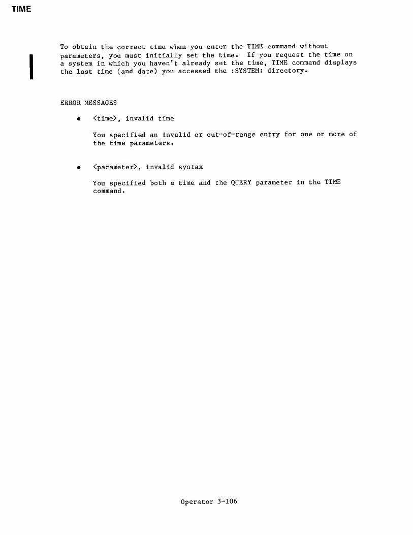
TIME
To obtain the correct time when you enter the TIME command without
parameters, you must initially set the time. If you request the time on
a system in which you haven't already set the time, TIME command displays
the last time (and date) you accessed the : SYSTEM: directory.
ERROR MESSAGES
• <time>, invalid time
You specified an invalid or out-of-range entry for one or more of
the time parameters.
• <parameter>, invalid syntax
You specified both a time and the QUERY parameter in the TIME
command
.
Operator 3-106

UPCOPY
UPCOPY
This command copies files from a volume on ISIS-II secondary storage to a
volume on iRMX 86 secondary storage.
INPUT PARAMETERS
inpath-list
QUERY
List of one or more filenames of the ISIS-II files
that are to be copied to iRMX 86 secondary
storage, either on a one-for-one basis or
concatenated into one or more iRMX 86 output files.
Causes the Human Interface to prompt for
permission to copy each ISIS-II file to the listed
iRMX 86 output file. Depending on whichpreposition you specify (TO, OVER, or AFTER), the
Human Interface prompts with one of the following
queries:
<in-pathname>, copy up TO <out-pathname>?
<in-pathname>, copy up OVER <out-pathname>?
<in-pathname>, copy up AFTER <out~pathname>?
Enter one of the following (followed by a carriage
return) in response to the query:
Entry Action
Y or y Copy the file.
E or e Exit from the UPCOPY command.
R or r Continue copying files without
further query.
Any other Do not copy this file; go to
character the next file in sequence.
Operator 3-107

UPCOPY
OUTPUT PARAMETERS
TO
OVER
AFTER
outpath-list
Copies the ISIS-II file or files TO a newiRMX 86 file or files in the listed sequence.If the output file already exists, UPCOPYdisplays the the following message:
<pathnarae>, already exists, OVERWRITE?
Enter Y, y, R, or r if you wish to write overthe existing file. Enter any other character if
you do not wish the file to be overwritten.
If no preposition is specified, TO :C0: is the
default. If more input files than output filesare specified in the command line, the remaininginput files will be appended to the end of thelast listed output file.
Copies the listed ISIS-II input file or filesOVER existing iRMX 86 destination files in thelisted sequence. If more input files thanoutput files are listed in the command line, theremaining input files will be appended to theend of the last listed output file.
Appends the listed ISIS-II input file or filesAFTER the end-of-data on an existing iRMX 86
output file or files in the listed sequence.
One or more pathnames of the iRMX 86 destinationfiles. Multiple pathnames must be separated bycommas. Separating blanks are optional. If thepreposition and output parameter defaults areused in the command line, the output will go tothe iRMX 86 console screen.
DESCRIPTION
Before you enter an UPCOPY command on the iRMX 86 console keyboard, youmust have your target system connected to a development system via themonitor. To do this, you must start your iRMX 86 system from thedevelopment system terminal (either by loading the software into thetarget system and using the monitor G command to start execution, or byusing the monitor B command to bootstrap load the software). UPCOPY doesnot function if you start up your system, from the iRMX 86 terminal or ifyou establish the link between development system and target system afterstarting up your iRMX 86 system.
The user ID of the user who invokes the UPCOPY command is considered theowner of new files created by UPCOPY. Only the owner can change theaccess rights associated with the file (refer to the PERMIT command).
Operator 3--108

UPCOPY
As it copies each ISIS-II file in the input list, UPCOPY displays one of
the following messages at the terminal, as appropriate:
<in-pathname>, copied up TO <out-pathname>
<in-pathname>, copied up OVER <out~pathname>
<in-pathname>, copied up AFTER <out-pathname>
When the UPCOPY command is executing, the monitor disables interrupts.
This action affects services such as the time-of-day clock. Also, the
Operating System is unable to receive any characters that you type-ahead
while the UPCOPY command is executing.
ERROR MESSAGES
• <pathname>, ISIS ERROR: <nnn>
An ISIS-II Operating System error occurred when UPCOPY tried to
transfer the file to the Microcomputer Development System. Refer
to the INTELLEC SERIES III MICROCOMPUTER DEVELOPMENT SYSTEM
CONSOLE OPERATING INSTRUCTIONS for a description of the resulting
error code-
• ISIS link not present
The the iRMX 86 system is not connected to the development system
via the monitor.
• <pathnarae>, UPDATE or ADD access required
Either you cannot overwrite the information in a file because you
do not have update access to it, or you cannot copy information
to a new file because you do not have add entry access to the
file's parent directory.
Operator 3-109

VERSION
VERSION
This command displays the version number of a file if that file has aversion number. The file can be an object file or library. The formatof this command is as follows:
INPUT PARAMETER
pathname-list One or more pathnames, separated by commas, ofcommands for which a version number is desired,
DESCRIPTION
When you enter the VERSION command, it displays the version number ofeach file, if there is one, in the following format:
<pathname>, <command-name> version is x.
y
where:
<pathname>
<command-name>
x.y
Pathname of the file containing the command.
Name of the specified command; Intel-suppliedcommands have names as listed in this manual.
Version number of the command.
You can use VERSION to determine the version number of any HumanInterface command. You can also use it to determine the version numbersof commands that you write. If the file is a library, the command showsthe current and previous version numbers. However, for VERSION to workon your commands, you must include a literal string in the command'ssource code to specify the name of the command and its version. Thestring must contain the following information:
' progran^versionjiumbe^xxxx'
,
' program_name=yyyy . .. yyy '
,
where:
program__version_number= You must specify this portion exactly asshown (lower case, underscore separating thewords, no spaces).
Operator 3-110

program name=
yyyy...yyy
xxxx Version number of the product. This can beany four characters, but it must be exactlyfour characters long.
This portion is optional. However, if youwant VERSION to recognize and display theprogram name, you must specify this portionexactly as shown.
Name of the command. This name can be anynumber of characters.
The literal string must be terminated with abyte of binary zero.
An example of such a literal string is:
DECLARE version (*) BYTE DATA( f programmersion_number=V8.5 '
,
' program_name=MYPROGRAM' ,0)
;
If your program includes this declaration, when you invoke VERSION, itwill display the following information:
<pathname>, MYPROG version is V8.5
A literal string that does not include the program name is:
DECLARE vers2(*) BYTE DATA( 'programmersion_number=l 983 ' ,0);
If your program includes this declaration, when you invoke VERSION, itwill display the following information:
<pathname>, version is 1983
ERROR MESSAGES
• <pathname>, does not contain a program version number.
• <pathname>, is not an object module.
Operator 3-111

WHOAMI
WHOAMI
This command lists the currents user's Identification and access rights
WHOAMI
DESCRIPTION
This example shows the output from WHOAMI:
—WHOAMIUSER ID: 5
ACCESS ID'S: 5, WORLD
The number after USER is the user's ID number. The numbers after ACCESS
are the ID'S of people who have given the user access to their files.
See the iRMX 86 BASIC I/O SYSTEM REFERENCE MANUAL for more information on
USER groups.
***
Operator 3-112

CHAPTER 4HUMAN INTERFACE EXAMPLES
This chapter shows you how to use some of the Human Interface commands.Its primary intent is to introduce you to basic techniques by presenting a
series of examples that illustrate typical command entries.
COMMAND EXAMPLES FORMAT
To make it easier to follow the interactive dialog between the user andHuman Interface in the examples, the user keyboard entries areunderscored . All other items displayed in the examples are Human Interfacecommand output. For instance, in the example:
-copy samp to testsamp copied TO test-copy testaaaaabbbbbtest copied TO :C0:
the underscored items are user command entries; all other characters and
lines are output by the Human Interface or the supplied commands.
Control characters, such as (CTRL/z), are enclosed in parentheses in the
examples to indicate that such entries are not echoed at the console screenas they are entered. Do not actually enclose control key entries inparentheses.
HOW TO BEGIN A CONSOLE SESSION
You can begin an interactive dialog with the Human Interface after the
initial program displays a sign-on message at your console screen.Although the sign-on message is a system configuration option, the messagesupplied with the default initial program of the Human Interface is asfollows:
1RMX 86 HI CLI Vx.y: USER = <userid>COPYRIGHT <year> Intel Corporation
This message tells you the Human Interface is running; it also tells youyour user ID. The hyphen (-) is a Human Interface prompt to indicate thatit is ready to accept your first command line. Begin entering a commandimmediately after and on the same line as the prompt. For example:
-copy :ci: to testl
Operator 4-1

HUMAN INTERFACE EXAMPLES
HOW TO CREATE A SIMPLE DATA FILE
You can use the COPY command to create data files during a console
session. Assume you wish to create a file called ALPHA and write two
lines of data into the file. Also assume you wish the data file to be
listed under your default directory. Enter the following command and
data:
-copy :ci: to alphaaaaaabbbbbcr (carriage return)
(CTRL/z)
:ci: copied TO alpha
In this example, the :ci: in the COPY command line tells the command to
read data from the keyboard (:ci: = console input) and write the data
(aaaaa and bbbbb) to a new file named ALPHA. Because you did not preface
the file name with a directory name, COPY places the file ALPHA in yourdefault directory.
The command does not prompt you for the data lines; you simply begin
entering data after you press RETURN at the end of the command line.
Your CTRL/z entry writes an end-of-file mark at the end of your data to
inform the COPY command that there is no more data to be copied.
Note that after you enter the last line of data, you must press the
RETURN key before you enter a CTRL/z to insert an end-of-file.
Otherwise, none of the characters entered after you press the RETURN key
and before you enter a CTRL/z are written to the file. For example:
-copy :ci: to alphacccccddddd (CTRL/z) (then press RETURN)
would only write the data ccccc to the new file named ALPHA.
Since control characters are not echoed on the screen as you enter them,
(such as a RETURN or CTRL function), the above file creation sequence
would be displayed on the screen as follows:
-copy :ci: to alphacccccddddd
:ci: copied TO alpha
Now, assume that when you entered the COPY command line, the HumanInterface sent you the following message and query:
-copy :ci: to alphaalpha, already exists, OVERWRITE?
Operator 4-2

HUMAN INTERFACE EXAMPLES
Whenever you create a new data file, the COPY command expects a newpathname rather than one already listed in the directory file. If yourentry to the query is:
alpha, already exists, OVERWRITE? v_
the COPY command deletes the data in the existing file and waits for you
to enter new data under that pathname.
If your response to the query is:
alpha, already exists, OVERWRITE? n (or any other character except y)
your COPY command is ignored and the Human Interface prompts for a newcommand entry by issuing a hyphen (-).
HOW TO COPY FILES
COPY command options provide a number of different ways for you to copyexisting files. You exercise these options either by specifying one of
the TO/OVER/AFTER prepositions, by the way in which you specify your inputfile and output file pathname lists, or by a combination of bothtechniques. The services of the COPY command include:
Copying files on a one-for-one basis.
Displaying the contents of files at the console screen.
Creating multiple copies of the same file.
Copying data from multiple files to a new or existing file.
Replacing data in one file with data from another file.
Adding data from one or more files to the end of the data inanother file.
Combining one-for-one file copying with file concatenation in a
single COPY command.
The examples that follow show you how to use these services. They also
call your attention to certain file handling considerations when using theCOPY command.
Operator 4-3

HUMAN INTERFACE EXAMPLES
HOW TO COPY TO NEW FILES
Copying existing files to new files is most frequently done on a one-for-one
basis; that is, you list a number of existing files to be copied and a
matching list of files to receive the copies. The files are copied in the
same sequence you specify in the input list and output list on the commandline. For example, assume you wished to copy files Al, A2, and A3 to filesBl, B2, and B3 respectively. Enter the following command:
-copy al, a2, a3 to bl, b2, b3
al copied TO bl
a2 copied TO b2
a3 copied TO b3
You could also make use of the wild card feature when copying files. If the
files Al, A2, and A3 are the only files in the directory that begin with thecharacter "A", you can use the following command to perform the same operation:
-copy a* to b*al copied TO bl
a2 copied TO b2a3 copied TO b3
The asterisks in the command are the wild card characters. In this instance,the command copies all files in the default directory that start with the
character "A" to new files starting with the character "B." If files other
than Al, A2, and A3 also begin with the character "A", this command will copythem also.
When you copy files, you can specify wild card characters (as in the previousexample), lists of file names (as in the example before that), or a
combination of both. However, some of the possible combinations are invalid.When copying files, remember the following rules:
• If you specify multiple input pathnames and a single output pathname,
file concatenation takes place. If the output parameter is simply a
directory with no wild card in its pathname, then the Human Interfacecopies all the files listed in the input parameter into the
directory. Each file keeps its original name in the new directory(such as alpha).
• If you specify multiple output pathnames, you must specify the same
number of input pathnames as output pathnames. Specifying more inputpathnames than output pathnames results in an error message. Forexample, the command:
-copy a,b,c to d,e (invalid)
returns an error message. The command:
-copy a,b to c,d,e (invalid)
also returns an error message. Refer to the "Inpath-List and
Outpath-List" section of Chapter 2 for more information.
Operator 4-4

HUMAN INTERFACE EXAMPLES
HOW TO DISPLAY THE CONTENTS OF FILES
When you perform a number of file manipulations during a single session,
it is occasionally advisable to display a file's contents at the terminal
before proceeding further. Assume you wish to display the contents of a
file named ALPHA that is contained in your default directory. Simply
enter the command:
-copy alphaaaaaaaaaaa
alpha copied TO :C0:
This COPY command example uses the default preposition (TO) and default
output file (:C0:) t which means that the command copies the output to theconsole screen.
You can halt the scrolling of a displayed list to examine the data moreclosely. Press the following CTRL keys to control scrolling of the
output:
CTRL/s Stops the data from scrolling off the screen until youpress a CNTRL/q.
CTRL/q Resumes scrolling of listed data until the end-of-file is
reached or you enter a CTRL/c.
CTRL/c Cancels listing the data and returns control to the Human
Interface, which prompts for a new command.
HOW TO REPLACE EXISTING FILES
There may be occasions when you wish to update the contents of an
existing file. One way to do this updating is to create a new file andthen replace the contents of the old file with the new data. Although
you can use the RENAME command to perform this operation, this section
shows how to replace the contents of a file with the COPY command's OVERpreposition.
Assume the following conditions:
• You have a file named ALPHA that is accessed under that name by a
number of different programs. ALPHA has outmoded data.
• Since you cannot change the name without also modifying the
programs that access ALPHA, you must retain the name but updatethe outmoded file contents.
Operator 4-5

HUMAN INTERFACE EXAMPLES
I
Enter the following command sequence:
-copy :cl: to tempnu nu nu nunu nu nu nu(CTRL/z )
:ci: copied TO temp-copy temp over alphatemp copied OVER alpha-copy alphanu nu nu nunu nu nu nu
alpha copied TO :C0:
The last COPY ALPHA command lists the file at the terminal to show that
the old file contents have been successfully replaced.
You could have used the TO preposition in the COPY command to write TEMPover ALPHA; but since the Human Interface always expects a new outputfile when the TO preposition is used, this would have caused unnecessarykeystrokes, as shown in the following:
-copy temp to alphaalpha, already exists, OVERWRITE? %_temp copied TO alpha
Note that you now have two copies of the same new data; one in the TEMPfile and one in the ALPHA file. If you had used the OVER preposition ina RENAME command instead of the COPY command, file TEMP would have beendeleted automatically when RENAME was executed. However, if you did notwant two existing copies of the same data, you could update the existingfile directly from the keyboard. Enter the following command:
-copy :ci: over alphanewnewnew(CTRL/z):ci: copied OVER alpha
HOW TO CONCATENATE FILES
Concatenation is the process of combining a number of files by appendingthem in sequence into a single file. You can use the COPY command inseveral ways to concatenate files:
• by specifying the AFTER preposition in the command line
• by specifying multiple input pathnames and a single outputpathname (if the output pathname is a directory, concatenationdoes not occur)
Operator 4-6

HUMAN INTERFACE EXAMPLES
• by using a combination of both techniques
Assume you have four existing files named A, B, C, D respectively, andwant to append the contents of B, C, and D to the end of file A.Although you could specify the TO preposition in the COPY command line,the TO preposition would force you to enter extra keystrokes because yourlisted output file (A) already exists. It would also force you to deletethe previous contents of A, which is not always desirable. Therefore,use the AFTER preposition, as follows:
-copy b,c,d after ab copied AFTER a
c copied AFTER a
d copied AFTER a
Now, assume you wish to concatenate all four files into a new file calledALL. You can still use the AFTER preposition, or you can use the TOparameter, as follows:
-copy a,b,c,d to alla copied TO allb copied AFTER allc copied AFTER alld copied AFTER all
In this example, file A is copied to ALL and the remaining input filesare automatically appended to the end of ALL.
You can save keystrokes when listing a series of files on the screen byusing this automatic concatenation in a single command line. Assume youwish to list files named ALPHA, BETA, and GAMMA. Enter the followingcommand, using the default TO preposition and default output file (:C0:):
-copy alpha, beta, gammaaaaaaaaaaaalpha copied TO :C0:
bbbbbbbbbbbeta copied AFTER :C0:
gggggggggggamma copied AFTER :C0:
When data sequence and/or data format are important in a concatenatedfile, remember that all copy operations are performed in the sequence youspecify in the command line.
Assume you have formatted data in a group of files named A, B, C, D, andE, and you wish to concatenate their contents into a new file namedSQUARE in that sequence. However, if you list the input files on thecommand line in a haphazard sequence, as follows:
-copy b,a,d,c,e to square
Operator 4-7

HUMAN INTERFACE EXAMPLES
the format of the total data block is destroyed, as can be seen in the
following incorrect and correct versions of the listed output. Although
the data block of Latin words shown in the left-hand example seems
correct when read horizontally, the intent and meaning of the vertical
columns has been lost. The right-hand example shows the corrected file
sequence:
b,a,d,c,e a,b,c,d,esequence sequence
AREPO SATORSATOR AREPOOPERA TENETTENET OPERAROTAS ROTAS
In the right-hand example, the Latin "magic square" now reads the same
both horizontally and vertically, which was the intended operation.
HOW TO DELETE FILES
It is vital to good file housekeeping that you routinely delete obsolete
or unused files and empty directories. (Deleting unused directories is
described later in this chapter.) In addition to the obvious benefit of
recovering unused secondary storage, deleting your obsolete files reducesconfusion and file manipulation errors.
Assume that you want to delete files ALPHA and BETA from the system.
Enter the following command:
-delete alpha, betaalpha, deletedbeta, deleted
Now, assume that you entered the following command line and received the
following error message:
-delete ay, bee, keyay, deletedbee, deletedkey, does not exist
The error message for the KEY file tells you one of three things:
• There is a syntax error in the spelling of the KEY file.
• The file does not exist.
• The file exists in a directory other than the one you are
currently accessing (see the directory examples later in this
chapter).
Operator 4-8

HUMAN INTERFACE EXAMPLES
HOW TO USE DIRECTORIES
A directory is a kind of file under which you assign and maintain otherfiles or directories. It is distinguished from a data file by a
directory heading that is automatically created when you create a newdirectory. Under that heading, the directory maintains a formatted listof its containing files and directories . This heading is updatedwhenever you assign new files to the directory. Directories provide youwith a convenient and efficient technique for organizing large numbers of
files into logical groupings. Creating your own directories aids you intwo ways:
• It allows you to organize your files into logical groupings.This capability eases the task of maintaining large numbers offiles on the system.
• It reduces the possibility of accidental destruction of files,either by yourself or other system users.
A directory contains a list of all files assigned under its name, whichyou can display by using the DIR command (described later). Optional DIRcommand parameters also allow you to access and display other pertinentinformation about each file, such as file size and other file attributes.
Previous command examples in this chapter, when creating and accessingfiles, have used the default directory configured for your user ID. Thefollowing examples show you how to create and use your own directoriesfor easier file management.
HOW TO CREATE A NEW DIRECTORY
Whenever you wish to group a series of files under a single topicalstructure, you normally create a new directory in which to assign thembefore creating the files themselves. (You can also move existing files
under a new directory name by using the RENAME command, as describedlater.
)
You create new directories by using the CREATEDIR command to specify a
list of directory names for the new directories. You will find it easierto keep track of both your directories and files if you use directorynames that give some, hint of a directory's topical structure.
Assume you wish to create two directories named MYTEST and NUTEST underwhich you will assign several practice files. Enter the followingcommand
:
-createdir MYTEST, NUTESTMYTEST, directory createdNUTEST, directory created
Operator 4-9

HUMAN INTERFACE EXAMPLES
This example specified the directory pathnames as uppercase characters.
It is suggested that you also capitalize all directory pathnames in a
CREATEDIR command and use lowercase characters for data pathnames when
you create new files with the COPY command. This practice is recommendedbecause, when you subsequently list a directory by using the DIR command(described later), it will be much easier for you to distinguish betweendata file names and directory names.
Once you create directories and data files, you can enter their pathnames
in either lowercase or uppercase characters in subsequent commands; theHuman Interface commands make no distinction in interpretation.
HOW TO REFER TO A DIRECTORY
After you create a new directory, all named files or directories that you
assign to that directory will have a hierarchical relationship to this"parent" directory. This relationship to the parent is called a path .
When you wish to access any file or other directory assigned to theparent, you must specifically identify the path in the form of a pathnamein your command.
For example, assume your default directory has a directory named NUTEST
under which you have another directory named SAMP. SAMP, in turn, has a
data file named TEST. NUTEST is then the parent directory for the SAMPdirectory and SAMP, in turn, is the parent for the TEST data file. In a
command, the pathname for the SAMP directory would be NUTEST/SAMP, wherethe slash characters separate the individual hierarchical components ofthe pathname. The pathname for the TEST data file would be
NUTEST/SAMP/TEST.
If the files are contained in your default directory, you can refer to
them without specifying a logical name as a prefix. When you enter the
pathname:
NUTEST/SAMP/TEST
the Human Interface automatically appends the prefix :$: to the
beginning. However, if the files are contained in a directory other thanyour default directory, you must enter the complete pathname for the
file. For example, if the files reside on a device whose logical name is
:AD3:, you must include this logical name as the prefix portion of the
pathname, as follows:
:AD3: NUTEST /SAMP/TEST
If you omit the :AD3: portion, the Human Interface assumes the files
reside in the default directory.
Operator 4-10

HUMAN INTERFACE EXAMPLES
HOW TO ADD NEW ENTRIES TO A DIRECTORY
Previous data file examples in this chapter used the default directory(as configured for your system) for all file creation and access.Consequently, each example that created a new file or accessed anexisting file specified only the last component of the file's pathname;it did not need to specify a logical name or intermediate pathnamecomponents. However, whenever you wish to create a new data file to beassigned to a specific directory, you must precede the filename with the
directory name and separate the two names with a slash (/) in the COPYcommand, as described in the previous subsection. You might also need to
specify a logical name, if the directories do not reside in your defaultdirectory.
For example, assume you wish to create files named SAMPl and SAMP2 and
assign them to the MYTEST directory (MYTEST resides in your defaultdirectory). Enter the following commands:
-copy :ci: to mytest/samplaaaaa(CTRL/z)
:ci: copied TO mytest/sampl-copy :ci: to mytest/samp2bbbbb(CTRL/z)
:ci: copied TO mytest/samp2
Remember that once you have added files to a specific directory, everysubsequent operation involving those files must specify a precedingdirectory name and the slash separator (unless you change your defaultdirectory, as described in a later section). For example, assume youwant to delete files SAMPl and SAMP2 from the MYTEST directory. Youmight enter the following command:
-delete mytest/sampl, samp2mytest/sampl, deletedsamp2, does not exist
The Human Interface issues the "does not exist" message for SAMP2 becauseit looked for the file in your default directory instead of the MYTESTdirectory. The correct command line entry should have been:
-delete mytest/sampl, mytest/samp2
so that the Human Interface would search the correct directory for eachlisted file.
Operator 4-11

HUMAN INTERFACE EXAMPLES
HOW TO CREATE A DIRECTORY WITHIN A DIRECTORY
In the same manner that you create new directories in your defaultdirectory, you can also create new directories in other directories,therefore expanding the file hierarchy.
For example, assume you have data files ALPHA, BETA, and GAMMA assignedto the MYTEST directory and now wish to add a new directory file namedURTEST to the directory. Enter a CREATEDIR command, as follows:
-createdir mytest/URTESTmytest/URTEST, directory created
Now, assume you wish to create a new data file named NOMOR and assign it
to the URTEST directory. Enter the following COPY command:
-copy :ci: to mytest/urtest/nomornonononnononon(CONTROL/z )
:ci: copied TO mytest/urtest/nomor
The "MYTEST/URTEST" sequence is the path from your default directory tothe URTEST directory, and the "MYTEST/URTEST/NOMOR" sequence is the pathfrom your default directory to the NOMOR file. When you usefile-handling commands, you must always specify a path to the file,either a path from your default directory to the file, or a path fromsome other known point (such as from the root directory for anotherdevice). For example, assume you have another data file in URTEST namedSUMOR and wish to list both NOMOR and SUMOR on the console screen. Enterthe following command and specify the pathname for each file:
-copy mytest/urtest/nomor,mytest/urtest/sumornonononnonononmytest/urtest/nomor copied TO :C0:
sumsumsumsumsumsummytest/urtest/sumor copied TO :C0:
If the directory MYTEST resides on a device (for example, :F6:) otherthan your default device, you would specify the previous command asfollows:
-copy :f6:mytest/urtest/nomor, :f6:mytest/urtest/sumornonononnononon:f6:mytest/urtest/nomor copied TO :C0:
sumsumsumsumsumsum:f6:mytest/urtest/sumor copied TO :C0:
Operator 4-12

HUMAN INTERFACE EXAMPLES
You can also specify file operations involving two or more different
directories, and these directories need not be on the same path. Assumeyou wish to list the ALPHA file from MYEST and a file named DIFF on a
directory path ONE/MOR. Enter the following command:
-copy mytest/alpha,one/mor/dif
f
aaaaaaaaaamytest/alpha copied TO :C0:
yyyyyyyyyyone/more/dif f copied TO :C0:
HOW TO LIST DIRECTORIES
Previous examples have shown you how to list the contents of data files
by specifying a directory pathname in a COPY command. However, you
should not use the COPY command to list the contents of directories,
because COPY lists the directory as though it were a data file. For
example, if you enter the COPY command to list the MYTEST directory on
the screen, you obtain:
-copy mytestalphabetagammaurtest copied to :C0:
The resulting output is almost unreadable. Instead, use the DIR command
to list the directory's catalog of files as follows:
-dir mytest
01 JAN 78 00:00:00DIRECTORY OF MYTEST ON VOLUME disk2
alpha beta g£imma
URTEST
This example used the DIR command's default TO preposition and FAST
format for the listing. You could have sent the directory listing to
another output file and specified either the OVER preposition, to write
the listing over the file's previous contents, or the AFTER preposition,
to append the directory listing to other data. If you want to list more
information about each file, specify the EXTENDED parameter. See the DIR
description in Chapter 3 for examples of the available listing formats.
Operator 4-13

HUMAN INTERFACE, EXAMPLES
HOW TO MOVE FILES BETWEEN DIRECTORIES
There may be situations when you wish to reorganize a large group ofexisting files under new headings (directories). You can copy files fromone directory to another by using the COPY command. For example, assumeyou wish to copy files ALPHA, BETA, and GAMMA from your default directoryto the existing directory MYTEST. Enter the following command line,using the QUERY parameter (optional):
-COPY alpha, beta, gamma, to MYTEST QUERYalpha, COPY TO MYTEST/alpha? y_
alpha COPIED TO MYTEST/alphabeta, COPY TO MYTEST/beta? ybeta COPIED TO MYTEST/betagamma, COPY TO MYTEST/gamma? ygamma COPIED TO MYTEST/gamma
Assume you later decide to move file ALPHA back to your defaultdirectory. You need not specify the default directory in the newpathname for ALPHA. Enter the following command:
-rename mytest/alpha to alphamytest/alpha renamed TO alpha
Any subsequent operations involving file ALPHA would only require thefile name. For example:
-copy alphaaaaaaaaaaaalpha copied TO :C0:
HOW TO DELETE A DIRECTORY
You delete unused directories from secondary storage by using the DELETEcommand. However, the Human Interface protects you from accidentlydestroying valuable files by refusing to delete a directory that containsone or more files. For example, assume you wish to delete directoryMYTEST and do not realize it contains a data file named ALPHA and adirectory named DED that itself contains a data file named LIV. Youenter the following command:
-delete mytestmytest, directory not empty
Operator 4-14

HUMAN INTERFACE EXAMPLES
At this point you should list the MYTEST directory by using the DIRcommand to determine the contents of MYTEST, as follows:
-dir mytest
01 JAN 78 00:00:00DIRECTORY OF MYTEST ON VOLUME disk2
alpha DED
You now have two options. You can use the RENAME command to move anyfiles to be saved to a different directory on the same volume, or you canuse the DELETE command to delete the entire contents of MYTEST beforedeleting the directory.
Assume you wish to move ALPHA to the NUTEST directory and delete the restof the directory's contents so that MYTEST itself can be deleted. Enterthe following commands:
-rename mytest/alpha to nutest/alphamytest/alpha renamed TO nutest/alpha-delete mytest/ded/liv,mytest/ded,mytestmytest/ded/liv deletedmytest/ded deletedmytest deleted
The RENAME command automatically deleted the MYTEST/ALPHA pathname fromthe MYTEST directory. Note how the pathname sequence in the DELETEcommand travelled upward through the hierarchical structure, with theMYTEST directory being the. last item to be deleted.
HOW TO CHANGE YOUR DEFAULT DIRECTORY
Suppose your default: directory contains a directory called MYTEST whichcontains another directory called URTEST which in turn contains severaldata files called MOR, SUMOR, STILMOR, and N0M0R. If you plan tomanipulate these data files extensively, your Human Interface commandscan become very cumbersome, due to the length of the pathnames involved.For example, suppose you wish to copy the data files to files calledALPHA, BETA, DELTA, and GAMMA in the same directory. The command to dothis is:
-copy mytest/urtest/mor, mytest/urtest/sumor, mytest/urtest/stilmor, &**mytest/urtest7nomor to mytest/urtest/alpha, mytest/urtest/beta, &**mytest/urtest/delta, mytest/urtest/gamma
If there are more levels in the directory structure, your commands canbecome even longer.
Operator 4-15

HUMAN INTERFACE EXAMPLES
To eliminate some of these long pathnames, you can use the ATTACHFILE
command to change your default directory to be a directory closer to thelevel of the files with which you are working. To make the previous
command shorter, you could change your default directory to the URTESTdirectory, as follows:
-attachfile mytest/urtest as :$;
mytest/urtest attached AS :$:
Now, when you make references to files without specifying the entirepathname, the Human Interface assumes that they reside in the URTESTdirectory, not your previous default directory. Therefore, to perform
the same operation as in the previous COPY command, you could now enterthe following command:
-copy mor, sumor, stilmor, nomor to alpha, beta, delta, gamma
You can use the ATTACHFILE command to change your default directory to
any directory that you wish, so that you can manipulate the files in thatdirectory more easily. To return to your original default directory,
enter the following command:
-attachfile
This command uses the default parameters and has the same effect as
"ATTACHFILE :HOME: AS :$:". The :HOME: logical name represents youroriginal default directory; therefore the command returns :$: to its
original value.
HOW TO RENAME FILES AND DIRECTORIES
The most direct method to save the contents of a file or directory but
change its pathname is to use the the RENAME command. To make the
process easier to follow, this section discusses the renaming of files
and directories separately.
HOW TO RENAME FILES
Assume you wish to change the name of file ALPHA to a new name of OMEGA,
where OMEGA does not already exist. Enter the following command:
-rename alpha to omegaalpha renamed TO omega
The ALPHA pathname is automatically deleted from the system when the
RENAME command is executed. You can also rename lists of files to newpathnames In this case, it is useful to include the QUERY parameter in
your command line to make certain that your old pathnames and newpathnames are matched up in the way you intend.
Operator 4-16

HUMAN INTERFACE EXAMPLES
Assume you wish to rename files ALPHA, BETA, and GAMMA to TOM, DICK, and
HARRY respectively. Enter the following command sequence:
-rename alpha, beta, gamma to torn, dick, harryalpha renamed TO torn
beta renamed TO dickgamma renamed TO harry
Remember that when using the RENAME command, you must always have a
one-for-one match of pathnames between the new list and the old filelist. For example, more old pathnames than new pathnames would cause the
following exchange at the terminal:
-rename alpha, beta to torn
alpha renamed TO torn
TO or OVER preposition expected
Similarly, specifying fewer old pathnames than new pathnames would causethe following exchange:
-rename alpha to beta, torn
008B: E$UNMATCHED LISTS
So far, these RENAME examples have used the TO parameter to give newnames to existing files. However, you can also use the OVER prepositionwith RENAME. The primary purpose of OVER is to move data from one namedfile over the data in another existing file. This use of the OVERpreposition matches the action of the OVER preposition in the COPYcommand with one important distinction: RENAME automatically deletes theinput file when the command is executed.
Exercise a little care here! It's easy to get into semantic confusionwhen using the OVER preposition in a RENAME command. Just remember a fewsimple rules:
• Use the pathname of the data to be moved to a different but
existing pathname as the input parameter; that is, on theleft-hand side of the OVER preposition. This pathname will bedeleted when the command is executed.
• Use the pathname that receives the input data as the ouputparameter; that is, on the right-hand side of the OVERpreposition. The previous contents of this file will be replacedwhen the command is executed.
For example, assume you have a file named ABLE whose contents consist of
the data line aaaaa, and another file named BAKER whose contents consistof the data line bbbbb. You wish to rename ABLE with the name BAKER.Enter the following command:
-rename able over bakerable renamed OVER baker
Operator 4-17

human interface; examples
Now display the contents of the file previously named ABLE but now namedBAKER:
-copy bakeraaaaa
baker copied TO :C0:
The previous contents of BAKER have been deleted, and pathname ABLE hasbeen deleted from its directory. You can also use the TO preposition torename files x^ith other existing pathnames. Using TO might be slightlyless confusing but you must enter extra keystrokes. For example, assumeyou wish to rename ALPHA and BETA with the existing file names GAMMA andDELTA. Enter the following command:
-rename alpha, beta to gamma, deltagamma, already exists, OVERWRITE? y_
alpha renamed TO gammadelta, already exists, OVERWRITE?
j_
beta renamed TO DELTA
HOW TO RENAME DIRECTORIES
A directory can be renamed to new pathname on the same volume (but not toan existing pathname). Assume you have a directory whose pathname isALPHA/BETA and you wish to rename it with a new pathname of AY/BEE.Enter the following command:
-rename alpha/beta to AY/BEEalpha/beta renamed TO AY/BEE-dir alpha/betaalpha/beta, does not exist
Be careful when renaming directories! The last message explains theconsequences of renaming a directory to a new pathname. ONCE YOU RENAMEA DIRECTORY, ALL FILES LISTED UNDER THAT DIRECTORY WILL ALSO HAVE THIERPATHNAMES CHANGED. If your system has other programs that use data filesthat are listed under the old directory name, those programs will neverfind the files. In such a case, you must either rename the directoriesto their original names or modify the programs.
In summary, the distinctions between using the RENAME and COPY commandsare as follows:
• When you use COPY to move the contents of an existing file TO a
new file or OVER an existing file, the input file still exists.
• When you use RENAME to move the contents of an input file TO a
named new file or OVER an existing file, the input pathname isautomatically released for new uses.
Operator 4-18

HUMAN INTERFACE EXAMPLES
HOW TO MOVE FILES ACROSS VOLUME BOUNDARIES
You can use all Human Interface file-handling commands except RENAME to
manipulate files across volume boundaries. That is, you can copy filesor directories from one diskette or disk platter to another one mountedon a different drive. The restriction against using RENAME across volumeboundaries is intended for the protection of files against accidentaldeletion.
You access a different volume by entering the logical name for the device(the drive on which the volume is mounted) as the first item in thepathname. For example, assume you have a volume mounted on a drive whoselogical name is :fl:. Further assume you wish to list the root directoryfor that volume to see what directories and data files you have on thevolume. Enter the following command:
-dir :fl ;
01 JAN 81 00:00:00DIRECTORY OF :fl: ON VOLUME disk2
able baker chuck OMNI sampBUS nusamp STATS
Assume you wish to copy file ABLE from this volume mounted on :fl: to theMYTEST directory (which resides in your default directory). Enter thefollowing command:
-copy :fl:/able to mytest/able:fl:/able copied TO mytest/able
If you then wish to delete files ABLE and BAKER from the : f1 : volume,simply enter the command:
-delete : f 1: /able, :f 1 : /baker:fl:/able, deleted:fl: /baker, deleted
Now, assume the following conditions:
• You have two data files on the :fl: volume with the pathnamesSTATS/SALES/FEB and STATS /SALES/MAR.
• You wish to merge both files to a new file with the pathnameMYTEST/PEEK/SUBTOT on your system's default volume.
Enter the following command:
-copy : fl:/stats/sales/f eb, : fl: /stats/sales/mar to mytest/peek/subtot: f 1: /stats/sales/feb copied TO mytest/peek/subtot:fl: /stats/sales/mar copied AFTER mytest/peek/subtot
Operator 4-19

HUMAN INTERFACE EXAMPLES
Note that a volume prefix must be specified for each pathname in any
command that crosses volume boundaries. A volume uses the prefix of the
drive on which it is mounted.
HOW TO FORMAT A NEW VOLUME
Whenever you wish to use a new volume on a secondary storage device (such
a diskette, disk platter, or bubble memory), you must format the volume
before you can write any information in it. Assume you are going to
mount a new diskette on a disk drive with the prefix :fl: that you have
attached (with the ATTACHDEVICE command) as a named device.
Enter the following command:
-format :fl;
volume () will be formatted as a NAMED volumegranularity = 128 map start = 938interleave = 5 sides = 1
files = 200 density = singleextensionsize = 3 disk size = standard (8")
volume size = 250K
TTTTTTTTTTTTTTTTTT. .
.
volume formatted
This formatting example exercised all the default options.
This example did not specify a volume name as parameter of FORMAT. Avolume name is not required; however, for diskettes, a volume name gives
you a method for identifying a volume in case the stick-on label on the
diskette gets lost or destroyed. You need only mount the disk on a driveand enter a DIR command for that drive to get a directory listing that
specifies the volume name.
The GRANULARITY, INTERLEAVE, EXTENSIONSIZE, MAPSTART, and FILES
parameters tell the FORMAT command how you want the physical space (for
instance, disk surface space) on the volume allocated and accessed for
maximum efficiency. The default parameters caused the NEWVOL example to
be formatted with the following attributes:
• Since the device is attached as a named device, the NAMEDparameter is the default with FORMAT. It specifies that you willbe using the volume only to handle named files and directories.If you specified the PHYSICAL parameter, the entire volume wouldbe treated as a single, large physical file. Once you you definethe volume as NAMED or PHYSICAL, you can only use it for thatpurpose.
Operator 4-20

HUMAN INTERFACE EXAMPLES
• The GRANULARITY parameter specifies the minimum number of bytes
to be allocated for each increment of file size on the volume.The default granularity is the granularity of the physical
device. Once the volume granularity is defined, it is applied to
every file you create on the volume.
For example, assume the default volume granularity for your
device is 1024 bytes. Each time you create a new file on the
volume, the I/O System automatically allocates 1024 bytes of
primary storage to that file, whether or not the file requires
the full 1024 bytes. If the size of your file exceeds 1024bytes, the I/O System will increment your file size by still
another block of 1024 bytes, and so on, until the end-of-file is
reached.
• The INTERLEAVE default specifies that you want an interleave
factor of 5. The interleave factor defines the number ofphysical sectors that occur between sequential logical sectors.
This value maximizes access speed for the files on a given
volume, depending upon the intent of the volume and the deviceconfiguration of your system.
For example, an interleave value of 5 for a flexible disk systemmeans that, for each file, the 1/0 System will read every fifthsector on the diskette, starting from an index of 1 (other, hard
disk systems may be different, depending on your hardwareconfiguration). Therefore, the I/O System does not need to wait
for the disk to make a complete revolution before^ it accesses the
next sector; the next sector by an increment of 5 is ready to be
accessed for read/write by the time the first accessed sector has
been processed.
Note that the INTERLEAVE is the only optional parameter that is
meaningful for volumes formatted for PHYSICAL files; the FILES,
EXTENSIONSIZE, and GRANULARITY options are ignored in FORMATcommands that specify a PHYSICAL file format for the volume.
• The default FILES parameter specifies that you wish create a
maximum of 50 user files on the volume. Although the actual
number of files you can specify is 1 through 32,761, at a
practical level, one of your determining factors will be theincremental file size you specify in the GRANULARITY parameter.
The default EXTENSIONSIZE parameter specifies that you wish to
create three bytes of extension data for each file. The Human
Interface requires that at least three bytes of extension data be
available. Other system programs included in your system mayrequire larger values.
• The MAP START gives the volume block number where the fnode andmap files start. If you do not specify a number, the HumanInterface places the fnode and map files in the center of the
volume.
Operator 4-21

human interface; examples
DISKETTE SWITCHING PROCEDURES
If your system is configured with the iSBC 204 flexible disk controller
and you are using single-density diskettes to perform file management
functions, a special procedure is required to switch the diskettes.
Perform the following steps:
1. Remove the old diskette and mount the new one into the drive.
2. Enter a DIR command for the root directory of the new diskette to
force physical access. The root directory "name" is actually the
prefix (logical name) for the drive on which the diskette is
mounted. For example:
-dir :fl:
The following exception message will be displayed:
E$I0
3. Ignore the error message and begin entering Human Interfacecommands that access the volume.
***
Operator 4-22

CHAPTER 5PATCHING UTILITY
The iAPX 86, 88 Patching Utility is a utility that runs on both iRMX 86
application systems and Series III Microcomputer Development Systems. Itmodifies combine-type attributes of object modules, permitting them to bewritten over (or repaired) with replacement modules. This capabilityprovides you with a method of modifying relocatable object modules withsoftware updates or repair code. The process requires that thereplacement code first be generated with the ASM86 Assembler.
The Patching Utility also enables you to list the translator headerrecords of the modules in a library. This listing allows you to seewhich patches have been installed in a module or a library.
In previous releases of the iRMX 86 Operating System, the PatchingUtility served as a means of applying Intel-supplied software updates to
your system. This method of applying software updates is no longer ineffect. Software updates are now being distributed by Intel through theiRMX 86 Update Package. Fixes to software problems (referred to now bythe general term "ZAP's") are applied to your system automatically whenthe update is installed. You will not have to invoke the patch utilityto do this. Instructions for installing the update are included in thecustomer letter that accompanies each update package. The update packageis describe in detail in the Installation Guide.
TYPES OF PATCHES
You can update a module to a newer version or add repair code in two ways:
• As a patch that generates a jump instruction to the replacementcode and appends the replacement code to the end of the originalmodule.
• As an in-place patch that directly overlays the replacement codeon that of the original module.
An example of each technique is provided later in this chapter.
Operator 5-1

PATCHING UTILITY
KINDS OF CODES THAT CAN BE PATCHED
The Patching Utility requires you to relink your object modules after you
install the patches. Therefore you cannot patch modules which have beenlocated at absolute addresses (run through LOC86) or those which havebeen linked using the BIND control of LINK86. Absolute and bound modules
cannot be relinked; therefore they cannot be patched.For example:
Object Module Patch
iRMX 86 System Libraries Yes
Human Interface Commands No
An iRMX 86 Application System No
VERSIONS OF THE PATCHING UTILITY
There is one version of the Patching Utility. The Patching Utility runson an iRMX 86 application system and can be invoked with a HumanInterface command. The Patching Utility can also run on a Series III
Microcomputer Development System and can be invoked using the Series IIIRUN command. The name of the file containing the Patching Utility is
called PTCH86.86.
If you are using a Series III system and your release diskette is in ISIS
format (media type B), use the COPY command to copy PTCH86.86 from theRelease Diskette onto an Intellec disk. If your release diskette is in
iRMX 86 format (either media type E or media type J), use the HumanInterface DOWNCOPY command (refer to Chapter 3) or the Files Utility
(refer to Chapter 6) to transfer a copy of PTCH86.86 to the Intellec disk.
If you are using an iRMX 86 system and your release diskette is in iRMX
86 format (either media type E or media type J), execute the "instal.csd"command file (using the SUBMIT command) residing on the ReleaseDiskette. The instal.csd file copies PTCH86.86 from the diskette into
the appropriate iRMX directory. In the process PTCH86.86 is
automatically renamed to PTCH86. (Your system must conform to thestandard iRMX 86 directory structure in order for the instal.csd commandfile to work.) If your Release Diskette is in ISIS-II format (media typeB), use the Human Interface UPCOPY command (refer to Chapter 3) or the
Files Utility (refer to Chapter 6) to transfer a copy of PTCH86.86 intothe RMX system. Since iRMX 86 does not require the ".86" suffix in orderto run the Patch Utility, you may want to change the PTCH86.86 name (e.g.
from PTCH86.86 to PTCH86).
INVOKING THE PATCHING UTILITY
Before invoking the Patching Utility, ensure that the file containing it
resides in the proper place. If you are using the Series III version,ensure that the PTCH86.86 resides on drive of your development system.
Operator 5-2

PATCHING UTILITY
If you are using the iRMX 86 version, ensure that PTCH86 resides in yourdefault directory or in one of the directories that the Operating Systemautomatically searches (usually :PROG: and : SYSTEM:). Then you caninvoke the Patching Utility by entering one of the following commands:
Series III Invocation
iRMX 86 Invocation
where:
pathname Pathname of the file containing an iAPX 86, 88
object module produced by PL/M-86, ASM86, orLINK86. If you are listing the translatorheader records, the object module can be oneproduced by LOC86 or LIB86.
segmentname Name of the segment whose combine-type attributeis to be modified. The name must be a validsegment name (usually CODE). If you omit thisparameter (and the segraentattribute parameter),the utility does not modify the attributes ofany segment. Instead, it displays thetranslator header records contained in themodule
.
segmentat tribute Combine-type attribute to be given to the namedsegment. You must specify one of the followingvalues for this attribute:
COMMON
PUBLIC
Allows patch code to be overlaid on the segment.
Returns the segment to the combination modenormally given by the PL/M-86 compiler.
Operator 5-3

PATCHING UTILITY
Refer to the ASM86 LANGUAGE REFERENCE MANUAL for a more detailedexplanation of combine-type attributes.
In response, the Patching Utility displays the following header message:
Operating system> iAPX 86, 88 OBJECT PATCHING UTILITY, Vx.y
Copyright <year> Intel Corporation
where:
<operating system> Name of the operating system, either iRMX 86 or
SERIES III.
x.y Version number of the Patching Utility.
If you exclude the optional segmentname and segmentattribute parameters,
the utility next displays the translator header records contained in the
object file. These header records serve to identify the patches thathave been made to a module (described later in this chapter). Thisdisplays allows you to determine the update status of the file.
If you specify the segmentname and segmentattribute parameters, the
utility omits the display of the translator header records. Instead, it
changes the combine-type attribute as specified and displays the
following message:
ATTRIBUTE MODIFIED
Any other message indicates an error condition.
ERROR MESSAGES
When the Patching Utility encounters an error condition during a modulerepair session, it displays one of the following error messages:
• ERROR nnn
When using the Patching Utility on a Series III developmentsystem, the operating system returned an error message. Refer to
the INTELLEC SERIES III MICROCOMPUTER DEVELOPMENT SYSTEM CONSOLEOPERATING INSTRUCTIONS for a description of numbered messages of
this form.
<exception code value> : <exception code mnemonic>
When using the Patching Utility on an iRMX 86 application system,
the operating system returned an exceptional condition code.
Refer to Appendix A of this manual for summary of these conditioncodes. Refer to the appropriate iRMX 86 manual for detaileddescriptions of iRMX 86 exception codes.
Operator 5-4

PATCHING UTILITY
INVALID MODULE TYPE
The file specified is not suitable for the segment attributemodification and subsequent patching.
INVALID RECORD TYPE
The object file contains an invalid record type for the objectmodule format. Perhaps you entered the wrong file name or
specified a file that contains code other than object code.
INVALID SYNTAX
The command line contains an error that was caused by a missingfile name or a missing or misspelled keyword.
SEGMENT NOT FOUND
The desired record was not found before the end of the module.
PATCHING PROCEDURES
Repair modules that you insert into existing modules must be generatedwith the ASM86 Assembler. To patch an independent object modulecontaining errors (patching library modules is described later in thischapter), you must first invoke the Patching Utility to modify thecombine-type attribute in the desired module segment to COMMON. This
step allows you to use LINK86 to overlay the repair module on the segmentto be patched. After linking with the repair module, you then use the
Patching Utility to restore the PUBLIC attribute to the segment. The
following example illustrates the steps for repairing independent objectmodule files:
1. Enter the PTCH86 command to set: the CODE segment combine-typeattribute to COMMON. For example, on a Series III developmentsystem, enter:
RUN PTCH86 badmodule CODE COMMON
2. Enter the LINK86 command to overlay the repair object module on
the original version. (When entering the LINK86 input parameterlist, the name of the original module MUST precede the name of
the repair module) For example:
RUN LINK86 badmodule, repairmodule TO newmodule
3. Enter the PTCH86 command to restore the CODE segment to PUBLIC,for example:
RUN PTCH86 newmodule CODE PUBLIC
Operator 5-5

PATCHING UTILITY
Typical examples of jump instruction overlays, in-place patch overlays,library module patching, and listing module header records are given inthe following sections. A submit file, PATCH. CSD, is provided on theRelease Diskette as an example of how to use the Patching Utility.
JUMP INSTRUCTION PATCH
In the following example, the module generates a patch that overlays athree-byte jump instruction on offset 0100H through 0102H of the originalmodule. The jump transfers control to repair code at offset 0500H. Therepair code is appended to the end of the module.
EXAMPLE
:
NAME REPAIR_V00001 ;
CODE SEGMENT WORD COMMONCGROUP GROUP CODE
ASSUME CS : CGROUP
; Identifying module name.
CODE 1
ORG 0100H ; Offset of area in original; module to be patched.
JMP REPAIRCODE
RETURN LABEL NEAR ;
ORG 0500H ;
REPAIRCODE:
; (Repair goes here)
JMP RETURN ;
CODE ENDSEND
; Return here from repair area.
Offset of end of originalmodule.
; Return control to originalmodule.
When making a jump instruction patch similar to the one listedpreviously, you must overlay the three-byte jump instruction on one ofthe following:
• A three-byte instruction
• A two-byte instruction and a one-byte instruction
• Three one-byte instructions
Otherwise, you must place NOP instructions after the JMP instruction andbefore the RETURN label so that the repair code returns to the start ofthe next instruction (not to the middle of a previous instruction).
Operator 5-6

PATCHING UTILITY
IN-PLACE PATCH
The following example generates an in-place patch that directly overlaysrepair code on a module's previous code.
EXAMPLE
:
NAME
CODE
END
REPAIR V00002 ; Module name identification.
CODE SEGMENTCGROUP GROUP
ASSUME
ORG
ADD
ENDS
WORD COMMONCODECS : CGROUP
CODE'
0200H ; Offset of the original operand.
AX, 3 ; Replaces the original value with a "3"
; (the new instruction must be the same
; size as the original instruction).
LISTING TRANSLATOR HEADER RECORDS
If you want the Patching Utility to list an object module's translatorheader records on the console screen, enter the PTCH86 command withoutspecifying the segment name or segment attribute. The listed records
allow you to identify the patches that have been made to the module. Atypical PTCH86 command entry (from an 1RMX 86 system) and resultingheader record display is as follows:
-PTCH86 FILE. OBJiRMX 86 iAPX 86, 88 OBJECT PATCHING UTILITY, Vx.y
ORIGINALMODULE0RIGINALM0DULE_REPAIR_V030-01ORIGINALMODULE_REPAIR__V030-02
The "030" stands for version 3.0 of the software being patched, and "01'
and "02" are the patch numbers of the Intel-supplied patches that have
been made to the module. The Patching Utility can perform this listingoperation on both object modules and libraries.
***
Operator 5-7


CHAPTER 6FILES UTILITY SYSTEM
Because INTELLEC Microcomputer Development Systems do not recognize
iRMX 86 diskette files, you cannot read, write, or format iRMX 86
diskettes directly from the ISIS-II operating system. However, you can
perform these operations indirectly from the Development System by using
the iRMX 86 Files Utility System. The iRMX 86 Files Utility System is an
iRMX 86 application system that allows you to perform the following
operations:
Format an iRMX 86 diskette.
Copy a file from an ISIS-II diskette to an iRMX 86 diskette.
Copy a file from an iRMX 86 diskette to an ISIS-II diskette.
Delete a file from an iRMX 86 diskette.
Create a directory on an iRMX 86 diskette.
Display, on the Development System terminal, the contents of a
directory of an iRMX 86 diskette.
If you cannot use the startup system (described in the iRMX 86
INSTALLATION GUIDE) to format your first iRMX 86 secondary storage
volumes and transfer necessary files (such as Human Interface commands)
to these volumes, you can use the Files Utility for this purpose. The
Files Utility System also gives you the ability to build and maintainsecondary storage volumes for iRMX 86 application systems that do not
include the Human Interface.
HARDWARE REQUIRED
The Files Utility System requires the following hardware:
• A Series III Microcomputer Development System having at least 64k
bytes of memory and at least one disk drive (hard or flexible).
The Files Utility is not supported on Series IV Microcomputer
Development Systems.
• A target system consisting of an iAPX 86, 88, 186, or 188-based
Single Board Computer, at least 192k bytes of memory, and at
least one disk drive (hard or flexible). THE FILES UTILITY DOES
NOT RUN ON iAPX 286 MICROPROCESSOR BASED SYSTEMS.
• The iSDM 86 MONITOR.
Operator 6-1

FILES UTILITY SYSTEM
STARTING THE FILES UTILITY
Before you can enter commands to the Files Utility, you must start itup. This involves connecting certain hardware modules and then enteringappropriate commands at the Series III terminal.
After you have assembled your hardware, perform the following steps:
1. Place an ISIS-II system diskette containing the iSDM 86 monitorsoftware into drive of your INTELLEC Microcomputer DevelopmentSystem and the Utilities release diskette into any other drive.
2. Load the ISIS-II system.
3. Enter the following:
ISDM 86
. R :fx:fs86
or
. R :fx:fs!86
where
:
fx Identifier of the disk drive containing the Utilityrelease diskette.
fs86 Identifies the monitor as iAPX 86 microprocessorbased.
fsl86 Identifies the monitor as iAPX 186 microprocessorbased.
These commands instruct the monitor to load the Files Utility System froma diskette on the INTELLEC system into RAM on the target system.The screen of your INTELLEC system should display the heading:
iRMX 86 FILES UTILITY Vx.yCopyright <year> Intel Corporation
The Files Utility signals that it is ready to accept your next command bydisplaying an asterisk (*) at the screen of the INTELLEC system.
Operator 6-2

FILES UTILITY SYSTEM
USING THE FILES UTILITY
The Files Utility provides 10 file management commands, as follows:
ATTACHDEV DIRBREAK DOWNCOPYCREATEDIR FORMATDELETE HELPDETACH UPCOPY
The commands are described in alphabetical sequence later in this
chapter. However, before actually using the commands, you should
understand the diskette handling procedures and how the Files UtilitySystem handles errors.
CHANGING DISKETTES
When the Files Utility is running and you have already performed an
operation on a particular diskette, you cannot simply remove that
diskette from the drive and replace it with another. The Utility System
is not aware of diskette changes and treats the second diskette as if it
were the first, and thereby possibly writes over or destroys valuable
information. To change diskettes in a drive, you must enter a DETACH
command to logically detach the drive from the system, change diskettes,
and then (with one exception) enter an ATTACHDEV command to againlogically attach the device.
The one exception to this command entry sequence is the FORMAT command.
As described later in this chapter, this command writes iRMX 86
formatting information on blank diskettes. Since the FORMAT command
always expects a blank diskette and a detached drive, you can replace
diskettes in a drive any number of times if you use only the FORMATcommand before entering the ATTACHDEV command. The FORMAT command
destroys the information, if any, previously contained on the diskette.
COMMANDS
This section provides descriptions of the Files Utility commands and
their parameters in alphabetical sequence. Each command has a
two-character abbreviation. You can use either the full name or its
abbreviation when entering a command.
ATTACHDEV (AD)
This command attaches a physical device to the system and associates a
logical name with the device. The command can also be used to display
the current attachment of a logical name. The format is as follows:
Operator 6-3

where
:
FILES UTILITY SYSTEM
AD) (T :logicalname:J)-
: logical-name: A 1-to 12-character ASCII name, surrounded bycolons.
=physical-name If used, there must be no spaces surrounding theequal sign. This specifies the physical devicename as configured in the I/O System (see Table3-2). If physical name is omitted, the currentattachment is displayed by default; for example:
AD :F0: (command entry):F0: = FXO (displayed output)
BREAK (BR)
This command causes an exit from the Files Utility System to themonitor. The format is as follows:
CREATEDIR (CD)
This command creates an iRMX 86 directory file on the attached device,The format is as follows:
where:
rmx-pathname Pathname of the iRMX 86 directory file to becreated.
Operator 6-4

FILES UTILITY SYSTEM
DELETE (DE)
This command removes the specified iRMX 86 file from the directory where
it is listed. The format command is as follows:
where:
rmx~pathname Pathname of the iRMX 86 file to be deleted.
DETACH (DT)
This command detaches a logical name from the system. The command is
used for changing diskettes, prior to entering a FORMAT command, or to
reconfigure a device to a different sector size. The format is as
follows:
DT \——(Tlogical-devicename:
where:
: logical-name
:
The logical name you assigned to a physicaldevice via an ATTACHDEV command.
DIR (DI)
This command lists an iRMX 86 directory file at the Development Systemconsole. The format is as follows:
where:
rmx-pathname Pathname of the iRMX 86 directory file to be
listed.
Operator 6-5

FILES UTILITY SYSTEM
S Switch that causes a "long" or expanded displayof directory file that includes: file type (a"DR" heading for a directory file, a "MP" headingfor the bit map file, or a blank heading for adata file), number of blocks, and number of bytesin file. If S is not specified, a "fast" formatwill be displayed, consisting of file names only.
The directory file listing includes a line that lists the size of thedirectory. This line appears as:
<n> FILES
In this line, <n> specifies the number of entries currently present inthe directory. If you specify the S parameter, this command also liststhe following information about the directory:
<numblks> BLOCKS <numbytes> BYTES
In this line, <numblks> specifies the number of volume-granularity blocksallocated to files in the directory and <numbytes> specifies the numberof bytes allocated to files in the directory.
DOWNCOPY (DC)
This command creates an ISIS-II file and copies the specified iRMX 86file to it. If the ISIS-II file already exists, it is written over. Theformat is as follows:
where:
rmx-pathname Pathname of the iRMX 86 file to be copied,
isis-filename Name of the ISIS-II file to be created.
FORMAT (FO)
This command writes iRMX 86 formatting information on a secondary storagedevice. It performs the same kind of operations as the Human InterfaceFORMAT command described in Chapter 3. All information previouslycontained on the device is destroyed by the formatting operation. Eachdevice must be formatted before it can be used by the iRMX 86 OperatingSystem.
Operator 6-6

FILES UTILITY SYSTEM
The FORMAT command expects an unattached device. The device can either
be unattached at system start up, or you can detach it by entering a
DETACH command prior to entering the FORMAT command. Since the device
remains unattached after FORMAT completes execution, you must attach the
device by entering an ATTACHDEV command before entering any other Utility
command except another FORMAT command. (See also the "ChangingDiskettes" section in this chapter, and the ATTACHDEV and DETACH commanddescriptions.)
The FORMAT command contains parameters that are specified in the form
"keyword=value". When entering parameters of this type, you must notplace any spaces around the equal sign. Also, you can abbreviate each of
these keywords as shown. The abbreviations and the format of this
command are as follows:
x-220
where:
physicalname Physical device name for the drive, as configuredin the I/O System, that denotes the iRMX 86 driveon which the diskette resides. Possible valuesare itemized in Table 3-2.
volumename A 1- to 10-character volume name that identifies
the diskette. Decimal digits, uppercase and
lowercase letters, and the following specialcharacters can be used in the volume names:
%
+ /= ?
nodes The number of files (including internal system
files) that can be created on this volume. If
you omit this parameter, a default value of 57 is
assumed.
Operator 6-7

FILES UTILITY SYSTEM
gran The granularity, in bytes, for this volume. Thegranularity is the number of bytes obtainedduring each diskette access. If you omit thisparameter, the default volume granularity is thedevice granularity (the number of bytes in a
physical sector). Specifying any value less thanthe device granularity causes the default to beused. Any non-multiple of device granularity(such as 128 or 512) is rounded upward to thenext higher multiple of device granularity.
num
ileave
Size, in bytes, of the extension data associatedwith each file. This data is used byA$GET$EXTENSION$DATA and A$SET$EXTENSION$DATAsystem calls (refer to the iRMX 86 BASIC I/OSYSTEM REFERENCE MANUAL). The Human Interfacerequires files it accesses to have three bytes ofextension data. The range is through 255(decimal). If not specified, the default isthree bytes.
The interleave factor for the volume, or thenumber of physical sectors between logicalsectors. You can specify any integer from 1 to13 for this value. If you omit this parameter, a
default value of 5 is assumed.
switch A switch that indicates the support option forthis volume. One value can be entered for theswitch:
NAMED The volume is created to contain namedfiles. The ROOT directory is
initialized.
If you omit this switch, the volume is created asa single physical file. In this case, FORMATrecords the interleave information on thediskette but does not initialize any of theiRMX 86 file structures.
When it formats a named volume, the FORMAT command creates six internalsystem files. It names four of these files and lists their names in theroot directory of the volume. The files are:
file description
R7SPACEMAPR?FNODEMAPR7BADBL0CKMAPR7V0LUMELABEL
Volume free space mapFree fnodes mapBad blocks mapVolume label
The command assumes that the user WORLD is the owner of these files.Refer to the iRMX 86 DISK VERIFICATION UTILITY REFERENCE MANUAL for moreinformation about these files.
Operator 6-8

FILES UTILITY SYSTEM
HELP (HE)
This command displays a list of the available Files Utility commands andtheir syntax on the console screen. The format is as follows:
€>
UPCOPY (UC)
This command creates an iRMX 86 file and copies the specified ISIS-IIfile to it. If the iRMX 86 file already exists, it is written over. Theformat is as follows:
®-cwhere:
isis-filename Name of the ISIS-II file to be copied,
rmx-pathname Pathname of the iRMX 86 file to be created.
ERROR MESSAGES
The Files Utility displays all error messages on the screen of theINTELLEC Microcomputer Development System. These messages can be in anyof three forms. They are:
• UNRECOGNIZED COMMAND
The Files Utility does not recognize the spelling of yourcommand. It prompts for another command. 1
• ISIS ERROR # <nnn>
The Files Utility actually uses the ISIS-II operating system to
read and write diskettes attached to the INTELLEC MicrocomputerDevelopment System. If the ISIS-II system detects any errors, itreturns an error code to the Files Utility. To interpret thiserror message, refer to the INTELLEC SERIES III MICROCOMPUTERDEVELOPMENT SYSTEM CONSOLE OPERATING INSTRUCTIONS. Fatal errorsrequire you to restart the Files Utility System by using theFILES. CSD file, as described earlier in this chapter.
Operator 6-9

FILES UTILITY SYSTEM
RMX EXCEPTION # <mmmm>
When reading or writing on drives attached to the target system,
the Files Utility System uses the iRMX 86 Nucleus and the iRMX 86
I/O System. If either of these layers returns an exceptional
condition code, the Files Utility displays the condition code in
this format, where mmmm is in hexadecimal. For a brief
explanation of such an error message, refer to Appendix A. Afterdisplaying this message, the Files Utility prompts for the next
command.
***
Operator 6-10

APPENDIX ACONDITION CODES SUMMARY
Table A-l provides a list of the iRMX 86 condition codes that can occurduring system operations. This table provides a minimum of informationabout each condition code. In most cases, the condition code must beconsidered in terms of the unique circumstances that caused thecondition. Table A-l is provided to guide you to the most appropriatemanual. The appropriate iRMX 86 manuals have more detailed descriptionsof the meanings. The appropriate manual is listed in the column marked"Manuals".
Table A-l. iRMXw 86 Condition Codes
Hex.Value
Mnemonic ManualsN B E L H
Meaning
OH E$OK ***** No exceptional conditions (normal)
Environmental Conditions
IH E$TIME ***** A time limit (possibly a limit of
zero time) expired without a task'srequest being satisfied.
2H E$MEM ***** Insufficient available memory to
satisfy a task's request.
3H E$BUSY * Another task currently has access to
data protected by a region.
4H E$LIMIT ***** A task attempted an operation which,if it had been successful, wouldhave violated a Nucleus-enforcedlimit.
5H E$CONTEXT ***** A system call was issued out ofproper context.
6H E$EXIST ***** A token parameter has a value whichis not the token of an existingobject.
N Nu
B Ba
E Ex
icleus Referesic I/O Syst[tended I/O S
nee Manualem Ref Manualys Ref Manual
L Loader Reference ManualH Human Interface Reference Manual
Operator A-l

CONDITION CODE SUMMARY
Table A-l. iRMX™ 86 Condition Codes (continued)
Hex.Value
Mnemonic ManualsN B E L H
Meaning
Environmental Conditions (continued)
7H E$ STATE * A task attempted an operation which
would have caused an impossibletransition of a task's state.
8H E$NOT$CON-FIGURED
***** This system call is not part of the
present configuration.
9H E$INTER-RUPT $SAT-URATION
* An interrupt task has accumulated the
maximum allowable amount of
SIGNAL$INTERRUPT requests.
OAH E$ INTER-RUPT$-OVERFLOW
* An interrupt task has accumulatedmore than the maximum allowableamount of SIGNAL$INTERRUPT requests.
20H E$FEXIST * * File already exists.
21H E$FNEXIST * * * * File does not exist.
22H E$DEVFD * * * Device and file driver are
incompatible.
23H E$ SUPPORT * * * * Combination of parameters notsupported.
24H E$EMPTY$-ENTRY
* * The specified slot in a directoryfile is empty.
25H E$DIR$END * * The specified slot is beyond the end
of a directory file.
26H E$FACCESS * * * * File access not granted.
27H E$FTYPE * * * Incompatible file type.
28H E$ SHARE * * * * Improper file sharing requested.
29H E$SPACE * * No space left.
N NuB BaE Ex
cleus Referencsic I/O Systentended I/O Sys
.e Manual1 Ref Manual» Ref Manual
L Loader Reference ManualH Human Interface Reference Manual
Operator A-2

CONDITION CODE SUMMARY
Table A-l. iRMX™ 86 Condition Codes (continued)
Hex.Value
Mnemonic ManualsN B E L H
Meaning
Environmental Conditions (continued)
2AH E$IDDR * * Invalid device driver request.
2BH E$IO * * * * An I/O error occurred.
2CH E$FLUSHING * * * * Connection specified in call wasdeleted before the operation wascompleted.
2DH E$ILLVOL * * * Invalid volume name.
2EH E$DEV$OFF-LINE
* The device being accessed is nowoffline.
2FH E$IFDR * * Invalid file driver request.
3OH E$FRAGMENT-ATION
* The file is too fragmented to be
extended.
31H E$DIR$NOT$-EMPTY
* * The call attempted to delete a
directory with files.
32H E$NOT$FILE$-CONN
* The connection parameter is not a
file connection.
33H E$NOT$DEV~ICE$CONN
* The connection parameter is not a
device connection.
34H E$CONN$NOT$-OPEN
* The connection is closed or open but
not compatible with current request.
35H E$CONN$OPEN * The task is trying to open a connectionwhich is already open.
36H E$BUFFERED$-CONN
* The connection was opened with one or
more buffers.
37H E$OUTSTAND-ING$CONN
* A soft detach was specified, but
connections to the device still exist.
N NucB BasE Ext
leus Referenceic I/O System Rended I/O Sys R
Manualef Manualef Manual
L Loader Reference Manual
H Human Interface Reference Manual
Operator A-3

CONDITION CODE SUMMARY
Table A-l. iRMX™ 86 Condition Codes (continued)
Hex.Value
Mnemonic ManualsN B E L H
Meaning
Environmental Conditions (continued)
38H
39H
3AH
3BH
3CH
3DH
3EH
3FH
40H
42H
44H
45H
E$ALREADY$-ATTACHED
E$DEV$-DETACHING
E$NOT$SAME$-DEVICE
E$ILLOGICAL$-RENAME
E$STREAM$-SPECIAL
E$INVALID$-FNODE
E$PATHNAME$-SYNTAX
E$FNODE$-
LIMIT
E$LOG$NAME$-SYNTAX
E$IOMEM
E$MEDIA
E$LOG$NAME$-NEXIST
The specified device is alreadyattached.
The file is on device that is
being detached.
The existing pathname and the newpathname refer to different devices.You cannot simultaneously rename aa file and move it.
The call attempted to rename a dir-ectory to a new path containingitself.
A stream file is out of context.
The connection refers to a file withan invalid fnode.
The specified pathname contains invalidcharacters.
The volume already contains the maximumnumber of files.
The specified path starts with a colon(:) but does not contain a second,matching colon.
The Basic I/O System has insufficientmemory to process a request.
The device containing a specified fileis not online.
The Extended I/O System was unableto find a specified logical name inthe object directories that it checks.
N Nucleus Reference ManualB Basic I/O System Ref ManualE Extended I/O Sys Ref Manual
L Loader Reference ManualH Human Interface Reference Manual
Operator A-4

CONDITION CODE SUMMARY
Table A-l. iRMXm 86 Condition Codes (continued)
Hex.Value
Mnemonic ManualsN B E L H
Meaning
Environmental Conditions (continued)
46H E$NOT$OWNER * The user who attempted to detach the
device is not the owner of the device.
47H E$IO$JOB * The Extended I/O System cannot create
an I/O job because the size specifiedfor the object directory is too small.
50H E$IO$UNCLASS * An unknown type of I/O error occurred.
51H E$IO$SOFT * * A soft I/O error occurred. A retrymight be successful.
52H E$IO$HARD * * A hard I/O error occurred. A retry is
probably useless.
53H E$IO$OPRINT * * The device was off-line. Operatorintervention is required.
54H E$IO$WRPROT * * The volume is write-protected.
55H E$IO$NO$DATA * * A tape drive attempted to read the next
record, but found no data.
56H E$IO$MODE * * A tape drive attempted a read (write)
operation before the previous write(read) operation completed.
61H E$BAD$GROUP * * Invalid group component in the a groupdefinition record.
62H E$BAD$-HEADER
* * Invalid header record in the objectfile.
63H E$BAD$SEG-DEF
* * Invalid segment definition record.
64H E$CHECKSUM * * A checksum error occurred whilereading an object record.
N Nuc
B BasE Ext
leus Reference Manualic I/O System Ref Manualended I/O Sys Ref Manual
L Loader Reference ManualH Human Interface Reference Manual
Operator A-5

CONDITION CODE SUMMARY
Table A-l . iRMX 1" 86 Condition Codes (continued)
Hex.
ValueMneraoni c Manuals
N B E L HMeaning
Envi ronmental Conditions (continued)
65H E$EOF * * Unexpected end of file encounteredwhile reading object records.
66H E$FIXUP * * Invalid fixup record in the objectfile.
67H E$NO$LOADER$MEM
* * Insufficient memory to satisfyloader dynamic memory requirements.
68H E$NO$MEM * * Insufficient memory to create PIC/LTLsegments.
69H E$REC$FOR-MAT
* * Invalid record format encountered.
6AH E$REC$-LENGTH
* * Record length of an object recordexceeds configured loader-buffer size.
6BH E$REC$TYPE * * Invalid record type encountered in theobject file.
6CH E$NO$START * * Start address not found.
6DH E$JOB$SIZE * * Maximum job-size specified is lessthan the memory requirement specifiedin the object file.
6EH E$OVERLAY * Overlay name does not match with anyof the overlay module names.
6FH E$LOADER$SUPPORT
* * The object file being loaded requiresfeatures not supported by theconfigured loader.
70H E$SEG$BOUNDS
* One of the data records in a moduleloaded by the Application Loaderreferred to an address outside thesegment created for it.
N Nuc
B Bas
E Ext
:leus Referencejic I/O System:ended I/O Sys
i ManualRef ManualRef Manual
L Loader Reference ManualH Human Interface Reference Manual
Operator A-6

Hex.Value
CONDITION CODE SUMMARY
Table A-l. iRMX™ 86 Condition Codes (continued)
Mnemonic ManualsN B E L H
Meaning
Environmental Conditions (continued)
80H
81H
87H
88H
89H
8AH
8BH
E$LITERAL
E$STRING$-BUFFER
82H E$SEPARA-TOR
83H E$CONTINUED
84H E$INVALID$-NUMERIC
85H E$LIST
86H E$WILDCARD
E$PREPOSI-TION
E$PATH
E$CONTROL$C
E$CONTROL
E$UNMATCHED$LISTS
The parse buffer contains a literalwith no closing quote.
The string to be returned as the
parameter name exceeds the size of
the buffer the user provided in thecall.
The parse buffer contains a commandseparator.
The parse buffer contains a
continuation character.
A numeric value contains invalid
characters.
The last value of the value list is
missing.
A wild-card character appears in an
invalid context, such as anintermediate component of a pathname.
The same preposition as on the the
command line was indicated, but can
not be used.
The command line specifies an invalid
pathname.
The user typed CONTROL-C while the
command was being loaded.
The command line contains an invalid
control.
There were no more input pathnamesalthough the output pathname list wasnot empty.
N Nucleus Reference Manual L
B Basic I/O System Ref Manual HE Extended I/O Sys Ref Manual
Loader Reference ManualHuman Interface Reference Manual
Operator A-7

CONDITION CODE SUMMARY
Table A-l. iRMXw 86 Condition Codes (continued)
Hex.
ValueMnemonic Manuals
N B E L HMeaning
Programmer Errors
8CH E$DATE * The operator entered an invalid date.
8DH E$NO$PARAM-ETERS
* A command expected parameters, but theoperator didn't supply any.
8EH E$VERSION * The Human Interface is not compatiblewith the version of the command theoperator invoked.
8FH E$GET$PATH$-
ORDER
* A command called C$GET$OUTPUT $PATHNAMEbefore calling C$GET$INPUT$PATHNAME
.
00C0H E$UNKNOWN$-EXIT
The program exited normally.
00C1H E$WARNING$EXIT
The program issued warning messages.
00C2H E$ERROR$EXIT The program detected errors.
00C3H E$FATAL$EXIT A fatal error occurred in the program.
00C4H E$ABORT$EXIT The system aborted the program.
00C5H E$UDI$ IN-TERNAL A UDI internal error occurred.
8000H E$ZERO$-DIVIDE
* A task attempted to divide by zero.
8001H E$OVERFLOW * An overflow interrupt occurred.
8002H E$TYPE * * * * * A token parameter referred to anexisting object that is not of therequired type.
N Nuc
B BasE Ext
leus Reference Manualic I/O System Ref Manualended I/O Sys Ref Manual
L Loader Reference ManualH Human Interface Reference Manual
Operator A-8

CONDITION CODE SUMMARY
Table A-l. iRMX™ 86 Condition Codes (continued)
Hex. Mnemonic Manuals MeaningValue N B E L H
Programmer Errors (continued)
8004H E$PARAM ***** A parameter which is neither a token
nor an offset has an invalid value.
8005H E$BAD$CALL * * The. I/O System code has been damaged,
probably due to a bug in an
application task. Recovery is notpossible.
8006H E$ARRAY$- * Hardware or software has detected an
BOUNDS array overflow.
8007H E$NDP$- * An 8087 Numeric Processor Extension
STATUS error has been detected; OperatingSystem extensions can return the
status of the 8087 to the exceptionhandler.
8008H E$CHECK$EX~CEPTION
* A software interrupt 17 has occurred.
8009H E$EMULATOR$- * The iAPX 186 or 286 processor triedTRAP to execute an ESC instruction with
the "emulator" bit set in the
relocation register (iAPX 186) or themachine status word (iAPX 286).
800AH E$INTERRUPT$- * An iAPX 286 LIDT instruction changed
TABLE$LIMIT the interrupt table limit to a value
between 20H and 42H.
800BH E$CPUXFER$- * For an iAPX 286 processor, the
DATA$LIMIT processor extension data transferexceeded the offset of OFFFFH in a
segment
.
800CH E$SEG$WRAP$- * For an iAPX 286 processor, either a
AROUND word operation attempted a segment
wraparound at offset OFFFFH; or a
PUSH, CALL, or INT instructionattempted to execute while SP=1.
N Nilcleus Reference Manual L Loader Reference Manual
B Biisic I/O System Ref Manual H Human Interface Reference Manual
E E2ctended I/O Sys Ref Manual
Operator A-9

CONDITION CODE SUMMARY
Table A-l. iRMX™ 86 Condition Codes (continued)
Hex.Value
Mnemonic ManualN B E L
5
HMeaning
Programmer Errors (continued)
8017H E$CHECK$EX-CEPTION
* A Pascal task has exceeded the boundsof a CASE statement.
8021H E$NOUSER * * * No default user.
8022H E$NOPREFIX * * * No default prefix.
8040H E$NOT$LOG$-NAME
* * Specified object is not a deviceconnection or file connection.
8041H E$NOT$-DEVICE
* A token parameter referred to anexisting object that is not, butshould be, a device connection.
8042H E$NOT$CON-NECTION
* A token parameter referred to anexisting object that is not, butshould be, a file connection.
8060H E$JOB$PARAM * * The maximum job-size specified is
less than the minimum job-size.
8080H E$PARSE$-TABLES
* There is an error in the internalparse tables.
8081H E$JOB$-TABLES
•k An internal Human Interface table wasoverwritten, causing it to contain aninvalid value.
8085H E$ERROR$~OUTPUT
* The command invoked by C$SEND$COMMANDincludes a call to C$SEND$EO$RESPONSE,but the command connection does notpermit C$SEND$EO$RESPONSE calls.
N Nu<
B Bas
E Ex1
:leus Referencsic I/O Systemtended I/O Sys
e ManualRef ManualRef Manual
L Loader Reference ManualH Human Interface Reference Manual
Operator A--10

CONDITION CODE SUMMARY
Table A-l. iRMX™ 86 Condition Codes (continued)
Hex.Value
Mnemonic ManualsN B E L H
Meaning
Programmer E rrors (continued)
8083H E$DEFAULT$SO * The default output name STRING is
invalid.
8084H E$ STRING * The pathname to be returned exceeds253 characters in length.
80C6H E$RESERVE$-PARAM
The calling program tried to reserve
memory for more than 12 files or
buffers.
80C7H E$OPEN$PARM The calling program requested more
than two buffers when opening a file.
N Nuc
B Ba«
E Ext
ileus Reference Manualsic I/O System Ref Manual:ended I/O Sys Ref Manual
L Loader Reference Manual
H Human Interface Reference Manual
Operator A-ll


INDEX
Primary references are underscored .
:$: logical name 2-14, 2-18, 3-13
access rights 3-8, 3-26, 3-28, 3-35, 3-46, 3-83 , 3-89
accessing the Human Interface 2-6
AD command (Files Utility) 6-3
AFTER preposition 2-21, 2-28ampersand 2-25
AS preposition 2-28
ATTACHDEVICE command 2-15, 3-7
ATTACHFILE command 2-16, ^vET"attaching
devices 3-7
files 3-13
automatic device recognition 2-22
automatic search 2-27
BACKUP command 3-16
backup volumes 3-93:BB: logical name 2-18
see also: byte bucketbeginning a console session 2-4
,4-1
blocks 3-49
Bootstrap Loader 2-3, 3-71
BR command (Files Utility) 6-4bubble memory 2-22
byte bucket (:BB:) 2-18
carriage return 1-2
CD command (Files Utility) 6-4CHANGEID sub-command 3-102
changing diskettes 6-3
:CI: logical name 2-19
:C0: logical name 2-19combine-type attributes 5-1
commanddictionary 3-5
file 3-98
line interpreter (CLI) 2-3
name 2-25, 2-27syntax 2-25
commands 3-1
comment 2-26
COMMON attribute 5-3
communicating with devices 2-22
concatenating files 2-30, 4-6condition codes A-lconfiguration 2-2
Operator Index-1

INDEX (continued)
connections 2-16, 3-13, 3-57
continuation mark 2-25
control characters 1-1
Control-"key", see CTRL/"key"COPY command 3-24 ,
4-2
CREATEDIR command 3-28, 4-9
creating data files 4-2
creating directories 6-4CTRL/c 1-5
CTRL/o 1-4
CTRL/p 1-2
CTRL/q 1-4
CTRL/r 1-3
CTRL/s 1-4
CTRL/t 1-4
CTRL/t 1-4
CTRL/u 1-3
CTRL/w 1-4
CTRL/x 1-3
CTRL/z 1-3
data files 4-2
DATE command 3-29
DC command (Files Utility) 6-6
DE command (Files Utility) 6-4
DEBUG command 3-31
default prefix 2-18,4-15
DELETE command IF3J, 4-8, 4-14
deleting files 3-33 , 4-8, 6-5
DETACHDEVICE command 3-35
DETACHFILE command 3-38
detachingdevices 3-35
files 3-38
logical names 6-5
devicecommunications 2-23
logical names 2-15
name 3^9, 3-67, 3-75
device unit information block (DUIB) 2-23, 3-8
DI command (Files Utility) 6-5dictionary 3-5
DIR command 3-40 , 4-13directories 2-10, 3-40, 4-9
creation of 3-28, 4-9
deletion of 4-14
discarding mode 1-3, 1-4
diskette switching 4-21, 6-3
DISKVERIFY command 3-48displaying memory 3-80D0WNC0PY command 3-53
DT command (Files Utility) 6-5DUIB 2-23, 3-8
Operator Index-2

INDEX (continued)
error messages (Human Interface) 3-1
escape sequences 1-6
examples 4-1
exception codes A-lEXIT sub-command 3-103extension data 3-57, 3-60 , 4-21, 6-8
filedata 2-10
directory 2-10
length 3-45
named 2-9, 3-7
physical 2-9, 3-7
root directory 2-11
stream 2-9
structure 2-9
Files Utility 6-1
commands 6-3
error messages 6-9
hardware 6-1invocation 6-2
fnodes 3-57, 3-59 ,6-7
FO command (Files Utility) 6-7
FORMAT command 3-56 , 4-20
formatting volumes 6-7
global object directory 2-16, 3-13, 3-38
granularity 3-45, 3-49, 3-57, 3-60, 4-20, 6-8
groups 3-31
hard-copy mode 1-2
HE command (files utility) 6-9
header records 5-8
hierarchy 2-9
:H0ME: logical name 2-18 , 3-13Human Interface commands 3-1, 3-73
in-place patch 5-6
initial program 2-3
INITSTATUS command 3-67
inpath-list 2-25, 2-29
interactive job 2-]_, 3-69, 3-75
interleave factor 3-58, 3-61, 4-21, 6-8
selection of 3-62importance of 3-62
internal files 3-59
invisible files 3-41iSBC 957B package 3-31
iSDM 86,286 System Debug Monitors 2-3, 2-4, 3-31
ISIS-II files 3-53, 3-107, 6-6
job ID 3-68, 3-69
J0BDELETE command 3-69
jump instruction patch 5-5
Operator Index-3

INDEX (continued)
keyword parameters 2-31
L-module 3-72
:LANG: logical name 2-18
library module patching 5-7
line editing 1-1
line feed 1-2
line terminator 1-2, 2-25link map 3-31
listing directories 4-13, 6-5
listing translator header records 5-8loading the operating system 2-3
local object directory 2-17 , 2-19
LOCDATA command 3-71
LOCK command 3-75
LOGICALNAMES command 3-77
logical names 2-14devices 2-15
files 2-15
logon file 2-7
MEMORY command 3-80
monitor 2-3, 3-31, 3-53multi-access 2-2
named files 2-9,3-7
normal mode 1-3
null string 3-100
object directories 2-16
global 2-16 , 2-18, 3-13, 3-38local 2£D7 2-19
root 2-16 ,3-7
outpath-list 2-25, 2-29
output mode 1-3
OVER preposition 2-28
owner 2j-2_, 3-35, 3-45, 3-85
paragraph 3-71
parameters 2-25, 2-31
password 3-102Patching Utility 5-1
error messages 5-4
invocation 5-2
patching procedures 5-5
versions 5-2
PATH command 3-81
pathnames 2-11
listing of 3-81
separators 2-11PERMIT command 3-83physical files 2-9, 3-7
physical names 3-9
prefix 2-14, 2-18, 2-27
preposition 2-25, 2-28
Operator Index-4

INDEX (continued)
:PROG: logical name 2.-18
:PROG:R?LOGON file 2-7
PROM-based loading 2-5
prompt 2-7, 3-102PTCH86.86 5-2
PTCH86.R86 5-2PUBLIC attribute 5-3
quoting characters 1-2, 2-18
R?BADBL0CKMAP file 3-59, 6-8
R7FN0DEMAP file 3-59, 6-8
R7L0G0N file 2-7
R?SPACEMAP file 3-59, 6-8
R7V0LUMELABEL file 3-59, 6-8
RAM disk 2-3, 3-73
RENAME command 3-88 , 4-14, 4-16replacing files 4-5
requirements 2-1
RESTORE command 3-91RMX86 file 2-3
root directory 2-11 , 2-14, 3-60
root object directory 2-16 , 3-7
rubout 1-2
scrolling mode 1-3, 1.-4
SCSI (Small Computer Systems Interface) driver 3-11:SD: logical name 2-18
search order 2-27
segments 3-31, 5-3
separators 2-13
single-access 2-2
state 3-68
stopped mode 1-3, 1-4
storing logical names 2-16stream files 2-9
: STREAM: logical name 2-18structure of files 2-9
sub-commands 3-87
SUBMIT command 2-8, 3-98
SUPER command 2-32, 3-102switching of diskettes 4-21
syntax 2-25 , 3-3
System Confidence Test: (SCT) 2-5
system device 2-18
: SYSTEM: logical name 2-18 , 3-1
system manager 2-32 , 3-8, 3-35, 3-102SYSTEM/RMX86 file 2-5
terminal device name 3-67, 3-75
Terminal Handler 1-1
Terminal Support Code 1-1
TIME command 3-105TO preposition 2-28
Operator Index-5

INDEX (continued)
translator header records 5-8
trees 2-9
type-ahead 1-1
UC command (Files Utility) 6-9
UPCOPY command 3-107
user ID 2-2, 2-32, 3-46, 3-68, 3-102, 4-Luser state 3-68
:UTILS: logical name 2-18
VERSION command 3-95volume 2-11
, 3-91
boundaries 4-18
name 3-59, 6-7
wild cards 2-19,4-4
WHOAMI command 3-112:W0RK: logical name 2-18
WORLD 2-7, 3-8, 3-35
ZAP (Patching Utility) 5-1
***
Operator Index-6

iRMX™ 86DISK VERIFICATION UTILITY
REFERENCE MANUAL


This manual documents the Disk Verification Utility, a software tool that
runs as a Human Interface command, verifying and modifying the datastructures of iRMX 86 named and physical volumes. The manual describes
the utility invocation and contains detailed descriptions of all utilitycommands. Also, because users must be familiar with the structure of
iRMX 86 volumes to use the Disk Verification Utility featuresintelligently, the manual contains an appendix that describes the
structure of iRMX 86 named volumes.
READER LEVEL
This manual is intended for system programmers who have had experience in
examining actual volume information. It does not attempt to teach the
user the proper procedures for examining and editing volume information.
NOTATIONAL CONVENTIONS
This manual uses the following conventions to illustrate syntax.
UPPERCASE Uppercase information must be entered exactly as
shown. You can, however, enter this information in
uppercase or lowercase.
lowercase Lowercase fields contain variable information. You
must enter the appropriate value or symbol for
variable fields.
underscore
<variable>
In examples of dialog at the terminal, user input is
underscored to distinguish it from system output.
Whenever an error message or the output resultingfrom a DISKVERIFY command contains a variable part,
that variable part is enclosed in angle brackets < >.
Also, this manual uses the "railroad track" schematic to illustrate the
syntax of the disk verification commands. This syntax consists of whatlooks like an aerial view of a model railroad setup, with syntacticelements scattered along the track. To interpret the command syntax, you
start at the left side of the schematic, follow the track through all the
syntactic elements you desire (sharp turns and backing up are not
allowed), and exit at the right side of the schematic. The syntacticelements that you encounter, separated by spaces, comprise a valid
command. For example, a command that consists of a command name and two
optional parameters would have the following schematic representation:
Disk Verify iii

PREFACE(continued)
You could enter this command in any of the following forms:
COMMANDCOMMAND paramlCOMMAND param2COMMAND paraml param2
The arrows indicate the possible flow through the tracks; they areomitted in the remainder of the manual.
Disk Verify iv

CONTENTS
PAGE
CHAPTER 1
INVOKING THE DISK VERIFICATION UTILITYInvocation 1-2
Output „ 1-4
Invocation Error Messages. 1-5
CHAPTER 2
DISKVERIFY COMMANDSCommand NamesParameters .
Input RadicesAborting DISKVERIFY Commands,Command Error Messages,
2-1
2-12-22-22-3
Command Dictionary. 2-4
ALLOCATE Command. „ ,
DISK CommandDISPLAYBYTE Command ,
DISPLAYDIRECTORY Command....,DISPLAYFNODE CommandDISPLAYNEXTBLOCK Command....DISPLAYPREVIOUSBLOCK Command,
DISPLAYWORD CommandEXIT CommandFREE Command ,
HELP Command ,
LISTBADBLOCKS Command.......Miscellaneous Commands......
ADD.ADDRESS
,
BLOCK..DECDIV.
HEX.
MODMULSUB
QUIT CommandREAD Command ,
SAVE CommandSUBSTITUTEBYTE Command.SUBSTITUTEWORD Command.VERIFY Command ,
WRITE Command ,
2-52-82-102-132-152-202-212-222-252-262-282-29
2-302-302-302-312-322-322-322-332-332-342-362-372-382-402-432-462-56
Disk Verify v

CONTENTS(continued)
PAGEAPPENDIX ASTRUCTURE OF iRMX™ 86 NAMED VOLUMESIntroduction A-lVolume Labels A-
2
ISO Volume Label A-21RMX™ 86 Volume Label A-
4
Initial Files A-8Fnode File A-8Fnode (Fnode File) A-13Fnode 1 (Volume Free Space Map File) A-14Fnode 2 (Free Fnodes Map File) A-14Fnode 4 (Bad Blocks File) A-15Fnode 5 (Volume Label File) A-15Fnode 6 (Root Directory) A-16Other Fnodes A-16
Long and Short Files A-16Short Files A-16Long Files A-18
Flexible Diskette Formats A-20
TABLES
A-l . Eight-Inch Diskette Characteristics A-20A-2. 5 1/4-Inch Diskette Characteristics A-21
FIGURES
2-1
.
DISPLAYBYTE Format 2-112-2
.
DISPLAYWORD Format 2-232-3
.
LISTBADBLOCKS Format 2-292-4. NAMED1 Verification Output 2-482-5
.
NAMED2 Verification Output 2-492-6. PHYSICAL Verification Output 2-49A-l
.
General Structure Of Named Volumes A-lA-2
.
Short File Fnode A-17A-3. Long File Fnode A-19
Disk Verify vi

CHAPTER 1
INVOKING THE DISK VERIFICATION UTILITY
In the process of using an iRMX 86 application system, you may haveoccasion to store data on secondary storage devices, sometimes largeamounts of data. Due to the nature of secondary storage devices,unforseen circumstances such as power irregularities or accidental resetmay destroy information on these devices, causing them to be inaccessibleto your iRMX 86 system. In some cases, the loss of only a small amountof data can render an entire volume, such as a disk, useless.
In such cases, it is desirable to have a mechanism to examine and modifythe damaged volume. This mechanism would allow you to determine how muchof the information on the volume was damaged. It would also allow you torecreate file structures on the damaged volume so that you could salvagesome of the valid data. The iRMX 86 disk verification utility is a toolthat allows you to perform these functions.
The disk verification utility verifies the data structures of iRMX 86physical and named volumes. It can also be used to reconstruct the freefnodes map, the volume free space map, and the bad blocks map of thevolume and perform absolute editing.
You can use the disk verification utility in one of two ways:
• As a single command which verifies the structures of a volume andreturns control to the Human Interface.
• As an interactive program which allows you to check and modifyinformation on the volume by entering individual diskverification commands.
To take full advantage of the capabilities of the disk verificationutility, you must be familiar with the structure of iRMX 86 namedvolumes. Appendix A contains detailed information about the volumestructure. If you are unfamiliar with the iRMX 86 volume structure, youshould avoid using the individual disk verification commands. When usedcarelessly, these commands can make your volumes unusable.
However, even if you know nothing about iRMX 86 volume structures, youcan still use the utility as a single command to verify that the datastructures on an iRMX 86 volume are valid.
Disk Verify 1-1

INVOKING THE DISK VERIFICATION UTILITY
INVOCATION
The format of the Human Interface command used to invoke the disk
verification utility is as follows:
DISKVERIFYj-^ :logical name: \*r
outpathV' ^'-{yERIFY)
DISK
{PHYSICAL}
where:
: logical-name:
TO
OVER
AFTER
outpath
Logical name of the secondary storage devicecontaining the volume.
Copies the output from the disk verificationutility to the specified file. If no prepositionis specified, TO :;C0: is the default.
Copies the output from the disk verificationutility over the specified file.
Appends the output from the disk verificationutility to the end of the specified file.
Pathname of the file to receive the output from the
disk verification utility. If you omit thisparameter and the TO/OVER/AFTER preposition, theutility copies the output to the console screen (TO
:C0:). You cannot direct the output to a file onthe volume being verified. If you attempt this,
the utility returns an E$NOT_CONNECTION errormessage.
Disk Verify 1-2

INVOKING THE DISK VERIFICATION UTILITY
DISK Displays the attributes of the volume being verified.
If you specify this parameter, the utility performs
the disk function and returns control to you at the
Human Interface level. You can then enter any HumanInterface command provided that the device verifiedis not the system device. Refer to the descriptionof the DISK command in Chapter 2 for more
information. Any parameter after this one is
ignored.
VERIFY or V Performs a verification of the volume. This
verification function and the associated options aredescribed in detail in the "VERIFY Command" section
of Chapter 2. If you specify this parameter andomit the options, the utility performs the NAMEDverification.
NAMED 1 or Nl
NAMED or N
ALL
NAMED2 or N2
If you specify this parameter, the utility performsthe verification function and returns control to youat the Human Interface level. You can then enterany Human Interface command if the device is not the
system device (:sd:).
If you omit this parameter and the DISK parameter,the utility displays a header message and the
utility prompt (*). You can then enter any of the
disk verification commands listed in Chapter 2.
VERIFY option that applies to named volumes only.
This option checks the fnodes of the volume to
ensure that they match the directories in terms of
file type and file heirarchy. This option alsochecks the information in each fnode to ensure that
it is consistent. Refer to the description of the
VERIFY command in Chapter 2 for more information.
VERIFY option that performs both the NAMEDl and
NAMED2 verification functions on a named volume. If
you omit the VERIFY option, NAMED is the defaultoption.
VERIFY option that applies to both named andphysical volumes. For named volumes, this optionperforms both the NAMED and PHYSICAL verificationfunctions. For physical volumes, this optionperforms the PHYSICAL verification function.
VERIFY option that applies to named volumes only.
This option checks the allocation of fnodes on the
volume, checks the allocation of space on the
volume, and verifies that the fnodes point to the
correct locations on the volume. Refer to the
description of the VERIFY command in Chapter 2 for
more information.
Disk Verify 1-3

INVOKING THE DISK VERIFICATION UTILITY
PHYSICAL VERIFY option that applies to both named andphysical volumes. This option reads all blocks onthe volume and checks for I/O errors.
LIST VERIFY option that you can use with those VERIFYparameters that, either explicitly or implicitly,specify the NAMED1 parameter. When you use thisoption, the file information generated by VERIFY isdisplayed for every file on the volume, even if thefile contains no errors. Refer to the descriptionof the VERIFY command in Chapter 2 for moreinformation.
OUTPUT
When you enter the DISKVERIFY command, the utility responds by displayingthe following line:
iRMX 86 DISK VERIFY UTILITY, Vx.xCopyright <year> Intel Corporation
where Vx.x is the version number of the utility. If you specify theVERIFY or V parameter in the DISKVERIFY command, the utility performs averification of the volume and copies the verification information to theconsole (or to the file specified by the outpath parameter). Theverification information is the same as that produced by the VERIFYutility command. Refer to the description of the VERIFY command inChapter 2 for a description of the verification output. After generatingthe verification output, the utility returns control to the HumanInterface, which prompts you for more Human Interface commands. Thefollowing is an example of such a DISKVERIFY command:
-DISKVERIFY : Fl : VERIFY NAMED2iRMX 86 DISK VERIFY UTILITY , Vx.xDEVICE NAME = Fl : DEVICE SIZE = 0003E900 : BLOCK SIZE = 0080
' NAMED2 ' VERIFlCATION
BIT MAPS O.K.
However, if you omit the VERIFY (or V) parameter from the DISKVERIFYcommand, the utility does not return control to the Human Interface.Instead, it issues an asterisk (*) as a prompt and waits for you to enterindividual DISKVERIFY commands. The following is an example of such aDISKVERIFY command:
-DISKVERIFY :F1:
iRMX 86 DISK VERIFY UTILITY , Vx.x
Disk Verify 1-4

INVOKING THE DISK VERIFICATION UTILITY
After you receive the asterisk prompt, you can enter any of the
DISKVERIFY commands listed in the next section. If you enter anythingelse, the utility will display an error message.
NOTE
Although DISKVERIFY many be used to
verify the system device (:sd:), youmust be aware that all connections to
the device are deleted by the OperatingSystem. After you exit, you will haveto reboot the Operating System.
INVOCATION ERROR MESSAGES
Message
argument error
Description
The VERIFY option you specified is
not valid.
0021 : E$FILE_NOT_EXIST or0040 : E$L0GICAL NAME SYNTAX
0045 : E$LOG_NAME_NEXIST or<logical name>, logical namedoes not exist
8042 : E$N0T CONNECTION
command syntax error
device size inconsistentsize in volume label =! <valuel>: computed size = <value2>
not a named disk
The logical name you specified was
not surrounded by colons (:), waslonger than 12 characters, or
contained invalid characters.
You specified a nonexistent <logicalname> in either the : logical name:parameter or the outpath parameter.
You attempted to direct output to a
file on the volume being verified.
You made a syntax error whenentering the command.
When the disk verification utilitycomputed the size of the volume,
the size it computed did not matchthe information recorded in the
iRMX 86 volume label. It is likelythat the volume label containsinvalid or corrupted information.This error is not a fatal error, butit is an indication that furthererror conditions may result duringthe verification session. You mayhave to reformat the volume or use
the disk verification utility to
modify the volume label.
You tried to perform a NAMED,
NAMED1, or NAMED2 verification on a
physical volume.
*•*#
Disk Verify 1-5


CHAPTER 2DISKVERIFY COMMANDS
When the disk verification utility issues the asterisk prompt, you can
enter individual DISKVERIFY commands to examine or change systeminformation on the volume. This process usually involves reading a
portion of the volume into a buffer, modifying that buffer, and writingthe information back to the volume. This chapter describes the commandsthat allow you to perform these operations.
The commands in this chapter are presented in alphabetical order, withoutregard to function. Before describing the individual commands, this
chapter discusses command names, parameters, input radices, and errormessages. It also provides a command dictionary.
COMMAND NAMES
When you enter a DISKVERIFY command, you can enter the command name orcommand name abbreviation as listed in this chapter, or you can enter anyportion of , the command name that uniquely identifies the command from allother DISKVERIFY commands.
For example, when specifying the DISPLAYFNODE command, you can enter the
command name as:
DISPLAYFNODEDFDISPLAYF
or any other partial form of the word DISPLAYFNODE that contains at leastthe characters DISPLAYF.
PARAMETERS
Several DISKVERIFY commands have parameters which this chapter describes
as being in the form:
keyword = value
Even though the individual command descriptions do not mention this, youcan also enter these parameters in the form:
keyword (value)
Disk Verify 2-1

DISKVERIFY COMMANDS
For example, the following are two acceptable ways of specifying a FREEcommand
:
FREE FNODE =10
FREE FNODE (10)
INPUT RADICES
DISKVERIFY always produces numerical output in hexadecimal format.
However, when you provide input to DISKVERIFY, you can specify the radixof numerical quantities by including a radix character immediately afterthe number. The valid radix characters include:
radix character example
hexadecimal h or H 16h, 7CH
decimal t or T 23t, 100T
octal o, 0, q, or Q 27o, 33Q
If you omit the radix character, DISKVERIFY assumes the number ishexadecimal.
ABORTING DISKVERIFY COMMANDS
You can abort the following DISKVERIFY commands by typing a C0NTR0L-C(press the CONTROL key, and while holding it down, press the C key) atyour keyboard.
DISKDISPLAYBYTEDISPLAYDIRECTORYDISPLAYFNODEDISPLAYNEXTBLOCKDISPLAYPREVIOUSBLOCKDISPLAYWORDLISTBADBLOCKSSUBSTITUTEBYTESUBSTITUTEWORDVERIFY
C0NTR0L-C terminates the command and returns control to the diskverification utility.
Disk Verify 2-2

DISKVERIFY COMMANDS
COMMAND ERROR MESSAGES
Each DISKVERIFY command can generate a number of error messages whichindicate errors in the way you specified the command or problems with thevolume itself. The messages for each command are listed with the commanditself. However, the following messages can also occur with many of the
commands:
Message
block I/O error
command syntax error
illegal command
Description
The utility attempted to read or write a
block on the volume and found that the blockwas physically flawed. Thus it cannotcomplete the requested command.
You made a syntax error in a command.
The command you specified is not a validDISKVERIFY command.
fnodes/space map fnodefnode data inconsistent
not a named disk
The command cannot find the initial fnode
files. See Appendix A for more informationconcerning the initial fnode files.
When the disk verification utility beginsprocessing, it obtains some information fromthe iRMX 86 volume label. If the labelcontains invalid information, the utility(in some cases) can assume that a namedvolume is a physical volume. If thisoccurs, the commands that apply to namedvolumes only (such as DISPLAYFNODE,DISPLAYDIRECTORY, and VERIFY NAMED) issuethis message. If you are convinced thatyour volume is indeed a named volume, this
message may indicate that the iRMX 86 volumelabel is corrupted.
seek error The utility unsuccessfully attempted to seekto a location on the volume. This errornormally results from invalid information in
the iRMX 86 volume label or in the fnodes.
Disk Verify 2-3

COMMAND DICTIONARY
Command Synopsis Page
ALLOCATE Marks a particular fnode or volumeblock as allocated 2-5
DISK Lists the attributes of the volume 2-8
DISPLAYBYTE Displays the working buffer in byte format 2-10
DISPLAYD IRECTORY Displays directory contents 2-13
DISPLAYFNODE Displays fnode information 2-15
DISPLAYNEXTBLOCK Displays the "next" volume block 2-20
DISPLAYPREVIOUSBLOCK Displays the "previous" volume block 2-21
DISPLAYWORD Displays the working buffer in word format 2-22
EXIT Exits the disk verification utility 2-25
FREE Marks a particular fnode or volumeblock as free 2-26
HELP Lists the DISKVERIFY commands 2-28
LI STBADBLOCKS Displays all the bad blocks on the volume 2-29
miscellaneous Perform useful arithmetic and conversioncommands functions; the commands include ADD,
SUB, MUL, DIV, MOD, HEX, DEC, ADDRESS,and BLOCK. 2-30
QUIT Exits the disk verification utility 2-36
READ Reads a volume block into the workingbuffer 2-37
SAVE Writes the updated fnode, free space maps,and bad block maps to the volume 2-38
SUBSTITUTEBYTE Modifies the contents of the workingbuffer in byte format 2-40
SUBSTITUTEWORD Modifies the contents of the workingbuffer in word format 2-43
VERIFY Verifies the volume 2-46
WRITE Writes the working buffer to the volume 2-55
Disk Verify 2-4

ALLOCATE COMMAND
This command designates file descriptor nodes (fnodes) and volume blocks
as allocated. You can also use this command to designate one or a rangeof volume blocks as "bad." The format of the ALLOCATE command is as
follows:
ALLOCATE
-(allocate)-h
<!FNODE = fnodenum*
-f FNODE == fnodenum, fnodenum V
-(bLOCK = blocknum)-
-f BLOCK = blocknum, blocknum V
«BAD BLOCK = blocknum^MiBAD BLOCK = blocknum, blocknum
INPUT PARAMETERS
fnodenum
blocknum
Number of the fnode to allocate. This number can
range from through (max fnodes - 1), where maxfnodes is the number of fnodes defined when the
volume was originally formatted. Two fnode valuesseperated by a comma signifies a range of fnodes.
Number of the volume block to allocate. This
number can range from through (max blocks - 1),
where max blocks is the number of volume blocks in
the volume. Two block numbers seperated by a commasignifies a range of fnodes.
OUTPUT
If you are using ALLOCATE to allocate fnodes, ALLOCATE displays the
following message:
<fnodenum>, fnode marked allocated
where <fnodenum> is the number of the fnode that the utility designated
as allocated.
If you are using ALLOCATE to allocate volume blocks, ALLOCATE displaysthe following message:
<blocknum>, block marked allocated
where <blocknum> is the number of the volume block that the utilitydesignated as allocated.
Disk Verify 2-5

ALLOCATE
If you are using ALLOCATE to designate one or more volume blocks as"bad," ALLOCATE displays the following message:
<blocknum>, block marked bad
where <blocknum> is the number of the volume block that the utilitydesignated as "bad." If this block was not allocated before you attemptto designate it as "bad", ALLOCATE also displays:
<blocknum>, block marked allocated
ALLOCATE checks the allocation status of fnodes or blocks beforeallocating them. Therefore, if you specify ALLOCATE for a block or fnodethat is already allocated, ALLOCATE returns one of the following messages:
<fnodenum>, fnode already marked allocated
<blocknum>, block already marked allocated
<blocknum>, block already marked bad
DESCRIPTION
Fnodes are data structures on the volume that describe the files on thevolume. They are created when the volume is formatted. An allocatedfnode is one that represents an actual file. ALLOCATE designates fnodesas allocated by updating the FLAGS field of the fnode and free fnodes mapfile with this information.
An allocated volume block is a block of data storage that is part of afile; it is not available to be assigned to a new file. ALLOCATEdesignates volume blocks as allocated by updating the volume free spacemap with this information.
When you use ALLOCATE to designate bad blocks, it not only updates thevolume free space map, but it also marks the bit as "bad" in the badblocks file.
ERROR MESSAGES
Message
argument error
<blocknum>, block out of range
Description
You made a syntax error in thecommand or specified a nonnumericcharacter in the blocknum orfnodenum parameter.
The block number that you specifiedwas larger than the largest blocknumber in the volume.
Disk Verify 2-6

ALLOCATE
<fnodenum>, fnode out of range The fnode number that you specifiedwas larger than the largest fnodenumber in the volume.
no badblocks file Your system does not have a badblocks file. This message could
appear because you used a Release 4
or earlier version of the HumanInterface command, FORMAT, when you
formatted your disk.
Disk Verify 2-7

DISK
DISK COMMAND
This command displays the attributes of the volume being verified. Youcan abort this command by typing a CONTROL-C (press the CONTROL key, andwhile holding it down, press the C key). The format of the DISK commandis as follows:
OUTPUT
The output of the DISK command depends on whether the volume is formattedas a physical or named volume. For a physical volume, the DISK commanddisplays the following information:
Device name = <devname>Physical disk
Device granBlock size
No of blocksVolume size
<devgran><devgran><numblocks><size>
where:
<devname> Name of the device containing the volume. This is
the physical name of the device, as specified in theATTACHDEVICE Human Interface command.
<devgran> Granularity of the device, as defined in the deviceunit information block (DUIB) for the device. Referto the iRMX 86 CONFIGURATION GUIDE for moreinformation about DUIBs. For physical devices, thisis also the volume block size.
<numblocks> Number of volume blocks in the volume.
<size> Size of the volume, in bytes.
For a named volume, the DISK command displays the following information:
Device name = <devname>Named disk, Volume name = <volname>
Device gran = <devgran>Block size = <volgran>
No of blocks = <numblocks> : No of Free blocks = <numfreeblocks>Volume size = <size>Interleave = <inleave>
Extension Size = <xsize>No of fnodes = <numfnodes> : No of Free fnodes = <numfreefnodes>
Disk Verify 2-8

The <devnarae>, <devgran>, <numblocks>, and <size> fields are the same asfor physical files. The remaining fields are as follows:
<volname>
<volgran>
<numfreeblocks>
<inleave>
<xsize>
<numfnodes>
<numfreefnodes>
Name of the volume, as specified when the volumewas formatted.
Volume granularity, as specified when the volumewas formatted.
Number of available volume blocks in the volume.
The interleave factor for a named volume.
Size, in bytes, of the extension data portion of
each file descriptor node (fnode).
Number of fnodes in the volume. The fnodes werecreated when the volume was formatted.
Number of available fnodes in the named volume.
Refer to Appendix A or to the description of the FORMAT command in theiRMX 86 OPERATOR'S MANUAL for more information about the named diskfields.
DESCRIPTION
The DISK command displays the attributes of the volume. The format ofthe output from DISK depends on whether the volume is formatted as anamed or physical volume.
Disk Verify 2-9

DISPLAYBYTE
DISPLAYBYTE COMMAND
This command displays the specified portion of the working buffer in byte
format. It displays the buffer in 16-byte rows. You can abort thiscommand by typing a CONTROL-C (press the CONTROL key, and while holding
it down, press the C key). The format of the DISPLAYBYTE command is asfollows:
INPUT PARAMETERS
startof fset
endoff set
Number of the byte, relative to the start of the
buffer, which begins the display. DISPLAYBYTEstarts the display with the row containing the
specified offset. If you omit this parameter,DISPLAYBYTE starts displaying from the beginning of
the working buffer.
Number of the byte, relative to the start of the
buffer, which ends the display. If you omit thisparameter, DISPLAYBYTE displays only the rowindicated by startof fset . However, if you omitboth startof f set and endoff set, DISPLAYBYTEdisplays the entire working buffer.
OUTPUT
In response to the command, DISPLAYBYTE displays the specified portion of
the working buffer in rows, with 16 bytes displayed in each row. Figure2-1 illustrates the format of the display.
As Figure 2-1 shows, DISPLAYBYTE begins by listing the block number of
the data from the contents of the buffer. It then lists the specifiedportion of the buffer, providing the column numbers as a header andbeginning each row with the relative address of the first byte in the
row. It also includes, at the right of the listing, the ASCIIequivalents of the bytes, if the ASCII equivalents are printable
characters. (If a byte is not a printable character, DISPLAYBYTEdisplays a period in the corresponding position.)
Disk Verify 2-10

DISPLAYBYTE
BLOCK NUMBER = blocknum
offset 0123456789ABCDEF ASCII STRING0000 00 01 02 03 04 05 06 07 08 09 OA OB OC OD OE OF0010 00 00 00 00 00 00 00 00 00 00 00 00 00 00 00 00 ,
0020 FF FF FF FF FF FF FF FF FF FF FF FF FF FF FF FF
Figure 2-1. DISPLAYBYTE Format
DESCRIPTION
DISKVERIFY inanintains a working buffer for READ and WRITE commands. The
size of the buffer is equal to the volume's granularity value. After youread a volume block of memory into the working buffer with the READcommand, you can display part or all of that memory, in byte format, byentering the DISPLAYBYTE command. DISPLAYBYTE displays the hexadecimalvalue for each byte in the specified portion of the buffer.
If you omit all parameters, DISPLAYBYTE displays the entire block storedin the working buffer.
ERROR MESSAGES
Message
argument error
invalid offset
Description
You made a syntax error in the command or
specified a nonnumeric character in one ofthe offset parameters.
You either specified a larger value for
startoffset than for endoffset or youspecified an offset value that was largerthan the number of bytes in the block.
Disk Verify 2-11

DISPLAYBYTE
EXAMPLES
Assuming that the volume granularity is 128 bytes and assuming that youhave read block 20h into the working buffer with the READ command, thefollowing command displays that block.
*DISPLAYBYTE
BLOCK NUMBER =20
offset 0123456789ABCDEF ASCII STRING0000 00 00 00 00 00 00 00 00 00 00 00 00 00 00 00 000010 00 00 08 00 00 00 00 00 00 00 01 00 OF FF FF 000020 00 00 00 00 00 05 00 00 00 00 25 00 08 01 FF FF %...
0030 25 IF 00 00 2E 00 00 00 25 IF 00 00 2B 00 00 00 % %...+.
0040 01 00 00 00 01 00 80 00 00 00 00 00 00 00 00 000050 00 00 00 00 00 00 00 00 00 00 00 00 00 00 00 000060 00 00 00 00 00 00 00 00 00 00 00 00 80 00 00 000070 00 00 00 00 01 00 OF FF FF 00 00 00 00 00 00 05
*
The following command displays the portion of the block containing theoffsets 31h through 45h.
*D 31, 45
BLOCK NUMBER =20
offset 0123456789ABCDEF ASCII STRING0030 25 IF 00 00 2E 00 00 00 25 IF 00 00 2B 00 00 00 % %...+.0040 01 00 00 00 01 00 80 00 00 00 00 00 00 00 00 00
*
Disk Verify 2-12

DISPLAYDIRECTOFT
DISPLAYDIRECTORY COMMAND
This command lists all the files contained in a directory. You can abortthis command by typing a CONTROL-C (press the CONTROL key, and whileholding it down, press the C key). The format of the DISPLAYDIRECTORYcommand is as follows:
INPUT PARAMETER
fnodenum Number of the fnode that corresponds to a directoryfile. This number can range from through (maxfnodes - 1), where max fnodes is the number offnodes defined when the volume was originallyformatted. DISPLAYDIRECTORY lists all filescontained in this directory.
OUTPUT
In response to the command, DISPLAYDIRECTORY lists information about allfiles contained in the specified directory. The format of this displayis as follows:
FILE NAME FNODE TYPE FILE NAME FNODE TYPE FILE NAME FNODE TYPE
<filenam> <fnode> <type> <filenam> <fnode> <type> <filenam> <fnode> <type><filenam> <fnode> <type> <filenam> <fnode> <type> <filenam> <fnode> <type>
where:
<f ilenam>
<fnode>
Name of the file contained in the directory.
Number of the fnode that describes the file.
Disk Verify 2-13

DISPLAYDIRECTORY
<type> Type of the file., The <type> can be:
Type of fileDATADIRSMAPFMAPBMAPVLAB
Descriptiondata filesdirectory filesvolume free space mapfree fnodes mapbad blocks mapvolume label file
DESCRIPTION
DISPLAYDIRECTORY displays a list of files contained in the specifieddirectory, along with their fnode numbers and types. With thisinformation you can use other disk verification commands to examine theindividual files.
ERROR MESSAGES
Message
argument error
Description
You specified a nonnumeric characterin the fnodenum parameter.
<fnodenum>, fnode not allocated The number you specified for thefnodenum parameter does notcorrespond to an allocated fnode.This fnode does not represent anactual file.
<fnodenum>, not a directoryfnode
<fnodenum>, fnode out of range
The number you specified for thefnodenum parameter is not an fnodefor a directory file.
The number you specified for thefnodenum parameter is larger thanthe largest fnode number on thevolume
.
EXAMPLE
The following command lists the files contained in the directory whosefnode is fnode 9.
*DISPLAYDIRECTORY 5
FILE NAME FNODE TYPE
change. p86 0006 DATAPLACES 0009 DIR
FILE NAME FNODE TYPE
samp.txt 0007 DATAchange. plm 000A DATA
FILE NAME FNODE TYPE
NAMES 0008 DIR
Disk Verify 2-14

DISPLAYFNODE
DISPLAYFNODE COMMAND
This command displays the fields associated with an fnode. You can abort
this command by typing a CONTROL-C (press the CONTROL key, and whileholding it down, press the C key). The format of the DISPLAYFNODE
command is as follows:
INPUT PARAMETER
fnodenum Number of the fnode to be displayed. This number
can range from through (max fnodes - 1), wheremax fnodes is the number of fnode s defined when the
volume was originally formatted.
OUTPUT
In response to this command, DISPLAYFNODE displays the fields of the
specified fnode. The format of the display is as follows:
Fnode number = <fnodenum>flagstype
file gran/vol granowner
create, access, mod timestotal size
total blocksblock pointer(l)block pointer(2)block pointer(3)block pointer(4)block pointer (5)block pointer (6)block pointer (7)block pointer(8)
this sizeid count
accessor(l)accessor(2)accessor(3)
parentaux(*)
<flgs><typ><gran><own><crtime>, <acctime>, <modtime><totsize><totblks><blks>, <blkptr><blks>, <blkptr><blks>, <blkptr><blks>, <blkptr><blks>, <blkptr><blks>, <blkptr><blks>, <blkptr><blks>, <blkptr><thissize><count>(access), <id><access>, <id><access>, <id><prnt><auxbytes>
Disk Verify 2-15

DISPLAYFNODE
where
:
<fnodenum>
<flgs>
Number of the fnode being displayed. If the fnodedoes not describe an actual file (that is, if it isnot allocated), the following message appears nextto this field:
*** ALLOCATION STATUS BIT IN THIS FNODE NOT SET ***
In this case, the fnode fields are normally set to
zero.
A word defining the attributes of the file.Significant bits of this word are:
Bit Meaning
Allocation status. This bit is set to
1 for allocated fnodes and set to forfree fnodes.
<typ>
1 Long or short file attribute. This bitis set to 1 for long files and set tofor short files.
5 Modification attribute. This bit is
set to 1 whenever a file is modified.
6 Deletion attribute. This bit is set to
1 to indicate a temporary file or a
file that is going to be deleted.
The DISPLAYFNODE command displays a message next to
this field to indicate whether the file is a longor short file.
Type of file. This field contains a value and a
message. The possible values and messages are:
Value Message
00 fnode file01 volume map file02 fnode map file03 account file04 bad block file06 directory file08 data file09 volume label file
<gran>
<own>
File granularity, specified as a multiple of thevolume granularity.
User ID of the owner of the file.
Disk Verify 2-16

DISPLAY FNODE
<crtime><acctime><modtime>
<totsize>
<totblks>
<blks>, <blkptr>
<thissize>
<count>
<access>, <id>
Time and date of file creation, last access, andlast modification. These values are expressed asthe time since January 1, 1978.
Total size, in bytes, of the actual data in thefile.
Total number of volume blocks used by the file,including indirect block overhead.
Values which identify the data blocks of thefile. For short files, each <blks> parameterindicates the number of volume blocks in the datablock and each <blkptr> is the number of thefirst such volume block. For long files, each<blks> parameter indicates the number of volumeblocks pointed to by an indirect block and each<blkptr> is the block number of the indirectblock.
Size in bytes of the total data space allocatedto the file, minus any space used for indirectblocks.
Number of user IDs associated with the file.
Each pair of fields indicate the access rightsfor the file (access) and the ID of the user whohas that access ID. Bits in the <access> fieldare set to indicate the following access rights:
Bit
1
2
3
Data FileOperation
deletereadappendupdate
DirectoryOperation
deletedisplayadd entrychange entry
<prnt>
<auxbytes>
Appendix A contains a
The first ID listed is the owning user's ID.
Fnode number of the directory file which containsthe file.
Auxiliary bytes associated with the file.
more detailed description of the fnode fields.
Disk Verify 2-17

DISPLAYFNODE
DESCRIPTION
Fnodes are system data structures on the volume that describe the files
on the volume. The fnode structures are created when the volume is
formatted. Each time a file is created on the volume, the iRMX 86 Basic
I/O System allocates an fnode for the file and fills in the fnode fieldsto describe the file. The DISPLAYFNODE command allows you to examine
these fnodes and determine where the data for each file resides.
ERROR MESSAGES
Message
argument error
<fnodenum>, fnode out of range
Description
You entered a value for the fnodenumparameter that was not a legitimatefnode number.
The number you specified for the
fnodenum parameter is larger than
the largest fnode number on the
volume.
EXAMPLE
The following example displays fnode 6 (root directory) of a volume.
Notice that the parent of the root directory is the root directory itself
*DISPLAYFNODE 6
Fnode number = 6
flagstype
file gran/vol granowner
create, access, mod timestotal size
total blocksblock pointer (1)block pointer(2)block pointer(3)block pointer(4)block pointer(5)block pointer(6)block pointer (7)block pointer(8)
this sizeid count
accessor(l)accessor(2)
0025 => short file06 => directory file
01000000000017, 00000158, 0000001800000400000000010001, 0000500000, 0000000000, 0000000000, 0000000000, 0000000000, 0000000000, 0000000000, 000000000004000001OF, 000000. 0000
Disk Verify 2-18

DISPLAYFNODE
accessor(3) : 00, 0000parent : 0006aux(*) : 000000
Disk Verify 2-19

DISPLAYNEXTBLOCK
DISPLAYNEXTBLOCK
This command displays the "next" volume block. (The "next" volume block
is the block which immediately follows the block currently in the working
buffer.) The display format can be either WORD or BYTE. The utility
remembers the mode in which you displayed the volume block currently in
the working buffer and it displays the next block in that format. So, if
you used DISPLAYBYTE to display the current volume block, the next volumeblock appears in BYTE format; if you used DISPLAYWORD, the next volume
block appears in WORD format. DISPLAYNEXTBLOCK uses the BYTE format as a
default if you have not yet displayed a volume block. You can abort this
command by typing a CONTROL-C (press the CONTROL key, and while holding
it down, press the C key)
.
<Ehcarriage return
1123
OUTPUT
In response to the command, DISPLAYNEXTBLOCK reads the "next" volume
block into the working buffer and displays it on the screen. The format
(WORD or BYTE) of the new volume block depends upon the command you used
to display the current volume block.
DESCRIPTION
The DISPLAYNEXTBLOCK command copies the "next" volume block from the
volume to the working buffer and displays it at your terminal. It
destroys any data currently in the working buffer. Once the block is in
the working buffer, you can use SUBSTITUTEBYTE and SUBSTITUTEWORD to
change the data in the block. Finally, you can use the WRITE command to
write the modified block back out to the volume.
NOTE
If you specify the DISPLAYNEXTBLOCKcommand at the end of the volume, the
utility "wraps around" and displays the
first block in the volume.
Disk Verify 2-20

DISPLAYPREVIOUSBLOC
DISPLAYPREVIOUSBLOCK
This command displays the "previous" volume block. (The "previous"
volume block is the block which immediately precedes the block currentlyin the working buffer.) The display format can be either WORD or BYTE.
The utility remembers the mode in which you displayed the volume blockcurrently in the working buffer and it displays the previous block in
that format. So, if you used DISPLAYBYTE to display the current volumeblock, the previous volume block appears in BYTE format; if you used
DISPLAYWORD, the previous volume block appears in WORD format.DISPLAYPREVIOUSBLOCK uses the BYTE format as a default if you have not
yet displayed a volume block. You can abort this command by typing a
CONTROL-C (press the CONTROL key, and while holding it down, press the C
key).
<
1121
OUTPUT
In response to the command, DISPLAYPREVIOUSBLOCK reads the "previous"
volume block into the working buffer and displays it on the screen. The
format (WORD or BYTE) of the new volume block depends upon the command
you used to display the current volume block.
DESCRIPTION
The DISPLAYPREVIOUSBLOCK command copies the "previous" volume block from
the volume to the working buffer and displays it at your terminal. It
destroys any data currently in the working buffer. Once the block is in
the working buffer, you can use SUBSTITUTEBYTE and SUBSTITUTEWORD to
change the data in the block. Finally, you can use the WRITE command to
write the modified block back out to the volume.
NOTE
If you specify the DISPLAYPREVIOUSBLOCKcommand at the beginning of the volume,
the utility "wraps around" and displaysthe last block in the volume.
Disk Verify 2-21

DISPLAYWORD
DISPLAYWORD COMMAND
This command displays the specified portion of the working buffer in wordformat. It displays the buffer in 8-word rows. You can abort thiscommand by typing a CONTROL-C (press the CONTROL key, and while holdingit down, press the C key). The format of the DISPLAYWORD command is asfollows:
^-<DISPLAYWORc£W
> (pvvJ
startoffset ^N
INPUT PARAMETERS
startoffset Number of the byte, relative to the start of the
buffer, which begins the display. DISPLAYWORDstarts the display with the row containing the
specified offset. If you omit this parameter,DISPLAYWORD starts displaying from the beginning of
the working buffer.
endof fset Number of the byte, relative to the start of thebuffer, which ends the display. If you omit thisparameter, DISPLAYWORD displays only the rowindicated by startoffset. However, if you omitboth startoffset and endoff set, DISPLAYWORDdisplays the entire working buffer.
OUTPUT
In response to the command, DISPLAYWORD displays the specified portion of
the working buffer in rows, with 8 words displayed in each row. Figure2-2 illustrates the format of the display.
As Figure 2-2 shows, DISPLAYWORD begins by listing the block number of
the data being displayed. It then lists the specified portion of thebuffer, providing the column numbers as a header and beginning each rowwith the relative address of the first word in the row.
Disk Verify 2-22

DISPLAYWORI
BLOCK NUMBER = blocknum
offset 02468ACE0000 0100 0302 0504 0706 0908 0B0A ODOC OFOE
0010 0000 0000 0000 0000 0000 0000 0000 0000
0020 FFFF FFFF FFFF FFFF FFFF FFFF FFFF FFFF
Figure 2-2. DISFLAYWORD Format
DESCRIPTION
After you read a block of memory into the working buffer with the READ
command, you can display part or all of that memory, in word format, by
entering the DISPLAYWORD command. DISPLAYWORD displays the hexadecimal
value for each word in the specified portion of the buffer.
If you omit all parameters, DISPLAYWORD displays the entire block stored
in the working buffer.
ERROR MESSAGES
Message
argument error
invalid offset
Description
You made a syntax error in the
command or specified a nonnuraeric
character in one of the offset
parameters.
You either specified a larger value
for startoffset than for endoffsetor you specified an offset value
that was larger than the number of
bytes in the block.
Disk Verify 2-23

DISPLAYWORD
EXAMPLES
Assuming that the volume granularity is 128 bytes and that you have readblock 20h into the working buffer with the READ command, the followingcommand displays that block in word format.
*DISPLAYWORD
BLOCK NUMBER = 20
offset 2 4 6 8 A c E0000 0000 0000 0000 0000 0000 0000 0000 00000010 0000 0080 0000 0000 0000 0001 FF0F 00FF0020 0000 0000 0500 0000 0000 0025 0108 FFFF0030 1F25 0000 002E 0000 1F25 0000 002B 00000040 0001 0000 0001 0080 0000 0000 0000 00000050 0000 0000 0000 0000 0000 0000 0000 00000060 0000 0000 0000 0000 0000 0000 0080 00000070
*0000 0000 0001 FF0F 00FF 0000 0000 0500
The following command displays the portion of the block that contains theoffsets 31h through 45h (words beginning at odd addresses).
*DW 31, 45
BLOCK NUMBER =20
offset 02468ACE0031 001F 2E00 0000 2500 001F 2B00 0000 01000041 0000 0100 8000 0000 0000 0000 0000 0000
*
The following command displays the portion of the block that contains theoffsets 30h through 45h (words beginning at even addresses).
*DISPLAYWORD 30 , 45
BLOCK NUMBER =20
offset00300040
*
02468ACE1F25 0000 002E 0000 1F25 0000 002B 00000001 0000 0001 0080 0000 0000 0000 0000
Disk Verify 2-24

EXIT COMMAND
This command exits the disk verification utility and returns control tothe Human Interface command level. The format of the EXIT command is asfollows:
—< EXIT
This command is identical to the QUIT command,
Disk Verify 2-25

FREE
FREE COMMAND
This command designates fnodes and volume blocks as free (unallocated),
It also removes volume blocks from the bad blocks file. The format ofthe FREE command is as follows:
iFNODE == fnodenum»FNODE = fnodenum, fnodenum
—@
—
(
<BLOCK == blocknum
<urn V
BLOCK = blocknum, blocknum>< BADBLOCK = blocknum>BADBLOCK = blocknum, blocknumy-"
INPUT PARAMETERS
fnodenum
blocknum
Number of the fnode to free. This number can rangefrom through (max fnodes - 1), where max fnodesis the number of fnodes defined when the volume wasoriginally formatted.
Number of the volume block to free. This numbercan range from through (max blocks - 1), wheremax blocks is the number of volume blocks in thevolume.
OUTPUT
If you are using FREE to deallocate fnodes, FREE displays the followingmessage:
<fnodenum>, fnode marked free
where <fnodenum> is the number of the fnode that the utility designatedas free.
If you are using FREE to deallocate volume blocks, FREE displays thefollowing message:
<blocknum>, block marked free
where <blocknum> is the number of the volume block that the utilitydesignated as free.
If you are using FREE to designate one or more "bad" blocks as "good",
FREE displays the following message:
<blocknum>, block marked good
where <blocknum> is the number of the volume block that the utilitydesignated as "good."
Disk Verify 2-26

FREE
FREE checks the allocation status of fnodes or blocks before freeingthem. Therefore, if you specify FREE for a block or fnode that is
already allocated, FREE returns one of the following messages:
<fnodenum>, fnode already marked free
<blocknum>, block already marked free
<blocknum>, block already marked good
DESCRIPTION
Free fnodes are fnodes for which no actual files exist. FREE designates
fnodes as free by updating both the FLAGS field of the fnode and the freefnodes map file.
Free volume blocks are blocks that are not part of any file; they areavailable to be assigned to any new or current file. FREE designatesvolume blocks as free by updating the volume free space map.
When you use the FREE command to designate one or more bad blocks as
"good", it removes the block number from the bad blocks file. However,
it does not update the volume free space map which designates the blockas available for use. Therefore, DISKVERIFY does not know that the blockis free.
ERROR MESSAGES
Message
argument error
<blocknum>, block out of range
<fnodenum>, fnode out of range
no badblocks file
Description
You made a syntax error in the
command or specified a nonnumericcharacter in the blocknum orfnodenum parameter.
The block number that you specifiedwas larger than the largest blocknumber in the volume.
The fnode number that you specifiedwas larger than the largest fnodenumber in the volume.
Your system does not have a bad
blocks file. This message couldappear because you used an oldversion of the Human Interfacecommand, FORMAT, when you formattedyour disk.
Disk Verify 2-27

HELP
HELP COMMAND
This command lists all available DISKVERIFY commands and provides a shortdescription of each command. The format of this command is:
OUTPUT
In response to this command, HELP displays the following information:
readdisplay byte/worddisplay next block
display previous blocksubstitute byte/word
writeverify
save
allocate/freelistbadblocks
diskexit/quitControl-C
display directorydisplay fnode
miscellaneous commandsaddress
blockhex/ dec
add/sub/mul/div/mod
read a disk block into the bufferdisplay the buffer (byte/word format)read and display 'next' volume blockread and display 'previous' volume blockmodify the buffer (byte/word format)write to the disk block from the bufferverify the disksave free fnodes, free space, and bad blocks mapsallocate/free fnodes, space blocks, or bad blockslist bad blocks on the volumedisplay disk attributesquit disk verifyabort the command in progressdisplay the directory contentsdisplay fnode information
convert block number to absolute addressconvert absolute address to block numberdisplay number as hexadecimal/decimal numberarithmetic operations on unsigned numbers
Disk Verify 2-28

LISTBADBLOCK!
LISTBADBLOCKS
This command displays all the bad blocks on a named volume. You canabort this command by typing a CONTROL-C (press the CONTROL key, andwhile holding it down, press the C key) . The format of the LISTBADBLOCKScommand is as follows:
(LISTBADBLOCKS
OUTPUT
In response to this command, LISTBADBLOCKS displays up to eight columnsof block numbers that you specified as "bad." Figure 2-3 illustrates theformat of the display.
Bad Blocks on Volume: volumenum
<blocknum> <blocknum> <blocknum> <blocknum> <blocknum> <blocknum><blocknum> <blocknum> <blocknum> <blocknum> <blocknum> <blocknum>
<blocknum> <blocknum> <blocknum> <blocknum> <blocknum> <blocknum>
Figure 2-3. LISTBADBLOCKS Format
If you have not specified any bad blocks, LISTBADBLOCKS displays thefollowing message:
no badblocks.
ERROR MESSAGES
Message
no badblocks file
Description
Your system does not have a bad blocksfile., This message could appearbecause you used an old version of theHuman Interface command, FORMAT, whenyou formatted your disk or because thedisk is a physical volume.
Disk Verify 2-29

MISCELLANEOUS COMMANDS
MISCELLANEOUS COMMANDS
The following commands provide you with the ability to perform arithmetic
and conversion operations within the disk verification utility. Thecommands perform the operations on unsigned numbers only and do not
report any overflow conditions.
ADD
This command adds two numbers together. Its format is:
where
:
argl and arg2 Numbers which the command adds together.
In response, the command displays the unsigned sum of the two numbers in
both hexadecimal and decimal format.
ADDRESS
All memory in a volume is divided into volume blocks, which are areas of
memory the same size as the volume granularity. Volume blocks are
numbered sequentially in the volume, starting with the block containingthe smallest addresses (block 0). The ADDRESS command converts a block
number into an absolute address on the volume, so that you don't have to
perform this conversion by hand. The format of this command is:
where:
blocknum Volume block number which ADDRESS converts into an
absolute address. This parameter can range fromthrough (max blocks - 1), where max blocks is the
number of volume blocks in the volume.
Disk Verify 2-30

MISCELLANEOUS COMMANDS
ADDRESS (continued)
In response, ADDRESS displays the following information:
absolute address = <addr>
where:
<addr> Absolute address (in hexadecimal) that corresponds
to the specified block number. This address
represents the number of the byte that begins the
block and can range from through (volume size -
1), where volume size is the size, in bytes, of the
volume.
BLOCK
The BLOCK command is the inverse of the address command. It converts a
32-bit absolute address into a volume block number, so that you don't
have to perform this conversion by hand. The format of this command is:
where
:
address Absolute address, which BLOCK converts into a block
number. This parameter can range from through
(volume size - 1), where volume size is the size,
in bytes, of the volume.
In response, BLOCK displays the following information:
block number = <blocknum>
where:
<blocknum> Number of the volume block that contains the
specified absolute address. The BLOCK command
determines this value by dividing the absolute
address by the volume block size and truncating
the result.
Disk Verify 2-31

MISCELLANEOUS COMMANDS
DEC
This command finds the decimal equivalent of a number. Its format is:
where
:
arg Number for which the command finds the decimalequivalent. This number can be no longer than 10digits. The default base is in hexadecimal.
In response, the command displays the decimal equivalent of the specifiednumber
.
DIV
This command divides one number by another. Its format is:
where:
argl and arg2 Numbers on which the command operates. Itdivides argl by arg2. These arguments can be nolonger than 10 digits decimal or 8 digitshexadecimal.
In response, the command displays the unsigned, integer quotient in bothhexadecimal and decimal format.
HEX
This command finds the hexadecimal equivalent of a number. Its format is;
x-235
Disk Verify 2-32

MISCELLANEOUS COMMANDS
HEX (continued)
where:
arg Number for which the command finds the hexadecimalequivalent. This number can be no longer than 10
digits decimal.
In response, the command displays equivalent of the specified number.
MOD
This command finds the remainder of one number divided by another,format is:
Its
x-236
where:
argl and arg2 Numbers on which the command operates. It performsthe operation argl modulo arg2. These argumentscan be no longer than 10 digits decimal or 8 digitshexadecimal.
.
In response, the command displays the value argl modulo arg2 in bothhexadecimal and decimal format.
MUL
This command multiplies two numbers together. Its format is:
where:
argl and arg2 Numbers which the command multiplies together.These arguments can be no longer than 10 digitsdecimal or 8 digits hexadecimal.
In response, the command displays the unsigned product of the two numbersin both hexadecimal and decimal format..
Disk Verify 2-33
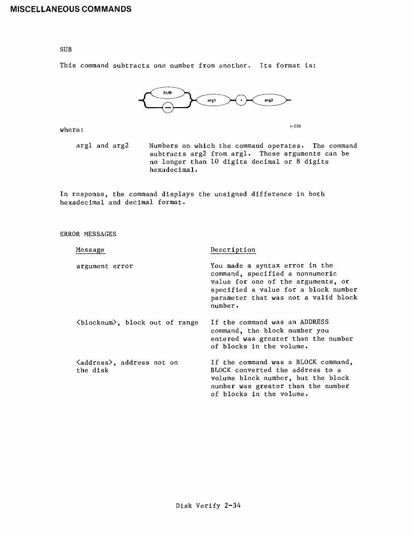
MISCELLANEOUS COMMANDS
SUB
This command subtracts one number from another. Its format is:
where
:
argl and arg2 Numbers on which the command operates. The commandsubtracts arg2 from argl. These arguments can be
no longer than 10 digits decimal or 8 digitshexadecimal.
In response, the command displays the unsigned difference in bothhexadecimal and decimal format.
ERROR MESSAGES
Message
argument error
<blocknum>, block out of range
<address>, address not onthe disk
Description
You made a syntax error in thecommand, specified a nonnumericvalue for one of the arguments, or
specified a value for a block numberparameter that was not a valid blocknumber
.
If the command was an ADDRESScommand, the block number youentered was greater than the numberof blocks in the volume.
If the command was a BLOCK command,BLOCK converted the address to a
volume block number, but the blocknumber was greater than the numberof blocks in the volume.
Disk Verify 2-34

EXAMPLES
MISCELLANEOUS COMMANDS
*MUL 134T, 13T
6CE ( 1742T)*+ 8, 4
OC ( 12T)*SUB 8884, 256862E (34350T)*MOD 1225, 256T
25 ( 37T)*HEX 155T9B
*ADDRESS 15
absolute address = 0A80*
*BLOCK 2236block number = 44
Disk Verify 2-35

QUIT
QUIT COMMAND
This command exits the disk verification utility and returns control to
the Human Interface command level. The format of the QUIT command is asfollows:
This command is identical to the EXIT command.
Disk Verify 2-36

READ COMMAND
This command reads a volume block from the disk into the working buffer,
The format of the READ command is:
INPUT PARAMETER
blocknum Number of the volume block to read. This number
can range from through (max blocks - 1), wheremax blocks is the number of volume blocks in the
volume.
OUTPUT
In response to the command, READ reads the block into the working buffer
and displays the following message:
read block number: <blocknum>
where <blocknum> is the number of the block.
DESCRIPTION
The READ command copies a specified volume block from the volume to the
working buffer. It destroys any data currently in the working buffer.
Once the block is in the working buffer, you can use DISPLAYBYTE and
DISPLAYWORD to display the block and you can use SUBSTITUTEBYTE and
SUBSTITUTEWORD to change the data in the block. Finally, you can use the
WRITE command to write the modified block back out to the volume to
repair damaged system data.
ERROR MESSAGES
Message
argument error
<blocknum>, block out of range
Description
You specified a nonnumeric character
in the blocknum parameter.
The block number that you specified
was larger than the largest blocknumber in the volume.
Disk Verify 2-37

SAVE
SAVE COMMAND
This command writes the reconstructed free fnodes map, volume free spacemap, and the bad blocks map to the volume being verified. (The NAMED2and PHYSICAL options of the VERIFY command originally created the maps.)The format of the SAVE command is:
OUTPUT
In response to this command, SAVE displays the following message:
save fnode map?
If you want to write the reconstructed free fnodes map to the volume,enter Y or YES. Otherwise, enter any other character or a carriagereturn alone. If you enter YES, SAVE writes the free fnodes map to thevolume and displays the following message:
free fnode map saved
In any case, SAVE next displays the following message:
save space map?
If you want to write the reconstructed free space map to the volume,enter Y or YES. Otherwise, enter any other character or a carriagereturn alone. If you enter YES, SAVE writes the volume free space map tothe volume and displays the following message:
free space map saved
SAVE displays the following message if the bad blocks map is constructed:
save bad blocks map?
If you want to write the reconstructed bad blocks map to the volume,enter Y or YES. Otherwise, enter any other character or a carriagereturn alone. If you enter YES, SAVE writes the volume bad blocks map tothe volume and displays the following message:
bad block map saved
Disk Verify 2-38

DESCRIPTION
Whenever you perform a VERIFY function with the NAMED2 option (refer to
the description of the VERIFY command for more information), VERIFY
creates its own free fnodes map and volume free space map. It does this
by examining all directories and fnodes on the volume, not by copying the
maps that exist on the volume. To create the free fnodes map, it
examines every directory on the volume to determine which fnodes
represent actual files. To create the volume free space map, it examines
the POINTER(n) fields of the fnodes to determine which volume blocks the
files use.
If the volume has a bad blocks file, and you perform a VERIFY function
with the PHYSICAL option (refer to the description of the VERIFY command
for more information), VERIFY creates its own bad blocks map. It does
this by examining every block on the volume, not by copying the maps that
exist on the volume.
VERIFY then compares the newly created maps with the maps that exist on
the volume. If a discrepancy exists, VERIFY displays a message to
indicate the discrepancy.
The SAVE command takes the free fnodes map, the volume free space map,
and the bad block map created during the VERIFY operation and writes them
to the volume, replacing the maps that currently exist.
ERROR MESSAGE
Message
nothing to save
Description
You did not enter the VERIFY command
with the NAMED2, NAMED, PHYSICAL, or
ALL options prior to entering the
SAVE command. Thus SAVE has no free
fnode map, volume free space map, or
bad block map with which to replace
those that exist on the volume.
EXAMPLE
The following example illustrates the format of the SAVE command after
you use VERIFY and the NAMED or NAMED2 option.
*SAVEsave fnode map? nosave space map? v_
free space map saved
Disk Verify 2-39

SUBSTITUTEBYTE
SUBSTITUTEBYTE COMMAND
This command allows you to interactively change the contents of theworking buffer (in byte format). You can abort this command by typing aCONTROL-C (press the CONTROL key, and while holding it down, press the Ckey). The format of the SUBSTITUTEBYTE command is:
INPUT PARAMETER
offset Number of the byte, relative to the start of theworking buffer, which the command can change inresponse to user input. This number can range from
to (block size - 1), where block size is the sizeof a volume block (and thus the size of the workingbuffer). If you omit this parameter, the commandassumes a value of 0.
OUTPUT
In response to the command, SUBSTITUTEBYTE displays the specified byteand waits for you to enter a new value. This display appears as:
<offset>: val -
where <offset> Is the number of the byte, relative to the start of thebuffer, and val is the current value of the byte. At this point, you canenter one of the following:
• A value followed by a carriage return. This causesSUBSTITUTEBYTE to substitute the new value for the current byte.If the value you enter requires more than one byte of storage,SUBSTITUTEBYTE uses only the low-order byte of the value.SUBSTITUTEBYTE then displays the next byte in the buffer andwaits for your further response.
• A carriage return alone. This causes SUBSTITUTEBYTE to leave thecurrent value as is and display the next byte in the buffer. Itthen waits for your response.
Disk Verify 2-40

SUBSTITUTEBYTE
A value followed by a period (.) and a carriage return. Thiscauses SUBSTITUTEBYTE to substitute the new value for the currentbyte. It then exits from the SUBSTITUTEBYTE command and givesyou the asterisk (*) prompt, permitting you to enter anyDISKVERIFY command.
A period (.) followed by a carriage return. This exits theSUBSTITUTEBYTE command and gives you the asterisk (*) prompt,permitting you to enter any DISKVERIFY command.
DESCRIPTION
The SUBSTITUTEBYTE command gives you the ability to interactively changebytes in the working buffer. Once you enter the command, SUBSTITUTEBYTEdisplays the offset and the value of the first byte. You can change thebyte by entering a new byte value, or you can leave the byte as is byentering a carriage return only. The command then displays the next bytein the buffer. In this manner, you can consecutively step through thebuffer, changing whatever bytes are appropriate. When you finishchanging the buffer, you can enter a period followed by a carriage returnto exit the command.
The SUBSTITUTEBYTE command considers the working buffer to be a circularbuffer. That is, entering a carriage return when you are positioned atthe last byte of the buffer causes SUBSTITUTEBYTE to display the firstbyte of the buffer.
The SUBSTITUTEBYTE command changes only the values in the workingbuffer. To make the changes in the volume, you must enter the WRITEcommand to write the working buffer back to the volume.
ERROR MESSAGES
Message
argument error
<offsetnum>, invalid offset
Description
You specified a nonnumeric characterin the offset parameter.
You specified an offset value thatwas larger than the number of bytesin the block.
Disk Verify 2-41

SUBSTITUTEBYTE
EXAMPLE
This example changes several bytes in two portions of the workingbuffer. Two SUBSTITUTEBYTE commands are used. Carriage returns aredenoted by a <cr> to aid your understanding of this example.
*SUBSTITUTEBYTE<cr>
0000: A0 - 00<cr>0001: 80 - <cr>0002: E5 - <cr>0003: FF - 31<cr>0004: FF - .<cr>
*SUBSTITUTEBYTE 40<cr>
0040: 00 - E6<cr>0041: 00 - E6<cr>0042: 00 - .<cr>
Disk Verify 2-42

SUBSTITUTEWORD
SUBSTITUTEWORD COMMAND
This command allows you to interactively change the contents of the workingbuffer (in word format). You can abort this command by typing a CONTROL-C(press the CONTROL key, and while holding it down, press the C key). Theformat of the SUBSTITUTEWORD command is:
^^JJUBSTITUTEWORtT^v
V i 1 SW > Joffset
x-243
INPUT PARAMETER
offset Number of the byte, relative to the start of the
working buffer, which the command can change in
response to user input. This number can range fromto (block size - 1), where block size is the size of a
volume block (and thus the size of the workingbuffer). If you omit this parameter, the commandassumes a value of 0.
OUTPUT
In response to the command, SUBSTITUTEWORD displays the word beginning at
the specified byte and waits for you to enter a new value. This displayappears as:
<offset>: val -
where <offset> is the number of the byte which begins the word, relative to
the start of the buffer, and val is the current value of the word. At thispoint, you can enter one of the following:
• A value followed by a carriage return. This causes SUBSTITUTEWORDto substitute the new value for the current word. If the value youenter requires more than one word of storage, SUBSTITUTEWORD usesonly the low-order word of the value. SUBSTITUTEWORD then displaysthe next word in the buffer and waits for your further response.
• A carriage return alone. This causes SUBSTITUTEWORD to leave the
current value as is and display the next word in the buffer. It
then waits for your response.
• A value followed by a period (.) and a carriage return. Thiscauses SUBSTITUTEWORD to substitute the new value for the currentbyte. It then exits from the SUBSTITUTEWORD command and gives youthe asterisk (*) prompt, permitting you to enter any DISKVERIFYcommand.
Disk Verify 2-43

SUBSTITUTEWORD
A period (.) followed by a carriage return. This exits theSUBSTITUTEWORD command and gives you the asterisk (*) prompt,permitting you to enter any DISKVERIFY command.
DESCRIPTION
The SUBSTITUTEWORD command is exactly like the SUBSTITUTEBYTE commandexcept that it allows you to interactively modify words instead ofbytes. Once you enter the command, SUBSTITUTEWORD displays the offsetand the value of the first word. You can change the word by entering anew word value, or you can leave the word as is by entering a carriagereturn only. The command then displays the next word in the buffer. Inthis manner, you can consecutively step through the buffer, changingwhatever words are appropriate. When you finish changing the buffer, youcan enter a period followed by a carriage return to exit the command.
The SUBSTITUTEWORD command considers the working buffer to be a circularbuffer. That is, entering a carriage return when you are positioned atthe last byte of the buffer causes SUBSTITUTEWORD to display the firstbyte of the buffer.
The SUBSTITUTEWORD command changes only the values in the workingbuffer. To make the changes in the volume, you must enter the WRITEcommand to write the working buffer back to the volume.
ERROR MESSAGES
Message
argument error
<offsetnum>, invalid offset
Description
You specified a nonnuraeric characterin the offset parameter.
You specified an offset value thatwas larger than the number of bytesin the block.
EXAMPLE
This example changes several bytes in two areas of the working buffer.Two SUBSTITUTEWORD commands are used. Carriage returns are denoted by a<cr> to aid your understanding of this example.
Disk Verify 2-44

SUBSTITUTEWORD
EXAMPLE (continued)
*SUBSTITUTEWORD<cr>
0000: A0B0 - 0000<cr>0002: 8070 - gcjrT
0004: E511 - <cr>0006: FFFF - 3111<cr>0008: FFFF - .<cr>
* SUBSTITUTEWORD 35<cr>
0035: 0000 - E6FF<cr>0037: 0000 - E6AB<cr>0039: 0000 - .<cr>
Disk Verify 2-45

VERIFY
VERIFY COMMAND
This command checks the structures on the volume to determine whether thevolume is properly formatted. You can abort this command by typing aCONTROL-C (press the CONTROL key, and while holding it down, press the C
key). The format of the VERIFY command is:
INPUT PARAMETERS
NAMED1 or Nl Checks named volumes to ensure that the informationrecorded in the fnodes is consistent and matchesthe information obtained from the directoriesthemselves. VERIFY performs the followingoperations during a NAMED1 verification:
• Checks fnode numbers in the directories to seeif they correspond to allocated fnodes.
• Checks the parent fnode numbers recorded in thefnodes to see if they match with the informationrecorded in the directories.
• Checks the fnodes against the files to determineif the fnodes specify the proper file type.
• Checks the POINTER(n) structures of long filesto see if the indirect blocks accurately reflectthe number of blocks used by the file.
• Checks each fnode to see if the TOTAL SIZE,TOTAL BLKS, and THIS SIZE fields are consistent.
• Checks the bad blocks file to see if the blocksin the file correspond to the blocks marked as"bad" on the volume.
Disk Verify 2-46

VERIFY
NAMED or N
ALL
NAMED2 or N2
Performs both the NAMED1 and NAMED2 operations on
a named volume. If you omit the parameter fromthe VERIFY command, NAMED is the default parameter.
Performs all operations appropriate to the
volume. For named volumes, this option performsboth the NAMED and PHYSICAL operations. Forphysical volumes, this option performs the
PHYSICAL operations.
Checks named volumes to ensure that the
information recorded in the free fnodes map and
the volume free space map matches the actual files
and fnodes. VERIFY performs the following
operations during a NAMED2 verification:
• Creates a free fnodes map by examining everydirectory in the volume. It then compares that
free fnodes map with the one already on thevolume.
• Creates a free space map by examining the
information in the fnodes. It then compares
that free space map with the one already on the
volume.
• Checks to see if the block numbers recorded in
the fnodes and the indirect blocks actuallyexist.
• Checks to see if two or more files use the same
volume block.
• Checks to see if two or more files use the same
fnode
.
• Checks the volume free space map for any badblocks that are marked as "free."
PHYSICAL
LIST
Reads all blocks on the volume and checks for I/O
errors. This parameter applies to both named and
physical volumes. VERIFY also creates a bad
blocks map by examining every block on the volume.
When you specify this option, the file information
in Figure 2-4 is displayed for every file on thevolume, even if the file contains no errors. Youcan use this option with all parameters that,
either explicitly or implicitly, specify theNAMEDl parameter.
Disk Verify 2-47

VERIFY
OUTPUT
VERIFY produces a different kind of output for each of the NAMED1,NAMED2, and PHYSICAL options. The NAMED and ALL options producecombinations of the first three kinds of output.
Figure 2-4 illustrates the format of the NAMEDl output (without the LISToption)
.
DEVICE NAME = <devname>
'NAMEDl' VERIFICATION
DEVICE SIZE = <devsize> BLK = <blksize>
FILE=(<filename>, <fnodenum>): LEVEL=<lev>: PARENT=<parnt> : TYPE=<typ><error messages>
FILE=(<filename>, <fnodenum>): LEVEL=<lev>: PARENT=<parnt> : TYPE=<typ><error messages>
FILE=(<filename>, <fnodenum>): LEVEL=<lev>: PARENT=<parnt>:<error messages>
Figure 2-4. NAMEDl Verification Output
TYPE=<typ>
The following paragraphs identify the fields listed in Figure 2-4.
<devname>
<devsize>
<blksize>
<filename>
<fnodenum>
<lev>
<parnt>
<typ>
Physical name of the device, as specified in theATTACHDEVICE Human Interface command.
Hexadecimal size of the volume, in bytes.
Hexadecimal volume granularity. This number is thesize of a volume block.
Name of the file (1 to 14 characters).
Hexadecimal number of the file's fnode.
Hexadecimal level of the file in the file hierarchy.The root directory of the volume is the only levelfile. Files contained in the root directory are level1 files. Files contained in level 1 directories arelevel 2 files. This numbering continues for all levels
of files in the volume.
Fnode number of the directory which contains this file,
in hexadecimal.
File type, either DATA (for data files) or DIR (fordirectory files). If VERIFY cannot ascertain that thefile is a directory or data file, it displays thecharacters "****" ±n this field.
Disk Verify 2-48

VERIFY
<error messages> Messages, which indicate the errors associated withthe previously-listed file. The error messageswhich can occur are listed later in this section.
As Figure 2-4 shows, the NAMEDl option (without the LIST option) displaysinformation about each file that is in error. If you used the LISToption with the NAMEDl option, the file information in Figure 2-4 isdisplayed for every file, even if the file contains no errors. TheNAMEDl display also contains error messages which immediately follow thelisting of the affected files.
Figure 2-5 illustrates the format of the NAMED2 output.
DEVICE NAME = <devname> : DEVICE SIZE = <devsize> : BLK SIZE - <blksize>
'NAMED2' VERIFICATION
BIT MAPS O.K.
Figure 2-5. NAMED2 Verification Output
The fields in Figure 2-5 are exactly the same as the corresponding fieldsin Figure 2-4.
If VERIFY detects an error during NAMED2 verification, it displays one or
more error message in place of the "BIT MAPS O.K." message.
Figure 2-6 illustrates the format of the PHYSICAL output.
DEVICE NAME - <devname> : DEVICE SIZE = <devsize> : BLK SIZE - <blksize>
'PHYSICAL' VERIFICATION
NO ERRORS
Figure 2-6. PHYSICAL Verification Output
The fields in Figure 2-6 are exactly the same as the corresponding fieldsin Figure 2-4.
Disk Verify 2-49

VERIFY
If VERIFY detects an error during PHYSICAL verification, it displays one
or more error message in place of the "NO ERRORS" message.
If you specify NAMED verification, VERIFY displays both the NAMEDl and
NAMED2 output. If you specify the ALL verification for a named volume,
VERIFY displays the NAMEDl, NAMED2, and PHYSICAL output. If you specifythe ALL verification for a physical volume, VERIFY displays the PHYSICALoutput.
DESCRIPTION
The VERIFY command checks physical and named volumes to ensure that the
volumes contain valid file structures and data areas. VERIFY can performthree kinds of verification: NAMEDl, NAMED2, and PHYSICAL. NAMEDl and
NAMED2 verifications check the file structures of named volumes. They donot apply to physical volumes. A PHYSICAL verification checks each datablock of the volume for I/O errors. PHYSICAL verification applies to
both named and physical volumes.
As part of the NAMED2 verification, VERIFY creates a free fnodes map and
a volume free space map which it compares with the corresponding maps onthe volume. You can use the SAVE command to write the maps producedduring NAMED2 verification to the volume, overwriting the maps on thevolume.
When you perform a PHYSICAL verification on a named volume, VERIFY alsocreates a bad blocks map. You can use the SAVE command to write the badblocks map produced during PHYSICAL verification to the volume; this
destroys the bad blocks map already on the volume.
ERROR MESSAGES
Four kinds of error messages can occur as a result of entering the VERIFYcommand: VERIFY command errors, NAMEDl errors, NAMED2 errors, andPHYSICAL errors.
VERIFY command error
Message
argument error
Description
The parameter you specified is not a
valid VERIFY parameter.
Disk Verify 2-50

NAMEDl errors
VERIFY
The following messages can appear in a NAMEDl display, immediately after
the file to which they refer.
Message
<blocknum^-blocknumn>
,
block bad
<blocknumi-blocknumn>
,
invalid block// recorded in
the fnode/indirect block
Description
The block numbers displayed in this
message are marked as "bad."
One of the POINTER(n) fields in the
fnode specifies block numbers thatare larger than the largest blocknumber in the volume.
directory stack overflow This message can indicate aninternal error in the diskverification utility. However, it
can also indicate that a directoryon the volume lists, as one of its
entries, itself or one of the parentdirectories in its pathname. If
this happens, the utility, when it
searches through the directory tree,
continually loops through a portionof the tree, overflowing an internalbuffer area.
file size inconsistenttotal$size = <totsize> :
this$size = <thsize> ::
data blocks = <numblks>
The TOTAL SIZE, THIS SIZE, and TOTALBLKS fields of the fnode areinconsistent.
<filetype>, illegal file type The file type of a user file, as
recorded in TYPE field of the fnode,
is not valid. The valid file types
and their descriptions are asfollows:
Filetype Description
DIR directoryDATA dataSMAP volume free
space mapFMAP free fnodes mapBMAP bad blocks mapVLAB volume label file
Disk Verify 2-51

VERIFY
<fnodenum>, allocation statusbit in this fnode not set
<fnodenum>, fnode out of range
The file is listed in a directorybut the flags field of its fnodeindicates that fnode is free. Thefree fnodes map may or may not listthe fnode as allocated.
The fnode number is larger than thelargest fnode number in the fnodefile.
<fnodenum>, parent fnode numberdoes not match
invalid block//
recorded in the
fnode/indirect block
insufficient memory tocreate directory stack
sum of the blks in theindirect block does notmatch block in the fnode
The parent fnode number in the filedoes not match the parent fnodenumber in the directory. VERIFYdisplays the fnode number of thedirectory that contains the file,not the fnode number recorded in thePARENT field of the file's fnode.
The file is a long file and oneof the fnodes or indirect blocksspecifies a block number that islarger than the largest block numberin the volume.
There is not enough dynamic memoryin the system for the utility toperform the verification.
The file is a long file, and thenumber of blocks listed in a
POINTER(n) field of the fnode doesnot agree with the number of blockslisted in the indirect block.
total-blocks does not reflectthe data-blocks correctly
The TOTAL BLKS field of the fnodeand the number of blocks recorded inthe POINTER(n) fields areinconsistent.
NAMED2 errors
The following messages can appear in a NAMED2 display.
Message Description
<blocknum^-blocknum2>
,
bad block not allocatedThe volume free space map indicatesthat the blocks are free, but theyare marked as "bad" in the badblocks file.
Disk Verify 2-52

VERIFY
<blocknum>, block allocatedbut not referenced
<blocknum>, block referencedbut not allocated
The volume free space map lists the
specified volume block as allocated,but no fnode specifies the block as
part of a file.
An fnode indicates that the specified
volume block is part of a file, but
the volume free space map lists the
block as free.
directory stack overflow This message can indicate an internal
error in the disk verification utility.
However, it can also indicate that a
directory on the volume lists, as one
of its entries, itself or one of the
parent directories in its pathname.If this happens, the utility, when it
searches through the directory tree,
continually loops through a portion of
the tree, overflowing an internalbuffer area.
Fnodes map indicatesfnodes > max$ fnode
<fnodenum>, fnode map bit markedallocated but not referenced
The free fnodes map indicates that
there are a greater number of
unallocated fnodes than the maximumnumber of fnodes in the volume.
The free fnodes map lists the specifiedfnode as allocated, but no directorycontains a file with the fnode number.
<fnodenum>, fnode referenced but The specified fnode number is listed
fnode map bit marked free in a directory, but the free fnodesmap lists the fnode as free.
Free space map indicatesVolume block > max$Volume$block
The free space map indicates that there
are a greater number of unallocatedblocks than the maximum number of
blocks in the volume.
insufficient memory to createdirectory stack
insufficient memory to createfnode and space maps
insufficient memory to createbad blocks map
There is not enough dynamic memory in
the system for the utility to performthe verification.
During a NAMED2 verification, the
utility tried to create a free fnodesmap and a volume free space map.
However, there is not enough dynamic
memory available in the system to
create these maps.
During a PHYSICAL verification, the
utility tried to create a bad blocksmap. However, there is not enough
dynamic memory available in the systemto create the map.
Disk Verify 2-53

VERIFY
<blocknum>, multiple referenceto this block<fnodenum> , multiple referenceto this fnode
More than one fnode specifies thisblock as part of a file.The directories on the volume listmore than one file associated withthis fnode number.
PHYSICAL error
Message
<blocknum>, error
Description
An I/O error occurred when VERIFYtried to access the specified volumeblock. The volume is probably flawed,
other errors
The following error messages indicate internal errors in the diskverification utility. Under normal conditions these messages should neverappear. However, if these messages (or other undocumented messages thatalso appear to indicate internal problems) do appear during a NAMEDl orNAMED2 verification, you should exit the disk verification utility andre-enter the DISKVERIFY command.
directory stack emptydirectory stack errordirectory stack underflow
EXAMPLE
The following command performs both named and physical verification on anamed volume.
*VERIFY ALL
DEVICE NAME = Fl : DEVICE SIZE = 0003E900 : BLK SIZE = 0080
'NAMEDl' VERIFICATION
'NAMED2' VERIFICATION
BIT MAPS O.K.
'PHYSICAL' VERIFICATION
NO ERRORS
*
Disk Verify 2-54

WRIT
WRITE COMMAND
This command writes the contents of the working buffer to the volume
The format of this command is:
INPUT PARAMETER
blocknum Number of the volume block to which the commandwrites the working buffer. If you omit thisparameter, WRITE writes the buffer back to the
block most recently accessed.
OUTPUT
In response to the command, WRITE displays the following message:
write to block <blocknum>?
where <blocknum> is the number of the volume block to which WRITE intends
to write the working buffer. If you respond by entering Y or any
character string beginning with Y, WRITE copies the working buffer to the
specified block on the volume and displays the following message:
written to block number block <blocknum>
Any other response aborts the write process.
DESCRIPTION
The WRITE command is used in conjunction with the READ, DISPLAYBYTE,
DISPLAYWORD, SUBSTITUTEBYTE, and SUBSTITUTEWORD commands to modifyinformation on the volume. Initially you use READ to copy a volume block
from the volume to a working buffer. Then you can use DISPLAYBYTE and
DISPLAYWORD to view the buffer and SUBSTITUTEBYTE and SUBSTITUTEWORD to
change the buffer. Finally, you can use WRITE to write the modified
buffer back to the volume. By default, WRITE copies the buffer to the
block most recently accessed by a READ or WRITE command.
A WRITE command does not destroy the data in the working buffer. The
data remains the same until the next SUBSTITUTEBYTE, SUBSTITUTEWORD, or
READ command modifies the buffer.
Disk Verify 2-55

WRITE
ERROR MESSAGES
Message
argument error
<blocknum>, block out of range
Description
You made a syntax error or specifiednonnumeric characters in theblocknum parameter.
The block number you specified waslarger than the largest block numberin the volume.
EXAMPLE
The following command copies the working buffer to the block from whichit was read.
*WRITEwrite to block 4B? v_
*written to block number 4B
***
Disk Verify 2-56

APPENDIX ASTRUCTURE OF iRMX™ 86 NAMED VOLUMES
This appendix describes the structure of an iRMX 86 volume that containsnamed files. Those users who wish to examine named file volumes or
create their own formatting utility programs can use this information.
This appendix is intended for system programmers who have had experiencein reading and writing actual volume information. It does not attempt to
teach the reader these functions.
INTRODUCTION
Each iRMX 86 named volume contains ISO (International Organization for
Standardization) label information as well as iRMX 86 label informationand files. Figure A-l illustrates the general structure of a named filevolume.
reservedfor
BootstrapLoader
iRMX™ 86VolumeLabel
absolute bytenumber
uninitialized,
reservedfor future
ISOstandard-ization
ISOVolumeLabel
uninitialized,
reservedfor future
ISOstandard-ization
reservedfor
BootstrapLoader
fnodefile
badblocks
file
volumefree spacemap file
Data
and
Directory
files
free (nodesmap file
rootdirectory
383 384 511J512767|768 895J896
1023|l024 3327J3328-
X-645
Figure A-l. General Structure Of Named Volumes
Disk Verify A-l

STRUCTURE OF iRMX"1
86 NAMED VOLUMES
This appendix discusses the structure in more detail. It includesinformation concerning the following:
ISO Volume LabeliRMX 86 Volume Labelfnode filevolume free space map filefree fnodes map filebad blocks map fileroot directory
It also discusses the structure of directory files and the concepts oflong and short files.
The blocks in Figure A-l that are reserved for the Bootstrap Loader arenot discussed. To include these blocks on a new volume that you areformatting, you should copy them from an already formatted volume.
NOTE
The following sections of this appendixrefer to a data type called DWORD.DWORD must be declared literally asPOINTER. This results in a 32-bitvariable for the PLM/86 models COMPACT,MEDIUM, and LARGE.
VOLUME LABELS
This section describes the structure of the volume labels that must bepresent on a named volume. These labels are the ISO volume label and theiRMX 86 volume label.
ISO VOLUME LABEL
The ISO (International Organization for Standardization) volume label is
recorded in absolute byte positions 768 through 895 of the volume (forexample, sector 07 of a single density flexible diskette). The structureof this volume label is as follows:
Disk Verify A-2

STRUCTURE OF iRMX™ 86 NAMED VOLUMES
DECLAREISO$VOL$LABEL STRUCTURE
(
LABEL$ID(3) BYTE,
RESERVED$A BYTE,VOL$NAME(6) BYTE,
VOL$STRUC BYTE,
RESERVED$B(60) BYTE,REC$SIDE BYTE,
RESERVED$C(4) BYTE,
ILEAVE(2) BYTE,RESERVED$D BYTE,
ISO$VERSION BYTE,RESERVED$E(48) BYTE);
where:
LABEL$ID(3)
RESERVED$A
VOL$NAME(6)
VOL$STRUC
RESERVED$B(60)
REC$SIDE
RESERVED$C(4)
ILEAVE(2)
RESERVED$D
ISO$VERS ION
RESERVED$D(48)
Label identifier. For named file volumes, this
field contains the ASCII characters "VOL".
Reserved field containing the ASCII character "1".
Volume name. This field can contain up to six
printable ASCII characters, left justified and
space filled. A value of all spaces implies that
the volume name is recorded in the iRMX 86 VolumeLabel (absolute byte positions 384-393).
For named file volumes, this field contains the
ASCII character "N", indicating that this volumehas a non-ISO file structure.
This is a reserved field containing 60 bytes of
ASCII spaces.
For named file volumes, this field contains the
ASCII character "1" to indicate that only one side
of the volume is to be recorded.
This is a reserved field containing four bytes of
ASCII spaces.
Two ASCII digits indicating the interleave factor
for the volume, in decimal. ASCII digits consistof the numbers through 9. When formatting named
volumes, you should set this field to the same
interleave factor that you use when physicallyformatting the volume.
This is a reserved field containing an ASCII space.
For named file volumes, this field contains the
ASCII character "1", which indicates ISO versionnumber one.
This is a reserved field containing 48 ASCII spaces.
Disk Verify A-3

STRUCTURE OF iRMX™ 86 NAMED VOLUMES
iRMX1" 86 VOLUME LABEL
The iRMX 86 Volume Label is recorded in absolute byte positions 384through 511 of the volume (sector 04 of a single density flexiblediskette). The structure of this volume label is as follows:
DECLARERMX$VOLUME$ INFORMATION STRUCTURE
(
VOL$NAME(10) BYTE,FLAGS BYTE
,
FILE$DRIVER BYTE,VOL$GRAN WORD,VOL$SIZE DWORD,MAX$FN0DE WORD,FNODE$START DWORD,FNODE$SIZE WORD,R00T$FN0DE WORD,,
DEV$GRAN WORD,INTERLEAVE WORD,TRACK$SKEW WORD,SYSTEM$ ID WORD,SYSTEM$NAME(12) BYTE,,
DEVICE$SPECIAL(8) BYTE);
where:
VOL$NAME(10)
FLAGS
Volume name in printable ASCII characters, leftjustified and zero filled.
BYTE which lists the device characteristics forautomatic device recognition. The individual bitsin this byte indicate the following characteristics(bit is right-most bit):
Bit Meaning
VF$AUT0 flag. When set toone, this bit indicates thatthe FLAGS byte contains validdata for automatic devicerecognition. When set tozero, it indicates that theremaining flags containmeaningless data.
VF$DENSITY flag. This bitindicates the recordingdensity of the volume. Whenset to one, it indicatesmodified frequency modulation(MFM) or double-densityrecording. When set to zero,
Disk Verify A-4

STRUCTURE OF iRMX1" 86 NAMED VOLUMES
Bit Meaning
it indicates frequency
modulation (FM) orsingle-density recording.
2 VF$SIDES flag. This bitindicates the number of
recording sides on thevolume. When set to one, itindicates a double-sidedvolume. When set to zero, it
indicates a single-sidedvolume.
3 VF$MINI flag. This bit
indicates the size of therecording media. When set to
one, it indicates a5 1/4-inch volume. When set
to zero, it indicates an8-inch volume
.
4 VF$NOT$FLOPPY. This bit
indicates the type of diskyou are using. When this bitis set to one and when Bitis set to one, it indicates a
Winchester disk.
FILE$DRIVER Number of the file driver used with this volume.
For named file volumes, this field is set to four.
VOL$GRAN Volume granularity, specified in bytes. This value
must be a multiple of the device granularity. It
sets the size of a logical device block, alsocalled a volume block.
VOL$SIZE Size of the entire volume, in bytes.
MAX$FNODE Number of fnodes in the. fnode file. Refer to the
next section for a description of fnodes.
FNODE$START A 32-bit value which represents the number of the
first byte in the fnode file (byte is the first
byte of the volume).
FNODE$SIZE Size of an fnode, in bytes.
ROOT$FNODE Number of the fnode describing the root directory.Refer to the next section for further information.
Disk Verify A-5

STRUCTURE OF iRMXw 86 NAMED VOLUMES
DEV$GRAN
INTERLEAVE
TRACK$SKEW
Device granularity of all tracks except track zero(which contains the volume label). This field isimportant only when the system requires automaticdevice recognition.
Block interleave factor for this volume. Thisvalue indicates the physical distance, in blocks,between consecutively-numbered blocks on thevolume. A value of one indicates thatconsecutively-numbered blocks are adjacent. Avalue of zero indicates an unknown or undefinedinterleave factor.
Offset, in bytes, between the first block on onetrack and the first block on the next track. Avalue of zero indicates that all tracks areidentical.
SYSTEM$ID Numerical code identifying the operating systemthat formatted the volume. The following codes arereserved for Intel operating systems:
Operating System Code
iRMX 86iRMX 88
OS 88
- OFhlOh - lFh20h - 2Fh
SYSTEM$NAME(12)
Currently, the iRMX 86 Operating System places a
zero in this field,.
Name of the operating system which formatted thevolume, in printable ASCII characters, leftjustified and space filled. Zeros (ASCII nulls)indicate that the operating system is unknown. TheiRMX 86 Operating System currently places severalpieces of information into this field, as follows:
• The left-most six bytes of this field containthe ASCII characters "iRMX86" to identify theoperating system. Former iRMX 86 releasesfilled this field with zeros.
• The next byte is an ASCII character whichidentifies the program that formatted thevolume. The following characters apply:
Character
F
U
Formatting Program
Human Interface FORMAT command
iRMX 86 Files Utility
Disk Verify A-6

STRUCTURE OF iRMX 1" 86 NAMED VOLUMES
If the formatting program is unable to provide thisinformation, it places an ASCII space in this field.
• The next two bytes contain a two-digit ASCIIsequence number which is incremented by theformatting program each time the formattingprogram changes in a way that affects the volumeformat. The Release 4 FORMAT Human Interfacecommand places the characters "00" in this field.
• The right-most: three bytes of the field containa three-digit ASCII number specifying theversion of the Basic I/O System that was used informatting the volume (for example, thecharacters "030" would indicate version 3.0).If the formatting program is unable to obtainthis information, it places ASCII spaces in thisfield.
DEVICE$SPECIAL(8) Reserved for special device-specific information.When no device-specific information exists, thisfield must contain zeros. If the device is aWinchester disk with an iSBC 215 controller or ifthe device is a disk with an iSBC 220 controller,the iRMX 86 Operating System imposes a structure onthis field and supplies the following information:
SPECIAL STRUCTURE
(
CYLINDERS WORD,FIXED BYTE,REMOVABLE BYTE,SECTORS BYTE,SECTOR SIZE WORD,ALTERNATES BYTE);
where:
CYLINDERS Total number of cylinders on thedrive.
FIXED Number of heads on the fixeddisk or Winchester disk.
REMOVABLE Number of heads on the removabledisk cartridge.
SECTORS Number of sectors in a track.
SECTOR_SIZE Sector size, in bytes.
ALTERNATES Number of alternate cylinders.
The remainder of the Volume Label (bytes 430 through 511) is reserved andmust be set to zero.
Disk Verify A-7

STRUCTURE OF iRMX 1" 86 NAMED VOLUMES
INITIAL FILES
Any mechanism that formats iRMX 86 named volumes must place five files on
the volume during the format process. These five files are the fnode file,
the volume free space map file, the frees fnodes map file, the bad blocks
file, and the root directory. The first: of these files, the fnode file,
contains information about all of the files on the volume. The general
structure of the fnode file is discussed first. Then all of the files are
discussed in terms of their fnode entries and their functions.
FNODE FILE
A data structure called a file descriptor node (or fnode) describes eachfile in a named file volume. All the fnodes for the entire volume aregrouped together in a file called the fnode file . When the I/O Systemaccesses a file on a named volume, it examines the iRMX 86 Volume Label(described in the previous section) to determine the location of the fnode
file, and then examines the appropriate fnode to determine the actuallocation of the file.
When a volume is formatted, the fnode file contains six allocated fnodes. In
addition to the six allocated files, there also any number of unallocatedfnodes. The original number of unallotted fnodes depends on the FILESparameter of the FORMAT command. These allocated fnodes represent the fnodefile, the volume free space map file, the free fnodes map file, the bad
blocks file, the root directory, and one other file. Later sections of thischapter describe these files. The size of the fnode file is determined by
the number of fnodes that it contains. The number of fnodes in the fnodefile also determines the number of files that can be created on the volume.
The number of files is set when you format the storage medium.
The structure of an individual fnode in a named file volume is as follows:
DECLAREFNODE STRUCTURE
(
FLAGS WORD,TYPE BYTE,GRAN BYTE,OWNER WORD,CR$TIME DWORD,ACCESS$TIME DWORD,MOD$TIME DWORD,TOTAL$SIZE DWORD,TOTAL$BLKS DWORD,
P0INTR(40) BYTE,
THIS$SIZE DWORD,RESERVED$A WORD,RESERVED$B WORD,ID$COUNT WORD,
ACC(9) BYTE,PARENT WORD,AUX(*) BYTE);
Disk Verify A-8

where:
STRUCTURE OF iRMX™ 86 NAMED VOLUMES
FLAGS A WORD which defines a set of attributes for the
file. The individual bits in this word indicatethe following attributes (bit is the right-mostbit):
Bit Meaning
Allocation status. If set to one, thisfnode describes an actual file. If setto zero, this fnode is available forallocation. When formatting a volume,this bit is set to one in the sixallocated fnodes. In other fnodes, it is
set to zero.
1 Long or short file attribute. This bitdescribes how the PTR fields of the fnodeare interpreted. If set to zero,indicating a short file, the PTR fieldsidentify the actual data blocks of thefile. If set to one, indicating a long
file, the PTR fields identify indirectblocks. Indirect blocks are describedlater in this section. When formatting a
volume, this bit is always set to zero,
since the initial files on the volume areshort files.
Bit Meaning
2 Reserved bit which is always set to one.
3-4 Reserved bits which are always set to
zero.
5 Modification attribute. Whenever a file
is modified, this bit is set to one.Initially, when a volume is formatted,this bit is set to zero in each fnode.
6 Deletion attribute. This bit is set to
one to indicate that the file is a
temporary file or that the file is goingto be deleted (the deletion may bepostponed because additional connectionsexist to the file). Initially, when the
volume is formatted, this bit is set to
zero in each fnode.
7-15 Reserved bits which are always set tozero.
Disk Verify A-9

STRUCTURE OF iRMX 1" 86 NAMED VOLUMES
TYPE Type of file. The following are acceptable types:
Mnemonic Value Type
FT$FNODE fnode fileFT$VOLMAP 1 volume free space mapFT$FNODEMAP 2 free fnodes mapFT$ACCOUNT 3 space accounting fileFT$BADBLOCK 4 bad device blocks fileFT$DIR 6 directory fileFT$DATA 8 data fileFT$VLABEL 9 volume label file
During system operation, only the I/O System canaccess file types other than FT$DATA and FT$DIR.These file types are discussed later in thissection.
GRAN
OWNER
CR$TIME
File granularity, specified in multiples of thevolume granularit)'. The default value is 1. Forthe files initially present on the volume (fnodefile, volume free space map file, free fnodes mapfile, bad blocks file, root directory), this valuecan be set to any multiple of the volumegranularity.
User ID of the owner of the file. For the filesinitially present on the volume, this parameter isimportant only for the root directory. For theroot directory, this parameter should specify theuser WORLD (FFFFH). The I/O System does notexamine this parameter for the other files (fnodefile, volume free space map file, free fnodes mapfile, bad blocks file) and so a value of zero canbe specified.
Time and date that:
as a 32-bit value.,
of seconds since a
time. By convent
1
A.M., January 1, 1
present on the volonly for the rootspecified for thefree space map filblocks file).
the file was created, expressedThis value indicates the numberfixed, user-determined point in
on, this point in time is 12:00978. For the files initiallyume, this parameter is importantdirectory. A zero can be
other files (fnode file, volumee, free fnodes map file, bad
ACCESS$TIME
M0D$TIME
Time and date of the last file access (read or
write), expressed as a 32-bit value. For the filesinitially present on the volume, this parameter is
important only for the root directory.
Time and date of the last file modification,expressed as a 32--bit value. For the filesinitially present on the volume, this parameter is
important only for the root directory.
Disk Verify A-10

STRUCTURE OF iRMX™ 86 NAMED VOLUMES
TOTAL$SIZE Total size, in bytes, of the actual data in thefile.
TOTAL$BLKS Total number of volume blocks used by this file,including indirect block overhead. A volume blockis a block of data whose size is the same as thevolume granularity. All memory in the volume isdivided into volume blocks, which are numberedsequentially, starting with the block containingthe smallest addresses (block 0). Indirect blocksare discussed later in this section.
POINTR(40) A group of bytes on which the following structureis imposed:
PTR(8) STRUCTURE
(
NUM$BL0CKS WORD,BLK$PTR(3) BYTE);
This structure identifies the data blocks of thefile. These data blocks may be scatteredthroughout the volume, but together they make up a
complete file. If the file is a short file (bit 1
of the FLAGS field is set to zero), each PTRstructure identifies an actual data block. In thiscase, the fields of the PTR structure contain thefollowing:
NUM$BL0CKS Number of volume blocks in thedata block.
BLK$PTR(3) A 24-bit value specifying thenumber of the first volume blockin the data block. Volume blocksare numbered sequentially,starting with the block with thesmallest address (block 0). Thebytes in the BLK$PTR array rangefrom least significant(BLK$PTR(0)) to most significant(BLK$PTR(2)).
If the file is a long file (bit 1 of the FLAGSfield is set to one), each PTR structure identifiesan indirect block (possibly consisting of more thanone contiguous volume block) , which in turnidentifies the data blocks of the file. In thiscase, the fields of the PTR structure contain thefollowing:
NUM$BLOCKS Number of volume blocks pointed to
by the indirect block.
Disk Verify A-ll

STRUCTURE OF iRMX 1" 86 NAMED VOLUMES
BLK$PTR(3) A 24-bit volume block number of theIndirect block.
THIS$SIZE
RESERVED$A
RESERVED$B
ID$COUNT
ACC(9)
Indirect blocks are discussed later in this section.
Size, in bytes, of the total data space allocated to thefile. This figure does not include space used forindirect blocks, but it does include any data space
allocated to the file, regardless of whether the filefills that allocated space.
Reserved field which is set to zero.
Reserved field which is set to zero.
Number of access-ID pairs declared in the ACC(9) field.
A group of bytes on which the following structure is
imposed:
ACCESS0R(3)ACCESSID
STRUCTURE
(
BYTE,WORD);
This structure contains the access-ID pairs which definethe access rights for the users of the file. Byconvention, when a file is created, the owning user's IDis inserted in ACCESSOR(O), along with the code for theaccess rights. The fields of the ACCESSOR structurecontain the following:
ACCESS Encoded access rights for the file. Thesettings of the individual bits in this fieldgrant (if set to one) or deny (if set to zero)permission for the corresponding operation.Bit is the right-most bit.
Bit
1
2
3
4-7
Data FileOperationdeletereadappendupdate
DirectoryOperationdeletedisplayadd entrychange entry
reserved (must be 0)
ID ID of the user who gains the correspondingaccess permission.
PARENT Fnode number of directory file which lists this file.
For files initially present on the volume, thisparameter is important only for the root directory. Forthe root directory, this parameter should specify thenumber of the root directory's own fnode. For otherfiles (fnode file, volume free space map file, freefnodes map file, bad blocks file) the I/O System doesnot examine this field.
Disk Verify A-12

STRUCTURE OF iRMX" 86 NAMED VOLUMES
AUX(*) Auxiliary bytes associated with the file. Thenamed file driver does not interpret this field,but the user can access it by makingGET$EXTENSION$DATA and SET$EXTENSION$DATA systemcalls. The size of this field is determined by the
size of the fnode, which is specified in the iRMX86 Volume Label. The Files Utility allocates threebytes for this field by default. If you use theHuman Interface FORMAT command or create your ownutility to format a volume, you can make this fieldas large as you wish; however, a larger AUX fieldimplies slower file access.
Certain fnodes designate special files that appear on the volume,
following sections discuss these fnodes and the associated files.The
FNODE (FNODE FILE)
The first fnode structure in the fnode file describes the fnode file
itself. This file contains all the fnode structures for the entirevolume. It must reside in contiguous locations in the volume. Fields of
fnode must be set as follows:
• The bits in the FLAGS field are set to the following (bit is
the right-most bit):
Bit Value Description1 Allocated file
1 Short file2 1 Primary fnode
3-4 Reserved bits5 Initial status is unmodified6 File will not be deleted
7-15 Reserved bits
The TYPE field is set to FT$FNODE.
The GRAN field is set to 1.
The OWNER field is set to 0.
The CR$TIME, ACCESS$TIME, and M0D$TIME fields are set to 0.
Since the iRMX 86 Volume Label specifies the size of anindividual fnode structure and the number of fnodes in the fnodefile, the value specified in the T0TAL$SIZE field of fnode must
equal the product of the values in the FN0DE$SIZE and MAX$FN0DEfields of the iRMX 86 Volume Label.
The T0TAL$BL0CKS field specifies enough volume blocks to account
for the memory listed in the T0TAL$SIZE field. The product of
the value in the T0TAL$BL0CKS field and the volume granularityequals the value of the THIS$SIZE field, since the fnode file is
a short file.
Disk Verify A-13

STRUCTURE OF iRMX 1" 86 NAMED VOLUMES
• Since the fnode file must reside in contiguous locations in the
volume, only one PTR structure describes the location of thefile. The value in the NUM$BLOCKS field of that PTR structureequals the value in the TOTAL$BLOCKS field. The BLK$PTR fieldindicates the number of the first block of the fnode file.
• The ID$COUNT field is set to zero, indicating that no users canaccess the file.
FNODE 1 (VOLUME FREE SPACE MAP FILE)
The second fnode, fnode 1, describes the volume free space map file. TheTYPE field for fnode 1 is set to FT$VOLMAP to designate the file as such.
The volume free space map file keeps track of all the space on the
volume. It is a bit map of the volume, in which each bit represents onevolume block (a block of space whose size is the same as the volumegranularity). If a bit in the map is set to one, the correspondingvolume block is free to be allocated to any file. If a bit in the map is
set to zero, the corresponding volume block is already allocated to a
file. The bits of the map correspond to volume blocks such that bit n of
byte m represents volume block (8 * m) -I- n. The bits in the remainingspace allocated to the map file (those that do not correspond to actualblocks of memory) must be set to zero.
When the volume is formatted, the volume free space map file indicatesthat the first 3328 bytes of the volume (the label and bootstrapinformation) plus any files initially placed on the volume (fnode file,
volume free space map file, free fnodes map file, bad blocks file) areallocated.
FNODE 2 (FREE FNODES MAP FILE)
The third fnode, fnode 2, describes the free fnodes map file. The TYPEfield of fnode 2 is set to FT$FNODEMAP to designate the file as such.
The free fnodes map file keeps track of all the fnodes in the fnodesfile. It is a bit map in which each bit represents an fnode. If a bitin the map is set to one, the corresponding fnode is not in use and doesnot represent an actual file. If a bit in the map is set to zero, thecorresponding fnode already describes an existing file. The bits in the
map correspond to fnodes such that bit n of byte m represents fnodenumber (8 * m) + n. The bits in the remaining space allocated to the mapfile (those that do not correspond to actual fnode structures) must beset to zero.
When the volume is formatted, the free fnodes map file indicates that
fnodes 0, 1, 2, 3, and 4 are in use. If other files are initially placedon the volume, the free fnodes map file must be set to indicate this aswell.
Disk Verify A-14

STRUCTURE OF iRMX™ 8(3 NAMED VOLUMES
FNODE 4 (BAD BLOCKS FILE)
The fifth fnode, fnode 4, contains all the bad blocks on the volume,
TYPE field of fnode 4 is set to FT$BADBLOCK to indicate this.
The
If there are any unusable blocks on a volume, this fnode must be
initialized to describe a file which consists of all such bad blocks. Ifthere are no bad blocks on the volume, the fnode must still be set up as
allocated, and of the indicated type, but it should not assign any actualspace for the file.
FNODE 5 (VOLUME LABEL FILE)
This fnode contains the first 3328 bytes of any volume. The informationin this file defines the volume as a whole. The TYPE field of this nodeis set to FT$VLABEL. You cannot write to this fnode.
FNODE 6 (ROOT DIRECTORY)
The root directory is a special directory file. It is the root of the
named file hierarchy for the volume. The iRMX 86 Volume Label specifiesthe fnode number of the root directory. The root directory is its own
parent. That is, the PARENT field of its fnode specifies its own fnodenumber.
The root directory (and all directory files) associates file names with
fnode numbers. It consists of a number of entries that have the
following structures
DECLAREDIR$ENTRY STRUCTURE(
FNODE WORD
,
COMPONENT ( 14
)
BYTE )
;
where:
FNODE
COMPONENT (14)
Fnode number of a file listed in the directory.
A string of ASCII characters that is the final
component of the path name identifying the file.
This string is left justified and null padded to
14 characters.
When a file is deleted, its fnode number in the directory entry is set to
zero.
Disk Verify A-15

STRUCTURE OF iRMX™ 86 NAMED VOLUMES
OTHER FNODES
When a volume is formatted, one other fnode is set up, fnode 3,representing a file of type FT$ACCOUNT, The fnode is set up asallocated, and of the indicated type, but it does not assign any actualspace for the file.
When formatting a volume, no other fnodes in the fnode file representactual files. The remaining fnodes must have bit zero (allocationstatus) set to zero.
LONG AND SHORT FILES
A file on a volume is not necessarily one contiguous string of bytes. Inmany cases, it consists of several contiguous blocks of data scatteredthroughout the volume. The fnode for the file indicates the locationsand sizes of these blocks in one of two ways, as short files or as longfiles.
SHORT FILES
If the file consists of eight or less distinct blocks of data, its fnodecan specify it as a short file. The fnode for a short file has bit 1 ofthe FLAGS field set to zero. This indicates to the I/O System that thePTR structures of the fnode identify the actual data blocks that make upthe file. Figure A-2 illustrates an fnode for a short file. Decimalnumbers are used in the figure for clarity.
Disk Verify A-16

STRUCTURE OF iRMX 1" 86 NAMED VOLUMES
Label andBootstrapInformation
data block
Volume granularity = 1024
Figure A-2. Short File Fnode
As you can see from Figure A-2, fnode 8 identifies the short file. The
file consists of three distinct data blocks. Three PTR structures give
the locations of the data, blocks. The NUM$BLOCKS field of each PTR
structure gives the length of the data block (in volume blocks) and the
BLK$PTR field points to the first volume block of the data block.
The other fields shown in Figure A-2 include TOTAL$BLKS, THIS$SIZE, and
TOTAL$SIZE. The TOTAL$BLKS field specifies the number of volume blocks
allocated to the file, which in this case is eight. This equals the sum
of NUM$BLOCKS values (3+2+3), since short files use all allocated
space as data space.
Disk Verify A-17

STRUCTURE OF iRMXw 86 NAMED VOLUMES
The THIS$SIZE field specifies the number of bytes of data space allocatedto the file. This is the sum of the NUM$BLOCKS values (3+2+3)multiplied by the volume granularity (1024) and equals 8192.
The TOTAL$SIZE field specifies the number of bytes of data space that thefile occupies. This is designated in Figure A-2 by the shaded area. Asyou can see, the file does not occupy all the space allocated for it, andso the TOTAL$SIZE value (8000) is not as large as the THIS$SIZE value.
LONG FILES
If the file consists of more than eight distinct blocks of data, itsfnode must specify it as a long file. The fnode for a long file has bit1 of the FLAGS field set to one. This tells the I/O System that the PTRstructures of the fnode identify indirect blocks. The indirect blocksidentify the actual data blocks that make up the file.
Each indirect block contains of a number of indirect pointers, which arestructures similar to the PTR structures. However, an indirect block cancontain more than eight structures and thus can point to more than eightdata blocks. In fact, an indirect block can consist of more than onevolume block; however, all volume blocks of of an indirect block must becontiguous. The structure of each indirect pointer is as follows:
DECLAREIND$PTR
NBLOCKSBLK$PTR
STRUCTURE
(
BYTE,BL0CK$NUM)
;
where:
NBLOCKS
BLK$PTR
Number of volume blocks in the data block.
A 24-bit volume block number of first volume blockin the data block. Volume blocks are numberedsequentially throughout the volume, starting withthe block with the smallest address (block 0).
The iRMX 86 Operating System determines how many indirect pointers thereare in an indirect block by comparing the NBLOCKS fields of the indirectpointers with the NUM$BLOCKS field of the fnode. It assumes that theindirect block contains as many pointers as necessary for the sum of theNBLOCKS fields to equal the NUM$BLOCKS field.
Figure A-3 illustrates an fnode for a long file,used in the figure for clarity.
Decimal numbers are
Disk Verify A-18

STRUCTURE OF iRMX'" 86 NAMED VOLUMES
Label and bootstrapinformation
(node 9
volume granularity -• 1024
Figure A-3. Long File Fnode
As you can see from Figure A-3, fnode 9 identifies the long file. Theactual file consists of nine distinct data blocks. One PTR structure andan indirect block give the locations of the data blocks. The NUM$BLOCKSfield of the PTR structure contains the number of volume blocks pointedto by the indirect block. The BLK$PTR field points to the first volumeblock of the indirect block.
In the indirect block, each NBLOCKS field gives the length of anindividual data block and each BLK$PTR field points to the first volumeblock of a data block.
Disk Verify A-19

STRUCTURE OF iRMXm 86 NAMED VOLUMES
Figure A-3 also lists the TOTAL$BLKS, THIS$SIZE, and TOTAL$SIZE values,
which are more complex than for a short file. The TOTAL$BLKS fieldspecifies the number of volume blocks allocated to the file, which in
this case is 21. Twenty of the volume blocks are used for actual datastorage and one of the blocks is used for the indirect block.
The THIS$SIZE field specifies the number of bytes of data space allocatedto the file, and does not include the size of the indirect block. This
size is equal to the NUM$BLOCKS value (20) or the sum of NBLOCKS values
in the indirect block (2 +1+2+3+ 2 +3+3+2+2= 20) multipliedby the volume granularity (1024) and equals 20480.
The TOTAL$SIZE field specifies the number of bytes of data space that the
file currently occupies. This is designated in Figure A-3 by the shadedareas. As you can see, the file does not occupy all the space allocatedfor it, and so the TOTAL$SIZE value (20300) is not as large as the
THIS$SIZE value.
FLEXIBLE DISKETTE FORMATS
The flexible diskette device drivers supplied with the iRMX 86 Basic I/O
System can support several diskette characteristics. Tables A-l and A-2
list these characteristics.
Table A-l. Eight-Inch Diskette Characteristics
SectorSize
Density Sectorsper Track
Device Size (in bytes)
One sided Two Sided
128
256
5121024
256512
1024
SingleSingleSingleSingle
DoubleDoubleDouble
26
15
8
4
2615
8
. _ ,. ..... .. .
256256295168314880315392
509184587264626688
—
512512
590848630272630784
102169611776001255424
Disk Verify A-20

STRUCTURE OF iRMX™ 86 NAMED VOLUMES
Table A-2. 5 1/4-Inch Diskette Characteristics
SectorSize
Density Sectorsper Track
Device Size (in bytes)
One Sided Two Sided40 Tracks 80 Tracks 40 Tracks 80 Tracks
128 Single 16 81920 163840 163840 327680
256 Single 9 91904 184064 184064 368384512 Single 4 81920 163840 163840 327680
1024 Single 2 81920 163840 163840 327680
256 Double 16 1617921 325632 325632 653312
512 Double 8 1617921 325632 325632 6533121024 Double 4 1617921 325632 325632
. - ... i . '
653312
For compatibility with ECMA (European Computer Manufacturers Association)and ISO (International Organization for Standardization), the iRMX 86
device drivers, when called by the formatting tools (the FORMAT HumanInterface command and the FORMAT Files Utility command), can format thebeginning tracks of all flexible diskettes in the same manner. Aconfiguration option for each driver allows you to specify the following:
• For all 5 1/4-inch and 8-inch flexible diskettes, the devicedrivers format track of side with single-density, 128-bytesectors, with an interleave factor of 1.
• In addition, for 8-inch, double-sided, double-density flexiblediskettes, the device drivers format track of side 1 withdouble-density, 256-byte sectors.
The iRMX 86 device drivers map the sectors on these beginning tracks into
blocks of device granularity size so that the Basic 1/0 System andBootstrap Loader can treat flexible diskettes as if they contain acontiguous string of blocks, all of the same size.
However, this mapping is not exact when you use 8-inch, double-sided,double-density diskettes and specify a device granularity of 512 or
1024. A problem arises because there are 26 128-byte sectors in a track,
which is not an integral mapping for device granularities of 512 or1024. Thus the device driver combines the left-over 128-byte sectors of
track 0, side with the first sectors of track 0, side 1 in order to
make a block of device granularity size. This continues throughout track0, side 1, but the same problem occurs with the last 256-byte sectors of
track 0, side 1; there are not enough sectors to make a block of devicegranularity size. When the device driver tries to combine theseleft-over sectors of track 0, side 1 with the first sectors of track 1,
side 0, it finds that the sectors of track 1, side are already ofdevice granularity size. Therefore, since the device driver cannotaccess partial sectors, it is left with one block (the left-over sectorsof track 0, side 1) that is less than device granularity size. When the
device granularity is 512, this small block is block 19; when the devicegranularity is 1024, the small block is block 9.
Disk Verify A-21

STRUCTURE OF iRMX™ 86 NAMED VOLUMES
If nothing is done to exclude this smaller-than-normal block from use,
the device driver will treat this block as a normal block, assuming it is
of device granularity size. Thus if you try to write information to that
block, the driver will attempt to write an entire device granularityblock of information into a block that is much shorter, causing you to
lose information.
To prevent this situation, the Human Interface FORMAT commandautomatically declares this smaller-than-normal block as allocated in thevolume free space map when it formats the volume. This prevents the
Basic I/O System from ever writing information into this block. If youwrite your own formatting utility, you should also declare this block asallocated.
•kick
Disk Verify A-22

Primary references are underscored*
aborting DISKVERIFY commands 2-2
ALL option 2-47
ALLOCATE command 2-5automatic device recognition A-4auxiliary bytes A-13
bad blocks file A-15, A-28bad blocks
in FREE command 2-27map 2-38
command dictionary 2-4command error messages 2-3
Control-C 2-2
density A-4device granularity A-5device recognition A-4directory A-16DISK command 1-3, 2-8
DISKVERIFY command 1-2
error messages 1-5
output 1-4
DISPLAYBYTE command 2-10DISPLAYDIRECTORY command 2-13DISPLAYFNODE command 2-15DISPLAYNEXTBLOCK command 2-20DISPLAYPREVIOUSBLOCK command 2-21DISPLAYWORD command 2-22
example volume A-22EXIT command 2-25
filedriver A-5granularity 2-15, A-10owner 2-15, A-lltype 2-15, A-10
fnode file A-8, A-U_t A-24
fnodes 2-15, A-5, A-
7
FREE command 2-26free fnodes map 2-38, 2-39, A-15 , A-26, A-33free space map 2-38, 2-39, A-14, A-25, A-32
Disk Verify Index-1

INDEX (continued)
granularity 2-15, A-5, A-10
HELP command 2-28
initial files A-8input radices 2-2
interleave factor A-3, A-5
invoking of 1-1
iRMX 86 volume label A-4 , A-23
ISO information A-l
ISO label A-2 , A-22
keyword 2-1
LIST option 2-47
LISTBADBLOCKS command 2-29
long files 2-15, A-9, A-12, A-18
miscellaneous commands 2-30
ADD 2-30
ADDRESS 2-30
BLOCK 2-31
DEC 2-32DIV 2--32
HEX 2-32MOD 2--33
MUL 2--33
SUB 2--34
error messagesexaniples 2-35
2-34
named disk fields 2-9
NAMED verification 1-3, 2-47
named volume structure A-l
NAMED1 verification 1-3, 2-46
output 2-48
errors 2-51
NAMED2 verification 1-3, 2-47
output 2-49
errors 2-52
notational conventions iii
owner 2-15, A-ll
parameters 2-1
parent directory A-13PHYSICAL verification 1-3, 2-47
output 2-49
errors 2-54
QUIT command 2-36
railroad track schematic iii
READ command 2-37
reader level iii
Disk Verify Index-2

INDEX (continued)
recordingdensity A-4sides A-5size A-5
related publications ivroot directory A-5, A-16 , A-29, A-33
SAVE command 2-38
short files 2-15, A-9, A-12, A-17size A-5structure of iRMX 86 named volumes A-lSUBSTITUTEBYTE command 2-40
SUBSTITUTEWORD command 2-43
syntax iii
track skew A-6
variable iiiVERIFY command 1-3, 2-46
working buffer 2-3 7
WRITE command 2-55
***
Disk Verify Index-3