162P POWER PLANT - geindustrial.com | ABB US
92
Critical Power Product Manual 162P POWER PLANT 100 - 2000 Amps@ +24 VDC 10 - 80 Amps @ -48VDC [email protected] www.gecriticalpower.com Page 1 Service and Assistance - +1 877 546 3243 © 2015 General Electric Company. All rights reserved. 4380446PD Issue 10 May 2015
-
Upload
khangminh22 -
Category
Documents
-
view
0 -
download
0
Transcript of 162P POWER PLANT - geindustrial.com | ABB US

Critical Power Product Manual
162P POWER PLANT100 - 2000 Amps@ +24 VDC 10 - 80 Amps
@ -48VDC
[email protected] www.gecriticalpower.com
Page 1
Service and Assistance - +1 877 546 3243 © 2015 General Electric Company. All rights reserved. 4380446PD Issue 10 May 2015

GE Critical Power 162P Power System Manual
Page 2 Issue 10, May 2015
-This page intentionally left blank-
GE Critical Power 162P Power System Manual
Issue 10, May 2015 Page 3
TTTAAABBBLLLEEE OOOFFF CCCOOONNNTTTEEENNNTTTSSS TABLE OF CONTENTS ............................................................................................................................................3
CONTACTINFORMATION ......................................................................................................................................6
PRODUCT INFORMATION.....................................................................................................................................6
WARNINGS.................................................................................................................................................................7
CAUTIONS..................................................................................................................................................................7
SECTION 1: INSTALLATION INFORMATION..................................................................................................9
CHAPTER 1: GENERAL INFORMATION........................................................................................................9 1.1 GENERAL.......................................................................................................................................................9 1.2 EXPLANATION OF FEATURES..................................................................................................................11 1.3 ACRONYMS..................................................................................................................................................16
CHAPTER 2: MECHANICAL INSTALLATION.............................................................................................17 1.4 GENERAL.....................................................................................................................................................17 1.5 DIMENSIONS...............................................................................................................................................17 1.6 BAY INSTALLATION....................................................................................................................................17 1.7 PLUGGABLE RECTIFIER SHELF INSTALLATION AND REMOVAL ......................................................18
1.7.1 RECTIFIER MODULE INSTALLATION ...........................................................................................18 1.7.2 RECTIFIER SHELF REMOVAL .........................................................................................................19
1.8 RECTIFIER MODULE INSTALLATION AND REMOVAL .........................................................................20 1.8.1 RECTIFIER MODULE INSTALLATION ...........................................................................................20 1.8.2 RECTIFIER MODULE REMOVAL ....................................................................................................20
1.9 CONVERTER MODULE INSTALLATION AND REMOVAL.......................................................................21 1.9.1 CONVERTER MODULE INSTALLATION .......................................................................................21 1.9.2 CONVERTER MODULE REMOVAL.................................................................................................21
CHAPTER 3: ELECTRICAL CONNECTIONS ...............................................................................................22 1.10 AC CONNECTIONS ....................................................................................................................................22
1.10.1 AC CONDUIT FITTINGS ..................................................................................................................22 1.10.2 AC CONNECTIONS TO THE TERMINAL BLOCK........................................................................22
1.11 Distribution CONNECTIONS.....................................................................................................................23 1.12 DC GROUND CONNECTIONS .................................................................................................................24 1.13 L10 and L11 LOAD CONNECTIONS.........................................................................................................25
1.13.1 LOAD RETURN .................................................................................................................................25 1.13.2 +24VDC LOAD...................................................................................................................................25 1.13.3 L52 GMT DISTRIBUTION BOARD (6420556P-4) ..........................................................................26
1.14 L12 LOAD CONNECTIONS.......................................................................................................................27 1.14.1 LOAD RETURN .................................................................................................................................27 1.14.2 +24VDC LOAD...................................................................................................................................27
1.15 L13 LOAD CONNECTIONS.......................................................................................................................28 1.15.1 LOAD RETURN .................................................................................................................................28 1.15.2 +24VDC LOAD...................................................................................................................................28
1.16 L14 LOAD CONNECTIONS.......................................................................................................................29 1.16.1 LOAD RETURN .................................................................................................................................29 1.16.2 +24VDC LOAD...................................................................................................................................29
1.17 BATTERY CONNECTIONS........................................................................................................................30 1.17.1 BATTERY RETURNS TERMINATION ...........................................................................................30 1.17.2 (+) BATTERY TERMINATION ........................................................................................................31
1.18 - 48 VDC Distribution FROM DC/DC CONVERTERS..............................................................................32 1.18.1 LOAD RETURN .................................................................................................................................32 1.18.2 - 48VDC LOAD ..................................................................................................................................33
1.19 ALARM EXTENSION CONNECTIONS .....................................................................................................34 1.20 BTC SETUP................................................................................................................................................39
GE Critical Power 162P Power System Manual
Page 4 Issue 10, May 2015
CHAPTER 4: OPERATIONAL CHECKOUT ..................................................................................................40 1.21 OPERATIONAL CHECKOUT....................................................................................................................40 1.22 FACTORY SETTINGS ................................................................................................................................42 1.23 CHANGING PLANT SETTINGS ................................................................................................................42
1.23.1 SETTING UP LVLD...........................................................................................................................42 1.23.2 EQUALIZE TIMER ............................................................................................................................42
1.24 TRIPPING THE RECTIFIER INPUT CIRCUIT BREAKERS ....................................................................43 1.25 ENABLING/DISABLING THE ACO AUDiBLE ALARM ...........................................................................43
SECTION 2: NAVIGATING THE USER INTERFACE FOR THE DIGITAL CONTROLLER ...................45
2.1 GENERAL.....................................................................................................................................................45 2.2 MAIN SCREEN.............................................................................................................................................46 2.3 SUBMENU....................................................................................................................................................47 2.4 PLANT ..........................................................................................................................................................48
2.4.1 STAT .....................................................................................................................................................48 2.4.2 CTRL.....................................................................................................................................................50 2.4.3 INFO......................................................................................................................................................51 2.4.4 SETP......................................................................................................................................................52
2.5 ALRM............................................................................................................................................................54 2.6 BAY ...............................................................................................................................................................55
2.6.1 STAT .....................................................................................................................................................55 2.6.2 CTRL.....................................................................................................................................................57 2.6.3 INFO......................................................................................................................................................58 2.6.4 SETP......................................................................................................................................................59
2.7 RECT ............................................................................................................................................................60 2.7.1 STAT .....................................................................................................................................................61 2.7.2 CTRL.....................................................................................................................................................62 2.7.3 INFO......................................................................................................................................................63 2.7.4 SETP......................................................................................................................................................63
2.8 TEST .............................................................................................................................................................64 2.8.1 LED .......................................................................................................................................................64 2.8.2 RELAY..................................................................................................................................................64 2.8.3 BAYSW.................................................................................................................................................65
SECTION 3: PLANT INFORMATION.................................................................................................................67
3.1 PLANT SPECIFICATIONS...........................................................................................................................67 3.1.1 INPUT RATINGS .................................................................................................................................67 3.1.2 OUTPUT RATINGS FOR RECTIFIERS (+24VDC) ...........................................................................67 3.1.3 OUTPUT RATINGS FOR CONVERTERS (-48VDC) ........................................................................67 3.1.4 MISCELLANEOUS RATINGS............................................................................................................67
SECTION 4: GATEWAY SETUP (IF EQUIPPED).............................................................................................69
4.1 GENERAL................................................................................................................................................69 4.2 SETTING UP THE 162P TO COMMUNICATE VIA AN ETHERNET OR SERIAL PORT.....................69 4.3 CHANGING THE PASSWORD IN CON_UI...........................................................................................74 4.4 ENTERING SITE INFORMATION..........................................................................................................75 4.5 REPLACING THE BATTERY IN THE GATEWAY..................................................................................76
SECTION 5: WEB INTERFACES AND SNMP ...................................................................................................77
5.1 WEB IN GENERAL.......................................................................................................................................77 5.1.1 THE HOMEPAGE ................................................................................................................................78 5.1.2 SITE > SUMMARY..............................................................................................................................79 5.1.3 SITE > STATS Setup ............................................................................................................................80 5.1.4 SITE > INFORMATION.......................................................................................................................81 5.1.5 DC POWER PLANT > STATUS..........................................................................................................82 5.1.6 DC POWER PLANT > ALARM HISTORY ........................................................................................83 5.1.7 LOAD CURRENT STUDY (STATS)...................................................................................................84 5.1.8 DC POWER PLANT > RECTIFIERS > STATUS ...............................................................................85
GE Critical Power 162P Power System Manual
Issue 10, May 2015 Page 5
5.1.9 DC POWER PLANT > RECTIFIERS > INFORMATION ..................................................................86 5.1.10 DC POWER PLANT > RECTIFIERS > CONTROL..........................................................................87 5.1.11 DC POWER PLANT > BATTERIES > CONTROL ..........................................................................88 5.1.12 DC POWER PLANT > DISTRIBUTION > STATS Setup.................................................................89 5.1.13 DC POWER PLANT > CONVERTER > STATS...............................................................................90 5.1.14 DC POWER PLANT > SET POINTS.................................................................................................91 5.1.15 DC POWER PLANT > MONITORING INFORMATION ................................................................92
5.2 SNMP CAPABLE..........................................................................................................................................92
SECTION 6: J-DRAWING 438162P
SECTION 7: SCHEMATIC DRAWING 4391668SD-1
SECTION 8: T-DRAWING 4391668T-1
SECTION 9: 6573003P-23 RECTIFIER SHELF MANUAL 4380230PD
SECTION 10: RECTIFIER MODULE MANUAL 4380425PD
SECTION 11: MENU TREE DRAWING 4290071T
GE Critical Power 162P Power System Manual
Page 6 Issue 10, May 2015
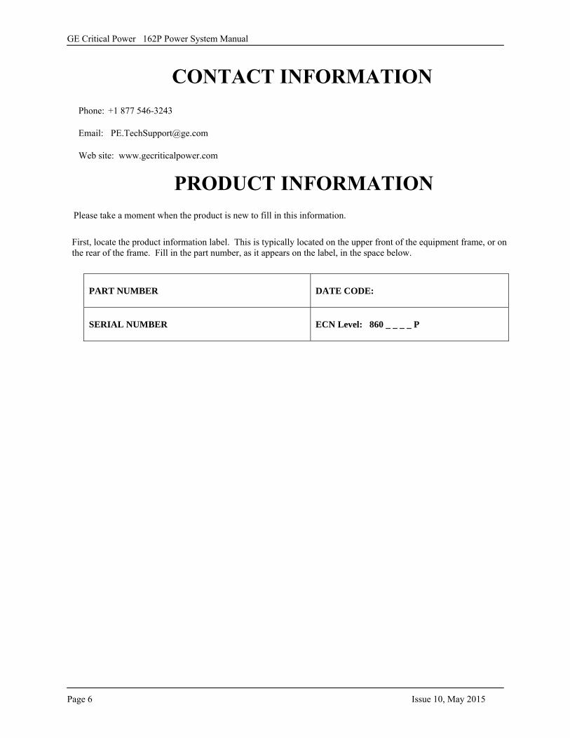
Please take a moment when the product is new to fill in this information.
First, locate the product information label. This is typically located on the upper front of the equipment frame, or on the rear of the frame. Fill in the part number, as it appears on the label, in the space below.
PART NUMBER DATE CODE:
SERIAL NUMBER ECN Level: 860 _ _ _ _ P
CONTACT INFORMATIONPhone: +1 877 546-3243
Email: [email protected]
Web site: www.gecriticalpower.com
PRODUCT INFORMATION
GE Critical Power 162P Power System Manual
Issue 10, May 2015 Page 7
WWWAAARRRNNNIIINNNGGGSSS CCCAAAUUUTTTIIIOOONNNSSS 1. Follow proper grounding instructions.1. Electrical shock hazard. Do not attempt to remove,
maintain, or install this equipment with power applied.Personnel that attempt to work on this equipment withthe power applied may subject themselves or others toelectrical shock that may cause serious injury or death.
2. If connecting batteries, remove the battery-box-fuseor trip the circuit breaker. Check batteries andconnections for proper polarity and power beforeconnecting the batteries to the system.
2. The use of this equipment by unauthorized oruntrained personnel should not be attempted.Personnel that work on this equipment without theproper training may subject themselves or others toelectrical shock that may cause serious injury or death.
3. To remove the circuit breakers or fuses, the DCand/or AC input to the system will need to bedisconnected, thereby disabling the system output tothe load(s). Take the necessary precautions andinform the plant engineer that the system outputpower to the loads will be disabled.
4. Before performing any maintenance, ensure AC orDC power is not applied to the system.
3. Do not attempt to work on this equipment if it is, or has been, exposed to a high moisture condition. It is recommended the equipment be returned to GE to be properly tested. Working on this equipment during a high moisture condition subjects the user to electrical shock that may cause serious injury or death.
5. Fuse holders, fuses, and circuit breakers are not to beloaded to more than 80 percent of their ampererating.
4. Use of an attachment other than one approved by GE will void any and all warranties, implied or other, and will increase risk of fire, or may possibly cause electrical shock, injury, or death to personnel.
6. This assembly contains electrostatic sensitivedevices. For installation and repair, a personalgrounding strap is required.
5. Do not operate this equipment if it has been droppedor otherwise damaged. Trying to operate thisequipment if it has been damaged subjects yourself orothers to electrical shock that may cause serious injuryor death.
6. Before you proceed, ensure the input source is not liveand the input circuit breaker(s)/fuse(s) has beentripped or removed. If these procedures have not beenfollowed and the input/output power is live, seriouspersonnel injury or death may occur.
7. A rack/shelf may contain several operating systems. Ifthere is another system in the general area you want toinstall this system, be cautious of any exposedconnectors or wires and, with permission, removepower to the other systems. Failure to take thenecessary safety precautions subjects the installer ormaintenance personnel to severe electrical shock thatmay cause serious injury or death.
8. This equipment may connect to lead-acid batteries.Battery posts, terminals, and related accessoriescontain lead and lead compounds, chemicals known tothe state of California to cause cancer and birth defectsor other reproductive harm. Wash hands aftertouching batteries.

GE Critical Power 162P Power System Manual
Page 8 Issue 10, May 2015
-This page is intentionally left blank-
GE Critical Power 162P Power System Manual
Issue 10, May 2015 Page 9
SSSEEECCCTTTIIIOOONNN 111::: IIINNNSSSTTTAAALLLLLLAAATTTIIIOOONNN IIINNNFFFOOORRRMMMAAATTTIIIOOONNN
CHAPTER 1: GENERAL INFORMATION
In this Chapter the User will learn: • General information about the 162P system.• What distribution options are available.• About each feature the 162P provides.• All about the available inputs, outputs, and setpoints.• What alarm LEDs are equipped with the system.• What each acronym means.
1.1 GENERAL
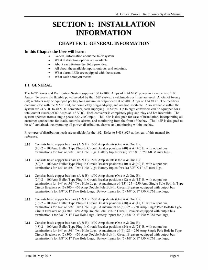
The 162P Power and Distribution System supplies 100 to 2000 Amps of + 24 VDC power in increments of 100 Amps. To create the flexible power needed by the 162P system, switchmode rectifiers are used. A total of twenty (20) rectifiers may be equipped per bay for a maximum output current of 2000 Amps at +24 VDC. The rectifiers communicate with the MMC unit, are completely plug-and-play, and are hot insertable. Also available within the system are 24 VDC to 48 VDC converters, each supplying 10 Amps. Up to eight converters can be equipped for a total output current of 80 Amps at -48 VDC. Each converter is completely plug-and-play and hot insertable. The system operates from a single phase 220 VAC input. The 162P is designed for ease of installation, incorporating all customer connections for loads, controls, alarms, and monitoring from the front of the bay. The 162P is designed to be self-contained, incorporating all power, distribution, alarms, and monitoring within one bay.
Five types of distribution heads are available for the 162. Refer to J-438162P at the rear of this manual for reference.
L10 Consists basic copper bus bars (A & B); 1500 Amp shunts (One A & One B); (80) 2 – 100Amp Bullet Type Plug-In Circuit Breaker positions (40) A & (40) B, with output bus terminations for 1/4" on 5/8” Two Hole Lugs; Battery Inputs for (6) 3/8” X 1” 750 MCM max lugs.
L11 Consists basic copper bus bars (A & B); 1500 Amp shunts (One A & One B); (80) 2 – 100Amp Bullet Type Plug-In Circuit Breaker positions (40) A & (40) B, with output bus terminations for 1/4" on 5/8” Two Hole Lugs; Battery Inputs for (18) 3/8” X 1” 4/0 max lugs.
L12 Consists basic copper bus bars (A & B); 1500 Amp shunts (One A & One B); (24) 2 – 100Amp Bullet Type Plug-In Circuit Breaker positions (12) A & (12) B, with output bus terminations for 1/4" on 5/8” Two Hole Lugs. A maximum of (13) 125 – 250 Amp Single Pole Bolt-In Type Circuit Breakers or (6) 300 – 450 Amp Double Pole Bolt-In Circuit Breakers equipped with output bus termination’s for 3/8” X 1” Two Hole Lugs. Battery Inputs for (6) 3/8” X 1” 750 MCM max lugs.
L13 Consists basic copper bus bars (A & B); 1500 Amp shunts (One A & One B); (36) 2 – 100Amp Bullet Type Plug-In Circuit Breaker positions (18) A & (18) B, with output bus terminations for 1/4" on 5/8” Two Hole Lugs. A maximum of (8) 125 – 250 Amp Single Pole Bolt-In Type Circuit Breakers or (4) 300 – 450 Amp Double Pole Bolt-In Circuit Breakers equipped with output bus termination’s for 3/8” X 1” Two Hole Lugs. Battery Inputs for (6) 3/8” X 1” 750 MCM max lugs.
L14 Consists basic copper bus bars (A & B); 1500 Amp shunts (One A & One B); (48) 2 – 100Amp Bullet Type Plug-In Circuit Breaker positions (24) A & (24) B, with output bus terminations for 1/4" on 5/8” Two Hole Lugs. A maximum of (6) 125 – 250 Amp Single Pole Bolt-In Type Circuit Breakers or (2) 300 – 450 Amp Double Pole Bolt-In Circuit Breakers equipped with output bus termination’s for 3/8” X 1” Two Hole Lugs. Battery Inputs for (6) 3/8” X 1” 750 MCM max lugs.
GE Critical Power 162P Power System Manual
Page 10 Issue 10, May 2015
Two types of converter distributions are available for the 162. Refer to J-438162P at the rear of this manual for reference. Note that the 24VDC to 48VDC converter shelves and number of converters are optional
L34 Consists of (4) 2 – 60 Amp Plug – In Circuit Breakers with output bus termination’s for 1/4" X 5/8” Two Hole Lugs. (Factory Installed Only.)
L35 Consists of (8) 2 – 60 Amp Plug – In Circuit Breakers with output bus termination’s for 1/4" X 5/8” Two Hole Lugs. (Factory Installed Only.)
The system is equipped with 8 relays for extending alarms and status remotely, and 22 LEDs for immediate visual notification of alarms and operating status. The system features an audible alarm and a cutoff switch to silence the alarm. A low voltage load disconnect (LVLD) is optional for each distribution (A, B, and C).
The 162P system controller may by accessed and monitored from one entry point via the meter, monitor, and control (MMC) unit, which is easy to use and provided as standard equipment. Refer to section 2 for the MMC portion of this manual.
GE Critical Power 162P Power System Manual
Issue 10, May 2015 Page 11
1.2 EXPLANATION OF FEATURES
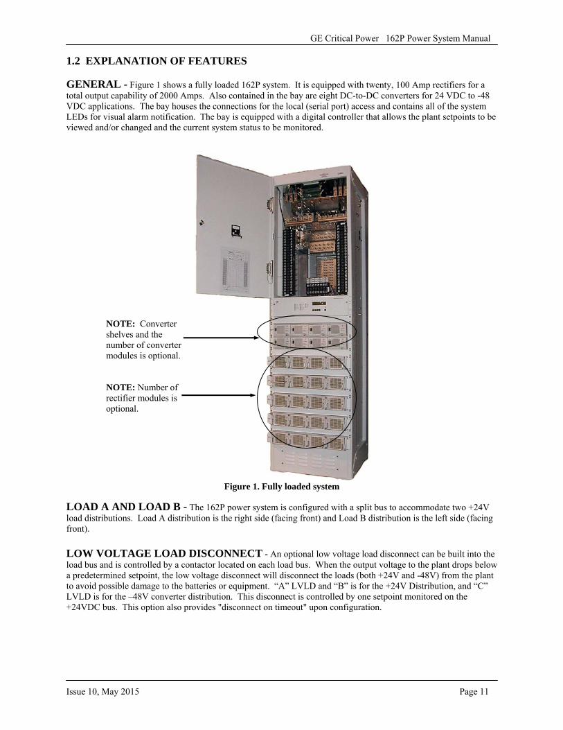
GENERAL - Figure 1 shows a fully loaded 162P system. It is equipped with twenty, 100 Amp rectifiers for a total output capability of 2000 Amps. Also contained in the bay are eight DC-to-DC converters for 24 VDC to -48 VDC applications. The bay houses the connections for the local (serial port) access and contains all of the system LEDs for visual alarm notification. The bay is equipped with a digital controller that allows the plant setpoints to be viewed and/or changed and the current system status to be monitored.
Figure 1. Fully loaded system
LOAD A AND LOAD B - The 162P power system is configured with a split bus to accommodate two +24V load distributions. Load A distribution is the right side (facing front) and Load B distribution is the left side (facing front).
LOW VOLTAGE LOAD DISCONNECT - An optional low voltage load disconnect can be built into the load bus and is controlled by a contactor located on each load bus. When the output voltage to the plant drops below a predetermined setpoint, the low voltage disconnect will disconnect the loads (both +24V and -48V) from the plant to avoid possible damage to the batteries or equipment. “A” LVLD and “B” is for the +24V Distribution, and “C” LVLD is for the –48V converter distribution. This disconnect is controlled by one setpoint monitored on the +24VDC bus. This option also provides "disconnect on timeout" upon configuration.
NOTE: Converter shelves and the number of converter modules is optional.
NOTE: Number of rectifier modules is optional.
GE Critical Power 162P Power System Manual
Page 12 Issue 10, May 2015
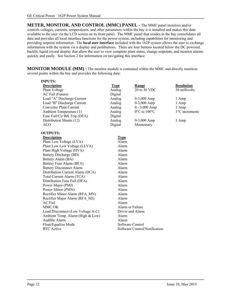
METER, MONITOR, AND CONTROL (MMC) PANEL - The MMC panel monitors and/or controls voltages, currents, temperatures, and other parameters within the bay it is installed and makes this data available to the user via the LCD screen on its front panel. The MMC panel that resides in the bay consolidates all data and provides all local interface functions for the power system, including capabilities for monitoring and providing setpoint information. The local user interface included with the 162P system allows the user to exchange information with the system via a display and pushbuttons. There are four buttons located below the DC powered, backlit, liquid crystal display that allow the user to view complete plant status, change setpoints, and monitor alarms quickly and easily. See Section 2 for information on navigating this interface.
MONITOR MODULE (MM) - The monitor module is contained within the MMC and directly monitors several points within the bay and provides the following data:
INPUTS: Description Type Range Resolution Plant Voltage Analog 20 to 30 VDC 50 millivolts AC Fail (Future) Digital Load "A" Discharge Current Analog 0-3,000 Amp 1 Amp Load "B" Discharge Current Analog 0-3,000 Amp 1 Amp Converter Plant Current Analog 0 - 3,000 Amp 1 Amp Ambient Temperature (1) Analog 0°C to 100°C 1°C increments Fuse Fail/Cir Brk Trip (DFA) Digital Distribution Shunts (12) Analog 0-3,000 Amp 1 Amp ACO Digital Momentary
OUTPUTS:Description Type Plant Low Voltage (LVA) Alarm Plant Low Low Voltage (LLVA) Alarm Plant High Voltage (HVA) Alarm Battery Discharge (BD) Alarm Battery Alarm (BA) Alarm Battery Fuse Alarm (BFA) Alarm Battery Disconnect Alarm Alarm Distribution Current Alarm (DCA) Alarm Total Current Alarm (TCA) Alarm Distribution Fuse Fail (DFA) Alarm Power Major (PMJ) Alarm Power Minor (PMN) Alarm Rectifier Minor Alarm (RFA_MN) Alarm Rectifier Major Alarm (RFA_MJ) Alarm AC Fail Alarm MMC OK Alarm or Failure Load Disconnect (Low Voltage A-C) Driver and Alarm Ambient Temp. Alarm (High & Low) Alarm Audible Alarm Alarm Float/Equalize Mode Software Control BTC Active Software Control/Notification
GE Critical Power 162P Power System Manual
Issue 10, May 2015 Page 13
PLA
NT
GRO
UN
D B
US
+24V
CH
ARG
E B
US
+24V
DIS
CHA
RGE
BUS
A
+24V
DIS
CHA
RGE
BUS B
LO
AD
AD
ISC
ON
NE
CT
LO
AD
BD
ISC
ON
NE
CT
LOA
DLO
AD
LOA
DLO
AD
LOA
DN
OTE
: ALL
LO
AD
CON
NEC
TIO
NS
ARE
NO
TSH
OW
N.
OPT
ION
AL
CO
NV
ER
TE
RPL
AN
T
-48V
DIS
CH
AR
GE
BUS
LO
AD
CD
ISC
ON
NE
CT
LOA
DLO
AD
LOA
D
CO
NV
ER
TE
RPL
AN
T S
HU
NT
LO
AD
A S
HU
NT
LO
AD
B S
HU
NT
LO
AD
C
SH
UN
T
2 - 6
0A C
IRC
UIT
BR
EAK
ERS
-48V
DC
(LO
AD
C)
2 - 1
00A
CIR
CU
IT B
REA
KER
S12
5 - 2
50A
CIR
CU
IT B
REA
KER
S30
0 - 4
50A
(D
OU
BLE
-PO
LE) C
IRC
UIT
BR
EAK
ERS
+24V
DC
(LO
AD
A a
nd
LOA
D B
)
LOA
DLO
AD
LOA
DLO
AD
LOA
D
+24
-48
BA
TT
ER
YST
RIN
GS
(UP
TO
6)
RE
CT
IFIE
RSH
EL
VE
S(U
P T
O 5
)
CO
MM
ER
ICA
LA
C S
OU
RC
E
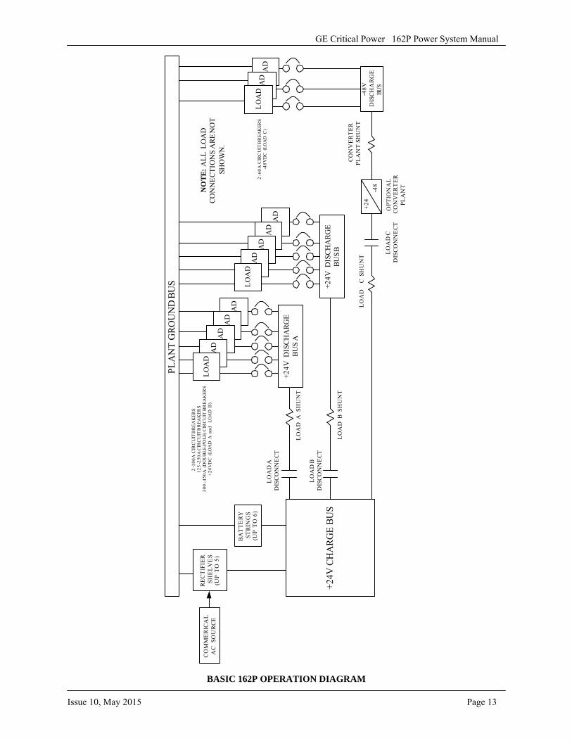
BASIC 162P OPERATION DIAGRAM
Page 14 Issue 10, May 2015
GE Critical Power 162P Power System Manual
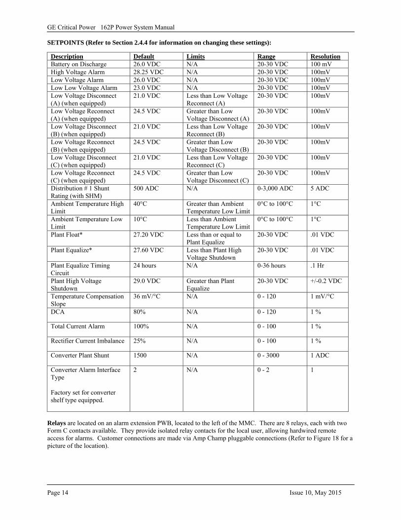
SETPOINTS (Refer to Section 2.4.4 for information on changing these settings):
Description Default Limits Range Resolution Battery on Discharge 26.0 VDC N/A 20-30 VDC 100 mV High Voltage Alarm 28.25 VDC N/A 20-30 VDC 100mV Low Voltage Alarm 26.0 VDC N/A 20-30 VDC 100mV Low Low Voltage Alarm 23.0 VDC N/A 20-30 VDC 100mV Low Voltage Disconnect (A) (when equipped)
21.0 VDC Less than Low Voltage Reconnect (A)
20-30 VDC 100mV
Low Voltage Reconnect (A) (when equipped)
24.5 VDC Greater than Low Voltage Disconnect (A)
20-30 VDC 100mV
Low Voltage Disconnect (B) (when equipped)
21.0 VDC Less than Low Voltage Reconnect (B)
20-30 VDC 100mV
Low Voltage Reconnect (B) (when equipped)
24.5 VDC Greater than Low Voltage Disconnect (B)
20-30 VDC 100mV
Low Voltage Disconnect (C) (when equipped)
21.0 VDC Less than Low Voltage Reconnect (C)
20-30 VDC 100mV
Low Voltage Reconnect (C) (when equipped)
24.5 VDC Greater than Low Voltage Disconnect (C)
20-30 VDC 100mV
Distribution # 1 Shunt Rating (with SHM)
500 ADC N/A 0-3,000 ADC 5 ADC
Ambient Temperature High Limit
40°C Greater than Ambient Temperature Low Limit
0°C to 100°C 1°C
Ambient Temperature Low Limit
10°C Less than Ambient Temperature Low Limit
0°C to 100°C 1°C
Plant Float* 27.20 VDC Less than or equal to Plant Equalize
20-30 VDC .01 VDC
Plant Equalize* 27.60 VDC Less than Plant High Voltage Shutdown
20-30 VDC .01 VDC
Plant Equalize Timing Circuit
24 hours N/A 0-36 hours .1 Hr
Plant High Voltage Shutdown
29.0 VDC Greater than Plant Equalize
20-30 VDC +/-0.2 VDC
Temperature Compensation Slope
36 mV/°C N/A 0 - 120 1 mV/°C
DCA 80% N/A 0 - 120 1 %
Total Current Alarm 100% N/A 0 - 100 1 %
Rectifier Current Imbalance 25% N/A 0 - 100 1 %
Converter Plant Shunt 1500 N/A 0 - 3000 1 ADC
Converter Alarm Interface Type
Factory set for converter shelf type equipped.
2 N/A 0 - 2 1
Relays are located on an alarm extension PWB, located to the left of the MMC. There are 8 relays, each with two Form C contacts available. They provide isolated relay contacts for the local user, allowing hardwired remote access for alarms. Customer connections are made via Amp Champ pluggable connections (Refer to Figure 18 for a picture of the location).
GE Critical Power 162P Power System Manual
Issue 10, May 2015 Page 15
An audible alarm is used to notify personnel of an alarm. The audible signal may be cut off with the “ACO” (Alarm Cut OFF) momentary switch (refer to section 1.25). Cutting off one condition will not prevent a different condition from activating the audible signal. ACO on a Major Alarm will result in an audible “chirp” every 30 seconds until the Major Alarm is retired, however an ACO on a minor alarm will silence the audible alarm without any reminder "chirps." The amber ACO indicator will illuminate whenever the ACO has been activated and the alarm condition has not been cleared.
The MMC in the bay is the hub for all PC connections. Located within the MMC, the DGC (Digital Controller) provides the user an electrical interface with the Monitor Module (MM), Rectifiers, and Converters. The panel is DC powered and runs off of +24 VDC (+18 to +30 range). It is operational from -40°C to +50°C with no degradation in performance.
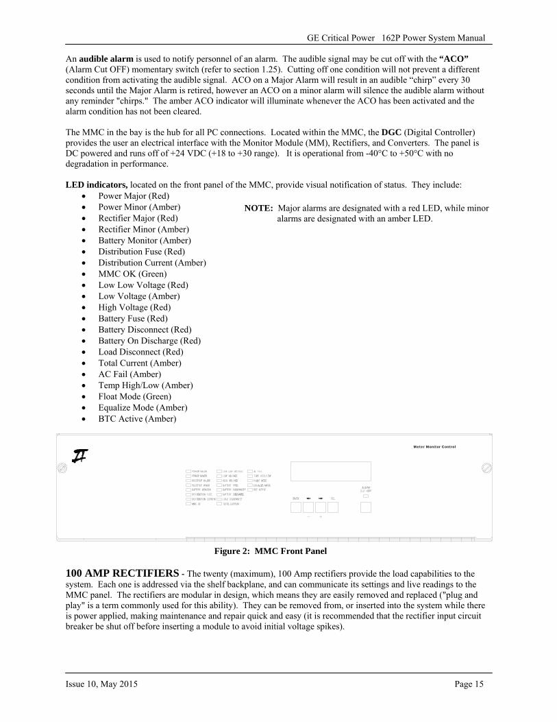
LED indicators, located on the front panel of the MMC, provide visual notification of status. They include: • Power Major (Red)• Power Minor (Amber)• Rectifier Major (Red)• Rectifier Minor (Amber)• Battery Monitor (Amber)• Distribution Fuse (Red)• Distribution Current (Amber)• MMC OK (Green)• Low Low Voltage (Red)• Low Voltage (Amber)• High Voltage (Red)• Battery Fuse (Red)• Battery Disconnect (Red)• Battery On Discharge (Red)• Load Disconnect (Red)• Total Current (Amber)• AC Fail (Amber)• Temp High/Low (Amber)• Float Mode (Green)• Equalize Mode (Amber)• BTC Active (Amber)
Meter Monitor Control
Figure 2: MMC Front Panel
100 AMP RECTIFIERS - The twenty (maximum), 100 Amp rectifiers provide the load capabilities to the system. Each one is addressed via the shelf backplane, and can communicate its settings and live readings to the MMC panel. The rectifiers are modular in design, which means they are easily removed and replaced ("plug and play" is a term commonly used for this ability). They can be removed from, or inserted into the system while there is power applied, making maintenance and repair quick and easy (it is recommended that the rectifier input circuit breaker be shut off before inserting a module to avoid initial voltage spikes).
NOTE: Major alarms are designated with a red LED, while minor alarms are designated with an amber LED.
GE Critical Power 162P Power System Manual
Page 16 Issue 10, May 2015
10 AMP DC/DC CONVERTERS - Up to eight DC/DC converters are available with the system. Each converter supplies 10 Amps at -48 VDC from an input voltage of + 24 VDC. Each one is addressed via the converter shelf backplane, and can communicate its settings and live readings to the MMC panel. The converters are modular in design, which means they are easily removed and replaced. They can be removed from, or inserted into, the system while there is power applied, making maintenance and repair quick and easy.
NOTE: The converter module alarm reporting function will report a Major alarm at the system level when: • (2) or more converters fail in a shelf containing more than (1) converter.• (2) or more converters fail in multiple shelves.• One converter failure occurs in a shelf containing only (1) converter.
The converter module alarm reporting function will report a Minor alarm at the system level when: • One converter fails in a single shelf containing more than (2) converters.
If a Minor alarm is always desired when only (1) converter fails in a system of (2) or more converters (independent of shelves), then the converters should be installed with at least (2) converters in each shelf for systems with more than (1) converter. e.g. for (1 to 4) converters, install all converters into a single shelf, leaving other shelf empty. If (5) converters are in the system, divide the converters between shelves so at least (2) converters are in each shelf.
1.3 ACRONYMS The telecom industry has many acronyms, some specific to this business. The table below includes both ANSI standards and GE additions.
ACO Alarm Cut Off EQ Equalize ALM Alarm FA Fuse Alarm AO Analog Output GND Ground BA Battery Alarm GUI Graphical User Interface BAP Battery Panel HVA High Voltage Alarm BATT Battery HVS High Voltage Shutdown BC Battery Current LCA Low Current Alarm BCX Battery Current (x represents any number) LLV Low Low Voltage BD Battery on Discharge LOA Low Output Alarm BFA Battery Fuse Alarm LSO Load Share Out BS Branch Shunt LV Low Voltage BTC Battery Temperature Compensation LVD Low Voltage DisconnectCFA Charger Failure Alarm LVLD Low Voltage Load Disconnect COF Charger Off (GND Signal) MJ Major CON Charger On (GND Signal) MM Monitor Module DCA Distribution Current Alarm MMC Meter, Monitor, and Control DFA Distribution Fuse Alarm MN Minor DGC Digital Controller MON Monitor DO Digital Output MP Mid Point EBD Emergency Battery Disconnect OC Over Current ECS End Cell Switch RXD Receive EPO Emergency Power Off SG Signal Ground PL Partial Load SH Shunt PMJ Power Major SHG Shield Ground PMN Power Minor TB Terminal Block PNL Panel TCA Total Current Alarm RCC Remote Charger Control TS Terminal Strip REMEQ Remote Equalize TXD Transmit RFA Rectifier Fail Alarm VM Volt Meter RS Rectifier Restart WD Watch Dog
TR Rectifier Turn On/Off
GE Critical Power 162P Power System Manual
Issue 10, May 2015 Page 17
CHAPTER 2: MECHANICAL INSTALLATION
In this Chapter the User will learn: • The dimensions of the 162P system• The mechanical installation steps necessary• How to install a rectifier module• How to install a converter module
1.4 GENERAL
The following instructions are provided to mechanically install the system. For information relevant to electrical connections, power requirements, etc. refer to Chapter 3.
1.5 DIMENSIONS
Height: 84.00" (2134mm) Width: 23.62" (600mm) Depth: 23.62" (600mm)
1.6 BAY INSTALLATION
NOTE: Refer to local codes for type of zone installation (anchor style and brace style).
A. Remove the bay from the shipping container and ensure all items are intact. If the contents are damaged, notify the delivery personnel and GE immediately.
B. Many options are available for the bay and should have been determined when the order was placed. Ensure the plant configuration matches the order.
C. Ensure the proper AC input voltage is available at the selected plant location (220 VAC single phase).
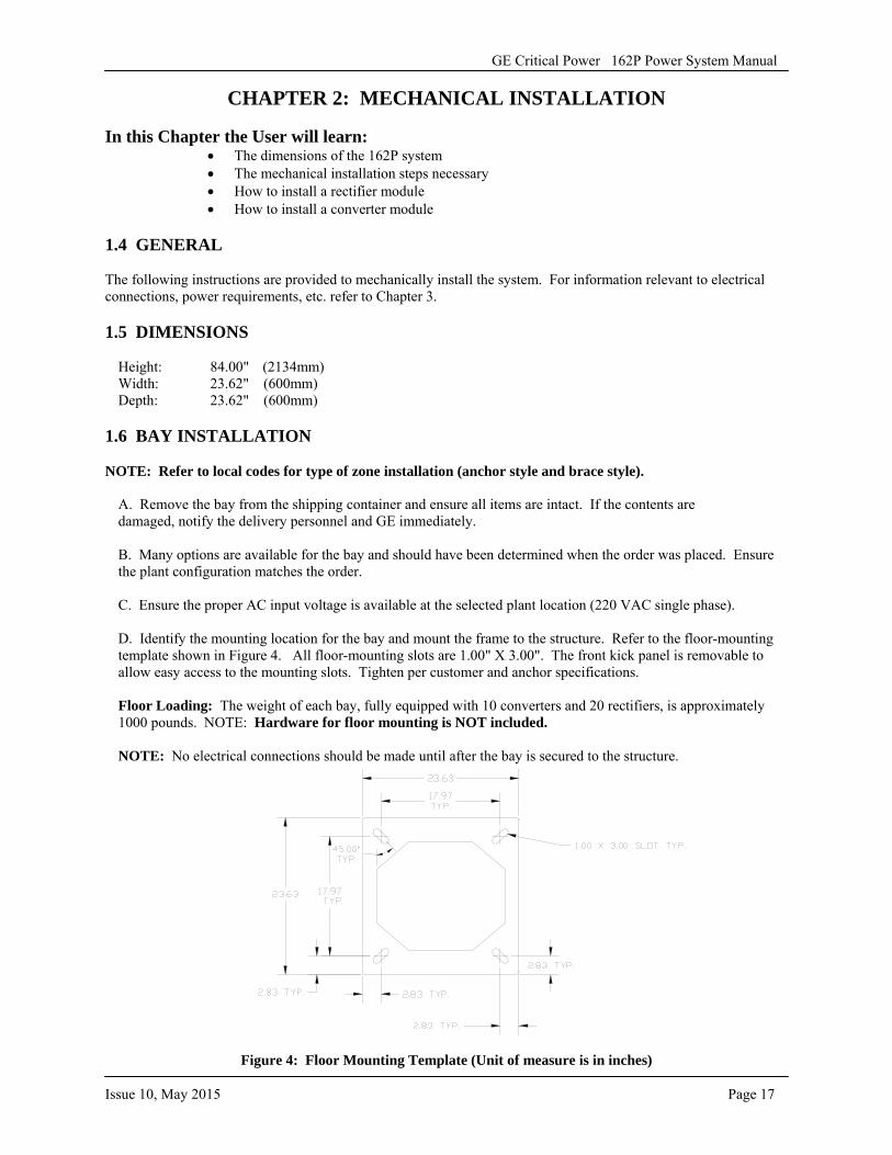
D. Identify the mounting location for the bay and mount the frame to the structure. Refer to the floor-mounting template shown in Figure 4. All floor-mounting slots are 1.00" X 3.00". The front kick panel is removable to allow easy access to the mounting slots. Tighten per customer and anchor specifications.
Floor Loading: The weight of each bay, fully equipped with 10 converters and 20 rectifiers, is approximately 1000 pounds. NOTE: Hardware for floor mounting is NOT included.
NOTE: No electrical connections should be made until after the bay is secured to the structure.
Figure 4: Floor Mounting Template (Unit of measure is in inches)
GE Critical Power 162P Power System Manual
Page 18 Issue 10, May 2015
1.7 PLUGGABLE RECTIFIER SHELF INSTALLATION AND REMOVAL
The rectifier shelves used with the 162P system are modular in design, which means they are easily installed or removed from the system. This section gives the procedures necessary for the installation and removal of the rectifier shelves. Typically, all (ordered) rectifier shelves are factory installed.
NOTE: Remove all input power to the associated rectifier shelf position prior to inserting or removing the rectifier shelf.
NOTE: If equipped, all rectifier modules must be removed from the shelf prior to shelf installation. Refer to Section 1.8.2 for rectifier module removal.
1.7.1 RECTIFIER SHELF INSTALLATION
A. Remove the blank filler panel where the rectifier shelf will be inserted.
B. Remove 1U blank directly above shelf position to be installed.
C. Insert the rectifier shelf into the empty position. The shelf should easily slide in place. Do not force it or damage to the shelf or plant backplane could occur.
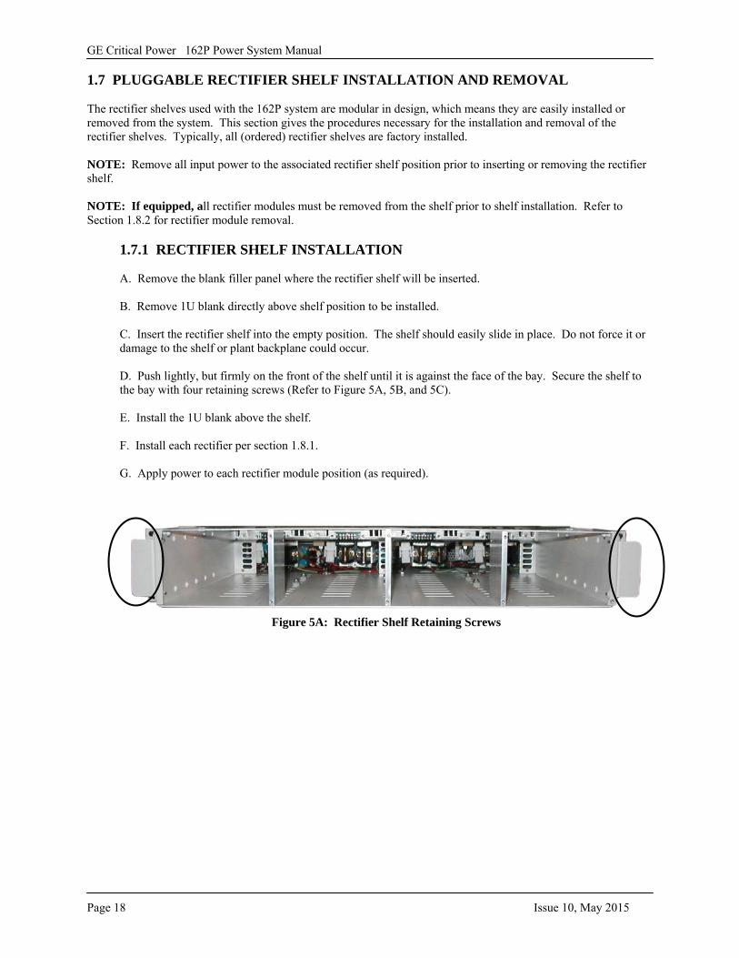
D. Push lightly, but firmly on the front of the shelf until it is against the face of the bay. Secure the shelf to the bay with four retaining screws (Refer to Figure 5A, 5B, and 5C).
E. Install the 1U blank above the shelf.
F. Install each rectifier per section 1.8.1.
G. Apply power to each rectifier module position (as required).
Figure 5A: Rectifier Shelf Retaining Screws
GE Critical Power 162P Power System Manual
Issue 10, May 2015 Page 19
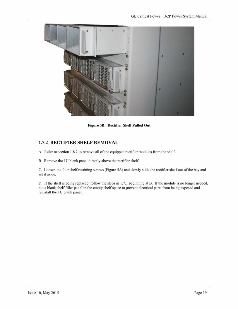
Figure 5B: Rectifier Shelf Pulled Out
1.7.2 RECTIFIER SHELF REMOVAL
A. Refer to section 1.8.2 to remove all of the equipped rectifier modules from the shelf.
B. Remove the 1U blank panel directly above the rectifier shelf.
C. Loosen the four shelf retaining screws (Figure 5A) and slowly slide the rectifier shelf out of the bay and set it aside.
D. If the shelf is being replaced, follow the steps in 1.7.1 beginning at B. If the module is no longer needed, put a blank shelf filler panel in the empty shelf space to prevent electrical parts from being exposed and reinstall the 1U blank panel.
GE Critical Power 162P Power System Manual
Page 20 Issue 10, May 2015
1.8 RECTIFIER MODULE INSTALLATION AND REMOVAL
The 100 Amp switchmode rectifiers used with the 162P system are modular in design. This section gives the procedures necessary for the installation and removal of the rectifier modules. Typically, all modules are factory installed.
1.8.1 RECTIFIER MODULE INSTALLATION
A. Remove the AC input associated with the module being installed.
B. Remove the blank filler panel where the rectifier module will be inserted.
C. Insert the rectifier into the rectifier shelf. The module should easily slide into place. Do not force it into the shelf or damage to the module or plant backplane could occur.
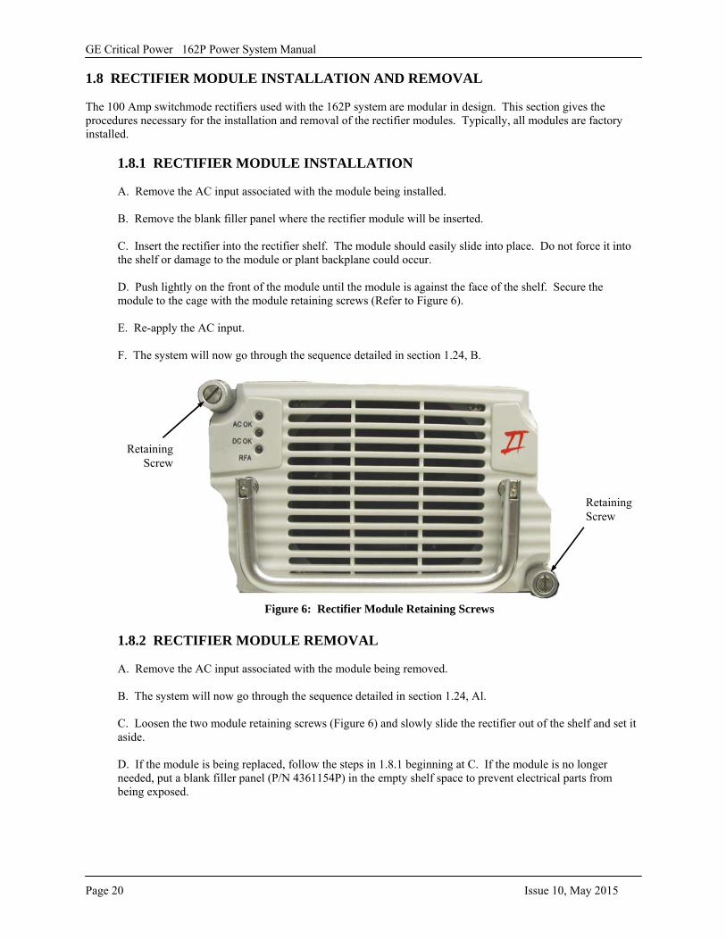
D. Push lightly on the front of the module until the module is against the face of the shelf. Secure the module to the cage with the module retaining screws (Refer to Figure 6).
E. Re-apply the AC input.
F. The system will now go through the sequence detailed in section 1.24, B.
Figure 6: Rectifier Module Retaining Screws
1.8.2 RECTIFIER MODULE REMOVAL
A. Remove the AC input associated with the module being removed.
B. The system will now go through the sequence detailed in section 1.24, Al.
C. Loosen the two module retaining screws (Figure 6) and slowly slide the rectifier out of the shelf and set it aside.
D. If the module is being replaced, follow the steps in 1.8.1 beginning at C. If the module is no longer needed, put a blank filler panel (P/N 4361154P) in the empty shelf space to prevent electrical parts from being exposed.
Retaining Screw
Retaining Screw
GE Critical Power 162P Power System Manual
Issue 10, May 2015 Page 21
1.9 CONVERTER MODULE INSTALLATION AND REMOVAL
The optional DC/DC converters used with the 162P system are modular in design, which means they are easily installed or removed from the system. This section gives the procedures necessary for the installation and removal of the converters. Typically (when ordered), all converter modules are factory installed.
1.9.1 CONVERTER MODULE INSTALLATION
A. Turn off the DC input circuit breaker, located on the converter module, associated with the module being installed.
B. Remove the blank filler panel where the converter module will be inserted.
C. Insert the module into the converter shelf. The module should easily slide into place. Do not force it into the shelf or damage to the module or plant backplane could occur.
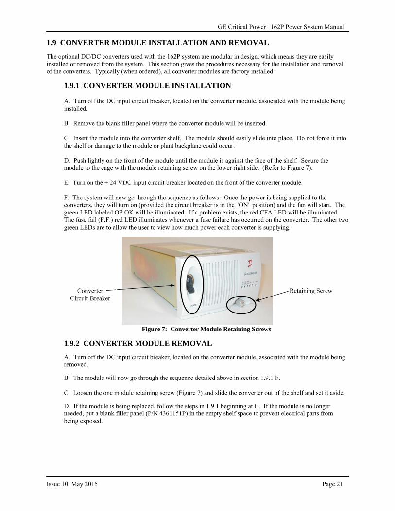
D. Push lightly on the front of the module until the module is against the face of the shelf. Secure the module to the cage with the module retaining screw on the lower right side. (Refer to Figure 7).
E. Turn on the + 24 VDC input circuit breaker located on the front of the converter module.
F. The system will now go through the sequence as follows: Once the power is being supplied to the converters, they will turn on (provided the circuit breaker is in the "ON" position) and the fan will start. The green LED labeled OP OK will be illuminated. If a problem exists, the red CFA LED will be illuminated. The fuse fail (F.F.) red LED illuminates whenever a fuse failure has occurred on the converter. The other two green LEDs are to allow the user to view how much power each converter is supplying.
Figure 7: Converter Module Retaining Screws
1.9.2 CONVERTER MODULE REMOVAL
A. Turn off the DC input circuit breaker, located on the converter module, associated with the module being removed.
B. The module will now go through the sequence detailed above in section 1.9.1 F.
C. Loosen the one module retaining screw (Figure 7) and slide the converter out of the shelf and set it aside.
D. If the module is being replaced, follow the steps in 1.9.1 beginning at C. If the module is no longer needed, put a blank filler panel (P/N 4361151P) in the empty shelf space to prevent electrical parts from being exposed.
Retaining Screw Converter Circuit Breaker
GE Critical Power 162P Power System Manual
Page 22 Issue 10, May 2015
CHAPTER 3: ELECTRICAL CONNECTIONS
In this Chapter the User will learn: • How to install the AC conduit fittings• How to install the AC wiring• How to connect ground• How to attach wiring to the loads• How to connect wiring to the batteries• How to wire the alarms
CAUTION: Before proceeding, note that all jumpers on the PWBs inside of the 162P system are factory set in the proper position. These should not be tampered with.
1.10 AC CONNECTIONS
1.10.1 AC CONNECTIONS TO THE TERMINAL BLOCK
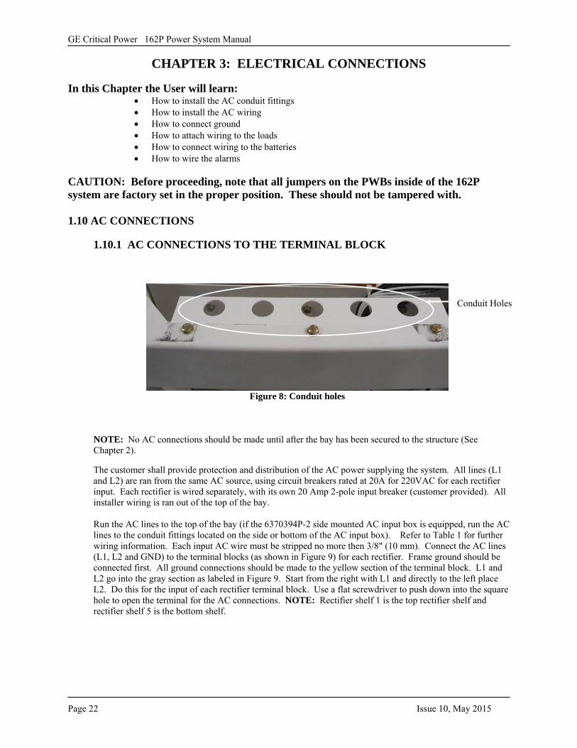
Figure 8: Conduit holes
NOTE: No AC connections should be made until after the bay has been secured to the structure (See Chapter 2).
The customer shall provide protection and distribution of the AC power supplying the system. All lines (L1 and L2) are ran from the same AC source, using circuit breakers rated at 20A for 220VAC for each rectifier input. Each rectifier is wired separately, with its own 20 Amp 2-pole input breaker (customer provided). All installer wiring is ran out of the top of the bay.
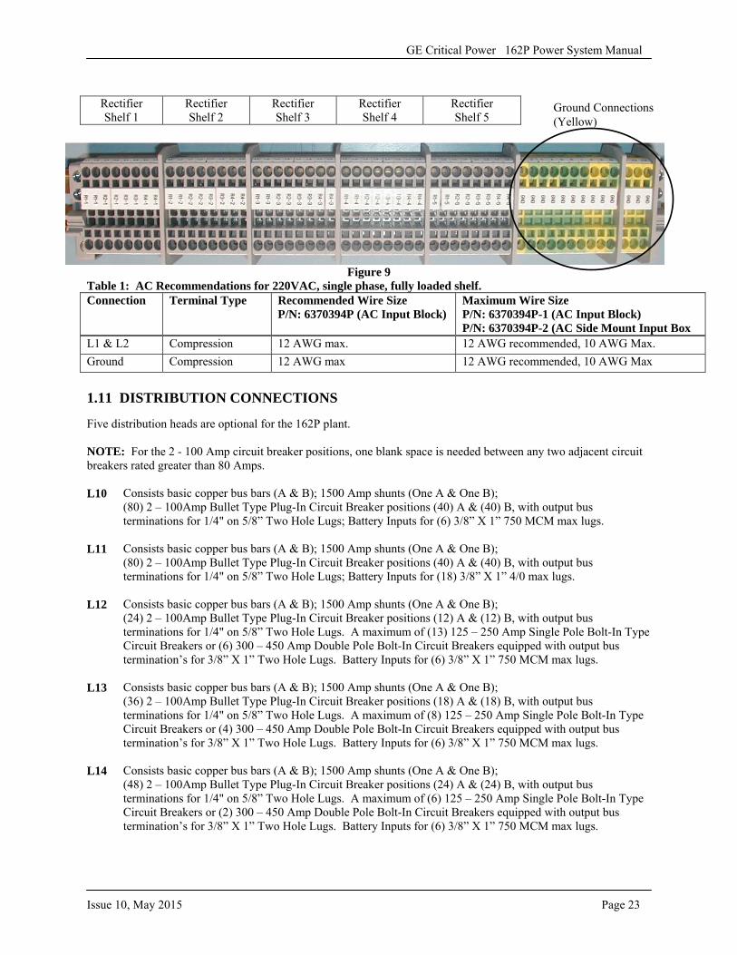
Run the AC lines to the top of the bay (if the 6370394P-2 side mounted AC input box is equipped, run the AC lines to the conduit fittings located on the side or bottom of the AC input box). Refer to Table 1 for further wiring information. Each input AC wire must be stripped no more then 3/8" (10 mm). Connect the AC lines (L1, L2 and GND) to the terminal blocks (as shown in Figure 9) for each rectifier. Frame ground should be connected first. All ground connections should be made to the yellow section of the terminal block. L1 and L2 go into the gray section as labeled in Figure 9. Start from the right with L1 and directly to the left place L2. Do this for the input of each rectifier terminal block. Use a flat screwdriver to push down into the square hole to open the terminal for the AC connections. NOTE: Rectifier shelf 1 is the top rectifier shelf and rectifier shelf 5 is the bottom shelf.
Conduit Holes
GE Critical Power 162P Power System Manual
Issue 10, May 2015 Page 23
Rectifier Shelf 1
Rectifier Shelf 2
Rectifier Shelf 3
Rectifier Shelf 4
Rectifier Shelf 5
Figure 9 Table 1: AC Recommendations for 220VAC, single phase, fully loaded shelf. Connection Terminal Type Recommended Wire Size
P/N: 6370394P (AC Input Block) Maximum Wire Size P/N: 6370394P-1 (AC Input Block) P/N: 6370394P-2 (AC Side Mount Input Box
L1 & L2 Compression 12 AWG max. 12 AWG recommended, 10 AWG Max. Ground Compression 12 AWG max 12 AWG recommended, 10 AWG Max
1.11 DISTRIBUTION CONNECTIONS
Five distribution heads are optional for the 162P plant.
NOTE: For the 2 - 100 Amp circuit breaker positions, one blank space is needed between any two adjacent circuit breakers rated greater than 80 Amps.
L10 Consists basic copper bus bars (A & B); 1500 Amp shunts (One A & One B); (80) 2 – 100Amp Bullet Type Plug-In Circuit Breaker positions (40) A & (40) B, with output bus terminations for 1/4" on 5/8” Two Hole Lugs; Battery Inputs for (6) 3/8” X 1” 750 MCM max lugs.
L11 Consists basic copper bus bars (A & B); 1500 Amp shunts (One A & One B); (80) 2 – 100Amp Bullet Type Plug-In Circuit Breaker positions (40) A & (40) B, with output bus terminations for 1/4" on 5/8” Two Hole Lugs; Battery Inputs for (18) 3/8” X 1” 4/0 max lugs.
L12 Consists basic copper bus bars (A & B); 1500 Amp shunts (One A & One B); (24) 2 – 100Amp Bullet Type Plug-In Circuit Breaker positions (12) A & (12) B, with output bus terminations for 1/4" on 5/8” Two Hole Lugs. A maximum of (13) 125 – 250 Amp Single Pole Bolt-In Type Circuit Breakers or (6) 300 – 450 Amp Double Pole Bolt-In Circuit Breakers equipped with output bus termination’s for 3/8” X 1” Two Hole Lugs. Battery Inputs for (6) 3/8” X 1” 750 MCM max lugs.
L13 Consists basic copper bus bars (A & B); 1500 Amp shunts (One A & One B); (36) 2 – 100Amp Bullet Type Plug-In Circuit Breaker positions (18) A & (18) B, with output bus terminations for 1/4" on 5/8” Two Hole Lugs. A maximum of (8) 125 – 250 Amp Single Pole Bolt-In Type Circuit Breakers or (4) 300 – 450 Amp Double Pole Bolt-In Circuit Breakers equipped with output bus termination’s for 3/8” X 1” Two Hole Lugs. Battery Inputs for (6) 3/8” X 1” 750 MCM max lugs.
L14 Consists basic copper bus bars (A & B); 1500 Amp shunts (One A & One B); (48) 2 – 100Amp Bullet Type Plug-In Circuit Breaker positions (24) A & (24) B, with output bus terminations for 1/4" on 5/8” Two Hole Lugs. A maximum of (6) 125 – 250 Amp Single Pole Bolt-In Type Circuit Breakers or (2) 300 – 450 Amp Double Pole Bolt-In Circuit Breakers equipped with output bus termination’s for 3/8” X 1” Two Hole Lugs. Battery Inputs for (6) 3/8” X 1” 750 MCM max lugs.
Ground Connections (Yellow)
GE Critical Power 162P Power System Manual
Page 24 Issue 10, May 2015
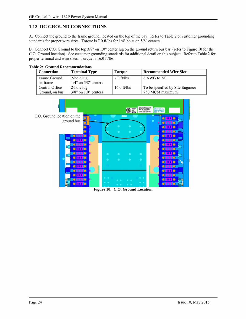
1.12 DC GROUND CONNECTIONS
A. Connect the ground to the frame ground, located on the top of the bay. Refer to Table 2 or customer grounding standards for proper wire sizes. Torque is 7.0 ft/lbs for 1/4" bolts on 5/8" centers.
B. Connect C.O. Ground to the top 3/8" on 1.0" center lug on the ground return bus bar (refer to Figure 10 for the C.O. Ground location). See customer grounding standards for additional detail on this subject. Refer to Table 2 for proper terminal and wire sizes. Torque is 16.0 ft/lbs.
Table 2: Ground Recommendations Connection Terminal Type Torque Recommended Wire Size Frame Ground, on frame
2-hole lug 1/4" on 5/8" centers
7.0 ft/lbs 6 AWG to 2/0
Central Office Ground, on bus
2-hole lug 3/8" on 1.0" centers
16.0 ft/lbs To be specified by Site Engineer 750 MCM maximum
Figure 10: C.O. Ground Location
C.O. Ground location on the ground bus
GE Critical Power 162P Power System Manual
Issue 10, May 2015 Page 25
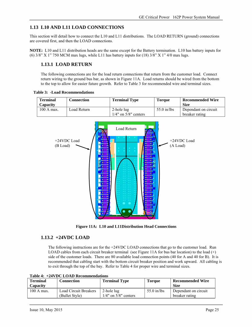
1.13 L10 AND L11 LOAD CONNECTIONS
This section will detail how to connect the L10 and L11 distributions. The LOAD RETURN (ground) connections are covered first, and then the LOAD connections.
NOTE: L10 and L11 distribution heads are the same except for the Battery termination. L10 has battery inputs for (6) 3/8” X 1” 750 MCM max lugs, while L11 has battery inputs for (18) 3/8” X 1” 4/0 max lugs.
1.13.1 LOAD RETURN
The following connections are for the load return connections that return from the customer load. Connect return wiring to the ground bus bar, as shown in Figure 11A. Load returns should be wired from the bottom to the top to allow for easier future growth. Refer to Table 3 for recommended wire and terminal sizes.
Table 3: -Load Recommendations
Figure 11A: L10 and L11Distribution Head Connections
1.13.2 +24VDC LOAD
The following instructions are for the +24VDC LOAD connections that go to the customer load. Run LOAD cables from each circuit breaker terminal (see Figure 11A for bus bar location) to the load (+) side of the customer loads. There are 80 available load connection points (40 for A and 40 for B). It is recommended that cabling start with the bottom circuit breaker position and work upward. All cabling is to exit through the top of the bay. Refer to Table 4 for proper wire and terminal sizes.
Table 4: +24VDC LOAD Recommendations Terminal Capacity
Connection Terminal Type Torque Recommended Wire Size
100 A max. Load Circuit Breakers (Bullet Style)
2-hole lug 1/4" on 5/8" centers
55.0 in/lbs Dependant on circuit breaker rating
Terminal Capacity
Connection Terminal Type Torque Recommended Wire Size
100 A max. Load Return 2-hole lug 1/4" on 5/8" centers
55.0 in/lbs Dependant on circuit breaker rating
+24VDC Load (B Load)
+24VDC Load (A Load)
Load Return
GE Critical Power 162P Power System Manual
Page 26 Issue 10, May 2015
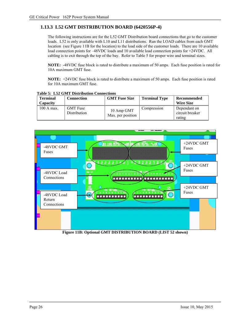
1.13.3 L52 GMT DISTRIBUTION BOARD (6420556P-4)
The following instructions are for the L52 GMT Distribution board connections that go to the customer loads. L52 is only available with L10 and L11 distributions. Run the LOAD cables from each GMT location (see Figure 11B for the location) to the load side of the customer loads. There are 10 available load connection points for –48VDC loads and 10 available load connection points for +24VDC. All cabling is to exit through the top of the bay. Refer to Table 5 for proper wire and terminal sizes.
NOTE: -48VDC fuse block is rated to distribute a maximum of 50 amps. Each fuse position is rated for 10A maximum GMT fuse.
NOTE: +24VDC fuse block is rated to distribute a maximum of 50 amps. Each fuse position is rated for 10A maximum GMT fuse.
Table 5: L52 GMT Distribution Connections Terminal Capacity
Connection GMT Fuse Size Terminal Type Recommended Wire Size
100 A max. GMT Fuse Distribution 10 Amp GMT
Max. per position
Compression Dependant on circuit breaker rating
Figure 11B: Optional GMT DISTRIBUTION BOARD (LIST 52 shown)
-48VDC GMT Fuses
-48VDC Load Connections
-48VDC Load Return Connections
+24VDC GMT Fuses
+24VDC GMT Fuses
+24VDC GMT Fuses
GE Critical Power 162P Power System Manual
Issue 10, May 2015 Page 27
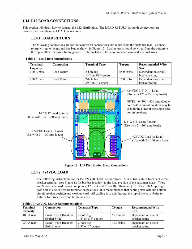
1.14 L12 LOAD CONNECTIONS
This section will detail how to connect the L12 distribution. The LOAD RETURN (ground) connections are covered first, and then the LOAD connections.
1.14.1 LOAD RETURN
The following connections are for the load return connections that return from the customer load. Connect return wiring to the ground bus bar, as shown in Figure 12. Load returns should be wired from the bottom to the top to allow for easier future growth. Refer to Table 6 for recommended wire and terminal sizes.
Table 6: -Load Recommendations
Figure 12: L12 Distribution Head Connections
1.14.2 +24VDC LOAD
The following instructions are for the +24VDC LOAD connections. Run LOAD cables from each circuit breaker terminal (see Figure 12 for bus bar location) to the load (+) side of the customer loads. There are 24 available load connection points (12 for A and 12 for B). There are (13) 125 – 250 Amp single pole bolt-in circuit breaker termination positions. It is recommended that cabling start with the bottom circuit breaker position and work upward. All cabling is to exit through the top of the bay. Refer to Table 7 for proper wire and terminal sizes.
Table 7: +24VDC LOAD Recommendations Terminal Capacity
Connection Terminal Type Torque Recommended Wire Size
100 A max. Load Circuit Breakers (Bullet Style)
2-hole lug 1/4" on 5/8" centers
55.0 in/lbs Dependant on circuit breaker rating
250 A max Load Circuit Breakers Bolt-In type
2-hole lug 3/8" on 1" centers
16.0 ft/lbs Dependant on circuit breaker rating
Terminal Capacity
Connection Terminal Type Torque Recommended Wire Size
100 A max. Load Return 2-hole lug 1/4" on 5/8" centers
55.0 in/lbs Dependant on circuit breaker rating
250 A max Load Return 2-hole lug 3/8" on 1" centers
16.0 ft/lbs Dependant on circuit breaker rating
+24VDC Load (B Load) (Use with 2 – 100 amp loads) +24VDC Load (A Load)
(Use with 2 – 100 amp loads)
1/4" X 5/8” Load Returns (Use with 2 – 100 amp loads)
3/8" X 1” Load Returns (Use with 125 – 250 amp loads)
+24VDC 3/8” X 1” Load (Use with 125 – 250 amp loads)
NOTE: 6 (300 – 450 amp double pole bolt in circuit breakers may be used in the place of the single pole bolt in breakers.
GE Critical Power 162P Power System Manual
Page 28 Issue 10, May 2015
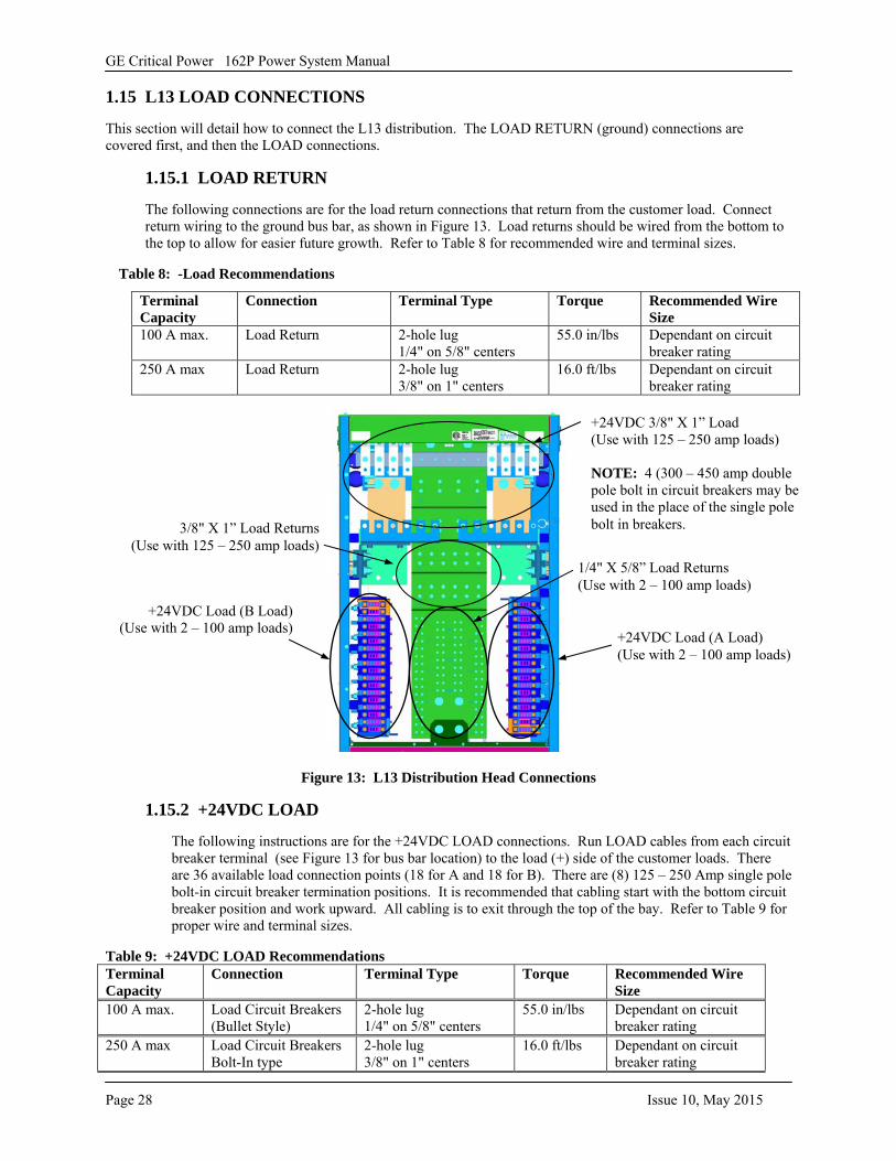
1.15 L13 LOAD CONNECTIONS
This section will detail how to connect the L13 distribution. The LOAD RETURN (ground) connections are covered first, and then the LOAD connections.
1.15.1 LOAD RETURN
The following connections are for the load return connections that return from the customer load. Connect return wiring to the ground bus bar, as shown in Figure 13. Load returns should be wired from the bottom to the top to allow for easier future growth. Refer to Table 8 for recommended wire and terminal sizes.
Table 8: -Load Recommendations
Figure 13: L13 Distribution Head Connections
1.15.2 +24VDC LOAD
The following instructions are for the +24VDC LOAD connections. Run LOAD cables from each circuit breaker terminal (see Figure 13 for bus bar location) to the load (+) side of the customer loads. There are 36 available load connection points (18 for A and 18 for B). There are (8) 125 – 250 Amp single pole bolt-in circuit breaker termination positions. It is recommended that cabling start with the bottom circuit breaker position and work upward. All cabling is to exit through the top of the bay. Refer to Table 9 for proper wire and terminal sizes.
Table 9: +24VDC LOAD Recommendations Terminal Capacity
Connection Terminal Type Torque Recommended Wire Size
100 A max. Load Circuit Breakers (Bullet Style)
2-hole lug 1/4" on 5/8" centers
55.0 in/lbs Dependant on circuit breaker rating
250 A max Load Circuit Breakers Bolt-In type
2-hole lug 3/8" on 1" centers
16.0 ft/lbs Dependant on circuit breaker rating
Terminal Capacity
Connection Terminal Type Torque Recommended Wire Size
100 A max. Load Return 2-hole lug 1/4" on 5/8" centers
55.0 in/lbs Dependant on circuit breaker rating
250 A max Load Return 2-hole lug 3/8" on 1" centers
16.0 ft/lbs Dependant on circuit breaker rating
+24VDC Load (B Load) (Use with 2 – 100 amp loads) +24VDC Load (A Load)
(Use with 2 – 100 amp loads)
1/4" X 5/8” Load Returns (Use with 2 – 100 amp loads)
3/8" X 1” Load Returns (Use with 125 – 250 amp loads)
+24VDC 3/8" X 1” Load (Use with 125 – 250 amp loads)
NOTE: 4 (300 – 450 amp double pole bolt in circuit breakers may be used in the place of the single pole bolt in breakers.
GE Critical Power 162P Power System Manual
Issue 10, May 2015 Page 29
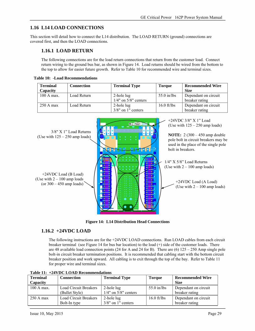
1.16 L14 LOAD CONNECTIONS
This section will detail how to connect the L14 distribution. The LOAD RETURN (ground) connections are covered first, and then the LOAD connections.
1.16.1 LOAD RETURN
The following connections are for the load return connections that return from the customer load. Connect return wiring to the ground bus bar, as shown in Figure 14. Load returns should be wired from the bottom to the top to allow for easier future growth. Refer to Table 10 for recommended wire and terminal sizes.
Table 10: -Load Recommendations
Figure 14: L14 Distribution Head Connections
1.16.2 +24VDC LOAD
The following instructions are for the +24VDC LOAD connections. Run LOAD cables from each circuit breaker terminal (see Figure 14 for bus bar location) to the load (+) side of the customer loads. There are 48 available load connection points (24 for A and 24 for B). There are (6) 125 – 250 Amp single pole bolt-in circuit breaker termination positions. It is recommended that cabling start with the bottom circuit breaker position and work upward. All cabling is to exit through the top of the bay. Refer to Table 11 for proper wire and terminal sizes.
Table 11: +24VDC LOAD Recommendations Terminal Capacity
Connection Terminal Type Torque Recommended Wire Size
100 A max. Load Circuit Breakers (Bullet Style)
2-hole lug 1/4" on 5/8" centers
55.0 in/lbs Dependant on circuit breaker rating
250 A max Load Circuit Breakers Bolt-In type
2-hole lug 3/8" on 1" centers
16.0 ft/lbs Dependant on circuit breaker rating
Terminal Capacity
Connection Terminal Type Torque Recommended Wire Size
100 A max. Load Return 2-hole lug 1/4" on 5/8" centers
55.0 in/lbs Dependant on circuit breaker rating
250 A max Load Return 2-hole lug 3/8" on 1" centers
16.0 ft/lbs Dependant on circuit breaker rating
+24VDC Load (B Load) (Use with 2 – 100 amp loads
(or 300 – 450 amp loads) +24VDC Load (A Load) (Use with 2 – 100 amp loads)
1/4" X 5/8” Load Returns (Use with 2 – 100 amp loads)
3/8" X 1” Load Returns (Use with 125 – 250 amp loads)
+24VDC 3/8" X 1” Load (Use with 125 – 250 amp loads)
NOTE: 2 (300 – 450 amp double pole bolt in circuit breakers may be used in the place of the single pole bolt in breakers.
GE Critical Power 162P Power System Manual
Page 30 Issue 10, May 2015
1.17 BATTERY CONNECTIONS
This section will detail how to connect the power to the batteries. The BAT Return connections are covered first, and then the +BAT connections. The customer's batteries connect to the output busses as shown in the following sections. All installer wiring is run out of the top of the bay.
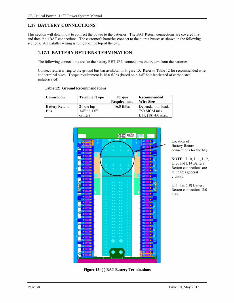
1.17.1 BATTERY RETURNS TERMINATION
The following connections are for the battery RETURN connections that return from the batteries.
Connect return wiring to the ground bus bar as shown in Figure 15. Refer to Table 12 for recommended wire and terminal sizes. Torque requirement is 16.0 ft/lbs (based on a 3/8” bolt fabricated of carbon steel, unlubricated).
Table 12: Ground Recommendations
Figure 15: (-) BAT Battery Terminations
Connection Terminal Type Torque Requirement
Recommended Wire Size
Battery Return Bus
2-hole lug 3/8" on 1.0" centers
16.0 ft/lbs Dependant on load. 750 MCM max. L11, (18) 4/0 max.
Location of Battery Return connections for the bay.
NOTE: L10, L11, L12, L13, and L14 Battery Return connections are all in this general vicinity.
L11 has (18) Battery Return connections 2/0 max.
GE Critical Power 162P Power System Manual
Issue 10, May 2015 Page 31
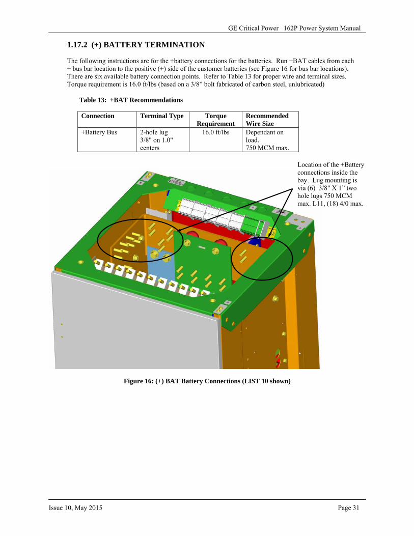
1.17.2 (+) BATTERY TERMINATION
The following instructions are for the +battery connections for the batteries. Run +BAT cables from each + bus bar location to the positive (+) side of the customer batteries (see Figure 16 for bus bar locations). There are six available battery connection points. Refer to Table 13 for proper wire and terminal sizes. Torque requirement is 16.0 ft/lbs (based on a 3/8” bolt fabricated of carbon steel, unlubricated)
Table 13: +BAT Recommendations
Connection Terminal Type Torque Requirement
Recommended Wire Size
+Battery Bus 2-hole lug 3/8" on 1.0" centers
16.0 ft/lbs Dependant on load. 750 MCM max.
Figure 16: (+) BAT Battery Connections (LIST 10 shown)
Location of the +Battery connections inside the bay. Lug mounting is via (6) 3/8" X 1” two hole lugs 750 MCM max. L11, (18) 4/0 max.
GE Critical Power 162P Power System Manual
Page 32 Issue 10, May 2015
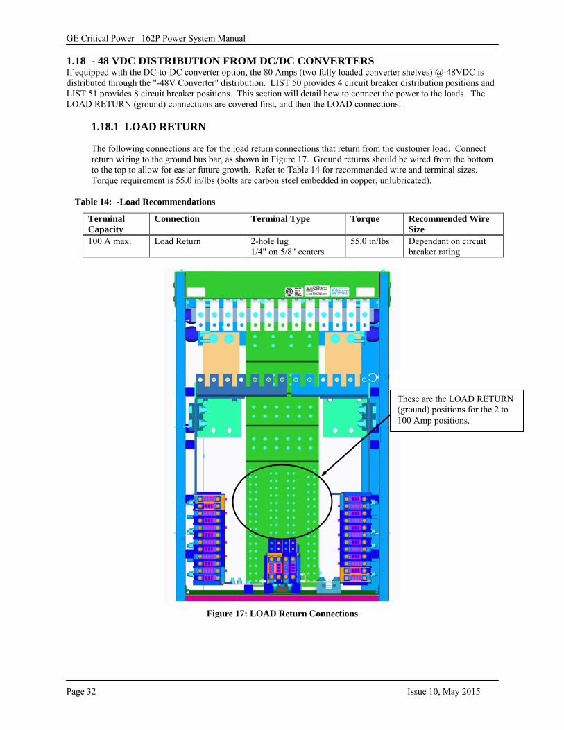
1.18 - 48 VDC DISTRIBUTION FROM DC/DC CONVERTERS If equipped with the DC-to-DC converter option, the 80 Amps (two fully loaded converter shelves) @-48VDC is distributed through the "-48V Converter" distribution. LIST 50 provides 4 circuit breaker distribution positions and LIST 51 provides 8 circuit breaker positions. This section will detail how to connect the power to the loads. The LOAD RETURN (ground) connections are covered first, and then the LOAD connections.
1.18.1 LOAD RETURN
The following connections are for the load return connections that return from the customer load. Connect return wiring to the ground bus bar, as shown in Figure 17. Ground returns should be wired from the bottom to the top to allow for easier future growth. Refer to Table 14 for recommended wire and terminal sizes. Torque requirement is 55.0 in/lbs (bolts are carbon steel embedded in copper, unlubricated).
Table 14: -Load Recommendations
Terminal Capacity
Connection Terminal Type Torque Recommended Wire Size
100 A max. Load Return 2-hole lug 1/4" on 5/8" centers
55.0 in/lbs Dependant on circuit breaker rating
Figure 17: LOAD Return Connections
These are the LOAD RETURN (ground) positions for the 2 to 100 Amp positions.
GE Critical Power 162P Power System Manual
Issue 10, May 2015 Page 33
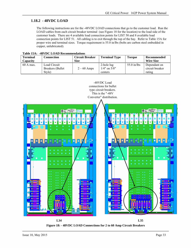
1.18.2 - 48VDC LOAD
The following instructions are for the -48VDC LOAD connections that go to the customer load. Run the LOAD cables from each circuit breaker terminal (see Figure 18 for the location) to the load side of the customer loads. There are 4 available load connection points for LIST 50 and 8 available load connection points for LIST 51. All cabling is to exit through the top of the bay. Refer to Table 15A for proper wire and terminal sizes. Torque requirement is 55.0 in/lbs (bolts are carbon steel embedded in copper, unlubricated).
Table 15A: -48VDC LOAD Recommendations Terminal Capacity
Connection Circuit Breaker Size
Terminal Type Torque Recommended Wire Size
60 A max. Load Circuit Breakers (Bullet Style)
2 – 60 Amps 2-hole lug 1/4" on 5/8" centers
55.0 in/lbs Dependant on circuit breaker rating
Figure 18: - 48VDC LOAD Connections for 2 to 60 Amp Circuit Breakers
-48VDC Load connections for bullet type circuit breakers.
This is the "-48V Converter" distribution.
L34 L35
GE Critical Power 162P Power System Manual
Page 34 Issue 10, May 2015
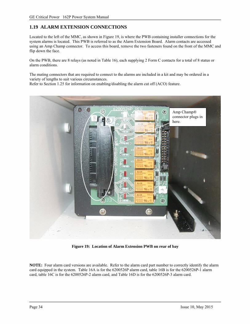
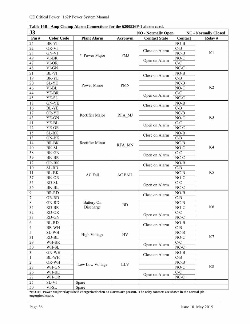
1.19 ALARM EXTENSION CONNECTIONS
Located to the left of the MMC, as shown in Figure 19, is where the PWB containing installer connections for the system alarms is located. This PWB is referred to as the Alarm Extension Board. Alarm contacts are accessed using an Amp Champ connector. To access this board, remove the two fasteners found on the front of the MMC and flip down the face.
On the PWB, there are 8 relays (as noted in Table 16), each supplying 2 Form C contacts for a total of 8 status or alarm conditions.
The mating connectors that are required to connect to the alarms are included in a kit and may be ordered in a variety of lengths to suit various circumstances. Refer to Section 1.25 for information on enabling/disabling the alarm cut off (ACO) feature.
Figure 19: Location of Alarm Extension PWB on rear of bay
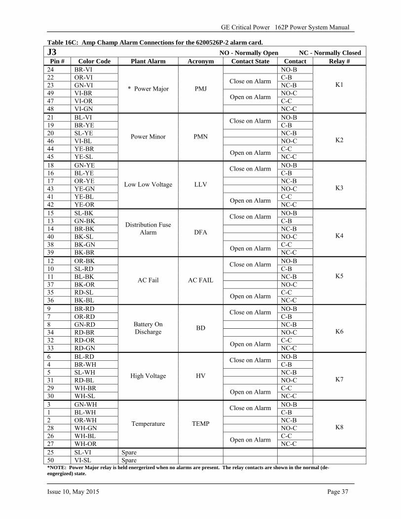
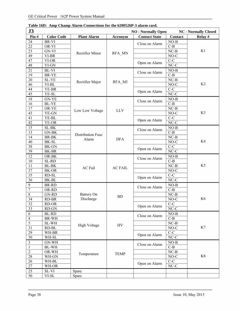
NOTE: Four alarm card versions are available. Refer to the alarm card part number to correctly identify the alarm card equipped in the system. Table 16A is for the 6200526P alarm card, table 16B is for the 6200526P-1 alarm card, table 16C is for the 6200526P-2 alarm card, and Table 16D is for the 6200526P-3 alarm card.
Amp Champ® connector plugs in here.
GE Critical Power 162P Power System Manual
Issue 10, May 2015 Page 35
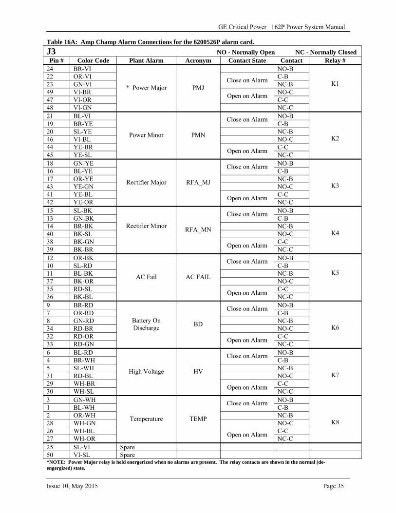
Table 16A: Amp Champ Alarm Connections for the 6200526P alarm card. J3 NO - Normally Open NC - Normally ClosedPin # Color Code Plant Alarm Acronym Contact State Contact Relay #
24 BR-VI NO-B 22 OR-VI C-B 23 GN-VI Close on Alarm NC-B49 VI-BR NO-C 47 VI-OR Open on Alarm C-C48 VI-GN
* Power Major PMJ
NC-C
K1
21 BL-VI NO-B 19 BR-YE
Close on Alarm C-B
20 SL-YE NC-B 46 VI-BL NO-C 44 YE-BR C-C 45 YE-SL
Power Minor PMN
Open on Alarm NC-C
K2
18 GN-YE NO-B 16 BL-YE
Close on Alarm C-B
17 OR-YE NC-B 43 YE-GN NO-C 41 YE-BL C-C 42 YE-OR
Rectifier Major RFA_MJ
Open on Alarm NC-C
K3
15 SL-BK NO-B 13 GN-BK
Close on Alarm C-B
14 BR-BK NC-B 40 BK-SL NO-C 38 BK-GN C-C 39 BK-BR
Rectifier Minor RFA_MN
Open on Alarm NC-C
K4
12 OR-BK NO-B 10 SL-RD
Close on Alarm C-B
11 BL-BK NC-B 37 BK-OR NO-C 35 RD-SL C-C 36 BK-BL
AC Fail AC FAIL
Open on Alarm NC-C
K5
9 BR-RD NO-B 7 OR-RD
Close on Alarm C-B
8 GN-RD NC-B 34 RD-BR NO-C 32 RD-OR C-C 33 RD-GN
Battery On Discharge BD
Open on Alarm NC-C
K6
6 BL-RD NO-B 4 BR-WH
Close on Alarm C-B
5 SL-WH NC-B 31 RD-BL NO-C 29 WH-BR C-C 30 WH-SL
High Voltage HV
Open on Alarm NC-C
K7
3 GN-WH NO-B 1 BL-WH
Close on Alarm C-B
2 OR-WH NC-B 28 WH-GN NO-C 26 WH-BL C-C 27 WH-OR
Temperature TEMP
Open on Alarm NC-C
K8
25 SL-VI Spare 50 VI-SL Spare *NOTE: Power Major relay is held energerized when no alarms are present. The relay contacts are shown in the normal (de-engergized) state.
GE Critical Power 162P Power System Manual
Page 36 Issue 10, May 2015
Table 16B: Amp Champ Alarm Connections for the 6200526P-1 alarm card. J3 NO - Normally Open NC - Normally ClosedPin # Color Code Plant Alarm Acronym Contact State Contact Relay #
24 BR-VI NO-B 22 OR-VI C-B 23 GN-VI Close on Alarm NC-B49 VI-BR NO-C 47 VI-OR Open on Alarm C-C48 VI-GN
* Power Major PMJ
NC-C
K1
21 BL-VI NO-B 19 BR-YE
Close on Alarm C-B
20 SL-YE NC-B 46 VI-BL NO-C 44 YE-BR C-C 45 YE-SL
Power Minor PMN
Open on Alarm NC-C
K2
18 GN-YE NO-B 16 BL-YE
Close on Alarm C-B
17 OR-YE NC-B 43 YE-GN NO-C 41 YE-BL C-C 42 YE-OR
Rectifier Major RFA_MJ
Open on Alarm NC-C
K3
15 SL-BK NO-B 13 GN-BK
Close on Alarm C-B
14 BR-BK NC-B 40 BK-SL NO-C 38 BK-GN C-C 39 BK-BR
Rectifier Minor RFA_MN
Open on Alarm NC-C
K4
12 OR-BK NO-B 10 SL-RD
Close on Alarm C-B
11 BL-BK NC-B 37 BK-OR NO-C 35 RD-SL C-C 36 BK-BL
AC Fail AC FAIL
Open on Alarm NC-C
K5
9 BR-RD NO-B 7 OR-RD
Close on Alarm C-B
8 GN-RD NC-B 34 RD-BR NO-C 32 RD-OR C-C 33 RD-GN
Battery On Discharge BD
Open on Alarm NC-C
K6
6 BL-RD NO-B 4 BR-WH
Close on Alarm C-B
5 SL-WH NC-B 31 RD-BL NO-C 29 WH-BR C-C 30 WH-SL
High Voltage HV
Open on Alarm NC-C
K7
3 GN-WH NO-B 1 BL-WH
Close on Alarm C-B
2 OR-WH NC-B 28 WH-GN NO-C 26 WH-BL C-C 27 WH-OR
Low Low Voltage LLV
Open on Alarm NC-C
K8
25 SL-VI Spare 50 VI-SL Spare *NOTE: Power Major relay is held energerized when no alarms are present. The relay contacts are shown in the normal (de-engergized) state.
GE Critical Power 162P Power System Manual
Issue 10, May 2015 Page 37
Table 16C: Amp Champ Alarm Connections for the 6200526P-2 alarm card. J3 NO - Normally Open NC - Normally ClosedPin # Color Code Plant Alarm Acronym Contact State Contact Relay #
24 BR-VI NO-B 22 OR-VI C-B 23 GN-VI Close on Alarm NC-B49 VI-BR NO-C 47 VI-OR Open on Alarm C-C48 VI-GN
* Power Major PMJ
NC-C
K1
21 BL-VI NO-B 19 BR-YE
Close on Alarm C-B
20 SL-YE NC-B 46 VI-BL NO-C 44 YE-BR C-C 45 YE-SL
Power Minor PMN
Open on Alarm NC-C
K2
18 GN-YE NO-B 16 BL-YE
Close on Alarm C-B
17 OR-YE NC-B 43 YE-GN NO-C 41 YE-BL C-C 42 YE-OR
Low Low Voltage LLV
Open on Alarm NC-C
K3
15 SL-BK NO-B 13 GN-BK
Close on Alarm C-B
14 BR-BK NC-B 40 BK-SL NO-C 38 BK-GN C-C 39 BK-BR
Distribution Fuse Alarm DFA
Open on Alarm NC-C
K4
12 OR-BK NO-B 10 SL-RD
Close on Alarm C-B
11 BL-BK NC-B 37 BK-OR NO-C 35 RD-SL C-C 36 BK-BL
AC Fail AC FAIL
Open on Alarm NC-C
K5
9 BR-RD NO-B 7 OR-RD
Close on Alarm C-B
8 GN-RD NC-B 34 RD-BR NO-C 32 RD-OR C-C 33 RD-GN
Battery On Discharge BD
Open on Alarm NC-C
K6
6 BL-RD NO-B 4 BR-WH
Close on Alarm C-B
5 SL-WH NC-B 31 RD-BL NO-C 29 WH-BR C-C 30 WH-SL
High Voltage HV
Open on Alarm NC-C
K7
3 GN-WH NO-B 1 BL-WH
Close on Alarm C-B
2 OR-WH NC-B 28 WH-GN NO-C 26 WH-BL C-C 27 WH-OR
Temperature TEMP
Open on Alarm NC-C
K8
25 SL-VI Spare 50 VI-SL Spare *NOTE: Power Major relay is held energerized when no alarms are present. The relay contacts are shown in the normal (de-engergized) state.
GE Critical Power 162P Power System Manual
Page 38 Issue 10, May 2015
Table 16D: Amp Champ Alarm Connections for the 6200526P-3 alarm card. J3 NO - Normally Open NC - Normally ClosedPin # Color Code Plant Alarm Acronym Contact State Contact Relay #
24 BR-VI NO-B 22 OR-VI
Close on Alarm C-B
23 GN-VI NC-B 49 VI-BR NO-C 47 VI-OR C-C 48 VI-GN
Rectifier Minor RFA_MN
Open on Alarm NC-C
K1
21 BL-VI NO-B 19 BR-YE
Close on Alarm C-B
20 SL-YE NC-B 46 VI-BL NO-C 44 YE-BR C-C 45 YE-SL
Rectifier Major RFA_MJ
Open on Alarm NC-C
K2
18 GN-YE NO-B 16 BL-YE
Close on Alarm C-B
17 OR-YE NC-B 43 YE-GN NO-C 41 YE-BL C-C 42 YE-OR
Low Low Voltage LLV
Open on Alarm NC-C
K3
15 SL-BK NO-B 13 GN-BK
Close on Alarm C-B
14 BR-BK NC-B 40 BK-SL NO-C 38 BK-GN C-C 39 BK-BR
Distribution Fuse Alarm DFA
Open on Alarm NC-C
K4
12 OR-BK NO-B 10 SL-RD
Close on Alarm C-B
11 BL-BK NC-B 37 BK-OR NO-C 35 RD-SL C-C 36 BK-BL
AC Fail AC FAIL
Open on Alarm NC-C
K5
9 BR-RD NO-B 7 OR-RD
Close on Alarm C-B
8 GN-RD NC-B 34 RD-BR NO-C 32 RD-OR C-C 33 RD-GN
Battery On Discharge BD
Open on Alarm NC-C
K6
6 BL-RD NO-B 4 BR-WH
Close on Alarm C-B
5 SL-WH NC-B 31 RD-BL NO-C 29 WH-BR C-C 30 WH-SL
High Voltage HV
Open on Alarm NC-C
K7
3 GN-WH NO-B 1 BL-WH
Close on Alarm C-B
2 OR-WH NC-B 28 WH-GN NO-C 26 WH-BL C-C 27 WH-OR
Temperature TEMP
Open on Alarm NC-C
K8
25 SL-VI Spare 50 VI-SL Spare
GE Critical Power 162P Power System Manual
Issue 10, May 2015 Page 39
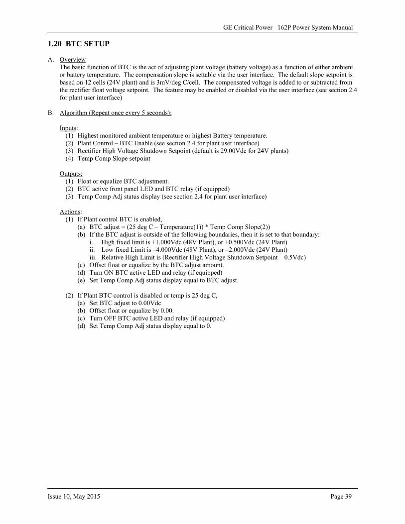
1.20 BTC SETUP
A. Overview The basic function of BTC is the act of adjusting plant voltage (battery voltage) as a function of either ambient or battery temperature. The compensation slope is settable via the user interface. The default slope setpoint is based on 12 cells (24V plant) and is 3mV/deg C/cell. The compensated voltage is added to or subtracted from the rectifier float voltage setpoint. The feature may be enabled or disabled via the user interface (see section 2.4 for plant user interface)
B. Algorithm (Repeat once every 5 seconds):
Inputs: (1) Highest monitored ambient temperature or highest Battery temperature. (2) Plant Control – BTC Enable (see section 2.4 for plant user interface) (3) Rectifier High Voltage Shutdown Setpoint (default is 29.00Vdc for 24V plants) (4) Temp Comp Slope setpoint
Outputs: (1) Float or equalize BTC adjustment. (2) BTC active front panel LED and BTC relay (if equipped) (3) Temp Comp Adj status display (see section 2.4 for plant user interface)
Actions: (1) If Plant control BTC is enabled,
(a) BTC adjust = (25 deg C – Temperature(1)) * Temp Comp Slope(2)) (b) If the BTC adjust is outside of the following boundaries, then it is set to that boundary:
i. High fixed limit is +1.000Vdc (48V Plant), or +0.500Vdc (24V Plant)ii. Low fixed Limit is –4.000Vdc (48V Plant), or –2.000Vdc (24V Plant)iii. Relative High Limit is (Rectifier High Voltage Shutdown Setpoint – 0.5Vdc)
(c) Offset float or equalize by the BTC adjust amount. (d) Turn ON BTC active LED and relay (if equipped) (e) Set Temp Comp Adj status display equal to BTC adjust.
(2) If Plant BTC control is disabled or temp is 25 deg C, (a) Set BTC adjust to 0.00Vdc (b) Offset float or equalize by 0.00. (c) Turn OFF BTC active LED and relay (if equipped) (d) Set Temp Comp Adj status display equal to 0.
GE Critical Power 162P Power System Manual
Page 40 Issue 10, May 2015
CHAPTER 4: OPERATIONAL CHECKOUT
In this Chapter the User will learn: • The procedure to turn the 162P system on• What happens when the rectifier input circuit breakers are tripped
1.21 OPERATIONAL CHECKOUT
The following chapter gives the procedures necessary for the operational checkout of the plant. These steps should be performed after initial installation and also after any maintenance has been performed. Complete this procedure before applying any load.
A. Turn "off" the circuit breakers associated with each rectifier contained in the bay.
B. Turn "on" the main AC circuit breaker(s) that supply power to the system.
C. Turn "on" the circuit breakers associated with each rectifier, one at a time. Each time a breaker is turned "on", the MMC will attempt to communicate with the corresponding module. This is called a self-test. During this test, a fan test will occur, the green DC OK LED and the green AC OK LED on the rectifier will both be on solid. (Note: The plant will go through the same type of self-test when a rectifier module is removed or installed. After the MMC has recognized the rectifier, the AC OK LED and the DC OK LED on the rectifier will stay on. This is accomplished quickly. When all rectifiers in the bay have been recognized, the LEDs on all the rectifiers will be illuminated, the green Float LED on the MMC panel will be illuminated, the rectifier will ramp to the setpoint, and the digital display will appear as follows:
Note: When a rectifier is installed and the corresponding breaker is off, an alarm condition will occur.
XX.XVDC XXXAAlarms - NONE s
If there is an alarm condition, the digital display will appear as either of the following screens:
XX.XVDC XXXAAlarms - MINOR s
XX.XVDC XXXAAlarms - MAJOR s
D. Ensure there are no alarms on the controller. If there is an alarm on the digital controller, refer to Section 2.5, ALRM to navigate the controller and find the cause of the error.
E. Verify all retaining screws securing the rectifiers and converters to the shelves are tight.
F. Verify the setpoints in Section 1.22 via the MMC panel. Refer to Section 2.6 to access these setpoints or Section 2.4.4 to change them.
GE Critical Power 162P Power System Manual
Issue 10, May 2015 Page 41
G. If the Site Engineer would like any plant settings verified or adjusted, refer to Section 2.4.4, Navigating The User Interface, PLANT, SETPT.
H. If all visual and meter indications are within tolerance and/or normal, the plant is serviceable and a load may be applied.
Table 17: Failure Descriptions:
Error Displayed Description TCA A, B, or C Total Current Alarm - This error is displayed when the total current on the specified
bus (A, B, or C) exceeds the current monitored by the shunt. Ambient High/Low Temp The temperature near the system is either too high or too low versus the setpoint. AC Fail (Rectifier) There has been an interruption in the AC service going to one or more of the
rectifiers. Must be externally wired to sense relay. DFA Distribution Fuse Alarm - There has been a failure in one of the output distribution
protection devices (fuse or circuit breaker). DCA1 Distribution Current Alarm - This alarm reflects the distribution fuse rating times the
percent of fuse rating to the monitored distribution current and provides an alarm when there is a discrepancy. The alarm is active when the measured current exceeds the % setpoint of the fuse rating.
HVSD High Voltage Shut Down - This alarm is transient in nature and results in the offending rectifier(s) switching to Standby mode.
DGC Digital Controller - This error is displayed when there has been a failure in the digital controller due to communication or power.
RFA Minor Rectifier Fail Minor - This indicated there is a single rectifier failure RFA Major Rectifier Fail Major - This indicated there are multiple rectifiers with failures MM Monitor Module Failure - This indicated there has been a failure associated with the
monitor PWB. PMN Power Minor - This is a broad failure mode that indicates there is a problem, but
nothing that is currently interrupting operation of the bay. It can indicate a single rectifier failure, a communication loss from a single rectifier, rectifier fan fail, plant low voltage alarm, battery alarm, distribution current alarm, total current alarm, AC Fail, monitor fail, or an ambient temperature alarm. There are many conditions that will be indicated by a PMN alarm. To obtain the cause for the alarm, refer to Section 2.5 on navigating the alarm screens.
PMJ Power Major - This is a broad failure mode that indicates there is a problem with the bay that is interrupting operation. It can indicate multiple rectifier failures, high voltage shutdown, high voltage alarm, low low voltage alarm, battery fuse alarm, battery on discharge, distribution fuse fail, or that a low voltage disconnect (A or C) is active. There are many conditions that will be indicated by a PMJ alarm. To obtain the cause for the alarm, refer to Section 2.5 on navigating the alarm screens.
High Voltage The output voltage of the bay is beyond the high voltage setpoint. Low Voltage The output of the bay is beyond the low voltage setpoint. This alarm appears before
the low low voltage alarm.Low Low Voltage The output of the bay has beyond the low low voltage alarm setpoint. LVLD Low Voltage Load Disconnect - The load has been disconnected due to the output
voltage reaching this setpoint, when equipped. “A” LVLD is for the +24V Distribution, and “C” LVLD is for the –48V converter distribution.
Batt on Dischg or BD Battery on Discharge - Indicates the battery voltage has dropped below the setpoint for this alarm.
Page 42 Issue 10, May 2015
GE Critical Power 162P Power System Manual
1.22 FACTORY SETTINGS
The following setpoints are factory
Float Voltage Setting:27.2 VDC • Ambient Temp Low Limit: 10°C
• Equalize Voltage Setting: 27.6 VDC • Plant Voltage HVA Setting: 28.25 VDC• Rectifier Max. Current: 105 Amps • Plant Voltage LLVA Setting: 23 VDC• Rectifier HVSD Setting: 28.5 VDC • Plant Voltage LVA Setting: 26 VDC• Temp Compensate Slope: 36 mV • Plant HVSD Setting: 29 VDC • Batt On Discharge Setting: 26 VDC • LVLD Disconnect Setting A: 21 VDC• Batt Temp High Limit (BTA): 50°C • LVLD Disconnect Setting B: 21 VDC• Batt Temp Low Limit (BTA): 10°C • LVLD Disconnect Setting C: 21 VDC• Batt V-low Disconnect Limit (LVBD): 21 VDC • LVLD Reconnect Setting A: 24.5 VDC• Batt V-low Reconnect Limit (LVBD): 24.5 VDC • LVLD Reconnect Setting B: 24.5 VDC• Ambient Temp High Limit: 40°C • LVLD Reconnect Setting C: 24.5 VDC
1.23 CHANGING PLANT SETTINGS
If the Site Engineer would like any plant settings verified or adjusted, refer to Section 2.4.4, Navigating The User Interface, Plant, SETP.
There are several settings that are unique to the 162P system and require further explanation, they are as follows:
1.23.1 SETTING UP LVLD
The LVLD (Low Voltage Load Disconnect) has features to customize the way it operates. It can be enabled or disabled by time. This means that when the amber Battery Discharge LED is illuminated (refer to Section 2.4.4 for changing the BD setting), this timer begins. After the timer setpoint is reached, the load will be dropped. To change or view this setpoint, follow the steps detailed in Section 2.4.2 for access via the user display.
The default setting for this feature is "disabled" mode. “A” LVLD is for the +24V Distribution, and “C” LVLD is for the –48V converter distribution.
The LVLD setting may also be set to be "equipped" for normal operation and disabled in timer mode.
NOTE: Before this feature may be used, the system must have been ordered equipped with the optional LVLD contactor feature.
1.23.2 EQUALIZE TIMER
The timer feature for equalize is the time the system will remain in equalize mode after being placed there by the user. It may be set from 0-36 hours. The factory setting for this feature is 24 hours.
The equalize timer may be set by following the steps detailed in section 2.4.4.
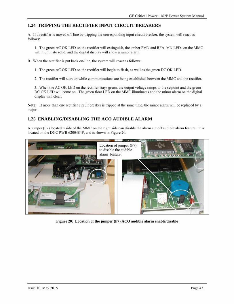
GE Critical Power 162P Power System Manual
Issue 10, May 2015 Page 43
1.24 TRIPPING THE RECTIFIER INPUT CIRCUIT BREAKERS
A. If a rectifier is moved off-line by tripping the corresponding input circuit breaker, the system will react as follows:
1. The green AC OK LED on the rectifier will extinguish, the amber PMN and RFA_MN LEDs on the MMCwill illuminate solid, and the digital display will show a minor alarm.
B. When the rectifier is put back on-line, the system will react as follows:
1. The green AC OK LED on the rectifier will begin to flash, as well as the green DC OK LED.
2. The rectifier will start up while communications are being established between the MMC and the rectifier.
3. When the AC OK LED on the rectifier stays green, the output voltage ramps to the setpoint and the greenDC OK LED will come on. The green float LED on the MMC illuminates and the minor alarm on the digital display will clear.
Note: If more than one rectifier circuit breaker is tripped at the same time, the minor alarm will be replaced by a major.
1.25 ENABLING/DISABLING THE ACO AUDIBLE ALARM
A jumper (P7) located inside of the MMC on the right side can disable the alarm cut off audible alarm feature. It is located on the DGC PWB 6200484P, and is shown in Figure 20.
Figure 20: Location of the jumper (P7) ACO audible alarm enable/disable
Location of jumper (P7) to disable the audible alarm feature.

GE Critical Power 162P Power System Manual
Page 44 Issue 10, May 2015
-This page intentionally left blank-
GE Critical Power 162P Power System Manual
Issue 10, May 2015 Page 45
SSSEEECCCTTTIIIOOONNN 222::: NNNAAAVVVIIIGGGAAATTTIIINNNGGG TTTHHHEEE UUUSSSEEERRR IIINNNTTTEEERRRFFFAAACCCEEE FFFOOORRR TTTHHHEEE DDDIIIGGGIIITTTAAALLL
CCCOOONNNTTTRRROOOLLLLLLEEERRR In this Section the User will learn:
• How to navigate through the digital controller• How to change and/or verify setpoints• How to view plant and/or bay alarms• How to view the present operating conditions of the system (voltage, current, etc.)
2.1 GENERAL
The user interface allows the user to view and navigate through the menus and screens of the digital controller. The arrow keys allow the different menus and screens to be scrolled through, the select button selects a screen or brings up a menu, and the back button takes the user back to the previously viewed screen.
On the right side of the LCD, there will be an s, ←, →, or ↔ symbol. Sometimes there will be a symbol displayed on both the top and bottom lines. The "s" indicates that select may be pressed from this screen to bring up a menu, and an arrow indicates which direction the user may scroll. To select an option from one of the menus, scroll until the proper selection begins to flash, then press the select button.
When navigating the controller, it is important to understand the numbering associated with some of the screens. The numbering on the rectifier screens represents the rectifier address that's information is being accessed. The first number is the bay number, the second number is the shelf number, and the third number is the position number. The initial bay is considered bay #1. The number viewed on the digital controller screen is a combination of the bay, shelf, and rectifier position (BSP). An example is bay 1, shelf 2, and rectifier 3: 123.
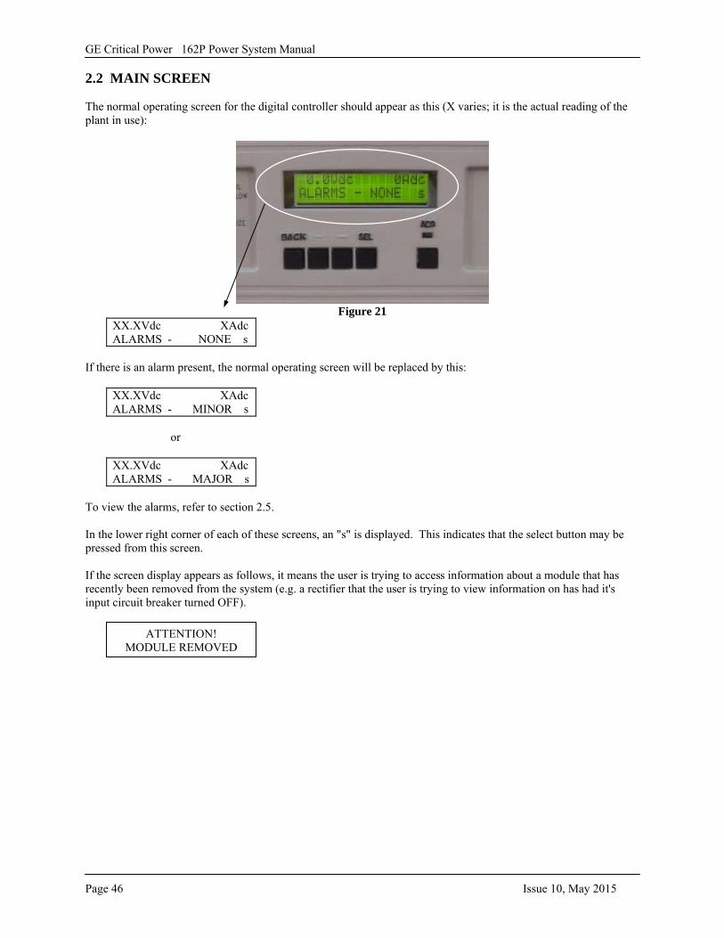
GE Critical Power 162P Power System Manual
Page 46 Issue 10, May 2015
2.2 MAIN SCREEN
The normal operating screen for the digital controller should appear as this (X varies; it is the actual reading of the plant in use):
Figure 21 XX.XVdc XAdc ALARMS - NONE s
If there is an alarm present, the normal operating screen will be replaced by this:
XX.XVdc XAdc ALARMS - MINOR s
or
XX.XVdc XAdc ALARMS - MAJOR s
To view the alarms, refer to section 2.5.
In the lower right corner of each of these screens, an "s" is displayed. This indicates that the select button may be pressed from this screen.
If the screen display appears as follows, it means the user is trying to access information about a module that has recently been removed from the system (e.g. a rectifier that the user is trying to view information on has had it's input circuit breaker turned OFF).
ATTENTION! MODULE REMOVED
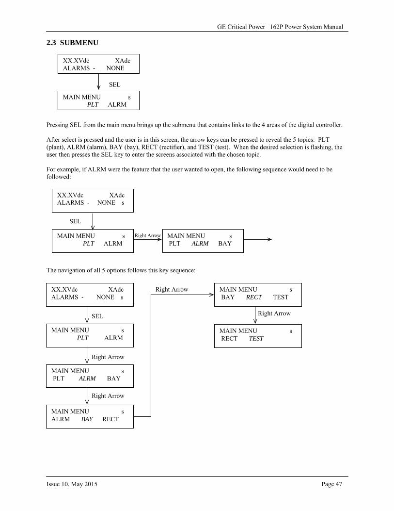
GE Critical Power 162P Power System Manual
Issue 10, May 2015 Page 47
2.3 SUBMENU
Pressing SEL from the main menu brings up the submenu that contains links to the 4 areas of the digital controller.
After select is pressed and the user is in this screen, the arrow keys can be pressed to reveal the 5 topics: PLT (plant), ALRM (alarm), BAY (bay), RECT (rectifier), and TEST (test). When the desired selection is flashing, the user then presses the SEL key to enter the screens associated with the chosen topic.
For example, if ALRM were the feature that the user wanted to open, the following sequence would need to be followed:
SEL
Right Arrow SEL to confirm the selection
The navigation of all 5 options follows this key sequence:
XX.XVdc XAdc ALARMS - NONE
MAIN MENU s PLT ALRM
SEL
MAIN MENU s PLT ALRM
XX.XVdc XAdc ALARMS - NONE s
MAIN MENU s PLT ALRM BAY
MAIN MENU s PLT ALRM
MAIN MENU s PLT ALRM BAY
MAIN MENU s ALRM BAY RECT
MAIN MENU s BAY RECT TEST
XX.XVdc XAdc ALARMS - NONE s
SEL
Right Arrow
Right Arrow
Right Arrow
MAIN MENU s RECT TEST
Right Arrow
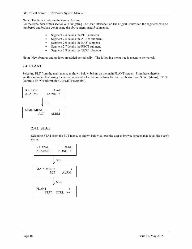
GE Critical Power 162P Power System Manual
Page 48 Issue 10, May 2015
Note: The Italics indicate the item is flashing For the remainder of this section on Navigating The User Interface For The Digital Controller, the segments will be numbered and broken down using the above-mentioned 5 submenus.
• Segment 2.4 details the PLT submenu• Segment 2.5 details the ALRM submenu• Segment 2.6 details the BAY submenu• Segment 2.7 details the RECT submenu• Segment 2.8 details the TEST submenu
Note: New features and updates are added periodically - The following menu tree is meant to be typical.
2.4 PLANT
Selecting PLT from the main menu, as shown below, brings up the main PLANT screen. From here, there is another submenu that, using the arrow keys and select button, allows the user to choose from STAT (status), CTRL (control), INFO (information), or SETP (setpoint).
2.4.1 STAT
Selecting STAT from the PLT menu, as shown below, allows the user to browse screens that detail the plant's status.
MAIN MENU s PLT ALRM
XX.XVdc XAdc ALARMS - NONE s
SEL
PLANT s STAT CTRL ↔
MAIN MENU s PLT ALRM
SEL
XX.XVdc XAdc ALARMS - NONE s
SEL
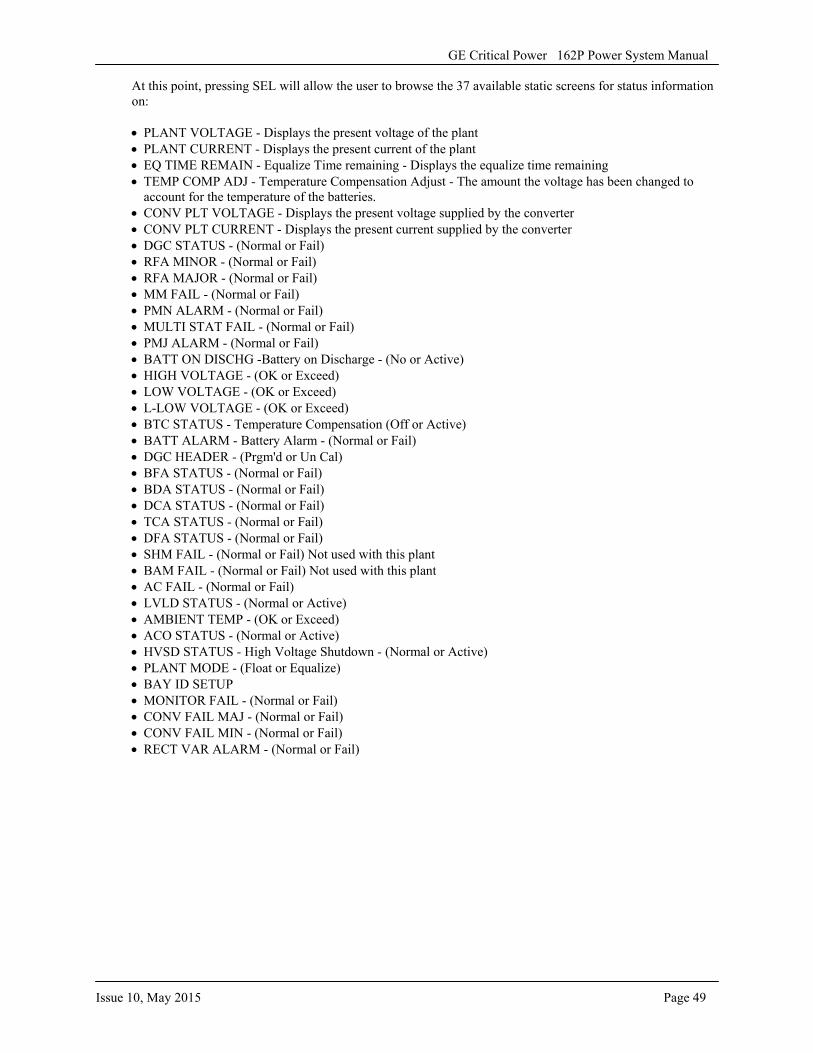
GE Critical Power 162P Power System Manual
Issue 10, May 2015 Page 49
At this point, pressing SEL will allow the user to browse the 37 available static screens for status information on:
• PLANT VOLTAGE - Displays the present voltage of the plant• PLANT CURRENT - Displays the present current of the plant• EQ TIME REMAIN - Equalize Time remaining - Displays the equalize time remaining• TEMP COMP ADJ - Temperature Compensation Adjust - The amount the voltage has been changed to
account for the temperature of the batteries.• CONV PLT VOLTAGE - Displays the present voltage supplied by the converter• CONV PLT CURRENT - Displays the present current supplied by the converter• DGC STATUS - (Normal or Fail)• RFA MINOR - (Normal or Fail)• RFA MAJOR - (Normal or Fail)• MM FAIL - (Normal or Fail)• PMN ALARM - (Normal or Fail)• MULTI STAT FAIL - (Normal or Fail)• PMJ ALARM - (Normal or Fail)• BATT ON DISCHG -Battery on Discharge - (No or Active)• HIGH VOLTAGE - (OK or Exceed)• LOW VOLTAGE - (OK or Exceed)• L-LOW VOLTAGE - (OK or Exceed)• BTC STATUS - Temperature Compensation (Off or Active)• BATT ALARM - Battery Alarm - (Normal or Fail)• DGC HEADER - (Prgm'd or Un Cal)• BFA STATUS - (Normal or Fail)• BDA STATUS - (Normal or Fail)• DCA STATUS - (Normal or Fail)• TCA STATUS - (Normal or Fail)• DFA STATUS - (Normal or Fail)• SHM FAIL - (Normal or Fail) Not used with this plant• BAM FAIL - (Normal or Fail) Not used with this plant• AC FAIL - (Normal or Fail)• LVLD STATUS - (Normal or Active)• AMBIENT TEMP - (OK or Exceed)• ACO STATUS - (Normal or Active)• HVSD STATUS - High Voltage Shutdown - (Normal or Active)• PLANT MODE - (Float or Equalize)• BAY ID SETUP• MONITOR FAIL - (Normal or Fail)• CONV FAIL MAJ - (Normal or Fail)• CONV FAIL MIN - (Normal or Fail)• RECT VAR ALARM - (Normal or Fail)
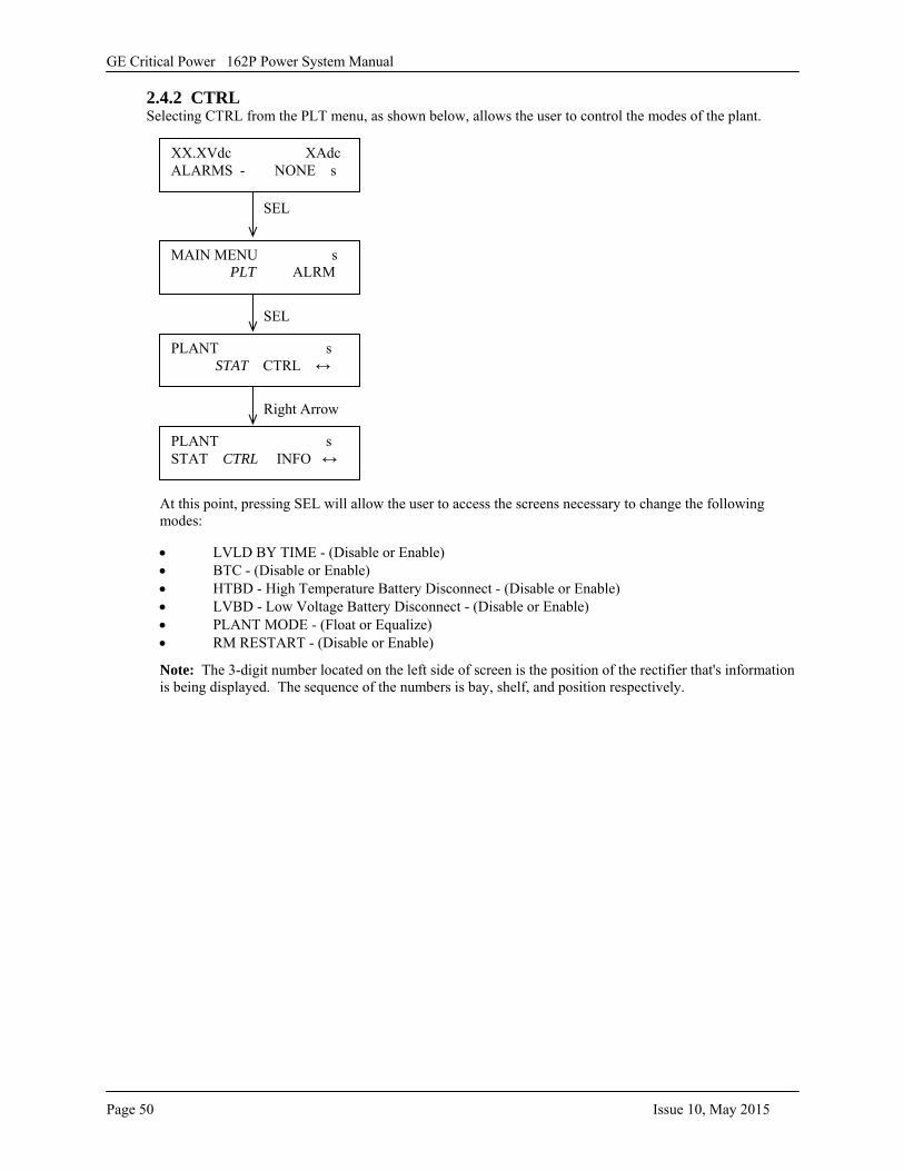
GE Critical Power 162P Power System Manual
Page 50 Issue 10, May 2015
2.4.2 CTRL Selecting CTRL from the PLT menu, as shown below, allows the user to control the modes of the plant.
At this point, pressing SEL will allow the user to access the screens necessary to change the following modes:
• LVLD BY TIME - (Disable or Enable)• BTC - (Disable or Enable)• HTBD - High Temperature Battery Disconnect - (Disable or Enable)• LVBD - Low Voltage Battery Disconnect - (Disable or Enable)• PLANT MODE - (Float or Equalize)• RM RESTART - (Disable or Enable)
Note: The 3-digit number located on the left side of screen is the position of the rectifier that's information is being displayed. The sequence of the numbers is bay, shelf, and position respectively.
PLANT s STAT CTRL ↔
MAIN MENU s PLT ALRM
SEL
XX.XVdc XAdc ALARMS - NONE s
SEL
PLANT s STAT CTRL INFO ↔
Right Arrow
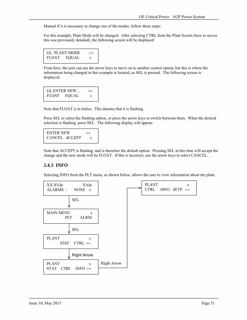
Issue 10, May 2015 Page 51
GE Critical Power 162P Power System
Manual If it is necessary to change one of the modes, follow these steps:
For this example, Plant Mode will be changed. After selecting CTRL from the Plant Screen (how to access this was previously detailed), the following screen will be displayed:
From here, the user can use the arrow keys to move on to another control option, but this is where the information being changed in this example is located, so SEL is pressed. The following screen is displayed:
Note that FLOAT is in Italics. This denotes that it is flashing.
Press SEL to select the flashing option, or press the arrow keys to switch between them. When the desired selection is flashing, press SEL. The following display will appear:
Note that ACCEPT is flashing, and is therefore the default option. Pressing SEL at this time will accept the change and the new mode will be FLOAT. If this is incorrect, use the arrow keys to select CANCEL.
2.4.3 INFO
Selecting INFO from the PLT menu, as shown below, allows the user to view information about the plant.
GL PLANT MODE ↔ FLOAT EQUAL s
GL ENTER NEW… ↔ FLOAT EQUAL s
ENTER NEW ↔ CANCEL ACCEPT s
PLANT s STAT CTRL ↔
MAIN MENU s PLT ALRM
SEL
XX.XVdc XAdc ALARMS - NONE s
SEL
PLANT s STAT CTRL INFO ↔
Right Arrow
PLANT s CTRL INFO SETP ↔
Right Arrow
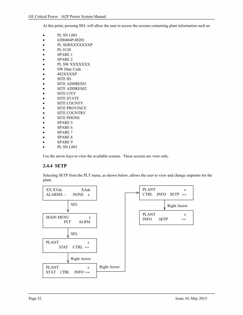
GE Critical Power 162P Power System Manual
Page 52 Issue 10, May 2015
At this point, pressing SEL will allow the user to access the screens containing plant information such as:
• PL SN L001• 6200484P-08201• PL SERXXXXXXXP• PL 0120• SPARE 1• SPARE 2• PL SW XXXXXXX• SW Date Code• 482XXXXP• SITE ID• SITE ADDRESS1• SITE ADDRESS2• SITE CITY• SITE STATE• SITE COUNTY• SITE PROVINCE• SITE COUNTRY• SITE PHONE• SPARE 5• SPARE 6• SPARE 7• SPARE 8• SPARE 9• PL SN L001
Use the arrow keys to view the available screens. These screens are view only.
2.4.4 SETP
Selecting SETP from the PLT menu, as shown below, allows the user to view and change setpoints for the plant.
PLANT s STAT CTRL ↔
MAIN MENU s PLT ALRM
SEL
XX.XVdc XAdc ALARMS - NONE s
SEL
PLANT s STAT CTRL INFO ↔
Right Arrow
PLANT s CTRL INFO SETP ↔
Right Arrow
Right Arrow
PLANT s INFO SETP ↔
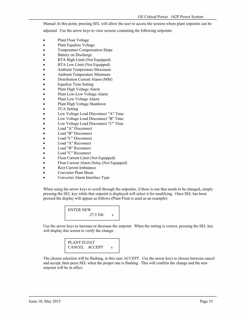
Issue 10, May 2015 Page 53
GE Critical Power 162P Power System
Manual At this point, pressing SEL will allow the user to access the screens where plant setpoints can be
adjusted. Use the arrow keys to view screens containing the following setpoints:
• Plant Float Voltage• Plant Equalize Voltage• Temperature Compensation Slope• Battery on Discharge• BTA High Limit (Not Equipped)• BTA Low Limit (Not Equipped)• Ambient Temperature Maximum• Ambient Temperature Minimum• Distribution Current Alarm (MM)• Equalize Time Setting• Plant High Voltage Alarm• Plant Low-Low Voltage Alarm• Plant Low Voltage Alarm• Plant High Voltage Shutdown• TCA Setting• Low Voltage Load Disconnect "A" Time• Low Voltage Load Disconnect "B" Time• Low Voltage Load Disconnect "C" Time• Load "A" Disconnect• Load "B" Disconnect• Load "C" Disconnect• Load "A" Reconnect• Load "B" Reconnect• Load "C" Reconnect• Float Current Limit (Not Equipped)• Float Current Alarm Delay (Not Equipped)• Rect Current Imbalance• Converter Plant Shunt• Converter Alarm Interface Type
When using the arrow keys to scroll through the setpoints, if there is one that needs to be changed, simply pressing the SEL key while that setpoint is displayed will select it for modifying. Once SEL has been pressed the display will appear as follows (Plant Float is used as an example):
Use the arrow keys to increase or decrease the setpoint. When the setting is correct, pressing the SEL key will display this screen to verify the change:
The chosen selection will be flashing, in this case ACCEPT. Use the arrow keys to choose between cancel and accept, then press SEL when the proper one is flashing. This will confirm the change and the new setpoint will be in effect.
ENTER NEW 27.5 Vdc s
PLANT FLOAT CANCEL ACCEPT s
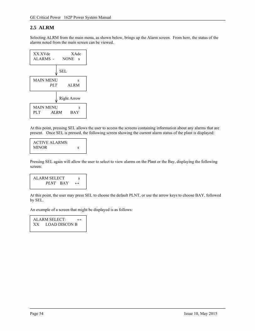
GE Critical Power 162P Power System Manual
Page 54 Issue 10, May 2015
2.5 ALRM
Selecting ALRM from the main menu, as shown below, brings up the Alarm screen. From here, the status of the alarms noted from the main screen can be viewed.
At this point, pressing SEL allows the user to access the screens containing information about any alarms that are present. Once SEL is pressed, the following screen showing the current alarm status of the plant is displayed:
Pressing SEL again will allow the user to select to view alarms on the Plant or the Bay, displaying the following screen:
At this point, the user may press SEL to choose the default PLNT, or use the arrow keys to choose BAY, followed by SEL.
An example of a screen that might be displayed is as follows:
MAIN MENU s PLT ALRM
XX.XVdc XAdc ALARMS - NONE s
SEL
MAIN MENU s PLT ALRM BAY
Right Arrow
ACTIVE ALARMS: MINOR s
ALARM SELECT s PLNT BAY ↔
ALARM SELECT: ↔ XX LOAD DISCON B
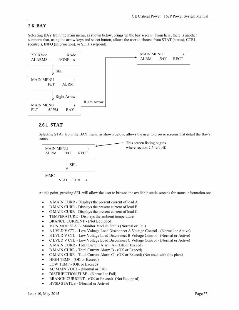
GE Critical Power 162P Power System Manual
Issue 10, May 2015 Page 55
2.6 BAY
Selecting BAY from the main menu, as shown below, brings up the bay screen. From here, there is another submenu that, using the arrow keys and select button, allows the user to choose from STAT (status), CTRL (control), INFO (information), or SETP (setpoint).
2.6.1 STAT
Selecting STAT from the BAY menu, as shown below, allows the user to browse screens that detail the Bay's status.
At this point, pressing SEL will allow the user to browse the available static screens for status information on:
• A MAIN CURR - Displays the present current of load A• B MAIN CURR - Displays the present current of load B• C MAIN CURR - Displays the present current of load C• TEMPERATURE - Displays the ambient temperature• BRANCH CURRENT - (Not Equipped)• MON MOD STAT - Monitor Module Status (Normal or Fail)• A LVLD V CTL - Low Voltage Load Disconnect A Voltage Control - (Normal or Active)• B LVLD V CTL - Low Voltage Load Disconnect B Voltage Control - (Normal or Active)• C LVLD V CTL - Low Voltage Load Disconnect C Voltage Control - (Normal or Active)• A MAIN CURR - Total Current Alarm A - (OK or Exceed)• B MAIN CURR - Total Current Alarm B - (OK or Exceed)• C MAIN CURR - Total Current Alarm C - (OK or Exceed) (Not used with this plant)• HIGH TEMP - (OK or Exceed)• LOW TEMP - (OK or Exceed)• AC MAIN VOLT - (Normal or Fail)• DISTRIBUTION FUSE - (Normal or Fail)• BRANCH CURRENT - (OK or Exceed) (Not Equipped)• HVSD STATUS - (Normal or Active)
MAIN MENU s PLT ALRM
XX.XVdc XAdc ALARMS - NONE s
SEL
MAIN MENU s PLT ALRM BAY
Right Arrow
MMC STAT CTRL s
MAIN MENU s ALRM BAY RECT
SEL
MAIN MENU s ALRM BAY RECT
Right Arrow
This screen listing begins where section 2.6 left off.
GE Critical Power 162P Power System Manual
Page 56 Issue 10, May 2015
• DFAR STATUS - (Normal or Fail)• A LVLD T CTL - Low Voltage Load Disconnect A, Temperature Controlled - (Normal or Active)• B LVLD T CTL - Low Voltage Load Disconnect B, Temperature Controlled - (Normal or Active)• C LVLD T CTL - Low Voltage Load Disconnect C, Temperature Controlled - (Normal or Active)• A LVLD STATE - (Connect or Disconnect)• B LVLD STATE - (Connect or Disconnect)• C LVLD STATE - (Connect or Disconnect)• BAY VOLTAGE - Displays the present voltage of the bay• BAY CURRENT - Displays the present current of the bay• CONV BAY VOLT - Displays the converter bay voltage• CONV BAY CURR - Displays the converter bay current• DGC STATUS - (Normal or Fail)• RFA MINOR - (Normal or Fail)• RFA MAJOR - (Normal or Fail)• MM STATUS - (Normal or Fail)• PMN ALARM - (Normal or Fail)• MULTI STAT - (Normal or Fail)• PMJ ALARM - (Normal or Fail)• BATT ON DISCHG - (No or Active)• HIGH VOLTAGE - (OK or Exceed)• LOW VOLTAGE - (OK or Exceed)• L-LOW VOLTAGE - (OK or Exceed)• BTC STATUS - Temperature Compensation (Off or Active)• DGC HEADER - (Prom'd or Un Cal)• SHM STATUS - (Normal or Fail) (Not used)• BAM STATUS - (Normal or Fail) (Not used)• ACO STATUS - (Normal or Active)• HVSD STATUS - High Voltage Shutdown - (Normal or Active)• PLANT MODE - (Float or Equal)• BAY ID SETUP - (OK or Fail)• MONITOR FAIL - (Normal or Fail)• CONV FAIL MAJ - (Normal or Fail)• CONV FAIL MIN - (Normal or Fail)• RECT VAR ALM - (Normal or Fail)
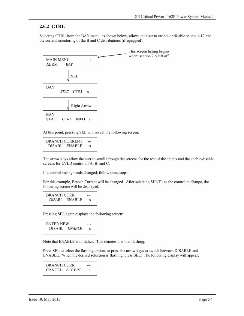
GE Critical Power 162P Power System Manual
Issue 10, May 2015 Page 57
2.6.2 CTRL
Selecting CTRL from the BAY menu, as shown below, allows the user to enable or disable shunts 1-12 and the current monitoring of the B and C distributions (if equipped).
At this point, pressing SEL will reveal the following screen:
The arrow keys allow the user to scroll through the screens for the rest of the shunts and the enable/disable screens for LVLD control of A, B, and C.
If a control setting needs changed, follow these steps:
For this example, Branch Current will be changed. After selecting SHNT1 as the control to change, the following screen will be displayed:
Pressing SEL again displays the following screen:
Note that ENABLE is in Italics. This denotes that it is flashing.
Press SEL to select the flashing option, or press the arrow keys to switch between DISABLE and ENABLE. When the desired selection is flashing, press SEL. The following display will appear:
MAIN MENU s ALRM BAY
This screen listing begins where section 2.6 left off.
BAY STAT CTRL s
SEL
BAY STAT CTRL INFO s
Right Arrow
BRANCH CURRENT ↔ DISABL ENABLE s
BRANCH CURR ↔ DISABL ENABLE s
BRANCH CURR ↔ CANCEL ACCEPT s
ENTER NEW… ↔ DISABL ENABLE s
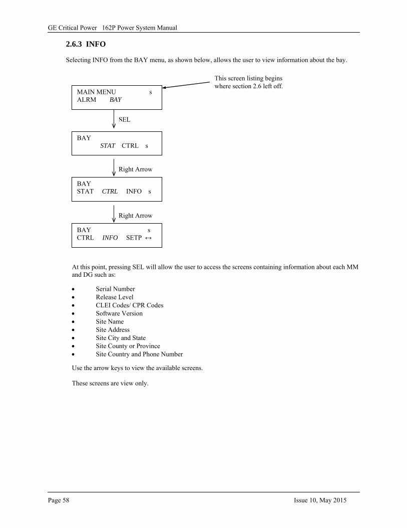
GE Critical Power 162P Power System Manual
Page 58 Issue 10, May 2015
2.6.3 INFO
Selecting INFO from the BAY menu, as shown below, allows the user to view information about the bay.
At this point, pressing SEL will allow the user to access the screens containing information about each MM and DG such as:
• Serial Number• Release Level• CLEI Codes/ CPR Codes• Software Version• Site Name• Site Address• Site City and State• Site County or Province• Site Country and Phone Number
Use the arrow keys to view the available screens.
These screens are view only.
MAIN MENU s ALRM BAY
This screen listing begins where section 2.6 left off.
BAY STAT CTRL s
SEL
BAY STAT CTRL INFO s
Right Arrow
BAY s CTRL INFO SETP ↔
Right Arrow
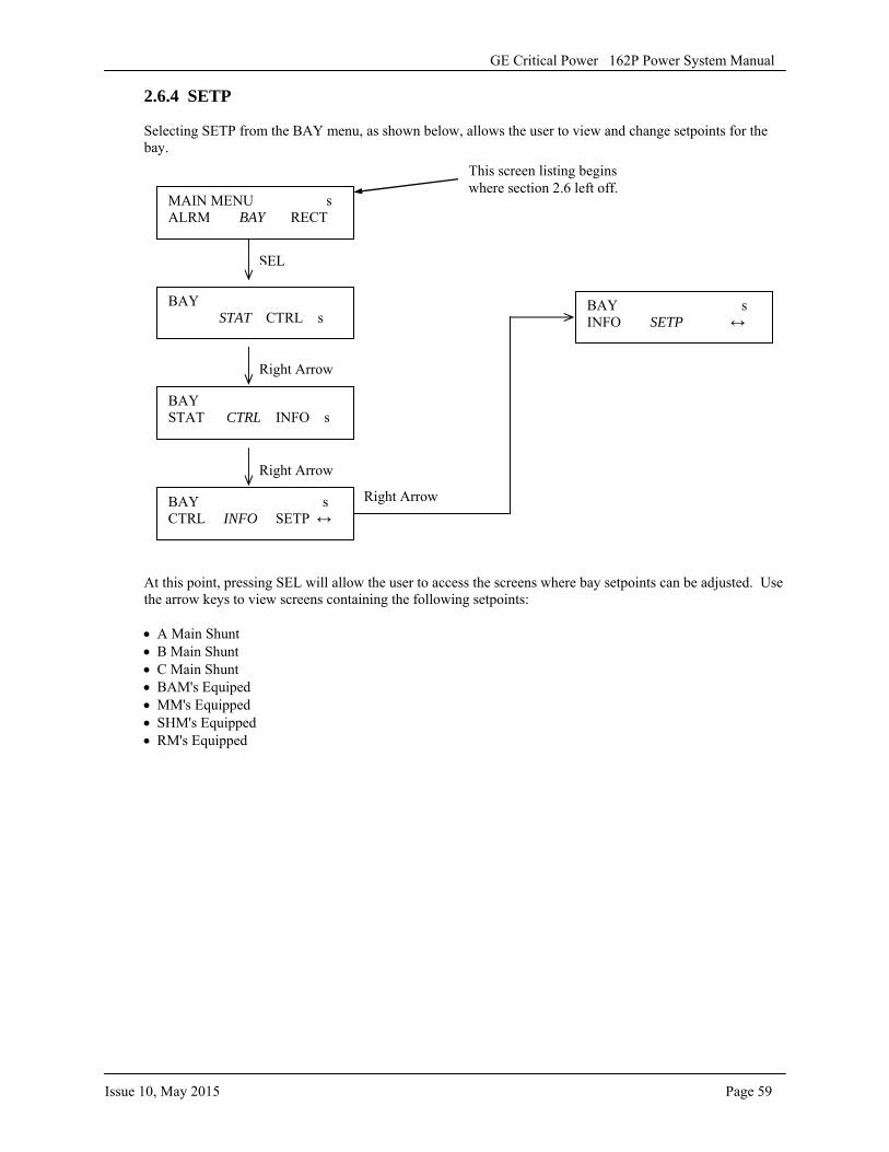
GE Critical Power 162P Power System Manual
Issue 10, May 2015 Page 59
2.6.4 SETP
Selecting SETP from the BAY menu, as shown below, allows the user to view and change setpoints for the bay.
At this point, pressing SEL will allow the user to access the screens where bay setpoints can be adjusted. Use the arrow keys to view screens containing the following setpoints:
• A Main Shunt• B Main Shunt• C Main Shunt• BAM's Equiped• MM's Equipped• SHM's Equipped• RM's Equipped
MAIN MENU s ALRM BAY RECT
BAY STAT CTRL s
SEL
BAY STAT CTRL INFO s
Right Arrow
BAY s CTRL INFO SETP ↔
Right Arrow
This screen listing begins where section 2.6 left off.
BAY s INFO SETP ↔
Right Arrow
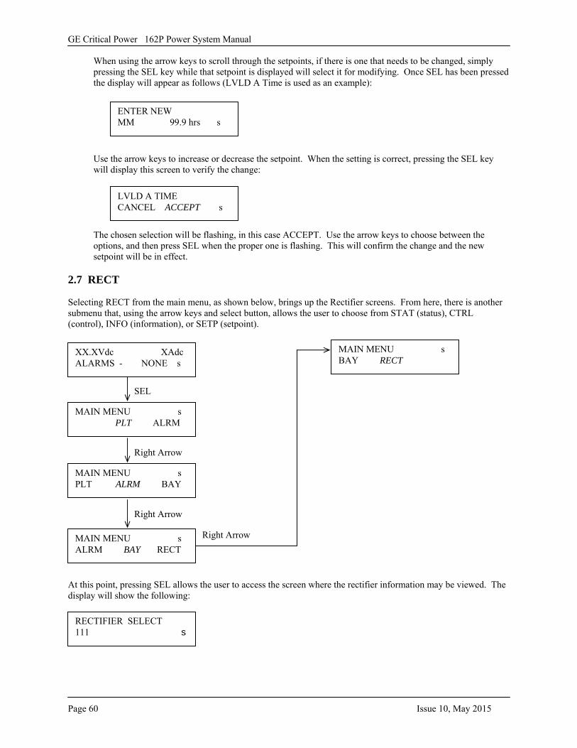
GE Critical Power 162P Power System Manual
Page 60 Issue 10, May 2015
When using the arrow keys to scroll through the setpoints, if there is one that needs to be changed, simply pressing the SEL key while that setpoint is displayed will select it for modifying. Once SEL has been pressed the display will appear as follows (LVLD A Time is used as an example):
Use the arrow keys to increase or decrease the setpoint. When the setting is correct, pressing the SEL key will display this screen to verify the change:
The chosen selection will be flashing, in this case ACCEPT. Use the arrow keys to choose between the options, and then press SEL when the proper one is flashing. This will confirm the change and the new setpoint will be in effect.
2.7 RECT
Selecting RECT from the main menu, as shown below, brings up the Rectifier screens. From here, there is another submenu that, using the arrow keys and select button, allows the user to choose from STAT (status), CTRL (control), INFO (information), or SETP (setpoint).
At this point, pressing SEL allows the user to access the screen where the rectifier information may be viewed. The display will show the following:
ENTER NEW MM 99.9 hrs s
LVLD A TIME CANCEL ACCEPT s
MAIN MENU s PLT ALRM
XX.XVdc XAdc ALARMS - NONE s
SEL
MAIN MENU s PLT ALRM BAY
Right Arrow
MAIN MENU s ALRM BAY RECT
Right Arrow
MAIN MENU s BAY RECT
Right Arrow
RECTIFIER SELECT 111 s
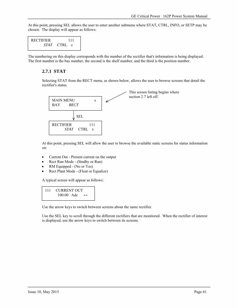
GE Critical Power 162P Power System Manual
Issue 10, May 2015 Page 61
At this point, pressing SEL allows the user to enter another submenu where STAT, CTRL, INFO, or SETP may be chosen. The display will appear as follows:
The numbering on this display corresponds with the number of the rectifier that's information is being displayed. The first number is the bay number, the second is the shelf number, and the third is the position number.
2.7.1 STAT
Selecting STAT from the RECT menu, as shown below, allows the user to browse screens that detail the rectifier's status.
At this point, pressing SEL will allow the user to browse the available static screens for status information on:
• Current Out - Present current on the output• Rect Run Mode - (Stndby or Run)• RM Equipped - (No or Yes)• Rect Plant Mode - (Float or Equalize)
A typical screen will appear as follows:
Use the arrow keys to switch between screens about the same rectifier.
Use the SEL key to scroll through the different rectifiers that are monitored. When the rectifier of interest is displayed, use the arrow keys to switch between its screens.
RECTIFIER 111 STAT CTRL s
111 CURRENT OUT 100.00 Adc ↔
MAIN MENU s BAY RECT
RECTIFIER 111 STAT CTRL s
SEL
This screen listing begins where section 2.7 left off.
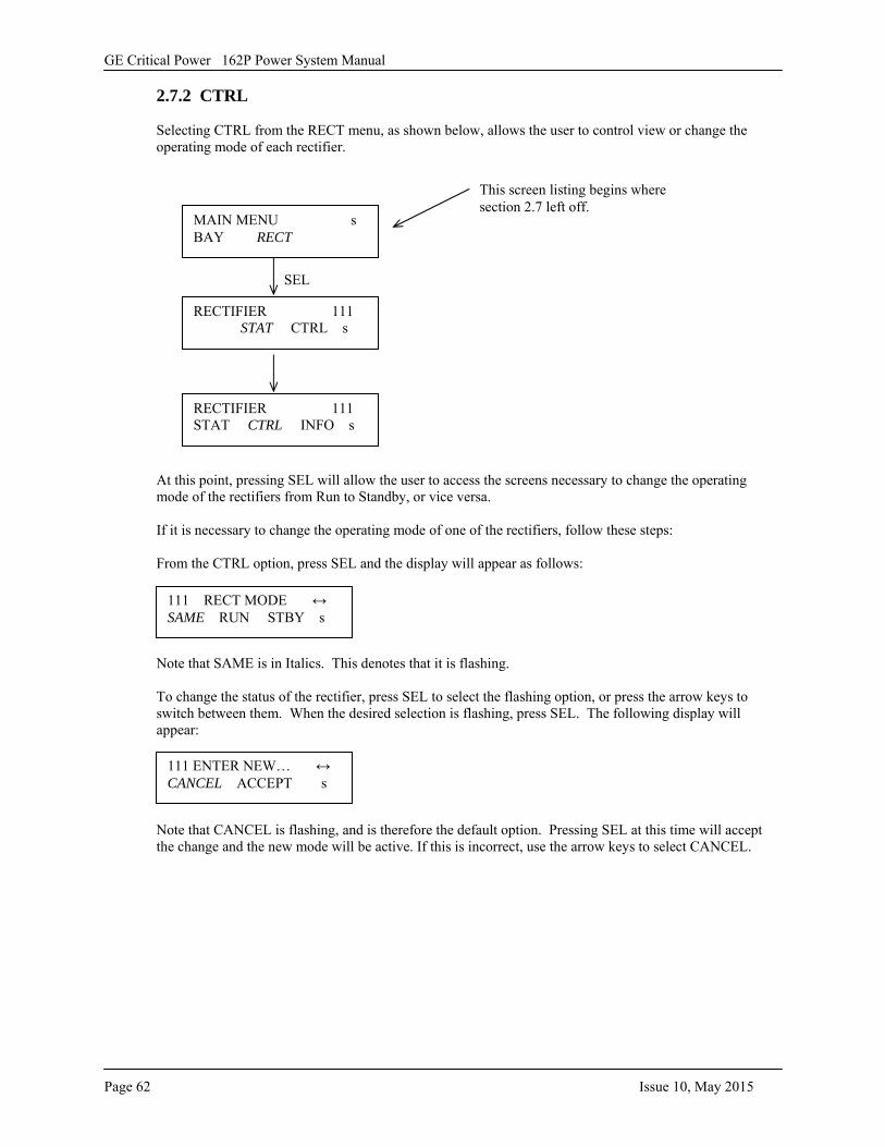
GE Critical Power 162P Power System Manual
Page 62 Issue 10, May 2015
2.7.2 CTRL
Selecting CTRL from the RECT menu, as shown below, allows the user to control view or change the operating mode of each rectifier.
At this point, pressing SEL will allow the user to access the screens necessary to change the operating mode of the rectifiers from Run to Standby, or vice versa.
If it is necessary to change the operating mode of one of the rectifiers, follow these steps:
From the CTRL option, press SEL and the display will appear as follows:
Note that SAME is in Italics. This denotes that it is flashing.
To change the status of the rectifier, press SEL to select the flashing option, or press the arrow keys to switch between them. When the desired selection is flashing, press SEL. The following display will appear:
Note that CANCEL is flashing, and is therefore the default option. Pressing SEL at this time will accept the change and the new mode will be active. If this is incorrect, use the arrow keys to select CANCEL.
111 ENTER NEW… ↔ CANCEL ACCEPT s
111 RECT MODE ↔ SAME RUN STBY s
MAIN MENU s BAY RECT
RECTIFIER 111 STAT CTRL s
SEL
This screen listing begins where section 2.7 left off.
RECTIFIER 111 STAT CTRL INFO s
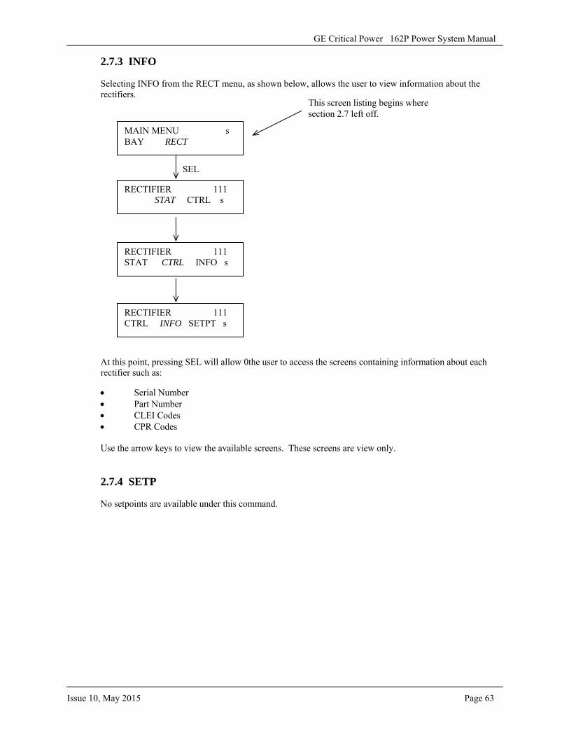
GE Critical Power 162P Power System Manual
Issue 10, May 2015 Page 63
2.7.3 INFO
Selecting INFO from the RECT menu, as shown below, allows the user to view information about the rectifiers.
At this point, pressing SEL will allow 0the user to access the screens containing information about each rectifier such as:
• Serial Number• Part Number• CLEI Codes• CPR Codes
Use the arrow keys to view the available screens. These screens are view only.
2.7.4 SETP
No setpoints are available under this command.
MAIN MENU s BAY RECT
RECTIFIER 111 STAT CTRL s
SEL
This screen listing begins where section 2.7 left off.
RECTIFIER 111 STAT CTRL INFO s
RECTIFIER 111 CTRL INFO SETPT s
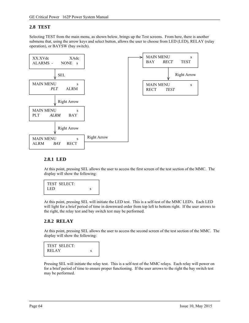
GE Critical Power 162P Power System Manual
Page 64 Issue 10, May 2015
2.8 TEST
Selecting TEST from the main menu, as shown below, brings up the Test screens. From here, there is another submenu that, using the arrow keys and select button, allows the user to choose from LED (LED), RELAY (relay operation), or BAYSW (bay switch).
2.8.1 LED
At this point, pressing SEL allows the user to access the first screen of the test section of the MMC. The display will show the following:
At this point, pressing SEL will initiate the LED test. This is a self-test of the MMC LED's. Each LED will light for a brief period of time in downward order from top left to bottom right. If the user arrows to the right, the relay test and bay switch test may be performed.
2.8.2 RELAY
At this point, pressing SEL allows the user to access the second screen of the test section of the MMC. The display will show the following:
Pressing SEL will initiate the relay test. This is a self-test of the MMC relays. Each relay will power on for a brief period of time to ensure proper functioning. If the user arrows to the right the bay switch test may be performed.
MAIN MENU s PLT ALRM
XX.XVdc XAdc ALARMS - NONE s
SEL
MAIN MENU s PLT ALRM BAY
Right Arrow
MAIN MENU s ALRM BAY RECT
Right Arrow
MAIN MENU s BAY RECT TEST
Right Arrow
TEST SELECT: LED s
MAIN MENU s RECT TEST
Right Arrow
TEST SELECT: RELAY s
GE Critical Power 162P Power System Manual
Issue 10, May 2015 Page 65
2.8.3 BAYSW
At this point, pressing SEL allows the user to access the final screen of the test section of the MMC. The display will show the following:
At this point, pressing SEL will initiate the bay switch test. This is a self-test of the MMC to ensure that the bay switch is operating correctly.
TEST SELECT: BAYSW s

GE Critical Power 162P Power System Manual
Page 66 Issue 10, May 2015
-This page intentionally left blank-
GE Critical Power 162P Power System Manual
Issue 10, May 2015 Page 67
SSSEEECCCTTTIIIOOONNN 333::: PPPLLLAAANNNTTT IIINNNFFFOOORRRMMMAAATTTIIIOOONNN 3.1 PLANT SPECIFICATIONS
3.1.1 INPUT RATINGS
A. Voltage: 170 to 264 VAC, single phase
B. Current: 220VAC, single phase: 18 Amps @ 100% load per rectifier
C. Frequency: 47-63Hz
D. Power Factor: >90%, 20-100% load
E. Recom. Feeder Breaker: 20 Amp breaker for 220VAC for each rectifier input
F. Converter Input +24 VDC, 75 Amps per converter module installed
3.1.2 OUTPUT RATINGS FOR RECTIFIERS (+24VDC)
A. Voltage: 23.5 VDC to 28.5 VDC, factory set at 27.2 VDC
B. Current: Maximum of 2000 Amps at + 24 VDC per bay. (From rectifiers)
3.1.3 OUTPUT RATINGS FOR CONVERTERS (-48VDC)
A. Voltage: -48 VDC Factory Set. Not field adjustable.
B. Current: Maximum of 10 Amps at - 48 VDC per converter module.
3.1.4 MISCELLANEOUS RATINGS
Size: Width: 600 mm (23.62 inches) Depth: 600 mm (23.62 inches) Height: 2134 mm (84 inches) Weight: 1,000 lbs. (equipped with 20 rectifiers and 8 converters)
Mounting: Floor
Temperature: Nominal 0°C to +50°C, from sea level to 4800 feet.
0°C to +40°C, from sea level to 13,100 feet. Hardened -40°C to + 70°C, from sea level to 4800 feet. The output is de-rated at 2.5% per °C
Storage -40°C to +85°C
Cooling: Front to rear single speed fan.
Humidity: 95% non-condensing, maximum
Shock: This equipment, in its shipping container, withstands shock developed during shipping without physical damage or degradation of the electrical performance.
Vibration: This equipment, in its shipping container, withstands vibration encountered in shipping without physical damage or degradation of the electrical performance.

GE Critical Power 162P Power System Manual
Page 68 Issue 10, May 2015
-This page intentionally left blank-
GE Critical Power 162P Power System Manual
Issue 10, May 2015 Page 69
SSSEEECCCTTTIIIOOONNN 444::: GGGAAATTTEEEWWWAAAYYY SSSEEETTTUUUPPP (((iiifff eeeqqquuuiiippppppeeeddd))) 4.1 GENERAL
The Gateway (LIST 94 or 95) is an optional feature that allows the 162P bay to communicate with a remote location or local maintenance port to control or adjust the system. Graphical User Interfaces (WEBs) are only accessible when the system is equipped with a Gateway.
It features:
• Ethernet 10 Base-T• Dial-In When Equipped With Optional Modem - PPP• HTML Server• Real Time Clock• Battery Backup (2 weeks)• Direct Cable Connect – PPP Through Null Modem• TCP/IP• PPP• FTP
4.2 SETTING UP THE 162P TO COMMUNICATE VIA AN ETHERNET OR SERIAL PORT
For information regarding the use of the user interface on the front of the MMC, refer to Section 2, Navigating The User Interface. This section will go over how to connect a PC to the 162P system, how to change the IP address of the PC to communicate with the 162, and then how to use Con_Ui to change the IP address of the 162P to that desired by the user.
Software Required:
Con_Ui, supplied by GE Critical Power
When the 162P system is equipped with a Gateway card, the system may be monitored by using Graphical User Interfaces (Web), Con_Ui and SNMP over the Internet using a dial up connection (modem) or an Ethernet 10 Base T connection, or via a serial port using PPP as a transport. Before accessing any of these browser interfaces, it is important that the 162P system has it's own IP address.
Follow the instructions below to establish an IP address. Use a ground eliminator on all computer AC connectors (if they are equipped with a ground pin) before plugging them in. This is required to prevent a ground loop between pin 7 on the serial connector in the Gateway, which is plant ground, and the outlet's ground.
A. Physical Connection to the User’s Network or the User’s PC
The User’s PC must be connected to the network on which the Gateway resides (See Figure 22A and 22B for the location of the RJ45 Connector). Alternately the User’s PC may be directly connected to the Gateway via an Ethernet cable (RJ45 to RJ45, cross connect wired) or through a serial cable (Figure 23), (DB9F to DB25M, null modem wired) connection. Note: If a serial connection is used, select an unused COM port on the User’s PC. An adapter is required if the selected COM port is not a DB9 connector.
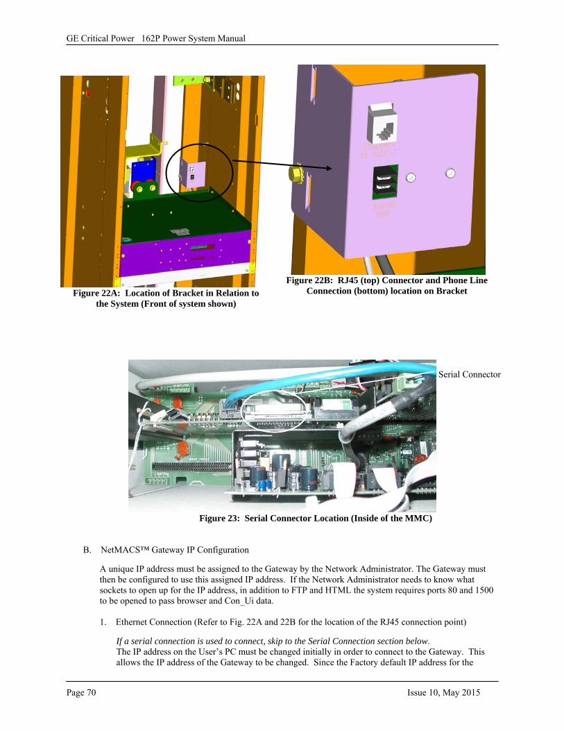
GE Critical Power 162P Power System Manual
Page 70 Issue 10, May 2015
Figure 22A: Location of Bracket in Relation to the System (Front of system shown)
Figure 22B: RJ45 (top) Connector and Phone Line Connection (bottom) location on Bracket
Figure 23: Serial Connector Location (Inside of the MMC)
B. NetMACS™ Gateway IP Configuration
A unique IP address must be assigned to the Gateway by the Network Administrator. The Gateway must then be configured to use this assigned IP address. If the Network Administrator needs to know what sockets to open up for the IP address, in addition to FTP and HTML the system requires ports 80 and 1500 to be opened to pass browser and Con_Ui data.
1. Ethernet Connection (Refer to Fig. 22A and 22B for the location of the RJ45 connection point)
If a serial connection is used to connect, skip to the Serial Connection section below.The IP address on the User’s PC must be changed initially in order to connect to the Gateway. Thisallows the IP address of the Gateway to be changed. Since the Factory default IP address for the
Serial Connector
GE Critical Power 162P Power System Manual
Issue 10, May 2015 Page 71
Gateway is 10.1.4.50, the IP address of the User’s PC must first be changed so that it is in the same scope as the Gateway’s address. Setting the IP address of the User’s PC to 10.1.4.30 satisfies this requirement. For specific instructions on changing the IP address of the User’s PC consult the Corporate Network Administrator or for Users who are familiar with this process, abbreviated instructions are as follows:
a. Abbreviated Instructions for Changing the User PC’s IP Address.
Please note: Changing the IP address of the User’s PC, which is network connected, will cause thePC to no longer be part of the local network. For this reason it is suggested that a portable PC beconfigured and direct connected to perform this task. In Windows9X™, the IP address can bechanged by selecting Start ⇒ Settings ⇒ Control Panel ⇒ Network ⇒ TCP/IP ⇒ ....Ethernet....... ⇒ Properties. Select the radio button next to “Specify an IP address” and type 10.1.4.30. For thesubnet mask, type 255.255.255.0. When all open Network windows are closed, Windows9X™ will prompt to restart for changes to take effect. Choose Yes. After the User’s PC restarts, it is ready to connect to the Gateway.
2. Serial Connection (Refer to Figure 23 for the location of the serial port)The Serial Connection does not require the IP address of the User’s PC to be changed. Rather, it usesthe Direct Cable Connection component of the Windows9X™ Operating System to establish a PPPconnection to the Gateway.
a. Abbreviated Instructions for Direct Cable ConnectionIt is suggested that a portable PC be configured and direct connected to perform this task. InWindows9X™, the direct cable connection screen can be changed by selecting Start ⇒ Programs⇒ Accessories ⇒ Direct Cable Connection (or Accessories ⇒ Communication ⇒ Direct CableConnection). If this option does not appear on the User’s PC, the Direct Cable Connectionprogram must be installed from the original Windows9X™ media. (Control Panel, Add/RemovePrograms, Communications, etc.)
The connection process will take the User through several dialog boxes, resulting in the directconnection. In the first Dialog box, select the radio button next to GUEST. In the next DialogBox, select the COM port to be used, and in the last Dialog Box, select finish.
As the process proceeds, Status Dialog Boxes will appear indicating User Name and Passwordverification. If prompted for “Enter Network Password”, select Cancel. Likewise, if prompted for“Host Computer Name” also select cancel. When successful, the status dialog box “Direct CableConnection” Status: Connected via Serial Cable on COMX will remain on the screen. Do notclose this box, doing so will drop the connection and end the session. If desired, this windowmay, however, be minimized.
When using Windows 98 R2, 2000, or NT it is necessary to add a script. From the "Network andDial-up Connections" folder, choose the dial up connection that is being used then select Securityfrom the tabs at the top of the window. Near the bottom of the window will be a selection box for"Run Script." Place an X in this box and type in the location where the following script is stored:(use a text editor and save it as sendclient.scp):
proc maintransmit "CLIENT"waitfor "CLIENTSERVER"endproc
C. Verifying the Network Connection Note: The Gateway responds to two IP addresses, one configurable, and the other fixed. The IP address depends on which connection was established (Ethernet or Serial). For the remainder of the document the Ethernet IP address will appear in the text, followed by the fixed Serial IP address in (parenthesis). Example 10.1.4.50 (10.0.0.1)
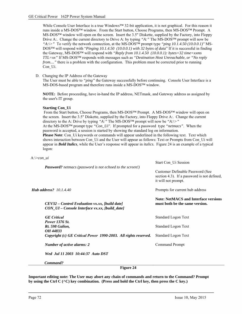
GE Critical Power 162P Power System Manual
Page 72 Issue 10, May 2015
While Console User Interface is a true Windows™ 32-bit application, it is not graphical. For this reason it runs inside a MS-DOS™ window. From the Start button, Choose Programs, then MS-DOS™ Prompt. A MS-DOS™ window will open on the screen. Insert the 3.5" Diskette, supplied by the Factory, into Floppy Drive A:. Change the current directory to Drive A: by typing “A:” The MS-DOS™ prompt will now be “A:\>” To verify the network connection, at the MS-DOS™ prompt type “ping 10.1.4.50 (10.0.0.1)" MS-DOS™ will respond with “Pinging 10.1.4.50 (10.0.0.1) with 32 bytes of data” If it is successful in finding the Gateway, MS-DOS™ will respond with “Reply from 10.1.4.50 (10.0.0.1): bytes=32 time=xxms TTL=xx” If MS-DOS™ responds with messages such as “Destination Host Unreachable, or “No reply from....” there is a problem with the configuration. This problem must be corrected prior to running Con_Ui.
D. Changing the IP Address of the Gateway The User must be able to “ping” the Gateway successfully before continuing. Console User Interface is a MS-DOS-based program and therefore runs inside a MS-DOS™ window.
NOTE: Before proceeding, have in-hand the IP address, NETmask, and Gateway address as assigned by the user's IT group.
Starting Con_Ui From the Start button, Choose Programs, then MS-DOS™ Prompt. A MS-DOS™ window will open on the screen. Insert the 3.5" Diskette, supplied by the Factory, into Floppy Drive A:. Change the current directory to the A: Drive by typing “A:” The MS-DOS™ prompt will now be “A:\>” At the MS-DOS™ prompt type “Con_Ui". If prompted for a password type “netmacs”. When the password is accepted, a session is started by showing the standard log on information. Please Note: Con_Ui keywords or commands will appear underlined in the following text. Text which shows interaction between Con_Ui and the User will appear as follows: Text or Prompts from Con_Ui will appear in Bold Italics, while the User’s response will appear in italics. Figure 24 is an example of a typical logon:
A:\>con_ui
Password? netmacs (password is not echoed to the screen!)
Hub address? 10.1.4.40
CEV32 – Control Evaluation vx.xx, [build date] CON_UI – Console Interface vx.xx, [build_date]
GE Critical Power 1376 St. Rt. 598 Galion, OH 44833 Copyright (c) GE Critical Power 1990-2003. All rights reserved.
Number of active alarms: 2
Wed Jul 11 2003 10:44:37 Auto DST
Command?
Start Con_Ui Session
Customer Definable Password (See section 4.3). If a password is not defined, it will not prompt.
Prompts for current hub address
Note: NetMACS and Interface versions must both be the same version.
Standard Logon Text
Standard Logon Text
Standard Logon Text
Command Prompt
Figure 24
Important editing note: The User may abort any chain of commands and return to the Command? Prompt by using the Ctrl C (^C) key combination. (Press and hold the Ctrl key, then press the C key.)
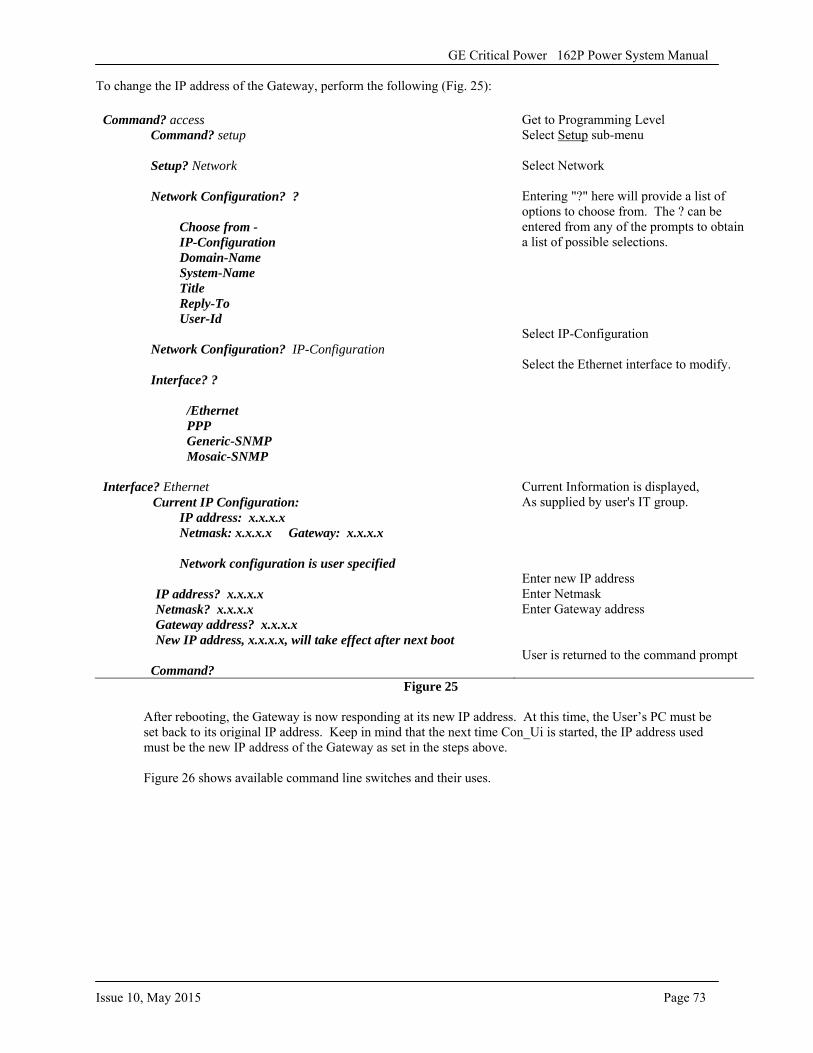
GE Critical Power 162P Power System Manual
Issue 10, May 2015 Page 73
To change the IP address of the Gateway, perform the following (Fig. 25):
Figure 25
After rebooting, the Gateway is now responding at its new IP address. At this time, the User’s PC must be set back to its original IP address. Keep in mind that the next time Con_Ui is started, the IP address used must be the new IP address of the Gateway as set in the steps above.
Figure 26 shows available command line switches and their uses.
Command? access Command? setup
Setup? Network
Network Configuration? ?
Choose from - IP-Configuration Domain-Name System-Name Title Reply-To User-Id
Network Configuration? IP-Configuration
Interface? ?
/Ethernet PPP Generic-SNMP Mosaic-SNMP
Interface? Ethernet Current IP Configuration:
IP address: x.x.x.x Netmask: x.x.x.x Gateway: x.x.x.x
Network configuration is user specified
IP address? x.x.x.x Netmask? x.x.x.x Gateway address? x.x.x.x New IP address, x.x.x.x, will take effect after next boot
Command?
Get to Programming Level Select Setup sub-menu
Select Network
Entering "?" here will provide a list of options to choose from. The ? can be entered from any of the prompts to obtain a list of possible selections.
Select IP-Configuration
Select the Ethernet interface to modify.
Current Information is displayed, As supplied by user's IT group.
Enter new IP address Enter Netmask Enter Gateway address
User is returned to the command prompt
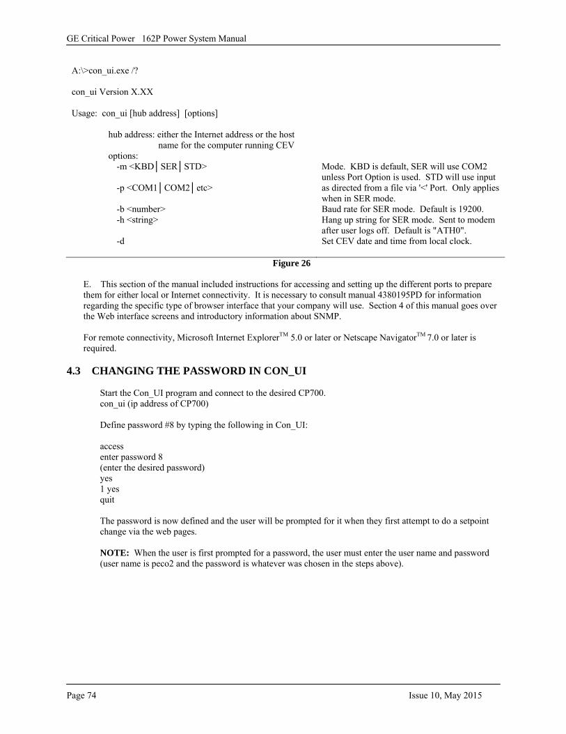
GE Critical Power 162P Power System Manual
Page 74 Issue 10, May 2015
A:\>con_ui.exe /?
con_ui Version X.XX
Usage: con_ui [hub address] [options]
hub address: either the Internet address or the host name for the computer running CEV
options: -m <KBD│SER│STD>
-p <COM1│COM2│etc>
-b <number> -h <string>
-d
Mode. KBD is default, SER will use COM2 unless Port Option is used. STD will use input as directed from a file via '<' Port. Only applies when in SER mode. Baud rate for SER mode. Default is 19200. Hang up string for SER mode. Sent to modem after user logs off. Default is "ATH0". Set CEV date and time from local clock.
Figure 26
E. This section of the manual included instructions for accessing and setting up the different ports to prepare them for either local or Internet connectivity. It is necessary to consult manual 4380195PD for information regarding the specific type of browser interface that your company will use. Section 4 of this manual goes over the Web interface screens and introductory information about SNMP.
For remote connectivity, Microsoft Internet ExplorerTM 5.0 or later or Netscape NavigatorTM 7.0 or later is required.
4.3 CHANGING THE PASSWORD IN CON_UI
Start the Con_UI program and connect to the desired CP700. con_ui (ip address of CP700)
Define password #8 by typing the following in Con_UI:
access enter password 8 (enter the desired password) yes 1 yes quit
The password is now defined and the user will be prompted for it when they first attempt to do a setpoint change via the web pages.
NOTE: When the user is first prompted for a password, the user must enter the user name and password (user name is peco2 and the password is whatever was chosen in the steps above).
GE Critical Power 162P Power System Manual
Issue 10, May 2015 Page 75
4.4 ENTERING SITE INFORMATION
The site information displayed on the web interface is retrieved from the gateway header.
You would start Con_UI just like the password business, but you would type the following text instead:
access enter header line 1 text line 2 text line 3 text line 4 text line 5 text line 6 text line 7 text line 8 text quit
The CP700 header can have up to 8 lines of text, 64 characters each. To not use all of the lines you would type the lines you want and then when it would prompt you for the next line, just hit return with no text. Plus, each line needs to be typed in on its own line - so you would type text for line #1 and then you have to hit return to start typing on line #2. If someone makes a mistake, then you can just enter it again, but they'd have to enter all the information in again - you can't edit any one particular line. Also, if you want a line to be blank, you would have to at least put a space in the line and then press enter - that's how you can space your few lines of header text out over the entire 8 lines available. Example of only using 3 lines:
access enter header line 1 text line 2 text line 3 text quit
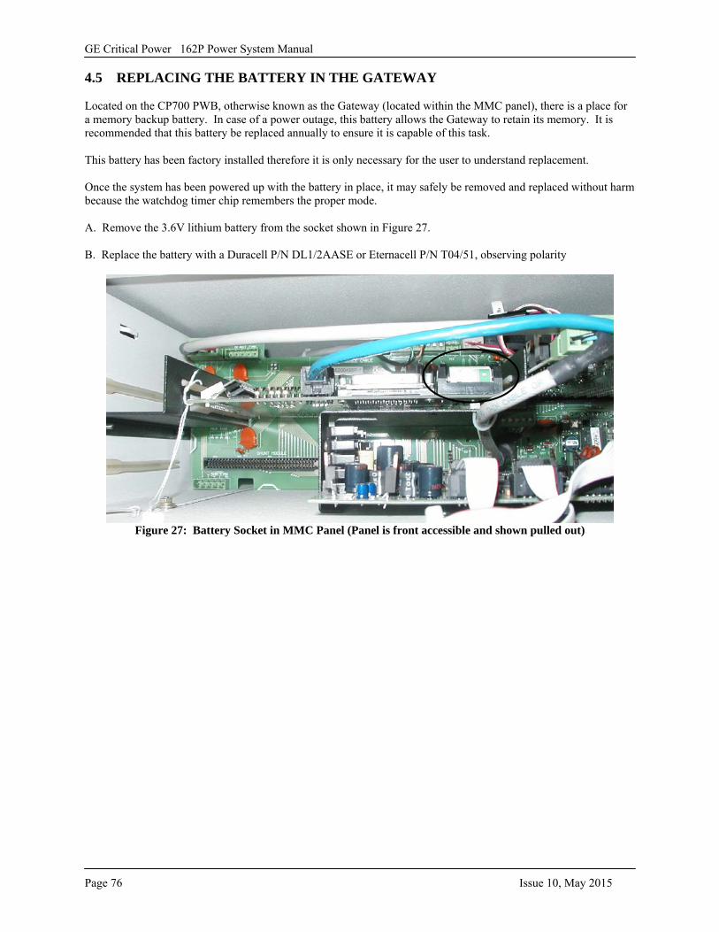
GE Critical Power 162P Power System Manual
Page 76 Issue 10, May 2015
4.5 REPLACING THE BATTERY IN THE GATEWAY
Located on the CP700 PWB, otherwise known as the Gateway (located within the MMC panel), there is a place for a memory backup battery. In case of a power outage, this battery allows the Gateway to retain its memory. It is recommended that this battery be replaced annually to ensure it is capable of this task.
This battery has been factory installed therefore it is only necessary for the user to understand replacement.
Once the system has been powered up with the battery in place, it may safely be removed and replaced without harm because the watchdog timer chip remembers the proper mode.
A. Remove the 3.6V lithium battery from the socket shown in Figure 27.
B. Replace the battery with a Duracell P/N DL1/2AASE or Eternacell P/N T04/51, observing polarity
Figure 27: Battery Socket in MMC Panel (Panel is front accessible and shown pulled out)
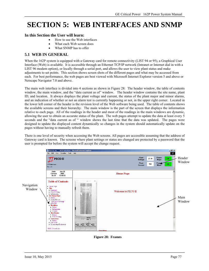
GE Critical Power 162P Power System Manual
Issue 10, May 2015 Page 77
SECTION 5: WEB INTERFACES AND SNMP In this Section the User will learn:
• How to use the Web interfaces• What each Web screen does• What SNMP has to offer
5.1 WEB IN GENERAL When the 162P system is equipped with a Gateway card for remote connectivity (LIST 94 or 95), a Graphical User Interface (Web) is available. It is accessible through an Ethernet TCP/IP network (Intranet or Internet dial in with a LIST 96 modem option), or locally through a serial port, and allows the user to view plant status and make adjustments to set points. This section shows screen shots of the different pages and what may be accessed from each. For best performance, the web pages are best viewed with Microsoft Internet Explorer version 5 and above or Netscape Navigator 7.0 and above.
The main web interface is divided into 4 sections as shown in Figure 28: The header window, the table of contents window, the main window, and the “data current as of” window. The header window contains the site name, plant ID, and location. It always displays the plant voltage and current, the status of the plant major and minor alarms, and an indication of whether or not an alarm test is currently happening or not, in the upper right corner. Located in the lower left corner of the header is the revision level of the Web software being used. The table of contents shows the available screens and their hierarchy. The main window is the part of the screen that displays the information relative to each page. All of the readings in the header and most of the readings in the main windows are dynamic, allowing the user to obtain an accurate status of the plant. The web pages attempt to update the data at least every 5 seconds and the “data current as of “ window shows the last time that the data was updated. The pages were designed to update the displayed content dynamically so changes in the system should automatically update on the pages without having to manually refresh them.
There is one level of security when accessing the Web screens. All pages are accessible assuming that the address of Gateway card is known. The screens where plant settings or status are changed are protected by a password that the user is prompted for before the system will accept the change request.
Figure 28: Frames
Header Window
Main Window
Navigation Window
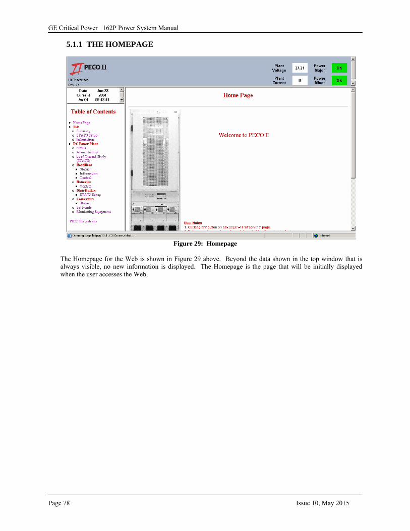
GE Critical Power 162P Power System Manual
Page 78 Issue 10, May 2015
5.1.1 THE HOMEPAGE
Figure 29: Homepage
The Homepage for the Web is shown in Figure 29 above. Beyond the data shown in the top window that is always visible, no new information is displayed. The Homepage is the page that will be initially displayed when the user accesses the Web.
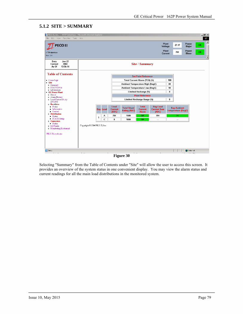
GE Critical Power 162P Power System Manual
Issue 10, May 2015 Page 79
5.1.2 SITE > SUMMARY
Figure 30
Selecting "Summary" from the Table of Contents under "Site" will allow the user to access this screen. It provides an overview of the system status in one convenient display. You may view the alarm status and current readings for all the main load distributions in the monitored system.
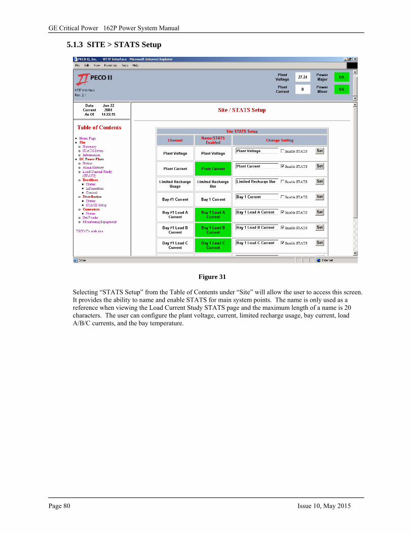
GE Critical Power 162P Power System Manual
Page 80 Issue 10, May 2015
5.1.3 SITE > STATS Setup
Figure 31
Selecting “STATS Setup” from the Table of Contents under “Site” will allow the user to access this screen. It provides the ability to name and enable STATS for main system points. The name is only used as a reference when viewing the Load Current Study STATS page and the maximum length of a name is 20 characters. The user can configure the plant voltage, current, limited recharge usage, bay current, load A/B/C currents, and the bay temperature.
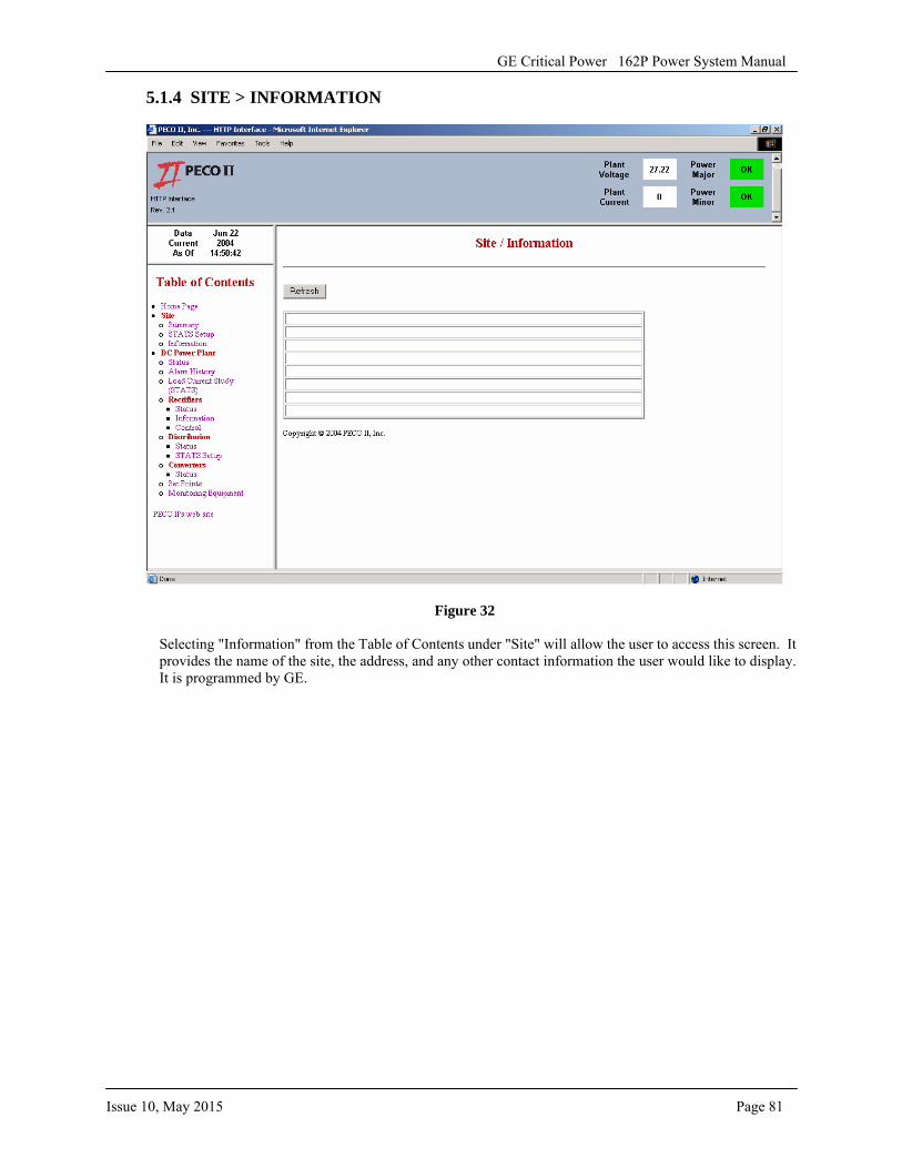
GE Critical Power 162P Power System Manual
Issue 10, May 2015 Page 81
5.1.4 SITE > INFORMATION
Figure 32
Selecting "Information" from the Table of Contents under "Site" will allow the user to access this screen. It provides the name of the site, the address, and any other contact information the user would like to display. It is programmed by GE.
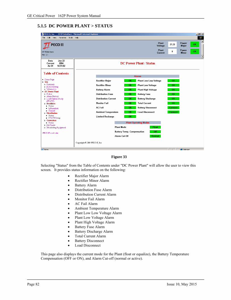
GE Critical Power 162P Power System Manual
Page 82 Issue 10, May 2015
5.1.5 DC POWER PLANT > STATUS
Figure 33
Selecting "Status" from the Table of Contents under "DC Power Plant" will allow the user to view this screen. It provides status information on the following:
• Rectifier Major Alarm• Rectifier Minor Alarm• Battery Alarm• Distribution Fuse Alarm• Distribution Current Alarm• Monitor Fail Alarm• AC Fail Alarm• Ambient Temperature Alarm• Plant Low Low Voltage Alarm• Plant Low Voltage Alarm• Plant High Voltage Alarm• Battery Fuse Alarm• Battery Discharge Alarm• Total Current Alarm• Battery Disconnect• Load Disconnect
This page also displays the current mode for the Plant (float or equalize), the Battery Temperature Compensation (OFF or ON), and Alarm Cut-off (normal or active).
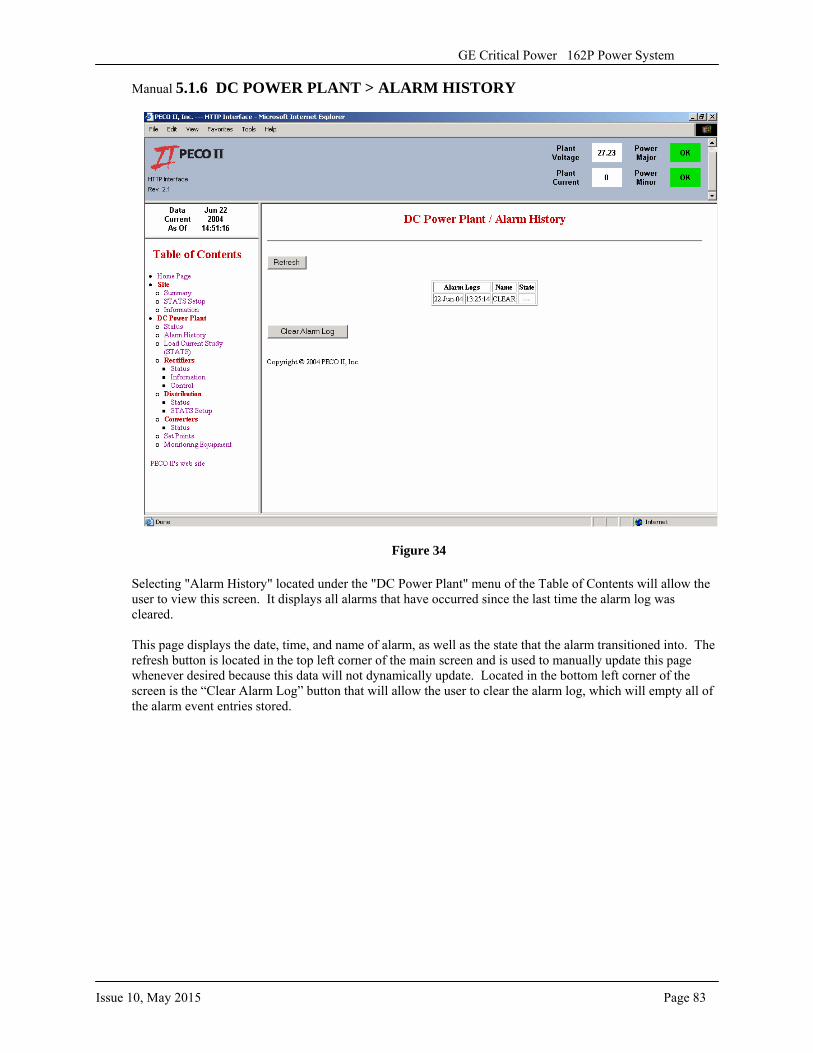
Issue 10, May 2015 Page 83
GE Critical Power 162P Power System
Manual 5.1.6 DC POWER PLANT > ALARM HISTORY
Figure 34
Selecting "Alarm History" located under the "DC Power Plant" menu of the Table of Contents will allow the user to view this screen. It displays all alarms that have occurred since the last time the alarm log was cleared.
This page displays the date, time, and name of alarm, as well as the state that the alarm transitioned into. The refresh button is located in the top left corner of the main screen and is used to manually update this page whenever desired because this data will not dynamically update. Located in the bottom left corner of the screen is the “Clear Alarm Log” button that will allow the user to clear the alarm log, which will empty all of the alarm event entries stored.
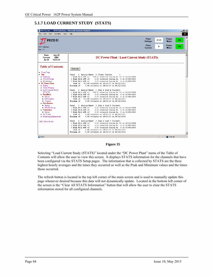
GE Critical Power 162P Power System Manual
Page 84 Issue 10, May 2015
5.1.7 LOAD CURRENT STUDY (STATS)
Figure 35
Selecting “Load Current Study (STATS)” located under the “DC Power Plant” menu of the Table of Contents will allow the user to view this screen. It displays STATS information for the channels that have been configured via the STATS Setup pages. The information that is collected by STATS are the three highest hourly averages and the times they occurred as well as the Peak and Minimum values and the times those occurred.
The refresh button is located in the top left corner of the main screen and is used to manually update this page whenever desired because this data will not dynamically update. Located in the bottom left corner of the screen is the “Clear All STATS Information” button that will allow the user to clear the STATS information stored for all configured channels.
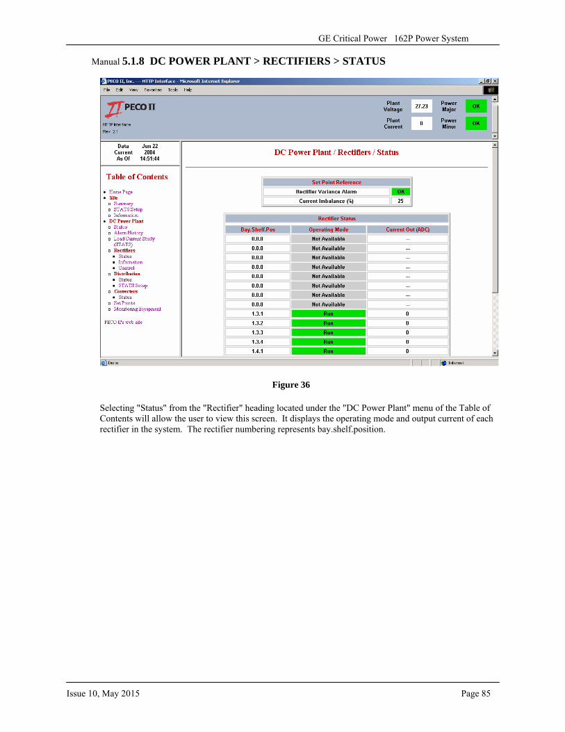
Issue 10, May 2015 Page 85
GE Critical Power 162P Power System
Manual 5.1.8 DC POWER PLANT > RECTIFIERS > STATUS
Figure 36
Selecting "Status" from the "Rectifier" heading located under the "DC Power Plant" menu of the Table of Contents will allow the user to view this screen. It displays the operating mode and output current of each rectifier in the system. The rectifier numbering represents bay.shelf.position.
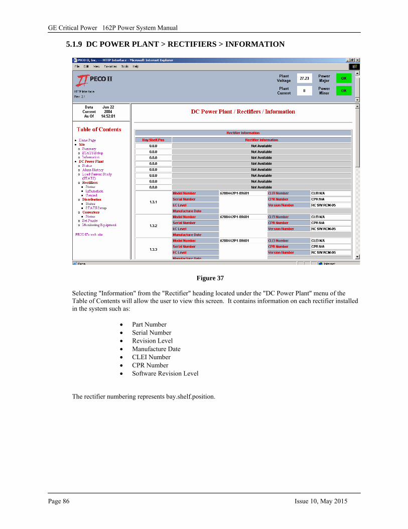
GE Critical Power 162P Power System Manual
Page 86 Issue 10, May 2015
5.1.9 DC POWER PLANT > RECTIFIERS > INFORMATION
Figure 37
Selecting "Information" from the "Rectifier" heading located under the "DC Power Plant" menu of the Table of Contents will allow the user to view this screen. It contains information on each rectifier installed in the system such as:
• Part Number• Serial Number• Revision Level• Manufacture Date• CLEI Number• CPR Number• Software Revision Level
The rectifier numbering represents bay.shelf.position.
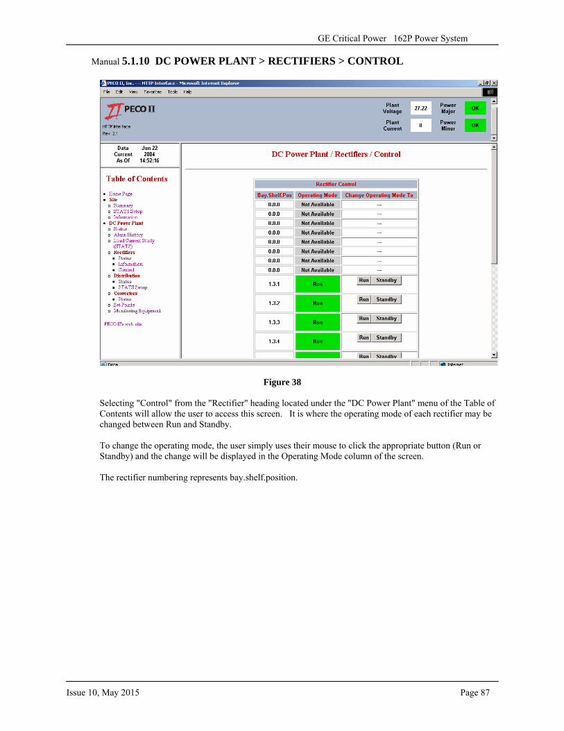
Issue 10, May 2015 Page 87
GE Critical Power 162P Power System
Manual 5.1.10 DC POWER PLANT > RECTIFIERS > CONTROL
Figure 38
Selecting "Control" from the "Rectifier" heading located under the "DC Power Plant" menu of the Table of Contents will allow the user to access this screen. It is where the operating mode of each rectifier may be changed between Run and Standby.
To change the operating mode, the user simply uses their mouse to click the appropriate button (Run or Standby) and the change will be displayed in the Operating Mode column of the screen.
The rectifier numbering represents bay.shelf.position.
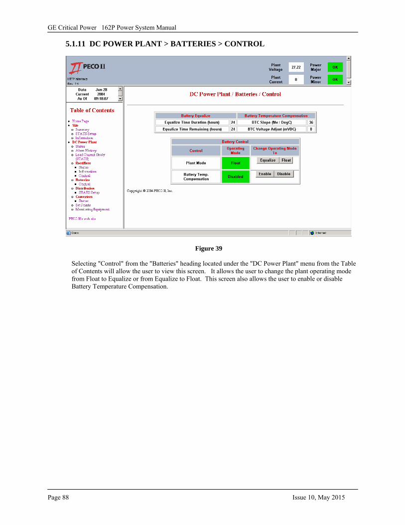
GE Critical Power 162P Power System Manual
Page 88 Issue 10, May 2015
5.1.11 DC POWER PLANT > BATTERIES > CONTROL
Figure 39
Selecting "Control" from the "Batteries" heading located under the "DC Power Plant" menu from the Table of Contents will allow the user to view this screen. It allows the user to change the plant operating mode from Float to Equalize or from Equalize to Float. This screen also allows the user to enable or disable Battery Temperature Compensation.
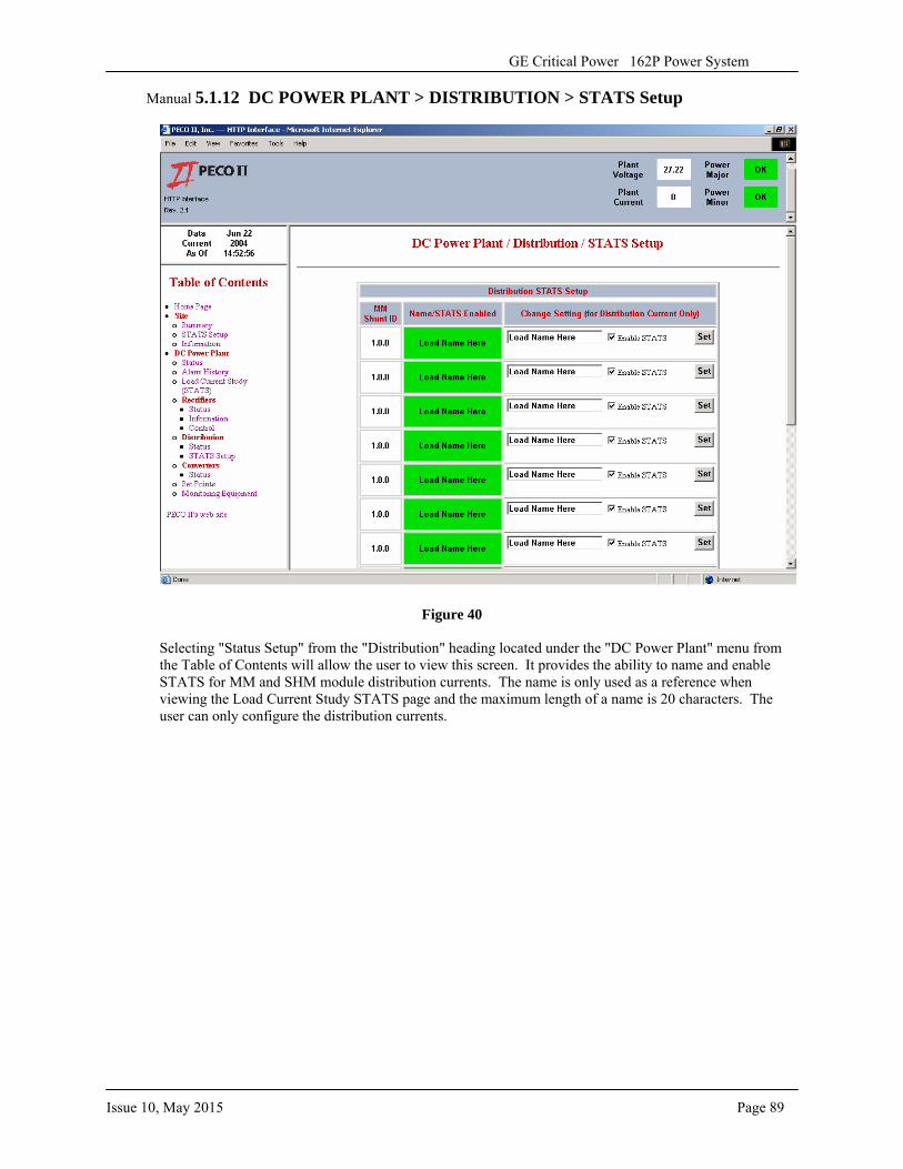
Issue 10, May 2015 Page 89
GE Critical Power 162P Power System
Manual 5.1.12 DC POWER PLANT > DISTRIBUTION > STATS Setup
Figure 40
Selecting "Status Setup" from the "Distribution" heading located under the "DC Power Plant" menu from the Table of Contents will allow the user to view this screen. It provides the ability to name and enable STATS for MM and SHM module distribution currents. The name is only used as a reference when viewing the Load Current Study STATS page and the maximum length of a name is 20 characters. The user can only configure the distribution currents.
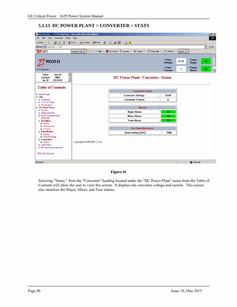
GE Critical Power 162P Power System Manual
Page 90 Issue 10, May 2015
5.1.13 DC POWER PLANT > CONVERTER > STATS
Figure 41
Selecting "Status " from the "Converter" heading located under the "DC Power Plant" menu from the Table of Contents will allow the user to view this screen. It displays the converter voltage and current. This screen also monitors the Major, Minor, and Fuse alarms.
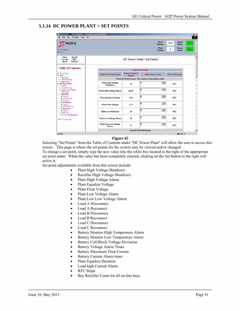
GE Critical Power 162P Power System Manual
Issue 10, May 2015 Page 91
5.1.14 DC POWER PLANT > SET POINTS
Figure 42 Selecting "Set Points" from the Table of Contents under "DC Power Plant" will allow the user to access this screen. This page is where the set points for the system may be viewed and/or changed. To change a set point, simply type the new value into the white box located to the right of the appropriate set point name. When the value has been completely entered, clicking on the Set button to the right will active it. Set point adjustments available from this screen include:
• Plant High Voltage Shutdown• Rectifier High Voltage Shutdown• Plant High Voltage Alarm• Plant Equalize Voltage• Plant Float Voltage• Plant Low Voltage Alarm• Plant Low Low Voltage Alarm• Load A Disconnect• Load A Reconnect• Load B Disconnect• Load B Reconnect• Load C Disconnect• Load C Reconnect• Battery Monitor High Temperature Alarm• Battery Monitor Low Temperature Alarm• Battery Cell/Block Voltage Deviation• Battery Voltage Alarm Timer• Battery Maximum Float Current• Battery Current Alarm timer• Plant Equalize Duration• Load high Current Alarm• BTC Slope• Bay Rectifier Count for all on-line bays
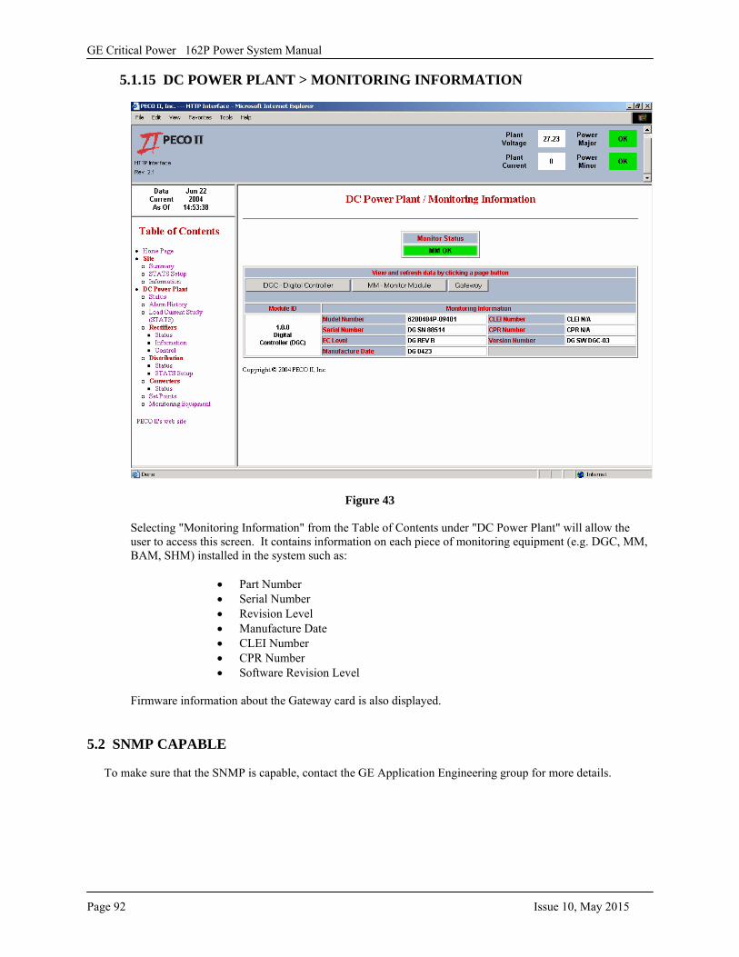
GE Critical Power 162P Power System Manual
Page 92 Issue 10, May 2015
5.1.15 DC POWER PLANT > MONITORING INFORMATION
Figure 43
Selecting "Monitoring Information" from the Table of Contents under "DC Power Plant" will allow the user to access this screen. It contains information on each piece of monitoring equipment (e.g. DGC, MM, BAM, SHM) installed in the system such as:
• Part Number• Serial Number• Revision Level• Manufacture Date• CLEI Number• CPR Number• Software Revision Level
Firmware information about the Gateway card is also displayed.
5.2 SNMP CAPABLE
To make sure that the SNMP is capable, contact the GE Application Engineering group for more details.