00 91 13.03 ADDENDUM NO. 3 - BidNet
87
ADDENDUM NO. 3 00 91 13.03 - 1 KER17340 – Water Treatment Plant THM Control Facility CITY OF KERRVILLE, TEXAS KERRVILLE WATER TREATMENT PLANT THM CONTROL FACILITY FNI PROJECT NO. KER17340 JANUARY 28, 2019 00 91 13.03 ADDENDUM NO. 3 The following additions, deletions, modifications, or clarifications shall be made to the appropriate sections of the Contract Documents. Bidders shall acknowledge receipt of this Addendum in the space provided on the Bid Form. ARTICLE 1 – BID REQUIREMENTS A3-1 Section 00 11 16 “Invitation to Bid” A. Amend section as follows: The time for receipt of Bids has been changed to February 15, 2019 at 3:00 p.m. B. The location for the receipt of Bids is unchanged. A3-2 Delete Section 00 42 23.01 “Bid Form Exhibit A” in its entirety and replace with Section 00 42 23.01 “Bid Form Exhibit A” attached to this Addendum. A3-3 Delete Section 01 29 00 “Payment Procedures” in its entirety and replace with Section 01 29 00 “Payment Procedures” attached to this Addendum. ARTICLE 2 – TECHNICAL SPECIFICATIONS: A3-4 Add the following specification sections: ADD Section Section Section Title 33 11 13.13 “Steel Pipe” 40 05 64 “Butterfly Valves” A3-5 Replace the following specification Sections: Replace Section With Section Section Section Title Section Section Title 09 96 00.01 “High-Performance Coatings” 09 96 00.01 “High-Performance Coatings” A3-6 Specification 40 72 00 “Level Instrumentation Devices” – See attached for modifications. A3-7 Specification 40 78 00 “Panel Mounted Control Devices” – See attached for modifications. A3-8 Specification 40 61 96 “Control Loop Descriptions” – See attached for modifications. A3-9 Specification 46 07 13 “Adsorption Systems for Use with Granulated Activated Carbon” A. Delete paragraph 2.02.E.7. in its entirety.
-
Upload
khangminh22 -
Category
Documents
-
view
0 -
download
0
Transcript of 00 91 13.03 ADDENDUM NO. 3 - BidNet
ADDENDUM NO. 3 00 91 13.03 - 1
KER17340 – Water Treatment Plant THM Control Facility
CITY OF KERRVILLE, TEXAS
KERRVILLE WATER TREATMENT PLANT THM CONTROL FACILITY
FNI PROJECT NO. KER17340
JANUARY 28, 2019
00 91 13.03 ADDENDUM NO. 3
The following additions, deletions, modifications, or clarifications shall be made to the appropriate
sections of the Contract Documents. Bidders shall acknowledge receipt of this Addendum in the space
provided on the Bid Form.
ARTICLE 1 – BID REQUIREMENTS
A3-1 Section 00 11 16 “Invitation to Bid”
A. Amend section as follows:
The time for receipt of Bids has been changed to February 15, 2019 at 3:00 p.m.
B. The location for the receipt of Bids is unchanged.
A3-2 Delete Section 00 42 23.01 “Bid Form Exhibit A” in its entirety and replace with Section 00 42
23.01 “Bid Form Exhibit A” attached to this Addendum.
A3-3 Delete Section 01 29 00 “Payment Procedures” in its entirety and replace with Section 01 29 00
“Payment Procedures” attached to this Addendum.
ARTICLE 2 – TECHNICAL SPECIFICATIONS:
A3-4 Add the following specification sections:
ADD Section
Section Section Title
33 11 13.13 “Steel Pipe”
40 05 64 “Butterfly Valves”
A3-5 Replace the following specification Sections:
Replace Section With Section
Section Section Title Section Section Title
09 96 00.01 “High-Performance Coatings” 09 96 00.01 “High-Performance Coatings”
A3-6 Specification 40 72 00 “Level Instrumentation Devices” – See attached for modifications.
A3-7 Specification 40 78 00 “Panel Mounted Control Devices” – See attached for modifications.
A3-8 Specification 40 61 96 “Control Loop Descriptions” – See attached for modifications.
A3-9 Specification 46 07 13 “Adsorption Systems for Use with Granulated Activated Carbon”
A. Delete paragraph 2.02.E.7. in its entirety.

ADDENDUM NO. 3 00 91 13.03 - 2
KER17340 – Water Treatment Plant THM Control Facility
B. Modify paragraph 2.02.H. as follows:
“H. The exterior surface of the adsorbers will be painted to a dry film thickness of 10 to 14
mil with a high solids epoxy (gray color) paint and a top coat of compatible polyurethane
paint at 2 to 4 mil dft. Approved coating manufacturers must be as specified in section 09
96 00.01 “High-Performance Coatings.”
C. Modify paragraph 2.07.G. as follows:
“G. Provide three (3) 1” sample nozzles and full port ball valves, to be located so Owner can
test for turbidity, pH, and temperature from each vessel effluent separately and for the full
system before effluent exits adsorption system.”
ARTICLE 3 – DRAWINGS:
A3-10 Replace the following Drawings:
Replace Drawing With Drawing
Drawing No. Drawing Title Drawing No. Drawing Title
G-3 “Process Flow Diagram” G-3 “Process Flow Diagram”
C-1 “Site Plan” C-1 “Site Plan”
C-2 “Yard Piping Plan Sheet 1” C-2 “Yard Piping Plan Sheet 1”
C-2A “Proposed Paving Plan” C-2A “Proposed Paving Plan”
C-4 “Site Yard Piping Profiles
Sheet 1” C-4
“Site Yard Piping Profiles
Sheet 1”
C-5 “Site Yard Piping Profiles
Sheet 2” C-5
“Site Yard Piping Profiles
Sheet 2”
E-4 “Enlarged Site Plan” E-4 “Enlarged Site Plan”
E-7 “One-Line Diagram – II” E-7 “One-Line Diagram – II”
E-9 “GAC One-Line Diagram – I” E-9 “GAC One-Line Diagram – I”
E-11 “Pump Station Control Panel” E-11 “Pump Station Control Panel”
E-12 “MCC Plan and Section” E-12 “MCC Plan and Section”
E-13 “Pump Station Plan, Section,
and Riser Diagram” E-13
“Pump Station Plan, Section,
and Riser Diagram”
E-14 “GAC Filter Plan” E-14 “GAC Filter Plan”
E-15 “Pump Station Installation
Details” E-15
“Pump Station Installation
Details”
E-16 “GAC Control Riser Diagram” E-16 “GAC Control Riser Diagram”
E-17 “GAC Power Riser Diagram” E-17 “GAC Power Riser Diagram”
E-18 “GAC Filter Heat Trace
Details” E-18
“GAC Filter Heat Trace
Details”
E-19 “RTU Interface Diagram” E-19 “RTU Interface Diagram”
E-20 “Pump Control Panel
Schematic” E-20
“Pump Control Panel
Schematic”
E-22 “Standard Details – II” E-22 “Standard Details – II”
E-23 “Standard Details – III” E-23 “Standard Details – III”
I-2 “Pump Station P&ID” I-2 “Pump Station P&ID”
I-3 “GAC Filters P&ID – I” I-3 “GAC Filters P&ID – I”
ADDENDUM NO. 3 00 91 13.03 - 3
KER17340 – Water Treatment Plant THM Control Facility
Replace Drawing With Drawing
Drawing No. Drawing Title Drawing No. Drawing Title
I-4 “GAC Filters P&ID – II” I-4 “GAC Filters P&ID – II”
I-5 “Installation Details” I-5 “Installation Details”
END OF ADDENDUM NO. 3
CITY OF KERRVILLE, TEXAS
KERRVILLE WATER TREATMENT PLANT THM CONTROL FACILITY
FNI PROJECT NO. KER17340
JANUARY 28, 2019
ADDENDUM NO. 3
The following additions, deletions, modifications, or clarifications shall be made to the appropriate
sections of the Contract Documents. Acknowledge receipt of this Addendum in the Bid Form submitted
for this Project. Failure to acknowledge receipt of this addendum in the Bid Form may render the Bid as
non-responsive and serve as the basis for rejecting the Bid.
Drawing E-14. Area lighting includes a switch at each lighting pole.
In specification 40 72 00 Level Instrumentation Devices add the following paragraph:
2.03 LEVEL TRANSMITTER - SUBMERSIBLE PRESSURE TYPE
A. Subject to compliance with the Contract Documents, the following Manufacturers are
acceptable:
1. Measurement Specialties MEAS KPSI 705 Submersible Transmitters for hydrostatic Level
2. No Equal
B. The listing of specific manufacturers above does not imply acceptance of their products that
do not meet the specified ratings, features and functions. Manufacturers listed above are
not relieved from meeting these specifications in their entirety.
C. General
1. Type: Measuring level by continuously measuring hydrostatic pressure via its sensing
element, Data is transmitted by an analog, 4 to 20 mA DC output signal.
D. Performance Requirements:
1. Accuracy: ±0.25 percent full scale.
2. Zero Offset: ±0.50 percent full scale minimum configurable.
3. Span: ±0.50 percent full scale minimum configurable by manufacture.
4. Operating Temperature Ranges: -20 to 60 degrees C.
E. Construction Features:
1. Sensor: Type 316 stainless steel.
2. Housing: Type 316 stainless steel.
3. Cable shall be provided of required length and fully submersible construction.
4. Power supply: 9 to 28 VDC with surge and lightning protection.
5. Electrical Connection: Attached 4-wire, 22AWG Conductors in a shielded cable with
vent tube and polyurethane outer jacket.
In specification section 40 78 00 Panel Mounted Control Devices add the following to paragraph 2.08 A.:

4. Siemens model RD200
In specification 40 61 96 Control Loop Descriptions replace paragraphs 3.02 and 3.03 with the following:
3.02 PUMP STATION
Following loops are associated with the new Pump Station. The Data Flow Systems RTU (PLC as
indicated on the drawings) shall be programmed with the following as described below.
A. Loop 600 Booster Pump Station
1. General: Series of float switches shall be installed as shown in the drawings The Low-
level Float shall be an interlock for both pumps. The pumps shall alternate, and the PLC
shall provide an indication to the OIT which pump is the lead pump.
2. GRANULAR ACTIVATED CARBON (GAC) filtration system permissive based on maximum
flow limits are provided as hardwired signals. These include YL-410 PV-1 and PV-2 IN
series, YL-420 PV-3 and PV-4 in Series, YL-411 PV-1 in Service, YL-412 PV-2 in service, YL-
421 PV-3 in Service and YL-422 PV-4 in service.
a. The maximum flow rate for all CAG units in service shall not be exceeded. By
monitoring these status points the maximum flow can be calculated.
b. The flow meters for each unit are interfaced to the pump control PLC as indicated
on the drawings.
c. If the YL-410 signal is true, then the flow from FI-301 will be the flow for the series
filter units PV-1 and PV-2.
d. If the YL-420 signal is true than the flow FI-303 be the flow for the series filter units
PV-3 and PV-4.
e. The flow through the CAG filters is the total of the in-service units by utilizing flow
meters minus
f. The maximum speed of the pump VFD shall be dynamically caped in automatic
mode to not exceed the max flow rate for the available CAG filters in their current
mode configuration.
3. Field Instruments: The High-Level float shall call for both pumps to run. The High float
shall start the lead pump. When the level reaches the low float, the pump shall stop,
and the pumps shall alternate.
4. Permissive include the level above the low-level float and a good level indication as
measured from the LIT-600 4-20mA signal transmitter.
5. The pump station shall operate pumping capacity to maintain a level setpoint within a
narrow dead-band as entered from the pump station control panel OIT. The VFD’s shall
operate from the minimum speed as determined by the pump curve from the pump
supplier to 100% speed. If the lead pump cannot maintain the level within range and is
operating at greater than 98% for a configurable delay, then the Lag pump shall be
called to run, and both pumps run at near the same speed. If both pumps are running
and the level is below the setpoint for a configurable delay time than the Lead pump
should be called to stop. The Lag becomes the Lead pump.
6. On a weekly basis the Lead shall become Lag and Lag become Lead as at least one pump
will be running continually in normal operation. This rotation will allow for more equal
utilization of pumping equipment.
B. HMI Control and Monitoring
1. This system should be incorporated into the Plant SCADA system as part of the CAG
(GRANULAR ACTIVATED CARBON) Filter System Displays
a. Indications and status as shown within the plans are to be included as a minimum.
3.03 GRANULAR ACTIVATED CARBON (GAC) FILTRATION SYSTEM
A. The CAG filtration system will run autonomously from the plant SCADA and shall be
controlled by the CAG system manufacturer supplied control system. This control panel is to
be installed on the MCC-1 platform as shown on the drawings.
B. Indications and statuses as shown on the plans are to be hardwired from the CAG control
Panel to the Data Flow Systems RTU (PLC as indicated on the drawings) panel as shown.
These signals are to be incorporated into the existing plant SCADA HMI for monitoring and
reporting
1. Individual flow meters are to be displayed and a Filter to Waste flow is to be calculated
within the GAC Manufactures control panel and made available to the plant SCADA
system as a hardwired indication. This signal is to assure all State of Texas reporting
requirements are meet.
2. Calculated signals to indicate in service shall be true when the filter unit is producing
filtered water regardless of parallel or series mode. The arrangement indication for
series mode shall also be made available.
C. The total flow through the CAG filter units shall be balance to the units that are currently in
service. The influent valve shall modulate to control the flow to achieve this balance and
protect the filters against exceeding the maximum flow rate.
The following plan sheets are replaced:
E-4, E-7, E-9, E-11, E-12, E-13, E-14, E-15, E-16, E-17, E-18, E-19, E-20, E-22, E-23, I-2, I-3, I-4, I-5
01/28/2019
AD
DE
ND
UM
NO
. 3
Bid
Fo
rm E
xhib
it ‘
A’
0
0 4
2 2
3.0
1 -
1
KE
R1
73
40
– W
ate
r T
rea
tme
nt
Pla
nt
TH
M C
on
tro
l Fa
cili
ty
00
42
23
.01
B
ID F
OR
M E
XH
IBIT
‘A
’
WA
TE
R T
RE
AT
ME
NT
PLA
NT
TH
M C
ON
TR
OL
FAC
ILIT
Y B
AS
E B
ID I
TE
MS
Ite
m
No
. D
esc
rip
tio
n
Un
it
Est
ima
ted
Qu
an
tity
U
nit
Pri
ce
Ext
en
de
d A
mo
un
t
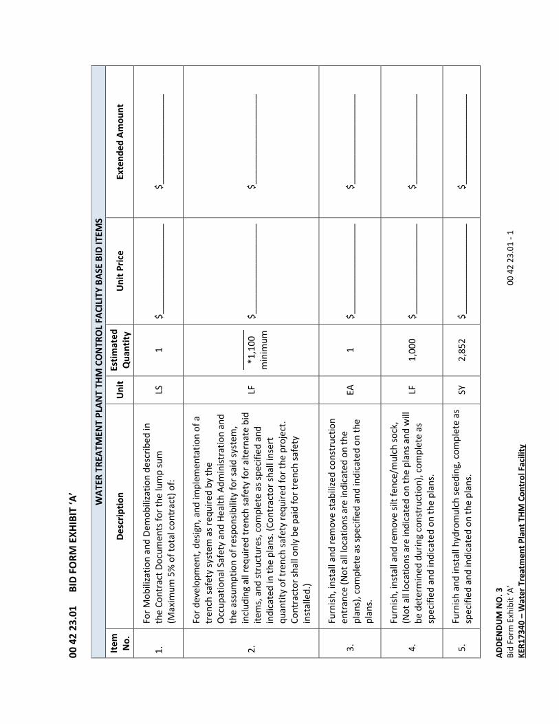
1.
For
Mo
bili
zati
on
an
d D
em
ob
iliza
tio
n d
esc
rib
ed
in
the
Co
ntr
act
Do
cum
en
ts f
or
the
lum
p s
um
(Ma
xim
um
5%
of
tota
l co
ntr
act
) o
f:
LS
1
$_
__
__
__
__
__
__
__
__
_
$_
__
__
__
__
__
__
__
__
_
2.
For
de
velo
pm
en
t, d
esi
gn
, a
nd
imp
lem
en
tati
on
of
a
tre
nch
sa
fety
sys
tem
as
req
uir
ed
by
the
Occ
up
ati
on
al S
afe
ty a
nd
He
alt
h A
dm
inis
tra
tio
n a
nd
the
ass
um
pti
on
of
resp
on
sib
ility
fo
r sa
id s
yste
m,
incl
ud
ing
all
req
uir
ed
tre
nch
sa
fety
fo
r a
lte
rna
te b
id
ite
ms,
an
d s
tru
ctu
res,
co
mp
lete
as
spe
cifi
ed
an
d
ind
ica
ted
in t
he
pla
ns.
(C
on
tra
cto
r sh
all
inse
rt
qu
an
tity
of
tre
nch
sa
fety
re
qu
ire
d f
or
the
pro
ject
.
Co
ntr
act
or
sha
ll o
nly
be
pa
id f
or
tre
nch
sa
fety
inst
alle
d.)
LF
__
__
__
__
*1
,10
0
min
imu
m
$_
__
__
__
__
__
__
__
__
_
$_
__
__
__
__
__
__
__
__
_
3.
Furn
ish
, in
sta
ll a
nd
re
mo
ve s
tab
ilize
d c
on
stru
ctio
n
en
tra
nce
(N
ot
all
loca
tio
ns
are
ind
ica
ted
on
th
e
pla
ns)
, co
mp
lete
as
spe
cifi
ed
an
d in
dic
ate
d o
n t
he
pla
ns.
EA
1
$
__
__
__
__
__
__
__
__
__
$
__
__
__
__
__
__
__
__
__
4.
Furn
ish
, in
sta
ll a
nd
re
mo
ve s
ilt f
en
ce/m
ulc
h s
ock
,
(No
t a
ll lo
cati
on
s a
re in
dic
ate
d o
n t
he
pla
ns
an
d w
ill
be
de
term
ine
d d
uri
ng
co
nst
ruct
ion
), c
om
ple
te a
s
spe
cifi
ed
an
d in
dic
ate
d o
n t
he
pla
ns.
LF
1,0
00
$
__
__
__
__
__
__
__
__
__
$
__
__
__
__
__
__
__
__
__
5.
Fu
rnis
h a
nd
inst
all
hyd
rom
ulc
h s
ee
din
g,
com
ple
te a
s
spe
cifi
ed
an
d in
dic
ate
d o
n t
he
pla
ns.
SY
2
,85
2
$_
__
__
__
__
__
__
__
__
_
$_
__
__
__
__
__
__
__
__
_
AD
DE
ND
UM
NO
. 3
Bid
Fo
rm E
xhib
it ‘
A’
0
0 4
2 2
3.0
1 -
2
KE
R1
73
40
– W
ate
r T
rea
tme
nt
Pla
nt
TH
M C
on
tro
l Fa
cili
ty
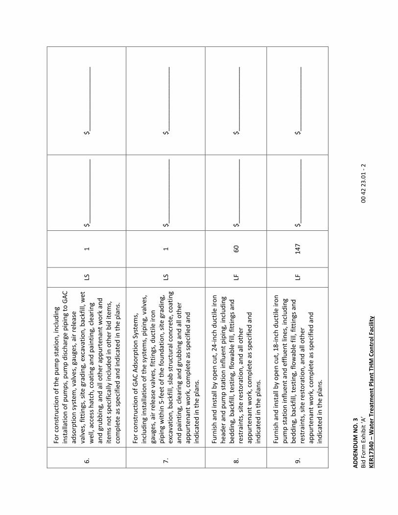
6.
For
con
stru
ctio
n o
f th
e p
um
p s
tati
on
, in
clu
din
g
inst
alla
tio
n o
f p
um
ps,
pu
mp
dis
cha
rge
pip
ing
to
GA
C
ad
sorp
tio
n s
yste
m,
valv
es,
ga
ug
es,
air
re
lea
se
valv
es,
fit
tin
gs,
sit
e g
rad
ing
, e
xca
vati
on
, b
ack
fill,
we
t
we
ll, a
cce
ss h
atc
h,
coa
tin
g a
nd
pa
inti
ng
, cl
ea
rin
g
an
d g
rub
bin
g,
an
d a
ll o
the
r a
pp
urt
en
an
t w
ork
an
d
ite
ms
no
t sp
eci
fica
lly in
clu
de
d in
oth
er
bid
ite
ms,
com
ple
te a
s sp
eci
fie
d a
nd
ind
ica
ted
in t
he
pla
ns.
LS
1
$_
__
__
__
__
__
__
__
__
_
$_
__
__
__
__
__
__
__
__
_
7.
For
con
stru
ctio
n o
f G
AC
Ad
sorp
tio
n S
yste
ms,
incl
ud
ing
inst
alla
tio
n o
f th
e s
yste
ms,
pip
ing
, va
lve
s,
ga
ug
es,
air
re
lea
se v
alv
es,
fit
tin
gs,
du
ctile
iro
n
pip
ing
wit
hin
5-f
ee
t o
f th
e f
ou
nd
ati
on
, si
te g
rad
ing
,
exc
ava
tio
n,
ba
ckfi
ll, s
lab
str
uct
ura
l co
ncr
ete
, co
ati
ng
an
d p
ain
tin
g,
cle
ari
ng
an
d g
rub
bin
g a
nd
all
oth
er
ap
pu
rte
na
nt
wo
rk,
com
ple
te a
s sp
eci
fie
d a
nd
ind
ica
ted
in t
he
pla
ns.
LS
1
$_
__
__
__
__
__
__
__
__
_
$_
__
__
__
__
__
__
__
__
_
8.
Furn
ish
an
d in
sta
ll b
y o
pe
n c
ut,
24
-in
ch d
uct
ile ir
on
he
ad
er
an
d p
um
p s
tati
on
infl
ue
nt
pip
ing
, in
clu
din
g
be
dd
ing
, b
ack
fill,
te
stin
g,
flo
wa
ble
fill
, fi
ttin
gs
an
d
rest
rain
ts,
site
re
sto
rati
on
, a
nd
all
oth
er
ap
pu
rte
na
nt
wo
rk,
com
ple
te a
s sp
eci
fie
d a
nd
ind
ica
ted
in t
he
pla
ns.
LF
60
$
__
__
__
__
__
__
__
__
__
$
__
__
__
__
__
__
__
__
__
9.
Furn
ish
an
d in
sta
ll b
y o
pe
n c
ut,
18
-in
ch d
uct
ile ir
on
pu
mp
sta
tio
n in
flu
en
t a
nd
eff
lue
nt
line
s, in
clu
din
g
be
dd
ing
, b
ack
fill,
te
stin
g,
flo
wa
ble
fill
, fi
ttin
gs
an
d
rest
rain
ts,
site
re
sto
rati
on
, a
nd
all
oth
er
ap
pu
rte
na
nt
wo
rk,
com
ple
te a
s sp
eci
fie
d a
nd
ind
ica
ted
in t
he
pla
ns.
LF
14
7
$_
__
__
__
__
__
__
__
__
_
$_
__
__
__
__
__
__
__
__
_

AD
DE
ND
UM
NO
. 3
Bid
Fo
rm E
xhib
it ‘
A’
0
0 4
2 2
3.0
1 -
3
KE
R1
73
40
– W
ate
r T
rea
tme
nt
Pla
nt
TH
M C
on
tro
l Fa
cili
ty
10
.
Furn
ish
an
d in
sta
ll b
y o
pe
n c
ut,
12
-in
ch C
-90
0 D
R1
4
PV
C b
ack
wa
sh w
ate
r lin
e,
incl
ud
ing
be
dd
ing
,
ba
ckfi
ll, t
est
ing
, a
sph
alt
ro
ad
wa
y re
pa
ir,
flo
wa
ble
fill
wit
hin
lag
oo
n b
erm
s, f
itti
ng
s a
nd
re
stra
ints
, tr
ee
pro
tect
ion
, si
te r
est
ora
tio
n,
an
d a
ll o
the
r
ap
pu
rte
na
nt
wo
rk,
com
ple
te a
s sp
eci
fie
d a
nd
ind
ica
ted
in t
he
pla
ns.
LF
77
2
$_
__
__
__
__
__
__
__
__
_
$_
__
__
__
__
__
__
__
__
_
11
.
Furn
ish
an
d in
sta
ll 2
4-i
nch
bu
tte
rfly
va
lve
on
pu
mp
sta
tio
n in
flu
en
t lin
e w
ith
be
vel g
ea
r, v
alv
e b
ox,
con
cre
te v
alv
e p
ad
an
d a
ll o
the
r a
pp
urt
en
an
t w
ork
,
com
ple
te a
s sp
eci
fie
d a
nd
ind
ica
ted
in t
he
pla
ns.
EA
1
$
__
__
__
__
__
__
__
__
__
$
__
__
__
__
__
__
__
__
__
12
.
Furn
ish
an
d in
sta
ll 1
8-i
nch
ga
te v
alv
e o
n p
um
p
sta
tio
n in
flu
en
t a
nd
eff
lue
nt
wa
ter
line
s w
ith
be
vel
ge
ar,
va
lve
bo
x, c
on
cre
te v
alv
e p
ad
, a
nd
all
oth
er
ap
pu
rte
na
nt
wo
rk,
com
ple
te a
s sp
eci
fie
d a
nd
ind
ica
ted
in t
he
pla
ns.
EA
2
$
__
__
__
__
__
__
__
__
__
$
__
__
__
__
__
__
__
__
__
13
.
Furn
ish
an
d in
sta
ll 1
2-i
nch
ga
te v
alv
e o
n b
ack
wa
sh
wa
ter
line
, va
lve
bo
x, c
on
cre
te v
alv
e p
ad
, a
nd
all
oth
er
ap
pu
rte
na
nt
wo
rk,
com
ple
te a
s sp
eci
fie
d a
nd
ind
ica
ted
in t
he
pla
ns.
EA
3
$
__
__
__
__
__
__
__
__
__
$
__
__
__
__
__
__
__
__
__
14
.
Furn
ish
an
d in
sta
ll tr
ace
r w
ire
te
st s
tati
on
s,
com
ple
te in
pla
ce a
s sp
eci
fie
d a
nd
ind
ica
ted
in t
he
pla
ns.
EA
4
$
__
__
__
__
__
__
__
__
__
$
__
__
__
__
__
__
__
__
__

AD
DE
ND
UM
NO
. 3
Bid
Fo
rm E
xhib
it ‘
A’
0
0 4
2 2
3.0
1 -
4
KE
R1
73
40
– W
ate
r T
rea
tme
nt
Pla
nt
TH
M C
on
tro
l Fa
cili
ty
15
.
Furn
ish
an
d in
sta
ll 2
4-i
nch
du
ctile
iro
n p
ipe
tie
-in
to
exi
stin
g p
ipin
g a
t cl
ari
fie
r, in
clu
din
g r
em
ovi
ng
exi
stin
g s
tee
l re
du
cer,
inst
alli
ng
pro
po
sed
ste
el
red
uce
r, t
ran
siti
on
co
up
ling
, co
ati
ng
s a
nd
lin
ing
s fo
r
exi
stin
g p
ipin
g,
an
d a
ll a
pp
urt
en
an
t w
ork
, co
mp
lete
as
spe
cifi
ed
an
d in
dic
ate
d o
n t
he
pla
ns.
LS
1
$_
__
__
__
__
__
__
__
__
_
$_
__
__
__
__
__
__
__
__
_
16
.
Furn
ish
an
d in
sta
ll 1
8-i
nch
du
ctile
iro
n p
ipe
tie
-in
to
exi
stin
g p
ipin
g f
rom
pla
nt,
incl
ud
ing
all
ap
pu
rte
na
nt
wo
rk,
com
ple
te a
s sp
eci
fie
d a
nd
ind
ica
ted
on
th
e
pla
ns.
LS
1
$_
__
__
__
__
$
__
__
__
__
__
17
.
Inst
all
con
cre
te o
utf
alls
at
lag
oo
ns,
incl
ud
ing
de
mo
ing
exi
stin
g o
utf
alls
, m
od
ifyi
ng
exi
stin
g p
ipin
g,
an
d a
ll a
pp
urt
en
an
t w
ork
, co
mp
lete
as
spe
cifi
ed
an
d
ind
ica
ted
in t
he
pla
ns.
EA
3
$
__
__
__
__
__
__
__
__
__
$
__
__
__
__
__
__
__
__
__
18
.
Pro
vid
e im
pro
vem
en
ts t
o c
hlo
rin
ati
on
sys
tem
incl
ud
ing
all
pip
ing
, e
qu
ipm
en
t, in
stru
me
nta
tio
n,
vau
lt a
nd
all
ap
pu
rte
na
nt
wo
rk,
com
ple
te a
s
spe
cifi
ed
an
d in
dic
ate
d in
th
e p
lan
s.
LS
1
$_
__
__
__
__
__
__
__
__
_
$_
__
__
__
__
__
__
__
__
_
19
.
Re
con
stru
ct a
sph
alt
pa
vem
en
t a
nd
pro
vid
e
pro
po
sed
pa
vem
en
t, c
om
ple
te a
s sp
eci
fie
d a
nd
ind
ica
ted
in t
he
pla
ns.
SY
1,2
69
$
__
__
__
__
__
__
__
__
__
$
__
__
__
__
__
__
__
__
__
20
.
For
the
inst
alla
tio
n o
f a
ll e
lect
rica
l eq
uip
me
nt,
ligh
tin
g,
con
du
it,
inst
rum
en
tati
on
an
d w
irin
g
imp
rove
me
nts
, a
nd
all
ap
pu
rte
na
nt
wo
rk,
com
ple
te
as
spe
cifi
ed
an
d in
dic
ate
d in
th
e p
lan
s.
LS
1
$_
__
__
__
__
__
__
__
__
_
$_
__
__
__
__
__
__
__
__
_
AD
DE
ND
UM
NO
. 3
Bid
Fo
rm E
xhib
it ‘
A’
0
0 4
2 2
3.0
1 -
5
KE
R1
73
40
– W
ate
r T
rea
tme
nt
Pla
nt
TH
M C
on
tro
l Fa
cili
ty
ALL
OW
AN
CE
IT
EM
S
Ite
m
No
. D
esc
rip
tio
n
Un
it
Est
ima
ted
Qu
an
tity
U
nit
Pri
ce
Ext
en
de
d A
mo
un
t
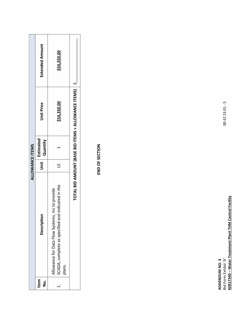
1.
Allo
wa
nce
fo
r D
ata
Flo
w S
yste
ms,
In
c to
pro
vid
e
SCA
DA
, co
mp
lete
as
spe
cifi
ed
an
d in
dic
ate
d in
th
e
pla
ns.
LS
1
$5
4,3
50
.00
$
54
,35
0.0
0
TO
TA
L B
ID A
MO
UN
T (
BA
SE B
ID I
TE
MS
+ A
LLO
WA
NC
E I
TE
MS
) $
__
__
__
__
__
__
__
__
__
__
EN
D O
F S
EC
TIO
N
ADDENDUM NO. 3
Payment Procedures 01 29 00 - 1
KER17340 – Water Treatment Plant THM Control Facility
01 29 00 PAYMENT PROCEDURES
1.00 GENERAL
1.01 WORK INCLUDED
A. Payments for Work shall conform to the provisions of the General Conditions, the
Supplementary Conditions, the Agreement, and this Section. Apply provisions for payments
in the Section to all Subcontractors and Suppliers.
B. Submit Applications for Payment at the amounts indicated in the Agreement:
1. Amounts for each item in the Agreement shall include but not be limited to cost for:
a. Mobilization, demobilization, cleanup, bonds, and insurance.
b. Professional services including but not limited to engineering and legal fees.
c. The products to be permanently incorporated into the Project.
d. The products consumed during the construction of the Project.
e. The labor and supervision to complete the Project.
f. The equipment, including tools, machinery, and appliances required to complete the
Project.
g. The field and home office administration and overhead costs related directly or
indirectly to the Project.
h. Any and all kinds, amount or class of excavation, backfilling, pumping or drainage,
sheeting, shoring and bracing, disposal of any and all surplus materials, permanent
protection of all overhead, surface or underground structures; removal and
replacement of any poles, conduits, pipelines, fences, appurtenances and
connections, cleaning up, overhead expense, bond, public liability and
compensation and property damage insurance, patent fees, and royalties, risk due
to the elements, and profits, unless otherwise specified.
2. Provide Work not specifically set forth as an individual payment item but required to
provide a complete and functional system. These items are a subsidiary obligation of
the Contractor and are to be included in the Cost of Work.
3. Payment will be made for materials on hand.
a. Store materials properly on Site as herein specified.
1). Payment will be made for the invoice amount less the specified retainage.
2). Provide invoices at the time materials are included on the materials-on-hand
tabulation.
b. Provide documentation of payment for materials-on-hand with the next payment
request. Adjust payment to the amount actually paid if this differs from the invoice
amount. Remove items from the materials on hand tabulation if this
documentation is not provided so payment will not be made.
c. Payment for materials-on-hand is provided for the convenience of the Contractor
and does not constitute acceptance of the product.
ADDENDUM NO. 3
Payment Procedures 01 29 00 - 2
KER17340 – Water Treatment Plant THM Control Facility
4. The Work covered by progress payments becomes the property of the Owner at the
time of payment.
1.02 SCHEDULE OF VALUES AND PAYMENTS
A. Submit a detailed Schedule of Values for the Work to be performed on the project.
1. Submit schedule within 10 days prior to submitting the first Application for Payment.
2. Line items in the Agreement are to be used as line items in the schedule.
3. Payment will be made on the quantity of Work completed per Contract Documents
during the payment period and as measured per this Section.
a. Payment amount is the Work quantity measured multiplied by the unit prices for
that line item in the Agreement.
b. Payment on a unit price basis will not be made for Work outside finished
dimensions shown in the Contract Documents.
c. Partial payments will be made for lump sum line items in the Agreement.
1). Lump sum line items in the Agreement are to be divided into smaller unit prices
to allow more accurate determination of the percentage of the item that has
been completed.
a). Provide adequate detail to allow more accurate determination of the
percentage of Work completed for each item.
b). Provide amounts for items that do not exceed $25,000.00. An exception
may be made for equipment packages that cannot be subdivided into units
or subassemblies.
c). Separate product costs and installation costs.
(1). Product costs include cost for product, delivery and unloading costs,
royalties and patent fees, taxes, and other cost paid directly to the
Subcontractor or Supplier.
(2). Installation costs include cost for the supervision, labor and equipment
for field fabrication, erection, installation, start-up, initial operation and
overhead and profit.
d). Lump sum items may be divided into an estimated number of units.
(1). The estimated number of units times the cost per unit must equal the
lump sum amount for that line item.
(2). Payment will be made for all of the lump sum line item amount.
e). Include a directly proportional amount of overhead and profit for each line
item.
f). Divide principal subcontract amounts into an adequate number of line items
to allow determination of the percentage of Work completed for each item.
2). These line items may be used to establish the value of Work to be added or
deleted from the Project.
ADDENDUM NO. 3
Payment Procedures 01 29 00 - 3
KER17340 – Water Treatment Plant THM Control Facility
3). Correlate line items with other administrative schedules and forms:
a). Progress schedule.
b). List of Subcontractors.
c). Schedule of allowances.
d). Schedule of alternatives.
e). List of products and principal Suppliers.
f). Schedule of Submittals.
4). Costs for mobilization shall be listed as a separate line item and shall be actual
cost for:
a). Bonds and insurance.
b). Transportation and setup for equipment.
c). Transportation and/or erection of all field offices, sheds and storage
facilities.
d). Salaries for preparation of submittals required before the first Application
for Payment.
e). Salaries for field personnel assigned to the Project related to the
mobilization of the Project.
f). Transportation, breakdown/loading, and removal of equipment.
g). Transportation and/or disassembly of all temporary facilities erected for
construction.
(1). Mobilization/demobilization may not exceed 3 percent of the total
Contract amount. Cost for mobilization and demobilization may be
submitted only for Work completed.
5). The sum of all values listed in the schedule must equal the total Contract
amount.
4. Submit a schedule indicating the anticipated schedule of payments to be made by the
Owner. Schedule shall indicate:
a. The Application for Payment number.
b. Date the request is to be submitted.
c. Anticipated amount of payment to be requested.
5. Update the Schedule of Values quarterly or more often if necessary to provide a
reasonably accurate indication of the funds that the Owner will need to have available
to make payment to the Contractor for the Work performed.
B. Provide written approval of the Schedule of Values, Application for Payment form, and
method of payment by the Surety Company providing performance, and bonds prior to
submitting the first Application for Payment. Payment will not be made without this
approval.

ADDENDUM NO. 3
Payment Procedures 01 29 00 - 4
KER17340 – Water Treatment Plant THM Control Facility
1.03 PAYMENT PROCEDURES
A. Submit Applications for Payment per the procedures indicated in Section 01 33 00
“Submittal Procedures.” Submit a Schedule of Values in the Application for Payment format
to be used.
B. Applications for Payment may be submitted on a pre-printed form acceptable to the Owner
and Engineer, or may be generated electronically. Computer generated payment requests
must have the same format and information indicated in the pre-printed form and be
approved by the Engineer.
1. Indicate the total contract amount and the Work completed to date on the Tabulation
of Values for Original Contract Performed.
2. Include only approved Change Order items in the Tabulation of Extra Work on Approved
Change Orders.
3. List all materials on hand that are presented for payment on the Tabulation of Materials
on Hand. Once an item has been entered on the tabulation it is not to be removed.
4. Include the Project Summary Report with each Application for Payment. Data included
in the Project Summary Report are to be taken from the other tabulations. Include a
completed summary as indicated in with each Applications for Payment submitted.
a. Number each application sequentially and indicate the payment period. Revised
Applications for Payment will be resubmitted as A, B, C and so forth to note changes
in content.
b. Show the total amounts for value of original Contract performed, extra Work on
approved Change Orders, and materials on hand on the Project Summary Report.
Show total amounts that correspond to totals indicated on the attached tabulation
for each.
c. Note the number of pages in tabulations in the blank space on the Project Summary
Report to allow a determination that all sheets have been submitted.
d. Execute Contractor’s certification by the Contractor’s agent of authority and
notarize for each Application for Payment.
5. Do not alter the schedule of values and the form for the submission of requests without
the written approval of the Engineer once these have been approved by the Engineer.
6. Final payment requires additional procedures and documentation per Section 01 70 00
“Execution and Closeout Requirements.”
C. Progress payments shall be made as the Work progresses on a monthly basis.
1. End the payment period on the day indicated in the Agreement and submit an
Application for Payment for Work completed and materials received since the end of
the last payment period.
2. At the end of the payment period, submit a draft copy of the Application for Payment
for that month to the Engineer. Agreement is to be reached on:
a. The percentage of Work completed for each lump sum item.
b. The quantity of Work completed for each unit price item.
ADDENDUM NO. 3
Payment Procedures 01 29 00 - 5
KER17340 – Water Treatment Plant THM Control Facility
c. The percentage of Work completed for each approved Change Order item.
d. The amount of materials-on-hand.
3. On the basis of these agreements the Contractor is to prepare a final copy of the
Application for Payment and submit it to the Engineer for approval.
4. The Engineer will review the Application for Payment and if appropriate will recommend
payment of the application to the Owner.
D. Provide a revised and up-to-date Progress Schedules per Section 01 32 16 “Construction
Progress Schedules” with each Application for Payment.
E. Provide project photographs per Section 01 32 34 “Video and Photographic Documentation”
with final Application for Payment.
1.04 ALTERNATES AND ALLOWANCES
Include amounts for specified Allowances for Work in the Agreement in accordance with Section
01 23 10 “Alternates and Allowances.”
1.05 MEASUREMENT PROCEDURES
Measure the Work described in the Agreement for payment, if applicable. Payment will be
made only for the actual measured and/or computed length, area, solid contents, number and
weight, unless otherwise specifically provided. No extra or customary measurements of any kind
will be allowed.
2.00 PRODUCTS (NOT APPLICABLE)
3.00 EXECUTION (NOT APPLICABLE)
END OF SECTION
ADDENDUM NO. 3
High-Performance Coatings 09 96 00.01 - 1
KER17340 – Water Treatment Plant THM Control Facility
09 96 00.01 HIGH-PERFORMANCE COATINGS
1.00 GENERAL
1.01 WORK INCLUDED
A. Furnish labor, materials, equipment and incidentals necessary to apply protective coatings
to material and equipment as specified herein, including the preparation of surfaces prior to
application of coatings.
B. Protective coatings must be applied to the following surfaces:
1. Metal surfaces located outside of buildings and other structures anywhere on the Site.
2. Proposed piping.
3. Existing piping and valves located in proposed chlorine injection vault.
C. The following shall not be coated and shall be protected from drips, overspray, etc. unless
indicated otherwise
1. Stainless steel piping, materials and equipment
2. Galvanized steel piping, materials and equipment unless specifically indicated to be
coated.
3. Aluminum materials and equipment
4. Interior electrical items
D. Special applications for painting include the following:
1. Buried pipe and valves shall receive a shop applied protective coating as described in
the appropriate Section of the Specifications.
2. Existing and proposed steel piping linings and coatings.
E. Special applications for painting include the following:
1. Aluminum surfaces in contact with or embedded in concrete shall be treated in
accordance with Section 03 30 00 “Cast-In-Place Concrete.”
2. Buried pipe and valves shall receive a shop applied protective coating as described in
the appropriate Section of the Specifications.
F. Contain, treat, and dispose of any dust, spray, drainage, or spillage resulting from coating
operations. It shall be the Contractor’s responsibility to determine if the materials to be
disposed of are classified as Hazardous Waste. Disposed of waste, hazardous or otherwise,
shall be in accordance with applicable regulations. The Contractor shall be aware of and
understand the regulations concerning disposal of waste generated by coating operations.
1.02 QUALITY ASSURANCE
A. Acceptable Manufacturers: Products which comply with the Contract Documents and are
manufactured by the following companies will be acceptable:
1. Tnemec Company, Inc.
2. Carboline.
ADDENDUM NO. 3
High-Performance Coatings 09 96 00.01 - 2
KER17340 – Water Treatment Plant THM Control Facility
3. PPG Protective & Marine Coatings.
4. The Sherwin-Williams Company.
5. Akzo Nobel / International Paint, LLC.
6. ICI Devoe High Performance Coatings.
7. Plasite Protective Coatings.
B. It is desired that the paint products be furnished by as few manufacturers as possible to
meet the requirements of the Specifications. Coating products of the same type shall be
supplied by the same manufacturer. Do not mix products from different sources.
C. Applicator’s Qualifications: Applicators must be qualified in this line of work and have a
minimum of 5 years of experience in the application of the protective coatings of the types
specified herein. Submit a list of recent projects and names of references for those projects.
D. Product Quality:
1. Use only the coatings specified in this Section. Use only those thinners and solvents
recommended by the manufacturer, only in the amounts necessary to produce the
manufacturer’s recommended spreading rate, and in amounts not exceeding the
maximum quantities stated in the manufacturer’s literature.
2. The coating material shall not show excessive settling in a freshly opened full can and
shall be easily re-dispersed with a paddle to a smooth, homogeneous state. It shall
show no curdling, livering, caking, or color separation and shall be free of lumps or skim
surfaces.
E. Inspection:
1. Inspect and provide substrate surfaces prepared in accordance with the Contract
Documents and the printed directions and recommendations of paint manufacturer
whose product is to be applied.
2. Provide Engineer minimum 3 days’ notice prior to start of surface preparation work or
coating application work.
3. Perform Work only in the presence of Engineer, unless Engineer grants prior approval to
perform such Work in Engineer’s absence. Approval to perform Work in the Engineer’s
absence is limited to the current day unless specifically noted to extend beyond the
completion of the work day.
4. Inspection by the Engineer, or the waiver of inspection of any particular portion of the
Work, shall not be construed to relieve the Contractor of responsibility to perform the
Work in accordance with the Contract Documents.
5. The Contractor shall be solely responsible for testing for this Section, at no further cost
to the Owner. The Engineer shall also make such tests if it is considered necessary.
Cooperate with the Engineer, providing equipment, scaffolds, and other equipment as
requested by the Engineer.
ADDENDUM NO. 3
High-Performance Coatings 09 96 00.01 - 3
KER17340 – Water Treatment Plant THM Control Facility
F. Testing Equipment: Furnish the testing apparatus necessary for testing coatings, including
the following:
1. One set of U.S. Department of Commerce thickness calibration plates, certified by the
National Bureau of Standards, to test dry film thickness.
2. Wet-film thickness gauges. Give one to Owner’s representative. Each painter must
keep one to test paint as it is applied.
3. One electronic dry-film thickness gauge capable or measuring 0-200 mils with
calibration standards approved by the Bureau of Standards.
4. One Elcometer 319 Dewpoint Meter.
5. One Tinker and Rasor Model M 1 Holiday Detector and recommended wetting agent
and/or High Voltage Holiday Detector if required for interior coating thickness specified.
6. One set of SSPC VIS 1, 3 and 4 - Visual Standards as applicable.
G. Testing Reports: Submit an inspection report for each coating applied on the Project. The
testing report shall be completed on a form furnished by the Engineer and shall bear the
signature of the Contractor and the Owner’s representative.
1.03 SUBMITTALS
A. Submittals must be in accordance with Section 01 33 00 “Document Management.”
B. The following Product Data for products, including manufacturer’s data sheets, are due prior
to ordering coating and surface preparation materials:
1. Coating manufacturer’s color selection literature for coating materials and caulk.
2. Sample warranty document for products.
3. Provide certification from the manufacturer that all coatings will not contain more than
0.06 percent by weight of lead in the cured coating for each coat applied.
4. Coating manufacturer’s Product Information and Safety Data Sheets (SDS) for each
coating and caulk material. Product Information must include the following:
a. The manufacturer’s published instructions for use in specifying and applying all
proposed coatings.
b. Application instructions written and published by the coating manufacturer.
c. All limitations, precautions and requirements that may adversely affect the coating,
that may cause unsatisfactory results after the application or that may cause the
coating not to serve the purpose for which it was intended, must be clearly and
completely stated in the instructions. Limitations and requirements must include,
but are not necessarily limited to the following:
1). Surface preparation.
2). Method(s) of application.
3). Thickness of each coat (maximum and minimum DFT).
4). Drying and curing time of each coat.
ADDENDUM NO. 3
High-Performance Coatings 09 96 00.01 - 4
KER17340 – Water Treatment Plant THM Control Facility
5). Time (minimum and maximum) allowed between coats.
6). Thinner and use of thinner.
7). Proper mixing of coating before application.
8). Weather limitations during and after application (temperature and humidity,
time weighted).
9). Physical properties of coating, including percent solids content by volume.
10). Equipment settings (air cap, fluid tip, equipment pressure settings, etc.).
11). Pot life at various temperature and humidity conditions.
12). Provide documentation that interior coating system is compatible with the
cathodic protection system.
C. The following samples are required prior to ordering the materials:
Three samples of selected exterior finish colors for approval on 6-inch by 6-inch swatches.
Label each swatch with the manufacturer’s name, coating name/type, color name and
number.
D. The following Product Data is required prior to coating work:
1. Coating Plan:
a. Anticipated coating process schedule by date, including dates when hold-point
inspections are anticipated. Schedule must indicate detailed activities on a daily
basis.
b. Detailed procedures and schedule for all pre-cleaning, surface preparation and
application of coating, including touch-up and repair procedures for all coating
systems.
c. Recoat schedule on the submitted coating materials.
d. Data sheets complete with a graduated scale or curve, produced by the coating
manufacturer, with curing characteristics and recommendations regarding complete
coating curing. The data sheets and scales or curves must include specific cure
times over a wide range of temperatures and humidity.
e. Provide a written plan documenting how spent cleaning debris and/or paint over
spray or droplets will be contained/confined to the Site and tank site during the
surface preparation and coating application operations. Reasonable care must be
exercised by the Contractor to prevent damage, nuisance, or hazardous conditions
to adjacent or nearby property Owners. Include all materials and method to be
used for protection of exterior surfaces, and allow for recovery and disposal of paint
scraps and blast media.
2. Provide documentation on proposed containment system methods for blasting and
coating operations.
3. The Contractor must submit evidence of notification of the appropriate office of the
Texas Commission on Environmental Quality (TCEQ) prior to abrasive blasting as
required. Submit copies of any obtained permits.
ADDENDUM NO. 3
High-Performance Coatings 09 96 00.01 - 5
KER17340 – Water Treatment Plant THM Control Facility
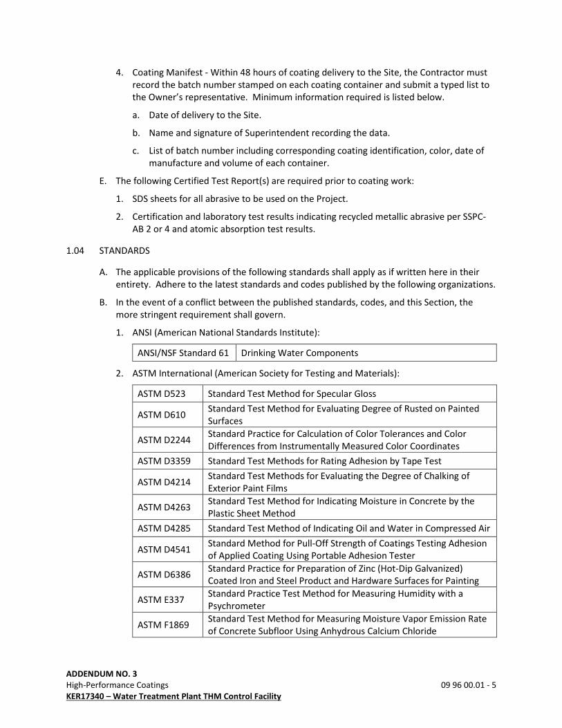
4. Coating Manifest - Within 48 hours of coating delivery to the Site, the Contractor must
record the batch number stamped on each coating container and submit a typed list to
the Owner’s representative. Minimum information required is listed below.
a. Date of delivery to the Site.
b. Name and signature of Superintendent recording the data.
c. List of batch number including corresponding coating identification, color, date of
manufacture and volume of each container.
E. The following Certified Test Report(s) are required prior to coating work:
1. SDS sheets for all abrasive to be used on the Project.
2. Certification and laboratory test results indicating recycled metallic abrasive per SSPC-
AB 2 or 4 and atomic absorption test results.
1.04 STANDARDS
A. The applicable provisions of the following standards shall apply as if written here in their
entirety. Adhere to the latest standards and codes published by the following organizations.
B. In the event of a conflict between the published standards, codes, and this Section, the
more stringent requirement shall govern.
1. ANSI (American National Standards Institute):
ANSI/NSF Standard 61 Drinking Water Components
2. ASTM International (American Society for Testing and Materials):
ASTM D523 Standard Test Method for Specular Gloss
ASTM D610 Standard Test Method for Evaluating Degree of Rusted on Painted
Surfaces
ASTM D2244 Standard Practice for Calculation of Color Tolerances and Color
Differences from Instrumentally Measured Color Coordinates
ASTM D3359 Standard Test Methods for Rating Adhesion by Tape Test
ASTM D4214 Standard Test Methods for Evaluating the Degree of Chalking of
Exterior Paint Films
ASTM D4263 Standard Test Method for Indicating Moisture in Concrete by the
Plastic Sheet Method
ASTM D4285 Standard Test Method of Indicating Oil and Water in Compressed Air
ASTM D4541 Standard Method for Pull-Off Strength of Coatings Testing Adhesion
of Applied Coating Using Portable Adhesion Tester
ASTM D6386 Standard Practice for Preparation of Zinc (Hot-Dip Galvanized)
Coated Iron and Steel Product and Hardware Surfaces for Painting
ASTM E337 Standard Practice Test Method for Measuring Humidity with a
Psychrometer
ASTM F1869 Standard Test Method for Measuring Moisture Vapor Emission Rate
of Concrete Subfloor Using Anhydrous Calcium Chloride
ADDENDUM NO. 3
High-Performance Coatings 09 96 00.01 - 6
KER17340 – Water Treatment Plant THM Control Facility
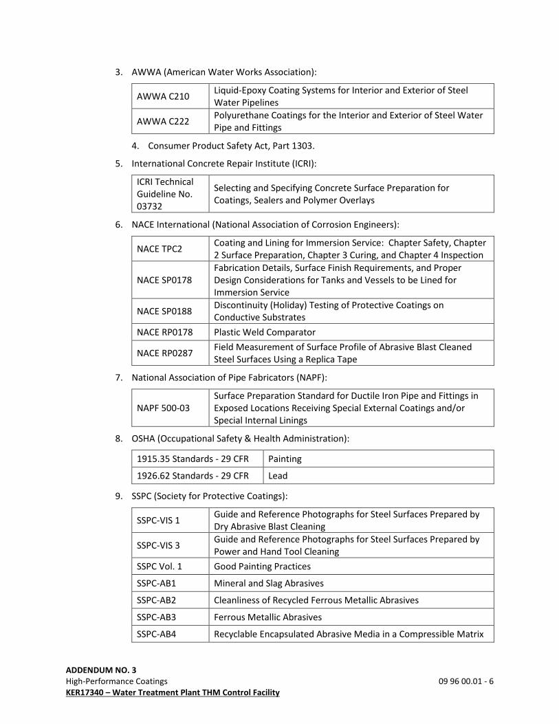
3. AWWA (American Water Works Association):
AWWA C210 Liquid-Epoxy Coating Systems for Interior and Exterior of Steel
Water Pipelines
AWWA C222 Polyurethane Coatings for the Interior and Exterior of Steel Water
Pipe and Fittings
4. Consumer Product Safety Act, Part 1303.
5. International Concrete Repair Institute (ICRI):
ICRI Technical
Guideline No.
03732
Selecting and Specifying Concrete Surface Preparation for
Coatings, Sealers and Polymer Overlays
6. NACE International (National Association of Corrosion Engineers):
NACE TPC2 Coating and Lining for Immersion Service: Chapter Safety, Chapter
2 Surface Preparation, Chapter 3 Curing, and Chapter 4 Inspection
NACE SP0178
Fabrication Details, Surface Finish Requirements, and Proper
Design Considerations for Tanks and Vessels to be Lined for
Immersion Service
NACE SP0188 Discontinuity (Holiday) Testing of Protective Coatings on
Conductive Substrates
NACE RP0178 Plastic Weld Comparator
NACE RP0287 Field Measurement of Surface Profile of Abrasive Blast Cleaned
Steel Surfaces Using a Replica Tape
7. National Association of Pipe Fabricators (NAPF):
NAPF 500-03
Surface Preparation Standard for Ductile Iron Pipe and Fittings in
Exposed Locations Receiving Special External Coatings and/or
Special Internal Linings
8. OSHA (Occupational Safety & Health Administration):
1915.35 Standards - 29 CFR Painting
1926.62 Standards - 29 CFR Lead
9. SSPC (Society for Protective Coatings):
SSPC-VIS 1 Guide and Reference Photographs for Steel Surfaces Prepared by
Dry Abrasive Blast Cleaning
SSPC-VIS 3 Guide and Reference Photographs for Steel Surfaces Prepared by
Power and Hand Tool Cleaning
SSPC Vol. 1 Good Painting Practices
SSPC-AB1 Mineral and Slag Abrasives
SSPC-AB2 Cleanliness of Recycled Ferrous Metallic Abrasives
SSPC-AB3 Ferrous Metallic Abrasives
SSPC-AB4 Recyclable Encapsulated Abrasive Media in a Compressible Matrix
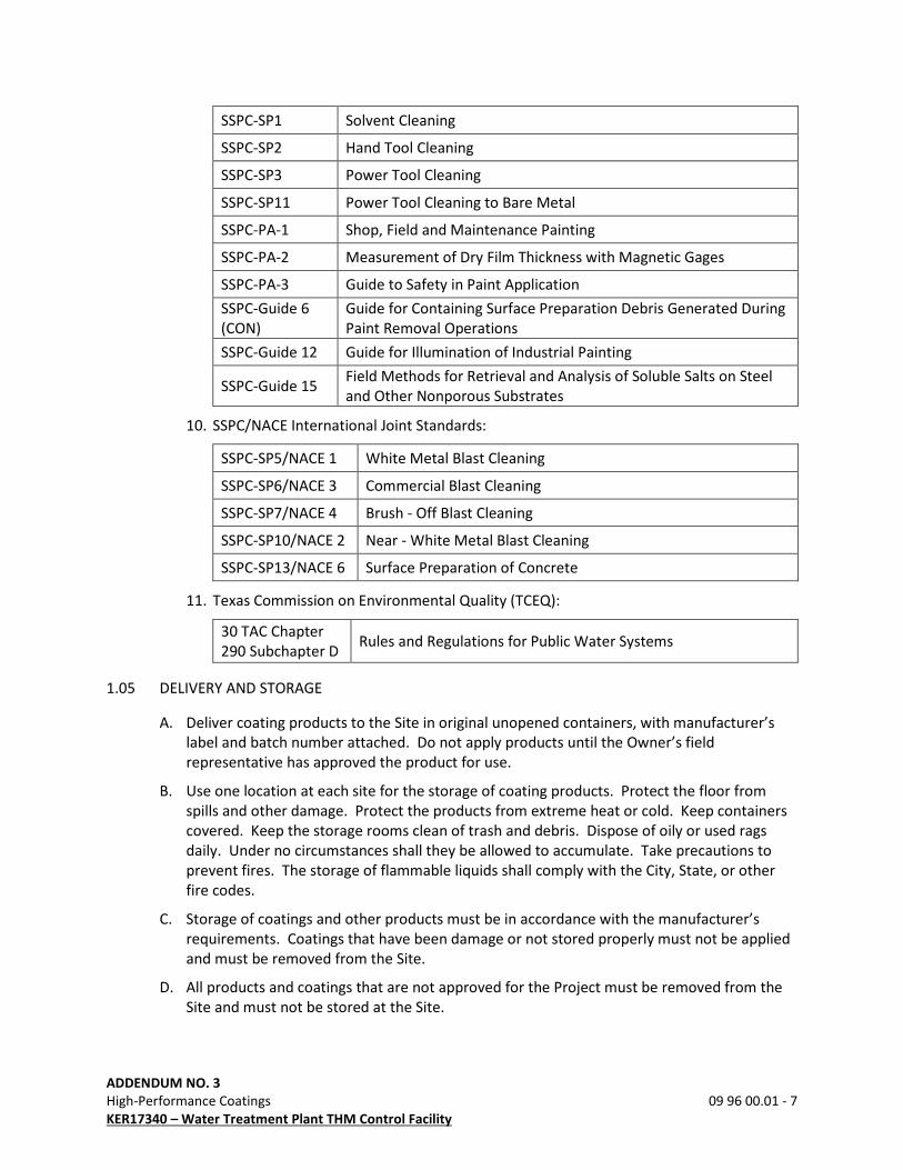
ADDENDUM NO. 3
High-Performance Coatings 09 96 00.01 - 7
KER17340 – Water Treatment Plant THM Control Facility
SSPC-SP1 Solvent Cleaning
SSPC-SP2 Hand Tool Cleaning
SSPC-SP3 Power Tool Cleaning
SSPC-SP11 Power Tool Cleaning to Bare Metal
SSPC-PA-1 Shop, Field and Maintenance Painting
SSPC-PA-2 Measurement of Dry Film Thickness with Magnetic Gages
SSPC-PA-3 Guide to Safety in Paint Application
SSPC-Guide 6
(CON)
Guide for Containing Surface Preparation Debris Generated During
Paint Removal Operations
SSPC-Guide 12 Guide for Illumination of Industrial Painting
SSPC-Guide 15 Field Methods for Retrieval and Analysis of Soluble Salts on Steel
and Other Nonporous Substrates
10. SSPC/NACE International Joint Standards:
SSPC-SP5/NACE 1 White Metal Blast Cleaning
SSPC-SP6/NACE 3 Commercial Blast Cleaning
SSPC-SP7/NACE 4 Brush - Off Blast Cleaning
SSPC-SP10/NACE 2 Near - White Metal Blast Cleaning
SSPC-SP13/NACE 6 Surface Preparation of Concrete
11. Texas Commission on Environmental Quality (TCEQ):
30 TAC Chapter
290 Subchapter D Rules and Regulations for Public Water Systems
1.05 DELIVERY AND STORAGE
A. Deliver coating products to the Site in original unopened containers, with manufacturer’s
label and batch number attached. Do not apply products until the Owner’s field
representative has approved the product for use.
B. Use one location at each site for the storage of coating products. Protect the floor from
spills and other damage. Protect the products from extreme heat or cold. Keep containers
covered. Keep the storage rooms clean of trash and debris. Dispose of oily or used rags
daily. Under no circumstances shall they be allowed to accumulate. Take precautions to
prevent fires. The storage of flammable liquids shall comply with the City, State, or other
fire codes.
C. Storage of coatings and other products must be in accordance with the manufacturer’s
requirements. Coatings that have been damage or not stored properly must not be applied
and must be removed from the Site.
D. All products and coatings that are not approved for the Project must be removed from the
Site and must not be stored at the Site.
ADDENDUM NO. 3
High-Performance Coatings 09 96 00.01 - 8
KER17340 – Water Treatment Plant THM Control Facility
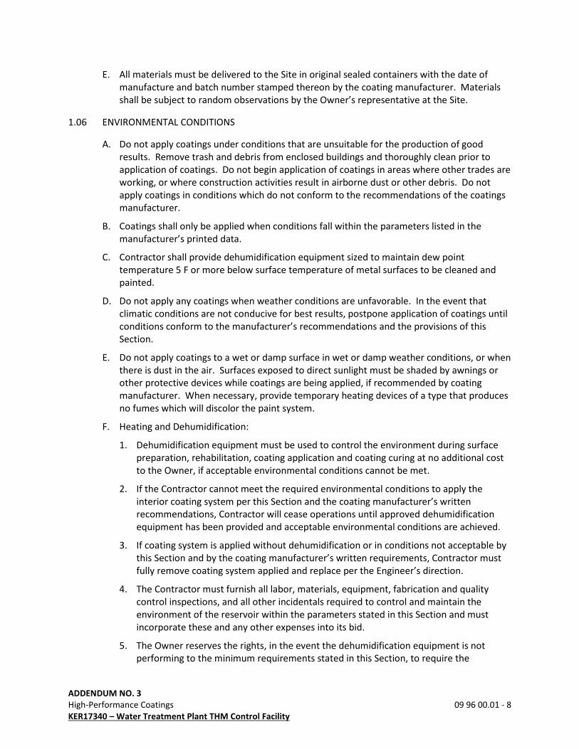
E. All materials must be delivered to the Site in original sealed containers with the date of
manufacture and batch number stamped thereon by the coating manufacturer. Materials
shall be subject to random observations by the Owner’s representative at the Site.
1.06 ENVIRONMENTAL CONDITIONS
A. Do not apply coatings under conditions that are unsuitable for the production of good
results. Remove trash and debris from enclosed buildings and thoroughly clean prior to
application of coatings. Do not begin application of coatings in areas where other trades are
working, or where construction activities result in airborne dust or other debris. Do not
apply coatings in conditions which do not conform to the recommendations of the coatings
manufacturer.
B. Coatings shall only be applied when conditions fall within the parameters listed in the
manufacturer’s printed data.
C. Contractor shall provide dehumidification equipment sized to maintain dew point
temperature 5 F or more below surface temperature of metal surfaces to be cleaned and
painted.
D. Do not apply any coatings when weather conditions are unfavorable. In the event that
climatic conditions are not conducive for best results, postpone application of coatings until
conditions conform to the manufacturer’s recommendations and the provisions of this
Section.
E. Do not apply coatings to a wet or damp surface in wet or damp weather conditions, or when
there is dust in the air. Surfaces exposed to direct sunlight must be shaded by awnings or
other protective devices while coatings are being applied, if recommended by coating
manufacturer. When necessary, provide temporary heating devices of a type that produces
no fumes which will discolor the paint system.
F. Heating and Dehumidification:
1. Dehumidification equipment must be used to control the environment during surface
preparation, rehabilitation, coating application and coating curing at no additional cost
to the Owner, if acceptable environmental conditions cannot be met.
2. If the Contractor cannot meet the required environmental conditions to apply the
interior coating system per this Section and the coating manufacturer’s written
recommendations, Contractor will cease operations until approved dehumidification
equipment has been provided and acceptable environmental conditions are achieved.
3. If coating system is applied without dehumidification or in conditions not acceptable by
this Section and by the coating manufacturer’s written requirements, Contractor must
fully remove coating system applied and replace per the Engineer’s direction.
4. The Contractor must furnish all labor, materials, equipment, fabrication and quality
control inspections, and all other incidentals required to control and maintain the
environment of the reservoir within the parameters stated in this Section and must
incorporate these and any other expenses into its bid.
5. The Owner reserves the rights, in the event the dehumidification equipment is not
performing to the minimum requirements stated in this Section, to require the
ADDENDUM NO. 3
High-Performance Coatings 09 96 00.01 - 9
KER17340 – Water Treatment Plant THM Control Facility
Contractor to modify and or add additional equipment to satisfy the conditions of this
Section, at the sole cost to the Contractor.
6. It is the Contractor’s responsibility to provide adequate dehumidification equipment to
meet the requirements of this Section and coating manufacturer’s requirements. The
coating manufacturer’s limits of surface temperature, tank inside air temperature and
relative humidity requirements will govern, if more stringent than the requirements
stated within this Section.
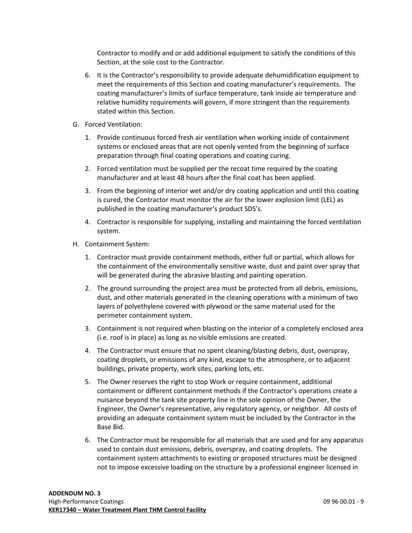
G. Forced Ventilation:
1. Provide continuous forced fresh air ventilation when working inside of containment
systems or enclosed areas that are not openly vented from the beginning of surface
preparation through final coating operations and coating curing.
2. Forced ventilation must be supplied per the recoat time required by the coating
manufacturer and at least 48 hours after the final coat has been applied.
3. From the beginning of interior wet and/or dry coating application and until this coating
is cured, the Contractor must monitor the air for the lower explosion limit (LEL) as
published in the coating manufacturer’s product SDS’s.
4. Contractor is responsible for supplying, installing and maintaining the forced ventilation
system.
H. Containment System:
1. Contractor must provide containment methods, either full or partial, which allows for
the containment of the environmentally sensitive waste, dust and paint over spray that
will be generated during the abrasive blasting and painting operation.
2. The ground surrounding the project area must be protected from all debris, emissions,
dust, and other materials generated in the cleaning operations with a minimum of two
layers of polyethylene covered with plywood or the same material used for the
perimeter containment system.
3. Containment is not required when blasting on the interior of a completely enclosed area
(i.e. roof is in place) as long as no visible emissions are created.
4. The Contractor must ensure that no spent cleaning/blasting debris, dust, overspray,
coating droplets, or emissions of any kind, escape to the atmosphere, or to adjacent
buildings, private property, work sites, parking lots, etc.
5. The Owner reserves the right to stop Work or require containment, additional
containment or different containment methods if the Contractor’s operations create a
nuisance beyond the tank site property line in the sole opinion of the Owner, the
Engineer, the Owner’s representative, any regulatory agency, or neighbor. All costs of
providing an adequate containment system must be included by the Contractor in the
Base Bid.
6. The Contractor must be responsible for all materials that are used and for any apparatus
used to contain dust emissions, debris, overspray, and coating droplets. The
containment system attachments to existing or proposed structures must be designed
not to impose excessive loading on the structure by a professional engineer licensed in
ADDENDUM NO. 3
High-Performance Coatings 09 96 00.01 - 10
KER17340 – Water Treatment Plant THM Control Facility
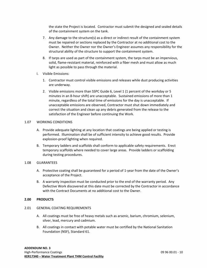
the state the Project is located. Contractor must submit the designed and sealed details
of the containment system on the tank.
7. Any damage to the structure(s) as a direct or indirect result of the containment system
must be repaired or sections replaced by the Contractor at no additional cost to the
Owner. Neither the Owner nor the Owner’s Engineer assumes any responsibility for the
structural ability of the structure to support the containment system.
8. If tarps are used as part of the containment system, the tarps must be an impervious,
solid, flame-resistant material, reinforced with a fiber mesh and must allow as much
light as possible to pass through the material.
I. Visible Emissions:
1. Contractor must control visible emissions and releases while dust producing activities
are underway.
2. Visible emissions more than SSPC Guide 6, Level 1 (1 percent of the workday or 5
minutes in an 8-hour shift) are unacceptable. Sustained emissions of more than 1
minute, regardless of the total time of emissions for the day is unacceptable. If
unacceptable emissions are observed, Contractor must shut down immediately and
correct the situation and clean up any debris generated from the release to the
satisfaction of the Engineer before continuing the Work.
1.07 WORKING CONDITIONS
A. Provide adequate lighting at any location that coatings are being applied or testing is
performed. Illumination shall be of sufficient intensity to achieve good results. Provide
explosion-proof lighting when required.
B. Temporary ladders and scaffolds shall conform to applicable safety requirements. Erect
temporary scaffolds where needed to cover large areas. Provide ladders or scaffolding
during testing procedures.
1.08 GUARANTEES
A. Protective coating shall be guaranteed for a period of 1-year from the date of the Owner’s
acceptance of the Project.
B. A warranty inspection must be conducted prior to the end of the warranty period. Any
Defective Work discovered at this date must be corrected by the Contractor in accordance
with the Contract Documents at no additional cost to the Owner.
2.00 PRODUCTS
2.01 GENERAL COATING REQUIREMENTS
A. All coatings must be free of heavy metals such as arsenic, barium, chromium, selenium,
silver, lead, mercury and cadmium.
B. All coatings in contact with potable water must be certified by the National Sanitation
Foundation (NSF), Standard 61.

ADDENDUM NO. 3
High-Performance Coatings 09 96 00.01 - 11
KER17340 – Water Treatment Plant THM Control Facility
C. No coating submitted or used on this Project may have a VOC (volatile organic content) in
excess of 360 grams/liter or 3.0 lb./gal.
D. Finish coatings must be from the same batch.
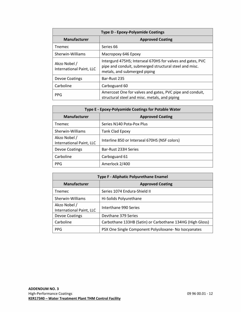
2.02 MATERIALS
A. Materials shall be the manufacturer’s top of line quality products, as listed herein. Products
used on this Project shall be as indicated below. Products shall be as follows:
Type A - Alkyd-Phenolic Universal Primer
Manufacturer Approved Coating
Tnemec Series 1 Purple Prime
Sherwin-Williams Kem Kromik Universal
Akzo Nobel /
International Paint, LLC Interlac 573
Devoe Coatings Devprime 1403
Carboline Carbocoat 150UP
PPG Multiprime 4160
Type B - Epoxy-Polyamide Primer
Manufacturer Approved Coating
Tnemec Series 66
Sherwin-Williams Copoxy Primer
Akzo Nobel /
International Paint, LLC
Intergard 251; Intergard 269 for valves and gates, submerged
structural steel and misc. metals, and submerged piping
Devoe Coatings Devran 201V Series
Carboline 890
PPG Amercoat One Single Component Epoxy for valves and gates,
structural steel and misc. metals, and piping
Type C – Alkyd Enamel
Manufacturer Approved Coating
Tnemec Series 23 Enduratone
Sherwin-Williams DTM Alkyd Enamel
Akzo Nobel /
International Paint, LLC Interlac 665
Devoe Coatings Devlac 1431
Carboline Carbocoat 8225
PPG Fast Dry 35
ADDENDUM NO. 3
High-Performance Coatings 09 96 00.01 - 12
KER17340 – Water Treatment Plant THM Control Facility
Type D - Epoxy-Polyamide Coatings
Manufacturer Approved Coating
Tnemec Series 66
Sherwin-Williams Macropoxy 646 Epoxy
Akzo Nobel /
International Paint, LLC
Intergurd 475HS; Interseal 670HS for valves and gates, PVC
pipe and conduit, submerged structural steel and misc.
metals, and submerged piping
Devoe Coatings Bar-Rust 235
Carboline Carboguard 60
PPG Amercoat One for valves and gates, PVC pipe and conduit,
structural steel and misc. metals, and piping
Type E - Epoxy-Polyamide Coatings for Potable Water
Manufacturer Approved Coating
Tnemec Series N140 Pota-Pox Plus
Sherwin-Williams Tank Clad Epoxy
Akzo Nobel /
International Paint, LLC Interline 850 or Interseal 670HS (NSF colors)
Devoe Coatings Bar-Rust 233H Series
Carboline Carboguard 61
PPG Amerlock 2/400
Type F - Aliphatic Polyurethane Enamel
Manufacturer Approved Coating
Tnemec Series 1074 Endura-Shield II
Sherwin-Williams Hi-Solids Polyurethane
Akzo Nobel /
International Paint, LLC Interthane 990 Series
Devoe Coatings Devthane 379 Series
Carboline Carbothane 133HB (Satin) or Carbothane 134HG (High Gloss)
PPG PSX One Single Component Polysiloxane- No Isocyanates
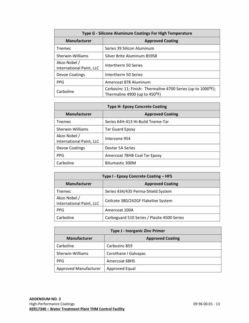
ADDENDUM NO. 3
High-Performance Coatings 09 96 00.01 - 13
KER17340 – Water Treatment Plant THM Control Facility
Type G - Silicone Aluminum Coatings For High Temperature
Manufacturer Approved Coating
Tnemec Series 39 Silicon Aluminum
Sherwin-Williams Silver Brite Aluminum B59S8
Akzo Nobel /
International Paint, LLC Intertherm 50 Series
Devoe Coatings Intertherm 50 Series
PPG Amercoat 878 Aluminum
Carboline Carbozinc 11; Finish: Thermaline 4700 Series (up to 1000⁰F);
Thermaline 4900 (up to 450⁰F)
Type H- Epoxy Concrete Coating
Manufacturer Approved Coating
Tnemec Series 64H-413 Hi-Build Tneme-Tar
Sherwin-Williams Tar Guard Epoxy
Akzo Nobel /
International Paint, LLC Interzone 954
Devoe Coatings Devtar 5A Series
PPG Amercoat 78HB Coal Tar Epoxy
Carboline Bitumastic 300M
Type I - Epoxy Concrete Coating – HFS
Manufacturer Approved Coating
Tnemec Series 434/435 Perma-Shield System
Akzo Nobel /
International Paint, LLC Ceilcote 380/242GF Flakeline System
PPG Amercoat 100A
Carboline Carboguard 510 Series / Plasite 4500 Series
Type J - Inorganic Zinc Primer
Manufacturer Approved Coating
Carboline Carbozinc 859
Sherwin-Williams Corothane I Galvapac
PPG Amercoat 68HS
Approved Manufacturer Approved Equal

ADDENDUM NO. 3
High-Performance Coatings 09 96 00.01 - 14
KER17340 – Water Treatment Plant THM Control Facility
Type K - High Solids Epoxy Siloxane
Manufacturer Approved Coating
Carboline Carboxane 2000
Sherwin-Williams Polysiloxane XLE-80
PPG PSX 700 Polysiloxane
Approved Manufacturer Approved Equal
Type L - Epoxy Mastic
Manufacturer Approved Coating
Carboline Carbomastic 15
Sherwin-Williams Epoxy Mastic II
PPG Amerlock 2/400 AL
Tnemec Chembuild Series 135
AkzoNobel/International
Paint, LLC Interseal 670HS
Type M – Elastomeric Polyurethane Hybrid
Manufacturer Approved Coating
Carboline Reactamine 760 Series
Sherwin-Williams Sherflex S
PPG Amerthane 490
Tnemec Elasto-Shield Series 406
AkzoNobel/International
Paint, LLC Polibrid 705E Elastomeric
Type N – Glass Flake Reinforced Epoxy
Manufacturer Approved Coating
Carboline Approved Equal
Sherwin-Williams Sher-Glass FF
PPG Approved Equal
Tnemec Approved Equal
AkzoNobel/International
Paint, LLC Approved Equal
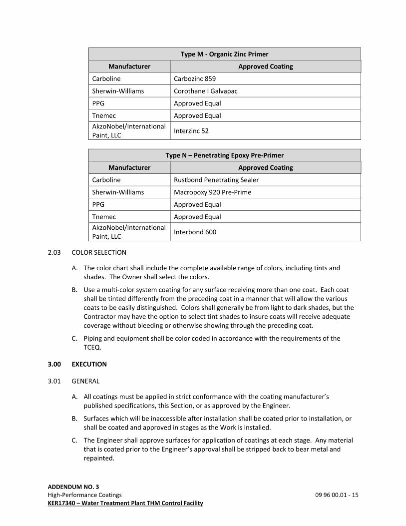
ADDENDUM NO. 3
High-Performance Coatings 09 96 00.01 - 15
KER17340 – Water Treatment Plant THM Control Facility
Type M - Organic Zinc Primer
Manufacturer Approved Coating
Carboline Carbozinc 859
Sherwin-Williams Corothane I Galvapac
PPG Approved Equal
Tnemec Approved Equal
AkzoNobel/International
Paint, LLC Interzinc 52
Type N – Penetrating Epoxy Pre-Primer
Manufacturer Approved Coating
Carboline Rustbond Penetrating Sealer
Sherwin-Williams Macropoxy 920 Pre-Prime
PPG Approved Equal
Tnemec Approved Equal
AkzoNobel/International
Paint, LLC Interbond 600
2.03 COLOR SELECTION
A. The color chart shall include the complete available range of colors, including tints and
shades. The Owner shall select the colors.
B. Use a multi-color system coating for any surface receiving more than one coat. Each coat
shall be tinted differently from the preceding coat in a manner that will allow the various
coats to be easily distinguished. Colors shall generally be from light to dark shades, but the
Contractor may have the option to select tint shades to insure coats will receive adequate
coverage without bleeding or otherwise showing through the preceding coat.
C. Piping and equipment shall be color coded in accordance with the requirements of the
TCEQ.
3.00 EXECUTION
3.01 GENERAL
A. All coatings must be applied in strict conformance with the coating manufacturer’s
published specifications, this Section, or as approved by the Engineer.
B. Surfaces which will be inaccessible after installation shall be coated prior to installation, or
shall be coated and approved in stages as the Work is installed.
C. The Engineer shall approve surfaces for application of coatings at each stage. Any material
that is coated prior to the Engineer’s approval shall be stripped back to bear metal and
repainted.
ADDENDUM NO. 3
High-Performance Coatings 09 96 00.01 - 16
KER17340 – Water Treatment Plant THM Control Facility
D. At least 7 days or as required by the coating manufacturer, must be allowed for drying of
finished surfaces before any machinery can be placed into service.
E. The number of coats called for in this Section are considered the minimum required. If
more coats are required for complete coverage and uniform appearance they shall be
provided at no additional cost to the Owner.
3.02 STEEL SURFACE PREPARATION
A. The adequacy of the preparation of steel surfaces will be determined by comparing the
surface with SSPC VIS 1 “Pictorial Surface Preparation Standards for Painting Steel Surfaces”
and SSPC VIS 3 “Guide and Reference Photographs for Steel Surfaces Prepared by Power and
Hand Tool Cleaning.” Prepare surfaces in accordance with the following requirements:
1. SSPC-SP1 “Solvent Cleaning”
2. SSPC-SP2 “Hand Tool Cleaning”
3. SSPC-SP3 “Power Tool Cleaning”
4. SSPC-SP5 / NACE 1 “White Metal Blast Cleaning”
5. SSPC-SP6 / NACE 3 “Commercial Blast Cleaning”
6. SSPC-SP7 / NACE 4 “Brush-Off Blast Cleaning”
7. SSPC-SP10 / NACE 2 “Near-White Blast Cleaning”
8. SSPC-SP11 “Power Tool Cleaning to Bare Metal”
B. The resulting surface profile must be in accordance with the coating manufacturer’s
recommendations.
C. All surface preparation of new equipment and surfaces shall be assumed to be on a SSPC
Grade A steel surface condition, unless specifically noted otherwise.
D. “Solvent Cleaning” must be performed prior to subsequent surface preparation, including
abrasive blast cleaning.
E. All sharp edges and welds must be ground smooth to a rounded contour and all weld
splatter must be removed prior to abrasive blasting. Edges of metal to be coated must be
rounded to a minimum of 1/16-inch radius of chamfered a minimum of 1/16 inch at an
angle of 45 degrees.
F. Welds and adjacent areas:
1. Prepared such that there is:
a. No undercutting or reverse ridges on the weld bead.
b. No weld spatter on or adjacent to the weld or any other area to be painted.
c. No sharp peaks or ridges along the weld bead.
d. Grind embedded pieces of electrode or wire flush with the adjacent surface of the
weld bead.
2. Weld profiles must conform to NACE RP0178, Profile ‘D’.
ADDENDUM NO. 3
High-Performance Coatings 09 96 00.01 - 17
KER17340 – Water Treatment Plant THM Control Facility
3.03 DUCTILE IRON PIPE AND FITTINGS SURFACE PREPARATION
A. Prepare surfaces in accordance with the following requirements:
1. NAPF 500-03-01 “Solvent Cleaning”
2. NAPF 500-03-02 “Hand Tool Cleaning”
3. NAPF 500-03-03 “Power Tool Cleaning”
4. NAPF 500-03-04 “Abrasive Blast Cleaning for Ductile Iron Pipe”
5. NAPF 500-03-05 “Abrasive Blast Cleaning for Cast Ductile Iron Fittings”
B. “Solvent Cleaning” must be performed prior to subsequent surface preparation as specified
in NAPF 500-03.
3.04 CONCRETE SURFACE PREPARATION
A. The adequacy of the preparation of concrete surfaces will be determined by comparing the
surface with ICRI Surface Finish Comparators. Prepare surfaces in accordance with the
following requirements:
SSPC-SP13 / NACE 6 – Surface Preparation of Concrete
B. Allow a minimum of 28 days curing time to elapse before coatings are applied. Concrete
surfaces which are scheduled to receive coatings must be in accordance with the coating
manufacturer’s moisture requirements.
C. Bug holes, air pockets, and other voids in the concrete will be filled or patched in chemical
exposure areas, secondary containment, and where specifically required.
D. Concrete Surface Preparation Inspection:
1. Adhesion Testing:
a. Tensile testing of the surface preparation shall be performed by the Engineer as
necessary using Type 4 or Type 5 pneumatic adhesion testing equipment in
accordance with ASTM D4541 using 2-inch diameter dollies for concrete surface
adhesion testing.
b. Concrete surface or applied coating shall be scored for concrete adhesion testing.
c. Adhesive failure greater than 50 percent of the dolly surface area shall indicate
inadequate surface preparation.
d. Cohesive failures which results in loss of sound concrete will be acceptable provided
the loss is greater than 50 percent of the dolly surface area.
e. Low adhesion cohesive failures with a thin layer of concrete due to weak concrete
or laitance over 50 percent of the dolly surface will be rejected.
2. Concrete Soundness: Concrete soundness shall be determined using the scratching or
hammer impact methods as defined in SSPC SP-13.
3. Moisture Content: Moisture shall be tested as specified in SSPC SP-13 and in
accordance with ASTM D4263 and ASTM F1869. Moisture content cannot exceed the
moisture content recommended by the coating manufacturer.
ADDENDUM NO. 3
High-Performance Coatings 09 96 00.01 - 18
KER17340 – Water Treatment Plant THM Control Facility
3.05 SURFACE PREPARATION
A. Clean and degrease surfaces prior to abrasive blasting by solvent cleaning as specified using
solvents, detergent/water, emulsions, and steam. Proposed method must be documented
in the coating plan. Contractor must contain and properly dispose of all runoff and debris
from cleaning.
B. If the following conditions exist or are prevalent, surface preparation and coating must be
delayed or postponed until conditions are favorable. Each day’s coating must be completed
in time to permit the film sufficient drying time prior to damage by atmospheric conditions
or changes. No surface preparation shall begin or coating applied:
1. When the surface, air or material is below or above the manufacturer’s printed
instructions.
2. When surfaces are wet or damp.
3. During weather conditions of rain, snow, fog or mist.
4. When the air and steel temperature is less-than or equal to 5 F above the dew point
temperature.
5. If the relative humidity is above 85 percent.
6. When it is expected that the air and/or surface temperature will be below or above the
coating manufacturer’s recommended temperatures within 4 hours after applications of
coating, minimum. Coating manufacturer may require additional time between
application and temperature and weather changes.
C. Shop Surface Preparation:
1. Notify Engineer at least 7 days prior to start of shop blast cleaning to allow for
inspection of the Work during surface preparation and shop application of paints. Work
shall be subject to the Engineer’s approval before shipment to the Site.
2. Items such as structural steel, metal doors and frames, metal louvers, and similar items
as reviewed by the Engineer may be shop prepared and primed. Centrifugal wheel blast
cleaning is an acceptable alternate to shop blast cleaning. Blast clean and prime in
accordance with the Specifications.
3. Prepare surfaces by abrasive blasting as specified and apply shop prime coat. Shop
primed steel plates must not have primer extended within 4 inches along all edges to be
welded. All primer within 4 inches of an area to be welded must be removed prior to
welding. Welding of painted surfaces will not be allowed.
D. All pre-assembled shop primed items must be prepared in accordance with these
specifications and inspected by the Owner’s representative before and after priming.
E. Abrasive Blasting:
1. Prior to extensive abrasive blasting operations, the Contractor must perform a test blast
to verify that the surface cleanliness and profile meet the requirements of these
specifications and meet the coating manufacturer’s requirements for the coating to be
applied. If the test section does not meet the requirements, the Contract must make
changes to the abrasive materials and methods to provide suitable blast.

ADDENDUM NO. 3
High-Performance Coatings 09 96 00.01 - 19
KER17340 – Water Treatment Plant THM Control Facility
2. Abrasive blast only the amount of surface area which can be primed the same day or
before any rust starts to form, whichever occurs first. Areas which are not painted the
same day must be re-blasted on the day the prime coat is applied.
3. Shrouding or recovery of all blast material will be mandatory during all exterior blasting.
4. Contractor must contain all waste and process discharge in accordance with the
accepted methods for the process and materials that are in abatement.
5. Where abrasive blast cleaning will not remove or properly prepare metal surfaces, hand
and/or power tool cleaning must be used to remove such conditions as weld splatter,
laminations and radius-sharp edges. Hand tool or power tool must be used on areas
less than 2 feet in diameter or smaller or on corners and edges.
6. All abrasive blast equipment must be equipped with, including but not limited to the
following:
a. Noise reducing devices.
b. Hose coupling safety devices.
c. Electrical grounding devices.
d. Moisture traps and filters.
e. Fresh air hoods for all blasters.
f. “Dead Man” switches on all blast hoses.
g. Air Dryers.
F. Surface profile must be in accordance with manufacturer’s printed requirements.
G. The adequacy of the preparation of surfaces must be determined by comparing the surface
with SSPC VIS 1, SSPC VIS 3, NACE RP0178 and ICRI Surface Finish Comparators.
H. Wherever the words “solvent cleaning”, “hand tool cleaning”, “wire brushing”, or “blast
cleaning”, or similar words of equal intent are used in the Specifications or in paint
manufacturer’s specifications, they shall be understood to refer to the applicable
specifications indicated.
I. Where OSHA or EPA regulations preclude standard abrasive blast cleaning, wet or vacuum-
blasting methods may be required. Coating manufacturers’ recommendations for wet blast
additives and first coat application will apply.
J. Clean surfaces of dust and residual particles from cleaning operations by dry (no oil or water
vapor) air blast cleaning or other method prior to painting. Vacuum clean enclosed areas
and other areas where dust settling is a problem and wiped with a tack cloth.
3.06 PREPARATION OF HOT-DIP GALVANIZED COATED IRON OR STEEL PRODUCTS
A. Remove all soluble and insoluble contaminants. Prepare hot-dip galvanized coated iron and
steel products in accordance with ASTM D6386 and abrasive blast per ASTM D6386 to
achieve an angular anchor profile as required by the coating manufacturer.
B. Contractor is responsible for coordinating with the coating manufacturer to verify
compatibility of the specified coating system with the provided surface preparation.
ADDENDUM NO. 3
High-Performance Coatings 09 96 00.01 - 20
KER17340 – Water Treatment Plant THM Control Facility
3.07 PREPARATION OF EXISTING COATED OR SHOP PRIMED SURFACES
A. General:
1. Factory-applied primers to equipment must be those specified or verified by the
Contractor to be compatible with the specified coating systems. Where possible, notify
manufacturers which shop prime coats will be required in order to be compatible with
field-applied finish coats.
2. Where equipment is purchased which has the manufacturer’s standard primer or a
factory finish which is other than as specified in this Section, remove the factory-applied
paint system or apply passivators or other special coatings as required to make the
surface compatible with the finish coat specified.
3. Do not apply any coating to machinery, piping, or other surfaces before testing has been
completed and systems approved. Any damage to coatings resulting from subsequent
corrective procedures shall be stripped back to bare metal and repainted with the
appropriate paint system as directed by the Engineer.
4. Check for compatibility when applying coatings over existing coatings. Apply a test
patch of the recommended coating system, covering at least 2 to 3 square feet or as
directed by the Engineer. Allow to cure 1 week before testing adhesion per ASTM
D3359 in the presence of the Engineer. If adhesion does not meet the manufacturer’s
published data, consult with the Engineer.
5. Shop primed or coated surfaces shall be reviewed with the Engineer to determine if the
extent of damage to the coating and suitability of finish coats to adhere to shop applied
coats.
6. If a cured epoxy, polyurethane, or plural-component material is to be top coated
provide brush-off blast as specified herein or as recommended by the coating
manufacturer.
7. Surface preparation recommendations of coating manufacturer shall be subject to
approval of the Engineer.
B. To be Recoated or Final Coated:
1. Solvent clean.
2. Perform touch-up repairs of existing coating.
3. Asphaltic coated ductile iron pipe will require an application of a seal coat prior to the
application of a cosmetic finish coat.
C. Touch-Up Repairs:
1. Clean loose, abraded, or damaged coatings to substrate by power tool to bare metal per
SSPC-SP11 and/or NAPF 500-03-03 “Power Tool Cleaning.”
2. Feather surrounding intact coating.
3. Apply one spot coat of the specified primer to bare areas overlapping the prepared
existing coating.
4. Apply one full finish coat of the specified primer or finish coat(s) overall.
ADDENDUM NO. 3
High-Performance Coatings 09 96 00.01 - 21
KER17340 – Water Treatment Plant THM Control Facility
D. Application of a Cosmetic Coat:
1. The exact nature of shop-applied coatings is not known in all cases.
2. Check compatibility by application to a small area prior to starting the coating.
3. If lifting or other problems occur, request disposition from the Engineer.
3.08 APPLICATION
A. After abrasive blast cleaning, dust and spent abrasive must be removed from the surfaces by
air blasting and brush sweeping. The prime coat must be applied as soon as possible after
the blasting and surface cleaning is completed, inspected and approved by the Inspector.
B. Blasted surfaces must be coated before rust forms on the surface. No prepared surface will
be allowed to receive a coating if “rust bloom” or surface discoloration has occurred. All
blasted surfaces must be coated to within 6 inches of the edge of a blasted area. No visible
rust must be coated under any circumstances, including rust bloom or if discoloration has
occurred, regardless of elapsed time between blasting and coating.
C. Provide mist coat if recommended by the coating manufacturer.
D. All weld seams, gaps, edges, bolts and difficult areas to coat must receive a stripe coat.
Stripe coat must be a contrasting color.
E. The Contractor must apply each coat at the rate and in the manner specified by the coating
manufacturer, except as may be modified herein. If material has thickened or must be
diluted for application, coating must be built up to the same dry film thickness as specified
for each coat of the complete system.
F. Maximum and minimum DFT must be per the supplied coating manufacturer’s printed
requirements and as required by this Section. DFT will be measured per SSPC-PA 2, Level 2
with an allowable measurement of spot DFT of:
1. Minimum DFT as specified, no less than the minimum specified will be accepted.
2. 120 percent of maximum DFT specified.
G. Contractor and painting technicians are responsible for the application of coating system
and must have current applicator certifications from the coating manufacturer. Submit
certifications with coating submittal.
H. No coating shall be used which has an expired shelf or pot life.
I. Coating must be applied by skilled workmen and must be brushed out or sprayed evenly,
without runs, crazing, sags, or other blemishes.
J. Sand between coats to remove over spray and dry fall.
K. Apply the first coat to the surface, including cutting in around edges, before the second coat
is applied. The second coat and any successive coats must not to be applied before
notifying the Owner’s field representative and obtaining approval. Each coat must be tested
before the successive coat is applied.
L. The coating curing period must be adjusted to compensate for less than adequate weather
conditions, as recommended by the coating manufacturer, for complete curing of the entire
coating system. The full curing time recommended by the manufacturer shall be provided.
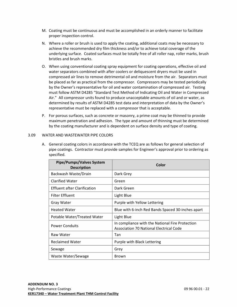
ADDENDUM NO. 3
High-Performance Coatings 09 96 00.01 - 22
KER17340 – Water Treatment Plant THM Control Facility
M. Coating must be continuous and must be accomplished in an orderly manner to facilitate
proper inspection control.
N. Where a roller or brush is used to apply the coating, additional coats may be necessary to
achieve the recommended dry film thickness and/or to achieve total coverage of the
underlying surface. Coated surfaces must be totally free of all roller nap, roller marks, brush
bristles and brush marks.
O. When using conventional coating spray equipment for coating operations, effective oil and
water separators combined with after coolers or deliquescent dryers must be used in
compressed air lines to remove detrimental oil and moisture from the air. Separators must
be placed as far as practical from the compressor. Compressors may be tested periodically
by the Owner’s representative for oil and water contamination of compressed air. Testing
must follow ASTM D4285 “Standard Test Method of Indicating Oil and Water in Compressed
Air.” All compressor units found to produce unacceptable amounts of oil and or water, as
determined by results of ASTM D4285 test data and interpretation of data by the Owner’s
representative must be replaced with a compressor that is acceptable.
P. For porous surfaces, such as concrete or masonry, a prime coat may be thinned to provide
maximum penetration and adhesion. The type and amount of thinning must be determined
by the coating manufacturer and is dependent on surface density and type of coating.
3.09 WATER AND WASTEWATER PIPE COLORS
A. General coating colors in accordance with the TCEQ are as follows for general selection of
pipe coatings. Contractor must provide samples for Engineer’s approval prior to ordering as
specified.
Pipe/Pumps/Valves System
Description Color
Backwash Waste/Drain Dark Grey
Clarified Water Green
Effluent after Clarification Dark Green
Filter Effluent Light Blue
Gray Water Purple with Yellow Lettering
Heated Water Blue with 6-inch Red Bands Spaced 30-inches apart
Potable Water/Treated Water Light Blue
Power Conduits In compliance with the National Fire Protection
Association 70 National Electrical Code
Raw Water Tan
Reclaimed Water Purple with Black Lettering
Sewage Grey
Waste Water/Sewage Brown

ADDENDUM NO. 3
High-Performance Coatings 09 96 00.01 - 23
KER17340 – Water Treatment Plant THM Control Facility
Chemical Lines Color
Liquid Alum Yellow w/Orange Bands
Alum (solution) Yellow w/ Green Bands
Ammonia Yellow w/ Brown Bands
Chlorine (gas, liquid, or vent) Yellow
Chlorine (solution) Yellow w/ Red Bands
Chlorine Dioxide (solution) Yellow with Blue Bands
Ferric Chloride Brown with Red Bands
Ferric Sulfate Brown with Yellow Bands
Fluoride White with Yellow Bands
Liquid Caustic White with Red Bands
Caustic (solution) White with Orange Bands
Polymers Orange w/ Green Bands or White with Green Bands
(Varies for Water or WW applications)
Ozone Stainless Steel with White Bands
Settled Water Green
Sulfur Dioxide Lime Green with Yellow Bands
Other Lines Color
Compressed Air Light Green
Instrument Air Light Green with Dark Green Bands
3.10 FIELD QUALITY CONTROL
A. Field Tests: Make wet film tests during painting operations to ensure proper thicknesses of
coating are being applied. After each coat has been applied, test the paint film thickness
with a nondestructive, magnetic type thickness gauge. The total dry-film thickness for each
coat shall not be less than 75 percent of the amount specified. If the thickness is less than
75 percent, apply additional coats until the total specified thickness is obtained. The total
thickness after the final coat has been applied shall be 100 percent of the thickness
specified, minimum. Apply additional coats until the specified thickness is reached or
exceeded.
B. Holiday Testing: Test the entire surface of coated submerged metal structures with a
holiday detector. For thickness between 10 and 20 mils (250 to 500 microns) a non-sudsing
type wetting agent, as recommended by the holiday detector manufacturer shall be added
to the water prior to wetting the detector sponge. Mark and repair pinholes in accordance
with the manufacturer’s printed instructions, then retest pinholes. No pinholes or other
irregularities shall be permitted in the final coats. Areas containing holidays shall receive
additional coats until tests indicate no holidays.

ADDENDUM NO. 3
High-Performance Coatings 09 96 00.01 - 24
KER17340 – Water Treatment Plant THM Control Facility
3.11 PROTECTION OF SURFACES NOT TO BE PAINTED
A. Remove, mask, or otherwise protect hardware, lighting fixtures, switch plates, aluminum
surfaces, machined surfaces, couplings, shafts, bearings, nameplates on machinery, and
other surfaces not intended to be painted.
B. Provide drop cloths to prevent paint materials from falling on or marring adjacent surfaces.
C. Protect working parts of mechanical and electrical equipment from damage during surface
preparation and painting process.
D. Mask openings in motors to prevent paint and other materials from entering the motors.
3.12 DAMAGED COATINGS, PINHOLES, AND HOLIDAYS
A. Feather edges and repaired in accordance with the recommendations of the paint
manufacturer.
B. Repair fusion bonded coatings to be as recommended by the original applicator. Applicator
shall provide liquid repair kits for this purpose as recommended by the coating
manufacturer.
C. Apply finish coats, including touchup and damage-repair coats in a manner that will present
a uniform texture and color-matched appearance.
3.13 UNSATISFACTORY APPLICATION
A. If the item has an improper finish color, or insufficient film thickness, clean and topcoat
surface with specified paint material to obtain the specified color and coverage. Obtain
specific surface preparation information from the coating manufacturer.
B. Hand or power sand visible areas of chipped, peeled, or abraded paint and feather the
edges. Follow with primer and finish coat in accordance with the Specifications. Depending
on the extent of repair and its appearance, a finish sanding and topcoat may be required.
C. Evidence of runs, bridges, shiners, laps, or other imperfections shall be cause for rejection.
D. Repair defects in coating system per written recommendations of coating manufacturer.
E. Leave all staging up until the Engineer has inspected the surface or coating. Replace staging
removed prior to approval by Engineer.
3.14 COATING INSPECTION
A. General:
1. All coats will be subject to inspection by the Engineer and the coating manufacturer’s
representative.
2. Visually inspect concrete, nonferrous metal, plastic, and wood surfaces to ensure proper
and complete coverage has been attained.
3. Give particular attention to edges, angles, flanges, and other areas where insufficient
film thicknesses are likely to be present and ensure proper millage in these areas.
ADDENDUM NO. 3
High-Performance Coatings 09 96 00.01 - 25
KER17340 – Water Treatment Plant THM Control Facility
B. Coating Thickness Testing:
1. Engineer will conduct coating thickness testing as necessary and without limitation.
Testing conformance to the requirements of SSPC PA-2 is specifically excluded from this
Section.
2. Measure coating thickness specified in mils with an electronic type dry film thickness
gauge as specified.
3. Check each coat for the correct millage. Do not make measurement before a minimum
of 8 hours after application of the coating.
4. Tests for concrete coating thickness shall be with a Tooke Gauge, a destructive test.
Contractor shall repair coating after thickness testing.
C. Coating Continuity Testing:
1. Test finish coat, except zinc primer, galvanizing, and elastomeric coatings in excess of 20
mils dry, for holidays and discontinuities with an electrical holiday detector, low voltage,
wet sponge type as specified.
2. Holiday detect coatings in excess of 20 mils dry and concrete and secondary
containment coatings with high voltage units recommended by the coating
manufacturer in accordance with NACE RP0188.
3.15 CLEAN AND ADJUST
A. Promptly remove trash and debris resulting from painting operation from the Site. Remove
drop cloths, masking tapes and other protective coverings. Remove paint spills, splatters,
overlap of paint from adjacent material and other defects. Spot paint nicks and other
defects.
B. Remove paint containers and waste products. Thoroughly clean paint storage rooms,
removing spilled paint from walls and floors.
C. Damages due to over spray on buildings, vehicles, trees, or other surfaces not specified to
be painted would be the responsibility of the Contractor.
3.16 SCHEDULES
Protective coatings shall be applied in accordance with the following paint schedule. If
additional primers, etc. are recommended by the coating manufacturer for any of the coatings
specified, they must be provided at no additional cost to the Owner to provide a complete and
compatible coating system.
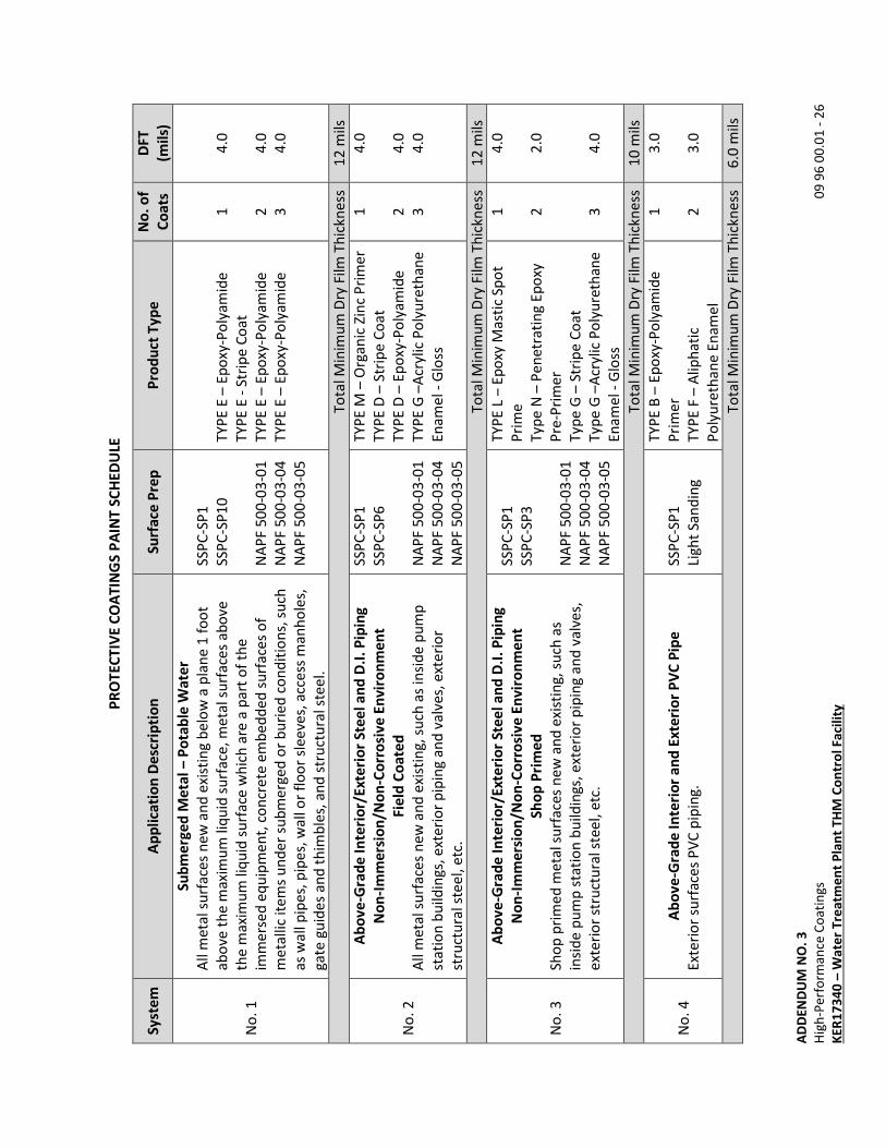
AD
DE
ND
UM
NO
. 3
Hig
h-P
erf
orm
an
ce C
oa
tin
gs
0
9 9
6 0
0.0
1 -
26
KE
R1
73
40
– W
ate
r T
rea
tme
nt
Pla
nt
TH
M C
on
tro
l F
aci
lity
PR
OT
EC
TIV
E C
OA
TIN
GS
PA
INT
SC
HE
DU
LE
Sy
ste
m
Ap
pli
cati
on
De
scri
pti
on
S
urf
ace
Pre
p
Pro
du
ct T
yp
e
No
. o
f
Co
ats
DF
T
(mil
s)
No
. 1
Su
bm
erg
ed
Me
tal
– P
ota
ble
Wa
ter
All
me
tal s
urf
ace
s n
ew
an
d e
xist
ing
be
low
a p
lan
e 1
fo
ot
ab
ove
th
e m
axi
mu
m li
qu
id s
urf
ace
, m
eta
l su
rfa
ces
ab
ove
the
ma
xim
um
liq
uid
su
rfa
ce w
hic
h a
re a
pa
rt o
f th
e
imm
ers
ed
eq
uip
me
nt,
co
ncr
ete
em
be
dd
ed
su
rfa
ces
of
me
talli
c it
em
s u
nd
er
sub
me
rge
d o
r b
uri
ed
co
nd
itio
ns,
su
ch
as
wa
ll p
ipe
s, p
ipe
s, w
all
or
flo
or
sle
eve
s, a
cce
ss m
an
ho
les,
ga
te g
uid
es
an
d t
him
ble
s, a
nd
str
uct
ura
l ste
el.
SSP
C-S
P1
SSP
C-S
P1
0
NA
PF
50
0-0
3-0
1
NA
PF
50
0-0
3-0
4
NA
PF
50
0-0
3-0
5
TY
PE
E –
Ep
oxy
-Po
lya
mid
e
TY
PE
E -
Str
ipe
Co
at
TY
PE
E –
Ep
oxy
-Po
lya
mid
e
TY
PE
E –
Ep
oxy
-Po
lya
mid
e
1 2
3
4.0
4.0
4.0
To
tal M
inim
um
Dry
Film
Th
ickn
ess
1
2 m
ils
No
. 2
Ab
ov
e-G
rad
e I
nte
rio
r/E
xte
rio
r S
tee
l a
nd
D.I
. P
ipin
g
No
n-I
mm
ers
ion
/No
n-C
orr
osi
ve
En
vir
on
me
nt
Fie
ld C
oa
ted
All
me
tal s
urf
ace
s n
ew
an
d e
xist
ing
, su
ch a
s in
sid
e p
um
p
sta
tio
n b
uild
ing
s, e
xte
rio
r p
ipin
g a
nd
va
lve
s, e
xte
rio
r
stru
ctu
ral s
tee
l, e
tc.
SSP
C-S
P1
SSP
C-S
P6
NA
PF
50
0-0
3-0
1
NA
PF
50
0-0
3-0
4
NA
PF
50
0-0
3-0
5
TY
PE
M –
Org
an
ic Z
inc
Pri
me
r
TY
PE
D –
Str
ipe
Co
at
TY
PE
D –
Ep
oxy
-Po
lya
mid
e
TY
PE
G –
Acr
ylic
Po
lyu
reth
an
e
En
am
el -
Glo
ss
1 2
3
4.0
4.0
4.0
To
tal M
inim
um
Dry
Film
Th
ickn
ess
1
2 m
ils
No
. 3
Ab
ov
e-G
rad
e I
nte
rio
r/E
xte
rio
r S
tee
l a
nd
D.I
. P
ipin
g
No
n-I
mm
ers
ion
/No
n-C
orr
osi
ve
En
vir
on
me
nt
Sh
op
Pri
me
d
Sho
p p
rim
ed
me
tal s
urf
ace
s n
ew
an
d e
xist
ing
, su
ch a
s
insi
de
pu
mp
sta
tio
n b
uild
ing
s, e
xte
rio
r p
ipin
g a
nd
va
lve
s,
ext
eri
or
stru
ctu
ral s
tee
l, e
tc.
SSP
C-S
P1
SSP
C-S
P3
NA
PF
50
0-0
3-0
1
NA
PF
50
0-0
3-0
4
NA
PF
50
0-0
3-0
5
TY
PE
L –
Ep
oxy
Ma
stic
Sp
ot
Pri
me
Typ
e N
– P
en
etr
ati
ng
Ep
oxy
Pre
-Pri
me
r
Typ
e G
– S
trip
e C
oa
t
Typ
e G
–A
cryl
ic P
oly
ure
tha
ne
En
am
el -
Glo
ss
1 2 3
4.0
2.0
4.0
To
tal M
inim
um
Dry
Film
Th
ickn
ess
1
0 m
ils
No
. 4
A
bo
ve
-Gra
de
In
teri
or
an
d E
xte
rio
r P
VC
Pip
e
Ext
eri
or
surf
ace
s P
VC
pip
ing
.
SSP
C-S
P1
Lig
ht
San
din
g
TY
PE
B –
Ep
oxy
-Po
lya
mid
e
Pri
me
r
TY
PE
F –
Alip
ha
tic
Po
lyu
reth
an
e E
na
me
l
1 2
3.0
3.0
To
tal M
inim
um
Dry
Film
Th
ickn
ess
6
.0 m
ils
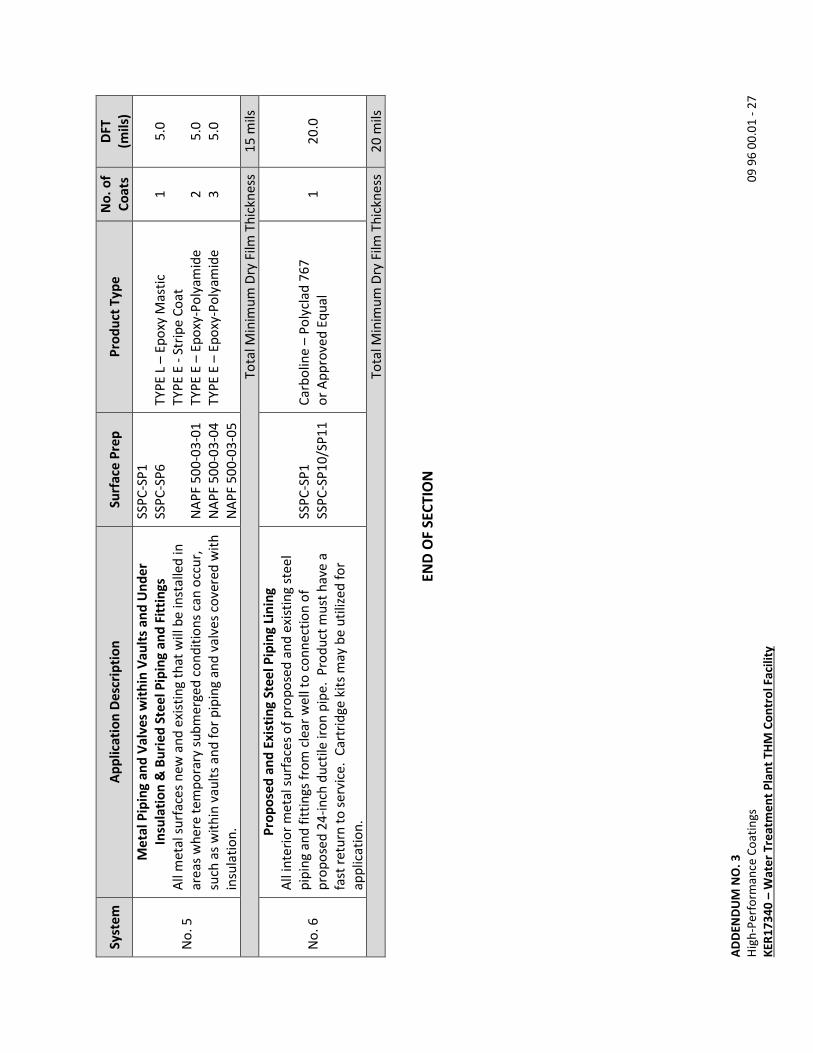
AD
DE
ND
UM
NO
. 3
Hig
h-P
erf
orm
an
ce C
oa
tin
gs
0
9 9
6 0
0.0
1 -
27
KE
R1
73
40
– W
ate
r T
rea
tme
nt
Pla
nt
TH
M C
on
tro
l F
aci
lity
Sy
ste
m
Ap
pli
cati
on
De
scri
pti
on
S
urf
ace
Pre
p
Pro
du
ct T
yp
e
No
. o
f
Co
ats
DF
T
(mil
s)
No
. 5
Me
tal
Pip
ing
an
d V
alv
es
wit
hin
Va
ult
s a
nd
Un
de
r
Insu
lati
on
& B
uri
ed
Ste
el
Pip
ing
an
d F
itti
ng
s
All
me
tal s
urf
ace
s n
ew
an
d e
xist
ing
th
at
will
be
inst
alle
d in
are
as
wh
ere
te
mp
ora
ry s
ub
me
rge
d c
on
dit
ion
s ca
n o
ccu
r,
such
as
wit
hin
va
ult
s a
nd
fo
r p
ipin
g a
nd
va
lve
s co
vere
d w
ith
insu
lati
on
.
SSP
C-S
P1
SSP
C-S
P6
NA
PF
50
0-0
3-0
1
NA
PF
50
0-0
3-0
4
NA
PF
50
0-0
3-0
5
TY
PE
L –
Ep
oxy
Ma
stic
TY
PE
E -
Str
ipe
Co
at
TY
PE
E –
Ep
oxy
-Po
lya
mid
e
TY
PE
E –
Ep
oxy
-Po
lya
mid
e
1 2
3
5.0
5.0
5.0
To
tal M
inim
um
Dry
Film
Th
ickn
ess
1
5 m
ils
No
. 6
Pro
po
sed
an
d E
xis
tin
g S
tee
l P
ipin
g L
inin
g
All
inte
rio
r m
eta
l su
rfa
ces
of
pro
po
sed
an
d e
xist
ing
ste
el
pip
ing
an
d f
itti
ng
s fr
om
cle
ar
we
ll to
co
nn
ect
ion
of
pro
po
sed
24
-in
ch d
uct
ile ir
on
pip
e.
Pro
du
ct m
ust
ha
ve a
fast
re
turn
to
se
rvic
e.
Ca
rtri
dg
e k
its
ma
y b
e u
tiliz
ed
fo
r
ap
plic
ati
on
.
SSP
C-S
P1
SSP
C-S
P1
0/S
P1
1
Ca
rbo
line
– P
oly
cla
d 7
67
or
Ap
pro
ved
Eq
ua
l 1
2
0.0
To
tal M
inim
um
Dry
Film
Th
ickn
ess
2
0 m
ils
EN
D O
F S
EC
TIO
N
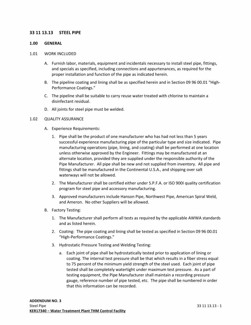
ADDENDUM NO. 3
Steel Pipe 33 11 13.13 - 1
KER17340 – Water Treatment Plant THM Control Facility
33 11 13.13 STEEL PIPE
1.00 GENERAL
1.01 WORK INCLUDED
A. Furnish labor, materials, equipment and incidentals necessary to install steel pipe, fittings,
and specials as specified, including connections and appurtenances, as required for the
proper installation and function of the pipe as indicated herein.
B. The pipeline coating and lining shall be as specified herein and in Section 09 96 00.01 “High-
Performance Coatings.”
C. The pipeline shall be suitable to carry reuse water treated with chlorine to maintain a
disinfectant residual.
D. All joints for steel pipe must be welded.
1.02 QUALITY ASSURANCE
A. Experience Requirements:
1. Pipe shall be the product of one manufacturer who has had not less than 5 years
successful experience manufacturing pipe of the particular type and size indicated. Pipe
manufacturing operations (pipe, lining, and coating) shall be performed at one location
unless otherwise approved by the Engineer. Fittings may be manufactured at an
alternate location, provided they are supplied under the responsible authority of the
Pipe Manufacturer. All pipe shall be new and not supplied from inventory. All pipe and
fittings shall be manufactured in the Continental U.S.A., and shipping over salt
waterways will not be allowed.
2. The Manufacturer shall be certified either under S.P.F.A. or ISO 900I quality certification
program for steel pipe and accessory manufacturing.
3. Approved manufacturers include Hanson Pipe, Northwest Pipe, American Spiral Weld,
and Ameron. No other Suppliers will be allowed.
B. Factory Testing:
1. The Manufacturer shall perform all tests as required by the applicable AWWA standards
and as listed herein.
2. Coating: The pipe coating and lining shall be tested as specified in Section 09 96 00.01
“High-Performance Coatings.”
3. Hydrostatic Pressure Testing and Welding Testing:
a. Each joint of pipe shall be hydrostatically tested prior to application of lining or
coating. The internal test pressure shall be that which results in a fiber stress equal
to 75 percent of the minimum yield strength of the steel used. Each joint of pipe
tested shall be completely watertight under maximum test pressure. As a part of
testing equipment, the Pipe Manufacturer shall maintain a recording pressure
gauge, reference number of pipe tested, etc. The pipe shall be numbered in order
that this information can be recorded.

ADDENDUM NO. 3
Steel Pipe 33 11 13.13 - 2
KER17340 – Water Treatment Plant THM Control Facility
b. Fittings shall be fabricated from hydrostatically tested pipe. All welds on fittings
shall be tested by hydrostatic test, ultrasonic test, air test, or magnetic particle test.
Air test shall be made by applying air to the welds at 10 pounds per square inch
pressure and checking for leaks around and through welds with a soap solution. In
addition, 5 percent of welds on fittings shall be checked with x-ray or ultrasonic
testing by an independent certified welding inspector paid for by the Pipe
Manufacturer.
4. Charpy V-Notch Test: Each heat of steel for plates or coil used for pipe barrels 0.25
inches and thicker shall be tested to verify minimum impact values of 25 ft-lb at 30 F in
accordance with ASTM A370.
5. Elongation: For the tensile test specified in ASTM A370, 2-inch test specimens shall
show elongations not less than 22 percent for each heat of steel.
6. Mill Certification: The Owner will require the Manufacturer to furnish mill test
certificates on reinforcing steel or wire, steel plate, steel coil, and cement. The
Manufacturer shall perform the tests described in AWWA C200, for all pipe, fittings, and
specials.
1.03 SUBMITTALS
A. Submittals shall be in accordance with Section 01 33 00 “Submittal Procedures” and shall
include:
1. Shop Drawings:
a. Prior to the fabrication of the pipe, submit fabrication and laying drawings to the
Engineer. Shop Drawings shall include a schematic location profile and a tabulated
layout schedule, both of which shall be appropriately referenced to the stationing of
the proposed pipeline as shown on the plan and profile sheets. Shop Drawings shall
be based on the drawings and Specifications and shall incorporate changes
necessary to avoid conflicts with existing utilities and structures. Shop Drawings
shall also include full details of reinforcement, and dimensions for pipe and fittings.
Details for the design and fabrication of all fittings, specials, and provisions for
thrust restraint shall be included.
b. Where welded joints are required, Shop Drawings shall include:
1). Welding requirements.
2). Location and dimension of all additional outlets required by the Contractor to
install welds.
2. Certificate of Adequacy of Design: Prior to shipment of the pipe, the Contractor/Pipe
Manufacturer shall submit an affidavit certifying that the pipe, fittings, specials, and
other products and materials furnished, comply with this Specification, Drawings, and
the applicable requirements of AWWA C200, AWWA C215, AWWA C222.
3. Certified Test Reports:
a. Submit the following Certified Test Reports prior to shipment of the pipe:
1). Copies of results of factory hydrostatic tests and test of fittings.
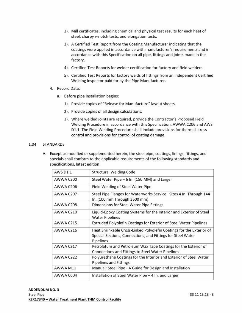
ADDENDUM NO. 3
Steel Pipe 33 11 13.13 - 3
KER17340 – Water Treatment Plant THM Control Facility
2). Mill certificates, including chemical and physical test results for each heat of
steel, charpy v-notch tests, and elongation tests.
3). A Certified Test Report from the Coating Manufacturer indicating that the
coatings were applied in accordance with manufacturer's requirements and in
accordance with this Specification on all pipe, fittings and joints made in the
factory.
4). Certified Test Reports for welder certification for factory and field welders.
5). Certified Test Reports for factory welds of fittings from an independent Certified
Welding Inspector paid for by the Pipe Manufacturer.
4. Record Data:
a. Before pipe installation begins:
1). Provide copies of “Release for Manufacture” layout sheets.
2). Provide copies of all design calculations.
3). Where welded joints are required, provide the Contractor’s Proposed Field
Welding Procedure in accordance with this Specification, AWWA C206 and AWS
D1.1. The Field Welding Procedure shall include provisions for thermal stress
control and provisions for control of coating damage.
1.04 STANDARDS
A. Except as modified or supplemented herein, the steel pipe, coatings, linings, fittings, and
specials shall conform to the applicable requirements of the following standards and
specifications, latest edition:
AWS D1.1 Structural Welding Code
AWWA C200 Steel Water Pipe – 6 In. (150 MM) and Larger
AWWA C206 Field Welding of Steel Water Pipe
AWWA C207 Steel Pipe Flanges for Waterworks Service Sizes 4 In. Through 144
In. (100 mm Through 3600 mm)
AWWA C208 Dimensions for Steel Water Pipe Fittings
AWWA C210 Liquid-Epoxy Coating Systems for the Interior and Exterior of Steel
Water Pipelines
AWWA C215 Extruded Polyolefin Coatings for Exterior of Steel Water Pipelines
AWWA C216 Heat Shrinkable Cross-Linked Polyolefin Coatings for the Exterior of
Special Sections, Connections, and Fittings for Steel Water
Pipelines
AWWA C217 Petrolatum and Petroleum Wax Tape Coatings for the Exterior of
Connections and Fittings to Steel Water Pipelines
AWWA C222 Polyurethane Coatings for the Interior and Exterior of Steel Water
Pipelines and Fittings
AWWA M11 Manual: Steel Pipe - A Guide for Design and Installation
AWWA C604 Installation of Steel Water Pipe – 4 In. and Larger

ADDENDUM NO. 3
Steel Pipe 33 11 13.13 - 4
KER17340 – Water Treatment Plant THM Control Facility
ASME Shop Welding Certification
ASTM A370 Standard Test Method and Definitions for Mechanical Testing of
Steel Products
ASTM C33 Standard Specification for Concrete Aggregates
ASTM C35 Standard Specification for Inorganic Aggregates for Use in Gypsum
Plaster
ASTM C150 Standard Specification for Portland Cement
ASTM D16 Standard Terminology for Paint, Related Coatings, Materials and
Applications
ASTM D522 Standard Test Methods for Mandrel Bend Test of Attached Organic
Coatings
ASTM E165 Standard Practice for Liquid Penetrant Examination for General
Industry
ASTM E709 Standard Guide for Magnetic Particle Testing
ASTM E1444 Standard Practice for Magnetic Particle Testing
SSPC-SP-1 Solvent Cleaning
SSPC-SP-10 Near-White Blast Cleaning
SSPC-PA2 Measurement of Dry Paint Thickness with Magnetic Gages
SSPC-PA/Guide 3 A Guide to Safety in Paint Application
SSPC-PS/Guide 17 A Guide for Selecting Urethane Painting Systems
1.05 DELIVERY AND STORAGE
A. Packing:
1. The pipe shall be prepared for shipment to afford maximum protection from normal
hazards of transportation and allow pipe to reach the Site in an undamaged condition.
Pipe damaged in shipment shall not be delivered to the Site unless such damaged pipe is
properly repaired.
2. After the completed pipe and fittings have been removed from the final cure at the
manufacturing plant, the pipe lining shall be protected from drying by means of plastic
end covers banded to the pipe ends. Covers shall be maintained over the pipe ends at
all times until ready to be placed in the trench. Moisture shall be maintained inside the
pipe by periodic addition of water as necessary.
3. Pipes shall be carefully supported during shipment and storage. Pipe, fittings, and
specials shall be separated so that they do not bear against each other, and the whole
load shall be securely fastened to prevent movement in transit. Ship pipe on padded
bunks with tie-down straps approximately over stulling. Store pipe on padded skids,
sand or dirt berms, tires, or other suitable means to protect the pipe from damage. As a
minimum, each end of each length of pipe, fitting, or special and the middle of each
pipe joint shall be internally supported and braced with stulls to maintain a true circular
shape. More internal stulls shall be included to protect the pipe, lining, and coating
from damage as determined by the Pipe Manufacturer. Internal stulls shall consist of
timber or steel firmly wedged and secured so that stulls remain in place during storage,
ADDENDUM NO. 3
Steel Pipe 33 11 13.13 - 5
KER17340 – Water Treatment Plant THM Control Facility
shipment, and installation. Pipe and liner shall be protected from damage from stulls
using shaped wood pads or similar devices. Stulls shall not be welded directly to the
pipe except at the end of the pipe where the lining is held back. Pipe shall be rotated so
that one stull remains vertical during storage, shipment and installation. Stulls shall not
be removed until the pipe is laid, set to grade, and backfilled.
4. Deliver, handle, and store pipe in accordance with the Manufacturer's
recommendations and in accordance with Paragraph 3.01.C.
B. Marking for Identification: Each joint of pipe and each fitting shall have plainly marked on
the inside of both ends, the class for which it is designed, the date of manufacture, and the
identification number as shown on the Shop Drawings. Beveled pipe shall be marked with
the amount of bevel. The top centerlines shall be marked on all specials.
C. Point of Delivery:
1. Pipe shall be hauled direct from pipe plant to the Site and strung along pipeline route,
thus avoiding re-handling of pipe and the possibility of damage thereto. Where fully
loaded truck and trailer cannot operate along the pipeline route, pipe may be unloaded
at access points along the route, and brought to the trench side by approved methods;
however, the Contractor shall be responsible to ensure that pipe is undamaged at the
time of laying.
2. If the pipe cannot be hauled directly from the pipe plant to the laying site, a maximum
of two handlings is allowed in which case the maximum number of coating repairs is
reduced to five.
3. Shipment by rail will be unacceptable, unless it can be demonstrated that it will not
damage the pipe.
2.00 PRODUCTS
2.01 MATERIALS
A. Steel: Steel shall meet the requirements of AWWA C200 and shall be of continuous casting.
Steel shall be homogeneous and shall be suitable for field welding, fully kilned and fine
austenitic grain size. Steel shall have a minimum yield strength of 42,000 psi.
B. Coatings and Linings:
1. Coatings:
Coating shall be in accordance with Section 09 96 00.01 “High-Performance Coatings”
and applied on all piping and fittings.
2. Linings:
Lining shall be in accordance with Section 09 96 00.01 “High-Performance Coatings” and
applied on all piping and fittings.
C. Flange Nuts and Bolts: Bolts shall conform to ASTM A193, Grade B7. Nuts shall conform to
ASTM A194, Grade 2H heavy hex nut. Use anti-seize compound during installation of all
nuts and bolts. Thrust rods shall be carbon steel conforming to ASTM A193.
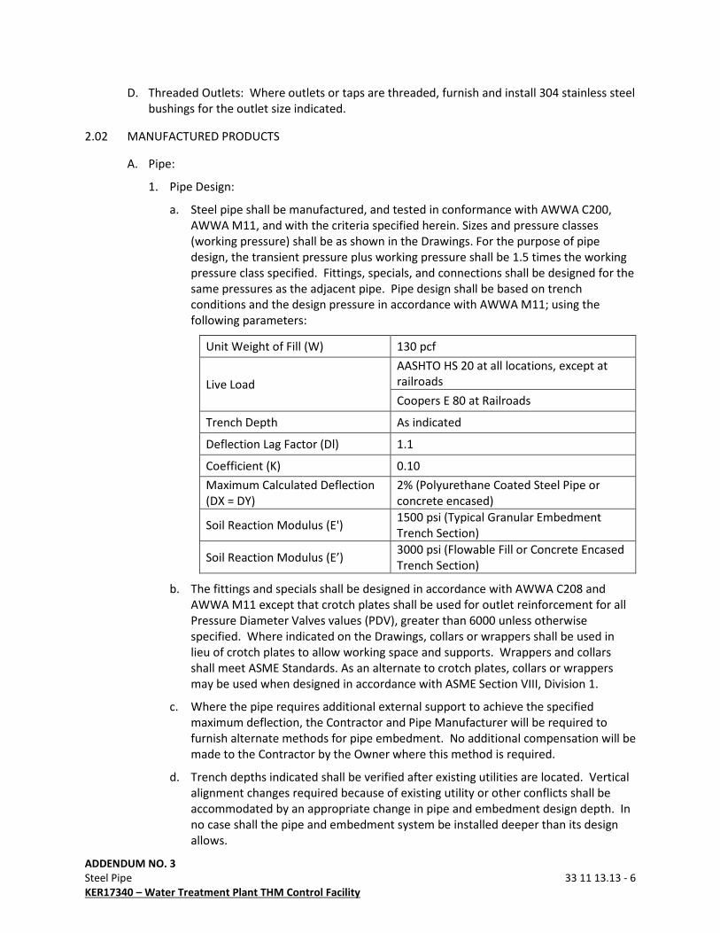
ADDENDUM NO. 3
Steel Pipe 33 11 13.13 - 6
KER17340 – Water Treatment Plant THM Control Facility
D. Threaded Outlets: Where outlets or taps are threaded, furnish and install 304 stainless steel
bushings for the outlet size indicated.
2.02 MANUFACTURED PRODUCTS
A. Pipe:
1. Pipe Design:
a. Steel pipe shall be manufactured, and tested in conformance with AWWA C200,
AWWA M11, and with the criteria specified herein. Sizes and pressure classes
(working pressure) shall be as shown in the Drawings. For the purpose of pipe
design, the transient pressure plus working pressure shall be 1.5 times the working
pressure class specified. Fittings, specials, and connections shall be designed for the
same pressures as the adjacent pipe. Pipe design shall be based on trench
conditions and the design pressure in accordance with AWWA M11; using the
following parameters:
Unit Weight of Fill (W) 130 pcf
Live Load
AASHTO HS 20 at all locations, except at
railroads
Coopers E 80 at Railroads
Trench Depth As indicated
Deflection Lag Factor (Dl) 1.1
Coefficient (K) 0.10
Maximum Calculated Deflection
(DX = DY)
2% (Polyurethane Coated Steel Pipe or
concrete encased)
Soil Reaction Modulus (E') 1500 psi (Typical Granular Embedment
Trench Section)
Soil Reaction Modulus (E’) 3000 psi (Flowable Fill or Concrete Encased
Trench Section)
b. The fittings and specials shall be designed in accordance with AWWA C208 and
AWWA M11 except that crotch plates shall be used for outlet reinforcement for all
Pressure Diameter Valves values (PDV), greater than 6000 unless otherwise
specified. Where indicated on the Drawings, collars or wrappers shall be used in
lieu of crotch plates to allow working space and supports. Wrappers and collars
shall meet ASME Standards. As an alternate to crotch plates, collars or wrappers
may be used when designed in accordance with ASME Section VIII, Division 1.
c. Where the pipe requires additional external support to achieve the specified
maximum deflection, the Contractor and Pipe Manufacturer will be required to
furnish alternate methods for pipe embedment. No additional compensation will be
made to the Contractor by the Owner where this method is required.
d. Trench depths indicated shall be verified after existing utilities are located. Vertical
alignment changes required because of existing utility or other conflicts shall be
accommodated by an appropriate change in pipe and embedment design depth. In
no case shall the pipe and embedment system be installed deeper than its design
allows.
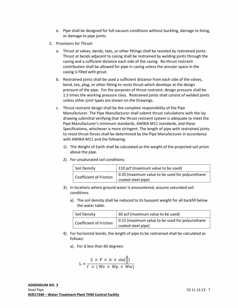
ADDENDUM NO. 3
Steel Pipe 33 11 13.13 - 7
KER17340 – Water Treatment Plant THM Control Facility
e. Pipe shall be designed for full vacuum conditions without buckling, damage to lining,
or damage to pipe joints.
2. Provisions for Thrust:
a. Thrust at valves, bends, tees, or other fittings shall be resisted by restrained joints.
Thrust at bends adjacent to casing shall be restrained by welding joints through the
casing and a sufficient distance each side of the casing. No thrust restraint
contribution shall be allowed for pipe in casing unless the annular space in the
casing is filled with grout.
b. Restrained joints shall be used a sufficient distance from each side of the valves,
bend, tee, plug, or other fitting to resist thrust which develops at the design
pressure of the pipe. For the purposes of thrust restraint, design pressure shall be
1.5 times the working pressure class. Restrained joints shall consist of welded joints
unless other joint types are shown on the Drawings.
c. Thrust restraint design shall be the complete responsibility of the Pipe
Manufacturer. The Pipe Manufacturer shall submit thrust calculations with the lay
drawing submittal verifying that the thrust restraint system is adequate to meet the
Pipe Manufacturer’s minimum standards, AWWA M11 standards, and these
Specifications, whichever is more stringent. The length of pipe with restrained joints
to resist thrust forces shall be determined by the Pipe Manufacturer in accordance
with AWWA M11 and the following:
1). The Weight of Earth shall be calculated as the weight of the projected soil prism
above the pipe.
2). For unsaturated soil conditions:
Soil Density 110 pcf (maximum value to be used)
Coefficient of Friction 0.20 (maximum value to be used for polyurethane
coated steel pipe)
3). In locations where ground water is encountered, assume saturated soil
conditions.
a). The soil density shall be reduced to its buoyant weight for all backfill below
the water table.
Soil Density 60 pcf (maximum value to be used)
Coefficient of Friction 0.15 (maximum value to be used for polyurethane
coated steel pipe)
4). For horizontal bends, the length of pipe to be restrained shall be calculated as
follows:
a). For Δ less than 60 degrees:
L = 2 × P × A × sin(Δ2) f × ( We + Wp + Ww)
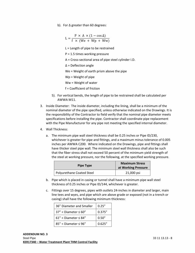
ADDENDUM NO. 3
Steel Pipe 33 11 13.13 - 8
KER17340 – Water Treatment Plant THM Control Facility
b). For Δ greater than 60 degrees:
L = P × A × (1 − cos Δ) f × (We + Wp + Ww)
L = Length of pipe to be restrained
P = 1.5 times working pressure
A = Cross-sectional area of pipe steel cylinder I.D.
Δ = Deflection angle
We = Weight of earth prism above the pipe
Wp = Weight of pipe
Ww = Weight of water
f = Coefficient of friction
5). For vertical bends, the length of pipe to be restrained shall be calculated per
AWWA M11.
3. Inside Diameter: The inside diameter, including the lining, shall be a minimum of the
nominal diameter of the pipe specified, unless otherwise indicated on the Drawings. It is
the responsibility of the Contractor to field verify that the nominal pipe diameter meets
specifications before installing the pipe. Contractor shall coordinate pipe replacement
with the Pipe Manufacturer for any pipe not meeting the specified internal diameter.
4. Wall Thickness:
a. The minimum pipe wall steel thickness shall be 0.25 inches or Pipe ID/230,
whichever is greater for pipe and fittings, and a maximum minus tolerance of 0.005
inches per AWWA C200. Where indicated on the Drawings, pipe and fittings shall
have thicker steel pipe wall. The minimum steel wall thickness shall also be such
that the fiber stress shall not exceed 50 percent of the minimum yield strength of
the steel at working pressure, nor the following, at the specified working pressure.
Pipe Type Maximum Stress
at Working Pressure
Polyurethane Coated Steel 21,000 psi
b. Pipe which is placed in casing or tunnel shall have a minimum pipe wall steel
thickness of 0.25 inches or Pipe ID/144, whichever is greater.
c. Fittings over 15 degrees, pipes with outlets 24-inches in diameter and larger, main
line tees and wyes, and pipe which are above grade or exposed (not in a trench or
casing) shall have the following minimum thickness:
36” Diameter and Smaller 0.25”
37” < Diameter ≤ 60” 0.375”
61” < Diameter ≤ 84” 0.50”
85” < Diameter ≤ 96” 0.625”

ADDENDUM NO. 3
Steel Pipe 33 11 13.13 - 9
KER17340 – Water Treatment Plant THM Control Facility
97” < Diameter ≤ 120” 0.75”
d. Pipe, fittings, and specials shall be designed such that the maximum stresses in the
pipe due to thrust loading will not exceed 18,000 psi nor 50 percent of the steel
yield strength at the thrust design pressure (1.5 times working pressure).
5. Seams: Except for mill-type pipe, the piping shall be made from steel plates rolled into
cylinders or sections thereof with the longitudinal and girth seams butt welded or shall
be spirally formed and butt welded. There shall be not more than two longitudinal
seams. Girth seams shall be butt welded and shall not be spaced closer than 6 feet
except in specials and fittings.
6. Joint Length: Maximum joint length shall not exceed 50 feet. Maximum joint length of
steel pipe installed in casing shall not exceed 25 feet.
B. Bend Fittings: All bend fittings shall have a minimum radius of 2.5 times the diameter to
permit passage of pipeline pigs.
C. Pipe Ends: Pipe ends shall be lap welded slip joint, butt strap joint, flanged joint, or flexible
coupled joint. Pipe that has a diameter of 48 inches or smaller together with pressure class
of 250 psi or lower may have welded joints or rubber gasket joints. Pipe ends shall be
suitable for full vacuum and the maximum surge pressures indicated.
1. Rubber Gasket Joints: Rubber gasket joints shall be a rolled spigot or carnegie joint with
rubber gasket for pressure classes up to 250 psi. Joints shall conform to AWWA M11 and
AWWA C200. Joints shall be of clearances such that water tightness shall be provided
under all operating and test conditions with a pipe diameter deflection of 4 percent.
The joint shall be suitable for the specified pressure and a deflected joint with a pull of
3/4 inches. At the Pipe Manufacturer’s option, all steel pipe joints may be lap-welded
slip joints in lieu of rubber gasket joints.
a. Rolled Spigot Joints: The joint shall consist of a flared bell end formed and sized by
forcing the pipe over a plug die or by expanding on segmental dies. The difference
in diameter between the I.D. of bell and the O.D. of spigot shoulder at point of full
engagement with an allowable deflection shall be no more than .00 inches to .04
inches as measured on the circumference with a diameter tape. The gasket shall
have sufficient volume to approximately fill the area of the groove and shall
conform to AWWA C200.
b. Carnegie Joints: The spigot end shall be a Carnegie shaped steel joint ring. Spigot
ring shall be welded to the outside of the pipe can, with an inside weld also required
where deemed necessary by the Manufacturer due to pipe loading conditions. The
welded area of bell and spigot pipe ends shall be checked after forming by the
magnetic particle method.
2. Lap Welded Slip Joint:
a. Lap welded slip joint shall be provided in all locations where any of the following
criteria is met, unless otherwise specified in the Drawings:
1). Pipe ID is 54 inches and larger.
2). Pressure class is 275 psi and greater.
3). Joints are welded for thrust restraint.
ADDENDUM NO. 3
Steel Pipe 33 11 13.13 - 10
KER17340 – Water Treatment Plant THM Control Facility
b. Ends of pipe, fittings, and specials for field welded joints shall be prepared with one
end expanded in order to receive a plain end making a bell and plain end type of
joint. Clearance between the surfaces of lap joints shall not exceed 1/8 of an inch at
any point around the periphery.
c. The depth of bell shall be such as to provide for a minimum clear distance of 2
inches between the weld and the nearest tangent of the bell radius when welds are
to be located on the inside of the pipe.
d. The depth of bell shall be such as to provide for a minimum lap of 2 inches. Provide
a deeper bell every 400 feet to accommodate thermal movement for which the
minimum lap shall be 4 inches.
e. Lap welded slip joints shall be welded from the inside for pipe diameters 48 inches
and larger. Lap welded slip joints shall be welded from the outside for diameters
smaller than 48 inches.
3. For Fittings with Flanges: Flanged joints shall be provided at connections to valves and
where indicated. Ends to be fitted with slip on flanges shall have the longitudinal or
spiral welds ground flush to accommodate the type of flanges provided. Pipe flanges
and welding of flanges to steel pipe shall conform to the requirements of AWWA C207
and AWWA C206. Pipe flanges shall be of rated pressure equal to or greater than the
adjacent pipe class. Flange drilling shall match the drilling of adjacent fittings or
appurtenances which the flanges are to be attached to. Flanges shall be spot faced or
back faced parallel to the front face.
4. Flexible Couplings: Flexible couplings shall be provided where shown in the Drawings
and as specified in Section 33 12 16.13 “Miscellaneous Valves.” Ends to be joined by
flexible couplings shall be of the plain end type, prepared as stipulated in AWWA C200.
Pipe ends shall be truly circular to within 0.25 inch or the Coupling Manufacturer’s
tolerances, whichever is smaller. In addition, the welds on ends to be joined by
couplings shall be ground flush to permit sliding the coupling in at least one direction to
clear the pipe joint. Harness bolts and lugs shall comply with AWWA M11 and the
Drawings.
5. Butt Strap Closure Joints:
a. Where necessary to make closure to pipe previously laid, closure joints shall be
installed using butt strap joints in accordance with AWWA C206 and applicable
provisions of this specification.
b. Butt strap shall have an inside and outside weld and shall be air tested. Air test shall
be low pressure from a threaded fitting between the welds.
3.00 EXECUTION
3.01 INSTALLATION
A. General:
1. Install steel pipe, fittings, specials, and appurtenances as specified and required for the
proper functioning of the completed pipeline. Install pipe, fittings, and specials in
accordance with the Manufacturer's recommendations, AWWA C604, and AWWA M11.

ADDENDUM NO. 3
Steel Pipe 33 11 13.13 - 11
KER17340 – Water Treatment Plant THM Control Facility
Pipe shall be laid to the lines and grade indicated. Before each joint of steel pipe is
lowered into the ditch, the coating is to be inspected and tested for holidays. All
damaged areas and holidays are to be repaired before the pipe is lowered into the
trench.
2. The requirements of Section 31 23 33 “Trenching and Backfill” govern for the excavation
and backfilling of trenches for laying steel pipe, fittings, and specials.
3. Keep the pipe clean during the laying operation and free of sticks, dirt, animals, and
trash, and at the close of each operating day, effectively seal the open end of the pipe
against the entrance of water using a gasketed night cap. Do not lay pipe in water. The
Contractor may install a vent at the top of the night cap to prevent flotation of the pipe
in the event of heavy rain during the night.
4. Install bonds at all pipe joints, other than welded joints or insulated joints.
5. Conformance with pipe deflection requirements shall be as set forth in the Pipe
Deflection section below. Where pipe has been reworked to comply with the deflection
requirements, Contractor shall re-measure for deflection no earlier than 7 days after the
repaired pipe is backfilled. No pipe installation shall be accepted until the entire
installation is in compliance with the deflection requirements.
6. Installed pipe joints will be inspected by the Owner’s Representative for flat spots and
internal lining stress cracks. Lining damage shall be repaired in accordance with the
Manufacturer’s recommendations and as directed by the Engineer at no additional cost
to the Owner.
a. The Contractor shall complete internal welding of joints, welding inspections and
grout of the inside joints prior to measuring deflection. The welding inspections
shall be done by an independent CWI as described in Section 01 40 00 “Quality
Control.”
b. The Contractor shall schedule the internal inspections with the on-site Owner’s
Representative.
c. Repair of flat spots may include uncovering the pipe, re-compaction of the pipe
bedding, and repair of the coating.
d. Owner’s Representative will re-inspect for flat spots where pipe has been reworked
to comply with the deflection requirements.
B. Pipe Deflection:
1. Pipe Deflection Measurements:
a. The Contractor shall complete internal welding of joints, welding inspections and
grout of the inside joints prior to measuring deflection. The welding inspections
shall be done by an independent CWI as described in Section 01 40 00 “Quality
Control.”
b. Deflection measurements shall be made by the Contractor in the presence of the
Owner’s Representative.
1). Method for taking measurements shall be agreed to by the Owner and Engineer
in writing prior to installing the first joint of pipe.
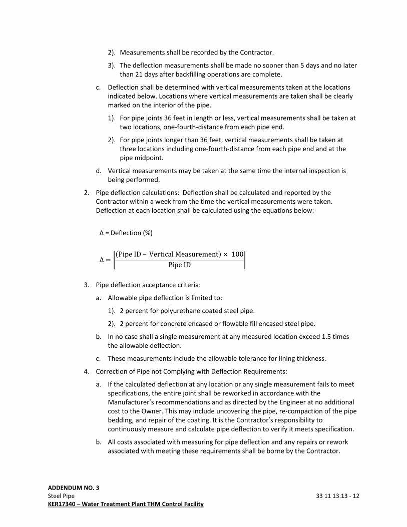
ADDENDUM NO. 3
Steel Pipe 33 11 13.13 - 12
KER17340 – Water Treatment Plant THM Control Facility
2). Measurements shall be recorded by the Contractor.
3). The deflection measurements shall be made no sooner than 5 days and no later
than 21 days after backfilling operations are complete.
c. Deflection shall be determined with vertical measurements taken at the locations
indicated below. Locations where vertical measurements are taken shall be clearly
marked on the interior of the pipe.
1). For pipe joints 36 feet in length or less, vertical measurements shall be taken at
two locations, one-fourth-distance from each pipe end.
2). For pipe joints longer than 36 feet, vertical measurements shall be taken at
three locations including one-fourth-distance from each pipe end and at the
pipe midpoint.
d. Vertical measurements may be taken at the same time the internal inspection is
being performed.
2. Pipe deflection calculations: Deflection shall be calculated and reported by the
Contractor within a week from the time the vertical measurements were taken.
Deflection at each location shall be calculated using the equations below:
Δ = Deflection (%)
∆ = �(Pipe ID – Vertical Measurement) × 100Pipe ID �
3. Pipe deflection acceptance criteria:
a. Allowable pipe deflection is limited to:
1). 2 percent for polyurethane coated steel pipe.
2). 2 percent for concrete encased or flowable fill encased steel pipe.
b. In no case shall a single measurement at any measured location exceed 1.5 times
the allowable deflection.
c. These measurements include the allowable tolerance for lining thickness.
4. Correction of Pipe not Complying with Deflection Requirements:
a. If the calculated deflection at any location or any single measurement fails to meet
specifications, the entire joint shall be reworked in accordance with the
Manufacturer’s recommendations and as directed by the Engineer at no additional
cost to the Owner. This may include uncovering the pipe, re-compaction of the pipe
bedding, and repair of the coating. It is the Contractor’s responsibility to
continuously measure and calculate pipe deflection to verify it meets specification.
b. All costs associated with measuring for pipe deflection and any repairs or rework
associated with meeting these requirements shall be borne by the Contractor.
ADDENDUM NO. 3
Steel Pipe 33 11 13.13 - 13
KER17340 – Water Treatment Plant THM Control Facility
5. Pipe Deflection Reports:
a. A monthly report shall be submitted as Record Data showing the following for each
joint of pipe:
1). Allowable deflection and 1.5 times allowable deflection for each pipe diameter
installed.
2). Deflection measurements and calculated deflection for each location measured
per joint.
3). It is the responsibility of the Contractor to verify that the nominal pipe diameter
meets specifications at all measured locations. Contractor shall coordinate pipe
replacement with the Pipe Manufacturer for any pipe not meeting the specified
internal diameter.
C. Pipe Handling: Pipe shall be handled at all times with a minimum of two wide non-abrasive
slings or belts to prevent damage to the coating or lining. The equipment shall be kept in
such repair that its continued use is not injurious to the coating. All pipe joints over 25 feet
shall be handled with a spreader bar. The spacing of pipe supports required to handle the
pipe shall be adequate to prevent cracking or damage to the lining or coating.
D. Line Up and Bends:
1. Line up pipe for joining so as to prevent damage thereto. Thoroughly clean the bell and
spigot ends of each joint of pipe of foreign matter, rust and scale before placing spigot
into bell. Welded joints shall have an overlap of 2 inches minimum to 4 inches
maximum
2. All under-stabbed joints shall be butt strapped or re-stabbed. All over-stabbed joints
shall be re-stabbed, butt strapped, or outside welded.
3. Where abrupt changes in grade and direction occur, the Contractor shall employ special
shop fabricated fittings for the purpose. Field cutting the ends of the steel pipe to
accomplish angular changes in grade or direction of the line shall not be permitted.
E. Pipe Laying - Rubber Gasket Joints: Join rubber gasket joints in accordance with the
Manufacturer’s recommendations. Clean bell and spigot of foreign materials. Lubricate
gasket and bell and relieve gasket tension around the perimeter of the pipe. Engage spigot
as far as possible in bell, allowing for 1inch gap for inside joint grouting after any joint
deflections. Joint deflection or pull shall not exceed the Manufacturer’s suggested
tolerance. Check gasket with feeler gauge all around the pipe.
F. Pipe Laying - Welded Joints:
1. Weld joints in accordance with the AWWA C206 for Field Welding of Steel Water Pipe
and AWS D1.1 Structural Welding Code. Contractor shall provide adequate ventilation
for welders and for Owner's Representative to observe welds. Unless otherwise
specified, welds shall be full circle fillet welds. Exterior joint welding shall be completed
before application of field applied joint coating for pipe 42 inches and smaller. It will be
acceptable to weld the joint from the inside after the exterior joint coating and
backfilling has been done for pipe 48 inches and larger, if it can be demonstrated that
this procedure will not damage the exterior joint coating.
ADDENDUM NO. 3
Steel Pipe 33 11 13.13 - 14
KER17340 – Water Treatment Plant THM Control Facility
2. A Welding Procedure Qualification shall be approved by the Engineer before welding of
joints begins. The procedure shall be in accordance with AWWA C206 and AWS D1.1.
3. Provide a deeper bell every 400 feet to accommodate thermal movement for which the
minimum lap shall be 4 inches.
4. Adequate provisions for reducing temperature stresses shall be the responsibility of the
Contractor.
5. After the pipe has been joined and properly aligned and prior to the start of the welding
procedure, the spigot and bell shall be made essentially concentric by tacking to obtain
a 1/8 of an inch maximum clearance tolerance around the periphery of the joint. In no
case shall the clearance tolerance be permitted to accumulate.
6. Before welding, thoroughly clean pipe ends to bare metal. All welding shall be hand
welding to avoid damage to the exterior joint coating. Welding shall be performed so as
not to damage lining or coating. Cover the lining and/or coating as necessary to protect
from welding splatter.
7. Furnish labor, equipment, tools and supplies including shielded type welding rod.
Protect welding rod from any deterioration prior to its use. If any portion of a box or
carton is damaged, reject the entire box or carton.
8. In all hand welding, the metal shall be deposited in successive layers. For hand welds,
not more than 1/8 of an inch of metal shall be deposited in each pass. Each pass except
the final one, whether in butt or fillet welds, shall be thoroughly bobbed or peened to
relieve shrinkage stresses and to remove dirt, slag, or flux before the succeeding bead is
applied. Each pass shall be thoroughly fused into the plates at each side of the welding
groove or fillet and shall not be permitted to pile up in the center of the weld.
Undercutting along the side shall not be permitted.
9. Welds shall be free from pin holes, non-metallic inclusions, air pockets, undercutting
and/or any other defects.
10. If the ends of the pipe are laminated, split or damaged to the extent that satisfactory
welding contact cannot be obtained, remove the pipe from the line.
11. Furnish each welder employed with a steel stencil for marking the welds, so that the
work of each welder may be identified. Have each welder stencil the pipe adjacent to
the weld with the stencil assigned to him. In the event any welder leaves the job, his
stencil shall be voided and not duplicated if another welder is employed.
12. Keep daily welding reports which identify the welder’s name and the joint welded.
Joints must be shown on the daily welding reports with the identification number
assigned in the lay drawings (ex. ID#1 – ID#2). Provide three copies of all daily welding
reports to Owner representative every month.
13. Use only competent, skilled and qualified workmen. Each welder employed by the
Contractor shall be both AWS D1.1 and C206 certified according to the Welding
Procedure Qualification approved for the Project. All welders shall have been certified
within the last 6 months or shall provide a welding continuity log to be allowed to weld
on the line.
ADDENDUM NO. 3
Steel Pipe 33 11 13.13 - 15
KER17340 – Water Treatment Plant THM Control Facility
14. Inspections shall be made of joints in the line for each welder qualified above. Any
welder making defective welds shall not be allowed to continue to weld.
15. Visual tests and magnetic particle tests in accordance with AWWA C206, ASTM E709 and
E1444, shall be performed by an independent testing laboratory under the direction of
Owner’s Representative on all field welded joints. Certified Weld Inspector will be paid
by the Owner. Welds that prove to be defective will be replaced or repaired, whichever
is deemed necessary by the Engineer, at Contractor’s expense.
16. If the Contractor disagrees with the Engineer's interpretation of welding tests, test
sections may be cut from the joint for physical testing. The Contractor shall bear the
expense of repairing the joint, regardless of the results of physical testing. The
procedure for repairing the joint shall be approved by the Engineer before proceeding.
17. Test double-welded buttstrap joints using the compressed air and soap method.
Following successful completion of the test, plug weld seal the threaded test fitting.
G. Protective Coating System for Welded Joints:
1. Perform field coating of joints in accordance with Section 09 96 00.01 “High-
Performance Coatings.”
2. The Contractor is responsible for his operations so that they do not damage the factory
applied coating system.
H. Protection of Buried Metal
Bolts, flanges, and other buried uncoated ferrous metal which cannot be protected with
factory or field-applied polyurethane coatings shall be coated with heat shrink sleeves
encased in flowable fill.
I. Quality Control of Field Applied Coating: See Section 09 96 00.01 “High-Performance
Coatings.”
3.02 DISINFECTION
Disinfect the piping system in accordance with Section 33 10 13 “Disinfecting Water Utility
Distribution Systems.”
3.03 HYDROSTATIC TEST
Perform a hydrostatic testing as specified.
END OF SECTION
ADDENDUM NO. 3
Butterfly Valves 33 01 02 - 1
KER17340 – Water Treatment Plant THM Control Facility
40 05 64 BUTTERFLY VALVES
1.00 GENERAL
1.01 WORK INCLUDED
A. Furnish labor, materials, equipment and incidentals necessary to install butterfly valves.
B. This project is subject to the American Iron and Steel (AIS) requirements of Section 608 of
the Federal Water Pollution Control Act. All iron and steel products for construction,
alteration, maintenance, or repairs incorporated in these plans must be produced in the
United States.
1.02 QUALITY ASSURANCE
Acceptable Manufacturers:
A. DeZurik
B. M&H
C. CMB/K-Flo
D. Pratt
E. Bray Valve Series 30 (Approved for GAC Absorption System Only)
F. Experience Requirements: The Manufacturer shall have had successful experience in
manufacturing tight-closing, rubber-seated butterfly valves for this type service in the sizes
indicated. The Manufacturer shall have at least 10 years’ experience in the manufacture of
valves.
G. Manufacturer’s Representative for Startup and Testing: The Valve Vendor or Manufacturer
shall provide the services of a competent manufacturer’s representative for an indefinite
period of time as required to insure proper adjustment, installation, and operation of the
valve.
1.03 SUBMITTALS
Submittals shall be in accordance with Section 01 33 00 “Submittal Procedures” and must
include:
A. Record Data:
1. Manufacturer’s data sheets
2. AIS Certifications
B. Operation and Maintenance Manuals
ADDENDUM NO. 3
Butterfly Valves 33 01 02 - 2
KER17340 – Water Treatment Plant THM Control Facility
1.04 STANDARDS
The applicable provisions of the following standards shall apply as if written here in their
entirety:
A. American National Standards Institute (ANSI) Standards:
ANSI B16.1 Cast Iron Pipe Flanges and Fittings
B. American Society for Testing and Materials (ASTM) Standards:
ASTM A48 Standard Specification for Gray Iron Castings
ASTM A126 Standard Specification for Gray Iron Castings for Valves, Flanges,
and Pipe Fittings
ASTM A276 Standard Specifications for Stainless Steel Bars
ASTM A536 Standard Specification for Ductile Iron Castings
ASTM B148 Standard Specifications for Aluminum Bronze Coatings
C. American Water Works Association (AWWA) Standards:
AWWA C504 Standard for Rubber-seated Butterfly Valves
AWWA C550 Standard for Protective Interior Coatings for Valves and Hydrants
2.00 PRODUCTS
2.01 VALVE CONSTRUCTION
A. General: Butterfly valves supplied under this Contract shall be of the tight-closing, rubber
seated type with rubber seats that are securely attached to the valve disc or body. Valves
shall be bubble tight at rated pressures with flow in either direction and shall be satisfactory
for applications involving valve operation after long periods of inactivity. Butterfly valves
shall conform to the applicable requirements of AWWA C504 and AWWA C550. All valves
for potable water service shall comply with NSF61 standards.
B. Valve Bodies: Valve bodies shall be constructed of cast iron ASTM A126, Class B or ASTM
A48, Class 40 or ductile iron in accordance with ASTM A536, Grade 65/45/12. Valve class
shall be suitable for the pressure class of the adjacent pipe in which it is installed. Valve may
have flanged ends with ANSI B16.1 Class 125 drilling or be of the wafer body style and be
suitable for use between ANSI B16.1 Class 125 cast iron flanges.
C. Valve Discs: Valve discs shall be cast iron conforming to ASTM A126, Class B, aluminum
bronze conforming to ASTM B148, or ductile iron conforming to ASTM A536, Grade
65/45/12.
D. Valve Shafts: Valve shafts shall be turned, ground and polished, constructed of stainless
steel conforming to ASTM A276. Valve shafts may consist of a one-piece unit extending
completely through the valve disc, or may be of the “stub shaft” type, which comprises two
separate shafts inserted into the valve disc hubs. If of the “stub shaft” construction, each
stub shaft shall be inserted into the valve disc hubs for a distance of at least 1-1/2 shaft
diameters. The shaft shall be tightly connected to the disc using tapered or wedged keying
devices.
ADDENDUM NO. 3
Butterfly Valves 33 01 02 - 3
KER17340 – Water Treatment Plant THM Control Facility
E. Valve Seats: Valves shall have Neoprene, Buna-N or other synthetic rubber resilient seas to
provide tight shut off at the pressure specified. The mating seat surface shall be ASTM
A276, 18-8 stainless steel or a 95 percent pure nickel overlay. All valves shall have
replaceable, adjustable seats. Valves 30 inches and larger shall have in-line replaceable
seats.
F. Valve Bearings: Valve shall be fitted with sleeve type bearings. Bearings shall be of
corrosion-resistant and “self-lubricated” materials that will not deteriorate natural or
synthetic rubber.
G. Valve Shaft Seals: Where shafts project through the valve bodies for operator connection, a
split-V or O-ring type shaft seal shall be provided.
H. All components, including seats, seals and gaskets, for use with the aeration or backwash air
system shall be suitable for 300-degree F service.
2.02 VALVE OPERATORS:
A. General: The valve operator shall be designed and manufactured in accordance with the
applicable requirements of AWWA C504 and AWWA C540, and shall be arranged for
horizontal or vertical valve shaft installation.
B. Manual Operators:
1. Manual operators shall have all gearing totally enclosed and shall be pre-lubricated or
grease packed. Operators shall be of the worm gear or travelling nut and link type with
field adjustable stops to prevent over travel in the open or closed positions. The
direction of the manual rotation shall be clockwise to close.
2. Operators for exposed valves shall be provided with a valve position indicator and a
handwheel or chain and sprocket device. Provide chain and sprocket for valves greater
than 6-feet above walking surface. Chains must be galvanized and loop within four feet
of the floor.
3. Operators for buried valves shall have an extended stem with a 2-inch square operating
nut within 12 inches of the finished grade. Provide a cast iron valve box to enclose the
operating stem. Valve box shall be per City of Kerrville Standard 370.06 with concrete
collars.
4. For valves which are installed with the shaft vertical, provide a level gear for vertical
operation of the operating nut.
C. Electric operators are to be provided per specification 46 07 13 “Adsorption Systems for use
with Granular Activated Carbon.”
2.03 BUTTERFLY VALVES FOR AIR SERVICE
Furnish lugged style butterfly valves for air service. Valves 10 inches and smaller shall have a
ten-position locking lever operator. Valves 12 inches and larger shall have a gear type hand-
wheel operator. The valve shall be resilient seated, bubble-tight shut off. The valve shall be
shipped loose for field installation. Valve seats and gaskets shall be suitable for operation in
temperatures up to 300-degrees F.

ADDENDUM NO. 3
Butterfly Valves 33 01 02 - 4
KER17340 – Water Treatment Plant THM Control Facility
3.00 EXECUTION
3.01 INSTALLATION
Installation shall be in accordance with the Manufacturer’s instructions. Valve shaft shall be
truly vertical or horizontal as indicated.
3.02 FIELD QUALITY CONTROL
Upon completion of installation of the butterfly valves an acceptance test shall be conducted to
verify the satisfactory operation of the valves. The valves must perform in a manner acceptable
to the Engineer before final acceptance will be made by the Owner.
END OF SECTION
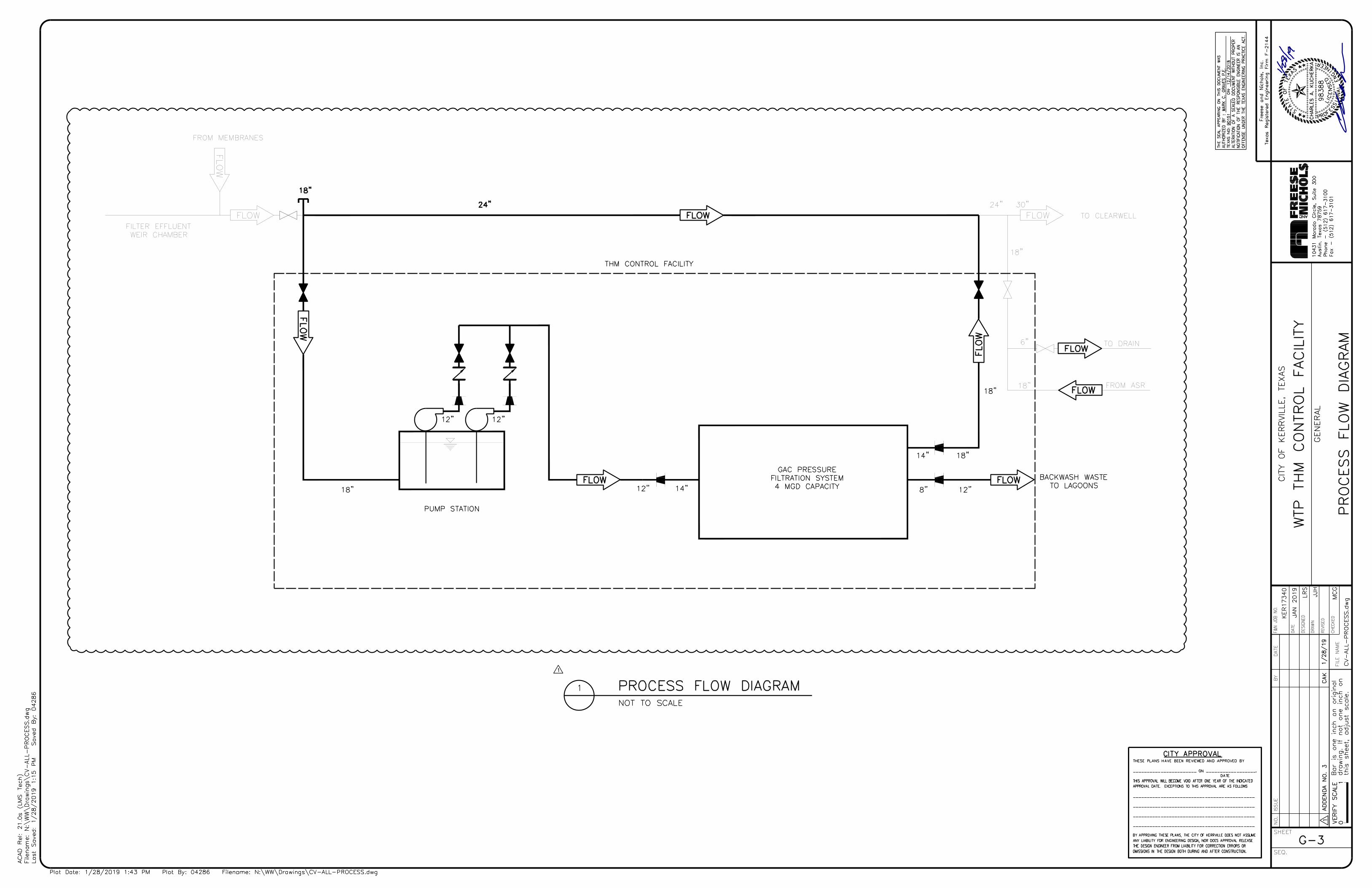
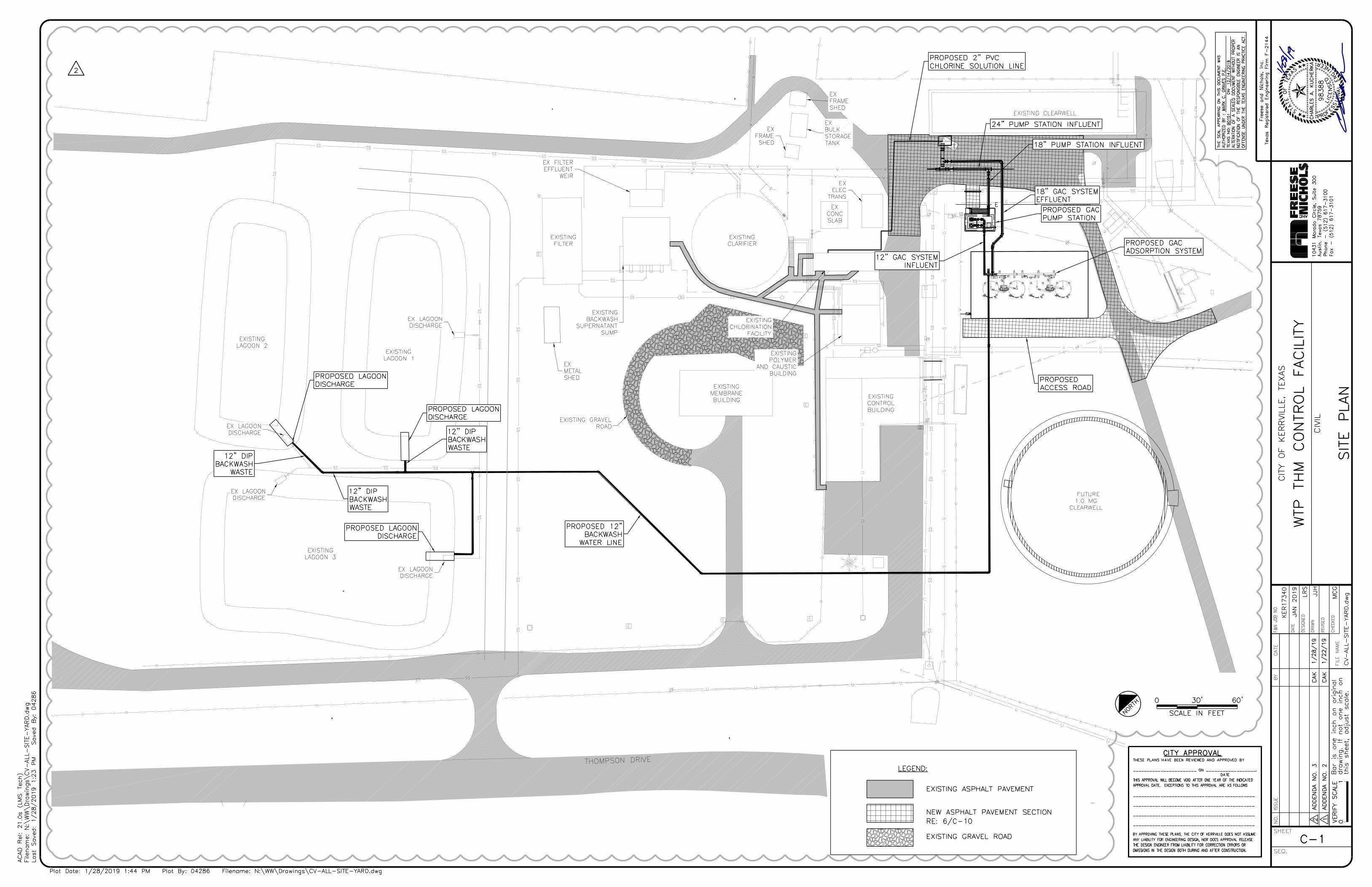
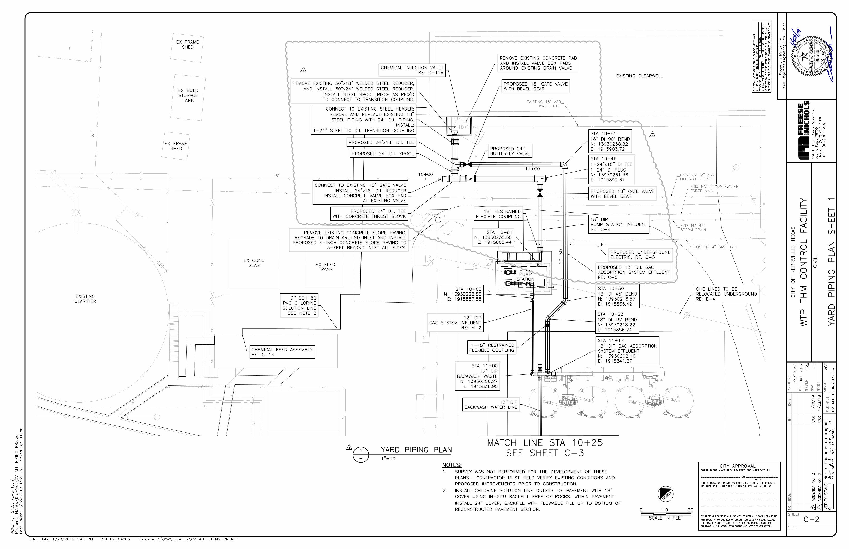
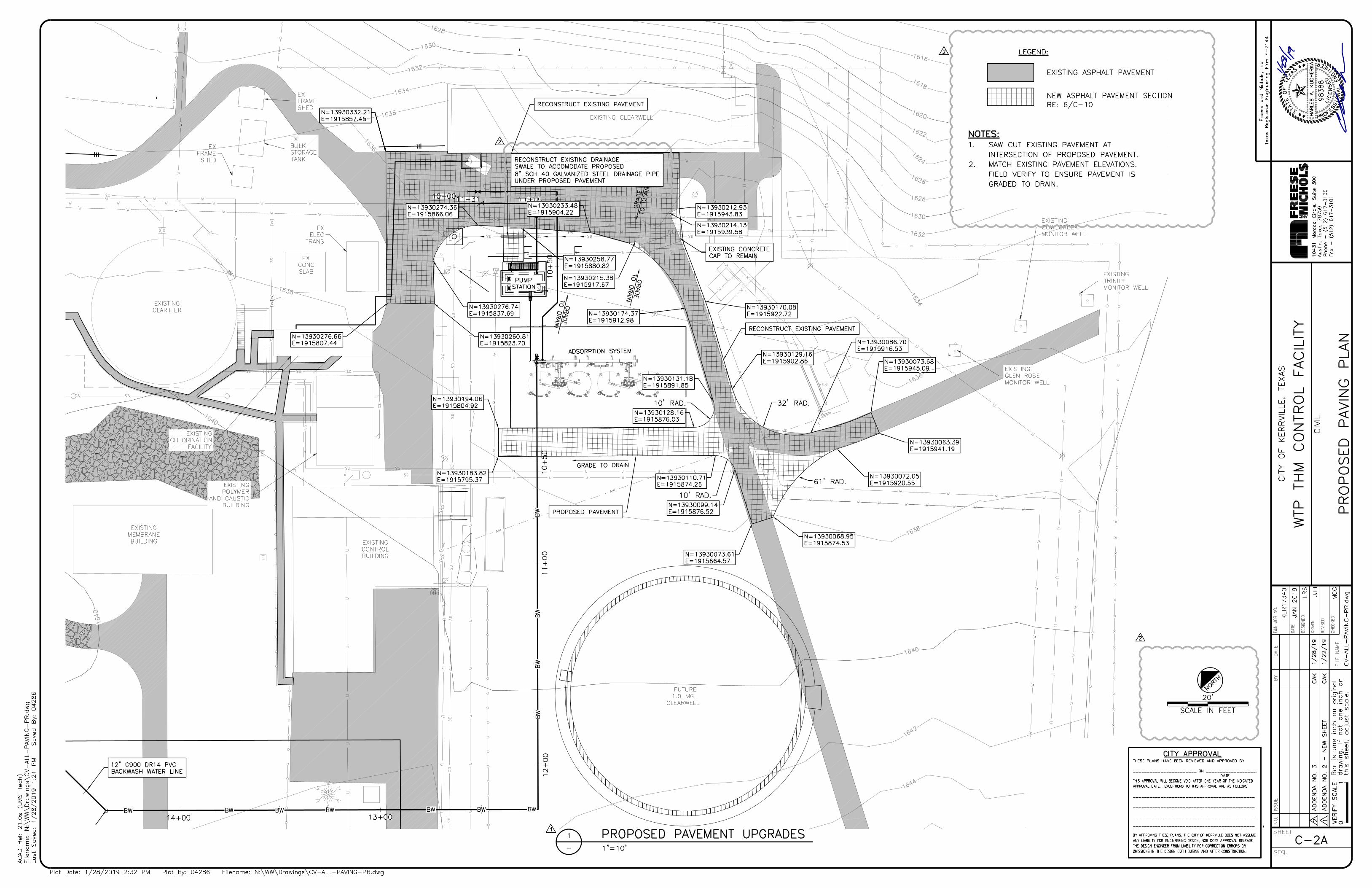
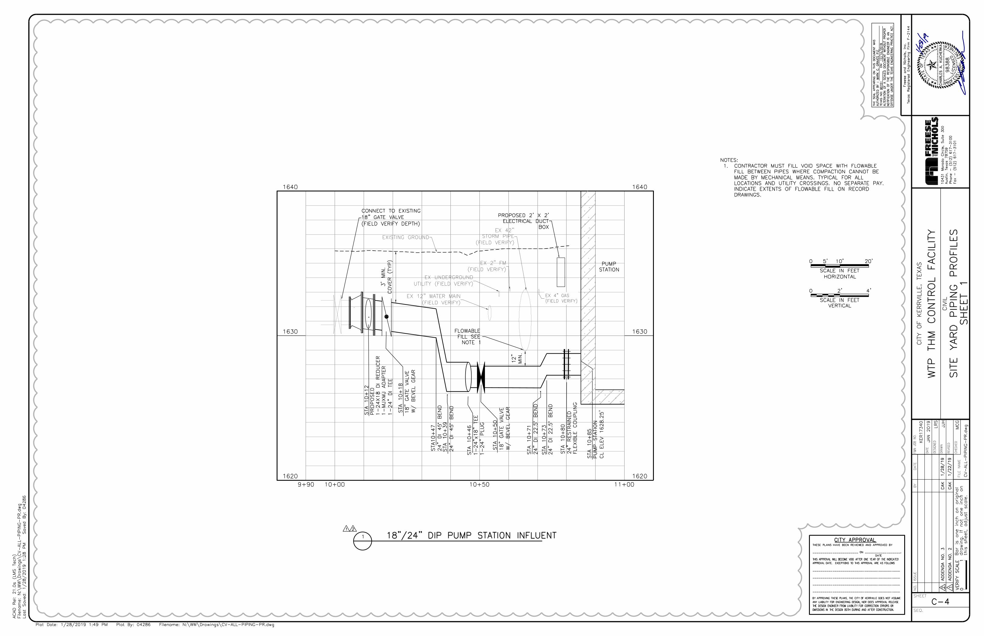
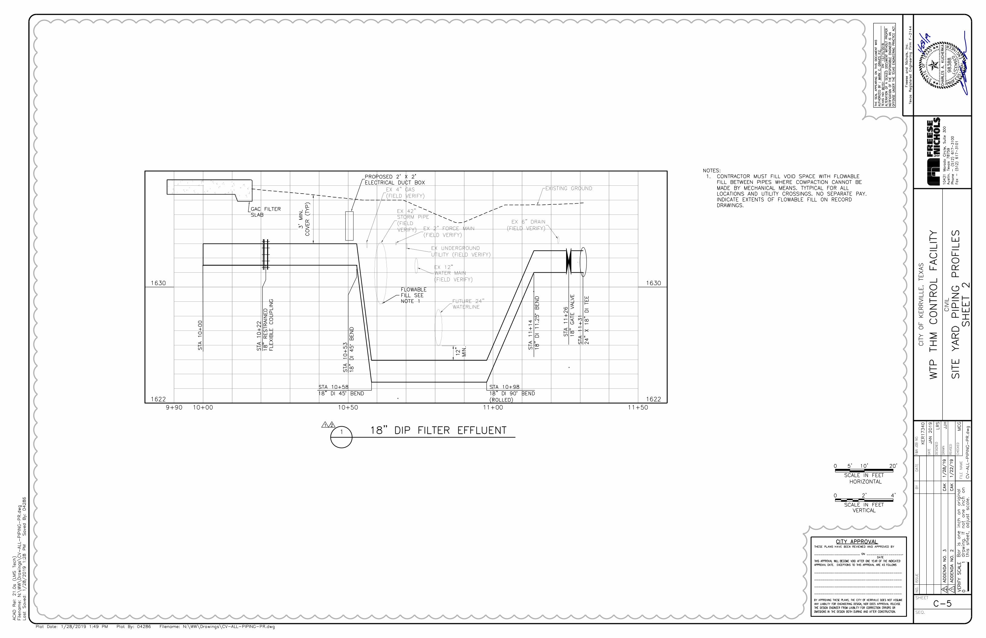

J
1371
7 N
eutro
n R
oad
Dal
las,
Texa
s 75
244
Tel:
972
-490
-766
1Fa
x: 9
72-4
90-7
125
emai
l:vkg
upta@ga
icon
sulting
.com
GAI
Gup
ta &
Ass
oci
ates
, In
c.C
ON
SU
LT
IN
G E
NG
IN
EE
RIN
G
Re
gistra
tio
n N
o. F
-2
59
3
10/30/18
CONDUIT
NO.
DESCRIPTIONCONDUIT TAG
TABLE FOR SECTION 2
CONDUIT
SIZE
1 VF1-P 2"C
VF2-P 2"C PUMP 2 POWER2
VF1-C, VF2-C2"C PUMP 1 AND PUMP 2 CONTROLS3
C-500 2"C
LE-600 MANUFACTURER CABLE TO
CONTROL PANEL
4
C-501 2"C
DISCRETE LEVEL SWITCHES TO
CONTROL PANEL PLC
5
PUMP 1 POWER
CONDUIT
NO.
DESCRIPTIONCONDUIT TAG
TABLE FOR SECTION 1
CONDUIT
SIZE
1 MCASR-P 3"C
SPARE 3"C -2
POWER TO MCC-ASR1
REFER TO SHEET
E-12 FOR WORK
IN THIS AREA
REFER TO SHEET
E-13 FOR WORK
IN THIS AREA
REFER TO SHEET
E-14 FOR WORK
IN THIS AREA
LC-8, 92"C
120V PUMP STATION LIGHTS AND
RECEPTACLES
6
SPARE 2"C SPARE7-8
CONDUIT
NO.
DESCRIPTIONCONDUIT TAG
TABLE FOR SECTION 3
CONDUIT
SIZE
1 C-401 4"C
C-402 4"C
DISCRETE SIGNALS FROM GAC
FILTERS TO GAC CONTROL PANEL
2
C-403 4"C
ANALOG SIGNALS FROM GAC
FILTERS TO GAC CONTROL PANEL
3
SPARE 4"C SPARE4
LC-1, 2, 3, 4, 52"C 120V GAC FLOW TRANSMITTERS5
DISCRETE SIGNALS FROM GAC
FILTERS TO GAC CONTROL PANEL
LC-6, 11, 21, 222"C
120V GAC LIGHTS AND
RECEPTACLES
6
LC-12, 13, 14, 15, 162"C 120V GAC HEAT TRACE7
HA-2, 3, 4, 5, 6
2"C 480V GAC VALVES8
HA-7, 8, 9, 10, 112"C 480V GAC VALVES9
HB-2, 3, 4, 5, 6,2"C 480V GAC VALVES10
HB-7, 8, 9, 10, 112"C11
2"C12
2"C13
SPARE 2"C SPARE14
2"C15
480V GAC VALVES
480V GAC VALVES
480V GAC VALVES
HA-13, 14
HB-12, 13, 14
LC-17, 18, 19, 20COMPRESSOR RECEPTACLES GAC
2"C16 SPARE SPARE
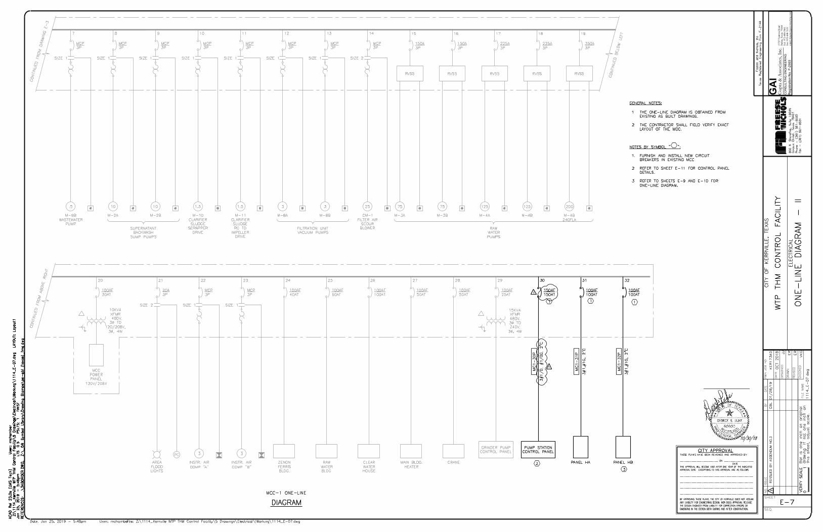
1371
7 N
eutro
n R
oad
Dal
las,
Texa
s 75
244
Tel:
972
-490
-766
1Fa
x: 9
72-4
90-7
125
emai
l:vkg
upta@ga
icon
sulting
.com
GAI
Gup
ta &
Ass
oci
ates
, In
c.C
ON
SU
LT
IN
G E
NG
IN
EE
RIN
G
Re
gistra
tio
n N
o. F
-2
59
3
10/30/18
PC
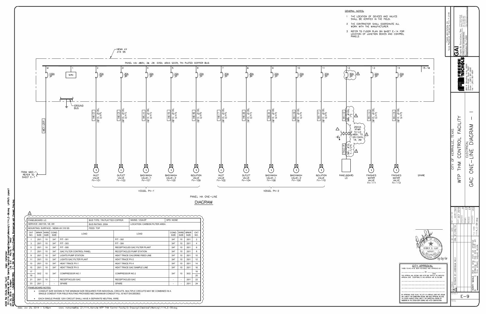
1371
7 N
eutro
n R
oad
Dal
las,
Texa
s 75
244
Tel:
972
-490
-766
1Fa
x: 9
72-4
90-7
125
emai
l:vkg
upta@ga
icon
sulting
.com
GAI
Gup
ta &
Ass
oci
ates
, In
c.C
ON
SU
LT
IN
G E
NG
IN
EE
RIN
G
Re
gistra
tio
n N
o. F
-2
59
3
10/30/18
SERVICE: 240/120, 1Ø, 3W
MOUNTING: SURFACE - NEMA 4X 316 SS
PANELBOARD: LC
20/1
20/1
9
7
20/1
20/1
20/1
3
1
5
GAC FILTER CONTROL PANEL
LIGHTS PUMP STATION
FIT - 303
FIT - 301
FIT - 500
LOAD
LOCATION: CARBON FILTER AREA
BRKR
SIZE
20/1
20/1
20/1
20/1
20/1
MAINS: 125A/2P
RECEPTACLES PUMP STATION
HEAT TRACE CHLORINE FEED LINE
FIT - 302
FIT - 304
RECEPTACLES GAC FILTER PLANT
FEED: TOP
BUS TYPE: TIN PLATTED COPPER
BUS RATING: 200A
10
LOAD
WIRE
SIZE
10
8
4
2
6
CKT
NO.
CKT
NO.
BRKR
SIZE
WIRE
SIZE
3/4"
3/4"
3/4"
3/4"
3/4"
COND.
SIZE
3/4"
3/4"
3/4"
3/4"
3/4"
COND.
SIZE
SPD: NONE
· CONDUIT SIZE SHOWN IS THE MINIMUM SIZE REQUIRED FOR INDIVIDUAL CIRCUITS. MULTIPLE CIRCUITS MAY BE COMBINED IN A
SINGLE CONDUIT FOR FIELD ROUTING PROVIDED NEC MAXIMUM CONDUIT FILL IS NOT EXCEEDED.
· EACH SINGLE PHASE 120V CIRCUIT SHALL HAVE A SEPARATE NEUTRAL WIRE.
PANELBOARD NOTES:
20/111 LIGHTS GAC FILTER PLANT 20/1HEAT TRACE PV-2 10 123/4"3/4"
20/113 10 HEAT TRACE PV-1 20/1HEAT TRACE PV-4 10 143/4"3/4"
20/115 10 HEAT TRACE PV-3 20/1HEAT TRACE GAC SAMPLE LINE 10 163/4"3/4"
30/2
17
COMPRESSOR NO.1 30/2COMPRESSOR NO.2
18
19 20
20/121 RECEPTACLES GAC 20/1RECEPTACLES GAC - 22--
20/123 - SPARE 20/1SPARE - 24--
10
10
10
10
10
10
10
10
103/4"3/4"
10
10
10
10
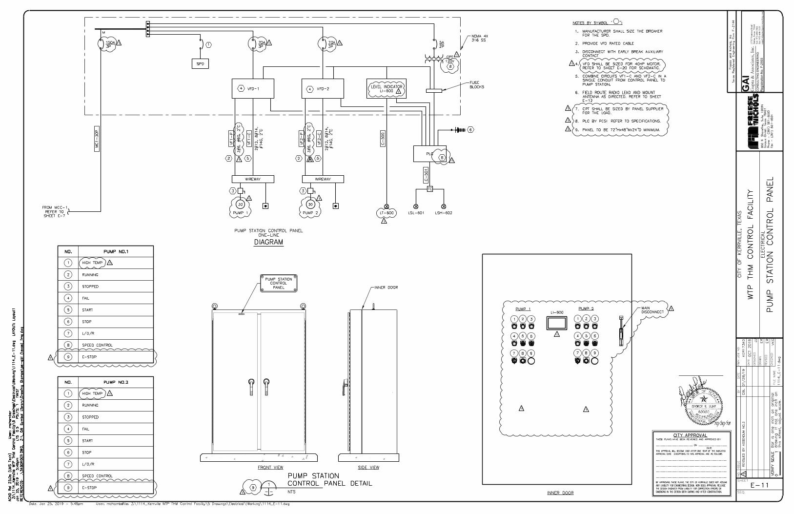
1371
7 N
eutro
n R
oad
Dal
las,
Texa
s 75
244
Tel:
972
-490
-766
1Fa
x: 9
72-4
90-7
125
emai
l:vkg
upta@ga
icon
sulting
.com
GAI
Gup
ta &
Ass
oci
ates
, In
c.C
ON
SU
LT
IN
G E
NG
IN
EE
RIN
G
Re
gistra
tio
n N
o. F
-2
59
3
10/30/18
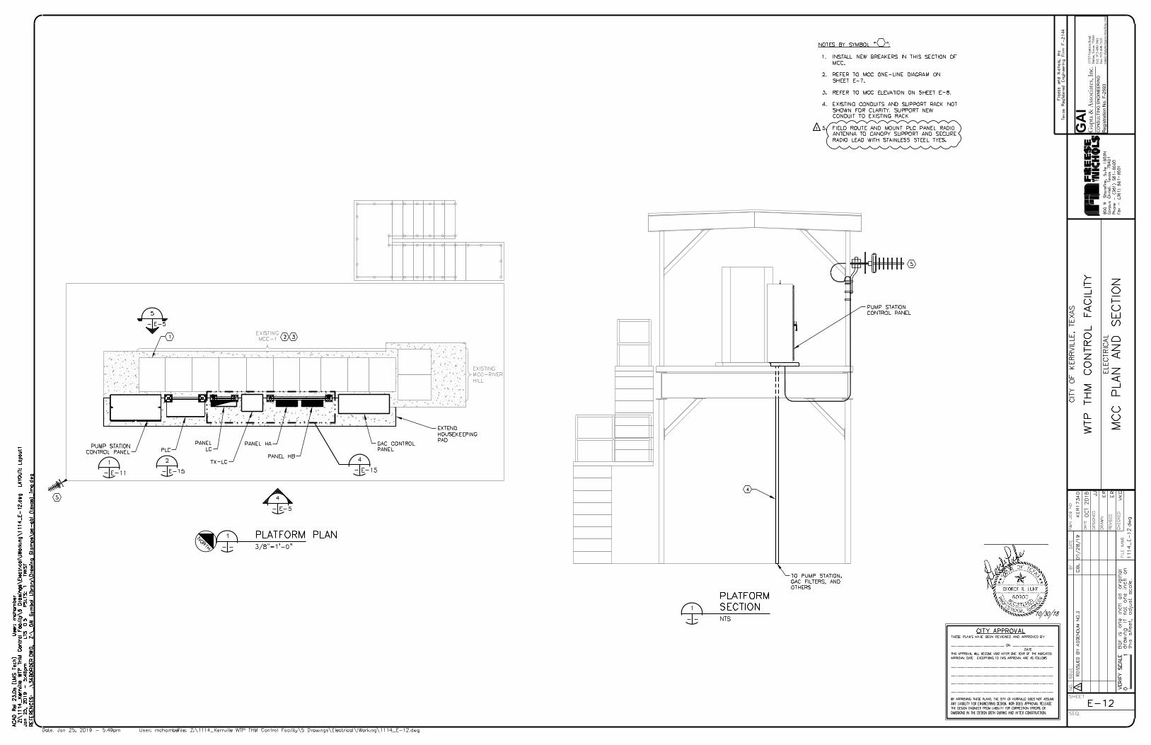
1371
7 N
eutro
n R
oad
Dal
las,
Texa
s 75
244
Tel:
972
-490
-766
1Fa
x: 9
72-4
90-7
125
emai
l:vkg
upta@ga
icon
sulting
.com
GAI
Gup
ta &
Ass
oci
ates
, In
c.C
ON
SU
LT
IN
G E
NG
IN
EE
RIN
G
Re
gistra
tio
n N
o. F
-2
59
3
10/30/18

1371
7 N
eutro
n R
oad
Dal
las,
Texa
s 75
244
Tel:
972
-490
-766
1Fa
x: 9
72-4
90-7
125
emai
l:vkg
upta@ga
icon
sulting
.com
GAI
Gup
ta &
Ass
oci
ates
, In
c.C
ON
SU
LT
IN
G E
NG
IN
EE
RIN
G
Re
gistra
tio
n N
o. F
-2
59
3
10/30/18
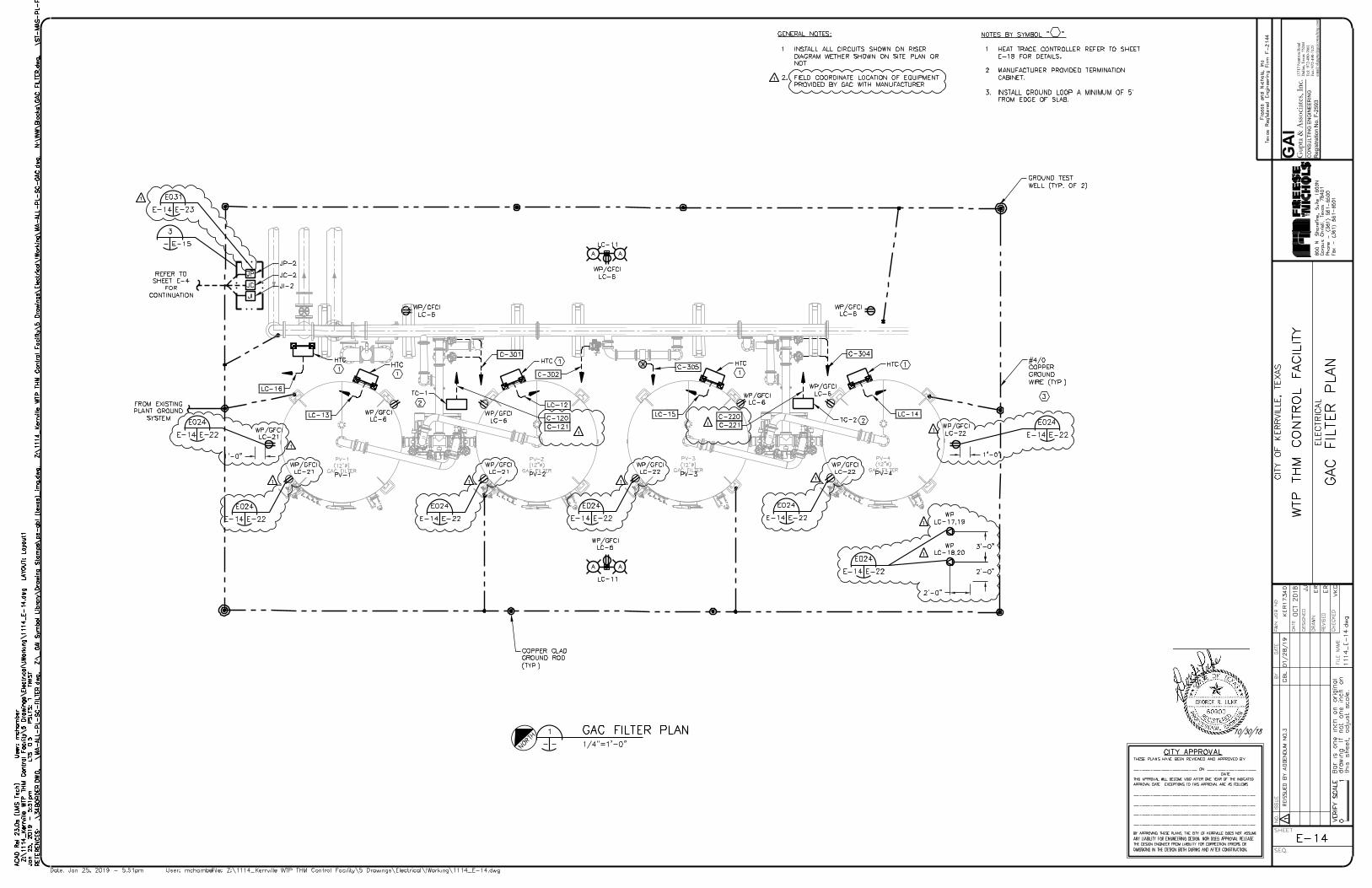
1371
7 N
eutro
n R
oad
Dal
las,
Texa
s 75
244
Tel:
972
-490
-766
1Fa
x: 9
72-4
90-7
125
emai
l:vkg
upta@ga
icon
sulting
.com
GAI
Gup
ta &
Ass
oci
ates
, In
c.C
ON
SU
LT
IN
G E
NG
IN
EE
RIN
G
Re
gistra
tio
n N
o. F
-2
59
3
10/30/18

1371
7 N
eutro
n R
oad
Dal
las,
Texa
s 75
244
Tel:
972
-490
-766
1Fa
x: 9
72-4
90-7
125
emai
l:vkg
upta@ga
icon
sulting
.com
GAI
Gup
ta &
Ass
oci
ates
, In
c.C
ON
SU
LT
IN
G E
NG
IN
EE
RIN
G
Re
gistra
tio
n N
o. F
-2
59
3
10/30/18
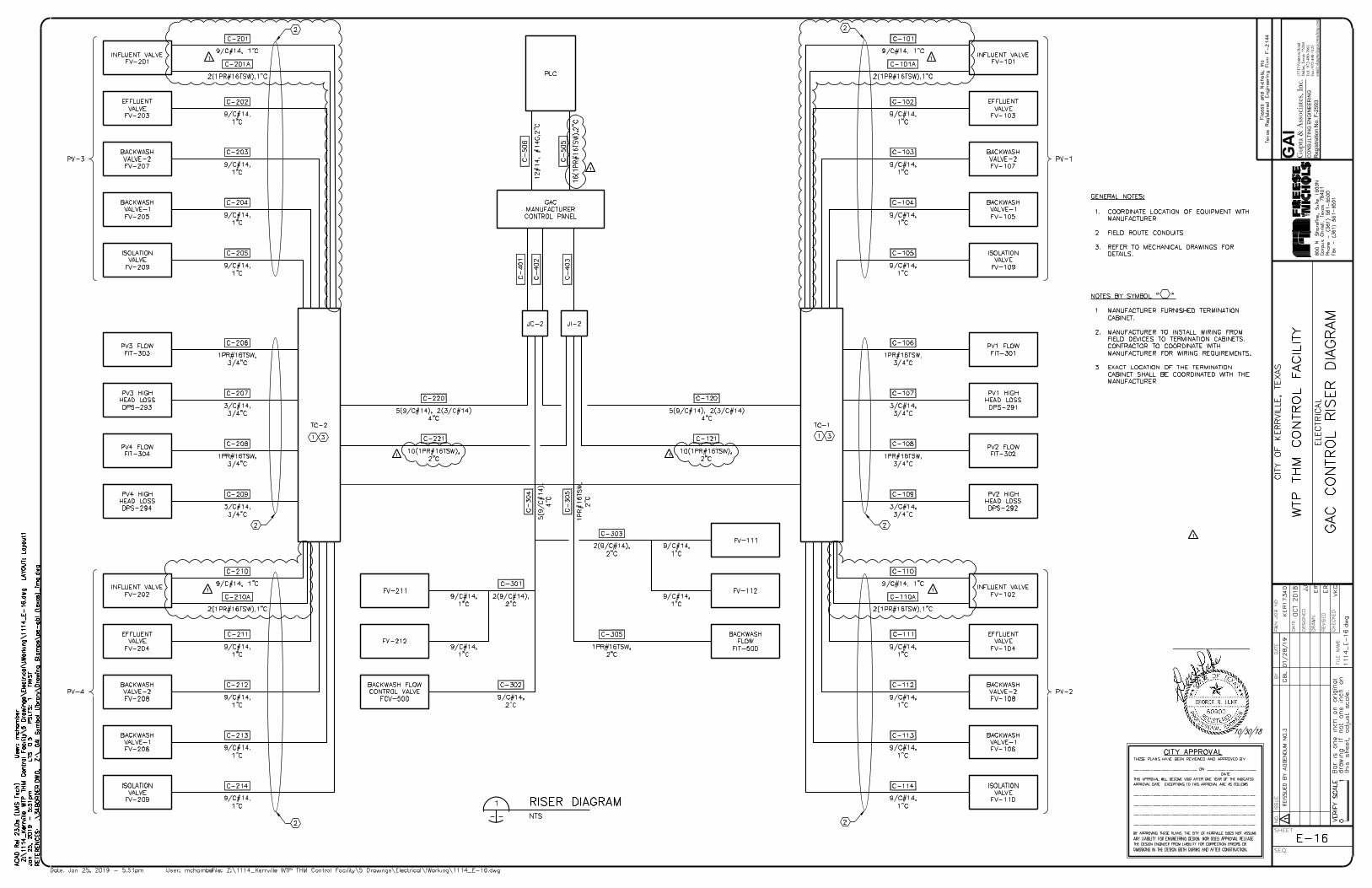
1371
7 N
eutro
n R
oad
Dal
las,
Texa
s 75
244
Tel:
972
-490
-766
1Fa
x: 9
72-4
90-7
125
emai
l:vkg
upta@ga
icon
sulting
.com
GAI
Gup
ta &
Ass
oci
ates
, In
c.C
ON
SU
LT
IN
G E
NG
IN
EE
RIN
G
Re
gistra
tio
n N
o. F
-2
59
3
10/30/18
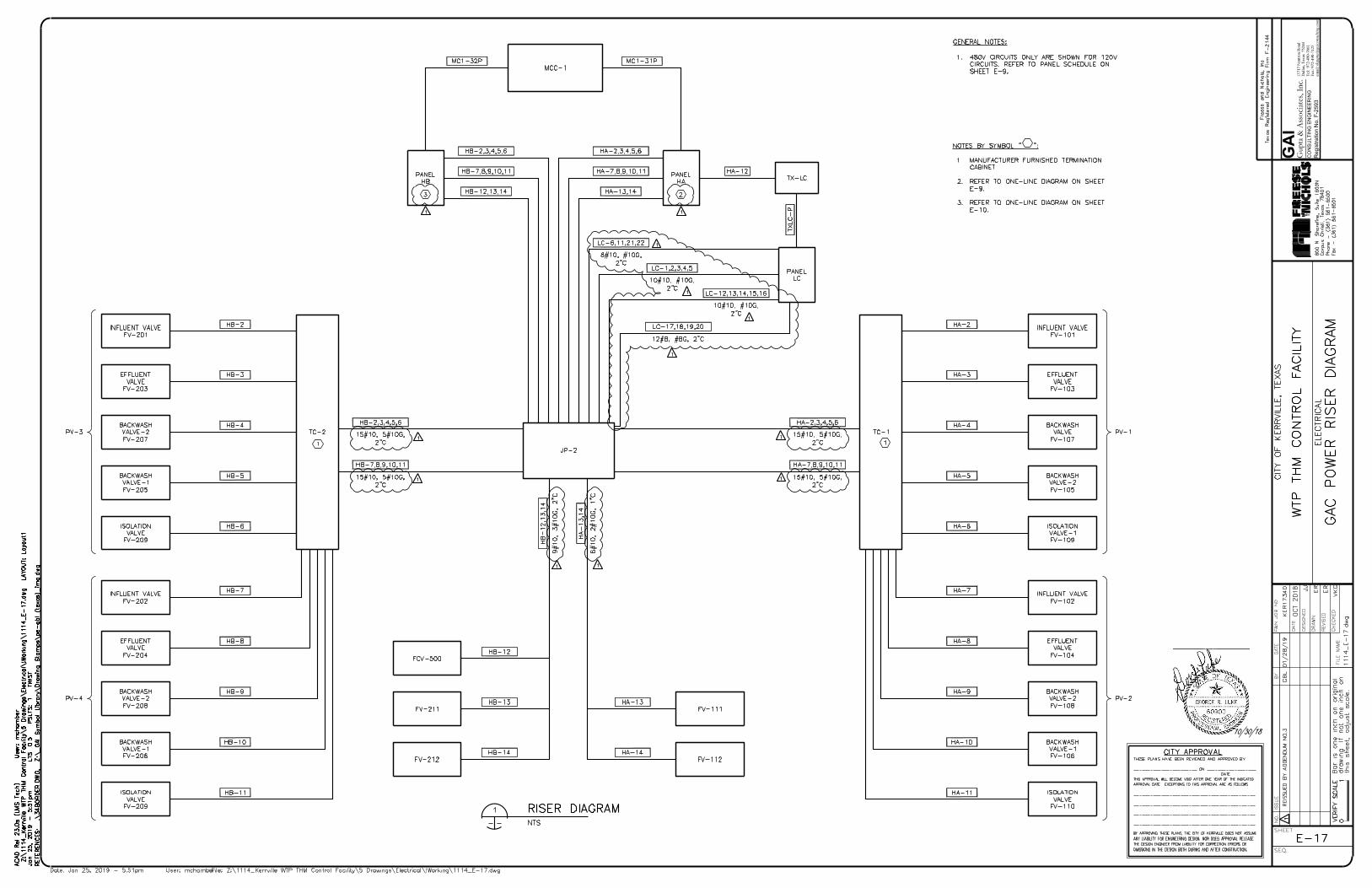
1371
7 N
eutro
n R
oad
Dal
las,
Texa
s 75
244
Tel:
972
-490
-766
1Fa
x: 9
72-4
90-7
125
emai
l:vkg
upta@ga
icon
sulting
.com
GAI
Gup
ta &
Ass
oci
ates
, In
c.C
ON
SU
LT
IN
G E
NG
IN
EE
RIN
G
Re
gistra
tio
n N
o. F
-2
59
3
10/30/18
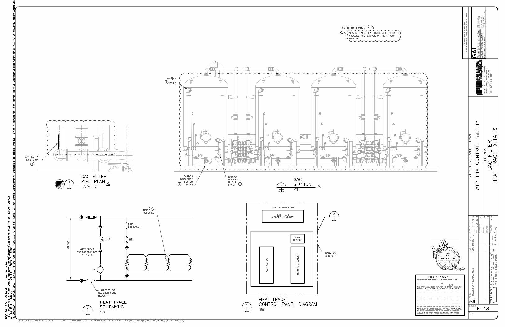
1371
7 N
eutro
n R
oad
Dal
las,
Texa
s 75
244
Tel:
972
-490
-766
1Fa
x: 9
72-4
90-7
125
emai
l:vkg
upta@ga
icon
sulting
.com
GAI
Gup
ta &
Ass
oci
ates
, In
c.C
ON
SU
LT
IN
G E
NG
IN
EE
RIN
G
Re
gistra
tio
n N
o. F
-2
59
3
10/30/18
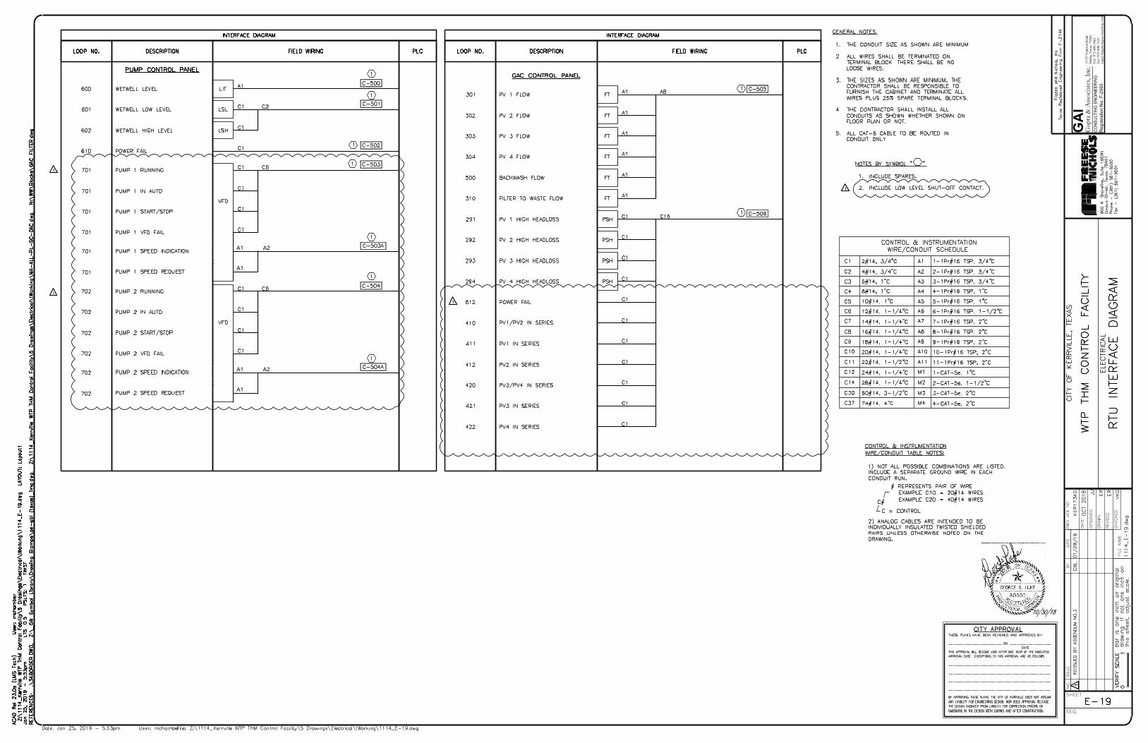
1371
7 N
eutro
n R
oad
Dal
las,
Texa
s 75
244
Tel:
972
-490
-766
1Fa
x: 9
72-4
90-7
125
emai
l:vkg
upta@ga
icon
sulting
.com
GAI
Gup
ta &
Ass
oci
ates
, In
c.C
ON
SU
LT
IN
G E
NG
IN
EE
RIN
G
Re
gistra
tio
n N
o. F
-2
59
3
10/30/18
A1
A1
A2
A1
A1
A2
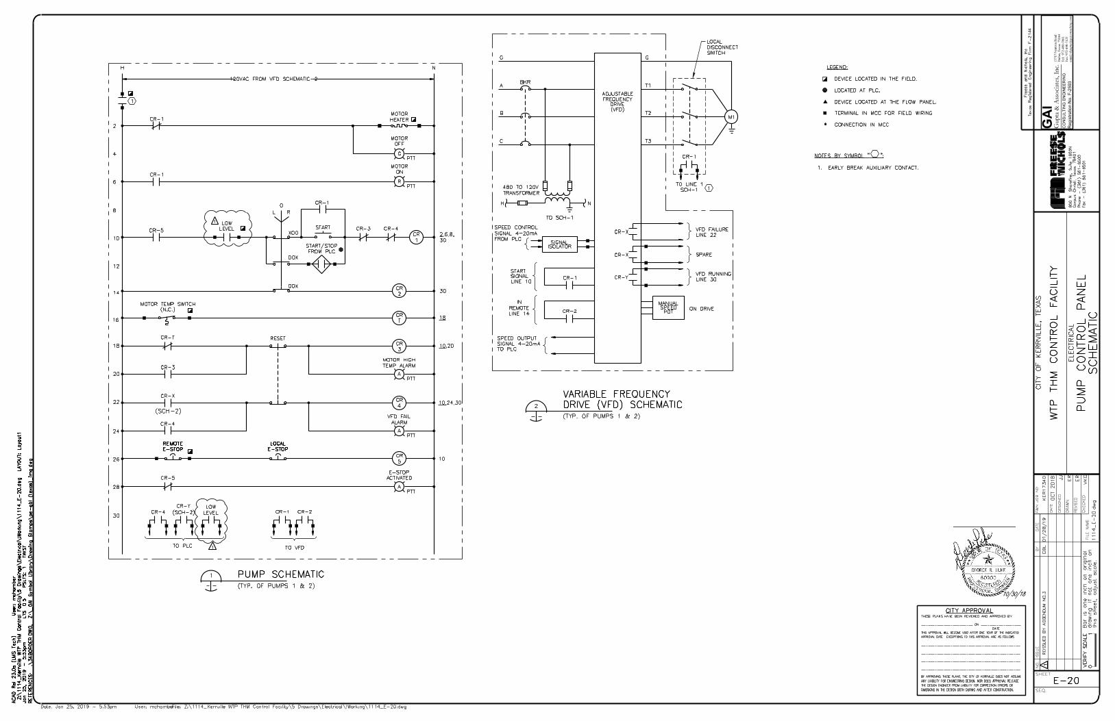
1371
7 N
eutro
n R
oad
Dal
las,
Texa
s 75
244
Tel:
972
-490
-766
1Fa
x: 9
72-4
90-7
125
emai
l:vkg
upta@ga
icon
sulting
.com
GAI
Gup
ta &
Ass
oci
ates
, In
c.C
ON
SU
LT
IN
G E
NG
IN
EE
RIN
G
Re
gistra
tio
n N
o. F
-2
59
3
10/30/18

INTERIOR EXTERIOR
WATERTIGHT SEAL
AS SPECIFIED WITH
316SS HARDWARE
316 SS SLEEVE WITH
WATER STOP, SLEEVE
DIAMETER AS REQUIRED
BY SEAL MANUFACTURER
316SS WALL SLEEVE
CONDUIT
1-5/8" 316 SS DOUBLE
SLOTTED CHANNEL
316 SS NUTS,
WASHERS (TYP.)
3/8" (MIN.)
316 SS ALL
THREAD ROD
ALUMINUM
CABLE TRAY
(TYP.)
316 SS
FASTENING
HARDWARE
I-BEAM OF
CHANNEL STEEL
316 SS BEAM
CLAMP
MIN. 1/4"
ALUMINUM OR
10'GA 316 SS
YELLOW WARNING
TAPE OVER ENTIRE
SURFACE
5/16" DIA. MIN ADHESIVE
TYPE AND 316 SS
ANCHOR BOLTS (TYP.)
2
1
1. PROVIDE 1/8" NEOPRENE GASKET WHERE
ALUMINUM IS SELECTED. DO NOT ALLOW
ALUMINUM TO COME INTO DIRECT CONTACT WITH
CONCRETE.
2. CONTRACTOR WILL BE RESPONSIBLE FOR
PROVIDING THE CORRECT SIZE ANCHOR BOLTS
BASED ON LOAD.
NOTES BY SYMBOL " ":
CONDUIT AS
SPECIFIED
PVC COATED
COUPLING (TYP.)
PVC COATED
ALUMINUM
ELBOW (TYP.)
CONCRETE CURB WITH
CHAMFERED EDGES
3" MINIMUM HOUSE
KEEPING PAD
CONCRETE
FLOOR OR SLAB
CONDUITS AS
SPECIFIED OR AS
PLANNED
1
1. THE FIRST FITTING PAST ANY FINISH SURFACE
SHALL BE A MIN. OF 3" ABOVE THAT FINISH
SURFACE.
NOTES BY SYMBOL " ":
ELECTRICAL
EQUIPMENT
ENCLOSURE AS
SPECIFIED
1-5/8" 316 SS
SLOTTED CHANNEL.
ALL CUT EDGES TO
BE FILED SMOOTH
5/16" DIA. MIN
ADHESIVE TYPE
AND 316 SS
ANCHOR BOLTS
1
1. CONTRACTOR SHALL BE RESPONSIBLE FOR
PROVIDING THE CORRECT SIZE ANCHOR BOLTS
BASED ON LOAD
NOTES BY SYMBOL " ":
1'-6"
WP/GFI
IN-USE COVER
UNISTRUT
1
1. THE FIRST FITTING PAST ANY FINISH SURFACE
SHALL BE A MIN. OF 3" ABOVE THAT FINISH
SURFACE.
NOTES BY SYMBOL " ":
PVC ADAPTERREBAR AS PER
DUCTBANK
DETAILS
EXISTING/NEW
FOOTING OR
FOUNDATION
COMPRESSIBLE
JOINT FILLER
PVC COATED
ALUMINUM CONDUIT
REFER TO APPLICABLE
WALL PENETRATION
DETAILS
ALUMINUM
CONDUIT
J-BOX
PULL BOX OR TERMINAL
CABINET AS INDICATED
ON THE DRAWINGS AND
SPECIFICATIONS
ALUMINUM
EXPANSION-
DEFLECTION
FITTING
3
1
4
2
CONCRETE
ENCASEMENT AS
PER DUCTBANK
DETAILS
PVC CONDUIT
AS SHOWN
ON PLANS
1. SEAL ALL CONDUITS ENTERING ENCLOSURES
WITH REMOVABLE SILICON CAULK.
2. ALLOW MINIMUM OF 12" OF WIRE SLACK IN
JUNCTION BOX TO ACCOMMODATE EXPANSION
JOINT.
3. APPLY RUBBER ELECTRICAL TAPE TO ALL
EXPOSED METAL CONDUIT OR CONDUIT THREADS.
EXTEND TAPE A MINIMUM 2" IN BOTH DIRECTIONS
BEYOND EXPOSED CONDUIT.
4. THE FIRST FITTING PAST ANY FINISH SURFACE
SHALL BE A MIN. OF 3" ABOVE THAT FINISH
SURFACE.
5. PROVIDE DEFLECTION FITTING ONLY WHEN
DUCTBANK APPROACH TO BUILDING IS NOT 90°
FROM BUILDING.
NOTES BY SYMBOL " ":
CONCRETE SLOPED
AWAY FROM BLDG. 1"
CHAMFER ALL AROUND
3"
(MIN.)
PVC
CONDUIT
PVC COATED
ALUMINUM LONG
SWEEP ELBOW
5
1371
7 N
eutro
n R
oad
Dal
las,
Texa
s 75
244
Tel:
972
-490
-766
1Fa
x: 9
72-4
90-7
125
emai
l:vkg
upta@ga
icon
sulting
.com
GAI
Gup
ta &
Ass
oci
ates
, In
c.C
ON
SU
LT
IN
G E
NG
IN
EE
RIN
G
Re
gistra
tio
n N
o. F
-2
59
3
10/30/18
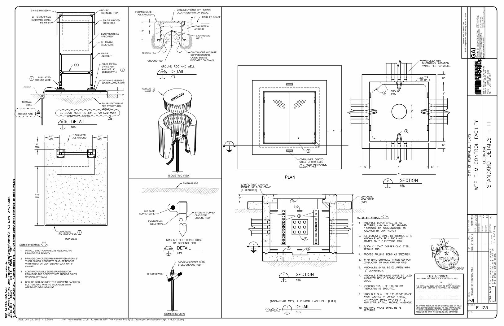
4"
1"
12"
12"
FORM SQUARE
ALL AROUND
MONUMENT CASE WITH COVER
OLDCASTLE 03 RT OR EQUAL.
FINISHED GRADE
CONCRETE ALL
AROUND
EXOTHERMIC
WELD
GROUND ROD
GRAVEL FILL
CONTINUOUS #4/0 BARE
COPPER GROUND
CABLE, SIZE AS
INDICATED ON PLANS
EXOTHERMIC
WELD (TYP)
#4/0 BARE
COPPER WIRE
3/4"X10'-0" COPPER
CLAD STEEL
GROUND ROD
FINISH GRADE
6"
3"
1'-0"
MIN.
4'-0"
MIN.
1'-0"
MIN.
316 SS HINGED
SUNSHIELD
ROUND
CORNERS (TYP.)
EQUIPMENTS AS
SPECIFIED
ALUMINUM
BACKPLATE
316 SS
UNISTRUT
FOUR 3/8" DIA.
316 SS ADH
ANCHOR, 4"
EMBED (TYP.)
3/4" NON-SHRINKING
GROUT (ASTM C1107)
EQUIPMENT PAD AS
PER STRUCTURAL
DETAILS
ALL SUPPORTING
HARDWARE SHALL
BE 316 SS
INSULATED
GROUND WIRE
GRADE
THERMAL
WELD
GROUND ROD
1" CHAMFER
ALL AROUND
CONCRETE
EQUIPMENT PAD
4
1
3
2
1. INSTALL STRUT CHANNEL AS REQUIRED TO
PROVIDE FOR RIGIDITY.
2. PROVIDE CONCRETE PAD IN UNPAVED AREAS. 6"
THICK, 3000PSI CONCRETE SLAB. REINFORCE
WITH #4@12" ON CENTER EACH WAY, ON 3"
CHAIRS.
3. CONTRACTOR WILL BE RESPONSIBLE FOR
PROVIDING THE CORRECT SIZE ANCHOR BOLTS
ON LOAD. (TYPICAL)
4. SECURE GROUND WIRE TO EQUIPMENT RACK LEG.
BOLT GROUND WIRE TO BACKPLATE WITH
APPROVED GROUND LUGS.
NOTES BY SYMBOL " ":
6"
MIN.
TOP VIEW
316 SS HINGED
1371
7 N
eutro
n R
oad
Dal
las,
Texa
s 75
244
Tel:
972
-490
-766
1Fa
x: 9
72-4
90-7
125
emai
l:vkg
upta@ga
icon
sulting
.com
GAI
Gup
ta &
Ass
oci
ates
, In
c.C
ON
SU
LT
IN
G E
NG
IN
EE
RIN
G
Re
gistra
tio
n N
o. F
-2
59
3
10/30/18
G
R
O
U
N
D
OLDCASTLE
03 RT LID
GROUND WIRE
3/4"x10'-0" COPPER CLAD
STEEL GROUND ROD
ISOMETRIC VIEW
ISOMETRIC VIEW
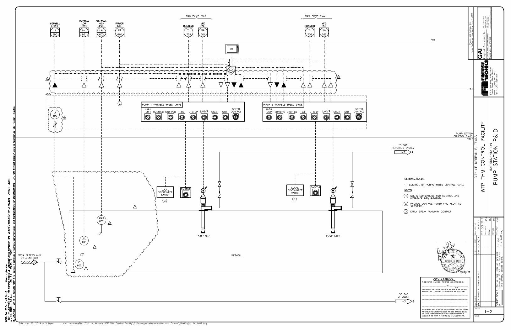
1371
7 N
eutro
n R
oad
Dal
las,
Texa
s 75
244
Tel:
972
-490
-766
1Fa
x: 9
72-4
90-7
125
emai
l:vkg
upta@ga
icon
sulting
.com
GAI
Gup
ta &
Ass
oci
ates
, In
c.C
ON
SU
LT
IN
G E
NG
IN
EE
RIN
G
Re
gistra
tio
n N
o. F
-2
59
3
10/30/18
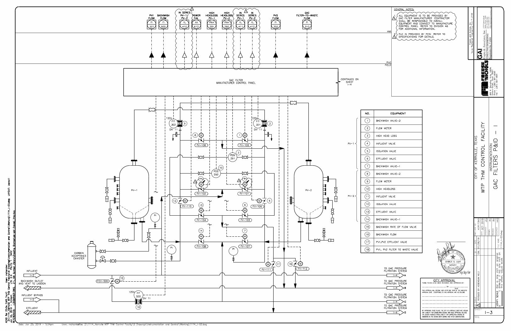
1371
7 N
eutro
n R
oad
Dal
las,
Texa
s 75
244
Tel:
972
-490
-766
1Fa
x: 9
72-4
90-7
125
emai
l:vkg
upta@ga
icon
sulting
.com
GAI
Gup
ta &
Ass
oci
ates
, In
c.C
ON
SU
LT
IN
G E
NG
IN
EE
RIN
G
Re
gistra
tio
n N
o. F
-2
59
3
10/30/18
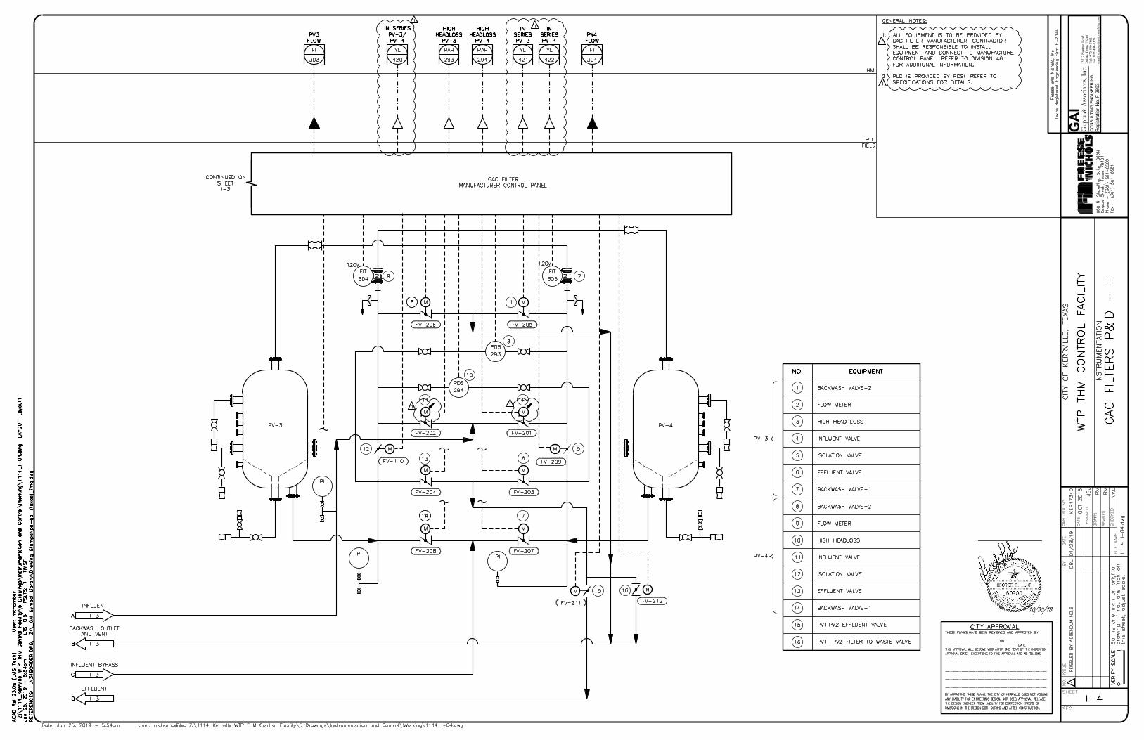
1371
7 N
eutro
n R
oad
Dal
las,
Texa
s 75
244
Tel:
972
-490
-766
1Fa
x: 9
72-4
90-7
125
emai
l:vkg
upta@ga
icon
sulting
.com
GAI
Gup
ta &
Ass
oci
ates
, In
c.C
ON
SU
LT
IN
G E
NG
IN
EE
RIN
G
Re
gistra
tio
n N
o. F
-2
59
3
10/30/18
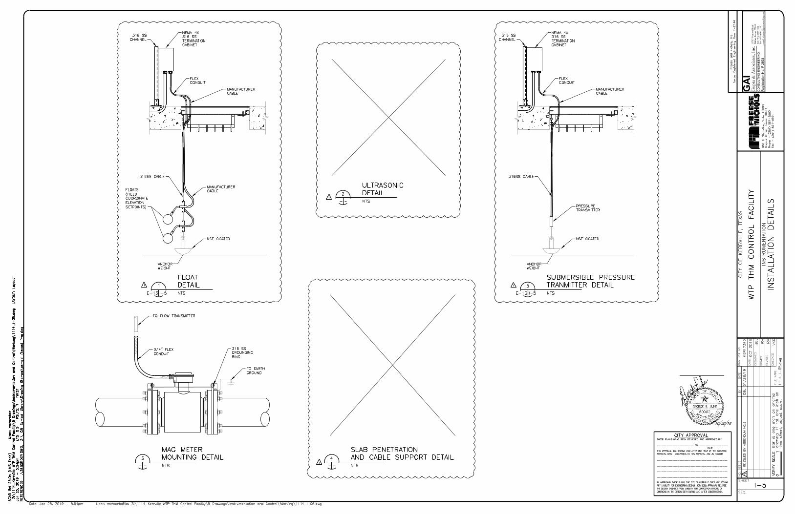
1371
7 N
eutro
n R
oad
Dal
las,
Texa
s 75
244
Tel:
972
-490
-766
1Fa
x: 9
72-4
90-7
125
emai
l:vkg
upta@ga
icon
sulting
.com
GAI
Gup
ta &
Ass
oci
ates
, In
c.C
ON
SU
LT
IN
G E
NG
IN
EE
RIN
G
Re
gistra
tio
n N
o. F
-2
59
3
10/30/18