
— Endura AZ20 oxygen monitor Combustion gas analysis - ABB
32
— ABB MEASUREMENT & ANALYTICS | DATA SHEET Endura AZ20 oxygen monitor Combustion gas analysis
-
Upload
khangminh22 -
Category
Documents
-
view
1 -
download
0
Transcript of — Endura AZ20 oxygen monitor Combustion gas analysis - ABB
—ABB MEASUREMENT & ANALYTICS | DATA SHEET
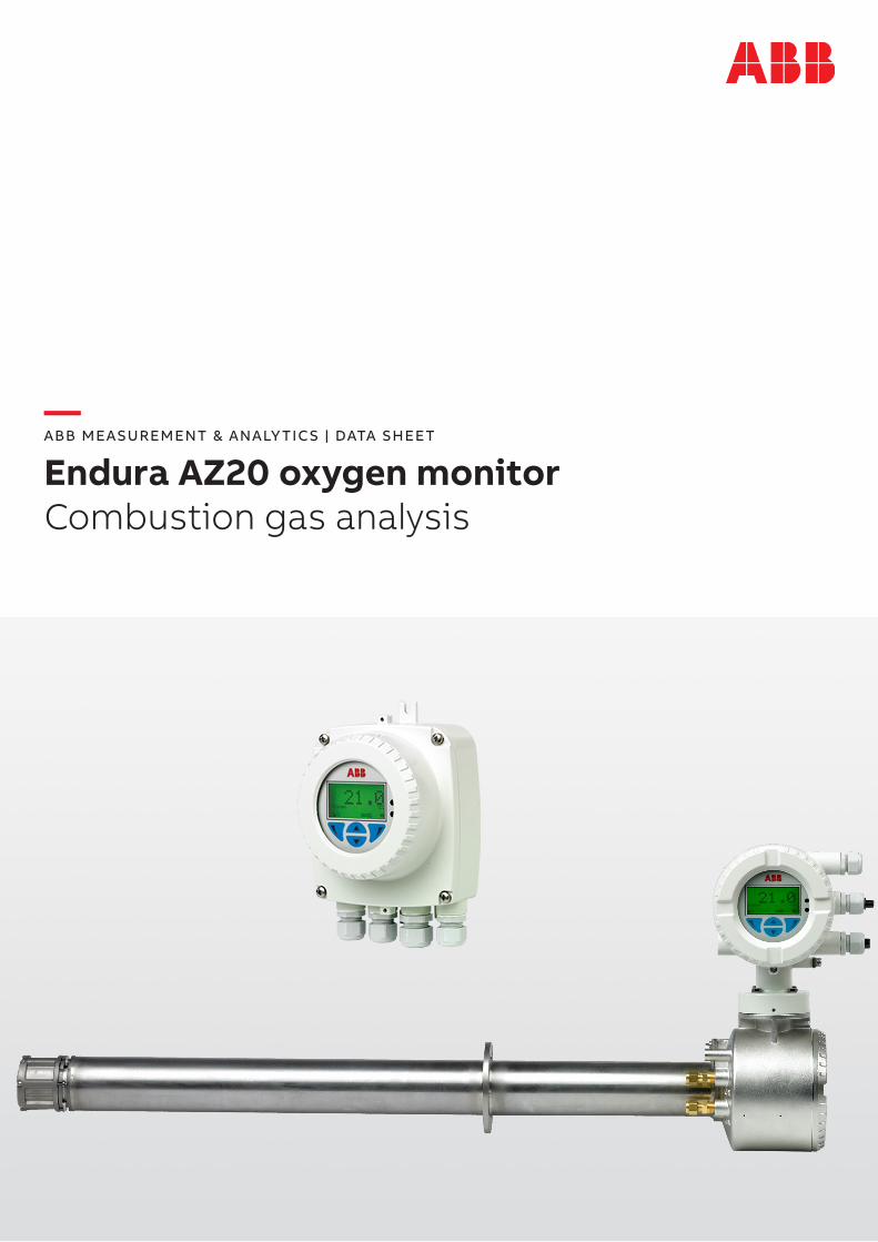
Endura AZ20 oxygen monitorCombustion gas analysis
2 ENDUR A AZ20 OX YGEN MONITOR COMBUSTION GAS ANALYSIS | DS/AZ20-EN REV. P
—Measurement made easy Superior technology and quality from the world leader in oxygen measurement
Advanced design and precision manufacturing• Robust, long-life probe for process temperatures up to 800 °C (1472 °F)• Proven cell design from over 50 years experience• Fast response to process variations• Stable and accurate oxygen measurement
Unique integrated auto-calibration system• Easy compliance for emission monitoring regulation• Reduced installation costs; eliminates requirement for expensive external
calibration panel• Reduced maintenance costs
Probe lengths up to 4.0 m (13.1 ft) and industry-standard
flange configurations• Suitable for a wide range of applications• Extensive installation options
Easy cell release• Fully site-serviceable probe• Easy access to internal components
Advanced transmitters• Easy configuration, monitoring and intuitive HMI• HART communications• Cell performance logging and diagnostics
3ENDUR A AZ20 OX YGEN MONITOR COMBUSTION GAS ANALYSIS | DS/AZ20-EN REV. P
—IntroductionThe Endura AZ20 is the latest in a long line of high-quality, combustion gas analyzers from ABB.
The sensor, based on a zirconium oxide cell, is mounted at the tip of the probe that is inserted in the flue duct. The resulting direct, in situ measurement provides accurate and rapid oxygen reading for combustion control optimization and emissions monitoring.
—Advanced designDesigned and manufactured to exacting standards, the Endura AZ20 ensures long periods of trouble-free operation in even the most arduous of applications.
The operating process temperature of up to 800 °C (1472 °F) extends system suitability into previously impossible applications and enables optimum probe location within the process.
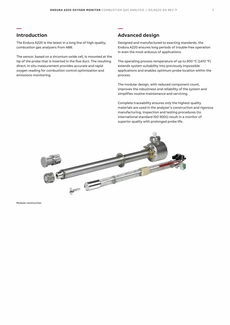
The modular design, with reduced component count, improves the robustness and reliability of the system and simplifies routine maintenance and servicing.
Complete traceability ensures only the highest quality materials are used in the analyzer’s construction and rigorous manufacturing, inspection and testing procedures (to international standard ISO 9001) result in a monitor of superior quality with prolonged probe life.
Modular construction
4 ENDUR A AZ20 OX YGEN MONITOR COMBUSTION GAS ANALYSIS | DS/AZ20-EN REV. P
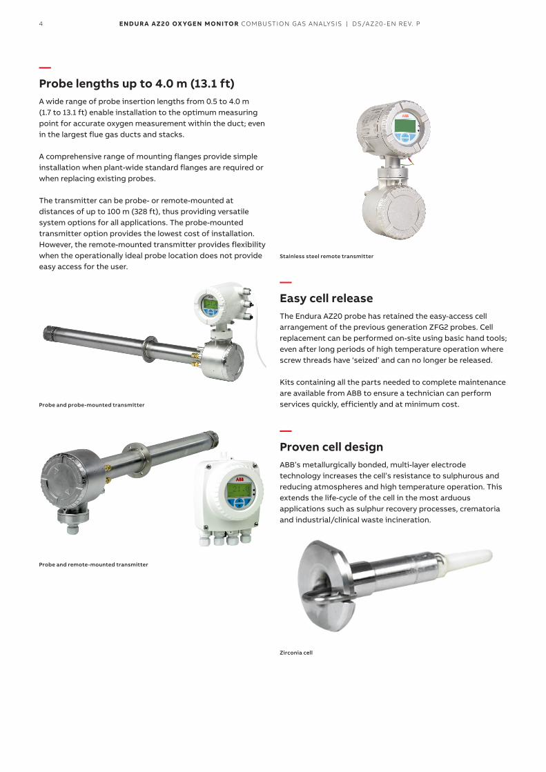
—Probe lengths up to 4.0 m (13.1 ft)A wide range of probe insertion lengths from 0.5 to 4.0 m (1.7 to 13.1 ft) enable installation to the optimum measuring point for accurate oxygen measurement within the duct; even in the largest flue gas ducts and stacks.
A comprehensive range of mounting flanges provide simple installation when plant-wide standard flanges are required or when replacing existing probes.
The transmitter can be probe- or remote-mounted at distances of up to 100 m (328 ft), thus providing versatile system options for all applications. The probe-mounted transmitter option provides the lowest cost of installation. However, the remote-mounted transmitter provides flexibility when the operationally ideal probe location does not provide easy access for the user.
Probe and probe-mounted transmitter
Probe and remote-mounted transmitter
Stainless steel remote transmitter
—Easy cell releaseThe Endura AZ20 probe has retained the easy-access cell arrangement of the previous generation ZFG2 probes. Cell replacement can be performed on-site using basic hand tools; even after long periods of high temperature operation where screw threads have ‘seized’ and can no longer be released.
Kits containing all the parts needed to complete maintenance are available from ABB to ensure a technician can perform services quickly, efficiently and at minimum cost.
—Proven cell designABB’s metallurgically bonded, multi-layer electrode technology increases the cell’s resistance to sulphurous and reducing atmospheres and high temperature operation. This extends the life-cycle of the cell in the most arduous applications such as sulphur recovery processes, crematoria and industrial/clinical waste incineration.
Zirconia cell
5ENDUR A AZ20 OX YGEN MONITOR COMBUSTION GAS ANALYSIS | DS/AZ20-EN REV. P
—Optional flow rate control to the sensorThe correct flow rate of test gas and reference air is essential to ensure the accurate operation of Zirconia-based AZ20 oxygen analyzers.
This is achieved using one of two options:• using flow restrictors (no flowmeters required):
– flow restrictors fitted in the sensor head guarantee thecorrect flow of test gases and reference air by applyingthe gases/air to the probe at a fixed pressure of 15 psi(1.0 bar)
• using flowmeters (no restrictors):– the Endura AZ20 uses flow meters with flow control
valves to regulate the flow of test gases and referenceair into the sensor
—Optional corrosion resistant coatingUsed in applications where the process temperature is close to the sample acid dew point. This PFA coating protects the probe body against corrosion caused when acids condense out onto the probe. The exact temperature at which this occurs is dependent on the acid gas concentration and the water vapor content of the sample. This option is suitable where the process temperature is below 250 °C (482 °F)
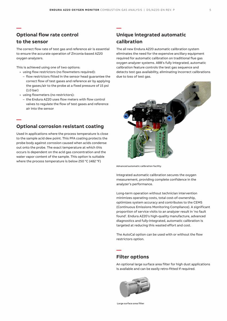
—Unique integrated automatic calibrationThe all new Endura AZ20 automatic calibration system eliminates the need for the expensive ancillary equipment required for automatic calibration on traditional flue gas oxygen analyzer systems. ABB’s fully integrated, automatic calibration feature controls the test gas sequence and detects test gas availability, eliminating incorrect calibrations due to loss of test gas.
Advanced automatic calibration facility
Integrated automatic calibration secures the oxygen measurement, providing complete confidence in the analyzer’s performance.
Long-term operation without technician intervention minimizes operating costs, total cost-of-ownership, optimizes system accuracy and contributes to the CEMS (Continuous Emissions Monitoring Compliance). A significant proportion of service visits to an analyzer result in ‘no fault found’. Endura AZ20’s high-quality manufacture, advanced diagnostics and fully-integrated, automatic calibration is targeted at reducing this wasted effort and cost.
The AutoCal option can be used with or without the flow restrictors option.
—Filter optionsAn optional large surface area filter for high dust applications is available and can be easily retro-fitted if required.
Large surface area filter
6 ENDUR A AZ20 OX YGEN MONITOR COMBUSTION GAS ANALYSIS | DS/AZ20-EN REV. P
—Advanced transmitterThe Endura AZ20 transmitter incorporates the most up-to-date design and technology available today.
ABB’s universal human/machine interface (HMI) with its large, clear, backlit graphical display, ‘through-the-glass’ control and intuitive menu structure simplifies transmitter configuration and operation.
The user-friendly interface enables fast, easy data entry for all parameters and the ‘Easy Setup’ menu speeds and simplifies system commissioning.
Advanced diagnostics, in accordance with NAMUR NE107, classify alarms and warnings as ‘Maintenance Required’, ‘Check Function’, ‘Failure’ and ‘Out-of-Specification’. Cell performance is monitored by the transmitter; indicators such as cell impedance, rate-of-response to test gases and changes in calibration offset/factor are recorded and analyzed. The current cell ‘quality’ is displayed by the transmitter as a visual indication of the measurement confidence; providing the operator all the information required to keep the monitor operating at peak performance.
The performance log holds up to 100 time-stamped events. When the log is full, the oldest data is overwritten by new entries. The log contains details of measurements and coefficients for all calibrations and accuracy checks.
2 relay outputs and a traditional analog output are fitted as standard, with the option of adding a second analog output or 2 digital inputs/outputs (I/O).
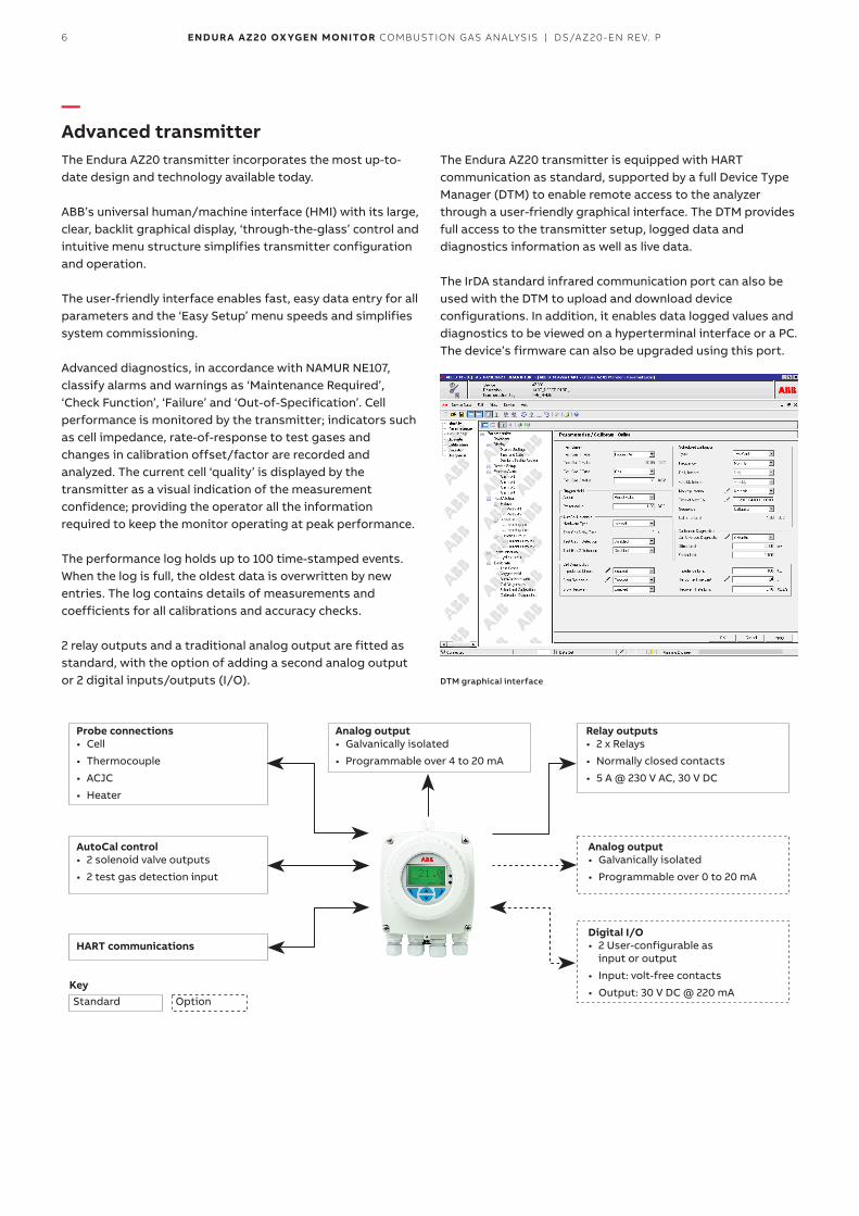
The Endura AZ20 transmitter is equipped with HART communication as standard, supported by a full Device Type Manager (DTM) to enable remote access to the analyzer through a user-friendly graphical interface. The DTM provides full access to the transmitter setup, logged data and diagnostics information as well as live data.
The IrDA standard infrared communication port can also be used with the DTM to upload and download device configurations. In addition, it enables data logged values and diagnostics to be viewed on a hyperterminal interface or a PC. The device’s firmware can also be upgraded using this port.
DTM graphical interface
Probe connections• Cell
• Thermocouple
• ACJC
• Heater
Digital I/O• 2 User-configurable as
input or output
• Input: volt-free contacts
• Output: 30 V DC @ 220 mA
Relay outputs• 2 x Relays
• Normally closed contacts
• 5 A @ 230 V AC, 30 V DC
Analog output• Galvanically isolated
• Programmable over 4 to 20 mA
AutoCal control• 2 solenoid valve outputs
• 2 test gas detection input
Analog output• Galvanically isolated
• Programmable over 0 to 20 mA
HART communications
KeyStandard Option
7ENDUR A AZ20 OX YGEN MONITOR COMBUSTION GAS ANALYSIS | DS/AZ20-EN REV. P
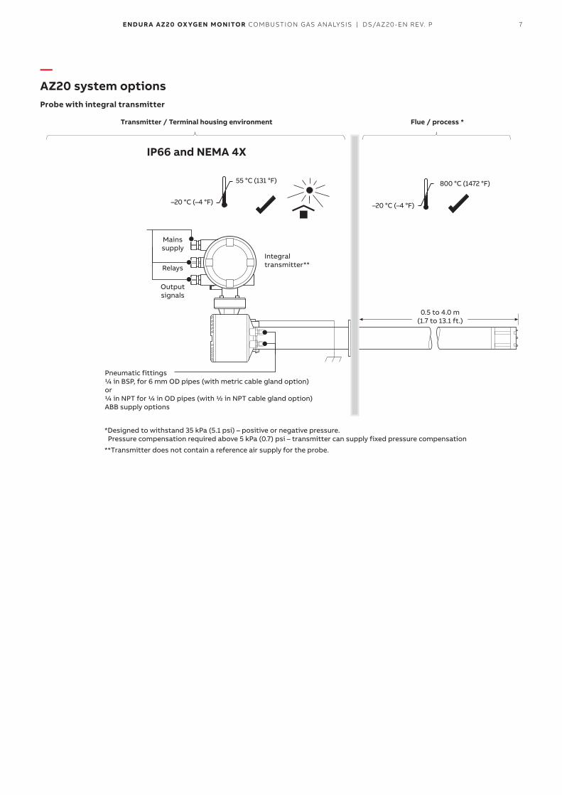
—AZ20 system optionsProbe with integral transmitter
–20 °C (–4 °F)
800 °C (1472 °F)
–20 °C (–4 °F)
55 °C (131 °F)
Transmitter / Terminal housing environment
IP66 and NEMA 4X
Flue / process *
0.5 to 4.0 m (1.7 to 13.1 ft.)
Pneumatic fittings 1/4 in BSP, for 6 mm OD pipes (with metric cable gland option) or 1/4 in NPT for 1/4 in OD pipes (with 1/2 in NPT cable gland option) ABB supply options
Mains supply
Relays
Output signals
*Designed to withstand 35 kPa (5.1 psi) – positive or negative pressure. Pressure compensation required above 5 kPa (0.7) psi – transmitter can supply fixed pressure compensation
**Transmitter does not contain a reference air supply for the probe.
Integral transmitter**
8 ENDUR A AZ20 OX YGEN MONITOR COMBUSTION GAS ANALYSIS | DS/AZ20-EN REV. P
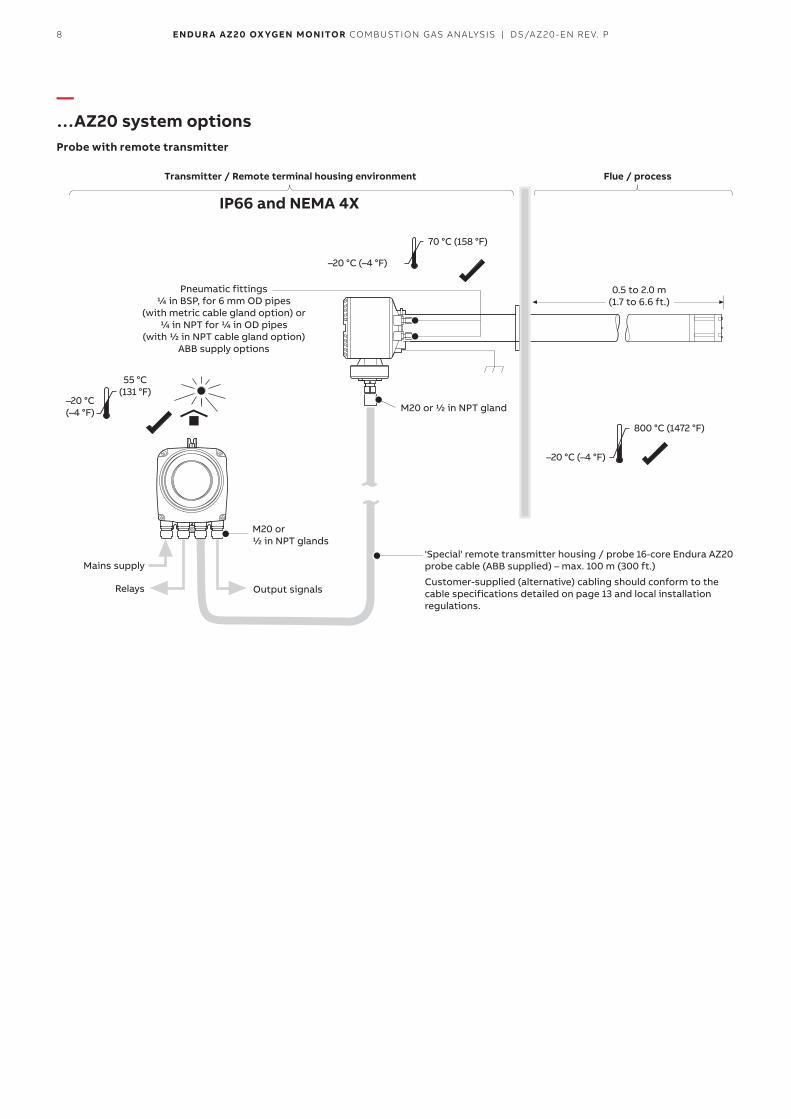
—…AZ20 system optionsProbe with remote transmitter
–20 °C (–4 °F)
800 °C (1472 °F)
–20 °C (–4 °F)
70 °C (158 °F)
–20 °C(–4 °F)
55 °C(131 °F)
Transmitter / Remote terminal housing environment
IP66 and NEMA 4X
Flue / process
0.5 to 2.0 m (1.7 to 6.6 ft.)
Mains supply
Relays Output signals
M20 or 1/2 in NPT glands
M20 or 1/2 in NPT gland
Pneumatic fittings 1/4 in BSP, for 6 mm OD pipes
(with metric cable gland option) or 1/4 in NPT for 1/4 in OD pipes
(with 1/2 in NPT cable gland option) ABB supply options
'Special' remote transmitter housing / probe 16-core Endura AZ20 probe cable (ABB supplied) – max. 100 m (300 ft.)
Customer-supplied (alternative) cabling should conform to the cable specifications detailed on page 13 and local installation regulations.
9ENDUR A AZ20 OX YGEN MONITOR COMBUSTION GAS ANALYSIS | DS/AZ20-EN REV. P
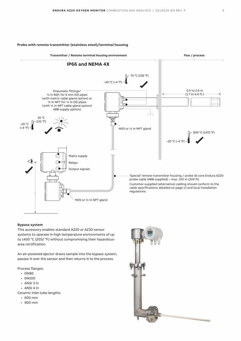
Probe with remote transmitter (stainless steel)/terminal housing
–20 °C (–4 °F)
800 °C (1472 °F)
–20 °C (–4 °F)
70 °C (158 °F)
–20 °C(–4 °F)
55 °C(131 °F)
Transmitter / Remote terminal housing environment
IP66 and NEMA 4X
Flue / process
0.5 to 2.0 m (1.7 to 6.6 ft.)
Mains supply
Relays
Output signals
M20 or 1/2 in NPT gland
M20 or 1/2 in NPT gland
Pneumatic fittings* 1/4 in BSP, for 6 mm OD pipes
(with metric cable gland option) or 1/4 in NPT for 1/4 in OD pipes
(with 1/2 in NPT cable gland option) ABB supply options
'Special' remote transmitter housing / probe 16-core Endura AZ20 probe cable (ABB supplied) – max. 100 m (300 ft)
Customer-supplied (alternative) cabling should conform to the cable specifications detailed on page 13 and local installation regulations.
Bypass systemThis accessory enables standard AZ20 or AZ30 sensor systems to operate in high temperature environments of up to 1400 °C (2552 °F) without compromising their hazardous-area certification.
An air-powered ejector draws sample into the bypass system, passes it over the sensor and then returns it to the process.
Process flanges:• DN80• DN100• ANSI 3 in• ANSI 4 in
Ceramic inlet tube lengths:• 600 mm• 900 mm
10 ENDUR A AZ20 OX YGEN MONITOR COMBUSTION GAS ANALYSIS | DS/AZ20-EN REV. P
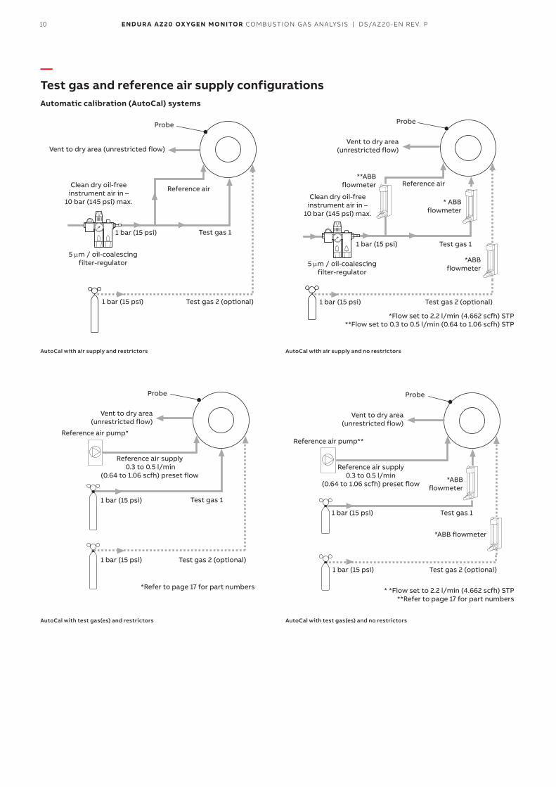
—Test gas and reference air supply configurationsAutomatic calibration (AutoCal) systems
Vent to dry area (unrestricted flow)
Probe
Clean dry oil-free instrument air in –
10 bar (145 psi) max.
1 bar (15 psi)
1 bar (15 psi)
5 µm / oil-coalescing filter-regulator
Reference air
Test gas 1
Test gas 2 (optional)
AutoCal with air supply and restrictors
1 bar (15 psi)
1 bar (15 psi)
Reference air supply 0.3 to 0.5 l/min
(0.64 to 1.06 scfh) preset flow
Vent to dry area (unrestricted flow)
Probe
Test gas 1
Test gas 2 (optional)
Reference air pump*
*Refer to page 17 for part numbers
AutoCal with test gas(es) and restrictors
1 bar (15 psi)
1 bar (15 psi)
5 µm / oil-coalescing filter-regulator
**ABB flowmeter
Vent to dry area (unrestricted flow)
Probe
Reference air
Test gas 1
*ABB flowmeter
* ABB flowmeter
*Flow set to 2.2 l/min (4.662 scfh) STP **Flow set to 0.3 to 0.5 l/min (0.64 to 1.06 scfh) STP
Test gas 2 (optional)
Clean dry oil-free instrument air in –
10 bar (145 psi) max.
AutoCal with air supply and no restrictors
1 bar (15 psi)
*ABB flowmeter
1 bar (15 psi)
Reference air supply 0.3 to 0.5 l/min
(0.64 to 1.06 scfh) preset flow
Probe
Vent to dry area (unrestricted flow)
Reference air pump**
Test gas 1
*ABB flowmeter
* *Flow set to 2.2 l/min (4.662 scfh) STP **Refer to page 17 for part numbers
Test gas 2 (optional)
AutoCal with test gas(es) and no restrictors
11ENDUR A AZ20 OX YGEN MONITOR COMBUSTION GAS ANALYSIS | DS/AZ20-EN REV. P
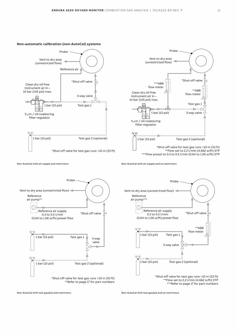
Non-automatic calibration (non-AutoCal) systems
Probe
Vent to dry area (unrestricted flow)
Reference air
Clean dry oil-free instrument air in –
10 bar (145 psi) max.
Test gas 1
3-way valve
*Shut-off valve
1 bar (15 psi)
1 bar (15 psi)
5 µm / oil-coalescing filter-regulator
Test gas 2 (optional)
*Shut-off valve for test gas runs >10 m (33 ft)
Non-AutoCal with air supply and restrictors
Probe
Vent to dry area (unrestricted flow)
Reference air pump**
Test gas 1 3-way valve
*Shut-off valve
1 bar (15 psi)
1 bar (15 psi)
Test gas 2 (optional)
*Shut-off valve for test gas runs >10 m (33 ft) **Refer to page 17 for part numbers
Reference air supply 0.3 to 0.5 l/min
(0.64 to 1.06 scfh) preset flow
Non-AutoCal with test gas(es) and restrictors
Probe
Vent to dry area (unrestricted flow)
Clean dry oil-free instrument air in –
10 bar (145 psi) max.
1 bar (15 psi)
1 bar (15 psi)
5 µm / oil-coalescing filter-regulator
Test gas 2 (optional)
*Shut-off valve for test gas runs >10 m (33 ft) **Flow set to 2.2 l/min (4.662 scfh) STP
***Flow preset to 0.3 to 0.5 l/min (0.64 to 1.06 scfh) STP
3-way valve
Test gas 1
**ABB flow meter
***ABB flow meter
*Shut-off valve
Non-AutoCal with air supply and no restrictors
Probe
Vent to dry area (unrestricted flow)
Reference air pump***
Test gas 1
3-way valve
**ABB flow meter
*Shut-off valve
1 bar (15 psi)
1 bar (15 psi)
Test gas 2 (optional)
*Shut-off valve for test gas runs >10 m (33 ft) **Flow set to 2.2 l/min (4.662 scfh) STP
***Refer to page 17 for part numbers
Reference air supply 0.3 to 0.5 l/min
(0.64 to 1.06 scfh) preset flow
Non-AutoCal with test gas(es) and no restrictors
12 ENDUR A AZ20 OX YGEN MONITOR COMBUSTION GAS ANALYSIS | DS/AZ20-EN REV. P
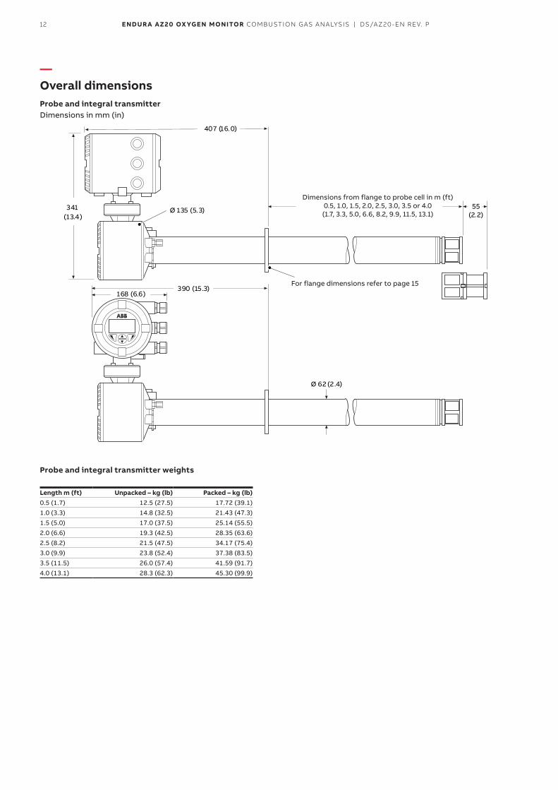
—Overall dimensionsProbe and integral transmitterDimensions in mm (in)
390 (15.3)
407 (16.0)
Ø 135 (5.3)341(13.4)
Ø 62 (2.4)
168 (6.6)
55(2.2)
Dimensions from flange to probe cell in m (ft) 0.5, 1.0, 1.5, 2.0, 2.5, 3.0, 3.5 or 4.0 (1.7, 3.3, 5.0, 6.6, 8.2, 9.9, 11.5, 13.1)
For flange dimensions refer to page 15
Probe and integral transmitter weights
Length m (ft) Unpacked – kg (lb) Packed – kg (lb)0.5 (1.7) 12.5 (27.5) 17.72 (39.1)1.0 (3.3) 14.8 (32.5) 21.43 (47.3)1.5 (5.0) 17.0 (37.5) 25.14 (55.5)2.0 (6.6) 19.3 (42.5) 28.35 (63.6)2.5 (8.2) 21.5 (47.5) 34.17 (75.4)3.0 (9.9) 23.8 (52.4) 37.38 (83.5)3.5 (11.5) 26.0 (57.4) 41.59 (91.7)4.0 (13.1) 28.3 (62.3) 45.30 (99.9)
13ENDUR A AZ20 OX YGEN MONITOR COMBUSTION GAS ANALYSIS | DS/AZ20-EN REV. P
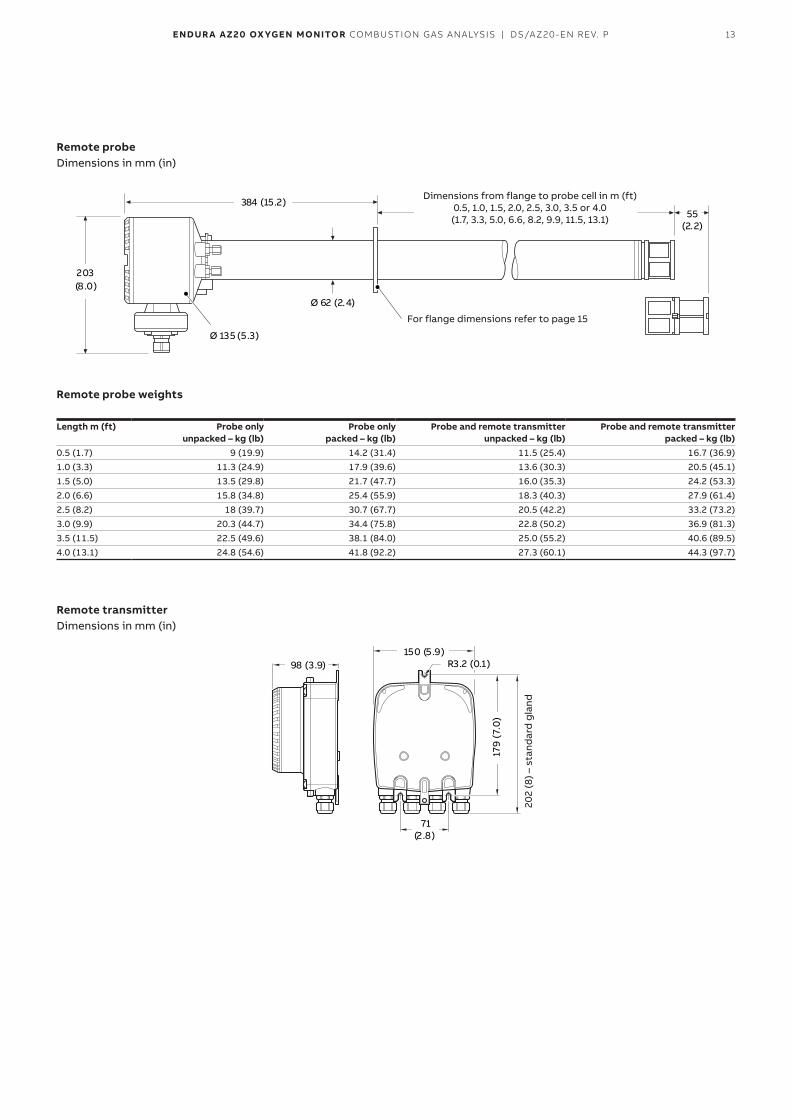
Remote probeDimensions in mm (in)
384 (15.2)
203(8.0)
Ø 135 (5.3)
Ø 62 (2.4)
55(2.2)
Dimensions from flange to probe cell in m (ft) 0.5, 1.0, 1.5, 2.0, 2.5, 3.0, 3.5 or 4.0 (1.7, 3.3, 5.0, 6.6, 8.2, 9.9, 11.5, 13.1)
For flange dimensions refer to page 15
Remote probe weights
Length m (ft) Probe only unpacked – kg (lb)
Probe only packed – kg (lb)
Probe and remote transmitter unpacked – kg (lb)
Probe and remote transmitter packed – kg (lb)
0.5 (1.7) 9 (19.9) 14.2 (31.4) 11.5 (25.4) 16.7 (36.9)1.0 (3.3) 11.3 (24.9) 17.9 (39.6) 13.6 (30.3) 20.5 (45.1)1.5 (5.0) 13.5 (29.8) 21.7 (47.7) 16.0 (35.3) 24.2 (53.3)2.0 (6.6) 15.8 (34.8) 25.4 (55.9) 18.3 (40.3) 27.9 (61.4)2.5 (8.2) 18 (39.7) 30.7 (67.7) 20.5 (42.2) 33.2 (73.2)3.0 (9.9) 20.3 (44.7) 34.4 (75.8) 22.8 (50.2) 36.9 (81.3)3.5 (11.5) 22.5 (49.6) 38.1 (84.0) 25.0 (55.2) 40.6 (89.5)4.0 (13.1) 24.8 (54.6) 41.8 (92.2) 27.3 (60.1) 44.3 (97.7)
Remote transmitterDimensions in mm (in)
98 (3.9) R3.2 (0.1)
71(2.8)
150 (5.9)
179
(7.0
)
202
(8) –
sta
ndar
d g
land
14 ENDUR A AZ20 OX YGEN MONITOR COMBUSTION GAS ANALYSIS | DS/AZ20-EN REV. P
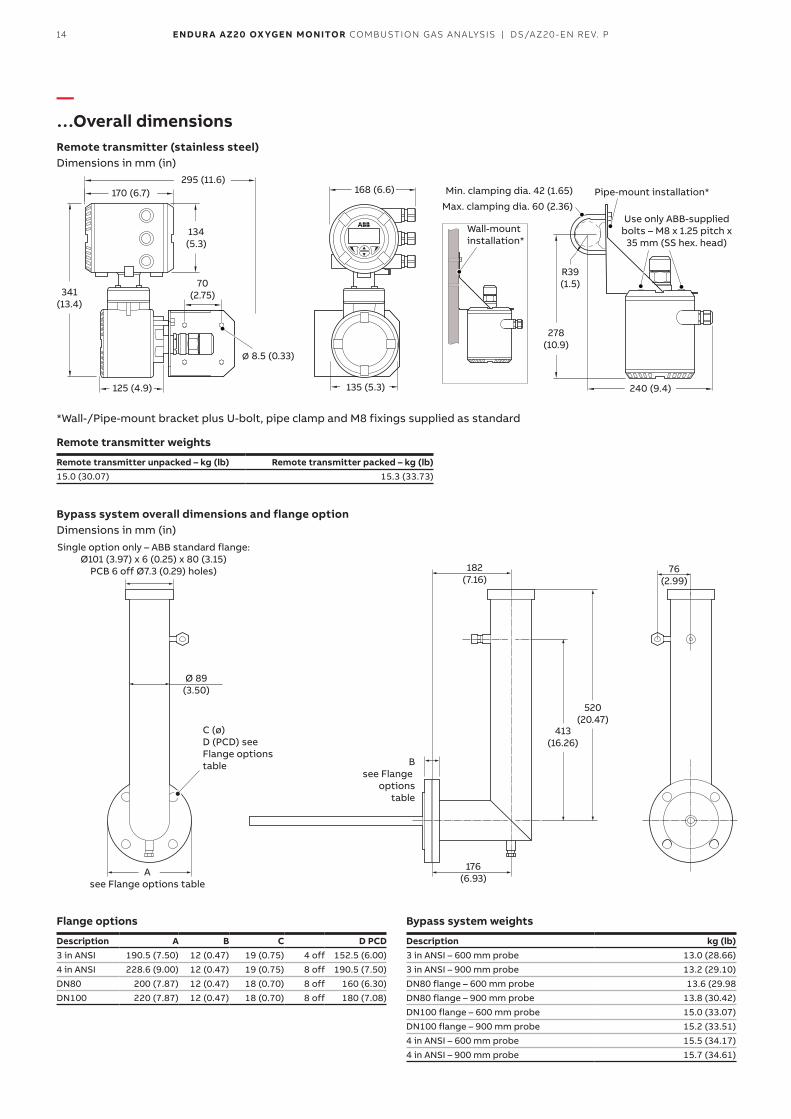
—…Overall dimensionsRemote transmitter (stainless steel)Dimensions in mm (in)
168 (6.6)295 (11.6)
240 (9.4)
170 (6.7)
135 (5.3)125 (4.9)
∅ 8.5 (0.33)
134(5.3)
70(2.75)341
(13.4)
278(10.9)
R39(1.5)
Min. clamping dia. 42 (1.65)
Max. clamping dia. 60 (2.36)Pipe-mount installation*
Wall-mount installation*
Use only ABB-supplied bolts – M8 x 1.25 pitch x
35 mm (SS hex. head)
*Wall-/Pipe-mount bracket plus U-bolt, pipe clamp and M8 fixings supplied as standard
Remote transmitter weights
Remote transmitter unpacked – kg (lb) Remote transmitter packed – kg (lb)15.0 (30.07) 15.3 (33.73)
Bypass system overall dimensions and flange optionDimensions in mm (in)
76(2.99)
182(7.16)
176(6.93)
Ø 89(3.50)
520(20.47)
413(16.26)
Asee Flange options table
C (ø) D (PCD) see Flange options table B
see Flange options
table
Single option only – ABB standard flange: Ø101 (3.97) x 6 (0.25) x 80 (3.15)
PCB 6 off Ø7.3 (0.29) holes)
Flange options
Description A B C D PCD3 in ANSI 190.5 (7.50) 12 (0.47) 19 (0.75) 4 off 152.5 (6.00)4 in ANSI 228.6 (9.00) 12 (0.47) 19 (0.75) 8 off 190.5 (7.50)DN80 200 (7.87) 12 (0.47) 18 (0.70) 8 off 160 (6.30)DN100 220 (7.87) 12 (0.47) 18 (0.70) 8 off 180 (7.08)
Bypass system weights
Description kg (lb)3 in ANSI – 600 mm probe 13.0 (28.66)3 in ANSI – 900 mm probe 13.2 (29.10)DN80 flange – 600 mm probe 13.6 (29.98DN80 flange – 900 mm probe 13.8 (30.42)DN100 flange – 600 mm probe 15.0 (33.07)DN100 flange – 900 mm probe 15.2 (33.51)4 in ANSI – 600 mm probe 15.5 (34.17)4 in ANSI – 900 mm probe 15.7 (34.61)
15ENDUR A AZ20 OX YGEN MONITOR COMBUSTION GAS ANALYSIS | DS/AZ20-EN REV. P
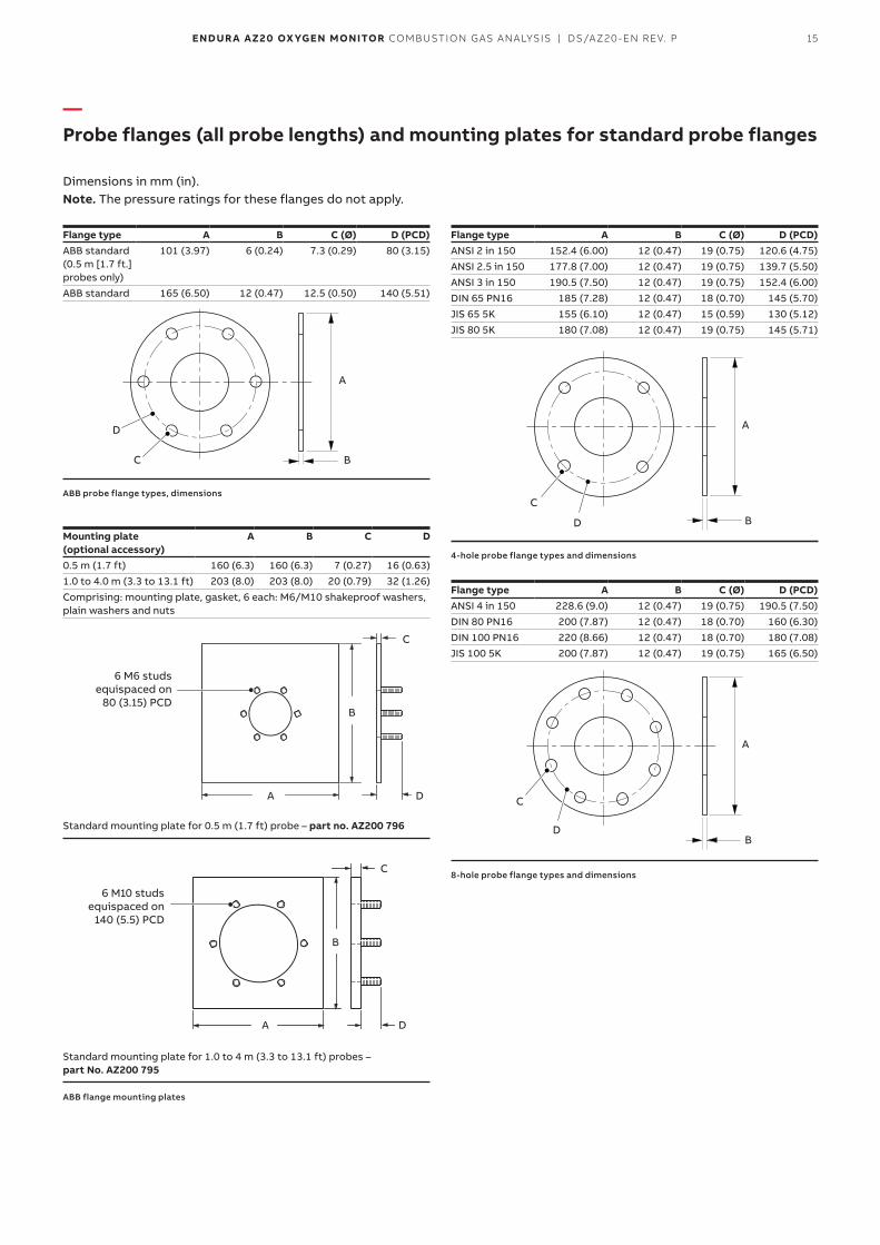
—Probe flanges (all probe lengths) and mounting plates for standard probe flanges
Dimensions in mm (in).Note. The pressure ratings for these flanges do not apply.
Flange type A B C (Ø) D (PCD)ABB standard (0.5 m [1.7 ft.] probes only)
101 (3.97) 6 (0.24) 7.3 (0.29) 80 (3.15)
ABB standard 165 (6.50) 12 (0.47) 12.5 (0.50) 140 (5.51)
A
BC
D
ABB probe flange types, dimensions
Mounting plate (optional accessory)
A B C D
0.5 m (1.7 ft) 160 (6.3) 160 (6.3) 7 (0.27) 16 (0.63)1.0 to 4.0 m (3.3 to 13.1 ft) 203 (8.0) 203 (8.0) 20 (0.79) 32 (1.26)Comprising: mounting plate, gasket, 6 each: M6/M10 shakeproof washers, plain washers and nuts
A
B
C
D
6 M6 studs equispaced on
80 (3.15) PCD
Standard mounting plate for 0.5 m (1.7 ft) probe – part no. AZ200 796
A
B
C
D
6 M10 studs equispaced on
140 (5.5) PCD
Standard mounting plate for 1.0 to 4 m (3.3 to 13.1 ft) probes – part No. AZ200 795
ABB flange mounting plates
Flange type A B C (Ø) D (PCD)ANSI 2 in 150 152.4 (6.00) 12 (0.47) 19 (0.75) 120.6 (4.75)ANSI 2.5 in 150 177.8 (7.00) 12 (0.47) 19 (0.75) 139.7 (5.50)ANSI 3 in 150 190.5 (7.50) 12 (0.47) 19 (0.75) 152.4 (6.00)DIN 65 PN16 185 (7.28) 12 (0.47) 18 (0.70) 145 (5.70)JIS 65 5K 155 (6.10) 12 (0.47) 15 (0.59) 130 (5.12)JIS 80 5K 180 (7.08) 12 (0.47) 19 (0.75) 145 (5.71)
A
B
C
D
4-hole probe flange types and dimensions
Flange type A B C (Ø) D (PCD)ANSI 4 in 150 228.6 (9.0) 12 (0.47) 19 (0.75) 190.5 (7.50)DIN 80 PN16 200 (7.87) 12 (0.47) 18 (0.70) 160 (6.30)DIN 100 PN16 220 (8.66) 12 (0.47) 18 (0.70) 180 (7.08)JIS 100 5K 200 (7.87) 12 (0.47) 19 (0.75) 165 (6.50)
A
B
C
D
8-hole probe flange types and dimensions
16 ENDUR A AZ20 OX YGEN MONITOR COMBUSTION GAS ANALYSIS | DS/AZ20-EN REV. P
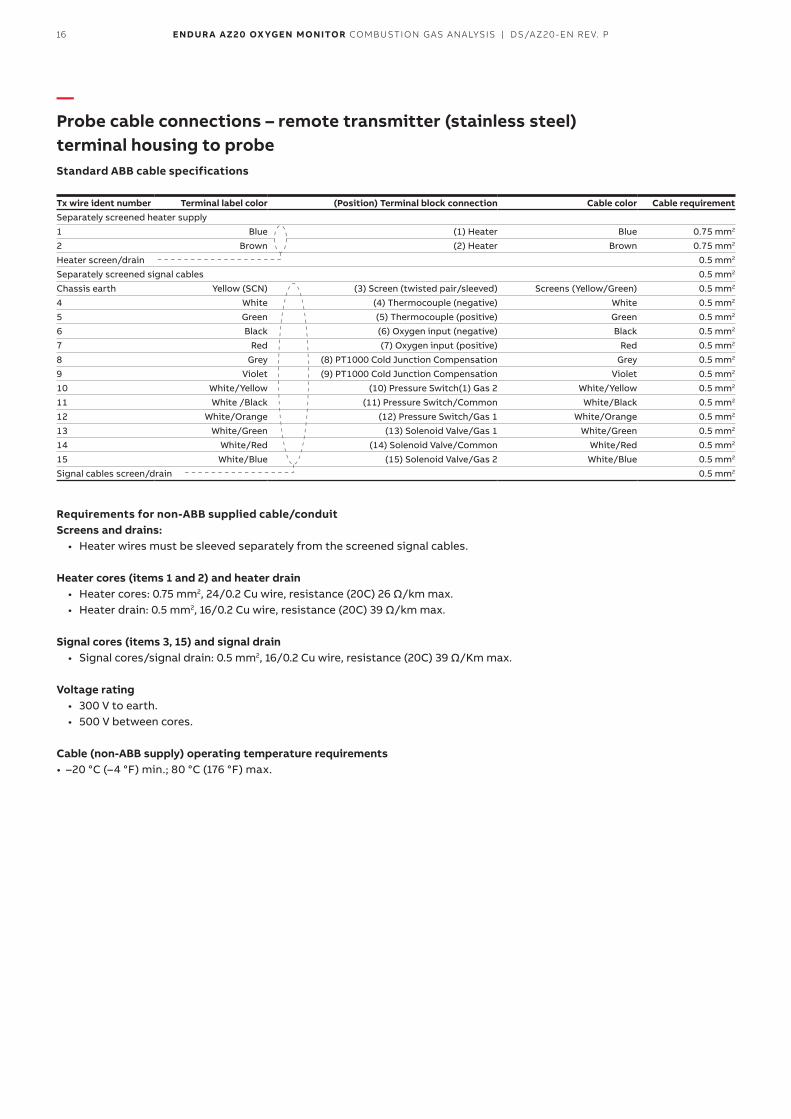
—Probe cable connections – remote transmitter (stainless steel) terminal housing to probeStandard ABB cable specifications
Tx wire ident number Terminal label color (Position) Terminal block connection Cable color Cable requirementSeparately screened heater supply1 Blue (1) Heater Blue 0.75 mm2
2 Brown (2) Heater Brown 0.75 mm2
Heater screen/drain 0.5 mm2
Separately screened signal cables 0.5 mm2
Chassis earth Yellow (SCN) (3) Screen (twisted pair/sleeved) Screens (Yellow/Green) 0.5 mm2
4 White (4) Thermocouple (negative) White 0.5 mm2
5 Green (5) Thermocouple (positive) Green 0.5 mm2
6 Black (6) Oxygen input (negative) Black 0.5 mm2
7 Red (7) Oxygen input (positive) Red 0.5 mm2
8 Grey (8) PT1000 Cold Junction Compensation Grey 0.5 mm2
9 Violet (9) PT1000 Cold Junction Compensation Violet 0.5 mm2
10 White/Yellow (10) Pressure Switch(1) Gas 2 White/Yellow 0.5 mm2
11 White /Black (11) Pressure Switch/Common White/Black 0.5 mm2
12 White/Orange (12) Pressure Switch/Gas 1 White/Orange 0.5 mm2
13 White/Green (13) Solenoid Valve/Gas 1 White/Green 0.5 mm2
14 White/Red (14) Solenoid Valve/Common White/Red 0.5 mm2
15 White/Blue (15) Solenoid Valve/Gas 2 White/Blue 0.5 mm2
Signal cables screen/drain 0.5 mm2
Requirements for non-ABB supplied cable/conduitScreens and drains:
• Heater wires must be sleeved separately from the screened signal cables.
Heater cores (items 1 and 2) and heater drain• Heater cores: 0.75 mm2, 24/0.2 Cu wire, resistance (20C) 26 Ω/km max.• Heater drain: 0.5 mm2, 16/0.2 Cu wire, resistance (20C) 39 Ω/km max.
Signal cores (items 3, 15) and signal drain• Signal cores/signal drain: 0.5 mm2, 16/0.2 Cu wire, resistance (20C) 39 Ω/Km max.
Voltage rating• 300 V to earth.• 500 V between cores.
Cable (non-ABB supply) operating temperature requirements• –20 °C (–4 °F) min.; 80 °C (176 °F) max.
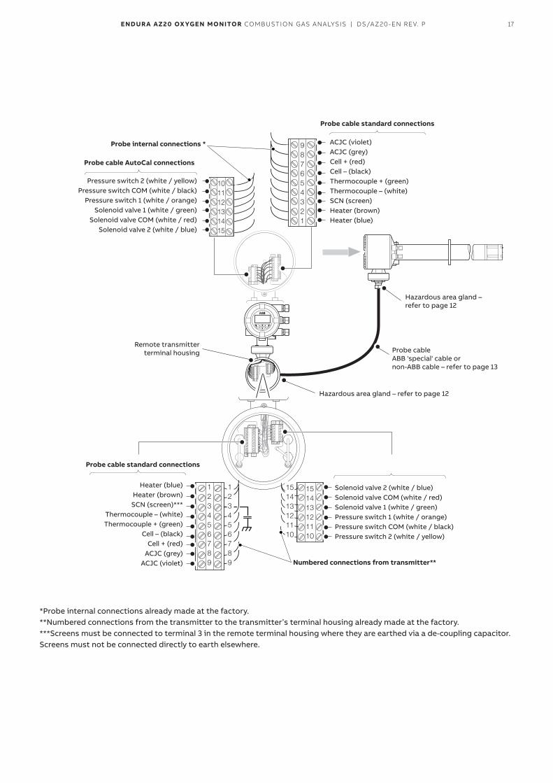
17ENDUR A AZ20 OX YGEN MONITOR COMBUSTION GAS ANALYSIS | DS/AZ20-EN REV. P
987654321
101112131415
123456789
151413121110
151413121110
123456789
Pressure switch 2 (white / yellow) Pressure switch COM (white / black)
Pressure switch 1 (white / orange) Solenoid valve 1 (white / green)
Solenoid valve COM (white / red)Solenoid valve 2 (white / blue)
Heater (blue) Heater (brown) SCN (screen)***
Thermocouple – (white) Thermocouple + (green)
Cell – (black) Cell + (red)
ACJC (grey) ACJC (violet)
Remote transmitter terminal housing
Hazardous area gland –refer to page 12
Hazardous area gland – refer to page 12
Probe cable ABB 'special' cable or non-ABB cable – refer to page 13
Probe cable AutoCal connections
Numbered connections from transmitter**
Probe cable standard connections
Probe cable standard connections
Probe internal connections * ACJC (violet) ACJC (grey) Cell + (red) Cell – (black) Thermocouple + (green) Thermocouple – (white) SCN (screen) Heater (brown) Heater (blue)
Solenoid valve 2 (white / blue) Solenoid valve COM (white / red) Solenoid valve 1 (white / green) Pressure switch 1 (white / orange) Pressure switch COM (white / black) Pressure switch 2 (white / yellow)
*Probe internal connections already made at the factory.**Numbered connections from the transmitter to the transmitter’s terminal housing already made at the factory.***Screens must be connected to terminal 3 in the remote terminal housing where they are earthed via a de-coupling capacitor. Screens must not be connected directly to earth elsewhere.
18 ENDUR A AZ20 OX YGEN MONITOR COMBUSTION GAS ANALYSIS | DS/AZ20-EN REV. P
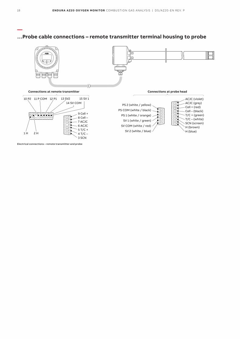
—…Probe cable connections – remote transmitter terminal housing to probe
10 P2
1 H 2 H
12 P1 13 SV2 15 SV 114 SV COM
11 P COM ACJC (violet) ACJC (grey) Cell + (red) Cell – (black) T/C + (green) T/C – (white) SCN (screen) H (brown) H (blue)
9 Cell + 8 Cell – 7 ACJC 6 ACJC 5 T/C + 4 T/C – 3 SCN
PS 2 (white / yellow)
PS COM (white / black)
PS 1 (white / orange)
SV 1 (white / green)
SV COM (white / red)
SV 2 (white / blue)
Connections at remote transmitter Connections at probe head
Electrical connections – remote transmitter and probe
19ENDUR A AZ20 OX YGEN MONITOR COMBUSTION GAS ANALYSIS | DS/AZ20-EN REV. P
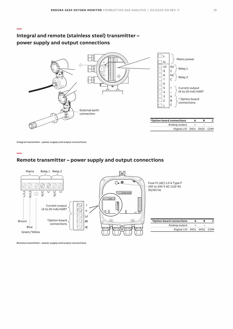
—Integral and remote (stainless steel) transmitter – power supply and output connections
1
L
N
1098765432
NCCNCC
+–ABC
External earth connection
*Option board connections A B CAnalog output + –
Digital I/O DIO1 DIO2 COM
Mains power
Relay 1
Relay 2
Current output (4 to 20 mA) HART
* Option board connections
Integral transmitter – power supply and output connections
—Remote transmitter – power supply and output connections
L/L1
N/L
2
N/C C
N/C C
A
B
C
+ –
Mains Relay 1 Relay 2
Fuse F1 (AC) 1.0 A Type F 100 to 240 V AC (±10 %) 50/60 Hz
Current output (4 to 20 mA) HART
*Option board connections
Brown
Blue
Green/Yellow
*Option board connections A B CAnalog output + –
Digital I/O DIO1 DIO2 COM
Remote transmitter – power supply and output connections
20 ENDUR A AZ20 OX YGEN MONITOR COMBUSTION GAS ANALYSIS | DS/AZ20-EN REV. P
—System specification
Measurement performanceRange:
0.01 to 100 % O2Test gas response time
• Initial dead time 3 seconds• T90 < 10 seconds
System accuracy< ±0.75 % of reading or 0.05 % O2, whichever is the greater, based on a nominal range of 0.01 to 25 % O2 or 20 to 100 % O2
Drift• < ± 1 % maximum % O2 range value per month
(without calibration)• < ± 0.2 % typical
Environmental dataAmbient operating temperature
• Transmitter –20 to 55 °C (–4 to 131 °F)• Probe –20 to 70°C (–4 to 158 °F)
Storage temperature–40 to 85 °C (–40 to 185 °F)
Operating humidityUp to 95 % RH, non-condensing
SunlightStore and operate out of direct sunlight
Ingress protection • Probe (excludes remote/integral transmitter):
IP66 (NEMA 4X)• Electronics enclosures – remote and integral:
IP66 (NEMA 4X)
Power supplyAC power supply
100 to 240 V AC ±10 % (90 V min. to 264 V max.) 50/60 HzElectronics
< 10 WProbe heater
< 100 W
Approvals• FM for USA and Canada• CE marked• EAC (Russia)• MCERTS (QAL 1)• TUV (QAL 1)• Metrology (Russia)
Emissions immunityConforms to EN61326-1
General safetyConforms to EN61010-1
PerformanceConforms to EN15267-3
SIL2Conforms to EN61508
21ENDUR A AZ20 OX YGEN MONITOR COMBUSTION GAS ANALYSIS | DS/AZ20-EN REV. P
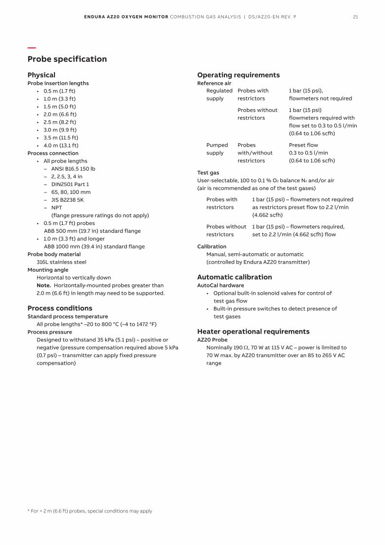
—Probe specification
PhysicalProbe insertion lengths
• 0.5 m (1.7 ft)• 1.0 m (3.3 ft)• 1.5 m (5.0 ft)• 2.0 m (6.6 ft)• 2.5 m (8.2 ft)• 3.0 m (9.9 ft)• 3.5 m (11.5 ft)• 4.0 m (13.1 ft)
Process connection• All probe lengths
– ANSI B16.5 150 lb – 2, 2.5, 3, 4 in – DIN2501 Part 1 – 65, 80, 100 mm – JIS B2238 5K – NPT
(flange pressure ratings do not apply)• 0.5 m (1.7 ft) probes
ABB 500 mm (19.7 in) standard flange• 1.0 m (3.3 ft) and longer
ABB 1000 mm (39.4 in) standard flangeProbe body material
316L stainless steelMounting angle
Horizontal to vertically downNote. Horizontally-mounted probes greater than 2.0 m (6.6 ft) in length may need to be supported.
Process conditionsStandard process temperature
All probe lengths* –20 to 800 °C (–4 to 1472 °F)Process pressure
Designed to withstand 35 kPa (5.1 psi) – positive or negative (pressure compensation required above 5 kPa (0.7 psi) – transmitter can apply fixed pressure compensation)
* For > 2 m (6.6 ft) probes, special conditions may apply
Operating requirementsReference air
Regulated supply
Probes with restrictors
1 bar (15 psi), flowmeters not required
Probes without restrictors
1 bar (15 psi) flowmeters required with flow set to 0.3 to 0.5 l/min (0.64 to 1.06 scfh)
Pumped supply
Probes with/without restrictors
Preset flow 0.3 to 0.5 l/min (0.64 to 1.06 scfh)
Test gasUser-selectable, 100 to 0.1 % O2 balance N2 and/or air (air is recommended as one of the test gases)
Probes with restrictors
1 bar (15 psi) – flowmeters not required as restrictors preset flow to 2.2 l/min (4.662 scfh)
Probes without restrictors
1 bar (15 psi) – flowmeters required, set to 2.2 l/min (4.662 scfh) flow
CalibrationManual, semi-automatic or automatic (controlled by Endura AZ20 transmitter)
Automatic calibrationAutoCal hardware
• Optional built-in solenoid valves for control of test gas flow
• Built-in pressure switches to detect presence of test gases
Heater operational requirementsAZ20 Probe
Nominally 190 Ω, 70 W at 115 V AC – power is limited to 70 W max. by AZ20 transmitter over an 85 to 265 V AC range
22 ENDUR A AZ20 OX YGEN MONITOR COMBUSTION GAS ANALYSIS | DS/AZ20-EN REV. P
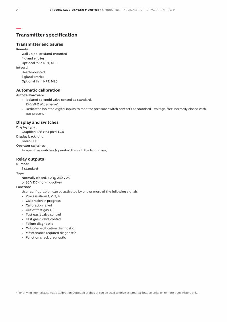
—Transmitter specification
Transmitter enclosuresRemote
Wall-, pipe- or stand-mounted 4 gland entriesOptional 1/2 in NPT, M20
IntegralHead-mounted3 gland entriesOptional 1/2 in NPT, M20
Automatic calibrationAutoCal hardware
• Isolated solenoid valve control as standard, 24 V @ 2 W per valve*
• Dedicated isolated digital inputs to monitor pressure switch contacts as standard – voltage-free, normally closed with gas present
Display and switchesDisplay type
Graphical 128 x 64 pixel LCDDisplay backlight
Green LEDOperator switches
4 capacitive switches (operated through the front glass)
Relay outputsNumber
2 standardType
Normally closed, 5 A @ 230 V AC or 30 V DC (non-inductive)
FunctionsUser-configurable – can be activated by one or more of the following signals:• Process alarm 1, 2, 3, 4• Calibration in progress• Calibration failed• Out of test gas 1, 2• Test gas 1 valve control• Test gas 2 valve control• Failure diagnostic• Out-of-specification diagnostic• Maintenance required diagnostic• Function check diagnostic
*For driving internal automatic calibration (AutoCal) probes or can be used to drive external calibration units on remote transmitters only.
23ENDUR A AZ20 OX YGEN MONITOR COMBUSTION GAS ANALYSIS | DS/AZ20-EN REV. P
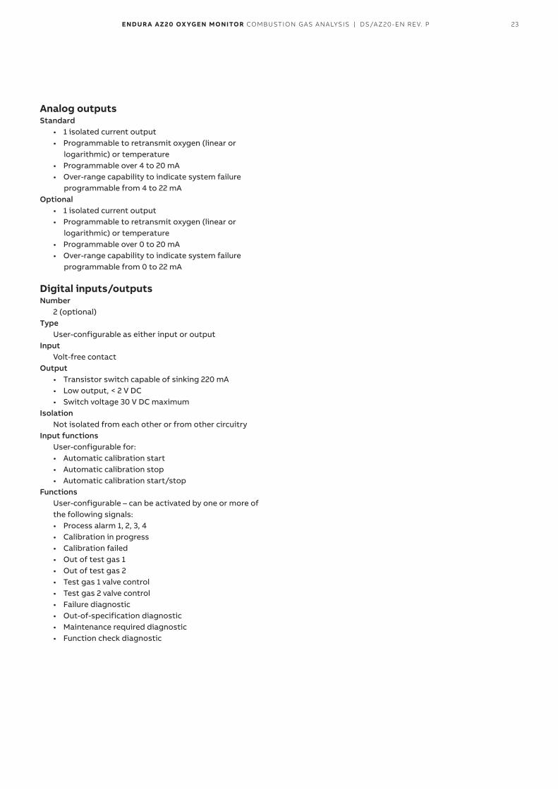
Analog outputsStandard
• 1 isolated current output• Programmable to retransmit oxygen (linear or
logarithmic) or temperature• Programmable over 4 to 20 mA• Over-range capability to indicate system failure
programmable from 4 to 22 mAOptional
• 1 isolated current output• Programmable to retransmit oxygen (linear or
logarithmic) or temperature• Programmable over 0 to 20 mA• Over-range capability to indicate system failure
programmable from 0 to 22 mA
Digital inputs/outputsNumber
2 (optional)Type
User-configurable as either input or outputInput
Volt-free contactOutput
• Transistor switch capable of sinking 220 mA• Low output, < 2 V DC• Switch voltage 30 V DC maximum
IsolationNot isolated from each other or from other circuitry
Input functionsUser-configurable for:• Automatic calibration start• Automatic calibration stop• Automatic calibration start/stop
FunctionsUser-configurable – can be activated by one or more of the following signals:• Process alarm 1, 2, 3, 4• Calibration in progress• Calibration failed• Out of test gas 1• Out of test gas 2• Test gas 1 valve control• Test gas 2 valve control• Failure diagnostic• Out-of-specification diagnostic• Maintenance required diagnostic• Function check diagnostic
24 ENDUR A AZ20 OX YGEN MONITOR COMBUSTION GAS ANALYSIS | DS/AZ20-EN REV. P
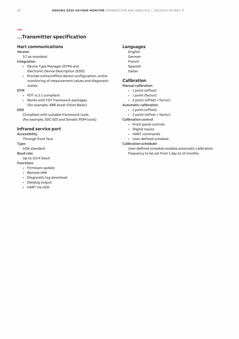
—…Transmitter specification
Hart communicationsVersion
5.7 as standardIntegration
• Device Type Manager (DTM) and Electronic Device Description (EDD)
• Provide online/offline device configuration, online monitoring of measurement values and diagnostic states
DTM• FDT v1.2.1 compliant• Works with FDT framework packages
(for example, ABB Asset Vision Basic)EDD
Compliant with suitable framework tools (for example, SDC 625 and Simatic PDM tools)
Infrared service portAccessibility
Through front faceType:
IrDA standardBaud rate
Up to 115 K baudFunctions
• Firmware update• Remote HMI• Diagnostic log download• Datalog output• HART via IrDA
Languages English German French Spanish Italian
CalibrationManual calibration
• 1 point (offset)• 1 point (factor)• 2 point (offset + factor)
Automatic calibration• 1 point (offset)• 2 point (offset + factor)
Calibration control• Front panel controls• Digital inputs• HART commands• User-defined schedule
Calibration schedulerUser-defined schedule enables automatic calibration frequency to be set from 1 day to 12 months
25ENDUR A AZ20 OX YGEN MONITOR COMBUSTION GAS ANALYSIS | DS/AZ20-EN REV. P
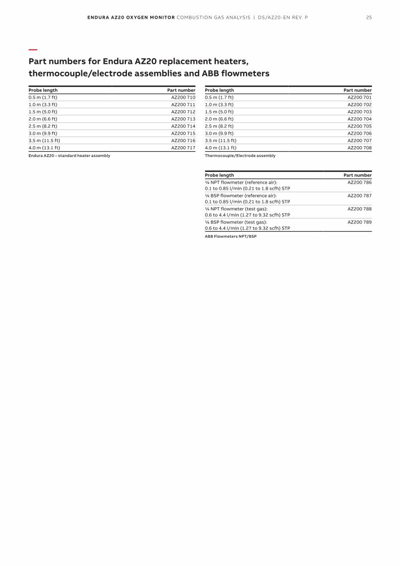
—Part numbers for Endura AZ20 replacement heaters, thermocouple/electrode assemblies and ABB flowmeters
Probe length Part number 0.5 m (1.7 ft) AZ200 7101.0 m (3.3 ft) AZ200 7111.5 m (5.0 ft) AZ200 7122.0 m (6.6 ft) AZ200 7132.5 m (8.2 ft) AZ200 7143.0 m (9.9 ft) AZ200 7153.5 m (11.5 ft) AZ200 7164.0 m (13.1 ft) AZ200 717
Endura AZ20 – standard heater assembly
Probe length Part number 0.5 m (1.7 ft) AZ200 7011.0 m (3.3 ft) AZ200 7021.5 m (5.0 ft) AZ200 7032.0 m (6.6 ft) AZ200 7042.5 m (8.2 ft) AZ200 7053.0 m (9.9 ft) AZ200 7063.5 m (11.5 ft) AZ200 7074.0 m (13.1 ft) AZ200 708
Thermocouple/Electrode assembly
Probe length Part number 1/4 NPT flowmeter (reference air): 0.1 to 0.85 l/min (0.21 to 1.8 scfh) STP
AZ200 786
1/4 BSP flowmeter (reference air): 0.1 to 0.85 l/min (0.21 to 1.8 scfh) STP
AZ200 787
1/4 NPT flowmeter (test gas): 0.6 to 4.4 l/min (1.27 to 9.32 scfh) STP
AZ200 788
1/4 BSP flowmeter (test gas): 0.6 to 4.4 l/min (1.27 to 9.32 scfh) STP
AZ200 789
ABB Flowmeters NPT/BSP
26 ENDUR A AZ20 OX YGEN MONITOR COMBUSTION GAS ANALYSIS | DS/AZ20-EN REV. P
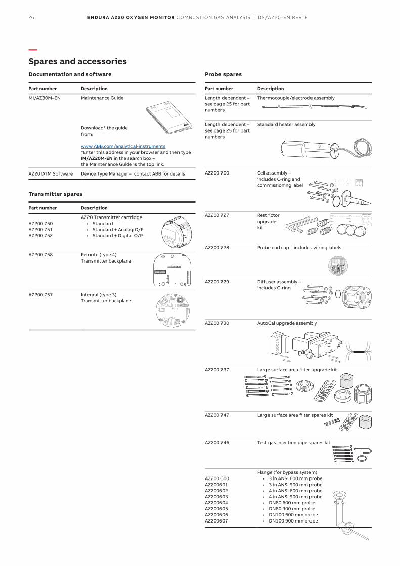
—Spares and accessoriesDocumentation and software
Part number Description
MI/AZ30M–EN Maintenance Guide
Download* the guide from: www.ABB.com/analytical-instruments *Enter this address in your browser and then type IM/AZ20M-EN in the search box – the Maintenance Guide is the top link.
AZ20 DTM Software Device Type Manager – contact ABB for details
Transmitter spares
Part number Description
AZ200 750 AZ200 751 AZ200 752
AZ20 Transmitter cartridge• Standard • Standard + Analog O/P• Standard + Digital O/P
AZ200 758 Remote (type 4) Transmitter backplane
AZ200 757 Integral (type 3) Transmitter backplane
Probe spares
Part number Description
Length dependent – see page 25 for part numbers
Thermocouple/electrode assembly
Length dependent – see page 25 for part numbers
Standard heater assembly
AZ200 700 Cell assembly – includes C-ring and commissioning label
AZ200 727 Restrictor upgrade kit
AZ200 728 Probe end cap – includes wiring labels
AZ200 729 Diffuser assembly – includes C-ring
AZ200 730 AutoCal upgrade assembly
AZ200 737 Large surface area filter upgrade kit
AZ200 747 Large surface area filter spares kit
AZ200 746 Test gas injection pipe spares kit
AZ200 600 AZ200601AZ200602 AZ200603AZ200604 AZ200605AZ200606AZ200607
Flange (for bypass system):• 3 in ANSI 600 mm probe• 3 in ANSI 900 mm probe• 4 in ANSI 600 mm probe• 4 in ANSI 900 mm probe• DN80 600 mm probe• DN80 900 mm probe• DN100 600 mm probe• DN100 900 mm probe
27ENDUR A AZ20 OX YGEN MONITOR COMBUSTION GAS ANALYSIS | DS/AZ20-EN REV. P
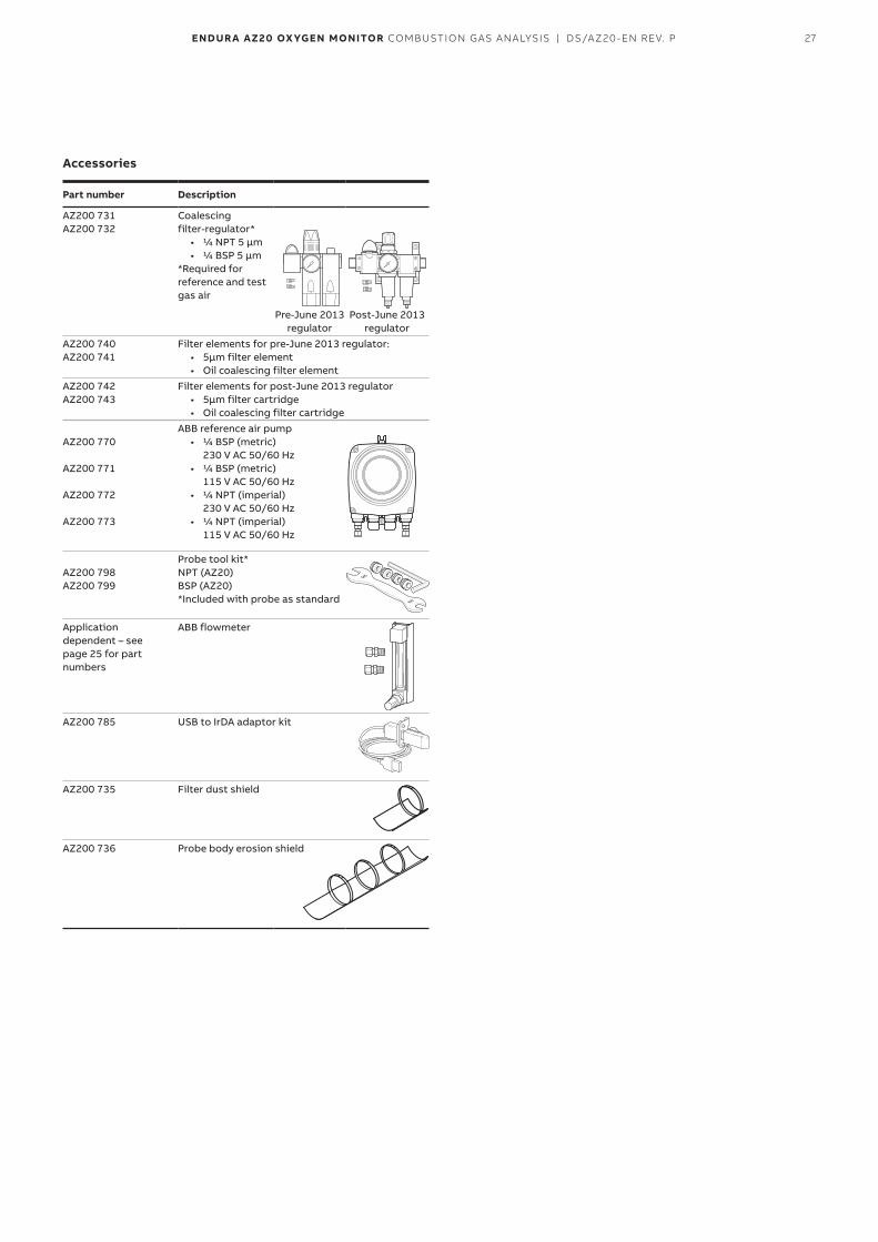
Accessories
Part number Description
AZ200 731 AZ200 732
Coalescing filter-regulator*
• 1/4 NPT 5 μm• 1/4 BSP 5 µm
*Required for reference and test gas air
Pre-June 2013 regulator
Post-June 2013 regulator
AZ200 740AZ200 741
Filter elements for pre-June 2013 regulator:• 5µm filter element• Oil coalescing filter element
AZ200 742AZ200 743
Filter elements for post-June 2013 regulator• 5µm filter cartridge• Oil coalescing filter cartridge
AZ200 770
AZ200 771
AZ200 772
AZ200 773
ABB reference air pump• 1/4 BSP (metric)
230 V AC 50/60 Hz• 1/4 BSP (metric)
115 V AC 50/60 Hz• 1/4 NPT (imperial)
230 V AC 50/60 Hz• 1/4 NPT (imperial)
115 V AC 50/60 Hz
AZ200 798AZ200 799
Probe tool kit*NPT (AZ20)BSP (AZ20)*Included with probe as standard
Application dependent – see page 25 for part numbers
ABB flowmeter
AZ200 785 USB to IrDA adaptor kit
AZ200 735 Filter dust shield
AZ200 736 Probe body erosion shield
28 ENDUR A AZ20 OX YGEN MONITOR COMBUSTION GAS ANALYSIS | DS/AZ20-EN REV. P
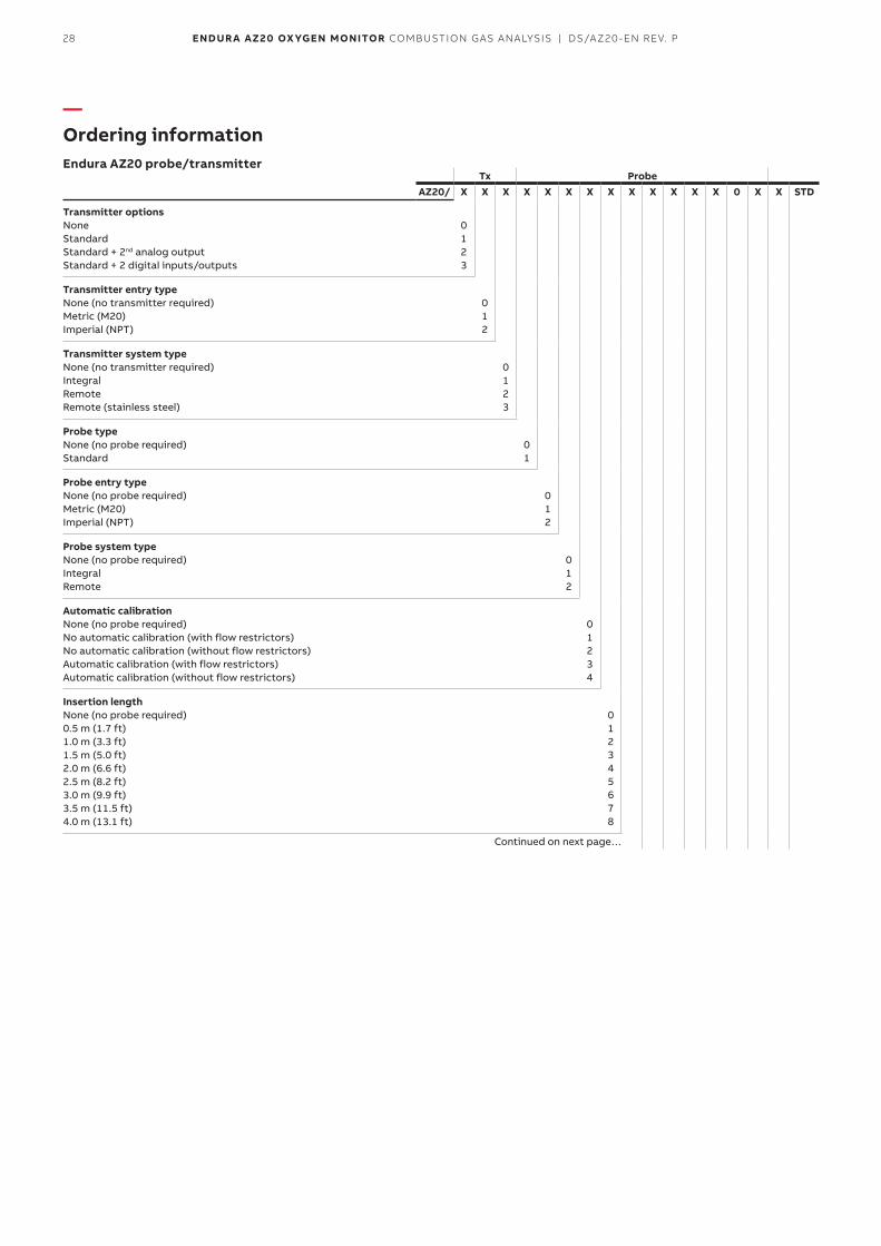
—Ordering informationEndura AZ20 probe/transmitter
Tx ProbeAZ20/ X X X X X X X X X X X X X 0 X X STD
Transmitter optionsNone Standard Standard + 2nd analog output Standard + 2 digital inputs/outputs
0 1 2 3
Transmitter entry typeNone (no transmitter required) Metric (M20) Imperial (NPT)
0 1 2
Transmitter system typeNone (no transmitter required) Integral Remote Remote (stainless steel)
0 1 2 3
Probe typeNone (no probe required) Standard
0 1
Probe entry typeNone (no probe required) Metric (M20) Imperial (NPT)
0 1 2
Probe system typeNone (no probe required) IntegralRemote
0 1 2
Automatic calibrationNone (no probe required) No automatic calibration (with flow restrictors) No automatic calibration (without flow restrictors) Automatic calibration (with flow restrictors) Automatic calibration (without flow restrictors)
0 1 2 3 4
Insertion lengthNone (no probe required) 0.5 m (1.7 ft) 1.0 m (3.3 ft) 1.5 m (5.0 ft) 2.0 m (6.6 ft) 2.5 m (8.2 ft) 3.0 m (9.9 ft) 3.5 m (11.5 ft) 4.0 m (13.1 ft)
0 1 2 3 4 5 6 7 8
Continued on next page…
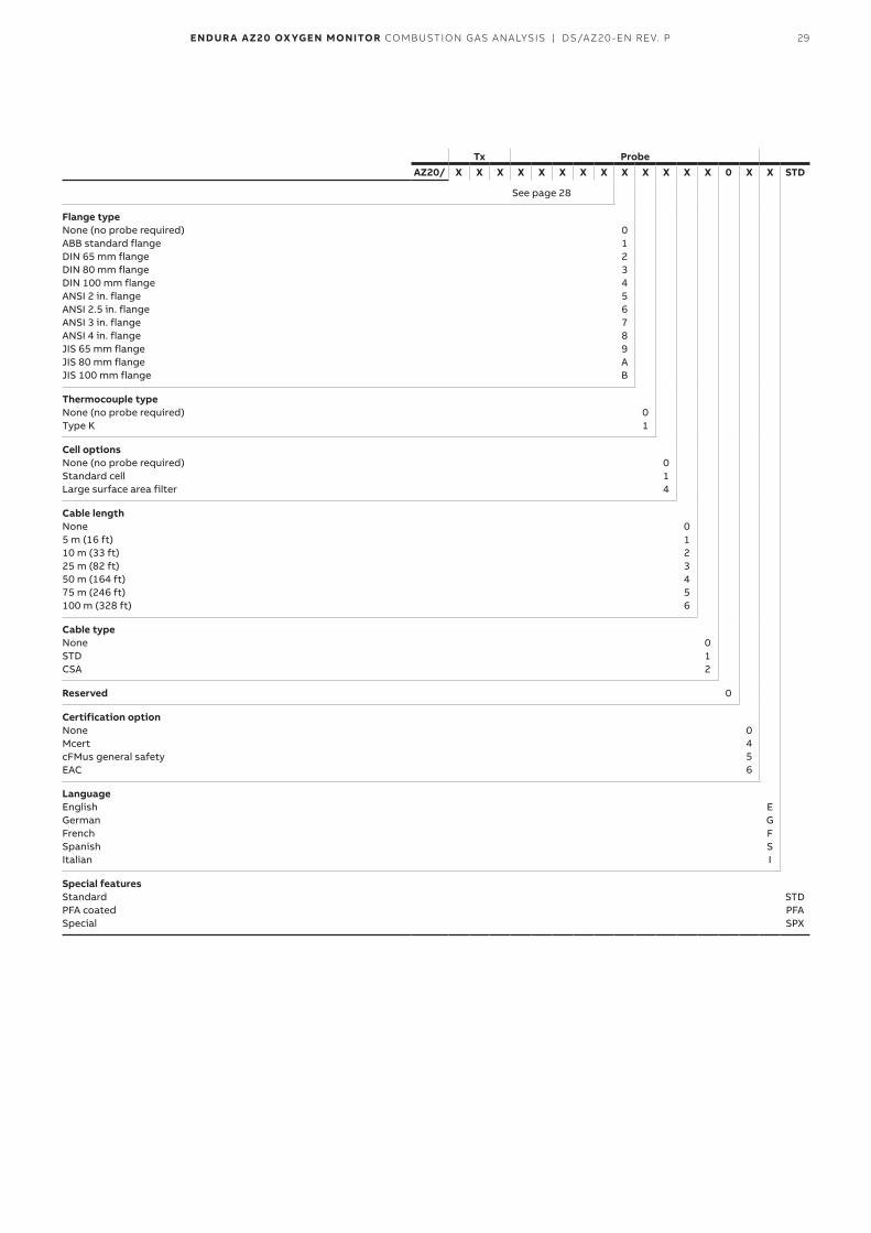
29ENDUR A AZ20 OX YGEN MONITOR COMBUSTION GAS ANALYSIS | DS/AZ20-EN REV. P
Tx ProbeAZ20/ X X X X X X X X X X X X X 0 X X STD
See page 28
Flange typeNone (no probe required) ABB standard flange DIN 65 mm flange DIN 80 mm flange DIN 100 mm flange ANSI 2 in. flange ANSI 2.5 in. flange ANSI 3 in. flange ANSI 4 in. flange JIS 65 mm flange JIS 80 mm flangeJIS 100 mm flange
0 1 2 3 4 5 6 7 8 9 A B
Thermocouple typeNone (no probe required) Type K
0 1
Cell optionsNone (no probe required) Standard cell Large surface area filter
0 1 4
Cable lengthNone 5 m (16 ft) 10 m (33 ft) 25 m (82 ft) 50 m (164 ft) 75 m (246 ft) 100 m (328 ft)
0 1 2 3 4 5 6
Cable typeNoneSTD CSA
0 1 2
Reserved 0
Certification optionNone Mcert cFMus general safety EAC
0 4 5 6
LanguageEnglish German French Spanish Italian
E G F S I
Special featuresStandard PFA coated Special
STD PFA SPX

30 ENDUR A AZ20 OX YGEN MONITOR COMBUSTION GAS ANALYSIS | DS/AZ20-EN REV. P
Sales Service SoftwareAcknowledgmentsHART is a registered trademark of the HART Communication Foundation.
—Notes

31ENDUR A AZ20 OX YGEN MONITOR COMBUSTION GAS ANALYSIS | DS/AZ20-EN REV. P

DS
/AZ
20-E
N R
ev. P
10
.20
20
—ABB Limited Measurement & AnalyticsOldends Lane Stonehouse Gloucestershire GL10 3TA UK Tel: +44 (0)1453 826 661 Fax: +44 (0)1453 829 671Email: [email protected]
ABB Inc. Measurement & Analytics125 E. County Line Road Warminster PA 18974 USA Tel: +1 215 674 6000 Fax: +1 215 674 7183
abb.com/measurement
We reserve the right to make technical changes or modify the contents of this document without prior notice. With regard to purchase orders, the agreed particulars shall prevail. ABB does not accept any responsibility whatsoever for potential errors or possible lack of information in this document.
We reserve all rights in this document and in the subject matter and illustrations contained therein. Any reproduction, disclosure to third parties or utilization of its contents – in whole or in parts – is forbidden without prior written consent of ABB.
© 2020 ABBAll rights reserved 3KXA722211R1001