Desain Suspensi
65
CAKRAWALA ELECTRIC VEHICLE Suspension Design Cakrawala Formula Elektrik Danny Kusuma & Rama Primadi 1/7/2015 Buku ini merupakan kumpulan referensi mengenai desain suspensi kendaraan darat, khususnya kendaraan balap. Dasar referensi tersebut digunakan untuk desain suspensi kendaraan balap dalam rangka lomba Formula SAE.
-
Upload
danny-kusuma -
Category
Documents
-
view
120 -
download
8
description
Belum selesai
Transcript of Desain Suspensi
Cakrawala Electric Vehicle
Suspension Design
Cakrawala Formula Elektrik
Danny Kusuma & Rama Primadi
1/7/2015
Buku ini merupakan kumpulan referensi mengenai desain suspensi kendaraan darat, khususnya kendaraan balap. Dasar referensi tersebut digunakan untuk desain suspensi kendaraan balap dalam rangka lomba Formula SAE.
CONTENTSContents................................................................................................................................................................1
Rules & Scoring Discussion....................................................................................................................................3
Daftar Literatur......................................................................................................................................................4
Books.................................................................................................................................................................4
Other Universities Design..................................................................................................................................4
Websites............................................................................................................................................................4
Introduction..........................................................................................................................................................5
Aim of the work.................................................................................................................................................5
Competition Objective.......................................................................................................................................5
The dynamic events...........................................................................................................................................5
What is Suspension?.........................................................................................................................................6
Design Aspect........................................................................................................................................................8
Vehicle Dynamics...............................................................................................................................................8
Modeling & Vibration Mechanics.................................................................................................................8
Coordinate System......................................................................................................................................10
Ride & Handling..........................................................................................................................................11
Lateral Dynamics.........................................................................................................................................13
Longitudinal Dynamics................................................................................................................................14
Terminology....................................................................................................................................................18
The wheelbase............................................................................................................................................18
Track............................................................................................................................................................20
Ride Height..................................................................................................................................................21
KingPin & Scrub Radius...............................................................................................................................22
Caster & Trail..............................................................................................................................................24
Camber........................................................................................................................................................26
Toe..............................................................................................................................................................30
Anti Features...............................................................................................................................................31
Instant Centre & Roll Centre.......................................................................................................................33
Tie Rod Location..........................................................................................................................................35
Anti-Rol Bar.................................................................................................................................................36
Damper.......................................................................................................................................................37
Spring..........................................................................................................................................................39
Design Step..........................................................................................................................................................40
Rules................................................................................................................................................................40
[1] 2015 Formula SAE® Rules.......................................................................................................................40

[2] FSAE/FS EV Design Score Sheet..............................................................................................................42
Suspension Types............................................................................................................................................42
Vertical Dycnamics (Ride&Handling – Pitch&Bounce).....................................................................................43
Lateral Dynamics – Cornering Performance....................................................................................................43
Steady State Cornering – Skidpad, Steady Turn...........................................................................................43
Transient Rollover – Slalom, Rapid steering................................................................................................43
Suspension Geometry.................................................................................................................................43
Anti Roll Bar design......................................................................................................................................43
Tire Performance.........................................................................................................................................43
Longitudinal Dynamics....................................................................................................................................43
Desain Suspensi Cakrawala Formula Electric.......................................................................................................44
Penetuan DR&O..............................................................................................................................................44
Data Kendaraan...............................................................................................................................................44
Perhitungan Kekakuan Pegas..........................................................................................................................44
Set Gaya Peredaman Bertingkat......................................................................................................................44
Penentuan Geometri Suspensi........................................................................................................................44
Performa Steady State Cornering....................................................................................................................44
Performa Transient Cornering.........................................................................................................................44
Perhitungan Kekakuan Anti Rollbar.................................................................................................................44
REFERENCES
BOOKS
Berdasarkan [3] Gillespie, Fundamentals of Vehicle Dunamics
Berdasarkan [4] Jazar, Vehicle Dunamics: Theory and Application
Berdasarkan [5] Dixon, The Shock Absorber Handbook
Berdasarkan [6] Miliken, Race Car Vehicle Dynamics
Berdasarkan [7] Reimpell, The Automotive Chassis: Engineering Principle
Berdasarkan [8] Mahyuddin, Andi Isra. Design Calculation of Vehicle Suspension System. JSAE Paper 2.
Berdasarkan [9] Theander, Design of a Suspension for a Formula Student Race Car
Berdasarkan [10] Subeng, Laporan Perancangan FSAE Mushika ITB: Divisi Suspensi
OTHER UNIVERSITIES DESIGN
WEBSITES
VIDEOS
INTRODUCTION
AIM OF THE WORK
The aim of this thesis work is to design the suspension geometry for a Formula Student race car. The design shall meet the demands caused by the different dynamic events in the competition.
COMPETITION OBJECTIVE
The objective of the competition is for students to conceive, design, fabricate and compete with small formula-style racing cars. The design of the car frame and engine are restricted in order to challenge the knowledge, creativity and the imagination of the students [1].
THE DYNAMIC EVENTS
· Acceleration· Skid-Pad· Autocross· Endurance and Fuel Economy
1.4.1 Acceleration EventThe objective of the acceleration event is to evaluate the car’s acceleration in a straight line on flat pavement. The cars will be staged 0.3m behind the starting line and when the cars cross the starting line the time will start. The goal is located 75m ahead of the starting line. Each team will have two drivers, who can do two runs each, a total of four runs. This is the event were the suspension design is of least importance among the dynamic events, but not negligible.
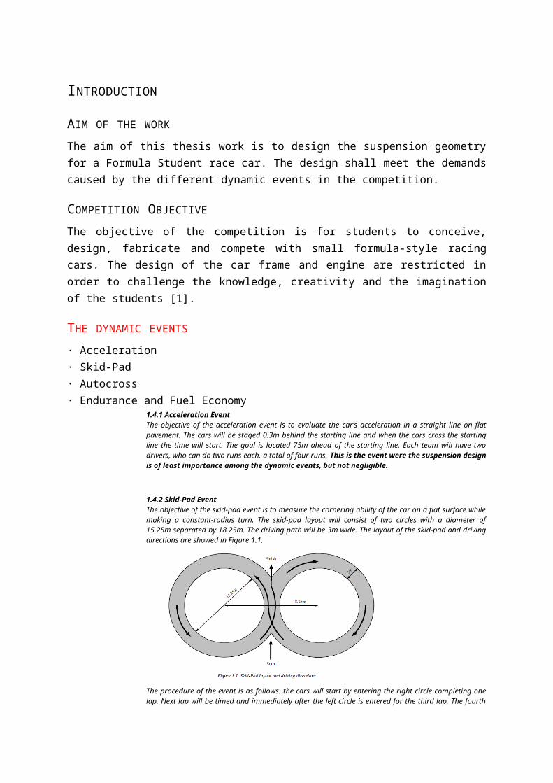
1.4.2 Skid-Pad EventThe objective of the skid-pad event is to measure the cornering ability of the car on a flat surface while making a constant-radius turn. The skid-pad layout will consist of two circles with a diameter of 15.25m separated by 18.25m. The driving path will be 3m wide. The layout of the skid-pad and driving directions are showed in Figure 1.1.
The procedure of the event is as follows: the cars will start by entering the right circle completing one lap. Next lap will be timed and immediately after the left circle is entered for the third lap. The fourth lap will be timed. Then the driver has the option to make a second run immediately after the first. Each team will have two drivers who can do two runs each. The design of the suspension and steering geometry will influence the performance much.
1.4.3 Autocross EventThe objective of the autocross event is to evaluate the car’s manoeuvrability and handling qualities on a tight course. The autocross course will combine the performance features of acceleration, braking and cornering. The layout of the autocross track is made to keep the speeds from being dangerously high, average speeds should be
between 40km/h and 48km/h. The layout is specified as follows: · Straights – No longer than 60m with hairpins at both ends or no longer than 45m with wide turns on the ends.· Constant Turns – 23m to 45m in diameter.· Hairpin Turns – Minimum of 9m outside diameter.· Slaloms – Cones in a straight line with 7.62m to 12.19m spacing.· Miscellaneous – Chicanes, multiple turns, decreasing radius turns, etc. Theminimum track width will be 3.5m· Length – Approximately 0.805km.Each team will have two drivers entering the event. Each driver will drive two timed laps and the best time for each driver will stand as the time for that heat.
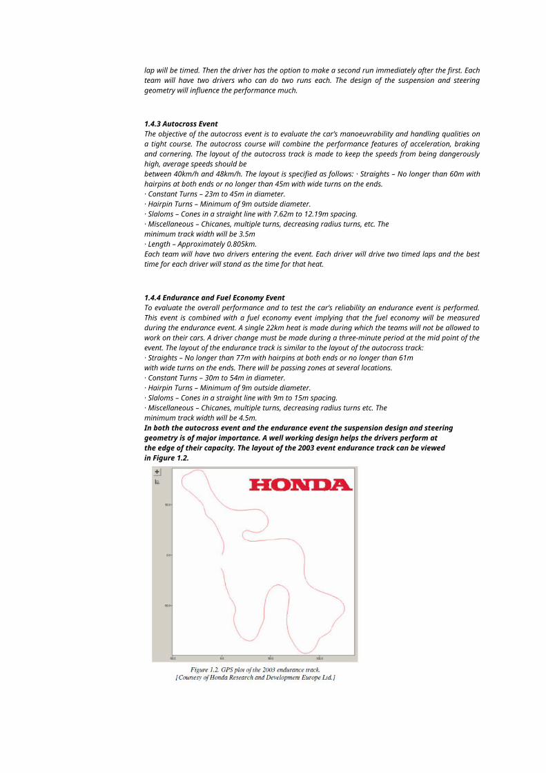
1.4.4 Endurance and Fuel Economy EventTo evaluate the overall performance and to test the car’s reliability an endurance event is performed. This event is combined with a fuel economy event implying that the fuel economy will be measured during the endurance event. A single 22km heat is made during which the teams will not be allowed to work on their cars. A driver change must be made during a three-minute period at the mid point of the event. The layout of the endurance track is similar to the layout of the autocross track:· Straights – No longer than 77m with hairpins at both ends or no longer than 61mwith wide turns on the ends. There will be passing zones at several locations.· Constant Turns – 30m to 54m in diameter.· Hairpin Turns – Minimum of 9m outside diameter.· Slaloms – Cones in a straight line with 9m to 15m spacing.· Miscellaneous – Chicanes, multiple turns, decreasing radius turns etc. Theminimum track width will be 4.5m.In both the autocross event and the endurance event the suspension design and steeringgeometry is of major importance. A well working design helps the drivers perform atthe edge of their capacity. The layout of the 2003 event endurance track can be viewedin Figure 1.2.
WHAT IS SUSPENSION?
The suspension on your car has two main functions. Its first job is to smooth the ride of your car. According to
Mr. Newton and his famed laws of physics, all forces of motion have both a magnitude and a direction. A bump
in the road causes the wheel to move up and down perpendicular to the road surface. The bigger the bump
encountered, the bigger the movement. The movement experienced by the wheel is called vertical
acceleration.
Without an intervening structure, all of the wheel's vertical energy is transferred to the frame, which tries to
move in the same direction. In such a situation the wheels can lose contact with the road completely. Then,
under the downward force of gravity, the wheels can slam back into the road surface. What you need is a
system that will absorb the energy of the vertically accelerated wheel allowing the frame and body to ride
undisturbed while the wheels follow bumps in the road and stay in contact with the asphalt.
The suspension shall help to keep the tires in constant contact with the ground so that the tires can be used to the limit of their capacity.
Will the tires stay in satisfactory contact with the road under all conditions? This category focuses primarily on the unsprung masses of the vehicle, particularly those related to road holding and directional control.
To provide good ride and handling performance–vertical compliance providing chassis isolation –ensuring that the wheels follow the road profile –very little tire load fluctuation •To ensure that steering control is maintained during maneuvering –wheels to be maintained in the proper position wrt road surface •To ensure that the vehicle responds favorably to control forces produced by the tires during –longitudinal braking –accelerating forces, –lateral cornering forces and –braking and accelerating torques –this requires the suspension geometry to be designed to resist squat, dive and roll of the vehicle body •To provide isolation from high frequency vibration from tire excitation –requires appropriate isolation in the suspension joints –Prevent transmission of ‘road noise’ to the vehicle body
DESIGN ASPECT
RULES
[1] 2015 FORMULA SAE® RULES
1. T1.2.2 Once the vehicle is approved to compete in the dynamic events, the ONLY modifications permitted to the vehicle are those listed below. They are also referred to in Part S of the Formula SAE Rules – Static Event Regulations. Adjustment of the suspension where no part substitution is required, (except that springs, sway bars and shims may be changed)Apakah suspensi akan didesain adjustable atau tidak? Mengapa? Referensi apa yang mendukung?
2. T5.8.1 To keep the driver’s legs away from moving or sharp components, all moving suspension and steering components, and other sharp edges inside the cockpit between the front roll hoop and a vertical plane 100 mm (4 inches) rearward of the pedals, must be shielded with a shield made of a solid material. Moving components include, but are not limited to springs, shock absorbers, rocker arms, anti-roll/sway bars, steering racks and steering column CV joints. T5.8.2 Covers over suspension and steering components must be removable to allow inspection of the mounting points. T6.1.2 All suspension mounting points must be visible at Technical Inspection, either by direct view or by removing any covers.Bagaimana desain penutup suspensi? Data apa saja yang diperlukan (ukuran chasis, dll)?
3. T6.1.1 The car must be equipped with a fully operational suspension system with shock absorbers, front and rear, with usable wheel travel of at least 50.8 mm (2 inches), 25.4 mm (1 inch) jounce and 25.4 mm (1 inch) rebound, with driver seated. The judges reserve the right to disqualify cars which do not CCC serious attempt at an operational suspension system or which demonstrate handling inappropriate for an autocross circuit. Apa itu wheel travel? Apa itu rebound & jounce? Parameter apa yang mempengaruhi nilai tersebut?
4. T6.5.2 The steering system must have positive steering stops that prevent the steering linkages from locking up (the inversion of a four-bar linkage at one of the pivots). The stops may be placed on the uprights or on the rack and must prevent the tires from contacting suspension, body, or frame members during the track events. Bagaimana desain stops/rack di upright?
5. T11.1.1 All threaded fasteners utilized in the driver’s cell structure, and the steering, braking, driver’s harness and suspension systems must meet or exceed, SAE Grade 5, Metric Grade 8.8 and/or AN/MS specifications.T11.2.1 All critical bolt, nuts, and other fasteners on the steering, braking, driver’s harness, and suspension must be secured from unintentional loosening by the use of positive locking mechanisms.Bagian-bagian mana saja yang dibutuhkan fasterner? Bagaimana pemasangannya? Apakah mudah untuk dibuka?
6. T11.2.3 All spherical rod ends and spherical bearings on the steering or suspension must be in double shear or captured by having a screw/bolt head or washer with an O.D. that is larger than spherical bearing housing I.D. Bagian mana saja yang harus memiliki double shear joint?
7. S6.1.2 The car that illustrates the best use of engineering to meet the design goals, a cost effective high performance autocross car, and the best understanding of the design by the team members will win the design event.
Comment: Teams are reminded that FSAE is an engineering design competition and that in the Design Event; teams are evaluated on their design. Components and systems that are incorporated into the design as finished items are not evaluated as a student designed unit, but are only assessed on the team’s selection and application of that unit. For example, teams that design and fabricate their own shocks are evaluated on the shock design itself as well as the shock’s application within the suspension system. Teams using commercially available shocks are evaluated only on selection and application within the suspension system.Bagaimana pengambilan keputusan make/buy setiap part suspensi? Bagian mana saja yang didesain sendiri/beli? Mengapa?
[2] FSAE/FS EV DESIGN SCORE SHEET1. Bagaimana desain masing-masing sub-sistem berikut?
Tires, wheels, hubs, uprights, control arms, steering linkage, springs, dampers, anti-roll bars, geometry, kinematics, vehicle dynamics. Selection and use of materials.
2. Bagaimana pula membuatnya?3. Bagaimana cara validasi nya? (tes) dan metode perbaikannya?4. Integrasi apa yang dibutuhkan suspensi dengan setiap divisi lain? (desain upright dari steering,
penempatan sensor dari telemetri)5. Apakah kemudahan perbaikan dan akses juga akan dipertimbangkan dalam mendesain?
Ease of repair? Sub-systems accessibility, parts interchangeability, manufacturing complexity? Have fasteners been standardized? Are special tools required to diagnose/service vehicle?
6. Apakah ada ide baru terkait desain suspensi? Atau hanya mengikuti desain yang biasa dipakai? Bagian mana dari suspensi yang benar-benar desain baru?Will this car cause a rules change? Have the judges learned something new? On rare occasions, creative or innovative design may merit special points.
7. Penting dalam penilaian desain:
Design (~25%): Assessment of design process used by team. Is this a new design, evolution, or complete carryover? Were different design options considered? Were appropriate pre-build analyses performed? Build (~25%): Does the physical specimen presented reflect the early design work? Is it reflected in design report? If not, why not? What special manufacturing considerations were encountered? Refinement/Validation (~25%): How thorough and honest has the team been about testing? Was a test plan developed and executed? Were discrepancies between predicted and tested results documented and acted upon to improve final build? Understanding (~25%): Is the team that presents the car at competition truly intimate with the design? Can they quickly give detailed answers about any sub-system? Or do they have to “go ask someone else”?
8. Apakah mengerti tentang Vehicle dynamic fundamental? Apa saja yang berhubungan dengan suspensi? Harus seperti apa?
9. Bagaimana pemilihan ban dan ukurannya?10. Apakah mengerti tentang ini: understanding of failure modes and critical limp-home requirements
should be addressed as well. This is known as robustness.11. Bagaimana handling dari desain suspensi kita? (respons dan traksi)12. Bagaimana cara menentukan dan menganalisis : wheel base, weight distribution, c.g. height, front and
rear track widths, roll axis location (static and dynamic), camber gain curves, link lengths, Ackerman, anti-squat/dive, king pin inclination scrub radius, bump steer, and other geometry/kinematics?
13. Bagaimana menentukan beban puncak untuk desain?14. Bagaimana pemilihan material? Perlukah heat treatment/coating?15. Apakah attachment sudah dianalisis?16. Bagaimana desain damper? Bagaimana mekanisme katupnya?17. Bagaimana menetukan wheel rate dan roll resistance?18. Apa saja yang dilakukan untuk mengurangi berat unsprung mass?19. Bagaimana desain suspensi agar bisa di-adjust?20. Bagaimana sistem friksi/lubrikasi?21. Bagaimana memvalidasi karakteristik handling sehingga sesuai dengan desain?
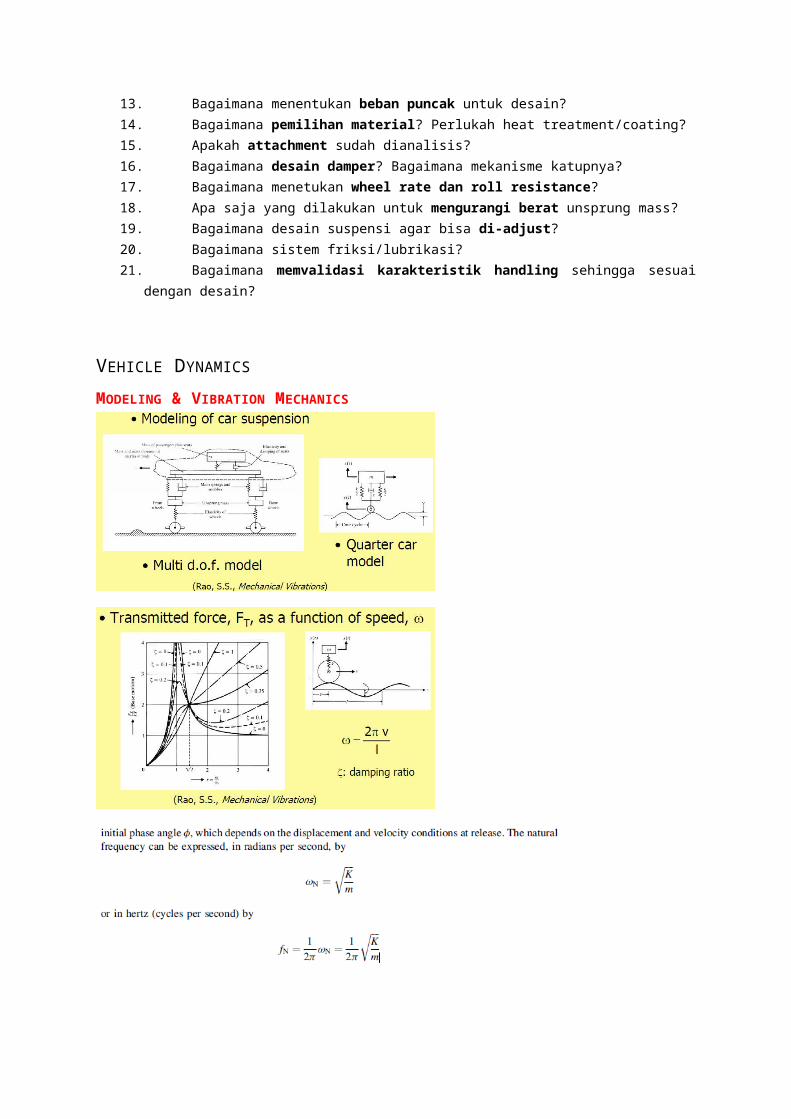
VEHICLE DYNAMICS
MODELING & VIBRATION MECHANICS
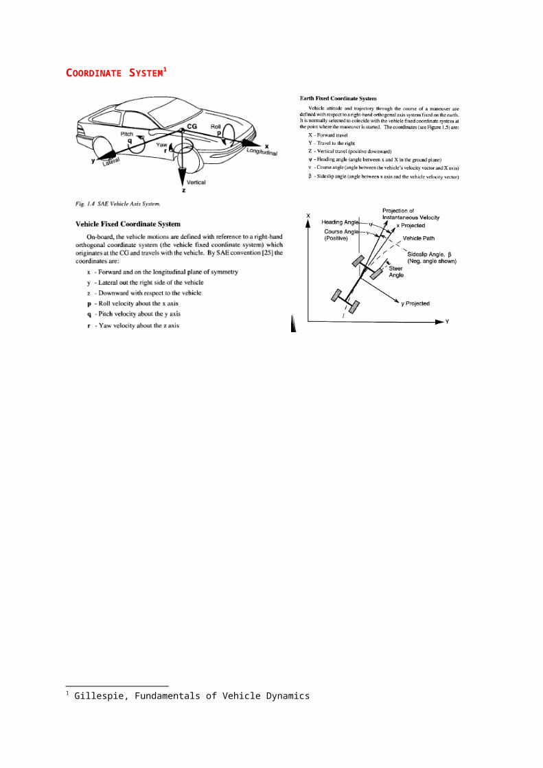
COORDINATE SYSTEM1
1 Gillespie, Fundamentals of Vehicle Dynamics
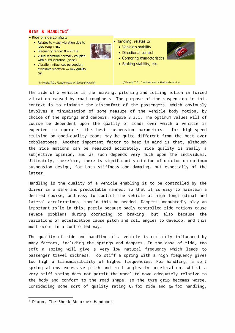
RIDE & HANDLING2
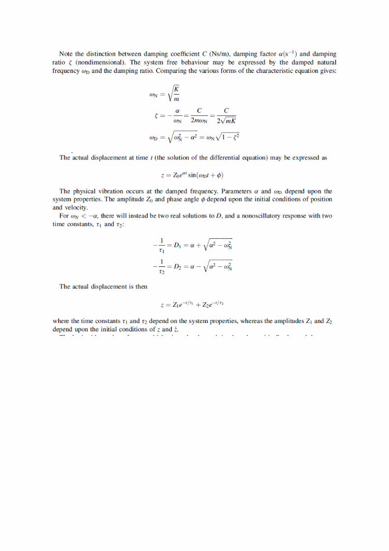
The ride of a vehicle is the heaving, pitching and rolling motion in forced vibration caused by road roughness. The purpose of the suspension in this context is to minimise the discomfort of the passengers, which obviously involves a minimisation of some measure of the vehicle body motion, by choice of the springs and dampers, Figure 3.3.1. The optimum values will of course be dependent upon the quality of roads over which a vehicle is expected to operate; the best suspension parameters for high-speed cruising on good-quality roads may be quite different from the best over cobblestones. Another important factor to bear in mind is that, although the ride motions can be measured accurately, ride quality is really a subjective opinion, and as such depends very much upon the individual. Ultimately, therefore, there is significant variation of opinion on optimum suspension design, for both stiffness and damping, but especially of the latter.
Handling is the quality of a vehicle enabling it to be controlled by the driver in a safe and predictable manner, so that it is easy to maintain a desired course, and easy to control the vehicle at high longitudinal and lateral accelerations, should this be needed. Dampers undoubtedly play an important roˆle in this, partly because badly controlled ride motions cause severe problems during cornering or braking, but also because the variations of acceleration cause pitch and roll angles to develop, and this must occur in a controlled way.
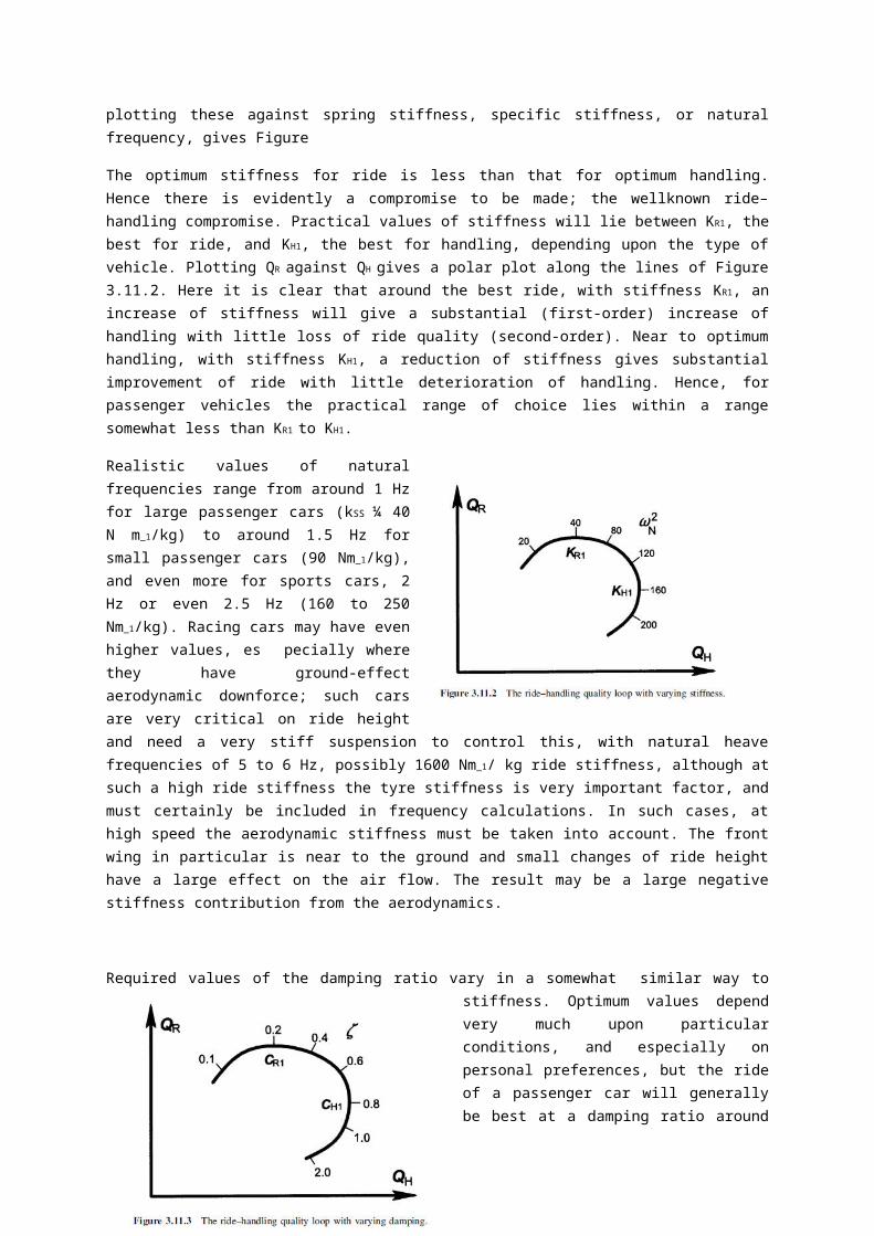
The quality of ride and handling of a vehicle is certainly influenced by many factors, including the springs and dampers. In the case of ride, too soft a spring will give a very low natural frequency which leads to passenger travel sickness. Too stiff a spring with a high frequency gives too high a transmissibility of higher frequencies. For handling, a soft spring allows excessive pitch and roll angles in acceleration, whilst a very stiff spring does not permit the wheel to move adequately relative to the body and conform to the road shape, so the tyre grip becomes worse. Considering some sort of quality rating QR for ride and QH for handling, plotting these against spring stiffness, specific stiffness, or natural frequency, gives Figure
The optimum stiffness for ride is less than that for optimum handling. Hence there is evidently a compromise to be made; the wellknown ride–handling compromise. Practical values of stiffness will lie between KR1, the best for ride, and KH1, the best for handling, depending upon the type of vehicle. Plotting QR against QH gives a polar plot along the lines of Figure 3.11.2. Here it is clear that around the best ride, with stiffness KR1, an increase of stiffness will give a substantial (first-order) increase of handling with little loss of ride quality (second-order). Near to optimum handling, with stiffness KH1, a reduction of stiffness gives substantial improvement of ride with little deterioration of handling. Hence, for passenger vehicles the practical range of choice lies within a range somewhat less than KR1 to KH1.
Realistic values of natural frequencies range from around 1 Hz for large passenger cars (kSS ¼ 40 N m_1/kg) to around 1.5 Hz for small passenger cars (90 Nm_1/kg), and even more for sports cars, 2 Hz or even 2.5 Hz (160 to 250 Nm_1/kg). Racing cars
2 Dixon, The Shock Absorber Handbook
may have even higher values, es pecially where they have ground-effect aerodynamic downforce; such cars are very critical on ride height and need a very stiff suspension to control this, with natural heave frequencies of 5 to 6 Hz, possibly 1600 Nm_1/ kg ride stiffness, although at such a high ride stiffness the tyre stiffness is very important factor, and must certainly be included in frequency calculations. In such cases, at high speed the aerodynamic stiffness must be taken into account. The front wing in particular is near to the ground and small changes of ride height have a large effect on the air flow. The result may be a large negative stiffness contribution from the aerodynamics.
Required values of the damping ratio vary in a somewhat similar way to stiffness. Optimum values depend very much upon particular conditions, and especially on personal preferences, but the ride of a passenger car will generally be best at a damping ratio around 0.2, and the best handling may require an average damping ratio around 0.8. Hence values chosen in practice are likely to be in the range 0.25–0.75, Figure 3.11.3. For
example, in a study of variable damping for a small passenger car, using a simple heave model, Sugasawa et al. (1985) found theoretically a damping ratio of 0.17 to be the ride optimum (minimum spectral energy of body heave motion) and a ratio of 0.45 the optimum for road holding (minimum tyre force variation). In more detail, the value found for optimum ride in ordinary driving was 0.16, a value of 0.43 to minimise ‘bouncy feel’, a value of 0.44 for road holding on rough roads, and a value of 0.71 for roll and pitch minimisation with control inputs. The analytical model for this did not include tyre stiffness.
LATERAL DYNAMICS3
Low Speed Turning – Ackerman
High Speed Cornering
3 Gillespie, Fundamentals of Vehicle Dynamics
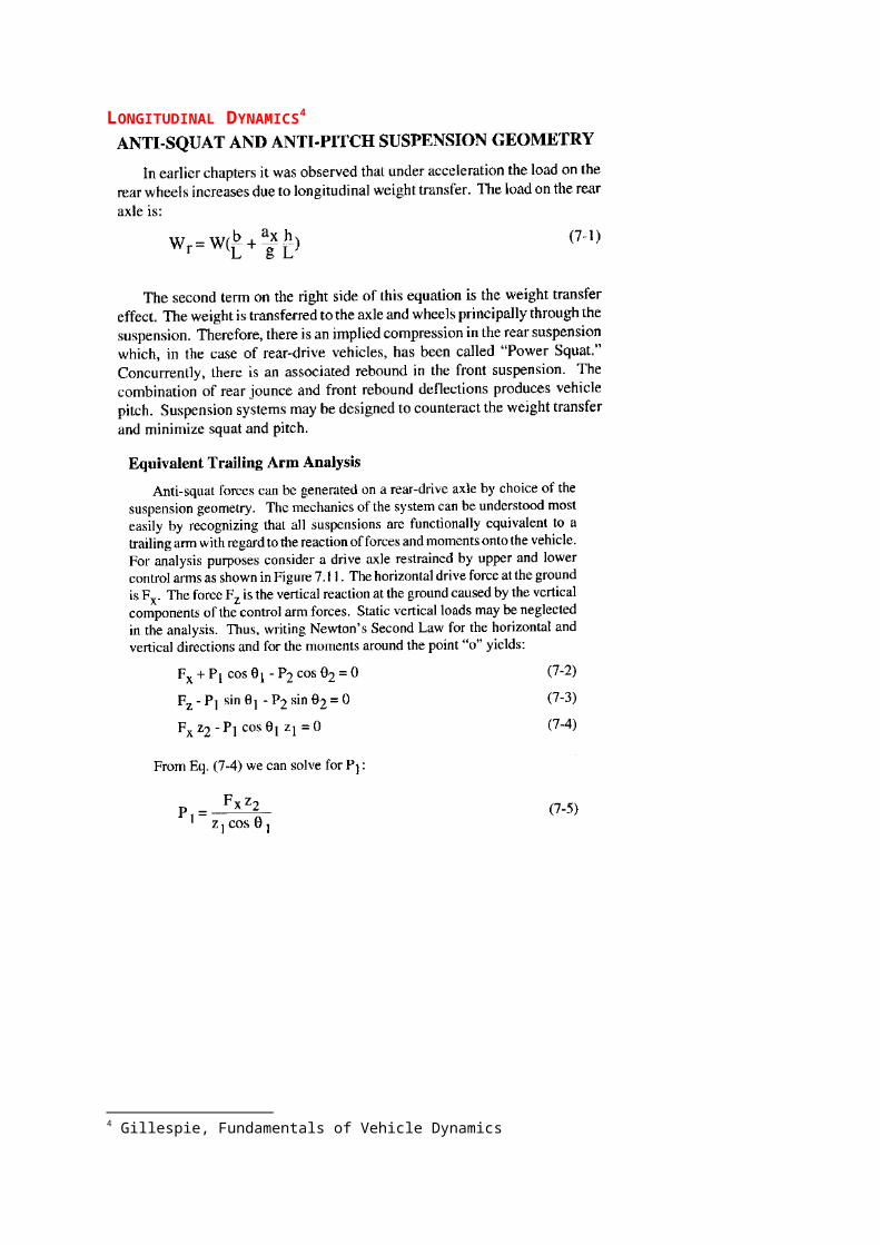
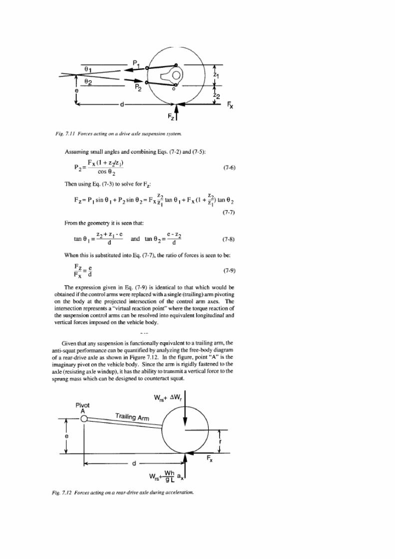
LONGITUDINAL DYNAMICS4
4 Gillespie, Fundamentals of Vehicle Dynamics
SUSPENSION TYPES

TERMINOLOGY
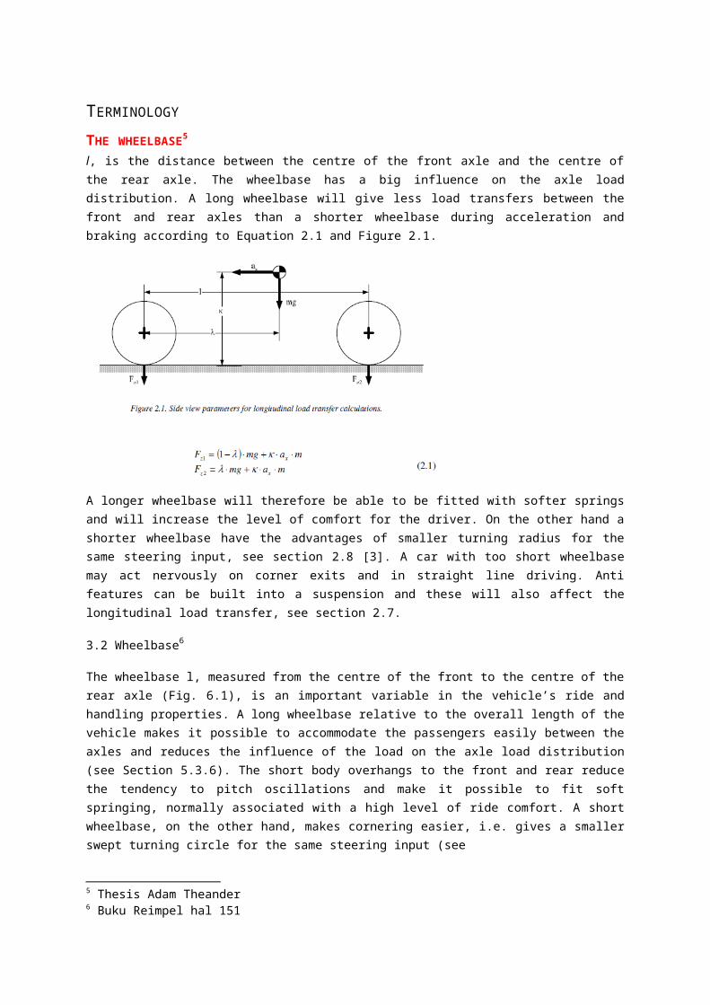
THE WHEELBASE5 l, is the distance between the centre of the front axle and the centre of the rear axle. The wheelbase has a big influence on the axle load distribution. A long wheelbase will give less load transfers between the front and rear axles than a shorter wheelbase during acceleration and braking according to Equation 2.1 and Figure 2.1.
A longer wheelbase will therefore be able to be fitted with softer springs and will increase the level of comfort for the driver. On the other hand a shorter wheelbase have the advantages of smaller turning radius for the same steering input, see section 2.8 [3]. A car with too short wheelbase may act nervously on corner exits and in straight line driving. Anti features can be built into a suspension and these will also affect the longitudinal load transfer, see section 2.7.
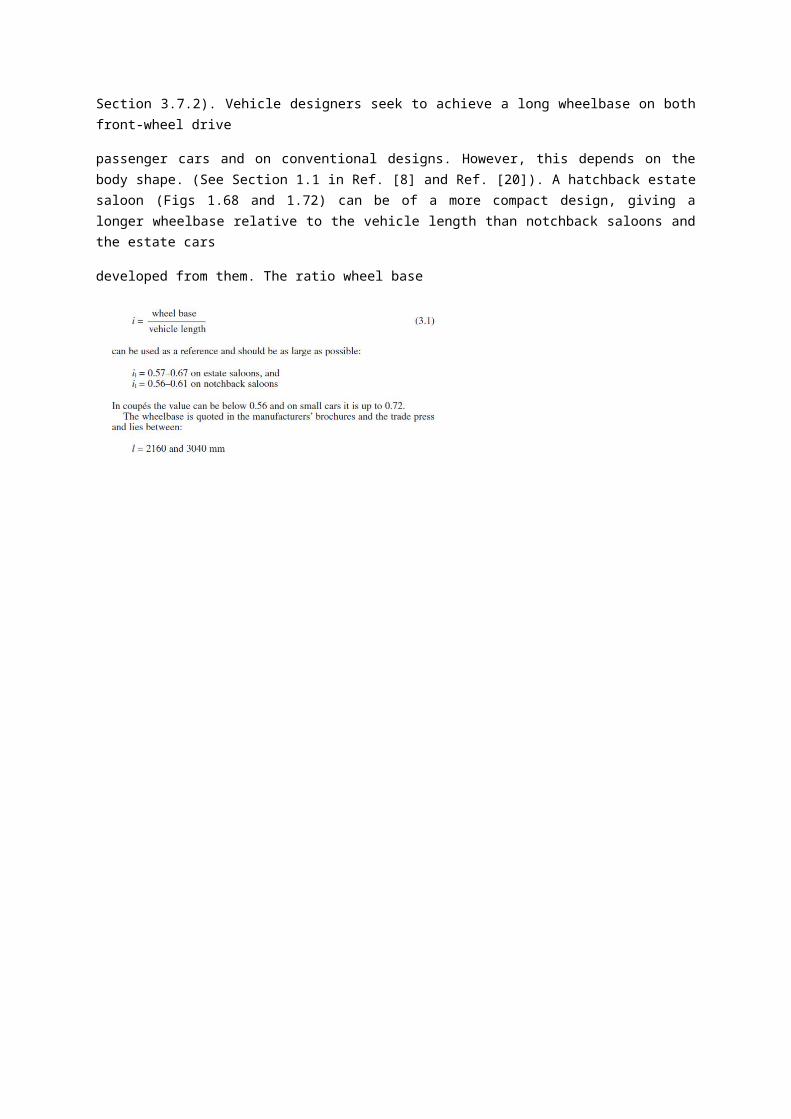
3.2 Wheelbase6
The wheelbase l, measured from the centre of the front to the centre of the rear axle (Fig. 6.1), is an important variable in the vehicle’s ride and handling properties. A long wheelbase relative to the overall length of the vehicle makes it possible to accommodate the passengers easily between the axles and reduces the influence of the load on the axle load distribution (see Section 5.3.6). The short body overhangs to the front and rear reduce the tendency to pitch oscillations and make it possible to fit soft springing, normally associated with a high level of ride comfort. A short wheelbase, on the other hand, makes cornering easier, i.e. gives a smaller swept turning circle for the same steering input (see
Section 3.7.2). Vehicle designers seek to achieve a long wheelbase on both front-wheel drive
passenger cars and on conventional designs. However, this depends on the body shape. (See Section 1.1 in Ref. [8] and Ref. [20]). A hatchback estate saloon (Figs 1.68 and 1.72) can be of a more compact design, giving a longer wheelbase relative to the vehicle length than notchback saloons and the estate cars
developed from them. The ratio wheel base
5 Thesis Adam Theander6 Buku Reimpel hal 151

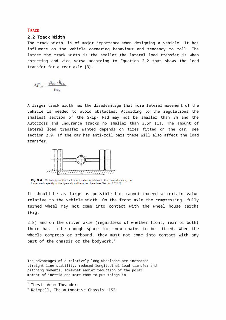
TRACK
2.2 Track WidthThe track width7 is of major importance when designing a vehicle. It has influence on the vehicle cornering behaviour and tendency to roll. The larger the track width is the smaller the lateral load transfer is when cornering and vice versa according to Equation 2.2 that shows the load transfer for a rear axle [3].
A larger track width has the disadvantage that more lateral movement of the vehicle is needed to avoid obstacles. According to the regulations the smallest section of the Skip- Pad may not be smaller than 3m and the Autocross and Endurance tracks no smaller than 3.5m [1]. The amount of lateral load transfer wanted depends on tires fitted on the car, see section 2.9. If the car has anti-roll bars these will also affect the load transfer.
It should be as large as possible but cannot exceed a certain value relative to the vehicle width. On the front axle the compressing, fully turned wheel may not come into contact with the wheel house (arch) (Fig.
2.8) and on the driven axle (regardless of whether front, rear or both) there has to be enough space for snow chains to be fitted. When the wheels compress or rebound, they must not come into contact with any part of the chassis or the bodywork.8
The advantages of a relatively long wheelbase are increasedstraight line stability, reduced longitudinal load transfer andpitching moments, somewhat easier reduction of the polarmoment of inertia and more room to put things in.
The advantages of a relatively short wheelbase are reducedoverall weight and increased maneuverability.
The advantages of wide track widths are reduced lateralload transfer for a given amount of centrifugal acceleration and room for longer suspension links. The major disadvan_
tage is increased frontal area. When we get intoaerodynamics,we will see that, at least on open wheeled carsthe importance of frontal area is overrated.
Very basically, the racing car with a long wheelbase andrelatively narrow track widths will be very stable in a
7 Thesis Adam Theander8 Reimpell, The Automotive Chassis, 152
straight line at the expense of cornering power andmaneuverability. The vehicle with a shorter wheelbase andwide tracks will be less stable, more maneuverable and willdevelop more cornering power.
Ibelieve that the front track should be considerably widerthan the rear track.
The wider the front track, the more resistancethere is going to be to diagonal load transfer and the lesserwill be the tendency for the car to "trip over itself' on cornerentry and/or to push into the wall from the effect of the driveon the inside rear wheel when the power is applied.
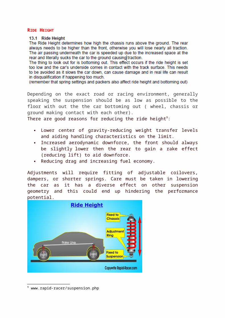
RIDE HEIGHT
Depending on the exact road or racing environment, generally speaking the suspension should be as low as possible to the floor with out the the car bottoming out ( wheel, chassis or ground making contact with each other).There are good reasons for reducing the ride height9:
Lower center of gravity-reducing weight transfer levels and aiding handling characteristics on the limit.
Increased aerodynamic downforce, the front should always be slightly lower then the rear to gain a rake effect (reducing lift) to aid downforce.
Reducing drag and increasing fuel economy.
Adjustments will require fitting of adjustable coilovers, dampers, or shorter springs. Care must be taken in lowering the car as it has a diverse effect on other suspension geometry and this could end up hindering the performance potential.
9 www.rapid-racer/suspension.php
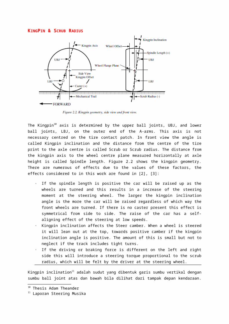
KINGPIN & SCRUB RADIUS
The Kingpin10 axis is determined by the upper ball joints, UBJ, and lower ball joints, LBJ, on the outer end of the A-arms. This axis is not necessary centred on the tire contact patch. In front view the angle is called Kingpin inclination and the distance from the centre of the tire print to the axle centre is called Scrub or Scrub radius. The distance from the kingpin axis to the wheel centre plane measured horizontally at axle height is called Spindle length. Figure 2.2 shows the kingpin geometry. There are numerous of effects due to the values of these factors, the effects considered to in this work are found in [2], [3]:
· If the spindle length is positive the car will be raised up as the wheels are turned and this results in a increase of the steering moment at the steering wheel. The larger the kingpin inclination angle is the more the car will be raised regardless of which way the front wheels are turned. If there is no caster present this effect is symmetrical from side to side. The raise of the car has a self-aligning effect of the steering at low speeds.
· Kingpin inclination affects the Steer camber. When a wheel is steered it will lean out at the top, towards positive camber if the kingpin inclination angle is positive. The amount of this is small but not to neglect if the track includes tight turns.
· If the driving or braking force is different on the left and right side this will introduce a steering torque proportional to the scrub radius, which will be felt by the driver at the steering wheel.
Kingpin inclination11 adalah sudut yang dibentuk garis sumbu vertikal dengan sumbu ball joint atas dan bawah bila dilihat dari tampak depan kendaraan. Untuk meminimalisasi scrub radius, kita harus mengatur kingpin inclination antara 0-10 derajat. Besar sudut kingpin sebesar 40.
Scrub radus12 adalah jarak pada tampak depan antara kingpin axis dan garis tengah ban ketika keduanya secara teoritik bersentuhan dengan tanah. Scrub radius harus diatur antara 0 sampai 10 mm agar dapat meminimalisasi yawing moment yang ditimbulkan karena adanya perbendaan resistansi antara ban kanan dan ban kiri terhadap permukaan jalan. Gambar geometri ban dapat dilihat pada gambar dibawah. Besar scrub radius yang didapat sebesar 1 mm.
10 Thesis Adam Theander11 Laporan Steering Musika12 Laporan Steering Musika

Pada geometri kingpin diatas, terlihat adanya kingpin axis. Kingpin axis atau steering axis merupakan garis bujur yang akan memutar upright dan roda. Momen yang terjadi pada kingpin axis dapat dicari dengan rumus dibawah ini:
𝑀𝑆𝐴=𝐹𝑋 𝑑cos𝑣 𝑐𝑜𝑠𝜆+ 𝑇𝑑sin(𝜆+𝜁) Keterangan : MSA = momen Steering axis [Nm] Fx = traksi roda = {besar gaya normal roda x μ (koefisien gesek)} [N] d = scrub radius [m] v = sudut caster [derajat] λ = kingpin inclination [derajat] Td = torsi pada axle [Nm] ζ = kemiringan tie rod terhadap sumbu horizontal [derajat]
The initial decision of zero degree kingpin inclination13 had to be reconsidered since the 56 mm of scrub radius resulted is large and will give an excessive feedback to the driver. Therefore 4 degree kingpin inclination is to be build in the front upright design that will result in an amount of scrub radius of 30mm calculated for last year wheel offset. Since this amount is still grater than 10% of the thread width (Heisler 1989), new wheels with less offset have been found therefore the resulting scrub radius is about 20 mm that is the amount we aimed for.
13 Desertasi Cristina Elena
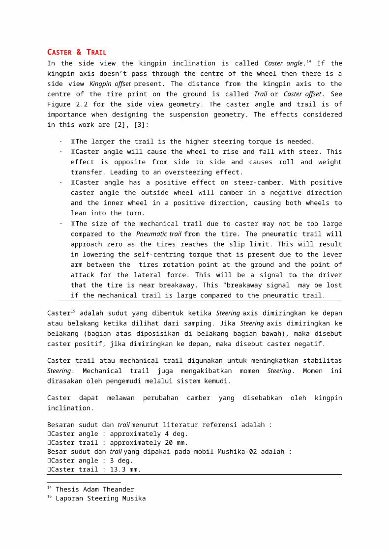
CASTER & TRAILIn the side view the kingpin inclination is called Caster angle.14 If the kingpin axis doesn’t pass through the centre of the wheel then there is a side view Kingpin offset present. The distance from the kingpin axis to the centre of the tire print on the ground is called Trail or Caster offset. See Figure 2.2 for the side view geometry. The caster angle and trail is of importance when designing the suspension geometry. The effects considered in this work are [2], [3]:
· The larger the trail is the higher steering torque is needed.· Caster angle will cause the wheel to rise and fall with steer. This effect is opposite from side to side
and causes roll and weight transfer. Leading to an oversteering effect.· Caster angle has a positive effect on steer-camber. With positive caster angle the outside wheel will
camber in a negative direction and the inner wheel in a positive direction, causing both wheels to lean into the turn.
· The size of the mechanical trail due to caster may not be too large compared to the Pneumatic trail from the tire. The pneumatic trail will approach zero as the tires reaches the slip limit. This will result in lowering the self-centring torque that is present due to the lever arm between the tires rotation point at the ground and the point of attack for the lateral force. This will be a signal to the driver that the tire is near breakaway. This “breakaway signal” may be lost if the mechanical trail is large compared to the pneumatic trail.
Caster15 adalah sudut yang dibentuk ketika Steering axis dimiringkan ke depan atau belakang ketika dilihat dari samping. Jika Steering axis dimiringkan ke belakang (bagian atas diposisikan di belakang bagian bawah), maka disebut caster positif, jika dimiringkan ke depan, maka disebut caster negatif.
Caster trail atau mechanical trail digunakan untuk meningkatkan stabilitas Steering. Mechanical trail juga mengakibatkan momen Steering. Momen ini dirasakan oleh pengemudi melalui sistem kemudi.
Caster dapat melawan perubahan camber yang disebabkan oleh kingpin inclination.
Besaran sudut dan trail menurut literatur referensi adalah : Caster angle : approximately 4 deg. Caster trail : approximately 20 mm. Besar sudut dan trail yang dipakai pada mobil Mushika-02 adalah : Caster angle : 3 deg. Caster trail : 13.3 mm.
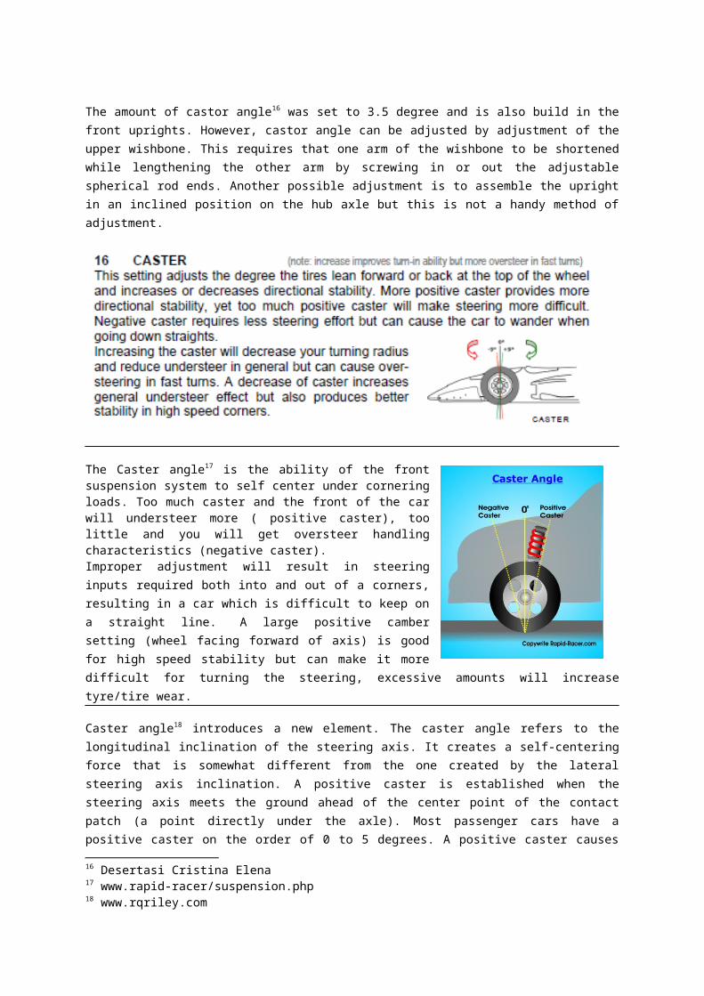
The amount of castor angle16 was set to 3.5 degree and is also build in the front uprights. However, castor angle can be adjusted by adjustment of the upper wishbone. This requires that one arm of the wishbone to be shortened while lengthening the other arm by screwing in or out the adjustable spherical rod ends. Another possible adjustment is to assemble the upright in an inclined position on the hub axle but this is not a handy method of adjustment.
14 Thesis Adam Theander15 Laporan Steering Musika16 Desertasi Cristina Elena

The Caster angle17 is the ability of the front suspension system to self center under cornering loads. Too much caster and the front of the car will understeer more ( positive caster), too little and you will get oversteer handling characteristics (negative caster).Improper adjustment will result in steering inputs required both into and out of a corners, resulting in a car which is difficult to keep on a straight line. A large positive camber setting (wheel facing forward of axis) is good for high speed stability but can make it more difficult for turning the steering, excessive amounts will increase tyre/tire wear.
Caster angle18 introduces a new element. The caster angle refers to the longitudinal inclination of the steering axis. It creates a self-centering force that is somewhat different from the one created by the lateral steering axis inclination. A positive caster is established when the steering axis meets the ground ahead of the center point of the contact patch (a point directly under the axle). Most passenger cars have a positive caster on the order of 0 to 5 degrees. A positive caster causes the wheel to trail behind the steering axis. When the vehicle is steered, the caster angle develops an opposing force that tends to steer the vehicle out of the turn
Another effect of caster angle is that it causes the camber angle to change when the wheels are steered. When the vehicle is steered, the inside wheel progresses into a positive camber and the outside wheel progresses into a negative camber. Considered independently of steering axis inclination, the effect of caster in a turn is to drop the side of the vehicle on the outside of the turn and to raise it on the inside of the turn.
17 www.rapid-racer/suspension.php18 www.rqriley.com
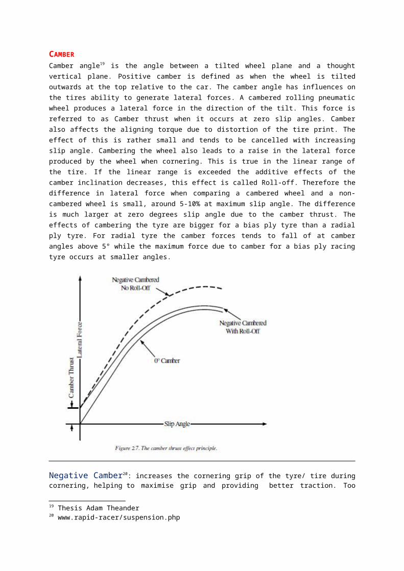
CAMBERCamber angle19 is the angle between a tilted wheel plane and a thought vertical plane. Positive camber is defined as when the wheel is tilted outwards at the top relative to the car. The camber angle has influences on the tires ability to generate lateral forces. A cambered rolling pneumatic wheel produces a lateral force in the direction of the tilt. This force is referred to as Camber thrust when it occurs at zero slip angles. Camber also affects the aligning torque due to distortion of the tire print. The effect of this is rather small and tends to be cancelled with increasing slip angle. Cambering the wheel also leads to a raise in the lateral force produced by the wheel when cornering. This is true in the linear range of the tire. If the linear range is exceeded the additive effects of the camber inclination decreases, this effect is called Roll-off. Therefore the difference in lateral force when comparing a cambered wheel and a non-cambered wheel is small, around 5-10% at maximum slip angle. The difference is much larger at zero degrees slip angle due to the camber thrust. The effects of cambering the tyre are bigger for a bias ply tyre than a radial ply tyre. For radial tyre the camber forces tends to fall of at camber angles above 5° while the maximum force due to camber for a bias ply racing tyre occurs at smaller angles.
Negative Camber20: increases the cornering grip of the tyre/ tire during cornering, helping to maximise grip and providing better traction. Too much Negative Camber will increase the inside tyres/tires wear and could result in handling imbalances.Neutral Camber: best suited for maximum acceleration and braking, this set up makes sure a flat contact patch is retained on flat road surfaces. The inside wheels may lift on the inner contact edge of the tyre/ tire duration extreme cornering.Positive Camber: used more for off road applications, especially with agricultural vehicles as this setting helps the wheels to turn with lighter steering effort required.The outside wheel under extreme cornering loads will benefit, but camber levels are normally linked ( might be a consideration for oval tracks).
19 Thesis Adam Theander20 www.rapid-racer/suspension.php
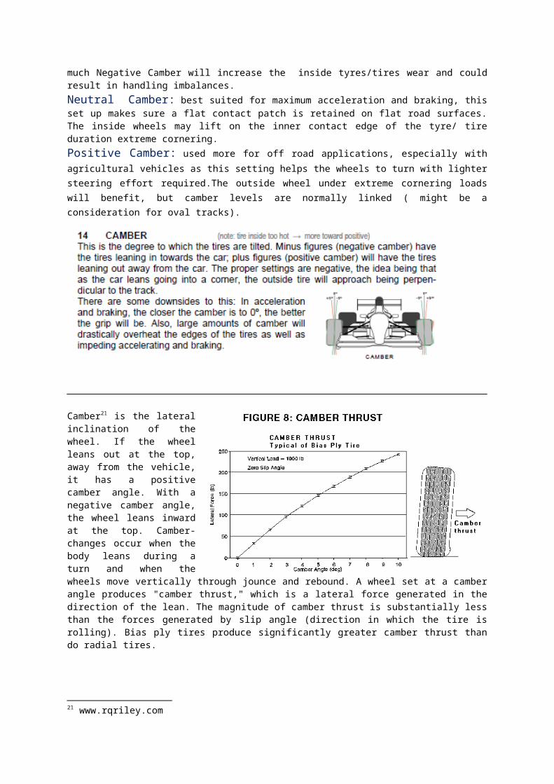
Camber21 is the lateral inclination of the wheel. If the wheel leans out at the top, away from the vehicle, it has a positive camber angle. With a negative camber angle, the wheel leans inward at the top. Camber-changes occur when the body leans during a turn and when the wheels move vertically through jounce and rebound. A wheel set at a camber angle produces "camber thrust," which is a lateral force generated in the direction of the lean. The magnitude of camber thrust is substantially less than the forces generated by slip angle (direction in which the tire is rolling). Bias ply tires produce significantly greater camber thrust than do radial tires.
` As a general rule, the vehicle will handle well if the camber angle meets certain criteria. At the fully laden ride height, the front wheels should assume a zero or slightly positive camber angle. During jounce, as the wheel moves upward through its arc, camber should progress to a negative angle in relation to the vehicle. The purpose of the negative camber angle is to maximize cornering forces by keeping the outside tire upright or at a slightly negative camber angle as the body leans to the outside of the turn. The second purpose of negative camber is to minimize lateral movement, or tire scrubbing, at the contact patch. When wheels move through the arc prescribed by the suspension linkages, they may be dragged laterally inboard and outboard as they move up and down. Lateral movement causes a scrubbing action at the contact patch, which reduces adhesion and shortens tire life. Severe lateral scrubbing can also cause a condition known as "bump-steer." A suspension system with a large
21 www.rqriley.com
scrubbing action will cause the vehicle to veer to one side when adhesion or vertical wheel movement is not equal at both side-by-side wheels. Ideally, the camber angle will change during jounce enough to compensate for the suspension-induced lateral movement at the hub. Camber change should also compensate for body roll to keep the outside wheel from lean away from the turn. Tire scrubbing (changes in the tread) should be minimized by good suspension design, and camber changes should be minimal as well.
Consideration of camber angle has traditionally emphasized the front wheels. With the proliferation of independent rear suspension systems, the effects of camber angle have become just as important at the rear of the vehicle. Rear wheel camber changes can augment cornering forces, and they can influence the balance between oversteer and understeer.
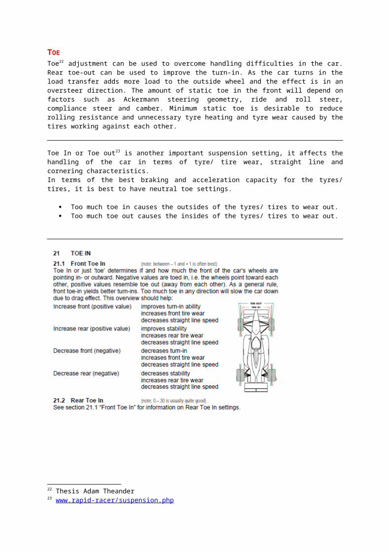
TOEToe22 adjustment can be used to overcome handling difficulties in the car. Rear toe-out can be used to improve the turn-in. As the car turns in the load transfer adds more load to the outside wheel and the effect is in an oversteer direction. The amount of static toe in the front will depend on factors such as Ackermann steering geometry, ride and roll steer, compliance steer and camber. Minimum static toe is desirable to reduce rolling resistance and unnecessary tyre heating and tyre wear caused by the tires working against each other.
Toe In or Toe out23 is another important suspension setting, it affects the handling of the car in terms of tyre/ tire wear, straight line and cornering characteristics.In terms of the best braking and acceleration capacity for the tyres/ tires, it is best to have neutral toe settings.
Too much toe in causes the outsides of the tyres/ tires to wear out. Too much toe out causes the insides of the tyres/ tires to wear out.
22 Thesis Adam Theander23 www.rapid-racer/suspension.php
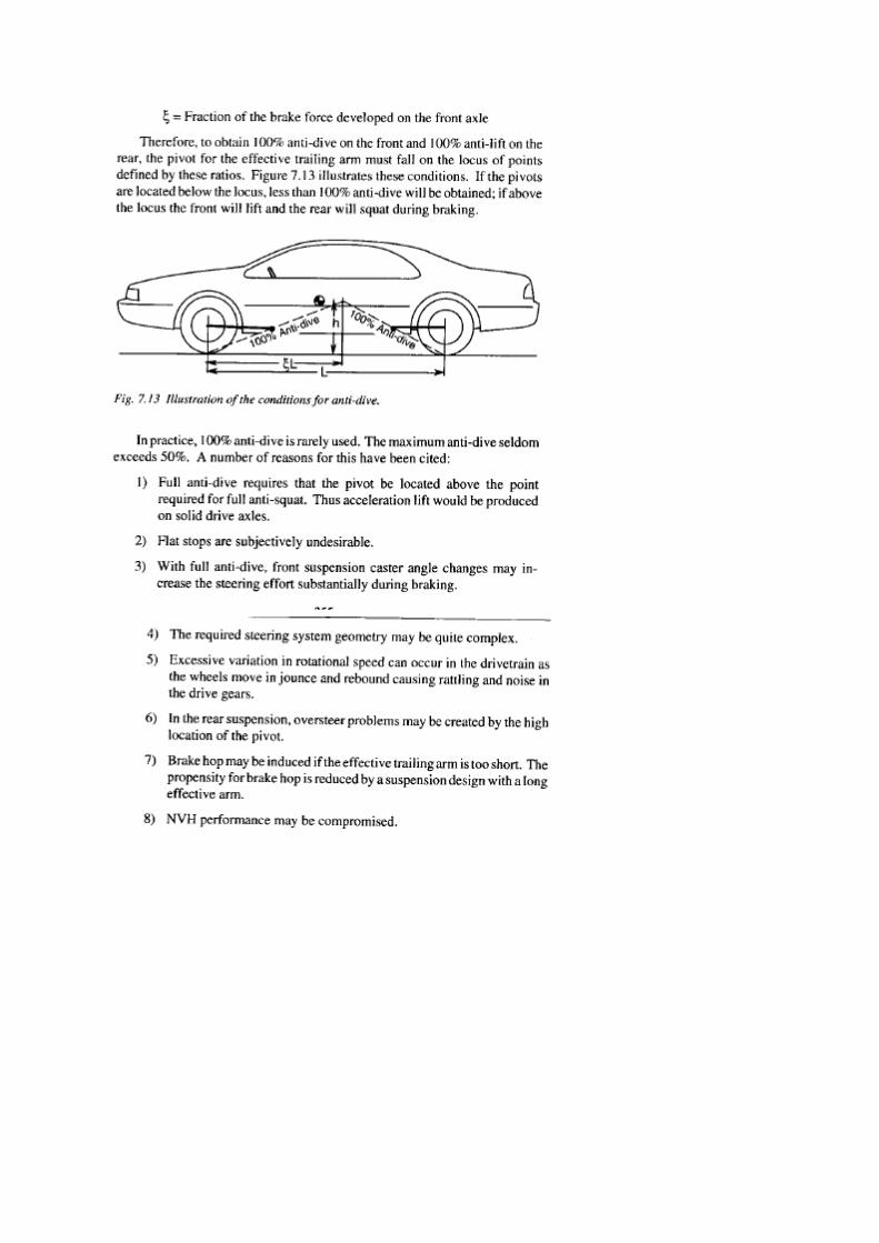
ANTI FEATURES
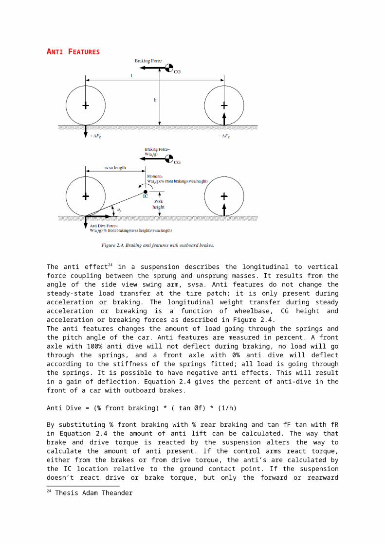
The anti effect24 in a suspension describes the longitudinal to vertical force coupling between the sprung and unsprung masses. It results from the angle of the side view swing arm, svsa. Anti features do not change the steady-state load transfer at the tire patch; it is only present during acceleration or braking. The longitudinal weight transfer during steady acceleration or breaking is a function of wheelbase, CG height and acceleration or breaking forces as described in Figure 2.4.The anti features changes the amount of load going through the springs and the pitch angle of the car. Anti features are measured in percent. A front axle with 100% anti dive will not deflect during braking, no load will go through the springs, and a front axle with 0% anti dive will deflect according to the stiffness of the springs fitted; all load is going through the springs. It is possible to have negative anti effects. This will result in a gain of deflection. Equation 2.4 gives the percent of anti-dive in the front of a car with outboard brakes.
Anti Dive = (% front braking) * ( tan Øf) * (1/h)
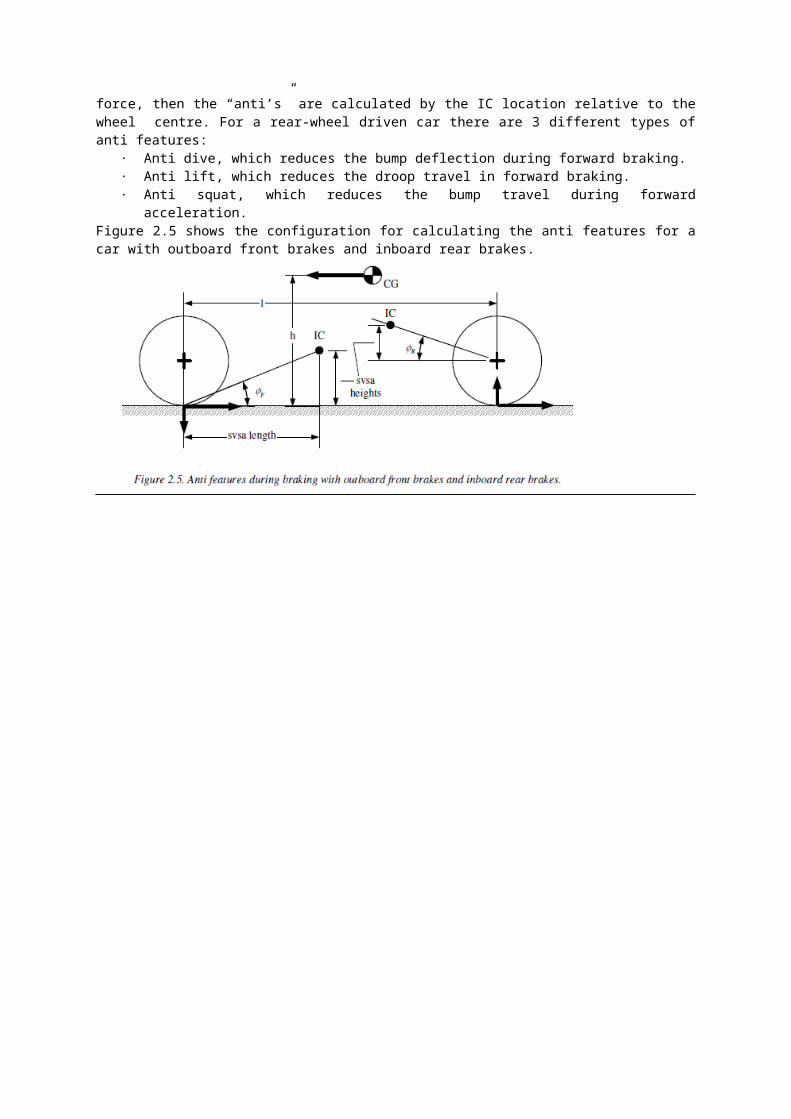
By substituting % front braking with % rear braking and tan fF tan with fR in Equation 2.4 the amount of anti lift can be calculated. The way that brake and drive torque is reacted by the suspension alters the way to calculate the amount of anti present. If the control arms react torque, either from the brakes or from drive torque, the anti’s are calculated by the IC location relative to the ground contact point. If the suspension doesn’t react drive or brake torque, but only the forward or rearward force, then the “anti’s” are calculated by the IC location relative to the wheel centre. For a rear-wheel driven car there are 3 different types of anti features:
· Anti dive, which reduces the bump deflection during forward braking.· Anti lift, which reduces the droop travel in forward braking.· Anti squat, which reduces the bump travel during forward acceleration.
Figure 2.5 shows the configuration for calculating the anti features for a car with outboard front brakes and inboard rear brakes.
24 Thesis Adam Theander

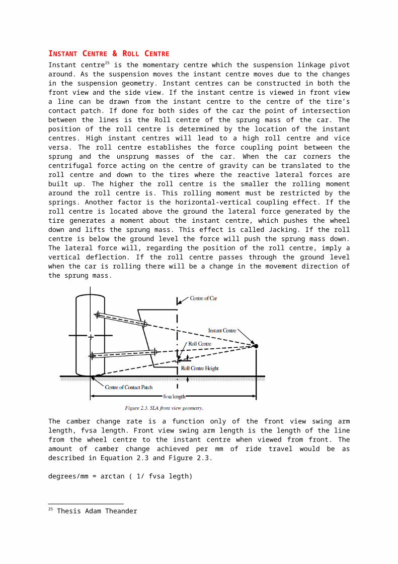
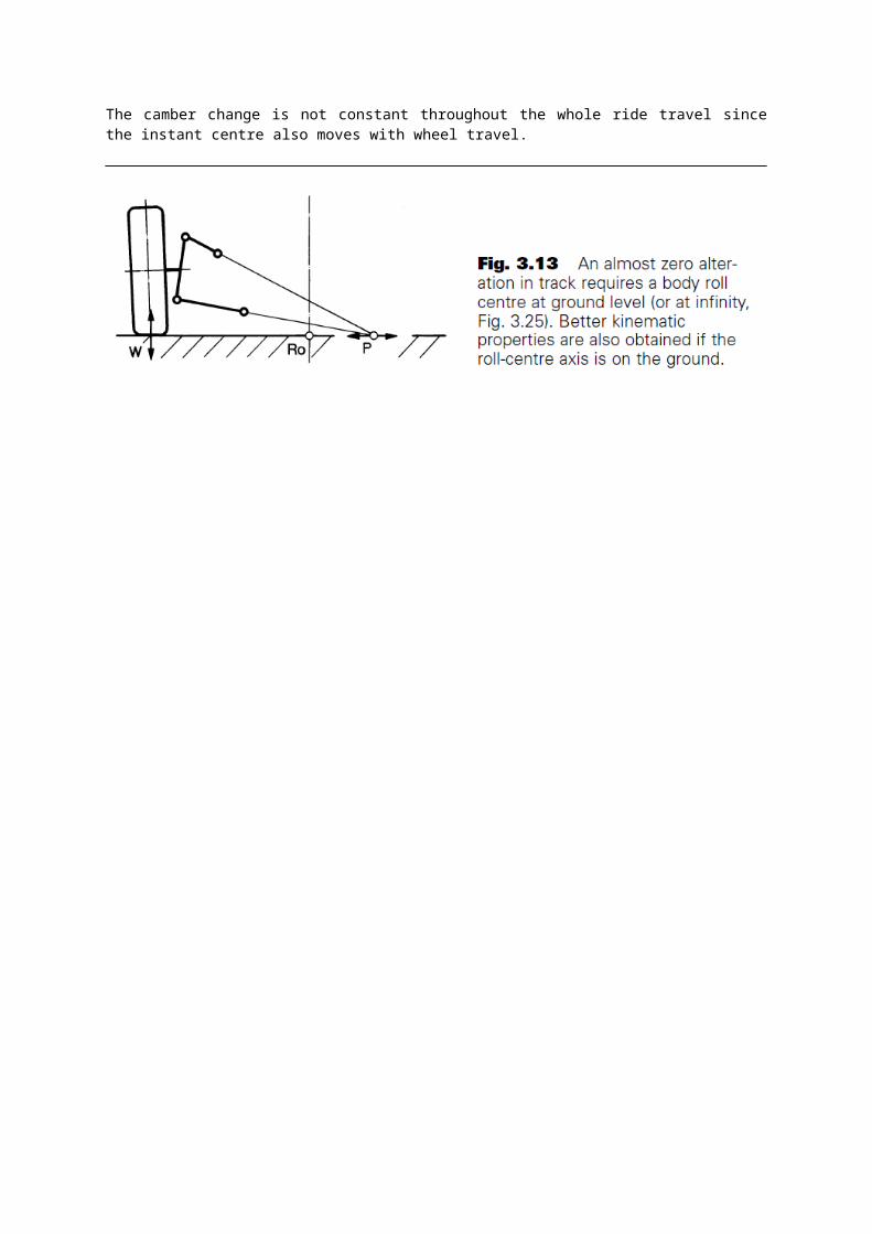
INSTANT CENTRE & ROLL CENTREInstant centre25 is the momentary centre which the suspension linkage pivot around. As the suspension moves the instant centre moves due to the changes in the suspension geometry. Instant centres can be constructed in both the front view and the side view. If the instant centre is viewed in front view a line can be drawn from the instant centre to the centre of the tire’s contact patch. If done for both sides of the car the point of intersection between the lines is the Roll centre of the sprung mass of the car. The position of the roll centre is determined by the location of the instant centres. High instant centres will lead to a high roll centre and vice versa. The roll centre establishes the force coupling point between the sprung and the unsprung masses of the car. When the car corners the centrifugal force acting on the centre of gravity can be translated to the roll centre and down to the tires where the reactive lateral forces are built up. The higher the roll centre is the smaller the rolling moment around the roll centre is. This rolling moment must be restricted by the springs. Another factor is the horizontal-vertical coupling effect. If the roll centre is located above the ground the lateral force generated by the tire generates a moment about the instant centre, which pushes the wheel down and lifts the sprung mass. This effect is called Jacking. If the roll centre is below the ground level the force will push the sprung mass down. The lateral force will, regarding the position of the roll centre, imply a vertical deflection. If the roll centre passes through the ground level when the car is rolling there will be a change in the movement direction of the sprung mass.
The camber change rate is a function only of the front view swing arm length, fvsa length. Front view swing arm length is the length of the line from the wheel centre to the instant centre when viewed from front. The amount of camber change achieved per mm of ride travel would be as described in Equation 2.3 and Figure 2.3.
degrees/mm = arctan ( 1/ fvsa legth)
The camber change is not constant throughout the whole ride travel since the instant centre also moves with wheel travel.
25 Thesis Adam Theander

TIE ROD LOCATIONThe location of the tie rods26 is of major importance. The location shall be such that Bump steer effects are kept at a minimum. Bump steer is the change in toe angle due to wheel travel. A car with much bump steer will have a tendency to change its movement direction when the front wheels runs over an obstacle. The affects of this can be hazardous when running on an uneven track. The simplest way to minimize bump steer is to locate the tie rod in the same plane as either the upper or lower A-arms. Another factor to keep in mind is the camber compliance under lateral force. If the tie rods are located either above and behind or below and in front of the wheel centre the effect on the steering will be in understeer direction. If the A-arms are stiff enough the effects will be small and thereby minimize the risk of oversteering effects due to compliance in the A- arms. The length of the lever arm from the outer tie rod end to the upper ball joint determine together with the steering rack ratio the total ratio from the steering wheel’s angle to the wheel’s steering angle.
26 Thesis Adam Theander
ANTI-ROL BARAnti-Roll /Sway Bars27 as discussed in the Suspension Upgrades page, can provide adjustable settings in the suspension set up. Especially useful in dialing out oversteer, or understeer handling characteristics and getting a better balanced car. They are the same effect as changing the springs, but their effects are only used in lateral cornering forces.The reason this is so useful, is that you can make adjustment to front and rear independently with out affecting other suspension settings. Stiffer settings will reduce body roll, while softer settings will increase body roll. The relationship between the front and rear settings ( roll coupling), will also have a direct affect on the handling of the car. Like most suspension adjustments, it is best to take small incremental adjustments rather then going to one extreme to the other.It is critical that the right Anti-Roll/Sway Bar is also selected to complement the other suspension components. I would suggest seeking profession advice on the overall suspension set as a whole and not just individual upgrades, when considering suspension adjustments. It is generally accepted that it is better to reduce the settings, rather then increase them to get a better balanced car. Softer settings will make weight transfer more gradual, with less abrupt loading, bending into corners rather then darting into them. Great care needs to be taken with too soft a setting as well, if the car has a low center of gravity, a soft setting could result in the car bottoming out. Also camber settings ranges could be affected with a soft setting, where the tyre/ tire exceeds the optimum set up.Having too stiff a setting could result in poor handling in tight corners, with the inside wheel lifting off the ground. Also if either of the two wheels linked on the axle are on different road surfaces (one wheel on track, other on the side of the track), having a stiff set up will result in imbalances being transmitted through the Anti-Roll/ Sway Bar to the other driven wheel.
Understeer: reduce front or increase rear anti-roll/ sway bar settings. Oversteer: increase front or reduce rear anti-roll/ sway bar settings
27 www.rapid-racer/suspension.php
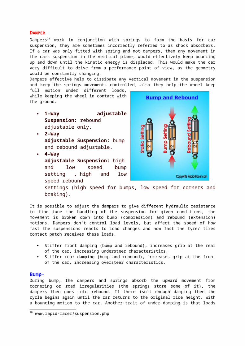
DAMPERDampers28 work in conjunction with springs to form the basis for car suspension, they are sometimes incorrectly referred to as shock absorbers. If a car was only fitted with spring and not dampers, then any movement in the cars suspension in the vertical plane, would effectively keep bouncing up and down until the kinetic energy is displaced. This would make the car very difficult to drive from a performance point of view, as the geometry would be constantly changing.Dampers effective help to dissipate any vertical movement in the suspension and keep the springs movements controlled, also they help the wheel keep full motion under different loads, while keeping the wheel in contact with the ground.
1-Way adjustable Suspension: rebound adjustable only.
2-Way adjustable Suspension: bump and rebound adjustable.
4-Way adjustable Suspension: high and low speed bump setting , high and low speed rebound settings (high speed for bumps, low speed for corners and braking).
It is possible to adjust the dampers to give different hydraulic resistance to fine tune the handling of the suspension for given conditions, the movement is broken down into bump (compression) and rebound (extension) motions. Dampers don't control load levels, but affect the speed of how fast the suspensions reacts to load changes and how fast the tyre/ tires contact patch receives these loads.
Stiffer front damping (bump and rebound), increases grip at the rear of the car, increasing understeer characteristics.
Stiffer rear damping (bump and rebound), increases grip at the front of the car, increasing oversteer characteristics.
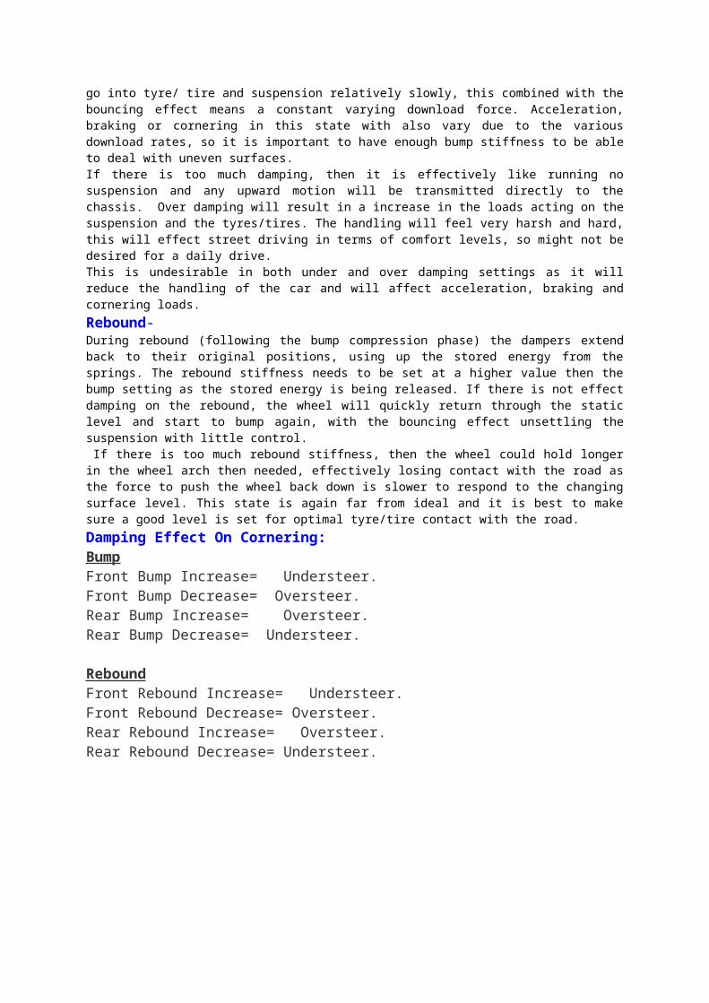
Bump- During bump, the dampers and springs absorb the upward movement from cornering or road irregularities (the springs store some of it), the dampers then goes into rebound. If there isn't enough damping then the cycle begins again until the car returns to the original ride height, with a bouncing motion to the car. Another trait of under damping is that loads go into tyre/ tire and suspension relatively slowly, this combined with the bouncing effect means a constant varying download force. Acceleration, braking or cornering in this state with also vary due to the various download rates, so it is important to have enough bump stiffness to be able to deal with uneven surfaces.If there is too much damping, then it is effectively like running no suspension and any upward motion will be transmitted directly to the chassis. Over damping will result in a increase in the loads acting on the suspension and the tyres/tires. The handling will feel very harsh and hard, this will effect street driving in terms of comfort levels, so might not be desired for a daily drive.This is undesirable in both under and over damping settings as it will reduce the handling of the car and will affect acceleration, braking and cornering loads.Rebound-During rebound (following the bump compression phase) the dampers extend back to their original positions, using up the stored energy from the springs. The rebound stiffness needs to be set at a higher value then the bump setting as the stored energy is being released. If there is not effect damping on the rebound, the wheel
28 www.rapid-racer/suspension.php
will quickly return through the static level and start to bump again, with the bouncing effect unsettling the suspension with little control. If there is too much rebound stiffness, then the wheel could hold longer in the wheel arch then needed, effectively losing contact with the road as the force to push the wheel back down is slower to respond to the changing surface level. This state is again far from ideal and it is best to make sure a good level is set for optimal tyre/tire contact with the road.Damping Effect On Cornering:BumpFront Bump Increase= Understeer.Front Bump Decrease= Oversteer.Rear Bump Increase= Oversteer.Rear Bump Decrease= Understeer.
ReboundFront Rebound Increase= Understeer.Front Rebound Decrease= Oversteer.Rear Rebound Increase= Oversteer.Rear Rebound Decrease= Understeer.
SPRING
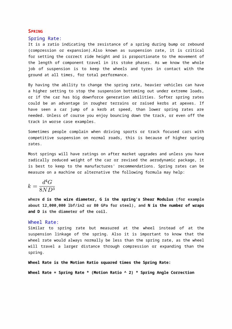
Spring Rate:It is a ratio indicating the resistance of a spring during bump or rebound (compression or expansion).Also known as suspension rate, it is critical for setting the correct ride height and is proportionate to the movement of the length of component travel in its stoke phases. As we know the whole job of suspension is to keep the wheels and tyres in contact with the ground at all times, for total performance.
By having the ability to change the spring rate, heavier vehicles can have a higher setting to stop the suspension bottoming out under extreme loads, or if the car has big downforce generation abilities. Softer spring rates could be an advantage in rougher terrains or raised kerbs at apexes. If have seen a car jump of a kerb at speed, than lower spring rates are needed. Unless of course you enjoy bouncing down the track, or even off the track in worse case examples.
Sometimes people complain when driving sports or track focused cars with competitive suspension on normal roads, this is because of higher spring rates.
Most springs will have ratings on after market upgrades and unless you have radically reduced weight of the car or revised the aerodynamic package, it is best to keep to the manufactures' recommendations. Spring rates can be measure on a machine or alternative the following formula may help:
where d is the wire diameter, G is the spring's Shear Modulus (for example about 12,000,000 lbf/in2 or 80 GPa for steel), and N is the number of wraps and D is the diameter of the coil.
Wheel Rate:Similar to spring rate but measured at the wheel instead of at the suspension linkage of the spring. Also it is important to know that the wheel rate would always normally be less than the spring rate, as the wheel will travel a larger distance through compression or expanding than the spring.
Wheel Rate is the Motion Ratio squared times the Spring Rate:
Wheel Rate = Spring Rate * (Motion Ratio ^ 2) * Spring Angle Correction
SUSPENSION GEOMETRY
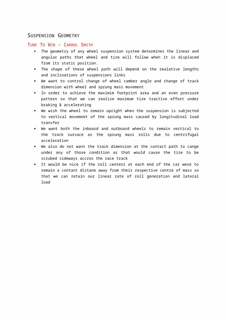
TUNE TO WIN – CARROL SMITH The geometry of any wheel suspension system determines the linear and angular paths that wheel
and tire will follow when it is displaced from its static position. The shape of these wheel path will depend on the realative lengths and inclinations of suspensions
links We want to control change of wheel camber angle and change of track dimension with wheel and
sprung mass movement In order to achieve the maximim footprint area and an even pressure pattern so that we can realize
maximum tire tractive effort under braking & accelerating We wish the wheel to remain upright when the suspension is subjected to vertical movemnet of the
sprung mass caused by longitudinal load transfer We want both the inboard and outboard wheels to remain vertical to the track survace as the sprung
mass rolls due to centrifugal acceleration We also do not want the track dimension at the contact path to cange under any of those condition as
that would cause the tire to be scrubed sideways accros the race track It would be nice if the roll centers at each end of the car were to remain a contant distane away from
their respective centre of mass so that we can retain our linear rate of roll generation and lateral load
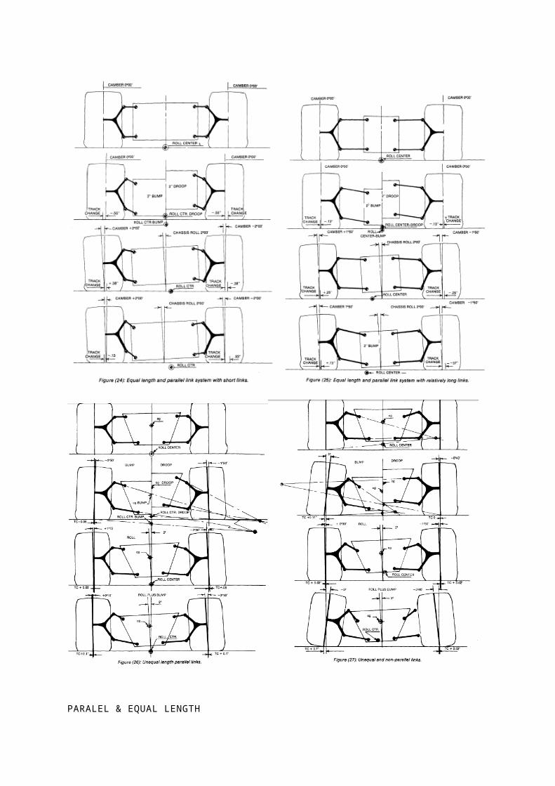
PARALEL & EQUAL LENGTH no camber change with vertical movement. There is, however, considerable change in track width-
which is not good. When the chasis rolls, the wheels and tires change camber by the exact amount of chassis roll-with the outside wheel cambering in the positive direction. This is not good under any condition and, the wider the tire involved, the less good it is.
We can reduce the amount of track change for a given amount of vertical motion by the simple expedient of
lengthening the suspension links, as in Figure (25). With this change, a given amount of vertical wheel or chassis movement results in less angular displacement of the wheel and therefore in less change in the track dimension
PARALEL & UNEQUAL LENGTH Now, in vertical travel, the upper link has a shorter radius than the lower which results in the wheel
assuming a negative camber angle in both bump and either negative or positive camber droop . If the wheels are allowed to travel very much, the camber curves will become very steep indeed.
At any rate, the roll center with unequal but parallel links stays pretty constant in relationship to the center of mass. Therefore the roll moment remains more or less constant, which is a good thing.
UNEQUAL AND NON PARALLEL LINKS By inclining the link pivot axes with respect to each other we can place the roll centers wherever we
please and we and further reduce the positive camber of the laden wheel in roll. What has happened is that the inclination of the upper link is too steep, resulting in a very short
instantaneous swing arm with the attendant very steep camber curves. By raising the inboard points of both the upper and the lower links we would achieve far better camber curves while maintaining the roll center in the same static location.
BASIC TRUTHS (1) While it is possible to control wheel camber either during vertical movement or during chassis roll,
it is not possible to achieve very good camber control under the combined condition (2) The longer we make the suspension links, the less angular and linear wheel displacement will
result from a given amount of chassis or wheel movement. (3) In vertical movement, the roll center moves with the center of gravity, tending to keep the roIl
moment constant. (4) Increasing the effective swing arm length decreases the amount of camber change due to vertical
wheel movement, decreases the amount of vertical roll center movement relative to the e.g. and increases the amount of lateral roll center movement
(5) Except in the case of equal length and paraIlellinks long effective swing arms don't stay long when the wheel moves into the bump position or, for the laden wheel, when the chassis rolls.
(6) Increasing the inclination of the upper link (or shortening its relative length) results in more negative camber in bump, less positive camber on the laden wheel in roIl and a decrease in the amount of wheel or chassis movement before we lose camber control.
COMPROMISE (1) The present generation of racing tires is relatively insensitive, within reasonable limits, to camber
change. (2) Load transfer characteristics are more important to tire performance and vehicle balance than
camber curves (3) Different design philosophies tend to even out in terms of lap time-the car whose geometry tends
to limit its abosolute cornering power may well put the power downbetter-what you gain on the straights you lose in the corners and soon
GUIDELINES The front camber curve should keep the laden wheel more upright in roIl than the rear. (2) The front roll center will always be lower than the rear. If it is too much lower, we will have a car
that does not enter corners well and which exits corner on three wheels. The big trick here is to keep the front and rear roll center movements approximately equal to each other-and in the same direction
(3) We can control wheel camber within narrow limits of chassis roll and rather more broad limits of vertical movement. At some point in the generation of roll or vertical movement, the geometry will go to hell and the wheel paths will start to change very rapidly . The longer that we make the suspension links, the more movement can take place before we lose camber control-and the less wheel displacement
we will suffer per unit of chassis movement. Vehicle balance or driveability is more important in terms of lap time and winning races than ultimate cornering power. So. I feel that we should design the geometry of our
suspensions to minimize rapid changes of camber and relative front to rear roll center movement as the car goes through its transitions from braking to cornering acceleration restrict chassis rol
( I) We can use high roll centers which result in low roll moments. We do not want to follow this approach because we will then have poor camber curves and high jacking forces.
(2) We can use anti-roll bars at each end of the car stiff enough to restrict roll to our desired maximum.
(3) We can use the suspension springs to restrict rolleither by making them stiffer, which is a bad idea, or by optimizing their placement so that we get maximum linear spring travel per degree of roll generated.
(4) We can use longer suspension links to reduce the amount of camber change generated per degree of roll.
CONSIDERATION Power to weight ratio (2) Aerodynamic downforce to be generated and range ofvehicle speeds (3) Tire width and characteristics (4) Track characteristics-smoothness, corner speed, degree of banking present and the amount of
braking that will take place.
The ubiquitous Formula Ford features low engine power, low gross weight, narrow tires, virtually no down force generation, and crazy drivers. They do not accelerate very hard because they don't have much torque. Since they are not allowed to run wings, the operating ride height does not change much with road speed. The narrow tires will tolerate a fair amount of camber.
What Formula Fords need from the suspension geometry is maximum braking power and maximum cornering power. They need the braking power, because one of the few places for a Formula Ford to get by another one is in the braking area. They need the cornering power, because they cannot afford to slow down any more.
We get the braking power by keeping the. front wheels as upright as possible in bump and not allowmg the rear wheels to go into positive camber in droop. This means long links with not much inclination at the front. At the rear, we don't need to worry a lot about the effects of squat since we won't have enough torque to cause much of it. We do, however, have to worry about the camber of the laden wheel. As no limited slip diffs are allowed, we also have to avoid inside rear wheelspin which means lots of droop travel, avoidance of extreme negative camber generation on the inside wheel and minimum lateral load transfer at the rear.
I believe that it is a hell of a lot more important to get the roll center locations and movements happy with each other and with the mass centroid axis than it is to get the camber curves perfect If you decide to make the links longer, take a really good look at the structural factors involved-they will necessarily have to be stiffer, particularly at the front, due to the brake torque loads being reacted over a longer distance.
Raising or lowering pivot points, at the front, is simply a case of making spacers for the ball joints, or of reducing the height of the uprights. It is always easier to do it outboard than inboard-except on production cars. The opposite condition exists at the rear where the outboard pivots are pretty well fixed in the hub carrier design but the inboards are bolt on structures or cross members which can be pretty easily replaced or modified
INTERNET SOURCE
ROLL CENTRE POSITION
http://www.f1technical.net/forum/viewtopic.php?f=6&t=8614
Now be may have 4 basic positions:
1) Roll center height (from now on RCH) = center of gravity (CoG)
No pivoting here, it means that there is no roll. Its like trying to spin a door applying force in the hinge. The car is turning, lateral force is applied, but there is no roll. Hence, all the force is "catched" by the wishbones. This makes the car as hard as a rock, as spring/dampers doesnt work here. Its good for nothing.
2) RCH between CoG and the ground.
Depending the percentage of that height you distribute how much force goes through the wishbones and how much through the spring/dampers. The range between 15% and 30% of RCH compared to CoG is the most common place to locate it in many racing cars.
3) RCH = ground height.
All the lateral forces passes from the chasis to the wheels throught dampers/springs, so virtually the wishbones makes no force under pure lateral load condition.
4) RCH below ground.
More force than whats actually transferred passes through the spring/dampers, so that the wishbones is loaded unders "a negative" force. This means outer top wishbone for example is not under compresion, but under traction.This is the case of tourism racing cars that have to maintain the suspension geometry from the original street car when you reduce their ride height, there you have to find the best compromise between what you gain from aero and reduced CoG height and what you loose for poor suspension geometry. Here you dont have jacking, but the contrary. Also it is the case of heavily "tuned" street cars.
POSITION EFFECT
If roll centres set too low, there will be more body roll and stiffer bars will be required at both ends, that will effect wheel rates and traction on bumps when cornering, and especially on slippery surfaces.Low roll centres and stiff bars (with the higher wheel rate during cornering this creates) will make it very fast in the dry but it will slide much too easily in the wet. This is the one big reason production cars have moderately high roll centres.
Roll centres set far too high will cause jacking and produce minimal body roll which makes the antiroll bars much less sensitive, and basically makes the car untunable.
ADJUSTING
http://speedtalk.com/forum/viewtopic.php?f=11&t=31210
First balance the car on a skid pad for a very slightly increasing understeering gradient with with increasing speed. You can get this right with the roll centres located just about anywhere. This is also the time to find optimum tire pressures and optimum camber. This will give you stable steady state cornering and get both ends of the car working.
The next step is to start adjusting the roll axis inclination for best TRANSIENT response. Load will transfer faster at the end of the car as the roll axis height is increased at that end. A low roll centre will feed the lateral load transfer produced from body roll mainly through the springs and bar. Body roll is not instantaneous, and either will be lateral load transfer at that end, response will be slower. A high roll centre will produce less body roll, because most of the lateral load transfer goes direct through the suspension links, it responds faster to sudden changes in direction.
What we want is a stable vehicle with fastest possible response. We do this by building in some steady state understeer (thicker front antiroll bar). And giving it just a bit of transient oversteer (higher rear roll centre).
If it is done right, it will be fast and stable around a chicane, where you rapidly turn first one way then the other. All this assumes there are no bump or roll steer problems to complicate things. Every time you move one of the roll centre heights, you ideally need to then rebalance the car on a skid pad before testing for a change in transient response.
Vehicles with extreme or unusual weight distribution can require unconventional roll centre inclinations, the front roll centre is not always lower than the rear, but it usually is.
The fastest way to get from one steady state condition to another is with just a bit of overshoot. That is where the transient oversteer comes in. It will not cause instability, unless there is far too much.What it does is speed up the response.
One more thought on roll centers. There are two types of weight transfer, geometric and elastic. Geometric weight transfer is weight transferred through the linkages (panhard bar or Jacob's ladder) and Elastic Weight Transfer is weight transferred through the springs. As we raise our roll center we are increasing the amount of Geometric Weight Transfer and reducing the amount of elastic. The issue with geometric weight transfer is it happens instantaneously, with elastic it happens slower because we have to wait for the spring to compress. As the roll center is raised, the ride becomes more harsh and the car can get a tenancy to hop and also does not absorb the ruts and bumps as well. This kinds goes against our wanting to loosen the car up or keep the car from rolling by raising roll centers in the rear on a rough or wet track to loosen the car.
READING AND ANALYZING CAMBER CURVES
http://www.auto-ware.com/setup/cam_curv.htm
PARTS OF THE CAMBER GRAPH
The numbers on the left side of the graph represent the up and down travel of a wheel or suspension. The line in the middle labeled "static" is the wheel (or suspension) position when the race car is at rest or standing still.
The negative (-) numbers represent the condition where the wheel moves downward from the frame. This could happen when the tire drops into a pothole, or when the inside of the chassis lifts as during body roll in a corner.
The positive numbers above the static line are where the wheel has moved up in relation to the chassis. This can be a case where the tire is going over a bump or when the outside of the frame drops as during body roll in a turn.
The numbers on the bottom of the graph are used to identify the wheel's camber change. The curving line on the graph is the camber change for each position of the wheel's vertical movement.
Using the static line and the "0" camber line, the graph can be divided into 4 quadrants (top left, top right, bottom left, bottom right). Typically, it is desirable to have a camber curve that is in the top left and bottom right quadrants.
Stock car suspensions from the 60s and 70s often had camber curves that ran from the top right through the bottom left quadrant. This is almost always undesirable for high performance handling.
DESIRED SHAPE OF LINE
The next step in analyzing and improving your camber curve after getting the line in the proper quadrants (or if you were lucky to have it in the proper quadrants to start), is to achieve a specific line shape on the camber graph.
Depending on the type of track and car you will have different requirements. On a flat track with small or no sway bars, generally your camber curve should be less of a curve and more of a straight line. Ideally the line would slope uniformly from the top left to the bottom right of the graph. On big bar soft spring setups the left and right sides may need different camber lines and often a very steep sloping line works better than a flatter sloped line.
GOOD AND BAD PARTS OF LINE
Many stock car suspensions will have a camber curve that looks like the one in the example. The hook part of the line where the arrow "A" is pointed is undesirable if you have a lot of rebound (or extention) of the inside suspension when cornering.
If your car squeals the inside front tire in a corner, there is a good chance you have a camber curve with a hook. Short track race cars that have a camber curve (like the example) often require larger amounts of positive camber in the left front tire in order to keep the car from pushing in the middle of the turns.
Again, the region of the line marked B is typically a desirable shape. Notice that here the line it is flatter and less curved than at the opposite end of the line.
When analyzing your suspension, if you are limited to modifications due to rules, your handling could be improved by lowering or raising your frame height. One way of thinking about this is that lowering or raising the ride height will move the camber curve to a different static spot on the graph. This can bring the better portion of the curve to the operating range in the corners.
If you want a scientific way to set camber curves it needs to be done on the back of testing. Attach some infra-red tyre temp sensors to your car and go running. You will find that the type of tyre matters. The sidewall stiffness is very important. One example from our testing is that the Goodyear tyres are very wear sensitive to camber even if they are a little faster. The thing to learn from that is to take the tyre test data with a grain of salt. Nothing beats on-track testing.
Analysing the data to find out what you should be running is a whole new topic. A really simple way is to break your data down into corners that represent low, medium and high speed corners and look at your temperature distribution in each of them. Remember to keep a reference of your steering angle for the front as it will have a great affect for the castor angles most of these cars run. You should be able to differentiate between the effect of static camber and dynamic camber.
I would not over-estimate the effect of geometry on a skidpan. Most of our time gains on the skidpan were made through damper work and driver training. Have a look at the data of a skidpan run and notice how much lateral g's are dropped for just a small steering or throttle change. Also note how difficult it is to hold constant throttle and steering on a really bumpy track.
LOAD TRANSFER
LONGITUDINAL
LATERAL
DESIGN STEP
READ AND UNDERSTAND
This is the first step you shold take before design anytihing. Understanding what a FSAE race is and each rule of it is very important thing. These knowledge help you determine the right design of your formula car, especially for this kind of race. Mistake on your design not also make a bad car, but you can not race eventually. The Scrutineers inspect every aspect of your car befor race. If anything go wrong, they forbid you race.
The winner of this competition is not the car that has best engine or the lightest weight, but other things matters.Suspension itself do a great influence to the performance of car. Suspension determine performance of a car when wheels hit a bump, corner in a turn, and also accelerate and brake. A good suspension stabilize the car in every road condition. Wheel base, track, roll centre, anti roll bar, transient dynamic, natural frequency, weight distribution, and many other aspect determine how your suspension perform. How on earth your suspension will work well if you don’t khow these things?
A good setting of suspension can give responses to the driver so that he know how to steer the wheel and when to pedal the gas or brake. It’s also very important that the suspension team understand what the driver need. King pin, camber, caster, trail, toel, roll bar stiffness, spring stiffness, damper stiffness, and other settings change how the suspension respons the force from road. As I said, driver can control his car by a particullar suspension settings that give him a good response. How on earth you can set th suspension parameter if you don’t understand those parameters and the effects?
So, guys, do a lot of reading!
DESIGN REQUIREMENT AND OBJECTIVES
Of corces, this is famiiar for those who has take Perancangan class. It is a set of qualification of our design/product that we want acheive. Just like you, before start doing anything you shold set your objectives. For example, before start a new year, it’s better for you to state your dream, what do want to reach, career, love, etc.
This is an example of qualitatitive DR&O, a laptop:
Can operate in 5 hour wih batteries Can do a lot of program simultaneously Light and handy Has Anti scratch LCD Etc
ITERATIVE PROCESS
Designing is an iterative process. Basically, it’s imposible to achive all reqirements in a one shot design. Especially, when designing a complex product such as a formula car. Whether you are a genius or just an coincident.
Analizing the vehichle dynamics requires the dimensions of your suspension design, length og push rod, arms, etc. Ohtrewise, before draw the 3D solid you need the fix dimension data that gives best vehicle dynamics performance. So, which one we do first? Dreaming!
VERTICAL DYCNAMICS (RIDE&HANDLING – PITCH&BOUNCE)1. Collecting Vehicle Spesification
Centre of Gravity, Wheelbase, Mass, Radius of gyration, Weight distribution2. Determining Quality of Ride & Handling
Desired natural frequncy, damping ratio, 3. Calculating Pitch&Bounce frequncy
Olley criterion, front/rear sping stiffness calculation, 4. Plotting damping force curve
Tension/compression ratio,5.
LATERAL DYNAMICS – CORNERING PERFORMANCE
STEADY STATE CORNERING – SKIDPAD, STEADY TURN
TRANSIENT ROLLOVER – SLALOM, RAPID STEERING
ANTI ROLL BAR DESIGN
TIRE PERFORMANCE
LONGITUDINAL DYNAMICS
DESAIN SUSPENSI CAKRAWALA FORMULA ELECTRIC
PENETUAN DR&ODari rama:
Ku coba ya:
Negative camber 1,5 - 3,5 degree Caster angle 2-3 degree Kingpin -> binun ini apa Wheel travel minimal kan ? 50,8 mm (regulasi) Toe nya normal aja Wheelbase minimal 1525 mm (regulasi) Trackwidth depan=belakang Wheel 203,2mm diameter minimal Ukuran tu si shock absorbernya? Belum diitung si dan tergantung vendor kayaba bisa bikin / ngak Frequency 1,1-3 Hz Damping ratio 0,4 - 1 Roll rate satuannya torsi/degree ? Gatau nyari dimana dan gunanya apa. Anti squad itu perbandingan depan sm belakang saat rem/akselerasi? Gtau dpt dr mana Camber gain, dynamic camber, static camber masi bingung gt Cost max 30juta Weight max 50kg (unsprung mass) weight suspension system gatau, dimushika gada Fastener cukup yg helical
DATA KENDARAAN
PERHITUNGAN KEKAKUAN PEGAS
SET GAYA PEREDAMAN BERTINGKAT
PENENTUAN GEOMETRI SUSPENSI
PERFORMA STEADY STATE CORNERING
PERFORMA TRANSIENT CORNERING
PERHITUNGAN KEKAKUAN ANTI ROLLBAR