


Bahasa
Halaman
Hukum

Studies on Transport Phenomena during DirectionalSolidification of a Noneutectic Binary Solution Cooledfrom the Top
P. KUMAR, S. CHAKRABORTY, K. SRINIVASAN, and P. DUTTA
In this article, we investigate the effects of laminar natural convection on directional solidification ofbinary fluids with noneutectic compositions when cooled and solidified from the top. The study isperformed using aqueous ammonium chloride solution as the model fluid. In the first case, the ini-tial concentration of ammonium chloride is less than the eutectic composition, leading to an aidingof the double-diffusive convection. In this case, solidification leads to the formation of a diffusedmatrix of dendritic crystals (mushy region) separating the pure solid and liquid regions. The mushyinterface is characterized by a waviness, which is caused by a Rayleigh–Benard type of cellular motionin the liquid region. The cellular motions, which are caused by thermal and solutal buoyancy, ceaseonce the thickness of the liquid layer falls below a critical value. The second case leads to a uniquesituation, in which crystals nucleated at the top wall of the cavity detach and descend through thelighter bulk fluid and, finally, settle at the floor of the cavity. In both the aforementioned cases, thefeatures of convective transport are visualized using a sheet of laser light scattered through neutrallybuoyant glass particles seeded in the solution. Numerical simulations are also performed for the firstcase, and the agreement with experimental results is found to be good.
I. INTRODUCTION
WHEN a homogeneous, stagnant fluid is subjected toa vertical temperature gradient, the resulting instabilities cangive rise to Rayleigh–Benard type convective flow patterns,once a critical value of the Rayleigh number is reached.However, if the resulting temperature at a particular loca-tion falls below the local liquidus temperature (i.e., the tem-perature below which the liquid starts crystallizing), it islikely to promote solidification. Also, if the initial melt hap-pens to be a multicomponent system, a mushy layer of den-dritic crystals may form during solidification, the intersticesof which accommodate the residual solute that is rejectedduring the process. Thus, in addition to temperature gradi-ents created by externally imposed boundary conditions aswell as due to release of latent heat, concentration gradi-ents are also created simultaneously by the preferential rejec-tion of solute across the solid/liquid interface. The rejectedsolute may be transported by diffusion on a local scale(leading to “microsegregation”) and by convective flow ona larger scale (leading to “macrosegregation”).
Depending upon the externally imposed boundary condi-tions, there can be a wide variety of physical issues pertinentto solidification processes. In the case in which a melt iscooled from below, the fluid layer is always thermally sta-ble, and, hence, a thermal-buoyancy-driven flow does notoccur. Additionally, if the system rejects a denser residualon solidification, the aforementioned configuration leads to
a situation where both thermal and compositional fields aregravitationally stable, and convective motions do not occur.On the other hand, if the fluid is cooled from the top, thesituation may become thermally unstable, once the verticalthermal gradient exceeds a critical value for the onset of con-vection. The situation is equivalent to heating a fluid layerfrom the bottom. This kind of situation leads to a classicalRayleigh–Benard type of convection. Moreover, solutal gra-dients are also likely to come into play, since there is simul-taneous redistribution of solute that is rejected during thesolidification process itself. Thus, a double-diffusiveRayleigh–Benard type of convection can occur if the fluid iscooled from the top, which is not possible if it is cooled fromthe bottom. However, the aforementioned double-diffusiveconvection may lead to various situations, depending onwhether the solutal gradients aid or oppose the existing ther-mal gradients. For instance, if the rejected fluid upon solidi-fication is denser than the bulk melt, it tends to aid thethermal-buoyancy-driven flow of a cooler (and thus, heav-ier) fluid. On the other hand, if the rejected fluid is lighter,solutal buoyancy opposes thermal buoyancy. A third situa-tion can also exist, when the melt is solidified at the eutecticcomposition, leading to an isothermal phase change withoutthe formation of any mushy zone. In this case, there cannotbe any compositional gradients in the domain, and the fluidflow (if at all) is driven by thermal-buoyancy effects only.The resultant convective flow during solidification influencesthe rate of solidification as well as the evolution of the solid-ifying interface. This interaction between the solidificationinterface and a double-diffusive Rayleigh–Benard type of con-vection is of particular significance in metallurgy, geologicalsciences, oceanography, crystal growth, and in several otherapplications.
Numerous theoretical, experimental, and numerical studieshave been devoted to the fluid-mechanics aspects of solidifi-cation, and a comprehensive review is presented by Huppert.[1]
METALLURGICAL AND MATERIALS TRANSACTIONS B VOLUME 34B, DECEMBER 2003—899
P. KUMAR, Doctoral Candidate, K. SRINIVASAN, Professor, and P.DUTTA, Associate Professor, are with the Department of Mechanical Engineer-ing, Indian Institute of Science, Bangalore–560012, India. S. CHAKRABORTY,Assistant Professor, is with the Department of Mechanical Engineering, IndianInstitute of Technology, Kharagpur–721302, India. Contact e-mail: [email protected]
Manuscript submitted October 29, 2002.
15_02-527B-H.qxd 10/31/03 10:51 AM Page 899
900—VOLUME 34B, DECEMBER 2003 METALLURGICAL AND MATERIALS TRANSACTIONS B
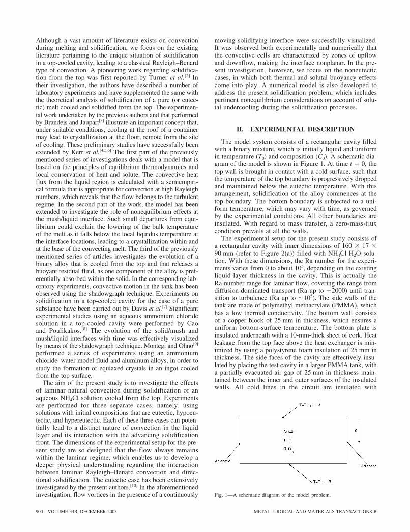
Fig. 1—A schematic diagram of the model problem.
Although a vast amount of literature exists on convectionduring melting and solidification, we focus on the existingliterature pertaining to the unique situation of solidificationin a top-cooled cavity, leading to a classical Rayleigh–Benardtype of convection. A pioneering work regarding solidifica-tion from the top was first reported by Turner et al.[2] Intheir investigation, the authors have described a number oflaboratory experiments and have supplemented the same withthe theoretical analysis of solidification of a pure (or eutec-tic) melt cooled and solidified from the top. The experimen-tal work undertaken by the previous authors and that performedby Brandeis and Jaupart[3] illustrate an important concept that,under suitable conditions, cooling at the roof of a containermay lead to crystallization at the floor, remote from the siteof cooling. These preliminary studies have successfully beenextended by Kerr et al.[4,5,6] The first part of the previouslymentioned series of investigations deals with a model that isbased on the principles of equilibrium thermodynamics andlocal conservation of heat and solute. The convective heatflux from the liquid region is calculated with a semiempiri-cal formula that is appropriate for convection at high Rayleighnumbers, which reveals that the flow belongs to the turbulentregime. In the second part of the work, the model has beenextended to investigate the role of nonequilibrium effects atthe mush/liquid interface. Such small departures from equi-librium could explain the lowering of the bulk temperatureof the melt as it falls below the local liquidus temperature atthe interface locations, leading to a crystallization within andat the base of the convecting melt. The third of the previouslymentioned series of articles investigates the evolution of abinary alloy that is cooled from the top and that releases abuoyant residual fluid, as one component of the alloy is pref-erentially absorbed within the solid. In the corresponding lab-oratory experiments, convective motion in the tank has beenobserved using the shadowgraph technique. Experiments onsolidification in a top-cooled cavity for the case of a puresubstance have been carried out by Davis et al.[7] Significantexperimental studies using an aqueous ammonium chloridesolution in a top-cooled cavity were performed by Caoand Poulikakos.[8] The evolution of the solid/mush andmush/liquid interfaces with time was effectively visualizedby means of the shadowgraph technique. Montegi and Ohno[9]
performed a series of experiments using an ammoniumchloride–water model fluid and aluminum alloys, in order tostudy the formation of equiaxed crystals in an ingot cooledfrom the top surface.
The aim of the present study is to investigate the effectsof laminar natural convection during solidification of anaqueous NH4Cl solution cooled from the top. Experimentsare performed for three separate cases, namely, usingsolutions with initial compositions that are eutectic, hypoeu-tectic, and hypereutectic. Each of these three cases can poten-tially lead to a distinct nature of convection in the liquidlayer and its interaction with the advancing solidificationfront. The dimensions of the experimental setup for the pre-sent study are so designed that the flow always remainswithin the laminar regime, which enables us to develop adeeper physical understanding regarding the interactionbetween laminar Rayleigh–Benard convection and direc-tional solidification. The eutectic case has been extensivelyinvestigated by the present authors.[10] In the aforementionedinvestigation, flow vortices in the presence of a continuously
moving solidifying interface were successfully visualized.It was observed both experimentally and numerically thatthe convective cells are characterized by zones of upflowand downflow, making the interface nonplanar. In the pre-sent investigation, however, we focus on the noneutecticcases, in which both thermal and solutal buoyancy effectscome into play. A numerical model is also developed toaddress the present solidification problem, which includespertinent nonequilibrium considerations on account of solu-tal undercooling during the solidification processes.
II. EXPERIMENTAL DESCRIPTION
The model system consists of a rectangular cavity filledwith a binary mixture, which is initially liquid and uniformin temperature (T0) and composition (C0). A schematic dia-gram of the model is shown in Figure 1. At time t � 0, thetop wall is brought in contact with a cold surface, such thatthe temperature of the top boundary is progressively droppedand maintained below the eutectic temperature. With thisarrangement, solidification of the alloy commences at thetop boundary. The bottom boundary is subjected to a uni-form temperature, which may vary with time, as governedby the experimental conditions. All other boundaries areinsulated. With regard to mass transfer, a zero-mass-fluxcondition prevails at all the walls.
The experimental setup for the present study consists ofa rectangular cavity with inner dimensions of 160 � 17 �90 mm (refer to Figure 2(a)) filled with NH4Cl-H2O solu-tion. With these dimensions, the Ra number for the experi-ments varies from 0 to about 105, depending on the existingliquid-layer thickness in the cavity. This is actually theRa number range for laminar flow, covering the range fromdiffusion-dominated transport (Ra up to �2000) until tran-sition to turbulence (Ra up to �105). The side walls of thetank are made of polymethyl methacrylate (PMMA), whichhas a low thermal conductivity. The bottom wall consistsof a copper block of 25 mm in thickness, which ensures auniform bottom-surface temperature. The bottom plate isinsulated underneath with a 10-mm-thick sheet of cork. Heatleakage from the top face above the heat exchanger is min-imized by using a polystyrene foam insulation of 25 mm inthickness. The side faces of the cavity are effectively insu-lated by placing the test cavity in a larger PMMA tank, witha partially evacuated air gap of 25 mm in thickness main-tained between the inner and outer surfaces of the insulatedwalls. All cold lines in the circuit are insulated with
15_02-527B-H.qxd 10/31/03 10:51 AM Page 900
METALLURGICAL AND MATERIALS TRANSACTIONS B VOLUME 34B, DECEMBER 2003—901
*PENTIUM is a trademark of the Intel Corporation, Santa Clara, CA.
(a)
(b)
(c)
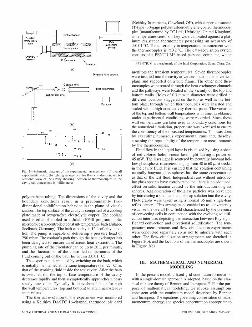
Fig. 2—Schematic diagram of the experimental arrangement: (a) overallexperimental setup, (b) lighting arrangement for flow visualization, and (c)sectional view of the cavity showing location of thermocouples in thecavity (all dimensions in millimeters)
polyurethane tubing. The dimensions of the cavity and theboundary conditions result in a predominantly two-dimensional solidification behavior in the plane of visual-ization. The top surface of the cavity is comprised of a coolingplate made of oxygen-free electrolytic copper. The coolantused is ethanol cooled in a Julabo-FP40 programmable,microprocessor-controlled constant-temperature bath (Julabo,Seelbach, Germany). The bath capacity is 12 L of ethyl alco-hol. The pump is capable of delivering a pressure head of290 mbar. The coolant’s path through the heat exchanger hasbeen designed to ensure an efficient heat extraction. Thepumping rate of the circulator can be up to 20 L per minute,and the fluctuations of the controlled temperatures of thefluid coming out of the bath lie within �0.01 °C.
The experiment is initiated by switching on the bath, whichis initially maintained at the same temperature (i.e., 27 °C) asthat of the working fluid inside the test cavity. After the bathis switched on, the top-surface temperature of the cavitydecreases rapidly and then asymptotically approaches a near-steady-state value. Typically, it takes about 1 hour for boththe wall temperatures (top and bottom) to attain near-steady-state values.
The thermal evolution of the experiment was monitoredusing a Keithley DASTC 16-channel thermocouple card
(Keithley Instruments, Cleveland, OH), with copper-constantan(T-type) 30-gage polytetrafloeroethylene-coated thermocou-ples (manufactured by TC Ltd., Uxbridge, United Kingdom)as temperature sensors. They were calibrated against a plat-inum resistance thermometer possessing an accuracy of�0.01 °C. The uncertainty in temperature measurement withthe thermocouples is �0.2 °C. The data-acquisition systemconsists of a PENTIUM*-based personal computer, which
monitors the transient temperatures. Seven thermocoupleswere inserted into the cavity at various locations in a verticalplane and supported on a wire frame. The other nine ther-mocouples were routed through the heat-exchanger channelsand the pathways were located in the vicinity of the top andbottom walls. Holes of 0.7 mm in diameter were drilled atdifferent locations staggered on the top as well as the bot-tom plate, through which thermocouples were inserted andsealed with a high-conductivity thermal paste. The variationof the top and bottom wall temperatures with time, as obtainedunder experimental conditions, were recorded. Since thesewall temperatures are later used as boundary conditions forthe numerical simulation, proper care was exercised to ensurethe consistency of the measured temperatures. This was doneby executing numerous experimental runs and, thereby,assessing the repeatability of the temperature measurementsby the thermocouples.
Fluid flow in the liquid layer is visualized by using a sheetof red-colored helium-neon laser light having a power of45 mW. The laser light is scattered by neutrally buoyant hol-low glass spheres (diameters ranging from 40 to 60 �m) seededin the cavity fluid. It is ensured that the solution containingneutrally buoyant glass spheres has the same concentrationas that of the test fluid. Independent runs without introduc-ing glass spheres have corroborated that there is no additionaleffect on solidification caused by the introduction of glassspheres. Agglomeration of the glass particles was preventedby introducing a small amount of soap solution into the cavity.Photographs were taken using a normal 35 mm single-lensreflex camera. This arrangement enabled us to convenientlyvisualize the overall flow field characterized by the presenceof convecting cells in conjunction with the evolving solidifi-cation interface, depicting the interaction between Rayleigh–Benard convection and directional solidification. The tem-perature measurements and flow-visualization experimentswere conducted separately so as not to interfere with eachother. The flow-visualization arrangements are sketched inFigure 2(b), and the locations of the thermocouples are shownin Figure 2(c).
III. MATHEMATICAL AND NUMERICALMODELING
In the present model, a fixed-grid continuum formulationwith a single-domain approach is adopted, based on the clas-sical mixture theory of Bennon and Incropera.[11] For the pur-pose of mathematical modeling, we invoke assumptionsconsistent with the continuum model described by Bennonand Incropera. The equations governing conservation of mass,momentum, energy, and species concentration appropriate to
15_02-527B-H.qxd 10/31/03 10:51 AM Page 901
902—VOLUME 34B, DECEMBER 2003 METALLURGICAL AND MATERIALS TRANSACTIONS B
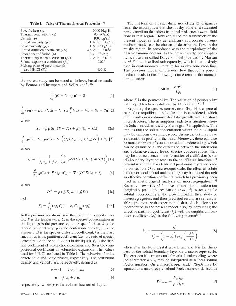
Table I. Table of Thermophysical Properties[12]
Specific heat (cP) 3000 J/kg KThermal conductivity (k) 0.4 W/mKDensity (�) 1000 kg/m3
Liquid viscosity (�1) 1 � 10� 3 kg/msSolid viscosity (�S) 1 � 104 kg/msLiquid diffusion coefficient (DL) 4.8 � 10� 9 m2/sLatent heat of fusion (L) 3 � 105 J/kgThermal expansion coefficient (�T) 4 � 10� 5 K� 1
Solutal expansion coefficient (�C) 0.025Melting point of pure materials,
i.e., NH4Cl (Tm) 630 K
the present study can be stated as follows, based on studiesby Bennon and Incropera and Voller et al.[12]:
[1]
[2]
where
[2a]
[3]
where
[3a]
[4]
where
[4a]
and
[4b]
In the previous equations, u is the continuum velocity vec-tor, T is the temperature, Cl is the species concentration inthe liquid, p is the pressure, cp is the specific heat, k is thethermal conductivity, � is the continuum density, � is theviscosity, D is the species diffusion coefficient, f is the massfraction, kp is the partition coefficient (i.e., the ratio of speciesconcentration in the solid to that in the liquid), �T is the ther-mal coefficient of volumetric expansion, and �C is the com-positional coefficient of volumetric expansion. The valuesused for NH4Cl are listed in Table I. The subscripts l and sdenote solid and liquid phases, respectively. The continuumdensity and velocity are, respectively, defined as
[5]
[6]
respectively, where � is the volume fraction of liquid.
u � fs us fl ul
r � (1 � x)rs xrl
Sc �
t (rfs Cl ) � kp Cl
t (rfs)
D � r ( fs Ds kp fl Dl)
t (rCl) § # (r uCl) � § # (D §Cl) Sc
Sh � �1
fs cps fl cpl a
t (rfl�H) § # (r u�H )b
t (rT ) § # (r uT ) � § # a( fs ks /cps fl kl /cpl)§Tb Sh
Sb � r g (bT (T � T0) bC (Cl � C0))
t (r u) r u # (§u) � § # (m1
r
rl§u) � §p Sb � S u
t (r) § # (r u) � 0
The last term on the right-hand side of Eq. [2] originatesfrom the assumption that the mushy zone is a saturatedporous medium that offers frictional resistance toward fluidflow in that region. However, since the framework of thepresent model is fairly general, any appropriate porous-medium model can be chosen to describe the flow in themushy region, in accordance with the morphology of thephase-changing domain. In the present study, for simplic-ity, we use a modified Darcy’s model provided by Morvanet al.,[13] as described subsequently, which is extensivelyused in contemporary literature for mushy-zone modeling.The previous model of viscous flow through a porousmedium leads to the following source term in the momen-tum equation:
[7]
where K is the permeability. The variation of permeabilitywith liquid fraction is detailed by Morvan et al.[13]
Regarding the species conservation (Eq. [4]), a generalcase of nonequilibrium solidification is considered, whichoften results in a columnar dendritic growth with a distinctmicrostructure. The assumption leads to a situation wherethe Scheil model, as used by Flemings,[14] is applicable. Thisimplies that the solute concentration within the bulk liquidmay be uniform over microscopic distances, but may havea nonuniform profile in the solid. Moreover, there can alsobe nonequilibrium effects due to solutal undercooling, whichcan be quantified as the difference between the interfacialand volume-averaged liquid species concentrations. Thismay be a consequence of the formation of a diffusion (solu-tal) boundary layer adjacent to the solid/liquid interface,[14]
beyond which the mass transport predominantly takes placeby convection. On a microscopic scale, the effect of solutebuildup or local solutal undercooling may be treated throughan effective partition coefficient, which has previously beenused in metallurgical analysis of microsegregation.[14]
Recently, Tewari et al.[15] have utilized this consideration(originally postulated by Burton et al.[16]) to account forsolutal undercooling at the growth front in their study ofmacrosegregation, and their predicted results are in reason-able agreement with experimental data. Such effects areincorporated in the present model also, by correlating theeffective partition coefficient (kp) with the equilibrium par-tition coefficient ( ) in the following manner[14]:
[8]
where R is the local crystal growth rate and � is the thick-ness of the solutal boundary layer on a microscopic scale.The exponential term accounts for solutal undercooling, wherethe parameter R�/Dl may be interpreted as a local solutalPeclet number. On a macroscopic scale, R�/Dl may beequated to a macroscopic solutal Peclet number, defined as
[9]Pemacro �Rpc lref
rs Dl r
kp �k*
p
k*p a1 � k*
pb exp a�Rd
Dl b
k*p
�Su � �ml
ru
Krl
15_02-527B-H.qxd 10/31/03 10:51 AM Page 902
METALLURGICAL AND MATERIALS TRANSACTIONS B VOLUME 34B, DECEMBER 2003—903
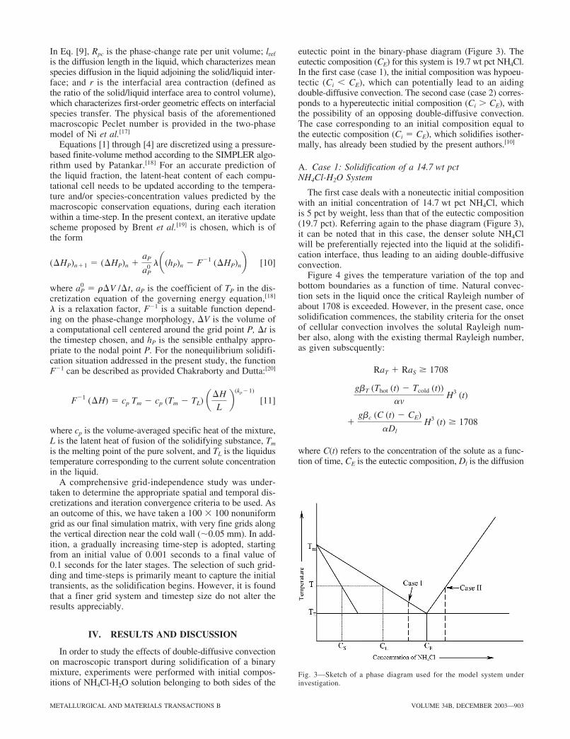
Fig. 3—Sketch of a phase diagram used for the model system underinvestigation.
In Eq. [9], Rpc is the phase-change rate per unit volume; lref
is the diffusion length in the liquid, which characterizes meanspecies diffusion in the liquid adjoining the solid/liquid inter-face; and r is the interfacial area contraction (defined asthe ratio of the solid/liquid interface area to control volume),which characterizes first-order geometric effects on interfacialspecies transfer. The physical basis of the aforementionedmacroscopic Peclet number is provided in the two-phasemodel of Ni et al.[17]
Equations [1] through [4] are discretized using a pressure-based finite-volume method according to the SIMPLER algo-rithm used by Patankar.[18] For an accurate prediction ofthe liquid fraction, the latent-heat content of each compu-tational cell needs to be updated according to the tempera-ture and/or species-concentration values predicted by themacroscopic conservation equations, during each iterationwithin a time-step. In the present context, an iterative updatescheme proposed by Brent et al.[19] is chosen, which is ofthe form
[10]
where , aP is the coefficient of TP in the dis-cretization equation of the governing energy equation,[18]
� is a relaxation factor, F�1 is a suitable function depend-ing on the phase-change morphology, V is the volume ofa computational cell centered around the grid point P, t isthe timestep chosen, and hP is the sensible enthalpy appro-priate to the nodal point P. For the nonequilibrium solidifi-cation situation addressed in the present study, the functionF�1 can be described as provided Chakraborty and Dutta:[20]
[11]
where cp is the volume-averaged specific heat of the mixture,L is the latent heat of fusion of the solidifying substance, Tm
is the melting point of the pure solvent, and TL is the liquidustemperature corresponding to the current solute concentrationin the liquid.
A comprehensive grid-independence study was under-taken to determine the appropriate spatial and temporal dis-cretizations and iteration convergence criteria to be used. Asan outcome of this, we have taken a 100 � 100 nonuniformgrid as our final simulation matrix, with very fine grids alongthe vertical direction near the cold wall (�0.05 mm). In add-ition, a gradually increasing time-step is adopted, startingfrom an initial value of 0.001 seconds to a final value of0.1 seconds for the later stages. The selection of such grid-ding and time-steps is primarily meant to capture the initialtransients, as the solidification begins. However, it is foundthat a finer grid system and timestep size do not alter theresults appreciably.
IV. RESULTS AND DISCUSSION
In order to study the effects of double-diffusive convectionon macroscopic transport during solidification of a binarymixture, experiments were performed with initial compos-itions of NH4Cl-H2O solution belonging to both sides of the
F�1 (�H) � cp Tm � cp (Tm � TL) a�H
L b (kp�1)
aP0 � r�V /�t
(�HP)n1 � (�HP)n aP
aP0 la(hP)n � F�1 (�HP)nb
eutectic point in the binary-phase diagram (Figure 3). Theeutectic composition (CE) for this system is 19.7 wt pct NH4Cl.In the first case (case 1), the initial composition was hypoeu-tectic (Ci � CE), which can potentially lead to an aidingdouble-diffusive convection. The second case (case 2) corres-ponds to a hypereutectic initial composition (Ci � CE), withthe possibility of an opposing double-diffusive convection.The case corresponding to an initial composition equal tothe eutectic composition (Ci � CE), which solidifies isother-mally, has already been studied by the present authors.[10]
A. Case 1: Solidification of a 14.7 wt pct NH4Cl-H2O System
The first case deals with a noneutectic initial compositionwith an initial concentration of 14.7 wt pct NH4Cl, whichis 5 pct by weight, less than that of the eutectic composition(19.7 pct). Referring again to the phase diagram (Figure 3),it can be noted that in this case, the denser solute NH4Clwill be preferentially rejected into the liquid at the solidifi-cation interface, thus leading to an aiding double-diffusiveconvection.
Figure 4 gives the temperature variation of the top andbottom boundaries as a function of time. Natural convec-tion sets in the liquid once the critical Rayleigh number ofabout 1708 is exceeded. However, in the present case, oncesolidification commences, the stability criteria for the onsetof cellular convection involves the solutal Rayleigh num-ber also, along with the existing thermal Rayleigh number,as given subscquently:
where C(t) refers to the concentration of the solute as a func-tion of time, CE is the eutectic composition, Dl is the diffusion
gbc (C (t) � CE)
aDl H3 (t) � 1708
gbT (Thot (t) � Tcold (t))av
H3 (t)
RaT RaS � 1708
15_02-527B-H.qxd 10/31/03 10:51 AM Page 903
904—VOLUME 34B, DECEMBER 2003 METALLURGICAL AND MATERIALS TRANSACTIONS B
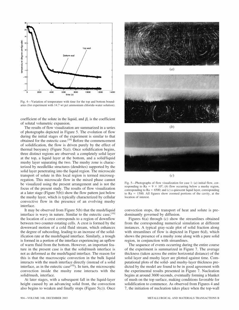
Fig. 4—Variation of temperature with time for the top and bottom bound-aries (for experiment with 14.7 wt pct ammonium chloride-water solution).
(a)
(b)
(c)
Fig. 5—Photographs of flow visualization for case 1: (a) initial flow, cor-responding to Ra � 9 � 104; (b) flow occurring below a mushy region,corresponding to Ra � 6500; and (c) a quiescent liquid layer, correspondingto Ra � 1500. All figures show zoomed portions of the cavity, at thelocation of interest.
coefficient of the solute in the liquid, and �c is the coefficientof solutal volumetric expansion.
The results of flow visualization are summarized in a seriesof photographs depicted in Figure 5. The evolution of flowduring the initial stages of the experiment is similar to thatobtained for the eutectic case.[10] Before the commencementof solidification, the flow is driven purely by the effect ofthermal buoyancy (Figure 5(a)). Once solidification begins,three distinct regions are observed: a completely solid layerat the top, a liquid layer at the bottom, and a solid/liquidmushy layer separating the two. The mushy zone is charac-terized by needlelike structures (dendrites) supported by thesolid layer penetrating into the liquid region. The microscaletransport of solute in this local region is termed microseg-regation. This microscale flow in the mixed phase cannotbe visualized using the present arrangement and is not thefocus of the present study. The results of flow visualizationat a later stage (Figure 5(b)) show the flow pattern just belowthe mushy layer, which is typically characterized by cellularconvective flow in the presence of an evolving mushyinterface.
It may be observed from Figure 5(b) that the mush/liquidinterface is wavy in nature. Similar to the eutectic case,[10]
the location of a crest corresponds to a region of downflowbetween two counter-rotating cells. A crest is formed by thedownward motion of a cold fluid stream, which enhancesthe degree of subcooling, leading to an increase of the solid-ification rate at the mush/liquid interface. Similarly, a troughis formed in a portion of the interface experiencing an upflowof warm fluid from the bottom. However, an important fea-ture in the present case is that the solid/mush interface isnot as deformed as the mush/liquid interface. The reason forthis is that the macroscopic convection in the bulk liquidinteracts with the mush interface directly (instead of a solidinterface, as in the eutectic case[10]). In turn, the microscopicconvection inside the mushy zone interacts with thesolid/mush, interface.
At later stages, with a subsequent fall in the liquid-layerheight caused by an advancing solid front, the convectionalso begins to weaken and finally stops (Figure 5(c)). Once
convection stops, the transport of heat and solute is pre-dominantly governed by diffusion.
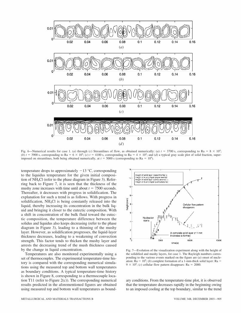
Figures 6(a) through (c) show the streamlines obtainedfrom the corresponding numerical simulation at differentinstances. A typical gray-scale plot of solid fraction alongwith streamlines of flow is depicted in Figure 6(d), whichshows the presence of a mushy zone along with a pure solidregion, in conjunction with streamlines.
The sequence of events occurring during the entire courseof the experiment is summarized in Figure 7. The averagethickness (taken across the entire horizontal distance) of thesolid layer and mushy layer are plotted against time. Com-putational plots of the solid- and mushy-layer thickness pre-dicted by the model are found to be in good agreement withthe experimental results presented in Figure 7. Nucleationbegins at around 3600 seconds, eventually forming a blanketof mush on the top surface, making conditions favorable forsolidification to commence. As observed from Figures 4 and7, the initiation of nucleation takes place when the top-wall
15_02-527B-H.qxd 10/31/03 10:51 AM Page 904
METALLURGICAL AND MATERIALS TRANSACTIONS B VOLUME 34B, DECEMBER 2003—905
(a)
(b)
(c)
(d )
Fig. 6—Numerical results for case 1. (a) through (c) Streamlines of flow, as obtained numerically: (a) t � 3700 s, corresponding to Ra � 8 � 104; (b) t � 3900 s, corresponding to Ra � 6 � 104; (c) t � 4100 s, corresponding to Ra � 4 � 104; and (d) a typical gray scale plot of solid fraction, super-imposed on streamlines, both being obtained numerically, at t � 5000 s (corresponding to Ra � 104).
Fig. 7—Evolution of the visualization experiment along with the height ofthe solidified and mushy layers, for case 1. The Rayleigh numbers corres-ponding to the various events marked on the figure are (a) onset of nucle-ation: Ra � 105; (b) complete formation of a 1-mm-thick solid layer: Ra �9 � 104; (c) cellular flow pattern disappears: Ra � 2000.
temperature drops to approximately �13 °C, correspondingto the liquidus temperature for the given initial composi-tion of NH4Cl (refer to the phase diagram in Figure 3). Refer-ring back to Figure 7, it is seen that the thickness of themushy zone increases with time until about t � 7500 seconds.Thereafter, it decreases with progress in solidification. Theexplanation for such a trend is as follows. With progress insolidification, NH4Cl is being constantly released into theliquid, thereby increasing its concentration in the bulk liq-uid and bringing it closer to the eutectic composition. Witha shift in concentration of the bulk fluid toward the eutec-tic composition, the temperature difference between thesolidus and liquidus also keeps decreasing (refer to the phasediagram in Figure 3), leading to a thinning of the mushylayer. However, as solidification progresses, the liquid-layerthickness decreases, leading to a weakening of convectionstrength. This factor tends to thicken the mushy layer andarrests the decreasing trend of the mush thickness causedby the change in liquid concentration.
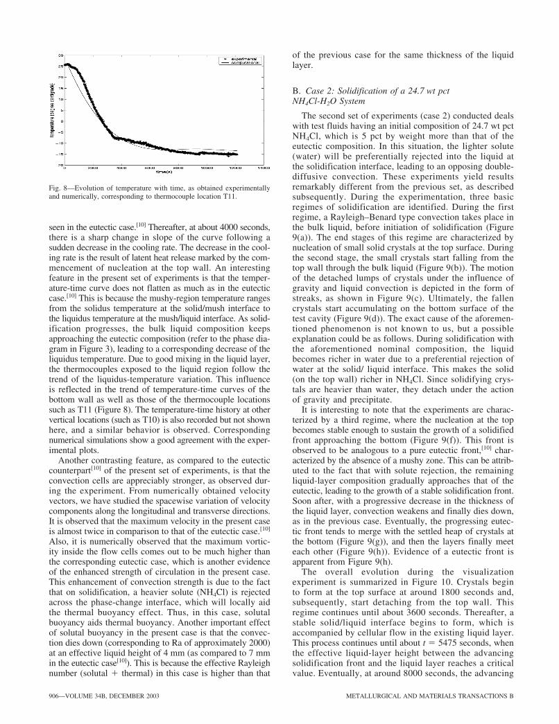
Temperatures are also monitored experimentally using aset of thermocouples. The experimental temperature-time his-tory is compared with the corresponding numerical simula-tions using the measured top and bottom wall temperaturesas boundary conditions. A typical temperature-time historyis shown in Figure 8, corresponding to a thermocouple loca-tion T11 (refer to Figure 2(c)). The corresponding numericalresults predicted in the aforementioned figures are obtainedusing measured top and bottom wall temperatures as bound-
ary conditions. From the temperature-time plot, it is observedthat the temperature decreases rapidly in the beginning owingto an imposed cooling at the top boundary, similar to the trend
15_02-527B-H.qxd 10/31/03 10:51 AM Page 905
906—VOLUME 34B, DECEMBER 2003 METALLURGICAL AND MATERIALS TRANSACTIONS B
Fig. 8—Evolution of temperature with time, as obtained experimentallyand numerically, corresponding to thermocouple location T11.
seen in the eutectic case.[10] Thereafter, at about 4000 seconds,there is a sharp change in slope of the curve following asudden decrease in the cooling rate. The decrease in the cool-ing rate is the result of latent heat release marked by the com-mencement of nucleation at the top wall. An interestingfeature in the present set of experiments is that the temper-ature-time curve does not flatten as much as in the eutecticcase.[10] This is because the mushy-region temperature rangesfrom the solidus temperature at the solid/mush interface tothe liquidus temperature at the mush/liquid interface. As solid-ification progresses, the bulk liquid composition keepsapproaching the eutectic composition (refer to the phase dia-gram in Figure 3), leading to a corresponding decrease of theliquidus temperature. Due to good mixing in the liquid layer,the thermocouples exposed to the liquid region follow thetrend of the liquidus-temperature variation. This influenceis reflected in the trend of temperature-time curves of thebottom wall as well as those of the thermocouple locationssuch as T11 (Figure 8). The temperature-time history at othervertical locations (such as T10) is also recorded but not shownhere, and a similar behavior is observed. Correspondingnumerical simulations show a good agreement with the exper-imental plots.
Another contrasting feature, as compared to the eutecticcounterpart[10] of the present set of experiments, is that theconvection cells are appreciably stronger, as observed dur-ing the experiment. From numerically obtained velocityvectors, we have studied the spacewise variation of velocitycomponents along the longitudinal and transverse directions.It is observed that the maximum velocity in the present caseis almost twice in comparison to that of the eutectic case.[10]
Also, it is numerically observed that the maximum vortic-ity inside the flow cells comes out to be much higher thanthe corresponding eutectic case, which is another evidenceof the enhanced strength of circulation in the present case.This enhancement of convection strength is due to the factthat on solidification, a heavier solute (NH4Cl) is rejectedacross the phase-change interface, which will locally aidthe thermal buoyancy effect. Thus, in this case, solutalbuoyancy aids thermal buoyancy. Another important effectof solutal buoyancy in the present case is that the convec-tion dies down (corresponding to Ra of approximately 2000)at an effective liquid height of 4 mm (as compared to 7 mmin the eutectic case[10]). This is because the effective Rayleighnumber (solutal thermal) in this case is higher than that
of the previous case for the same thickness of the liquidlayer.
B. Case 2: Solidification of a 24.7 wt pct NH4Cl-H2O System
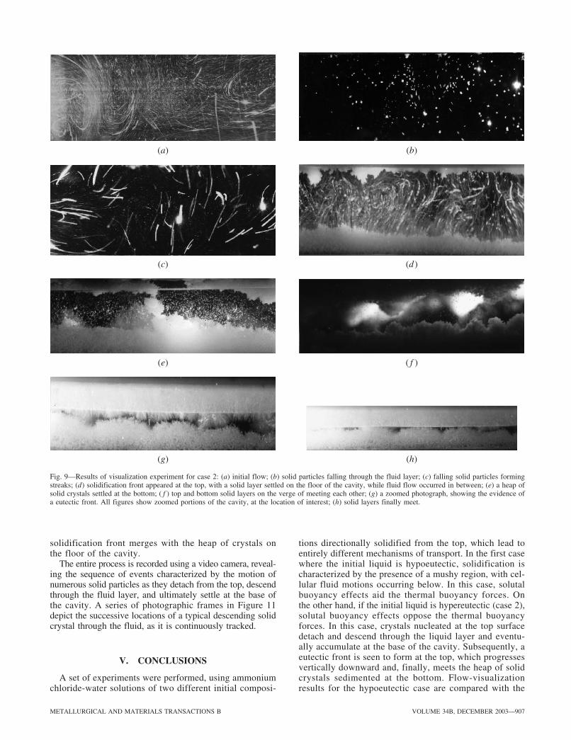
The second set of experiments (case 2) conducted dealswith test fluids having an initial composition of 24.7 wt pctNH4Cl, which is 5 pct by weight more than that of theeutectic composition. In this situation, the lighter solute(water) will be preferentially rejected into the liquid atthe solidification interface, leading to an opposing double-diffusive convection. These experiments yield resultsremarkably different from the previous set, as describedsubsequently. During the experimentation, three basicregimes of solidification are identified. During the firstregime, a Rayleigh–Benard type convection takes place inthe bulk liquid, before initiation of solidification (Figure9(a)). The end stages of this regime are characterized bynucleation of small solid crystals at the top surface. Duringthe second stage, the small crystals start falling from thetop wall through the bulk liquid (Figure 9(b)). The motionof the detached lumps of crystals under the influence ofgravity and liquid convection is depicted in the form ofstreaks, as shown in Figure 9(c). Ultimately, the fallencrystals start accumulating on the bottom surface of thetest cavity (Figure 9(d)). The exact cause of the aforemen-tioned phenomenon is not known to us, but a possibleexplanation could be as follows. During solidification withthe aforementioned nominal composition, the liquidbecomes richer in water due to a preferential rejection ofwater at the solid/ liquid interface. This makes the solid(on the top wall) richer in NH4Cl. Since solidifying crys-tals are heavier than water, they detach under the actionof gravity and precipitate.
It is interesting to note that the experiments are charac-terized by a third regime, where the nucleation at the topbecomes stable enough to sustain the growth of a solidifiedfront approaching the bottom (Figure 9(f)). This front isobserved to be analogous to a pure eutectic front,[10] char-acterized by the absence of a mushy zone. This can be attrib-uted to the fact that with solute rejection, the remainingliquid-layer composition gradually approaches that of theeutectic, leading to the growth of a stable solidification front.Soon after, with a progressive decrease in the thickness ofthe liquid layer, convection weakens and finally dies down,as in the previous case. Eventually, the progressing eutec-tic front tends to merge with the settled heap of crystals atthe bottom (Figure 9(g)), and then the layers finally meeteach other (Figure 9(h)). Evidence of a eutectic front isapparent from Figure 9(h).
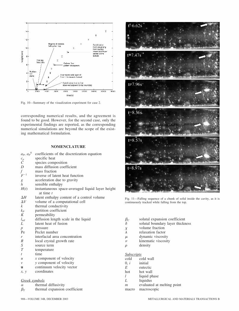
The overall evolution during the visualizationexperiment is summarized in Figure 10. Crystals beginto form at the top surface at around 1800 seconds and,subsequently, start detaching from the top wall. Thisregime continues until about 3600 seconds. Thereafter, astable solid/liquid interface begins to form, which isaccompanied by cellular flow in the existing liquid layer.This process continues until about t � 5475 seconds, whenthe effective liquid-layer height between the advancingsolidification front and the liquid layer reaches a criticalvalue. Eventually, at around 8000 seconds, the advancing
15_02-527B-H.qxd 10/31/03 10:51 AM Page 906
METALLURGICAL AND MATERIALS TRANSACTIONS B VOLUME 34B, DECEMBER 2003—907
(a) (b)
(c) (d )
Fig. 9—Results of visualization experiment for case 2: (a) initial flow; (b) solid particles falling through the fluid layer; (c) falling solid particles formingstreaks; (d) solidification front appeared at the top, with a solid layer settled on the floor of the cavity, while fluid flow occurred in between; (e) a heap ofsolid crystals settled at the bottom; ( f ) top and bottom solid layers on the verge of meeting each other; (g) a zoomed photograph, showing the evidence ofa eutectic front. All figures show zoomed portions of the cavity, at the location of interest; (h) solid layers finally meet.
(e) ( f )
(g) (h)
solidification front merges with the heap of crystals onthe floor of the cavity.
The entire process is recorded using a video camera, reveal-ing the sequence of events characterized by the motion ofnumerous solid particles as they detach from the top, descendthrough the fluid layer, and ultimately settle at the base ofthe cavity. A series of photographic frames in Figure 11depict the successive locations of a typical descending solidcrystal through the fluid, as it is continuously tracked.
V. CONCLUSIONS
A set of experiments were performed, using ammoniumchloride-water solutions of two different initial composi-
tions directionally solidified from the top, which lead toentirely different mechanisms of transport. In the first casewhere the initial liquid is hypoeutectic, solidification ischaracterized by the presence of a mushy region, with cel-lular fluid motions occurring below. In this case, solutalbuoyancy effects aid the thermal buoyancy forces. Onthe other hand, if the initial liquid is hypereutectic (case 2),solutal buoyancy effects oppose the thermal buoyancyforces. In this case, crystals nucleated at the top surfacedetach and descend through the liquid layer and eventu-ally accumulate at the base of the cavity. Subsequently, aeutectic front is seen to form at the top, which progressesvertically downward and, finally, meets the heap of solidcrystals sedimented at the bottom. Flow-visualizationresults for the hypoeutectic case are compared with the
15_02-527B-H.qxd 10/31/03 10:51 AM Page 907
908—VOLUME 34B, DECEMBER 2003 METALLURGICAL AND MATERIALS TRANSACTIONS B
Fig. 10—Summary of the visualization experiment for case 2.
Fig. 11—Falling sequence of a chunk of solid inside the cavity, as it iscontinuously tracked while falling from the top.
corresponding numerical results, and the agreement isfound to be good. However, for the second case, only theexperimental findings are reported, as the correspondingnumerical simulations are beyond the scope of the exist-ing mathematical formulation.
NOMENCLATURE
aP, aP0 coefficients of the discretization equation
cp specific heatC species compositionD mass diffusion coefficientf mass fractionF�1 inverse of latent heat functiong acceleration due to gravityh sensible enthalpyH(t) instantaneous space-averaged liquid layer height
at time t H latent enthalpy content of a control volume V volume of a computational cellk thermal conductivitykP partition coefficientK permeabilitylref diffusion length scale in the liquidL latent heat of fusionp pressurePe Peclet numberr interfacial area concentrationR local crystal growth rateS source termT temperaturet timeu x component of velocityv y component of velocityu continuum velocity vectorx, y coordinates
Greek symbols� thermal diffusivity�T thermal expansion coefficient
�C solutal expansion coefficient� solutal boundary layer thickness� volume fraction� relaxation factor� dynamic viscosity� kinematic viscosity� density
Subscriptscold cold wall0, i initialE eutectichot hot walll liquid phaseL liquidusm evaluated at melting pointmacro macroscopic
15_02-527B-H.qxd 10/31/03 10:51 AM Page 908
METALLURGICAL AND MATERIALS TRANSACTIONS B VOLUME 34B, DECEMBER 2003—909
n iteration levelP related to the grid point “P”s solid phase
REFERENCES1. H.E. Huppert: J. Fluid Mech., 1990, vol. 212, pp. 209-40.2. J.S. Turner, H.E. Huppert, and R.S.J. Sparks: J. Petrol., 1986, vol. 27,
pp. 397-437.3. G. Brandeis and C. Jaupart: Earth Planet. Sci. Lett., 1986, vol. 77,
pp. 345-61.4. R.C. Kerr, A.W. Woods, M.G. Worster, and H.E. Huppert: J. Fluid
Mech., 1990, vol. 216, pp. 323-42.5. R.C. Kerr, A.W. Woods, M.G. Worster, and H.E. Huppert: J. Fluid
Mech., 1990, vol. 217, pp. 331-48.6. R.C. Kerr, A.W. Woods, M.G. Worster, and H.E. Huppert: J. Fluid
Mech., 1990, vol. 218, pp. 337-54.7. S.H. Davis, U. Muller, and C. Dietsche: J. Fluid Mech., 1984, vol. 144,
pp. 133-51.8. W.Z. Cao and D. Poulikakos: Int. J. Heat Mass Transfer, 1989, vol. 33,
pp. 427-34.9. T. Motegi and A. Ohno: J. Jpn. Inst. Met., 1980, vol. 44, pp. 359-66.
10. P. Kumar, S. Chakraborty, K. Srininvasan, and P. Dutta: Metall. Mater.Trans. B, 2002, vol. 33B, pp. 605-12.
11. W.D. Bennon and F.P. Incropera: Int J. Heat Mass Transfer, 1987,vol. 30, pp. 2161-70.
12. V.R. Voller, A.D. Brent, and C. Prakash: Int. J. Heat Mass Transfer,1989, vol. 34, pp. 1717-32.
13. D. Morvan, M.El Ganaoui, and P. Bontoux: Int J. Heat Mass Transfer,1998, vol. 42, pp. 573-79.
14. M.C. Flemings: Solidification Processing, McGraw-Hill, New York,NY, 1974.
15. S.N. Tewari, R. Shah, and M.A. Chopra: Metall. Trans. A, 1993,vol. 24A, pp. 1661-69.
16. J.A. Burton, R. Prim, and W. Slichter: Theoretical. J. Chem. Phys.,1953, vol. 21, pp. 1987-91.
17. J. Ni, R.J. Feller, and C. Beckermann: in Modeling of Casting,Welding and Advanced Solidification Processes V, M. Rappaz,M.R. Ozgu, and K.W. Mahin, eds., TMS, Warrendale, PA, 1991.pp. 675-82.
18. S.V. Patankar: Numerical Heat Transfer and Fluid Flow, HemisphereMcGraw-Hill, Washington, D.C., 1980.
19. A.D. Brent, V.R. Voller, and K.J. Reid: Num. Heat Transfer, 1988,vol. 13, pp. 297-318.
20. S. Chakraborty and P. Dutta: Metall. Mater. Trans. B, 2001, vol. 32B,pp. 562-64.
15_02-527B-H.qxd 10/31/03 10:51 AM Page 909
Top Related
Copyright © 2022 FDOKUMEN

