
zenon driver manual - IEC850 - Copa-Data
175
zenon driver manual IEC850 v.8.00
-
Upload
khangminh22 -
Category
Documents
-
view
1 -
download
0
Transcript of zenon driver manual - IEC850 - Copa-Data
zenon driver manual IEC850
v.8.00

©2018 Ing. Punzenberger COPA-DATA GmbH
All rights reserved.
Distribution and/or reproduction of this document or parts thereof in any form are permitted solely with the written permission of the company COPA-DATA. Technical data is only used for product description and are not guaranteed qualities in the legal sense. Subject to change, technical or otherwise.

Contents
1. Welcome to COPA-DATA help ...................................................................................................... 6
2. IEC850 ......................................................................................................................................... 6
3. IEC850 - Data sheet ...................................................................................................................... 7
4. Requirements .............................................................................................................................. 8
4.1 PC ................................................................................................................................................................ 9
5. Configuration .............................................................................................................................. 9
5.1 Creating a driver ........................................................................................................................................ 10
5.2 Settings in the driver dialog ...................................................................................................................... 13
5.2.1 General ....................................................................................................................................... 14
5.2.2 Driver dialog basic settings ......................................................................................................... 18
5.2.3 Connections ................................................................................................................................ 24
6. Creating variables ...................................................................................................................... 49
6.1 Creating variables in the Editor ................................................................................................................. 49
6.2 Addressing ................................................................................................................................................. 52
6.3 Driver objects and datatypes .................................................................................................................... 56
6.3.1 Driver objects ............................................................................................................................. 56
6.3.2 Assignment of data types ........................................................................................................... 59
6.4 Creating variables by importing ................................................................................................................ 63
6.4.1 Online import ............................................................................................................................. 64
6.4.2 Offline import ............................................................................................................................. 68
6.4.3 XML import ................................................................................................................................. 71
6.4.4 DBF Import/Export ..................................................................................................................... 72
6.5 Communication details (Driver variables) ................................................................................................. 78
7. Driver command function .......................................................................................................... 83
7.1 SwitchConnection ..................................................................................................................................... 86
8. IEC850 client functions ............................................................................................................... 86
8.1 Establishment of a connection and detection of a connection failure ..................................................... 88

8.2 Commands (Control Model)...................................................................................................................... 91
8.2.1 Select and cancel ........................................................................................................................ 93
8.2.2 Additional Cause Diagnosis ........................................................................................................ 94
8.2.3 Service parameters of the command ......................................................................................... 96
8.3 Service Tracking ........................................................................................................................................ 99
8.4 Mapping of double point values ............................................................................................................. 102
8.5 Quality, time stamp and status bits of the variable ................................................................................ 104
8.5.1 TimeQuality and TimeAccuracy of a command ........................................................................ 107
8.6 Filetransfer .............................................................................................................................................. 108
8.6.1 Request folder information ...................................................................................................... 109
8.6.2 Get file from server .................................................................................................................. 109
8.6.3 Delete file ................................................................................................................................. 110
9. Reporting ................................................................................................................................ 110
9.1 Unbuffered Reporting ............................................................................................................................. 117
9.2 Buffered Reporting.................................................................................................................................. 120
9.3 RCB activation - verification possibilities ................................................................................................ 122
9.4 Dynamic Data Sets .................................................................................................................................. 125
10. Changing the driver mode in Runtime ...................................................................................... 126
11. Error analysis ........................................................................................................................... 129
11.1 Analysis tool ............................................................................................................................................ 129
11.2 Check list ................................................................................................................................................. 130
12. Appendix A - Description of the ‘Functional Constraints’ (FCs): ................................................. 132
13. Appendix B - Abbreviations for data object/data attribute........................................................ 133
14. Appendix C - Conformance statement ...................................................................................... 145
14.1 Protocol implementation conformance statement (PICS) ...................................................................... 146
14.2 Model implementation conformance statement (MICS) ........................................................................ 154
15. Appendix D - PIXIT ................................................................................................................... 155
16. Appendix E - TICS ..................................................................................................................... 170
16.1 Part 6 ....................................................................................................................................................... 171
16.2 Part 7-1 .................................................................................................................................................... 172

16.3 Part 7-2 .................................................................................................................................................... 172
16.4 Part 7-3 .................................................................................................................................................... 173
16.5 Part 7-4 .................................................................................................................................................... 174
16.6 Part 8-1 .................................................................................................................................................... 175

Welcome to COPA-DATA help
6
1. Welcome to COPA-DATA help
ZENON VIDEO-TUTORIALS
You can find practical examples for project configuration with zenon in our YouTube channel (https://www.copadata.com/tutorial_menu). The tutorials are grouped according to topics and give an initial insight into working with different zenon modules. All tutorials are available in English.
GENERAL HELP
If you cannot find any information you require in this help chapter or can think of anything that you would like added, please send an email to [email protected].
PROJECT SUPPORT
You can receive support for any real project you may have from our Support Team, who you can contact via email at [email protected].
LICENSES AND MODULES
If you find that you need other modules or licenses, our staff will be happy to help you. Email [email protected].
2. IEC850
Communication between the driver and the PLC is based on the IEC 61850 protocol with client/server MMS services via TCP/IP (A1/T1 profile). The driver acts as a client (master) when communicating.
You can create and configure the driver manually or - in the Energy Edition - with the help of the IEC850 Driver Configuration wizard, using an SCL file (SCD, CID, possibly ICD etc).
Furthermore, you can create the variables manually or import them, even without the wizard:
IEC850 - Data sheet
7
Offline - from an SCL file
Online - in communication with an 850 server.
: For simplified import of the variables from the Datasets in RCBs, the IEC850 Driver Configuration wizard provides additional possibilities.
Attention
Configurations that have been amended with a driver from a later version can no longer be opened with older drivers.
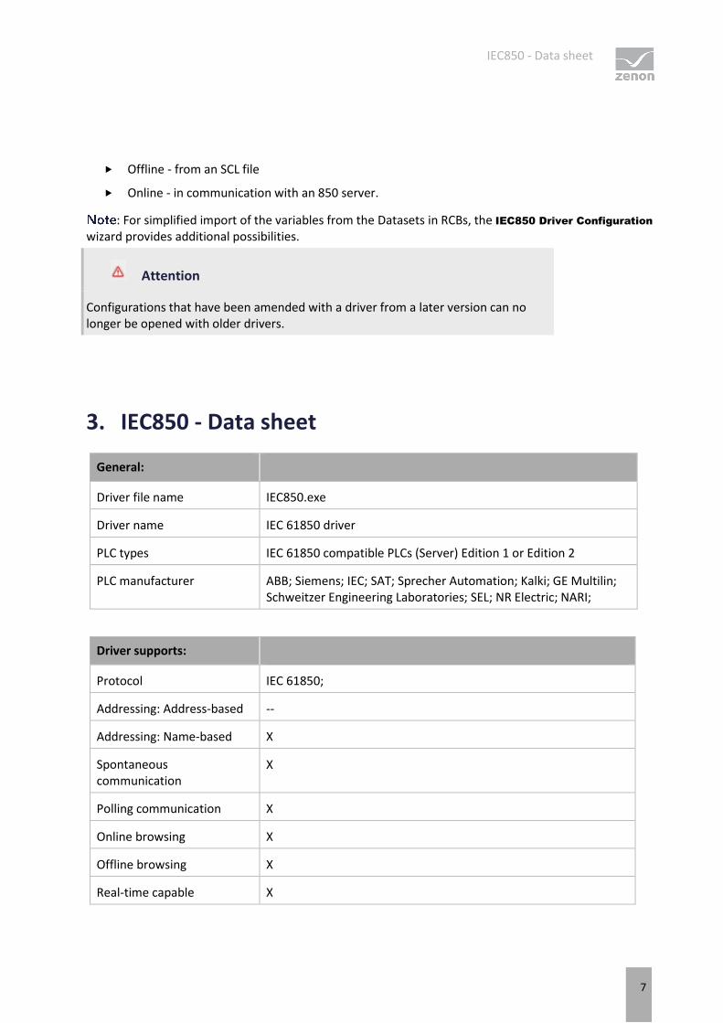
3. IEC850 - Data sheet
General:
Driver file name IEC850.exe
Driver name IEC 61850 driver
PLC types IEC 61850 compatible PLCs (Server) Edition 1 or Edition 2
PLC manufacturer ABB; Siemens; IEC; SAT; Sprecher Automation; Kalki; GE Multilin; Schweitzer Engineering Laboratories; SEL; NR Electric; NARI;
Driver supports:
Protocol IEC 61850;
Addressing: Address-based --
Addressing: Name-based X
Spontaneous communication
X
Polling communication X
Online browsing X
Offline browsing X
Real-time capable X
Requirements
8
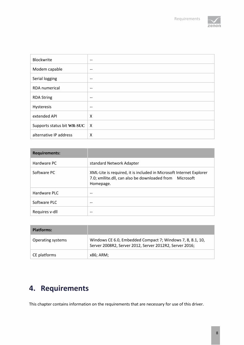
Blockwrite --
Modem capable --
Serial logging --
RDA numerical --
RDA String --
Hysteresis --
extended API X
Supports status bit WR-SUC X
alternative IP address X
Requirements:
Hardware PC standard Network Adapter
Software PC XML-Lite is required, it is included in Microsoft Internet Explorer 7.0; xmllite.dll, can also be downloaded from Microsoft Homepage.
Hardware PLC --
Software PLC --
Requires v-dll --
Platforms:
Operating systems Windows CE 6.0, Embedded Compact 7; Windows 7, 8, 8.1, 10, Server 2008R2, Server 2012, Server 2012R2, Server 2016;
CE platforms x86; ARM;
4. Requirements
This chapter contains information on the requirements that are necessary for use of this driver.

Configuration
9
4.1 PC
XML Lite, which is part of Microsoft Internet Explorer 7.0, is necessary; xmllite.dll can also be downloaded separately from the Microsoft website.
This driver supports a connection via the standard network card of the PC. Make sure that the PLC and the PC are in the same network range and that the subnet masks are set accordingly on both devices.
5. Configuration
In this chapter you will learn how to use the driver in a project and which settings you can change.
Information
Find out more about further settings for zenon variables in the chapter Variables (main.chm::/15247.htm) of the online manual.
Configuration
10
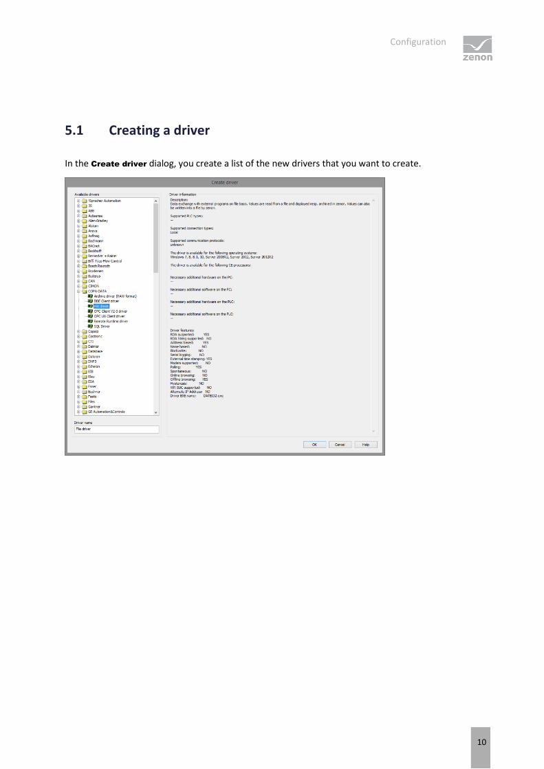
5.1 Creating a driver
In the Create driver dialog, you create a list of the new drivers that you want to create.
Configuration
11
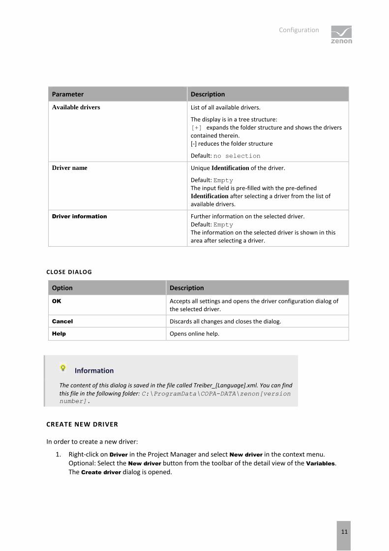
Parameter Description
Available drivers List of all available drivers.
The display is in a tree structure: [+] expands the folder structure and shows the drivers contained therein. [-] reduces the folder structure
Default: no selection
Driver name Unique Identification of the driver.
Default: Empty The input field is pre-filled with the pre-defined Identification after selecting a driver from the list of available drivers.
Driver information Further information on the selected driver. Default: Empty The information on the selected driver is shown in this area after selecting a driver.
CLOSE DIALOG
Option Description
OK Accepts all settings and opens the driver configuration dialog of the selected driver.
Cancel Discards all changes and closes the dialog.
Help Opens online help.
Information
The content of this dialog is saved in the file called Treiber_[Language].xml. You can find
this file in the following folder: C:\ProgramData\COPA-DATA\zenon[version number].
CREATE NEW DRIVER
In order to create a new driver:
1. Right-click on Driver in the Project Manager and select New driver in the context menu. Optional: Select the New driver button from the toolbar of the detail view of the Variables. The Create driver dialog is opened.
Configuration
12
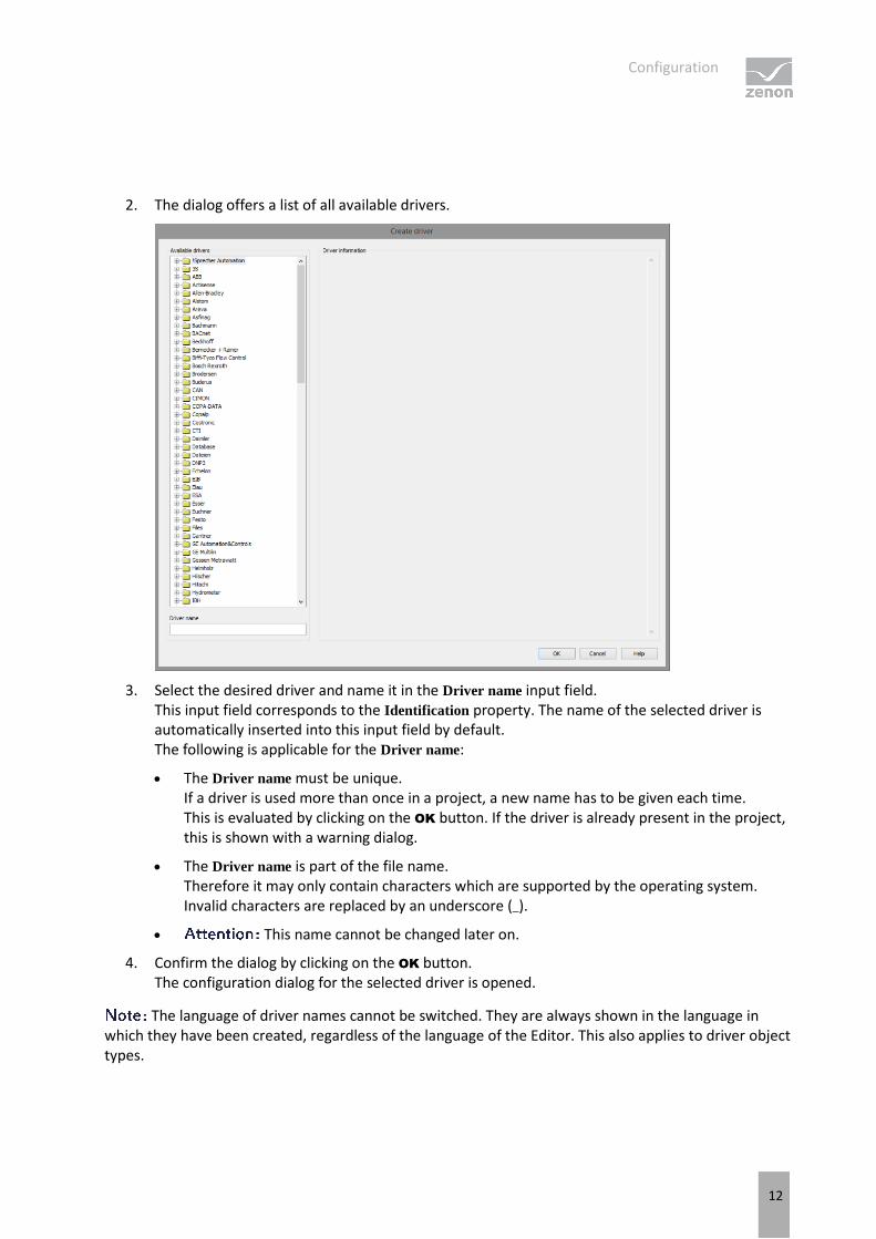
2. The dialog offers a list of all available drivers.
3. Select the desired driver and name it in the Driver name input field. This input field corresponds to the Identification property. The name of the selected driver is automatically inserted into this input field by default. The following is applicable for the Driver name:
The Driver name must be unique. If a driver is used more than once in a project, a new name has to be given each time. This is evaluated by clicking on the OK button. If the driver is already present in the project, this is shown with a warning dialog.
The Driver name is part of the file name. Therefore it may only contain characters which are supported by the operating system. Invalid characters are replaced by an underscore (_).
This name cannot be changed later on.
4. Confirm the dialog by clicking on the OK button. The configuration dialog for the selected driver is opened.
The language of driver names cannot be switched. They are always shown in the language in which they have been created, regardless of the language of the Editor. This also applies to driver object types.
Configuration
13
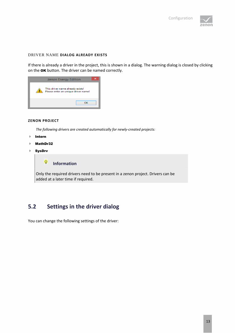
DRIVER NAME DIALOG ALREADY EXISTS
If there is already a driver in the project, this is shown in a dialog. The warning dialog is closed by clicking on the OK button. The driver can be named correctly.
ZENON PROJECT
The following drivers are created automatically for newly-created projects:
Intern
MathDr32
SysDrv
Information
Only the required drivers need to be present in a zenon project. Drivers can be added at a later time if required.
5.2 Settings in the driver dialog
You can change the following settings of the driver:
Configuration
14
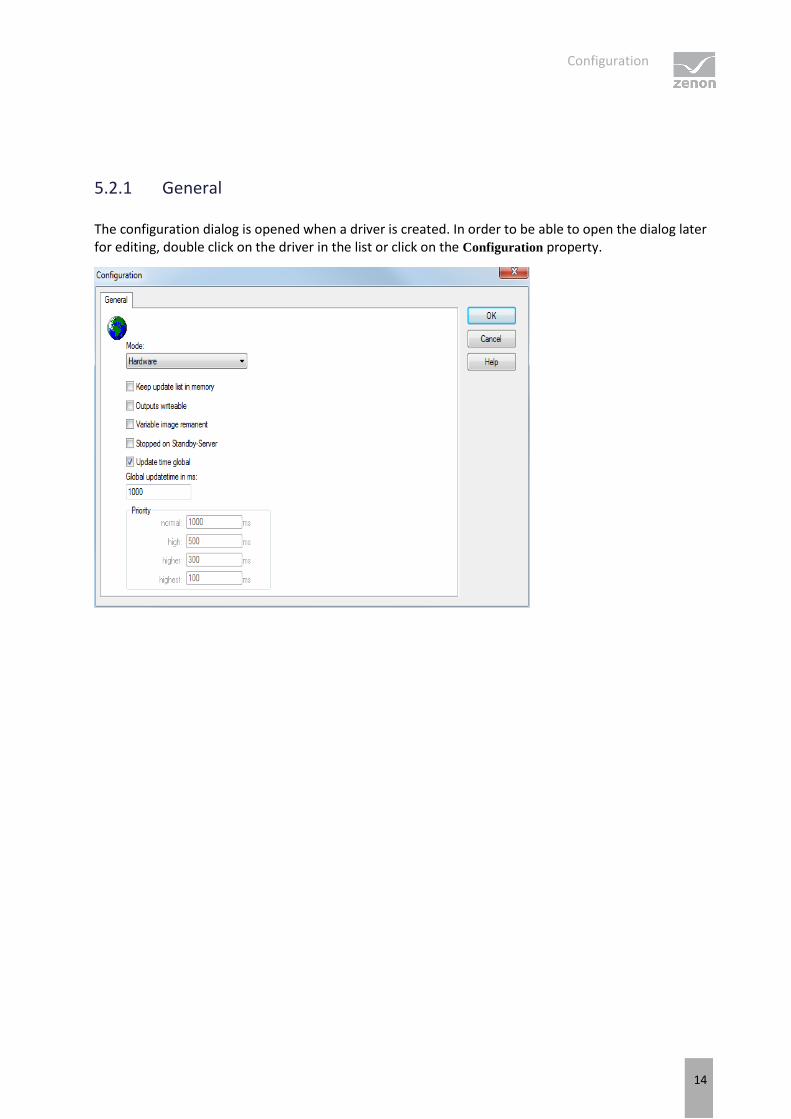
5.2.1 General
The configuration dialog is opened when a driver is created. In order to be able to open the dialog later for editing, double click on the driver in the list or click on the Configuration property.
Configuration
15
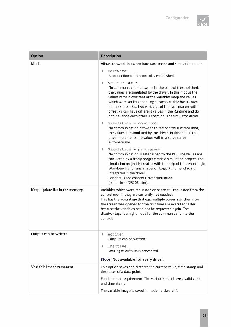
Option Description
Mode Allows to switch between hardware mode and simulation mode
Hardware: A connection to the control is established.
Simulation - static: No communication between to the control is established, the values are simulated by the driver. In this modus the values remain constant or the variables keep the values which were set by zenon Logic. Each variable has its own memory area. E.g. two variables of the type marker with offset 79 can have different values in the Runtime and do not influence each other. Exception: The simulator driver.
Simulation - counting: No communication between to the control is established, the values are simulated by the driver. In this modus the driver increments the values within a value range automatically.
Simulation - programmed: No communication is established to the PLC. The values are calculated by a freely programmable simulation project. The simulation project is created with the help of the zenon Logic Workbench and runs in a zenon Logic Runtime which is integrated in the driver. For details see chapter Driver simulation (main.chm::/25206.htm).
Keep update list in the memory Variables which were requested once are still requested from the control even if they are currently not needed. This has the advantage that e.g. multiple screen switches after the screen was opened for the first time are executed faster because the variables need not be requested again. The disadvantage is a higher load for the communication to the control.
Output can be written Active:
Outputs can be written.
Inactive:
Writing of outputs is prevented.
: Not available for every driver.
Variable image remanent This option saves and restores the current value, time stamp and the states of a data point.
Fundamental requirement: The variable must have a valid value and time stamp.
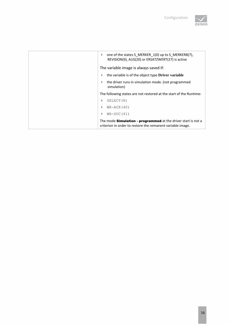
The variable image is saved in mode hardware if:
Configuration
16
one of the states S_MERKER_1(0) up to S_MERKER8(7), REVISION(9), AUS(20) or ERSATZWERT(27) is active
The variable image is always saved if:
the variable is of the object type Driver variable
the driver runs in simulation mode. (not programmed simulation)
The following states are not restored at the start of the Runtime:
SELECT(8)
WR-ACK(40)
WR-SUC(41)
The mode Simulation - programmed at the driver start is not a criterion in order to restore the remanent variable image.

Configuration
17
Stop on Standby Server Setting for redundancy at drivers which allow only one communication connection. For this the driver is stopped at the Standby Server and only started at the upgrade.
If this option is active, the gapless archiving is no longer guaranteed.
Active: Sets the driver at the not-process-leading Server automatically in a stop-like state. In contrast to stopping via driver command, the variable does not receive status switched off (statusverarbeitung.chm::/24150.htm) but an empty value. This prevents that at the upgrade to the Server irrelevant values are created in the AML, CEL and Historian.
Default: Inactive
Not available if the CE terminal serves as a data server. You can find further information in the zenon Operator manual in the CE terminal as a data server chapter.
Global Update time Setting for the global update times in milliseconds:
Active: The set Global update time is used for all variables in the project. The priority set at the variables is not used.
Inactive:
The set priorities are used for the individual variables.
Spontaneous drivers ignore this option. They generally use the shortest possible update time. For details, see the Spontaneous driver update time section.
Priority The polling times for the individual priority classes are set here. All variables with the according priority are polled in the set time.
The variables are allocated separately in the settings of the variable properties. The communication of the individual variables can be graded according to importance or required topicality using the priority classes. Thus the communication load is distributed better.
Priority classes are not supported by each driver, e.g. spontaneously communicating zenon drivers.
CLOSE DIALOG
Option Description
OK Applies all changes in all tabs and closes the dialog.

Configuration
18
Cancel Discards all changes in all tabs and closes the dialog.
Help Opens online help.
UPDATE TIME FOR SPONTANEOUS DRIVERS
With spontaneous drivers, for Set value, advising of variables and Requests, a read cycle is triggered immediately - regardless of the set update time. This ensures that the value is immediately available for visualization after writing. The update time is generally 100 ms.
Spontaneous drivers are ArchDrv, BiffiDCM, BrTcp32, DNP3, Esser32, FipDrv32, FpcDrv32, IEC850, IEC870, IEC870_103, Otis, RTK9000, S7DCOS, SAIA_Slave, STRATON32 and Trend32.
5.2.2 Driver dialog basic settings
Parameter Description
Configuration file name Name of the file in which the driver-specific configurations are saved. Click on the ... button to open the dialog for selecting a drop folder.
You can read about the structure of this configuration file in the Driver configuration file (on page 20) chapter.
Deactivate standard double point value
mapping
Inactive: The values of Double Point Values are adjusted to the operating elements of zenon. Use this configuration if you want to use the modules of the zenon Energy Edition. You can find details in the Double Point Value Mapping (on page 102) chapter.

Configuration
19
Active: The values of the Double Point Values are forwarded to zenon as they are. In this case, you cannot use the command processing function of zenon Energy or ALC for example.
Default: Inactive
Do not purge BRCB buffer at start Active: The buffer of the BRCBs are not deleted on the IED when the connection is first established after Runtime has started.
: For this BRCB , the last EntryID received has been saved. If no EntryID has been saved yet, the property is ignored and the driver sets BRCB.PurgeBuf=TRUE.
Only has an effect after the first attempt to activate a BRCB after Runtime has been restarted.
Is ignored with repeated attempts to set a BRCB.RptEna=TRUE - if the RCBs enable retries time has expired.
: If Runtime has not been stopped and only the connection to the IED has been disconnected, the setting is irrelevant. After reconnection, the driver attempts to get the buffered values again; the driver does not delete the values.
More in the Buffered reporting (on page 120) chapter.
Addressing: States which variable property is used in the driver for the addressing (ObjectReference ).
Variable name (Name)
Variable identification (Identification)
Symbolic address (Symbolic address)
Default: Symbolic address
: When importing the variables, the driver fills all three variable properties with valid references. You can rename the properties that the driver does not then use for addressing.
Originator category (orCat) The driver sends the configured orCat value in commands - in SBOw and Oper structures - that it writes to the IED .
Possible settings:
1 - Bay-control
2 - Station-control
3 - Remote-control
4 - Automatic-bay
5 - Automatic-station
6 - Automatic-remote

Configuration
20
7 - Maintenance
Default: 2 - Station-control
Directory for file transfer Directory for file transfer. All files loaded are saved in this folder.
More in the Filetransfer (on page 108) chapter.
Configuration of the driver
In the Editor, the driver saves its configuration in the TXT file as defined in Configuration file name. In Runtime, the driver gets its configuration from the copy of the file that the editor has provided.
Configuration
21
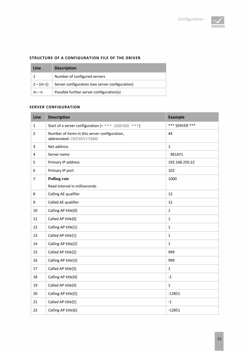
STRUCTURE OF A CONFIGURATION FILE OF THE DRIVER
Line Description
1 Number of configured servers
2 – (m-1) Server configuration (see server configuration)
m – n Possible further server configuration(s)
SERVER CONFIGURATION
Line Description Example
1 Start of a server configuration (= *** SERVER ***) *** SERVER ***
2 Number of items in this server configuration, abbreviated: CNTSRVITEMS
44
3 Net address 1
4 Server name RELAY1
5 Primary IP address 192.168.250.22
6 Primary IP port 102
7 Polling rate
Read interval in milliseconds
1000
8 Calling AE qualifier 12
9 Called AE qualifier 12
10 Calling AP title[0] 1
11 Called AP title[0] 1
12 Calling AP title[1] 1
13 Called AP title[1] 1
14 Calling AP title[2] 1
15 Called AP title[2] 999
16 Calling AP title[3] 999
17 Called AP title[3] 1
18 Calling AP title[4] -1
19 Called AP title[4] 1
20 Calling AP title[5] -12851
21 Called AP title[5] -1
22 Calling AP title[6] -12851

Configuration
22
23 Called AP title[6] -12851
24 Calling AP title[7] -12851
25 Called AP title[7] -12851
26 Calling AP title[8] -12851
27 Called AP title[8] -12851
28 Calling AP title[9] -12851
29 Called AP title[9] -12851
30 Max. auto used URCBs
Maximum number of Unbuffered Reports (URCBs) that the driver activates with automatic assignment per Logical Device
10
31 * - in newer configurations
With old configuration: names of the assigned Buffered Reports (BRCBs), separated with commas
*
32 Use preconfigured (SCL) options
0 = subsequently configured RCB settings (TrgOps, OptFlds, IntgPd, BufTm) are used
1 = the RCB settings that have already been preconfigured in the IEC61850 server - in its SCL file - are used
0
33 Use Report-ID for RCB assignment
0 = The RCB instances of the server are identified by name.
1 = Report ID that is used instead of the report name in the dialog for RCB assignment.
0
34 Use Authentication
0 = no ISO-Authentication used
1 = If active, the driver sends the Authentication String at establishing the connection.
0
35 Authentication String
36 Alternative IP address
37 Alternative IP port 0
38 TrgOp data-change: 0 = inactive ; 1 = active 1
39 TrgOp quality-change: 0 = inactive ; 1 = active 1
40 TrgOp data-update: 0 = inactive ; 1 = active 0
41 TrgOp integrity: 0 = inactive ; 1 = active 0
42 TrgOp general-interrogation: 0 = inactive ; 1 = active 1
43 GetNameList on DO 0

Configuration
23
0 = Normal GetNameList
1 = The driver reads the object model by requesting data objects (DO) for each Logical Node available in the server and each Functional Constraint (FC) defined in the IEC61850 standard.
This option has been removed from the configuration dialog in version 8.00 and replaced with an automated method.
44 Integrity Period 7000
45 Buffer Time 500
46 OptFlds Optional fields of the RCB
73
47 RCBs enable reties
Cycle in seconds in which an attempt is made to activate RCBs that were not activated successfully again. Only present if CNTSRVITEMS >= is 45
7
48 Automatic Watchdog 1
49 Data consistency scan 300
50 Use SCADA network orIdend 0
51 Number of client configurations
52 – (m-1)
Client configuration (see Client configuration)
m – n Possible further client configurations
CLIENT CONFIGURATION
Line Description Beispiel
1 Start of a client configuration (= *** CLIENTCFG ***) *** CLIENTCFG ***
2 Number of Items in this client configuration 1
3 Hostname (RT computer name)
Name of the computer on which the driver is running that receives the reports
WKS007
4 ClientLN.iedName SCADA_Server1
5 orIdent
6 Number of RCB configurations 2
7 – (i-1) RCB configuration (see RCB configuration)
i – (j-1) Possible further RCB configurations
y Number of dynamic dataset configurations
Configuration
24
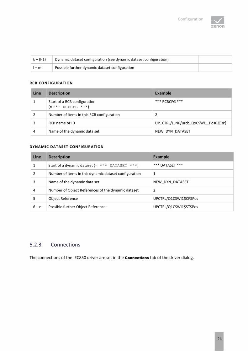
k – (l-1) Dynamic dataset configuration (see dynamic dataset configuration)
l – m Possible further dynamic dataset configuration
RCB CONFIGURATION
Line Description Example
1 Start of a RCB configuration (= *** RCBCFG ***)
*** RCBCFG ***
2 Number of items in this RCB configuration 2
3 RCB name or ID UP_CTRL/LLN0/urcb_QxCSWI1_Pos02[RP]
4 Name of the dynamic data set. NEW_DYN_DATASET
DYNAMIC DATASET CONFIGURATION
Line Description Example
1 Start of a dynamic dataset (= *** DATASET ***) *** DATASET ***
2 Number of items in this dynamic dataset configuration 1
3 Name of the dynamic data set NEW_DYN_DATASET
4 Number of Object References of the dynamic dataset 2
5 Object Reference UPCTRL/Q1CSWI1$CF$Pos
6 – n Possible further Object Reference. UPCTRL/Q1CSWI1$ST$Pos
5.2.3 Connections
The connections of the IEC850 driver are set in the Connections tab of the driver dialog.

Configuration
25
Parameter Description
Servers List of the already-configured connections to the IEC 61850 server.
New Creates a new connection to an IEC 61850 server. Opens the Server dialog.
Delete Removes the selected connection from the list.
Edit Opens the Server dialog to edit the selected connection
CLOSE DIALOG
Option Description
OK Applies all changes in all tabs and closes the dialog.
Cancel Discards all changes in all tabs and closes the dialog.
Help Opens online help.
Server
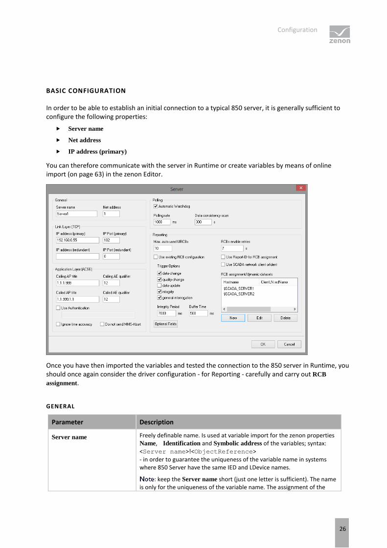
Clicking on New or Edit in the dialog Connection (on page 24) opens the dialog for the configuration of a connection to an IEC 61850 server:
This dialog is only available in English.
Configuration
26
BASIC CONFIGURATION
In order to be able to establish an initial connection to a typical 850 server, it is generally sufficient to configure the following properties:
Server name
Net address
IP address (primary)
You can therefore communicate with the server in Runtime or create variables by means of online import (on page 63) in the zenon Editor.
Once you have then imported the variables and tested the connection to the 850 server in Runtime, you should once again consider the driver configuration - for Reporting - carefully and carry out RCB
assignment.
GENERAL
Parameter Description
Server name Freely definable name. Is used at variable import for the zenon properties Name, Identification and Symbolic address of the variables; syntax: <Server name>!<ObjectReference> - in order to guarantee the uniqueness of the variable name in systems where 850 Server have the same IED and LDevice names.
: keep the Server name short (just one letter is sufficient). The name is only for the uniqueness of the variable name. The assignment of the
Configuration
27
variables to the connection (to the 850-Server) is undertaken by the driver from the Net address property, not from this name.
Default: Server1
Net address Corresponds to the Net address property (property group: Addressing) in variable configuration. Freely-selectable number.
The driver assigns the zenon variables to the 850 Server using this property.
Default: 1
Maximum value: 65535
LINK LAYER (TCP)
Connection settings to the 850 server to which the connection is to be established.
Parameter Description
IP adress (primary) IP address of the 850 server to which a connection is to be made.
Default: 192.168.0.55
IP Port (primary) IP port of the 850 server to which the connection is to be made. Default: 102
IP adress (redundant) Alternative IP address. If the connection to the first IP address fails, the alternative IP address will be used after the net error waiting time has passed (20-30 sec., depending on the network). The alternative address will be kept until the driver is restarted (via driver functions or restart of the zenon Runtime) or until the connection fails. Then, the first IP address will be used again.
In order to detect a loss of a connection, the Automatic
watchdog watchdog property should be activated or at least one variable, such as *LLN0/Mod/stVal[ST] should always be polled.
IP Port (redundant) Alternative IP port.
POLLING
Parameter Description
Automatic Watchdog Checkbox to activate the watchdog. If active, the driver automatically sends, for each Polling rate configured, a read request for *LLN0$ST$Mod$stVal in order to detect a possible loss of connection
: At least one data attribute should always be polled even if all data of the project is present in the report. Otherwise the failure of the IEC61850 server cannot be detected.
Only deactivate this property if it is guaranteed in the project that at least
Configuration
28
one polled variable is always signed in.
Default: active
Polling rate Defines the update frequency in milliseconds. The driver supports this rate to poll data that is not in active reports. At this a possible failure of the IEC61850 server is also considered.
Maximum value: 4294967295 If a higher value is entered, it is automatically changed to 1 when saved.
Default: 1000 ms
Exchange of data in Runtime does not depend on this setting or on the global update time. This is set to 100ms and fixed.
Data consistency scan Defines the cycle in which the driver checks the data model to see that it is consistent. Is only used if, in configured reports, the datasets contain individual data attributes instead of data objects.
Default: 300 seconds
Input range: 0 - 999999
REPORTING
Parameter Description
Reporting Settings for the reports (on page 110).
Max. auto used URCBs Maximum number of Unbuffered Reports which the driver activates at automatic allocation per Logical Device, i.e. in addition to RCBs that were configured in the RCB assignment dialog. Default: 10
Entry is only valid for Unbuffered Reports (URCB), does not affect any BRCBs .
: the setting makes the use of reporting easier in the test phase of the project already - even before the target settings for reporting have been set.
Configure the use of URCB in the RCB assignment dialog and set the property to 0 before you approve the project.
you can find more information on automatic allocation in the Unbuffered Report (on page 117) chapter.
Vertical group of the
option group Settings for URCBs that the driver automatically assigns and default values for properties with the same name in the RCB assignment dialog.
Configuration
29
Use existing RCB
configuration You can activate/deactivate the following Trigger Options regardless of one another.
data-change
Default: active
quality-change
Default: active
data-update
Default: Inactive
integrity
Default: active
general-interrogation
Default: active
: Not all servers support TrgOps data-change and data-update together. TrgOp intergity can also lead to an unnecessary overload of communication if a an IntgPd (Integrity Period) that is too short was defined in the server for RCB. In case of doubt, set TrgOps: data-change + quality-change + general-interrogation.
Integrity Period Time interval (IntgPd) in milliseconds in which the server sends an Integrity Report.
Default: 7000 ms
not active if TrgOp integrity is deactivated or Use
preconfigured (SCL) options is activated. Because an Integrity Report does not normally contain value changes, it is expressly recommended that only one single report on the server is activated with TrgOp: integrity. With an activated integrity report, the server can detect a connection failure more quickly. zenon does not need this report.
Default: 7000 ms
Buffer Time Time interval (BufTime) in milliseconds in which the server collects the data for a report.
Default: 500 ms
Inactive if the Use preconfigured (SCL) options option has been activated.
OptFlds Opens the dialog to configure the Optional Fields (on page 35) of the report.
If the Use preconfigured (SCL) options option has been activated, the dialog's options are displayed, but cannot be changed.

Configuration
30
Vertical group of the
settings Settings relevant for RCB assignment dialog.
RCBs enable retries Configuration of the periods of the renewed attempts to register the RCBs that have not been successfully registered. If the sign-in of an RCB is rejected by the 850 server, the driver will attempt it again - depending on RCBs enable retries.
Entry of the time in seconds.
Input range: 0 - 999999
Default: 7 the driver attempts to write again every 7 seconds RCB.RptEna=TRUE.
The variables are polled for as long as the sign-in is not successful. For this reason, the periods should be greater than the Polling
rate, otherwise it is not guaranteed the the variables affected have the initial values.
With an entry of 0, there is no attempt to register an RCB again.
These settings only concern RCBs that are listed in the RCB
assignment section.
Configuration
31
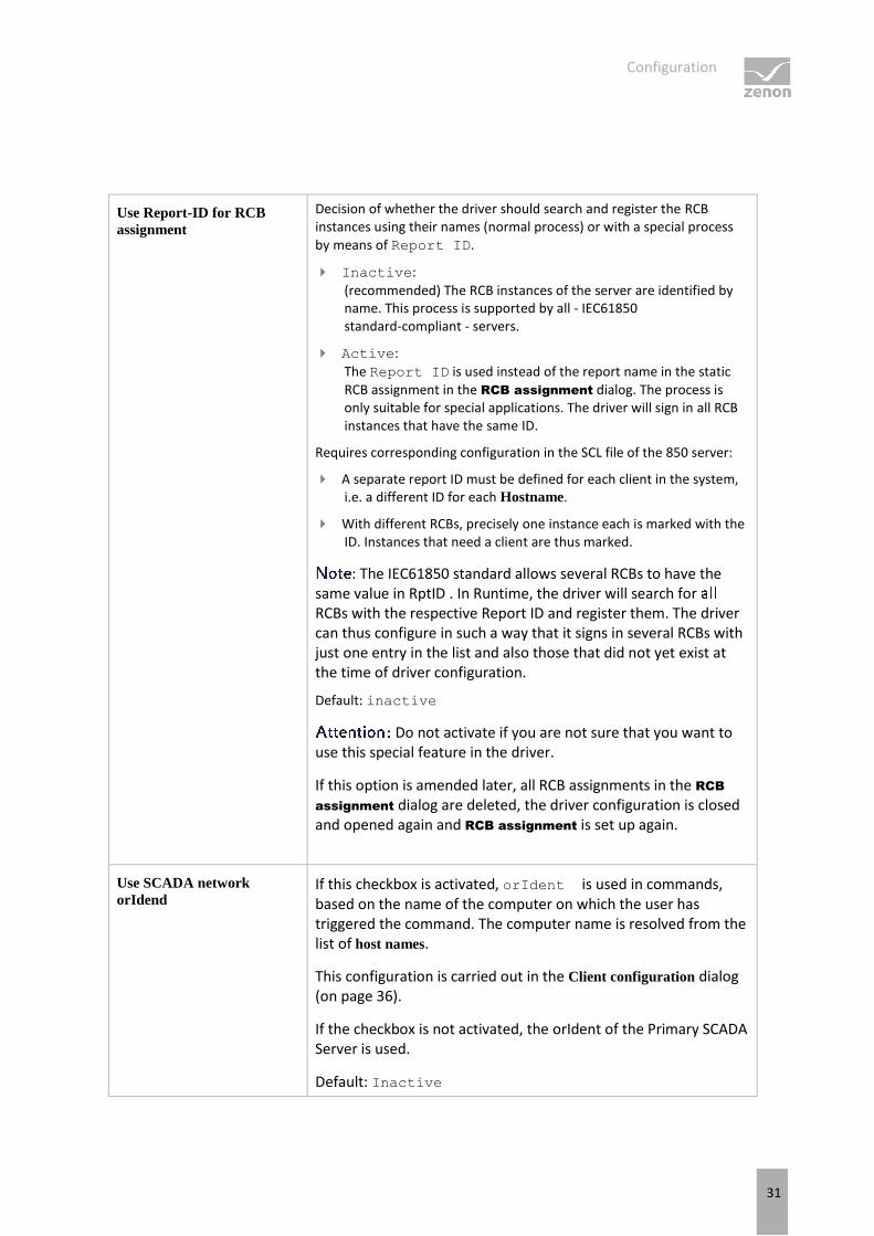
Use Report-ID for RCB
assignment
Decision of whether the driver should search and register the RCB instances using their names (normal process) or with a special process by means of Report ID.
Inactive:
(recommended) The RCB instances of the server are identified by name. This process is supported by all - IEC61850 standard-compliant - servers.
Active:
The Report ID is used instead of the report name in the static RCB assignment in the RCB assignment dialog. The process is only suitable for special applications. The driver will sign in all RCB instances that have the same ID.
Requires corresponding configuration in the SCL file of the 850 server:
A separate report ID must be defined for each client in the system, i.e. a different ID for each Hostname.
With different RCBs, precisely one instance each is marked with the ID. Instances that need a client are thus marked.
: The IEC61850 standard allows several RCBs to have the same value in RptID . In Runtime, the driver will search for RCBs with the respective Report ID and register them. The driver can thus configure in such a way that it signs in several RCBs with just one entry in the list and also those that did not yet exist at the time of driver configuration.
Default: inactive
Do not activate if you are not sure that you want to use this special feature in the driver.
If this option is amended later, all RCB assignments in the RCB
assignment dialog are deleted, the driver configuration is closed and opened again and RCB assignment is set up again.
Use SCADA network
orIdend If this checkbox is activated, orIdent is used in commands, based on the name of the computer on which the user has triggered the command. The computer name is resolved from the list of host names.
This configuration is carried out in the Client configuration dialog (on page 36).
If the checkbox is not activated, the orIdent of the Primary SCADA Server is used.
Default: Inactive
Configuration
32
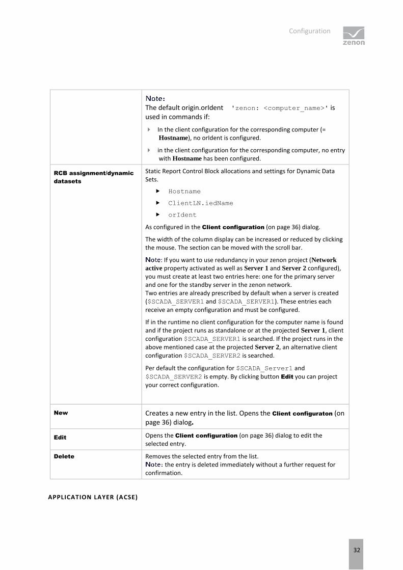
The default origin.orIdent 'zenon: <computer_name>' is used in commands if:
In the client configuration for the corresponding computer (= Hostname), no orIdent is configured.
in the client configuration for the corresponding computer, no entry with Hostname has been configured.
RCB assignment/dynamic
datasets
Static Report Control Block allocations and settings for Dynamic Data Sets.
Hostname
ClientLN.iedName
orIdent
As configured in the Client configuration (on page 36) dialog.
The width of the column display can be increased or reduced by clicking the mouse. The section can be moved with the scroll bar.
: If you want to use redundancy in your zenon project (Network
active property activated as well as Server 1 and Server 2 configured), you must create at least two entries here: one for the primary server and one for the standby server in the zenon network. Two entries are already prescribed by default when a server is created ($SCADA_SERVER1 and $SCADA_SERVER1). These entries each receive an empty configuration and must be configured.
If in the runtime no client configuration for the computer name is found and if the project runs as standalone or at the projected Server 1, client configuration $SCADA_SERVER1 is searched. If the project runs in the above mentioned case at the projected Server 2, an alternative client configuration $SCADA_SERVER2 is searched.
Per default the configuration for $SCADA_Server1 and
$SCADA_SERVER2 is empty. By clicking button Edit you can project your correct configuration.
New Creates a new entry in the list. Opens the Client configuraton (on page 36) dialog.
Edit Opens the Client configuration (on page 36) dialog to edit the selected entry.
Delete Removes the selected entry from the list. the entry is deleted immediately without a further request for
confirmation.
APPLICATION LAYER (ACSE)

Configuration
33
Setting for ACSE.
Parameter Description
Calling AP title Settings according to ISO 8650-1(ACSE), the value for the OSI ACSE AP
Title of the client in the Universal Identifier notation.
Default: 1.1.1.999 Should not normally be amended.
Calling AE qualifier Settings according to ISO 8650-1(ACSE).
Default: 12 Should not normally be amended.
Called AP title Settings according to ISO 8650-1(ACSE), OSI-AP-Title of the server in the format for Universal Identifier.
Default: 1.1.999.1.1 Should not normally be amended.
Called AE qualifier Settings according to ISO 8650-1(ACSE). Default: 12 Should not normally be amended.
Use Authentication Activate this checkbox if you want to use authentication according to ISO 8650-1.
Active: If active, the driver sends the Authentication String at establishing the connection.
[Input field for
Authentication
String]
Input field for Authentication String. Note the length limitation of 55 characters in accordance with ISO 8327-1 OSI session protocol.
Only active if Use Authentication is active. This option is deactivated by default.
Ignore time accuracy Checkbox to ignore the precision of the received time stamp.
Active All decimal comma points of the received time stamp are evaluated, regardless of how many decimal points the time stamp are valid according to TimeAccuracy.
Inactive:
The decimal points of the received time stamp are evaluated according to TimeAccuracy.
Do not send MMS-Abort Defines the way of how connections to the IED are closed.
active: The driver closes the TCP socket instead of sending a MMS (ACSE) compliant Abort.
inactive:

Configuration
34
The driver sends the standard compliant Abort service..
Default: Inactive
CLOSE DIALOG
Option Description
OK Applies settings and closes the dialog.
Cancel Discards all changes and closes the dialog.
Information
OSI value (ACSE)
The driver uses the following OSI selector values:
Presentation Selector (OSI-PSEL) = "00000001"
Session Selector (OSI-SSEL) = "0001"
Transport Selector (OSI-TSEL) = "0001"
In a server SCL file, it corresponds to the following entries:
<P type="OSI-AP-Title">41,999,1,1</P> - coded in accordance with Basic Encoding Rules (IEC 8825) for Object Identifier - corresponds to default values of the Universal Identifiers in the Called AP title.
<P type="OSI-AE-Qualifier">12</P> - corresponds to default values in the Called AE qualifier.
<P type="OSI-PSEL">00000001</P> - set in the driver; cannot be changed
<P type="OSI-SSEL">0001</P> - set in the driver; cannot be changed
<P type="OSI-TSEL">0001</P> - set in the driver; cannot be changed

Configuration
35
Optional Fields
The Optional Fields are written on the server when a report is activated. These correspond to the bits in the OptFlds data attribute of the RCB.
"Sequence number", "Data set name" and "Entry ID" are activated by default:
The Data set name option is activated by default. Deactivation of this option is not recommended.
The following is applicable if this option is deactivated: If an InformationReport is received without a DatSet Name, RptID is used to carry out a search to see which data set is linked in the RCB. A basic requirement for this is that the RptIDs is unique for the complete 850 server.
Entry ID is required for Buffered Reports (BRCB) in order to request the buffered values after the connection has been reestablished. Does not exist in URCB , is thus not written even if it has been configured.
Sequence number is only to check whether the reports have been transferred without omissions. Is possibly evaluated in LOG.
FURTHER OPTIONAL FIELDS:
Report time stamp sss
Reason for inclusion Activate "Reason for inclusion" in order to read the information for the variables with the status bits COTx, relating to how their value has been received: via a spontaneous report or GI or Integrity report.
Data reference Activation of the "Data reference" option results in the reports becoming very large. These reports then contain the ObjektReference - as a readable string - for each data attribute (variable) of the data set. This makes analysis easier, in Wireshark for example. These reports (with Data reference) are however not suitable for approved systems.
Configuration
36
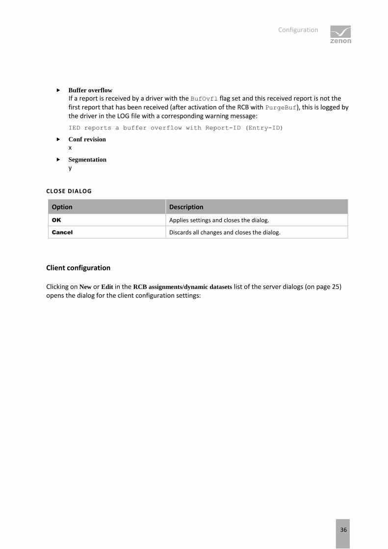
Buffer overflow If a report is received by a driver with the BufOvfl flag set and this received report is not the first report that has been received (after activation of the RCB with PurgeBuf), this is logged by the driver in the LOG file with a corresponding warning message:
IED reports a buffer overflow with Report-ID (Entry-ID)
Conf revision x
Segmentation y
CLOSE DIALOG
Option Description
OK Applies settings and closes the dialog.
Cancel Discards all changes and closes the dialog.
Client configuration
Clicking on New or Edit in the RCB assignments/dynamic datasets list of the server dialogs (on page 25) opens the dialog for the client configuration settings:

Configuration
37
This dialog is only available in English.

Configuration
38
Parameter Description
Hostname (RT computer name) Name of the computer on which the driver is running that receives the reports:
For standalone projects: $SCADA_SERVER1 Or computer name of the computer on which the zenon Runtime is running
In the zenon network: $SCADA_SERVER1 Or computer name of the project server Server 1 $SCADA_SERVER2 or computer name of the project standby server Server 2 Computer name of the network client for the determination of orIdent. This is only taken into account if option Use SCADA
network client orIdent in dialog Server is activated.
: Do not use "localhost"; use the computer names from the operating system instead.
The Hostname must not be empty if at least one of the following configuration settings has been configured.
If the driver does not find a host name that corresponds to the current Runtime computer name, it cannot activate the reports. It is logged as an error/warning.
ClientLN.iedName IED name of the IEC61850 clients as stated in the SCD file and given there under RCB.RptEnabled.ClientLN.
Permitted characters: A to Z, a to z and 0 to 9 and underscore _ maximum 64 characters.
Default: empty
In order to easily configure the driver with a SCD file, use the IEC850 Driver Configuration Wizard. You can find further details in the Wizard documentation.
The status of the Resv attribute is ignored when validating the availability of the RCB for statically-assigned URCBss if the ClientLN.iedName option is configured.
orIdent Input field for the configuration of the orIdent. For each computer in the zenon network, a freely-definable orIdent entry can be configured.
You can use up to 32 characters.
Default: empty (= 'zenon: <computer_name>')
The Originator that is used in commands is also dependent on the configuration in the Basic Settings dialog (orCat property) and in the Server dialog (Use Client orIdent checkbox).
If the Use Client orIdent checkbox is not active, the orIdent of the
Configuration
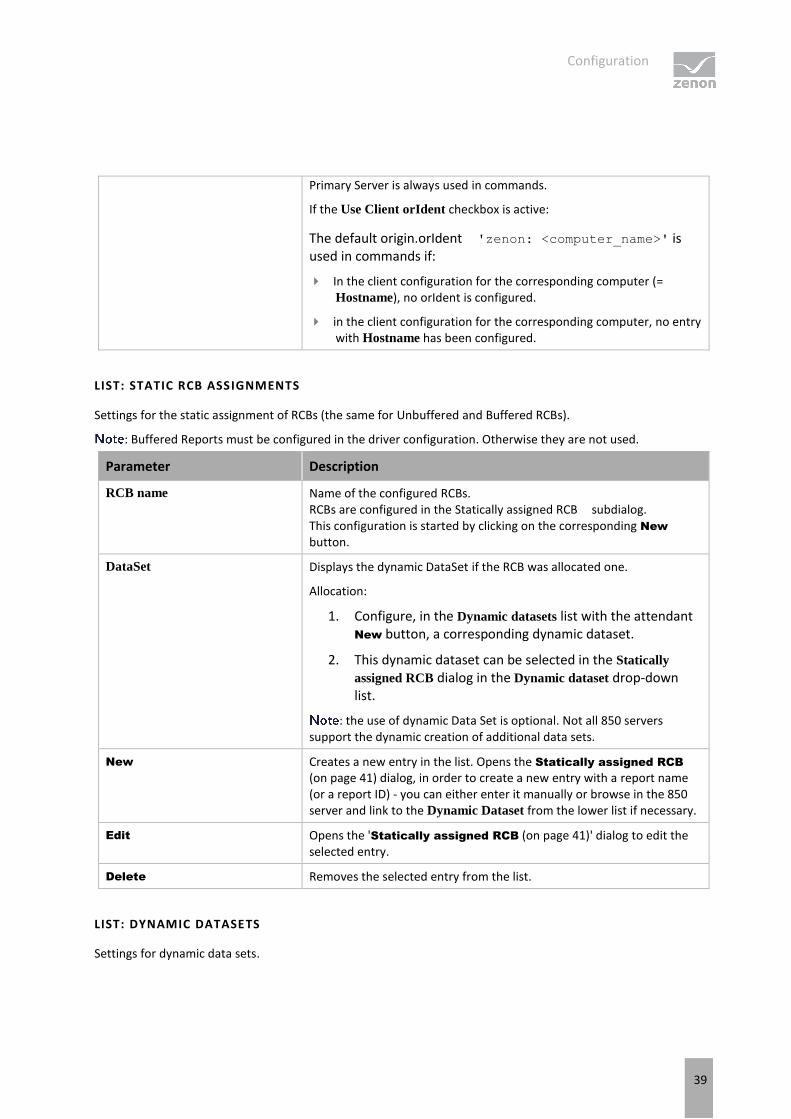
39
Primary Server is always used in commands.
If the Use Client orIdent checkbox is active:
The default origin.orIdent 'zenon: <computer_name>' is used in commands if:
In the client configuration for the corresponding computer (= Hostname), no orIdent is configured.
in the client configuration for the corresponding computer, no entry with Hostname has been configured.
LIST: STATIC RCB ASSIGNMENTS
Settings for the static assignment of RCBs (the same for Unbuffered and Buffered RCBs).
: Buffered Reports must be configured in the driver configuration. Otherwise they are not used.
Parameter Description
RCB name Name of the configured RCBs. RCBs are configured in the Statically assigned RCB subdialog. This configuration is started by clicking on the corresponding New button.
DataSet Displays the dynamic DataSet if the RCB was allocated one.
Allocation:
1. Configure, in the Dynamic datasets list with the attendant New button, a corresponding dynamic dataset.
2. This dynamic dataset can be selected in the Statically
assigned RCB dialog in the Dynamic dataset drop-down list.
: the use of dynamic Data Set is optional. Not all 850 servers support the dynamic creation of additional data sets.
New Creates a new entry in the list. Opens the Statically assigned RCB (on page 41) dialog, in order to create a new entry with a report name (or a report ID) - you can either enter it manually or browse in the 850 server and link to the Dynamic Dataset from the lower list if necessary.
Edit Opens the 'Statically assigned RCB (on page 41)' dialog to edit the selected entry.
Delete Removes the selected entry from the list.
LIST: DYNAMIC DATASETS
Settings for dynamic data sets.

Configuration
40
: Dynamic data sets are not a requirement for Buffered or Unbuffered Reports. They are optional settings if the IEC61850 server that is used supports this and, in selected RCBs, there is no unsuitable or replaceable configuration of the Dataset .
For more information, see dynamic data sets (on page 125).
Parameter Description
Name Shows the previously-entered Datasets - they are then available in the upper list.
New Opens the dialog to create a Dataset.
Edit Opens the Dynamic DataSet configuration (on page 47) dialog to edit the selected entry.
Delete Removes the selected entry from the list.
WARNING NOTICES
If the configuration is not correct, you are notified of this with a corresponding warning dialog. Confirm this dialog by clicking on the OK button to return to the configuration dialog. Then correct the error.
The warning dialog is only available in English.

Configuration
41
Statically assigned RCB
Clicking on New or Edit in the Static RCB assignment list of the Client configuration (on page 36) dialog opens the dialog to create an assignment to RCB or to assign an RCB a dynamic Dataset. RCBs are defined using their name (standard case) or ID (special case):
Configuration
42
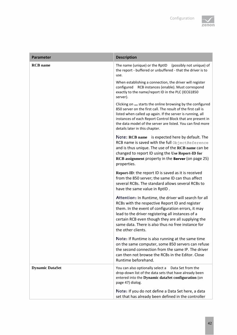
Parameter Description
RCB name The name (unique) or the RptID (possibly not unique) of the report - buffered or unbuffered - that the driver is to use.
When establishing a connection, the driver will register configured RCB instances (enable). Must correspond exactly to the name/report ID in the PLC (IEC61850 server).
Clicking on ... starts the online browsing by the configured 850 server on the first call. The result of the first call is listed when called up again. If the server is running, all instances of each Report Control Block that are present in the data model of the server are listed. You can find more details later in this chapter.
RCB name is expected here by default. The RCB name is saved with the full ObjectReference and is thus unique. The use of the RCB name can be changed to report ID using the Use Report-ID for
RCB assignment property in the Server (on page 25) properties.
Report-ID: the report ID is saved as it is received from the 850 server; the same ID can thus affect several RCBs. The standard allows several RCBs to have the same value in RptID .
In Runtime, the driver will search for all RCBs with the respective Report ID and register them. In the event of configuration errors, it may lead to the driver registering all instances of a certain RCB even though they are all supplying the same data. There is also thus no free instance for the other clients.
If Runtime is also running at the same time on the same computer, some 850 servers can refuse the second connection from the same IP. The driver can then not browse the RCBs in the Editor. Close Runtime beforehand.
Dynamic DataSet You can also optionally select a Data Set from the drop-down list of the data sets that have already been entered into the Dynamic dataSet configuration (on page 47) dialog.
If you do not define a Data Set here, a data set that has already been defined in the controller

Configuration
43
(IEC61850 Server) is used for this RCB (in the SCL file).
Use existing RCB configuration active: The driver activates a report without overwriting the data attributes of the RCB. The content of the SCL file of the server is defined as a result of this. The following data attributes are affected by this:
IntgPd
BufTime
TrgOps
OptFields
Inactive:
The driver writes the data attributes of the RCB during activation.
The driver overwrites the data attributes of the RCB in the IED only if they do not match the settings of the driver.
Default: Inactive
RCB CONFIGURATION
Parameter Description
Trigger Options You can activate/deactivate the following Trigger
Options regardless of one another.
data-change
Default: active
quality-change
Default: active
data-update
Default: Inactive
integrity
Default: active
general-interrogation
Default: active
: Not all servers support TrgOps data-change and data-update together. TrgOp intergity can also lead to an unnecessary overload of communication if a an IntgPd (Integrity Period) that is too short was defined in the server for RCB. In case of doubt, set TrgOps: data-change + quality-change +
Configuration
44
general-interrogation.
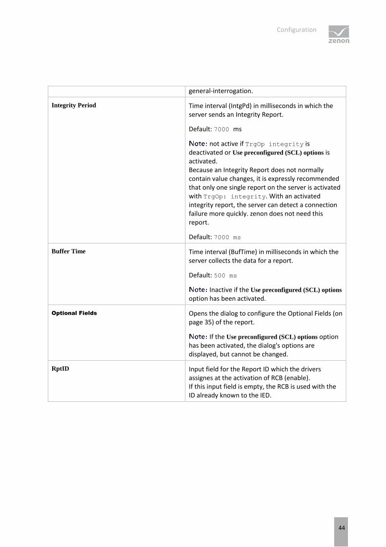
Integrity Period Time interval (IntgPd) in milliseconds in which the server sends an Integrity Report.
Default: 7000 ms
not active if TrgOp integrity is deactivated or Use preconfigured (SCL) options is activated. Because an Integrity Report does not normally contain value changes, it is expressly recommended that only one single report on the server is activated with TrgOp: integrity. With an activated integrity report, the server can detect a connection failure more quickly. zenon does not need this report.
Default: 7000 ms
Buffer Time Time interval (BufTime) in milliseconds in which the server collects the data for a report.
Default: 500 ms
Inactive if the Use preconfigured (SCL) options option has been activated.
Optional Fields Opens the dialog to configure the Optional Fields (on page 35) of the report.
If the Use preconfigured (SCL) options option has been activated, the dialog's options are displayed, but cannot be changed.
RptID Input field for the Report ID which the drivers assignes at the activation of RCB (enable). If this input field is empty, the RCB is used with the ID already known to the IED.
Configuration
45
CLOSE DIALOG
Option Description
OK Applies settings and closes the dialog.
Cancel Discards all changes and closes the dialog.
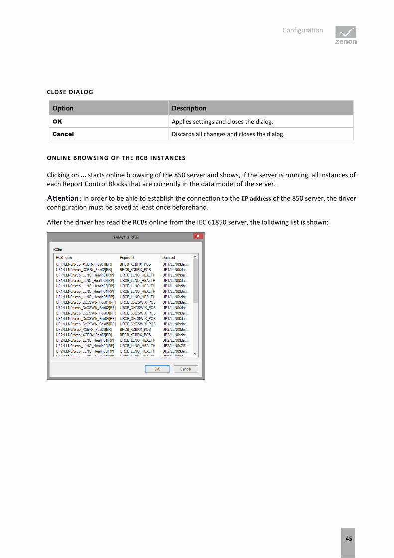
ONLINE BROWSING OF THE RCB INSTANCES
Clicking on ... starts online browsing of the 850 server and shows, if the server is running, all instances of each Report Control Blocks that are currently in the data model of the server.
In order to be able to establish the connection to the IP address of the 850 server, the driver configuration must be saved at least once beforehand.
After the driver has read the RCBs online from the IEC 61850 server, the following list is shown:
Configuration
46
Parameter Description
RCB name Name of the RCBs as configured in the data model on the server.
Report ID Identification of the RCB as configured in the data model on the server in the RptID attribute.
Data set Name of the datasets in the RCB as configured in the data model on the server.
OK Applies settings and closes the dialog. A validation is carried out before closing the dialog. In case of failure, a warning dialog pops up.
Cancel Discards all changes and closes the dialog.
Select the desired instance of a Report Control Block from the list and click OK. You can repeat the procedure as many times as you want in order to assign further RCBs.
Ensure that, for each Hostname, the instances with other names (and/or other number), or other report ID are selected. In accordance with the IEC61850 standard, an instance of the RCB can only be registered (enabled) by one client.
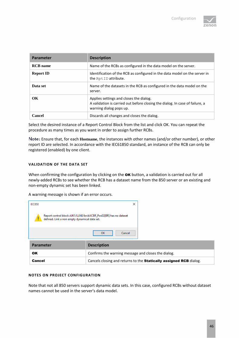
VALIDATION OF THE DATA SET
When confirming the configuration by clicking on the OK button, a validation is carried out for all newly-added RCBs to see whether the RCB has a dataset name from the 850 server or an existing and non-empty dynamic set has been linked.
A warning message is shown if an error occurs.
Parameter Description
OK Confirms the warning message and closes the dialog.
Cancel Cancels closing and returns to the Statically assigned RCB dialog.
NOTES ON PROJECT CONFIGURATION
Note that not all 850 servers support dynamic data sets. In this case, configured RCBs without dataset names cannot be used in the server's data model.

Configuration
47
If the 850 server does not support dynamic data sets, the IED must be updated with a corrected SCL file (CID).
Dynamic dataset configuration
Clicking on New or Edit in the dynamic data sets list of the Client configuration (on page 36) dialog opens the dialog to define a dynamic Data Set.
Configuration
48
Parameter Description
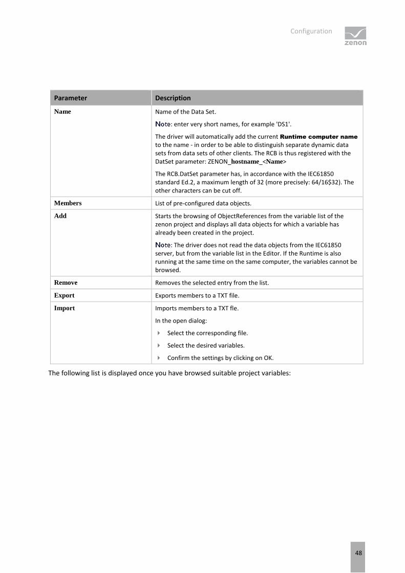
Name Name of the Data Set.
: enter very short names, for example 'DS1'.
The driver will automatically add the current Runtime computer name to the name - in order to be able to distinguish separate dynamic data sets from data sets of other clients. The RCB is thus registered with the DatSet parameter: ZENON_hostname_<Name>
The RCB.DatSet parameter has, in accordance with the IEC61850 standard Ed.2, a maximum length of 32 (more precisely: 64/16$32). The other characters can be cut off.
Members List of pre-configured data objects.
Add Starts the browsing of ObjectReferences from the variable list of the zenon project and displays all data objects for which a variable has already been created in the project.
: The driver does not read the data objects from the IEC61850 server, but from the variable list in the Editor. If the Runtime is also running at the same time on the same computer, the variables cannot be browsed.
Remove Removes the selected entry from the list.
Export Exports members to a TXT file.
Import Imports members to a TXT fle.
In the open dialog:
Select the corresponding file.
Select the desired variables.
Confirm the settings by clicking on OK.
The following list is displayed once you have browsed suitable project variables:

Creating variables
49
The driver displays all data objects - that are appropriate for data reporting - from the variable list of the zenon project, except those that have already been selected for the data set. In the upper list, you can filter and select the listed variables. Multiple selection is possible (with the Alt or Shift key held down).
Clicking on the Add button adds your selection to the lower list. Objects that have already been selected are kept. Use the OK button to add the selected variables (as references to the data objects) to the members of the dynamic data set.
6. Creating variables
This is how you can create variables in the zenon Editor:
6.1 Creating variables in the Editor
Variables can be created:
as simple variables
in arrays (main.chm::/15262.htm)
as structure variables (main.chm::/15278.htm)

Creating variables
50
VARIABLE DIALOG
To create a new variable, regardless of which type:
1. Select the New variable command in the Variables node in the context menu
The dialog for configuring variables is opened
2. Configure the variable
Creating variables
51
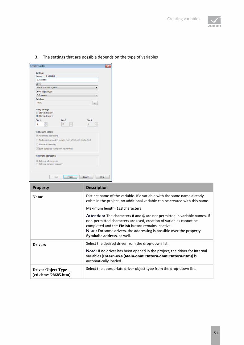
3. The settings that are possible depends on the type of variables
Property Description
Name Distinct name of the variable. If a variable with the same name already exists in the project, no additional variable can be created with this name.
Maximum length: 128 characters
The characters # and @ are not permitted in variable names. If non-permitted characters are used, creation of variables cannot be completed and the Finish button remains inactive.
For some drivers, the addressing is possible over the property Symbolic address, as well.
Drivers Select the desired driver from the drop-down list.
If no driver has been opened in the project, the driver for internal variables (Intern.exe (Main.chm::/Intern.chm::/Intern.htm)) is automatically loaded.
Driver Object Type (cti.chm::/28685.htm)
Select the appropriate driver object type from the drop-down list.

Creating variables
52
Data Type Select the desired data type. Click on the ... button to open the selection dialog.
Array settings Expanded settings for array variables. You can find details in the Arrays chapter.
Addressing options Expanded settings for arrays and structure variables. You can find details in the respective section.
Automatic element
activation Expanded settings for arrays and structure variables. You can find details in the respective section.
SYMBOLIC ADDRESS
The Symbolic address property can be used for addressing as an alternative to the Name or Identification of the variables. Selection is made in the driver dialog; configuration is carried out in the variable property. When importing variables of supported drivers, the property is entered automatically.
Maximum length: 1024 characters.
INHERITANCE FROM DATA TYPE
Measuring range, Signal range and Set value are always:
derived from the datatype
Automatically adapted if the data type is changed
If a change is made to a data type that does not support the set signal range, the signal
range is amended automatically. For example, for a change from INT to SINT, the signal range is changed to 127. The amendment is also carried out if the signal range was not inherited from the data type. In this case, the measuring range must be adapted manually.
6.2 Addressing
The addressing is based on the variable names.
Creating variables
53
Name Description
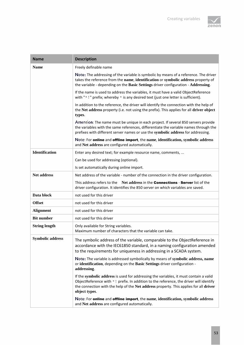
Name Freely definable name
The addressing of the variable is symbolic by means of a reference. The driver takes the reference from the name, identification or symbolic address property of the variable - depending on the Basic Settings driver configuration - Addressing.
If the name is used to address the variables, it must have a valid ObjectReference with "*!" prefix; whereby * is any desired text (just one letter is sufficient).
In addition to the reference, the driver will identify the connection with the help of the Net address property (i.e. not using the prefix). This applies for all driver object
types.
: The name must be unique in each project. If several 850 servers provide the variables with the same references, differentiate the variable names through the prefixes with different server names or use the symbolic address for addressing.
: For online and offline import, the name, identification, symbolic address and Net address are configured automatically.
Identification Enter any desired text; for example resource name, comments, ...
Can be used for addressing (optional).
Is set automatically during online import.
Net address Net address of the variable - number of the connection in the driver configuration.
This address refers to the Net address in the Connections - Server list of the driver configuration. It identifies the 850 server on which variables are saved.
Data block not used for this driver
Offset not used for this driver
Alignment not used for this driver
Bit number not used for this driver
String length Only available for String variables. Maximum number of characters that the variable can take.
Symbolic address The symbolic address of the variable, comparable to the ObjectReference in accordance with the IEC61850 standard, in a naming configuration amended to the requirements for uniqueness in addressing in a SCADA system.
The variable is addressed symbolically by means of symbolic address, name or identification, depending on the Basic Settings driver configuration - addressing.
If the symbolic address is used for addressing the variables, it must contain a valid ObjectReference with *! prefix. In addition to the reference, the driver will identify the connection with the help of the Net address property. This applies for all driver
object types.
: For online and offline import, the name, identification, symbolic address and Net address are configured automatically.

Creating variables
54
Driver
connection/Driver
Object Type
Depending on the type of variable, the object type is selected when the variables are created; the type can be changed here later. For more information, see also the driver objects (on page 56).
Driver
connection/Data
Type
Data type of variables that were selected when the variable was created; the type can be changed here later.
If you subsequently change the data type here, you must check all variable properties, such as value range for example, and change them if necessary.
Driver
connection/Priority not used for this driver The driver does not support cyclically-poling communication in priority classes.
You can create several variables with the same ObjectReference if the variable names for this are different, such as with a different prefix, for example.
SYNTAX OF THE REFERENCES FOR ADDRESSING THE VARIABLES
Addressing of the variables is symbolic via its references. The driver takes the reference from one of the properties of the variable (symbolic address, name or identification) - depending on the Basic Settings driver configuration - addressing. In addition to the reference, the driver will identify the connection with the help of the Net address property.
The following syntax is applicable for the references: SERVER!LD/LN/DataObject/DataAttr[FC]
In doing so:
The prefix (SERVER) is separated from the following identifiers by an exclamation mark (!). It is for the uniqueness of the variables in the project, not the addressing.
Further identifiers are separated from one another by a slash (/).
Only if an identifier itself is a structure are their elements are separated by a dot (.); for example: SERVER!LD/LN/DataObject/DataAttr.item[FC].
The Functional Constraint is defined in brackets [], at the end.
The designations are:

Creating variables
55
Parameter Description
SERVER Freely-definable name, whereby just one letter is sufficient. It can, for example, be an abbreviated name of the 850 server.
If the reference is in the Name property of the variable, the prefix should ensure that all variable names in the zenon project are unique.
Use the same names as defined in driver dialog Dialog Server (on page 25). However, the driver does not recognize the connection to be used from the server name (i.e. not from the prefix in the reference) but from net address settings.
LD Name of the IED and Logical Device, such as "GE_F650" for example.
LN Name of the logical node (Logical Node), for example "LLN0", "MMXU".
DataObject Name of the data object, for example "Mod", "PhV.phsA",
See Appendix B - data objects/data attributes
DataAttr Name of the data attribute, for example "stVal", "cVal.mag.f",
See Appendix B - data objects/data attributes
FC Functional Constraint of the data attribute, for example "ST", "MX",
See Appendix A - Description of the functional constraints (FCs):
Attention
The naming convention for references of the variables is not exactly the same as the ObjectReference defined in the IEC61850-7-1 standard.
In the standard, a slash (/) is only used as separator between LD and LD and otherwise separated by dots (.). If DataObject is a structure, dots make it impossible to distinguish what is a DataObject and what is a DataAttr. Therefore an own naming conversion is used for the variable addressing.
EXAMPLE:
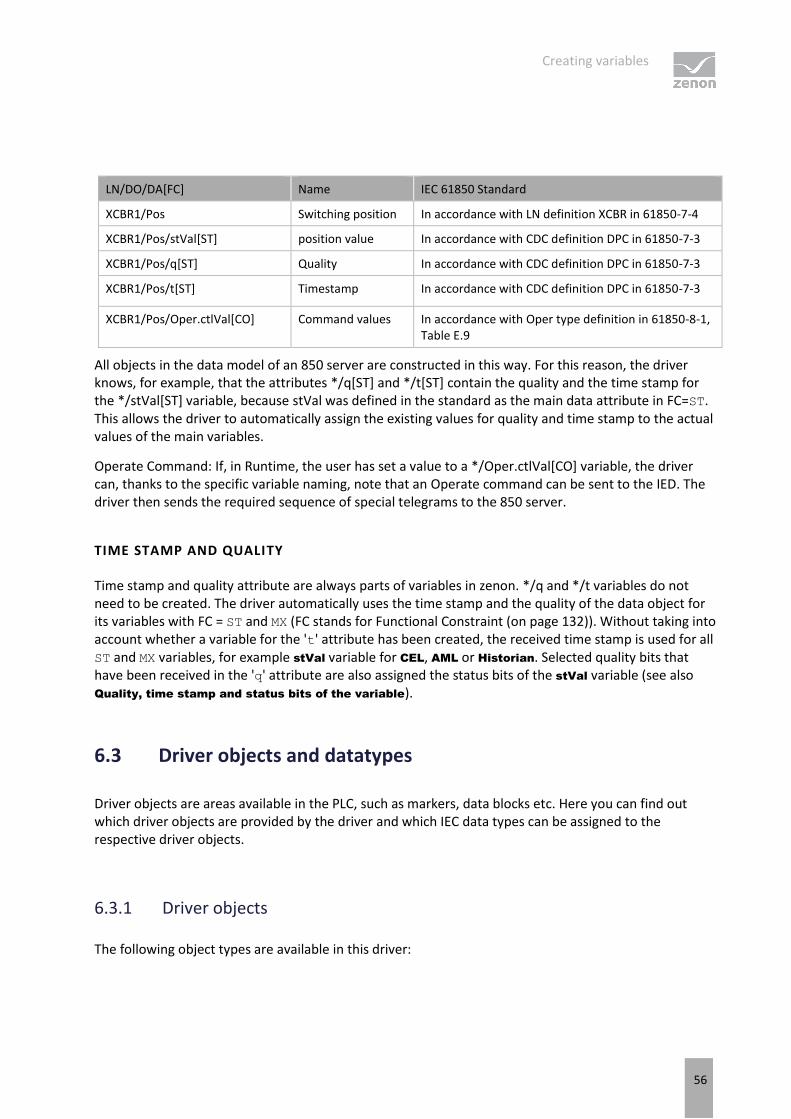
The 'XCBR1' logical node (circuit breaker 1) has, among other things, a data object 'Pos' of CDC (Common Data Class) 'Controllable Double Point' (DPC). This 'Pos' data object in turn has data attributes 'stVal', 'q' and 't', whose name and semantics are defined in IEC61850-7-3 - through its CDC.
Creating variables
56
LN/DO/DA[FC] Name IEC 61850 Standard
XCBR1/Pos Switching position In accordance with LN definition XCBR in 61850-7-4
XCBR1/Pos/stVal[ST] position value In accordance with CDC definition DPC in 61850-7-3
XCBR1/Pos/q[ST] Quality In accordance with CDC definition DPC in 61850-7-3
XCBR1/Pos/t[ST] Timestamp In accordance with CDC definition DPC in 61850-7-3
XCBR1/Pos/Oper.ctlVal[CO] Command values In accordance with Oper type definition in 61850-8-1, Table E.9
All objects in the data model of an 850 server are constructed in this way. For this reason, the driver knows, for example, that the attributes */q[ST] and */t[ST] contain the quality and the time stamp for the */stVal[ST] variable, because stVal was defined in the standard as the main data attribute in FC=ST. This allows the driver to automatically assign the existing values for quality and time stamp to the actual values of the main variables.
Operate Command: If, in Runtime, the user has set a value to a */Oper.ctlVal[CO] variable, the driver can, thanks to the specific variable naming, note that an Operate command can be sent to the IED. The driver then sends the required sequence of special telegrams to the 850 server.
TIME STAMP AND QUALITY
Time stamp and quality attribute are always parts of variables in zenon. */q and */t variables do not need to be created. The driver automatically uses the time stamp and the quality of the data object for its variables with FC = ST and MX (FC stands for Functional Constraint (on page 132)). Without taking into account whether a variable for the 't' attribute has been created, the received time stamp is used for all ST and MX variables, for example stVal variable for CEL, AML or Historian. Selected quality bits that have been received in the 'q' attribute are also assigned the status bits of the stVal variable (see also Quality, time stamp and status bits of the variable).
6.3 Driver objects and datatypes
Driver objects are areas available in the PLC, such as markers, data blocks etc. Here you can find out which driver objects are provided by the driver and which IEC data types can be assigned to the respective driver objects.
6.3.1 Driver objects
The following object types are available in this driver:
Creating variables
57
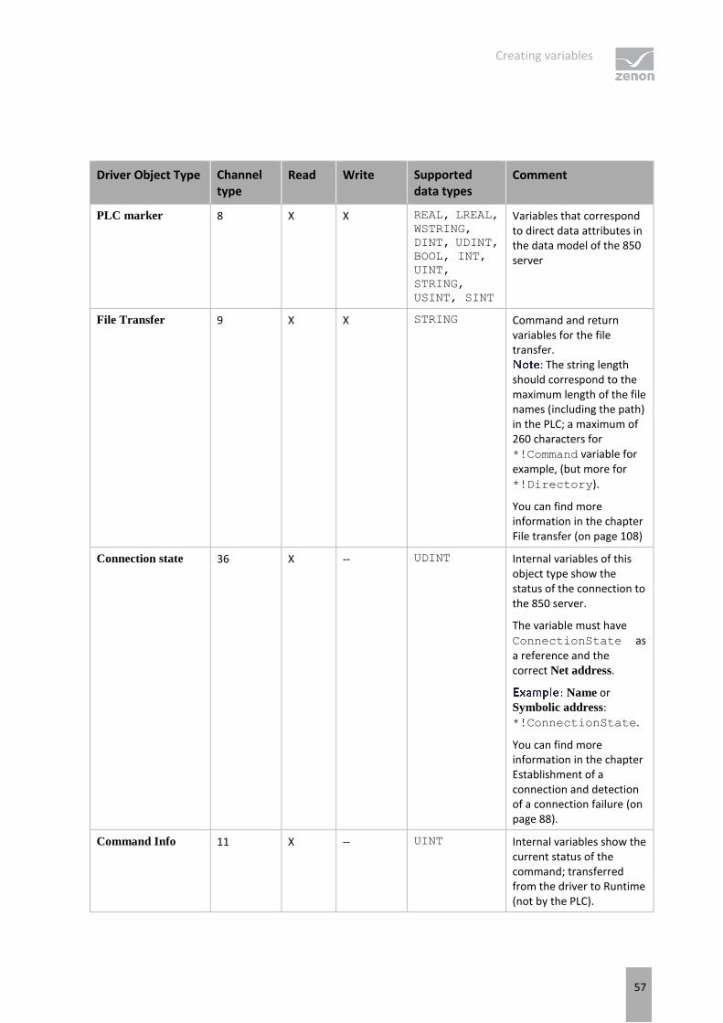
Driver Object Type Channel type
Read Write Supported data types
Comment
PLC marker 8 X X REAL, LREAL,
WSTRING,
DINT, UDINT,
BOOL, INT,
UINT,
STRING,
USINT, SINT
Variables that correspond to direct data attributes in the data model of the 850 server
File Transfer 9 X X STRING Command and return variables for the file transfer.
: The string length should correspond to the maximum length of the file names (including the path) in the PLC; a maximum of 260 characters for *!Command variable for example, (but more for *!Directory).
You can find more information in the chapter File transfer (on page 108)
Connection state 36 X -- UDINT Internal variables of this object type show the status of the connection to the 850 server.
The variable must have ConnectionState as a reference and the correct Net address.
Name or Symbolic address: *!ConnectionState.
You can find more information in the chapter Establishment of a connection and detection of a connection failure (on page 88).
Command Info 11 X -- UINT Internal variables show the current status of the command; transferred from the driver to Runtime (not by the PLC).

Creating variables
58
You can find more information in the chapter Additional Cause Diagnosis (on page 94).
Service tracking 64 X -- REAL, LREAL,
DINT, UDINT,
BOOL, INT,
UINT,
STRING,
USINT, SINT
Additional Service tracking (*[SR]) variables.
You can find more information in the chapter Service tracking (Main.chm::/IEC850.chm::/117281.htm).
Settings 65 X X USINT In accordance with Standard 61850-8-1, 8.1.3.7:
TimeQuality
TimeAccuracy
For the T-attribute in SBOw, Oper and
Cancel commands.
You can find more information in the chapter TimeQuality und TimeAccuracy (on page 107).
Communication
details 35 X X BOOL, SINT,
USINT, INT,
UINT, DINT,
UDINT, REAL,
STRING
Variables for the static analysis of the communication; is transferred between driver and Runtime (not to the PLC).
: The addressing and the behavior is the same for most zenon drivers.
You can find detailed information on this in the Communication details (Driver variables) (on page 78) chapter.
X: supported
--: not supported

Creating variables
59
6.3.2 Assignment of data types
All variables in zenon are derived from IEC data types. The following table compares the IEC datatypes with the datatypes of the PLC.

Creating variables
60
ASSIGNMENT OF DATA TYPES FROM THE PLC TO ZENON DATA TYPES
PLC zenon Data type Remark
BOOLEAN BOOL 8
INT8 SINT 10
INT8U USINT 9
INT16 INT 1
INT16U UINT 2
INT24 DINT 3
INT24U UDINT 4
INT32 DINT 3
INT32U UDINT 4
INT64/INT128 LINT, LREAL 3 In the (U)LINT variable value, only the lowest 52-bit is applied. The other bits are cut off and not taken into account.
Alternatively, the variable can be configured with the LREAL data type. As a result, it is possible to transfer the total value. In doing so, note that for values that are greater than 52 bit, the precision of the lowest points is lost.
FLOAT32 REAL 5
FLOAT64 LREAL 6
ENUMERATED INT 1
CODED ENUM UDINT, STRING 4, 12 MMS Bitstring
OCTET STRING STRING 12
VISIBLE STRING STRING 12
UNICODE STRING WSTRING 21 Coding is carried out in UTF-8
PACKED LIST UDINT, STRING 4, 12 MMS Bitstring, inverted bit order
TIMESTAMP LREAL 6 Only octets 0..7 (see also TimeQuality Bit mapping (on page 86))
EntryTime LREAL 6

Creating variables
61
TriggerConditions, Check UDINT, STRING 4, 12 MMS Bitstring, inverted bit order
Tcmd UDINT, BOOL 4, 8 MMS Bitstring,
FALSE corresponds to 0x40
and TRUE corresponds to 0x80
The property Data type is the internal numerical name of the data type. It is also used for the extended DBF import/export of the variables.
MMS BITSTRING DATA TYPE
The data attribute types that were assigned to the MMS Bitstring in accordance with the standard (see IEC61850-8-1), for example CODED ENUM, PACKED LIST, Check and TrigerConditions, correspond to the UDINT data type by default in zenon. During import, the driver creates the UDINT variables with the value range of the data type - 32 bits (0..4294967295). The number of bits that the that the values can have depends on the size of the Bitstrings of the data attribute in the 850 server and cannot automatically be detected and configured by an 850 client.
If the 850 server adheres to SCL requirements, the zenon variable will have much fewer values than 4294967296 in Runtime. However, there is no need to redefine or limit the value range of the variables. You can however amend the value ranges manually for better readability of the project, once the variables have been imported. You can also replace the variables with separate UDINT-based data types.
The driver also allows Bitstring variables with the STRING data type instead of creating UDINT manually (copying). The value of the variable if it was created as a string contains only the characters "0" and "1" in the same sequence as how the bits are defined in the IEC 61850 standard and limited to the length of the Bitstrings .
In the case of all Bitstrings, except CODED ENUM, the bit 0 was set as the highest value in its octet in the IEC 61850 standard.
This means that the UDINT value will contain a reversed bit order.
the value of the TrgOps attribute - 850 data type TriggerConditions (derived from PACKED LIST) - in MMS Bitstring(6):
als String="011111"
As UDINT=124 (01111100b), and not 11111b=31 (because the sequence has been reversed).
The value "011111" in the string means that all bits, except bit 0 which is not permitted, are set (61850-8-1):
Bit 0 - Reserved
Bit 1 - data-change
Bit 2 - quality-change
Creating variables
62
Bit 3 - data-update
Bit 4 - integrity
Bit 5 - general-interrogation
A further example - the value "010001" (in UDINT=68, because 0100 0100) has data-change and general-interrogation bits.
MMS BIT STRING IN COMMAND DIRECTION
Command variables (*/Oper.ctlVal[CO]) which match a MMS Bitstring and Tcmd or other CODED ENUM based bTypes are created as variables with data type UDINT at import. You can later change the data type manually to data type BOOL, e.g. for variables */TapChg/Oper.ctlVal[CO]. If the command variable has data type BOOL, the driver maps for write set value the value FALSE to 0x40 (lower) and the value TRUE to 0x80 (higher). Thus this variable can be directly linked to switching actions in zenon Command Processing.
DATA TYPE ENUMERATED
The data attribute types that were assigned to ENUMERATED in accordance with the standard (see IEC61850-8-1), correspond to the INT data type in zenon.
the data attribute Beh/stVal[ST] from Common Data Class ENS (see 850-7-3 and 850-7-4) is ENUMERATED and the standard defines only 5 possible values. An SCL file of the 850 server:
<EnumType id="Beh">
<EnumVal ord="1">on</EnumVal>
<EnumVal ord="2">blocked</EnumVal>
<EnumVal ord="3">test</EnumVal>
<EnumVal ord="4">test/blocked</EnumVal>
<EnumVal ord="5">off</EnumVal>
</EnumType>
However, there is no need to redefine or limit the value range of the INT variables. You can however amend the value ranges manually for better readability or evaluation in the project, once the variables have been imported. You can also replace the variables with separate INT-based data types.
you can already link a reaction matrix to a data type - it is then applicable for all variables of the data type.
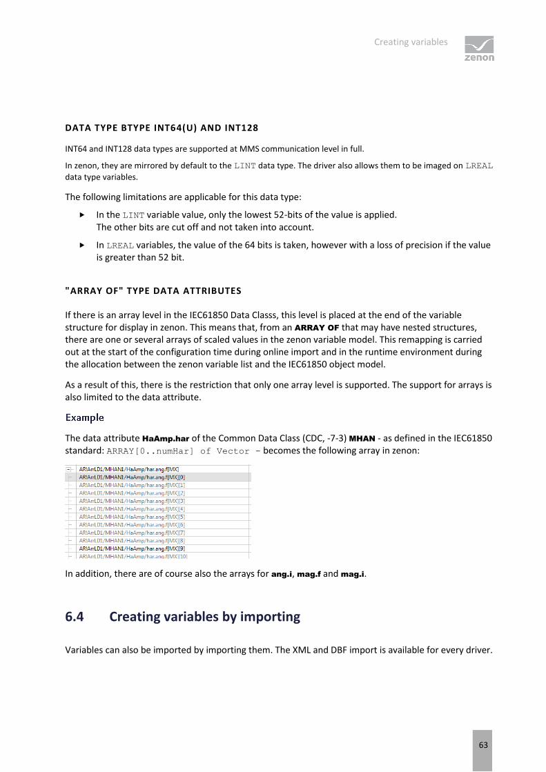
Creating variables
63
DATA TYPE BTYPE INT64(U) AND INT128
INT64 and INT128 data types are supported at MMS communication level in full.
In zenon, they are mirrored by default to the LINT data type. The driver also allows them to be imaged on LREAL
data type variables.
The following limitations are applicable for this data type:
In the LINT variable value, only the lowest 52-bits of the value is applied. The other bits are cut off and not taken into account.
In LREAL variables, the value of the 64 bits is taken, however with a loss of precision if the value is greater than 52 bit.
"ARRAY OF" TYPE DATA ATTRIBUTES
If there is an array level in the IEC61850 Data Classs, this level is placed at the end of the variable structure for display in zenon. This means that, from an ARRAY OF that may have nested structures, there are one or several arrays of scaled values in the zenon variable model. This remapping is carried out at the start of the configuration time during online import and in the runtime environment during the allocation between the zenon variable list and the IEC61850 object model.
As a result of this, there is the restriction that only one array level is supported. The support for arrays is also limited to the data attribute.
The data attribute HaAmp.har of the Common Data Class (CDC, -7-3) MHAN - as defined in the IEC61850 standard: ARRAY[0..numHar] of Vector - becomes the following array in zenon:
In addition, there are of course also the arrays for ang.i, mag.f and mag.i.
6.4 Creating variables by importing
Variables can also be imported by importing them. The XML and DBF import is available for every driver.
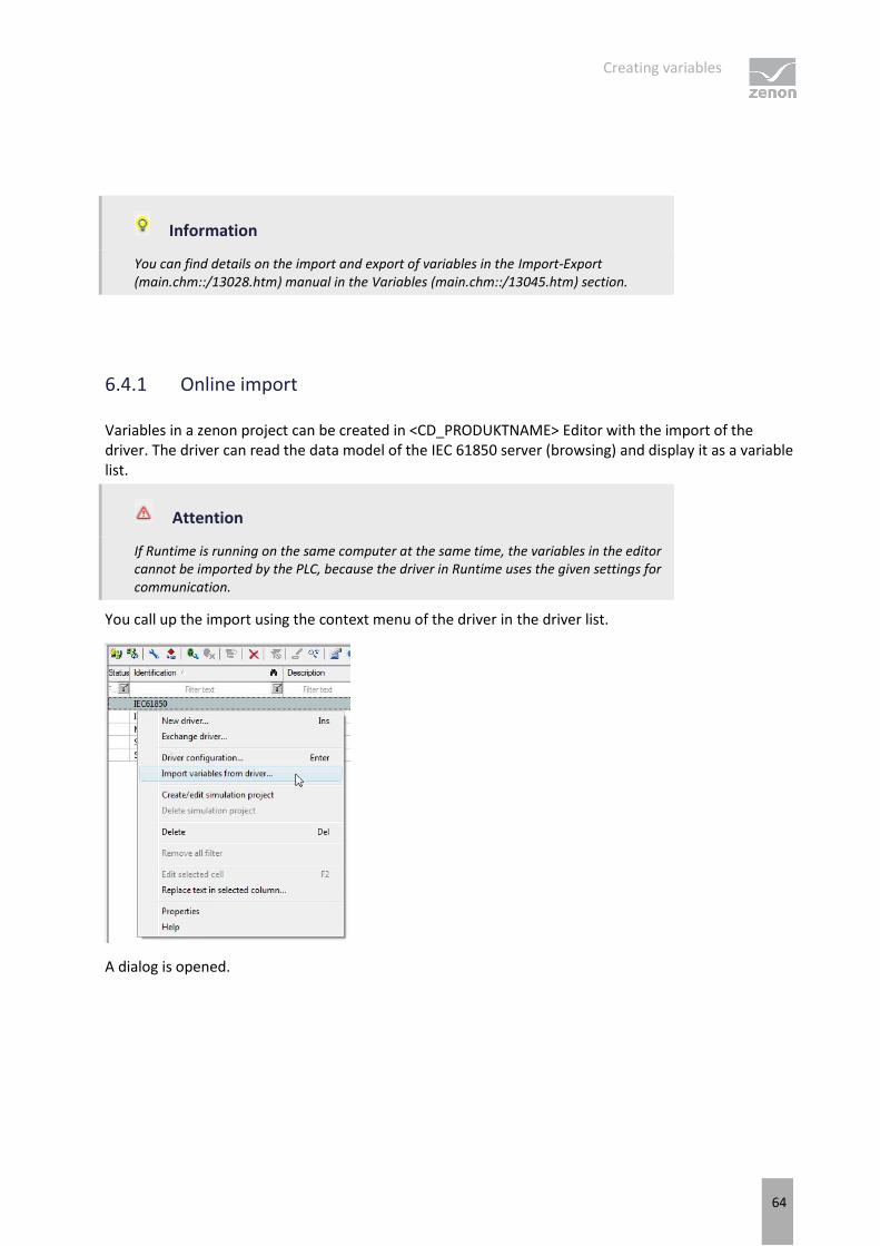
Creating variables
64
Information
You can find details on the import and export of variables in the Import-Export (main.chm::/13028.htm) manual in the Variables (main.chm::/13045.htm) section.
6.4.1 Online import
Variables in a zenon project can be created in <CD_PRODUKTNAME> Editor with the import of the driver. The driver can read the data model of the IEC 61850 server (browsing) and display it as a variable list.
Attention
If Runtime is running on the same computer at the same time, the variables in the editor cannot be imported by the PLC, because the driver in Runtime uses the given settings for communication.
You call up the import using the context menu of the driver in the driver list.
A dialog is opened.

Creating variables
65
SELECT A SERVER
Parameter Description
Server List of the connections to IEC61850 servers created in the driver.
You can read further information about the configuration of server connections in the Connections (on page 24) chapter.
Source Source of the data model:
PLC Browsing Variables are imported from an IEC61850 server that is available online.
File Browsing Variables are imported from an SCL file. You can read further information about the SCL file in the IEC61850-6 standard.
OK Applies settings and closes the dialog.
Cancel Discards all changes and closes the dialog.
PROCEDURE FOR PLC BROWSING
In the dialog that opens, select the PLC Browsing option and select a server from which the variables can be imported.
The connection to the server is established and the list of existing data points (LDs, LNs, data objects, data attributes) is read.
If the reading in has ended, an important dialog opens in which you can filter the browsed variables (capitalization, for example *XCBR1*stVal*), select them (including multiple selection) and add them from the upper to lower list.
You create the selected variables in the project using the OK button.
Attention
The driver creates variables with default value ranges, for example a UDINT with <0... 4294967295> and a LREAL with <-1000..1000>, which may not correspond to the value ranges of the attributes, for example stVal-attribute UDINT <0..3> or t-attribute LREAL<0.. 2147483647> with three decimal places for milliseconds. Therefore ensure after import after that all variables have the correct value range properties and the string is the right length.

Creating variables
66
IMPORT OF ADDRESSES WITH MORE THAN 128 CHARACTERS
When reading (browsing) the data model, the driver generates the addresses of the variables. This is displayed in the 'Symbolic address' column. The generated address is Server!ObjectReference[FC].
If this address is longer than the 128 characters permitted for the variable name, it is shortened to 124 characters and supplemented with _###. ### stands for a serial number. This number counts up from 001 to 999.
If new variables are created, whose generated name was longer than 128 characters, this shortened number supplemented with figures is used as variable Name and Identification. The unshortened address is used as Symbolic address.
Attention
In Runtime, more than 128 characters is only supported if, in the driver configuration, in the Basic settings (on page 18) dialog, Symbolic address is selected for the addressing.
RECOMMENDATION
Rename the variables after the import. Otherwise naming conflicts could occur after another import.
"ARRAY OF" IMPORT
As a result of the limitation of only one array level being supported (on page 59), the support of arrays is also limited to the data attributes.
These ARRAY OF variables are created as zenon arrays when imported.
Example
The data attribute HaAmp.har of the Common Data Class MHAN - as defined in the IEC61850 standard: ARRAY[0..numHar] of Vector - becomes up to four arrays in zenon, with the same respective number of elements:
*/HaAmp.har.ang.f[MX][0..count-1]
*/HaAmp.har.ang.i[MX][0..count-1]
*/HaAmp.har.mag.f[MX][0..count-1]
*/HaAmp.har.mag.i[MX][0..count-1]
SERVICE TRACKING IMPORT
Service tracking (Main.chm::/IEC850.chm::/117281.htm) is only offered if one or more elements with FC = SR are present on the Logical Device. For example, one or more Logical Nodes LTRK. For import,
Creating variables
67
only Service tracking is automatically offered for Control Services. Control Services means: only Service tracking command execution information.
If there is Service tracking on the server, a proposal for the creation of additional service tracking variables is created for each data object that contains the data attributes with FC = CO.
Example
S1!Device/Node/Pos/Oper.ctlVal[CO]
These additional variables no longer exist on the server but are additionally created in the respective data object with a possible command execution.
The variables that are actually created as additional service tracking variables are selected from this list of proposals. The mane of this proposal comprises the following: Datenobjektreferenz_Servicetracking-Datenattributname[SR]. As a service tracking data attribute name, the data attributes that are present in the Logical Node LRTK for Control Services are proposed.
Example
S1!Device/Node/Pos_errorCode[SR].
The data type of the additional service tracking variable corresponds to the data type of the SR data attribute that is present in the Logical Node LRTK. The driver object type is Service tracking.
In addition, a string variable *_allCTS[SR] is also offered. This string variable contains the complete Service tracking (Main.chm::/IEC850.chm::/117281.htm) Information and can be evaluated with the help of zenon Logic or VBA/VSTA.
GETNAMELIST ON DO
The GetNameList on DO option from versions before 8.00 is ignored in the IEC850 driver. From zenon version
8.00, the driver always sends getVariableAccessAttributes to the server for each node. If the driver receives a negative response from the server, another query at a lower level is sent to the server for the corresponding Node. If this renewed query also fails, there is refinement at DataObject level.
A corresponding LOG entry is generated in the event of an error. Failed to retrieve variable information for <Failed Request Name>
The following is applicable for the online import of variables:
The online reading of the variables only takes into account the highest level from a DataObject. If this depth is not sufficient, import the variables from an SCL file.
Refinement takes place down to DataAttribute level in Runtime.

Creating variables
68
If the DataAttribute cannot be read, the Runtime without values and receives the status Invalid.
The following is applicable for the online import of variables in zenon Editor:
The node must be read in full in order for the variables contained in the node to be offered in the selection dialog.
If the zenon project is compiled for a version before version 8.00, a corresponding entry in the configuration file continues to be taken into account.
6.4.2 Offline import
Variables for a project can be created with the import of the driver in a zenon project. The driver can read the data model from an SCL file and display it as a variable list.
: For simplified import of the variables from the Datasets in RCBs, the IEC850 Driver Configuration wizard provides additional possibilities. The wizard is only available in the Energy Edition.
The following file endings are accepted for offline import:
*.scl
*.scd
*.cid
*.icd
*.xml, if the content of the file has been defined in accordance with the rules of the IED61850-6 standard.
The driver only imports DOI elements offline. The Control Blocks, for example ReportControl (Report Control Block) and SettingControl (Setting Control Block) are not supported for offline import. You can create the variables for these attributes by means of online import or manually.
Attention
The driver can then only import from the data model of the IED if the data model is compliant with the IEC61850 standard. All non-compliant elements are then ignored and cannot be selected in the import dialog. For example, the driver ignores the Logical Nodes that are linked directly to the IED nodes, instead of to the Logical Device nodes.
To import variables from a file:
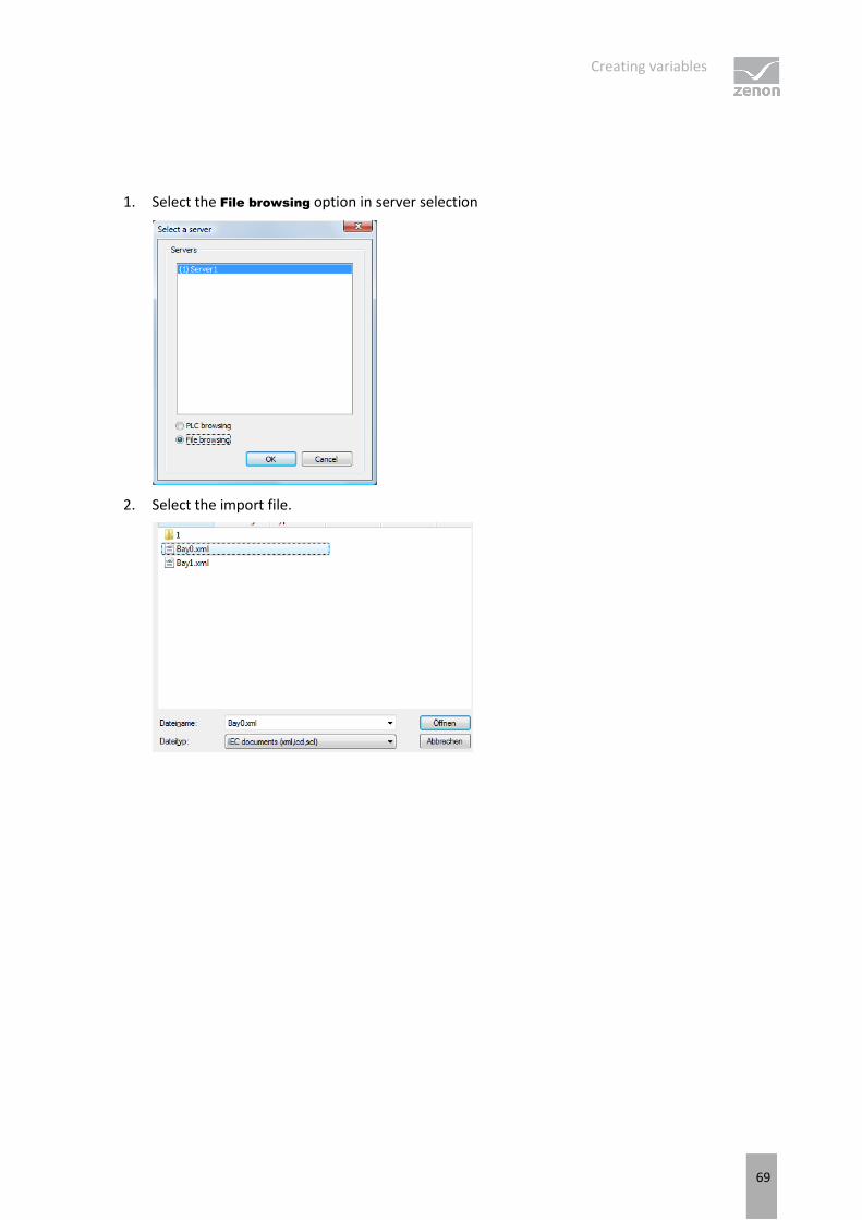
Creating variables
69
1. Select the File browsing option in server selection
2. Select the import file.

Creating variables
70
3. The following steps for the selection of variables are similar to online import.
IMPORT OF ADDRESSES WITH MORE THAN 128 CHARACTERS
When reading (browsing) the data model, the driver generates the addresses of the variables. This is displayed in the 'Symbolic address' column. The generated address is Server!ObjectReference[FC].
If this address is longer than the 128 characters permitted for the variable name, it is shortened to 124 characters and supplemented with _###. ### stands for a serial number. This number counts up from 001 to 999.
If new variables are created, whose generated name was longer than 128 characters, this shortened number supplemented with figures is used as variable Name and Identification. The unshortened address is used as Symbolic address.
Attention
In Runtime, more than 128 characters is only supported if, in the driver configuration, in the Basic settings (on page 18) dialog, Symbolic address is selected for the addressing.
RECOMMENDATION
RENAME THE VARIABLES AFTER THE IMPORT. OTHERWISE NAMING CONFLICTS COULD OCCUR AFTER ANOTHER IMPORT.SERVICE TRACKING IMPORT
Service tracking is only offered if one or more elements with FC = SR are present on the Logical Device. For example, one or more Logical Nodes LTRK. For import, only Service tracking is automatically offered for Control Services. Control Services means: only Service tracking command execution information.
Creating variables
71
If there is Service tracking in the SCL file, a proposal for the creation of additional service tracking variables is created for each data object that contains the data attributes with FC = CO.
Example
S1!Device/Node/Pos/Oper.ctlVal[CO]
These additional variables no longer exist on the server but are additionally created in the respective data object with a possible command execution.
The variables that are actually created as additional service tracking variables are selected from this list of proposals. The mane of this proposal comprises the following: Datenobjektreferenz_Servicetracking-Datenattributname[SR]. As a service tracking data attribute name, the data attributes that are present in the Logical Node LRTK for Control Services are proposed.
Example
S1!Device/Node/Pos_errorCode[SR]
The data type of an additional service tracking variable corresponds to the data type of the SR data attribute, that is in the Logical Node LRTK. The driver object type is Service tracking.
In addition, a string variable *_allCTS[SR] is also offered. This string variable contains the complete service tracking Information and can be evaluated with the help of zenon Logic or VBA/VSTA.
6.4.3 XML import
During XML import of variables or data types, these are first assigned to a driver and then analyzed. Before import, the user decides whether and how the respective element (variable or data type) is to be imported:
Import: The element is imported as a new element.
Overwrite: The element is imported and overwrites a pre-existing element.
Do not import: The element is not imported.
The actions and their durations are shown in a progress bar during import.
REQUIREMENTS
The following conditions are applicable during import:

Creating variables
72
Backward compatibility
At the XML import/export there is no backward compatibility. Data from older zenon versions cannot be taken over. The handover of data from newer to older versions is not supported.
Consistency
The XML file to be imported has to be consistent. There is no plausibility check on importing the file. If there are errors in the import file, this can lead to undesirable effects in the project.
Particular attention must be paid to this, primarily if not all properties exist in the XML file and these are then filled with default values. E.g.: A binary variable has a limit value of 300.
Structure data types
Structure data types must have the same number of structure elements. Example: A structure data type in the project has 3 structure elements. A data type with the same name in the XML file has 4 structure elements. Then none of the variables based on this data type in the file are imported into the project.
Hint
You can find further information on XML import in the Import - Export manual, in the XML import (main.chm::/13046.htm) chapter.
6.4.4 DBF Import/Export
Data can be exported to and imported from dBase.
Information
Import and Export via CSV or dBase supported; no driver specific variable settings, such as formulas. Use export/import via XML for this.
IMPORT DBF FILE
To start the import:
1. right-click on the variable list
2. in the drop-down list of Extended export/import... select the Import dBase command
3. follow the import assistant
Creating variables
73
The format of the file is described in the chapter File structure.
Information
Note:
Driver object type and data type must be amended to the target driver in the DBF file in order for variables to be imported.
dBase does not support structures or arrays (complex variables) at import.
EXPORT DBF FILE
To start the export:
1. right-click on the variable list
2. in the drop-down list of Extended export/import... select the Export dBase... command
3. follow the export assistant
Attention
DBF files:
must correspond to the 8.3 DOS format for filenames (8 alphanumeric characters for name, 3 character suffix, no spaces)
must not have dots (.) in the path name. e.g. the path C:\users\John.Smith\test.dbf is invalid.
Valid: C:\users\JohnSmith\test.dbf
must be stored close to the root directory in order to fulfill the limit for file name length including path: maximum 255 characters
The format of the file is described in the chapter File structure.
Information
dBase does not support structures or arrays (complex variables) at export.
FILE STRUCTURE OF THE DBASE EXPORT FILE
The dBaseIV file must have the following structure and contents for variable import and export:

Creating variables
74
Attention
dBase does not support structures or arrays (complex variables) at export.
DBF files must:
conform with their name to the 8.3 DOS format (8 alphanumeric characters for name, 3 characters for extension, no space)
Be stored close to the root directory (Root)
STRUCTURE
Identification Type
Field size Comment
KANALNAME Char 128 Variable name.
The length can be limited using the MAX_LAENGE entry in the project.ini file.
KANAL_R C 128 The original name of a variable that is to be replaced by the new name entered under "VARIABLENNAME” (variable name) (field/column must be entered manually).
The length can be limited using the MAX_LAENGE entry in the project.ini file.
KANAL_D Log 1 The variable is deleted with the 1 entry (field/column has to be created by hand).
TAGNR C 128 Identification.
The length can be limited using the MAX_LAENGE entry in the project.ini file.
EINHEIT C 11 Technical unit
DATENART C 3 Data type (e.g. bit, byte, word, ...) corresponds to the data type.
KANALTYP C 3 Memory area in the PLC (e.g. marker area, data area, ...) corresponds to the driver object type.
HWKANAL Num 3 Net address
BAUSTEIN N 3 Datablock address (only for variables from the data area of the PLC)
ADRESSE N 5 Offset
BITADR N 2 For bit variables: bit address For byte variables: 0=lower, 8=higher byte For string variables: Length of string (max. 63 characters)
ARRAYSIZE N 16 Number of variables in the array for index variables ATTENTION: Only the first variable is fully available. All others are only available for VBA or the Recipegroup Manager

Creating variables
75
LES_SCHR L 1 Write-Read-Authorization 0: Not allowed to set value. 1: Allowed to set value.
MIT_ZEIT R 1 time stamp in zenon (only if supported by the driver)
OBJEKT N 2 Driver-specific ID number of the primitive object comprises TREIBER-OBJEKTTYP and DATENTYP
SIGMIN Float 16 Non-linearized signal - minimum (signal resolution)
SIGMAX F 16 Non-linearized signal - maximum (signal resolution)
ANZMIN F 16 Technical value - minimum (measuring range)
ANZMAX F 16 Technical value - maximum (measuring range)
ANZKOMMA N 1 Number of decimal places for the display of the values (measuring range)
UPDATERATE F 19 Update rate for mathematics variables (in sec, one decimal possible) not used for all other variables
MEMTIEFE N 7 Only for compatibility reasons
HDRATE F 19 HD update rate for historical values (in sec, one decimal possible)
HDTIEFE N 7 HD entry depth for historical values (number)
NACHSORT R 1 HD data as postsorted values
DRRATE F 19 Updating to the output (for zenon DDE server, in [s], one decimal possible)
HYST_PLUS F 16 Positive hysteresis, from measuring range
HYST_MINUS F 16 Negative hysteresis, from measuring range
PRIOR N 16 Priority of the variable
REAMATRIZE C 32 Allocated reaction matrix
ERSATZWERT F 16 Substitute value, from measuring range
SOLLMIN F 16 Minimum for set value actions, from measuring range
SOLLMAX F 16 Maximum for set value actions, from measuring range
VOMSTANDBY R 1 Get value from standby server; the value of the variable is not requested from the server but from the Standby Server in redundant networks
RESOURCE C 128 Resources label. Free string for export and display in lists.
The length can be limited using the MAX_LAENGE entry in project.ini.
ADJWVBA R 1 Non-linear value adaption: 0: Non-linear value adaption is used
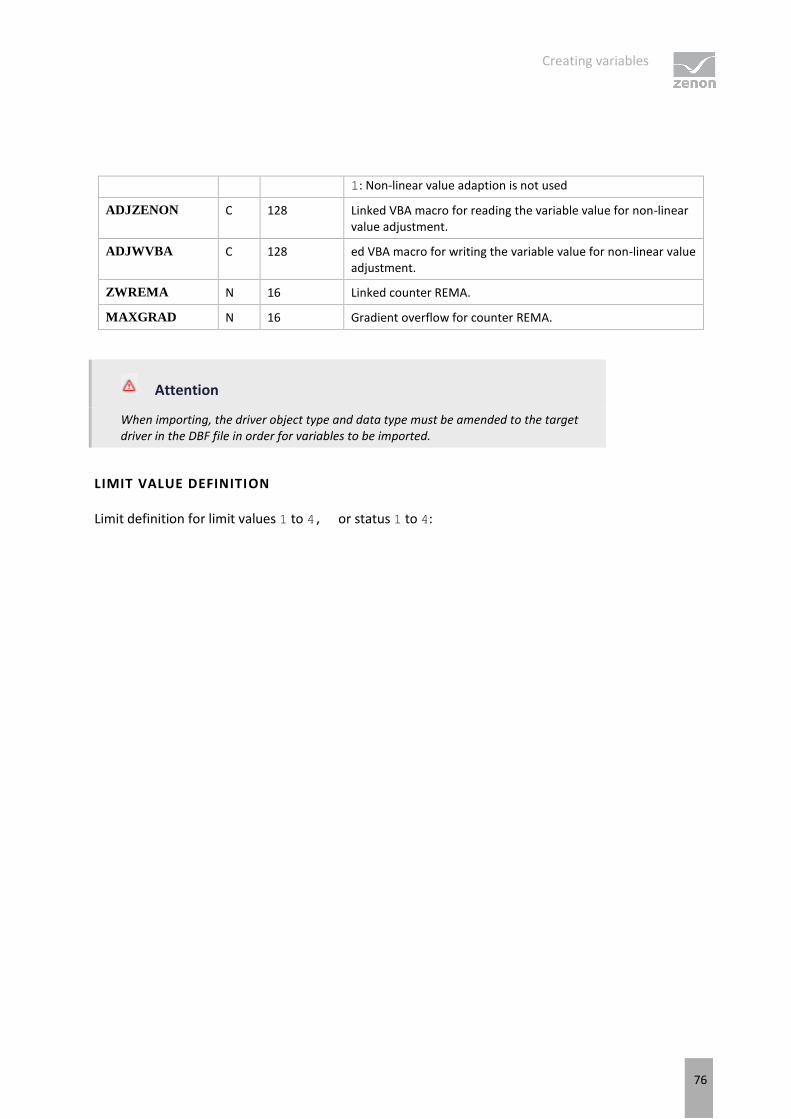
Creating variables
76
1: Non-linear value adaption is not used
ADJZENON C 128 Linked VBA macro for reading the variable value for non-linear value adjustment.
ADJWVBA C 128 ed VBA macro for writing the variable value for non-linear value adjustment.
ZWREMA N 16 Linked counter REMA.
MAXGRAD N 16 Gradient overflow for counter REMA.
Attention
When importing, the driver object type and data type must be amended to the target driver in the DBF file in order for variables to be imported.
LIMIT VALUE DEFINITION
Limit definition for limit values 1 to 4, or status 1 to 4:
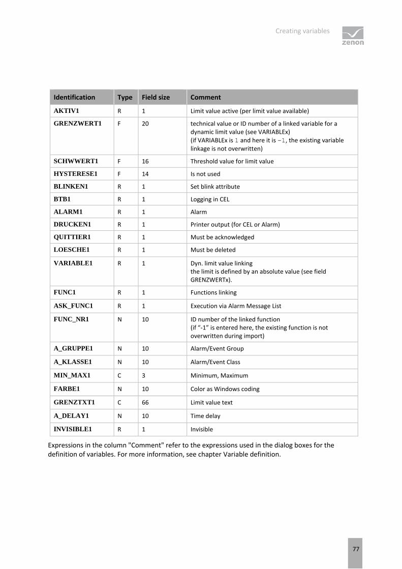
Creating variables
77
Identification Type Field size Comment
AKTIV1 R 1 Limit value active (per limit value available)
GRENZWERT1 F 20 technical value or ID number of a linked variable for a dynamic limit value (see VARIABLEx) (if VARIABLEx is 1 and here it is -1, the existing variable linkage is not overwritten)
SCHWWERT1 F 16 Threshold value for limit value
HYSTERESE1 F 14 Is not used
BLINKEN1 R 1 Set blink attribute
BTB1 R 1 Logging in CEL
ALARM1 R 1 Alarm
DRUCKEN1 R 1 Printer output (for CEL or Alarm)
QUITTIER1 R 1 Must be acknowledged
LOESCHE1 R 1 Must be deleted
VARIABLE1 R 1 Dyn. limit value linking the limit is defined by an absolute value (see field GRENZWERTx).
FUNC1 R 1 Functions linking
ASK_FUNC1 R 1 Execution via Alarm Message List
FUNC_NR1 N 10 ID number of the linked function (if “-1” is entered here, the existing function is not overwritten during import)
A_GRUPPE1 N 10 Alarm/Event Group
A_KLASSE1 N 10 Alarm/Event Class
MIN_MAX1 C 3 Minimum, Maximum
FARBE1 N 10 Color as Windows coding
GRENZTXT1 C 66 Limit value text
A_DELAY1 N 10 Time delay
INVISIBLE1 R 1 Invisible
Expressions in the column "Comment" refer to the expressions used in the dialog boxes for the definition of variables. For more information, see chapter Variable definition.

Creating variables
78
6.5 Communication details (Driver variables)
The driver kit implements a number of driver variables. This variables are part of the driver object type Communication details. These are divided into:
Information
Configuration
Statistics and
Error message
The definitions of the variables implemented in the driver kit are available in the import file drvvar.dbf
(on the installation medium in the \Predefined\Variables folder) and can be imported from there.
Variable names must be unique in zenon. If driver variables of the driver object type Communication details are to be imported from drvvar.dbf again, the variables that were imported beforehand must be renamed.
Information
Not every driver supports all driver variables of the driver object type Communication
details.
For example:
Variables for modem information are only supported by modem-compatible drivers
Driver variables for the polling cycle only for pure polling drivers
Connection-related information such as ErrorMSG only for drivers that only edit one connection at a a time
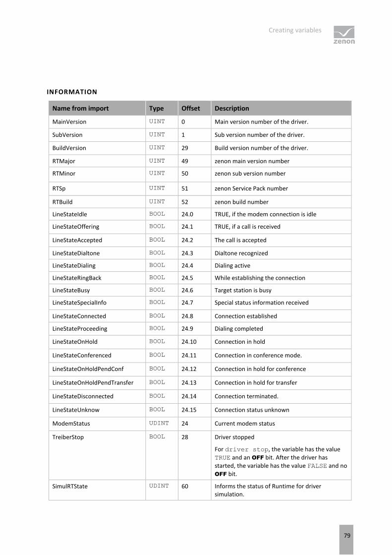
Creating variables
79
INFORMATION
Name from import Type Offset Description
MainVersion UINT 0 Main version number of the driver.
SubVersion UINT 1 Sub version number of the driver.
BuildVersion UINT 29 Build version number of the driver.
RTMajor UINT 49 zenon main version number
RTMinor UINT 50 zenon sub version number
RTSp UINT 51 zenon Service Pack number
RTBuild UINT 52 zenon build number
LineStateIdle BOOL 24.0 TRUE, if the modem connection is idle
LineStateOffering BOOL 24.1 TRUE, if a call is received
LineStateAccepted BOOL 24.2 The call is accepted
LineStateDialtone BOOL 24.3 Dialtone recognized
LineStateDialing BOOL 24.4 Dialing active
LineStateRingBack BOOL 24.5 While establishing the connection
LineStateBusy BOOL 24.6 Target station is busy
LineStateSpecialInfo BOOL 24.7 Special status information received
LineStateConnected BOOL 24.8 Connection established
LineStateProceeding BOOL 24.9 Dialing completed
LineStateOnHold BOOL 24.10 Connection in hold
LineStateConferenced BOOL 24.11 Connection in conference mode.
LineStateOnHoldPendConf BOOL 24.12 Connection in hold for conference
LineStateOnHoldPendTransfer BOOL 24.13 Connection in hold for transfer
LineStateDisconnected BOOL 24.14 Connection terminated.
LineStateUnknow BOOL 24.15 Connection status unknown
ModemStatus UDINT 24 Current modem status
TreiberStop BOOL 28 Driver stopped
For driver stop, the variable has the value
TRUE and an OFF bit. After the driver has
started, the variable has the value FALSE and no
OFF bit.
SimulRTState UDINT 60 Informs the status of Runtime for driver simulation.

Creating variables
80
ConnectionStates STRING 61 Internal connection status of the driver to the PLC.
Connection statuses:
0: Connection OK
1: Connection failure
2: Connection simulated
Formating:
<Netzadresse>:<Verbindungszustand
>;…;…;
A connection is only known after a variable has first signed in. In order for a connection to be contained in a string, a variable of this connection must be signed in once.
The status of a connection is only updated if a variable of the connection is signed in. Otherwise there is no communication with the corresponding controller.
CONFIGURATION
Name from import Type Offset Description
ReconnectInRead BOOL 27 If TRUE, the modem is automatically reconnected for reading
ApplyCom BOOL 36 Apply changes in the settings of the serial interface. Writing to this variable immediately results in the method SrvDrvVarApplyCom being called (which currently has no further function).
ApplyModem BOOL 37 Apply changes in the settings of the modem. Writing this variable immediately calls the method SrvDrvVarApplyModem. This closes the current connection and opens a new one according to the settings PhoneNumberSet and ModemHwAdrSet.
PhoneNumberSet STRING 38 Telephone number, that should be used
ModemHwAdrSet DINT 39 Hardware address for the telephone number
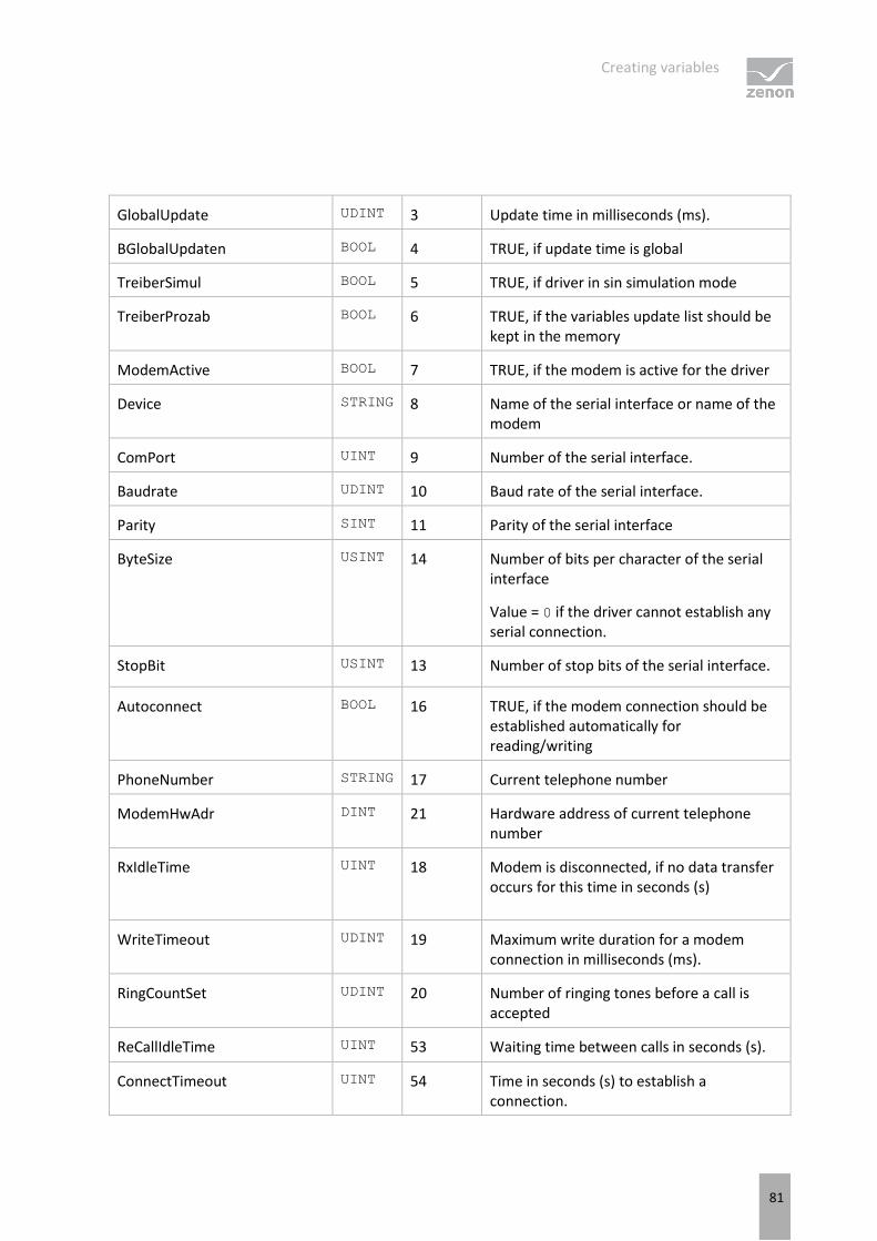
Creating variables
81
GlobalUpdate UDINT 3 Update time in milliseconds (ms).
BGlobalUpdaten BOOL 4 TRUE, if update time is global
TreiberSimul BOOL 5 TRUE, if driver in sin simulation mode
TreiberProzab BOOL 6 TRUE, if the variables update list should be kept in the memory
ModemActive BOOL 7 TRUE, if the modem is active for the driver
Device STRING 8 Name of the serial interface or name of the modem
ComPort UINT 9 Number of the serial interface.
Baudrate UDINT 10 Baud rate of the serial interface.
Parity SINT 11 Parity of the serial interface
ByteSize USINT 14 Number of bits per character of the serial interface
Value = 0 if the driver cannot establish any serial connection.
StopBit USINT 13 Number of stop bits of the serial interface.
Autoconnect BOOL 16 TRUE, if the modem connection should be established automatically for reading/writing
PhoneNumber STRING 17 Current telephone number
ModemHwAdr DINT 21 Hardware address of current telephone number
RxIdleTime UINT 18 Modem is disconnected, if no data transfer occurs for this time in seconds (s)
WriteTimeout UDINT 19 Maximum write duration for a modem connection in milliseconds (ms).
RingCountSet UDINT 20 Number of ringing tones before a call is accepted
ReCallIdleTime UINT 53 Waiting time between calls in seconds (s).
ConnectTimeout UINT 54 Time in seconds (s) to establish a connection.

Creating variables
82
STATISTICS
Name from import Type Offset Description
MaxWriteTime UDINT 31 The longest time in milliseconds (ms) that is required for writing.
MinWriteTime UDINT 32 The shortest time in milliseconds (ms) that is required for writing.
MaxBlkReadTime UDINT 40 Longest time in milliseconds (ms) that is required to read a data block.
MinBlkReadTime UDINT 41 Shortest time in milliseconds (ms) that is required to read a data block.
WriteErrorCount UDINT 33 Number of writing errors
ReadSucceedCount UDINT 35 Number of successful reading attempts
MaxCycleTime UDINT 22 Longest time in milliseconds (ms) required to read all requested data.
MinCycleTime UDINT 23 Shortest time in milliseconds (ms) required to read all requested data.
WriteCount UDINT 26 Number of writing attempts
ReadErrorCount UDINT 34 Number of reading errors
MaxUpdateTimeNormal UDINT 56 Time since the last update of the priority group Normal in milliseconds (ms).
MaxUpdateTimeHigher UDINT 57 Time since the last update of the priority group Higher in milliseconds (ms).
MaxUpdateTimeHigh UDINT 58 Time since the last update of the priority group High in milliseconds (ms).
MaxUpdateTimeHighest UDINT 59 Time since the last update of the priority group Highest in milliseconds (ms).
PokeFinish BOOL 55 Goes to 1 for a query, if all current pokes were
executed
ERROR MESSAGE
Name from import Type Offset Description

Driver command function
83
ErrorTimeDW UDINT 2 Time (in seconds since 1.1.1970), when the last error occurred.
ErrorTimeS STRING 2 Time (in seconds since 1.1.1970), when the last error occurred.
RdErrPrimObj UDINT 42 Number of the PrimObject, when the last reading error occurred.
RdErrStationsName STRING 43 Name of the station, when the last reading error occurred.
RdErrBlockCount UINT 44 Number of blocks to read when the last reading error occurred.
RdErrHwAdresse DINT 45 Hardware address when the last reading error occurred.
RdErrDatablockNo UDINT 46 Block number when the last reading error occurred.
RdErrMarkerNo UDINT 47 Marker number when the last reading error occurred.
RdErrSize UDINT 48 Block size when the last reading error occurred.
DrvError USINT 25 Error message as number
DrvErrorMsg STRING 30 Error message as text
ErrorFile STRING 15 Name of error log file
7. Driver command function
The zenon Driver commands function is to influence drivers using zenon. You can do the following with a driver command:
Start
Stop
Shift a certain driver mode
Instigate certain actions
The zenon Driver commands function is not identical to driver commands that can be executed in Runtime with Energy drivers!
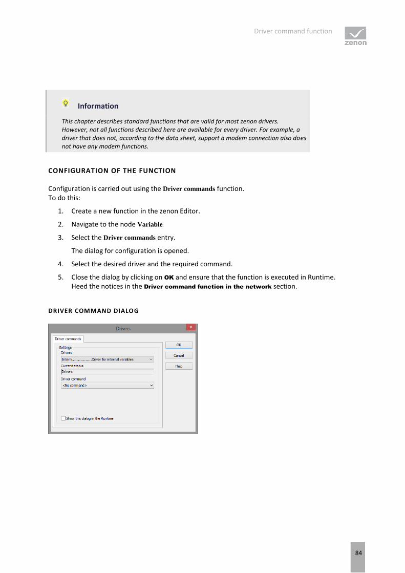
Driver command function
84
Information
This chapter describes standard functions that are valid for most zenon drivers. However, not all functions described here are available for every driver. For example, a driver that does not, according to the data sheet, support a modem connection also does not have any modem functions.
CONFIGURATION OF THE FUNCTION
Configuration is carried out using the Driver commands function. To do this:
1. Create a new function in the zenon Editor.
2. Navigate to the node Variable.
3. Select the Driver commands entry.
The dialog for configuration is opened.
4. Select the desired driver and the required command.
5. Close the dialog by clicking on OK and ensure that the function is executed in Runtime. Heed the notices in the Driver command function in the network section.
DRIVER COMMAND DIALOG
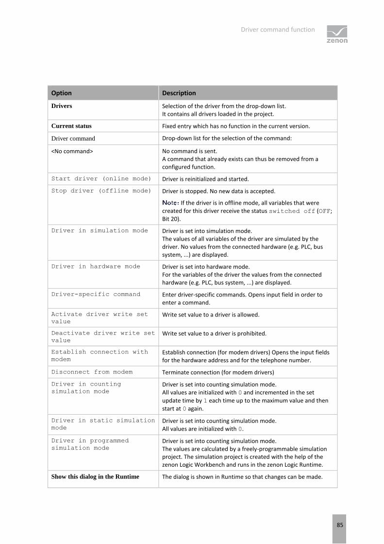
Driver command function
85
Option Description
Drivers Selection of the driver from the drop-down list. It contains all drivers loaded in the project.
Current status Fixed entry which has no function in the current version.
Driver command Drop-down list for the selection of the command:
<No command> No command is sent. A command that already exists can thus be removed from a configured function.
Start driver (online mode) Driver is reinitialized and started.
Stop driver (offline mode) Driver is stopped. No new data is accepted.
If the driver is in offline mode, all variables that were created for this driver receive the status switched off (OFF;
Bit 20).
Driver in simulation mode Driver is set into simulation mode. The values of all variables of the driver are simulated by the driver. No values from the connected hardware (e.g. PLC, bus system, ...) are displayed.
Driver in hardware mode Driver is set into hardware mode. For the variables of the driver the values from the connected hardware (e.g. PLC, bus system, ...) are displayed.
Driver-specific command Enter driver-specific commands. Opens input field in order to enter a command.
Activate driver write set
value Write set value to a driver is allowed.
Deactivate driver write set
value Write set value to a driver is prohibited.
Establish connection with
modem Establish connection (for modem drivers) Opens the input fields for the hardware address and for the telephone number.
Disconnect from modem Terminate connection (for modem drivers)
Driver in counting
simulation mode Driver is set into counting simulation mode. All values are initialized with 0 and incremented in the set
update time by 1 each time up to the maximum value and then
start at 0 again.
Driver in static simulation
mode Driver is set into counting simulation mode. All values are initialized with 0.
Driver in programmed
simulation mode Driver is set into counting simulation mode. The values are calculated by a freely-programmable simulation project. The simulation project is created with the help of the zenon Logic Workbench and runs in the zenon Logic Runtime.
Show this dialog in the Runtime The dialog is shown in Runtime so that changes can be made.
IEC850 client functions
86
DRIVER COMMAND FUNCTION IN THE NETWORK
If the computer on which the Driver commands function is executed is part of the zenon network, further actions are also carried out. A special network command is sent from the computer to the project server, which then executes the desired action on its driver. In addition, the Server sends the same driver command to the project standby. The standby also carries out the action on its driver.
This makes sure that Server and Standby are synchronized. This only works if the Server and the Standby both have a working and independent connection to the hardware.
7.1 SwitchConnection
The driver-specific command SwitchConnection switches between a primary and secondary IP address.
Procedure:
1. The active IP address is closed for the Net address entered with the command.
2. In doing so, the INVALID bit is not set for the variables.
3. The connection is then established via the other IP address.
4. If the connection is not successfully established, the INVALID bit is set and a switch back to the active connection is made.
The driver command is taken into account if the connection to an IP address has been established successfully. The command is ignored if there is no connection or a connection is currently being established.
Syntax:
SwitchConnection <NetAddr> <NetAddr> Stands for the number of the Net address.
Example:
SwitchConnection 1 Switches between primary and secondary address for the connection to net address 1.
8. IEC850 client functions
Special specifications of the IEC 61850 standard were implemented as specific functions in the IEC 850 client driver.
You can find detailed information in the respective chapters:
IEC850 client functions
87
Verbindungaufbau und Verbindungsausfallerkennung (on page 88)
Commands (Control Model) (on page 91)
commands - overview
Select und Cancel (on page 93)
Additional Cause Diagnosis (on page 94)
Service parameters of the command (on page 96)
Service Tracking (Main.chm::/IEC850.chm::/117281.htm)
Mapping of double point values (on page 102)
Quality bits, time stamp and status bits of the variable (on page 104)
TimeQuality and TimeAccuracy (on page 107)
Filetransfer (on page 108)
There are three functions implemented for the file transfer:
Request folder information
Get file from server
Delete file
LIMITATIONS
Data type: ARRAY OF Only one array level is supported. The support for arrays is limited to the data attributes. It is not possible to write array elements. When reading by means of polling or reporting, as with other data attributes too, the complete Data Object (FCD reference), which contains the array attribute, is always read.
Data typeINT64(U): In the (U)LINT variable value, only the lowest 52-bit is applied. The other bits are cut off and not taken into account.
Alternatively, the variable can be configured with the LREAL data type. As a result, it is possible to transfer the total value. In doing so, note that for values that are greater than 52 bit, the precision of the lowest points is lost.
For reports with Service Tracking, only datasets with references are supported.
Conformance statement (PICS, MICS): You can find the information on supported or required services and data types in Appendix C (on page 145).
IEC850 client functions
88
8.1 Establishment of a connection and detection of a connection failure
When starting zenon Runtime, the driver also starts, and starts establishing the connections to IEDs. The driver only opens a connection to a Logical Device if at least one variable from the LD is created in the project. For performance reasons, the driver also ignores the Logical Nodes for which no variables have been created in the project. LLN0 - the content of LLN0 (its RCBs) is always read.
On Windows operating systems, the information can only be provided via the operating system's TCP timeout (20-30s) when sending (not when receiving). The driver therefore cannot detect an interruption in the connection if all variables are received by means of Reports . After a communication breakdown (due to a network failure, for example), the connection to the Logical Device is then only reestablished automatically if at least one variable of the LD is being polled.
To detect a connection failure, activate the Automatic Watchdog property in the driver configuration.
If Automatic Watchdoghas been activated: the driver automatically starts to poll the */LLN0/Mod/stVal[ST] data attribute as soon as all other data of the Logical Device only comes via reports, i.e. whilst all polled variables are not signed in. The drivers polls the data attribute regardless of whether it would be present in one of the RCBs. The MMS.Read queries that are sent cyclically, in the cycle of the Polling rate driver setting force the operating system to check the TCP connection again and to report to the driver if the connection has been disconnected.
TCP KEEP_ALIVE
The driver opens the TCP socket in Windows with the following keep-alive parameters:
The timeout for keep_alive is 20 seconds.
The interval for keep_alive is 1 second.
Retries are defined and fixed by the operating system at 10 retries.
This means: If the driver does not send a TCP telegram within 20 seconds (no MMS request), the Windows operating system sends a TCP keep_alive message every second. If no response is received for 10 such keep_alive messages, the connection to the 850 server is closed.
CANCEL WITH PENDING MMS REQUESTS
If the IEC850 driver does not receive any responses from the 850 sever for the MMS requests sent, these remain pending until the number of negociatedMaxServOutstandingCalled (from MMS Initiate) has been reached. If, as a result, the driver is blocked for longer than 50 seconds, the connection to the server is automatically disconnected. This prevents an incorrect IED blocking the driver's communication process.

IEC850 client functions
89
This disconnection creates the following error message in the LOG file: Outstanding requests are not answered for more than 50s
CONNECTION STATE VARIABLE
A Connection State variable, if created, provides information on whether the driver has a TCP and then MMS connection to the server and whether the connection consists of primary or secondary IP addresses. Furthermore, you receive information on whether all configured static RCB assignments have been successfully registered.
This variable must be created with the Connection state Driver object type (on page 56). It must contain the correct net address of the connection, the reference with a configured syntax *!ConnectionState and the data type has to be UDINT.
The bits of the variable value mean the following:
For the primary TCP/IP connection to the 850 server:
Bit Meaning Value (hex)
1 TCP_CONNECTED 0x02
2 TCP_CONNECTING 0x04
3 TCP_CONNECT_FAILED 0x08
16 MMS_ASSOCIATED 0x10000
17 MMS_RCB_ENABLE_FAILED
0x20000
For the secondary TCP/IP connection:
Bit Meaning Value (hex)
5 TCP_CONNECTED 0x20
6 TCP_CONNECTING 0x40
7 TCP_CONNECT_FAILED 0x80
24 MMS_ASSOCIATED 0x1000000
25 MMS_RCB_ENABLE_FAILED
0x2000000
The bit MMS_RCB_ENABLE_FAILED is only set if one (or more) RCBs that have been configured in the driver configuration in RCB assignment (on page 41) could not be activated. This happens for example if the IEC850 server does not write to RCB data attributes because another client is already using this report.

IEC850 client functions
90
The Connection State variable does not provide an evaluation of whether it was possible to activate the URCBs via 'max. auto used URCBs (on page 25)'.
Example
The standard process for the value change of the variable is:
The Runtime starts (o. TCP_CONNECT_FAILED) => TCP_CONNECTING => TCP_CONNECTED => TCP_CONNECTED + MMS_ASSOCIATED
Or, in the event of a permanent TCP error:
TCP_CONNECT_FAILED => TCP_CONNECTING => TCP_CONNECT_FAILED
Or, if the connection was established correctly but activation of an RCB failed:
=> TCP_CONNECTED + MMS_ ASSOCIATED + MMS_RCB_ENABLE_FAILED
When starting zenon Runtime, it is possible that the TCP connections to some IEDs get to the drive before Runtime is ready for the evaluation of the Connection State variables; whilst the variables have not yet been registered in Runtime. In this case, only TCP_CONNECTED, or MMS_ASSOCIATED bits are evaluated (and visible in the CEL for example).
REDUNDANT ZENON NETWORK
In a redundant zenon network, both the Primary Server and the Standby Server start their own IEC850 driver. Both drivers must register different RCB instances (otherwise they are in conflict because an 850 server can only issue a client the RCB instance).
If you use redundancy in your zenon project (Network active property and Server 1 and Server 2 have been configured), you must create at least two entries in the driver configuration RCB
assiggment: a Hostname forServer 1 and second Hostname for Server 2 (Standby). You must then select different instances of the RCB for these entries.
Per default the IEC850 driver creates two host names: $SCADA_SERVER1 and $SCADA_SERVER2.
The Connection State variable cannot result in a different evaluation for drivers on the Server 1 network than that on Server 2. For the user, also on the Standby, only the current value of the current Primary Server is visible. If you also want to make the current evaluation for Standby Server visible - in order, for example, to trigger an alarm if the Standby could not register its RCBs, you can create a copy of the Connection State variable - with the same reference (in Symbolic address), a different prefix in the Name and with the Read from Standby Server only property activated.
For Evaluated network, you do not need any of the variables requested by the Standby in the Valuations property. The evaluation takes place separately on both servers, using the local values of the variables. Therefore in the standby, it is always the value of the Connection State variable that is evaluated by its internal image, even if no copy has been created in the project.

IEC850 client functions
91
ESTABLISHMENT OF A CONNECTION TO IED WITH SMALL PDU SIZE
The driver automatically reads the data model in zenon Runtime from an IED during the Association (establishment of the connection). If the IED uses a different frame size to that necessary for the reading of the data model, this is automatically detected and the procedure is amended dynamically. The basis is the variables created in the zenon project. The following is applicable for the creation of the variables in zenon Editor: If the the data model cannot be fully imported online by IED, use the offline import from an SCL file.
8.2 Commands (Control Model)
The driver supports the 'Direct Operate' and 'Select Before Operate' commands (SBO) with normal and increased security. To trigger a command, set a value to the variable with the reference */Oper.ctlVal*. The driver then automatically checks the actual Control Model of the data object and executes a complete command sequence accordingly. For the pending command, the required command sequences are automatically executed by the driver in the correct sequence accordingly.
If the user amends the value of the variable with a reference */CSWI1/Pos/Oper.ctlVal[CO], the driver first carries out a Select and then an Operate or just an Operate. The decision as to whether a Select is required is made by the driver itself. No additional configuration steps are necessary for this.
Attention
Do not create any variables that correspond to the data attributes */SBO, */SBOw* or */Cancel*.
To send a command to the server, only set the value of the */Oper.ctlVal*[CO] variable. The driver will automatically recognize that the command sequence must also contain a Select. A Select is then executed automatically.
DATA ATTRIBUTES WITH FUNCTIONAL CONSTRAINT CO
With Functional Constraint CO, variables are only supported with the following references:
*/Oper.ctlVal[CO], */Oper.ctlVal.i[CO] and */Oper.ctlVal.f[CO] - the triggers of a command
*/Oper.Test[CO] and */Oper.Check[CO] - optional service parameters of the command that has been triggered by writing the set value to ctlVal.
In Runtime, only the values of the CO variables Oper.ctlVal*, Oper.Check and Oper.Test are displayed, other zenon variables with Functional Constraint CO, even if configured, are ignored by the driver. The driver only supports remaining CO data attributes in the Oper, SBOw and Cancel structures for communication with an 850 server, not for the exchange of data with Runtime.
In Runtime, the variables with Functional Constraint CO are only 'write-only'. That means:

IEC850 client functions
92
These only have a value once it has been set in Runtime - by the user.
These variables still do not have a value after starting in Runtime.
They are reset to the value 0 after a connection has been lost and is established again.
WRITE SET VALUE TO OPER.CTLVAL
If a value is set to a project variable that corresponds to the ctlVal item in a structure data attribute with the name 'Oper' and it has the Functional Constraint CO or SP (*/Oper.ctlVal[CO|SP], */Oper.ctlVal.i[CO] or */Oper.ctlVal.f[CO]), the driver automatically checks which Control Model is required for a command in thisData Object (p.e.: Pos if the reference is */Pos/Oper.ctlVal[CO]). To do this, the data attribute */ctlModel[CF] of the data object is read first ( */Pos/ctlModel[CF]). Depending on the value of this data attribute, the respective Control Model is used and the command is executed in the corresponding procedure. Control Model:
Value 0 - status only: No action, execution of the command not possible
Value 1 - direct control with normal security: An 'Operate' service is executed - the value is written to the */Oper[CO] structure (and the structure sent to the 850 server).
Value 2 - select before operate with normal security: The 'Select' and 'Operate' services are executed - read of */SBO[CO], write to */Oper[CO].
Value 3 - direct control with enhanced security: An 'Operate' service is executed - the value is written to */Oper[CO].
Value 4 - select before operate with enhanced security: The 'SelectWithValue' and 'Operate' services are executed - write to */SBOw[CO], write to */Oper[CO].
The */Oper[CO] and */SBOw[CO] written to the 850 server are structures with several data attributes. The driver fills them automatically; you can find further information in the Service parameters of the command (on page 96) chapter.
Info
The driver always reads the ctlModel data attribute again - from the 850 server - in order to execute the command correctly. However the driver does not transfer the ctlModel to the Runtime automatically. This includes situations where a variable was created for the ctlModel. If a variable was created, it is updated in accordance with the Polling Rate that is defined in the driver configuration.
COMMANDS FOR ANALOG VALUES
If it is a command to an analog value (*/Oper.ctlVal.i[CO] or */Oper.ctlVal.f[CO]), the driver checks to see whether the respective counterpart (f or i) exists for the set value in the data model of

IEC850 client functions
93
the server. If both values are present in the object, the other respective value is calculated automatically using the previously-read configuration of the data object with the formula f = ((i * scaleFactor) + offset) / 10^unitsMultiplier ( 10 high unitsMultiplier) automatically calculated. Then both values (i and f) are sent as a structure in a command. No configuration steps are necessary for this.
COMMANDS FOR MMS BIT STRINGS
Command variables (*/Oper.ctlVal[CO]) which match a MMS Bitstring and Tcmd or other CODED ENUM based bTypes are created as variables with data type UDINT at import. You can later change the data type manually to data type BOOL, e.g. for variables */TapChg/Oper.ctlVal[CO]. If the command variable has data type BOOL, the driver maps for write set value the value FALSE to 0x40 (lower) and the value TRUE to 0x80 (higher). Thus this variable can be directly linked to switching actions in zenon Command Processing.
COMMANDS - OVERVIEW
Select and Cancel (on page 93)
Additional Cause Diagnosis (on page 94)
Service parameters of the command (on page 96)
8.2.1 Select and cancel
The IEC850 driver works together with the zenon module Command Processing. The driver provides the Command Processing with special features for commands Select and Cancel.
Thus in Command Processing e.g. a Select can be separated from an Operate. After the Select, instead of an Operate it is possible for a Cancel to follow.
Prerequisite for this is that at the action in the Command Processing property two-stage is enabled. At the action variable property Select Before Operate must be enabled.
The driver supports a Cancel during a command only with zenon Command Processing.
PROCEDURE
The driver always sends a Select automatically to the IED if this is required according to the Control Model.
If the command processing sends a two-stage command and the Select Before Operate property of the action variable is active, the driver then - in accordance with the ctlModel of the data object - sends a Select during the first stage of the command action.
For ctlModel=2 or 4 a Select is sent to the IED.

IEC850 client functions
94
A Select for values ctlModel=1 or 3 (direct control) is immediately responded positively for the Command Processing. Thus the driver confirms a positive execution of the Select to the action of the Command Processing without the IED being involved in the communication.
A Select for value ctlModel=0 (status only) is responded negatively as an IED will not carry out a command.
Select Before Operate means the property for the Oper.ctlVal[CO] variable in zenon and must not be confused with the data attribute SBO in the data model of the 850 server.
If the IEC 61850 server responds to the Select positively, the driver saves the information using the selected data object. In the following command (from the second stage of the command processing) the driver only executes the Operate .
The Select Before Operate property of the ctlVal variables has no influence on the execution of commands if the value of the ctlVal has been set directly and not by an action of the Command Processing.
CANCEL OF SELECT
If in the Command Processing the command action is canceled at the second step, the driver sends a Cancel (ctlModel=2 or 4) or immediately confirms the Cancel for the action of the Command Processing (ctlModel=1 or 3).
CANCEL OF OPERATE
The driver supports Cancel operate only for the Command Processing module in zenon. If the Cancel Operate property is activated for the command variable, an Operate that has not yet been canceled can be canceled with Control Model with enhanced safety (3 or 4). If an ongoing Operate is canceled in the command processing, the driver sends a Cancel to the server.
The Cancel Operate property of the ctlVal variable has no influence on the execution of commands if the value of the ctlVal has been set directly and not by an action of the Command Processing.
not all IEC 61850 servers support a Cancel after an Operate has been started.
8.2.2 Additional Cause Diagnosis
In accordance with the IEC 61850 standard, an IEC61850 server should also send an additional service with AdditionalCauseDiagnosis to the driver (AddCause in LastApplError structure) for negative responses to a command. The possible values of the AddCause service parameter are listed in the IEC 61850-7-2. The driver can forward the AddCause received to zenon. To do this, the drive
object type Command Info variables are used.

IEC850 client functions
95
The driver also uses further Command Info driver object variables to inform Runtime of the current status of the ongoing command (for example Select/Operate/Cancel) and provides information on whether the command was successful.
'COMMAND INFO' VARIABLES
Whilst already running, the driver provides the additional information in variables of the Command Info driver object type (see driver objects (on page 56)) as soon as these have been created in the project. Variables that relay the stage of the current command can be created for each */Oper structure. They then provide information not just about Operate , but also about Select and Cancel commands. The driver supports Command Info variables with the following references:
*/Oper.AddCause: After a command has failed, the value shows the error information - AddCause. This information is only available if it has been sent by the 850 server. Not every server supports this service. In this case, the value of the variable remains 0.
*/Oper.ControlRun: The variable shows the condition or the result of the current command:
1 = command is running
0 = command successful
-1 = command failed
*/Oper.ControlState: The variable shows the condition of the command that is currently running (processed sequentially):
-1 = command ended
0 = read ctlModel
1 = 'Select' sent
2 = 'Operate' sent
3 = 'Cancel of Selectsent
4 = 'Operate response' received (only in ctlModel=3 or 4)
5 = 'Cancel of Operate' received (only in ctlModel=3 or 4)
The references of the Command Info variables do not need a Functional Constraint, but they must address the data object of the corresponding */Oper.ctlVal*[CO] variable.
:
For the variable PLC marker, BOOL, with the reference (for example symbolic address) GE650!GEDeviceF650/CSWI1/Pos/Oper.ctlVal[CO], you can create the Command Info variables with the following references:
Command Info, SINT: X!GEDeviceF650/CSWI1/Pos/Oper.AddCause

IEC850 client functions
96
Command Info, SINT: X!GEDeviceF650/CSWI1/Pos/Oper.ControlRun
Command Info, SINT: X!GEDeviceF650/CSWI1/Pos/Oper.ControlState
Case 1:
If you set the value to */Oper.ctlVal directly or the variable does not have the Select Before Operate property, the sequence of states is as follows:
1. */Oper.ControlRun = 1 and */Oper.ControlState = 0
2. */Oper.ControlState = 1 and dann */Oper.ControlState = 2
3. */Oper.ControlRun = 0 and */Oper.ControlState = -1
Case 2:
If you use the two-stage command processing for */Oper.ctlVal with the Select before Operate property, the sequence of states for each command service (for Select, Operate or Cancel) is as follows:
1. */Oper.ControlRun = 1 and */Oper.ControlState = 0
2. */Oper.ControlState = x
3. */Oper.ControlRun = 0 and */Oper.ControlState = -1
For this, the following applies: x=1 or 2 or 3, depending on the command service.
Case 3:
If a command has been sent and the value */Oper.ControlRun remains 1 ("running") for a while, i.e. it does not change to either 0 or -1, this means that the driver must still wait for the attendant response from the 850 server. The 850 server has not yet initiated the command - neither positively nor negatively. This can happen regardless of whether the other data exchange with the server continues to work. It can happen whilst the 850 server checks the time-intensive Interlocking for example, or there would be a notification of an overload of the 850 server (or incorrect behavior with regard to command processing).
Attention
The Command Info variables do not have any value if no command was given. To
evaluate these variables, you must first set a value to the */Oper.ctlVal[CO]
variable.
8.2.3 Service parameters of the command
The command services (for example Operate) that the driver sends to the 850 server consist of defined structures with additional parameters. The structure is defined in the IEC 61850 standard.
IEC850 client functions
97
These parameters are handled as follows.
CHECK PARAMETERS
The driver sends all commands with Check = 0 by default. There are two methods for setting the Check value for the following Operate or SelectWithValue service:
1. The Check parameter can be pre-defined by setting a value for the */Oper.Check[CO] variable. The current value of the variable is used for the command service parameter.
: The Check data attribute is a PACKED LIST (MMS bit string) with 2 bits. In accordance with IEC61850-8-1 8.1.3.5, the first member of the PACKED LIST is mapped to bit(0) and this bit should be the highest value (most significant) bit of the octet. This means that the valid set values for the Check data attribute 128 (0x80 synchrocheck), 64 (0x40 interlock-check), are 192 (0xC0 both check bits) and 0x00.
2. In zenon by setting in the command processing: Action - property Qualifier of Command. The valid set values are 2 - synchrocheck (inverted 01b), 1 - interlock-check (inverted 10b), 3 (both check bits) and 0. With this method, the */Oper.Check[CO] variable, which may have been created, is ignored.
TEST PARAMETER
The driver sends all commands with Test = 0 by default. The Test flag for the following Operate, SelectWithValue and Cancel services can be predefined by setting a value for the */Oper.Test[CO] variable. The current value of the variable is used for the command service parameter.
Attention
If you set the new values to the *[CO] variables in Runtime, these are forwarded to the driver. The values are then set to the next Operate or SelectWithValue in the driver.
The new values are initially written to the server in the subsequent command.
A loss of the connection sets the values, including the values of all CO variables, to the status INVALID. The reestablishment of the connection then resets the values to 0.
ORIGINATOR
The Originator data attributes orCat (Category) and orIdent (Identification) show which Originator (for example a client that is at bay level) has caused the last change of data (issued a command for example).
The driver compiles the Originator when sending a command, consisting of:
IEC850 client functions
98
orCat Dialog Basic Settings
orIdent Dialog Client configuration
The orIdent can be used, based on the computer name of the computer on which the user has triggered the command. To do this, activate the Use Client orIdent property in the Server dialog. Then also create, in the Client configuration driver dialog, a Hostname for each computer in the zenon network.
The default origin.orIdent 'zenon: <computer_name>' is used in commands if:
In the client configuration for the corresponding computer (= Hostname), no orIdent is configured.
in the client configuration for the corresponding computer, no entry with Hostname has been configured.
If the Use Client orIdent property is not active, the orIdent of the Primary Server is used.
Example
When a command is executed, the driver sets the originator for the Originator data attributes SBOw, Oper and Cancel as follows:
Example 1 - default settings:
orCat = 2 (station control)
orIdent = empty
2,'zenon: <computer_name>' (string between quotation marks - CHAR(27)) , e.g. 'zenon: MyPC'
Example 2 - "Use Client orIdent" checkbox deactivated:
orCat = 2 (station control)
orIdent = “SCADA_850_Client" Configured in the Hostname for Server 1 and Server 2 in the dialog Client
configuration
2,'SCADA_850_Client'
Example 3 - "Use Client orIdent" checkbox activated:
orCat = 2 (station control)
orIdent = "PC_Room01" Configured in the Hostname for all computers in the zenon network that are physically in the same room.
2,'PC_Room01'

IEC850 client functions
99
The Origin attributes are an obligatory part of the Oper, SBOw and Cancel services and optional for the upper node of a data object, e.g. 'Pos'. In order to be able to analyze the Originator of the */Pos/stVal[ST] value changes in Runtime, you can create attendant project variables in zenon if */Pos/origin.orCat[ST] and */Pos/origin.orIdent[ST] exist in the data model of the 850 server. If the 850 server does not support Service Tracking, then it is evident in these attributes which client was the last to give a successful command. The attributes with Functional Constraintt CO are not suitable for this because, according to the standard, it is not permitted to read them from an 850 server.
In order to analyze the Originator of a data object, the 850 server must be programmed accordingly. The server must accept the Origin of the received command from */Oper.origin.*[CO] in these ST attributes.
If a Report is received, the driver forwards the Originator to Runtime with priority before it forwards the other data attributes of the received data object.
You can use orCat or orIdent variables to compile a dynamic limit value text for value changes to the stVal variables.
CTLNUM (CONTROL SEQUENCE NUMBER) PARAMETER
The driver automatically creates the values of the ctlNum parameter and sends it in commands. Each time a value is set to the */Oper.ctlVal[CO] variable, the driver automatically increases the value of the */Oper.ctlNum[CO]. The driver restarts at 0 if the value 127 has been reached. A zenon variable ctlNum[CO], even if configured, is not however updated in Runtime. The ctlNum value is only for correct execution of commands, not for the information of users. The driver also counts write set value to ctlVal if ctlModel=0 (no action).
T (TIME) PARAMETER
The driver automatically sends the time of command execution, TimeQuality and TimeAccuracy information in commands. You can find further details in the TimeQuality and TimeAccuracy of a
command chapter.
8.3 Service Tracking
Service tracking was introduced with edition 2 of the IEC61850 standard. As a basic requirement, the IEC61850 server must contain at least one logical node LTRKin the data model.
In order to use this functionality, corresponding additional service tracking variables must be created.
You can find detailed information on creating these variables in the Online import of an IEC 61850 server (on page 64) and Offline import (on page 68) chapters.
IEC850 client functions
100
Attention
The additional service tracking variables - "Service tracking" driver object type - only get the values in Runtime if at least one *[SR] "PLC marker" driver object type variable of Logical Node LTRK in this Logical Device has been created in the project.
A PLC marker of LTRK need only exist and does not need to be requested nor shown in a screen.
If a PLC marker is created, the driver automatically requests all relevant data attributes of the following data objects with Service tracking from the controller: SpcTrk, DpcTrk, IncTrk, EncTrk, ApcFTrk, ApcIntTrk, BscTrk, IscTrk, BacTrk. These data objects all belong to the CTS common data class.
In order to be able to receive further data objects with service tracking information - that belongs to a different common data class (different than CTS):
Create the LTRK*[SR] PLC marker driver object variables. By means of online or offline import.
Create additional "service tracking" driver object type service tracking variables. This is to be carried out manually.
EXAMPLE:
To receive service tracking by means of value changes of the RptEna[BR] attribute in report control blocks ‘brcbA01‘ and ‘brcbB02‘, create the following variables:
A PLC marker variable *LTRK*BrcbTrk/rptEna[SR]
The "service tracking" variables: *brcbA01_rptEna[SR] and *brcbB02_rptEna[SR]
A service tracking object with FC = SR can be received from polling or by means of a report. The driver also supports data models with more than one instance of the LTRK node per logical device.
If a screen contains service tracking variables that have not previously been registered, the variables remain empty until service tracking information is received by the Server.
ERRORCODE[SR] VARIABLES - ACTION FOR STATUS BIT M1
If additional service tracking variables are created for a data object, there is no pre-defined sequence in which the values are transferred from the driver to Runtime.
The consistency of data, for example for the creation of dynamic limit texts for the CEL, is however ensured by the following process:
Each time service tracking is received, the driver sets the status bit M1 with the service tracking variable *_errorCode[SR].
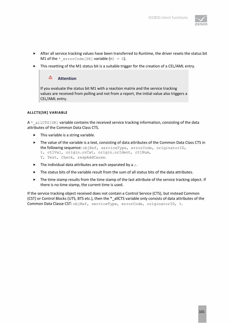
IEC850 client functions
101
After all service tracking values have been transferred to Runtime, the driver resets the status bit M1 of the *_errorCode[SR] variable (M1 = 0).
This resetting of the M1 status bit is a suitable trigger for the creation of a CEL/AML entry.
Attention
If you evaluate the status bit M1 with a reaction matrix and the service tracking values are received from polling and not from a report, the initial value also triggers a CEL/AML entry.
ALLCTS[SR] VARIABLE
A *_allCTS[SR] variable contains the received service tracking information, consisting of the data attributes of the Common Data Class CTS.
This variable is a string variable.
The value of the variable is a text, consisting of data attributes of the Common Data Class CTS in the following sequence: objRef, serviceType, errorCode, originatorID, t, ctlVal, origin.orCat, origin.orIdent, ctlNum,
T, Test, Check, respAddCause.
The individual data attributes are each separated by a ;.
The status bits of the variable result from the sum of all status bits of the data attributes.
The time stamp results from the time stamp of the last attribute of the service tracking object. If there is no time stamp, the current time is used.
If the service tracking object received does not contain a Control Service (CTS), but instead Common (CST) or Control Blocks (UTS, BTS etc.), then the *_allCTS variable only consists of data attributes of the Common Data Classe CST: objRef, serviceType, errorCode, originatorID, t.
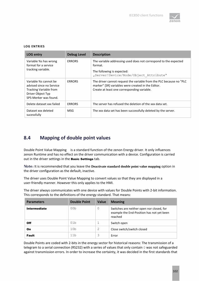
IEC850 client functions
102
LOG ENTRIES
LOG entry Debug Level Description
Variable %s has wrong format for a service tracking variable.
ERRORS The variable addressing used does not correspond to the expected format.
The following is expected: „Server!Device/Node/Object_Attribute“
Variable %s cannot be advised since no Service Tracking Variable from Driver Object Typ SPS-Merker was found.
ERRORS The driver cannot request the variable from the PLC because no "PLC marker" [SR] variables were created in the Editor. Create at least one corresponding variable.
Delete dataset xxx failed ERRORS The server has refused the deletion of the xxx data set.
Dataset xxx deleted sucessfully
MSG The xxx data set has been successfully deleted by the server.
8.4 Mapping of double point values
Double Point Value Mapping is a standard function of the zenon Energy driver. It only influences zenon Runtime and has no effect on the driver communication with a device. Configuration is carried out in the driver settings in the Basic Settings tab.
It is recommended that you leave the Deactivate standard double point value mapping option in the driver configuration as the default, inactive.
The driver uses Double Point Value Mapping to convert values so that they are displayed in a user-friendly manner. However this only applies to the HMI.
The driver always communicates with one device with values for Double Points with 2-bit information. This corresponds to the definitions of the energy standard. That means:
Parameters Double Point Value Meaning
Intermediate 00b 0 Switches are neither open nor closed, for example the End-Position has not yet been reached
Off 01b 1 Switch open
On 10b 2 Close switch/switch closed
Fault 11b 3 Error
Double Points are coded with 2-bits in the energy sector for historical reasons: The transmission of a telegram to a serial connection (RS232) with a series of values that only contain 0 was not safeguarded against transmission errors. In order to increase the certainty, it was decided in the first standards that

IEC850 client functions
103
the value for OFF is not to be sent as 0 but as 01b, which corresponds to decimal 1. These Double Point Values also precisely reflect the type of how two sensors record the physical position of a switch.
However, the values sent this way may be confusing for people:
OFF = 1
ON = 2
Humans are used to all other devices and systems:
OFF = 0
ON = 1
At the same time, Single Point Values are also defined with OFF = 0 in the same standard.
The user must always be aware of the technical level on which they are acting and receiving or sending information. In stressful situations, this can very easily lead to serious mistakes. For example, if ON is sent instead of OFF.
In order to avoid this dangerous error, the zenon Energy driver offers its own Double Point Value Mapping.
MAPPING VOR HMI
With the Double Point Value Mapping, all Double Points in zenon have the following values:
Intermediate = 2
Off = 0
On = 1
Fault = 3
Information
This function can be deactivated in the driver settings. However some features such as Command Processing or ALC can no longer be used then.
Do not use numerical elements and numerical values to display OFF/ON or OPEN/CLOSE. Use combined elements with graphic symbols or text elements instead.
DPI MAPPING IN IEC61850 CLIENT DRIVER
In accordance with the IEC61850-7-3 standard, in Common Data Classes, Double Point Status (DPS) and Controllable Double Point (DPC), the stVal attribute has the data type CODED ENUM with the value range: intermediate-state (00) | off (01) | on (10) | bad-state (11). The driver therefore waits until a Double Point attribute of the data type CODED ENUM is mapped to the communication protocol as an
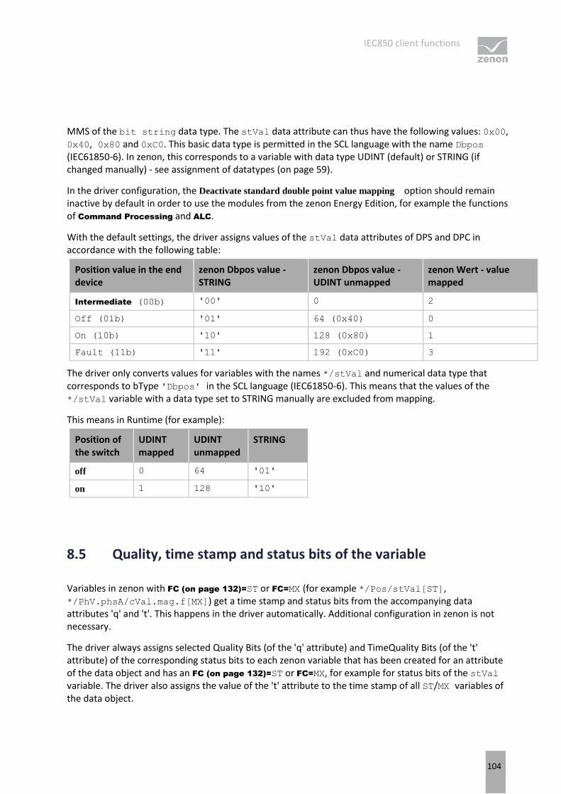
IEC850 client functions
104
MMS of the bit string data type. The stVal data attribute can thus have the following values: 0x00, 0x40, 0x80 and 0xC0. This basic data type is permitted in the SCL language with the name Dbpos (IEC61850-6). In zenon, this corresponds to a variable with data type UDINT (default) or STRING (if changed manually) - see assignment of datatypes (on page 59).
In the driver configuration, the Deactivate standard double point value mapping option should remain inactive by default in order to use the modules from the zenon Energy Edition, for example the functions of Command Processing and ALC.
With the default settings, the driver assigns values of the stVal data attributes of DPS and DPC in accordance with the following table:
Position value in the end device
zenon Dbpos value - STRING
zenon Dbpos value - UDINT unmapped
zenon Wert - value mapped
Intermediate (00b) '00' 0 2
Off (01b) '01' 64 (0x40) 0
On (10b) '10' 128 (0x80) 1
Fault (11b) '11' 192 (0xC0) 3
The driver only converts values for variables with the names */stVal and numerical data type that corresponds to bType 'Dbpos' in the SCL language (IEC61850-6). This means that the values of the */stVal variable with a data type set to STRING manually are excluded from mapping.
This means in Runtime (for example):
Position of the switch
UDINT mapped
UDINT unmapped
STRING
off 0 64 '01'
on 1 128 '10'
8.5 Quality, time stamp and status bits of the variable
Variables in zenon with FC (on page 132)=ST or FC=MX (for example */Pos/stVal[ST], */PhV.phsA/cVal.mag.f[MX]) get a time stamp and status bits from the accompanying data attributes 'q' and 't'. This happens in the driver automatically. Additional configuration in zenon is not necessary.
The driver always assigns selected Quality Bits (of the 'q' attribute) and TimeQuality Bits (of the 't' attribute) of the corresponding status bits to each zenon variable that has been created for an attribute of the data object and has an FC (on page 132)=ST or FC=MX, for example for status bits of the stVal variable. The driver also assigns the value of the 't' attribute to the time stamp of all ST/MX variables of the data object.
IEC850 client functions
105
The driver automatically uses the time stamp and the quality of the data object for other variables in this DO. For this reason, no variables for the attributes 'q' and 't' need to be created separately, except if you want to analyze the quality bits that are not assigned to status bits or want to see the updates of the time stamp without changing the position (stVal) or measured value (mag). If the zenon variables with references to data attributes 'q' or 't' have however also been created, the driver will support the received values 'q' and 't' as variable values.
The time stamp, received as 't' attribute, is used for the corresponding */stVal[ST] variable in the CEL. If the */t[ST] variable has been created in the project, it has the received Unix time as an LREAL value, with milliseconds in decimal places.
Info
The driver takes the TimeQuality byte of the 't' attribute into account by default. In addition to 3 status bits for the quality of the time information, the TimeQualitybyte also contains 5 bits for the TimeAccuracy information - the accuracy value (N bits of accuracy - performance class). The theoretically-possible accuracy values are between 0 - 24 and value 31 is defined as "unspecified" (all bits). However only some of the precisions can use a valid 850 server. The lowest precision permitted for an 850 product is class T0 - 7 bits - 10ms.
If TimeAccuracy is not 31 "unspecified", the FractionOfSeconds field of the time value - the binary decimal places - correspond to the precision - N+1 - shortened. The time stamp is then rounded to the milliseconds.
TimeAccuracy = 10 bits (class T1, 11 binary decimal places): the driver shortens the received time value to the precision 1/2048=0.00048828125 [s] and rounds up to the milliseconds.
TimeAccuracy = 0 bits (no valid performance class in the 850-7-2 standard, 1 binary decimal place): the driver shortens the time value received down to the seconds.
If you want to ignore TimeAccuracy, activate the Ignore time accuracy checkbox in the Server (on page 25) driver configuration dialog.
The selected Quality and TimeQuality bits are assigned to the status bits of the variables in the same data object as follows:

IEC850 client functions
106
IEC61850 Quality or TimeQuality bits
Status bit in zenon Notes
Validity = Invalid or Reserved or Questionable
INVALID Identified by a red square on the linked element.
Overflow OV_870 (Overflow) This is also an IEC 60870 status
OutOfRange OR_DRV (value outside the
valid range)
Source = Substituted SB_870 (Substituted) This is also an IEC 60870 status
Test TEST (Test bit) This is also an IEC 60870 status
OperatorBlocked BL_870 (Blocked) This is also an IEC 60870 status
ClockFailure T_INVAL (Time invalid) The value of the 't' attribute is ignored - stValhas the time stamp of the local PC.
ClockNotSynchronized T_UNSYNC
(ClockNotSynchronized) The value of the 't' attribute is considered - stVal has the time stamp of the IED.
version 7.50 and earlier: T_INVAL and T_EXTERN,
since 7.60: T_UNSYNC.
The TimeQuality bit LeapSecondsKnown is not assigned any status bits.
The variables of a data object without 't' attribute (or with 't' value 0) and the variables with a Functional Constraint other than ST/MX receive the time stamp of the local PC clock.
Info
You can evaluate status bits (such as T_INVAL) by using a combined element or
reaction matrix (of type "Multi"). The status bits can be filtered in CEL or AML.
CAUSE OF TRANSMISSION (COT)
For each variable, the driver provides information about whether the value of the variable was received from polling or by means of a report. The information is written to the status bits COTx .
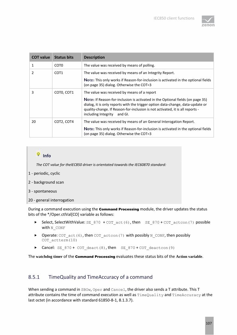
IEC850 client functions
107
COT value Status bits Description
1 COT0 The value was received by means of polling.
2 COT1 The value was received by means of an Integrity Report.
This only works if Reason-for-inclusion is activated in the optional fields (on page 35) dialog. Otherwise the COT=3
3 COT0, COT1 The value was received by means of a report
If Reason-for-inclusion is activated in the Optional fields (on page 35) dialog, it is only reports with the trigger option data-change, data-update or quality-change. If Reason-for-inclusion is not activated, it is all reports - including Integrity and GI.
20 COT2, COT4 The value was received by means of an General Interogation Report.
This only works if Reason-for-inclusion is activated in the optional fields (on page 35) dialog. Otherwise the COT=3
Info
The COT value for theIEC850 driver is orientated towards the IEC60870 standard:
1 - periodic, cyclic
2 - background scan
3 - spontaneous
20 - general interrogation
During a command execution using the Command Processing module, the driver updates the status bits of the */Oper.ctlVal[CO] variable as follows:
Select, SelectWithValue: SE_870 + COT_act(6), then SE_870 + COT_actcon(7) possible with N_CONF
Operate: COT_act(6), then COT_actcon(7) with possibly N_CONF, then possibly COT_actterm(10)
Cancel: SE_870 + COT_deact(8), then SE_870 + COT_deactcon(9)
The watchdog timer of the Command Processing evaluates these status bits of the Action variable.
8.5.1 TimeQuality and TimeAccuracy of a command
When sending a command in SBOw, Oper and Cancel, the driver also sends a T attribute. This T attribute contains the time of command execution as well as TimeQuality and TimeAccuracy at the last octet (in accordance with standard 61850-8-1, 8.1.3.7).
IEC850 client functions
108
The user can determine manually which values for TimeQuality and TimeAccuracy are used for this command. To do this, configure two Settings driver object type variables. Name these TimeQuality and TimeAccuracy.
If a command is sent with a time stamp, the values for TimeQuality and TimeAccuracy from these variables are used.
If not variables have been created or a value was never written to the TimeQuality and TimeAccuracy variables, the last octet of the T attribute is sent with 0.
TIMEQUALITY:
Bit 0 = LeapSecondsKnown
Bit 1 = ClockFailure
Bit 2 = ClockNotSynchronized
TIMEACCURACY:
Value 0 - 24: Bit number accuracy of the decimal places of the T attribute
Value 31: Accuracy not specified (unspecified)
8.6 Filetransfer
Filetransfer is a functionality defined in the IEC 61850 standard for the transfer of files between 850 server and client. For example, you can get the SCL file of the 850 server, or disturbance data after a problem (typically in COMTRADE format). Whether, and which files are available for the transfer is decided solely by the IED (850 server).
The transferred files are saved with the same name, format and content as the 850 server forwards them to the driver, for example the IED provides the files in COMTRADE format for transfer, the files are already saved in COMTRADE format on the driver's drive with the name and content as received by the IED.
There are three functions implemented for Filetransfer:
Request folder information (on page 109)
Get file from server (on page 109)
Delete file on the server (on page 110)

IEC850 client functions
109
ERROR TREATMENT
If the errors occur when carrying out the file transfer, such as the server responding negatively, the command variable changes its value to "XXX ERROR" (XXX = DIR, GET or DEL) and the driver optionally writes an entry into the LOG file (see also error analysis (on page 129)).
8.6.1 Request folder information
To request folder information from the IED (850 server):
1. Create, in your zenon project, two string variables of the driver object type File Transfer with the corresponding net address:
a) The first variable, hereafter called the command variable, with the reference (name / symbolic address) "*!Command" can also be used to get files and to delete them.
b) The second variable with the reference "*!Directory" is only used for the result of the folder query. It receives the folder content as legible text. For this reason, its size should correspond to the maximum size of the file name (including the folder) in the IED.
2. For the command variable, set the value "DIR" (for the root directory) or "DIR <file_spec>". <file_spec> is a string that is sent to the IED as a transfer parameter.
If the folder has been successfully received:
The command variable changes its value to "DIR OK"
The folder variable contains the received folder content as legible text. One line of this text has the following format:
<File name>;<File length>;<Time stamp>.
8.6.2 Get file from server
To get a file from the IED (850 server), set the value "GET <file name>" for the command variable.
If the file has been successfully received:
It is saved in the folder that was defined as Directory for file transfer in the driver dialog Basic
settings (on page 18). Files from a subfolder are also stored in the main folder.
The command variable changes its value to "GET OK"

Reporting
110
The transferred files are saved with the same name, format and content as the 850 server forwards them to the driver.
8.6.3 Delete file
To delete a file in the IED (850 server), set the value "DEL <file name>" for the command variable.
If the file was deleted successfully, the command variable changes its value to "DEL OK"
9. Reporting
Reporting was introduced by the IEC 61850 standard for spontaneous communication. The variables that are linked to a successfully-activated (RCB enable) Report Control Block are no longer polled, but are reported by the controller (an 850 server, Intelligent Electronic Device - IED) if a value change occurs. The variables that are reported if an 850 client registers a certain Report Control Block (RCB) (enabled), is defined in the DatSet (Data Set) attribute of the RCB . The Data Set is defined in the SCL file of the IED and contains the data objects, whose value changes are reported spontaneously by the 850 server.
The configuration of the reporting is carried out in driver configuration - server (on page 25). In RCB
assignement/dynamic datasets (on page 41), Buffered and Unbuffered Reports can be configured. RCBs configured this way have a higher priority than any automatically-searched Unbuffered Reports. If the activation of an RCB is unsuccessful, the driver can instead automatically activate a URCB, which also contains datasets if it contains the required data. If you do not want the driver to activate the URCBs automatically, set the Max. auto used URCBs property in the driver configuration to 0.
If the driver cannot activate the reports for any reason, polling is used instead. In this case, in the Connection State variable (on page 88), the bit 17 or 25 (MMS_RCB_ENABLE_FAILED) is set.
You can find further information on the different possibilities for checking the activation of RCBs in the RCB activation - checking possibilities (on page 122) chapter.
You can configure RCB assignment manually in the driver or - in Energy Edition - with the help of the IEC850 Driver Configuration wizard, using an SCL file (SCD, CID, possible ICD etc).
: For simplified import of variables from the RCB data sets, the IEC850 Driver Configuration provides additional possibilities.

Reporting
111
ASSIGNMENT USING REPORT NAME OR REPORT ID
By default, the driver identifies the RCB instances of the 850 server using its name. This process is supported by all - IEC 61850 standard-compliant - IEDs (850 servers).
By activating the Use Report-ID for RCB assignment setting in the driver configuration, you can use a special process: the report ID (RCB.RptId) is used instead of the report name. The process is only suitable for special applications. The driver will thus register all RCB instances that have the same ID. The IEC61850 standard also allows different RCBs, with different Data Sets to have the same value in RptID. In Runtime, the driver will search for all RCBs with the respective Report ID and register them. The driver can thus configure in such a way that it registers several RCBs with just one entry in the list and also automatically registers those that did not yet exist at the time of driver configuration.
: If several instances of an RCB have the same ID on the 850 server (which often happens) the driver will register them all, even if they all contain the same Data Sets. Consequently, no further 850 client will have access to the RCBs concerned!
Use of report ID requires corresponding configuration in the SCL file of the 850 server:
A separate report ID must be defined for each 850 client in the system; also a different ID for each Hostname - a different one for the Primary Server, another for the Standby Server.
With different RCBs, precisely one instance should be configured with the ID in SCL. Instances that need a client are thus marked, for example the first instances of each RCB for drivers on the Primary Server, the second for drivers on the Standby Server, the third for a different 850 client in the system, etc.
Only activate the process using report ID if you are sure that you want to use this special feature in the driver and the IED has also been preconfigured accordingly.
: If this option is subsequently changed, all RCB assignments in the RCB assignment dialog are deleted, the driver configuration is closed and opened again, and RCB assignment is set up again.
Reporting
112
GENERAL INTERROGATION (GI)
The driver also sends, if the RCBs is activated, a General Interrogation (RCB.GI=TRUE) command to get the most recent value of the variables. The first time the RCB is activated (i.e. when Runtime is started) and when the connection is reestablished (after a connection has been lost), it sends a GI. The driver also sends the GI at the same time as requesting the buffered events to be transferred via BRCB.EntryID, in order to ensure the updating of the process data, even if the reason for the loss of the connection was the failure of the 850 server.
However the general query is not sent if it is a repeated attempt to enable a report. This happens after expiry of the time configured in the RCBs enable retries property. This avoids data duplicates, because the values have already been received from the polling.
DATA SETS
The IEC850 driver supports reports with the Data Sets predefined in the IED (in the SCL file) or with Dynamic Data Sets - with the RCB.DatSet attribute, which was dynamically defined during activation of the RCB .
As envisaged by the IEC 61850 Standard, for a Report data object with Functional Constraints (FC) the following is available:
Status - ST
Measurands - MX
Service tracking - SR
Configuration - CF
and further: SP, SV
If a non-standards-compliant reference has been defined in a Data Set (other than the FCs listed here), the driver nevertheless activates the RCB. However the data with invalid FCs is ignored in the reports received. The data objects and data attributes concerned continue to be polled.
In a Data Set:
Data objects with different FCs can be used together if the 850 server supports this.
Data objects from different Logical Devices can be contained.
To make activation of reporting possible, the following conditions should be met:
The Data Set and the Reporting Control Block that uses the data set must be in the same Logical Device.
At least one variable of the Logical Node, in which the RCB is included, must have been created in the project. Otherwise the driver does not take this Logical Node into account at all whilst the connection is established.
: LLN0. All RCBs defined in the logical node LLN0 are automatically taken into account for each Logical Device if the LD has at least one variable that was created in the project variable list.
You can find details of dynamic datasets in the Dynamic datasets (on page 125) chapter.
Reporting
113
DATA SETS WITH FCD OR FCDA
The dynamic data sets configured in the driver always consist of FCD references:
Functional Constraints (FC)
Reference to the Data Object (LD/LN/DO)
Datasets already defined in an IED usually consist of FCD references, but they can also consist of FCDA references.
An FCDA reference consists of:
FCD reference, and
Data Attribute (daName)
In a SCL file the elements in a dataset always start with XML keyword "FCDA". This is also true for element which are a FCD reference:
FCD reference: <FCDA ldInst="ANN" prefix="PLT" lnClass="GGIO" lnInst="2" doName="Ind01" fc="ST" />
FCDA reference: <FCDA ldInst="LD0" prefix="X" lnClass="GGIO" lnInst="110" doName="Ind1" daName="stVal" fc="ST" />
The difference is the "daName" element.
To preclude data inconsistencies, it is recommended that data sets are always used with FCD references. To do this, the SCL file must always be configured accordingly. The "daName" elements of references must be removed and possible duplicates must be deleted.
Note also that it is only with FCD references where the value changes are contained in the report with the current time stamp of the 850 server in the report. With FCDA references, only the reports with GI or Integrity contain the time stamp of the server.
If the 850 server uses the FCDA references that cannot be reconfigured to FCD references (for example because the server does not accept any updates to the SCL file) the driver will however activate a report with such data sets. Reports with Service Tracking are only supported with FCD!
REPORTS WITH DATA SET WITH FCDA
For reports with a data set with FCDA , the driver works according to the following rules:
Whilst activating the RCB, the structure of the DataSet is recognized. If there are individual data attributes present here, a check is made to see whether, in this DataSet, an attendant Quality has also been defined at the same time. If no FCDA reference for the corresponding Quality attribute is found, that is however in the data model, the driver writes a LOG entry:
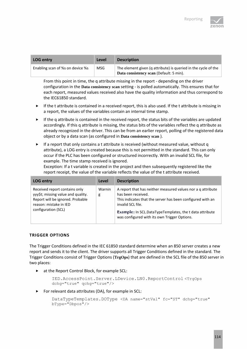
Reporting
114
LOG entry Level Description
Enabling scan of %s on device %s MSG The element given (q attribute) is queried in the cycle of the Data consistency scan (Default: 5 min).
From this point in time, the q attribute missing in the report - depending on the driver configuration in the Data consistency scan setting - is polled automatically. This ensures that for each report, measured values received also have the quality information and thus correspond to the IEC61850 standard.
If the t attribute is contained in a received report, this is also used. If the t attribute is missing in a report, the values of the variables contain an internal time stamp.
If the q attribute is contained in the received report, the status bits of the variables are updated accordingly. If this q attribute is missing, the status bits of the variables reflect the q attribute as already recognized in the driver. This can be from an earlier report, polling of the registered data object or by a data scan (as configured in Data consistency scan ).
If a report that only contains a t attribute is received (without measured value, without q attribute), a LOG entry is created because this is not permitted in the standard. This can only occur if the PLC has been configured or structured incorrectly. With an invalid SCL file, for example. The time stamp received is ignored. Exception: If a t variable is created in the project and then subsequently registered like the report receipt, the value of the variable reflects the value of the t attribute received.
LOG entry Level Description
Received report contains only yyy$t; missing value and quality. Report will be ignored. Probable reason: mistake in IED configuration (SCL)
Warning
A report that has neither measured values nor a q attribute has been received. This indicates that the server has been configured with an invalid SCL file.
In SCL.DataTypeTemplates, the t data attribute was configured with its own Trigger Options.
TRIGGER OPTIONS
The Trigger Conditions defined in the IEC 61850 standard determine when an 850 server creates a new report and sends it to the client. The driver supports all Trigger Conditions defined in the standard. The Trigger Conditions consist of Trigger Options (TrgOps) that are defined in the SCL file of the 850 server in two places:
at the Report Control Block, for example SCL:
IED.AccessPoint.Server.LDevice.LN0.ReportControl <TrgOps dchg="true" qchg="true"/>
For relevant data attributes (DA), for example in SCL:
DataTypeTemplates.DOType <DA name="stVal" fc="ST" dchg="true"
bType="Dbpos"/>
Reporting
115
An 850 server only creates a new dchg, dupd or qchg report if both conditions - for RCB and for DA - have been met, the reports GI and Integrity - only depending on TrgOps in the RCB. In accordance with the standard, a client (the driver) can only have an influence on TrgOps in RCB , but not on the TrgOps of the data attributes - these are fixed in the SCL, but first determine whether the IED should take the change in value of the data attribute into account as a trigger for reports.
RCB TRIGGER OPTIONS
In the driver configuration, use the Use preconfigured (SCL) options to configure whether the driver should activate (enable) the RCB with the TrgOps (and IntgPg, BufTm and OptFlds) already predefined in the SCL file of the IED or that the driver should first overwrite with settings from the driver configuration and only then sign in the RCB.
If the Use preconfigured (SCL) options checkbox has not been activated, the driver sends the configured Trigger Options to the 850 server. Possible write errors are ignored and the RCB continues to be used.
: with a write error to RCB.TrgOps, it would be expected that the 850 server then acts using its TrgOps from the SCL file.
The Trigger Options in the RCB define the conditions under which an IED (the 850 server) creates and sends a new report:
TrgOp: data-change - an IED creates a new report if one of the data attributes that have the dchg or dupd flag in their SCL definition changes the value. For example: stVal.
TrgOp: quality-change - an IED creates a new report if one of the data attributes changes its value with the qchg flag. In accordance with the standard, only data attributes q can have qchg .
TrgOp: data-update - an IED creates a new report if one of the data attributes is updated with dupd ; even if the value remains the same (and possible only the time stamp has been updated). For example: mag.
: for TrgOps: dchg, qchg and dupd ; an IED collects the value changes of individual data attributes using the Buffer Time (RCB.BufTm) length, in order to minimize the number of reports created. The BufTm is applicable for URCB (Unbuffered) and BRCB (Buffered). In the event of a connection loss, an IED creates the Buffered Reports, but does not send them. The buffered reports are only sent after the connection has been re-established if the client (the driver) requests them with a valid EntryID.
TrgOp: integrity - an IED creates cyclically - for each Integrity Period - a report that contains all values; also those that have already been sent due to dchg, qchg or dupd and those that have not changed in the mean time.
TrgOp: general-interrogation - an IED creates a report that contains all values if the client (the driver) requests the general query (RCB.GI).
Not all servers support TrgOps data-change and data-update together. TrgOp integritycan also lead to an unnecessary overload of communication if an IntgPd (Integrity Period) that is too short was defined in the server for RCB. In the event of doubt, set TrgOps: data-change + quality-change + general-interrogation. Ensure that TrgOp: general-interrogation is activated. Otherwise the driver cannot receive values for the variables present in the report when first started up.

Reporting
116
BTYPE TRIGGERCONDITIONS
The TrigerConditions data attribute type that was assigned to the MMS Bitstring(6) in accordance with the standard if the corresponding *TrgOps[RP|BR] variable was created during import, corresponds to the UDINT data type in zenon by default (Motorola format, bit 0 highest value in its octet). In addition, the driver allows such variables with the data type STRING instead of UDINT. The value of the STRING has the length 6 and only contains the characters "0" and "1"; in the same sequence as the bits are defined in the standard.
Example
Value as string "011111" (as UDINT=124=01111100b) means that all TriggerCondition bits (except bit 0) - are set as 'Reserved'.
The value "000010" (as UDINT=8=00001000b) means that only the bit 4 - 'intergity' is set.
REDUNDANT ZENON NETWORK
In a redundant zenon network, both the Primary Server and the Standby Server start their own IEC850 driver. Both drivers must register different RCB instances (otherwise they are in conflict because an 850 server can only issue a client the RCB instance).
If you use redundancy in your zenon project (Network active property and Server 1 and Server 2 have been configured), you must create at least two entries in the driver configuration RCB
assiggment: a Hostname forServer 1 and second Hostname for Server 2 (Standby). You must then select different instances of the RCB for these entries.
Per default the IEC850 driver creates two host names: $SCADA_SERVER1 and $SCADA_SERVER2.
The Connection State variable cannot result in a different evaluation for drivers on the Server 1 network than that on Server 2. For the user, also on the Standby, only the current value of the current Primary Server is visible. If you also want to make the current evaluation for Standby Server visible - in order, for example, to trigger an alarm if the Standby could not register its RCBs, you can create a copy of the Connection State variable - with the same reference (in Symbolic address), a different prefix in the Name and with the Read from Standby Server only property activated.
For Evaluated network, you do not need any of the variables requested by the Standby in the Valuations property. The evaluation takes place separately on both servers, using the local values of the variables. Therefore in the standby, it is always the value of the Connection State variable that is evaluated by its internal image, even if no copy has been created in the project.

Reporting
117
9.1 Unbuffered Reporting
The use of Unbuffered Report Control Blocks (URCB) can be configured in the IEC850 driver in two ways:
1. Automatic assignment: property max. auto used URCBs: Automatic assignment makes the use of reporting easier in the test phase of the project already - the driver checks the content of all existing Unbuffered Report Control Blocks (URCB) (data sets). The driver then reports first the URCBs that contain the most variables of the project;
2. Static assignment - statically assigned RCB (on page 41) dialog: The driver uses the assignment of Report Control Blocks to the computer - Hostname - as it is defined in the driver configuration - client configuration (on page 36). This is applicable for URCB and BRCB.
AUTOMATIC ASSIGNMENT
Automatic assignment works with data sets and linkings of data sets with Report Control Blocks that are already predefined in the 850 server - using its SCL file. The dynamic datasets are not supported for automatic assignment.
During the establishment of a connection to the 850 server, the driver reads all data sets that are present in the 850 server and assigns them according to their usability - according to the number of variables from the project included. This sorting indicates the sequence in which the driver attempts to activate free URCBs for reporting (enable). At most, only as many URSBs per Logical Device are activated as are defined in Driver configuration (on page 25) in the max. auto used URCBs property. All data objects of the data set that are successfully linked to an activated URCB are no longer polled but are reported in the event of a value change.
: automatic assignment makes the use of reporting easier in the test phase of the project already - even before the static assignments have been set. However, before you approve the project, also configure the static assignment for URCB - in the RCB assignment dialog and set the max. auto used URCBs property to 0. The standard proposes that in a system, the client that uses a certain instance of an RCB should be clearly regulated. It prevents possible conflicts between several 850 clients.
RULES FOR CONFLICTS THAT OCCUR
When activating reporting, the driver also recognizes URCBs with the same content; the name of these reports can be different. Before the URCBs are sorted for the zenon project according to their usability, the driver first sorts the data objects of the data sets of each URCB and compares them in order to avoid duplicates. The following applies for conflicts when activating the URCBs:
For the same reports - with identical or different sequences of the same data objects: only one URCB is activated.
If an URCB is already occupied by another client, the next free URCB is activated.
If all URCBs are already occupied by other clients, the data points are polled.
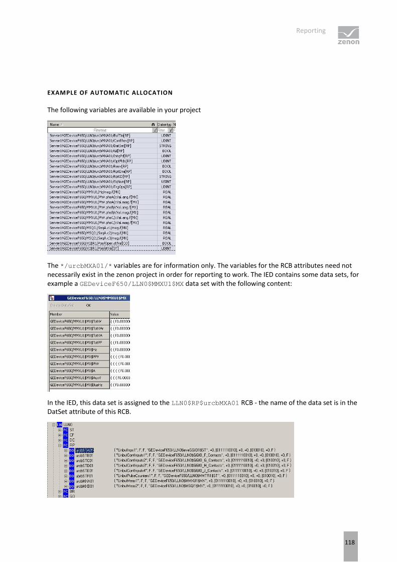
Reporting
118
EXAMPLE OF AUTOMATIC ALLOCATION
The following variables are available in your project
The */urcbMXA01/* variables are for information only. The variables for the RCB attributes need not necessarily exist in the zenon project in order for reporting to work. The IED contains some data sets, for example a GEDeviceF650/LLN0$MMXU1$MX data set with the following content:
In the IED, this data set is assigned to the LLN0$RP$urcbMXA01 RCB - the name of the data set is in the DatSet attribute of this RCB.
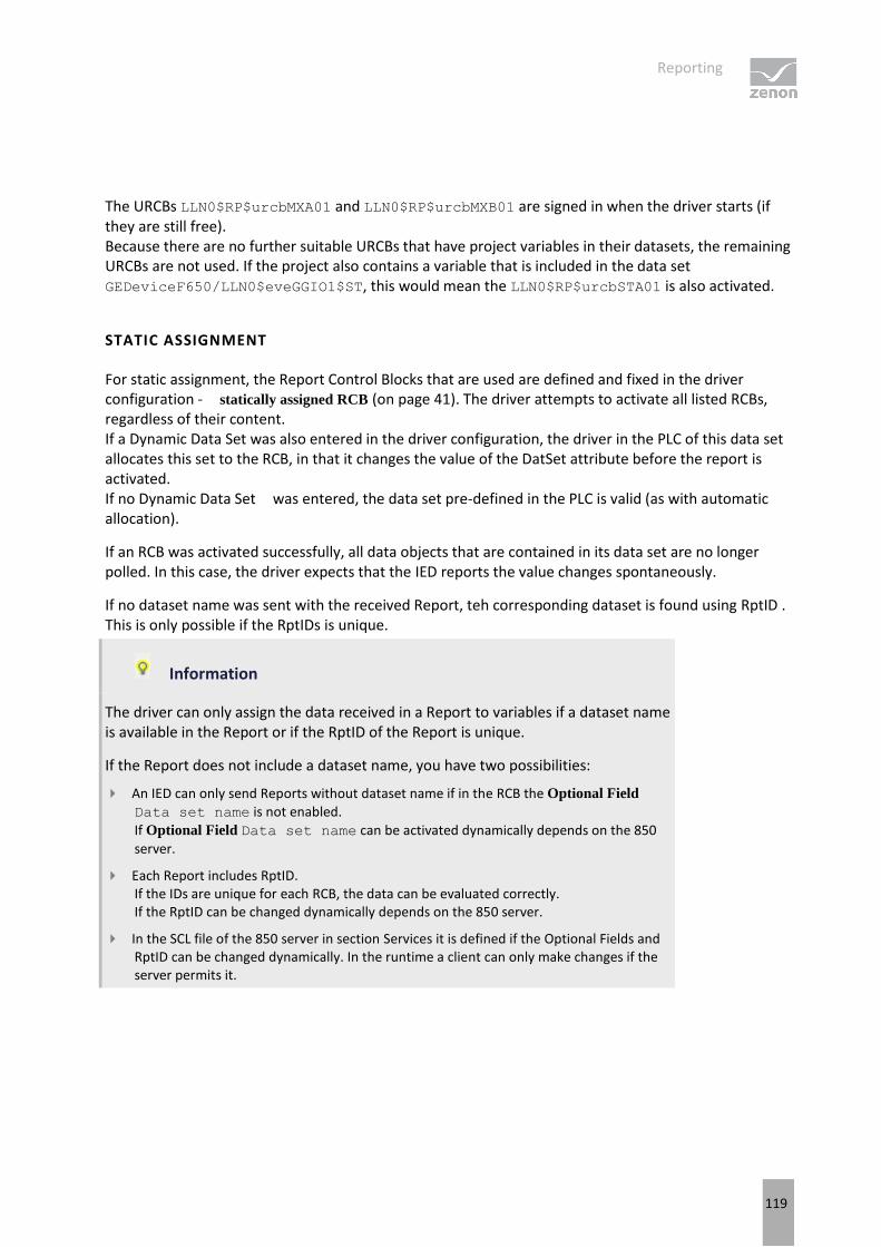
Reporting
119
The URCBs LLN0$RP$urcbMXA01 and LLN0$RP$urcbMXB01 are signed in when the driver starts (if they are still free). Because there are no further suitable URCBs that have project variables in their datasets, the remaining URCBs are not used. If the project also contains a variable that is included in the data set GEDeviceF650/LLN0$eveGGIO1$ST, this would mean the LLN0$RP$urcbSTA01 is also activated.
STATIC ASSIGNMENT
For static assignment, the Report Control Blocks that are used are defined and fixed in the driver configuration - statically assigned RCB (on page 41). The driver attempts to activate all listed RCBs, regardless of their content. If a Dynamic Data Set was also entered in the driver configuration, the driver in the PLC of this data set allocates this set to the RCB, in that it changes the value of the DatSet attribute before the report is activated. If no Dynamic Data Set was entered, the data set pre-defined in the PLC is valid (as with automatic allocation).
If an RCB was activated successfully, all data objects that are contained in its data set are no longer polled. In this case, the driver expects that the IED reports the value changes spontaneously.
If no dataset name was sent with the received Report, teh corresponding dataset is found using RptID . This is only possible if the RptIDs is unique.
Information
The driver can only assign the data received in a Report to variables if a dataset name is available in the Report or if the RptID of the Report is unique.
If the Report does not include a dataset name, you have two possibilities:
An IED can only send Reports without dataset name if in the RCB the Optional Field Data set name is not enabled.
If Optional Field Data set name can be activated dynamically depends on the 850
server.
Each Report includes RptID. If the IDs are unique for each RCB, the data can be evaluated correctly. If the RptID can be changed dynamically depends on the 850 server.
In the SCL file of the 850 server in section Services it is defined if the Optional Fields and RptID can be changed dynamically. In the runtime a client can only make changes if the server permits it.

Reporting
120
9.2 Buffered Reporting
For Buffered Reports, an 850 server (IED) saves the changes in the time in which a connected 850 client cannot be reached. If the client (the IEC850 driver) is online again (if the connection is reestablished, for example), the driver reads all buffered changes from the IED and processes them; it creates omitted alarms, for example.
There is no automatic allocation for Buffered Reporting. The allocation of BRCBs to the driver is always static:
Either using the driver configuration as described for static allocation with Unbuffered Reporting (on page 117);
Or for reasons of compatibility with older drivers, via the the Report ID of the BRCB that was configured in the SCL file and contains certain text. To do this, the Use Report-ID for RCB
assignment property should be activated in the driver configuration. If the assignments are to be configured in the SCL file, the assigned report ID (RptID) of the BRCB must contain a string with the following nomenclature 'zenon_Computername_*'; for example: zenon_MyPC_Measurands1. The driver then signs in the RCB driver and uses the RCB data set that is defined in the SCL file.
A Buffered Report can only be activated by a host (a client). To prevent the driver from activating all Buffered Reports and blocking access for other 850 clients, these must be explicitly defined in the driver configuration (on page 9).
Irrespective of buffered events, the basic behavior is the same as with Unbuffered Reporting.
Information
Once Runtime is started, the driver first reads the RCB attributes and only writes to enable if the RCB:
Is free
Is not yet enabled (for example by another 850 client)
Is not reserved
Contains a valid dataset
In the event of repetitions - from the RCBs enable retries properties - the driver no longer reads the RCB. In this case, it always writes RCB.RptEna=TRUE and then checks whether the PLC confirms success or returns an error.
An RCB with empty data set is not used in Runtime. Corresponding warning entries are generated in the LOG file for this automatic deactivation.
An RCB is not activated:
If no dataset is linked.
If an empty data set is linked.

Reporting
121
If the linked data set does not exist or cannot be found.
GET OR DELETE BRCB BUFFER
If the RCB of the previously-used BRCB is activated again (RCB enable) (i.e. another establishment of the connection after a loss of the connection), the driver sends a saved EntryID to the 850 server to get the buffered value changes from the IED . This procedure is defined as such in the IEC 61850 standard. The Do not purge BRCB buffer at start option has no influence on this.
The first time an attempt to enable a report is made (i.e. when Runtime is started), the driver can also send the value of the EntryID. However, the driver only does this if the Do not purge BRCB buffer at start
option is activated and if the driver has saved an EntryID beforehand.
The driver saves the last-received EntryID for each ObjectReference to BRCB first internally and then - each minute or if Runtime is closed - to a TXT file in the directory of the Runtime data.
In the following situations however, the driver sends the purge buffer command to delete the buffer on the IED :
It is the first connection after Runtime has been started and the Do not purge BRCB buffer at
start option in the basic settings (on page 18) is deactivated.
The driver has not received a valid EntryID value beforehand.
It is a repeated attempt to sign in a report - after the RCBs enable retries time has expired. The BRCB.PurgeBuf command is always sent with a repeated attempt. This avoids data duplicates, because the values have already been received from the polling. The Do not purge BRCB buffer
at start option has no effect on repetitions.
Attention
An 850 server is obliged to first confirm the writing of EntryID and only then to send the buffered values. The reports are ignored as long as the BRCB activation has not yet been confirmed.
BUFFERED REPORTS AND ZENON REDUNDANCY
Because zenon supports redundancy (see zenon network) and a BRCB can only be activated once by a PC, you must define separately, for the project Server 1 and Server 2 (Standby Server) which PC is to activate which report. The driver is started on both the Primary Server and the Standby and checks the driver configuration (Hostname property), to see if it finds a configuration that corresponds to the computer name that is running on Runtime.
For this reason, you need two copies of the Buffered Report in the IED (850 server) in the event of a redundant configuration; one for the driver that runs on the project server and one for the driver that runs on the Standby Server. You also create two entries in the RCB assignment (on page 41) list in the driver configuration. One with the computer name of the project server and one with the computer name of the Standby Server.
Reporting
122
: With the configuration entry for the computer name of Server 1, you can enter the first instance of the BRCB ("brcbA01" for example) and for the configuration entry of Server 2 - the second instance ("brcbA02" for example).
Attention
Even if you do not use redundancy, you must nevertheless define which reports are used for the PC (Hostname property) in the driver configuration on which zenon Runtime runs.
BRCB.RESVTMS HANDLING
The driver only handles the data attribute BRCB.ResvTms if no ClientLN.iedName has been defined in the driver configuration. You configure this ClientLN.iedName in the client configuration (on page 36) driver dialog or with the IEC850 Driver Configuration wizard from an SCD file.
If ClientLN.iedName has been configured, then it is assumed that the 850 server has also been pre-configured with the same SCD file. i.e. the 850 server obliges all exclusively-reserved BRCBs to set ResvTms to -1 and to only issue the BRCBs to the envisaged clients.
If no ClientLN.iedName is defined in the driver configuration, when the connection to the server is established, the BRCBs that are to be enabled are checked to see if there is the optional attribute ResvTms. In doing so, the value -1 in ResvTms means that this BRCB is exclusively reserved in the SCD for a different client. In this case there is an incorrect configuration and a warning is issued in the LOG.
Possible cause of the error:
The driver was not configured with the correct Client IED name.
In the driver, BRCBs were configured statically that were however reserved for another client according to the SCD file.
If no ClientLN.iedName has been configured in the driver, the driver sets the ResvTms attribute to 32767 seconds (7fff hex) in order to reserve this BRCB for the longest possible time in the event of a connection failure. This time is approximately 9 hours and ensures that no other client can sign this BRCB in during the time that the connection has failed.
URCB.RESV HANDLING
The driver only takes the data attribute URCB.Resv into account if no ClientLN.iedName has been defined in the driver configuration.
9.3 RCB activation - verification possibilities
To find out if a certain RCB has been activated, read the value of the *RptEna[RP/BR] data attribute.
Reporting
123
If the value of this variable is TRUE, then the RCB is assigned by a client. This information is only meaningful and reliable if only one single client communicates with the 850 server (IED).
Otherwise you do see that the report has been enabled, but there is no information about the client that activated this report. Additional information on the fact that one of the RCBs could not be activated can be read from the values of the Connection State variable (on page 88).
If the driver cannot activate the statically-assigned reports for any reason, polling is used instead for variables from missing RCBs. In this case, in the Connection State variable, bit 17 or 25 (MMS_RCB_ENABLE_FAILED) is set and the driver will - after the RCBs enable retries time has elapsed - attempt to write the RptEna data attribute with true again. As soon as the 850 server, after another attempt, accepts the missing sign ins for RCB, the driver no longer polls the variables. After all RCBs have been signed in, the MMS_RCB_ENABLE_FAILED bit of the Connection State variable is reset.
DIAGNOSIS VIEWER
You can get more details if you read the LOG file with the Diagnosis Viewer. In the LOG file, the corresponding information on the enabling of the reports by the driver (IEC850 client) is logged at MSG level. The attendant LOG entry:
"Trying to enable xxx on device nnn". Example for xxx: LLN0$BR$brcbA01.
Only the ERROR level is logged by default in the Diagnosis Viewer. You must configure the corresponding Messagelevel in the Diagnosis Viewer. This configuration in the DiagViewer is only possible if the corresponding driver tasks have already been started. This is then the case if Runtime is running or the driver configuration is open in the zenon Editor.
If the MSG level has been activated in the Diagnosis Viewer, but the "Trying to enable xxx on device nnn" LOG entry is not there, then ensure that the "Hostname " property of the driver configuration has been configured correctly.
This configuration must be configured either with a keyword $SCADA_SERVER1 ($SCADA_SERVER2) or with the computer name on which the driver runs (= zenon Runtime).
You configure the Hostname configuration in the Client configuration (on page 36) driver dialog.
Also ensure that there is at least one *[ST|MX] variable in your zenon project whose value is signed in by this report.
Additional LOG entries
Enabling of the report is refused by the 850 server - 'ERROR' LOG entry with the number of the MMS error code as received by the server.
Enabling the report is accepted by the 850 server:
'MSG' LOG entry with text: "Successfully enabled xxx on device yyy"
'DEBUG' LOG entries with the list of data objects with text: "Disabled ST polling for zzz on device nnn".
Reporting
124
Example for zzz: */XCBR1$ST$Pos. These data objects are now only expected via a report and will not be polled.
Information
If the driver is configured for the use of certain RCBs and these RCBs have an incorrect dataset definition, the report is activated but some data objects still need to be polled. In the LOG file, you can find entries via enabling of RCB, but not the entries via deactivated polling.
CAUSE OF TRANSMISSION (COT)
For each variable, the driver provides information about whether the value of the variable was received from polling or by means of a report. The information is written to the status bits COTx .
COT value Status bits Description
1 COT0 The value was received by means of polling.
2 COT1 The value was received by means of an Integrity Report.
This only works if Reason-for-inclusion is activated in the optional fields (on page 35) dialog. Otherwise the COT=3
3 COT0, COT1 The value was received by means of a report
If Reason-for-inclusion is activated in the Optional fields (on page 35) dialog, it is only reports with the trigger option data-change, data-update or quality-change. If Reason-for-inclusion is not activated, it is all reports - including Integrity and GI.
20 COT2, COT4 The value was received by means of an General Interogation Report.
This only works if Reason-for-inclusion is activated in the optional fields (on page 35) dialog. Otherwise the COT=3
Info
The COT value for theIEC850 driver is orientated towards the IEC60870 standard:
1 - periodic, cyclic
2 - background scan
3 - spontaneous
20 - general interrogation
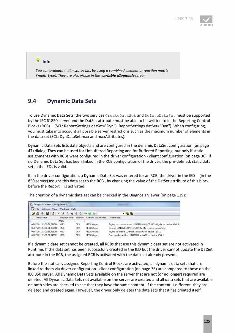
Reporting
125
Info
You can evaluate COTx status bits by using a combined element or reaction matrix ('multi' type). They are also visible in the variable diagnosis screen.
9.4 Dynamic Data Sets
To use Dynamic Data Sets, the two services CreateDataSet and DeleteDataSet must be supported by the IEC 61850 server and the DatSet attribute must be able to be written to in the Reporting Control Blocks (RCB) (SCL: ReportSettings.datSet="Dyn"). ReportSettings.datSet="Dyn"). When configuring, you must take into account all possible server restrictions such as the maximum number of elements in the data set (SCL: DynDataSet.max and maxAttributes).
Dynamic Data Sets lists data objects and are configured in the dynamic DataSet configuration (on page 47) dialog. They can be used for Unbuffered Reporting and for Buffered Reporting, but only if static assignments with RCBs were configured in the driver configuration - client configuration (on page 36). If no Dynamic Data Set has been linked in the RCB configuration of the driver, the pre-defined, static data set in the IEDs is valid.
If, in the driver configuration, a Dynamic Data Set was entered for an RCB, the driver in the IED (in the 850 server) assigns this data set to the RCB , by changing the value of the DatSet attribute of this block before the Report is activated.
The creation of a dynamic data set can be checked in the Diagnosis Viewer (on page 129):
If a dynamic date set cannot be created, all RCBs that use this dynamic data set are not activated in Runtime. If the data set has been successfully created in the IED but the driver cannot update the DatSet attribute in the RCB, the assigned RCB is activated with the data set already present.
Before the statically assigned Reporting Control Blocks are activated, all dynamic data sets that are linked to them via driver configuration - client configuration (on page 36) are compared to those on the IEC 850 server. All Dynamic Data Sets available on the server that are not (or no longer) required are deleted. All Dynamic Data Sets not available on the server are created and all data sets that are available on both sides are checked to see that they have the same content. If the content is different, they are deleted and created again. However, the driver only deletes the data sets that it has created itself.
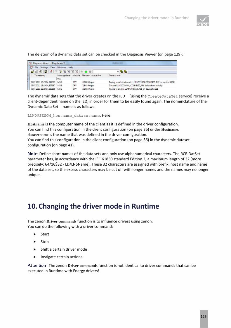
Changing the driver mode in Runtime
126
The deletion of a dynamic data set can be checked in the Diagnosis Viewer (on page 129):
The dynamic data sets that the driver creates on the IED (using the CreateDataSet service) receive a client-dependent name on the IED, in order for them to be easily found again. The nomenclature of the Dynamic Data Set name is as follows:
LLN0$ZENON_hostname_datasetname. Here:
Hostname is the computer name of the client as it is defined in the driver configuration. You can find this configuration in the client configuration (on page 36) under Hostname. datasetname is the name that was defined in the driver configuration. You can find this configuration in the client configuration (on page 36) in the dynamic dataset configuration (on page 41).
: Define short names of the data sets and only use alphanumerical characters. The RCB.DatSet parameter has, in accordance with the IEC 61850 standard Edition 2, a maximum length of 32 (more precisely: 64/16$32 - LD/LN$Name). These 32 characters are assigned with prefix, host name and name of the data set, so the excess characters may be cut off with longer names and the names may no longer unique.
10. Changing the driver mode in Runtime
The zenon Driver commands function is to influence drivers using zenon. You can do the following with a driver command:
Start
Stop
Shift a certain driver mode
Instigate certain actions
The zenon Driver commands function is not identical to driver commands that can be executed in Runtime with Energy drivers!

Changing the driver mode in Runtime
127
Information
This chapter describes standard functions that are valid for most zenon drivers. However, not all functions described here are available for every driver. For example, a driver that does not, according to the data sheet, support a modem connection also does not have any modem functions.
CONFIGURATION OF THE FUNCTION
Configuration is carried out using the Driver commands function. To do this:
1. Create a new function in the zenon Editor.
2. Navigate to the node Variable.
3. Select the Driver commands entry.
The dialog for configuration is opened.
4. Select the desired driver and the required command.
5. Close the dialog by clicking on OK and ensure that the function is executed in Runtime. Heed the notices in the Driver command function in the network section.
DRIVER COMMAND DIALOG

Changing the driver mode in Runtime
128
Option Description
Drivers Selection of the driver from the drop-down list. It contains all drivers loaded in the project.
Current status Fixed entry which has no function in the current version.
Driver command Drop-down list for the selection of the command:
<No command> No command is sent. A command that already exists can thus be removed from a configured function.
Start driver (online mode) Driver is reinitialized and started.
Stop driver (offline mode) Driver is stopped. No new data is accepted.
If the driver is in offline mode, all variables that were created for this driver receive the status switched off (OFF;
Bit 20).
Driver in simulation mode Driver is set into simulation mode. The values of all variables of the driver are simulated by the driver. No values from the connected hardware (e.g. PLC, bus system, ...) are displayed.
Driver in hardware mode Driver is set into hardware mode. For the variables of the driver the values from the connected hardware (e.g. PLC, bus system, ...) are displayed.
Driver-specific command Enter driver-specific commands. Opens input field in order to enter a command.
Activate driver write set
value Write set value to a driver is allowed.
Deactivate driver write set
value Write set value to a driver is prohibited.
Establish connection with
modem Establish connection (for modem drivers) Opens the input fields for the hardware address and for the telephone number.
Disconnect from modem Terminate connection (for modem drivers)
Driver in counting
simulation mode Driver is set into counting simulation mode. All values are initialized with 0 and incremented in the set
update time by 1 each time up to the maximum value and then
start at 0 again.
Driver in static simulation
mode Driver is set into counting simulation mode. All values are initialized with 0.
Driver in programmed
simulation mode Driver is set into counting simulation mode. The values are calculated by a freely-programmable simulation project. The simulation project is created with the help of the zenon Logic Workbench and runs in the zenon Logic Runtime.
Show this dialog in the Runtime The dialog is shown in Runtime so that changes can be made.
Error analysis
129
DRIVER COMMAND FUNCTION IN THE NETWORK
If the computer on which the Driver commands function is executed is part of the zenon network, further actions are also carried out. A special network command is sent from the computer to the project server, which then executes the desired action on its driver. In addition, the Server sends the same driver command to the project standby. The standby also carries out the action on its driver.
This makes sure that Server and Standby are synchronized. This only works if the Server and the Standby both have a working and independent connection to the hardware.
11. Error analysis
Should there be communication problems, this chapter will assist you in finding out the error.
11.1 Analysis tool
All zenon modules such as Editor, Runtime, drivers, etc. write messages to a joint log file. To display them correctly and clearly, use the Diagnosis Viewer (main.chm::/12464.htm) program that was also installed with zenon. You can find it under Start/All programs/zenon/Tools 8.00 -> Diagviewer.
zenon driver log all errors in the LOG files.LOG files are text files with a special structure. The default folder for the LOG files is subfolder LOG in the folder ProgramData. For example:
%ProgramData%\COPA-DATA\LOG.
With the default settings, a driver only logs error information. With the Diagnosis Viewer you can enhance the diagnosis level for most of the drivers to "Debug" and "Deep Debug". With this the driver also logs all other important tasks and events.
In the Diagnosis Viewer you can also:
Follow newly-created entries in real time
customize the logging settings
change the folder in which the LOG files are saved
1. The Diagnosis Viewer displays all entries in UTC (coordinated world time) and not in local time.
2. The Diagnosis Viewer does not display all columns of a LOG file per default. To display more columns activate property Add all columns with entry in the context menu of the column header.

Error analysis
130
3. If you only use Error-Logging, the problem description is in the column Error text. For other diagnosis level the description is in the column General text.
4. For communication problems many drivers also log error numbers which the PLC assigns to them. They are displayed in Error text or Error code or Driver error parameter (1 and 2). Hints on the meaning of error codes can be found in the driver documentation and the protocol/PLC description.
5. At the end of your test set back the diagnosis level from Debug or Deep Debug. At Debug and Deep Debug there are a great deal of data for logging which are saved to the hard drive and which can influence your system performance. They are still logged even after you close the Diagnosis Viewer.
Attention
In Windows CE errors are not logged per default due to performance reasons.
You can find further information on the Diagnosis Viewer in the Diagnose Viewer (main.chm::/12464.htm) manual.
11.2 Check list
Check your system for errors using the driver documentation; for example correct driver configuration, addressing of the variables in zenon projects, report settings in the control unit, etc.
Check most of all:
1. Is the device (IEC 61850 server) connected to the power grid and ready for use?
a) Can a TCP connection to the device be created (check this using a 'ping') via the defined port (check this via Telnet)?
b) Is communication between this device and another IEC 61850 client possible?
c) Is the driver in hardware mode and not in simulation mode?
2. Have you analyzed the errors which are protocoled in the LOG file (for more information refer to manual Tools in chapter Diagnosis Viewer) of the drivers?
a) Which ERROR entries occurred?
b) Have you checked the information in the columns: Error Text and General Text?
In the General Text column, the "... failed due to error N" information shows the error number (N) - defined in the MMS protocol - with which the IED responded, e.g.: 3 - "access-violation", 5 - "parameter-value-inconsistent", 11 - "value-out-of-range" etc.
a) Was the logging activated, for the correct driver, at least for the error level and for all driver modules?
b) Have you taken into account that the times in the Diagnosis Viewer are always UTC?

Error analysis
131
c) Are the entries in the LOG comparable to recordings in Wireshark?
The driver is logging in addition to (not instead of) information that Wireshark is showing with the filter set to "mms".
a) Is the Diagnosis Viewer set so that all registered and all columns are diplayed with the content (without filtering)?
3. Variable addressing (if the variables have been created manually or by means of offline import from the SCL file):
a) Have you tried to import the variable online?
b) Do all variables have the correct net addresses?
c) Are the symbolic addresses (or names, identifications) of the variables valid (SERVER!LD/LN/DO/DA[FC])?
d) Do the variables have the correct driver object type (PLC marker), data type and value range?
4. General information and reporting:
a) Was at least one variable for each Logical Device created in the project?
For performance reasons, the driver in Runtime skips all Logical Devices for which no variables exist in the project; the statically-configured RCBs can also be ignored in the process.
a) Has at least one Logical Device variable been polled or is automatic watchdog activated?
If, with automatic watchdog activated, no MMS.Read is sent periodically, MMS is blocked (MaxOustandingCallings has been reached) - the 850 server has reacted with TCP.ACK but did not respond to the MMS request PDUs. An 850 client can then send no further MMS requests; it must wait. The situation occurs if the IED has an error (reacts with a delay and does not send and Abort by Reset). The driver creates an error entry in the LOG file and the connection is canceled.
a) If an RCB that is not in the LLN0 is not taken into account: was at least one variable from the Logical Node of the RCB created in the project?
For performance reasons, the driver skips Logical Nodes except LLN0 in Runtime for which there are no variables in the project.
a) Has, in the driver configuration, the use Report ID property has been activated but not used or not synced with the SCL file of the IED?
If use Report ID has been changed: was the static assignment of the RCBs configured again as required?
a) Have, in the driver configuration - in the host name - the keywords $SCADA_SERVER1 or $SCADA_SERVER2 or the names of Runtime computers been entered and linked to other instances of the RCB?
The network server and standby server must not use the same instances.
The host name must also be entered in projects without a network.
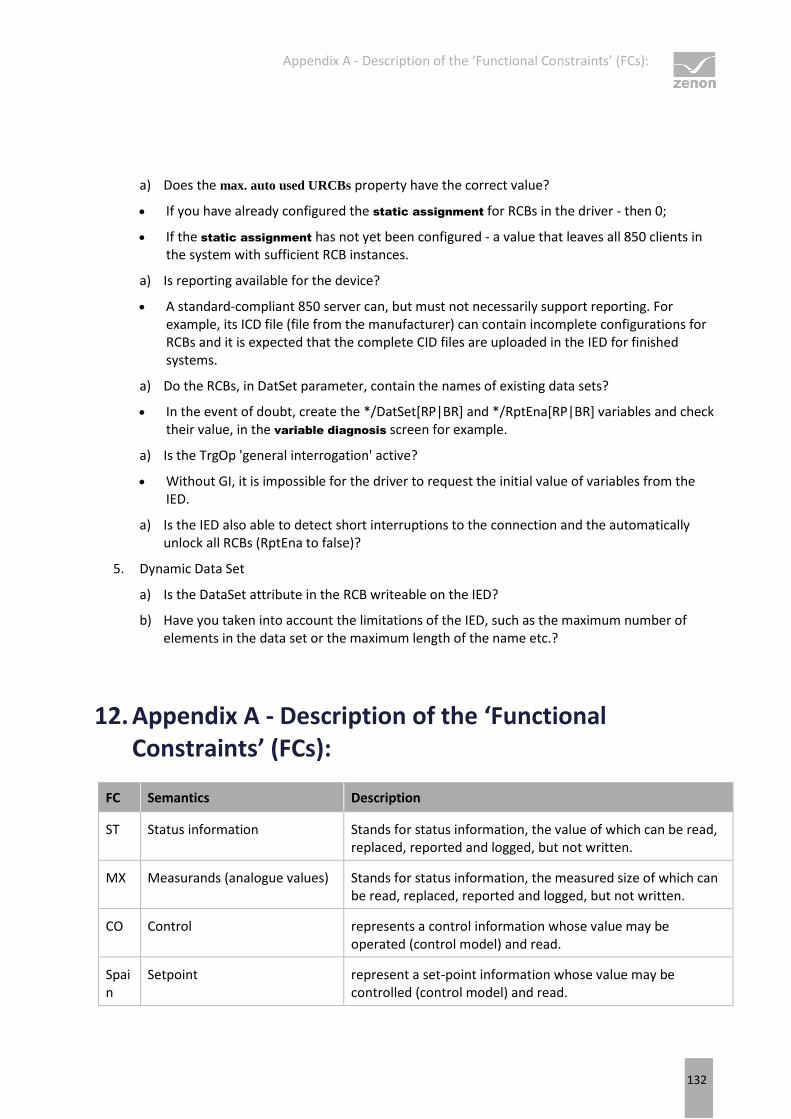
Appendix A - Description of the ‘Functional Constraints’ (FCs):
132
a) Does the max. auto used URCBs property have the correct value?
If you have already configured the static assignment for RCBs in the driver - then 0;
If the static assignment has not yet been configured - a value that leaves all 850 clients in the system with sufficient RCB instances.
a) Is reporting available for the device?
A standard-compliant 850 server can, but must not necessarily support reporting. For example, its ICD file (file from the manufacturer) can contain incomplete configurations for RCBs and it is expected that the complete CID files are uploaded in the IED for finished systems.
a) Do the RCBs, in DatSet parameter, contain the names of existing data sets?
In the event of doubt, create the */DatSet[RP|BR] and */RptEna[RP|BR] variables and check their value, in the variable diagnosis screen for example.
a) Is the TrgOp 'general interrogation' active?
Without GI, it is impossible for the driver to request the initial value of variables from the IED.
a) Is the IED also able to detect short interruptions to the connection and the automatically unlock all RCBs (RptEna to false)?
5. Dynamic Data Set
a) Is the DataSet attribute in the RCB writeable on the IED?
b) Have you taken into account the limitations of the IED, such as the maximum number of elements in the data set or the maximum length of the name etc.?
12. Appendix A - Description of the ‘Functional Constraints’ (FCs):
FC Semantics Description
ST Status information Stands for status information, the value of which can be read, replaced, reported and logged, but not written.
MX Measurands (analogue values) Stands for status information, the measured size of which can be read, replaced, reported and logged, but not written.
CO Control represents a control information whose value may be operated (control model) and read.
Spain
Setpoint represent a set-point information whose value may be controlled (control model) and read.

Appendix B - Abbreviations for data object/data attribute
133
SV Substitution represents a substitution information whose value may be written to substitute the value attribute and read.
CF Configuration represents a configuration information whose value may be written and read.
DC Description represents a description information whose value may be written and read
EX Extended definition represents an extension information providing a reference to a name space. Extensions are used in conjunction with extended definitions of LNs, DATA, and DataAttributes in 61850-7-3 and IEC 61850- 7-4. Value may be read.
13. Appendix B - Abbreviations for data object/data attribute
Information
Appendix B - Data object / data attribute is only available in English.
Term Description
f floating point (analog value)
i integer (analog value)
d Visible String(255)
q Quality
t Timestamp
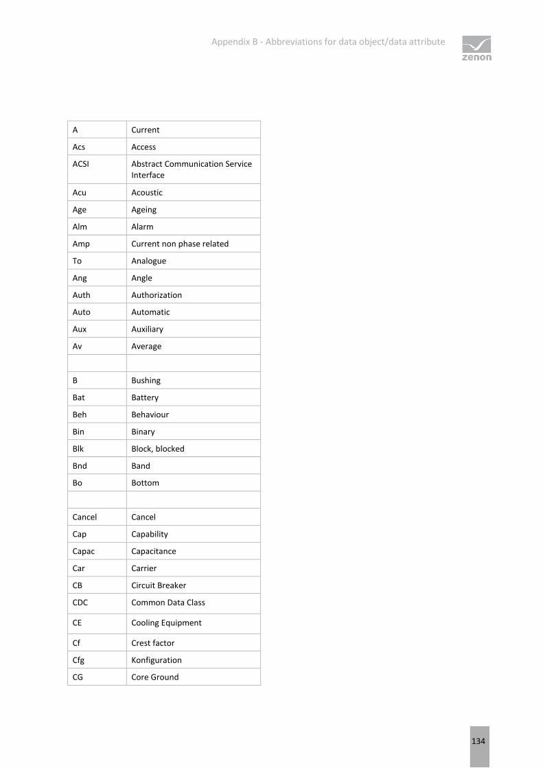
Appendix B - Abbreviations for data object/data attribute
134
A Current
Acs Access
ACSI Abstract Communication Service Interface
Acu Acoustic
Age Ageing
Alm Alarm
Amp Current non phase related
To Analogue
Ang Angle
Auth Authorization
Auto Automatic
Aux Auxiliary
Av Average
B Bushing
Bat Battery
Beh Behaviour
Bin Binary
Blk Block, blocked
Bnd Band
Bo Bottom
Cancel Cancel
Cap Capability
Capac Capacitance
Car Carrier
CB Circuit Breaker
CDC Common Data Class
CE Cooling Equipment
Cf Crest factor
Cfg Konfiguration
CG Core Ground

Appendix B - Abbreviations for data object/data attribute
135
Ch Channel
Cha Charger
Chg Change
Chk Check
Chr Characteristic
Cir Circulating
Clc Calculate
Clk Clock, clockwise
Cls Close
Cnt Counter
Col Coil
Cor Correction
Crd Coordination
Crv Curve
CT Current Transducer
Ctl Control
Ctr Center
Cyc Cycle

Appendix B - Abbreviations for data object/data attribute
136
Dea Dead
Den Density
Det Detected
DExt De-excitation
Diag Diagnostics
Dif Differential, difference
Dir Richtung
Dis Distance
Dl Delay
Dlt Delete
Dmd Demand
Dn Down
DPCSO Double point controllable status output
DQ0 Direct, Quadrature, and zero axis quantities
Drag Drag hand
Drv Drive
DS Device State
Dsch Discharge
Dur Duration

Appendix B - Abbreviations for data object/data attribute
137
EC Earth Coil
EE External Equipment
EF Earth Fault
Ena Enabled
Eq Equalization, Equal
Ev Evaluation
Ex External
Exc Exceeded
Excl Exclusion
Ext Excitation
FA Fault Arc
Fact Factor
Fan Fan
Flt Fault
Flw Flow
FPF Forward Power Flow
Fu Fuse
Fwd Forward
Gen General
Gn Generator
Gnd Ground
Gr Group
Grd Guard
Gri Grid

Appendix B - Abbreviations for data object/data attribute
138
H Harmonics (phase related)
H2 Hydrogen
H2O Water
Ha Harmonics (non phase related)
Hi High, highest
HP Hot point
Hz Frequency
IEEE Institute of Electrical and Electronic Engineers
Imb Imbalance
Imp Impedance non phase related
In Input
Ina Inactivity
Incr Increment
Ind Indication
Inh Inhibit
Ins Insulation
Int Integer
ISCSO Integer status controllable status output

Appendix B - Abbreviations for data object/data attribute
139
Km Kilometer
L Lower
LD Logical Device
LDC Line Drop Compensation
LDCR Line Drop Compensation Resistance
LDCX Line Drop Compensation Reactance
LDCZ Line Drop Compensation Impedance
LED Light Emitting Diode
Len Length
Lev Level
Lg Lag
Lim Limit
Lin Line
Liv Live
Lo Low
LO Lockout
Loc Local
Lod Load, loading
Lok Locked
Los Loss
Lst List
LTC Load Tap Changer
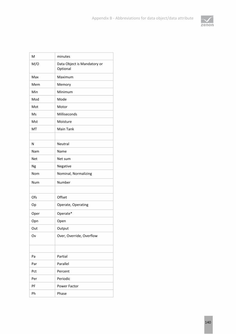
Appendix B - Abbreviations for data object/data attribute
140
M minutes
M/O Data Object is Mandatory or Optional
Max Maximum
Mem Memory
Min Minimum
Mod Mode
Mot Motor
Ms Milliseconds
Mst Moisture
MT Main Tank
N Neutral
Nam Name
Net Net sum
Ng Negative
Nom Nominal, Normalizing
Num Number
Ofs Offset
Op Operate, Operating
Oper Operate*
Opn Open
Out Output
Ov Over, Override, Overflow
Pa Partial
Par Parallel
Pct Percent
Per Periodic
PF Power Factor
Ph Phase

Appendix B - Abbreviations for data object/data attribute
141
Phy Physical
Pls Pulse
Plt Plate
Pmp Pump
Po Polar
Pol Polarizing
Pos Position
POW Point on wave switching
PP Phase to phase
PPV Phase to phase voltage
Pres Pressure
Prg Progress, in progress
Pri Primary
Pro Protection
Ps Positive
Pst Post
Pwr Power
Qty Quantity
R Raise
R0 Zero sequence resistance
R1 Positive sequence resistance
Rat Winding ratio
Rcd Record, recording
Rch Reach
Rcl Reclaim
Re Retry
React Reactance; Reactive
Rec Reclose
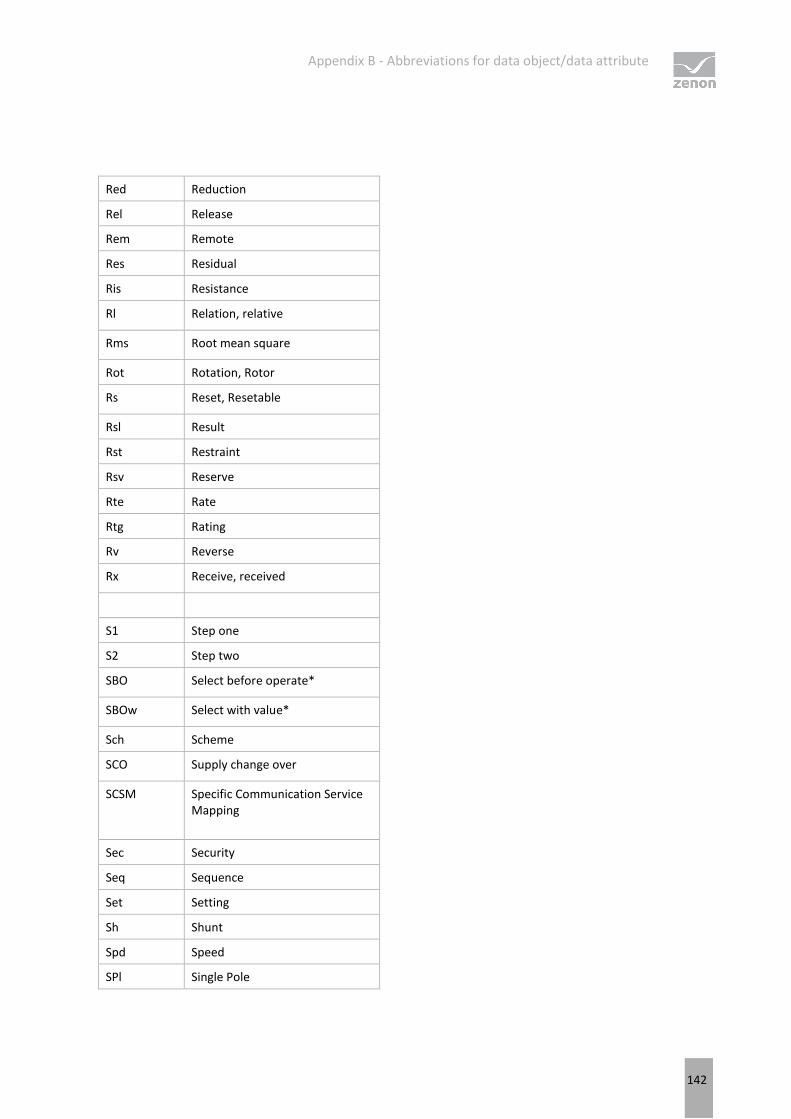
Appendix B - Abbreviations for data object/data attribute
142
Red Reduction
Rel Release
Rem Remote
Res Residual
Ris Resistance
Rl Relation, relative
Rms Root mean square
Rot Rotation, Rotor
Rs Reset, Resetable
Rsl Result
Rst Restraint
Rsv Reserve
Rte Rate
Rtg Rating
Rv Reverse
Rx Receive, received
S1 Step one
S2 Step two
SBO Select before operate*
SBOw Select with value*
Sch Scheme
SCO Supply change over
SCSM Specific Communication Service Mapping
Sec Security
Seq Sequence
Set Setting
Sh Shunt
Spd Speed
SPl Single Pole
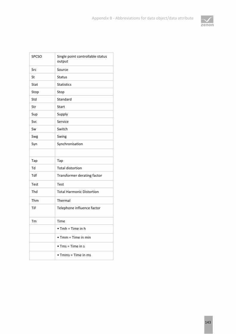
Appendix B - Abbreviations for data object/data attribute
143
SPCSO Single point controllable status output
Src Source
St Status
Stat Statistics
Stop Stop
Std Standard
Str Start
Sup Supply
Svc Service
Sw Switch
Swg Swing
Syn Synchronisation
Tap Tap
Td Total distortion
Tdf Transformer derating factor
Test Test
Thd Total Harmonic Distortion
Thm Thermal
TiF Telephone influence factor
Tm Time
• Tmh = Time in h
• Tmm = Time in min
• Tms = Time in s
• Tmms = Time in ms
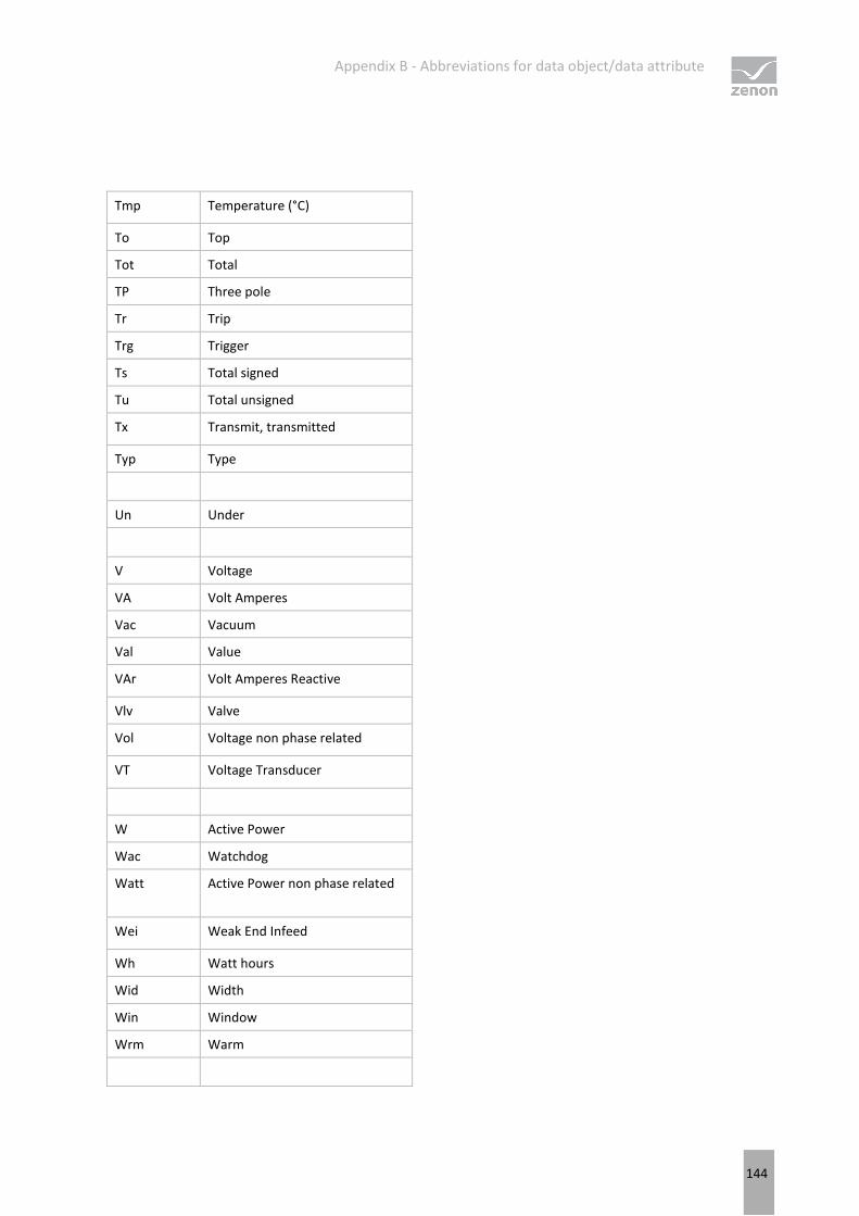
Appendix B - Abbreviations for data object/data attribute
144
Tmp Temperature (°C)
To Top
Tot Total
TP Three pole
Tr Trip
Trg Trigger
Ts Total signed
Tu Total unsigned
Tx Transmit, transmitted
Typ Type
Un Under
V Voltage
VA Volt Amperes
Vac Vacuum
Val Value
VAr Volt Amperes Reactive
Vlv Valve
Vol Voltage non phase related
VT Voltage Transducer
W Active Power
Wac Watchdog
Watt Active Power non phase related
Wei Weak End Infeed
Wh Watt hours
Wid Width
Win Window
Wrm Warm
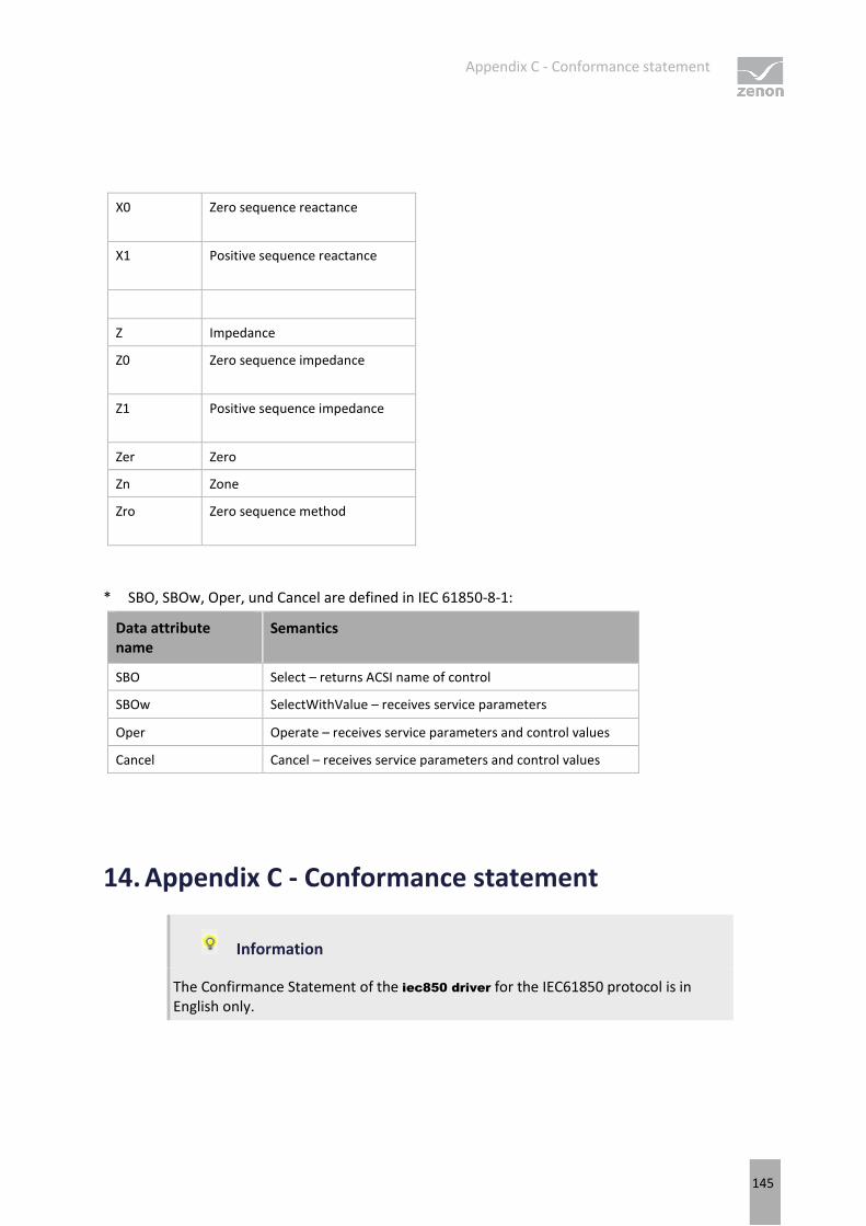
Appendix C - Conformance statement
145
X0 Zero sequence reactance
X1 Positive sequence reactance
Z Impedance
Z0 Zero sequence impedance
Z1 Positive sequence impedance
Zer Zero
Zn Zone
Zro Zero sequence method
* SBO, SBOw, Oper, und Cancel are defined in IEC 61850-8-1:
Data attribute name
Semantics
SBO Select – returns ACSI name of control
SBOw SelectWithValue – receives service parameters
Oper Operate – receives service parameters and control values
Cancel Cancel – receives service parameters and control values
14. Appendix C - Conformance statement
Information
The Confirmance Statement of the iec850 driver for the IEC61850 protocol is in English only.

Appendix C - Conformance statement
146
14.1 Protocol implementation conformance statement (PICS)
This document specifies the PICS of the IEC 61850 interface in the client system: "zenon
Supervisor/Energy Edition", Version 7.50, further referred to as "Client". The zenon Editor and Runtime are further referred to as "HMI".
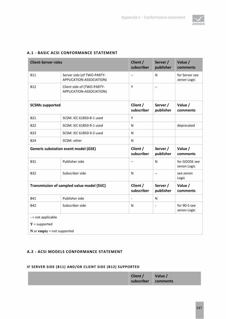
Appendix C - Conformance statement
147
A.1 - BASIC ACSI CONFORMANCE STATEMENT
Client-Server roles Client / subscriber
Server / publisher
Value / comments
B11 Server side (of TWO-PARTY- APPLICATION-ASSOCIATION)
-- N for Server see zenon Logic
B12 Client side of (TWO-PARTY- APPLICATION-ASSOCIATION)
Y --
SCSMs supported Client / subscriber
Server / publisher
Value / comments
B21 SCSM: IEC 61850-8-1 used Y
B22 SCSM: IEC 61850-9-1 used N deprecated
B23 SCSM: IEC 61850-9-2 used N
B24 SCSM: other N
Generic substation event model (GSE) Client / subscriber
Server / publisher
Value / comments
B31 Publisher side -- N for GOOSE see zenon Logic
B32 Subscriber side N -- see zenon Logic
Transmission of sampled value model (SVC) Client / subscriber
Server / publisher
Value / comments
B41 Publisher side - N
B42 Subscriber side N - for 90-5 see zenon Logic
- = not applicable
Y = supported
N or empty = not supported
A.2 - ACSI MODELS CONFORMANCE STATEMENT
IF SERVER SIDE (B11) AND/OR CLIENT SIDE (B12) SUPPORTED
Client / subscriber
Value / comments

Appendix C - Conformance statement
148
M1 Logical device Y
M2 Logical node Y
M3 Data Y
M4 Data set Y
M5 Substitution Y
M6 Setting group control Y
Reporting Client / subscriber
Value / comments
M7 Buffered report control Y
M7-1 sequence-number Y
M7-2 report-time-stamp Y
M7-3 reason-for-inclusion Y
M7-4 data-set-name Y
M7-5 data-reference Y
M7-6 buffer-overflow Y
M7-7 entryID Y
M7-8 BufIm Y
M7-9 IntgPd Y
M7-10 GI Y
M8 Unbuffered report control Y
M8-1 sequence-number Y
M8-2 report-time-stamp Y
M8-3 reason-for-inclusion Y
M8-4 data-set-name Y
M8-5 data-reference Y
M8-6 BufIm Y
M8-7 IntgPd Y
M8-8 GI Y
Logging Client / subscriber
Value / comments
M9 Log control N
M9-1 IntgPd N
M10 Log N
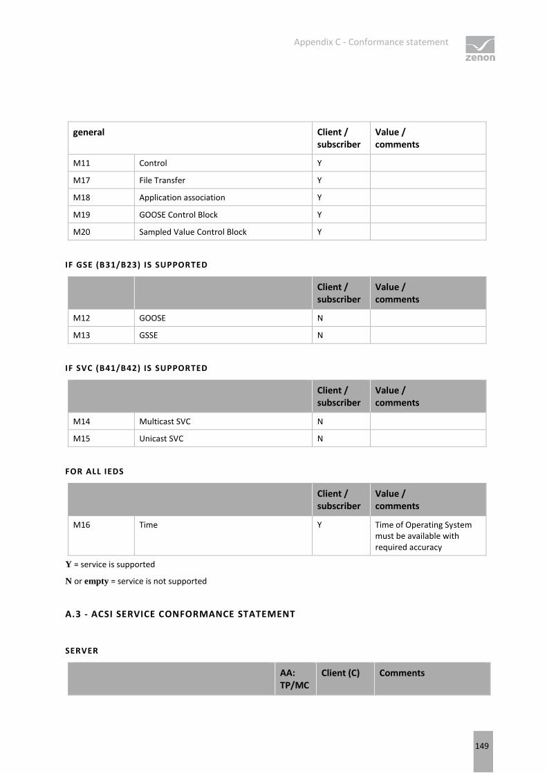
Appendix C - Conformance statement
149
general Client / subscriber
Value / comments
M11 Control Y
M17 File Transfer Y
M18 Application association Y
M19 GOOSE Control Block Y
M20 Sampled Value Control Block Y
IF GSE (B31/B23) IS SUPPORTED
Client / subscriber
Value / comments
M12 GOOSE N
M13 GSSE N
IF SVC (B41/B42) IS SUPPORTED
Client / subscriber
Value / comments
M14 Multicast SVC N
M15 Unicast SVC N
FOR ALL IEDS
Client / subscriber
Value / comments
M16 Time Y Time of Operating System must be available with required accuracy
Y = service is supported
N or empty = service is not supported
A.3 - ACSI SERVICE CONFORMANCE STATEMENT
SERVER
AA: TP/MC
Client (C) Comments
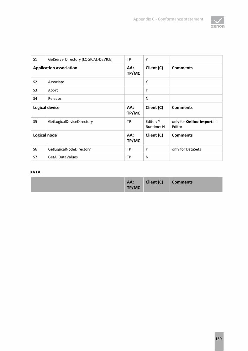
Appendix C - Conformance statement
150
S1 GetServerDirectory (LOGICAL-DEVICE) TP Y
Application association AA: TP/MC
Client (C) Comments
S2 Associate Y
S3 Abort Y
S4 Release N
Logical device AA: TP/MC
Client (C) Comments
S5 GetLogicalDeviceDirectory TP Editor: Y Runtime: N
only for Online Import in Editor
Logical node AA: TP/MC
Client (C) Comments
S6 GetLogicalNodeDirectory TP Y only for DataSets
S7 GetAllDataValues TP N
DATA
AA: TP/MC
Client (C) Comments
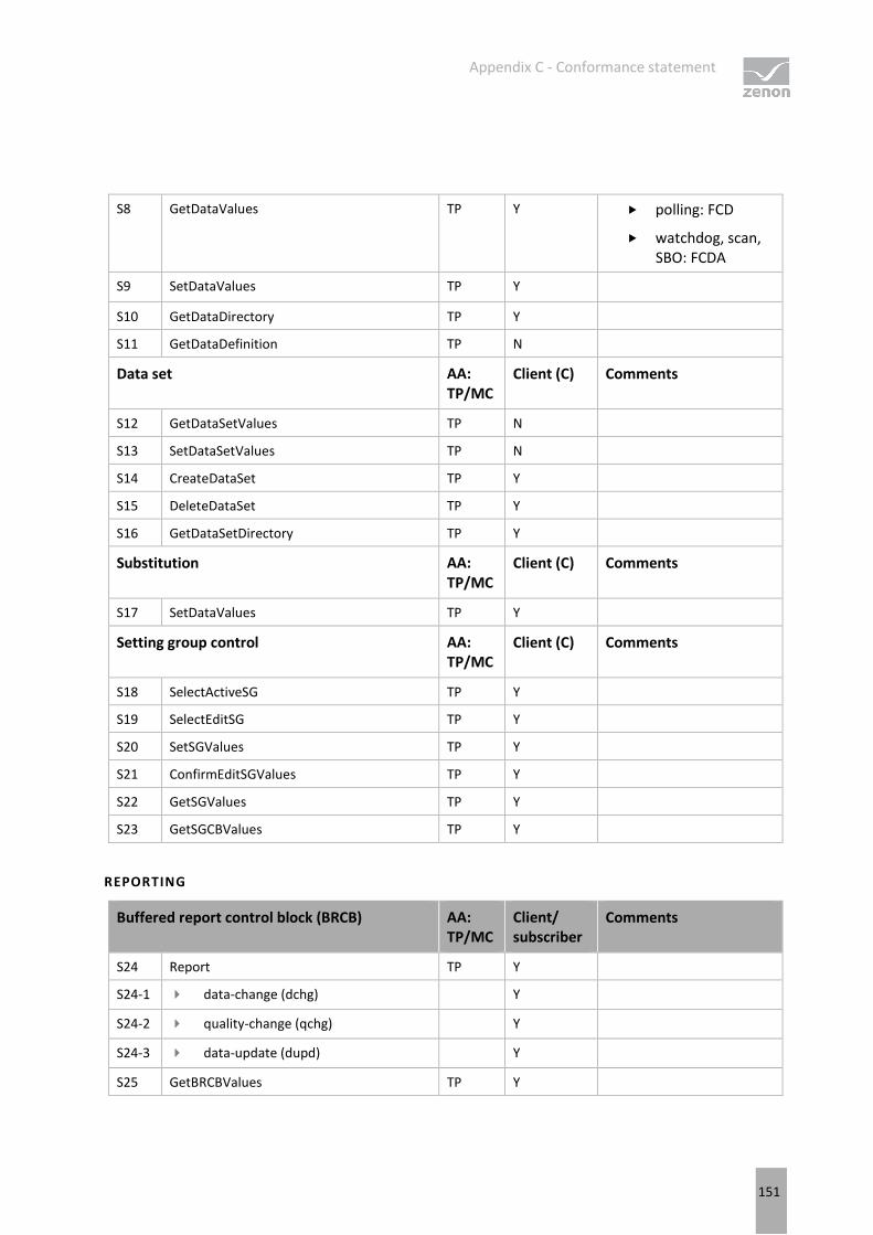
Appendix C - Conformance statement
151
S8 GetDataValues TP Y polling: FCD
watchdog, scan, SBO: FCDA
S9 SetDataValues TP Y
S10 GetDataDirectory TP Y
S11 GetDataDefinition TP N
Data set AA: TP/MC
Client (C) Comments
S12 GetDataSetValues TP N
S13 SetDataSetValues TP N
S14 CreateDataSet TP Y
S15 DeleteDataSet TP Y
S16 GetDataSetDirectory TP Y
Substitution AA: TP/MC
Client (C) Comments
S17 SetDataValues TP Y
Setting group control AA: TP/MC
Client (C) Comments
S18 SelectActiveSG TP Y
S19 SelectEditSG TP Y
S20 SetSGValues TP Y
S21 ConfirmEditSGValues TP Y
S22 GetSGValues TP Y
S23 GetSGCBValues TP Y
REPORTING
Buffered report control block (BRCB) AA: TP/MC
Client/ subscriber
Comments
S24 Report TP Y
S24-1 data-change (dchg) Y
S24-2 quality-change (qchg) Y
S24-3 data-update (dupd) Y
S25 GetBRCBValues TP Y
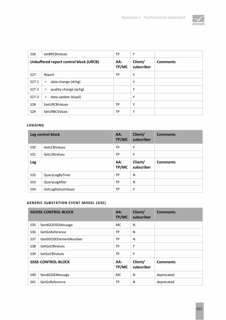
Appendix C - Conformance statement
152
S26 SetBRCBValues TP Y
Unbuffered report control block (URCB) AA: TP/MC
Client/ subscriber
Comments
S27 Report TP Y
S27-1 data-change (dchg) Y
S27-2 quality-change (qchg) Y
S27-3 data-update (dupd) Y
S28 GetURCBValues TP Y
S29 SetURBCValues TP Y
LOGGING
Log control block AA: TP/MC
Client/ subscriber
Comments
S30 GetLCBValues TP Y
S31 SetLCBValues TP Y
Log AA: TP/MC
Client/ subscriber
Comments
S32 QueryLogByTime TP N
S33 QueryLogAfter TP N
S34 GetLogStatusValues TP Y
GENERIC SUBSTATION EVENT MODEL (GSE)
GOOSE-CONTROL-BLOCK AA: TP/MC
Client/ subscriber
Comments
S35 SendGOOSEMessage MC N
S36 GetGoReference TP N
S37 GetGOOSEElementNumber TP N
S38 GetGoCBValues TP Y
S39 SetGoCBValues TP Y
GSSE-CONTROL-BLOCK AA: TP/MC
Client/ subscriber
Comments
S40 SendGSSEMessage MC N deprecated
S41 GetGsReference TP N deprecated
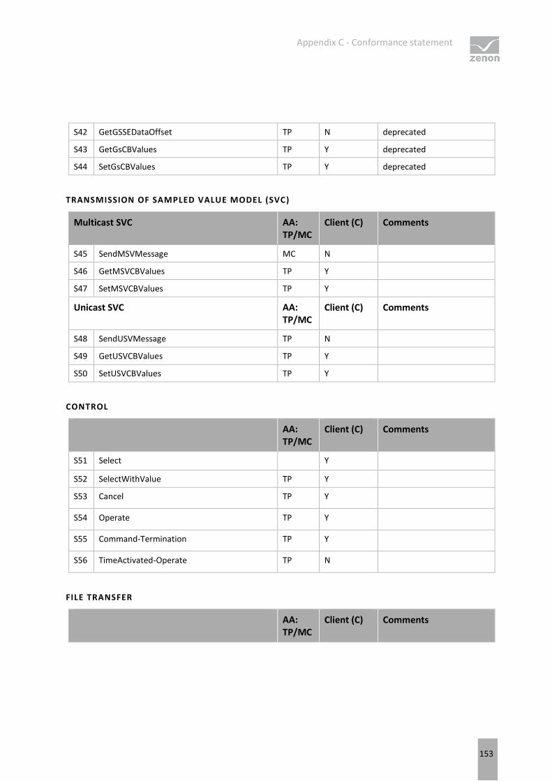
Appendix C - Conformance statement
153
S42 GetGSSEDataOffset TP N deprecated
S43 GetGsCBValues TP Y deprecated
S44 SetGsCBValues TP Y deprecated
TRANSMISSION OF SAMPLED VALUE MODEL (SVC)
Multicast SVC AA: TP/MC
Client (C) Comments
S45 SendMSVMessage MC N
S46 GetMSVCBValues TP Y
S47 SetMSVCBValues TP Y
Unicast SVC AA: TP/MC
Client (C) Comments
S48 SendUSVMessage TP N
S49 GetUSVCBValues TP Y
S50 SetUSVCBValues TP Y
CONTROL
AA: TP/MC
Client (C) Comments
S51 Select Y
S52 SelectWithValue TP Y
S53 Cancel TP Y
S54 Operate TP Y
S55 Command-Termination TP Y
S56 TimeActivated-Operate TP N
FILE TRANSFER
AA: TP/MC
Client (C) Comments
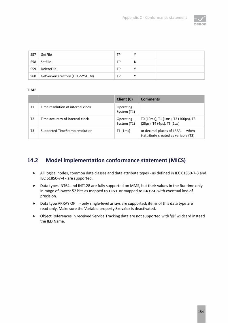
Appendix C - Conformance statement
154
S57 GetFile TP Y
S58 SetFile TP N
S59 DeleteFile TP Y
S60 GetServerDirectory (FILE-SYSTEM) TP Y
TIME
Client (C) Comments
T1 Time resolution of internal clock Operating System (T1)
T2 Time accuracy of internal clock Operating System (T1)
T0 (10ms), T1 (1ms), T2 (100µs), T3 (25µs), T4 (4µs), T5 (1µs)
T3 Supported TimeStamp resolution T1 (1ms) or decimal places of LREAL when t-attribute created as variable (T3)
14.2 Model implementation conformance statement (MICS)
All logical nodes, common data classes and data attribute types - as defined in IEC 61850-7-3 and IEC 61850-7-4 - are supported.
Data types INT64 and INT128 are fully supported on MMS, but their values in the Runtime only in range of lowest 52 bits as mapped to LINT or mapped to LREAL with eventual loss of precision.
Data type ARRAY OF - only single-level arrays are supported; items of this data type are read-only. Make sure the Variable property Set value is deactivated.
Object References in received Service Tracking data are not supported with '@' wildcard instead the IED Name.
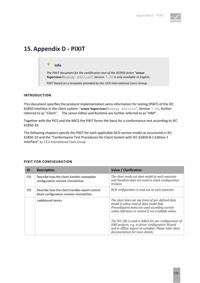
Appendix D - PIXIT
155
15. Appendix D - PIXIT
Info
The PIXIT document for the certification test of the IEC850 driver "zenon
Supervisor/Energy Edition", Version 7.50 is only available in English.
PIXIT based on a template provided by the UCA International Users Group.
INTRODUCTION
This document specifies the protocol implementation extra information for testing (PIXIT) of the IEC 61850 interface in the client system: "zenon Supervisor/Energy Edition", Version 7.50, further referred to as “Client”. The zenon Editor and Runtime are further referred to as "HMI".
Together with the PICS and the MICS the PIXIT forms the basis for a conformance test according to IEC 61850-10.
The following chapters specify the PIXIT for each applicable ACSI service model as structured in IEC 61850-10 and the “Conformance Test Procedures for Client System with IEC 61850-8-1 Edition 2 interface” by UCA International Users Group.
PIXIT FOR CONFIGURATION
ID Description Value / Clarification
Cf1 Describe how the client handles nameplate configuration revision mismatches
The client reads out data model at each associate and therefore does not need to check configuration revision.
Cf2 Describe how the client handles report control block configuration revision mismatches
RCB configuration is read out at each associate.
<additional items> The client does not use items of pre-defined data model if online read of data model fails. Preconfigured items are used according current online definition or omited if not available online.
The SCL-file is used in Editor for pre-configuration of HMI projects, e.g. in driver configuration Wizard and in offline import of variables. Please refer client documentation for more details.
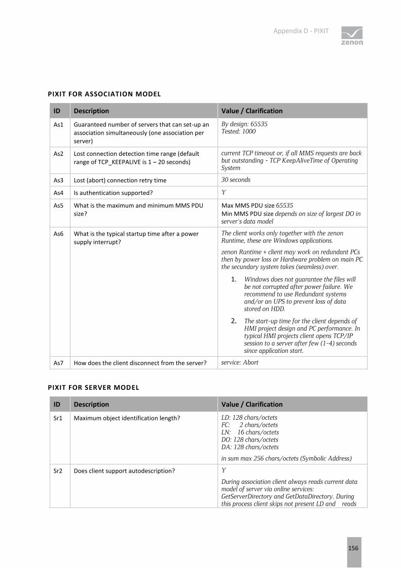
Appendix D - PIXIT
156
PIXIT FOR ASSOCIATION MODEL
ID Description Value / Clarification
As1 Guaranteed number of servers that can set-up an association simultaneously (one association per server)
By design: 65535 Tested: 1000
As2 Lost connection detection time range (default range of TCP_KEEPALIVE is 1 – 20 seconds)
current TCP timeout or, if all MMS requests are back but outstanding - TCP KeepAliveTime of Operating System
As3 Lost (abort) connection retry time 30 seconds
As4 Is authentication supported? Y
As5 What is the maximum and minimum MMS PDU size?
Max MMS PDU size 65535 Min MMS PDU size depends on size of largest DO in server's data model
As6 What is the typical startup time after a power supply interrupt?
The client works only together with the zenon Runtime, these are Windows applications.
zenon Runtime + client may work on redundant PCs then by power loss or Hardware problem on main PC the secundary system takes (seamless) over.
1. Windows does not guarantee the files will be not corrupted after power failure. We recommend to use Redundant systems and/or an UPS to prevent loss of data stored on HDD.
2. The start-up time for the client depends of HMI project design and PC performance. In typical HMI projects client opens TCP/IP session to a server after few (1-4) seconds since application start.
As7 How does the client disconnect from the server? service: Abort
PIXIT FOR SERVER MODEL
ID Description Value / Clarification
Sr1 Maximum object identification length? LD: 128 chars/octets FC: 2 chars/octets LN: 16 chars/octets DO: 128 chars/octets DA: 128 chars/octets
in sum max 256 chars/octets (Symbolic Address)
Sr2 Does client support autodescription? Y
During association client always reads current data model of server via online services: GetServerDirectory and GetDataDirectory. During this process client skips not present LD and reads
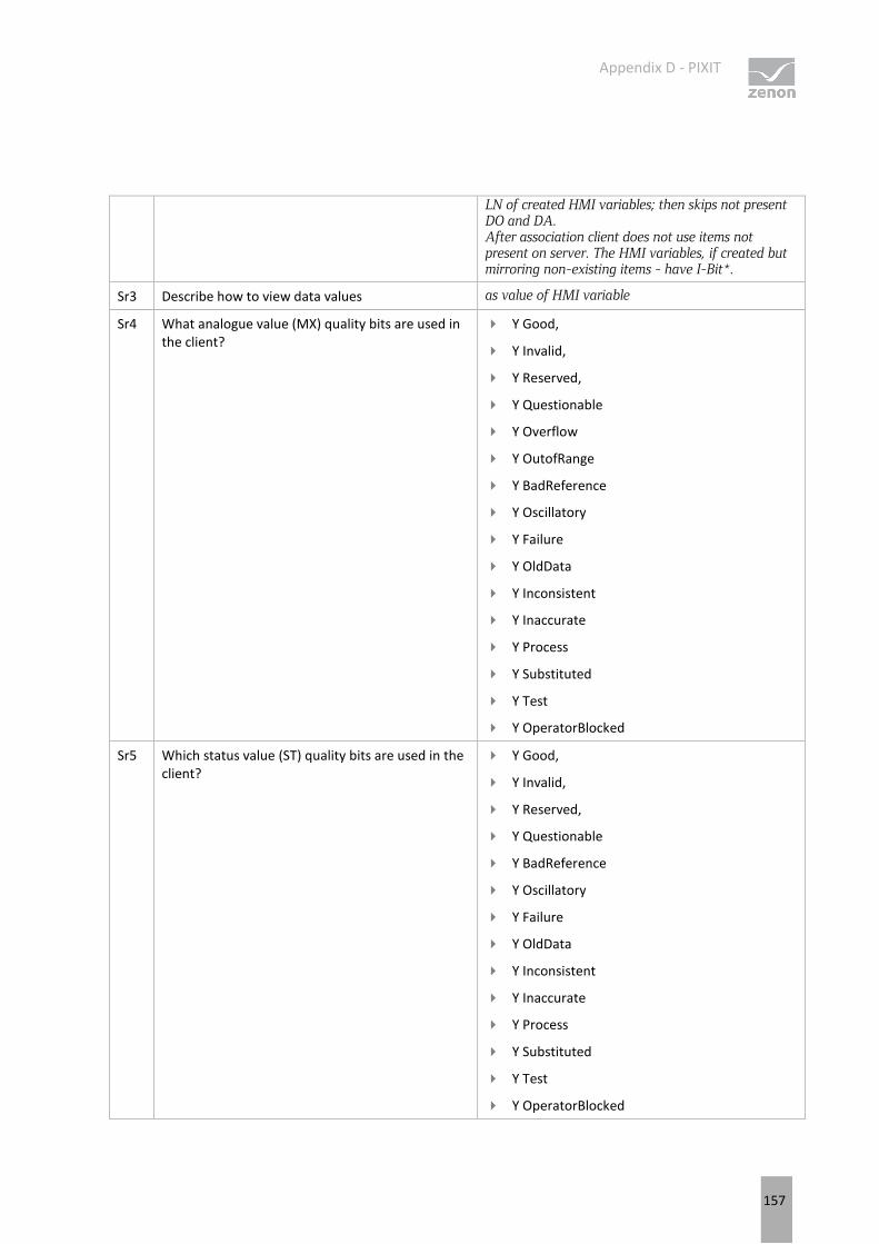
Appendix D - PIXIT
157
LN of created HMI variables; then skips not present DO and DA. After association client does not use items not present on server. The HMI variables, if created but mirroring non-existing items - have I-Bit*.
Sr3 Describe how to view data values as value of HMI variable
Sr4 What analogue value (MX) quality bits are used in the client?
Y Good,
Y Invalid,
Y Reserved,
Y Questionable
Y Overflow
Y OutofRange
Y BadReference
Y Oscillatory
Y Failure
Y OldData
Y Inconsistent
Y Inaccurate
Y Process
Y Substituted
Y Test
Y OperatorBlocked
Sr5 Which status value (ST) quality bits are used in the client?
Y Good,
Y Invalid,
Y Reserved,
Y Questionable
Y BadReference
Y Oscillatory
Y Failure
Y OldData
Y Inconsistent
Y Inaccurate
Y Process
Y Substituted
Y Test
Y OperatorBlocked
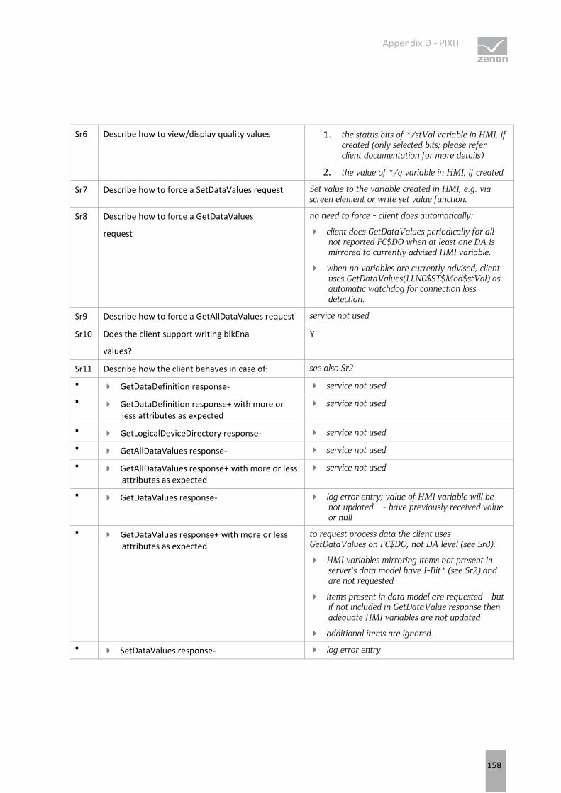
Appendix D - PIXIT
158
Sr6 Describe how to view/display quality values 1. the status bits of */stVal variable in HMI, if created (only selected bits; please refer client documentation for more details)
2. the value of */q variable in HMI, if created
Sr7 Describe how to force a SetDataValues request Set value to the variable created in HMI, e.g. via screen element or write set value function.
Sr8 Describe how to force a GetDataValues
request
no need to force - client does automatically:
client does GetDataValues periodically for all not reported FC$DO when at least one DA is mirrored to currently advised HMI variable.
when no variables are currently advised, client uses GetDataValues(LLN0$ST$Mod$stVal) as automatic watchdog for connection loss detection.
Sr9 Describe how to force a GetAllDataValues request service not used
Sr10 Does the client support writing blkEna
values?
Y
Sr11 Describe how the client behaves in case of: see also Sr2
GetDataDefinition response- service not used
GetDataDefinition response+ with more or less attributes as expected
service not used
GetLogicalDeviceDirectory response- service not used
GetAllDataValues response- service not used
GetAllDataValues response+ with more or less attributes as expected
service not used
GetDataValues response- log error entry; value of HMI variable will be not updated - have previously received value or null
GetDataValues response+ with more or less attributes as expected
to request process data the client uses GetDataValues on FC$DO, not DA level (see Sr8).
HMI variables mirroring items not present in server's data model have I-Bit* (see Sr2) and are not requested
items present in data model are requested but if not included in GetDataValue response then adequate HMI variables are not updated
additional items are ignored.
SetDataValues response- log error entry
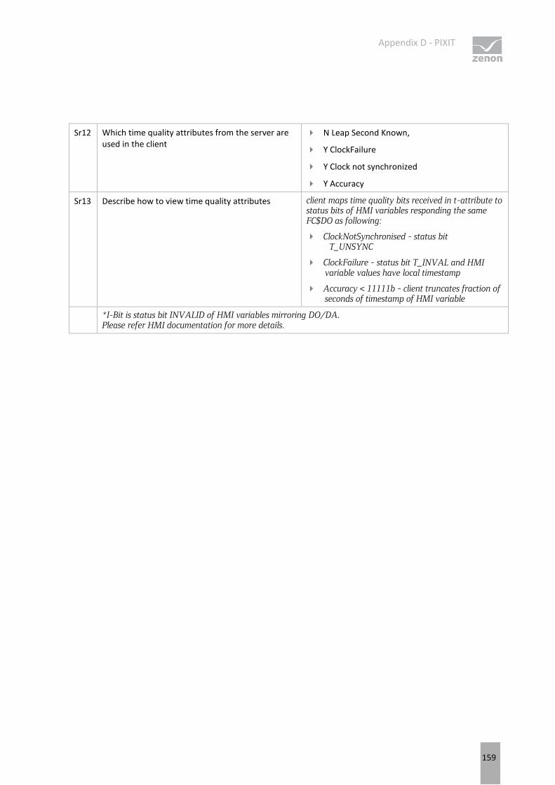
Appendix D - PIXIT
159
Sr12 Which time quality attributes from the server are used in the client
N Leap Second Known,
Y ClockFailure
Y Clock not synchronized
Y Accuracy
Sr13 Describe how to view time quality attributes client maps time quality bits received in t-attribute to status bits of HMI variables responding the same FC$DO as following:
ClockNotSynchronised - status bit T_UNSYNC
ClockFailure - status bit T_INVAL and HMI variable values have local timestamp
Accuracy < 11111b - client truncates fraction of seconds of timestamp of HMI variable
*I-Bit is status bit INVALID of HMI variables mirroring DO/DA. Please refer HMI documentation for more details.
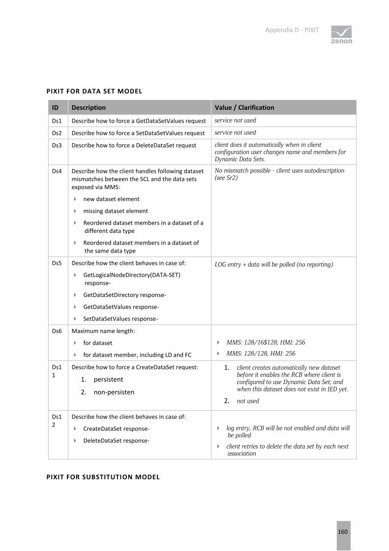
Appendix D - PIXIT
160
PIXIT FOR DATA SET MODEL
ID Description Value / Clarification
Ds1 Describe how to force a GetDataSetValues request service not used
Ds2 Describe how to force a SetDataSetValues request service not used
Ds3 Describe how to force a DeleteDataSet request client does it automatically when in client configuration user changes name and members for Dynamic Data Sets.
Ds4 Describe how the client handles following dataset mismatches between the SCL and the data sets exposed via MMS:
new dataset element
missing dataset element
Reordered dataset members in a dataset of a different data type
Reordered dataset members in a dataset of the same data type
No mismatch possible - client uses autodescription (see Sr2)
Ds5 Describe how the client behaves in case of:
GetLogicalNodeDirectory(DATA-SET) response-
GetDataSetDirectory response-
GetDataSetValues response-
SetDataSetValues response-
LOG entry + data will be polled (no reporting)
Ds6 Maximum name length:
for dataset
for dataset member, including LD and FC
MMS: 128/16$128, HMI: 256
MMS: 128/128, HMI: 256
Ds11
Describe how to force a CreateDataSet request:
1. persistent
2. non-persisten
1. client creates automatically new dataset before it enables the RCB where client is configured to use Dynamic Data Set; and when this dataset does not exist in IED yet.
2. not used
Ds12
Describe how the client behaves in case of:
CreateDataSet response-
DeleteDataSet response-
log entry, RCB will be not enabled and data will be polled
client retries to delete the data set by each next association
PIXIT FOR SUBSTITUTION MODEL
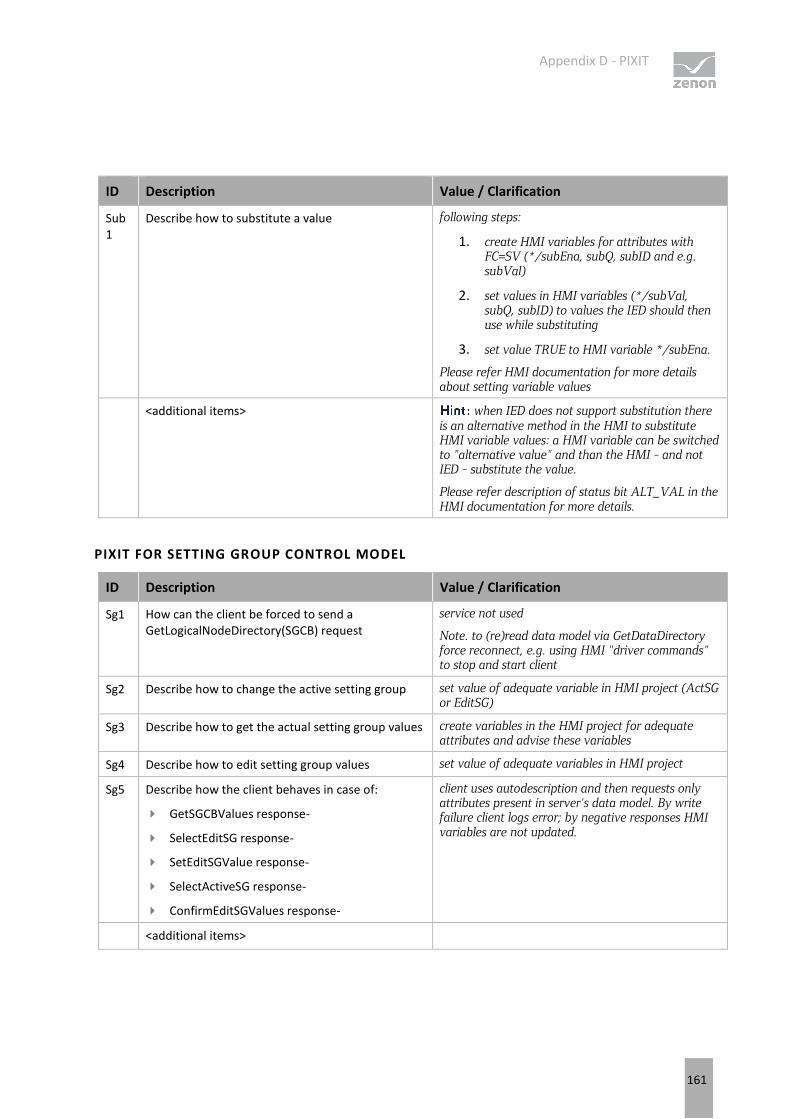
Appendix D - PIXIT
161
ID Description Value / Clarification
Sub1
Describe how to substitute a value following steps:
1. create HMI variables for attributes with FC=SV (*/subEna, subQ, subID and e.g. subVal)
2. set values in HMI variables (*/subVal, subQ, subID) to values the IED should then use while substituting
3. set value TRUE to HMI variable */subEna.
Please refer HMI documentation for more details about setting variable values
<additional items> when IED does not support substitution there is an alternative method in the HMI to substitute HMI variable values: a HMI variable can be switched to "alternative value" and than the HMI - and not IED - substitute the value.
Please refer description of status bit ALT_VAL in the HMI documentation for more details.
PIXIT FOR SETTING GROUP CONTROL MODEL
ID Description Value / Clarification
Sg1 How can the client be forced to send a GetLogicalNodeDirectory(SGCB) request
service not used
Note. to (re)read data model via GetDataDirectory force reconnect, e.g. using HMI "driver commands" to stop and start client
Sg2 Describe how to change the active setting group set value of adequate variable in HMI project (ActSG or EditSG)
Sg3 Describe how to get the actual setting group values create variables in the HMI project for adequate attributes and advise these variables
Sg4 Describe how to edit setting group values set value of adequate variables in HMI project
Sg5 Describe how the client behaves in case of:
GetSGCBValues response-
SelectEditSG response-
SetEditSGValue response-
SelectActiveSG response-
ConfirmEditSGValues response-
client uses autodescription and then requests only attributes present in server's data model. By write failure client logs error; by negative responses HMI variables are not updated.
<additional items>
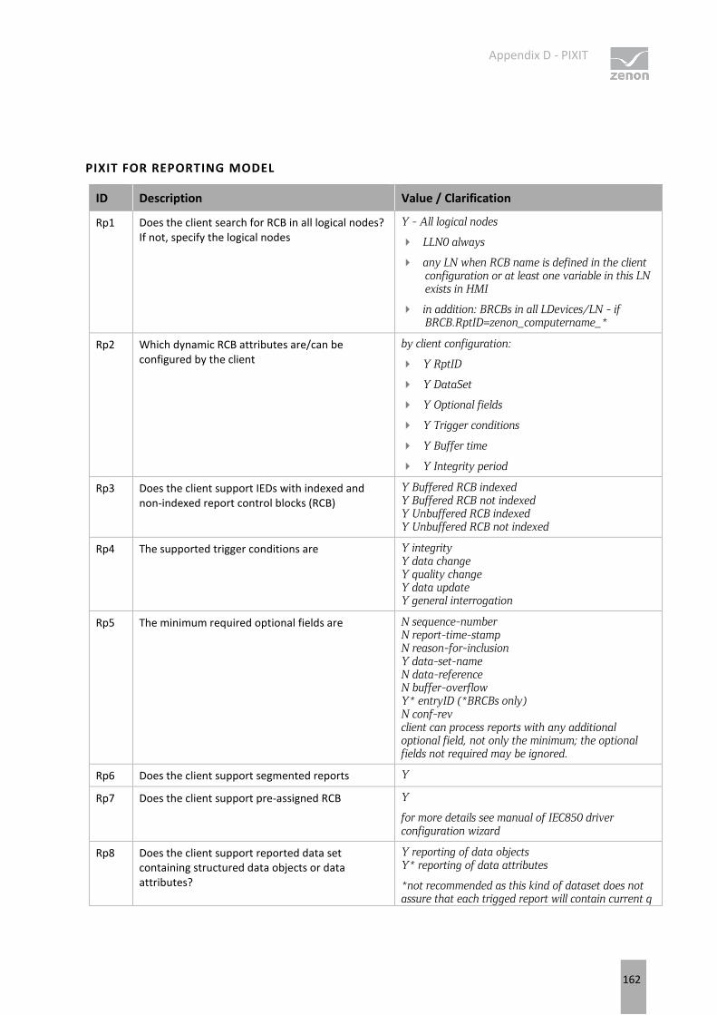
Appendix D - PIXIT
162
PIXIT FOR REPORTING MODEL
ID Description Value / Clarification
Rp1 Does the client search for RCB in all logical nodes? If not, specify the logical nodes
Y - All logical nodes
LLN0 always
any LN when RCB name is defined in the client configuration or at least one variable in this LN exists in HMI
in addition: BRCBs in all LDevices/LN - if BRCB.RptID=zenon_computername_*
Rp2 Which dynamic RCB attributes are/can be configured by the client
by client configuration:
Y RptID
Y DataSet
Y Optional fields
Y Trigger conditions
Y Buffer time
Y Integrity period
Rp3 Does the client support IEDs with indexed and non-indexed report control blocks (RCB)
Y Buffered RCB indexed Y Buffered RCB not indexed Y Unbuffered RCB indexed Y Unbuffered RCB not indexed
Rp4 The supported trigger conditions are Y integrity Y data change Y quality change Y data update Y general interrogation
Rp5 The minimum required optional fields are N sequence-number N report-time-stamp N reason-for-inclusion Y data-set-name N data-reference N buffer-overflow Y* entryID (*BRCBs only) N conf-rev client can process reports with any additional optional field, not only the minimum; the optional fields not required may be ignored.
Rp6 Does the client support segmented reports Y
Rp7 Does the client support pre-assigned RCB Y
for more details see manual of IEC850 driver configuration wizard
Rp8 Does the client support reported data set containing structured data objects or data attributes?
Y reporting of data objects Y* reporting of data attributes
*not recommended as this kind of dataset does not assure that each trigged report will contain current q
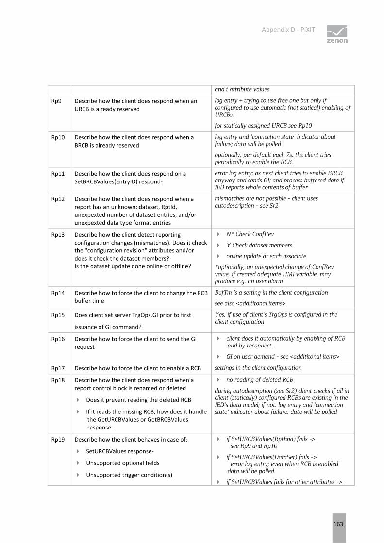
Appendix D - PIXIT
163
and t attribute values.
Rp9 Describe how the client does respond when an URCB is already reserved
log entry + trying to use free one but only if configured to use automatic (not statical) enabling of URCBs.
for statically assigned URCB see Rp10
Rp10 Describe how the client does respond when a BRCB is already reserved
log entry and 'connection state' indicator about failure; data will be polled
optionally, per default each 7s, the client tries periodically to enable the RCB.
Rp11 Describe how the client does respond on a SetBRCBValues(EntryID) respond-
error log entry; as next client tries to enable BRCB anyway and sends GI; and process buffered data if IED reports whole contents of buffer
Rp12 Describe how the client does respond when a report has an unknown: dataset, RptId, unexpexted number of dataset entries, and/or unexpexted data type format entries
mismatches are not possible - client uses autodescription - see Sr2
Rp13 Describe how the client detect reporting configuration changes (mismatches). Does it check the "configuration revision" attributes and/or does it check the dataset members? Is the dataset update done online or offline?
N* Check ConfRev
Y Check dataset members
online update at each associate
*optionally, an unexpected change of ConfRev value, if created adequate HMI variable, may produce e.g. an user alarm
Rp14 Describe how to force the client to change the RCB buffer time
BufTm is a setting in the client configuration
see also <addititonal items>
Rp15 Does client set server TrgOps.GI prior to first
issuance of GI command?
Yes, if use of client's TrgOps is configured in the client configuration
Rp16 Describe how to force the client to send the GI request
client does it automatically by enabling of RCB and by reconnect.
GI on user demand - see <addititonal items>
Rp17 Describe how to force the client to enable a RCB settings in the client configuration
Rp18 Describe how the client does respond when a report control block is renamed or deleted
Does it prevent reading the deleted RCB
If it reads the missing RCB, how does it handle the GetURCBValues or GetBRCBValues response-
no reading of deleted RCB
during autodescription (see Sr2) client checks if all in client (statically) configured RCBs are existing in the IED's data model; if not: log entry and 'connection state' indicator about failure; data will be polled
Rp19 Describe how the client behaves in case of:
SetURCBValues response-
Unsupported optional fields
Unsupported trigger condition(s)
if SetURCBValues(RptEna) fails -> see Rp9 and Rp10
if SetURCBValues(DataSet) fails -> error log entry; even when RCB is enabled data will be polled
if SetURCBValues fails for other attributes ->
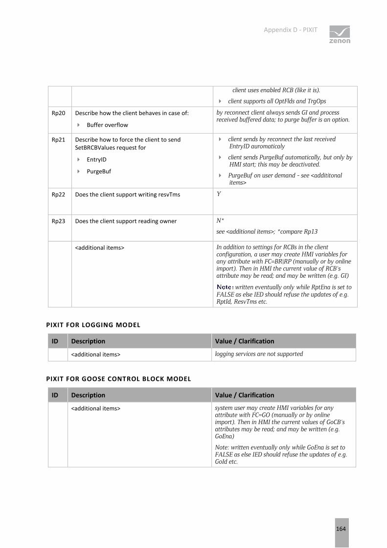
Appendix D - PIXIT
164
client uses enabled RCB (like it is).
client supports all OptFlds and TrgOps
Rp20 Describe how the client behaves in case of:
Buffer overflow
by reconnect client always sends GI and process received buffered data; to purge buffer is an option.
Rp21 Describe how to force the client to send SetBRCBValues request for
EntryID
PurgeBuf
client sends by reconnect the last received EntryID auromaticaly
client sends PurgeBuf automatically, but only by HMI start; this may be deactivated.
PurgeBuf on user demand - see <addititonal items>
Rp22 Does the client support writing resvTms Y
Rp23 Does the client support reading owner N*
see <additional items>; *compare Rp13
<additional items> In addition to settings for RCBs in the client configuration, a user may create HMI variables for any attribute with FC=BR|RP (manually or by online import). Then in HMI the current value of RCB's attribute may be read; and may be written (e.g. GI)
written eventually only while RptEna is set to FALSE as else IED should refuse the updates of e.g. RptId, ResvTms etc.
PIXIT FOR LOGGING MODEL
ID Description Value / Clarification
<additional items> logging services are not supported
PIXIT FOR GOOSE CONTROL BLOCK MODEL
ID Description Value / Clarification
<additional items> system user may create HMI variables for any attribute with FC=GO (manually or by online import). Then in HMI the current values of GoCB's attributes may be read; and may be written (e.g. GoEna)
Note: written eventually only while GoEna is set to FALSE as else IED should refuse the updates of e.g. GoId etc.
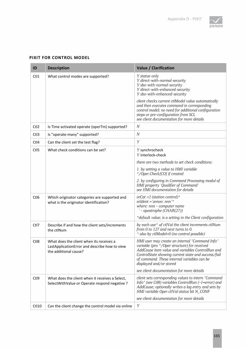
Appendix D - PIXIT
165
PIXIT FOR CONTROL MODEL
ID Description Value / Clarification
Ctl1 What control modes are supported? Y status-only Y direct-with-normal-security Y sbo-with-normal-security Y direct-with-enhanced-security Y sbo-with-enhanced-security
client checks current ctlModel value automatically and then executes command in corresponding control model; no need for additional configuration steps or pre-configuration from SCL see client documentation for more details
Ctl2 Is Time activated operate (operTm) supported? N
Ctl3 Is "operate-many" supported? N
Ctl4 Can the client set the test flag? Y
Ctl5 What check conditions can be set? Y synchrocheck Y interlock-check
there are two methods to set check conditions:
1. by setting a value to HMI variable */Oper.Check[CO] if created
2. by configuring in Command Processing modul of HMI property 'Qualifier of Command' see HMI documentation for details
Ctl6 Which originator categories are supported and what is the originator identification?
orCat =2 (station control)* orIdent ='zenon: nnn'* where: nnn - computer name ' - apostrophe (CHAR(27))
*default value; is a setting in the Client configuration
Ctl7 Describe if and how the client sets/increments the ctlNum
by each use* of ctlVal the client increments ctlNum from 0 to 127 and next turns to 0. * also by ctlModel=0 (no control possible)
Ctl8 What does the client when its receives a LastApplicationError and describe how to view the additional cause?
HMI user may create an internal "Command Info" variable (pro */Oper structure) for received AddCause item value and variables ControlRun and ControlState showing current state and success/fail of command. These internal variables can be displayed and/or stored
see client documentation for more details
Ctl9 What does the client when it receives a Select, SelectWithValue or Operate respond negative ?
client sets corresponding values to intern "Command Info" (see Ctl8) variables ControlRun (-1=error) and AddCause; optionally writes a log entry and sets by HMI variable Oper.ctlVal status bit N_CONF
see client documentation for more details
Ctl10 Can the client change the control model via online Y
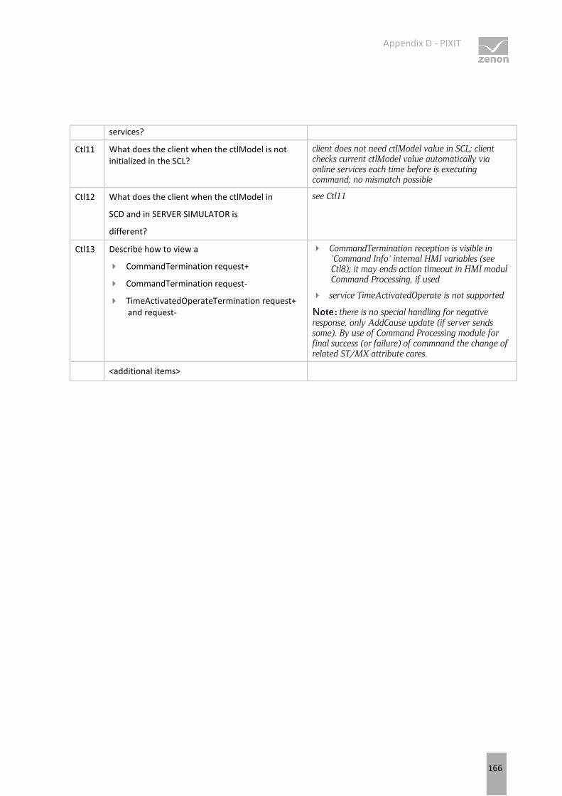
Appendix D - PIXIT
166
services?
Ctl11 What does the client when the ctlModel is not initialized in the SCL?
client does not need ctlModel value in SCL; client checks current ctlModel value automatically via online services each time before is executing command; no mismatch possible
Ctl12 What does the client when the ctlModel in
SCD and in SERVER SIMULATOR is
different?
see Ctl11
Ctl13 Describe how to view a
CommandTermination request+
CommandTermination request-
TimeActivatedOperateTermination request+ and request-
CommandTermination reception is visible in 'Command Info' internal HMI variables (see Ctl8); it may ends action timeout in HMI modul Command Processing, if used
service TimeActivatedOperate is not supported
there is no special handling for negative response, only AddCause update (if server sends some). By use of Command Processing module for final success (or failure) of commnand the change of related ST/MX attribute cares.
<additional items>
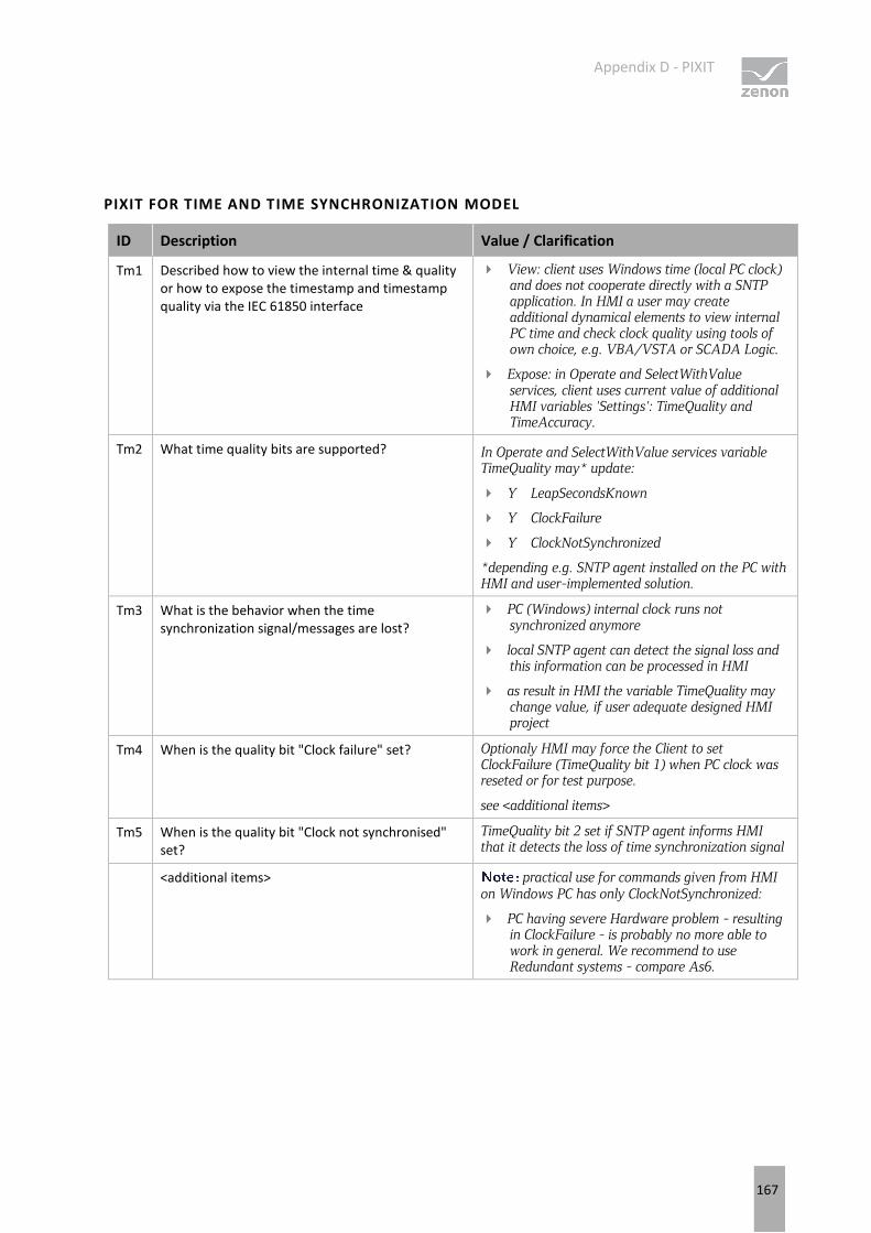
Appendix D - PIXIT
167
PIXIT FOR TIME AND TIME SYNCHRONIZATION MODEL
ID Description Value / Clarification
Tm1 Described how to view the internal time & quality or how to expose the timestamp and timestamp quality via the IEC 61850 interface
View: client uses Windows time (local PC clock) and does not cooperate directly with a SNTP application. In HMI a user may create additional dynamical elements to view internal PC time and check clock quality using tools of own choice, e.g. VBA/VSTA or SCADA Logic.
Expose: in Operate and SelectWithValue services, client uses current value of additional HMI variables 'Settings': TimeQuality and TimeAccuracy.
Tm2 What time quality bits are supported? In Operate and SelectWithValue services variable TimeQuality may* update:
Y LeapSecondsKnown
Y ClockFailure
Y ClockNotSynchronized
*depending e.g. SNTP agent installed on the PC with HMI and user-implemented solution.
Tm3 What is the behavior when the time synchronization signal/messages are lost?
PC (Windows) internal clock runs not synchronized anymore
local SNTP agent can detect the signal loss and this information can be processed in HMI
as result in HMI the variable TimeQuality may change value, if user adequate designed HMI project
Tm4 When is the quality bit "Clock failure" set? Optionaly HMI may force the Client to set ClockFailure (TimeQuality bit 1) when PC clock was reseted or for test purpose.
see <additional items>
Tm5 When is the quality bit "Clock not synchronised" set?
TimeQuality bit 2 set if SNTP agent informs HMI that it detects the loss of time synchronization signal
<additional items> practical use for commands given from HMI on Windows PC has only ClockNotSynchronized:
PC having severe Hardware problem - resulting in ClockFailure - is probably no more able to work in general. We recommend to use Redundant systems - compare As6.
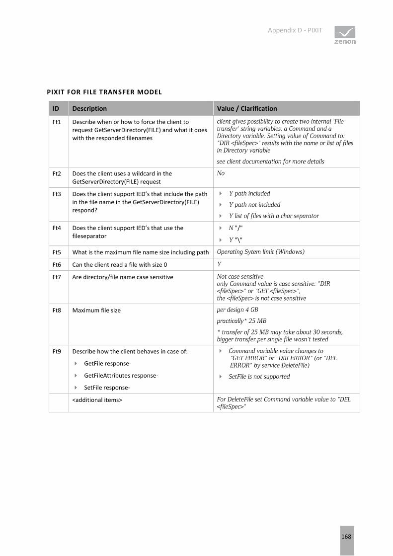
Appendix D - PIXIT
168
PIXIT FOR FILE TRANSFER MODEL
ID Description Value / Clarification
Ft1 Describe when or how to force the client to request GetServerDirectory(FILE) and what it does with the responded filenames
client gives possibility to create two internal 'File transfer' string variables: a Command and a Directory variable. Setting value of Command to: "DIR <fileSpec>" results with the name or list of files in Directory variable
see client documentation for more details
Ft2 Does the client uses a wildcard in the GetServerDirectory(FILE) request
No
Ft3 Does the client support IED’s that include the path in the file name in the GetServerDirectory(FILE) respond?
Y path included
Y path not included
Y list of files with a char separator
Ft4 Does the client support IED’s that use the fileseparator
N "/"
Y "\"
Ft5 What is the maximum file name size including path Operating Sytem limit (Windows)
Ft6 Can the client read a file with size 0 Y
Ft7 Are directory/file name case sensitive Not case sensitive only Command value is case sensitive: "DIR <fileSpec>" or "GET <fileSpec>", the <fileSpec> is not case sensitive
Ft8 Maximum file size per design 4 GB
practically* 25 MB
* transfer of 25 MB may take about 30 seconds, bigger transfer per single file wasn't tested
Ft9 Describe how the client behaves in case of:
GetFile response-
GetFileAttributes response-
SetFile response-
Command variable value changes to "GET ERROR" or "DIR ERROR" (or "DEL ERROR" by service DeleteFile)
SetFile is not supported
<additional items> For DeleteFile set Command variable value to "DEL <fileSpec>"

Appendix D - PIXIT
169
PIXIT FOR SERVICE TRACKING MODEL
ID Description Value / Clarification
Tr1 Which tracking services are supported by the client:
BrcbTrk
UrcbTrk
LocbTrk
GocbTrk
MsvcbTrk
UsvcbTrk
SgcbTrk
SpcTrk
DpcTrk
IncTrk
EncTrk
ApcFTrk
ApcIntTrk
BscTrk
IscTrk
BacTrk
GenTrk
Y* - BrcbTrk
Y* - UrcbTrk
Y* - LocbTrk
Y* - GocbTrk
Y* - MsvcbTrk
Y* - UsvcbTrk
Y* - SgcbTrk
Y - SpcTrk
Y - DpcTrk
Y - IncTrk
Y - EncTrk
Y - ApcFTrk
Y - ApcIntTrk
Y - BscTrk
Y - IscTrk
Y - BacTrk
Y - GenTrk
*) per default only CST attributes, the rest of data attributes optionally. See client documentation for more details.
Tr2 Describe how to view the tracking objects or their attributes
in additional HMI variables with reference: *LN/DO_xxx[SR] and 'driver object type' = 'service tracking', where xxx is "allCTS" or name of data attribute in CTS class or in another common data class possible in LTRK.
See client documentation for more details
<additional items>
Appendix E - TICS
170
16. Appendix E - TICS
This document specifies the TICS of the IEC 61850 interface in the client system: “zenon
Supervisor/Energy Edition", Version 7.50, further referred to as “Client”. The zenon Editor and Runtime are further referred to as "HMI".
MANDATORY EDITION 2 TISSUES
Below tables give an overview of the applicable mandatory Tissues.
SUPPORTED BY CLIENT:
"Y": means that the client supports servers that have implemented the respective tissue.
"ni": No impact on testing
"na": not applicable if the client does not support the corresponding ACSI service(s)

Appendix E - TICS
171
16.1 Part 6
Tissue Description Supported by client
658 Tracking related features Y
663 FCDA element cannot be a "functionally constrained logical node" Y
668 Autotransformer modeling Y
719 ConfDataSet - maxAttributes definition is confusing na
721 Log element name na
768 bType VisString65 is missing Y
779 object references na
788 SICS S56 from optional to mandatory Y
789 ConfLdName as services applies to both server and client (supportsLdname)
Y
804 valKind and IED versus System configuration (valimport) na
806 Max length of log name inconsistent between -6 and -7-2 ni
807 Need a way to indicate if "Owner" present in RCB Y
822 Extension of IED capabilities Y
823 ValKind for structured data attributes Y
824 Short addresses on structured data attributes Y
825 Floating point value Y
845 SGCB ResvTms Y
853 SBO and ProtNs Y
855 Recursive SubFunction na
856 VoltageLevel frequency and phases ni
857 Function/SubFunction for ConductingEquipment na
886 Missing 8-1 P-types Y
901 tServices as AP or as IED element Y
936 SupSubscription parameter usage is difficult na
1175 IPv6 address lowercase only na
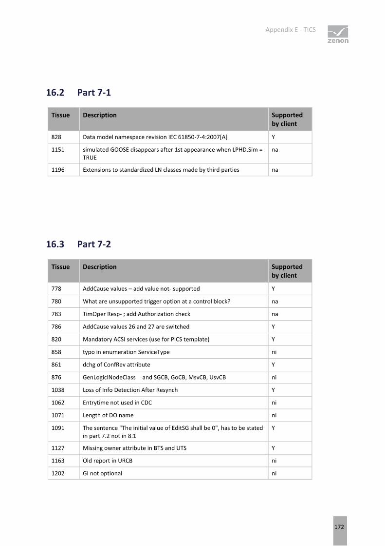
Appendix E - TICS
172
16.2 Part 7-1
Tissue Description Supported by client
828 Data model namespace revision IEC 61850-7-4:2007[A] Y
1151 simulated GOOSE disappears after 1st appearance when LPHD.Sim = TRUE
na
1196 Extensions to standardized LN classes made by third parties na
16.3 Part 7-2
Tissue Description Supported by client
778 AddCause values – add value not- supported Y
780 What are unsupported trigger option at a control block? na
783 TimOper Resp- ; add Authorization check na
786 AddCause values 26 and 27 are switched Y
820 Mandatory ACSI services (use for PICS template) Y
858 typo in enumeration ServiceType ni
861 dchg of ConfRev attribute Y
876 GenLogiclNodeClass and SGCB, GoCB, MsvCB, UsvCB ni
1038 Loss of Info Detection After Resynch Y
1062 Entrytime not used in CDC ni
1071 Length of DO name ni
1091 The sentence "The initial value of EditSG shall be 0", has to be stated in part 7.2 not in 8.1
Y
1127 Missing owner attribute in BTS and UTS Y
1163 Old report in URCB ni
1202 GI not optional ni
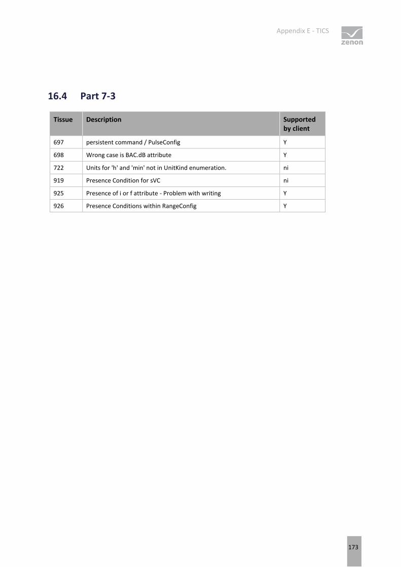
Appendix E - TICS
173
16.4 Part 7-3
Tissue Description Supported by client
697 persistent command / PulseConfig Y
698 Wrong case is BAC.dB attribute Y
722 Units for 'h' and 'min' not in UnitKind enumeration. ni
919 Presence Condition for sVC ni
925 Presence of i or f attribute - Problem with writing Y
926 Presence Conditions within RangeConfig Y
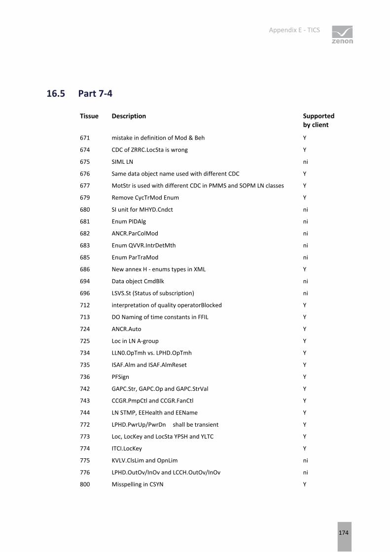
Appendix E - TICS
174
16.5 Part 7-4
Tissue Description Supported by client
671 mistake in definition of Mod & Beh Y
674 CDC of ZRRC.LocSta is wrong Y
675 SIML LN ni
676 Same data object name used with different CDC Y
677 MotStr is used with different CDC in PMMS and SOPM LN classes Y
679 Remove CycTrMod Enum Y
680 SI unit for MHYD.Cndct ni
681 Enum PIDAlg ni
682 ANCR.ParColMod ni
683 Enum QVVR.IntrDetMth ni
685 Enum ParTraMod ni
686 New annex H - enums types in XML Y
694 Data object CmdBlk ni
696 LSVS.St (Status of subscription) ni
712 interpretation of quality operatorBlocked Y
713 DO Naming of time constants in FFIL Y
724 ANCR.Auto Y
725 Loc in LN A-group Y
734 LLN0.OpTmh vs. LPHD.OpTmh Y
735 ISAF.Alm and ISAF.AlmReset Y
736 PFSign Y
742 GAPC.Str, GAPC.Op and GAPC.StrVal Y
743 CCGR.PmpCtl and CCGR.FanCtl Y
744 LN STMP, EEHealth and EEName Y
772 LPHD.PwrUp/PwrDn shall be transient Y
773 Loc, LocKey and LocSta YPSH and YLTC Y
774 ITCI.LocKey Y
775 KVLV.ClsLim and OpnLim ni
776 LPHD.OutOv/InOv and LCCH.OutOv/InOv ni
800 Misspelling in CSYN Y
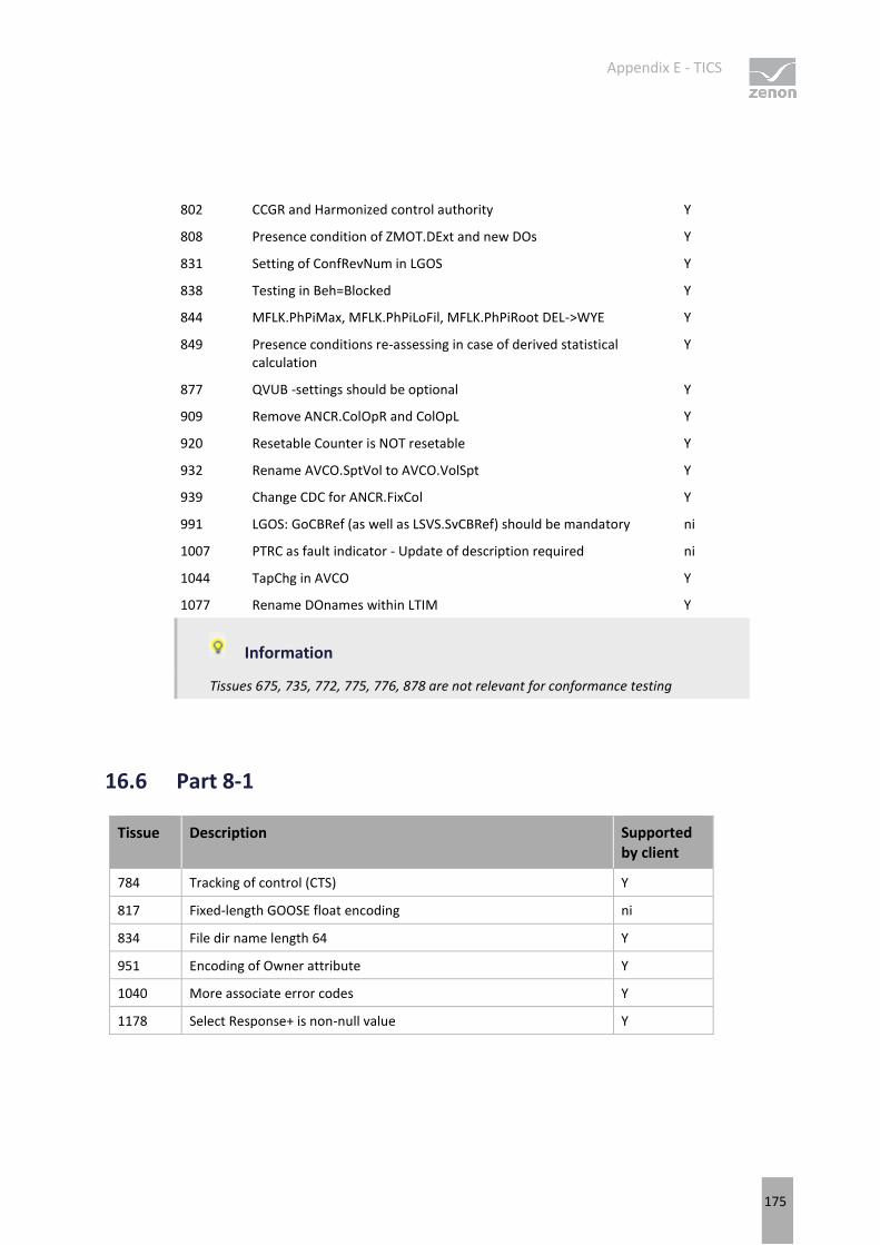
Appendix E - TICS
175
802 CCGR and Harmonized control authority Y
808 Presence condition of ZMOT.DExt and new DOs Y
831 Setting of ConfRevNum in LGOS Y
838 Testing in Beh=Blocked Y
844 MFLK.PhPiMax, MFLK.PhPiLoFil, MFLK.PhPiRoot DEL->WYE Y
849 Presence conditions re-assessing in case of derived statistical calculation
Y
877 QVUB -settings should be optional Y
909 Remove ANCR.ColOpR and ColOpL Y
920 Resetable Counter is NOT resetable Y
932 Rename AVCO.SptVol to AVCO.VolSpt Y
939 Change CDC for ANCR.FixCol Y
991 LGOS: GoCBRef (as well as LSVS.SvCBRef) should be mandatory ni
1007 PTRC as fault indicator - Update of description required ni
1044 TapChg in AVCO Y
1077 Rename DOnames within LTIM Y
Information
Tissues 675, 735, 772, 775, 776, 878 are not relevant for conformance testing
16.6 Part 8-1
Tissue Description Supported by client
784 Tracking of control (CTS) Y
817 Fixed-length GOOSE float encoding ni
834 File dir name length 64 Y
951 Encoding of Owner attribute Y
1040 More associate error codes Y
1178 Select Response+ is non-null value Y