Alarms administration - Copa-Data
209
zenon manual Alarms administration v.8.00
-
Upload
khangminh22 -
Category
Documents
-
view
3 -
download
0
Transcript of Alarms administration - Copa-Data

zenon manual Alarms administration
v.8.00

©2018 Ing. Punzenberger COPA-DATA GmbH
All rights reserved.
Distribution and/or reproduction of this document or parts thereof in any form are permitted solely with the written permission of the company COPA-DATA. Technical data is only used for product description and are not guaranteed qualities in the legal sense. Subject to change, technical or otherwise.
Contents
1. Welcome to COPA-DATA help ...................................................................................................... 5
2. Alarms administration ................................................................................................................. 5
3. Configuring alarms ....................................................................................................................... 6
3.1 Creating an Alarm Message List screen ...................................................................................................... 7
3.1.1 Control elements .......................................................................................................................... 8
3.1.2 Customize the display of the AML in the Runtime ..................................................................... 12
3.2 Creating an Alarm Message List filter screen ............................................................................................ 16
3.2.1 Control elements ........................................................................................................................ 18
3.2.2 Template .................................................................................................................................... 36
3.2.3 Pre-defined names ..................................................................................................................... 38
3.2.4 Filter screens .............................................................................................................................. 38
3.3 Defining alarms ......................................................................................................................................... 40
3.4 Alarm handling .......................................................................................................................................... 41
3.5 Grouping of alarms ................................................................................................................................... 43
3.5.1 Alarm/event groups ................................................................................................................... 44
3.5.2 Alarm/event classes ................................................................................................................... 47
3.5.3 Alarm Areas ................................................................................................................................ 50
3.6 Alarm classes, alarm groups and alarm areas in the global project and local projects ............................ 57
3.7 Alarm engineering with filters .................................................................................................................. 57
3.7.1 Column setting for Alarm Message List ...................................................................................... 58
3.7.2 Filter for Alarm Message List screen switching. ......................................................................... 61
3.7.3 Filter for Alarm Message List screen switching filter................................................................ 110
3.8 Functions ................................................................................................................................................. 139
3.8.1 AML screen switching ............................................................................................................... 139
3.8.2 AML filter screen switching ...................................................................................................... 142
3.8.3 Functions for alarm administration .......................................................................................... 144
4. Operating during Runtime ....................................................................................................... 175
4.1 Alarm status line ..................................................................................................................................... 180
4.2 Alarm Message List ................................................................................................................................. 182
4.2.1 Alarm causes ............................................................................................................................ 185

4.2.2 Display unacknowledged alarms as flashing ............................................................................ 187
4.3 Acknowledge alarms ............................................................................................................................... 188
4.3.1 Required comments for acknowledgment ............................................................................... 189
4.3.2 Linking of an alarm cause for acknowledgment ....................................................................... 189
4.3.3 Visual acknowledgment ........................................................................................................... 190
4.4 Alarms: acknowledge flashing ................................................................................................................. 191
4.5 Confirm alarm acknowledgment............................................................................................................. 192
4.6 Filtering alarms ....................................................................................................................................... 192
4.6.1 Filter profiles ............................................................................................................................ 194
4.6.2 Use alarm message list filter .................................................................................................... 196
4.7 Printing and exporting alarms ................................................................................................................. 198
4.7.1 Online printing .......................................................................................................................... 199
4.7.2 Offline printing ......................................................................................................................... 202
4.7.3 FRM configuration file .............................................................................................................. 205
4.7.4 Exporting alarms ....................................................................................................................... 209

Welcome to COPA-DATA help
5
1. Welcome to COPA-DATA help
ZENON VIDEO-TUTORIALS
You can find practical examples for project configuration with zenon in our YouTube channel. The tutorials are grouped according to topics and give an initial insight into working with different zenon modules. All tutorials are available in English.
GENERAL HELP
If you cannot find any information you require in this help chapter or can think of anything that you would like added, please send an email to [email protected].
PROJECT SUPPORT
You can receive support for any real project you may have from our Support Team, who you can contact via email at [email protected].
LICENSES AND MODULES
If you find that you need other modules or licenses, our staff will be happy to help you. Email [email protected].
2. Alarms administration
Alarm administration informs you of faults that occur such as limit values being exceeded. It comprises:
1. Alarm status line: (on page 180) Information line that is always shown in the foreground in Runtime and contains, depending on the configuration, the most recent or oldest unacknowledged alarm.
2. Alarm Message List (AML) (on page 182): Administers the alarms in a list in Runtime. The AML:

Configuring alarms
6
Displays alarms and their causes in an unfiltered or filtered list
Enables localization of the cause of the alarm
Enables acknowledgment of alarms
Enables deletion of alarms.
Enables printing and saving of alarms
Configure (on page 40) alarms by means of:
Setting limit values for variables
With reaction matrices
Properties of the alarms
3. Configuring alarms
Alarm administration is operated in Runtime using alarm message list screens and alarm message list filters as well as the alarm status line. The alarm status line is automatically created as a template.
EDITOR
To be able to use alarms in Runtime, the following must be carried out in the Editor:
A screen of alarm message list type (on page 7) can be configured
Limit value violations of variables or reaction matrixes are defined
In addition you can:
Configure alarms using filters (on page 57)
Grouping (on page 43) alarms
Adapt the screens of alarm message list type (on page 16) that are available in Runtime
RUNTIME
For the operation in the Runtime (on page 175) the following is used:
AML screen switching (on page 139)
AML filter screen switching (on page 142)
The zenon alarm functions (on page 144)
Using Alarm Message List screens (on page 196)

Configuring alarms
7
Alarm status line (on page 180)
3.1 Creating an Alarm Message List screen
CREATING AN ALARM MESSAGE LIST FILTER SCREEN
The Alarm Message List screen is for displaying and logging current and past alarms in Runtime. The display can be changed using a filter. Functions make it possible to export and print the displayed alarms.
ENGINEERING
There are two procedures for the creation of a screen from zenon version 8.00:
The use of the screen creation dialog
The creation of a screen using the properties
Steps to create the screen using the properties if the screen creation dialog has been deactivated in the menu bar under Tools, Settings and Use assistant:
1. Create a new screen.
To do this, select the New screen command in the tool bar or in the context menu of the Screens node.
2. Change the properties of the screen:
a) Name the screen in the Name property.
b) Select Alarm Message List in the Screen type property.
c) Select the desired frame in the Frame property.
3. Configure the content of the screen:
a) select menu item Control elements from the menu bar
b) Select Insert template in the drop-down list. The dialog to select pre-defined layouts is opened. Certain control elements are inserted into the screen at predefined positions.
c) Remove elements that are not required from the screen.
d) If necessary, select additional elements in the Elements drop-down list. Place these at the desired position in the screen.
Configuring alarms
8
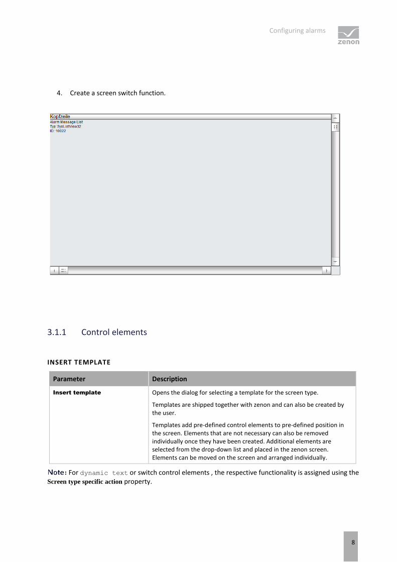
4. Create a screen switch function.
3.1.1 Control elements
INSERT TEMPLATE
Parameter Description
Insert template Opens the dialog for selecting a template for the screen type.
Templates are shipped together with zenon and can also be created by the user.
Templates add pre-defined control elements to pre-defined position in the screen. Elements that are not necessary can also be removed individually once they have been created. Additional elements are selected from the drop-down list and placed in the zenon screen. Elements can be moved on the screen and arranged individually.
For dynamic text or switch control elements , the respective functionality is assigned using the Screen type specific action property.

Configuring alarms
9
CONTROL ELEMENTS
WINDOW
Control element Description
Window Display in Runtime
Alarm Message List Display of the alarms. The appearance is configurable (on page 12). Columns are set using the column settings (on page 98) filter in the screen switching.
The Column settings AML property in the project properties in the Alarm Message List group are used to define the settings for export in CSV, XML and DBF. These also serve as a pre-setting for the screen switching function.
Set filter Display of the currently-selected filter conditions.
Status Display if Alarm Message List is active or not (Project property Alarm
Message List active).
Total number Shows number of all alarms.
Number of unacknowledged Displays number of unacknowledged alarms.
LIST FUNCTIONS
Control element Description
List functions Buttons to control the lists.
Filter Opens the dialog for filter selection.
Stop/Continue Switch for filling the list:
Stop: New elements are no longer added automatically.
Next: New elements are added automatically.
The labeling of the button can be changed in the editor but is not carried over to Runtime.
Print Prints filtered list.
Print with dialog Opens printer settings before printing.
ALARM FUNCTIONS
Control element Description
Alarm functions Buttons for acknowledging and deleting alarms.
Acknowledge Acknowledging alarm messages in Runtime.
Acknowledging page All alarms displayed on the current page are acknowledged.

Configuring alarms
10
Acknowl. All All alarms for the current filter criteria are acknowledged
Alarms are only acknowledged for projects for which the user has authorizations. (for details on multi-user projects, see Distributed engineering chapter)
Visual acknowledgment The selected alarms are visually acknowledged (on page 190).
Visual acknowledgment and
acknowledgment The selected alarms are first visually acknowledged and then acknowledged (on page 190).
Confirm acknowledgement Deletes alarm from the Alarm Message List in Runtime. Alarm must already be acknowledged.
Confirm acknowledgement
page Deletes all acknowledged alarms that are displayed on the current page.
Confirm acknowledgement
all Deletes all acknowledged alarms that correspond to the current filter criteria.
Linked function (display) Displays the function allocated to the alarm message.
Execute function Executes the functions configured for the alarm in Runtime.
With the Start program function, the variable name of the selected alarm can be transferred as a parameter for the program to be started using the key word @alarm.name.
Open help... Calls up configured Help.
Display Status and elements of alarm administration.
Comment field Input of free text by the user for the selected alarm.
Maximum length: 79 characters
This text can also be displayed in the list. To do this, the comment option in the column settings of the alarm administration is activated.
The comment field is a dynamic text element. The Write set value property is automatically activated for this element during configuration. In addition, the Write set value via property is set to the element value.
Changes to comments can be documented by activating the Alarm
comments property.
Select alarm cause... Opens the dialog for selecting an alarm cause.
An alarm cause can be assigned to the alarm selected in the alarm message list using the dialog.
Inactive if no entry is selected in the alarm message list.
See also chapter Alarm cause (on page 185).
Configuring alarms
11
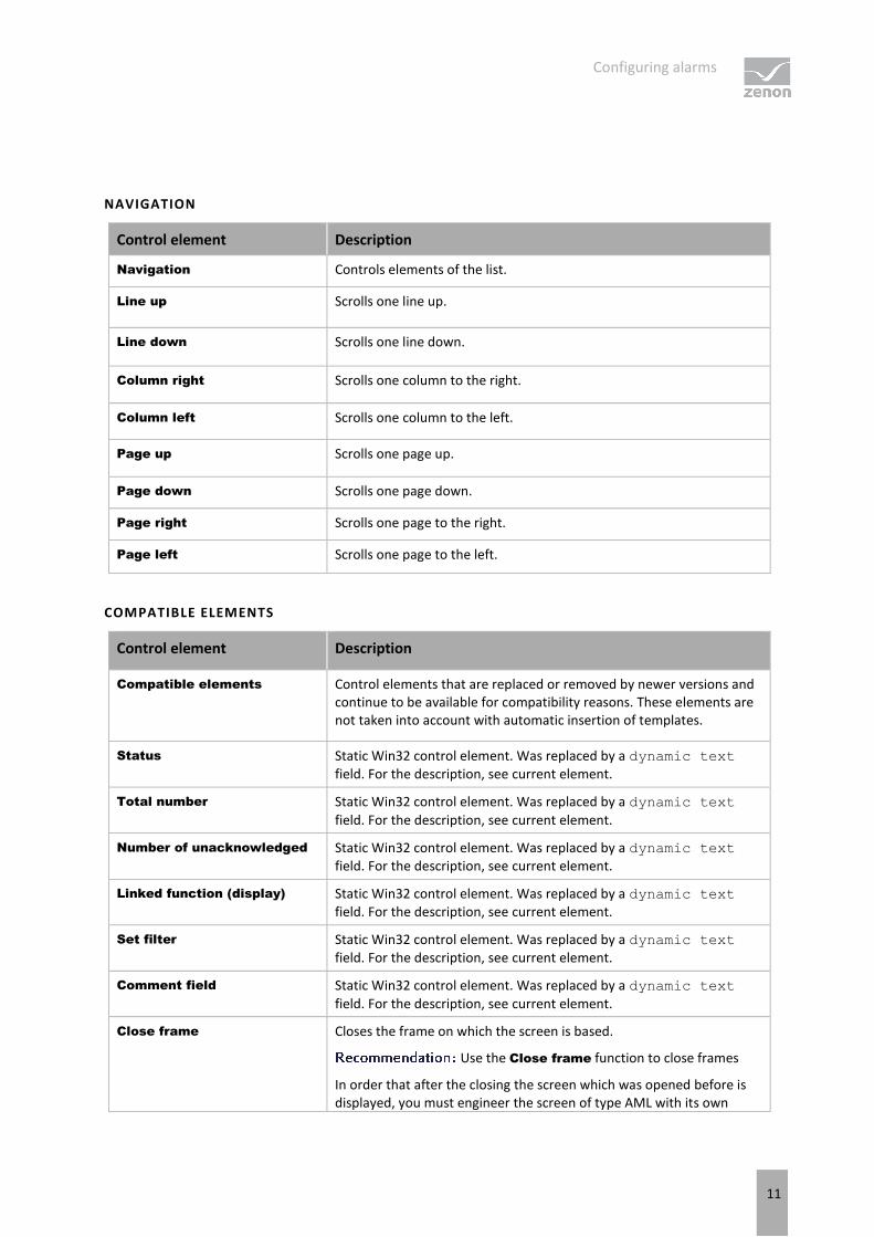
NAVIGATION
Control element Description
Navigation Controls elements of the list.
Line up Scrolls one line up.
Line down Scrolls one line down.
Column right Scrolls one column to the right.
Column left Scrolls one column to the left.
Page up Scrolls one page up.
Page down Scrolls one page down.
Page right Scrolls one page to the right.
Page left Scrolls one page to the left.
COMPATIBLE ELEMENTS
Control element Description
Compatible elements Control elements that are replaced or removed by newer versions and continue to be available for compatibility reasons. These elements are not taken into account with automatic insertion of templates.
Status Static Win32 control element. Was replaced by a dynamic text field. For the description, see current element.
Total number Static Win32 control element. Was replaced by a dynamic text
field. For the description, see current element.
Number of unacknowledged Static Win32 control element. Was replaced by a dynamic text field. For the description, see current element.
Linked function (display) Static Win32 control element. Was replaced by a dynamic text field. For the description, see current element.
Set filter Static Win32 control element. Was replaced by a dynamic text field. For the description, see current element.
Comment field Static Win32 control element. Was replaced by a dynamic text
field. For the description, see current element.
Close frame Closes the frame on which the screen is based.
Use the Close frame function to close frames
In order that after the closing the screen which was opened before is displayed, you must engineer the screen of type AML with its own

Configuring alarms
12
frame.
FILTER PROFILES
Control element Description
Filter profiles Buttons for filter settings in Runtime.
Profile selection Select profile from list.
Save Saves current setting as a profile.
The name can be a maximum of 31 characters long and must only contain valid characters. Prohibited are: ! \ / : * ? < > | ""
Delete Deletes selected profile.
Import Imports filter profiles from export file.
Export Exports filter profiles in the file.
Information
The current filter is displayed with the Show filter control element.
With a:
Text filter, the expression [Txt] is displayed
Relative time filter: is displayed as a print-out with the following scheme: [T,Rel:%dd,%dh,%dm;%ds]
[T,Rel:1d,0h,0m,0s] equals one day.
3.1.2 Customize the display of the AML in the Runtime
You can individually customize the tabular display of the Alarm Message List in the zenon Runtime:
SCROLL BARS, HEADERS AND GRIDS
To define the size and appearance of scroll bars, the header or grids for the table:
1. Activate, in the Representation group, the Extended graphical settings property.
2. Define the desired properties in the groups Scroll bars and Header and grid.

Configuring alarms
13
Information
If the Graphics file property is selected for the Display style property, then all elements for which no graphics file has been selected are shown with a color gradient. Transparent graphics cannot be used for control elements for lists.
ENGINEERING IN THE EDITOR
You can configure the display of the entries in the AML in the Runtime in the project settings in property group Alarm Message List.
There are different ways to display alarms, that:
Occur for the first time: Alarm received
Have already gone: Alarm cleared
Occur again: Alarm reactivated
Have already been acknowledged: Alarm acknowledged
Have an already-confirmed alarm acknowledgment: Confirm alarm acknowledgement
For Alarm received, Alarm cleared and Alarm reactivated you can configure the display with the following properties:
Text/status color
Background color
Prefix
Graphic file alarm status
Graphics file prefix
For acknowledged alarms the display is configured with the following properties:
Text/status color - received
Background color - received
Text/status color - cleared
Background color - cleared
Text/status color - reactivated
Background color - reactivated
Prefix
Graphic file alarm status
Graphics file prefix
You can configure the following settings for Confirm alarm acknowledgement:
Color

Configuring alarms
14
Graphic file alarm status
You can activate the following properties under Alarm status line:
Status line active
display next
You can define the following settings:
Display
Font
Text color
Background color
You can define the following settings for messages 1 to 4 respectively:
Message [n] number of alarms
Message [n] text
Message [n] text color
All settings are stored in the project.ini file. You can find details in relation to this in the Editor AML [ALARM] chapter.
The following settings can be made for the respective alarm:

Configuring alarms
15
Parameter Description
Color Color selection for the respective alarm:
Alarm received
Alarm cleared
Alarm reactivated
Alarm acknowledged
Alarm acknowledgment confirmed
The color selection made is applicable for the text of the corresponding time column of the status and for the graphics in the alarm status column.
Prefix Possibility to enter a prefix in order to quickly detect the respective time stamp in Runtime.
Not available for alarm acknowledgment confirmed.
Graphic file alarm status Possibility to select a graphics file for display in the Runtime of the respective alarm.
Graphics file prefix Possibility to select a graphics file that is to be displayed in Runtime to the left in front of the time stamp of the cleared alarm instead of the prefix.
Not available for alarm acknowledgment confirmed.
if an older project is converted into a zenon version 8.00 project, the color and status indication of Alarm received are also used for Alarm reactivated. Prefix and Graphics file prefix remain empty. If older Runtime files are started with version 8.00 of Runtime, the same effects occur.
SORTING IN RUNTIME
To mark the relevant column for sorting in Runtime and to determine the sorting sequence, configure the graphic element for the title line:
1. Select the Graphics files for the Display style property.
2. Link the Sort ascending and Sort descending properties with a graphics file.
The selected graphic for the respective sorting direction is displayed in Runtime for the sorting of relevant columns
Clicking on the graphic changes the sorting sequence.
Clicking in the column title activates the column for sorting.
OPERATING THE HEADER IN RUNTIME
You can make it possible for users to operate the header in Runtime. With this an individual customization of the look is possible in the Runtime:

Configuring alarms
16
Move columns with Drag&Drop
Change column width with the mouse
Change sorting
To do this, use the following properties:
Freeze column location: Controls the possibility to amend or move the width of table columns in Runtime with mouse actions.
active: The columns cannot be moved with Drag&Drop and the width cannot be amended.
Inactive: The columns can be arranged by means of Drag&Drop and the width of the columns can be amended by dragging with the mouse
Disable sorting: Controls the possibility to sort table columns in Runtime.
active: The table cannot be sorted.
Inactive: The table can be sorted by clicking on the header.
In order to be able to configure these properties, Editable header must be selected for the Header AML property in the project settings for the Alarm Message List group. Here, you can also generally switch the header to inoperable or invisible here. These settings apply for all headers in the project.
PREVIEW
The header and the scroll bars are shown as a preview in the Editor by activating the Extended graphical
settings property. Details such as colors, fill effects, lighting effects or grids can thus be configured more easily.
As the size of the scroll bars equals their size in the Runtime, the total size of the list in the Editor can vary from the size in the Runtime. This is also true for the size of the header and the font of the header.
3.2 Creating an Alarm Message List filter screen
It is possible to adjust filter settings for the Alarm Message List in Runtime with the help of the Alarm Message List Filter screen. Only the filter elements that are actually required are configured and provided to the user. The appearance can also be freely defined and thus adapted to different end devices. All filter settings that are available in the filter (on page 57) for the function to switch the screen to the Chronological Event List screen (on page 139) can be configured.
Therefore:
Only the filter elements that are actually required are configured and provided to the user.
The user only has these filters displayed and has an overview

Configuring alarms
17
The appearance can be freely defined and can, for example, ensure ease of use by means of a touch screen.
For details of use in Runtime, see Using the Alarm Message List Filter (on page 196) chapter.
For the definition of filter criteria, see Filter Alarm Message List Filter (on page 110) chapter.
Attention
Screens of type Alarm Message List Filter, Chronological Event List Filter and Time Filter must be engineered with an own frame. If they use the same frame as other screens, all screens based on this frame are closed when the screen is closed.
ENGINEERING
There are two procedures for the creation of a screen from zenon version 8.00:
The use of the screen creation dialog
The creation of a screen using the properties
Steps to create the screen using the properties if the screen creation dialog has been deactivated in the menu bar under Tools, Settings and Use assistant:
1. Create a new screen.
To do this, select the New screen command in the tool bar or in the context menu of the Screens node.
2. Change the properties of the screen:
a) Name the screen in the Name property.
b) In the Screen type property, select Alarm Message List filter.
c) Select the desired frame in the Frame property. The AML filter screen must not be based on the same frame as other screens!
3. Configure the content of the screen:
a) select menu item Control elements from the menu bar
b) Select Insert template in the drop-down list. The dialog to select pre-defined layouts is opened. Certain control elements are inserted into the screen at predefined positions.
c) Remove elements that are not required from the screen.
d) If necessary, select additional elements in the Elements drop-down list. Place these at the desired position in the screen.

Configuring alarms
18
4. Create a screen switch function.
3.2.1 Control elements
The Alarm Message filter screen can contain the following control and display elements.

Configuring alarms
19
INSERT TEMPLATE
Control element Description
Insert template Opens the dialog for selecting a template for the screen type.
Templates are shipped together with zenon and can also be created by the user.
Templates add pre-defined control elements to pre-defined position in the screen. Elements that are not necessary can also be removed individually once they have been created. Additional elements are selected from the drop-down list and placed in the zenon screen. Elements can be moved on the screen and arranged individually.
You can read more about templates for this screen type in the Templates (on page 36) chapter.
GENERAL FILTERS
Drop-down list of different general filters (on page 113).
Control element Description
Insert all elements: General filters Inserts all elements from the area of general filters into pre-defined places. Elements can be arranged individually.
Insert all elements: General filter (Touch) Inserts all elements from the area of general filters into pre-defined places. Elements can be arranged individually. The elements were optimized for touch operation.
Variables Alarms of which variables are displayed:
Name Filter according to names of variables.
Identification Filter according to identification of variables.
Case sensitive Note capitalization when filtering the variables.
Type of alarms Which alarms are displayed:
Only not acknowledged alarms Only non-acknowledged alarms.
Only cleared alarms Cleared alarms only.
Only current alarms Current alarms only
Comment required Alarms that require a comment when acknowledged.
Alarm cause required Alarms whose acknowledgment requires the linking of an alarm cause.

Configuring alarms
20
Minimum time active alarms Time for which alarms must be active as a minimum.
Days Only alarms that have been current for at least the given number of days.
Hours Only alarms that have been current for at least the given number of hours.
Minutes Only alarms that have been current for at least the given number of minutes.
Seconds Only alarms that have been current for at least the given number of seconds.
Milliseconds Only alarms that have been current for at least the given number of milliseconds.
Minimum time active alarms (touch) Elements optimized for touch operation for configuration of the minimum time for pending alarms.
Button: Days (up)
Touchbox: Days
Button: Days (down)
Button: Hours (up)
Touchbox: Hours
Button: Hours (down)
Button: Minutes (up)
Touchbox: Minutes
Button: Minutes (down)
Button: Seconds (up)
Touchbox: Seconds
Button: Seconds (down)
Button: Milliseconds (up)
Touchbox: Milliseconds
Button: Milliseconds (down)
Origin of the data Where does the data come from:
Ring buffer From the ring buffer.
Historical data From an archive.
Maximum number (input field) Input of the maximum alarms to be displayed when historical alarms are displayed.

Configuring alarms
21
0: displays all
Alarm/event groups/alarm/event
classes/alarm areas
List field for grouped display (on page 43):
Alarm/event groups Alarm/event groups
Alarm/event classes Alarm/event classes
Alarm Areas Alarm areas If the Use hierarchical alarming of the
Equipment Model property is activated, the Alarm area column is empty. The checkbox is in the alarm handling item of the variable properties.
Compatible elements Standard Win32 control elements that have been replaced or removed by zenon elements (dynamic text, switch) and continue to be available due to compatibility reasons. These elements are not taken into account with automatic insertion of templates.
For the description, see current elements.
Variables
Name
Identification
Type of alarm
Only non-acknowledged alarms
Only cleared alarms
Only current alarms
Comment required
Origin of the data
Ring buffer
Historic data
Maximum number (input field)
TIME FILTER
Elements for time filters.

Configuring alarms
22
Control element Description
Insert all elements Opens drop-down list to select pre-defined elements for certain time periods.
Absolute time period - classic display Elements for the absolute time period in classic display.
Absolute time period - compact display Elements for the absolute time period in compact display.
Relative time period Elements for the relative time period.
Starting from HH:MM:SS Elements for a time period from a defined time.
Starting from day - HH:MM:SS Elements for a time period from a defined day at a defined time.
Starting from day, month - HH:MM:SS Elements for a time period from a defined day in a defined month at a defined time.
Time period: 15/30/60 minutes Elements for a time period of 15, 30 or 60 minutes.
Time period - one day Elements for a time period of one day.
Time period - 1 or 2 weeks Elements for a time period over one or two weeks.
Each week can be selected, both for the view for a week as well as for the view for two weeks. With the two-week view, a time period of 14 days is selected, depending on the week selected.
Time period - one month Elements for a time period of one month.
Time period - one year Elements for a time period of one year.
Insert all elements (Touch) Opens the drop-down list to select pre-defined elements for certain time periods, which have been optimized for touch operation. Like Insert all elements, the following are available:
Absolute time period - classic display
Relative time period
Starting from HH:MM:SS
Starting from day - HH:MM:SS
Starting from day, month - at HH:MM:SS
Time period - 15/30/60 minutes
Time period - one day
Time period - 1 or 2 weeks

Configuring alarms
23
Time period - one month
Time period - one year

Configuring alarms
24
Set filter type (Display) Dynamic text element for the display of the set filter type.
Time filter type (label) Labeling for time filter type.
Time filter type (combobox) Combobox: Time filter type
Time filter type (radio group) Switch elements that show or hide certain elements in Runtime:
No filter
Absolute time filter
Relative time filter
Starting from day, month - HH:MM:SS
Starting from day - HH:MM:SS
Starting from HH:MM:SS
Time period 15 minutes
Time period 30 minutes
Time period 60 minutes
Time period 1 day
Time period 1 week
Time period 2 weeks
Time period 1 month
Time period 1 year
Time from Fields and labeling for stating "from" time.
From year (label)
From year (combobox)
From month (label)
From month (combobox)
From day (label)
From day (combobox)
From hour (label)
From hour (combobox)
From minute (label)
From minute (combobox)
From second (label)
From second (combobox)

Configuring alarms
25
From (spin control)

Configuring alarms
26
Time to Fields and labeling for stating "to" time.
To year (label)
To year (combobox)
To month (label)
To month (combobox)
To day (label)
To day (combobox)
To hour (label)
To hour (combobox)
To minute (label)
To minute (combobox)
To second (label)
To second (combobox)
To (spin control)
Time from (Touch) Fields and labeling for stating "from" time, optimized for touch operation.
From year (label)
From year (button: up)
From year (Touch box)
From year (button: down)
From month (label)
From month (button: up)
From month (Touch box)
From month (button: down)
From day (label)
From day (button: up)
From day (Touch box)
From day (button: down)
From hour (label)
From hour (button: up)
From hour (Touch box)
From hour (button: down)
From minute (label)
From minute (button: up)

Configuring alarms
27
From minute (Touch box)
From minute (button: down)
From second (label)
From second (button: up)
From second (Touch box)
From second (button: down)

Configuring alarms
28
Time to (Touch) Fields and labeling for stating "to" time, optimized for touch operation.
To year (label)
To year (button: up)
To year (Touch box)
To year (button: down)
To month (label)
To month (button: up)
To month (Touch box)
To month (button: down)
To day (label)
To day (button: up)
To day (Touch box)
To day (buttton: down)
To hour (label)
To hour (button: up)
To hour (Touch box)
To hour (button: down)
To minute (label)
To minute (button: up)
To minute (Touch box)
To minute (button: down)
To second (label)
To second (button: up)
To second (Touch box)
To second (button: down)
Filter absolute time Fields and labeling for stating absolute time filter.
From (label)
From date (calendar display)
From date (date display)
From time (time display)
To (label)
To date (calendar display)
To date (date display)
Configuring alarms
29
To time (time display)

Configuring alarms
30
Time period Fields and labeling for stating time periods.
From year (label)
From year (combobox)
From month (label)
From month (combobox)
Week (label)
Week (combobox)
From day (label)
From day (combobox)
Start time (label)
Start time (combobox)
Time period (Touch) Fields and labeling for stating "from" time, optimized for touch operation.
From year (label)
From year (button: up)
From year (Touch box)
From year (button: down)
From month (label)
From month (button: up)
From month (Touch box)
From month (button: down)
Week (label)
Week (button:up)
Week (touchbox)
Week (button: down)
From day (label)
From day (button: up)
From day (Touch box)
From day (button: down)
Start time (label)
Start time (button:up)
Start time (Touch box)
Start time (button:down)
Compatible elements Control elements that are replaced or removed by

Configuring alarms
31
newer versions and continue to be available for compatibility reasons. These elements are not taken into account with automatic insertion of templates.
Time filter type (radio group) Radiobutton Win32 control elements. Has been replaced by switch elements. For the description, see current elements.
Set time filter type (display) Static Win32 control element. Was replaced by a dynamic text field. For the description, see
current element.
LOT FILTER
Elements for lot selection in Runtime.

Configuring alarms
32
Control element Description
Insert all elements Inserts all subelements into the screen.
Archive list List of archives available in Runtime.
If you want to edit the list directly using the monitor, activate the Multi-Touch functionality. You can find detailed information in relation to this in the Configure interactions chapter.
Longer texts can also be displayed in Runtime over several lines using the Automatic word wrap property.
In the Editor, go to Representation in the properties of the respective list properties and activate the checkbox of the Automatic word wrap property.
The line height must be amended manually.
Archive list status Status of the archive list with number for:
available
Filtered
displayed
Lot list List of available lots.
If you want to edit the list directly using the monitor, activate the Multi-Touch functionality. You can find detailed information in relation to this in the Configure interactions chapter.
Longer texts can also be displayed in Runtime over several lines using the Automatic word wrap property.
In the Editor, go to Representation in the properties of the respective list properties and activate the checkbox of the Automatic word wrap property.
The line height must be amended manually.
Lot list status Status of the lot list with number for:
available
Filtered
displayed
Apply time filter to lot list Applies the configured time filter to the selection in the lot list.
Lot name filter (Input field) Entry of a character sequence for filtering the lot names

Configuring alarms
33
in the lot list.
Lot name filter (Button) Button to execute filtering for lot names.
Deactivated if the Lot name filter element is not present.
Compatible elements Control elements that are replaced or removed by newer versions and continue to be available for compatibility reasons.
These elements are not taken into account with automatic insertion of templates.
The following Win32 elements were replaced by dynamic text elements.
Archive list status
Lot list status
Lot name filter (Input field)
SHIFT FILTER
Drop-down list for element of the shift filter.

Configuring alarms
34
Control element Description
Insert all elements Inserts all subelements into the screen.
Shift list List of available shifts.
Status of the shift list Status of the shift list with number for:
Total
Filtered
Selected
Update shift list Clicking on the button updates the display of the shift
list.
TEXT FILTER
Drop-down list of different text filters.
Control element Description
Insert all elements: Text filter Inserts all elements for text filters.
No text filter Radio button to deselect text filter.
Search for (separate words by Space) Radio button to activate the search
Text: Search text Labeling for search field.
Input field: Search text Field for input of search term.
Options Search options
Case sensitive Capitalization must be noted.
Words do not need to be in the text
completely Fragments can also be searched for.
At least one word must be in the text At least one search term from several must be in the result.
All words must be in the text All search terms must be included in the result.
Exact filter text must be in the text Exact text from the input field must be contained in the result.

Configuring alarms
35
Compatible elements Standard Win32 control elements that have been replaced or removed by zenon elements (dynamic text, switch) and continue to be available due to compatibility reasons. These elements are not taken into account with automatic insertion of templates.
For the description, see current elements.
No text filter
Search for (separate words by Space)
Input field: Search text
Case sensitivity
Words do not need to appear in full within
the text
At least one word should be in the text
All words must exist in the text
Filter string has to appear exactly in the
text
BUTTONS
Buttons in Runtime.
OK Button: Applies the filter settings and closes the screen.
In faceplates, AML filter, CEL
filter and time/lot/shift filter screens can be used. When configuring these in Runtime, clicking on OK closes the complete faceplate. If the filter settings are to be saved and the faceplate is to stay open, click on Accept.
Cancel Button: Cancels the configuration of the filter settings.
Apply Button: Accepts the filter settings.
Update Button: Updates the filtered display.
Compatible elements Standard Win32 control elements that have been replaced or removed by zenon elements (dynamic text, switch) and continue to be available due to compatibility reasons. These elements are not taken into account with automatic insertion of templates.
Show list without refresh

Configuring alarms
36
3.2.2 Template

Configuring alarms
37
Template Description
List field templates (left) Displays all pre-defined and user-defined template.
Preview and description (right) Shows preview and description of the selected template.
Standard Inserts standard elements.
Scada Special templates, optimized for mouse operation.
Only variable & text filter Adds elements for filtering for variables and text.
Without alarm groups Adds elements for filtering for variables, text and pending minimum time without alarm groups.
Standard Inserts standard elements.
Filters for variables, text & time Adds elements for filtering for variables, text and time.
Filters for variables, text & time (from month) Adds variables for filtering for variables, text and relative time range from month.
Filters for variables, text & time (from hour) Adds variables for filtering for variables, text and relative time range from hour.
Filters for variables, text & time (from day) Adds variables for filtering for variables, text and relative time range from day.
Filters for variables, text & time (absolute -
table) Adds elements for filtering for variables, text and absolute time range.
Filters for variables, text & time (absolute -
compact) Adds elements for filtering for variables, text and absolute time range in compact form.
Filters for variables, text & time (absolute) Adds elements for filtering for variables, text and absolute time range.
CLOSE DIALOG
Button Description
Delete existing screen elements Active: Pre-existing elements in the screen are deleted when the template is applied.
Apply Adds the selected tempalte to the screen and closes the dialog.
Cancel Closes dialog without inserting elements.
Help Opens online help.

Configuring alarms
38
3.2.3 Pre-defined names
Pre-defined names are available for time filters.
The pre-defined names are not available under Windows CE.
To select a name:
1. In the detail view, define as a time filter, chronological event list filter or alarm message list filter
2. Click twice in the name field in the 'Name' column
3. Select the desired pre-defined name from the drop-down.
AML_Filter
TIMEFILTER_ABSOLUTE
TIMEFILTER_DAY
TIMEFILTER_HOUR
TIMEFILTER_MONTH
TIMEFILTER_PERIOD
TIMEFILTER_PERIOD_DAY
TIMEFILTER_PERIOD_MINUTE
TIMEFILTER_PERIOD_MONTH
TIMEFILTER_PERIOD_WEEK
TIMEFILTER_PERIOD_YEAR
TIMEFILTER_RELATIVE
3.2.4 Filter screens
FILTER SCREENS
Filter screens make it possible to transfer a preset filter from one screen to another. The filter of the source screen is set using the target screen. The screens can also be of a different screen type.
Attention
In order for the time to be taken from the screen to be called up in Runtime, the following time range must be selected in the Editor for the screen switching function for the Alarm
Message List or the Chronological Event List in the time filter: Set filter at time filter type
Configuring alarms
39
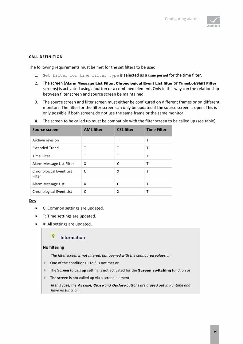
CALL DEFINITION
The following requirements must be met for the set filters to be used:
1. Set filter for time filter type is selected as a time period for the time filter.
2. The screen (Alarm Message List Filter, Chronological Event List filter or Time/Lot/Shift Filter screens) is activated using a button or a combined element. Only in this way can the relationship between filter screen and source screen be maintained.
3. The source screen and filter screen must either be configured on different frames or on different monitors. The filter for the filter screen can only be updated if the source screen is open. This is only possible if both screens do not use the same frame or the same monitor.
4. The screen to be called up must be compatible with the filter screen to be called up (see table).
Source screen AML filter CEL filter Time Filter
Archive revision T T T
Extended Trend T T T
Time Filter T T X
Alarm Message List Filter X C T
Chronological Event List Filter
C X T
Alarm Message List X C T
Chronological Event List C X T
Key:
C: Common settings are updated.
T: Time settings are updated.
X: All settings are updated.
Information
No filtering
The filter screen is not filtered, but opened with the configured values, if:
One of the conditions 1 to 3 is not met or
The Screen to call up setting is not activated for the Screen switching function or
The screen is not called up via a screen element
In this case, the Accept, Close and Update buttons are grayed out in Runtime and have no function.

Configuring alarms
40
3.3 Defining alarms
Define alarms using:
Limit values and statuses with variables
Reaction matrices
ALARMING USING VARIABLES
Define the limit values for variables (see Variables manual, Limits chapter). If these are violated in Runtime, an alarm is generated and displayed in the alarm status line (on page 180). You configure further properties for alarm configuration with:
Variable properties of the group Limit Values and the subgroups for each limit value contained therein:
In Alarm Message List: The alarm is incorporated into the AML. When it is there as displayed, control it in Runtime using the alarm message list (on page 182) or a screen of type alarm message list filter (on page 196).
In Chronological Event List: The alarm is also included in the CEL. When it is there as displayed, control it in Runtime using the Chronological Event List or a screen of type Chronological Event List Filter.
To acknowledge: The alarm must be acknowledged before it is removed from the ring buffer (on page 41).
Two-stage acknowledgement: the alarm must be deleted manually before it is removed from the ring buffer (on page 41).
Print: Prints alarm to defined printer. Either the CEL or the AML is printed. You define which of the two lists is printed in project properties under Printing for.
Alarm cause required: It is required to link an alarm cause (on page 189) in order to acknowledge the alarm.
Comment required: You should enter a comment (on page 189) in order to acknowledge the alarm.
Alarm/event group: allocation of an alarm/event group (on page 44).
Alarm/event class: allocation of an alarm/event class (on page 47).
Variable properties of the group Alarm handling:
Alarm area_n: allocation of an alarm area (on page 50).
Acknowledgement variable: Sets the value 0 or 1 for the variables defined here when an alarm is acknowledged.
Acknowledgement value: Value that is written to the variable defined in Acknowledgement
variable.

Configuring alarms
41
Save in IPA database: Alarm is available in the Industrial Performance Analyzer for evaluation.
Project properties of the group AML and CEL:
Selection with border: selected lines are emphasized by a frame in Runtime.
Same comments: comments that are entered in Runtime for an alarm are also accepted in the CEL.
Printing active: activates online printing.
Printing for: defines if AML or CEL is printed online.
Project properties of the group Alarm Message List
There are many properties to configure alarms available here. Above all:
AML activation
Data storage AML
Signalization of alarm states
Activation of alarm status line
You can find details of the individual settings in the embedded help pages.
ALARMING VIA REACTION MATRIXES
You use a reaction matrix to evaluate limit value states and status bits (see Variables manual, Reaction matrixes). Violations of the established rules lead to an alarm. As with variables, you can also define the action to be carried out when an alarm is raised with reaction matrixes. To do this, activate the corresponding properties in the configuration dialog of the reaction matrixes.
3.4 Alarm handling
Alarms are saved in a ring buffer (alarm.bin) and in an alarm file (*.aml) in the Runtime folder as soon as they occur. The ring buffer is a volatile memory, from which alarms can be removed again according to certain rules. The AML saves alarms and important information in relation to these on a lasting basis.
RING BUFFER
The ring buffer includes all active alarms. At this the following things are managed:
Time received in millisecond as unique signature
Additional information such as cause, value, etc.
Time cleared
Time acknowledged

Configuring alarms
42
Behavior when removing from the ring buffer:
As soon as the alarm is cleared, it is removed from the ring buffer.
If the To acknowledge property has been activated, the alarm must be acknowledged by a user authorized to do this before it can be removed from the ring buffer. When acknowledging alarms, all alarms of a variable with the same limit value violation are removed from the ring buffer at the same time.
If the Two-stage acknowledgement property is activated, it must be specifically removed from the ring buffer by a person authorized to do this. Example: The alarm has cleared and was acknowledged by the operator. It continues to be retained in the ring buffer until removal has been confirmed.
The entries are never deleted in the AML; it is always only their status that is documented.
SIZE OF THE RINGBUFFER
The size of the ring buffer must be set to an appropriated size in the project properties via property Size
of the ring buffer. At least number of variables for which alarms can occur.
The ring buffer is automatically saved as file alarm.bin when the Runtime is closed. If the Runtime is closed due to an unexpected event, e.g. power outage, data will be lost. To prevent this the ring buffer can be saved manually via property Save ring buffer on change at every new entry or via function Save AML and CEL ring buffer (on page 168).
In the Runtime the ring buffer is handled dynamically in the memory. Alarms the do not have a cleared time stamp can be displayed by means of the defined number of alarms. Thus alarms are displayed which exceed the size of the ring buffer.
Example
Size of the ring buffer: 100 entries
Active alarms in the Runtime without cleared time stamp: 120
Display in the AML in the Runtime: 120
ALARM FILE
All alarms are written in an alarm file (*.aml) at the same time as in the ring buffer. This file is created for every calendar day automatically and is managed via property Save AML data. The name of the alarm file is put together by the letter A, followed by the date in form JJMMDD and the suffix .aml; e.g. A100623.aml. These files are created automatically for every day and must be evacuated or deleted by
the user if the storage space is limited. *.aml files are saved in the ...\Project folder\Computer name\Project name folder.

Configuring alarms
43
SYNCHRONIZING RING BUFFER AND ALARM FILE
Ring buffer and alarm file are synchronized. This synchronization ensues from the ring buffer to the alarm file. All changes such as acknowledging are only carried out in the ring buffer and are then synchronized with the alarm file. Thus for example all unacknowledged alarms can be displayed in the alarm file and the acknowledge can be induced. The action however is taking place in the ring buffer.
SAVING PERIODS
The alarm file *.aml is saved each time a new entry is made.
The ring buffer (*.bin) is saved:
when the Runtime is closed
after every new entry if property Save ring buffer on change is active
when function Save AML and CEL ring buffer is carried out
If option Save ring buffer on change is deactivated, it is possible that the entries in the AML and in the ring buffer do not match after a power outage.
Attention
If the ring buffer overflows because it is too small, unacknowledged entries remain in the alarm file. They are displayed during filtering but they cannot be acknowledged anymore. The attempt to acknowledge them can trigger the acknowledgment on the ring buffer if the alarms concern the same variable and the same limit value violation.
3.5 Grouping of alarms
Alarms can be grouped and prioritized by means of:
Alarm/event groups (on page 44): group alarms (or events) together logically
Alarm/event classes (on page 47): serve to prioritize alarms (or events) and are used to color-code alarms in the AML and by events in the CEL
Alarm areas (on page 50): allow the combining of the alarms with a focus on the location in equipment.
Each group or class can be assigned a name, a number, a color, a function, a status variable, a graphic and an equipment group.
Alarms can be exported and imported via XML using the context menu.

Configuring alarms
44
Information
A maximum of 65536 alarm/event classes and 65536 alarm/event groups can be created.
PROJECT MANAGER ALARM CONTEXT MENU
Menu item Action
Export all as XML Exports all entries as an XML file.
Import XML... Imports entries from an XML file.
Help Opens online help.
Information
Use clear, different IDs in the global project, the integration project and subprojects for alarm/event groups, class and alarm areas. You avoid clashes this way. These can lead to incorrect displays.
3.5.1 Alarm/event groups
Alarm/event groups combine related messages.
CREATING ALARM/EVENT GROUPS
To create a new alarm/event group:
1. In the Project Manager, in Variables and Alarm, right-click on the Alarm/event groups sub-node
2. Select the command: New alarm/event group
(alternatively select the corresponding symbol in the toolbar (on page 46) or press the Ins key.)
Each group can be allocated additional information via its properties:

Configuring alarms
45
Parameter Description
Name Name of alarm/event group.
Is displayed in the filter condition of AML and CEL.
No. Identifies the alarm/event group. The number is automatically given and cannot be changed.
Minimum: 1
Maximum: 2147483647
Within a project, each respective number can only be given once for the alarm/event group. Identical numbers can be given in other projects/areas.
A check for conflicts is carried out when the Runtime files are created. If conflicts are found, these are displayed in the output window. However the creation of IDs that conflict one another is not prevented. Mode of checking.
The project is compared with the global project when checking individual projects.
In multi-project administration, the project is first compared with the uppermost project, then with all other projects of this multi-project administration. Synchronization with the global project is then carried out
Other, independent projects are not included in the synchronization.
Color Color of alarm/event group.
A click on the ... button opens the palette for color selection
Description Name of alarm/event group.
Status variable Bit variable which the zenon Runtime indicates whether the group is active or whether the alarms of this group are ignored at the moment.
Activation/deactivation is carried out via the Alarm/event group connection active/inactive (on page 144) function. The status of this group is logged in the Chronologic Event List (CEL).
Clicking on the ... button opens the dialog for variable selection.
Function Function that is to be executed if an alarm of this group is activated. Click on the ... button to open the dialog to select the function.
Graphics File Selection of a graphic that represents the alarm/event group in the AML.
To display the graphic in the AML, select in the AML filter, in the Column
settings (on page 98) tab for the Alarm/event group symbol the Graphics file display type.

Configuring alarms
46
the column height in the AML depends on the selected font. The selected graphics are also scaled and adapted to the column height.
Equipment Groups Links equipment model to the alarm/event group.
Define the membership of an equipment group. Click on the ... button to open the dialog to select the equipment group.
DELETING ALARM/EVENT GROUPS
To delete an alarm/event group:
1. Select the alarm/event group
2. Select Delete in the context menu or in the toolbar
3. confirm this when requested to do so
All linked variables lose their group assignment when deleted.
Context menus and alarm/event-groups toolbar
PROJECT MANAGER CONTEXT MENU
Menu item Action
New alarm/event group Creates a new alarm/event group.
Editor profile Opens the drop-down list to select a pre-defined Editor profile.
Help Opens online help.
DETAIL VIEW OF CONTEXT MENU AND TOOLBAR

Configuring alarms
47
Menu item Action
New alarm/event group Inserts a new alarm/event group into the list.
Jump back to starting
element Allows a jump to the starting element.
Copy Copies the selected entries to the clipboard.
Paste Pastes the content from the clipboard. If an entry with the same name already exists, the content is pasted as "Copy of...".
Delete Deletes selected entries after a confirmation from list.
Edit selected cell Opens the selected cell for editing. The binocular symbol in the header shows which cell has been selected in a highlighted line. Only cells that can be edited can be selected.
Replace text in selected
column Opens the dialog for searching and replacing texts.
Properties Opens the Properties window.
Remove all filters Removes all filter settings.
Help Opens online help.
3.5.2 Alarm/event classes
Alarm/event classes serve the following purpose:
To prioritize alarms for the screen alarming
To determine the alarm color in the alarm message list
As a filter criterion in the alarm list and the Chronological Event List
To trigger acoustic alarms, for example
CREATING ALARM/EVENT CLASSES
To create a new alarm/event class:
1. In Project Manager, right click on the Alarm/Event classes subnode
2. Select the command: New alarm/event class

Configuring alarms
48
(alternatively select the corresponding symbol in the toolbar (on page 46) or press on the Ins key.)
Each can be allocated additional information via the properties:
Parameter Description
Name Name of alarm/event class.
Is displayed in the filter condition of AML and CEL.
No. Identifies the alarm/event class. The number is automatically given and cannot be changed.
Minimum: 1
Maximum: 2147483647
Within a project, each respective number can only be given once for the alarm/event class. Identical numbers can be given in other projects/areas.
A check for conflicts is carried out when the Runtime files are created. If conflicts are found, these are displayed in the output window. However the creation of IDs that conflict one another is not prevented. Mode of checking.
The project is compared with the global project when checking individual projects.
In multi-project administration, the project is first compared with the uppermost project, then with all other projects of this multi-project administration. Synchronization with the global project is then carried out
Other, independent projects are not included in the synchronization.
Color Color of the alarm/event class can be used for labeling in the AML. A click on the ... button opens the color palette.
Color is used for long description and status text in the AML and screen alarming
Description Description of alarm/event class.
Status variable Bit variable which the zenon Runtime indicates whether the class is active or whether the alarms of this class are ignored at the moment.
Activation/deactivation is carried out via the Alarm/event group connection active/inactive (on page 144) function. The status of this group is logged in the Chronologic Event List (CEL).
Clicking on the ... button opens the dialog for variable selection.

Configuring alarms
49
Function Function that is to be executed if an alarm of this class is activated.
Click on the ... button to open the dialog to select the function.
Not available for project configuration content in the global project.
Graphics File Selection of graphics that represent the alarm/event class in the AML.
To display the graphic in the AML, select in the AML filter, in the Column
settings (on page 98) tab for the Alarm/event class symbol the Graphics file display type.
In the AML, the column height is aligned to the selected font; for this reason, the graphics selected are scaled if necessary and adjusted to suit the column height.
Equipment Groups Links equipment model to the alarm/event class.
Click on the ... button to open the dialog to select the equipment group.
DELETING ALARM/EVENT CLASSES
To delete an alarm/event class:
1. Select the alarm/event class
2. Select Delete in the context menu or in the toolbar
3. confirm this when requested to do so
All linked variables lose their class assignment when deleted.
Alarm/event classes context menus and alarm/event-groups toolbar
PROJECT MANAGER CONTEXT MENU
Menu item Action
New alarm/event class Creates a new alarm/event class.
Editor profile Opens the drop-down list with predefined editor profiles.
Help Opens online help.
DETAIL VIEW OF CONTEXT MENU AND TOOLBAR

Configuring alarms
50
Menu item Action
New alarm/event class Inserts a new alarm/event class into the list.
Copy Copies the selected entries to the clipboard.
Paste Pastes the content from the clipboard. If an entry with the same name already exists, the content is pasted as "Copy of...".
Delete Deletes selected entries after a confirmation from list.
Edit selected cell Opens the selected cell for editing. The binocular symbol in the header shows which cell has been selected in a highlighted line. Only cells that can be edited can be selected.
Replace text in selected
column Opens the dialog for searching and replacing texts.
Properties Opens the Properties window.
Remove all filters Removes all filter settings.
Help Opens online help.
3.5.3 Alarm Areas
Alarm areas (on page 50) allow the combining of the alarms with a focus on the location in equipment. Alarm areas can be linked to alarm classes (on page 55). Further flexibility can be gained by linking to status variables. The individual bits of a status variable can be evaluated using a combined element for example.
CREATING ALARM AREAS
To create a new alarm area:
1. In Project Manager, right click on the Alarm areas subnode.
2. Select the command: New Alarm area.
(Alternatively select the corresponding symbol in the toolbar (on page 46) or press on the Ins key.)
3. For the evaluation of an alarm area, link the corresponding variables by clicking on the ... button in the General node
4. Optional: Create a new area entry in the Class linking node by clicking on {New class link}. the number of possible area entries is limited to the number of existing alarm/event classes.

Configuring alarms
51
PROPERTIES FOR ALARM AREAS
Property Description
General
Name Name of the alarm area.
Is displayed in the filter condition of AML and CEL.
Empty if the Use hierarchical alarming of the
Equipment Model property is active.
Status variable Byte variable:
First bit: Displays if the alarm area contains active alarms. Second bit: Displays if this alarm area contains unacknowledged alarms. For details, see "Status
variable bits".
The ... button opens the dialog for variable selection.
Number of active alarms Variables with a value that displays the number of active alarms in this alarm area. The ... button opens the dialog to select variables.
Number of unacknowledged alarms Variable that contains the number of unacknowledged alarms in this alarm area as a numerical value.

Configuring alarms
52
No. Identifies the alarm area. The number is automatically given and cannot be changed.
Minimum: 1
Maximum: 2147483647
Within a project, each respective number can only be given once for the alarm area. Identical numbers can be given in other projects/areas.
A check for conflicts is carried out when the Runtime files are created. If conflicts are found, these are displayed in the output window. However the creation of IDs that conflict one another is not prevented. Mode of checking.
The project is compared with the global project when checking individual projects.
In multi-project administration, the project is first compared with the uppermost project, then with all other projects of this multi-project administration. Synchronization with the global project is then carried out
Other, independent projects are not included in the synchronization.
Empty if the Use hierarchical alarming of the
Equipment Model property is active.
Equipment Groups Links equipment model to the alarm area.
Define the membership of an equipment group. Click on the ... button to open the dialog to select the equipment group.
Class linking Collects area entries. A Class linking summarizes the status variable and number of active and unacknowledged alarms for an alarm/event class. Area entries are created via the {New class link} property.
{New class link} Creates a new area entry (on page 55).

Configuring alarms
53
Alarm/event class Alarm class for the area entry.
{Delete class linking} Deletes the area entry.
Alarm/event class Selection of alarm/event class for area entry from drop-down list. Alarm/event class must already have been created.
Further entries are similar to general settings per area entry with:
Status variable
Number of active alarms
Number of unacknowledged alarms
STATUS VARIABLE BITS
Bit Meaning
0 1 = Alarms are active
0 = No alarms are active
1 1 = Unacknowledged alarms present
0 = No unacknowledged alarms
All set values for status and counter variables which are linked to alarm areas are cumulated and sent to the driver in blocked form every 500 ms. In doing so, it is always only the last value that is used for each status variable. Transients that occur in the interim period are suppressed. As a result, the network and communication load is reduced considerably.
ASSIGN ALARM RANGES VARIABLES, STRUCTURES OR DATA TYPES
The assignment of variables, structures and simple data types to the alarm areas can be configured with two possibilities:
Hierarchically with equipment modeling.
Statically by linking up to four alarm areas. If several alarm areas are linked, then a only the first linked area is taken into account
when sorting according to areas.
The allocation is always configured at the respective element (variable or data type).

Configuring alarms
54
STATIC LINKING
The following properties are available in the Alarm handling group of properties for the static linking of alarm areas:
Alarm area 1
Alarm area 2
Alarm area 3
Alarm area 4
For each alarm area, the desired alarm area can be selected from drop-down list of the respective area of the desired alarm area and assigned to the object.
In the Runtime, the columns Alarm area and Alarm area no. of the alarm message lists contain all linked alarm areas that are displayed as separated by a comma (,).
In the Message Control module, the Alarm area field contains all linked alarm areas, displayed as separated by a comma (,).
LINKING TO THE EQUIPMENT MODEL
If the Use hierarchical alarming of the Equipment Model property is activated in the zenon Editor configuration, the configurations of the alarm areas are taken from the equipment model. Instead of the configuration of individual alarm areas 1 - 4 per variable, the alarm modeling in the equipment model is used in this case.
You can also find further information in the hierarchical alarming of equipment groups in the equipment modeling manual.

Configuring alarms
55
Alarm area context menus and toolbar
PROJECT MANAGER CONTEXT MENU
Menu item Action
New Alarm area Creates a new alarm area.
Editor profile Opens the drop-down list with predefined editor profiles.
Help Opens online help.
DETAIL VIEW OF CONTEXT MENU AND TOOLBAR
Menu item Action
New Alarm area Inserts a new alarm area into the list.
Copy Copies the selected entries to the clipboard.
Paste Pastes the content from the clipboard. If an entry with the same name already exists, the content is pasted as "Copy of...".
Delete Deletes selected entries after a confirmation from list.
Edit selected cell Opens the selected cell for editing. The binocular symbol in the header shows which cell has been selected in a highlighted line. Only cells that can be edited can be selected.
Replace text in selected
column Opens the dialog for searching and replacing texts.
Properties Opens the Properties window.
Remove all filters Removes all filter settings.
Help Opens online help.
Configuring alarm areas
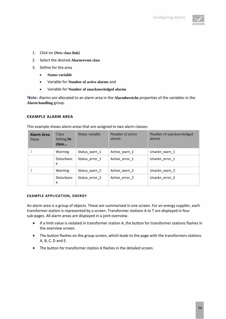
To link an alarm area to classes, carry out the following steps:
Configuring alarms
56
1. Click on {New class link}
2. Select the desired Alarm/event class
3. Define for the area
Status variable
Variable for Number of active alarms and
Variable for Number of unacknowledged alarms
Alarms are allocated to an alarm area in the Alarmbereiche properties of the variables in the Alarm handling group.
EXAMPLE ALARM AREA
This example shows alarm areas that are assigned to two alarm classes:
Alarm Area Name
Class
linking to class...
Status variable Number of active
alarms Number of unacknowledged
alarms
1 Warning Status_warn_1 Active_warn_1 Unackn_warn_1
Disturbance
Status_error_1 Active_error_1 Unackn_error_1
2 Warning Status_warn_2 Active_warn_2 Unackn_warn_2
Disturbance
Status_error_2 Active_error_2 Unackn_error_2
EXAMPLE APPLICATION, ENERGY
An alarm area is a group of objects. These are summarized in one screen. For an energy supplier, each transformer station is represented by a screen. Transformer stations A to T are displayed in four sub-pages. All alarm areas are displayed in a joint overview.
If a limit value is violated in transformer station A, the button for transformer stations flashes in the overview screen.
The button flashes on the group screen, which leads to the page with the transformers stations A, B, C, D and E.
The button for transformer station A flashes in the detailed screen.

Configuring alarms
57
3.6 Alarm classes, alarm groups and alarm areas in the global project and local projects
Each project saves its own IDs for alarm classes, alarm groups and alarm areas. When using global projects, there can be overlaps with integration projects and subprojects. If the same IDs are used in different projects, this can lead to entries being overwritten in the filter selection dialogs.
It often makes more sense to use both alarm classes, alarm groups and alarm areas from both the global project as well as local projects.
To avoid overlaps, ensure that you use different IDs in all projects. To do this, it is best when you create a separate number circle for each project. To do this, give a correspondingly high number for the first element. Newly-created elements are automatically created from this number.
EXAMPLE
Global project: Elements start at ID: 1
Integration project: Elements start at ID: 5000
Subproject A: Elements start at ID: 10000
Subproject B: Elements start at ID: 15000
3.7 Alarm engineering with filters
You configure the display of alarms using the filter. For this you have several possibilities:
1. Define information that is displayed in Runtime in the Alarm Message List: With this, you define the information that is shown for an alarm. For details, see: Column setting for Alarm Message List (on page 58).
2. Filter alarms for the Alarm Message List when switching and modify them in Runtime: With this, you pre-define filters, giving the user at the machine the possibility to define their own filters. For details, see: Filter for Alarm Message List screen switching. (on page 61)
3. Fixed filters for the Runtime: With this you create filters which are tailor-made for the actual use and hide unnecessary filter criteria. For details see: Filter Alarm Message List filters (on page 110).
Configuring alarms
58
3.7.1 Column setting for Alarm Message List
You define the information that is displayed in the Alarm Message List in Runtime in the column settings. You configure these in the properties of the Alarm Message List in the project:
1. Open the Alarm Message List node in project settings.
2. Click on the Column settings AML property.
3. The dialog for the column setting (on page 98) is opened.
4. Configure the desired columns. When configuring the screen switching, this configuration is accepted by default and can
be individually adapted in the column settings (on page 98) tab.
For calculating the column width the average character width of the selected font is used.
Information
In project settings, you can set a default setting for the sequence and size of columns using the Column settings AML property or the Column settings CEL property. If you create a new screen switching function from an Alarm Message List screen or Chronological Event List screen, this setting is used as a default and can be amended in the corresponding tab. The setting is stored in the project.ini file.
COLUMN CONFIGURATION
COLUMNS
In the list field of this tab all available column types are displayed.
You can change the sequence of column types by dragging & dropping in the list field:
Click in the Column type column
Move the individual entries as desired

Configuring alarms
59
Alternatively, you can adjust the sequence with the Move selected entry up and Move selected entry down.
Parameter Description
Checkbox: Select which column types are displayed.
Description Free text entry for a description of the column.
left-click on the corresponding area. Enter the desired value in the editing field.
for column descriptions, zenon language switching is available.
Column width Defines the width of the column in characters.
left-click on the corresponding area. Enter the desired value in the editing field. -1 Width is calculated in Runtime using average character width
For compatibility reasons, columns with time indications (time columns), whose width could not be changed in earlier zenon versions, automatically receive the value -1.
Display For column types
Alarm/event class symbol
Alarm/event group symbol
Alarm status
Actual form of display can be selected in Runtime. Select the desired form from the drop-down list.
For the equipment group column type, an equipment model can be selected for the display. The drop-down menu for selection is then only visible if you click on the Display column at the height of the entry.
Move selected entry up Moves selected entry up one place.
Move selected entry down Moves selected entry down one place.
Preview field Displays the columns defined in the list field in the width displayed there.
Column types activated by means of a checkbox are updated in real time in the preview.
You can also amend the column widths in the preview field by left-clicking on the right end of a column, holding down the mouse button and moving the column edge to the left or right accordingly with the mouse button held down. In this case, the mouse pointer display switches from a mouse pointer to a cross symbol.

Configuring alarms
60
TABLE SETTINGS
Parameter Description
Sort descending Initially sorts the entries in the list according to the Time
received column in descending order. This setting applies for calling up a screen. You can change the sorting order in Runtime by clicking on the column header. The sorting sequence currently being used is shown by an arrow on the column header.
Default: Inactive
Show grid Shows a grid when the list is displayed in Runtime.
Default: active
Use alternating background colors Uses line color 1 and line color 2 alternately as background colors for the list in Runtime.
Default: active
Row color 1 Color that is used as a background color in in the list Runtime for all uneven numbers (1, 3, 5 etc.), if you have activated Alternating Background Colors.
Row color 2 Color that is used as a background color in in the list Runtime for all even numbers (2, 4, 6 etc.), if you have activated Alternating
Background Colors.
SHOW IN THE TIME COLUMNS
Parameter Description
Time Displays the time for a list entry in the following form: HH:MM:SS
Default: active
Date Displays the date for a list entry in the following form: TT:MM:YYYY
Default: active
Milliseconds Expands the time entry by milliseconds. Milliseconds are shown as a decimal point percentage for the seconds.
Default: Inactive
Must be activated if milliseconds are to be provided in exports or print-outs.
Microseconds Expands the time entry by microseconds. Microseconds are shown as a decimal point percentage for the seconds.

Configuring alarms
61
Default: Inactive
Only available if the Milliseconds option has been activated.
If you activate the automatic keyboard in Runtime, each time entry or selection from a drop-down list is necessary, a window with the keyboard is called up. You can thus also use the columns to configure the columns if you are using a computer without a keyboard.
Attention
The column width is given in characters and is dependent on the font used.
If the column width is not a multiple of the character width of the used font, the actual column width can differ from the set column width. This can result in the text being cut of or an empty space being created.
Solution: Use fonts with a fixed character width.
3.7.2 Filter for Alarm Message List screen switching.
You define which alarms are to be displayed in Runtime using filters and which are to be hidden. Filters can be defined in the editor and - depending on the requirements in the Editor - in Runtime.
To tailor the filter selection to the requirements of the operator in Runtime, use an Alarm Message List filter (on page 110) screen instead of an Alarm Message List screen.
To configure screen switching for an Alarm Message List (on page 7) screen:
1. engineer a function screen switch to a screen of type Alarm Message List
2. the filter dialog is opened and offers several tabs with filter criteria:
General (on page 62)
Time (on page 67)
Lots (on page 82)
Shift (on page 90)
Column settings (on page 98)
Text (on page 103)
Status (on page 105)
Project (on page 106) (only available in the integration project of the multi-project administration.)

Configuring alarms
62
Equipment Modeling (on page 106)
If linked variables or indexes are available, the following tabs can be displayed as an option.
Replace links
Replace indices
For details see in chapter Screens sections Replace links of variables and functions and Symbols.
General
With the general filter, you define which alarms are shown and what access you have to the setting in Runtime. To do this, alarms are classified according to:
Type

Configuring alarms
63
Origin of the data
Variables
Time active
Alarm/event groups, classes and alarm areas
The following properties are available:

Configuring alarms
64
VARIABLE FILTER
Parameter Description
Variable filter Limitation to alarms of certain variables
Variable name Enter the name or part of the name of the variable you want to filter.
Use of the wild card * is possible. Wildcards are only permitted as a prefix or suffix; e.g. *xxx or xxx*.
Filter terms entered in Runtime or in the Editor are automatically saved on the local computer in zenon6.ini and are available for selection in the drop-down list.
The comma character (,) "only" serves as a separator between several variables to be filtered. However it is not possible to filter for a comma character in variables names! This results in the special filtering of array variables for Dim 2 and Dim 3 not being possible.
Identification Enter the identification or part of the identification of the variables you want to filter. Wild card * is possible.
Use of the wild card * is possible. Wildcards are only permitted as a prefix or suffix; e.g. *xxx or xxx*.
Filter terms entered in Runtime or in the Editor are automatically saved on the local computer in zenon6.ini and are available for selection in the drop-down list.
Case sensitive Active: Capitalization is recognized when filtering for variable name or identification.
TYPE OF ALARMS
Parameter Description
Type of alarms Type of alarm that is displayed.
Only not acknowledged alarms Active: Only alarms that have not yet been acknowledged by the user are displayed.
Only cleared alarms Active: Only alarms that have already passed, i.e. whose values no longer in the critical range, are displayed.
Only current alarms Active: Only alarms that are still active, i.e. whose values are still in the critical range, are displayed.
Comment required Active: Only alarms for which it is required to enter a comment (on page 189) during acknowledging are displayed.
Alarm cause required Active: Only alarms that are required for the linking

Configuring alarms
65
of an alarm cause (on page 189) are displayed.
Alarms have to be pending at least Use the spin control to define the minimum time that an alarm should be active in order for it to be displayed. Possible settings:
Days
Hours (hr.)
Minutes (min.)
Seconds (sec.)
Milliseconds (ms)
ORIGIN OF THE DATA
Parameter Description
Origin of the data Display of current or current and historical alarms.
Ring buffer Active: Only data from the ring buffer (on page 41) are
displayed.
Historical data Maximum number
Active: Data from the ring buffer and historical data
from the AML are displayed.
The maximum number of the data which should be displayed includes the data from the ring buffer.
ALARM/EVENT GROUPS/CLASSES, ALARM AREAS
Parameter Description
Alarm/Event Groups/Classes, Alarm Areas
Selection of groups, classes and alarm area.
Alarm/event groups From the existing alarm/event groups (on page 44) select the one from which alarms should be displayed.
Alarm/event classes From the existing alarm/event classes (on page 47) select the one from which alarms should be displayed.
ALARM AREAS
Parameter Description
Alarm areas From the existing alarm areas (on page 50) select the one from which alarms should be displayed.
RUNTIME SETTINGS

Configuring alarms
66
Parameter Description
Runtime settings Behavior of the AML in Runtime
Show list without refresh Active: As long as the list is displayed no new entries are added.
(Not available for Export AML (on page 159) function.)
Show this dialog in the Runtime Active: Before every call of the screen the filter dialog is opened. The filter settings can be modified. This option is not available with Windows CE.
If, in the Lots tab, the Show lot selection dialog option is also selected, then the lot selection dialog is called up in Runtime. This is no longer displayed after reloading.
Show this dialog in the Runtime active:
The filter is opened in Runtime in screen switching. The filter is no longer offered on reloading. This behavior can differ for individual screen types if the dialog was displayed in screen switching and canceled.
The last time period that has finished is always used.
Show this dialog in Runtime inactive:
Use last finished time range active:
The last time period that has finished is always used
Use last finished time period inactive: The current time period is used.
Replace dialog in Runtime with screen Definition of a screen that is to be switched in Runtime instead of the dialog if the Show this dialog in Runtime option is active. Only screens of the type AML Filter or
Time filter will be offered.
Click the ... button and a dialog opens to select a screen.
If the linked screen is not found in Runtime, a search is made for corresponding screens with specific names.
Attention
Concerns zenon under Windows CE: CE systems on which the filter dialog should be displayed must have a screen resolution higher than 800*600 pixel for the dialog to be displayed completely.

Configuring alarms
67
Time
Time filters make it possible to limit the data to be displayed or exported. The time filters are very flexible to implement and can be pre-set in the editor or adjusted in Runtime.
Time is saved in UTC. For details see chapter Handling of date and time in chapter Runtime.
Time filters can be pre-set in both the Editor and in Runtime for:
Absolute time period (on page 71)
Relative period of time (on page 72)
From (on page 74)
Time period (on page 76)
Time filtering can be carried out in two ways:
1. Define time period in the Editor (on page 79) Fixed time areas are used. A time period is given in the editor. It is only possible to filter according to this time period in Runtime. Other filters - such as filtering according to variable name, alarm/event groups and alarm/event classes etc. can no longer be amended in Runtime.
2. Time filter amendable in Runtime (on page 81) Pre-defined times are used. The time filter is defined in the Editor and can be changed in Runtime as desired.

Configuring alarms
68
TIME FILTER

Configuring alarms
69
FILTER
Selection of the filter.
Parameter Description
No time filter Active: No time filter is used. all Runtime entries since 1. 1. 1990 are displayed. Use of this filter setting
is not supported by Extended Trend.
Absolute filter Active: A fixed period of time is entered in the editor. When the function is
executed, the defined absolute time period is exactly used.
In the settings section, the corresponding options can be shown and configured there.
Time is saved in UTC. For details see chapter Handling of date and time in chapter Runtime.
Relative time period Active: A relative time period is entered.
In the settings section, the corresponding options can be shown and configured there.
this filter is constantly updated.
From Active: A time from which the filter is effective is stated. If the time is not reached on the current day, filtering takes place from the corresponding time the previous day.
Selection of the area mode from drop-down list:
Starting from HH:MM:SS
Starting from day - HH:MM:SS
Starting from day, month - at HH:MM:SS
In the settings section, the corresponding options can be shown and configured there.
The start point of this filter is not updated automatically. Only the existing times are used when shown. The end time point is not defined with this filter, it is carried over.

Configuring alarms
70
Time period Active: A fixed time period is entered. Selection of the area mode from drop-down list:
One day
One week
Two weeks
One month
One Year
15 minutes
30 minutes
60 minutes
In the settings section, the corresponding options can be shown and configured there.
The following selection is also enabled on activation:
Display selection dialog
Use current date and time
The Modify time period property can be activated.
The time period can be moved to the future.
The time period can be amended.
Create a screen switch, for example to an AML screen. In the screen switching filter dialog in the Time tab, set the filter to time period and select One Month in the drop-down list. Select Use current
date/time under Settings. Activate the Modify the checkbox of the time period property Enter the following setting under Move time period to
the future: HH = 0. Activate, under Change time period by, the checkbox of the Use last-completed time period property.
Evaluation: today's date: 2/22/2018
Result of the time filter in Runtime: 01.01.2018 - 31.01.2018
CLOSE DIALOG
Option Description
OK Applies all changes in all tabs and closes the dialog.
Cancel Discards all changes in all tabs and closes the dialog.

Configuring alarms
71
Help Opens online help.
Absolute time period
You define a fixed time period with the absolute filter. When the function is executed, the defined absolute time period is exactly used. To set the filter:
1. Select, in the Filter section, the Absolute time period option
2. Configure the desired time in the Settings section
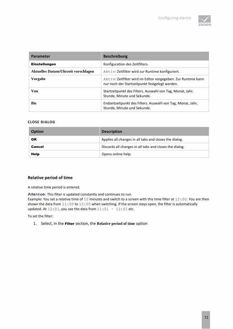
Configuring alarms
72
Parameter Beschreibung
Einstellungen Konfiguration des Zeitfilters.
Aktuelles Datum/Uhrzeit vorschlagen Aktiv: Zeitfilter wird zur Runtime konfiguriert.
Vorgabe Aktiv: Zeitfilter wird im Editor vorgegeben. Zur Runtime kann nur noch der Startzeitpunkt festgelegt werden.
Von Startzeitpunkt des Filters. Auswahl von Tag, Monat, Jahr, Stunde, Minute und Sekunde.
Bis Endzeitzeitpunkt des Filters. Auswahl von Tag, Monat, Jahr, Stunde, Minute und Sekunde.
CLOSE DIALOG
Option Description
OK Applies all changes in all tabs and closes the dialog.
Cancel Discards all changes in all tabs and closes the dialog.
Help Opens online help.
Relative period of time
A relative time period is entered.
This filter is updated constantly and continues to run. Example: You set a relative time of 10 minutes and switch to a screen with this time filter at 12:00. You are then
shown the data from 11:50 to 12:00 when switching. If the screen stays open, the filter is automatically
updated. At 12:01, you see the data from 11:51 - 12:01 etc.
To set the filter:
1. Select, in the Filter section, the Relative period of time option

Configuring alarms
73
2. Configure the desired time in the Settings section

Configuring alarms
74
Parameter Description
Settings Configuration of the time filter.
Propose current date/time Active: Time filter is displayed in Runtime.
Preset Active: The time filter is prescribed in the Editor. Only the start time can still be configured in Runtime.
Selection of the relative time period in days, hours, minutes and seconds.
CLOSE DIALOG
Option Description
OK Applies all changes in all tabs and closes the dialog.
Cancel Discards all changes in all tabs and closes the dialog.
Help Opens online help.
From
A time from which the filter is effective is defined. To set the filter:
1. Select, in the Filter section, the Off option
2. Select the desired filter from the drop-down list.
Starting from HH:MM:SS
Starting from day - HH:MM:SS
Starting from day, month - at HH:MM:SS

Configuring alarms
75
3. Configure the desired time in the Settings section
Parameter Description
Settings Configuration of the time filter.
[Date/Time] Depending on the settings of the Off option, the time from which the filter is effective is configured here:
Starting from HH:MM:SS
Starting from day - HH:MM:SS
Starting from day, month - at HH:MM:SS
The start point of this filter is not updated automatically. Only the existing times are used when shown, even if the screen remains open and 23:00:00 is reached. The end time point is not defined with this filter, it is carried over.
Starting from HH:MM:SS A time from which the filter is effective is stated. If the time is

Configuring alarms
76
not reached on the current day, filtering takes place from the corresponding time the previous day.
You enter 23:00:00. If it is then 23:30 when executing the function, then it is filtered from 23:00:00 up to the current point in time. If it is 22:30 however, then filtering takes place from 23:00:00 on the previous day to the current point in time.
Starting from day - HH:MM:SS
A day and time for the start of the filter are entered. If the time given has not been reached in the current month, the corresponding time from the previous month is used.
You enter day 5 - 23:00:00. If it is the 10th of the month at 23:30, then filtering takes place from the 5th of the month from 23:00:00 to the current time point. If, however, it is the 4th of the month, then filtering takes place from the 5th of the previous month to the current time point.
Starting from day, month - at HH:MM:SS
A month, day and time for the start of the filter are entered. If the time stated has not been reached in the current year, the corresponding time from the previous year is used.
You enter Day 5, Month October -
23:00:00. If it is October 10th at 23:30, then filtering takes place from October 5th from 23:00:00 to the current time point. If, however, it is only October 4th, then filtering takes place from the 5th of the previous year to the current time point.
CLOSE DIALOG
Option Description
OK Applies all changes in all tabs and closes the dialog.
Cancel Discards all changes in all tabs and closes the dialog.
Help Opens online help.
Time period
A time period in which the filter is effective is defined. To set the filter:
1. Select, in the Filter section, the Time period option
2. Configure the desired time in the Settings section

Configuring alarms
77
3. The Offer selection dialog and Use current date/time entries are deactivated if, in the Filter... dialog in the Display tab under Runtime, the Show this dialog in Runtime property has been activated.

Configuring alarms
78
Option Description
Time period Selection of a time range from a drop-down list.
Filtering for this time range is carried out in Runtime. The filter relates to the time of screen switching. For example: The value 60 minutes shows all archives of the last hour.
If this dialog is also offered in Runtime, the start time of the time range can be selected.
The following possibilities for selection are activated:
Display selection dialog
Use current date and time
The Modify time period property can be activated.
The time period can be moved to the future.
The time period can be amended.
Settings Optional setting for the time range.
Display selection dialog The selection dialog for the start time of the filter is offered in Runtime.
Use current date and time The current date/time is set for the filter.
Modify time period Allows amendments to cycles, postponements and extensions of time periods.
Active: Evaluation is carried out in accordance with the following
rules:
First, the Use last finished time period option is evaluated.
After this, Change time period by is used.
Move time period to the future by is then applied.
Inactive: No changes to the time period are made.
With version 7.10, filter actions on the basis of this function led to different results than those in the versions before.
Move time period to the future by Active: The time period defined in the filter is postponed to the future. The start and end time are moved by the set time span.
Given in hours - minutes - seconds.
If a postponement that is the same or greater than the selected time period is set, a note to check the configuration is displayed.
The default value for HH is 1. If, for example, an evaluation
of the last month is to be undertaken, this value must be set to 0.

Configuring alarms
79
Change time period by Active: The time period defined in the filter is modified. The end time is moved by the set time span. The start time remains unchanged.
Given in hours - minutes - seconds.
The time range can be added or deducted. Selection by means of radio buttons:
Add time: The time stated in Change time period by is added to the time defined in the Time range option.
Deduct time: The time stated in Change time period by is deducted from the time defined in the Time range option.
If a change and a postponement that are the same or greater than the selected time period is set, a note to check the configuration is displayed next to the control element for time configuration.
Use last finished time period Active: The last selected and fully-completed time period in the Time period option is used.
Example: For the Time period option, One day was selected. Filtering is thus carried out for "Yesterday", because this is the last day that was completed in full.
CLOSE DIALOG
Option Description
OK Applies all changes in all tabs and closes the dialog.
Cancel Discards all changes in all tabs and closes the dialog.
Help Opens online help.
Specify time period in the Editor
With this method, you enter a fixed time period into the editor, which is applied when the function is carried out in Runtime. You can then only define the start time in Runtime, but no further filter settings.
For example: You set a 30 minute time filter. In Runtime, you can now only set when this 30 minute time period is to start. However, you cannot change the filter to a day filter.
Attention
When using this type of filter, you can also no longer amend all other filters in Runtime that are available in the General tab. It is still possible to filter for text, status and equipment.
To create the filter:

Configuring alarms
80
1. The screen must have the Filter button to start the filter in Runtime
2. select the desired filter
3. Configure the selected time period
Activate the Show this dialog in Runtime option in the filter dialog. This way you can amend the start time before the function is carried out. Do not have the filter displayed in Runtime when the function is turned on; this way the current time period is always used. If you have activated the Use last closed time period option, the previous time period is shown. For example: You have set a 30 minute filter. It is 10.45 when the function is activated. If the Use last
closed time period option is deactivated, the filter is set to the current time period 10:30:00 to 10:59:59. If the option is activated, the filter is set to the previous time period of 10:00:00 to 10:29:59.

Configuring alarms
81
Time filter can be configured in Runtime
With this method, the time filter can be amended in Runtime before execution.
To create the filter:
1. select the desired filter:
Absolute time period
Relative time period
Time period
2. Select, in the Settings section, the option Propose current date/time
3. The filter dialog is opened in Runtime with the current date and time

Configuring alarms
82
Lots
You configure the limitation of the display to certain lots in this tab. The lot information is also applied to the existing filter.
If the lot filter is activated, a list of all configured lots that correspond to the configured time period is obtained from the archive server in Runtime in advance when the AML is loaded.
If the lot filter is activated, the shift filter is automatically deactivated. Both filters mutually exclude one another.
All variables and archives that belong to an item of equipment and the lot archive must be linked to the same equipment in the equipment model.
Information
Some filters in zenon can be configured independently of one another and then combined in Runtime. This is only possible to a limited extent with the lot filter.
The lot filter can offer a list of existing lots in Runtime. It is Runtime data that is not available in the Editor.
When configuring the screen switching in the Editor, the time filter tab can only be used in conjunction with the lot filter as a prefilter for the lot selection dialog. If you then select a lot from this list in Runtime, the time filter is overwritten with the data from the selected lot, in order to achieve precise filtering for the selected lot.
That means: If the lot selection dialog is used in Runtime and a lot is selected, the time filter displayed does not correspond to the one configured in the Editor.
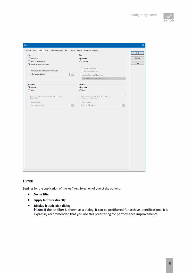
Configuring alarms
83
FILTER
Settings for the application of the lot filter. Selection of one of the options:
No lot filter
Apply lot filter directly
Display lot selection dialog If the lot filter is shown as a dialog, it can be prefiltered for archive identifications. It is
expressly recommended that you use this prefiltering for performance improvements.

Configuring alarms
84
Option Description
No lot filter Active: The lot filter is deactivated and cannot be
configured. Filtering for lots is not carried out in Runtime.
Apply lot filter directly Active: The filter configured here is applied in Runtime directly.
There is no possibility to have all lots in a list displayed and to select one manually. If a certain lot is to be shown, the filter for the archives, name and time must be configured accordingly. This requires the existing data to be known very well. Alternatively, it is recommended that the Show lot
selection dialog option is selected.
Display lot selection dialog Active: The dialog for lot selection is shown in Runtime when:
Clicking on Filter or
screen switching, if the Show this dialog in Runtime option has been activated (Not available for each function/screen type)
The dialog is not shown on reloading.
Options can be pre-selected in the Editor.
Replace dialog with screen in Runtime Only available if the Show lot selection dialog option has been selected.
Definition of a screen that is to be called up in Runtime instead of the lot selection dialog. Only time/lot/shift
filter screens are offered.
Click the ... button and the dialog opens to select a screen.
If the linked screen is not found in Runtime, a search is made for corresponding screens with specific names.
A lot filter screen can also be selected using the Show
this dialog in Runtime option. However this is not used as a lot filter here, but as a time filter screen. The lot filter options are not correctly applied at this position.
Relative lot selection This option is only available for Extended
Trend. With faceplates, it is displayed for all screen types, but here it is also only available for ETM.
Configuration for ETM:
In order for the option to be available, the Show lot
selection dialog option must be activated and the Windows CE project property must be deactivated in the project properties.
Active: Enables several lots to be compared directly.

Configuring alarms
85
Display always starts from the zero point.
Note: If the option is activated, the Diagram and X-axis buttons are not available in Runtime. This also applies for the right-click functionality.
Overview of the implementation of configuration in Runtime:
TIME
Configuration of the time filter for lot selection. Selection of one of the options:
No filter
Last lots
Use time filter from "Time" tab

Configuring alarms
86
Option Description
No filter Active: The time range set in the Time tab is not taken
into account. All completed and current lots are displayed.
Last lots Only works in conjunction with the Apply lot filter
directly option.
The option allows the combination of both options Display
current lots and Display completed lots. At least one of the two options must be activated. If both options have been deactivated, this corresponds to the No filter setting.
Active: Input of the number of lots last concluded, according to what they should be filtered for. Input of the number in the number field or configuration via arrow keys.
Example: 3 was entered as a value for the option. 2 lots run and 10 have been ended. The following is shown: the two that are current and one that has been completed.
The setting of the time filter is not used as a time period for the current lots, but the last year. This filter will not be executed as a prefilter and can therefore not be used to improve performance.
If the project is compiled for a version before 7.11, the following is applicable: If the current lots are selected or the combination of current and completed lots, then only the completed lots are shown in Runtime.
Display current lots Active: The current lots are displayed.
If the number of lots to be displayed is greater than the number of current lots, lots that have been completed are also shown until the set limit has been reached. Example: 3 lots are to be displayed. 1 lot is running, 5 have been completed. The one current lot and two completed lots are displayed.
Display completed lots Active: The completed lots are displayed.
If the number of lots to be displayed is greater than the number of completed lots, lots that have been completed are also shown until the set limit has been reached.
Use time filter from "Time" tab Active: Pre-filtering is carried out with the settings of the Time tab.
The effective range of the filter can be amended within this time range. Select from drop-down list:
Start and end also outside filter limits: (Default) Lots can start before the start time configured in the Time

Configuring alarms
87
filter and end after the configured end time.
Start and end only outside filter limits: Lots must start and end within the time points configured in the Time filter for the start and end.
Start also before filter limit: Lots can start before the start time configured in the Time filter and end after the configured end time.
End also after the filter limit: Lots can also end after the end time set in the time filter, but must start at or after the configured start time.
Adjust start and end to filter limits: Lots are cut to the time points configured in the Time filter for the start and end.
ARCHIVES
Configuration of filtering for archives. This filter is applied as a prefilter for the lot selection dialog.
Selection of one of the following options:
No filter
Static
From variable

Configuring alarms
88
Option Description
No filter Active: Filtering for archive names is not carried out.
Static Active: Archives whose identification corresponds to the character string entered in the input field are filtered for.
Input of the archive identifications in the input field:
Several identifications are separated by a comma (,).
* or empty: All archives, no filter.
From variable Active: The value of the variables linked here is applied as
a filter for archive names in Runtime.
Click on button ... in order to open the dialog for selecting a variable.
Available for AML and CEL modules if the Apply lot filter
directly option has been selected: Other modules use their own configurations.
The variable selection is only activated in Runtime if a valid variable has already been linked in Runtime. The ... button is always deactivated in Runtime. The option can be selected, but no new variable can be linked.
If the variable is not signed into the driver at the time at which the lot filter is applied, the variable is signed in and read. This can lead to delays with slow driver connections/protocols.
If the selected variable is not found in Runtime, there is no filtering for archive names. This also applies if the value of the variable cannot be determined. The filter then corresponds to the No filter setting.
In the ETM, the archives are established by the curves configured in screen switching. This is only possible in Runtime with the relative lots option. With this, the variables must be selected in Runtime, which is in turn stipulated by the possible selection of archives. The archive, once filtered, must be one of the archives that relate to the configured curves. No data is displayed if this is not the case. This setting can also be used to limit the displayed curves. However these remain shown in the curve list.
ETM example:

Configuring alarms
89
Configured curves
Data source Archive prefiltering in the lot filter
Result in the screen
A AR AR Is shown in the curve list and drawn in the trend.
B EA Is only shown in the curve list.
C EP Is only shown in the curve list.
The archive for which the screen is opened is already selected in the screen switching function. Because only 1 archive can be selected, further limitation makes no sense.
Example of archive revision:
Configured archive
Archive prefiltering in the lot filter
Result in the screen
AR EA No data is displayed.
NAMES
Configuration of the filtering to names. Selection of one of the options:
No filter
Static
From variable

Configuring alarms
90
Option Description
No filter Active: Filtering for lot names is not carried out.
Static Active: Lot names that correspond to the character string entered in the input field are filtered for.
Input of the lot name in the input field:
Several entries are separated by a pipe character (|). Lot name must not contain a | character!
* or empty: All lots of all displayed archives, no filter.
From variable Active: The value of the variable linked here is applied as a filter for lot names in Runtime.
Click on the ... button to open the dialog for selecting a variable.
Only available if the option Apply lot filter directly has been selected.
The variable selection is only activated in Runtime if a valid variable has already been linked in Runtime. The ... button is always deactivated in Runtime. The option can be selected, but no new variable can be linked.
If the variable is not signed into the driver at the time at which the lot filter is applied, the variable is signed in and read. This can lead to delays with slow driver connections/protocols.
If the selected variable is not found in Runtime, there is no filtering for lot names. This also applies if the value of the variable cannot be determined. The filter then corresponds to the No filter setting.
CLOSE DIALOG
Option Description
OK Applies all changes in all tabs and closes the dialog.
Cancel Discards all changes in all tabs and closes the dialog.
Help Opens online help.
Shift
You configure the limitation of the display to certain shifts in this tab. The shift information is also applied to the existing filter.

Configuring alarms
91
The shift filter requires a configured time filter. If the time filter is set to the No time filter option, the shift filter is deactivated. A notice of the cause of the deactivation is shown.
If the lot filter is activated, the shift filter is automatically deactivated. Both filters mutually exclude one another. A notice of the cause of the deactivation is shown.
CONFIGURATION
To filter for shifts:
1. Configure the time filter.
Absolute time filter: Shifts from the absolute defined time period are shown.
Relative time filter: Shifts from the relative defined time range are shown. The upper limit is set at 1440 minutes by default.
From: Shifts from a certain time point are shown.
Time range: Shifts within a certain time range are shown.
2. Configure the shift filter. To do this, select one of the options:
Apply shift filter directly: The configured time filter is used to filter the shifts in Runtime. In doing so, all shifts that are at least partly in the time filter range are taken into account. Even if the time filter is defined in Runtime, the shift filter is applied after selecting the time period. If there is no suitable shift, no data is shown in the CEL screen. The set filter continues to have an effect on the CEL data. If a shift is only partially within the set time range, only the CEL entries that are both in the time filter and the shift are shown.
Show shift selection: The shift filter is configured and applied when called up in Runtime. All shifts that are at least partly in the time filter range are offered in a list for selection. After selecting one or more shifts, the time filter is overwritten and set to the times of the selected shifts. It is thus ensured that the complete shift is always included in the filter.
If, in the General tab, the Show this dialog in Runtime option is activated at the same time, the complete configuration dialog with all tabs is called up instead of the shift selection. The user can then redefine all options.
3. Configure Name and Options if required.
With the Apply shift filter directly option, the shifts are permanently monitored by the filter and the filter is amended if necessary. The shifts for filtering the data are redetermined if:
Shifts are reconfigured
Shifts are newly-created in the filter time period
The time period is reconfigured

Configuring alarms
92
The following are not taken into account in the filter:
Deleted shifts
Shifts that are removed from the time filter due to a change of the time period
SCREEN SWITCHING TO A LINKED SCREEN
Screen switching to a linked filter screen can also be carried out. Shift filters can be used in the process. To do this:
1. Define, for screen switching, the desired filter screen in the General tab in the Replace dialog
with screen in Runtime option.
2. Ensure that the filter screen contains the necessary control elements for the shift list.
3. Define the desired time filter.
4. Activate, in the Shift tab, the Show shift selection option.
5. Define the shift filter.
The linked filter screen is called up in Runtime during screen switching. The shifts are shown in the shift list as defined in the screen switching. Control elements for lots are not shown.

Configuring alarms
93
SHIFT DIALOG
FILTER
Settings for the application of the shift filter. Selection of one of the options:
No shift filter
Apply shift filter directly
Display shift selection

Configuring alarms
94
Option Description
No shift filter Shift filter selection:
Active: The shift filter is deactivated and cannot be configured. Filtering for shifts is not carried out in Runtime.
Apply shift filter directly Applying the shift filter in Runtime:
Active: The filter configured here is applied in Runtime directly.
Equipment groups and shift names can be preselected.
The shift list and Update button are not shown in Runtime.
Display shift selection Display of the shift selection in Runtime:
Active: The dialog for shift selection is shown in Runtime.
The settings chosen in the Editor are applicable for the reading of the shifts in Runtime.
The dialog is shown in Runtime when:
Clicking on the Filter button. Or:
Executing screen switching. The dialog is not shown on reloading.
At least 1 shift must be selected in Runtime in order to call up the page or to be able to configure the filter. If, in the General tab, the Show this dialog in Runtime option is activated at the same time, the complete configuration dialog is called up.
EQUIPMENT MODELING
Configuration of the equipment groups for filtering for shifts.

Configuring alarms
95
Option Description
Equipment Groups Selection of equipment groups to which shifts must be linked.
Clicking on the ... button opens the dialog to select equipment groups.
If several equipment groups are selected, they are displayed in the option separated by a semicolon (;).
Include shifts without
equipment linking Selection of whether linking to an equipment group is necessary.
Active: Shifts that are not linked to an equipment group are also
taken into account.
Inactive: Only shifts that are linked to at least one equipment
group are taken into account.
Default: Active
NAME
Configuration of the shift names for which filtering is to take place. Selection of one of the options:
No filter
Name with wildcards
Name from variable
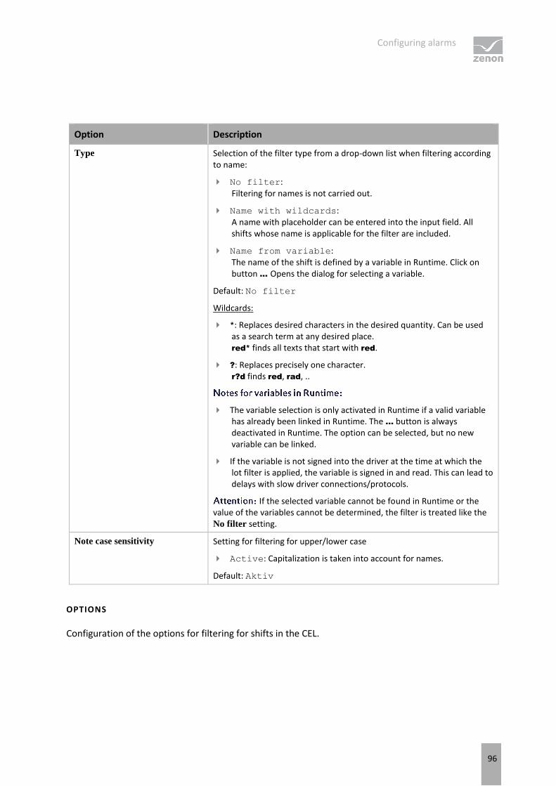
Configuring alarms
96
Option Description
Type Selection of the filter type from a drop-down list when filtering according to name:
No filter: Filtering for names is not carried out.
Name with wildcards: A name with placeholder can be entered into the input field. All shifts whose name is applicable for the filter are included.
Name from variable: The name of the shift is defined by a variable in Runtime. Click on button ... Opens the dialog for selecting a variable.
Default: No filter
Wildcards:
*: Replaces desired characters in the desired quantity. Can be used as a search term at any desired place. red* finds all texts that start with red.
?: Replaces precisely one character. r?d finds red, rad, ..
The variable selection is only activated in Runtime if a valid variable has already been linked in Runtime. The ... button is always deactivated in Runtime. The option can be selected, but no new variable can be linked.
If the variable is not signed into the driver at the time at which the lot filter is applied, the variable is signed in and read. This can lead to delays with slow driver connections/protocols.
If the selected variable cannot be found in Runtime or the value of the variables cannot be determined, the filter is treated like the No filter setting.
Note case sensitivity Setting for filtering for upper/lower case
Active: Capitalization is taken into account for names.
Default: Aktiv
OPTIONS
Configuration of the options for filtering for shifts in the CEL.

Configuring alarms
97
Option Description
Only include shifts that are
fully in the filter range Configuration of which shifts are displayed.
Active: Only shifts that are fully in the time filter set are shown.
Inactive: Shifts that start earlier and/or finish later are also shown.
Default: Inactive
Example:
Time filter: Today 08:00 – 12:00.
Existing shift: Today 8:30 AM – 5:00 PM.
Result for:
Option active: The shift is not taken into account because it is not fully in the time filter.
Inactive option: The shift is taken into account because it is partly in the time filter.
Use shifts found Selection of shifts that are taken into account, from drop-down list:
All: All shifts found are taken into account.
Earliest shift only: Of the shifts found, only the earliest are taken into account. The earliest shift is the shift with the earliest start time. If several shifts have the same start time, one of these shifts is selected randomly.
Only last shift: Of the shifts found, only the latest shift is taken into account. The latest shift is the shift with the latest end time. If several shifts have the same end time, one of these shifts is selected randomly.
Default: all
: The Only include shifts that are fully in the filter range influences the evaluation of this option. If it is active, only shifts that are fully in the time range can be found. If it is inactive, shifts that start earlier or end later can be found.
Example:
Configuration and shifts:
Only include shifts that are fully in the filter range option: active.
Use found shifts option: Latest shift only
Time filter: Today 08:00 – 10:00 AM.
Shift 1: Today 08:00 – 8:30 AM.
Shift 2: Today 8:30 AM – 9:00 AM.
Shift 3: Today 10:00 AM – 11:00 AM.

Configuring alarms
98
Result:
Shift 2 is used
Switch to "Show shift selection"
mode
Active: The filter acts as with the Show shift selection option. The time filter is set to absolute; start and end correspond to the start time and end time of the shifts. If no shift is found, the times are set to 0 for the time filter.
Default: Inactive
Behavior in Runtime:
If the shift management is set to Show shift selection in Runtime, the filter options also have an effect on the shifts shown in the shift list. The shift list is filtered accordingly by clicking on the Update button.
CLOSE DIALOG
Option Description
OK Applies all changes in all tabs and closes the dialog.
Cancel Discards all changes in all tabs and closes the dialog.
Help Opens online help.
FILTER BUTTON IN THE SCREEN IN RUNTIME
If the Filter button is pressed in the AML screen, depending on the configuration, the complete filter dialog including the shift selection list is shown. The filter settings can thus be amended and the shift list can be updated in order to select another shift.
Column settings
In this dialog, you define which columns you want to have displayed, including the form, sequence and sorting.
All settings which you make in this tab are default settings for:
Alarm Message List screen
Alarm Message List filter screen
Alarm status line
Export (on page 159) to CSV, dBase or XML
These default settings can be changed when defining the individual alarm functions.

Configuring alarms
99
Information
In project settings, you can set a default setting for the sequence and size of columns using the Column settings AML property or the Column settings CEL property. If you create a new screen switching function from an Alarm Message List screen or Chronological Event List screen, this setting is used as a default and can be amended in the corresponding tab. The setting is stored in the project.ini file.
COLUMNS
In the list field of this tab all available column types are displayed.
You can change the sequence of column types by dragging & dropping in the list field:
Click in the Column type column
Move the individual entries as desired

Configuring alarms
100
Alternatively, you can adjust the sequence with the Move selected entry up and Move selected entry down.
Parameter Description
Checkbox: Select which column types are displayed.
Description Free text entry for a description of the column.
left-click on the corresponding area. Enter the desired value in the editing field.
for column descriptions, zenon language switching is available.
Column width Defines the width of the column in characters.
left-click on the corresponding area. Enter the desired value in the editing field. -1 Width is calculated in Runtime using average character width
For compatibility reasons, columns with time indications (time columns), whose width could not be changed in earlier zenon versions, automatically receive the value -1.
Display For column types
Alarm/event class symbol
Alarm/event group symbol
Alarm status
Actual form of display can be selected in Runtime. Select the desired form from the drop-down list.
For the equipment group column type, an equipment model can be selected for the display. The drop-down menu for selection is then only visible if you click on the Display column at the height of the entry.
Move selected entry up Moves selected entry up one place.
Move selected entry down Moves selected entry down one place.
Preview field Displays the columns defined in the list field in the width displayed there.
Column types activated by means of a checkbox are updated in real time in the preview.
You can also amend the column widths in the preview field by left-clicking on the right end of a column, holding down the mouse button and moving the column edge to the left or right accordingly with the mouse button held down. In this case, the mouse pointer display switches from a mouse pointer to a cross symbol.

Configuring alarms
101
TABLE SETTINGS
Parameter Description
Sort descending Initially sorts the entries in the list according to the Time
received column in descending order. This setting applies for calling up a screen. You can change the sorting order in Runtime by clicking on the column header. The sorting sequence currently being used is shown by an arrow on the column header.
Default: Inactive
Show grid Shows a grid when the list is displayed in Runtime.
Default: active
Use alternating background colors Uses line color 1 and line color 2 alternately as background colors for the list in Runtime.
Default: active
Row color 1 Color that is used as a background color in in the list Runtime for all uneven numbers (1, 3, 5 etc.), if you have activated Alternating Background Colors.
Row color 2 Color that is used as a background color in in the list Runtime for all even numbers (2, 4, 6 etc.), if you have activated Alternating
Background Colors.
SHOW IN THE TIME COLUMNS
Parameter Description
Time Displays the time for a list entry in the following form: HH:MM:SS
Default: active
Date Displays the date for a list entry in the following form: TT:MM:YYYY
Default: active
Milliseconds Expands the time entry by milliseconds. Milliseconds are shown as a decimal point percentage for the seconds.
Default: Inactive
Must be activated if milliseconds are to be provided in exports or print-outs.
Microseconds Expands the time entry by microseconds. Microseconds are shown as a decimal point percentage for the seconds.

Configuring alarms
102
Default: Inactive
Only available if the Milliseconds option has been activated.
If you activate the automatic keyboard in Runtime, each time entry or selection from a drop-down list is necessary, a window with the keyboard is called up. You can thus also use the columns to configure the columns if you are using a computer without a keyboard.
Attention
The column width is given in characters and is dependent on the font used.
If the column width is not a multiple of the character width of the used font, the actual column width can differ from the set column width. This can result in the text being cut of or an empty space being created.
Solution: Use fonts with a fixed character width.
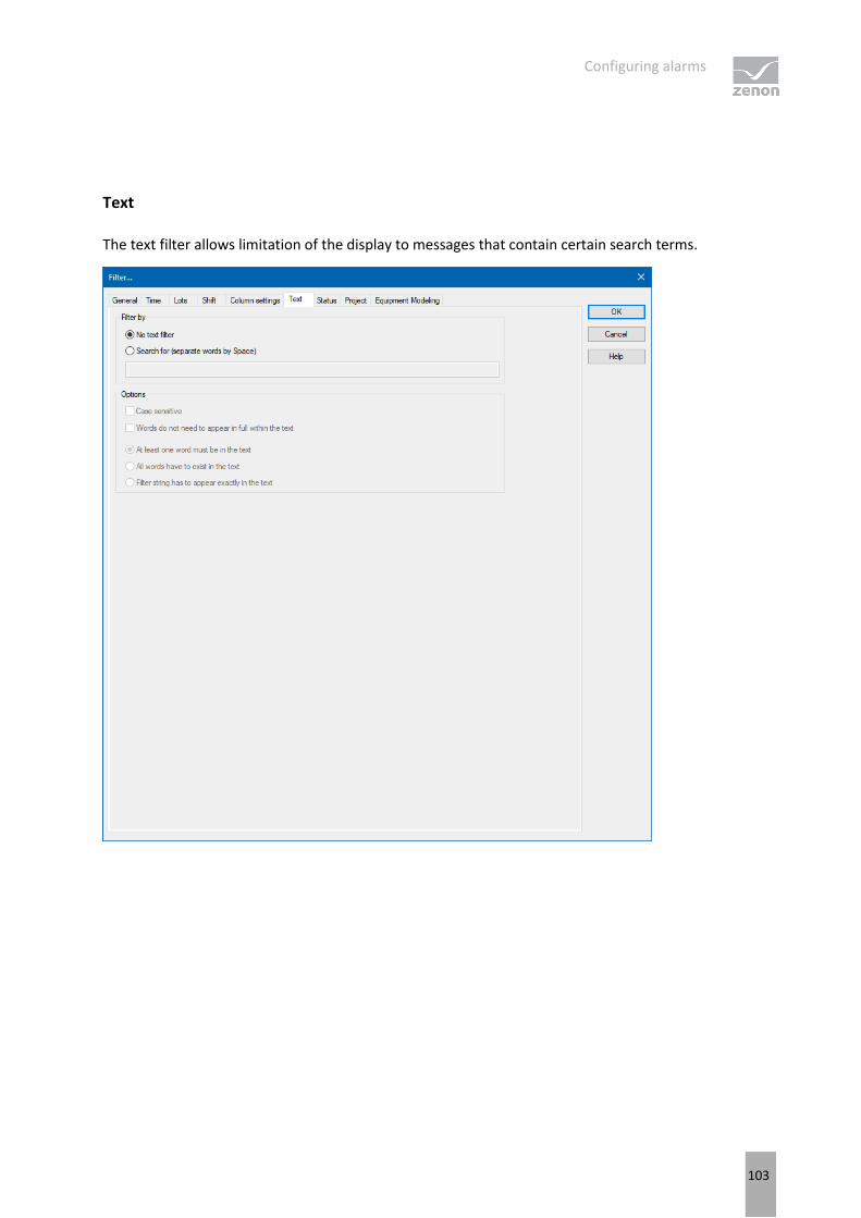
Configuring alarms
103
Text
The text filter allows limitation of the display to messages that contain certain search terms.

Configuring alarms
104
FILTER BY
FILTER BY
Parameter Description
Filter by
No text filter The text filter is not used.
Search for (words separated by spaces) The text filter is used.
Further options are activated.
Input field Enter the corresponding words or character strings.
OPTIONS
Parameter Description
Options
Note capitalization Active: The filtering is case-sensitive.
Words do not have to appear in the text in full Active: Parts of words can also be taken into
account during filtering.
At least one word must be in the text Active: At least one word of the search string has to be in the text.
All words must be present in the text Active: All words must be present in the search string. In doing so, the sequence plays no role.
Filter text must appear in the text exactly Active: The text must be exactly as defined in the search string.

Configuring alarms
105
Status
The status of the checkbox indicates if the status bit is to be evaluated.
Status of checkbox Description
Black dot The status bit is not evaluated.
0 Only the entries where the status bit is set to false are displayed.
1 Only the entries where the status bit is set to true are displayed.
Example
If the checkbox SPONT is set to 1, only the alarms are shown that are triggered by spontaneous values are displayed.

Configuring alarms
106
You can read details on status bits in the Status processing chapter.
Project
Selection of projects that are to be taken into account for the AML. The filter for selecting sub projects is only available in the integration project of the multi-project administration.
The selection from the integration project and all sub projects is carried out by means of multi-select, by pressing and holding the Ctrl key and clicking the mouse on the desired projects.
Equipment Modeling
In this dialog, you configure the filtering of the Alarm Message List according to equipment models. In the filter all already existing equipment models are displayed. The configuration of the equipment

Configuring alarms
107
model can be enhanced and amended for a project (but not the global project however) directly using the tool bar in this dialog.
To show the equipment group for Alarm Message List entries, in the Column settings tab (on page 98), activate the checkbox for the equipment group column type and select the desired equipment model for this entry in the Display column from the drop-down list.
To add groups to the filter:
1. Select the desired element.
2. Click on the Add button.
3. Repeat the process until all necessary groups are available in the list Multi-select is not possible
To remove groups from the filter:
1. Select the desired element (multiselect: Hold down the Ctrl key or shift key and click on the desired element.
2. Click the Delete button.

Configuring alarms
108
EQUIPMENT MODELING DIALOG

Configuring alarms
109
EQUIPMENT MODELING
Option Description
Toolbar Symbols to:
Edit local equipment models
Expand or collapse the display
Display of information
List of equipment models provides models and groups for selection The list separates the display into equipment models from the global project and from local projects.
Local equipment models can be created, edited or deleted.
Equipment models from the global project cannot be displayed if there are models with the same name from the local project. Affected models are displayed by clicking on the warning symbol (triangle with exclamation mark). For details, see the Equipment modeling manual, Editing local equipment models chapter.
Add Adds the selected groups to the filter list.
Remove Removes all selected groups from the filter list.
Hierarchic filter Checkbox for the activation of the hierarchical filtering of the equipment model
active: Variables that are linked to a subhierarchy of the selected equipment group are taken into account when filtering and are contained in the display in Runtime.
inactive: When filtering, only variables that are linked to the selected equipment group are taken into account.Default: activated
Filter list Shows all equipment groups that are to be filtered.
CLOSE DIALOG
Option Description
OK Applies all changes in all tabs and closes the dialog.
Cancel Discards all changes in all tabs and closes the dialog.
Help Opens online help.

Configuring alarms
110
3.7.3 Filter for Alarm Message List screen switching filter.
To create an Alarm Message List filter (on page 16) screen:
1. Create a Screen switching function on an Alarm Message List filter screen
2. the filter is displayed with all tabs:
Screens (on page 111)
General (on page 113)
Text (on page 116)
Time (on page 118)
Lots (on page 121)
Shift (on page 126)
Column settings (on page 132)

Configuring alarms
111
Screens
On this tab, you can define the screens that are to be updated by the screen filter.
The following settings are available:

Configuring alarms
112
FILTER IS TAKEN FROM THE FOLLOWING SCREEN
Parameter Description
Filter is taken from the
following screen Definition of the screen form which the filter is to be taken.
Calling screen Active: The filter settings are take over from the screen from which the filter screen is called up. The screen button is grayed out. You cannot explicitly select a screen, because the filter is always updated from the calling screen with this setting.
Settings in the General, Text and Time tabs are locked.
Predefined screen Click on button opens the Screen selection dialog.
Select the screen from which the filter - when clicking button Update during Runtime - should be read.
Subscreens of faceplates can also be selected for screen switching to AML filter, CEL filter, time filter, equipment model and shift management. For these screens, the name of the faceplate screen is placed in front of the subscreen in order to clearly distinguish them from other screens.
When the filter screen is first called up using the function, the filter configured in the function is used, not the filter of the screen stated here!
It therefore only makes sense to select a screen that can adopt or fill the screen filter.
The selected screen is entered into the list of screens to be updated. If you delete it from the list, the next selected screen from the list automatically takes its place.
Not available if you have activated the Calling screen checkbox.
SCREENS TO BE UPDATED
Parameter Description
Screens to be updated Selection of the screens that are to be updated.
Subscreens of faceplates can also be selected for screen switching to AML filter, CEL filter, time filter, equipment model and shift management. For these screens, the name of the faceplate screen is placed in front of the subscreen in order to clearly distinguish them from other screens.
Screen selection Click the button to open dialog Screen selection of the filter screens. Select the desired screen.
Update Stipulation of where the filter should take effect.
Update on all monitors Active: The screens from the list of the monitors that must be updated
are updated on all accessible monitors.

Configuring alarms
113
General

Configuring alarms
114
VARIABLE FILTER
Parameter Description
Variable filter Limitation to alarms of certain variables
Variable name Enter the name or part of the name of the variable you want to filter.
Use of the wild card * is possible. Wildcards are only permitted as a prefix or suffix; e.g. *xxx or xxx*.
Filter terms entered in Runtime or in the Editor are automatically saved on the local computer in zenon6.ini and are available for selection in the drop-down list.
The comma character (,) "only" serves as a separator between several variables to be filtered. However it is not possible to filter for a comma character in variables names! This results in the special filtering of array variables for Dim 2 and Dim 3 not being possible.
Identification Enter the identification or part of the identification of the variables you want to filter. Wild card * is possible.
Use of the wild card * is possible. Wildcards are only permitted as a prefix or suffix; e.g. *xxx or xxx*.
Filter terms entered in Runtime or in the Editor are automatically saved on the local computer in zenon6.ini and are available for selection in the drop-down list.
Case sensitive Active: Capitalization is recognized when filtering for variable name or identification.
TYPE OF ALARMS
Parameter Description
Type of alarms Type of alarm that is displayed.
Only not acknowledged alarms Active: Only alarms that have not yet been acknowledged by the user are displayed.
Only cleared alarms Active: Only alarms that have already passed, i.e. whose values no longer in the critical range, are displayed.
Only current alarms Active: Only alarms that are still active, i.e. whose values are still in the critical range, are displayed.
Comment required Active: Only alarms for which it is required to enter a comment (on page 189) during acknowledging are displayed.
Alarm cause required Active: Only alarms that are required for the linking

Configuring alarms
115
of an alarm cause (on page 189) are displayed.
Alarms have to be pending at least Use the spin control to define the minimum time that an alarm should be active in order for it to be displayed. Possible settings:
Days
Hours (hr.)
Minutes (min.)
Seconds (sec.)
Milliseconds (ms)
ORIGIN OF THE DATA
Parameter Description
Origin of the data Display of current or current and historical alarms.
Ring buffer Active: Only data from the ring buffer (on page 41) are
displayed.
Historical data Maximum number
Active: Data from the ring buffer and historical data
from the AML are displayed.
The maximum number of the data which should be displayed includes the data from the ring buffer.
ALARM/EVENT GROUPS/CLASSES, ALARM AREAS
Parameter Description
Alarm/Event Groups/Classes, Alarm Areas
Selection of groups, classes and alarm area.
Alarm/event groups From the existing alarm/event groups (on page 44) select the one from which alarms should be displayed.
Alarm/event classes From the existing alarm/event classes (on page 47) select the one from which alarms should be displayed.
Alarm areas From the existing alarm areas (on page 50) select the one from which alarms should be displayed.
If the Use hierarchical alarming of the
Equipment Model property is activated, the Alarm area column is empty. The checkbox is in the alarm handling item of the variable properties.
Runtime settings Behavior of the AML in Runtime
Show list without refresh Active: As long as the list is displayed no new entries are added.

Configuring alarms
116
Text

Configuring alarms
117
FILTER BY
Parameter Description
Filter by
No text filter The text filter is not used.
Search for (words separated by spaces) The text filter is used.
Further options are activated.
Input field Enter the corresponding words or character strings.
OPTIONS
Parameter Description
Options
Note capitalization Active: The filtering is case-sensitive.
Words do not have to appear in the text in full Active: Parts of words can also be taken into account during filtering.
At least one word must be in the text Active: At least one word of the search string has to be in the text.
All words must be present in the text Active: All words must be present in the search string. In doing so, the sequence plays no role.
Filter text must appear in the text exactly Active: The text must be exactly as defined in the
search string.

Configuring alarms
118
Time
On this tab, you define the time period that is to be used when the filter screen is opened.
You can read details of the time filter options in the Filter for screen switching, Alarm Message List (on page 61)/time (on page 67) chapter.

Configuring alarms
119
FILTER
Selection of the filter.
Parameter Description
No time filter Active: No time filter is used. all Runtime entries since 1. 1. 1990 are displayed. Use of this filter setting
is not supported by Extended Trend.
Absolute filter Active: A fixed period of time is entered in the editor. When the function is
executed, the defined absolute time period is exactly used.
In the settings section, the corresponding options can be shown and configured there.
Time is saved in UTC. For details see chapter Handling of date and time in chapter Runtime.
Relative time period Active: A relative time period is entered.
In the settings section, the corresponding options can be shown and configured there.
this filter is constantly updated.
From Active: A time from which the filter is effective is stated. If the time is not reached on the current day, filtering takes place from the corresponding time the previous day.
Selection of the area mode from drop-down list:
Starting from HH:MM:SS
Starting from day - HH:MM:SS
Starting from day, month - at HH:MM:SS
In the settings section, the corresponding options can be shown and configured there.
The start point of this filter is not updated automatically. Only the existing times are used when shown. The end time point is not defined with this filter, it is carried over.

Configuring alarms
120
Time period Active: A fixed time period is entered. Selection of the area mode from drop-down list:
One day
One week
Two weeks
One month
One Year
15 minutes
30 minutes
60 minutes
In the settings section, the corresponding options can be shown and configured there.
The following selection is also enabled on activation:
Display selection dialog
Use current date and time
The Modify time period property can be activated.
The time period can be moved to the future.
The time period can be amended.
Create a screen switch, for example to an AML screen. In the screen switching filter dialog in the Time tab, set the filter to time period and select One Month in the drop-down list. Select Use current
date/time under Settings. Activate the Modify the checkbox of the time period property Enter the following setting under Move time period to
the future: HH = 0. Activate, under Change time period by, the checkbox of the Use last-completed time period property.
Evaluation: today's date: 2/22/2018
Result of the time filter in Runtime: 01.01.2018 - 31.01.2018
CLOSE DIALOG
Option Description
OK Applies all changes in all tabs and closes the dialog.
Cancel Discards all changes in all tabs and closes the dialog.
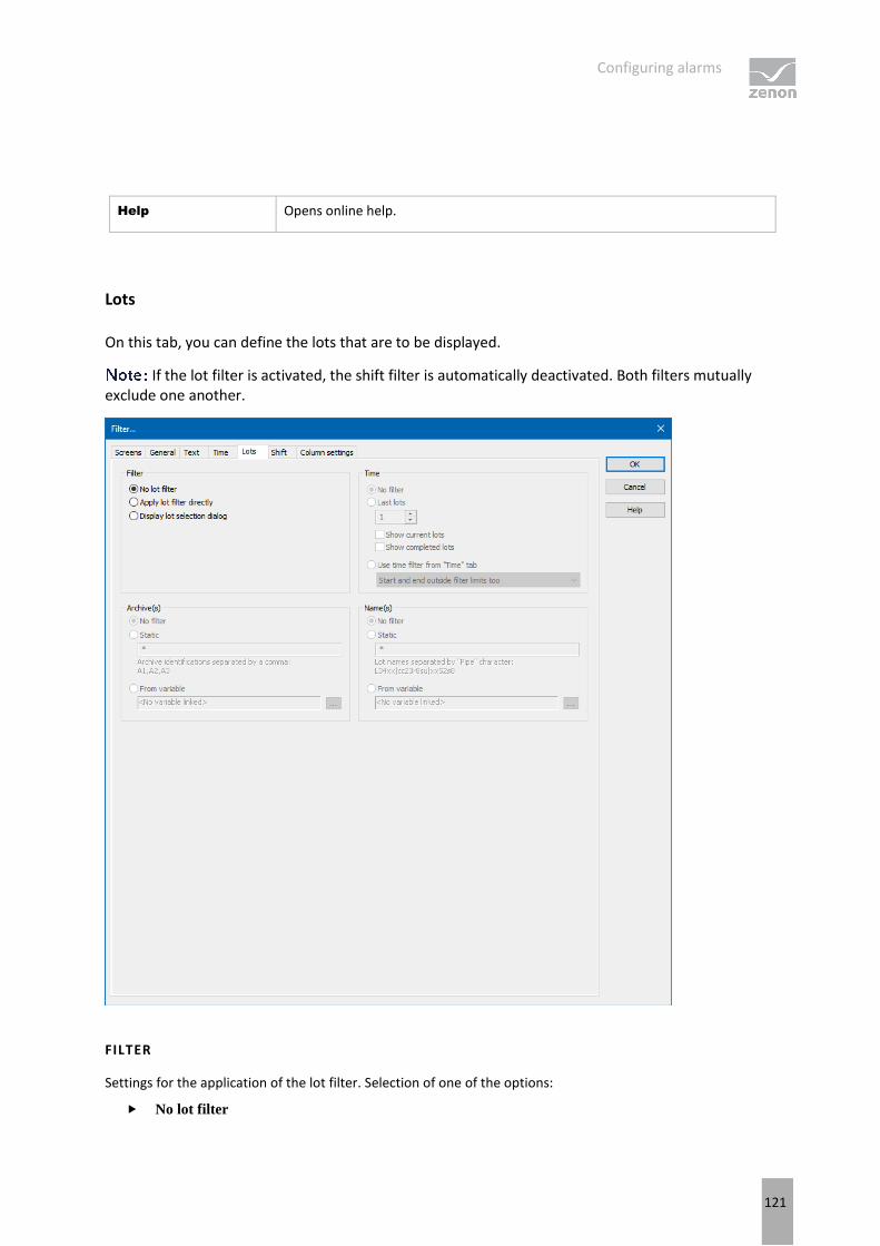
Configuring alarms
121
Help Opens online help.
Lots
On this tab, you can define the lots that are to be displayed.
If the lot filter is activated, the shift filter is automatically deactivated. Both filters mutually exclude one another.
FILTER
Settings for the application of the lot filter. Selection of one of the options:
No lot filter

Configuring alarms
122
Apply lot filter directly
Display lot selection dialog If the lot filter is shown as a dialog, it can be prefiltered for archive identifications. It is
expressly recommended that you use this prefiltering for performance improvements.
Option Description
No lot filter Active: The lot filter is deactivated and cannot be configured. Filtering for lots is not carried out in Runtime.
Apply lot filter directly Active: The filter configured here is applied in Runtime directly.
Display lot selection dialog Active: The dialog for lot selection is shown in Runtime when:
Clicking on Filter or
screen switching, if the Show this dialog in Runtime option has been activated (Not available for each function/screen type)
The dialog is not shown on reloading.
Options can be pre-selected in the Editor.
TIME
Configuration of the time filter for lot selection. Selection of one of the options:
No filter
Last lots
Use time filter from "Time" tab

Configuring alarms
123
Option Description
No filter Active: The time range set in the Time tab is not taken into account. All completed and current lots are displayed.
Last lots Only works in conjunction with the Apply lot
filter directly option.
The option allows the combination of both options Display
current lots and Display completed lots. At least one of the two options must be activated. If both options have been deactivated, this corresponds to the No filter setting.
Active: Input of the number of lots last concluded, according to what they should be filtered for. Input of the number in the number field or configuration via arrow keys.
Example: 3 was entered as a value for the option. 2 lots run and 10 have been ended. The following is shown: the two that are current and one that has been completed.
The setting of the time filter is not used as a time period for the current lots, but the last year. This filter will not be executed as a prefilter and can therefore not be used to improve performance.
If the project is compiled for a version before 7.11, the following is applicable: If the current lots are selected or the combination of current and completed lots, then only the completed lots are shown in Runtime.
Display current lots Active: The current lots are displayed.
If the number of lots to be displayed is greater than the number of current lots, lots that have been completed are also shown until the set limit has been reached. Example: 3 lots are to be displayed. 1 lot is running, 5 have been completed. The one current lot and two completed lots are displayed.
Display completed lots Active: The completed lots are displayed.
If the number of lots to be displayed is greater than the number of completed lots, lots that have been completed are also shown until the set limit has been reached.
Use time filter from "Time" tab Active: Pre-filtering is carried out with the settings of
the Time tab.
The effective range of the filter can be amended within this time range. Select from drop-down list:
Start and end also outside filter limits: (Default)

Configuring alarms
124
Lots can start before the start time configured in the Time filter and end after the configured end time.
Start and end only outside filter limits: Lots must start and end within the time points configured in the Time filter for the start and end.
Start also before filter limit: Lots can start before the start time configured in the Time filter and end after the configured end time.
End also after the filter limit: Lots can also end after the end time set in the time filter, but must start at or after the configured start time.
Adjust start and end to filter limits: Lots are cut to the time points configured in the Time filter for the start and end.
ARCHIVE(S)
Configuration of filtering for archives. Selection of one of the options:
No filter
Static
From variable

Configuring alarms
125
Option Description
No filter Active: Filtering for archive names is not carried out.
Static Active: Archives whose identification corresponds to the character string entered in the input field are filtered for.
Input of the archive identifications in the input field:
Several identifications are separated by a comma (,).
* or empty: All archives, no filter.
From variable Active: The value of the variables linked here is applied as a
filter for archive names in Runtime.
Click on button ... in order to open the dialog for selecting a variable.
Only available for all modules if the Apply lot filter directly option has been selected:
The variable selection is only activated in Runtime if a valid variable has already been linked in Runtime. The ... button is always deactivated in Runtime. The option can be selected, but no new variable can be linked.
If the variable is not signed into the driver at the time at which the lot filter is applied, the variable is signed in and read. This can lead to delays with slow driver connections/protocols.
If the selected variable is not found in Runtime, there is no filtering for archive names. This also applies if the value of the variable cannot be determined. The filter then corresponds to the No filter setting.
NAME(S)
Configuration of the filtering to names. Selection of one of the options:
No filter
Static
From variable

Configuring alarms
126
Option Description
No filter Active: Filtering for lot names is not carried out.
Static Active: Lot names that correspond to the character string entered in the input field are filtered for.
Input of the lot name in the input field:
Several entries are separated by a pipe character (|).
* or empty: All lots of all displayed archives, no filter.
From variable Active: The value of the variable linked here is applied as a
filter for lot names in Runtime.
Click on the ... button to open the dialog for selecting a variable.
Only available if the option Apply lot filter directly has been selected.
The variable selection is only activated in Runtime if a valid variable has already been linked in Runtime. The ... button is always deactivated in Runtime. The option can be selected, but no new variable can be linked.
If the variable is not signed into the driver at the time at which the lot filter is applied, the variable is signed in and read. This can lead to delays with slow driver connections/protocols.
If the selected variable is not found in Runtime, there is no filtering for lot names. This also applies if the value of the variable cannot be determined. The filter then corresponds to the No filter setting.
CLOSE DIALOG
Option Description
OK Applies all changes in all tabs and closes the dialog.
Cancel Discards all changes in all tabs and closes the dialog.
Help Opens online help.
Shift
You configure the limitation of the display to certain shifts in this tab. The shift information is also applied to the existing filter.

Configuring alarms
127
The shift filter requires a configured time filter. If the time filter is set to the No time filter option, the shift filter is deactivated. A notice of the cause of the deactivation is shown.
If the lot filter is activated, the shift filter is automatically deactivated. Both filters mutually exclude one another. A notice of the cause of the deactivation is shown.
CONFIGURATION
To filter for shifts:
1. Configure the time filter.
Absolute time filter: Shifts from the absolute defined time period are shown.
Relative time filter: Shifts from the relative defined time range are shown. The upper limit is set at 1440 minutes by default.
From: Shifts from a certain time point are shown.
Time range: Shifts within a certain time range are shown.
2. Configure the shift filter. To do this, select one of the options:
Apply shift filter directly: The configured time filter is used to filter the shifts in Runtime. In doing so, all shifts that are at least partly in the time filter range are taken into account. Even if the time filter is defined in Runtime, the shift filter is applied after selecting the time period. If there is no suitable shift, no data is shown in the CEL screen. The set filter continues to have an effect on the CEL data. If a shift is only partially within the set time range, only the CEL entries that are both in the time filter and the shift are shown.
Show shift selection: The shift filter is configured and applied when called up in Runtime. All shifts that are at least partly in the time filter range are offered in a list for selection. After selecting one or more shifts, the time filter is overwritten and set to the times of the selected shifts. It is thus ensured that the complete shift is always included in the filter.
3. Configure Name and Options if required.
With the Apply shift filter directly option, the shifts are permanently monitored by the filter and the filter is amended if necessary. The shifts for filtering the data are redetermined if:
Shifts are reconfigured
Shifts are newly-created in the filter time period
The time period is reconfigured
The following are not taken into account in the filter:
Deleted shifts
Shifts that are removed from the time filter due to a change of the time period

Configuring alarms
128
SHIFT DIALOG
FILTER
Settings for the application of the shift filter. Selection of one of the options:
No shift filter
Apply shift filter directly
Display shift selection

Configuring alarms
129
Option Description
No shift filter Shift filter selection:
Active: The shift filter is deactivated and cannot be configured. Filtering for shifts is not carried out in Runtime.
Apply shift filter directly Applying the shift filter in Runtime:
Active: The filter configured here is applied in Runtime directly.
Equipment groups and shift names can be preselected.
Display shift selection Display of the shift selection in Runtime:
Active: The dialog for shift selection is shown in Runtime.
The settings chosen in the Editor are applicable for the reading of the shifts in Runtime.
The dialog is shown in Runtime when:
Clicking on the Filter button. Or:
Executing screen switching. The dialog is not shown on reloading.
EQUIPMENT MODELING
Configuration of the equipment groups for filtering for shifts.
Option Description
Equipment Groups Selection of equipment groups to which shifts must be linked.
Clicking on the ... button opens the dialog to select equipment groups.
If several equipment groups are selected, they are displayed in the option separated by a semicolon (;).
Include shifts without
equipment linking Selection of whether linking to an equipment group is necessary.
Active: Shifts that are not linked to an equipment group are also
taken into account.
Inactive: Only shifts that are linked to at least one equipment
group are taken into account.
Default: Active
NAME
Configuration of the shift names for which filtering is to take place. Selection of one of the options:
No filter

Configuring alarms
130
Name with wildcards
Name from variable
Option Description
Type Selection of the filter type from a drop-down list when filtering according to name:
No filter:
Filtering for names is not carried out.
Name with wildcards: A name with placeholder can be entered into the input field. All shifts whose name is applicable for the filter are included.
Name from variable: The name of the shift is defined by a variable in Runtime. Click on button ... Opens the dialog for selecting a variable.
Default: No filter
Wildcards:
*: Replaces desired characters in the desired quantity. Can be used as a search term at any desired place. red* finds all texts that start with red.
?: Replaces precisely one character. r?d finds red, rad, ..
The variable selection is only activated in Runtime if a valid variable has already been linked in Runtime. The ... button is always deactivated in Runtime. The option can be selected, but no new variable can be linked.
If the variable is not signed into the driver at the time at which the lot filter is applied, the variable is signed in and read. This can lead to delays with slow driver connections/protocols.
If the selected variable cannot be found in Runtime or the value of the variables cannot be determined, the filter is treated like the No filter setting.
Note case sensitivity Setting for filtering for upper/lower case
Active: Capitalization is taken into account for names.
Default: Aktiv
OPTIONS
Configuration of the options for filtering for shifts in the CEL.

Configuring alarms
131
Option Description
Only include shifts that are
fully in the filter range Configuration of which shifts are displayed.
Active: Only shifts that are fully in the time filter set are shown.
Inactive: Shifts that start earlier and/or finish later are also shown.
Default: Inactive
Example:
Time filter: Today 08:00 – 12:00.
Existing shift: Today 8:30 AM – 5:00 PM.
Result for:
Option active: The shift is not taken into account because it is not fully in the time filter.
Inactive option: The shift is taken into account because it is partly in the time filter.
Use shifts found Selection of shifts that are taken into account, from drop-down list:
All: All shifts found are taken into account.
Earliest shift only: Of the shifts found, only the earliest are taken into account. The earliest shift is the shift with the earliest start time. If several shifts have the same start time, one of these shifts is selected randomly.
Only last shift: Of the shifts found, only the latest shift is taken into account. The latest shift is the shift with the latest end time. If several shifts have the same end time, one of these shifts is selected randomly.
Default: all
: The Only include shifts that are fully in the filter range influences the evaluation of this option. If it is active, only shifts that are fully in the time range can be found. If it is inactive, shifts that start earlier or end later can be found.
Example:
Configuration and shifts:
Only include shifts that are fully in the filter range option: active.
Use found shifts option: Latest shift only
Time filter: Today 08:00 – 10:00 AM.
Shift 1: Today 08:00 – 8:30 AM.
Shift 2: Today 8:30 AM – 9:00 AM.
Shift 3: Today 10:00 AM – 11:00 AM.

Configuring alarms
132
Result:
Shift 2 is used
Switch to "Show shift selection"
mode
Active: The filter acts as with the Show shift selection option. The time filter is set to absolute; start and end correspond to the start time and end time of the shifts. If no shift is found, the times are set to 0 for the time filter.
Default: Inactive
Behavior in Runtime:
If the shift management is set to Show shift selection in Runtime, the filter options also have an effect on the shifts shown in the shift list. The shift list is filtered accordingly by clicking on the Update button.
CLOSE DIALOG
Option Description
OK Applies all changes in all tabs and closes the dialog.
Cancel Discards all changes in all tabs and closes the dialog.
Help Opens online help.
FILTER BUTTON IN THE SCREEN IN RUNTIME
If the Filter button is pressed in the CEL screen, the complete filter dialog including the shift selection list is shown depending on the configuration. The filter settings can thus be amended and the shift list can be updated in order to select another shift.
Column settings
In this tab, you define how the archive list, the lot list and the shift list are displayed in Runtime:
Selection of the columns to be displayed
Sorting of the columns
Formatting of columns:
Labeling
Width
Alignment

Configuring alarms
133
COLUMN SETTINGS DIALOG

Configuring alarms
134
ARCHIVE LIST
Option Description
Archive list Configuration of the archive list. Display of the configured columns.
If you want to edit the list directly using the monitor, activate the Multi-Touch functionality. You can find detailed information in relation to this in the Configure interactions chapter.
Longer texts can also be displayed in Runtime over several lines using the Automatic word wrap property.
In the Editor, go to Representation in the properties of the respective list properties and activate the checkbox of the Automatic word wrap property.
The line height must be amended manually.
Column selection Clicking on the button opens a dialog to select and sort the columns.
Column format Clicking on the button opens a dialog to format the list.
LOT LIST
Option Description
Lot list Configuration of the lot list. Display of the configured columns.
If you want to edit the list directly using the monitor, activate the Multi-Touch functionality. You can find detailed information in relation to this in the Configure interactions chapter.
Longer texts can also be displayed in Runtime over several lines using the Automatic word wrap property.
In the Editor, go to Representation in the properties of the respective list properties and activate the checkbox of the Automatic word wrap property.
The line height must be amended manually.
Column selection Clicking on the button opens a dialog to select and sort the columns.
Column format Clicking on the button opens a dialog to format the list.
SHIFT LIST

Configuring alarms
135
Option Description
Shift list Configuration of the shift list. Display of the configured columns.
Longer texts can also be displayed in Runtime over several lines using the Automatic word wrap property.
In the Editor, go to Representation in the properties of the respective list properties and activate the checkbox of the Automatic word wrap property.
The line height must be amended manually.
Column selection Clicking on the button opens a dialog to select and sort the columns.
Column format Clicking on the button opens a dialog to format the list.
CLOSE DIALOG
Option Description
OK Applies all changes in all tabs and closes the dialog.
Cancel Discards all changes in all tabs and closes the dialog.
Help Opens online help.
Column selection
Selection and sequence of the columns.

Configuring alarms
136
Option Function
Available columns List of columns that can be displayed in the table.
Selected columns Columns that are displayed in the table.
Add -> Moves the selected column from the available ones to the selected items. After you confirm the dialog with OK, they are shown in the detail view.
Add all -> Moves all available columns to the selected columns.
<- Remove Removes the marked columns from the selected items and shows them in the list of available columns. After you confirm the dialog with OK, they are removed from the detail view.
<- Remove all All columns are removed from the list of the selected columns.
Up Moves the selected entry upward. This function is only available for unique entries, multiple selection is not possible.
Down Moves the selected entry downward. This function is only available for unique entries, multiple selection is not possible.
CLOSE DIALOG
Options Description
OK Applies settings and closes the dialog.
Cancel Discards all changes and closes the dialog.
Help Opens online help.

Configuring alarms
137
Column Format
Configuration of the properties of the columns for configurable lists. The settings have an effect on the respective list in the Editor or - when configuring screen switching - in Runtime.
Configuring alarms
138
AVAILABLE COLUMNS
Option Description
Available columns List of the available columns via Column selection. The highlighted column is configured via the options in the Settings area.
SETTINGS
Option Description
Settings Settings for selected column.
Labeling Name for column title.
The column title is online language switchable. To do this, the @ character must be entered in front of the name.
Width Width of the column in characters. Calculation: Number time average character width of the selected font.
Alignment Alignment. Selection by means of radio buttons.
Possible settings:
Left: Text is justified on the left edge of the column.
Centered: Text is displayed centered in the column.
Right: Text is justified on the right edge of the column.
User-defined colors Properties in order to define user-defined colors for text and background. The settings have an effect on the Editor and Runtime.
These settings are only available for configurable lists.
In addition, the respective focus in the list can be signalized in Runtime by means of different text and background colors. These are configured using the project properties.
User defined colors Active: User-defined colors are used.
Text color Color for text display. Clicking on the color opens the color palette to select a color.
Background color Color for the display of the cell background. Clicking on the color opens the color palette to select a color.

Configuring alarms
139
Lock column filter in the Runtime Active: The filter for this column cannot be changed in Runtime.
Only available for:
Batch Control
Extended Trend
Filter screens
Message Control
Recipe Group Manager
Shift Management
Context List
CLOSE DIALOG
Option Description
OK Applies all changes in all tabs and closes the dialog.
Cancel Discards all changes in all tabs and closes the dialog.
Help Opens online help.
3.8 Functions
The display and handling of the Alarm Message List is controlled in Runtime using functions.
Attention
If functions are used in the network, regard their execution location.
3.8.1 AML screen switching
To open an Alarm Message List filter in Runtime:
1. Create an Alarm Message List (on page 7) screen
2. create a screen switch function for this screen
3. define the desired filter properties (on page 57)

Configuring alarms
140
In the Runtime you can modify the filter properties. Exception: In the Editor fixed time filter (on page 79) was defined.
CONFIGURE SCREEN SWITCHING
To create a screen switch to a screen of type AML:
1. in the context menu of node function select command New function
2. click on screen switch
3. the dialog for the screen selection will be opened
4. select the screen of type alarm or create it in this dialog by clicking symbol New screen
5. the filter is displayed with all tabs:
General (on page 62)
Time (on page 67)
Column settings (on page 98)
Text (on page 103)
Status (on page 105)
Project (on page 106) (only available in the integration project of the multi-project administration.)
Equipment Modeling (on page 106)
If linked variables or indexes are available, the following tabs can be displayed as an option.
Replace links

Configuring alarms
141
Replace indices
6. define the filters which should be pre-defined in the Runtime
7. confirm the settings and close the dialog by clicking OK
8. link the function with a button in order to call up the screen and to display the filter properties in the Runtime
Information
If a screen that does not have a time filter is referenced, the time filters (on page 67) are deactivated.

Configuring alarms
142
AML screen switching filter
Several filters are offered when screen switching is created for an AML screen. For details, see the Alarm configuration using filters (on page 57) section, in the Filters for Alarm Message List screen switching (on page 61) chapter.
3.8.2 AML filter screen switching
To open an Alarm Message List filter screen in Runtime:
1. Create an Alarm Message List filter (on page 16) screen
2. create a screen switch function for this screen
3. define the desired filter properties (on page 143)
In the Runtime the filter properties can only be controlled via the buttons defined in the screen.
CONFIGURE SCREEN SWITCHING
To create a screen switch to a screen of type Alarm Message List Filter:
1. in the context menu of node function select command New function
2. click on screen switch
3. the dialog for the screen selection will be opened
4. select the screen of type Alarm Message List Filter or create it in this dialog by clicking symbol New screen
5. the filter is displayed with all tabs:
Screens (on page 111)
General (on page 113)
Text (on page 116)

Configuring alarms
143
Time (on page 118)
6. define the filters which should be pre-defined in the Runtime
7. confirm the settings and close the dialog by clicking OK
8. link the function with a button in order to call up the screen and to display the filter properties in the Runtime
AML filter screen switching filter
Several filters are offered when screen switching is created for an AML screen. For details, see Alarm configuration using filters (on page 57) section, Filters for Alarm Message List filter (on page 110) section.

Configuring alarms
144
3.8.3 Functions for alarm administration
Different functions make it possible to handle alarms in Runtime.
To create a function for alarm administration:
1. navigate to the Functions node
2. select New function in the context menu or from the toolbar
3. the dialog for selecting functions is opened
4. navigate to the AML/CEL node
5. select the desired function
6. configure the function if necessary
7. link the function to a button
Alarm/event group log in/log off
To optimize the performance of the connection, alarm/event groups (on page 44) that are not required can be deactivated. Its variables are thus no longer requested from the driver if no other elements are linked to them. You can find detailed information on the signing-in and signing-out of variables in the Signing in variables in zenon chapter.
For the Alarm/event group log in/log off function, you must:
1. Define the action: logout or login

Configuring alarms
145
2. Define the alarm/event group. Only one group per function can be linked.
ALARM/EVENT GROUP
Option Description
Action Defines action. Available actions:
Logout: Deactivates the alarm/event group
Login: Activates the alarm/event group
Alarm/Event Group Selection of alarm/event group. Click the button and a dialog opens to select the group.
OK Applies settings and closes the dialog.
Cancel Discards all changes and closes the dialog.
Help Opens online help.
EXAMPLE
An alarm group bit is created in the PLC. If this bit is set, the Alarm group active function is called via the limit value administration. The variables are requested and the corresponding limit values in zenon are checked. The bit can be reset in the PLC. The alarm/event group can be deactivated again above a certain limit value. On program start all limit value variables are polled.
Alarms: acknowledge flashing
When flash-acknowledging (on page 191) in Runtime, only the flash attribute of the process variables and the flashing of all graphic elements in all screens that use this variable are reset. The entry in the alarm list is not acknowledged - except if the Flashing acknowledgement property is active.
This function is not identical to the Adopt flashing from limit value property that is defined for each element in the Adopt flashing from limit value group of the element properties. The function relates

Configuring alarms
146
to the flashing of the element content, for example text. The Adopt flashing from limit value property relates to the whole element.
ENGINEERING OF A FUNCTION
To acknowledge the flashing of alarms in Runtime:
1. Create a new function (on page 144).
2. Select the Alarms: acknowledge flashing function in the AML and CEL group.
3. Select the frame you wish to assign
4. Select the desired monitor for multi-monitor systems

Configuring alarms
147
ALARMS: ACKNOWLEDGE FLASHING
Option Description
Alarms: acknowledge
flashing Configuration of which alarms are to be flash-acknowledged.
All alarms in the frame All alarms on screens of a frame with the selected name are flash acknowledged, even if it is open several times.
Click on the ... button to open the dialog to select a frame. For details, see the Frame selection dialog (on page 147) section.
All alarms in the
calling frame The alarms on the screen of the calling frame are flash-acknowledged. With this option selected, the monitor selection cannot be configured manually.
MONITOR SELECTION
Option Description
Monitor selection Configuration of the monitor for which flash acknowledgment of the alarms is to be configured.
Monitor Selection of the monitor from the list:
All monitors
Current monitor
Selection of a virtual monitor
Only available for Multi-monitor systems and only for the All alarms in the frame option.
OK Applies settings and closes the dialog.
Cancel Discards all changes and closes the dialog.
Help Opens online help.
Frame selection dialog
In the frame selection dialog, frames can be selected for the execution of functions, from:
Current project
Subprojects

Configuring alarms
148
All projects in the workspace with the Keep project in memory option active
Parameter Description
Project tree window Displays all projects in the workspace. Frames can be selected from the current project and from all projects with the Keep project in memory option active.
Frames window Selection of a frame.
If several frames are selected, the frame at the top of the list is used to execute the function.
No selection Removes selection and closes dialog.
OK Applies settings and closes the dialog.
Cancel Discards all changes and closes the dialog.
Help Opens online help.
Examples of alarm acknowledgment in Runtime
EXAMPLE 1
The following were configured:
Frame_1 (red) with the variables Var_1, Var_2 and Var_3

Configuring alarms
149
Frame_2 (green) with the variables Var_1 and Var_2
Initial situation:
Frame_1 is switched to Monitor_1.
Frame_2 is switched to Monitor_2.
All three variables flash due to a limit value violation.
Reactions to the execution of the Alarms: acknowledge flashing function:
Execution on Frame_2 on Monitor_1: Nothing happens, because this frame is not present on Monitor_1.
Execution on all monitors or on Monitor_2: All variables of the frame are flash-acknowledged. This means: Var_1 and Var_2 are flash-acknowledged. Var_3 continues to flash
EXAMPLE 2
There is Button_1 on Frame_1. This flash-acknowledges the calling frame. If this button is pressed, Var_1, Var_2 and Var_3 are flash-acknowledged.

Configuring alarms
150
EXAMPLE 3
Initial situation:
Frame_1 (red) is switched to Monitor_1 4 times. This frame contains certain variables. However it contains other variables in each frame due to substitution. The only common one is Var_1.
Frame_2 (blue) is switched to Monitor_2. This frame contains different variables to Frame_1.
Reactions to the execution of the Alarms: acknowledge flashing function:
If Frame_1 is now flash-acknowledged on this monitor - or on all monitors - then:
The command is flash-acknowledged on all frames on this monitor
And thus on all variables of Frame_1
This means:
Var_1 to Var_5 are flash acknowledged
Var_7 to Var_9 continue to flash
Confirm alarm acknowledgment
Use the Confirm alarm acknowledgement function to confirm the acknowledgment of alarms jointly via filter criteria:
1. Create a new function (on page 144).
2. Select Confirm alarm acknowledgement.

Configuring alarms
151
The dialog for selecting filter criteria opens. This corresponds to the filter criteria in the screen switching.
3. Define the criteria for:
General (on page 62)
Time (on page 67)
Text (on page 103)
Status (on page 105)
4. Link the function to a button.
USER AUTHORIZATION
The functions Acknowledge alarms (on page 152)and Confirm alarm acknowledgment (on page 150) can be assigned to a user group via Function authorization. Only authorized user can acknowledge and delete alarms.

Configuring alarms
152
In addition, for the limit values, it is possible to use the Two-stage acknowledgement property in the respective subgroup of the Limit Values group to set an additional operating authorization. Selected alarms can only be removed from the Alarm Message List by users with the necessary rights.
If the Two-stage acknowledgement property is set, alarms are then only removed from the list of active alarms if their acknowledgment has been confirmed. Acknowledgment alone is not sufficient.
Acknowledge alarms
With this function, you acknowledge Runtime alarms from the Alarm Message List. Most importantly, global acknowledgment (on page 188) is possible with this.
When activating this function in Runtime, the flashing attribute of the variables and therefore screen alarming (only present for SICAM 230) will also be reset.
All alarms of the linked variable are always acknowledged when acknowledging.
ENGINEERING
To acknowledge alarms with this function:
1. Create a new function (on page 144).
2. Select the Acknowledge alarms function in the AML and CEL group.

Configuring alarms
153
The dialog to select the filter criteria is opened. (similar to filter criteria in screen switching)
3. Define the criteria for:
General (on page 62)
Time (on page 67)
Text (on page 103)
Status (on page 105)
Equipment Modeling (on page 106)
Project (on page 106) (only available in the integration project of multi-project administration)
4. Link the function to a button.

Configuring alarms
154
USER AUTHORIZATION
The functions Acknowledge alarms (on page 152)and Confirm alarm acknowledgment (on page 150) can be assigned to a user group via Function authorization. Only authorized user can acknowledge and delete alarms.
In addition, for the limit values, it is possible to use the Two-stage acknowledgement property in the respective subgroup of the Limit Values group to set an additional operating authorization. Selected alarms can only be removed from the Alarm Message List by users with the necessary rights.
If the Two-stage acknowledgement property is set, alarms are then only removed from the list of active alarms if their acknowledgment has been confirmed. Acknowledgment alone is not sufficient.
Alarm Message List active
This function switches the status of the Alarm Message List in Runtime to active when selected.
Alarm Message List active/inactive
This function switches the status of the Alarm Message List in Runtime between active and inactive when selected.
Alarm Message List inactive
This function switches the status of the Alarm Message List in Runtime to inactive when selected.
Alarm Message List: Activate or deactivate alarm/event groups/classes
The function makes it possible to activate or deactivate alarms of a certain group or class (on page 43) or all alarms of the AML or to switch between these two states.
To activate or deactivate alarms:
1. Create a new function (on page 144).
2. Select, under AML and CEL Alarm message list, Activate/deactivate alarm/event
groups/classes
The dialog to select alarms opens
3. Define the criteria for the function

Configuring alarms
155
4. Link the function to a button.
SELECTION
Option Description
Selection Selection of the alarms.
Whole alarm message list Function applies for the whole alarm message list.
Alarms of the alarm/event group Function applies for a certain group.
Selection: Click on the ... button to open the selection dialog.
Alarms of the alarm/event class Function applies for a certain class.
Selection: Click on the ... button to open the selection dialog.
ACTIVATE/DEACTIVATE
Parameter Description
activate/deactivate Action of the function.
Activate Activates selected element.
deactivate Deactivates selected element.
toggle Switches status (active/inactive).
Dialog to select alarm/event group
In this dialog, you can create, filter, edit and select alarm/event groups.

Configuring alarms
156
TOOL BAR, CONTEXT MENU AND DESCRIPTION OF THE DIALOG
Symbols Description
New alarm/event group Creation of a new alarm/event group
Remove all filters Resetting of the filter settings
Edit selected cell Editing of a highlighted cell
Replace text in selected column... Finding and replacing of text in highlighted columns
Option Description
Project Manager Shows the local project used.
Detail view Details for the module selected in the Project Manager.
No selection Allows the closing of the dialog, without previously having made a selection. If an alarm/event group has already been selected, this selection is deleted.
OK Applies settings and closes the dialog.
Cancel Discards all changes and closes the dialog.
Help Opens online help.
Selection of an alarm/event group.
Configure using the Alarm message list, Activate/deactivate alarm/event groups/classes dialog
1. Select, under Selection of alarms of the alarm/event group.

Configuring alarms
157
2. Click on the ... selection button.
The Selection of alarm/event group dialog is opened.
3. Highlight the desired alarm/event group. You can also create a new entry if there is no entry present. To do this, click on the tool bar or in the context menu on the New alarm/event group symbol.
4. Confirm the selection by clicking on OK.
The dialog is closed. The selected alarm/event group is entered into the text field.
If you open the selection dialog again and select None, the selection in the text field behind Alarms of the alarm/event group are deleted.
Dialog to select of alarm/event class
In this dialog, you can create, filter, edit and select alarm/event classes.
TOOL BAR, CONTEXT MENU AND DESCRIPTION OF THE DIALOG

Configuring alarms
158
Symbol Description
New alarm/event class Creation of a new alarm/event class
Remove all filters Resetting of the filter settings
Edit selected cell Editing of a highlighted cell
Replace text in selected column... Finding and replacing of text in highlighted columns
Option Description
No selection Allows the closing of the dialog, without previously having made a selection. This selection is deleted if a variable has already been selected.
OK Applies settings and closes the dialog.
Cancel Discards all changes and closes the dialog.
Help Opens online help.
Selection of an alarm/event class
Configure using the Alarm message list, Activate/deactivate alarm/event groups/classes dialog
1. Select, under Selection of alarms of the alarm/event class.
2. Click on the ... selection button.
The Selection of alarm/event class is opened.
3. Highlight the desired alarm/event class. You can also create a new entry if there is no entry present. To do this, click on the tool bar or in the context menu on the New alarm/event class symbol.
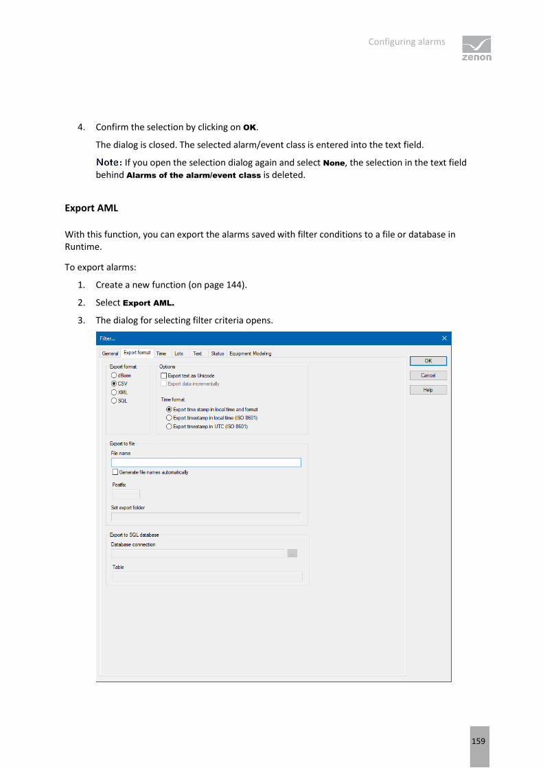
Configuring alarms
159
4. Confirm the selection by clicking on OK.
The dialog is closed. The selected alarm/event class is entered into the text field.
If you open the selection dialog again and select None, the selection in the text field behind Alarms of the alarm/event class is deleted.
Export AML
With this function, you can export the alarms saved with filter conditions to a file or database in Runtime.
To export alarms:
1. Create a new function (on page 144).
2. Select Export AML.
3. The dialog for selecting filter criteria opens.

Configuring alarms
160
4. Define the criteria for:
Export format (on page 160)
General (on page 62)
Time (on page 67)
Text (on page 103)
Status (on page 105)
Equipment Modeling (on page 106)
Project (on page 106)
5. Link the function to a button.
Export format
Exports can be carried out in different formats. Which columns are exported, and how, depends on the source (AML/CEL) and the export format:
Data is exported in different ways for:
CSV (on page 165)
dBase (on page 165)
SQL (on page 166)
XML (on page 165)
Information
The export to SQL is incremental. If there is data that has already been exported, only new and amended data is exported.
COLUMN SELECTION
The selection of the columns to be exported depends on the export format:
CSV, DBF and XML: Selection using the dialog (on page 58) of the Column settings AML project property for the AML and Column settings CEL for the CEL.
SQL: Pre-defined columns are exported.

Configuring alarms
161
CONFIGURE EXPORT

Configuring alarms
162
EXPORT FORMAT
Parameter Description
Export format Selection of the file type. Possible formats:
dBase: DBaseIV format (*.dbf):
CSV
XML
SQL
Filenames cannot be longer than eight characters.
Configured column width is used for export. If, for example, a value of 40 is set under Column settings, a maximum of 40 characters is then exported.
A maximum of 255 characters are exported.
OPTIONS
Parameter Description
Options
Export as unicode An export to ASCII format is performed in Unicode
Incremental export Only differences since the last backup are exported.
TIME FORMAT
Parameter Description
Time format Definition of the format in which time is saved.
Export time stamp in local time and format Time stamp is exported in the local time and the local format.
Export time stamp in local time (ISO 8601) Time stamp is exported in UTC time plus time lag.
Export time stamp in UTC (ISO 8601) Time stamp is exported in Coordinated World Time (UTC). UTC is shown as a world time everywhere where a uniform time scale is needed.
EXPORT TO FILE
Parameter Description
Export to file Determining the file in which the export is saved.
File name Define file name individually.
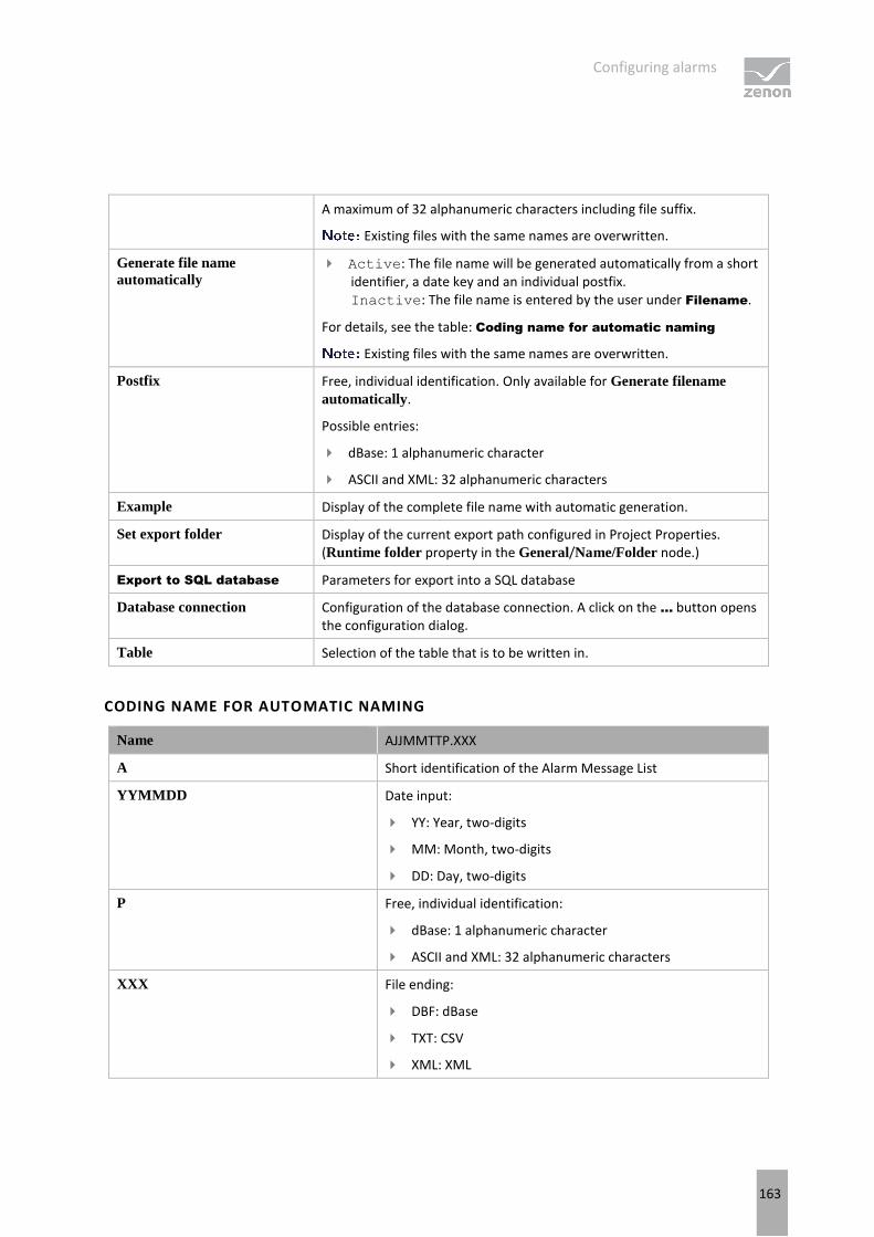
Configuring alarms
163
A maximum of 32 alphanumeric characters including file suffix.
Existing files with the same names are overwritten.
Generate file name
automatically Active: The file name will be generated automatically from a short
identifier, a date key and an individual postfix. Inactive: The file name is entered by the user under Filename.
For details, see the table: Coding name for automatic naming
Existing files with the same names are overwritten.
Postfix Free, individual identification. Only available for Generate filename
automatically.
Possible entries:
dBase: 1 alphanumeric character
ASCII and XML: 32 alphanumeric characters
Example Display of the complete file name with automatic generation.
Set export folder Display of the current export path configured in Project Properties. (Runtime folder property in the General/Name/Folder node.)
Export to SQL database Parameters for export into a SQL database
Database connection Configuration of the database connection. A click on the ... button opens the configuration dialog.
Table Selection of the table that is to be written in.
CODING NAME FOR AUTOMATIC NAMING
Name AJJMMTTP.XXX
A Short identification of the Alarm Message List
YYMMDD Date input:
YY: Year, two-digits
MM: Month, two-digits
DD: Day, two-digits
P Free, individual identification:
dBase: 1 alphanumeric character
ASCII and XML: 32 alphanumeric characters
XXX File ending:
DBF: dBase
TXT: CSV
XML: XML
Configuring alarms
164
FORMAL MATTERS
Format of the line entries: Is taken from the settings of the Column settings AML or Column
settings CEL property.
Column separator: Semi-colon (;)
Attention
Milliseconds for printing or export
If, when printing or exporting the AML or CEL to CSV, XML or dBase format, the time in milliseconds is to be given, this property must be activated in the dialog for the column settings (on page 98). To do this:
Go to the Alarm Message List or Chronological Event List nodes in the project properties.
Click on the ... button of the Column settings AML or Column settings CEL property.
The dialog for the column settings is opened.
Activate the checkbox in front of the Milliseconds property.
The additional setting must be made for both AML and CEL.
NOTES SQL
Attention
Ensure that the provider configured in the connection is also available on the Runtime computer in Runtime.
An SQL client is also installed with the zenon Editor. Because the zenon Runtime does not need an SQL Server, no SQL client is automatically installed. This can be downloaded from the Microsoft website and must be installed individually.
Ensure you install the correct version when installing the provider. This must suit the zenon version being used. This means: If a 32-bit zenon Runtime is used, the provider must be a 32-bit version. This also applies if it is installed on a 64-bit operating system and also if the database itself is a 64-bit application.
Attention
When using Native Client 10 and 11, the password is not automatically carried over to the provider string. It must be entered manually
e.g.: ...;User ID=sqlExampleUser1;Password=secretPassword;...

Configuring alarms
165
CSV: Exported columns
Export to CSV is mostly for further processing in other applications. The data is exported according to the selection in Column settings AML or Column settings CEL:
Only data from the selected columns is exported.
The sequence in the export file corresponds to the one defined in the dialog.
Separator: Semi-colon (;)
Column titles are not exported.
dBase: Exported columns
For export in to a dBase file, the data is exported in accordance with the selection in Column settings
AML or Column settings CEL:
Only data from the selected columns is exported.
The sequence in the export file is defined and cannot be changed.
Information
The column description for export does not depend on the language in which Runtime was started. It always corresponds to the description stated in the table below (Column).
Columns in exported sequence:

Configuring alarms
166
Column Type Size Description
DATUM_KOMM Date 8 Alarm occurred: Date.
ZEIT_KOMMT Character 10 Alarm occurred: Time.
MILLI_KOMM Numeric 3 Alarm occurred: Milliseconds.
DATUM_GEHT Date 8 Alarm ended: Date.
ZEIT_GEHT Character 10 Alarm ended: Time.
MILLI_GEHT Numeric 3 Alarm ended: Milliseconds.
DATUM_OK Date 8 Alarm acknowledged: Date.
ZEIT_OK Character 10 Alarm acknowledged: Time.
ALARMTEXT Character 40 Limit value text.
TAG_NR Character 40 Variable identification.
KOMMENTAR Character 45 Comment.
STATUS Character 4 Status of variable.
DATUM_REA Date 8 Alarm reactivated: Date.
ZEIT_REA Character 10 Alarm reactivated: Time.
MILLI_REA Character 3 Alarm reactivated: Fraction of a millisecond.
ANZ_REA Character 3 Alarm reactivated: Meter.
STAT_REA Character 1 Alarm reactivated: Variable status.
WERT Character 10 Variable value.
USER Character 6 User identification.
COMPUTER Character 48 Computer name.
VAR_NAME Character 32 Variable name.
RESLABEL Character 15 Resources label.
PROJ_NAME Character 31 Project name
CLASS Character 31 Name of the alarm class.
GROUP Character 31 Name of the alarm group.
CAUSE Character 255 Alarm cause text.
SQL: Exported columns
For SQL export, the files are exported incrementally in a fixed, pre-defined sequence.
Columns in exported sequence:

Configuring alarms
167
Column Type Description
[VAR] varchar(128) Variable name.
[TAG] varchar(128) Variable identification.
[RESLABEL] varchar(255) Resources label.
[TEXT] varchar(1024) Limit value text.
[COMES_S] int Alarm occurred in Unix time (seconds since 01. 01. 1970).
[COMES_MS] int Alarm occurred: Fraction of a millisecond.
[GOES_S] int Alarm ended in Unix time (seconds since 01. 01. 1970).
[GOES_MS] int Alarm ended: Fraction of a millisecond.
[QUIT] int Alarm acknowledged in Unix time (seconds since 01. 01. 1970).
[STATUS] int Status of variable.
[VALUE] varchar(8000) Variable value.
[USERID] varchar(20) User identification.
[COMP] varchar(255) Computer name.
[REACT_S] int Alarm reactivated in Unix time (seconds since 01. 01. 1970).
[REACT_MS] int Alarm reactivated: Fraction of a millisecond.
[REACT_COUNT] int Alarm reactivated: Meter.
[REACT_STAT] int Alarm reactivated: Variable status.
[ACT_TEXT] varchar(80) Alarm: Comment.
[PRJ] varchar(31) Project name.
[CLASS] varchar(8000) Name of the alarm class.
[GROUP] varchar(8000) Name of the alarm group.
[LASTING_S] int Alarm active in seconds.
[LASTING_MS] int Alarm active: Fraction of a millisecond.
[CLASS_NR] int Alarm Classes ID.
[GROUP_NR] int Alarm groups ID.
[USERNAME] varchar(120) User name.
[CAUSEID] varchar(36) Alarm cause ID.
[CAUSE] varchar(1279) Alarm cause text.

Configuring alarms
168
XML: Exported columns
When exporting to an XML file, the data is exported in accordance with the selection in Column settings
AML or Column settings CEL:
Only data from the selected columns is exported.
The sequence in the export file corresponds to the one defined in the dialog.
Column titles are used as tags. All characters that are not permitted are removed and replaced in the process. Rules for replacement:
Space: Underscore (_).
Other non-permitted characters: Hyphen (-).
Save AML and CEL ring buffer
With this function, the content of the ring buffer for alarms and events as well as the values of mathematical variables (counters) can be saved. The entries are saved in the following files:
File Contents The size can be set in Properties
ALARM.BIN Alarms Size of the ring buffer
CEL.BIN Chronological Event List entries Size of the ring buffer
SY_MA32.BIN Values of mathematical variables (e.g. counters)
Saving the AML ring buffer.
Engineering:
1. Create a new function (on page 144).
2. Select Save AML and CEL ring buffer.
3. Link the function to a button.
Print AML or CEL
The saved alarms and their filter conditions can be output to a printer in Runtime with this function
To configure the function:
1. Create a new function (on page 144)
2. select Print AML or CEL

Configuring alarms
169
3. the dialog for selecting the list opens
4. Select Alarm Message List
5. the dialog for selecting filter criteria opens
6. define the criteria for:
General (on page 62)
Time (on page 67)
Text (on page 103)
Status (on page 105)
Font: Selection from the fonts defined in zenon
7. link the function to a button
Information
In the Runtime you cannot switch between CEL and AML. To print both lists, you must engineer two functions.
LINE STRUCTURE
Date/Time received Date/Time cleared
Date/Time acknowledged
Long text Status text
The keywords available for the formatting file (ALAR.FRM for online printing and
ALAR_G.FRM for offline printing) and examples of these being used can be found in the FRM configuration file (on page 205) chapter in the Operation in Runtime (on page 175) section.
The FRM file has three parts:
Header: at the beginning of the page
List part: cyclic per line
Footer: at the end of the page
PRINCIPLES
When editing FRM files regard the following:

Configuring alarms
170
Separating the list parts:
Header and list part and list part and footer are separated by %%.
The separation marking must be used only once for the list and the footer.
The last line must be followed by at least two empty paragraphs. Otherwise the footer is not printed!
Positioning the individual entries: You may only use space, no tabulators.
Editing the FRM file in a text editor: Automatic line break must be deactivated otherwise undesired effects in the formatting may occur.
KEYWORDS
The setting for the page length is made in Project Properties under AML and CEL or via the ALARM.frm or ALAR_G.frm file for the AML or BTB.frm and BTB_G.frm for the CEL.
Note:
The number of the alarm entries per page results from the predetermined number of lines (e.g. Lines per page 72), less the lines used for header and footer text.
The Use reactivated time option must be activated in order to be able to use the keywords that evaluate the reactivation (time, number).
Free texts and keywords can be used in the formatting file. Key words can be used either in German or in English. The use of English key words is recommended.
Not every key word is suitable for every kind of printing (AML, CEL, online, offline).
The following table contains key words in English and German and their field of application:
German English AML offline
CEL offline
AML online
CEL online
Description
Key words for the list part
@BMKENNUNG @RESOURCELABEL
X X X X Resources label

Configuring alarms
171
@DATZEITKOMMT @DTRECEIVED X X X X Time and Date when the alarm occurred
@DATZEITGEHT @DTCLEARED X - X - Time and Date when the alarm ended
@DATZEITOK @DTACK X - X - Time and Date when the alarm was acknowledged
@DATZEITREAKT @DTREACTIVATE X - X - Time and Date of reactivating:
Property Use reactivated
time in the project properties must be activated.
@DATZEIT @DTLASTEVENT - - X - Time and date of alarm received or cleared or acknowledged or reactivated
@ZEIT @TLASTEVENT - - X X Time of alarm received or cleared or acknowledged or reactivated
@ZEITOK @TACK X - X - only displays time of acknowledging
@ZTKOMMT @TRECEIVED X X X X only displays time of alarm received
@ZTGEHT @TCLEARED X - X - only displays time of end of alarm
@ZTREAKT @TREACTIVATE X - X - only displays time of reactivating
@TIMELASTING @TACTIVE X - X - Time active (difference time received - time cleared)
@ANWENDUNG @PROJECTNAME X X X X Project name
@KANALNAME @VARNAME X X X X Variable name CEL: Only entries with variables
@AK @ACLASSNR X X X X Alarm/event class name
@AG @AGROUPNR X X X X Alarm/event group number
@AGNAME @AGROUPNAME
X X X X Name of alarm/event group
@AKNAME ACLASSNAME X X X X Name of alarm/event class
@TAGNR @IDENTIFICATION
X X X X Identification (company-specific label)
@AMELDUNG @TEXT X X X X Alarm message text
@REAKTANZ @NRREACTIVATE
X - X - Number of reactivations

Configuring alarms
172
@STATUS @STATUS X X X X Status information as in Alarm Message List
@WERT @VALUE X X X X Variable value of alarm
@REAKTIONSTEXT @COMMENT X X X X Commentary from the Alarm Message List.
If dynamic limit value texts are used, this is only available if the Long dynamic limit
value texts AML or Long
dynamic limit value texts
CEL properties have been activated.
@USER @USERID X X X X AML: User who acknowledged alarm.
@RECHNER @COMPUTER X X X X AML: Computer on which alarm was acknowledged.
Key words for header and footer
@ANWENDUNG @PROJECTNAME X X X X Project name
@SEITE @PAGE X X X X Page number
@HEADDATZEIT @DTSYSTEM X X X X System date and system time
@HEADDATUM @DSYSTEM X X X X System date
@HEADZEIT @TSYSTEM X X X X System time
@USER @USERID X X X X User who prints
@USERNAME @USERNAME X X X X Full user name who triggered action
@RECHNER @COMPUTER X X X X Computer from which printing is carried out
[Text] [Text] Random text
Attention
Between the key words there must be enough space so that entries are not overwritten. In doing so, you make sure that long limit value texts are also displayed correctly.
Example:
@TEXT (spaces up to here)

Configuring alarms
173
SETTING MILLISECONDS
Attention
Milliseconds for printing or export
If, when printing or exporting the AML or CEL to CSV, XML or dBase format, the time in milliseconds is to be given, this property must be activated in the dialog for the column settings (on page 98). To do this:
Go to the Alarm Message List or Chronological Event List nodes in the project properties.
Click on the ... button of the Column settings AML or Column settings CEL property.
The dialog for the column settings is opened.
Activate the checkbox in front of the Milliseconds property.
The additional setting must be made for both AML and CEL.
Switch online printing on/off
Online printing is set to a status when this function is used:
on: Switches online printing on
off: Switches online printing off
active/inactive: Switches online printing
To configure the function:
1. Create a new function (on page 144)
2. Select Switch online printing on/off
3. the dialog for selecting the action opens
4. select the desired action
5. link the function to a button
Online printing start new page
With this function, you control the form feed in Runtime when printing online:
The configured footer will be printed onto the current page of the printout, and then the printout will advance to the beginning of a new page. The page counter will be reset to 1 and the header will be printed out.

Configuring alarms
174
To configure the function:
1. Create a new function (on page 144)
2. Select Start online printing on a new page
3. link the function to a button
Switch online printer
With this function, the printer for online printing can be changed in Runtime.
Information
This function is not available under Windows CE.
To configure the function:
1. Create a new function (on page 144).
2. Select Switch online printer.
The dialog for selection of the printer opens.
3. Select the desired printer from the drop-down list.
4. Link the function to a button.
Parameters Description
select printer Selection of the desired printer from the drop-down list.
Show this dialog in the Runtime Active: When this function is executed, the dialog is opened and the printer can be defined in Runtime.

Operating during Runtime
175
4. Operating during Runtime
The Alarm Message List is called up in Runtime via a screen switching function (on page 139).
The available control elements and the look are engineered in the Editor (on page 7).

Operating during Runtime
176
WINDOW
Control element Description
Window Display in Runtime
Alarm Message List Display of the alarms. The appearance is configurable (on page 12). Columns are set using the column settings (on page 98) filter in the screen switching.
The Column settings AML property in the project properties in the Alarm Message List group are used to define the settings for export in CSV, XML and DBF. These also serve as a pre-setting for the screen switching function.
Set filter Display of the currently-selected filter conditions.
Status Display if Alarm Message List is active or not (Project property Alarm
Message List active).
Total number Shows number of all alarms.
Number of unacknowledged Displays number of unacknowledged alarms.
LIST FUNCTIONS
Control element Description
List functions Buttons to control the lists.
Filter Opens the dialog for filter selection.
Stop/Continue Switch for filling the list:
Stop: New elements are no longer added automatically.
Next: New elements are added automatically.
The labeling of the button can be changed in the editor but is not carried over to Runtime.
Print Prints filtered list.
Print with dialog Opens printer settings before printing.
ALARM FUNCTIONS
Control element Description
Alarm functions Buttons for acknowledging and deleting alarms.
Acknowledge Acknowledging alarm messages in Runtime.
Acknowledging page All alarms displayed on the current page are acknowledged.
Acknowl. All All alarms for the current filter criteria are acknowledged
Alarms are only acknowledged for

Operating during Runtime
177
projects for which the user has authorizations. (for details on multi-user projects, see Distributed engineering chapter)
Visual acknowledgment The selected alarms are visually acknowledged (on page 190).
Visual acknowledgment and
acknowledgment The selected alarms are first visually acknowledged and then acknowledged (on page 190).
Confirm acknowledgement Deletes alarm from the Alarm Message List in Runtime. Alarm must already be acknowledged.
Confirm acknowledgement
page Deletes all acknowledged alarms that are displayed on the current page.
Confirm acknowledgement
all Deletes all acknowledged alarms that correspond to the current filter criteria.
Linked function (display) Displays the function allocated to the alarm message.
Execute function Executes the functions configured for the alarm in Runtime.
With the Start program function, the variable name of the selected alarm can be transferred as a parameter for the program to be started using the key word @alarm.name.
Open help... Calls up configured Help.
Display Status and elements of alarm administration.
Comment field Input of free text by the user for the selected alarm.
Maximum length: 79 characters
This text can also be displayed in the list. To do this, the comment option in the column settings of the alarm administration is activated.
The comment field is a dynamic text element. The Write set value
property is automatically activated for this element during configuration. In addition, the Write set value via property is set to the element value.
Changes to comments can be documented by activating the Alarm
comments property.
Select alarm cause... Opens the dialog for selecting an alarm cause.
An alarm cause can be assigned to the alarm selected in the alarm message list using the dialog.
Inactive if no entry is selected in the alarm message list.
See also chapter Alarm cause (on page 185).
NAVIGATION

Operating during Runtime
178
Control element Description
Navigation Controls elements of the list.
Line up Scrolls one line up.
Line down Scrolls one line down.
Column right Scrolls one column to the right.
Column left Scrolls one column to the left.
Page up Scrolls one page up.
Page down Scrolls one page down.
Page right Scrolls one page to the right.
Page left Scrolls one page to the left.
COMPATIBLE ELEMENTS
Control element Description
Compatible elements Control elements that are replaced or removed by newer versions and continue to be available for compatibility reasons. These elements are not taken into account with automatic insertion of templates.
Status Static Win32 control element. Was replaced by a dynamic text field. For the description, see current element.
Total number Static Win32 control element. Was replaced by a dynamic text
field. For the description, see current element.
Number of unacknowledged Static Win32 control element. Was replaced by a dynamic text field. For the description, see current element.
Linked function (display) Static Win32 control element. Was replaced by a dynamic text field. For the description, see current element.
Set filter Static Win32 control element. Was replaced by a dynamic text field. For the description, see current element.
Comment field Static Win32 control element. Was replaced by a dynamic text
field. For the description, see current element.
Close frame Closes the frame on which the screen is based.
Use the Close frame function to close frames
In order that after the closing the screen which was opened before is displayed, you must engineer the screen of type AML with its own frame.

Operating during Runtime
179
FILTER PROFILES
Control element Description
Filter profiles Buttons for filter settings in Runtime.
Profile selection Select profile from list.
Save Saves current setting as a profile.
The name can be a maximum of 31 characters long and must only contain valid characters. Prohibited are: ! \ / : * ? < > | ""
Delete Deletes selected profile.
Import Imports filter profiles from export file.
Export Exports filter profiles in the file.
CONFIGURATION OF THE DISPLAY
You configure which information is displayed in the alarm status line and Alarm Message List using the alarm configuration column setting. You can reach the column setting via:
Project settings -> Alarm Message List -> Column settings AML (only tab Column settings (on page 98) )
or
Function screen switch to a screen of type AML (all tabs (on page 57))
DISPLAY IN THE VALUE COLUMN
Only values of numeric data types can be displayed in the Value column. The column remains empty for entries with a String data type.
FUNCTIONS FOR LIMIT VALUES AS ALARM
When Runtime starts, a check is made to see if the alarm for the limit value has already occurred before Runtime was ended. If this is the case, the linked function is not carried out again.
If the limit is not an alarm, execution of the limit value function when Runtime starts may be influenced by the Execute limit value function at RT start project setting in the Functions group. This setting is only influences limit values that are not alarms.
COMMENT FIELD
Entries or changes in the comment field cause the following actions:
The user authorization for the creation or amending of a comment is checked.

Operating during Runtime
180
An Event is created for the API (AlarmUsertextChanged).
An entry is made in the CEL:
With clients or the standby server, the comment is sent to the primary server.
If the Alarm comments property has been activated, an entry in the CEL that refers to a change is made when a change is made.
4.1 Alarm status line
ALARMS: STATUS MESSAGES IN RED STATUS LINE
The alarm status line displays alarms that cannot be acknowledged in Runtime as a red line with black text. It contains information on the variables to be triggered and the time. The alarm status line is defined as the uppermost Windows window and thus covers all zenon screens, as well as all other applications.
Alarms are acknowledged (on page 188) by double-clicking the right mouse button.
The appearance of the alarm status line can be amended in the project properties. The alarm status line can be covered by a further status line (blue as standard), by informing users of the number of alarms or the overrunning of the buffer.
WARNINGS: WARNING NOTICES IN THE BLUE STATUS LINE
You can define three status messages to inform the user that the number of alarms has exceeded a certain number, or that the ring buffer of the alarm information list is going to overflow soon. These are displayed in white text with a blue background by default. The appearance can be amended in the project properties. The status messages cover the red alarm status line as long as they are not acknowledged. You can acknowledge them by double-clicking them with the right mouse button. For that, the user must be in the according authorization group. These can be set in the user administration using the function authorizations.
The following applies for opening up the alarm status line:
The blue line has higher priority for the display than the red alarm status line.
The blue line only reacts to the total number of entries in the list
The maximums for the overall number of entries in the list can be defined using the properties of the Alarm status line group.
Message 1 number of alarms

Operating during Runtime
181
Message 2 number of alarms
Message 3 number of alarms
Each maximum can be allocated a message that is displayed from the bottom when it is exceeded.
The highest possible maximum is active at any time.
The blue line can only be deactivated with a right mouse click. In doing so, the adjacent maximum is only then triggered if it has been explicitly reached.
A deactivated maximum is only then reactivated again when it is exceeded again.
CONFIGURING THE ALARM STATUS LINE
To display the alarm status line in Runtime, activate the Status line active property in the Alarm Message
List group in product properties.
The actions of the alarm status line in Runtime and the font to be used are defined in project properties of the Alarm status line in the Alarm Message List group:
display next: defines the alarm status line as a ring. The Size of the ring buffer property is used as a ring size. If this property is deactivated, the alarm status line always contains only one alarm.
Display: defines if the oldest filter or the most recent alarm is displayed. The selection is made from the drop-down list.
oldest alarm: FIFO buffer
Most recent alarm: LIFO buffer
Attention
Behavior in multi-project administration:
The setting in the integration project defines the behavior for sub projects, regardless of the setting of the sub projects.
If the alarm status line is deactivated in a subproject, but not in the integration as a start project, the alarm status line nevertheless continues to be displayed.
If the alarm status line is activated in the superordinate project then it is also displayed in the sub project, even if it has been deactivated here.
The alarm status line of the uppermost project is always used in Runtime.
POSITIONING
By default, the alarm status line is displayed on the top border of the monitor (height=18 pixels with standard font). You can also change the size and position in the frames. In order to do this, select the alarm status bar and deactivated option Use standard position. After that you can position the alarm status bar - in the same way as a frame - anywhere on the screen.

Operating during Runtime
182
For multi-project administration, the alarm status line of the integration project determines the position. The settings of the subprojects are ignored.
COLORS FOR ALARM STATUS LINE
The colors of the alarm status line can be amended using the properties of the Alarm status line group.
For Alarms:
Text color
Background color
For warnings of exceeding the defined number of alarms or the ring buffer exceeding capacity:
Message 1 text color
Message 1 background color
Message 2 text color
Message 2 background color
Message 3 text color
Message 3 background color
4.2 Alarm Message List
The alarm information list shows alarm messages line by line during runtime. Lines with unacknowledged alarms can be displayed as flashing (on page 187).
To create and display the AML, activate the Alarm Message List active property in the Alarm Message List group. You can configure the display format in the filter of the screen switch function in the Column settings (on page 98) tab.
Alarms are saved in a ring buffer (alarm.bin) and in an alarm file (*.aml) in the Runtime folder as soon as they occur. The ring buffer is a volatile memory, from which alarms can be removed again according to certain rules. The AML saves alarms and important information in relation to these on a lasting basis.
RING BUFFER
The ring buffer includes all active alarms. At this the following things are managed:
Time received in millisecond as unique signature
Additional information such as cause, value, etc.
Time cleared
Time acknowledged
Operating during Runtime
183
Behavior when removing from the ring buffer:
As soon as the alarm is cleared, it is removed from the ring buffer.
If the To acknowledge property has been activated, the alarm must be acknowledged by a user authorized to do this before it can be removed from the ring buffer. When acknowledging alarms, all alarms of a variable with the same limit value violation are removed from the ring buffer at the same time.
If the Two-stage acknowledgement property is activated, it must be specifically removed from the ring buffer by a person authorized to do this. Example: The alarm has cleared and was acknowledged by the operator. It continues to be retained in the ring buffer until removal has been confirmed.
The entries are never deleted in the AML; it is always only their status that is documented.
SIZE OF THE RINGBUFFER
The size of the ring buffer must be set to an appropriated size in the project properties via property Size
of the ring buffer. At least number of variables for which alarms can occur.
The ring buffer is automatically saved as file alarm.bin when the Runtime is closed. If the Runtime is closed due to an unexpected event, e.g. power outage, data will be lost. To prevent this the ring buffer can be saved manually via property Save ring buffer on change at every new entry or via function Save AML and CEL ring buffer (on page 168).
In the Runtime the ring buffer is handled dynamically in the memory. Alarms the do not have a cleared time stamp can be displayed by means of the defined number of alarms. Thus alarms are displayed which exceed the size of the ring buffer.
Example
Size of the ring buffer: 100 entries
Active alarms in the Runtime without cleared time stamp: 120
Display in the AML in the Runtime: 120
ALARM FILE
All alarms are written in an alarm file (*.aml) at the same time as in the ring buffer. This file is created for every calendar day automatically and is managed via property Save AML data. The name of the alarm file is put together by the letter A, followed by the date in form JJMMDD and the suffix .aml; e.g. A100623.aml. These files are created automatically for every day and must be evacuated or deleted by
the user if the storage space is limited. *.aml files are saved in the ...\Project folder\Computer name\Project name folder.

Operating during Runtime
184
SYNCHRONIZING RING BUFFER AND ALARM FILE
Ring buffer and alarm file are synchronized. This synchronization ensues from the ring buffer to the alarm file. All changes such as acknowledging are only carried out in the ring buffer and are then synchronized with the alarm file. Thus for example all unacknowledged alarms can be displayed in the alarm file and the acknowledge can be induced. The action however is taking place in the ring buffer.
SAVING PERIODS
The alarm file *.aml is saved each time a new entry is made.
The ring buffer (*.bin) is saved:
when the Runtime is closed
after every new entry if property Save ring buffer on change is active
when function Save AML and CEL ring buffer is carried out
If option Save ring buffer on change is deactivated, it is possible that the entries in the AML and in the ring buffer do not match after a power outage.
Attention
If the ring buffer overflows because it is too small, unacknowledged entries remain in the alarm file. They are displayed during filtering but they cannot be acknowledged anymore. The attempt to acknowledge them can trigger the acknowledgment on the ring buffer if the alarms concern the same variable and the same limit value violation.
AML IN RUNTIME
Alarms in the Alarm Message List can have three states:
Not cleared
Not acknowledged
Not deleted
It is also possible to set for alarms that they:
Must be acknowledged (To acknowledge)
Must be acknowledged in two stages (Two-stage acknowledgement)
Acknowledgment resets the flashing attribute of the variables. The deletion of an entry can only be made with a prior acknowledgment of a gone alarm event. An obligation to acknowledge and two-stage acknowledgment are configured using the To acknowledge and Two-stage acknowledgement properties in the Limit Values/AML/CEL nodes of the variable configuration.
Example for the structure of the alarm information list in the runtime:
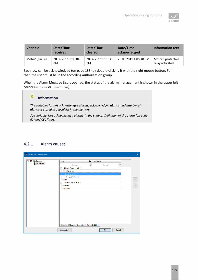
Operating during Runtime
185
Variable Date/Time received
Date/Time cleared
Date/Time acknowledged
Information text
Motor1_failure 20.06.2011 1:00:04 PM
20.06.2011 1:05:35 PM
20.06.2011 1:05:40 PM Motor's protective relay activated
Each row can be acknowledged (on page 188) by double-clicking it with the right mouse button. For that, the user must be in the according authorization group.
When the Alarm Message List is opened, the status of the alarm management is shown in the upper left corner (active or inactive).
Information
The variables for not acknowledged alarms, acknowledged alarms and number of
alarms is stored in a local list in the memory.
See variable 'Not acknowledged alarms' in the chapter Definition of the alarm (on page 62) and CEL filters.
4.2.1 Alarm causes

Operating during Runtime
186
CONFIGURATION OF ALARM CAUSES
Alarm causes in the project are configured in Runtime using a Context List screen.
ASSIGNMENT OF ALARM CAUSES
Alarm causes can be assigned in Runtime.
To assign an alarm cause:
1. Select an entry in the alarm message list
2. Click on the element with the Screen type specific action Select alarm cause...
3. Select an alarm cause and confirm the dialog with OK
If a subnode is assigned, the higher-level nodes (texts) are inserted before the selected text with periods (.).
Example: Alarm Causes Hall 1.Conveyor.Conveyor 1
The alarm causes can now be displayed in a separate column in the alarm message list.
Information
It is possible to use the Allow end nodes as alarm cause only project property in the alarm message list group to determine whether texts of all levels or only texts from end nodes can be selected as an alarm cause.
By activating this property, it is possible for example to prevent a generic selection of alarm causes.
ALLOCATION OF ALARM CAUSES USING A CONTEXT LIST SCREEN
You can also allocate alarm causes to alarms using a Context List screen.
You can find detailed information on this in chapterUse of a Context List screen to select alarm causes.
LOGGING IN THE CEL
If an alarm is assigned to an alarm cause or the linking is changed, this is logged in the CEL. In doing so, if present, the old value and the new value are displayed. Linkings that are carried out using the API are also logged.
Operating during Runtime
187
Cross-project use of alarm causes
Alarm causes can also be used throughout projects. In doing so, you can link alarm causes from the integration project for alarms from subprojects.
For this, the following applies:
For the display of alarm causes in the alarm message list:
If the alarm message list is opened in the integration project, the Context List from the subproject that belongs to the alarm is searched first and this entry is used.
If no entry is found there, the Context List of the integration project is searched.
If the alarm message list from the project to which the alarm belongs is opened, only the Context List of this project is searched.
If an alarm cause from the integration project has been linked and the alarm message list is opened in the subproject, the Alarm cause does not exist entry is shown
For the dialog to select alarm causes (from an integration project with subprojects):
If, in the alarm message list, one or more alarms are selected from the same subproject, both the corresponding subproject and the integration project are offered in the alarm causes dialog.
If several alarms from different projects are selected, only the integration project is offered for selection.
4.2.2 Display unacknowledged alarms as flashing
Unacknowledged alarms can be displayed as flashing in the AML.
With the Unacknowledged alarms flash property active, the foreground color and background color alternate in all unacknowledged and unselected lines in the Alarm Message List every second. Selected lines do not flash.
To do this:
1. In the Editor, navigate to the Alarm Message List section in Project Properties.
2. Activate the checkbox in front of the Unacknowledged alarms flash property.
3. Configure the desired colors (foreground) for Alarm received, Alarm cleared, Alarm acknowledged
Set the Alarm/event class color property to as line background. The color of the alarm class is then used as a background color.

Operating during Runtime
188
4.3 Acknowledge alarms
Alarms can be acknowledged via:
double right-click on the alarm status bar
double right-click on an entry in the Alarm Message List
Function Acknowledge alarms
Acknowledge button or Visual acknowledge and Acknowledge in the zenon alarm message list screen.
Acknowledged alarms are shown in the AML as "Acknowledged".
When acknowledging an alarm:
All alarms of a variable with the same limit value are acknowledged together.
Name and ID of the user who deletes the alarm are written in the Alarm Message List
the name of the computer from which the alarm was acknowledged is written in the Alarm Message List
acknowledging the alarm can be written in the Chronological Event List additionally
Alarms are saved in the ring buffer up to when they are acknowledged. At the same time they are written to a filterable alarm file (*.aml) and kept synchronized.
The Size of the ring buffer property must be chosen appropriately. If alarms are no longer saved in the ring buffer (on page 41) due to a buffer overflow, unacknowledged alarms remain in the alarm file. For details see chapter Alarm Message List (AML) (on page 5).
Information
If alarms require a comment (on page 189) or the linking of an alarm clause is required (on page 189), it can only be acknowledged if a comment has been entered or an alarm cause has been linked. The user must be authorized to carry out the necessary function.
If there is an attempt to acknowledge an alarm without these conditions being met, a notice dialog is displayed.
FUNCTION ACKNOWLEDGE ALARMS
The Acknowledge alarms function allows:
acknowledge alarms from the AML using a function call
global acknowledgment
When using this function in Runtime, the flashing attribute of the variables and therefore screen alarming (only SICAM 230) will also be reset. The selected alarms are acknowledged. For details, see Acknowledging alarms (on page 152) chapter.

Operating during Runtime
189
USER AUTHORIZATION
The functions Acknowledge alarms (on page 152)and Confirm alarm acknowledgment (on page 150) can be assigned to a user group via Function authorization. Only authorized user can acknowledge and delete alarms.
In addition, for the limit values, it is possible to use the Two-stage acknowledgement property in the respective subgroup of the Limit Values group to set an additional operating authorization. Selected alarms can only be removed from the Alarm Message List by users with the necessary rights.
If the Two-stage acknowledgement property is set, alarms are then only removed from the list of active alarms if their acknowledgment has been confirmed. Acknowledgment alone is not sufficient.
4.3.1 Required comments for acknowledgment
Alarms that require acknowledgment can be configured in such a way that a comment must be entered before acknowledgment. To be able to enter a comment, the user needs to enter the corresponding function authorization alarm comment.
To make an alarm require a comment, the corresponding option can be set at:
The configuration of the Reaction matrixes
The Comment required property in the Limit Values group of the variables or the data types
Comments that require alarms can subsequently only be amended by users with the Change alarm
comment function authorization. If comments are changed, an entry into the CEL is made, stating the variable name and the original and amended comment.
Alarms that require a comment are checked for comments for all acknowledgment possibilities (including the API). The necessary authorization is also checked when changes are made. The Alarm Message List can be filtered for alarms that require a comment by means of:
Alarm Message List (on page 62) filter
Alarm Message List filter (on page 16) screen
4.3.2 Linking of an alarm cause for acknowledgment
Alarms that require acknowledgment can be configured in such a way that an alarm cause must be linked before acknowledgment.
The corresponding option can be set for:
The configuration of the Reaction matrixes
The Alarm cause required property in the Limit Values group of the variables and the data types

Operating during Runtime
190
If an attempt is made to acknowledge the alarm without a linked alarm cause, a corresponding warning dialog is called up.
Alarm cause linkings can be subsequently amended.If an alarm is assigned to an alarm cause or the linking is changed, this is logged in the CEL. In doing so, if present, the old value and the new value are displayed. Linkings that are carried out using the API are also logged.
Alarms required for the linking of an alarm cause are, for all acknowledgment possibilities (including the API), checked to see whether there is a linked alarm cause. The alarm message list can be filtered for alarms for which an alarm cause is required by means of the:
Alarm Message List (on page 62) filter
Alarm Message List filter (on page 16) screen
You can find further information about alarm causes in the Driver variables (on page 185) chapter.
4.3.3 Visual acknowledgment
Visual acknowledgment makes it possible for the user to confirm that they have become aware of an alarm without resetting this immediately. For example, it is possible to visually acknowledge several alarms that are unrelated to one another first, and then acknowledge them and thus reset them later.
ELEMENTS FOR VISUAL ACKNOWLEDGMENT
There are two buttons available for visual acknowledgment in AML screens:
Visual acknowledgment
Visual acknowledgment and acknowledgment
The following properties are available for variables in the Alarm handling group:
Acknowledgement variable
Visual acknowledgement variable
Acknowledgement value
USE VISUAL ACKNOWLEDGMENT
To confirm an alarm with visual acknowledgment:
1. Configure the buttons Visual acknowledgment and Visual acknowledgment and acknowledgment in the screen.
2. Configure the Acknowledgement variable, Visual acknowledgement variable and Acknowledgement
value properties for the corresponding variables.
3. Click on the button in Runtime

Operating during Runtime
191
a) Visual acknowledgment: The highlighted alarms are confirmed with visual acknowledgment. The Acknowledgement value is written to the Visual acknowledgement
variable.
b) Visual acknowledgment and acknowledgment: The highlighted alarms are only confirmed with visual acknowledgment and then acknowledged (on page 188). The Acknowledgement
value is written to the Visual acknowledgement variable and to the Acknowledgement variable.
Information
Visual acknowledgment and acknowledgment need different rights. For visual acknowledgment, operating authorization and keyboard authorization in the context of the user and the interlocking are necessary. For acknowledgment (on page 188), the corresponding rules including validation of the entries and rights are applicable. It is therefore possible that a user can visually acknowledge an alarm but not acknowledge it.
Visual acknowledgment is always set but only if the variable already has this value.
4.4 Alarms: acknowledge flashing
In addition to acknowledging alarms (on page 152) from the alarm message list, screens with alarms can also be acknowledged by template. Flash acknowledgment is called up using the flash-acknowledge alarms (on page 145) function or by double clicking on the corresponding element with the right mouse button. In doing so, only the flash attribute of the variables and the flashing of all graphic elements on the screen is reset. The entries are not however acknowledged in the AML.
FLASHING ACKNOWLEDGMENT IN AML
A flash-acknowledgment acknowledges the alarms in the AML if the Flashing acknowledgement option is also set in alarm administration.
The acknowledgment in the alarm message list or on the alarm line level at the upper screen edge also acknowledges the alarm in the screen and screen alarm guidance.
FLASH-ACKNOWLEDGING IN INTEGRATION PROJECTS
If alarms are to be acknowledged in integration projects using the Alarms: acknowledge flashing function, all affected screens must be opened.
If screens in superordinate and subordinate project templates have the same name, the screens in the subordinate project are not opened. If the template names are different, the screens of the sub project in the background are opened and can be flash-acknowledged.

Operating during Runtime
192
FLASH ACKNOWLEDGMENT IN THE NETWORK
If flash-acknowledgment is used in the network, it is only executed locally at the respective client.
Behavior for flash acknowledgment of local variables:
If an alarm is created by a local variable, this alarm is then created on the server. The alarm is also visible on the client however.
If the alarm is acknowledged using the alarm message list or the status window, the alarm is acknowledged on the server.
If the acknowledgment is only acknowledged using the control element in the screen, the alarm is only acknowledged if the acknowledgment is made on the server.
If the limit value of a local variable is breached on a client, the local flash status is also local and is flash-acknowledged locally.
4.5 Confirm alarm acknowledgment
The following is required to confirm an alarm acknowledgment:
A confirm alarm acknowledgment (on page 150) function is executed or
the Confirm acknowledgment button on a screen of type Alarm Message List is pressed
USER AUTHORIZATION
The functions Acknowledge alarms (on page 152)and Confirm alarm acknowledgment (on page 150) can be assigned to a user group via Function authorization. Only authorized user can acknowledge and delete alarms.
In addition, for the limit values, it is possible to use the Two-stage acknowledgement property in the respective subgroup of the Limit Values group to set an additional operating authorization. Selected alarms can only be removed from the Alarm Message List by users with the necessary rights.
If the Two-stage acknowledgement property is set, alarms are then only removed from the list of active alarms if their acknowledgment has been confirmed. Acknowledgment alone is not sufficient.
4.6 Filtering alarms
Alarms can be displayed with a filter in Runtime using:
filter use in the Runtime
Screen switching with pre-defined filter to a screen of alarm message list (on page 7) type
Screen switching with filter when calling up a screen of alarm message list (on page 7) type

Operating during Runtime
193
Screen switching to a screen of alarm message list filter (on page 196) type
FILTERING IN THE RUNTIME
Filters can be used in Runtime in screens of the alarm message list type. To filter the alarms displayed in the AML:
1. you must have engineered button Filter
2. click on the button
3. The alarm message list filter dialog (on page 57) is opened
Set filter can be saved in profiles (on page 194).
SCREEN SWITCHING TO A SCREEN OF ALARM MESSAGE LIST TYPE
Alarms can be displayed after pre-filtering. To do this:
1. Configure a filter (on page 57) for the screen switching to an alarm message list screen (on page 139) function
2. The alarm message list is displayed in a filtered state when called up
3. if the option Display dialog in the Runtime is activated for the function, you can newly define the filter before the display

Operating during Runtime
194
4. in the Runtime further filter settings are possible via button filter
SCREEN SWITCHING TO AN ALARM MESSAGE LIST FILTER SCREEN
In order to only offer users the filters they need in Runtime, use an alarm message list filter (on page 196) screen. To do this:
1. Configure screen switching to an alarm message list filter screen (on page 142)
2. Call up the AML in Runtime using this function
3. The user has an Alarm Message List that is tailor-made (on page 110) to their requirements.
4.6.1 Filter profiles
Filter profiles are filter settings that the user can save and call up in Runtime in relation to a certain screen.
To be able to use filter profiles, the following control elements must be configured:
Control element Description
Filter profiles Profile administration in Runtime.
Profile selection Selection of a saved profile from a drop-down list.
Save Clicking on the button in the Runtime saves the filter settings as a profile.
The name can be a maximum of 31 characters long and must only contain valid characters. Prohibited are: ! \ / : * ? < > | ""
Delete Clicking on button in Runtime deletes the selected profile.
With this you can in the Runtime:
save filters
use saved filters
delete filter profiles
Filter profiles can also be exported and imported with further control elements.
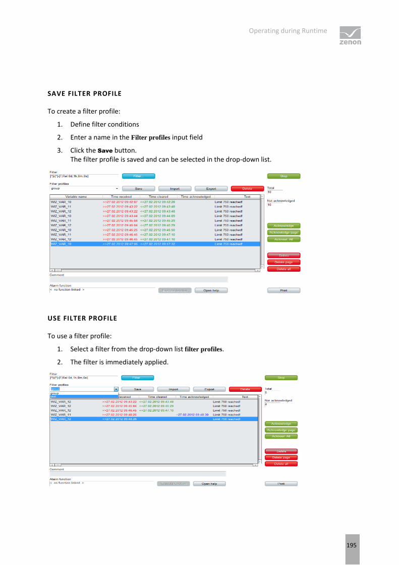
Operating during Runtime
195
SAVE FILTER PROFILE
To create a filter profile:
1. Define filter conditions
2. Enter a name in the Filter profiles input field
3. Click the Save button. The filter profile is saved and can be selected in the drop-down list.
USE FILTER PROFILE
To use a filter profile:
1. Select a filter from the drop-down list filter profiles.
2. The filter is immediately applied.

Operating during Runtime
196
DELETE FILTER PROFILE
To delete a filter profile:
1. Select a filter from the drop-down list filter profiles
2. Click on the Delete button. The filter profile is deleted.
3. The deleted filter is still applied as long as a new filter is defined or selected.
4.6.2 Use alarm message list filter
It is possible to adjust filter settings for the Alarm Message List in Runtime with the help of the Alarm Message List Filter (on page 16) screen. All filter settings that are available in the filter (on page 57) for the function to switch the screen to the Chronological Event List screen (on page 139) can be configured.
Therefore:
Only the filter elements that are actually required are configured and provided to the user.
The user only has these filters displayed and has an overview
The appearance can be freely defined and can, for example, ensure ease of use by means of a touch screen.
FILTER SCREENS
Filter screens make it possible to transfer a preset filter from one screen to another. The filter of the source screen is set using the target screen. The screens can also be of a different screen type.
Attention
In order for the time to be taken from the screen to be called up in Runtime, the following time range must be selected in the Editor for the screen switching function for the Alarm
Message List or the Chronological Event List in the time filter: Set filter at time filter type
CALL DEFINITION
The following requirements must be met for the set filters to be used:
1. Set filter for time filter type is selected as a time period for the time filter.
2. The screen (Alarm Message List Filter, Chronological Event List filter or Time/Lot/Shift Filter screens) is activated using a button or a combined element. Only in this way can the relationship between filter screen and source screen be maintained.

Operating during Runtime
197
3. The source screen and filter screen must either be configured on different frames or on different monitors. The filter for the filter screen can only be updated if the source screen is open. This is only possible if both screens do not use the same frame or the same monitor.
4. The screen to be called up must be compatible with the filter screen to be called up (see table).
Source screen AML filter CEL filter Time Filter
Archive revision T T T
Extended Trend T T T
Time Filter T T X
Alarm Message List Filter X C T
Chronological Event List Filter
C X T
Alarm Message List X C T
Chronological Event List C X T
Key:
C: Common settings are updated.
T: Time settings are updated.
X: All settings are updated.
Information
No filtering
The filter screen is not filtered, but opened with the configured values, if:
One of the conditions 1 to 3 is not met or
The Screen to call up setting is not activated for the Screen switching function or
The screen is not called up via a screen element
In this case, the Accept, Close and Update buttons are grayed out in Runtime and have no function.
UPDATE
When a filter screen is called up (Alarm Message List filter, Chronological Event List filter, time filter), the screens configured in the screen switching function are updated in two ways:
If the filter screen is called up using a screen element, the target screens that are on the same monitor as the source screen are updated.
If the filter screen is called up in a different way or if the Update on all monitors setting is activated, all configured target screens are updated.

Operating during Runtime
198
They are updated as soon as you click the Accept button or as soon as you closes the filter screen with the close Close button. The Cancel button discards the changes and closes the filter screen.
UPDATE FILTER SETTINGS
You update the current filter settings for the source screen using the Update button. If the filter screen is not called up by a screen element or if the Calling screen has not been activated, all monitors are searched for screens that can be used for updating. The first screen that is found is then this is used for updating.
4.7 Printing and exporting alarms
AML alarms can be documented and archived by:
AML Print online (on page 199): each event is printed on a line printer when it is displayed in the list
AML (on page 199)offline printing: (on page 202)The AML is printed out as a list in its current state
Export (on page 209) contents of AML (filtered)
The print used for printouts is defined via menu File -> General configuration -> Standard.
Attention
A *.frm configuration file is used for the print-out:
Online: ALARM.frm
Offline: ALAR_G.frm.
This FRM file must be in the project tree in the Files section in the Texts and
formats folder.
You can find templates for FRM files in the following folder: %ProgramData%\COPA-DATA\zenon800
These can be added to the Texts and formats section using Add File and edited there.
You can find key words for FRM files in the FRM configuration file (on page 205).

Operating during Runtime
199
4.7.1 Online printing
With online printing, any alarm that occurs is immediately sent to the printer.
The online printing takes place line by line, in accordance with the ESC/P (Epson Standard for Printers) and requires an Epson-compatible printer.
To print out alarms online:
1. Define a printer.
2. Navigate to the AML and CEL node in the project properties.
3. Activate the Printing active property.
4. Select the Printing for property in the Alarm Message List drop-down list.
5. Define the number of lines with the Lines per page property (default: 72).
6. Configure ALARM.frm (on page 205).
7. Add ALARM.frm to the Files/texts and formats node.
Information
This function is not available under Windows CE.
CONTROL PRINT AND PRINTER IN RUNTIME
PAGE CHANGE
Form feed is carried out if:
a page is fully written
the Runtime is closed and online printing is active
function Online printing start new page (on page 173) is executed
HALT PRINTING
To halt or to continue online printing:
Carry out function Switch online printer on/off (on page 173).
CHANGING AND SETTING UP A PRINTER
To change the printer in Runtime:
Carry out the Switch online printer (on page 174) function
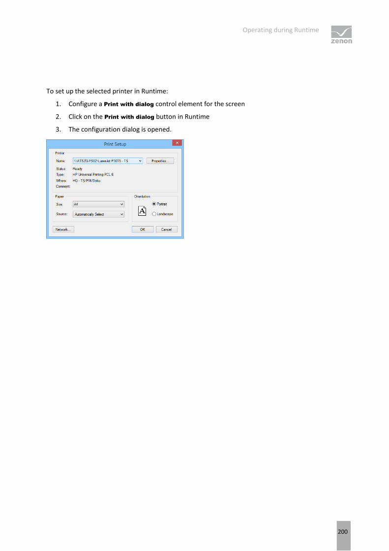
Operating during Runtime
200
To set up the selected printer in Runtime:
1. Configure a Print with dialog control element for the screen
2. Click on the Print with dialog button in Runtime
3. The configuration dialog is opened.

Operating during Runtime
201
PRINTER
Parameters Description
Printer Settings for the printer.
Name: Selection of the printer from the drop-down list. The list contains all printers configured in the operating system.
Properties... Opens printer configuration dialog.
Status: Display printer state. For information only.
Type: Display printer type. For information only
Location: Display the location of the printer if configured. For information only.
Comment: Display comment about printer if configured. For information only.
PAPER
Parameters Description
Paper Configuration of the printout.
Size Select paper format from drop-down list.
Source Select paper feed from drop-down list.
ALIGNMENT
Parameters Description
Alignment Select paper alignment. Possible parameters:
Portrait
Landscape
Network Opens dialog for selecting a printer in the network.
OK Applies configuration and closes the dialog. With this printing is started in the Runtime.
Cancel Discards configuration and closes the dialog. In the Runtime this also cancels the printout.
FORMATTING EXAMPLE
Configuration (on page 205) in ALARM.FRM:

Operating during Runtime
202
Date: @DSYSTEM Alarm inf. list/demo proj. Time @TSYSTEM o'clock
Text
Date/Time received Time cleared Information text Status text
%%
@DTRECEIVED @TCLEARED @IDENTIFICATION @TEXT
%%
Page @PAGE
Printout on the printer
Date: 20.03.2011 Alarm inf. list/demo proj. Time: 12:00 PM: Text
Date/Time received Time cleared Information
text Status text
20.03.2011 13:00:00 20.03.2011 1:03:59 PM Message 1 Limit exceeded
20.03.2011 13:00:00 1:05:35 PM Demo information
Limit 750 reached
20.03.2011 1:03:59 PM Message 2 Limit value
20.03.2011 1:11:23 PM Message 3 off
20.03.2011 1:03:59 PM 1:12:45 PM Demo information
off
Page 1
4.7.2 Offline printing
Offline printing means that the Alarm Message List is printed out as it is displayed at the time in Runtime. This print-out is a snapshot including all filters that have been set and their restrictions. The print out is carried out regardless of whether the variables concerned having option print.
To print the Alarm Message List offline:
1. define a printer
2. Configure ALAR_G.frm (on page 205)
3. Add ALAR_G.frm to the Files/texts and formats node
4. In the Runtime click button print or print with dialog.
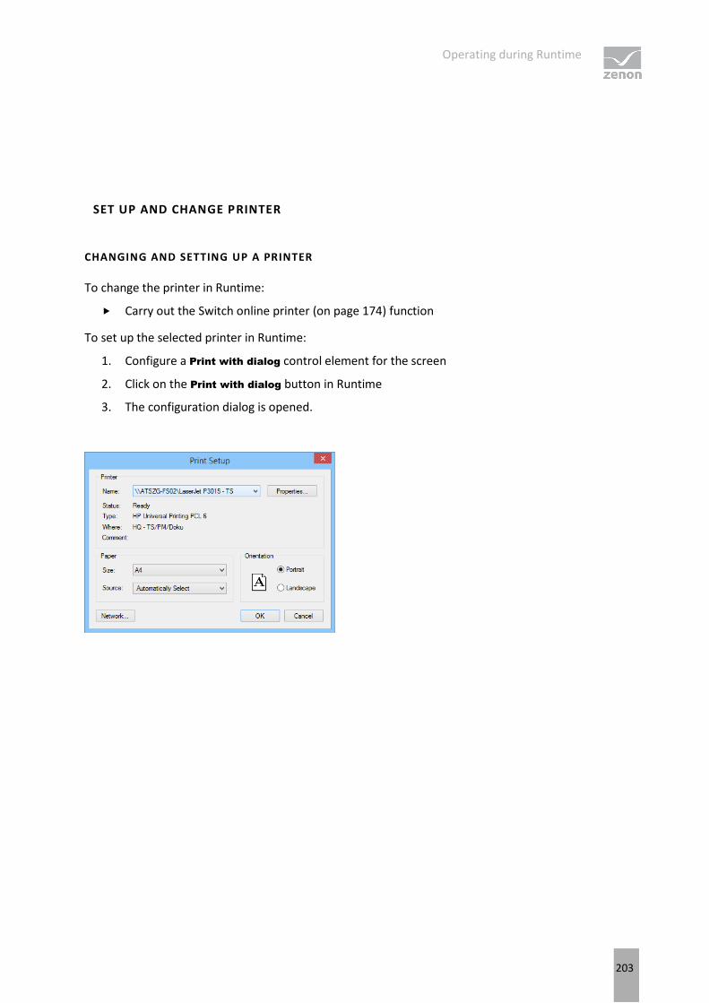
Operating during Runtime
203
SET UP AND CHANGE PRINTER
CHANGING AND SETTING UP A PRINTER
To change the printer in Runtime:
Carry out the Switch online printer (on page 174) function
To set up the selected printer in Runtime:
1. Configure a Print with dialog control element for the screen
2. Click on the Print with dialog button in Runtime
3. The configuration dialog is opened.

Operating during Runtime
204
PRINTER
Parameter Description
Printer Settings for the printer.
Name: Selection of the printer from the drop-down list. The list contains all printers configured in the operating system.
Properties... Opens printer configuration dialog.
Status: Display printer state. For information only.
Type: Display printer type. For information only
Location: Display the location of the printer if configured. For information only.
Comment: Display comment about printer if configured. For information only.
PAPER
Parameter Description
Paper Configuration of the printout.
Size Select paper format from drop-down list.
Source Select paper feed from drop-down list.
ALIGNMENT
Parameter Description
Alignment Select paper alignment. Possible parameters:
Portrait
Landscape
Network Opens dialog for selecting a printer in the network.
OK Applies configuration and closes the dialog. With this printing is started in the Runtime.
Cancel Discards configuration and closes the dialog. In the Runtime this also cancels the printout.
FORMATTING EXAMPLE
Configuration in ALAR_G.frm:

Operating during Runtime
205
Date: @DSYSTEM Closed Alarm Message List Demo Project
Time @TSYSTEM o'clock
Text
Date/Time received Time cleared Information text Status text
%%
@DTRECEIVED @TCLEARED @IDENTIFICATION @TEXT
%%
Page @PAGE
Printout on the printer
Date: 20.03.2011 Closed Alarm Message List Demo Project
Time: 12:00 PM: Text
Date/Time received Time cleared Information
text Status text
20.03.2011 13:00:00 20.03.2011 1:03:59 PM Message 1 Limit exceeded
20.03.2011 13:00:00 1:05:35 PM Demo information
Limit 750 reached
20.03.2011 1:03:59 PM Message 2 Limit value
20.03.2011 1:11:23 PM Message 3 off
20.03.2011 1:03:59 PM 1:12:45 PM Demo information
off
Page 1
4.7.3 FRM configuration file
FRM files (format files) are configuration files for printing out lists.
The FRM file has three parts:
Header: at the beginning of the page
List part: cyclic per line
Footer: at the end of the page
PRINCIPLES
When editing FRM files regard the following:
Separating the list parts:

Operating during Runtime
206
Header and list part and list part and footer are separated by %%.
The separation marking must be used only once for the list and the footer.
The last line must be followed by at least two empty paragraphs. Otherwise the footer is not printed!
Positioning the individual entries: You may only use space, no tabulators.
Editing the FRM file in a text editor: Automatic line break must be deactivated otherwise undesired effects in the formatting may occur.
KEYWORDS
The setting for the page length is made in Project Properties under AML and CEL or via the ALARM.frm or ALAR_G.frm file for the AML or BTB.frm and BTB_G.frm for the CEL.
Note:
The number of the alarm entries per page results from the predetermined number of lines (e.g. Lines per page 72), less the lines used for header and footer text.
The Use reactivated time option must be activated in order to be able to use the keywords that evaluate the reactivation (time, number).
Free texts and keywords can be used in the formatting file. Key words can be used either in German or in English. The use of English key words is recommended.
Not every key word is suitable for every kind of printing (AML, CEL, online, offline).
The following table contains key words in English and German and their field of application:
German English AML offline
CEL offline
AML online
CEL online
Description
Key words for the list part
@BMKENNUNG @RESOURCELABEL
X X X X Resources label

Operating during Runtime
207
@DATZEITKOMMT @DTRECEIVED X X X X Time and Date when the alarm occurred
@DATZEITGEHT @DTCLEARED X - X - Time and Date when the alarm ended
@DATZEITOK @DTACK X - X - Time and Date when the alarm was acknowledged
@DATZEITREAKT @DTREACTIVATE X - X - Time and Date of reactivating:
Property Use reactivated
time in the project properties must be activated.
@DATZEIT @DTLASTEVENT - - X - Time and date of alarm received or cleared or acknowledged or reactivated
@ZEIT @TLASTEVENT - - X X Time of alarm received or cleared or acknowledged or reactivated
@ZEITOK @TACK X - X - only displays time of acknowledging
@ZTKOMMT @TRECEIVED X X X X only displays time of alarm received
@ZTGEHT @TCLEARED X - X - only displays time of end of alarm
@ZTREAKT @TREACTIVATE X - X - only displays time of reactivating
@TIMELASTING @TACTIVE X - X - Time active (difference time received - time cleared)
@ANWENDUNG @PROJECTNAME X X X X Project name
@KANALNAME @VARNAME X X X X Variable name CEL: Only entries with variables
@AK @ACLASSNR X X X X Alarm/event class name
@AG @AGROUPNR X X X X Alarm/event group number
@AGNAME @AGROUPNAME
X X X X Name of alarm/event group
@AKNAME ACLASSNAME X X X X Name of alarm/event class
@TAGNR @IDENTIFICATION
X X X X Identification (company-specific label)
@AMELDUNG @TEXT X X X X Alarm message text
@REAKTANZ @NRREACTIVATE
X - X - Number of reactivations

Operating during Runtime
208
@STATUS @STATUS X X X X Status information as in Alarm Message List
@WERT @VALUE X X X X Variable value of alarm
@REAKTIONSTEXT @COMMENT X X X X Commentary from the Alarm Message List.
If dynamic limit value texts are used, this is only available if the Long dynamic limit
value texts AML or Long
dynamic limit value texts
CEL properties have been activated.
@USER @USERID X X X X AML: User who acknowledged alarm.
@RECHNER @COMPUTER X X X X AML: Computer on which alarm was acknowledged.
Key words for header and footer
@ANWENDUNG @PROJECTNAME X X X X Project name
@SEITE @PAGE X X X X Page number
@HEADDATZEIT @DTSYSTEM X X X X System date and system time
@HEADDATUM @DSYSTEM X X X X System date
@HEADZEIT @TSYSTEM X X X X System time
@USER @USERID X X X X User who prints
@USERNAME @USERNAME X X X X Full user name who triggered action
@RECHNER @COMPUTER X X X X Computer from which printing is carried out
[Text] [Text] Random text
Attention
Between the key words there must be enough space so that entries are not overwritten. In doing so, you make sure that long limit value texts are also displayed correctly.
Example:
@TEXT (spaces up to here)

Operating during Runtime
209
4.7.4 Exporting alarms
Alarms can be exported in different formats:
dBase
CSV
XML
SQL
EXPORT
To export alarms
1. Create an Export AML (on page 159) function
2. link the function to a button
3. execute the function in the Runtime
Information
The export to SQL is incremental. If there is data that has already been exported, only new and amended data is exported.