Young's modulus, hardness and scratch adhesion of Ni–P–W multilayered alloy coatings produced by...
10
Thin Solid Films 396 (2001) 173–182 0040-6090/01/$ - see front matter 2001 Elsevier Science B.V. All rights reserved. PII: S0040-6090 Ž 01 . 01223-8 Young’s modulus, hardness and scratch adhesion of Ni–P–W multilayered alloy coatings produced by pulse plating V.D. Papachristos *, C.N. Panagopoulos , L.W. Christoffersen , A. Markaki a, a b c Laboratory of Physical Metallurgy, National Technical University of Athens, 157 80 Zografos, Athens, Greece a Department of Manufacturing Engineering, Technical University of Denmark, 2800 Lyngby, Denmark b Department of Materials Science and Metallurgy, University of Cambridge, Cambridge, UK c Received 20 October 2000; received in revised form 8 May 2001; accepted 20 June 2001 Abstract The effect of layering on Young’s modulus, hardness and deformation behaviour of Ni–P–W multilayered alloy coatings in a scratch adhesion test was studied. The coatings were deposited on copper substrates by electro-deposition and the wavelengths studied were 8–4000 nm. The Young’s moduli of the amorphous multilayered Ni–P–W coatings, measured by an acoustic-wave resonance method, are higher than the Young’s modulus of crystalline nickel. Their hardness was found to increase with decreasing wavelength of the coatings, the increase being more pronounced for wavelengths below 120 nm. The cohesive load of the multilayered coatings ranges from 5 to 16 N, while the critical load range for coating detachment in scratch adhesion tests was found to be 50–75 N. The values of adhesive and cohesive loads seem to be independent from the wavelength of the Ni–P–W coatings. The failure modes observed in the scratch tracks of the Ni–P–W multilayered coatings are common in every coating in the scratch tests under increasing load, and they are a result of substrate deformation and coating brittleness. 2001 Elsevier Science B.V. All rights reserved. Keywords: Young’s modulus; Adhesion; Hardness; Multilayers 1. Introduction The investigation of the mechanical properties of many metallic multilayered coatings, and the effect that layering may have on them, has attracted the attention of many researchers during the last 20 years and espe- cially during the last decade. The reason is that knowl- edge of the elastic moduli, hardness and adhesion of a coating is very important for its evaluation in terms of load carrying capacity, necessary in numerous applications. Since the work of Yang et al. w1x, who reported a 120% increase in the w111x biaxial modulus of strongly oriented, vacuum deposited Au y Ni multilayered coat- * Corresponding author. Tel.: q30-1-772-2171; fax: q30-1-772- 2119. E-mail address: [email protected] (V.D. Papachristos). ings, comparing to the biaxial modulus of a homoge- neous coating of the same composition, a lot of studies have also reported anomalously high values (up to 310% increase), in the elastic moduli of crystalline multilayers with wavelength below 4 nm w2–5x. The above results were initially interpreted by the researchers as a ‘super- modulus effect’, and various theories based on either the electronic structure of the atoms in the layers or the existence of interface related stresses, were developed in order to explain the elastic anomalies w1–7x. However, later studies disputed the existence of a supermodulus effect w8–13x, and finally, new tests in multilayered systems that had been reported to show a supermodulus effect, showed that the first results were erroneous owing to shortcomings of the initial testing procedures w12x. Investigation of the effect of layering on the hardness of metallic multilayered coatings has not resulted in such controversy. It is generally accepted that the hard-
Transcript of Young's modulus, hardness and scratch adhesion of Ni–P–W multilayered alloy coatings produced by...

Thin Solid Films 396(2001) 173–182
0040-6090/01/$ - see front matter� 2001 Elsevier Science B.V. All rights reserved.PII: S0040-6090Ž01.01223-8
Young’s modulus, hardness and scratch adhesion of Ni–P–W multilayeredalloy coatings produced by pulse plating
V.D. Papachristos *, C.N. Panagopoulos , L.W. Christoffersen , A. Markakia, a b c
Laboratory of Physical Metallurgy, National Technical University of Athens, 157 80 Zografos, Athens, Greecea
Department of Manufacturing Engineering, Technical University of Denmark, 2800 Lyngby, Denmarkb
Department of Materials Science and Metallurgy, University of Cambridge, Cambridge, UKc
Received 20 October 2000; received in revised form 8 May 2001; accepted 20 June 2001
Abstract
The effect of layering on Young’s modulus, hardness and deformation behaviour of Ni–P–W multilayered alloy coatings in ascratch adhesion test was studied. The coatings were deposited on copper substrates by electro-deposition and the wavelengthsstudied were 8–4000 nm. The Young’s moduli of the amorphous multilayered Ni–P–W coatings, measured by an acoustic-waveresonance method, are higher than the Young’s modulus of crystalline nickel. Their hardness was found to increase with decreasingwavelength of the coatings, the increase being more pronounced for wavelengths below 120 nm. The cohesive load of themultilayered coatings ranges from 5 to 16 N, while the critical load range for coating detachment in scratch adhesion tests wasfound to be 50–75 N. The values of adhesive and cohesive loads seem to be independent from the wavelength of the Ni–P–Wcoatings. The failure modes observed in the scratch tracks of the Ni–P–W multilayered coatings are common in every coating inthe scratch tests under increasing load, and they are a result of substrate deformation and coating brittleness.� 2001 ElsevierScience B.V. All rights reserved.
Keywords: Young’s modulus; Adhesion; Hardness; Multilayers
1. Introduction
The investigation of the mechanical properties ofmany metallic multilayered coatings, and the effect thatlayering may have on them, has attracted the attentionof many researchers during the last 20 years and espe-cially during the last decade. The reason is that knowl-edge of the elastic moduli, hardness and adhesion of acoating is very important for its evaluation in terms ofload carrying capacity, necessary in numerousapplications.Since the work of Yang et al.w1x, who reported a
120% increase in thew111x biaxial modulus of stronglyoriented, vacuum deposited AuyNi multilayered coat-
* Corresponding author. Tel.:q30-1-772-2171; fax:q30-1-772-2119.
E-mail address: [email protected](V.D. Papachristos).
ings, comparing to the biaxial modulus of a homoge-neous coating of the same composition, a lot of studieshave also reported anomalously high values(up to 310%increase), in the elastic moduli of crystalline multilayerswith wavelength below 4 nmw2–5x. The above resultswere initially interpreted by the researchers as a ‘super-modulus effect’, and various theories based on eitherthe electronic structure of the atoms in the layers or theexistence of interface related stresses, were developedin order to explain the elastic anomaliesw1–7x. However,later studies disputed the existence of a supermoduluseffect w8–13x, and finally, new tests in multilayeredsystems that had been reported to show a supermoduluseffect, showed that the first results were erroneous owingto shortcomings of the initial testing proceduresw12x.Investigation of the effect of layering on the hardness
of metallic multilayered coatings has not resulted insuch controversy. It is generally accepted that the hard-
174 V.D. Papachristos et al. / Thin Solid Films 396 (2001) 173–182
ness of crystalline multilayered coatings reaches a max-imum value for wavelengths in the range between 2 and5 nm, while it decreases for both larger and smallerwavelengthsw14–20x. At its maximum value, the hard-ness of the metallic multilayered coatings can beincreased up to 100%, compared with the rule of mixturevalue, estimated using the hardness of the elementsconsisting of the multilayer.The decrease in hardness for larger wavelengths has
been found to follow the Hall–Petch relationship(HsH qkyd ), whered is 1y2 the bilayer thickness,1y2
o
H is the rule of mixture hardness andk is a constant.o
According to this approach, the interfaces are consideredto act in a similar way as grain boundaries, pilling upthe dislocations and thus obstructing their movement.Increased plastic resistance(i.e. hardness) of crystallinemultilayered coatings is also expected by the Kohelertheory w21x, since a sequence of layers with differentelastic constants obstructs dislocation movementbetween the layers, whereas the small layer thicknessblocks the dislocation sources.The decrease in hardness for smaller wavelengths
(l-2 nm) cannot be explained by Hall–Petch theory,since its validity does not hold for such small wave-lengthsw22x. Therefore, it was suggested, that in smallwavelengths, hardness is controlled by film stressesw17–19x, coherency stressesw16x, and integrity of layeringw20x.Up to now, the adhesion of a few multilayered
coatings has been studied, and the majority of them areceramic or metallicyceramic w23x multilayers. To thebest of our knowledge, the only adhesion study inmetallic multilayers comes from Lin et al.w24x, whostudied the adhesion of multilayered AlyMoyNi andAl yZnyNi–P coatings on a silicon substrate, with theaid of a pull test.In the present study, the effect of layering on Young’s
modulus, hardness and adhesion of an electro-depositedNi–P–W multilayered coating, consisting of alternateamorphous layers of Ni–P–W ternary alloys with differ-ent composition is investigated. Furthermore, using theset up of the scratch test, the deformation behaviour ofthe coating–substrate system under the tangential move-ment of the load acting on the surface of the coating isstudied.
2. Experimental
The Ni–P–W multilayered coatings were depositedon annealed(1 h at 3508C in an inert atmosphere)copper substrates. Prior to the deposition, the substrateswere cleaned for 2–5 min in a cathodic degreasing bath(NaCN 15 gy l, Na CO 15 gy l, NaOH 60 gy l, at 258C,2 3
voltage between anode and cathode 3 V, anode: IrO2
coated Ti), rinsed with water and activated for 10 s in
a bath containing 10% in weight H SO and 100 mly l2 4
H O (35%), at room temperature.2 2
The plating solution had the following composition:
NiSO Ø6H O4 2 17 gy lNa WO Ø2H O2 4 2 66 gy lH PO3 3 25 gy lCitric acid monohydrate 63 gy lpH 5.5Temperature 708CAnodes IrO coated Ti or AISI 316 stainless steel2
From this solution, amorphous alternate Ni–P–Wlayers of low and high tungsten content were deposited.The average composition of the layers was Ni–8%P–15%W and Ni–5%P–45%W in weight(Ni–16%P–5%Wand Ni–13%P–19%W at.%), for the low and hightungsten layers, respectively. The thickness ratio of themultilayered Ni–P–W coatings was one-quarter of thewavelength thickness for the low-W layer and three-quarters of the wavelength thickness for the high-Wlayer. The amorphous nature of the alternate layers wasshown by transmission electron microscope(TEM)images, X-ray diffraction(XRD) and selected areaelectron diffraction(SAED) patterns, while the compo-sition of the layers was measured by EDS on cross-sections of the coatings, in a transmission electronmicroscope. More details on the structure of the amor-phous Ni–P–W coatings can be found elsewherew25x.The low tungsten content layer was deposited during
the low current density step of the cathodic pulse whichwas 20 mAycm , whereas the high tungsten content2
layer was deposited during the high current density stepof the cathodic pulse, which was 200 mAycm . Both2
pulses were followed by an anodic pulse with an anodic-to-cathodic charge ratioq yq 3.6 and 3.2%, respective-a c
ly. Each layer was deposited with the use of its ownbasic waveform(cathodic pulse followed by the anodicpulse), which was repeated 1–500 times, until thedesired layer thickness had been reached. The high-Wlayer was always on the top.For the measurement of Young’s modulus, the Ni–P–
W coatings were deposited on both sides of 30=10=0.6mm copper sheets. The wavelengths(bilayer thickness)3
of the multilayered coatings were 8, 16, 40, 400 and4000 nm and their total thickness(on each side) 39–46mm.An acoustic-wave resonance method was used for the
measurement of Young’s modulus. The specimens weresuspended from two elastic nodes placed at distances0.224L from their edges(whereL is the length of thespecimen), while they were also supported by a plasticbar at their midpoint. The specimens were set intoflexural oscillation by an acoustic drive at their middle,for a range of acoustic frequencies. A transducer placedin the plastic bar at the middle of the specimens and incontact with them, recorded the resonant frequenciesand the dominant resonant frequencyf (in Hz) was
175V.D. Papachristos et al. / Thin Solid Films 396 (2001) 173–182
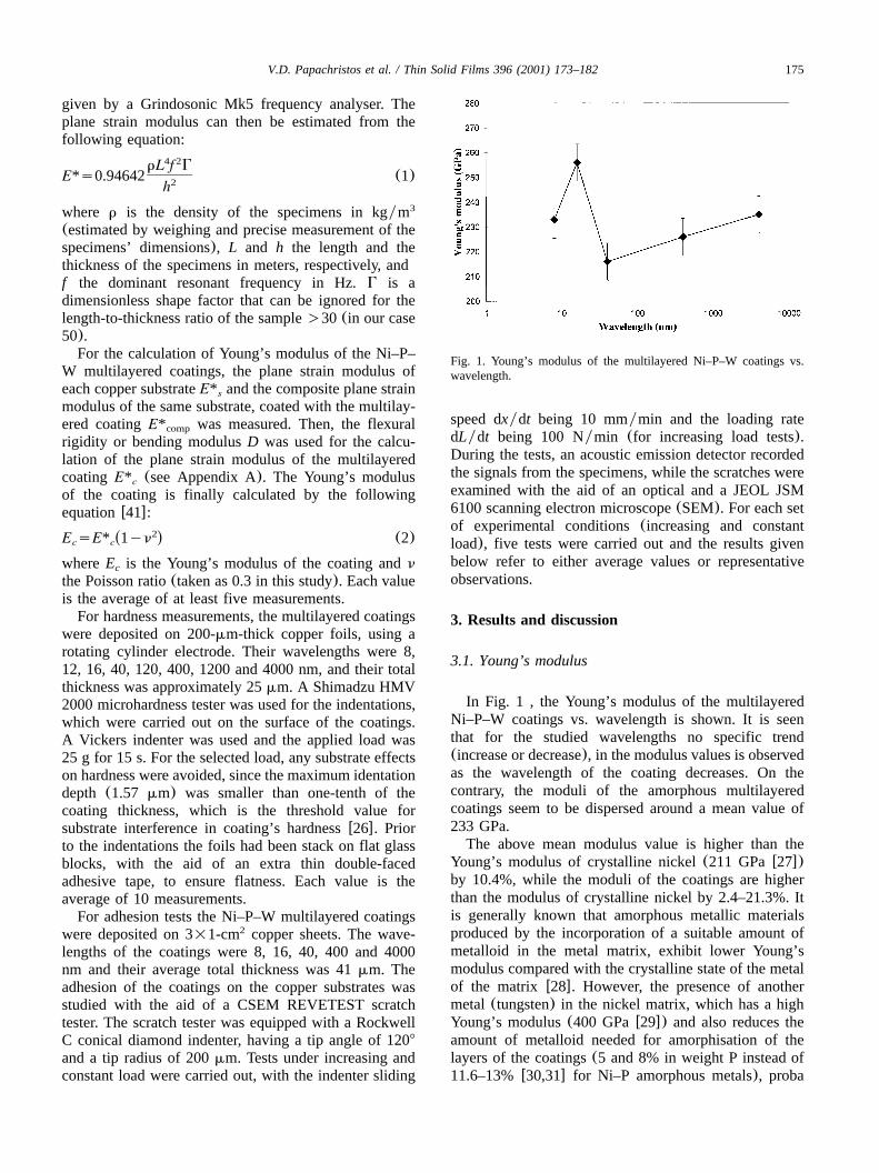
Fig. 1. Young’s modulus of the multilayered Ni–P–W coatings vs.wavelength.
given by a Grindosonic Mk5 frequency analyser. Theplane strain modulus can then be estimated from thefollowing equation:
4 2rL f GE*s0.94642 (1)2h
where r is the density of the specimens in kgym3
(estimated by weighing and precise measurement of thespecimens’ dimensions), L and h the length and thethickness of the specimens in meters, respectively, andf the dominant resonant frequency in Hz.G is adimensionless shape factor that can be ignored for thelength-to-thickness ratio of the sample)30 (in our case50).For the calculation of Young’s modulus of the Ni–P–
W multilayered coatings, the plane strain modulus ofeach copper substrate and the composite plane strainE* smodulus of the same substrate, coated with the multilay-ered coating was measured. Then, the flexuralE* comp
rigidity or bending modulusD was used for the calcu-lation of the plane strain modulus of the multilayeredcoating (see Appendix A). The Young’s modulusE* cof the coating is finally calculated by the followingequationw41x:
2Ž .E sE* 1yn (2)c c
whereE is the Young’s modulus of the coating andnc
the Poisson ratio(taken as 0.3 in this study). Each valueis the average of at least five measurements.For hardness measurements, the multilayered coatings
were deposited on 200-mm-thick copper foils, using arotating cylinder electrode. Their wavelengths were 8,12, 16, 40, 120, 400, 1200 and 4000 nm, and their totalthickness was approximately 25mm. A Shimadzu HMV2000 microhardness tester was used for the indentations,which were carried out on the surface of the coatings.A Vickers indenter was used and the applied load was25 g for 15 s. For the selected load, any substrate effectson hardness were avoided, since the maximum identationdepth (1.57 mm) was smaller than one-tenth of thecoating thickness, which is the threshold value forsubstrate interference in coating’s hardnessw26x. Priorto the indentations the foils had been stack on flat glassblocks, with the aid of an extra thin double-facedadhesive tape, to ensure flatness. Each value is theaverage of 10 measurements.For adhesion tests the Ni–P–W multilayered coatings
were deposited on 3=1-cm copper sheets. The wave-2
lengths of the coatings were 8, 16, 40, 400 and 4000nm and their average total thickness was 41mm. Theadhesion of the coatings on the copper substrates wasstudied with the aid of a CSEM REVETEST scratchtester. The scratch tester was equipped with a RockwellC conical diamond indenter, having a tip angle of 1208
and a tip radius of 200mm. Tests under increasing andconstant load were carried out, with the indenter sliding
speed dxydt being 10 mmymin and the loading ratedLydt being 100 Nymin (for increasing load tests).During the tests, an acoustic emission detector recordedthe signals from the specimens, while the scratches wereexamined with the aid of an optical and a JEOL JSM6100 scanning electron microscope(SEM). For each setof experimental conditions(increasing and constantload), five tests were carried out and the results givenbelow refer to either average values or representativeobservations.
3. Results and discussion
3.1. Young’s modulus
In Fig. 1 , the Young’s modulus of the multilayeredNi–P–W coatings vs. wavelength is shown. It is seenthat for the studied wavelengths no specific trend(increase or decrease), in the modulus values is observedas the wavelength of the coating decreases. On thecontrary, the moduli of the amorphous multilayeredcoatings seem to be dispersed around a mean value of233 GPa.The above mean modulus value is higher than the
Young’s modulus of crystalline nickel(211 GPaw27x)by 10.4%, while the moduli of the coatings are higherthan the modulus of crystalline nickel by 2.4–21.3%. Itis generally known that amorphous metallic materialsproduced by the incorporation of a suitable amount ofmetalloid in the metal matrix, exhibit lower Young’smodulus compared with the crystalline state of the metalof the matrix w28x. However, the presence of anothermetal (tungsten) in the nickel matrix, which has a highYoung’s modulus(400 GPaw29x) and also reduces theamount of metalloid needed for amorphisation of thelayers of the coatings(5 and 8% in weight P instead of11.6–13%w30,31x for Ni–P amorphous metals), proba
176 V.D. Papachristos et al. / Thin Solid Films 396 (2001) 173–182
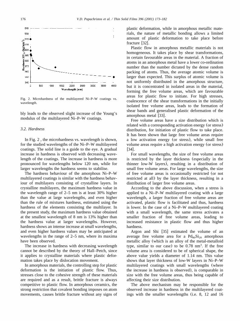
Fig. 2. Microhardness of the multilayered Ni–P–W coatings vs.wavelength.
bly leads to the observed slight increase of the Young’smodulus of the multilayered Ni–P–W coatings.
3.2. Hardness
In Fig. 2 , the microhardness vs. wavelength is shown,for the studied wavelengths of the Ni–P–W multilayeredcoatings. The solid line is a guide to the eye. A gradualincrease in hardness is observed with decreasing wave-length of the coatings. The increase in hardness is morepronounced for wavelengths below 120 nm, while forlarger wavelengths the hardness seems to stabilise.The hardness behaviour of the amorphous Ni–P–W
multilayered coatings is similar with the hardness behav-iour of multilayers consisting of crystalline layers. Incrystalline multilayers, the maximum hardness value inthe wavelength range of 2–5 nm is at least 30% higherthan the value at large wavelengths, and even higherthan the rule of mixtures hardness, estimated using thehardness of the elements consisting the multilayer. Inthe present study, the maximum hardness value obtainedat the smallest wavelength of 8 nm is 13% higher thanthe hardness value at larger wavelengths. However,hardness shows an intense increase at small wavelengths,and even higher hardness values may be anticipated atwavelengths in the range of 2–5 nm, where its maximahave been observed.The increase in hardness with decreasing wavelength
cannot be described by the theory of Hall–Petch, sinceit applies to crystalline materials where plastic defor-mation takes place by dislocation movement.In amorphous materials, the controlling step for plastic
deformation is the initiation of plastic flow. Thus,stresses close to the cohesive strength of these materialsare required and as a result, brittle fracture is alwayscompetitive to plastic flow. In amorphous ceramics, thestrong restriction that covalent bonding imposes on atommovements, causes brittle fracture without any signs of
plastic deformation, while in amorphous metallic mate-rials, the nature of metallic bonding allows a limitedamount of plastic deformation to take place beforefracturew32x.
Plastic flow in amorphous metallic materials is nothomogeneous. It takes place by shear transformations,in certain favourable areas in the material. A fraction ofatoms in an amorphous metal have a lower co-ordinationnumber than the number dictated by the dense randompacking of atoms. Thus, the average atomic volume islarger than expected. This surplus of atomic volume isnot uniformly distributed in the amorphous structure,but it is concentrated in isolated areas in the material,forming the free volume areas, which are favourableareas for plastic flow to initiate. For high stresses,coalescence of the shear transformations in the initiallyisolated free volume areas, leads to the formation ofshear bands and generalised plastic deformation of theamorphous metalw33x.
Free volume areas have a size distribution which isrelated with a corresponding activation energy(or stress)distribution, for initiation of plastic flow to take place.It has been shown that large free volume areas requirea low activation energy(or stress), while small freevolume areas require a high activation energy(or stress)w34x.For small wavelengths, the size of free volume areas
is restricted by the layer thickness(especially in thethinner low-W layers), resulting in a distribution ofsmall free volume areas. For large wavelengths, the sizeof free volume areas is occasionally restricted(or notrestricted at all) by the layer thickness, resulting in adistribution of larger free volume areas.According to the above discussion, when a stress is
applied to a Ni–P–W multilayered coating with a largewavelength, a larger fraction of free volume areas areactivated, plastic flow is facilitated and thus, hardnessis lower. In the case of a Ni–P–W multilayered coatingwith a small wavelength, the same stress activates asmaller fraction of free volume areas, leading toincreased resistance in plastic flow and thus higherhardness.Argon and Shi w35x estimated the volume of an
average free volume area for a Pd Si amorphous80 20
metallic alloy (which is an alloy of the metal-metalloidtype, similar to our case) to be 0.78 nm . If the free3
volume area is considered to be of spherical shape, theabove value yields a diameter of 1.14 nm. This valueshows that layer thickness of low-W layers in Ni–P–Wmultilayered coatings with small wavelengths(wherethe increase in hardness is observed), is comparable insize with the free volume areas, thus being capable ofaffecting their size distribution.The above mechanism may be responsible for the
observed increase in hardness in the multilayered coat-ings with the smaller wavelengths(i.e. 8, 12 and 16
177V.D. Papachristos et al. / Thin Solid Films 396 (2001) 173–182
nm, where the low-W layers are 2, 3 and 4 nm thick,respectively), but it is not expected to be effective forintermediate wavelengths(40 and 120 nm), where aless pronounced increase in hardness is observed.TEM images of cross-sections of the multilayered
coatings showed that for coatings with wavelength of40 nm and larger, despite the generally amorphousnature of the layers in the multilayered coatings, smallcrystalline grains;5 nm in diameter can be seen in thelow-W layers, adjacent to the interface with the previoushigh-W layer. It is observed that the small crystallinegrains only form at the side of the low-W layers, whichfollow a high-W layer. The opposite is not observed(more details in reference Panagopoulos et al.w25x).These small crystallites are believed to have high plasticresistances acting as rigid filler in the amorphous phase,thus leading to increased hardnessw36x. The effect ofthe crystallites is stronger in the coatings with theintermediate wavelengths due to the higher number ofinterfaces in their structure, leading to the slight increasein hardness, whereas for larger wavelengths, the smallernumber of interfaces results in a low volume fraction ofthe crystallites in the structure, rendering them ratherincapable of affecting the hardness of the coatings whichseems to stabilise.
3.3. Adhesion
For the description of the integrity and adhesion of arelatively brittle coating during the scratch test, twocharacteristic loads are used in literaturew23,37x. Thefirst load is the load where the first cracks appear onthe coating. It is called cohesive loadL and is ac
measure of the cohesive(intrinsic) strength of thecoating. The second load is the minimum load that isrequired for detachment of the coating from the sub-strate. It is a measure of the adhesive strength of thecoating and it is called adhesive loadL . For brittleA
materials, the adhesive load is usually higher than thecohesive load.The above loads are identified with the aid of the
acoustic emission pattern that is produced during thescratch test. The identification of adhesive load is basedon the corresponding sharp increase in the acousticsignal, in case of coating detachmentw37,38x. Thecohesive load coincides with the load where an acousticsignal is observed for the first time. Examination of thescratch in the optical microscope is very helpful for theidentification of cohesive load, since at this load, thefirst crack can be observed on the surface of the coating,while optical examination can also confirm the detach-ment of a coating from the substrate. However, it mustalways be born in mind that the detachment of a coatingfrom its substrate is not necessarily accompanied by aremoval of the coating.
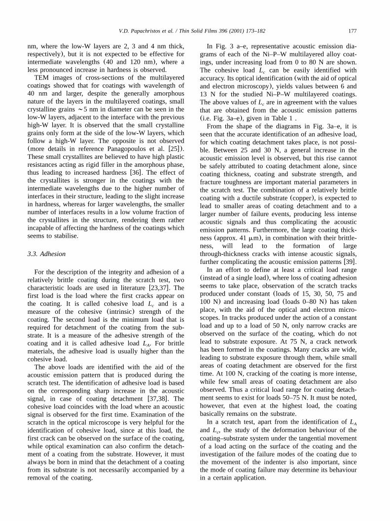
In Fig. 3 a–e, representative acoustic emission dia-grams of each of the Ni–P–W multilayered alloy coat-ings, under increasing load from 0 to 80 N are shown.The cohesive loadL can be easily identified withc
accuracy. Its optical identification(with the aid of opticaland electron microscopy), yields values between 6 and13 N for the studied Ni–P–W multilayered coatings.The above values ofL are in agreement with the valuesc
that are obtained from the acoustic emission patterns(i.e. Fig. 3a–e), given in Table 1 .From the shape of the diagrams in Fig. 3a–e, it is
seen that the accurate identification of an adhesive load,for which coating detachment takes place, is not possi-ble. Between 25 and 30 N, a general increase in theacoustic emission level is observed, but this rise cannotbe safely attributed to coating detachment alone, sincecoating thickness, coating and substrate strength, andfracture toughness are important material parameters inthe scratch test. The combination of a relatively brittlecoating with a ductile substrate(copper), is expected tolead to smaller areas of coating detachment and to alarger number of failure events, producing less intenseacoustic signals and thus complicating the acousticemission patterns. Furthermore, the large coating thick-ness(approx. 41mm), in combination with their brittle-ness, will lead to the formation of largethrough-thickness cracks with intense acoustic signals,further complicating the acoustic emission patternsw39x.
In an effort to define at least a critical load range(instead of a single load), where loss of coating adhesionseems to take place, observation of the scratch tracksproduced under constant(loads of 15, 30, 50, 75 and100 N) and increasing load(loads 0–80 N) has takenplace, with the aid of the optical and electron micro-scopes. In tracks produced under the action of a constantload and up to a load of 50 N, only narrow cracks areobserved on the surface of the coating, which do notlead to substrate exposure. At 75 N, a crack networkhas been formed in the coatings. Many cracks are wide,leading to substrate exposure through them, while smallareas of coating detachment are observed for the firsttime. At 100 N, cracking of the coating is more intense,while few small areas of coating detachment are alsoobserved. Thus a critical load range for coating detach-ment seems to exist for loads 50–75 N. It must be noted,however, that even at the highest load, the coatingbasically remains on the substrate.In a scratch test, apart from the identification ofLA
and L , the study of the deformation behaviour of thec
coating–substrate system under the tangential movementof a load acting on the surface of the coating and theinvestigation of the failure modes of the coating due tothe movement of the indenter is also important, sincethe mode of coating failure may determine its behaviourin a certain application.
178 V.D. Papachristos et al. / Thin Solid Films 396 (2001) 173–182
Table 1Values of cohesive load obtained by acoustic emission patterns
Coating wavelength Cohesive loadLc
(nm) (N)
8 1616 1440 9
400 134000 5
Fig. 3. Acoustic emission diagrams of the Ni–P–W multilayered alloy coatings, under increasing load from 0 to 80 N and for the differentwavelengths studied:(a) 8 nm, (b) 16 nm,(c) 40 nm,(d) 400 nm and(e) 4000 nm.
The presence of the relatively high acoustic emissionlevel over the whole range of applied normal loads inthe scratches under increasing load, which complicatesthe identification ofL , is probably an indication of theA
compression of the hard coating into the soft substratew40x. The compressed coating produces an appreciableacoustic signal by further cracking, even after its detach-ment from the substrate, as it is compressed into thesubstrate by the action of the moving stylus. Observationof the scratch tracks by the optical microscope, con-firmed the existence of the major part of the coatingson the substrate at higher loads, although the coatingswere heavily cracked. Any occasional layer detachmentsalong the inner interfaces of the multilayered coatings,
which are also observed for loads above 30 N, furthercomplicate the shape of the acoustic emission diagrams.The stepwise increase of acoustic emission signals in
the acoustic emission patterns as the load increases and
179V.D. Papachristos et al. / Thin Solid Films 396 (2001) 173–182
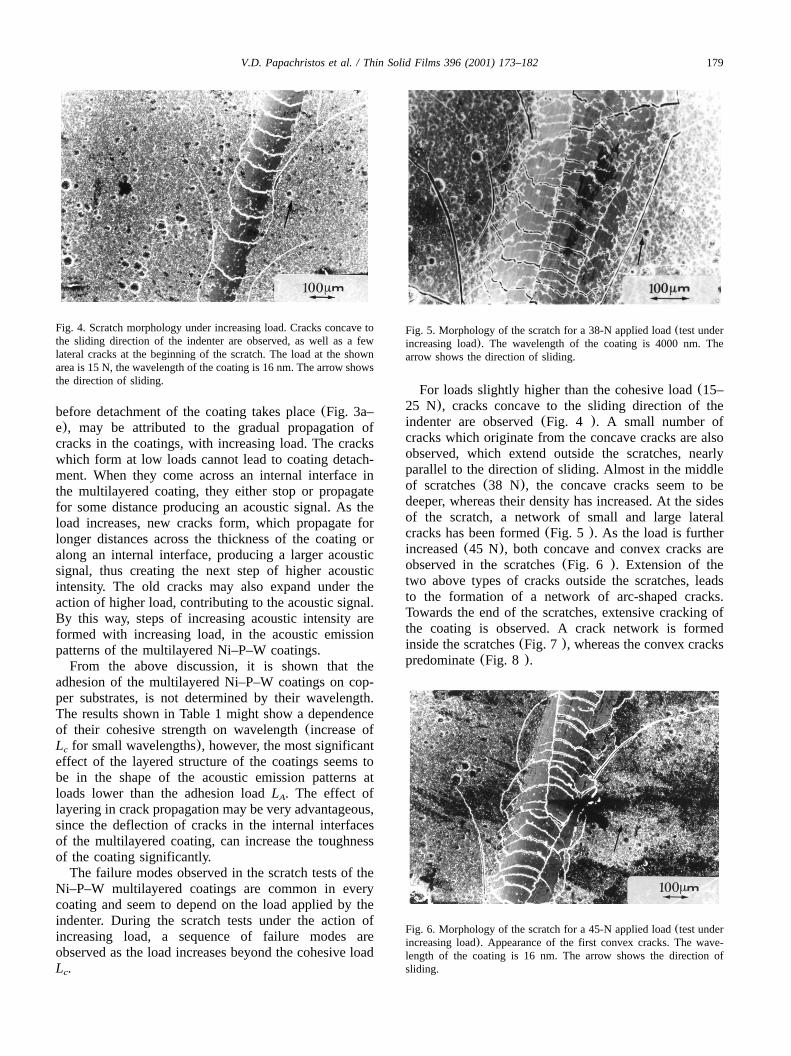
Fig. 4. Scratch morphology under increasing load. Cracks concave tothe sliding direction of the indenter are observed, as well as a fewlateral cracks at the beginning of the scratch. The load at the shownarea is 15 N, the wavelength of the coating is 16 nm. The arrow showsthe direction of sliding.
Fig. 5. Morphology of the scratch for a 38-N applied load(test underincreasing load). The wavelength of the coating is 4000 nm. Thearrow shows the direction of sliding.
Fig. 6. Morphology of the scratch for a 45-N applied load(test underincreasing load). Appearance of the first convex cracks. The wave-length of the coating is 16 nm. The arrow shows the direction ofsliding.
before detachment of the coating takes place(Fig. 3a–e), may be attributed to the gradual propagation ofcracks in the coatings, with increasing load. The crackswhich form at low loads cannot lead to coating detach-ment. When they come across an internal interface inthe multilayered coating, they either stop or propagatefor some distance producing an acoustic signal. As theload increases, new cracks form, which propagate forlonger distances across the thickness of the coating oralong an internal interface, producing a larger acousticsignal, thus creating the next step of higher acousticintensity. The old cracks may also expand under theaction of higher load, contributing to the acoustic signal.By this way, steps of increasing acoustic intensity areformed with increasing load, in the acoustic emissionpatterns of the multilayered Ni–P–W coatings.From the above discussion, it is shown that the
adhesion of the multilayered Ni–P–W coatings on cop-per substrates, is not determined by their wavelength.The results shown in Table 1 might show a dependenceof their cohesive strength on wavelength(increase ofL for small wavelengths), however, the most significantc
effect of the layered structure of the coatings seems tobe in the shape of the acoustic emission patterns atloads lower than the adhesion loadL . The effect ofA
layering in crack propagation may be very advantageous,since the deflection of cracks in the internal interfacesof the multilayered coating, can increase the toughnessof the coating significantly.The failure modes observed in the scratch tests of the
Ni–P–W multilayered coatings are common in everycoating and seem to depend on the load applied by theindenter. During the scratch tests under the action ofincreasing load, a sequence of failure modes areobserved as the load increases beyond the cohesive loadL .c
For loads slightly higher than the cohesive load(15–25 N), cracks concave to the sliding direction of theindenter are observed(Fig. 4 ). A small number ofcracks which originate from the concave cracks are alsoobserved, which extend outside the scratches, nearlyparallel to the direction of sliding. Almost in the middleof scratches(38 N), the concave cracks seem to bedeeper, whereas their density has increased. At the sidesof the scratch, a network of small and large lateralcracks has been formed(Fig. 5 ). As the load is furtherincreased(45 N), both concave and convex cracks areobserved in the scratches(Fig. 6 ). Extension of thetwo above types of cracks outside the scratches, leadsto the formation of a network of arc-shaped cracks.Towards the end of the scratches, extensive cracking ofthe coating is observed. A crack network is formedinside the scratches(Fig. 7 ), whereas the convex crackspredominate(Fig. 8 ).
180 V.D. Papachristos et al. / Thin Solid Films 396 (2001) 173–182
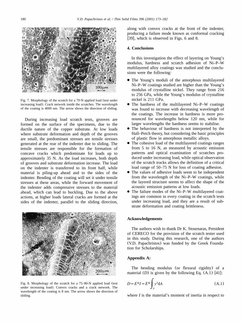
Fig. 7. Morphology of the scratch for a 70-N applied load(test underincreasing load). Crack network inside the scratches. The wavelengthof the coating is 4000 nm. The arrow shows the direction of sliding.
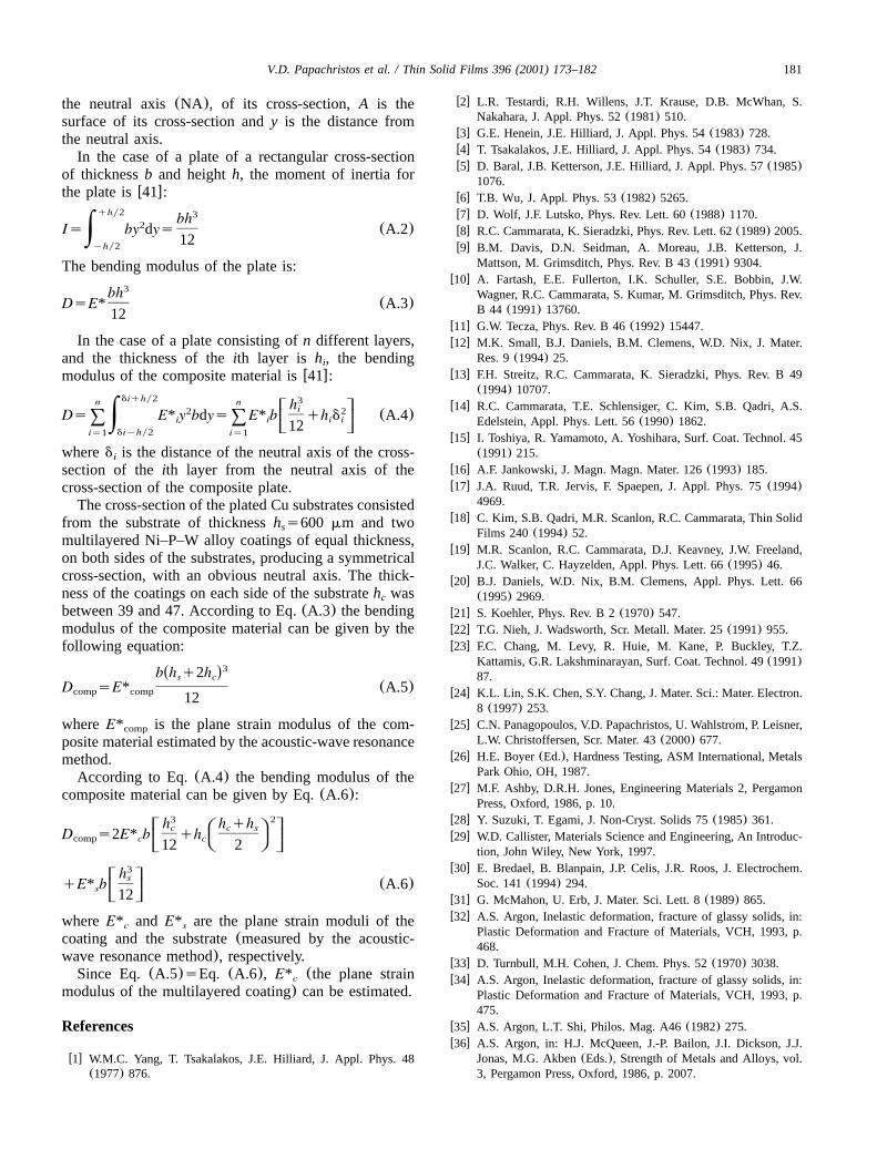
Fig. 8. Morphology of the scratch for a 75–80-N applied load(testunder increasing load). Convex cracks and a crack network. Thewavelength of the coating is 8 nm. The arrow shows the direction ofsliding.
During increasing load scratch tests, grooves areformed on the surface of the specimens, due to theductile nature of the copper substrate. At low loadswhere substrate deformation and depth of the groovesare small, the predominant stresses are tensile stressesgenerated at the rear of the indenter due to sliding. Thetensile stresses are responsible for the formation ofconcave cracks which predominate for loads up toapproximately 35 N. As the load increases, both depthof grooves and substrate deformation increase. The loadon the indenter is transferred to its front half, whilematerial is piling-up ahead and to the sides of theindenter. Bending of the coating will set it under tensilestresses at these areas, while the forward movement ofthe indenter adds compressive stresses to the materialahead, which can lead to buckling. Due to the aboveactions, at higher loads lateral cracks are formed at thesides of the indenter, parallel to the sliding direction,
along with convex cracks at the front of the indenter,producing a failure mode known as conformal crackingw39x, which is observed in Figs. 6 and 8.
4. Conclusions
In this investigation the effect of layering on Young’smodulus, hardness and scratch adhesion of Ni–P–Wmultilayered alloy coatings was studied and the conclu-sions were the following:
● The Young’s moduli of the amorphous multilayeredNi–P–W coatings studied are higher than the Young’smodulus of crystalline nickel. They range from 216to 256 GPa, while the Young’s modulus of crystallinenickel is 211 GPa.
● The hardness of the multilayered Ni–P–W coatingswas found to increase with decreasing wavelength ofthe coatings. The increase in hardness is more pro-nounced for wavelengths below 120 nm, while forlarger wavelengths the hardness seems to stabilise.
● The behaviour of hardness is not interpreted by theHall–Petch theory, but considering the basic principlesof plastic flow in amorphous metallic alloys.
● The cohesive load of the multilayered coatings rangesfrom 5 to 16 N, as measured by acoustic emissionpatterns and optical examination of scratches pro-duced under increasing load, while optical observationof the scratch tracks allows the definition of a criticalload range of 50–75 N for loss of coating adhesion.
● The values of adhesive loads seem to be independentfrom the wavelength of the Ni–P–W coatings, whilethe layered structure seems to affect the shape of theacoustic emission patterns at low loads.
● The failure modes of the Ni–P–W multilayered coat-ings are common in every coating in the scratch testsunder increasing load, and they are a result of sub-strate deformation and coating brittleness.
Acknowledgements
The authors wish to thank Dr K. Stournaras, Presidentof CERECO for the provision of the scratch tester usedin this study. During this research, one of the authors(V.D. Papachristos) was funded by the Greek Founda-tion for Scholarships.
Appendix A:
The bending modulus(or flexural rigidity) of amaterial(D) is given by the following Eq.(A.1) w41x:
2DsE*IsE* y dA (A.1)|A
whereI is the material’s moment of inertia in respect to
181V.D. Papachristos et al. / Thin Solid Films 396 (2001) 173–182
the neutral axis(NA), of its cross-section,A is thesurface of its cross-section andy is the distance fromthe neutral axis.In the case of a plate of a rectangular cross-section
of thicknessb and heighth, the moment of inertia forthe plate isw41x:
qhy2 3bh2Is by dys (A.2)| 12yhy2
The bending modulus of the plate is:3bh
DsE* (A.3)12
In the case of a plate consisting ofn different layers,and the thickness of theith layer is h , the bendingi
modulus of the composite material isw41x:diqhy2 3n n w zhi2 2x |Ds E* y bdys E* b qh d (A.4)i i i i|8 8 y ~12
diyhy2is1 is1
whered is the distance of the neutral axis of the cross-i
section of theith layer from the neutral axis of thecross-section of the composite plate.The cross-section of the plated Cu substrates consisted
from the substrate of thicknessh s600 mm and twos
multilayered Ni–P–W alloy coatings of equal thickness,on both sides of the substrates, producing a symmetricalcross-section, with an obvious neutral axis. The thick-ness of the coatings on each side of the substrateh wasc
between 39 and 47. According to Eq.(A.3) the bendingmodulus of the composite material can be given by thefollowing equation:
3Ž .b h q2hs cD sE* (A.5)comp comp 12
where is the plane strain modulus of the com-E* comp
posite material estimated by the acoustic-wave resonancemethod.According to Eq.(A.4) the bending modulus of the
composite material can be given by Eq.(A.6):
3 2w zB Eh h qhc c sx |C FD s2E* b qhcomp c cy ~D G12 2
3w zhsx |qE* b (A.6)sy ~12
where and are the plane strain moduli of theE* E*c s
coating and the substrate(measured by the acoustic-wave resonance method), respectively.Since Eq.(A.5)sEq. (A.6), (the plane strainE* c
modulus of the multilayered coating) can be estimated.
References
w1x W.M.C. Yang, T. Tsakalakos, J.E. Hilliard, J. Appl. Phys. 48(1977) 876.
w2x L.R. Testardi, R.H. Willens, J.T. Krause, D.B. McWhan, S.Nakahara, J. Appl. Phys. 52(1981) 510.
w3x G.E. Henein, J.E. Hilliard, J. Appl. Phys. 54(1983) 728.w4x T. Tsakalakos, J.E. Hilliard, J. Appl. Phys. 54(1983) 734.w5x D. Baral, J.B. Ketterson, J.E. Hilliard, J. Appl. Phys. 57(1985)
1076.w6x T.B. Wu, J. Appl. Phys. 53(1982) 5265.w7x D. Wolf, J.F. Lutsko, Phys. Rev. Lett. 60(1988) 1170.w8x R.C. Cammarata, K. Sieradzki, Phys. Rev. Lett. 62(1989) 2005.w9x B.M. Davis, D.N. Seidman, A. Moreau, J.B. Ketterson, J.
Mattson, M. Grimsditch, Phys. Rev. B 43(1991) 9304.w10x A. Fartash, E.E. Fullerton, I.K. Schuller, S.E. Bobbin, J.W.
Wagner, R.C. Cammarata, S. Kumar, M. Grimsditch, Phys. Rev.B 44 (1991) 13760.
w11x G.W. Tecza, Phys. Rev. B 46(1992) 15447.w12x M.K. Small, B.J. Daniels, B.M. Clemens, W.D. Nix, J. Mater.
Res. 9(1994) 25.w13x F.H. Streitz, R.C. Cammarata, K. Sieradzki, Phys. Rev. B 49
(1994) 10707.w14x R.C. Cammarata, T.E. Schlensiger, C. Kim, S.B. Qadri, A.S.
Edelstein, Appl. Phys. Lett. 56(1990) 1862.w15x I. Toshiya, R. Yamamoto, A. Yoshihara, Surf. Coat. Technol. 45
(1991) 215.w16x A.F. Jankowski, J. Magn. Magn. Mater. 126(1993) 185.w17x J.A. Ruud, T.R. Jervis, F. Spaepen, J. Appl. Phys. 75(1994)
4969.w18x C. Kim, S.B. Qadri, M.R. Scanlon, R.C. Cammarata, Thin Solid
Films 240(1994) 52.w19x M.R. Scanlon, R.C. Cammarata, D.J. Keavney, J.W. Freeland,
J.C. Walker, C. Hayzelden, Appl. Phys. Lett. 66(1995) 46.w20x B.J. Daniels, W.D. Nix, B.M. Clemens, Appl. Phys. Lett. 66
(1995) 2969.w21x S. Koehler, Phys. Rev. B 2(1970) 547.w22x T.G. Nieh, J. Wadsworth, Scr. Metall. Mater. 25(1991) 955.w23x F.C. Chang, M. Levy, R. Huie, M. Kane, P. Buckley, T.Z.
Kattamis, G.R. Lakshminarayan, Surf. Coat. Technol. 49(1991)87.
w24x K.L. Lin, S.K. Chen, S.Y. Chang, J. Mater. Sci.: Mater. Electron.8 (1997) 253.
w25x C.N. Panagopoulos, V.D. Papachristos, U. Wahlstrom, P. Leisner,L.W. Christoffersen, Scr. Mater. 43(2000) 677.
w26x H.E. Boyer(Ed.), Hardness Testing, ASM International, MetalsPark Ohio, OH, 1987.
w27x M.F. Ashby, D.R.H. Jones, Engineering Materials 2, PergamonPress, Oxford, 1986, p. 10.
w28x Y. Suzuki, T. Egami, J. Non-Cryst. Solids 75(1985) 361.w29x W.D. Callister, Materials Science and Engineering, An Introduc-
tion, John Wiley, New York, 1997.w30x E. Bredael, B. Blanpain, J.P. Celis, J.R. Roos, J. Electrochem.
Soc. 141(1994) 294.w31x G. McMahon, U. Erb, J. Mater. Sci. Lett. 8(1989) 865.w32x A.S. Argon, Inelastic deformation, fracture of glassy solids, in:
Plastic Deformation and Fracture of Materials, VCH, 1993, p.468.
w33x D. Turnbull, M.H. Cohen, J. Chem. Phys. 52(1970) 3038.w34x A.S. Argon, Inelastic deformation, fracture of glassy solids, in:
Plastic Deformation and Fracture of Materials, VCH, 1993, p.475.
w35x A.S. Argon, L.T. Shi, Philos. Mag. A46(1982) 275.w36x A.S. Argon, in: H.J. McQueen, J.-P. Bailon, J.I. Dickson, J.J.
Jonas, M.G. Akben(Eds.), Strength of Metals and Alloys, vol.3, Pergamon Press, Oxford, 1986, p. 2007.

182 V.D. Papachristos et al. / Thin Solid Films 396 (2001) 173–182
w37x A.R. Chalker, S.J. Bull, D.S. Rickerby, Mater. Sci. Eng. A140(1991) 583.
w38x A.J. Perry, Thin Solid Films 107(1983) 167.w39x S.J. Bull, Surf. Coat. Technol. 50(1991) 25.
w40x H. Jensen, U.M. Jensen, G. Sorensen, Surf. Coat. Technol. 74–75 (1995) 297.
w41x L.H. Crandall, N.C. Dahl, T.J. Lardner, An Introduction to theMechanics of Solids, McGraw–Hill, 1978.