
Digi-Sign Certification Services Limited BOCHK Certificate ...
Upload
khangminh22Category
view
3download
0
XLR PRO™Radio Frequency (RF) Modem
User Guide
Revision history—90002202
Revision Date Description
D December2015
Added certifications for Mexico and Australia.Added USB support available with XLR PRO firmware version 1007.
E February2016
Noted that user guide applies to all XLR PRO models (XLR PRO and XLR PROINTL).Moved source content and made miscellaneous editorial corrections.
F January2017
Added a serial cable warning. Added Brazil and Peru certificationinformation. Updated AT commands and API frames.
G December2017
Added RF power level saturation information.
H May 2018 Added note on range estimation. Changed IC to ISED.
Trademarks and copyrightDigi, Digi International, and the Digi logo are trademarks or registered trademarks in the UnitedStates and other countries worldwide. All other trademarks mentioned in this document are theproperty of their respective owners.© 2018 Digi International Inc. All rights reserved.
DisclaimersInformation in this document is subject to change without notice and does not represent acommitment on the part of Digi International. Digi provides this document “as is,” without warranty ofany kind, expressed or implied, including, but not limited to, the implied warranties of fitness ormerchantability for a particular purpose. Digi may make improvements and/or changes in this manualor in the product(s) and/or the program(s) described in this manual at any time.
WarrantyTo view product warranty information, go to the following website:www.digi.com/howtobuy/terms
Send commentsDocumentation feedback: To provide feedback on this document, send your comments [email protected].
Customer supportDigi Technical Support: Digi offers multiple technical support plans and service packages to help ourcustomers get the most out of their Digi product. For information on Technical Support plans andpricing, contact us at +1 952.912.3444 or visit us at www.digi.com/support.
XLR PRO Radio Frequency (RF) Modem User Guide 2

Contents
XLR PRO Radio Frequency (RF) Modem User GuideOperational modes 9For more information 10
HardwareXLR PRO front panel 12RJ45 serial port pinout 12Hardware interfaces 13Power supply 13LEDs 13
Startup 14Data transmission 14
Reset button 14Antenna port 15
Set up the hardwareXLR PRO kit contents 17Connect the hardware 18Mount the XLR PRO 19
Right-angle mount DIN rail (not to scale) 19Flush-mount bracket (not to scale) 20
Mounting guidelines 20Antenna placement 21
Technical specificationsGeneral specifications 23RF characteristics 23Rural range line-of-sight 23Receiver sensitivity 24UART interface data rates (software selectable) 24Networking and security specifications 24Power requirements 25Power supply 25Environmental 25Regulatory conformity summary 25Connectors 26
XLR PRO Radio Frequency (RF) Modem User Guide 3
XLR PRO Radio Frequency (RF) Modem User Guide 4
OperationsXLR PRO operational design 28Ethernet RF bridging 28Serial mode selection 29USB mode 30Serial mode 30
RS-232 30RS-485/422 30
IP socket mode 31Controlling parameters 31Operational description 32
Serial communications 32Serial buffers 32
Networking methodsMAC/PHY layers 34Ethernet bridging 34
Ethernet packet handling 34Bridging precautions 35Enable bridging 3564-bit addresses 35Unicast 35Broadcast 35
Serial addressing basics 3664-bit addresses 36Unicast 36Broadcast 36Delivery methods 36
AT commandsSpecial commands 40
AC (Apply Changes) 40FR (Software Reset) 40RE command 40WR command 40
MAC/PHY commands 41ID (Network ID) 41BR (RF Data Rate) 41PL (Power Level) 42RR (Unicast Retries) 42MT (Broadcast Multi-Transmits) 42
Diagnostic commands 42DB (Received Signal Strength) 43EA (MAC ACK Timeouts) 43ER (Received Error Count) 43GD (Good Packets Received) 43TR (Transmission Failure Count) 44UA (Unicasts Attempted) 44%H (MAC Unicast One Hop Time) 44%8 (MAC Broadcast One Hop Time) 44N? (Network Discovery Timeout) 45

XLR PRO Radio Frequency (RF) Modem User Guide 5
Network commands 45CE (Node Messaging Options) 45BH command 45NH (Network Hops) 46NN (Network Delay Slots) 46
Addressing commands 46SH command 46SL command 46DH command 47DL command 47TO (Transmit Options) 47NI command 48NT (Node Discovery Timeout) 48NO (Node Discovery Options) 48CI (Cluster ID) 49DE command 49SE command 49
Addressing discovery and configuration commands 50DN (Discover Node) 50ND (Network Discover) 50FN (Find Neighbors) 51
Security commands 52KY (AES Encryption Key) 52
Serial interfacing commands 52BD (Baud Rate) 52NB (Parity) 52SB (Stop Bits) 53RO command 53FT (Flow Control Threshold) 54API Mode 54AO command 544E (Serial Protocol) 554D (RS-485 Duplex) 554T (RS-485 Termination) 55D6 (RTS Flow Control) 55D7 (CTS Flow Control) 56
Hardware diagnostics commands 56TP command 56RP command 56
Ethernet and IP socket mode commands 57ES (IP Socket Mode Enable) 57IB (IP Socket Baud Rate) 57IP (IP Protocol) 58DX (Destination IP Address) 58C0 (Source Port) 58DY (Destination Port) 59TM command 59TS (TCP Server Connection Timeout) 59MA (IP Addressing Mode) 59MY command 60MK command 60GW command 61NS (DNS Address) 61%M (Ethernet MAC address) 61
Remote Manager commands 61
XLR PRO Radio Frequency (RF) Modem User Guide 6
DO (Device Cloud Enable) 61KP (Device Description) 62KC (Device Contact) 62KL (Device Location) 62LX (Latitude) 62LY (Longitude) 62EQ (Device Cloud FQDN) 63DI (Device Cloud Indicator) 63
Web configuration commands 63HE (Web Configuration Enable) 63HU (Web Configuration User Name) 64HW (Web Configuration Password) 64
Ethernet bridging commands 64BE (Ethernet RF Bridging Enable) 64BA (Bridge Destination MAC) 65
Command mode options 65CC (Command Sequence Character) 65CN command 65CT command 65GT command 66
Firmware commands 66VB (Firmware Version) 66VR (XLR PRO Firmware Version) 66HV command 66VH command 67*C (compatibility) 67DD command 67PN (Part Number) 67NP (Maximum Packet Payload Bytes) 67CK (Configuration CRC) 68
Operate in API modeAPI mode overview 70Use the AP command to set the operation mode 70API frame format 70
API operation (AP parameter = 1) 70API operation with escaped characters (AP parameter = 2) 71
API serial exchanges 73AT command frames 73Transmit and receive RF data 73Remote AT commands 73
Code to support future API frames 74API frames 74
AT Command frame - 0x08 74AT Command - Queue Parameter Value frame - 0x09 76Transmit Request frame - 0x10 77Explicit Addressing Command frame - 0x11 79Remote AT Command Request frame - 0x17 82AT Command Response frame - 0x88 84Modem Status frame - 0x8A 86Transmit Status frame - 0x8B 87Receive Packet frame - 0x90 89Explicit Rx Indicator frame - 0x91 91Remote Command Response frame - 0x97 93
XLR PRO Radio Frequency (RF) Modem User Guide 7
Advanced application featuresNetwork commissioning and diagnostics 96Local configuration 96Remote configuration 96
Send a remote command 96Apply changes on remote devices 96Remote command response 96
Test links in a network - loopback cluster 97Test links between adjacent devices 97
Example 99RSSI indicators 99Discover all the devices on a network 99
General Purpose Flash Memory 100Access General Purpose Flash Memory 100Work with flash memory 111
Over-the-air (OTA) firmware updates 111Distribute the new application 112Verify the new application 112Install the application 113Keep in mind 113
Configure the XLR PRO using the web configuration interfaceAccess the XLR PRO web configuration interface 115Set general options 115Set Ethernet network options 115Set Ethernet RF bridging options 116Set Device Cloud connectivity options 117Set XLR radio options 117Set XLR radio serial options 118Set XLR radio IP socket (Ethernet) options 119Update firmware 120Set web configuration options 120
Configure the XLR PRO using XCTUDownload and install XCTU 123Download and install the USB driver 123Connect XLR PRO to your PC 123Launch XCTU and add the XLR PRO 123Configure parameters using XCTU 123Determine or assign an IP address 124
Determine the assigned DHCP address 124Assign a static IP address 124
Update firmware with XCTU 124
Configure the XLR PRO using Digi Remote ManagerCreate a Remote Manager account 127Get the XLR PRO MAC address 127Add a XLR PRO to Remote Manager 127Update firmware with Remote Manager 128
XLR PRO Radio Frequency (RF) Modem User Guide 8
Configure Device Cloud connectivity options 128Configure Ethernet network options 129Configure Ethernet RF bridging options 129Configure IP socket mode options 130Configure serial mode options 131Configure system options 132Configure web configuration options 133Configure XLR radio configuration options 133Schedule Device Cloud configuration changes 135
TroubleshootingSerial interface issues 137
Condition 137Solution 137Condition 137Solution 137
Ethernet issues 137Condition 137Solution 137
General issues 137Condition 137Solution 137
Safety notices and certificationsRF exposure statement 139Class 1, Division 2 (C1D2) certification—USA and Canada 139FCC (United States) certification 140ISED (Innovation, Science and Economic Development Canada) certification 140Australia certification 141Mexico IFETEL 141Brazil (ANATEL) 141
AntennasOmni-directional antennas 143Yagi antennas 145
XLR PRO Radio Frequency (RF) Modem User Guide
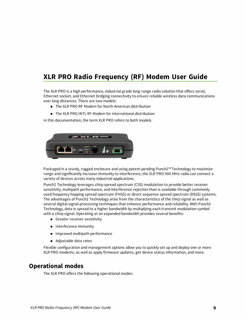
The XLR PRO is a high performance, industrial grade long-range radio solution that offers serial,Ethernet socket, and Ethernet bridging connectivity to ensure reliable wireless data communicationsover long distances. There are two models:
n The XLR PRO RF Modem for North American distribution
n The XLR PRO INTL RF Modem for international distribution
In this documentation, the term XLR PRO refers to both models.
Packaged in a sturdy, rugged enclosure and using patent-pending Punch2™ Technology to maximizerange and significantly increase immunity to interference, the XLR PRO 900 MHz radio can connect avariety of devices across many industrial applications.Punch2 Technology leverages chirp spread spectrum (CSS) modulation to provide better receiversensitivity, multipath performance, and interference rejection than is available through commonlyused frequency hopping spread spectrum (FHSS) or direct sequence spread spectrum (DSSS) systems.The advantages of Punch2 Technology arise from the characteristics of the chirp signal as well asseveral digital-signal-processing techniques that enhance performance and reliability. With Punch2Technology, data is spread to a higher bandwidth by multiplying each transmit modulation symbolwith a chirp signal. Operating at an expanded bandwidth provides several benefits:
n Greater receiver sensitivity
n Interference immunity
n Improved multipath performance
n Adjustable data rates
Flexible configuration and management options allow you to quickly set up and deploy one or moreXLR PRO modems, as well as apply firmware updates, get device status information, and more.
Operational modesThe XLR PRO offers the following operational modes:
XLR PRO Radio Frequency (RF) Modem User Guide 9
XLR PRO Radio Frequency (RF) Modem User Guide For more information
XLR PRO Radio Frequency (RF) Modem User Guide 10
n Serial (RS-232/RS-485/USB): In serial mode, the front panel serial port provides connectivityto the XLR PRO via RS-232 or RS-485/422 as well as a USB serial virtual COM port.
n Ethernet (IP socket): In IP socket mode, an XLR PRO can transmit and receive serial data via aTCP or UDP connection from either of the front panel Ethernet ports.
n Ethernet RF Bridging: In Ethernet RF bridging mode, an XLR PRO functions as an Ethernetcable replacement, supporting point-to-multi-point transmission for a maximum of 16 XLR PRORF modems. By default, bridging mode is disabled. Serial data from serial or IP socket modeoperates concurrently with Ethernet RF Bridging. If serial and Ethernet traffic are sent at thesame time, there will be some latency.
For more informationThe XLR PRO Radio Frequency (RF) family of products includes the following publications:
TitlePartnumber Description
XLRPRO Radio Frequency(RF) Module UserGuide
90001407 Provides complete information on all XLR PRO Radio Frequency(RF) Module features; describes how to configure XLR PROsusing XCTU; provides reference information on all supported ATcommands and API frames.
XLR PRO RadioFrequency (RF)Modem Quick StartGuide
90002204 Provides a brief summary of the XLR PRO and XLR PRO INTLRadio Frequency (RF) Modem kit.
XLR PRO RadioFrequency (RF)Modem GettingStarted Guide
90002203 Provides step-by-step instructions for setting up a pair of XLRPRO (or XLR PRO INTL) modems to test over-the-aircommunications between the radios.
Hardware
XLR PRO front panel 12RJ45 serial port pinout 12Hardware interfaces 13Power supply 13LEDs 13Reset button 14Antenna port 15
XLR PRO Radio Frequency (RF) Modem User Guide 11
Hardware XLR PRO front panel
XLR PRO Radio Frequency (RF) Modem User Guide 12
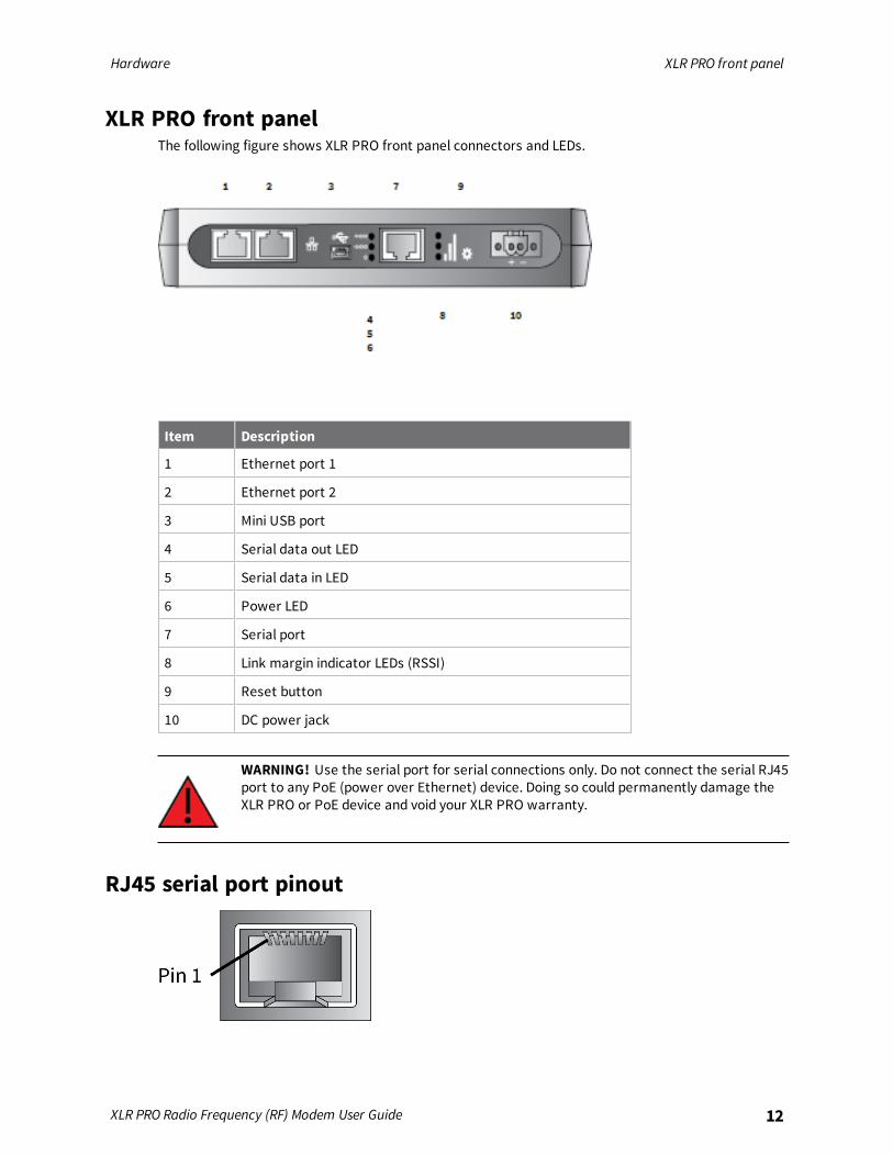
XLR PRO front panelThe following figure shows XLR PRO front panel connectors and LEDs.
Item Description
1 Ethernet port 1
2 Ethernet port 2
3 Mini USB port
4 Serial data out LED
5 Serial data in LED
6 Power LED
7 Serial port
8 Link margin indicator LEDs (RSSI)
9 Reset button
10 DC power jack
WARNING! Use the serial port for serial connections only. Do not connect the serial RJ45port to any PoE (power over Ethernet) device. Doing so could permanently damage theXLR PRO or PoE device and void your XLR PRO warranty.
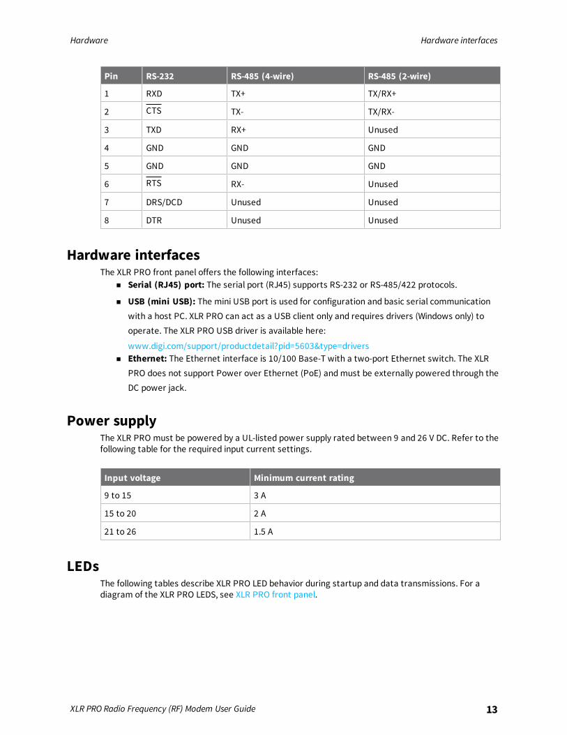
RJ45 serial port pinout
Hardware Hardware interfaces
XLR PRO Radio Frequency (RF) Modem User Guide 13
Pin RS-232 RS-485 (4-wire) RS-485 (2-wire)
1 RXD TX+ TX/RX+
2 CTS TX- TX/RX-
3 TXD RX+ Unused
4 GND GND GND
5 GND GND GND
6 RTS RX- Unused
7 DRS/DCD Unused Unused
8 DTR Unused Unused
Hardware interfacesThe XLR PRO front panel offers the following interfaces:
n Serial (RJ45) port: The serial port (RJ45) supports RS-232 or RS-485/422 protocols.
n USB (mini USB): The mini USB port is used for configuration and basic serial communicationwith a host PC. XLR PRO can act as a USB client only and requires drivers (Windows only) tooperate. The XLR PRO USB driver is available here:
www.digi.com/support/productdetail?pid=5603&type=driversn Ethernet: The Ethernet interface is 10/100 Base-T with a two-port Ethernet switch. The XLR
PRO does not support Power over Ethernet (PoE) and must be externally powered through theDC power jack.
Power supplyThe XLR PRO must be powered by a UL-listed power supply rated between 9 and 26 V DC. Refer to thefollowing table for the required input current settings.
Input voltage Minimum current rating
9 to 15 3 A
15 to 20 2 A
21 to 26 1.5 A
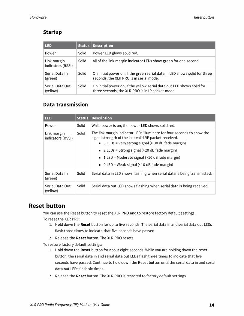
LEDsThe following tables describe XLR PRO LED behavior during startup and data transmissions. For adiagram of the XLR PRO LEDS, see XLR PRO front panel.
Hardware Reset button
XLR PRO Radio Frequency (RF) Modem User Guide 14
Startup
LED Status Description
Power Solid Power LED glows solid red.
Link marginindicators (RSSI)
Solid All of the link margin indicator LEDs show green for one second.
Serial Data In(green)
Solid On initial power on, if the green serial data in LED shows solid for threeseconds, the XLR PRO is in serial mode.
Serial Data Out(yellow)
Solid On initial power on, if the yellow serial data out LED shows solid forthree seconds, the XLR PRO is in IP socket mode.
Data transmission
LED Status Description
Power Solid While power is on, the power LED shows solid red.
Link marginindicators (RSSI)
Solid The link margin indicator LEDs illuminate for four seconds to show thesignal strength of the last valid RF packet received.
n 3 LEDs = Very strong signal (> 30 dB fade margin)
n 2 LEDs = Strong signal (>20 dB fade margin)
n 1 LED = Moderate signal (>10 dB fade margin)
n 0 LED = Weak signal (<10 dB fade margin)
Serial Data In(green)
Solid Serial data in LED shows flashing when serial data is being transmitted.
Serial Data Out(yellow)
Solid Serial data out LED shows flashing when serial data is being received.
Reset buttonYou can use the Reset button to reset the XLR PRO and to restore factory default settings.To reset the XLR PRO:
1. Hold down the Reset button for up to five seconds. The serial data in and serial data out LEDsflash three times to indicate that five seconds have passed.
2. Release the Reset button. The XLR PRO resets.
To restore factory default settings:1. Hold down the Reset button for about eight seconds. While you are holding down the reset
button, the serial data in and serial data out LEDs flash three times to indicate that fiveseconds have passed. Continue to hold down the Reset button until the serial data in and serialdata out LEDs flash six times.
2. Release the Reset button. The XLR PRO is restored to factory default settings.
Hardware Antenna port
XLR PRO Radio Frequency (RF) Modem User Guide 15
Antenna portThe antenna port is a 50 ohm RF signal connector for connecting to an external antenna. Theconnector type is Reverse Polarity TNC (RPTNC) female. The connector has threads on the outside ofa barrel and a male center conductor.
Set up the hardware
XLR PRO kit contents 17Connect the hardware 18Mount the XLR PRO 19Mounting guidelines 20Antenna placement 21
XLR PRO Radio Frequency (RF) Modem User Guide 16
Set up the hardware XLR PRO kit contents
XLR PRO Radio Frequency (RF) Modem User Guide 17
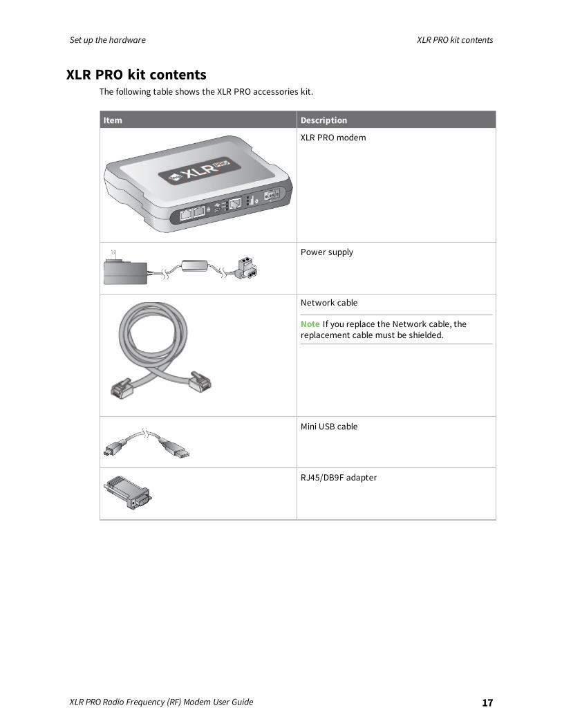
XLR PRO kit contentsThe following table shows the XLR PRO accessories kit.
Item Description
XLR PRO modem
Power supply
Network cable
Note If you replace the Network cable, thereplacement cable must be shielded.
Mini USB cable
RJ45/DB9F adapter
Set up the hardware Connect the hardware
XLR PRO Radio Frequency (RF) Modem User Guide 18
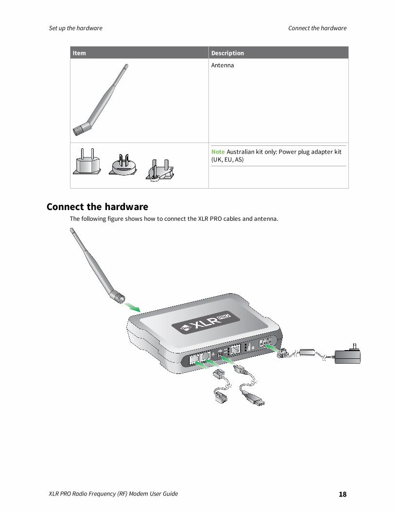
Item Description
Antenna
Note Australian kit only: Power plug adapter kit(UK, EU, AS)
Connect the hardwareThe following figure shows how to connect the XLR PRO cables and antenna.
Set up the hardware Mount the XLR PRO
XLR PRO Radio Frequency (RF) Modem User Guide 19
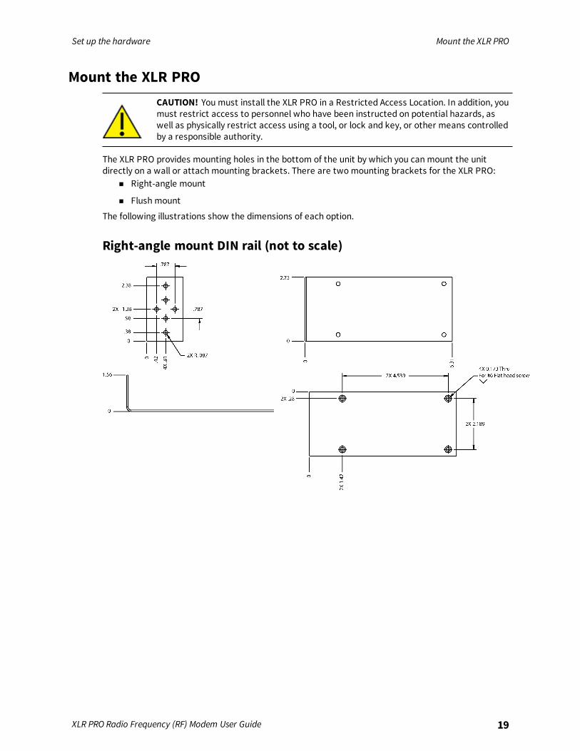
Mount the XLR PROCAUTION! You must install the XLR PRO in a Restricted Access Location. In addition, youmust restrict access to personnel who have been instructed on potential hazards, aswell as physically restrict access using a tool, or lock and key, or other means controlledby a responsible authority.
The XLR PRO provides mounting holes in the bottom of the unit by which you can mount the unitdirectly on a wall or attach mounting brackets. There are two mounting brackets for the XLR PRO:
n Right-angle mount
n Flush mount
The following illustrations show the dimensions of each option.
Right-angle mount DIN rail (not to scale)
Set up the hardware Mounting guidelines
XLR PRO Radio Frequency (RF) Modem User Guide 20
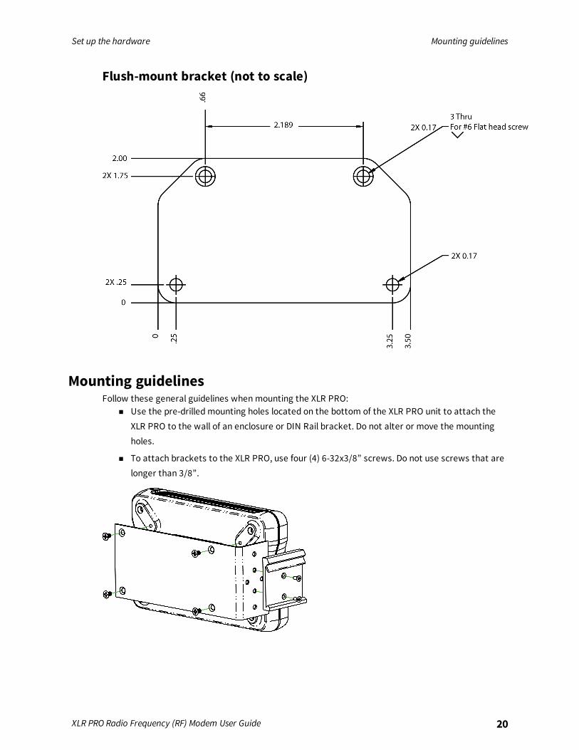
Flush-mount bracket (not to scale)
Mounting guidelinesFollow these general guidelines when mounting the XLR PRO:
n Use the pre-drilled mounting holes located on the bottom of the XLR PRO unit to attach theXLR PRO to the wall of an enclosure or DIN Rail bracket. Do not alter or move the mountingholes.
n To attach brackets to the XLR PRO, use four (4) 6-32x3/8” screws. Do not use screws that arelonger than 3/8”.

Set up the hardware Antenna placement
XLR PRO Radio Frequency (RF) Modem User Guide 21
Antenna placementn Mount the XLR PRO antenna vertically—that is, pointed directly up or down.
n If the XLR PRO is mounted within a metal enclosure, use an antenna external to the enclosureconnected to the XLR PRO using a a 50 Ω coaxial cable, suitable for 900 MHz UHF radiotransmission.
Technical specifications
The following tables provide the device's technical specifications.
General specifications 23RF characteristics 23Rural range line-of-sight 23Receiver sensitivity 24UART interface data rates (software selectable) 24Networking and security specifications 24Power requirements 25Power supply 25Environmental 25Regulatory conformity summary 25Connectors 26
XLR PRO Radio Frequency (RF) Modem User Guide 22

Technical specifications General specifications
XLR PRO Radio Frequency (RF) Modem User Guide 23
General specificationsThe following table describes the general specifications for the devices.
Specification Value
Dimensions 18 x 13 x 3.8 cm (7.1 x 5 x 1.5 inches)
Weight 0.68kg (1.5 lbs)
Ethernet protocols UDP/TCP, DHCP client
Ethernet physical layer 10/100BASET-T/TX
RoHS Compliant
RF characteristicsThe following table provides the RF characteristics for the device.
Specification Value
Frequency range: USA, Canadaand Mexico
ISM 902 to 928 MHz
Frequency range: Australia andBrazil
ISM 915 to 928 MHz
RF data rate 9.4 kb/s to 3.2 Mb/s
Receiver selectivity at 141 kb/sRF data rate
70 dB (below 908 MHz, above 922 MHz)40 dB (908 MHz to 922 MHz)
Maximum transmit power(software selectable)
+30 dBm (1 W)
Modulation Chirp Spread Spectrum
RF power level saturation Receiver input begins to saturate at 0 dBm.Input damage level is 4 dBm.We recommend placing the modems at least 2 meters apart fromeach other when transmitting.
Rural range line-of-sightNote Range figure estimates are based on free-air terrain with limited sources of interference. Actualrange will vary based on transmitting power, orientation of transmitter and receiver, height oftransmitting antenna, height of receiving antenna, weather conditions, interference sources in thearea, and terrain between receiver and transmitter, including indoor and outdoor structures such aswalls, trees, buildings, hills, and mountains.

Technical specifications Receiver sensitivity
XLR PRO Radio Frequency (RF) Modem User Guide 24
Speed Range
1.2 Mb/s up to 100+ miles1
Receiver sensitivityThe following table lists the available data rates along with the corresponding receiver sensitivity.
RF data rate setting (BR command) Data rate Receiver sensitivity (dBm, 25 °C)
0 9.4 kb/s -120
1 28 kb/s -118
2 66 kb/s -116
3 141 kb/s -112
4 291 kb/s -109
5 591 kb/s -106
6 1.2 Mb/s -103
7 2.4 Mb/s -100
8 3.2 Mb/s -98
UART interface data rates (software selectable)
UART interface Data rate
TCP/UDP socket 460.8 kb/s
Serial RS-485 921.6 kb/s
Serial RS-232 460.8 kb/s
UART Up to 921.6 kb/s
Networking and security specificationsThe following table describes the networking and security specifications for the devices.
Item Specification
Supported network topologies Point-to-point/point-to-multipoint
Encryption 128-bit AES
1Based on 100-mile range results. Other data rates scale based on sensitivity levels. Results will vary based onnoise levels and line of sight quality.
Technical specifications Power requirements
XLR PRO Radio Frequency (RF) Modem User Guide 25
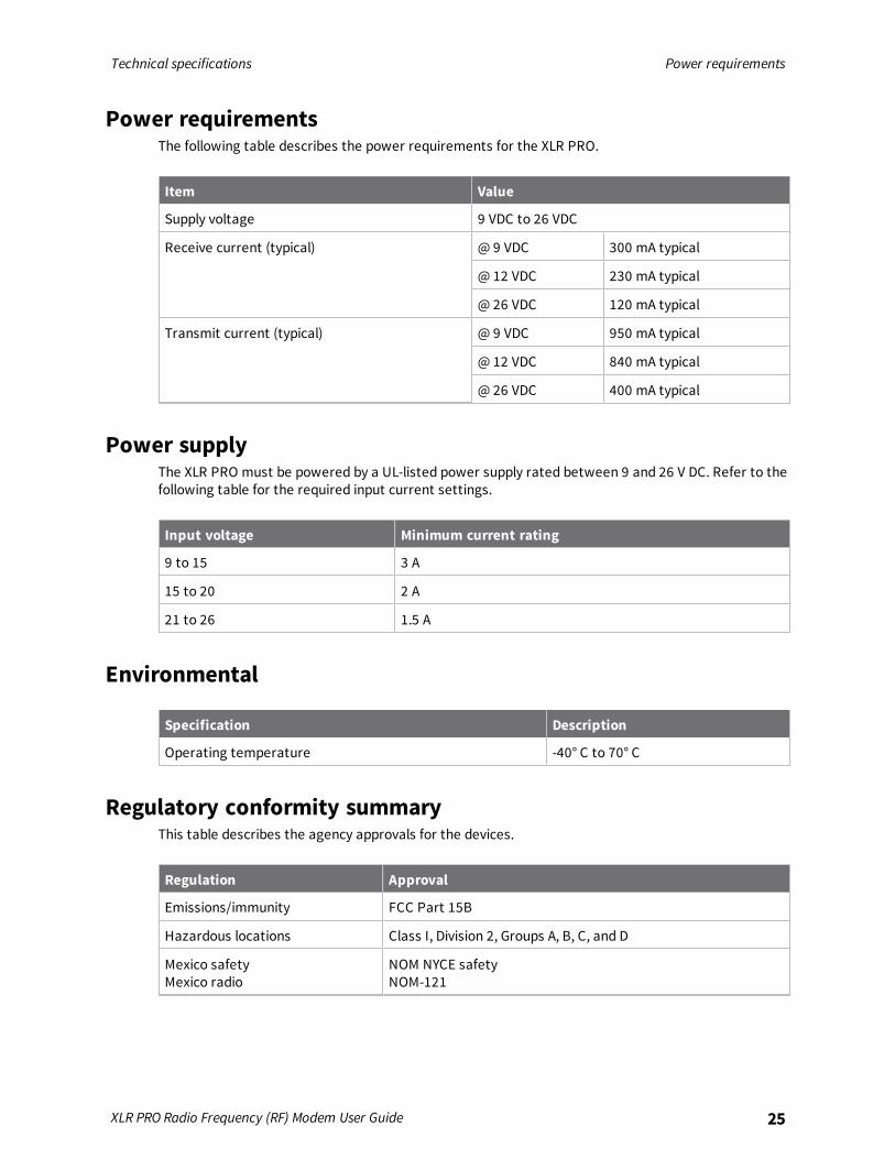
Power requirementsThe following table describes the power requirements for the XLR PRO.
Item Value
Supply voltage 9 VDC to 26 VDC
Receive current (typical) @ 9 VDC 300 mA typical
@ 12 VDC 230 mA typical
@ 26 VDC 120 mA typical
Transmit current (typical) @ 9 VDC 950 mA typical
@ 12 VDC 840 mA typical
@ 26 VDC 400 mA typical
Power supplyThe XLR PRO must be powered by a UL-listed power supply rated between 9 and 26 V DC. Refer to thefollowing table for the required input current settings.
Input voltage Minimum current rating
9 to 15 3 A
15 to 20 2 A
21 to 26 1.5 A
Environmental
Specification Description
Operating temperature -40° C to 70° C
Regulatory conformity summaryThis table describes the agency approvals for the devices.
Regulation Approval
Emissions/immunity FCC Part 15B
Hazardous locations Class I, Division 2, Groups A, B, C, and D
Mexico safetyMexico radio
NOM NYCE safetyNOM-121
Technical specifications Connectors
XLR PRO Radio Frequency (RF) Modem User Guide 26
Regulation Approval
Australia RCM
Brazil ANATEL: 0621-16-1209
Peru Yes
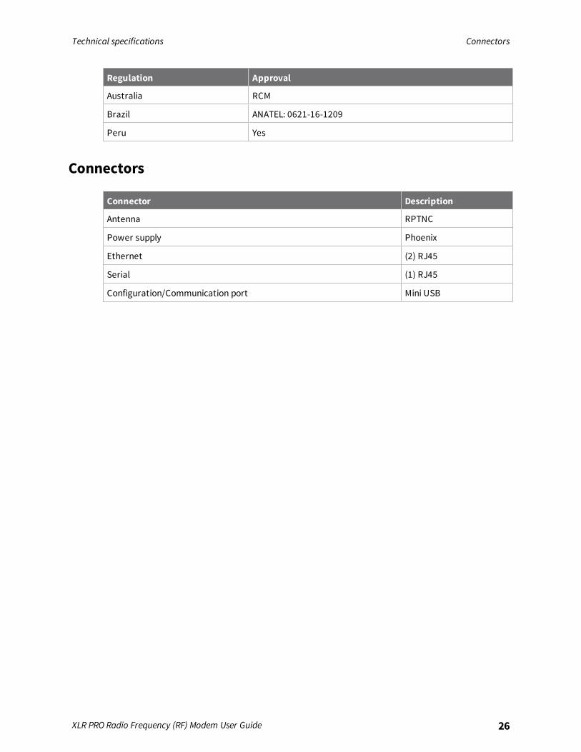
Connectors
Connector Description
Antenna RPTNC
Power supply Phoenix
Ethernet (2) RJ45
Serial (1) RJ45
Configuration/Communication port Mini USB
Operations
XLR PRO operational design 28Ethernet RF bridging 28Serial mode selection 29USB mode 30Serial mode 30IP socket mode 31Serial communications 32
XLR PRO Radio Frequency (RF) Modem User Guide 27
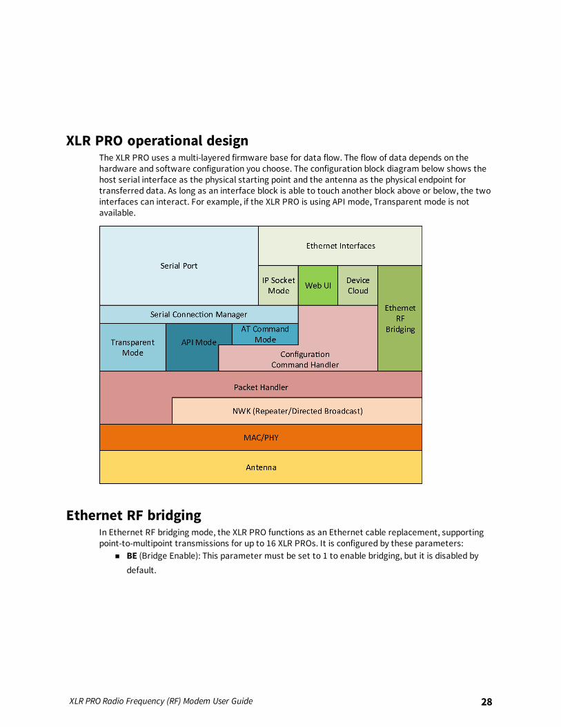
XLR PRO operational designThe XLR PRO uses a multi-layered firmware base for data flow. The flow of data depends on thehardware and software configuration you choose. The configuration block diagram below shows thehost serial interface as the physical starting point and the antenna as the physical endpoint fortransferred data. As long as an interface block is able to touch another block above or below, the twointerfaces can interact. For example, if the XLR PRO is using API mode, Transparent mode is notavailable.
Ethernet RF bridgingIn Ethernet RF bridging mode, the XLR PRO functions as an Ethernet cable replacement, supportingpoint-to-multipoint transmissions for up to 16 XLR PROs. It is configured by these parameters:
n BE (Bridge Enable): This parameter must be set to 1 to enable bridging, but it is disabled bydefault.
XLR PRO Radio Frequency (RF) Modem User Guide 28
Operations Serial mode selection
XLR PRO Radio Frequency (RF) Modem User Guide 29
n BA (Destination RF MAC address for Ethernet bridging): Default value is 0xFFFF which is thebroadcast address. If pairing XLR PRO devices is desired, then this should be set to the RF MACaddress of the opposing XLR PRO. This can be identified by querying the SH (serial numberhigh) and SL (serial number low) parameters on the opposite XLR PRO (example:BA=0x0013A20012345678).
With bridging enabled, the XLR PRO radios on the RF network should be treated as if they were asingle Ethernet cable. Consult a qualified network administrator to evaluate the radio deployment ifmultiple XLR PRO radios will be used on the same LAN or if bridging multiple large networks together.
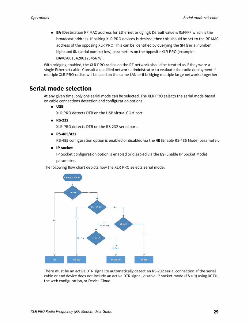
Serial mode selectionAt any given time, only one serial mode can be selected. The XLR PRO selects the serial mode basedon cable connections detection and configuration options.
n USBXLR PRO detects DTR on the USB virtual COM port.
n RS-232XLR PRO detects DTR on the RS-232 serial port.
n RS-485/422RS-485 configuration option is enabled or disabled via the 4E (Enable RS-485 Mode) parameter.
n IP socketIP Socket configuration option is enabled or disabled via the ES (Enable IP Socket Mode)parameter.
The following flow chart depicts how the XLR PRO selects serial mode:
There must be an active DTR signal to automatically detect an RS-232 serial connection. If the serialcable or end device does not include an active DTR signal, disable IP socket mode (ES = 0) using XCTU,the web configuration, or Device Cloud.

Operations USB mode
XLR PRO Radio Frequency (RF) Modem User Guide 30
By default, RS-485 mode is disabled (4E = 0) and IP socket mode is enabled (ES = 1). So, by default, RS-232 mode is selected if DTR is present. Otherwise, IP socket mode is selected. Use the 4E and ESconfiguration parameters to select other modes, independent of DTR, which may not be present on aserial port connection.
USB modeThe mini USB port is used for configuration and basic serial communication. To use the mini USB port,install the XLR PRO USB driver (Windows only) on the host PC. (The driver is available atwww.digi.com/support/productdetail?pid=5603&type=drivers.) When connected via the mini USB port,the XLR PRO appears as a virtual COM port on the host. The XLR PRO detects an active virtual DTRsignal to determine if a USB connection is active.When communicating to the XLR PRO using the USB mode, serial settings and flow control are notused. Serial settings (baud rate, parity, and stop bits) can be set to any value on the host PC and donot affect the XLR PRO connection. If a host application requires flow control, use RS-232 serial mode.
Serial modeWhen serial mode is the primary interface, the Serial Data In (green) LED lights for about threeseconds. Serial mode can be either RS-232 or RS-485/422, depending on serial mode selection. Thefollowing parameters must be configured to match the host device, regardless of whether RS-232 orRS-485 is selected:
n BD: Baud rate (See the AT command table for limits)
n NB: Parity (None, Even, or Odd)
n SB: Stop bits (1 or 2)
RS-232RS-232 connections support hardware flow control using CTS and RTS and require matchingparameters on the XLR PRO and the host device. This includes the following:
n D6: RTS flow control. If enabled, then the XLR PRO will not output data unless RTS is asserted.The host device should not de-assert RTS for long periods of time to avoid filling the serialtransmit buffer. If an RF data packet is received, and the serial transmit buffer does not haveenough space for all of the data bytes, the entire RF data packet will be discarded.
n D7: CTS flow control. If enabled, then the XLR PRO will not assert CTS low unless it can handlemore data from the host.
n FT: Flow control threshold. If CTS flow control is enabled (with the D7 parameter), the XLR PROde-asserts CTS when the serial receive buffer reaches the threshold defined by the FTparameter. Once CTS is de-asserted, it will not be asserted again until the receive buffer has17 bytes less than the threshold defined by FT. By default, FT is 65 bytes less than themaximum space available for receive data.
RS-485/422An RS-485 connection requires that 4E=1 and it also requires matching parameters on the XLR PROand the host device. This includes the following:
Operations IP socket mode
XLR PRO Radio Frequency (RF) Modem User Guide 31
n 4E: Enable RS-485/422. If 4E is set to 0, then the XLR PRO will use RS-232. This parameterneeds to be set to 1 in order to use RS-485/422 on the serial port.
n 4D: Full duplex (4-wire) or half duplex (2-wire) operation. A default value of 0 selects half duplexoperation and 1 selects full duplex.
n 4T: RS-485/422 termination. Enable or disable line termination on the RS-485/422 interface.The default value of 0 indicates that there is no line termination on the XLR PRO. If 4T is set to1, then a 120 W termination resistor will be present on the RS-485/422 connection. Thisparameter will have no effect on the XLR PRO if it is configured for RS-232.
IP socket modeIP socket mode provides serial communication for a single TCP or UDP port on the XLR PRO (multiplesimultaneous connections are not supported). This would normally happen over the Ethernetconnection, but it may also occur over the bridge if Ethernet RF bridging is enabled and another XLRPRO (which also has Ethernet RF bridging enabled) provides the Ethernet connection to an IP host.With the factory default settings, the XLR PRO listens on port 9750 for incoming TCP traffic. A telnetsession can be initiated to the XLR PRO IP address as a simple IP socket connection.The same operations that can occur in serial mode can also occur in IP socket mode. Those operationsare based on the payload of the IP frames. In other words, serial data coming to and from the XLRPRO is equivalent to the payload of the IP socket mode data.
Controlling parametersIP socket mode is configured by these parameters:
n IB: IP socket mode baud rate. This is set to the maximum rate of 460800 b/s by default, but itmay be set to a lower rate for throttling, if desired.
n IP: IP protocol. Default value of 1 selects TCP and 0 selects UDP. This parameter must matchthe protocol used by the IP host.
n C0: TCP or UDP port on which the XLR PRO listens. The IP host must send data to this port forthe XLR PRO to accept the incoming data. If configuring the XLR PRO using XCTU, the portnumber is displayed in hexadecimal.
n DY: Destination IP port. (See DX.)
n DX: Destination IP address. Tells the XLR PRO where to send data if it initiates theconversation. If operating in TCP mode and a TCP connection does not currently exist, then theXLR PRO attempts to make a connection to this IP address (and the IP port given by DY) tosend the data to the selected IP host and port. However, if a TCP connection already exists,then the data is sent to that connection, ignoring the DX and DY parameters. If operating inUDP mode, this rule changes slightly because it is a connectionless protocol. If the first IPsocket mode data comes from the XLR PRO, then DX/DY is used. If not, then all UDP data issent to the IP address and port from which the original data arrived.
Operations Serial communications
XLR PRO Radio Frequency (RF) Modem User Guide 32
n TM: TCP client connection timeout. A client connection is one which was initiated by the XLRPRO. This parameter tells how many seconds a TCP client connection remains connected whenno data is being sent or received on the connection.
n TS: TCP server connection timeout. A server connection is one which was initiated by anexternal IP host. This parameter tells how many seconds a TCP server connection remainsconnected when no data is being sent or received on the connection.
In addition to the above IP socket mode parameters, the MY parameter is also used in IP socketmode:
n MY: IP address of the XLR PRO. By default, this address is learned from a DHCP server, but itmay be set to any value if static mode is used (MA=1).
Operational descriptionIP socket mode may start up in the following cases:
n Reset: Based on the mode selection rules previously described.
n Configuration parameters: Parameters that affect the mode are changed and applied.
n Unplugged cable: An RS-232 cable is unplugged.
When IP socket mode is the primary interface, the Serial Data Out (yellow) LED lights for about threeseconds.Upon starting or restarting the XLR PRO, either a TCP or a UDP listener is set up depending on the IPparameter. If UDP data is received or if a TCP connection gets established before the XLR PROattempts to send data, then the DX and DY parameters are unused. In this case, the XLR PRO takesthe role of a TCP or UDP server. But if the XLR PRO has data to send before an IP host sends data tothe XLR PRO, then DX and DY determine the destination of that data until the TCP connection timesout or until IP socket mode is restarted, whichever comes first.
Serial communicationsWhether the XLR PRO is configured for USB, RS-232, RS-485/422, or IP socket mode, the XLR PROhandles the traffic as serial data, and the XLR PRO handles all serial traffic the same, regardless of theinterface in use.
Serial buffersn Serial receive buffer
When serial data enters the XLR PRO, the data is stored in the serial receive buffer until it canbe processed. Under certain conditions, the XLR PRO may not be able to process data in theserial receive buffer immediately. If large amounts of serial data are sent to the XLR PRO suchthat the serial receive buffer would overflow, then new data is discarded. If using RS-232, thiscan be avoided by using hardware flow control. Software flow control can be used regardless ofwhich serial interface is used.
n Serial transmit bufferWhen serial RF data is received, the data is moved into the serial transmit buffer and sent outof the active serial interface of the XLR PRO. If the serial transmit buffer becomes full andsystem buffers are also full, then the entire RF data packet is dropped. Whenever data isreceived faster than it can be processed and transmitted out the serial port, there is apotential of dropping data.
Networking methods
MAC/PHY layers 34Ethernet bridging 34Serial addressing basics 36
XLR PRO Radio Frequency (RF) Modem User Guide 33
Networking methods MAC/PHY layers
XLR PRO Radio Frequency (RF) Modem User Guide 34
MAC/PHY layersPHY stands for “physical layer.” The PHY layer manages the hardware that modulates anddemodulates the RF bits.MAC stands for “media access control.” The MAC layer sends and receives RF frames. Each packetincludes a MAC layer data header that contains addressing information, as well as packet options. Thislayer implements packet acknowledgments (ACKs), packet tracking to eliminate duplicates, and soon.When a radio is transmitting, it cannot receive packets. There are no beacons or master/slaverequirements in the design of the MAC/PHY.The following table shows the AT commands related to the MAC/PHY layers.
ATcommand Description
ID The ID (network identifier) command sets the network identifier. For XLR PRO radios tocommunicate, you must configure them with the same network identifier.
PL The PL (power level) command sets the transmit (TX) power level. You can reduce thepower level from the maximum to reduce current power consumption or to test atshort distances. This comes at the expense of reduced radio range.
RR The RR (unicast retries) command specifies the number of times a sending radioattempts to get an ACK from a destination radio when sending a unicast packet.
MT The MT (broadcast multi-transmit) command specifies the number of times a broadcastpacket is repeatedly transmitted. This adds redundancy to improve reliability.
Ethernet bridgingThe purpose of Ethernet RF bridging is to act as an Ethernet cable replacement. The MAC/PHY layer ofthe Ethernet standard handles all Ethernet traffic. As a result, the XLR PRO does not have to have avalid IP address on the network for bridging to work.
Ethernet packet handlingIf the XLR PRO receives an Ethernet packet with a MAC address that does not match its own MACaddress, and if you enable Ethernet bridging, then the entire Ethernet packet is encapsulated inside ofa radio frame and sent over the air (OTA) to another XLR PRO.The XLR PRO does not support fragmentation, so the unit sends the entire Ethernet packet in one OTAframe. This can cause an issue at lower data rates. If BR (RF data rate) is less than 3 (141 kb/s), thenfull size Ethernet frames cannot be transmitted. However, smaller frames can be transmitted atlower data rates. We do not recommend this for typical Ethernet applications, but you could use it insome scenarios.
n BR = 0 or 1: 195 bytes maximum frame size
n BR = 2: 451 bytes maximum frame size
When the XLR PRO receives an RF bridging packet, it inspects the Ethernet MAC address of thepacket. If the address matches the Ethernet MAC address of the XLR PRO, then the XLR PRO handlesthe packet on board. Otherwise, it forwards the frame over the Ethernet interface.The MT (broadcast multi-transmit) and RR (unicast retries) parameters do not apply to Ethernetbridging packets, but they do apply for all non-bridging traffic (serial or IP socket mode). Serial data
Networking methods Ethernet bridging
XLR PRO Radio Frequency (RF) Modem User Guide 35
from serial or IP socket mode operates concurrently with Ethernet bridging. If the XLR PRO sendsserial and Ethernet traffic at the same time, the traffic encounters latency.
Bridging precautionsThe practical application of an Ethernet bridge is to span two Ethernet networks that are nototherwise connected. If they are connected by another path, then a bridge loop allows multiple pathsto the same node. When multiple paths to the same node occur, then a broadcast storm can result ina saturated network, resulting in denial of service for legitimate traffic. Typically, this is alleviated by anetwork switch that support the Spanning Tree Protocol (STP) to detect and prevent such a networkloop. The XLR PRO does not implement STP.As a precaution, when using bridging, only connect one of the XLR PRO devices to the same Ethernetnetwork to avoid bridging loops. If you create multiple paths and you connect enterprise levelswitches with STP to the XLR PRO devices, then the connected switch ports are shutdown.When bridging two networks, if each has its own DHCP server, it can create many problems.
Enable bridgingTo enable bridging, set BE (Ethernet RF Bridging Enable) to 1. This parameter is disabled by defaultdue to the risk of encountering a bridging loop during initial configuration.
64-bit addressesEach radio has a unique factory-assigned IEEE 64-bit address. You can read the factory-assignedaddress with the SH (serial number high) and SL (serial number low) commands. Addresses use thefollowing form:
0x0013A2XXXXXXXXXX
The first six digits are the Digi Organizationally Unique Identifier (OUI). The broadcast address is0x000000000000FFFF.
UnicastTo transmit to a specific device:
n For Ethernet RF bridging, set BA (bridge destination MAC) to the SH:SL of the destination radio.BA is the entire 64-bit address and is not broken into two 32-bit values. For example:
BA=0x0013A20012345678
n If you have configured Ethernet bridging for unicasts, up to three retries occur while waiting foran ACK. As a result, unicasts are slower, but more reliable than broadcasts.
BroadcastTo transmit to all devices:
n When using Transparent mode, set DH to all 0's and DL to 0xFFFF.
n For API mode set 0x000000000000FFFF in the 64-bit destination address field of the API frame.
By default, Ethernet bridging uses broadcasts and no retransmissions occur. If you send packets viaTCP, then the TCP protocol provides the retransmissions as needed to provide for reliability. UDPpackets may be lost when BA is set to a broadcast address.
Networking methods Serial addressing basics
XLR PRO Radio Frequency (RF) Modem User Guide 36
Serial addressing basics
64-bit addressesEach radio has a unique factory-assigned IEEE 64-bit address. You can read the factory-assignedaddress with the SH (serial number high) and SL (serial number low) commands. Addresses use thefollowing form:
0x0013A2XXXXXXXXXX
The first six digits are the Digi Organizationally Unique Identifier (OUI). The broadcast address is0x000000000000FFFF.
UnicastTo transmit to a specific device:
n When using Transparent mode, set DH and DL (destination address high and destinationaddress low) to match the SH and SL (serial number high and serial number low) of thedestination device.
n For API mode, set SH and SL address in the 64-bit destination address field of the API frame.
BroadcastTo transmit to all devices:
n When using Transparent mode, set DH to all 0's and DL to 0xFFFF.
n For API mode set 0x000000000000FFFF in the 64-bit destination address field of the API frame.
By default, Ethernet bridging uses broadcasts and no retransmissions occur. If you send packets viaTCP, then the TCP protocol provides the retransmissions as needed to provide for reliability. UDPpackets may be lost when BA is set to a broadcast address.
Delivery methodsThe TO (Transmit Options) command sets the default delivery method that the device uses when inTransparent mode. In API mode, the TxOptions field of the API frame overrides the TO command, ifnon-zero.The XLR PRO supports two delivery methods:
n Point-to-multipoint (0x40)
n Repeater (directed broadcast) (0x80)
Point to Point / Point to Multipoint (P2MP)This delivery method does not use a network header, only the MAC header.In P2MP, the sending devices always send all messages directly to the destination. Other nodes do notrepeat the packet. The sending device only delivers a P2MP unicast directly to the destination device,which must be in range of the sending device.The XLR PRO uses patented technology that allows the destination device to receive unicasttransmissions directed to it, even when there is a large amount of traffic. This works best if you keepbroadcast transmissions to a minimum.
Networking methods Serial addressing basics
XLR PRO Radio Frequency (RF) Modem User Guide 37
A sending node repeats a P2MP broadcast transmission MT+1 times, but the receiving nodes do notrepeat it, so like a unicast transmission, the receiving device must be in range.All devices that receive a P2MP broadcast transmission will output the data through the active serialinterface.
Repeater/directed broadcastEthernet RF bridging does not support repeater/directed broadcast. All Ethernet frames aretransmitted as point-to-point or point-to-multipoint regardless of what the TO (transmit option)parameter.All of the routers in a network receive and repeat directed broadcast transmissions. Because it doesnot use ACKs, the originating node sends the broadcast multiple times. By default a broadcasttransmission is sent four times—the extra transmissions become automatic retries withoutacknowledgments. This results in all nodes repeating the transmission four times. Sending frequentbroadcast transmissions can quickly reduce the available network bandwidth, so use broadcasttransmissions sparingly.
MAC layerThe MAC layer is the building block that is used to build repeater capability. To implement Repeatermode, we use a network layer header that comes after the MAC layer header in each packet. In thisnetwork layer there is additional packet tracking to eliminate duplicate broadcasts.In this delivery method, unicasts and broadcast packets are both sent out as broadcasts that arealways repeated. All repeated packets are sent to every radio. Broadcast data is sent out the activeserial interface of all radios that receive it.When a unicast is sent, it specifies a destination address in the network header. Only the radio thathas the matching destination address sends it out the serial port. This is called a directed broadcast.Any node that has a CE (node messaging option) set to route will rebroadcast the packet if its BH(broadcast hops) or broadcast radius values have not been depleted. If a repeated broadcast hasalready been seen, the node will ignore it. The NH (network hops) parameter sets the maximumnumber of hops that a broadcast will be repeated. This value is always used, unless a smaller BH valueis specified.By default, the CE (node messaging option) parameter is set to not route broadcasts. Due to the long-range of the XLR PRO, Digi advises you to evaluate on a per-radio basis which nodes should beconfigured as repeaters. Limiting the amount of congestion and generated RF traffic provides a morereliable network.
Transmission timeoutsWhen a node receives an API Tx Request while in API mode or an RO command while in Transparentmode, the time required to route the data to its destination depends on a number of configuredparameters and whether the transmission is a unicast or a broadcast.
Note The timeouts in this section are theoretical timeouts. An application should pad the calculatedmaximum timeouts by a few hundred milliseconds. When using API mode, Tx Status API packetsshould be the primary method of determining if a transmission has completed.
Transmit a broadcastAll of the routers in a network must relay a broadcast transmission.The maximum delay occurs when the sender and receiver are on the opposite ends of the network.The NH and %H parameters define the maximum broadcast delay as follows:
BroadcastTxTime = NH * NN * %8

Networking methods Serial addressing basics
XLR PRO Radio Frequency (RF) Modem User Guide 38
Unless BH < NH, in which case the formula is:BroadcastTxTime = BH * NN * %8

AT commands
Special commands 40MAC/PHY commands 41Diagnostic commands 42Network commands 45Addressing commands 46Addressing discovery and configuration commands 50Security commands 52Serial interfacing commands 52Hardware diagnostics commands 56Ethernet and IP socket mode commands 57Remote Manager commands 61Web configuration commands 63Ethernet bridging commands 64Command mode options 65Firmware commands 66
XLR PRO Radio Frequency (RF) Modem User Guide 39
AT commands Special commands
XLR PRO Radio Frequency (RF) Modem User Guide 40
Special commandsThe following commands are special commands.
AC (Apply Changes)Immediately applies new settings without exiting Command mode.
Parameter rangeN/A
DefaultN/A
FR (Software Reset)Resets the device. The device responds immediately with an OK and performs a reset 100 ms later.If you issue FR while the device is in Command Mode, the reset effectively exits Command mode.
Parameter rangeN/A
DefaultN/A
RE commandRestore device parameters to factory defaults.In order for the default parameters to persist through subsequent resets, send a separate WRcommand after RE.
Parameter rangeN/A
DefaultN/A
WR commandWrites parameter values to non-volatile memory so that parameter modifications persist throughsubsequent resets.When you issue a WR command add a 100 millisecond delay or wait for an OK response before issuingany subsequent AT commands.
Note Once you issue a WR command, do not send any additional characters to the device until afteryou receive the OK response.
Parameter rangeN/A

AT commands MAC/PHY commands
XLR PRO Radio Frequency (RF) Modem User Guide 41
DefaultN/A
MAC/PHY commandsThe following AT commands are MAC/PHY commands.
ID (Network ID)Sets or displays the network identifier for the module. To communicate with other modules in anetwork, the modules must have matching network identifiers. If you are using OEM networkidentifiers, set ID to FFFF to use the factory value.
Parameter range0 - 0x7FFF
Default0x7FFF
BR (RF Data Rate)Sets or displays the rate at which RF data is transmitted for all operational modes. Devices within anetwork do not need to have matching data transmission rates. The BR setting does not control therate at which devices receive data.
RangeAn integer from 0 through 8:
Value Description
0 9.38 kb/s
1 28.14 kb/s
2 65.66 kb/s
3 140.7 kb/s
4 290.8 kb/s
5 590.9 kb/s
6 1.191 Mb/s
7 2.392 Mb/s
8 3.189 Mb/s
Default4
AT commands Diagnostic commands
XLR PRO Radio Frequency (RF) Modem User Guide 42
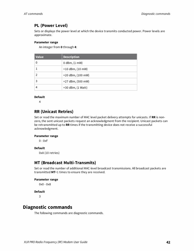
PL (Power Level)Sets or displays the power level at which the device transmits conducted power. Power levels areapproximate.
Parameter rangeAn integer from 0 through 4:
Value Description
0 0 dBm, (1 mW)
1 +10 dBm, (10 mW)
2 +20 dBm, (100 mW)
3 +27 dBm, (500 mW)
4 +30 dBm, (1 Watt)
Default4
RR (Unicast Retries)Set or read the maximum number of MAC level packet delivery attempts for unicasts. If RR is non-zero, the sent unicast packets request an acknowledgment from the recipient. Unicast packets canbe retransmitted up to RR times if the transmitting device does not receive a successfulacknowledgment.
Parameter range0 - 0xF
Default0xA (10 retries)
MT (Broadcast Multi-Transmits)Set or read the number of additional MAC-level broadcast transmissions. All broadcast packets aretransmitted MT+1 times to ensure they are received.
Parameter range0x0 - 0x8
Default3
Diagnostic commandsThe following commands are diagnostic commands.
AT commands Diagnostic commands
XLR PRO Radio Frequency (RF) Modem User Guide 43
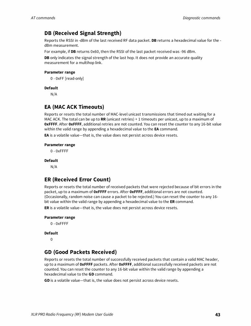
DB (Received Signal Strength)Reports the RSSI in -dBm of the last received RF data packet. DB returns a hexadecimal value for the -dBm measurement.For example, if DB returns 0x60, then the RSSI of the last packet received was -96 dBm.DB only indicates the signal strength of the last hop. It does not provide an accurate qualitymeasurement for a multihop link.
Parameter range0 - 0xFF [read-only]
DefaultN/A
EA (MAC ACK Timeouts)Reports or resets the total number of MAC-level unicast transmissions that timed out waiting for aMAC ACK. The total can be up to RR (unicast retries) + 1 timeouts per unicast, up to a maximum of0xFFFF. After 0xFFFF, additional retries are not counted. You can reset the counter to any 16-bit valuewithin the valid range by appending a hexadecimal value to the EA command.EA is a volatile value—that is, the value does not persist across device resets.
Parameter range0 - 0xFFFF
DefaultN/A
ER (Received Error Count)Reports or resets the total number of received packets that were rejected because of bit errors in thepacket, up to a maximum of 0xFFFF errors. After 0xFFFF, additional errors are not counted.(Occasionally, random noise can cause a packet to be rejected.) You can reset the counter to any 16-bit value within the valid range by appending a hexadecimal value to the ER command.ER is a volatile value—that is, the value does not persist across device resets.
Parameter range0 - 0xFFFF
Default0
GD (Good Packets Received)Reports or resets the total number of successfully received packets that contain a valid MAC header,up to a maximum of 0xFFFF packets. After 0xFFFF, additional successfully received packets are notcounted. You can reset the counter to any 16-bit value within the valid range by appending ahexadecimal value to the GD command.GD is a volatile value—that is, the value does not persist across device resets.

AT commands Diagnostic commands
XLR PRO Radio Frequency (RF) Modem User Guide 44
Parameter range0 - 0xFFFF
DefaultN/A (0 after reset)
TR (Transmission Failure Count)Reports or resets the total number of unicast transmissions for which all retries failed with no MACACK from the destination node, up to a maximum of 0xFFFF transmission failures. After 0xFFFF,failures are no longer counted. You can reset the counter to any 16-bit value within the valid range byappending a hexadecimal value to the TR command.TR is a volatile value—that is, the value does not persist across device resets.
Parameter range0 - 0xFFFF
DefaultN/A
UA (Unicasts Attempted)Reports or resets the total number of MAC unicast transmissions for which an ACK is requested, up toa maximum of 0xFFFF transmissions. After 0xFFFF, additional transmissions are not counted. You canreset the counter to any 16-bit value within the valid range by appending a hexadecimal value to theUA command.UA is a volatile value—that is, the value does not persist across device resets.
Parameter range0 - 0xFFFF
Default0
%H (MAC Unicast One Hop Time)The MAC unicast one hop time timeout in milliseconds. If you change the MAC parameters it canchange this value.
Parameter range[read-only]
Default0x267
%8 (MAC Broadcast One Hop Time)The MAC broadcast one hop time timeout in milliseconds. If you change MAC parameters, it canchange this value.
AT commands Network commands
XLR PRO Radio Frequency (RF) Modem User Guide 45
Parameter range[read-only]
Default0x23D
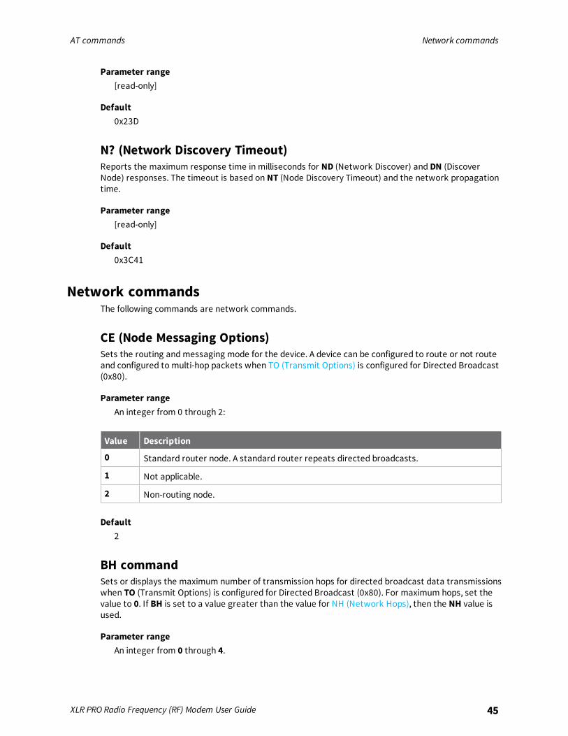
N? (Network Discovery Timeout)Reports the maximum response time in milliseconds for ND (Network Discover) and DN (DiscoverNode) responses. The timeout is based on NT (Node Discovery Timeout) and the network propagationtime.
Parameter range[read-only]
Default0x3C41
Network commandsThe following commands are network commands.
CE (Node Messaging Options)Sets the routing and messaging mode for the device. A device can be configured to route or not routeand configured to multi-hop packets when TO (Transmit Options) is configured for Directed Broadcast(0x80).
Parameter rangeAn integer from 0 through 2:
Value Description
0 Standard router node. A standard router repeats directed broadcasts.
1 Not applicable.
2 Non-routing node.
Default2
BH commandSets or displays the maximum number of transmission hops for directed broadcast data transmissionswhen TO (Transmit Options) is configured for Directed Broadcast (0x80). For maximum hops, set thevalue to 0. If BH is set to a value greater than the value for NH (Network Hops), then the NH value isused.
Parameter rangeAn integer from 0 through 4.

AT commands Addressing commands
XLR PRO Radio Frequency (RF) Modem User Guide 46
Default0
NH (Network Hops)Sets or displays the maximum number of hops expected for a Directed Broadcast network.
Parameter rangeAn integer from 0 through 4.
Default4
NN (Network Delay Slots)Sets or displays the maximum delay slots before rebroadcasting a Directed Broadcast packet.
Parameter rangeAn integer from 0 through 8.
Default3
Addressing commandsThe following AT commands are addressing commands.
SH commandDisplays the upper 32 bits of the unique IEEE 64-bit extended address assigned to the XLR PRO in thefactory.
Parameter range0 - 0xFFFFFFFF [read-only]
DefaultSet in the factory
SL commandDisplays the lower 32 bits of the unique IEEE 64-bit RF extended address assigned to the XLR PRO inthe factory.
Parameter range0 - 0xFFFFFFFF [read-only]
DefaultSet in the factory

AT commands Addressing commands
XLR PRO Radio Frequency (RF) Modem User Guide 47
DH commandDisplays the upper 32 bits of the unique IEEE 64-bit RF extended address for the destination module.DH and DL command together define the destination address used for transmission of transparentdata. For broadcast, use the destination address 0x000000000000FFFF.
Parameter range0 - 0xFFFFFFFF
Default0
DL commandDisplays the lower 32 bits of the unique IEEE 64-bit RF extended address for the destination device.DH and DL together define the destination address used for transmission of transparent data in eitherserial or IP socket modes.0x000000000000FFFF is the broadcast address.
Parameter range0 - 0xFFFFFFFF
Default0xFFFF
TO (Transmit Options)The bitfield that configures the transmit options for Transparent mode.Sets or displays transmit options for all serial transmissions. TO options can be overridden packet-by-packet using the TxOptions field of an API TxRequest frame.
Parameter rangeOne of the following hexadecimal values:
Value Description
0x40 Point-to-point/multipoint, ACK enabled
0x41 Point-to-point/mulitpoint, ACK disabled
0x80 Repeater/Directed broadcast, ACK enabled
0x81 Repeater/Directed broadcast, ACK disabled
When you set BR to 0 the TO option has the DigiMesh and Repeater mode disabled automatically.
Default0x40
AT commands Addressing commands
XLR PRO Radio Frequency (RF) Modem User Guide 48
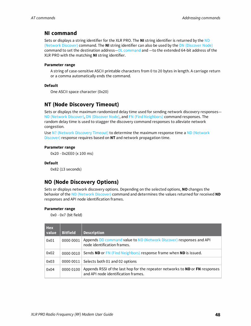
NI commandSets or displays a string identifier for the XLR PRO. The NI string identifier is returned by the ND(Network Discover) command. The NI string identifier can also be used by the DN (Discover Node)command to set the destination address—DL command and —to the extended 64-bit address of theXLR PRO with the matching NI string identifier.
Parameter rangeA string of case-sensitive ASCII printable characters from 0 to 20 bytes in length. A carriage returnor a comma automatically ends the command.
DefaultOne ASCII space character (0x20)
NT (Node Discovery Timeout)Sets or displays the maximum randomized delay time used for sending network discovery responses—ND (Network Discover), DN (Discover Node), and FN (Find Neighbors) command responses. Therandom delay time is used to stagger the discovery command responses to alleviate networkcongestion.Use N? (Network Discovery Timeout) to determine the maximum response time a ND (NetworkDiscover) response requires based on NT and network propagation time.
Parameter range0x20 - 0x2EE0 (x 100 ms)
Default0x82 (13 seconds)
NO (Node Discovery Options)Sets or displays network discovery options. Depending on the selected options, NO changes thebehavior of the ND (Network Discover) command and determines the values returned for received NDresponses and API node identification frames.
Parameter range0x0 - 0x7 (bit field)
Hexvalue Bitfield Description
0x01 0000 0001 Appends DD command value to ND (Network Discover) responses and APInode identification frames.
0x02 0000 0010 Sends ND or FN (Find Neighbors) response frame when ND is issued.
0x03 0000 0011 Selects both 01 and 02 options
0x04 0000 0100 Appends RSSI of the last hop for the repeater networks to ND or FN responsesand API node identification frames.

AT commands Addressing commands
XLR PRO Radio Frequency (RF) Modem User Guide 49
Hexvalue Bitfield Description
0x05 0000 0101 Selects both 01 and 04 options.
0x06 0000 0110 Both 02 and 04 options.
0x07 0000 0111 Select all options: 01, 02, and 04.
Default0x0
CI (Cluster ID)Sets or displays the default application layer cluster identifier used for all data transmissions.
Parameter range0 - 0xFFFF
Value Description
0x11 Transparent data
0x12 Loopback (the destination node echoes transmitted packets back to the originator)
0x14 Link test
0x23 Memory Access (GPM)
Default0x11
DE commandSets or displays the application layer destination ID value. The value is used as the destinationendpoint for all data transmissions. The default value (0xE8) is the Digi data endpoint.
Parameter range
Value Description
0xE6 Digi device endpoint
0xE8 Digi data endpoint
Default0xE8
SE commandSets or displays the application layer source endpoint value. The value is used as the source endpointfor all data transmissions. The default value (0xE8) is the Digi data endpoint.
AT commands Addressing discovery and configuration commands
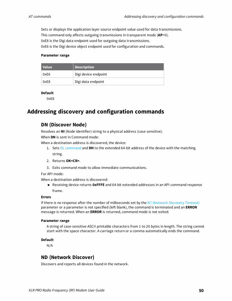
XLR PRO Radio Frequency (RF) Modem User Guide 50
Sets or displays the application layer source endpoint value used for data transmissions.This command only affects outgoing transmissions in transparent mode (AP=0).0xE8 is the Digi data endpoint used for outgoing data transmissions.0xE6 is the Digi device object endpoint used for configuration and commands.
Parameter range
Value Description
0xE6 Digi device endpoint
0xE8 Digi data endpoint
Default0xE8
Addressing discovery and configuration commands
DN (Discover Node)Resolves an NI (Node identifier) string to a physical address (case sensitive).When DN is sent in Command mode:When a destination address is discovered, the device:
1. Sets DL command and DH to the extended 64-bit address of the device with the matchingstring.
2. Returns OK<CR>.
3. Exits command mode to allow immediate communications.
For API mode:When a destination address is discovered:
n Receiving device returns 0xFFFE and 64-bit extended addresses in an API command responseframe.
ErrorsIf there is no response after the number of milliseconds set by the N? (Network Discovery Timeout)parameter or a parameter is not specified (left blank), the command is terminated and an ERRORmessage is returned. When an ERROR is returned, command mode is not exited.
Parameter rangeA string of case-sensitive ASCII printable characters from 1 to 20 bytes in length. The string cannotstart with the space character. A carriage return or a comma automatically ends the command.
DefaultN/A
ND (Network Discover)Discovers and reports all devices found in the network.
AT commands Addressing discovery and configuration commands
XLR PRO Radio Frequency (RF) Modem User Guide 51
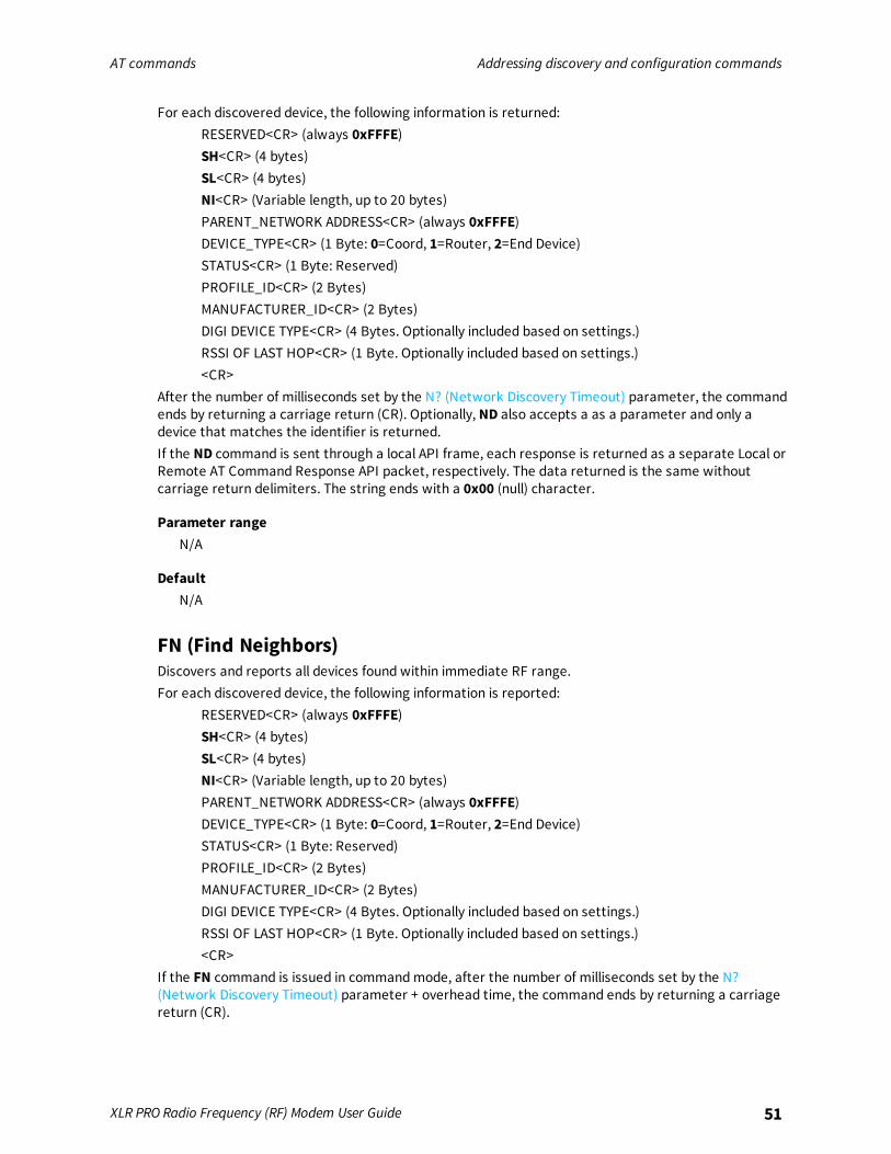
For each discovered device, the following information is returned:RESERVED<CR> (always 0xFFFE)SH<CR> (4 bytes)SL<CR> (4 bytes)NI<CR> (Variable length, up to 20 bytes)PARENT_NETWORK ADDRESS<CR> (always 0xFFFE)DEVICE_TYPE<CR> (1 Byte: 0=Coord, 1=Router, 2=End Device)STATUS<CR> (1 Byte: Reserved)PROFILE_ID<CR> (2 Bytes)MANUFACTURER_ID<CR> (2 Bytes)DIGI DEVICE TYPE<CR> (4 Bytes. Optionally included based on settings.)RSSI OF LAST HOP<CR> (1 Byte. Optionally included based on settings.)<CR>
After the number of milliseconds set by the N? (Network Discovery Timeout) parameter, the commandends by returning a carriage return (CR). Optionally, ND also accepts a as a parameter and only adevice that matches the identifier is returned.If the ND command is sent through a local API frame, each response is returned as a separate Local orRemote AT Command Response API packet, respectively. The data returned is the same withoutcarriage return delimiters. The string ends with a 0x00 (null) character.
Parameter rangeN/A
DefaultN/A
FN (Find Neighbors)Discovers and reports all devices found within immediate RF range.For each discovered device, the following information is reported:
RESERVED<CR> (always 0xFFFE)SH<CR> (4 bytes)SL<CR> (4 bytes)NI<CR> (Variable length, up to 20 bytes)PARENT_NETWORK ADDRESS<CR> (always 0xFFFE)DEVICE_TYPE<CR> (1 Byte: 0=Coord, 1=Router, 2=End Device)STATUS<CR> (1 Byte: Reserved)PROFILE_ID<CR> (2 Bytes)MANUFACTURER_ID<CR> (2 Bytes)DIGI DEVICE TYPE<CR> (4 Bytes. Optionally included based on settings.)RSSI OF LAST HOP<CR> (1 Byte. Optionally included based on settings.)<CR>
If the FN command is issued in command mode, after the number of milliseconds set by the N?(Network Discovery Timeout) parameter + overhead time, the command ends by returning a carriagereturn (CR).
AT commands Security commands
XLR PRO Radio Frequency (RF) Modem User Guide 52
If the FN command is sent through a local API frame, each response is returned as a separate Local orRemote AT Command Response API packet, respectively. The data returned is the same withoutcarriage return delimiters. The string ends with a 0x00 (null) character.
Parameter rangeN/A
DefaultN/A
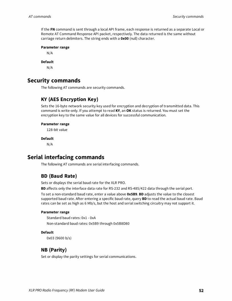
Security commandsThe following AT commands are security commands.
KY (AES Encryption Key)Sets the 16-byte network security key used for encryption and decryption of transmitted data. Thiscommand is write-only. If you attempt to read KY, an OK status is returned. You must set theencryption key to the same value for all devices for successful communication.
Parameter range128-bit value
DefaultN/A
Serial interfacing commandsThe following AT commands are serial interfacing commands.
BD (Baud Rate)Sets or displays the serial baud rate for the XLR PRO.BD affects only the interface data rate for RS-232 and RS-485/422 data through the serial port.To set a non-standard baud rate, enter a value above 0x5B9. BD adjusts the value to the closestsupported baud rate. After entering a specific baud rate, query BD to read the actual baud rate. Baudrates can be set as high as 6 Mb/s, but the host and serial switching circuitry may not support it.
Parameter rangeStandard baud rates: 0x1 - 0xANon-standard baud rates: 0x5B9 through 0x5B8D80
Default0x03 (9600 b/s)
NB (Parity)Set or display the parity settings for serial communications.
AT commands Serial interfacing commands
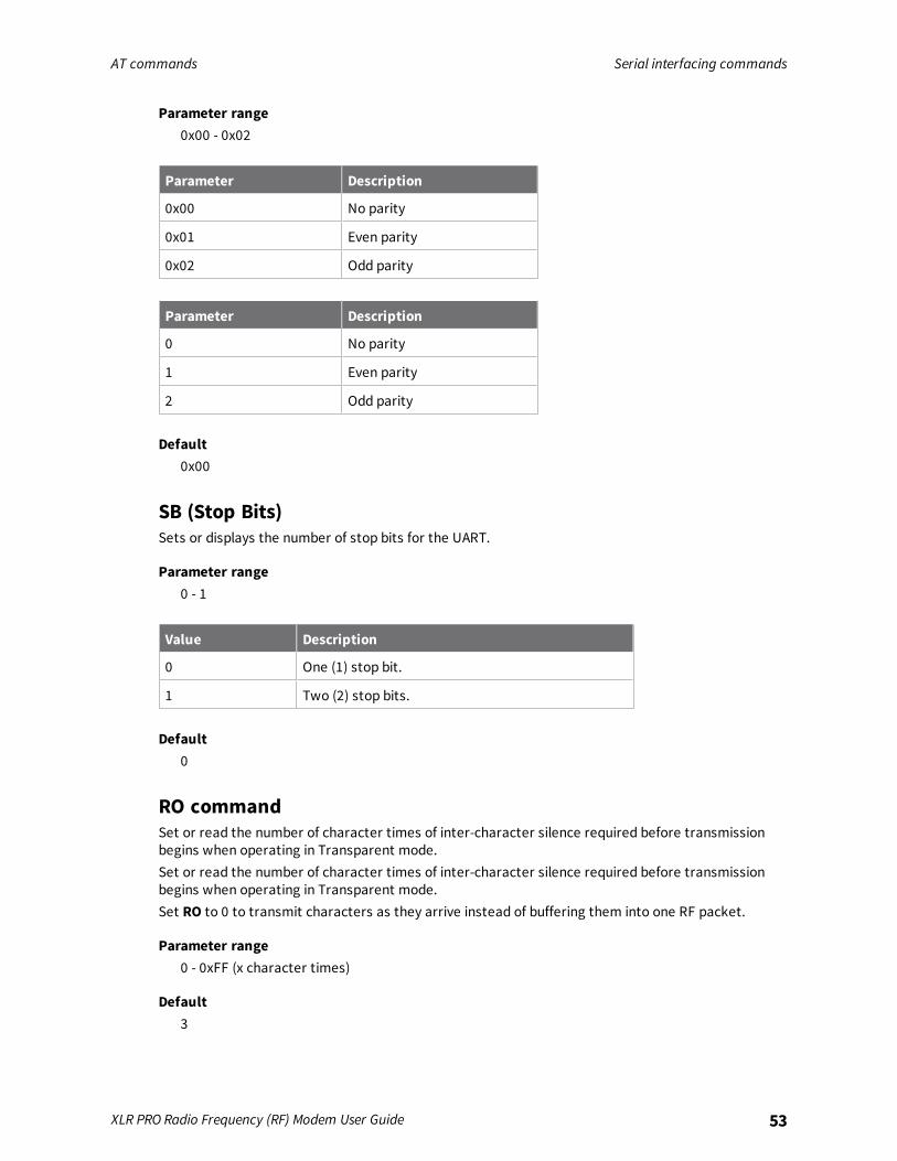
XLR PRO Radio Frequency (RF) Modem User Guide 53
Parameter range0x00 - 0x02
Parameter Description
0x00 No parity
0x01 Even parity
0x02 Odd parity
Parameter Description
0 No parity
1 Even parity
2 Odd parity
Default0x00
SB (Stop Bits)Sets or displays the number of stop bits for the UART.
Parameter range0 - 1
Value Description
0 One (1) stop bit.
1 Two (2) stop bits.
Default0
RO commandSet or read the number of character times of inter-character silence required before transmissionbegins when operating in Transparent mode.Set or read the number of character times of inter-character silence required before transmissionbegins when operating in Transparent mode.Set RO to 0 to transmit characters as they arrive instead of buffering them into one RF packet.
Parameter range0 - 0xFF (x character times)
Default3
AT commands Serial interfacing commands
XLR PRO Radio Frequency (RF) Modem User Guide 54
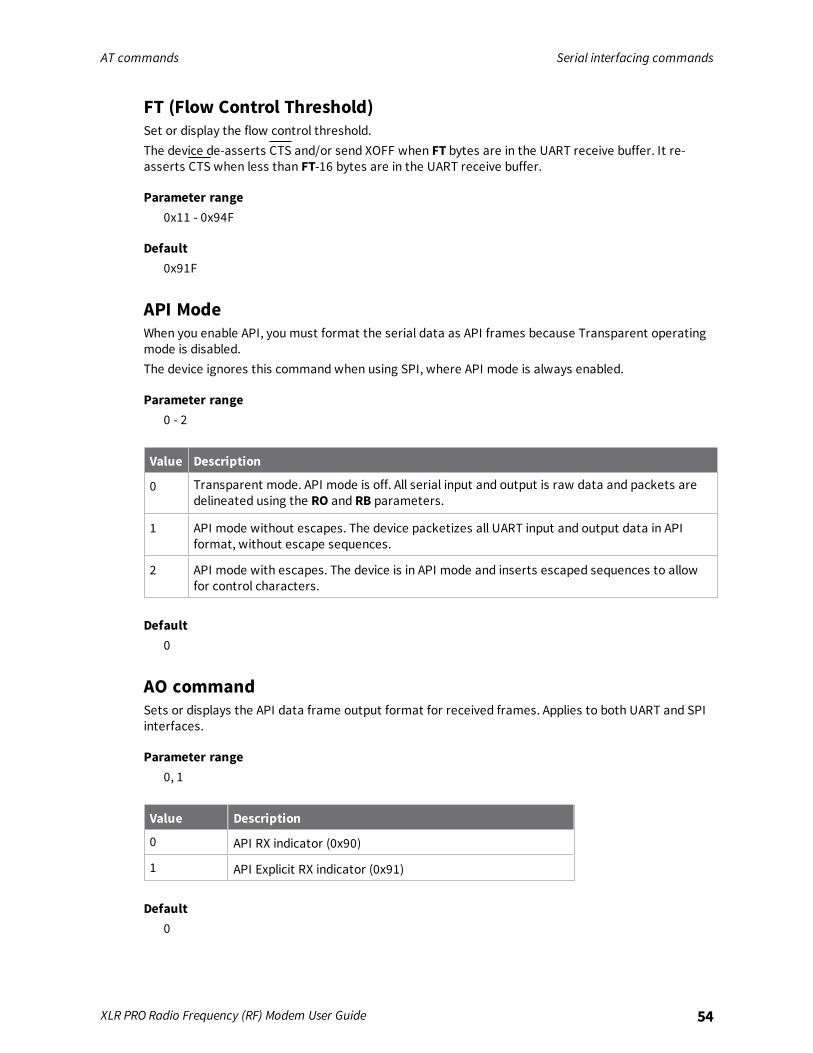
FT (Flow Control Threshold)Set or display the flow control threshold.The device de-asserts CTS and/or send XOFF when FT bytes are in the UART receive buffer. It re-asserts CTS when less than FT-16 bytes are in the UART receive buffer.
Parameter range0x11 - 0x94F
Default0x91F
API ModeWhen you enable API, you must format the serial data as API frames because Transparent operatingmode is disabled.The device ignores this command when using SPI, where API mode is always enabled.
Parameter range0 - 2
Value Description
0 Transparent mode. API mode is off. All serial input and output is raw data and packets aredelineated using the RO and RB parameters.
1 API mode without escapes. The device packetizes all UART input and output data in APIformat, without escape sequences.
2 API mode with escapes. The device is in API mode and inserts escaped sequences to allowfor control characters.
Default0
AO commandSets or displays the API data frame output format for received frames. Applies to both UART and SPIinterfaces.
Parameter range0, 1
Value Description
0 API RX indicator (0x90)
1 API Explicit RX indicator (0x91)
Default0
AT commands Serial interfacing commands
XLR PRO Radio Frequency (RF) Modem User Guide 55
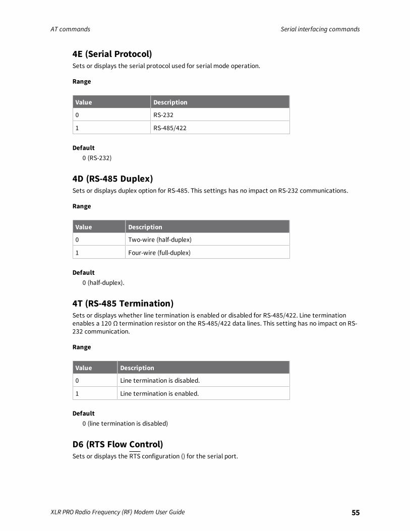
4E (Serial Protocol)Sets or displays the serial protocol used for serial mode operation.
Range
Value Description
0 RS-232
1 RS-485/422
Default0 (RS-232)
4D (RS-485 Duplex)Sets or displays duplex option for RS-485. This settings has no impact on RS-232 communications.
Range
Value Description
0 Two-wire (half-duplex)
1 Four-wire (full-duplex)
Default0 (half-duplex).
4T (RS-485 Termination)Sets or displays whether line termination is enabled or disabled for RS-485/422. Line terminationenables a 120 Ω termination resistor on the RS-485/422 data lines. This setting has no impact on RS-232 communication.
Range
Value Description
0 Line termination is disabled.
1 Line termination is enabled.
Default0 (line termination is disabled)
D6 (RTS Flow Control)Sets or displays the RTS configuration () for the serial port.

AT commands Hardware diagnostics commands
XLR PRO Radio Frequency (RF) Modem User Guide 56
Parameter range0 - 1
Value Description
0 RTS flow control is disabled
1 RTS flow control is enabled
Default0
D7 (CTS Flow Control)Sets or displays whether CTS flow control is enabled or disabled for the serial port.
Parameter range
Parameter Description
0 CTS flow control is disabled
1 CTS flow control is enabled
Default0x1
Hardware diagnostics commands
TP commandDisplays the temperature of the XLR PRO in degrees Celsius. The temperature value is displayed in 8-bit two’s compliment format. For example, 0x1A = 26 °C, and 0xF6 = -10 °C.Because the XLR PRO produces heat, this temperature reading is usually above the ambienttemperature.
Parameter range0 - 0xFF which indicates degrees Celsius displayed in 8-bit two's compliment format.
DefaultN/A
RP commandSets or displays the amount of time (in deciseconds) the RSSI LEDs are active after a valid RF packet isreceived. When RP is FF, output is always on.
AT commands Ethernet and IP socket mode commands
XLR PRO Radio Frequency (RF) Modem User Guide 57
Parameter range0 - 0xFF (x 100 ms)
Default0x28 (four seconds)
Ethernet and IP socket mode commands
ES (IP Socket Mode Enable)Sets or displays whether IP socket mode is enabled. Enabling socket mode allows serial traffic to besent to a TCP or UDP port based on the parameter. The XLR PRO remains in listen-only state unlessDX (Destination IP Address) is set to a valid IP address.
Range
Value Description
0 IP socket mode is disabled.
1 IP socket mode is enabled.
Default1 (IP socket mode is enabled)
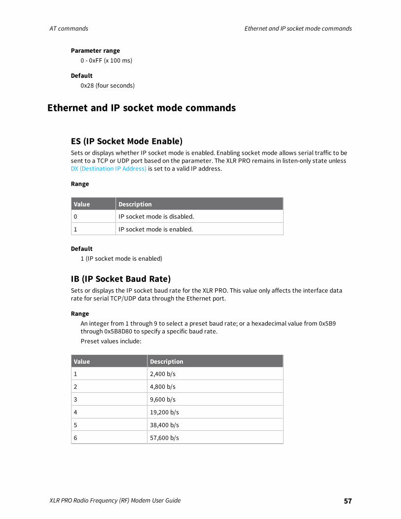
IB (IP Socket Baud Rate)Sets or displays the IP socket baud rate for the XLR PRO. This value only affects the interface datarate for serial TCP/UDP data through the Ethernet port.
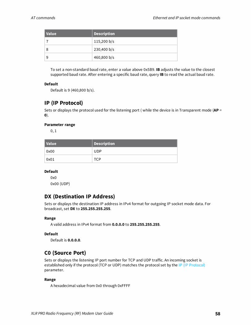
RangeAn integer from 1 through 9 to select a preset baud rate; or a hexadecimal value from 0x5B9through 0x5B8D80 to specify a specific baud rate.Preset values include:
Value Description
1 2,400 b/s
2 4,800 b/s
3 9,600 b/s
4 19,200 b/s
5 38,400 b/s
6 57,600 b/s
AT commands Ethernet and IP socket mode commands
XLR PRO Radio Frequency (RF) Modem User Guide 58
Value Description
7 115,200 b/s
8 230,400 b/s
9 460,800 b/s
To set a non-standard baud rate, enter a value above 0x5B9. IB adjusts the value to the closestsupported baud rate. After entering a specific baud rate, query IB to read the actual baud rate.
DefaultDefault is 9 (460,800 b/s).
IP (IP Protocol)Sets or displays the protocol used for the listening port ( while the device is in Transparent mode (AP =0).
Parameter range0, 1
Value Description
0x00 UDP
0x01 TCP
Default0x00x00 (UDP)
DX (Destination IP Address)Sets or displays the destination IP address in IPv4 format for outgoing IP socket mode data. Forbroadcast, set DX to 255.255.255.255.
RangeA valid address in IPv4 format from 0.0.0.0 to 255.255.255.255.
DefaultDefault is 0.0.0.0.
C0 (Source Port)Sets or displays the listening IP port number for TCP and UDP traffic. An incoming socket isestablished only if the protocol (TCP or UDP) matches the protocol set by the IP (IP Protocol)parameter.
RangeA hexadecimal value from 0x0 through 0xFFFF
AT commands Ethernet and IP socket mode commands
XLR PRO Radio Frequency (RF) Modem User Guide 59
Default0x2616 (port 9750)
DY (Destination Port)Sets or displays the outgoing IP port number for TCP and UDP socket connections. A socket to this IPport is made to the destination IPv4 address defined by the DX (Destination IP Address) parameterusing the protocol defined by the IP (IP Protocol) parameter.
RangeA hexadecimal value from 0x0 through 0xFFFF.
DefaultDefault is hexadecimal 0x2616 (port 9750).
TM commandSets or displays the timeout in seconds for outgoing TCP socket connections when the XLR PRO isacting as a TCP client. The connection is closed if no activity is detected during this timeout period.When set to 0x0, the connection is closed immediately after data is sent. The maximum timeout is 1day.
RangeA hexadecimal value from 0x0 through 0x15180 (86400 seconds or 24 hours).
Default0x3C (60 seconds).
TS (TCP Server Connection Timeout)Sets or displays the timeout in seconds for incoming TCP socket connections when the XLR PRO isacting as a TCP server. The connection is closed if no activity is detected during this timeout period.When set to 0, the connection is closed immediately after data is sent. The maximum timeout is 1 day.
Parameter RangeA hexadecimal value from 0x0 through 0x15180 (86400 seconds or 24 hours).
Default0x3C (60 seconds).
MA (IP Addressing Mode)Sets or displays the IP addressing mode: DHCP or static.If you configure DHCP and no DHCP server is detected, Auto-IP is used. See MY command for details.

AT commands Ethernet and IP socket mode commands
XLR PRO Radio Frequency (RF) Modem User Guide 60
Range
Value Description
0 DHCP addressing mode.
1 Static addressing mode.
Default0
MY commandSets or displays the IP address of the XLR PRO. If MA (IP Addressing Mode) is DHCP, this parameter isread-only and an IP address is requested from an available DHCP server on the network.If no DHCP server is detected on the network after 1 minute, then an Auto-IP address is assigned.After an Auto-IP address is assigned, the XLR PRO requests a DHCP address assignment every 5minutes.The format of the Auto-IP address is as follows:
169.254.xxx.yyy
xxx Second to last byte of the Ethernet MAC address.
yyy Last byte of the Ethernet MAC address.
If the Auto-IP address of the XLR PRO conflicts with another address on the network, then the Auto-IPaddress is incremented by one until the conflict is resolved.Auto-IP Example: Ethernet MAC = 0x409D5A329. The last two bytes are 0xA3 and 0x29. Whenconverted from hexadecimal to decimal, these bytes become 163 and 41. The Auto-IP addressassigned to this radio is 169.254.163.41.
RangeA valid address in IPv4 format from 0.0.0.0 to 255.255.255.255.
DefaultN/A
MK commandSets or displays the network subnet mask of the XLR PRO. If MA (IP Addressing Mode) is DHCP, thisparameter is read-only and the subnet mask is assigned by a DHCP server on the network. The subnetmask that is assigned in Auto-IP is 255.255.0.0.
RangeA valid address in IPv4 format from 0.0.0.0 to 255.255.255.255.
DefaultN/A

AT commands Remote Manager commands
XLR PRO Radio Frequency (RF) Modem User Guide 61
GW commandSets or displays the gateway address of the XLR PRO. If MA (IP Addressing Mode) is DHCP, thisparameter is read-only and the gateway address is assigned by a DHCP server on the network. Thegateway address that is assigned in Auto-IP is 0.0.0.0.
RangeA valid address in IPv4 format from 0.0.0.0 to 255.255.255.255.
DefaultN/A
NS (DNS Address)Sets or displays the IPv4 address of the domain name server for the XLR PRO.
RangeA valid address in IPv4 format from 0.0.0.0 to 255.255.255.255
DefaultN/A
%M (Ethernet MAC address)Displays the Ethernet MAC Address assigned to the XLR PRO. This is a read-only parameter.
RangeA hexadecimal value from 0x0 through 0xFFFFFFFFFF.
DefaultDefault is a factory set value.
Remote Manager commands
DO (Device Cloud Enable)Sets or displays whether Remote Manager support is enabled.
Range0x00 - 0x03
Value Description
0x00 Disable Remote Manager support.
0x01 Enable Remote Manager support.
Default0x01
AT commands Remote Manager commands
XLR PRO Radio Frequency (RF) Modem User Guide 62
KP (Device Description)Sets or displays a user-defined description for the XLR PRO displayed in Remote Manager and webconfiguration interfaces.
RangeFrom 0 through 31 ASCII characters
DefaultOne ASCII space character (0x20)
KC (Device Contact)Sets or displays a user-defined contact for the XLR PRO displayed in Remote Manager and webconfiguration interfaces.
RangeFrom 0 through 31 ASCII characters.
DefaultOne ASCII space character (0x20).
KL (Device Location)Sets or displays a user-defined physical location for the XLR PRO displayed in Remote Manager andweb configuration interfaces.
RangeFrom 0 through 31 ASCII characters.
DefaultOne ASCII space character (0x20).
LX (Latitude)Sets or displays a user-defined GPS latitude coordinate for the XLR PRO displayed in Remote Managerand web configuration interfaces. The latitude is a user-defined field—the XLR PRO does not have GPSfunctionality.
RangeFrom 0 through 15 ASCII characters.
Default0.000
LY (Longitude)Sets or displays a user-defined GPS longitude coordinate for the XLR PRO displayed in RemoteManager and web configuration interfaces. The longitude is a user-defined field—the XLR PRO doesnot have GPS functionality.
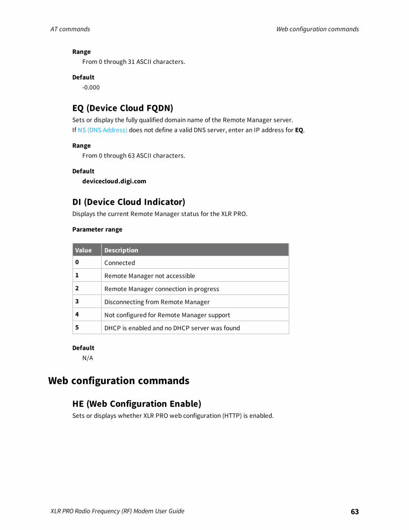
AT commands Web configuration commands
XLR PRO Radio Frequency (RF) Modem User Guide 63
RangeFrom 0 through 31 ASCII characters.
Default-0.000
EQ (Device Cloud FQDN)Sets or display the fully qualified domain name of the Remote Manager server.If NS (DNS Address) does not define a valid DNS server, enter an IP address for EQ.
RangeFrom 0 through 63 ASCII characters.
Defaultdevicecloud.digi.com
DI (Device Cloud Indicator)Displays the current Remote Manager status for the XLR PRO.
Parameter range
Value Description
0 Connected
1 Remote Manager not accessible
2 Remote Manager connection in progress
3 Disconnecting from Remote Manager
4 Not configured for Remote Manager support
5 DHCP is enabled and no DHCP server was found
DefaultN/A
Web configuration commands
HE (Web Configuration Enable)Sets or displays whether XLR PRO web configuration (HTTP) is enabled.
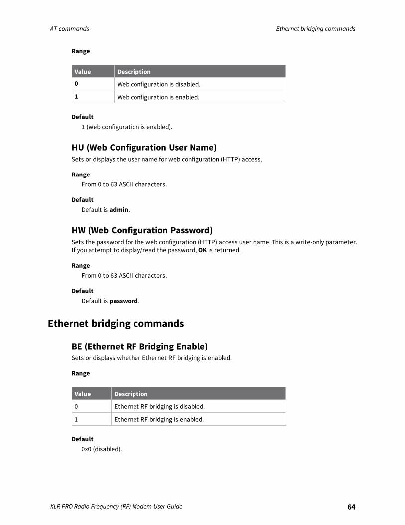
AT commands Ethernet bridging commands
XLR PRO Radio Frequency (RF) Modem User Guide 64
Range
Value Description
0 Web configuration is disabled.
1 Web configuration is enabled.
Default1 (web configuration is enabled).
HU (Web Configuration User Name)Sets or displays the user name for web configuration (HTTP) access.
RangeFrom 0 to 63 ASCII characters.
DefaultDefault is admin.
HW (Web Configuration Password)Sets the password for the web configuration (HTTP) access user name. This is a write-only parameter.If you attempt to display/read the password, OK is returned.
RangeFrom 0 to 63 ASCII characters.
DefaultDefault is password.
Ethernet bridging commands
BE (Ethernet RF Bridging Enable)Sets or displays whether Ethernet RF bridging is enabled.
Range
Value Description
0 Ethernet RF bridging is disabled.
1 Ethernet RF bridging is enabled.
Default0x0 (disabled).
AT commands Command mode options
XLR PRO Radio Frequency (RF) Modem User Guide 65
BA (Bridge Destination MAC)Sets or displays the destination RF MAC address to use for Ethernet RF Bridging. Set BA to 0xFFFF asthe broadcast address.
RangeA hexadecimal value from 0x0 to 0013A200FFFFFFFF
Default0xFFFF (broadcast address)
Command mode optionsThe following commands are Command mode option commands.
CC (Command Sequence Character)Sets or displays the ASCII sequence character to use for entering Command mode. Repeating the CCcharacter three times causes the XLR PRO to enter Command mode. The device responds with OK\rwhen Command mode is successfully entered. The following commands are related to CC:
n Use GT command to define a guard time—the amount of time before and after entering acommand sequence—to guard against inadvertently entering Command mode.
n Use CT command to define the timeout for Command mode.
n Use CN command to immediately exit Command mode and return to Idle mode.
Parameter range0 - 0xFF
Default0x2B (the ASCII plus character: +)
CN commandExits Command mode and returns the XLR PRO to Idle mode.
Parameter rangeN/A
DefaultN/A
CT commandSets or displays the Command mode timeout parameter. If a device does not receive any validcommands within this time period, it returns to Idle mode from Command mode.
Parameter range2 - 0x1770 (x 100 ms)

AT commands Firmware commands
XLR PRO Radio Frequency (RF) Modem User Guide 66
Default0x64 (10 seconds)
GT commandSet the required period of silence before and after the command sequence characters of theCommand mode sequence (GT + CC + GT). The period of silence prevents inadvertently enteringCommand mode.
Parameter range0x0 - 0xFFFF
Default0x3E8 (one second)
Firmware commandsThe following AT commands are firmware commands.
VB (Firmware Version)Displays the XLR PRO firmware version.
RangeN/A
DefaultN/A
VR (XLR PRO Firmware Version)Displays the XLR PRO module firmware.
RangeN/A
DefaultN/A
HV commandDisplay the hardware version number of the device.
Parameter rangeN/A
DefaultN/A
AT commands Firmware commands
XLR PRO Radio Frequency (RF) Modem User Guide 67
VH commandDisplays the XLR PRO RF modem baseboard hardware version.
RangeN/A
DefaultN/A
*C (compatibility)Displays the compatibility setting for the XLR PRO.
RangeN/A
DefaultN/A
DD commandStores the Digi device type identifier value. Use this value to differentiate between multiple XBeedevices.If you change DD, RE command will not restore defaults. The only way to get DD back to default valuesis to explicitly set it to defaults.The XLR PRO product code upper word is 0x000E.
Parameter range0 - 0xFFFFFFFF
Default0xE001C
PN (Part Number)Displays the manufacturing part number for the XLR PRO.
RangeN/A
DefaultN/A
NP (Maximum Packet Payload Bytes)Reads the maximum number of RF payload bytes that you can send in a transmission.
Parameter range0 - 0xFFFF (bytes) [read-only]
AT commands Firmware commands
XLR PRO Radio Frequency (RF) Modem User Guide 68
Default0x640 (1600d)
CK (Configuration CRC)Displays the cyclic redundancy check (CRC) of the current AT command configuration settings.This command allows you to detect an unexpected configuration change on a device.After a firmware update this command may return a different value.
Parameter range0 - 0xFFFF
DefaultN/A

Operate in API mode
API mode overview 70Use the AP command to set the operation mode 70API frame format 70API serial exchanges 73Code to support future API frames 74API frames 74
XLR PRO Radio Frequency (RF) Modem User Guide 69
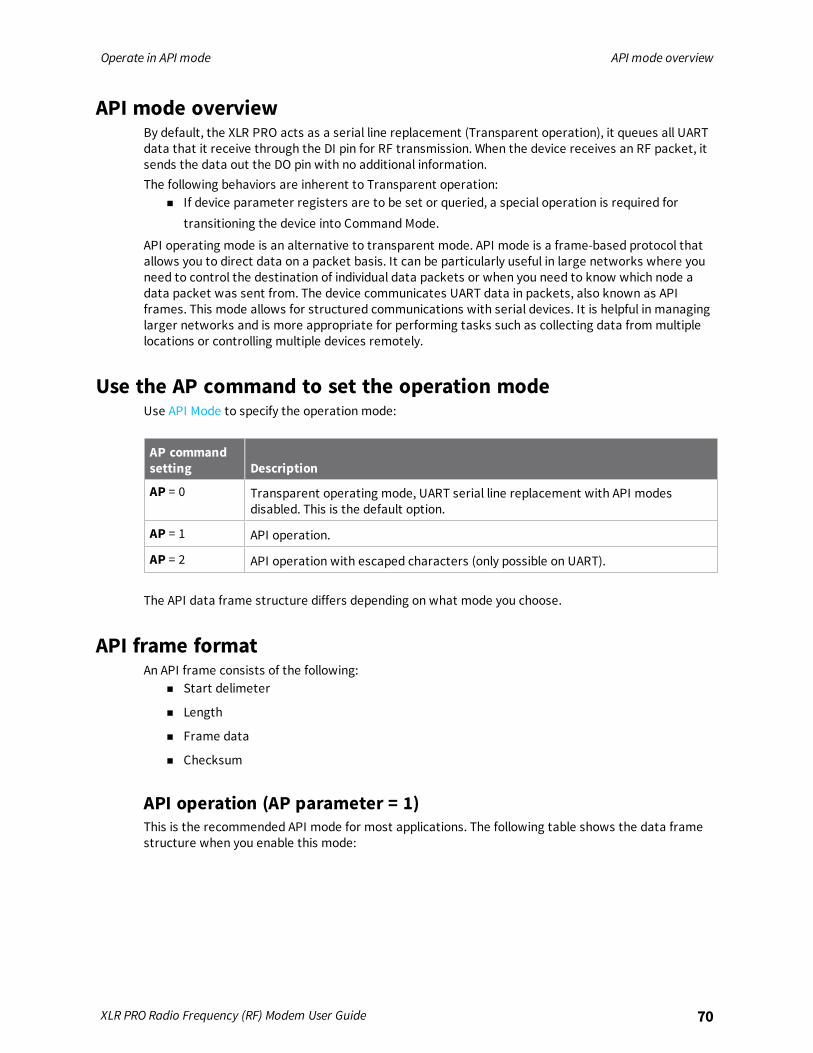
Operate in API mode API mode overview
XLR PRO Radio Frequency (RF) Modem User Guide 70
API mode overviewBy default, the XLR PRO acts as a serial line replacement (Transparent operation), it queues all UARTdata that it receive through the DI pin for RF transmission. When the device receives an RF packet, itsends the data out the DO pin with no additional information.The following behaviors are inherent to Transparent operation:
n If device parameter registers are to be set or queried, a special operation is required fortransitioning the device into Command Mode.
API operating mode is an alternative to transparent mode. API mode is a frame-based protocol thatallows you to direct data on a packet basis. It can be particularly useful in large networks where youneed to control the destination of individual data packets or when you need to know which node adata packet was sent from. The device communicates UART data in packets, also known as APIframes. This mode allows for structured communications with serial devices. It is helpful in managinglarger networks and is more appropriate for performing tasks such as collecting data from multiplelocations or controlling multiple devices remotely.
Use the AP command to set the operation modeUse API Mode to specify the operation mode:
AP commandsetting Description
AP = 0 Transparent operating mode, UART serial line replacement with API modesdisabled. This is the default option.
AP = 1 API operation.
AP = 2 API operation with escaped characters (only possible on UART).
The API data frame structure differs depending on what mode you choose.
API frame formatAn API frame consists of the following:
n Start delimeter
n Length
n Frame data
n Checksum
API operation (AP parameter = 1)This is the recommended API mode for most applications. The following table shows the data framestructure when you enable this mode:

Operate in API mode API frame format
XLR PRO Radio Frequency (RF) Modem User Guide 71
Frame fields Byte Description
Start delimiter 1 0x7E
Length 2 - 3 Most Significant Byte, Least Significant Byte
Frame data 4 - number (n) API-specific structure
Checksum n + 1 1 byte
Any data received prior to the start delimiter is silently discarded. If the frame is not received correctlyor if the checksum fails, the XLR PRO replies with a radio status frame indicating the nature of thefailure.
API operation with escaped characters (AP parameter = 2)Setting API to 2 allows escaped control characters in the API frame. Due to its increased complexity,we only recommend this API mode in specific circumstances. API 2 may help improve reliability if theserial interface to the device is unstable or malformed frames are frequently being generated.When operating in API 2, if an unescaped 0x7E byte is observed, it is treated as the start of a new APIframe and all data received prior to this delimiter is silently discarded. For more information on usingthis API mode, see the Escaped Characters and API Mode 2 in the Digi Knowledge base.API escaped operating mode works similarly to API mode. The only difference is that when working inAPI escaped mode, the software must escape any payload bytes that match API frame specific data,such as the start-of-frame byte (0x7E). The following table shows the structure of an API frame withescaped characters:
Frame fields Byte Description
Start delimiter 1 0x7E
Length 2 - 3 Most Significant Byte, Least Significant Byte Characters escaped if needed
Frame data 4 - n API-specific structure
Checksum n + 1 1 byte
Start delimiter fieldThis field indicates the beginning of a frame. It is always 0x7E. This allows the device to easily detect anew incoming frame.
Escaped characters in API framesIf operating in API mode with escaped characters (AP parameter = 2), when sending or receiving aserial data frame, specific data values must be escaped (flagged) so they do not interfere with thedata frame sequencing. To escape an interfering data byte, insert 0x7D and follow it with the byte tobe escaped (XORed with 0x20).The following data bytes need to be escaped:
n 0x7E: start delimiter
n 0x7D: escape character
n 0x11: XON
n 0x13: XOFF
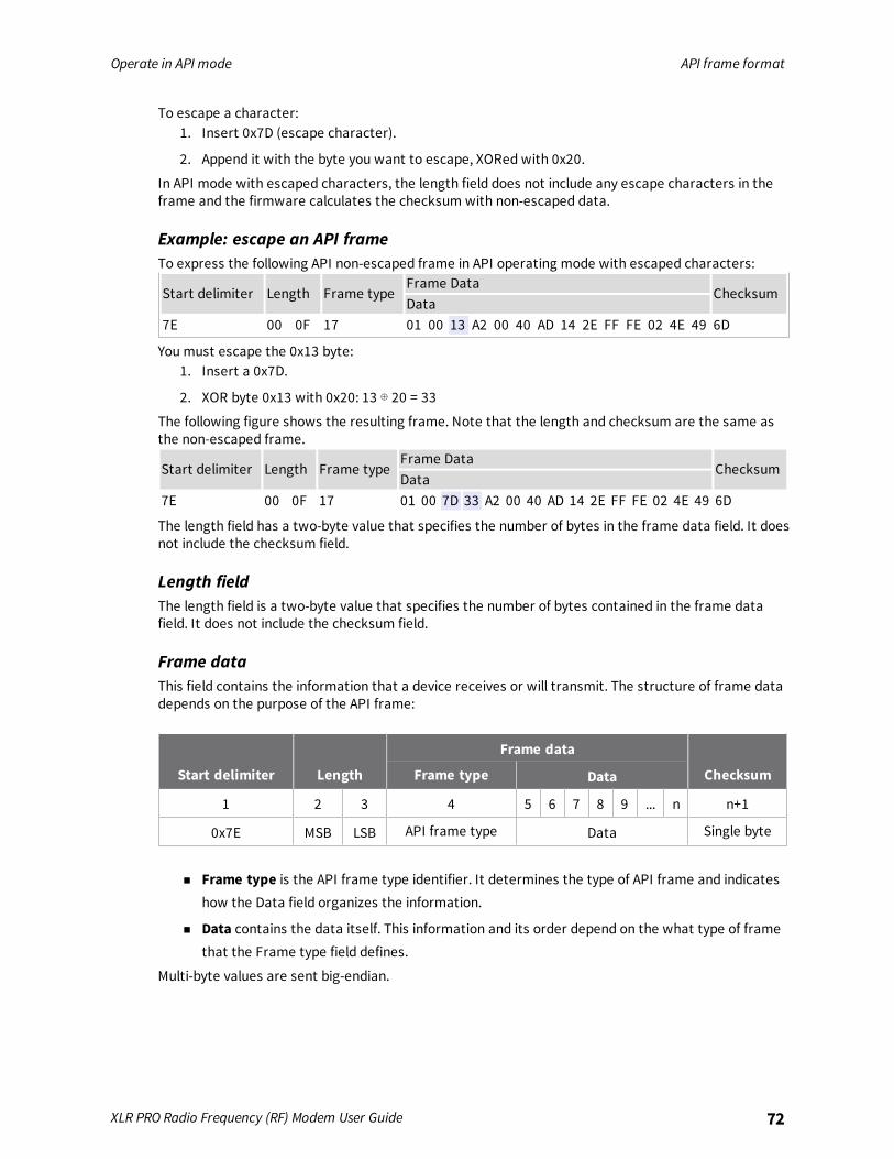
Operate in API mode API frame format
XLR PRO Radio Frequency (RF) Modem User Guide 72
To escape a character:1. Insert 0x7D (escape character).
2. Append it with the byte you want to escape, XORed with 0x20.
In API mode with escaped characters, the length field does not include any escape characters in theframe and the firmware calculates the checksum with non-escaped data.
Example: escape an API frameTo express the following API non-escaped frame in API operating mode with escaped characters:
Start delimiter Length Frame typeFrame Data
ChecksumData
7E 00 0F 17 01 00 13 A2 00 40 AD 14 2E FF FE 02 4E 49 6D
You must escape the 0x13 byte:1. Insert a 0x7D.
2. XOR byte 0x13 with 0x20: 13 ⊕ 20 = 33
The following figure shows the resulting frame. Note that the length and checksum are the same asthe non-escaped frame.
Start delimiter Length Frame typeFrame Data
ChecksumData
7E 00 0F 17 01 00 7D 33 A2 00 40 AD 14 2E FF FE 02 4E 49 6D
The length field has a two-byte value that specifies the number of bytes in the frame data field. It doesnot include the checksum field.
Length fieldThe length field is a two-byte value that specifies the number of bytes contained in the frame datafield. It does not include the checksum field.
Frame dataThis field contains the information that a device receives or will transmit. The structure of frame datadepends on the purpose of the API frame:
Start delimiter Length
Frame data
ChecksumFrame type Data
1 2 3 4 5 6 7 8 9 ... n n+1
0x7E MSB LSB API frame type Data Single byte
n Frame type is the API frame type identifier. It determines the type of API frame and indicateshow the Data field organizes the information.
n Data contains the data itself. This information and its order depend on the what type of framethat the Frame type field defines.
Multi-byte values are sent big-endian.
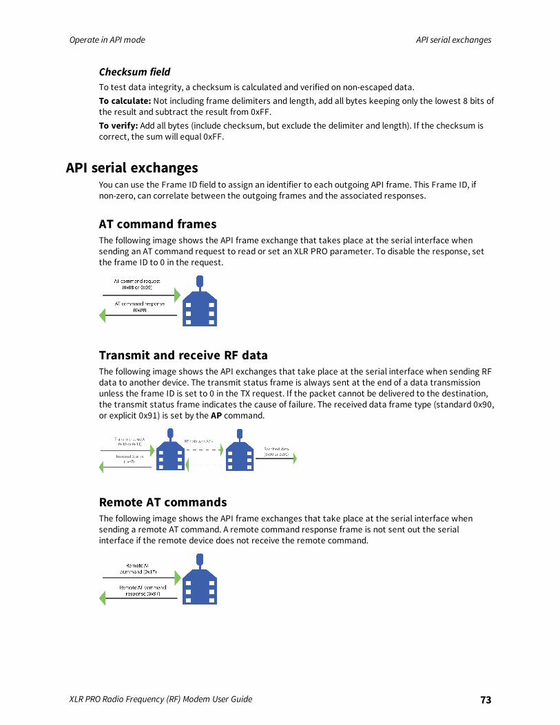
Operate in API mode API serial exchanges
XLR PRO Radio Frequency (RF) Modem User Guide 73
Checksum fieldTo test data integrity, a checksum is calculated and verified on non-escaped data.To calculate: Not including frame delimiters and length, add all bytes keeping only the lowest 8 bits ofthe result and subtract the result from 0xFF.To verify: Add all bytes (include checksum, but exclude the delimiter and length). If the checksum iscorrect, the sum will equal 0xFF.
API serial exchangesYou can use the Frame ID field to assign an identifier to each outgoing API frame. This Frame ID, ifnon-zero, can correlate between the outgoing frames and the associated responses.
AT command framesThe following image shows the API frame exchange that takes place at the serial interface whensending an AT command request to read or set an XLR PRO parameter. To disable the response, setthe frame ID to 0 in the request.
Transmit and receive RF dataThe following image shows the API exchanges that take place at the serial interface when sending RFdata to another device. The transmit status frame is always sent at the end of a data transmissionunless the frame ID is set to 0 in the TX request. If the packet cannot be delivered to the destination,the transmit status frame indicates the cause of failure. The received data frame type (standard 0x90,or explicit 0x91) is set by the AP command.
Remote AT commandsThe following image shows the API frame exchanges that take place at the serial interface whensending a remote AT command. A remote command response frame is not sent out the serialinterface if the remote device does not receive the remote command.

Operate in API mode Code to support future API frames
XLR PRO Radio Frequency (RF) Modem User Guide 74
Code to support future API framesIf your software application supports the API, you should make provisions that allow for new APIframes in future firmware releases. For example, you can include the following section of code on ahost microprocessor that handles serial API frames that are sent out the device's DOUT pin:
void XBee_HandleRxAPIFrame(_apiFrameUnion *papiFrame)switch(papiFrame->api_id)
case RX_RF_DATA_FRAME://process received RF data framebreak;
case RX_IO_SAMPLE_FRAME://process IO sample framebreak;
case NODE_IDENTIFICATION_FRAME://process node identification framebreak;
default://Discard any other API frame types that are not being usedbreak;
API framesThe following sections document API frame types.
AT Command frame - 0x08
DescriptionUse this frame to query or set device parameters on the local device. This API command applieschanges after running the command. You can query parameter values by sending the 0x08 ATCommand frame with no parameter value field (the two-byte AT command is immediately followed bythe frame checksum).A 0x88 response frame is populated with the parameter value that is currently set on the device.
FormatThe following table provides the contents of the frame. For details on frame structure, see API frameformat.
Framedatafields Offset Description
Frametype
3 0x08
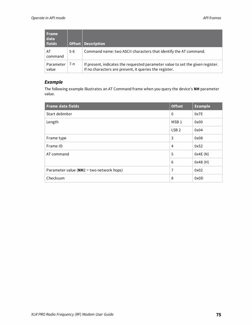
Operate in API mode API frames
XLR PRO Radio Frequency (RF) Modem User Guide 75
Framedatafields Offset Description
ATcommand
5-6 Command name: two ASCII characters that identify the AT command.
Parametervalue
7-n If present, indicates the requested parameter value to set the given register.If no characters are present, it queries the register.
ExampleThe following example illustrates an AT Command frame when you query the device's NH parametervalue.
Frame data fields Offset Example
Start delimiter 0 0x7E
Length MSB 1 0x00
LSB 2 0x04
Frame type 3 0x08
Frame ID 4 0x52
AT command 5 0x4E (N)
6 0x48 (H)
Parameter value (NH2 = two network hops) 7 0x02
Checksum 8 0x0D
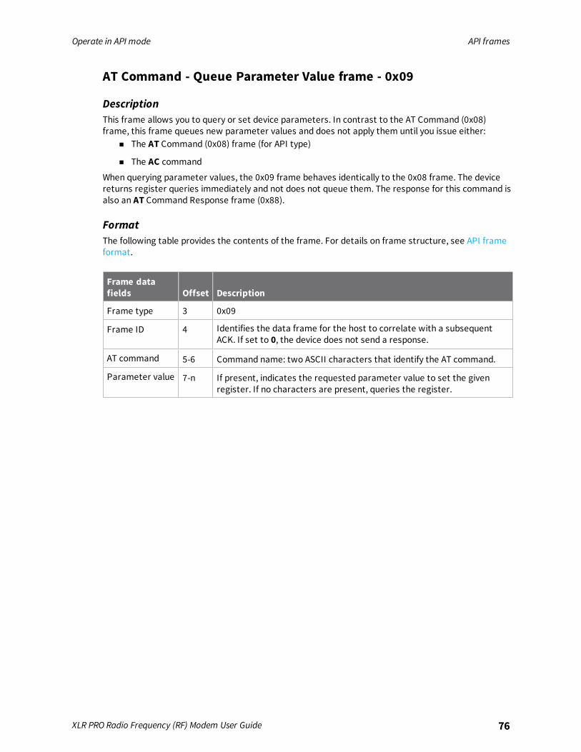
Operate in API mode API frames
XLR PRO Radio Frequency (RF) Modem User Guide 76
AT Command - Queue Parameter Value frame - 0x09
DescriptionThis frame allows you to query or set device parameters. In contrast to the AT Command (0x08)frame, this frame queues new parameter values and does not apply them until you issue either:
n The AT Command (0x08) frame (for API type)
n The AC command
When querying parameter values, the 0x09 frame behaves identically to the 0x08 frame. The devicereturns register queries immediately and not does not queue them. The response for this command isalso an AT Command Response frame (0x88).
FormatThe following table provides the contents of the frame. For details on frame structure, see API frameformat.
Frame datafields Offset Description
Frame type 3 0x09
Frame ID 4 Identifies the data frame for the host to correlate with a subsequentACK. If set to 0, the device does not send a response.
AT command 5-6 Command name: two ASCII characters that identify the AT command.
Parameter value 7-n If present, indicates the requested parameter value to set the givenregister. If no characters are present, queries the register.
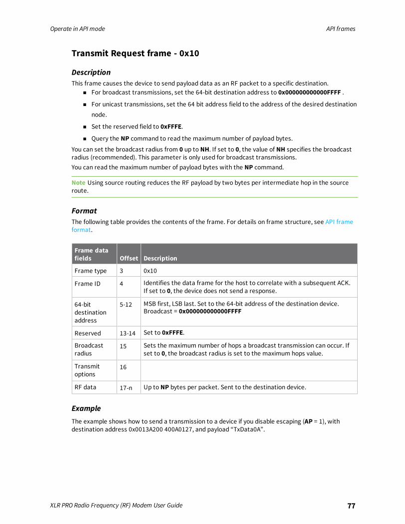
Operate in API mode API frames
XLR PRO Radio Frequency (RF) Modem User Guide 77
Transmit Request frame - 0x10
DescriptionThis frame causes the device to send payload data as an RF packet to a specific destination.
n For broadcast transmissions, set the 64-bit destination address to 0x000000000000FFFF .
n For unicast transmissions, set the 64 bit address field to the address of the desired destinationnode.
n Set the reserved field to 0xFFFE.
n Query the NP command to read the maximum number of payload bytes.
You can set the broadcast radius from 0 up to NH. If set to 0, the value of NH specifies the broadcastradius (recommended). This parameter is only used for broadcast transmissions.You can read the maximum number of payload bytes with the NP command.
Note Using source routing reduces the RF payload by two bytes per intermediate hop in the sourceroute.
FormatThe following table provides the contents of the frame. For details on frame structure, see API frameformat.
Frame datafields Offset Description
Frame type 3 0x10
Frame ID 4 Identifies the data frame for the host to correlate with a subsequent ACK.If set to 0, the device does not send a response.
64-bitdestinationaddress
5-12 MSB first, LSB last. Set to the 64-bit address of the destination device.Broadcast = 0x000000000000FFFF
Reserved 13-14 Set to 0xFFFE.
Broadcastradius
15 Sets the maximum number of hops a broadcast transmission can occur. Ifset to 0, the broadcast radius is set to the maximum hops value.
Transmitoptions
16
RF data 17-n Up to NP bytes per packet. Sent to the destination device.
Example
The example shows how to send a transmission to a device if you disable escaping (AP = 1), withdestination address 0x0013A200 400A0127, and payload “TxData0A”.
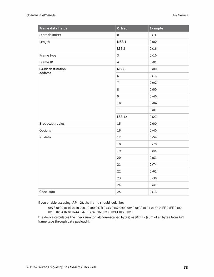
Operate in API mode API frames
XLR PRO Radio Frequency (RF) Modem User Guide 78
Frame data fields Offset Example
Start delimiter 0 0x7E
Length MSB 1 0x00
LSB 2 0x16
Frame type 3 0x10
Frame ID 4 0x01
64-bit destinationaddress
MSB 5 0x00
6 0x13
7 0xA2
8 0x00
9 0x40
10 0x0A
11 0x01
LSB 12 0x27
Broadcast radius 15 0x00
Options 16 0x40
RF data 17 0x54
18 0x78
19 0x44
20 0x61
21 0x74
22 0x61
23 0x30
24 0x41
Checksum 25 0x13
If you enable escaping (AP = 2), the frame should look like:0x7E 0x00 0x16 0x10 0x01 0x00 0x7D 0x33 0xA2 0x00 0x40 0x0A 0x01 0x27 0xFF 0xFE 0x000x00 0x54 0x78 0x44 0x61 0x74 0x61 0x30 0x41 0x7D 0x33
The device calculates the checksum (on all non-escaped bytes) as [0xFF - (sum of all bytes from APIframe type through data payload)].

Operate in API mode API frames
XLR PRO Radio Frequency (RF) Modem User Guide 79
Explicit Addressing Command frame - 0x11
DescriptionThis frame is similar to Transmit Request (0x10), but it also requires you to specify the application-layer addressing fields: endpoints, cluster ID, and profile ID.This frame causes the device to send payload data as an RF packet to a specific destination, usingspecific source and destination endpoints, cluster ID, and profile ID.
n For broadcast transmissions, set the 64-bit destination address to 0x000000000000FFFF .
n For unicast transmissions, set the 64 bit address field to the address of the desired destinationnode.
n Set the reserved field to 0xFFFE.
Query the NP command to read the maximum number of payload bytes. For more information, seeFirmware commands.You can set the broadcast radius from 0 up to NH to 0xFF. If set to 0, the value of NH specifies thebroadcast radius (recommended). This parameter is only used for directed broadcast transmissions(transmit options = 0x80).
FormatThe following table provides the contents of the frame. For details on the frame structure, see APIframe format.
Frame datafields Offset Description
Frame type 3 0x11
Frame ID 4 Identifies the data frame for the host to correlate with a subsequent ACK(0x8B). If set to 0, the device does not send a response.
64-bitdestinationaddress
5-12 MSB first, LSB last. Set to the 64-bit address of the destination device.Broadcast = 0x000000000000FFFF
Reserved 13-14 Set to 0xFFFE.
Sourceendpoint
15 Source endpoint for the transmission.
Destinationendpoint
16 Destination endpoint for the transmission.
Cluster ID 17-18 The Cluster ID that the host uses in the transmission.
Profile ID 19-20 The Profile ID that the host uses in the transmission.
Broadcastradius
21 Sets the maximum number of hops a broadcast transmission can traverse.If set to 0, the transmission radius set to the network maximum hops value.
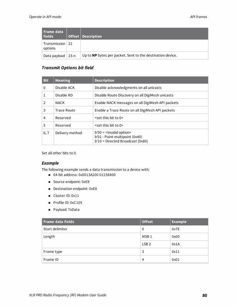
Operate in API mode API frames
XLR PRO Radio Frequency (RF) Modem User Guide 80
Frame datafields Offset Description
Transmissionoptions
22
Data payload 23-n Up to NP bytes per packet. Sent to the destination device.
Transmit Options bit field
Bit Meaning Description
0 Disable ACK Disable acknowledgments on all unicasts
1 Disable RD Disable Route Discovery on all DigiMesh unicasts
2 NACK Enable NACK messages on all DigiMesh API packets
3 Trace Route Enable a Trace Route on all DigiMesh API packets
4 Reserved <set this bit to 0>
5 Reserved <set this bit to 0>
6, 7 Delivery method b’00 = <invalid option>b’01 - Point-multipoint (0x40)b'10 = Directed Broadcast (0x80)
Set all other bits to 0.
ExampleThe following example sends a data transmission to a device with:
n 64-bit address: 0x0013A200 01238400
n Source endpoint: 0xE8
n Destination endpoint: 0xE8
n Cluster ID: 0x11
n Profile ID: 0xC105
n Payload: TxData
Frame data fields Offset Example
Start delimiter 0 0x7E
Length MSB 1 0x00
LSB 2 0x1A
Frame type 3 0x11
Frame ID 4 0x01
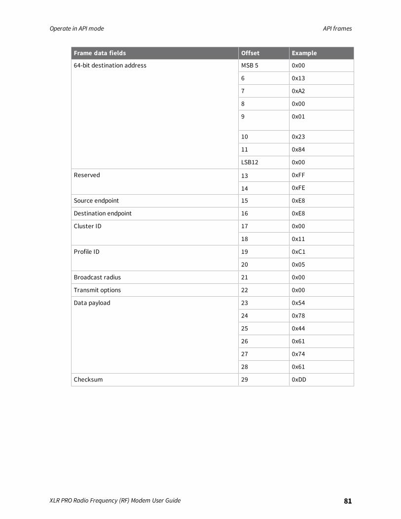
Operate in API mode API frames
XLR PRO Radio Frequency (RF) Modem User Guide 81
Frame data fields Offset Example
64-bit destination address MSB 5 0x00
6 0x13
7 0xA2
8 0x00
9 0x01
10 0x23
11 0x84
LSB12 0x00
Reserved 13 0xFF
14 0xFE
Source endpoint 15 0xE8
Destination endpoint 16 0xE8
Cluster ID 17 0x00
18 0x11
Profile ID 19 0xC1
20 0x05
Broadcast radius 21 0x00
Transmit options 22 0x00
Data payload 23 0x54
24 0x78
25 0x44
26 0x61
27 0x74
28 0x61
Checksum 29 0xDD

Operate in API mode API frames
XLR PRO Radio Frequency (RF) Modem User Guide 82
Remote AT Command Request frame - 0x17
DescriptionUsed to query or set device parameters on a remote device. For parameter changes on the remotedevice to take effect, you must apply changes, either by setting the Apply Changes options bit, or bysending an AC command to the remote.
FormatThe following table provides the contents of the frame. For details on frame structure, see API frameformat.
Frame datafields Offset Description
Frame type 3 0x17
Frame ID 4 Identifies the data frame for the host to correlate with a subsequent ACK(0x97). If set to 0, the device does not send a response.
64-bitdestinationaddress
5-12 MSB first, LSB last. Set to the 64-bit address of the destination device.
Reserved 13-14
Remotecommandoptions
15 0x02 = Apply changes on remote. If you do not set this, you must send theAC command for changes to take effect.Set all other bits to 0.
AT command 16-17 Command name: two ASCII characters that identify the command.
Commandparameter
18-n If present, indicates the parameter value you request for a given register.If no characters are present, it queries the register.
ExampleThe following example sends a remote command:In this example, the 64-bit address of the remote device is 0x0013A200 40401122.
Frame data fields Offset Example
Start delimiter 0 0x7E
Length MSB 1 0x00
LSB 2 0x10
Frame type 3 0x17
Frame ID 4 0x01
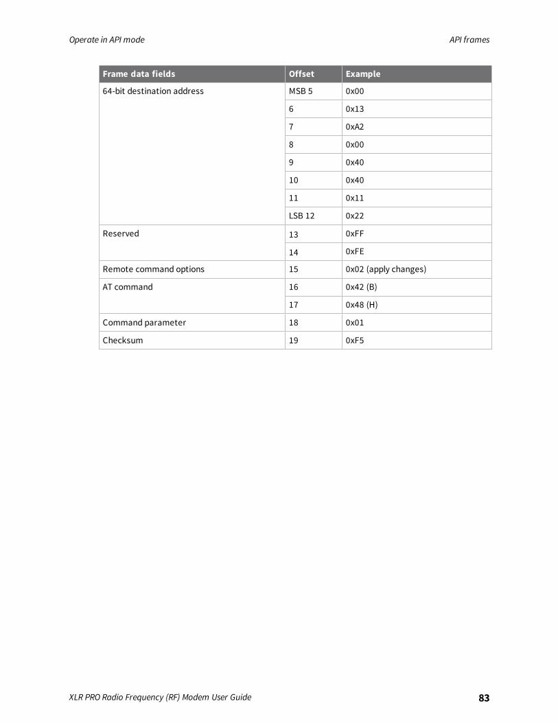
Operate in API mode API frames
XLR PRO Radio Frequency (RF) Modem User Guide 83
Frame data fields Offset Example
64-bit destination address MSB 5 0x00
6 0x13
7 0xA2
8 0x00
9 0x40
10 0x40
11 0x11
LSB 12 0x22
Reserved 13 0xFF
14 0xFE
Remote command options 15 0x02 (apply changes)
AT command 16 0x42 (B)
17 0x48 (H)
Command parameter 18 0x01
Checksum 19 0xF5
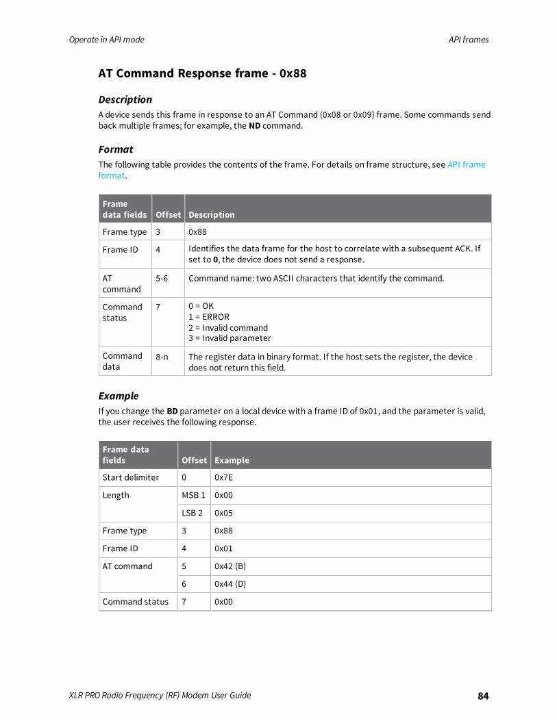
Operate in API mode API frames
XLR PRO Radio Frequency (RF) Modem User Guide 84
AT Command Response frame - 0x88
DescriptionA device sends this frame in response to an AT Command (0x08 or 0x09) frame. Some commands sendback multiple frames; for example, the ND command.
FormatThe following table provides the contents of the frame. For details on frame structure, see API frameformat.
Framedata fields Offset Description
Frame type 3 0x88
Frame ID 4 Identifies the data frame for the host to correlate with a subsequent ACK. Ifset to 0, the device does not send a response.
ATcommand
5-6 Command name: two ASCII characters that identify the command.
Commandstatus
7 0 = OK1 = ERROR2 = Invalid command3 = Invalid parameter
Commanddata
8-n The register data in binary format. If the host sets the register, the devicedoes not return this field.
ExampleIf you change the BD parameter on a local device with a frame ID of 0x01, and the parameter is valid,the user receives the following response.
Frame datafields Offset Example
Start delimiter 0 0x7E
Length MSB 1 0x00
LSB 2 0x05
Frame type 3 0x88
Frame ID 4 0x01
AT command 5 0x42 (B)
6 0x44 (D)
Command status 7 0x00
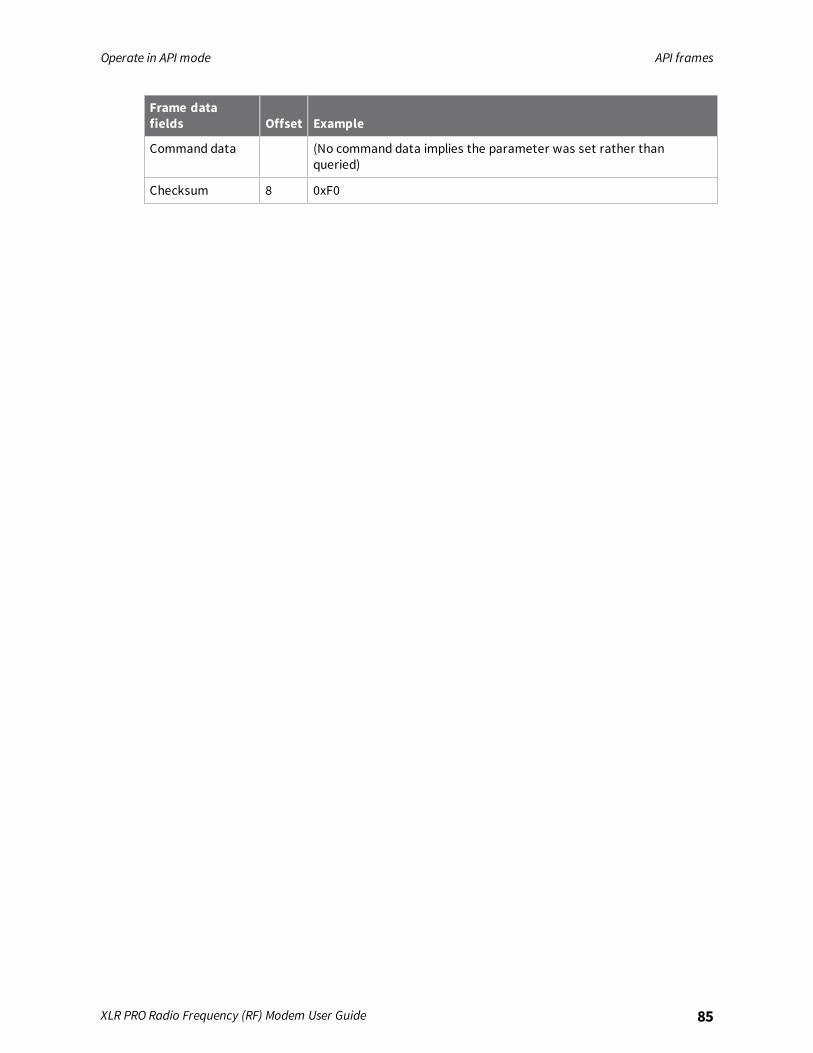
Operate in API mode API frames
XLR PRO Radio Frequency (RF) Modem User Guide 85
Frame datafields Offset Example
Command data (No command data implies the parameter was set rather thanqueried)
Checksum 8 0xF0
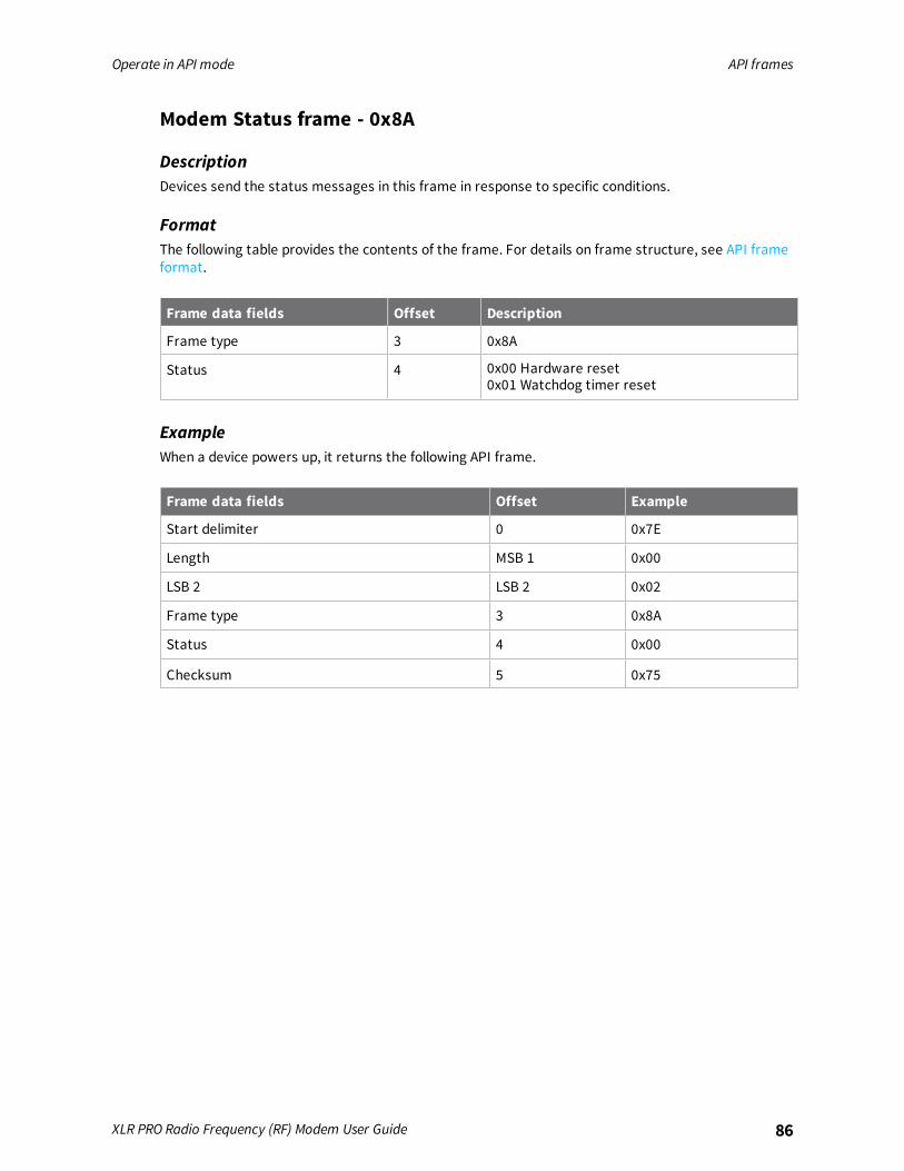
Operate in API mode API frames
XLR PRO Radio Frequency (RF) Modem User Guide 86
Modem Status frame - 0x8A
DescriptionDevices send the status messages in this frame in response to specific conditions.
FormatThe following table provides the contents of the frame. For details on frame structure, see API frameformat.
Frame data fields Offset Description
Frame type 3 0x8A
Status 4 0x00 Hardware reset0x01 Watchdog timer reset
ExampleWhen a device powers up, it returns the following API frame.
Frame data fields Offset Example
Start delimiter 0 0x7E
Length MSB 1 0x00
LSB 2 LSB 2 0x02
Frame type 3 0x8A
Status 4 0x00
Checksum 5 0x75
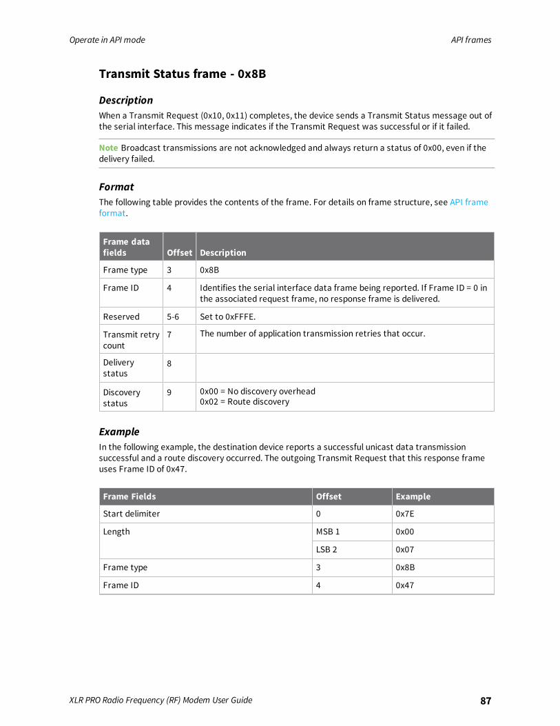
Operate in API mode API frames
XLR PRO Radio Frequency (RF) Modem User Guide 87
Transmit Status frame - 0x8B
DescriptionWhen a Transmit Request (0x10, 0x11) completes, the device sends a Transmit Status message out ofthe serial interface. This message indicates if the Transmit Request was successful or if it failed.
Note Broadcast transmissions are not acknowledged and always return a status of 0x00, even if thedelivery failed.
FormatThe following table provides the contents of the frame. For details on frame structure, see API frameformat.
Frame datafields Offset Description
Frame type 3 0x8B
Frame ID 4 Identifies the serial interface data frame being reported. If Frame ID = 0 inthe associated request frame, no response frame is delivered.
Reserved 5-6 Set to 0xFFFE.
Transmit retrycount
7 The number of application transmission retries that occur.
Deliverystatus
8
Discoverystatus
9 0x00 = No discovery overhead0x02 = Route discovery
ExampleIn the following example, the destination device reports a successful unicast data transmissionsuccessful and a route discovery occurred. The outgoing Transmit Request that this response frameuses Frame ID of 0x47.
Frame Fields Offset Example
Start delimiter 0 0x7E
Length MSB 1 0x00
LSB 2 0x07
Frame type 3 0x8B
Frame ID 4 0x47
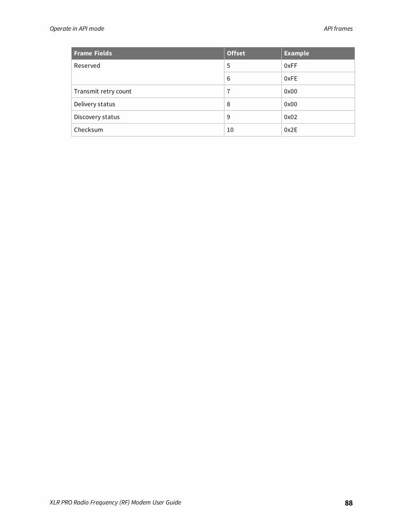
Operate in API mode API frames
XLR PRO Radio Frequency (RF) Modem User Guide 88
Frame Fields Offset Example
Reserved 5 0xFF
6 0xFE
Transmit retry count 7 0x00
Delivery status 8 0x00
Discovery status 9 0x02
Checksum 10 0x2E
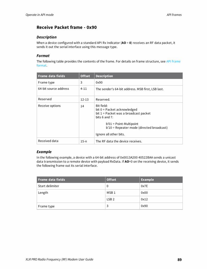
Operate in API mode API frames
XLR PRO Radio Frequency (RF) Modem User Guide 89
Receive Packet frame - 0x90
DescriptionWhen a device configured with a standard API Rx Indicator (AO = 0) receives an RF data packet, itsends it out the serial interface using this message type.
FormatThe following table provides the contents of the frame. For details on frame structure, see API frameformat.
Frame data fields Offset Description
Frame type 3 0x90
64-bit source address 4-11 The sender's 64-bit address. MSB first, LSB last.
Reserved 12-13 Reserved.
Receive options 14 Bit field:bit 0 = Packet acknowledgedbit 1 = Packet was a broadcast packetbits 6 and 7:
b’01 = Point-Multipointb’10 = Repeater mode (directed broadcast)
Ignore all other bits.
Received data 15-n The RF data the device receives.
ExampleIn the following example, a device with a 64-bit address of 0x0013A200 40522BAA sends a unicastdata transmission to a remote device with payload RxData. If AO=0 on the receiving device, it sendsthe following frame out its serial interface.
Frame data fields Offset Example
Start delimiter 0 0x7E
Length MSB 1 0x00
LSB 2 0x12
Frame type 3 0x90

Operate in API mode API frames
XLR PRO Radio Frequency (RF) Modem User Guide 90
Frame data fields Offset Example
64-bit source addressMSB 4 0x00
5 0x13
6 0xA2
7 0x00
8 0x40
9 0x52
10 0x2B
LSB 11 0xAA
Reserved 12 0xFF
13 0xFE
Receive options 14 0x01
Received data 15 0x52
16 0x78
17 0x44
18 0x61
19 0x74
20 0x61
Checksum 21 0x11
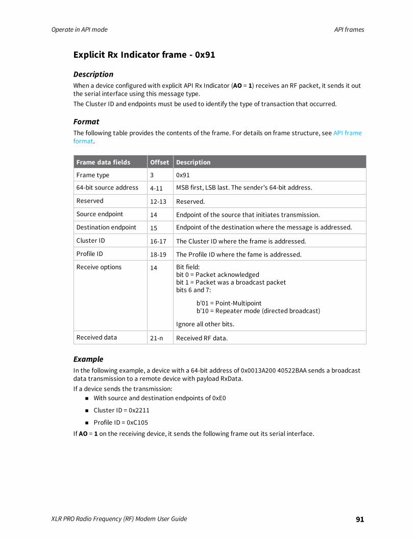
Operate in API mode API frames
XLR PRO Radio Frequency (RF) Modem User Guide 91
Explicit Rx Indicator frame - 0x91
DescriptionWhen a device configured with explicit API Rx Indicator (AO = 1) receives an RF packet, it sends it outthe serial interface using this message type.The Cluster ID and endpoints must be used to identify the type of transaction that occurred.
FormatThe following table provides the contents of the frame. For details on frame structure, see API frameformat.
Frame data fields Offset Description
Frame type 3 0x91
64-bit source address 4-11 MSB first, LSB last. The sender's 64-bit address.
Reserved 12-13 Reserved.
Source endpoint 14 Endpoint of the source that initiates transmission.
Destination endpoint 15 Endpoint of the destination where the message is addressed.
Cluster ID 16-17 The Cluster ID where the frame is addressed.
Profile ID 18-19 The Profile ID where the fame is addressed.
Receive options 14 Bit field:bit 0 = Packet acknowledgedbit 1 = Packet was a broadcast packetbits 6 and 7:
b’01 = Point-Multipointb’10 = Repeater mode (directed broadcast)
Ignore all other bits.
Received data 21-n Received RF data.
ExampleIn the following example, a device with a 64-bit address of 0x0013A200 40522BAA sends a broadcastdata transmission to a remote device with payload RxData.If a device sends the transmission:
n With source and destination endpoints of 0xE0
n Cluster ID = 0x2211
n Profile ID = 0xC105
If AO = 1 on the receiving device, it sends the following frame out its serial interface.

Operate in API mode API frames
XLR PRO Radio Frequency (RF) Modem User Guide 92
Frame data fields Offset Example
Start delimiter 0 0x7E
Length MSB 1 0x00
LSB 2 0x18
Frame type 3 0x91
64-bit source address MSB 4 0x00
5 0x13
6 0xA2
7 0x00
8 0x40
9 0x52
10 0x2B
LSB 11 0xAA
Reserved 12 0xFF
13 0xFE
Source endpoint 14 0xE0
Destination endpoint 15 0xE0
Cluster ID 16 0x22
17 0x11
Profile ID 18 0xC1
19 0x05
Receive options 20 0x02
Received data 21 0x52
22 0x78
23 0x44
24 0x61
25 0x74
26 0x61
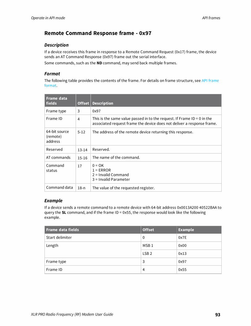
Operate in API mode API frames
XLR PRO Radio Frequency (RF) Modem User Guide 93
Remote Command Response frame - 0x97
DescriptionIf a device receives this frame in response to a Remote Command Request (0x17) frame, the devicesends an AT Command Response (0x97) frame out the serial interface.Some commands, such as the ND command, may send back multiple frames.
FormatThe following table provides the contents of the frame. For details on frame structure, see API frameformat.
Frame datafields Offset Description
Frame type 3 0x97
Frame ID 4 This is the same value passed in to the request. If Frame ID = 0 in theassociated request frame the device does not deliver a response frame.
64-bit source(remote)address
5-12 The address of the remote device returning this response.
Reserved 13-14 Reserved.
AT commands 15-16 The name of the command.
Commandstatus
17 0 = OK1 = ERROR2 = Invalid Command3 = Invalid Parameter
Command data 18-n The value of the requested register.
ExampleIf a device sends a remote command to a remote device with 64-bit address 0x0013A200 40522BAA toquery the SL command, and if the frame ID = 0x55, the response would look like the followingexample.
Frame data fields Offset Example
Start delimiter 0 0x7E
Length MSB 1 0x00
LSB 2 0x13
Frame type 3 0x97
Frame ID 4 0x55
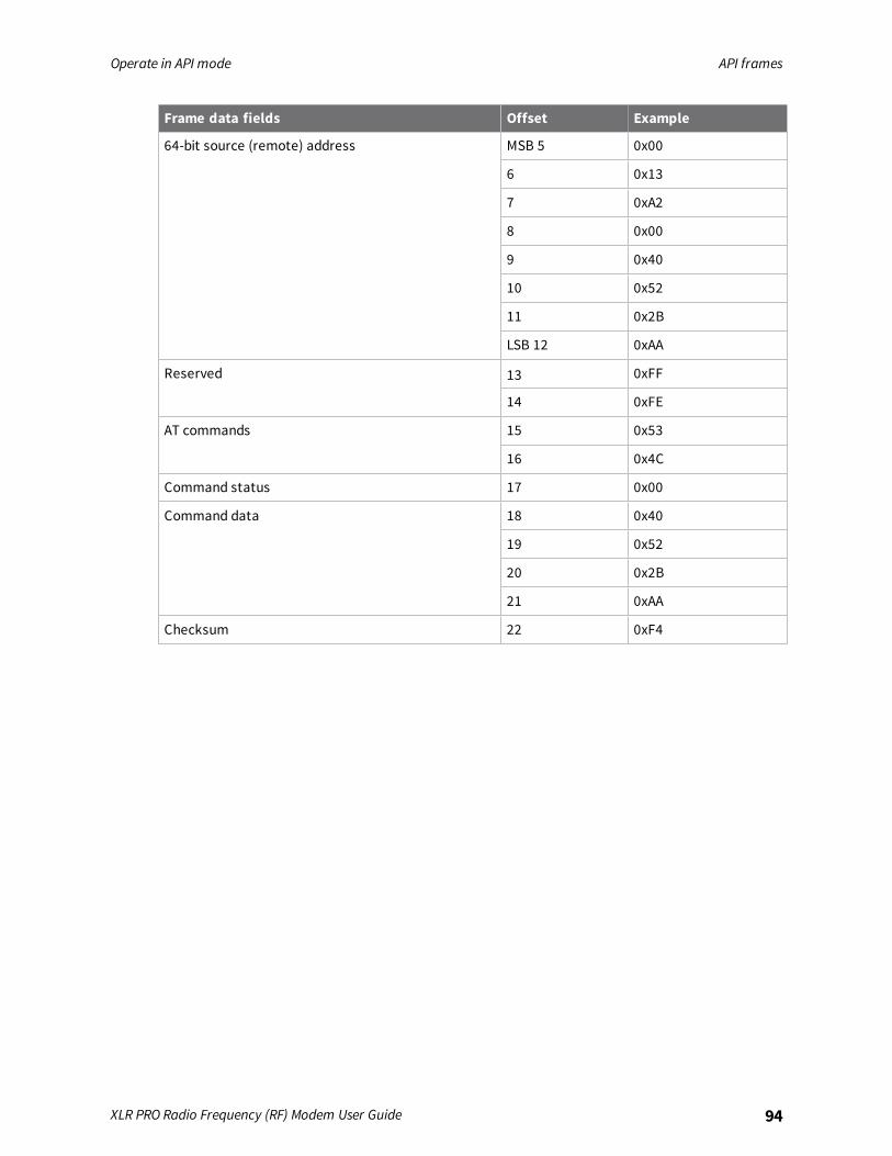
Operate in API mode API frames
XLR PRO Radio Frequency (RF) Modem User Guide 94
Frame data fields Offset Example
64-bit source (remote) address MSB 5 0x00
6 0x13
7 0xA2
8 0x00
9 0x40
10 0x52
11 0x2B
LSB 12 0xAA
Reserved 13 0xFF
14 0xFE
AT commands 15 0x53
16 0x4C
Command status 17 0x00
Command data 18 0x40
19 0x52
20 0x2B
21 0xAA
Checksum 22 0xF4
Advanced application features
Network commissioning and diagnostics 96Local configuration 96Remote configuration 96Test links in a network - loopback cluster 97Test links between adjacent devices 97General Purpose Flash Memory 100Over-the-air (OTA) firmware updates 111
XLR PRO Radio Frequency (RF) Modem User Guide 95
Advanced application features Network commissioning and diagnostics
XLR PRO Radio Frequency (RF) Modem User Guide 96
Network commissioning and diagnosticsWe call the process of discovering and configuring devices in a network for operation, "networkcommissioning." Devices include several device discovery and configuration features. In addition toconfiguring devices, you must develop a strategy to place devices to ensure reliable routes. Toaccommodate these requirements, modules include features to aid in placing devices, configuringdevices, and network diagnostics.
Local configurationYou can configure devices locally using serial commands in Transparent or API mode, or remotelyusing remote API commands. Devices that are in API mode can send configuration commands to setor read the configuration settings of any device in the network.
Remote configurationWhen you do not have access to the device's serial port, you can use a separate device in API mode toremotely configure it. To remotely configure devices, use the following steps.
Send a remote commandTo send a remote command, populate the Remote AT Command Request frame - 0x17 with:
1. The 64-bit address of the remote device.
2. The correct command options value.
3. Optionally, the command and parameter data.
4. If you want a command response, set the Frame ID field to a non-zero value.
The firmware only supports unicasts of remote commands. You cannot broadcast remote commands.XCTU has a Frames Generator tool that can assist you with building and sending a remote AT frame;see Frames generator tool in the XCTU User Guide.
Apply changes on remote devicesWhen you use remote commands to change the command parameter settings on a remote device,you must apply the parameter changes or they do not take effect. For example, if you change the BDparameter, the actual serial interface rate does not change on the remote device until you apply thechanges. You can apply the changes using remote commands in one of three ways:
1. Set the apply changes option bit in the API frame.
2. Send an AC command to the remote device.
3. Send the WR command followed by the FR command to the remote device to save the changesand reset the device.
Remote command responseIf a local device sends a command request to a remote device, and the API frame ID is non-zero, theremote device sends a remote command response transmission back to the local device.
When the local device receives a remote command response transmission, it sends a remotecommand response API frame out its UART. The remote command response indicates:

Advanced application features Test links in a network - loopback cluster
XLR PRO Radio Frequency (RF) Modem User Guide 97
1. The status of the command, which is either success or the reason for failure.
2. In the case of a command query, it includes the register value.
The device that sends a remote command does not receive a remote command response frame if:1. It could not reach the destination device.
2. You set the frame ID to 0 in the remote command request.
Test links in a network - loopback clusterTo measure the performance of a network, you can send unicast data through the network from onedevice to another to determine the success rate of several transmissions. To simplify link testing, thedevices support a Loopback cluster ID (0x12) on the data endpoint (0xE8). The cluster ID on the dataendpoint sends any data transmitted to it back to the sender.The following figure demonstrates how you can use the Loopback cluster ID and data endpoint tomeasure the link quality in a mesh network.
The configuration steps for sending data to the loopback cluster ID depend on what mode the deviceis in. For details on setting the mode, see API Mode. The following sections list the steps based on thedevice's mode.
Transparent operating mode configuration (AP = 0)To send data to the loopback cluster ID on the data endpoint of a remote device:
1. Set the CI command to 0x12.
2. Set the DH and DL commands to the address of the remote device.
After exiting Command mode, the device transmits any serial characters it received to the remotedevice, which returns those characters to the sending device.
API operating mode configuration (AP = 1 or AP = 2)Send an Explicit Addressing Command frame - 0x11 using 0x12 as the cluster ID and 0xE8 as both thesource and destination endpoint.The remote device echoes back the data packets it receives to the sending device.
Test links between adjacent devicesIt often helps to test the quality of a link between two adjacent modules in a network. You can use theTest Link Request Cluster ID to send a number of test packets between any two devices in a network.
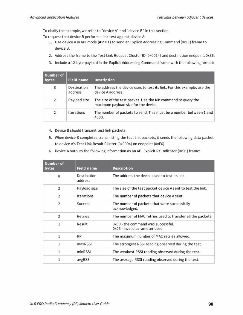
Advanced application features Test links between adjacent devices
XLR PRO Radio Frequency (RF) Modem User Guide 98
To clarify the example, we refer to "device A" and "device B" in this section.To request that device B perform a link test against device A:
1. Use device A in API mode (AP = 1) to send an Explicit Addressing Command (0x11) frame todevice B.
2. Address the frame to the Test Link Request Cluster ID (0x0014) and destination endpoint: 0xE6.
3. Include a 12-byte payload in the Explicit Addressing Command frame with the following format:
Number ofbytes Field name Description
8 Destinationaddress
The address the device uses to test its link. For this example, use thedevice A address.
2 Payload size The size of the test packet. Use the NP command to query themaximum payload size for the device.
2 Iterations The number of packets to send. This must be a number between 1 and4000.
4. Device B should transmit test link packets.
5. When device B completes transmitting the test link packets, it sends the following data packetto device A's Test Link Result Cluster (0x0094) on endpoint (0xE6).
6. Device A outputs the following information as an API Explicit RX Indicator (0x91) frame:
Number ofbytes Field name Description
8 Destinationaddress
The address the device used to test its link.
2 Payload size The size of the test packet device A sent to test the link.
2 Iterations The number of packets that device A sent.
2 Success The number of packets that were successfullyacknowledged.
2 Retries The number of MAC retries used to transfer all the packets.
1 Result 0x00 - the command was successful.0x03 - invalid parameter used.
1 RR The maximum number of MAC retries allowed.
1 maxRSSI The strongest RSSI reading observed during the test.
1 minRSSI The weakest RSSI reading observed during the test.
1 avgRSSI The average RSSI reading observed during the test.
Advanced application features Test links between adjacent devices
XLR PRO Radio Frequency (RF) Modem User Guide 99
ExampleSuppose that you want to test the link between device A (SH/SL = 0x0013A200 40521234) and deviceB (SH/SL=0x0013A 200 4052ABCD) by transmitting 1000 40-byte packets:Send the following API packet to the serial interface of device A.In the following example packet, whitespace marks fields, bold text is the payload portion of thepacket:7E 0020 11 01 0013A20040521234 FFFE E6 E6 0014 C105 00 00 0013A2004052ABCD 0028 03E8 EBWhen the test is finished, the following API frame may be received:7E 0027 91 0013A20040521234 FFFE E6 E6 0094 C105 00 0013A2004052ABCD 0028 03E8 03E7 006400 0A 50 53 52 9FThis means:
n 999 out of 1000 packets were successful.
n The device made 100 retries.
n RR = 10.
n maxRSSI = -80 dBm.
n minRSSI = -83 dBm.
n avgRSSI = -82 dBm.
If the Result field does not equal zero, an error has occurred. Ignore the other fields in the packet.If the Success field equals zero, ignore the RSSI fields.The device that sends the request for initiating the Test link and outputs the result does not need tobe the sender or receiver of the test. It is possible for a third node, "device C", to request device A toperform a test link against device B and send the results back to device C to be output. It is alsopossible for device B to request device A to perform the previously mentioned test. In other words, theframes can be sent by either device A, device B or device C and in all cases the test is the same: deviceA sends data to device B and reports the results.
RSSI indicatorsThe received signal strength indicator (RSSI) measures the amount of power present in a radio signal.It is an approximate value for signal strength received on an antenna.You can use the DB command to measure the RSSI on a device. DB returns the RSSI value measured in-dBm of the last packet the device received. This number can be misleading in multi-hop DigiMeshnetworks. The DB value only indicates the received signal strength of the last hop. If a transmissionspans multiple hops, the DB value provides no indication of the overall transmission path, or thequality of the worst link, it only indicates the quality of the last link.To determine the DB value in hardware:
1. Use the RSSI module pin (pin 36). When the device receives data, it sets the RSSI PWM dutycycle to a value based on the RSSI of the packet it receives.
This value only indicates the quality of the last hop of a multi-hop transmission. You could connect thispin to an LED to indicate if the link is stable or not.
Discover all the devices on a networkYou can use the ND (Network Discovery) command to discover all devices on a network. When yousend the ND command:
Advanced application features General Purpose Flash Memory
XLR PRO Radio Frequency (RF) Modem User Guide 100
1. The device sends a broadcast ND command through the network.
2. All devices that receive the command send a response that includes their addressinginformation, node identifier string and other relevant information. For more information on thenode identifier string, see NI command.
ND is useful for generating a list of all device addresses in a network.When a device receives the network discovery command, it waits a random time before sending itsown response. You can use the NT command to set the maximum time delay on the device that youuse to send the ND command.
n The device that sends the ND includes its NT setting in the transmission to provide a delaywindow for all devices in the network.
n The default NT value is 0x82 (13 seconds).
Discover devices within RF rangen You can use the FN (Find Neighbors) command to discover the devices that are immediate
neighbors (within RF range) of a particular device.
n FN is useful in determining network topology and determining possible routes.
You can send FN locally on a device in Command mode or you can use a local AT Command frame -0x08.To use FN remotely, send the target node a Remote AT Command Request frame - 0x17 using FN asthe name of the AT command.The device you use to send FN transmits a zero-hop broadcast to all of its immediate neighbors. All ofthe devices that receive this broadcast send an RF packet to the device that transmitted the FNcommand. If you sent FN remotely, the target devices respond directly to the device that sent the FNcommand. The device that sends FN outputs a response packet in the same format as an ATCommand Response frame - 0x88.
General Purpose Flash MemoryXLR PROs provide 119 512-byte blocks of flash memory that an application can read and write to. Thismemory provides a non-volatile data storage area that an application uses for many purposes. Somecommon uses of this data storage include:
n Storing logged sensor data
n Buffering firmware update data for a host microcontroller
n Storing and retrieving data tables needed for calculations performed by a host microcontroller
The General Purpose Memory (GPM) is also used to store a firmware update file for over-the-airfirmware updates of the device itself.
Access General Purpose Flash MemoryTo access the GPM of a target node locally or over-the-air, send commands to the MEMORY_ACCESScluster ID (0x23) on the DIGI_DEVICE endpoint (0xE6) of the target node using explicit API frames. Fora description of Explicit API frames, see Operate in API mode.To issue a GPM command, format the payload of an explicit API frame as follows:
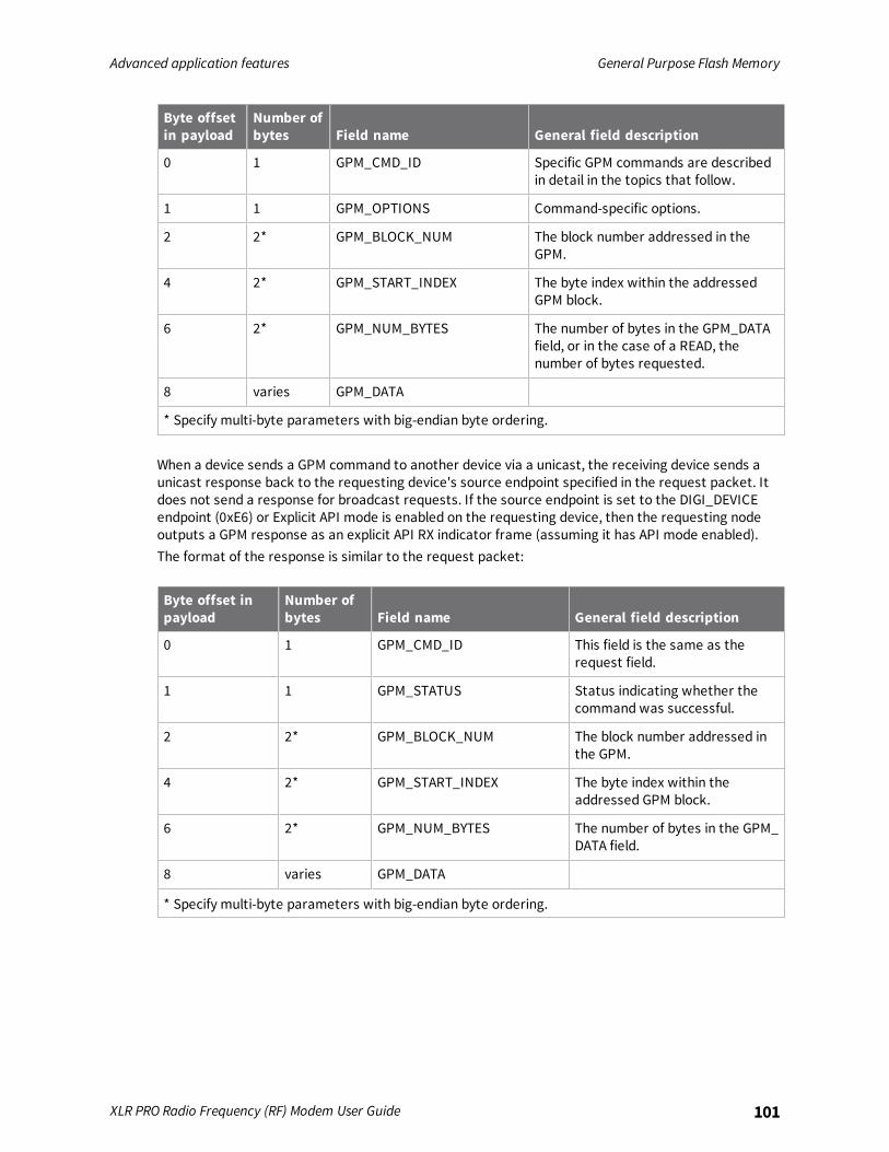
Advanced application features General Purpose Flash Memory
XLR PRO Radio Frequency (RF) Modem User Guide 101
Byte offsetin payload
Number ofbytes Field name General field description
0 1 GPM_CMD_ID Specific GPM commands are describedin detail in the topics that follow.
1 1 GPM_OPTIONS Command-specific options.
2 2* GPM_BLOCK_NUM The block number addressed in theGPM.
4 2* GPM_START_INDEX The byte index within the addressedGPM block.
6 2* GPM_NUM_BYTES The number of bytes in the GPM_DATAfield, or in the case of a READ, thenumber of bytes requested.
8 varies GPM_DATA
* Specify multi-byte parameters with big-endian byte ordering.
When a device sends a GPM command to another device via a unicast, the receiving device sends aunicast response back to the requesting device's source endpoint specified in the request packet. Itdoes not send a response for broadcast requests. If the source endpoint is set to the DIGI_DEVICEendpoint (0xE6) or Explicit API mode is enabled on the requesting device, then the requesting nodeoutputs a GPM response as an explicit API RX indicator frame (assuming it has API mode enabled).The format of the response is similar to the request packet:
Byte offset inpayload
Number ofbytes Field name General field description
0 1 GPM_CMD_ID This field is the same as therequest field.
1 1 GPM_STATUS Status indicating whether thecommand was successful.
2 2* GPM_BLOCK_NUM The block number addressed inthe GPM.
4 2* GPM_START_INDEX The byte index within theaddressed GPM block.
6 2* GPM_NUM_BYTES The number of bytes in the GPM_DATA field.
8 varies GPM_DATA
* Specify multi-byte parameters with big-endian byte ordering.
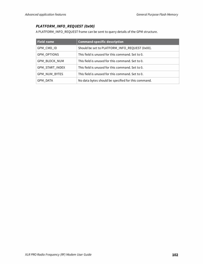
Advanced application features General Purpose Flash Memory
XLR PRO Radio Frequency (RF) Modem User Guide 102
PLATFORM_INFO_REQUEST (0x00)A PLATFORM_INFO_REQUEST frame can be sent to query details of the GPM structure.
Field name Command-specific description
GPM_CMD_ID Should be set to PLATFORM_INFO_REQUEST (0x00).
GPM_OPTIONS This field is unused for this command. Set to 0.
GPM_BLOCK_NUM This field is unused for this command. Set to 0.
GPM_START_INDEX This field is unused for this command. Set to 0.
GPM_NUM_BYTES This field is unused for this command. Set to 0.
GPM_DATA No data bytes should be specified for this command.
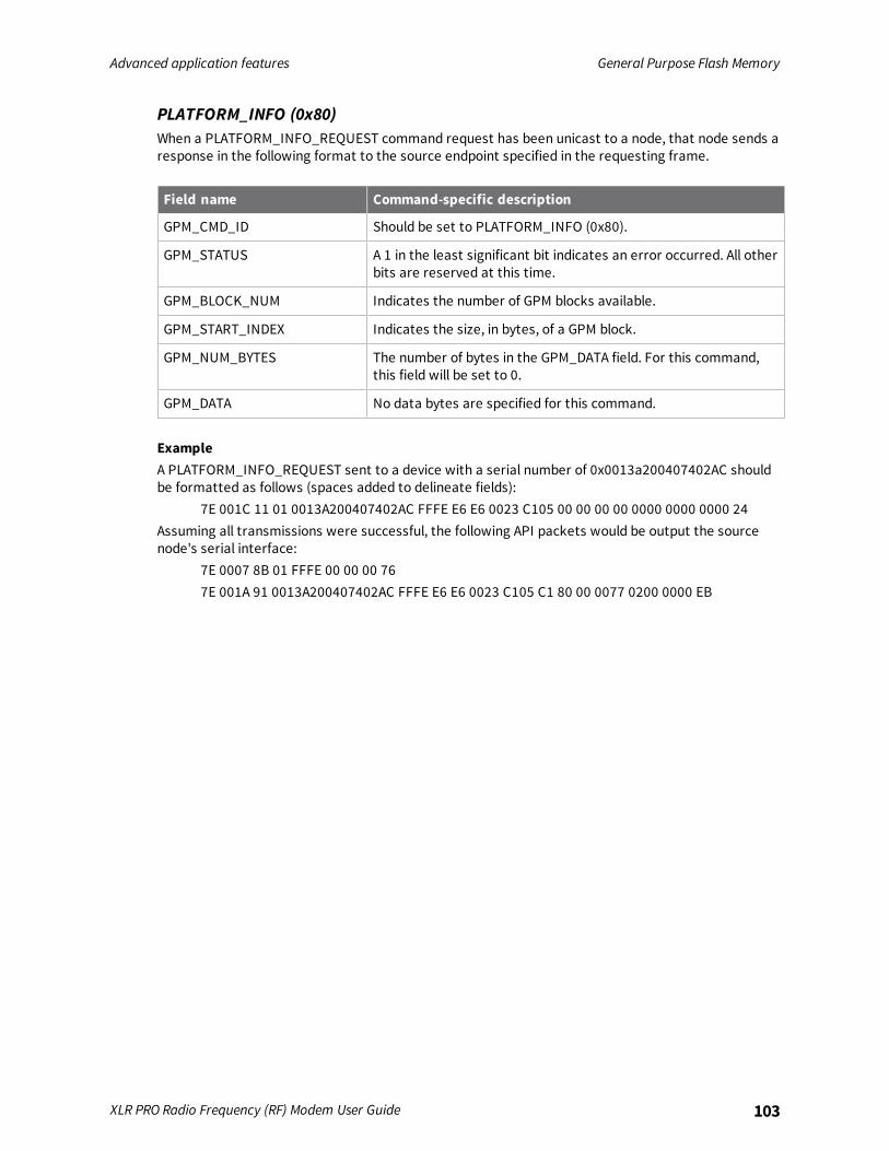
Advanced application features General Purpose Flash Memory
XLR PRO Radio Frequency (RF) Modem User Guide 103
PLATFORM_INFO (0x80)When a PLATFORM_INFO_REQUEST command request has been unicast to a node, that node sends aresponse in the following format to the source endpoint specified in the requesting frame.
Field name Command-specific description
GPM_CMD_ID Should be set to PLATFORM_INFO (0x80).
GPM_STATUS A 1 in the least significant bit indicates an error occurred. All otherbits are reserved at this time.
GPM_BLOCK_NUM Indicates the number of GPM blocks available.
GPM_START_INDEX Indicates the size, in bytes, of a GPM block.
GPM_NUM_BYTES The number of bytes in the GPM_DATA field. For this command,this field will be set to 0.
GPM_DATA No data bytes are specified for this command.
ExampleA PLATFORM_INFO_REQUEST sent to a device with a serial number of 0x0013a200407402AC shouldbe formatted as follows (spaces added to delineate fields):
7E 001C 11 01 0013A200407402AC FFFE E6 E6 0023 C105 00 00 00 00 0000 0000 0000 24Assuming all transmissions were successful, the following API packets would be output the sourcenode's serial interface:
7E 0007 8B 01 FFFE 00 00 00 767E 001A 91 0013A200407402AC FFFE E6 E6 0023 C105 C1 80 00 0077 0200 0000 EB
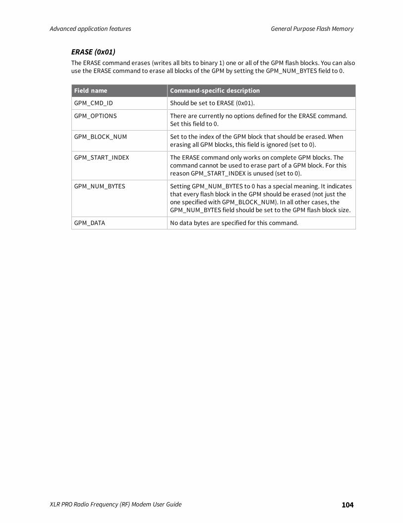
Advanced application features General Purpose Flash Memory
XLR PRO Radio Frequency (RF) Modem User Guide 104
ERASE (0x01)The ERASE command erases (writes all bits to binary 1) one or all of the GPM flash blocks. You can alsouse the ERASE command to erase all blocks of the GPM by setting the GPM_NUM_BYTES field to 0.
Field name Command-specific description
GPM_CMD_ID Should be set to ERASE (0x01).
GPM_OPTIONS There are currently no options defined for the ERASE command.Set this field to 0.
GPM_BLOCK_NUM Set to the index of the GPM block that should be erased. Whenerasing all GPM blocks, this field is ignored (set to 0).
GPM_START_INDEX The ERASE command only works on complete GPM blocks. Thecommand cannot be used to erase part of a GPM block. For thisreason GPM_START_INDEX is unused (set to 0).
GPM_NUM_BYTES Setting GPM_NUM_BYTES to 0 has a special meaning. It indicatesthat every flash block in the GPM should be erased (not just theone specified with GPM_BLOCK_NUM). In all other cases, theGPM_NUM_BYTES field should be set to the GPM flash block size.
GPM_DATA No data bytes are specified for this command.

Advanced application features General Purpose Flash Memory
XLR PRO Radio Frequency (RF) Modem User Guide 105
ERASE_RESPONSE (0x81)When an ERASE command request has been unicast to a node, that node sends a response in thefollowing format to the source endpoint specified in the requesting frame.
Field name Command-specific description
GPM_CMD_ID Should be set to ERASE_RESPONSE (0x81).
GPM_STATUS A 1 in the least significant bit indicates an error occurred. Allother bits are reserved at this time.
GPM_BLOCK_NUM Matches the parameter passed in the request frame.
GPM_START_INDEX Matches the parameter passed in the request frame.
GPM_NUM_BYTES The number of bytes in the GPM_DATA field. For this command,this field will be set to 0.
GPM_DATA No data bytes are specified for this command.
ExampleTo erase flash block 42 of a target radio with serial number of 0x0013a200407402ac format an ERASEpacket as follows (spaces added to delineate fields):
7E 001C 11 01 0013A200407402AC FFFE E6 E6 0023 C105 00 C0 01 00 002A 0000 0200 37Assuming all transmissions were successful, the following API packets would be output the sourcenode's serial interface:
7E 0007 8B 01 FFFE 00 00 00 767E 001A 91 0013A200407402AC FFFE E6 E6 0023 C105 C1 81 00 002A 0000 0000 39

Advanced application features General Purpose Flash Memory
XLR PRO Radio Frequency (RF) Modem User Guide 106
WRITE (0x02) and ERASE_THEN_WRITE (0x03)The WRITE command writes the specified bytes to the specified GPM location. Before writing bytes toa GPM block, make sure all the bytes have first been erased. The ERASE_THEN_WRITE commandperforms an ERASE of the entire GPM block specified with the GPM_BLOCK_NUM field prior to doing aWRITE.
Field name Description
GPM_CMD_ID Set to WRITE (0x02) or ERASE_THEN_WRITE (0x03).
GPM_OPTIONS At present, there are no defined options for this command. Set thisfield to 0.
GPM_BLOCK_NUM Set to the index of the GPM block to be written.
GPM_START_INDEX Set to the byte index within the GPM block where the data shouldbe written.
GPM_NUM_BYTES Set to the number of bytes specified in the GPM_DATA field. Onlyone GPM block can be operated on per command. For this reason,the GPM_START_INDEX plus the GPM_NUM_BYTES cannot begreater than the GPM block size.
Note The number of bytes sent in an explicit API frame (includingthe GPM command fields) cannot exceed the maximum payload sizeof the radio. Use the ATNP command to query the maximumpayload size.
GPM_DATA Data to be written.
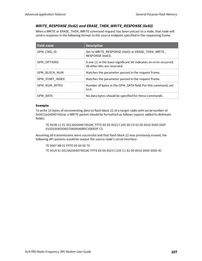
Advanced application features General Purpose Flash Memory
XLR PRO Radio Frequency (RF) Modem User Guide 107
WRITE_RESPONSE (0x82) and ERASE_THEN_WRITE_RESPONSE (0x83)When a WRITE or ERASE_THEN_WRITE command request has been unicast to a node, that node willsend a response in the following format to the source endpoint specified in the requesting frame.
Field name Description
GPM_CMD_ID Set to WRITE_RESPONSE (0x82) or ERASE_THEN_WRITE_RESPONSE (0x83).
GPM_OPTIONS A one (1) in the least-significant bit indicates an error occurred.All other bits are reserved.
GPM_BLOCK_NUM Matches the parameter passed in the request frame.
GPM_START_INDEX Matches the parameter passed in the request frame.
GPM_NUM_BYTES Number of bytes in the GPM_DATA field. For this command, setto 0.
GPM_DATA No data bytes should be specified for these commands.
Example:To write 15 bytes of incrementing data to flash block 22 of a target radio with serial number of0x0013a200407402ac a WRITE packet should be formatted as follows (spaces added to delineatefields):
7E 002B 11 01 0013A200407402AC FFFE E6 E6 0023 C105 00 C0 02 00 0016 0000 000F0102030405060708090A0B0C0D0E0F C5
Assuming all transmissions were successful and that flash block 22 was previously erased, thefollowing API packets would be output the source node's serial interface:
7E 0007 8B 01 FFFE 00 00 00 767E 001A 91 0013A200407402AC FFFE E6 E6 0023 C105 C1 82 00 0016 0000 0000 4C
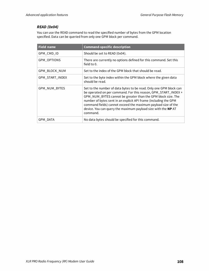
Advanced application features General Purpose Flash Memory
XLR PRO Radio Frequency (RF) Modem User Guide 108
READ (0x04)You can use the READ command to read the specified number of bytes from the GPM locationspecified. Data can be queried from only one GPM block per command.
Field name Command-specific description
GPM_CMD_ID Should be set to READ (0x04).
GPM_OPTIONS There are currently no options defined for this command. Set thisfield to 0.
GPM_BLOCK_NUM Set to the index of the GPM block that should be read.
GPM_START_INDEX Set to the byte index within the GPM block where the given datashould be read.
GPM_NUM_BYTES Set to the number of data bytes to be read. Only one GPM block canbe operated on per command. For this reason, GPM_START_INDEX +GPM_NUM_BYTES cannot be greater than the GPM block size. Thenumber of bytes sent in an explicit API frame (including the GPMcommand fields) cannot exceed the maximum payload size of thedevice. You can query the maximum payload size with the NP ATcommand.
GPM_DATA No data bytes should be specified for this command.
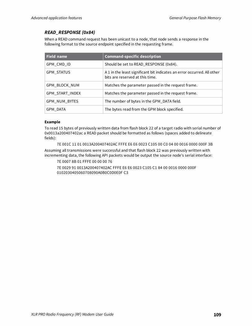
Advanced application features General Purpose Flash Memory
XLR PRO Radio Frequency (RF) Modem User Guide 109
READ_RESPONSE (0x84)When a READ command request has been unicast to a node, that node sends a response in thefollowing format to the source endpoint specified in the requesting frame.
Field name Command-specific description
GPM_CMD_ID Should be set to READ_RESPONSE (0x84).
GPM_STATUS A 1 in the least significant bit indicates an error occurred. All otherbits are reserved at this time.
GPM_BLOCK_NUM Matches the parameter passed in the request frame.
GPM_START_INDEX Matches the parameter passed in the request frame.
GPM_NUM_BYTES The number of bytes in the GPM_DATA field.
GPM_DATA The bytes read from the GPM block specified.
ExampleTo read 15 bytes of previously written data from flash block 22 of a target radio with serial number of0x0013a200407402ac a READ packet should be formatted as follows (spaces added to delineatefields):
7E 001C 11 01 0013A200407402AC FFFE E6 E6 0023 C105 00 C0 04 00 0016 0000 000F 3BAssuming all transmissions were successful and that flash block 22 was previously written withincrementing data, the following API packets would be output the source node's serial interface:
7E 0007 8B 01 FFFE 00 00 00 767E 0029 91 0013A200407402AC FFFE E6 E6 0023 C105 C1 84 00 0016 0000 000F0102030405060708090A0B0C0D0E0F C3
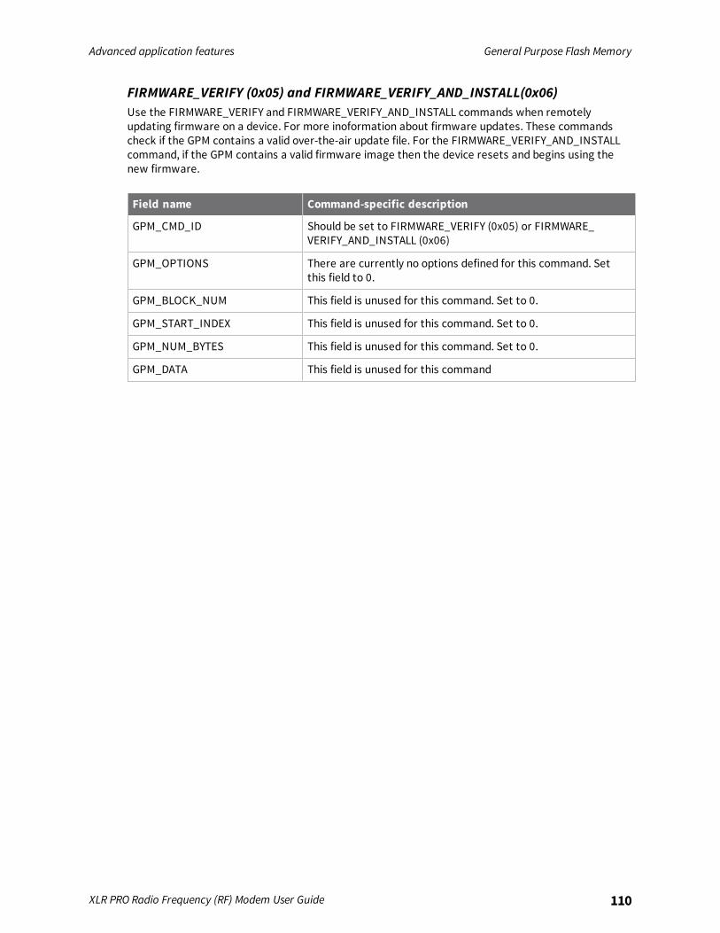
Advanced application features General Purpose Flash Memory
XLR PRO Radio Frequency (RF) Modem User Guide 110
FIRMWARE_VERIFY (0x05) and FIRMWARE_VERIFY_AND_INSTALL(0x06)Use the FIRMWARE_VERIFY and FIRMWARE_VERIFY_AND_INSTALL commands when remotelyupdating firmware on a device. For more inoformation about firmware updates. These commandscheck if the GPM contains a valid over-the-air update file. For the FIRMWARE_VERIFY_AND_INSTALLcommand, if the GPM contains a valid firmware image then the device resets and begins using thenew firmware.
Field name Command-specific description
GPM_CMD_ID Should be set to FIRMWARE_VERIFY (0x05) or FIRMWARE_VERIFY_AND_INSTALL (0x06)
GPM_OPTIONS There are currently no options defined for this command. Setthis field to 0.
GPM_BLOCK_NUM This field is unused for this command. Set to 0.
GPM_START_INDEX This field is unused for this command. Set to 0.
GPM_NUM_BYTES This field is unused for this command. Set to 0.
GPM_DATA This field is unused for this command
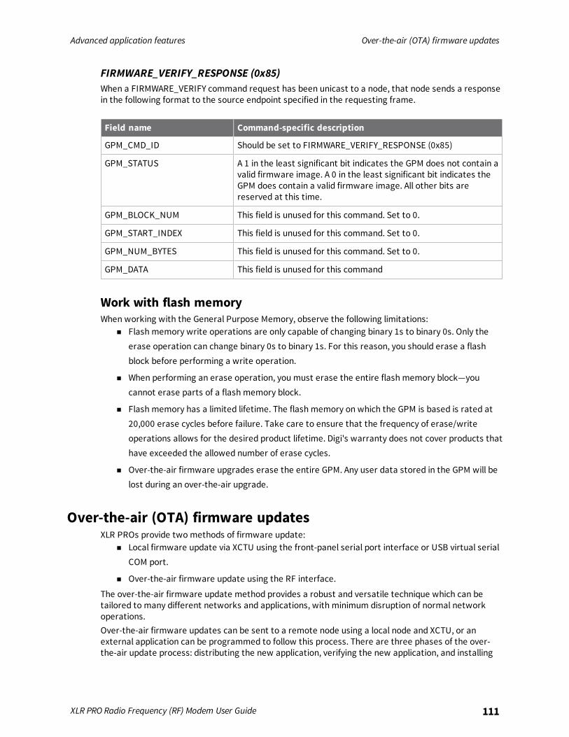
Advanced application features Over-the-air (OTA) firmware updates
XLR PRO Radio Frequency (RF) Modem User Guide 111
FIRMWARE_VERIFY_RESPONSE (0x85)When a FIRMWARE_VERIFY command request has been unicast to a node, that node sends a responsein the following format to the source endpoint specified in the requesting frame.
Field name Command-specific description
GPM_CMD_ID Should be set to FIRMWARE_VERIFY_RESPONSE (0x85)
GPM_STATUS A 1 in the least significant bit indicates the GPM does not contain avalid firmware image. A 0 in the least significant bit indicates theGPM does contain a valid firmware image. All other bits arereserved at this time.
GPM_BLOCK_NUM This field is unused for this command. Set to 0.
GPM_START_INDEX This field is unused for this command. Set to 0.
GPM_NUM_BYTES This field is unused for this command. Set to 0.
GPM_DATA This field is unused for this command
Work with flash memoryWhen working with the General Purpose Memory, observe the following limitations:
n Flash memory write operations are only capable of changing binary 1s to binary 0s. Only theerase operation can change binary 0s to binary 1s. For this reason, you should erase a flashblock before performing a write operation.
n When performing an erase operation, you must erase the entire flash memory block—youcannot erase parts of a flash memory block.
n Flash memory has a limited lifetime. The flash memory on which the GPM is based is rated at20,000 erase cycles before failure. Take care to ensure that the frequency of erase/writeoperations allows for the desired product lifetime. Digi's warranty does not cover products thathave exceeded the allowed number of erase cycles.
n Over-the-air firmware upgrades erase the entire GPM. Any user data stored in the GPM will belost during an over-the-air upgrade.
Over-the-air (OTA) firmware updatesXLR PROs provide two methods of firmware update:
n Local firmware update via XCTU using the front-panel serial port interface or USB virtual serialCOM port.
n Over-the-air firmware update using the RF interface.
The over-the-air firmware update method provides a robust and versatile technique which can betailored to many different networks and applications, with minimum disruption of normal networkoperations.Over-the-air firmware updates can be sent to a remote node using a local node and XCTU, or anexternal application can be programmed to follow this process. There are three phases of the over-the-air update process: distributing the new application, verifying the new application, and installing
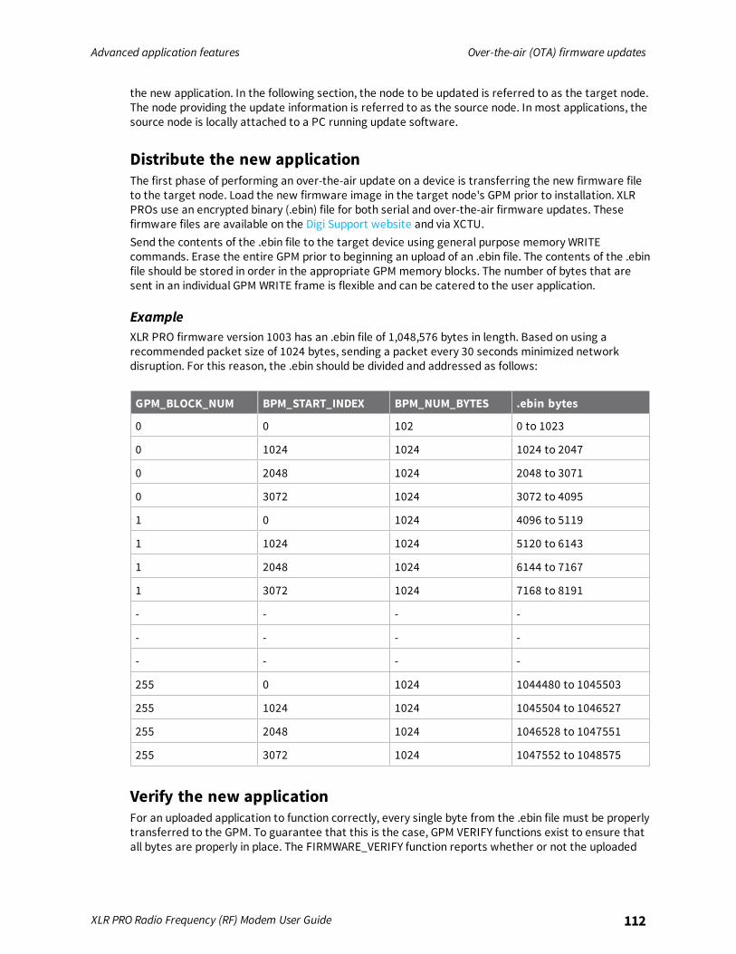
Advanced application features Over-the-air (OTA) firmware updates
XLR PRO Radio Frequency (RF) Modem User Guide 112
the new application. In the following section, the node to be updated is referred to as the target node.The node providing the update information is referred to as the source node. In most applications, thesource node is locally attached to a PC running update software.
Distribute the new applicationThe first phase of performing an over-the-air update on a device is transferring the new firmware fileto the target node. Load the new firmware image in the target node's GPM prior to installation. XLRPROs use an encrypted binary (.ebin) file for both serial and over-the-air firmware updates. Thesefirmware files are available on the Digi Support website and via XCTU.Send the contents of the .ebin file to the target device using general purpose memory WRITEcommands. Erase the entire GPM prior to beginning an upload of an .ebin file. The contents of the .ebinfile should be stored in order in the appropriate GPM memory blocks. The number of bytes that aresent in an individual GPM WRITE frame is flexible and can be catered to the user application.
ExampleXLR PRO firmware version 1003 has an .ebin file of 1,048,576 bytes in length. Based on using arecommended packet size of 1024 bytes, sending a packet every 30 seconds minimized networkdisruption. For this reason, the .ebin should be divided and addressed as follows:
GPM_BLOCK_NUM BPM_START_INDEX BPM_NUM_BYTES .ebin bytes
0 0 102 0 to 1023
0 1024 1024 1024 to 2047
0 2048 1024 2048 to 3071
0 3072 1024 3072 to 4095
1 0 1024 4096 to 5119
1 1024 1024 5120 to 6143
1 2048 1024 6144 to 7167
1 3072 1024 7168 to 8191
- - - -
- - - -
- - - -
255 0 1024 1044480 to 1045503
255 1024 1024 1045504 to 1046527
255 2048 1024 1046528 to 1047551
255 3072 1024 1047552 to 1048575
Verify the new applicationFor an uploaded application to function correctly, every single byte from the .ebin file must be properlytransferred to the GPM. To guarantee that this is the case, GPM VERIFY functions exist to ensure thatall bytes are properly in place. The FIRMWARE_VERIFY function reports whether or not the uploaded
Advanced application features Over-the-air (OTA) firmware updates
XLR PRO Radio Frequency (RF) Modem User Guide 113
data is valid. The FIRMWARE_VERIFY_AND_INSTALL command reports if the uploaded data is invalid. Ifthe data is valid, it begins installing the application. No installation takes place on invalid data.
Install the applicationWhen the entire .ebin file has been uploaded to the GPM of the target node a FIRMWARE_VERIFY_AND_INSTALL command can be issued. Once the target receives the command it will verify the .ebinfile loaded in the GPM. If it is found to be valid, the XLR PRO will install the new firmware. Thisinstallation process can take up to 8 seconds. During the installation the XLR PRO will be unresponsiveto both serial and RF communication. To complete the installation, the target XLR PRO will reset. AnyAT parameter settings which have not been written to flash using the WR (write) command will belost.
Keep in mindThe firmware upgrade process requires that the XLR PRO resets itself and parameters which have notbeen written to flash will be lost after the reset. To avoid this, write all parameters with the WR(write) command before doing a firmware upgrade.Because explicit API Tx frames can be addressed to a local node (accessible via the SPI or UART) or aremote node (accessible over the RF port) the same process can be used to update firmware on anXLR PRO in either case.
Configure the XLR PRO using the web configurationinterface
Access the XLR PRO web configuration interface 115Set general options 115Set Ethernet network options 115Set Ethernet RF bridging options 116Set Device Cloud connectivity options 117Set XLR radio options 117Set XLR radio serial options 118Set XLR radio IP socket (Ethernet) options 119Update firmware 120Set web configuration options 120
XLR PRO Radio Frequency (RF) Modem User Guide 114
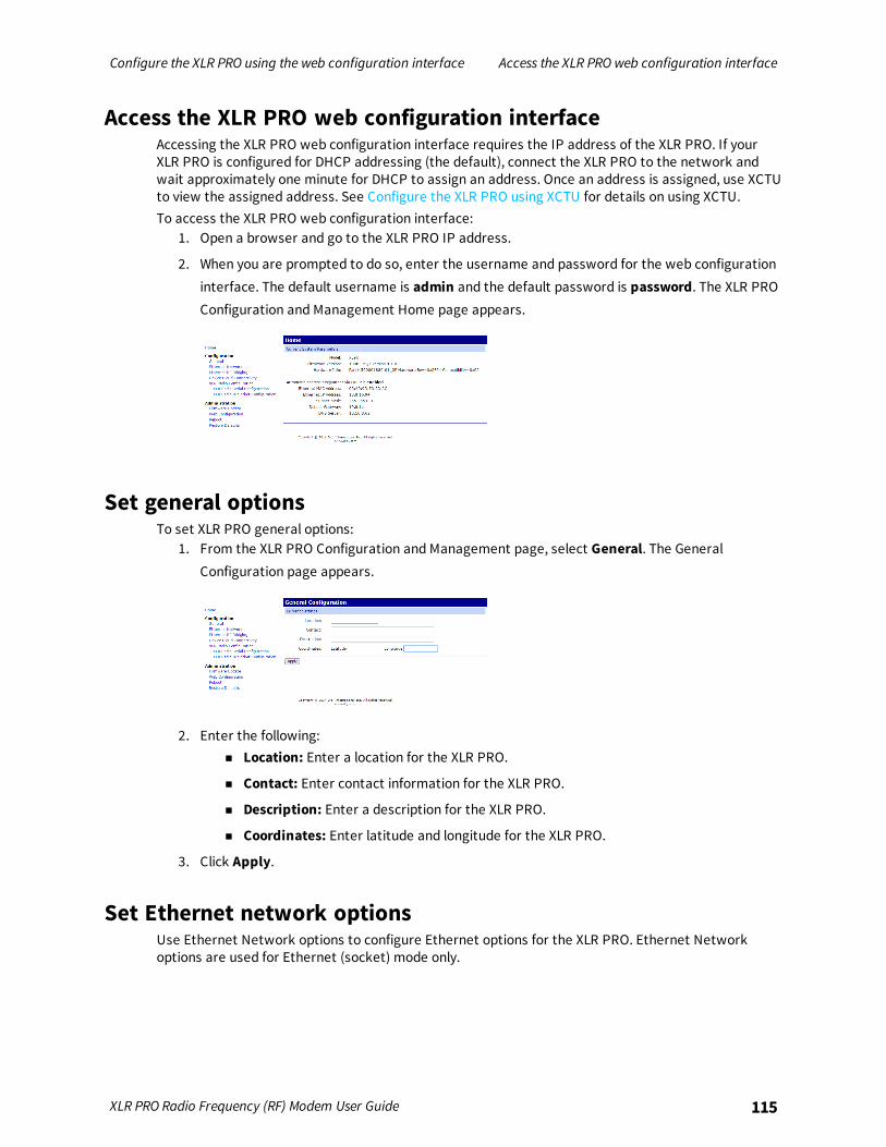
Configure the XLR PRO using the web configuration interface Access the XLR PROweb configuration interface
XLR PRO Radio Frequency (RF) Modem User Guide 115
Access the XLR PRO web configuration interfaceAccessing the XLR PRO web configuration interface requires the IP address of the XLR PRO. If yourXLR PRO is configured for DHCP addressing (the default), connect the XLR PRO to the network andwait approximately one minute for DHCP to assign an address. Once an address is assigned, use XCTUto view the assigned address. See Configure the XLR PRO using XCTU for details on using XCTU.To access the XLR PRO web configuration interface:
1. Open a browser and go to the XLR PRO IP address.
2. When you are prompted to do so, enter the username and password for the web configurationinterface. The default username is admin and the default password is password. The XLR PROConfiguration and Management Home page appears.
Set general optionsTo set XLR PRO general options:
1. From the XLR PRO Configuration and Management page, select General. The GeneralConfiguration page appears.
2. Enter the following:n Location: Enter a location for the XLR PRO.
n Contact: Enter contact information for the XLR PRO.
n Description: Enter a description for the XLR PRO.
n Coordinates: Enter latitude and longitude for the XLR PRO.
3. Click Apply.
Set Ethernet network optionsUse Ethernet Network options to configure Ethernet options for the XLR PRO. Ethernet Networkoptions are used for Ethernet (socket) mode only.
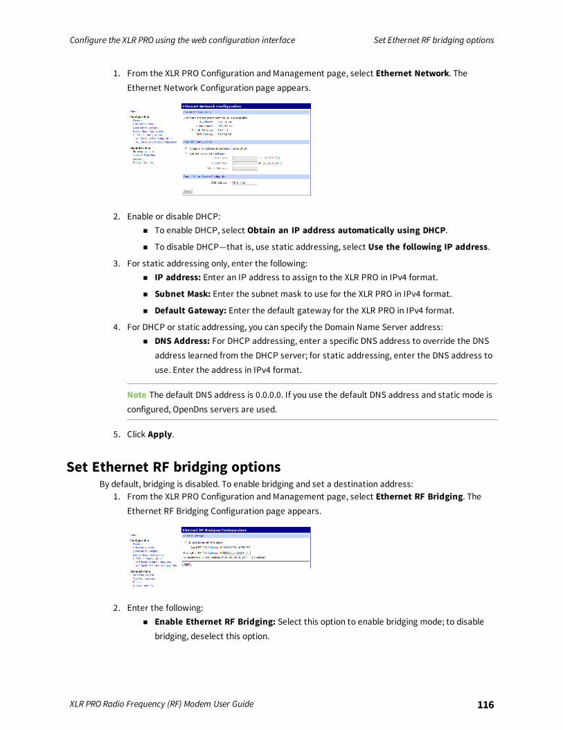
Configure the XLR PRO using the web configuration interface Set Ethernet RF bridging options
XLR PRO Radio Frequency (RF) Modem User Guide 116
1. From the XLR PRO Configuration and Management page, select Ethernet Network. TheEthernet Network Configuration page appears.
2. Enable or disable DHCP:n To enable DHCP, select Obtain an IP address automatically using DHCP.
n To disable DHCP—that is, use static addressing, select Use the following IP address.
3. For static addressing only, enter the following:n IP address: Enter an IP address to assign to the XLR PRO in IPv4 format.
n Subnet Mask: Enter the subnet mask to use for the XLR PRO in IPv4 format.
n Default Gateway: Enter the default gateway for the XLR PRO in IPv4 format.
4. For DHCP or static addressing, you can specify the Domain Name Server address:n DNS Address: For DHCP addressing, enter a specific DNS address to override the DNS
address learned from the DHCP server; for static addressing, enter the DNS address touse. Enter the address in IPv4 format.
Note The default DNS address is 0.0.0.0. If you use the default DNS address and static mode isconfigured, OpenDns servers are used.
5. Click Apply.
Set Ethernet RF bridging optionsBy default, bridging is disabled. To enable bridging and set a destination address:
1. From the XLR PRO Configuration and Management page, select Ethernet RF Bridging. TheEthernet RF Bridging Configuration page appears.
2. Enter the following:n Enable Ethernet RF Bridging: Select this option to enable bridging mode; to disable
bridging, deselect this option.
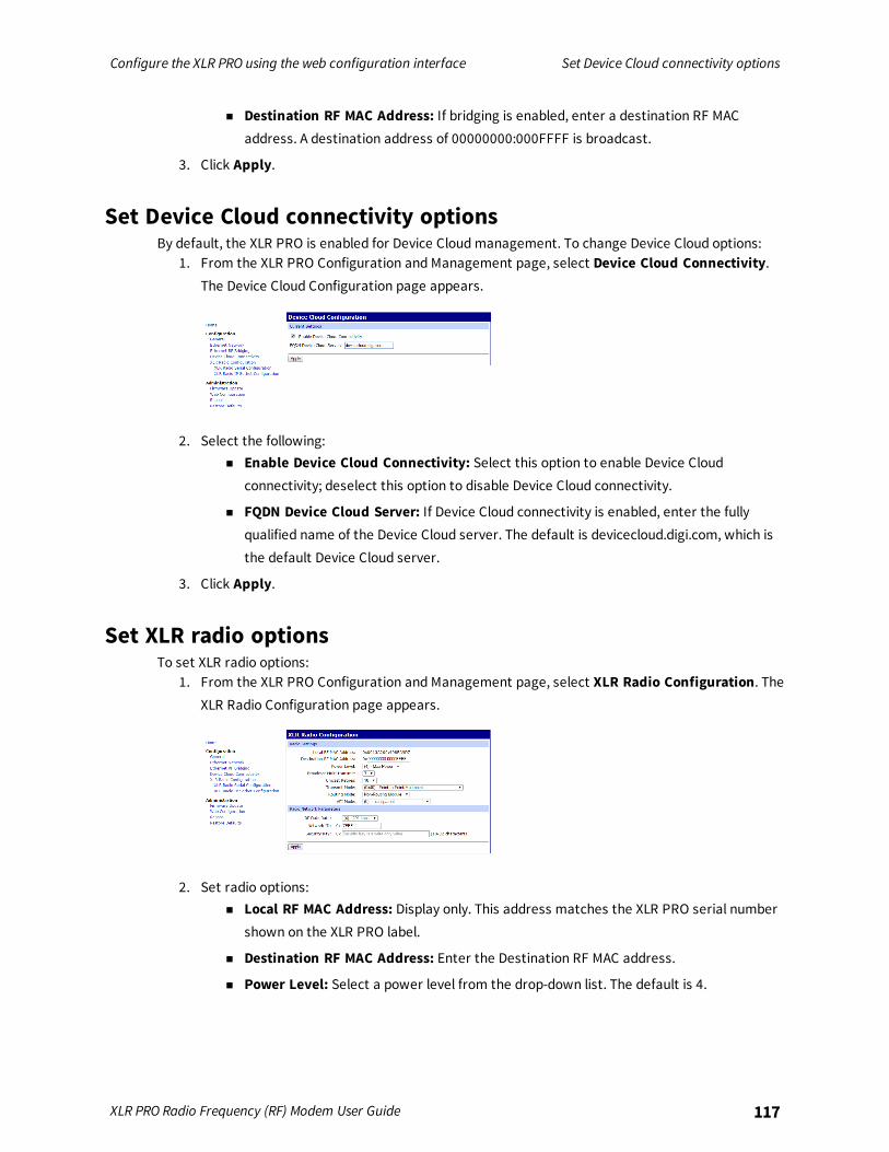
Configure the XLR PRO using the web configuration interface Set Device Cloud connectivity options
XLR PRO Radio Frequency (RF) Modem User Guide 117
n Destination RF MAC Address: If bridging is enabled, enter a destination RF MACaddress. A destination address of 00000000:000FFFF is broadcast.
3. Click Apply.
Set Device Cloud connectivity optionsBy default, the XLR PRO is enabled for Device Cloud management. To change Device Cloud options:
1. From the XLR PRO Configuration and Management page, select Device Cloud Connectivity.The Device Cloud Configuration page appears.
2. Select the following:n Enable Device Cloud Connectivity: Select this option to enable Device Cloud
connectivity; deselect this option to disable Device Cloud connectivity.
n FQDN Device Cloud Server: If Device Cloud connectivity is enabled, enter the fullyqualified name of the Device Cloud server. The default is devicecloud.digi.com, which isthe default Device Cloud server.
3. Click Apply.
Set XLR radio optionsTo set XLR radio options:
1. From the XLR PRO Configuration and Management page, select XLR Radio Configuration. TheXLR Radio Configuration page appears.
2. Set radio options:n Local RF MAC Address: Display only. This address matches the XLR PRO serial number
shown on the XLR PRO label.
n Destination RF MAC Address: Enter the Destination RF MAC address.
n Power Level: Select a power level from the drop-down list. The default is 4.
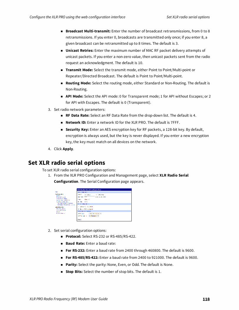
Configure the XLR PRO using the web configuration interface Set XLR radio serial options
XLR PRO Radio Frequency (RF) Modem User Guide 118
n Broadcast Multi-transmit: Enter the number of broadcast retransmissions, from 0 to 8retransmissions. If you enter 0, broadcasts are transmitted only once; if you enter 8, agiven broadcast can be retransmitted up to 8 times. The default is 3.
n Unicast Retries: Enter the maximum number of MAC RF packet delivery attempts ofunicast packets. If you enter a non-zero value, then unicast packets sent from the radiorequest an acknowledgment. The default is 10.
n Transmit Mode: Select the transmit mode, either Point to Point/Multi-point orRepeater/Directed Broadcast. The default is Point to Point/Multi-point.
n Routing Mode: Select the routing mode, either Standard or Non-Routing. The default isNon-Routing.
n API Mode: Select the API mode: 0 for Transparent mode; 1 for API without Escapes; or 2for API with Escapes. The default is 0 (Transparent).
3. Set radio network parameters:n RF Data Rate: Select an RF Data Rate from the drop-down list. The default is 4.
n Network ID: Enter a network ID for the XLR PRO. The default is 7FFF.
n Security Key: Enter an AES encryption key for RF packets, a 128-bit key. By default,encryption is always used, but the key is never displayed. If you enter a new encryptionkey, the key must match on all devices on the network.
4. Click Apply.
Set XLR radio serial optionsTo set XLR radio serial configuration options:
1. From the XLR PRO Configuration and Management page, select XLR Radio SerialConfiguration. The Serial Configuration page appears.
2. Set serial configuration options:n Protocol: Select RS-232 or RS-485/RS-422.
n Baud Rate: Enter a baud rate:
n For RS-232: Enter a baud rate from 2400 through 460800. The default is 9600.
n For RS-485/RS-422: Enter a baud rate from 2400 to 921000. The default is 9600.
n Parity: Select the parity: None, Even, or Odd. The default is None.
n Stop Bits: Select the number of stop bits. The default is 1.
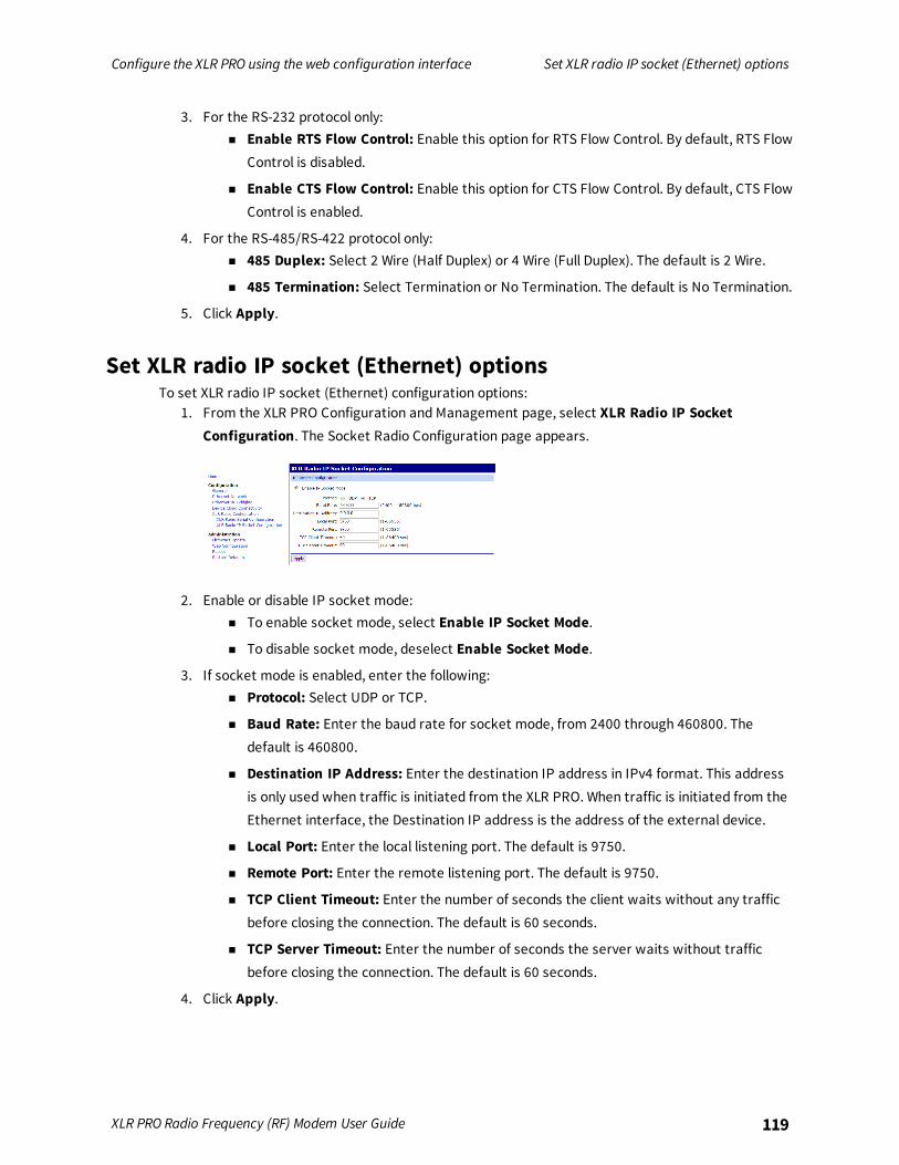
Configure the XLR PRO using the web configuration interface Set XLR radio IP socket (Ethernet) options
XLR PRO Radio Frequency (RF) Modem User Guide 119
3. For the RS-232 protocol only:n Enable RTS Flow Control: Enable this option for RTS Flow Control. By default, RTS Flow
Control is disabled.
n Enable CTS Flow Control: Enable this option for CTS Flow Control. By default, CTS FlowControl is enabled.
4. For the RS-485/RS-422 protocol only:n 485 Duplex: Select 2 Wire (Half Duplex) or 4 Wire (Full Duplex). The default is 2 Wire.
n 485 Termination: Select Termination or No Termination. The default is No Termination.
5. Click Apply.
Set XLR radio IP socket (Ethernet) optionsTo set XLR radio IP socket (Ethernet) configuration options:
1. From the XLR PRO Configuration and Management page, select XLR Radio IP SocketConfiguration. The Socket Radio Configuration page appears.
2. Enable or disable IP socket mode:n To enable socket mode, select Enable IP Socket Mode.
n To disable socket mode, deselect Enable Socket Mode.
3. If socket mode is enabled, enter the following:n Protocol: Select UDP or TCP.
n Baud Rate: Enter the baud rate for socket mode, from 2400 through 460800. Thedefault is 460800.
n Destination IP Address: Enter the destination IP address in IPv4 format. This addressis only used when traffic is initiated from the XLR PRO. When traffic is initiated from theEthernet interface, the Destination IP address is the address of the external device.
n Local Port: Enter the local listening port. The default is 9750.
n Remote Port: Enter the remote listening port. The default is 9750.
n TCP Client Timeout: Enter the number of seconds the client waits without any trafficbefore closing the connection. The default is 60 seconds.
n TCP Server Timeout: Enter the number of seconds the server waits without trafficbefore closing the connection. The default is 60 seconds.
4. Click Apply.
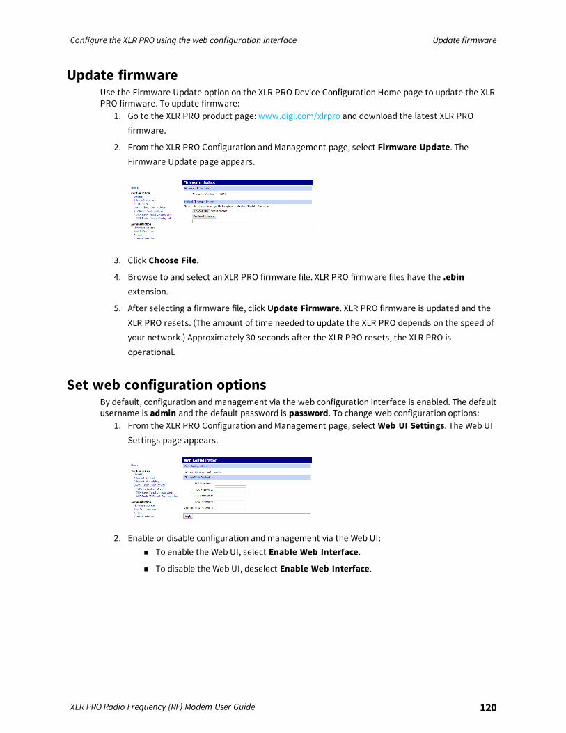
Configure the XLR PRO using the web configuration interface Update firmware
XLR PRO Radio Frequency (RF) Modem User Guide 120
Update firmwareUse the Firmware Update option on the XLR PRO Device Configuration Home page to update the XLRPRO firmware. To update firmware:
1. Go to the XLR PRO product page: www.digi.com/xlrpro and download the latest XLR PROfirmware.
2. From the XLR PRO Configuration and Management page, select Firmware Update. TheFirmware Update page appears.
3. Click Choose File.
4. Browse to and select an XLR PRO firmware file. XLR PRO firmware files have the .ebinextension.
5. After selecting a firmware file, click Update Firmware. XLR PRO firmware is updated and theXLR PRO resets. (The amount of time needed to update the XLR PRO depends on the speed ofyour network.) Approximately 30 seconds after the XLR PRO resets, the XLR PRO isoperational.
Set web configuration optionsBy default, configuration and management via the web configuration interface is enabled. The defaultusername is admin and the default password is password. To change web configuration options:
1. From the XLR PRO Configuration and Management page, select Web UI Settings. The Web UISettings page appears.
2. Enable or disable configuration and management via the Web UI:n To enable the Web UI, select Enable Web Interface.
n To disable the Web UI, deselect Enable Web Interface.
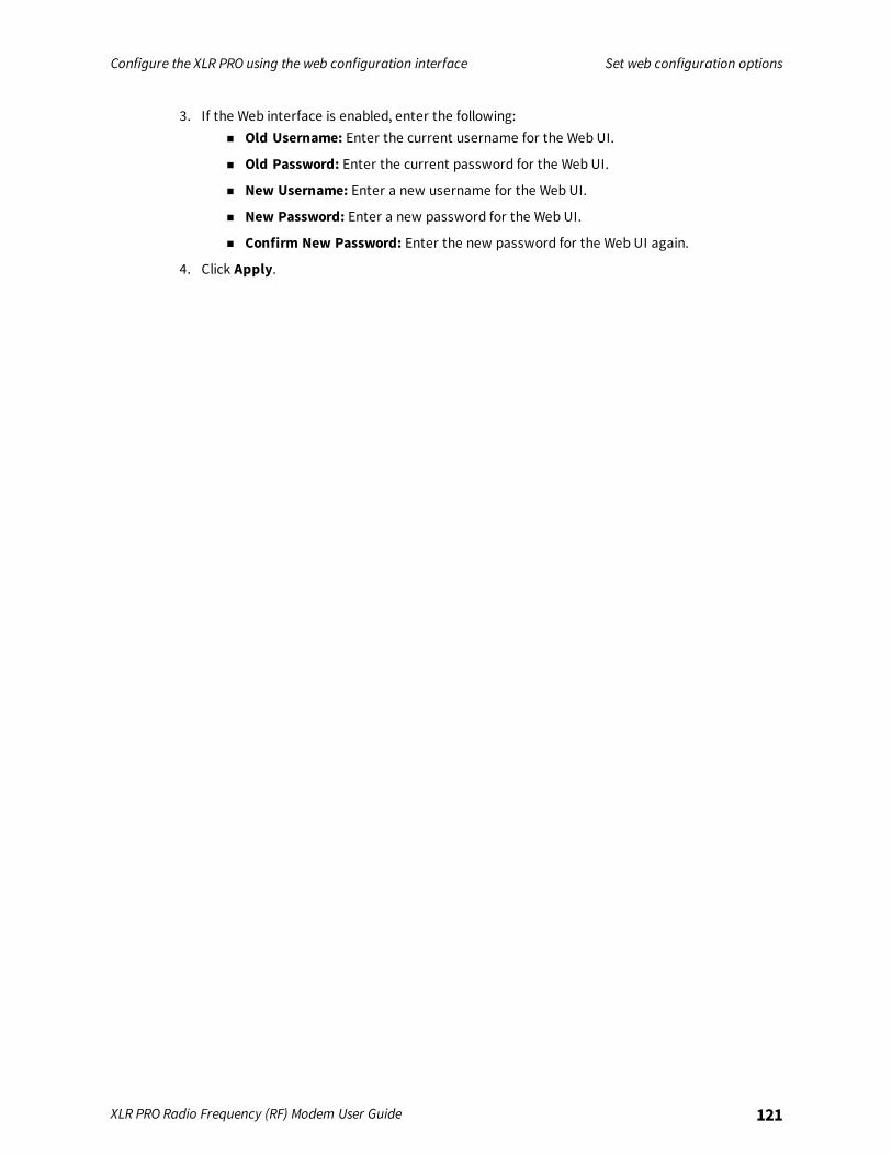
Configure the XLR PRO using the web configuration interface Set web configuration options
XLR PRO Radio Frequency (RF) Modem User Guide 121
3. If the Web interface is enabled, enter the following:n Old Username: Enter the current username for the Web UI.
n Old Password: Enter the current password for the Web UI.
n New Username: Enter a new username for the Web UI.
n New Password: Enter a new password for the Web UI.
n Confirm New Password: Enter the new password for the Web UI again.
4. Click Apply.

Configure the XLR PRO using XCTU
Download and install XCTU 123Download and install the USB driver 123Connect XLR PRO to your PC 123Launch XCTU and add the XLR PRO 123Configure parameters using XCTU 123Determine or assign an IP address 124Update firmware with XCTU 124
XLR PRO Radio Frequency (RF) Modem User Guide 122
Configure the XLR PRO using XCTU Download and install XCTU
XLR PRO Radio Frequency (RF) Modem User Guide 123
Download and install XCTUFor XLR PRO support, make sure you install XCTU version 6.2 or later.To download and install XCTU:
1. Go to www.digi.com/xctu.
2. Launch the XCTU installer and follow the prompts on the installation screens.
Download and install the USB driverTo download and install the XLR PRO USB driver:
1. Go to the Drivers section of the product page.
2. Launch the XLR PRO USB driver installer and follow the prompts on the installation screens.
Connect XLR PRO to your PCTo connect XLR PRO to your PC:
1. Connect the XLR PRO mini USB port to an available USB port on your PC using the mini USBcable.
2. Power on the XLR PRO.
Launch XCTU and add the XLR PROTo launch XCTU and add the XLR PRO:
1. Double-click on the XCTU program icon. The XCTU main menu appears.
2. Click the Add a radio icon . The Add a radio device dialog appears.
3. Provide connection information for the XLR PRO:n Select the Serial/USB port: Select the USB port connected to the XLR PRO.
n Baud Rate: Select the default, 9600.
n Data Bits: Select the default, 8.
n Parity: Select the default, None.
n Stop Bits: Select the default 1.
n Flow Control: Select the default, None.
n The radio module is programmable: Keep the default, unselected.
4. Click Finish. XCTU connects to the XLR PRO and displays the device in the list of radios.
5. Click the XLR PRO to display current properties and configure parameters in the right-handpane.
Configure parameters using XCTUAll of the XLR PRO parameter values are displayed in the XCTU configuration pane. For a complete listof all parameters, see AT commands.To change a configuration parameter:
Configure the XLR PRO using XCTU Determine or assign an IP address
XLR PRO Radio Frequency (RF) Modem User Guide 124
1. Locate the parameter in the XCTU configuration display.
2. Use the Search function in the upper right corner to quickly locate a parameter.
3. Select a new value for the parameter.
4. If you want to permanently change the parameter value:n To save an individual parameter value, click on the Write icon to the right of the
parameter.
n To save all parameter settings, click on the Write icon at the top of the XCTUconfiguration pane.
Determine or assign an IP addressBy default, the XLR PRO gets an IP address automatically assigned using DHCP.
Determine the assigned DHCP addressTo determine the assigned DHCP address:
1. Connect the XLR PRO to the network via either Ethernet port on the XLR PRO front panel.
2. Wait approximately one minute. An IP address should be automatically assigned within oneminute. If a DHCP server hasn’t assigned an IP address within that time period, the XLR PROassigns an IP address using the following format:
169.254.xxx.yyy
where xxx is the decimal value of the 2nd to last byte of the XLR PRO Ethernet MAC addressand yyy is the last byte of the XLR PRO Ethernet MAC address. If the assigned address isalready in use, the address is incremented until a free address is found.Once an IP address is assigned, you can read the IP address using the MY parameter.
Assign a static IP addressTo assign a static IP address:
1. Set the following XLR PROparameters:n MA (addressing mode): Set the addressing mode to 1 (static).
n MY (XLR IP address): Enter the IP address for the XLR PRO.
n MK (XLR subnet mask): Enter the subnet mask for the XLR PRO.
n GW (XLR gateway address): Enter the default gateway address for the XLR PRO.
2. After setting the parameters, write the new parameter values to save the settings.
Update firmware with XCTUTo update XLR PRO firmware, you need XCTU version 6.1.2 (or above).To update firmware using XCTU:
Configure the XLR PRO using XCTU Update firmware with XCTU
XLR PRO Radio Frequency (RF) Modem User Guide 125
1. Launch XCTU.
2. Click Add devices or Discover devices to add the XLR PRO to the list of radios.n Select the COM port to which the XLR PRO serial port is connected.
n Select the baud rate (9600 8-N-1 by default).
n Switch baud rate to 115200b/s to reduce the time required to update the firmware.
n Close the COM port and reopen it at the new baud rate.
3. Select the radio configuration tab.
4. Click the icon to download the firmware.
5. Select the desired firmware, function set, and firmware version.
6. Click Finish and then the Yes.
Configure the XLR PRO using Digi Remote Manager
Use Digi Remote Manager (https://remotemanager.digi.com/) to perform the operations in thissection. Each operation requires that you enable Remote Manager with the DO command and thatyou connect the XLR PRO to an access point that has an external Internet connection to allow accessto Digi Remote Manager.
Note Digi is consolidating our cloud services, Digi Device Cloud and Digi Remote Manager®, under theRemote Manager name. This phased process does not affect device functionality or the functionalityof the web services and other features. However, customers will find that some user interface andfirmware functionality mention both Device Cloud and Digi Remote Manager.
Create a Remote Manager account 127Get the XLR PRO MAC address 127Add a XLR PRO to Remote Manager 127Update firmware with Remote Manager 128Configure Device Cloud connectivity options 128Configure Ethernet network options 129Configure Ethernet RF bridging options 129Configure IP socket mode options 130Configure serial mode options 131Configure system options 132Configure web configuration options 133Configure XLR radio configuration options 133Schedule Device Cloud configuration changes 135
XLR PRO Radio Frequency (RF) Modem User Guide 126
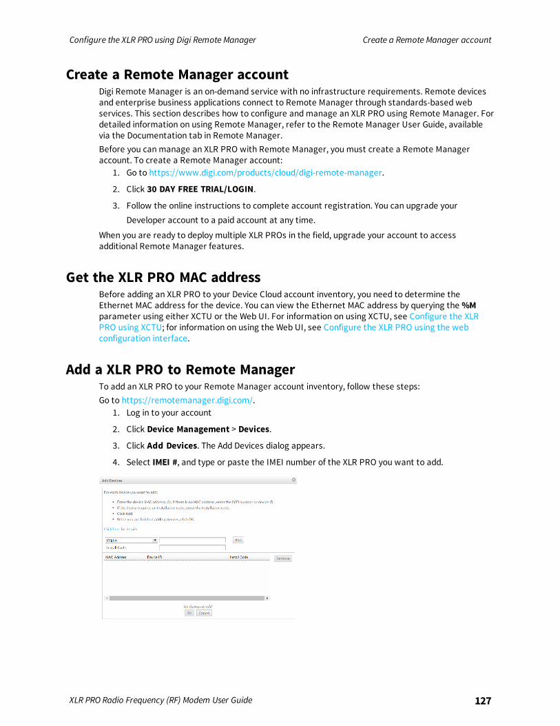
Configure the XLR PRO using Digi Remote Manager Create a Remote Manager account
XLR PRO Radio Frequency (RF) Modem User Guide 127
Create a Remote Manager accountDigi Remote Manager is an on-demand service with no infrastructure requirements. Remote devicesand enterprise business applications connect to Remote Manager through standards-based webservices. This section describes how to configure and manage an XLR PRO using Remote Manager. Fordetailed information on using Remote Manager, refer to the Remote Manager User Guide, availablevia the Documentation tab in Remote Manager.Before you can manage an XLR PRO with Remote Manager, you must create a Remote Manageraccount. To create a Remote Manager account:
1. Go to https://www.digi.com/products/cloud/digi-remote-manager.
2. Click 30 DAY FREE TRIAL/LOGIN.
3. Follow the online instructions to complete account registration. You can upgrade yourDeveloper account to a paid account at any time.
When you are ready to deploy multiple XLR PROs in the field, upgrade your account to accessadditional Remote Manager features.
Get the XLR PRO MAC addressBefore adding an XLR PRO to your Device Cloud account inventory, you need to determine theEthernet MAC address for the device. You can view the Ethernet MAC address by querying the %Mparameter using either XCTU or the Web UI. For information on using XCTU, see Configure the XLRPRO using XCTU; for information on using the Web UI, see Configure the XLR PRO using the webconfiguration interface.
Add a XLR PRO to Remote ManagerTo add an XLR PRO to your Remote Manager account inventory, follow these steps:Go to https://remotemanager.digi.com/.
1. Log in to your account
2. Click Device Management > Devices.
3. Click Add Devices. The Add Devices dialog appears.
4. Select IMEI #, and type or paste the IMEI number of the XLR PRO you want to add.
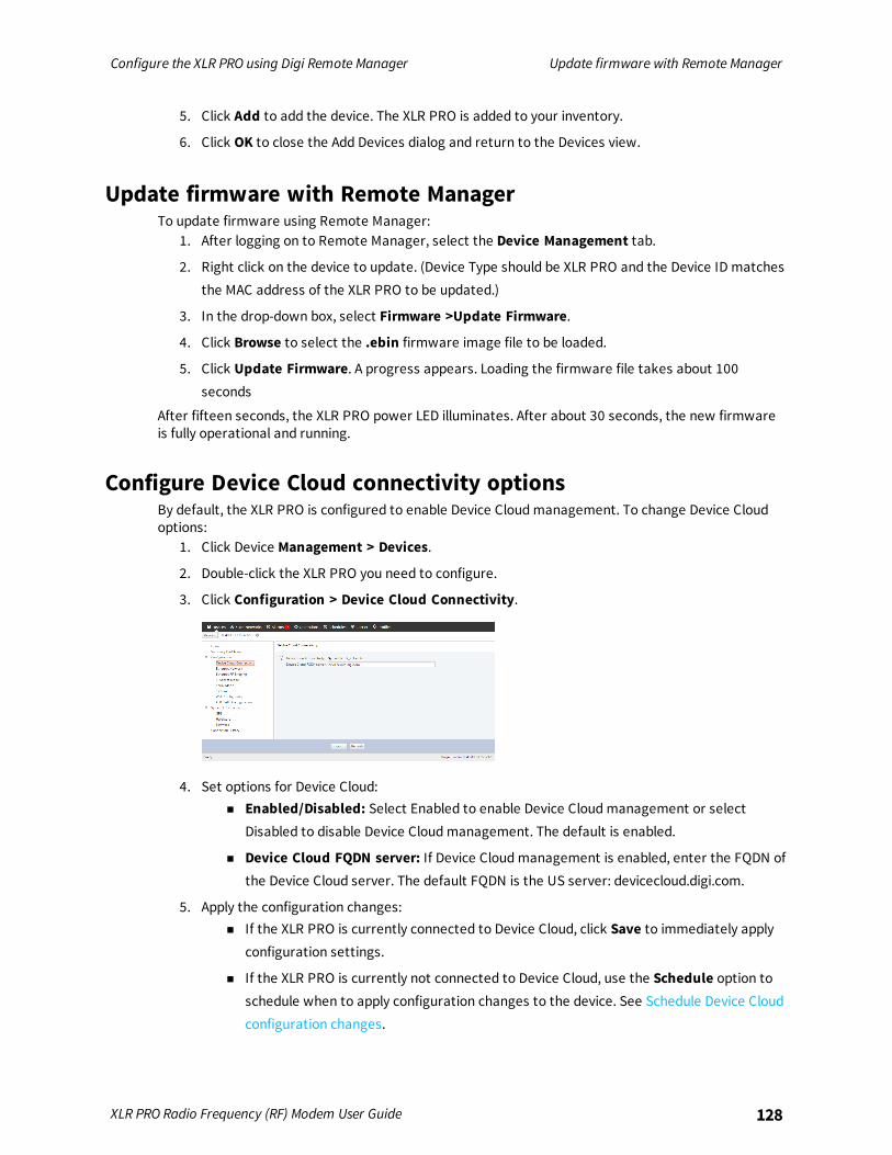
Configure the XLR PRO using Digi Remote Manager Update firmware with Remote Manager
XLR PRO Radio Frequency (RF) Modem User Guide 128
5. Click Add to add the device. The XLR PRO is added to your inventory.
6. Click OK to close the Add Devices dialog and return to the Devices view.
Update firmware with Remote ManagerTo update firmware using Remote Manager:
1. After logging on to Remote Manager, select the Device Management tab.
2. Right click on the device to update. (Device Type should be XLR PRO and the Device ID matchesthe MAC address of the XLR PRO to be updated.)
3. In the drop-down box, select Firmware >Update Firmware.
4. Click Browse to select the .ebin firmware image file to be loaded.
5. Click Update Firmware. A progress appears. Loading the firmware file takes about 100seconds
After fifteen seconds, the XLR PRO power LED illuminates. After about 30 seconds, the new firmwareis fully operational and running.
Configure Device Cloud connectivity optionsBy default, the XLR PRO is configured to enable Device Cloud management. To change Device Cloudoptions:
1. Click Device Management > Devices.
2. Double-click the XLR PRO you need to configure.
3. Click Configuration > Device Cloud Connectivity.
4. Set options for Device Cloud:n Enabled/Disabled: Select Enabled to enable Device Cloud management or select
Disabled to disable Device Cloud management. The default is enabled.
n Device Cloud FQDN server: If Device Cloud management is enabled, enter the FQDN ofthe Device Cloud server. The default FQDN is the US server: devicecloud.digi.com.
5. Apply the configuration changes:n If the XLR PRO is currently connected to Device Cloud, click Save to immediately apply
configuration settings.
n If the XLR PRO is currently not connected to Device Cloud, use the Schedule option toschedule when to apply configuration changes to the device. See Schedule Device Cloudconfiguration changes.
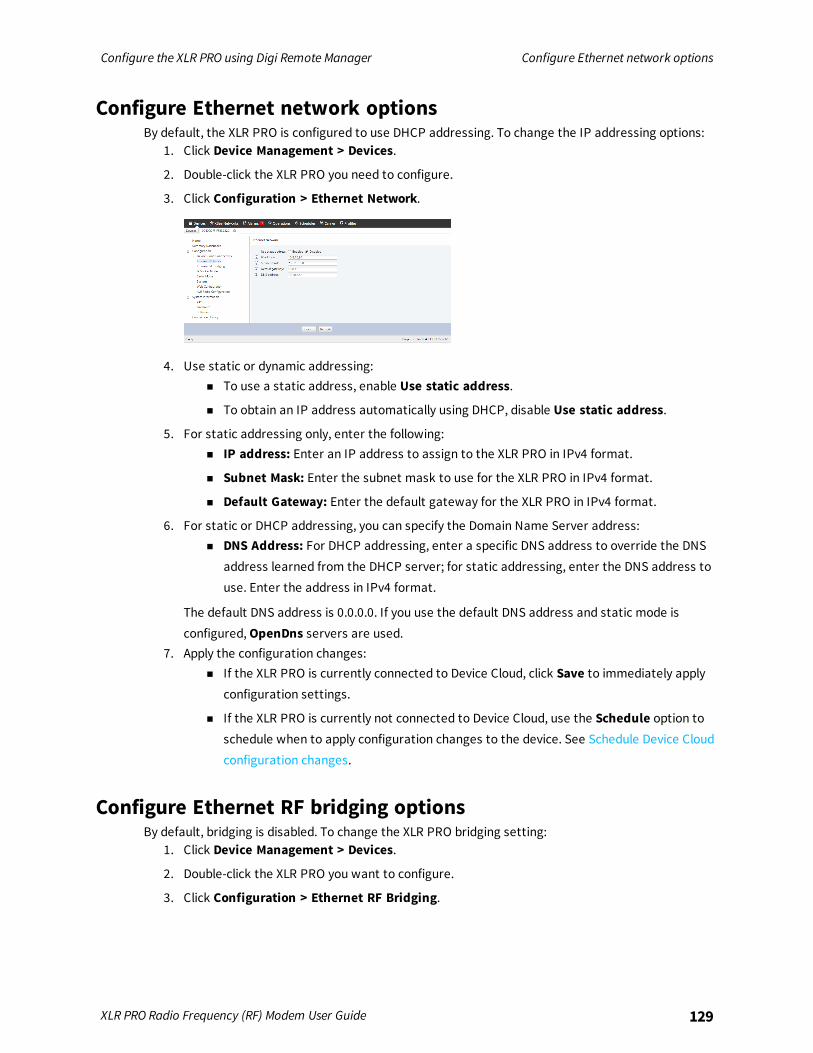
Configure the XLR PRO using Digi Remote Manager Configure Ethernet network options
XLR PRO Radio Frequency (RF) Modem User Guide 129
Configure Ethernet network optionsBy default, the XLR PRO is configured to use DHCP addressing. To change the IP addressing options:
1. Click Device Management > Devices.
2. Double-click the XLR PRO you need to configure.
3. Click Configuration > Ethernet Network.
4. Use static or dynamic addressing:n To use a static address, enable Use static address.
n To obtain an IP address automatically using DHCP, disable Use static address.
5. For static addressing only, enter the following:n IP address: Enter an IP address to assign to the XLR PRO in IPv4 format.
n Subnet Mask: Enter the subnet mask to use for the XLR PRO in IPv4 format.
n Default Gateway: Enter the default gateway for the XLR PRO in IPv4 format.
6. For static or DHCP addressing, you can specify the Domain Name Server address:n DNS Address: For DHCP addressing, enter a specific DNS address to override the DNS
address learned from the DHCP server; for static addressing, enter the DNS address touse. Enter the address in IPv4 format.
The default DNS address is 0.0.0.0. If you use the default DNS address and static mode isconfigured, OpenDns servers are used.
7. Apply the configuration changes:n If the XLR PRO is currently connected to Device Cloud, click Save to immediately apply
configuration settings.
n If the XLR PRO is currently not connected to Device Cloud, use the Schedule option toschedule when to apply configuration changes to the device. See Schedule Device Cloudconfiguration changes.
Configure Ethernet RF bridging optionsBy default, bridging is disabled. To change the XLR PRO bridging setting:
1. Click Device Management > Devices.
2. Double-click the XLR PRO you want to configure.
3. Click Configuration > Ethernet RF Bridging.
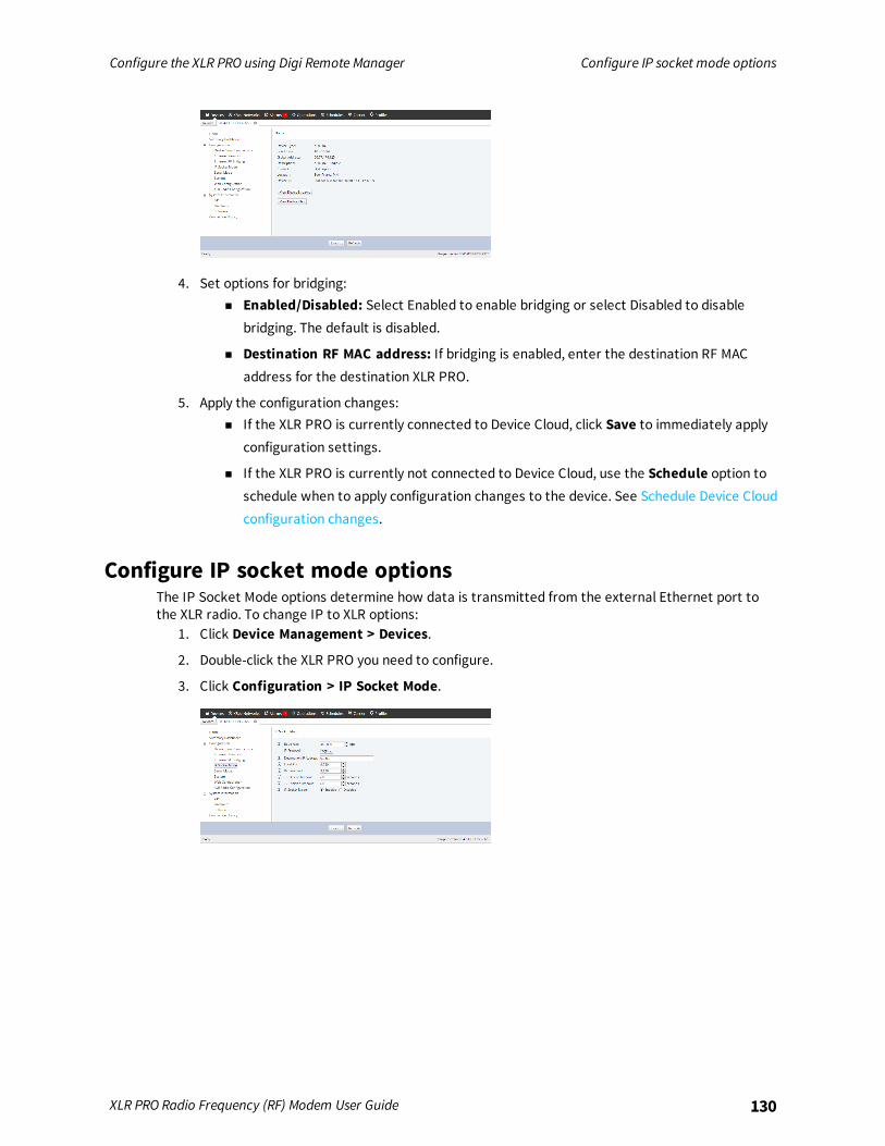
Configure the XLR PRO using Digi Remote Manager Configure IP socket mode options
XLR PRO Radio Frequency (RF) Modem User Guide 130
4. Set options for bridging:n Enabled/Disabled: Select Enabled to enable bridging or select Disabled to disable
bridging. The default is disabled.
n Destination RF MAC address: If bridging is enabled, enter the destination RF MACaddress for the destination XLR PRO.
5. Apply the configuration changes:n If the XLR PRO is currently connected to Device Cloud, click Save to immediately apply
configuration settings.
n If the XLR PRO is currently not connected to Device Cloud, use the Schedule option toschedule when to apply configuration changes to the device. See Schedule Device Cloudconfiguration changes.
Configure IP socket mode optionsThe IP Socket Mode options determine how data is transmitted from the external Ethernet port tothe XLR radio. To change IP to XLR options:
1. Click Device Management > Devices.
2. Double-click the XLR PRO you need to configure.
3. Click Configuration > IP Socket Mode.
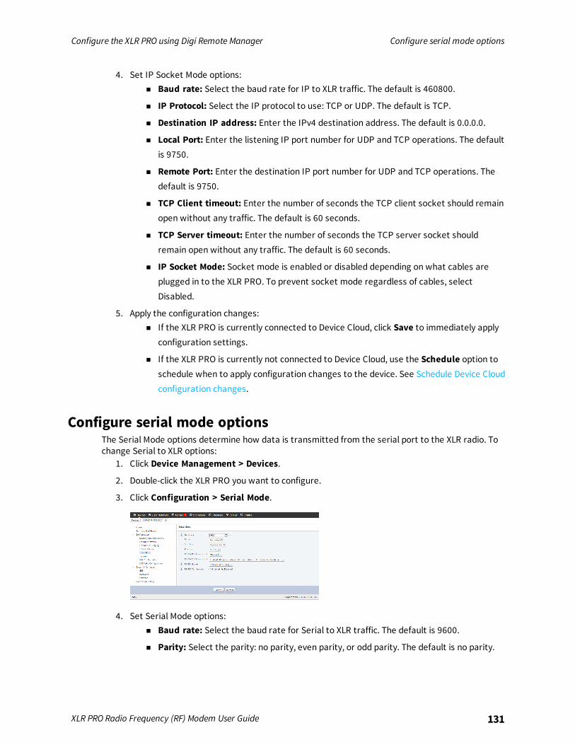
Configure the XLR PRO using Digi Remote Manager Configure serial mode options
XLR PRO Radio Frequency (RF) Modem User Guide 131
4. Set IP Socket Mode options:n Baud rate: Select the baud rate for IP to XLR traffic. The default is 460800.
n IP Protocol: Select the IP protocol to use: TCP or UDP. The default is TCP.
n Destination IP address: Enter the IPv4 destination address. The default is 0.0.0.0.
n Local Port: Enter the listening IP port number for UDP and TCP operations. The defaultis 9750.
n Remote Port: Enter the destination IP port number for UDP and TCP operations. Thedefault is 9750.
n TCP Client timeout: Enter the number of seconds the TCP client socket should remainopen without any traffic. The default is 60 seconds.
n TCP Server timeout: Enter the number of seconds the TCP server socket shouldremain open without any traffic. The default is 60 seconds.
n IP Socket Mode: Socket mode is enabled or disabled depending on what cables areplugged in to the XLR PRO. To prevent socket mode regardless of cables, selectDisabled.
5. Apply the configuration changes:n If the XLR PRO is currently connected to Device Cloud, click Save to immediately apply
configuration settings.
n If the XLR PRO is currently not connected to Device Cloud, use the Schedule option toschedule when to apply configuration changes to the device. See Schedule Device Cloudconfiguration changes.
Configure serial mode optionsThe Serial Mode options determine how data is transmitted from the serial port to the XLR radio. Tochange Serial to XLR options:
1. Click Device Management > Devices.
2. Double-click the XLR PRO you want to configure.
3. Click Configuration > Serial Mode.
4. Set Serial Mode options:n Baud rate: Select the baud rate for Serial to XLR traffic. The default is 9600.
n Parity: Select the parity: no parity, even parity, or odd parity. The default is no parity.

Configure the XLR PRO using Digi Remote Manager Configure system options
XLR PRO Radio Frequency (RF) Modem User Guide 132
n Stop bits: Select the stop bits to use: one or two. The default is one stop bit.
n Protocol: Select the protocol: RS-232 or RS-485/RS-422. The default is RS-232.
n RS-232 RTS flow control: Select RTS flow control for RS-232: disabled or UART clear tosend. The default is disabled.
n RS-232 CTS flow control: Select CTS flow control for RS-232: disabled or UART clear tosend. The default is UART clear to send.
n RS-485 duplex: Select the duplex for RS-485: half-duplex or full-duplex. The default ishalf-duplex.
n RS-485 Termination: Enable or disable RS-485 termination. The default is disabled.
5. Apply the configuration changes:n If the XLR PRO is currently connected to Device Cloud, click Save to immediately apply
configuration settings.
n If the XLR PRO is currently not connected to Device Cloud, use the Schedule option toschedule when to apply configuration changes to the device. See Schedule Device Cloudconfiguration changes.
Configure system optionsThe System options determine the contact information and location of the XLR radio. To changeSystem options:
1. Click Device Management > Devices.
2. Double-click the XLR PRO you want to configure.
3. Click Configuration > System.
4. Set system options:n Description: Enter a description for the XLR PRO radio.
n Contact: Enter contact information for the XLR PRO radio.
n Location: Enter the location of the XLR PRO radio.
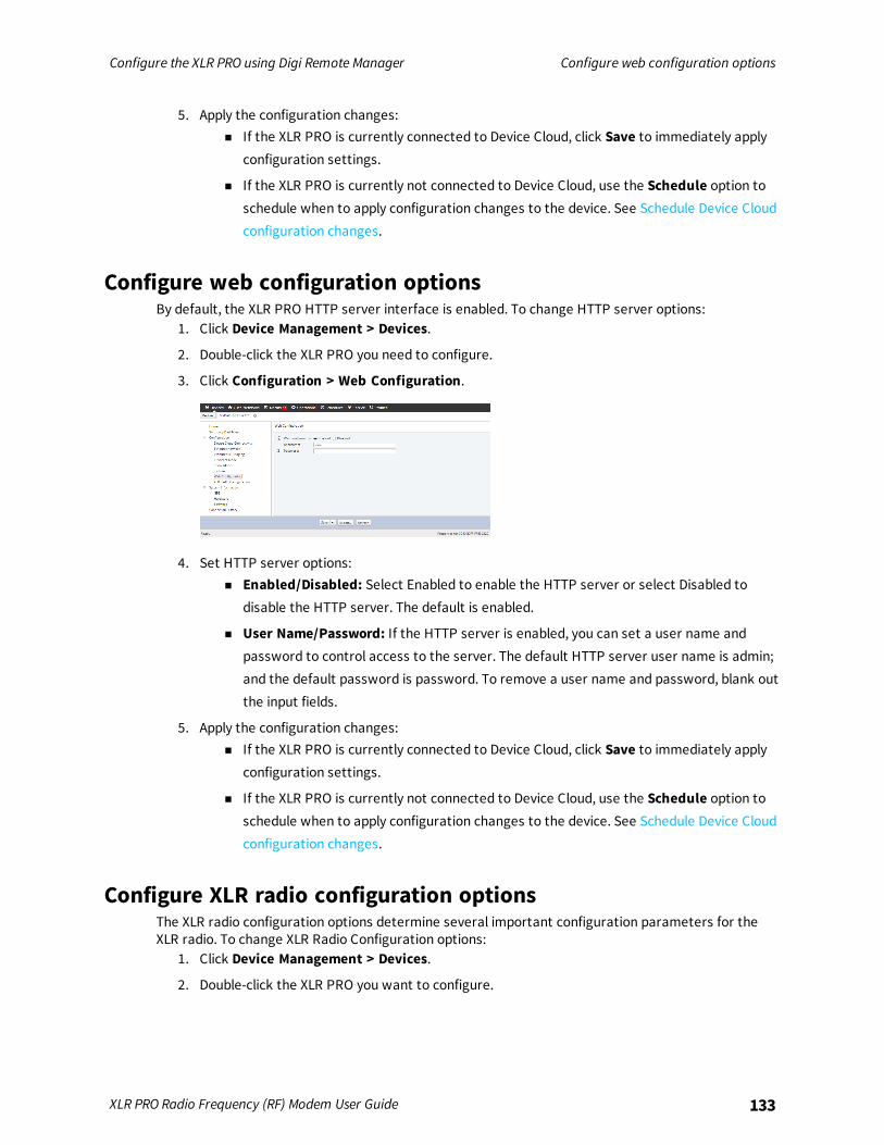
Configure the XLR PRO using Digi Remote Manager Configure web configuration options
XLR PRO Radio Frequency (RF) Modem User Guide 133
5. Apply the configuration changes:n If the XLR PRO is currently connected to Device Cloud, click Save to immediately apply
configuration settings.
n If the XLR PRO is currently not connected to Device Cloud, use the Schedule option toschedule when to apply configuration changes to the device. See Schedule Device Cloudconfiguration changes.
Configure web configuration optionsBy default, the XLR PRO HTTP server interface is enabled. To change HTTP server options:
1. Click Device Management > Devices.
2. Double-click the XLR PRO you need to configure.
3. Click Configuration > Web Configuration.
4. Set HTTP server options:n Enabled/Disabled: Select Enabled to enable the HTTP server or select Disabled to
disable the HTTP server. The default is enabled.
n User Name/Password: If the HTTP server is enabled, you can set a user name andpassword to control access to the server. The default HTTP server user name is admin;and the default password is password. To remove a user name and password, blank outthe input fields.
5. Apply the configuration changes:n If the XLR PRO is currently connected to Device Cloud, click Save to immediately apply
configuration settings.
n If the XLR PRO is currently not connected to Device Cloud, use the Schedule option toschedule when to apply configuration changes to the device. See Schedule Device Cloudconfiguration changes.
Configure XLR radio configuration optionsThe XLR radio configuration options determine several important configuration parameters for theXLR radio. To change XLR Radio Configuration options:
1. Click Device Management > Devices.
2. Double-click the XLR PRO you want to configure.

Configure the XLR PRO using Digi Remote Manager Configure XLR radio configuration options
XLR PRO Radio Frequency (RF) Modem User Guide 134
3. Click Configuration > XLR Radio Configuration.
4. Set XLR radio configuration options:n Firmware version: Displays the current firmware version. This value cannot be
changed.
n Local RF MAC address: Displays the serial number. This value cannot be changed.
n Destination RF MAC address: Enter the destination RF MAC address for the XLR PRO.The default is 00000000:0000FFFF.
n API mode: Select the API mode for the XLR PRO: none (transparent), API, or API withescapes. The default is none (transparent).
n Network ID: Enter a network ID for the XLR PRO. The default is 7FFF. Only XLR PROswith matching network IDs can communicate with each other.
n RF data rate: Select an RF Data Rate from the drop-down list. The default is 290,800b/s.
n Encryption key: Enter an AES encryption key for RF packets, a 128-bit key. By default,encryption is always used, but the key is never displayed. If you enter a new encryptionkey, the key must match on all devices on the network.
n Power Level: Select a power level from the drop-down list. The default is Max Power.
n Broadcast Multi-transmit: Enter the number of broadcast retransmissions, from 0 to 8retransmissions. If you enter 0, broadcasts are transmitted only once; if you enter 8, agiven broadcast can be retransmitted up to 8 times. The default is 3.
n Unicast Retries: Enter the maximum number of MAC RF packet delivery attempts ofunicast packets. If you enter a non-zero value, then unicast packets sent from the radiorequest an acknowledgment. The default is 10.
n Transmit Mode: Select the transmit mode, either Point to Point/Multi-point orRepeater/Directed Broadcast. The default is Point to Point/Multi-point.
n Routing Mode: Select the routing mode, either Standard or Non-Routing. The default isNon-Routing.
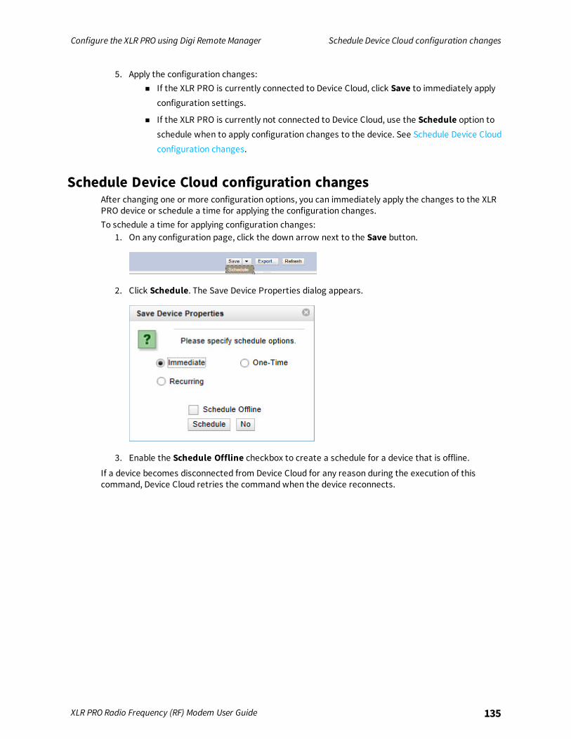
Configure the XLR PRO using Digi Remote Manager Schedule Device Cloud configuration changes
XLR PRO Radio Frequency (RF) Modem User Guide 135
5. Apply the configuration changes:n If the XLR PRO is currently connected to Device Cloud, click Save to immediately apply
configuration settings.
n If the XLR PRO is currently not connected to Device Cloud, use the Schedule option toschedule when to apply configuration changes to the device. See Schedule Device Cloudconfiguration changes.
Schedule Device Cloud configuration changesAfter changing one or more configuration options, you can immediately apply the changes to the XLRPRO device or schedule a time for applying the configuration changes.To schedule a time for applying configuration changes:
1. On any configuration page, click the down arrow next to the Save button.
2. Click Schedule. The Save Device Properties dialog appears.
3. Enable the Schedule Offline checkbox to create a schedule for a device that is offline.
If a device becomes disconnected from Device Cloud for any reason during the execution of thiscommand, Device Cloud retries the command when the device reconnects.
Troubleshooting
This section contains troubleshooting steps for the XLR PRO.
Serial interface issues 137Ethernet issues 137General issues 137
XLR PRO Radio Frequency (RF) Modem User Guide 136
Troubleshooting Serial interface issues
XLR PRO Radio Frequency (RF) Modem User Guide 137
Serial interface issues
ConditionNo data on serial port.
SolutionTo enable the XLR PRO serial port, the DTR line on your RS-232 cable must be active and connected. Ifthe DTR line is not present, the XLR PRO uses IP socket mode instead of the serial port for serialcommunication.If you do not have a DTR line on your serial cable or end device, explicitly disable socket mode bysetting the ES (IP socket mode enable) parameter to 0.
ConditionRS-485/422 does not work.
SolutionRS-232 is the default serial protocol used for the front panel serial port. In order to use RS-485/422,the 4E parameter must be set to 1. This will also disable IP socket mode, so it would be advisable toconnect the XLR PRO to your Ethernet network if configuration changes need to be made.
Ethernet issues
ConditionLAN stopped working when XLR PRO was plugged in.
SolutionWith Ethernet RF bridging enabled, the XLR PRO acts like an Ethernet cable. If two XLR PRO areconnected to the same LAN, a bridging loop could occur and cause a broadcast storm. Make sure thatonly one XLR PRO is connected to a LAN to avoid this.
General issues
ConditionAll of the LEDs are lit on the XLR PRO.
SolutionIf all of the LEDs on the front panel are lit solid, this indicates that the XLR PRO is in a bootloader stateand will not respond to any user input. This can happen if the reset button is held down upon startup,verify that the reset button is clear of obstructions and perform a power cycle.

Safety notices and certifications
Before installing and powering on the XLR PRO, read all instructions and keep these instructions in asafe place for future reference.Changes or modifications not expressly approved by the party responsible for compliance could voidthe user’s authority to operate the equipment.Do not attempt to repair the product. Any attempt to service or repair the unit by the user will voidthe product warranty.The XLR PRO must be maintained by Digi or a Digi qualified technician only.
RF exposure statement 139Class 1, Division 2 (C1D2) certification—USA and Canada 139FCC (United States) certification 140ISED (Innovation, Science and Economic Development Canada) certification 140Australia certification 141Mexico IFETEL 141Brazil (ANATEL) 141
XLR PRO Radio Frequency (RF) Modem User Guide 138
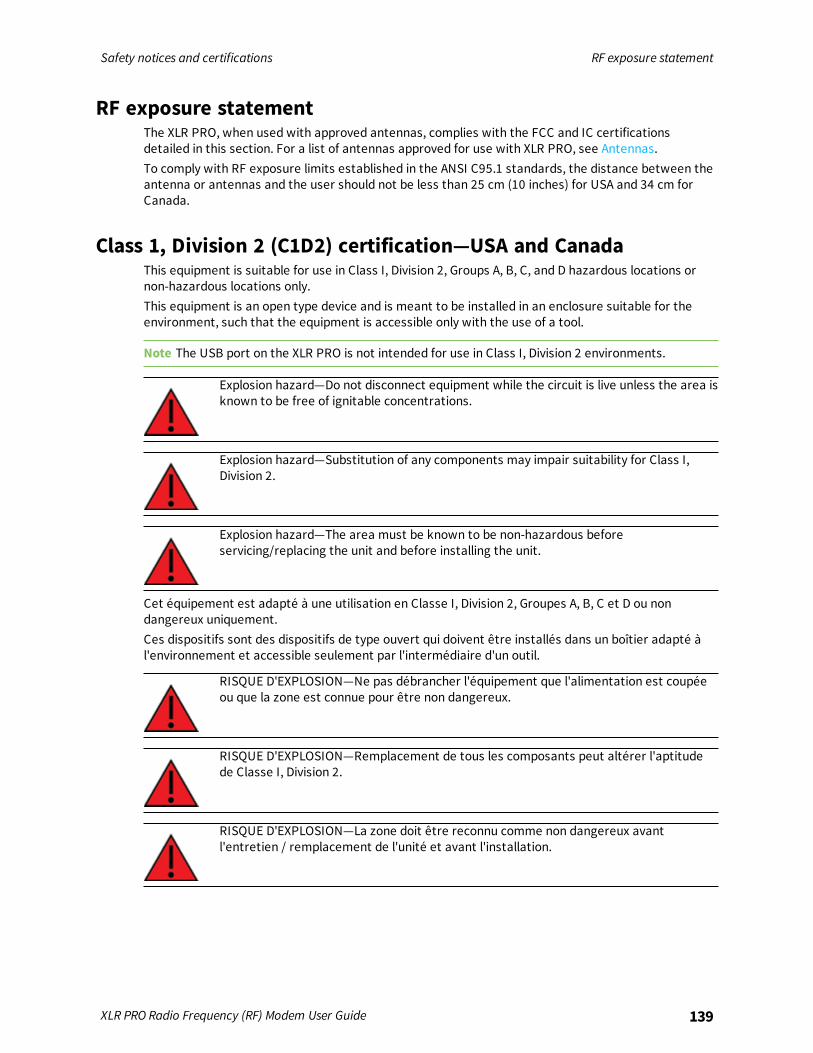
Safety notices and certifications RF exposure statement
XLR PRO Radio Frequency (RF) Modem User Guide 139
RF exposure statementThe XLR PRO, when used with approved antennas, complies with the FCC and IC certificationsdetailed in this section. For a list of antennas approved for use with XLR PRO, see Antennas.To comply with RF exposure limits established in the ANSI C95.1 standards, the distance between theantenna or antennas and the user should not be less than 25 cm (10 inches) for USA and 34 cm forCanada.
Class 1, Division 2 (C1D2) certification—USA and CanadaThis equipment is suitable for use in Class I, Division 2, Groups A, B, C, and D hazardous locations ornon-hazardous locations only.This equipment is an open type device and is meant to be installed in an enclosure suitable for theenvironment, such that the equipment is accessible only with the use of a tool.
Note The USB port on the XLR PRO is not intended for use in Class I, Division 2 environments.
Explosion hazard—Do not disconnect equipment while the circuit is live unless the area isknown to be free of ignitable concentrations.
Explosion hazard—Substitution of any components may impair suitability for Class I,Division 2.
Explosion hazard—The area must be known to be non-hazardous beforeservicing/replacing the unit and before installing the unit.
Cet équipement est adapté à une utilisation en Classe I, Division 2, Groupes A, B, C et D ou nondangereux uniquement.Ces dispositifs sont des dispositifs de type ouvert qui doivent être installés dans un boîtier adapté àl'environnement et accessible seulement par l'intermédiaire d'un outil.
RISQUE D'EXPLOSION—Ne pas débrancher l'équipement que l'alimentation est coupéeou que la zone est connue pour être non dangereux.
RISQUE D'EXPLOSION—Remplacement de tous les composants peut altérer l'aptitudede Classe I, Division 2.
RISQUE D'EXPLOSION—La zone doit être reconnu comme non dangereux avantl'entretien / remplacement de l'unité et avant l'installation.

Safety notices and certifications FCC (United States) certification
XLR PRO Radio Frequency (RF) Modem User Guide 140
FCC (United States) certification
FCC Part 15 Class B
Radio Frequency Interface (RFI) (FCC 15.105)This device has been tested and found to comply with the limits for Class B digital devices pursuant toPart 15 Subpart B of the FCC rules. These limits are designed to provide reasonable protectionagainst harmful interference in a residential environment. This equipment generates, uses, and canradiate radio frequency energy, and if not installed and used in accordance with the instructionmanual, may cause harmful interference to radio communications. However, there is no guaranteethat interference will not occur in a particular installation. If this equipment does cause harmfulinterference to radio or television reception, which can be determined by turning the equipment offand on, the user is encouraged to try to correct the interference by one or more of the followingmeasures:
n Reorient or relocate the receiving antenna.
n Increase the separation between the equipment and receiver.
n Connect the equipment into an outlet on a circuit different from that to which the receiver isconnected.
n Consult the dealer or an experienced radio/TV technician for help.
Labeling requirements (FCC 15.19)This device complies with Part 15 of FCC rules. Operation is subject to the following two conditions: (1)this device may not cause harmful interference, and (2) this device must accept any interferencereceived, including interference that may cause undesired operation.
Modifications (FCC 15.21)Changes or modifications to this equipment not expressly approved by Digi may void the user’sauthority to operate this equipment.
ISED (Innovation, Science and Economic Development Canada)certification
This digital apparatus does not exceed the Class B limits for radio noise emissions from digitalapparatus set out in the Radio Interference Regulations of the Canadian Department ofCommunications.Le present appareil numerique n’emet pas de bruits radioelectriques depassant les limites applicablesaux appareils numeriques de la class B prescrites dans le Reglement sur le brouillage radioelectriqueedicte par le ministere des Communications du Canada.

Safety notices and certifications Australia certification
XLR PRO Radio Frequency (RF) Modem User Guide 141
RF ExposureThis equipment is approved for mobile and base station transmitting devices only.Antenna(s) used for this transmitter must be installed to provide a separation distanceof at least 34 cm from all persons and must not be co-located or operating in conjunctionwith any other antenna or transmitter.
Cet équipement est approuvé pour les périphériques de transmission de mobile etstation de base seulement. Antenne (s) utilisée pour ce transmetteur doit être installépour fournir une distance de séparation d'au moins 34 cm de toutes les personnes et nedoivent pas être co-implantés ou utilisés dans conjointement avec une autre antenne ouémetteur.
Australia certificationThis radio module complies with requirements to be operated in end products in Australia. All productswith EMC and radio communications must have a registered RCM mark. Registration to use thecompliance mark will only be accepted from Australian manufacturers or importers, or their agent, inAustralia.In order to have a RCM mark on an end product, a company must comply with a or b below.
n Have a company presence in Australia.
n Have a company/distributor/agent in Australia that will sponsor the importing of the endproduct.
Contact Digi for questions related to locating a contact in Australia.
Mexico IFETELManufacturer: Digi International Inc.Country: USABrand: DigiThe XLR Pro RF Modem for carries the following Mexican approval marks:
Mexico: 1502CE10266IFT# RCPDIXL15-1494
Note Only the 2.1 dBi dipole antenna (A09-HATM-10) is approved for use with the modem in Mexico.
Brazil (ANATEL)XLR PRO INTL radio modem complies with Brazil ANATEL standards in Resolution No.506.

Safety notices and certifications Brazil (ANATEL)
XLR PRO Radio Frequency (RF) Modem User Guide 142
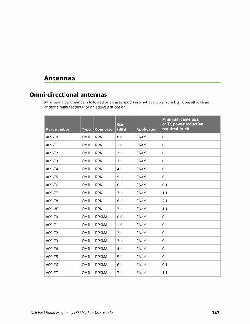
Antennas
Omni-directional antennasAll antenna part numbers followed by an asterisk (*) are not available from Digi. Consult with anantenna manufacturer for an equivalent option.
Part number Type ConnectorGain(dBi) Application
Minimum cable lossor TX power reductionrequired in dB
A09-F0 OMNI RPN 0.0 Fixed 0
A09-F1 OMNI RPN 1.0 Fixed 0
A09-F2 OMNI RPN 2.1 Fixed 0
A09-F3 OMNI RPN 3.1 Fixed 0
A09-F4 OMNI RPN 4.1 Fixed 0
A09-F5 OMNI RPN 5.1 Fixed 0
A09-F6 OMNI RPN 6.1 Fixed 0.1
A09-F7 OMNI RPN 7.1 Fixed 1.1
A09-F8 OMNI RPN 8.1 Fixed 2.1
A09-W7 OMNI RPN 7.1 Fixed 1.1
A09-F0 OMNI RPSMA 0.0 Fixed 0
A09-F1 OMNI RPSMA 1.0 Fixed 0
A09-F2 OMNI RPSMA 2.1 Fixed 0
A09-F3 OMNI RPSMA 3.1 Fixed 0
A09-F4 OMNI RPSMA 4.1 Fixed 0
A09-F5 OMNI RPSMA 5.1 Fixed 0
A09-F6 OMNI RPSMA 6.1 Fixed 0.1
A09-F7 OMNI RPSMA 7.1 Fixed 1.1
XLR PRO Radio Frequency (RF) Modem User Guide 143
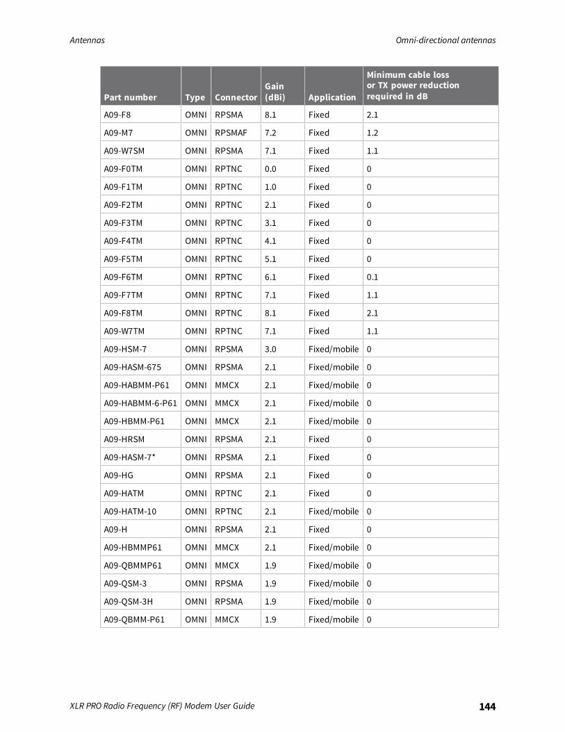
Antennas Omni-directional antennas
XLR PRO Radio Frequency (RF) Modem User Guide 144
Part number Type ConnectorGain(dBi) Application
Minimum cable lossor TX power reductionrequired in dB
A09-F8 OMNI RPSMA 8.1 Fixed 2.1
A09-M7 OMNI RPSMAF 7.2 Fixed 1.2
A09-W7SM OMNI RPSMA 7.1 Fixed 1.1
A09-F0TM OMNI RPTNC 0.0 Fixed 0
A09-F1TM OMNI RPTNC 1.0 Fixed 0
A09-F2TM OMNI RPTNC 2.1 Fixed 0
A09-F3TM OMNI RPTNC 3.1 Fixed 0
A09-F4TM OMNI RPTNC 4.1 Fixed 0
A09-F5TM OMNI RPTNC 5.1 Fixed 0
A09-F6TM OMNI RPTNC 6.1 Fixed 0.1
A09-F7TM OMNI RPTNC 7.1 Fixed 1.1
A09-F8TM OMNI RPTNC 8.1 Fixed 2.1
A09-W7TM OMNI RPTNC 7.1 Fixed 1.1
A09-HSM-7 OMNI RPSMA 3.0 Fixed/mobile 0
A09-HASM-675 OMNI RPSMA 2.1 Fixed/mobile 0
A09-HABMM-P61 OMNI MMCX 2.1 Fixed/mobile 0
A09-HABMM-6-P61 OMNI MMCX 2.1 Fixed/mobile 0
A09-HBMM-P61 OMNI MMCX 2.1 Fixed/mobile 0
A09-HRSM OMNI RPSMA 2.1 Fixed 0
A09-HASM-7* OMNI RPSMA 2.1 Fixed 0
A09-HG OMNI RPSMA 2.1 Fixed 0
A09-HATM OMNI RPTNC 2.1 Fixed 0
A09-HATM-10 OMNI RPTNC 2.1 Fixed/mobile 0
A09-H OMNI RPSMA 2.1 Fixed 0
A09-HBMMP61 OMNI MMCX 2.1 Fixed/mobile 0
A09-QBMMP61 OMNI MMCX 1.9 Fixed/mobile 0
A09-QSM-3 OMNI RPSMA 1.9 Fixed/mobile 0
A09-QSM-3H OMNI RPSMA 1.9 Fixed/mobile 0
A09-QBMM-P61 OMNI MMCX 1.9 Fixed/mobile 0
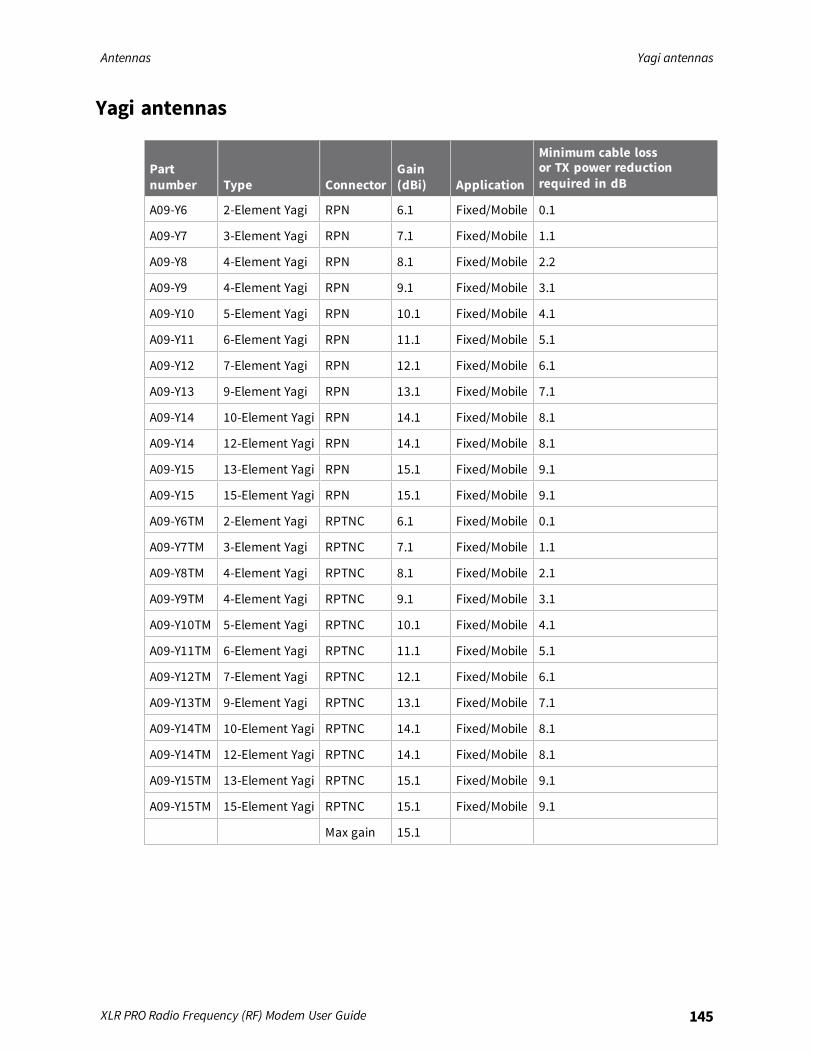
Antennas Yagi antennas
XLR PRO Radio Frequency (RF) Modem User Guide 145
Yagi antennas
Partnumber Type Connector
Gain(dBi) Application
Minimum cable lossor TX power reductionrequired in dB
A09-Y6 2-Element Yagi RPN 6.1 Fixed/Mobile 0.1
A09-Y7 3-Element Yagi RPN 7.1 Fixed/Mobile 1.1
A09-Y8 4-Element Yagi RPN 8.1 Fixed/Mobile 2.2
A09-Y9 4-Element Yagi RPN 9.1 Fixed/Mobile 3.1
A09-Y10 5-Element Yagi RPN 10.1 Fixed/Mobile 4.1
A09-Y11 6-Element Yagi RPN 11.1 Fixed/Mobile 5.1
A09-Y12 7-Element Yagi RPN 12.1 Fixed/Mobile 6.1
A09-Y13 9-Element Yagi RPN 13.1 Fixed/Mobile 7.1
A09-Y14 10-Element Yagi RPN 14.1 Fixed/Mobile 8.1
A09-Y14 12-Element Yagi RPN 14.1 Fixed/Mobile 8.1
A09-Y15 13-Element Yagi RPN 15.1 Fixed/Mobile 9.1
A09-Y15 15-Element Yagi RPN 15.1 Fixed/Mobile 9.1
A09-Y6TM 2-Element Yagi RPTNC 6.1 Fixed/Mobile 0.1
A09-Y7TM 3-Element Yagi RPTNC 7.1 Fixed/Mobile 1.1
A09-Y8TM 4-Element Yagi RPTNC 8.1 Fixed/Mobile 2.1
A09-Y9TM 4-Element Yagi RPTNC 9.1 Fixed/Mobile 3.1
A09-Y10TM 5-Element Yagi RPTNC 10.1 Fixed/Mobile 4.1
A09-Y11TM 6-Element Yagi RPTNC 11.1 Fixed/Mobile 5.1
A09-Y12TM 7-Element Yagi RPTNC 12.1 Fixed/Mobile 6.1
A09-Y13TM 9-Element Yagi RPTNC 13.1 Fixed/Mobile 7.1
A09-Y14TM 10-Element Yagi RPTNC 14.1 Fixed/Mobile 8.1
A09-Y14TM 12-Element Yagi RPTNC 14.1 Fixed/Mobile 8.1
A09-Y15TM 13-Element Yagi RPTNC 15.1 Fixed/Mobile 9.1
A09-Y15TM 15-Element Yagi RPTNC 15.1 Fixed/Mobile 9.1
Max gain 15.1
Copyright © 2022 FDOKUMEN