ZLinx® Xtreme IP67 Radio Modem - Advantech
157
ZLinx ® Xtreme IP67 Radio Modem USER MANUAL
-
Upload
khangminh22 -
Category
Documents
-
view
2 -
download
0
Transcript of ZLinx® Xtreme IP67 Radio Modem - Advantech
ZLinx® Xtreme IP67 Radio Modem
USER MANUAL

ZLinx® Xtreme Radio Modem
ii
Advantech - Americas 707 Dayton Road
Ottawa, IL 61350 USA Phone 1 (815) 433-5100
Fax 1 (815) 433-5105
Advantech - European Headquarters Westlink Commercial Park
Oranmore, Co. Galway, Ireland Phone +353 91-792444
Fax +353 91-792445
www.advantech.com [email protected]
2019 Advantech. No part of this publication may be reproduced or transmitted in any form or by any means, electronic or mechanical, including photography, recording, or any information storage and retrieval system without written consent. Information in this manual is subject to change without notice, and does not represent a commitment on the part of Advantech.
Advantech shall not be liable for incidental or consequential damages resulting from the furnishing, performance, or use of this manual.
All brand names used in this manual are the registered trademarks of their respective owners. The use of trademarks or other designations in this publication is for reference purposes only and does not constitute an endorsement by the trademark holder.
Documentation Number: ZXTx-RM_2419m
ZLinx® Xtreme Radio Modem
iii
TABLE OF CONTENTS
Table of Contents ................................................................................................................................................. iii
1 - Overview ........................................................................................................................................................... 1
1.1 PREREQUISITES ................................................................................................................................................. 1
1.2 SAFETY INFORMATION ..................................................................................................................................... 1
1.3 INSTALLATION INFORMATION .......................................................................................................................... 1
1.4 ABOUT THIS MANUAL ...................................................................................................................................... 2
1.5 PRODUCT FEATURES SUMMARY ....................................................................................................................... 2
2 - Product Information ........................................................................................................................................ 3
2.1 ZLINX® XTREME RADIO MODEM MODELS ...................................................................................................... 3
2.2 PACKAGE CONTENTS ........................................................................................................................................ 3
2.3 MODES OF OPERATION ..................................................................................................................................... 3
2.3.1 Point-to-Point Serial .................................................................................................................................. 3 2.3.2 Point-to-Point Serial to Xtreme I/O ............................................................................................................ 3 2.3.3 Point-to-Multi Point (Serial or Xtreme I/O) ................................................................................................ 3
2.4. OPERATING STATES ......................................................................................................................................... 4
2.4.1 Idle State ................................................................................................................................................... 4 2.4.2 Transmit State ........................................................................................................................................... 4 2.4.3 Receive State ............................................................................................................................................ 4 2.4.4 Sleep State ................................................................................................................................................ 4 2.4.5 Command Mode ........................................................................................................................................ 4
2.5 USER INTERFACE COMPONENTS ....................................................................................................................... 4
2.5.1 Signal Strength (RSSI) LED’s ................................................................................................................... 4 2.5.2 Transmit LED ............................................................................................................................................ 4 2.5.3 Receive LED ............................................................................................................................................. 5 2.5.4 Power LED ................................................................................................................................................ 5 2.5.5 Internal User Interfaces ............................................................................................................................. 5 2.5.6 Push Button ............................................................................................................................................... 6 2.5.7 USB Connector ......................................................................................................................................... 6 2.5.8 Terminal Block .......................................................................................................................................... 7 2.5.9 DIP Switch ................................................................................................................................................. 7
3.0 Hardware Installation...................................................................................................................................... 8
3.1 MECHANICAL DIAGRAM ................................................................................................................................... 8
ZLinx® Xtreme Radio Modem
iv
3.2 IP67 CABLE GLAND INSTALLATION ................................................................................................................. 8
3.2.1 Cable Gland Description ........................................................................................................................... 8 3.2.2 Cable Gland Installation ............................................................................................................................ 9
3.3 WATERTIGHT THREADED CONDUIT HUB ......................................................................................................... 9
3.3.1 Description ................................................................................................................................................ 9 3.3.2 Water Tight Threaded Conduit Installation ............................................................................................... 9
3.4 IP67 MEMBRANE CABLE GLAND ................................................................................................................... 10
3.4.1 Description .............................................................................................................................................. 10 3.4.2 IP67 Membrane Cable Gland Installation ............................................................................................... 10
3.5 SUPPLIED ANTENNA ....................................................................................................................................... 10
3.5.1 ZXT9-RM Supplied Antenna ................................................................................................................... 10 3.5.2 ZXT24-RM Supplied Antenna ................................................................................................................. 11
3.6 OPTIONAL ANTENNAS .................................................................................................................................... 11
3.6.1 Omni Antenna Description ...................................................................................................................... 11 3.6.2 Yagi Antenna Description ........................................................................................................................ 13
3.7 ANTENNA CABLES .......................................................................................................................................... 14
3.8 LIGHTNING ARRESTORS.................................................................................................................................. 14
4 - Electrical Installation ..................................................................................................................................... 15
4.1 WIRING ........................................................................................................................................................... 15
4.1.1 Terminal Block ........................................................................................................................................ 15 4.1.2 Power Supply Connections ..................................................................................................................... 15 4.1.3 RS-232 Connections ............................................................................................................................... 16 4.1.4 RS-485 Two-Wire Connections .............................................................................................................. 17 4.1.5 RS-422/485 Four-Wire Connections ....................................................................................................... 17 4.1.6 Termination and Biasing ......................................................................................................................... 18 4.1.7 Fault Output ............................................................................................................................................ 18
5 - Software Installation ...................................................................................................................................... 20
5.1 ZLINX® MANAGER SOFTWARE OVERVIEW ................................................................................................... 20
5.1.1 Computer System Requirements ............................................................................................................ 20
5.2 INSTALLING ZLINX® MANAGER SOFTWARE .................................................................................................. 20
5.2.1 Installing Zlinx® Manager Software ........................................................................................................ 20 5.2.2 Installing USB Drivers ............................................................................................................................. 23
5.3 STARTING ZLINX® MANAGER SOFTWARE ...................................................................................................... 23
ZLinx® Xtreme Radio Modem
v
5.3.1 Starting the manager software ................................................................................................................ 23 5.3.2 Radio Modem Configuration Screen ....................................................................................................... 24 5.3.3 Radio Modem Configuration Screen (Off-Line)....................................................................................... 48 5.3.4 Radio Modem Firmware Update Screen ................................................................................................. 48 5.3.5 Return to Manager .................................................................................................................................. 48 5.3.6 ExiT ......................................................................................................................................................... 48
6 - Startup and Configuration ............................................................................................................................ 49
6.1 BASIC SETTINGS ............................................................................................................................................. 49
6.1.1 Channel Number ..................................................................................................................................... 49 6.1.2 Network Identifier .................................................................................................................................... 49 6.1.3 Baud Rate, Stop Bits, Parity, and Flow Control ...................................................................................... 49
6.2 ADVANCED SETTINGS ..................................................................................................................................... 49
6.3 RF MODEM OPERATION ................................................................................................................................. 49
6.3.1 Transport Operation ................................................................................................................................ 49 6.3.2 Serial to RF Packetization ....................................................................................................................... 50 6.3.3 API Operation .......................................................................................................................................... 50 6.3.4 Flow Control ............................................................................................................................................ 51 6.3.5 Sleep Mode ............................................................................................................................................. 52
6.3.5.3 CYCLE SLEEP MODE ................................................................................................................................. 53
6.3.6 Command Mode ...................................................................................................................................... 53 6.3.7 AT Command Mode ................................................................................................................................ 54 6.3.8 Binary Command Mode .......................................................................................................................... 54
6.4 ZXT9-RM CONFIGURATION ........................................................................................................................... 56
6.4.1 Advanced Programming .......................................................................................................................... 56 6.4.2 Command Reference Table .................................................................................................................... 57 6.4.2.1 Command Descriptions ........................................................................................................................ 60
6.5 ZXT24-RM CONFIGURATION ......................................................................................................................... 80
6.5.1 Advanced Programming .......................................................................................................................... 80
6.6 FIRMWARE UPDATE ...................................................................................................................................... 128
6.6.1 Caution .................................................................................................................................................. 128
6.6.2 FIRMWARE UPDATE PROCEDURE ............................................................................................................... 128
7 - Use Cases ..................................................................................................................................................... 130
7.1 POINT-TO-POINT SERIAL .............................................................................................................................. 130
7.1.1 Use Case Parameters ........................................................................................................................... 130
ZLinx® Xtreme Radio Modem
vi
7.2 POINT-TO-POINT SERIAL TO XTREME I/O .................................................................................................... 135
7.2.1 Use Case Parameters ........................................................................................................................... 135 8 - Testing and Trouble Shooting .................................................................................................................... 136
8.1 RSSI RANGE TEST ........................................................................................................................................ 136
Appendix A – Specifications ........................................................................................................................... 138
Appendix B – Default Configurations ............................................................................................................. 141
B.1 RESTORE DEFAULT CONFIGURATIONS ........................................................................................................ 141
B.2 ZXT9-RM DEFAULT CONFIGURATION ........................................................................................................ 141
B.3 ZXT24-RM DEFAULT CONFIGURATION ...................................................................................................... 142
Appendix C – Dimensional Diagram / Mounting Instructions ...................................................................... 144
C.1 DIMENSIONAL DIAGRAM ............................................................................................................................. 144
C.2 MOUNTING ................................................................................................................................................... 145
C.3 SUPPLIED ANTENNA ..................................................................................................................................... 146
Appendix D – Radio Frequency Basics .......................................................................................................... 148
D.1 WHAT IS DBM? ............................................................................................................................................ 148
D.2 LOWER FREQUENCIES = BETTER PROPAGATION ......................................................................................... 148
D.3 RANGE IS NOT JUST A FUNCTION OF TRANSMITTER POWER ......................................................................... 148
D.4 YOU MUST CONSIDER RF NOISE .................................................................................................................. 149
D.5 FADE MARGIN IS CRITICAL FOR RELIABLE OPERATION IN ADVERSE WEATHER AND INTERFERENCE ......... 149
D.6 REMEMBER YOUR MATH ............................................................................................................................. 149
D.7 RF ATTENUATION AND LINE OF SIGHT ....................................................................................................... 150
D.8 PATH LOSS RULE OF THUMB ....................................................................................................................... 151
D.9 ANTENNAS ................................................................................................................................................... 151
D.10 CABLE LOSS ............................................................................................................................................... 151
D.11 LATENCY AND PACKETIZATION ................................................................................................................ 151

ZLinx® Xtreme Radio Modem
1
1 - OVERVIEW
1.1 PREREQUISITES
This manual assumes you have a basic understanding of wireless communications, serial protocols (RS-232/422/485), and basic electronics.
1.2 SAFETY INFORMATION
WARNING
Exposure to RF energy is an important safety consideration. The FCC has adopted a safety standard for human exposure to radio frequency electromagnetic energy emitted by FCC regulated equipment as a result of its actions in Docket 93-62 and OET Bulleting 65 Edition 97-01.
DO NOT OPERATE unless all RF connectors are secure and any open connectors are properly terminated.
A separation distance of 20 cm or more should be maintained between the antenna of this device and persons during device operation. To ensure compliance, operation at closer than this distance is not recommended. The antenna used for this device must not be co-located in conjunction with any other antenna or transmitter.
1.3 INSTALLATION INFORMATION
Operating Voltage 10 to 30 VDC
Maximum Surrounding Ambient Air Temp 74 °C
Wiring Terminals Use Copper Wire Only, One Conductor Per Terminal
Wire Range 30 to 12 AWG
Tightening Torque 0.5 to 0.6 Nm
Temperature Rating of Field Installed Conductors 105 °C minimum, sized for 60 °C ampacity
Note: Please see the Quick Start Guide for UL Class 1 / Division 2 installation instructions.

ZLinx® Xtreme Radio Modem
2
1.4 ABOUT THIS MANUAL
This manual has been created to assist you in installing, configuring, operating, and troubleshooting your Zlinx® Xtreme Radio Modem. It is divided into key sections as follows:
Product Information – covers what is included with your radio modem, operating modes, operating states and user interface components.
Hardware Installation – covers how to install your radio modem. Additional information is provided about RF considerations, accessory antennas and cable selection.
Electrical Installation – covers wiring connections and powering your radio modem.
Software Installation – covers installing the manager software and basic software functionality.
Startup and Configuration – contains more detailed information about how to configure your radio modem.
Use Cases – contains information concerning the most widely used configurations.
Testing and Troubleshooting – contains information about trouble shooting aids.
Appendices – additional information.
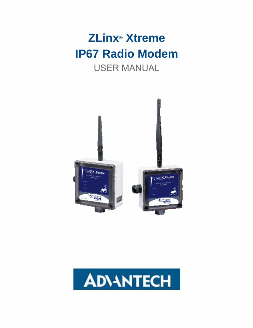
1.5 PRODUCT FEATURES SUMMARY
Need to extend an RS-232/422/485 signal across a highway or across the building? Your Zlinx ® Xtreme Radio Modem will do the job faster, easier, and less expensively than stringing cable. The Zlinx Xtreme Radio Modem connects serial devices that can be set up in point to point or point to multi point networks. Easy plug-and-play set-up saves installation and maintenance time. In addition, Zlinx Xtreme Radio Modem meets the IP67 standard and is built to handle the heat, cold and environments of industrial operations.
Modbus compatible – no additional converters needed
RS-232, 422, 485 (2-wire & 4-wire) serial communications
Frequency range: ISM band, 902 to 928 MHz or 2.4 to 2.5 GHz
Signal strength indicators aids troubleshooting.
900 MHz or 2.4 GHz antenna included
256-bit AES Encryption
Wide Operating Temperature: -40 to +74 °C
Rugged Circuitry for Indoor and Outdoor Applications
IP67 Rated for total protection against dust and water up to 1 meter
Software Support: Windows XP, Vista, 7, 8, 8.1, 10 (32 / 64 bit)
Field Upgradable Firmware
ZLinx® Xtreme Radio Modem
3
2 - PRODUCT INFORMATION
2.1 ZLINX® XTREME RADIO MODEM MODELS
ZXT9-RM – 900 MHz ISM Band Radio Modem
ZXT24-RM – 2.4 GHz ISM Band Radio Modem
2.2 PACKAGE CONTENTS
Zlinx Xtreme Radio Modem
Software CD
Quick Start Guide
Antenna
Enclosure Mounting Ears and Hardware
Note: Cable Glands cannot be used for Class 1/Division 2 applications. Please see the Quick Start Guide for additional information about UL Class 1/Division 2 installation instructions.
2.3 MODES OF OPERATION
2.3.1 POINT-TO-POINT SERIAL This configuration is used to wirelessly transmit serial data from one location to another. A Zlinx Xtreme Radio Modem is configured with another radio modem of same frequency in a master slave relationship to transmit serial data wirelessly. Typical applications include connecting a device such as a pressure/flow transmitter to a PLC or SCADA system.
2.3.2 POINT-TO-POINT SERIAL TO XTREME I/O This configuration is employed to connect a PLC/HMI/SCADA system to a remote Xtreme I/O (or Zlinx standard I/O) module to monitor or control discrete devices via Modbus. The serial master (PLC/HMI/SCADA) is a Modbus RTU master and must be connected to the serial port of the Radio Modem. Each Xtreme I/O device populates and updates its own Modbus map and support Modbus RTU Slave format. The radio modem is connected to the respective Modbus Master. Typical examples include a water tank monitoring system where a float sensor level data is transmitted to a HMI through the wireless network.
2.3.3 POINT-TO-MULTI POINT (SERIAL OR XTREME I/O) A Radio Modem is configured to communicate with multiple other modems or I/O modules. The “master” modem is connected to the Modbus Master and can communicate with Modbus Slaves connected to other radio modems or Xtreme I/O units. An example is a PLC Process control/monitoring application requiring analog, digital and serial data to be brought to a central PLC.

ZLinx® Xtreme Radio Modem
4
2.4. OPERATING STATES
The Zlinx Radio Modem has a variety of operating states:
2.4.1 IDLE STATE Checks for valid RF data received and discards invalid data
Checks for serial data to be packaged and RF transmitted
Received valid RF data in buffer to be output serially
Checks if Sleep Mode condition is met
Checks for Command Mode commands
2.4.2 TRANSMIT STATE Packages serial data (2048 bytes maximum in RF packet)
o ZXT9RM – 2048 bytes maximum o ZXT24RM – 202 bytes maximum
Returns to Idle State
2.4.3 RECEIVE STATE Switches to Receive State to start receiving RF packets if RF data was detected while in the Idle State
Returns to Idle State when data is no longer detected or an error is detected
2.4.4 SLEEP STATE This allows the radio modem to enter a state of low power consumption when not in use.
2.4.5 COMMAND MODE Enters AT Command mode with +++ sent to serial input with Guard Time before and after. Exits after Timeout.
The guard times and the entry characters are user configurable.
2.5 USER INTERFACE COMPONENTS
2.5.1 SIGNAL STRENGTH (RSSI) LED’S
There are eight green LED’s to indicate signal strength (Received Signal Strength Indicator, “RSSI”). They are arranged to indicate RSSI from weakest (bottom LED lighted) to strongest (all eight LED’s lighted). See figure 2-1.
Figure 2-1 RSSI Indicator
2.5.2 TRANSMIT LED The green transmit LED flashes when data is transmitted out the serial port. See figure 2-2 below.

ZLinx® Xtreme Radio Modem
5
2.5.3 RECEIVE LED The green receive LED flashes when data is received by the serial port. See Figure 2-2 below.
Figure 2-2 Transmit and Receive LEDs
2.5.4 POWER LED The green power LED is ON when power is applied.
Figure 2-3 Power LED
2.5.5 INTERNAL USER INTERFACES The remaining user interfaces are located inside the radio modem enclosure. To access these interfaces, the cover must be removed. The cover is held in place with four plastic Phillips style screws.

ZLinx® Xtreme Radio Modem
6
2.5.6 PUSH BUTTON Push Button PB1 is located on the circuit board behind the radio modem cover. It is used to temporarily set the serial port to a known condition. To do this, use the RS-232 port. Press and hold the button while power cycling the device. Once power comes up, release the button and the unit will temporarily be restored to a known condition and in command mode for about 20 seconds. You will then be able to connect to the device using the manager at the settings below:
Baud rate = 9600
Data bit = 8
Parity = None
Stop bit = 1
Figure 2-4 Push Button
2.5.7 USB CONNECTOR The USB connector is located on the circuit board inside the radio modem enclosure. It is used to connect a PC to the radio modem to perform configurations and firmware updates. The connector is a Type B female. Any commercially available USB cable can be used to connect to the radio modem. Figure 2-5 shows the USB connector location.
Figure 2-5 USB Connector

ZLinx® Xtreme Radio Modem
7
2.5.8 TERMINAL BLOCK The terminal block is used to connect serial signals and power. Figure 2-6 shows the TB location.
Figure 2-6 Terminal Block
2.5.9 DIP SWITCH
OFF
ON Switch RS-232 RS-422 RS-485
4-Wire
RS-485
2-Wire
4-Wire 2-Wire 1 OFF OFF OFF ON
4-Wire 2-Wire 2 OFF OFF OFF ON
Termination Out Termination In 3 OFF OFF* OFF* OFF*
RS-422 RS-485 4 OFF OFF ON ON
Note: The use of built in termination is optional and depends on your application.
Note: For RS-232 operation, set all switches OFF.
Figure 2-7 DIP Switch

ZLinx® Xtreme Radio Modem
8
3.0 HARDWARE INSTALLATION
3.1 MECHANICAL DIAGRAM
The mechanical diagram in Appendix C contains information for mounting your radio modem.
Note: Cable Glands cannot be used for Class 1/Division 2 applications. See the Quick Start Guide for UL Class 1/Division 2 installation instructions.
3.2 IP67 CABLE GLAND INSTALLATION
3.2.1 CABLE GLAND DESCRIPTION The Cable Gland is used to maintain the water tight rating while allowing a cable to enter the enclosure. The assembly consists of black molded nylon body, hex nut, cable nut and a rubber gasket and cable seal.
Figure 3-1 IP67 Cable Gland
Figure 3-2 IP67 Cable Gland

ZLinx® Xtreme Radio Modem
9
3.2.2 CABLE GLAND INSTALLATION
1. The Cable Gland will accept cable diameters from 5.99 to 11.99 mm (0.236 to 0.472 in).
2. Insert the non-tapered end of the Body (D) through the conduit knock-out on the radio modem enclosure.
3. Place the Gasket around the body on the outside of the enclosure.
4. Thread the Hex Nut onto the Body from the inside of the enclosure.
5. Place the Cable Nut onto the cable being careful to position the threaded side so that it can be attached to the Cable Body.
6. Tighten the Cable Nut. This will cause the tapered end of the Cable Body to compress, ensuring a water-tight seal.
3.3 WATERTIGHT THREADED CONDUIT HUB
Note: Unused conduit openings: Class 1/Division 2 installation requires a UL Recognized conduit plug (UL Category Code QCRV2) be used when a conduit opening is not being used.
3.3.1 DESCRIPTION
Another method to bring a cable into the enclosure is to use the water tight threaded conduit hub. It is used to secure threaded half-inch rigid service entrance conduit. It consists of a Body, Nut and Gasket.
Figure 3-3 ½ Inch Threaded Conduit Hub
Figure 3-4 ½ Inch Threaded Conduit Hub
3.3.2 WATER TIGHT THREADED CONDUIT INSTALLATION
1. Insert the threaded end of the body into the conduit knock-out from the outside of the enclosure. The rubber gasket should be on the outside of the enclosure.
2. Thread the nut onto the conduit body from inside the enclosure.
3. 1/2 and 3/8 inch conduit fittings as well as 1/2 inch, rigid, threaded conduit can be attached to the threaded hub.
ZLinx® Xtreme Radio Modem
10
3.4 IP67 MEMBRANE CABLE GLAND
Note: the Cable Glands cannot be used for Class 1/Division 2 applications. Please see the Quick Start Guide for UL Class 1/Division 2 installation instructions.
3.4.1 DESCRIPTION
The membrane cable gland is used to plug an unused hole in the enclosure.
Figure 3-5 IP67 Membrane Cable Gland
3.4.2 IP67 MEMBRANE CABLE GLAND INSTALLATION
1. Stuff the cable gland into the knock-out hole with the narrow end toward the inside of the radio modem enclosure. The enclosure wall will fit into the indentation between the inside and outside portions of the gland.
3.5 SUPPLIED ANTENNA
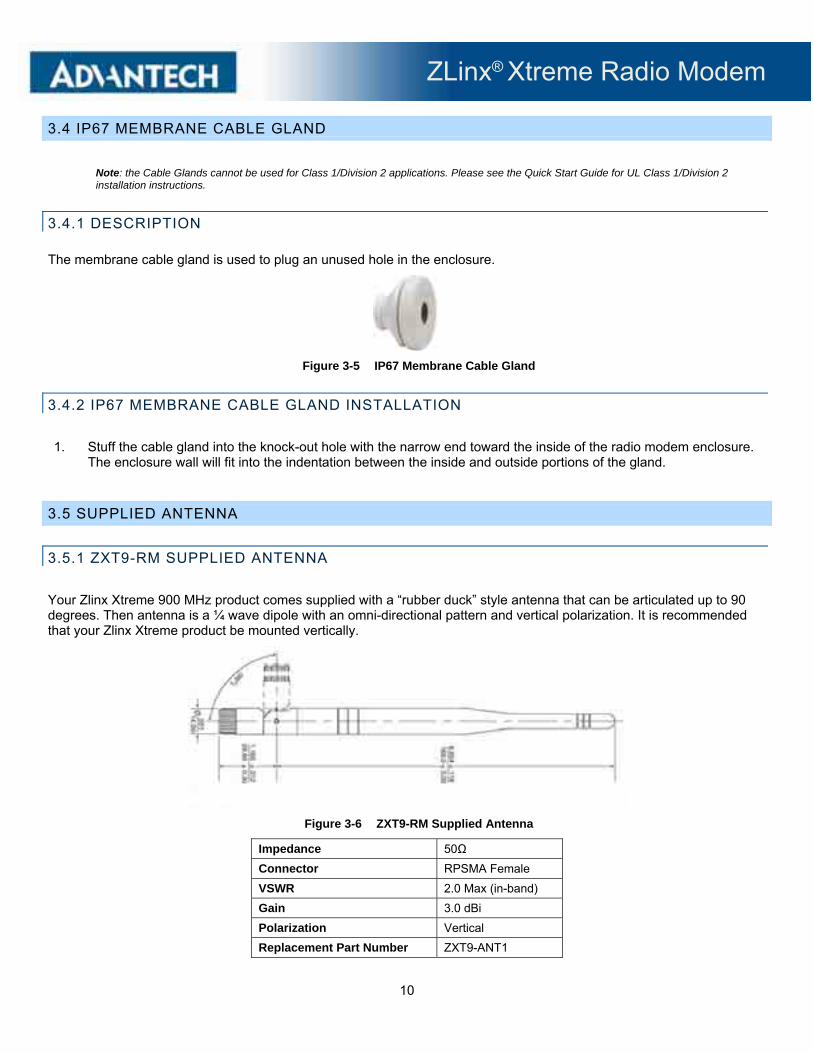
3.5.1 ZXT9-RM SUPPLIED ANTENNA
Your Zlinx Xtreme 900 MHz product comes supplied with a “rubber duck” style antenna that can be articulated up to 90 degrees. Then antenna is a ¼ wave dipole with an omni-directional pattern and vertical polarization. It is recommended that your Zlinx Xtreme product be mounted vertically.
Figure 3-6 ZXT9-RM Supplied Antenna
Impedance 50Ω
Connector RPSMA Female
VSWR 2.0 Max (in-band)
Gain 3.0 dBi
Polarization Vertical
Replacement Part Number ZXT9-ANT1

ZLinx® Xtreme Radio Modem
11
3.5.2 ZXT24-RM SUPPLIED ANTENNA
Your Zlinx Xtreme 2.4 GHz product comes supplied with a “rubber duck” style antenna that can be articulated up to 90 degrees. Then antenna is a ¼ wave dipole with an omni-directional pattern and vertical polarization.
It is recommended that your Zlinx Xtreme product be mounted with the antenna on the top, perpendicular with the horizon
Figure 3-7 ZXT24-RM Supplied Antenna
Impedance 50Ω
Connector RPSMA Female
VSWR 2.0 Max (in-band)
Gain 2.1 dBi
Polarization Vertical
Replacement Part Number ZZ24D-ANT1
3.6 OPTIONAL ANTENNAS
3.6.1 OMNI ANTENNA DESCRIPTION
In some applications, a higher gain omni-directional antenna may be required. An omni-directional antenna is an antenna system that radiates power uniformly in one plane with a directive pattern shape in a perpendicular plane. This pattern is often described as "donut shaped". An omni-directional antenna can be used to link multiple directional antennas in outdoor point-to-multipoint communication.
Omni-directional antennas are a good choice if you need to mount your antenna on a mast to increase its elevation. Please note that mounting brackets must also be purchased. Also note that these antennas have an N style connector.
Figure 3-8 Representative Photograph of Optional Omni Antenna
ZLinx® Xtreme Radio Modem
12
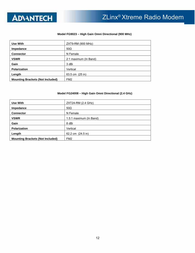
Model FG9023 – High Gain Omni Directional (900 MHz)
Use With ZXT9-RM (900 MHz)
Impedance 50Ω
Connector N Female
VSWR 2:1 maximum (In Band)
Gain 3 dBi
Polarization Vertical
Length 63.5 cm (25 in)
Mounting Brackets (Not Included) FM2
Model FG24008 – High Gain Omni Directional (2.4 GHz)
Use With ZXT24-RM (2.4 GHz)
Impedance 50Ω
Connector N Female
VSWR 1.5:1 maximum (In Band)
Gain 8 dBi
Polarization Vertical
Length 62.2 cm (24.5 in)
Mounting Brackets (Not Included) FM2

ZLinx® Xtreme Radio Modem
13
3.6.2 YAGI ANTENNA DESCRIPTION A Yagi-Uda Antenna, commonly known simply as a Yagi antenna or Yagi, is a directional antenna system consisting of an array of a dipole and additional closely coupled parasitic elements (usually a reflector and one or more directors). The dipole in the array is driven, and another element, typically 5% longer, effectively operates as a reflector. Other parasitic elements shorter than the dipole may be added in front of the dipole and are referred to as directors. This arrangement increases antenna directionality and gain in the preferred direction over a single dipole. (Contact Advantech for antenna model information and availability.)
Note: Since Yagi Antennas are directional, they must point directly at the other antenna through a clear line of sight.
Figure 3-9 Representative Enclosed Yagi Photograph
Figure 3-10 Representative Yagi Antenna Photograph
High Gain Yagi (900 MHz)
Use With ZXT9-RM (900 MHz)
Impedance 50Ω
Connector N Female
VSWR 1.5:1 maximum (In Band)
Gain 6 dBi
Polarization Vertical
Length 42.7 cm (16.8 in)
Mounting Brackets Included
High Gain Yagi (2.4 GHz)
Use With ZXT24-RM (2.4 GHz)
Impedance 50Ω
Connector N Female
VSWR 1.5:1 maximum (In Band)
Gain 12.5 dBi
Polarization Vertical
Length 45.7 cm (18 in)
Mounting Brackets Included

ZLinx® Xtreme Radio Modem
14
3.7 ANTENNA CABLES
If you decide to use one of the optional antennas, you will need to select the appropriate cable and connector. It is important to select a cable that matches the radio’s impedance. An impedance mismatch will cause the radio link to become inefficient and could damage the radio. Selecting the incorrect cable could also cause significant signal loss. A rule of thumb is: for every 3 dB of loss, your system will lose half the output power emitted from the radio.
It is recommended that you use the shortest possible cable run in your application. Along with the type of cable, you need to select the correct connector. This product uses an RPSMA Male (plug) connector. Therefore, you will need a cable that has a RPSMA Female (jack) on one end. If you are using one of the optional antennas, you will need an N type Male connector, since these antennas have an N type Female on them. If you are extending the included antenna, you will need an RPSMA Male (plug) since the supplied antenna has an RPSMA female (jack).
3.8 LIGHTNING ARRESTORS
When installed properly, a lightning arrestor can prevent damage to your radio due to high energy transients during lightning strikes. Our arrestors limit surges to less than 45 Volts in approximately 100 nanoseconds. A gas discharge tube changes from an open circuit to a short circuit in the presence of energy and voltage surges giving those surges a direct path to ground, thus protecting equipment.
They are designed with a rugged housing and high quality plated brass "N" connectors They are available as Models LABH350NN and LABH2400N which both allow bulkhead mounting and connector pass-through. (Contact Advantech for more information, availability and ordering.)

ZLinx® Xtreme Radio Modem
15
4 - ELECTRICAL INSTALLATION
Note: Please see the Quick Start Guide for UL Class 1/Division 2 installation instructions.
4.1 WIRING
4.1.1 TERMINAL BLOCK
Both power and data signals are connected to the terminal block. Figure 4-1 shows the layout.
Operating Voltage 10 to 20 VDC
Maximum Surrounding Ambient Air Temperature +74 °C
Wiring Terminals Use Copper Wire Only, One Conductor Per Terminal
Wire Range 30 to 12 AWG
Tightening Torque 0.5 to 0.6 Nm
Temperature Rating of Field Installed Conductors 105 °C minimum, sized for 6 0°C ampacity.
Figure 4-1 Terminal Block
4.1.2 POWER SUPPLY CONNECTIONS
The radio modem requires power from an external source. The radio modem requires 10 to 30 VDC. Power use depends on the model:
ZXT9RM – 1.7 Watts typical, 5.8 Watts maximum
ZXT24RM – 1.2 Watts typical, 3.5 Watts maximum
Connect the positive and negative power leads to the Power In(+) and Power In (-) terminals on the terminal block.
.

ZLinx® Xtreme Radio Modem
16
4.1.3 RS-232 CONNECTIONS
4.1.3.1 RS-232 SIGNAL CONVENTION (DTE / DCE) There are two types of RS-232 ports: DTE (Data Terminal Equipment) and DCE (Data Communications Equipment). The signal names and pin numbers are the same, but signal flow is opposite. The pin labeled TD can be input, and RD the output.
The two ports types are complementary: the Output signals on a DTE port are Inputs to a DCE port, and Output signals on a DCE port are Inputs to a DTE port. The signal names match each other and connect pin for pin. Signal flow is in the direction of the arrows.
The Radio Modem is a DCE device.
. Figure 4-2 shows RS-232 DTE to RS-232 DCE connections with associated DB9 pin numbers and the signal direction.
Figure 4-2 Terminal Block
4.1.3.2 WIRING AN RS-232 DEVICE TO THE RADIO MODEM .
The Radio Modem supports TD, RD, RTS, and CTS. Please note that if Sleep Mode is enabled, the DTR signal is used to “wake up” the device. Figure 4-3 is a wiring diagram for connecting a DTE device such as a computer or PLC.
Figure 4-3 RS-232 Wiring
ZLinx® Xtreme Radio Modem
17
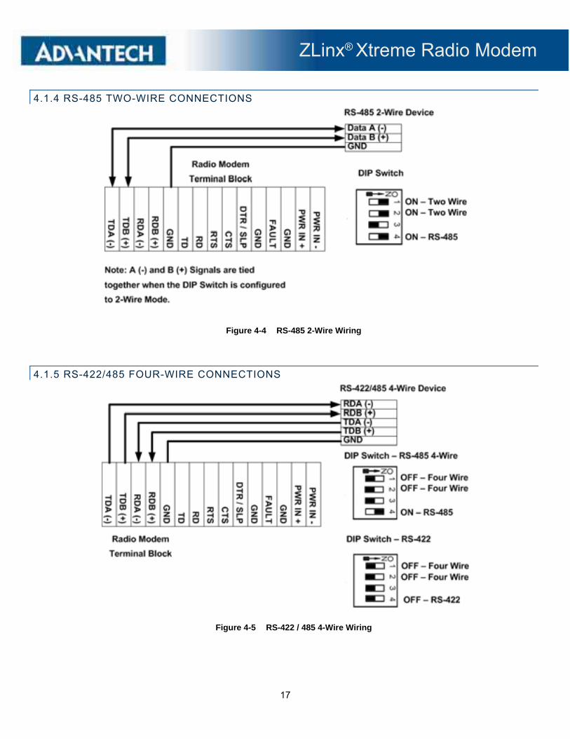
4.1.4 RS-485 TWO-WIRE CONNECTIONS
Figure 4-4 RS-485 2-Wire Wiring
4.1.5 RS-422/485 FOUR-WIRE CONNECTIONS
Figure 4-5 RS-422 / 485 4-Wire Wiring

ZLinx® Xtreme Radio Modem
18
4.1.6 TERMINATION AND BIASING
The radio modem has built in 1.2 kΩ pull-up and pull-down resistors( R17 and R14). There is also a built in 120 Ω termination resistor (R21). These resistors are located on the PCB behind the cover. Termination is switchable using DIP Switch Position 3. To enable the termination, set switch 3 to ON “Termination IN”. To disable the termination, set switch 3 to OFF “Termination OUT”.
It is possible to use different value resistors by removing the surface mount components and placing through-hole resistors (R16, R13, and R19) in the space provided. The surface mount components are located directly opposite of the through-hole pads that are visible.
Figure 4-6 Through-hole Resistor Pads
4.1.7 FAULT OUTPUT
The radio modem has a sourcing (PNP) 50 mA output that is used as a fault indicator. This output is activated when the received signal strength drops below a critical level. To use this function, the RSSI indicator must be set to continuously update. This is accomplished by setting the RP-RSSI PWM Timer to FF in the diagnostics section of the advanced modem settings tab. See Figures 4-7 and 4-8. Figure 4-9 shows the wiring connections.
Figure 4-7 RP – RSSI PWM Timer, ZXT9-RM

ZLinx® Xtreme Radio Modem
19
Figure 4-8 RP – RSSI PWM Timer, ZXT9-RM
Figure 4-9 Fault Output Wiring
ZLinx® Xtreme Radio Modem
20
5 - SOFTWARE INSTALLATION
5.1 ZLINX® MANAGER SOFTWARE OVERVIEW
5.1.1 COMPUTER SYSTEM REQUIREMENTS
The Zlinx Manager software requires the following computer hardware and operating systems:
A PC with a USB port
One of the following operating systems installed
Windows XP (32 or 64 bit)
Windows Vista (32 bit or 64 bit)
Windows 7 (32 or 64 bit)
Windows 8 or 8.1 (32 or 64 bit)
Windows 10 (32 or 64 bit)
5.2 INSTALLING ZLINX® MANAGER SOFTWARE
5.2.1 INSTALLING ZLINX® MANAGER SOFTWARE
The manager software is contained on the CD ROM which was included with your radio modem. Insert the CD into your CD drive. The installation process should start automatically. If it does not, navigate to the CD drive in Windows Explorer and double click the executable file on the CD.
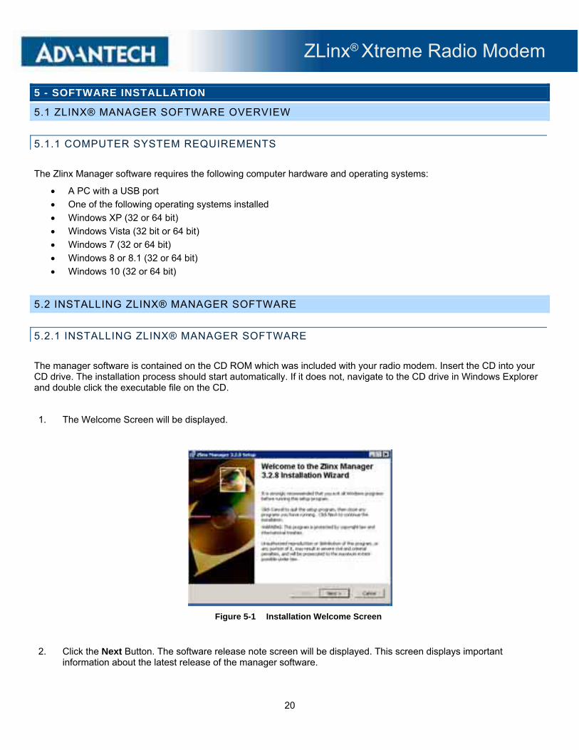
1. The Welcome Screen will be displayed.
Figure 5-1 Installation Welcome Screen
2. Click the Next Button. The software release note screen will be displayed. This screen displays important information about the latest release of the manager software.

ZLinx® Xtreme Radio Modem
21
Figure 5-2 Software Release Notes Screen
3. Click the Next button. The software license agreement screen will be displayed. Accept the License Agreement and click the Next button.
Figure 5-3 License Agreement Screen
4. The User Information screen will be displayed. Fill in the required information and click the Next button.
Figure 5-4 User Information Screen
ZLinx® Xtreme Radio Modem
22
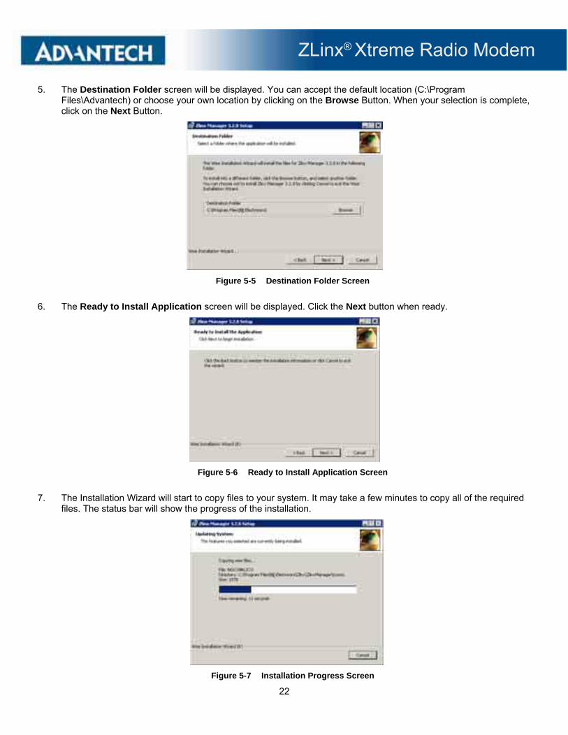
5. The Destination Folder screen will be displayed. You can accept the default location (C:\Program Files\Advantech) or choose your own location by clicking on the Browse Button. When your selection is complete, click on the Next Button.
Figure 5-5 Destination Folder Screen
6. The Ready to Install Application screen will be displayed. Click the Next button when ready.
Figure 5-6 Ready to Install Application Screen
7. The Installation Wizard will start to copy files to your system. It may take a few minutes to copy all of the required files. The status bar will show the progress of the installation.
Figure 5-7 Installation Progress Screen

ZLinx® Xtreme Radio Modem
23
8. The Installation Complete screen will be displayed. Click the Finish button.
Figure 5-8 Installation Progress Screen
5.2.2 INSTALLING USB DRIVERS
1. The USB driver is installed with the manager software. You should not connect to the USB port before installing the manager software.
2. If the found new hardware wizard appears after attaching the cable, follow the wizard. The drivers are located in the “USB Drivers” folder on the CD.
5.3 STARTING ZLINX® MANAGER SOFTWARE
5.3.1 STARTING THE MANAGER SOFTWARE
Double-click on the Zlinx Desktop Icon or press the start button and locate the software. The manager software will start. Select the Radio Modem option on the startup screen.
Figure 5-9 Zlinx Selection Screen
The Radio Modem Configuration screen will be displayed. This screen allows you to configure your radio modem directly or off-line, update the firmware, return to the initial screen or exit.

ZLinx® Xtreme Radio Modem
24
Figure 5-10 Radio Modem Configuration Screen
5.3.2 RADIO MODEM CONFIGURATION SCREEN
The Radio Modem Configuration screen is used to configure your radio modem
The first screen contains options that configure your PC COM port to communicate with the radio modem.
Use the pull-down menu items to select the following options.
Model: This allows you to specify the model number you are trying to connect to.
Figure 5-11 Model Number Selection Pull-down Menu
COM Port: This allows you to specify the COM Port your PC is configured to use to connect to the radio modem. COM1 through COM16 may be specified.

ZLinx® Xtreme Radio Modem
25
Figure 5-12 COM Port Pull-down Menu
Baud Rate: This allows you to specify the COM Port baud rate. Choices are from 1200 to 230400 baud.
Figure 5-13 Baud Rate Pull-down Menu
Data Bits: This allows you to select the number of data bits. Choices are from five to eight.
Figure 5-14 Data Bits Pull-down Menu

ZLinx® Xtreme Radio Modem
26
The number of data bits in each character can be 5 (for Baudot code), 6 (rarely used), 7 (for true ASCII), or 8 (for any kind of data, as this matches the size of a byte). Eight data bits are almost universally used in newer applications. 5 or 7 bits generally only make sense with older equipment.
Parity: This allows you to select the parity. Choices are None, Odd, Even, Mark, Space, or 9 Bit Passing.
Figure 5-15 Parity Pull-down Menu
Parity is a method of detecting errors in transmission. When parity is used with a serial port, an extra data bit is sent with each data character, arranged so that the number of 1 bits in each character, including the parity bit, is always odd or always even. If a byte is received with the wrong number of 1's, then it must have been corrupted. However, an even number of errors can pass the parity check.
The parity bit in each character can be set to none (N), odd (O), even (E), mark (M), or space (S). None means that no parity bit is sent at all. Mark parity means that the parity bit is always set to the mark signal condition (logical 1) and, likewise, Space parity always sends the parity bit in the space signal condition. Some uncommon applications that use the 9th (parity) bit for some form of addressing or special signaling. Mark or space parity is also uncommon, as it adds no error detection information. Odd parity is more common than Even, since it ensures that at least one state transition occurs in each character, which makes it more reliable. The most common parity setting, however, is "none", with error detection handled by a communication protocol.
Stop Bits: This allows you to select the number of Stop Bits. Choices are 1, 1.5 and 2.
Figure 5-16 Stop Bits Down Menu
Stop bits sent at the end of every character allow the receiving signal hardware to detect the end of a character and to resynchronize with the character stream. Electronic devices usually use one stop bit. If slow devices are used, one-and-one-half or two stop bits are required.

ZLinx® Xtreme Radio Modem
27
Connect Button connects to a radio modem using the configuration selected using the pull-down menu items.
Figure 5-17 Connect Button
When you press the Connect button, the manager software will attempt to connect to the radio modem using the settings selected with the pull-down options. The Radio Modem Search screen will be displayed. If the settings are correct and a Radio Modem is found, click the OK button, the Radio Modem Settings screen will be displayed.
Figure 5-18 Radio Modem Search Screen

ZLinx® Xtreme Radio Modem
28
Figure 5-19 Radio Modem Settings screen
If settings are not correct, an error screen will be displayed. Correct the COM Port Settings or use the Auto Search button.
Figure 5-20 Radio Modem Not Found screen
Auto Search Button: The Auto Search button will search for Zlinx devices connected to a COM port and connect. This is useful if you do not know the radio modem configuration.
ZLinx® Xtreme Radio Modem
29
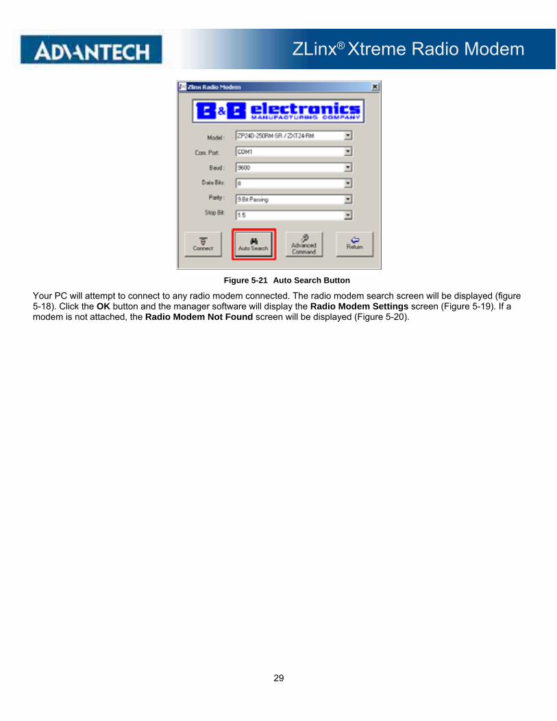
Figure 5-21 Auto Search Button
Your PC will attempt to connect to any radio modem connected. The radio modem search screen will be displayed (figure 5-18). Click the OK button and the manager software will display the Radio Modem Settings screen (Figure 5-19). If a modem is not attached, the Radio Modem Not Found screen will be displayed (Figure 5-20).

ZLinx® Xtreme Radio Modem
30
Advanced Command Button is used to select the character sequence to enter command mode as well as required “quiet times” before and after the command sequence. It is recommended that you do not change these values.
Figure 5-22 Advanced Command Button
Pressing the Advanced Command button will bring up the following screen.
Figure 5-23 Advanced Command Button
CC – Command Sequence: The CC command is used to set/read the ASCII character used between guard times of the AT Command Mode Sequence (BT + CC + AT). This sequence enters the modem into AT Command Mode so that data entering the modem (from the host) is recognized as a command instead of payload. The default value of 2B is equivalent to “+” in ASCII.
BT – Guard Time Before & AT Guard Time After: Sets the required period of silence before, after and between the Command Mode Characters of the Command Mode Sequence (GT + CC + GT). The period of silence is used to prevent inadvertent entrance into AT Command Mode.
ZLinx® Xtreme Radio Modem
31
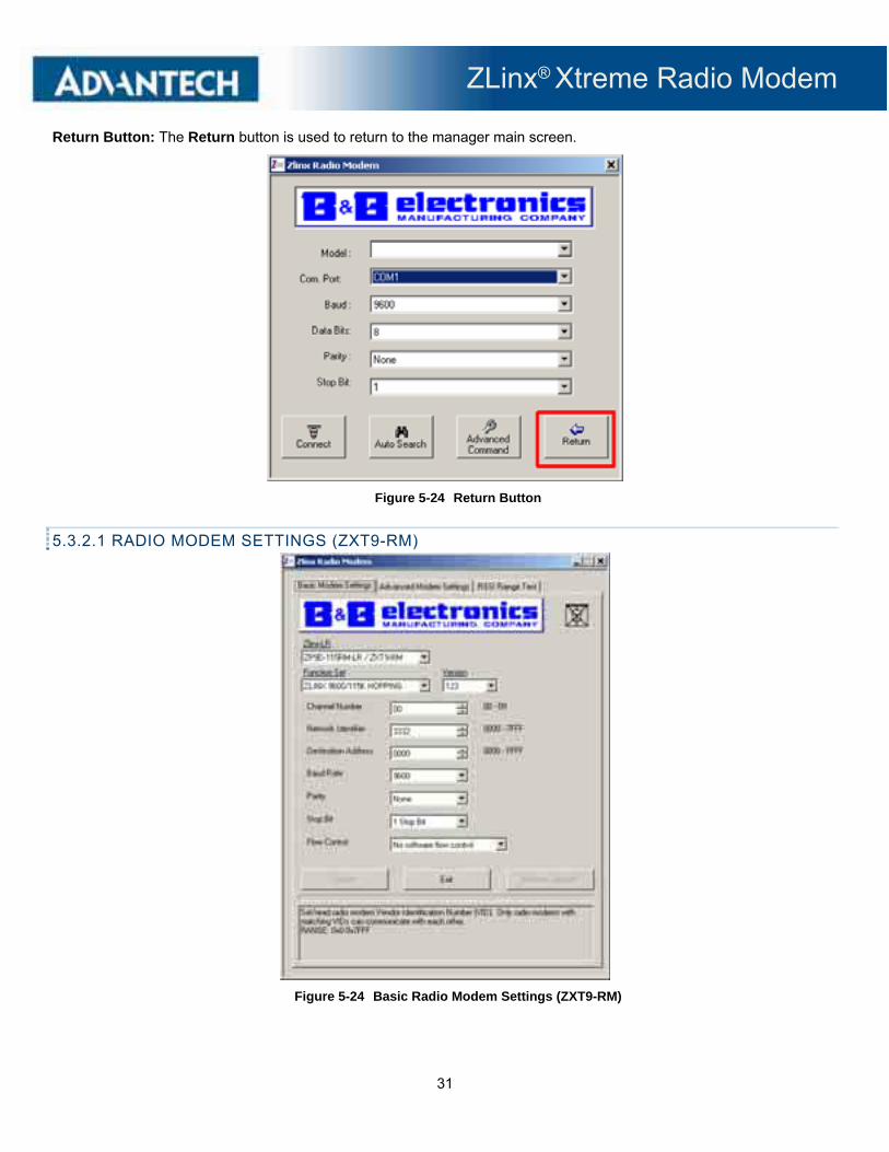
Return Button: The Return button is used to return to the manager main screen.
Figure 5-24 Return Button
5.3.2.1 RADIO MODEM SETTINGS (ZXT9-RM)
Figure 5-24 Basic Radio Modem Settings (ZXT9-RM)

ZLinx® Xtreme Radio Modem
32
Basic Modem Settings Tab:
The Basic Modem Settings tab is used to configure the following parameters:
Model Number: Displays the model number of the radio modem.
Function Set: Dependent on firmware.
Version: Dependent on firmware.
Channel Number: Set/read spread spectrum channel on which modem communicates. Separate channels minimize interference between multiple sets of modems operating in the same vicinity. The range is: 0x0 to 0x9. Default is 00.
Network Identifier: Set/read radio modem Vendor Identification Number (VID). Only radio modems with matching VIDs can communicate with each other.
The range is 0x0-0x7FFF. Default is 3332.
Destination Address: Set/read module's destination address. The range is 0x0-0xFFFF. Default is FFF7.
Baud Rate: Select serial interface rate (speed for data transfer between radio modem and host). Serial data rate does not have to match the RF data rate which is adjustable using the BR command on the Advanced Tab. If the serial data rate is set higher than the RF data rate, CTS may need to be observed to prevent buffer overrun. Range is 1200 to 230400 baud. Default is 9600.
Parity: Refer to section 5.3.2
Stop Bit: Refer to section 5.3.2
Flow Control: Select flow control options. Enables software flow control (XON/XOFF) between radio modem and host. Choices are Software Flow Control or No Flow Software Flow Control. Default is No Software Flow Control.
Click Update to save changed settings. Click Restore Defaults to restore the default settings. Click Exit to exit.
Advanced Modem Settings Tab:
The Advanced Modem Settings tab is used to configure Networking/Security, Serial Interfacing, RF Interfacing, Diagnostics, Sleep (Low Power), and Command Mode features.
Click Update to save changed settings. Click Restore Defaults to restore the default settings. Click Exit to exit.
Figure 5-25 Advanced Radio Modem Settings (ZXT9-RM)
ZLinx® Xtreme Radio Modem
33
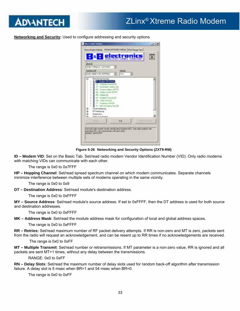
Networking and Security: Used to configure addressing and security options.
Figure 5-26 Networking and Security Options (ZXT9-RM)
ID – Modem VID: Set on the Basic Tab. Set/read radio modem Vendor Identification Number (VID). Only radio modems with matching VIDs can communicate with each other.
The range is 0x0 to 0x7FFF
HP – Hopping Channel: Set/read spread spectrum channel on which modem communicates. Separate channels minimize interference between multiple sets of modems operating in the same vicinity.
The range is 0x0 to 0x9
DT – Destination Address: Set/read module's destination address.
The range is 0x0 to 0xFFFF
MY – Source Address: Set/read module's source address. If set to 0xFFFF, then the DT address is used for both source and destination addresses.
The range is 0x0 to 0xFFFF
MK – Address Mask: Set/read the module address mask for configuration of local and global address spaces.
The range is 0x0 to 0xFFFF
RR – Retries: Set/read maximum number of RF packet delivery attempts. If RR is non-zero and MT is zero, packets sent from the radio will request an acknowledgement, and can be resent up to RR times if no acknowledgements are received.
The range is 0x0 to 0xFF
MT – Multiple Transmit: Set/read number or retransmissions. If MT parameter is a non-zero value, RR is ignored and all packets are sent MT+1 times, without any delay between the transmissions.
RANGE: 0x0 to 0xFF
RN – Delay Slots: Set/read the maximum number of delay slots used for random back-off algorithm after transmission failure. A delay slot is 5 msec when BR=1 and 54 msec when BR=0.
The range is 0x0 to 0xFF
ZLinx® Xtreme Radio Modem
34
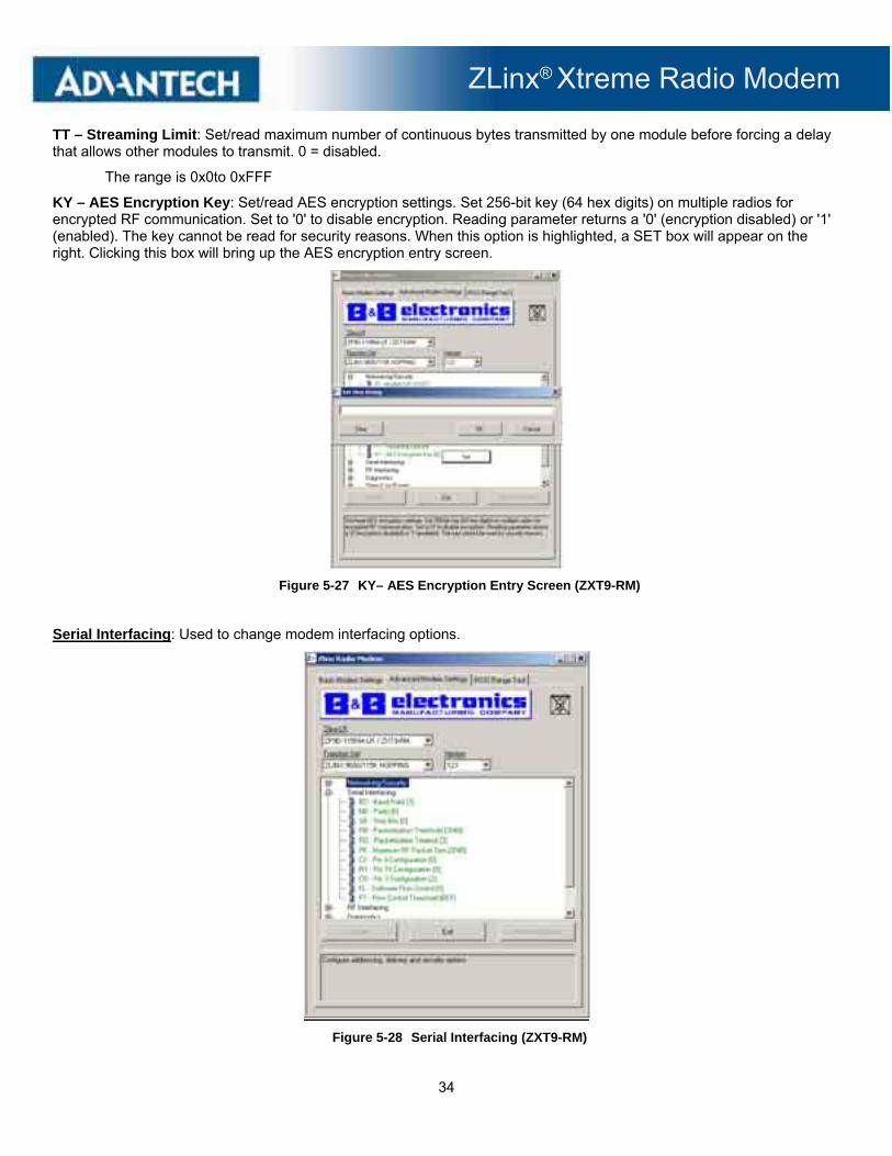
TT – Streaming Limit: Set/read maximum number of continuous bytes transmitted by one module before forcing a delay that allows other modules to transmit. 0 = disabled.
The range is 0x0to 0xFFF
KY – AES Encryption Key: Set/read AES encryption settings. Set 256-bit key (64 hex digits) on multiple radios for encrypted RF communication. Set to '0' to disable encryption. Reading parameter returns a '0' (encryption disabled) or '1' (enabled). The key cannot be read for security reasons. When this option is highlighted, a SET box will appear on the right. Clicking this box will bring up the AES encryption entry screen.
Figure 5-27 KY– AES Encryption Entry Screen (ZXT9-RM)
Serial Interfacing: Used to change modem interfacing options.
Figure 5-28 Serial Interfacing (ZXT9-RM)

ZLinx® Xtreme Radio Modem
35
BD – Baud Rate: Select serial interface rate (speed for data transfer between radio modem and host). Serial data rate does not have to match RF data rate which is adjustable using the BR command. If the serial data rate is set higher than the RF data rate, CTS may need to be observed to prevent DI buffer overrun. This is a pull-down option. Selections are:
0 – 1200 1 – 2400 2 – 4800 3 – 9600 4 – 19200 5 – 38400 6 – 57600 7 – 115200 8 – 230400
NB – Parity: Select parity settings for UART communications. This is a pull-down option. Selections are:
0 – None 1 – Even 2 – Odd 3 – Mark 4 – Space
SB – Stop Bits: Select number of stop bits used for UART communications. This is a pull-down option. Selections are:
0 – 1 Stop Bit 1 – 2 Stop Bits
RB – Packetization Threshold: Set/read character threshold. RF transmission is begun after receiving RB bytes, or after receiving at least 1 byte and seeing RO character times of silence on the UART.
RO – Packetization Timeout: RF transmission begins after receiving RB bytes, or after receiving at least 1 byte and seeing RO character times of silence on the UART. If RO=0, then RB bytes must be received before beginning transmission.
Range: 0x0 to 0xFFFF.
PK – Maximum RF Packet Size: Set/read maximum RF packet size. Must be 256 (0x100) or less for 9600 baud RF rate (BR=0), and 2048 (0x800) or less for 115200 baud RF rate (BR=1).
Range is 0x1 to 0x800.
CS – Pin 9 Configuration: Select behavior of serial Terminal Block position 9 (CTS). This is a pull-down option. Selections are:
0 – CTS Flow Control 1 – RS-485 Enable Low 2 – GP01 Static High 3 – RS-485 Enable High 4 – GP01 Static Low
ZLinx® Xtreme Radio Modem
36
RT – Pin 10 Configuration: Select function for serial Terminal Block position 8 (RTS). This is a pull-down option. Selections are:
0 – Unused 1 – Binary Command Indicator 2 – RTS Flow Control FL – Software Flow Control: Select flow control options. Enables software flow control (XON/XOFF) between radio modem and host. This is a pul- down option.
0 – No Software Flow Control 1 – Use Software Flow Control FT – Flow Control Threshold: Set/read the flow control threshold. De-assert CTS and/or send XOFF when FT bytes are in the UART receive buffer. The range is 0x0 to 0xFFFF.
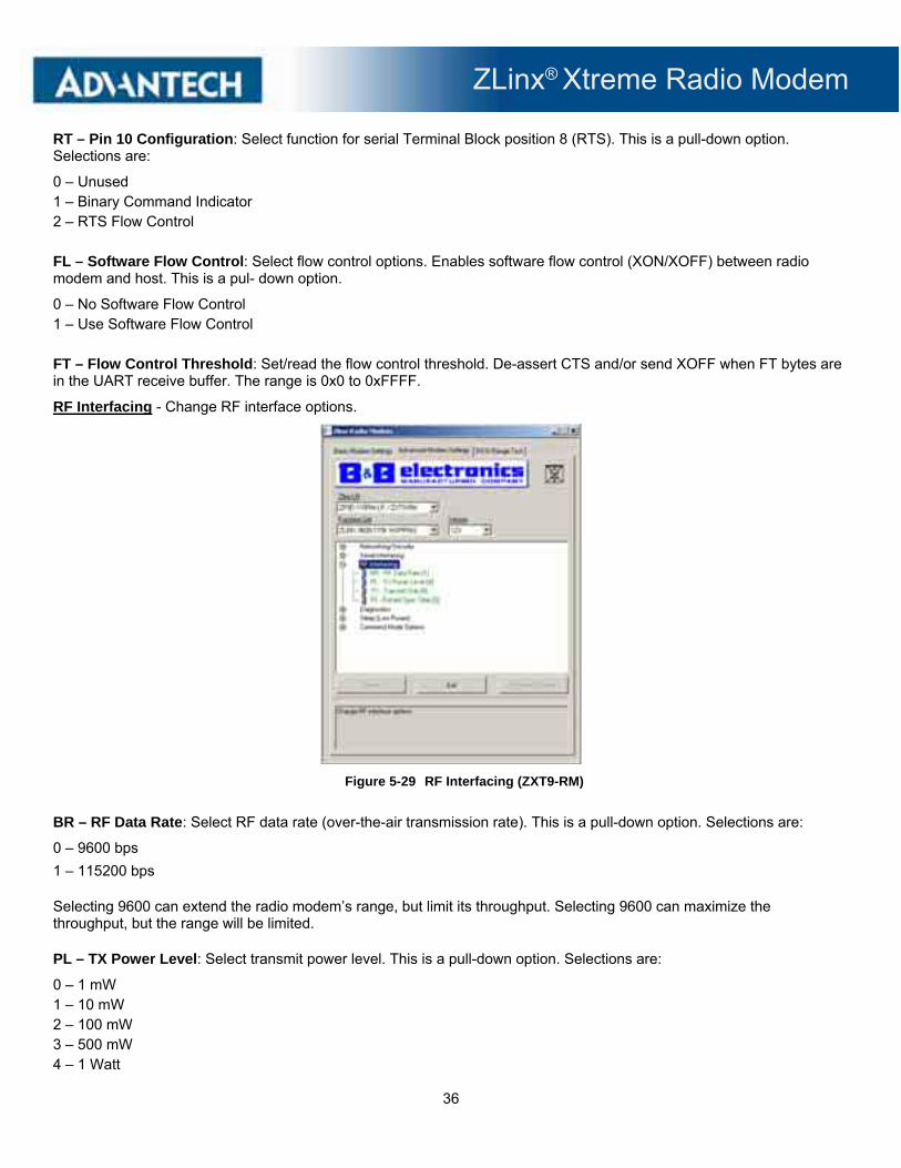
RF Interfacing - Change RF interface options.
Figure 5-29 RF Interfacing (ZXT9-RM)
BR – RF Data Rate: Select RF data rate (over-the-air transmission rate). This is a pull-down option. Selections are:
0 – 9600 bps
1 – 115200 bps
Selecting 9600 can extend the radio modem’s range, but limit its throughput. Selecting 9600 can maximize the throughput, but the range will be limited.
PL – TX Power Level: Select transmit power level. This is a pull-down option. Selections are:
0 – 1 mW 1 – 10 mW 2 – 100 mW 3 – 500 mW 4 – 1 Watt

ZLinx® Xtreme Radio Modem
37
TX – Transmit Only: Select TX/RX or TX Only. This is a pull-down option. Selections are:
0 – Transmit and Receive
1 – Transmit Only
FS – Forced Sync Time: Set/read forced re-sync period. Normally only the first packet of a transmission event contains the sync preamble. This command allows forced periodic sync preambles during long transmission events. Zero disables this feature. The range is 0x0 to 0xFFFF.
Diagnostics: Access diagnostic parameters.
Figure 5-30 Diagnostics (ZXT9-RM)
VR – Firmware Version: Read module firmware version number. Read-only function. HV – Hardware Version: Read module hardware version number. Read-only function. SH – Serial Number High: Read high 16 bits of 3- bit unique serial number. Read-only function. SL – Serial Number Low: Read low 16 bits of 32-bit unique serial number. Read-only function. RP – RSSI PWM Timer: Set/read duration of PWM (pulse width modulated) output. The PWM output encodes fade margin (RX signal strength relative to RX sensitivity) by varying the duty cycle of a 125Hz square wave. The range is 0x0 to 0xFF TP – Board Temperature: Read current temperature of module in degrees Celsius (8-bit twos-complement, eg. 26C = 0x1A, -10C = 0xF6). Read-only function.

ZLinx® Xtreme Radio Modem
38
%V – Board Voltage: Read supply voltage to module (VCC) multiplied by 65536 (eg. 5.02V = 5.02*65536 = 0x5051F, maximum of 5 digits returned). Read-only function. DB – Receive Signal Strength: Read signal level of last good packet received (RSSI) in dB (reports absolute value, eg. -88dBm = 0x58, accurate between -40 dBm to RX sensitivity). Read-only function. ER – Receive Error Count: Set/read number of RF Packets rejected because of bit errors in packet. Read-only function. GD – Receive Good Count: Set/read number of RF Packets successfully received. Read-only function. TR – Delivery FailureCount: Read number of RF packets sent where retries expire with no ACK received (when RR>0). Read-only function. Sleep – Low Power: Radio modem can be put into Sleep Mode to reduce the amount of power consumed.
Figure 5-31 Sleep (Low Power) (ZXT9-RM)
SM – Sleep Mode: Select Sleep Mode option. Lowest power is achieved using the SHDN signal. Cyclic sleep can be used to trade idle current consumption for transmission latency. This is a pull-down option. Selections are:
0 – No Sleep 1 – Pin Sleep (DTR Pin used for this feature) 2 – Serial Port Sleep 3 – Reserved 4 – Cycle 1 Second 5 – Cycle 2 Seconds 6 – Cycle 4 Seconds 7 – Cycle 8 Seconds 8 – Cycle 16 Seconds ST – Time Before Sleep: Set/read time period of inactivity (no serial or RF data is sent or received) before activating Sleep Mode - Only valid with Cyclic and Serial Port Sleep settings. The range is 0x10 to 0xFFFF.
ZLinx® Xtreme Radio Modem
39
HT – Time Before Wakeup Initializer: Set/read time of inactivity (no serial or RF data is sent or received) before a Wake-up Initializer is sent. HT should be set shorter than ST of all remote radios. The range is 0x0 to 0xFFFF.
LH – Wake-up Initializer Timer: Set/read time of the Wake-up Initializer used to wake remote radios that are in cyclic sleep mode. Time of Wake-up Initializer should be longer than that of the remotes radio's cyclic sleep cycle (SM 4-8). The range is 0x0 to 0xFF.
PW – Pin Wake-up: Select pin wake-up options. When PW=1, pin wake-up from Cyclic Sleep Mode is enabled. This is a pull-down option. Selections are:
0 – Disable 1 – Enable
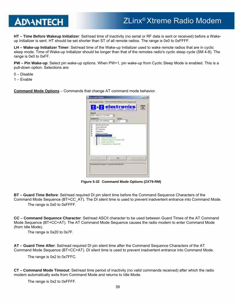
Command Mode Options – Commands that change AT command mode behavior.
Figure 5-32 Command Mode Options (ZXT9-RM)
BT – Guard Time Before: Set/read required DI pin silent time before the Command Sequence Characters of the Command Mode Sequence (BT+CC_AT). The DI silent time is used to prevent inadvertent entrance into Command Mode.
The range is 0x0 to 0xFFFF.
CC – Command Sequence Character: Set/read ASCII character to be used between Guard Times of the AT Command Mode Sequence (BT+CC+AT). The AT Command Mode Sequence causes the radio modem to enter Command Mode (from Idle Mode).
The range is 0x20 to 0x7F.
AT – Guard Time After: Set/read required DI pin silent time after the Command Sequence Characters of the AT Command Mode Sequence (BT+CC+AT). DI silent time is used to prevent inadvertent entrance into Command Mode.
The range is 0x2 to 0x7FFC.
CT – Command Mode Timeout: Set/read time period of inactivity (no valid commands received) after which the radio modem automatically exits from Command Mode and returns to Idle Mode.
The range is 0x2 to 0xFFFF.

ZLinx® Xtreme Radio Modem
40
5.3.2.2 RADIO MODEM SETTINGS (ZXT24-RM)
Figure 5-33 Basic Radio Modem Settings (ZXT24-RM)
Basic Modem Settings Tab is used to configure the following parameters:
Model Number: Displays the radio modem model number.
Function Set: Functions supported by firmware.
Version: Firmware version.
Channel Number: Set/read the channel number (uses 802.15.4 channel numbers).
The range is 0xC to 0x17
Network Identifier: Set the PAN (Personal Area Network) ID. Use 0xFFFF to send message to all PAN's.
The range is 0x0 to 0xFFFF.
Destination Address: Set/read the lower 32 bits of the 64 bit destination address. Set the DH register to zero and DL less than 0xFFFF to transmit using a 16 bit address. 0x000000000000FFFF is the broadcast address for the PAN.
The range is 0x0-0xFFFFFFFF.
Baud Rate: Set/read the serial interface baud rate for communication between modem serial port and host. Request non-standard baud rates with values above 0x80 using a terminal window. Read BD register to find actual baud rate achieved
Parity: Not Selectable
Stop Bit: Not Selectable
Flow Control: Not Selectable
Click Update to save changed settings. Click Restore Defaults to restore the default settings. Click Exit to exit.

ZLinx® Xtreme Radio Modem
41
Advanced Modem Settings Tab:
The Advanced Settings tab is used to configure Networking/Security, RF Interfacing, Sleep Modes (Non Beacon), Serial Interfacing, Diagnostics, and AT Command Mode features.
Click Update to save changed settings. Click Restore Defaults to restore the default settings. Click Exit to exit.
Figure 5-34 Advanced Radio Modem Settings (ZXT24-RM)
Networking and Security: Used to configure addressing and security options.
Figure 5-35 Network and Security Settings (ZXT24-RM)
Networking and Security: Set/read the channel number (uses 802.15.4 channel numbers).
The range is 0xC to 0x17.

ZLinx® Xtreme Radio Modem
42
ID – PAN ID: Set the PAN (Personal Area Network) ID. Use 0xFFFF to send message to all PAN's.
The range is 0x0 to 0xFFFF.
DH – Destination Address High: Set/read the upper 32 bits of the 64 bit destination address. Set the DH register to zero and DL less than 0xFFFF to transmit using a 16-bit address. 0x000000000000FFFF is the broadcast address for the PAN.
The range is 0x0 to 0xFFFFFFFF.
DL – Destination Address Low: Set/read the lower 32 bits of the 64 bit destination address. Set the DH register to zero and DL less than 0xFFFF to transmit using a 16-bit address. 0x000000000000FFFF is the broadcast address for PAN.
The range is 0x0 to 0xFFFFFFFF
MY – 16 Bit Source Address: Set/read the 16-bit source address for the modem. Set MY = 0xFFFF to disable reception of packets with 16-bit addresses. 64-bit source address is the serial number and is always enabled.
The range is 0x0 to 0xFFFF.
RM – Random Delay Slots: Set/Read the minimum value of the back-off exponent in the CSMA-CA algorithm that is used for collision avoidance. If RN=0, collision avoidance is disabled during the first iteration of the algorithm (802.15.4 - macMinBE).
The range is 0x0 to 0x3.
MM – Mack Code: Set/Read MAC Mode value. MAC Mode enables/disables the use of a the header in the 802.15.4 RF packet. When Mode 0 is enabled (MM=0), duplicate packet detection is enabled as well as certain AT commands. Modes 1 and 2 are strict 802.15.4 modes. This is a pull-down option. Selections are: 0 – 802.15.4 + MaxStream® Header 1 – 802.15.4 No ACKS’s 2 – 802.15.4 With ACK’s
CE – Coordinator Enable: Set/Read the coordinator setting. This is a pull-down option. Selections are: 0 - End Device 1 - Coordinator
SC – Scan Channels: Read/set list of channels to scan for Active and Energy Scans as bitfield. Scans may be initiated by ATAS, ATED commands and during End Device Association and Coordinator startup: Bit 15 - Ch. 0x1A . . . Bit 0 -Ch. 0x0B (bits 15, 14 and 0 not available on ZLinx).
The range is 0x0 to 0xFFFF.
SD – Scan Duration: Set read the Scan duration exponent. The exponent configures the duration of the active scan during association. Set End Device SD = BE of beaconing coordinator. Scan Time = N* (2 ^ SD) * 15.36ms. N=# channels: ZLinx = 16, ZLinx/Pro = 13.
The range is 0x0 to 0x0F.

ZLinx® Xtreme Radio Modem
43
A1 – End Device Association: Set/read End Device association options. Options enabled when bits are set: bit3 - Poll coordinator on pin wake, bit2 - Auto Associate, bit1 - Allow Channel reassignment, bit0 - Allow PanId reassignment. This is a pull-down option. Selections are:
0 – 0000b 1 – 0001b 2 – 0010b 3 – 0011b 4 – 0100b 5 – 0101b 6 – 0110b 7 – 0111b 8 – 1000b 9 – 1001b 10 – 1010b 11 – 1011b 12 – 1100b 13 – 1101b 14 – 1110b 15 – 1111b
A2 – Coordinator Association: Set/read Coordinator association options. Options enabled when bits are set: bit2 - Allow Association, bit1 - Allow Channel reassignment, bit0 - Allow PanId reassignment. This is a pull-down option. Selections are: 0 – 000b 1 – 001b 2 – 010b 3 – 011b 4 – 100b 5 – 101b 6 – 110b 7 – 111b
RF Interfacing: Used to change RF interface options.
Figure 5-36 RF Interfacing (ZXT24-RM)
ZLinx® Xtreme Radio Modem
44
PL – Power Level: Select/Read transmitter output power. This is a pull-down option. Selections are: 0 – 10dBm (Lowest) 1 – 12dBm (Low) 2 – 14dBm (Medium) 3 – 16dBm (High) 4 – 18dBm (Highest)
CA – CCA Threshold: Set/read the Clear Channel Assessment (CCA) threshold. If the modem detects energy above the CCA Threshold, if will not transmit. The CCA parameter is measured in units of -dBm. The range is 0x0 to 0x50.
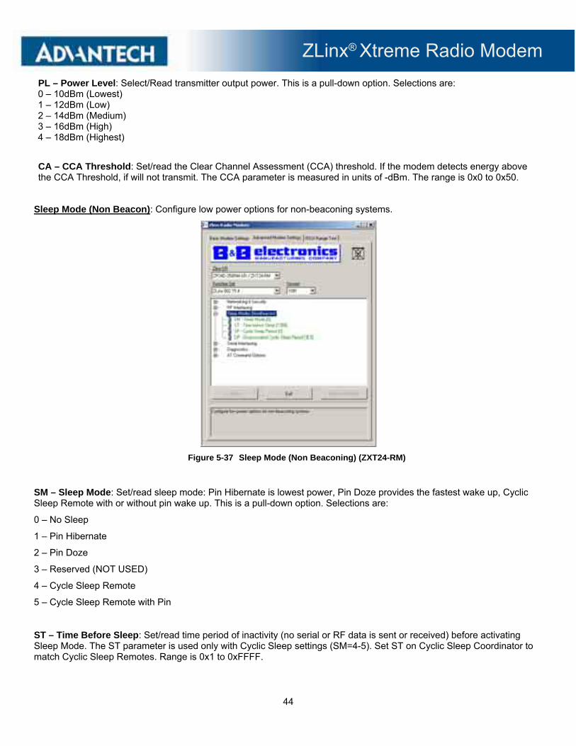
Sleep Mode (Non Beacon): Configure low power options for non-beaconing systems.
Figure 5-37 Sleep Mode (Non Beaconing) (ZXT24-RM)
SM – Sleep Mode: Set/read sleep mode: Pin Hibernate is lowest power, Pin Doze provides the fastest wake up, Cyclic Sleep Remote with or without pin wake up. This is a pull-down option. Selections are:
0 – No Sleep
1 – Pin Hibernate
2 – Pin Doze
3 – Reserved (NOT USED)
4 – Cycle Sleep Remote
5 – Cycle Sleep Remote with Pin
ST – Time Before Sleep: Set/read time period of inactivity (no serial or RF data is sent or received) before activating Sleep Mode. The ST parameter is used only with Cyclic Sleep settings (SM=4-5). Set ST on Cyclic Sleep Coordinator to match Cyclic Sleep Remotes. Range is 0x1 to 0xFFFF.

ZLinx® Xtreme Radio Modem
45
SP – Cycle Sleep Period: Set/read Cyclic sleep period for cyclic sleeping remotes. Set SP on Coordinator to match End Device. Coordinator will discard indirect messages after a period of 2.5*SP, set Coordinator SP = 0 to send direct messages. Maximum sleep period is 268 seconds (0x68B0).
Range is 0x0 to 0x68B0.
DP – Disassociated Sleep Period: Set/read sleep period for cyclic sleeping remotes that are configured for Association but that are not associated to a Coordinator. Maximum sleep period is 268 seconds (0x68B0). Range is 0x1 to 0x68B0.
Serial Interfacing: Change modem interfacing options.
Figure 5-38 Serial Interfacing (ZXT24-RM)
BD – Interface Data Rate: Set/read the serial interface baud rate for communication between modem serial port and host. Request non-standard baud rates with values above 0x80 using a terminal window. Read BD register to find actual baud rate achieved. This is a pull-down option. Selections are:
0 – 1200 1 – 2400 2 – 4800 3 – 9600 4 – 19200 5 – 38400 6 – 57600 7 – 115200
RD – Receive Packetization Timeout: Set/read number of character times of inter-character delay required before transmission
begins. Set to zero to transmit characters as they arrive instead of buffering them into one RF packet.
The range is 0x0 to 0xFF.
D7 – DIO7 Configuration: Configure options for the DIO7 line of the module. Options include: CTS flow control. This is a pull-down option. Selections are:
0 – Disable 1 – CTS Flow Control

ZLinx® Xtreme Radio Modem
46
D6 – DIO6 Configuration: Configure options for the DIO6 line of the module. Options include: RTS flow control. This is a pull-down option. Selections are:
0 – Disable 1 – RTS Flow Control
D5 – DIO5 Configuration: Configure options for the DIO5 line of the module. Options include: Associated LED indicator (blinks when associated). This is a pull-down option. Selections are:
0 – Disable 1 – Associated Indicator
P0 – PWMO Configuration: Select/Read function for PWM0. This is a pull-down option. Selections are:
0 – Disable 1 – RSSI
AP – API Enable: Enables API mode. This is a pull-down option. Selections are:
0 – API Disabled 1 – API Enabled 2 – API Enabled with PPI
PR – Pull Up Resistor Enable: Set/read bitfield to configure internal pullup resistors status for I/O lines. 1=internal pullup enabled, 0=no internal pullup. Bitfield map: Bit 7 - DIN (P3), Bit 6 - IO8/SLEEP_RQ (P9), Bit 5 - DIO6/RTS (P16), Bit 4 - DIO0 (P20), Bit 3 - DIO1 (P19), Bit 2 - DIO2 (P18), Bit 1 - DIO3 (P17), Bit 0 - DIO4 (P11).
The range is 0x0 to 0xFF
Diagnostics: Access diagnostic parameters.
Figure 5-39 Diagnostics (ZXT24-RM)

ZLinx® Xtreme Radio Modem
47
RP – RSSI PMW Timer: Set/read PWM timer register. Set duration of PWM (pulse width modulation) signal output. The signal duty cycle is updated with each received packet and is shut off when the timer expires. The range is 0x0 to 0xFF.
AT Command Options: Change AT command mode behavior.
Figure 5-40 AT Command Options (ZXT24-RM)
CT – AT Command Mode Timeout: Set/read command mode timeout parameter. If no valid commands have been received within this time period, the modem returns to Idle Mode from AT Command Mode.
The range is 0x2 to 0xFFFF
GT – Guard Times: Set required period of silence before, after and between the Command Mode Characters of the Command Mode Sequence (GT + CC + GT). The period of silence is used to prevent inadvertent entrance into AT Command Mode.
The range is 0x2 to 0xFFFF.
CC – Command Sequence Character: Set/read character value to be used to break from data mode to command mode. The default value <2Bh> is the ASCII code for the plus ('+') character.
The range is 0x0 to 0xFF.
ZLinx® Xtreme Radio Modem
48
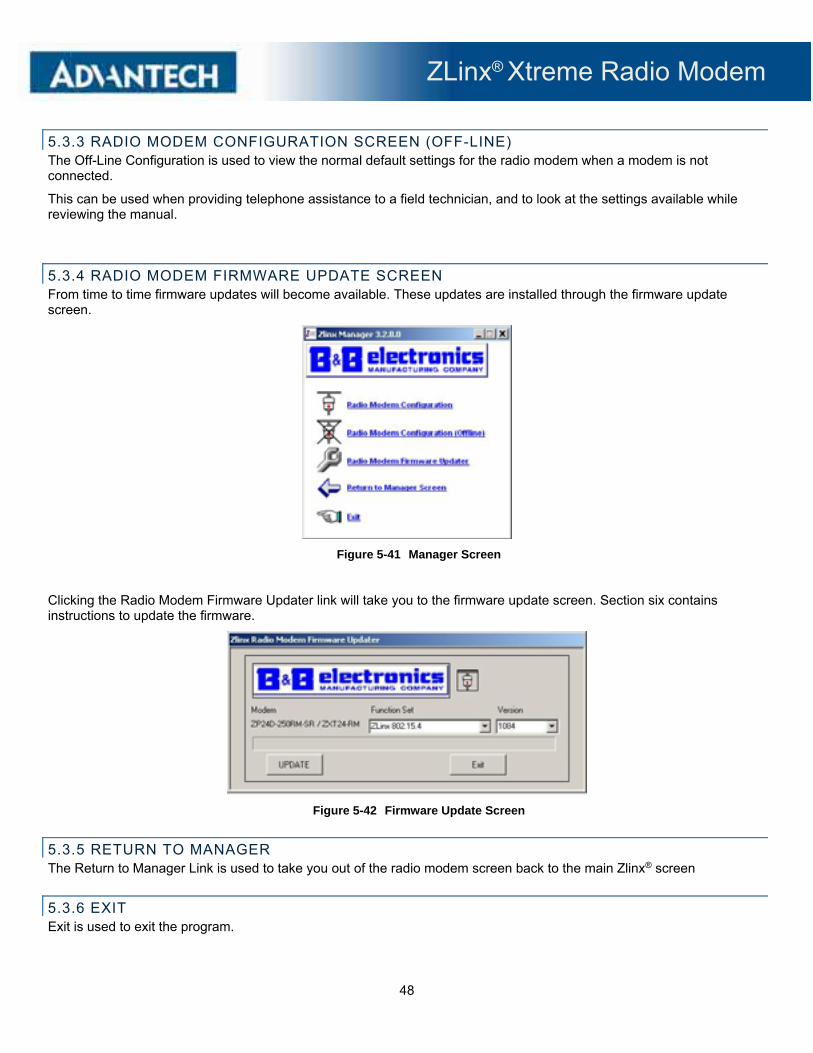
5.3.3 RADIO MODEM CONFIGURATION SCREEN (OFF-LINE) The Off-Line Configuration is used to view the normal default settings for the radio modem when a modem is not connected.
This can be used when providing telephone assistance to a field technician, and to look at the settings available while reviewing the manual.
5.3.4 RADIO MODEM FIRMWARE UPDATE SCREEN From time to time firmware updates will become available. These updates are installed through the firmware update screen.
Figure 5-41 Manager Screen
Clicking the Radio Modem Firmware Updater link will take you to the firmware update screen. Section six contains instructions to update the firmware.
Figure 5-42 Firmware Update Screen
5.3.5 RETURN TO MANAGER The Return to Manager Link is used to take you out of the radio modem screen back to the main Zlinx® screen
5.3.6 EXIT Exit is used to exit the program.
ZLinx® Xtreme Radio Modem
49
6 - STARTUP AND CONFIGURATION
6.1 BASIC SETTINGS
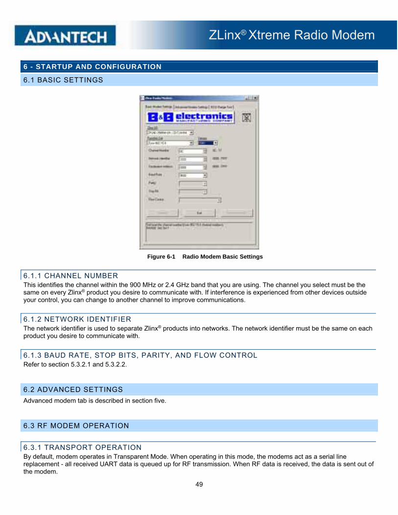
Figure 6-1 Radio Modem Basic Settings
6.1.1 CHANNEL NUMBER This identifies the channel within the 900 MHz or 2.4 GHz band that you are using. The channel you select must be the same on every Zlinx® product you desire to communicate with. If interference is experienced from other devices outside your control, you can change to another channel to improve communications.
6.1.2 NETWORK IDENTIFIER The network identifier is used to separate Zlinx® products into networks. The network identifier must be the same on each product you desire to communicate with.
6.1.3 BAUD RATE, STOP BITS, PARITY, AND FLOW CONTROL Refer to section 5.3.2.1 and 5.3.2.2.
6.2 ADVANCED SETTINGS
Advanced modem tab is described in section five.
6.3 RF MODEM OPERATION
6.3.1 TRANSPORT OPERATION By default, modem operates in Transparent Mode. When operating in this mode, the modems act as a serial line replacement - all received UART data is queued up for RF transmission. When RF data is received, the data is sent out of the modem.

ZLinx® Xtreme Radio Modem
50
6.3.2 SERIAL TO RF PACKETIZATION
Data is buffered in the input buffer until one of the following causes the data to be packetized and transmitted:
No serial characters are received for the amount of time determined by the RO (Packetization Timeout) parameter. If RO = 0 packetization begins when a character is received.
The maximum number of characters that will fit in an RF packet (2048 for ZXT9-RM) (202 for ZXT24-RM) is received.
The Command Mode Sequence (GT + CC + GT) is received. Any character buffered in the input buffer before the sequence is transmitted.
If the modem cannot immediately transmit (for instance, if it is already receiving RF data), the serial data is stored in the input buffer. The data is packetized and sent at any RO timeout or when the maximum packet size is received.
If the input buffer becomes full, hardware or software flow control must be implemented in order to prevent overflow (loss of data between the host and modem).
6.3.3 API OPERATION
API (Application Programming Interface) Operation is an alternative to the default Transparent Operation. The frame-based API extends the level to which a host application can interact with the networking capabilities of the modem.
When in API mode, all data entering and leaving the modem is contained in frames that define operations or events within the modem.
Transmit Data Frames (received by modem) include:
RF transmit data frame
Command frame (equivalent to AT commands)
Receive Data Frames (sent out by modem) include:
RF received data frame
Command response
Event notifications such as reset, associate, disassociate, etc.
The API provides alternative means of configuring modems and routing data at the host application layer. A host application can send data frames to the modem that contain address and payload information instead of using command mode to modify addresses. The modem will send data frames to the application containing status packets; as well as source, RSSI and payload information from received data packets.
The API operation option facilitates many operations such as the examples cited below:
Transmitting data to multiple destinations without entering Command Mode
Receive success/failure status of each transmitted RF packet
Identify the source address of each received packet
Note: to implement API operations, refer to API sections.

ZLinx® Xtreme Radio Modem
51
6.3.4 FLOW CONTROL Input Buffer
When serial data received by modem, the data is stored in the Input Buffer until it can be processed.
Hardware Flow Control (CTS) When the input buffer is 17 bytes away from being full, by default, the modem de-asserts CTS (high) to signal to the host device to stop sending data [refer to FT (Flow Control Threshold) and CS (GPO1 Configuration) Commands]. CTS is re-asserted after the buffer has 34 bytes of memory available.
Software Flow Control (XON) XON/XOFF software flow control can be enabled using the FL (Software Flow Control) Command. This option only works with ASCII data.
How to eliminate the need for flow control:
Send messages that are smaller than the input buffer size. The size of the input buffer varies according to the packet size (PK parameter) and the parity setting (NB parameter) used.
Interface at a lower baud rate [BD (Interface Data Rate) parameter] than the RF data rate (BR parameter).
Two cases in which the input Buffer may become full and possibly overflow:
If the serial interface data rate is set higher than the RF data rate of the modem, the modem will receive data from the host faster than it can transmit the data over-the-air.
If the modem is receiving a continuous stream of RF data or if the modem is monitoring data on a network, any serial data that arrives on the modem is placed in the Input Buffer. The data in the input buffer will be transmitted over-the-air when the modem no longer detects RF data in the network.
Output Buffer
When RF data is received, the data enters the output buffer and is sent out the serial port to a host device. Once the output buffer reaches capacity, any additional incoming RF data is lost. The output buffer stores at least 2.1 KB.
Hardware Flow Control (RTS) If RTS is enabled for flow control (RT Parameter = 2), data will not be sent out the output buffer as long as RTS (pin 10) is de-asserted.
Software Flow Control (XOFF) XON/XOFF software flow control can be enabled using the FL (Software Flow Control) Command. This option only works with ASCII data.
Two cases in which the output buffer may become full and possibly overflow:
If the RF data rate is set higher than the interface data rate of the modem, the modem will receive data from the transmitting modem faster than it can send the data to the host.
If the host does not allow the modem to transmit data out from the output buffer because of being held off by hardware or software flow control.
ZLinx® Xtreme Radio Modem
52
6.3.5 SLEEP MODE
Sleep Modes enable the module to enter states of low-power consumption when not in use. Three software Sleep Modes are supported:
Pin Sleep (Host Controlled)
Serial Port Sleep (Wake on Serial Port activity)
Cyclic Sleep (Wake on RF activity)
In order to enter Sleep Mode, one of the following conditions must be met (in addition to the modem having a non-zero SM parameter value):
The modem is idle (no data transmission or reception) for the amount of time defined by the ST (Time before Sleep) parameter. [Note: ST is only active when SM = 4-5.]
SLEEP (DTR) is asserted (only for the 'Pin Sleep' option).
When in Sleep Mode, the modem will not transmit or receive data until the modem first transitions to Idle Mode. All Sleep Modes are enabled and disabled using SM Command. Transitions into and out of Sleep Modes are triggered by various mechanisms as shown in the table below.
The SM (Sleep Mode) command is central to setting all Sleep Mode configurations. By default, Sleep Modes are disabled (SM = 0) and the modem remains in Idle/Receive Mode. When in this state, the modem is constantly ready to respond to serial or RF activity.
Refer to 'Hardware Sleep' section of the 'Shutdown Mode' section to enable the modem's lowest power-consuming state.
6.3.5.1 PIN SLEEP MODE
Pin Sleep (SM = 1)
Pin/Host-controlled
This mode is voltage level activated. When DTR/SLP is asserted, the modem will finish any transmitting or receiving activity, enter idle mode, then enter a state of sleep. When in Pin Sleep Mode, the modem will not respond to serial or RF activity.
After enabling Pin Sleep, the SLEEP pin controls whether the modem is active or sleeping. When SLEEP is de-asserted, the modem is fully operational. When SLEEP is asserted, the modem transitions to Sleep Mode and remains in its lowest power-consuming state until the pin is de-asserted.
Note: The modem will complete a transmission or reception before activating Pin Sleep.
6.3.5.2 SERIAL PORT SLEEP MODE
Serial Port Sleep (SM = 2)
Wake on serial port activity
Serial Port Sleep is a Sleep Mode in which the modem runs in a low power state until serial data is detected on the modem.
The period of time the modem sleeps is determined by ST (Time before Sleep) Command. Once a character is received through the input, the modem returns to Idle Mode and is fully operational.

ZLinx® Xtreme Radio Modem
53
6.3.5.3 CYCLE SLEEP MODE
Cyclic Sleep (SM = 4-8) Cyclic Sleep Modes allow modems to periodically wake and check for RF data. The modem wakes according to the times designated by the Cyclic sleep settings. If the modem detects a wake-up initializer during the time it is awake, the modem synchronizes with the transmitting modem and receives data after the wake-up initializer runs its duration. Otherwise, the modem returns to Sleep Mode and continues to cycle in and out of activity until a wake-up initializer is detected.
While the modem is in Cyclic Sleep Mode, CTS is de-asserted (high) to indicate that data should not be sent to the modem. When the modem awakens to listen for data, CTS is asserted and any data received on the modem input is transmitted.
The modem remains in Sleep Mode for a user-defined period of time ranging from 0.5 seconds to 16 seconds (SM parameters 4 through 8). After this interval of time, the modem returns to Idle Mode and listens for a valid data packet for 100 ms. If the modem does not detect valid data (on any frequency), the modem returns to Sleep Mode. If valid data is detected, the modem transitions into Receive Mode and receives the incoming RF packets. The modem then returns to Sleep Mode after a period of inactivity determined by the ST "Time before Sleep" parameter.
The modem can also be configured to wake from Cyclic Sleep when DTR/SLP is de-asserted. To configure a modem to operate in this manner, PW (Pin Wake-up) Command must be issued. Once the SLEEP pin is de-asserted, the modem is forced into Idle Mode and can begin transmitting or receiving data. It remains active until data is no longer detected for the period of time specified by the ST Command, at which point it resumes its low-power cyclic state.
Cyclic Scanning Each RF transmission consists of an RF Initializer and Payload. The RF initializer contains initialization information and all receiving modems must wake during the wake-up initializer portion of data transmission in order to be synchronized with the transmitting modem and receive the data.
6.3.6 COMMAND MODE
To modify or read RF modem parameters, the modem must first enter into Command Mode (state in which incoming characters are interpreted as commands). Two command types are supported: AT Commands and Binary Commands.
For modified parameter values to persist in the modem registry, changes must be saved to non-volatile memory using the WR (Write) command. Otherwise, parameters are restored to previously saved values when the modem is powered off and then on again.
6.3.6.1 MODEM CONFIGURATION SWITCH
The Configuration Switch provides an alternate method for entering into Command Mode.
To enter Command Mode at the default RF data rate of the modem, remove power, hold the Configuration Switch (PB1) down and power up the modem, then release the Configuration Switch.
The Serial port default is 115200, 8, N, 1.
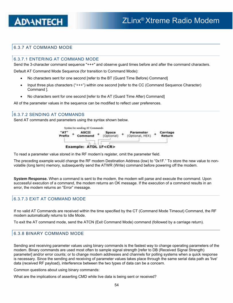
ZLinx® Xtreme Radio Modem
54
6.3.7 AT COMMAND MODE
6.3.7.1 ENTERING AT COMMAND MODE Send the 3-character command sequence "+++" and observe guard times before and after the command characters.
Default AT Command Mode Sequence (for transition to Command Mode):
No characters sent for one second [refer to the BT (Guard Time Before) Command]
Input three plus characters (“+++”) within one second [refer to the CC (Command Sequence Character) Command ].
No characters sent for one second [refer to the AT (Guard Time After) Command]
All of the parameter values in the sequence can be modified to reflect user preferences.
6.3.7.2 SENDING AT COMMANDS Send AT commands and parameters using the syntax shown below.
To read a parameter value stored in the RF modem’s register, omit the parameter field.
The preceding example would change the RF modem Destination Address (low) to “0x1F.” To store the new value to non-volatile (long term) memory, subsequently send the ATWR (Write) command before powering off the modem.
System Response. When a command is sent to the modem, the modem will parse and execute the command. Upon successful execution of a command, the modem returns an OK message. If the execution of a command results in an error, the modem returns an “Error” message.
6.3.7.3 EXIT AT COMMAND MODE
If no valid AT Commands are received within the time specified by the CT (Command Mode Timeout) Command, the RF modem automatically returns to Idle Mode.
To exit the AT command mode, send the ATCN (Exit Command Mode) command (followed by a carriage return).
6.3.8 BINARY COMMAND MODE
Sending and receiving parameter values using binary commands is the fastest way to change operating parameters of the modem. Binary commands are used most often to sample signal strength [refer to DB (Received Signal Strength) parameter] and/or error counts; or to change modem addresses and channels for polling systems when a quick response is necessary. Since the sending and receiving of parameter values takes place through the same serial data path as 'live' data (received RF payload), interference between the two types of data can be a concern.
Common questions about using binary commands:
What are the implications of asserting CMD while live data is being sent or received?

ZLinx® Xtreme Radio Modem
55
After sending serial data, is there a minimum time delay before CMD can be asserted?
Is a time delay required after CMD is de-asserted before payload data can be sent?
How does one discern between live data and data received in response to a command?
The CMD pin (pin 10) must be asserted in order to send binary commands to the modem. The CMD pin can be asserted to recognize binary commands anytime during the transmission or reception of data. The status of the CMD signal is only checked at the end of the stop bit as the byte is shifted into the serial port. The application does not allow control over when data is received, except by waiting for dead time between bursts of communication.
If the command is sent in the middle of a stream of payload data to be transmitted, the command will essentially be executed in the order it is received. If the modem is continuously receiving data, the radio will wait for a break in the received data before executing the command. The CTS signal will frame the response coming from the binary command.
A minimum time delay of 100 μs (after the stop bit of the command byte has been sent) must be observed before the CMD pin can be de-asserted. The command executes after all parameters associated with the command have been sent. If all parameters are not received within 0.5 seconds, the modem returns to Idle Mode.
Note: When parameters are sent, they are two bytes long with the least significant byte sent first. Binary commands that return one parameter byte must be written with two parameter bytes.
Commands can be queried for their current value by sending the command logically ORed (bit-wise) with the value 0x80 (hexadecimal) with CMD asserted. When the binary value is sent (with no parameters), the current value of the command parameter is sent back through the DO pin.
IMPORTANT: In order for the modem to recognize a binary command, the RT (GPI1 Configuration) parameter must be set to one. If binary programming is not enabled (RT parameter value is not equal to ‘1’), the modem will not recognize that the CMD pin is asserted and therefore will not recognize the data as binary commands.
ZLinx® Xtreme Radio Modem
56
6.4 ZXT9-RM CONFIGURATION
6.4.1 ADVANCED PROGRAMMING
6.4.1.1 PROGRAMMING EXAMPLES USING AT COMMANDS
The programming examples in this section require the installation of a hyper terminal program and a connection to a PC.
6.4.1.2 PROGRAMMING USING BINARY COMMANDS
Example: Use binary commands to change the RF modem's destination address to 0x1A0D and save the new address to non-volatile memory.
1. RT Command must be set to '1' in AT Command Mode to enable binary programming
2. Assert CMD (Pin 10 is driven high). (Enter Binary Command Mode)
3. Send Bytes [parameter bytes must be 2 bytes long]:
00 (Send DT (Destination Address) Command)
0D (Least significant byte of parameter bytes)
1A (Most significant byte of parameter bytes)
08 (Send WR (Write) Command)
4. De-assert CMD (pin 10 is driven low). (Exit Binary Command Mode)
Note: CTS is high when a command is being executed. Hardware flow control must be disabled as CTS will hold off parameter bytes.
‘CR’ stands for carriage return:
Method 1 (One line per command)
Send AT Command System Response_
+++ OK <CR> (Enter into Command Mode)
ATDT <Enter> current value <CR> (Read Destination Address)
ATDT1A0D <Enter> OK <CR> (Modify Destination Address)
ATWR <Enter> OK <CR> (Write to non-volatile memory)
ATCN <Enter> OK <CR> (Exit Command Mode)
Method 2 (Multiple commands on one line)
Send AT Command_ System Response_
+++ OK <CR> (Enter into Command Mode)
ATDT <Enter> current value <CR> (Read Destination Address)
ATDT1A0D,WR,CN <Enter> OK <CR> (Execute commands)

ZLinx® Xtreme Radio Modem
57
6.4.2 COMMAND REFERENCE TABLE
Modems expect numerical values in hexadecimal. Hexadecimal values are designated by a “0x” prefix. Decimal equivalents are designated by a “d” suffix.
AT Command
Binary Command AT Command Name Parameter Range
Command Category
# Bytes Returned Default
%V 0x3B (59d) Board Voltage 0x2CCCA - 0x5BFFA [read-only] Diagnostics 4 -
AM 0x40 (64d) Auto-set MY - Networking & Security - -
AP v2.x20* - API Enable 0 - 2 Serial Interfacing 1 0
AT 0x05 (5d) Guard Time After 2 - (ATST-3) [x 100 msec] Command Mode Options 2 0x0A (10d)
BD 0x15 (21d) Interface Data Rate
0 - 8 (standard rates) 0x39 - 0x1C9C38 (non-standard rates) Serial Interfacing 4 3
BR 0x39 (57d) RF Data Rate 0 - 1 RF Interfacing 1 1
BT 0x04 (4d) Guard Time Before 0 - 0xFFFF [x 100 msec] Command Mode Options 2 0x0A (10d)
CC 0x13 (19d) Command Sequence Character 0x20 - 0x7F
Command Mode Options 1 0x2B ["+"] (43d)
CD 0x28 (40d) GPO2 Configuration 0 - 4 Serial Interfacing 1 2
CF - Number Base 0 - 2 Command Mode Options 1 1
CN 0x09 (9d) Exit Command Mode - Command Mode Options - -
CS 0x1F (31d) GPO1 Configuration 0 - 4 Serial Interfacing 1 0
CT 0x06 (6d) Command Mode Timeout 2 - 0xFFFF [x 100 ms] Command Mode Options 2 0xC8 (200d)
DB 0x36 (54d) Received Signal Strength 0x6E - 0x28 [read-only] Diagnostics 2 -
DT 0x00 (0d) Destination Address 0 - 0xFFFF Networking & Security 2 0
E0 0x0A (10d) Echo Off - Command Mode Options - -
E1 0x0B (11d) Echo On - Command Mode Options - -
ER 0x0F (15d) Receive Error Count 0 - 0xFFFF Diagnostics 2 0
FH 0x0D (13d) Force Wake-up Initializer - Sleep (Low - -
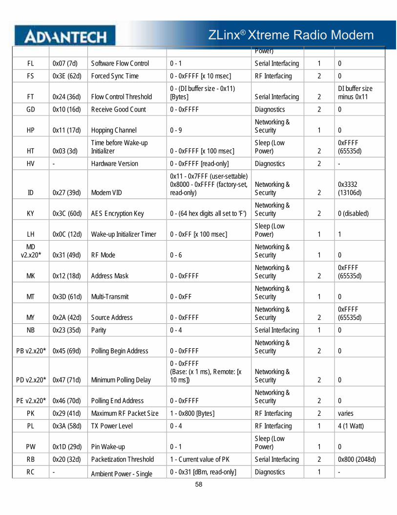
ZLinx® Xtreme Radio Modem
58
Power)
FL 0x07 (7d) Software Flow Control 0 - 1 Serial Interfacing 1 0
FS 0x3E (62d) Forced Sync Time 0 - 0xFFFF [x 10 msec] RF Interfacing 2 0
FT 0x24 (36d) Flow Control Threshold 0 - (DI buffer size - 0x11) [Bytes] Serial Interfacing 2
DI buffer size minus 0x11
GD 0x10 (16d) Receive Good Count 0 - 0xFFFF Diagnostics 2 0
HP 0x11 (17d) Hopping Channel 0 - 9 Networking & Security 1 0
HT 0x03 (3d) Time before Wake-up Initializer 0 - 0xFFFF [x 100 msec]
Sleep (Low Power) 2
0xFFFF (65535d)
HV - Hardware Version 0 - 0xFFFF [read-only] Diagnostics 2 -
ID 0x27 (39d) Modem VID
0x11 - 0x7FFF (user-settable) 0x8000 - 0xFFFF (factory-set, read-only)
Networking & Security 2
0x3332 (13106d)
KY 0x3C (60d) AES Encryption Key 0 - (64 hex digits all set to 'F') Networking & Security 2 0 (disabled)
LH 0x0C (12d) Wake-up Initializer Timer 0 - 0xFF [x 100 msec] Sleep (Low Power) 1 1
MD v2.x20* 0x31 (49d) RF Mode 0 - 6
Networking & Security 1 0
MK 0x12 (18d) Address Mask 0 - 0xFFFF Networking & Security 2
0xFFFF (65535d)
MT 0x3D (61d) Multi-Transmit 0 - 0xFF Networking & Security 1 0
MY 0x2A (42d) Source Address 0 - 0xFFFF Networking & Security 2
0xFFFF (65535d)
NB 0x23 (35d) Parity 0 - 4 Serial Interfacing 1 0
PB v2.x20* 0x45 (69d) Polling Begin Address 0 - 0xFFFF Networking & Security 2 0
PD v2.x20* 0x47 (71d) Minimum Polling Delay
0 - 0xFFFF (Base: (x 1 ms), Remote: [x 10 ms])
Networking & Security 2 0
PE v2.x20* 0x46 (70d) Polling End Address 0 - 0xFFFF Networking & Security 2 0
PK 0x29 (41d) Maximum RF Packet Size 1 - 0x800 [Bytes] RF Interfacing 2 varies
PL 0x3A (58d) TX Power Level 0 - 4 RF Interfacing 1 4 (1 Watt)
PW 0x1D (29d) Pin Wake-up 0 - 1 Sleep (Low Power) 1 0
RB 0x20 (32d) Packetization Threshold 1 - Current value of PK Serial Interfacing 2 0x800 (2048d)
RC - Ambient Power - Single 0 - 0x31 [dBm, read-only] Diagnostics 1 -

ZLinx® Xtreme Radio Modem
59
Channel
RE 0x0E (14d) Restore Defaults - (Special) - -
RM - Ambient Power - All Channels No parameter - 0x7D0 Diagnostics 2 -
RN 0x19 (25d) Delay Slots 0 - 0xFF [slots] Networking & Security 1 0
RO 0x21 (33d) Packetization Timeout 0 - 0xFFFF [x UART character time] Serial Interfacing 2 3
RP 0x22 (34d) RSSI PWM Timer 0 - 0xFF [x 100 msec] Diagnostics 1 0x20 (32d)
RR 0x18 (24d) Retries 0 - 0xFF Networking & Security 1 0x0A (10d)
RT 0x16 (22d) GPI1 Configuration 0 - 2 Serial Interfacing 1 0
SB 0x37 (55d) Stop Bits 0 - 1 Serial Interfacing 1 0
SH 0x25 (37d) Serial Number High 0 - 0xFFFF [read-only] Diagnostics 2 varies
SL 0x26 (38d) Serial Number Low 0 - 0xFFFF [read-only] Diagnostics 2 varies
SM 0x01 (1d) Sleep Mode 0 - 8 (3 is reserved) Sleep (Low Power) 1 0
ST 0x02 (2d) Time before Sleep (ATAT+3) - 0x7FFF [x 100 msec]
Sleep (Low Power) 2 0x64 (100d)
TP 0x38 (56d) Board Temperature 0 - 0x7F [read-only] Diagnostics 1 -
TR 0x1B (27d) Delivery Failure Count 0 - 0xFFFF [read-only] Diagnostics 2 0
TT 0x1A (26d) Streaming Limit 0 - 0xFFFF [0 = disabled] Networking & Security 2 0
TX 0x3F (63d) Transmit Only 0 - 1 RF Interfacing 1 0
VL - Firmware Version - verbose Returns string Diagnostics - -
VR 0x14 (20d) Firmware Version 0 - 0xFFFF [read-only] Diagnostics 2 -
*Firmware version in which the command was first introduced (firmware versions are numbered in hexadecimal notation.)
ZLinx® Xtreme Radio Modem
60
6.4.2.1 COMMAND DESCRIPTIONS Command descriptions in this section are listed alphabetically. Command categories are designated within "< >" symbols that follow each command title. Zlinx Xtreme Radio Modems expect parameter values in hexadecimal (designated by the "0x" prefix).

ZLinx® Xtreme Radio Modem
61

ZLinx® Xtreme Radio Modem
62
ZLinx® Xtreme Radio Modem
63

ZLinx® Xtreme Radio Modem
64
ZLinx® Xtreme Radio Modem
65

ZLinx® Xtreme Radio Modem
66
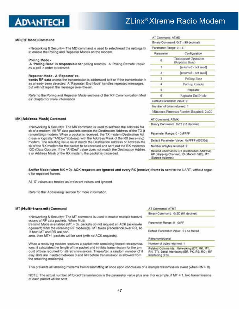
ZLinx® Xtreme Radio Modem
67

ZLinx® Xtreme Radio Modem
68

ZLinx® Xtreme Radio Modem
69

ZLinx® Xtreme Radio Modem
70

ZLinx® Xtreme Radio Modem
71

ZLinx® Xtreme Radio Modem
72

ZLinx® Xtreme Radio Modem
73

ZLinx® Xtreme Radio Modem
74

ZLinx® Xtreme Radio Modem
75
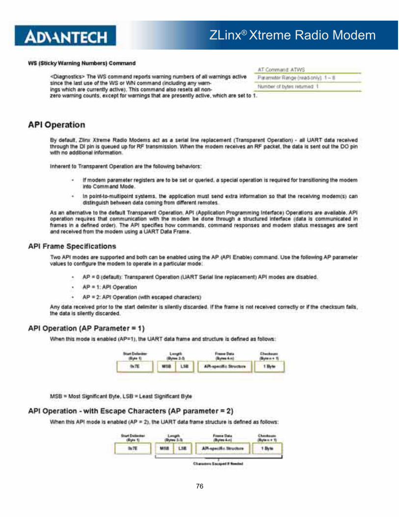
ZLinx® Xtreme Radio Modem
76

ZLinx® Xtreme Radio Modem
77
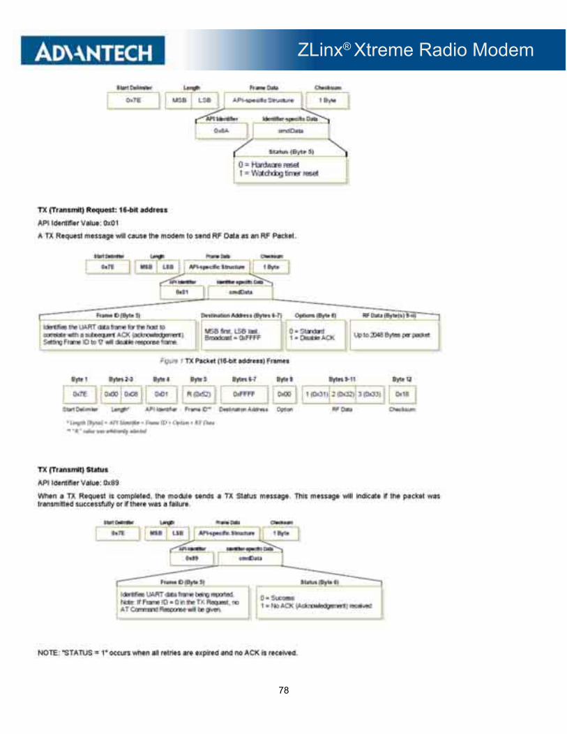
ZLinx® Xtreme Radio Modem
78
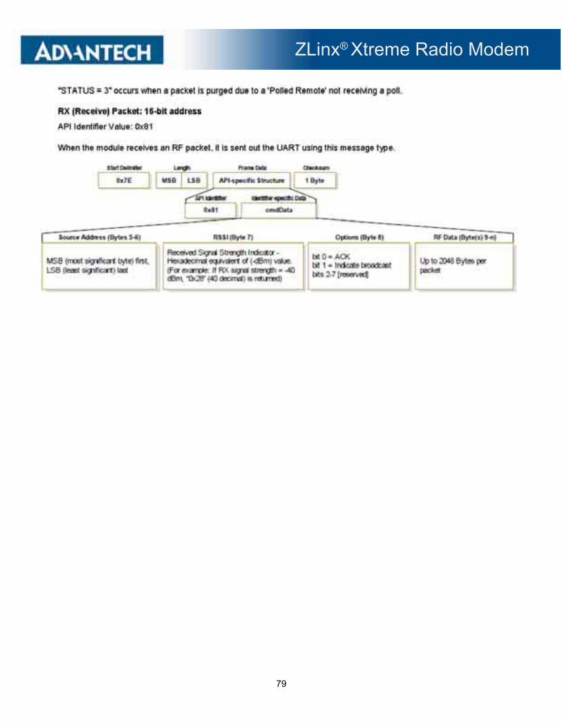
ZLinx® Xtreme Radio Modem
79

ZLinx® Xtreme Radio Modem
80
6.5 ZXT24-RM CONFIGURATION
6.5.1 ADVANCED PROGRAMMING

ZLinx® Xtreme Radio Modem
81

ZLinx® Xtreme Radio Modem
82
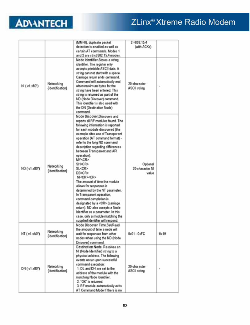
ZLinx® Xtreme Radio Modem
83
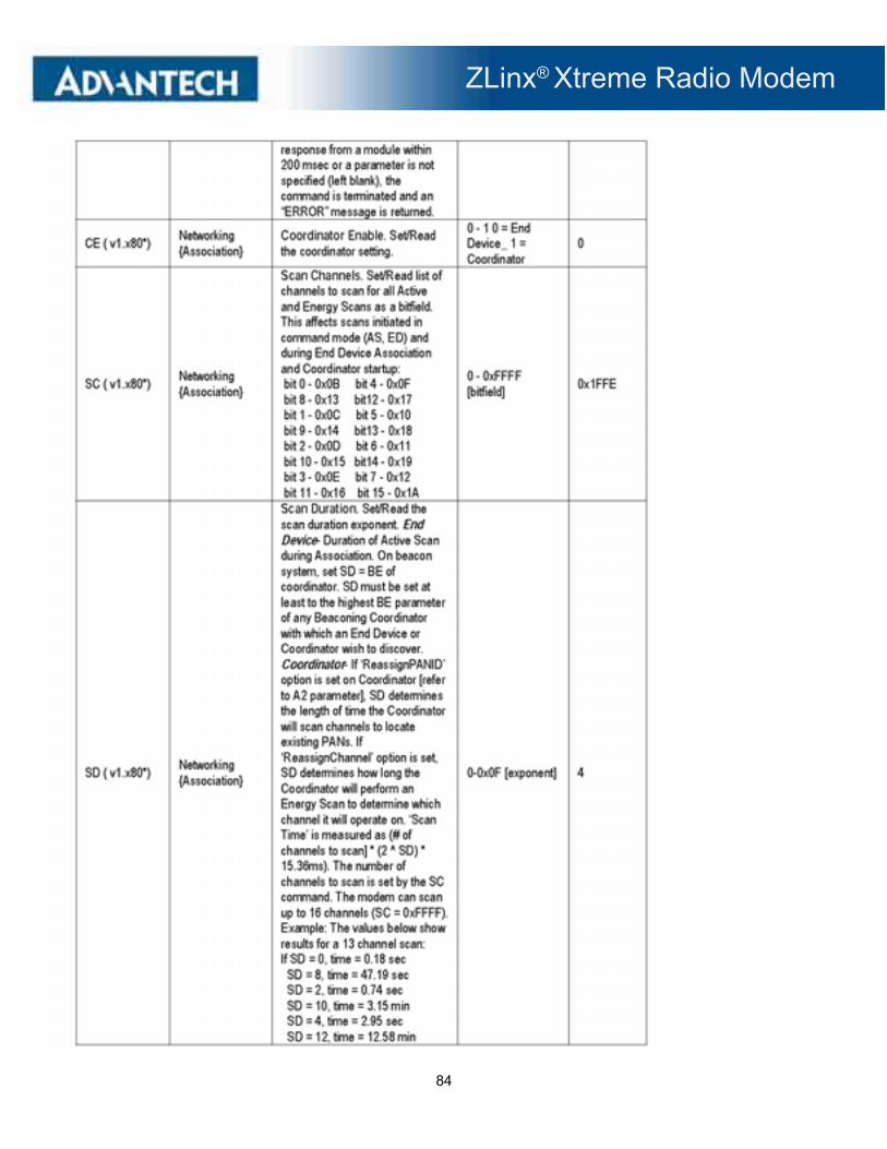
ZLinx® Xtreme Radio Modem
84
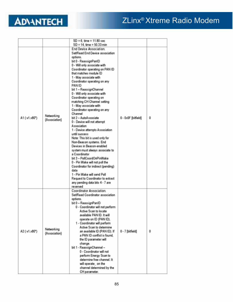
ZLinx® Xtreme Radio Modem
85
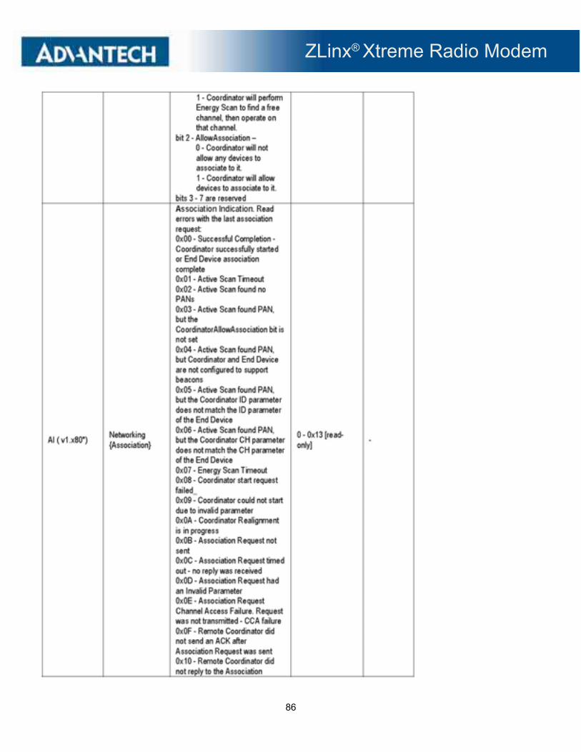
ZLinx® Xtreme Radio Modem
86

ZLinx® Xtreme Radio Modem
87

ZLinx® Xtreme Radio Modem
88
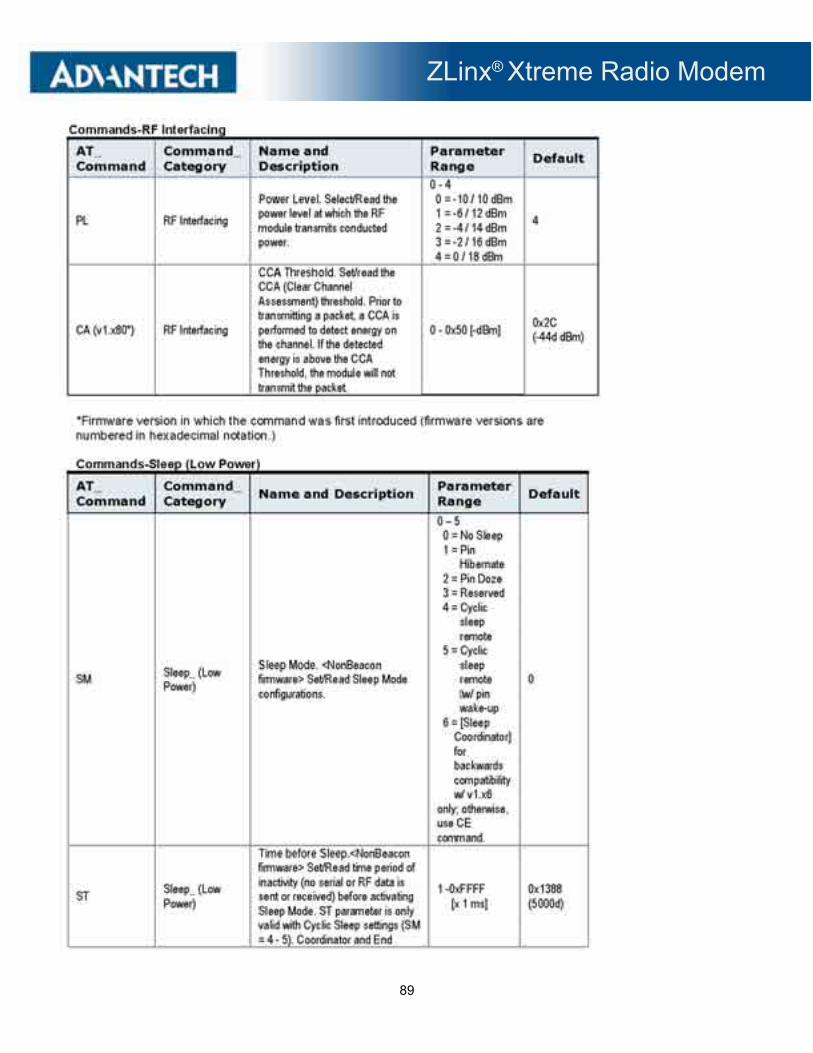
ZLinx® Xtreme Radio Modem
89

ZLinx® Xtreme Radio Modem
90
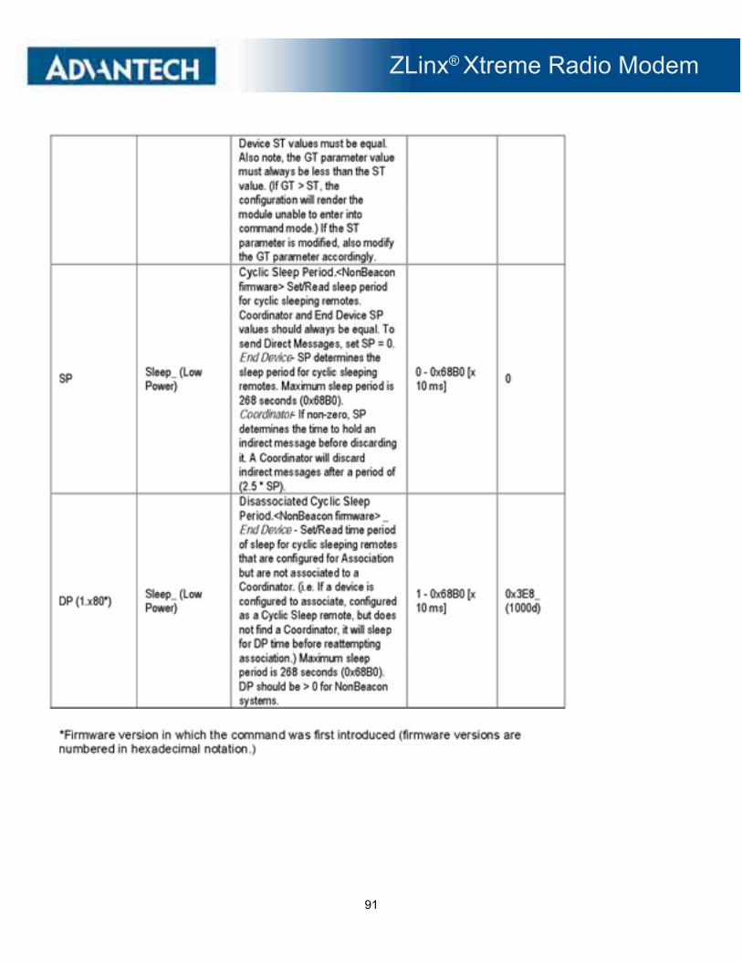
ZLinx® Xtreme Radio Modem
91
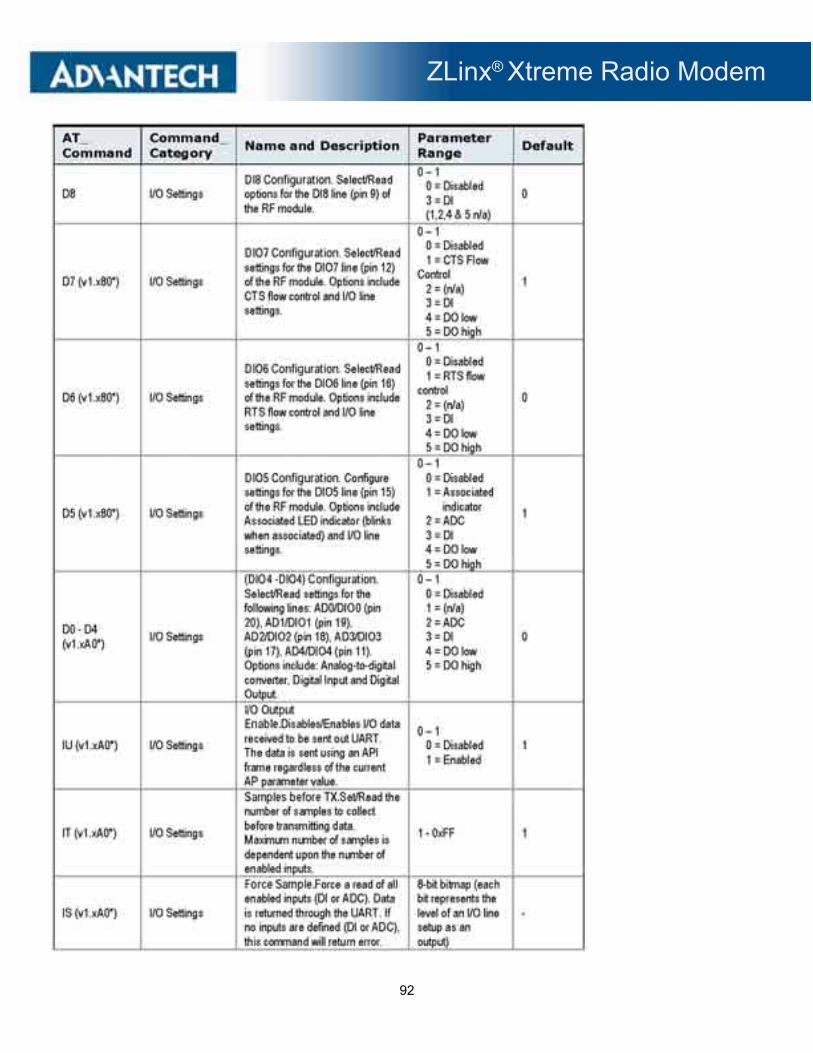
ZLinx® Xtreme Radio Modem
92

ZLinx® Xtreme Radio Modem
93

ZLinx® Xtreme Radio Modem
94

ZLinx® Xtreme Radio Modem
95

ZLinx® Xtreme Radio Modem
96
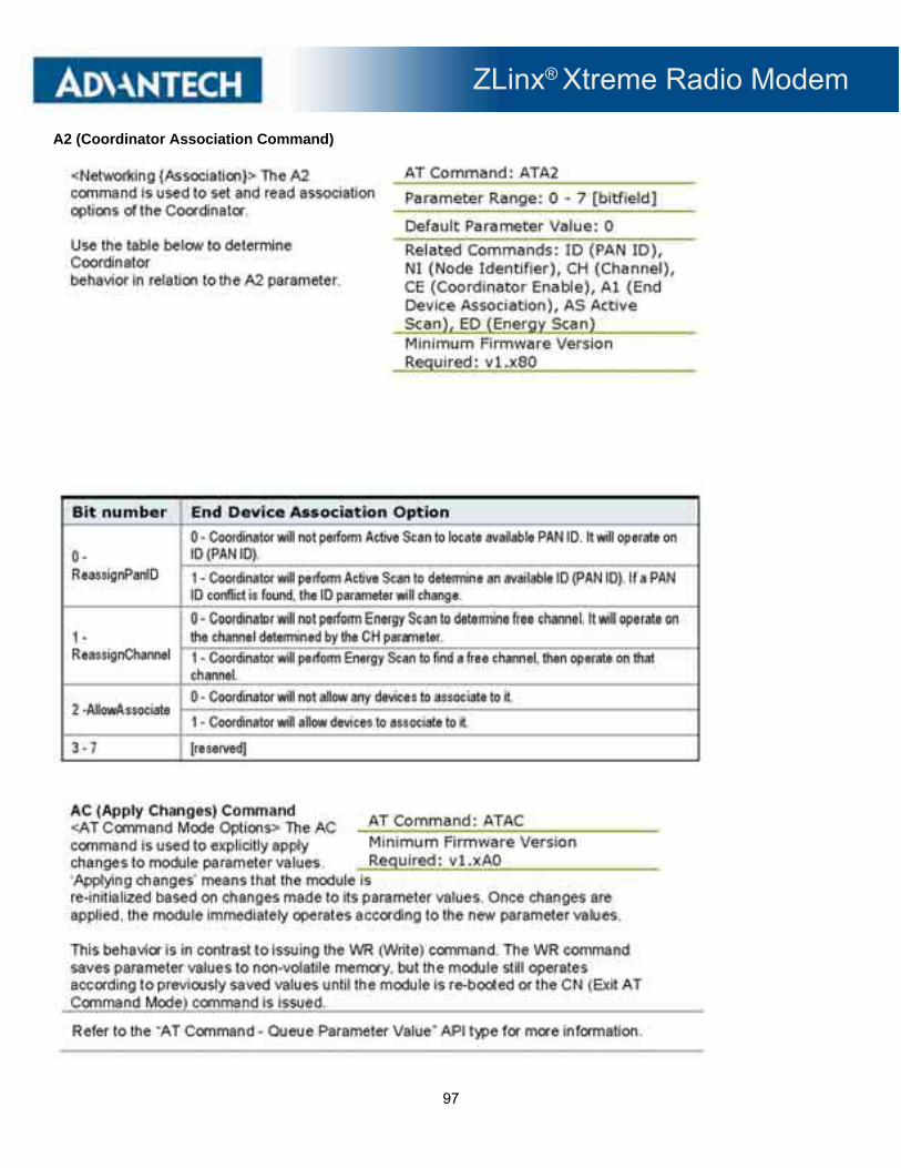
ZLinx® Xtreme Radio Modem
97
A2 (Coordinator Association Command)

ZLinx® Xtreme Radio Modem
98

ZLinx® Xtreme Radio Modem
99

ZLinx® Xtreme Radio Modem
100

ZLinx® Xtreme Radio Modem
101

ZLinx® Xtreme Radio Modem
102
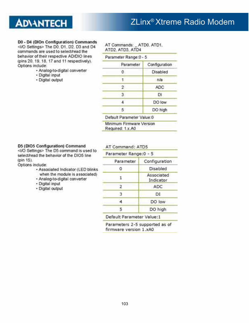
ZLinx® Xtreme Radio Modem
103

ZLinx® Xtreme Radio Modem
104
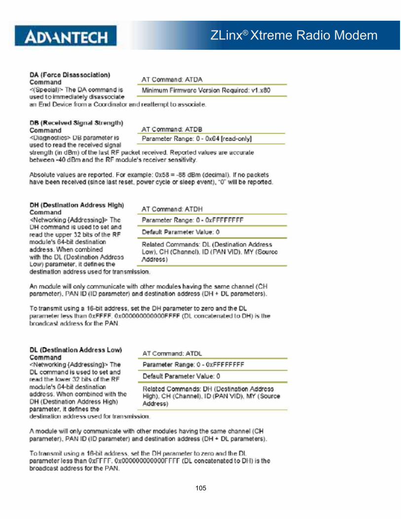
ZLinx® Xtreme Radio Modem
105

ZLinx® Xtreme Radio Modem
106
DN (Destination Node) Command)

ZLinx® Xtreme Radio Modem
107

ZLinx® Xtreme Radio Modem
108

ZLinx® Xtreme Radio Modem
109
IC (DIO Change Detect) Command

ZLinx® Xtreme Radio Modem
110
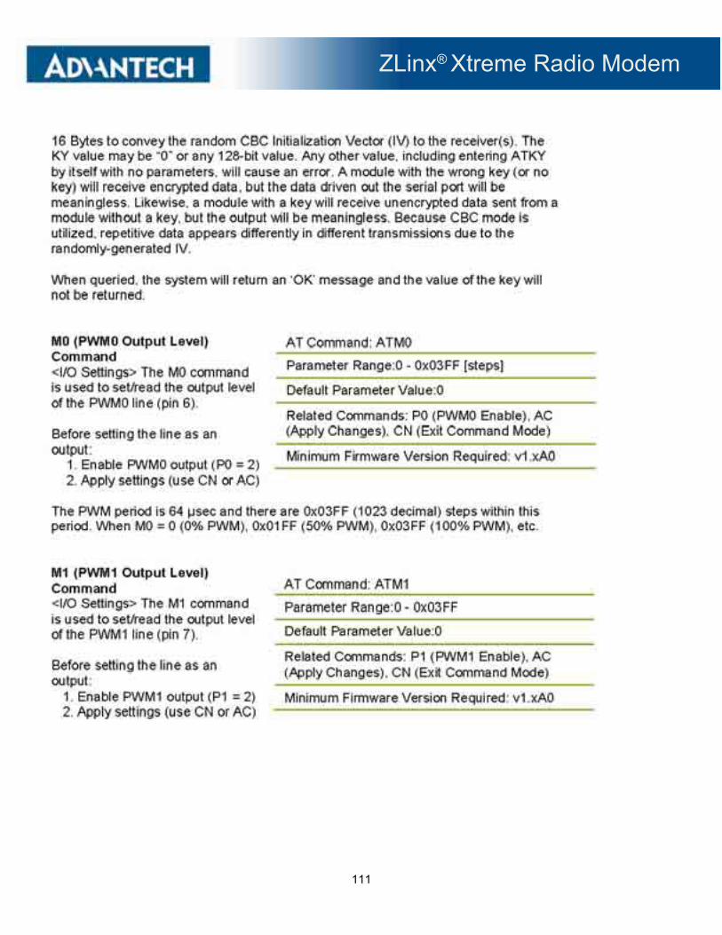
ZLinx® Xtreme Radio Modem
111

ZLinx® Xtreme Radio Modem
112
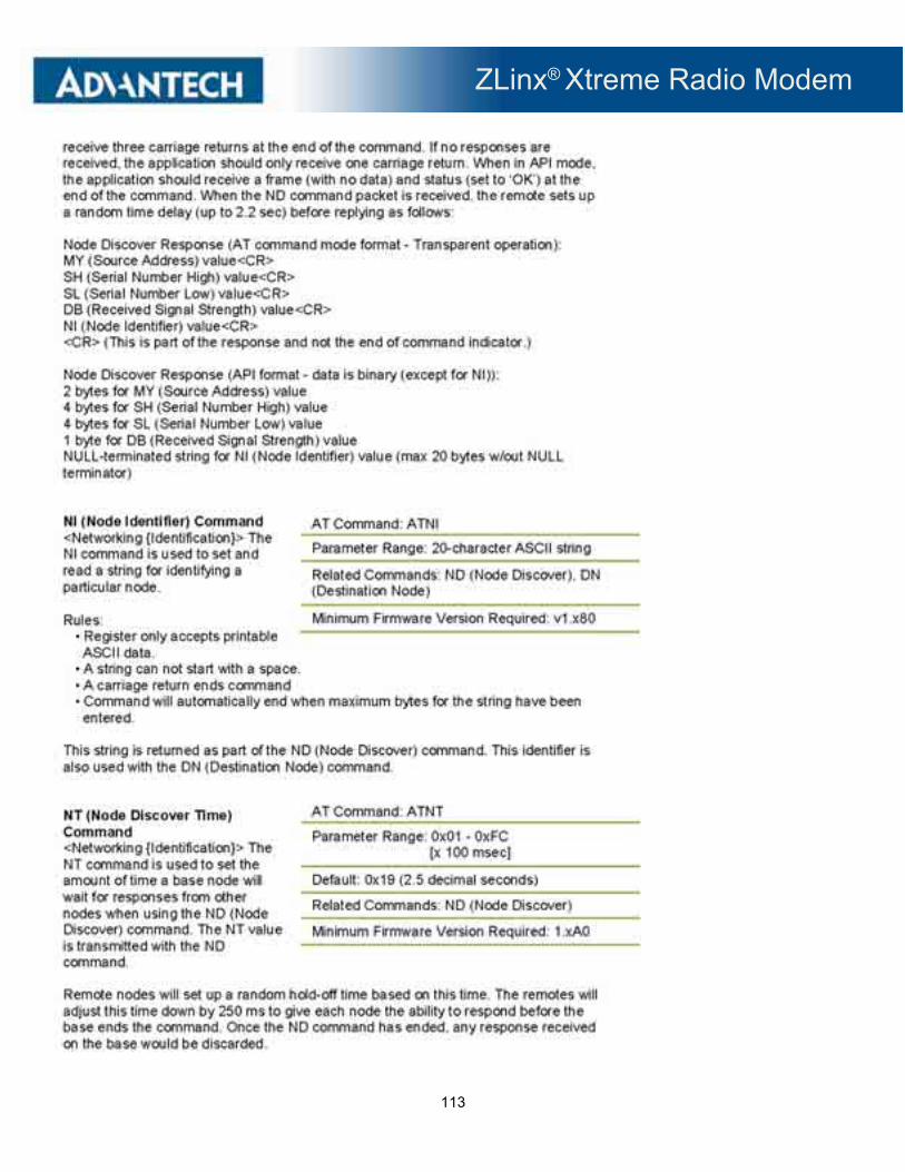
ZLinx® Xtreme Radio Modem
113
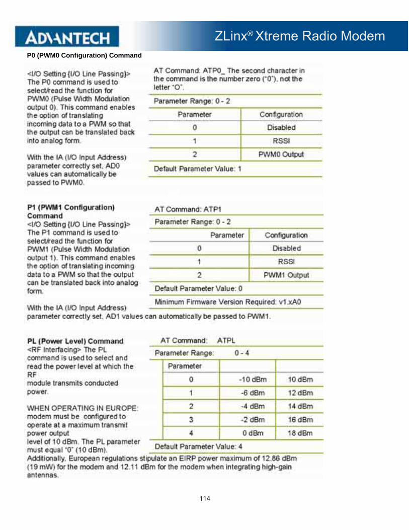
ZLinx® Xtreme Radio Modem
114
P0 (PWM0 Configuration) Command

ZLinx® Xtreme Radio Modem
115
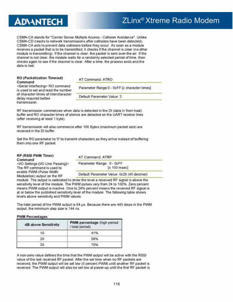
ZLinx® Xtreme Radio Modem
116

ZLinx® Xtreme Radio Modem
117
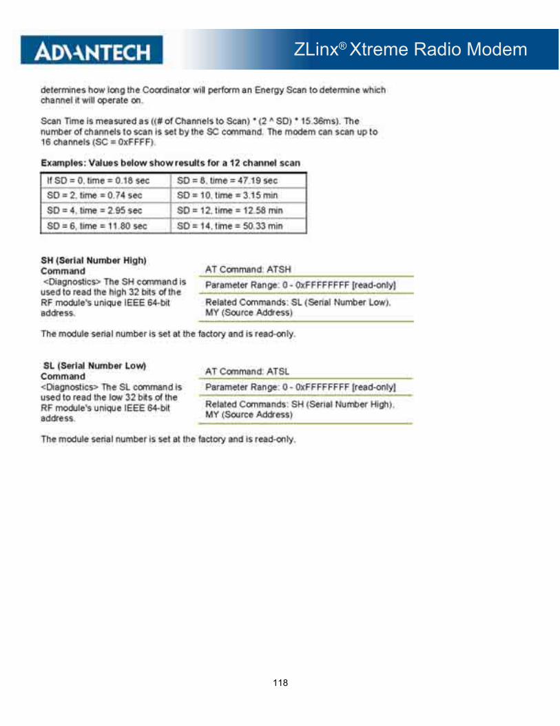
ZLinx® Xtreme Radio Modem
118
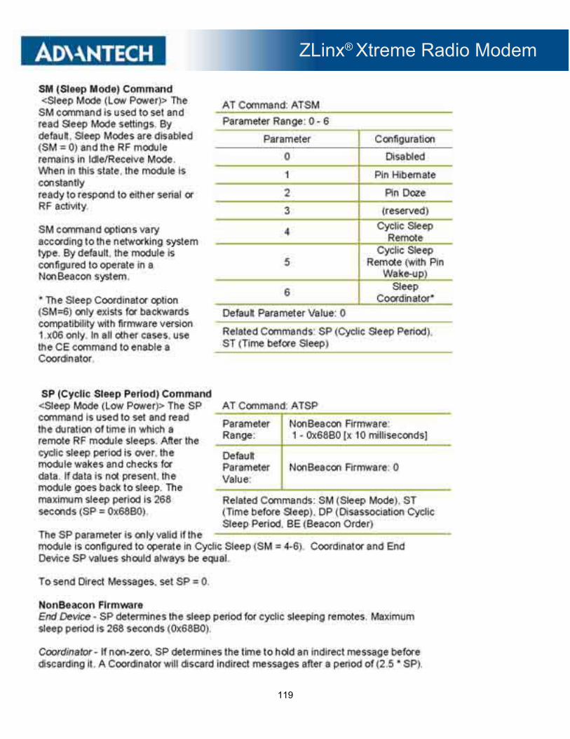
ZLinx® Xtreme Radio Modem
119
ZLinx® Xtreme Radio Modem
120

ZLinx® Xtreme Radio Modem
121

ZLinx® Xtreme Radio Modem
122

ZLinx® Xtreme Radio Modem
123

ZLinx® Xtreme Radio Modem
124

ZLinx® Xtreme Radio Modem
125

ZLinx® Xtreme Radio Modem
126

ZLinx® Xtreme Radio Modem
127

ZLinx® Xtreme Radio Modem
128
6.6 FIRMWARE UPDATE
6.6.1 CAUTION
Note: A firmware update should never be interrupted before it is finished.
6.6.2 FIRMWARE UPDATE PROCEDURE
1. Download the new firmware file and store it in the firmware directory:
C:\Program Files\Advantech\Zlinx\Zlinx Manager\update
2. Connect your PC to the radio modem using a USB cable.
3. From the manager launch screen, click on the radio modem firmware update link.
Figure 6-2 Manager Launch Screen
4. The radio modem communications parameters screen will appear. Verify the parameters and click the connect button.
Figure 6-3 Radio modem communications parameters screen

ZLinx® Xtreme Radio Modem
129
5. Once connected, the software will determine which firmware versions are available on the PC and what version is loaded in the modem. The firmware updater screen will appear. This screen is used to choose which firmware version to load:
Firmware Updater Screen
6. Select the firmware and version from the pull-down menu.
7. Click the UPDATE button.
8. The progress bar will indicate that the firmware is being updated. Do not interrupt this process. When complete, you will be returned to firmware updater screen.

ZLinx® Xtreme Radio Modem
130
7 - USE CASES
** With any RF system it is best to set up and bench test before field installation. **
7.1 POINT-TO-POINT SERIAL
7.1.1 USE CASE PARAMETERS
Serial RS-232 wire replacement. RS-232, 115.2 kbps, hardware flow control (CTS/RTS). 900 MHz Radio Modem with encryption.
7.1.1.1 SETUP INSTRUCTIONS
1. Wire your RS-232 devices and power as described in section three.
2. Connect to the modem using the USB port.
3. Configure both radio modems the same with the exception of the destination address.
4. Remember to save your new settings by clicking on the update button.
5. On the Basic Modem Settings Tab, ensure ZXT9-RM is displayed in the model number box
6. Select a unique channel number. This is the same for both radio modems.
ZLinx® Xtreme Radio Modem
131
7. Select a unique Network Identifier. This is the same for both radio modems
8. Select a destination address. This should be different for each radio modem. For example, radio modem number 1 could be 0001 and radio modem number two could be 0002. Another option is to leave the destination address at its default value of 0000 and proceed to the next step.

ZLinx® Xtreme Radio Modem
132
9. On the Advanced Modem Settings Tab, under the Networking and Security Tab, select the Source Address (MY – Source Address). This sets the address of the modem and should be comparable with the destination addresses set above. For example, if you set the destination address on modem number two to 0002, the source address on modem number one should be 0002. Another option is to leave the source address at its default value of FFFF. When the source address is FFFF, the source and destination address are the same (FFFF). Because this could cause cross talk between networks, it is recommended that you select a unique source and destination address as previously described.
10. On the Basic Modem Settings Tab, select 115.2 kbps from the pull-down menu. This should be the same for both radio modems.

ZLinx® Xtreme Radio Modem
133
11. On the Basic Modem Settings Tab, select parity and stop bit as desired.
12. Save settings by clicking the update button.
13. On the Advanced Modem Settings Tab, set encryption. Under the Networking/Security tree, double click the KY – AES Encryption Key. A button will appear that says “set”. Click on this button.

ZLinx® Xtreme Radio Modem
134
14. The key entry box will appear. Enter up to 64 HEX digits and click OK. Click the Update Button to save the key.
Record this key and save in a safe location.
15. Set the same key on the other radio modem.
16. Your radio modems are now configured. It is recommended to bench test this configuration before installing in the field.

ZLinx® Xtreme Radio Modem
135
7.2 POINT-TO-POINT SERIAL TO XTREME I/O
7.2.1 USE CASE PARAMETERS In this parameter, a radio modem is being used to connect PLC or similar device to a remote Xtreme I/O module.
1. Wire the radio modem input and power as described in section three. 2. Configure the radio modem as described in section 7.1.1.1. 3. Configure the I/O module radio settings to match the radio modem.
4. Channel Number must match the channel selected in section 7.3 step 6. 5. Network identifier must match the network identifier selected in section 7.1.1.1 step 7. 6. Set the Modem RF data rate to match the I/O module. On the Advanced Modem Settings tab, under the RF
interfacing tab, click on BR- RF Data Rate and set the desired data rate from the pull-down menu.
7. If encryption is being used, the same key must be used in the I/O module. The radio modem uses a hexadecimal
string. When entering your key in the I/O module, you must enter it in HEX.
8. It is recommended that you bench test your configuration before installing it in the field.

ZLinx® Xtreme Radio Modem
136
8 - TESTING AND TROUBLE SHOOTING
8.1 RSSI RANGE TEST
The RSSI Range Test is used to check communication between two radio modems.
1. Connect the first modem to a computer running the Zlinx® Manager software. Set up the modem for RS-232 operation as described in Section Six.
2. Configure the second modem to RS-232 operation as described in Section Six. The second modem will also require a loop-back setup.
a. RS-232 Configuration
1) Set Dip Switch 1 and 2 in the ON Position
3. In the Zlinx® Manager Software, click the RSSI Range Test Tab.
Figure 8-1 RSSI Range Test Screen
4. Press the ‘Start’ button in the Zlinx® Manager RSSI Range Test screen. The screen will change to show the results of the test.

ZLinx® Xtreme Radio Modem
137
Figure 8-2 RSSI Range Test Results Screen
5. RSSI Range Test Features
Test Results section of the screen shows the total packets sent. The section also shows the percentage of good packets received back from the modem.
Test Signal Strength checkbox will turn on/off the Signal Strength value displaying graphically on the progress bar.
The Start button will start the range test as configured. Once the test is running the button will be shown as Stop.
The list box at the bottom will display all the received packet data both good and bad. It will display “Timeout waiting for data” for missed packets.
Clear Messages and Statistics button will clear the list box and packet count/percentages for a clean start to a new test.
The Show Advanced Options check box will toggle the advance test options on to the screen.
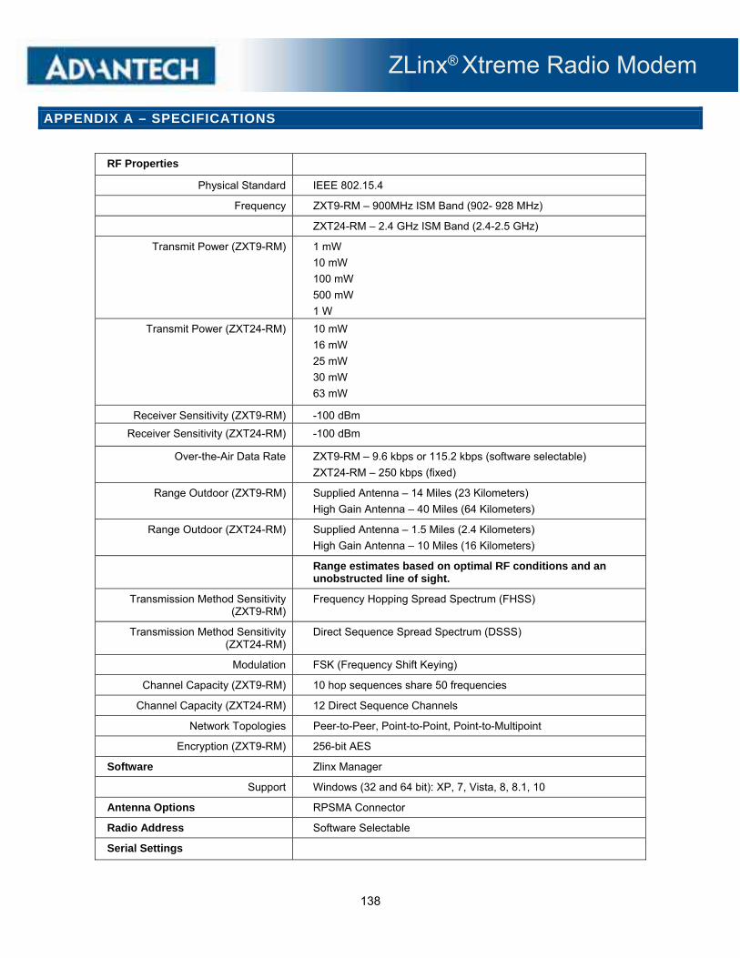
ZLinx® Xtreme Radio Modem
138
APPENDIX A – SPECIFICATIONS
RF Properties
Physical Standard IEEE 802.15.4
Frequency ZXT9-RM – 900MHz ISM Band (902- 928 MHz)
ZXT24-RM – 2.4 GHz ISM Band (2.4-2.5 GHz)
Transmit Power (ZXT9-RM) 1 mW
10 mW
100 mW
500 mW
1 W
Transmit Power (ZXT24-RM) 10 mW
16 mW
25 mW
30 mW
63 mW
Receiver Sensitivity (ZXT9-RM) -100 dBm
Receiver Sensitivity (ZXT24-RM) -100 dBm
Over-the-Air Data Rate ZXT9-RM – 9.6 kbps or 115.2 kbps (software selectable)
ZXT24-RM – 250 kbps (fixed)
Range Outdoor (ZXT9-RM) Supplied Antenna – 14 Miles (23 Kilometers)
High Gain Antenna – 40 Miles (64 Kilometers)
Range Outdoor (ZXT24-RM) Supplied Antenna – 1.5 Miles (2.4 Kilometers)
High Gain Antenna – 10 Miles (16 Kilometers)
Range estimates based on optimal RF conditions and an unobstructed line of sight.
Transmission Method Sensitivity (ZXT9-RM)
Frequency Hopping Spread Spectrum (FHSS)
Transmission Method Sensitivity (ZXT24-RM)
Direct Sequence Spread Spectrum (DSSS)
Modulation FSK (Frequency Shift Keying)
Channel Capacity (ZXT9-RM) 10 hop sequences share 50 frequencies
Channel Capacity (ZXT24-RM) 12 Direct Sequence Channels
Network Topologies Peer-to-Peer, Point-to-Point, Point-to-Multipoint
Encryption (ZXT9-RM) 256-bit AES
Software Zlinx Manager
Support Windows (32 and 64 bit): XP, 7, Vista, 8, 8.1, 10
Antenna Options RPSMA Connector
Radio Address Software Selectable
Serial Settings
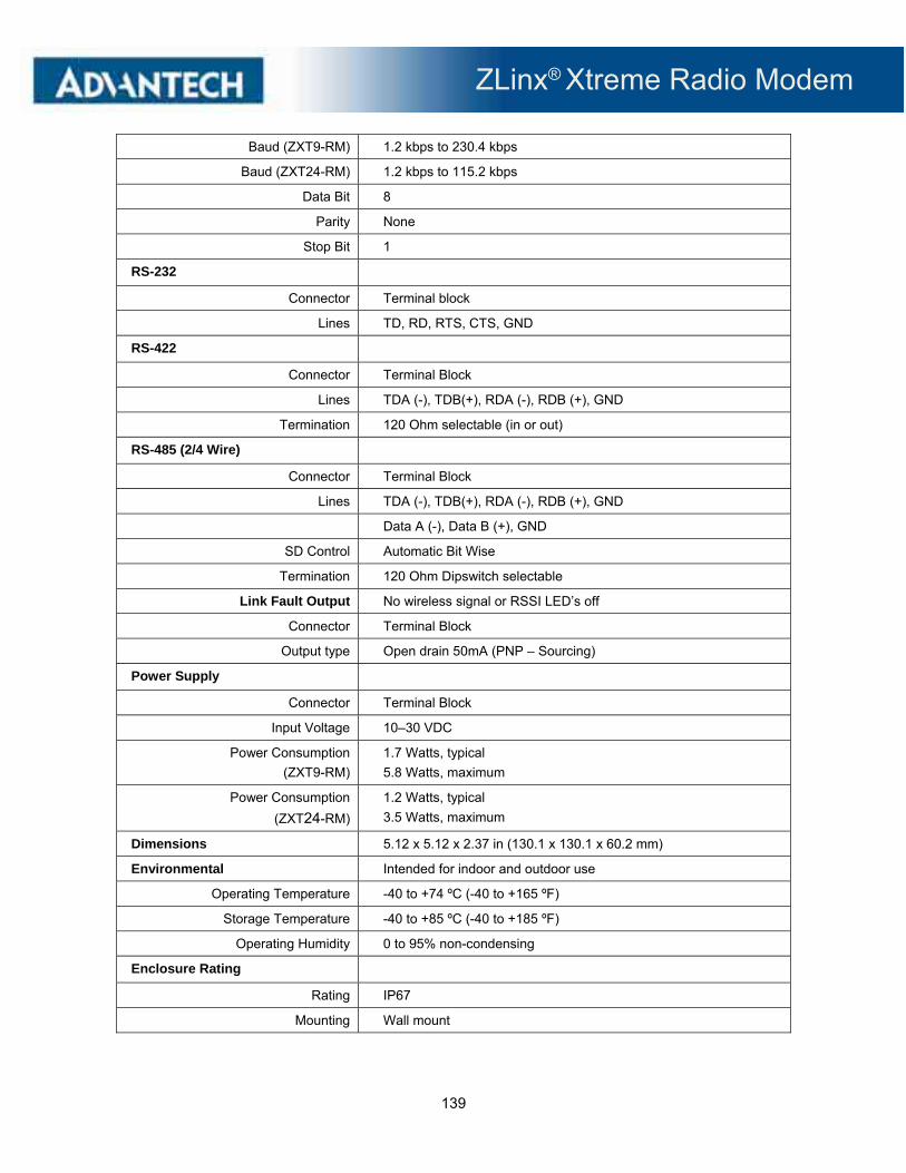
ZLinx® Xtreme Radio Modem
139
Baud (ZXT9-RM) 1.2 kbps to 230.4 kbps
Baud (ZXT24-RM) 1.2 kbps to 115.2 kbps
Data Bit 8
Parity None
Stop Bit 1
RS-232
Connector Terminal block
Lines TD, RD, RTS, CTS, GND
RS-422
Connector Terminal Block
Lines TDA (-), TDB(+), RDA (-), RDB (+), GND
Termination 120 Ohm selectable (in or out)
RS-485 (2/4 Wire)
Connector Terminal Block
Lines TDA (-), TDB(+), RDA (-), RDB (+), GND
Data A (-), Data B (+), GND
SD Control Automatic Bit Wise
Termination 120 Ohm Dipswitch selectable
Link Fault Output No wireless signal or RSSI LED’s off
Connector Terminal Block
Output type Open drain 50mA (PNP – Sourcing)
Power Supply
Connector Terminal Block
Input Voltage 10–30 VDC
Power Consumption
(ZXT9-RM)
1.7 Watts, typical
5.8 Watts, maximum
Power Consumption
(ZXT24-RM)
1.2 Watts, typical
3.5 Watts, maximum
Dimensions 5.12 x 5.12 x 2.37 in (130.1 x 130.1 x 60.2 mm)
Environmental Intended for indoor and outdoor use
Operating Temperature -40 to +74 ºC (-40 to +165 ºF)
Storage Temperature -40 to +85 ºC (-40 to +185 ºF)
Operating Humidity 0 to 95% non-condensing
Enclosure Rating
Rating IP67
Mounting Wall mount

ZLinx® Xtreme Radio Modem
140
Agency Approvals
CE EN55022: 2006 Class A Emissions
EN61000-6-2 Generic Standards for Industrial Environments
FCC Class A
FCC ID – ZXT9-RM – OUR-9XTEND
FCC ID – ZXT24-RM – OUR-XBEEPRO
LED Status
Note: In order for the RSSI LED to continuously indicate the signal strength, set the RP command (RSSI PWM Timer) to FF.
Front Panel LED Status
RSSI (Signal Strength) 8 Green LED’s indicate signal from weak to strong
Power Green LED
Receive Data Green LED – blinks when Serial data is received
Transmit Data Green LED – blinks when Serial data is transmitted.
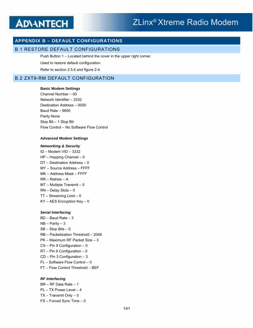
ZLinx® Xtreme Radio Modem
141
APPENDIX B – DEFAULT CONFIGURATIONS
B.1 RESTORE DEFAULT CONFIGURATIONS
Push Button 1 – Located behind the cover in the upper right corner.
Used to restore default configuration
Refer to section 2.5.6 and figure 2-4.
B.2 ZXT9-RM DEFAULT CONFIGURATION
Basic Modem Settings
Channel Number – 00
Network Identifier – 3332
Destination Address – 0000
Baud Rate – 9600
Parity None
Stop Bit – 1 Stop Bit
Flow Control – No Software Flow Control
Advanced Modem Settings
Networking & Security
ID – Modem VID – 3332
HP – Hopping Channel – 0
DT – Destination Address – 0
MY – Source Address – FFFF
MK – Address Mask – FFFF
RR – Retries – A
MT – Multiple Transmit – 0
RN – Delay Slots – 0
TT – Streaming Limit – 0
KY – AES Encryption Key – 0
Serial Interfacing
BD – Baud Rate – 3
NB – Parity – 3
SB – Stop Bits – 0
RB – Packetization Threshold – 2048
PK – Maximum RF Packet Size – 3
CS – Pin 9 Configuration – 0
RT – Pin 9 Configuration – 0
CD – Pin 3 Configuration – 3
FL – Software Flow Control – 0
FT – Flow Control Threshold – BEF
RF Interfacing
BR – RF Data Rate – 1
PL – TX Power Level – 4
TX – Transmit Only – 0
FS – Forced Sync Time – 0
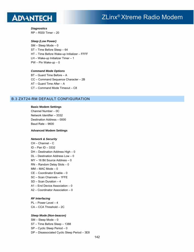
ZLinx® Xtreme Radio Modem
142
Diagnostics
RP – RSSI Timer – 20
Sleep (Low Power)
SM – Sleep Mode – 0
ST – Time Before Sleep – 64
HT – Time Before Wake-up Initializer – FFFF
LH – Wake-up Initializer Timer – 1
PW – Pin Wake-up – 0
Command Mode Options
BT – Guard Time Before – A
CC – Command Sequence Character – 2B
AT – Guard Time After – A
CT – Command Mode Timeout – C8
B.3 ZXT24-RM DEFAULT CONFIGURATION
Basic Modem Settings
Channel Number – 0C
Network Identifier – 3332
Destination Address – 0000
Baud Rate – 9600
Advanced Modem Settings
Network & Security
CH – Channel – C
ID – Pan ID – 3332
DH – Destination Address High – 0
DL – Destination Address Low – 0
MY – 16 Bit Source Address – 0
RN – Random Delay Slots – 0
MM – MAC Mode – 0
CE – Coordinator Enable – 0
SC – Scan Channels – 1FFE
SD – Scan Duration – 4
A1 – End Device Association – 0
A2 – Coordinator Association – 0
RF Interfacing
PL – Power Level – 4
CA – CCA Threshold – 2C
Sleep Mode (Non-beacon)
SM – Sleep Mode – 0
ST – Time Before Sleep – 1388
SP – Cyclic Sleep Period – 0
DP – Disassociated Cyclic Sleep Period – 3E8

ZLinx® Xtreme Radio Modem
143
Serial Interfacing
BD – Interface Data Rate – 3
RO – Packetization Timeout – 3
D7 – DIO7 Configuration – 1
D6 – DIO6 Configuration – 0
D5 – DIO5 Configuration – 1
P0 – PWM0 Configuration – 1
AP – API Enable – 0
PR – Pull-up Resistor Enable – FF
Diagnostics
RP – RSSI PWM Timer – 28
AT Command Options
CT – AT Command Mode Timeout – 64
GT – Guard Times – 3E8
CC – Command Sequence Character – 2B

ZLinx® Xtreme Radio Modem
144
APPENDIX C – DIMENSIONAL DIAGRAM / MOUNTING INSTRUCTIONS
C.1 DIMENSIONAL DIAGRAM

ZLinx® Xtreme Radio Modem
145
C.2 MOUNTING
The radio modem can be mounted directly to a panel or bulkhead or by attaching the supplied mounting ears. In either case, the cover must be removed to allow access to the screw pass-through holes. The mounting ears are packaged with screws. If you want to mount
the device without using the ears, you will need to procure longer number 6 screws.

ZLinx® Xtreme Radio Modem
146
C.3 SUPPLIED ANTENNA
The supplied antenna has a male RPSMA connector. The antenna is attached to the female RPSMA jack on the enclosure. In order to operate, the antenna must be vertical.
900 MHz Antenna Mechanical Drawing:\

ZLinx® Xtreme Radio Modem
147
2.4 GHz Antenna Mechanical Drawing:
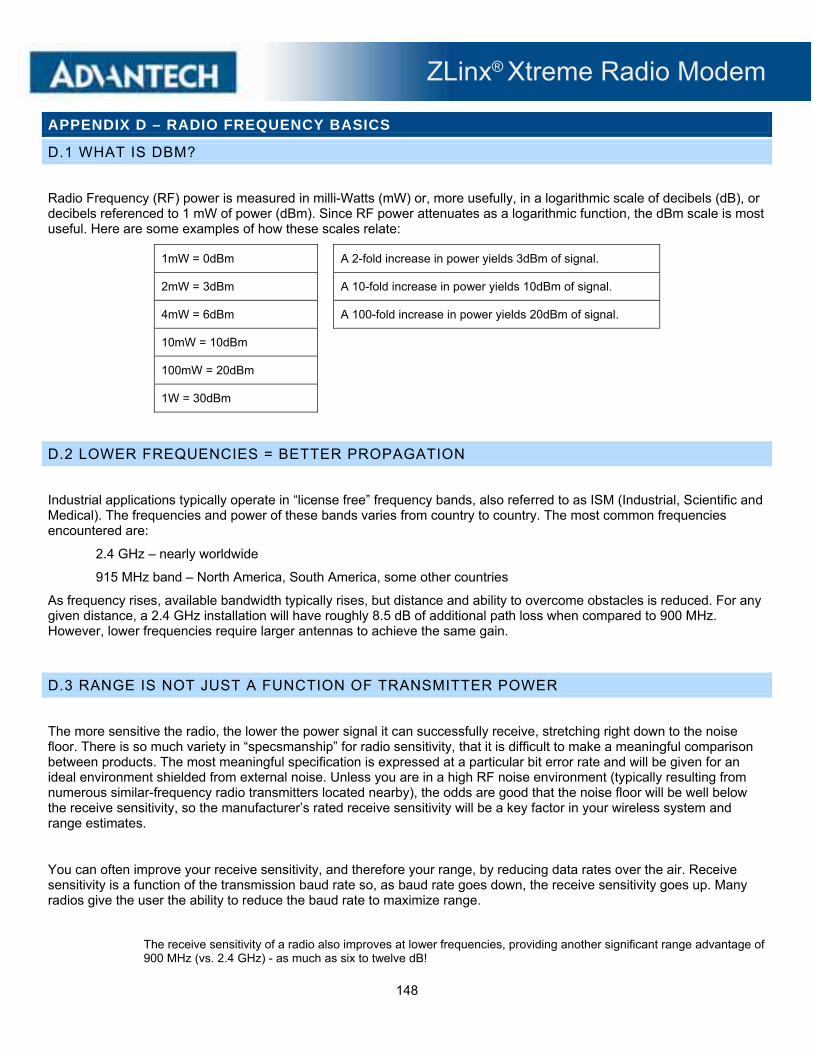
ZLinx® Xtreme Radio Modem
148
APPENDIX D – RADIO FREQUENCY BASICS
D.1 WHAT IS DBM?
Radio Frequency (RF) power is measured in milli-Watts (mW) or, more usefully, in a logarithmic scale of decibels (dB), or decibels referenced to 1 mW of power (dBm). Since RF power attenuates as a logarithmic function, the dBm scale is most useful. Here are some examples of how these scales relate:
1mW = 0dBm A 2-fold increase in power yields 3dBm of signal.
2mW = 3dBm A 10-fold increase in power yields 10dBm of signal.
4mW = 6dBm A 100-fold increase in power yields 20dBm of signal.
10mW = 10dBm
100mW = 20dBm
1W = 30dBm
D.2 LOWER FREQUENCIES = BETTER PROPAGATION
Industrial applications typically operate in “license free” frequency bands, also referred to as ISM (Industrial, Scientific and Medical). The frequencies and power of these bands varies from country to country. The most common frequencies encountered are:
2.4 GHz – nearly worldwide
915 MHz band – North America, South America, some other countries
As frequency rises, available bandwidth typically rises, but distance and ability to overcome obstacles is reduced. For any given distance, a 2.4 GHz installation will have roughly 8.5 dB of additional path loss when compared to 900 MHz. However, lower frequencies require larger antennas to achieve the same gain.
D.3 RANGE IS NOT JUST A FUNCTION OF TRANSMITTER POWER
The more sensitive the radio, the lower the power signal it can successfully receive, stretching right down to the noise floor. There is so much variety in “specsmanship” for radio sensitivity, that it is difficult to make a meaningful comparison between products. The most meaningful specification is expressed at a particular bit error rate and will be given for an ideal environment shielded from external noise. Unless you are in a high RF noise environment (typically resulting from numerous similar-frequency radio transmitters located nearby), the odds are good that the noise floor will be well below the receive sensitivity, so the manufacturer’s rated receive sensitivity will be a key factor in your wireless system and range estimates.
You can often improve your receive sensitivity, and therefore your range, by reducing data rates over the air. Receive sensitivity is a function of the transmission baud rate so, as baud rate goes down, the receive sensitivity goes up. Many radios give the user the ability to reduce the baud rate to maximize range.
The receive sensitivity of a radio also improves at lower frequencies, providing another significant range advantage of 900 MHz (vs. 2.4 GHz) - as much as six to twelve dB!
ZLinx® Xtreme Radio Modem
149
D.4 YOU MUST CONSIDER RF NOISE RF background noise comes from many sources, ranging from solar activity to high frequency digital products to all forms of other radio communications. That background noise establishes a noise floor which is the point where the desired signals are lost in the background ruckus. The noise floor will vary by frequency.
Typically the noise floor will be lower than the receive sensitivity of your radio, so it will not be a factor in your system design. If, however, you’re in an environment where high degrees of RF noise may exist in your frequency band, then use the noise floor figures instead of radio receive sensitivity in your calculations. If you suspect this is the case, a simple site survey to determine the noise floor value can be a high payoff investment.
When in doubt, look about. Antennas are everywhere nowadays - on the sides of buildings, water towers, billboards, chimneys, even disguised as trees. Many sources of interference may not be obvious.
D.5 FADE MARGIN IS CRITICAL FOR RELIABLE OPERATION IN ADVERSE WEATHER AND INTERFERENCE Fade margin is a term critical to wireless success. Fade margin describes how many dB a received signal may be reduced by without causing system performance to fall below an acceptable value. Walking away from a newly commissioned wireless installation without understanding how much fade margin exists is the number one cause of wireless woes.
Establishing a fade margin of no less than 10dB in good weather conditions will provide a high degree of assurance that the system will continue to operate effectively in a variety of weather, solar, and RF interference conditions.
There are a number of creative ways to estimate fade margin of a system without investing in specialty gear. Pick one or more of the following and use it to ensure you’ve got a robust installation:
Some radios have programmable output power. Reduce the power until performance degrades, then dial the power back up a minimum of 10dB. Remember again, doubling output power yields 3 dB, and an increase of 10dB requires a ten-fold increase in transmit power.
Invest in a small 10dB attenuator (pick the correct one for your radio frequency!). If you lose communications when you install the attenuator installed in-line with one of your antennas, you don’t have enough fade margin.
Antenna cable is lossy, more so at higher frequencies. Specifications vary by type and manufacturer so check them yourself but, at 900MHz, a coil of RG58 in the range of 50 to 100 feet (15 to 30 m) will be 10dB. At 2.4GHz, a cable length of 20-40 feet (6 to 12 m) will yield 10dB. If your system still operates reliably with the test length of cable installed, you’ve got at least 10dB of fade margin.
D.6 REMEMBER YOUR MATH
Contrary to popular opinion, no black art is required to make a reasonable prediction of the range of a given radio signal. Several simple concepts must be understood first, and then we can apply some simple rules of thumb.
The equation for successful radio reception is:
TX power + TX antenna gain – Path loss – Cabling loss + RX antenna gain – 10dB fade margin > RX Radio sensitivity or (less commonly) RF noise floor
Note that most of the equation’s parameters are easily gleaned from the manufacturer’s data. That leaves only path loss and, in cases of heavy RF interference, RF noise floor as the two parameters that you must established for your particular installation.
In a perfect world, you will measure your path loss and your RF noise conditions. For the majority of us that don’t, there are rules of thumb to follow to help ensure a reliable radio connection.

ZLinx® Xtreme Radio Modem
150
D.7 RF ATTENUATION AND LINE OF SIGHT
In a clear path through the air, radio signals attenuate with the square of distance. Doubling range requires a four-fold increase in power, therefore:
Halving the distance decreases path loss by 6dB.
Doubling the distance increases path loss by 6dB.
When indoors, paths tend to be more complex, so use a more aggressive rule of thumb, as follows:
Halving the distance decreases path loss by 9dB.
Doubling the distance increases path loss by 9dB.
Radio manufacturers advertise “line of sight” range figures. Line of sight means that, from antenna A, you can see antenna B. Being able to see the building that antenna B is in does not count as line of sight. For every obstacle in the path, de-rate the “line of sight” figure specified for each obstacle in the path. The type of obstacle, the location of the obstacle, and the number of obstacles will all play a role in path loss.
Visualize the connection between antennas, picturing lines radiating in an elliptical path between the antennas in the shape of a football. Directly in the center of the two antennas the RF path is wide with many pathways. A single obstacle here will have minimal impact on path loss. As you approach each antenna, the meaningful RF field is concentrated on the antenna itself. Obstructions located close to the antennas cause dramatic path loss.
Be sure you know the distance between antennas. This is often underestimated. If it is a short-range application, pace it off. If it is a long-range application, establish the actual distance with a GPS or Google Maps.
The most effective way to reduce path loss is to elevate the antennas. At approximately 6 feet high (2 m), line of sight due to the Earth’s curvature is about 3 miles (5 km), so anything taller than a well-manicured lawn becomes an obstacle.
Weather conditions also play a large role. Increased moisture in the air increases path loss. The higher the frequency is, the higher the path loss.
Beware leafy greens. While a few saplings mid-path are tolerable, it’s very difficult for RF to penetrate significant woodlands. If you’re crossing a wooded area you must elevate your antennas over the treetops.
Industrial installations often include many reflective obstacles leading to numerous paths between the antennas. The received signal is the vector sum of each of these paths. Depending on the phase of each signal, they can be added or subtracted. In multiple path environments, simply moving the antenna slightly can significantly change the signal strength.
Some obstacles are mobile. More than one wireless application has been stymied by temporary obstacles such as a stack of containers, a parked truck or material handling equipment. Remember, metal is not your friend. An antenna will not transmit out from inside a metal box or through a storage tank.
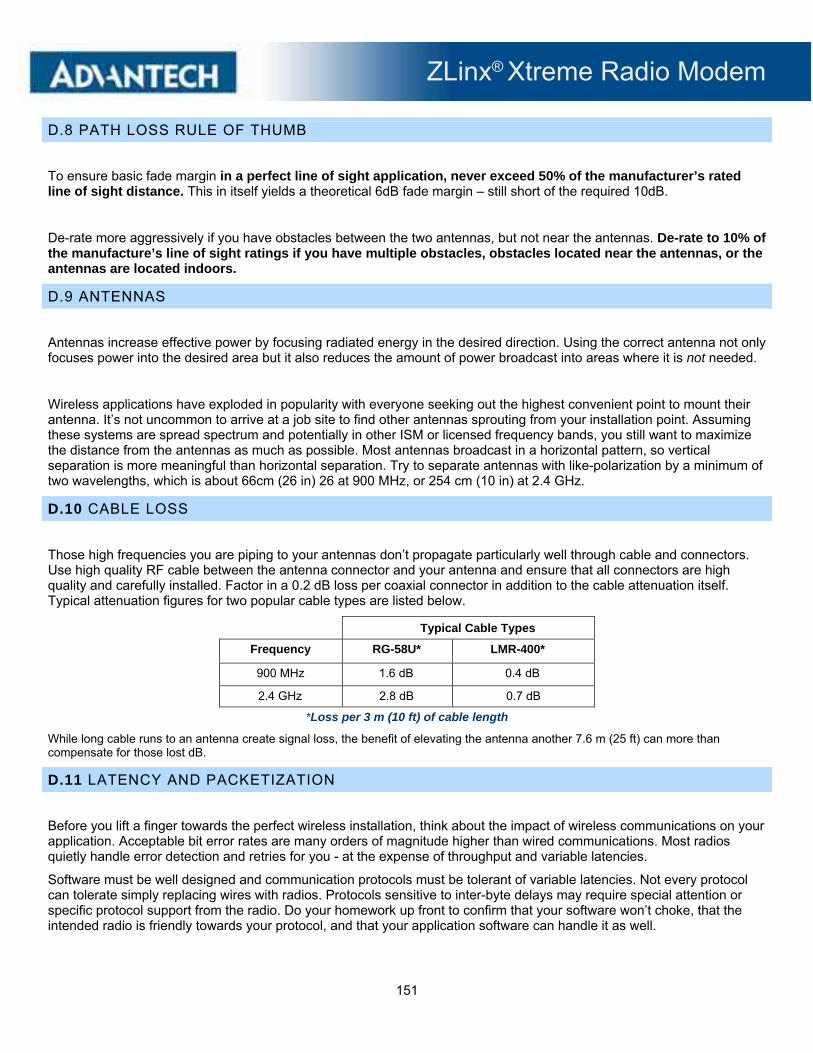
ZLinx® Xtreme Radio Modem
151
D.8 PATH LOSS RULE OF THUMB
To ensure basic fade margin in a perfect line of sight application, never exceed 50% of the manufacturer’s rated line of sight distance. This in itself yields a theoretical 6dB fade margin – still short of the required 10dB.
De-rate more aggressively if you have obstacles between the two antennas, but not near the antennas. De-rate to 10% of the manufacture’s line of sight ratings if you have multiple obstacles, obstacles located near the antennas, or the antennas are located indoors.
D.9 ANTENNAS
Antennas increase effective power by focusing radiated energy in the desired direction. Using the correct antenna not only focuses power into the desired area but it also reduces the amount of power broadcast into areas where it is not needed.
Wireless applications have exploded in popularity with everyone seeking out the highest convenient point to mount their antenna. It’s not uncommon to arrive at a job site to find other antennas sprouting from your installation point. Assuming these systems are spread spectrum and potentially in other ISM or licensed frequency bands, you still want to maximize the distance from the antennas as much as possible. Most antennas broadcast in a horizontal pattern, so vertical separation is more meaningful than horizontal separation. Try to separate antennas with like-polarization by a minimum of two wavelengths, which is about 66cm (26 in) 26 at 900 MHz, or 254 cm (10 in) at 2.4 GHz.
D.10 CABLE LOSS
Those high frequencies you are piping to your antennas don’t propagate particularly well through cable and connectors. Use high quality RF cable between the antenna connector and your antenna and ensure that all connectors are high quality and carefully installed. Factor in a 0.2 dB loss per coaxial connector in addition to the cable attenuation itself. Typical attenuation figures for two popular cable types are listed below.
Typical Cable Types
Frequency RG-58U* LMR-400*
900 MHz 1.6 dB 0.4 dB
2.4 GHz 2.8 dB 0.7 dB
*Loss per 3 m (10 ft) of cable length
While long cable runs to an antenna create signal loss, the benefit of elevating the antenna another 7.6 m (25 ft) can more than compensate for those lost dB.
D.11 LATENCY AND PACKETIZATION
Before you lift a finger towards the perfect wireless installation, think about the impact of wireless communications on your application. Acceptable bit error rates are many orders of magnitude higher than wired communications. Most radios quietly handle error detection and retries for you - at the expense of throughput and variable latencies.
Software must be well designed and communication protocols must be tolerant of variable latencies. Not every protocol can tolerate simply replacing wires with radios. Protocols sensitive to inter-byte delays may require special attention or specific protocol support from the radio. Do your homework up front to confirm that your software won’t choke, that the intended radio is friendly towards your protocol, and that your application software can handle it as well.