51206 - Aegis Xtreme Duty Floor Scale Installation Manual
30
51206 Revision 3 09/18 © 2018 by Fairbanks Scales, Inc. All rights reserved Aegis Xtreme-Duty Floor Scale Installation Manual
-
Upload
khangminh22 -
Category
Documents
-
view
0 -
download
0
Transcript of 51206 - Aegis Xtreme Duty Floor Scale Installation Manual

51206 Revision 3 09/18
© 2018 by Fairbanks Scales, Inc. All rights reserved
Aegis Xtreme-Duty Floor
Scale
Installation Manual
09/18 2 51206 Rev. 3
Amendment Record
Aegis Xtreme-Duty Floor Scale
Document 51206
Manufactured by Fairbanks Scales Inc.
821 Locust
Kansas City, Missouri 64106
Created 9/08 Created Document
Revision 1 11/08 Document Release
Revision 2 09/18 Updated Pit Installation Instructions

09/18 3 51206 Rev. 3
Disclaimer Every effort has been made to provide complete and accurate information in this manual. However, although this manual may include a specifically identified warranty notice for the product, Fairbanks Scales makes no representations or warranties with respect to the contents of this manual, and reserves the right to make changes to this manual without notice when and as improvements are made. Fairbanks Scales shall not be liable for any loss, damage, cost of repairs, incidental or consequential damages of any kind, whether or not based on express or implied warranty, contract, negligence, or strict liability arising in connection with the design, development, installation, or use the scale. © Copyright 2018
This document contains proprietary information protected by copyright. All rights are reserved; no part of this manual may be reproduced, copied, translated or transmitted in any form or by any means without prior written permission of the manufacturer.

09/18 4 51206 Rev. 3
Table of Contents
SECTION 1: GENERAL INFORMATION .................................................................. 5
1.1. Introduction ................................................................................................................ 5
1.1.1. Specifications ....................................................................................................................... 5 1.1.1. Specifications, Continued .................................................................................................... 6 1.1.2. Accessories.......................................................................................................................... 7
SECTION 2: GENERAL SERVICE POLICY.............................................................. 8
2.1. General Service Policy ............................................................................................... 8
2.1.1. Service Technician’s Responsibilities .................................................................................. 9 2.1.2. Users’ Responsibility ........................................................................................................... 9
SECTION 3: SCALE INSTALLATION ...................................................................... 10
3.1. Conferring with Our Client ........................................................................................ 10
3.2. Standard Installation Steps ...................................................................................... 12
3.2.1. Unpacking .......................................................................................................................... 13 3.2.2. Positioning the Scale ......................................................................................................... 14 3.2.3 Positioning Steps ................................................................................................................ 15 3.2.4. Installing the Platform ........................................................................................................ 16 3.2.4. Installing the Scales, Continued ........................................................................................ 17 3.2.5. Wiring the Junction Box ..................................................................................................... 18
3.3. Installing Accessories/Modifications ......................................................................... 19
3.3.1. Ramp Installation ............................................................................................................... 19 3.3.2. Pillar Installation Steps ...................................................................................................... 20 3.3.3. Aegis Xtreme-Duty Installation(Pit Version) ...................................................................... 20
SECTION 4: SERVICE & MAINTENANCE .............................................................. 23
4.1. General Troubleshooting .......................................................................................... 23
4.2. Scale Platform Troubleshooting ............................................................................... 24
4.2.1. Scale Platform Testing ....................................................................................................... 24 4.2.2. Load Cell Testing ............................................................................................................... 24 4.2.3. Load Cell Replacement Steps ........................................................................................... 25
SECTION 5: PARTS ................................................................................................. 26
5.1. Parts Lists #107979 – 5’ X 5’ X 8”, 20K .................................................................... 26
5.2. Parts List #106966 – 6’ X 8’ X 8”, 40K ..................................................................... 26
5.3. Parts Diagram .......................................................................................................... 27
5.4. Accessory Part Numbers ......................................................................................... 28
5.4.1. Aegis Xtreme-Duty Ramp Assembly ................................................................................. 28 5.4.2. Mild Steel Stand-alone Instrument Pillar ........................................................................... 28
5.5 Platform Model Matrix ............................................................................................... 29
5.5.1. Aegis Xtreme-Duty – Above Ground ................................................................................. 29 5.5.2. Aegis Xtreme-Duty – Pit Version ....................................................................................... 29
09/18 5 51206 Rev. 3
Section 1: General Information
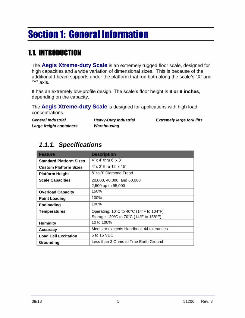
1.1. INTRODUCTION
The Aegis Xtreme-duty Scale is an extremely rugged floor scale, designed for
high capacities and a wide variation of dimensional sizes. This is because of the additional I-beam supports under the platform that run both along the scale’s “X” and “Y” axis.
It has an extremely low-profile design. The scale’s floor height is 8 or 9 inches, depending on the capacity.
The Aegis Xtreme-duty Scale is designed for applications with high load
concentrations.
General Industrial Heavy-Duty Industrial Extremely large fork lifts
Large freight containers Warehousing
1.1.1. Specifications
Feature Description
Standard Platform Sizes 4’ x 4’ thru 6’ x 8’
Custom Platform Sizes 4’ x 2’ thru 12’ x 15’
Platform Height 8” to 9” Diamond Tread
Scale Capacities 20,000, 40,000, and 60,000
2,500 up to 95,000
Overload Capacity 150%
Point Loading 100%
Endloading 100%
Temperatures Operating: 10°C to 40°C (14°F to 104°F)
Storage: -20°C to 70°C (14°F to 158°F)
Humidity 10 to 100%
Accuracy Meets or exceeds Handbook 44 tolerances
Load Cell Excitation 5 to 15 VDC
Grounding Less than 3 Ohms to True Earth Ground

Section 1: General Information
09/18 6 51206 Rev. 3
1.1.1. Specifications, Continued
Feature Description
Scale Construction Type A36 carbon steel
Deck plate – ¼” to ½”
Full I-beam support
Diamond Tread
Junction Box Watertight Analog
Stainless Steel
NEMA 4X
Load Cells Four (4) Rocker Column Design
IP69K “True” Hermetically Sealed
17-4 ph Stainless Steel
15,000 to 50,000 Capacity
Combined Error -- +/< 0.02% of Rated Capacity
Interface Cable 31’ PVC Jacketed
Approvals FM Approved
NTEP Approval CC# 07-097 (for 6,000 divisions)
Load Cell NTEP Approval CC# 07-037
Standard Platform dimensions: 4’ x 4’ thru 6’ x 8. Height: 8” or 9”. Scale Capacities: 20K, 40K & 60K. Steel Deck: ¼” – ½”. J-Box: NEMA 4X.
Section 1: General Information
09/18 7 51206 Rev. 3
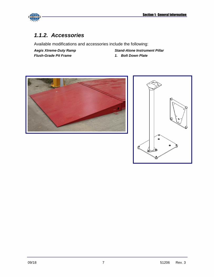
1.1.2. Accessories
Available modifications and accessories include the following:
Aegis Xtreme-Duty Ramp Stand-Alone Instrument Pillar
Flush-Grade Pit Frame 1. Bolt Down Plate

09/18 8 51206 Rev. 3
Section 2: General Service Policy
2.1. GENERAL SERVICE POLICY
Prior to installation, always verify that the equipment satisfies the customer's requirements as supplied, and as described in this manual.
If the equipment cannot satisfy the application and the application cannot be
modified to meet the design parameters of the equipment, the installation should NOT be attempted.
It is the customer/operator's responsibility to ensure the equipment provided by Fairbanks is operated within the parameters of the equipment's specifications and protected from accidental or malicious damage.
Absolutely NO physical, electrical or program modifications other than selection of standard options and accessories can be made by customers to this equipment
Repairs are performed by Fairbanks Scales Service Technicians and Authorized Distributor Personnel ONLY!
Failure to comply with this policy voids all implied and/or written warranties
W A R N I N G !
Section 2: General Service Policy
09/18 9 51206 Rev. 3
2.1.1. Service Technician’s Responsibilities
✓ All electronic and mechanical calibrations and/or adjustments required for making this equipment perform to accuracy and operational specifications are considered to be part of the original installation.
─ They are included in the installation charge.
─ Only those charges which are incurred as a result of the equipment's inability to be adjusted or calibrated to performance specifications may be charged to warranty.
✓ The equipment consists of printed circuit assemblies which must be handled using ESD handling procedures and must be replaced as units.
─ Replacement of individual components is not allowed.
─ The assemblies must be properly packaged in ESD protective material and returned intact for replacement credit per normal procedures.
2.1.2. Users’ Responsibility
✓ Absolutely no physical, electrical or program modifications other than selection of standard options and accessories are to be made to this equipment.

09/18 10 51206 Rev. 3
Section 3: Scale Installation
3.1. CONFERRING WITH OUR CLIENT
• The technician must be prepared to recommend the arrangement of components which provide the most efficient layout, utilizing the equipment to the best possible advantage.
• Assist the customer in selecting a site which allows easy access to and from the scale, ensuring enough area for straight and level approaches, if applicable.
─ The site needs good drainage away from the scale, elevated enough so the surrounding areas drain away from the scale.
─ Obtain all the necessary permits and licenses prior to beginning construction.
• Explain and review the warranty policy with the customer.
The installing technician is responsible that all personnel are fully trained and familiar with the equipment's capabilities and limitations before the installation is considered complete.
• All electrical assemblies must be returned intact for replacement credit using the standard procedures.
• At the time of installation, all electronic and mechanical adjustments are considered to be part of the installation and are included in the installation charge(s).
• The AC receptacle/outlet shall be located near the Indicator and easily accessible.
• Electrical connections other than those specified may not be performed.

Section 3: Scale Installation
09/18 11 51206 Rev. 3
IMPORTANT INSTALLATION NOTICE
• All load cells, load cell cables and interconnecting cables used to connect all
scale components shall be located a minimum of thirty-six (36”) inches distance away from all single and multiple phase high energy circuits and
electric current carrying conductors.
• This includes digital weight indicators, junction boxes, sectional controllers, and power supplies.
• This includes any peripheral devices, such as printers, remote displays, relay boxes, remote terminals, card readers, and auxiliary data entry devices.
• Also included is the scale components themselves, such as 120 volt AC, 240 volt AC, 480 volt AC and electric supply of higher voltage wiring runs and stations, AC power transformers, overhead or buried cables, electric distribution panels, electric motors, florescent and high intensity lighting which utilize ballast assemblies, electric heating equipment, traffic light wiring and power, and relay boxes.
• All scale components, including digital weight indicators and peripheral devices are not designed to operate on internal combustion engine driven electric generators and other similar equipment.
• Electric arc welding can severely damage scale components such as digital
weight indicators, junction boxes, sectional controllers, power supplies, and load cells.
NOTE: For additional information, please contact your Fairbanks Scales Service Representative.

Section 3: Scale Installation
09/18 12 51206 Rev. 3
3.2. STANDARD INSTALLATION STEPS
The Aegis Xtreme-Duty Scale Platform is shipped fully assembled and
wired. The standard scale installation consists of the following steps.
• Unpack the Scale, and any components.
• Selecting the best Platform Site Location.
• Connect lifting straps or chains to the lifting lugs on the sides of the platform, then move it to the designated site using a crane.
• Install the Ramps (if applicable).
• Level the Platform.
• Install and wire the Instrument to the Platform.
• Adjust and Calibrate the Scale according to the appropriate Indicator Service Manual.

Section 3: Scale Installation
09/18 13 51206 Rev. 3
3.2.1. Unpacking
Follow these guidelines when unpacking all equipment.
✓ Check in all components and accessories according to the customer's order.
✓ Remove all components from their packing material, checking against the invoice that they are accounted for and not damaged.
▪ Advise the shipper immediately, if damage has occurred.
▪ Keep the shipping container and packing material for future use.
▪ Order any parts necessary to replace those which have been damaged.
▪ Check the packing list.
The CUSTOMER is the receiving party if the equipment was shipped to
the Customer’s address.
FAIRBANKS is the receiving party if the equipment was shipped to the
Fairbanks Service Center.
✓ Collect all necessary installation manuals for the equipment and accessories.
✓ Open the equipment and perform an inspection, making certain that all hardware, electrical connections and printed circuit assemblies are secure.
✓ Do not reinstall the cover if the final installation is to be performed after the pre-installation checkout.
✓ Do not load the platform if there is any evidence of damage to the platform or supporting structure.
NOTE: It is the owner's responsibility to document, notify, and follow-up
regarding shipping damage with the carrier.

Section 3: Scale Installation
09/18 14 51206 Rev. 3
3.2.2. Positioning the Scale
Position the Scale with these points in mind:
✓ Use the proper lifting equipment to position and place the scale.
✓ The scale is to be placed on a flat, solid, level surface, one that fully supports the weight of the platform plus a full capacity load.
✓ The smooth surface must be within 1/8”, and on a level plane, within ¼” across both the length and width of the platform.
✓ The four corners of the Platform must rest solidly on the surface, and not rock. Irregular bumps and foreign material under the Platform can cause an “out-of-level” condition, which will affect the weight accuracy.
✓ Platform vibrations may also affect the weighing accuracy. Wherever possible, locate the platform as far away from heavy, low frequency vibrations as much as possible.
✓ Do not load the platform if there is any evidence of damage to the platform or supporting structure.
✓ Ease of access is very important. Allow plenty of room for maneuvering a fork lift.
✓ Reading the Indicator is also important to workers, so place it in a very visible position.
✓ When installing the Scale and Indicator in an outdoor location, set it up so the snow, ice accumulation, rain and other conditions do not affect the platform operations.

Section 3: Scale Installation
09/18 15 51206 Rev. 3
3.2.3 Positioning Steps
1. Position the Scale into its final location.
2. Place the hooks of the straps or chains into the specific lifting points of the Scale.
─ The straps or chains should be long enough to form a minimum 45° angle
with the platform while lifting.
3. Place the platform in the desired location.
─ The platform should be made stable and level.
─ Shims are not included with the platform and must be supplied locally as needed.
To lift and move the Platform, place strap hooks into brackets on each side of it, and also into each hole of the ramp.
Section 3: Scale Installation
09/18 16 51206 Rev. 3
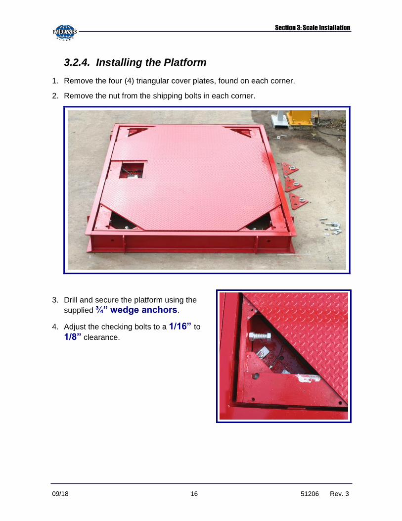
3.2.4. Installing the Platform
1. Remove the four (4) triangular cover plates, found on each corner.
2. Remove the nut from the shipping bolts in each corner.
3. Drill and secure the platform using the
supplied ¾” wedge anchors.
4. Adjust the checking bolts to a 1/16” to
1/8” clearance.

Section 3: Scale Installation
09/18 17 51206 Rev. 3
3.2.4. Installing the Scales, Continued
5. Verify that the platform is plumb, square and level.
─ If Ramps are to be installed, do it at this time.
─ If this is a pit version installation, at this point you would go ahead and complete the second pouring of the concrete (around the scale: encompassing the scale Nelson studs and outside of the frame). Once the pour has cured, then finalize the installation.
6. Replace the nut on the shipping bolt, then loosen it two (2) full threads.
7. Replace the four (4) triangular cover plates, found on each corner.
8. Calibrate the unit according to the appropriate indicator service manual.
Shipping Bolts
Checking Bolts
Wedge Anchor

Section 3: Scale Installation
09/18 18 51206 Rev. 3
3.2.5. Wiring the Junction Box
Load Cells are preinstalled, plumbed, and pre-wired to the Junction Box at the factory, prior to shipping.
─ Dip Switches are not set.
─ Interconnecting cables are not installed.
1. Open the platform access cover, then the junction box cover.
2. Loosen all gland bushing nuts.
3. Wire the Indicator to Junction Box according to the chart below.
4. Follow the indicator installation manual to properly connect it with the platform.
5. Tighten all gland bushing nuts.
IMPORTANT NOTE: Leave the Junction Box Cover off until all corner
adjustments are completed.
WIRE COLOR FUNCTION
Red () Signal
White (+) Signal
Black () Excitation
Green (+) Excitation
Yellow Ground

Section 3: Scale Installation
09/18 19 51206 Rev. 3
C A U T I O N
3.3. INSTALLING ACCESSORIES/MODIFICATIONS
Listed below are the standard Aegis Xtreme-Duty Scale Accessories.
Aegis Xtreme-Duty Ramp Stand-alone Instrument Pillar
Intrinsically Safe Controllers Smart Sectional Controllers
Flush-Grade Pit Frame Intalogix Technology (QMB)
3.3.1. Ramp Installation
The ramps are optional, and used different ways in varied applications.
• Each ramp has two (2) bolt down tabs, one on each side.
1. Place the ramp against the platform frame
─ The ramp’s slot is fits inside the scale’s lifting point.
─ Level and stabilize the ramp against the platform.
─ Shims are not included with the ramps and must be supplied.
2. Drill and anchor the ramp(s) using the supplied 3/4” wedge anchors.
─ Up to four (4) ramps can be installed on the Aegis Xtreme-duty Scale, one on each side.
Absolutely NO ARC WELDING is to be performed on, or near this scale while the Load Cells are in place and/or connected.
Disconnected and removed ALL the Load Cells during ANY welding.

Section 3: Scale Installation
09/18 20 51206 Rev. 3
3.3.2. Pillar Installation Steps
1. To remove the Top Plate, loosen the three (3) one quarter inch (¼”) Allen Screws.
2. Carefully run the Interface Cable into the bottom Access Hole, up through the Pillar, and then thread it out through the top Access Hole.
─ Allow extra cable slack to accommodate the Instrument wiring.
3. Replace the Top Plate, then secure it into
position using the one eighth inch (1/8”) Allen Wrench.
4. Install the Instrument Top Bracket, secure it with the supplied hardware
5. Connect the Interface Cable to the Indicator.
─ Refer to the appropriate instrument service manual for correct wiring information.
3.3.3. Aegis Xtreme-Duty Installation(Pit Version)
The pit frame accessory is a one-piece welded unit designed for in-floor or “flush” applications with no additional welding required. The standard AXD comes with a frame. When an AXD pit version is manufactured, Nelson studs are welded to this frame that will be embedded in the concrete. The AXD is constructed from mild steel and is available in 3 different sizes. The concrete work is usually done by a contractor, with a scale technician setting and installing the scale.
AXD Frame
In general, the concrete pouring for the pit is done in two stages:
• Stage 1 is poured to the correct depth,
• Stage 2 is poured with the scale / frame in-place.

Section 3: Scale Installation
09/18 21 51206 Rev. 3
Building the Scale Pit
1. Outline the AXD in the approximate position it will occupy on the floor.
2. Mark out the position of the hole to be made. The hole MUST be a minimum of 12” larger than the pit frame on all sides. Should pit drainage be required, slope the pit floor to an installed drain while maintaining level area at each corner. Use the attached drawings for measurements.
3. The hole will have to be deep enough to accommodate the thickness of the pit floor. Use the attached drawings for measurements.
The pit dimensions are determined by the dimensional size of the AXD. (See the AXD Pit Installation Diagram)
• At least 9” thickness of concrete is required for pit floor in non-hostile applications.
• At least 10” concrete floor with minimum 1” bottom slope (as shown in the AXD Pit Installation Diagram) is required. If drainage is necessary (for hostile applications), 4” diameter drain is recommended.
Use Section 3.2 Standard Installation Steps to properly set the scale.
Additional Notes:
• A soil bearing pressure of at least 1500 lbs. per square foot is required. The corner piers should be designed to supports 2/3 of the total capacity of the scale.
• A ¾” diameter conduit for scale interface cable is recommended. The scale frame is arranged with a 1 /18” diameter hole for cable exit. Locate conduit to match hole location.
• With a frame level (+/- 1/8”) in both directions, and secured, concrete is filled in around the outside of the frame and pit floor to form the scale pit. It is recommended the f=4000 psi and 3” to 4” slump concrete be used.
• When concrete has reached a minimum of 2000 psi, pull the interface cable through the conduit to the instrumentation location, and lower the platform assembly into position.
• With the scale in place, the clearance around the edge of the platform and pit frame should be ¼” to 3/8”.

Section 3: Scale Installation
09/18 22 51206 Rev. 3

09/18 23 51206 Rev. 3
Section 4: Service & Maintenance
4.1. GENERAL TROUBLESHOOTING
From the following chart, identify the symptom(s) and cause(s) of each malfunction, solving each issue with an appropriate solution.
SYMPTOM CAUSE SOLUTION
Displays stay at zero
1. Load Cell connections faulty.
2. Instrument faulty.
3. Faulty/bad Load Cell(s).
1. Cable replacement.
2. Service Instrument.
3. Test and replace the Load Cell(s) as
shown in Section 4.2.3.
Erratic Weights 1. Foreign object around load cells, ramps, or under platform.
2. Excessive vibration near platform.
3. Instrument faulty.
4. Platform not level within ¼” (3.0°).
5. Surface not smooth enough (within 1/8”).
6. Faulty/bad Load Cell(s).
1. Clear the area.
2. Remove the vibration source.
3. Service Instrument.
4. Level the platform surface.
5. Find a smoother surface for the platform.
6. Test and replace the Load Cell(s) as
shown in Section 4.2.3.
Inaccurate Weights
1. Instrument out of span.
2. Instrument not properly adjusted to zero.
3. Faulty/bad Load Cell(s).
1. Check and alter per the Instrument Service Manual.
2. Zero the instrument according to normal operation procedures.
3. Test and replace the Load Cell(s) as
shown in Section 4.2.3.

Section 4: Service & Maintenance
09/18 24 51206 Rev. 3
4.2. SCALE PLATFORM TROUBLESHOOTING
Except for severe structural damages, most Platform Assembly problems can be traced to the following causes.
• Material under or around the Platform.
• Broken Load Cell receiver cups..
• Faulty Load Cells.
4.2.1. Scale Platform Testing
1. Inspect the Interface Cable from the Platform to the Instrument for visible breaks or cracks.
2. ZERO the Instrument Display.
3. Apply a test load of 25% of the Load Cell capacity to one corner.
─ The Instrument should display a weight reading within 0.1% of the applied weight, or One Instrument Division, whichever is greater.
4. Repeat Step 3 for all the corners, placing the same Test Load on each corner.
4.2.2. Load Cell Testing
When corners do not match the correct tolerances, unsolder each Load Cell Cable, then test each Load Cell for the settings on the following chart.
.
TEST READING REMARKS
Green to Black (Input) 1106 Ohms (+5 / -2 Ohms) Input Resistance
Red to White (Output) 1000 Ohms (+5 / -2 Ohms) Output / Bridge Resistance
Yellow (Shield) to Load Cell Case
More than 1,000 megohms Insulation Resistance Input and Output Leads to Shield
Input and Output Leads to Case
Section 4: Service & Maintenance
09/18 25 51206 Rev. 3
4.2.3. Load Cell Replacement Steps
1. Cycle-down the power to the indicator, then unplug the unit.
2. Remove the platform and junction box access covers.
3. Loosen the gland bushing, and tie a string or wire to the end of the cable to act as a pull wire.
4. Place wire markers on the cable ends.
─ Masking tape is an effective alternative
5. Disconnect the faulty load cells wires from the terminal block.
6. Lift the platform end with a forklift or heavy pry bar, using wood blocks for safety.
7. Remove the load cell, pulling the cable through the scale while leaving the pull string/wire in the scale.
8. Remove the defective load cell from the receiver cups, then install the new load cell.
─ Use a lubricant on the O-rings.
9. Disconnect the pull string/wire from the defective load cell's cable, then attach to the replacement load cell's cable end.
10. Pull the cable from the new cell through to the junction box.
11. Lower the scale to the surface removing the safety blocks.
12. Distribute the scale’s weight evenly on all four (4) load cells..
13. Connect the load cell wires into the junction box, then tighten the box gland bushing(s).
14. Replace the platform access cover.

09/18 26 51206 Rev. 3
Section 5: Parts
5.1. PARTS LISTS #107979 – 5’ X 5’ X 8”, 20K
ITEM QTY PART No. DESCRIPTION
1 1 107972 PLATFORM WELDMENT, X-TREME DUTY FS 2 1 107978 FRAME WELDMENT
3 2 107701 BASE PLATE W/LOWER CUP
4 2 107702 BASE PLATE W/LOWER CUP
5 4 105718 UPPER CUP W/O ANTI-ROTATION
6 1 67171M J- BOX ASSY. SS
7 4 108120 3 ½” RC L/C /, 15k
8 12 61743 CLAMP BAR
9 4 54555 ¾”–10 x 3 ½” HEX HEAD CAP SCREW
10 16 54264 ¾” HEX NUT
11 1 83861 WEDGE ANCHOR BOX
12 STICKER, FAIRBANKS SCALES
13 13 54406 ½”-13 x ¾” LG FLAT HEAD SOCKET SCREW 14 4 54233 ¾” FLAT WASHER
15 4 107797 SHIM, .01 x 1 ½” ID x 2 1/8” OD
16 4 107798 SHIM, .03 x 1 ½” ID x 2 1/8” OD
17 4 72967 FULL THD BOLT, ¾”- 10 x 5” LG
18 4 54218 FULL THD BOLT, ¾”- 10 x 3” LG
5.2. PARTS LIST #106966 – 6’ X 8’ X 8”, 40K
ITEM QTY PART No. DESCRIPTION
1 1 106975 PLATFORM WELDMENT, X-TREME DUTY FS 2 1 107976 FRAME WELDMENT
3 2 107701 BASE PLATE W/LOWER CUP
4 2 107702 BASE PLATE W/LOWER CUP
5 4 105718 UPPER CUP W/O ANTI-ROTATION
6 1 67171M J- BOX ASSY. SS
7 4 108121 3 ½” RC L/C /, 30k
8 12 61743 CLAMP BAR
9 4 54555 ¾”–10 x 3 ½” HEX HEAD CAP SCREW
10 16 54264 ¾” HEX NUT
11 1 83861 WEDGE ANCHOR BOX
12 STICKER, FAIRBANKS SCALES
13 13 66979 ½”-13 x 1” LG FLAT HEAD SOCKET SCREW 14 4 54233 ¾” FLAT WASHER
15 4 107797 SHIM, .01 x 1 ½” ID x 2 1/8” OD
16 4 107798 SHIM, .03 x 1 ½” ID x 2 1/8” OD
17 4 72967 FULL THD BOLT, ¾”- 10 x 5” LG
18 4 54218 FULL THD BOLT, ¾”- 10 x 3” LG

Section 5: Parts
09/18 27 51206 Rev. 3
5.3. PARTS DIAGRAM

Section 5: Parts
09/18 28 51206 Rev. 3
5.4. ACCESSORY PART NUMBERS
5.4.1. Aegis Xtreme-Duty Ramp Assembly
Part No. Description
108413 Aegis Xtreme-Duty Ramp Assembly, 4’ ramp
107988 Aegis Xtreme-Duty Ramp Assembly, 5’ ramp
107307 Aegis Xtreme-Duty Ramp Assembly, 6’ ramp
108415 Aegis Xtreme-Duty Ramp Assembly, 8’ ramp
5.4.2. Mild Steel Stand-alone Instrument Pillar
Part No. Description
28396 Stand-alone Pillar Assembly, Mild Steel
28392 MS Base Plate
28561 MS Base Plate Support
28760 MS Top Plate Assy
27787 MS Pillar Weldment
12777 Foot

09/18 29 51206 Rev. 3
5.5 PLATFORM MODEL MATRIX
5.5.1. Aegis Xtreme-Duty – Above Ground
PRODUCT NO. SIZE CAPACITY
108400 4’ x 4’ 20,000 lbs
108401 4’ x 8’ 20,000 lbs
107979 5’ x 5’ 20,000 lbs
108402 6’ x 6’ 20,000 lbs
108403 6’ x 8’ 20,000 lbs
108404 6’ x 6’ 40,000 lbs
106966 6’ x 8’ 40,000 lbs
108409 6’ x 6’ 60,000 lbs
108410 6’ x 8’ 60,000 lbs
5.5.2. Aegis Xtreme-Duty – Pit Version
PRODUCT NO. SIZE CAPACITY
108440 4’ x 4’ 20,000 lbs
108441 4’ x 8’ 20,000 lbs
108442 5’ x 5’ 20,000 lbs
108443 6’ x 6’ 20,000 lbs
108444 6’ x 8’ 20,000 lbs
108445 6’ x 6’ 40,000 lbs
108446 6’ x 8’ 40,000 lbs
108451 6’ x 8’ 60,000 lbs
108452 8’ x 8’ 60,000 lbs

Aegis Xtreme-Duty
Floor Scale
Installation Manual
Document 51206
Manufactured by Fairbanks Scales, Inc.
821 Locust Kansas City, MO 64106
www.fairbanks.com