xa9744115 technology developments for japanese bwr mox ...
16
XA9744115 TECHNOLOGY DEVELOPMENTS FOR JAPANESE BWR MOX FUEL UTILIZATION M. OGUMA, T. MOCHIDA Hitachi Ltd, Ibaraki-ken T. NOMATA Toshiba Corporation Yokohama K. ASAHI Nippon Nuclear Fuel Development Company Ltd, Japan Abstract The Long-Tenn Program for Research, Development and Utilization of Nuclear Energy established by the Atomic Energy Commission of Japan asserts that Japan will promote systematic utilization of MOX fuel in LWRs. Based on this Japanese nuclear energy policy, we have been pushing development of MOX fuel technology aimed at future full scale utilization of this fuel in BWRs. In this paper, the main R & D topics are described from three subject areas, MOX core and fuel design, MOX fuel irradiation behavior, and MOX fuel fabrication technology. For the first area, we explain the compatibility of MOX fuel with UO 2 core, the feasibility of the full MOX core, and the adaptability of MOX design methods based on a mock-up criticality experiment, hi the second, we outline the Tsuruga MOX irradiation program and the DOMO program, and suggest that MOX fuel behavior is comparable to ordinary BWR UO 2 fuel behavior. In the third, we examine the development of a fully automated MOX bundle assembling apparatus and its features. 1. INTRODUCTION The Long-Term Program for Research, Development and Utilization of Nuclear Energy revised by the Atomic Energy Commission of Japan June, 1994 asserts that Japan will promote systematic utilization of MOX fuel in light water reactors (LWRs). This utilization is important from the viewpoint of establishment of the technology and systems needed for nuclear fuel recycling on a practical scale as a prerequisite for future practical use of fast breeder reactors (FBRs). Furthermore in advancing the utilization of MOX fuel in LWRs, the program suggests that for the time up to commercial commissioning of FBRs, it is necessary to undertake use of MOX fuel in LWRs on an appropriate scale which considers the scale of nuclear fuel recycling. Specifically, the program indicates it is appropriate to start using MOX fuel in a few LWRs in the second half of the nineties and to increase the number of such reactors in a planned manner, but with some flexibility, to about ten by the year 2000 and over ten by 2010. In line with this Japanese nuclear energy policy, we have been pushing development of MOX fuel technology aimed at future full scale utilization of MOX fuel in boiling water reactors (BWRs). The technology developments consist of a wide range of technical areas, such as MOX core and fuel design, MOX fuel irradiation behavior, MOX fuel fabrication technology, design and performance codes for MOX fuel, MOX fuel bundle handling and shipping, and MOX bundle inspection technique, etc. Some of these research and development (R & D) programs have been performed with support from electrical utilities or the Japanese government. In this paper we select three main areas, the MOX core and fuel design, the MOX fuel irradiation behavior, and the MOX fuel fabrication technology, and describe the main topics of the R & D programs in these areas. 155
-
Upload
khangminh22 -
Category
Documents
-
view
4 -
download
0
Transcript of xa9744115 technology developments for japanese bwr mox ...
XA9744115TECHNOLOGY DEVELOPMENTS FOR JAPANESEBWR MOX FUEL UTILIZATION
M. OGUMA, T. MOCHIDAHitachi Ltd,Ibaraki-ken
T. NOMATAToshiba CorporationYokohama
K. ASAHINippon Nuclear Fuel Development Company Ltd,
Japan
Abstract
The Long-Tenn Program for Research, Development and Utilization of Nuclear Energy established bythe Atomic Energy Commission of Japan asserts that Japan will promote systematic utilization of MOX fuel inLWRs. Based on this Japanese nuclear energy policy, we have been pushing development of MOX fueltechnology aimed at future full scale utilization of this fuel in BWRs. In this paper, the main R & D topics aredescribed from three subject areas, MOX core and fuel design, MOX fuel irradiation behavior, and MOX fuelfabrication technology. For the first area, we explain the compatibility of MOX fuel with UO2 core, the feasibilityof the full MOX core, and the adaptability of MOX design methods based on a mock-up criticality experiment,hi the second, we outline the Tsuruga MOX irradiation program and the DOMO program, and suggest that MOXfuel behavior is comparable to ordinary BWR UO2 fuel behavior. In the third, we examine the development ofa fully automated MOX bundle assembling apparatus and its features.
1. INTRODUCTION
The Long-Term Program for Research, Development and Utilization of Nuclear Energy revisedby the Atomic Energy Commission of Japan June, 1994 asserts that Japan will promote systematicutilization of MOX fuel in light water reactors (LWRs). This utilization is important from the viewpointof establishment of the technology and systems needed for nuclear fuel recycling on a practical scale asa prerequisite for future practical use of fast breeder reactors (FBRs). Furthermore in advancing theutilization of MOX fuel in LWRs, the program suggests that for the time up to commercial commissioningof FBRs, it is necessary to undertake use of MOX fuel in LWRs on an appropriate scale which considersthe scale of nuclear fuel recycling. Specifically, the program indicates it is appropriate to start using MOXfuel in a few LWRs in the second half of the nineties and to increase the number of such reactors in aplanned manner, but with some flexibility, to about ten by the year 2000 and over ten by 2010.
In line with this Japanese nuclear energy policy, we have been pushing development of MOX fueltechnology aimed at future full scale utilization of MOX fuel in boiling water reactors (BWRs). Thetechnology developments consist of a wide range of technical areas, such as MOX core and fuel design,MOX fuel irradiation behavior, MOX fuel fabrication technology, design and performance codes for MOXfuel, MOX fuel bundle handling and shipping, and MOX bundle inspection technique, etc. Some of theseresearch and development (R & D) programs have been performed with support from electrical utilitiesor the Japanese government.
In this paper we select three main areas, the MOX core and fuel design, the MOX fuel irradiationbehavior, and the MOX fuel fabrication technology, and describe the main topics of the R & D programsin these areas.
155
2. DESIGN STUDY OF BWR-MOX CORE AND FUEL
2.1 BASIC FEATURES OF MOX FUEL IN BWR
For the design of MOX fuel and MOX loaded core, good understanding of the basic characteristicsof MOX and adequate design considerations are required because of the differences between UO2 andMOX. The MOX behavior in the LWRs is quite similar to that for UO2 and just a few designconsiderations are enough to ensure proper utilization of MOX fuels in BWRs without significantmodification in reactor plant designs. Compared to UO2, the major features of MOX are summarized asfollows.
(1) Nuclear characteristics
a. More negative reactivity coefficient in void, Doppler and moderator temperature.b. Smaller reactivity control worth in the control rod and for burnable poison.c. Possible higher power peaking in the MOX fuel rod which is adjacent to the soft neutron
spectrum area.d. Shorter prompt neutron lifetime and smaller fraction of delayed neutron.e. Less reactivity reduction during burnup.f. Slight differences in He generation and fission yield.
(2) Material properties and fuel irradiation behavior
a. Lower pellet melting point and pellet thermal conductivity as a function of Pu content.b. Higher pellet creep rate as a function of Pu content.c. Slightly higher fission product release rate.
2.2 DESIGN CONSIDERATIONS IN MOX FUEL AND CORE
There are several ways to eliminate any effects from the difference between UO2 and MOX fuelsin practical MOX design. For the present use of MOX fuels in Japanese BWRs, MOX fuels are plannedas part of reload fuels. Therefore, fuel assembly configurations for MOX fuels are designed to maintaincompatibility and exchangeability with those of UO2 assemblies. That is, fuel rod arrangement, roddimensions, materials and thicknesses for fuel cladding, and fuel spacers and tie-plates designs are identicalto those of UO2 fuel assemblies. Maximum bundle exposure is designed to stay less than that of UO2 fuels.
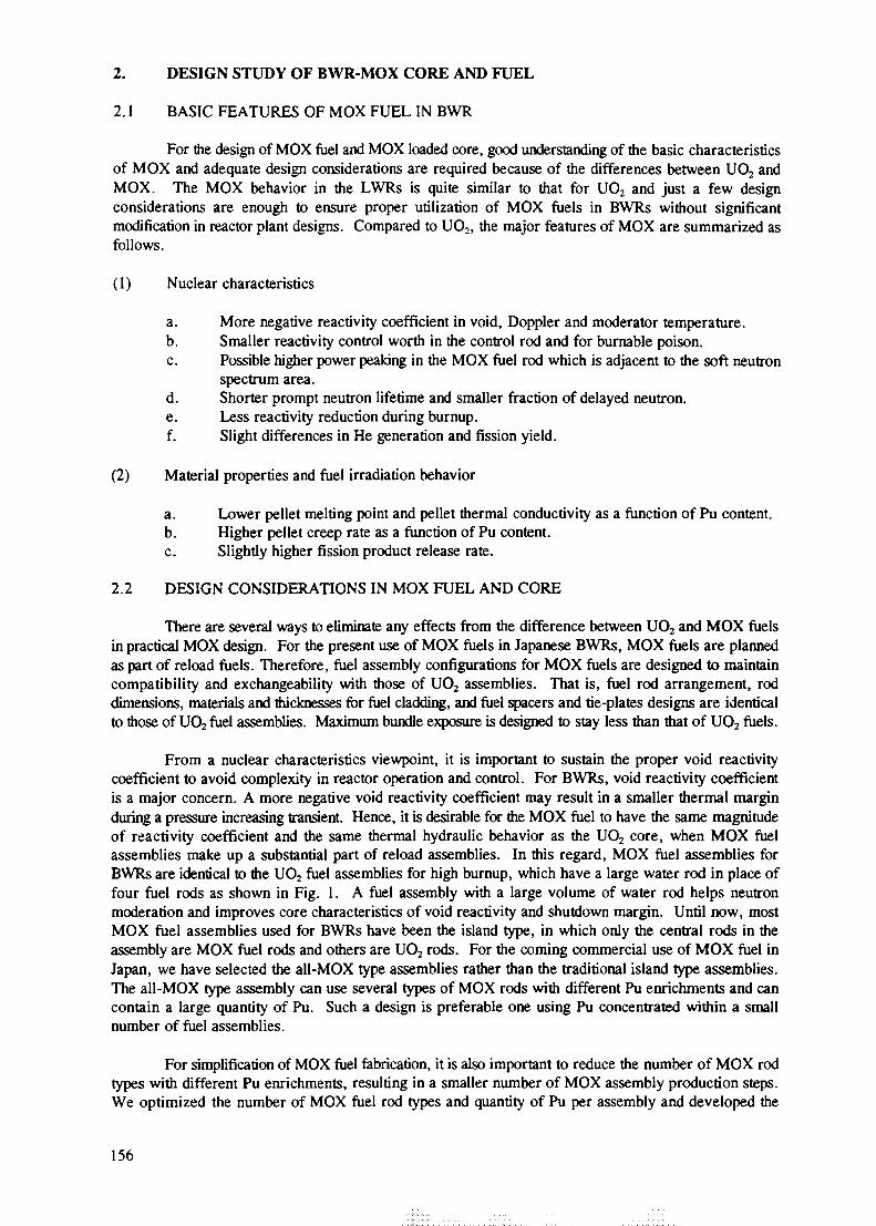
From a nuclear characteristics viewpoint, it is important to sustain the proper void reactivitycoefficient to avoid complexity in reactor operation and control. For BWRs, void reactivity coefficientis a major concern. A more negative void reactivity coefficient may result in a smaller thermal marginduring a pressure increasing transient. Hence, it is desirable for the MOX fuel to have the same magnitudeof reactivity coefficient and the same thermal hydraulic behavior as the UO2 core, when MOX fuelassemblies make up a substantial part of reload assemblies. In this regard, MOX fuel assemblies forBWRs are identical to the UO2 fuel assemblies for high burnup, which have a large water rod in place offour fuel rods as shown in Fig. 1. A fuel assembly with a large volume of water rod helps neutronmoderation and improves core characteristics of void reactivity and shutdown margin. Until now, mostMOX fuel assemblies used for BWRs have been the island type, in which only the central rods in theassembly are MOX fuel rods and others are UO2 rods. For the coming commercial use of MOX fuel inJapan, we have selected the all-MOX type assemblies rather than the traditional island type assemblies.The all-MOX type assembly can use several types of MOX rods with different Pu enrichments and cancontain a large quantity of Pu. Such a design is preferable one using Pu concentrated within a smallnumber of fuel assemblies.
For simplification of MOX fuel fabrication, it is also important to reduce the number of MOX rodtypes with different Pu enrichments, resulting in a smaller number of MOX assembly production steps.We optimized the number of MOX fuel rod types and quantity of Pu per assembly and developed the
156
LSI
oto
n
CTQ
so1—1.
c
o
S5
S305
©
CO
era
C
3
a?is
CD<-••
n
oa,
ooooooooooooooooooooooooooo@ooooo o o o®o o ooooooooooooooooo£ooooooa
fboooooooooooooooooooopoo
n=.ooaooooooooooooooooooOOQ,
all-MOX type assembly with four types of MOX rods of different Pu enrichments and small number ofuranium rods at the location of high power peaking. Based on the BWR-MOX design and irradiationexperience at Tsuruga Unit - 1 [1], a detailed Pu and Gd distribution design for the commercialBWR-MOX assembly is now in progress. The design is expected to be suitable for the MOX utilizationprogram in BWRs with the UO2 assemblies for high burnup.
2.3 FEASIBILITY STUDY OF FULL-MOX BWR CORE
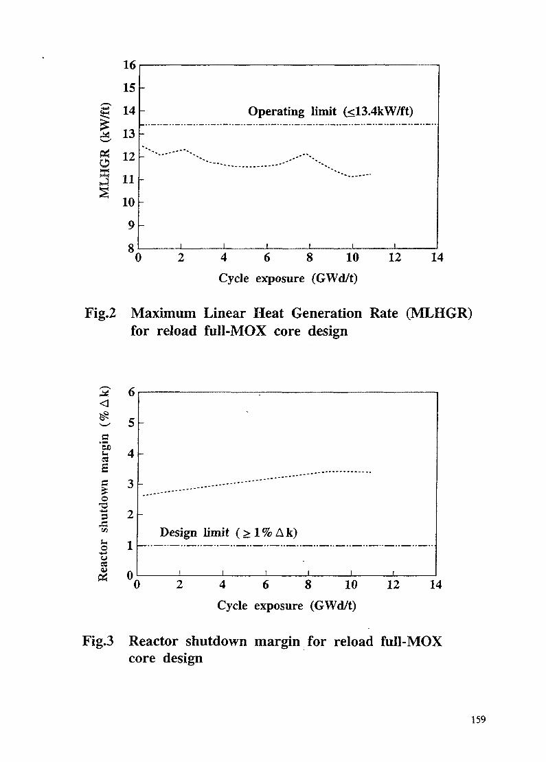
It is desirable for BWR to have some flexibility in the quantity of Pu utilization by adding Puinventory per reactor. It is helpful to adjust Pu surplus from the imbalance of demand and supply. Forthis reason, Hitachi, Ltd. (Hitachi) studied an Advanced BWR (ABWR) core loaded fully with MOX fuelassemblies. Table I describes the specifications of this MOX core. Preliminary core characteristicsevaluation showed satisfactory results in shutdown margin, thermal margin and reactivity coefficientagainst core design criteria as shown in Figs. 2 and 3. This study also showed that greater moderation ofneutrons such as by addition of water rods is a key factor for further improvement of burnup and corecharacteristics.
2.4 MOX CORE DESIGN METHOD AND ITS VERIFICATION
The BWR core design method for the UO2 core is based on the three dimensional neutron diffusionanalysis of the whole core with a few energy-group nuclear constants from fuel lattice cell neutrontransport. This method includes heterogeneity in the BWR core which comes from the void distributionin core, the enrichment distribution and the local gadolinia location in the lattice cell. We planned to usethis method for design of the MOX fuel core.
One verification of this method was confirmed by the power profile trace of Tsuruga MOX fuel.The difference in the power profile between TIP (Traversing In-core Probe) measurements and core
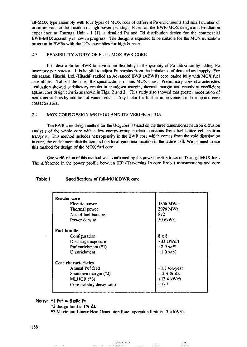
Table 1 Specifications of full-MOX BWR core
Reactor coreElectric powerThermal powerNo. of fuel bundlesPower density
Fuel bundleConfigurationDischarge exposurePuf enrichment (* 1)U enrichment
Core characteristicsAnnual Puf feedShutdown margin (*2)MLHGR (*3)Core stability decay ratio
1356 MWe3926 MWt87250.6kW/I
8x8-33 GWd/t-2.9 wt%~1.0wt%
-1.1 ton-yeari 2.4 % Aks 12.4 kW/ft<0.7
Notes: *1 Puf = fissile Pu*2 design limit is 1 % Ak.*3 Maximum Linear Heat Generation Rate, operation limit is 13.4 kW/ft.
158
(kW
/ft)
16
15
14
13
12
11
10
9
8t
-
-
-- " " • - • "
i
) 2
Operating
i i
4 6
Cycle exposure
limit (<13.4kW/ft)
i i i
8 10 12 V
(GWd/t)
Fig.2 Maximum Linear Heat Generation Rate (MLHGR)for reload full-MOX core design
S
o
3r"sum
a
Design limit ( > l % A k )
0 4 6 8 10Cycle exposure (GWd/t)
12 14
Fig.3 Reactor shutdown margin for reload full-MOXcore design
159
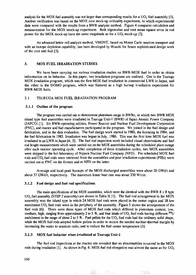
analysis for the MOX fuel assembly was not larger than corresponding results for a UO2 fuel assembly [1].Another verification was based on the MOX core mock-up criticality experiment, in which experimentaldata were compared with the results from a BWR analysis method. Figure 4 compares calculation andmeasurement for the MOX mock-up experiment. Both eigenvalue and root mean square error in rodpower for the MOX mock-up have the same magnitude as for a UO2 mock-up [2].
An advanced lattice cell analysis method, VMONT, based on Monte Carlo neutron transport andwith an isotope depletion capability, has been developed by Hitachi for future sophisticated design workof the core and fuel [3].
3. MOX FUEL IRRADIATION STUDIES
We have been carrying out various irradiation studies on BWR-MOX fuel in order to obtaininformation on its behavior. In this paper, two irradiation programs are outlined. One is the TsurugaMOX irradiation program, which was the first MOX fuel irradiation in commercial LWR in Japan, andthe other is the DOMO program, which was featured as a high burnup irradiation experiment forBWR-MOX fuels.
3.1 TSURUGA MOX FUEL IRRADIATION PROGRAM
3.1.1 Outline of the program
The program was carried out to demonstrate plutonium usage in BWRs, in which two BWR MOXisland type fuel assemblies were irradiated in Tsuruga Unit-1 (BWR) of Japan Atomic Power Company(JAPCO) [1]. Six BWR-operating utilities, Power Reactor and Nuclear Fuel Development Corporation(PNC), and reactor and fuel manufacturers participated in the program. We joined in the fuel design andfabrication, and in the data evaluation. The fuel design work started in 1980, the licensing in 1984, andthe fuel fabrication in 1985. Irradiation was begun in July, 1986. This was the first time MOX fuel wasirradiated in an LWR in Japan [4, 5]. The fuel rod inspection work included visual observations and fuelrod length measurements which were carried out on the MOX assemblies during the scheduled plant outageafter each reactor operating cycle. After completion of three irradiation cycles, two MOX assemblieswere shipped to the hot laboratory of Nippon Nuclear Fuel Company (NFD). Pre-scheduled MOX fuelrods and UO2 fuel rods were retrieved from the assemblies and post irradiation experiments (PIEs) werecarried out at PNC on the former and at NFD on the latter.
Average and local peak burnups of the MOX discharged assemblies were about 26 GWd/t andabout 37 GWd/t, respectively. The maximum linear heat rate was about 330 W/cm.
3.1.2 Fuel design and fuel rod specifications
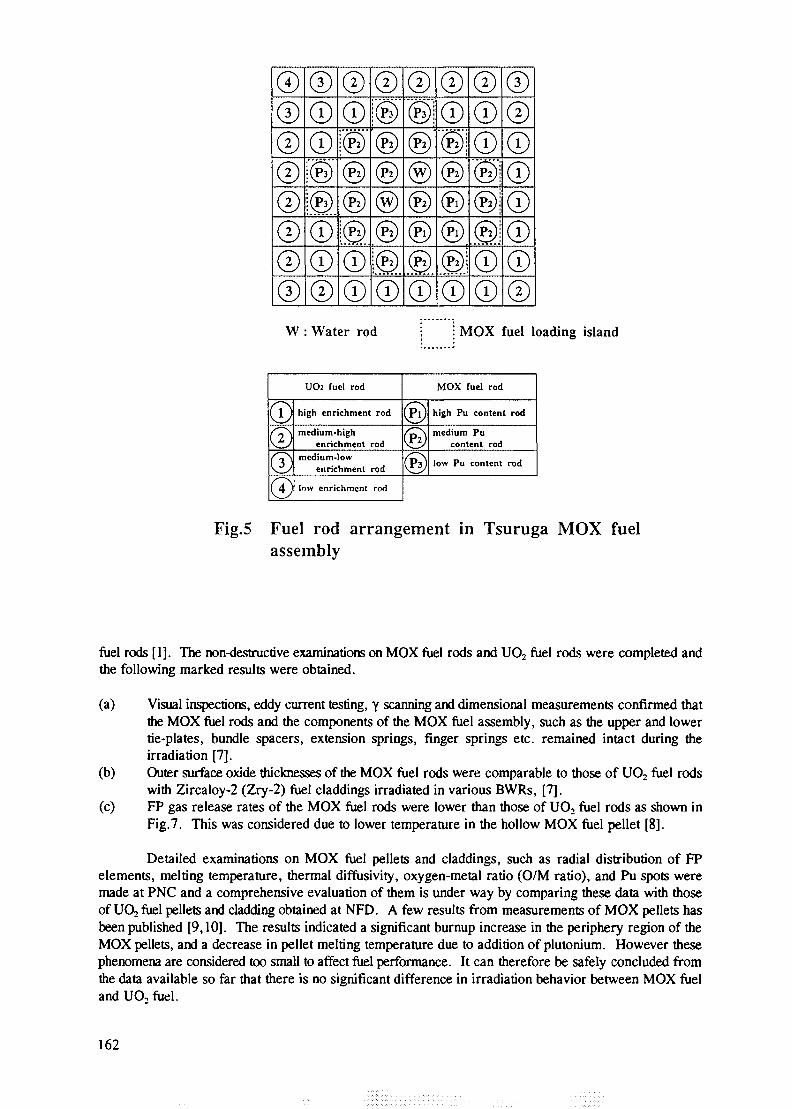
The main specifications of the MOX assemblies, which were the identical with the BWR 8 x 8 typeUO2fuel assembly (STEP-2 assembly) are shown in Table II [1]. The fuel rod arrangement in the MOXassembly was the island type in which 24 MOX fuel rods were placed in the center region and 38 lowenrichment UO2 fuel rods were in the periphery of the assembly. Figure 5 shows the arrangement of thefuel rods [6]. There were three types of MOX fuel rods which differed in plutonium content, low,medium, high, ranging from approximately 2 to 5 %, and four kinds of UO2 fuel rods having different ^ Uenrichment in the range of about 2 to 3 %. Fuel pellets for the UO2 fuel rods had the ordinary solid shape,while die MOX fuel rods adopted hollow pellets in order to secure the needed nuclear-thermal margin byincreasing the water to uranium ratio, and to reduce the fuel center temperature [1].
3.1.3 MOX fuel behavior when irradiated at Tsuruga Unit-1
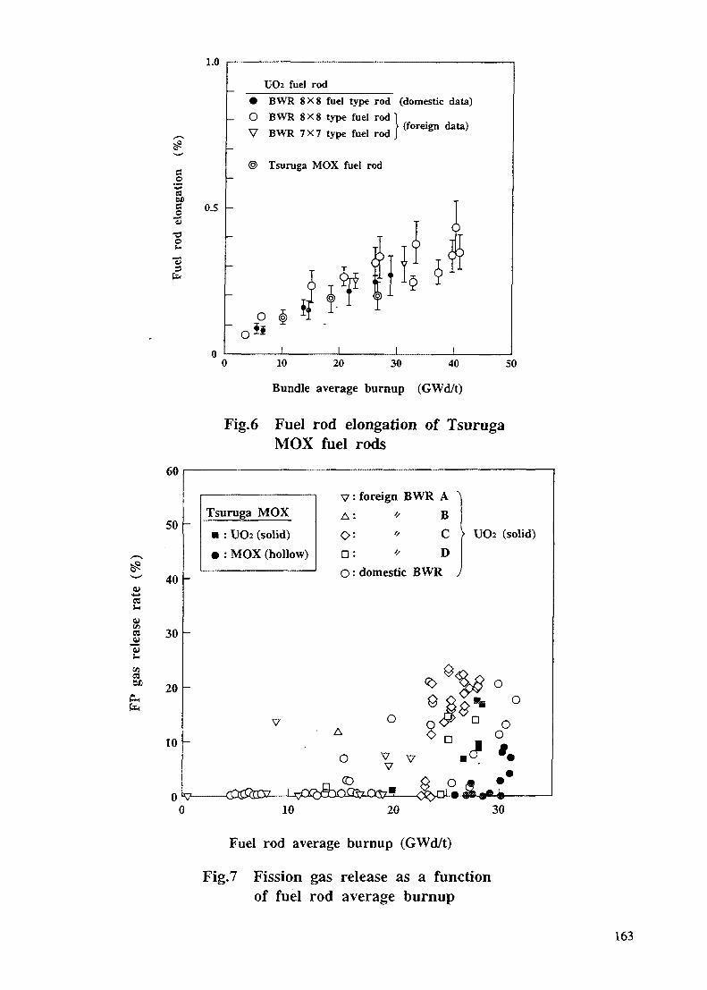
The fuel rod inspections at the reactor site revealed that no abnormalities occurred in the MOXrods during irradiation [1]. As shown in Fig. 6, MOX fuel rod elongation was almost the same as for UO2
160
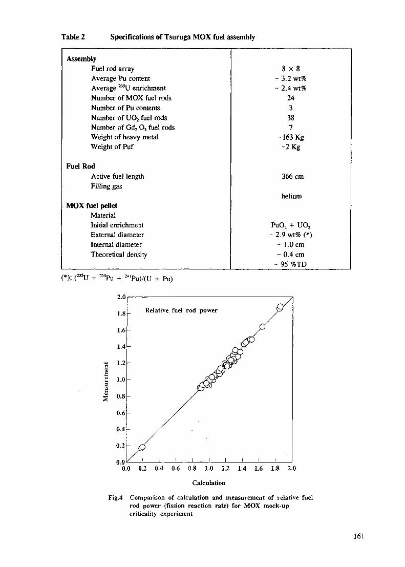
Table 2 Specifications of Tsuruga MOX fuel assembly
AssemblyFuel rod arrayAverage Pu contentAverage ^ U enrichmentNumber of MOX fuel rodsNumber of Pu contentsNumber of UO2 fuel rodsNumber of Gd2 O3 fuel rodsWeight of heavy metalWeight of Puf
Fuel RodActive fuel lengthFilling gas
MOX fuel pelletMaterialInitial enrichmentExternal diameterInternal diameterTheoretical density
8 x 8~ 3.2 wt%~ 2.4 wt%
243
387
-163 Kg~2Kg
366 cm
helium
PuO2 + UO2
- 2.9 wt% (*)~ 1.0 cm~ 0.4 cm
- 95 %TD
'Pu)/(U + Pu)
Relative fuel rod power
0.0 0.2 0.4 0.6 0.8 1.0 1.2 1.4 1.6 1.8 2.0
Calculation
Fig.4 Comparison of calculation and measurement of relative fuelrod power (fission reaction rate) for MOX mock-upcriticality experiment
161
I®® \®
©
®
W : Water rod i MOX fuel loading island
©UO2 fuel rod
®
high enrichment rod
medium-highenrichment rod
medium-lowenrichment rod
low enrichment rod
MOX fuel rod
high Pu content rod
medium Pucontent rod
low Pu content rod
Fig.5 Fuel rod arrangement in Tsuruga MOX fuelassembly
fuel rods [1]. The non-destructive examinations on MOX fuel rods and UO2 fuel rods were completed andthe following marked results were obtained.
(a) Visual inspections, eddy current testing, y scanning and dimensional measurements confirmed thatthe MOX fuel rods and the components of the MOX fuel assembly, such as the upper and lowertie-plates, bundle spacers, extension springs, finger springs etc. remained intact during theirradiation [7].
(b) Outer surface oxide thicknesses of the MOX fuel rods were comparable to those of UO2 fuel rodswith Zircaloy-2 (Zry-2) fuel claddings irradiated in various BWRs, [7].
(c) FP gas release rates of the MOX fuel rods were lower than those of UO2 fuel rods as shown inFig.7. This was considered due to lower temperature in the hollow MOX fuel pellet [8].
Detailed examinations on MOX fuel pellets and claddings, such as radial distribution of FPelements, melting temperature, thermal diffusivity, oxygen-metal ratio (O/M ratio), and Pu spots weremade at PNC and a comprehensive evaluation of them is under way by comparing these data with thoseof UO2 fuel pellets and cladding obtained at NFD. A few results from measurements of MOX pellets hasbeen published [9,10]. The results indicated a significant burnup increase in the periphery region of theMOX pellets, and a decrease in pellet melting temperature due to addition of plutonium. However thesephenomena are considered too small to affect fuel performance. It can therefore be safely concluded fromthe data available so far that there is no significant difference in irradiation behavior between MOX fueland UO, fuel.
162
1.0
£
B
0>inCZ
Iaen
aCD©
o
"3fa
60
50
40
30
20
10 -
0.5
UO2 fuel rod
• BWR 8X8 fuel type rod (domestic data)
O BWR 8X8 type fuel rodV BWR 7X7 type fuel rod
Tsuruga MOX fuel rod
(foreign data)
O h
I0 10 20 30 40 50
Bundle average burnup (GWd/t)
Fig.6 Fuel rod elongation of TsurugaMOX fuel rods
Tsuruga MOX
• : UO2 (solid)
• : MOX (hollow)
V: foreign BWR A
A: * B
O : * C
D: '' D
O: domestic BWR
UO2 (solid)
20 30
Fuel rod average burnup (GWd/t)
Fig.7 Fission gas release as a functionof fuel rod average burnup
163
3.2 HIGH BURNUP MOX FUEL IRRADIATION BEHAVIOR-DOMO PROGRAM
3.2.1 Outline of the program
The high burnup program for UO2 fuel has been progressing towards one of its goals of improvedeconomy of BWRs [6]. In order to obtain high burnup data of BWR-MOX fuel the international researchprogram, DOMO, was started in 1986 [11,12]. It has been carried out under the sponsorship of utilities,fuel manufacturers, reactor manufacturers and research organizations in Japan (six BWR-operatingutilities, Hitachi, Toshiba, PNC, Japan Nuclear Fuel Co., Ltd (JNF) and NFD), the Netherlands (GKNand KEMA) and Switzerland (PSI) [12]. The director of the program has been Belgonucleaire (BN) ofBelgium. In the program, five assemblies containing BWR-MOX fuel rods are irradiated in theDodewaard BWR in the Netherlands. The MOX fuel rods are individually retrieved after achieving targetburnups of 20, 40 and 60 GWd/t and subjected to PIEs. A couple of rods are selected out of the retrievedrods at the respective burnups and ramp tested in the BR2 up to the maximum power of 600 W/cm [12].
3.2.2 Test parameters and fuel rod specifications
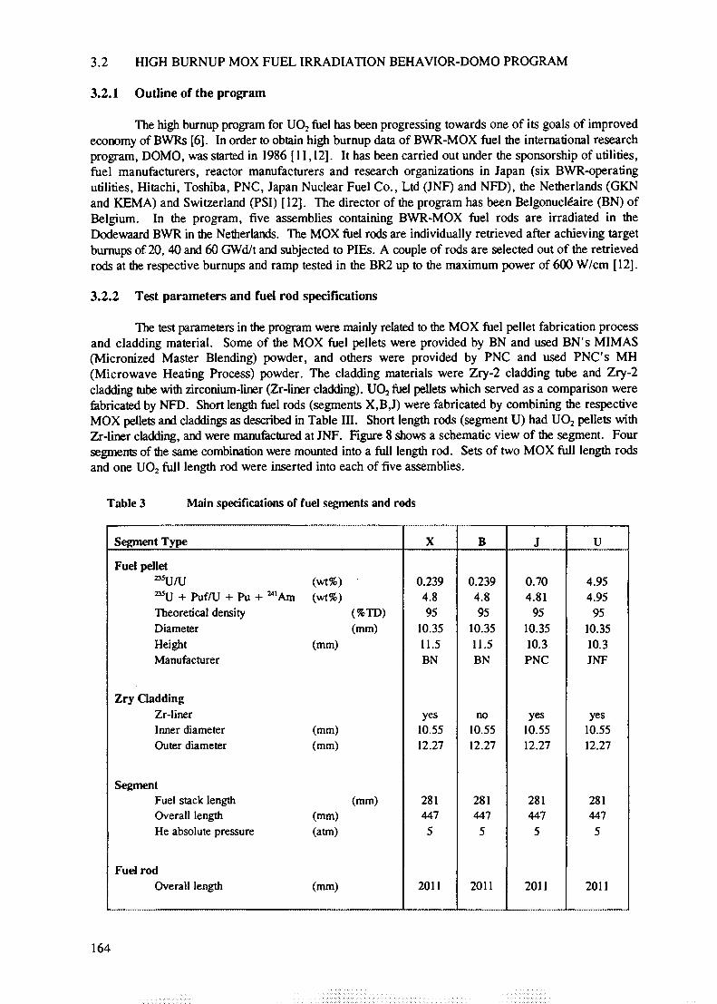
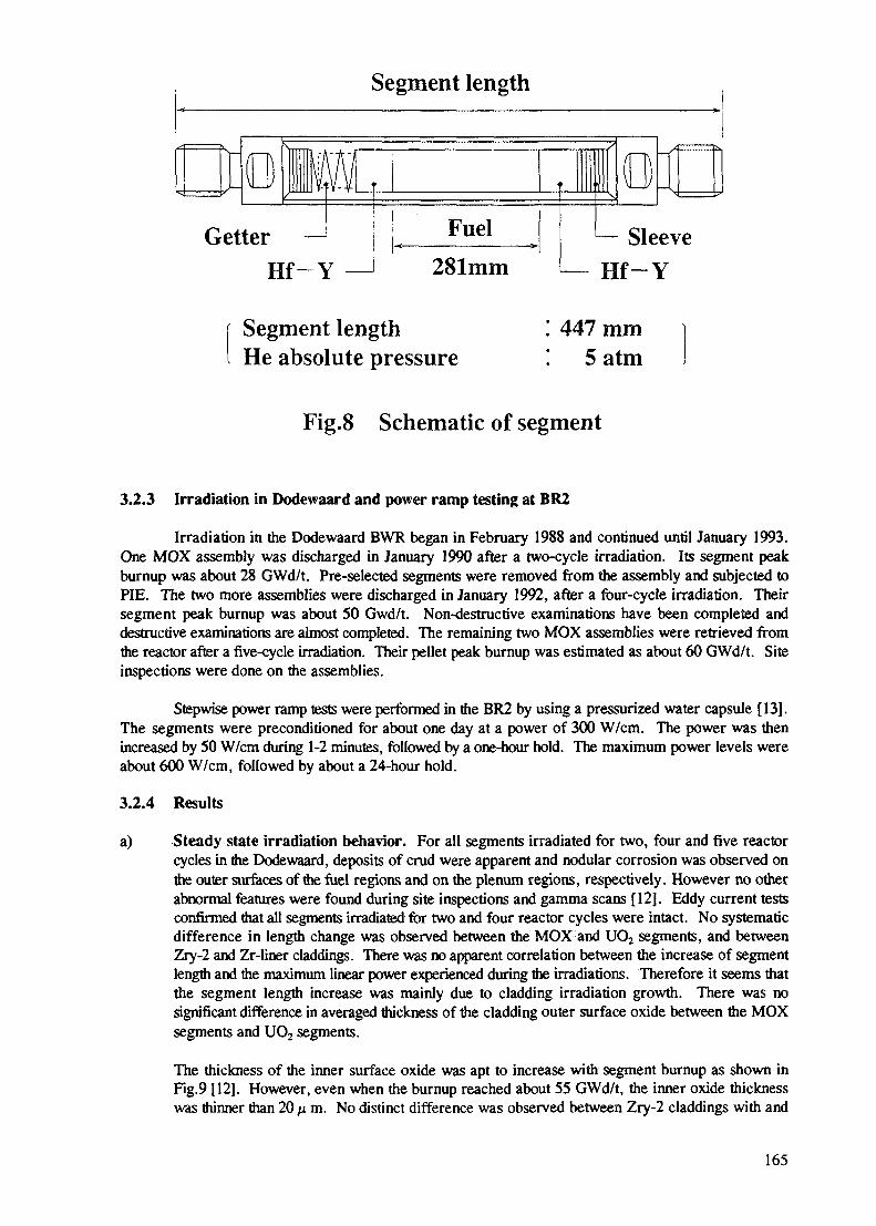
The test parameters in the program were mainly related to the MOX fuel pellet fabrication processand cladding material. Some of the MOX fuel pellets were provided by BN and used BN's MIMAS(Micronized Master Blending) powder, and others were provided by PNC and used PNC's MH(Microwave Heating Process) powder. The cladding materials were Zry-2 cladding tube and Zry-2cladding tube with zirconium-liner (Zr-liner cladding). UO2 fuel pellets which served as a comparison werefabricated by NFD. Short length fuel rods (segments X,B,J) were fabricated by combining the respectiveMOX pellets and claddings as described in Table III. Short length rods (segment U) had UO2 pellets withZr-liner cladding, and were manufactured at JNF. Figure 8 shows a schematic view of the segment. Foursegments of the same combination were mounted into a full length rod. Sets of two MOX full length rodsand one UO2 full length rod were inserted into each of five assemblies.
Table 3 Main specifications of fuel segments and rods
Segment Type
Fuel pellet^U/U (wt%)^ U + Puf/U + Pu + "'Am (wt%)Theoretical density (%TD)Diameter (mm)Height (mm)Manufacturer
Zry CladdingZr-linerInner diameter (mm)Outer diameter (mm)
SegmentFuel stack length (mm)Overall length (mm)He absolute pressure (atm)
Fuel rodOverall length (mm)
X
0.2394.895
10.3511.5BN
yes10.5512.27
2814475
2011
B
0.2394.895
10.3511.5BN
no10.5512.27
2814475
2011
J
0.704.81
9510.3510.3PNC
yes10.5512.27
2814475
2011
U
4.954.95
9510.3510.3JNF
yes10.5512.27
2814475
2011
164
Segment length
GetterHf~Y
Fuel
281mm— SleeveHf-Y
Segment lengthHe absolute pressure
! 447 mm5 atm
Fig.8 Schematic of segment
3.2.3 Irradiation in Dodewaard and power ramp testing at BR2
Irradiation in the Dodewaard BWR began in February 1988 and continued until January 1993.One MOX assembly was discharged in January 1990 after a two-cycle irradiation. Its segment peakburnup was about 28 GWd/t. Pre-selected segments were removed from the assembly and subjected toPIE. The two more assemblies were discharged in January 1992, after a four-cycle irradiation. Theirsegment peak burnup was about 50 Gwd/t. Non-destructive examinations have been completed anddestructive examinations are almost completed. The remaining two MOX assemblies were retrieved fromthe reactor after a five-cycle irradiation. Their pellet peak burnup was estimated as about 60 GWd/t. Siteinspections were done on the assemblies.
Stepwise power ramp tests were performed in the BR2 by using a pressurized water capsule [13].The segments were preconditioned for about one day at a power of 300 W/cm. The power was thenincreased by 50 W/cm during 1-2 minutes, followed by a one-hour hold. The maximum power levels wereabout 600 W/cm, followed by about a 24-hour hold.
3.2.4 Results
a) Steady state irradiation behavior. For all segments irradiated for two, four and five reactorcycles in the Dodewaard, deposits of crud were apparent and nodular corrosion was observed onthe outer surfaces of the fuel regions and on the plenum regions, respectively. However no otherabnormal features were found during site inspections and gamma scans [12]. Eddy current testsconfirmed that all segments irradiated for two and four reactor cycles were intact. No systematicdifference in length change was observed between the MOX and UO2 segments, and betweenZry-2 and Zr-liner claddings. There was no apparent correlation between the increase of segmentlength and the maximum linear power experienced during the irradiations. Therefore it seems thatthe segment length increase was mainly due to cladding irradiation growth. There was nosignificant difference in averaged thickness of the cladding outer surface oxide between the MOXsegments and UO2 segments.
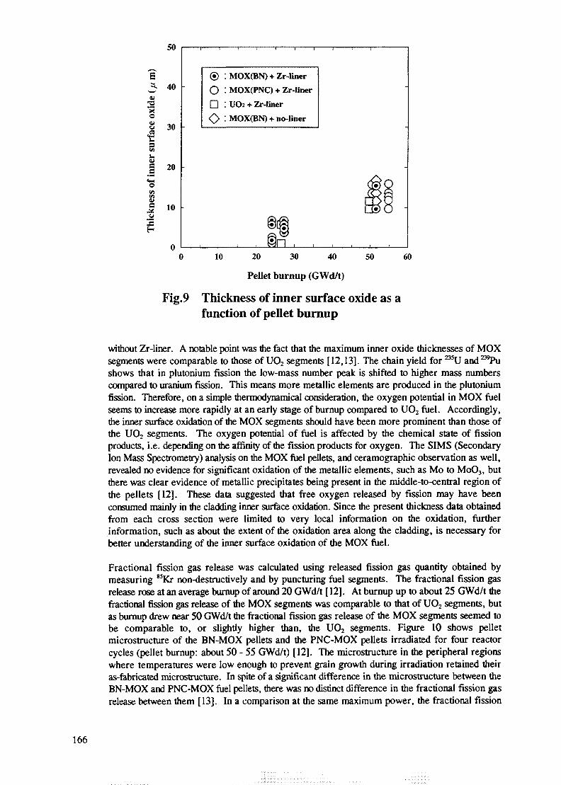
The thickness of the inner surface oxide was apt to increase with segment burnup as shown inFig.9 [12]. However, even when the burnup reached about 55 GWd/t, the inner oxide thicknesswas thinner than 20 p. m. No distinct difference was observed between Zry-2 claddings with and
165
5
zu
I
oen
2
50
40
30
20
10
® : MOX(BN) + Zr-liner
O : MOX(PNC) + Zr-liner
• ! UO2 + Zr-liner
<0 : MOX(BN) + no-liner
0 10 20 30 40 50 60
Pellet burnup (GWd/t)
Fig.9 Thickness of inner surface oxide as afunction of pellet burnup
without Zr-liner. A notable point was the feet that the maximum inner oxide thicknesses of MOXsegments were comparable to those of UO2 segments [ 12,13]. The chain yield for ^ U and 239Pushows that in plutonium fission the low-mass number peak is shifted to higher mass numberscompared to uranium fission. This means more metallic elements are produced in the plutoniumfission. Therefore, on a simple thermodynamical consideration, the oxygen potential in MOX fuelseems to increase more rapidly at an early stage of burnup compared to UO2 fuel. Accordingly,the inner surface oxidation of the MOX segments should have been more prominent than those ofthe UO, segments. The oxygen potential of fuel is affected by the chemical state of fissionproducts, i.e. depending on the affinity of the fission products for oxygen. The SIMS (SecondaryIon Mass Spectrometry) analysis on the MOX fuel pellets, and ceramographic observation as well,revealed no evidence for significant oxidation of the metallic elements, such as Mo to MoO3, butthere was clear evidence of metallic precipitates being present in the middle-to-central region ofthe pellets [12]. These data suggested that free oxygen released by fission may have beenconsumed mainly in the cladding inner surface oxidation. Since the present thickness data obtainedfrom each cross section were limited to very local information on the oxidation, furtherinformation, such as about the extent of the oxidation area along the cladding, is necessary forbetter understanding of the inner surface oxidation of the MOX fuel.
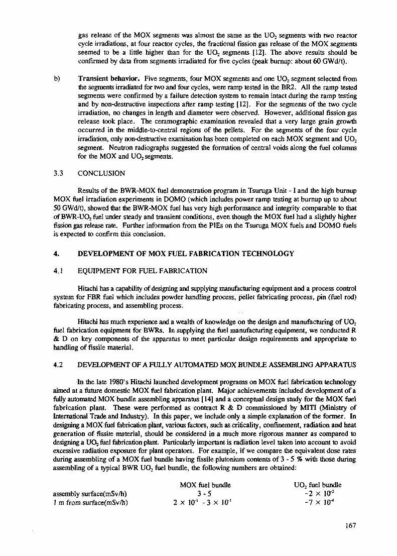
Fractional fission gas release was calculated using released fission gas quantity obtained bymeasuring 85Kr non-destructively and by puncturing fuel segments. The fractional fission gasrelease rose at an average burnup of around 20 GWd/t [ 12]. At burnup up to about 25 GWd/t thefractional fission gas release of the MOX segments was comparable to that of UO2 segments, butas burnup drew near 50 GWd/t the fractional fission gas release of the MOX segments seemed tobe comparable to, or slightly higher than, the UO2 segments. Figure 10 shows pelletmicrostructure of the BN-MOX pellets and the PNC-MOX pellets irradiated for four reactorcycles (pellet burnup: about 50 - 55 GWd/t) [12]. The microstructure in the peripheral regionswhere temperatures were low enough to prevent grain growth during irradiation retained theiras-fabricated microstructure. In spite of a significant difference in the microstructure between theBN-MOX and PNC-MOX fuel pellets, there was no distinct difference in the fractional fission gasrelease between them [13]. In a comparison at the same maximum power, the fractional fission
166
gas release of the MOX segments was almost the same as the UO2 segments with two reactorcycle irradiations, at four reactor cycles, the fractional fission gas release of the MOX segmentsseemed to be a little higher than for the UO2 segments [12]. The above results should beconfirmed by data from segments irradiated for five cycles (peak burnup: about 60 GWd/t).
b) Transient behavior. Five segments, four MOX segments and one UO2 segment selected fromthe segments irradiated for two and four cycles, were ramp tested in the BR2. All the ramp testedsegments were confirmed by a failure detection system to remain intact during the ramp testingand by non-destructive inspections after ramp testing [12]. For the segments of the two cycleirradiation, no changes in length and diameter were observed. However, additional fission gasrelease took place. The ceramographic examination revealed that a very large grain growthoccurred in the middle-to-central regions of the pellets. For the segments of the four cycleirradiation, only non-destructive examination has been completed on each MOX segment and UO2
segment. Neutron radiographs suggested the formation of central voids along the fuel columnsfor the MOX and UO2 segments.
3.3 CONCLUSION
Results of the BWR-MOX fuel demonstration program in Tsuruga Unit -1 and the high burnupMOX fuel irradiation experiments in DOMO (which includes power ramp testing at burnup up to about50 GWd/t), showed that the BWR-MOX fuel has very high performance and integrity comparable to thatof BWR-UO2 fuel under steady and transient conditions, even though the MOX fuel had a slightly higherfission gas release rate. Further information from the PIEs on the Tsuruga MOX fuels and DOMO fuelsis expected to confirm this conclusion.
4. DEVELOPMENT OF MOX FUEL FABRICATION TECHNOLOGY
4.1 EQUIPMENT FOR FUEL FABRICATION
Hitachi has a capability of designing and supplying manufacturing equipment and a process controlsystem for FBR fuel which includes powder handling process, pellet fabricating process, pin (fuel rod)fabricating process, and assembling process.
Hitachi has much experience and a wealth of knowledge on the design and manufacturing of UO2
fuel fabrication equipment for BWRs. In supplying the fuel manufacturing equipment, we conducted R& D on key components of the apparatus to meet particular design requirements and appropriate tohandling of fissile material.
4.2 DEVELOPMENT OF A FULLY AUTOMATED MOX BUNDLE ASSEMBLING APPARATUS
In the late 1980' s Hitachi launched development programs on MOX fuel fabrication technologyaimed at a future domestic MOX fuel fabrication plant. Major achievements included development of afully automated MOX bundle assembling apparatus [14] and a conceptual design study for the MOX fuelfabrication plant. These were performed as contract R & D commissioned by MITI (Ministry ofInternational Trade and Industry). In this paper, we include only a simple explanation of the former. Indesigning a MOX fuel fabrication plant, various factors, such as criticality, confinement, radiation and heatgeneration of fissile material, should be considered in a much more rigorous manner as compared todesigning a UOj fuel fabrication plant. Particularly important is radiation level taken into account to avoidexcessive radiation exposure for plant operators. For example, if we compare the equivalent dose ratesduring assembling of a MOX fuel bundle having fissile plutonium contents of 3 - 5 % with those duringassembling of a typical BWR UO2 fuel bundle, the following numbers are obtained:
MOX fuel bundle UO2 fuel bundleassembly surface(mSv/h) 3 - 5 ~2 x Iff2
1 m from surface(mSv/h) 2 x Iff1 - 3 x Iff1 - 7 x 10"4
167
The equivalent dose rates for a MOX fuel bundle are more than 200 times higher than those ofthe UO2 fuel bundle. In the MOX bundle assembling process, therefore, it becomes important to automateas many features as possible for the bundle assembling apparatus and to use remote controlled steps. Fromthis viewpoint we set out to develop the fully automated MOX bundle assembling apparatus.
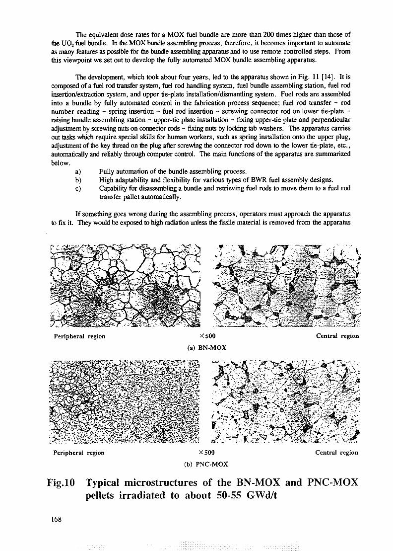
The development, which took about four years, led to the apparatus shown in Fig. 11 [14]. It iscomposed of a fuel rod transfer system, fuel rod handling system, fuel bundle assembling station, fuel rodinsertion/extraction system, and upper tie-plate installation/dismantling system. Fuel rods are assembledinto a bundle by fully automated control in the fabrication process sequence; fuel rod transfer - rodnumber reading - spring insertion - fuel rod insertion - screwing connector rod on lower tie-plate -raising bundle assembling station - upper-tie plate installation - fixing upper-tie plate and perpendicularadjustment by screwing nuts on connector rods - fixing nuts by locking tab washers. The apparatus carriesout tasks which require special skills for human workers, such as spring installation onto the upper plug,adjustment of the key thread on the plug after screwing the connector rod down to the lower tie-plate, etc.,automatically and reliably through computer control. The main functions of the apparatus are summarizedbelow.
a) Fully automation of the bundle assembling process.b) High adaptability and flexibility for various types of BWR fuel assembly designs.c) Capability for disassembling a bundle and retrieving fuel rods to move them to a fuel rod
transfer pallet automatically.
If something goes wrong during the assembling process, operators must approach the apparatusto fix it. They would be exposed to high radiation unless the fissile material is removed from the apparatus
ru& J"> S-rX- •*
Peripheral region
vX500
(a) BN-MOX
Central region
x.
i .- - v *3tS «- V. ^ "V <cS^ f'-̂ -rf vr'-rT •• I T" ft' '•iffiauM
Peripheral region X500
(b) PNC-MOX
Central region
Fig.10 Typical microstructures of the BN-MOX and PNC-MOXpellets irradiated to about 50-55 GWd/t
168
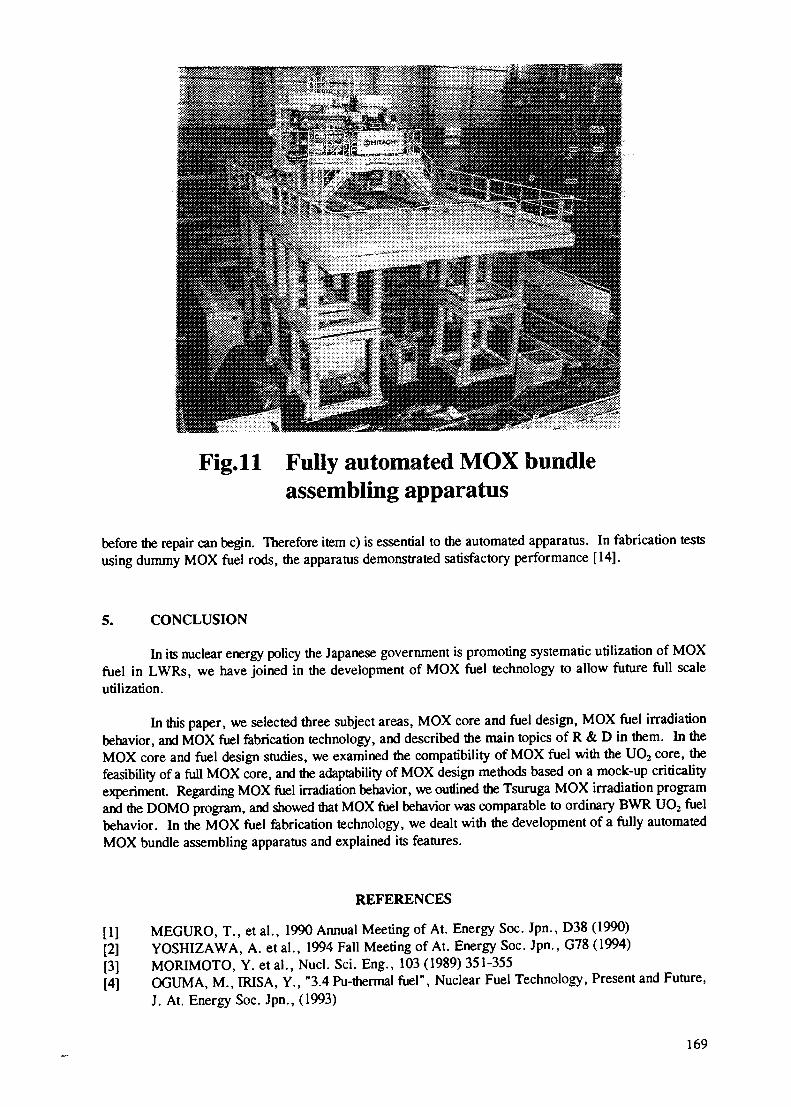
Fig.ll Fully automated MOX bundleassembling apparatus
before the repair can begin. Therefore item c) is essential to the automated apparatus. In fabrication testsusing dummy MOX fuel rods, the apparatus demonstrated satisfactory performance [14].
5. CONCLUSION
In its nuclear energy policy the Japanese government is promoting systematic utilization of MOXfuel in LWRs, we have joined in the development of MOX fuel technology to allow future full scaleutilization.
In this paper, we selected three subject areas, MOX core and fuel design, MOX fuel irradiationbehavior, and MOX fuel fabrication technology, and described the main topics of R & D in them. In theMOX core and fuel design studies, we examined the compatibility of MOX fuel with the UO2 core, thefeasibility of a full MOX core, and the adaptability of MOX design methods based on a mock-up criticalityexperiment. Regarding MOX fuel irradiation behavior, we outlined the Tsuruga MOX irradiation programand the DOMO program, and showed that MOX fuel behavior was comparable to ordinary BWR UO2 fuelbehavior. In the MOX fuel fabrication technology, we dealt with the development of a fully automatedMOX bundle assembling apparatus and explained its features.
REFERENCES
[1] MEGURO, T., et al., 1990 Annual Meeting of At. Energy Soc. Jpn., D38 (1990)[2] YOSHIZAWA, A. et al., 1994 Fall Meeting of At. Energy Soc. Jpn., G78 (1994)[3] MORIMOTO, Y. et al., Nucl. Sci. Eng., 103 (1989) 351-355[4] OGUMA, M., IRISA, Y., "3.4 Pu-thermal fuel", Nuclear Fuel Technology, Present and Future,
J. At. Energy Soc. Jpn., (1993)
169
[5] MEGURO, T., et-al., 1990 Annual Meeting of At. Energy Soc. Jpn., D39 (1990)[6] OGUMA, M., et al., Nucl. Enrg, 31, 1 (1992) 25-39[7] KATAYAMA, N, et al., 1992 Fall Meeting of At. Energy Soc. Jpn., F53 (1992)[8] KATAYAMA, N, et al., ibid., F54 (1992)[9] UNNO, I., et al., 1994 Spring Meeting of At. Energy Soc. Jpn., E29 (1994)[10] MITSUGI, T, et al., ibid., E30 (1994)[11] ASAHI, K., et al., 1993 Fall Meeting of At. Energy Soc. Jpn., K17 (1993)[12] ASAHI, K., et al., ANS 1994 Int. Topical Mtg. on Light Water Reactor Fuel Performance, Proc.
(1994) 726-732[13] ASAHI, K., et al., 1994 Fall Meeting of At. Energy Soc. Jpn., J34 (1994)[14] OGUMA, M., et al., 1991 Spring Meeting of At. Energy Soc. Jpn., J10 (1991)
170