X Series MANUAL - Powersoft
108
Keep this manual for future reference ©2019 Powersoſt X Series X4L X8 X4 Série X / Serie X / X 系列 X-Serie / X Серия / X Série MANUAL DO000200.01 R01
-
Upload
khangminh22 -
Category
Documents
-
view
3 -
download
0
Transcript of X Series MANUAL - Powersoft
Keep this manualfor future reference
©2019 Powersoft
X Series
X4L
X8
X4
Série X / Serie X / X 系列X-Serie / X Серия / X Série
MANUAL
DO000200.01 R01
powersoft_XSeries_qguide_mul
Data are subject to change without notice.For latest update please refer to the Englishonline version available on www.powersoft-audio.com.
Les données sont sujettes à changement sans préavis.Pour la dernière mise à jour, s’il vous plaît se référer à la version anglaisedisponible en ligne sur www.powersoft-audio.com.
Esta información está sujeta a cambios sin previo aviso.Para la última actualización por favor refiérase a la versión disponibleen Ingles en nuestro sitio de internet www.powersoft-audio.com.
I dati sono soggetti a cambiamenti senza preavviso.Per gli aggiornamenti si prega di consultare la versione inglesedisponibile online su www.powersoft-audio.com.
数据如有更改,恕不另行通知。最新更新,请参考在线的英文版本:http://www.powersoft-audio.com
Данные могут быть изменены без предварительного уведомления.Для более детальной информации используйте полное руководство на английском языке.Электронная версия доступна на сайте - http://www.powersoft-audio.com.
Alle Angaben können jederzeit ohne vorherige Ankündigung geändert werden. Den jeweils jüngsten Versionsstand finden Sie als englischsprachige Ausgabe auf www.powersoft-audio.com.
Os dados estão sujeitos a alterações sem aviso prévio.Para obter atualizações, consulte a versão em Inglêsdisponível online em www.powersoft-audio.com.
Designed in Italy by Powersoft S.p.A. (via E. Conti, 5 - 50018 Scandicci, Firenze) Factory 1: MW.FEP S.p.A. (Via Modena, 68 - 40017 San Giovanni in Persiceto, Bologna - Italy)Factory 2: MW.FEP S.p.A. (Via Mario Stoppani, 23 - 34077 Ronchi dei Legionari, Gorizia - Italy)
Ital
iano
中文
Deu
tsch
Pусс
кий
Port
uguê
sX
Serie
sEs
paño
lEn
glis
hFr
ança
ise
16
26
36
46
56
66
76
86
X SeriesSérie XSerie XX 系列X SerieX СерияX Série
Table of contents 2Table des matières 2Tabla de contenido 3Sommario 3目录 4Inhaltsverzeichnis 4Содержание 5Sumário 5Regulatory information 15Appendix: X Series Mains Wiring Option 97
X Series | 1
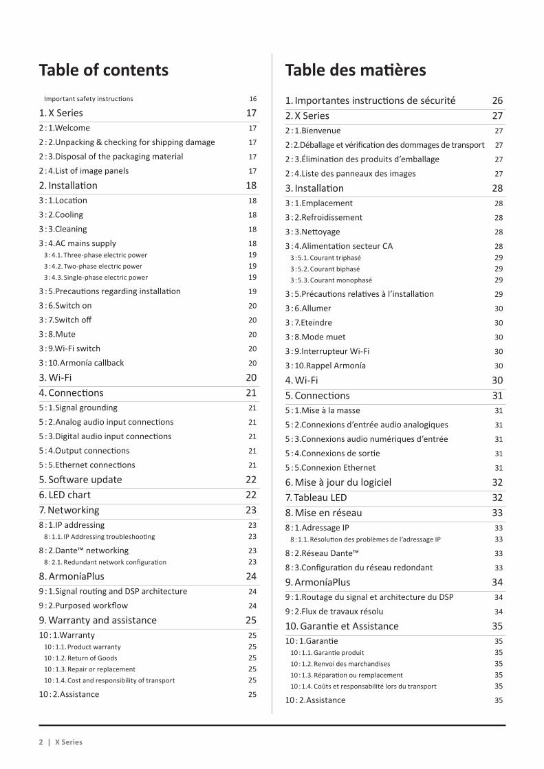
Table of contents Table des matièresImportant safety instructions 16
1. X Series 172 : 1.Welcome 17
2 : 2.Unpacking & checking for shipping damage 17
2 : 3.Disposal of the packaging material 17
2 : 4.List of image panels 17
2. Installation 183 : 1.Location 18
3 : 2.Cooling 18
3 : 3.Cleaning 18
3 : 4.AC mains supply 183 : 4.1. Three-phase electric power 193 : 4.2. Two-phase electric power 193 : 4.3. Single-phase electric power 19
3 : 5.Precautions regarding installation 19
3 : 6.Switch on 20
3 : 7.Switch off 20
3 : 8.Mute 20
3 : 9.Wi-Fi switch 20
3 : 10.Armonía callback 20
3. Wi-Fi 204. Connections 215 : 1.Signal grounding 21
5 : 2.Analog audio input connections 21
5 : 3.Digital audio input connections 21
5 : 4.Output connections 21
5 : 5.Ethernet connections 21
5. Software update 226. LED chart 227. Networking 238 : 1.IP addressing 23
8 : 1.1. IP Addressing troubleshooting 23
8 : 2.Dante™ networking 238 : 2.1. Redundant network configuration 23
8. ArmoníaPlus 249 : 1.Signal routing and DSP architecture 24
9 : 2.Purposed workflow 24
9. Warranty and assistance 2510 : 1.Warranty 25
10 : 1.1. Product warranty 2510 : 1.2. Return of Goods 2510 : 1.3. Repair or replacement 2510 : 1.4. Cost and responsibility of transport 25
10 : 2.Assistance 25
1. Importantes instructions de sécurité 262. X Series 272 : 1.Bienvenue 27
2 : 2.Déballage et vérification des dommages de transport 27
2 : 3.Élimination des produits d’emballage 27
2 : 4.Liste des panneaux des images 27
3. Installation 283 : 1.Emplacement 28
3 : 2.Refroidissement 28
3 : 3.Nettoyage 28
3 : 4.Alimentation secteur CA 283 : 5.1. Courant triphasé 293 : 5.2. Courant biphasé 293 : 5.3. Courant monophasé 29
3 : 5.Précautions relatives à l’installation 29
3 : 6.Allumer 30
3 : 7.Eteindre 30
3 : 8.Mode muet 30
3 : 9.Interrupteur Wi-Fi 30
3 : 10.Rappel Armonía 30
4. Wi-Fi 305. Connections 315 : 1.Mise à la masse 31
5 : 2.Connexions d’entrée audio analogiques 31
5 : 3.Connexions audio numériques d’entrée 31
5 : 4.Connexions de sortie 31
5 : 5.Connexion Ethernet 31
6. Mise à jour du logiciel 327. Tableau LED 328. Mise en réseau 338 : 1.Adressage IP 33
8 : 1.1. Résolution des problèmes de l’adressage IP 33
8 : 2.Réseau Dante™ 33
8 : 3.Configuration du réseau redondant 33
9. ArmoníaPlus 349 : 1.Routage du signal et architecture du DSP 34
9 : 2.Flux de travaux résolu 34
10. Garantie et Assistance 3510 : 1.Garantie 35
10 : 1.1. Garantie produit 3510 : 1.2. Renvoi des marchandises 3510 : 1.3. Réparation ou remplacement 3510 : 1.4. Coûts et responsabilité lors du transport 35
10 : 2.Assistance 35
2 | X Series
X Se
ries
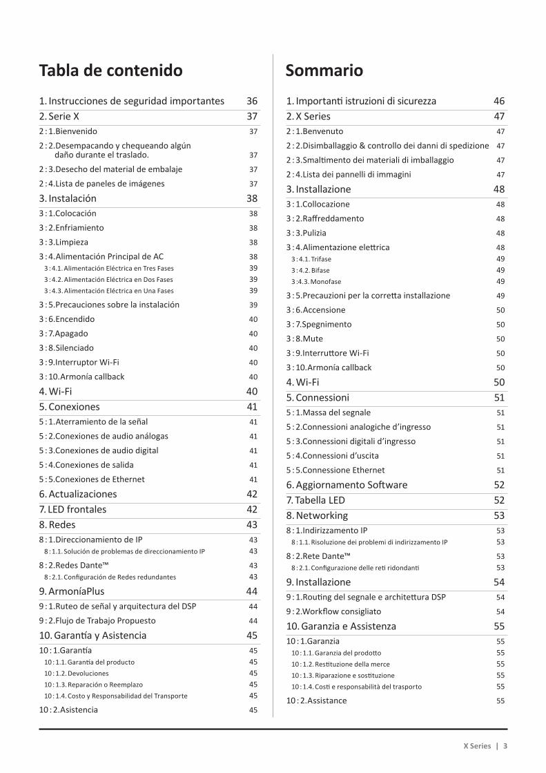
Tabla de contenido Sommario1. Instrucciones de seguridad importantes 362. Serie X 372 : 1.Bienvenido 37
2 : 2.Desempacando y chequeando algún daño durante el traslado. 37
2 : 3.Desecho del material de embalaje 37
2 : 4.Lista de paneles de imágenes 37
3. Instalación 383 : 1.Colocación 38
3 : 2.Enfriamiento 38
3 : 3.Limpieza 38
3 : 4.Alimentación Principal de AC 383 : 4.1. Alimentación Eléctrica en Tres Fases 393 : 4.2. Alimentación Eléctrica en Dos Fases 393 : 4.3. Alimentación Eléctrica en Una Fases 39
3 : 5.Precauciones sobre la instalación 39
3 : 6.Encendido 40
3 : 7.Apagado 40
3 : 8.Silenciado 40
3 : 9.Interruptor Wi-Fi 40
3 : 10.Armonía callback 40
4. Wi-Fi 405. Conexiones 415 : 1.Aterramiento de la señal 41
5 : 2.Conexiones de audio análogas 41
5 : 3.Conexiones de audio digital 41
5 : 4.Conexiones de salida 41
5 : 5.Conexiones de Ethernet 41
6. Actualizaciones 427. LED frontales 428. Redes 438 : 1.Direccionamiento de IP 43
8 : 1.1. Solución de problemas de direccionamiento IP 43
8 : 2.Redes Dante™ 438 : 2.1. Configuración de Redes redundantes 43
9. ArmoníaPlus 449 : 1.Ruteo de señal y arquitectura del DSP 44
9 : 2.Flujo de Trabajo Propuesto 44
10. Garantía y Asistencia 4510 : 1.Garantía 45
10 : 1.1. Garantía del producto 4510 : 1.2. Devoluciones 4510 : 1.3. Reparación o Reemplazo 4510 : 1.4. Costo y Responsabilidad del Transporte 45
10 : 2.Asistencia 45
1. Importanti istruzioni di sicurezza 462. X Series 472 : 1.Benvenuto 47
2 : 2.Disimballaggio & controllo dei danni di spedizione 47
2 : 3.Smaltimento dei materiali di imballaggio 47
2 : 4.Lista dei pannelli di immagini 47
3. Installazione 483 : 1.Collocazione 48
3 : 2.Raffreddamento 48
3 : 3.Pulizia 48
3 : 4.Alimentazione elettrica 483 : 4.1. Trifase 493 : 4.2. Bifase 493 :4.3. Monofase 49
3 : 5.Precauzioni per la corretta installazione 49
3 : 6.Accensione 50
3 : 7.Spegnimento 50
3 : 8.Mute 50
3 : 9.Interruttore Wi-Fi 50
3 : 10.Armonía callback 50
4. Wi-Fi 505. Connessioni 515 : 1.Massa del segnale 51
5 : 2.Connessioni analogiche d’ingresso 51
5 : 3.Connessioni digitali d’ingresso 51
5 : 4.Connessioni d’uscita 51
5 : 5.Connessione Ethernet 51
6. Aggiornamento Software 527. Tabella LED 528. Networking 538 : 1.Indirizzamento IP 53
8 : 1.1. Risoluzione dei problemi di indirizzamento IP 53
8 : 2.Rete Dante™ 538 : 2.1. Configurazione delle reti ridondanti 53
9. Installazione 549 : 1.Routing del segnale e architettura DSP 54
9 : 2.Workflow consigliato 54
10. Garanzia e Assistenza 5510 : 1.Garanzia 55
10 : 1.1. Garanzia del prodotto 5510 : 1.2. Restituzione della merce 5510 : 1.3. Riparazione e sostituzione 5510 : 1.4. Costi e responsabilità del trasporto 55
10 : 2.Assistance 55
X Series | 3

目录 Inhaltsverzeichnis1. 重要的安全指示 562. X系列 572:1.欢迎 57
2:2.开包&检查船运损伤 57
2:3.包装材料处理 57
2:4.图片列表 57
3. 安装 583:1.位置 58
3:2.散热 58
3:3.清洁 58
3:4.交流电源 583:4.1.三相电源 593:4.2.双相电源 593:4.3.单相电源 59
3:5.安装注意事项 59
3:6.开启 60
3:7.关闭 60
3:8.静音 60
3:9.Wi-Fi开关 60
3:10.Armonía回叫 60
4. Wi-Fi 605. 连接 615:1.信号接地 61
5:2.模拟音频输入连接 61
5:3.数字音频输入连接 61
5:4.输出连接 61
5:5.以太网连接 61
6. 软件升级 627. LED表格 628. 联网 638:1.IP寻址 638:1.1.IP地址故障排除 63
8:2.Dante™网络连接 638:2.1.冗余网络配置 63
9. ArmoníaPlus 649:1.信号路由和DSP架构 64
9:2.计划的工作流 64
10. 保修和帮助 6510:1.保修 6510:1.1.产品保修 6510:1.2.退货 6510:1.3.修理或替换 6510:1.4.运输成本和责任 65
10:2.帮助 65
1. Wichtige Sicherheitshinweise 662. X Serie 672 : 1.Willkommen 67
2 : 2.Auspacken und auf Transportschäden prüfen 67
2 : 3.Entsorgung des Verpackungsmaterials 67
2 : 4.Liste der Abbildungen 67
3. Installation 683 : 1.Positionierung 68
3 : 2.Kühlung 68
3 : 3.Reinigung 68
3 : 4.Stromversorgung 683 : 4.1. Dreiphasen-Stromversorgung 693 : 4.2. Zweiphasen-Stromversorgung 693 : 4.3. Einphasen-Stromversorgung 69
3 : 5.Vorsichtsmassnahmen bei der Installation 69
3 : 6.Einschalten 70
3 : 7.Ausschalten 70
3 : 8.Stummschalten 70
3 : 9.Wi-Fi Ein-/Ausschalter 70
3 : 10.Armonía Rückruffunktion 70
4. Wi-Fi 705. Anschlüsse 715 : 1.Signalerdung 71
5 : 2.Analoge Audio Eingänge 71
5 : 3.Digitale Audio Eingänge 71
5 : 4.Lautsprecheranschlüsse 71
5 : 5.Ethernet Anschluss 71
6. Software update 727. LED Anzeigen 728. Vernetzung 738 : 1.IP Adressierung 73
8 : 1.1. Störungsbehebung IP Adressierung 73
8 : 2.Dante™ Vernetzung 738 : 2.1. Redundante Netzwerk Konfiguration 73
9. ArmoníaPlus 749 : 1.Signalführung und DSP Architektur 74
9 : 2.Vorschlag zum Arbeitsablauf 74
10. Gewährleistung und Hilfeleistung 7510 : 1.Gewährleistung 75
10 : 1.1. Produktgarantie 7510 : 1.2. Rücksendungen 7510 : 1.3. Reparatur oder Ersatz 7510 : 1.4. Transportkosten und -risiko 75
10 : 2.Technische Unterstützung 75
4 | X Series
X Se
ries
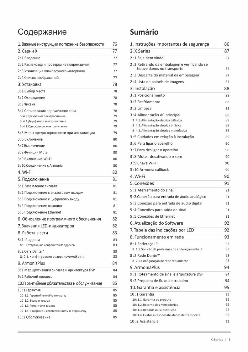
Содержание Sumário1. Важные инструкции по технике безопасности 762. Серии X 772 : 1.Введение 77
2 : 2.Распаковка и проверка на повреждения 77
2 : 3.Утилизация упаковочного материала 77
2 : 4.Список изображений 77
3. Установка 783 : 1.Выбор места 78
3 : 2.Охлаждение 78
3 : 3.Чистка 78
3 : 4.Сеть питания переменного тока 783 : 4.1. Трехфазное электропитание 793 : 4.2. Двухфазное электропитание 793 : 4.3. Однофазное электропитание 79
3 : 5.Меры предосторожности при инсталляции 79
3 : 6.Включение 80
3 : 7.Выключение 80
3 : 8.Функция Mute 80
3 : 9.Включение Wi-Fi 80
3 : 10.Соединение с Armonía 80
4. Wi-Fi 805. Подключение 815 : 1.Заземление сигнала 81
5 : 2.Подключение к аналоговым входам 81
5 : 3.Подключение к цифровому входу 81
5 : 4.Подключение выходов 81
5 : 5.Подключение Ethernet 81
6. Обновление программного обеспечения 827. Значения LED-индикаторов 828. Работа в сети 838 : 1.IP-адреса 83
8 : 1.1. Устранение конфликтов IP-адресов 83
8 : 2.Сеть Dante™ 838 : 2.1. Конфигурация резервируемой сети 83
9. ArmoníaPlus 849 : 1.Маршрутизация сигнала и архитектура DSP 84
9 : 2.Рабочий процесс 84
10. Гарантийные обязательства и обслуживание 8510 : 1.Гарантия 85
10 : 1.1. Гарантийные обязательства 8510 : 1.2. Возврат товара 8510 : 1.3. Ремонт или замена 8510 : 1.4. Издержки и ответственность за пересылку 85
10 : 2.Обслуживание 85
1. Instruções importantes de segurança 862. X Series 872 : 1.Seja bem vindo 87
2 : 2.Retirando da embalagem e verificando se houve danos no transporte 87
2 : 3.Descarte do material da embalagem 87
2 : 4.Lista de painéis de imagens 87
3. Instalação 883 : 1.Posicionamento 88
3 : 2.Resfriamento 88
3 : 3.Limpeza 88
3 : 4.Alimentação AC principal 883 : 4.1. Alimentação elétrica trifásica 893 : 4.2. Alimentação elétrica bifásica 893 : 4.3. Alimentação elétrica monofásica 89
3 : 5.Cuidados em relação à instalação 89
3 : 6.Para ligar o aparelho 90
3 : 7.Para desligar o aparelho 90
3 : 8.Mute - desativando o som 90
3 : 9.Chave Wi-Fi 903 : 10.Armonía callback 90
4. Wi-Fi 905. Conexões 915 : 1.Aterramento do sinal 91
5 : 2.Conexão para entrada de áudio analógico 91
5 : 3.Conexão para entrada de áudio digital 91
5 : 4.Conexões para saída de sinal 91
5 : 5.Conexões de Ethernet 91
6. Atualização do Software 927. Tabela das indicações por LED 928. Funcionamento em rede 938 : 1.Endereço IP 93
8 : 1.1. Solução de problemas no endereçamento IP 93
8 : 2.Rede Dante™ 938 : 2.1. Configuração de rede redundante 93
9. ArmoníaPlus 949 : 1.Roteamento de sinal e arquitetura DSP 94
9 : 2.Proposta de fluxo de trabalho 94
10. Garantia e assistência 9510 : 1.Garantia 95
10 : 1.1. Garantia do produto 9510 : 1.2. Retorno das mercadorias 9510 : 1.3. Reparos ou substituição 9510 : 1.4. Custos e responsabilidades de transporte 95
10 : 2.Assistência 95
X Series | 5
A
6 | X Series
X4L - X8

B
X Series | 7
X4

C
D
E
8 | X Series
1
13 14 15 16 17 18 19 20
2 3 4 5 6 7 8 9 10 11 12
A
A
K L I J
B
B
C
C
D
DN
E
EM
F
F
G
G
H
OUT5
POWER OUTPUTS
DO NOT CONNECT ANYOUTPUT TERMINAL TO GROUND
CH 1 CH 2 CH 3 CH 41+ 1- 2+ 2-
1+ 1-1+ 1- 2+ 2-
1+ 1-1+ 1- 2+ 2- 3+ 3- 4+ 4-
OUT 1OUT 2OUT 3OUT 4OUT 5
CH1/4
IJ HK O L
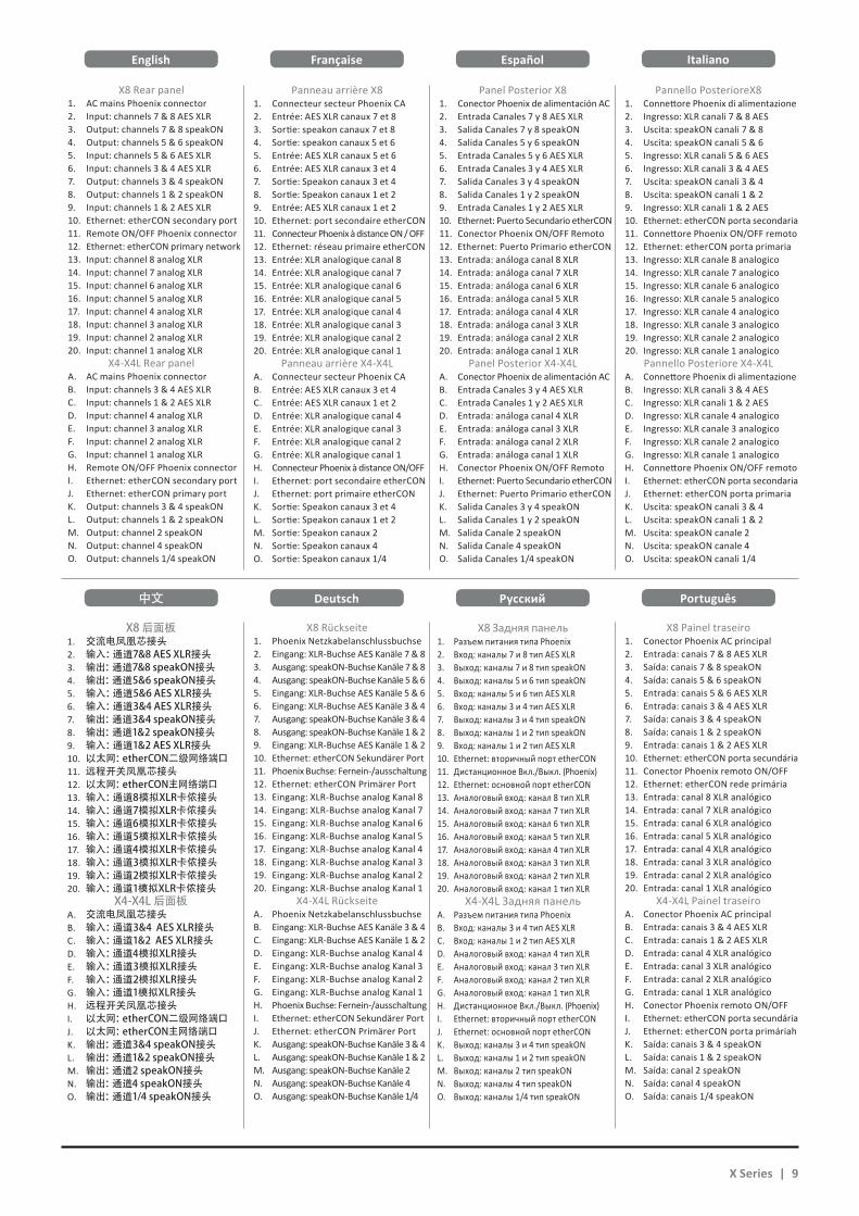
X8 Rear panel1. AC mains Phoenix connector2. Input: channels 7 & 8 AES XLR3. Output: channels 7 & 8 speakON4. Output: channels 5 & 6 speakON5. Input: channels 5 & 6 AES XLR6. Input: channels 3 & 4 AES XLR7. Output: channels 3 & 4 speakON8. Output: channels 1 & 2 speakON9. Input: channels 1 & 2 AES XLR10. Ethernet: etherCON secondary port11. Remote ON/OFF Phoenix connector12. Ethernet: etherCON primary network13. Input: channel 8 analog XLR14. Input: channel 7 analog XLR15. Input: channel 6 analog XLR16. Input: channel 5 analog XLR17. Input: channel 4 analog XLR18. Input: channel 3 analog XLR19. Input: channel 2 analog XLR20. Input: channel 1 analog XLR
X4-X4L Rear panelA. AC mains Phoenix connectorB. Input: channels 3 & 4 AES XLRC. Input: channels 1 & 2 AES XLRD. Input: channel 4 analog XLRE. Input: channel 3 analog XLRF. Input: channel 2 analog XLRG. Input: channel 1 analog XLRH. Remote ON/OFF Phoenix connectorI. Ethernet: etherCON secondary portJ. Ethernet: etherCON primary portK. Output: channels 3 & 4 speakONL. Output: channels 1 & 2 speakONM. Output: channel 2 speakONN. Output: channel 4 speakONO. Output: channels 1/4 speakON
X8后面板1. 交流电凤凰芯接头2. 输入:通道7&8AESXLR接头3. 输出:通道7&8speakON接头4. 输出:通道5&6speakON接头5. 输入:通道5&6AESXLR接头6. 输入:通道3&4AESXLR接头7. 输出:通道3&4speakON接头8. 输出:通道1&2speakON接头9. 输入:通道1&2AESXLR接头10. 以太网:etherCON二级网络端口11. 远程开关凤凰芯接头12. 以太网:etherCON主网络端口13. 输入:通道8模拟XLR卡侬接头14. 输入:通道7模拟XLR卡侬接头15. 输入:通道6模拟XLR卡侬接头16. 输入:通道5模拟XLR卡侬接头17. 输入:通道4模拟XLR卡侬接头18. 输入:通道3模拟XLR卡侬接头19. 输入:通道2模拟XLR卡侬接头20. 输入:通道1模拟XLR卡侬接头
X4-X4L后面板A. 交流电凤凰芯接头B. 输入:通道3&4AESXLR接头C. 输入:通道1&2AESXLR接头D. 输入:通道4模拟XLR接头E. 输入:通道3模拟XLR接头F. 输入:通道2模拟XLR接头G. 输入:通道1模拟XLR接头H. 远程开关凤凰芯接头I. 以太网:etherCON二级网络端口J. 以太网:etherCON主网络端口K. 输出:通道3&4speakON接头L. 输出:通道1&2speakON接头M. 输出:通道2speakON接头N. 输出:通道4speakON接头O. 输出:通道1/4speakON接头
Pannello PosterioreX81. Connettore Phoenix di alimentazione2. Ingresso: XLR canali 7 & 8 AES3. Uscita: speakON canali 7 & 84. Uscita: speakON canali 5 & 65. Ingresso: XLR canali 5 & 6 AES6. Ingresso: XLR canali 3 & 4 AES7. Uscita: speakON canali 3 & 48. Uscita: speakON canali 1 & 29. Ingresso: XLR canali 1 & 2 AES10. Ethernet: etherCON porta secondaria11. Connettore Phoenix ON/OFF remoto12. Ethernet: etherCON porta primaria13. Ingresso: XLR canale 8 analogico14. Ingresso: XLR canale 7 analogico15. Ingresso: XLR canale 6 analogico16. Ingresso: XLR canale 5 analogico17. Ingresso: XLR canale 4 analogico18. Ingresso: XLR canale 3 analogico19. Ingresso: XLR canale 2 analogico20. Ingresso: XLR canale 1 analogico
Pannello Posteriore X4-X4LA. Connettore Phoenix di alimentazioneB. Ingresso: XLR canali 3 & 4 AESC. Ingresso: XLR canali 1 & 2 AESD. Ingresso: XLR canale 4 analogicoE. Ingresso: XLR canale 3 analogicoF. Ingresso: XLR canale 2 analogicoG. Ingresso: XLR canale 1 analogicoH. Connettore Phoenix ON/OFF remotoI. Ethernet: etherCON porta secondariaJ. Ethernet: etherCON porta primariaK. Uscita: speakON canali 3 & 4L. Uscita: speakON canali 1 & 2M. Uscita: speakON canale 2N. Uscita: speakON canale 4O. Uscita: speakON canali 1/4
X8 Painel traseiro1. Conector Phoenix AC principal2. Entrada: canais 7 & 8 AES XLR3. Saída: canais 7 & 8 speakON4. Saída: canais 5 & 6 speakON5. Entrada: canais 5 & 6 AES XLR6. Entrada: canais 3 & 4 AES XLR7. Saída: canais 3 & 4 speakON8. Saída: canais 1 & 2 speakON9. Entrada: canais 1 & 2 AES XLR10. Ethernet: etherCON porta secundária11. Conector Phoenix remoto ON/OFF12. Ethernet: etherCON rede primária13. Entrada: canal 8 XLR analógico14. Entrada: canal 7 XLR analógico15. Entrada: canal 6 XLR analógico16. Entrada: canal 5 XLR analógico17. Entrada: canal 4 XLR analógico18. Entrada: canal 3 XLR analógico19. Entrada: canal 2 XLR analógico20. Entrada: canal 1 XLR analógico
X4-X4L Painel traseiroA. Conector Phoenix AC principalB. Entrada: canais 3 & 4 AES XLRC. Entrada: canais 1 & 2 AES XLRD. Entrada: canal 4 XLR analógicoE. Entrada: canal 3 XLR analógicoF. Entrada: canal 2 XLR analógicoG. Entrada: canal 1 XLR analógicoH. Conector Phoenix remoto ON/OFFI. Ethernet: etherCON porta secundáriaJ. Ethernet: etherCON porta primáriahK. Saída: canais 3 & 4 speakONL. Saída: canais 1 & 2 speakONM. Saída: canal 2 speakONN. Saída: canal 4 speakONO. Saída: canais 1/4 speakON
Panneau arrière X81. Connecteur secteur Phoenix CA2. Entrée: AES XLR canaux 7 et 83. Sortie: speakon canaux 7 et 84. Sortie: speakon canaux 5 et 65. Entrée: AES XLR canaux 5 et 66. Entrée: AES XLR canaux 3 et 47. Sortie: Speakon canaux 3 et 48. Sortie: Speakon canaux 1 et 29. Entrée: AES XLR canaux 1 et 210. Ethernet: port secondaire etherCON11. Connecteur Phoenix à distance ON / OFF12. Ethernet: réseau primaire etherCON13. Entrée: XLR analogique canal 814. Entrée: XLR analogique canal 715. Entrée: XLR analogique canal 616. Entrée: XLR analogique canal 517. Entrée: XLR analogique canal 418. Entrée: XLR analogique canal 319. Entrée: XLR analogique canal 220. Entrée: XLR analogique canal 1
Panneau arrière X4-X4LA. Connecteur secteur Phoenix CAB. Entrée: AES XLR canaux 3 et 4C. Entrée: AES XLR canaux 1 et 2D. Entrée: XLR analogique canal 4E. Entrée: XLR analogique canal 3F. Entrée: XLR analogique canal 2G. Entrée: XLR analogique canal 1H. Connecteur Phoenix à distance ON/OFFI. Ethernet: port secondaire etherCONJ. Ethernet: port primaire etherCONK. Sortie: Speakon canaux 3 et 4L. Sortie: Speakon canaux 1 et 2M. Sortie: Speakon canaux 2N. Sortie: Speakon canaux 4O. Sortie: Speakon canaux 1/4
X8 Rückseite1. Phoenix Netzkabelanschlussbuchse 2. Eingang: XLR-Buchse AES Kanäle 7 & 83. Ausgang: speakON-Buchse Kanäle 7 & 84. Ausgang: speakON-Buchse Kanäle 5 & 65. Eingang: XLR-Buchse AES Kanäle 5 & 66. Eingang: XLR-Buchse AES Kanäle 3 & 47. Ausgang: speakON-Buchse Kanäle 3 & 48. Ausgang: speakON-Buchse Kanäle 1 & 29. Eingang: XLR-Buchse AES Kanäle 1 & 210. Ethernet: etherCON Sekundärer Port11. Phoenix Buchse: Fernein-/ausschaltung12. Ethernet: etherCON Primärer Port13. Eingang: XLR-Buchse analog Kanal 814. Eingang: XLR-Buchse analog Kanal 715. Eingang: XLR-Buchse analog Kanal 616. Eingang: XLR-Buchse analog Kanal 517. Eingang: XLR-Buchse analog Kanal 418. Eingang: XLR-Buchse analog Kanal 319. Eingang: XLR-Buchse analog Kanal 220. Eingang: XLR-Buchse analog Kanal 1
X4-X4L RückseiteA. Phoenix Netzkabelanschlussbuchse B. Eingang: XLR-Buchse AES Kanäle 3 & 4 C. Eingang: XLR-Buchse AES Kanäle 1 & 2 D. Eingang: XLR-Buchse analog Kanal 4E. Eingang: XLR-Buchse analog Kanal 3F. Eingang: XLR-Buchse analog Kanal 2G. Eingang: XLR-Buchse analog Kanal 1H. Phoenix Buchse: Fernein-/ausschaltungI. Ethernet: etherCON Sekundärer PortJ. Ethernet: etherCON Primärer PortK. Ausgang: speakON-Buchse Kanäle 3 & 4L. Ausgang: speakON-Buchse Kanäle 1 & 2M. Ausgang: speakON-Buchse Kanäle 2N. Ausgang: speakON-Buchse Kanäle 4O. Ausgang: speakON-Buchse Kanäle 1/4
X8 Задняя панель1. Разъем питания типа Phoenix2. Вход: каналы 7 и 8 тип AES XLR3. Выход: каналы 7 и 8 тип speakON4. Выход: каналы 5 и 6 тип speakON5. Вход: каналы 5 и 6 тип AES XLR6. Вход: каналы 3 и 4 тип AES XLR7. Выход: каналы 3 и 4 тип speakON8. Выход: каналы 1 и 2 тип speakON9. Вход: каналы 1 и 2 тип AES XLR10. Ethernet: вторичный порт etherCON11. Дистанционное Вкл./Выкл. (Phoenix)12. Ethernet: основной порт etherCON13. Аналоговый вход: канал 8 тип XLR14. Аналоговый вход: канал 7 тип XLR15. Аналоговый вход: канал 6 тип XLR16. Аналоговый вход: канал 5 тип XLR17. Аналоговый вход: канал 4 тип XLR18. Аналоговый вход: канал 3 тип XLR19. Аналоговый вход: канал 2 тип XLR20. Аналоговый вход: канал 1 тип XLR
X4-X4L Задняя панельA. Разъем питания типа PhoenixB. Вход: каналы 3 и 4 тип AES XLRC. Вход: каналы 1 и 2 тип AES XLRD. Аналоговый вход: канал 4 тип XLRE. Аналоговый вход: канал 3 тип XLRF. Аналоговый вход: канал 2 тип XLRG. Аналоговый вход: канал 1 тип XLRH. Дистанционное Вкл./Выкл. (Phoenix)I. Ethernet: вторичный порт etherCONJ. Ethernet: основной порт etherCONK. Выход: каналы 3 и 4 тип speakONL. Выход: каналы 1 и 2 тип speakONM. Выход: каналы 2 тип speakONN. Выход: каналы 4 тип speakONO. Выход: каналы 1/4 тип speakON
Panel Posterior X81. Conector Phoenix de alimentación AC2. Entrada Canales 7 y 8 AES XLR3. Salida Canales 7 y 8 speakON4. Salida Canales 5 y 6 speakON5. Entrada Canales 5 y 6 AES XLR6. Entrada Canales 3 y 4 AES XLR7. Salida Canales 3 y 4 speakON8. Salida Canales 1 y 2 speakON9. Entrada Canales 1 y 2 AES XLR10. Ethernet: Puerto Secundario etherCON11. Conector Phoenix ON/OFF Remoto12. Ethernet: Puerto Primario etherCON13. Entrada: análoga canal 8 XLR14. Entrada: análoga canal 7 XLR15. Entrada: análoga canal 6 XLR16. Entrada: análoga canal 5 XLR17. Entrada: análoga canal 4 XLR18. Entrada: análoga canal 3 XLR19. Entrada: análoga canal 2 XLR20. Entrada: análoga canal 1 XLR
Panel Posterior X4-X4LA. Conector Phoenix de alimentación ACB. Entrada Canales 3 y 4 AES XLRC. Entrada Canales 1 y 2 AES XLRD. Entrada: análoga canal 4 XLRE. Entrada: análoga canal 3 XLRF. Entrada: análoga canal 2 XLRG. Entrada: análoga canal 1 XLRH. Conector Phoenix ON/OFF RemotoI. Ethernet: Puerto Secundario etherCONJ. Ethernet: Puerto Primario etherCONK. Salida Canales 3 y 4 speakONL. Salida Canales 1 y 2 speakONM. Salida Canale 2 speakONN. Salida Canale 4 speakONO. Salida Canales 1/4 speakON
English
中文
Italiano
Português
Française
Deutsch
Español
Pусский
X Series | 9
F
G H
1 1
1 RU
1 RU
1 RU
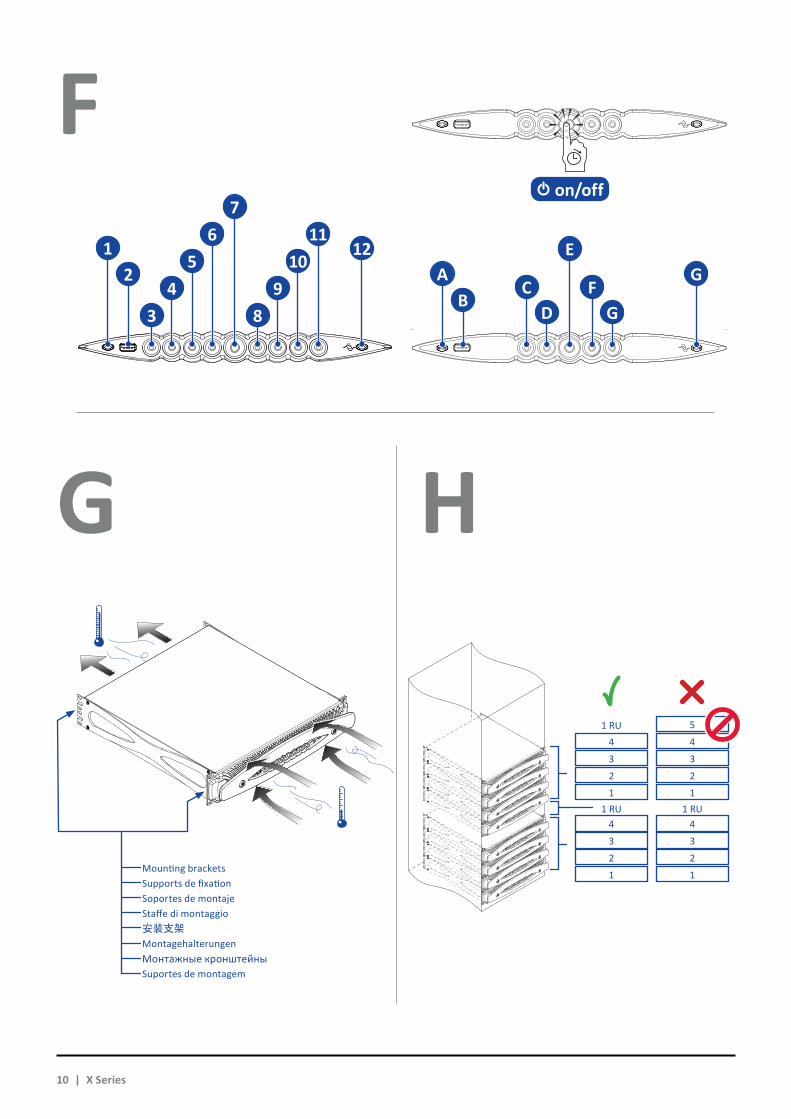
安装支架MontagehalterungenМонтажные кронштейныSuportes de montagem
Staffe di montaggio
Mounting brackets
Soportes de montajeSupports de fixation
1 1
2 2
2 2
3 3
3 3
4 4
4 4
5
10 | X Series
1A G
C
E
F2
BD G3 8
4 95 10
7
126 11
on/off
English ItalianoFrançaise Español
中文
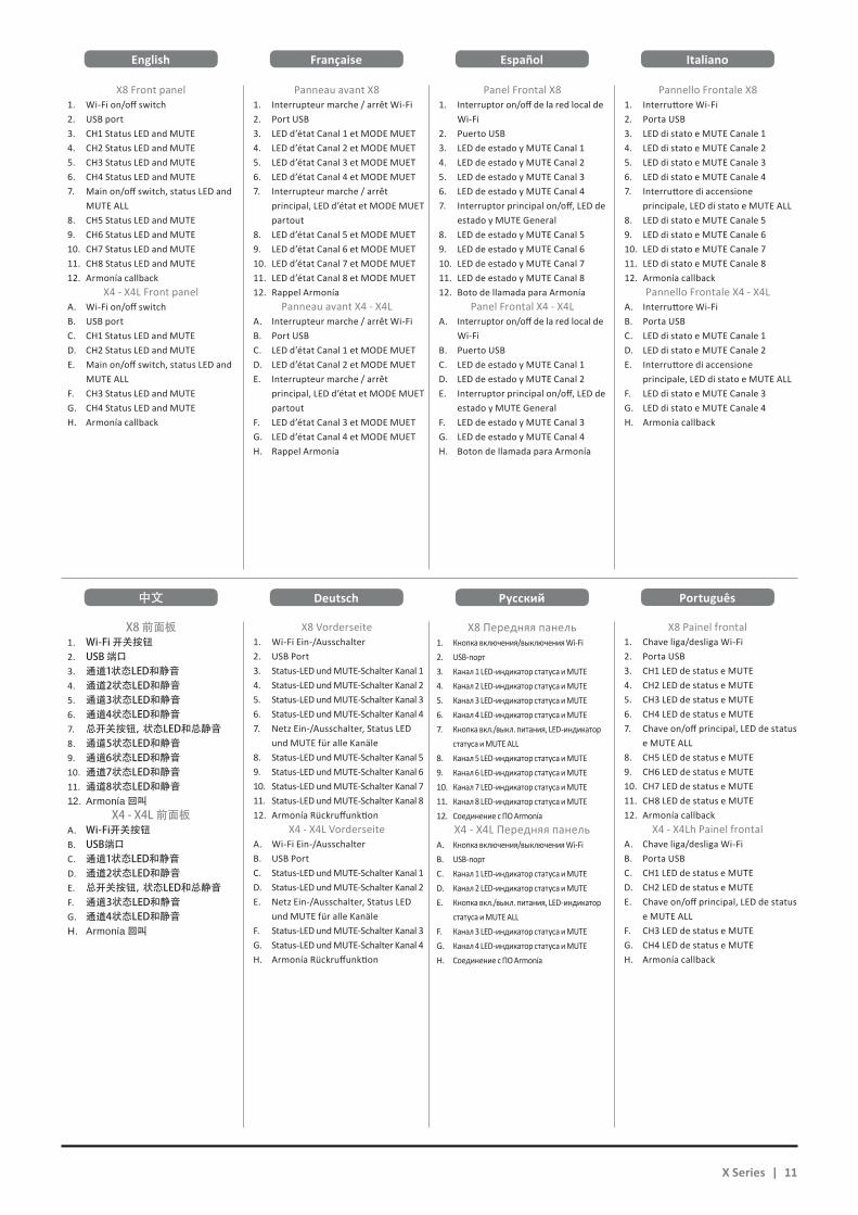
X8 Front panel1. Wi-Fi on/off switch2. USB port3. CH1 Status LED and MUTE4. CH2 Status LED and MUTE5. CH3 Status LED and MUTE6. CH4 Status LED and MUTE7. Main on/off switch, status LED and
MUTE ALL8. CH5 Status LED and MUTE9. CH6 Status LED and MUTE10. CH7 Status LED and MUTE11. CH8 Status LED and MUTE12. Armonía callback
X4 - X4L Front panelA. Wi-Fi on/off switchB. USB portC. CH1 Status LED and MUTED. CH2 Status LED and MUTEE. Main on/off switch, status LED and
MUTE ALLF. CH3 Status LED and MUTEG. CH4 Status LED and MUTEH. Armonía callback
X8前面板1. Wi-Fi开关按钮2. USB端口3. 通道1状态LED和静音4. 通道2状态LED和静音5. 通道3状态LED和静音6. 通道4状态LED和静音7. 总开关按钮,状态LED和总静音8. 通道5状态LED和静音9. 通道6状态LED和静音10. 通道7状态LED和静音11. 通道8状态LED和静音12. Armonía回叫
X4-X4L前面板A. Wi-Fi开关按钮B. USB端口C. 通道1状态LED和静音D. 通道2状态LED和静音E. 总开关按钮,状态LED和总静音F. 通道3状态LED和静音G. 通道4状态LED和静音H. Armonía回叫
Pannello Frontale X81. Interruttore Wi-Fi2. Porta USB3. LED di stato e MUTE Canale 1 4. LED di stato e MUTE Canale 2 5. LED di stato e MUTE Canale 3 6. LED di stato e MUTE Canale 4 7. Interruttore di accensione
principale, LED di stato e MUTE ALL8. LED di stato e MUTE Canale 5 9. LED di stato e MUTE Canale 6 10. LED di stato e MUTE Canale 7 11. LED di stato e MUTE Canale 8 12. Armonía callback
Pannello Frontale X4 - X4LA. Interruttore Wi-FiB. Porta USBC. LED di stato e MUTE Canale 1D. LED di stato e MUTE Canale 2E. Interruttore di accensione
principale, LED di stato e MUTE ALLF. LED di stato e MUTE Canale 3 G. LED di stato e MUTE Canale 4H. Armonía callback
Panneau avant X81. Interrupteur marche / arrêt Wi-Fi2. Port USB3. LED d’état Canal 1 et MODE MUET4. LED d’état Canal 2 et MODE MUET5. LED d’état Canal 3 et MODE MUET6. LED d’état Canal 4 et MODE MUET7. Interrupteur marche / arrêt
principal, LED d’état et MODE MUET partout
8. LED d’état Canal 5 et MODE MUET9. LED d’état Canal 6 et MODE MUET10. LED d’état Canal 7 et MODE MUET11. LED d’état Canal 8 et MODE MUET12. Rappel Armonía
Panneau avant X4 - X4LA. Interrupteur marche / arrêt Wi-FiB. Port USBC. LED d’état Canal 1 et MODE MUETD. LED d’état Canal 2 et MODE MUETE. Interrupteur marche / arrêt
principal, LED d’état et MODE MUET partout
F. LED d’état Canal 3 et MODE MUETG. LED d’état Canal 4 et MODE MUETH. Rappel Armonía
X8 Vorderseite1. Wi-Fi Ein-/Ausschalter2. USB Port3. Status-LED und MUTE-Schalter Kanal 14. Status-LED und MUTE-Schalter Kanal 25. Status-LED und MUTE-Schalter Kanal 36. Status-LED und MUTE-Schalter Kanal 47. Netz Ein-/Ausschalter, Status LED
und MUTE für alle Kanäle8. Status-LED und MUTE-Schalter Kanal 59. Status-LED und MUTE-Schalter Kanal 610. Status-LED und MUTE-Schalter Kanal 711. Status-LED und MUTE-Schalter Kanal 812. Armonía Rückruffunktion
X4 - X4L VorderseiteA. Wi-Fi Ein-/AusschalterB. USB PortC. Status-LED und MUTE-Schalter Kanal 1D. Status-LED und MUTE-Schalter Kanal 2E. Netz Ein-/Ausschalter, Status LED
und MUTE für alle KanäleF. Status-LED und MUTE-Schalter Kanal 3G. Status-LED und MUTE-Schalter Kanal 4H. Armonía Rückruffunktion
X8 Передняя панель1. Кнопка включения/выключения Wi-Fi 2. USB-порт3. Канал 1 LED-индикатор статуса и MUTE4. Канал 2 LED-индикатор статуса и MUTE5. Канал 3 LED-индикатор статуса и MUTE6. Канал 4 LED-индикатор статуса и MUTE7. Кнопка вкл./выкл. питания, LED-индикатор
статуса и MUTE ALL8. Канал 5 LED-индикатор статуса и MUTE9. Канал 6 LED-индикатор статуса и MUTE10. Канал 7 LED-индикатор статуса и MUTE11. Канал 8 LED-индикатор статуса и MUTE12. Соединение с ПО Armonía
X4 - X4L Передняя панельA. Кнопка включения/выключения Wi-FiB. USB-портC. Канал 1 LED-индикатор статуса и MUTED. Канал 2 LED-индикатор статуса и MUTEE. Кнопка вкл./выкл. питания, LED-индикатор
статуса и MUTE ALLF. Канал 3 LED-индикатор статуса и MUTEG. Канал 4 LED-индикатор статуса и MUTEH. Соединение с ПО Armonía
Panel Frontal X81. Interruptor on/off de la red local de
Wi-Fi2. Puerto USB3. LED de estado y MUTE Canal 14. LED de estado y MUTE Canal 25. LED de estado y MUTE Canal 36. LED de estado y MUTE Canal 47. Interruptor principal on/off, LED de
estado y MUTE General8. LED de estado y MUTE Canal 59. LED de estado y MUTE Canal 610. LED de estado y MUTE Canal 711. LED de estado y MUTE Canal 812. Boto de llamada para Armonía
Panel Frontal X4 - X4LA. Interruptor on/off de la red local de
Wi-FiB. Puerto USBC. LED de estado y MUTE Canal 1D. LED de estado y MUTE Canal 2E. Interruptor principal on/off, LED de
estado y MUTE GeneralF. LED de estado y MUTE Canal 3G. LED de estado y MUTE Canal 4H. Boton de llamada para Armonía
PortuguêsDeutsch Pусский
X8 Painel frontal1. Chave liga/desliga Wi-Fi2. Porta USB3. CH1 LED de status e MUTE4. CH2 LED de status e MUTE5. CH3 LED de status e MUTE6. CH4 LED de status e MUTE7. Chave on/off principal, LED de status
e MUTE ALL8. CH5 LED de status e MUTE9. CH6 LED de status e MUTE10. CH7 LED de status e MUTE11. CH8 LED de status e MUTE12. Armonía callback
X4 - X4Lh Painel frontalA. Chave liga/desliga Wi-FiB. Porta USBC. CH1 LED de status e MUTED. CH2 LED de status e MUTEE. Chave on/off principal, LED de status
e MUTE ALLF. CH3 LED de status e MUTEG. CH4 LED de status e MUTEH. Armonía callback
X Series | 11
X8, X4 X4L
NL4speakONconnector
CHA
CHB CHBCHA
CHCCHD
OUT 1 / OUT 3Two single-ended loads
NL4speakONconnector
CHA
OUT 2 / OUT 4Single-ended load
outputstage A
outputstage B
CHA +
CHB +
CHB –
CHA –A
B
CHC +
CHD +
CHD –
CHC –C
D
outputstage C
outputstage D
OUT 5Four single-ended loads
NL8speakONconnector
1+
2+1–
2–
1+
2+1–
2–
1+
2+
1–
2–
1+
2+
1–
2–
4+3-
2+1-
3+
2-
1+
4-
NL4speakONconnector
CHA
CHB CHBCHA
CHCCHD
OUT 1 / OUT 3Two single-ended loads
NL4speakONconnector
CHA
OUT 2 / OUT 4Single-ended load
outputstage A
outputstage B
CHA +
CHB +
CHB –
CHA –A
B
CHC +
CHD +
CHD –
CHC –C
D
outputstage C
outputstage D
OUT 5Four single-ended loads
NL8speakONconnector
1+
2+1–
2–
1+
2+1–
2–
1+
2+
1–
2–
1+
2+
1–
2–
4+3-
2+1-
3+
2-
1+
4-
I J
K
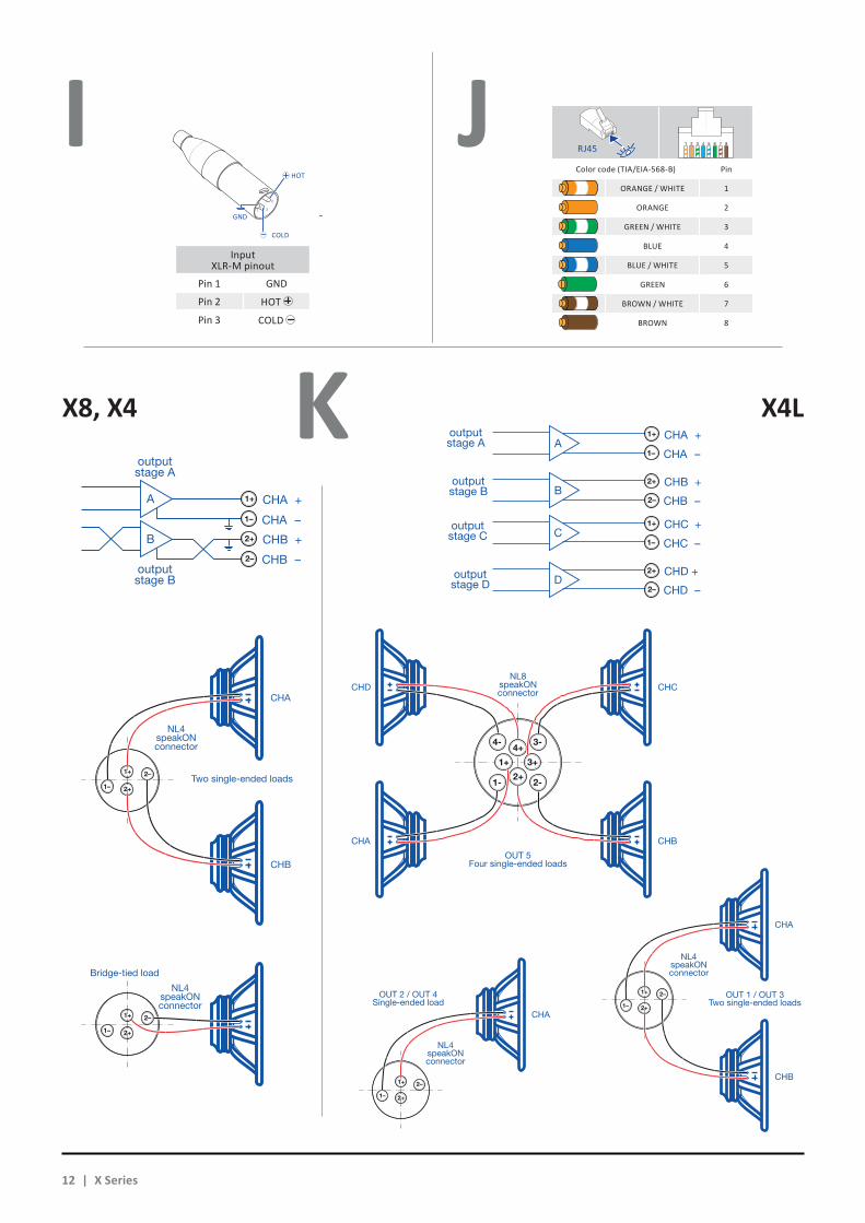
Input XLR-M pinout
Pin 1 GND
Pin 2 HOT
Pin 3 COLD
HOT
1
2
3
COLD
GND
1 2 3 4 5 6 7 8
Color code (TIA/EIA-568-B) Pin
ORANGE / WHITE 1
ORANGE 2
GREEN / WHITE 3
BLUE 4
BLUE / WHITE 5
GREEN 6
BROWN / WHITE 7
BROWN 8
RJ45
NL4speakONconnector
outputstage A
outputstage B
CHA +
CHA
CHB +
CHB
Bridge-tied load
Two single-ended loads
CHB –
CHA –
A
B
NL4speakONconnector
1+
2+
1–
2–
1+
2+1–
2–
1+
2+1–
2–
NL4speakONconnector
outputstage A
outputstage B
CHA +
CHA
CHB +
CHB
Bridge-tied load
Two single-ended loads
CHB –
CHA –
A
B
NL4speakONconnector
1+
2+
1–
2–
1+
2+1–
2–
1+
2+1–
2–
NL4speakONconnector
outputstage A
outputstage B
CHA +
CHA
CHB +
CHB
Bridge-tied load
Two single-ended loads
CHB –
CHA –
A
B
NL4speakONconnector
1+
2+
1–
2–
1+
2+1–
2–
1+
2+1–
2–
12 | X Series
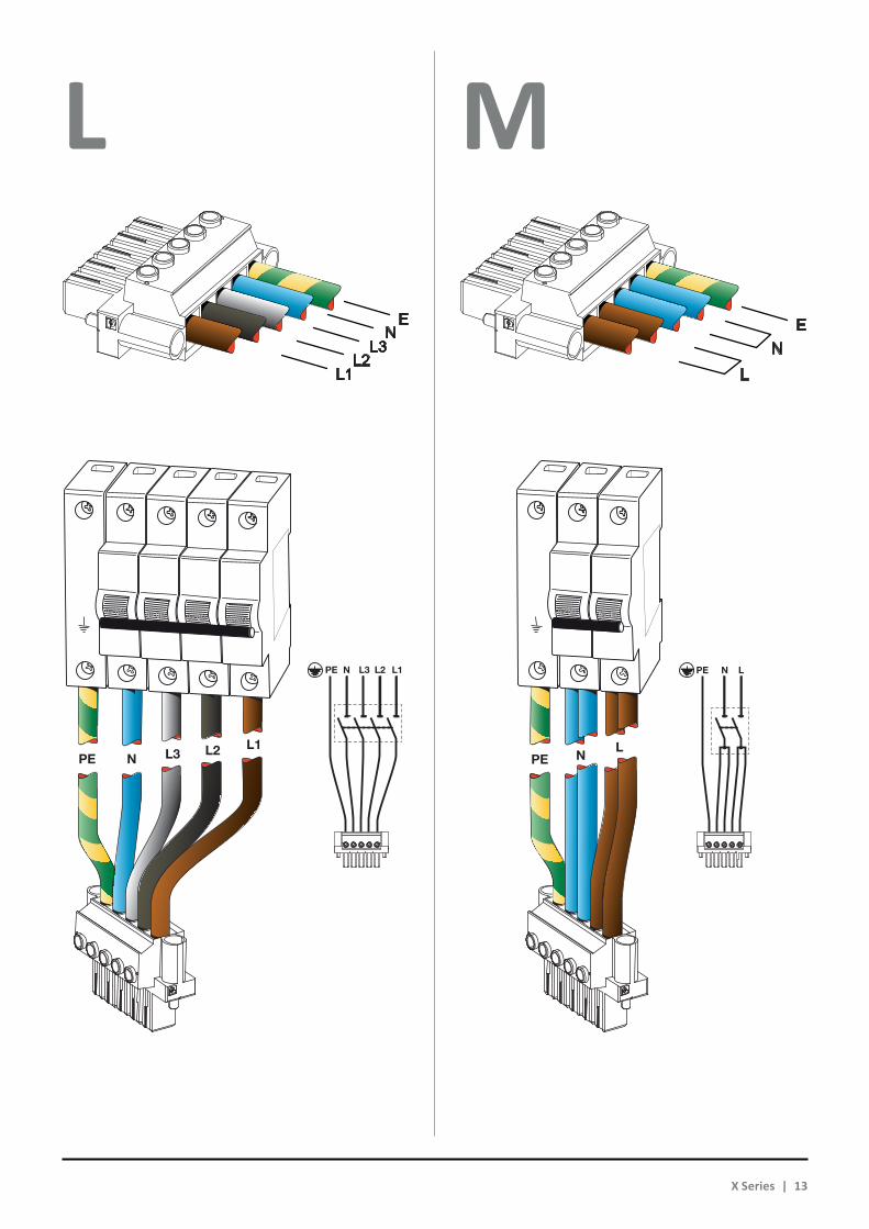
L M
LNPE
LNPE
L1L2L3
L3 L2 L1
N
N
PE
PE
X Series | 13

N O
Once properly wired, insert and lock the flying connector into the
shell provided by Powersoft.
Una vez cableado apropiadamente, inserte y asegure el conector volante dentro de las cubiertas proveídas por Powersoft.
Une fois correctement câblé, insérer et verrouiller le connecteur volant dans l’enveloppe fournie par Powersoft.
Dopo essere stato correttamente cablato, inserire e serrare il connettore volante
nel guscio fornito da Powersoft.
Nach korrekter Verdrahtung montieren Sie bitte den Kabelstecker in die beiden mitgelieferten Powersoft
Steckergehäuseschalen und verschliessen diese.
Uma vez corretamente instaladas, inserir e travar o conector voando para o
shell fornecido pela Powersoft.
Правильно соединив провода, вставьте штекер в защитный корпус и защелкните его.
警告一旦正确完成接线,请将飞行接头插入Powersoft提供的外壳中并固紧。空开断路器必须放在随时可取用的地方
L1L2PE
L1L2PE
14 | X Series

P Regulatory information
FCC COMPLIANCE NOTICEThis device complies with part 15 of the FCC rules. Operation is sub-ject to the following two conditions: (1) This device may not cause harmful interference, and (2) this device must accept any interfer-ence received, including interference that may cause undesired operation.CAUTION: Changes or modifications not expressly approved by the party responsible for compliance could void the user’s au-thority to operate the equipment.NOTE: This equipment has been tested and found to comply with the limits for a Class A digital device, pursuant to part 15 of the FCC Rules. These limits are designed to provide reasonable protec-tion against harmful interference in a residential installation. This equipment generates, uses, and can radiate radio frequency ener-gy and, if not installed and used in accordance with the instruction manual, may cause harmful interference to radio communications. However, there is no guarantee that interference will not occur in a particular installation. If this equipment does cause harmful inter-ference to radio or television reception, which can be determined by turning the equipment off and on, the user is encouraged to try to correct the interference by one or more of the following meas-ures:XX Reorient or relocate the receiving antenna.XX Increase the separation between the equipment and receiver.XX Connect the equipment into an outlet on a circuit different
from that to which the receiver is connected.XX Consult the dealer or an experienced radio/TV technician for help.
WEEE DIRECTIVE If the time arises to throw away your product, please recycle all the components possible.
This symbol indicates that when the end-user wishes to discard this product, it must be sent to separate col-lection facilities for recovery and recycling. By sepa-rating this product from other household-type waste, the volume of waste sent to incinerators or land-fills will be reduced and natural resources will thus be con-served.
The Waste Electrical and Electronic Equipment Directive (WEEE Directive) aims to minimise the impact of electrical and electronic goods on the environment. Powersoft S.p.A. comply with the Directive 2002/96/EC and 2003/108/EC of the European Parliament on waste electrical finance the cost of treatment and recovery of electronic equipment (WEEE) in order to reduce the amount of WEEE that is being disposed of in land-fill site.All of our products are marked with the WEEE symbol; this indicates that this product must NOT be disposed of with other waste. Instead it is the user’s responsibility to dispose of their waste electrical and electronic equipment by handing it over to an approved reprocessor, or by returning it to Powesoft S.p.A. for reprocessing. For more infor-mation about where you can send your waste equipment for recy-cling, please contact Powesoft S.p.a. or one of your local distributors.
EC DECLARATION OF CONFORMITYManufacturer:Powersoft S.p.A.via E. Conti 550018 Scandicci (Fi)Italy
We declare that under our sole responsibility the products:Model Names: X8, X4, X4LIntended use: Professional Audio Amplifier
Are in conformity with the provisions of the following EC Directives, including all amendments, and with national legisla-tion implementing these directives:XX 2006/95/EC Low Voltage DirectiveXX 2004/108/EC Electromagnetic Compatibility DirectiveXX 2002/95/CE RoHs Directive
The following armonized standards are applied:EN 55103-1EN 61000-3-2EN 61000-3-3EN 55103-2EN 61000-4-2EN 61000-4-3EN 61000-4-4EN 61000-4-5EN 61000-4-6EN 61000-4-11EN 60065
Scandicci,July 2014
Luca Lastrucci Managing Director
For compliance questions only: [email protected]
X Series | 15
English
CAUTION
RISK OF ELECTRICK SHOCKDO NOT OPEN
Electrical energy can perform many useful functions. This unit has been engineered and manufactured to ensure your personal safety. But IMPROPER USE CAN RESULT IN POTENTIAL ELECTRICAL SHOCK OR FIRE HAZARD.In order not to defeat the safeguards incorporated into this prod-uct, observe the following basic rules for its installation, use and service. Please read these “Important Safeguards” carefully be-fore use.
Important safety instructions1. Read these instructions.2. Keep these instructions.3. Heed all warnings.4. Follow all instructions.5. Do not use this equipment near water.6. Clean only with a dry cloth.7. Do not block any ventilation openings. Install in accordance
with the manufacturer’s instructions.8. Do not install near any heat sources such as radiators, heat
registers, stoves, or other apparatus (including amplifiers) that produce heat.
9. Protect the power cord from being walked on or pinched particularly at plugs, convenience receptacles, and the point where they exit from the apparatus.
10. Only use attachments/accessories specified by the manu-facturer.
11. Use only with the cart, stand, tripod, bracket, or table speci-fied by the manufacturer, or sold with the ap-paratus. When a cart is used, use caution when moving the cart/apparatus combination to avoid injury from tip-over.
12. Unplug this apparatus during lightning storms or when un-used for long periods of time.
13. Refer all servicing to qualified service personnel. Servicing is required when the apparatus has been damaged in any way, such as power-supply cord or plug is damaged, liquid has been spilled or objects have fallen into the apparatus, the apparatus has been exposed to rain or moisture, does not operate normally, or has been dropped.
WARNING: TO REDUCE THE RISK OF ELECTRIC SHOCK, DO NOT ATTEMPT TO OPEN ANY PART OF THE UNIT. NO USER-SERVICEABLE PARTS INSIDE. REFER SERVICING TO QUALIFIED SERVICE PERSONNEL.
DO NOT EXPOSE THIS EQUIPMENT TO RAIN OR MOISTURE, DRIPPING OR SPLASHING LIQUIDS. OBJECTS FILLED WITH LIQUIDS, SUCH AS VASES, SHOULD NOT BE PLACED ON THIS APPARATUS.
THE UNIT MUST BE INSTALLED IN RACK CABINETS ONLY: PLUG THE AMPLIFIER’S MAINS CONNECTIONS VIA A SECTIONING BREAKER TO A POWER DISTRIBUTION PANEL INSIDE THE RACK CABINET.
THE SECTIONING BREAKER MUST REMAIN READILY ACCESSIBLE.
WHEN THE UNIT IS INSTALLED IN A RACK CABINET, MAKE SURE THAT IT HAS SUFFICIENT SPACE ON ALL SIDES TO ALLOW FOR PROPER VENTILATION (50 CM FROM THE FRONT AND REAR VENTILATION OPENINGS).
CONNECTION TO THE MAINS SHALL BE DONE ONLY BY A ELECTROTECHNICAL SKILLED PERSON ACCORDING THE NATIONAL REQUIREMENTS OF THE COUNTRIES WHERE THE UNIT IS SOLD.
WARNING: FUSE ON NEUTRAL
CLASS3WIRING
CLASS3WIRING
CLASS3WIRING
CLASS3WIRING
CLASS3WIRING
CLASS3WIRING
CLASS3WIRING
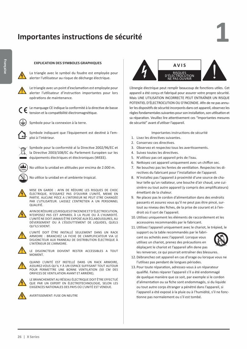
EXPLANATIONS OF GRAPHICAL SYMBOLS
CLASS3WIRING
The triangle with the lightning bolt is used to alert the user to the risk of electric shock.
CLASS3WIRING
The triangle with the exclamation point is used to alert the user to important operating or maintenance instruc-tions.The CE-mark indicates the compliance with the low volt-age and electromagnetic compatibility.
Symbol for earth/ground connection.
Symbol indicating that the equipment is for indoor use only.
Symbol for conformity with Directive 2002/96/EC and Directive 2003/108/EC of the European Parliament on waste electrical and electronic equipment (WEEE).
Do not use the unit at altitudes above 2000 m.
Do not use the unit in tropical environment.
Important safety instructions 1
16 | X Series
Engl
ish
X Series Quick Guide 2
2 : 1.Welcome
Congratulations on buying a Powersoft X Series amplifier!We know you are eager to use the X Series amplifier platform,
but please take a moment to read this quick guide and the safety instructions. In case you have any questions, please do not hesi-tate to contact your dealer or Powersoft.
Powersoft X Series innovates the concept of amplifier plat-form: it implements a new system of channel routing, new power supply and a revolutionary full featured DSP. Powersoft X Series natively supports AES3, two redundant Dante™ by Audinate® digital streams (optional) and analog inputs, providing up to 4 different selectable input sources per channel.
For system configuration and fine tuning, ArmoníaPlus™ offers an intuitive interface, a comprehensive control over the digital audio processing and complete real-time monitoring of the system performance. The integrated Wi-Fi connection allows the Powersoft X Series to be accessed and managed via any mobile device through a user interface specifically developed for local monitoring.
Powersoft X Series raises power amplification to a new stand-ard of quality and usability: they suit any configuration, save space and weight and offer you the legendary Powersoft efficiency with new worldwide compatible multi-phase power supplies.
2 : 2.Unpacking & checking for shipping damage
Your Powersoft product has been completely tested and inspected before leaving the factory. Carefully inspect the ship-ping package before opening it, and then immediately inspect your new product. If you find any damage, notify the shipping company or reseller immediately.
The box contains the following:XX 1x X Series amplifier.XX 1x AC mains PC 5/5-STF1-7,62 Phoenix plugXX 1x shell for the AC mains plugXX 1x quick guide
2 : 4.List of image panels
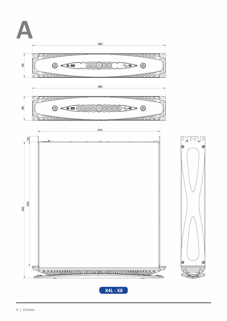
A. X8/X4L mechanical drawings: all dimensions in millimetersB. X4 mechanical drawings: all dimensions in millimetersC. X8 rear panelD. X4L rear panelE. X4 rear panelF. X8 and X4L/X4 front panelsG. Mounting brackets and air flow directionH. Rule for stacking amplifiers in closed racksI. Input connector pinoutJ. RJ45 Ethernet pinoutK. Loudspeakers wiringsL. Three-phase electric power: AC mains plug wiringM. Single-phase electric power: AC mains plug wiringN. Two-phase electric power: AC mains plug wiringO. AC mains plug shieldP. Regulatory information
2 : 3.Disposal of the packaging material
The protective transport packaging has been selected from materials which are environmentally friendly for disposal and can normally be recycled.
Rather than just throwing these materials away, please ensure they are offered for recycling.
English | 17
English
Installation 3 3 : 1.Location
The intended use of X Series amplifiers is in a rack only. The AC mains wirings of the units must be connected to a terminal box provided with a properly breaker (refer to §3 : 4.Alimentazione elettrica for more details). It is not allowed to connect the X Series AC mains connection directly to the power distribution system. For North America market we recommend to use an approved UL/CSA cable (i.e. ST 600Vac 105°C 5x13AWG).
In order to limit the risk of mechanical damages, the ampli-fiers must be fixed to the rack using both frontal and rear mount-ing brackets. We recommends to use eight M6 or 12-24 UNC-2B screws for threaded holes or cage nuts.
Install this amplifier as far as possible from radio tuners and TV sets. An amplifier installed in close proximity of such equipment may experience noise or generic performance degradation. Placing and using the amplifier for long periods of time on heat generating sources will affect its performance. Avoid placing the amplifier on heat generating sources.
This device must be powered exclusively by earth connected mains sockets in electrical
networks compliant to the IEC 364 or similar rules.
Since the main power switch on this unit does not provide a complete insulation of the equipment from the main power, you must disconnect the main power source to turn off all power.
Provide a sectioning breaker between the mains connections and the amplifier.
3 : 2.Cooling
Install the amplifier in a well-ventilated location: the ventila-tion openings must not be impeded by any item such as newspa-pers, tablecloths, curtains, etc; keep a distance of at least 50 cm from the front and rear ventilation openings of the amplifier.
All Powersoft amplifiers implement a forced-air cooling system to maintain low and constant operating temperatures. Drawn by the internal fans, air enters from the front panel and is forced over all components, exiting at the back of the amplifier.
The amplifier’s cooling system features “intelligent” variable-speed DC fans which are controlled by the heatsink temperature sensing circuits: the fans speed will increase only when the temperature detected by the sensors rises over carefully pre-determined values. This ensures that fan noise and internal dust accumulation are kept to a strict minimum.
Should however the amplifier be subject to an extreme ther-mal load, the fan will force a very large volume of air through the heat sink. In the extremely rare event that the amplifier should dangerously overheat, sensing circuits shut down all channels until the amplifier cools down to a safe operating temperature. Normal operation is resumed automatically without the need for user intervention.
X Series amplifiers can be stacked one on top of the other due to the efficient cooling system they are equipped with.
There is however a safety limit to be observed: in case a rack with closed back panels is used, leave one rack unit empty every four installed amplifiers to guarantee adequate air flow (see Panel G, p. 10).
3 : 3.Cleaning
Always use a dry cloth for cleaning the chassis and the front panel. Air filter cleaning should be scheduled according to the dust levels in the amplifier’s operating environment.
Disconnect the AC mains source before attempting to clean any part of the amplifier
In order to clean the vent filters you need to remove the front cover: never attempt to open any other part of the unit.
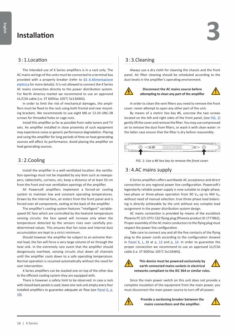
By means of a metric hex key #6, unscrew the two screws located on the left and right sides of the front panel, (see FIG. 1) gently lift the cover and remove the filter. You may use compressed air to remove the dust from filters, or wash it with clean water: in the latter case ensure that the filter is dry before reassembly.
3 : 4.AC mains supply
X Series amplifiers offers worldwide AC acceptance and direct connection to any regional power line configuration. Powersoft’s legendarily reliable power supply is now suitable to single-phase, two-phase or three-phase operation from 90 VAC up to 464 VAC without need of manual selection: true three-phase load balanc-ing is directly achievable by the unit without any complex load assignment in the power distribution system design.
AC mains connection is provided by means of the euroblock Phoenix PC 5/5-STF1-7,62 flying plug (Phoenix product ID 1777862). Proper assembly of the AC mains conductors to the flying plug must respect the power line configuration.
Take care to connect any and all the five contacts of the flying plug to the power cords according to the configuration showed in Panel K, L, M at p. 13 and p. 14. In order to guarantee the proper connection we recommend to use an approved UL/CSA cable (i.e. ST 600Vac 105°C 5x13AWG).
FIG. 1: Use a #6 hex key to remove the front cover.
18 | X Series

Engl
ish3 The proper device to use depends on mains configuration; for
X8 Powersoft suggests:single-phase AC (P+N+E): 32 A rating, C or D curve, 10 kA;three-phase AC (3P+N+E): 4 x 16 A rating, C or D curve, 10 kA.
For X4 Powersoft suggests:single-phase AC (P+N+E): 16 A rating, C or D curve, 10 kA;three-phase AC (3P+N+E): 4 x 10 A rating, C or D curve, 10 kA.
NOTE: The pictures and instructions about AC wiring refer to the European CENELEC standards April 2004 (IEC 60446) color code for conductor identification (see TAB. 1).
Conductor Color
Neutral or mid-point conductor N blue
AC phase conductors
L1 brown
L2 black
L3 grey
Protective conductor (earth) E green/ yellow
TAB. 1: Color code for conductor identification.
AC mains connections must be performed only by professional or qualified personnel
according to local electrical authoritie guidelines.
3 : 4.1. Three-phase electric powerEach single conductor must be secured to the
PC 5/5-STF1-7,62 flying plug as shown in Panel K, p. 13. In some instances neutral connection may lack: on three-phase systems neutral connection is not even necessary given the capability of the X Series to work in delta connection.
3 : 4.2. Two-phase electric powerBalanced two-phase AC mains in the configura-
tions 2P+E without neutral must be secured to the PC 5/5-STF1-7,62 flying plug as shown in Panel M, p. 14. Take care to double the phase wires at the connecting terminals of the sectioning breaker in order to guarantee the proper conduction gauge.
3 : 4.3. Single-phase electric powerP+N+E, unbalanced single-phase with neutral is the usual
configuration for signle-phase AC mains; wiring must be config-ured as shown in Panel L, p. 13. Take care to double the phase and neutral wires at the connecting terminals of the sectioning breaker in order to guarantee the proper conduction gauge.
3 : 5.Precautions regarding installation
WARNING: TO PREVENT FIRE OR ELECTRIC SHOCK
Xf This device must be powered exclusively by earth connect-ed mains sockets in electrical networks compliant to the IEC 364 or similar rules.
Xf Install the unit into rack cabinet only.
Xf A sectioning breaker between the mains connections and the amplifier must be installed inside the rack cabinet.
Xf Take care to properly lock each power cord wire to the flying connector Phoenix PC 5/5-STF1-7,62.
Xf Once properly wired, insert and lock the flying connector into the shell provided by Powersoft.
Xf Lock the flying connector to the amplifier inlet.
Xf Before powering this amplifier, verify that the correct volt-age rating is being used.
Xf Verify that your mains connection is capable of satisfying the power ratings of the device.
Xf Do not use this amplifier if the electrical power cord is frayed or broken.
Xf Output terminals are hazardous: wiring connection to these terminals require installation by an instructed person and the use of ready-made leads.
Xf Take care to lock the output terminal before switching the device on.
Xf To avoid electrical shock, do not touch any exposed speaker wiring while the amplifier is operating.
Xf Do not spill water or other liquids into or on the amplifier.
Xf No naked flame sources such as lighted candles should be placed on the amplifier.
Xf Do not remove the cover. Failing to do so will expose you to potentially dangerous voltage.
Xf The manufacturer cannot be held responsible for damages caused to persons, things or data due to an improper or missing ground connection.
Xf Contact the authorized service center for ordinary and ex-traordinary maintenance.
It is absolutely necessary to verify these fundamental requirement of safety and, in case of doubt, require
an accurate check by qualified personnel.
English | 19

English
3 : 6.Switch on
As soon as you connect the amplifier to the power grid, the amplifier’s power supply will start supplying power to the aux-iliary systems. The border of the central button starts blinking white: the amplifier is in standby mode.
A pressure on the central button will wake up the amplifier.The factory default frequency setting on an X Series amplifier
is 5GHz, but it’s possible to change it to 2.4 GHz via ArmoníaPlus. Follow this procedure to activate the Wi-Fi connection and
remotely access your Powersoft X Series amplifier platform.
1. Switch on the amplifier by holding down the central button on the front panel;
2. Press the leftmost button in the front panel: the button will light up and the system will establish a new local Wi-Fi net-work whose SSID is in the form:
Powersoft-MODELNAME-SERIAL (e.g. Powersoft-X8-71520)
3. Access your mobile device and edit the Wi-Fi configuration;
4. Hang the Wi-Fi network with the right SSID;
5. Insert the following default Wi-Fi encryption password:
0123456789
3 : 7.Switch off
Keep pressed the central button for 3 seconds to switch the amplifier off. The amplifier platform passes to the standby mode and the border of the central button blinks white.
The amplifier platform turns completely off only when the mains connector is unplugged.
3 : 8.Mute
A short pressure on the central button toggles MUTE/ UNMUTE to all active channels: any previously muted channel will remain in mute status.
All other circular buttons (except the central one) toggle the MUTE/UNMUTE to the specified output channel.
NOTE: Please note that when the amplifier platform is linked and controlled by ArmoníaPlus™ all MUTE switches are locally disa-bled.
3 : 9.Wi-Fi switch
Press the leftmost button: the button will light up and the system will establish a new local Wi-Fi network whose SSID is in the form: Powersoft-MODELNAME-SERIAL (e.g. Powersoft-X8-70133) and default password: 0123456789.
Press again the leftmost button to switch the Wi-Fi off.
3 : 10.Armonía callback
In order to identify the unit into the Armonía Workspace, push on the rightmost button. On the other hand, if you click on Un/Blink from the contextual menu of the amplifier into the Armonía Workspace, all the front LEDs of the amplifier will blink for a while.
6. Open the web browser and type the following IP address in the address bar:
192.168.0.1
7. The system will push the user interface to the browser: now you can start managing your X Series amplifier platform.
8. For simple recall and operation with the interface, we sug-gest to bookmark the page on the home screen of your mobile device; for example, in iOS device click on the share icon and select “Add to Home Screen” when the interface has been completely loaded.
9. Remember to switch the local Wi-Fi network off when monitoring and basic setup are no more necessary: press the leftmost button in the front panel in order to switch off the Wi-Fi.
Wi-Fi 4
MUTE/UNMUTE CH2
MUTE/UNMUTE ALL
20 | X Series

Engl
ish
Connections 5 Make sure the power switch is off before attempting to make
any input or output connections.By using good quality input and speaker cables, the likelihood
of erratic signal behavior is reduced to a minimum. Whether you make them or buy them, look for good quality wires, connectors and soldering techniques.
5 : 1.Signal grounding
There is no ground switch or terminal on the X Series ampli-fiers. All shield terminals of input connections are directly con-nected to the chassis. This means that the unit’s signal grounding system is automatic. In order to limit hum and/or interference entering the signal path, use balanced input connections.
In the interests of safety, the unit MUST always operate with electrical safety earth connected to the chassis via the dedicated Protective Earth wire.
5 : 2.Analog audio input connections
Analog input is provided by means of Neutrik XLR female connectors, one per channel input. Signal polarity of analog input connections is shown in Panel H, p. 12.
5 : 3.Digital audio input connections
Digital input is supported via AES3 (AES/EBU) and Dante™ standard protocols in Dante equipped devices.
AES3 connectors are Neutrik XLR female, one per channel pair. The AES3 connection carries a channel pair through a 110 Ω nominal impedance wire in the form of a balanced (differential) digital signal: in AES3 XLR connectors the identification of hot and cold pins is not an issue; take care to never tie pin 2 or pin 3 (balanced signals) to pin 1 (ground). Avoid the use of microphone cables in AES connections: impedance mismatch can result in signal reflections and jitter, causing bit errors at the receiver.
In Dante equipped devices, Dante connectivity is supported via two Neutrik etherCON ports located on the rightmost side of the X8 and X4 rear panels. Fast Ethernet (IEEE 802.3u, 100 Mbit/s) and Gigabit Ethernet (IEEE 802.3ab, 1 Gbit/s) network protocols are supported; Cat5e or Cat6 standard UTP twisted pair cables shall be used for connections up to 100 meters (328 ft).
Ethernet cabling must comply to TIA/EIA-568-B and adopt the T568B scheme pinout, as shown in Panel I, p. 12.
5 : 4.Output connections
CLASS3WIRING
CLASS 3 WIRINGOutput terminals are hazardous: wiring connection to these terminals require installation by an instructed
person and the use of ready made leads. Take care to secure the output terminals before switching the device on.
Single-ended and bridge-tied loudspeakers connection are supported as shown in Panel J, p. 12.
5 : 5.Ethernet connections
X Series amplifier platforms can be remotely controlled via an Ethernet connection through a personal computer and Powersoft ArmoníaPlus software.
Powersoft recommends the use of Ethernet Cat5 straight through – patch – cables with pin/pair assignments TIA/EIA-568-B, i.e. T568B, as shown in Panel I, p. 12.
4
1 2 3 4 5 6 7 8
25 26 27 28 29 30 31 32
9 10 11 12 13 14 15 16
33 34 35 36 37 38 39 40
17 18 19 20 21 22 23 24
41 42 43 44 45 46 47 48 UP Link
Power
L1 L2 L3 N PE
AES3 IN7-8 5-6 AES3 IN3-4 1-2
ANALOG INANALOG IN
8 7 6 5 4 3 2 1
3PH 1PH
L1
L2
L3
N
L
N
1=GND2 = IN+3 = IN-
MAINS
TURN TO LOCK TURN TO LOCKTURN TO LOCK TURN TO LOCK
FIG. 2: Example of X8 connections.
English | 21
AC mains
AES3 Analog Gigabit Switch
Dante™
Dante ControllerArmoníaPlus
English
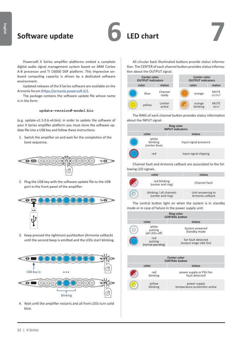
Software update LED chart6 7 All circular back illuminated buttons provide status informa-
tion. The CENTER of each channel button provides status informa-tion about the OUTPUT signal.
Center colorOUTPUT indicators
Center colorOUTPUT indicators
color status color status
blue Channel ready orange MUTE
OUTPUT
yellow Limiter active
orangeblinking
MUTE INPUT
The RING of each channel button provides status information about the INPUT signal.
Ring colorINPUT indicators
color statuswhite
blinking (center blue)
Input signal presence
red Input signal clipping
Channel fault and Armonía callback are associated to the fol-lowing LED signals.
color status
red blinking (center and ring) Channel fault
blinking / all channels (center and ring)
Unit answering toArmonía callback
The central button light on when the system is in standby mode or in case of failure in the power supply unit:
Ring colorCENTRAL button
color statuswhite
pulsing (all LEDs off)
System poweredStandby mode
red pulsing
(normal operating)fan fault detected
(output stage side fan)
Center colorCENTRAL button
color status
red blinking
power supply or PSU fan fault detected
yellow blinking
power supply temperature protection active
Powersoft X Series amplifier platforms embed a complete digital audio signal management system based on ARM Cortex A-8 processor and TI C6000 DSP platform. This impressive on-board computing capacity is driven by a dedicated software environment.
Updated releases of the X Series software are available on the Armonía forum (https://armonia.powersoft.it/).
The package contains the software update file whose name is in the form:
update-version#-model.bin
(e.g. update-v1.5.0.6-x4.bin); in order to update the software of your X Series amplifier platform you must store the software up-date file into a USB key and follow these instructions:
1. Switch the amplifier on and wait for the completion of the boot sequence.
2. Plug the USB key with the software update file to the USB port in the front panel of the amplifier.
3. Keep pressed the rightmost pushbutton (Armonía callback) until the second beep is emitted and the LEDs start blinking.
4. Wait until the amplifier restarts and all front LEDs turn solid blue.
Blinking
USB Key in ...
22 | X Series
Networking 8 X Series amplifier platforms support linear daisy-chain, star
and loop network topologies; in a daisy-chained network the PC with ArmoníaPlus must always be at one end of the chain.
Be aware that daisy-chaining does not guarantee reliability in production environment, since any fault may yield to network sectioning and loss of system control.
When efficiency and reliability are paramount, a redundant network topology is advisable. In order to exploit the Dante features, only star and open daisy-chain network topology are allowed.
8 : 1.IP addressing
Factory default network settings are DHCP/AutoIP, in order for the amplifier platform to self-configure when connected to an existing LAN or PC. Fixed IP policy can also be adopted and configured through ArmoníaPlus.
If a DHCP server is not active within the network, the ampli-fier platform initiates a stateless address auto-configuration (i.e. Zero-configuration networking methodology – Zeroconf): it self assigns a local numeric network address (of the type 169.254.x.y – 172.31.*.* for the secondary network if present – with a subnet mask 255.255.0.0) and automatically distributes and resolves the hostnames of networked devices. For setting a static IP address, please refer to the ArmoníaPlus user guide.
8 : 1.1. IP Addressing troubleshootingWhen connecting the X Series to a network environment it
may happen that ArmoníaPlus does not discover or import the amplifier.
Usually this is a problem of IP addressing: both Armonia and the X Series must belong to the same subnet. If a DHCP server is present on the network and a X Series amplifier platform is in AUTO IP, networking may become unstable.
As a rule of thumb, turn the DHCP server on before connecting the amplifiers.
IP addressing of a X Series amplifier is established during the bootstrap: when the X Series amplifier platform discovers a DHCP server on the network during the startup, it negotiates the networking parameters. If the X Series amplifier platform does not reveal a DHCP server on the network during the startup, it set itself in AUTO IP mode.
8 : 2.Dante™ networking
The Dante equiped models of the X Series amplifier platforms support Dante redundant networking via the two etherCON ports on the rear panel:
XX Primary/ETH1 is the Primary network port;
XX Secondary/ETH2 is the Secondary network port.
Dante connectivity is always supported on the Primary/ETH1 Gigabit Ethernet port; the Secondary/ETH2 Gigabit Ethernet port offers continuity of operation when a parallel redundant network is established.
In order to implement a Dante network, a computer running Dante Controller have to be used. Dante Controller is a software application that manages devices on the network. X series am-plifier platforms are automatically discovered and displayed in Dante Controller with the default identifier MODELNAME-SERIAL (e.g. X8-71520).
Dante networks will almost always require at least one network switch. Redundant infrastructures may require multiple switches. For maximum reliability, network switch shall:
Xf be Rated for Gigabit Ethernet;
Xf be Non-blocking;
Xf have Quality of Service (QoS) with at least four queues;
Xf have Diffserv (DSCP) QoS with strict priority;
Xf have EEE (Energy efficient ethernet) switched off.
For detailed information on setting up a switch, please refer to the manufacturer’s documentation.
8 : 2.1. Redundant network configuration Dante Redundancy can be set-up and used between any sup-
porting Dante-enabled audio equipment: it works by using two completely independent and separate networks, the Primary Network and the Secondary Network.
To setup and use Dante Redundancy, connect the X Series amplifier platform and other redundant Dante-enabled audio equipment using duplicate Gigabit switches and Ethernet cables. Connect your computer running Dante Virtual Soundcard and Dante Controller, and other non-redundant Dante-enabled audio equipment to the Primary Network.
The primary and secondary networks MUST NOT be intercon-nected at any point. Make sure any computer is set to automati-cally configure its IP address.
English | 23
English
ArmoníaPlus 9
9 : 1.Signal routing and DSP architecture
Signal processing on Powersoft X Series amplifier platforms accomplishes multiple functions that affect the audio signal before power amplification. The main adjustments include gain, polarity, delay, limiting and signal equalization; some processing are related only to particular stages, such as limiting and damping control that are implemented on the output section only, or input priority assignment available in the input section.
The processing architecture is composed of six sections:XX Input source selection. The input section allows you to
manage input gain and delay of analog and digital sources, in order to compensate transmission latency and levels. Furthermore, the X Series implements a backup policy aimed to improve reliability against signal fault. By assigning a bus priority to the four different input sources – analog,
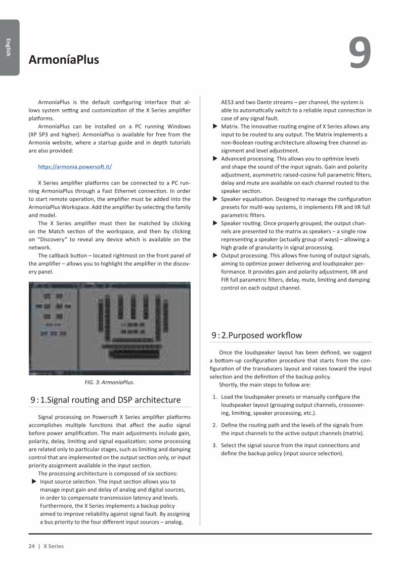
ArmoníaPlus is the default configuring interface that al-lows system setting and customization of the X Series amplifier platforms.
ArmoníaPlus can be installed on a PC running Windows (XP SP3 and higher). ArmoníaPlus is available for free from the Armonía website, where a startup guide and in depth tutorials are also provided:
https://armonia.powersoft.it/
X Series amplifier platforms can be connected to a PC run-ning ArmoníaPlus through a Fast Ethernet connection. In order to start remote operation, the amplifier must be added into the ArmoníaPlus Workspace. Add the amplifier by selecting the family and model.
The X Series amplifier must then be matched by clicking on the Match section of the workspace, and then by clicking on “Discovery” to reveal any device which is available on the network.
The callback button – located rightmost on the front panel of the amplifier – allows you to highlight the amplifier in the discov-ery panel.
9 : 2.Purposed workflow
Once the loudspeaker layout has been defined, we suggest a bottom-up configuration procedure that starts from the con-figuration of the transducers layout and raises toward the input selection and the definition of the backup policy.
Shortly, the main steps to follow are:
1. Load the loudspeaker presets or manually configure the loudspeaker layout (grouping output channels, crossover-ing, limiting, speaker processing, etc.).
2. Define the routing path and the levels of the signals from the input channels to the active output channels (matrix).
3. Select the signal source from the input connections and define the backup policy (input source selection).
AES3 and two Dante streams – per channel, the system is able to automatically switch to a reliable input connection in case of any signal fault.XX Matrix. The innovative routing engine of X Series allows any
input to be routed to any output. The Matrix implements a non-Boolean routing architecture allowing free channel as-signment and level adjustment.XX Advanced processing. This allows you to optimize levels
and shape the sound of the input signals. Gain and polarity adjustment, asymmetric raised-cosine full parametric filters, delay and mute are available on each channel routed to the speaker section.XX Speaker equalization. Designed to manage the configuration
presets for multi-way systems, it implements FIR and IIR full parametric filters.XX Speaker routing. Once properly grouped, the output chan-
nels are presented to the matrix as speakers – a single row representing a speaker (actually group of ways) – allowing a high grade of granularity in signal processing.XX Output processing. This allows fine-tuning of output signals,
aiming to optimize power delivering and loudspeaker per-formance. It provides gain and polarity adjustment, IIR and FIR full parametric filters, delay, mute, limiting and damping control on each output channel.
FIG. 3: ArmoníaPlus.
24 | X Series
Engl
ish
Warranty and assistance 10 10 : 1.Warranty
10 : 1.1. Product warrantyPowersoft guarantees its manufactured products to be free
from defective components and factory workmanship for a period of 48 (forty eight) months, starting from the date of pur-chase printed on Powersoft’s (or any of its Authorized Dealer’s) invoice to the end customer. All warranty repairs and retrofits must be performed at Powersoft facilities or at an Authorized Service Center at no cost for the purchaser. Warranty exclusion: Powersoft’s warranty does not cover product malfunctioning or failure caused by: misuse, abuse, repair work or alterations performed by non-authorized personnel, incorrect connections, exposure to harsh weather conditions, mechanical damages (in-cluding shipping accidents), and normal wear and tear. Powersoft will perform warranty services provided that the product is not damaged during transportation.
10 : 1.2. Return of GoodsGoods can be returned to Powersoft only after they have been
granted a Return Merchandise Authorization (RMA) number to be attached to the external packaging. Powersoft (or its Authorized Service Center) has the right to refuse any returned good without a RMA number.
10 : 1.3. Repair or replacementPowersoft reserves the right to repair or replace any defective
goods covered by product warranty at its sole discretion and as it deems best.
10 : 1.4. Cost and responsibility of transportThe purchaser (or end user/customer) is solely responsible
for all transportation costs and risks associated with sending warranty covered goods to Powersoft or its Authorized Service Center. Powersoft will assume full responsibility and cover all costs incurred to send the goods back to the purchaser (or end user/customer).
10 : 2.Assistance
There are no user-serviceable parts in your amplifier. Refer servicing to qualified technical personnel. In addition to having an in-house service department, Powersoft supports a network of authorized service centers. If your amplifier needs repair, contact your Powersoft dealer (or distributor). You can also contact the Powersoft Technical Service department to obtain the location of the nearest authorized service center.
Even though most product malfunctioning can be solved at your premises through Powersoft Customer Care or your direct knowledge, occasionally, due the nature of the failure, it might be necessary to return defective products to Powersoft for repair. In the latter case, before shipping, you are kindly asked to follow step by step the procedure described below:XX Obtain the “Defect Report Form” by contacting our
Customer Care Department via email: [email protected] or download the “Defect Report Form” from Powersoft’s website (http://www.powersoft-audio.com/en/support/service).XX Fill out one “Defect Report form” for each returned item
(the form is an editable tab guided document) and save as your name, amp model and serial Number (for example: distributornamek10sn17345.doc) providing all required information except the RMA code/s and send it to [email protected] for Powersoft approval.XX In case of defect reports approved by the Powersoft
Customer Service Representative you will receive an RMA authorization code (one RMA code for each returning de-vice).XX Upon receiving the RMA code you must package the unit
and attach the RMA code outside the pack, protected in a waterproof transparent envelope so it is clearly visible.
All returning items must be shipped to the following address: PowersoftVia dei Cadolingi, 1350018 Scandicci (FI) Italy
In case of shipment from countries NOT belonging to the European Community make sure you have also followed the in-structions described in the document available for download at the TEMPORARY EXPORTATION / IMPORTATION PROCEDURE link at http://www.powersoft-audio.com/en/support/service.
Thank you for your understanding and cooperation and con-tinued support as we work to improve our partnership.
9
English | 25
Française
A V I SRISQUES
D’ÉLECTROCUTIONNE PAS OUVRIR
L’énergie électrique peut remplir beaucoup de fonctions utiles. Cet appareil a été conçu et fabriqué pour assurer votre propre sécurité. Mais UNE UTILISATION INCORRECTE PEUT ENTRAÎNER UN RISQUE POTENTIEL D’ÉLECTROCUTION OU D’INCENDIE. Afin de ne pas annu-ler les dispositifs de sécurité incorporés dans cet appareil, observez les règles fondamentales suivantes pour son installation, son utilisation et sa réparation. Veuillez lire attentivement ces “Importantes mesures de sécurité” avant d’utiliser l’appareil.
Importantes instructions de sécurité1. Lisez les directives suivantes.2. Conservez ces directives.3. Observez et respectez tous les avertissements.4. Suivez toutes les directives.5. N’utilisez pas cet appareil près de l’eau.6. Nettoyez cet appareil uniquement avec un chiffon sec.7. Ne bouchez pas les fentes de ventilation. Respectez les di-
rectives du fabricant pour l’installation de l’appareil.8. N’installez pas l’appareil à proximité d’une source de cha-
leur telle qu’un radiateur, une bouche d’air chaud, une cui-sinière ou tout autre appareil (y compris des amplificateurs) émettant de la chaleur.
9. Ne placez pas le cordon d’alimentation dans des endroits passants et assurez vous qu’il ne peut pas être pincé, sur-tout au niveau des fiches, de la prise de courant et à l’en-droit où il sort de l’appareil.
10. Utilisez uniquement les éléments de raccordement et les accessoires recommandés par le fabricant.
11. Utilisez l’appareil uniquement avec le chariot, le trépied, le support ou la table recommandés par le fabri-cant ou achetés avec l’appareil. Lorsque vous utilisez un chariot, prenez des précautions en déplaçant le chariot et l’appareil afin dene pas les renverser, ce qui pourrait entraîner des blessures.
12. Débranchez cet appareil en cas d’orage ou lorsque vous ne l’utilisez pas pendant de longues périodes.
13. Pour toute réparation, adressez-vous à un réparateur qualifié. Faites réparer l’appareil s’il a été endommagé de quelque manière que ce soit, par exemple si le cordon d’alimentation ou sa fiche sont endommagés, si du liquide ou tout autre corps étranger a pénétré dans l’appareil, si l’appareil a été exposé à la pluie ou à l’humidité, s’il ne fonc-tionne pas normalement ou s’il est tombé.
MISE EN GARDE : AFIN DE RÉDUIRE LES RISQUES DE CHOC ÉLECTRIQUE, N’ESSAYEZ PAS D’OUVRIR L’UNITÉ, MEME EN PARTIE. AUCUNE PIÈCE A L’INTERIEUR NE PEUT ETRE CHANGÉE PAR L’UTILISATEUR. LAISSEZ L’ENTRETIEN A UN PERSONNEL QUALIFIÉ.
AFIN DE RÉDUIRE LES RISQUES D’INCENDIE ET D’ÉLECTROCUTION, N’EXPOSEZ PAS CET APPAREIL À LA PLUIE OU À L’HUMIDITÉ. L’UNITÉ NE DOIT JAMAIS ÊTRE EXPOSÉ AUX ÉCLABOUSSURES, AU DÉVERSEMENT OU À L’ÉGOUTTEMENT DE LIQUIDES, QUELS QU’ILS SOIENT.
L’UNITÉ DOIT ÊTRE INSTALLÉ SEULEMENT DANS UN RACK ARMOIRE : BRANCHEZ LA FICHE DE L’AMPLIFICATEUR VIA LE DISJONCTEUR AUX PANNEAU DE DISTRIBUTION ÉLECTRIQUE À L’INTÉRIEUR DE L’ARMOIRE.
LE DISJONCTEUR DOIVENT RESTER ACCESSIBLES A TOUT MOMENT.
QUAND L’UNITÉ EST INSTELLÉ DANS UN RACK ARMOIRE, ASSUREZ-VOUS QU’IL Y À UN ESPACE SUFFISANT TOUT AUTOUR POUR PERMETTRE UNE BONNE VENTILATION (50 CM DES ORIFICES DE VENTILATION AVANT ET ARRIÈRE).
LE BRANCHEMENT AU RÉSEAU ÉLECTRIQUE DOIT ÊTRE EFFECTUÉ QUE PAR UN EXPERT EN ÉLECTROTECHNOLOGIE, SELON LES EXIGENCES NATIONALES DES PAYS OÙ L’UNITÉ EST VENDUE.
AVERTISSEMENT: FUSE ON NEUTRE
Le marquage CE indique la conformité à la directive de basse tension et la compatibilité électromagnétique.
Symbole pour la connexion à la terre.
Symbole indiquant que l’équipement est destiné à l’em-ploi à l’intérieur.
Symbole pour la conformité al la Directive 2002/96/EC et la Directive 2003/108/EC du Parlement Européen sur les équipements électriques et électroniques (WEEE).
No utilice la unidad en altitudes por encima de 2.000 m.
No utilice la unidad en el ambiente tropical.
EXPLICATION DES SYMBOLES GRAPHIQUES
La triangle avec le symbol du foudre est employée pour alerter l’utilisateur au risque de décharge électrique.
Le triangle avec un point d’exclamation est employée pour alerter l’utilisateur d’instruction importantes pour lors opérations de maintenance.
Importantes instructions de sécurité 1
26 | X Series

Fran
çais
e
1 X Series Guide rapide 2
2 : 1.Bienvenue
Félicitations pour l’achat d’un amplificateur Powersoft X Series!
Nous savons que vous êtes désireux d’utiliser le X8 ou X4, mais merci de prendre un moment pour lire ce guide rapide et les consignes de sécurité. Dans le cas où vous auriez des ques-tions, ne pas hésiter à contacter votre revendeur ou directement Powersoft.
Powersoft X Series innove le concept de la plate-forme d’amplification: X8 est un amplificateur de puissance à 8 canaux; X4 offre 4 canaux sur une unité de rack. Les deux mettent en œuvre un nouveau système de routage des canaux, un nouveau bloc d’alimentation et un DSP multifonctions révolutionnaire. Powersoft X8 et X4 sont d’origine compatibles avec AES3, deux flux numériques à redondance Dante™ par Audinate® (en option) et les entrées analogiques, ce qui offre jusqu’à 4 sources d’entrée sélectionnables différentes par canal.
Pour la configuration du système et le réglage fin, ArmoníaPlus™ offre une interface intuitive, un contrôle complet sur le traitement numérique du signal audio et un contrôle com-plet en temps réel de la performance du système. La connexion Wi-Fi intégrée permet au Powersoft X Series d’être accessible et géré via n’importe quel dispositif mobile via une interface utilisa-teur spécialement développée pour un contrôle local.
Powersoft X4 et X8 augmentent l’amplification de puis-sance vers une nouvelle norme de qualité et d’utilisabilité: ils conviennent à votre configuration, ils font gagner de l’espace et du poids et ils vous offrent la légendaire efficacité Powersoft et un nouveau bloc d’alimentation multi-phases compatible dans le monde entier.
2 : 2.Déballage et vérification des dommages de transport
Votre produit Powersoft a été complètement testé et inspec-té avant de quitter l’usine. Gardez toutes les parties d’emballage pour l’inspection par le transporteur, puis inspecter immédiate-ment votre nouveau produit. Dans le cas peu probable ou vous constateriez un dégât, merci de bien vouloir en informer l’entre-prise de livraison immédiatement.
Chaque emballage contient :XX 1x X Series plate-forme d’amplification.XX 1x PC 5/5-STF1-7,62 Phoenix connecteur d’alimentation.XX 1x enveloppe pour le connecteur d’alimentation.XX 1x guide rapide.
2 : 3.Élimination des produits d’emballage
L’emballage de transport et de protection a été sélectionné à partir de matériaux qui sont respectueux de l’environnement pour l’élimination et peut normalement être recyclés.
Plutôt que de jeter ces matériaux de suite, s’il vous plaît assurez-vous qu’ils sont offerts pour le recyclage.
2 : 4.Liste des panneaux des images
A. X8/X4L dessins techniques: dimensions en millimètresB. X4 dessins techniques: dimensions en millimètresC. Panneau arrière X8D. Panneau arrière X4LE. Panneau arrière X4F. Panneaux avant X8 et X4L/X4G. Supports de montage et direction du flux d’airH. Règle pour empiler les amplificateurs dans des racks fermésI. Brochage du connecteur d’entréeJ. Brochage RJ45 EthernetK. Câblages des haut-parleursL. Courant triphasé : Câblage fiche secteur CAM. Courant monophasé : Câblage fiche secteur CAN. Courant biphasé : Câblage fiche secteur CAO. Fiche secteur blindé CAP. Informations réglementaires
Française | 27
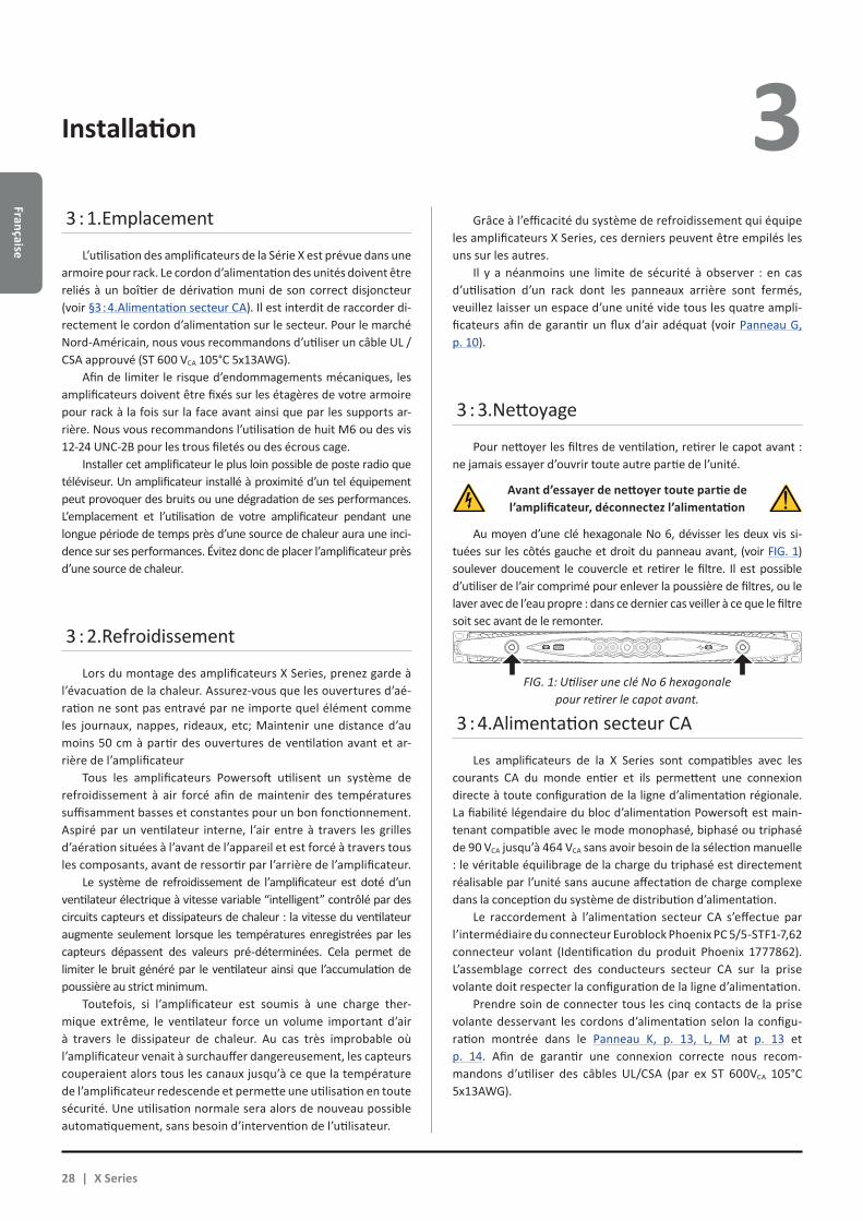
Française
Installation 3 3 : 1.Emplacement
L’utilisation des amplificateurs de la Série X est prévue dans une armoire pour rack. Le cordon d’alimentation des unités doivent être reliés à un boîtier de dérivation muni de son correct disjoncteur (voir §3 : 4.Alimentation secteur CA). Il est interdit de raccorder di-rectement le cordon d’alimentation sur le secteur. Pour le marché Nord-Américain, nous vous recommandons d’utiliser un câble UL / CSA approuvé (ST 600 VCA 105°C 5x13AWG).
Afin de limiter le risque d’endommagements mécaniques, les amplificateurs doivent être fixés sur les étagères de votre armoire pour rack à la fois sur la face avant ainsi que par les supports ar-rière. Nous vous recommandons l’utilisation de huit M6 ou des vis 12-24 UNC-2B pour les trous filetés ou des écrous cage.
Installer cet amplificateur le plus loin possible de poste radio que téléviseur. Un amplificateur installé à proximité d’un tel équipement peut provoquer des bruits ou une dégradation de ses performances. L’emplacement et l’utilisation de votre amplificateur pendant une longue période de temps près d’une source de chaleur aura une inci-dence sur ses performances. Évitez donc de placer l’amplificateur près d’une source de chaleur.
3 : 2.Refroidissement
Lors du montage des amplificateurs X Series, prenez garde à l’évacuation de la chaleur. Assurez-vous que les ouvertures d’aé-ration ne sont pas entravé par ne importe quel élément comme les journaux, nappes, rideaux, etc; Maintenir une distance d’au moins 50 cm à partir des ouvertures de ventilation avant et ar-rière de l’amplificateur
Tous les amplificateurs Powersoft utilisent un système de refroidissement à air forcé afin de maintenir des températures suffisamment basses et constantes pour un bon fonctionnement. Aspiré par un ventilateur interne, l’air entre à travers les grilles d’aération situées à l’avant de l’appareil et est forcé à travers tous les composants, avant de ressortir par l’arrière de l’amplificateur.
Le système de refroidissement de l’amplificateur est doté d’un ventilateur électrique à vitesse variable “intelligent” contrôlé par des circuits capteurs et dissipateurs de chaleur : la vitesse du ventilateur augmente seulement lorsque les températures enregistrées par les capteurs dépassent des valeurs pré-déterminées. Cela permet de limiter le bruit généré par le ventilateur ainsi que l’accumulation de poussière au strict minimum.
Toutefois, si l’amplificateur est soumis à une charge ther-mique extrême, le ventilateur force un volume important d’air à travers le dissipateur de chaleur. Au cas très improbable où l’amplificateur venait à surchauffer dangereusement, les capteurs couperaient alors tous les canaux jusqu’à ce que la température de l’amplificateur redescende et permette une utilisation en toute sécurité. Une utilisation normale sera alors de nouveau possible automatiquement, sans besoin d’intervention de l’utilisateur.
3 : 3.Nettoyage
Pour nettoyer les filtres de ventilation, retirer le capot avant : ne jamais essayer d’ouvrir toute autre partie de l’unité.
Avant d’essayer de nettoyer toute partie de l’amplificateur, déconnectez l’alimentation
Au moyen d’une clé hexagonale No 6, dévisser les deux vis si-tuées sur les côtés gauche et droit du panneau avant, (voir FIG. 1) soulever doucement le couvercle et retirer le filtre. Il est possible d’utiliser de l’air comprimé pour enlever la poussière de filtres, ou le laver avec de l’eau propre : dans ce dernier cas veiller à ce que le filtre soit sec avant de le remonter.
3 : 4.Alimentation secteur CA
Les amplificateurs de la X Series sont compatibles avec les courants CA du monde entier et ils permettent une connexion directe à toute configuration de la ligne d’alimentation régionale. La fiabilité légendaire du bloc d’alimentation Powersoft est main-tenant compatible avec le mode monophasé, biphasé ou triphasé de 90 VCA jusqu’à 464 VCA sans avoir besoin de la sélection manuelle : le véritable équilibrage de la charge du triphasé est directement réalisable par l’unité sans aucune affectation de charge complexe dans la conception du système de distribution d’alimentation.
Le raccordement à l’alimentation secteur CA s’effectue par l’intermédiaire du connecteur Euroblock Phoenix PC 5/5-STF1-7,62 connecteur volant (Identification du produit Phoenix 1777862). L’assemblage correct des conducteurs secteur CA sur la prise volante doit respecter la configuration de la ligne d’alimentation.
Prendre soin de connecter tous les cinq contacts de la prise volante desservant les cordons d’alimentation selon la configu-ration montrée dans le Panneau K, p. 13, L, M at p. 13 et p. 14. Afin de garantir une connexion correcte nous recom-mandons d’utiliser des câbles UL/CSA (par ex ST 600VCA 105°C 5x13AWG).
Grâce à l’efficacité du système de refroidissement qui équipe les amplificateurs X Series, ces derniers peuvent être empilés les uns sur les autres.
Il y a néanmoins une limite de sécurité à observer : en cas d’utilisation d’un rack dont les panneaux arrière sont fermés, veuillez laisser un espace d’une unité vide tous les quatre ampli-ficateurs afin de garantir un flux d’air adéquat (voir Panneau G, p. 10).
FIG. 1: Utiliser une clé No 6 hexagonale pour retirer le capot avant.
28 | X Series
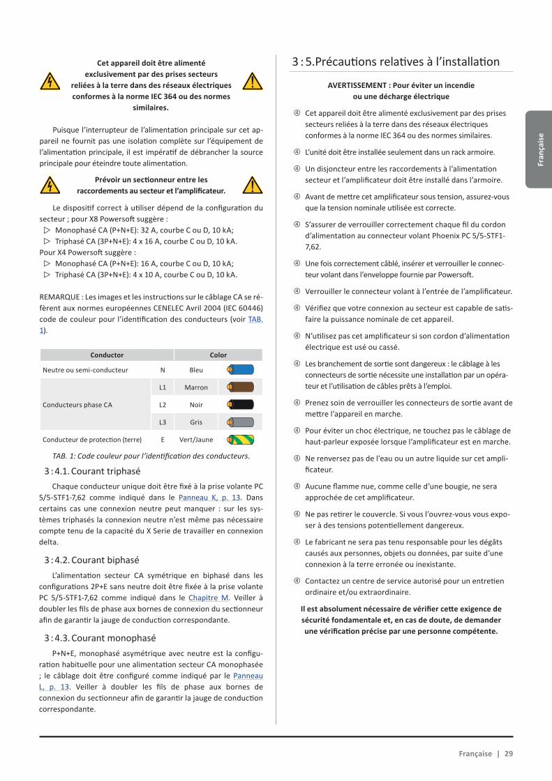
Fran
çais
e
3 Cet appareil doit être alimenté exclusivement par des prises secteurs
reliées à la terre dans des réseaux électriques conformes à la norme IEC 364 ou des normes
similaires.
Puisque l’interrupteur de l’alimentation principale sur cet ap-pareil ne fournit pas une isolation complète sur l’équipement de l’alimentation principale, il est impératif de débrancher la source principale pour éteindre toute alimentation.
Prévoir un sectionneur entre les raccordements au secteur et l’amplificateur.
Le dispositif correct à utiliser dépend de la configuration du secteur ; pour X8 Powersoft suggère :
Monophasé CA (P+N+E): 32 A, courbe C ou D, 10 kA;Triphasé CA (3P+N+E): 4 x 16 A, courbe C ou D, 10 kA.
Pour X4 Powersoft suggère :Monophasé CA (P+N+E): 16 A, courbe C ou D, 10 kA;Triphasé CA (3P+N+E): 4 x 10 A, courbe C ou D, 10 kA.
REMARQUE : Les images et les instructions sur le câblage CA se ré-fèrent aux normes européennes CENELEC Avril 2004 (IEC 60446) code de couleur pour l’identification des conducteurs (voir TAB. 1).
Conductor Color
Neutre ou semi-conducteur N Bleu
Conducteurs phase CA
L1 Marron
L2 Noir
L3 Gris
Conducteur de protection (terre) E Vert/Jaune
TAB. 1: Code couleur pour l’identification des conducteurs.
3 : 4.1. Courant triphaséChaque conducteur unique doit être fixé à la prise volante PC
5/5-STF1-7,62 comme indiqué dans le Panneau K, p. 13. Dans certains cas une connexion neutre peut manquer : sur les sys-tèmes triphasés la connexion neutre n’est même pas nécessaire compte tenu de la capacité du X Serie de travailler en connexion delta.
3 : 4.2. Courant biphaséL’alimentation secteur CA symétrique en biphasé dans les
configurations 2P+E sans neutre doit être fixée à la prise volante PC 5/5-STF1-7,62 comme indiqué dans le Chapitre M. Veiller à doubler les fils de phase aux bornes de connexion du sectionneur afin de garantir la jauge de conduction correspondante.
3 : 4.3. Courant monophaséP+N+E, monophasé asymétrique avec neutre est la configu-
ration habituelle pour une alimentation secteur CA monophasée ; le câblage doit être configuré comme indiqué par le Panneau L, p. 13. Veiller à doubler les fils de phase aux bornes de connexion du sectionneur afin de garantir la jauge de conduction correspondante.
3 : 5.Précautions relatives à l’installation
AVERTISSEMENT : Pour éviter un incendie ou une décharge électrique
Xf Cet appareil doit être alimenté exclusivement par des prises secteurs reliées à la terre dans des réseaux électriques conformes à la norme IEC 364 ou des normes similaires.
Xf L’unité doit être installée seulement dans un rack armoire.
Xf Un disjoncteur entre les raccordements à l’alimentation secteur et l’amplificateur doit être installé dans l’armoire.
Xf Avant de mettre cet amplificateur sous tension, assurez-vous que la tension nominale utilisée est correcte.
Xf S’assurer de verrouiller correctement chaque fil du cordon d’alimentation au connecteur volant Phoenix PC 5/5-STF1-7,62.
Xf Une fois correctement câblé, insérer et verrouiller le connec-teur volant dans l’enveloppe fournie par Powersoft.
Xf Verrouiller le connecteur volant à l’entrée de l’amplificateur.
Xf Vérifiez que votre connexion au secteur est capable de satis-faire la puissance nominale de cet appareil.
Xf N’utilisez pas cet amplificateur si son cordon d’alimentation électrique est usé ou cassé.
Xf Les branchement de sortie sont dangereux : le câblage à les connecteurs de sortie nécessite une installation par un opéra-teur et l’utilisation de câbles prêts à l’emploi.
Xf Prenez soin de verrouiller les connecteurs de sortie avant de mettre l’appareil en marche.
Xf Pour éviter un choc électrique, ne touchez pas le câblage de haut-parleur exposée lorsque l’amplificateur est en marche.
Xf Ne renversez pas de l’eau ou un autre liquide sur cet ampli-ficateur.
Xf Aucune flamme nue, comme celle d’une bougie, ne sera approchée de cet amplificateur.
Xf Ne pas retirer le couvercle. Si vous l’ouvrez-vous vous expo-ser à des tensions potentiellement dangereux.
Xf Le fabricant ne sera pas tenu responsable pour les dégâts causés aux personnes, objets ou données, par suite d’une connexion à la terre erronée ou inexistante.
Xf Contactez un centre de service autorisé pour un entretien ordinaire et/ou extraordinaire.
Il est absolument nécessaire de vérifier cette exigence de sécurité fondamentale et, en cas de doute, de demander une vérification précise par une personne compétente.
Française | 29
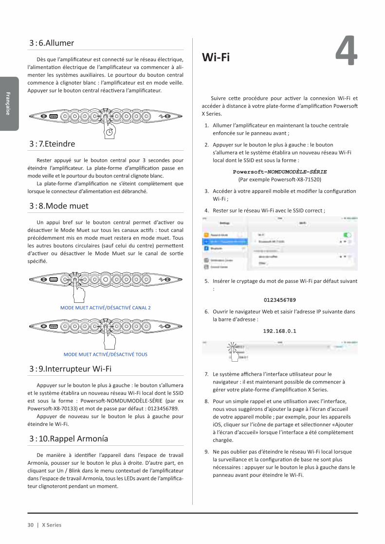
Française
4 3 : 6.Allumer
Dès que l’amplificateur est connecté sur le réseau électrique, l’alimentation électrique de l’amplificateur va commencer à ali-menter les systèmes auxiliaires. Le pourtour du bouton central commence à clignoter blanc : l’amplificateur est en mode veille. Appuyer sur le bouton central réactivera l’amplificateur.
3 : 7.Eteindre
Rester appuyé sur le bouton central pour 3 secondes pour éteindre l’amplificateur. La plate-forme d’amplification passe en mode veille et le pourtour du bouton central clignote blanc.
La plate-forme d’amplification ne s’éteint complètement que lorsque le connecteur d’alimentation est débranché.
3 : 8.Mode muet
Un appui bref sur le bouton central permet d’activer ou désactiver le Mode Muet sur tous les canaux actifs : tout canal précédemment mis en mode muet restera en mode muet. Tous les autres boutons circulaires (sauf celui du centre) permettent d’activer ou désactiver le Mode Muet sur le canal de sortie spécifié.
3 : 9.Interrupteur Wi-Fi
Appuyer sur le bouton le plus à gauche : le bouton s’allumera et le système établira un nouveau réseau Wi-Fi local dont le SSID est sous la forme : Powersoft-NOMDUMODÈLE-SÉRIE (par ex Powersoft-X8-70133) et mot de passe par défaut : 0123456789.
Appuyer de nouveau sur le bouton le plus à gauche pour éteindre le Wi-Fi.
3 : 10.Rappel Armonía
De manière à identifier l’appareil dans l’espace de travail Armonía, pousser sur le bouton le plus à droite. D’autre part, en cliquant sur Un / Blink dans le menu contextuel de l’amplificateur dans l’espace de travail Armonía, tous les LEDs avant de l’amplifica-teur clignoteront pendant un moment.
Wi-Fi
Suivre cette procédure pour activer la connexion Wi-Fi et accéder à distance à votre plate-forme d’amplification Powersoft X Series.
1. Allumer l’amplificateur en maintenant la touche centrale enfoncée sur le panneau avant ;
2. Appuyer sur le bouton le plus à gauche : le bouton s’allumera et le système établira un nouveau réseau Wi-Fi local dont le SSID est sous la forme :
Powersoft-NOMDUMODÈLE-SÉRIE (Par exemple Powersoft-X8-71520)
3. Accéder à votre appareil mobile et modifier la configuration Wi-Fi ;
4. Rester sur le réseau Wi-Fi avec le SSID correct ;
5. Insérer le cryptage du mot de passe Wi-Fi par défaut suivant :
0123456789
6. Ouvrir le navigateur Web et saisir l’adresse IP suivante dans la barre d’adresse :
192.168.0.1
7. Le système affichera l’interface utilisateur pour le navigateur : il est maintenant possible de commencer à gérer votre plate-forme d’amplification X Series.
8. Pour un simple rappel et une utilisation avec l’interface, nous vous suggérons d’ajouter la page à l’écran d’accueil de votre appareil mobile ; par exemple, pour les appareils iOS, cliquer sur l’icône de partage et sélectionner «Ajouter à l’écran d’accueil» lorsque l’interface a été complètement chargée.
9. Ne pas oublier pas d’éteindre le réseau Wi-Fi local lorsque la surveillance et la configuration de base ne sont plus nécessaires : appuyer sur le bouton le plus à gauche dans le panneau avant pour éteindre le Wi-Fi.
MODE MUET ACTIVÉ/DÉSACTIVÉ CANAL 2
MODE MUET ACTIVÉ/DÉSACTIVÉ TOUS
30 | X Series
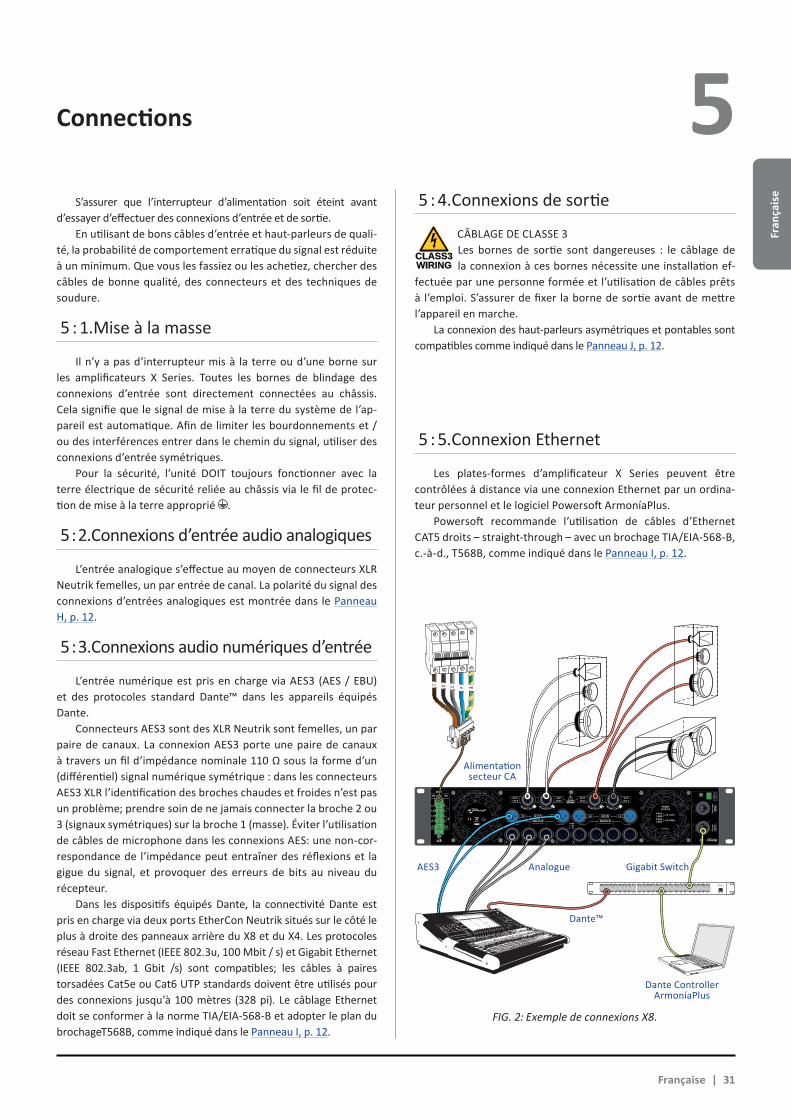
Fran
çais
e
Connections 5 S’assurer que l’interrupteur d’alimentation soit éteint avant
d’essayer d’effectuer des connexions d’entrée et de sortie.En utilisant de bons câbles d’entrée et haut-parleurs de quali-
té, la probabilité de comportement erratique du signal est réduite à un minimum. Que vous les fassiez ou les achetiez, chercher des câbles de bonne qualité, des connecteurs et des techniques de soudure.
5 : 1.Mise à la masse
Il n’y a pas d’interrupteur mis à la terre ou d’une borne sur les amplificateurs X Series. Toutes les bornes de blindage des connexions d’entrée sont directement connectées au châssis. Cela signifie que le signal de mise à la terre du système de l’ap-pareil est automatique. Afin de limiter les bourdonnements et / ou des interférences entrer dans le chemin du signal, utiliser des connexions d’entrée symétriques.
Pour la sécurité, l’unité DOIT toujours fonctionner avec la terre électrique de sécurité reliée au châssis via le fil de protec-tion de mise à la terre approprié .
5 : 2.Connexions d’entrée audio analogiques
L’entrée analogique s’effectue au moyen de connecteurs XLR Neutrik femelles, un par entrée de canal. La polarité du signal des connexions d’entrées analogiques est montrée dans le Panneau H, p. 12.
5 : 3.Connexions audio numériques d’entrée
L’entrée numérique est pris en charge via AES3 (AES / EBU) et des protocoles standard Dante™ dans les appareils équipés Dante.
Connecteurs AES3 sont des XLR Neutrik sont femelles, un par paire de canaux. La connexion AES3 porte une paire de canaux à travers un fil d’impédance nominale 110 Ω sous la forme d’un (différentiel) signal numérique symétrique : dans les connecteurs AES3 XLR l’identification des broches chaudes et froides n’est pas un problème; prendre soin de ne jamais connecter la broche 2 ou 3 (signaux symétriques) sur la broche 1 (masse). Éviter l’utilisation de câbles de microphone dans les connexions AES: une non-cor-respondance de l’impédance peut entraîner des réflexions et la gigue du signal, et provoquer des erreurs de bits au niveau du récepteur.
Dans les dispositifs équipés Dante, la connectivité Dante est pris en charge via deux ports EtherCon Neutrik situés sur le côté le plus à droite des panneaux arrière du X8 et du X4. Les protocoles réseau Fast Ethernet (IEEE 802.3u, 100 Mbit / s) et Gigabit Ethernet (IEEE 802.3ab, 1 Gbit /s) sont compatibles; les câbles à paires torsadées Cat5e ou Cat6 UTP standards doivent être utilisés pour des connexions jusqu’à 100 mètres (328 pi). Le câblage Ethernet doit se conformer à la norme TIA/EIA-568-B et adopter le plan du brochageT568B, comme indiqué dans le Panneau I, p. 12.
5 : 5.Connexion Ethernet
Les plates-formes d’amplificateur X Series peuvent être contrôlées à distance via une connexion Ethernet par un ordina-teur personnel et le logiciel Powersoft ArmoníaPlus.
Powersoft recommande l’utilisation de câbles d’Ethernet CAT5 droits – straight-through – avec un brochage TIA/EIA-568-B, c.-à-d., T568B, comme indiqué dans le Panneau I, p. 12.
5 : 4.Connexions de sortie
CÂBLAGE DE CLASSE 3Les bornes de sortie sont dangereuses : le câblage de la connexion à ces bornes nécessite une installation ef-
fectuée par une personne formée et l’utilisation de câbles prêts à l’emploi. S’assurer de fixer la borne de sortie avant de mettre l’appareil en marche.
La connexion des haut-parleurs asymétriques et pontables sont compatibles comme indiqué dans le Panneau J, p. 12.
CLASS3WIRING
1 2 3 4 5 6 7 8
25 26 27 28 29 30 31 32
9 10 11 12 13 14 15 16
33 34 35 36 37 38 39 40
17 18 19 20 21 22 23 24
41 42 43 44 45 46 47 48 UP Link
Power
L1 L2 L3 N PE
AES3 IN7-8 5-6 AES3 IN3-4 1-2
ANALOG INANALOG IN
8 7 6 5 4 3 2 1
3PH 1PH
L1
L2
L3
N
L
N
1=GND2 = IN+3 = IN-
MAINS
TURN TO LOCK TURN TO LOCKTURN TO LOCK TURN TO LOCK
FIG. 2: Exemple de connexions X8.
Française | 31
Alimentation secteur CA
AES3 Analogue Gigabit Switch
Dante™
Dante ControllerArmoníaPlus

Française
Mise à jour du logiciel Tableau LED6 7 Les plates-formes d’amplificateurs Powersoft X Series in-
tègrent un système de gestion de signal audio numérique complet basé sur le processeur ARM Cortex A-8 et la plateforme TI C6000 DSP. Cette impressionnante capacité informatique intégrée est entraîné par un environnement logiciel spécialisé.
Les nouvelles mises à jour du logiciel X Series sont disponibles sur le forum Armonía (https://armonia.powersoft.it/).
Le paquet logiciel contient le fichier de mise à jour dont le nom est sous la forme :
update-version#-model.bin (Par exemple update-v1.5.0.6-x4.bin);
afin de mettre à jour le logiciel de votre plate-forme d’amplifica-tion X Series, stocker le fichier de mise à jour du logiciel dans une clé USB et suivre ces instructions :
1. Mettre l’amplificateur en marche et attendre la fin de la séquence de démarrage.
2. Brancher la clé USB avec le fichier de mise à jour logicielle sur le port USB sur le panneau avant de l’amplificateur.
3. Rester appuyé sur le bouton-poussoir le plus à droite (Rappel Armonía) jusqu’à ce que le deuxième bip soit émis et que les LED commencent à clignoter.
4. Attendre jusqu’à ce que l’amplificateur redémarre et que tous les LEDs avant deviennent complètement bleues.
Tous les boutons circulaires rétroéclairés fournissent des informations d’état. Le CENTRE de chaque bouton fournit des informations sur l’état du signal de SORTIE.
Centre couleurIndicateurs de SORTIE
Centre couleurIndicateurs de SORTIE
couleur état couleur état
Bleu Canal prêt Orange Muet Sortie
Jaune Limiteur activé
clignotmentOrange
Muet Entrée
L’ANNEAU de chaque bouton fournit des informations sur l’état du signal d’ENTRÉE.
Couleur de l’anneauIndicateurs d’ENTRÉE
couleur étatclignotement
blanc (centre bleu)
Présence du signal d’entrée
Rouge Saturation signal d’entrée
L’erreur de canal et rappel Armonía sont associés aux signaux LED suivants.
couleur état
clignotement rouge(Centre et anneau) Erreur de canal
clignotement / tous les canaux(Centre et anneau)
Unité répondant àRappel Armonía
Le bouton central s’allume lorsque le système est en mode veille ou en cas de panne de l’unité d’alimentation:
Couleur de l’anneaubouton CENTRAL
couleur étatblanc
impulsions (tous les LED
éteintes)
Système alimentéMode veille
rouge impulsions
(fonctionnement normal)
fan défaut détecté(fan sur le côté étage de sortie)
Couleur du centrebouton CENTRAL
couleur état
clignotement rouge
alimentateur ou PSU fan défaut détecté
clignotement jaune
protection de la température d’alimentation actif
clignotement
Clé USB insérée ...
32 | X Series
Fran
çais
e
Mise en réseau 8 Les plates-formes d’amplification X Series sont compatibles
avec les topologies de réseau linéaires en daisy chain, en étoile et en anneau ; dans un réseau en daisy-chain le PC avec ArmoníaPlus doit toujours être à une extrémité de la chaîne.
Il est à noter que le réseau en daisy-chain ne garantit pas la fiabilité dans l’environnement de production, car toute faute peut céder au sectionnement du réseau et perdre le contrôle du système.
Lorsque l’efficacité et la fiabilité sont primordiales, une topologie de réseau redondant est conseillée. Afin d’exploiter les caractéristiques Dante, la topologie du réseau en étoile et en daisy chain ouvert sont autorisées
8 : 1.Adressage IP
Les paramètres du réseau aux valeurs d’usine sont DHCP / Auto IP, pour que la plate-forme d’amplification s’auto-configure lorsqu’elle est connectée à un réseau local ou un PC existant. La politique d’IP fixe peut également être adoptée et configurée via ArmoníaPlus.
Si un serveur DHCP n’est pas actif au sein du réseau, la plate-forme d’amplification initie une auto-configuration d’adresse sans état (c’est-à-dire la méthodologie de mise en réseau sans configuration – Zeroconf) : elle-même attribue une adresse de réseau numérique local (du type 169.254.x.y – 172.31.*.* pour le réseau secondaire s’il est présent - avec un masque de sous-réseau 255.255.0.0) et distribue et résout automatiquement les noms d’hôtes des périphériques en réseau. Pour paramétrer une adresse IP statique merci de se référer à la notice d’utilisation d’ArmoníaPlus.
8 : 1.1. Résolution des problèmes de l’adressage IPLors de la connexion du X Series à un environnement réseau, il
peut arriver qu’ArmoníaPlus ne puisse pas découvrir ou importer l’amplificateur.
En général, c’est un problème d’adressage IP : Armonia et le X Series doivent tous les deux appartenir au même sous-réseau. Si un serveur DHCP est présent sur le réseau et que la plate-forme d’amplification X Series est en AUTO IP, la mise en réseau peut devenir instable.
En règle générale, mettre en marche le serveur DHCP avant de brancher les amplificateurs.
L’adressage IP d’un amplificateur X Series est établi au cours de l’amorçage : lorsque la plate-forme d’amplification X Series détecte un serveur DHCP sur le réseau pendant le démarrage, elle négocie les paramètres réseau. Si la plate-forme d’amplificateur X Series ne révèle pas un serveur DHCP sur le réseau pendant le démarrage, elle se paramètre elle-même en mode AUTO IP.
8 : 2.Réseau Dante™
Les modèles équipés de Dante des plates-formes d’amplification X Series sont compatibles avec le réseau redondant Dante via les deux ports etherCON sur le panneau arrière :XX Primaire/ETH1 est le port réseau primaire ;XX Secondaire/ETH2 est le port réseau secondaire. La connectivité Dante est toujours compatible sur le port
primaire/ETH1 Gigabit Ethernet ; le port secondaire/ETH2 Gigabit Ethernet offre une continuité de fonctionnement quand un réseau redondant parallèle est établi.
Afin de mettre en œuvre un réseau Dante, un ordinateur exécutant Dante Controller doit être utilisé. Dante Controller est une application logicielle qui gère les périphériques sur le réseau. Les amplificateurs X Series sont automatiquement détectées et affichées dans Dante Controller avec l’identifiant par défaut NOMDUMODÈLE-SÉRIE (Par exemple X8-71520).
Les réseaux Dante nécessitent presque toujours d’au moins un commutateur de réseau. Les infrastructures redondantes peuvent nécessiter plusieurs commutateurs. Pour une fiabilité maximale, le commutateur de réseau doit :
XX être classé Gigabit Ethernet ;
XX être non-bloquant ;
XX avoir la Qualité de service (QoS) avec au moins quatre files d’attente ;
XX avoir la QoS Diffserv (DSCP) avec priorité stricte ;
XX avoir EEE (Energy efficient ethernet) éteint.
Pour des informations détaillées sur l’installation d’un commutateur, merci de se référer à la documentation du fabricant.
8 : 3.Configuration du réseau redondant
La redondance Dante peut être configurée et utilisée entre tous les appareils audio compatibles avec la connexion Dante activée : Elle fonctionne en utilisant deux réseaux totalement indépendants et distincts, le réseau primaire et le réseau secondaire.
Pour configurer et utiliser la redondance Dante, connecter la plate-forme d’amplification X Series et les autres équipements audio redondants avec la connexion Dante activée à l’aide des commutateurs Gigabit double et des câbles Ethernet. Connecter votre ordinateur qui exécute Dante Virtual Soundcard et Dante Controller, et les autres équipements audio non-redondants avec la connexion Dante activée au réseau primaire.
Les réseaux primaires et secondaires NE DOIVENT PAS être reliés entre eux à aucun moment. S’assurer que tous les ordinateurs soient paramétrés pour configurer automatiquement leur adresse IP.
Française | 33
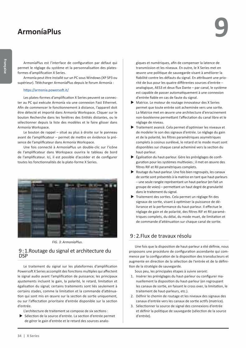
Française
ArmoníaPlus 9 ArmoníaPlus est l’interface de configuration par défaut qui
permet le réglage du système et la personnalisation des plates-formes d’amplification X Series.
Armonía peut être installé sur un PC sous Windows (XP SP3 ou supérieur). Télécharger ArmoníaPlus depuis le forum Armonía :
https://armonia.powersoft.it/
Les plates-formes d’amplification X Series peuvent se connec-ter au PC qui exécute Armonía via une connexion Fast Ethernet. Afin de commencer le fonctionnement à distance, l’appareil doit être détecté et importé dans Armonía Workspace. Cliquer sur le bouton Recherche dans les fenêtres des Entités distantes, ou le sélectionner depuis la liste des modèles et le faire glisser dans Armonía Workspace.
Le bouton de rappel – situé au plus à droite sur le panneau avant de l’amplificateur – permet de mettre en évidence la pré-sence de l’amplificateur dans Armonía Workspace.
Une fois connecté à ArmoníaPlus un double-clic sur l’icône de l’amplificateur dans Workspace ouvrira le tableau de bord de l’amplificateur. Ici, il est possible d’accéder et de configurer toutes les fonctionnalités de la plate-forme X Series.
9 : 1.Routage du signal et architecture du DSP
Le traitement du signal sur les plateformes d’amplification Powersoft X Series accomplit des fonctions multiples qui affectent le signal audio avant l’amplification de puissance; les principaux ajustements incluent le gain, la polarité, le retard, limitation et égalisation du signal; certains traitements sont liés seulement à certains stades, comme la limitation et la commande d’atténua-tion qui sont mis en œuvre sur la section de sortie uniquement, ou sur l’affectation prioritaire d’entrée disponible sur la section d’entrée.
L’architecture de traitement se compose de six sections :XX Sélection de la source d’entrée. La section d’entrée permet
de gérer le gain d’entrée et le retard des sources analo-
giques et numériques, afin de compenser la latence de transmission et les niveaux. En outre, le X Series met en œuvre une politique de sauvegarde visant à améliorer la fiabilité contre les défauts du signal. En attribuant une prio-rité de bus pour les quatre différentes sources d’entrée – analogique, AES3 et deux flux Dante – par canal, le système est capable de passer automatiquement à une connexion d’entrée fiable en cas de faute du signal.XX Matrice. Le moteur de routage innovateur des X Series
permet que toute entrée soit acheminée vers une sortie. La Matrice met en œuvre une architecture d’enracinement non-booléenne permettant l’affectation du canal libre et le réglage de niveau.XX Traitement avancé. Cela permet d’optimiser les niveaux et
de modeler le son des signaux d’entrée. Le réglage du gain et de la polarité, les filtres paramétriques asymétriques complets à cosinus surélevé, le retard et le mode muet sont disponibles sur chaque canal acheminé vers la section du haut-parleur.XX Égalisation du haut-parleur. Gére les préréglages de confi-
guration pour les systèmes multivoies ; il met en œuvre des filtres RIF et RII paramétriques complets.XX Routage du haut-parleur. Une fois bien regroupés, les canaux
de sortie sont présentés à la matrice en tant que haut-parleurs – une seule rangée représentant un haut-parleur (en fait un groupe de voies) – permettant un haut degré de granularité dans le traitement du signal.XX Traitement des sorties. Cela permet un réglage fin des
signaux de sortie, visant à optimiser la puissance de dé-livrance et la performance du haut-parleur. Il effectue le réglage de gain et de polarité, des filtres RIF et RII paramé-triques complets, du délai, du mode muet, de limitation et de commande d’atténuation sur chaque canal de sortie.
9 : 2.Flux de travaux résolu
Une fois que la disposition de haut-parleur a été définie, nous proposons une procédure de configuration ascendante qui com-mence par la configuration de la disposition des transducteurs et augmente en direction de la sélection de l’entrée et de la défini-tion de la stratégie de sauvegarde.
Sous peu, les principales étapes à suivre seront:1. Insérer les préréglages du haut-parleur ou configurer ma-
nuellement la disposition du haut-parleur (en regroupant les canaux de sortie, en faisant le cross over, la limitation, le traitement de haut-parleurs, etc.).
2. Définir le chemin de routage et les niveaux des signaux des canaux d’entrée vers les canaux de sortie actifs (matrice).
3. Sélectionner la source de signal des connexions d’entrée et définir la politique de sauvegarde (sélection de la source d’entrée).
FIG. 3: ArmoníaPlus.
34 | X Series
Fran
çais
e
Garantie et Assistance9 10 10 : 1.Garantie
10 : 1.1. Garantie produitPowersoft assure un garantie pièces et main d’œuvre de ses
produits pour une période de 48 (quarante huit) mois, à compter de la date d’achat figurant sur la facture Powersoft (ou la facture de ses revendeurs agrées) remise au client. Toutes les réparations et modifications sous garantie doivent être effectuées dans les locaux Powersoft ou dans un centre “revendeur agréé” et sont gratuites pour le propriétaire. Exclusions de garantie : la garantie Powersoft ne couvre pas les dysfonctionnements ou défaillances causés par une mauvaise utilisation, une exposition à des condi-tions climatiques difficiles, des réparations ou altérations effec-tuées par du personnel non autorisé, de mauvaises connexions, des dommages mécaniques (y compris les accidents de transport) ainsi que l’usure normale. Powersoft honorera les réparations sous garantie à condition que le produit ne soit pas endommagé pendant le transport.
10 : 1.2. Renvoi des marchandisesLes marchandises peuvent être renvoyées à Powersoft seu-
lement après l’attribution d’un numéro d’autorisation de retour de marchandise (Return Merchandise Authorization ou RMA) qui devra être joint à l’emballage externe. Powersoft (ou ses centres de Revendeurs Agréés) a le droit de refuser toute marchandise renvoyée sans numéro RMA.
10 : 1.3. Réparation ou remplacementPowersoft se réserve le droit de réparer ou remplacer, à sa
discrétion et lorsqu’il le considère nécessaire, tout produit défec-tueux couvert par une garantie produit.
10 : 1.4. Coûts et responsabilité lors du transportL’acheteur (ou l’utilisateur/client final) est entièrement
responsable des coûts inhérents au transport et aux risques en-courus lors de l’envoi des produits sous garantie à Powersoft ou ses centres de réparation autorisés. Powersoft endossera toute la responsabilité ainsi que l’intégralité des coûts inhérents au renvoi des marchandises à l’acheteur (ou utilisateur/client final).
10 : 2.Assistance
Bien que la majorité des dysfonctionnements du produit puisse être résolue dans vos locaux grâce à l’assistance clientèle Powersoft ou vos connaissances personnelles, le renvoi d’un pro-duit défectueux en réparation chez Powersoft peut être néces-saire selon la nature du dysfonctionnement. Dans ce cas, avant l’envoi, nous vous demandons de bien vouloir suivre la procédure décrite ci-dessous. XX Obtenez le formulaire de rapport de panne (“Defect Report
Form”) en contactant notre département assistance clien-tèle par email: [email protected] ou téléchargez le for-mulaire de rapport de panne.XX Remplissez une copie du formulaire de rapport de panne
pour chaque produit renvoyé (le formulaire est un docu-ment à onglets modifiables) et sauvegardez le document en remplissant nom, modèle d’amplificateur et numéro de série (par exemple: nomdudistributeurk10sn17345.doc) en remplissant tous les champs requis à l’exception du/des co-des RMA et envoyez le document à l’adresse mail [email protected] pour validation par Powersoft.XX Lorsqu’un employé de l’assistance clientèle Powersoft aura
validé votre rapport de panne, vous recevrez un numéro d’autorisation RMA (un numéro RMA pour chaque appareil renvoyé).XX Lorsque vous recevez ce numéro RMA, vous devez emballer
l’appareil et joindre le numéro RMA à l’extérieur du paquet, protégé par une enveloppe transparente étanche afin qu’il soit clairement visible.
Tous les produits doivent être renvoyés à l’adresse suivante:
PowersoftVia dei Cadolingi, 1350018 Scandicci (FI) Italy
Si votre envoi est effectué depuis un pays EN DEHORS de la Communauté Européenne, assurez vous que vous avez bien suivi toutes les instructions décrites dans le document à télécharger sur le lien PROCÉDURE D’EXPORTATION / IMPORTATION TEMPORAIRE http://www.powersoft-audio.com/en/support/service.
Dans notre volonté d’amélioration constante de nos partena-riats, nous vous remercions par avance pour votre compréhen-sion et votre coopération.
Française | 35
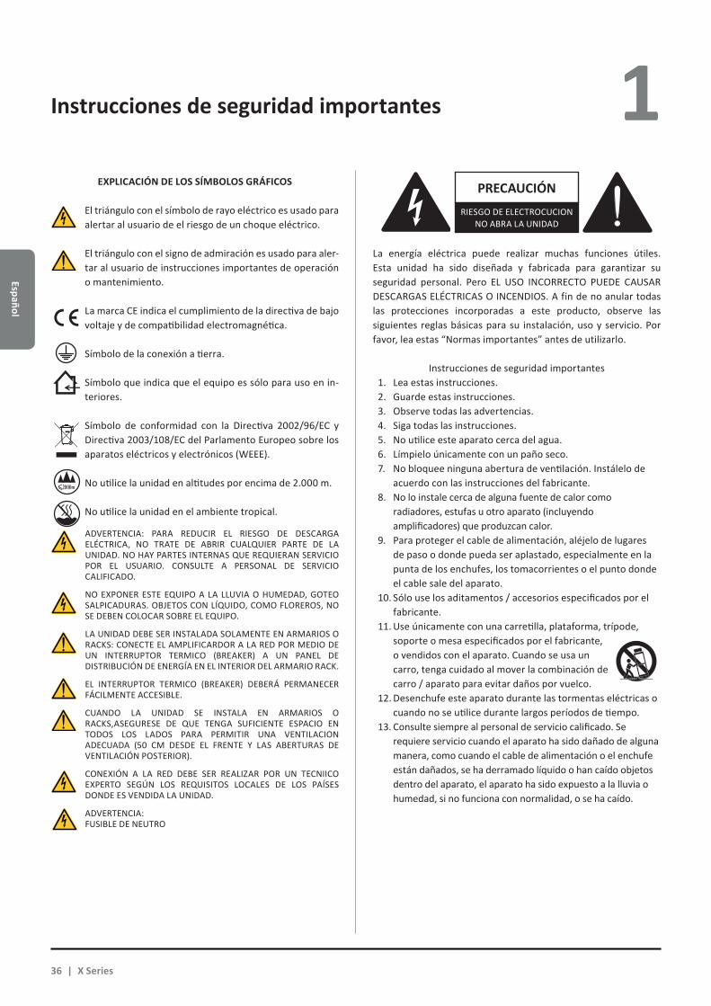
Español
PRECAUCIÓNRIESGO DE ELECTROCUCION
NO ABRA LA UNIDAD
La energía eléctrica puede realizar muchas funciones útiles. Esta unidad ha sido diseñada y fabricada para garantizar su seguridad personal. Pero EL USO INCORRECTO PUEDE CAUSAR DESCARGAS ELÉCTRICAS O INCENDIOS. A fin de no anular todas las protecciones incorporadas a este producto, observe las siguientes reglas básicas para su instalación, uso y servicio. Por favor, lea estas “Normas importantes” antes de utilizarlo.
Instrucciones de seguridad importantes1. Lea estas instrucciones.2. Guarde estas instrucciones.3. Observe todas las advertencias.4. Siga todas las instrucciones.5. No utilice este aparato cerca del agua.6. Límpielo únicamente con un paño seco.7. No bloquee ninguna abertura de ventilación. Instálelo de
acuerdo con las instrucciones del fabricante.8. No lo instale cerca de alguna fuente de calor como
radiadores, estufas u otro aparato (incluyendo amplificadores) que produzcan calor.
9. Para proteger el cable de alimentación, aléjelo de lugares de paso o donde pueda ser aplastado, especialmente en la punta de los enchufes, los tomacorrientes o el punto donde el cable sale del aparato.
10. Sólo use los aditamentos / accesorios especificados por el fabricante.
11. Use únicamente con una carretilla, plataforma, trípode, soporte o mesa especificados por el fabricante, o vendidos con el aparato. Cuando se usa un carro, tenga cuidado al mover la combinación de carro / aparato para evitar daños por vuelco.
12. Desenchufe este aparato durante las tormentas eléctricas o cuando no se utilice durante largos períodos de tiempo.
13. Consulte siempre al personal de servicio calificado. Se requiere servicio cuando el aparato ha sido dañado de alguna manera, como cuando el cable de alimentación o el enchufe están dañados, se ha derramado líquido o han caído objetos dentro del aparato, el aparato ha sido expuesto a la lluvia o humedad, si no funciona con normalidad, o se ha caído.
Instrucciones de seguridad importantes 1
ADVERTENCIA: PARA REDUCIR EL RIESGO DE DESCARGA ELÉCTRICA, NO TRATE DE ABRIR CUALQUIER PARTE DE LA UNIDAD. NO HAY PARTES INTERNAS QUE REQUIERAN SERVICIO POR EL USUARIO. CONSULTE A PERSONAL DE SERVICIO CALIFICADO.
NO EXPONER ESTE EQUIPO A LA LLUVIA O HUMEDAD, GOTEO SALPICADURAS. OBJETOS CON LÍQUIDO, COMO FLOREROS, NO SE DEBEN COLOCAR SOBRE EL EQUIPO.
LA UNIDAD DEBE SER INSTALADA SOLAMENTE EN ARMARIOS O RACKS: CONECTE EL AMPLIFICARDOR A LA RED POR MEDIO DE UN INTERRUPTOR TERMICO (BREAKER) A UN PANEL DE DISTRIBUCIÓN DE ENERGÍA EN EL INTERIOR DEL ARMARIO RACK.
EL INTERRUPTOR TERMICO (BREAKER) DEBERÁ PERMANECER FÁCILMENTE ACCESIBLE.
CUANDO LA UNIDAD SE INSTALA EN ARMARIOS O RACKS,ASEGURESE DE QUE TENGA SUFICIENTE ESPACIO EN TODOS LOS LADOS PARA PERMITIR UNA VENTILACION ADECUADA (50 CM DESDE EL FRENTE Y LAS ABERTURAS DE VENTILACIÓN POSTERIOR).
CONEXIÓN A LA RED DEBE SER REALIZAR POR UN TECNIICO EXPERTO SEGÚN LOS REQUISITOS LOCALES DE LOS PAÍSES DONDE ES VENDIDA LA UNIDAD.
ADVERTENCIA: FUSIBLE DE NEUTRO
La marca CE indica el cumplimiento de la directiva de bajo voltaje y de compatibilidad electromagnética.
Símbolo de la conexión a tierra.
Símbolo que indica que el equipo es sólo para uso en in-teriores.
Símbolo de conformidad con la Directiva 2002/96/EC y Directiva 2003/108/EC del Parlamento Europeo sobre los aparatos eléctricos y electrónicos (WEEE).
No utilice la unidad en altitudes por encima de 2.000 m.
No utilice la unidad en el ambiente tropical.
EXPLICACIÓN DE LOS SÍMBOLOS GRÁFICOS
El triángulo con el símbolo de rayo eléctrico es usado para alertar al usuario de el riesgo de un choque eléctrico.
El triángulo con el signo de admiración es usado para aler-tar al usuario de instrucciones importantes de operación o mantenimiento.
36 | X Series

Espa
ñol
1 Serie X Guía rápida 2
2 : 1.Bienvenido
Felicitaciones por la compra de un amplificador Powersoft Serie X!
Sabemos que usted está ansioso por utilizar el X8 o X4, pero por favor tome un momento para leer esta guía rápida y las ins-trucciones de seguridad. En caso de tener alguna pregunta, por favor no dude en ponerse en contacto con su proveedor o con Powersoft directamente.
Powersoft Serie X innova el concepto de la plataforma de amplificación: X8 es un amplificador de potencia de 8 canales; X4 ofrece 4 canales en una unidad de rack; ambos implementan un nuevo sistema de enrutamiento del canal, nueva fuente de alimentación y un revolucionario DSP con todas las funciones. Powersoft X8 y X4 soportan nativamente AES3, dos entradas redundantes Dante™ Audinate® digitales (opcional) y entradas analógicas, que proporciona hasta 4 fuentes de entrada seleccio-nables y diferentes por canal.
Para la configuración del sistema y puesta a punto, ArmoníaPlus™ ofrece una interfaz intuitiva, un control integral del procesamiento de audio digital y monitoreo completo en tiempo real del rendimiento del sistema. La conexión Wi-Fi integrada permite la Serie X de Powersoft acceder y gestionar a través de cualquier dispositivo móvil una interfaz de usuario desarrollada específicamente para el monitoreo local.
Powersoft X4 y X8 sube a un nuevo estándar de calidad y facilidad de uso de la amplificación: adaptan a su configuración, ahorro de espacio y peso, la legendaria eficiencia Powersoft y una nueva fuente de alimentación multi-fase compatible en todo el mundo.
2 : 2.Desempacando y chequeando algún daño durante el traslado.
Su producto Powersoft ha sido completamente probado e inspeccionado antes de salir de fábrica. Inspeccione cuidadosa-mente el paquete de envío antes de abrirlo, y luego inspeccione inmediatamente su nuevo producto. Si encuentra algún daño notificar a la empresa transportista.
La caja contiene lo siguiente:XX 1x Amplificador Serie X;XX 1x Conector de alimentación Phoenix PC 5/5-STF1-7,62;XX 1x Cubierta para el conector de alimentaciónXX 1x Guía Rápida.
2 : 3.Desecho del material de embalaje
El embalaje de transporte y protección ha sido seleccionado a partir de materiales que respetan el medio ambiente para su eliminación y, normalmente, pueden ser reciclados.
En lugar de simplemente tirar estos materiales a la basura, asegúrese de que se ofrezcan para su reciclaje.
2 : 4.Lista de paneles de imágenes
A. Dibujo Mecánico X8/X4L : dimensiones en milímetrosB. Dibujo Mecánico X4 : dimensiones en milímetrosC. Panel Trasero X8D. Panel Trasero X4LE. Panel Trasero X4F. Paneles Frontales X8 y X4L/X4G. Soportes de montaje y dirección del flujo de aireH. Regla para el apilamiento de amplificadores en estantes cerradosI. Cableado del conector de entrada XLRJ. Cableado del conector de Ethernet RJ45K. Cableado de altoparlantesL. Cableado para alimentación eléctrica en tres fases de acM. Cableado para alimentación eléctrica en una fase de acN. Cableado para alimentación eléctrica en dos fases de acO. Cubierta para el conector de alimentaciónP. Información regulatoria
Español | 37

Español
Instalación 3 3 : 1.Colocación
Los amplificadores de la Serie X están destinados a ser usados en racks solamente. La conexión de alimentación de AC de la unidad debe ser conectada a el terminal de conexión provisto a través de un interrup-tor térmico o breaker apropiado (vea §3 : 4.Alimentación Principal de AC). No está permitido conectar una unidad de la Serie X directamente a la línea de alimentación de AC. Para el Mercado de Norte América re-comendamos usar cable aprobado bajo la norma UL/CSA (Ej. ST 600Vac 105°C 5x13AWG).
Para limitar el riesgo de daños mecánicos, el amplificador debe ser debidamente atornillado al rack o estante tanto en su parte frontal como en la porterior. Recomendamos usar ocho tornillos M6 o 12-24 UNC-2B para los rieles del rack o usar tuercas de caja (cage nuts).
Instale el amplificador lo más retirado posible de radios o aparatos de televisión. Una unidad instalada muy próxima a este tipo de equipo se puede ver afectada por ruidos o por una degradación en su desem-peño. No colocar y utilizar el amplificador durante largos períodos de tiempo cercano a fuentes generadoras de calor que afectar su rendi-miento. Evite colocar el amplificador en fuentes generadoras de calor.
3 : 2.Enfriamiento
Instale el amplificador en un lugar bien ventilado: las aberturas de ventilación no deben ser obstaculizadas por cualquier elemento, como periódicos, manteles, cortinas, etc.; mantener una distancia de al menos 50 cm de los orificios de ventilación delanteros y traseros del amplificador.
Todos los amplificadores powersoft implementan un sistema de enfriamiento de aire forzado para mantener las temperaturas de funcio-namiento bajas y constantes. atraídos por los ventiladores internos, el aire entra desde el panel frontal y es forzado sobre todos los componentes, saliendo en la parte posterior del amplificador.
El sistema de enfriamiento de el amplificador cuenta con ventila-dores “inteligentes” de velocidad variable de cc que son controlados por los sensores de temperatura del disipador de calor: la velocidad del ventilador aumentará sólo cuando la temperatura detectada por los sensores se eleva sobre valores cuidadosamente predeterminados. Esto asegura que el ruido del ventilador y la acumulación de polvo interno se mantienen al mínimo.
Sin embargo si el amplificador esta sujeto a una carga térmica ex-trema, el ventilador fuerza un volumen muy grande de aire a través del disipador de calor. En el caso extremadamente raro que el amplificador detecte circuitos peligrosamente sobrecalentados, los circuitos de pro-tección apagaran todos los canales hasta que el amplificador se enfría a una temperatura de operación segura. El funcionamiento normal se reanuda automáticamente sin necesi-dad de intervención del usuario.
Los amplificadores de la serie X se pueden apilar uno encima del otro gracias al sistema de refrigeración eficiente con que están equipados.
Sin embargo, existe un límite de seguridad que debe observarse:
3 : 3.Limpieza
Siempre utilice un paño seco para limpiar el chasis y el panel frontal. La limpieza del filtro de aire debe ser programada de acuerdo a los niveles de polvo en el entorno operativo del amplificador.
Desconecte la fuente principal de energía antes de limpiar cualquier parte del amplificador.
Para limpiar los filtros de aire es necesario remover la cubierta frontal: nunca intente abrir ninguna otra parte de la unidad. Con una llave milimétrica hexagonal #6, remueva los dos tornillos ubicados a cada lado del panel frontal, (vea la FIG. 1) con cuidado levante la cu-bierta y remueva el filtro. Puede usar aire comprimido para eliminar el polvo, o puede lavarlo (una vez fuera de la unidad) con agua limpia: en este caso asegúrese de que el filtro este totalmente seco antes de reinstalarlo.
3 : 4.Alimentación Principal de AC
Los amplificadores de la Serie X ofrecen total compatibilidad global de CA y la conexión directa a cualquier configuración de línea de po-tencia regional. La fuente de alimentación legendariamente confiable de Powersoft es ahora adecuada para operación monofásica, bifásica o trifásica desde 85 VCA hasta 440 VCA (nominal 100 VCA a 240 VCA ± 10% monofásica y 173 VCA a 440 VCA ± 10% trifásica) sin necesidad de selección manual: el equilibrio de carga trifásica real es directamente efectuado por la unidad sin ninguna compleja asignación de la carga en el diseño del sistema de distribución de energía.
Para la conexión de la alimentación principal se proporciona un conector euroblock Phoenix PC 5/5-STF1-7,62 conector volante (Phoenix producto ID 1777862). Se debe respetar la configuración de cableado del servicio eléctrico en el ensamblaje del conector volante y los conductores de alimentación.
Es importante conectar cada uno de los cinco contac-tos en el conector volante a los cables de alimentación de acuerdo a la configuración mostrada en el Panel K, L, M a p. 13 and p. 14. De manera de garantizar una apropiada conexión recomendamos usar cables aprobados bajo la norma UL/CSA (i.e. ST 600Vac 105°C 5x13AWG).
en caso de que se utilice un estante o rack con paneles cerrados atrás, dejar una unidad de rack vacía cada cuatro amplificadores instalados para garantizar el flujo de aire adecuado (vea Panel G, p. 10).
FIG. 1: Use una llave hexagonal #6 para remover la cubierta frontal.
38 | X Series
Espa
ñol
3
NOTA: La imagines e instrucciones mostradas se refieren a la nor-ma Europea CENELEC de Abril 2004 (IEC 60446) identificación de código de colores en cables (ver TAB. 1).
Conductor Color
Neutro N Azul
Líneas o Fases
L1 Marrón
L2 Negro
L3 Gris
Tierra Eléctrica E Verde/ Amarillo
TAB. 1: Código de colores para identificación de conductores.
La conexión a la red eléctrica local debe ser hecha por personal calificado de acuerdo a las
normas regionales.
3 : 4.1. Alimentación Eléctrica en Tres FasesCada conductor único debe fijarse a la clavija de conexión PC
5/5-STF1-7,62, como se muestra en el Panel K, p. 13. En algunos casos la conexión a neutro puede no ser necesaria: en sistemas trifásicos Delta la conexión del neutro no es ni siquiera necesario dada la capacidad de la Serie X para trabajar bajo esta condición.
3 : 4.2. Alimentación Eléctrica en Dos FasesPara alimentar la unidad bajo la configuración de dos fases
balanceadas sin neutro 2L+T se debe hacer la conexión a la cla-vija volante PC 5/5-STF1-7,62 como se muestra en el Panel M, p. 14. Tome la precaución de duplicar la sección del cable en el disyuntor o interruptor automático de manera de garantizar la apropiada conducción.
3 : 4.3. Alimentación Eléctrica en Una FaseUna configuración básica L+N+T, para una fase desbalanceada
es comúnmente usada en alimentaciones con una fase y neutro; el cableado debe ser efectuado como se muestra en el Panel L, p. 13. Tome la precaución de duplicar la sección del cable en el disyuntor o interruptor automático de manera de garantizar la apropiada conducción.
3 : 5.Precauciones sobre la instalaciónADVERTENCIA PARA PREVENIR FUEGOS
O CHOQUES ELECTRICOS
Xf Este dispositivo tiene que ser conectado a la tierra eléctrica de la red de acuerdo a la norma IEC 364 o similar.
Xf Instalar la unidad solamente dentro de un estante o rack.
Xf Un disyuntor o interruptor automático debe ser instalado para cada amplificador en el estante o rack.
Xf Preste atención a asegurar correctamente cada cable de alimentación a la clavija volante Phoenix PC 5/5-STF1-7,62.
Xf Una vez cableada correctamente fije la clavija volante den-tro de la cubierta protectora proveida por Powersoft.
Xf Fije la clavija volante a la entrada eléctrica de la unidad.
Xf Antes de encender este amplificador verifique que el voltaje de alimentación es el correcto.
Xf Verifique que su conexión eléctrica es capaz de satisfacer el consumo de potencia que requerido por el amplificador.
Xf No utilice este amplificador si el cable de alimentación eléc-trica está roto o defectuoso.
Xf Los terminales de salida son peligrosos: la conexión del ca-bleado a estos terminales requiere de una persona instruida en el uso de cables confeccionados.
Xf Tenga cuidado de asegurar los terminales de salida antes de encender el equipo.
Xf Para evitar una descarga eléctrica no toque ningún cable de parlante expuesto mientras el amplificador esté operando.
Xf No salpique otros líquidos sobre el amplificador.
Xf Ningún tipo de objeto con llama expuesta como por ejemplo velas debe colocarse sobre el amplificador.
Xf No remueva la tapa del equipo. El hacer esto puede expo-nerlo a voltajes potencialmente peligrosos.
Xf El fabricante no se hace responsable de los daños causados a personas, cosas o datos debido a una conexión a tierra inadecuada u omitida.
Xf Para el mantenimiento de rutina y reparaciones, póngase en contacto con su distribuidor autorizado más cercano.
Es absolutamente necesario verificar estos requisitos fundamentales de seguridad y, en caso de duda, requieren
una comprobación precisa de personal calificado.
Este dispositivo tiene que ser conectado a la tierra eléctrica de la red de acuerdo a
la norma IEC 364 o similar.
Dado que el interruptor eléctrico principal de esta unidad no provee una total aislación de la red eléctrica se debe desconectar físicamente el cableado a la red para una total desconexión de la fuente eléctrica
El amplificador debe ser conectado a la red eléctrica a través de un disyuntor o
interruptor automático.
Interruptores sugeridos para X8 dependiendo del tipo de alimentación eléctrica:
Una Fase AC (L+N+T): 32 A de rango, curva C o D, 10 kA;Tres Fases AC (3L+N+T): 4 x 16 A de rango, curva C o D, 10kA.
Para X4:single-phase AC (P+N+E): 16 A rating, C or D curve, 10 kA;three-phase AC (3P+N+E): 4 x 10 A rating, C or D curve, 10 kA.
Español | 39

Español
3 : 6.Encendido
Tan pronto como se conecta el amplificador a la red de energía, la fuente de alimentación del amplificador empezará a suministrar energía a los sistemas auxiliares. El círculo exterior del botón central empieza a parpadear blanco: el amplificador está en modo de espera.
Presionando el botón central se encenderá el amplificador.
3 : 7.Apagado
Mantenga presionado el botón central durante 3 segundos para apagar el amplificador. La unidad pasa al modo de espera y el círculo exterior del botón central parpadea blanco. La unidad se apaga por completo sólo cuando el conector de alimentación está desenchufado.
3 : 8.Silenciado
Una pulsación corta en el botón central silencia todos los canales activos: cualquier canal previamente silenciado permane-cerá en estado de silencio. Todos los demás botones circulares (excepto el central) silencian el canal de salida correspondiente.
NOTA: Tenga en cuenta que cuando el amplificador está vincula-do y controlado por Armonía Pro Audio™ Suite todos los interrupto-res MUTE se desactivan a nivel local.
3 : 9.Interruptor Wi-Fi
Pulse el botón blanco de la izquierda: el botón se iluminará y el sistema establecerá una nueva red Wi-Fi local cuyo SSID es en la forma: Powersoft-MODELO-NUMERO DE SERIE (por ejemplo Powersoft-X8-70133) y la contraseña de fábrica es: 0123456789. Pulse de nuevo el botón de la izquierda para apagar esta red Wi-Fi.
3 : 10.Armonía callback
Con el fin de detectar la unidad en el espacio de trabajo en Armonía, presione en el botón blanco más a la derecha. Por otra parte, si hace clic en Un / Blink en el menú contextual del amplifi-cador en el área de trabajo en Armonía, todos los LEDs frontales del amplificador van a parpadear durante un tiempo.
Wi-Fi 4 Siga este procedimiento para activar la conexión Wi-Fi y acce-
der remotamente a su amplificador Powersoft Serie X.
1. Encienda el amplificador manteniendo pulsado el botón central en el panel frontal;
2. Pulse el botón de la izquierda en el panel frontal: el botón se iluminará y el sistema establecerá una nueva red Wi-Fi local cuyo SSID es en la forma:
Powersoft-MODELNAME-SERIE (e.d. Powersoft-X8-71520)
3. Conecte su dispositivo móvil y seleccione la red Wi-Fi;
4. Conéctese a la red Wi-Fi con el SSID correcto;
5. Introduzca la contraseña de cifrado establecida en fábrica para esta red Wi-Fi:
0123456789
6. Abra el navegador web y escriba la dirección IP siguiente en la barra de direcciones:
192.168.0.1
7. El sistema enviará la interfase de usuario al navegador: ahora usted puede empezar a gestionar su plataforma am-plificador de la Serie X.
8. Para llamar la interfase rápidamente, sugerimos marcar la página en la pantalla de inicio de su dispositivo móvil; por ejemplo, en iOS dispositivo, haga clic en el icono de acción y seleccione “Añadir a pantalla de inicio” cuando la interfaz se ha cargado por completo.
9. Recuerde apagar la red Wi-Fi local, cuando el seguimiento y la configuración básica no son más necesarios: pulse el botón más a la izquierda en el panel frontal por apagar el Wi-Fi.
MUTEAR/DESMUTEAR CH2
MUTEAR/DESMUTEAR TODOS
40 | X Series
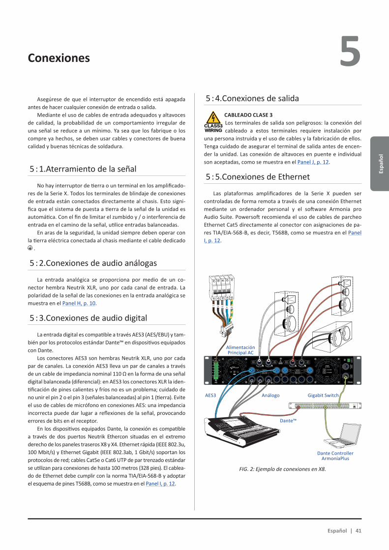
Espa
ñol
4 Conexiones 5 Asegúrese de que el interruptor de encendido está apagada
antes de hacer cualquier conexión de entrada o salida.Mediante el uso de cables de entrada adequados y altavoces
de calidad, la probabilidad de un comportamiento irregular de una señal se reduce a un mínimo. Ya sea que los fabrique o los compre ya hechos, se deben usar cables y conectores de buena calidad y buenas técnicas de soldadura.
5 : 1.Aterramiento de la señal
No hay interruptor de tierra o un terminal en los amplificado-res de la Serie X. Todos los terminales de blindaje de conexiones de entrada están conectados directamente al chasis. Esto signi-fica que el sistema de puesta a tierra de la señal de la unidad es automática. Con el fin de limitar el zumbido y / o interferencia de entrada en el camino de la señal, utilice entradas balanceadas.
En aras de la seguridad, la unidad siempre deben operar con la tierra eléctrica conectada al chasis mediante el cable dedicado
.
5 : 2.Conexiones de audio análogas
La entrada analógica se proporciona por medio de un co-nector hembra Neutrik XLR, uno por cada canal de entrada. La polaridad de la señal de las conexiones en la entrada analógica se muestra en el Panel H, p. 10.
5 : 3.Conexiones de audio digital
La entrada digital es compatible a través AES3 (AES/EBU) y tam-bién por los protocolos estándar Dante™ en dispositivos equipados con Dante.
Los conectores AES3 son hembras Neutrik XLR, uno por cada par de canales. La conexión AES3 lleva un par de canales a través de un cable de impedancia nominal 110 Ω en la forma de una señal digital balanceada (diferencial): en AES3 los conectores XLR la iden-tificación de pines calientes y fríos no es un problema; cuidado de no unir el pin 2 o el pin 3 (señales balanceadas) al pin 1 (tierra). Evite el uso de cables de micrófono en conexiones AES: una impedancia incorrecta puede dar lugar a reflexiones de la señal, provocando errores de bits en el receptor.
En los dispositivos equipados Dante, la conexión es compatible a través de dos puertos Neutrik Ethercon situadas en el extremo derecho de los paneles traseros X8 y X4. Ethernet rápida (IEEE 802.3u, 100 Mbit/s) y Ethernet Gigabit (IEEE 802.3ab, 1 Gbit/s) soportan los protocolos de red; cables Cat5e o Cat6 UTP de par trenzado estándar se utilizan para conexiones de hasta 100 metros (328 pies). El cablea-do de Ethernet debe cumplir con la norma TIA/EIA-568-B y adoptar el esquema de pines T568B, como se muestra en el Panel I, p. 12.
5 : 4.Conexiones de salida
CABLEADO CLASE 3Los terminales de salida son peligrosos: la conexión del cableado a estos terminales requiere instalación por
una persona instruida y el uso de cables y la fabricación de ellos. Tenga cuidado de asegurar el terminal de salida antes de encen-der la unidad. Las conexión de altavoces en puente e individual son aceptadas, como se muestra en el Panel J, p. 12.
5 : 5.Conexiones de Ethernet
Las plataformas amplificadores de la Serie X pueden ser controladas de forma remota a través de una conexión Ethernet mediante un ordenador personal y el software Armonia pro Audio Suite. Powersoft recomienda el uso de cables de parcheo Ethernet Cat5 directamente al conector con asignaciones de pa-res TIA/EIA-568-B, es decir, T568B, como se muestra en el Panel I, p. 12.
CLASS3WIRING
1 2 3 4 5 6 7 8
25 26 27 28 29 30 31 32
9 10 11 12 13 14 15 16
33 34 35 36 37 38 39 40
17 18 19 20 21 22 23 24
41 42 43 44 45 46 47 48 UP Link
Power
L1 L2 L3 N PE
AES3 IN7-8 5-6 AES3 IN3-4 1-2
ANALOG INANALOG IN
8 7 6 5 4 3 2 1
3PH 1PH
L1
L2
L3
N
L
N
1=GND2 = IN+3 = IN-
MAINS
TURN TO LOCK TURN TO LOCKTURN TO LOCK TURN TO LOCK
FIG. 2: Ejemplo de conexiones en X8.
Español | 41
Alimentación Principal AC
AES3 Análogo Gigabit Switch
Dante™
Dante ControllerArmoníaPlus
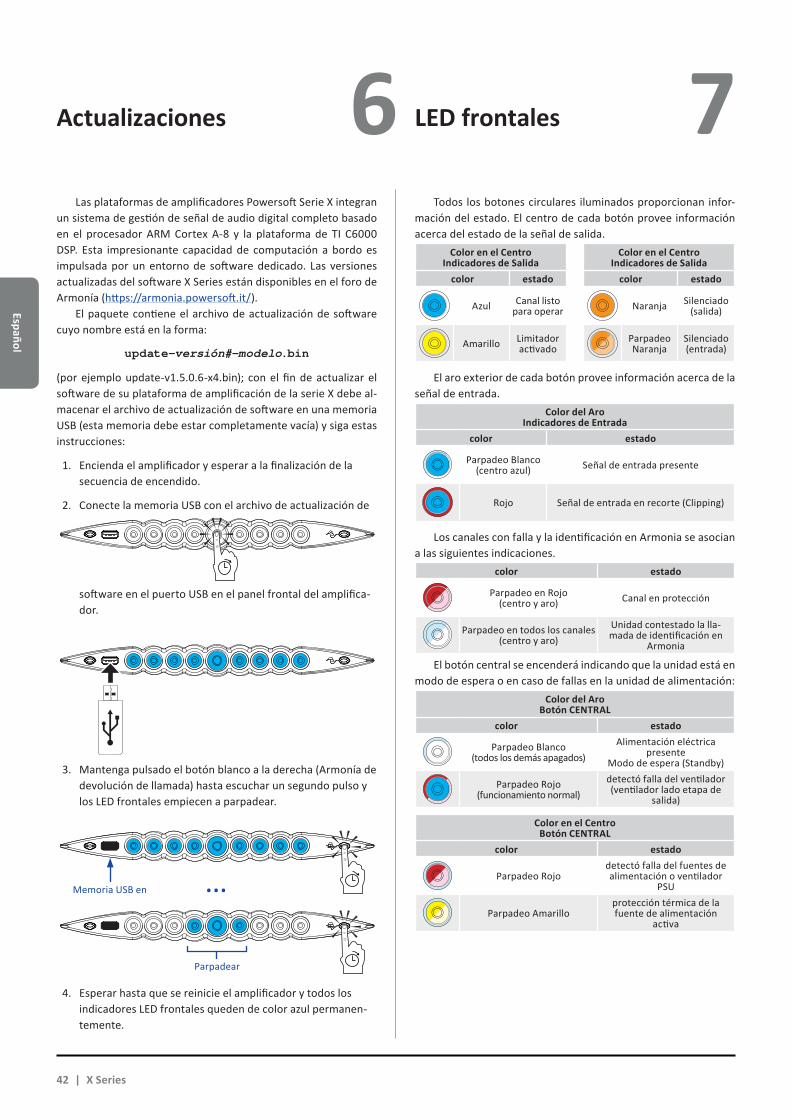
Español
Actualizaciones LED frontales6 7 Las plataformas de amplificadores Powersoft Serie X integran
un sistema de gestión de señal de audio digital completo basado en el procesador ARM Cortex A-8 y la plataforma de TI C6000 DSP. Esta impresionante capacidad de computación a bordo es impulsada por un entorno de software dedicado. Las versiones actualizadas del software X Series están disponibles en el foro de Armonía (https://armonia.powersoft.it/).
El paquete contiene el archivo de actualización de software cuyo nombre está en la forma:
update-versión#-modelo.bin
(por ejemplo update-v1.5.0.6-x4.bin); con el fin de actualizar el software de su plataforma de amplificación de la serie X debe al-macenar el archivo de actualización de software en una memoria USB (esta memoria debe estar completamente vacía) y siga estas instrucciones:
1. Encienda el amplificador y esperar a la finalización de la secuencia de encendido.
2. Conecte la memoria USB con el archivo de actualización de
software en el puerto USB en el panel frontal del amplifica-dor.
3. Mantenga pulsado el botón blanco a la derecha (Armonía de devolución de llamada) hasta escuchar un segundo pulso y los LED frontales empiecen a parpadear.
4. Esperar hasta que se reinicie el amplificador y todos los indicadores LED frontales queden de color azul permanen-temente.
Todos los botones circulares iluminados proporcionan infor-mación del estado. El centro de cada botón provee información acerca del estado de la señal de salida.
Color en el CentroIndicadores de Salida
Color en el CentroIndicadores de Salida
color estado color estado
Azul Canal listo para operar Naranja Silenciado
(salida)
Amarillo Limitador activado
Parpadeo Naranja
Silenciado (entrada)
El aro exterior de cada botón provee información acerca de la señal de entrada.
Color del AroIndicadores de Entrada
color estado
Parpadeo Blanco (centro azul) Señal de entrada presente
Rojo Señal de entrada en recorte (Clipping)
Los canales con falla y la identificación en Armonia se asocian a las siguientes indicaciones.
color estado
Parpadeo en Rojo(centro y aro) Canal en protección
Parpadeo en todos los canales(centro y aro)
Unidad contestado la lla-mada de identificación en
Armonia
El botón central se encenderá indicando que la unidad está en modo de espera o en caso de fallas en la unidad de alimentación:
Color del AroBotón CENTRAL
color estado
Parpadeo Blanco (todos los demás apagados)
Alimentación eléctrica presente
Modo de espera (Standby)
Parpadeo Rojo (funcionamiento normal)
detectó falla del ventilador(ventilador lado etapa de
salida)
Color en el CentroBotón CENTRAL
color estado
Parpadeo Rojodetectó falla del fuentes de alimentación o ventilador
PSU
Parpadeo Amarilloprotección térmica de la fuente de alimentación
activa
Parpadear
Memoria USB en ...
42 | X Series
Espa
ñol
Redes 8 Las plataformas de amplificación de la Serie X soportan topo-
logías de conexión en cadena, en estrella o en círculos; en una red en cadena el ordenador con el programa ArmoníaPlus debe estar siempre al final de la cadena.
Tenga presente que este tipo de conexión en cadena no ga-rantiza confiabilidad en ambientes de producción, debido a que una falla puede seccionar la red y se puede perder el control del sistema.
Cuando la eficiencia y la confiabilidad son inobjetables es aconsejable un sistema redundante de la conexión a la red. Para poder explotar las características Dante se recomienda usar cone-xiones en estrella y en cadena.
8 : 1.Direccionamiento de IP
La configuración de red predeterminada de fábrica son DHCP / IP automática, a fin de que la plataforma de amplificación se auto-configure cuando se conecta a una red LAN o PC existente. La opción IP fija también puede ser adoptada y se configura me-diante ArmoníaPlus. Si un servidor DHCP no está activo dentro de la red, la plataforma de amplificación inicia una dirección sin estado de configuración automática (es decir, la metodología Zeroconf – Zeroconf): se auto asigna una dirección local de red numérica (del tipo 169.254.xy – 172.31. * * para la red secundaria si está presente – con una máscara de subred 255.255.0.0) y automáticamente distribuye y resuelve los nombres de host de dispositivos en red. Para configurar una dirección IP estática, consulte la guía del usuario Audio Suite Pro Armonía
8 : 1.1. Solución de problemas de direccionamiento IP
Al conectar la Serie X en un entorno de red, puede ocurrir que ArmoníaPlus no descubre o importe el amplificador.
Por lo general, se trata de un problema de direccionamiento IP: tanto Armonia y la Serie X deben pertenecer a la misma su-bred. Si un servidor DHCP presente en la red y una plataforma de amplificación de la Serie X están en AUTO IP, las redes pueden volverse inestable
Como regla general, encender el servidor DHCP antes de conectar los amplificadores.
Se establece el direccionamiento IP de un amplificador de la Serie X durante el arranque: cuando la plataforma de amplifica-ción de la Serie X descubre un servidor DHCP en la red durante el inicio, negocia los parámetros de red. Si la plataforma de ampli-ficación no revela un servidor DHCP en la red durante el inicio se fija en el modo AUTO IP.
8 : 2.Redes Dante™
Los modelos de la plataforma de amplificación de la serie X equipados con Dante soportan redes redundantes a través de los dos puertos Ethernet ubicados en el panel trasero:XX Primary/ETH1 es el puerto primario;XX Secondary/ETH2 es el puerto secundario de red. La conexión Dante está siempre apoyada en el puerto Primario
/ ETH1 Gigabit Ethernet; el / puerto ETH2 Gigabit Ethernet secun-dario ofrece continuidad de la operación cuando se establece una red redundante en paralelo. Con el fin de implementar una red de Dante, tiene que ser usado un equipo que ejecuta el controlador Dante. El controlador de Dante es una aplicación de software que gestiona los dispositivos en la red. Las plataformas de amplifica-ción de la serie X se detectan automáticamente y se muestran en el controlador de Dante con el identificador seleccionado de fábrica NOMBREDEMODELO-SERIAL (e.g. X8-71520).
Las redes Dante casi siempre requerirán al menos un con-mutador de red. Infraestructuras redundantes pueden requerir múltiples conmutadores. Para obtener la máxima fiabilidad, el conmutador de red deberá:
Xf Rango Gigabit Ethernet;
Xf Non-blocking;
Xf Calidad de Servicio (QoS) de al menos cuatro estados;
Xf Tener Diffserv (DSCP) QoS con estricta prioridad;
Xf Tener EEE (Energy efficient ethernet) apagado.
Para una información más detallada acerca de las caracte-rísticas de operación de un conmutador refiérase al manual del fabricante.
8 : 2.1. Configuración de Redes redundantes Una red Dante redundante se puede configurar y utilizar
entre cualquier equipo de audio habilitado con Dante: funciona mediante el uso de dos redes completamente independientes y separadas, la red primaria y la red secundaria. Para configurar y usar Dante redundante, conecte la plataforma amplificación de la Serie X y otros equipos de audio equipados con Dante utilizando conmutadores Gigabit duplicados y cables Ethernet. Conecte su equipo con la tarjeta de sonido virtual Dante y el controlador de Dante, y otros equipos con Dante no redundante a la Red Primaria.
Las redes primarias y secundarias, no deberán estar conecta-das entre sí en ningún punto. Asegúrese de que cualquier equipo está configurado para obtener automáticamente su dirección IP.
Español | 43

Español
ArmoníaPlus 9 ArmoníaPlus es la interface que permite la configuración del
sistema y la personalización de las plataformas de amplificación de la Serie X. Armonía se puede instalar en un PC con Windows (XP SP3 y superior). Descarga ArmoníaPlus del foro Armonía:
https://armonia.powersoft.it/
Las plataformas de amplificación de la Serie X pueden conec-tarse a la PC con Armonía a través de una conexión Ethernet rápida. Con el fin de iniciar la operación remota, el dispositivo debe ser descubierto e importado al espacio de trabajo en Armonia. Haga clic en el botón Descubrir en la ventana entidades remotas, o se-leccionarlo de la lista Modelo y arrastrarlo al espacio de trabajo en Armonía (Workspace).
El botón de devolución de llamada - situado más a la dere-cha en el panel frontal del amplificador - le permite resaltar la presencia del amplificador en Armonía en el espacio de trabajo. Una vez conectado a ArmoníaPlus un doble clic en el icono de amplificador en el espacio de trabajo abrirá el panel de control del amplificador. Aquí es posible acceder y configurar todas las características de la plataforma de la serie X.
9 : 1.Ruteo de señal y arquitectura del DSP
El procesamiento de señales en las plataformas del amplifica-ción Powersoft Serie X realiza múltiples funciones que afectan a la señal de audio antes de la amplificación de potencia; los prin-cipales ajustes incluyen ganancia, polaridad, retraso, limitación y ecualización de la señal; algunos procesos están relacionados sólo a determinadas etapas, como la limitación y control de la amortiguación que se implementan únicamente en la sección de salida, o la asignación de prioridad de entrada disponible en la sección de entrada.
La arquitectura del proceso está compuesta por seis secciones:XX Selección de fuente de entrada. La sección de entrada le per-
mite gestionar de ganancia de entrada y el retraso de fuentes analógicas y digitales, con el fin de compensar la latencia de
transmisión y niveles. Además, la Serie X implementa una po-lítica de copia de seguridad destinada a mejorar la fiabilidad contra defecto a la señal. Al asignar una prioridad para las cuatro fuentes de entrada diferentes - analógica, AES3 y dos Dante - por canal, el sistema es capaz de cambiar automática-mente a una conexión de entrada fiable en caso de cualquier fallo de la señal. XX Matriz. La innovadora matriz de enrutamiento de la Serie X
permite enviar cualquier entrada a cualquier salida. La matriz implementa una arquitectura de enraizamiento no booleana que permite la asignación de canal libre y ajuste de nivel. XX Procesamiento Avanzado. Esto le permite optimizar los nive-
les y las formas de onda de las señales de entrada. Es posible manipular ganancia y ajuste de polaridad, filtros paramétricos completos de coseno elevado asimétricos, retardo y mute en cada canal en la sección de altavoces.XX Ecualización de altavoces. Diseñado para gestionar las defini-
ciones de configuración para sistemas multi-vias, implementa filtros paramétricos completos FIR e IIR.XX Enrutamiento altavoz. Una vez agrupados correctamente,
los canales de salida se presentan a la matriz como altavoces - una sola fila que representa un altavoz (en realidad grupo por vías) - permitiendo un alto grado ajuste fino en el proce-samiento de la señal.XX El procesamiento de salida. Esto permite el ajuste fino de las
señales de salida, con el objetivo de optimizar la entrega de potencia y el rendimiento del altavoz. Proporciona ganancia y ajuste de polaridad, IIR y filtros paramétricos completos FIR, retraso, mute, limitación y control de la amortiguación en cada canal de salida.
9 : 2.Flujo de Trabajo Propuesto
Una vez que el diseño del altavoz se ha definido, se sugiere un procedimiento de configuración de abajo hacia arriba que comienza a partir de la configuración de la disposición de trans-ductores y avanzando hacia la selección de entrada y la definición de la política de seguridad a la entrada.
Brevemente, los principales pasos a seguir son:1. Cargue los preset del altavoz o manualmente configure las
características del mismo (agrupamiento de los canales de salida, cortes de frecuencia, limitadores, procesamiento del parlante, etc.).
2. Defina el enrutamiento y los niveles de las señales de cada canal de entrada a cada canal de salida. (matriz).
3. Seleccione la fuente de señal desde las conexiones de en-trada y defina su política de reserva (selección de fuente de entrada).
FIG. 3: ArmoníaPlus.
44 | X Series

Espa
ñol
Garantía y Asistencia 10 10 : 1.Garantía
10 : 1.1. Garantía del productoPowersoft garantiza sus productos manufacturados de estar
libres de componentes y fabricación defectuosa por un período de 48 (cuarenta y ocho) meses, a partir de la fecha de compra impresa en la factura de Powersoft (o de cualquiera de las de su distribuidor autorizado) al cliente final. Todas las reparaciones y modificaciones deben realizarse en las instalaciones de Powersoft o en un centro de servicio autorizado, sin costo para el comprador. Exclusión de garantías: La garantía Powersoft no cubre el mal funcionamiento o avería causada por: mal uso, abuso, reparaciones o alteraciones realizadas por personal no autorizado, conexiones incorrectas, la exposición a condiciones climáticas adversas, daños mecánicos (incluyendo accidentes de envío), y desgaste normal. Powersoft llevará a cabo los servicios de garantía, siempre que el producto no se dañe durante el transporte.
10 : 1.2. DevolucionesLos bienes pueden ser devueltos a Powersoft sólo después
de que se han concedido un número de autorización de devo-lución de mercancía (RMA) para ser fijado al empaque externo. Powersoft (o su servicio autorizado) tiene el derecho de rechazar cualquier equipo retornado sin un número de RMA.
10 : 1.3. Reparación o ReemplazoPowersoft se reserva el derecho de reparar o reemplazar los
bienes defectuosos cubiertos por la garantía del producto, a su sola discreción y como lo considere mejor.
10 : 1.4. Costo y Responsabilidad del TransporteEl comprador (o usuario final / cliente) es el único responsable
de todos los costos de transporte y los riesgos asociados con el envío de bienes cubiertos por garantía a Powersoft o su centro de servicio autorizado. Powersoft asumirá plena responsabilidad y cubrirá todos los costos incurridos para enviar la mercancía de vuelta al comprador (o usuario final / cliente).
10 : 2.Asistencia
No hay piezas reparables por el usuario en su amplificador. Consulte el servicio a personal técnico calificado. Además de con-tar con un departamento de servicio en la empresa, Powersoft respalda una red de centros de servicio autorizados. Si su amplifi-cador necesita reparación contacte con su distribuidor Powersoft. También puede ponerse en contacto con el departamento de ser-vicio técnico de Powersoft para obtener la ubicación del centro de servicio autorizado más cercano.
Aunque la mayoría de los problemas de mal funcionamiento
del producto puede ser resueltos en sus instalaciones a través de la línea de Powersoft de Atención al Cliente o con su conocimiento directo, en ocasiones, debido a la naturaleza de la falla, puede ser que sea necesario devolver productos defectuosos a Powersoft para su reparación. En este último caso, antes de enviar, se ruega a seguir paso a paso el procedimiento descrito a continuación:XX Obtener el "Forma Reporte de Defecto" poniéndose en
contacto con nuestro Departamento de Atención a través del correo electrónico [email protected] o descargar el "Formulario de Informe de Defecto" de la página web de Powersoft (http://www.powersoft-audio.com/en/support/service).XX Llene una "forma de informe de defectos" para cada
artículo devuelto (la forma es una pestaña editable en el documento) y guardar como su nombre, modelo de amplificador y número de serie, por ejemplo (distributor-namek10sn17345.doc) proporcionar toda la información requerida, excepto el código RMA / s y enviarlo a [email protected] para su aprobación Powersoft.XX En el caso de informes de defectos aprobados por el
Representante de Servicio al Cliente de Powersoft usted recibirá un código de autorización de RMA (un código de RMA para cada equipo retornado).XX Al recibir el código RMA debe empaquetar la unidad y colo-
que el código RMA fuera del paquete, protegido en un sobre transparente resistente al agua y que sea claramente visible.
Todos los artículos de vuelta deben ser enviados a la siguiente dirección:
PowersoftVia dei Cadolingi, 1350018 Scandicci (FI) Italy
En caso de envío desde países no pertenecientes a la Comunidad Europea asegúrese de que también ha seguido las instrucciones descritas en el documento disponible para su des-carga en el enlace TEMPORARY EXPORTATION / IMPORTATION PROCEDURE (procedimiento exportación / importación tempo-ral) en http://www.powersoft-audio.com/en/support/service.
Gracias por su comprensión y cooperación y el apoyo conti-nuado a medida que trabajamos para mejorar nuestra asociación.
9
Español | 45
Italiano
L’elettricità viene usata per svolgere molte funzioni utili, ma può anche causare danni personali o agli oggetti se applicata in modo improprio. Questo prodotto è stato progettato e realizzato con la massima attenzione alla sicurezza. Tuttavia, UN USO IMPROPRIO PUÒ PRODURRE SCOSSE ELETTRICHE E/O INCENDI. Per evitare po-tenziali pericoli, osservare le seguenti istruzioni durante l’installa-zione, l’utilizzo e la pulizia del prodotto. Per garantire la sicurezza e prolungare la vita utile del monitor LCD, leggere attentamente le seguenti precauzioni prima di usare il prodotto.
Importanti istruzioni di sicurezza1. Leggere queste istruzioni.2. Conservare le istruzioni.3. Tenere conto di tutti gli avvisi.4. Seguire tutte le istruzioni.5. Non usare l’apparecchio in prossimità di acqua.6. Pulire solo con un panno asciutto.7. Non ostruire le prese di ventilazione. Installare secondo le
indicazioni del produttore.8. Non installare vicino a fonti di calore quali radiatori, boc-
chette dell’aria calda, stufe o altri apparecchi (compresi gli amplificatori) che producono calore.
9. Evitare di calpestare o di schiacciare il cavo di alimentazio-ne, in particolare in corrispondenza di spine, prese della corrente e punto di uscita dall’apparecchio.
10. Usare solo accessori specificati dal produttore.11. Usare solo con il supporto indicato dal produttore (carrello,
piedistallo, cavalletto, staffa o tavolo) o venduto con l’apparecchio. Se si usa il carrello, fare atten-zione durante il trasporto dell’apparecchio sul carrello per evitare danni causati dal ribaltamen-to.
12. Scollegare l’apparecchio dalla presa di corrente durante i temporali o se inutilizzato per lunghi periodi di tempo.
13. Ricorrere a personale qualificato per qualsiasi intervento. Tali interventi sono necessari in caso di guasti dell’apparec-chio quali danneggiamento del cavo di alimentazione o della spina, versamento di liquidi o caduta di oggetti nell’apparec-chio, esposizione a pioggia o umidità o se l’apparecchio non funziona normalmente o è caduto
AT TENZIONE
RISCHIO DI SCOSSE ELETTRICHE, NON APRIRE
ATTENZIONE: PER RIDURRE IL RISCHIO DI SCOSSE ELETTRICHE, NON TENTARE DI APRIRE ALCUNA PARTE DELL’UNITÀ. NON CI SONO PARTI INTERNE AD USO UTENTE. RIVOLGERSI A PERSONALE QUALIFICATO PER L’ASSISTENZA.
NON ESPORRE QUESTO APPARECCHIO ALLA PIOGGIA, UMIDITÀ O SOSTANZE LIQUIDE. OGGETTI PIENI DI LIQUIDI, COME VASI, NON DEVONO ESSERE COLLOCATI SU QUESTO APPARATO.
L’UNITÀ DEVE ESSERE INSTALLATA SOLO IN ARMADI RACK: COLLEGARE IL CAVO DI ALIMENTAZIONE DELL’AMPLIFICATORE AD UN INTERRUTTORE DI SEZIONAMENTO IN UN PANNELLO DI DISTRIBUZIONE ALL’INTERNO DELL’ARMADIO RACK.
L’INTERRUTTORE DI SEZIONAMENTO DEVE ESSERE SEMPRE ACCESSIBILE.
QUANDO L’UNITÀ È INSTALLATA IN UN ARMADIO RACK, ASSICURARSI CHE RIMANGA SPAZIO SUFFICIENTE SU TUTTI I LATI PER CONSENTIRE UN’ADEGUATA VENTILAZIONE (50 CM DAI FORI DI VENTILAZIONE ANTERIORI E POSTERIORI).
LA CONNESSIONE ALLA RETE ELETTRICA DEVE ESSERE EFFETTUATA DA PERSONALE ESPERTO IN ELETTROTECNICA, IN ACCORDO CON I REQUISITI NAZIONALI DEL PAESE IN CUI L’UNITÀ È VENDUTA.
ATTENZIONE: FUSIBILE SUL NEUTRO
SPIEGAZIONE DEI SIMBOLI GRAFICI
Il triangolo con il lampo è utilizzato per avvisare l’utente del rischio di scossa elettrica.
Il triangolo con il punto esclamativo è utilizzato per avvisa-re l’utente di importanti istruzioni d’uso e manutenzione.
Il marchio CE indica la conformita’ del prodotto atutte le direttive europee applicabili.
Simbolo della connessine di terra.
Simbolo che indica che l’apparecchio è solo per uso inter-no.
Simbolo di conformità alla Direttiva 2002/96/CE e alla Direttiva 2003/108/CE del Parlamento Europeo sulle appa-recchiature elettriche ed elettroniche (RAEE).
Non utilizzare l’unità ad altitudini superiori ai 2000 m.
Non utilizzare l’unità in ambiente tropicale.
Importanti istruzioni di sicurezza 1
46 | X Series
Ital
iano
1 2 X Series Guida rapida
2 : 1.Benvenuto
Congratulazioni per l’acquisto di un amplificatore Powersoft Serie X!
Sappiamo che sei impaziente di utilizzare il tuo nuovo ampli-ficatore, ma ti preghiamo di dedicare un momento alla lettura di questo manuale d’uso e delle istruzioni di sicurezza. Per domande di qualsiasi genere non esitare a chiamare il rivenditore oppure Powersoft.
La Serie X di Powersoft innova il concetto di piattaforma di amplificazione: X8 è un amplificatore a 8 canali; X4 offre 4 canali in una singola unità rack; entrambi implementano un nuovo sistema di routing, nuovi alimentatori e un rivoluzionario DSP. Powersoft X8 e X4 supportano nativamente connessioni AES3, due flussi di-gitali Audinate® Dante™ ridondanti (opzionali) e ingressi analogici, fornendo fino a 4 differenti sorgenti di segnale selezionabili per canale.
ArmoníaPlus™ offre un’interfaccia intuitiva per la configura-zione del sistema e la messa a punto fine, grazie alla completa gestione di tutti i parametri di processamento e il controllo in tempo reale delle prestazioni del sistema. La connessione Wi-Fi integrata permette di accedere e gestire la Serie X di Powersoft attraverso qualsiasi dispositivo mobile, grazie alla specifica inter-faccia utente, sviluppata per il controllo locale.
X4 e X8 di Powersoft elevano l’amplificazione di potenza a nuovi standard di qualità e usabilità: si adattano ad ogni configu-razione, pesano e ingombrano poco e offrono la leggendaria effi-cienza Powersoft unita a nuovi alimentatori multi-fase universali.
2 : 2.Disimballaggio & controllo dei danni di spedizione
I prodotti Powersoft sono stati completamenti testati ed ispezionati prima di lasciare la fabbrica. Ispeziona attentamente il pacco prima di aprirlo e poi immediatamente controlla il tuo nuovo prodotto. Se trovi qualsiasi tipo di danno notificalo imme-diatamente alla compagnia di trasporti.
Il contenuto dell’imballo è il seguente:XX 1x amplificatore Serie XXX 1x connettore Phoenix PC 5/5-STF1-7,62 per l’alimentazione ACXX 1x guscio per il connettore di alimentazioneXX 1x guida rapida
2 : 3.Smaltimento dei materiali di imballaggio
I materiali utilizzati per il trasporto e l’imballaggio sono stati appositamente scelti in quanto ecocompatibli normalmente riciclabili.
Piuttosto che gettare via questi materiali ti preghiamo di assicurarti che siano conferiti al riciclo.
2 : 4.Lista dei pannelli di immagini
A. Disegno meccanico di X8/X4L: dimensioni in millimetriB. Disegno meccanico di X4: dimensioni in millimetriC. Pannello posteriore X8D. Pannello posteriore X4LE. Pannello posteriore X4F. Pannello anteriore X8 e X4L/X4G. Staffe di montaggio e direzione di ventilazioneH. Regole per impilare gli amplificatori in armadi chiusiI. Contatti del connettore d’ingressoJ. Contatti del connettore Ethernet Rj45K. Collegamento degli altoparlantiL. Alimentazione trifase: cablaggio del connettore ACM. Alimentazione bifase: cablaggio del connettore ACN. Alimentazione monofase: cablaggio del connettore ACO. Guscio per connettore ACP. Informazioni sulle normative
Italiano | 47
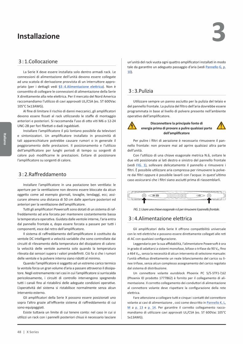
Italiano
Installazione 3 3 : 1.Collocazione
La Serie X deve essere installata solo dentro armadi rack. Le connessioni di alimentazione dell’unità devono essere collegate ad una scatola di derivazione provvista di un interruttore appro-priato (per i dettagli vedi §3 : 4.Alimentazione elettrica). Non è consentito di collegare le connessioni di alimentazione della Serie X direttamente alla rete elettrica. Per il mercato del Nord America raccomandiamo l’utilizzo di cavi approvati UL/CSA (es. ST 600Vac 105°C 5x13AWG).
Al fine di limitare il rischio di danni meccanici, gli amplificatori devono essere fissati al rack utilizzando le staffe di montaggio anteriori e posteriori. Si raccomanda l’uso di otto viti M6 o 12-24 UNC-2B per fori filettati o dadi ingabbiati.
Installare l’amplificatore il più lontano possibile da televisori e sintonizzatori. Un amplificatore installato in prossimità di tali apparecchiature potrebbe causare rumori o in generale il peggioramento delle prestazioni. Il posizionamento e l’utilizzo dell’amplificatore per lunghi periodi di tempo su sorgenti di calore può modificarne le prestazioni. Evitare di posizionare l’amplificatore su sorgenti di calore.
3 : 2.Raffreddamento
Installare l’amplificatore in una postazione ben ventilata: le aperture per la ventilazione non devono essere bloccate da alcun oggetto come ad esempio giornali, tovaglie, tendaggi, ecc; assi-curare almeno una distanza di 50 cm dalle aperture posteriori ed anteriori per la ventilazione dell’amplificatore.
Tutti gli amplificatori Powersoft sono dotati di un sistema di raf-freddamento ad aria forzata per mantenere costantemente bassa la temperatura operativa. Guidata dalle ventole interne, l’aria entra dal pannello frontale e, dopo essere forzata a passare per tutti i componenti, esce dal retro dell’amplificatore.
Il sistema di raffreddamento dell’amplificatore è costituito da ventole DC intelligenti a velocità variabile che sono controllate dai circuiti di rilevamento della temperatura del dissipatore di calore: la velocità delle ventole aumenta solo quando la temperatura rilevata dai sensori supera i valori predefiniti. Ciò fa si che i rumori delle ventole e la polvere interna siano ridotti al minimo.
Quando l’amplificatore è soggetto ad un estremo carico termico la ventola forza un gran volume d’aria a passare attraverso il dissipa-tore. Negli estremamente rari casi in cui l’amplificatore si surriscalda pericolosamente, i circuiti di controllo intervengono spegnendo tutti i canali fino al ristabilirsi delle adeguate condizioni operative. L’operatività del sistema si ristabilisce normalmente senza alcun intervento esterno.
Gli amplificatori della Serie X possono essere posizionati uno sopra l’altro grazie all’efficente sistema di raffreddamento di cui sono equipaggiati.
Esiste tuttavia un limite di cui tenere conto: nel caso in cui si utilizzi un rack con i pannelli posteriori chiusi è necessario lasciare
un’unità del rack vuota ogni quattro amplificatori installati in modo tale da garantire un adeguato passaggio d’aria (vedi Pannello G, p. 10).
3 : 3.Pulizia
Utilizzare sempre un panno asciutto per la pulizia del telaio e del pannello frontale. La pulizia del filtro dell’aria dovrebbe essere programmata in base al livello di polvere presente nell’ambiente operativo dell’amplificatore.
Disconnettere la principale fonte di energia prima di provare a pulire qualsiasi parte
dell’amplificatore
Per pulire i filtri di aerazione è necessario rimuovere il pan-nello frontale: non provare mai ad aprire qualsiasi altra parte dell’unità.
Con l’utilizzo di una chiave esagonale metrica N.6, svitare le due viti posizionate ai lati destro e sinistro del pannello frontale (vedi FIG. 1), sollevare delicatamente il pannello e rimuovere i filtri. È possibile utilizzare aria compressa per rimuovere la polve-re dai filtri oppure è possibile lavarli con l’acqua: in quest’ultimo caso assicurarsi che i filtri siano asciutti prima di riassemblarli.
3 : 4.Alimentazione elettrica
Gli amplificatori della Serie X offrono compatibilità universale con le reti elettriche e possono essere direttamente collegati alle reti di AC con qualsiasi configurazione.
Leggendario per la sua affidabilità, l’alimentatore Powersoft è ora in grado di adattarsi a sistemi monofase, bifase o trifase da 90 VAC fino a 464 VAC, senza la necessità di alcun intervento di selezione manuale: l’unità effettua direttamente un reale bilanciamento del carico su li-nee trifase, senza alcun complesso assegnamento del carico regolato dal sistema di distribuzione.
Un connettore volante euroblock Phoenix PC 5/5-STF1-7,62 (Phoenix ID prodotto 1777862) è fornito per il collegamento di ali-mentazione. Il corretto collegamento dei conduttori di alimentazione al connettore volante deve rispettare la configurazione della rete elettrica.
Fare attenzione a collegare tutti e cinque i contatti del connettore volante ai cavi di alimentazione , così come descritto in Pannello K, L, M a p. 13 e p. 14. Per garantire il corretto collegamento racco-mandiamo di utilizzare cavi approvati UL/CSA (es. ST 600Vac 105°C 5x13AWG).
FIG. 1: Usare una chiave esagonale n.6 per rimuovere il pannello frontale.
48 | X Series
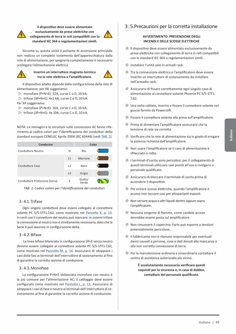
Ital
iano
Il dispositivo deve essere alimentatoesclusivamente da prese elettriche con
collegamento di terra in reti compatibili con lo standard IEC 364 o regolamentazioni simili.
Siccome su questa unità il pulsante di accensione principale non realizza un completo isolamento dell’apparecchiatura dalla rete di alimentazione, per spegnerla completamente è necessario scollegare l’alimentazione elettrica.
Inserire un interruttore magneto-termico tra la rete elettrica e l’amplificatore.
Il dispositivo adatto dipende dalla configurazione della rete di alimentazione; per X8 suggeriamo:
monofase (P+N+E): 32A, curve C o D, 10 kA;trifase (3P+N+E): 4x1 6A, curve C o D, 10 kA.
Per X4 suggeriamo:monofase (P+N+E): 16A, curve C o D, 10 kA;trifase (3P+N+E): 4x 10A, curve C o D, 10 kA.
NOTA: Le immagini e le istruzioni sulle connessioni AC fanno rife-rimento al codice colori per l’identificazione dei conduttori dello standard europeo CENELEC Aprile 2004 (IEC 60446) (vedi TAB. 1).
Conductor Color
Conduttore Neutro N Blu
Conduttore Fase
L1 Marrone
L2 Nero
L3 Grigio
Conduttore Protezione (terra) E Giallo/Verde
TAB. 1: Codice colore per l’identificazione dei conduttori.
3 : 4.1. TrifaseOgni singolo conduttore deve essere collegato al connettore
volante PC 5/5-STF1-7,62, come mostrato nel Pannello K, p. 13. In certi casi il connettore del neutro può mancare: in sistemi trifase la connessione al neutro non è strettamente necessaria, dato che la Serie X può lavorare in configurazione delta.
3 : 4.2. Bifase Le linee bifase bilanciate in configurazione 2P+E senza neutro
devono essere collegate al connettore volante PC 5/5-STF1-7,62, come mostrato nel Pannello M, p. 14. Assicurarsi di sdoppiare i cavi delle fasi ai terminali dell’interruttore di sezionamento al fine di garantire la corretta sezione di conduzione.
3 : 4.3. MonofaseLa configurazione P+N+E sbilanciata monofase con neutro è
la più comune per l’alimentazione AC; il cablaggio deve essere configurato come mostrato nel Pannello L, p. 13. Assicurarsi di sdoppiare i cavi di fase e neutro ai terminali dell’interruttore di se-zionamento al fine di garantire la corretta sezione di conduzione.
3 : 5.Precauzioni per la corretta installazione
AVVERTIMENTO: PREVENZIONE DEGLI INCENDI E DELLE SCOSSE ELETTRICHE
Xf Il dispositivo deve essere alimentato esclusivamente da prese elettriche con collegamento di terra in reti compatibili con lo standard IEC 364 o regolamentazioni simili.
Xf Installare l’unità solo in armadi rack.
Xf Tra la connessione elettrica e l’amplificatore deve essere inserito un interruttore di sezionamento da installare nell’armadio rack.
Xf Assicurarsi di fissare correttamente ogni singolo cavo di alimentazione al connettore volante Phoenix PC 5/5-STF1-7,62.
Xf Una volta cablato, inserire e fissare il connettore volante nel guscio fornito da Powersoft.
Xf Fissare il connettore volante alla presa sull’amplificatore.
Xf Prima di alimentare l’amplificatore assicurarsi che la tensione di rete sia corretta.
Xf Verificare che la rete di alimentazione sia in grado di erogare la potenza richiesta dall’amplificatore.
Xf Non usare l’amplificatore se il cavo di alimentazione è sfilacciato o rotto.
Xf I terminali d’uscita sono pericolosi: per il collegamento di questi terminali utilizzare cavi pronti all’uso e rivolgersi a personale qualificato.
Xf Assicurarsi di bloccare il terminale di uscita prima di accendere il dispositivo.
Xf Per evitare scosse elettriche, quando l’amplificatore è acceso non toccare cavi per altoparlanti esposti.
Xf Non versare acqua o altri liquidi dentro oppure sopra l’amplificatore.
Xf Nessuna sorgente di fiamme, come candele accese dovrebbe essere posta sul amplificatore.
Xf Non rimuovere il coperchio. Farlo può esporre a tensioni potenzialmente pericolose.
Xf Il fabbricante non è ritenuto responsabile per eventuali danni causati a persone, cose e dati dovuti alla mancanza o alla non corretta connessione di terra.
Xf Per la manutenzione ordinaria e straordinaria contattare il centro di assistenza autorizzato più vicino.
È assolutamente necessario verificare questi requisiti per la sicurezza e, in caso di dubbio,
contattare del personale qualificato.
Italiano | 49
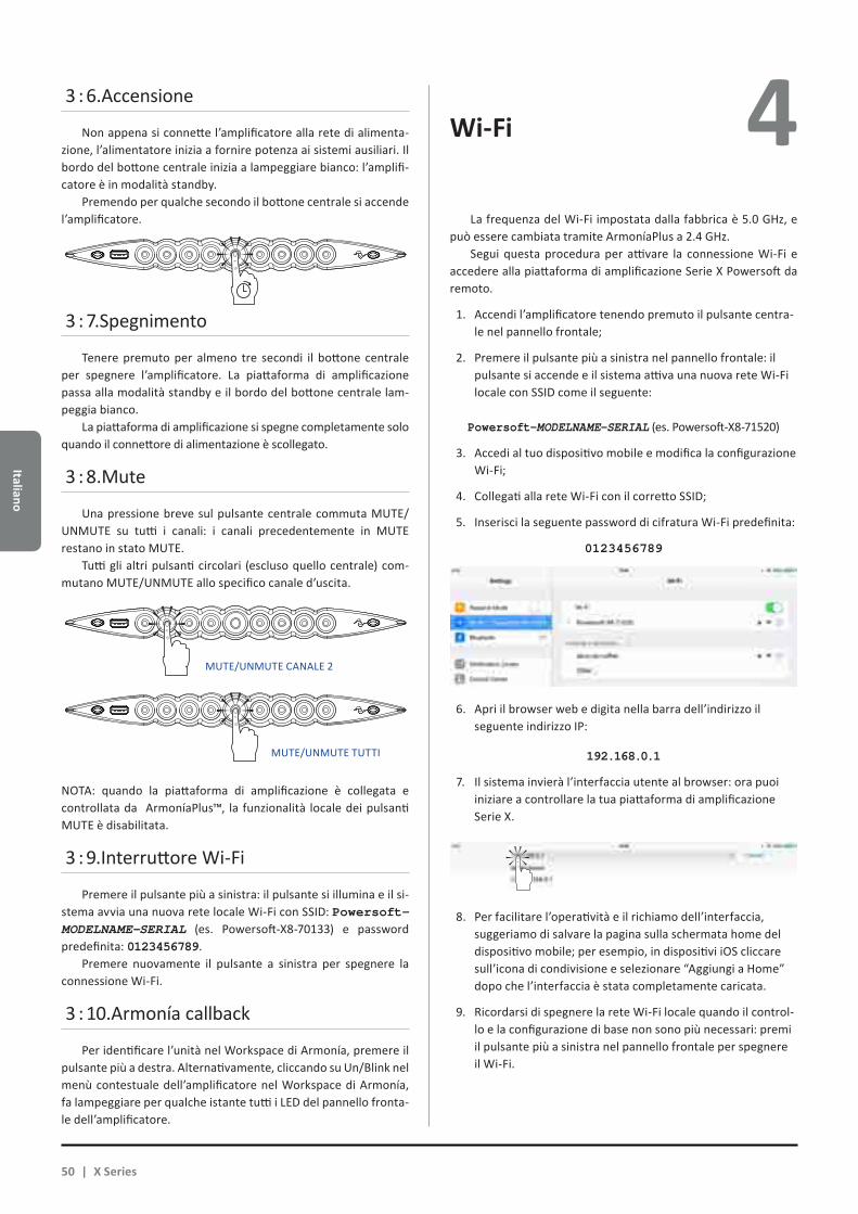
Italiano
3 : 6.Accensione
Non appena si connette l’amplificatore alla rete di alimenta-zione, l’alimentatore inizia a fornire potenza ai sistemi ausiliari. Il bordo del bottone centrale inizia a lampeggiare bianco: l’amplifi-catore è in modalità standby.
Premendo per qualche secondo il bottone centrale si accende l’amplificatore.
3 : 7.Spegnimento
Tenere premuto per almeno tre secondi il bottone centrale per spegnere l’amplificatore. La piattaforma di amplificazione passa alla modalità standby e il bordo del bottone centrale lam-peggia bianco.
La piattaforma di amplificazione si spegne completamente solo quando il connettore di alimentazione è scollegato.
3 : 8.Mute
Una pressione breve sul pulsante centrale commuta MUTE/UNMUTE su tutti i canali: i canali precedentemente in MUTE restano in stato MUTE.
Tutti gli altri pulsanti circolari (escluso quello centrale) com-mutano MUTE/UNMUTE allo specifico canale d’uscita.
NOTA: quando la piattaforma di amplificazione è collegata e controllata da ArmoníaPlus™, la funzionalità locale dei pulsanti MUTE è disabilitata.
3 : 9.Interruttore Wi-Fi
Premere il pulsante più a sinistra: il pulsante si illumina e il si-stema avvia una nuova rete locale Wi-Fi con SSID: Powersoft-MODELNAME-SERIAL (es. Powersoft-X8-70133) e password predefinita: 0123456789.
Premere nuovamente il pulsante a sinistra per spegnere la connessione Wi-Fi.
3 : 10.Armonía callback
Per identificare l’unità nel Workspace di Armonía, premere il pulsante più a destra. Alternativamente, cliccando su Un/Blink nel menù contestuale dell’amplificatore nel Workspace di Armonía, fa lampeggiare per qualche istante tutti i LED del pannello fronta-le dell’amplificatore.
Wi-Fi 4 La frequenza del Wi-Fi impostata dalla fabbrica è 5.0 GHz, e
può essere cambiata tramite ArmoníaPlus a 2.4 GHz.Segui questa procedura per attivare la connessione Wi-Fi e
accedere alla piattaforma di amplificazione Serie X Powersoft da remoto.
1. Accendi l’amplificatore tenendo premuto il pulsante centra-le nel pannello frontale;
2. Premere il pulsante più a sinistra nel pannello frontale: il pulsante si accende e il sistema attiva una nuova rete Wi-Fi locale con SSID come il seguente: Powersoft-MODELNAME-SERIAL (es. Powersoft-X8-71520)
3. Accedi al tuo dispositivo mobile e modifica la configurazione Wi-Fi;
4. Collegati alla rete Wi-Fi con il corretto SSID;
5. Inserisci la seguente password di cifratura Wi-Fi predefinita:
0123456789
6. Apri il browser web e digita nella barra dell’indirizzo il seguente indirizzo IP:
192.168.0.1
7. Il sistema invierà l’interfaccia utente al browser: ora puoi iniziare a controllare la tua piattaforma di amplificazione Serie X.
8. Per facilitare l’operatività e il richiamo dell’interfaccia, suggeriamo di salvare la pagina sulla schermata home del dispositivo mobile; per esempio, in dispositivi iOS cliccare sull’icona di condivisione e selezionare “Aggiungi a Home” dopo che l’interfaccia è stata completamente caricata.
9. Ricordarsi di spegnere la rete Wi-Fi locale quando il control-lo e la configurazione di base non sono più necessari: premi il pulsante più a sinistra nel pannello frontale per spegnere il Wi-Fi.
MUTE/UNMUTE CANALE 2
MUTE/UNMUTE TUTTI
50 | X Series
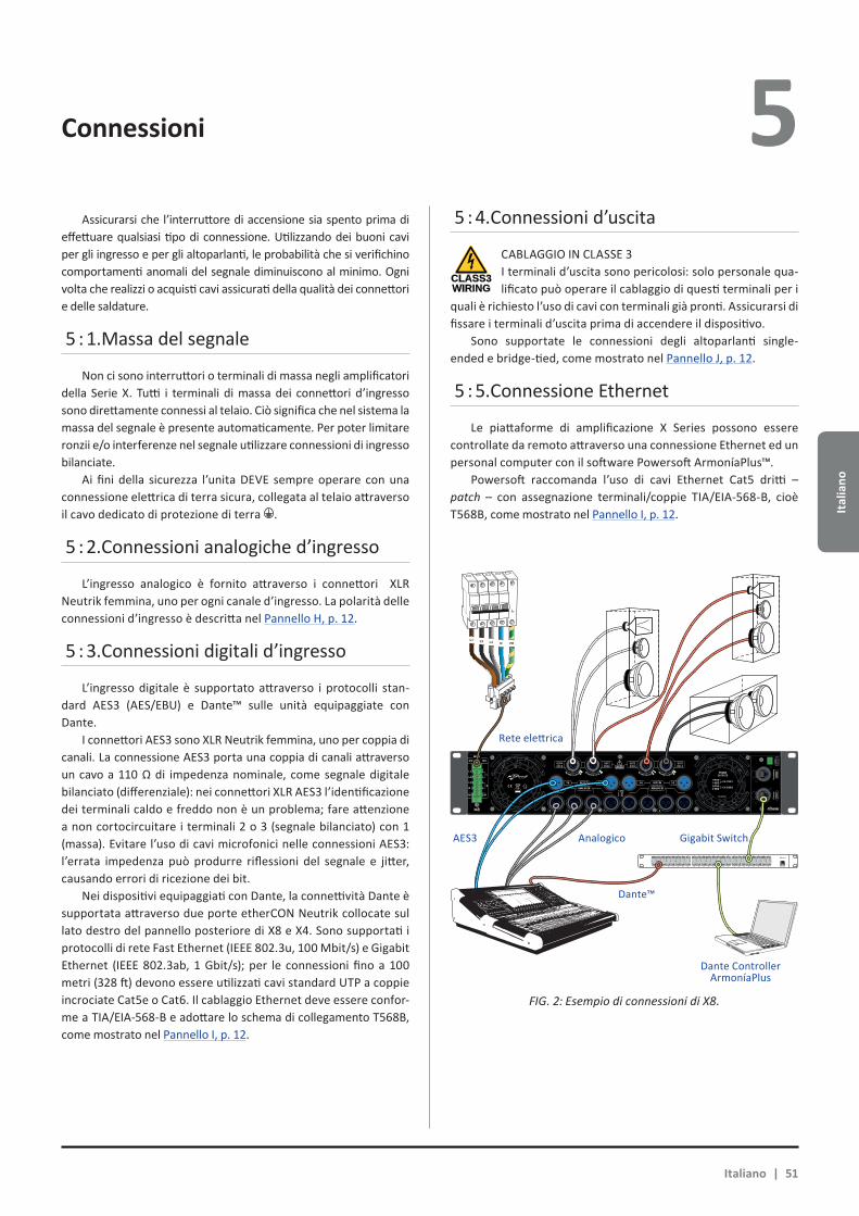
Ital
iano
4 Connessioni 5 Assicurarsi che l’interruttore di accensione sia spento prima di
effettuare qualsiasi tipo di connessione. Utilizzando dei buoni cavi per gli ingresso e per gli altoparlanti, le probabilità che si verifichino comportamenti anomali del segnale diminuiscono al minimo. Ogni volta che realizzi o acquisti cavi assicurati della qualità dei connettori e delle saldature.
5 : 1.Massa del segnale
Non ci sono interruttori o terminali di massa negli amplificatori della Serie X. Tutti i terminali di massa dei connettori d’ingresso sono direttamente connessi al telaio. Ciò significa che nel sistema la massa del segnale è presente automaticamente. Per poter limitare ronzii e/o interferenze nel segnale utilizzare connessioni di ingresso bilanciate.
Ai fini della sicurezza l’unita DEVE sempre operare con una connessione elettrica di terra sicura, collegata al telaio attraverso il cavo dedicato di protezione di terra .
5 : 2.Connessioni analogiche d’ingresso
L’ingresso analogico è fornito attraverso i connettori XLR Neutrik femmina, uno per ogni canale d’ingresso. La polarità delle connessioni d’ingresso è descritta nel Pannello H, p. 12.
5 : 3.Connessioni digitali d’ingresso
L’ingresso digitale è supportato attraverso i protocolli stan-dard AES3 (AES/EBU) e Dante™ sulle unità equipaggiate con Dante.
I connettori AES3 sono XLR Neutrik femmina, uno per coppia di canali. La connessione AES3 porta una coppia di canali attraverso un cavo a 110 Ω di impedenza nominale, come segnale digitale bilanciato (differenziale): nei connettori XLR AES3 l’identificazione dei terminali caldo e freddo non è un problema; fare attenzione a non cortocircuitare i terminali 2 o 3 (segnale bilanciato) con 1 (massa). Evitare l’uso di cavi microfonici nelle connessioni AES3: l’errata impedenza può produrre riflessioni del segnale e jitter, causando errori di ricezione dei bit.
Nei dispositivi equipaggiati con Dante, la connettività Dante è supportata attraverso due porte etherCON Neutrik collocate sul lato destro del pannello posteriore di X8 e X4. Sono supportati i protocolli di rete Fast Ethernet (IEEE 802.3u, 100 Mbit/s) e Gigabit Ethernet (IEEE 802.3ab, 1 Gbit/s); per le connessioni fino a 100 metri (328 ft) devono essere utilizzati cavi standard UTP a coppie incrociate Cat5e o Cat6. Il cablaggio Ethernet deve essere confor-me a TIA/EIA-568-B e adottare lo schema di collegamento T568B, come mostrato nel Pannello I, p. 12.
5 : 4.Connessioni d’uscita
CABLAGGIO IN CLASSE 3I terminali d’uscita sono pericolosi: solo personale qua-lificato può operare il cablaggio di questi terminali per i
quali è richiesto l’uso di cavi con terminali già pronti. Assicurarsi di fissare i terminali d’uscita prima di accendere il dispositivo.
Sono supportate le connessioni degli altoparlanti single-ended e bridge-tied, come mostrato nel Pannello J, p. 12.
5 : 5.Connessione Ethernet
Le piattaforme di amplificazione X Series possono essere controllate da remoto attraverso una connessione Ethernet ed un personal computer con il software Powersoft ArmoníaPlus™.
Powersoft raccomanda l’uso di cavi Ethernet Cat5 dritti – patch – con assegnazione terminali/coppie TIA/EIA-568-B, cioè T568B, come mostrato nel Pannello I, p. 12.
CLASS3WIRING
1 2 3 4 5 6 7 8
25 26 27 28 29 30 31 32
9 10 11 12 13 14 15 16
33 34 35 36 37 38 39 40
17 18 19 20 21 22 23 24
41 42 43 44 45 46 47 48 UP Link
Power
L1 L2 L3 N PE
AES3 IN7-8 5-6 AES3 IN3-4 1-2
ANALOG INANALOG IN
8 7 6 5 4 3 2 1
3PH 1PH
L1
L2
L3
N
L
N
1=GND2 = IN+3 = IN-
MAINS
TURN TO LOCK TURN TO LOCKTURN TO LOCK TURN TO LOCK
FIG. 2: Esempio di connessioni di X8.
Italiano | 51
Rete elettrica
AES3 Analogico Gigabit Switch
Dante™
Dante ControllerArmoníaPlus

Italiano
Aggiornamento Software Tabella LED6 7 Le piattaforme di amplificazione Serie X Powersoft incorpora-
no un completo sistema di gestione dell’audio digitale basato sul processore ARM Cortex A-8 e la piattaforma DSP Ti C6000.
I rilasci degli aggiornamenti del software della Serie X sono disponibili sul forum Armonía (https://armonia.powersoft.it/).
Il pacchetto contiene il file di aggiornamento software il cui nome è:
update-versione#-modello.bin
(es. update-v1.5.0.6-x4.bin); per aggiornare il software della piat-taforma di amplificazione X Serie è necessario salvare il file in una chiavetta USB e seguire le seguenti istruzioni:
1. Accendi l’amplificatore e attendi il completamento della sequenza di inizializzazione.
2. Inserisci la chiavetta USB con il file di aggiornamento softwa-re nella porta USB nel pannello frontale dell’amplificatore.
3. Tieni premuto il pulsante più a destra (Armonía callback) fino a che non senti il secondo beep e i LED iniziano a lam-peggiare.
4. Attendi fino al riavvio dell’amplificatore e tutti i LED si ac-cendono blu.
Tutti i pulsanti tondi retroilluminati forniscono informazioni di stato. Il CENTRO di ogni pulsante fornisce informazioni di stato sul segnale d’USCITA.
Colore centraleindicazioni d’USCITA
Colore centraleindicazioni d’USCITA
Colore Stato Colore Stato
Blu Canale pronto Arancione MUTE
uscita
Giallo Limiter attivato
Arancionelampeg-giante
MUTEingresso
L’ANELLO di ogni pulsante di canale fornisce informazioni sul segnale d’INGRESSO.
Colore dell’anelloindicazioni d’INGRESSO
Colore StatoBianco
lampeggiante (centro blu)
Presenza segnale d’ingresso
Rosso Clipping segnale d’ingresso
Il guasto del canale e l’Armonía callback sono associati ai seguenti segnali LED.
Colore Stato
Rosso lampeggiante (centro e anello) Guasto del canale
lampeggiante / tutti i canali (centro e anello)
L’unità risponde all’Armonía callback
Il pulsante centrale si illumina quando il sistema è in standby o in caso di guasto dell’alimentatore:
Colore dell’anellopulsante CENTRALE
Colore StatoBianco
lampeggiante (tutti LED spenti)
Sistema alimentato in modalità standby
Rosso lampeggiante
(operativo)rilevato guasto alla ventola(ventola dal lato dei finali)
Colore del centropulsante CENTRALE
Colore Stato
Rosso lampeggiante
Rilevato guasto all’alimentatore o alla ventola dell’alimentatore
Giallo lampeggiante
Protezione termica dell’alimentatore attivaBlinking
USB Key in ...
52 | X Series
Ital
iano
Networking 8 Le piattaforme di amplificazione Serie X supportano le topo-
logie di rete daisy-chain, star e loop; in una rete daisy-chain, il PC con ArmoníaPlus deve essere sempre ad uno degli estremi della catena.
Si tenga presente che il daisy-chain non garantisce affidabilità in ambienti di produzione, poiché qualsiasi guasto può provocare il sezionamento della rete e perdita di controllo del sistema.
Quando efficienza e affidabilità sono fondamentali, è consi-gliabile adottare una topologia di rete ridondante. Per sfruttare le caratteristiche di Dante, sono consentite solo le topologie di rete star e daisy-chain aperta.
8 : 1.Indirizzamento IP
DHCP/AutoIP è la configurazione di rete impostata di fabbrica, al fine di garantire alle piattaforme di amplificazione di configurarsi autonomamente quando collegate a PC o LAN esistenti. Il metodo a IP fisso può essere adottato e configurato con ArmoníaPlus.
Se nella rete non è attivo un server DHCP, la piattaforma di amplificazione avvia una procedura di auto-configurazione senza stato (cioè con metodologia Zero-configurazione di rete – Zeroconf): si assegna un indirizzo numerico locale (del tipo 169.254.x.y – 172.31.*.* per la rete secondaria, se presente – con maschera di sottorete 255.255.0.0) e automaticamente distribuisce e risolve gli hostname dei dispositivi in rete. Per configurare un indirizzo IP statico, fare riferimento alla guida di ArmoníaPlus.
8 : 1.1. Risoluzione dei problemi di indirizzamento IPQuando si collega la Serie X ad un ambiente di rete, può succe-
dere che ArmoníaPlus non scopra o importi l’amplificatore.Generalmente si tratta di un problema di indirizzamento IP:
sia ArmoníaPlus, sia la Serie X devono appartenere alla stessa sot-torete. Se un server DHCP è presente sulla rete e la piattaforma di amplificazione Serie X è in AUTO IP, la rete può diventare instabile.
Come regola pratica, accendere il server DHCP prima di connettere gli amplificatori.
L’indirizzamento IP di un amplificatore Serie X si realizza durante l’accensione: quando una piattaforma di amplificazione Serie X rileva un server DHCP sulla rete durante l’avvio, negozia i parametri di rete. Se la piattaforma di amplificazione Serie X non rileva un server DHCP sulla rete durante l’avvio, si auto-configura in modalità AUTO IP.
8 : 2.Rete Dante™
I modelli di piattaforma di amplificazione equipaggiati con Dante supportano le reti Dante ridondanti grazie alle due porte etherCON nel pannello posteriore:
XX Primary/ETH1 è la porta di rete primaria;
XX Secondary/ETH2 è la porta di rete secondaria.
La connettività Dante è sempre supportata sulla porta Gigabit Ethernet Primary/ETH1; la porta Gigabit Ethernet Secondary/ETH2 garantisce continuità operativa quando è collegata ad una rete parallela ridondante.
Per implementare una rete Dante deve essere utilizzato un computer su cui è avviato il Dante Controller. Dante Controller è un’applicazione software che gestisce i dispositivi sulla rete. Le piattaforme di amplificazione Serie X sono automaticamente riconosciute e mostrate nel Dante Controller con l’identificativo predefinito MODELNAME-SERIAL (e.g. X8-71520).
Le reti Dante richiedono sempre quasi sempre un switch di rete. Per la massima affidabilità, lo switch di rete deve:
Xf essere Gigabit Ethernet;
Xf essere Non-blocking;
Xf avere Quality of Service (QoS) con almeno quattro code;
Xf avere Diffserv (DSCP) QoS con strict priority;
Xf avere EEE (Energy efficient ethernet) spenta.
Per maggiori informazioni sulla configurazione dello switch, fare riferimento alla documentazione del costruttore.
8 : 2.1. Configurazione delle reti ridondanti Dante Redundancy può essere usato tra qualsiasi apparec-
chiatura audio che supporti e abiliti Dante: funziona utilizzando due reti separate, completamente indipendenti, la rete Primaria e la rete Secondaria.
Per configurare Dante Redundancy, connetti la piattaforma di amplificazione Serie X e altre apparecchiature abilitate alla ridondanza Dante, duplicando gli switch Gigabit e i cavi Ethernet. Connetti il tuo computer su cui girano Dante Virtual Soundcard e Dante Controller e altre apparecchiature audio con Dante non ridondanti alla rete Primaria.
Le reti Primaria e Secondaria NON DEVONO essere intercon-nesse in alcun punto. Assicurati che ogni computer sia impostato per configurare automaticamente il proprio indirizzo IP.
Italiano | 53
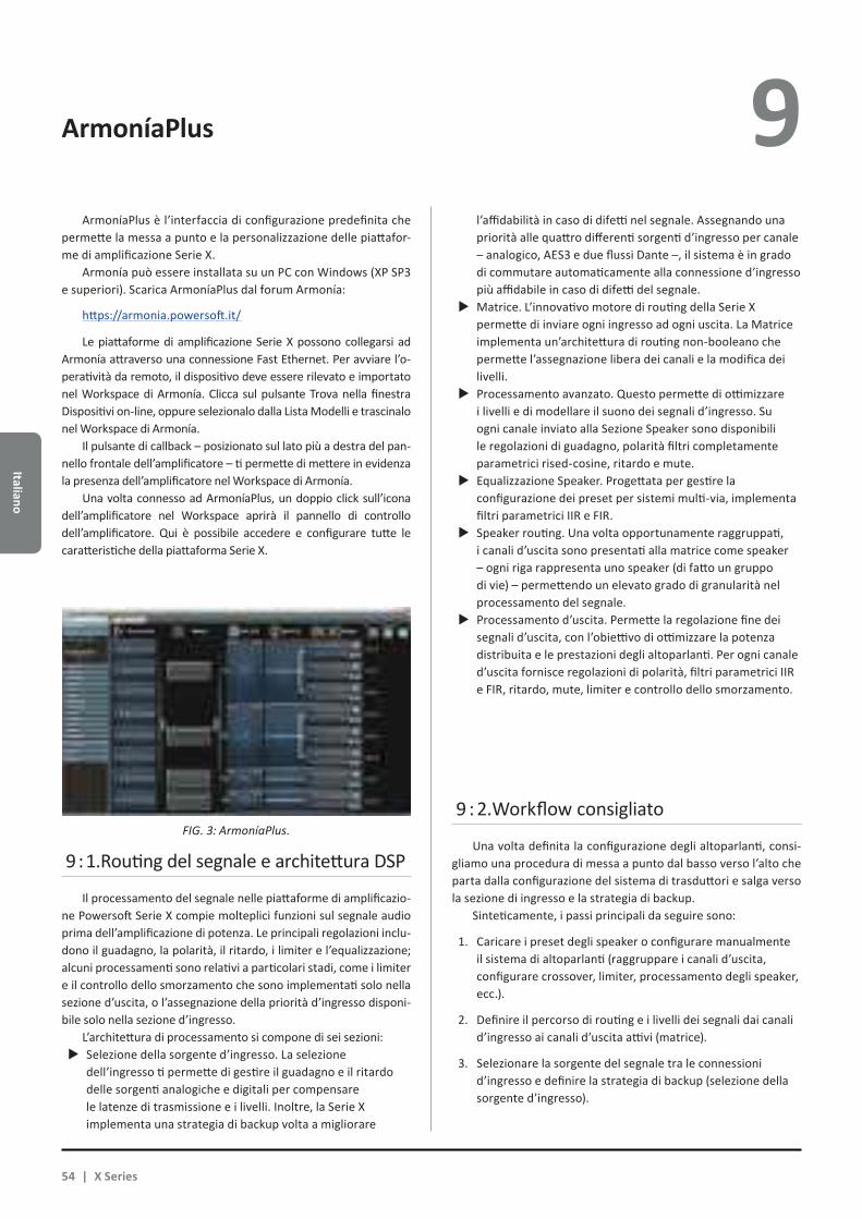
Italiano
ArmoníaPlus 9 ArmoníaPlus è l’interfaccia di configurazione predefinita che
permette la messa a punto e la personalizzazione delle piattafor-me di amplificazione Serie X.
Armonía può essere installata su un PC con Windows (XP SP3 e superiori). Scarica ArmoníaPlus dal forum Armonía:
https://armonia.powersoft.it/
Le piattaforme di amplificazione Serie X possono collegarsi ad Armonía attraverso una connessione Fast Ethernet. Per avviare l’o-peratività da remoto, il dispositivo deve essere rilevato e importato nel Workspace di Armonía. Clicca sul pulsante Trova nella finestra Dispositivi on-line, oppure selezionalo dalla Lista Modelli e trascinalo nel Workspace di Armonía.
Il pulsante di callback – posizionato sul lato più a destra del pan-nello frontale dell’amplificatore – ti permette di mettere in evidenza la presenza dell’amplificatore nel Workspace di Armonía.
Una volta connesso ad ArmoníaPlus, un doppio click sull’icona dell’amplificatore nel Workspace aprirà il pannello di controllo dell’amplificatore. Qui è possibile accedere e configurare tutte le caratteristiche della piattaforma Serie X.
9 : 1.Routing del segnale e architettura DSP
Il processamento del segnale nelle piattaforme di amplificazio-ne Powersoft Serie X compie molteplici funzioni sul segnale audio prima dell’amplificazione di potenza. Le principali regolazioni inclu-dono il guadagno, la polarità, il ritardo, i limiter e l’equalizzazione; alcuni processamenti sono relativi a particolari stadi, come i limiter e il controllo dello smorzamento che sono implementati solo nella sezione d’uscita, o l’assegnazione della priorità d’ingresso disponi-bile solo nella sezione d’ingresso.
L’architettura di processamento si compone di sei sezioni:XX Selezione della sorgente d’ingresso. La selezione
dell’ingresso ti permette di gestire il guadagno e il ritardo delle sorgenti analogiche e digitali per compensare le latenze di trasmissione e i livelli. Inoltre, la Serie X implementa una strategia di backup volta a migliorare
l’affidabilità in caso di difetti nel segnale. Assegnando una priorità alle quattro differenti sorgenti d’ingresso per canale – analogico, AES3 e due flussi Dante –, il sistema è in grado di commutare automaticamente alla connessione d’ingresso più affidabile in caso di difetti del segnale.XX Matrice. L’innovativo motore di routing della Serie X
permette di inviare ogni ingresso ad ogni uscita. La Matrice implementa un’architettura di routing non-booleano che permette l’assegnazione libera dei canali e la modifica dei livelli.XX Processamento avanzato. Questo permette di ottimizzare
i livelli e di modellare il suono dei segnali d’ingresso. Su ogni canale inviato alla Sezione Speaker sono disponibili le regolazioni di guadagno, polarità filtri completamente parametrici rised-cosine, ritardo e mute.XX Equalizzazione Speaker. Progettata per gestire la
configurazione dei preset per sistemi multi-via, implementa filtri parametrici IIR e FIR.XX Speaker routing. Una volta opportunamente raggruppati,
i canali d’uscita sono presentati alla matrice come speaker – ogni riga rappresenta uno speaker (di fatto un gruppo di vie) – permettendo un elevato grado di granularità nel processamento del segnale.XX Processamento d’uscita. Permette la regolazione fine dei
segnali d’uscita, con l’obiettivo di ottimizzare la potenza distribuita e le prestazioni degli altoparlanti. Per ogni canale d’uscita fornisce regolazioni di polarità, filtri parametrici IIR e FIR, ritardo, mute, limiter e controllo dello smorzamento.
9 : 2.Workflow consigliato
Una volta definita la configurazione degli altoparlanti, consi-gliamo una procedura di messa a punto dal basso verso l’alto che parta dalla configurazione del sistema di trasduttori e salga verso la sezione di ingresso e la strategia di backup.
Sinteticamente, i passi principali da seguire sono:
1. Caricare i preset degli speaker o configurare manualmente il sistema di altoparlanti (raggruppare i canali d’uscita, configurare crossover, limiter, processamento degli speaker, ecc.).
2. Definire il percorso di routing e i livelli dei segnali dai canali d’ingresso ai canali d’uscita attivi (matrice).
3. Selezionare la sorgente del segnale tra le connessioni d’ingresso e definire la strategia di backup (selezione della sorgente d’ingresso).
FIG. 3: ArmoníaPlus.
54 | X Series
Ital
iano
Garanzia e Assistenza 10 10 : 1.Garanzia
10 : 1.1. Garanzia del prodottoPowersoft garantisce l’assenza di difetti nei componenti
e nella fabbricazione del prodotto finito per un periodo di 48 (quarantotto) mesi dalla data di acquisto indicata sulla fattura d’acquisto emessa da Powersoft (o da un rivenditore autorizzato) verso il cliente finale.
Le riparazioni e riconfigurazioni in garanzia devono essere effettuate da Powersoft o dai Centri Assistenza Autorizzati, senza costi per il cliente. Esclusioni dalla garanzia: la garanzia Powersoft non copre difetti o malfunzionamenti causati da: abusi, ripara-zioni svolte da personale non autorizzato, connessione errate, esposizione a intemperie, danni meccanici (compresi incidenti durante il trasporto) e normale logorio. Powersoft offrirà servizi di garanzia, a condizione che il prodotto non si sia danneggiato durante il trasporto.
10 : 1.2. Restituzione della merceI beni possono essere restituiti a Powersoft solo dopo aver
ottenuto un numero di RMA (Return Merchandise Authorization) che deve essere attaccato all’esterno dell’imballo. Powersoft (o un suo Centro Assistenza Autorizzato) ha il diritto di rifiutare la la restituzione della merce priva del codice RMA.
10 : 1.3. Riparazione e sostituzionePowersoft si riserva il diritto di riparare o sostituire qualsiasi
merce difettosa coperta da garanzia a sua sola discrezione.
10 : 1.4. Costi e responsabilità del trasportoL’acquirente (oppure l’utente finale) è il solo responsabile per
tutti i costi di trasporto e i rischi associati all’invio di merce coperta da garanzia a Powersoft o un suo Centro Assistenza Autorizzato. Powersoft si assumerà la completa responsabilità e coprirà tutti i costi per l’invio in restituzione della merce all’acquirente (oppure all’utente finale).
10 : 2.Assistenza
Non ci sono parti riparabili dall’utente nell’amplificatore. Rivolgersi a tecnici qualificati. Oltre ad avere un reparto di servizio interno, Powersoft possiede una rete di Centri Assistenza Autorizzati. Se l’amplificatore dovesse necessitare di riparazioni contatta il rivenditore (o distributore) Powersoft. È inoltre possibile contattare il Servizio di Assistenza Tecnica Powersoft per conoscere la posizione del Centro Assistenza Autorizzato più vicino.
Anche se la maggior parte dei malfunzionamenti può essere risolta dall’utente interpellando l’Assistenza Clienti Powersoft, occasionalmente, la natura del guasto potrebbe rendere necessario far tornare i prodotti difettosi a Powersoft.
In quest’ultimo caso, prima dell’invio, bisogna seguire la seguente procedura:XX ottenere il “Defect Report Form” contattando l’Assistenza
Clienti Powersoft via email a [email protected] op-pure scaricando il “Defect Report Form” dal sito internet Powersoft (http://www.powersoft-audio.com/en/support/service). XX Completare un modulo “Defect Report form” per ogni
dispositivo da inviare (il modulo è un documento in cui l’inserimento dei dati è guidato) e salvarlo con il proprio nome, modello di amplificatore e numero di serie (per esempio: distributornamek10sn17345.doc) inserendo tutte le informazioni richieste eccetto il codice RMA. Iviare il file a [email protected] per approvazione.XX In caso di approvazione il Responsabile dell’Assistenza
Clienti Powersoft rilascia il codice di autorizzazione RMA e lo invia al cliente (un RMA per ogni dispositivo da inviare).XX Dopo aver ricevuto il codice RMA, applicarlo all’esterno
dell’imballo del dispositivo da restituire, protetto in una bu-sta trasparente resistente all’acqua e chiaramente visibile.
La merce in restituzione va inviata al seguente indirizzo: PowersoftVia dei Cadolingi, 1350018 Scandicci (FI) Italy
In caso di spedizione da Paesi al di fuori della Comunità Europea, assicurarsi di seguire le istruzioni descritte nel documento disponibile per il download sul sito Powersoft alla voce TEMPORARY EXPORTATION / IMPORTATION PROCEDURE http://www.powersoft-audio.com/en/support/service.
Grazie per la vostra comprensione, collaborazione e continuo supporto mentre noi lavoriamo per migliorare.
Italiano | 55

中文
警告
触电危险请勿打开
电能可帮助实现很多有用的功能。本设备在设计与制造上竭力确保您的个人安全。但是,不当操作可能会造成触电或火灾。为确保本产品的安全使用,请遵守基本的安装、使用与维修规定。请在使用前仔细阅读这些“重要的安全保障措施”。
重要的安全指示1. 请阅读所有指示。2. 请保留所有指示。3. 注意所有警告。4. 遵守所有指示。5. 使用设备时,请勿靠近水源。6. 仅用干布清洁。7. 请勿堵塞通风口。按照生产商说明书安装。8. 安装请勿靠近任何热源,包括散热器、火炉或其他产生热量的设备。
9. 保护电源线不被踩踏或挤压,特别是在插头、电源插座以及连接设备处。
10. 仅选用生产商指定的附件/配件。11. 仅选用生产商指定或随设备配套销售的推车、支架、三脚架、托架或桌子。若使用推车,移动推车/设备的组合时务必谨慎小心,避免翻倒造成伤害。
12. 雷雨天或长时间不使用,请拔掉电源。13. 请将维修服务交予授权的人员。本设备因任何原因造成的损坏均需维修,包括电源线或插头损坏,液体滴落或异物落入设备,淋雨或受潮,运行异常或设备跌落。
警告:为减少电击风险,请勿试图打开本设备的任何部件。设备内部无用户可维修部件。如需维修,请联系授权的专业人员。
请避免设备淋雨、受潮或让液体滴洒在设备上。诸如花瓶一类带有液体的物体不得放置在本设备上面。
该单元必须安装在机架机柜中:将功放的电源接头通过一个分段断路器插入到机架机柜内的接线板上。
分段断路器必须保证放在在可接近的位置。
当本单元安装在机柜中或(架子)时,请确保各面都有足够的空间进行散热(前后通风口位置相距50厘米)。
电源连接需交付技术娴熟的电力工作人员,根据设备销售所在国的国家标准完成。
警告:保险丝连接中线
图形符号含义
带闪电标志的三角形用于警告用户该产品存在触电危险。
带感叹号的三角形用于提醒用户此处有重要的操作和维修指示。
CE标志表示低压兼容和电磁兼容。
该标志表示接地。
该标志表示该设备只在室内使用。
该标志表示该产品符合欧洲议会关于报废电子电气设备(WEEE)的2002/96/EC指令与2003/108/EC指令。
仅适用于在海拔2000m以下地区使用。
仅适用于在非热带气候条件下使用。
重要的安全指示 1
56 | X 系列
中文
2 X系列 快速指南
2 : 1.欢迎
恭喜您购买了PowersoftX系列功放!我们知道您已急不可待,想立即体验X8或X4,但请稍微花点时间,阅读本用户手册和安全指示。若有任何问题,请随时联系您的经销商或Powersoft。Powersft X系列改写了功放平台这个概念:X8是8通道功放;X4在一个机架单位里提供4路通道。这两个型号都具有全新的通道路由系统、电源以及功能全面的DSP。Powersoft X8与X4 支持AES3、两个冗余的Dante™(Dante™是Audinate公司的产品,可实现数字音频流传输)以及模拟输入,每通道可提供最多4个可选择的不同输入源。Armonía ProAudio Suite™专业音频软件包为系统配置与调试提供直观界面,可全面控制数字音频处理,实时监控系统性能。集成的WiFi连接让用户在智能手机或平板电脑上,通过专为本地监控而开发的用户界面访问和管理PowersoftX系列。PowersoftX4与X8使功放的质量和易用性标准更上一个台阶:它们适合您的配置,节省空间,质量轻便,继承了Powersoft传奇般的高效能,并且具有全新的全球兼容的多相电源。
2 : 2.开包&检查船运损伤
每只Powersoft功放都在出厂前经过全面检测,到达时应该为全新状态。打开包装前,请仔细检查船运损伤,打开包装后请立即检查你的新产品。如果你发现有任何损坏,请立即通知船运公司。每一台M系列功放的箱子内包含下列内容:XX 1xX系列功放XX 1x交流电PC5/5-STF1-7,62凤凰芯接头XX 1x交流电外壳XX 1x快速指南
2 : 4.图片列表
A. X8/X4L机械制图:所有尺寸以毫米为单位B. X4机械制图:所有尺寸以毫米为单位C. X8后面板D. X4L后面板E. X4后面板F. X8和X4L/X4前面板G. 安装支架和气流方向H. 密闭机架内堆叠安装功放注意事项I. 输入接头引脚分配J. RJ45以太网引脚分配K. 引线接线L. 三相电源:交流电源插头接线M. 单相电源:交流电源插头接线N. 双相电源:交流电源插头接线O. 交流电源插头屏蔽P. 合规信息
2 : 3.包装材料处理
运输材料和保护性包装材料均对生态环境无害,可正常处理并回收利用。请不要把这些材料简单扔掉,保证将它们交付以便回收利
用。
中文 | 57
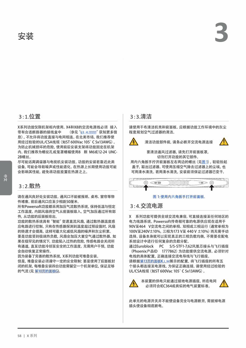
中文
安装 3
3 : 1.位置
X系列功放仅限机架柜内使用。X4和X8的交流电源线必须 接入带有合适断路器的接线盒中 (参见“§3 : 4.交交交交”获知更多信息),不允许将功放直接与电网相连。在北美市场,我们推荐使用经过检验的UL/CSA线缆(如ST600Vac105°C5x13AWG)。为防止机械损坏的危险,使用前后安装支架将功放固定在机架内。我们推荐为螺纹孔或笼罩螺帽使用8 颗 M6或12-24 UNC-2B螺丝。尽可能远离调谐器与电视机安装功放。功放的安装若靠近此类设备,可能会导致噪声或性能退化。在热源上长期使用功放可能会影响其性能,避免将功放放置在热源之上。
3 : 2.散热
请在通风良好处安装功放。通风口不能被报纸、桌布、窗帘等物件堵塞。前后通风口应至少相距50厘米。所有Powersoft功放都采用加压气流散热系统,保持低温与恒定工作温度。内部风扇将空气从前面板吸入,空气加压通过所有部件,从功放的后面板排出。功放的散热系统具有“智能”变速直流风扇,通过散热器温度感应电路进行控制。只有在传感器探测到温度超过预设值时,风扇的转速才会提高。这样可最大化减低风扇的噪声和灰尘积累。要是功放受到极端热负载,风扇会加压大量空气通过散热器。如果在极罕见的情况下,功放陷入过热的危险,传感电路会关闭所有通道,直至功放冷却至安全的工作温度。无需用户干预,功放会自动恢复正常操作。因为装备了完善的散热系统,X系列功放可堆叠安装。但是,堆叠安装必须遵守一定的安全限制:要是使用了后面板封闭的机架,每堆叠安装四台功放需留空一个机架单位,保证足够的气流(见第10页的面板G)。
3 : 3.清洁
请使用干布清洁机壳和前面板。应根据功放工作环境中的灰尘程度规划空气过滤器的清洁。
清洁功放部件前,请务必断开交流电源连接
要清洁通风过滤器,请先打开前面板罩,切勿打开功放的其它部件。
用内六角扳手拧开前面板左右两边的螺丝(见图1),轻轻抬起盖子,取出过滤器。可使用压缩空气除去过滤器上的尘埃,也可用清水清洗。若用清水清洗,安装前须保证过滤器已变干。
3 : 4.交流电源
X 系列功放可提供全球交流电兼容,可直接连接至任何地区的电力线路系统。Powersoft传奇般可靠的电源供应现在适用于90V至464 V交流电之间的单相、双相或三相运行(通常单相为100V至240V±10%,三相为173V至440V±10%)而无需手动选择。设备本身就可以实现真正的三相负载均衡,不需要在配电系统设计中进行任何复杂的负载分配。通过Euroblock PC 5/5-STF1-7,62凤凰芯接头与飞行插座(Phoenix产品ID 1777862)为功放提供交流电源。必须针对电线的具体配置,正确连接交流电导线与飞行插座。请根据第13页的面板K,L,M展示的配置,将飞行插座的所有五个接头都连接至电源线,为保证正确连接,请使用经过检验的UL/CSA线缆(如ST600Vac105°C5x13AWG)。
本装置的供电只能通过接地电源插座,所在电网必须符合IEC364或类似的电气装置标准。
此单元的电源开关并不能使设备完全与电源断开,需拔掉电源插头使设备彻底断电。
图1:使用内六角扳手打开前面板.
58 | X 系列
中文
3 请在电源与功放间提供空开断路器。
使用何种装置取决于电源配置。对于X8,Powersoft建议:单相交流电(P+N+E):32A额定,C或D曲线,10kA;三相交流电(3P+N+E):4x16A额定,C或D曲线,10kA。
对于X4,Powersoft建议:单相交流电(P+N+E):16A额定,C或D曲线,10kA;三相交流电(3P+N+E):4x10A额定,C或D曲线,10kA。
注意:以下图片与指示皆以2004年4月欧洲CENELEC标准(IEC60446)中的色码进行导线识别(见表1)。
注意:以下图片与指示皆以2004年4月欧洲CENELEC标准(IEC60446)中的色码进行导线识别(见表1)。
导线 颜色
中性线或中点线 N 蓝色
交流电相线
L1 褐色
L2 黑色
L3 灰色
保护线(地线) E 绿色/黄色
表1:导线识别色码.
只有专业或授权的人员,按照本地电力机构的相关指南才能进行下列操作。
3 : 4.1. 三相电源每一条导线都必须固定连接至PC5/5-STF1-7,62飞行插座,见第13页的面板K。有时可能没有零线连接:在三相系统中,零线连接不是必须,因为X系列可在三角形连接中正常运作。
3 : 4.2. 双相电源在2P+E不带零线的配置中,平衡双相交流电源导线必须固定连接至PC 5/5-STF1-7,62飞行插座,如第14页的面板M。请在电源空开断路器的接线端子处将相线桥接,以保证合适的导线截面。
3 : 4.3. 单相电源P+N+E,带零线的非平衡单相是最常见的单相电源配置。必须按第13页的面板L所示进行接线配置。请在电源空开断路器的接线端子处将相线桥接,以保证合适的导线截面。
3 : 5.安装注意事项
警告:避免火灾或触电危险
Xf 此设备供电只能通过接地电源插座,所在电网必须符合IEC364或类似的电气装置标准。
Xf 本设备仅限机柜内安装。
Xf 请在机架柜内的电源与功放间提供空开断路器。
Xf 确保电源线皆正确连接至飞行接头凤凰头PC5/5-STF1-7,62并锁定。
Xf 一旦正确完成接线,请将飞行接头插入Powersoft提供的外壳中并固紧。
Xf 请将飞行接头锁定至功放输入。
Xf 打开功放前,请确定使用的是正确的额定电压。
Xf 请确保电源连接可满足设备所需的额定功率。
Xf 切勿在电源线已磨损或毁坏的情况下使用此功放。
Xf 输出端子很危险:需由受过培训的人员使用现成引线安装接线。
Xf 启动设备前,请锁定输出端子。
Xf 为避免电击,功放运行过程中切勿触碰任何裸露的扬声器线缆。
Xf 不能将水或其他液体倒进或洒在功放上面。
Xf 不能将明火火源,例如点亮的蜡烛,放置在功放上面。
Xf 不要移除盖子。无视这一规定有可能使您受到潜在危险电压的威胁。
Xf 由不正确接地连接或忽略接地连接对人身或事物造成的最终伤害,生产商不负有责任。
Xf 联系授权的服务中心进行常规或非常规维修。
请确保符合这些基本的安装需求,如有任何疑问,请咨询有资质的相关人士确认。
中文 | 59

中文
3 : 6.开启
将功放连接至电网后,功放的电源开始为辅助系统供电。中间按钮的边缘白光闪烁,意味着功放处于待机模式。按下中间按钮将启动功放。
3 : 7.关闭
长按中间按钮3秒关闭功放。功放平台转入待机模式,中间按钮的边沿白光闪烁。只有拔掉电源插头,才能完全关闭功放平台。
3 : 8.静音
短按中间按钮可使所有启用通道静音/解除静音,按下此键,已静音的通道扔然保持静音状态。除了中间按钮的所有其它圆形按钮,可使特定的输出通道静音/解除静音。
注意:请注意当ArmoníaPlus™与功放平台连接并控制功放平台时,所有的本地静音开关将被禁用。
3 : 9.Wi-Fi开关
按下最左边的按钮,按钮变亮,系统会建立新的本地WiFi网络,网络名的组成为:Powersoft-型号名-序列号(如Powersoft-X8-70133),默认密码为0123456789。再次按下最左边的按钮将关闭Wi-Fi。
3 : 10.Armonía回叫
要让Armonía工作空间识别该单元,按下最右边的按钮。如果点击功放上下文菜单中的无/闪烁(Un/Blink),进入Armonía工作空间,所有前面板的LED灯会闪烁一阵。
Wi-Fi 4 按照以下程序激活WiFi连接,远程访问您的Powersoft X 系列功放平台。
1. 按下前面板的中间按钮,打开功放;
2. 按下前面板最左边的按钮:按钮会变亮,系统将建立新的本地WiFi网络,网络名的组成形式为:
Powersoft-型号名-序列号(如Powersoft-X8-71520)
3. 访问您的移动装置,编辑WiFi配置;
4. 选择具有正确网络名的WiFi网络;
5. 输入下列WiFi密码:
0123456789
6. 打开Web浏览器,在地址栏输入下列IP地址:
192.168.0.1
7. 浏览器显示用户界面:现在可以开始管理您的X系列功放平台。
8. 为方便调用、操作界面,我们建议您在移动装置的主屏幕将它设为标签。如,在iOS装置上,点击share共享图标,在界面完全加载后,选择“AddtoHomeScreen”添加入主屏幕选项。
9. 完成监控与基本设置后,记得关闭本地WiFi网络:按下前面板最左边的按钮,关闭WiFi。
静音/解除静音通道2
静音/解除静音所有通道
60 | X 系列
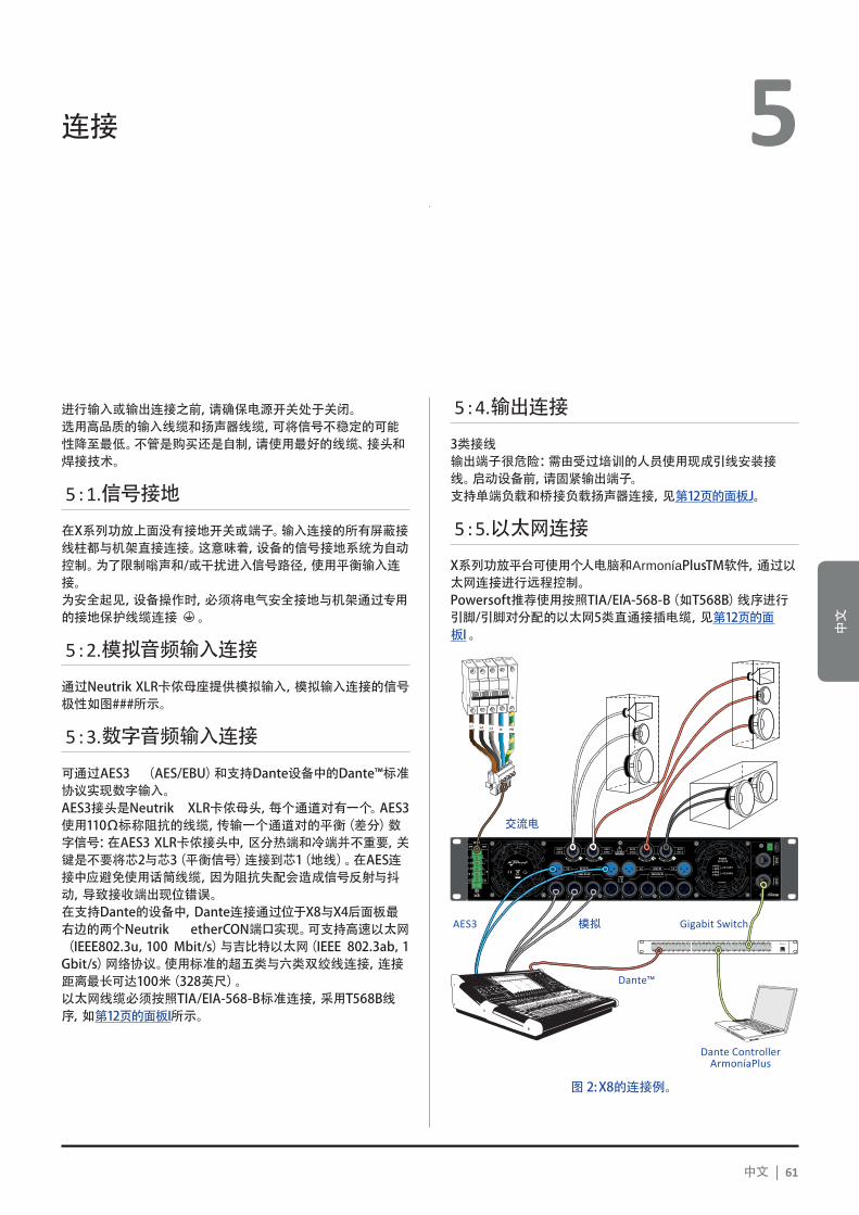
中文
4 连接 5
进行输入或输出连接之前,请确保电源开关处于关闭。选用高品质的输入线缆和扬声器线缆,可将信号不稳定的可能性降至最低。不管是购买还是自制,请使用最好的线缆、接头和焊接技术。
5 : 1.信号接地
在X系列功放上面没有接地开关或端子。输入连接的所有屏蔽接线柱都与机架直接连接。这意味着,设备的信号接地系统为自动控制。为了限制嗡声和/或干扰进入信号路径,使用平衡输入连接。为安全起见,设备操作时,必须将电气安全接地与机架通过专用的接地保护线缆连接 。
5 : 2.模拟音频输入连接
通过NeutrikXLR卡侬母座提供模拟输入,模拟输入连接的信号极性如图###所示。
5 : 3.数字音频输入连接
可通过AES3 (AES/EBU)和支持Dante设备中的Dante™标准协议实现数字输入。AES3接头是Neutrik XLR卡侬母头,每个通道对有一个。AES3使用110Ω标称阻抗的线缆,传输一个通道对的平衡(差分)数字信号:在AES3XLR卡侬接头中,区分热端和冷端并不重要,关键是不要将芯2与芯3(平衡信号)连接到芯1(地线)。在AES连接中应避免使用话筒线缆,因为阻抗失配会造成信号反射与抖动,导致接收端出现位错误。在支持Dante的设备中,Dante连接通过位于X8与X4后面板最右边的两个Neutrik etherCON端口实现。可支持高速以太网(IEEE802.3u,100 Mbit/s)与吉比特以太网(IEEE 802.3ab,1Gbit/s)网络协议。使用标准的超五类与六类双绞线连接,连接距离最长可达100米(328英尺)。以太网线缆必须按照TIA/EIA-568-B标准连接,采用T568B线序,如第12页的面板I所示。
5 : 4.输出连接
3类接线输出端子很危险:需由受过培训的人员使用现成引线安装接线。启动设备前,请固紧输出端子。支持单端负载和桥接负载扬声器连接,见第12页的面板J。
5 : 5.以太网连接
X系列功放平台可使用个人电脑和ArmoníaPlusTM软件,通过以太网连接进行远程控制。Powersoft推荐使用按照TIA/EIA-568-B(如T568B)线序进行引脚/引脚对分配的以太网5类直通接插电缆,见第12页的面板I。
1 2 3 4 5 6 7 8
25 26 27 28 29 30 31 32
9 10 11 12 13 14 15 16
33 34 35 36 37 38 39 40
17 18 19 20 21 22 23 24
41 42 43 44 45 46 47 48 UP Link
Power
L1 L2 L3 N PE
AES3 IN7-8 5-6 AES3 IN3-4 1-2
ANALOG INANALOG IN
8 7 6 5 4 3 2 1
3PH 1PH
L1
L2
L3
N
L
N
1=GND2 = IN+3 = IN-
MAINS
TURN TO LOCK TURN TO LOCKTURN TO LOCK TURN TO LOCK
图2:X8的连接例。
中文 | 61
交流电
AES3 模拟 Gigabit Switch
Dante™
Dante ControllerArmoníaPlus
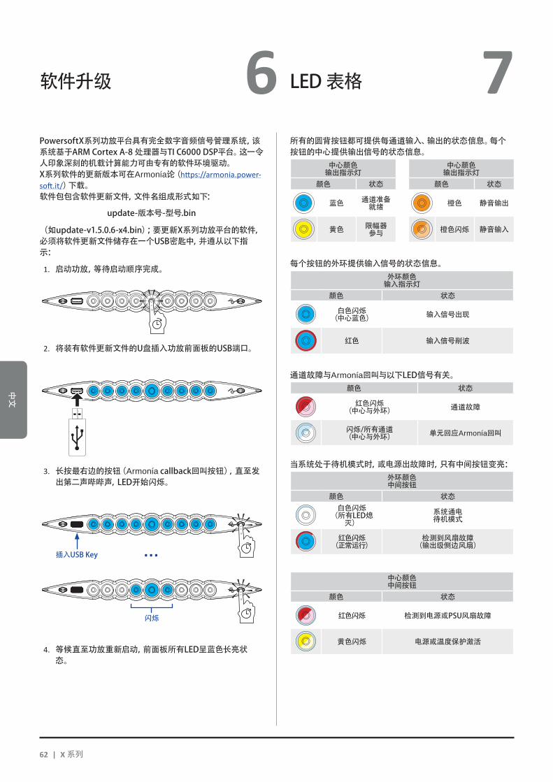
中文
软件升级 LED表格6 7 PowersoftX系列功放平台具有完全数字音频信号管理系统,该系统基于ARMCortexA-8处理器与TIC6000DSP平台。这一令人印象深刻的机载计算能力可由专有的软件环境驱动。X系列软件的更新版本可在Armonía论(https://armonia.power-soft.it/)下载。软件包包含软件更新文件,文件名组成形式如下:
update-版本号-型号.bin
(如update-v1.5.0.6-x4.bin);要更新X系列功放平台的软件,必须将软件更新文件储存在一个USB密匙中,并遵从以下指示:
1. 启动功放,等待启动顺序完成。
2. 将装有软件更新文件的U盘插入功放前面板的USB端口。
3. 长按最右边的按钮(Armoníacallback回叫按钮),直至发出第二声哔哔声,LED开始闪烁。
4. 等候直至功放重新启动,前面板所有LED呈蓝色长亮状态。
所有的圆背按钮都可提供每通道输入、输出的状态信息。每个按钮的中心提供输出信号的状态信息。
中心颜色输出指示灯
中心颜色输出指示灯
颜色 状态 颜色 状态
蓝色 通道准备就绪 橙色 静音输出
黄色 限幅器参与 橙色闪烁 静音输入
每个按钮的外环提供输入信号的状态信息。外环颜色输入指示灯
颜色 状态
白色闪烁(中心蓝色) 输入信号出现
红色 输入信号削波
通道故障与Armonía回叫与以下LED信号有关。颜色 状态
红色闪烁(中心与外环) 通道故障
闪烁/所有通道(中心与外环) 单元回应Armonía回叫
当系统处于待机模式时,或电源出故障时,只有中间按钮变亮:外环颜色中间按钮
颜色 状态白色闪烁(所有LED熄灭)
系统通电待机模式
红色闪烁(正常运行)
检测到风扇故障(输出级侧边风扇)
中心颜色中间按钮
颜色 状态
红色闪烁 检测到电源或PSU风扇故障
黄色闪烁 电源或温度保护激活
闪烁
插入USBKey ...
62 | X 系列

中文
联网 8
X系列功放平台支持线性菊花链、星型或环路拓扑网络。在菊花链网络中,装有ArmoníaPlus™专业音频软件包的个人电脑必须总是位于菊花链的一端。注意,在制作环境中,菊花链连接无法保证可靠性,若出现故障,可能会导致网络中断,失去对系统的控制。若同时需要高效能与可靠性,建议您使用冗余网络拓扑。为了使用Dante™功能,可允许星型和开放菊花链网络拓扑。
8 : 1.IP寻址
出厂网络设置默认为DHCP/AutoIP,这样可让功放平台与现有的局域网或个人电脑连接时,自己进行配置。也可采用固定的IP策略,通过Armonía Pro AudioSuite™专业音频软件包进行配置。若DHCP服务器没在网络中激活,功放平台会激活无状态地址自动配置(即零配置联网方法Zeroconf):它自动分配一个本地的数字网络地址(若有二级网络,地址类型为169.254.x.y –172.31.*.*,子网掩码255.255.0.0),并自动分配、解析联网装置的主机名称。关于如何设置静态IP地址,请参与《ArmoníaPlus用户指南》。
8 : 1.1. IP地址故障排除X系列连接至网络环境后,有可能ArmoníaPlus™专业音频软件包不能发现或导入功放。通常这是IP寻址的问题:Armonía与X系列必须属于同一个子网络。若网络中有DHCP服务器,但X系列功放处于AutoIP模式,联网可能不稳定。
根据经验,连接功放前先打开DHCP服务器。
X系列功放在引导程序(bootstrap)中确定IP地址:在启动过程中,若X系列功放平台发现DHCP服务器,就会协商联网参数。若X系列功放平台不能在网络中找到DHCP服务器,就会自动设置为AUTOIP模式。
8 : 2.Dante™网络连接
X系列功放平台的Dante™版本通过后面板的两个ether-CON端口支持Dante™冗余网络连接:XX Primary/ETH1为主网络端口XX Secondary/ETH2为二级网络端口
Primary/ETH1千兆以太网端口总是支持Dante™连接;若创建了并联冗余网络,Secondary/ETH2千兆以太网端口可保证操作的连续性。要创建Dante网络,必须使用一台运行Dante控制器的电脑。Dante控制器是管理网络上设备的软件应用。X系列功放平台可以自动被Dante控制器搜索到,并以型号名-序列号的形式(如X8-71520)显示在Dante控制器上。Dante网络至少需要一个网络开关。冗余的基建设备可能需要多个开关。要使可靠性达到最大,网络开关必须:XX 适用于吉比特以太网;XX 非阻塞型;XX 具有服务质量(QoS),带至少四个队列XX 具有严格优先级的Diffserv(DSCP)QoSXX 具有EEE(节能以太网)切断
更多网络开关的信息,请参阅Powersoft相关文件。
8 : 2.1. 冗余网络配置通过使用两个完全独立和分开的网络——主网络与二级网络,可在任何支持Dante的音频设备间安装和使用Dante冗余。要安装和使用Dante冗余,请使用两个千兆交换机和网线连接X系列功放平台与其它冗余的Dante音频设备。将运行Dante虚拟声卡与Dante控制器的个人电脑或Mac,以及其它非冗余的Dante音频设备连接至主网络。切勿将主网络和二级网络互相连接。确保所有个人电脑与Mac自动配置它们的IP地址。
中文 | 63

中文
9 ArmoníaPlus
ArmoníaPlus™专业音频软件包是默认设置界面,可设置和自定义X系列功放平台。Armonía可安装在运行Wiidows系统(XPSP3及更高版本)的个人电脑上。可从Armonía论坛下载ArmoníaPlus™专业音频软件包:
https://armonia.powersoft.it/
X系列功放平台可通过高速以太网连接与运行Armonía的个人电脑相连。要远程操作设备,必须找到它并将它导入Armonía工作区。在“远程设备”窗口上点击“搜索”按钮,或从“型号列表”中选定单元,拖曳至Armonía工作区。回叫按钮位于功放前面板的最右边,可让您的Armonía工作空间中迅速找到该功放。一旦与ArmoníaPlus软件连接,双击工作空间的功放图标,打开功放仪表板。在这里,可以访问X系列功放平台的所有功能。
9 : 1.信号路由和DSP架构
图 3: ArmoníaPlus.
Powersoft X系列功放平台的信号处理具有多种功能,可在功率放大之前,对音频信号进行处理。主要的调整包括增益、极性、延时、限幅和信号均衡;有些处理与特定的阶段有关,如限幅与阻尼控制只出现在输出阶段,输入极性分配只出现在输入阶段。处理架构由六个部分组成:XX 输入源选择。输入选择让您管理输入增益、模拟与数字源延时,以补偿传输延迟与电平。另外,X系列使用备份策略应对信号故障,提高系统的可靠度。系统为每通道四个不同的输入源(模拟、AES3与两个Dante™数字流输入)分配优先级,一旦出现信号故障,可自动切换至可靠的输入连接。XX 矩阵。X系列创新的路由引擎可将任何输入路由至任何输出。矩阵使用非布尔路由结构,可自由进行通道分配与电平调整。XX 高级处理。高级处理功能让您优化电平,调整输入信号的声音。路由至扬声器的每通道都具有增益和极性调整、不对称升余弦参量滤波器、延时和静音。XX 扬声器均衡。扬声器均衡处理可管理多分频扬声器系统的配置预设,它具有FIR与IIR参量滤波器。
XX 扬声器理由。正确编组后,输出通道以扬声器的形式出现在矩阵中,每一行代表一个扬声器(其实是不同频段的编组),为信号处理提供精细的信息粒度。XX 输出处理。输出处理级可调整输出信号,优化功率传输与扬声器性能。它在每一输出通道提供增益与极性调整、IIR与FIR参量滤波器、延时、静音、限幅与阻尼控制。
9 : 2.计划的工作流
我们建议,确定扬声器的布局后,采取自下而上的配置流程。先配置换能器,然后选择输入源、定义备份策略。简言之,主要步骤如下:
1. 装载扬声器预设或手动配置扬声器(编组输出通道,进行分频、限幅、扬声器处理等设置)。
2. 定义路由通路,以及从输入通道到有源输出通道的信号电平(矩阵)。
3. 从输入端选择信号源,定义备份策略(输入源选择)。
64 | X 系列
中文
9 保修和帮助 10 10 : 1.保修
10 : 1.1. 产品保修Powersoft可向终端用户确保,从Powersoft(或任何授权
经销商)发票上记录的购买日期开始算起,其生产产品在48个月内无任何部件和工厂工艺缺陷。所有保修和翻新服务必须在Powersoft 厂家或其授权维修中心为购买者免费提供。保修例外情形:Powersoft的保修范围不包括由下列原因造成的产品故障或失效:使用不当,滥用,非授权人员执行的维修工作或改动,不正确连接,暴露于恶劣的气候条件,机械损失(包括运输事故),以及正常磨损。如果产生在运输途中没有收到损害,Powersoft将会执行保修服务。
10 : 1.2. 退货只有在为产品授予一个退货授权(RMA)编号并
将该编号附着在外包装上之后,才可以将产品返回给Powersoft。Powersoft(或其授权维修中心)有权利拒绝任何不带RMA编号的退货。
10 : 1.3. 修理或替换Powersoft 有权按照自己认为的最佳方式对产品保修范围
内的缺陷产品进行维修或替换。
10 : 1.4. 运输成本和责任将保修范围内商品送到Powersoft或其授权维修中心相关的
所有运输成本和风险由购买人(或终端用户/客户)全权负责。在将产品返回给购买人(或终端用户/客户)时,Powersoft将会承担与之相关的所有责任并负责所有成本费用。
10 : 2.帮助
在您的功放中没有用户可维修部件。请将维修工作交给有资质的技术人员进行。除了拥有一个内部的维修部门,Powersoft还支持一个授权维修中心网络。如果您的功放需要维修,请联系您的Powersoft代理商(或经销商)。您也可以联系Powersoft 的技术服务部门索取离您最近的授权服务中心地址。
尽管大多数产品故障可在您的场所通过Powersoft的客户服务或者您自己的专业知识就地解决。偶尔,由于故障性质,也有必要将缺陷产品返回给Powersoft进行维修。在后一种情况下,建议您在运送前按照下列步骤一步步进行:邮件联系我们的客户服务部门([email protected])获取“缺陷报告表格”或者直接下载“缺陷报告表格”。为每件返回商品(该表格是一个可编辑、有标签指导的文件)填写“缺陷报告表格”,并另存为您的姓名,功放型号和序列号(例如:distributornamek10sn17345.doc),提供RMA编码之外的任何信息,并将其发送到[email protected]获取Powersoft审批。在Powersoft客户服务代表批准了您的缺陷报告后,您会收到一个RMA授权代码(每个返回设备只有一个RMA代码)。在收到RMA代码后,你必须包装设备并将RMA代码贴在包装外侧,并用防水透明邮袋将其保护,从而使其倾斜可辨。所有返回产品都必须船运到以下地址:PowersoftViadeiCadolingi,1350018Scandicci(FI)Italy
在从欧洲共同市场以外国家船运时,请从http://www.powersoft-audio.com/en/support/service网站的 TEMPORARY EXPORTATION / IMPORTATIONPROCEDURE链接下载可用文件,按照文件中的指示操作。感谢您在我们不断提高伙伴关系的过程中,给与我们一如既
往的理解、合作与支持。
中文 | 65

Deutsch
ACHTUNG
STROMSCHLAGRISIKONICHT ÖFFNEN
Elektrische Energie kann viele nützliche Funktionen erfüllen. Dieses Gerät wurde entwickelt und gefertigt mit dem Ziel, Ihre persönliche Sicherheit zu gewährleisten. UNANGEMESSENE VERWENDUNG KANN ZU STROMSCHLAG ODER AUSBRUCH VON FEUER FÜHREN.Um die in diesem Produkt eingebauten Schutzvorrichtungen nicht ausser Funktion zu setzen, beachten Sie bitte die folgenden Regeln zu Installation, Nutzung und Wartung. Bitte lesen Sie diese “Wichtigen Sicherheitshinweise”sorgfältig vor Benutzung durch.
Wichtige Sicherheitshinweise1. Lesen Sie diese Anweisungen.2. Bewahren Sie diese Anweisungen auf.3. Befolgen Sie alle Warnhinweise.4. Befolgen Sie alle Anweisungen.5. Benutzen Sie dieses Gerät nicht in der Nähe von Wasser.6. Reinigen Sie dieses Gerät nur mit einem trockenen Tuch.7. Blockieren Sie keine Lüftungsöffnungen. Installieren Sie das
Gerät nur in Übereinstimmung mit den Anweisungen des Herstellers.
8. Installieren Sie das Gerät nicht in der Nähe von Wärmequellen wie Radiatoren, Heizungen, Öfen oder anderen Geräten (einschließlich Verstärkern), die Wärme produzieren.
9. Schützen Sie das Netzanschlußkabel vor Tritten und Knicken, insbesondere in der Nähe von Steckern, Steckdosen und der Netzkabelbuchse des Geräts.
10. Verwendung Sie ausschließlich Montageteile, die vom Hersteller spezifiziert sind.
11. Verwenden Sie ausschließlich vom Hersteller spezifizierte oder mit dem Gerät zusammen verkaufte Zubehörteile wie Gerätewagen, Ständer, Montagebügel, etc. Bei Verwendung eines Gerätewagens bewegen Sie diesen bitte vorsichtig, um ein Verletzungsrisiko durch Umstürzen zu vermeiden. .
12. Bitte trennen Sie das Gerät vom Stromnetz während Gewittern oder wenn das Gerät für längere Zeit nicht benutzt wird.
13. Wenden Sie sich für Wartungsarbeiten ausschließlich an qualifiziertes Fachpersonal. Wartungsarbeiten werden notwendig, sobald das Gerät in irgendeiner Weise beschädigt worden sein könnte, wie z. B. im Falle eines beschädigten Netzkabel oder Netzsteckers, sobald Flüssigkeiten oder Objekte in das Gehäuseinnere gelangt sein könnten, das Gerät Feuchtigkeit oder Regen ausgesetzt war, es nicht korrekt arbeitet oder fallen gelassen wurde.
WARNHINWEIS: VERSUCHEN SIE NCHT, IRGENDEINEN TEIL DIESES GERÄTES ZU ÖFFNEN, DENN DANN BESTEHT DIE GEFAHR EINES STROMSCHLAGS. IM INNERN GIBT ES KEINE TEILE, DIE DURCH DEN ANWENDER REPARIERT WERDEN KÖNNTEN. ÜBERLASSEN SIE REPARATUR- UND WARTUNGSARBEITEN AUSSCHLIESSLICH QUALIFIZIERTEM FACHPERSONAL.
SETZEN SIE DIESES GERÄT NICHT REGEN ODER FEUCHTIGKEIT, TRÖPFELDEN ODER SPRITZENDEN FLÜSSIGKEITEN AUS. MIT FLÜSSIGKEITEN GEFÜLLTE OBJEKTE WIE VASEN SOLLEN NICHT AUF DEM GERÄT ABGESTELLT WERDEN.
DAS GERÄT MUSS NUR IN RACKS EINGEBAUT WERDEN: STECKER DES VERSTÄRKERS NETZVERBINDUNGEN ÜBER EINE SCHNEIDEUNTERBRECHER ZU EINEM STROMVERTEILERTAFEL IM INNEREN DES RACK-SCHRANK.
DIE SCHNITTSCHUTZSCHALTER MUSS LEICHT ZUGÄNGLICH BLEIBEN.
SOLLTE DAS GERÄT IN EINEM GESTELLSCHRANK INSTALLIERT SEIN , SO STELLEN SIE SICHER, DASS GENÜGEND ABSTAND NACH ALLEN SEITEN BESTEHT, UM EINE ORDNUNGSGEMÄSSE KÜHLUNG ZU GEWÄHRLEISTEN (50 CM VON DEN VORDEREN UND HINTEREN KÜHLLUFTÖFFNUNGEN).
DER ANSCHLUSS AN DAS STROMNETZ SOLLTE AUSSCHLIESSLICH VON FACHPERSONAL ENTSPRECHEND DEN NATIONALEN BESTIMMUNGEN DES LANDES VORGENOMMEN WERDEN, IN WELCHEM DAS GERÄT VERKAUFT WIRD.
WARNUNG: SICHERUNG AUF NEUTRAL
CLASS3WIRING
CLASS3WIRING
CLASS3WIRING
CLASS3WIRING
CLASS3WIRING
CLASS3WIRING
CLASS3WIRING
Erklärung der Graphischen Zeichen / Pictogramme
CLASS3WIRING
Das Dreieck mit dem Blitz warnt den Nutzer vor dem Risiko eines Stromschlags.
CLASS3WIRING
Das Dreieck mit dem Ausrufezeichen weist den Nutzer auf wichtige Bedienungs- und Wartungsanweisungen hin.
Das CE-Zeichen steht für die Einhaltung der Niederspan-nungsrichtlinie und den Bestimmungen betreffend der Elektro-Magnetischen-Verträglichkeit (EMV).
Zeichen für den Erde/Masse Anschluß.
Zeichen für den ausschließlichen Gebrauch in geschlosse-nen Räumen.
Zeichen für die Konformität mit Direktive 2002/96/EC und Direktive 2003/108/EC des Europäischen Parlaments be-treffend Entsorgung von elektrischen und elektronischen Geräten (WEEE).
Verwenden Sie das Gerät nicht auf Höhen über 2000 m.
Das Gerät in der tropischen Umgebung nicht verwenden.
Wichtige Sicherheitshinweise 1
66 | X Series
Deu
tsch
X Serie KURZANLEITUNG 2
2 : 1.Willkommen
Wir gratulieren herzlich zum Kauf eines Powersoft X-Serie Verstärkers!
Sicherlich können Sie es kaum erwarten, Ihren neuen X8 oder X4 Verstärker in Betrieb zu nehmen. Bitte nehmen Sie sich jedoch einen Moment Zeit, um diese Kurzanleitung und die Sicherheitsanweisungen zu lesen. Sollten Sie noch Fragen haben, so zögern Sie bitte nicht, Ihren Powersoft Händler oder Powersoft direkt anzusprechen.
Die Powersoft X Serie bringt das Konzept der Verstärkerplattform auf eine vollkommen neue Ebene: Das Modell X8 ist ein 8-Kanal-Verstärker, das Modell X4 bietet 4 Kanäle in einem 1HE-Gehäuse.
Beide verfügen über ein neues System des Kanalsignalführung, eine wahrlich neuartiges Netzteil und einen revolutionären voll-ausgestatteten DSP. Die Powersoft X8 and X4 Verstärker unter-stützen schon von Haus aus AES3, dazu analoge Eingänge, sowie optional zwei redundante Dante™ by Audinate® Digital Audio Netzwerke, die zusammen bis zu 4 verschiedene und frei wähl-bare Eingangsquellen pro Kanal zur Verfügung stellen.
Zur Systemkonfiguration und Feinabstimmung bietet die ArmoníaPlus™ Software eine intuitive Bedienoberfläche und da-mit allumfassende Kontrolle über die digitale Signalverarbeitung und vollständige Echtzeitüberwachung des Systemverhaltens.
Die integrierte WiFi-Anbindung erlaubt die Ansprache und die Steuerung der Powersoft X-Serie Geräte durch mobile Endgeräte über eine speziell für die locale Steuerung und Überwachung ent-wickelte Schnittstelle.
Die Powersoft Modelle X4 und X8 heben das Thema Leistungsverstärkung auf einen neuen Qualitäts- und Anwendungsstandard: Sie passen sich Ihrer Systemkonfiguration an, sparen Platz und Gewicht und bieten Ihnen die legendäre Powersoft Effizienz und ein neuartiges, weltweit kompatibles Mehrphasen-Netzteil.
2 : 2.Auspacken und auf Transportschäden prüfen
Ihr Powersoft Gerät wurde vollumfänglich getestet und kon-trolliert, bevor es das Werk verlassen hat. Untersuchen Sie bitte die Verpackung vor dem Öffnen sorgfältig und daraufhin auch Ihr neues Gerät. Sollten Sie irgendeinen Schaden feststellen, so informieren Sie bitte unverzüglich die Transportfirma.
Die Verpackung muss folgende Teile enthalten:XX 1 x X Serie VerstärkerXX 1 x PC 5/5-STF1-7,62 Phoenix KabelsteckerXX 1 x Steckergehäuse SchalenXX 1 x Kurzanleitung
2 : 3.Entsorgung des Verpackungsmaterials
Die Transport- und Schutzverpackung wurde aus umwelt-freundlichen Materialien hergestellt, die wieder verwendet werden können.
Bitte bieten Sie diese Wertstoffe zur Wiederverwertung an, bevor Sie sie wegwerfen.
2 : 4.Liste der Abbildungen
A. Gehäuseabmessungen X8/X4L: Alle Angaben in MillimeterB. Gehäuseabmessungen X4: Alle Angaben in MillimeterC. X8 GeräterückseiteD. X4L GeräterückseiteE. X4 GeräterückseiteF. X8 und X4L/X4 GerätefrontseitenG. Montagepunkte und KühlluftströmungH. Regel für den Einbau in geschlossenen GestellschränkenI. Stiftbelegung EingangssteckverbinderJ. Stiftbelegung RJ45 Ethernet K. LautsprecherverkabelungL. Dreiphasenbetrieb: Belegung NetzanschlusskabelsteckerM. Einphasenbetrieb: Belegung NetzanschlusskabelsteckerN. Einphasenbetrieb: Belegung NetzanschlusskabelsteckerO. Montage Schalen NetzanschlusskabelsteckerP. Gesetzliche Regelungen
Deutsch | 67

Deutsch
Installation 3 3 : 1.Positionierung
Die X-Serie Verstärker sind ausschliesslich für die Verwendung in einem Gestellrahmen (Rack) vorgesehen. Die Netzspannungsversorgung der Geräte darf nur an einem Anschluss erfolgen, der über einen geeigneten Sicherungsautomaten ver-fügt (siehe §3 : 4.Stromversorgung). Der direkte Anschluss von X-Serie Geräten an die Stromverteilung ist nicht zulässig. Für den nordamerikanischen Markt empfehlen wir die Verwendung eines zugelassenen UL/USA Kabels (z. B. ST 600Vac 105°C 5x13AWG).
Um die Risiken mechanischer Beschädigungen zu begrenzen, müssen die Verstärker im Gestellrahmen mittels der frontseitigen und rückwärtigen Montagehalterungen befestigt werden. Wir emp-fehlen die Verwendung von acht M6 oder 12-24 UNC-2B Schrauben für Gewindelöcher oder Käfigmuttern. Stellen Sie diesen Verstärker so weit wie möglich entfernt von Rundfunk- oder Fernsehempfängern auf. Ein in unmittelbarer Nähe zu solchen Geräten platzierter Verstärker kann dadurch rauschen oder sich in seinen typischen Leistungsmerkmalen verschlechtern. Die Verwendung des Verstärkers über längere Zeit in der Nähe Wärmequellen kann seine Leistungsfähigkeit beeinträchtigen. Vermeiden Sie daher die Aufstelllung des Verstärkers direkt auf Wärmequellen.
3 : 2.Kühlung
Stellen Sie den Verstärker nur an gut gelüfteten Orten auf: Die Kühlluftauslässe dürfen nicht durch Dinge wie Zeitungen, Tischtücher, Vorhänge, etc. abgedeckt sein. Halten Sie einen Mindestabstand von 50cm zu den Kühlluftein- und auslässen ein.
Alle Powersoft Verstärker verfügen über ein Zwangskühlungssystem, um eine möglichst niedrige und konstante Betriebstemperatur aufrecht zu erhalten. Von den internen Lüftern angesaugt strömt Luft durch die Öffnungen in der Vorderseite, wird über alle Bauteile hinweg geleitet und wird auf der Rückseite wieder ausgeblasen.
Das Kühlsystem des Verstärkers nutzt “intelligente” Gleichstromlüfter mit variabler Geschwindigkeit, die durch Sensoren an den Kühlkörpern gesteuert wird: So erhöht sich die Lüftergeschwindigkeit nur, sobald die von den Sensoren gemesse-ne Temperatur über gewissenhaft abgestimmte Schwellenwerte steigt.
Dadurch werden Lüfter- und Windgeräusche sowie Staubansammlungen im Gehäuseinnern auf ein Minimum beschränkt.
Sollte der Verstärker jedoch einer hohen themischen Belastung ausgesetzt sein, so wird der Lüfter ein sehr großes Luftvolumen durch die Kühlkörper drücken. Im extrem seltenen Fall einer ge-fährlichen Überhitzung des Verstärkers schalten Sensoren alle Kanäle solange ab, bis der Verstärker wieder auf eine ungefährliche Betriebstemperatur abgekühlt ist. Der normale Betrieb wird wieder aufgnommen, ohne dass der Anwender eingreifen muss.
Durch das wirkungsvolle Kühlsystem können X Serie Verstärker einfach aufeinander gestellt werden.
Ein Sicherheitslimit muss jedoch beachtet werden: Wird ein Gestellschrank mit geschlossener Rückseite verwendet, so muss nach vier aufeinander montierten Verstärkern eine Höheneinheit für die eine adäquate Luftzirkulation frei bleiben.
3 : 3.Reinigung
Benutzen Sie ausschliesslich ein trockenes Tuch zur Reinigung des Gehäuses und der Vorderseite. Die Reinigung der Staubschutzfilter sollte entsprechend der Staubbelastung im Betriebsbereich des Verstärkers vorgenommen werden.
Trennen Sie das Gerät vom Stromnetz bevor Sie irgendein Teil des Verstärkers reinigen wollen
Um die Staubschutzfilter zu reinigen müssen Sie lediglich die Gerätefrontseite demontieren. Versuchen Sie niemals, irgendein anderes Gehäuseteil des Gerätes zu öffnen.
Um den Staubschutzfilter zu entnehmen, lösen Sie bitte die beiden Schrauben links und rechts auf der Frontseite mit einem #6-Innensechskant-Schraubendreher (siehe BILD 1) und heben Sie vorsichtig die Abdeckung ab. Sie können Staubpartikel mit Druckluft aus dem Filter blasen oder ihn mit klarem Wasser aus-waschen. In letzterem Fall stellen Sie bitte sicher, dass der Filter trocken ist, bevor Sie ihn wieder einsetzen.
3 : 4.Stromversorgung
Durch ihre global kompatiblen Netzteile lassen sich X Serie Verstärker direkt an jede regionale Stromversorgung anschlies-sen. Die legendär zuverlässigen Powersoft Netzteile arbeiten nun mit Einphasen-, Zweiphasen- oder Dreiphasen-Stromversorgung in einem Netzspannungsbereich von 90 VAC bis 464 VAC ohne Notwendigkeit der manuellen Voreinstellung: Eine echter Dreiphasen-Lastausgleich wird vom Gerät direkt vorgenommen ohne komplexe Lastzuteilungen durch entsprechendes Design der Stromverteilersysteme.
Der Anschluss an das Stromnetz erfolgt mit einem Phoenix eu-roblock PC 5/5-STF1-7,62 Steckverbinder (Phoenix Artikelnummer 1777862). Die Montage der Netzzuleitung an den Kabelstecker muss korrekt entsprechend der Netzkabelkonfiguration erfolgen.
Achten Sie darauf, alle fünf Kontakte des Kabelsteckers entspre-chend der Konfiguration wie in Abbildung K, L, M auf s. 13 und s.
BILD 1: Verwenden Sie einen #6 Innensechskant-Schraubendreher zur Demontage der Frontplatte.
68 | X Series
Deu
tsch
3 14 gezeigt. Um die korrekte Verbindung zu gewährleisten, emp-fehlen wir den Einsatz einer genehmigten UL / CSA-Kabel verwenden (z. B. ST 600Vac 105°C 5x13AWG).
Dieses Gerät darf ausschliesslich an geerdeten Netzleitungen konform zu IEC 364 oder entsprechenden Vorschriften betrieben werden.
Der Netzschalter stellt keine vollständige Trennung vom Stromnetz her. Um das Gerät endgültig vom Stromnetz zu neh-men müssen Sie es von der Stromquelle trennen.
Versehen Sie die Netzzuleitung mit einem Sicherungsautomaten zwischen
Stromquelle und Verstärker.
Entsprechend der Netzkonfiguration empfiehlt Powersoft für das Modell X8:
Einphasen Wechselstrom (P+N+E): 32 A, C oder D Kennlinie, 10 kA.Dreiphasen Wechselstrom (3P+N+E): 4 x 16 A, C oder D Kennlinie, 10 kA.
Für das Modell X4 empfiehlt Powersoft:Einphasen Wechselstrom (P+N+E): 16 A, C oder D Kennlinie, 10 kA.Dreiphasen Wechselstrom (3P+N+E): 4 x 10 A, C oder D Kennlinie, 10 kA.
HINWEIS: Die Abbildungen und Anweisungen zur Netzkabelverdrahtung beziehen sich auf die Europäischen CENELEC Standards vom April 2004 (IEC 60446) betreffend Farbcodierungen zur Identifikation von Leitern (siehe TAB. 1).
Conductor Color
Neutralleiter N Blau
Phasenleiter
L1 Braun
L2 Schwarz
L3 Grau
Schutzleiter (Erde) E Grün/Gelb
TAB. 1: Farbcodierungen zur Identifikation von Leitern.
Anschlüsse an das Stromnetz dürfen nur von qualifiziertem gewerlichen Fachpersonal entsprechend den lokalen gesetzlichen Bestimmungen vorgenommen werden.
3 : 4.1. Dreiphasen-StromversorgungJeder einzelne Leiter muss fest mit dem PC5/5-STF1-7,62
Kabelstecker verbunden werden wie in Abbildung K, s. 13 ge-zeigt. In manchen Fällen kann der Neutralleiter auch fehlen. Da die Geräte der X-Serie auch in Dreieckschaltung arbeiten, ist der Neutralleiter bei Dreiphasenbetrieb nicht zwingend notwendig.
3 : 4.2. Zweiphasen-StromversorgungEine symmetrierte Zweiphasen-Stromversorgung in der
Konfiguration 2P+E ohne Neutralleiter muss entsprechend Abbildung M, s. 14 am Kabelstecker PC5/5-STF1-7,62 auf-gelegt werden. Sorgen Sie dafür, dass die Phasenleiter jeweils doppelt belegt sind, um den notwendigen Leiterquerschnitt zu gewährleisten.
3 : 4.3. Einphasen-StromversorgungDie unsymmetrische Einphasen-Stromversorgung P+N+E
mit Neutralleiter ist die übliche Konfiguration für einphasige herkömmliche Haushaltsstromnetze. Die Verkabelung muss wie in Abbildung L, s. 13 erfolgen. Sorgen Sie dafür, dass Phasen- und Neutralleiter jeweils doppelt am Kabelstecker als auch am Sicherungsautomaten aufgelegt werden, um den notwendigen Leiterquerschnitt zu gewährleisten
3 : 5.Vorsichtsmassnahmen bei der Installation
WARNHINWEISE: VERMEIDUNG VON STROMSCHLAGXf Dieses Gerät darf ausschliesslich an Steckdosen mit Schutzleiter in
Stromnetzen entsprechend IEC 364 oder ähnlich betrieben werden.
Xf Nur installieren Sie das Gerät in ein Gehäuse nur oder einen Gestellschrank.
Xf Im Gestellschrank oder Gehäuse muss ein Sicherungsautomat zwi-schen Stromnetz und Verstärker installiert sein.
Xf Sorgen Sie dafür, dass jeder einzelne Leiter des Netzkabels korrekt am Kabelstecker Phoenix PC 5/5-STF1-7,62 befestigt ist.
Xf Sobald die korrekte Verkabelung hergestellt ist setzen Sie bitte den Kabelstecker in die beiden von Powersoft mitgelieferten Steckergehäuseschalen ein und fixieren sie ihn.
Xf Befestigen Sie den fertigen Kabelstecker an der Netzbuchse des Verstärkergehäuses.
Xf Stellen Sie sicher, dass die korrekte Netzspannung vorliegt, bevor Sie den Verstärker an das Stromnetz anschliessen.
Xf Stellen Sie sicher, dass Ihre Stromversorgung in der Lage ist, die Leistungsaufnahme des Gerätes zu liefern.
Xf Benutzen Sie diesen Verstärker nicht wenn das Netzkabel Beschädigungen oder Brüche aufweist.
Xf An den Ausgangsbuchsen können gefährliche Spannungen anliegen: Anschlussverbindungen zu diesen Buchsen erfordern die Installation durch Fachpersonal und die Verwendung vorgefertigter Kabel.
Xf Sorgen Sie dafür, dass die Ausgangsbuchsen belegt sind bevor Sie den Verstärker einschalten.
Xf Um einen Stromschlag zu vermeiden berühren Sie niemals blanke Enden von Lautsprecherkabeln solange der Verstärker in Betrieb ist.
Xf Schütten Sie kein Wasser oder andere Flüssigkeiten auf oder in den Verstärker.
Xf Stellen Sie keine offenen Feuerquellen wie beispielsweise brennen-de Kerzen auf den Verstärker.
Xf Öffnen Sie nicht das Gehäuse, da Sie sich sonst möglicherweise gefährlichen Spannungen aussetzen.
Xf Der Hersteller kann nicht für Schäden an Personen, Sachen oder Daten verantwortlich gemacht werden, die durch eine unzurei-chende oder fehlende Erdung des Geräts verursacht werden.
Xf Wenden Sie sich für regelmäßige Wartungsarbeiten oder Reparaturen an ein Authorisiertes Servicecenter.
Es ist unbedingt notwengig, diese fundamentale Sicherheitsanforderung zu befolgen. Lassen Sie im Zweifelsfall
eine Prüfung durch Fachpersonal durchführen.
Deutsch | 69

Deutsch
3 : 6.Einschalten
Sobald Sie den Verstärker mit dem Stromnetz verbunden ha-ben versorgt das Verstärkernetzteil die Hilfssysteme mit Strom. Der äußere Ring des zentralen Druckschalters blinkt weiss, d. h., der Verstärker befindet sic him Bereitschaftsmodus. Durch Druck auf diesen Schalter nehmen Sie den Verstärker in Betrieb.
3 : 7.Ausschalten
Halten Sie den zentralen Druckschalter 3 Sekunden lang ge-drückt , um den Verstärker ausser Betrieb zu nehmen. Das Gerät geht in den Bereitschaftsmodus und der äußere Ring des zentralen Drucktasters blinkt weiss. Das Gerät ist vollständig ausgeschaltet, sobald der Netzstecker aus der Steckdose gezogen wird.
3 : 8.Stummschalten
Ein kurzer Druck auf den zentralen Druckschalter schaltet alle aktiven Kanäle zwischen MUTE und UNMUTE um, wobei bereits gemutete Kanäle in diesem Zustand verbleiben. Die anderen Drucktaster schalten die jeweiligen einzelnen Kanäle zwischen MUTE und UNMUTE um.
3 : 9.Wi-Fi Ein-/Ausschalter
Drücken Sie den Knopf ganz links aussen auf der Frontplatte: Der Knopf leuchtet auf und das System baut eine neues lokales WiFi-Netzwerk mit der SSID: Powersoft-MODELNAME-SERIAL (e.g. Powersoft-X8-70133) und dem voreingestellten Passwort 0123456789 auf.
3 : 10.Armonía Rückruffunktion
Um das betreffende Gerät auf dem Workspace der Armonía Software zu identifizieren drücken Sie den Knopf ganz rechts aussen auf der Frontplatte.
Durch Klicken auf die Schaltfläche “Un/Blink” im Kontextmenü eines auf dem Armonía Workspace abgebildeten Verstärkers blin-ken alle LED’S auf der Frontplatte des betreffenden Verstärkers eine Zeit lang.
Wi-Fi 4 Folgen Sie dem nachstehenden Ablauf, um die WiFi-
Verbindung zu aktivieren und lokal auf Ihren Powersoft X-Serie Verstärker zuzugreifen:
1. Schalten Sie den Verstärker durch längeren Druck auf den zentralen Durckschalter auf der Frontplatte ein.
2. Drücken Sie den Knopf ganz links aussen auf der Frontplatte. Der Knopf leuchtet auf und das System baut eine neues lokales WiFi-Netzwerk mit der SSID
Powersoft-MODELNAME-SERIAL (e.g. Powersoft-X8-71520) auf.
3. Rufen Sie die WiFi-Einstellungen auf Ihrem mobilen Endgerät auf.
4. Wählen Sie das WiFi-Netzwerk des Verstärkers mit der o. g. SSID aus, sobald dieses angezeigt wird.
5. Geben Sie das voreingestellte WiFi-Passwort:
0123456789 ein.
6. Öffnen Sie Ihren Internet-Browser und geben Sie die folgen-de IP-Adresse in die Adresszeile ein:
192.168.0.1
7. Das System schiebt nun die Bedienoberfläche auf Ihren Browser und Sie können damit beginnen, Ihren Verstärker zu verwalten.
8. Um das Wiederauffinden und das Arbeiten mit der Bedienoberfläche zu vereinfachen schlagen wir vor, diese Seite mit einem Lesezeichen auf Ihrer Startseite Ihres Mobilgerätes zu markieren. Auf einem iOS-Gerät bespie-slweise klicken Sie auf das Icon “Teilen” und wählen dann “Add to Home Screen” aus, sobald die Bedienoberfläche vollständig geladen wurde.
9. Vergessen Sie nicht, das lokale WiFi-Netzwerk wieder abzu-schalten, wenn es nicht mehr verwendet wird. Drücken Sie dazu wieder
MUTE/UNMUTE KANAL 2
MUTE/UNMUTE ALLE
70 | X Series
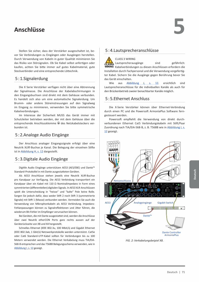
Deu
tsch
4 Anschlüsse 5 Stellen Sie sicher, dass der Verstärker ausgeschaltet ist, be-
vor Sie Verbindungen zu Eingängen oder Ausgängen herstellen. Durch Verwendung von Kabeln in guter Qualität minimieren Sie das Risiko von Störsignalen. Ob Sie Kabel selbst anfertigen oder kaufen, achten Sie bitte immer auf gutes Kabelmaterial, gute Steckverbinder und eine entsprechende Löttechnik.
5 : 1.Signalerdung
Die X Serie Verstärker verfügen nicht über eine Abtrennung der Signalmasse. Die Anschlüsse der Kabelabschirmungen in den Eingangsbuchsen sind direkt mit dem Gehäuse verbunden. Es handelt sich also um eine automatische Signalerdung. Um Brumm- oder andere Störeinstreuungen auf den Signalweg im Eingang zu minimieren, verwenden Sie bitte symmetrische Kabelverbindungen.
Im Interesse der Sicherheit MUSS das Gerät immer mit Schutzleiter betrieben werden, der mit dem Gehäuse über die entsprechende Anschlussklemme des Netzkabelsteckers ver-bunden ist.
5 : 2.Analoge Audio Eingänge
Der Anschluss analoger Eingangssignale erfolgt über eine Neutrik XLRf-Buchse je Kanal. Die Belegung der einzelnen Stifte ist in Abbildung H, s. 12 dargestellt.
5 : 3.Digitale Audio Eingänge
Digitile Audio Eingänge unterstützen AES3 (AES/EBE) und Dante™ Standard-Protokollel in mit Dante ausgestatteten Geräten.
Als AES3 Anschlüsse stehen jeweils eine Neutrik XLRf-Buchse pro Kanalpaar zur Verfügung. Die AES3 Verbindung transportiert ein Kanalpaar über ein Kabel mit 110 Ω Nominalimpedanz in Form eines symmtrierten (differentiellen) digitalen Signals. In AES3 XLR-Anschlüssen spielt die Unterscheidung in “heisse” und “kalte” Pole keine Rolle. Sorgen Sie jedoch dafür, dass weder Stift 2 noch Stift 3 (symmetrierte Signale) mit Stift 1 (Masse) verbunden werden. Vermeiden Sie auch die Verwendung von Mikrophonkabeln als AES3 Verbindung. Impedanz-Fehlanpassungen können zu Signalreflektionen und Jitter führen, die wiederum Bit-Fehler im Empfänger verursachen können.
Bei Geräten, die mit Dante ausgestattet sind, werden die Anschlüsse über zwei Neutrik etherCON Ports ganz rechts aussen auf der Geräterückseite von X8 und X4 hergestellt.
Schnelles Ethernet (IEEE 802.3u, 100 Mbit/s) and Gigabit Ethernet (IEEE 802.3ab, 1 Gbit/s) Netzwerkprotokolle werden unterstützt. Cat5e oder Cat6 Standard-UTP-Kabel sollten für Verbindungen bis zu 100 Metern verwendet werden. Die Ethernet Verkabelung muss TIA/EIA-568-B entsprechen und das T568B Belegungsschema verwenden, wie in Abbildung I, s. 12 gezeigt.
5 : 4.Lautsprecheranschlüsse
CLASS3WIRING
CLASS 3 WIRINGLautsprecherausgänge sind gefährlich: Kabelverbindungen zu diesen Anschlüssen erfordern die
Installation durch Fachpersonal und die Verwendung vorgefertig-ter Kabel. Sichern Sie die Ausgänge gegen Berührung bevor Sie das Gerät einschalten.
Wie aus Abbildung J, s. 12. ersichtlich sind Lautsprecheranschlüsse für die individuellen Kanäle als auch für den Brückenbetrieb zweier benachbarter Kanäle möglich.
5 : 5.Ethernet Anschluss
Die X-Serie Verstärker können über Ethernet-Verbindung durch einen PC und die Powersoft ArmoníaPlus Software fern-gesteuert werden.
Powersoft empfiehlt die Verwendung von direkt durch-verbundenen Ethernet Cat5 Verbindungskabeln mit Stift/Paar Zuordnung nach TIA/EIA-568-B, z. B. T568B wie in Abbildung I, s. 12 gezeigt.
1 2 3 4 5 6 7 8
25 26 27 28 29 30 31 32
9 10 11 12 13 14 15 16
33 34 35 36 37 38 39 40
17 18 19 20 21 22 23 24
41 42 43 44 45 46 47 48 UP Link
Power
L1 L2 L3 N PE
AES3 IN7-8 5-6 AES3 IN3-4 1-2
ANALOG INANALOG IN
8 7 6 5 4 3 2 1
3PH 1PH
L1
L2
L3
N
L
N
1=GND2 = IN+3 = IN-
MAINS
TURN TO LOCK TURN TO LOCKTURN TO LOCK TURN TO LOCK
FIG. 2: Verkabelungsbeipiel X8.
Deutsch | 71
Netzanschlussv
AES3 Analogeingänge Gigabit Switch
Dante™
Dante ControllerArmoníaPlus

Deutsch
Software update LED Anzeigen6 7 Die Powersoft X-Serie Verstärker schliessen ein vollständiges
Digital Audio Signalverarbeitungssystem mit ein, welches auf einem ARM Cortex A8 Prozessor und der TI C6000 DSP-Plattform basiert. Diese beeindruckende Rechenleistung wird von einer speziell dafür entwickelten Softwareumgebung betrieben.
Aktualisierte Versionsstände der X Serie Software sind auf dem Armonía Forum (https://armonia.powersoft.it/) zum Download erhältlich.
Dass Paket enthält die aktualisierte Versionsdatei mit folgen-der Bezeichnung:
update-version#-model.bin (e.g. update-v1.5.0.6-x4.bin);
Zur Aktualisierung der Software Ihres X-Serie Verstärkers müssen Sie zunächst die aktualisierte Versionsdatei in einem USB-Stick abspei-chern und danach diesen Anweisungen folgen:
1. Schalten Sie den Verstärker ein und warten Sie, bis er voll-ständig hochgefahren ist.
2. Stecken Sie den USB-Stick mit der aktualisierten
Versionsdatei in den USB-Port auf der Frontseite des Verstärkers.
3. Halten Sie den Armonia callback Knopf ganz rechts auf der Frontseite so lange gedrückt, bis der zweite Piepston ertönt und die LED’s zu blinken anfangen.
4. Warten Sie bis der Verstärker neu startet und alle LED’s blau aufleuchten.
Alle kreisrunden hinterleuchteten Druckschalter liefern Statusinformationen. Der innere Kreis eines jeden Druckschalters liefert Statusinformationen über das Ausgangssignal.
Farbe des inneren KreisesAnzeigen AUSGANG
Farbe des inneren KreisesAnzeigen AUSGANG
Farbe Status Farbe Status
BlauKanal
betriebs-bereit
Orange MUTEAusgang
Gelb Limiter in Funktion
Orangeblinkend
MUTEEingang
Der äussere Ring eines jeden Druckschalters liefert Statusinformationen über das Eingangssignal.
Farbe des äusseren RingsAnzeigen EINGANG
Farbe StatusWeiss blinkend(innerer Kreis
blau)Eingangssignal liegt an
Rot Eingangssignal ist übersteuert
Fehlfunktionen in den Kanälen und Armonia callback werden durch folgende LED Signale angezeigt.
Farbe StatusRot blinkend
(innerer Kreis und äusserer Ring)
Fehlfunktion im Kanal
Blinkend / alle Kanäle(innerer Kreis und äusserer
Ring)Gerät antwortet auf
Armonía callback Anfrage
Die zentrale Taste Licht auf, wenn sich das System im Bereitschaftsmodus oder im Falle des Scheiterns in der Stromversorgungseinheit:
Farbe des äusseren RingsZENTRALER Druckschalter
Farbe StatusWeiss
pulsierend (alle LED’s aus)
System am NetzBereitschaftsmodus
Rotpulsierend(normalen Betriebs)
Lüfterfehler erkannt(Stromversorgung Seitenlüfter)
Farbe des inneren KreisesZENTRALER Druckschalter
Farbe Status
Rot blinkendStromversorgung oder
Netzteillüfter Fehler erkannt
Gelb blinkend Stromversorgung Temperaturschutz aktiv
LED’S blinken
USB-Stick hier einstecken ...
72 | X Series
Deu
tsch
Vernetzung 8 X-Serie Verstärker unterstützen lineare Verkettung-, Stern-
und Schleifen-Netzwerkstrukturen. In einer linearen Verkettung muss muss sich der PC mit der ArmoníaPlus Software immer am Ende der Kette befinden.
Seien Sie sich bewusst, dass eine lineare Verkettung in einer Produktionsumgebung keine Zuverlässigkeit gewährleis-tet, da jeder Fehler eine Netwerktrennung und den Verlust der Systemkontrolle hervor rufen kann.
Wenn Effizienz und Zuverlässigkeit gleichermassen vorrangig sind, ist eine redundante Netzwerkstruktur angeraten. Um die Dante Funktionen auszuschöpfen sind offene lineare Verkettung und Stern-Netzwerkstruktur erlaubt.
8 : 1.IP Adressierung
Die Verstärker sind werksseitig auf DHCP/AutoIP voreingestellt, damit sie sich selbständig konfigurieren können, sobald sie mit einem existierenden LAN oder einem PC verbunden werden. Feste IP-Adressierung kann auch übernommen und durch ArmoníaPlus konfiguriert werden.
Ist in einem Netzwerk kein DHCP-Servier aktiv, so initiiert der Verstärker eine Auto-Konfiguration einer zustandslosen Adresse (z. B. Zero-configuration networking methodology – Zeroconf): Er teilt sich selbständig eine lokale numerische Netzwerkadresse des Typs 169.254.x.y (172.31.*.* für das sekundäre Netzwerk, falls vorhanden) mit einer Subnet Maske 255.255.0.0 zu, verteilt und bestimmt automatisch die Hostnamen der im Netzwerk befindli-chen Geräte.
Zur Einstellung eines statischen IP-Adresse ziehen Sie bitte die Bedienungsanlaitung der ArmoníaPlus Software zu Rate.
8 : 1.1. Störungsbehebung IP AdressierungWenn Sie ein X-.Serie Gerät in eine Netzwrkumgebung ein-
binden kann es passieren, dass ArmoníaPlus den Verstärker nicht erkennt oder nicht importiert.
Üblicherweise ist diese ein Problem der Netzwerk-adressierung: Sowohl Armonía als auch das X-Serie Gerät müs-sen zum gleichen Subnet gehören. Sollte ein DHCP-Server im Netzwerk vorhanden sein und ein X-Serie Verstärker im AUTO IP Modus arbeiten, so kann das Netzwerk instabil werden.
Als Faustregel gilt: DHCP-Server einschalten, bevor die Verstärker mit dem Netzwerk verbunden werden
Die IP Adressierung eines X-Serie Verstärkers wird während des Startprogramms aufgebaut: Sollte der X-Serie Verstärker während seiner Startphase einen DHCP-Server im Netzwerk er-kennen, so wird er die Netzwerkparameter mit ihm aushandeln. Sollte der X-Serie Verstärker keinen DHCP-Server während seiner Startphase vorfinden, wird er sich selbst in AUTO IP Modus schalten.
8 : 2.Dante™ Vernetzung
Die mit Dante ausgerüsteten X-Serie Versionen unterstützen redundante Dante Netzwerke über die beiden etherCON Ports auf der Gehäuserückseite:XX Primary/ETH1 ist der primäre Netzwerk Port.XX Secondary/ETH2 ist der sekundäre Netzwerk Port. Die Dante Verbindung wird immer vom Primary/ETH1 Gigabit
Ethernet Port zur Verfügung gestellt. Der Secondary/ETH2 Gigabit Ethernet Port sorgt für ein Fortbestehen des Betriebs wenn ein paralleles redundantes Netzwerk aufgebaut ist.
Um ein Dante Netzwerk aufzubauen muss ein Rechner mit dem Dante Controller verwendet werden.
Dante Controller ist eine Software-Anwendung, die Geräte im Netzwerk verwaltet. X Serie Verstärker werden automatisch erkannt und im Dante Controller mit ihrer voreingestellten Identifizierung MODELNAME-SERIAL (e.g. X8-71520) dargestellt. Dante Netzwerke benötigen in jedem Fall zumindest einen Netzwerk-Switch. Redundante Aufbauten können mehrere Switches benötigen. Für höchste Zuverlässigkeit gelten folgende Voraussetzung für Switches:
Xf Für Gigabit Ethernet klassifiziert;
Xf Nichtsperrend;
Xf haben Quality of Service (QoS) mit mindestens vier Warteschlangen;
Xf haben Diffserv (DSCP) QoS mit strenge Priorität;
Xf haben EEE (Energy efficient ethernet) ausgeschaltet.
Genaue Informationen zum Einsatz eines Switches entnehmen Sie bitte der Herstellerdokumentation.
8 : 2.1. Redundante Netzwerk Konfiguration Dante Redundanz kann installiert und genutzt werden
zwischen allen Audiogeräten, die Dante unterstützen und arbeitet mit zwei verschiedenen und vollkommen voneinander unabhängigen Netzwerken, dem primären und dem sekundären Netzwerk.
Um Dante Redundanz herzustellen und zu nutzen verbinden Sie den X-Serie Verstärker und andere redundante Audiogeräte über zweifach vorhandene Gigabit Switches und Ethernet-Kabel. Verbinden Sie Ihren Rechner mit Dante Virtual Soundcard und Dante Controller mit den anderen nicht-redundanten Dante Audiogeräten im primären Netzwerk.
Primäres und sekundärs Netzwerk dürfen in keinem Fall an irgendeinem Punkt miteinander verbunden sein. Stellen Sie sicher, dass jeder Rechner für automatische IP Adressierung konfiguriert ist.
Deutsch | 73
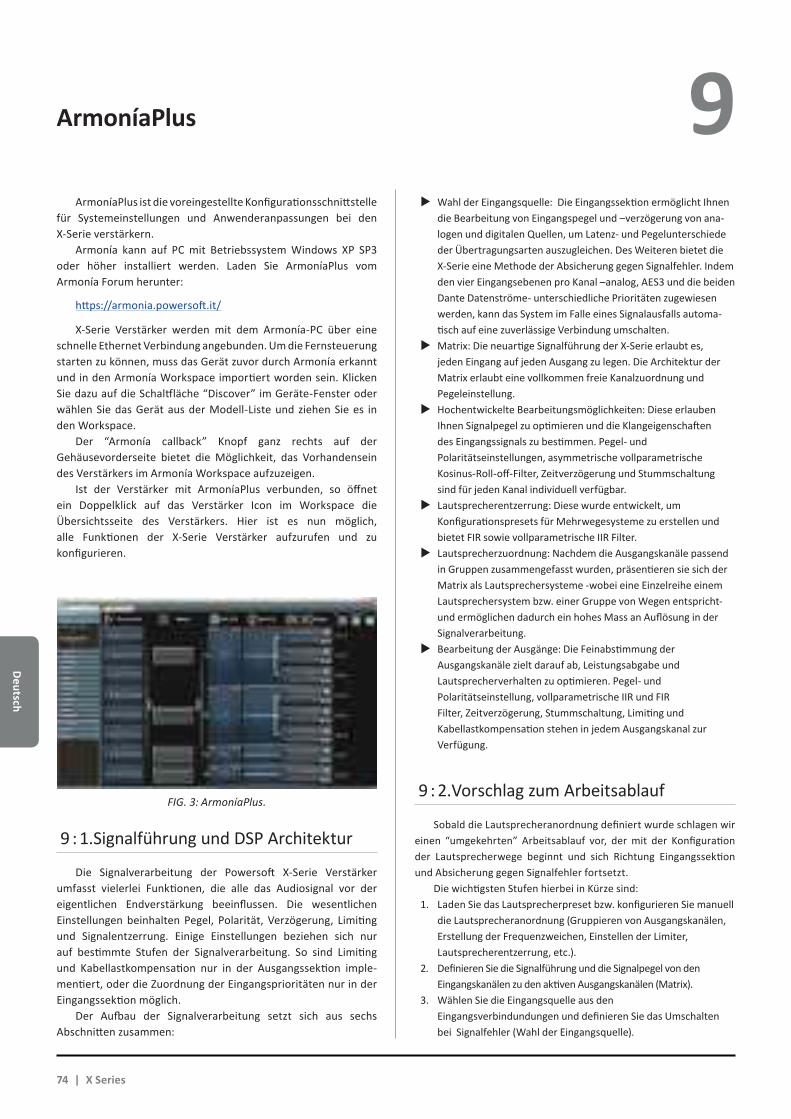
Deutsch
ArmoníaPlus 9 ArmoníaPlus ist die voreingestellte Konfigurationsschnittstelle
für Systemeinstellungen und Anwenderanpassungen bei den X-Serie verstärkern.
Armonía kann auf PC mit Betriebssystem Windows XP SP3 oder höher installiert werden. Laden Sie ArmoníaPlus vom Armonía Forum herunter:
https://armonia.powersoft.it/
X-Serie Verstärker werden mit dem Armonía-PC über eine schnelle Ethernet Verbindung angebunden. Um die Fernsteuerung starten zu können, muss das Gerät zuvor durch Armonía erkannt und in den Armonía Workspace importiert worden sein. Klicken Sie dazu auf die Schaltfläche “Discover” im Geräte-Fenster oder wählen Sie das Gerät aus der Modell-Liste und ziehen Sie es in den Workspace.
Der “Armonía callback” Knopf ganz rechts auf der Gehäusevorderseite bietet die Möglichkeit, das Vorhandensein des Verstärkers im Armonía Workspace aufzuzeigen.
Ist der Verstärker mit ArmoníaPlus verbunden, so öffnet ein Doppelklick auf das Verstärker Icon im Workspace die Übersichtsseite des Verstärkers. Hier ist es nun möglich, alle Funktionen der X-Serie Verstärker aufzurufen und zu konfigurieren.
9 : 1.Signalführung und DSP Architektur
Die Signalverarbeitung der Powersoft X-Serie Verstärker umfasst vielerlei Funktionen, die alle das Audiosignal vor der eigentlichen Endverstärkung beeinflussen. Die wesentlichen Einstellungen beinhalten Pegel, Polarität, Verzögerung, Limiting und Signalentzerrung. Einige Einstellungen beziehen sich nur auf bestimmte Stufen der Signalverarbeitung. So sind Limiting und Kabellastkompensation nur in der Ausgangssektion imple-mentiert, oder die Zuordnung der Eingangsprioritäten nur in der Eingangssektion möglich.
Der Aufbau der Signalverarbeitung setzt sich aus sechs Abschnitten zusammen:
XX Wahl der Eingangsquelle: Die Eingangssektion ermöglicht Ihnen die Bearbeitung von Eingangspegel und –verzögerung von ana-logen und digitalen Quellen, um Latenz- und Pegelunterschiede der Übertragungsarten auszugleichen. Des Weiteren bietet die X-Serie eine Methode der Absicherung gegen Signalfehler. Indem den vier Eingangsebenen pro Kanal –analog, AES3 und die beiden Dante Datenströme- unterschiedliche Prioritäten zugewiesen werden, kann das System im Falle eines Signalausfalls automa-tisch auf eine zuverlässige Verbindung umschalten.XX Matrix: Die neuartige Signalführung der X-Serie erlaubt es,
jeden Eingang auf jeden Ausgang zu legen. Die Architektur der Matrix erlaubt eine vollkommen freie Kanalzuordnung und Pegeleinstellung.XX Hochentwickelte Bearbeitungsmöglichkeiten: Diese erlauben
Ihnen Signalpegel zu optimieren und die Klangeigenschaften des Eingangssignals zu bestimmen. Pegel- und Polaritätseinstellungen, asymmetrische vollparametrische Kosinus-Roll-off-Filter, Zeitverzögerung und Stummschaltung sind für jeden Kanal individuell verfügbar.XX Lautsprecherentzerrung: Diese wurde entwickelt, um
Konfigurationspresets für Mehrwegesysteme zu erstellen und bietet FIR sowie vollparametrische IIR Filter.XX Lautsprecherzuordnung: Nachdem die Ausgangskanäle passend
in Gruppen zusammengefasst wurden, präsentieren sie sich der Matrix als Lautsprechersysteme -wobei eine Einzelreihe einem Lautsprechersystem bzw. einer Gruppe von Wegen entspricht- und ermöglichen dadurch ein hohes Mass an Auflösung in der Signalverarbeitung.XX Bearbeitung der Ausgänge: Die Feinabstimmung der
Ausgangskanäle zielt darauf ab, Leistungsabgabe und Lautsprecherverhalten zu optimieren. Pegel- und Polaritätseinstellung, vollparametrische IIR und FIR Filter, Zeitverzögerung, Stummschaltung, Limiting und Kabellastkompensation stehen in jedem Ausgangskanal zur Verfügung.
9 : 2.Vorschlag zum Arbeitsablauf
Sobald die Lautsprecheranordnung definiert wurde schlagen wir einen “umgekehrten” Arbeitsablauf vor, der mit der Konfiguration der Lautsprecherwege beginnt und sich Richtung Eingangssektion und Absicherung gegen Signalfehler fortsetzt.
Die wichtigsten Stufen hierbei in Kürze sind:1. Laden Sie das Lautsprecherpreset bzw. konfigurieren Sie manuell
die Lautsprecheranordnung (Gruppieren von Ausgangskanälen, Erstellung der Frequenzweichen, Einstellen der Limiter, Lautsprecherentzerrung, etc.).
2. Definieren Sie die Signalführung und die Signalpegel von den Eingangskanälen zu den aktiven Ausgangskanälen (Matrix).
3. Wählen Sie die Eingangsquelle aus den Eingangsverbindundungen und definieren Sie das Umschalten bei Signalfehler (Wahl der Eingangsquelle).
FIG. 3: ArmoníaPlus.
74 | X Series
Deu
tsch
Gewährleistung und Hilfeleistung 10 10 : 1.Gewährleistung
10 : 1.1. ProduktgarantiePowersoft gewährt auf seine selbst hergestellen
Produkte eine Garantie von 48 (achtundvierzig) Monaten auf Teile- und Verarbeitungsfehler. Diese Frist beginnt mit dem Rechnungsdatum, an dem das Gerät vom Endanwender bei Powersoft oder einem der authorisierten Powersoft Händler erworben wurde. Alle Reparaturen oder Nachrüstungen dür-fen nur von Powersoft selbst oder von einem authorisierten Powersoft Service Center kostenlos durchgeführt werden. Von der Garantie ausgeschlossen sind Fehlfunktionen oder Ausfälle, die verursacht wurden durch unsachgemäßen Gebrauch, miss-bräuchliche Verwendung, Reparaturen oder Modifikationen durch nicht-authorisiertes Personal, fehlerhafte Verkabelung, Wettereinwirkungen, mechanische Beschädigungen (einschließ-lich Transportschäden) sowie normalen Verschleiss. Powersoft kann Garantieleistungen nur dann gewähren, wenn das Produkt während des Transports nicht beschädigt wurde.
10 : 1.2. RücksendungenWaren können nur dann zu Powersoft oder einem authorisier-
ten Service Center eingesandt werden, sobald eine RMA (“Return Merchandise Authoriation”) Nummer von dort zugeteilt wurde. Diese muss gut sichtbar aussen an der Transportverpackung an-gebracht sein. Powersoft und seine authorisierten Service Center sind dazu berechtigt, die Annahme von Einsendungen ohne RMA Nummer zu verweigern.
10 : 1.3. Reparatur oder ErsatzPowersoft behält sich nach eigenem Ermessen vor, beschädig-
te Waren, die von der Gewährleistung abgedeckt sind entweder zu reparieren oder zu ersetzen.
10 : 1.4. Transportkosten und -risikoDer Käufer (oder Endanwender/Kunde) trägt die alleini-
ge Verantwortung für alle Transportkosten und Risiken im Zusammenhang mit einer Einsendung von Garantiefällen zu Powersoft oder seinen authorisierten Service Centern. Diese wie-derum werden die volle Verantwortung und alle Kosten betref-fend Rücksendung der Waren zum Käufer (oder Endanwender/Kunde) übernehmen.
10 : 2.Technische Unterstützung
In Ihrem Verstärker befinden sich keine Teile, die vom Anwender selbst repariert werden könnten. Wenden Sie sich in jedem Fall an qualifiziertes Fachpersonal. Neben der hauseigenen Service-Abteilung verfügt Powersoft über ein Netzwerk von authorisierten Service Centern. Sollte Ihr Verstärker repariert
werden müssen, so wenden Sie sich bitte an Ihren Powersoft Händler oder Vertrieb. Sie können auch die Powersoft Service Abteilung ansprechen, um Informationen zum nächstgelegenen authorisierten Service Center zu erhalten.
Auch wenn die meisten Fehlfunktionen eines Produktes durch Unterstützung der Powersoft Kundenbetreuung oder auch aufgrund Ihrer eigenen Kenntnisse bei Ihnen vor Ort auf-geklärt werden können, kann es von Fall zu Fall aufgrund der Art des Schadens notwendig werden, beschädigte Produkte zur Reparatur zu Powersoft einzusenden. In diesem Fall bitten wir Sie herzlich, Schritt für Schritt dem nachstehenden Ablauf zu folgen, bevor Sie das Gerät versenden:XX Besorgen Sie sich von unserer Kundenbetreuung das “Defect
Report Form” Formular, indem Sie es per e-Mail von [email protected] anfordern oder von der Powersoft website (http://www.powersoft-audio.com/en/support/service) her-unter laden.XX Füllen Sie für jedes zurück zu sendende Gerät ein eige-
nes Fomular aus (dieses ist ein editierbares Dokument). Dadurch stellen Sie alle notwendigen Informationen ausser der RMA Nummer(n) zur Verfügung. Speichern Sie es wie folgt ab: Name, Verstärkermodell, Seriennummer (z. B. DistributornameK10sn17345.doc) und senden Sie es an [email protected] zur Prüfung durch Powersoft.XX Bei positiver Prüfung durch einen Mitarbeiter der Powersoft
Serviceabteilung erhalten Sie für jedes einzelne Gerät eine individuelle RMA Nummer.XX Danach verpacken Sie das Gerät und bringen die RMA
Nummer gut sichtbar in einer wasserfesten Schutzhülle an der Aussenseite der Verpackung an.
Alle Rücksendung müssen an die folgende Adresse gerichtet sein:
PowersoftVia dei Cadolingi, 1350018 Scandicci (FI) Italy
Bei Rücksendungen aus Ländern ausserhalb der Europäischen Union stellen Sie bitte sicher, dass alle Anweisungen wie im “TEMPORARY EXPORTATION/IMPORTATION PROCEDURE” Dokument beschrieben ausgeführt sind. Dieses Dokument können Sie von http://www.powersoft-audio.com/en/support/service herunter laden.
Wir danken für Ihr Verständnis, Ihre Zusammemnarbeit und Ihre Unterstützung in unserem Bestreben, unsere Partnerschaft stetig zu Verbessern.
Deutsch | 75
Pусский
76 | X серии
Важные инструкции по технике безопасности 1 ВНИМАНИЕ
ОПАСНОСТЬ УДАРА ТОКОМНЕ ОТКРЫВАТЬ
Электрическая энергия может выполнять множество полезных функций. Данное оборудование было разработано и произве-дено, чтобы обеспечить Вашу личную безопасность. Однако, не корректное использование может повлечь риск электрического шока или пожара. Во избежание повреждений системы защи-ты устройства ознакомьтесь с перечисленными ниже правила-ми установки, использования и технического обслуживания. Пожалуйста, прочитайте эти инструкции внимательно.
Инструкции по технике безопасности1. Прочитайте данные инструкции.2. Сохраните данные инструкции.3. Обращайте внимание на все предупреждения.4. Следуйте указаниям.5. Не используйте оборудование вблизи воды.6. Протирайте только сухой тканью.7. Не блокируйте вентиляционные отверстия. Следуйте
инструкциям производителя.8. Не устанавливайте вблизи источников тепла, таких как ра-
диаторы, обогреватели, печи или другие приборы (включая усилители), которые выделяют тепло.
9. Не наступайте на сетевой шнур и защищайте его от зажатия или сдавливания, особенно около вилки и в месте выхода шнура из аппарата.
10. Используйте приспособления и аксессуары, указанные про-изводителем.
11. Используйте транспортные тележки, стойки, треноги, кре-пления, указанные производителем или входящие в ком-плект поставки. При использовании транспорт-ных тележек соблюдайте осторожность при разгрузке и погрузке, чтобы избежать травм при опрокидывании.
12. Отключайте оборудование от сети во время бурь и при долгом простое.
13. Для технического обслуживания обращайтесь к квалифи-цированным специалистам. Техническое обслуживание требуется во всех случаях, когда было повреждено само оборудование, кабель или разъем системы питания, внутрь устройства попала жидкость или посторонний предмет, оборудование находилось под воздействием дождя или влаги, оборудование не работает должным образом или его уронили.
ОБОЗНАЧЕНИЯ ГРАФИЧЕСКИХ СИМВОЛОВ
Треугольник с молнией обозначает угрозу удара электри-ческим током.
Треугольник с восклицательным знаком обозначает важ-ные инструкции, связанные с эксплуатацией или техни-ческим обслуживанием.
ПРЕДУПРЕЖДЕНИЕ: ВО ИЗБЕЖАНИИ УДАРА ЭЛЕКТРИЧЕСКИМ ТОКОМ НЕ ПЫТАЙТЕСЬ ВСКРЫВАТЬ ОБОРУДОВАНИЕ. ВНУТРИ НЕТ ДЕТАЛЕЙ ДЛЯ ТЕХНИЧЕ-СКОГО ОБСЛУЖИВАНИЯ ПОЛЬЗОВАТЕЛЕМ. ДЛЯ ОБСЛУЖИВАНИЯ ОБРАЩАЙТЕСЬ К КВАЛИФИЦИРОВАН-НЫМ СПЕЦИАЛИСТАМ.
НЕ ПОДВЕРГАЙТЕ ПРИБОР ВОЗДЕЙСТВИЮ ДОЖДЯ ИЛИ ВЛАГИ, КАПЕЛЬ ИЛИ БРЫЗГ ЖИДКОСТЕЙ. ПРЕДМЕТЫ С ВОДОЙ, НАПРИМЕР, ВАЗЫ, НЕ ДОЛЖНЫ ПОМЕЩАТЬСЯ НА ДАННОЕ УСТРОЙСТВО.
УСТРОЙСТВО МОЖЕТ ИСПОЛЬЗОВАТЬСЯ ТОЛЬКО УСТАНОВЛЕННЫМ В РЭКОВУЮ СТОЙКУ. ПИТАНИЕ ПОДКЛЮЧАЕТСЯ ТОЛЬКО ЧЕРЕЗ СЕКЦИОННЫЙ ЗАЩИТНЫЙ АВТОМАТ ОТКЛЮЧЕНИЯ.
АВТОМАТ ОТКЛЮЧЕНИЯ ВСЕГДА ДОЛЖЕН ОСТАВАТЬСЯ ЛЕГКО ДОСТУПНЫМ.
УСТАНОВИВ УСТРОЙСТВО В РЭКОВЫЙ ШКАФ, УБЕДИТЕСЬ, ЧТО ВОКРУГ ДОСТАТОЧНО МЕСТА ДЛЯ ЦИРКУЛЯЦИИ ВОЗДУХА (НЕ МЕНЕЕ 50 САНТИМЕТРОВ ОТ ПЕРЕДНИХ И ЗАДНИХ ВЕНТИЛЯЦИОННЫХ ОТВЕРСТИЙ УСИЛИТЕЛЯ).
ПОДКЛЮЧЕНИЕ К ЭЛЕКТРИЧЕСКОЙ СЕТИ ДОЛЖНО ОСУЩЕСТВЛЯТЬСЯ ТОЛЬКО СПЕЦИАЛИСТАМИ В ЭЛЕКТРОТЕХНИЧЕСКОЙ ОБЛАСТИ С УЧЕТОМ ТРЕБОВАНИЙ СТРАНЫ, В КОТОРОЙ ОСУЩЕСТВЛЯЕТСЯ ПРОДАЖА ОБОРУДОВАНИЯ.
ВНИМАНИЕ ПРЕДОХРАНИТЕЛЬ НА НЕЙТРАЛЬНЫЙ.
CLASS3WIRING
CLASS3WIRING
CLASS3WIRING
CLASS3WIRING
CLASS3WIRING
CLASS3WIRING
CLASS3WIRING
Символ “CE” обозначает соответствие директиве Low Voltage и стандартам электромагнитной совместимости.
Символ обозначает необходимость “заземления”.
Символ обозначает возможность использования обору-дования только в помещениях.
Символ обозначает соответствие директивам Европейского парламента 2002/96/EC и 2003/108/EC об утилизации электронного и электрического оборудова-ния (WEEE).
Не используйте устройство на высотах выше 2000 м.
Не используйте устройство в условиях тропического кли-мата.
Pусс
кий
Pусский | 77
Серии X Краткое руководство 2
2 : 1.Введение
Поздравляем вас с покупкой усилителя мощности Powersoft X-серии!
Мы знаем, что вы сгораете от нетерпения включить ваш новый X8 или X4, но прежде чем сделать это, пожалуйста, най-дите несколько минут, чтобы прочитать данное руководство. В случае, если у вас есть какие-либо вопросы, пожалуйста, не стесняйтесь задать их вашему дилеру или непосредственно компании Powersoft.
Powersoft X-серии — это инновационная концепция усили-тельной платформы: X8 — 8-канальный усилитель мощности; X4 — 4-канальный усилитель формата 1U; в обеих моделях применена новая система маршрутизации сигнала, новый блок питания и революционный многофункциональный DSP.
Powersoft X8 и X4 по умолчанию поддерживают AES3, имеют основной и резервный порты Dante™ Audinate® (опционально) и аналоговые входы, что в сумме предоставляет пользователю выбор из 4 разных типов входов для каждого канала.
Конфигурация системы и ее точная настройка осуществляют-ся посредством программного обеспечения ArmoníaPlus™, пред-лагающего интуитивно понятный интерфейс, исчерпывающий контроль над процессами обработки звука и полный монито-ринг системы в режиме реального времени. Каждый усилитель Powersoft X-серии оснащен встроенным Wi-Fi-передатчиком, что позволяет управлять системой через любое мобильное устройство посредством пользовательского интерфейса, специ-ально созданного для локального мониторинга.
Powersoft X4 и X8 устанавливают новый стандарт качества и удобство в использовании, они подходят для любой конфи-гурации, экономят пространство и вес, а также предлагают легендарную эффективность Powersoft, дополненную новым универсальным мультифазным блоком питания, работающим в любом из известных мировых стандартов электрических сетей.
2 : 2.Распаковка и проверка на повреждения
Ваше изделие Powersoft было полностью проверено, пре-жде чем покинуть завод. Перед вскрытием тщательно осмотри-те упаковку, а затем незамедлительно осмотрите ваше изделие. Если вы обнаружили повреждения, немедленно уведомьте об этом транспортную компанию или компанию, продавшую вам усилитель.
Комплект поставки:XX 1x усилитель X-серииXX 1x разъем типа PC 5/5-STF1-7,62 PhoenixXX 1x корпус кабельного разъемаXX 1x руководство пользователя
2 : 3.Утилизация упаковочного материала
Транспортировочная и защитная упаковки были созданы из перерабатываемых материалов. Вместо того, чтобы просто вы-бросить упаковку, убедитесь что она была отправлена в центр переработки.
2 : 4.Список изображений
A. X8/X4L механический чертеж: все размеры в миллиметрахB. X4 механический чертеж: все размеры в миллиметрахC. X8 задняя панельD. X4L задняя панельE. X4 задняя панельF. X8 и X4L/X4-передняя панельG. Монтажные кронштейны и воздуховодыH. Порядок расположения усилителей в рэковой стойкеI. Распиновка входных разъемовJ. Распиновка RJ45 EthernetK. Схема подключения акустических системL. 3-фазное питание: схема подключенияM. 1-фазное питание: схема подключенияN. 2-фазное питание: схема подключенияO. Сетевой кабельный разъемP. Нормативная информация
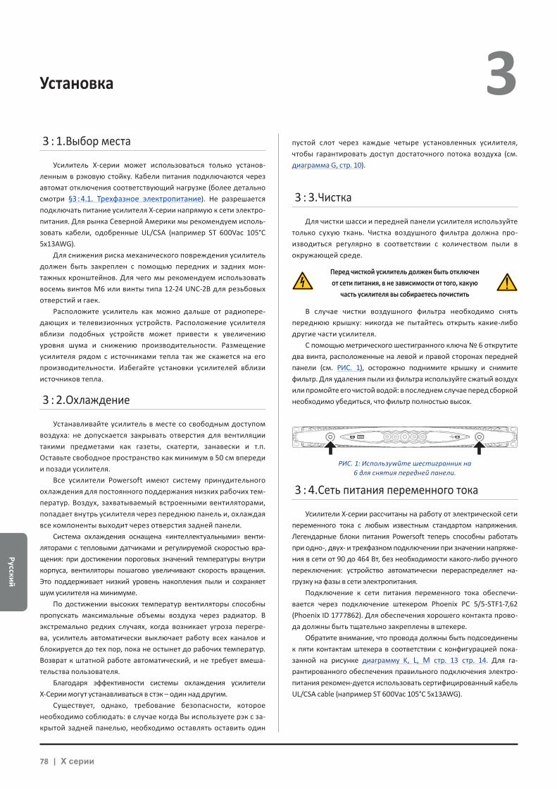
Pусский
78 | X серии
Установка 3 3 : 1.Выбор места
Усилитель X-серии может использоваться только установ-ленным в рэковую стойку. Кабели питания подключаются через автомат отключения соответствующий нагрузке (более детально смотри §3 : 4.1. Трехфазное электропитание). Не разрешается подключать питание усилителя X-серии напрямую к сети электро-питания. Для рынка Северной Америки мы рекомендуем исполь-зовать кабели, одобренные UL/CSA (например ST 600Vac 105°C 5x13AWG).
Для снижения риска механического повреждения усилитель должен быть закреплен с помощью передних и задних мон-тажных кронштейнов. Для чего мы рекомендуем использовать восемь винтов M6 или винты типа 12-24 UNC-2B для резьбовых отверстий и гаек.
Расположите усилитель как можно дальше от радиопере-дающих и телевизионных устройств. Расположение усилителя вблизи подобных устройств может привести к увеличению уровня шума и снижению производительности. Размещение усилителя рядом с источниками тепла так же скажется на его производительности. Избегайте установки усилителей вблизи источников тепла.
3 : 2.Охлаждение
Устанавливайте усилитель в месте со свободным доступом воздуха: не допускается закрывать отверстия для вентиляции такими предметами как газеты, скатерти, занавески и т.п. Оставьте свободное пространство как минимум в 50 см впереди и позади усилителя.
Все усилители Powersoft имеют систему принудительного охлаждения для постоянного поддержания низких рабочих тем-ператур. Воздух, захватываемый встроенными вентиляторами, попадает внутрь усилителя через переднюю панель и, охлаждая все компоненты выходит через отверстия задней панели.
Система охлаждения оснащена «интеллектуальными» венти-ляторами с тепловыми датчиками и регулируемой скоростью вра-щения: при достижении пороговых значений температуры внутри корпуса, вентиляторы пошагово увеличивают скорость вращения. Это поддерживает низкий уровень накопления пыли и сохраняет шум усилителя на минимуме.
По достижении высоких температур вентиляторы способны пропускать максимальные объемы воздуха через радиатор. В экстремально редких случаях, когда возникает угроза перегре-ва, усилитель автоматически выключает работу всех каналов и блокируется до тех пор, пока не остынет до рабочих температур. Возврат к штатной работе автоматический, и не требует вмеша-тельства пользователя.
Благодаря эффективности системы охлаждения усилители X-Серии могут устанавливаться в стэк – один над другим.
Существует, однако, требование безопасности, которое необходимо соблюдать: в случае когда Вы используете рэк с за-крытой задней панелью, необходимо оставлять оставить один
пустой слот через каждые четыре установленных усилителя, чтобы гарантировать доступ достаточного потока воздуха (см. диаграмма G, стр. 10).
3 : 3.Чистка
Для чистки шасси и передней панели усилителя используйте только сухую ткань. Чистка воздушного фильтра должна про-изводиться регулярно в соответствии с количеством пыли в окружающей среде.
Перед чисткой усилитель должен быть отключен от сети питания, в не зависимости от того, какую
часть усилителя вы собираетесь почистить
В случае чистки воздушного фильтра необходимо снять переднюю крышку: никогда не пытайтесь открыть какие-либо другие части усилителя.
С помощью метрического шестигранного ключа № 6 открутите два винта, расположенные на левой и правой сторонах передней панели (см. РИС. 1), осторожно поднимите крышку и снимите фильтр. Для удаления пыли из фильтра используйте сжатый воздух или промойте его чистой водой: в последнем случае перед сборкой необходимо убедиться, что фильтр полностью высох.
3 : 4.Сеть питания переменного тока
Усилители X-серии рассчитаны на работу от электрической сети переменного тока с любым известным стандартом напряжения. Легендарные блоки питания Powersoft теперь способны работать при одно-, двух- и трехфазном подключении при значении напряже-ния в сети от 90 до 464 Вт, без необходимости какого-либо ручного переключения: устройство автоматически перераспределяет на-грузку на фазы в сети электропитания.
Подключение к сети питания переменного тока обеспечи-вается через подключение штекером Phoenix PC 5/5-STF1-7,62 (Phoenix ID 1777862). Для обеспечения хорошего контакта прово-да должны быть тщательно закреплены в штекере.
Обратите внимание, что провода должны быть подсоединены к пяти контактам штекера в соответствии с конфигурацией пока-занной на рисунке диаграмму K, L, M стр. 13 стр. 14. Для га-рантированного обеспечения правильного подключения электро-питания рекомен-дуется использовать сертифицированный кабель UL/CSA cable (например ST 600Vac 105°C 5x13AWG).
РИС. 1: Используwйте шестигранник на 6 для снятия передней панели.
Pусс
кий
Pусский | 79
3 Устройство должно быть подключено к сети электропитания с заземлением, сеть
электропитания должна соответствовать стандарту IEC 364 или аналогичным.
Поскольку главный включатель на этом устройстве не обе-спечивает полного отключения электропитания, необходимо отсоединить усилитель от сети питания, чтобы обеспечить его полное отключение.
Между усилителем и сетью электропитания необходимо использовать сетевой автомат защиты.
Модель автомата зависит от конфигурации питания. Для Powersoft X8 рекомендуется:
однофазное подключение переменного тока (P+N+E): 32 A, кривая C или D, 10 kA;трехфазное подключение переменного тока (3P+N+E): 4 x 16 A, кривая C или D, 10 kA.
Для Powersoft X4 рекомендуется:однофазное подключение переменного тока (P+N+E): 16 A, кривая C или D, 10 kA;трехфазное подключение переменного тока (3P+N+E): 4 x 10 A, кривая C или D, 10 kA.
ПРИМЕЧАНИЕ: Схемы подключения приведены в соответствие с европейским стандартом CENELEC от апреля 2004 года (IEC 60446), цветовая кодировка проводов указана в ТАБ. 2.
Провод Цвет
“Нейтраль” или “Средняя точка” N голубой
“фазовые провода”
L1 коричневый
L2 черный
L3 серый
Защитное заземление (земля) E зеленый с желтым
ТАБ. 2: Цветовая идентификация проводов.
3 : 4.1. Трехфазное электропитаниеКаждый провод должен быть закреплен в разъеме PC 5/5-
STF1-7,62, как показано на рисунке диаграмма K, стр. 13. В неко-торых случаях подсоединение “нейтраль” может отсутствовать: в таком случае усилитель X-серии автоматически переключится в соединение типа “треугольник”.
3 : 4.2. Двухфазное электропитаниеСимметричное электропитание в конфигурации 2P+E без
“нейтрали” должно быть подключено к разъему 5/5-STF1-7,62 че-рез автомат защиты, как показано на рисунке диаграмма M, стр. 14. Автомат должен обеспечивать правильное размыкание.
3 : 4.3. Однофазное электропитаниеP+N+E, несимметричное однофазное подключение с “ней-
тралью” является стандартным подключением к электросети и должно быть подключено, как показано на рисунке диаграмма L, стр. 13. Позаботьтесь о том, чтобы автомат обеспечивал правильное отключение.
3 : 5.Меры предосторожности при инсталляции
ВНИМАНИЕ! Во избежание пожара или удара электрическим током
Xf Для питания усилителя используется только розетка с за-землением, электрическая сеть должна соответствовать стандарту IEC 364 или его аналогу.
Xf Установите устройство в рэковую стойку.
Xf Автомат отключения усилителя от сети электропитания должен быть установлен внутри рэковой стойки.
Xf Позаботьтесь о том, чтобы каждый провод был надежно зафиксирован в разъеме Phoenix PC 5/5-STF1-7,62.
Xf Закрепив провода в сетевом штекере, вставьте штекер в защитный короб поставляемый Powersoft.
Xf Вставьте и защелкните сетевой штекер в разъеме усилите-ля.
Xf Прежде чем подать питание на усилитель, убедитесь, что напряжение в сети соответствует необходимым параме-трам.
Xf Убедитесь, что сетевые кабели и их соединения соответ-ствуют требуемой мощности.
Xf Не используйте усилитель, если электрический кабель из-ношен или поврежден.
Xf Выходные терминалы могут представлять опасность: под-ключение проводов к клеммам должно выполняться ква-лифицированным персоналом. Либо используйте готовые кабели.
Xf Убедитесь, что выходные штекеры защелкнуты, прежде чем включать усилитель.
Xf Во избежание удара током не трогайте провода подключе-ния акустических систем в процессе работы усилителя.
Xf Не проливайте воду и любые другие жидкости на усили-тель или внутрь его.
Xf Запрещается размещать на усилителе открытые источники огня, например свечи.
Xf Не снимайте верхнюю крышку усилителя. В противном случае вы можете подвергнуться воздействию опасного электрического напряжения.
Xf Производитель не несет ответственность за ущерб, при-чиненный лицам или имуществу, а также за потерю данных возникших в результате неправильного заземления усили-теля.
Xf Для проведения планового и внепланового обслуживания обратитесь в авторизованный сервисный центр.
Необходимо точно следовать базовым требованиям безопасности. В случае, если у вас есть сомнения
в безопасности использования, обратитесь к квалифицированному специалисту
Pусский
80 | X серии
3 : 6.Включение
Как только вы подключите усилитель к сети питания, блок питания подаст напряжение на все вспомогательные системы усилителя. Окантовка центральной кнопки начнет мигать белым цветом. Это означает, что усилитель перешел в режим ожидания. Чтобы включить усилитель, нажмите на центральную кнопку.
3 : 7.Выключение
Нажмите и удерживайте 3 секунды центральную кнопку, чтобы выключить усилитель. Усилитель перейдет в режим ожи-дания и окантовка центральной кнопки начнет мигать белым цветом. Чтобы выключить усилитель полностью, отсоедините усилитель от сети электропитания.
3 : 8.Функция Mute
Короткое нажатие на центральную кнопку активирует/деак-тивирует функцию MUTE/ UNMUTE для всех активных каналов: все прежде “замьютированные” каналы будут оставаться в режиме MUTE.
Все остальные круглые кнопки (за исключением централь-ной) приводят в действие функцию MUTE/UNMUTE на назначен-ных для них каналах.
ПРЕДУПРЕЖДЕНИЕ: Пожалуйста, обратите внимание, что в слу-чае, если усилитель управляется ПО ArmoníaPlus™, все кнопки MUTE деактивированы.
3 : 9.Включение Wi-Fi
Нажмите самую левую кнопку: включится подсветка кнопки и система создаст новое локальное соединение Wi-Fi со следу-ющим значением SSID: Powersoft - название модели - серийный номер (например Powersoft-X8-70133), пароль по умолчанию: 0123456789. Повторное нажатие кнопки приведет к отключению Wi-Fi-соединения.
3 : 10.Соединение с Armonía
Чтобы определить устройство в рабочем пространстве Armonía, нажмите на самую правую кнопку усилителя. Или выберите контекстное меню усилителя и нажмите Un/Blink, в подтверждение соединения все светодиоды усилителя будут мигать некоторое время.
Чтобы активировать Wi-Fi-соединение и получить дистан-ционный доступ к усилителю Powersoft X-серии необходимо проделать следующие действия:
1. Нажатием на центральную кнопку включить усилитель;
2. Нажать крайнюю левую кнопку на усилителе: включившая-ся подсветка кнопки говорит о том, что установлено новое Wi-Fi-соединение со следующим SSID:
Powersoft-НОМЕР МОДЕЛИ-СЕРИЙНЫЙ НОМЕР (например Powersoft-X8-71520);
3. Найдите новое Wi-Fi-соединение в вашем мобильном устройстве;
4. Настройте Wi-Fi-соединение, используя правильный SSID;
5. Для подключений к Wi-Fi-соединению используйте пароль по умолчанию:
Wi-Fi 4
0123456789
6. Откройте веб-браузер устройства и в адресной строке вве-дите следующий IP-адрес:
192.168.0.1
7. В окне браузера появится пользовательский интерфейс: теперь вы можете управлять усилителем X-серии;
8. Для более быстрого и простого доступа к веб-интерфейсу мы рекомендуем вам добавить соответствующую кнопку на “Домашний экран” вашего мобильного устройства; на-пример, в устройстве работающем под iOS необходимо нажать кнопку экспорта и выбрать кнопку “Добавить на Домашний экран”.
9. Не забудьте отключить Wi-Fi-соединение, если процесс на-стройки и мониторинга системы уже выполнен и в доступе больше нет необходимости: нажмите левую кнопку на лице-вой панели усилителя и отключите Wi-Fi.
MUTE/UNMUTE канал 2
MUTE/UNMUTE все каналы
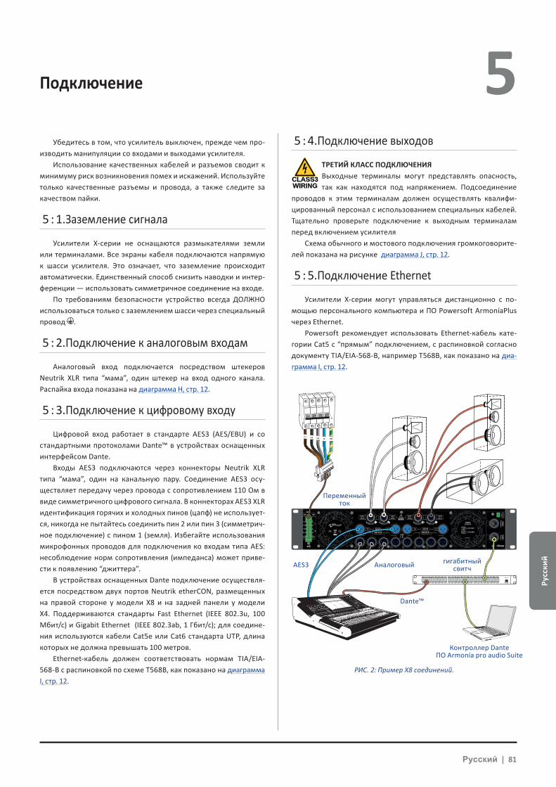
Pусс
кий
Pусский | 81
4 Подключение 5 Убедитесь в том, что усилитель выключен, прежде чем про-
изводить манипуляции со входами и выходами усилителя. Использование качественных кабелей и разъемов сводит к
минимуму риск возникновения помех и искажений. Используйте только качественные разъемы и провода, а также следите за качеством пайки.
5 : 1.Заземление сигнала
Усилители X-серии не оснащаются размыкателями земли или терминалами. Все экраны кабеля подключаются напрямую к шасси усилителя. Это означает, что заземление происходит автоматически. Единственный способ снизить наводки и интер-ференции — использовать симметричное соединение на входе.
По требованиям безопасности устройство всегда ДОЛЖНО использоваться только с заземлением шасси через специальный провод .
5 : 2.Подключение к аналоговым входам
Аналоговый вход подключается посредством штекеров Neutrik XLR типа “мама”, один штекер на вход одного канала. Распайка входа показана на диаграмма H, стр. 12.
5 : 3.Подключение к цифровому входу
Цифровой вход работает в стандарте AES3 (AES/EBU) и со стандартными протоколами Dante™ в устройствах оснащенных интерфейсом Dante.
Входы AES3 подключаются через коннекторы Neutrik XLR типа “мама”, один на канальную пару. Соединение AES3 осу-ществляет передачу через провода с сопротивлением 110 Ом в виде симметричного цифрового сигнала. В коннекторах AES3 XLR идентификация горячих и холодных пинов (цапф) не использует-ся, никогда не пытайтесь соединить пин 2 или пин 3 (симметрич-ное подключение) с пином 1 (земля). Избегайте использования микрофонных проводов для подключения ко входам типа AES: несоблюдение норм сопротивления (импеданса) может приве-сти к появлению “джиттера”.
В устройствах оснащенных Dante подключение осуществля-ется посредством двух портов Neutrik etherCON, размещенных на правой стороне у модели X8 и на задней панели у модели X4. Поддерживаются стандарты Fast Ethernet (IEEE 802.3u, 100 Мбит/с) и Gigabit Ethernet (IEEE 802.3ab, 1 Гбит/с); для соедине-ния используются кабели Cat5e или Cat6 стандарта UTP, длина которых не должна превышать 100 метров.
Ethernet-кабель должен соответствовать нормам TIA/EIA-568-B с распиновкой по схеме T568B, как показано на диаграмма I, стр. 12.
5 : 4.Подключение выходов
CLASS3WIRING
ТРЕТИЙ КЛАСС ПОДКЛЮЧЕНИЯВыходные терминалы могут представлять опасность, так как находятся под напряжением. Подсоединение
проводов к этим терминалам должен осуществлять квалифи-цированный персонал с использованием специальных кабелей. Тщательно проверьте подключение к выходным терминалам перед включением усилителя
Схема обычного и мостового подключения громкоговорите-лей показана на рисунке диаграмма J, стр. 12.
5 : 5.Подключение Ethernet
Усилители Х-серии могут управляться дистанционно с по-мощью персонального компьютера и ПО Powersoft ArmoníaPlus через Ethernet.
Powersoft рекомендует использовать Ethernet-кабель кате-гории Cat5 с “прямым” подключением, с распиновкой согласно документу TIA/EIA-568-B, например T568B, как показано на диа-грамма I, стр. 12.
1 2 3 4 5 6 7 8
25 26 27 28 29 30 31 32
9 10 11 12 13 14 15 16
33 34 35 36 37 38 39 40
17 18 19 20 21 22 23 24
41 42 43 44 45 46 47 48 UP Link
Power
L1 L2 L3 N PE
AES3 IN7-8 5-6 AES3 IN3-4 1-2
ANALOG INANALOG IN
8 7 6 5 4 3 2 1
3PH 1PH
L1
L2
L3
N
L
N
1=GND2 = IN+3 = IN-
MAINS
TURN TO LOCK TURN TO LOCKTURN TO LOCK TURN TO LOCK
РИС. 2: Пример X8 соединений.
Переменный ток
AES3 Аналоговый гигабитный свитч
Dante™
Контроллер Dante ПО Аrmonía pro audio Suite
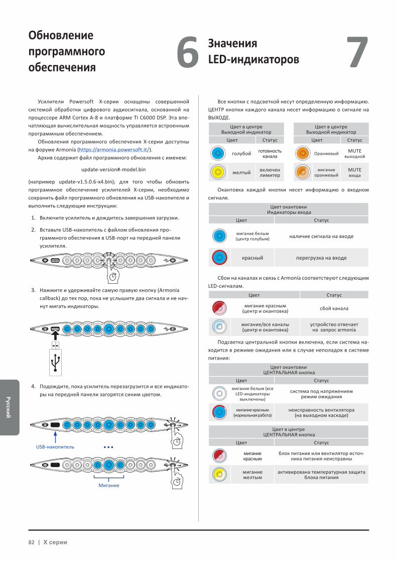
Pусский
82 | X серии
Обновление программного обеспечения
Значения LED-индикаторов6 7
Усилители Powersoft Х-серии оснащены совершенной системой обработки цифрового аудиосигнала, основанной на процессоре ARM Cortex A-8 и платформе TI C6000 DSP. Эта впе-чатляющая вычислительная мощность управляется встроенным программным обеспечением.
Обновления программного обеспечения Х-серии доступны на форуме Armonía (https://armonia.powersoft.it/).
Архив содержит файл программного обновления с именем:
update-version#-model.bin
(например update-v1.5.0.6-x4.bin); для того чтобы обновить программное обеспечение усилителей Х-серии, необходимо сохранить файл программного обновления на USB-накопителе и выполнить следующие инструкции:
1. Включите усилитель и дождитесь завершения загрузки.
2. Вставьте USB-накопитель с файлом обновления про-граммного обеспечения в USB-порт на передней панели усилителя.
3. Нажмите и удерживайте самую правую кнопку (Armonía callback) до тех пор, пока не услышите два сигнала и не нач-нут мигать индикаторы.
4. Подождите, пока усилитель перезагрузится и все индикато-ры на передней панели загорятся синим цветом.
Все кнопки с подсветкой несут определенную информацию. ЦЕНТР кнопки каждого канала несет информацию о сигнале на ВЫХОДЕ.
Цвет в центреВыходной индикатор
Цвет в центреВыходной индикатор
Цвет Статус Цвет Статус
голубой готовность канала Оранжевый MUTE
выходной
желтый включен лимитер
мигание оранжевый
MUTEвхода
Окантовка каждой кнопки несет информацию о входном сигнале.
Цвет окантовки Индикаторы входа
Цвет Статус
мигание белым (центр голубым) наличие сигнала на входе
красный перегрузка на входе
Сбои на каналах и связь с Armonía соответствуют следующим LED-сигналам.
Цвет Статус
мигание красным(центр и окантовка) сбой канала
мигание/все каналы(центр и окантовка)
устройство отвечаетна запрос armonía
Подсветка центральной кнопки включена, если система на-ходится в режиме ожидания или в случае неполадок в системе питания:
Цвет окантовки ЦЕНТРАЛЬНАЯ кнопка
Цвет Статусмигание белым (все
LED-индикаторы выключены)
система под напряжениемрежим ожидания
мигание красным (нормальная работа)
неисправность вентилятора (на выходном каскаде)
Цвет в центре ЦЕНТРАЛЬНАЯ кнопка
Цвет Статус
мигание красным
блок питания или вентилятор источ-ника питания неисправны
мигание желтым
активирована температурная защита блока питания
Мигание
USB-накопитель ...
Pусс
кий
Pусский | 83
Работа в сети 8 Усилительные платформы X-серии могут соединяться в сеть
последовательно, параллельно (соединение типа “звезда”) или в петлю; при последовательном подключении ПК с ArmoníaPlus должен быть всегда в конце цепи.
Будьте осторожны, последовательное подключение не га-рантирует надежности, поскольку любая неисправность может привести к разрыву в сети и потере контроля.
Когда эффективность и надежность являются первосте-пенными, необходимо аварийное резервирование сети. Для подключения интерфейса Dante необходимо использовать топо-логию “звезда” или открытое последовательное подключение.
8 : 1.IP-адреса
Для подключения усилителя к уже существующей локальной сети или ПК заводские настройки по умолчанию — DHCP/AutoIP. Фиксированные IP-адреса могут быть изменены в программном обеспечении ArmoníaPlus.
Если в сети нет активного DHCP-сервера, усилитель иници-ирует автоматическую конфигурацию в режиме stateless (без сохранения конфигурации, например нулевая сетевая конфи-гурация Zeroconf). Локальный сетевой адрес назначается само-стоятельно (тип 169.254.x.y – 172.31.*.* для вторичной сети, если используется — с маской подсети 255.255.0.0) и автоматически раздает имена хостов для устройств данной сети. Для установки статического IP обратитесь к инструкции ArmoníaPlus.
8 : 1.1. Устранение конфликтов IP-адресовПри подключении усилителя ПО ArmoníaPlus может не обна-
ружить или не импортировать новый усилитель. Обычно эта проблема кроется в IP-адресах: и ПО и усилитель
X-серии должны работать в одной подсети. Если в сети находит-ся DHCP-сервер, а усилитель X-серии находится в режиме AUTO IP, сеть может работать нестабильно.
Практический совет, включите DHCP-сервер перед подключением усилителей
IP-адресация усилителей Х-серии определяется при за-грузке: когда усилитель Х-серии обнаруживает DHCP-сервер в сети во время запуска, он определяет сетевые параметры. Если усилитель Х-серии не обнаруживает этот сервер в сети во время запуска, то он переходит в режим AUTO IP.
8 : 2.Сеть Dante™
Усилители Х-серии, оснащенные интерфейсом Dante, под-ключаются к сети передачи Dante посредством двух портов etherCON на задней панели:XX Первичный/ETH1 - первичный сетевой порт;XX Вторичный/ETH2 - вторичный сетевой порт.Передача сигнала по Dante всегда производится через
первичный порт /ETH1 Gigabit Ethernet; Вторичный порт /ETH2 Gigabit Ethernet осуществляет работу, когда задействована па-раллельная резервная сеть.
Для работы с интерфейсом Dante, необходимо использовать ПК с Dante-контроллером. Dante-контроллер является программ-ным приложением, который управляет устройствами в сети. Усилители Х-серии автоматически обнаруживаются и отобра-жаются в Dante-контроллере со следующим идентификатором НОМЕР МОДЕЛИ-СЕРИЙНЫЙ НОМЕР (например X8-71520).
Для сетей Dante необходим хотя бы один сетевой комму-татор (switch). При резервировании соединений могут пона-добиться дополнительные коммутаторы. Для максимальной надежности сетевой коммутатор должен:
Xf поддерживать Gigabit Ethernet;
Xf поддерживать Non-blocking;
Xf соответствовать Quality of Service (QoS) с минимум четырь-мя очередями (queues);
Xf поддерживать Diffserv (DSCP) QoS с жестким приоритетом;
Xf поддерживать EEE (Energy efficient ethernet) отключение
Для более точной информации по настройке коммутатора, пожалуйста, смотрите его инструкцию.
8 : 2.1. Конфигурация резервируемой сети
Резервируемую сеть Dante можно создавать и использовать между любым аудиооборудованием, поддерживающим ПО Dante. Передача данных может осуществляться через две со-вершенно независимые сети, Первичную и Вторичную.
Для установки и использования резервируемой сети Dante подсоедините усилители Х-серии и другое аудиооборудование с поддержкой Dante, используя запасные Gigabit-коммутаторы и Ethernet-кабели. Подсоедините ваш компьютер, управляющий виртуальной звуковой картой Dante и Dante-контроллером, и другое не резервируемое аудиооборудование с поддержкой Dante к первичной сети.
Первичные и вторичные сети НЕ ДОЛЖНЫ соединяться ни в какой точке. Убедитесь, что компьютер установлен в режиме автоматической конфигурации IP-адреса.
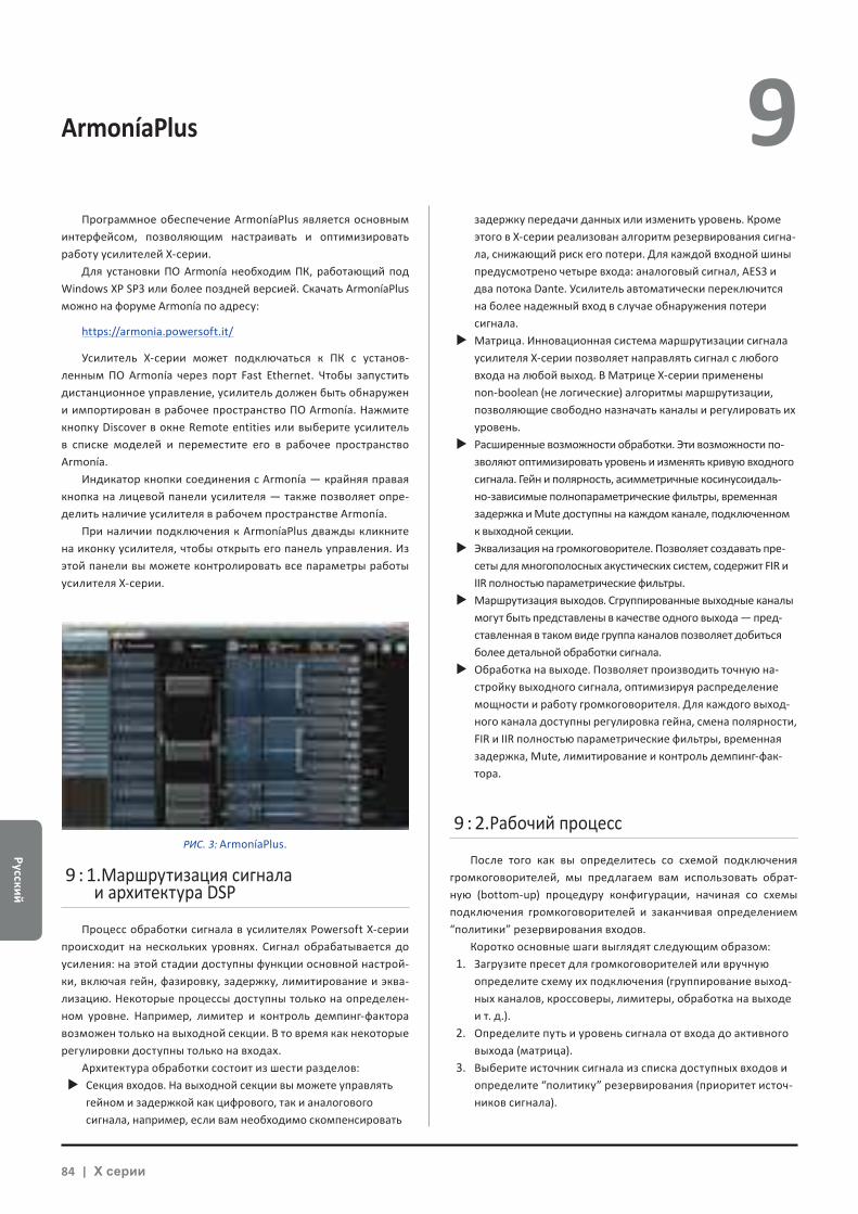
Pусский
84 | X серии
ArmoníaPlus 9 Программное обеспечение ArmoníaPlus является основным
интерфейсом, позволяющим настраивать и оптимизировать работу усилителей X-серии.
Для установки ПО Armonía необходим ПК, работающий под Windows XP SP3 или более поздней версией. Скачать ArmoníaPlus можно на форуме Armonía по адресу:
https://armonia.powersoft.it/
Усилитель X-серии может подключаться к ПК с установ-ленным ПО Armonía через порт Fast Ethernet. Чтобы запустить дистанционное управление, усилитель должен быть обнаружен и импортирован в рабочее пространство ПО Armonía. Нажмите кнопку Discover в окне Remote entities или выберите усилитель в списке моделей и переместите его в рабочее пространство Armonía.
Индикатор кнопки соединения с Armonía — крайняя правая кнопка на лицевой панели усилителя — также позволяет опре-делить наличие усилителя в рабочем пространстве Armonía.
При наличии подключения к ArmoníaPlus дважды кликните на иконку усилителя, чтобы открыть его панель управления. Из этой панели вы можете контролировать все параметры работы усилителя X-серии.
9 : 1.Маршрутизация сигнала и архитектура DSP
Процесс обработки сигнала в усилителях Powersoft X-серии происходит на нескольких уровнях. Сигнал обрабатывается до усиления: на этой стадии доступны функции основной настрой-ки, включая гейн, фазировку, задержку, лимитирование и эква-лизацию. Некоторые процессы доступны только на определен-ном уровне. Например, лимитер и контроль демпинг-фактора возможен только на выходной секции. В то время как некоторые регулировки доступны только на входах.
Архитектура обработки состоит из шести разделов: XX Секция входов. На выходной секции вы можете управлять
гейном и задержкой как цифрового, так и аналогового сигнала, например, если вам необходимо скомпенсировать
задержку передачи данных или изменить уровень. Кроме этого в X-серии реализован алгоритм резервирования сигна-ла, снижающий риск его потери. Для каждой входной шины предусмотрено четыре входа: аналоговый сигнал, AES3 и два потока Dante. Усилитель автоматически переключится на более надежный вход в случае обнаружения потери сигнала. XX Матрица. Инновационная система маршрутизации сигнала
усилителя X-серии позволяет направлять сигнал с любого входа на любой выход. В Матрице X-серии применены non-boolean (не логические) алгоритмы маршрутизации, позволяющие свободно назначать каналы и регулировать их уровень. XX Расширенные возможности обработки. Эти возможности по-
зволяют оптимизировать уровень и изменять кривую входного сигнала. Гейн и полярность, асимметричные косинусоидаль-но-зависимые полнопараметрические фильтры, временная задержка и Mute доступны на каждом канале, подключенном к выходной секции. XX Эквализация на громкоговорителе. Позволяет создавать пре-
сеты для многополосных акустических систем, содержит FIR и IIR полностью параметрические фильтры.XX Маршрутизация выходов. Сгруппированные выходные каналы
могут быть представлены в качестве одного выхода — пред-ставленная в таком виде группа каналов позволяет добиться более детальной обработки сигнала. XX Обработка на выходе. Позволяет производить точную на-
стройку выходного сигнала, оптимизируя распределение мощности и работу громкоговорителя. Для каждого выход-ного канала доступны регулировка гейна, смена полярности, FIR и IIR полностью параметрические фильтры, временная задержка, Mute, лимитирование и контроль демпинг-фак-тора.
9 : 2.Рабочий процесс
После того как вы определитесь со схемой подключения громкоговорителей, мы предлагаем вам использовать обрат-ную (bottom-up) процедуру конфигурации, начиная со схемы подключения громкоговорителей и заканчивая определением “политики” резервирования входов.
Коротко основные шаги выглядят следующим образом:1. Загрузите пресет для громкоговорителей или вручную
определите схему их подключения (группирование выход-ных каналов, кроссоверы, лимитеры, обработка на выходе и т. д.).
2. Определите путь и уровень сигнала от входа до активного выхода (матрица).
3. Выберите источник сигнала из списка доступных входов и определите “политику” резервирования (приоритет источ-ников сигнала).
РИС. 3: ArmoníaPlus.
Pусс
кий
Pусский | 85
10 Гарантийные обязательства и обслуживание
10 : 1.Гарантия10 : 1.1. Гарантийные обязательства
Powersoft гарантирует работу изделий и компонентов в течение 48 месяцев с даты продажи, указанной в гарантийном талоне Powersoft или авторизованного дилера. Все процедуры гарантийного ремонта и модернизации должны проводиться на фабрике Powersoft или в авторизованных сервисных цен-трах бесплатно для покупателя. Гарантийные обязательства Powersoft не распространяются на неисправности, полученные в результате неправильного использования, неаккуратного обра-щения, ремонта, проведенного не уполномоченными лицами, неправильного подключения, воздействия суровых погодных ус-ловий, механических повреждений (включая повреждения при доставке) и при естественном износе оборудования. Powersoft осуществляет гарантийный ремонт только в случае если продукт не был поврежден при транспортировке.
10 : 1.2. Возврат товараТовар может быть возвращен Powersoft только после одо-
брения возврата и получения номера RMA (Return Merchandise Authorization), который необходимо будет прикрепить к коробке при возврате. Powersoft (или авторизованный сервисный центр) вправе отказать в возврате товара без номера RMA.
10 : 1.3. Ремонт или заменаPowersoft оставляет за собой право на ремонт или замену
неисправного товара, покрываемого гарантией, по своему усмо-трению и, как считает лучшим.
10 : 1.4. Издержки и ответственность за пересылкуПокупатель (или конечный пользователь) несет полную от-
ветственность за все транспортные расходы и риски, связанные с отправкой оборудования, подлежащего гарантийному ремонту. Powersoft или авторизованный сервисный центр несет полную ответственность за обратную пересылку исправного оборудова-ния покупателю (или конечному пользователю).
10 : 2.Обслуживание
В Вашем усилителе нет частей для обслуживания пользова-телем. Для технического обслуживания обращайтесь к квали-фицированным специалистам. Кроме сервисных возможностей самой фабрики, Powersoft имеет сеть авторизованных сервис центров. Если Ваш усилитель нуждается в ремонте обратитесь к региональному дилеру или дистрибьютору. Вы также можете обратиться в службу поддержки Powersoft для того, чтобы полу-чить информацию о расположении ближайшего авторизованно-го сервисного центра.
Даже сложные проблемы могут быть решены обращением в службу поддержки Powersoft Customer Care и благодаря Вашему опыту. Хотя в некоторых случаях без отправки оборудования для ремонта никак не обойтись. При отправке оборудования на фабрику Powersoft Вы должны будете пройти стандартную про-цедуру оформления возврата, описанную ниже.XX Форму для заполнения данных о неисправности (“Defect
Report Form”) можно получить, обратившись в службу под-держки по адресу [email protected], или загрузив доку-мент с сайта (http://www.powersoft-audio.com/en/support/service). XX Заполните форму “Defect Report form” отдельно для каж-
дого пересылаемого устройства. Сохраните файл под име-нем, включающим Ваше имя, название модели усилителя и его серийный номер (например: distributornamek10sn17345.doc). Сообщите всю необходимую информацию без кода RMA и отправьте письмо на адрес [email protected] для получения подтверждения со стороны Powersoft.XX В случае подтверждения Вы получите от службы поддерж-
ки код авторизации (один код RMA присваивается одному устройству).XX Получив код RMA, Вы сможете приступать к пересылке
оборудования, размещая соответствующий код на транс-портировочных коробках так, чтобы он был разборчив и виден.
Все возвращаемые устройства должны направляться по адресу: PowersoftVia dei Cadolingi, 1350018 Scandicci (FI) Italy
В случае если Вы отправляете оборудование из стран не вхо-дящих в зону Европейского Союза, убедитесь, что Вы корректно выполнили соответствующие инструкции процедуры временно-го ввоза/вывоза – http://www.powersoft-audio.com/en/support/service.
Спасибо за понимание и продолжительную поддержку. Мы работаем, чтобы улучшить наше сотрудничество.
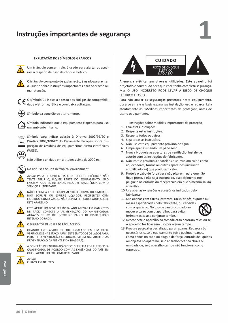
Português
Instruções importantes de segurança 1
A energia elétrica tem diversas utilidades. Este aparelho foi projetado e construido para que você tenha completa segurança. Mas O USO INCORRETO PODE LEVAR A RISCO DE CHOQUE ELÉTRICO E FOGO.Para não anular as seguranças presentes neste equipamento, observe as regras básicas para sua instalação, uso e reparos. Leia atentamente as “Medidas importantes de proteção”, antes de usar o equipamento.
Instruções sobre medidas importantes de proteção1. Leia estas instruções.2. Respeite estas instruções.3. Respeite todos os avisos.4. Siga todas as instruções.5. Não use este equipamento próximo de água.6. Limpe apenas usando um pano seco.7. Nunca bloqueie as aberturas de ventilação. Instale de
acordo com as instruções do fabricante.8. Não instale próximo a aparelhos que irradiam calor, como
aquecedores, fornos ou outros aparelhos (incluindo amplificadores) que produzem calor.
9. Proteja o cabo de força para não pisarem, para que não fique preso, e não seja tracionado, especialmente nos plugue e na entrada do receptáculo em que o mesmo sai do aparelho.
10. Use apenas extensões e acessórios indicados pelo fabricante.
11. Use apenas com carros, estantes, racks, tripés, suporte ou mesas especificadas pelo fabricante, ou vendidas com o aparelho. No uso de carros, cuidado ao mover o carro com o aparelho, para evitar ferimentos caso o conjunto tombe.
12. Desconecte o aparelho da tomada caso ocorram raios ou se o aparelho for ficar sem uso por algum tempo.
13. Procure pessoal especializado para reparos. Reparos são necessários caso o equipamento sofra qualquer danos, como danos no cabo ou plugue de força, entrada de líquidos ou objetos no aparelho, se o aparelho ficar na chuva ou umidade ou, se o aparelho cair ou não funcionar como esperado.
CUIDADORISCO DE CHOQUE
ELÉTRICONÃO ABRA
AVISO: PARA REDUZIR O RISCO DE CHOQUE ELÉTRICO, NÃO TENTE ABRIR QUALQUER PARTE DO EQUIPAMENTO. NÃO EXISTEM AJUSTES INTERNOS. PROCURE ASSISTÊNCIA COM O SERVIÇO AUTORIZADO.
NÃO EXPONHA ESTE EQUIPAMENTO À CHUVA OU UMIDADE, NÃO BORRIFE OU ESPIRRE LÍQUIDOS. RECIPENTES COM LÍQUIDOS, COMO VASOS, NÃO DEVEM SER COLOCADOS SOBRE ESTE APARELHO.
ESTE APARELHO DEVE SER INSTALADO APENAS EM GABINETES DE RACK: CONECTE A ALIMENTAÇÃO DO AMPLIFICADOR ATRAVÉS DE UM DISJUNTOR NO PAINEL DE DISTRIBUIÇÃO INTERNO DO RACK.
O DISJUNTOR DEVE SER DE FÁCIL ACESSO.
QUANDO ESTE APARELHO FOR INSTALADO EM UM RACK, VERIFIQUE SE HÁ ESPAÇO SUFICIENTE EM TODOS OS LADOS PARA PERMITIR A VENTILAÇÃO ADEQUADA (50 CM NAS ABERTURAS DE VENTILAÇÃO DA FRENTE E DA TRASEIRA).
A CONEXÃO DE ENERGIZAÇÃO DEVE SER FEITA POR ELETRICISTA QUALIFICADO, DE ACORDO COM AS EXIGÊNCIAS DO PAÍS EM QUE O APARELHO FOI COMERCIALIZADO.
AVISO: FUSÍVEL EM NEUTRO
CLASS3WIRING
CLASS3WIRING
CLASS3WIRING
CLASS3WIRING
CLASS3WIRING
CLASS3WIRING
CLASS3WIRING
EXPLICAÇÃO DOS SÍMBOLOS GRÁFICOS
Um triângulo com um raio, é usado para alertar os usuá-rios a respeito de risco de choque elétrico.
O triângulo com ponto de exclamação, é usado para avisar o usuário sobre instruções importantes para operação ou manutenção.
CLASS3WIRING
CLASS3WIRING O símbolo CE indica a adesão aos códigos de compatibili-
dade eletromagnética e com baixa voltagem.
Símbolo da conexão de aterramento.
Símbolo indicando que o equipamento é apenas para uso em ambiente interno.
Símbolo para indicar adesão à Diretiva 2002/96/EC e Diretiva 2003/108/EC do Parlamento Europeu sobre dis-posição de resíduos de equipamentos eletro-eletrônicos (WEEE).
Não utilize a unidade em altitudes acima de 2000 m.
Do not use the unit in tropical environment
86 | X Series
Port
uguê
s
1 X Series Guia Rápido 2
2 : 1.Seja bem vindo
Parabéns por sua aquisição do amplificador Powersoft da Série X!
Sabemos que você está ansioso para usar o seu X8 ou X4, mas reserve um momento para ler este manual de usuário e as instruções de segurança. Caso tenha qualquer dúvida, não hesite em entrar em contato com o seu distribuidor ou com a Powersoft.
Os amplificadores Powersoft da Série X inovam o conceito de plataforma de amplificação: o X8 é um amplificador de potência com 8 canais; o X4 oferece 4 canais em uma unidade de rack; ambos implementam um novo sistema de roteamento de canais, nova alimentação de potência e um DSP revolucionário pleno de recursos. Powersoft X8 e X4 suportam nativamente o AES3, com dois Dante™ redundantes para streaming de sinal digital Audinate® e entradas analógicas, permitindo a seleção entre até 4 entradas diferentes em cada canal.
Para a configuração do sistema e ajuste fino, o ArmoníaPlus™ oferece uma interface intuitiva, com controles amplos sobre o processamento de sinal de áudio digital, e monitoramento completo em tempo real da performance do sistema. A conexão Wi-Fi integrada permite que os amplificadores da Série X sejam acessados e controlados por qualquer aparelho móvel através de uma interface de usuário desenvolvida especificamente para a monitoração local.
Os amplificadores Powersoft X4 e X8 elevam a potência de amplificação a novos patamares em questões de qualidade e usabilidade: permitem se adequar à sua configuração, salvar espaço e peso, e oferecem a eficiência reconhecida da Powersoft com compatibilidade mundial na alimentação multi-fase.
2 : 2.Retirando da embalagem e verificando se houve danos no transporte
Seu produto Powersoft foi completamente testado e inspecionado antes de deixar a fábrica. Faça uma inspeção cuidadosa na embalagem antes da abertura, depois inspecione imediatamente o produto. Se encontrar qualquer dano, avise a empresa transportadora imediatamente.
A embalagem contém os seguintes itens:XX Amplificador Série X x1;XX plugue AC principal PC 5/5-STF1-7,62 Phoenix x1;XX Blindagem do plugue AC principal x1;XX Guia Rápido x1.
2 : 3.Descarte do material da embalagem
O material de transporte e proteção foi escolhido entre materiais que não agridem o ambiente e podem ser descartados para reciclagem.
Em vez de apenas jogar fora estes materiais, faça com que sejam reciclados.
2 : 4.Lista de painéis de imagens
A. X8/X4L projeto mecânico: todas as dimensões em milímetrosB. X4 projeto mecânico: todas as dimensões em milímetrosC. X8 painel traseiroD. X4L painel traseiroE. X4 painel traseiroF. X8 e X4L/X4 painéis frontaisG. Hastes de montagem e direção do fluxo da ventilaçãoH. Regras para empilhamento de amplificadores em racks
fechadosI. Pinagem do conector de entradaJ. Pinagem do conector Ethernet RJ45K. Cabeamento de alto-falantesL. Alimentação elétrica trifásica: cabeamento do plugue AC principalM. Alimentação elétrica em fase única: cabeamento do plugue AC
principalN. Alimentação elétrica em duas fases: cabeamento do plugue AC
principalO. Blindagem do plugue AC principalP. Informações de regulamentos
Português | 87

Português
Instalação 3 3 : 1.Posicionamento
Os amplificadores da Série X foram concebidos para uso em rack. O cabeamento principal de energia deve ser ligado ao conec-tor que acompanha o produto, bem como à um disjuntor (consulte §3 : 4.Alimentação AC principal). Não é permitido conectar os am-plificadores da Série X diretamente à linha de distribuição de ener-gia sem antes passar por um disjuntor adequado. Para o mercado da América do Norte, recomendamos utilizar cabos aprovados pela UL/CSA (por exemplo: ST 600Vac 105º 5x13AWG).
A fim de reduzir o risco de danos mecânicos, o amplificador deve ser fixado ao rack utilizando as abas frontais e os suportes traseiros. Recomendamos utilizar oito parafusos M6 ou 12-24 UNC-2B para furos rosqueados ou porca-gaiola.
Instale o amplificador o mais distante possível de sintonizado-res de rádio e televisores, pois pode haver um ruído ou degradação no desempenho dos mesmos. Colocar e utilizar o amplificador por longos períodos de tempo em fontes geradoras de calor poderá afetar seu desempenho. Evite colocar o amplificador em fontes geradoras de calor.
3 : 2.Resfriamento
Instale o amplificador em locais com boa ventilação: as aber-turas de ventilação não podem ser obstruidas por qualquer item como papel, toalhas, cortinas, etc. Mantenha a distância mínima de 50 cm para as aberturas frontais de traseiras de ventilação do amplificador.
Todos os amplificadores Powersoft tem implementados siste-mas de refrigeração de ar forçada, para manter temperaturas de operação constantes e baixas. Com a ventilação interna forçada, o ar entra pelo painel frontal e é jogado sobre todos os compo-nentes, saindo pela traseira do amplificador.
O sistema de resfriamento do amplificador tem um sistema ventilação DC “inteligente” de velocidade variável controlado pelo circuito de detecção de temperatura do dissipador: a ve-locidade da ventilação aumenta apenas quando a temperatura detectada pelo sensor atinge valores previamente determinados. Desta forma, pode-se assegurar que o ruído da ventilação e o acumulo interno de poeira fique restrito ao mínimo.
Se por acaso o amplificador for submetido a carga térmica extre-ma, a ventilação força um volume de ar maior sobre o dissipador. Em eventos extremamente raros, que podem causar danos pelo aque-cimento, o circuito sensor desliga todos os canais até o amplificador ser resfriado a uma temperatura segura. O funcionamento normal é retomado automaticamente sem necessidade de intervenção do usuário.
Os amplificadores da Série X podem ser empilhados uns sobre os outros em virtude da eficiência do sistema de ventilação com que estão equipados.
Mas existe limites de segurança a serem observados: caso um rack com painel posterior fechado seja usado, deixe uma unidade
3 : 3.Limpeza
Sempre use um pano seco para a limpeza do gabinete e painel frontal. A limpeza de filtros de ar deve ser programada de acordo com a quantidade de poeira no ambiente em que o amplificador é usado.
Desconecte o amplificador da tomada AC antes de fazer a limpeza de qualquer parte do
amplificador
Para a limpeza dos filtros de ventilação, você precisa retirar a tampa frontal: nunca tente abrir outras partes do aparelho.
Usando uma chave hexagonal número 6, solte os dois parafusos que ficam nas laterais esquerda e direita do painel frontal, (veja FIG. 1) suspenda a tampa com cuidado e retire o filtro. Use ar comprimido para remover a poeira dos filtros, ou lave usando água limpa: se usar água, verifique se o filtro está completamente seco antes de refazer a montagem.
3 : 4.Alimentação AC principal
Os amplificadores da Série X são compatíveis com alimentação AC de qualquer lugar do mundo, aceitando conexão direta em qualquer forma de alimentação regional. A confiabilidade comprovada da Powersoft na alimentação elétrica agora permite conexão monofásica, bifásica ou trifásica, de 90 VAC até 464 VAC sem necessidade de seleção manual: a carga trifásica real com balanceamento é conseguida diretamente pela unidade sem qualquer endereçamento complexo no projeto de sistema de distribuição de potência.
A conexão AC principal é fornecida com o uso do plugue euroblock Phoenix PC 5/5-STF1-7,62 (produto Phoenix ID 1777862). A montagem correta do conector de tomada AC ao plugue deve respeitar a configuração da alimentação.
Cuidado ao conectar qualquer um dos cinco contatos do plugue aos cabos de força, e faça de acordo com a configuração mostrada no painel ###. Para garantir a conexão correta, recomendamos o uso de um cabo com secção de 2,5 mm2 / 13 AWG.
de rack vazia para cada quatro amplificadores instalados, para garantir um fluxo de ar adequado (veja Painel G, p. 10).
FIG. 1: Use uma chave hexagonal nº 6 para retirar a tampa frontal.
88 | X Series
Port
uguê
s
3 Este aparelho deve ser alimentado exclusivamente com uso de aterramento do plugue elétrico
da rede, obedecendo os padrões IEC 364 ou padrões similares.
Como a chave de força principal deste aparelho não fornece isolamento completo do equipamento em relação à alimentação, você deve desconectar o aparelho da tomada quando quiser desligar completamente o equipamento.
Providencie um disjuntor entre a conexão principal de alimentação e o amplificador.
O equipamento correto a ser usado, depende da configuração da alimentação; para o X8 a Powersoft sugere:
AC monofásico (P+N+E): em 32 A, C ou curva D , 10 kA;AC trifásico (3P+N+E): 4 x em 16 A , C ou curva D , 10 kA.
Para o X4 a Powersoft sugere:AC (P+N+E): em 16 A, C ou curva D, 10 kA;AC trifásico (3P+N+E): 4 x em 10 A, C ou curva D, 10 kA.
NOTA: As imagens e instruções sobre o cabeamento AC são para o padrão europeu CENELEC de Abril de 2004 (IEC 60446) em relação ao código de cor para identificação dos condutores (veja TAB. 1).
Conductor Color
Neutro ou condutor médio N Azul
Condutor de fase AC
L1 Marrom
L2 Preto
L3 Cinza
Condutor de proteção (aterramento) E Verde/
Amarelo
TAB. 1: Código de cor para identificação dos condutores.
3 : 4.1. Alimentação elétrica trifásicaCada condutor deve ser fixado ao PC 5/5-STF1-7,62 que é
o plugue de conexão mostrado no Painel K, p. 13. Em alguns casos a conexão do neutro pode não existir: em sistemas trifásicos a conexão do neutro não é exigida, pela capacidade dos equipamentos da Série X para trabalhar em conexão delta.
3 : 4.2. Alimentação elétrica bifásicaAlimentação AC balanceada em duas fases na configuração
2P+E sem neutro, usando o conector PC 5/5-STF1-7,62 , mostrado no Painel M, p. 14. Cuidado na dobra de cabos de fase na conexão de terminais no interruptor para garantir a calibragem correta da alimentação.
3 : 4.3. Alimentação elétrica monofásicaA conexão monofásica P+N+E, com neutro é a configuração
usual para alimentação AC monofásica; o cabeamento deve estar de acordo com o mostrado no Painel L, p. 13. Cuidado na dobra de cabos de fase e neutro na conexão dos terminais do interruptor para garantir a calibragem correta da alimentação.
3 : 5.Cuidados em relação à instalação
AVISO: PARA PREVENÇÃO CONTRA RISCO DE FOGO E CHOQUE ELÉTRICO
Xf Este aparelho deve ser alimentado exclusivamente em tomadas com aterramento, em instalações que sigam o pa-drão IEC 364 ou similar.
Xf Instale este equipamento apenas em um gabinete de rack.
Xf Um disjuntor entre a tomada principal e o amplificador deve ser instalado dentro do rack.
Xf Cuidado ao conectar os cabos de força no conector Phoenix PC 5/5-STF1-7,62.
Xf Depois de fazer o cabeamento correto, insira e trave o co-nector no protetor fornecido pela Powersoft.
Xf Trave o conector na entrada do amplificador.
Xf Antes de ligar o amplificador, verifique se está sendo usada a voltagem correta.
Xf Verifique se a conexão principal tem potência para alimen-tar este equipamento.
Xf Não use este amplificador se o cabo de força estiver danifi-cado ou quebrado.
Xf Os terminais de saída são perigosos: o cabeamento para a conexão destes terminais exige a instalação por pessoas qualificadas e o uso de cabeamentos prontos.
Xf Tenha o cuidado de travar o terminal de saída antes de ligar o aparelho.
Xf Para evitar o risco de choque elétrico, não toque em qual-quer cabeamento de alto-falante exposto, enquanto o am-plificador estiver em funcionamento.
Xf Não respingue água ou outros líquidos no amplificador.
Xf Não aproxime fogo ou chama (como velas) do amplificador.
Xf Nunca remova as tampas do equipamento. A falha neste cuidado expõe pessoas a voltagens de risco.
Xf O fabricante não pode ser responsabilizado por danos cau-sados a pessoas, coisas ou dados devido a uso incorreto ou negligência no aterramento.
Xf Contate o Centro de Serviço Autorizado para manutenções normais ou extraordinárias.
É absolutamente necessário observar estas exigências de segurança. Em caso de dúvida, solicite uma
verificação precisa por pessoal qualificado..
Português | 89
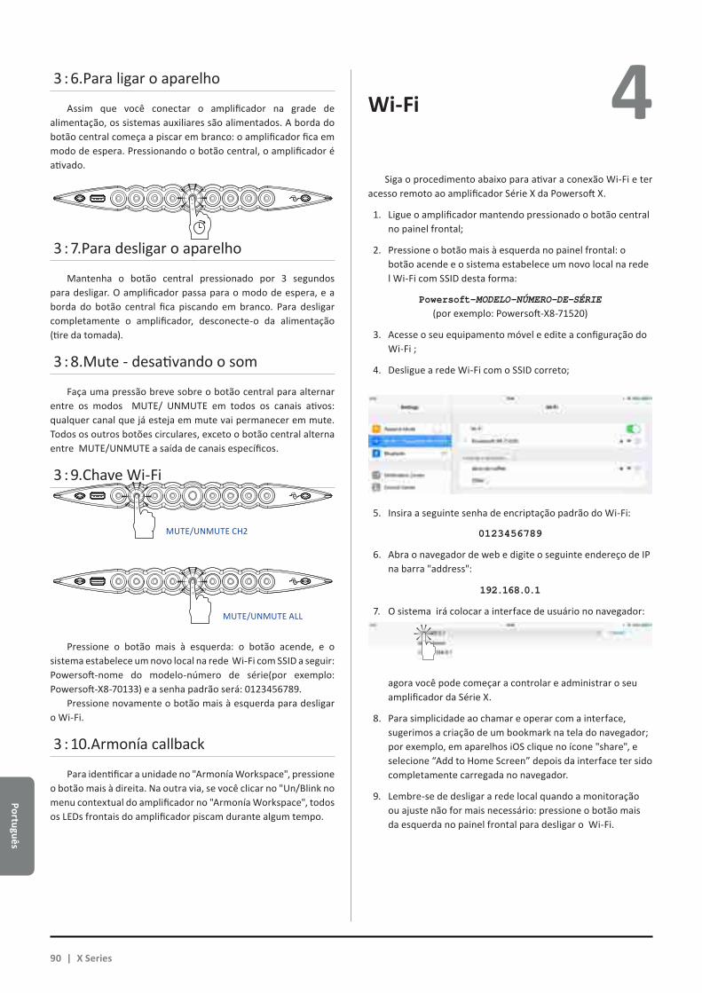
Português
3 : 6.Para ligar o aparelho
Assim que você conectar o amplificador na grade de alimentação, os sistemas auxiliares são alimentados. A borda do botão central começa a piscar em branco: o amplificador fica em modo de espera. Pressionando o botão central, o amplificador é ativado.
3 : 7.Para desligar o aparelho
Mantenha o botão central pressionado por 3 segundos para desligar. O amplificador passa para o modo de espera, e a borda do botão central fica piscando em branco. Para desligar completamente o amplificador, desconecte-o da alimentação (tire da tomada).
3 : 8.Mute - desativando o som
Faça uma pressão breve sobre o botão central para alternar entre os modos MUTE/ UNMUTE em todos os canais ativos: qualquer canal que já esteja em mute vai permanecer em mute. Todos os outros botões circulares, exceto o botão central alterna entre MUTE/UNMUTE a saída de canais específicos.
3 : 9.Chave Wi-Fi
Pressione o botão mais à esquerda: o botão acende, e o sistema estabelece um novo local na rede Wi-Fi com SSID a seguir: Powersoft-nome do modelo-número de série(por exemplo: Powersoft-X8-70133) e a senha padrão será: 0123456789.
Pressione novamente o botão mais à esquerda para desligar o Wi-Fi.
3 : 10.Armonía callback
Para identificar a unidade no "Armonía Workspace", pressione o botão mais à direita. Na outra via, se você clicar no "Un/Blink no menu contextual do amplificador no "Armonía Workspace", todos os LEDs frontais do amplificador piscam durante algum tempo.
Wi-Fi 4 Siga o procedimento abaixo para ativar a conexão Wi-Fi e ter
acesso remoto ao amplificador Série X da Powersoft X.
1. Ligue o amplificador mantendo pressionado o botão central no painel frontal;
2. Pressione o botão mais à esquerda no painel frontal: o botão acende e o sistema estabelece um novo local na rede l Wi-Fi com SSID desta forma:
Powersoft–MODELO–NÚMERO-DE-SÉRIE (por exemplo: Powersoft-X8-71520)
3. Acesse o seu equipamento móvel e edite a configuração do Wi-Fi ;
4. Desligue a rede Wi-Fi com o SSID correto;
5. Insira a seguinte senha de encriptação padrão do Wi-Fi:
0123456789
6. Abra o navegador de web e digite o seguinte endereço de IP na barra "address":
192.168.0.1
7. O sistema irá colocar a interface de usuário no navegador:
agora você pode começar a controlar e administrar o seu amplificador da Série X.
8. Para simplicidade ao chamar e operar com a interface, sugerimos a criação de um bookmark na tela do navegador; por exemplo, em aparelhos iOS clique no ícone "share", e selecione “Add to Home Screen” depois da interface ter sido completamente carregada no navegador.
9. Lembre-se de desligar a rede local quando a monitoração ou ajuste não for mais necessário: pressione o botão mais da esquerda no painel frontal para desligar o Wi-Fi.
MUTE/UNMUTE CH2
MUTE/UNMUTE ALL
90 | X Series
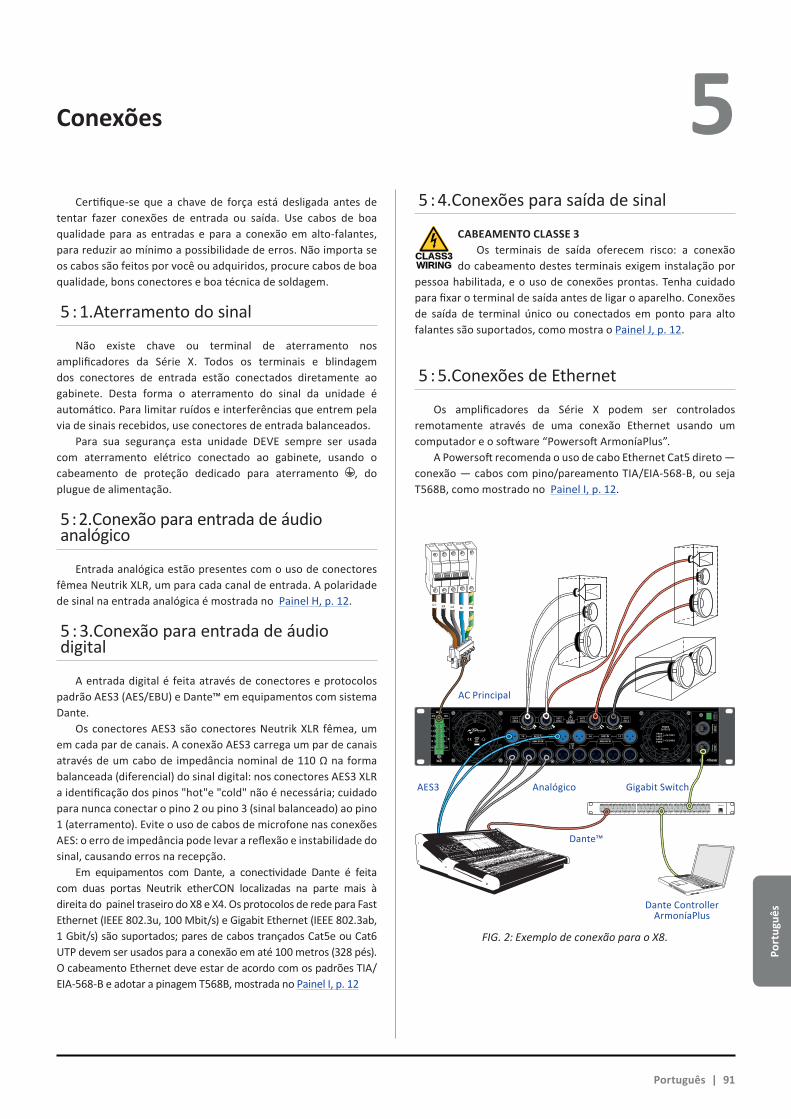
Port
uguê
s
4 Conexões 5 Certifique-se que a chave de força está desligada antes de
tentar fazer conexões de entrada ou saída. Use cabos de boa qualidade para as entradas e para a conexão em alto-falantes, para reduzir ao mínimo a possibilidade de erros. Não importa se os cabos são feitos por você ou adquiridos, procure cabos de boa qualidade, bons conectores e boa técnica de soldagem.
5 : 1.Aterramento do sinal
Não existe chave ou terminal de aterramento nos amplificadores da Série X. Todos os terminais e blindagem dos conectores de entrada estão conectados diretamente ao gabinete. Desta forma o aterramento do sinal da unidade é automático. Para limitar ruídos e interferências que entrem pela via de sinais recebidos, use conectores de entrada balanceados.
Para sua segurança esta unidade DEVE sempre ser usada com aterramento elétrico conectado ao gabinete, usando o cabeamento de proteção dedicado para aterramento , do plugue de alimentação.
5 : 2.Conexão para entrada de áudio analógico
Entrada analógica estão presentes com o uso de conectores fêmea Neutrik XLR, um para cada canal de entrada. A polaridade de sinal na entrada analógica é mostrada no Painel H, p. 12.
5 : 3.Conexão para entrada de áudio digital
A entrada digital é feita através de conectores e protocolos padrão AES3 (AES/EBU) e Dante™ em equipamentos com sistema Dante.
Os conectores AES3 são conectores Neutrik XLR fêmea, um em cada par de canais. A conexão AES3 carrega um par de canais através de um cabo de impedância nominal de 110 Ω na forma balanceada (diferencial) do sinal digital: nos conectores AES3 XLR a identificação dos pinos "hot"e "cold" não é necessária; cuidado para nunca conectar o pino 2 ou pino 3 (sinal balanceado) ao pino 1 (aterramento). Evite o uso de cabos de microfone nas conexões AES: o erro de impedância pode levar a reflexão e instabilidade do sinal, causando erros na recepção.
Em equipamentos com Dante, a conectividade Dante é feita com duas portas Neutrik etherCON localizadas na parte mais à direita do painel traseiro do X8 e X4. Os protocolos de rede para Fast Ethernet (IEEE 802.3u, 100 Mbit/s) e Gigabit Ethernet (IEEE 802.3ab, 1 Gbit/s) são suportados; pares de cabos trançados Cat5e ou Cat6 UTP devem ser usados para a conexão em até 100 metros (328 pés). O cabeamento Ethernet deve estar de acordo com os padrões TIA/EIA-568-B e adotar a pinagem T568B, mostrada no Painel I, p. 12
5 : 4.Conexões para saída de sinal
CLASS3WIRING
CABEAMENTO CLASSE 3Os terminais de saída oferecem risco: a conexão
do cabeamento destes terminais exigem instalação por pessoa habilitada, e o uso de conexões prontas. Tenha cuidado para fixar o terminal de saída antes de ligar o aparelho. Conexões de saída de terminal único ou conectados em ponto para alto falantes são suportados, como mostra o Painel J, p. 12.
5 : 5.Conexões de Ethernet
Os amplificadores da Série X podem ser controlados remotamente através de uma conexão Ethernet usando um computador e o software “Powersoft ArmoníaPlus”.
A Powersoft recomenda o uso de cabo Ethernet Cat5 direto — conexão — cabos com pino/pareamento TIA/EIA-568-B, ou seja T568B, como mostrado no Painel I, p. 12.
1 2 3 4 5 6 7 8
25 26 27 28 29 30 31 32
9 10 11 12 13 14 15 16
33 34 35 36 37 38 39 40
17 18 19 20 21 22 23 24
41 42 43 44 45 46 47 48 UP Link
Power
L1 L2 L3 N PE
AES3 IN7-8 5-6 AES3 IN3-4 1-2
ANALOG INANALOG IN
8 7 6 5 4 3 2 1
3PH 1PH
L1
L2
L3
N
L
N
1=GND2 = IN+3 = IN-
MAINS
TURN TO LOCK TURN TO LOCKTURN TO LOCK TURN TO LOCK
FIG. 2: Exemplo de conexão para o X8.
Português | 91
AC Principal
AES3 Analógico Gigabit Switch
Dante™
Dante ControllerArmoníaPlus

Português
Atualização do Software
Tabela das indicações por LED6 7
Os amplificadores Powersoft da Série X tem internamente o controle total do processamento de sinal de áudio digital baseado em um processador ARM Cortex A-8 e plataforma DSP TI C6000 DSP. Esta enorme capacidade de processamento interna é alimentada por um ambiente com software dedicado.
Atualizações do software da Série X são disponibilizados no forum Armonía (https://armonia.powersoft.it/).
O pacote contém o software update de atualização, com o nome da seguinte forma :
update-version#-model.bin (e.g. update-v1.5.0.6-x4.bin);
para atualizar o software do seu amplificador da Série X, você deve armazenar o programa de atualização em um pendrive USB e seguir as instruções abaixo:
1. Ligue o amplificador e espere o término da sequência de inicialização.
2. Conecte o pendrive USB com o software de atualização na porta USB do painel frontal do amplificador.
3. Mantenha pressionado o botão mais à direita (Armonía call-back) até um segundo bip ser emitido e os LEDs começarem a piscar.
4. Espere até o amplificador desligar e voltar a ligar e todos os LEDs ficarem acesos em azul.
Todos os botões circulares retro iluminados tem informações sobre a condição de entrada e saída de cada canal. O centro de cada botão tem informação da condição do sinal de saída.
Cor do centroindicadores OUTPUT
Cor do centroindicadores OUTPUT
Cor Condição Cor Condição
AzulCanal
pronto para uso
Laranja MUTE OUTPUT
Amarelo Limiter ativado
Laranjapiscando
MUTE INPUT
O anel de cada botão dá informação da condição do sinal de entrada.
Cor do anelindicadores INPUT
Cor CondiçãoBranco
piscando (centro azul)
Presença do sinal de entrada
Vermelho Sinal de entrada excessivo (clip)
Falha de canal e Armonía callback estão associados aos se-guintes sinais de LED .
Cor Condição
Vermelho piscando(centro e anel) Falha no canal
piscando / todos os canais(centro e anel)
Unidade respondendo aoArmonía callback
Apenas o botão central acende quando o sistema estiver em espera (inativo) ou em caso de falha na fonte de alimentação:
Cor do anel do botão CENTRAL
Cor CondiçãoBranco
piscando (todos os LEDs
apagados)
Sistema com alimentação, em modo de espera (Standby)
Vermelho piscando
(operação normal)falha detectada no ventilador
(ventilador lado estágio de saída)
Cor do centro do botão CENTRAL
Cor Condição
Vermelho piscando
falha detectada no fonte de alimentação ou ventilador
Amarelo piscando
fonte de alimentação:proteção de temperatura ativa
Piscando
Conexão do pendrive USB
...
92 | X Series

Port
uguê
s
Funcionamento em rede 8 Os amplificadores da Série X suportam topologia de rede
linear em “daisy-chain”, “estrela” e “loop”; na conexão em “daisy--chain” o PC com o ArmoníaPlus deve sempre estar em uma ponta da rede.
Cuidado, esta conexão não garante a confiabilidade para um sistema de produção, uma vez que qualquer falha pode travar a rede e fazer com que seja perdido o controle do sistema.
Quando a eficiência e confiabilidade forem essenciais, uma topologia de rede redundante é desejável. Para aproveitar os recursos Dante, a rede em estrela e daisy-chain aberta são permitidas.
8 : 1.Endereço IP
Os ajustes padrões de rede são DHCP/AutoIP, para que o am-plificador faça a auto configuração ao ser conectado a uma LAN ou PC. Uma política de IP fixo pode ser adotada e configurada através do ArmoníaPlus.
Se o servidor DHCP não estiver ativo dentro da rede, o amplificador inicializa uma auto configuração de endereço (ou seja configuração zero na metodologia de rede – Zeroconf): a auto configuração determina um número para a rede local (do tipo 169.254.x.y – 172.31.*.* para a rede secundária, caso esteja presente – com subnet mask 255.255.0.0) e automaticamente distribui e resolve os host names dos equipamentos da rede. Para ajustar o endereço de IP estático, consulte o guia de usuário do ArmoníaPlus.
8 : 1.1. Solução de problemas no endereçamento IPAo conectar amplificadores da Série X em um ambiente de
rede, pode acontecer que o ArmoníaPlus não descubra ou impor-te um amplificador.
Normalmente o problema é o endereçamento IP: tanto o Armonia como os equipamentos da Série X precisam pertencer à mesma subnet. Se o servidor DHCP estiver presente na rede ou a rede o amplificador da Série X estiverem em AUTO IP, a rede pode ficar instável.
Como regra geral, ligue o servidor DHCP antes de conectar os amplificadores.
O endereçamento IP de amplificadores da Série X é estabele-cido durante a inicialização: quando um amplificador da Série X descobre um servidor DHCP na rede durante a inicialização, ele negocia os parâmetros de rede. Se o amplificador da Série X não perceber o servidor DHCP da rede durante a inicialização ele se ajusta no modo AUTO IP.
8 : 2.Rede Dante™
Modelos equipados com Dante nos amplificadores da Série X suportam a rede redundante Dante através de duas portas etherCON do painel traseiro:XX Primary/ETH1 é a porta da rede primária;XX Secondary/ETH2 é a porta da rede secundária. A conectividade Dante sempre é suportada na porta Primary/
ETH1 Gigabit Ethernet; a porta Secondary/ETH2 Gigabit Ethernet permite a continuidade do funcionamento quando uma rede paralela redundante é estabelecida.
Para implementar a rede Dante, um computador com o controlador Dante precisa ser usado. "Dante Controller" é um software de administração de equipamentos de rede. Amplificadores da Série X descobrem automaticamente e aparecem no controlador Dante com o identificador inicial padrão MODELO–NÚMERO-DE-SÉRIE (por exemplo X8-71520).
A rede Dante sempre exige pelo menos uma chave de rede. A estrutura redundante exige múltiplas chaves. Para confiabilidade máxima a chave de rede necessita:
Xf estar no padrão Gigabit Ethernet;
Xf precisa ser do tipo Non-blocking;
Xf precisa ter Quality of Service (QoS) com pelo menos quatro vias;
Xf precisa ter Diffserv (DSCP) QoS com prioridade estrita;
Xf precisa estar com o sistema EEE (Energy efficient ethernet) desligado.
Para informações detalhadas do ajuste da chave de rede, consulte a documentação do fabricante.
8 : 2.1. Configuração de rede redundante A redundância da rede Dante (Dante Redundancy) pode
ser ajustada e usada entre quaisquer equipamentos de áudio com suporte de rede Dante ativo: o funcionamento é com duas redes independentes completamente separadas, a rede primária e a rede secundária. Para ajustar e usar a redundância Dante, conecte o amplificador da Série X e outros equipamentos com a redundância Dante ativa, usando chaves duplicadas do tipo Gigabit e cabos Ethernet. Conecte o computador que tenha o programa "Dante Virtual Soundcard" e o programa "Dante Controller", e outros equipamentos Dante de áudio não redundante na rede primária.
As redes primária e secundária NÃO DEVEM estar interconectadas em nenhum ponto. Certifique-se que todos os computadores fiquem ajustados para ter endereço de IP automático.
Português | 93
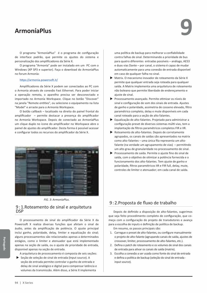
Português
ArmoníaPlus 9 O programa "ArmoníaPlus" é o programa de configuração
de interface padrão, que permite os ajustes do sistema e personalização dos amplificadores da Série X.
O programa "Armonía" pode ser instalado em um PC com o Windows (XP SP3 e superior). Faça o download do ArmoníaPlus no forum Armonía:
https://armonia.powersoft.it/
Amplificadores da Série X podem ser conectados ao PC com o Armonía através de conexão Fast Ethernet. Para poder iniciar a operação remota, o aparelho precisa ser desconectado e importado no Armonía Workspace. Clique no botão "Discover" na janela "Remote entities", ou selecione o equipamento na lista "Model" e arraste para o Armonía Workspace.
O botão callback – localizado na direita do painel frontal do amplificador – permite destacar a presença do amplificador no Armonía Workspace. Depois de conectado ao ArmoníaPlus um clique duplo no ícone do amplificador no Workspace abre o painel de ajustes do amplificador. Desta forma é possível acessar e configurar todos os recursos do amplificador da Série X.
9 : 1.Roteamento de sinal e arquitetura DSP
O processamento de sinal do amplificador da Série X da Powersoft X realiza diversas funções que afetam o sinal de áudio, antes da amplificação de potência. O ajuste principal inclui ganho, polaridade, delay, limiter e equalização do sinal; alguns processamentos são relacionados apenas a determinados estágios, como o limiter e atenuador que está implementado apenas na seção de saída, ou o ajuste de prioridade de entrada, disponível apenas na seção de entrada.
A arquitetura de processamento é composta de seis seções:XX Seção de seleção de sinal de entrada (Input source). A
seção de entrada permite controlar o ganho de entrada e delay de sinal analógico e digital para compensar latência e volumes da transmissão. Além disso, a Série X implementa
uma política de backup para melhorar a confiabilidade contra falhas de sinal. Determinando a prioridade de bus para quatro diferentes entradas possíveis – análogo, AES3 e duas vias Dante – por canal, o sistema é capaz de mudar automaticamente para uma conexão de entrada disponível em caso de qualquer falha no sinal.XX Matrix. O mecanismo inovador de roteamento da Série X
permite que qualquer entrada seja roteada para qualquer saída. A Matrix implementa uma arquitetura de roteamento não boleano que permite liberdade de endereçamento e ajuste de sinal.XX Processamento avançado. Permite otimizar os níveis de
sinal e configuração de som dos sinais de entrada. Ajustes de ganho e polaridade, assimetria de cosseno elevado, filtro paramétrico completo, delay e mute disponíveis em cada canal roteado para a seção de alto falantes.XX Equalização de alto-falantes. Projetado para administrar a
configuração preset de diversos sistemas múlti-vias, tem a implantação de filtros paramétricos completos FIR e IIR.XX Roteamento de alto-falantes. Depois de corretamente
agrupados, os canais de saídas são apresentados na matrix como alto-falantes – uma única fila representa um alto-falante (na verdade um agrupamento de vias) – permitindo um alto grau de granularidade no processamento de sinal.XX Processamento de saída. Permite o ajuste fino do sinal de
saída, com o objetivo de otimizar a potência fornecida e o funcionamento dos alto-falantes. Tem ajuste de ganho e polaridade, filtros paramétricos IIR e FIR full, delay, mute, controles de limiter e atenuador; em cada canal de saída.
9 : 2.Proposta de fluxo de trabalho
Depois de definido a disposição de alto-falantes, sugerimos que seja feito procedimento completo de configuração, que co-meça com a configuração do projeto de transdutores e avança para a escolha de inputs e definição de política de backup.
Em resumo, os passos principais são:1. Carregue o preset de alto-falantes, ou configure manualmente
o projeto de alto-falante (agrupando canais de saída, ajustes de crossover, limiter, processamento de alto-falantes, etc.).
2. Defina o patch de roteamento e os volumes de sinal dos canais de entrada para ativar os canais de saída (matrix).
3. Escolha a conexão a ser usada como fonte do sinal de entrada e defina a política de backup (seleção do sinal de entrada - input source).
FIG. 3: ArmoníaPlus.
94 | X Series

Port
uguê
s
10 10 : 1.Garantia
10 : 1.1. Garantia do produtoA Powersoft garante que a fabricação deste produto é livre
de defeitos de componentes e de montagem, por um período de 48 (quarenta e oito) meses, a partir da data de compra impresso na fatura da Powersoft (ou de qualquer Revendedor Autorizado) ao usuário final. Todos os reparos de garantia e revisões devem ser realizados nas unidades Powersoft ou em um Serviço Técnico Autorizado sem custo para o comprador. Exclusões da Garantia: A garantia da Powersoft não cobre mau funcionamento do produto ou falhas provocadas por: mau uso, abuso, reparos ou alterações realizadas por pessoas não autorizadas, conexões incorretas, exposição a clima inadequado, danos mecânicos (incluindo acidentes de transporte) e desgaste normal. A Powersoft realiza os serviços de garantia desde que o produto não seja danificado durante o transporte.
10 : 1.2. Retorno das mercadoriasAs mercadorias apenas podem ser enviadas para Powersoft
após receberem um número com a concessão de retorno de mercadoria (RMA) que deve ser colocado na parte externa da embalagem. A Powersoft (ou o Serviço Técnico Autorizado) tem o direito de recusar qualquer mercadoria que esteja sem o número de RMA.
10 : 1.3. Reparos ou substituiçãoA Powersoft reserva-se o direito de reparar ou substituir
qualquer mercadoria com defeitos cobertas pela garantida do produto, à seu exclusivo critério, do que julgar melhor.
10 : 1.4. Custos e responsabilidades de transporteO comprador (ou o usuário final) é inteiramente responsável
pelos custos de transportes e riscos associados ao mesmo, ao enviar produtos em garantia para a Powersoft ou para o Serviço Técnico Autorizado. A Powersoft não assume a responsabilidade de cobrir todos os custos para mandar a mercadoria de volta para o comprador (ou usuário final).
10 : 2.Assistência
Não existem ajustes para usuários na parte interna do amplificador. Procure técnicos qualificados para reparos. Além do departamento de serviço próprio, a Powersoft tem uma rede de Centros de Serviços Autorizados. Se o seu amplificador precisar de reparos, consulte um Distribuidor Powersoft. Você também pode entrar em contato com departamento de Serviço Técnico Powersoft para informações sobre o Centro de Serviço Autorizado mais próximo.
Mesmo que a maioria dos problemas de mau funcionamento possam ser resolvidos nas instalações de Atenção ao Consumidor Powersoft ou por conhecimentos pessoais, dependendo da natureza da falha, pode ser necessário que o produto com defeito seja mandado para a Powersoft para reparos. Neste último caso, antes de enviar o produto, solicitamos que você faça a gentileza de seguir passo a passo o procedimento descrito abaixo:XX Obtenha o formulário “Relatório de Danos” contatando
nosso departamento Customer Care pelo email: [email protected] ou faça o download do “Defect Report Form” no website da Powersoft (http://www.powersoft-audio.com/en/support/service).XX Preencha um formulário “Defect Report form” para cada
item a ser enviado (o formulário é um documento editável com instruções) e salve com o seu nome, modelo de am-plificador e número de série (por exemplo: distributorna-mek10sn17345.doc) fornecendo todas as informações solici-tadas, exceto o código RMA e mande para aprovação, para o endereço: [email protected], aguardando a aprovação da Powersoft.XX No caso do relatório de danos ser aprovado pelo
Representante do Serviço do Consumidor Powersoft você receberá um código de autorização RMA (um código RMA para cada item a ser enviado).XX Depois de receber o código RMA, você precisa fazer uma
embalagem com o produto e identificar com o código RMA na parte externa da embalagem, de uma forma que esteja protegida de umidade no transporte, em um envelope e que fique claramente visível.
Todos os itens a serem enviados devem ser mandados para o seguinte endereço:
PowersoftVia dei Cadolingi, 1350018 Scandicci (FI) Italy
No caso de embarque a partir de países que NÃO pertençam à Comunidade Européia, certifique-se de também seguir as instruções descritas no documento disponível para download: “TEMPORARY EXPORTATION / IMPORTATION PROCEDURE http://www.powersoft-audio.com/en/support/service.
Obrigado pelo seu entendimento, cooperação e suporte contínuo enquanto trabalhamos para melhorar a nossa parceria.
Garantia e assistência
Português | 95

Page intentionally left blank
96 | X Series

Appe
ndix
A CONNECTION
SYSTEMCABLE
WIRINGX SERIES
CONNECTOR BREAKER CONNECTION
1
A
N
B
C
A
N
B
C
A
B
C
A
B
C
A
N
B
C
A
N
B
A
C
B
L1
L2
N
N
L
C
A
N
B
N
L
N
AB
A
C
B
A L1
B L2
C L3
N N
3-Phase Wye: 4-Wire; Grounded Neutral and Contiguous Ground.
2
A
N
B
C
A
N
B
C
A
B
C
A
B
C
A
N
B
C
A
N
B
A
C
B
L1
L2
N
N
L
C
A
N
B
N
L
N
AB
A
C
B
A L1 // L2
B L3 // NN n.c.
Symbol “L1 // L2” (parallel connection) means connect the pole L1 together with the pole L2.
The parallel connection must be done at the breaker output and not at the connector level.
Symbol “n.c.” means not connected.
2-Phase Wye: 3-Wire; Grounded Neutral and Contiguous Ground (typi-
cally called a single phase supply in North america).
3
A
N
B
C
A
N
B
C
A
B
C
A
B
C
A
N
B
C
A
N
B
A
C
B
L1
L2
N
N
L
C
A
N
B
N
L
N
AB
A
C
B
A L1
B L2
C L3
N n.c.
3-Phase Delta: 4-Wire; Grounded at Midpoint pf Phase and Contiguous
Ground
4
A
N
B
C
A
N
B
C
A
B
C
A
B
C
A
N
B
C
A
N
B
A
C
B
L1
L2
N
N
L
C
A
N
B
N
L
N
AB
A
C
B
A L1 // L2
B L3 // NC n.c.N n.c.
Symbol “L1 // L2” (parallel connection) means connect the pole L1 together with the pole L2.
The parallel connection must be done at the breaker output and not at the connector level.
Symbol “n.c.” means not connected.
3-Phase Open Delta: 4-Wire; Grounded at Midpoint pf Phase; Contiguous
Ground
5
A
N
B
C
A
N
B
C
A
B
C
A
B
C
A
N
B
C
A
N
B
A
C
B
L1
L2
N
N
L
C
A
N
B
N
L
N
AB
A
C
B
L1 L1 // L2
L2 L3 // NN n.c.
Symbol “L1 // L2” (parallel connection) means connect the pole L1 together with the pole L2.
The parallel connection must be done at the breaker output and not at the connector level.
Symbol “n.c.” means not connected.
Single-Phase: 3-Wire; Grounded Neutral; Grounded at Midpoint pf
Phase; Contiguous Ground
Appendix: X Series Mains Wiring Option
Appendix | 97
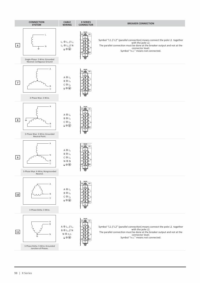
CONNECTION SYSTEM
CABLE WIRING
X SERIES CONNECTOR BREAKER CONNECTION
6
A
N
B
C
A
N
B
C
A
B
C
A
B
C
A
N
B
C
A
N
B
A
C
B
L1
L2
N
N
L
C
A
N
B
N
L
N
AB
A
C
B
L1 L1 // L2
L2 L3 // N
Symbol “L1 // L2” (parallel connection) means connect the pole L1 together with the pole L2.
The parallel connection must be done at the breaker output and not at the connector level.
Symbol “n.c.” means not connected.
Single-Phase: 2-Wire; Grounded Neutral; Contiguous Ground
7
A
N
B
C
A
N
B
C
A
B
C
A
B
C
A
N
B
C
A
N
B
A
C
B
L1
L2
N
N
L
C
A
N
B
N
L
N
AB
A
C
B
A L1
B L2
C L3
3-Phase Wye: 3-Wire.
8
A
N
B
C
A
N
B
C
A
B
C
A
B
C
A
N
B
C
A
N
B
A
C
B
L1
L2
N
N
L
C
A
N
B
N
L
N
AB
A
C
B
A L1
B L2
C L3
3-Phase Wye: 3-Wire; Grounded Neutral Point.
9
A
N
B
C
A
N
B
C
A
B
C
A
B
C
A
N
B
C
A
N
B
A
C
B
L1
L2
N
N
L
C
A
N
B
N
L
N
AB
A
C
B
A L1
B L2
C L3
N N
3-Phase Wye: 4-Wire; Nongrounded Neutral.
10
A
N
B
C
A
N
B
C
A
B
C
A
B
C
A
N
B
C
A
N
B
A
C
B
L1
L2
N
N
L
C
A
N
B
N
L
N
AB
A
C
B
A L1
B L2
C L3
3-Phase Delta: 3-Wire.
11
A
N
B
C
A
N
B
C
A
B
C
A
B
C
A
N
B
C
A
N
B
A
C
B
L1
L2
N
N
L
C
A
N
B
N
L
N
AB
A
C
B
A L1 // L2
B L3 // NN n.c.
Symbol “L1 // L2” (parallel connection) means connect the pole L1 together with the pole L2.
The parallel connection must be done at the breaker output and not at the connector level.
Symbol “n.c.” means not connected.
3-Phase Delta: 3-Wire; Grounded Junction of Phases.
98 | X Series
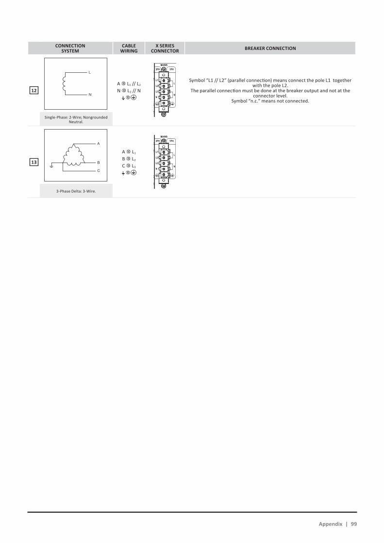
CONNECTION SYSTEM
CABLE WIRING
X SERIES CONNECTOR BREAKER CONNECTION
12
A
N
B
C
A
N
B
C
A
B
C
A
B
C
A
N
B
C
A
N
B
A
C
B
L1
L2
N
N
L
C
A
N
B
N
L
N
AB
A
C
B
A L1 // L2
N L3 // N
Symbol “L1 // L2” (parallel connection) means connect the pole L1 together with the pole L2.
The parallel connection must be done at the breaker output and not at the connector level.
Symbol “n.c.” means not connected.
Single-Phase: 2-Wire; Nongrounded Neutral.
13
A
N
B
C
A
N
B
C
A
B
C
A
B
C
A
N
B
C
A
N
B
A
C
B
L1
L2
N
N
L
C
A
N
B
N
L
N
AB
A
C
B
A L1
B L2
C L3
3-Phase Delta: 3-Wire.
Appendix | 99
Channel Handling
Number of output channels 4 mono, bridgeable per ch. pair
Number of input channels:
Analog 4 (4x XLR)
AES3 4 (2x XLR)
Dante™* 16 (2x RJ45)
* DANTE version only
AudioOutput Noise A-Weighted @ 8 Ω - Analog to Analog / Digital to Analog < -70.0 dBV
Dynamic Range A-Weighted @ 8 Ω - Analog to Analog / Digital to Analog 114,3 dB
Damping Factor @ 8 Ω, 20Hz - 500Hz > 5000
Slew Rate (input filter bypassed) > 50 V/µs
Frequency Response ( -3 dB , 1 W @ 8 Ω) 5 Hz - 30 kHz
Crosstalk (1 kHz) -70 dB
THD+N (from 0.1 W to Full Power) < 0.5% (typical < 0.01%)
DIM (from 0.1 W to Full Power) < 0.5% (typical < 0.01%)
Input Impedance 20 kΩ Balanced
Input Acceptance +27 dBu
DSP
AD converters Dual 24 bit 48 kHz Tandem® architecture with 129 dBA of dynamic range
DA converters Dual 24 bit 48 kHz Tandem® architecture with 121 dBA of dynamic range
Sample rate converter 24 Bit @ 44.1 kHz to 192 kHz 140 dB Dynamic Range - 0.0001 % THD+N
Internal precision 40 bit floating point
Delay up to 2 s on input sectionup to 100 ms per output for time alignment
EqualizerRaised-cosine, custom FIR, parametric IIR:
peaking, hi/lo-shelving, all-pass, band-pass, band-stop, hi/lo-pass
Crossover Linear phase (FIR), hybrid (FIR-IIR), Butterworth, Linkwitz-Riley, Bessel: 6 dB/oct to 48 dB/oct (IIR)
Limiters TruePower™, RMS voltage, RMS current, Peak limiter
Damping control Active DampingControl™
ConstructionDimensions 483 mm x 44.5 mm x 495 mm (19.0 in x 1.75 in x 19.5 in)
Weight 15 kg (33.0 lb)
Output StageMaximum output power per channel @ 8 Ω 1600 W
Maximum output power per channel @ 4 Ω 3000 W
Maximum output power per channel @ 2.7 Ω 4000 W
Maximum output power per channel @ 2 Ω 5200 W
Maximum output power @ 8 Ω Bridged 6000 W
Maximum output power @ 4 Ω Bridged 10400 W
Peak total output, all channels driven 20000 W
Maximum unclipped output voltage 175 Vpeak
Maximum output current 130 Apeak
The power figure is calculated by driving and loading symmetrically all the channels: uneven loads allow to achieve highest performance.
AC Mains PowerSingle-Phase
Nominal Voltage 100 - 240 V @ 50/60Hz
Operating Range 90 - 264 V from DC to 200Hz
Power Factor 1/8 Maximum Output Power @ 4 Ω > 0.9
Current Draw1/8 Maximum Output Power @ 4 Ω
18 Arms
@ 100V9 Arms
@ 240V
Suggested circuit breaker C16
Three-Phase
Nominal Voltage**208Y / 120 - 416Y / 240 V, 3~, 3W+N+PE
@ 50/60Hz200 V~, 3W+PE @ 50/60Hz
Power Factor1/8 Maximum Output Power @ 4 Ω > 0.9
Current Drawn from Each Single Phase1/8 Maximum Output Power @ 4 Ω
6 Arms @ 208Y
3 Arms
@ 416Y
Suggested circuit breaker (per phase) C10
Bi-Phase
Nominal Voltage 200/100 V, 2W+PE @ 50/60Hz
Idle Consumption (all AC MAINS cases) < 100 W
Max Consumption (all AC MAINS cases) < 3500 W
** Note: 208Y/120 V = 208 V phase-to-phase, 120 V phase-to-neutral
Specifications
ThermalOperating temperature 0° - 15°C / 32° - 113°F
Cooling Fan, continuously variable speed, teperature controlled
Thermal dissipation
Single phase 115V 230V
1/8 Maximum Output Power @ 8 Ω 1127 BTU/h 1058 BTU/h
1/4 Maximum Output Power @ 8 Ω 2124 BTU/h 1639 BTU/h
X4
100 | X Series
AC Mains PowerSingle-Phase
Nominal Voltage 100 - 240 V @ 50/60Hz
Operating Range 90 - 264 V from DC to 200Hz
Power Factor 1/8 Maximum Output Power @ 4 Ω > 0.9
Current Draw1/8 Maximum Output Power @ 4 Ω
32 Arms
@ 100V18 Arms
@ 240V
Suggested circuit breaker C32
Three-Phase
Nominal Voltage**208Y / 120 - 416Y / 240 V, 3~, 3W+N+PE
@ 50/60Hz200 V~, 3W+PE @ 50/60Hz
Power Factor1/8 Maximum Output Power @ 4 Ω > 0.9
Current Drawn from Each Single Phase1/8 Maximum Output Power @ 4 Ω
12 Arms @ 208Y
6 Arms
@ 416Y
Suggested circuit breaker (per phase) C16
Bi-Phase
Nominal Voltage 200/100 V, 2W+PE @ 50/60Hz
Idle Consumption (all AC MAINS cases) < 200 W
Max Consumption (all AC MAINS cases) < 5000 W
** Note: 208Y/120 V = 208 V phase-to-phase, 120 V phase-to-neutral
X8
Channel Handling
Number of output channels 8 mono, bridgeable per ch. pair
Number of input channels:
Analog 8 (8x XLR)
AES3 8 (4x XLR)
Dante™* 16 (2x RJ45)
* DANTE version only
AudioOutput Noise A-Weighted @ 8 Ω - Analog to Analog / Digital to Analog < -70.0 dBV
Dynamic Range A-Weighted @ 8 Ω - Analog to Analog / Digital to Analog 114,3 dB
Damping Factor @ 8 Ω, 20Hz - 500Hz > 5000
Slew Rate (input filter bypassed) > 50 V/µs
Frequency Response ( -3 dB , 1 W @ 8 Ω) 5 Hz - 30 kHz
Crosstalk (1 kHz) -70 dB
THD+N (from 0.1 W to Full Power) < 0.5% (typical < 0.01%)
DIM (from 0.1 W to Full Power) < 0.5% (typical < 0.01%)
Input Impedance 20 kΩ Balanced
Input Acceptance +27 dBu
DSP
AD converters Dual 24 bit 48 kHz Tandem® architecture with 129 dBA of dynamic range
DA converters Dual 24 bit 48 kHz Tandem® architecture with 121 dBA of dynamic range
Sample rate converter 24 Bit @ 44.1 kHz to 192 kHz 140 dB Dynamic Range - 0.0001 % THD+N
Internal precision 40 bit floating point
Delay up to 2 s on input sectionup to 100 ms per output for time alignment
EqualizerRaised-cosine, custom FIR, parametric IIR:
peaking, hi/lo-shelving, all-pass, band-pass, band-stop, hi/lo-pass
Crossover Linear phase (FIR), hybrid (FIR-IIR), Butterworth, Linkwitz-Riley, Bessel: 6 dB/oct to 48 dB/oct (IIR)
Limiters TruePower™, RMS voltage, RMS current, Peak limiter
Damping control Active DampingControl™
ConstructionDimensions 483 mm x 89 mm x 495 mm (19.0 in x 3.5 in x 19.5 in)
Weight 24 kg (52.9 lb)
Output StageMaximum output power per channel @ 8 Ω 1600 W
Maximum output power per channel @ 4 Ω 3000 W
Maximum output power per channel @ 2.7 Ω 4000 W
Maximum output power per channel @ 2 Ω 5200 W
Maximum output power @ 8 Ω Bridged 6000 W
Maximum output power @ 4 Ω Bridged 10400 W
Peak total output, all channels driven 40000 W
Maximum unclipped output voltage 175 Vpeak
Maximum output current 130 Apeak
The power figure is calculated by driving and loading symmetrically all the channels: uneven loads allow to achieve highest performance.
Specifications
ThermalOperating temperature 0° - 15°C / 32° - 113°F
Cooling Fan, continuously variable speed, teperature controlled
Thermal dissipation
Single phase 115V 230V
1/8 Maximum Output Power @ 8 Ω 2117 BTU/h 1946 BTU/h
1/4 Maximum Output Power @ 8 Ω 3892 BTU/h 2875 BTU/h
Spec
ifica
tions
Specifications | 101

Specifications
X4L
Channel HandlingNumber of output channels 4 mono
Number of input channels:
Analog 4 (4x XLR)
AES3 4 (2x XLR)
Dante™* 16 (2x RJ45)
* DANTE version only
Audio
Gain 17 dB - 47 dB(0.1 dB increments)
Default Gain 32 dB
Output Noise A-Weighted @ 8 Ω - Analog to Analog / Digital to Analog < -67 dBV / < -67.5 dBV
Dynamic Range A-Weighted @ 8 Ω - Analog to Analog / Digital to Analog 113.5 dB / 114 dB
Damping Factor @ 8 Ω, 20Hz - 500Hz > 5000
Slew Rate (input filter bypassed) > 50 V/µs
Frequency Response ( -3 dB , 1 W @ 8 Ω) 5 Hz - 22.5 kHz
Crosstalk (1 kHz) -70 dB
THD+N (from 0.1 W to Full Power) < 0.5% (typical < 0.01%)
DIM (from 0.1 W to Full Power) < 0.5% (typical < 0.01%)
Input Impedance 20 kΩ Balanced
Input Acceptance +27 dBu
Output Stage Symmetrical* Asymmetrical**
Maximum output power per channel @ 8 Ω 4800 W 5000 W
Maximum output power per channel @ 4 Ω 6800 W 8400 W
Maximum output power per channel @ 2.7 Ω 7700 W 9600 W
Maximum output power per channel @ 2 Ω 8200 W 10000 W
Peak total output, all channels driven 32800 W
Maximum unclipped output voltage 300 Vpeak
Maximum output current 140 Apeak
*Measured by driving and loading symmetrically all the channels.**Measured with half the channels at the stated power and the other channels at 25% of that power (i.e. -6 dB)
AC Mains Power
Single Phase
Nominal Voltage 100 - 240 V @ 50/60Hz
Operating Range 90 - 264 V from DC to 200 Hz
Current Draw1/8 Maximum Output Power1
26 Arms
@115V13 Arms
@230V
Suggested circuit breaker C32 C32 / C16
Three Phase
Nominal Voltage 173Y / 100 - 416Y / 240 V
3~, 3W+N+PE / 3W+PE
Current Drawn from Each Single Phase1/8 Maximum Output Power1
9 Arms @ 199V Y
three phase 115V
5 Arms @ 400V Y
three phase 230V
Suggested circuit breaker (per phase) C16
Idle Consumption (all AC MAINS cases) < 230 W
Max consumption (all AC MAINS cases) < 5000 W
11/8 Maximum Output Power into a typical 4 Ω loudspeaker
DSP
AD converters Dual 24 bit 48 kHz Tandem® architecture with 129 dBA of dynamic range
DA converters Dual 24 bit 48 kHz Tandem® architecture with 121 dBA of dynamic range
Sample rate converter 24 Bit @ 44.1 kHz to 192 kHz 140 dB Dynamic Range - 0.0001 % THD+N
Internal precision 40 bit floating point
Delay up to 2 s on input sectionup to 100 ms per output for time alignment
EqualizerRaised-cosine, custom FIR, parametric IIR:
peaking, hi/lo-shelving, all-pass, band-pass, band-stop, hi/lo-pass
Crossover Linear phase (FIR), hybrid (FIR-IIR), Butterworth, Linkwitz-Riley, Bessel: 6 dB/oct to 48 dB/oct (IIR)
Limiters TruePower™, RMS voltage, RMS current, Peak limiter
Damping control Active DampingControl™
ThermalOperating temperature 0° - 35°C / 32° - 95°F
Cooling Fan, continuously variable speed, temperature controlled
Fan Noise - 1/8 Maximum Output Power (1m)1 40 dBA SPL
Thermal dissipation
Single phase 115V 230V
1/8 Maximum Output Power1 2970 BTU/h 3650 BTU/h
11/8 Maximum Output Power into a typical 4 Ω loudspeaker. This is lower than with a resistive dummy load thanks to the reactive behavior of loudspeakers. Please see our white paper about this.
ConstructionDimensions 483 mm x 88 mm x 495 mm (19.0 in x 3.5 in x 19.5 in)
Weight 24 kg (52.9 lb)
OUT5
POWER OUTPUTS
DO NOT CONNECT ANYOUTPUT TERMINAL TO GROUND
CH 1 CH 2 CH 3 CH 41+ 1- 2+ 2-
1+ 1-1+ 1- 2+ 2-
1+ 1-1+ 1- 2+ 2- 3+ 3- 4+ 4-
OUT 1OUT 2OUT 3OUT 4OUT 5
CH1/4
102 | X Series

Page intentionally left blank
Specifications | 103

Page intentionally left blank
104 | X Series


DRIVING HUMAN AUDIO EXPERIENCE
POWERSOFT S.P.A.Via E. Conti, 5 - Scandicci (FI) 50018 - Italy
+39 055 73 50 230
+39 055 73 56 235
POWERSOFT.COM