G-Series Users Manual
438
Cat. No. I566-E1-01 USER’S MANUAL OMNUC G SERIES R88M-G@ (AC Servomotors) R88D-GN@-ML2 (AC Servo Drives) AC SERVOMOTORS/SERVO DRIVES WITH BUILT-IN MECHATROLINK-II COMMUNICATIONS
-
Upload
khangminh22 -
Category
Documents
-
view
0 -
download
0
Transcript of G-Series Users Manual

Cat. No. I566-E1-01
USER’S MANUAL
OMNUC G SERIES
R88M-G@(AC Servomotors)R88D-GN@-ML2
(AC Servo Drives)
AC SERVOMOTORS/SERVO DRIVESWITH BUILT-IN MECHATROLINK-II COMMUNICATIONS
Trademarks and Copyrights
•
© OMRON, 2008All rights reserved. No part of this publication may be reproduced, stored in a retrieval system, or transmitted, in anyform, or by any means, mechanical, electronic, photocopying, recording, or otherwise, without the prior written permis-sion of OMRON.
No patent liability is assumed with respect to the use of the information contained herein. Moreover, because OMRON isconstantly striving to improve its high-quality products, the information contained in this manual is subject to changewithout notice. Every precaution has been taken in the preparation of this manual. Nevertheless, OMRON assumes noresponsibility for errors or omissions. Neither is any liability assumed for damages resulting from the use of the informa-tion contained in this publication.
Product names and system names in this manual are trademarks or registered trademarks of their respective companies.MECHATROLINK is a registered trademark of the MECHATROLINK Members Association.•
Introduction
IntroductionThank you for choosing the OMNUC G Series. This User’s Manual describes installation/wiring methods and parameter setting procedures required for the operation of the OMNUC G Series as well as troubleshooting and inspection methods.
Intended ReadersThis manual is intended for the following personnel.Those with knowledge of electrical systems (a qualified electrical engineer or the equivalent) as follows:
Personnel in charge of introducing FA equipmentPersonnel in charge of designing FA systemsPersonnel in charge of managing FA systems and facilities
NOTICEThis manual contains information necessary to ensure safe and proper use of the OMNUC G Series and its peripheral devices. Please read this manual thoroughly and understand its contents before using the products. Please keep this manual handy for future reference. Make sure this User’s Manual is delivered to the actual end user of the products.
1
Read and Understand This Manual
Read and Understand This ManualPlease read and understand this manual before using the product. Please consult your OMRON representative if you have any questions or comments.
Warranty and Limitations of Liability
WARRANTY
OMRON's exclusive warranty is that the products are free from defects in materials and workmanship for a period of one year (or other period if specified) from date of sale by OMRON.
OMRON MAKES NO WARRANTY OR REPRESENTATION, EXPRESS OR IMPLIED, REGARDING NON-INFRINGEMENT, MERCHANTABILITY, OR FITNESS FOR PARTICULAR PURPOSE OF THE PRODUCTS. ANY BUYER OR USER ACKNOWLEDGES THAT THE BUYER OR USER ALONE HAS DETERMINED THAT THE PRODUCTS WILL SUITABLY MEET THE REQUIREMENTS OF THEIR INTENDED USE. OMRON DISCLAIMS ALL OTHER WARRANTIES, EXPRESS OR IMPLIED.
LIMITATIONS OF LIABILITY
OMRON SHALL NOT BE RESPONSIBLE FOR SPECIAL, INDIRECT, OR CONSEQUENTIAL DAMAGES, LOSS OF PROFITS OR COMMERCIAL LOSS IN ANY WAY CONNECTED WITH THE PRODUCTS, WHETHER SUCH CLAIM IS BASED ON CONTRACT, WARRANTY, NEGLIGENCE, OR STRICT LIABILITY.
In no event shall the responsibility of OMRON for any act exceed the individual price of the product on which liability is asserted.
IN NO EVENT SHALL OMRON BE RESPONSIBLE FOR WARRANTY, REPAIR, OR OTHER CLAIMS REGARDING THE PRODUCTS UNLESS OMRON'S ANALYSIS CONFIRMS THAT THE PRODUCTS WERE PROPERLY HANDLED, STORED, INSTALLED, AND MAINTAINED AND NOT SUBJECT TO CONTAMINATION, ABUSE, MISUSE, OR INAPPROPRIATE MODIFICATION OR REPAIR.
2
Read and Understand This Manual
Application Considerations
SUITABILITY FOR USE
OMRON shall not be responsible for conformity with any standards, codes, or regulations that apply to the combination of products in the customer's application or use of the products.
At the customer's request, OMRON will provide applicable third party certification documents identifying ratings and limitations of use that apply to the products. This information by itself is not sufficient for a complete determination of the suitability of the products in combination with the end product, machine, system, or other application or use.
The following are some examples of applications for which particular attention must be given. This is not intended to be an exhaustive list of all possible uses of the products, nor is it intended to imply that the uses listed may be suitable for the products:
• Outdoor use, uses involving potential chemical contamination or electrical interference, or conditions or uses not described in this manual.
• Nuclear energy control systems, combustion systems, railroad systems, aviation systems, medical equipment, amusement machines, vehicles, safety equipment, and installations subject to separate industry or government regulations.
• Systems, machines, and equipment that could present a risk to life or property.
Please know and observe all prohibitions of use applicable to the products.
NEVER USE THE PRODUCTS FOR AN APPLICATION INVOLVING SERIOUS RISK TO LIFE OR PROPERTY WITHOUT ENSURING THAT THE SYSTEM AS A WHOLE HAS BEEN DESIGNED TO ADDRESS THE RISKS, AND THAT THE OMRON PRODUCTS ARE PROPERLY RATED AND INSTALLED FOR THE INTENDED USE WITHIN THE OVERALL EQUIPMENT OR SYSTEM.
PROGRAMMABLE PRODUCTS
OMRON shall not be responsible for the user's programming of a programmable product, or any consequence thereof.
3
Read and Understand This Manual
Disclaimers
CHANGE IN SPECIFICATIONS
Product specifications and accessories may be changed at any time based on improvements and other reasons.
It is our practice to change model numbers when published ratings or features are changed, or when significant construction changes are made. However, some specifications of the products may be changed without any notice. When in doubt, special model numbers may be assigned to fix or establish key specifications for your application on your request. Please consult with your OMRON representative at any time to confirm actual specifications of purchased products.
DIMENSIONS AND WEIGHTS
Dimensions and weights are nominal and are not to be used for manufacturing purposes, even when tolerances are shown.
PERFORMANCE DATA
Performance data given in this manual is provided as a guide for the user in determining suitability and does not constitute a warranty. It may represent the result of OMRON's test conditions, and the users must correlate it to actual application requirements. Actual performance is subject to the OMRON Warranty and Limitations of Liability.
ERRORS AND OMISSIONS
The information in this manual has been carefully checked and is believed to be accurate; however, no responsibility is assumed for clerical, typographical, or proofreading errors, or omissions.
4
Precautions for Safe Use
Precautions for Safe UseTo ensure safe and proper use of the OMNUC G Series and its peripheral devices, read the “Precautions for Safe Use” and the rest of the manual thoroughly to acquire sufficient knowledge of the devices, safety information, and precautions before using the products.
Make sure this User’s Manual is delivered to the actual end users of the products.
Please keep this manual close at hand for future reference.
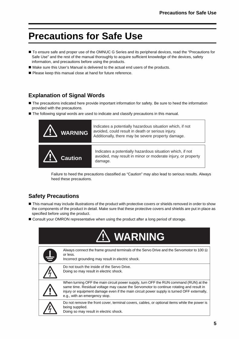
Explanation of Signal WordsThe precautions indicated here provide important information for safety. Be sure to heed the information provided with the precautions.
The following signal words are used to indicate and classify precautions in this manual.
Failure to heed the precautions classified as “Caution” may also lead to serious results. Always heed these precautions.
Safety PrecautionsThis manual may include illustrations of the product with protective covers or shields removed in order to show the components of the product in detail. Make sure that these protective covers and shields are put in place as specified before using the product.
Consult your OMRON representative when using the product after a long period of storage.
Always connect the frame ground terminals of the Servo Drive and the Servomotor to 100 Ω or less.Incorrect grounding may result in electric shock.
Do not touch the inside of the Servo Drive.Doing so may result in electric shock.
When turning OFF the main circuit power supply, turn OFF the RUN command (RUN) at the same time. Residual voltage may cause the Servomotor to continue rotating and result in injury or equipment damage even if the main circuit power supply is turned OFF externally, e.g., with an emergency stop.
Do not remove the front cover, terminal covers, cables, or optional items while the power is being supplied.Doing so may result in electric shock.
WARNING
Caution
Indicates a potentially hazardous situation which, if not avoided, could result in death or serious injury. Additionally, there may be severe property damage.
Indicates a potentially hazardous situation which, if not avoided, may result in minor or moderate injury, or property damage.
WARNING
5
Precautions for Safe Use
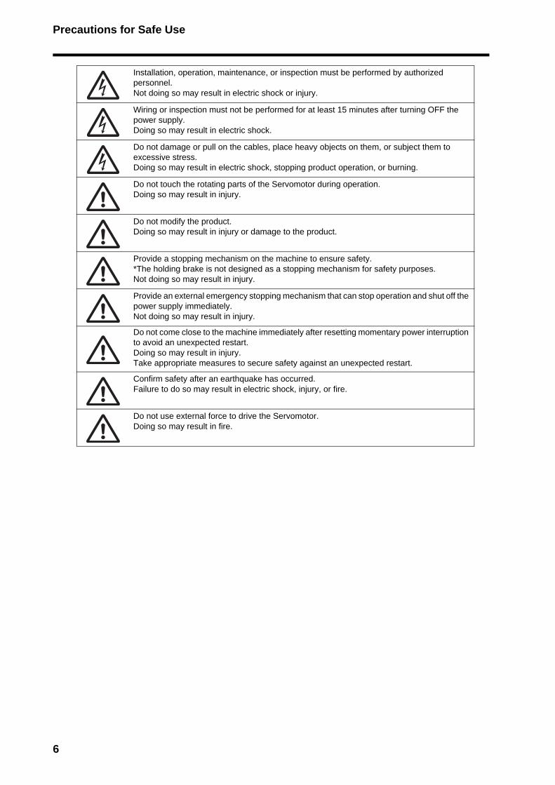
Installation, operation, maintenance, or inspection must be performed by authorized personnel.Not doing so may result in electric shock or injury.
Wiring or inspection must not be performed for at least 15 minutes after turning OFF the power supply.Doing so may result in electric shock.
Do not damage or pull on the cables, place heavy objects on them, or subject them to excessive stress.Doing so may result in electric shock, stopping product operation, or burning.
Do not touch the rotating parts of the Servomotor during operation.Doing so may result in injury.
Do not modify the product.Doing so may result in injury or damage to the product.
Provide a stopping mechanism on the machine to ensure safety.*The holding brake is not designed as a stopping mechanism for safety purposes.Not doing so may result in injury.
Provide an external emergency stopping mechanism that can stop operation and shut off the power supply immediately.Not doing so may result in injury.
Do not come close to the machine immediately after resetting momentary power interruption to avoid an unexpected restart.Doing so may result in injury.Take appropriate measures to secure safety against an unexpected restart.
Confirm safety after an earthquake has occurred.Failure to do so may result in electric shock, injury, or fire.
Do not use external force to drive the Servomotor. Doing so may result in fire.
6
Precautions for Safe Use
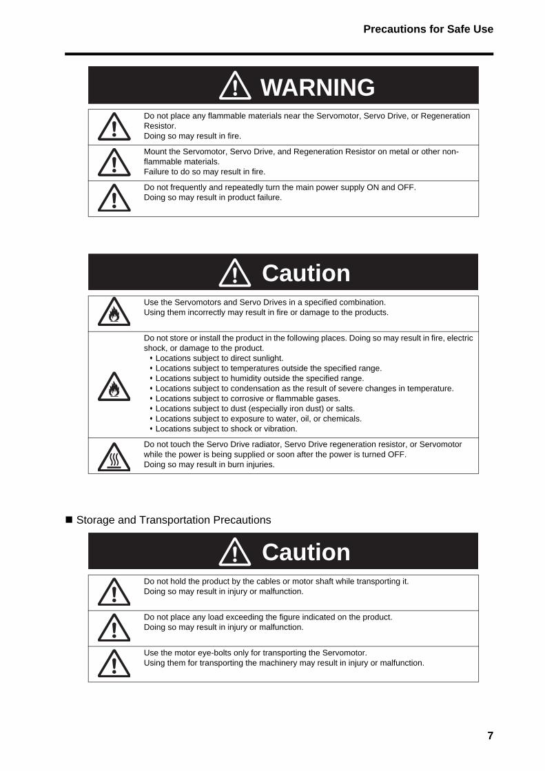
Storage and Transportation Precautions
Do not place any flammable materials near the Servomotor, Servo Drive, or Regeneration Resistor. Doing so may result in fire.
Mount the Servomotor, Servo Drive, and Regeneration Resistor on metal or other non-flammable materials. Failure to do so may result in fire.
Do not frequently and repeatedly turn the main power supply ON and OFF. Doing so may result in product failure.
Use the Servomotors and Servo Drives in a specified combination.Using them incorrectly may result in fire or damage to the products.
Do not store or install the product in the following places. Doing so may result in fire, electric shock, or damage to the product.
Locations subject to direct sunlight. Locations subject to temperatures outside the specified range. Locations subject to humidity outside the specified range. Locations subject to condensation as the result of severe changes in temperature. Locations subject to corrosive or flammable gases. Locations subject to dust (especially iron dust) or salts. Locations subject to exposure to water, oil, or chemicals. Locations subject to shock or vibration.
Do not touch the Servo Drive radiator, Servo Drive regeneration resistor, or Servomotor while the power is being supplied or soon after the power is turned OFF.Doing so may result in burn injuries.
Do not hold the product by the cables or motor shaft while transporting it. Doing so may result in injury or malfunction.
Do not place any load exceeding the figure indicated on the product.Doing so may result in injury or malfunction.
Use the motor eye-bolts only for transporting the Servomotor. Using them for transporting the machinery may result in injury or malfunction.
WARNING
Caution
Caution
7

Precautions for Safe Use
Installation and Wiring Precautions
Do not step on or place a heavy object on the product.Doing so may result in injury.
Do not cover the inlet or outlet ports and prevent any foreign objects from entering the product.Covering them or not preventing entry of foreign objects may result in fire.
Be sure to install the product in the correct direction.Not doing so may result in malfunction.
Provide the specified clearances between the Servo Drive and the control panel or with other devices.Not doing so may result in fire or malfunction.
Do not subject Servomotor shaft or Servo Drive to strong impacts.Doing so may result in malfunction.
Be sure to wire correctly and securely.Not doing so may result in motor runaway, injury, or malfunction.
Be sure that all the mounting screws, terminal screws, and cable connector screws are tightened properly.Incorrect tightening torque may result in malfunction.
Use crimp terminals for wiring.Do not connect bare stranded wires directly to the protective ground terminal.Doing so may result in burning.
Always use the power supply voltage specified in the User’s Manual.An incorrect voltage may result in malfunction or burning.
Take appropriate measures to ensure that the specified power with the rated voltage and frequency is supplied. Be particularly careful in places where the power supply is unstable.An incorrect power supply may result in equipment damage.
Install external breakers and take other safety measures against short-circuiting in external wiring.Insufficient safety measures against short-circuiting may result in burning.
Take appropriate and sufficient shielding measures when installing systems in the following locations. Failure to do so may result in damage to the product.
Locations subject to static electricity or other forms of noise. Locations subject to strong electromagnetic fields and magnetic fields. Locations subject to possible exposure to radioactivity. Locations close to power supplies.
Connect an emergency stop cutoff relay in series with the brake control relay. Failure to do so may result in injury or product failure.
Do not reverse the polarity of the battery when connecting it. Reversing the polarity may damage the battery or cause it to explode.
Caution
8

Precautions for Safe Use
Operation and Adjustment Precautions
Maintenance and Inspection Precautions
Confirm that no adverse effects will occur in the system before performing the test operation.Not doing so may result in equipment damage.
Check the newly set parameters for proper operation before actually running them.Not doing so may result in equipment damage.
Do not make any extreme adjustments or setting changes.Doing so may result in unstable operation and injury.
Separate the Servomotor from the machine, check for proper operation, and then connect to the machine.Not doing so may cause injury.
When an alarm occurs, remove the cause, reset the alarm after confirming safety, and then resume operation.Not doing so may result in injury.
Do not use the built-in brake of the Servomotor for ordinary braking.Doing so may result in malfunction.
Do not operate the Servomotor connected to a load that exceeds the applicable load moment of inertia.Doing so may result in malfunction.
Resume operation only after transferring to the new Unit the contents of the data required for operation.Not doing so may result in equipment damage.
Do not attempt to disassemble or repair any of the products.Any attempt to do so may result in electric shock or injury.
Caution
Caution
9

Precautions for Safe Use
Warning Label PositionWarning labels are located on the product as shown in the following illustration.Be sure to follow the instructions given there.
Warning Label Contents
Disposing of the Product• Dispose of the batteries according to local ordinances and regulations. Wrap the batteries in tape
or other insulative material before disposing of them. • Dispose of the product as industrial waste.
(R88D-GN01H-ML2)
Location of warning label
10
Items to Check When Unpacking
Items to Check When UnpackingCheck the following items after removing the product from the package.
• Has the correct product been delivered?• Has the product been damaged in shipping?
Accessories Provided with ProductSafety Precautions document × 1• No connectors or mounting screws are provided. They have to be prepared by the user.• Should you find any problems (missing parts, damage to the Servo Drive, etc.), please contact
your local sales representative or OMRON sales office.
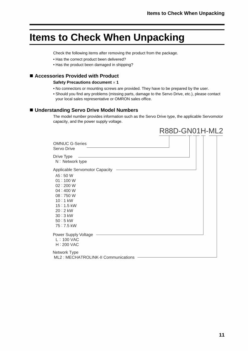
Understanding Servo Drive Model NumbersThe model number provides information such as the Servo Drive type, the applicable Servomotor capacity, and the power supply voltage.
R88D-GN01H-ML2
Power Supply Voltage L : 100 VAC H : 200 VAC
A5 : 50 W01 : 100 W02 : 200 W04 : 400 W08 : 750 W10 : 1 kW15 : 1.5 kW20 : 2 kW30 : 3 kW50 : 5 kW75 : 7.5 kW
Network Type ML2 : MECHATROLINK-II Communications
OMNUC G-SeriesServo Drive
Drive TypeN : Network type
Applicable Servomotor Capacity
11
Items to Check When Unpacking
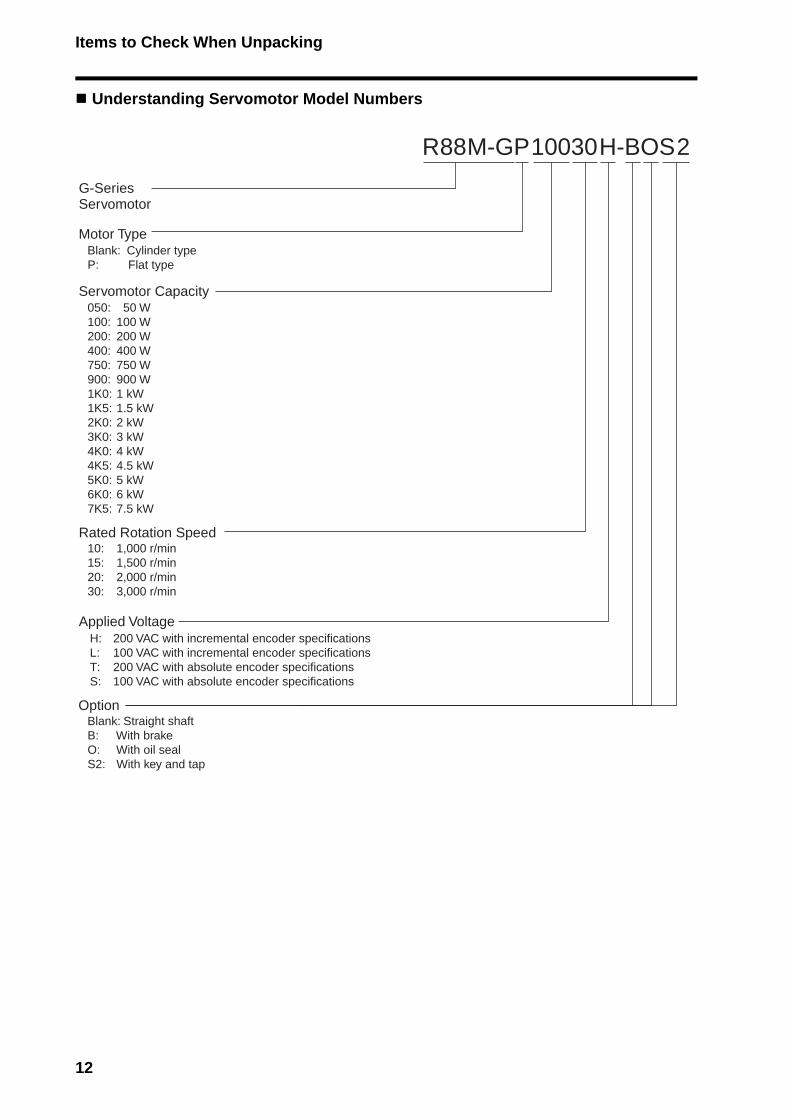
Understanding Servomotor Model Numbers
R88M-GP10030H-BOS2
G-SeriesServomotor
Servomotor Capacity
Rated Rotation Speed
Motor TypeBlank: Cylinder typeP: Flat type
050:100:200:400:750:900:1K0:1K5:2K0:3K0:4K0:4K5:5K0:6K0:7K5:
10:15:20:30:
50 W100 W200 W400 W750 W900 W1 kW1.5 kW2 kW3 kW4 kW4.5 kW5 kW6 kW7.5 kW
1,000 r/min1,500 r/min2,000 r/min3,000 r/min
Applied VoltageH:L:T:S:
200 VAC with incremental encoder specifications100 VAC with incremental encoder specifications200 VAC with absolute encoder specifications100 VAC with absolute encoder specifications
OptionBlank: Straight shaftB:O:S2:
With brakeWith oil sealWith key and tap
12
Items to Check When Unpacking
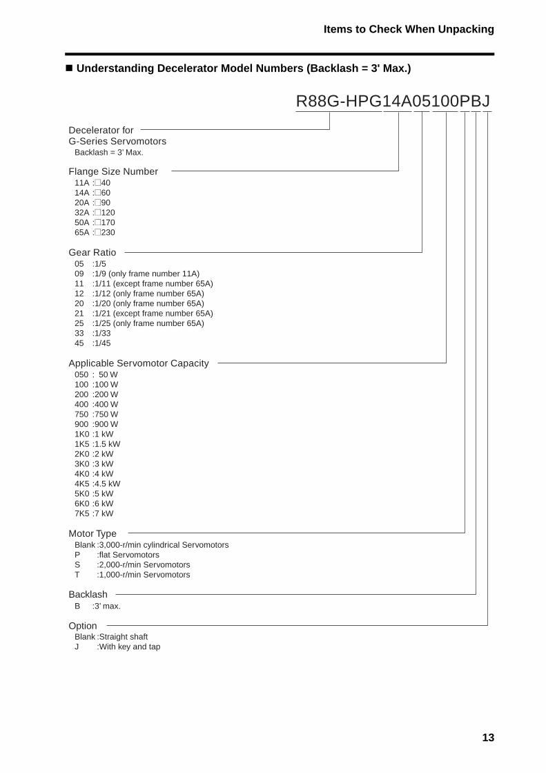
Understanding Decelerator Model Numbers (Backlash = 3' Max.)
R88G-HPG14A05100PBJ
Decelerator for G-Series Servomotors
Applicable Servomotor Capacity0501002004007509001K01K52K03K04K04K55K06K07K5
: 50 W:100 W:200 W:400 W:750 W:900 W:1 kW:1.5 kW:2 kW:3 kW:4 kW:4.5 kW:5 kW:6 kW:7 kW
Backlash = 3’ Max.
Gear Ratio050911122021253345
:1/5:1/9 (only frame number 11A):1/11 (except frame number 65A):1/12 (only frame number 65A):1/20 (only frame number 65A):1/21 (except frame number 65A):1/25 (only frame number 65A):1/33:1/45
Flange Size Number11A14A20A32A50A65A
:@40:@60:@90:@120:@170:@230
Motor TypeBlankPST
:3,000-r/min cylindrical Servomotors:flat Servomotors:2,000-r/min Servomotors:1,000-r/min Servomotors
BacklashB :3’ max.
OptionBlankJ
:Straight shaft:With key and tap
13
Items to Check When Unpacking
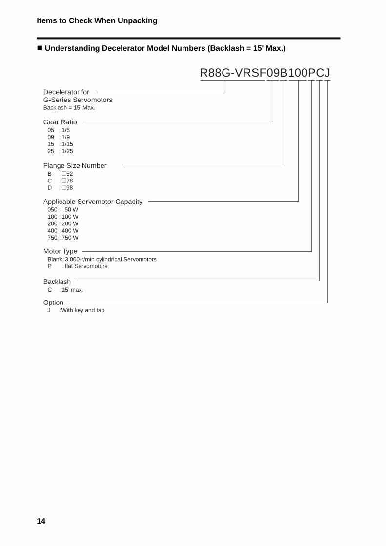
Understanding Decelerator Model Numbers (Backlash = 15' Max.)
R88G-VRSF09B100PCJ
Applicable Servomotor Capacity050100200400750
: 50 W:100 W:200 W:400 W:750 W
OptionJ :With key and tap
BacklashC :15’ max.
Motor TypeBlankP
:3,000-r/min cylindrical Servomotors:flat Servomotors
Decelerator for G-Series ServomotorsBacklash = 15’ Max.
Gear Ratio05091525
:1/5:1/9:1/15:1/25
Flange Size NumberBCD
:@52:@78:@98
14
About This Manual
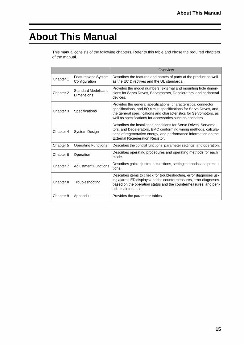
About This ManualThis manual consists of the following chapters. Refer to this table and chose the required chapters of the manual.
Overview
Chapter 1Features and System Configuration
Describes the features and names of parts of the product as well as the EC Directives and the UL standards.
Chapter 2Standard Models and Dimensions
Provides the model numbers, external and mounting hole dimen-sions for Servo Drives, Servomotors, Decelerators, and peripheral devices.
Chapter 3 Specifications
Provides the general specifications, characteristics, connector specifications, and I/O circuit specifications for Servo Drives, and the general specifications and characteristics for Servomotors, as well as specifications for accessories such as encoders.
Chapter 4 System Design
Describes the installation conditions for Servo Drives, Servomo-tors, and Decelerators, EMC conforming wiring methods, calcula-tions of regenerative energy, and performance information on the External Regeneration Resistor.
Chapter 5 Operating Functions Describes the control functions, parameter settings, and operation.
Chapter 6 OperationDescribes operating procedures and operating methods for each mode.
Chapter 7 Adjustment FunctionsDescribes gain adjustment functions, setting methods, and precau-tions.
Chapter 8 Troubleshooting
Describes items to check for troubleshooting, error diagnoses us-ing alarm LED displays and the countermeasures, error diagnoses based on the operation status and the countermeasures, and peri-odic maintenance.
Chapter 9 Appendix Provides the parameter tables.
15

Table of Contents
Introduction ...................................................................................... 1
Read and Understand This Manual ................................................. 2
Precautions for Safe Use................................................................. 5
Items to Check When Unpacking .................................................... 11
About This Manual........................................................................... 15
Chapter 1 Features and System Configuration1-1 Overview........................................................................................... 1-11-2 System Configuration ....................................................................... 1-21-3 Names of Parts and Functions ......................................................... 1-31-4 System Block Diagrams ................................................................... 1-51-5 Applicable Standards........................................................................ 1-10
Chapter 2 Standard Models and Dimensions2-1 Standard Models .............................................................................. 2-12-2 External and Mounting Hole Dimensions ......................................... 2-23
Chapter 3 Specifications3-1 Servo Drive Specifications................................................................ 3-13-2 Servomotor Specifications................................................................ 3-173-3 Decelerator Specifications................................................................ 3-323-4 Cable and Connector Specifications ................................................ 3-423-5 Parameter Unit Specifications .......................................................... 3-783-6 External Regeneration Resistor Specifications ................................ 3-793-7 Reactor Specifications...................................................................... 3-80
Chapter 4 System Design4-1 Installation Conditions ...................................................................... 4-14-2 Wiring ............................................................................................... 4-114-3 Wiring Conforming to EMC Directives .............................................. 4-264-4 Regenerative Energy Absorption...................................................... 4-44
16

Table of Contents
Chapter 5 Operating Functions5-1 Position Control ................................................................................ 5-15-2 Speed Control .................................................................................. 5-45-3 Torque Control ................................................................................. 5-75-4 Forward and Reverse Drive Prohibit ................................................ 5-105-5 Brake Interlock ................................................................................. 5-115-6 Torque Limit ..................................................................................... 5-165-7 Soft Start .......................................................................................... 5-185-8 Acceleration/Deceleration Time Settings ......................................... 5-195-9 Moving Average Time ...................................................................... 5-205-10 Electronic Gear ................................................................................ 5-215-11 Speed Limit ...................................................................................... 5-225-12 Sequence Input Signals ................................................................... 5-235-13 Sequence Output Signals ................................................................ 5-255-14 Backlash Compensation .................................................................. 5-275-15 Overrun Protection ........................................................................... 5-295-16 Gain Switching ................................................................................. 5-315-17 Speed Feed-forward ........................................................................ 5-385-18 Torque Feed-forward ....................................................................... 5-395-19 Speed Feedback Filter Selection ..................................................... 5-405-20 P Control Switching.......................................................................... 5-415-21 Torque Command Filter Time Constant ........................................... 5-425-22 Notch Filter ....................................................................................... 5-435-23 Adaptive Filter .................................................................................. 5-455-24 Instantaneous Speed Observer ....................................................... 5-485-25 Damping Control .............................................................................. 5-505-26 User Parameters .............................................................................. 5-555-27 Details on Important Parameters ..................................................... 5-86
Chapter 6 Operation6-1 Operational Procedure ..................................................................... 6-16-2 Preparing for Operation.................................................................... 6-26-3 Using the Parameter Unit ................................................................. 6-86-4 Setting the Mode .............................................................................. 6-96-5 Trial Operation ................................................................................. 6-31
Chapter 7 Adjustment Functions7-1 Gain Adjustment............................................................................... 7-17-2 Realtime Autotuning......................................................................... 7-37-3 Normal Mode Autotuning ................................................................. 7-97-4 Manual Tuning ................................................................................. 7-14
17

Table of Contents
Chapter 8 Troubleshooting8-1 Error Processing............................................................................... 8-18-2 Alarm Table ...................................................................................... 8-38-3 Troubleshooting................................................................................ 8-78-4 Overload Characteristics (Electronic Thermal Function) .................. 8-208-5 Periodic Maintenance....................................................................... 8-21
Chapter 9 Appendix9-1 Parameter Tables ............................................................................. 9-1
18

Chapter 1
Features and System Configuration1-1 Overview ............................................................ 1-1Overview ...............................................................................1-1
Features................................................................................1-1
1-2 System Configuration......................................... 1-2
1-3 Names of Parts and Functions........................... 1-3Servo Drive Part Names .......................................................1-3
Servo Drive Functions...........................................................1-4
1-4 System Block Diagrams ..................................... 1-5
1-5 Applicable Standards ......................................... 1-10EC Directives ........................................................................1-10
UL and CSA Standards.........................................................1-10
1-1 Overview
1
Fea
ture
s an
d S
yste
m C
on
fig
ura
tio
n
1-1 Overview
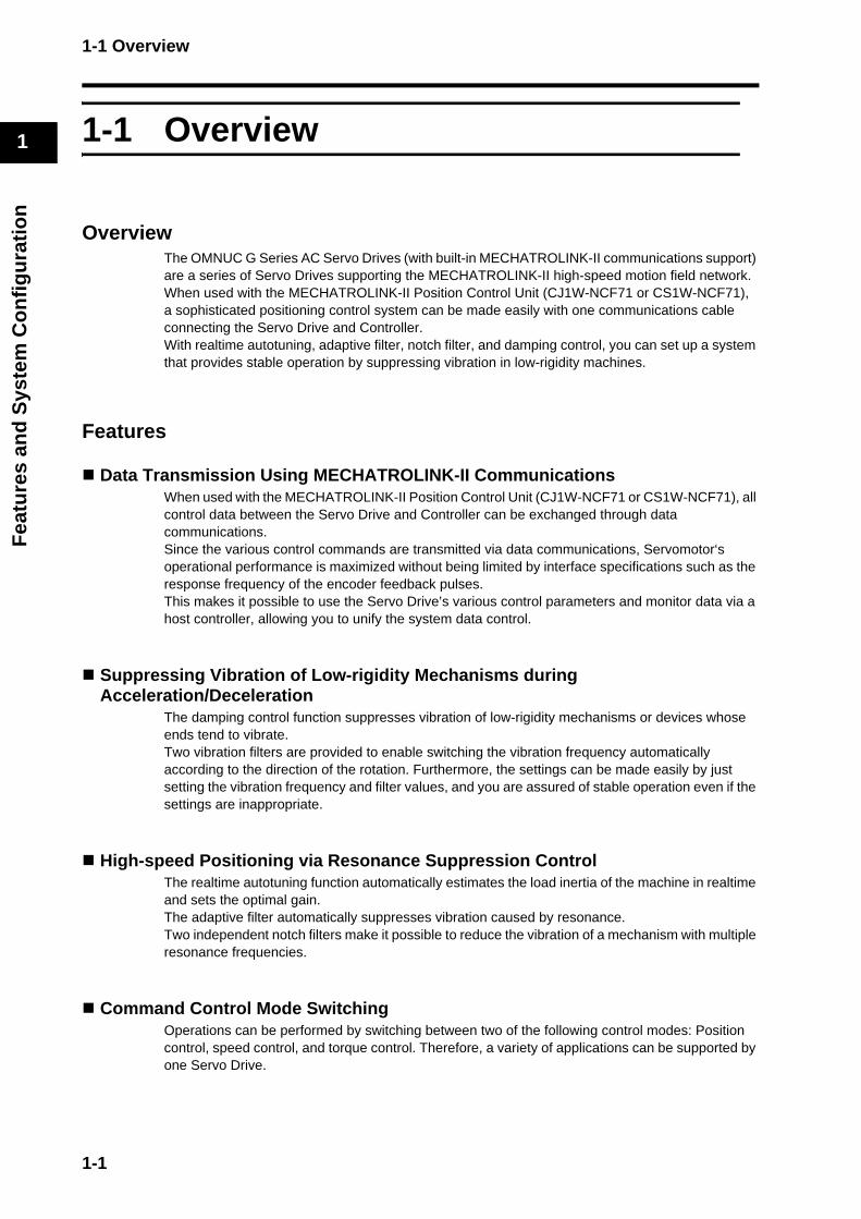
OverviewThe OMNUC G Series AC Servo Drives (with built-in MECHATROLINK-II communications support) are a series of Servo Drives supporting the MECHATROLINK-II high-speed motion field network.When used with the MECHATROLINK-II Position Control Unit (CJ1W-NCF71 or CS1W-NCF71), a sophisticated positioning control system can be made easily with one communications cable connecting the Servo Drive and Controller.With realtime autotuning, adaptive filter, notch filter, and damping control, you can set up a system that provides stable operation by suppressing vibration in low-rigidity machines.
Features
Data Transmission Using MECHATROLINK-II CommunicationsWhen used with the MECHATROLINK-II Position Control Unit (CJ1W-NCF71 or CS1W-NCF71), all control data between the Servo Drive and Controller can be exchanged through data communications. Since the various control commands are transmitted via data communications, Servomotor‘s operational performance is maximized without being limited by interface specifications such as the response frequency of the encoder feedback pulses. This makes it possible to use the Servo Drive’s various control parameters and monitor data via a host controller, allowing you to unify the system data control.
Suppressing Vibration of Low-rigidity Mechanisms during Acceleration/Deceleration
The damping control function suppresses vibration of low-rigidity mechanisms or devices whose ends tend to vibrate.Two vibration filters are provided to enable switching the vibration frequency automatically according to the direction of the rotation. Furthermore, the settings can be made easily by just setting the vibration frequency and filter values, and you are assured of stable operation even if the settings are inappropriate.
High-speed Positioning via Resonance Suppression ControlThe realtime autotuning function automatically estimates the load inertia of the machine in realtime and sets the optimal gain.The adaptive filter automatically suppresses vibration caused by resonance.Two independent notch filters make it possible to reduce the vibration of a mechanism with multiple resonance frequencies.
Command Control Mode SwitchingOperations can be performed by switching between two of the following control modes: Position control, speed control, and torque control. Therefore, a variety of applications can be supported by one Servo Drive.
1-1
1-2 System Configuration
1
Fea
ture
s an
d S
yste
m C
on
fig
ura
tio
n
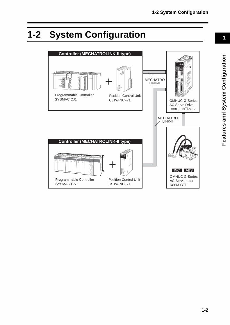
1-2 System Configuration
INCINC ABSABS
MECHATROLINK-II
Programmable ControllerSYSMAC CS1
Controller (MECHATROLINK-ll type)
Programmable ControllerSYSMAC CJ1
Position Control Unit
MECHATROLINK-II
Controller (MECHATROLINK-ll type)
OMNUC G-SeriesAC Servo DriveR88D-GN@-ML2
OMNUC G-Series AC ServomotorR88M-G@
CJ1W-NCF71
Position Control UnitCS1W-NCF71
1-2

1-3 Names of Parts and Functions
1
Fea
ture
s an
d S
yste
m C
on
fig
ura
tio
n
1-3 Names of Parts and Functions
Servo Drive Part Names
Display area
MECHATROLINK-IIcommunications connector (CN6A, CN6B)
Analog monitor check pins (SP, IM, G)
Servomotor connection terminals(U, V, W)
Control-circuit power terminals(L1C, L2C)
Main-circuit power terminals(L1, L2, L3)
External Regeneration Resistorconnection terminals
(B1, B2, B3)
Protective ground terminals
Control I/O connector (CN1)
RS-232communications connector (CN3)
Encoder connector (CN2)
MECHATROLINK-II communications status LED indicator
Rotary switches
G
IM
SP
COM
X10
32
10ADR
AC SERVO DRIVE
X1
6
78
9 0 1
23
45
1-3

1-3 Names of Parts and Functions
1
Fea
ture
s an
d S
yste
m C
on
fig
ura
tio
n
Servo Drive Functions
Display AreaA 2-digit 7-segment LED display shows the Servo Drive status, alarm codes, parameters, and other information.
Analog Monitor Check Pins (SP, IM, and G)The actual motor speed, command speed, torque, and number of accumulated pulses can be measured based on the analog voltage level by using an oscilloscope.Set the type of signal to be output and the output voltage level by setting the Speed Monitor (SP) Selection (Pn007) and Torque Monitor (IM) Selection (Pn008).For details, refer to User Parameters on page 5-55.
MECHATROLINK-II Status LED IndicatorIndicates the communications status of the MECHATROLINK-II. For details, refer to MECHATROLINK-II Status LED Indicator on page 6-4.
Rotary SwitchesSets the node address.For details, refer to Servo Drive Display and Settings on page 6-3.
1-4
1-4 System Block Diagrams
1
Fea
ture
s an
d S
yste
m C
on
fig
ura
tio
n
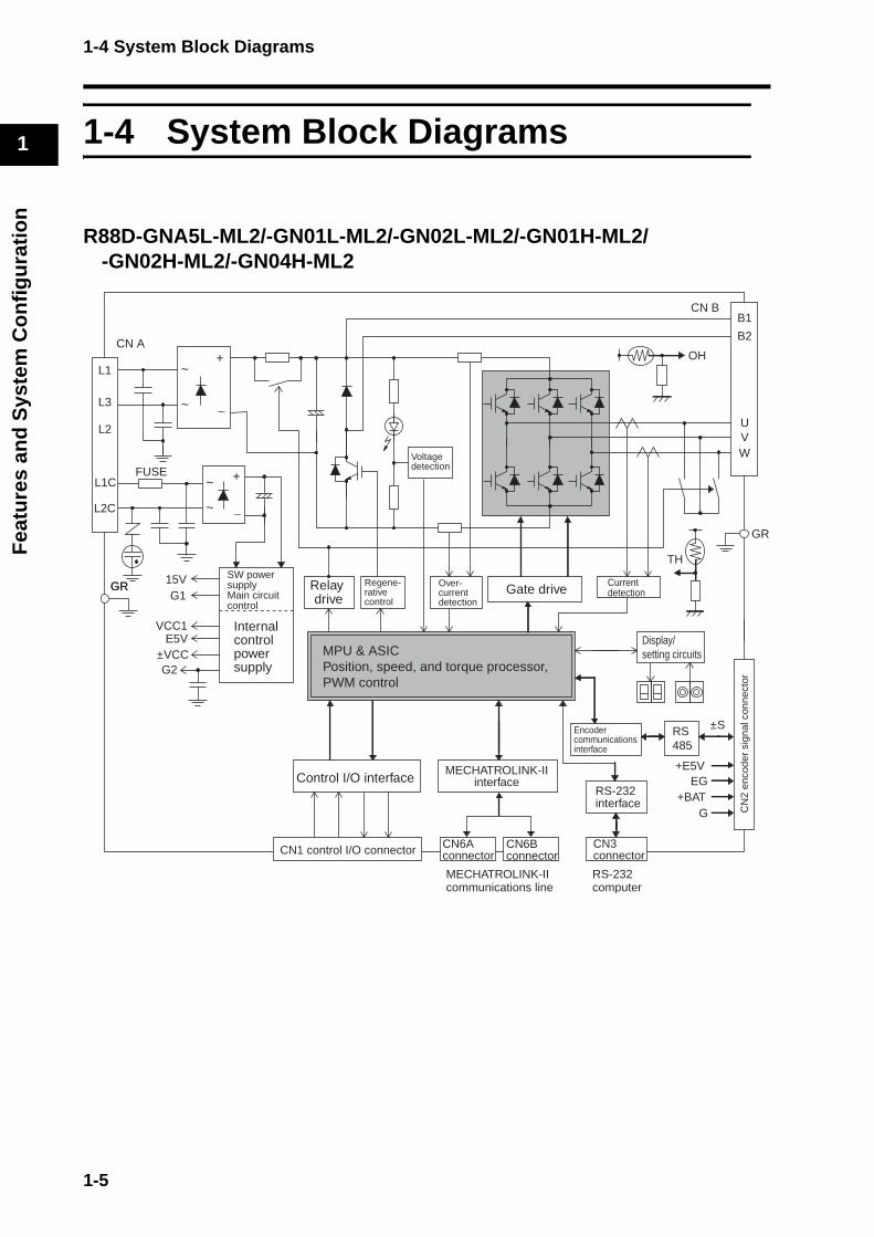
1-4 System Block Diagrams
R88D-GNA5L-ML2/-GN01L-ML2/-GN02L-ML2/-GN01H-ML2/-GN02H-ML2/-GN04H-ML2
GR
Control I/O interfaceMECHATROLINK-II
interface
MECHATROLINK-IIcommunications line
RS-232computer
Display/setting circuits
Gate driveSW power supply Main circuit control
Internal control power supply
RS-232interface
CN6Bconnector
CN6Aconnector
CN3connector
CN
2 en
code
r si
gnal
con
nect
or
GR
L2C
L1C
L2
L3
L1
FUSE
CN A+
−
~
+
−
~
~
~
15VG1
VCC1
±VCCG2
E5V
Over-current detection
Currentdetection
Voltagedetection
Regene-rative control
Relay drive
TH
GR
CN1 control I/O connector
RS485
±S
+E5V
+BATEG
G
B1
B2
CN B
OH
UVW
MPU & ASICPosition, speed, and torque processor,PWM control
Encoder communications interface
1-5

1-4 System Block Diagrams
1
Fea
ture
s an
d S
yste
m C
on
fig
ura
tio
n
R88D-GN04L-ML2/-GN08H-ML2/-GN10H-ML2/-GN15H-ML2
Gate driveSW power supply Main circuitcontrol
Internal control power supply
GR
L2C
L1C
L2
L3
L1
FUSE
CN A
+
−
~
~
+
−
~
~
~
15VG1
VCC1
±VCCG2
E5V
Over-current detection
Currentdetection
Voltagedetection
Regene-rative control
Relay drive
TH
GR
CN B
UVW
B1
B3
B2Internal regeneration resistor
Cooling fan Control I/O interface MECHATROLINK-IIinterface
Display/setting circuits
RS-232interface
CN6Bconnector
CN6Aconnector
CN3connector
CN
2 en
code
r si
gnal
con
nect
orCN1 control I/O connector
RS485
±S
+E5V
+BATEG
G
MPU & ASICPosition, speed, and torque processor,PWM control
Encoder communications interface
MECHATROLINK-IIcommunications line
RS-232computer
1-6
1-4 System Block Diagrams
1
Fea
ture
s an
d S
yste
m C
on
fig
ura
tio
n
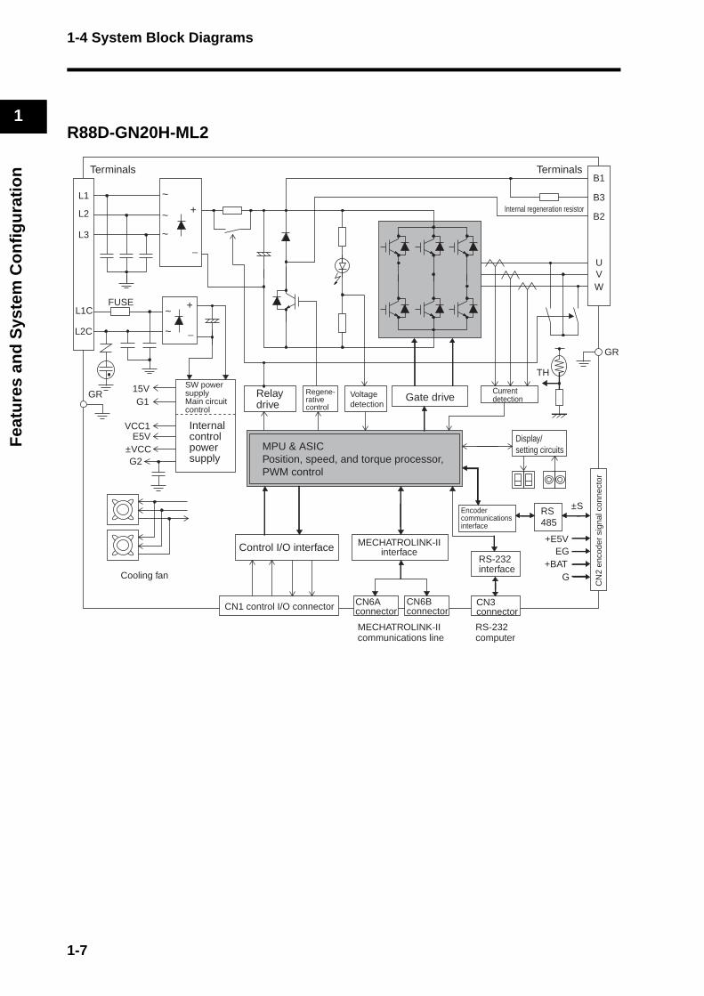
R88D-GN20H-ML2
GR Gate driveSW power supply Main circuit control
Internal control power supply
L2C
L1C
L2
L3
L1
FUSE
+
−
~
+
−
~
~
~
15VG1
VCC1
±VCCG2
E5V
Voltagedetection
Currentdetection
Regene-rative control
Relay drive
TH
GR
TerminalsTerminals
UVW
Cooling fan
B1
B3
B2Internal regeneration resistor
Control I/O interface MECHATROLINK-IIinterface
RS-232interface
CN6Bconnector
CN6Aconnector
CN3connector
CN
2 en
code
r si
gnal
con
nect
orCN1 control I/O connector
RS485
±S
+E5V
+BATEG
G
MPU & ASICPosition, speed, and torque processor,PWM control
Encoder communications interface
Display/setting circuits
~
MECHATROLINK-IIcommunications line
RS-232computer
1-7
1-4 System Block Diagrams
1
Fea
ture
s an
d S
yste
m C
on
fig
ura
tio
n
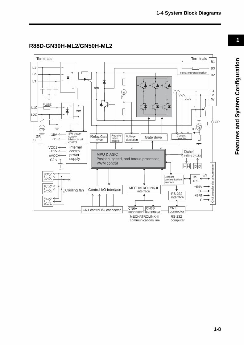
R88D-GN30H-ML2/GN50H-ML2
GR Gate driveSW powersupply Main circuitcontrol
Internal control power supply
L2C
L1C
L2
L3
L1
FUSE
+
−
~
~
+
−
~
~
~
15VG1
VCC1
±VCCG2
E5V
Voltagedetection
Currentdetection
Regene-rative control
Relay,Gate drive
TH
GR
TerminalsTerminals
UVW
Cooling fan
B1
B3
B2Internal regeneration resistor
Control I/O interface MECHATROLINK-IIinterface
Display/setting circuits
RS-232interface
CN6Bconnector
CN6Aconnector
CN3connector
CN
2 en
code
r si
gnal
con
nect
orCN1 control I/O connector
RS485
±S
+E5V
+BATEG
G
MPU & ASICPosition, speed, and torque processor,PWM control
Encoder communications interface
MECHATROLINK-IIcommunications line
RS-232computer
1-8
1-4 System Block Diagrams
1
Fea
ture
s an
d S
yste
m C
on
fig
ura
tio
n
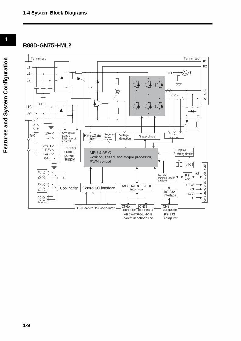
R88D-GN75H-ML2
GR
TH
Gate driveSW powersupply Main circuit control
Internal control power supply
L2C
L1C
L2
L3
L1
FUSE
+
−
~
~
+
+− −
~
~
~
15VG1
VCC1
±VCCG2
E5V
Voltagedetection
Currentdetection
Regene-rative control
Relay,Gate drive
B1
B2
TerminalsTerminals
UVW
Cooling fan
~~ ~
Control I/O interface MECHATROLINK-IIinterface
Display/setting circuits
RS-232interface
CN6Bconnector
CN6Aconnector
CN3connector
CN
2 en
code
r si
gnal
con
nect
orCN1 control I/O connector
RS485
±S
+E5V
+BATEG
G
MPU & ASICPosition, speed, and torque processor,PWM control
Encoder communications interface
MECHATROLINK-IIcommunications line
RS-232computer
1-9
1-5 Applicable Standards
1
Fea
ture
s an
d S
yste
m C
on
fig
ura
tio
n
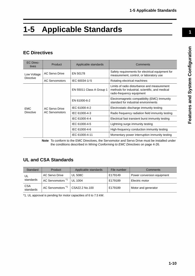
1-5 Applicable Standards
EC Directives
Note To conform to the EMC Directives, the Servomotor and Servo Drive must be installed under the conditions described in Wiring Conforming to EMC Directives on page 4-26.
UL and CSA Standards
*1. UL approval is pending for motor capacities of 6 to 7.5 kW.
EC Direc-tives
Product Applicable standards Comments
Low Voltage Directive
AC Servo Drive EN 50178Safety requirements for electrical equipment for measurement, control, or laboratory use
AC Servomotors IEC 60034-1/-5 Rotating electrical machines
EMC Directive
AC Servo DriveAC Servomotors
EN 55011 Class A Group 1Limits of radio disturbance and measurement methods for industrial, scientific, and medical radio-frequency equipment
EN 61000-6-2Electromagnetic compatibility (EMC) Immunity standard for industrial environments
IEC 61000-4-2 Electrostatic discharge immunity testing
IEC 61000-4-3 Radio frequency radiation field immunity testing
IEC 61000-4-4 Electrical fast transient burst immunity testing
IEC 61000-4-5 Lightning surge immunity testing
IEC 61000-4-6 High-frequency conduction immunity testing
IEC 61000-4-11 Momentary power interruption immunity testing
Standard Product Applicable standards File number Comments
UL standards
AC Servo Drive UL 508C E179149 Power conversion equipment
AC Servomotors *1 UL 1004 E179189 Electric motor
CSA standards
AC Servomotors *1 CSA22.2 No.100 E179189 Motor and generator
1-10

Chapter 2
Standard Models and Dimensions2-1 Standard Models ................................................ 2-1Servo Drives .........................................................................2-1
Servomotors..........................................................................2-2
Servo Drive-Servomotor Combinations ................................2-5
Decelerators..........................................................................2-7
Accessories and Cables .......................................................2-14
2-2 External and Mounting Hole Dimensions ........... 2-23Servo Drives .........................................................................2-23
Servomotors..........................................................................2-33
Parameter Unit Dimensions ..................................................2-43
Servomotor and Decelerator Combinations..........................2-44
Decelerator Dimensions........................................................2-47
External Regeneration Resistor Dimensions ........................2-61
Reactor Dimensions..............................................................2-62

2-1 Standard Models
2
Sta
nd
ard
Mo
del
s an
d D
imen
sio
ns
2-1 Standard Models
Servo Drives
Specifications Model
Single-phase 100 VAC
50 W R88D-GNA5L-ML2
100 W R88D-GN01L-ML2
200 W R88D-GN02L-ML2
400 W R88D-GN04L-ML2
Single-phase 200 VAC
50 WR88D-GN01H-ML2
100 W
200 W R88D-GN02H-ML2
400 W R88D-GN04H-ML2
Single-phase/three-phase 200 VAC
750 W R88D-GN08H-ML2
1 kW R88D-GN10H-ML2
900 W
R88D-GN15H-ML21 kW
1.5 kW
Three-phase 200 VAC
2 kW R88D-GN20H-ML2
2 kWR88D-GN30H-ML2
3 kW
3 kW
R88D-GN50H-ML24 kW
4.5 kW
5 kW
6 kWR88D-GN75H-ML2
7.5 kW
2-1
2-1 Standard Models
2
Sta
nd
ard
Mo
del
s an
d D
imen
sio
ns
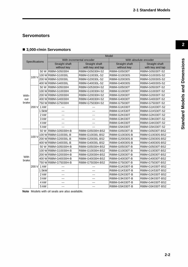
Servomotors
3,000-r/min Servomotors
Note Models with oil seals are also available.
Specifications
ModelWith incremental encoder With absolute encoder
Straight shaftwithout key
Straight shaftwith key and tap
Straight shaftwithout key
Straight shaftwith key and tap
With-out
brake
100 V
50 W R88M-G05030H R88M-G05030H-S2 R88M-G05030T R88M-G05030T-S2100 W R88M-G10030L R88M-G10030L-S2 R88M-G10030S R88M-G10030S-S2200 W R88M-G20030L R88M-G20030L-S2 R88M-G20030S R88M-G20030S-S2400 W R88M-G40030L R88M-G40030L-S2 R88M-G40030S R88M-G40030S-S2
200 V
50 W R88M-G05030H R88M-G05300H-S2 R88M-G05030T R88M-G05030T-S2100 W R88M-G10030H R88M-G10030H-S2 R88M-G10030T R88M-G10030T-S2200 W R88M-G20030H R88M-G20030H-S2 R88M-G20030T R88M-G20030T-S2400 W R88M-G40030H R88M-G40030H-S2 R88M-G40030T R88M-G40030T-S2750 W R88M-G75030H R88M-G75030H-S2 R88M-G75030T R88M-G75030T-S21 kW --- --- R88M-G1K030T R88M-G1K030T-S2
1.5kW --- --- R88M-G1K530T R88M-G1K530T-S22 kW --- --- R88M-G2K030T R88M-G2K030T-S23 kW --- --- R88M-G3K030T R88M-G3K030T-S24 kW --- --- R88M-G4K030T R88M-G4K030T-S25 kW --- --- R88M-G5K030T R88M-G5K030T-S2
With brake
100 V
50 W R88M-G05030H-B R88M-G05030H-BS2 R88M-G05030T-B R88M-G05030T-BS2100 W R88M-G10030L-B R88M-G10030L-BS2 R88M-G10030S-B R88M-G10030S-BS2200 W R88M-G20030L-B R88M-G20030L-BS2 R88M-G20030S-B R88M-G20030S-BS2400 W R88M-G40030L-B R88M-G40030L-BS2 R88M-G40030S-B R88M-G40030S-BS2
200 V
50 W R88M-G05030H-B R88M-G05030H-BS2 R88M-G05030T-B R88M-G05030T-BS2100 W R88M-G10030H-B R88M-G10030H-BS2 R88M-G10030T-B R88M-G10030T-BS2200 W R88M-G20030H-B R88M-G20030H-BS2 R88M-G20030T-B R88M-G20030T-BS2400 W R88M-G40030H-B R88M-G40030H-BS2 R88M-G40030T-B R88M-G40030T-BS2750 W R88M-G75030H-B R88M-G75030H-BS2 R88M-G75030T-B R88M-G75030T-BS21 kW --- --- R88M-G1K030T-B R88M-G1K030T-BS2
1.5kW --- --- R88M-G1K530T-B R88M-G1K530T-BS22 kW --- --- R88M-G2K030T-B R88M-G2K030T-BS23 kW --- --- R88M-G3K030T-B R88M-G3K030T-BS24 kW --- --- R88M-G4K030T-B R88M-G4K030T-BS25 kW --- --- R88M-G5K030T-B R88M-G5K030T-BS2
2-2
2-1 Standard Models
2
Sta
nd
ard
Mo
del
s an
d D
imen
sio
ns
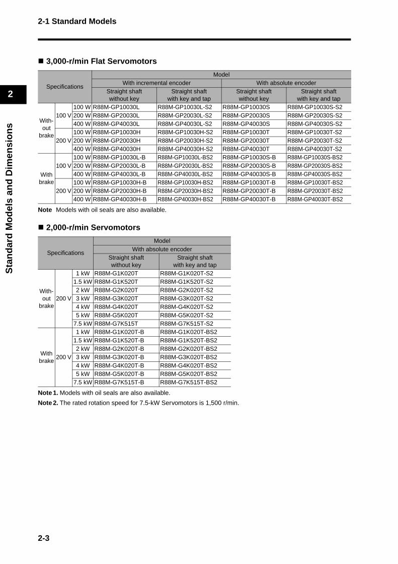
3,000-r/min Flat Servomotors
Note Models with oil seals are also available.
2,000-r/min Servomotors
Note 1. Models with oil seals are also available.
Note 2. The rated rotation speed for 7.5-kW Servomotors is 1,500 r/min.
Specifications
ModelWith incremental encoder With absolute encoder
Straight shaftwithout key
Straight shaftwith key and tap
Straight shaftwithout key
Straight shaftwith key and tap
With-out
brake
100 V100 W R88M-GP10030L R88M-GP10030L-S2 R88M-GP10030S R88M-GP10030S-S2200 W R88M-GP20030L R88M-GP20030L-S2 R88M-GP20030S R88M-GP20030S-S2400 W R88M-GP40030L R88M-GP40030L-S2 R88M-GP40030S R88M-GP40030S-S2
200 V100 W R88M-GP10030H R88M-GP10030H-S2 R88M-GP10030T R88M-GP10030T-S2200 W R88M-GP20030H R88M-GP20030H-S2 R88M-GP20030T R88M-GP20030T-S2400 W R88M-GP40030H R88M-GP40030H-S2 R88M-GP40030T R88M-GP40030T-S2
With brake
100 V100 W R88M-GP10030L-B R88M-GP10030L-BS2 R88M-GP10030S-B R88M-GP10030S-BS2200 W R88M-GP20030L-B R88M-GP20030L-BS2 R88M-GP20030S-B R88M-GP20030S-BS2400 W R88M-GP40030L-B R88M-GP40030L-BS2 R88M-GP40030S-B R88M-GP40030S-BS2
200 V100 W R88M-GP10030H-B R88M-GP10030H-BS2 R88M-GP10030T-B R88M-GP10030T-BS2200 W R88M-GP20030H-B R88M-GP20030H-BS2 R88M-GP20030T-B R88M-GP20030T-BS2400 W R88M-GP40030H-B R88M-GP40030H-BS2 R88M-GP40030T-B R88M-GP40030T-BS2
Specifications
ModelWith absolute encoder
Straight shaftwithout key
Straight shaftwith key and tap
With-out
brake200 V
1 kW R88M-G1K020T R88M-G1K020T-S21.5 kW R88M-G1K520T R88M-G1K520T-S22 kW R88M-G2K020T R88M-G2K020T-S23 kW R88M-G3K020T R88M-G3K020T-S24 kW R88M-G4K020T R88M-G4K020T-S25 kW R88M-G5K020T R88M-G5K020T-S2
7.5 kW R88M-G7K515T R88M-G7K515T-S2
With brake
200 V
1 kW R88M-G1K020T-B R88M-G1K020T-BS21.5 kW R88M-G1K520T-B R88M-G1K520T-BS22 kW R88M-G2K020T-B R88M-G2K020T-BS23 kW R88M-G3K020T-B R88M-G3K020T-BS24 kW R88M-G4K020T-B R88M-G4K020T-BS25 kW R88M-G5K020T-B R88M-G5K020T-BS2
7.5 kW R88M-G7K515T-B R88M-G7K515T-BS2
2-3
2-1 Standard Models
2
Sta
nd
ard
Mo
del
s an
d D
imen
sio
ns
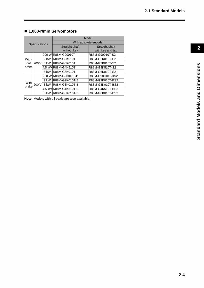
1,000-r/min Servomotors
Note Models with oil seals are also available.
Specifications
ModelWith absolute encoder
Straight shaftwithout key
Straight shaftwith key and tap
With-out
brake200 V
900 W R88M-G90010T R88M-G90010T-S22 kW R88M-G2K010T R88M-G2K010T-S23 kW R88M-G3K010T R88M-G3K010T-S2
4.5 kW R88M-G4K510T R88M-G4K510T-S26 kW R88M-G6K010T R88M-G6K010T-S2
With brake
200 V
900 W R88M-G90010T-B R88M-G90010T-BS22 kW R88M-G2K010T-B R88M-G2K010T-BS23 kW R88M-G3K010T-B R88M-G3K010T-BS2
4.5 kW R88M-G4K510T-B R88M-G4K510T-BS26 kW R88M-G6K010T-B R88M-G6K010T-BS2
2-4
2-1 Standard Models
2
Sta
nd
ard
Mo
del
s an
d D
imen
sio
ns
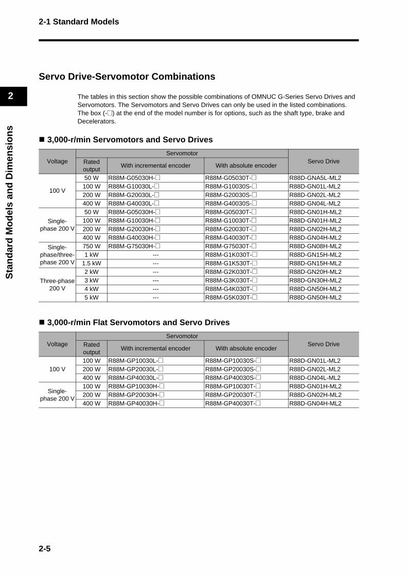
Servo Drive-Servomotor Combinations
The tables in this section show the possible combinations of OMNUC G-Series Servo Drives and Servomotors. The Servomotors and Servo Drives can only be used in the listed combinations.The box (-@) at the end of the model number is for options, such as the shaft type, brake and Decelerators.
3,000-r/min Servomotors and Servo Drives
3,000-r/min Flat Servomotors and Servo Drives
VoltageServomotor
Servo DriveRated output
With incremental encoder With absolute encoder
100 V
50 W R88M-G05030H-@ R88M-G05030T-@ R88D-GNA5L-ML2100 W R88M-G10030L-@ R88M-G10030S-@ R88D-GN01L-ML2200 W R88M-G20030L-@ R88M-G20030S-@ R88D-GN02L-ML2400 W R88M-G40030L-@ R88M-G40030S-@ R88D-GN04L-ML2
Single-phase 200 V
50 W R88M-G05030H-@ R88M-G05030T-@ R88D-GN01H-ML2100 W R88M-G10030H-@ R88M-G10030T-@ R88D-GN01H-ML2200 W R88M-G20030H-@ R88M-G20030T-@ R88D-GN02H-ML2400 W R88M-G40030H-@ R88M-G40030T-@ R88D-GN04H-ML2
Single-phase/three-phase 200 V
750 W R88M-G75030H-@ R88M-G75030T-@ R88D-GN08H-ML21 kW --- R88M-G1K030T-@ R88D-GN15H-ML2
1.5 kW --- R88M-G1K530T-@ R88D-GN15H-ML2
Three-phase 200 V
2 kW --- R88M-G2K030T-@ R88D-GN20H-ML23 kW --- R88M-G3K030T-@ R88D-GN30H-ML24 kW --- R88M-G4K030T-@ R88D-GN50H-ML25 kW --- R88M-G5K030T-@ R88D-GN50H-ML2
VoltageServomotor
Servo DriveRated output
With incremental encoder With absolute encoder
100 V100 W R88M-GP10030L-@ R88M-GP10030S-@ R88D-GN01L-ML2200 W R88M-GP20030L-@ R88M-GP20030S-@ R88D-GN02L-ML2400 W R88M-GP40030L-@ R88M-GP40030S-@ R88D-GN04L-ML2
Single-phase 200 V
100 W R88M-GP10030H-@ R88M-GP10030T-@ R88D-GN01H-ML2200 W R88M-GP20030H-@ R88M-GP20030T-@ R88D-GN02H-ML2400 W R88M-GP40030H-@ R88M-GP40030T-@ R88D-GN04H-ML2
2-5
2-1 Standard Models
2
Sta
nd
ard
Mo
del
s an
d D
imen
sio
ns
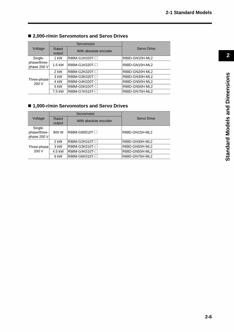
2,000-r/min Servomotors and Servo Drives
1,000-r/min Servomotors and Servo Drives
VoltageServomotor
Servo DriveRated output
With absolute encoder
Single-phase/three-phase 200 V
1 kW R88M-G1K020T-@ R88D-GN10H-ML2
1.5 kW R88M-G1K520T-@ R88D-GN15H-ML2
Three-phase 200 V
2 kW R88M-G2K020T-@ R88D-GN20H-ML23 kW R88M-G3K020T-@ R88D-GN30H-ML24 kW R88M-G4K020T-@ R88D-GN50H-ML25 kW R88M-G5K020T-@ R88D-GN50H-ML2
7.5 kW R88M-G7K515T-@ R88D-GN75H-ML2
VoltageServomotor
Servo DriveRated output
With absolute encoder
Single-phase/three-phase 200 V
900 W R88M-G90010T-@ R88D-GN15H-ML2
Three-phase 200 V
2 kW R88M-G2K010T-@ R88D-GN30H-ML23 kW R88M-G3K010T-@ R88D-GN50H-ML2
4.5 kW R88M-G4K510T-@ R88D-GN50H-ML26 kW R88M-G6K010T-@ R88D-GN75H-ML2
2-6
2-1 Standard Models
2
Sta
nd
ard
Mo
del
s an
d D
imen
sio
ns
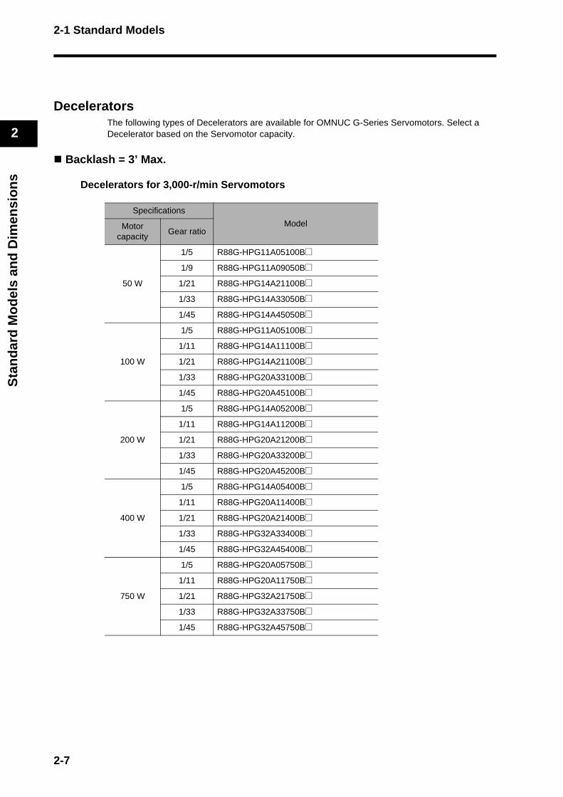
DeceleratorsThe following types of Decelerators are available for OMNUC G-Series Servomotors. Select a Decelerator based on the Servomotor capacity.
Backlash = 3’ Max.
Decelerators for 3,000-r/min Servomotors
Specifications
ModelMotor capacity
Gear ratio
50 W
1/5 R88G-HPG11A05100B@
1/9 R88G-HPG11A09050B@
1/21 R88G-HPG14A21100B@
1/33 R88G-HPG14A33050B@
1/45 R88G-HPG14A45050B@
100 W
1/5 R88G-HPG11A05100B@
1/11 R88G-HPG14A11100B@
1/21 R88G-HPG14A21100B@
1/33 R88G-HPG20A33100B@
1/45 R88G-HPG20A45100B@
200 W
1/5 R88G-HPG14A05200B@
1/11 R88G-HPG14A11200B@
1/21 R88G-HPG20A21200B@
1/33 R88G-HPG20A33200B@
1/45 R88G-HPG20A45200B@
400 W
1/5 R88G-HPG14A05400B@
1/11 R88G-HPG20A11400B@
1/21 R88G-HPG20A21400B@
1/33 R88G-HPG32A33400B@
1/45 R88G-HPG32A45400B@
750 W
1/5 R88G-HPG20A05750B@
1/11 R88G-HPG20A11750B@
1/21 R88G-HPG32A21750B@
1/33 R88G-HPG32A33750B@
1/45 R88G-HPG32A45750B@
2-7
2-1 Standard Models
2
Sta
nd
ard
Mo
del
s an
d D
imen
sio
ns
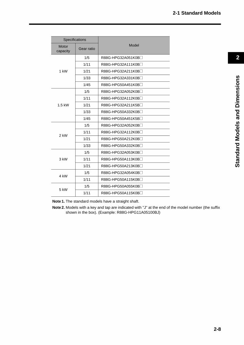
Note 1. The standard models have a straight shaft.
Note 2. Models with a key and tap are indicated with "J" at the end of the model number (the suffix shown in the box). (Example: R88G-HPG11A05100BJ)
Specifications
ModelMotor capacity
Gear ratio
1 kW
1/5 R88G-HPG32A051K0B@
1/11 R88G-HPG32A111K0B@
1/21 R88G-HPG32A211K0B@
1/33 R88G-HPG32A331K0B@
1/45 R88G-HPG50A451K0B@
1.5 kW
1/5 R88G-HPG32A052K0B@
1/11 R88G-HPG32A112K0B@
1/21 R88G-HPG32A211K5B@
1/33 R88G-HPG50A332K0B@
1/45 R88G-HPG50A451K5B@
2 kW
1/5 R88G-HPG32A052K0B@
1/11 R88G-HPG32A112K0B@
1/21 R88G-HPG50A212K0B@
1/33 R88G-HPG50A332K0B@
3 kW
1/5 R88G-HPG32A053K0B@
1/11 R88G-HPG50A113K0B@
1/21 R88G-HPG50A213K0B@
4 kW1/5 R88G-HPG32A054K0B@
1/11 R88G-HPG50A115K0B@
5 kW1/5 R88G-HPG50A055K0B@
1/11 R88G-HPG50A115K0B@
2-8
2-1 Standard Models
2
Sta
nd
ard
Mo
del
s an
d D
imen
sio
ns
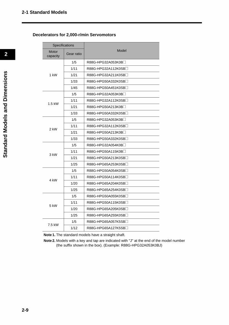
Decelerators for 2,000-r/min Servomotors
Note 1. The standard models have a straight shaft.
Note 2. Models with a key and tap are indicated with "J" at the end of the model number (the suffix shown in the box). (Example: R88G-HPG32A053K0BJ)
Specifications
ModelMotor capacity
Gear ratio
1 kW
1/5 R88G-HPG32A053K0B@
1/11 R88G-HPG32A112K0SB@
1/21 R88G-HPG32A211K0SB@
1/33 R88G-HPG50A332K0SB@
1/45 R88G-HPG50A451K0SB@
1.5 kW
1/5 R88G-HPG32A053K0B@
1/11 R88G-HPG32A112K0SB@
1/21 R88G-HPG50A213K0B@
1/33 R88G-HPG50A332K0SB@
2 kW
1/5 R88G-HPG32A053K0B@
1/11 R88G-HPG32A112K0SB@
1/21 R88G-HPG50A213K0B@
1/33 R88G-HPG50A332K0SB@
3 kW
1/5 R88G-HPG32A054K0B@
1/11 R88G-HPG50A115K0B@
1/21 R88G-HPG50A213K0SB@
1/25 R88G-HPG65A253K0SB@
4 kW
1/5 R88G-HPG50A054K0SB@
1/11 R88G-HPG50A114K0SB@
1/20 R88G-HPG65A204K0SB@
1/25 R88G-HPG65A254K0SB@
5 kW
1/5 R88G-HPG50A055K0SB@
1/11 R88G-HPG50A115K0SB@
1/20 R88G-HPG65A205K0SB@
1/25 R88G-HPG65A255K0SB@
7.5 kW1/5 R88G-HPG65A057K5SB@
1/12 R88G-HPG65A127K5SB@
2-9
2-1 Standard Models
2
Sta
nd
ard
Mo
del
s an
d D
imen
sio
ns
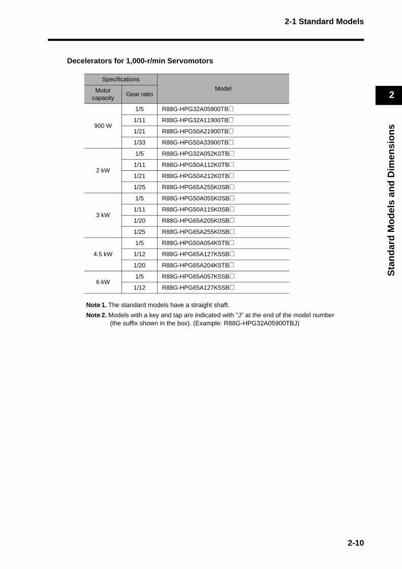
Decelerators for 1,000-r/min Servomotors
Note 1. The standard models have a straight shaft.
Note 2. Models with a key and tap are indicated with "J" at the end of the model number (the suffix shown in the box). (Example: R88G-HPG32A05900TBJ)
Specifications
ModelMotor capacity
Gear ratio
900 W
1/5 R88G-HPG32A05900TB@
1/11 R88G-HPG32A11900TB@
1/21 R88G-HPG50A21900TB@
1/33 R88G-HPG50A33900TB@
2 kW
1/5 R88G-HPG32A052K0TB@
1/11 R88G-HPG50A112K0TB@
1/21 R88G-HPG50A212K0TB@
1/25 R88G-HPG65A255K0SB@
3 kW
1/5 R88G-HPG50A055K0SB@
1/11 R88G-HPG50A115K0SB@
1/20 R88G-HPG65A205K0SB@
1/25 R88G-HPG65A255K0SB@
4.5 kW
1/5 R88G-HPG50A054K5TB@
1/12 R88G-HPG65A127K5SB@
1/20 R88G-HPG65A204K5TB@
6 kW1/5 R88G-HPG65A057K5SB@
1/12 R88G-HPG65A127K5SB@
2-10
2-1 Standard Models
2
Sta
nd
ard
Mo
del
s an
d D
imen
sio
ns
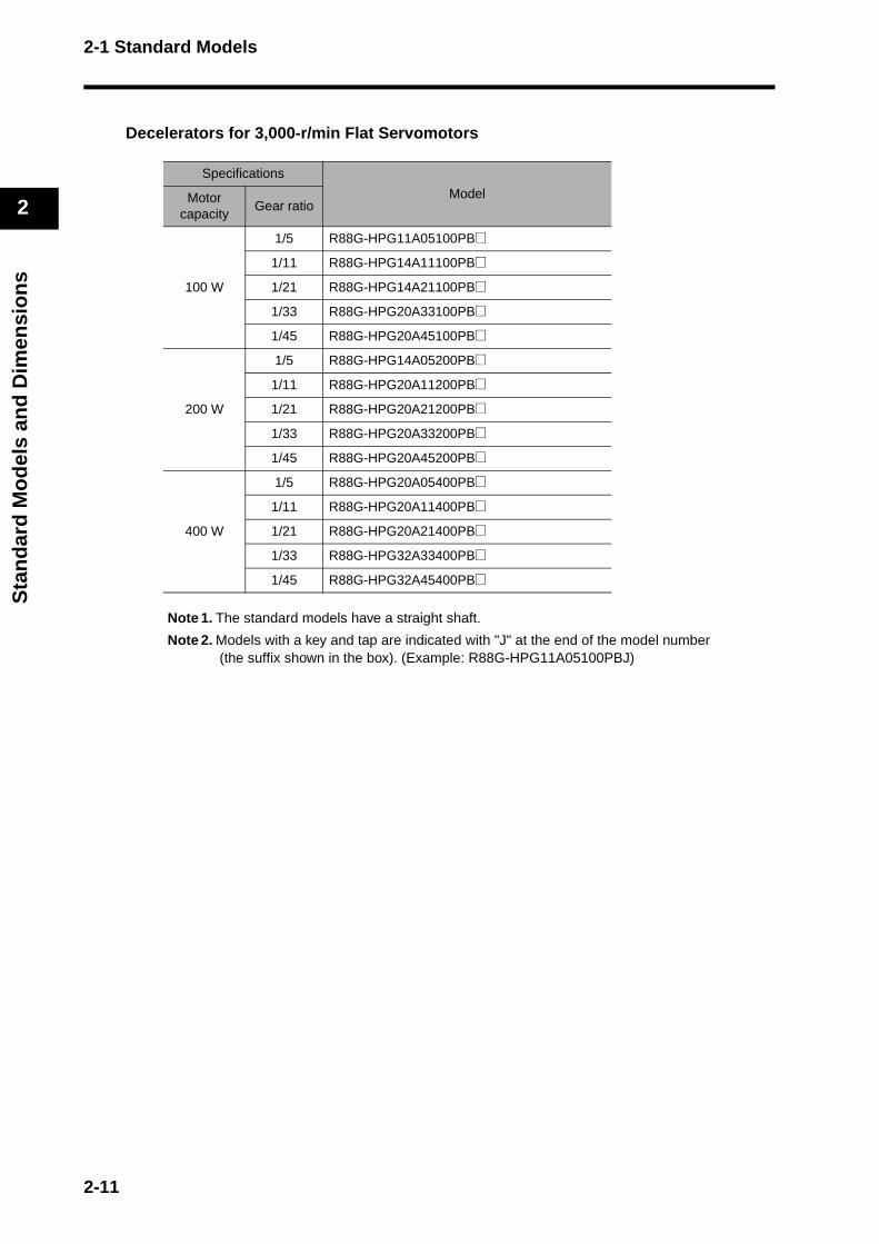
Decelerators for 3,000-r/min Flat Servomotors
Note 1. The standard models have a straight shaft.
Note 2. Models with a key and tap are indicated with "J" at the end of the model number (the suffix shown in the box). (Example: R88G-HPG11A05100PBJ)
Specifications
ModelMotor capacity
Gear ratio
100 W
1/5 R88G-HPG11A05100PB@
1/11 R88G-HPG14A11100PB@
1/21 R88G-HPG14A21100PB@
1/33 R88G-HPG20A33100PB@
1/45 R88G-HPG20A45100PB@
200 W
1/5 R88G-HPG14A05200PB@
1/11 R88G-HPG20A11200PB@
1/21 R88G-HPG20A21200PB@
1/33 R88G-HPG20A33200PB@
1/45 R88G-HPG20A45200PB@
400 W
1/5 R88G-HPG20A05400PB@
1/11 R88G-HPG20A11400PB@
1/21 R88G-HPG20A21400PB@
1/33 R88G-HPG32A33400PB@
1/45 R88G-HPG32A45400PB@
2-11
2-1 Standard Models
2
Sta
nd
ard
Mo
del
s an
d D
imen
sio
ns
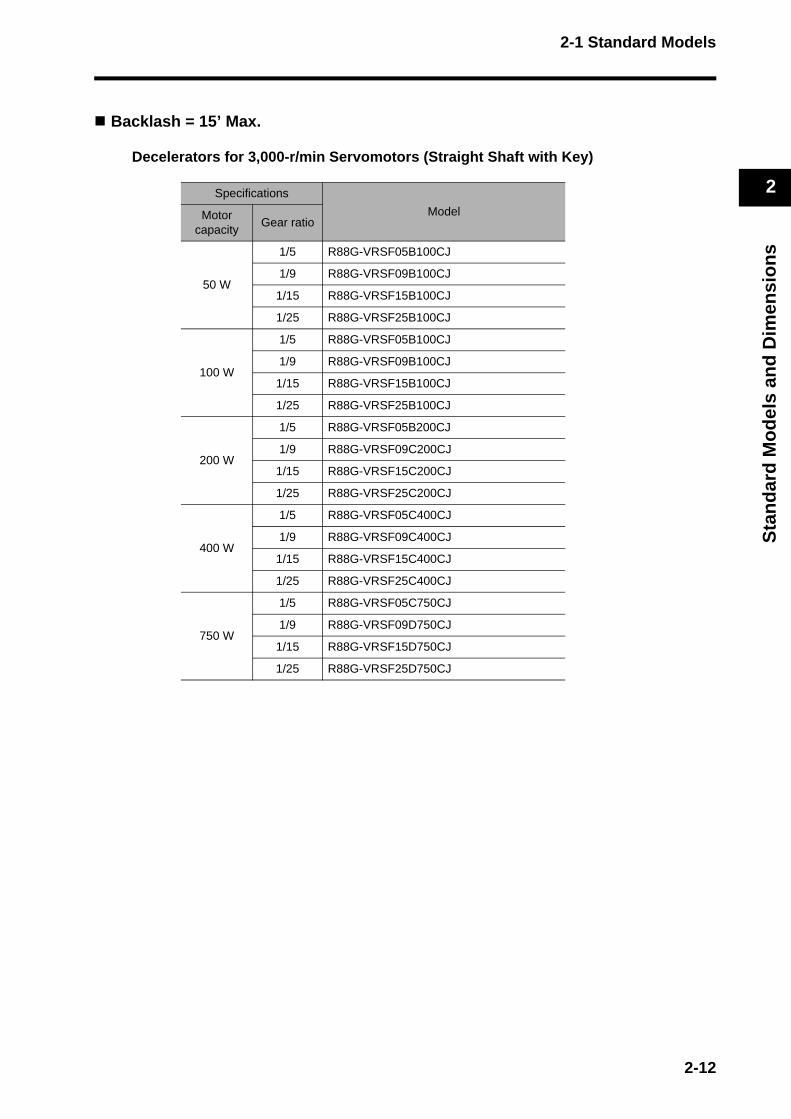
Backlash = 15’ Max.
Decelerators for 3,000-r/min Servomotors (Straight Shaft with Key)
Specifications
ModelMotor capacity
Gear ratio
50 W
1/5 R88G-VRSF05B100CJ
1/9 R88G-VRSF09B100CJ
1/15 R88G-VRSF15B100CJ
1/25 R88G-VRSF25B100CJ
100 W
1/5 R88G-VRSF05B100CJ
1/9 R88G-VRSF09B100CJ
1/15 R88G-VRSF15B100CJ
1/25 R88G-VRSF25B100CJ
200 W
1/5 R88G-VRSF05B200CJ
1/9 R88G-VRSF09C200CJ
1/15 R88G-VRSF15C200CJ
1/25 R88G-VRSF25C200CJ
400 W
1/5 R88G-VRSF05C400CJ
1/9 R88G-VRSF09C400CJ
1/15 R88G-VRSF15C400CJ
1/25 R88G-VRSF25C400CJ
750 W
1/5 R88G-VRSF05C750CJ
1/9 R88G-VRSF09D750CJ
1/15 R88G-VRSF15D750CJ
1/25 R88G-VRSF25D750CJ
2-12

2-1 Standard Models
2
Sta
nd
ard
Mo
del
s an
d D
imen
sio
ns
Decelerators for 3,000-r/min Flat Servomotors (Straight Shaft with Key)
Specifications
ModelMotor capacity
Gear ratio
100 W
1/5 R88G-VRSF05B100PCJ
1/9 R88G-VRSF09B100PCJ
1/15 R88G-VRSF15B100PCJ
1/25 R88G-VRSF25B100PCJ
200 W
1/5 R88G-VRSF05B200PCJ
1/9 R88G-VRSF09C200PCJ
1/15 R88G-VRSF15C200PCJ
1/25 R88G-VRSF25C200PCJ
400 W
1/5 R88G-VRSF05C400PCJ
1/9 R88G-VRSF09C400PCJ
1/15 R88G-VRSF15C400PCJ
1/25 R88G-VRSF25C400PCJ
2-13
2-1 Standard Models
2
Sta
nd
ard
Mo
del
s an
d D
imen
sio
ns
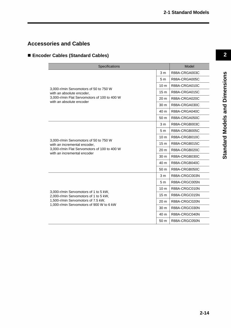
Accessories and Cables
Encoder Cables (Standard Cables)
Specifications Model
3,000-r/min Servomotors of 50 to 750 W with an absolute encoder,3,000-r/min Flat Servomotors of 100 to 400 Wwith an absolute encoder
3 m R88A-CRGA003C
5 m R88A-CRGA005C
10 m R88A-CRGA010C
15 m R88A-CRGA015C
20 m R88A-CRGA020C
30 m R88A-CRGA030C
40 m R88A-CRGA040C
50 m R88A-CRGA050C
3,000-r/min Servomotors of 50 to 750 W with an incremental encoder,3,000-r/min Flat Servomotors of 100 to 400 Wwith an incremental encoder
3 m R88A-CRGB003C
5 m R88A-CRGB005C
10 m R88A-CRGB010C
15 m R88A-CRGB015C
20 m R88A-CRGB020C
30 m R88A-CRGB030C
40 m R88A-CRGB040C
50 m R88A-CRGB050C
3,000-r/min Servomotors of 1 to 5 kW,2,000-r/min Servomotors of 1 to 5 kW,1,500-r/min Servomotors of 7.5 kW, 1,000-r/min Servomotors of 900 W to 6 kW
3 m R88A-CRGC003N
5 m R88A-CRGC005N
10 m R88A-CRGC010N
15 m R88A-CRGC015N
20 m R88A-CRGC020N
30 m R88A-CRGC030N
40 m R88A-CRGC040N
50 m R88A-CRGC050N
2-14
2-1 Standard Models
2
Sta
nd
ard
Mo
del
s an
d D
imen
sio
ns
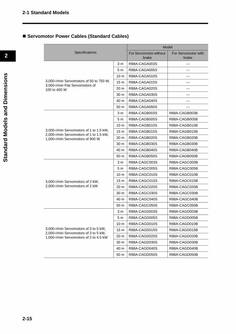
Servomotor Power Cables (Standard Cables)
Specifications
Model
For Servomotor without brake
For Servomotor with brake
3,000-r/min Servomotors of 50 to 750 W,3,000-r/min Flat Servomotors of 100 to 400 W
3 m R88A-CAGA003S ---
5 m R88A-CAGA005S ---
10 m R88A-CAGA010S ---
15 m R88A-CAGA015S ---
20 m R88A-CAGA020S ---
30 m R88A-CAGA030S ---
40 m R88A-CAGA040S ---
50 m R88A-CAGA050S ---
3,000-r/min Servomotors of 1 to 1.5 kW,2,000-r/min Servomotors of 1 to 1.5 kW,1,000-r/min Servomotors of 900 W
3 m R88A-CAGB003S R88A-CAGB003B
5 m R88A-CAGB005S R88A-CAGB005B
10 m R88A-CAGB010S R88A-CAGB010B
15 m R88A-CAGB015S R88A-CAGB015B
20 m R88A-CAGB020S R88A-CAGB020B
30 m R88A-CAGB030S R88A-CAGB030B
40 m R88A-CAGB040S R88A-CAGB040B
50 m R88A-CAGB050S R88A-CAGB050B
3,000-r/min Servomotors of 2 kW,2,000-r/min Servomotors of 2 kW
3 m R88A-CAGC003S R88A-CAGC003B
5 m R88A-CAGC005S R88A-CAGC005B
10 m R88A-CAGC010S R88A-CAGC010B
15 m R88A-CAGC015S R88A-CAGC015B
20 m R88A-CAGC020S R88A-CAGC020B
30 m R88A-CAGC030S R88A-CAGC030B
40 m R88A-CAGC040S R88A-CAGC040B
50 m R88A-CAGC050S R88A-CAGC050B
3,000-r/min Servomotors of 3 to 5 kW,2,000-r/min Servomotors of 3 to 5 kW,1,000-r/min Servomotors of 2 to 4.5 kW
3 m R88A-CAGD003S R88A-CAGD003B
5 m R88A-CAGD005S R88A-CAGD005B
10 m R88A-CAGD010S R88A-CAGD010B
15 m R88A-CAGD015S R88A-CAGD015B
20 m R88A-CAGD020S R88A-CAGD020B
30 m R88A-CAGD030S R88A-CAGD030B
40 m R88A-CAGD040S R88A-CAGD040B
50 m R88A-CAGD050S R88A-CAGD050B
2-15
2-1 Standard Models
2
Sta
nd
ard
Mo
del
s an
d D
imen
sio
ns
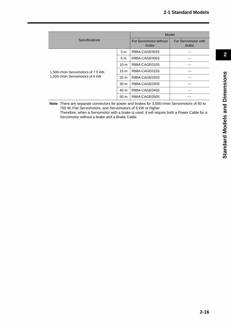
Note There are separate connectors for power and brakes for 3,000-r/min Servomotors of 50 to 750 W, Flat Servomotors, and Servomotors of 6 kW or higher.Therefore, when a Servomotor with a brake is used, it will require both a Power Cable for a Servomotor without a brake and a Brake Cable.
Specifications
Model
For Servomotor without brake
For Servomotor with brake
1,500-r/min Servomotors of 7.5 kW,1,000-r/min Servomotors of 6 kW
3 m R88A-CAGE003S ---
5 m R88A-CAGE005S ---
10 m R88A-CAGE010S ---
15 m R88A-CAGE015S ---
20 m R88A-CAGE020S ---
30 m R88A-CAGE030S ---
40 m R88A-CAGE040S ---
50 m R88A-CAGE050S ---
2-16
2-1 Standard Models
2
Sta
nd
ard
Mo
del
s an
d D
imen
sio
ns
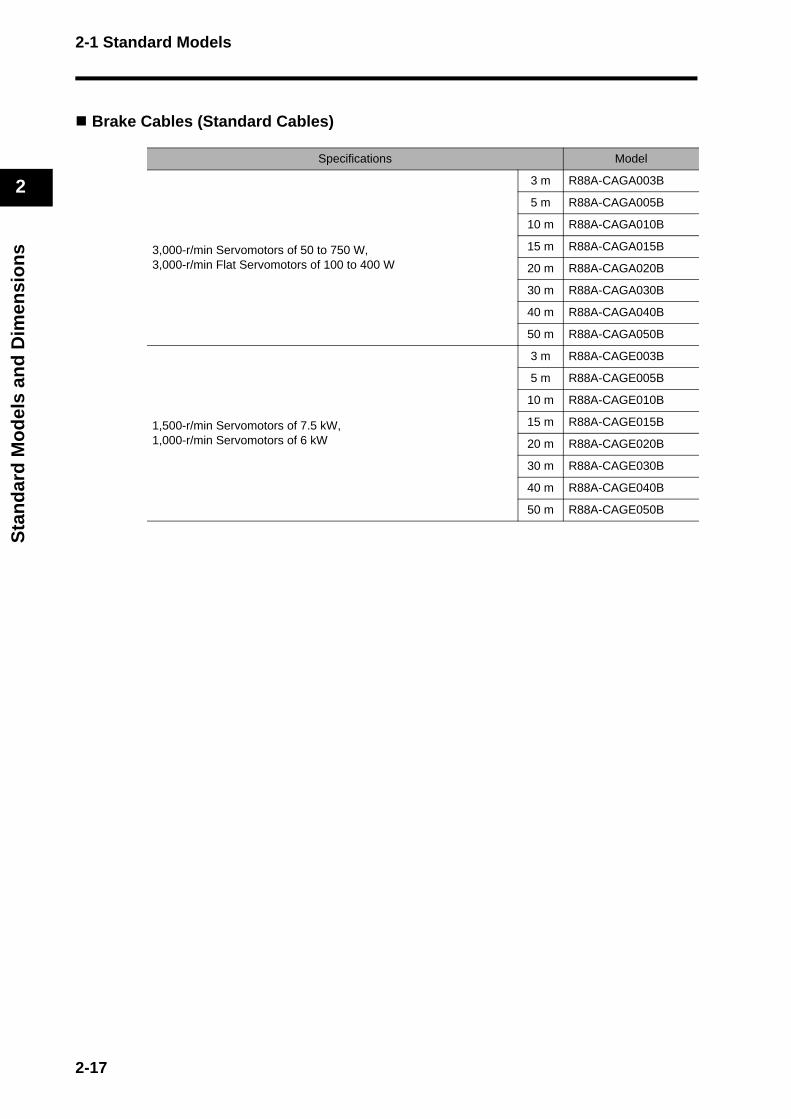
Brake Cables (Standard Cables)
Specifications Model
3,000-r/min Servomotors of 50 to 750 W,3,000-r/min Flat Servomotors of 100 to 400 W
3 m R88A-CAGA003B
5 m R88A-CAGA005B
10 m R88A-CAGA010B
15 m R88A-CAGA015B
20 m R88A-CAGA020B
30 m R88A-CAGA030B
40 m R88A-CAGA040B
50 m R88A-CAGA050B
1,500-r/min Servomotors of 7.5 kW,1,000-r/min Servomotors of 6 kW
3 m R88A-CAGE003B
5 m R88A-CAGE005B
10 m R88A-CAGE010B
15 m R88A-CAGE015B
20 m R88A-CAGE020B
30 m R88A-CAGE030B
40 m R88A-CAGE040B
50 m R88A-CAGE050B
2-17
2-1 Standard Models
2
Sta
nd
ard
Mo
del
s an
d D
imen
sio
ns
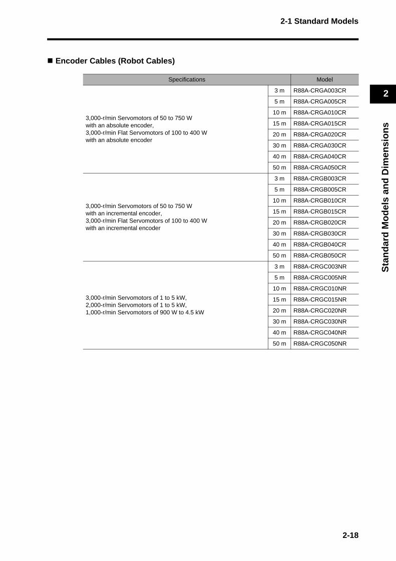
Encoder Cables (Robot Cables)
Specifications Model
3,000-r/min Servomotors of 50 to 750 W with an absolute encoder,3,000-r/min Flat Servomotors of 100 to 400 Wwith an absolute encoder
3 m R88A-CRGA003CR
5 m R88A-CRGA005CR
10 m R88A-CRGA010CR
15 m R88A-CRGA015CR
20 m R88A-CRGA020CR
30 m R88A-CRGA030CR
40 m R88A-CRGA040CR
50 m R88A-CRGA050CR
3,000-r/min Servomotors of 50 to 750 W with an incremental encoder,3,000-r/min Flat Servomotors of 100 to 400 Wwith an incremental encoder
3 m R88A-CRGB003CR
5 m R88A-CRGB005CR
10 m R88A-CRGB010CR
15 m R88A-CRGB015CR
20 m R88A-CRGB020CR
30 m R88A-CRGB030CR
40 m R88A-CRGB040CR
50 m R88A-CRGB050CR
3,000-r/min Servomotors of 1 to 5 kW,2,000-r/min Servomotors of 1 to 5 kW,1,000-r/min Servomotors of 900 W to 4.5 kW
3 m R88A-CRGC003NR
5 m R88A-CRGC005NR
10 m R88A-CRGC010NR
15 m R88A-CRGC015NR
20 m R88A-CRGC020NR
30 m R88A-CRGC030NR
40 m R88A-CRGC040NR
50 m R88A-CRGC050NR
2-18
2-1 Standard Models
2
Sta
nd
ard
Mo
del
s an
d D
imen
sio
ns
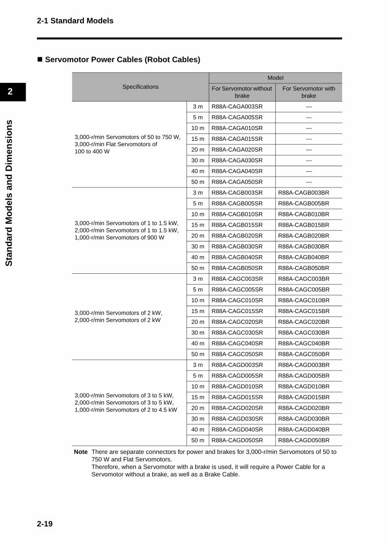
Servomotor Power Cables (Robot Cables)
Note There are separate connectors for power and brakes for 3,000-r/min Servomotors of 50 to 750 W and Flat Servomotors. Therefore, when a Servomotor with a brake is used, it will require a Power Cable for a Servomotor without a brake, as well as a Brake Cable.
Specifications
Model
For Servomotor without brake
For Servomotor with brake
3,000-r/min Servomotors of 50 to 750 W,3,000-r/min Flat Servomotors of 100 to 400 W
3 m R88A-CAGA003SR ---
5 m R88A-CAGA005SR ---
10 m R88A-CAGA010SR ---
15 m R88A-CAGA015SR ---
20 m R88A-CAGA020SR ---
30 m R88A-CAGA030SR ---
40 m R88A-CAGA040SR ---
50 m R88A-CAGA050SR ---
3,000-r/min Servomotors of 1 to 1.5 kW,2,000-r/min Servomotors of 1 to 1.5 kW,1,000-r/min Servomotors of 900 W
3 m R88A-CAGB003SR R88A-CAGB003BR
5 m R88A-CAGB005SR R88A-CAGB005BR
10 m R88A-CAGB010SR R88A-CAGB010BR
15 m R88A-CAGB015SR R88A-CAGB015BR
20 m R88A-CAGB020SR R88A-CAGB020BR
30 m R88A-CAGB030SR R88A-CAGB030BR
40 m R88A-CAGB040SR R88A-CAGB040BR
50 m R88A-CAGB050SR R88A-CAGB050BR
3,000-r/min Servomotors of 2 kW,2,000-r/min Servomotors of 2 kW
3 m R88A-CAGC003SR R88A-CAGC003BR
5 m R88A-CAGC005SR R88A-CAGC005BR
10 m R88A-CAGC010SR R88A-CAGC010BR
15 m R88A-CAGC015SR R88A-CAGC015BR
20 m R88A-CAGC020SR R88A-CAGC020BR
30 m R88A-CAGC030SR R88A-CAGC030BR
40 m R88A-CAGC040SR R88A-CAGC040BR
50 m R88A-CAGC050SR R88A-CAGC050BR
3,000-r/min Servomotors of 3 to 5 kW,2,000-r/min Servomotors of 3 to 5 kW,1,000-r/min Servomotors of 2 to 4.5 kW
3 m R88A-CAGD003SR R88A-CAGD003BR
5 m R88A-CAGD005SR R88A-CAGD005BR
10 m R88A-CAGD010SR R88A-CAGD010BR
15 m R88A-CAGD015SR R88A-CAGD015BR
20 m R88A-CAGD020SR R88A-CAGD020BR
30 m R88A-CAGD030SR R88A-CAGD030BR
40 m R88A-CAGD040SR R88A-CAGD040BR
50 m R88A-CAGD050SR R88A-CAGD050BR
2-19
2-1 Standard Models
2
Sta
nd
ard
Mo
del
s an
d D
imen
sio
ns
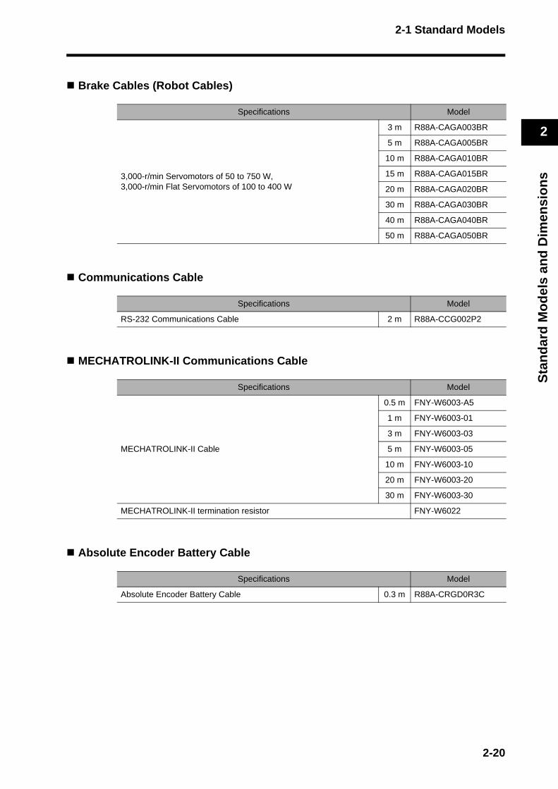
Brake Cables (Robot Cables)
Communications Cable
MECHATROLINK-II Communications Cable
Absolute Encoder Battery Cable
Specifications Model
3,000-r/min Servomotors of 50 to 750 W,3,000-r/min Flat Servomotors of 100 to 400 W
3 m R88A-CAGA003BR
5 m R88A-CAGA005BR
10 m R88A-CAGA010BR
15 m R88A-CAGA015BR
20 m R88A-CAGA020BR
30 m R88A-CAGA030BR
40 m R88A-CAGA040BR
50 m R88A-CAGA050BR
Specifications Model
RS-232 Communications Cable 2 m R88A-CCG002P2
Specifications Model
MECHATROLINK-II Cable
0.5 m FNY-W6003-A5
1 m FNY-W6003-01
3 m FNY-W6003-03
5 m FNY-W6003-05
10 m FNY-W6003-10
20 m FNY-W6003-20
30 m FNY-W6003-30
MECHATROLINK-II termination resistor FNY-W6022
Specifications Model
Absolute Encoder Battery Cable 0.3 m R88A-CRGD0R3C
2-20
2-1 Standard Models
2
Sta
nd
ard
Mo
del
s an
d D
imen
sio
ns
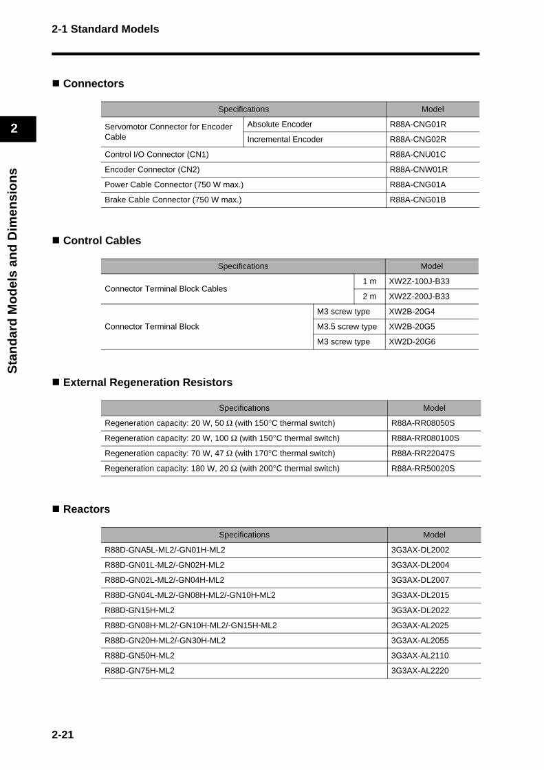
Connectors
Control Cables
External Regeneration Resistors
Reactors
Specifications Model
Servomotor Connector for Encoder Cable
Absolute Encoder R88A-CNG01R
Incremental Encoder R88A-CNG02R
Control I/O Connector (CN1) R88A-CNU01C
Encoder Connector (CN2) R88A-CNW01R
Power Cable Connector (750 W max.) R88A-CNG01A
Brake Cable Connector (750 W max.) R88A-CNG01B
Specifications Model
Connector Terminal Block Cables1 m XW2Z-100J-B33
2 m XW2Z-200J-B33
Connector Terminal Block
M3 screw type XW2B-20G4
M3.5 screw type XW2B-20G5
M3 screw type XW2D-20G6
Specifications Model
Regeneration capacity: 20 W, 50 Ω (with 150°C thermal switch) R88A-RR08050S
Regeneration capacity: 20 W, 100 Ω (with 150°C thermal switch) R88A-RR080100S
Regeneration capacity: 70 W, 47 Ω (with 170°C thermal switch) R88A-RR22047S
Regeneration capacity: 180 W, 20 Ω (with 200°C thermal switch) R88A-RR50020S
Specifications Model
R88D-GNA5L-ML2/-GN01H-ML2 3G3AX-DL2002
R88D-GN01L-ML2/-GN02H-ML2 3G3AX-DL2004
R88D-GN02L-ML2/-GN04H-ML2 3G3AX-DL2007
R88D-GN04L-ML2/-GN08H-ML2/-GN10H-ML2 3G3AX-DL2015
R88D-GN15H-ML2 3G3AX-DL2022
R88D-GN08H-ML2/-GN10H-ML2/-GN15H-ML2 3G3AX-AL2025
R88D-GN20H-ML2/-GN30H-ML2 3G3AX-AL2055
R88D-GN50H-ML2 3G3AX-AL2110
R88D-GN75H-ML2 3G3AX-AL2220
2-21
2-1 Standard Models
2
Sta
nd
ard
Mo
del
s an
d D
imen
sio
ns
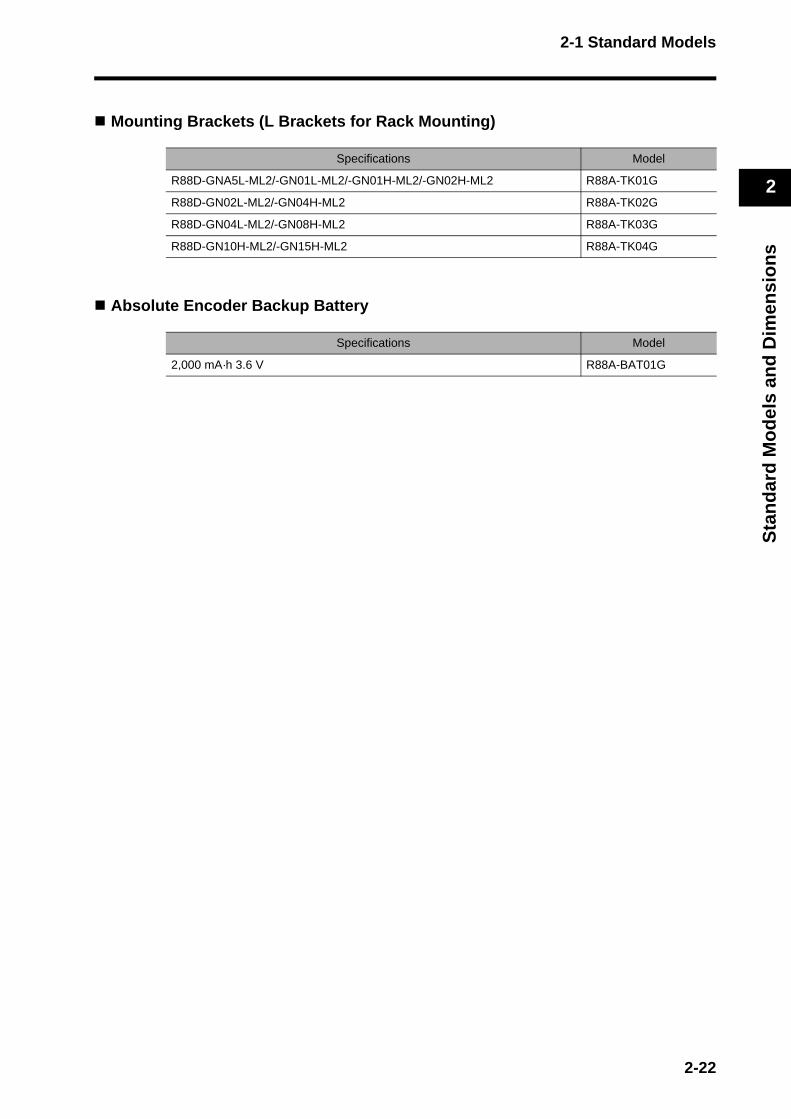
Mounting Brackets (L Brackets for Rack Mounting)
Absolute Encoder Backup Battery
Specifications Model
R88D-GNA5L-ML2/-GN01L-ML2/-GN01H-ML2/-GN02H-ML2 R88A-TK01G
R88D-GN02L-ML2/-GN04H-ML2 R88A-TK02G
R88D-GN04L-ML2/-GN08H-ML2 R88A-TK03G
R88D-GN10H-ML2/-GN15H-ML2 R88A-TK04G
Specifications Model
2,000 mA·h 3.6 V R88A-BAT01G
2-22

2-2 External and Mounting Hole Dimensions
2
Sta
nd
ard
Mo
del
s an
d D
imen
sio
ns
2-2 External and Mounting Hole Dimensions
Servo Drives
Single-phase 100 VAC: R88D-GNA5L-ML2/-GN01L-ML2 (50 to 100 W)Single-phase 200 VAC: R88D-GN01H-ML2/-GN02H-ML2 (50 to 200 W)
Wall Mounting
External Dimensions Mounting Hole Dimensions
G
IM
SP
COM
X10
32
10ADR
AC SERVO DRIVER
X1
6
78
9 0 1
23
45
13270
4
150
40
28±0.57
( 42 )
Two, M4
140±
0.5
(150
)
2-23

2-2 External and Mounting Hole Dimensions
2
Sta
nd
ard
Mo
del
s an
d D
imen
sio
ns
Front Panel Mounting (Using Mounting Brackets)
External Dimensions Mounting Hole Dimensions
( 42)
Two, M4
158
170
±0.5
Square hole
5.2
7
13270
4
180
170
150
21
75.2 dia.
R2.6
2.6
24
2.6 8
5 4
32
109
87
6
X1
AC SERVO DRIVERADR
0 1
23
X10
COM
SP
IM
G
2-24
2-2 External and Mounting Hole Dimensions
2
Sta
nd
ard
Mo
del
s an
d D
imen
sio
ns
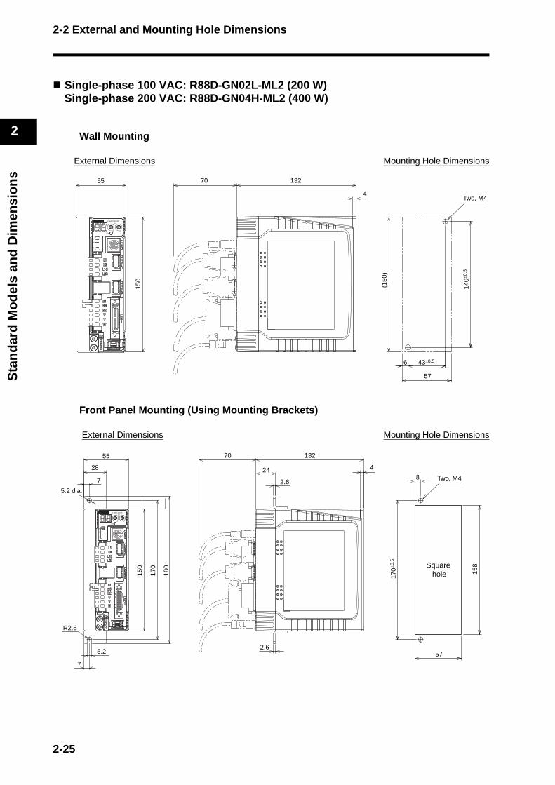
Single-phase 100 VAC: R88D-GN02L-ML2 (200 W)Single-phase 200 VAC: R88D-GN04H-ML2 (400 W)
Wall Mounting
External Dimensions Mounting Hole Dimensions
Front Panel Mounting (Using Mounting Brackets)
External Dimensions Mounting Hole Dimensions
43±0.56
57
Two, M4
140±
0.5
(150
)
13270
4
150
55
0
G
IM
SP
COM
X10
32
1ADR
AC SERVO DRIVER
X1
6
78
9 0 1
23
45
57
Two, M415
8
170±
0.5
Square hole
8
5.2
7
13270
4
180
170
150
7
5.2 dia.
R2.6
55
28
2.6
24
2.6
0
G
IM
SP
COM
X10
32
1ADR
AC SERVO DRIVER
X1
6
78
9 0 1
23
45
2-25
2-2 External and Mounting Hole Dimensions
2
Sta
nd
ard
Mo
del
s an
d D
imen
sio
ns
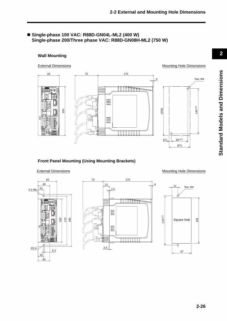
Single-phase 100 VAC: R88D-GN04L-ML2 (400 W)Single-phase 200/Three phase VAC: R88D-GN08H-ML2 (750 W)
Wall Mounting
External Dimensions Mounting Hole Dimensions
Front Panel Mounting (Using Mounting Brackets)
External Dimensions Mounting Hole Dimensions
50±0.58.5
(67)
Two, M4
140±
0.5
(150
)
0
G
IM
SP
COM
X10
32
1ADR
AC SERVO DRIVER
X1
6
78
9 0 1
23
45
17070
4
150
65
67
Two, M4
158
170±
0.5
Square hole
21
0
G
IM
SP
COM
X10
32
1ADR
AC SERVO DRIVER
X1
6
78
9 0 1
23
45
5.22.6
17070
4
180
170
150
5.2 dia.
R2.6
65
40
20
20
40
22
2.6
2-26
2-2 External and Mounting Hole Dimensions
2
Sta
nd
ard
Mo
del
s an
d D
imen
sio
ns
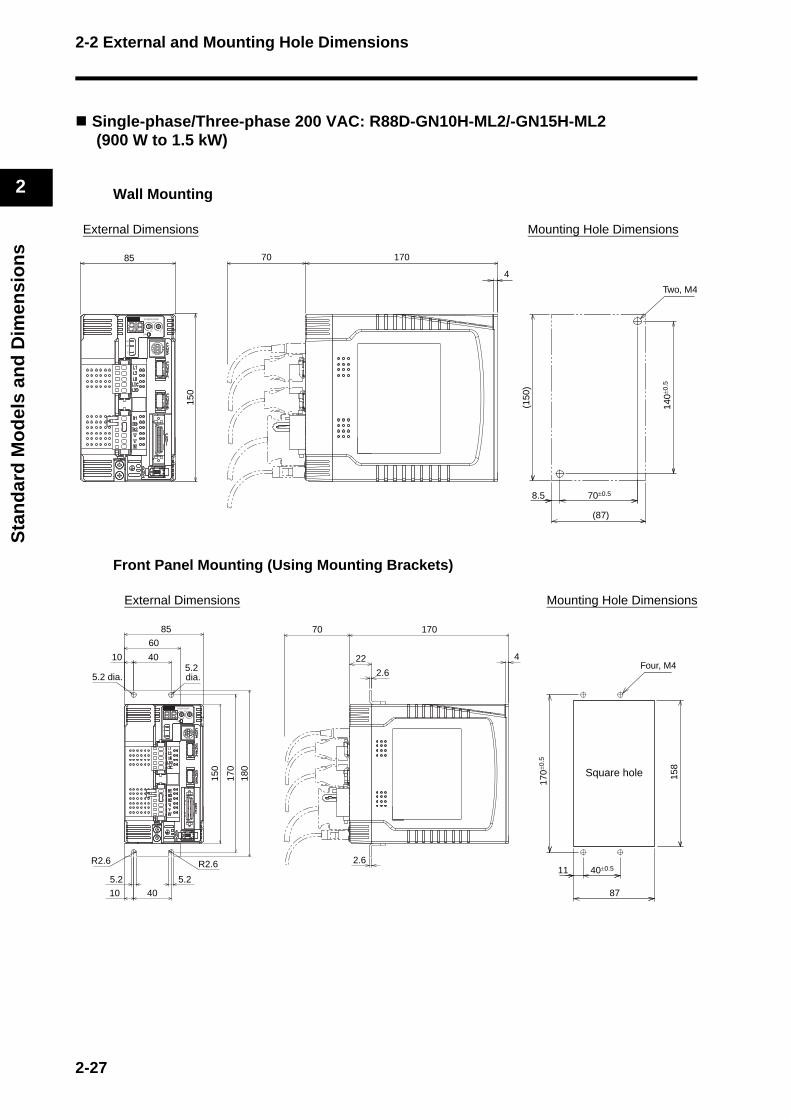
Single-phase/Three-phase 200 VAC: R88D-GN10H-ML2/-GN15H-ML2 (900 W to 1.5 kW)
Wall Mounting
External Dimensions Mounting Hole Dimensions
Front Panel Mounting (Using Mounting Brackets)
External Dimensions Mounting Hole Dimensions
70±0.58.5
(87)
Two, M4
140±
0.5
(150
)
17070
4
150
85
0
G
IM
SP
COM
X10
32
1ADR
AC SERVO DRIVER
X1
6
78
9 0 1
23
45
87
Four, M415
8
170±
0.5
Square hole
40±0.5115.25.2
17070
4
180
170
150
5.2 dia.5.2 dia.
R2.6 R2.6
10 40
85
60
4010
2.6
22
2.6
0
G
IM
SP
COM
X10
32
1ADR
AC SERVO DRIVER
X1
6
78
9 0 1
23
45
2-27

2-2 External and Mounting Hole Dimensions
2
Sta
nd
ard
Mo
del
s an
d D
imen
sio
ns
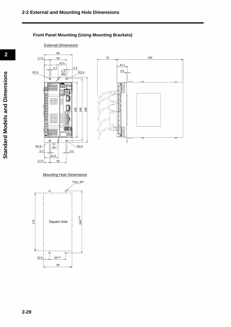
Three-phase 200 VAC: R88D-GN20H-ML2 (2 kW)
Wall Mounting
External Dimensions
Mounting Hole Dimensions
3.5
3.55.25.2
5.25.2
R2.6R2.6
R2.6 R2.6
5.2dia.
5.2 dia.
20070
198
188
168
85
5017.5
5017.5
42.5
42.5
0
G
IM
SP
COM
X10
32
1ADR
AC SERVO DRIVER
X1
6
78
9 0 1
23
45
(87)
Four, M4
(168
)
188±
0.5
18.5 50±0.5
2-28
2-2 External and Mounting Hole Dimensions
2
Sta
nd
ard
Mo
del
s an
d D
imen
sio
ns
Front Panel Mounting (Using Mounting Brackets)
External Dimensions
Mounting Hole Dimensions
5.25.2
5.25.2
R2.6R2.6
R2.6 R2.6
5.2 dia.
5.2 dia.
20070
32.1
2.6
198
188
168
85
5017.5
5017.5
42.5
42.5
0
G
IM
SP
COM
X10
32
1ADR
AC SERVO DRIVER
X1
6
78
9 0 1
23
45
89
Four, M4
176 Square hole
188
20.5 50±0.5
±0.5
2-29

2-2 External and Mounting Hole Dimensions
2
Sta
nd
ard
Mo
del
s an
d D
imen
sio
ns
Three-phase 200 VAC: R88D-GN30H-ML2/-GN50H-ML2 (2 to 5 kW)
Wall Mounting
External Dimensions
Mounting Hole Dimensions
5.25.2
10015
65
5.2R2.6R2.6
R2.6 R2.6
5.2 dia.
5.2 dia.
5.2
200
250
240
220
13010015
65
70 3.5
3.5
0
G
IM
SP
COM
X10
32
1ADR
AC SERVO DRIVER
X1
6
78
9 0 1
23
45
132
Six, M4
(220
)
16
240±
0.5
100±0.5
50±0.5
2-30
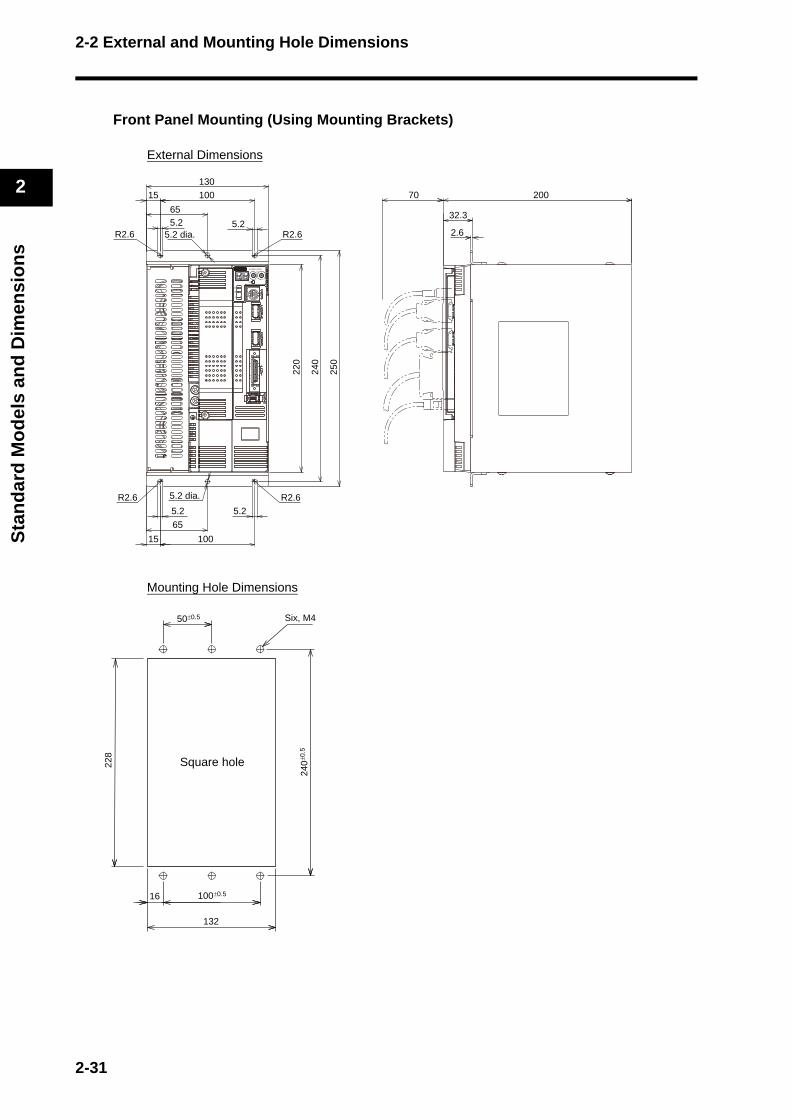
2-2 External and Mounting Hole Dimensions
2
Sta
nd
ard
Mo
del
s an
d D
imen
sio
ns
Front Panel Mounting (Using Mounting Brackets)
External Dimensions
Mounting Hole Dimensions
5.25.2
10015
65
5.2R2.6R2.6
R2.6 R2.6
5.2 dia.
5.2 dia.
5.2
20070
32.3
2.6
250
240
220
13010015
65
0
G
IM
SP
COM
X10
32
1ADR
AC SERVO DRIVER
X1
6
78
9 0 1
23
45
132
Six, M4
228
Square hole
16
240±
0.5
100±0.5
50±0.5
2-31

2-2 External and Mounting Hole Dimensions
2
Sta
nd
ard
Mo
del
s an
d D
imen
sio
ns
Three-phase 200 VAC: R88D-GN75H-ML2 (7.5 kW)
Front Panel Mounting (Using Mounting Brackets)
External Dimensions
Mounting Hole Dimensions
5.2 5.2 5.2
Four, 5.2 dia.
5.2 5.2 5.2
248
339.345.1
70 (4)
(2.3)
(4)
250
220
235
85
909082.5
9037.5
M
W
V
U
B2B2
B1B1
L3L3
L2L2
L1L1
0
G
IM
SP
COM
X10
32
1ADR
AC SERVO DRIVER
X1
6
78
9 0 1
23
45
250
Six, M4
229
38.5
240±
0.5
90±0.590±0.5
Square hole
2-32

2-2 External and Mounting Hole Dimensions
2
Sta
nd
ard
Mo
del
s an
d D
imen
sio
ns
Servomotors
3,000-r/min Servomotors
50 W/100 WR88M-G05030H(-S2)/-G10030L(-S2)/-G10030H(-S2)/-G05030H-B(S2)
/-G10030L-B(S2)/-G10030H-B(S2)
R88M-G05030T(-S2)/-G10030S(-S2)/-G10030T(-S2)/-G05030T-B(S2)
/-G10030S-B(S2)/-G10030T-B(S2)
Note The standard models have a straight shaft. Models with a key and tap are indicated with "S2" at the end of the model number.
ModelDimensions (mm)
LL LNR88M-G05030@ 72 26.5
R88M-G10030@ 92 46.5
R88M-G05030@-B@ 102 26.5R88M-G10030@-B@ 122 46.5
INC
ABS
230
200
36LL 25
32
40 × 40
LN
Motor connectorEncoderconnector
8 di
a., h
: 6
46 dia.
Two, 4.3 dia.
30 d
ia.,
h: 7
Brake connector
Three, h: 912.5
M3 (depth: 6)
1.8
3
14
(Dimensions of shaft end with key and tap)
2-33

2-2 External and Mounting Hole Dimensions
2
Sta
nd
ard
Mo
del
s an
d D
imen
sio
ns
3,000-r/min Servomotors
200 W/400 W/750 WR88M-G20030L(-S2)/-G40030L(-S2)/-G20030H(-S2)/-G40030H(-S2)
/-G75030H(-S2)/-G20030L-B(S2)/-G40030L-B(S2)
/-G20030H-B(S2)/-G40030H-B(S2)/-G75030H-B(S2)
R88M-G20030S(-S2)/-G40030S(-S2)/-G20030T(-S2)/-G40030T(-S2)
/-G75030T(-S2)/-G20030S-B(S2)/-G40030S-B(S2)
/-G20030T-B(S2)/-G40030T-B(S2)/-G75030T-B(S2)
Note The standard models have a straight shaft. Models with a key and tap are indicated with "S2" at the end of the model number.
ModelDimensions (mm)
LL LR S D1 D2 C G KL1 Z QK b h M t1 LR88M-G20030@ 79.5
3011
70 50 60 6.5 43 4.518 4h9 4 M4 2.5 8
R88M-G40030@ 99 14 22.5 5h9 5M5
310
R88M-G75030@ 112.2 35 19 90 70 80 8 53 6 22 6h9 6 3.5R88M-G20030@-B@ 116
3011
70 50 60 6.5 43 4.518 4h9 4 M4 2.5 8
R88M-G40030@-B@ 135.5 14 22.5 5h9 5M5
310
R88M-G75030@-B@ 149.2 35 19 90 70 80 8 53 6 22 6h9 6 3.5
INC
ABS
220
200
3G
LL LR
S d
ia.,
h: 6
D1 dia.
Motor connectorEncoderconnector
Four, Z dia.
D2
dia.
, h: 7
Brake connector
KL1
C × C
QK
M(effective depth: L)
b
t1
h
(Dimensions of shaft end with key and tap)
2-34
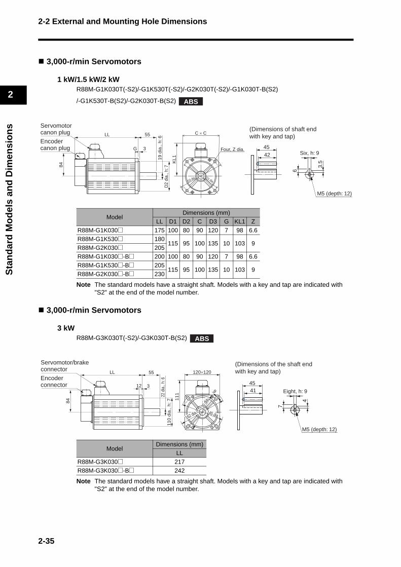
2-2 External and Mounting Hole Dimensions
2
Sta
nd
ard
Mo
del
s an
d D
imen
sio
ns
3,000-r/min Servomotors
1 kW/1.5 kW/2 kWR88M-G1K030T(-S2)/-G1K530T(-S2)/-G2K030T(-S2)/-G1K030T-B(S2)
/-G1K530T-B(S2)/-G2K030T-B(S2)
Note The standard models have a straight shaft. Models with a key and tap are indicated with "S2" at the end of the model number.
3,000-r/min Servomotors
3 kWR88M-G3K030T(-S2)/-G3K030T-B(S2)
Note The standard models have a straight shaft. Models with a key and tap are indicated with "S2" at the end of the model number.
ModelDimensions (mm)
LL D1 D2 C D3 G KL1 Z
R88M-G1K030@ 175 100 80 90 120 7 98 6.6R88M-G1K530@ 180
115 95 100 135 10 103 9R88M-G2K030@ 205
R88M-G1K030@-B@ 200 100 80 90 120 7 98 6.6R88M-G1K530@-B@ 205
115 95 100 135 10 103 9R88M-G2K030@-B@ 230
ModelDimensions (mm)
LL
R88M-G3K030@ 217R88M-G3K030@-B@ 242
ABS
4542
M5 (depth: 12)
Six, h: 9
3.5
6
(Dimensions of shaft endwith key and tap)LL 55
G 3
KL1
84
C × C
Encodercanon plug
Servomotorcanon plug
Four, Z dia.
D1 dia.
D2
dia.
, h: 7
19
dia.
, h: 6
D3 dia.
ABS
LL 55
12 39
111
84
120×120Encoderconnector
Servomotor/brakeconnector
110
dia.
, h: 7
22 d
ia.,
h: 6
130 d
ia.
145 dia.162 dia.
4541
M5 (depth: 12)
Eight, h: 9
4
7
(Dimensions of the shaft endwith key and tap)
2-35
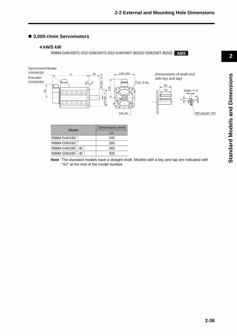
2-2 External and Mounting Hole Dimensions
2
Sta
nd
ard
Mo
del
s an
d D
imen
sio
ns
3,000-r/min Servomotors
4 kW/5 kWR88M-G4K030T(-S2)/-G5K030T(-S2)/-G4K030T-B(S2)/-G5K030T-B(S2)
Note The standard models have a straight shaft. Models with a key and tap are indicated with "S2" at the end of the model number.
ModelDimensions (mm)
LLR88M-G4K030@ 240
R88M-G5K030@ 280
R88M-G4K030@-B@ 265R88M-G5K030@-B@ 305
ABS
LL 65
12 6
118
84
130×130
Four, 9 dia.
110
dia.
, h: 7
24 d
ia.,
h: 6
165 dia.
Encoderconnector
Servomotor/brakeconnector
145 dia.
55
51 Eight, h: 9
4
7
M8 (depth: 20)
(Dimensions of shaft endwith key and tap)
2-36

2-2 External and Mounting Hole Dimensions
2
Sta
nd
ard
Mo
del
s an
d D
imen
sio
ns
3,000-r/min Flat Servomotors
100 W/200 W/400 WR88M-GP10030L(-S2)/-GP20030L(-S2)/-GP40030L(-S2)/-GP10030H(-S2)/-GP20030H(-S2)/-GP40030H(-S2)/-GP10030L-B(S2)/-GP20030L-B(S2)/-GP40030L-B(S2)/-GP10030H-B(S2)/-GP20030H-B(S2)/-GP40030H-B(S2)
R88M-GP10030S(-S2)/-GP20030S(-S2)/-GP40030S(-S2)/-GP10030T(-S2)/-GP20030T(-S2)/-GP40030T(-S2)/-GP10030S-B(S2)/-GP20030S-B(S2)/-GP40030S-B(S2)/-GP10030T-B(S2)/-GP20030T-B(S2)/-GP40030T-B(S2)
Note The standard models have a straight shaft. Models with a key and tap are indicated with "S2" at the end of the model number.
ModelDimensions (mm)
LL LR S D1 D2 C F G KL1 Z QK b h t1 M LR88M-GP10030LR88M-GP10030H
60.525 8 70 50 60 3 7 43 4.5 12.5 3h9 3 1.8 M3 6
R88M-GP10030SR88M-GP10030T
87.5
R88M-GP20030LR88M-GP20030H
67.5
30
11
90 70 80 5 8 53 5.5
18 4h9 4 2.5 M4 8R88M-GP20030SR88M-GP20030T
94.5
R88M-GP40030LR88M-GP40030H
82.514 22.5 5h9 5 3 M5 10
R88M-GP40030SR88M-GP40030T
109.5
R88M-GP10030L-B@R88M-GP10030H-B@ 84.5
25 8 70 50 60 3 7 43 4.5 12.5 3h9 3 1.8 M3 6R88M-GP10030S-B@R88M-GP10030T-B@ 111.5
R88M-GP20030L-B@R88M-GP20030H-B@ 100
30
11
90 70 80 5 8 53 5.5
18 4h9 4 2.5 M4 8R88M-GP20030S-B@R88M-GP20030T-B@ 127
R88M-GP40030L-B@R88M-GP40030H-B@ 115
14 22.5 5h9 5 3 M5 10R88M-GP40030S-B@R88M-GP40030T-B@ 142
INC
ABS
LL LR
FG
200
220
KL1
C × C
Brake connector
Motor connector
(7) (7)
Encoderconnector
Four, Z dia.
D2
dia.
, h: 7
S d
ia.,
h: 6
D1 dia.b
QK
M (depth: L)
t1
h
(Dimensions of shaft endwith key and tap)
2-37
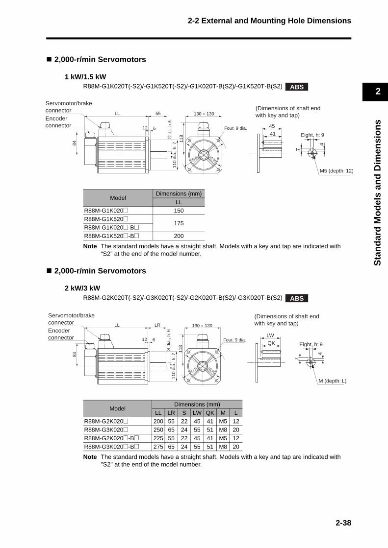
2-2 External and Mounting Hole Dimensions
2
Sta
nd
ard
Mo
del
s an
d D
imen
sio
ns
2,000-r/min Servomotors
1 kW/1.5 kWR88M-G1K020T(-S2)/-G1K520T(-S2)/-G1K020T-B(S2)/-G1K520T-B(S2)
Note The standard models have a straight shaft. Models with a key and tap are indicated with “S2” at the end of the model number.
2,000-r/min Servomotors
2 kW/3 kWR88M-G2K020T(-S2)/-G3K020T(-S2)/-G2K020T-B(S2)/-G3K020T-B(S2)
Note The standard models have a straight shaft. Models with a key and tap are indicated with "S2" at the end of the model number.
ModelDimensions (mm)
LL
R88M-G1K020@ 150
R88M-G1K520@175
R88M-G1K020@-B@R88M-G1K520@-B@ 200
Model Dimensions (mm)
LL LR S LW QK M L
R88M-G2K020@ 200 55 22 45 41 M5 12R88M-G3K020@ 250 65 24 55 51 M8 20
R88M-G2K020@-B@ 225 55 22 45 41 M5 12
R88M-G3K020@-B@ 275 65 24 55 51 M8 20
ABS
Encoderconnector
Servomotor/brakeconnector
LL 55
12 6
118
84
130 × 130
Four, 9 dia.
145 dia.
110
dia.
, h: 7
22 d
ia.,
h: 6
165 dia.
45
41 Eight, h: 9
4
7
M5 (depth: 12)
(Dimensions of shaft endwith key and tap)
ABS
LL LR
12 6
84
S d
ia.,
h: 6
118
130 × 130
Four, 9 dia.
145 dia.
110
dia.
, h: 7
165 dia.
Encoderconnector
Servomotor/brakeconnector
LW
QK Eight, h: 9
4
7
M (depth: L)
(Dimensions of shaft endwith key and tap)
2-38

2-2 External and Mounting Hole Dimensions
2
Sta
nd
ard
Mo
del
s an
d D
imen
sio
ns
2,000-r/min Servomotors
4 kW/5 kWR88M-G4K020T(-S2)/-G5K020T(-S2)/-G4K020T-B(S2)/-G5K020T-B(S2)
Note The standard models have a straight shaft. Models with a key and tap are indicated with "S2" at the end of the model number.
ModelDimensions (mm)
LL LR S D1 D2 C D3 KL1 Z QK b h t1 M L
R88M-G4K020@ 242 65 28 165 130 150 190 128 11 51 8h9 7 4 M8 20R88M-G5K020@ 225 70 35 200 114.3 176 233 143 13.5 50 10h9 8 5 M12 25
R88M-G4K020@-B@ 267 65 28 165 130 150 190 128 11 51 8h9 7 4 M8 20
R88M-G5K020@-B@ 250 70 35 200 114.3 176 233 143 13.5 50 10h9 8 5 M12 25
ABS
LL LR
18 3.2
KL1
84
C × C
D1 dia.D
2 di
a., h
: 7S
dia
.,h: 6
D3 dia.
Four, Z dia.
Encoderconnector
Servomotor/brakeconnector
QK
t1
h
b
M (depth: L)
(Dimensions of shaft end with key and tap)
2-39
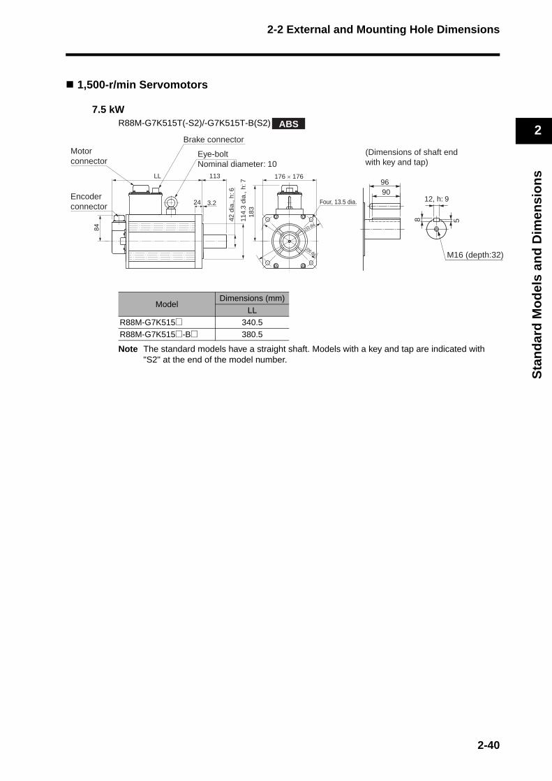
2-2 External and Mounting Hole Dimensions
2
Sta
nd
ard
Mo
del
s an
d D
imen
sio
ns
1,500-r/min Servomotors
7.5 kWR88M-G7K515T(-S2)/-G7K515T-B(S2)
Note The standard models have a straight shaft. Models with a key and tap are indicated with "S2" at the end of the model number.
ModelDimensions (mm)
LL
R88M-G7K515@ 340.5R88M-G7K515@-B@ 380.5
ABS
9096
M16 (depth:32)
12, h: 9
8 5
(Dimensions of shaft endwith key and tap)
Eye-boltNominal diameter: 10
Brake connector
LL 113
24 3.2
183
84
176 × 176
Four, 13.5 dia.
200 dia.
114.
3 di
a., h
: 7
42 d
ia.,
h: 6
233 dia.
Motorconnector
Encoderconnector
2-40
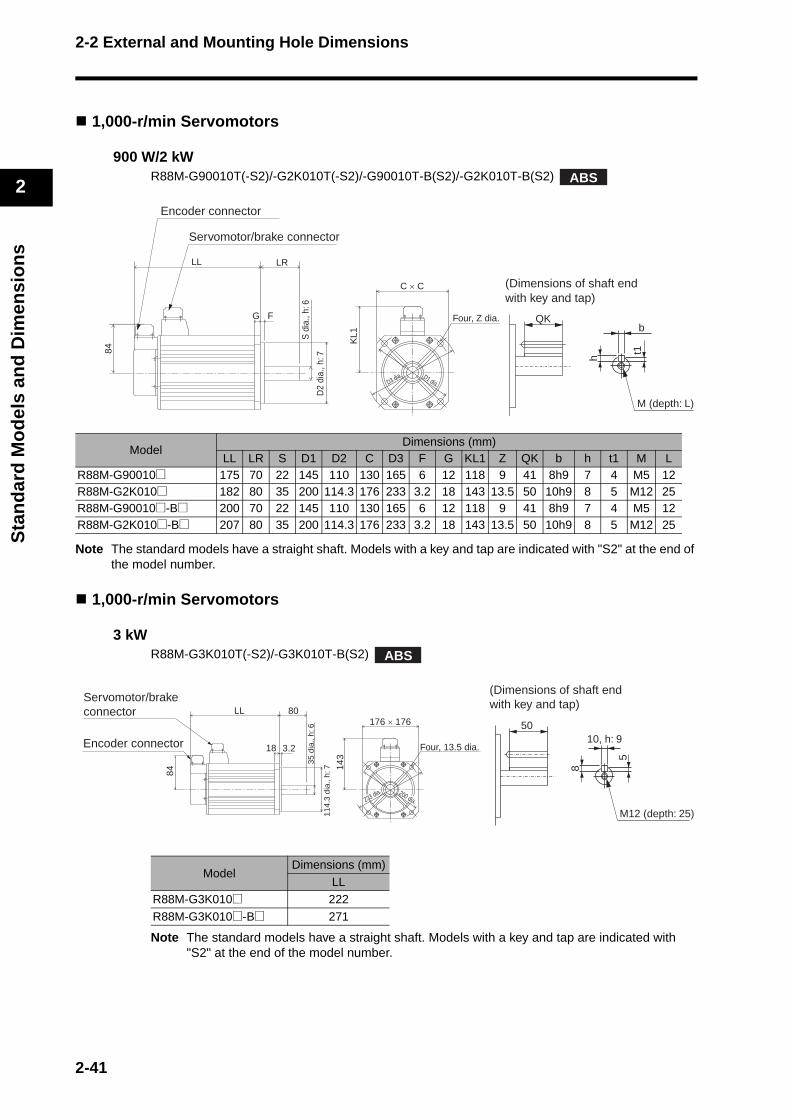
2-2 External and Mounting Hole Dimensions
2
Sta
nd
ard
Mo
del
s an
d D
imen
sio
ns
1,000-r/min Servomotors
900 W/2 kWR88M-G90010T(-S2)/-G2K010T(-S2)/-G90010T-B(S2)/-G2K010T-B(S2)
Note The standard models have a straight shaft. Models with a key and tap are indicated with "S2" at the end of the model number.
1,000-r/min Servomotors
3 kWR88M-G3K010T(-S2)/-G3K010T-B(S2)
Note The standard models have a straight shaft. Models with a key and tap are indicated with "S2" at the end of the model number.
ModelDimensions (mm)
LL LR S D1 D2 C D3 F G KL1 Z QK b h t1 M LR88M-G90010@ 175 70 22 145 110 130 165 6 12 118 9 41 8h9 7 4 M5 12R88M-G2K010@ 182 80 35 200 114.3 176 233 3.2 18 143 13.5 50 10h9 8 5 M12 25R88M-G90010@-B@ 200 70 22 145 110 130 165 6 12 118 9 41 8h9 7 4 M5 12R88M-G2K010@-B@ 207 80 35 200 114.3 176 233 3.2 18 143 13.5 50 10h9 8 5 M12 25
ModelDimensions (mm)
LLR88M-G3K010@ 222
R88M-G3K010@-B@ 271
ABS
C × C
S d
ia.,
h: 6
D2
dia.
, h: 7
LR
F
LL
G
KL1
84
Encoder connector
Servomotor/brake connector
Four, Z dia.
D1 dia.D3 dia.
QKb
t1
h
M (depth: L)
(Dimensions of shaft endwith key and tap)
ABS
35 d
ia.,
h: 6
114.
3 di
a ., h
: 7
80
3.2
LL
18
84
176 × 176
143
Four, 13.5 dia.Encoder connector
Servomotor/brake connector
233 dia. 200 dia.
5010, h: 9
5
8
M12 (depth: 25)
(Dimensions of shaft endwith key and tap)
2-41
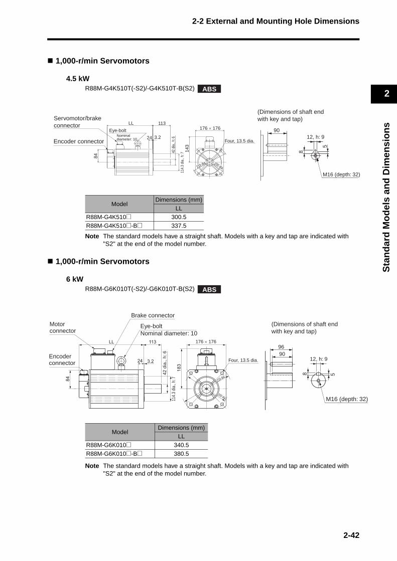
2-2 External and Mounting Hole Dimensions
2
Sta
nd
ard
Mo
del
s an
d D
imen
sio
ns
)
1,000-r/min Servomotors
4.5 kWR88M-G4K510T(-S2)/-G4K510T-B(S2)
Note The standard models have a straight shaft. Models with a key and tap are indicated with "S2" at the end of the model number.
1,000-r/min Servomotors
6 kWR88M-G6K010T(-S2)/-G6K010T-B(S2)
Note The standard models have a straight shaft. Models with a key and tap are indicated with "S2" at the end of the model number.
ModelDimensions (mm)
LL
R88M-G4K510@ 300.5
R88M-G4K510@-B@ 337.5
ModelDimensions (mm)
LL
R88M-G6K010@ 340.5
R88M-G6K010@-B@ 380.5
ABS
114.
3 di
a., h
: 7
42 d
ia.,
h: 6
113LL
24 3.2
84
176 × 176
143
Four, 13.5 dia.Encoder connector
Servomotor/brake connector
Eye-bolt Nominal diameter: 10
200 dia.233 dia.
9012, h: 9
5
8
M16 (depth: 32)
(Dimensions of shaft endwith key and tap)
ABS
Eye-boltNominal diameter: 10
Motor connector
Brake connector
Encoderconnector
176 × 176
Four, 13.5 dia.
42 d
ia.,
h: 6
114.
3 di
a., h
: 7 233 dia.
200 dia.
9096
M16 (depth: 32
12, h: 9
8 5(Dimensions of shaft endwith key and tap)
2-42
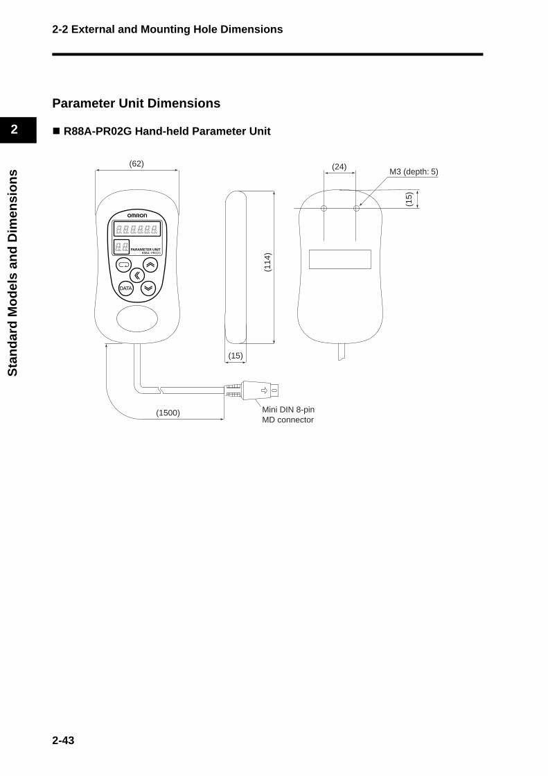
2-2 External and Mounting Hole Dimensions
2
Sta
nd
ard
Mo
del
s an
d D
imen
sio
ns
Parameter Unit Dimensions
R88A-PR02G Hand-held Parameter Unit
Mini DIN 8-pinMD connector
(62) (24)
(15)
(1500)
M3 (depth: 5)
(114
)
(15)
2-43
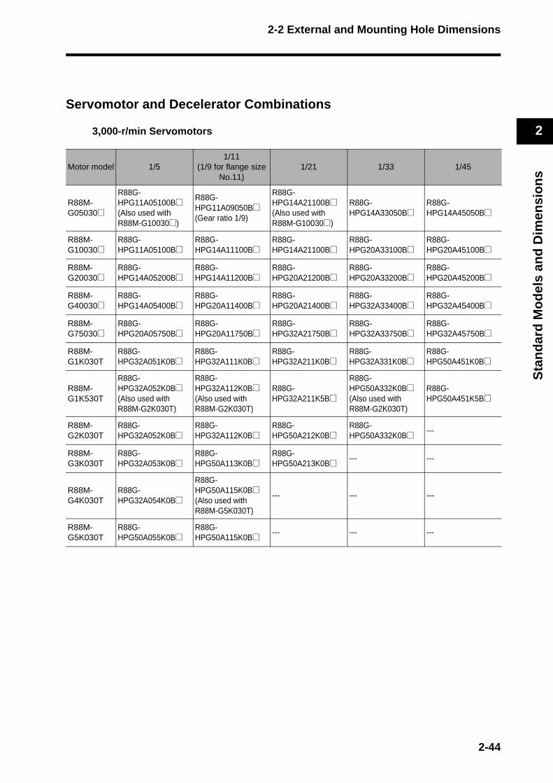
2-2 External and Mounting Hole Dimensions
2
Sta
nd
ard
Mo
del
s an
d D
imen
sio
ns
Servomotor and Decelerator Combinations
3,000-r/min Servomotors
Motor model 1/51/11
(1/9 for flange size No.11)
1/21 1/33 1/45
R88M-G05030@
R88G-HPG11A05100B@(Also used with R88M-G10030@)
R88G-HPG11A09050B@(Gear ratio 1/9)
R88G-HPG14A21100B@(Also used with R88M-G10030@)
R88G-HPG14A33050B@
R88G-HPG14A45050B@
R88M-G10030@
R88G-HPG11A05100B@
R88G-HPG14A11100B@
R88G-HPG14A21100B@
R88G-HPG20A33100B@
R88G-HPG20A45100B@
R88M-G20030@
R88G-HPG14A05200B@
R88G-HPG14A11200B@
R88G-HPG20A21200B@
R88G-HPG20A33200B@
R88G-HPG20A45200B@
R88M-G40030@
R88G-HPG14A05400B@
R88G-HPG20A11400B@
R88G-HPG20A21400B@
R88G-HPG32A33400B@
R88G-HPG32A45400B@
R88M-G75030@
R88G-HPG20A05750B@
R88G-HPG20A11750B@
R88G-HPG32A21750B@
R88G-HPG32A33750B@
R88G-HPG32A45750B@
R88M-G1K030T
R88G-HPG32A051K0B@
R88G-HPG32A111K0B@
R88G-HPG32A211K0B@
R88G-HPG32A331K0B@
R88G-HPG50A451K0B@
R88M-G1K530T
R88G-HPG32A052K0B@(Also used with R88M-G2K030T)
R88G-HPG32A112K0B@(Also used with R88M-G2K030T)
R88G-HPG32A211K5B@
R88G-HPG50A332K0B@(Also used with R88M-G2K030T)
R88G-HPG50A451K5B@
R88M-G2K030T
R88G-HPG32A052K0B@
R88G-HPG32A112K0B@
R88G-HPG50A212K0B@
R88G-HPG50A332K0B@ ---
R88M-G3K030T
R88G-HPG32A053K0B@
R88G-HPG50A113K0B@
R88G-HPG50A213K0B@ --- ---
R88M-G4K030T
R88G-HPG32A054K0B@
R88G-HPG50A115K0B@(Also used with R88M-G5K030T)
--- --- ---
R88M-G5K030T
R88G-HPG50A055K0B@
R88G-HPG50A115K0B@ --- --- ---
2-44
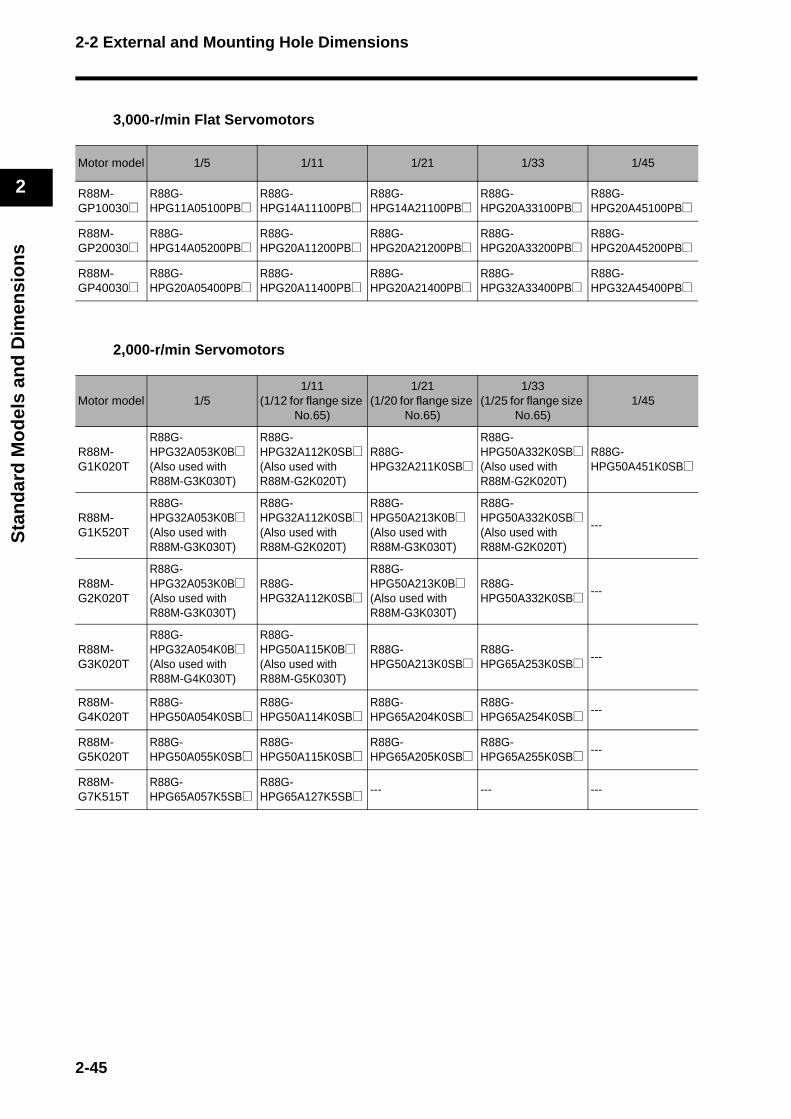
2-2 External and Mounting Hole Dimensions
2
Sta
nd
ard
Mo
del
s an
d D
imen
sio
ns
3,000-r/min Flat Servomotors
2,000-r/min Servomotors
Motor model 1/5 1/11 1/21 1/33 1/45
R88M-GP10030@
R88G-HPG11A05100PB@
R88G-HPG14A11100PB@
R88G-HPG14A21100PB@
R88G-HPG20A33100PB@
R88G-HPG20A45100PB@
R88M-GP20030@
R88G-HPG14A05200PB@
R88G-HPG20A11200PB@
R88G-HPG20A21200PB@
R88G-HPG20A33200PB@
R88G-HPG20A45200PB@
R88M-GP40030@
R88G-HPG20A05400PB@
R88G-HPG20A11400PB@
R88G-HPG20A21400PB@
R88G-HPG32A33400PB@
R88G-HPG32A45400PB@
Motor model 1/51/11
(1/12 for flange size No.65)
1/21(1/20 for flange size
No.65)
1/33(1/25 for flange size
No.65)1/45
R88M-G1K020T
R88G-HPG32A053K0B@(Also used with R88M-G3K030T)
R88G-HPG32A112K0SB@(Also used with R88M-G2K020T)
R88G-HPG32A211K0SB@
R88G-HPG50A332K0SB@(Also used with R88M-G2K020T)
R88G-HPG50A451K0SB@
R88M-G1K520T
R88G-HPG32A053K0B@(Also used with R88M-G3K030T)
R88G-HPG32A112K0SB@(Also used with R88M-G2K020T)
R88G-HPG50A213K0B@(Also used with R88M-G3K030T)
R88G-HPG50A332K0SB@(Also used with R88M-G2K020T)
---
R88M-G2K020T
R88G-HPG32A053K0B@(Also used with R88M-G3K030T)
R88G-HPG32A112K0SB@
R88G-HPG50A213K0B@(Also used with R88M-G3K030T)
R88G-HPG50A332K0SB@ ---
R88M-G3K020T
R88G-HPG32A054K0B@(Also used with R88M-G4K030T)
R88G-HPG50A115K0B@(Also used with R88M-G5K030T)
R88G-HPG50A213K0SB@
R88G-HPG65A253K0SB@ ---
R88M-G4K020T
R88G-HPG50A054K0SB@
R88G-HPG50A114K0SB@
R88G-HPG65A204K0SB@
R88G-HPG65A254K0SB@ ---
R88M-G5K020T
R88G-HPG50A055K0SB@
R88G-HPG50A115K0SB@
R88G-HPG65A205K0SB@
R88G-HPG65A255K0SB@ ---
R88M-G7K515T
R88G-HPG65A057K5SB@
R88G-HPG65A127K5SB@ --- --- ---
2-45
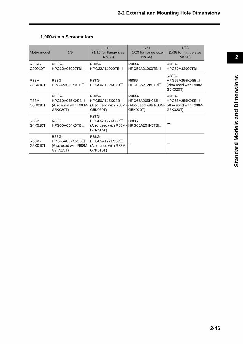
2-2 External and Mounting Hole Dimensions
2
Sta
nd
ard
Mo
del
s an
d D
imen
sio
ns
1,000-r/min Servomotors
Motor model 1/51/11
(1/12 for flange size No.65)
1/21(1/20 for flange size
No.65)
1/33(1/25 for flange size
No.65)
R88M-G90010T
R88G-HPG32A05900TB@
R88G-HPG32A11900TB@
R88G-HPG50A21900TB@
R88G-HPG50A33900TB@
R88M-G2K010T
R88G-HPG32A052K0TB@
R88G-HPG50A112K0TB@
R88G-HPG50A212K0TB@
R88G-HPG65A255K0SB@(Also used with R88M-G5K020T)
R88M-G3K010T
R88G-HPG50A055K0SB@(Also used with R88M-G5K020T)
R88G-HPG50A115K0SB@(Also used with R88M-G5K020T)
R88G-HPG65A205K0SB@(Also used with R88M-G5K020T)
R88G-HPG65A255K0SB@(Also used with R88M-G5K020T)
R88M-G4K510T
R88G-HPG50A054K5TB@
R88G-HPG65A127K5SB@(Also used with R88M-G7K515T)
R88G-HPG65A204K5TB@ ---
R88M-G6K010T
R88G-HPG65A057K5SB@(Also used with R88M-G7K515T)
R88G-HPG65A127K5SB@(Also used with R88M-G7K515T)
--- ---
2-46
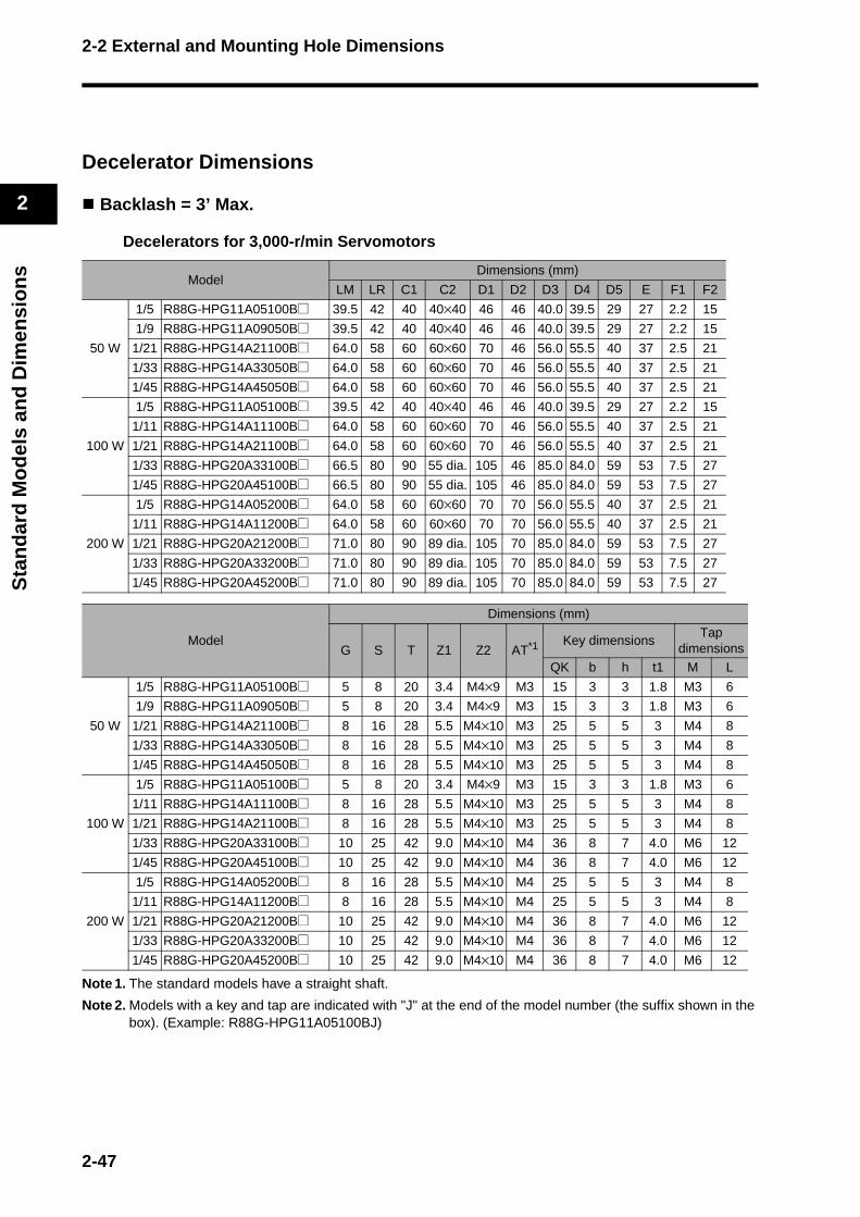
2-2 External and Mounting Hole Dimensions
2
Sta
nd
ard
Mo
del
s an
d D
imen
sio
ns
Decelerator Dimensions
Backlash = 3’ Max.
Decelerators for 3,000-r/min Servomotors
Note 1. The standard models have a straight shaft.
Note 2. Models with a key and tap are indicated with "J" at the end of the model number (the suffix shown in the box). (Example: R88G-HPG11A05100BJ)
Model Dimensions (mm)
LM LR C1 C2 D1 D2 D3 D4 D5 E F1 F2
50 W
1/5 R88G-HPG11A05100B@ 39.5 42 40 40×40 46 46 40.0 39.5 29 27 2.2 15
1/9 R88G-HPG11A09050B@ 39.5 42 40 40×40 46 46 40.0 39.5 29 27 2.2 15
1/21 R88G-HPG14A21100B@ 64.0 58 60 60×60 70 46 56.0 55.5 40 37 2.5 21
1/33 R88G-HPG14A33050B@ 64.0 58 60 60×60 70 46 56.0 55.5 40 37 2.5 21
1/45 R88G-HPG14A45050B@ 64.0 58 60 60×60 70 46 56.0 55.5 40 37 2.5 21
100 W
1/5 R88G-HPG11A05100B@ 39.5 42 40 40×40 46 46 40.0 39.5 29 27 2.2 15
1/11 R88G-HPG14A11100B@ 64.0 58 60 60×60 70 46 56.0 55.5 40 37 2.5 21
1/21 R88G-HPG14A21100B@ 64.0 58 60 60×60 70 46 56.0 55.5 40 37 2.5 21
1/33 R88G-HPG20A33100B@ 66.5 80 90 55 dia. 105 46 85.0 84.0 59 53 7.5 27
1/45 R88G-HPG20A45100B@ 66.5 80 90 55 dia. 105 46 85.0 84.0 59 53 7.5 27
200 W
1/5 R88G-HPG14A05200B@ 64.0 58 60 60×60 70 70 56.0 55.5 40 37 2.5 21
1/11 R88G-HPG14A11200B@ 64.0 58 60 60×60 70 70 56.0 55.5 40 37 2.5 21
1/21 R88G-HPG20A21200B@ 71.0 80 90 89 dia. 105 70 85.0 84.0 59 53 7.5 27
1/33 R88G-HPG20A33200B@ 71.0 80 90 89 dia. 105 70 85.0 84.0 59 53 7.5 27
1/45 R88G-HPG20A45200B@ 71.0 80 90 89 dia. 105 70 85.0 84.0 59 53 7.5 27
Model
Dimensions (mm)
G S T Z1 Z2 AT*1 Key dimensionsTap
dimensions
QK b h t1 M L
50 W
1/5 R88G-HPG11A05100B@ 5 8 20 3.4 M4×9 M3 15 3 3 1.8 M3 6
1/9 R88G-HPG11A09050B@ 5 8 20 3.4 M4×9 M3 15 3 3 1.8 M3 6
1/21 R88G-HPG14A21100B@ 8 16 28 5.5 M4×10 M3 25 5 5 3 M4 8
1/33 R88G-HPG14A33050B@ 8 16 28 5.5 M4×10 M3 25 5 5 3 M4 8
1/45 R88G-HPG14A45050B@ 8 16 28 5.5 M4×10 M3 25 5 5 3 M4 8
100 W
1/5 R88G-HPG11A05100B@ 5 8 20 3.4 M4×9 M3 15 3 3 1.8 M3 6
1/11 R88G-HPG14A11100B@ 8 16 28 5.5 M4×10 M3 25 5 5 3 M4 8
1/21 R88G-HPG14A21100B@ 8 16 28 5.5 M4×10 M3 25 5 5 3 M4 8
1/33 R88G-HPG20A33100B@ 10 25 42 9.0 M4×10 M4 36 8 7 4.0 M6 12
1/45 R88G-HPG20A45100B@ 10 25 42 9.0 M4×10 M4 36 8 7 4.0 M6 12
200 W
1/5 R88G-HPG14A05200B@ 8 16 28 5.5 M4×10 M4 25 5 5 3 M4 8
1/11 R88G-HPG14A11200B@ 8 16 28 5.5 M4×10 M4 25 5 5 3 M4 8
1/21 R88G-HPG20A21200B@ 10 25 42 9.0 M4×10 M4 36 8 7 4.0 M6 12
1/33 R88G-HPG20A33200B@ 10 25 42 9.0 M4×10 M4 36 8 7 4.0 M6 12
1/45 R88G-HPG20A45200B@ 10 25 42 9.0 M4×10 M4 36 8 7 4.0 M6 12
2-47
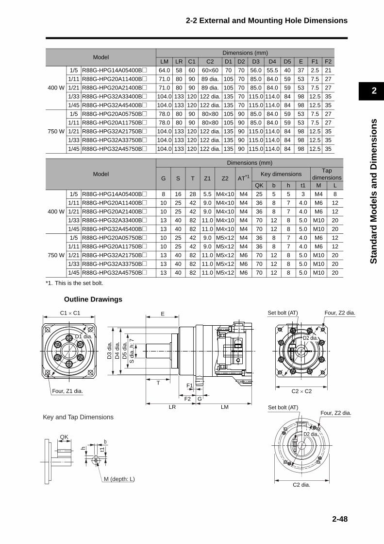
2-2 External and Mounting Hole Dimensions
2
Sta
nd
ard
Mo
del
s an
d D
imen
sio
ns
.
*1. This is the set bolt.
Outline Drawings
Model Dimensions (mm)
LM LR C1 C2 D1 D2 D3 D4 D5 E F1 F2
400 W
1/5 R88G-HPG14A05400B@ 64.0 58 60 60×60 70 70 56.0 55.5 40 37 2.5 21
1/11 R88G-HPG20A11400B@ 71.0 80 90 89 dia. 105 70 85.0 84.0 59 53 7.5 27
1/21 R88G-HPG20A21400B@ 71.0 80 90 89 dia. 105 70 85.0 84.0 59 53 7.5 27
1/33 R88G-HPG32A33400B@ 104.0 133 120 122 dia. 135 70 115.0 114.0 84 98 12.5 35
1/45 R88G-HPG32A45400B@ 104.0 133 120 122 dia. 135 70 115.0 114.0 84 98 12.5 35
750 W
1/5 R88G-HPG20A05750B@ 78.0 80 90 80×80 105 90 85.0 84.0 59 53 7.5 27
1/11 R88G-HPG20A11750B@ 78.0 80 90 80×80 105 90 85.0 84.0 59 53 7.5 27
1/21 R88G-HPG32A21750B@ 104.0 133 120 122 dia. 135 90 115.0 114.0 84 98 12.5 35
1/33 R88G-HPG32A33750B@ 104.0 133 120 122 dia. 135 90 115.0 114.0 84 98 12.5 35
1/45 R88G-HPG32A45750B@ 104.0 133 120 122 dia. 135 90 115.0 114.0 84 98 12.5 35
Model
Dimensions (mm)
G S T Z1 Z2 AT*1 Key dimensionsTap
dimensionsQK b h t1 M L
400 W
1/5 R88G-HPG14A05400B@ 8 16 28 5.5 M4×10 M4 25 5 5 3 M4 8
1/11 R88G-HPG20A11400B@ 10 25 42 9.0 M4×10 M4 36 8 7 4.0 M6 12
1/21 R88G-HPG20A21400B@ 10 25 42 9.0 M4×10 M4 36 8 7 4.0 M6 12
1/33 R88G-HPG32A33400B@ 13 40 82 11.0 M4×10 M4 70 12 8 5.0 M10 20
1/45 R88G-HPG32A45400B@ 13 40 82 11.0 M4×10 M4 70 12 8 5.0 M10 20
750 W
1/5 R88G-HPG20A05750B@ 10 25 42 9.0 M5×12 M4 36 8 7 4.0 M6 12
1/11 R88G-HPG20A11750B@ 10 25 42 9.0 M5×12 M4 36 8 7 4.0 M6 12
1/21 R88G-HPG32A21750B@ 13 40 82 11.0 M5×12 M6 70 12 8 5.0 M10 20
1/33 R88G-HPG32A33750B@ 13 40 82 11.0 M5×12 M6 70 12 8 5.0 M10 20
1/45 R88G-HPG32A45750B@ 13 40 82 11.0 M5×12 M6 70 12 8 5.0 M10 20
C1 × C1
Four, Z1 dia.
S d
ia.,h
: 7D
5 di
a.D
4 di
a.D
3 di
a.
E
T F1
F2
LR
G
LM
C2 × C2
D2 dia.D1 dia.
Four, Z2 diaSet bolt (AT)
C2 dia.
Four, Z2 dia.Set bolt (AT)
D2 dia.QK
Key and Tap Dimensions
b
h t1
M (depth: L)
2-48

2-2 External and Mounting Hole Dimensions
2
Sta
nd
ard
Mo
del
s an
d D
imen
sio
ns
Note 1. The standard models have a straight shaft.
Note 2. Models with a key and tap are indicated with "J" at the end of the model number (the suffix shown in the box). (Example: R88G-HPG32A051K0BJ)
Model Dimensions (mm)
LM LR C1 C2 D1 D2 D3 D4 D5 E F1 F2
1 kW
1/5 R88G-HPG32A051K0B@ 104 133 120 122 dia. 135 100 115 114 84 98 12.5 35
1/11 R88G-HPG32A111K0B@ 104 133 120 122 dia. 135 100 115 114 84 98 12.5 35
1/21 R88G-HPG32A211K0B@ 104 133 120 122 dia. 135 100 115 114 84 98 12.5 35
1/33 R88G-HPG32A331K0B@ 104 133 120 122 dia. 135 100 115 114 84 98 12.5 35
1/45 R88G-HPG50A451K0B@ 123 156 170 170 dia. 190 100 165 163 122 103 12.0 53
1.5 kW
1/5 R88G-HPG32A052K0B@ 110 133 120 135 dia. 135 115 115 114 84 98 12.5 35
1/11 R88G-HPG32A112K0B@ 110 133 120 135 dia. 135 115 115 114 84 98 12.5 35
1/21 R88G-HPG32A211K5B@ 110 133 120 135 dia. 135 115 115 114 84 98 12.5 35
1/33 R88G-HPG50A332K0B@ 123 156 170 170 dia. 190 115 165 163 122 103 12.0 53
1/45 R88G-HPG50A451K5B@ 123 156 170 170 dia. 190 115 165 163 122 103 12.0 53
2 kW
1/5 R88G-HPG32A052K0B@ 110 133 120 135 dia. 135 115 115 114 84 98 12.5 35
1/11 R88G-HPG32A112K0B@ 110 133 120 135 dia. 135 115 115 114 84 98 12.5 35
1/21 R88G-HPG50A212K0B@ 123 156 170 170 dia. 190 115 165 163 122 103 12.0 53
1/33 R88G-HPG50A332K0B@ 123 156 170 170 dia. 190 115 165 163 122 103 12.0 53
3 kW
1/5 R88G-HPG32A053K0B@ 107 133 120 130×130 135 145 115 114 84 98 12.5 35
1/11 R88G-HPG50A113K0B@ 123 156 170 170 dia. 190 145 165 163 122 103 12.0 53
1/21 R88G-HPG50A213K0B@ 123 156 170 170 dia. 190 145 165 163 122 103 12.0 53
4 kW1/5 R88G-HPG32A054K0B@ 129 133 120 130×130 135 145 115 114 84 98 12.5 35
1/11 R88G-HPG50A115K0B@ 149 156 170 130×130 190 145 165 163 122 103 12.0 53
5 kW1/5 R88G-HPG50A055K0B@ 149 156 170 130×130 190 145 165 163 122 103 12.0 53
1/11 R88G-HPG50A115K0B@ 149 156 170 130×130 190 145 165 163 122 103 12.0 53
2-49
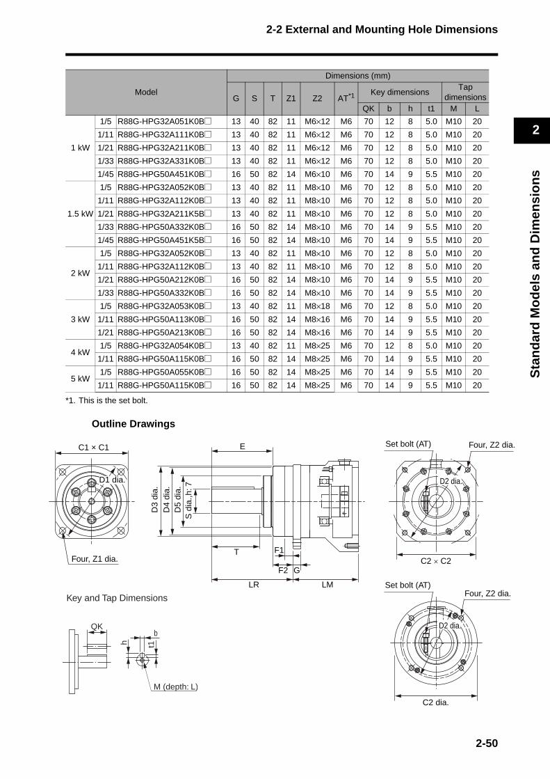
2-2 External and Mounting Hole Dimensions
2
Sta
nd
ard
Mo
del
s an
d D
imen
sio
ns
a.
.
*1. This is the set bolt.
Outline Drawings
Model
Dimensions (mm)
G S T Z1 Z2 AT*1 Key dimensionsTap
dimensionsQK b h t1 M L
1 kW
1/5 R88G-HPG32A051K0B@ 13 40 82 11 M6×12 M6 70 12 8 5.0 M10 20
1/11 R88G-HPG32A111K0B@ 13 40 82 11 M6×12 M6 70 12 8 5.0 M10 20
1/21 R88G-HPG32A211K0B@ 13 40 82 11 M6×12 M6 70 12 8 5.0 M10 20
1/33 R88G-HPG32A331K0B@ 13 40 82 11 M6×12 M6 70 12 8 5.0 M10 20
1/45 R88G-HPG50A451K0B@ 16 50 82 14 M6×10 M6 70 14 9 5.5 M10 20
1.5 kW
1/5 R88G-HPG32A052K0B@ 13 40 82 11 M8×10 M6 70 12 8 5.0 M10 20
1/11 R88G-HPG32A112K0B@ 13 40 82 11 M8×10 M6 70 12 8 5.0 M10 20
1/21 R88G-HPG32A211K5B@ 13 40 82 11 M8×10 M6 70 12 8 5.0 M10 20
1/33 R88G-HPG50A332K0B@ 16 50 82 14 M8×10 M6 70 14 9 5.5 M10 20
1/45 R88G-HPG50A451K5B@ 16 50 82 14 M8×10 M6 70 14 9 5.5 M10 20
2 kW
1/5 R88G-HPG32A052K0B@ 13 40 82 11 M8×10 M6 70 12 8 5.0 M10 20
1/11 R88G-HPG32A112K0B@ 13 40 82 11 M8×10 M6 70 12 8 5.0 M10 20
1/21 R88G-HPG50A212K0B@ 16 50 82 14 M8×10 M6 70 14 9 5.5 M10 20
1/33 R88G-HPG50A332K0B@ 16 50 82 14 M8×10 M6 70 14 9 5.5 M10 20
3 kW
1/5 R88G-HPG32A053K0B@ 13 40 82 11 M8×18 M6 70 12 8 5.0 M10 20
1/11 R88G-HPG50A113K0B@ 16 50 82 14 M8×16 M6 70 14 9 5.5 M10 20
1/21 R88G-HPG50A213K0B@ 16 50 82 14 M8×16 M6 70 14 9 5.5 M10 20
4 kW1/5 R88G-HPG32A054K0B@ 13 40 82 11 M8×25 M6 70 12 8 5.0 M10 20
1/11 R88G-HPG50A115K0B@ 16 50 82 14 M8×25 M6 70 14 9 5.5 M10 20
5 kW1/5 R88G-HPG50A055K0B@ 16 50 82 14 M8×25 M6 70 14 9 5.5 M10 20
1/11 R88G-HPG50A115K0B@ 16 50 82 14 M8×25 M6 70 14 9 5.5 M10 20
E
T F1
F2
LR
G
LM
S d
ia.,h
: 7D
5 di
a.D
4 di
a.D
3 di
a.
Four, Z2 diSet bolt (AT)
C2 dia.
C1 × C1
D1 dia.
Four, Z1 dia.
D2 dia.
C2 × C2
Four, Z2 diaSet bolt (AT)
D2 dia.QK
Key and Tap Dimensions
b
h t1
M (depth: L)
2-50
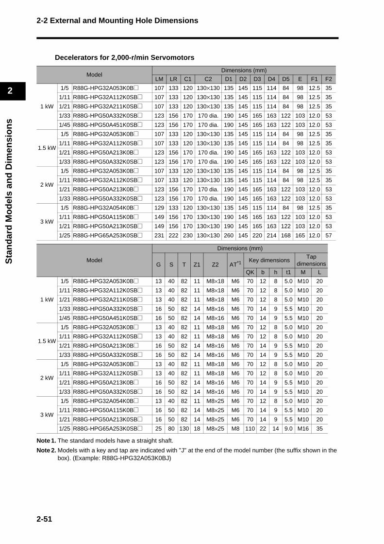
2-2 External and Mounting Hole Dimensions
2
Sta
nd
ard
Mo
del
s an
d D
imen
sio
ns
Decelerators for 2,000-r/min Servomotors
Note 1. The standard models have a straight shaft.
Note 2. Models with a key and tap are indicated with "J" at the end of the model number (the suffix shown in the box). (Example: R88G-HPG32A053K0BJ)
Model Dimensions (mm)
LM LR C1 C2 D1 D2 D3 D4 D5 E F1 F2
1 kW
1/5 R88G-HPG32A053K0B@ 107 133 120 130×130 135 145 115 114 84 98 12.5 35
1/11 R88G-HPG32A112K0SB@ 107 133 120 130×130 135 145 115 114 84 98 12.5 35
1/21 R88G-HPG32A211K0SB@ 107 133 120 130×130 135 145 115 114 84 98 12.5 35
1/33 R88G-HPG50A332K0SB@ 123 156 170 170 dia. 190 145 165 163 122 103 12.0 53
1/45 R88G-HPG50A451K0SB@ 123 156 170 170 dia. 190 145 165 163 122 103 12.0 53
1.5 kW
1/5 R88G-HPG32A053K0B@ 107 133 120 130×130 135 145 115 114 84 98 12.5 35
1/11 R88G-HPG32A112K0SB@ 107 133 120 130×130 135 145 115 114 84 98 12.5 35
1/21 R88G-HPG50A213K0B@ 123 156 170 170 dia. 190 145 165 163 122 103 12.0 53
1/33 R88G-HPG50A332K0SB@ 123 156 170 170 dia. 190 145 165 163 122 103 12.0 53
2 kW
1/5 R88G-HPG32A053K0B@ 107 133 120 130×130 135 145 115 114 84 98 12.5 35
1/11 R88G-HPG32A112K0SB@ 107 133 120 130×130 135 145 115 114 84 98 12.5 35
1/21 R88G-HPG50A213K0B@ 123 156 170 170 dia. 190 145 165 163 122 103 12.0 53
1/33 R88G-HPG50A332K0SB@ 123 156 170 170 dia. 190 145 165 163 122 103 12.0 53
3 kW
1/5 R88G-HPG32A054K0B@ 129 133 120 130×130 135 145 115 114 84 98 12.5 35
1/11 R88G-HPG50A115K0B@ 149 156 170 130×130 190 145 165 163 122 103 12.0 53
1/21 R88G-HPG50A213K0SB@ 149 156 170 130×130 190 145 165 163 122 103 12.0 53
1/25 R88G-HPG65A253K0SB@ 231 222 230 130×130 260 145 220 214 168 165 12.0 57
Model
Dimensions (mm)
G S T Z1 Z2 AT*1 Key dimensionsTap
dimensions
QK b h t1 M L
1 kW
1/5 R88G-HPG32A053K0B@ 13 40 82 11 M8×18 M6 70 12 8 5.0 M10 20
1/11 R88G-HPG32A112K0SB@ 13 40 82 11 M8×18 M6 70 12 8 5.0 M10 20
1/21 R88G-HPG32A211K0SB@ 13 40 82 11 M8×18 M6 70 12 8 5.0 M10 20
1/33 R88G-HPG50A332K0SB@ 16 50 82 14 M8×16 M6 70 14 9 5.5 M10 20
1/45 R88G-HPG50A451K0SB@ 16 50 82 14 M8×16 M6 70 14 9 5.5 M10 20
1.5 kW
1/5 R88G-HPG32A053K0B@ 13 40 82 11 M8×18 M6 70 12 8 5.0 M10 20
1/11 R88G-HPG32A112K0SB@ 13 40 82 11 M8×18 M6 70 12 8 5.0 M10 20
1/21 R88G-HPG50A213K0B@ 16 50 82 14 M8×16 M6 70 14 9 5.5 M10 20
1/33 R88G-HPG50A332K0SB@ 16 50 82 14 M8×16 M6 70 14 9 5.5 M10 20
2 kW
1/5 R88G-HPG32A053K0B@ 13 40 82 11 M8×18 M6 70 12 8 5.0 M10 20
1/11 R88G-HPG32A112K0SB@ 13 40 82 11 M8×18 M6 70 12 8 5.0 M10 20
1/21 R88G-HPG50A213K0B@ 16 50 82 14 M8×16 M6 70 14 9 5.5 M10 20
1/33 R88G-HPG50A332K0SB@ 16 50 82 14 M8×16 M6 70 14 9 5.5 M10 20
3 kW
1/5 R88G-HPG32A054K0B@ 13 40 82 11 M8×25 M6 70 12 8 5.0 M10 20
1/11 R88G-HPG50A115K0B@ 16 50 82 14 M8×25 M6 70 14 9 5.5 M10 20
1/21 R88G-HPG50A213K0SB@ 16 50 82 14 M8×25 M6 70 14 9 5.5 M10 20
1/25 R88G-HPG65A253K0SB@ 25 80 130 18 M8×25 M8 110 22 14 9.0 M16 35
2-51
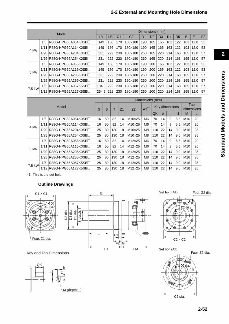
2-2 External and Mounting Hole Dimensions
2
Sta
nd
ard
Mo
del
s an
d D
imen
sio
ns
*1. This is the set bolt.
Outline Drawings
Model Dimensions (mm)
LM LR C1 C2 D1 D2 D3 D4 D5 E F1 F2
4 kW
1/5 R88G-HPG50A054K0SB@ 149 156 170 180×180 190 165 165 163 122 103 12.0 53
1/11 R88G-HPG50A114K0SB@ 149 156 170 180×180 190 165 165 163 122 103 12.0 53
1/20 R88G-HPG65A204K0SB@ 231 222 230 180×180 260 165 220 214 168 165 12.0 57
1/25 R88G-HPG65A254K0SB@ 231 222 230 180×180 260 165 220 214 168 165 12.0 57
5 kW
1/5 R88G-HPG50A055K0SB@ 149 156 170 180×180 190 200 165 163 122 103 12.0 53
1/11 R88G-HPG50A115K0SB@ 149 156 170 180×180 190 200 165 163 122 103 12.0 53
1/20 R88G-HPG65A205K0SB@ 231 222 230 180×180 260 200 220 214 168 165 12.0 57
1/25 R88G-HPG65A255K0SB@ 231 222 230 180×180 260 200 220 214 168 165 12.0 57
7.5 kW1/5 R88G-HPG65A057K5SB@ 184.5 222 230 180×180 260 200 220 214 168 165 12.0 57
1/12 R88G-HPG65A127K5SB@ 254.5 222 230 180×180 260 200 220 214 168 165 12.0 57
Model
Dimensions (mm)
G S T Z1 Z2 AT*1 Key dimensionsTap
dimensionsQK b h t1 M L
4 kW
1/5 R88G-HPG50A054K0SB@ 16 50 82 14 M10×25 M6 70 14 9 5.5 M10 20
1/11 R88G-HPG50A114K0SB@ 16 50 82 14 M10×25 M6 70 14 9 5.5 M10 20
1/20 R88G-HPG65A204K0SB@ 25 80 130 18 M10×25 M8 110 22 14 9.0 M16 35
1/25 R88G-HPG65A254K0SB@ 25 80 130 18 M10×25 M8 110 22 14 9.0 M16 35
5 kW
1/5 R88G-HPG50A055K0SB@ 16 50 82 14 M12×25 M6 70 14 9 5.5 M10 20
1/11 R88G-HPG50A115K0SB@ 16 50 82 14 M12×25 M6 70 14 9 5.5 M10 20
1/20 R88G-HPG65A205K0SB@ 25 80 130 18 M12×25 M8 110 22 14 9.0 M16 35
1/25 R88G-HPG65A255K0SB@ 25 80 130 18 M12×25 M8 110 22 14 9.0 M16 35
7.5 kW1/5 R88G-HPG65A057K5SB@ 25 80 130 18 M12×25 M8 110 22 14 9.0 M16 35
1/12 R88G-HPG65A127K5SB@ 25 80 130 18 M12×25 M8 110 22 14 9.0 M16 35
E
T F1
F2
LR
G
LM
S d
ia.,h
: 7D
5 di
a.D
4 di
a.D
3 di
a.
Four, Z2 dia.Set bolt (AT)
C2 dia.
C1 × C1
D1 dia.
Four, Z1 dia.
D2 dia.
C2 × C2
Four, Z2 dia.Set bolt (AT)
D2 dia.QK
Key and Tap Dimensions
b
h t1
M (depth: L)
2-52

2-2 External and Mounting Hole Dimensions
2
Sta
nd
ard
Mo
del
s an
d D
imen
sio
ns
Decelerators for 1,000-r/min Servomotors
Note 1. The standard models have a straight shaft.
Note 2. Models with a key and tap are indicated with "J" at the end of the model number (the suffix shown in the box). (Example: R88G-HPG32A05900TBJ)
Model Dimensions (mm)
LM LR C1 C2 D1 D2 D3 D4 D5 E F1 F2
900 W
1/5 R88G-HPG32A05900TB@ 129 133 120 130×130 135 145 115 114 84 98 12.5 35
1/11 R88G-HPG32A11900TB@ 129 133 120 130×130 135 145 115 114 84 98 12.5 35
1/21 R88G-HPG50A21900TB@ 149 156 170 130×130 190 145 165 163 122 103 12.0 53
1/33 R88G-HPG50A33900TB@ 149 156 170 130×130 190 145 165 163 122 103 12.0 53
2 kW
1/5 R88G-HPG32A052K0TB@ 129 133 120 180×180 135 200 115 114 84 98 12.5 35
1/11 R88G-HPG50A112K0TB@ 149 156 170 180×180 190 200 165 163 122 103 12.0 53
1/21 R88G-HPG50A212K0TB@ 149 156 170 180×180 190 200 165 163 122 103 12.0 53
1/25 R88G-HPG65A255K0SB@ 231 222 230 180×180 260 200 220 214 168 165 12.0 57
3 kW
1/5 R88G-HPG50A055K0SB@ 149 156 170 180×180 190 200 165 163 122 103 12.0 53
1/11 R88G-HPG50A115K0SB@ 149 156 170 180×180 190 200 165 163 122 103 12.0 53
1/20 R88G-HPG65A205K0SB@ 231 222 230 180×180 260 200 220 214 168 165 12.0 57
1/25 R88G-HPG65A255K0SB@ 231 222 230 180×180 260 200 220 214 168 165 12.0 57
4.5 kW
1/5 R88G-HPG50A054K5TB@ 149 156 170 180×180 190 200 165 163 122 103 12.0 53
1/12 R88G-HPG65A127K5SB@ 254.5 222 230 180×180 260 200 220 214 168 165 12.0 57
1/20 R88G-HPG65A204K5TB@ 254.5 222 230 180×180 260 200 220 214 168 165 12.0 57
6 kW1/5 R88G-HPG65A057K5SB@ 184.5 222 230 180×180 260 200 220 214 168 165 12.0 57
1/12 R88G-HPG65A127K5SB@ 254.5 222 230 180×180 260 200 220 214 168 165 12.0 57
2-53
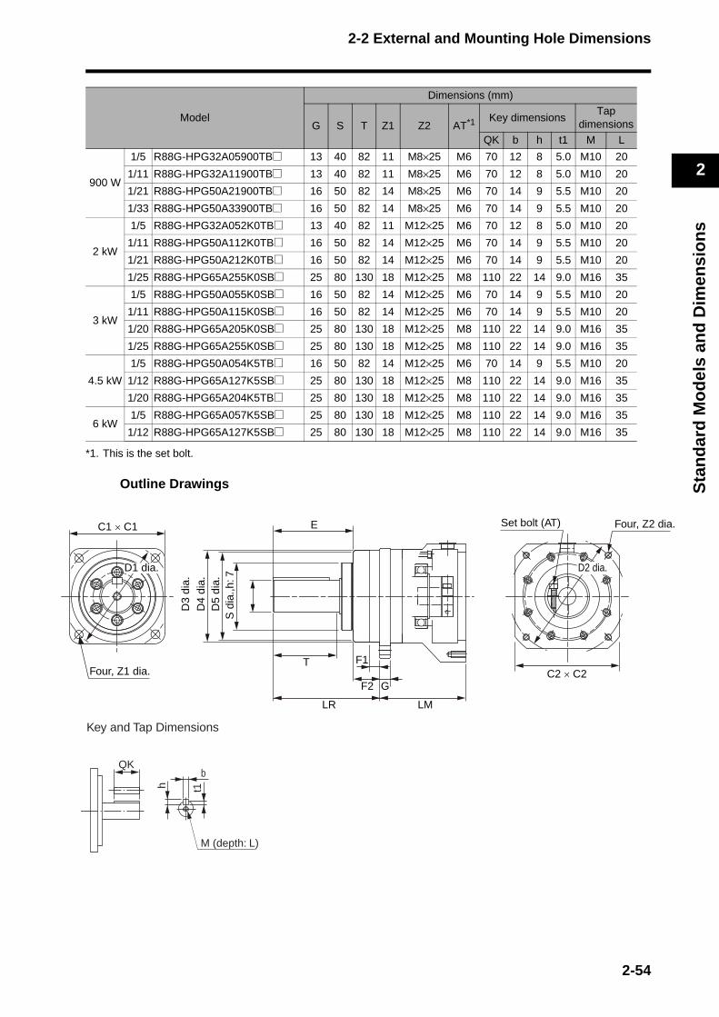
2-2 External and Mounting Hole Dimensions
2
Sta
nd
ard
Mo
del
s an
d D
imen
sio
ns
ia.
*1. This is the set bolt.
Outline Drawings
Model
Dimensions (mm)
G S T Z1 Z2 AT*1 Key dimensionsTap
dimensions
QK b h t1 M L
900 W
1/5 R88G-HPG32A05900TB@ 13 40 82 11 M8×25 M6 70 12 8 5.0 M10 20
1/11 R88G-HPG32A11900TB@ 13 40 82 11 M8×25 M6 70 12 8 5.0 M10 20
1/21 R88G-HPG50A21900TB@ 16 50 82 14 M8×25 M6 70 14 9 5.5 M10 20
1/33 R88G-HPG50A33900TB@ 16 50 82 14 M8×25 M6 70 14 9 5.5 M10 20
2 kW
1/5 R88G-HPG32A052K0TB@ 13 40 82 11 M12×25 M6 70 12 8 5.0 M10 20
1/11 R88G-HPG50A112K0TB@ 16 50 82 14 M12×25 M6 70 14 9 5.5 M10 20
1/21 R88G-HPG50A212K0TB@ 16 50 82 14 M12×25 M6 70 14 9 5.5 M10 20
1/25 R88G-HPG65A255K0SB@ 25 80 130 18 M12×25 M8 110 22 14 9.0 M16 35
3 kW
1/5 R88G-HPG50A055K0SB@ 16 50 82 14 M12×25 M6 70 14 9 5.5 M10 20
1/11 R88G-HPG50A115K0SB@ 16 50 82 14 M12×25 M6 70 14 9 5.5 M10 20
1/20 R88G-HPG65A205K0SB@ 25 80 130 18 M12×25 M8 110 22 14 9.0 M16 35
1/25 R88G-HPG65A255K0SB@ 25 80 130 18 M12×25 M8 110 22 14 9.0 M16 35
4.5 kW
1/5 R88G-HPG50A054K5TB@ 16 50 82 14 M12×25 M6 70 14 9 5.5 M10 20
1/12 R88G-HPG65A127K5SB@ 25 80 130 18 M12×25 M8 110 22 14 9.0 M16 35
1/20 R88G-HPG65A204K5TB@ 25 80 130 18 M12×25 M8 110 22 14 9.0 M16 35
6 kW1/5 R88G-HPG65A057K5SB@ 25 80 130 18 M12×25 M8 110 22 14 9.0 M16 35
1/12 R88G-HPG65A127K5SB@ 25 80 130 18 M12×25 M8 110 22 14 9.0 M16 35
E
T F1
F2
LR
G
LM
C1 × C1
Four, Z1 dia.
S d
ia.,h
: 7D
5 di
a.D
4 di
a.D
3 di
a.
D1 dia.
Four, Z2 dSet bolt (AT)
D2 dia.
C2 × C2
QK
Key and Tap Dimensions
b
h t1
M (depth: L)
2-54
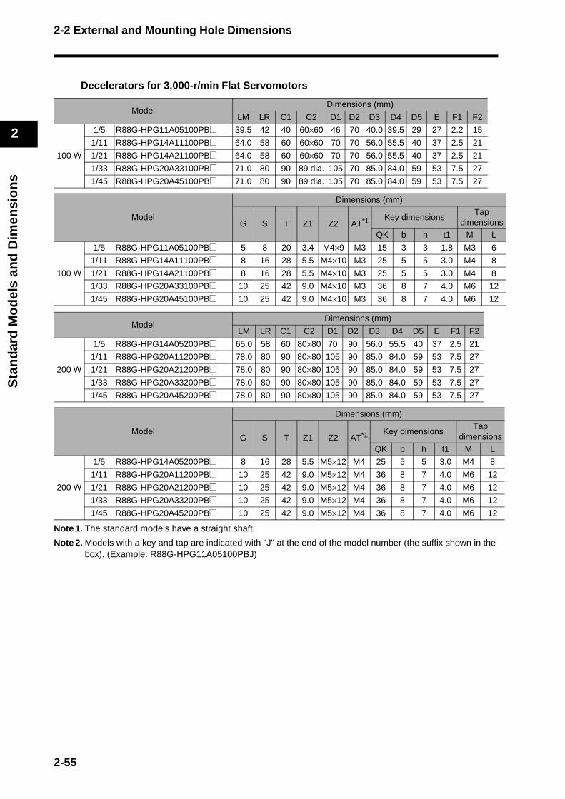
2-2 External and Mounting Hole Dimensions
2
Sta
nd
ard
Mo
del
s an
d D
imen
sio
ns
Decelerators for 3,000-r/min Flat Servomotors
Note 1. The standard models have a straight shaft.
Note 2. Models with a key and tap are indicated with "J" at the end of the model number (the suffix shown in the box). (Example: R88G-HPG11A05100PBJ)
Model Dimensions (mm)
LM LR C1 C2 D1 D2 D3 D4 D5 E F1 F2
100 W
1/5 R88G-HPG11A05100PB@ 39.5 42 40 60×60 46 70 40.0 39.5 29 27 2.2 15
1/11 R88G-HPG14A11100PB@ 64.0 58 60 60×60 70 70 56.0 55.5 40 37 2.5 21
1/21 R88G-HPG14A21100PB@ 64.0 58 60 60×60 70 70 56.0 55.5 40 37 2.5 21
1/33 R88G-HPG20A33100PB@ 71.0 80 90 89 dia. 105 70 85.0 84.0 59 53 7.5 27
1/45 R88G-HPG20A45100PB@ 71.0 80 90 89 dia. 105 70 85.0 84.0 59 53 7.5 27
Model
Dimensions (mm)
G S T Z1 Z2 AT*1 Key dimensionsTap
dimensions
QK b h t1 M L
100 W
1/5 R88G-HPG11A05100PB@ 5 8 20 3.4 M4×9 M3 15 3 3 1.8 M3 6
1/11 R88G-HPG14A11100PB@ 8 16 28 5.5 M4×10 M3 25 5 5 3.0 M4 8
1/21 R88G-HPG14A21100PB@ 8 16 28 5.5 M4×10 M3 25 5 5 3.0 M4 8
1/33 R88G-HPG20A33100PB@ 10 25 42 9.0 M4×10 M3 36 8 7 4.0 M6 12
1/45 R88G-HPG20A45100PB@ 10 25 42 9.0 M4×10 M3 36 8 7 4.0 M6 12
Model Dimensions (mm)
LM LR C1 C2 D1 D2 D3 D4 D5 E F1 F2
200 W
1/5 R88G-HPG14A05200PB@ 65.0 58 60 80×80 70 90 56.0 55.5 40 37 2.5 21
1/11 R88G-HPG20A11200PB@ 78.0 80 90 80×80 105 90 85.0 84.0 59 53 7.5 27
1/21 R88G-HPG20A21200PB@ 78.0 80 90 80×80 105 90 85.0 84.0 59 53 7.5 27
1/33 R88G-HPG20A33200PB@ 78.0 80 90 80×80 105 90 85.0 84.0 59 53 7.5 27
1/45 R88G-HPG20A45200PB@ 78.0 80 90 80×80 105 90 85.0 84.0 59 53 7.5 27
Model
Dimensions (mm)
G S T Z1 Z2 AT*1 Key dimensionsTap
dimensionsQK b h t1 M L
200 W
1/5 R88G-HPG14A05200PB@ 8 16 28 5.5 M5×12 M4 25 5 5 3.0 M4 8
1/11 R88G-HPG20A11200PB@ 10 25 42 9.0 M5×12 M4 36 8 7 4.0 M6 12
1/21 R88G-HPG20A21200PB@ 10 25 42 9.0 M5×12 M4 36 8 7 4.0 M6 12
1/33 R88G-HPG20A33200PB@ 10 25 42 9.0 M5×12 M4 36 8 7 4.0 M6 12
1/45 R88G-HPG20A45200PB@ 10 25 42 9.0 M5×12 M4 36 8 7 4.0 M6 12
2-55
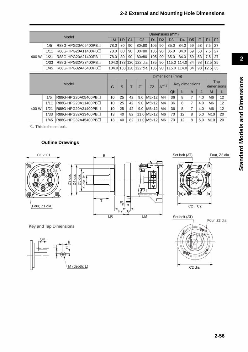
2-2 External and Mounting Hole Dimensions
2
Sta
nd
ard
Mo
del
s an
d D
imen
sio
ns
.
*1. This is the set bolt.
Outline Drawings
Model Dimensions (mm)
LM LR C1 C2 D1 D2 D3 D4 D5 E F1 F2
400 W
1/5 R88G-HPG20A05400PB@ 78.0 80 90 80×80 105 90 85.0 84.0 59 53 7.5 27
1/11 R88G-HPG20A11400PB@ 78.0 80 90 80×80 105 90 85.0 84.0 59 53 7.5 27
1/21 R88G-HPG20A21400PB@ 78.0 80 90 80×80 105 90 85.0 84.0 59 53 7.5 27
1/33 R88G-HPG32A33400PB@ 104.0 133 120 122 dia. 135 90 115.0 114.0 84 98 12.5 35
1/45 R88G-HPG32A45400PB@ 104.0 133 120 122 dia. 135 90 115.0 114.0 84 98 12.5 35
Model
Dimensions (mm)
G S T Z1 Z2 AT*1 Key dimensionsTap
dimensions
QK b h t1 M L
400 W
1/5 R88G-HPG20A05400PB@ 10 25 42 9.0 M5×12 M4 36 8 7 4.0 M6 12
1/11 R88G-HPG20A11400PB@ 10 25 42 9.0 M5×12 M4 36 8 7 4.0 M6 12
1/21 R88G-HPG20A21400PB@ 10 25 42 9.0 M5×12 M4 36 8 7 4.0 M6 12
1/33 R88G-HPG32A33400PB@ 13 40 82 11.0 M5×12 M6 70 12 8 5.0 M10 20
1/45 R88G-HPG32A45400PB@ 13 40 82 11.0 M5×12 M6 70 12 8 5.0 M10 20
C1 × C1
Four, Z1 dia.
S d
ia.,h
: 7D
5 di
a.D
4 di
a.D
3 di
a.
E
T F1
F2
LR
G
LM
C2 × C2
D2 dia.D1 dia.
Four, Z2 diaSet bolt (AT)
C2 dia.
Four, Z2 dia.Set bolt (AT)
D2 dia.QK
Key and Tap Dimensions
b
h t1
M (depth: L)
2-56
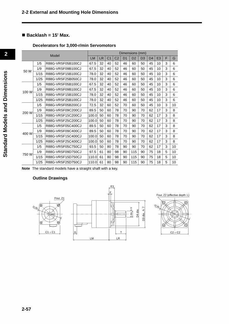
2-2 External and Mounting Hole Dimensions
2
Sta
nd
ard
Mo
del
s an
d D
imen
sio
ns
Backlash = 15' Max.
Decelerators for 3,000-r/min Servomotors
Note The standard models have a straight shaft with a key.
Outline Drawings
Model Dimensions (mm)
LM LR C1 C2 D1 D2 D3 D4 E3 F G
50 W
1/5 R88G-VRSF05B100CJ 67.5 32 40 52 46 60 50 45 10 3 6
1/9 R88G-VRSF09B100CJ 67.5 32 40 52 46 60 50 45 10 3 6
1/15 R88G-VRSF15B100CJ 78.0 32 40 52 46 60 50 45 10 3 6
1/25 R88G-VRSF25B050CJ 78.0 32 40 52 46 60 50 45 10 3 6
100 W
1/5 R88G-VRSF05B100CJ 67.5 32 40 52 46 60 50 45 10 3 6
1/9 R88G-VRSF09B100CJ 67.5 32 40 52 46 60 50 45 10 3 6
1/15 R88G-VRSF15B100CJ 78.0 32 40 52 46 60 50 45 10 3 6
1/25 R88G-VRSF25B100CJ 78.0 32 40 52 46 60 50 45 10 3 6
200 W
1/5 R88G-VRSF05B200CJ 72.5 32 60 52 70 60 50 45 10 3 10
1/9 R88G-VRSF09C200CJ 89.5 50 60 78 70 90 70 62 17 3 8
1/15 R88G-VRSF15C200CJ 100.0 50 60 78 70 90 70 62 17 3 8
1/25 R88G-VRSF25C200CJ 100.0 50 60 78 70 90 70 62 17 3 8
400 W
1/5 R88G-VRSF05C400CJ 89.5 50 60 78 70 90 70 62 17 3 8
1/9 R88G-VRSF09C400CJ 89.5 50 60 78 70 90 70 62 17 3 8
1/15 R88G-VRSF15C400CJ 100.0 50 60 78 70 90 70 62 17 3 8
1/25 R88G-VRSF25C400CJ 100.0 50 60 78 70 90 70 62 17 3 8
750 W
1/5 R88G-VRSF05C750CJ 93.5 50 80 78 90 90 70 62 17 3 10
1/9 R88G-VRSF09D750CJ 97.5 61 80 98 90 115 90 75 18 5 10
1/15 R88G-VRSF15D750CJ 110.0 61 80 98 90 115 90 75 18 5 10
1/25 R88G-VRSF25D750CJ 110.0 61 80 98 90 115 90 75 18 5 10
Four, Z2 (effective depth: L)
C2 × C2C1 × C1
D1 dia.
E3
F
LM
G T
LR
D3
dia.
, h: 7
D4
dia.
S d
ia.,
h: 6
Four, Z1
D2 dia.
2-57
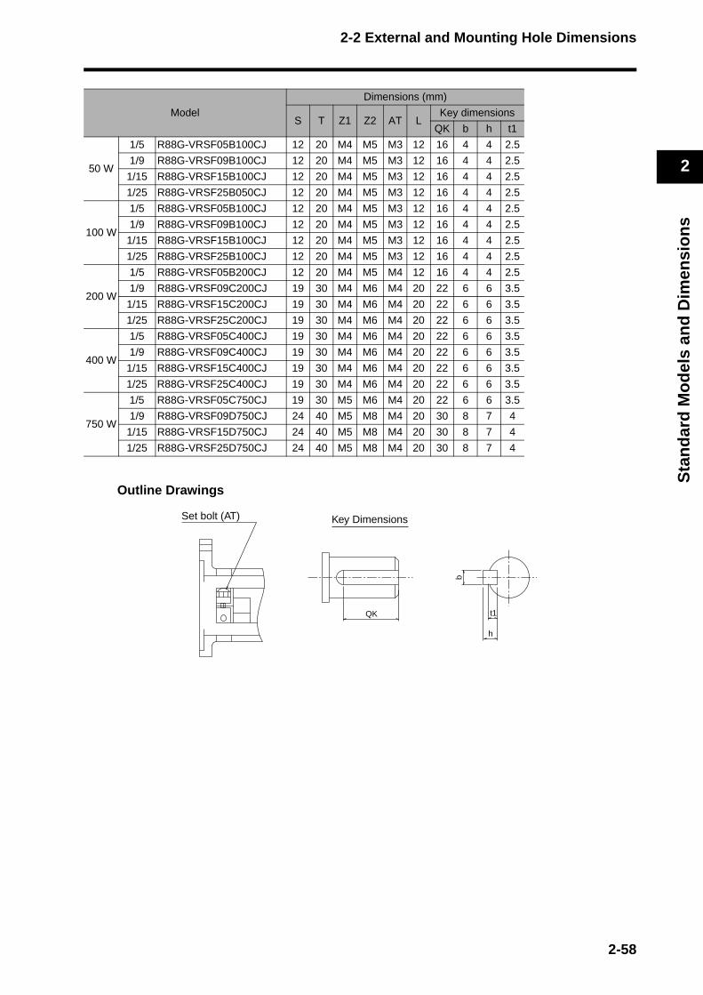
2-2 External and Mounting Hole Dimensions
2
Sta
nd
ard
Mo
del
s an
d D
imen
sio
ns
Outline Drawings
Model
Dimensions (mm)
S T Z1 Z2 AT LKey dimensions
QK b h t1
50 W
1/5 R88G-VRSF05B100CJ 12 20 M4 M5 M3 12 16 4 4 2.5
1/9 R88G-VRSF09B100CJ 12 20 M4 M5 M3 12 16 4 4 2.5
1/15 R88G-VRSF15B100CJ 12 20 M4 M5 M3 12 16 4 4 2.5
1/25 R88G-VRSF25B050CJ 12 20 M4 M5 M3 12 16 4 4 2.5
100 W
1/5 R88G-VRSF05B100CJ 12 20 M4 M5 M3 12 16 4 4 2.5
1/9 R88G-VRSF09B100CJ 12 20 M4 M5 M3 12 16 4 4 2.5
1/15 R88G-VRSF15B100CJ 12 20 M4 M5 M3 12 16 4 4 2.5
1/25 R88G-VRSF25B100CJ 12 20 M4 M5 M3 12 16 4 4 2.5
200 W
1/5 R88G-VRSF05B200CJ 12 20 M4 M5 M4 12 16 4 4 2.5
1/9 R88G-VRSF09C200CJ 19 30 M4 M6 M4 20 22 6 6 3.5
1/15 R88G-VRSF15C200CJ 19 30 M4 M6 M4 20 22 6 6 3.5
1/25 R88G-VRSF25C200CJ 19 30 M4 M6 M4 20 22 6 6 3.5
400 W
1/5 R88G-VRSF05C400CJ 19 30 M4 M6 M4 20 22 6 6 3.5
1/9 R88G-VRSF09C400CJ 19 30 M4 M6 M4 20 22 6 6 3.5
1/15 R88G-VRSF15C400CJ 19 30 M4 M6 M4 20 22 6 6 3.5
1/25 R88G-VRSF25C400CJ 19 30 M4 M6 M4 20 22 6 6 3.5
750 W
1/5 R88G-VRSF05C750CJ 19 30 M5 M6 M4 20 22 6 6 3.5
1/9 R88G-VRSF09D750CJ 24 40 M5 M8 M4 20 30 8 7 4
1/15 R88G-VRSF15D750CJ 24 40 M5 M8 M4 20 30 8 7 4
1/25 R88G-VRSF25D750CJ 24 40 M5 M8 M4 20 30 8 7 4
Set bolt (AT)
QK
h
t1
b
Key Dimensions
2-58

2-2 External and Mounting Hole Dimensions
2
Sta
nd
ard
Mo
del
s an
d D
imen
sio
ns
Decelerators for 3,000-r/min Flat Servomotors
Note The standard models have a straight shaft with a key.
Outline Drawings
Model Dimensions (mm)
LM LR C1 C2 D1 D2 D3 D4 E3 F G
100 W
1/5 R88G-VRSF05B100PCJ 67.5 32 60 52 70 60 50 45 10 3 8
1/9 R88G-VRSF09B100PCJ 67.5 32 60 52 70 60 50 45 10 3 8
1/15 R88G-VRSF15B100PCJ 78.0 32 60 52 70 60 50 45 10 3 8
1/25 R88G-VRSF25B100PCJ 78.0 32 60 52 70 60 50 45 10 3 8
200 W
1/5 R88G-VRSF05B200PCJ 72.5 32 80 52 90 60 50 45 10 3 12
1/9 R88G-VRSF09C200PCJ 89.5 50 80 78 90 90 70 62 17 3 12
1/15 R88G-VRSF15C200PCJ 100.0 50 80 78 90 90 70 62 17 3 12
1/25 R88G-VRSF25C200PCJ 100.0 50 80 78 90 90 70 62 17 3 12
400 W
1/5 R88G-VRSF05C400PCJ 89.5 50 80 78 90 90 70 62 17 3 12
1/9 R88G-VRSF09C400PCJ 89.5 50 80 78 90 90 70 62 17 3 12
1/15 R88G-VRSF15C400PCJ 100.0 50 80 78 90 90 70 62 17 3 12
1/25 R88G-VRSF25C400PCJ 100.0 50 80 78 90 90 70 62 17 3 12
Four, Z1
E3
F
C1 × C1
LM
G T
LR
D3
dia.
, h: 7
D4
dia.
S di
a., h
: 6
Four, Z2 (effective depth: L)
C2 × C2
D2 dia.D1 dia.
2-59
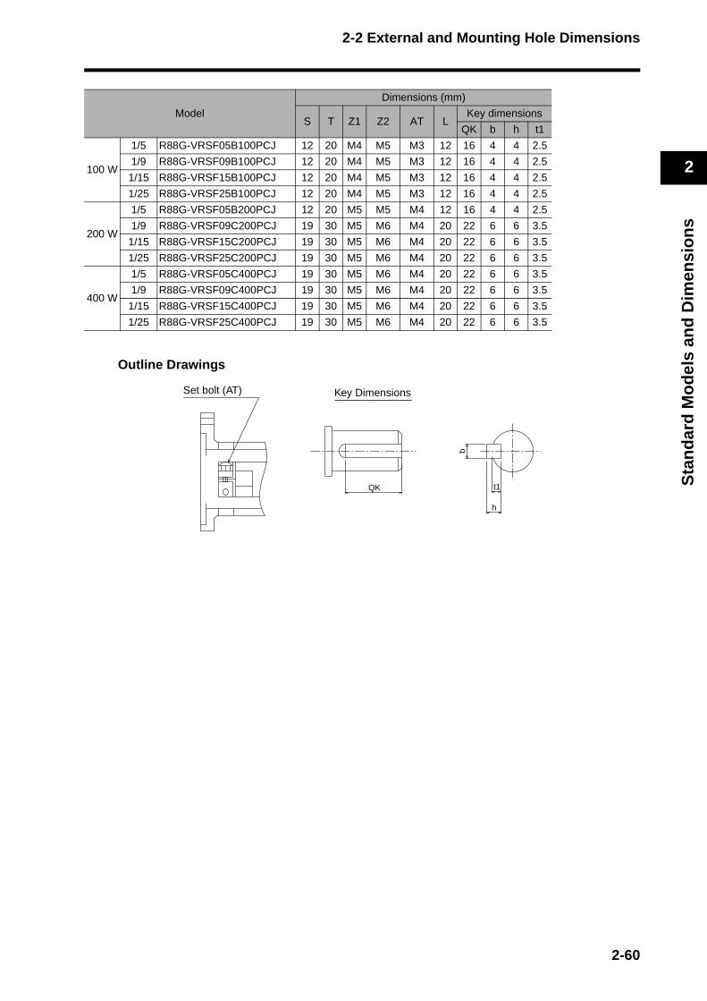
2-2 External and Mounting Hole Dimensions
2
Sta
nd
ard
Mo
del
s an
d D
imen
sio
ns
Outline Drawings
Model
Dimensions (mm)
S T Z1 Z2 AT LKey dimensions
QK b h t1
100 W
1/5 R88G-VRSF05B100PCJ 12 20 M4 M5 M3 12 16 4 4 2.5
1/9 R88G-VRSF09B100PCJ 12 20 M4 M5 M3 12 16 4 4 2.5
1/15 R88G-VRSF15B100PCJ 12 20 M4 M5 M3 12 16 4 4 2.5
1/25 R88G-VRSF25B100PCJ 12 20 M4 M5 M3 12 16 4 4 2.5
200 W
1/5 R88G-VRSF05B200PCJ 12 20 M5 M5 M4 12 16 4 4 2.5
1/9 R88G-VRSF09C200PCJ 19 30 M5 M6 M4 20 22 6 6 3.5
1/15 R88G-VRSF15C200PCJ 19 30 M5 M6 M4 20 22 6 6 3.5
1/25 R88G-VRSF25C200PCJ 19 30 M5 M6 M4 20 22 6 6 3.5
400 W
1/5 R88G-VRSF05C400PCJ 19 30 M5 M6 M4 20 22 6 6 3.5
1/9 R88G-VRSF09C400PCJ 19 30 M5 M6 M4 20 22 6 6 3.5
1/15 R88G-VRSF15C400PCJ 19 30 M5 M6 M4 20 22 6 6 3.5
1/25 R88G-VRSF25C400PCJ 19 30 M5 M6 M4 20 22 6 6 3.5
Set bolt (AT)
QK
h
t1
b
Key Dimensions
2-60
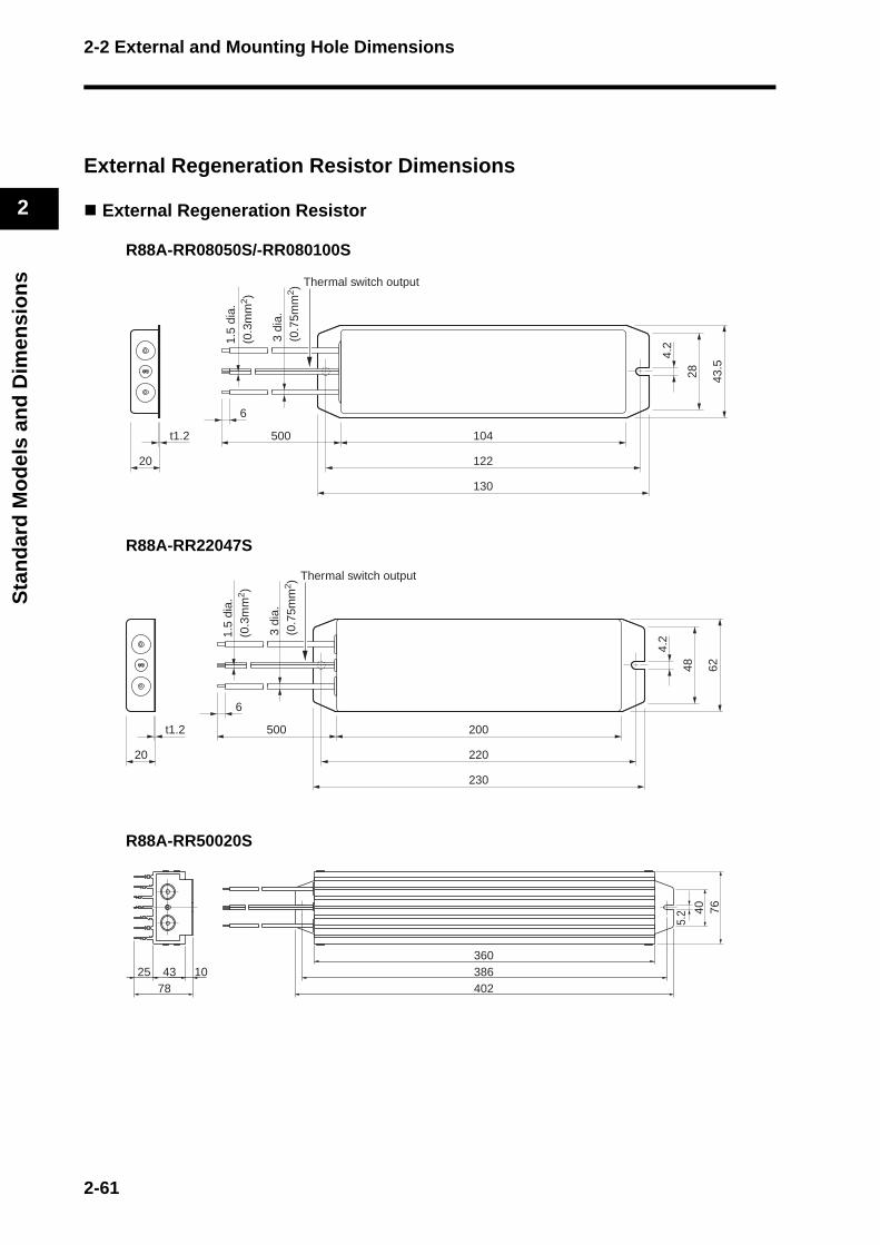
2-2 External and Mounting Hole Dimensions
2
Sta
nd
ard
Mo
del
s an
d D
imen
sio
ns
External Regeneration Resistor Dimensions
External Regeneration Resistor
R88A-RR08050S/-RR080100S
R88A-RR22047S
R88A-RR50020S
20
t1.2 104
122
130
43.5
28
4.2
6
Thermal switch output
500
1.5
dia.
(0
.3m
m2 )
3 di
a.
(0.7
5mm
2 )
20
t1.2 200
220
230
6248
4.2
6
500
Thermal switch output
1.5
dia.
(0
.3m
m2 )
3 di
a.
(0.7
5mm
2 )
360386402
4325 1078
7640
5.2
2-61
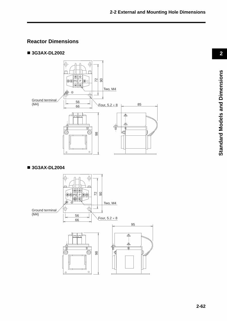
2-2 External and Mounting Hole Dimensions
2
Sta
nd
ard
Mo
del
s an
d D
imen
sio
ns
Reactor Dimensions
3G3AX-DL2002
3G3AX-DL2004
Ground terminal(M4)
6656
72 90Four, 5.2 × 8
Two, M4
98
85
6656
72 90 9
8
95
Ground terminal(M4)
Two, M4
Four, 5.2 × 8
2-62

2-2 External and Mounting Hole Dimensions
2
Sta
nd
ard
Mo
del
s an
d D
imen
sio
ns
3G3AX-DL2007
3G3AX-DL2015
6656
72 9098
105
Ground terminal(M4)
Two, M4
Four, 5.2 × 8
6656
72 9098
115
Ground terminal(M4)
Two, M4
Four, 5.2 × 8
2-63

2-2 External and Mounting Hole Dimensions
2
Sta
nd
ard
Mo
del
s an
d D
imen
sio
ns
3G3AX-DL2022
3G3AX-AL2025/-AL2055
Model Dimensions (mm)
A C Y3G3AX-AL2025 130 82 673G3AX-AL2055 140 98 75
8671
80 100
Four, 6 × 9
116
105
Ground terminal(M4)
Two, M4
Ground terminal (M5)Six, M4 terminal screws
Terminal block
150
92
C
4060
A
Ro R So S To T
Connection Diagram
Y±150±1
Ro R So S To T
9.5
Four, 6 dia. (Notch)
2-64
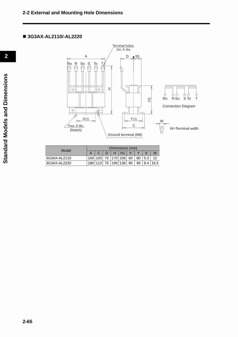
2-2 External and Mounting Hole Dimensions
2
Sta
nd
ard
Mo
del
s an
d D
imen
sio
ns
3G3AX-AL2110/-AL2220
Model Dimensions (mm)
A C D H H1 X Y K W3G3AX-AL2110 160 103 70 170 106 60 80 5.3 123G3AX-AL2220 180 113 75 190 136 90 90 8.4 16.5
W=Terminal width
H
H1
A
Ro R So S To T
C
Y±1X±1W
55D
Ro R So S To T
Ground terminal (M6)
Connection Diagram
Four, 6 dia. (Notch)
Terminal holes: Six, K dia.
2-65
Chapter 3
Specifications3-1 Servo Drive Specifications ................................. 3-1General Specifications ..........................................................3-1
Characteristics ......................................................................3-2
Main Circuit and Servomotor Connector Specifications........3-7
Control I/O Connector Specifications (CN1) .........................3-10
Control Input Circuits ............................................................3-14
Control Output Circuits..........................................................3-14
Control Sequence Timing .....................................................3-15
Encoder Connector Specifications (CN2) .............................3-16
Parameter Unit Connector Specifications (CN3) ..................3-16
3-2 Servomotor Specifications ................................. 3-17General Specifications ..........................................................3-17
Characteristics ......................................................................3-18
Encoder Specifications .........................................................3-31
3-3 Decelerator Specifications ................................. 3-32Standard Models and Specifications.....................................3-32
3-4 Cable and Connector Specifications .................. 3-42Encoder Cable Specifications ...............................................3-42
Absolute Encoder Battery Cable Specifications....................3-48
Servomotor Power Cable Specifications...............................3-49
Communications Cable Specifications..................................3-67
Connector Specifications ......................................................3-68
MECHATROLINK-II Communications CableSpecifications........................................................................3-71
Control Cable Specifications.................................................3-73
3-5 Parameter Unit Specifications...........................3-78
3-6 External Regeneration ResistorSpecifications ....................................................3-79
External Regeneration Resistor Specifications.....................3-79
3-7 Reactor Specifications ......................................3-80

3-1 Servo Drive Specifications
3
Sp
ecif
icat
ion
s
3-1 Servo Drive Specifications
Select the Servo Drive matching the Servomotor to be used. (For details, refer to Servo Drive-Servomotor Combinations on page 2-5.)OMNUC G-series Servo Drives are designed specifically for use with MECHATROLINK-II communication.
General Specifications
Note 1. The above items reflect individual evaluation testing. The results may differ under compound conditions.
Note 2. Never perform withstand-voltage or other megameter tests on the Servo Drive. Doing so may damage the internal elements.
Note 3. Depending on the operating conditions, some Servo Drive parts will require maintenance. For details, refer to Periodic Maintenance on page 8-21.
Note 4. The service life of the Servo Drive is 28,000 hours at an average ambient temperature of 55°C at 100% of the rated torque.
Item Specifications
Ambient operating temperature and humidity
0 to 55°C, 90% RH max. (with no condensation)
Ambient storage temperature and humidity
−20 to 65°C, 90% RH max. (with no condensation)
Operating and storage atmosphere
No corrosive gases
Vibration resistanceSmaller of either 10 to 60 Hz with double amplitude of 0.1 mm or acceleration of 5.88 m/s2 max. in X, Y, and Z directions.
Impact resistance Acceleration of 19.6m/s2 max. 2 times each in X, Y, and Z directions
Insulation resistanceBetween power supply/power line terminals and frame ground: 0.5 MΩ min. (at 500 VDC)
Dielectric strengthBetween power supply/power line terminals and frame ground: 1,500 VAC for 1 min at 50/60 HzBetween each control signal and frame ground: 500 VAC for 1 min
Protective structure Built into panel (IP10).
Interna-tional standards
ECDirec-tives
EMC Directive
EN 55011 Class A Group 1
EN 61000-6-2, IEC 61000-4-2/-3/-4/-5/-6/-11
Low Voltage Directive
EN 50178
UL standards UL 508C
CSA standards CSA 22.2 No.14
3-1
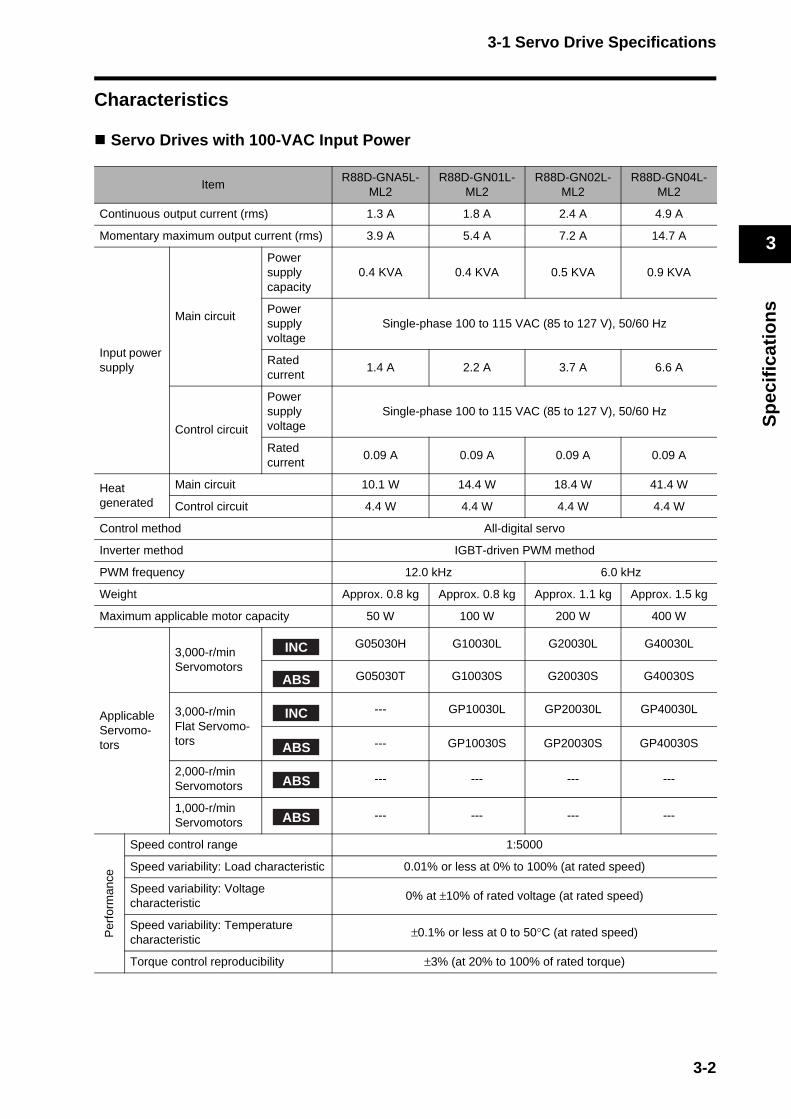
3-1 Servo Drive Specifications
3
Sp
ecif
icat
ion
s
Characteristics
Servo Drives with 100-VAC Input Power
ItemR88D-GNA5L-
ML2R88D-GN01L-
ML2R88D-GN02L-
ML2R88D-GN04L-
ML2
Continuous output current (rms) 1.3 A 1.8 A 2.4 A 4.9 A
Momentary maximum output current (rms) 3.9 A 5.4 A 7.2 A 14.7 A
Input power supply
Main circuit
Power supply capacity
0.4 KVA 0.4 KVA 0.5 KVA 0.9 KVA
Power supply voltage
Single-phase 100 to 115 VAC (85 to 127 V), 50/60 Hz
Rated current
1.4 A 2.2 A 3.7 A 6.6 A
Control circuit
Power supply voltage
Single-phase 100 to 115 VAC (85 to 127 V), 50/60 Hz
Rated current
0.09 A 0.09 A 0.09 A 0.09 A
Heat generated
Main circuit 10.1 W 14.4 W 18.4 W 41.4 W
Control circuit 4.4 W 4.4 W 4.4 W 4.4 W
Control method All-digital servo
Inverter method IGBT-driven PWM method
PWM frequency 12.0 kHz 6.0 kHz
Weight Approx. 0.8 kg Approx. 0.8 kg Approx. 1.1 kg Approx. 1.5 kg
Maximum applicable motor capacity 50 W 100 W 200 W 400 W
Applicable Servomo-tors
3,000-r/min Servomotors
G05030H G10030L G20030L G40030L
G05030T G10030S G20030S G40030S
3,000-r/min Flat Servomo-tors
--- GP10030L GP20030L GP40030L
--- GP10030S GP20030S GP40030S
2,000-r/min Servomotors
--- --- --- ---
1,000-r/min Servomotors
--- --- --- ---
Per
form
ance
Speed control range 1:5000
Speed variability: Load characteristic 0.01% or less at 0% to 100% (at rated speed)
Speed variability: Voltage characteristic
0% at ±10% of rated voltage (at rated speed)
Speed variability: Temperature characteristic
±0.1% or less at 0 to 50°C (at rated speed)
Torque control reproducibility ±3% (at 20% to 100% of rated torque)
INC
ABS
INC
ABS
ABS
ABS
3-2
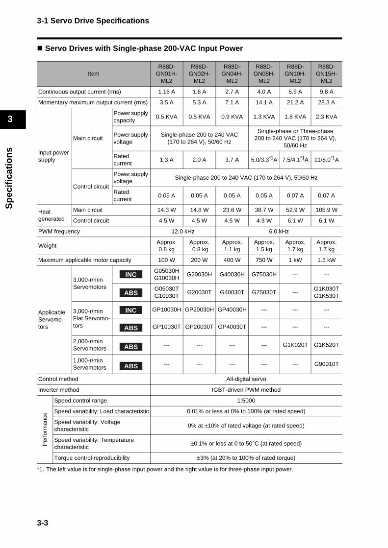
3-1 Servo Drive Specifications
3
Sp
ecif
icat
ion
s
Servo Drives with Single-phase 200-VAC Input Power
*1. The left value is for single-phase input power and the right value is for three-phase input power.
ItemR88D-
GN01H-ML2
R88D-GN02H-
ML2
R88D-GN04H-
ML2
R88D-GN08H-
ML2
R88D-GN10H-
ML2
R88D-GN15H-
ML2
Continuous output current (rms) 1.16 A 1.6 A 2.7 A 4.0 A 5.9 A 9.8 A
Momentary maximum output current (rms) 3.5 A 5.3 A 7.1 A 14.1 A 21.2 A 28.3 A
Input power supply
Main circuit
Power supply capacity
0.5 KVA 0.5 KVA 0.9 KVA 1.3 KVA 1.8 KVA 2.3 KVA
Power supply voltage
Single-phase 200 to 240 VAC (170 to 264 V), 50/60 Hz
Single-phase or Three-phase 200 to 240 VAC (170 to 264 V),
50/60 Hz
Rated current
1.3 A 2.0 A 3.7 A 5.0/3.3*1A 7.5/4.1*1A 11/8.0*1A
Control circuit
Power supply voltage
Single-phase 200 to 240 VAC (170 to 264 V), 50/60 Hz
Rated current
0.05 A 0.05 A 0.05 A 0.05 A 0.07 A 0.07 A
Heat generated
Main circuit 14.3 W 14.8 W 23.6 W 38.7 W 52.9 W 105.9 W
Control circuit 4.5 W 4.5 W 4.5 W 4.3 W 6.1 W 6.1 W
PWM frequency 12.0 kHz 6.0 kHz
WeightApprox. 0.8 kg
Approx. 0.8 kg
Approx. 1.1 kg
Approx. 1.5 kg
Approx. 1.7 kg
Approx. 1.7 kg
Maximum applicable motor capacity 100 W 200 W 400 W 750 W 1 kW 1.5 kW
Applicable Servomo-tors
3,000-r/min Servomotors
G05030HG10030H
G20030H G40030H G75030H --- ---
G05030TG10030T
G20030T G40030T G75030T ---G1K030TG1K530T
3,000-r/min Flat Servomo-tors
GP10030H GP20030H GP40030H --- --- ---
GP10030T GP20030T GP40030T --- --- ---
2,000-r/min Servomotors
--- --- --- --- G1K020T G1K520T
1,000-r/min Servomotors
--- --- --- --- --- G90010T
Control method All-digital servo
Inverter method IGBT-driven PWM method
Per
form
ance
Speed control range 1:5000
Speed variability: Load characteristic 0.01% or less at 0% to 100% (at rated speed)
Speed variability: Voltage characteristic
0% at ±10% of rated voltage (at rated speed)
Speed variability: Temperature characteristic
±0.1% or less at 0 to 50°C (at rated speed)
Torque control reproducibility ±3% (at 20% to 100% of rated torque)
INC
ABS
INC
ABS
ABS
ABS
3-3
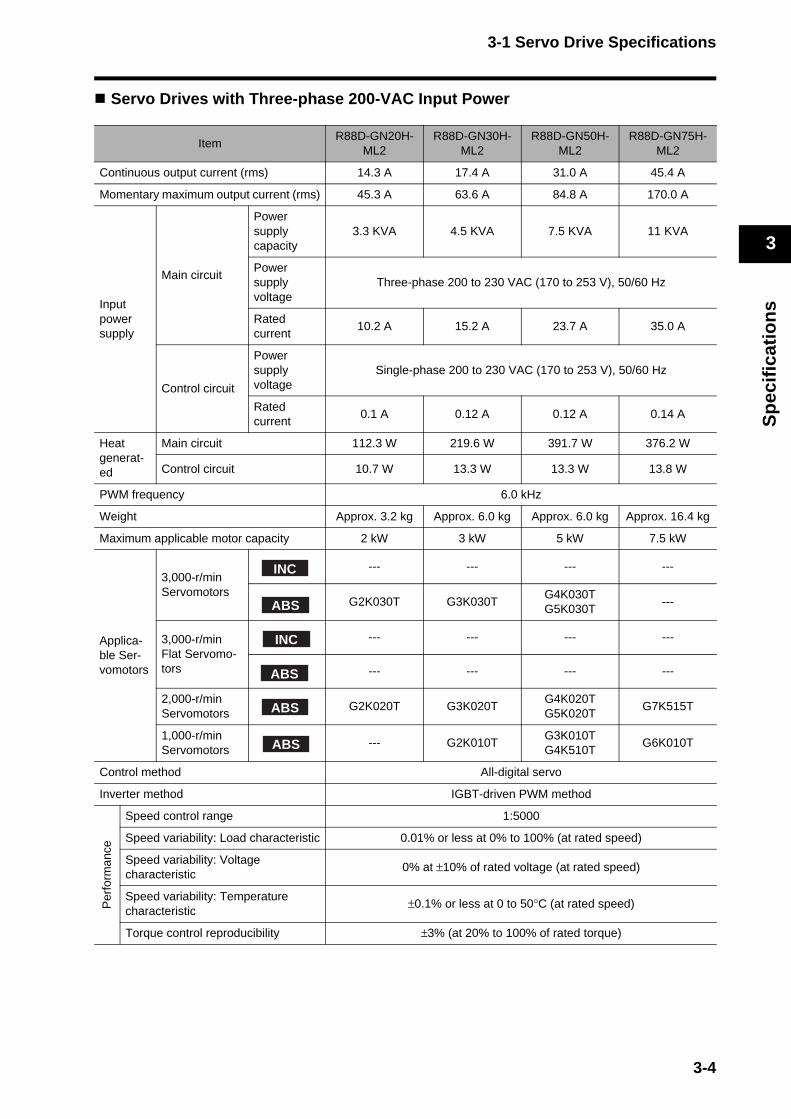
3-1 Servo Drive Specifications
3
Sp
ecif
icat
ion
s
Servo Drives with Three-phase 200-VAC Input Power
ItemR88D-GN20H-
ML2R88D-GN30H-
ML2R88D-GN50H-
ML2R88D-GN75H-
ML2
Continuous output current (rms) 14.3 A 17.4 A 31.0 A 45.4 A
Momentary maximum output current (rms) 45.3 A 63.6 A 84.8 A 170.0 A
Input power supply
Main circuit
Power supply capacity
3.3 KVA 4.5 KVA 7.5 KVA 11 KVA
Power supply voltage
Three-phase 200 to 230 VAC (170 to 253 V), 50/60 Hz
Rated current
10.2 A 15.2 A 23.7 A 35.0 A
Control circuit
Power supply voltage
Single-phase 200 to 230 VAC (170 to 253 V), 50/60 Hz
Rated current
0.1 A 0.12 A 0.12 A 0.14 A
Heat generat-ed
Main circuit 112.3 W 219.6 W 391.7 W 376.2 W
Control circuit 10.7 W 13.3 W 13.3 W 13.8 W
PWM frequency 6.0 kHz
Weight Approx. 3.2 kg Approx. 6.0 kg Approx. 6.0 kg Approx. 16.4 kg
Maximum applicable motor capacity 2 kW 3 kW 5 kW 7.5 kW
Applica-ble Ser-vomotors
3,000-r/min Servomotors
--- --- --- ---
G2K030T G3K030TG4K030TG5K030T
---
3,000-r/min Flat Servomo-tors
--- --- --- ---
--- --- --- ---
2,000-r/min Servomotors
G2K020T G3K020TG4K020TG5K020T
G7K515T
1,000-r/min Servomotors
--- G2K010TG3K010TG4K510T
G6K010T
Control method All-digital servo
Inverter method IGBT-driven PWM method
Per
form
ance
Speed control range 1:5000
Speed variability: Load characteristic 0.01% or less at 0% to 100% (at rated speed)
Speed variability: Voltage characteristic
0% at ±10% of rated voltage (at rated speed)
Speed variability: Temperature characteristic
±0.1% or less at 0 to 50°C (at rated speed)
Torque control reproducibility ±3% (at 20% to 100% of rated torque)
INC
ABS
INC
ABS
ABS
ABS
3-4

3-1 Servo Drive Specifications
3
Sp
ecif
icat
ion
s
Protective Functions
Error detection Description
Control power supply undervoltageThe voltage between P and N in the control voltage converter has dropped below the specified value.
OvervoltageThe voltage between P and N in the converter has exceeded the specified value.
Undervoltage
The main power supply between L1 and L3 was interrupted for longer than the time set in the Momentary Hold Time (Pn06D) when the Undervoltage Alarm Selection (Pn065) was set to 1. Alternatively, the voltage between P and N in the main power supply converter dropped below the specified val-ue while the Servo Drive was ON.
Overcurrent The current flowing to the converter exceeded the specified value.
OverheatingThe temperature of the Servo Drive radiator or power elements exceeded the specified value.
OverloadThe torque command value exceeded the level set in the Overload Detec-tion Level Setting (Pn072), resulting in an overload due to the time charac-teristics.
Regeneration overloadThe regenerative energy exceeded the capacity of the regeneration resis-tor.
Encoder communications errorThe disconnection detection function was activated because communica-tions between the encoder and Servo Drive were interrupted for a specified number of times.
Encoder communications data errorThere was an error in the communications data from the encoder. (The en-coder is connected, but there is an error in the communications data.)
Deviation counter overflowThe number of position deviation pulses exceeded the Deviation Counter Overflow Level (Pn209).
OverspeedThe rotation speed of the Servomotor exceeded the setting of the Over-speed Detection Level Setting (Pn073).
Command error The operation command ended in an error.
Internal deviation counter overflowThe value of the deviation counter (internal control unit) exceeded 227(134217728).
Overrun limit errorThe allowable range of movement set in the Overrun Limit Setting (Pn026) was exceeded by the Servomotor.
Parameter errorThe data in the parameter storage area was corrupted when the data was read from EEPROM at power-ON.
Parameter corruptionThe EEPROM write verification data was corrupted when the data was read from EEPROM at power-ON.
Drive prohibit input error
Both the Forward and Reverse Drive Prohibit Inputs were open when the Drive Prohibit Input Selection (Pn004) was set to 0 or either the forward or reverse drive prohibit input was open when the Drive Prohibit Input Selec-tion (Pn004) was set to 2.
Absolute encoder system down error
The power supply and battery to the absolute encoder went down and the capacitor voltage dropped below the specified value.
Absolute encoder counter overflow error
The multiturn counter for the absolute encoder has exceeded the specified value.
Absolute encoder overspeed error
The Servomotor speed exceeded the specified value when the power to the absolute encoder was interrupted and power was supplied only from the battery.
Absolute encoder one-turn counter error
An error was detected in the one-turn counter for the absolute encoder.
Absolute encoder multi-turn counter error
An error was detected in the multiturn counter for the absolute encoder.
Absolute encoder status error
The number of rotations of the encoder exceeded the specified value when the power supply was turned ON.
ABS
ABS
ABS
ABS
ABS
ABS
3-5
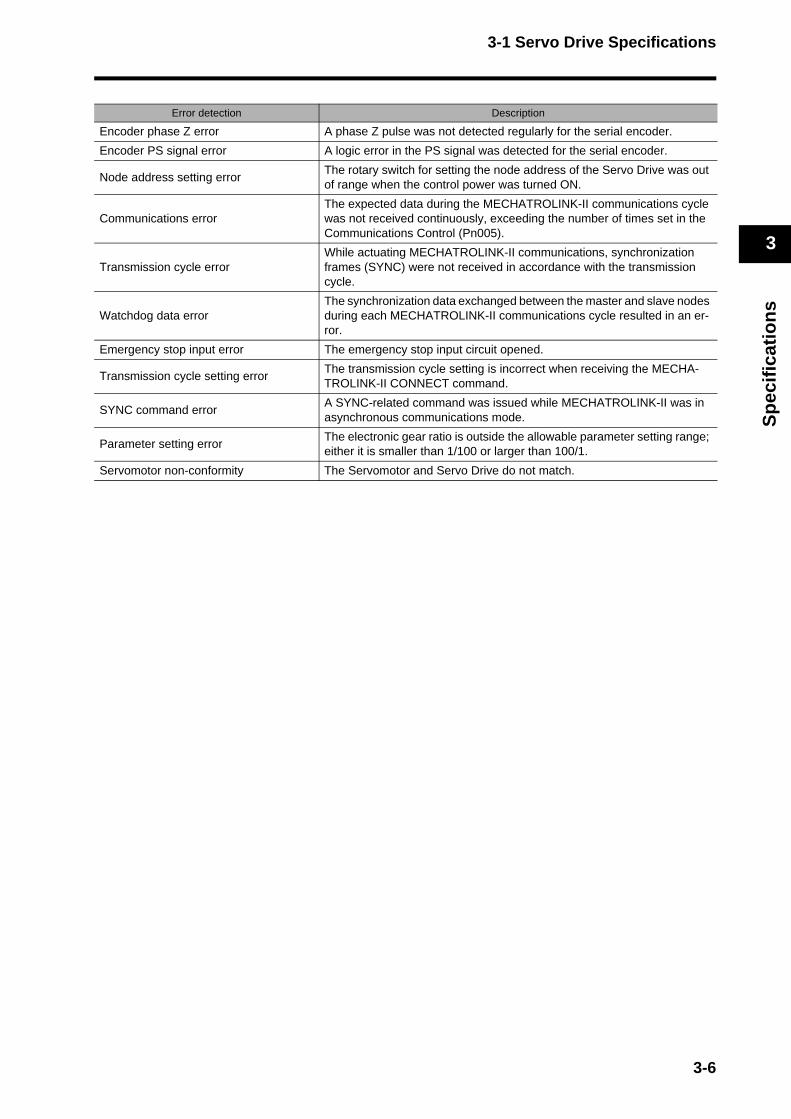
3-1 Servo Drive Specifications
3
Sp
ecif
icat
ion
s
Error detection Description
Encoder phase Z error A phase Z pulse was not detected regularly for the serial encoder.
Encoder PS signal error A logic error in the PS signal was detected for the serial encoder.
Node address setting errorThe rotary switch for setting the node address of the Servo Drive was out of range when the control power was turned ON.
Communications errorThe expected data during the MECHATROLINK-II communications cycle was not received continuously, exceeding the number of times set in the Communications Control (Pn005).
Transmission cycle errorWhile actuating MECHATROLINK-II communications, synchronization frames (SYNC) were not received in accordance with the transmission cycle.
Watchdog data errorThe synchronization data exchanged between the master and slave nodes during each MECHATROLINK-II communications cycle resulted in an er-ror.
Emergency stop input error The emergency stop input circuit opened.
Transmission cycle setting errorThe transmission cycle setting is incorrect when receiving the MECHA-TROLINK-II CONNECT command.
SYNC command errorA SYNC-related command was issued while MECHATROLINK-II was in asynchronous communications mode.
Parameter setting errorThe electronic gear ratio is outside the allowable parameter setting range; either it is smaller than 1/100 or larger than 100/1.
Servomotor non-conformity The Servomotor and Servo Drive do not match.
3-6

3-1 Servo Drive Specifications
3
Sp
ecif
icat
ion
s
Main Circuit and Servomotor Connector SpecificationsWhen wiring the main circuit, use proper wire sizes, grounding systems, and anti-noise measures.
R88D-GNA5L-ML2/-GN01L-ML2/-GN02L-ML2/-GN04L-ML2R88D-GN01H-ML2/-GN02H-ML2/-GN04H-ML2/-GN08H-ML2/-GN10H-ML2/-GN15H-ML2
Main Circuit Connector Specifications (CNA)
Servomotor Connector Specifications (CNB)
Symbol Name Function
L1
Main circuit power supply input
R88D-GN@L-ML2 (50 to 400 W): Single-phase 100 to 115 VAC (85 to 127 V), 50/60 Hz
R88D-GN@H-ML2 (50 W to 1.5 kW): Single-phase 200 to 240 VAC (170 to 264 V), 50/60 Hz
(750 W to 1.5 kW): Three-phase 200 to 240 VAC (170 to 264 V), 50/60Hz
L2
L3
L1C Control circuit power supply input
R88D-GN@L-ML2: Single-phase 100 to 115 VAC (85 to 127 V), 50/60 HzR88D-GN@H-ML2: Single-phase 200 to 240 VAC (170 to 264V), 50/60 HzL2C
Symbol Name Function
B1External Regeneration Resistorconnection terminals
50 to 400 W: These terminals normally do not need to be connected. If there is high regenerative energy, connect an External Regeneration Resistor between B1 and B2.
750 W to 1.5 kW: Normally B2 and B3 are connected. If there is high regenerative energy, remove the short-circuit bar between B2 and B3 and connect an Exter-nal Regeneration Resistor between B1 and B2.
B2
B3
U
Servomotor connection terminals
Red
These are the output terminals to the Servomotor.Be sure to wire them correctly.
V White
W Blue
Green/Yellow
Frame ground This is the ground terminal. Ground to 100 Ω or less.
3-7

3-1 Servo Drive Specifications
3
Sp
ecif
icat
ion
s
R88D-GN20H-ML2/-GN30H-ML2/-GN50H-ML2
Main Circuit Terminal Block Specifications
Symbol Name Function
L1Main circuit power supply input
R88D-GN@H-ML2 (2 to 5 kW): Three-phase 200 to 230 VAC (170 to 253 V), 50/60HzL2
L3
L1C Control circuit power supply input
R88D-GN@H-ML2: Single-phase 200 to 230 VAC (170 to 253V), 50/60 HzL2C
B1 External Regeneration Resistor connection terminals
2 to 5 kW: Normally B2 and B3 are connected. If there is high regenerative energy, remove the short-circuit bar between B2 and B3 and connect an External Regeneration Resistor between B1 and B2.
B2
B3
U
Servomotor connection terminals
Red
These are the output terminals to the Servomotor.Be sure to wire them correctly.
V White
W Blue
Green/Yellow
Frame ground This is the ground terminal. Ground to 100 Ω or less.
3-8

3-1 Servo Drive Specifications
3
Sp
ecif
icat
ion
s
R88D-GN75H-ML2
Main Circuit Terminal Block Specifications (TB1)
Main Circuit Terminal Block Specifications (TB2)
Symbol Name Function
L1Main circuit power supply input
R88D-GN75H-ML2 (6 to 7.5 kW): Three-phase 200 to 230 VAC (170 to 253 V), 50/60Hz
L2
L3
B1 External Regeneration Resistor connection terminals
6 to 7.5 kW: A regeneration resistor is not built in.Connect an External Regeneration Resistor between B1 and B2, if necessary.B2
U
Servomotor connection terminals
Red
These are the output terminals to the Servomotor.Be sure to wire them correctly.
V White
W Blue
Green/Yellow
Frame ground This is the ground terminal. Ground to 100 Ω or less.
Symbol Name Function
NC --- Do not connect.
L1C Control circuit power supply input
R88D-GN75H-ML2: Single-phase 200 to 230 VAC (170 to 253 V), 50/60HzL2C
Frame ground This is the ground terminal. Ground to 100 Ω or less.
NC
--- Do not connect.
EX1
EX2
EX3
NC
FN(+)Fan Stop Output
Outputs a warning signal when the fan inside the Servo Drive stops. (30 VDC, 50 mA max.)FN(−)
3-9

3-1 Servo Drive Specifications
3
Sp
ecif
icat
ion
s
Control I/O Connector Specifications (CN1)
Control I/O Signal Connections and External Signal Processing
*1. If a backup battery is connected, a cable with a battery is not required.*2. Inputs for pins 19 and 20 are determined by parameter settings. The diagram shows the default configuration.
Emergency Stop
/ALM
Alarm Output
ALMCOM
15
16
8NCL
7PCL
6IN1
5EXT1
4EXT2
3EXT3
2STOP
1+24VIN
Forword Torque Limit Input
General-purpose Input 1
External Latch 1
External Latch 2
External Latch 3
12 to 24 VDC
19POT
Forward Drive Prohibit Input
20NOT
21DECOrigin ProximityInput
Shell FG
BAT
BATCOM
Backup Battery *1
34
33
22IN0General-purpose Input0
23IN2General-purpose Input 2
4.7kΩ
1kΩ
4.7kΩ
1kΩ
4.7kΩ
1kΩ
4.7kΩ
1kΩ
4.7kΩ
1kΩ
4.7kΩ
1kΩ
4.7kΩ
1kΩ
4.7kΩ
1kΩ
4.7kΩ
1kΩ
4.7kΩ
1kΩ
4.7kΩ
1kΩ
4.7kΩ
1kΩ
OUTM1
General-purpose Output 1
OUTM1COM
36
35
OUTM2
General-purpose Output 2
OUTM2COM
29
30
OUTM3
General-purpose Output 3
OUTM3COM
31
32
Reverse Torque Limit Input
Reverse Drive Prohibit Input
3-10
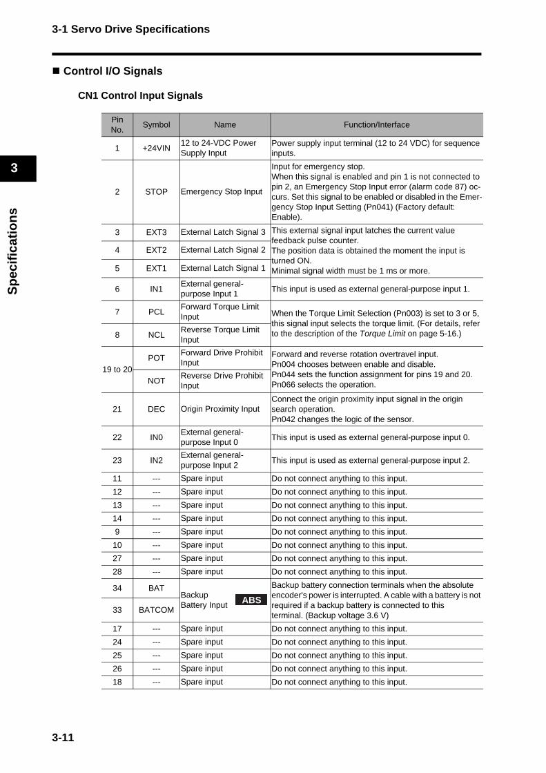
3-1 Servo Drive Specifications
3
Sp
ecif
icat
ion
s
Control I/O Signals
CN1 Control Input Signals
PinNo.
Symbol Name Function/Interface
1 +24VIN12 to 24-VDC Power Supply Input
Power supply input terminal (12 to 24 VDC) for sequence inputs.
2 STOP Emergency Stop Input
Input for emergency stop.When this signal is enabled and pin 1 is not connected to pin 2, an Emergency Stop Input error (alarm code 87) oc-curs. Set this signal to be enabled or disabled in the Emer-gency Stop Input Setting (Pn041) (Factory default: Enable).
3 EXT3 External Latch Signal 3 This external signal input latches the current value feedback pulse counter.The position data is obtained the moment the input is turned ON. Minimal signal width must be 1 ms or more.
4 EXT2 External Latch Signal 2
5 EXT1 External Latch Signal 1
6 IN1External general-purpose Input 1
This input is used as external general-purpose input 1.
7 PCLForward Torque Limit Input When the Torque Limit Selection (Pn003) is set to 3 or 5,
this signal input selects the torque limit. (For details, refer to the description of the Torque Limit on page 5-16.)8 NCL
Reverse Torque Limit Input
19 to 20POT
Forward Drive Prohibit Input
Forward and reverse rotation overtravel input. Pn004 chooses between enable and disable.Pn044 sets the function assignment for pins 19 and 20.Pn066 selects the operation. NOT
Reverse Drive Prohibit Input
21 DEC Origin Proximity InputConnect the origin proximity input signal in the origin search operation. Pn042 changes the logic of the sensor.
22 IN0External general-purpose Input 0
This input is used as external general-purpose input 0.
23 IN2External general-purpose Input 2
This input is used as external general-purpose input 2.
11 --- Spare input Do not connect anything to this input.
12 --- Spare input Do not connect anything to this input.
13 --- Spare input Do not connect anything to this input.
14 --- Spare input Do not connect anything to this input.
9 --- Spare input Do not connect anything to this input.
10 --- Spare input Do not connect anything to this input.
27 --- Spare input Do not connect anything to this input.
28 --- Spare input Do not connect anything to this input.
34 BATBackup Battery Input
Backup battery connection terminals when the absolute encoder's power is interrupted. A cable with a battery is not required if a backup battery is connected to this terminal. (Backup voltage 3.6 V)
33 BATCOM
17 --- Spare input Do not connect anything to this input.
24 --- Spare input Do not connect anything to this input.
25 --- Spare input Do not connect anything to this input.
26 --- Spare input Do not connect anything to this input.
18 --- Spare input Do not connect anything to this input.
ABS
3-11
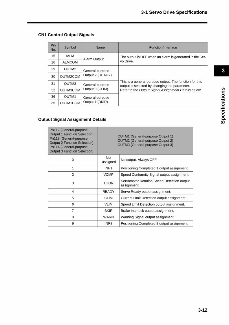
3-1 Servo Drive Specifications
3
Sp
ecif
icat
ion
s
CN1 Control Output Signals
Output Signal Assignment Details
PinNo.
Symbol Name Function/Interface
15 /ALMAlarm Output
The output is OFF when an alarm is generated in the Ser-vo Drive.16 ALMCOM
29 OUTM2 General-purpose Output 2 (READY)
This is a general-purpose output. The function for this output is selected by changing the parameter.Refer to the Output Signal Assignment Details below.
30 OUTM2COM
31 OUTM3 General-purpose Output 3 (CLIM)32 OUTM3COM
36 OUTM1 General-purpose Output 1 (BKIR)35 OUTM1COM
Pn112 (General-purpose Output 1 Function Selection)Pn113 (General-purpose Output 2 Function Selection)Pn114 (General-purpose Output 3 Function Selection)
OUTM1 (General-purpose Output 1)OUTM2 (General-purpose Output 2)OUTM3 (General-purpose Output 3)
0Not
assignedNo output. Always OFF.
1 INP1 Positioning Completed 1 output assignment.
2 VCMP Speed Conformity Signal output assignment.
3 TGONServomotor Rotation Speed Detection output assignment.
4 READY Servo Ready output assignment.
5 CLIM Current Limit Detection output assignment.
6 VLIM Speed Limit Detection output assignment.
7 BKIR Brake Interlock output assignment.
8 WARN Warning Signal output assignment.
9 INP2 Positioning Completed 2 output assignment.
3-12
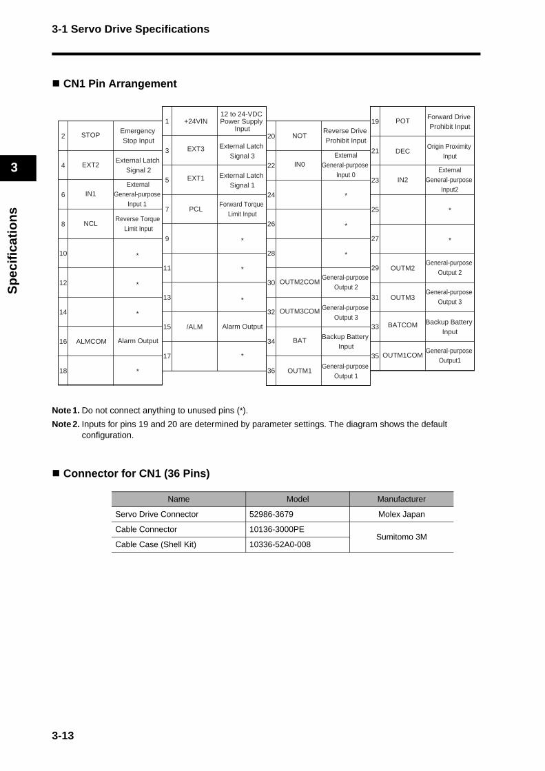
3-1 Servo Drive Specifications
3
Sp
ecif
icat
ion
s
CN1 Pin Arrangement
Note 1. Do not connect anything to unused pins (*).
Note 2. Inputs for pins 19 and 20 are determined by parameter settings. The diagram shows the default configuration.
Connector for CN1 (36 Pins)
Name Model Manufacturer
Servo Drive Connector 52986-3679 Molex Japan
Cable Connector 10136-3000PESumitomo 3M
Cable Case (Shell Kit) 10336-52A0-008
2
4
6
8
10
12
14
16
18
20
22
24
12 to 24-VDC Power Supply
InputEmergency Stop Input
+24VIN1
3
5
7
9
11
13
15
17
19
21
23
25
27
29
31
33
35
26
28
30
32
34
36
POT
IN1
Forward Drive Prohibit Input
EXT3
Reverse Torque Limit Input
NOTSTOP
DEC
IN0
Origin Proximity Input
OUTM2General-purpose
Output 2
BAT Backup Battery Input
BATCOM
ALMCOM Alarm Output
/ALM Alarm Output
NCL
PCL
External Latch Signal 3
Reverse Drive Prohibit Input
ExternalGeneral-purpose
Input 0
Forward Torque Limit Input
ExternalGeneral-purpose
Input 1
EXT2External Latch
Signal 2EXT1 External Latch
Signal 1
*
*
*
*
*
*
*
IN2External
General-purpose Input2
*
*
OUTM2COMGeneral-purpose
Output 2
OUTM3General-purpose
Output 3OUTM3COM General-purpose
Output 3Backup Battery
Input
OUTM1COMGeneral-purpose
Output1
OUTM1General-purpose
Output 1
*
*
*
*
3-13
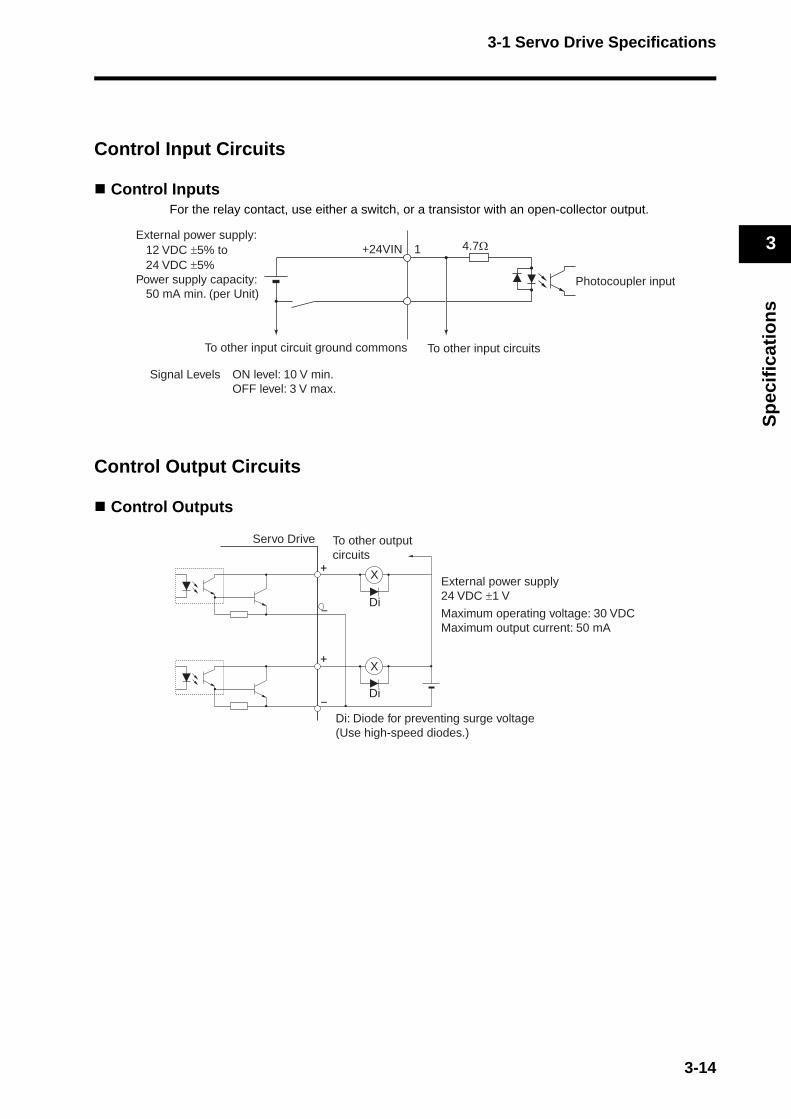
3-1 Servo Drive Specifications
3
Sp
ecif
icat
ion
s
Control Input Circuits
Control InputsFor the relay contact, use either a switch, or a transistor with an open-collector output.
Control Output Circuits
Control Outputs
1+24VIN 4.7Ω
Signal Levels ON level: 10 V min.OFF level: 3 V max.
External power supply: 12 VDC ±5% to 24 VDC ±5%Power supply capacity: 50 mA min. (per Unit)
Photocoupler input
To other input circuit ground commons To other input circuits
Servo Drive
+
−
−
X
Di
To other outputcircuits
X
Di
+
External power supply24 VDC ±1 V
Maximum operating voltage: 30 VDCMaximum output current: 50 mA
Di: Diode for preventing surge voltage (Use high-speed diodes.)
3-14

3-1 Servo Drive Specifications
3
Sp
ecif
icat
ion
s
Control Sequence Timing
Power ON operation timing
*1. Servo Ready (READY) turns ON and returns a response when these conditions are met: MPU initialization is completed, main power is established, no alarms exist, MECHATROLINK-II communications are established, and the servo is synchronized.
*2. Once the internal control power is established, the protective function starts working about 1.5 s after the CPU starts initializing itself. Be sure that the input signals, in particular the Emergency Stop (STOP) and Drive Prohibit (POT/NOT) inputs are settled before the protective function starts working.
ON
OFF
ON
OFF
ON
OFF
ON
OFF
ON
OFF
ON
OFF
ON
OFF
ON
OFF
ON
OFF
ON
OFF
ON
OFF
ON
OFF
Pn06A
Approx. 10 ms after the main circuit power is turned ON after initialization is completed.
Alarm Output(ALM)
Positioning Completed Output (INP)
Brake Interlock Output(BKIR)
RUN Command Input(RUN)
Approx. 2 s
Approx. 100 to 300 ms
Approx. 2 ms
Approx. 2 ms
100 ms min.
0 ms min.
0 ms min.
1 to 5 ms
Approx. 40 ms
Dynamic brake
Servomotorpower supply
Servomotor position, speed, or torque input
Control power supply (L1C, L2C)
Internal control power supply
MPU initialization completed
Main circuit power supply(L1, L2, L3)
Servo Ready Output(READY)*1
Initialize*2
3-15
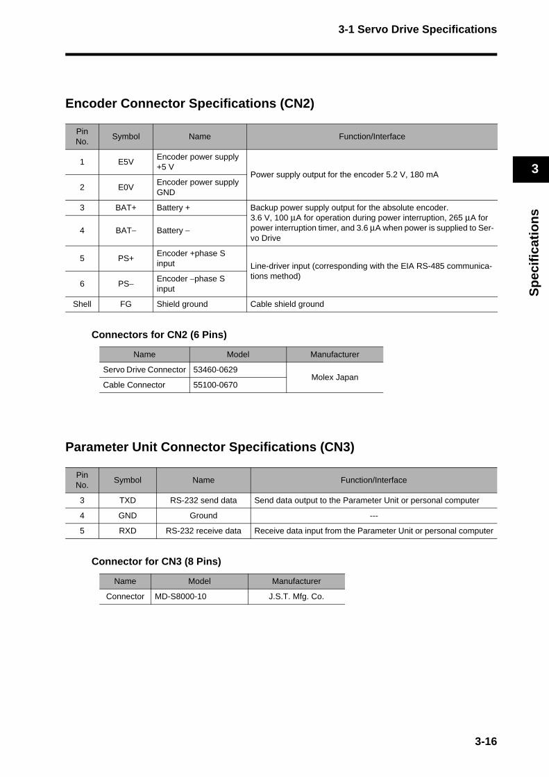
3-1 Servo Drive Specifications
3
Sp
ecif
icat
ion
s
Encoder Connector Specifications (CN2)
Connectors for CN2 (6 Pins)
Parameter Unit Connector Specifications (CN3)
Connector for CN3 (8 Pins)
PinNo.
Symbol Name Function/Interface
1 E5VEncoder power supply +5 V
Power supply output for the encoder 5.2 V, 180 mA
2 E0VEncoder power supply GND
3 BAT+ Battery + Backup power supply output for the absolute encoder.3.6 V, 100 μA for operation during power interruption, 265 μA for power interruption timer, and 3.6 μA when power is supplied to Ser-vo Drive
4 BAT− Battery −
5 PS+Encoder +phase S input Line-driver input (corresponding with the EIA RS-485 communica-
tions method)6 PS− Encoder −phase S
input
Shell FG Shield ground Cable shield ground
Name Model Manufacturer
Servo Drive Connector 53460-0629Molex Japan
Cable Connector 55100-0670
PinNo.
Symbol Name Function/Interface
3 TXD RS-232 send data Send data output to the Parameter Unit or personal computer
4 GND Ground ---
5 RXD RS-232 receive data Receive data input from the Parameter Unit or personal computer
Name Model Manufacturer
Connector MD-S8000-10 J.S.T. Mfg. Co.
3-16
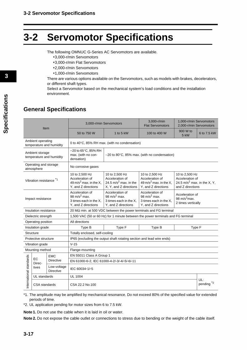
3-2 Servomotor Specifications
3
Sp
ecif
icat
ion
s
3-2 Servomotor SpecificationsThe following OMNUC G-Series AC Servomotors are available.
3,000-r/min Servomotors3,000-r/min Flat Servomotors2,000-r/min Servomotors1,000-r/min Servomotors
There are various options available on the Servomotors, such as models with brakes, decelerators, or different shaft types.Select a Servomotor based on the mechanical system’s load conditions and the installation environment.
General Specifications
*1. The amplitude may be amplified by mechanical resonance. Do not exceed 80% of the specified value for extended periods of time.
*2. UL application pending for motor sizes from 6 to 7.5 kW.
Note 1. Do not use the cable when it is laid in oil or water.
Note 2. Do not expose the cable outlet or connections to stress due to bending or the weight of the cable itself.
Item
3,000-r/min Servomotors3,000-r/min
Flat Servomotors1,000-r/min Servomotors2,000-r/min Servomotors
50 to 750 W 1 to 5 kW 100 to 400 W900 W to
5 kW6 to 7.5 kW
Ambient operating temperature and humidity
0 to 40°C, 85% RH max. (with no condensation)
Ambient storage temperature and humidity
−20 to 65°C, 85% RH max. (with no con-densation)
−20 to 80°C, 85% max. (with no condensation)
Operating and storage atmosphere
No corrosive gases
Vibration resistance *1
10 to 2,500 HzAcceleration of 49 m/s2 max. in the X, Y, and Z directions
10 to 2,500 HzAcceleration of 24.5 m/s2 max. in the X, Y, and Z directions
10 to 2,500 HzAcceleration of 49 m/s2 max. in the X, Y, and Z directions
10 to 2,500 HzAcceleration of 24.5 m/s2 max. in the X, Y, and Z directions
Impact resistance
Acceleration of 98 m/s2 max. 3 times each in the X, Y, and Z directions
Acceleration of 98 m/s2 max. 3 times each in the X, Y, and Z directions
Acceleration of 98 m/s2 max. 3 times each in the X, Y, and Z directions
Acceleration of 98 m/s2max.2 times vertically
Insulation resistance 20 MΩ min. at 500 VDC between the power terminals and FG terminal
Dielectric strength 1,500 VAC (50 or 60 Hz) for 1 minute between the power terminals and FG terminal
Operating position All directions
Insulation grade Type B Type F Type B Type F
Structure Totally enclosed, self-cooling
Protective structure IP65 (excluding the output shaft rotating section and lead wire ends)
Vibration grade V-15
Mounting method Flange-mounting
Inte
rnat
iona
l sta
ndar
ds
EC Direc-tives
EMC Directive
EN 55011 Class A Group 1
EN 61000-6-2, IEC 61000-4-2/-3/-4/-5/-6/-11
Low-voltageDirective
IEC 60034-1/-5
UL standards UL 1004UL:pending *2
CSA standards CSA 22.2 No.100
3-17

3-2 Servomotor Specifications
3
Sp
ecif
icat
ion
s
Characteristics
3,000-r/min Servomotors
Model (R88M-)
Item Unit
100 VAC
G05030H G10030L G20030L G40030L
G05030T G10030S G20030S G40030S
Rated output *1 W 50 100 200 400
Rated torque *1 N·m 0.16 0.32 0.64 1.3
Rated rotation speed r/min 3000
Max. momentary rotation speed
r/min 5000
Max. momentary torque *1 N·m 0.45 0.93 1.78 3.6
Rated current *1 A (rms) 1.1 1.7 2.5 4.6
Max. momentary current *1 A (rms) 3.4 5.1 7.6 13.9
Rotor inertiakg·m2
(GD2/4)2.5 × 10-6 5.1 × 10⁻⁶ 1.4 × 10⁻⁵ 2.6 × 10⁻⁵
Applicable load inertia --- 30 times the rotor inertia max.*2
Torque constant *1 N·m/A 0.14 0.19 0.26 0.28
Power rate *1 kW/s 10.4 20.1 30.3 62.5
Mechanical time constant
ms 1.56 1.11 0.72 0.55
Electrical time constant ms 0.7 0.8 2.5 2.9
Allowable radial load *3 N 68 68 245 245
Allowable thrust load *3 N 58 58 98 98
WeightWithout brake kg Approx. 0.3 Approx. 0.5 Approx. 0.8 Approx. 1.2
With brake kg Approx. 0.5 Approx. 0.7 Approx. 1.3 Approx. 1.7
Radiation shield dimensions (material)
100 × 80 × t10 (AI) 130 × 120 × t12 (AI)
Applicable Servo Drives (R88D-) GNA5L-ML2 GN01L-ML2 GN02L-ML2 GN04L-ML2
Bra
ke s
peci
ficat
ions
Brake inertiakg·m2
(GD2/4)2 × 10-7 2 × 10⁻⁷ 1.8 × 10⁻⁶ 1.8 × 10⁻⁶
Excitation voltage *4 V 24 VDC ±5%
Power consumption (at 20°C)
W 7 7 9 9
Current consumption (at 20°C)
A 0.3 0.3 0.36 0.36
Static friction torque N·m 0.29 min. 0.29 min. 1.27 min. 1.27 min.
Attraction time *5 ms 35 max. 35 max. 50 max. 50 max.
Release time *5 ms 20 max. 20 max. 15 max. 15 max.
Backlash 1° (reference value)
Allowable work per braking
J 39.2 39.2 137 137
Allowable total work J 4.9 × 10³ 4.9 × 10³ 44.1 × 10³ 44.1 × 10³
Allowable angularacceleration
rad/s2 30,000 max.(Speed of 2,800 r/min or more must not be changed in less than 10 ms)
Brake life --- 10,000,000 operations
Rating --- Continuous
Insulation grade --- Type B
3-18

3-2 Servomotor Specifications
3
Sp
ecif
icat
ion
s
Model (R88M-)
Item Unit
200 VAC
G05030H G10030H G20030H G40030H G75030H
G05030T G10030T G20030T G40030T G75030T
Rated output *1 W 50 100 200 400 750
Rated torque *1 N·m 0.16 0.32 0.64 1.3 2.4
Rated rotation speed r/min 3000
Max. momentary rotation speed
r/min 5000
Max. momentary torque *1 N·m 0.45 0.90 1.78 3.67 7.05
Rated current *1 A (rms) 1.1 1.1 1.6 2.6 4
Max. momentary current *1 A (rms) 3.4 3.4 4.9 7.9 12.1
Rotor inertiakg·m2
(GD2/4)2.5 × 10-6 5.1 × 10⁻⁶ 1.4 × 10⁻⁵ 2.6 × 10⁻⁵ 8.7 × 10⁻⁵
Applicable load inertia --- 30 times the rotor inertia max.*220 times the rotor inertia
max.*2
Torque constant *1 N·m/A 0.14 0.19 0.41 0.51 0.64
Power rate *1 kW/s 10.4 20.1 30.3 62.5 66
Mechanical time constant
ms 1.56 1.1 0.71 0.52 0.45
Electrical time constant ms 0.7 0.79 2.6 3 4.6
Allowable radial load *3 N 68 68 245 245 392
Allowable thrust load *3 N 58 58 98 98 147
WeightWithout brake kg Approx. 0.3 Approx. 0.5 Approx. 0.8 Approx. 1.2 Approx. 2.3
With brake kg Approx. 0.5 Approx. 0.7 Approx. 1.3 Approx. 1.7 Approx. 3.1
Radiation shield dimensions (material)
100 × 80 × t10 (AI) 130 × 120 × t12 (AI)170 × 160 ×
t12 (AI)
Applicable Servo Drives (R88D-) GN01H-ML2 GN01H-ML2 GN02H-ML2 GN04H-ML2 GN08H-ML2
Bra
ke s
peci
ficat
ions
Brake inertiakg·m2
(GD2/4)2 × 10-7 2 × 10⁻⁷ 1.8 × 10⁻⁶ 1.8 × 10⁻⁶ 7.5 × 10⁻⁶
Excitation voltage *4 V 24 VDC ±5%
Power consumption (at 20°C)
W 7 7 9 9 10
Current consumption (at 20°C)
A 0.3 0.3 0.36 0.36 0.42
Static friction torque N·m 0.29 min. 0.29 min. 1.27 min. 1.27 min. 2.45 min.
Attraction time *5 ms 35 max. 35 max. 50 max. 50 max. 70 max.
Release time *5 ms 20 max. 20 max. 15 max. 15 max. 20 max.
Backlash 1° (reference value)
Allowable work per braking
J 39.2 39.2 137 137 196
Allowable total work J 4.9 × 10³ 4.9 × 10³ 44.1 × 10³ 44.1 × 10³ 147 × 103
Allowable angular acceleration
rad/s2 30,000 max.(Speed of 2,800 r/min or more must not be changed in less than 10 ms)
Brake life --- 10,000,000 operations
Rating --- Continuous
Insulation grade --- Type B
3-19

3-2 Servomotor Specifications
3
Sp
ecif
icat
ion
s
Model (R88M-)
Item Unit
200 VAC
G1K030T G1K530T G2K030T G3K030T G4K030T G5K030T
Rated output *1 W 1000 1500 2000 3000 4000 5000
Rated torque *1 N·m 3.18 4.77 6.36 9.54 12.6 15.8
Rated rotation speed r/min 3000
Max. momentary rotation speed
r/min 5000 4500
Max. momentary torque *1 N·m 9.1 12.8 18.4 27.0 36.3 45.1
Rated current *1 A (rms) 7.2 9.4 13 18.6 24.7 28.5
Max. momentary current *1 A (rms) 21.4 28.5 40 57.1 75 85.7
Rotor inertiakg·m2
(GD2/4)1.69 × 10-4 2.59 × 10⁻⁴ 3.46 × 10⁻⁴ 6.77 × 10⁻⁴ 1.27 × 10⁻³ 1.78 × 10⁻³
Applicable load inertia --- 15 times the rotor inertia max.*2
Torque constant *1 N·m/A 0.44 0.51 0.48 0.51 0.51 0.57
Power rate *1 kW/s 60 88 117 134 125 140
Mechanical time constant
ms 0.78 0.54 0.53 0.46 0.51 0.46
Electrical time constant ms 6.7 10 10.8 20 20 20
Allowable radial load *3 N 392 490 490 490 784 784
Allowable thrust load *3 N 147 196 196 196 343 343
WeightWithout brake kg Approx. 4.5 Approx. 5.1 Approx. 6.5 Approx. 9.3
Approx. 12.9
Approx. 17.3
With brake kg Approx. 5.1 Approx. 6.5 Approx. 7.9 Approx. 11Approx.
14.8Approx.
19.2
Radiation shield dimensions (material)
170 × 160 × t12(AI)
320 × 300 × t30 (AI)
320 × 300 × t20 (AI)
380 × 350 × t30 (AI)
Applicable Servo Drives (R88D-)GN15H-
ML2GN15H-
ML2GN20H-
ML2GN30H-
ML2GN50H-
ML2GN50H-
ML2
Bra
ke s
peci
ficat
ions
Brake inertiakg·m2
(GD2/4)2.5 × 10-5 3.3 × 10⁻⁵ 3.3 × 10⁻⁵ 3.3 × 10⁻⁵ 1.35 × 10⁻⁴ 1.35 × 10⁻⁴
Excitation voltage *4 V 24 VDC ±10%
Power consumption (at 20°C)
W 18 19 19 19 22 22
Current consumption (at 20°C)
A 0.74 0.81 0.81 0.81 0.9 0.9
Static friction torque N·m 4.9 min. 7.8 min. 7.8 min. 11.8 min. 16.1 min. 16.1 min.
Attraction time *5 ms 50 max. 50 max. 50 max. 80 max. 110 max. 110 max.
Release time *5 ms 15 max. 15 max. 15 max. 15 max. 50 max. 50 max.
Backlash 1° (reference value)
Allowable work per braking
J 392 392 392 392 1470 1470
Allowable total work J 2.0 × 10⁵ 4.9 × 10⁵ 4.9 × 10⁵ 4.9 × 10⁵ 2.2 × 10⁶ 2.2 × 10⁶
Allowable angular acceleration
rad/s2 10,000 max.(Speed of 900 r/min or more must not be changed in less than 10 ms)
Brake life --- 10,000,000 operations
Rating --- Continuous
Insulation grade --- Type F
3-20
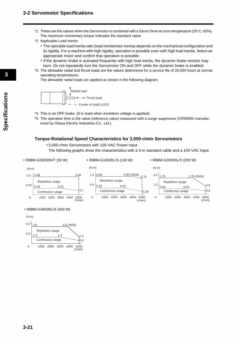
3-2 Servomotor Specifications
3
Sp
ecif
icat
ion
s
*1. These are the values when the Servomotor is combined with a Servo Drive at room temperature (20°C, 65%). The maximum momentary torque indicates the standard value.
*2. Applicable Load InertiaThe operable load inertia ratio (load inertia/rotor inertia) depends on the mechanical configuration and its rigidity. For a machine with high rigidity, operation is possible even with high load inertia. Select an appropriate motor and confirm that operation is possible.If the dynamic brake is activated frequently with high load inertia, the dynamic brake resistor may burn. Do not repeatedly turn the Servomotor ON and OFF while the dynamic brake is enabled.
*3. The allowable radial and thrust loads are the values determined for a service life of 20,000 hours at normal operating temperatures.The allowable radial loads are applied as shown in the following diagram.
*4. This is an OFF brake. (It is reset when excitation voltage is applied).*5. The operation time is the value (reference value) measured with a surge suppressor (CR50500 manufac-
tured by Okaya Electric Industries Co., Ltd.).
Torque-Rotational Speed Characteristics for 3,000-r/min Servomotors3,000-r/min Servomotors with 100-VAC Power InputThe following graphs show the characteristics with a 3-m standard cable and a 100-VAC input.
R88M-G05030H/T (50 W) R88M-G10030L/S (100 W) R88M-G20030L/S (200 W)
R88M-G40030L/S (400 W)
Radial load
Thrust load
Center of shaft (LR/2)
0.25
0 1000 2000 3000 4000 5000
0.5 0.48
0.16 0.16
0.48
0.1
Repetitive usage
Continuous usage
(N·m)
(r/min)
0.5
0 1000 2000 3000 4000 5000
1.0 0.83
0.32 0.32
0.75
0.28
0.83 (3600)
Repetitive usage
Continuous usage
(N·m)
(r/min)
1.0
0 1000 2000 3000 4000 5000
2.0 1.78
0.64 0.64 0.9
0.6
1.78 (3500)
Repetitive usage
Continuous usage
(N·m)
(r/min)
2.0
0 1000 2000 3000 4000 5000
4.0 3.6
1.3 1.3 1.30.6
3.6 (3000)
Repetitive usage
Continuous usage
(N·m)
(r/min)
3-21
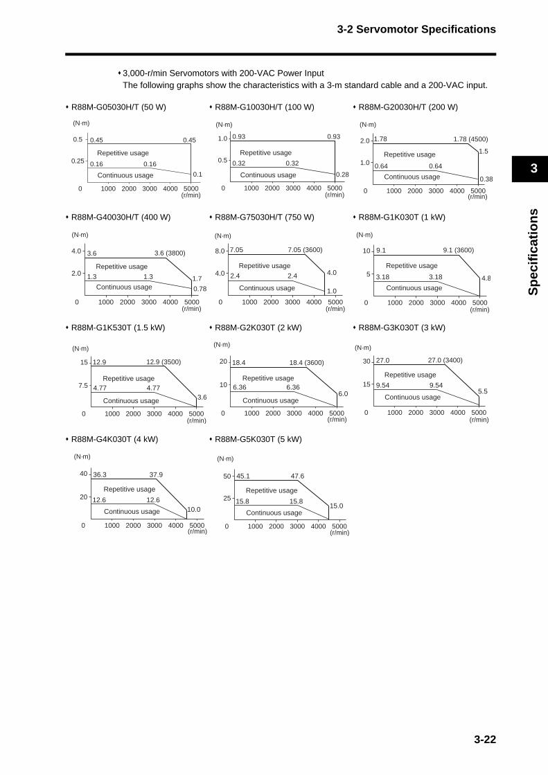
3-2 Servomotor Specifications
3
Sp
ecif
icat
ion
s
3,000-r/min Servomotors with 200-VAC Power InputThe following graphs show the characteristics with a 3-m standard cable and a 200-VAC input.
R88M-G05030H/T (50 W) R88M-G10030H/T (100 W) R88M-G20030H/T (200 W)
R88M-G40030H/T (400 W) R88M-G75030H/T (750 W) R88M-G1K030T (1 kW)
R88M-G1K530T (1.5 kW) R88M-G2K030T (2 kW) R88M-G3K030T (3 kW)
R88M-G4K030T (4 kW) R88M-G5K030T (5 kW)
0.5
0 1000 2000 3000 4000 5000
1.0 0.93
0.32 0.32
0.93
0.28
Repetitive usage
Continuous usage
(N·m)
(r/min)
1.0
0 1000 2000 3000 4000 5000
2.0 1.78
0.64 0.64
0.38
1.5
1.78 (4500)
Repetitive usage
Continuous usage
(N·m)
(r/min)
0.25
0 1000 2000 3000 4000 5000
0.5 0.45
0.16 0.16
0.1
0.45
Repetitive usage
Continuous usage
(N·m)
(r/min)
4.0
0 1000 2000 3000 4000 5000
8.0 7.05
2.4 2.4 4.0
1.0
7.05 (3600)
Repetitive usage
Continuous usage
(N·m)
(r/min)
5
0 1000 2000 3000 4000 5000
10 9.1
3.18 3.18 4.8
9.1 (3600)
Repetitive usage
Continuous usage
(N·m)
(r/min)
2.0
0 1000 2000 3000 4000 5000
4.0 3.6
1.3 1.3 1.7
0.78
3.6 (3800)
Repetitive usage
Continuous usage
(N·m)
(r/min)
10
0 1000 2000 3000 4000 5000
20 18.4
6.36 6.366.0
18.4 (3600)
Repetitive usage
Continuous usage
(N·m)
(r/min)
15
0 1000 2000 3000 4000 5000
30 27.0
5.59.54 9.54
27.0 (3400)
Repetitive usage
Continuous usage
(N·m)
(r/min)
7.5
0 1000 2000 3000 4000 5000
15 12.9
4.77 4.773.6
12.9 (3500)
Repetitive usage
Continuous usage
(N·m)
(r/min)
25
0 1000 2000 3000 4000 5000
50 45.1
15.8 15.815.0
47.6
Repetitive usage
Continuous usage
(N·m)
(r/min)
20
0 1000 2000 3000 4000 5000
40 36.3
12.6 12.610.0
37.9
Repetitive usage
Continuous usage
(N·m)
(r/min)
3-22

3-2 Servomotor Specifications
3
Sp
ecif
icat
ion
s
R88M-G05030H/T R88M-G05030H/T R88M-G10030H/T 50 W (Without Oil Seal) 50 W (With Oil Seal) 100 W (Without Oil Seal)
R88M-G10030H/T R88M-G20030H/T R88M-G40030H/T 100 W (With Oil Seal) 200 W (With Oil Seal) 400 W (Without Oil Seal)
R88M-G40030H/T R88M-G1K530T (1.5 kW) R88M-G2K030T (2 kW) 400 W (With Oil Seal)
R88M-G3K030T (3 kW) R88M-G4K030T (4 kW) R88M-G5K030T (5 kW)
Use the following Servomotors in the ranges shown in the graphs below. Using outside of these ranges may cause the Servomotor to generate heat, which could result in encoder malfunction.
Precautions for Correct Use
Rated Torque (%)
Ambient temperature
100% 95%
100 20 30 40
With brake
100%
70%60%
100 20 30 40
Without brakeRated Torque (%)
Ambient temperature
With brake 100% 95%
100 20 30 40
Rated Torque (%)
Ambient temperature
With brake
100%
75%70%
100 20 30 40
Without brakeRated Torque (%)
Ambient temperature
With brake 100%
80%70%
100 20 30 40
Without brakeRated Torque (%)
Ambient temperature
With brake 100%90%
100 20 30 40
Rated Torque (%)
Ambient temperature
With brake
100%
75%
100 20 30 40
Rated Torque (%)
Ambient temperature
With brake100%
85%
100 20 30 40
Without brakeRated Torque (%)
Ambient temperature
With brake100%
85%70%
100 20 30 40
Without brakeRated Torque (%)
Ambient temperature
With brake
100%
85%90%
100 20 30 40
Without brakeRated Torque (%)
Ambient temperature
With brake100%
85%90%
100 20 30 40
Without brakeRated Torque (%)
Ambient temperature
With brake100%
70%
100 20 30 40
Rated Torque (%)
Ambient temperature
With brake
3-23
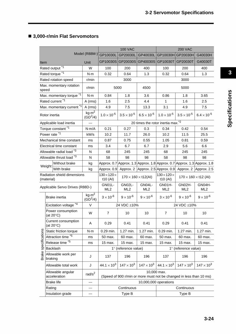
3-2 Servomotor Specifications
3
Sp
ecif
icat
ion
s
3,000-r/min Flat Servomotors
Model (R88M-)
Item Unit
100 VAC 200 VAC
GP10030L GP20030L GP40030L GP10030H GP20030H G40030H
GP10030S GP20030S GP40030S GP10030T GP20030T G40030T
Rated output *1 W 100 200 400 100 200 400
Rated torque *1 N·m 0.32 0.64 1.3 0.32 0.64 1.3
Rated rotation speed r/min 3000 3000
Max. momentary rotation speed
r/min 5000 4500 5000
Max. momentary torque *1 N·m 0.84 1.8 3.6 0.86 1.8 3.65
Rated current *1 A (rms) 1.6 2.5 4.4 1 1.6 2.5
Max. momentary current *1 A (rms) 4.9 7.5 13.3 3.1 4.9 7.5
Rotor inertiakg·m2
(GD2/4)1.0 × 10-5 3.5 × 10⁻⁵ 6.5 × 10⁻⁵ 1.0 × 10⁻⁵ 3.5 × 10⁻⁵ 6.4 × 10⁻⁵
Applicable load inertia --- 20 times the rotor inertia max.*2
Torque constant *1 N·m/A 0.21 0.27 0.3 0.34 0.42 0.54
Power rate *1 kW/s 10.2 11.7 26.0 10.2 11.5 25.5
Mechanical time constant ms 0.87 0.75 0.55 1.05 0.81 0.59
Electrical time constant ms 3.4 6.7 6.7 2.9 5.6 6.6
Allowable radial load *3 N 68 245 245 68 245 245
Allowable thrust load *3 N 58 98 98 58 98 98
WeightWithout brake kg Approx. 0.7 Approx. 1.3 Approx. 1.8 Approx. 0.7 Approx. 1.3 Approx. 1.8
With brake kg Approx. 0.9 Approx. 2 Approx. 2.5 Approx. 0.9 Approx. 2 Approx. 2.5
Radiation shield dimensions(material)
130 × 120 × t10 (AI)
170 × 160 × t12(AI)130 × 120 ×
t10 (AI)170 × 160 × t12 (AI)
Applicable Servo Drives (R88D-)GN01L-
ML2GN02L-
ML2GN04L-
ML2GN01H-
ML2GN02H-
ML2GN04H-
ML2
Bra
ke s
peci
ficat
ions
Brake inertiakg·m2
(GD2/4)3 × 10-6 9 × 10⁻⁶ 9 × 10⁻⁶ 3 × 10⁻⁶ 9 × 10⁻⁶ 9 × 10⁻⁶
Excitation voltage *4 V 24 VDC ±10% 24 VDC ±10%
Power consumption (at 20°C)
W 7 10 10 7 10 10
Current consumption (at 20°C)
A 0.29 0.41 0.41 0.29 0.41 0.41
Static friction torque N·m 0.29 min. 1.27 min. 1.27 min. 0.29 min. 1.27 min. 1.27 min.
Attraction time *5 ms 50 max. 60 max. 60 max. 50 max. 60 max. 60 max.
Release time *5 ms 15 max. 15 max. 15 max. 15 max. 15 max. 15 max.
Backlash 1° (reference value) 1° (reference value)
Allowable work per braking
J 137 196 196 137 196 196
Allowable total work J 44.1 × 10³ 147 × 103 147 × 103 44.1 × 10³ 147 × 103 147 × 103
Allowable angular acceleration
rad/s2 10,000 max.(Speed of 900 r/min or more must not be changed in less than 10 ms)
Brake life --- 10,000,000 operations
Rating --- Continuous Continuous
Insulation grade --- Type B Type B
3-24
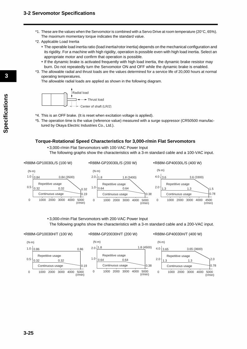
3-2 Servomotor Specifications
3
Sp
ecif
icat
ion
s
*1. These are the values when the Servomotor is combined with a Servo Drive at room temperature (20°C, 65%). The maximum momentary torque indicates the standard value.
*2. Applicable Load InertiaThe operable load inertia ratio (load inertia/rotor inertia) depends on the mechanical configuration and its rigidity. For a machine with high rigidity, operation is possible even with high load inertia. Select an appropriate motor and confirm that operation is possible.If the dynamic brake is activated frequently with high load inertia, the dynamic brake resistor may burn. Do not repeatedly turn the Servomotor ON and OFF while the dynamic brake is enabled.
*3. The allowable radial and thrust loads are the values determined for a service life of 20,000 hours at normal operating temperatures.The allowable radial loads are applied as shown in the following diagram.
*4. This is an OFF brake. (It is reset when excitation voltage is applied).*5. The operation time is the value (reference value) measured with a surge suppressor (CR50500 manufac-
tured by Okaya Electric Industries Co., Ltd.).
Torque-Rotational Speed Characteristics for 3,000-r/min Flat Servomotors3,000-r/min Flat Servomotors with 100-VAC Power InputThe following graphs show the characteristics with a 3-m standard cable and a 100-VAC input.
R88M-GP10030L/S (100 W) R88M-GP20030L/S (200 W) R88M-GP40030L/S (400 W)
3,000-r/min Flat Servomotors with 200-VAC Power InputThe following graphs show the characteristics with a 3-m standard cable and a 200-VAC input.
R88M-GP10030H/T (100 W) R88M-GP20030H/T (200 W) R88M-GP40030H/T (400 W)
Radial load
Thrust load
Center of shaft (LR/2)
0.5
0 1000 2000 3000 4000 5000
1.0 0.84
0.32 0.32 0.32
0.19
0.84 (3500)
Repetitive usage
Continuous usage
(N·m)
(r/min)
1.0
0 1000 2000 3000 4000 5000
2.0 1.8
0.64 0.64
0.38
1.8 (3400)
Repetitive usage
Continuous usage
(N·m)
(r/min)
2.0
0 1000 2000 3000 4000 4500
4.0 3.6
1.3 1.3 1.5
0.78
3.6 (3300)
Repetitive usage
Continuous usage
(N·m)
(r/min)
0.5
0 1000 2000 3000 4000 5000
1.0 0.86
0.32 0.32
0.19
0.86
Repetitive usage
Continuous usage
(N·m)
(r/min)
1.0
0 1000 2000 3000 4000 5000
2.0 1.8
0.64
0.38
0.64
1.8 (4500)
Repetitive usage
Continuous usage
(N·m)
(r/min)
2.0
0 1000 2000 3000 4000 5000
4.0 3.65
1.3 1.3 2.0
0.78
3.65 (3600)
Repetitive usage
Continuous usage
(N·m)
(r/min)
3-25

3-2 Servomotor Specifications
3
Sp
ecif
icat
ion
s
2,000-r/min Servomotors
Model (R88M-)
Item Unit
200 VAC
G1K020T G1K520T G2K020T G3K020T G4K020T G5K020T G7K515T
Rated output *1 W 1000 1500 2000 3000 4000 5000 7500
Rated torque *1 N·m 4.8 7.15 9.54 14.3 18.8 23.8 48
Rated rotation speed r/min 2000 1500
Max. momentary rotation speed
r/min 3000 2000
Max. momentary torque *1 N·m 13.5 19.6 26.5 41.2 54.9 70.6 111
Rated current *1 A (rms) 5.6 9.4 12.3 17.8 23.4 28 46.6
Max. momentary current *1 A (rms) 17.1 28.5 37.1 54.2 71.4 85.7 117.8
Rotor inertiakg·m2
(GD2/4)6.17 × 10-4 1.12 × 10⁻³ 1.52 × 10⁻³ 2.23 × 10⁻³ 4.25 × 10⁻³ 6.07 × 10⁻³ 9.9 × 10⁻³
Applicable load inertia --- 10 times the rotor inertia max.*2
Torque constant *1 N·m/A 0.88 0.76 0.78 0.81 0.81 0.85 1.03
Power rate *1 kW/s 37.3 45.8 60 91.6 83.2 93.5 230
Mechanical time constant
ms 0.7 0.81 0.75 0.72 1 0.9 0.71
Electrical time constant ms 18 19 21 20 24 32 34
Allowable radial load *3 N 490 490 490 784 784 784 1176
Allowable thrust load *3 N 196 196 196 343 343 343 490
WeightWithout brake kg
Approx. 6.8
Approx. 8.5
Approx. 10.6
Approx. 14.6
Approx. 18.8
Approx. 25
Approx. 41
With brake kgApprox.
8.7Approx.
10.1Approx.
12.5Approx.
16.5Approx.
21.3Approx.
28.5Approx.
45
Radiation shield dimensions (material)
275 × 260 × t15 (AI)380 × 350 × t30 (AI)
470 × 440 × t30 (AI)
Applicable Servo Drives (R88D-)GN10H-
ML2GN15H-
ML2GN20H-
ML2GN30H-
ML2GN50H-
ML2GN50H-
ML2GN75H-
ML2
Bra
ke s
peci
ficat
ions
Brake inertiakg·m2
(GD2/4)1.35 × 10-4 4.25 × 10⁻⁴ 4.7 × 10⁻⁴ 4.7 × 10⁻⁴
Excitation voltage *4 V 24 VDC ±10%
Power consumption(at 20°C)
W 14 19 19 22 26 31 34
Current consumption (at 20°C)
A 0.59 0.79 0.79 0.9 1.1 1.3 1.4
Static friction torque N·m 4.9 min. 13.7 min. 13.7 min. 16.1 min. 21.5 min. 24.5 min. 58.8 min.
Attraction time *5 ms 80 max. 100 max. 100 max. 110 max. 90 max. 80 max. 150 max.
Release time *5 ms 70 max. 50 max. 50 max. 50 max. 35 min. 25 min. 50 max.
Backlash 1° (reference value)
Allowable work per braking
J 588 1176 1176 1170 1078 1372 1372
Allowable total work J 7.8 × 10⁵ 1.5 × 10⁶ 1.5 × 10⁶ 2.2 × 10⁶ 2.5 × 10⁶ 2.9 × 10⁶ 2.9 × 10⁶
Allowable angular acceleration
rad/s2 10,000 max.(Speed of 900 r/min or more must not be changed in less than 10 ms)
Brake life --- 10,000,000 operations
Rating --- Continuous
Insulation grade --- Type F
3-26

3-2 Servomotor Specifications
3
Sp
ecif
icat
ion
s
*1. These are the values when the Servomotor is combined with a Servo Drive at room temperature (20°C, 65%). The maximum momentary torque indicates the standard value.
*2. Applicable Load InertiaThe operable load inertia ratio (load inertia/rotor inertia) depends on the mechanical configuration and its rigidity. For a machine with high rigidity, operation is possible even with high load inertia. Select an appropriate motor and confirm that operation is possible.If the dynamic brake is activated frequently with high load inertia, the dynamic brake resistor may burn. Do not repeatedly turn the Servomotor ON and OFF while the dynamic brake is enabled.
*3. The allowable radial and thrust loads are the values determined for a service life of 20,000 hours at normal operating temperatures.The allowable radial loads are applied as shown in the following diagram.
*4. This is an OFF brake. (It is reset when excitation voltage is applied).*5. The operation time is the value (reference value) measured with a surge suppressor (CR50500 manufac-
tured by Okaya Electric Industries Co., Ltd.).
Torque-Rotational Speed Characteristics for 2,000-r/min Servomotors2,000-r/min Servomotors with 200-VAC Power InputThe following graphs show the characteristics with a 3-m standard cable and a 200-VAC input.
R88M-G1K020T (1 kW) R88M-G1K520T (1.5 kW) R88M-G2K020T (2 kW)
R88M-G3K020T (3 kW) R88M-G4K020T (4 kW) R88M-G5K020T (5 kW)
R88M-G7K515T (7.5 kW)
Radial load
Thrust load
Center of shaft (LR/2)
0 1000 2000
5
10
15
3000
13.5
4.8 4.8 5.53.2
13.5 (2200)
Repetitive usage
Continuous usage
(N·m)
(r/min)
10
0
20
1000 2000 3000
18.5
14.3
4.7
7.15 7.15
18.5 (2200)
Repetitive usage
Continuous usage
(N·m)
(r/min)
15
0
30
1000 2000 3000
26.5
9.54 9.54 13.26.3
26.5 (2200)
Repetitive usage
Continuous usage
(N·m)
(r/min)
25
0
50
1000 2000 3000
41.2
14.3 14.3 14.39.5
41.2 (2200)
Repetitive usage
Continuous usage
(N·m)
(r/min)
Repetitive usage
Continuous usage
(N·m)
54.9 (2000)
(r/min)
35
0
70
1000 2000 3000
70.6
23.8 23.823.0
15.8
70.6 (2000)
Repetitive usage
Continuous usage
(N·m)
(r/min)
50
0
100
1000 1500 2000
111
48 48
111100
36
Repetitive usage
Continuous usage
(N·m)
(r/min)
3-27

3-2 Servomotor Specifications
3
Sp
ecif
icat
ion
s
1,000-r/min Servomotors
Model (R88M-)
Item Unit
200 VAC
G90010T G2K010T G3K010T G4K510T G6K010T
Rated output *1 W 900 2000 3000 4500 6000
Rated torque *1 N·m 8.62 19.1 28.4 42.9 57.2
Rated rotation speed r/min 1000
Max. momentary rotation speed
r/min 2000
Max. momentary torque *1 N·m 18.4 41.5 60 101 130
Rated current *1 A (rms) 7.6 18.5 24 33 57.2
Max. momentary current *1 A (rms) 17.1 44 57.1 84.2 121.4
Rotor inertiakg·m2
(GD2/4)1.12 × 10-3 3.55 × 10⁻³ 5.57 × 10⁻³ 8.09 × 10⁻³ 9.9 × 10⁻³
Applicable load inertia --- 10 times the rotor inertia max.*2
Torque constant *1 N·m/A 1.13 1 1.1 1.3 1.22
Power rate *1 kW/s 66.3 103 145 228 331
Mechanical time constant ms 0.88 0.97 0.74 0.7 0.65
Electrical time constant ms 20 25 30 31 46.2
Allowable radial load *3 N 686 1176 1470 1470 1764
Allowable thrust load *3 N 196 490 490 490 588
WeightWithout brake kg Approx. 8.5 Approx. 17.5 Approx. 25 Approx. 34 Approx. 41
With brake kg Approx. 10 Approx. 21 Approx. 28.5 Approx. 39.5 Approx. 45
Radiation shield dimensions (material)
275 × 260 × t15 (AI)
470 × 440 × t30 (AI)
Applicable Servo Drives (R88D-) GN15H-ML2 GN30H-ML2 GN50H-ML2 GN50H-ML2 GN75H-ML2
Bra
ke s
peci
ficat
ions
Brake inertiakg·m2
(GD2/4)1.35 × 10-4 4.7 × 10⁻⁴ 4.7 × 10⁻⁴ 4.7 × 10⁻⁴ 4.7 × 10⁻⁴
Excitation voltage *4 V 24 VDC ±10%
Power consumption (at 20°C)
W 19 31 34 34 34
Current consumption (at 20°C)
A 0.79 1.3 1.4 1.4 1.4
Static friction torque N·m 13.7 min. 24.5 min. 58.8 min. 58.8 min. 58.8 min.
Attraction time *5 ms 100 max. 80 max. 150 max. 150 max. 150 max.
Release time *5 ms 50 max. 25 max. 50 max. 50 max. 50 max.
Backlash 1° (reference value)
Allowable work per braking
J 1176 1372 1372 1372 1372
Allowable total work J 1.6 × 10⁶ 2.9 × 10⁶ 2.9 × 10⁶ 2.9 × 10⁶ 2.9 × 10⁶
Allowable angular acceleration
rad/s2 10,000 max.(Speed of 900 r/min or more must not be changed in less than 10 ms)
Brake life --- 10,000,000 operations
Rating --- Continuous
Insulation grade --- Type F
3-28
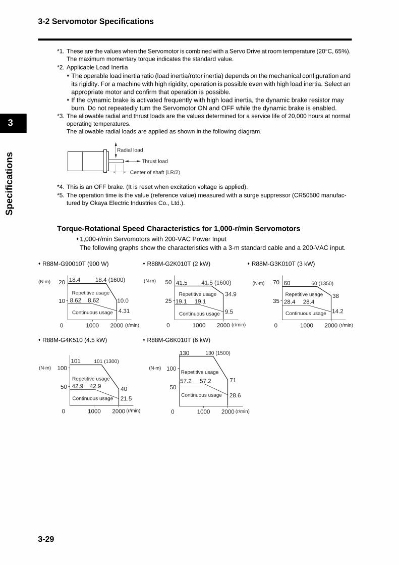
3-2 Servomotor Specifications
3
Sp
ecif
icat
ion
s
*1. These are the values when the Servomotor is combined with a Servo Drive at room temperature (20°C, 65%). The maximum momentary torque indicates the standard value.
*2. Applicable Load InertiaThe operable load inertia ratio (load inertia/rotor inertia) depends on the mechanical configuration and its rigidity. For a machine with high rigidity, operation is possible even with high load inertia. Select an appropriate motor and confirm that operation is possible.If the dynamic brake is activated frequently with high load inertia, the dynamic brake resistor may burn. Do not repeatedly turn the Servomotor ON and OFF while the dynamic brake is enabled.
*3. The allowable radial and thrust loads are the values determined for a service life of 20,000 hours at normal operating temperatures.The allowable radial loads are applied as shown in the following diagram.
*4. This is an OFF brake. (It is reset when excitation voltage is applied).*5. The operation time is the value (reference value) measured with a surge suppressor (CR50500 manufac-
tured by Okaya Electric Industries Co., Ltd.).
Torque-Rotational Speed Characteristics for 1,000-r/min Servomotors1,000-r/min Servomotors with 200-VAC Power InputThe following graphs show the characteristics with a 3-m standard cable and a 200-VAC input.
R88M-G90010T (900 W) R88M-G2K010T (2 kW) R88M-G3K010T (3 kW)
R88M-G4K510 (4.5 kW) R88M-G6K010T (6 kW)
Radial load
Thrust load
Center of shaft (LR/2)
10
0
20 18.4
10.0
4.31
8.62 8.62
1000 2000
18.4 (1600)
Repetitive usage
Continuous usage
(N·m)
(r/min)
25
0
50
1000 2000
41.5
19.1 19.134.9
9.5
41.5 (1600)
Repetitive usage
Continuous usage
(N·m)
(r/min)
35
0
70
1000 2000
60
28.4 28.4
14.2
38
60 (1350)
Repetitive usage
Continuous usage
(N·m)
(r/min)
50
0
100
1000 2000
101
42.9 42.9 40
21.5
101 (1300)
Repetitive usage
Continuous usage
(N·m)
(r/min)
50
0
100
1000 2000
130
57.2 57.2 71
28.6
130 (1500)
Repetitive usage
Continuous usage
(N·m)
(r/min)
3-29

3-2 Servomotor Specifications
3
Sp
ecif
icat
ion
s
R88M-G4K510 R88M-G6K010T 4.5 kW (Without Oil Seal) 6 kW (With Oil Seal)
Temperature Characteristics of the Servomotor and Mechanical SystemOMNUC G-Series AC Servomotors use rare earth magnets (neodymium-iron magnets).The temperature coefficient for these magnets is approximately −0.13%/°C. As the temperature drops, the Servomotor's maximum momentary torque increases, and as the temperature rises, the Servomotor's maximum momentary torque decreases.
The maximum momentary torque rises by 4% at a normal temperature of 20°C compared to a temperature of −10°C. Conversely, the maximum momentary torque decreases about 8% when the magnet warms up to 80°C from the normal temperature.
Generally, when the temperature drops in a mechanical system, the friction torque and the load torque increase.For that reason, overloading may occur at low temperatures. In particular, in systems that use a Decelerator, the load torque at low temperatures may be nearly twice as much as the load torque at normal temperatures.Check whether overloading may occur at low temperature startup.Also check to see whether abnormal Servomotor overheating or alarms occur at high temperatures.
An increase in load friction torque seemingly increases load inertia.Therefore, even if the Servo Drive gains are adjusted at a normal temperature, the Servomotor may not operate properly at low temperatures.Check to see whether there is optimal operation even at low temperatures.
Use the following Servomotors in the ranges shown in the graphs below. Using outside of these ranges may cause the Servomotor to generate heat, which could result in encoder malfunction.
Precautions for Correct Use
100%
70%85%
100 20 30 40
Without brakeRated Torque (%)
Ambient temperature
With brake100%
85%90%
100 20 30 40
Without brakeRated Torque (%)
Ambient temperature
With brake
3-30

3-2 Servomotor Specifications
3
Sp
ecif
icat
ion
s
Encoder Specifications
Incremental Encoders
Absolute Encoders
Item Specifications
Encoder system Optical encoder
No. of output pulsesPhases A and B: 2,500 pulses/rotationPhase Z: 1 pulse/rotation
Power supply voltage 5 VDC ±5%
Power supply current 180 mA (max.)
Output signals +S, −S
Output interface RS-485 compliance
Item Specifications
Encoder systemOptical encoder
17 bits
No. of output pulsesPhases A and B: 32,768 pulses/rotationPhase Z: 1 pulse/rotation
Maximum rotations −32,768 to +32,767 rotations or 0 to 65,534 rotations
Power supply voltage
5 VDC ±5%
Power supply current 110 mA (max.)
Applicable battery voltage
3.6 VDC
Current consumption of battery
265 μA for a maximum of 5 s right after power interruption100 μA for operation during power interruption3.6 μA when power is supplied to Servo Drive
Output signals +S, −S
Output interface RS-485 compliance
3-31
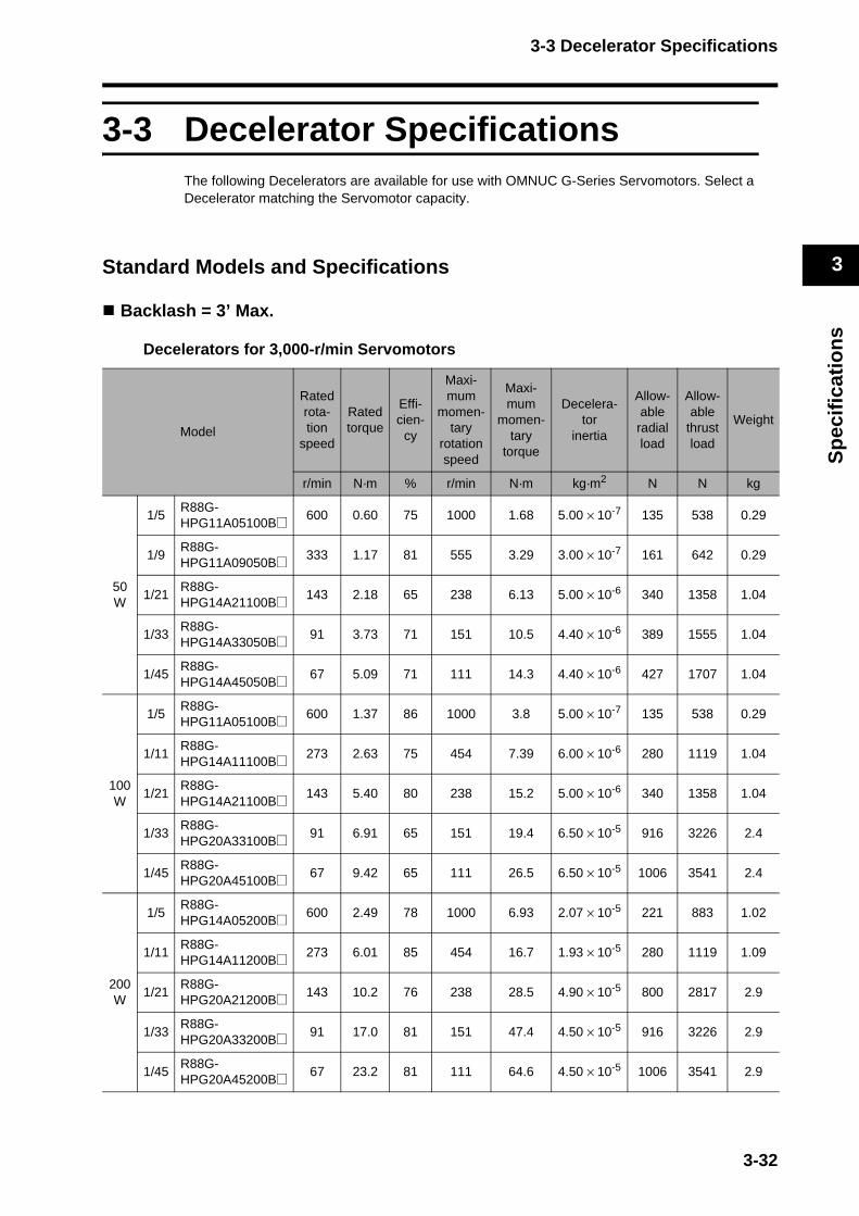
3-3 Decelerator Specifications
3
Sp
ecif
icat
ion
s
3-3 Decelerator SpecificationsThe following Decelerators are available for use with OMNUC G-Series Servomotors. Select a Decelerator matching the Servomotor capacity.
Standard Models and Specifications
Backlash = 3’ Max.
Decelerators for 3,000-r/min Servomotors
Model
Ratedrota-tion
speed
Rated torque
Effi-cien-
cy
Maxi-mum
momen-tary
rotation speed
Maxi-mum
momen-tary
torque
Decelera-tor
inertia
Allow-ableradialload
Allow-able
thrustload
Weight
r/min N·m % r/min N·m kg·m2 N N kg
50 W
1/5R88G-HPG11A05100B@ 600 0.60 75 1000 1.68 5.00 × 10⁻⁷ 135 538 0.29
1/9R88G-HPG11A09050B@ 333 1.17 81 555 3.29 3.00 × 10⁻⁷ 161 642 0.29
1/21R88G-HPG14A21100B@ 143 2.18 65 238 6.13 5.00 × 10⁻⁶ 340 1358 1.04
1/33R88G-HPG14A33050B@ 91 3.73 71 151 10.5 4.40 × 10⁻⁶ 389 1555 1.04
1/45R88G-HPG14A45050B@ 67 5.09 71 111 14.3 4.40 × 10⁻⁶ 427 1707 1.04
100 W
1/5R88G-HPG11A05100B@ 600 1.37 86 1000 3.8 5.00 × 10⁻⁷ 135 538 0.29
1/11R88G-HPG14A11100B@ 273 2.63 75 454 7.39 6.00 × 10⁻⁶ 280 1119 1.04
1/21R88G-HPG14A21100B@ 143 5.40 80 238 15.2 5.00 × 10⁻⁶ 340 1358 1.04
1/33R88G-HPG20A33100B@ 91 6.91 65 151 19.4 6.50 × 10⁻⁵ 916 3226 2.4
1/45R88G-HPG20A45100B@ 67 9.42 65 111 26.5 6.50 × 10⁻⁵ 1006 3541 2.4
200 W
1/5R88G-HPG14A05200B@ 600 2.49 78 1000 6.93 2.07 × 10⁻⁵ 221 883 1.02
1/11R88G-HPG14A11200B@ 273 6.01 85 454 16.7 1.93 × 10⁻⁵ 280 1119 1.09
1/21R88G-HPG20A21200B@ 143 10.2 76 238 28.5 4.90 × 10⁻⁵ 800 2817 2.9
1/33R88G-HPG20A33200B@ 91 17.0 81 151 47.4 4.50 × 10⁻⁵ 916 3226 2.9
1/45R88G-HPG20A45200B@ 67 23.2 81 111 64.6 4.50 × 10⁻⁵ 1006 3541 2.9
3-32

3-3 Decelerator Specifications
3
Sp
ecif
icat
ion
s
Model
Ratedrota-tion
speed
Rated torque
Effi-cien-
cy
Maxi-mum
momen-tary
rotation speed
Maxi-mum
momen-tary
torque
Decelera-tor
inertia
Allow-able
radialload
Allow-able
thrustload
Weight
r/min N·m % r/min N·m kg·m2 N N kg
400 W
1/5R88G-HPG14A05400B@ 600 5.66 87 1000
16.0(15.7)
2.07 × 10⁻⁵ 221 883 1.09
1/11R88G-HPG20A11400B@ 273 11.7 82 454
33.1(32.5)
5.70 × 10⁻⁵ 659 2320 2.9
1/21R88G-HPG20A21400B@ 143 23.5 86 238
66.5(65.2)
4.90 × 10⁻⁵ 800 2547 2.9
1/33R88G-HPG32A33400B@ 91 34.7 81 151
98.2(96.3)
6.20 × 10⁻⁵ 1565 6240 7.5
1/45R88G-HPG32A45400B@ 67 47.4 81 111
133.9(131.4)
6.10 × 10⁻⁵ 1718 6848 7.5
750 W
1/5R88G-HPG20A05750B@ 600 9.94 83 1000 29.2 6.80 × 10⁻⁵ 520 1832 2.9
1/11R88G-HPG20A11750B@ 273 23.2 88 454 68.1 6.00 × 10⁻⁵ 659 2320 3.1
1/21R88G-HPG32A21750B@ 143 42.3 84 238 124.3 3.00 × 10⁻⁴ 1367 5448 7.8
1/33R88G-HPG32A33750B@ 91 69.7 88 151 204.7 2.70 × 10⁻⁴ 1565 6240 7.8
1/45R88G-HPG32A45750B@ 67 95.0 88 111 279.2 2.70 × 10⁻⁴ 1718 6848 7.8
1kW
1/5R88G-HPG32A051K0B@ 600 11.5 72 1000 32.9 3.90 × 10⁻⁴ 889 3542 7.3
1/11R88G-HPG32A111K0B@ 273 28.9 83 454 82.6 3.40 × 10⁻⁴ 1126 4488 7.8
1/21R88G-HPG32A211K0B@ 143 58.1 87 238 166.1 3.00 × 10⁻⁴ 1367 5488 7.8
1/33R88G-HPG32A331K0B@ 91 94.3 90 151 270.0 2.80 × 10⁻⁴ 1565 6240 7.8
1/45R88G-HPG50A451K0B@ 67 124.2 87 100*1 355.4 4.70 × 10⁻⁴ 4538 15694 19.0
1.5 kW
1/5R88G-HPG32A052K0B@ 600 19.1 80 1000 51.3 3.90 × 10⁻⁴ 889 3542 7.4
1/11R88G-HPG32A112K0B@ 273 45.7 87 454 122.5 3.40 × 10⁻⁴ 1126 4488 7.9
1/21R88G-HPG32A211K5B@ 143 90.1 90 238 241.9 3.00 × 10⁻⁴ 1367 5448 7.9
1/33R88G-HPG50A332K0B@ 91 141.5 90 136*1 379.7 4.80 × 10⁻⁴ 4135 14300 19.0
1/45R88G-HPG50A451K5B@ 67 192.9 90 100*1 517.8 4.70 × 10⁻⁴ 4538 15694 19.0
3-33
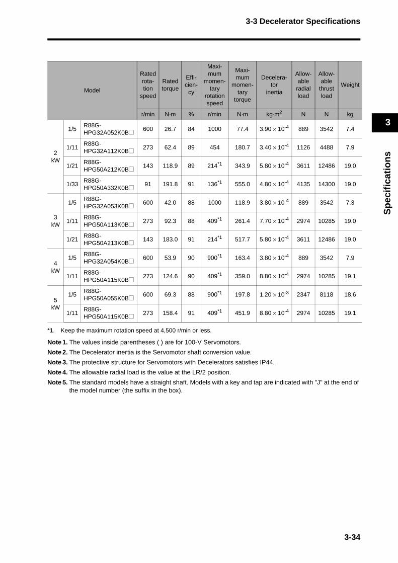
3-3 Decelerator Specifications
3
Sp
ecif
icat
ion
s
*1. Keep the maximum rotation speed at 4,500 r/min or less.
Note 1. The values inside parentheses ( ) are for 100-V Servomotors.
Note 2. The Decelerator inertia is the Servomotor shaft conversion value.
Note 3. The protective structure for Servomotors with Decelerators satisfies IP44.
Note 4. The allowable radial load is the value at the LR/2 position.
Note 5. The standard models have a straight shaft. Models with a key and tap are indicated with "J" at the end of the model number (the suffix in the box).
Model
Ratedrota-tion
speed
Rated torque
Effi-cien-
cy
Maxi-mum
momen-tary
rotation speed
Maxi-mum
momen-tary
torque
Decelera-tor
inertia
Allow-able
radialload
Allow-able
thrustload
Weight
r/min N·m % r/min N·m kg·m2 N N kg
2kW
1/5R88G-HPG32A052K0B@ 600 26.7 84 1000 77.4 3.90 × 10⁻⁴ 889 3542 7.4
1/11R88G-HPG32A112K0B@ 273 62.4 89 454 180.7 3.40 × 10⁻⁴ 1126 4488 7.9
1/21R88G-HPG50A212K0B@ 143 118.9 89 214*1 343.9 5.80 × 10⁻⁴ 3611 12486 19.0
1/33R88G-HPG50A332K0B@ 91 191.8 91 136*1 555.0 4.80 × 10⁻⁴ 4135 14300 19.0
3kW
1/5R88G-HPG32A053K0B@ 600 42.0 88 1000 118.9 3.80 × 10⁻⁴ 889 3542 7.3
1/11R88G-HPG50A113K0B@ 273 92.3 88 409*1 261.4 7.70 × 10⁻⁴ 2974 10285 19.0
1/21R88G-HPG50A213K0B@ 143 183.0 91 214*1 517.7 5.80 × 10⁻⁴ 3611 12486 19.0
4kW
1/5R88G-HPG32A054K0B@ 600 53.9 90 900*1 163.4 3.80 × 10⁻⁴ 889 3542 7.9
1/11R88G-HPG50A115K0B@ 273 124.6 90 409*1 359.0 8.80 × 10⁻⁴ 2974 10285 19.1
5kW
1/5R88G-HPG50A055K0B@ 600 69.3 88 900*1 197.8 1.20 × 10⁻³ 2347 8118 18.6
1/11R88G-HPG50A115K0B@ 273 158.4 91 409*1 451.9 8.80 × 10⁻⁴ 2974 10285 19.1
3-34

3-3 Decelerator Specifications
3
Sp
ecif
icat
ion
s
Decelerators for 2,000-r/min Servomotors
Model
Ratedrota-tion
speed
Rated torque
Effi-cien-
cy
Maxi-mum
momen-tary
rotation speed
Maxi-mum
momen-tary
torque
Deceleratorinertia
Allow-ableradialload
Allow-able
thrustload
Weight
r/min N·m % r/min N·m kg·m2 N N kg
1kW
1/5R88G-HPG32A053K0B@ 400 20.4 85 600 57.4 3.80 × 10⁻⁴ 889 3542 7.3
1/11R88G-HPG32A112K0SB@ 182 47.3 90 273 133.1 3.40 × 10⁻⁴ 1126 4488 7.8
1/21R88G-HPG32A211K0SB@ 95 92.3 92 143 259.7 2.90 × 10⁻⁴ 1367 5448 7.8
1/33R88G-HPG50A332K0SB@ 60 144.9 92 91 407.6 4.70 × 10⁻⁴ 4135 14300 19.0
1/45R88G-HPG50A451K0SB@ 44 197.7 92 67 555.9 4.70 × 10⁻⁴ 4538 15694 19.0
1.5 kW
1/5R88G-HPG32A053K0B@ 400 31.7 89 600 86.8 3.80 × 10⁻⁴ 889 3542 7.3
1/11R88G-HPG32A112K0SB@ 182 72.1 92 273 197.7 3.40 × 10⁻⁴ 1126 4488 7.8
1/21R88G-HPG50A213K0B@ 95 137.5 92 143 377.0 5.80 × 10⁻⁴ 3611 12486 19.0
1/33R88G-HPG50A332K0SB@ 60 219.4 93 91 601.5 4.70 × 10⁻⁴ 4135 14300 19.0
2kW
1/5R88G-HPG32A053K0B@ 400 43.2 91 600 119.9 3.80 × 10⁻⁴ 889 3542 7.3
1/11R88G-HPG32A112K0SB@ 182 97.4 93 273 270.5 3.40 × 10⁻⁴ 1126 4488 7.8
1/21R88G-HPG50A213K0B@ 95 185.6 93 143 515.9 5.80 × 10⁻⁴ 3611 12486 19.0
1/33R88G-HPG50A332K0SB@ 60 270.0*1 93 91 815.0 4.70 × 10⁻⁴ 4135 14300 19.0
3-35
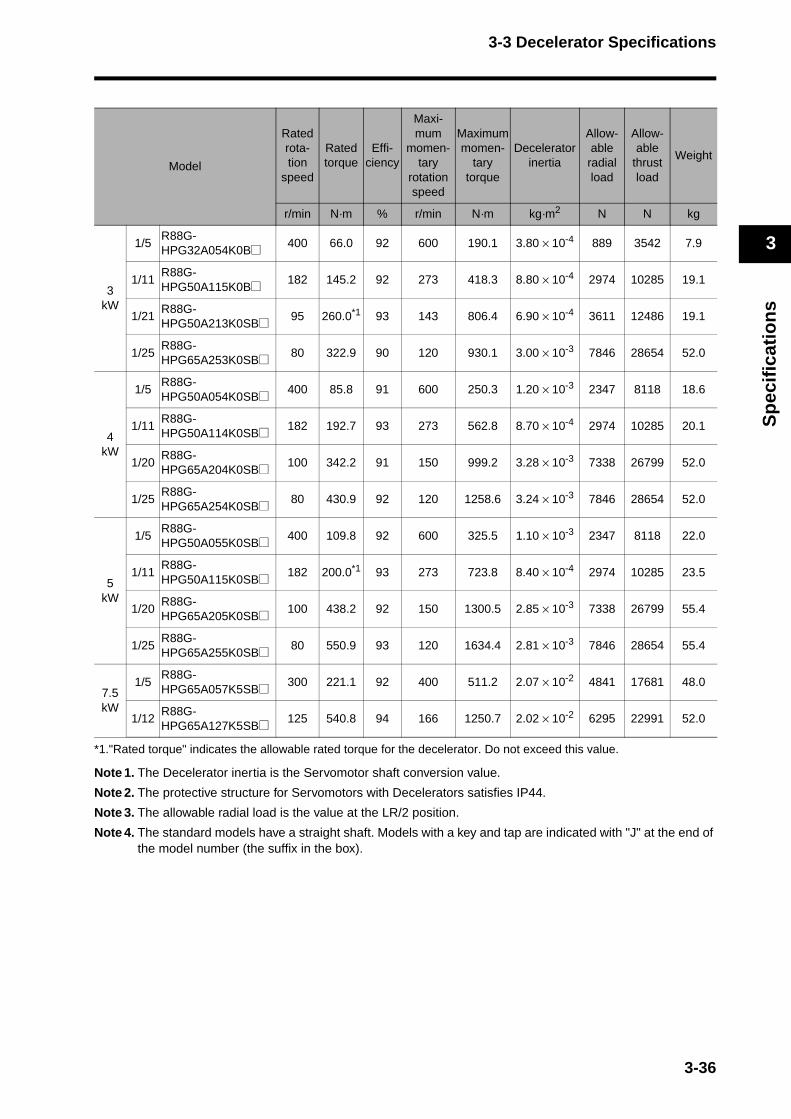
3-3 Decelerator Specifications
3
Sp
ecif
icat
ion
s
*1."Rated torque" indicates the allowable rated torque for the decelerator. Do not exceed this value.Note 1. The Decelerator inertia is the Servomotor shaft conversion value.
Note 2. The protective structure for Servomotors with Decelerators satisfies IP44.
Note 3. The allowable radial load is the value at the LR/2 position.
Note 4. The standard models have a straight shaft. Models with a key and tap are indicated with "J" at the end of the model number (the suffix in the box).
Model
Ratedrota-tion
speed
Rated torque
Effi-ciency
Maxi-mum
momen-tary
rotation speed
Maximummomen-
tarytorque
Deceleratorinertia
Allow-able
radialload
Allow-able
thrustload
Weight
r/min N·m % r/min N·m kg·m2 N N kg
3kW
1/5R88G-HPG32A054K0B@ 400 66.0 92 600 190.1 3.80 × 10⁻⁴ 889 3542 7.9
1/11R88G-HPG50A115K0B@ 182 145.2 92 273 418.3 8.80 × 10⁻⁴ 2974 10285 19.1
1/21R88G-HPG50A213K0SB@ 95 260.0*1 93 143 806.4 6.90 × 10⁻⁴ 3611 12486 19.1
1/25R88G-HPG65A253K0SB@ 80 322.9 90 120 930.1 3.00 × 10⁻³ 7846 28654 52.0
4kW
1/5R88G-HPG50A054K0SB@ 400 85.8 91 600 250.3 1.20 × 10⁻³ 2347 8118 18.6
1/11R88G-HPG50A114K0SB@ 182 192.7 93 273 562.8 8.70 × 10⁻⁴ 2974 10285 20.1
1/20R88G-HPG65A204K0SB@ 100 342.2 91 150 999.2 3.28 × 10⁻³ 7338 26799 52.0
1/25R88G-HPG65A254K0SB@ 80 430.9 92 120 1258.6 3.24 × 10⁻³ 7846 28654 52.0
5kW
1/5R88G-HPG50A055K0SB@ 400 109.8 92 600 325.5 1.10 × 10⁻³ 2347 8118 22.0
1/11R88G-HPG50A115K0SB@ 182 200.0*1 93 273 723.8 8.40 × 10⁻⁴ 2974 10285 23.5
1/20R88G-HPG65A205K0SB@ 100 438.2 92 150 1300.5 2.85 × 10⁻³ 7338 26799 55.4
1/25R88G-HPG65A255K0SB@ 80 550.9 93 120 1634.4 2.81 × 10⁻³ 7846 28654 55.4
7.5 kW
1/5R88G-HPG65A057K5SB@ 300 221.1 92 400 511.2 2.07 × 10⁻² 4841 17681 48.0
1/12R88G-HPG65A127K5SB@ 125 540.8 94 166 1250.7 2.02 × 10⁻² 6295 22991 52.0
3-36
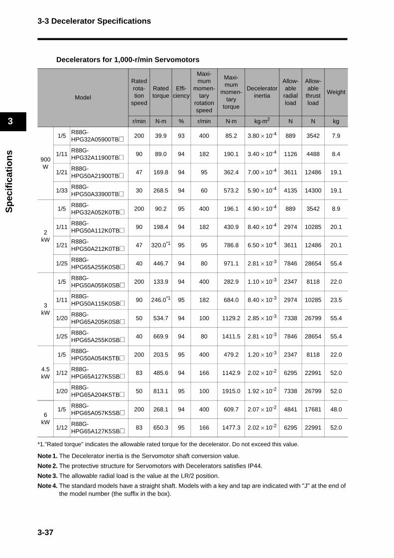
3-3 Decelerator Specifications
3
Sp
ecif
icat
ion
s
Decelerators for 1,000-r/min Servomotors
*1."Rated torque" indicates the allowable rated torque for the decelerator. Do not exceed this value.
Note 1. The Decelerator inertia is the Servomotor shaft conversion value.
Note 2. The protective structure for Servomotors with Decelerators satisfies IP44.
Note 3. The allowable radial load is the value at the LR/2 position.
Note 4. The standard models have a straight shaft. Models with a key and tap are indicated with "J" at the end of the model number (the suffix in the box).
Model
Ratedrota-tion
speed
Rated torque
Effi-ciency
Maxi-mum
momen-tary
rotation speed
Maxi-mum
momen-tary
torque
Deceleratorinertia
Allow-able
radialload
Allow-able
thrustload
Weight
r/min N·m % r/min N·m kg·m2 N N kg
900 W
1/5R88G-HPG32A05900TB@ 200 39.9 93 400 85.2 3.80 × 10⁻⁴ 889 3542 7.9
1/11R88G-HPG32A11900TB@ 90 89.0 94 182 190.1 3.40 × 10⁻⁴ 1126 4488 8.4
1/21R88G-HPG50A21900TB@ 47 169.8 94 95 362.4 7.00 × 10⁻⁴ 3611 12486 19.1
1/33R88G-HPG50A33900TB@ 30 268.5 94 60 573.2 5.90 × 10⁻⁴ 4135 14300 19.1
2kW
1/5R88G-HPG32A052K0TB@ 200 90.2 95 400 196.1 4.90 × 10⁻⁴ 889 3542 8.9
1/11R88G-HPG50A112K0TB@ 90 198.4 94 182 430.9 8.40 × 10⁻⁴ 2974 10285 20.1
1/21R88G-HPG50A212K0TB@ 47 320.0*1 95 95 786.8 6.50 × 10⁻⁴ 3611 12486 20.1
1/25R88G-HPG65A255K0SB@ 40 446.7 94 80 971.1 2.81 × 10⁻³ 7846 28654 55.4
3kW
1/5R88G-HPG50A055K0SB@ 200 133.9 94 400 282.9 1.10 × 10⁻³ 2347 8118 22.0
1/11R88G-HPG50A115K0SB@ 90 246.0*1 95 182 684.0 8.40 × 10⁻³ 2974 10285 23.5
1/20R88G-HPG65A205K0SB@ 50 534.7 94 100 1129.2 2.85 × 10⁻³ 7338 26799 55.4
1/25R88G-HPG65A255K0SB@ 40 669.9 94 80 1411.5 2.81 × 10⁻³ 7846 28654 55.4
4.5 kW
1/5R88G-HPG50A054K5TB@ 200 203.5 95 400 479.2 1.20 × 10⁻³ 2347 8118 22.0
1/12R88G-HPG65A127K5SB@ 83 485.6 94 166 1142.9 2.02 × 10⁻² 6295 22991 52.0
1/20R88G-HPG65A204K5TB@ 50 813.1 95 100 1915.0 1.92 × 10⁻² 7338 26799 52.0
6kW
1/5R88G-HPG65A057K5SB@ 200 268.1 94 400 609.7 2.07 × 10⁻² 4841 17681 48.0
1/12R88G-HPG65A127K5SB@ 83 650.3 95 166 1477.3 2.02 × 10⁻² 6295 22991 52.0
3-37
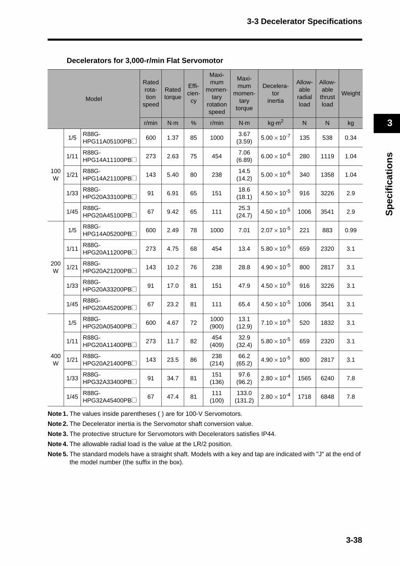
3-3 Decelerator Specifications
3
Sp
ecif
icat
ion
s
Decelerators for 3,000-r/min Flat Servomotor
Note 1. The values inside parentheses ( ) are for 100-V Servomotors.
Note 2. The Decelerator inertia is the Servomotor shaft conversion value.
Note 3. The protective structure for Servomotors with Decelerators satisfies IP44.
Note 4. The allowable radial load is the value at the LR/2 position.
Note 5. The standard models have a straight shaft. Models with a key and tap are indicated with "J" at the end of the model number (the suffix in the box).
Model
Ratedrota-tion
speed
Rated torque
Effi-cien-
cy
Maxi-mum
momen-tary
rotation speed
Maxi-mum
momen-tary
torque
Decelera-tor
inertia
Allow-able
radialload
Allow-able
thrustload
Weight
r/min N·m % r/min N·m kg·m2 N N kg
100 W
1/5R88G-HPG11A05100PB@ 600 1.37 85 1000
3.67(3.59)
5.00 × 10⁻⁷ 135 538 0.34
1/11R88G-HPG14A11100PB@ 273 2.63 75 454
7.06(6.89)
6.00 × 10⁻⁶ 280 1119 1.04
1/21R88G-HPG14A21100PB@ 143 5.40 80 238
14.5(14.2)
5.00 × 10⁻⁶ 340 1358 1.04
1/33R88G-HPG20A33100PB@ 91 6.91 65 151
18.6(18.1)
4.50 × 10⁻⁵ 916 3226 2.9
1/45R88G-HPG20A45100PB@ 67 9.42 65 111
25.3(24.7)
4.50 × 10⁻⁵ 1006 3541 2.9
200 W
1/5R88G-HPG14A05200PB@ 600 2.49 78 1000 7.01 2.07 × 10⁻⁵ 221 883 0.99
1/11R88G-HPG20A11200PB@ 273 4.75 68 454 13.4 5.80 × 10⁻⁵ 659 2320 3.1
1/21R88G-HPG20A21200PB@ 143 10.2 76 238 28.8 4.90 × 10⁻⁵ 800 2817 3.1
1/33R88G-HPG20A33200PB@ 91 17.0 81 151 47.9 4.50 × 10⁻⁵ 916 3226 3.1
1/45R88G-HPG20A45200PB@ 67 23.2 81 111 65.4 4.50 × 10⁻⁵ 1006 3541 3.1
400 W
1/5R88G-HPG20A05400PB@ 600 4.67 72
1000(900)
13.1(12.9)
7.10 × 10⁻⁵ 520 1832 3.1
1/11R88G-HPG20A11400PB@ 273 11.7 82
454(409)
32.9(32.4)
5.80 × 10⁻⁵ 659 2320 3.1
1/21R88G-HPG20A21400PB@ 143 23.5 86
238(214)
66.2(65.2)
4.90 × 10⁻⁵ 800 2817 3.1
1/33R88G-HPG32A33400PB@ 91 34.7 81
151(136)
97.6(96.2)
2.80 × 10⁻⁴ 1565 6240 7.8
1/45R88G-HPG32A45400PB@ 67 47.4 81
111(100)
133.0(131.2)
2.80 × 10⁻⁴ 1718 6848 7.8
3-38
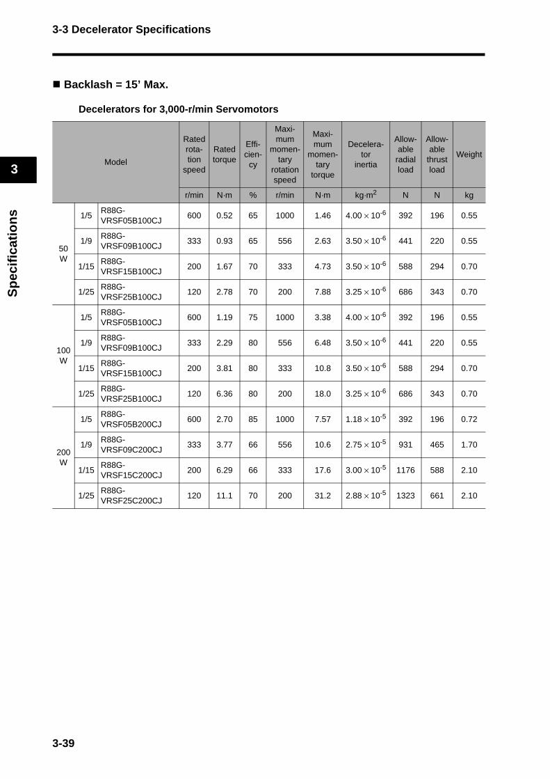
3-3 Decelerator Specifications
3
Sp
ecif
icat
ion
s
Backlash = 15’ Max.
Decelerators for 3,000-r/min Servomotors
Model
Ratedrota-tion
speed
Rated torque
Effi-cien-
cy
Maxi-mum
momen-tary
rotation speed
Maxi-mum
momen-tary
torque
Decelera-tor
inertia
Allow-able
radialload
Allow-able
thrustload
Weight
r/min N·m % r/min N·m kg·m2 N N kg
50 W
1/5R88G-VRSF05B100CJ
600 0.52 65 1000 1.46 4.00 × 10⁻⁶ 392 196 0.55
1/9R88G-VRSF09B100CJ
333 0.93 65 556 2.63 3.50 × 10⁻⁶ 441 220 0.55
1/15R88G-VRSF15B100CJ
200 1.67 70 333 4.73 3.50 × 10⁻⁶ 588 294 0.70
1/25R88G-VRSF25B100CJ
120 2.78 70 200 7.88 3.25 × 10⁻⁶ 686 343 0.70
100 W
1/5R88G-VRSF05B100CJ
600 1.19 75 1000 3.38 4.00 × 10⁻⁶ 392 196 0.55
1/9R88G-VRSF09B100CJ
333 2.29 80 556 6.48 3.50 × 10⁻⁶ 441 220 0.55
1/15R88G-VRSF15B100CJ
200 3.81 80 333 10.8 3.50 × 10⁻⁶ 588 294 0.70
1/25R88G-VRSF25B100CJ
120 6.36 80 200 18.0 3.25 × 10⁻⁶ 686 343 0.70
200 W
1/5R88G-VRSF05B200CJ
600 2.70 85 1000 7.57 1.18 × 10⁻⁵ 392 196 0.72
1/9R88G-VRSF09C200CJ
333 3.77 66 556 10.6 2.75 × 10⁻⁵ 931 465 1.70
1/15R88G-VRSF15C200CJ
200 6.29 66 333 17.6 3.00 × 10⁻⁵ 1176 588 2.10
1/25R88G-VRSF25C200CJ
120 11.1 70 200 31.2 2.88 × 10⁻⁵ 1323 661 2.10
3-39

3-3 Decelerator Specifications
3
Sp
ecif
icat
ion
s
L
Note 1. The values inside parentheses ( ) are for 100-V Servomotors.
Note 2. The Decelerator inertia is the Servomotor shaft conversion value.
Note 3. The protective structure for Servomotors with Decelerators satisfies IP44.
Note 4. The allowable radial load is the value at the LR/2 position.
Note 5. The standard models have a straight shaft with a key.
Model
Ratedrota-tion
speed
Rated torque
Effi-cien-
cy
Maxi-mum
momen-tary
rotation speed
Maxi-mum
momen-tary
torque
Decelera-tor
inertia
Allow-ableradialload
Allow-able
thrustload
Weight
r/min N·m % r/min N·m kg·m2 N N kg
400 W
1/5R88G-VRSF05C400CJ
600 5.40 85 100015.6
(15.3)3.63 × 10⁻⁵ 784 392 1.70
1/9R88G-VRSF09C400CJ
333 9.50 83 55627.4
(26.8)2.75 × 10⁻⁵ 931 465 1.70
1/15R88G-VRSF15C400CJ
200 15.8 83 33345.7
(44.8)3.00 × 10⁻⁵ 1176 588 2.10
1/25R88G-VRSF25C400CJ
120 26.4 83 20076.1
(74.7)2.88 × 10⁻⁵ 1323 661 2.10
750 W
1/5R88G-VRSF05C750CJ
600 10.7 90 1000 31.7 7.13 × 10⁻⁵ 784 392 2.10
1/9R88G-VRSF09D750CJ
333 18.2 85 556 53.9 6.50 × 10⁻⁵ 1176 588 3.40
1/15R88G-VRSF15D750CJ
200 30.4 85 333 89.9 7.00 × 10⁻⁵ 1372 686 3.80
1/25R88G-VRSF25D750CJ
120 50.7 85 200 149.8 6.80 × 10⁻⁵ 1617 808 3.80
3-40

3-3 Decelerator Specifications
3
Sp
ecif
icat
ion
s
Decelerators for 3,000-r/min Flat Servomotors
Note 1. The values inside parentheses ( ) are for 100-V Servomotors.
Note 2. The Decelerator inertia is the Servomotor shaft conversion value.
Note 3. The protective structure for Servomotors with Decelerators satisfies IP44.
Note 4. The allowable radial load is the value at the LR/2 position.
Note 5. The standard models have a straight shaft with a key.
Model
Ratedrota-tion
speed
Rated torque
Effi-cien-
cy
Maxi-mum
momen-tary
rotation speed
Maxi-mum
momen-tary
torque
Decelera-tor
inertia
Allow-able
radialload
Allow-able
thrustload
Weight
r/min N·m % r/min N·m kg·m2 N N kg
100 W
1/5R88G-VRSF05B100PCJ
600 1.19 75 1000 3.15 4.00 × 10⁻⁶ 392 196 0.72
1/9R88G-VRSF09B100PCJ
333 2.29 80 556 6.048 3.50 × 10⁻⁶ 441 220 0.72
1/15R88G-VRSF15B100PCJ
200 3.81 80 333 10.08 3.50 × 10⁻⁶ 588 294 0.87
1/25R88G-VRSF25B100PCJ
120 6.36 80 200 16.8 3.25 × 10⁻⁶ 686 343 0.85
200 W
1/5R88G-VRSF05B200PCJ
600 2.70 85 1000 7.65 1.18 × 10⁻⁵ 392 196 0.85
1/9R88G-VRSF09C200PCJ
333 3.77 66 556 10.692 2.75 × 10⁻⁵ 931 465 1.80
1/15R88G-VRSF15C200PCJ
200 6.29 66 333 17.82 3.00 × 10⁻⁵ 1176 588 2.20
1/25R88G-VRSF25C200PCJ
120 11.1 70 200 31.5 2.88 × 10⁻⁵ 1323 661 2.20
400 W
1/5R88G-VRSF05C400PCJ
600 5.40 851000(900)
15.5(15.3)
3.63 × 10⁻⁵ 784 392 1.80
1/9R88G-VRSF09C400PCJ
333 9.50 83556
(500)27.3
(26.9)2.75 × 10⁻⁵ 931 465 1.80
1/15R88G-VRSF15C400PCJ
200 15.8 83333
(300)45.4
(44.8)3.00 × 10⁻⁵ 1176 588 2.20
1/25R88G-VRSF25C400PCJ
120 26.4 83200
(180)75.7
(74.7)2.88 × 10⁻⁵ 1323 661 2.20
3-41
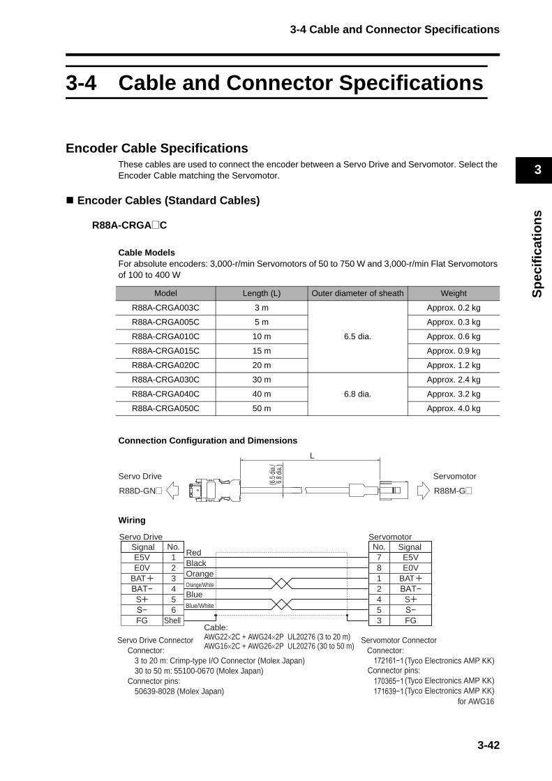
3-4 Cable and Connector Specifications
3
Sp
ecif
icat
ion
s
3-4 Cable and Connector Specifications
Encoder Cable SpecificationsThese cables are used to connect the encoder between a Servo Drive and Servomotor. Select the Encoder Cable matching the Servomotor.
Encoder Cables (Standard Cables)
R88A-CRGA@C
Cable ModelsFor absolute encoders: 3,000-r/min Servomotors of 50 to 750 W and 3,000-r/min Flat Servomotors of 100 to 400 W
Connection Configuration and Dimensions
Wiring
Model Length (L) Outer diameter of sheath Weight
R88A-CRGA003C 3 m
6.5 dia.
Approx. 0.2 kg
R88A-CRGA005C 5 m Approx. 0.3 kg
R88A-CRGA010C 10 m Approx. 0.6 kg
R88A-CRGA015C 15 m Approx. 0.9 kg
R88A-CRGA020C 20 m Approx. 1.2 kg
R88A-CRGA030C 30 m
6.8 dia.
Approx. 2.4 kg
R88A-CRGA040C 40 m Approx. 3.2 kg
R88A-CRGA050C 50 m Approx. 4.0 kg
Servo Drive Servomotor
R88D-GN@ R88M-G@
L
(6.5
dia.
/ 6
.8 d
ia.)
Signal No.Servo Drive
E5V 1E0V 2
BAT 34
S 56
FG Shell
RedBlackOrangeOrange/White
Cable:AWG22×2C + AWG24×2P UL20276 (3 to 20 m)AWG16×2C + AWG26×2P UL20276 (30 to 50 m)
No.781245
E5VE0V
BAT
S
FG
SignalServomotor
3
Servo Drive Connector Servomotor ConnectorConnector:
3 to 20 m: Crimp-type I/O Connector (Molex Japan)30 to 50 m: 55100-0670 (Molex Japan)
Connector pins:50639-8028 (Molex Japan)
Blue/White
for AWG16
Blue
Connector:(Tyco Electronics AMP KK)
(Tyco Electronics AMP KK)(Tyco Electronics AMP KK)
Connector pins:
3-42
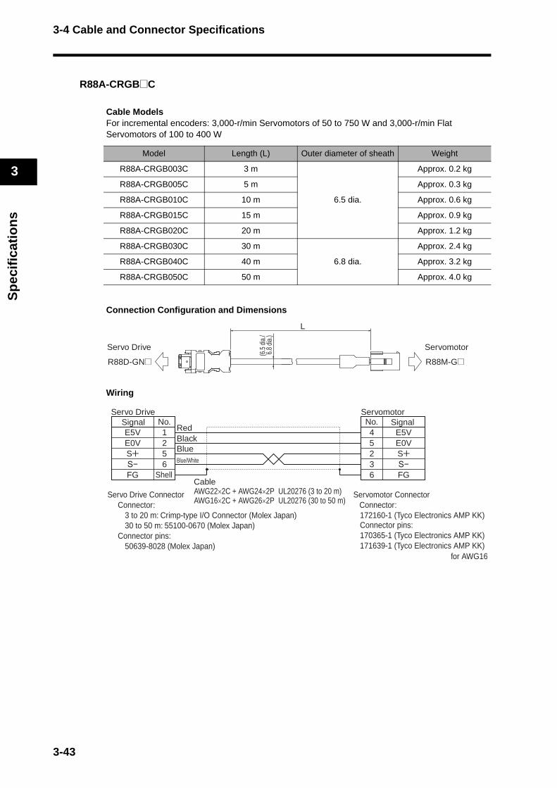
3-4 Cable and Connector Specifications
3
Sp
ecif
icat
ion
s
R88A-CRGB@C
Cable ModelsFor incremental encoders: 3,000-r/min Servomotors of 50 to 750 W and 3,000-r/min Flat Servomotors of 100 to 400 W
Connection Configuration and Dimensions
Wiring
Model Length (L) Outer diameter of sheath Weight
R88A-CRGB003C 3 m
6.5 dia.
Approx. 0.2 kg
R88A-CRGB005C 5 m Approx. 0.3 kg
R88A-CRGB010C 10 m Approx. 0.6 kg
R88A-CRGB015C 15 m Approx. 0.9 kg
R88A-CRGB020C 20 m Approx. 1.2 kg
R88A-CRGB030C 30 m
6.8 dia.
Approx. 2.4 kg
R88A-CRGB040C 40 m Approx. 3.2 kg
R88A-CRGB050C 50 m Approx. 4.0 kg
Servo Drive Servomotor
R88D-GN@ R88M-G@
L
(6.5
dia.
/ 6
.8 d
ia.)
No.E5V 1E0V 2S 5
6FG
No.4523
E5VE0VS
FG6
SignalServo Drive
Shell
RedBlack
Blue/White
Blue
CableAWG22×2C + AWG24×2P UL20276 (3 to 20 m)AWG16×2C + AWG26×2P UL20276 (30 to 50 m)
SignalServomotor
Servo Drive Connector Servomotor ConnectorConnector:
3 to 20 m: Crimp-type I/O Connector (Molex Japan)30 to 50 m: 55100-0670 (Molex Japan)
Connector pins:50639-8028 (Molex Japan)
for AWG16
Connector:172160-1 (Tyco Electronics AMP KK)
170365-1 (Tyco Electronics AMP KK)171639-1 (Tyco Electronics AMP KK)
Connector pins:
3-43

3-4 Cable and Connector Specifications
3
Sp
ecif
icat
ion
s
R88A-CRGC@N
Cable ModelsFor both absolute encoders and incremental encoders: 3,000-r/min Servomotors of 1 to 5 kW,2,000-r/min Servomotors of 1 to 5 kW, 1,500-r/min Servomotors of 7.5 kW, and 1,000-r/min Servomotors of 900 W to 6 kW
Connection Configuration and Dimensions
Wiring
Model Length (L) Outer diameter of sheath Weight
R88A-CRGC003N 3 m
6.5 dia.
Approx. 0.3 kg
R88A-CRGC005N 5 m Approx. 0.4 kg
R88A-CRGC010N 10 m Approx. 0.7 kg
R88A-CRGC015N 15 m Approx. 1.0 kg
R88A-CRGC020N 20 m Approx. 1.5 kg
R88A-CRGC030N 30 m
6.8 dia.
Approx. 2.5 kg
R88A-CRGC040N 40 m Approx. 3.3 kg
R88A-CRGC050N 50 m Approx. 4.1 kg
Servo Drive Servomotor
R88D-GN@ R88M-G@
L
(6.5
dia.
/ 6
.8 d
ia.)
No.E5V 1E0V 2
BAT 34
S 56
FG
Straight plug:N/MS3106B20-29S (Japan Aviation Electronics)
Cable clamp:N/MS3057-12A (Japan Aviation Electronics)
No.HGTSKL
E5VE0V
BAT
S
FGJ
Signal
Shell
RedBlackOrangeOrange/White
Cable:AWG22×2C + AWG24×2P UL20276 (3 to 20 m)AWG16×2C + AWG26×2P UL20276 (30 to 50 m)
Signal
Servo Drive Connector Servomotor ConnectorConnector:
3 to 20 m: Crimp-type I/O Connector (Molex Japan)30 to 50 m: 55100-0670 (Molex Japan)
Connector pins:50639-8028 (Molex Japan)
Blue/White
Blue
3-44

3-4 Cable and Connector Specifications
3
Sp
ecif
icat
ion
s
Encoder Cables (Robot Cables)
R88A-CRGA@CRCable ModelsFor absolute encoders: 3,000-r/min Servomotors of 50 to 750 W and 3,000-r/min Flat Servomotors of 100 to 400 W
Connection Configuration and Dimensions
Wiring (3 to 20 m)
Wiring (30 to 50 m)
Model Length (L) Outer diameter of sheath Weight
R88A-CRGA003CR 3 m
7.5 dia.
Approx. 0.2 kg
R88A-CRGA005CR 5 m Approx. 0.4 kg
R88A-CRGA010CR 10 m Approx. 0.8 kg
R88A-CRGA015CR 15 m Approx. 1.1 kg
R88A-CRGA020CR 20 m Approx. 1.5 kg
R88A-CRGA030CR 30 m
8.2 dia.
Approx. 2.8 kg
R88A-CRGA040CR 40 m Approx. 3.7 kg
R88A-CRGA050CR 50 m Approx. 4.6 kg
Servo Drive Servomotor
R88D-GN@ R88M-G@
L
(7.5
/8.
2 di
a.)
Signal No.Servo Drive
E5V 1
E0V 23
BAT− 45
S− 6FG Shell
Pink/Red
Pink/Black
Green/Red
Orange/Black
Green/Black
Orange/Red
Cable:AWG24×4P UL20276
No.7
81245
E5V
E0VBATBAT−
SS−FG
SignalServomotor
3
Servomotor ConnectorConnector: 172161-1(Tyco Electronics AMP KK)Connector pins: 170365-1(Tyco Electronics AMP KK)
Servo Drive ConnectorConnector: Crimp-type I/O Connector (Molex Japan)Connector pins: 50639-8028 (Molex Japan)
Blue/RedBlue/Black
+
+
BAT+
S+
Signal No.Servo Drive
E5V 1
E0V 2BAT+ 3BAT− 4
S+ 5S− 6FG Shell
YellowBrown
Green
BlackRed
Grey
CableAWG25 × 6P UL2517
No.7 E5V
SignalServomotor
81245
E0VBAT+BAT−
S+S−FG3
Servomotor Connector Connector: 172161−1 (Tyco Electronics AMP KK) Connector pins: 170365−1 (Tyco Electronics AMP KK)
Servo Drive Connector Connector: Crimp-type I/O Connector (Molex Japan) Connector pins: 50639-8028 (Molex Japan)
Blue
White
PurpleOrange
BlueBrown
3-45

3-4 Cable and Connector Specifications
3
Sp
ecif
icat
ion
s
R88A-CRGB@CRCable ModelsFor incremental encoders: 3,000-r/min Servomotors of 50 to 750 W and 3,000-r/min Flat Servomotors of 100 to 400 W
Connection Configuration and Dimensions
Wiring (3 to 20 m)
Wiring (30 to 50 m)
Model Length (L) Outer diameter of sheath Weight
R88A-CRGB003CR 3 m
7.5 dia.
Approx. 0.2 kg
R88A-CRGB005CR 5 m Approx. 0.4 kg
R88A-CRGB010CR 10 m Approx. 0.8 kg
R88A-CRGB015CR 15 m Approx. 1.1 kg
R88A-CRGB020CR 20 m Approx. 1.5 kg
R88A-CRGB030CR 30 m
8.2 dia.
Approx. 2.8 kg
R88A-CRGB040CR 40 m Approx. 3.7 kg
R88A-CRGB050CR 50 m Approx. 4.6 kg
Servo Drive Servomotor
R88D-GN@ R88M-G@
L
(7.5
/8.
2 di
a.)
Signal No.Servo Drive
E5V 1
E0V 2S 5S− 6FG
Cable:AWG24×4P UL20276
No.4
523
E5V
E0VSS−FG
Servomotor
6
Signal
Servomotor Connector Connector: 172160-1(Tyco Electronics AMP KK) Connector pins: 170365-1(Tyco Electronics AMP KK)
Servo Drive Connector Connector: Crimp-type I/O Connector (Molex Japan) Connector pins: 50639-8028 (Molex Japan)
Shell
Pink/Red
Pink/Black
Orange/Black
Orange/Red+ +
Blue/RedBlue/Black
No.E5V 1
E0V 2S+ 5S− 6FG Shell
No.4 E5V
5 E0V23
S+S−FG6
CableAWG25 × 6P UL2517 Servomotor Connector
Connector: 172160−1 (Tyco Electronics AMP KK) Connector pins: 170365−1 (Tyco Electronics AMP KK)
Servo Drive Connector Connector: Crimp-type I/O Connector (Molex Japan) Connector pins: 50639-8028 (Molex Japan)
YellowBrown
Green
BlackRed
Grey
Blue
White
BlueBrown
Servo Drive ServomotorSignal Signal
3-46

3-4 Cable and Connector Specifications
3
Sp
ecif
icat
ion
s
R88A-CRGC@NRCable ModelsFor both absolute encoders and incremental encoders: 3,000-r/min Servomotors of 1 to 5 kW,2,000-r/min Servomotors of 1 to 5 kW, 1,000-r/min Servomotors of 900 W to 4.5 kW
Connection Configuration and Dimensions
Wiring (3 to 20 m)
Wiring (30 to 50 m)
Model Length (L) Outer diameter of sheath Weight
R88A-CRGC003NR 3 m
7.5 dia.
Approx. 0.4 kg
R88A-CRGC005NR 5 m Approx. 0.5 kg
R88A-CRGC010NR 10 m Approx. 0.9 kg
R88A-CRGC015NR 15 m Approx. 1.3 kg
R88A-CRGC020NR 20 m Approx. 1.6 kg
R88A-CRGC010NR 30 m
8.2 dia.
Approx. 2.9 kg
R88A-CRGC015NR 40 m Approx. 3.8 kg
R88A-CRGC020NR 50 m Approx. 4.7 kg
Servo Drive Servomotor
R88D-GN@ R88M-G@
L
(7.5
/8.
2 di
a.)
No.Servo Drive
E5V 1
E0V 2BAT 3BAT− 4
S 5S− 6FG
No.H
GTSKL
E5V
E0VBATBAT−
SS−FG
SignalServomotor
J
Straight plug:N/MS3106B20-29S (Japan Aviation Electronics)
Cable clamp:N/MS3057-12A (Japan Aviation Electronics)
Servomotor Connector
Cable:AWG24×4P UL20276 Servo Drive Connector
Connector:Crimp-type I/O Connector (Molex Japan)
Connector pins:50639-8028 (Molex Japan)
Signal
Pink/Red
Pink/Black
Green/Red
Orange/Black
Green/Black
Orange/Red
Shell
+
+
+
+
Blue/RedBlue/Black
No.E5V 1
E0V 2BAT+ 3BAT− 4
S+ 5S− 6FG
No.H E5V
GTSKL
E0VBAT+BAT−
S+S−FGJ
CableAWG25 × 6P UL2517 Servomotor Connector
Connector: N/MS3106B20-29S (Japan Aviation Electronics) Connector pins: N/MS3057-12A (Japan Aviation Electronics)
Servo Drive Connector Connector: Crimp-type I/O Connector (Molex Japan) Connector pins: 50639-8028 (Molex Japan)
SignalServo Drive
YellowBrown
Green
BlackRed
Grey
SignalServomotor
Blue
White
PurpleOrange
BlueBrown
Shell
3-47
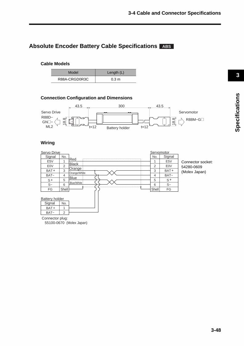
3-4 Cable and Connector Specifications
3
Sp
ecif
icat
ion
s
Absolute Encoder Battery Cable Specifications
Cable Models
Connection Configuration and Dimensions
Wiring
Model Length (L)
R88A-CRGD0R3C 0.3 m
ABS
Servo Drive
Battery holder
Servomotor R88D−GN@−
ML2
R88M−G@
43.530043.5
18.8
18.8
t=12t=12
Signal No.Servo Drive
S− 6S 5
BAT− 4BAT 3E0V 2E5V 1
FGS−S
BAT−BATE0VE5V
FGShell
Signal No.Battery holder
BAT− 2BAT 1
No.
654321
Shell
SignalServomotor
Orange/White
Orange
RedBlack
+
+
+ +
+BlueBlue/White
Connector plug:55100-0670 (Molex Japan)
Connector socket: 54280-0609(Molex Japan)
3-48
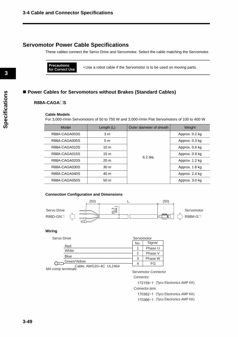
3-4 Cable and Connector Specifications
3
Sp
ecif
icat
ion
s
Servomotor Power Cable SpecificationsThese cables connect the Servo Drive and Servomotor. Select the cable matching the Servomotor.
Power Cables for Servomotors without Brakes (Standard Cables)
R88A-CAGA@S
Cable ModelsFor 3,000-r/min Servomotors of 50 to 750 W and 3,000-r/min Flat Servomotors of 100 to 400 W
Connection Configuration and Dimensions
Wiring
Use a robot cable if the Servomotor is to be used on moving parts.
Model Length (L) Outer diameter of sheath Weight
R88A-CAGA003S 3 m
6.2 dia.
Approx. 0.2 kg
R88A-CAGA005S 5 m Approx. 0.3 kg
R88A-CAGA010S 10 m Approx. 0.6 kg
R88A-CAGA015S 15 m Approx. 0.9 kg
R88A-CAGA020S 20 m Approx. 1.2 kg
R88A-CAGA030S 30 m Approx. 1.8 kg
R88A-CAGA040S 40 m Approx. 2.4 kg
R88A-CAGA050S 50 m Approx. 3.0 kg
Precautions for Correct Use
(50) (50)L
Servo Drive Servomotor
R88D-GN@ R88M-G@
(6.2
dia
.)
No.1234
Phase UPhase VPhase W
FG
BlueGreen/Yellow
Cable: AWG20×4C UL2464M4 crimp terminals
Servo Drive
RedWhite
SignalServomotor
Servomotor ConnectorConnector:
(Tyco Electronics AMP KK)
(Tyco Electronics AMP KK)(Tyco Electronics AMP KK)
Connector pins:
3-49
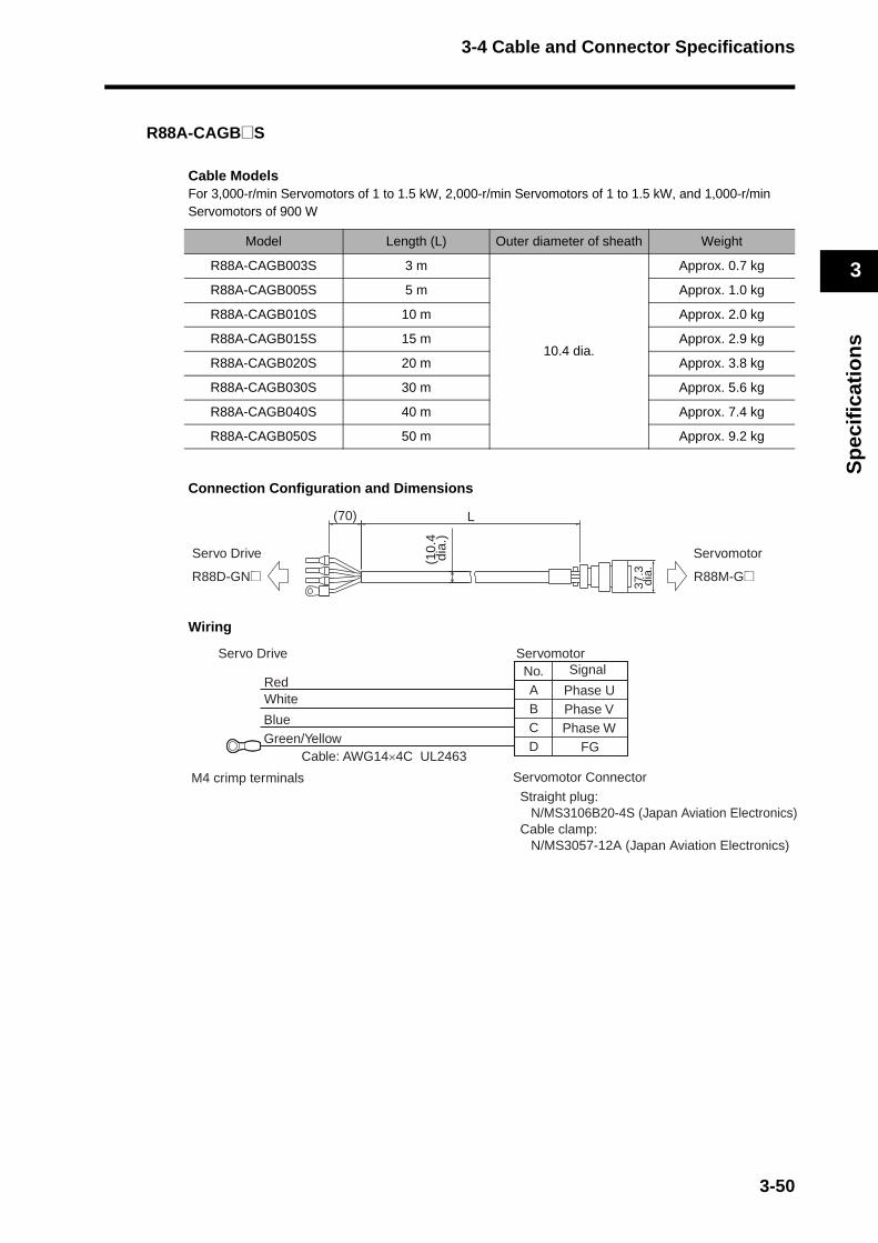
3-4 Cable and Connector Specifications
3
Sp
ecif
icat
ion
s
R88A-CAGB@S
Cable ModelsFor 3,000-r/min Servomotors of 1 to 1.5 kW, 2,000-r/min Servomotors of 1 to 1.5 kW, and 1,000-r/min Servomotors of 900 W
Connection Configuration and Dimensions
Wiring
Model Length (L) Outer diameter of sheath Weight
R88A-CAGB003S 3 m
10.4 dia.
Approx. 0.7 kg
R88A-CAGB005S 5 m Approx. 1.0 kg
R88A-CAGB010S 10 m Approx. 2.0 kg
R88A-CAGB015S 15 m Approx. 2.9 kg
R88A-CAGB020S 20 m Approx. 3.8 kg
R88A-CAGB030S 30 m Approx. 5.6 kg
R88A-CAGB040S 40 m Approx. 7.4 kg
R88A-CAGB050S 50 m Approx. 9.2 kg
(70) L
Servo Drive Servomotor
R88D-GN@ R88M-G@
(10.
4 d
ia.)
37.3
dia
.
No.ABCD
M4 crimp terminals
Phase UPhase VPhase W
FG
BlueGreen/Yellow
Cable: AWG14×4C UL2463
Servo Drive
RedWhite
SignalServomotor
Servomotor Connector
Straight plug:N/MS3106B20-4S (Japan Aviation Electronics)
Cable clamp:N/MS3057-12A (Japan Aviation Electronics)
3-50
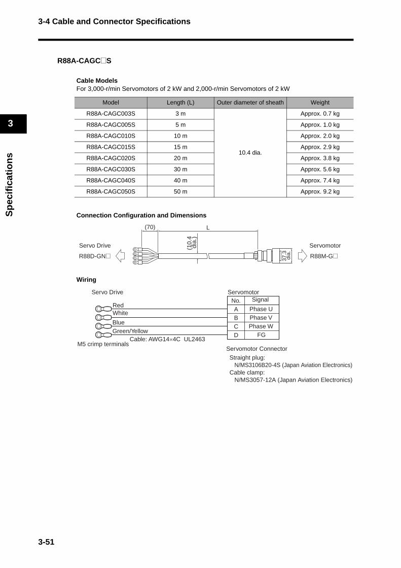
3-4 Cable and Connector Specifications
3
Sp
ecif
icat
ion
s
R88A-CAGC@S
Cable ModelsFor 3,000-r/min Servomotors of 2 kW and 2,000-r/min Servomotors of 2 kW
Connection Configuration and Dimensions
Wiring
Model Length (L) Outer diameter of sheath Weight
R88A-CAGC003S 3 m
10.4 dia.
Approx. 0.7 kg
R88A-CAGC005S 5 m Approx. 1.0 kg
R88A-CAGC010S 10 m Approx. 2.0 kg
R88A-CAGC015S 15 m Approx. 2.9 kg
R88A-CAGC020S 20 m Approx. 3.8 kg
R88A-CAGC030S 30 m Approx. 5.6 kg
R88A-CAGC040S 40 m Approx. 7.4 kg
R88A-CAGC050S 50 m Approx. 9.2 kg
(70) L
Servo Drive Servomotor
R88D-GN@ R88M-G@
(10.
4 d
ia.)
37.3
dia
.
No.ABCD
M5 crimp terminals
Phase UPhase VPhase W
FG
BlueGreen/Yellow
Cable: AWG14×4C UL2463
Servo Drive
RedWhite
SignalServomotor
Servomotor Connector
Straight plug:N/MS3106B20-4S (Japan Aviation Electronics)
Cable clamp:N/MS3057-12A (Japan Aviation Electronics)
3-51
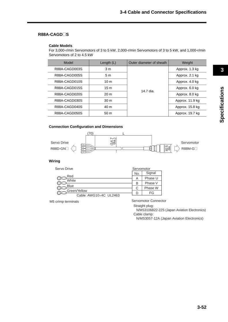
3-4 Cable and Connector Specifications
3
Sp
ecif
icat
ion
s
R88A-CAGD@S
Cable ModelsFor 3,000-r/min Servomotors of 3 to 5 kW, 2,000-r/min Servomotors of 3 to 5 kW, and 1,000-r/min Servomotors of 2 to 4.5 kW
Connection Configuration and Dimensions
Wiring
Model Length (L) Outer diameter of sheath Weight
R88A-CAGD003S 3 m
14.7 dia.
Approx. 1.3 kg
R88A-CAGD005S 5 m Approx. 2.1 kg
R88A-CAGD010S 10 m Approx. 4.0 kg
R88A-CAGD015S 15 m Approx. 6.0 kg
R88A-CAGD020S 20 m Approx. 8.0 kg
R88A-CAGD030S 30 m Approx. 11.9 kg
R88A-CAGD040S 40 m Approx. 15.8 kg
R88A-CAGD050S 50 m Approx. 19.7 kg
(70) L
Servo Drive Servomotor
R88D-GN@ R88M-G@
(14.
7 d
ia.)
40.5
dia
.
No.ABCD
M5 crimp terminals
Phase UPhase VPhase W
FG
BlueGreen/Yellow
Cable: AWG10×4C UL2463
Servo Drive
RedWhite
SignalServomotor
Servomotor Connector
Straight plug:N/MS3106B22-22S (Japan Aviation Electronics)
Cable clamp:N/MS3057-12A (Japan Aviation Electronics)
3-52
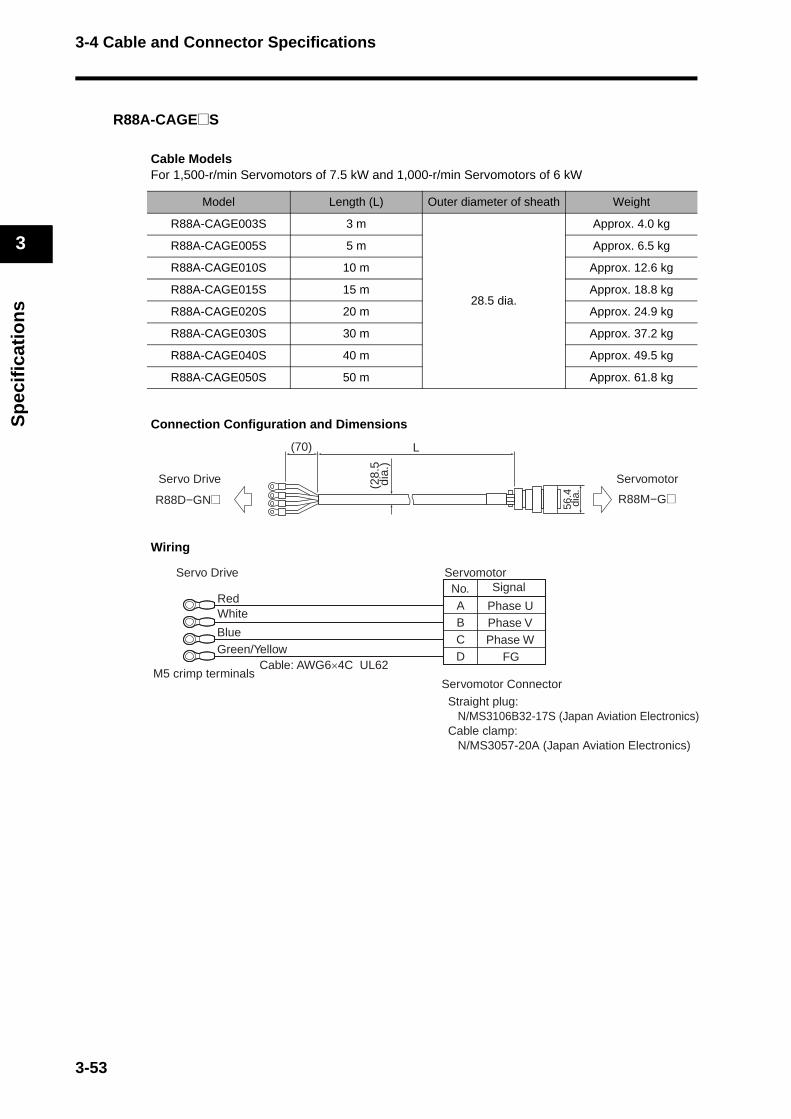
3-4 Cable and Connector Specifications
3
Sp
ecif
icat
ion
s
R88A-CAGE@S
Cable ModelsFor 1,500-r/min Servomotors of 7.5 kW and 1,000-r/min Servomotors of 6 kW
Connection Configuration and Dimensions
Wiring
Model Length (L) Outer diameter of sheath Weight
R88A-CAGE003S 3 m
28.5 dia.
Approx. 4.0 kg
R88A-CAGE005S 5 m Approx. 6.5 kg
R88A-CAGE010S 10 m Approx. 12.6 kg
R88A-CAGE015S 15 m Approx. 18.8 kg
R88A-CAGE020S 20 m Approx. 24.9 kg
R88A-CAGE030S 30 m Approx. 37.2 kg
R88A-CAGE040S 40 m Approx. 49.5 kg
R88A-CAGE050S 50 m Approx. 61.8 kg
(70) L
Servo Drive Servomotor
R88D−GN@ R88M−G@
(28.
5 d
ia.)
56.4
dia
.No.ABCD
Cable: AWG6×4C UL62M5 crimp terminals
Phase UPhase VPhase W
FG
BlueGreen/Yellow
Servo Drive
RedWhite
SignalServomotor
Servomotor Connector
Straight plug: N/MS3106B32-17S (Japan Aviation Electronics)
Cable clamp:N/MS3057-20A (Japan Aviation Electronics)
3-53
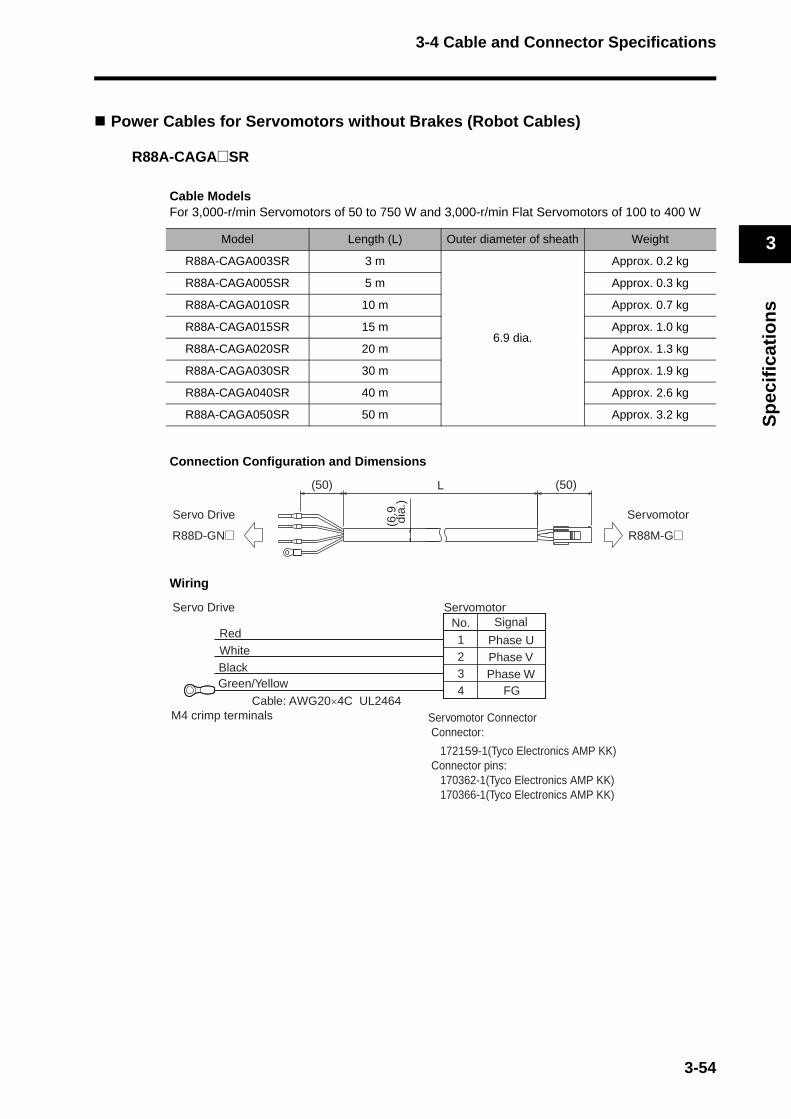
3-4 Cable and Connector Specifications
3
Sp
ecif
icat
ion
s
Power Cables for Servomotors without Brakes (Robot Cables)
R88A-CAGA@SR
Cable ModelsFor 3,000-r/min Servomotors of 50 to 750 W and 3,000-r/min Flat Servomotors of 100 to 400 W
Connection Configuration and Dimensions
Wiring
Model Length (L) Outer diameter of sheath Weight
R88A-CAGA003SR 3 m
6.9 dia.
Approx. 0.2 kg
R88A-CAGA005SR 5 m Approx. 0.3 kg
R88A-CAGA010SR 10 m Approx. 0.7 kg
R88A-CAGA015SR 15 m Approx. 1.0 kg
R88A-CAGA020SR 20 m Approx. 1.3 kg
R88A-CAGA030SR 30 m Approx. 1.9 kg
R88A-CAGA040SR 40 m Approx. 2.6 kg
R88A-CAGA050SR 50 m Approx. 3.2 kg
(50) (50)L
Servo Drive Servomotor
R88D-GN@ R88M-G@
(6.9
dia
.)
No.1234 FG
Servo Drive
RedWhiteBlackGreen/Yellow
Cable: AWG20×4C UL2464
Servomotor
Servomotor ConnectorConnector:
172159-1(Tyco Electronics AMP KK)Connector pins: 170362-1(Tyco Electronics AMP KK) 170366-1(Tyco Electronics AMP KK)
Signal
Phase UPhase VPhase W
M4 crimp terminals
3-54
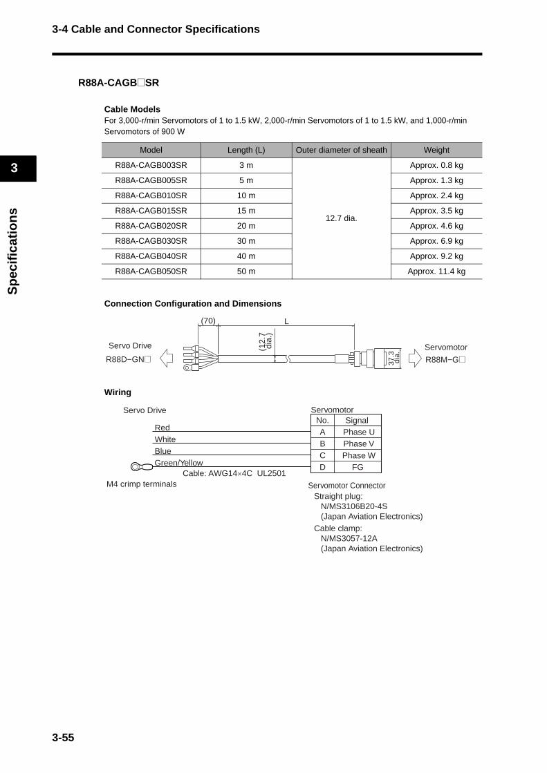
3-4 Cable and Connector Specifications
3
Sp
ecif
icat
ion
s
R88A-CAGB@SR
Cable ModelsFor 3,000-r/min Servomotors of 1 to 1.5 kW, 2,000-r/min Servomotors of 1 to 1.5 kW, and 1,000-r/min Servomotors of 900 W
Connection Configuration and Dimensions
Wiring
Model Length (L) Outer diameter of sheath Weight
R88A-CAGB003SR 3 m
12.7 dia.
Approx. 0.8 kg
R88A-CAGB005SR 5 m Approx. 1.3 kg
R88A-CAGB010SR 10 m Approx. 2.4 kg
R88A-CAGB015SR 15 m Approx. 3.5 kg
R88A-CAGB020SR 20 m Approx. 4.6 kg
R88A-CAGB030SR 30 m Approx. 6.9 kg
R88A-CAGB040SR 40 m Approx. 9.2 kg
R88A-CAGB050SR 50 m Approx. 11.4 kg
(70) L
Servo Drive Servomotor
R88D−GN@ R88M−G@
(12.
7 d
ia.)
37.3
dia
.
No.ABCD FG
SignalServo Drive
RedWhiteBlueGreen/Yellow
Servomotor
Cable: AWG14×4C UL2501
Straight plug:N/MS3106B20-4S (Japan Aviation Electronics)
Cable clamp:N/MS3057-12A (Japan Aviation Electronics)
Servomotor Connector
Phase UPhase VPhase W
M4 crimp terminals
3-55
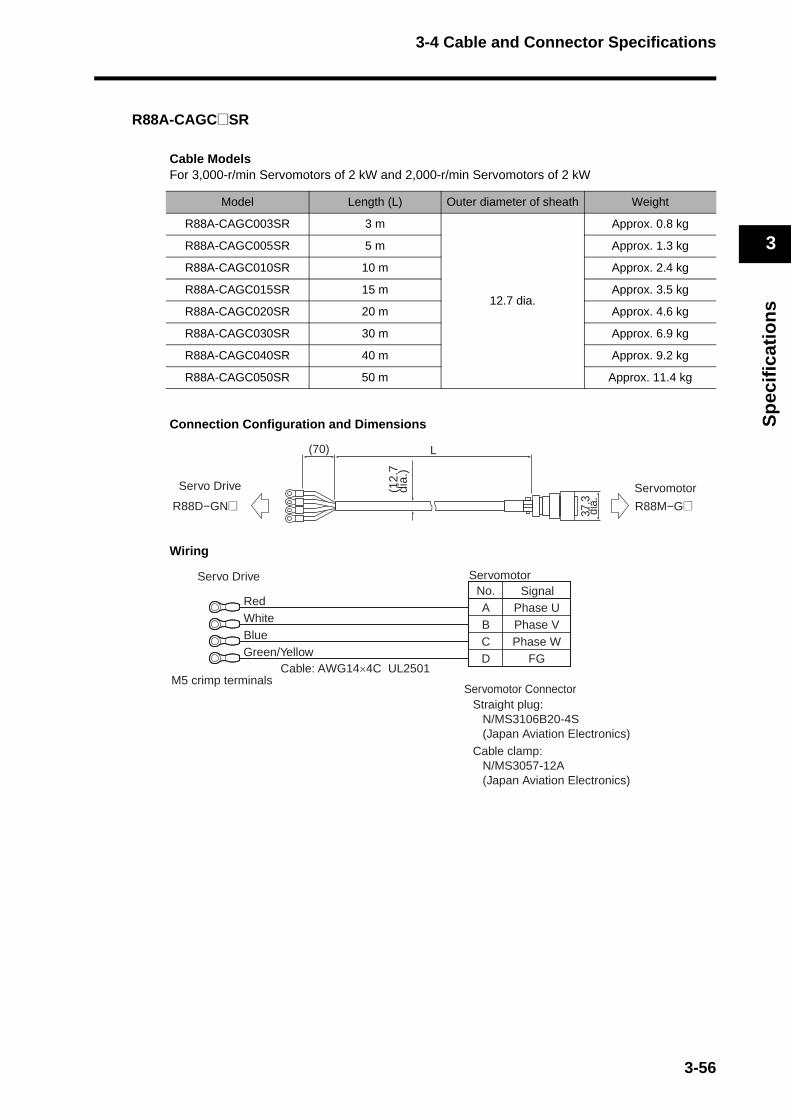
3-4 Cable and Connector Specifications
3
Sp
ecif
icat
ion
s
R88A-CAGC@SR
Cable ModelsFor 3,000-r/min Servomotors of 2 kW and 2,000-r/min Servomotors of 2 kW
Connection Configuration and Dimensions
Wiring
Model Length (L) Outer diameter of sheath Weight
R88A-CAGC003SR 3 m
12.7 dia.
Approx. 0.8 kg
R88A-CAGC005SR 5 m Approx. 1.3 kg
R88A-CAGC010SR 10 m Approx. 2.4 kg
R88A-CAGC015SR 15 m Approx. 3.5 kg
R88A-CAGC020SR 20 m Approx. 4.6 kg
R88A-CAGC030SR 30 m Approx. 6.9 kg
R88A-CAGC040SR 40 m Approx. 9.2 kg
R88A-CAGC050SR 50 m Approx. 11.4 kg
(70) L
37.3
dia.
(12.
7di
a.)
Servo Drive Servomotor
R88M−G@R88D−GN@
No.ABCD
Phase UPhase VPhase W
FG
SignalServo Drive
RedWhiteBlueGreen/Yellow
M5 crimp terminals
Servomotor
Cable: AWG14×4C UL2501
Straight plug:N/MS3106B20-4S (Japan Aviation Electronics)
Cable clamp:N/MS3057-12A (Japan Aviation Electronics)
Servomotor Connector
3-56
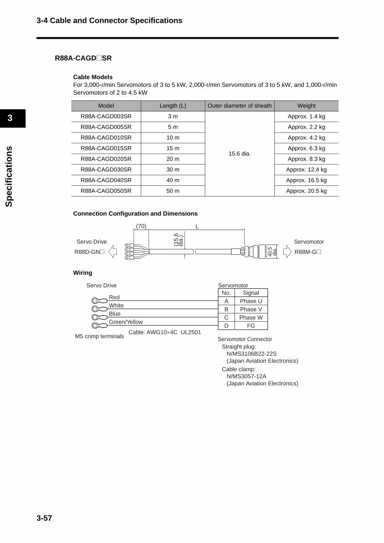
3-4 Cable and Connector Specifications
3
Sp
ecif
icat
ion
s
R88A-CAGD@SR
Cable ModelsFor 3,000-r/min Servomotors of 3 to 5 kW, 2,000-r/min Servomotors of 3 to 5 kW, and 1,000-r/min Servomotors of 2 to 4.5 kW
Connection Configuration and Dimensions
Wiring
Model Length (L) Outer diameter of sheath Weight
R88A-CAGD003SR 3 m
15.6 dia.
Approx. 1.4 kg
R88A-CAGD005SR 5 m Approx. 2.2 kg
R88A-CAGD010SR 10 m Approx. 4.2 kg
R88A-CAGD015SR 15 m Approx. 6.3 kg
R88A-CAGD020SR 20 m Approx. 8.3 kg
R88A-CAGD030SR 30 m Approx. 12.4 kg
R88A-CAGD040SR 40 m Approx. 16.5 kg
R88A-CAGD050SR 50 m Approx. 20.5 kg
(15.
6di
a.)
40.5
dia.
(70) L
Servo Drive Servomotor
R88D-GN@ R88M-G@
No.ABCD
Phase UPhase VPhase W
FG
SignalServo Drive
M5 crimp terminals
Servomotor
Straight plug:N/MS3106B22-22S (Japan Aviation Electronics)
Cable clamp:N/MS3057-12A (Japan Aviation Electronics)
Servomotor ConnectorCable: AWG10×4C UL2501
RedWhiteBlueGreen/Yellow
3-57
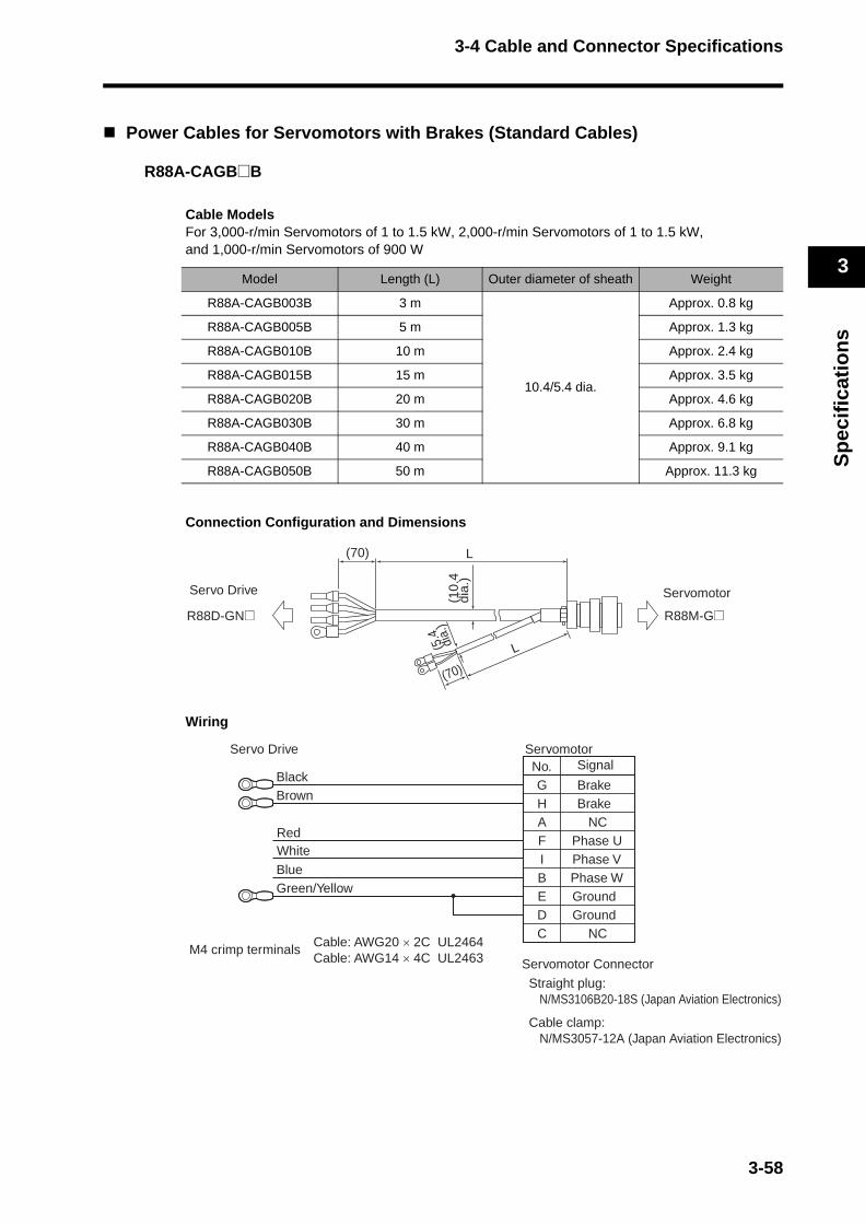
3-4 Cable and Connector Specifications
3
Sp
ecif
icat
ion
s
Power Cables for Servomotors with Brakes (Standard Cables)
R88A-CAGB@B
Cable ModelsFor 3,000-r/min Servomotors of 1 to 1.5 kW, 2,000-r/min Servomotors of 1 to 1.5 kW, and 1,000-r/min Servomotors of 900 W
Connection Configuration and Dimensions
Wiring
Model Length (L) Outer diameter of sheath Weight
R88A-CAGB003B 3 m
10.4/5.4 dia.
Approx. 0.8 kg
R88A-CAGB005B 5 m Approx. 1.3 kg
R88A-CAGB010B 10 m Approx. 2.4 kg
R88A-CAGB015B 15 m Approx. 3.5 kg
R88A-CAGB020B 20 m Approx. 4.6 kg
R88A-CAGB030B 30 m Approx. 6.8 kg
R88A-CAGB040B 40 m Approx. 9.1 kg
R88A-CAGB050B 50 m Approx. 11.3 kg
Servo Drive Servomotor
R88D-GN@ R88M-G@
L(70)
L
(70)
(5.4 dia.
)(1
0.4
dia.
)
No.GHAF
BrakeBrake
NC
BlackBrown
IBEDC
GroundGround
NCCable: AWG20 × 2C UL2464Cable: AWG14 × 4C UL2463
M4 crimp terminals
Phase UPhase VPhase W
BlueGreen/Yellow
Servo Drive
RedWhite
SignalServomotor
Servomotor Connector
Straight plug:N/MS3106B20-18S (Japan Aviation Electronics)
Cable clamp:N/MS3057-12A (Japan Aviation Electronics)
3-58
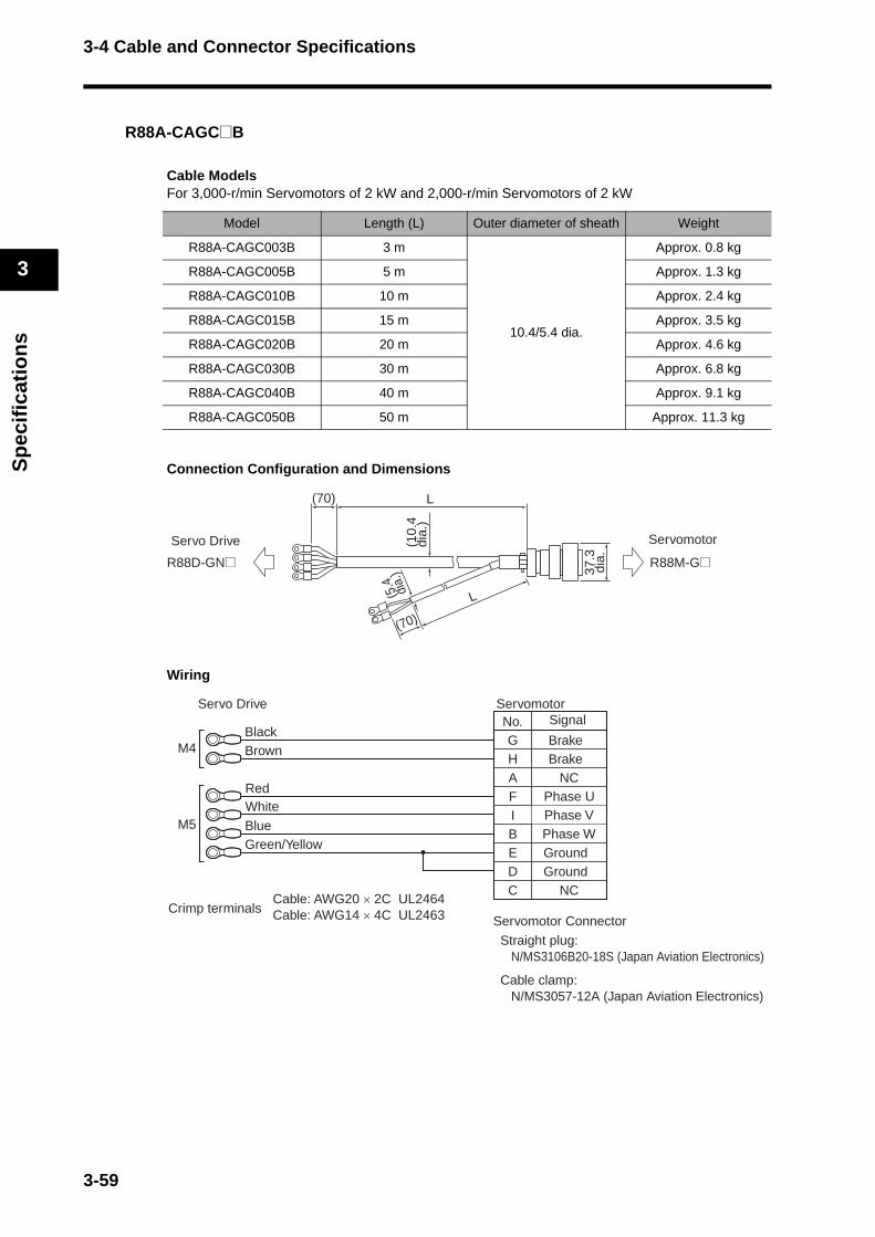
3-4 Cable and Connector Specifications
3
Sp
ecif
icat
ion
s
R88A-CAGC@B
Cable ModelsFor 3,000-r/min Servomotors of 2 kW and 2,000-r/min Servomotors of 2 kW
Connection Configuration and Dimensions
Wiring
Model Length (L) Outer diameter of sheath Weight
R88A-CAGC003B 3 m
10.4/5.4 dia.
Approx. 0.8 kg
R88A-CAGC005B 5 m Approx. 1.3 kg
R88A-CAGC010B 10 m Approx. 2.4 kg
R88A-CAGC015B 15 m Approx. 3.5 kg
R88A-CAGC020B 20 m Approx. 4.6 kg
R88A-CAGC030B 30 m Approx. 6.8 kg
R88A-CAGC040B 40 m Approx. 9.1 kg
R88A-CAGC050B 50 m Approx. 11.3 kg
Servo Drive Servomotor
R88D-GN@ R88M-G@
L(70)
37.3
dia.
(10.
4di
a.)
L
(70)
(5.4 dia.
)
No.GHAF
BrakeBrake
NC
IBEDC
GroundGround
NCCable: AWG20 × 2C UL2464Cable: AWG14 × 4C UL2463Crimp terminals
M4
M5
BlackBrown
Phase UPhase VPhase W
BlueGreen/Yellow
Servo Drive
RedWhite
SignalServomotor
Servomotor Connector
Straight plug:N/MS3106B20-18S (Japan Aviation Electronics)
Cable clamp:N/MS3057-12A (Japan Aviation Electronics)
3-59
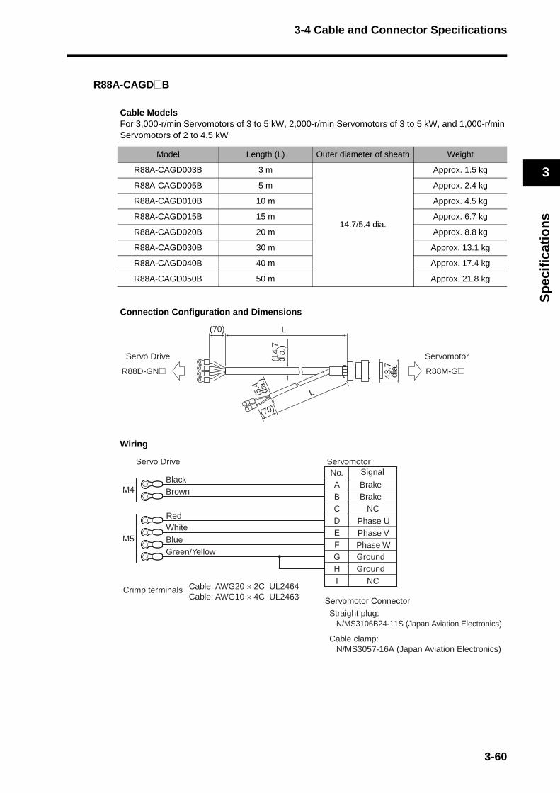
3-4 Cable and Connector Specifications
3
Sp
ecif
icat
ion
s
R88A-CAGD@B
Cable ModelsFor 3,000-r/min Servomotors of 3 to 5 kW, 2,000-r/min Servomotors of 3 to 5 kW, and 1,000-r/min Servomotors of 2 to 4.5 kW
Connection Configuration and Dimensions
Wiring
Model Length (L) Outer diameter of sheath Weight
R88A-CAGD003B 3 m
14.7/5.4 dia.
Approx. 1.5 kg
R88A-CAGD005B 5 m Approx. 2.4 kg
R88A-CAGD010B 10 m Approx. 4.5 kg
R88A-CAGD015B 15 m Approx. 6.7 kg
R88A-CAGD020B 20 m Approx. 8.8 kg
R88A-CAGD030B 30 m Approx. 13.1 kg
R88A-CAGD040B 40 m Approx. 17.4 kg
R88A-CAGD050B 50 m Approx. 21.8 kg
Servo Drive Servomotor
R88D-GN@ R88M-G@
L(70)
43.7
dia.
(14.
7di
a.)
L
(70)
(5.4 dia.
)
No.ABCD
BrakeBrake
NC
EFGHI
GroundGround
NCCable: AWG20 × 2C UL2464Cable: AWG10 × 4C UL2463
Crimp terminals
M4
M5
BlackBrown
Phase UPhase VPhase W
BlueGreen/Yellow
Servo Drive
RedWhite
SignalServomotor
Servomotor Connector
Straight plug: N/MS3106B24-11S (Japan Aviation Electronics)
Cable clamp:N/MS3057-16A (Japan Aviation Electronics)
3-60

3-4 Cable and Connector Specifications
3
Sp
ecif
icat
ion
s
Power Cables for Servomotors with Brakes (Robot Cables)
R88A-CAGB@BR
Cable ModelsFor 3,000-r/min Servomotors of 1 to 1.5 kW, 2,000-r/min Servomotors of 1 to 1.5 kW, and 1,000-r/min Servomotors of 900 W
Connection Configuration and Dimensions
Wiring
Model Length (L) Outer diameter of sheath Weight
R88A-CAGB003BR 3 m
12.7/6.1 dia.
Approx. 0.9 kg
R88A-CAGB005BR 5 m Approx. 1.5 kg
R88A-CAGB010BR 10 m Approx. 2.8 kg
R88A-CAGB015BR 15 m Approx. 4.2 kg
R88A-CAGB020BR 20 m Approx. 5.5 kg
R88A-CAGB030BR 30 m Approx. 8.2 kg
R88A-CAGB040BR 40 m Approx. 10.9 kg
R88A-CAGB050BR 50 m Approx. 13.6 kg
Servo Drive Servomotor
R88D-GN@ R88M-G@
L(70)
L
(70)
(6.1 dia.
)(1
2.7
dia.
)
No.GHAF
BrakeBrake
NCPhase U
Servo Drive
IBEDC
Phase WGroundGround
NC
Phase V
Servomotor
M4 crimp terminals
Straight plug:N/MS3106B20-18S (Japan Aviation Electronics)
Cable clamp:N/MS3057-12A (Japan Aviation Electronics)
Servomotor Connector
Cable: AWG20 × 2C UL2464Cable: AWG14 × 4C UL2501
Red
White
Black
WhiteBlue
Green/Yellow
Signal
3-61
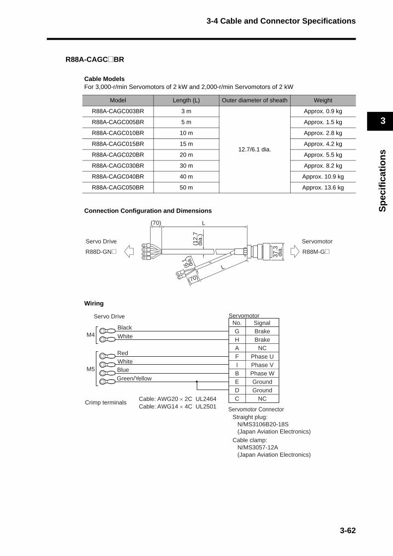
3-4 Cable and Connector Specifications
3
Sp
ecif
icat
ion
s
R88A-CAGC@BR
Cable ModelsFor 3,000-r/min Servomotors of 2 kW and 2,000-r/min Servomotors of 2 kW
Connection Configuration and Dimensions
Wiring
Model Length (L) Outer diameter of sheath Weight
R88A-CAGC003BR 3 m
12.7/6.1 dia.
Approx. 0.9 kg
R88A-CAGC005BR 5 m Approx. 1.5 kg
R88A-CAGC010BR 10 m Approx. 2.8 kg
R88A-CAGC015BR 15 m Approx. 4.2 kg
R88A-CAGC020BR 20 m Approx. 5.5 kg
R88A-CAGC030BR 30 m Approx. 8.2 kg
R88A-CAGC040BR 40 m Approx. 10.9 kg
R88A-CAGC050BR 50 m Approx. 13.6 kg
Servo Drive Servomotor
R88D-GN@ R88M-G@
L(70)
37.3
dia.
(12.
7di
a.)
L
(70)
(6.1 dia.
)
No.GHAF
BrakeBrake
NCPhase U
SignalServo Drive
IBEDC
Phase WGroundGround
NC
Phase V
Servomotor
Crimp terminals
M4
M5
Straight plug:N/MS3106B20-18S (Japan Aviation Electronics)
Cable clamp:N/MS3057-12A (Japan Aviation Electronics)
Servomotor Connector
Cable: AWG20 × 2C UL2464Cable: AWG14 × 4C UL2501
Red
White
Black
WhiteBlue
Green/Yellow
3-62

3-4 Cable and Connector Specifications
3
Sp
ecif
icat
ion
s
R88A-CAGD@BR
Cable ModelsFor 3,000-r/min Servomotors of 3 to 5 kW, 2,000-r/min Servomotors of 3 to 5 kW, and 1,000-r/min Servomotors of 2 to 4.5 kW
Connection Configuration and Dimensions
Wiring
Model Length (L) Outer diameter of sheath Weight
R88A-CAGD003BR 3 m
15.6/6.1 dia.
Approx. 1.6 kg
R88A-CAGD005BR 5 m Approx. 2.5 kg
R88A-CAGD010BR 10 m Approx. 4.7 kg
R88A-CAGD015BR 15 m Approx. 7.0 kg
R88A-CAGD020BR 20 m Approx. 9.2 kg
R88A-CAGD030BR 30 m Approx. 13.7 kg
R88A-CAGD040BR 40 m Approx. 18.2 kg
R88A-CAGD050BR 50 m Approx. 22.7 kg
Servo Drive Servomotor
R88D-GN@ R88M-G@
L(70)
43.7
dia.
(15.
6di
a.)
L
(70)
(6.1 dia.
)
No.ABCD
BrakeBrake
NCPhase U
SignalServo Drive
EFGHI
Phase WGroundGround
NC
Phase V
Servomotor
Crimp terminals
M4
M5
Red
White
Black
WhiteBlue
Green/Yellow
Cable: AWG20 × 2C UL2464Cable: AWG10 × 4C UL2501
Straight plug:N/MS3106B24-11S (Japan Aviation Electronics)
Cable clamp:N/MS3057-16A (Japan Aviation Electronics)
Servomotor Connector
3-63

3-4 Cable and Connector Specifications
3
Sp
ecif
icat
ion
s
Brake Cables (Standard Cables)
R88A-CAGA@B
Cable ModelsFor 3,000-r/min Servomotors of 50 to 750 W and 3,000-r/min Flat Servomotors of 100 to 400 W
Connection Configuration and Dimensions
Wiring
Model Length (L) Outer diameter of sheath Weight
R88A-CAGA003B 3 m
5.4 dia.
Approx. 0.1 kg
R88A-CAGA005B 5 m Approx. 0.2 kg
R88A-CAGA010B 10 m Approx. 0.4 kg
R88A-CAGA015B 15 m Approx. 0.6 kg
R88A-CAGA020B 20 m Approx. 0.8 kg
R88A-CAGA030B 30 m Approx. 1.2 kg
R88A-CAGA040B 40 m Approx. 1.6 kg
R88A-CAGA050B 50 m Approx. 2.1 kg
Servo Drive Servomotor
R88D-GN@ R88M-G@
(5.4
dia.
)
(50) (50)L
No.AB
BrakeBrake
Cable: AWG20 × 2C UL2464M4 crimp terminals
BlackBrown
Servo DriveSignal
Servomotor
Servomotor Connector
Connector:
172157-1 (Tyco Electronics AMP KK)
170362-1 (Tyco Electronics AMP KK)
170366-1 (Tyco Electronics AMP KK)
Connector pins:
3-64

3-4 Cable and Connector Specifications
3
Sp
ecif
icat
ion
s
s)
R88A-CAGE@B
Cable ModelsFor 1,500-r/min Servomotors of 7.5 kW and 1,000-r/min Servomotors of 6 kW
Connection Configuration and Dimensions
Wiring
Model Length (L) Outer diameter of sheath Weight
R88A-CAGE003B 3 m
5.4 dia.
Approx. 0.2 kg
R88A-CAGE005B 5 m Approx. 0.3 kg
R88A-CAGE010B 10 m Approx. 0.5 kg
R88A-CAGE015B 15 m Approx. 0.7 kg
R88A-CAGE020B 20 m Approx. 0.9 kg
R88A-CAGE030B 30 m Approx. 1.3 kg
R88A-CAGE040B 40 m Approx. 1.7 kg
R88A-CAGE050B 50 m Approx. 2.1 kg
Servo Drive Servomotor
R88D-GN@ R88M-G@
(70) L
(5.4
dia.
)
No.AB
BrakeBrake
Cable: AWG20 × 2C UL2464M4 crimp terminals
Straight plug:
N/MS3106B14S-2S (Japan Aviation Electronic
Cable clamp:
N/MS3057-6A (Japan Aviation Electronics)
BlackBrown
Servo DriveSignal
Servomotor
Servomotor Connector
3-65

3-4 Cable and Connector Specifications
3
Sp
ecif
icat
ion
s
Brake Cables (Robot Cables)
R88A-CAGA@BR
Cable ModelsFor 3,000-r/min Servomotors of 50 to 750 W and 3,000-r/min Flat Servomotors of 100 to 400 W
Connection Configuration and Dimensions
Wiring
Model Length (L) Outer diameter of sheath Weight
R88A-CAGA003BR 3 m
6.1 dia.
Approx. 0.1 kg
R88A-CAGA005BR 5 m Approx. 0.2 kg
R88A-CAGA010BR 10 m Approx. 0.4 kg
R88A-CAGA015BR 15 m Approx. 0.7 kg
R88A-CAGA020BR 20 m Approx. 0.9 kg
R88A-CAGA030BR 30 m Approx. 1.3 kg
R88A-CAGA040BR 40 m Approx. 1.8 kg
R88A-CAGA050BR 50 m Approx. 2.2 kg
Servo Drive Servomotor
R88D-GN@ R88M-G@
(6.1
dia.
)
(50) (50)L
No.AB
BrakeBrake
SignalServo Drive
Black
White
Servomotor
M4 crimp terminalsServomotor ConnectorConnector:
172157-1 (Tyco Electronics AMP KK)Connector pins: 170362-1 (Tyco Electronics AMP KK) 170366-1 (Tyco Electronics AMP KK)
Cable: AWG20 × 2C UL2464
3-66

3-4 Cable and Connector Specifications
3
Sp
ecif
icat
ion
s
Communications Cable Specifications
Computer Monitor Cable
Cable Models
Cables for RS-232 Communications
Connection Configuration and Dimensions
Wiring
Model Length (L) Outer diameter of sheath Weight
R88A-CCG002P2 2 m 4.2 dia. Approx. 0.1 kg
Communications with the Host DeviceAfter confirming the startup of the Servo Drive, initiate communications with the host device. Note that irregular signals may be received from the host interface during startup. For this reason, take appropriate initialization measures such as clearing the receive buffer.
Personal computer Servo Drive
R88D-GN@
200038
No.Personal computer
RTS 7CTS 8RXD 2GND 5TXD 3FG Shell
Cable: AWG28 × 3C UL20276
No.345
Shell
TXDGNDRXDFG
PC Connector
17JE-13090-02 (D8A) (DDK Ltd.)
Servo DriveSignal
Signal
Precautions for Correct Use
3-67
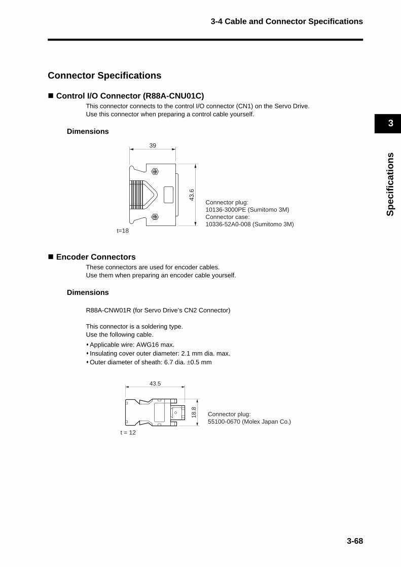
3-4 Cable and Connector Specifications
3
Sp
ecif
icat
ion
s
Connector Specifications
Control I/O Connector (R88A-CNU01C)This connector connects to the control I/O connector (CN1) on the Servo Drive. Use this connector when preparing a control cable yourself.
Dimensions
Encoder ConnectorsThese connectors are used for encoder cables. Use them when preparing an encoder cable yourself.
Dimensions
R88A-CNW01R (for Servo Drive’s CN2 Connector)
This connector is a soldering type.Use the following cable.
Applicable wire: AWG16 max.Insulating cover outer diameter: 2.1 mm dia. max.Outer diameter of sheath: 6.7 dia. ±0.5 mm
43.6
39
t=18
Connector plug: 10136-3000PE (Sumitomo 3M)Connector case: 10336-52A0-008 (Sumitomo 3M)
43.5
18.8
Connector plug: 55100-0670 (Molex Japan Co.)
t = 12
3-68
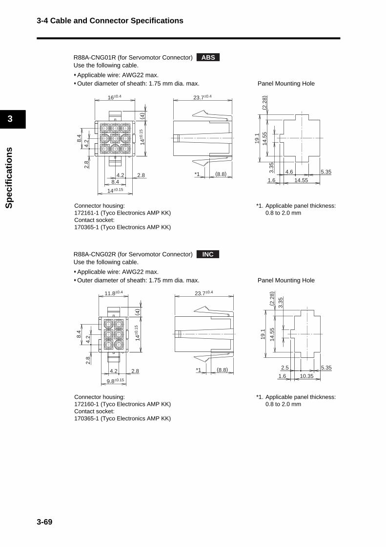
3-4 Cable and Connector Specifications
3
Sp
ecif
icat
ion
s
R88A-CNG01R (for Servomotor Connector)Use the following cable.
Applicable wire: AWG22 max.Outer diameter of sheath: 1.75 mm dia. max. Panel Mounting Hole
R88A-CNG02R (for Servomotor Connector)Use the following cable.
Applicable wire: AWG22 max.Outer diameter of sheath: 1.75 mm dia. max. Panel Mounting Hole
Connector housing:172161-1 (Tyco Electronics AMP KK)Contact socket:170365-1 (Tyco Electronics AMP KK)
*1. Applicable panel thickness: 0.8 to 2.0 mm
Connector housing:172160-1 (Tyco Electronics AMP KK)Contact socket:170365-1 (Tyco Electronics AMP KK)
*1. Applicable panel thickness: 0.8 to 2.0 mm
ABS
14±0
.15
( 4)
14.551.6
4.6 5.35
14.5
5( 2
.28)
3.35
19.1
8.4
16±0.4 23.7±0.4
14±0.15
8.42.84.2
2.8
4.2
(8.8)*1
INC
14±0
.15
( 4)
10.351.6
2.5 5.35
14.5
5( 2
.28)
3.35
19.1
8.4
11.8±0.4 23.7±0.4
9.8±0.15
2.84.2
2.8
4.2
(8.8)*1
3-69

3-4 Cable and Connector Specifications
3
Sp
ecif
icat
ion
s
Power Cable Connector (R88A-CNG01A)This connector is used for power cables.Use it when preparing a power cable yourself.
Panel Mounting Hole
Brake Cable Connector (R88A-CNG01B)This connector is used for brake cables.Use it when preparing a brake cable yourself.
Panel Mounting Hole
Connector housing:172159-1 (Tyco Electronics AMP KK)Contact socket:170366-1 (Tyco Electronics AMP KK)
Applicable panel thickness: 0.8 to 2.0 mm
Connector housing:172157-1 (Tyco Electronics AMP KK)Contact socket:170366-1 (Tyco Electronics AMP KK)
Applicable panel thickness: 0.8 to 2.0 mm
10.351.6
2.5 5.35
10.3
5( 2
.28)
3.35
14.9
23.7±0.4
9.8±0
.15
( 4)
11.8±0.4
9.8±0.15
2.84.2
2.8
4.2
(8.8)
10.351.6
2.5 5.35
6.15
( 2.2
8)
3.35
10.7
23.7±0.4
(8.8)
5.6±0
.15
9.8±0.15
2.84.2
2.8
( 4)
3-70
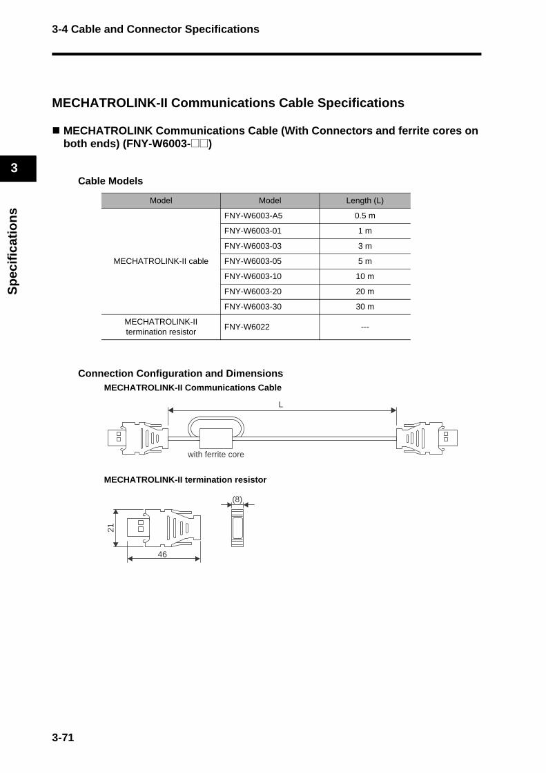
3-4 Cable and Connector Specifications
3
Sp
ecif
icat
ion
s
MECHATROLINK-II Communications Cable Specifications
MECHATROLINK Communications Cable (With Connectors and ferrite cores on both ends) (FNY-W6003-@@)
Cable Models
Connection Configuration and DimensionsMECHATROLINK-II Communications Cable
MECHATROLINK-II termination resistor
Model Model Length (L)
MECHATROLINK-II cable
FNY-W6003-A5 0.5 m
FNY-W6003-01 1 m
FNY-W6003-03 3 m
FNY-W6003-05 5 m
FNY-W6003-10 10 m
FNY-W6003-20 20 m
FNY-W6003-30 30 m
MECHATROLINK-II termination resistor
FNY-W6022 ---
L
with ferrite core
(8)
21
46
3-71
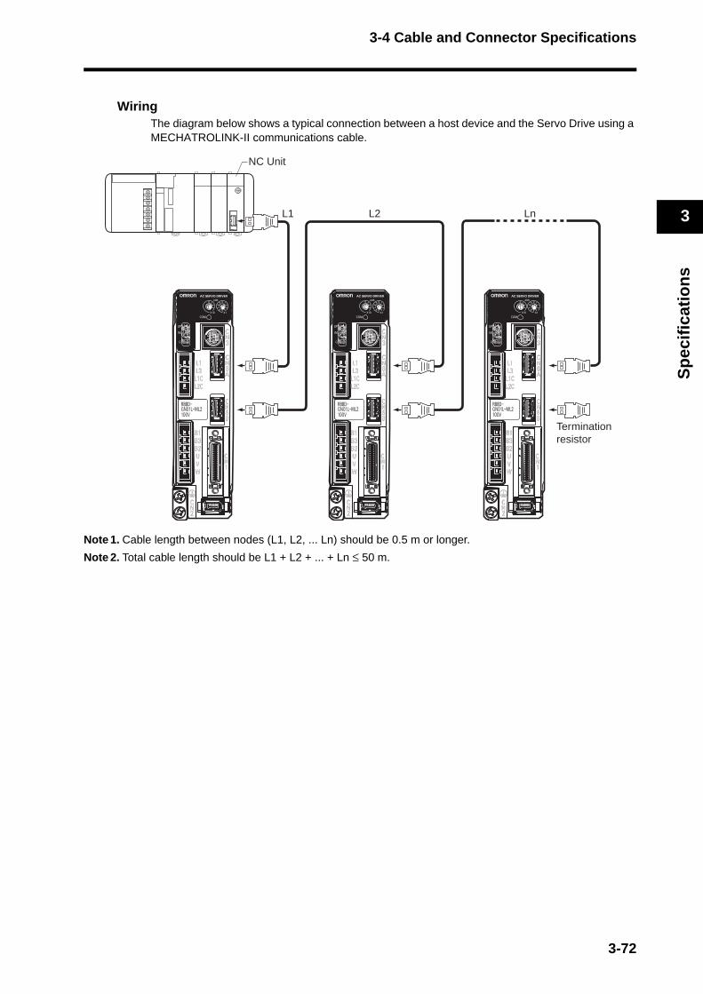
3-4 Cable and Connector Specifications
3
Sp
ecif
icat
ion
s
WiringThe diagram below shows a typical connection between a host device and the Servo Drive using a MECHATROLINK-II communications cable.
Note 1. Cable length between nodes (L1, L2, ... Ln) should be 0.5 m or longer.
Note 2. Total cable length should be L1 + L2 + ... + Ln ≤ 50 m.
0123456789A
BCDE
NC Unit
L1 L2 Ln
Termination resistor
3-72

3-4 Cable and Connector Specifications
3
Sp
ecif
icat
ion
s
Control Cable Specifications
Connector Terminal Block Cables (XW2Z-@J-B33)This is the connector terminal block cable for the G-Series Servo Drive (with built-in MECHATROLINK-II).
Cable Models
Connection Configuration and Dimensions
Wiring
Model Length (L) Outer diameter of sheath Weight
XW2Z-100J-B33 1 m 8.0 dia.
Approx. 0.1 kg
XW2Z-200J-B33 2 m Approx. 0.2 kg
Connector terminal block
43.5
39L
XW2B-20G4XW2B-20G5XW2D-20G6
6
30
t=18
Servo Drive
R88D-GN@
No.
123456789
10
1314151617181920
No.
123456789
10
1314151617181920
Terminal block Connector
No. Signal
1 +24VIN
2 STOP2119 POT20
33 BATCOM34 BAT35 OUTM1COM36 OUTM116 ALMCOM15 /ALM
Servo Drive
DEC
NOT1111 EXT1
EXT2543 EXT3
1212
Shell FG
+24VIN
STOP
POT
BATCOMBAT
OUTM1COMOUTM1
ALMCOM/ALM
DEC
NOTEXT1EXT2EXT3
FG
0V+24VIN
0V+24VIN
0V
Blue/Red (1)Blue/Black (1)Pink/Red (1)Pink/Black (1)Green/Red (1)Green/Black (1)Orange/Red (1)Orange/Black(1)Gray/Red (1)Gray/Black (1)Blue/Red (2)Blue/Black (2)Pink/Red (2)Green/Red (2)Green/Black (2)Orange/Red (2)Orange/Black (2)Gray/Red (2)Gray/Black (2)
Wire/mark color Wires with the same wire color and the same number of marks form a twisted pair.Example: A yellow/black (1) wire and pink/black (1) wire form a twisted pair.
Servo Drive ConnectorConnector plug: 10136-3000PE (Sumitomo 3M)Connector case: 10336-52A0-008 (Sumitomo 3M)
Terminal Block Connector Connector socket: XG4M-2030
(OMRON) Strain relief: XG4T-2004
(OMRON)
Cable AWG28×10P UL2464
Signal
3-73
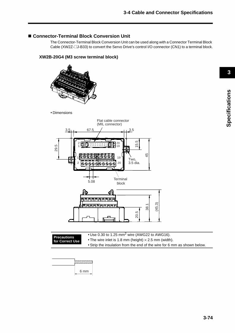
3-4 Cable and Connector Specifications
3
Sp
ecif
icat
ion
s
Connector-Terminal Block Conversion UnitThe Connector-Terminal Block Conversion Unit can be used along with a Connector Terminal Block Cable (XW2Z-@J-B33) to convert the Servo Drive's control I/O connector (CN1) to a terminal block.
XW2B-20G4 (M3 screw terminal block)
Dimensions
Use 0.30 to 1.25 mm2 wire (AWG22 to AWG16).The wire inlet is 1.8 mm (height) × 2.5 mm (width).Strip the insulation from the end of the wire for 6 mm as shown below.
Flat cable connector(MIL connector)
Terminal block
(45.
3)
38.1
20.5
Two, 3.5 dia.
45
15.5
29.5
3.53.5 67.5
5.08
2
2
20
20
19
19
1
1
Precautions for Correct Use
6 mm
3-74

3-4 Cable and Connector Specifications
3
Sp
ecif
icat
ion
s
XW2B-20G5 (M3.5 screw terminal block)
Dimensions
Terminal block pitch: 8.5 mm
When using crimp terminals, use crimp terminals with the following dimensions.When connecting wires and crimp terminals to a terminal block, tighten them with a tightening torque of 0.59 N·m.
Applicable Crimp Terminals Applicable Wires
Round Crimp Terminals
1.25-3AWG22-16
(0.3 to 1.25 mm2)
2-3.5AWG16-14
(1.25 to 2.0 mm2)
Fork Terminals
1.25Y-3AWG22-16
(0.3 to 1.25 mm2)
2-3.5AWG16-14
(1.25 to 2.0 mm2)
Flat cable connector(MIL connector)
3.5
2
2
20
20
19
19
1
1
7.38.5
7 7112.5 3.5
29.5 15
.5
(45.
3)
43.5
20.5
45
Terminal block
Two, 3.5 dia.
Precautions for Correct Use
Round Crimp Terminals Fork Terminals
6.8 mm max. 3.7 mm
3.2-mm dia.
6.8 mm max.
3-75

3-4 Cable and Connector Specifications
3
Sp
ecif
icat
ion
s
XW2D-20G6 (M3 screw terminal block)
Dimensions
The diagram on the next page shows a typical connection between a host device and the Servo Drive using a MECHATROLINK-II communications cable.
When using crimp terminals, use crimp terminals with the following dimensions.When connecting wires and crimp terminals to a terminal block, tighten them with a tightening torque of 0.7 N·m.
Applicable Crimp Terminals Applicable Wires
Round Crimp Terminals 1.25-3AWG22-16
(0.3 to 1.25 mm2)
Fork Terminals 1.25Y-3AWG22-16
(0.3 to 1.25 mm2)
A1 A2 A3 A4 A5 A6 A7 A8 A9 A10
B1 B2 B3 B4 B5 B 6 B7 B8 B9 B10
79
Two, 4.5 dia.57 17.6
39
(39.1)
640
(4.5
)
Precautions for Correct Use
Round Crimp Terminals Fork Terminals
5.8 mm max. 3.2 mm
3.2-mm dia.
5.8 mm max.
3-76
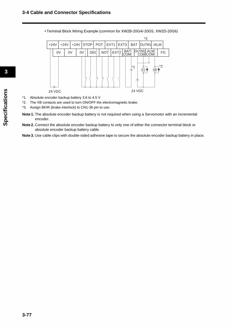
3-4 Cable and Connector Specifications
3
Sp
ecif
icat
ion
s
Terminal Block Wiring Example (common for XW2B-20G4/-20G5, XW2D-20G6)
*1. Absolute encoder backup battery 3.6 to 4.5 V*2. The XB contacts are used to turn ON/OFF the electromagnetic brake.*3. Assign BKIR (brake interlock) to CN1-36 pin to use.
Note 1. The absolute encoder backup battery is not required when using a Servomotor with an incremental encoder.
Note 2. Connect the absolute encoder backup battery to only one of either the connector terminal block or absolute encoder backup battery cable.
Note 3. Use cable clips with double-sided adhesive tape to secure the absolute encoder backup battery in place.
+24V
0V
+24V +24V STOP POT EXT1 EXT3 BAT OUTM1 /ALM
0V 0V DEC EXT2 BATCOMNOT OUTM1
COM FG
24 VDC 24 VDC
*2*1
*3
ALMCOM
X1 XB
3-77
3-5 Parameter Unit Specifications
3
Sp
ecif
icat
ion
s
3-5 Parameter Unit Specifications
R88A-PR02G Hand-held Parameter UnitThe Parameter Unit is required to operate the Servo Drive from a distance away from the Servo Drive, or to operate and monitor the Servo Drive from a control panel.The cable connected to the Parameter Unit is 1.5 m long.
General Specifications
Performance Specifications
Item Specifications
Ambient operating temperature and humidity
0 to 55°C, 90% RH max. (with no condensation)
Ambient storage temperature and humidity
−20 to 80°C, 90% RH max. (with no condensation)
Operating and storage atmosphere
No corrosive gases
Vibration resistance 5.9 m/s2 max.
Item Specifications
Type Hand-held
Cable length 1.5 m
Connectors Mini DIN 8-pin MD connector
Display Seven-segment LED display
Outer diameter 62 (W) × 114 (H) × 15 (D) mm
Weight Approx. 0.1 kg (including cable)
Com
mun
icat
ions
spe
cific
atio
ns Standard RS-232
Communications method Asynchronous (ASYNC)
Baud rate 9,600 bps
Start bits 1 bit
Data 8 bits
Parity No
Stop bits 1 bit
3-78
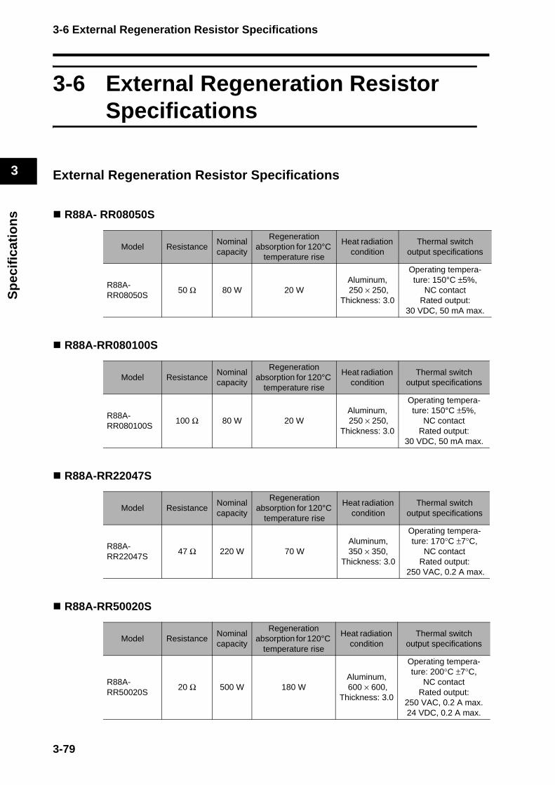
3-6 External Regeneration Resistor Specifications
3
Sp
ecif
icat
ion
s
3-6 External Regeneration Resistor Specifications
External Regeneration Resistor Specifications
R88A- RR08050S
R88A-RR080100S
R88A-RR22047S
R88A-RR50020S
Model ResistanceNominalcapacity
Regeneration absorption for 120°C
temperature rise
Heat radiation condition
Thermal switchoutput specifications
R88A- RR08050S
50 Ω 80 W 20 WAluminum, 250 × 250,
Thickness: 3.0
Operating tempera-ture: 150°C ±5%,
NC contactRated output:
30 VDC, 50 mA max.
Model ResistanceNominalcapacity
Regeneration absorption for 120°C
temperature rise
Heat radiation condition
Thermal switchoutput specifications
R88A-RR080100S
100 Ω 80 W 20 WAluminum, 250 × 250,
Thickness: 3.0
Operating tempera-ture: 150°C ±5%,
NC contactRated output:
30 VDC, 50 mA max.
Model ResistanceNominalcapacity
Regeneration absorption for 120°C
temperature rise
Heat radiation condition
Thermal switchoutput specifications
R88A-RR22047S
47 Ω 220 W 70 WAluminum, 350 × 350,
Thickness: 3.0
Operating tempera-ture: 170°C ±7°C,
NC contactRated output:
250 VAC, 0.2 A max.
Model ResistanceNominalcapacity
Regeneration absorption for 120°C
temperature rise
Heat radiation condition
Thermal switchoutput specifications
R88A-RR50020S
20 Ω 500 W 180 WAluminum, 600 × 600,
Thickness: 3.0
Operating tempera-ture: 200°C ±7°C,
NC contactRated output:
250 VAC, 0.2 A max.24 VDC, 0.2 A max.
3-79
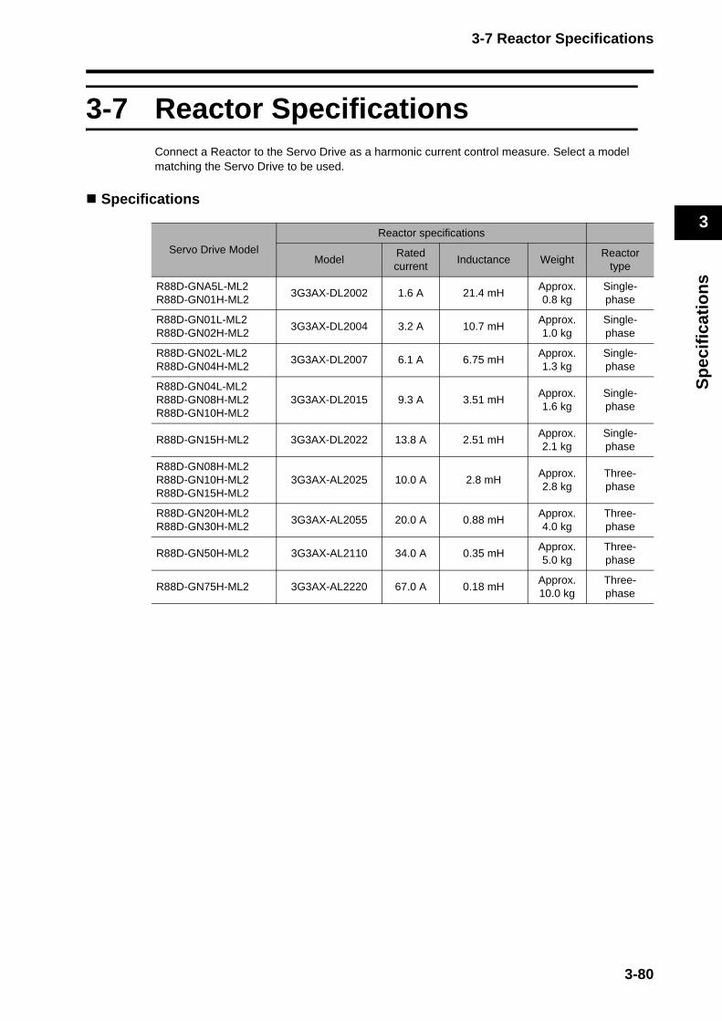
3-7 Reactor Specifications
3
Sp
ecif
icat
ion
s
3-7 Reactor SpecificationsConnect a Reactor to the Servo Drive as a harmonic current control measure. Select a model matching the Servo Drive to be used.
Specifications
Servo Drive Model
Reactor specifications
Model Rated current
Inductance WeightReactor
type
R88D-GNA5L-ML2R88D-GN01H-ML2
3G3AX-DL2002 1.6 A 21.4 mHApprox. 0.8 kg
Single-phase
R88D-GN01L-ML2R88D-GN02H-ML2
3G3AX-DL2004 3.2 A 10.7 mHApprox. 1.0 kg
Single-phase
R88D-GN02L-ML2R88D-GN04H-ML2
3G3AX-DL2007 6.1 A 6.75 mHApprox. 1.3 kg
Single-phase
R88D-GN04L-ML2R88D-GN08H-ML2R88D-GN10H-ML2
3G3AX-DL2015 9.3 A 3.51 mHApprox. 1.6 kg
Single-phase
R88D-GN15H-ML2 3G3AX-DL2022 13.8 A 2.51 mHApprox. 2.1 kg
Single-phase
R88D-GN08H-ML2R88D-GN10H-ML2R88D-GN15H-ML2
3G3AX-AL2025 10.0 A 2.8 mHApprox. 2.8 kg
Three-phase
R88D-GN20H-ML2R88D-GN30H-ML2
3G3AX-AL2055 20.0 A 0.88 mHApprox. 4.0 kg
Three-phase
R88D-GN50H-ML2 3G3AX-AL2110 34.0 A 0.35 mHApprox. 5.0 kg
Three-phase
R88D-GN75H-ML2 3G3AX-AL2220 67.0 A 0.18 mHApprox. 10.0 kg
Three-phase
3-80


Chapter 4
System Design4-1 Installation Conditions ........................................ 4-1Servo Drives .........................................................................4-1
Servomotors..........................................................................4-3
Decelerators..........................................................................4-7
4-2 Wiring ................................................................. 4-11Connecting Cables................................................................4-11
Selecting Connecting Cables................................................4-12
Peripheral Device Connection Examples..............................4-16
Main Circuit and Servomotor Connector Specifications........4-20
4-3 Wiring Conforming to EMC Directives................ 4-26Wiring Method.......................................................................4-26
Selecting Connection Components.......................................4-31
4-4 Regenerative Energy Absorption ....................... 4-44Calculating the Regenerative Energy ...................................4-44
Servo Drive Regenerative Energy AbsorptionCapacity ................................................................................4-47
Absorbing Regenerative Energy with an ExternalRegeneration Resistor ..........................................................4-48
Connecting an External Regeneration Resistor....................4-49
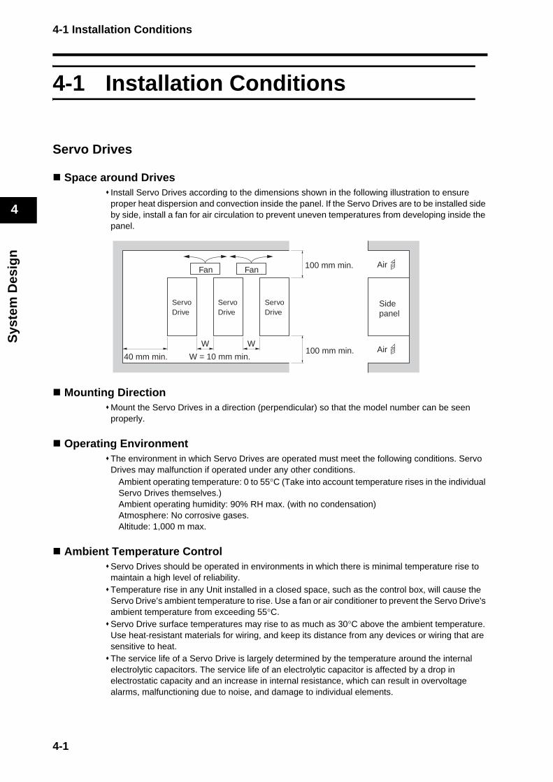
4-1 Installation Conditions
Sys
tem
Des
ign
4
4-1 Installation Conditions
Servo Drives
Space around DrivesInstall Servo Drives according to the dimensions shown in the following illustration to ensure proper heat dispersion and convection inside the panel. If the Servo Drives are to be installed side by side, install a fan for air circulation to prevent uneven temperatures from developing inside the panel.
Mounting DirectionMount the Servo Drives in a direction (perpendicular) so that the model number can be seen properly.
Operating EnvironmentThe environment in which Servo Drives are operated must meet the following conditions. Servo Drives may malfunction if operated under any other conditions.
Ambient operating temperature: 0 to 55°C (Take into account temperature rises in the individual Servo Drives themselves.)Ambient operating humidity: 90% RH max. (with no condensation)Atmosphere: No corrosive gases.Altitude: 1,000 m max.
Ambient Temperature ControlServo Drives should be operated in environments in which there is minimal temperature rise to maintain a high level of reliability.Temperature rise in any Unit installed in a closed space, such as the control box, will cause the Servo Drive’s ambient temperature to rise. Use a fan or air conditioner to prevent the Servo Drive's ambient temperature from exceeding 55°C.Servo Drive surface temperatures may rise to as much as 30°C above the ambient temperature. Use heat-resistant materials for wiring, and keep its distance from any devices or wiring that are sensitive to heat.The service life of a Servo Drive is largely determined by the temperature around the internal electrolytic capacitors. The service life of an electrolytic capacitor is affected by a drop in electrostatic capacity and an increase in internal resistance, which can result in overvoltage alarms, malfunctioning due to noise, and damage to individual elements.
W W
ServoDrive
ServoDrive
ServoDrive
Sidepanel
40 mm min.
100 mm min.
100 mm min.
Air
Air
Fan Fan
W = 10 mm min.
4-1

4-1 Installation Conditions
Sys
tem
Des
ign
4
If a Servo Drive is always operated at the ambient temperature of 55°C and with 100% of the rated torque and rated rotation speed, its service life is expected to be approximately 28,000 hours (excluding the axial-flow fan). A drop of 10°C in the ambient temperature will double the expected service life.
Keeping Foreign Objects Out of UnitsPlace a cover over the Units or take other preventative measures to prevent foreign objects, such as drill filings, from getting into the Units during installation. Be sure to remove the cover after installation is complete. If the cover is left on during operation, Servo Drive’s heat dissipation is blocked, which may result in malfunction.Take measures during installation and operation to prevent foreign objects such as metal particles, oil, machining oil, dust, or water from getting inside of Servo Drives.
4-2
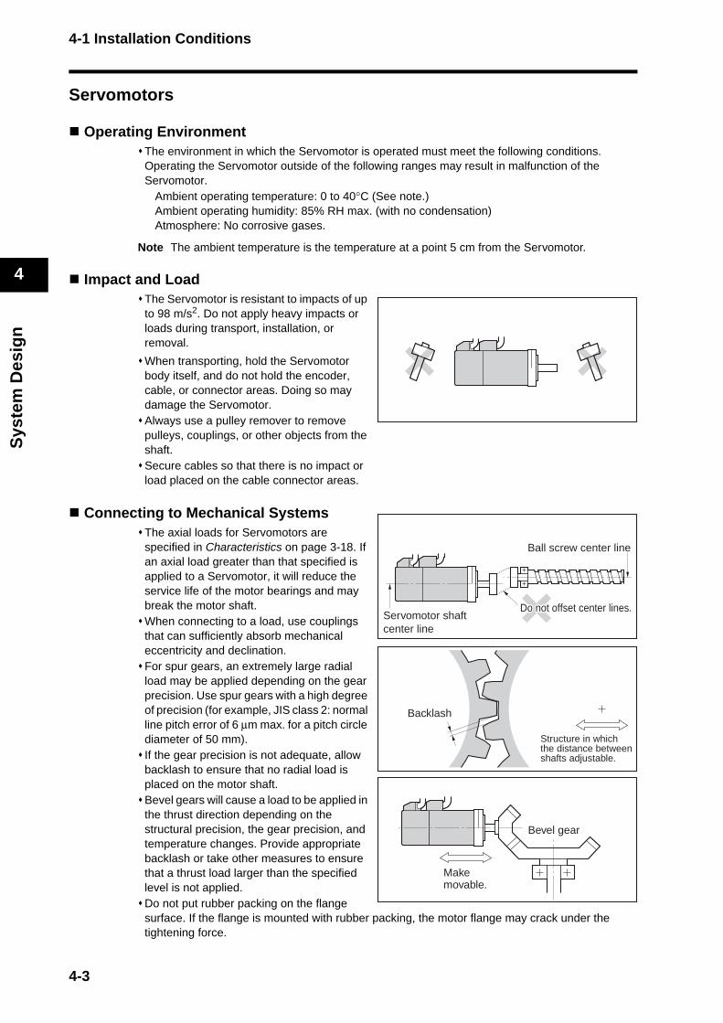
4-1 Installation Conditions
Sys
tem
Des
ign
4
Servomotors
Operating EnvironmentThe environment in which the Servomotor is operated must meet the following conditions. Operating the Servomotor outside of the following ranges may result in malfunction of the Servomotor.
Ambient operating temperature: 0 to 40°C (See note.)Ambient operating humidity: 85% RH max. (with no condensation)Atmosphere: No corrosive gases.
Note The ambient temperature is the temperature at a point 5 cm from the Servomotor.
Impact and LoadThe Servomotor is resistant to impacts of up to 98 m/s2. Do not apply heavy impacts or loads during transport, installation, or removal.
When transporting, hold the Servomotor body itself, and do not hold the encoder, cable, or connector areas. Doing so may damage the Servomotor.Always use a pulley remover to remove pulleys, couplings, or other objects from the shaft.Secure cables so that there is no impact or load placed on the cable connector areas.
Connecting to Mechanical SystemsThe axial loads for Servomotors are specified in Characteristics on page 3-18. If an axial load greater than that specified is applied to a Servomotor, it will reduce the service life of the motor bearings and may break the motor shaft.When connecting to a load, use couplings that can sufficiently absorb mechanical eccentricity and declination.For spur gears, an extremely large radial load may be applied depending on the gear precision. Use spur gears with a high degree of precision (for example, JIS class 2: normal line pitch error of 6 μm max. for a pitch circle diameter of 50 mm).If the gear precision is not adequate, allow backlash to ensure that no radial load is placed on the motor shaft.Bevel gears will cause a load to be applied in the thrust direction depending on the structural precision, the gear precision, and temperature changes. Provide appropriate backlash or take other measures to ensure that a thrust load larger than the specified level is not applied.Do not put rubber packing on the flange surface. If the flange is mounted with rubber packing, the motor flange may crack under the tightening force.
Makemovable.
Bevel gear
Structure in which the distance betweenshafts adjustable.
Backlash
Servomotor shaftcenter line
Ball screw center line
Do not offset center linesDo not offset center lines.Do not offset center lines.
4-3
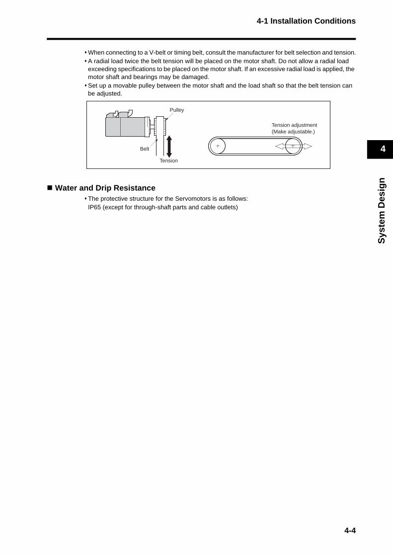
4-1 Installation Conditions
Sys
tem
Des
ign
4
When connecting to a V-belt or timing belt, consult the manufacturer for belt selection and tension.A radial load twice the belt tension will be placed on the motor shaft. Do not allow a radial load exceeding specifications to be placed on the motor shaft. If an excessive radial load is applied, the motor shaft and bearings may be damaged.Set up a movable pulley between the motor shaft and the load shaft so that the belt tension can be adjusted.
Water and Drip ResistanceThe protective structure for the Servomotors is as follows:IP65 (except for through-shaft parts and cable outlets)
Pulley
Belt
Tension
Tension adjustment(Make adjustable.)
4-4

4-1 Installation Conditions
Sys
tem
Des
ign
4
Oil Seal Part NumbersWith OMNUC G-Series Servomotors, an oil seal can be installed afterwards.Refer to the installation instructions from NOK Corporation for information on installing the oil seal.The following oil seals are not standard NOK products. Check with the manufacturer.The expected service life of the oil seals is approximately 5,000 hours, but the actual life depends on the application conditions and environment.
Motor modelShaft
diameter(mm)
Outer diameter
(mm)
Width(mm)
Material (rubber)
NOK part number (SC type)
R88M-G05030@ 8.9 17 4 A435 BC6646-E0
R88M-G10030@ 8.9 17 4 A435 BC6646-E0
R88M-G20030@ 14 28 4 A435 BC5102-E1
R88M-G40030@ 14 28 4 A435 BC5102-E1
R88M-G75030@ 19.8 30 4 A435 BC1141-E1
R88M-GP10030@ 8.9 22 4 A435 BC5101-E1
R88M-GP20030@ 14 28 4 A435 BC5102-E1
R88M-GP40030@ 14 28 4 A435 BC5102-E1
R88M-G1K030@ 20 35 7 A435 AC1012E2
R88M-G1K530@ 20 35 7 A435 AC1012E2
R88M-G2K030@ 20 35 7 A435 AC1012E2
R88M-G3K030@ 24 38 7 A435 AC1251E1-RA0
R88M-G4K030@ 24 38 7 A435 AC1251E1-RA0
R88M-G5K030@ 24 38 7 A435 AC1251E1-RA0
R88M-G1K020@ 24 38 7 A435 AC1251E1-RA0
R88M-G1K520@ 24 38 7 A435 AC1251E1-RA0
R88M-G2K020@ 24 38 7 A435 AC1251E1-RA0
R88M-G3K020@ 24 38 7 A435 AC1251E1-RA0
R88M-G4K020@ 30 45 7 A435 AC1677E1-RA0
R88M-G5K020@ 40 58 7 A435 AC2368E2
R88M-G7K515@ 45 62 9 A435 AC2651E2
R88M-G90010@ 24 38 7 A435 AC1251E1-RA0
R88M-G2K010@ 40 58 7 A435 AC2368E2
R88M-G3K010@ 40 58 7 A435 AC2368E2
R88M-G4K510@ 45 62 9 A435 AC2651E2
R88M-G6K010@ 45 62 9 A435 AC2651E2
4-5
4-1 Installation Conditions
Sys
tem
Des
ign
4
Other PrecautionsTake measures to protect the shaft from corrosion.The shafts are coated with anti-corrosion oil when shipped, but anti-corrosion oil or grease should also be applied when connecting the shaft to a load.
Do not apply commercial power directly to the Servomotor.Doing so may result in fire.
Do not dismantle or repair the product.Doing so may result in electric shock or injury.
WARNING
4-6
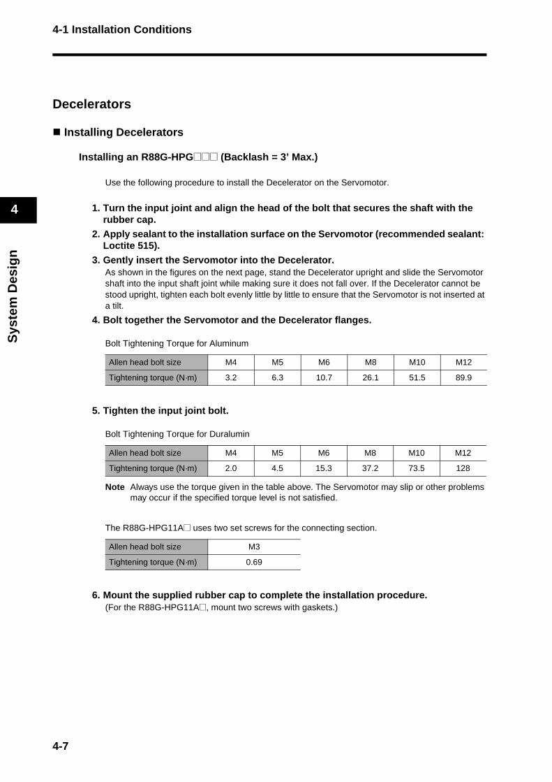
4-1 Installation Conditions
Sys
tem
Des
ign
4
Decelerators
Installing Decelerators
Installing an R88G-HPG@@@ (Backlash = 3’ Max.)
Use the following procedure to install the Decelerator on the Servomotor.
1. Turn the input joint and align the head of the bolt that secures the shaft with the rubber cap.
2. Apply sealant to the installation surface on the Servomotor (recommended sealant: Loctite 515).
3. Gently insert the Servomotor into the Decelerator.As shown in the figures on the next page, stand the Decelerator upright and slide the Servomotor shaft into the input shaft joint while making sure it does not fall over. If the Decelerator cannot be stood upright, tighten each bolt evenly little by little to ensure that the Servomotor is not inserted at a tilt.
4. Bolt together the Servomotor and the Decelerator flanges.
Bolt Tightening Torque for Aluminum
5. Tighten the input joint bolt.
Bolt Tightening Torque for Duralumin
Note Always use the torque given in the table above. The Servomotor may slip or other problems may occur if the specified torque level is not satisfied.
The R88G-HPG11A@ uses two set screws for the connecting section.
6. Mount the supplied rubber cap to complete the installation procedure.(For the R88G-HPG11A@, mount two screws with gaskets.)
Allen head bolt size M4 M5 M6 M8 M10 M12
Tightening torque (N·m) 3.2 6.3 10.7 26.1 51.5 89.9
Allen head bolt size M4 M5 M6 M8 M10 M12
Tightening torque (N·m) 2.0 4.5 15.3 37.2 73.5 128
Allen head bolt size M3
Tightening torque (N·m) 0.69
4-7
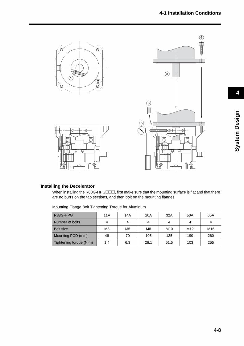
4-1 Installation Conditions
Sys
tem
Des
ign
4
Installing the DeceleratorWhen installing the R88G-HPG@@@, first make sure that the mounting surface is flat and that there are no burrs on the tap sections, and then bolt on the mounting flanges.
Mounting Flange Bolt Tightening Torque for Aluminum
R88G-HPG 11A 14A 20A 32A 50A 65A
Number of bolts 4 4 4 4 4 4
Bolt size M3 M5 M8 M10 M12 M16
Mounting PCD (mm) 46 70 105 135 190 260
Tightening torque (N·m) 1.4 6.3 26.1 51.5 103 255
E
D
CA
B
F
4-8

4-1 Installation Conditions
Sys
tem
Des
ign
4
Installing an R88G-VRSF@@@ (Backlash = 15’ Max.)
Use the following procedure to install the Decelerator on the Servomotor.
1. Turn the input joint and align the head of the bolt that secures the shaft with the rubber cap.Make sure the set bolts are loose.
2. Gently insert the Servomotor into the Decelerator.As shown in the figures below, stand the Decelerator upright and slide the Servomotor shaft into the input shaft joint while making sure it does not fall over. If the Decelerator cannot be stood upright, tighten each bolt evenly little by little to ensure that the Servomotor is not inserted at a tilt.
3. Bolt together the Servomotor and the Decelerator flanges.
Bolt Tightening Torque
4. Tighten the input joint bolt.
Bolt Tightening Torque for Duralumin
Note Always use the torque given in the table above. The Servomotor may slip or other problems may occur if the specified torque level is not satisfied.
5. Mount the supplied rubber cap to complete the installation procedure.
Allen head bolt size M4 M5 M6
Tightening torque (N·m) 3.0 5.8 9.8
Allen head bolt size M3 M4 M5
Tightening torque (N·m) 1.5 4.5 7.1
E
D
C
A
B
4-9
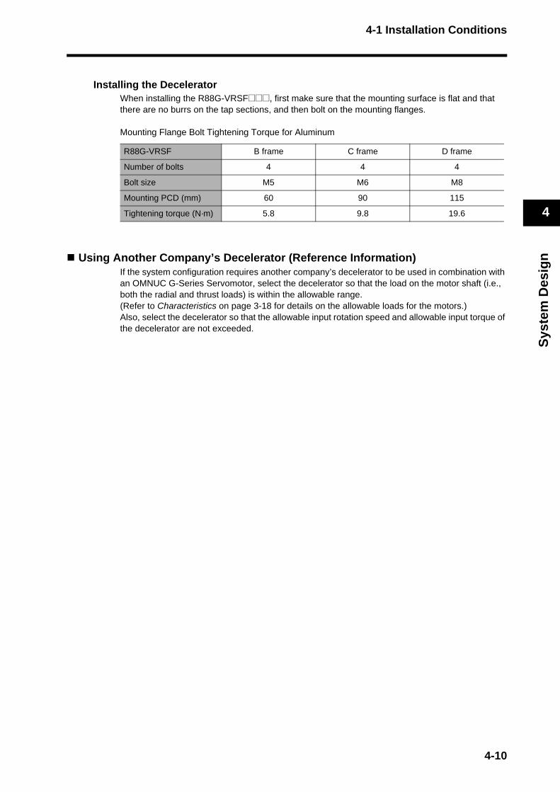
4-1 Installation Conditions
Sys
tem
Des
ign
4
Installing the DeceleratorWhen installing the R88G-VRSF@@@, first make sure that the mounting surface is flat and that there are no burrs on the tap sections, and then bolt on the mounting flanges.
Mounting Flange Bolt Tightening Torque for Aluminum
Using Another Company’s Decelerator (Reference Information)If the system configuration requires another company’s decelerator to be used in combination with an OMNUC G-Series Servomotor, select the decelerator so that the load on the motor shaft (i.e., both the radial and thrust loads) is within the allowable range. (Refer to Characteristics on page 3-18 for details on the allowable loads for the motors.)Also, select the decelerator so that the allowable input rotation speed and allowable input torque of the decelerator are not exceeded.
R88G-VRSF B frame C frame D frame
Number of bolts 4 4 4
Bolt size M5 M6 M8
Mounting PCD (mm) 60 90 115
Tightening torque (N·m) 5.8 9.8 19.6
4-10
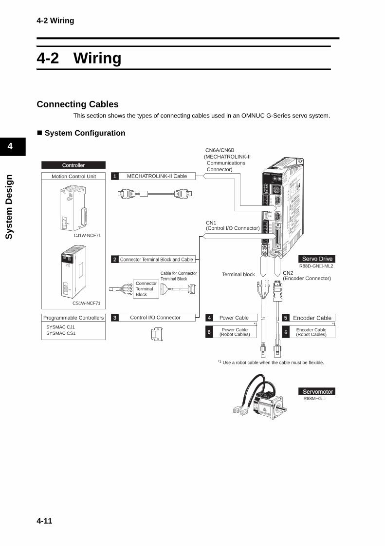
4-2 Wiring
Sys
tem
Des
ign
4
3
4
2
1
5 6
Servo Drive
Controller
Servomotor
4-2 Wiring
Connecting CablesThis section shows the types of connecting cables used in an OMNUC G-Series servo system.
System Configuration
ControllerController
Power Cable(Robot Cables)
Encoder Cable(Robot Cables)
MECHATROLINK-II Cable
CN6A/CN6B(MECHATROLINK-II Communications Connector)
2
3
1
4 5
R88D-GN@-ML2
R88M−G@
Use a robot cable when the cable must be flexible.
Programmable Controllers
SYSMAC CJ1SYSMAC CS1
CJ1W-NCF71
CS1W-NCF71
6 6
1
1 1
Motion Control Unit
Cable for ConnectorTerminal Block
ConnectorTerminal Block
Connector Terminal Block and Cable
Control I/O Connector Power Cable Encoder Cable
Servo DriveServo Drive
CN2(Encoder Connector)
ServomotorServomotor
Terminal block
CN1 (Control I/O Connector)
4-11
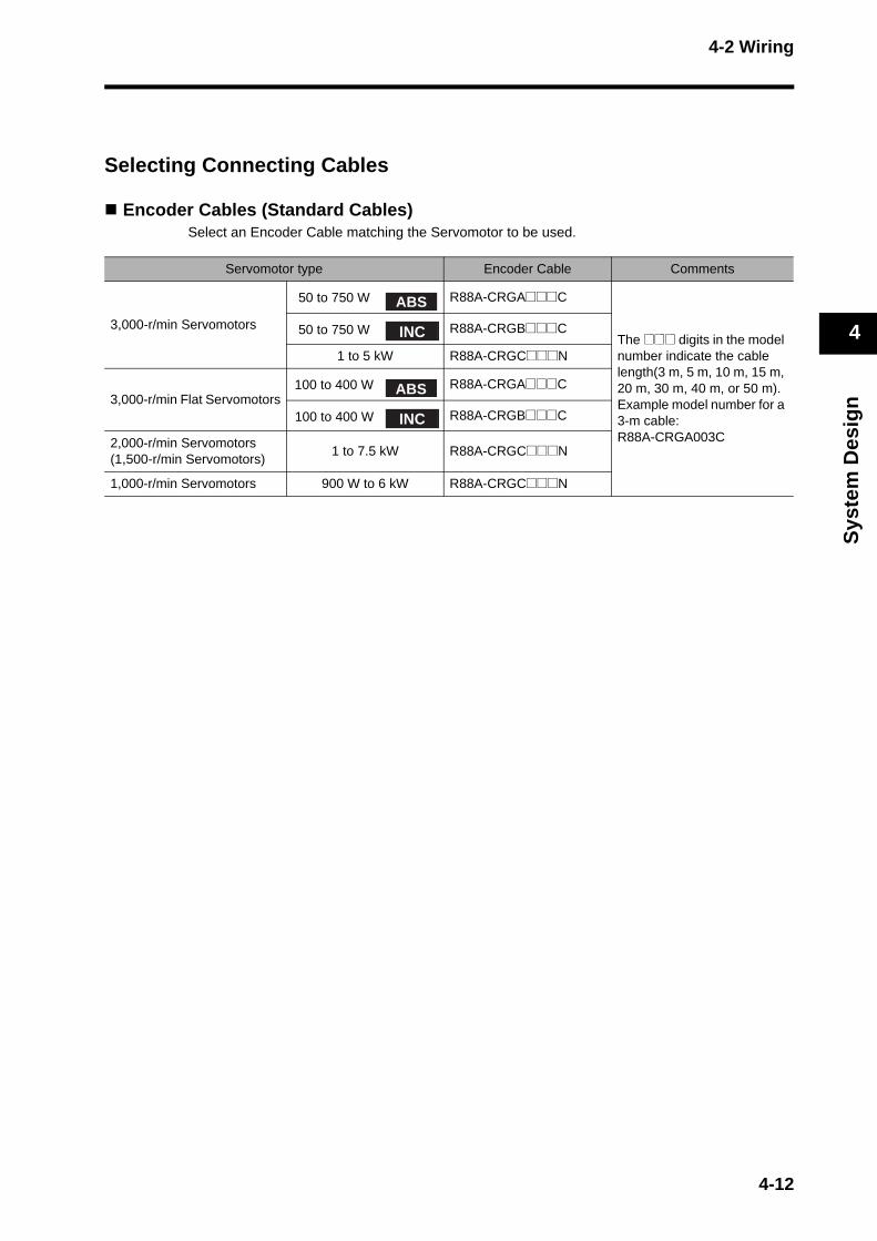
4-2 Wiring
Sys
tem
Des
ign
4
Selecting Connecting Cables
Encoder Cables (Standard Cables)Select an Encoder Cable matching the Servomotor to be used.
Servomotor type Encoder Cable Comments
3,000-r/min Servomotors
50 to 750 W R88A-CRGA@@@C
The @@@ digits in the model number indicate the cable length(3 m, 5 m, 10 m, 15 m, 20 m, 30 m, 40 m, or 50 m).Example model number for a 3-m cable: R88A-CRGA003C
50 to 750 W R88A-CRGB@@@C
1 to 5 kW R88A-CRGC@@@N
3,000-r/min Flat Servomotors100 to 400 W R88A-CRGA@@@C
100 to 400 W R88A-CRGB@@@C
2,000-r/min Servomotors(1,500-r/min Servomotors)
1 to 7.5 kW R88A-CRGC@@@N
1,000-r/min Servomotors 900 W to 6 kW R88A-CRGC@@@N
ABS
INC
ABS
INC
4-12

4-2 Wiring
Sys
tem
Des
ign
4
Power Cables (Standard Cables)Select a Power Cable matching the Servomotor to be used.
Note 1. The @@@ digits in the model number indicate the cable length (3 m, 5 m, 10 m, 15 m, 20 m, 30 m, 40 m, or 50 m). Example model number for a 3-m cable: R88A-CAGA003S
Note 2. For 50 to 750 W (3,000-r/min) Servomotors, Flat Servomotors, and 6-kW and higher Servomotors, there are separate connectors for power and brakes. Therefore, when a Servomotor with a brake is used, it will require both a Power Cable for a Servomotor without a brake and a Brake Cable.
Encoder Cables (Robot Cables)Use a robot cable when the encoder cable must be flexible.
Servomotor typePower Cables for Servomotors
Without BrakesPower Cables for Servomotors
With Brakes
3,000-r/min Servomotors
50 to 750 W R88A-CAGA@@@S
R88A-CAGA@@@S(For Power Connector)R88A-CAGA@@@B(For Brake Connector)
1 to 1.5 kW R88A-CAGB@@@S R88A-CAGB@@@B
2 kW R88A-CAGC@@@S R88A-CAGC@@@B
3 to 5 kW R88A-CAGD@@@S R88A-CAGD@@@B
3,000-r/min Flat Servomotors 100 to 400 W R88A-CAGA@@@S
R88A-CAGA@@@S(For Power Connector)R88A-CAGA@@@B(For Brake Connector)
2,000-r/min Servomotors(1,500-r/min Servomotors)
1 to 1.5 kW R88A-CAGB@@@S R88A-CAGB@@@B
2 kW R88A-CAGC@@@S R88A-CAGC@@@B
3 to 5 kW R88A-CAGD@@@S R88A-CAGD@@@B
7.5 kW R88A-CAGE@@@S
R88A-CAGE@@@S(For Power Connector)R88A-CAGE@@@B(For Brake Connector)
1,000-r/min Servomotors
900 W R88A-CAGB@@@S R88A-CAGB@@@B
2 to 4.5 kW R88A-CAGD@@@S R88A-CAGD@@@B
6 kW R88A-CAGE@@@S
R88A-CAGE@@@S(For Power Connector)R88A-CAGE@@@B(For Brake Connector)
Servomotor type Encoder Cable Comments
3,000-r/min Servomotors
50 to 750 W R88A-CRGA@@@CR
The @@@ digits in the model number indicate the cable length.(3 m, 5 m, 10 m, 15 m, 20 m, 30 m, 40 m, or 50 m).Example model number for a 3-m cable: R88A-CRGA003CR
50 to 750 W R88A-CRGB@@@CR
1 to 5 kW R88A-CRGC@@@NR
3,000-r/minFlat Servomotors
100 to 400 W R88A-CRGA@@@CR
100 to 400 W R88A-CRGB@@@CR
2,000-r/min Servomotors 1 to 5 kW R88A-CRGC@@@NR
1,000-r/min Servomotors 900 W to 4.5 kW R88A-CRGC@@@NR
ABS
INC
ABS
INC
4-13
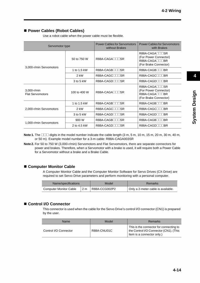
4-2 Wiring
Sys
tem
Des
ign
4
Power Cables (Robot Cables)Use a robot cable when the power cable must be flexible.
Note 1. The @@@ digits in the model number indicate the cable length (3 m, 5 m, 10 m, 15 m, 20 m, 30 m, 40 m, or 50 m). Example model number for a 3-m cable: R88A-CAGA003SR
Note 2. For 50 to 750 W (3,000-r/min) Servomotors and Flat Servomotors, there are separate connectors for power and brakes. Therefore, when a Servomotor with a brake is used, it will require both a Power Cable for a Servomotor without a brake and a Brake Cable.
Computer Monitor CableA Computer Monitor Cable and the Computer Monitor Software for Servo Drives (CX-Drive) are required to set Servo Drive parameters and perform monitoring with a personal computer.
Control I/O ConnectorThis connector is used when the cable for the Servo Drive’s control I/O connector (CN1) is prepared by the user.
Servomotor typePower Cables for Servomotors
without BrakesPower Cables for Servomotors
with Brakes
3,000-r/min Servomotors
50 to 750 W R88A-CAGA@@@SR
R88A-CAGA@@@SR(For Power Connector)R88A-CAGA@@@BR(For Brake Connector)
1 to 1.5 kW R88A-CAGB@@@SR R88A-CAGB@@@BR
2 kW R88A-CAGC@@@SR R88A-CAGC@@@BR
3 to 5 kW R88A-CAGD@@@SR R88A-CAGD@@@BR
3,000-r/minFlat Servomotors
100 to 400 W R88A-CAGA@@@SR
R88A-CAGA@@@SR(For Power Connector)R88A-CAGA@@@BR(For Brake Connector)
2,000-r/min Servomotors
1 to 1.5 kW R88A-CAGB@@@SR R88A-CAGB@@@BR
2 kW R88A-CAGC@@@SR R88A-CAGC@@@BR
3 to 5 kW R88A-CAGD@@@SR R88A-CAGD@@@BR
1,000-r/min Servomotors900 W R88A-CAGB@@@SR R88A-CAGB@@@BR
2 to 4.5 kW R88A-CAGD@@@SR R88A-CAGD@@@BR
Name/specifications Model Remarks
Computer Monitor Cable 2 m R88A-CCG002P2 Only a 2-meter cable is available.
Name Model Remarks
Control I/O Connector R88A-CNU01CThis is the connector for connecting to the Control I/O Connector (CN1). (This item is a connector only.)
4-14

4-2 Wiring
Sys
tem
Des
ign
4
Connector-Terminal Blocks and CablesThese are used to convert the Servo Drive's control I/O Connector (CN1) signals to a terminal block.
Connector Terminal Block Cable Comments
XW2B-20G4XW2B-20G5XW2D-20G6
XW2Z-@@@J-B33
The @@@ digits in the model number indicate the cable length (1 m and 2 m).Example model number for a 2-m cable: XW2Z-200J-B33
4-15
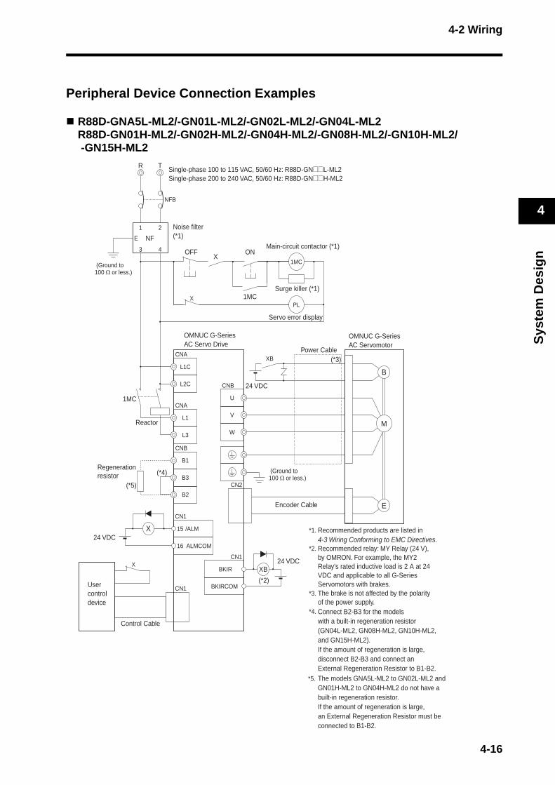
4-2 Wiring
Sys
tem
Des
ign
4
Peripheral Device Connection Examples
R88D-GNA5L-ML2/-GN01L-ML2/-GN02L-ML2/-GN04L-ML2R88D-GN01H-ML2/-GN02H-ML2/-GN04H-ML2/-GN08H-ML2/-GN10H-ML2/ -GN15H-ML2
R T
NFB
1 2
3 4
E NF
1MC
PL
L1C
L2C
L1
L3
ALMCOM
/ALM15
16
CN1
X
BKIR
BKIRCOM
XB
W
V
U
B
E
M
CN2
(*3)
(*2)
CN1
CN1
B1
B3
B2
(*4)
(*5)
CNB
CNB
CNA
CNA
OFF
X
ON
1MC
X
XB
1MC
X
Regenerationresistor
Servo error display
Usercontroldevice
Control Cable
Encoder Cable
*1. Recommended products are listed in 4-3 Wiring Conforming to EMC Directives.
*2.
*3.
*4. Connect B2-B3 for the models with a built-in regeneration resistor (GN04L-ML2, GN08H-ML2, GN10H-ML2, and GN15H-ML2). If the amount of regeneration is large, disconnect B2-B3 and connect an External Regeneration Resistor to B1-B2.
*5. The models GNA5L-ML2 to GN02L-ML2 and GN01H-ML2 to GN04H-ML2 do not have a built-in regeneration resistor. If the amount of regeneration is large, an External Regeneration Resistor must be connected to B1-B2.
Recommended relay: MY Relay (24 V), by OMRON. For example, the MY2 Relay's rated inductive load is 2 A at 24 VDC and applicable to all G-Series Servomotors with brakes.The brake is not affected by the polarity of the power supply.
Noise filter(*1)
(Ground to100 Ω or less.)
Main-circuit contactor (*1)
Surge killer (*1)
Single-phase 100 to 115 VAC, 50/60 Hz: R88D-GN@@L-ML2Single-phase 200 to 240 VAC, 50/60 Hz: R88D-GN@@H-ML2
24 VDC
(Ground to100 Ω or less.)
OMNUC G-SeriesAC Servomotor
OMNUC G-SeriesAC Servo Drive
Power Cable
Reactor
24 VDC
24 VDC
4-16
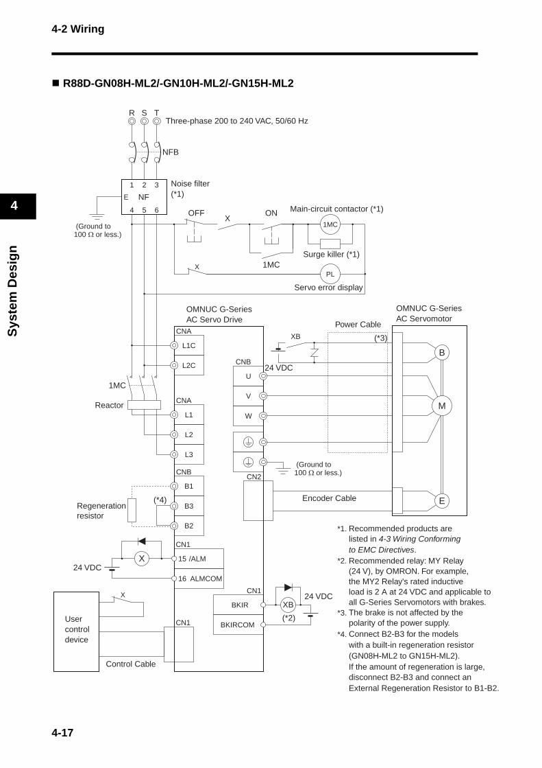
4-2 Wiring
Sys
tem
Des
ign
4
B2.
o
R88D-GN08H-ML2/-GN10H-ML2/-GN15H-ML2
R T
NFB
S
1 2 3
4 5 6
E NF
1MC
PL
L1C
L2C
L1
L2
L3
ALMCOM
/ALM15
16
CN1
X
BKIR
BKIRCOM
XB
W
V
U
B
E
M
CN2
(*3)
(*2)
CN1
CN1
B1
B3
B2
(*4)
CNB
CNB
CNA
CNA
OFF
X
ON
1MC
X
XB
1MC
X
*1. Recommended products are listed in 4-3 Wiring Conforming to EMC Directives.
*2.
*3.
*4. Connect B2-B3 for the models with a built-in regeneration resistor (GN08H-ML2 to GN15H-ML2). If the amount of regeneration is large, disconnect B2-B3 and connect an External Regeneration Resistor to B1-
Recommended relay: MY Relay (24 V), by OMRON. For example, the MY2 Relay's rated inductive load is 2 A at 24 VDC and applicable tall G-Series Servomotors with brakes.The brake is not affected by the polarity of the power supply.
Regenerationresistor
Servo error display
Usercontroldevice
Control Cable
Encoder Cable
Noise filter(*1)
(Ground to100 Ω or less.)
Main-circuit contactor (*1)
Surge killer (*1)
Three-phase 200 to 240 VAC, 50/60 Hz
24 VDC
(Ground to100 Ω or less.)
OMNUC G-SeriesAC Servomotor
OMNUC G-SeriesAC Servo Drive
Power Cable
Reactor
24 VDC
24 VDC
4-17

4-2 Wiring
Sys
tem
Des
ign
4
R88D-GN20H-ML2/-GN30H-ML2/-GN50H-ML2
R T
NFB
S
1 2 3
4 5 6
E NF
1MC
PL
L1C
L2C
L1
L2
L3
ALMCOM
/ALM15
16
CN1
X
BKIR
BKIRCOM
XB
W
V
U
B
E
M
CN2
(*3)
(*2)
CN1
CN1
B1
B3
B2
(*4)
TB1
TB1
TB1
OFF
X
ON
1MC
X
XB
1MC
X
*1. Recommended products are listed in 4-3 Wiring Conforming to EMC Directives.
*2.
*3.
*4. Connect B2-B3 for the models with a built-in regeneration resistor (GN20H-ML2 to GN50H-ML2). If the amount of regeneration is large, disconnect B2-B3 and connect an External Regeneration Resistor to B1-B2.
Recommended relay: MY Relay (24 V), by OMRON. For example, the MY2 Relay's rated inductive load is 2 A at 24 VDC and applicable to all G-Series Servomotors with brakes.The brake is not affected by the polarity of the power supply.
(Ground to100 Ω or less.)
Regenerationresistor
Servo error display
Usercontroldevice
Control Cable
Encoder Cable
Noise filter(*1)
Main-circuit contactor (*1)
Surge killer (*1)
Three-phase 200 to 230 VAC, 50/60 Hz
24 VDC
(Ground to100 Ω or less.)
OMNUC G-SeriesAC Servomotor
OMNUC G-SeriesAC Servo Drive
Power Cable
Reactor
24 VDC
24 VDC
4-18
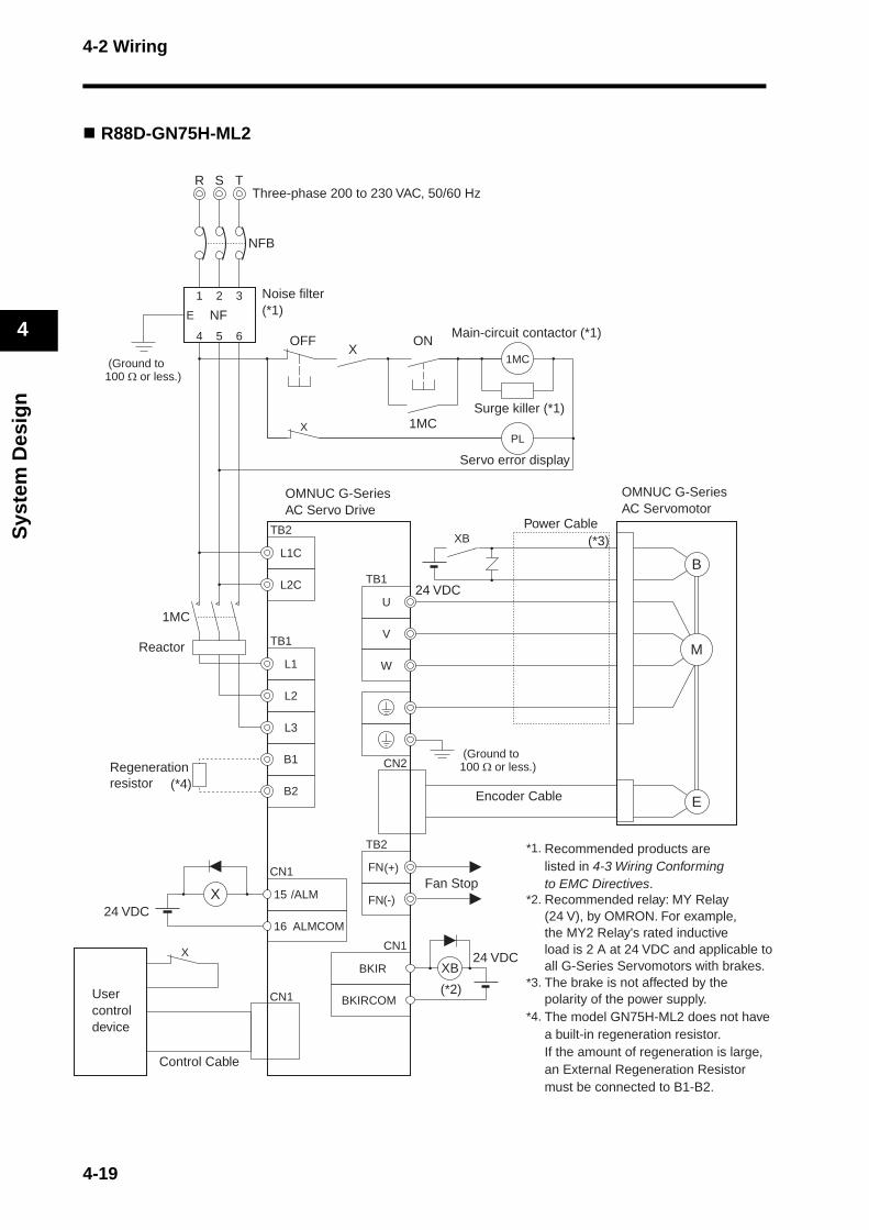
4-2 Wiring
Sys
tem
Des
ign
4
R88D-GN75H-ML2
R T
NFB
S
1 2 3
4 5 6
E NF
1MC
PL
L1C
L2C
L1
L2
L3
ALMCOM
/ALM15
16
CN1
X
BKIR
BKIRCOM
XB
W
V
U
B
E
M
CN2
(*3)
(*2)
CN1
CN1
B1
B2(*4)
TB1
TB2
TB2
TB1
FN
FNFan Stop
(-)
(+)
OFF
X
ON
1MC
X
XB
1MC
X
*1. Recommended products are listed in 4-3 Wiring Conforming to EMC Directives.
*2.
*3.
*4. The model GN75H-ML2 does not have a built-in regeneration resistor. If the amount of regeneration is large, an External Regeneration Resistor must be connected to B1-B2.
Recommended relay: MY Relay (24 V), by OMRON. For example, the MY2 Relay's rated inductive load is 2 A at 24 VDC and applicable to all G-Series Servomotors with brakes.The brake is not affected by the polarity of the power supply.
Regenerationresistor
Servo error display
Usercontroldevice
Control Cable
Encoder Cable
Noise filter(*1)
(Ground to100 Ω or less.)
Main-circuit contactor (*1)
Surge killer (*1)
Three-phase 200 to 230 VAC, 50/60 Hz
24 VDC
(Ground to100 Ω or less.)
OMNUC G-SeriesAC Servomotor
OMNUC G-SeriesAC Servo Drive
Power Cable
Reactor
24 VDC
24 VDC
4-19
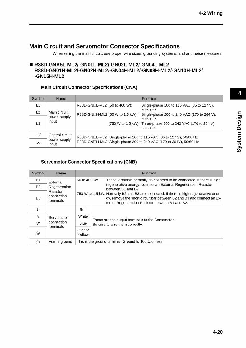
4-2 Wiring
Sys
tem
Des
ign
4
Main Circuit and Servomotor Connector SpecificationsWhen wiring the main circuit, use proper wire sizes, grounding systems, and anti-noise measures.
R88D-GNA5L-ML2/-GN01L-ML2/-GN02L-ML2/-GN04L-ML2R88D-GN01H-ML2/-GN02H-ML2/-GN04H-ML2/-GN08H-ML2/-GN10H-ML2/-GN15H-ML2
Main Circuit Connector Specifications (CNA)
Servomotor Connector Specifications (CNB)
Symbol Name Function
L1
Main circuit power supply input
R88D-GN@L-ML2 (50 to 400 W): Single-phase 100 to 115 VAC (85 to 127 V), 50/60 Hz
R88D-GN@H-ML2 (50 W to 1.5 kW): Single-phase 200 to 240 VAC (170 to 264 V), 50/60 Hz
(750 W to 1.5 kW): Three-phase 200 to 240 VAC (170 to 264 V), 50/60Hz
L2
L3
L1C Control circuit power supply input
R88D-GN@L-ML2 : Single-phase 100 to 115 VAC (85 to 127 V), 50/60 HzR88D-GN@H-ML2: Single-phase 200 to 240 VAC (170 to 264V), 50/60 HzL2C
Symbol Name Function
B1External Regeneration Resistor connection terminals
50 to 400 W: These terminals normally do not need to be connected. If there is high regenerative energy, connect an External Regeneration Resistor between B1 and B2.
750 W to 1.5 kW: Normally B2 and B3 are connected. If there is high regenerative ener-gy, remove the short-circuit bar between B2 and B3 and connect an Ex-ternal Regeneration Resistor between B1 and B2.
B2
B3
U
Servomotor connection terminals
Red
These are the output terminals to the Servomotor.Be sure to wire them correctly.
V White
W Blue
Green/Yellow
Frame ground This is the ground terminal. Ground to 100 Ω or less.
4-20
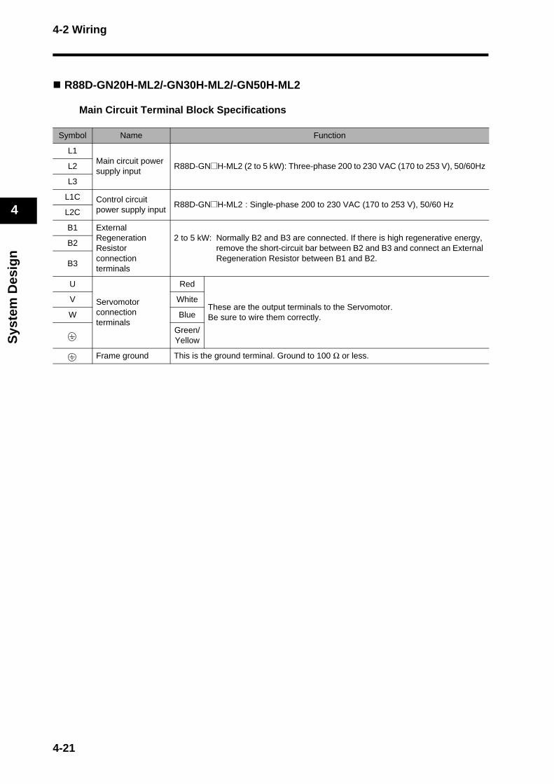
4-2 Wiring
Sys
tem
Des
ign
4
R88D-GN20H-ML2/-GN30H-ML2/-GN50H-ML2
Main Circuit Terminal Block Specifications
Symbol Name Function
L1Main circuit power supply input
R88D-GN@H-ML2 (2 to 5 kW): Three-phase 200 to 230 VAC (170 to 253 V), 50/60HzL2
L3
L1C Control circuit power supply input
R88D-GN@H-ML2 : Single-phase 200 to 230 VAC (170 to 253 V), 50/60 HzL2C
B1 External Regeneration Resistor connection terminals
2 to 5 kW: Normally B2 and B3 are connected. If there is high regenerative energy, remove the short-circuit bar between B2 and B3 and connect an External Regeneration Resistor between B1 and B2.
B2
B3
U
Servomotor connection terminals
Red
These are the output terminals to the Servomotor.Be sure to wire them correctly.
V White
W Blue
Green/Yellow
Frame ground This is the ground terminal. Ground to 100 Ω or less.
4-21
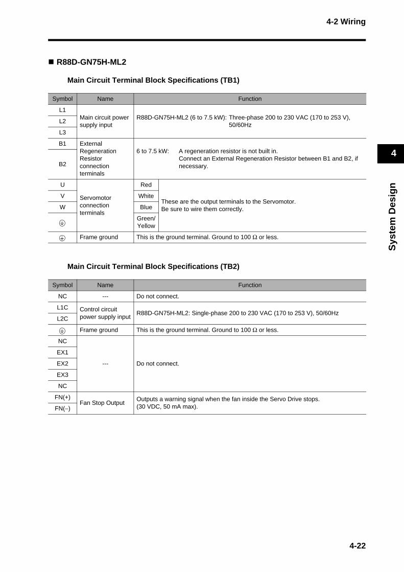
4-2 Wiring
Sys
tem
Des
ign
4
R88D-GN75H-ML2
Main Circuit Terminal Block Specifications (TB1)
Main Circuit Terminal Block Specifications (TB2)
Symbol Name Function
L1Main circuit power supply input
R88D-GN75H-ML2 (6 to 7.5 kW): Three-phase 200 to 230 VAC (170 to 253 V), 50/60Hz
L2
L3
B1 External Regeneration Resistor connection terminals
6 to 7.5 kW: A regeneration resistor is not built in.Connect an External Regeneration Resistor between B1 and B2, if necessary.B2
U
Servomotor connection terminals
Red
These are the output terminals to the Servomotor.Be sure to wire them correctly.
V White
W Blue
Green/Yellow
Frame ground This is the ground terminal. Ground to 100 Ω or less.
Symbol Name Function
NC --- Do not connect.
L1C Control circuit power supply input
R88D-GN75H-ML2: Single-phase 200 to 230 VAC (170 to 253 V), 50/60HzL2C
Frame ground This is the ground terminal. Ground to 100 Ω or less.
NC
--- Do not connect.
EX1
EX2
EX3
NC
FN(+)Fan Stop Output
Outputs a warning signal when the fan inside the Servo Drive stops. (30 VDC, 50 mA max).FN(−)
4-22
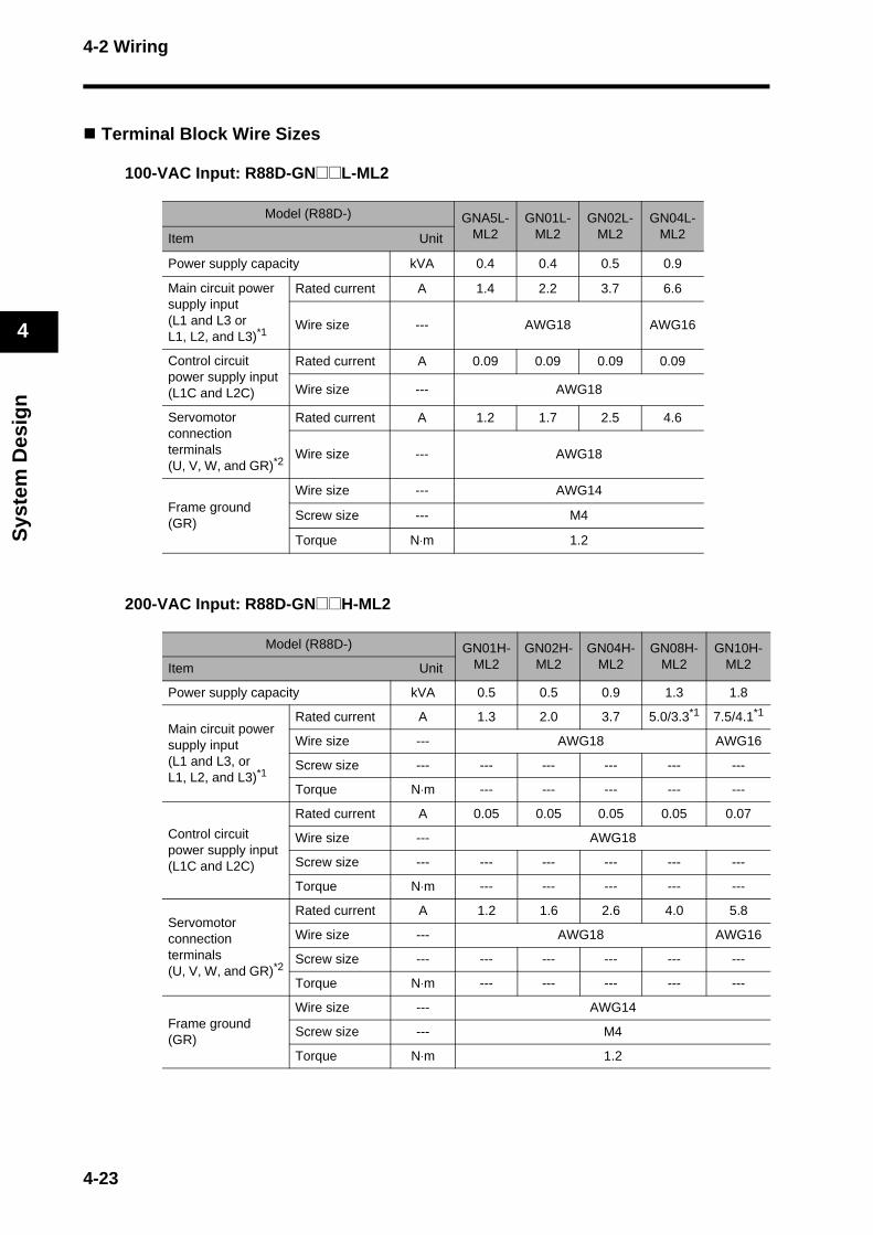
4-2 Wiring
Sys
tem
Des
ign
4
Terminal Block Wire Sizes
100-VAC Input: R88D-GN@@L-ML2
200-VAC Input: R88D-GN@@H-ML2
Model (R88D-) GNA5L-ML2
GN01L-ML2
GN02L-ML2
GN04L-ML2Item Unit
Power supply capacity kVA 0.4 0.4 0.5 0.9
Main circuit power supply input(L1 and L3 or L1, L2, and L3)*1
Rated current A 1.4 2.2 3.7 6.6
Wire size --- AWG18 AWG16
Control circuit power supply input(L1C and L2C)
Rated current A 0.09 0.09 0.09 0.09
Wire size --- AWG18
Servomotor connection terminals(U, V, W, and GR)*2
Rated current A 1.2 1.7 2.5 4.6
Wire size --- AWG18
Frame ground(GR)
Wire size --- AWG14
Screw size --- M4
Torque N⋅m 1.2
Model (R88D-) GN01H-ML2
GN02H-ML2
GN04H-ML2
GN08H-ML2
GN10H-ML2Item Unit
Power supply capacity kVA 0.5 0.5 0.9 1.3 1.8
Main circuit power supply input(L1 and L3, orL1, L2, and L3)*1
Rated current A 1.3 2.0 3.7 5.0/3.3*1 7.5/4.1*1
Wire size --- AWG18 AWG16
Screw size --- --- --- --- --- ---
Torque N⋅m --- --- --- --- ---
Control circuit power supply input(L1C and L2C)
Rated current A 0.05 0.05 0.05 0.05 0.07
Wire size --- AWG18
Screw size --- --- --- --- --- ---
Torque N⋅m --- --- --- --- ---
Servomotor connection terminals(U, V, W, and GR)*2
Rated current A 1.2 1.6 2.6 4.0 5.8
Wire size --- AWG18 AWG16
Screw size --- --- --- --- --- ---
Torque N⋅m --- --- --- --- ---
Frame ground(GR)
Wire size --- AWG14
Screw size --- M4
Torque N⋅m 1.2
4-23

4-2 Wiring
Sys
tem
Des
ign
4
*1. The left value is for single-phase input power, and the right value is for three-phase input power.*2. Use the same wire sizes for B1 and B2.*3. Connect an OMRON Servomotor Power Cable to the Servomotor connection terminals.
Wire Sizes and Allowable Current (Reference)The following table shows the allowable current when there are three power supply wires. Use a current below these specified values.
600-V Heat-resistant Vinyl Wire (HIV)
Model (R88D-) GN15H-ML2
GN20H-ML2
GN30H-ML2
GN50H-ML2
GN75H-ML2Item Unit
Power supply capacity kVA 2.3 3.3 4.5 7.5 11
Main circuit power supply input(L1 and L3, orL1, L2, and L3) *1
Rated current A 11.0/8.0*1 10.2 15.2 23.7 35.0
Wire size --- AWG14 AWG12 AWG10 AWG8
Screw size --- --- M5
Torque N⋅m --- 2.0
Control circuit power supply input(L1C and L2C)
Rated current A 0.07 0.1 0.12 0.12 0.14
Wire size --- AWG18
Screw size --- --- M5
Torque N⋅m --- 2.0
Servomotor connection terminals(U, V, W, and GR)*2
Rated current A 9.4 13.4 18.6 33.0 47.0
Wire size --- AWG14 AWG12 AWG8 AWG6
Screw size --- --- M5
Torque N⋅m --- 2.0
Frame ground(GR)
Wire size --- AWG14 AWG12 AWG8
Screw size --- M4 M5
Torque N⋅m 1.2 2.0
AWG size
Nominal cross-sec-tional area
(mm2)
Configura-tion
(wires/mm2)
Conductive resistance
(Ω/km)
Allowable current (A) for ambient temperature
30°C 40°C 50°C
20 0.5 19/0.18 39.5 6.6 5.6 4.5
--- 0.75 30/0.18 26.0 8.8 7.0 5.5
18 0.9 37/0.18 24.4 9.0 7.7 6.0
16 1.25 50/0.18 15.6 12.0 11.0 8.5
14 2.0 7/0.6 9.53 23 20 16
12 3.5 7/0.8 5.41 33 29 24
10 5.5 7/1.0 3.47 43 38 31
8 8.0 7/1.2 2.41 55 49 40
6 14.0 7/1.6 1.35 79 70 57
4-24
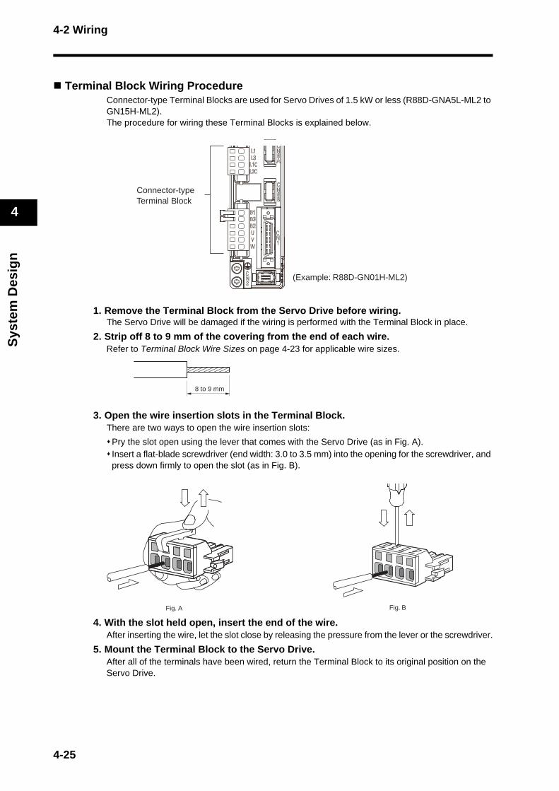
4-2 Wiring
Sys
tem
Des
ign
4
Terminal Block Wiring ProcedureConnector-type Terminal Blocks are used for Servo Drives of 1.5 kW or less (R88D-GNA5L-ML2 to GN15H-ML2).The procedure for wiring these Terminal Blocks is explained below.
1. Remove the Terminal Block from the Servo Drive before wiring.The Servo Drive will be damaged if the wiring is performed with the Terminal Block in place.
2. Strip off 8 to 9 mm of the covering from the end of each wire.Refer to Terminal Block Wire Sizes on page 4-23 for applicable wire sizes.
3. Open the wire insertion slots in the Terminal Block.There are two ways to open the wire insertion slots:
Pry the slot open using the lever that comes with the Servo Drive (as in Fig. A).Insert a flat-blade screwdriver (end width: 3.0 to 3.5 mm) into the opening for the screwdriver, and press down firmly to open the slot (as in Fig. B).
4. With the slot held open, insert the end of the wire.After inserting the wire, let the slot close by releasing the pressure from the lever or the screwdriver.
5. Mount the Terminal Block to the Servo Drive.After all of the terminals have been wired, return the Terminal Block to its original position on the Servo Drive.
Connector-typeTerminal Block
(Example: R88D-GN01H-ML2)
8 to 9 mm
Fig. A Fig. B
4-25

4-3 Wiring Conforming to EMC Directives
Sys
tem
Des
ign
4
4-3 Wiring Conforming to EMC DirectivesConformance to the EMC Directives (EN 55011 Class A Group 1 (EMI) and EN 61000-6-2 (EMS)) can be ensured by wiring under the conditions described below.These conditions are for conformance of OMNUC G-Series products to the EMC Directives. EMC-related performance of these products, however, depends on the configuration, wiring, and other conditions of the equipment in which the products are installed. The EMC conformance of the system as a whole must be confirmed by the customer.
The following are the requirements for EMC Directive conformance.
The Servo Drive must be installed in a metal case (control panel). (The Servomotor does not, however, have to be covered with a metal plate.)Noise filters and surge absorbers must be installed on power supply lines.Shielded cables must be used for all I/O signal lines and encoder lines. (Use tin-plated, mild steel wires for the shielding.)All cables, I/O wiring, and power lines connected to the Servo Drive must have clamp filters installed.The shields of all cables must be directly connected to a ground plate.
Wiring Method
R88D-GNA5L-ML2/-GN01L-ML2/-GN02L-ML2/-GN04L-ML2/-GN01H-ML2/-GN02H-ML2/-GN04H-ML2/-GN08H-ML2/-GN10H-ML2/-GN15H-ML2/-GN20H-ML2/-GN30H-ML2/-GN50H-ML2
*1. For models with a single-phase power supply input (R88D-GNA5L-ML2/-GN01L-ML2/-GN02L-ML2/-GN04L-ML2/-GN01H-ML2/-GN02H-ML2/-GN04H-ML2/-GN08H-ML2), the main circuit power supply input terminals are L1 and L3.
Ground the motor's frame to the machine ground when the motor is on a movable shaft.Use a ground plate for the frame ground for each Unit, as shown in the above diagrams, and ground to a single point.
L1
L2
L3
L1C
L2CSG
NF
FC FCSV
FC
FC
CNA
CN1
CNB
CN2
UV
W
SM
C
D
AB
F
E
G
H TB Controller
Single-phase: 100 VACThree-phase: 200 VAC
Single-phase: 100 VAC
4-26
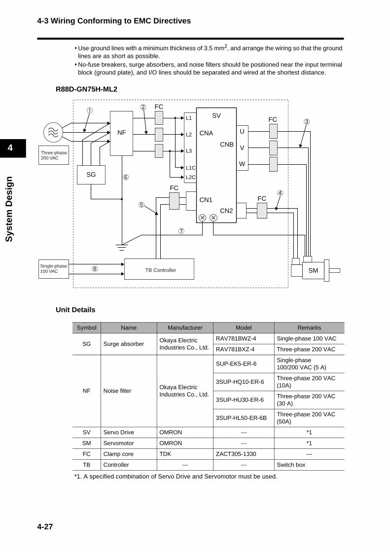
4-3 Wiring Conforming to EMC Directives
Sys
tem
Des
ign
4
Use ground lines with a minimum thickness of 3.5 mm2, and arrange the wiring so that the ground lines are as short as possible.No-fuse breakers, surge absorbers, and noise filters should be positioned near the input terminal block (ground plate), and I/O lines should be separated and wired at the shortest distance.
R88D-GN75H-ML2
Unit Details
*1. A specified combination of Servo Drive and Servomotor must be used.
Symbol Name Manufacturer Model Remarks
SG Surge absorberOkaya Electric Industries Co., Ltd.
RAV781BWZ-4 Single-phase 100 VAC
RAV781BXZ-4 Three-phase 200 VAC
NF Noise filterOkaya Electric Industries Co., Ltd.
SUP-EK5-ER-6 Single-phase100/200 VAC (5 A)
3SUP-HQ10-ER-6Three-phase 200 VAC (10A)
3SUP-HU30-ER-6Three-phase 200 VAC (30 A)
3SUP-HL50-ER-6BThree-phase 200 VAC (50A)
SV Servo Drive OMRON --- *1
SM Servomotor OMRON --- *1
FC Clamp core TDK ZACT305-1330 ---
TB Controller --- --- Switch box
L1
L2
L3
L1C
L2CSG
NF
FC
FCSV
FC
FC
CNA
CN1
CNB
CN2
U
V
W
SMTB ControllerSingle-phase: 100 VAC
Three-phase: 200 VAC
4-27

4-3 Wiring Conforming to EMC Directives
Sys
tem
Des
ign
4
Cable Details
Noise Filters for the Power Supply InputUse the following noise filters for the Servo Drive power supply.
Symbol Supplies from Connects to Cable name Length Remarks Shielded Ferrite
AC power supply Noise filter Power supply line 2 mThree-phase
200 VACNo No
Noise filter Servo Drive Power supply line 2 m --- No Yes
Servo Drive Servomotor Power cable 20 m --- Yes Yes
Servo Drive Servomotor Encoder cable 20 m --- No Yes
Switch box Servo Drive I/O cable 2 m --- No Yes
Frame ground Noise filter Frame ground line 1.5 m --- No No
Frame ground Noise filter Frame ground line 1.5 m --- No No
AC power supply Switch box Power supply line 1.5 m --- No No
Servo Drive model
Noise Filters for the Power Supply Input
ModelRated current
PhasesMaximum leakage
current (60 Hz)Manufacturer
R88D-GNA5L-ML2
SUP-EK5-ER-6 5 A Single1.0 mA
(at 250 VAC)
Okaya Electric Industries Co.,
Ltd.
R88D-GN01L-ML2
R88D-GN02L-ML2
R88D-GN04L-ML2 3SUP-HQ10-ER-6 10 A Three3.5 mA
(at 500 VAC)
R88D-GN01H-ML2
SUP-EK5-ER-6 5 A Single1.0 mA
(at 250 VAC)R88D-GN02H-ML2
R88D-GN04H-ML2
R88D-GN08H-ML2 3SUP-HQ10-ER-6 10 A Three3.5 mA
(at 500 VAC)
R88D-GN10H-ML2
3SUP-HU30-ER-6 30 A Three3.5 mA
(at 500 VAC)R88D-GN15H-ML2
R88D-GN20H-ML2
R88D-GN30H-ML2
3SUP-HL50-ER-6B 50 A Three8.0 mA
(at 500 VAC)R88D-GN50H-ML2
R88D-GN75H-ML2
4-28

4-3 Wiring Conforming to EMC Directives
Sys
tem
Des
ign
4
If no-fuse breakers are installed at the top and the power supply line is wired from the lower duct, use metal tubes for wiring or make sure that there is adequate distance between the input lines and the internal wiring. If input and output lines are wired together, noise resistance will decrease.Wire the noise filter as shown at the left in the following illustration. The noise filter must be installed as close as possible to the entrance of the control box.
Use twisted-pair cables for the power supply cables, or bind the cables.
Separate power supply cables and signal cables when wiring.
Control Panel StructureOpenings in the control panel, such as holes for cables, operating panel mounting holes, and gaps around the door, may allow electromagnetic waves into the panel. To prevent this, observe the recommendations described below when designing or selecting a control panel.
Case StructureUse a metal control panel with welded joints at the top, bottom, and sides so that the surfaces will be electrically conductive.If assembly is required, strip the paint off the joint areas (or mask them during painting), to make them electrically conductive.The panel may warp and gaps may appear when screws are tightened. Be sure that no gaps appear when tightening screws.Do not leave any conductive part unconnected.Ground all Units within the case to the case itself.
Door StructureUse a metal door.Use a water-draining structure where the door and case fit together, and leave no gaps. (Refer to the diagrams on the next page.)Use a conductive gasket between the door and the case. (Refer to the diagrams on the next page.)Strip the paint off the sections of the door and case that will be in contact with the conductive gasket (or mask them during painting), so that they will be electrically conductive.The panel may warp and gaps may appear when screws are tightened. Be sure that no gaps appear when tightening screws.
NF123
456E
NF123
456E
Correct: Separate input and output Wrong: Noise not filtered effectively
AC input AC input
GroundGround
AC output
AC output
L1CL1
L2
L3L2C
Correct: Properly twisted Correct: Cables are bound.Servo Drive Servo Drive
Binding
4-29

4-3 Wiring Conforming to EMC Directives
Sys
tem
Des
ign
4
A
B
Case
Door
Control panel
Door (interior view)
Cross-sectional view of A–B
Oil-resistant gasket
Conductive gasket
Door
Oil-resistant gasket Conductive gasket
4-30
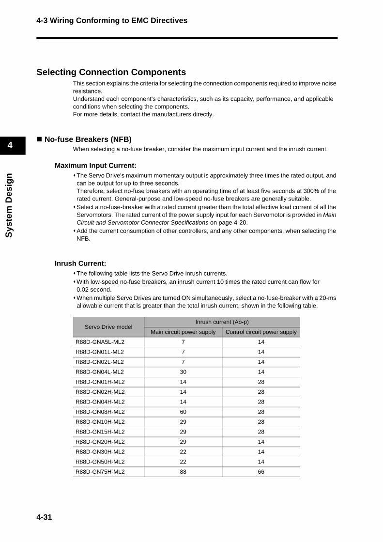
4-3 Wiring Conforming to EMC Directives
Sys
tem
Des
ign
4
Selecting Connection ComponentsThis section explains the criteria for selecting the connection components required to improve noise resistance.Understand each component's characteristics, such as its capacity, performance, and applicable conditions when selecting the components.For more details, contact the manufacturers directly.
No-fuse Breakers (NFB)When selecting a no-fuse breaker, consider the maximum input current and the inrush current.
Maximum Input Current:The Servo Drive's maximum momentary output is approximately three times the rated output, and can be output for up to three seconds.Therefore, select no-fuse breakers with an operating time of at least five seconds at 300% of the rated current. General-purpose and low-speed no-fuse breakers are generally suitable.Select a no-fuse-breaker with a rated current greater than the total effective load current of all the Servomotors. The rated current of the power supply input for each Servomotor is provided in Main Circuit and Servomotor Connector Specifications on page 4-20.Add the current consumption of other controllers, and any other components, when selecting the NFB.
Inrush Current:The following table lists the Servo Drive inrush currents.With low-speed no-fuse breakers, an inrush current 10 times the rated current can flow for 0.02 second.When multiple Servo Drives are turned ON simultaneously, select a no-fuse-breaker with a 20-ms allowable current that is greater than the total inrush current, shown in the following table.
Servo Drive modelInrush current (Ao-p)
Main circuit power supply Control circuit power supply
R88D-GNA5L-ML2 7 14
R88D-GN01L-ML2 7 14
R88D-GN02L-ML2 7 14
R88D-GN04L-ML2 30 14
R88D-GN01H-ML2 14 28
R88D-GN02H-ML2 14 28
R88D-GN04H-ML2 14 28
R88D-GN08H-ML2 60 28
R88D-GN10H-ML2 29 28
R88D-GN15H-ML2 29 28
R88D-GN20H-ML2 29 14
R88D-GN30H-ML2 22 14
R88D-GN50H-ML2 22 14
R88D-GN75H-ML2 88 66
4-31
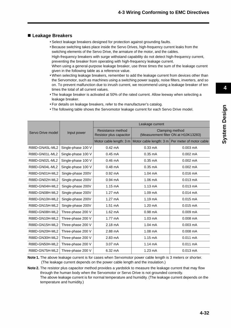
4-3 Wiring Conforming to EMC Directives
Sys
tem
Des
ign
4
Leakage BreakersSelect leakage breakers designed for protection against grounding faults.Because switching takes place inside the Servo Drives, high-frequency current leaks from the switching elements of the Servo Drive, the armature of the motor, and the cables.High-frequency breakers with surge withstand capability do not detect high-frequency current, preventing the breaker from operating with high-frequency leakage current.When using a general-purpose leakage breaker, use three times the sum of the leakage current given in the following table as a reference value.When selecting leakage breakers, remember to add the leakage current from devices other than the Servomotor, such as machines using a switching power supply, noise filters, inverters, and so on. To prevent malfunction due to inrush current, we recommend using a leakage breaker of ten times the total of all current values.The leakage breaker is activated at 50% of the rated current. Allow leeway when selecting a leakage breaker.For details on leakage breakers, refer to the manufacturer’s catalog.The following table shows the Servomotor leakage current for each Servo Drive model.
Note 1. The above leakage current is for cases when Servomotor power cable length is 3 meters or shorter. (The leakage current depends on the power cable length and the insulation.)
Note 2. The resistor plus capacitor method provides a yardstick to measure the leakage current that may flow through the human body when the Servomotor or Servo Drive is not grounded correctly.The above leakage current is for normal temperature and humidity. (The leakage current depends on the temperature and humidity.)
Servo Drive model Input power
Leakage current
Resistance methodResistor plus capacitor
Clamping method(Measurement filter ON at H10K13283)
Motor cable length: 3 m Motor cable length: 3 m Per meter of motor cable
R88D-GNA5L-ML2 Single-phase 100 V 0.42 mA 0.33 mA 0.003 mA
R88D-GN01L-ML2 Single-phase 100 V 0.45 mA 0.35 mA 0.002 mA
R88D-GN02L-ML2 Single-phase 100 V 0.46 mA 0.35 mA 0.002 mA
R88D-GN04L-ML2 Single-phase 100 V 0.48 mA 0.35 mA 0.002 mA
R88D-GN01H-ML2 Single-phase 200V 0.92 mA 1.04 mA 0.016 mA
R88D-GN02H-ML2 Single-phase 200V 0.94 mA 1.06 mA 0.013 mA
R88D-GN04H-ML2 Single-phase 200V 1.15 mA 1.13 mA 0.013 mA
R88D-GN08H-ML2 Single-phase 200V 1.27 mA 1.09 mA 0.014 mA
R88D-GN10H-ML2 Single-phase 200V 1.27 mA 1.19 mA 0.015 mA
R88D-GN15H-ML2 Single-phase 200V 1.51 mA 1.20 mA 0.015 mA
R88D-GN08H-ML2 Three-phase 200 V 1.62 mA 0.98 mA 0.009 mA
R88D-GN10H-ML2 Three-phase 200 V 1.77 mA 1.03 mA 0.008 mA
R88D-GN15H-ML2 Three-phase 200 V 2.18 mA 1.04 mA 0.003 mA
R88D-GN20H-ML2 Three-phase 200 V 2.88 mA 1.08 mA 0.008 mA
R88D-GN30H-ML2 Three-phase 200 V 2.83 mA 1.15 mA 0.011 mA
R88D-GN50H-ML2 Three-phase 200 V 3.07 mA 1.14 mA 0.011 mA
R88D-GN75H-ML2 Three-phase 200 V 6.32 mA 1.23 mA 0.013 mA
4-32
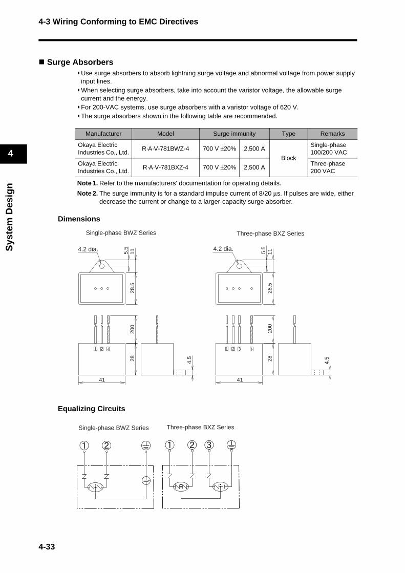
4-3 Wiring Conforming to EMC Directives
Sys
tem
Des
ign
4
Surge AbsorbersUse surge absorbers to absorb lightning surge voltage and abnormal voltage from power supply input lines.When selecting surge absorbers, take into account the varistor voltage, the allowable surge current and the energy.For 200-VAC systems, use surge absorbers with a varistor voltage of 620 V.The surge absorbers shown in the following table are recommended.
Note 1. Refer to the manufacturers' documentation for operating details.
Note 2. The surge immunity is for a standard impulse current of 8/20 μs. If pulses are wide, either decrease the current or change to a larger-capacity surge absorber.
Dimensions
Equalizing Circuits
Manufacturer Model Surge immunity Type Remarks
Okaya Electric Industries Co., Ltd.
R·A·V-781BWZ-4 700 V ±20% 2,500 A
Block
Single-phase 100/200 VAC
Okaya Electric Industries Co., Ltd.
R·A·V-781BXZ-4 700 V ±20% 2,500 AThree-phase 200 VAC
1 2 3
28 4.5
28.5
115.5
41
200
4.2 dia.
Three-phase BXZ Series
21
28 4.5
28.5
115.5
41
200
4.2 dia.
Single-phase BWZ Series
Three-phase BXZ Series Single-phase BWZ Series
4-33
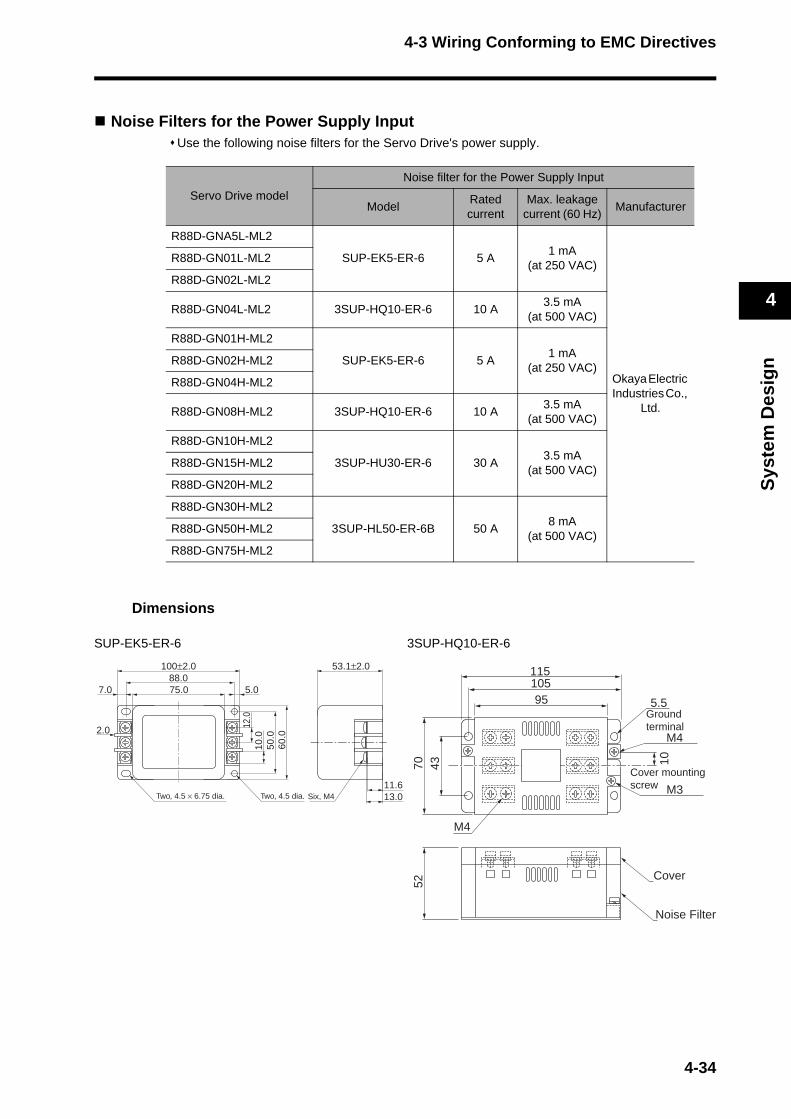
4-3 Wiring Conforming to EMC Directives
Sys
tem
Des
ign
4
Noise Filters for the Power Supply InputUse the following noise filters for the Servo Drive's power supply.
Dimensions
SUP-EK5-ER-6 3SUP-HQ10-ER-6
Servo Drive model
Noise filter for the Power Supply Input
Model Rated current
Max. leakage current (60 Hz)
Manufacturer
R88D-GNA5L-ML2
SUP-EK5-ER-6 5 A1 mA
(at 250 VAC)
Okaya Electric Industries Co.,
Ltd.
R88D-GN01L-ML2
R88D-GN02L-ML2
R88D-GN04L-ML2 3SUP-HQ10-ER-6 10 A3.5 mA
(at 500 VAC)
R88D-GN01H-ML2
SUP-EK5-ER-6 5 A1 mA
(at 250 VAC)R88D-GN02H-ML2
R88D-GN04H-ML2
R88D-GN08H-ML2 3SUP-HQ10-ER-6 10 A3.5 mA
(at 500 VAC)
R88D-GN10H-ML2
3SUP-HU30-ER-6 30 A3.5 mA
(at 500 VAC)R88D-GN15H-ML2
R88D-GN20H-ML2
R88D-GN30H-ML2
3SUP-HL50-ER-6B 50 A8 mA
(at 500 VAC)R88D-GN50H-ML2
R88D-GN75H-ML2
105115
5.5
437052
10
95
M4
M3
M4
Ground terminal
Cover mounting screw
Cover
Noise Filter
50.0
60.0
12.0
10.0
11.613.0
75.07.0
2.0
88.0100±2.0 53.1±2.0
5.0
Two, 4.5 × 6.75 dia. Two, 4.5 dia. Six, M4
4-34
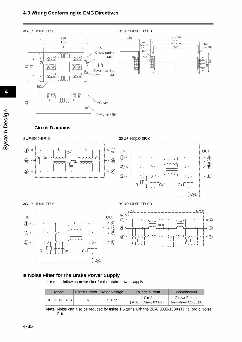
4-3 Wiring Conforming to EMC Directives
Sys
tem
Des
ign
4
3SUP-HU30-ER-6 3SUP-HL50-ER-6B
Circuit Diagrams
SUP-EK5-ER-6 3SUP-HQ10-ER-6
3SUP-HU30-ER-6 3SUP-HL50-ER-6B
Noise Filter for the Brake Power SupplyUse the following noise filter for the brake power supply.
Note Noise can also be reduced by using 1.5 turns with the ZCAT3035-1330 (TDK) Radio Noise Filter.
Model Rated current Rated voltage Leakage current Manufacturer
SUP-EK5-ER-6 5 A 250 V1.0 mA
(at 250 Vrms, 60 Hz)Okaya Electric
Industries Co., Ltd.
105115
5.5
437052
10
95
M4
M3
M4
Ground terminal
Cover mounting screw
Cover
Noise Filter
120
90±1
.01813
286±3.0
240
150270
255±1.0
M6
M6
Two, 5.5 × 7 dia.
Two, 5.5 dia.
CxR
Cy
Cy
Cx
L L
Cx1Cx1R
L1
Cy1
OUTIN
Cx1Cx1R
L1
Cy1
OUTIN
LOADLINE
4-35

4-3 Wiring Conforming to EMC Directives
Sys
tem
Des
ign
4
Radio Noise Filters and Emission Noise Prevention Clamp CoresUse one of the following filters to prevent switching noise of PWM of the Servo Drive and to prevent noise emitted from the internal oscillation circuit.
*1. Generally used for 1.5 kW or higher.*2. Generally used for 1.5 kW or lower. The maximum number of windings is three turns.*3. Generally used for 50/100 W. The maximum number of windings is two turns.*4. Also used on the Servo Drive output power lines to comply with the EMC Directives. Only a
clamp is used. This clamp can also be used to reduce noise current on a frame ground line.
Dimensions
Model Manufacturer Application
3G3AX-ZCL1 *1 OMRON Servo Drive output and power cable
3G3AX-ZCL2 *2 OMRON Servo Drive output and power cable
ESD-R-47B *3 NEC TOKIN Servo Drive output and power cable
ZCAT3035-1330 *4 TDK Encoder cable and I/O cable
95
26
78
80
12.5
72
50
7
39.5
3G3AX-ZCL23G3AX-ZCL1
51.5
17.53.0
6.5
34.0
ESD-R-47B
34 13
3039
ZCAT3035-1330
5.1 dia.
25.5
dia
.
Two, M5
Three, M4
83±235
31.5
80
13085
180±2160±2
7 × 14 oval hole 7 dia.
4-36

4-3 Wiring Conforming to EMC Directives
Sys
tem
Des
ign
4
Impedance Characteristics
10 100 10000
1000
100
10
1
0.11 1000
3G3AX-ZCL23G3AX-ZCL1
10000
1000
100
10
110 1001 1000
ESD-R-47B ZCAT3035-1330
10 100 1000
1000
100
10
20
40
60
80
1001 10 1000.1
4T
15T
Frequency (kHz)
Impe
danc
e (Ω
)
Frequency (kHz)
Impe
danc
e (Ω
)
Frequency (MHz)
Impe
danc
e (Ω
)
Frequency (MHz)
Impe
danc
e (Ω
)
4-37

4-3 Wiring Conforming to EMC Directives
Sys
tem
Des
ign
4
Surge SuppressorsInstall surge suppressors for loads that have induction coils, such as relays, solenoids, brakes, clutches, etc.The following table shows the types of surge suppressors and recommended products.
Thyristors and varistors are made by the following companies. Refer to manufacturers' documentation for details on these components.Thyristors: Ishizuka Electronics Co.Varistors: Ishizuka Electronics Co., Matsushita Electric Industrial Co.
ContactorsSelect contactors based on the circuit's inrush current and the maximum momentary phase current.The Servo Drive inrush current is covered in the preceding explanation of no-fuse breaker selection, and the maximum momentary phase current is approximately twice the rated current.The following table shows the recommended contactors.
Type Features Recommended products
Diode
Diodes are used for relatively small loads when the reset time is not an issue, such as relays.At power shutoff the surge voltage is the lowest, but the reset time takes longer.Used for 24/48-VDC systems.
Use a fast-recovery diode with a short re-verse recovery time (e.g. RU2 of Sanken Electric Co., Ltd.).
Thyristor or varistor
Thyristors and varistors are used for loads with large induction coils, as in electro-magnetic brakes, solenoids, etc., and when reset time is an issue. The surge voltage at power shutoff is approximately 1.5 times the varistor voltage.
Select the varistor voltage as follows:24 VDC system: Varistor V. 39V100 VDC system: Varistor V. 200 V100 VAC system: Varistor V. 270 V200 VAC system: Varistor V. 470 V
Capacitor+ resistor
The capacitor plus resistor combination is used to absorb vibration in the surge at power shutoff. The reset time can be shortened by selecting the appropriate ca-pacitance and resistance.
Okaya Electric Industries Co., Ltd.XEB12002 0.2 μF - 120 ΩXEB12003 0.3 μF - 120 Ω
Manufacturer Model Rated current Coil voltage
OMRON
J7L-09-22200 11 A 200 VAC
J7L-12-22200 13 A 200 VAC
J7L-18-22200 18 A 200 VAC
J7L-32-22200 26 A 200 VAC
J7L-40-22200 35 A 200 VAC
J7L-50-22200 50 A 200 VAC
J7L-65-22200 65 A 200 VAC
J7L-75-22200 75 A 200 VAC
4-38
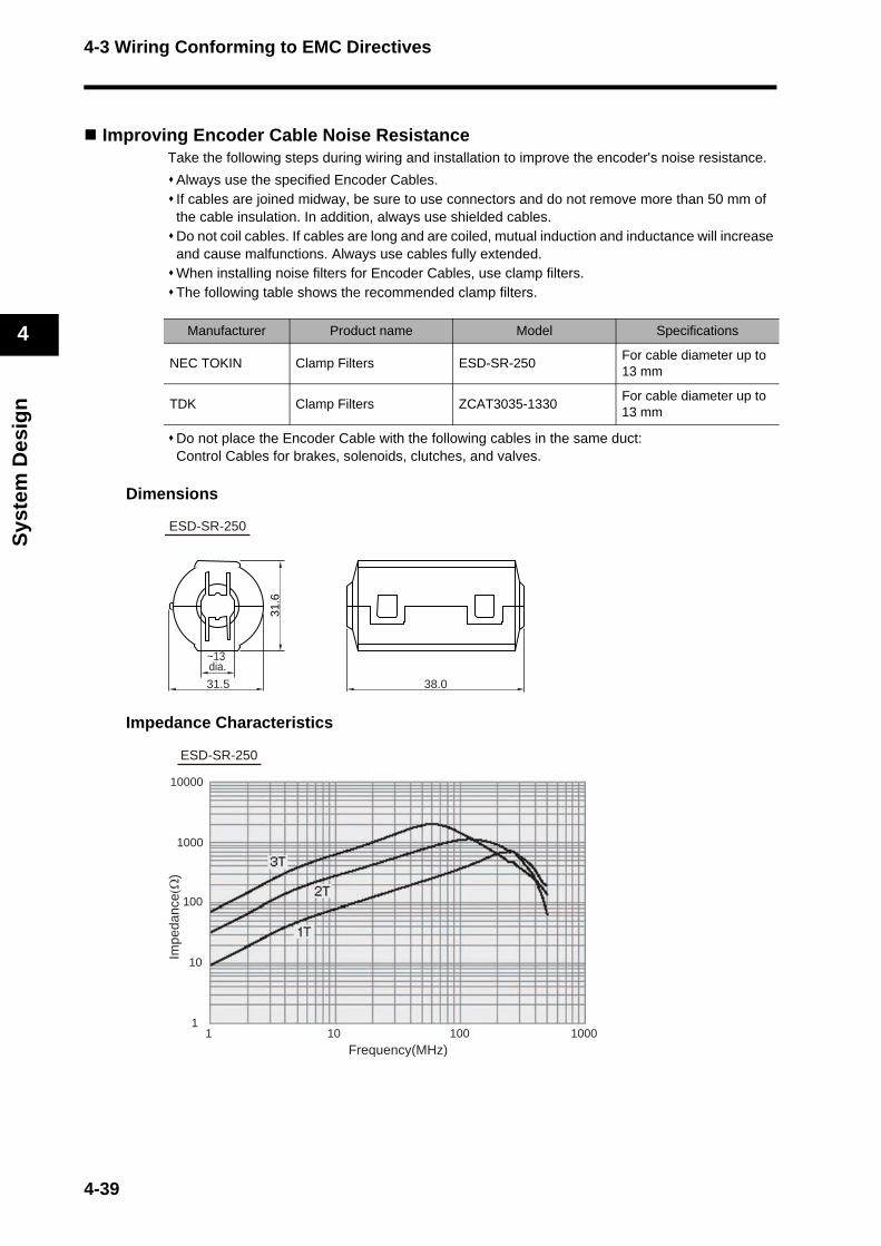
4-3 Wiring Conforming to EMC Directives
Sys
tem
Des
ign
4
Improving Encoder Cable Noise ResistanceTake the following steps during wiring and installation to improve the encoder's noise resistance.
Always use the specified Encoder Cables.If cables are joined midway, be sure to use connectors and do not remove more than 50 mm of the cable insulation. In addition, always use shielded cables.Do not coil cables. If cables are long and are coiled, mutual induction and inductance will increase and cause malfunctions. Always use cables fully extended.When installing noise filters for Encoder Cables, use clamp filters.The following table shows the recommended clamp filters.
Do not place the Encoder Cable with the following cables in the same duct:Control Cables for brakes, solenoids, clutches, and valves.
Dimensions
Impedance Characteristics
Manufacturer Product name Model Specifications
NEC TOKIN Clamp Filters ESD-SR-250For cable diameter up to 13 mm
TDK Clamp Filters ZCAT3035-1330For cable diameter up to 13 mm
31.5
~13 dia.
31.6
38.0
ESD-SR-250
10000
1000
100
10
1
Impe
danc
e(Ω
)
10 100Frequency(MHz)
1 1000
ESD-SR-250
4-39
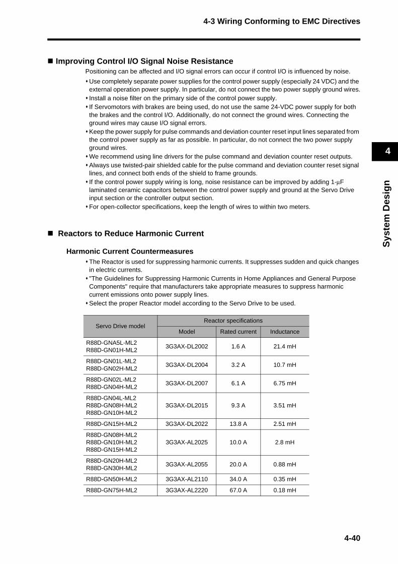
4-3 Wiring Conforming to EMC Directives
Sys
tem
Des
ign
4
Improving Control I/O Signal Noise ResistancePositioning can be affected and I/O signal errors can occur if control I/O is influenced by noise.
Use completely separate power supplies for the control power supply (especially 24 VDC) and the external operation power supply. In particular, do not connect the two power supply ground wires.Install a noise filter on the primary side of the control power supply.If Servomotors with brakes are being used, do not use the same 24-VDC power supply for both the brakes and the control I/O. Additionally, do not connect the ground wires. Connecting the ground wires may cause I/O signal errors.Keep the power supply for pulse commands and deviation counter reset input lines separated from the control power supply as far as possible. In particular, do not connect the two power supply ground wires.We recommend using line drivers for the pulse command and deviation counter reset outputs.Always use twisted-pair shielded cable for the pulse command and deviation counter reset signal lines, and connect both ends of the shield to frame grounds.If the control power supply wiring is long, noise resistance can be improved by adding 1-μF laminated ceramic capacitors between the control power supply and ground at the Servo Drive input section or the controller output section.For open-collector specifications, keep the length of wires to within two meters.
Reactors to Reduce Harmonic Current
Harmonic Current CountermeasuresThe Reactor is used for suppressing harmonic currents. It suppresses sudden and quick changes in electric currents."The Guidelines for Suppressing Harmonic Currents in Home Appliances and General Purpose Components" require that manufacturers take appropriate measures to suppress harmonic current emissions onto power supply lines. Select the proper Reactor model according to the Servo Drive to be used.
Servo Drive modelReactor specifications
Model Rated current Inductance
R88D-GNA5L-ML2R88D-GN01H-ML2
3G3AX-DL2002 1.6 A 21.4 mH
R88D-GN01L-ML2R88D-GN02H-ML2
3G3AX-DL2004 3.2 A 10.7 mH
R88D-GN02L-ML2R88D-GN04H-ML2
3G3AX-DL2007 6.1 A 6.75 mH
R88D-GN04L-ML2R88D-GN08H-ML2R88D-GN10H-ML2
3G3AX-DL2015 9.3 A 3.51 mH
R88D-GN15H-ML2 3G3AX-DL2022 13.8 A 2.51 mH
R88D-GN08H-ML2R88D-GN10H-ML2R88D-GN15H-ML2
3G3AX-AL2025 10.0 A 2.8 mH
R88D-GN20H-ML2R88D-GN30H-ML2
3G3AX-AL2055 20.0 A 0.88 mH
R88D-GN50H-ML2 3G3AX-AL2110 34.0 A 0.35 mH
R88D-GN75H-ML2 3G3AX-AL2220 67.0 A 0.18 mH
4-40

4-3 Wiring Conforming to EMC Directives
Sys
tem
Des
ign
4
Selecting Other Parts for Noise ResistanceThis section explains the criteria for selecting other connection components required to improve noise resistance.Understand each component's characteristics, such as its capacity, performance, and applicable conditions when selecting the components.For more details, contact the manufacturers directly.
Noise Filters for the Power Supply InputUse a noise filter to attenuate external noise and reduce noise emitted from the Servo Drive.Select a noise filter with a rated current that is at least two times greater than the effective load current (the rated current of the main circuit power supply input given in Main Circuit and Servomotor Connector Specifications on page 4-20).
Note 1. To attenuate noise at low frequencies below 200 kHz, use an isolation transformer and a noise filter.
Note 2. To attenuate noise at high frequencies over 30 MHz, use a ferrite core and a high-frequency noise filter with a feed-through capacitor.
Note 3. If multiple Servo Drives are connected to a single noise filter, select a noise filter with a rated current at least two times the total rated current of all the Servo Drives.
Manufacturer Model Rated current
Applicable standards Remarks
NEC TOKIN
GT-2050 5 A
UL, CSA, VDE, TÜVSingle-phase
GT-2100 10 A
GT-2150 15 A
GT-2150 20 A
HFP-2153 15 AUL, CSA, TÜV
Three-phaseHFP-2303 30 A
Okaya Electric Industries Co., Ltd.
SUP-EK10-ER-6 10 A
UL, cUL, TÜVSingle-phase
SUP-EK15-ER-6 15 A
SUP-EK20-ER-6 20 A
SUP-EK30-ER-6 30 A
3SUP-HL10-ER-6 10 A
UL, TÜVThree-phase
3SUP-HL15-ER-6 15 A
3SUP-HL30-ER-6 30 A
3SUP-HL75-ER-6 75 A
3SUP-HL100-ER-6 100 A
TDK
ZRCS2006-00S 6 A
UL, CSA, NEMKOSingle-phase
ZRCS2010-00S 10 A
ZRCS2020-00S 20 A
ZRCS2030-00S 30 A
ZRCT5050-MF 50 A
UL, CSA, NEMKOThree-phase
ZRCT5080-MF 80 A
ZRCT5100-MF 100 A
4-41
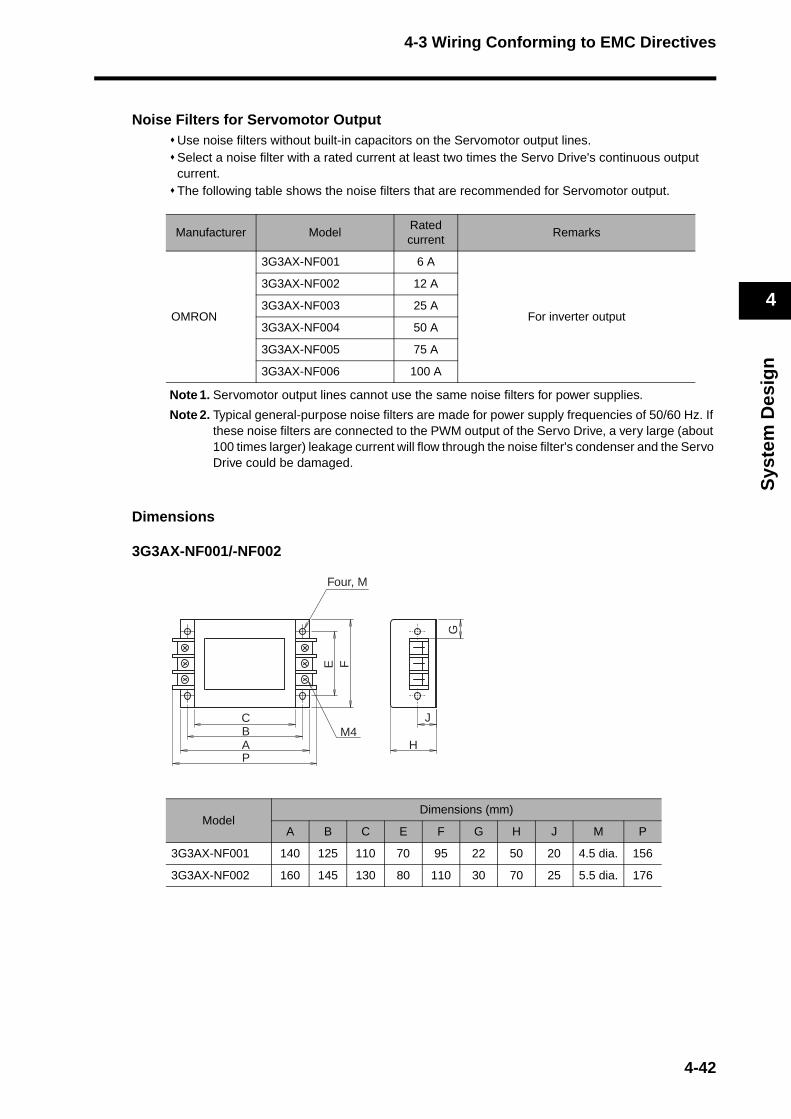
4-3 Wiring Conforming to EMC Directives
Sys
tem
Des
ign
4
Noise Filters for Servomotor OutputUse noise filters without built-in capacitors on the Servomotor output lines.Select a noise filter with a rated current at least two times the Servo Drive's continuous output current.The following table shows the noise filters that are recommended for Servomotor output.
Note 1. Servomotor output lines cannot use the same noise filters for power supplies.
Note 2. Typical general-purpose noise filters are made for power supply frequencies of 50/60 Hz. If these noise filters are connected to the PWM output of the Servo Drive, a very large (about 100 times larger) leakage current will flow through the noise filter's condenser and the Servo Drive could be damaged.
Dimensions
3G3AX-NF001/-NF002
Manufacturer Model Rated current
Remarks
OMRON
3G3AX-NF001 6 A
For inverter output
3G3AX-NF002 12 A
3G3AX-NF003 25 A
3G3AX-NF004 50 A
3G3AX-NF005 75 A
3G3AX-NF006 100 A
Model Dimensions (mm)
A B C E F G H J M P
3G3AX-NF001 140 125 110 70 95 22 50 20 4.5 dia. 156
3G3AX-NF002 160 145 130 80 110 30 70 25 5.5 dia. 176
M4CBAP
E F
J
H
G
Four, M
4-42
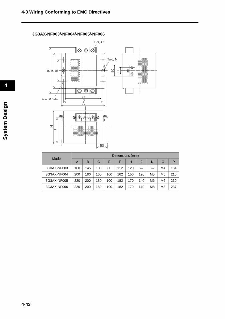
4-3 Wiring Conforming to EMC Directives
Sys
tem
Des
ign
4
3G3AX-NF003/-NF004/-NF005/-NF006
Model Dimensions (mm)
A B C E F H J N O P
3G3AX-NF003 160 145 130 80 112 120 --- --- M4 154
3G3AX-NF004 200 180 160 100 162 150 120 M5 M5 210
3G3AX-NF005 220 200 180 100 182 170 140 M6 M6 230
3G3AX-NF006 220 200 180 100 182 170 140 M8 M8 237
CBA
P F E
Six, O
Two, N
50 30
50
HJ
Four, 6.5 dia.
4-43
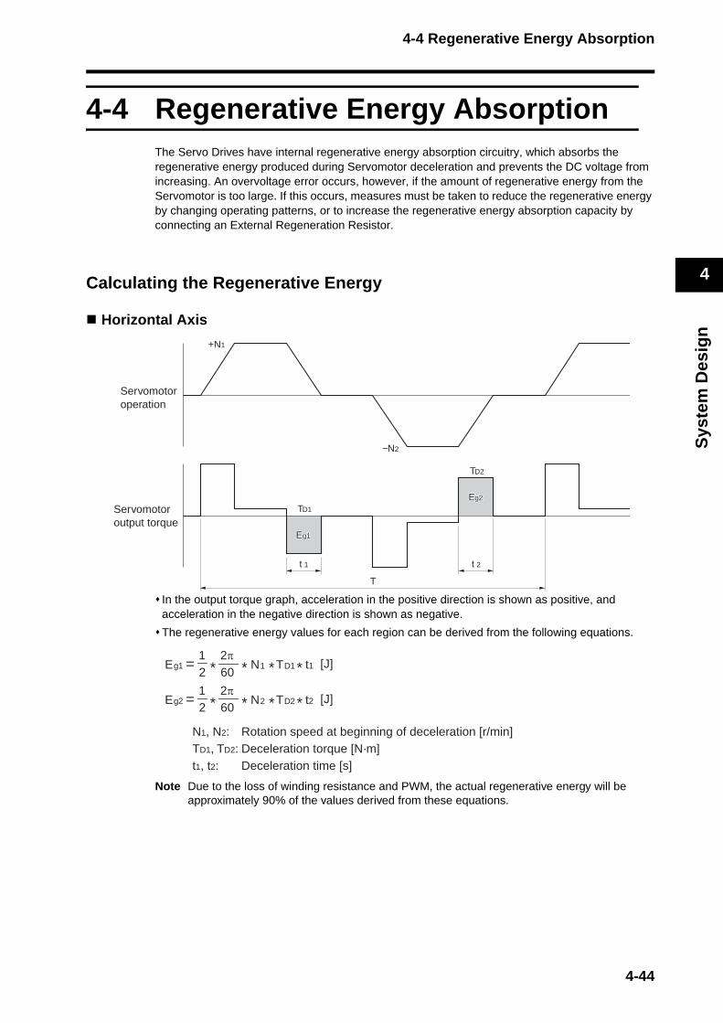
4-4 Regenerative Energy Absorption
Sys
tem
Des
ign
4
4-4 Regenerative Energy AbsorptionThe Servo Drives have internal regenerative energy absorption circuitry, which absorbs the regenerative energy produced during Servomotor deceleration and prevents the DC voltage from increasing. An overvoltage error occurs, however, if the amount of regenerative energy from the Servomotor is too large. If this occurs, measures must be taken to reduce the regenerative energy by changing operating patterns, or to increase the regenerative energy absorption capacity by connecting an External Regeneration Resistor.
Calculating the Regenerative Energy
Horizontal Axis
In the output torque graph, acceleration in the positive direction is shown as positive, and acceleration in the negative direction is shown as negative.
The regenerative energy values for each region can be derived from the following equations.
Note Due to the loss of winding resistance and PWM, the actual regenerative energy will be approximately 90% of the values derived from these equations.
+N1
−N2
TD1
TD2
t 1 t 2
T
Eg1g1Eg1
Eg2g2Eg2
Servomotoroperation
Servomotoroutput torque
1112π
21
t1TNE Dg =60* * * * [J]
2222π
21
t2TNE Dg =60* * * * [J]
N1, N2: Rotation speed at beginning of deceleration [r/min]TD1, TD2: Deceleration torque [N·m]t1, t2: Deceleration time [s]
4-44

4-4 Regenerative Energy Absorption
Sys
tem
Des
ign
4
For Servo Drive models with internal capacitors used for absorbing regenerative energy, the values for both Eg1 or Eg2 (unit: J) must be lower than the Servo Drive’s regenerative energy absorption capacity. (The capacity depends on the model. For details, refer to Servo Drive Regenerative Energy Absorption Capacity on page 4-47.)
For Servo Drive models with an internal regeneration resistor used for absorbing regenerative energy, the average amount of regeneration Pr (unit: W) must be calculated, and this value must be lower than the Servo Drive’s regenerative energy absorption capacity. (The capacity depends on the model. For details, refer to Servo Drive Regenerative Energy Absorption Capacity on page 4-47.)
The average regeneration power (Pr) is the regeneration power produced in one cycle of operation [W].
Pr = (Eg1 + Eg2) / T [W]
T: Operation cycle [s]
4-45
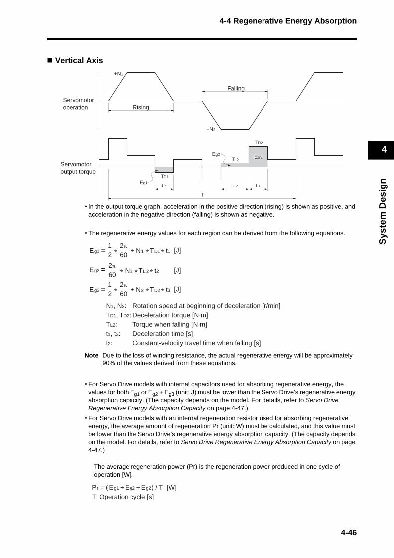
4-4 Regenerative Energy Absorption
Sys
tem
Des
ign
4
Vertical Axis
In the output torque graph, acceleration in the positive direction (rising) is shown as positive, and acceleration in the negative direction (falling) is shown as negative.
The regenerative energy values for each region can be derived from the following equations.
Note Due to the loss of winding resistance, the actual regenerative energy will be approximately 90% of the values derived from these equations.
For Servo Drive models with internal capacitors used for absorbing regenerative energy, the values for both Eg1 or Eg2 + Eg3 (unit: J) must be lower than the Servo Drive’s regenerative energy absorption capacity. (The capacity depends on the model. For details, refer to Servo Drive Regenerative Energy Absorption Capacity on page 4-47.)
For Servo Drive models with an internal regeneration resistor used for absorbing regenerative energy, the average amount of regeneration Pr (unit: W) must be calculated, and this value must be lower than the Servo Drive’s regenerative energy absorption capacity. (The capacity depends on the model. For details, refer to Servo Drive Regenerative Energy Absorption Capacity on page 4-47.)
The average regeneration power (Pr) is the regeneration power produced in one cycle of operation [W].
t 1 t 2 t 3
T
Eg1
Eg3g3Eg3
TD2
TL2
TD1
Eg2
Servomotoroperation
Servomotoroutput torque
Rising
Falling
+N1
−N2
1112π
21
t1TNE Dg =60* * * * [J]
2222π
t2TNE Lg =60 * * * [J]
222π
21
t3TNE Dg3 =60* * * * [J]
N1, N2: Rotation speed at beginning of deceleration [r/min]TD1, TD2: Deceleration torque [N·m]TL2: Torque when falling [N·m]t1, t3: Deceleration time [s]t2: Constant-velocity travel time when falling [s]
2Eg1Eg=Pr ( + ) / T [W]T: Operation cycle [s]
2Eg+
4-46
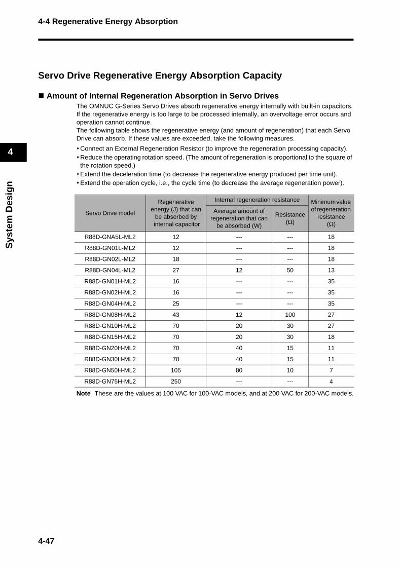
4-4 Regenerative Energy Absorption
Sys
tem
Des
ign
4
Servo Drive Regenerative Energy Absorption Capacity
Amount of Internal Regeneration Absorption in Servo DrivesThe OMNUC G-Series Servo Drives absorb regenerative energy internally with built-in capacitors.If the regenerative energy is too large to be processed internally, an overvoltage error occurs and operation cannot continue.The following table shows the regenerative energy (and amount of regeneration) that each Servo Drive can absorb. If these values are exceeded, take the following measures.
Connect an External Regeneration Resistor (to improve the regeneration processing capacity).Reduce the operating rotation speed. (The amount of regeneration is proportional to the square of the rotation speed.)Extend the deceleration time (to decrease the regenerative energy produced per time unit).Extend the operation cycle, i.e., the cycle time (to decrease the average regeneration power).
Note These are the values at 100 VAC for 100-VAC models, and at 200 VAC for 200-VAC models.
Servo Drive model
Regenerative energy (J) that can
be absorbed by internal capacitor
Internal regeneration resistance Minimum value of regeneration
resistance(Ω)
Average amount of regeneration that can
be absorbed (W)
Resistance(Ω)
R88D-GNA5L-ML2 12 --- --- 18
R88D-GN01L-ML2 12 --- --- 18
R88D-GN02L-ML2 18 --- --- 18
R88D-GN04L-ML2 27 12 50 13
R88D-GN01H-ML2 16 --- --- 35
R88D-GN02H-ML2 16 --- --- 35
R88D-GN04H-ML2 25 --- --- 35
R88D-GN08H-ML2 43 12 100 27
R88D-GN10H-ML2 70 20 30 27
R88D-GN15H-ML2 70 20 30 18
R88D-GN20H-ML2 70 40 15 11
R88D-GN30H-ML2 70 40 15 11
R88D-GN50H-ML2 105 80 10 7
R88D-GN75H-ML2 250 --- --- 4
4-47

4-4 Regenerative Energy Absorption
Sys
tem
Des
ign
4
Absorbing Regenerative Energy with an External Regeneration Resistor
If the regenerative energy exceeds the absorption capacity of the Servo Drive, connect an External Regeneration Resistor.Connect the External Regeneration Resistor between B1 and B2 terminals on the Servo Drive.Double-check the terminal names when connecting the resistor because the Servo Drive may be damaged by burning if connected to the wrong terminals.The External Regeneration Resistor will heat up to approximately 120°C. Do not place it near equipment and wiring that is easily affected by heat. Attach radiator plates suitable for the heat radiation conditions.
External Regeneration Resistor
Performance Specifications
Model ResistanceNominal capacity
Regeneration ab-sorption at 120°C
Heat radiation condition
Thermal switch output specifications
R88A-RR08050S 50 Ω 80 W 20 WAluminum, 250 × 250,
Thickness: 3.0
Operating tempera-ture: 150°C ±5% NC contactRated output: 30 VDC, 50 mA max.
R88A-RR080100S 100 Ω 80 W 20 WAluminum, 250 × 250,
Thickness: 3.0
Operating tempera-ture: 150°C ±5% NC contactRated output: 30 VDC, 50 mA max.
R88A-RR22047S 47 Ω 220 W 70 WAluminum, 350 × 350,
Thickness: 3.0
Operating tempera-ture: 170°C ±7°CNC contactRated output: 250 VAC, 0.2 A max.
R88A-RR50020S 20 Ω 500 W 180 WAluminum, 600 × 600,
Thickness: 3.0
Operating tempera-ture: 200°C ±7°CNC contactRated output: 250 VAC, 0.2 A max.24 VDC, 0.2 A max.
4-48
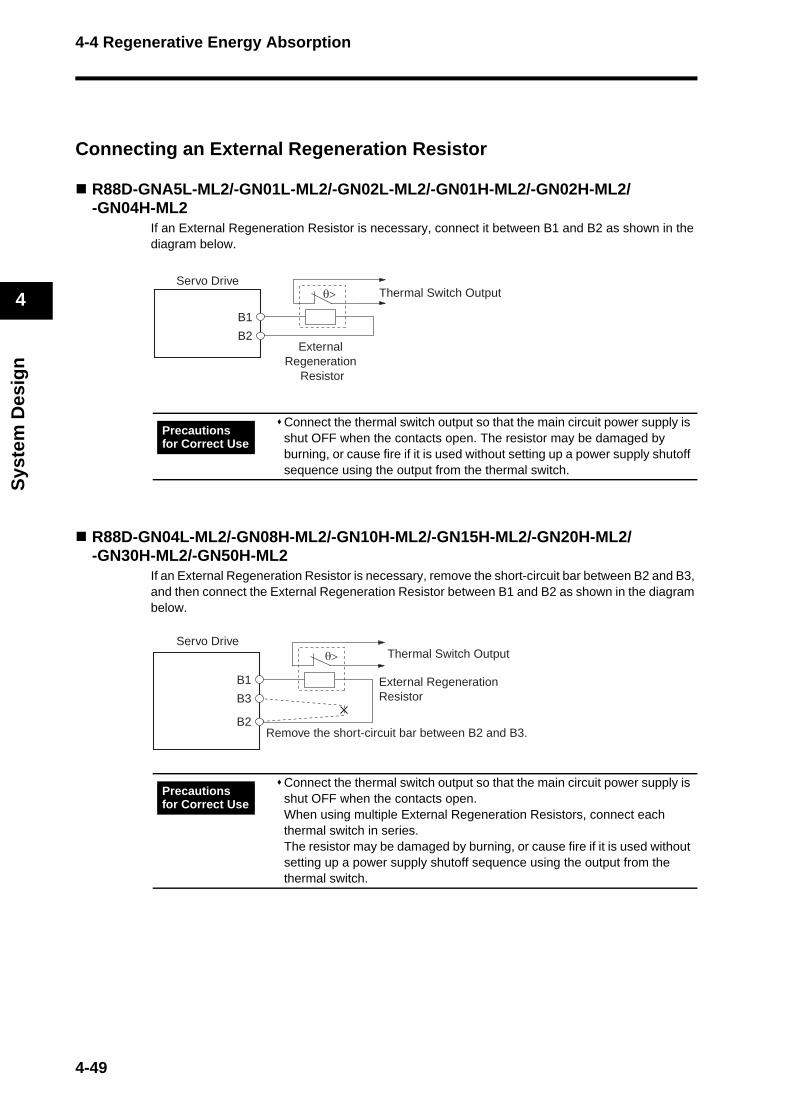
4-4 Regenerative Energy Absorption
Sys
tem
Des
ign
4
Connecting an External Regeneration Resistor
R88D-GNA5L-ML2/-GN01L-ML2/-GN02L-ML2/-GN01H-ML2/-GN02H-ML2/-GN04H-ML2
If an External Regeneration Resistor is necessary, connect it between B1 and B2 as shown in the diagram below.
R88D-GN04L-ML2/-GN08H-ML2/-GN10H-ML2/-GN15H-ML2/-GN20H-ML2/-GN30H-ML2/-GN50H-ML2
If an External Regeneration Resistor is necessary, remove the short-circuit bar between B2 and B3, and then connect the External Regeneration Resistor between B1 and B2 as shown in the diagram below.
Connect the thermal switch output so that the main circuit power supply is shut OFF when the contacts open. The resistor may be damaged by burning, or cause fire if it is used without setting up a power supply shutoff sequence using the output from the thermal switch.
Connect the thermal switch output so that the main circuit power supply is shut OFF when the contacts open.When using multiple External Regeneration Resistors, connect each thermal switch in series. The resistor may be damaged by burning, or cause fire if it is used without setting up a power supply shutoff sequence using the output from the thermal switch.
Servo Drive
B1
B2External
Regeneration Resistor
θ> Thermal Switch Output
Precautions for Correct Use
B1
B3
Remove the short-circuit bar between B2 and B3.B2
Servo Drive
External Regeneration Resistor
θ> Thermal Switch Output
Precautions for Correct Use
4-49

4-4 Regenerative Energy Absorption
Sys
tem
Des
ign
4
R88D-GN75H-ML2If an External Regeneration Resistor is necessary, connect it between B1 and B2 as shown in the diagram below.
Connect the thermal switch output so that the main circuit power supply is shut OFF when the contacts open.When using multiple External Regeneration Resistors, connect each thermal switch in series. The resistor may be damaged by burning, or cause fire if it is used without setting up a power supply shutoff sequence using the output from the thermal switch.
Servo Drive
B1
B2External
Regeneration Resistor
θ> Thermal Switch Output
Precautions for Correct Use
4-50
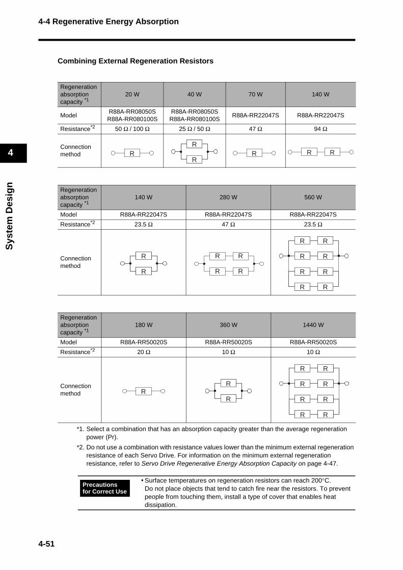
4-4 Regenerative Energy Absorption
Sys
tem
Des
ign
4
Combining External Regeneration Resistors
*1. Select a combination that has an absorption capacity greater than the average regeneration power (Pr).
*2. Do not use a combination with resistance values lower than the minimum external regeneration resistance of each Servo Drive. For information on the minimum external regeneration resistance, refer to Servo Drive Regenerative Energy Absorption Capacity on page 4-47.
Regeneration absorption capacity *1
20 W 40 W 70 W 140 W
Model R88A-RR08050S
R88A-RR080100SR88A-RR08050S
R88A-RR080100SR88A-RR22047S R88A-RR22047S
Resistance*2 50 Ω / 100 Ω 25 Ω / 50 Ω 47 Ω 94 Ω
Connection method
Regeneration absorption capacity *1
140 W 280 W 560 W
Model R88A-RR22047S R88A-RR22047S R88A-RR22047S
Resistance*2 23.5 Ω 47 Ω 23.5 Ω
Connection method
Regeneration absorption capacity *1
180 W 360 W 1440 W
Model R88A-RR50020S R88A-RR50020S R88A-RR50020S
Resistance*2 20 Ω 10 Ω 10 Ω
Connection method
Surface temperatures on regeneration resistors can reach 200°C. Do not place objects that tend to catch fire near the resistors. To prevent people from touching them, install a type of cover that enables heat dissipation.
RR
R
R
RR R R
R
R
R
R
R R
R R R R
R R
R R
R R
R R
R R
R R
R R
RR
R
R
R R R
R R
R R
R R
R R
R R
R R
R R
Precautions for Correct Use
4-51
Chapter 5
Operating Functions5-1 Position Control .................................................. 5-1
5-2 Speed Control .................................................... 5-4
5-3 Torque Control ................................................... 5-7
5-4 Forward and Reverse Drive Prohibit .................. 5-10
5-5 Brake Interlock ................................................... 5-11
5-6 Torque Limit ....................................................... 5-16
5-7 Soft Start ............................................................ 5-18
5-8 Acceleration/Deceleration Time Settings ........... 5-19
5-9 Moving Average Time ........................................ 5-20
5-10 Electronic Gear .................................................. 5-21
5-11 Speed Limit ........................................................ 5-22
5-12 Sequence Input Signals ..................................... 5-23
5-13 Sequence Output Signals .................................. 5-25
5-14 Backlash Compensation .................................... 5-27
5-15 Overrun Protection ............................................. 5-29
5-16 Gain Switching ................................................... 5-31
5-17 Speed Feed-forward .......................................... 5-38
5-18 Torque Feed-forward ......................................... 5-39
5-19 Speed Feedback Filter Selection ....................... 5-40
5-20 P Control Switching............................................ 5-41
5-21 Torque Command Filter Time Constant ............. 5-42
5-22 Notch Filter......................................................... 5-43
5-23 Adaptive Filter .................................................... 5-45
5-24 Instantaneous Speed Observer ......................... 5-48
5-25 Damping Control ................................................ 5-50
5-26 User Parameters ................................................ 5-55Setting and Checking Parameters ........................................5-55
Parameter Tables .................................................................5-61
5-27 Details on Important Parameters ....................... 5-86
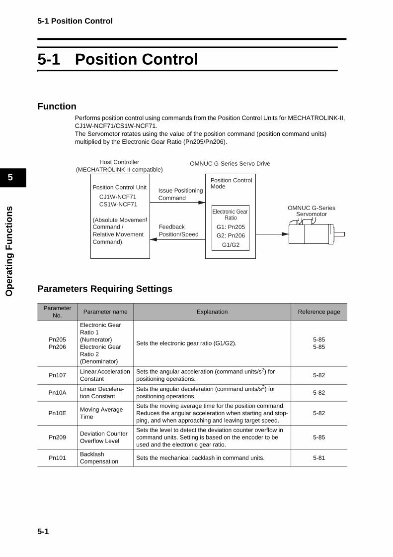
5-1 Position Control
Op
erat
ing
Fu
nct
ion
s
5
5-1 Position Control
FunctionPerforms position control using commands from the Position Control Units for MECHATROLINK-II, CJ1W-NCF71/CS1W-NCF71. The Servomotor rotates using the value of the position command (position command units) multiplied by the Electronic Gear Ratio (Pn205/Pn206).
Parameters Requiring Settings
ParameterNo.
Parameter name Explanation Reference page
Pn205Pn206
Electronic Gear Ratio 1(Numerator)Electronic Gear Ratio 2(Denominator)
Sets the electronic gear ratio (G1/G2). 5-855-85
Pn107Linear Acceleration Constant
Sets the angular acceleration (command units/s2) for positioning operations.
5-82
Pn10ALinear Decelera-tion Constant
Sets the angular deceleration (command units/s2) for positioning operations.
5-82
Pn10EMoving Average Time
Sets the moving average time for the position command. Reduces the angular acceleration when starting and stop-ping, and when approaching and leaving target speed.
5-82
Pn209Deviation Counter Overflow Level
Sets the level to detect the deviation counter overflow in command units. Setting is based on the encoder to be used and the electronic gear ratio.
5-85
Pn101BacklashCompensation
Sets the mechanical backlash in command units. 5-81
OMNUC G-Series Servo Drive
OMNUC G-SeriesServomotor
Host Controller(MECHATROLINK-II compatible)
Electronic Gear Ratio
G1: Pn205G2: Pn206
G1/G2
Position Control ModePosition Control Unit
CJ1W-NCF71CS1W-NCF71
(Absolute Movement Command /Relative MovementCommand)
FeedbackPosition/Speed
Issue Positioning Command
5-1
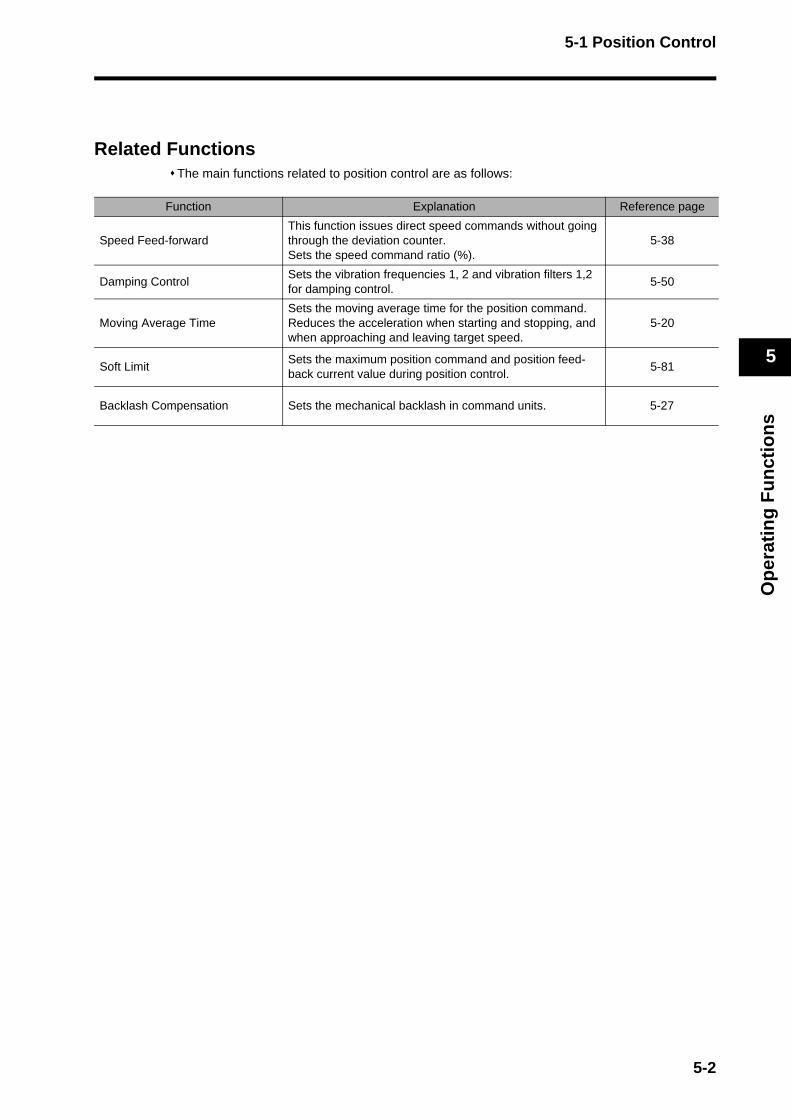
5-1 Position Control
Op
erat
ing
Fu
nct
ion
s
5
Related FunctionsThe main functions related to position control are as follows:
Function Explanation Reference page
Speed Feed-forward This function issues direct speed commands without going through the deviation counter.Sets the speed command ratio (%).
5-38
Damping ControlSets the vibration frequencies 1, 2 and vibration filters 1,2 for damping control.
5-50
Moving Average TimeSets the moving average time for the position command. Reduces the acceleration when starting and stopping, and when approaching and leaving target speed.
5-20
Soft LimitSets the maximum position command and position feed-back current value during position control.
5-81
Backlash Compensation Sets the mechanical backlash in command units. 5-27
5-2
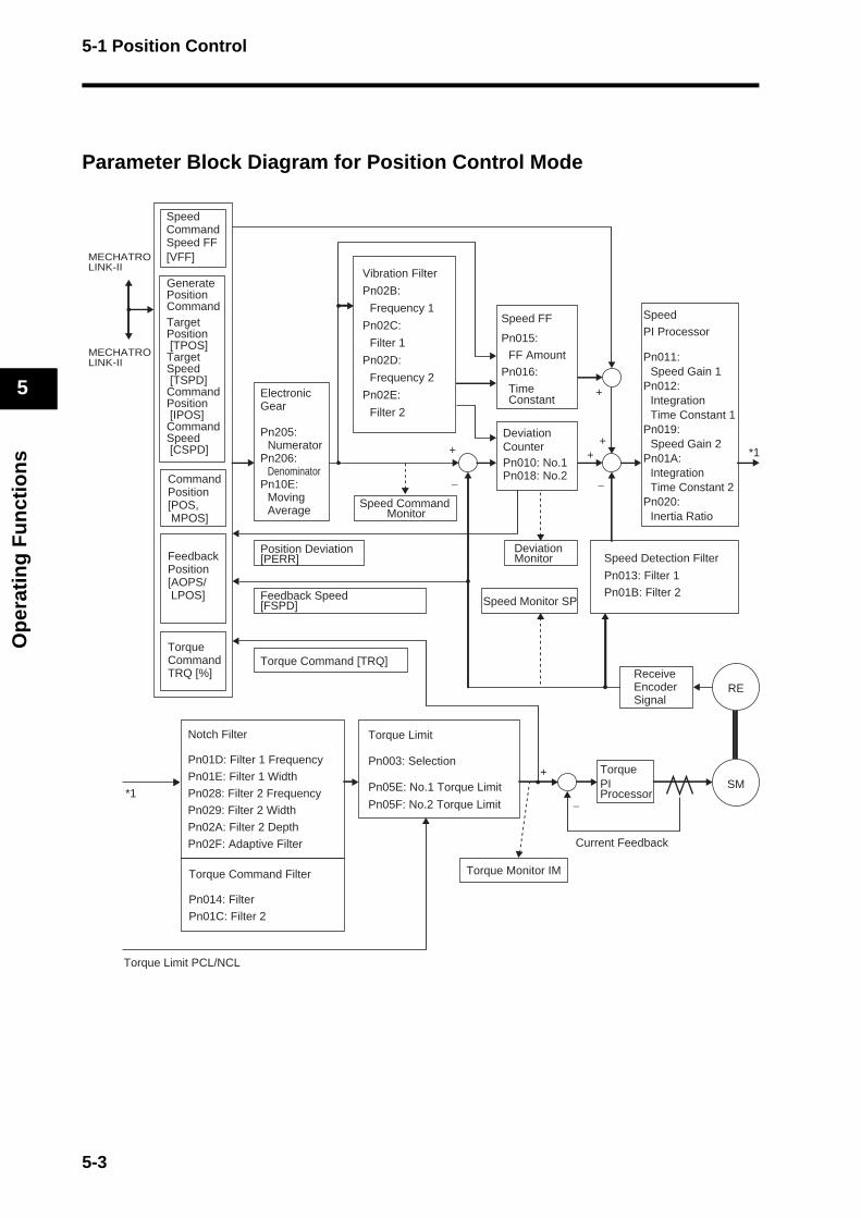
5-1 Position Control
Op
erat
ing
Fu
nct
ion
s
5
Parameter Block Diagram for Position Control Mode
Vibration Filter
Pn02B:
Frequency 1
Pn02C:
Filter 1
Pn02D:
Frequency 2
Pn02E:
Filter 2
Speed Command Monitor
Position Deviation[PERR]
Speed Monitor SP
Deviation Monitor
Torque Monitor IM
Speed
PI Processor
Pn011: Speed Gain 1
Pn012:Integration Time Constant 1
Pn019:Speed Gain 2
Pn01A:Integration Time Constant 2
Pn020:Inertia Ratio
Speed Detection Filter
Pn013: Filter 1
Pn01B: Filter 2
Torque Limit PCL/NCL
TorquePI Processor
Current Feedback
*1
SM
REReceive Encoder Signal
+
−
++
+
+
−−
ElectronicGear
Pn205:Numerator
Pn206:Denominator
Pn10E:Moving Average
Speed FF
Pn015:
FF Amount
Pn016:
Time Constant
Deviation CounterPn010: No.1Pn018: No.2
Notch Filter
Pn01D: Filter 1 Frequency
Pn01E: Filter 1 Width
Pn028: Filter 2 Frequency
Pn029: Filter 2 Width
Pn02A: Filter 2 Depth
Pn02F: Adaptive Filter
Torque Command Filter
Pn014: Filter
Pn01C: Filter 2
Torque Limit
Pn003: Selection
Pn05E: No.1 Torque Limit
Pn05F: No.2 Torque Limit*1
Generate Position CommandTarget Position [TPOS]Target Speed [TSPD]Command Position [IPOS]Command Speed [CSPD]
Command Position[POS, MPOS]
SpeedCommandSpeed FF[VFF]
Torque CommandTRQ [%]
FeedbackPosition[AOPS/ LPOS]
MECHATROLINK-II
MECHATROLINK-II
Feedback Speed[FSPD]
Torque Command [TRQ]
5-3
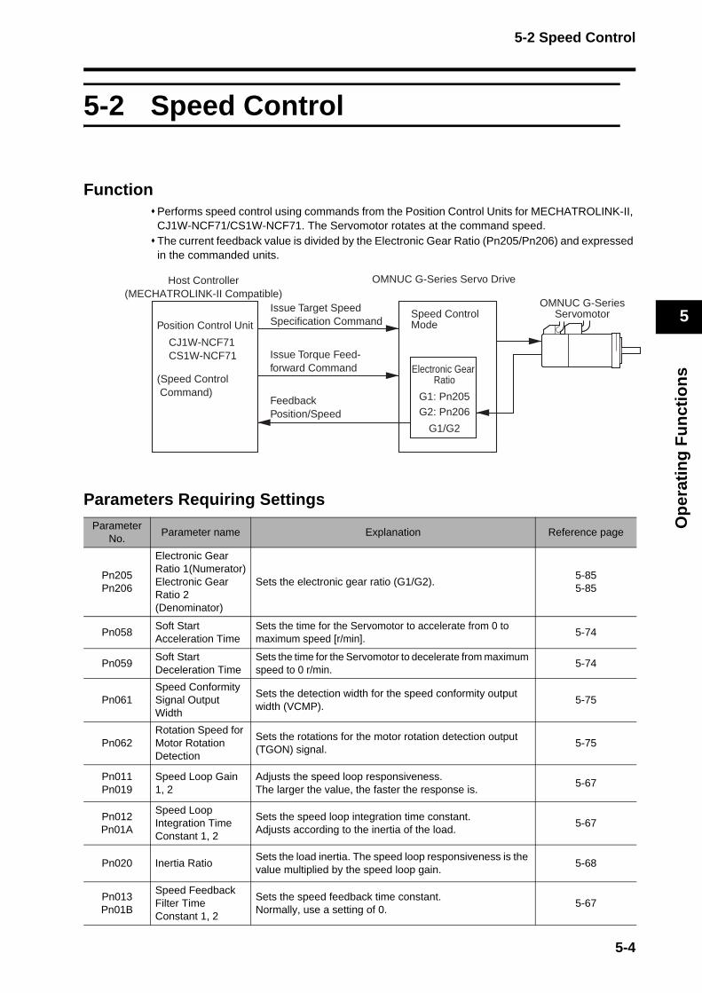
5-2 Speed Control
Op
erat
ing
Fu
nct
ion
s
5
5-2 Speed Control
FunctionPerforms speed control using commands from the Position Control Units for MECHATROLINK-II, CJ1W-NCF71/CS1W-NCF71. The Servomotor rotates at the command speed. The current feedback value is divided by the Electronic Gear Ratio (Pn205/Pn206) and expressed in the commanded units.
Parameters Requiring SettingsParameter
No.Parameter name Explanation Reference page
Pn205Pn206
Electronic Gear Ratio 1(Numerator)Electronic Gear Ratio 2(Denominator)
Sets the electronic gear ratio (G1/G2). 5-855-85
Pn058Soft StartAcceleration Time
Sets the time for the Servomotor to accelerate from 0 to maximum speed [r/min].
5-74
Pn059Soft StartDeceleration Time
Sets the time for the Servomotor to decelerate from maximum speed to 0 r/min.
5-74
Pn061Speed Conformity Signal Output Width
Sets the detection width for the speed conformity output width (VCMP).
5-75
Pn062Rotation Speed for Motor Rotation Detection
Sets the rotations for the motor rotation detection output (TGON) signal.
5-75
Pn011Pn019
Speed Loop Gain 1, 2
Adjusts the speed loop responsiveness.The larger the value, the faster the response is.
5-67
Pn012Pn01A
Speed Loop Integration Time Constant 1, 2
Sets the speed loop integration time constant.Adjusts according to the inertia of the load.
5-67
Pn020 Inertia RatioSets the load inertia. The speed loop responsiveness is the value multiplied by the speed loop gain.
5-68
Pn013Pn01B
Speed Feedback Filter Time Constant 1, 2
Sets the speed feedback time constant.Normally, use a setting of 0.
5-67
Host Controller(MECHATROLINK-II Compatible)
Position Control Unit
CJ1W-NCF71CS1W-NCF71
(Speed Control Command)
Speed Control Mode
OMNUC G-Series Servo Drive
Electronic Gear Ratio
G1: Pn205G2: Pn206
G1/G2
FeedbackPosition/Speed
Issue Target Speed Specification Command
Issue Torque Feed-forward Command
OMNUC G-SeriesServomotor
5-4
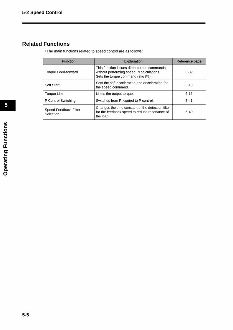
5-2 Speed Control
Op
erat
ing
Fu
nct
ion
s
5
Related FunctionsThe main functions related to speed control are as follows:
Function Explanation Reference page
Torque Feed-forwardThis function issues direct torque commands without performing speed PI calculations. Sets the torque command ratio (%).
5-39
Soft StartSets the soft acceleration and deceleration for the speed command.
5-18
Torque Limit Limits the output torque. 5-16
P Control Switching Switches from PI control to P control. 5-41
Speed Feedback Filter Selection
Changes the time constant of the detection filter for the feedback speed to reduce resonance of the load.
5-40
5-5
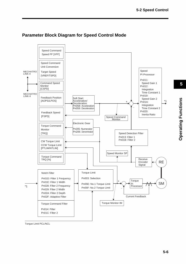
5-2 Speed Control
Op
erat
ing
Fu
nct
ion
s
5
Parameter Block Diagram for Speed Control Mode
*1
SM
RE
+
−
+
−
Soft StartAcceleration/DecelerationPn058: AccelerationPn059: Deceleration
*1
Target Speed
[VREF/TSPD]
Speed Command
Unit Conversion
CW Torque Limit
CCW Torque Limit[PTLIM/NTLIM]
Torque Command
Monitor
[TRQ]
Command Speed Monitor[CSPD]
Feedback Speed
[FSPD]
MECHATROLINK-II
MECHATROLINK-II
Speed Command
Speed FF [VFF]
Feedback Position[AOPS/LPOS]
Torque CommandTRQ [%]
Notch Filter
Pn01D: Filter 1 Frequency
Pn01E: Filter 1 Width
Pn028: Filter 2 Frequency
Pn029: Filter 2 Width
Pn02A: Filter 2 Depth
Pn02F: Adaptive Filter
Torque Command Filter
Pn014: Filter
Pn01C: Filter 2
Torque Limit PCL/NCL
Torque Limit
Pn003: Selection
Pn05E: No.1 Torque Limit
Pn05F: No.2 Torque Limit
Torque Monitor IM
Speed Monitor SP
TorquePI Processor
Current Feedback
Receive Encoder Signal
Speed Command Monitor
Speed Detection Filter
Pn013: Filter 1Pn01B: Filter 2
Electronic Gear
Pn205: NumeratorPn206: Denominator
Speed
PI Processor
Pn011: Speed Gain 1
Pn012:Integration Time Constant 1
Pn019:Speed Gain 2
Pn01A:Integration Time Constant 2
Pn020:Inertia Ratio
5-6

5-3 Torque Control
Op
erat
ing
Fu
nct
ion
s
5
5-3 Torque Control
FunctionPerforms torque control using commands from the Position Control Units for MECHATROLINK-II, CJ1W-NCF71/CS1W-NCF71. The Servomotor operates with the commanded torque output. The current feedback value is divided by the Electronic Gear Ratio (Pn205/Pn206) and expressed in the commanded units.
Parameters Requiring Settings
ParameterNo.
Parameter name Explanation Reference page
Pn205Pn206
Electronic Gear Ratio 1(Numerator)Electronic Gear Ratio 2(Denominator)
Sets the electronic gear ratio (G1/G2). 5-855-85
Pn053 Speed Limit Limits the speed during torque control. 5-74
Pn05BSpeed Limit Selection
Selects speed limit control from the network or through internal parameter Pn053.
5-74
Pn003Torque Limit Selection
Selects torque limit from the network or through parameter settings.
5-87
Pn05E No. 1 Torque Limit Sets the No. 1 Servomotor output torque limit. 5-75
Pn05F No. 2 Torque Limit Sets the No. 2 Servomotor output torque limit. 5-75
Pn01DNotch Filter 1 Frequency
Sets the notch filter 1 frequency for the torque command. 5-68
Pn028Notch Filter 2 Frequency
Sets the notch filter 2 frequency for the torque command. 5-71
Host Controller(MECHATROLINK-II Compatible)
Position Control Unit
CJ1W-NCF71CS1W-NCF71
(Torque Control Command)
OMNUC G-Series Servo Drive
OMNUC G-SeriesServomotor
Electronic Gear Ratio
G1: Pn205G2: Pn206
G1/G2
Torque Control Mode
FeedbackPosition/Speed
Issue Speed Limit Command
Issue Torque Specification Command
5-7
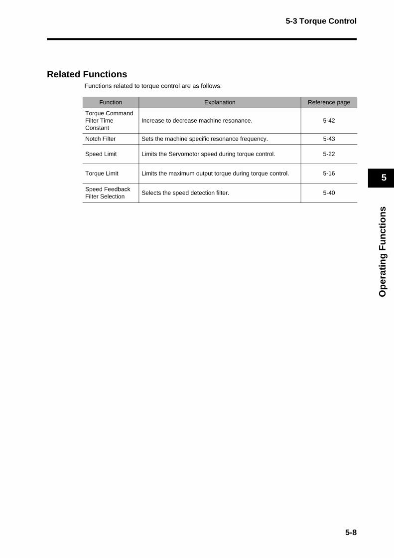
5-3 Torque Control
Op
erat
ing
Fu
nct
ion
s
5
Related FunctionsFunctions related to torque control are as follows:
Function Explanation Reference page
Torque Command Filter Time Constant
Increase to decrease machine resonance. 5-42
Notch Filter Sets the machine specific resonance frequency. 5-43
Speed Limit Limits the Servomotor speed during torque control. 5-22
Torque Limit Limits the maximum output torque during torque control. 5-16
Speed Feedback Filter Selection
Selects the speed detection filter. 5-40
5-8
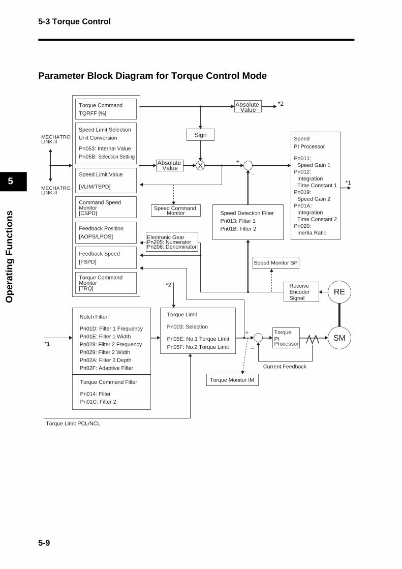
5-3 Torque Control
Op
erat
ing
Fu
nct
ion
s
5
Parameter Block Diagram for Torque Control Mode
Absolute Value
Sign
*1
SM
RE
+
−
+
−
*1
*2
*2
Pn053: Internal Value
Pn05B: Selection Setting
Speed Limit Value
[VLIM/TSPD]
Torque Command
TQRFF [%]
Torque Command Monitor[TRQ]
Command Speed Monitor[CSPD]
Feedback Position
[AOPS/LPOS]
Feedback Speed
[FSPD]
Absolute Value
X
MECHATROLINK-II
MECHATROLINK-II
Speed
PI Processor
Pn011: Speed Gain 1
Pn012:Integration Time Constant 1
Pn019:Speed Gain 2
Pn01A:Integration Time Constant 2
Pn020:Inertia Ratio
Speed Detection Filter
Pn013: Filter 1
Pn01B: Filter 2
Speed Command Monitor
Speed Monitor SP
Torque Monitor IM
TorquePI Processor
Receive Encoder Signal
Current Feedback
Torque Limit
Pn003: Selection
Pn05E: No.1 Torque Limit
Pn05F: No.2 Torque Limit
Torque Limit PCL/NCL
Notch Filter
Pn01D: Filter 1 Frequency
Pn01E: Filter 1 Width
Pn028: Filter 2 Frequency
Pn029: Filter 2 Width
Pn02A: Filter 2 Depth
Pn02F: Adaptive Filter
Torque Command Filter
Pn014: Filter
Pn01C: Filter 2
Electronic GearPn205: NumeratorPn206: Denominator
Speed Limit Selection
Unit Conversion
5-9

5-4 Forward and Reverse Drive Prohibit
Op
erat
ing
Fu
nct
ion
s
5
5-4 Forward and Reverse Drive Prohibit
FunctionThis function sets the Forward Drive Prohibit Input (POT) and Reverse Drive Prohibit Input (NOT) operation at the control I/O connector CN1 on the Servo Drive. You can stop the Servomotor from rotating beyond the machine's operating range with the drive prohibition inputs.
Parameters Requiring Settings
Operation[Stopping method when Pn004=0 and either POT or NOT turns OFF]
Drive Prohibit Input Error (alarm code 38) occurs when Pn004=0 and both Forward Drive Prohibit and Reverse Drive Prohibit inputs turn OFF. When Pn004=1, the inputs for both Forward Drive Prohibit and Reverse Drive Prohibit are disabled. Drive Prohibit Input Error (alarm code 38) occurs when Pn004=2, and either Forward Drive Prohibit input or Reverse Drive Prohibit input turns OFF. After stopping, a command in the direction of the drive prohibit input will cause a command warning.
ParameterNo.
Parameter name Explanation Reference page
Pn004Drive Prohibit Input Selection
Chooses whether to enable or disable this function when POT/NOT turns OFF.
5-88
Pn044Input Signal Selection
Sets the POT/NOT assignment. By default, CN1 pin 19 is set to POT, and CN1 pin 20 is set to NOT.
5-74
Pn066Stop Selection for Drive Prohibition Input
Sets the deceleration stopping method when POT/NOT turns OFF.
5-95
0
2
1
Stopped Status
Servo lock status
Deceleration Method
Decelerates with dynamic brake
Stop Selection for Drive Prohibition Input (Pn066)
POT (NOT) turns OFF. Use free-run to decelerate
Disables torque in drive prohibited
direction
Use Emergency Stop Torque (Pn06E) to decelerate.
5-10
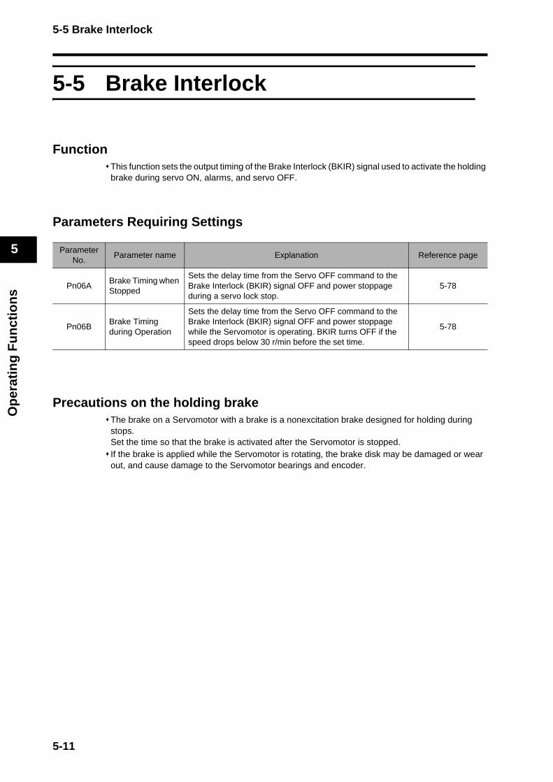
5-5 Brake Interlock
Op
erat
ing
Fu
nct
ion
s
5
5-5 Brake Interlock
FunctionThis function sets the output timing of the Brake Interlock (BKIR) signal used to activate the holding brake during servo ON, alarms, and servo OFF.
Parameters Requiring Settings
Precautions on the holding brakeThe brake on a Servomotor with a brake is a nonexcitation brake designed for holding during stops.Set the time so that the brake is activated after the Servomotor is stopped.If the brake is applied while the Servomotor is rotating, the brake disk may be damaged or wear out, and cause damage to the Servomotor bearings and encoder.
ParameterNo.
Parameter name Explanation Reference page
Pn06ABrake Timing when Stopped
Sets the delay time from the Servo OFF command to the Brake Interlock (BKIR) signal OFF and power stoppage during a servo lock stop.
5-78
Pn06BBrake Timing during Operation
Sets the delay time from the Servo OFF command to the Brake Interlock (BKIR) signal OFF and power stoppage while the Servomotor is operating. BKIR turns OFF if the speed drops below 30 r/min before the set time.
5-78
5-11
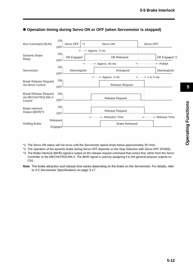
5-5 Brake Interlock
Op
erat
ing
Fu
nct
ion
s
5
Operation timing during Servo ON or OFF (when Servomotor is stopped)
*1. The Servo ON status will not occur until the Servomotor speed drops below approximately 30 r/min. *2. The operation of the dynamic brake during Servo OFF depends on the Stop Selection with Servo OFF (Pn069).*3. The Brake Interlock (BKIR) signal is output on the release request command that comes first, either from the Servo
Controller or the MECHATROLINK-II. The BKIR signal is used by assigning it to the general purpose outputs on CN1.
Note The brake attraction and release time varies depending on the brake on the Servomotor. For details, refer to 3-2 Servomotor Specifications on page 3-17.
Run Command (RUN)ON
OFF
Dynamic Brake Relay
ON
OFF
ServomotorON
OFF
Break Release Request via Servo Control
ON
OFF
Approx. 2 ms
Approx. 2 ms 1 to 5 ms
Approx. 40 ms
Brake InterlockOutput (BKIR)*3
Break Release Request via MECHATROLINK-II Control
ON
OFF
ON
OFF
Released
Engaged
Attraction Time Release Time
Servo OFF Servo OFFServo ON*1
DB Engaged DB Engaged *2DB Released
Energized
Release Request
Release Request
Release Request
Deenergized Deenergized
Pn06A
Holding Brake Brake Released
5-12

5-5 Brake Interlock
Op
erat
ing
Fu
nct
ion
s
5
Operation timing during Servo ON or OFF (when Servomotor is rotating)Regenerative energy occurs when the Servomotor is stopped on an alarm under this operation timing.For this reason, the operation cannot be repeated. Wait at least 10 minutes before the Servomotor cools down.
*1. The Servo ON status will not occur until the Servomotor speed drops below approximately 30 r/min. *2. The operation of the dynamic brake during Servo OFF depends on the Stop Selection with Servo OFF (Pn069).*3. The Brake Interlock (BKIR) signal is output on the release request command that comes first, either from the Servo
Controller or the MECHATROLINK-II. The BKIR signal is used by assigning it to the general purpose outputs on CN1. In the example above, a release request was not issued from the network.
*4. t1 is either the Brake Timing during Operation (Pn06B) setting or the time for the Servomotor speed to drop below approximately 30 r/min, whichever occurs first.
Note The Servomotor will not change to Servo ON until it stops even if the Servo ON input is turned ON while it is decelerating.
ON
OFF
ON
OFF
ON
OFF
ON
OFF
Approx. 2 ms Pn06B
*1
Brake Engaged
Brake Engaged
t1*4
Servomotor Rotation Speed
Servo ON Enabled
Approx. +30 r/minApprox. 30 r/min
Approx. 30 r/min
Approx. −30 r/min
Rotation Speed A
Rotation Speed B
BKIR
Run Command (RUN)
Dynamic Brake Relay
Servomotor
Approx. 2 ms
Approx. 40 ms
Brake InterlockOutput (BKIR)*3
Servo OFF Servo OFF
1 to 5 ms
Servo ON
DB Engaged DB Engaged *2DB Released
Energized
Release Request
Release Request
Deenergized Deenergized
5-13
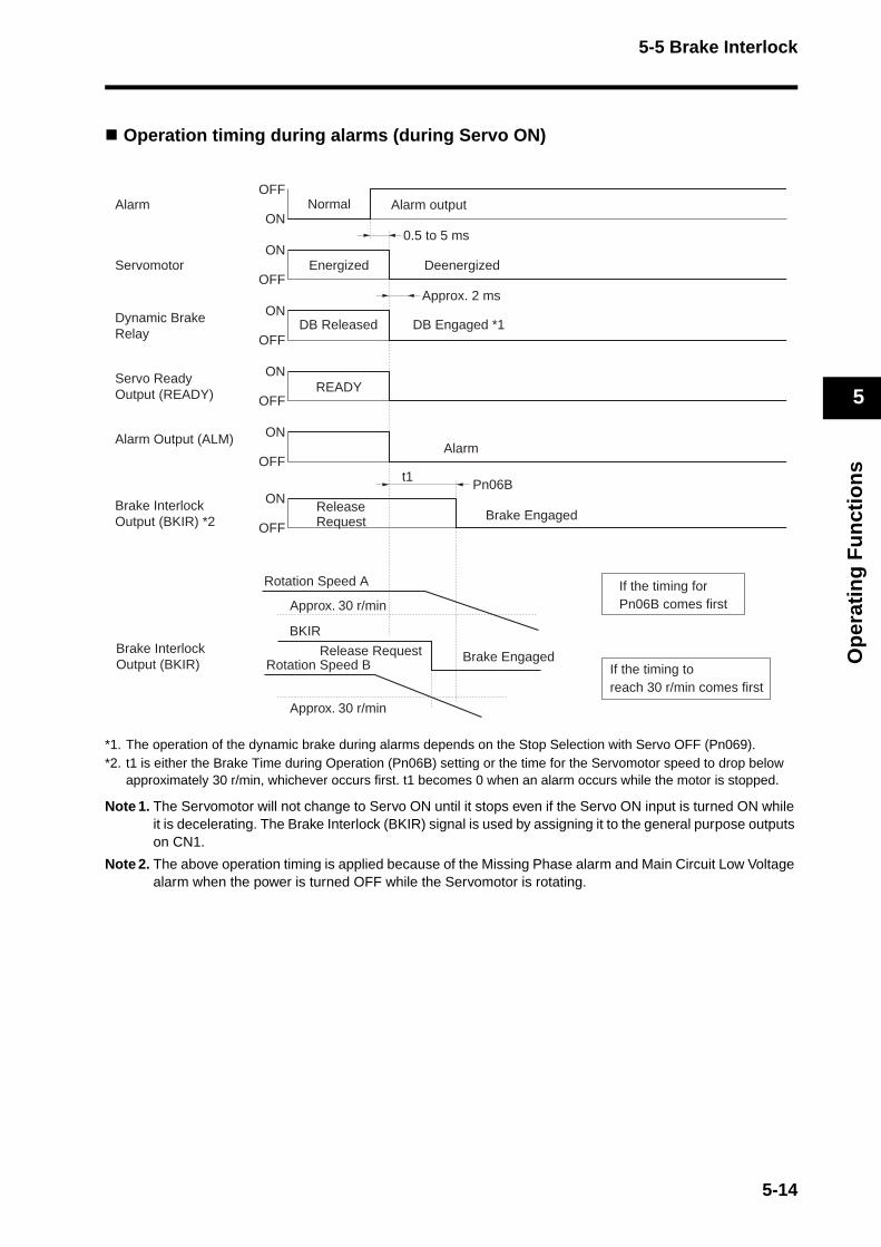
5-5 Brake Interlock
Op
erat
ing
Fu
nct
ion
s
5
Operation timing during alarms (during Servo ON)
*1. The operation of the dynamic brake during alarms depends on the Stop Selection with Servo OFF (Pn069).*2. t1 is either the Brake Time during Operation (Pn06B) setting or the time for the Servomotor speed to drop below
approximately 30 r/min, whichever occurs first. t1 becomes 0 when an alarm occurs while the motor is stopped.
Note 1. The Servomotor will not change to Servo ON until it stops even if the Servo ON input is turned ON while it is decelerating. The Brake Interlock (BKIR) signal is used by assigning it to the general purpose outputs on CN1.
Note 2. The above operation timing is applied because of the Missing Phase alarm and Main Circuit Low Voltage alarm when the power is turned OFF while the Servomotor is rotating.
AlarmOFF
ON0.5 to 5 ms
Approx. 2 ms
Servomotor
Dynamic Brake Relay
Brake InterlockOutput (BKIR) *2
Normal Alarm output
ON
OFFDeenergized
ON
OFF
ON
OFF
ON
OFF
ON
OFF
Energized
READYServo ReadyOutput (READY)
Alarm Output (ALM)Alarm
Pn06Bt1
Approx. 30 r/min
Approx. 30 r/min
BKIR
If the timing for Pn06B comes first
If the timing to reach 30 r/min comes first
Brake Engaged
Brake Engaged
Release Request
Release Request
Rotation Speed A
Rotation Speed BBrake InterlockOutput (BKIR)
DB Engaged *1DB Released
5-14
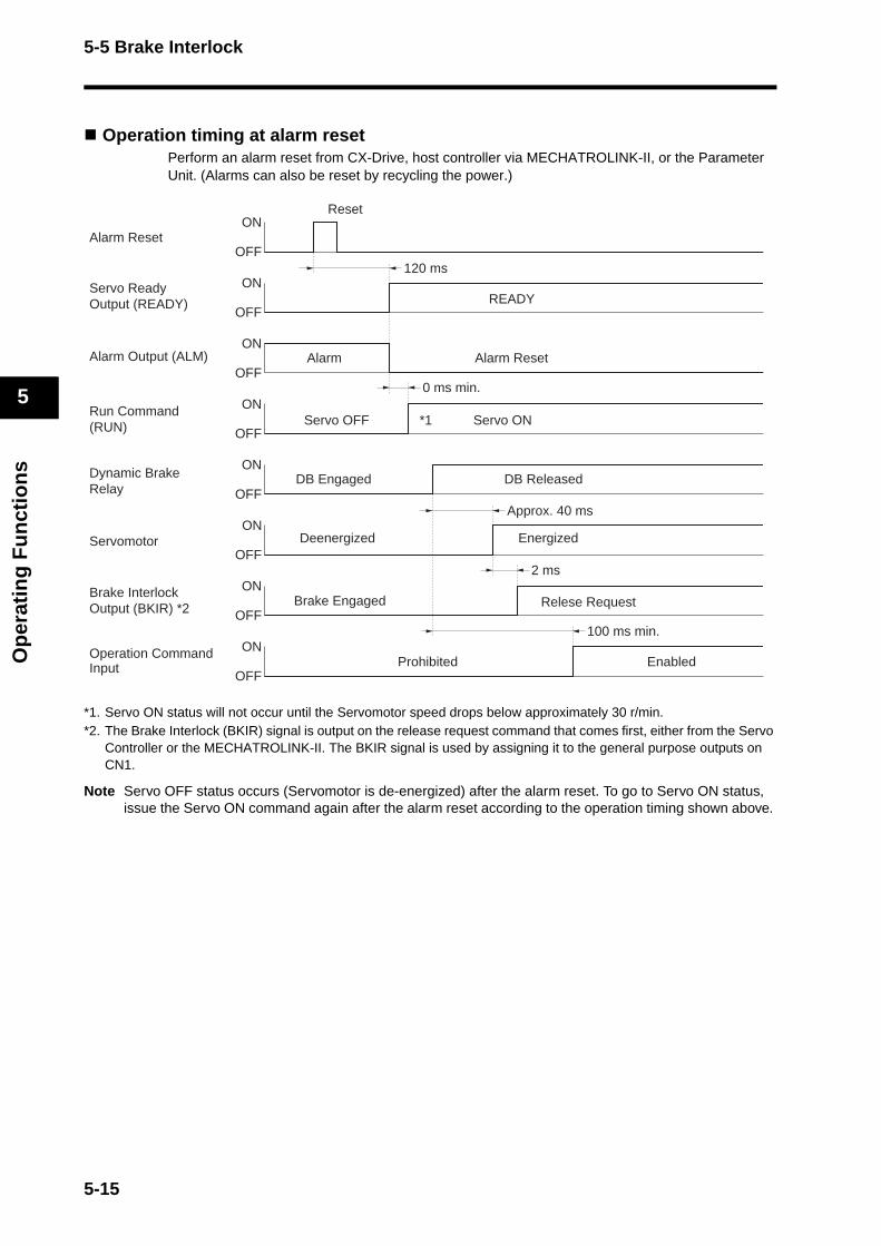
5-5 Brake Interlock
Op
erat
ing
Fu
nct
ion
s
5
Operation timing at alarm resetPerform an alarm reset from CX-Drive, host controller via MECHATROLINK-II, or the Parameter Unit. (Alarms can also be reset by recycling the power.)
*1. Servo ON status will not occur until the Servomotor speed drops below approximately 30 r/min. *2. The Brake Interlock (BKIR) signal is output on the release request command that comes first, either from the Servo
Controller or the MECHATROLINK-II. The BKIR signal is used by assigning it to the general purpose outputs on CN1.
Note Servo OFF status occurs (Servomotor is de-energized) after the alarm reset. To go to Servo ON status, issue the Servo ON command again after the alarm reset according to the operation timing shown above.
Alarm ResetON
OFF120 ms
Reset
OFF
ON
OFF
Run Command(RUN)
ON
OFF
ONREADY
ON
OFFApprox. 40 ms
OFF
ON
OFF
ON
OFF
ON
Operation Command Input
Servo OFF
Prohibited
Relese Request
Enabled
Servo ON*1
0 ms min.
2 ms
100 ms min.
Dynamic Brake Relay
Brake InterlockOutput (BKIR) *2
Servo ReadyOutput (READY)
Alarm Output (ALM) Alarm
Brake Engaged
DB Engaged DB Released
Alarm Reset
Servomotor Deenergized Energized
5-15

5-6 Torque Limit
Op
erat
ing
Fu
nct
ion
s
5
5-6 Torque Limit
FunctionThis function limits the torque output by the Servomotor. The function can be used for: · pressing in press machine applications· protecting a mechanical system by suppressing torque at start-up and decelerationThere are several methods to choose at the Torque Limit Selection (Pn003).
Parameters Requiring Settings
Torque limit settings for each ServomotorThe setting range for the torque limit is 0 to 300% and the standard default setting is 300% except for the following combinations of Servo Drives and Servomotors.
ParameterNo.
Parameter name Explanation Reference page
Pn003Torque Limit Selection
Selects the torque limit by various parameters and from the network.
5-87
Pn05E No. 1 Torque LimitSets the No.1 Servomotor output torque limit.
5-75
Pn05F No. 2 Torque LimitSets the No. 2 Servomotor output torque limit.
5-75
Servo Drive Applicable Servomotor Maximum torque limit [%]
R88D-GN15H-ML2 R88M-G90010T 225
R88D-GN30H-ML2 R88M-G2K010T 230
R88D-GN50H-ML2R88M-G3K010T 235
R88M-G4K510T 255
R88D-GN75H-ML2R88M-G6K010T 256
R88M-G7K515T 250
5-16
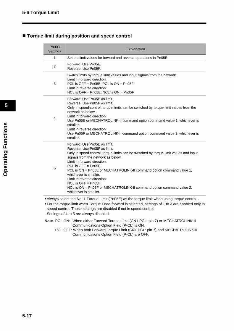
5-6 Torque Limit
Op
erat
ing
Fu
nct
ion
s
5
Torque limit during position and speed control
Always select the No. 1 Torque Limit (Pn05E) as the torque limit when using torque control. For the torque limit when Torque Feed-forward is selected, settings of 1 to 3 are enabled only in speed control. These settings are disabled if not in speed control.Settings of 4 to 5 are always disabled.
Note PCL ON: When either Forward Torque Limit (CN1 PCL: pin 7) or MECHATROLINK-II Communications Option Field (P-CL) is ON.
PCL OFF: When both Forward Torque Limit (CN1 PCL: pin 7) and MECHATROLINK-II Communications Option Field (P-CL) are OFF.
Pn003Settings
Explanation
1 Set the limit values for forward and reverse operations in Pn05E.
2Forward: Use Pn05E.Reverse: Use Pn05F.
3
Switch limits by torque limit values and input signals from the network. Limit in forward direction:PCL is OFF = Pn05E, PCL is ON = Pn05FLimit in reverse direction: NCL is OFF = Pn05E, NCL is ON = Pn05F
4
Forward: Use Pn05E as limit.Reverse: Use Pn05F as limit.Only in speed control, torque limits can be switched by torque limit values from the network as below. Limit in forward direction:Use Pn05E or MECHATROLINK-II command option command value 1, whichever is smaller.Limit in reverse direction:Use Pn05F or MECHATROLINK-II command option command value 2, whichever is smaller.
5
Forward: Use Pn05E as limit.Reverse: Use Pn05F as limit.Only in speed control, torque limits can be switched by torque limit values and input signals from the network as below. Limit in forward direction: PCL is OFF = Pn05E,PCL is ON = Pn05E or MECHATROLINK-II command option command value 1, whichever is smaller.Limit in reverse direction: NCL is OFF = Pn05F, NCL is ON = Pn05F or MECHATROLINK-II command option command value 2, whichever is smaller.
5-17
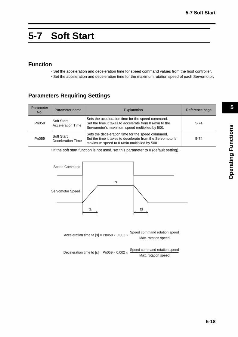
5-7 Soft Start
Op
erat
ing
Fu
nct
ion
s
5
5-7 Soft Start
FunctionSet the acceleration and deceleration time for speed command values from the host controller. Set the acceleration and deceleration time for the maximum rotation speed of each Servomotor.
Parameters Requiring Settings
If the soft start function is not used, set this parameter to 0 (default setting).
ParameterNo.
Parameter name Explanation Reference page
Pn058Soft Start Acceleration Time
Sets the acceleration time for the speed command.Set the time it takes to accelerate from 0 r/min to the Servomotor's maximum speed multiplied by 500.
5-74
Pn059Soft Start Deceleration Time
Sets the deceleration time for the speed command.Set the time it takes to decelerate from the Servomotor's maximum speed to 0 r/min multiplied by 500.
5-74
ta td
Speed Command
Servomotor Speed
Acceleration time ta [s] = Pn058 × 0.002 ×Speed command rotation speed
Max. rotation speed
Deceleration time td [s] = Pn059 × 0.002 ×Speed command rotation speed
Max. rotation speed
N
5-18
5-8 Acceleration/Deceleration Time Settings
Op
erat
ing
Fu
nct
ion
s
5
5-8 Acceleration/Deceleration Time Settings
FunctionSet the angular acceleration to reach the target speed and angular deceleration to stop for position commands. Units of setting is × 10,000 [command units/s2].
Parameters Requiring Settings
Note 1. The factory default setting for this parameter:Linear Acceleration Constant = Linear Deceleration Constant = 100 × 10,000 [command units/s2].
Note 2. The setting will be handled after conversion to an un-signed 16-bit data (0 to 65535). Example: −32768 → 8000h = 32768
−1 → FFFFh = 65535
Setting example (using a 2,500-p/r Incremental Encoder)
When the setting is 100 × 10,000 [command units/s2], target speed is 2,400 r/min, and the electronic gear ratio of G1/G2 is 2/1, the acceleration and deceleration time is as follows:2,400/60 = 40 r/s The position units for one turn is 5,000 [command units]. The rotation speed units for 2,400 r/min is 40 × 5,000 = 200,000 [command units/s]. The linear acceleration and deceleration time to reach 2,400 r/min is 200,000/1,000,000 = 0.2 s.Increasing the electronic gear ratio degrades the distribution accuracy of the linear acceleration and deceleration time. The setting must be increased in order to reduce the acceleration time.
Setting example (using a 17-bit Absolute Encoder)
When the setting is 100 × 10,000 [command units/s2], target speed is 2,400 r/min, and the electronic gear ratio of G1/G2 is 64/1, the acceleration and deceleration time is as follows:2,400/60 = 40 r/s The position units for one turn is 8,192 [command units]. The rotation speed units for 2,400 r/min is 40 × 8,192 = 327,680 [command units/s]. The linear acceleration and deceleration time to reach 2,400 r/min is 327,680/1,000,000 = 0.32768 s.Increasing the electronic gear ratio degrades the distribution accuracy of the linear acceleration and deceleration time. The setting must be decreased in order to reduce the acceleration time. In this example, set 328 for an acceleration time of 0.1 s.
ParameterNo.
Parameter name Explanation Reference page
Pn107Linear Acceleration Constant
Sets the acceleration speed for positioning moves.(Units: × 10,000 [command units/s2])
5-82
Pn10ALinear Deceleration Constant
Sets the deceleration speed for positioning moves.(Units: × 10,000 [command units/s2])
5-82
5-19

5-9 Moving Average Time
Op
erat
ing
Fu
nct
ion
s
5
5-9 Moving Average Time
FunctionThis function applies the Moving Average Filter (FIR) to the linear acceleration and deceleration time for position commands. This function can reduce vibration and impact during acceleration and deceleration. Time setting range: 0 to 510 ms.
Parameters Requiring Settings
ParameterNo.
Parameter name Explanation Reference page
Pn10EMoving Average Time
Sets the moving average time for the position command. Note If the Moving Average Time is set, speed commands
may not be executed seamlessly when switching the control modes, and when switching between interpolation feed motions and positioning motions (motions wherein the command waveforms are generated inside the Servo Drive).
5-82
Servomotor speedpattern
Command speed pattern
Pn10E
Pn10EPn10E
Pn10E
5-20
5-10 Electronic Gear
Op
erat
ing
Fu
nct
ion
s
5
5-10 Electronic Gear
FunctionThe Servomotor rotates at the value (the number of pulses) of the position command multipled by the electronic gear ratio. During speed and torque control, the pulses from the Servomotor encoder are divided by the electronic gear ratio and converted into command units before being fed back.
Parameters Requiring Settings
The factory default setting for this parameter is Electronic Gear ratio 1 = Electronic Gear ratio 2 = 1.
Setting example (using a 2,500-p/r Incremental Encoder)To make one turn using a setting unit of 5,000
Setting example (using a 17-bit Absolute Encoder)To make one turn using a setting unit of 10,000
ParameterNo.
Parameter name ExplanationReference
page
Pn205Electronic Gear Ratio 1 (Numerator)
Sets the numerator for the electronic gear ratio. Setting this parameter to 0 automatically sets the encoder resolution as the numerator. (131,072 for a 17-bit absolute encoder, and 10,000 for a 2,500-p/r incremental encoder). The electronic gear ratio can be set to 1/100 to 100 times. A parameter setting alarm (alarm code 93) will occur if the ra-tio is set outside this range.
5-85
Pn206Electronic Gear Ratio 2 (Denominator)
Sets the denominator for the electronic gear ratio.A parameter setting alarm (alarm code 93) will occur if the ra-tio is set outside this range.
5-85
=5000
10000 21
Pn205Pn206
=
=10000
131072 8192625
Pn205Pn206
=
5-21
5-11 Speed Limit
Op
erat
ing
Fu
nct
ion
s
5
5-11 Speed Limit
FunctionSet the Servomotor rotation speed limit when using torque control. The speed limit value can be set by the internal parameter (Pn053) or from a host controller.
Parameters Requiring Settings
ParameterNo.
Parameter name Explanation Reference page
Pn053 Speed Limit
Sets the speed limit when torque control is used.This value is the same for both forward and reverse directions. The setting must be less than the maximum rotation speed of the Servomotor.
5-74
Pn05BSpeed Limit Selection
Select to perform speed limit by the Speed Limit (Pn053), or the smaller value of either the speed limit from MECHA-TROLINK-II or the Speed Limit (Pn053).
5-74
5-22
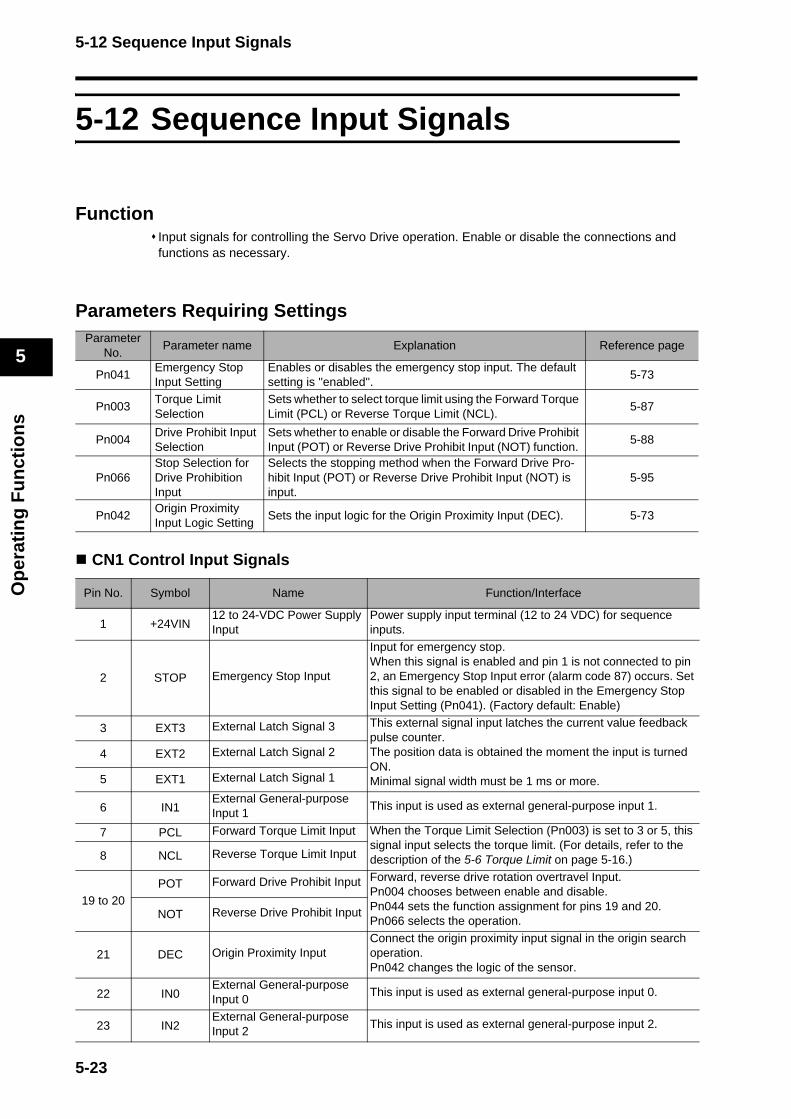
5-12 Sequence Input Signals
Op
erat
ing
Fu
nct
ion
s
5
5-12 Sequence Input Signals
FunctionInput signals for controlling the Servo Drive operation. Enable or disable the connections and functions as necessary.
Parameters Requiring Settings
CN1 Control Input Signals
ParameterNo.
Parameter name Explanation Reference page
Pn041Emergency Stop Input Setting
Enables or disables the emergency stop input. The default setting is ''enabled''.
5-73
Pn003Torque Limit Selection
Sets whether to select torque limit using the Forward Torque Limit (PCL) or Reverse Torque Limit (NCL).
5-87
Pn004Drive Prohibit Input Selection
Sets whether to enable or disable the Forward Drive Prohibit Input (POT) or Reverse Drive Prohibit Input (NOT) function.
5-88
Pn066Stop Selection for Drive Prohibition Input
Selects the stopping method when the Forward Drive Pro-hibit Input (POT) or Reverse Drive Prohibit Input (NOT) is input.
5-95
Pn042Origin Proximity Input Logic Setting
Sets the input logic for the Origin Proximity Input (DEC). 5-73
Pin No. Symbol Name Function/Interface
1 +24VIN12 to 24-VDC Power Supply Input
Power supply input terminal (12 to 24 VDC) for sequence inputs.
2 STOP Emergency Stop Input
Input for emergency stop.When this signal is enabled and pin 1 is not connected to pin 2, an Emergency Stop Input error (alarm code 87) occurs. Set this signal to be enabled or disabled in the Emergency Stop Input Setting (Pn041). (Factory default: Enable)
3 EXT3 External Latch Signal 3 This external signal input latches the current value feedback pulse counter. The position data is obtained the moment the input is turned ON.Minimal signal width must be 1 ms or more.
4 EXT2 External Latch Signal 2
5 EXT1 External Latch Signal 1
6 IN1External General-purpose Input 1
This input is used as external general-purpose input 1.
7 PCL Forward Torque Limit Input When the Torque Limit Selection (Pn003) is set to 3 or 5, this signal input selects the torque limit. (For details, refer to the description of the 5-6 Torque Limit on page 5-16.)8 NCL Reverse Torque Limit Input
19 to 20POT Forward Drive Prohibit Input Forward, reverse drive rotation overtravel Input.
Pn004 chooses between enable and disable.Pn044 sets the function assignment for pins 19 and 20. Pn066 selects the operation.NOT Reverse Drive Prohibit Input
21 DEC Origin Proximity InputConnect the origin proximity input signal in the origin search operation.Pn042 changes the logic of the sensor.
22 IN0External General-purpose Input 0
This input is used as external general-purpose input 0.
23 IN2External General-purpose Input 2
This input is used as external general-purpose input 2.
5-23
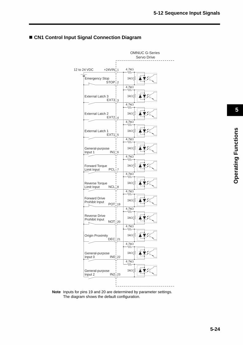
5-12 Sequence Input Signals
Op
erat
ing
Fu
nct
ion
s
5
CN1 Control Input Signal Connection Diagram
Note Inputs for pins 19 and 20 are determined by parameter settings. The diagram shows the default configuration.
Emergency Stop
8NCL
7PCL
6IN1
5EXT1
4EXT2
3EXT3
2STOP
1+24VIN
Reverse Torque Limit Input
Forward Torque Limit Input
General-purposeInput 1
External Latch 1
External Latch 2
External Latch 3
12 to 24 VDC
19POT
Forward Drive Prohibit Input
20NOT
Reverse Drive Prohibit Input
21DECOrigin Proximity
22IN0General-purpose Input 0
23IN2General-purpose Input 2
4.7kΩ
1kΩ
4.7kΩ
1kΩ
4.7kΩ
1kΩ
4.7kΩ
1kΩ
4.7kΩ
1kΩ
4.7kΩ
1kΩ
4.7kΩ
1kΩ
4.7kΩ
1kΩ
4.7kΩ
1kΩ
4.7kΩ
1kΩ
4.7kΩ
1kΩ
4.7kΩ
1kΩ
OMNUC G-Series Servo Drive
5-24
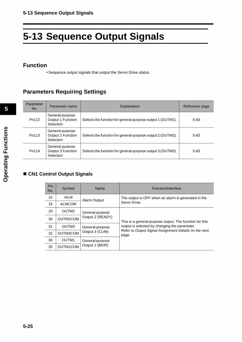
5-13 Sequence Output Signals
Op
erat
ing
Fu
nct
ion
s
5
5-13 Sequence Output Signals
FunctionSequence output signals that output the Servo Drive status.
Parameters Requiring Settings
CN1 Control Output Signals
ParameterNo.
Parameter name Explanation Reference page
Pn112General-purpose Output 1 Function Selection
Selects the function for general-purpose output 1 (OUTM1). 5-83
Pn113General-purpose Output 2 Function Selection
Selects the function for general-purpose output 2 (OUTM2). 5-83
Pn114General-purpose Output 3 Function Selection
Selects the function for general-purpose output 3 (OUTM3). 5-83
PinNo.
Symbol Name Function/Interface
15 /ALMAlarm Output
The output is OFF when an alarm is generated in the Servo Drive.16 ALMCOM
29 OUTM2 General-purpose Output 2 (READY)
This is a general-purpose output. The function for this output is selected by changing the parameter.Refer to Output Signal Assignment Details on the next page.
30 OUTM2COM
31 OUTM3 General-purpose Output 3 (CLIM)32 OUTM3COM
36 OUTM1 General-purpose Output 1 (BKIR)35 OUTM1COM
5-25
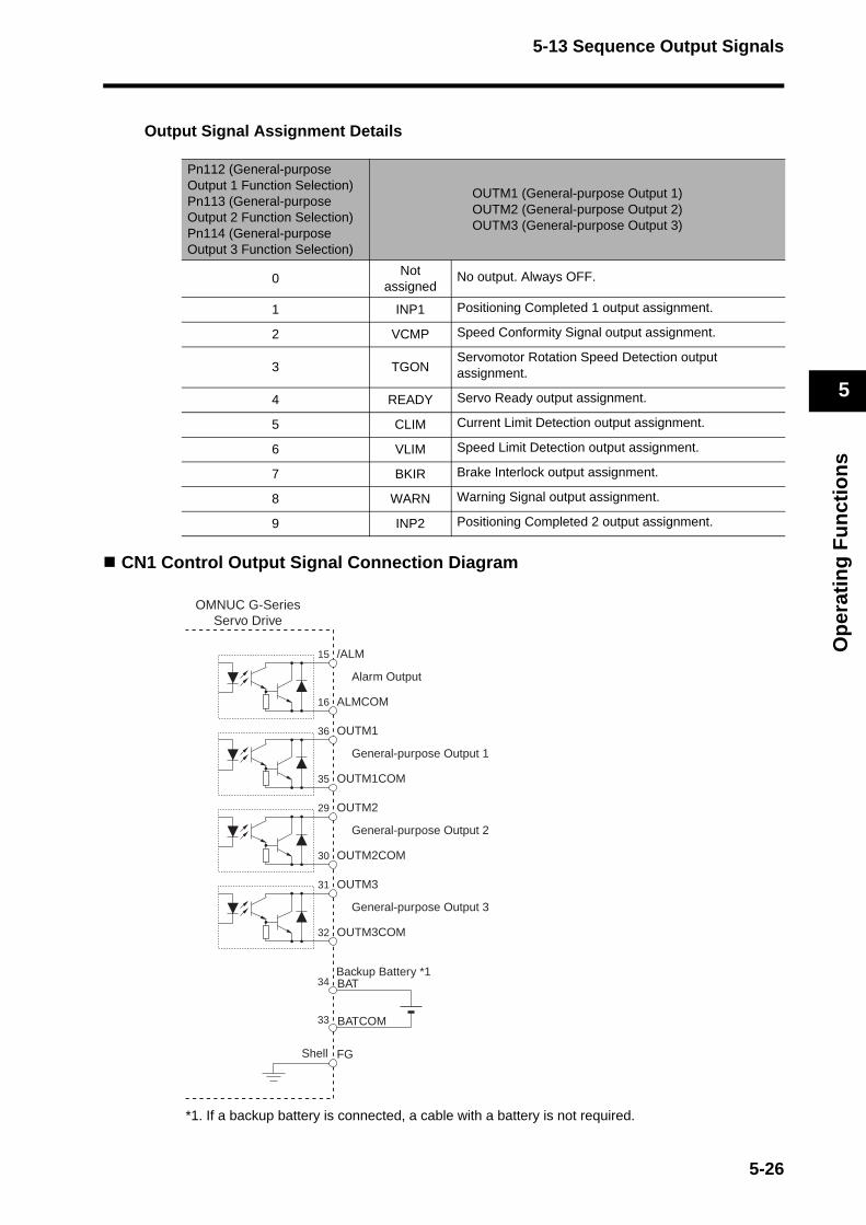
5-13 Sequence Output Signals
Op
erat
ing
Fu
nct
ion
s
5
Output Signal Assignment Details
CN1 Control Output Signal Connection Diagram
*1. If a backup battery is connected, a cable with a battery is not required.
Pn112 (General-purpose Output 1 Function Selection)Pn113 (General-purpose Output 2 Function Selection)Pn114 (General-purpose Output 3 Function Selection)
OUTM1 (General-purpose Output 1)OUTM2 (General-purpose Output 2)OUTM3 (General-purpose Output 3)
0Not
assignedNo output. Always OFF.
1 INP1 Positioning Completed 1 output assignment.
2 VCMP Speed Conformity Signal output assignment.
3 TGONServomotor Rotation Speed Detection output assignment.
4 READY Servo Ready output assignment.
5 CLIM Current Limit Detection output assignment.
6 VLIM Speed Limit Detection output assignment.
7 BKIR Brake Interlock output assignment.
8 WARN Warning Signal output assignment.
9 INP2 Positioning Completed 2 output assignment.
/ALM
Alarm Output
ALMCOM
15
16
FGShell
BAT
BATCOM
Backup Battery *134
33
OUTM1
General-purpose Output 1
OUTM1COM
36
35
OUTM2
General-purpose Output 2
OUTM2COM
29
30
OUTM3
General-purpose Output 3
OUTM3COM
31
32
OMNUC G-SeriesServo Drive
5-26

5-14 Backlash Compensation
Op
erat
ing
Fu
nct
ion
s
5
5-14 Backlash Compensation
FunctionCompensates the position error caused by backlash in the machine. The specified amount of command units is compensated when the operation direction changes.
Note 1. The backlash compensation status will be retained when you switch from position control to speed control or torque control. Backlash compensation will resume with the status retained during the previous position control.
Note 2. To determine the actual position of the Servomotor, offset the backlash compensation amount from the Servomotor position data acquired via the network.
Note 3. Position data acquired via RS-232 is the value after the backlash compensation.
Note 4. After the Servo ON, compensation will be performed on the first position command for operation in the set direction. Compensation will not be performed for prior reverse operations. Compensation will, however, be performed on the first reverse operation after the initial backlash compensation. Once backlash compensation has been performed, it will not be performed again as long as operation continues in the same direction.
Note 5. When the Servo OFF status occurs while backlash compensation is performed, the backlash compensation amount will be cleared by presetting the position command data within the Servo Drive with Servomotor position data including the backlash compensation amount. When the Servo ON occurs again, backlash compensation will be performed as described above.
Parameters Requiring Settings
ParameterNo.
Parameter name Explanation Reference page
Pn100BacklashCompensation Selection
Enables or disables backlash compensation and sets the direction for compensation.
5-81
Pn101BacklashCompensation
Sets the backlash compensation amount in command units. 5-81
Pn102BacklashCompensation Time Constant
Sets the time to apply backlash compensation. The value dividing the compensation amount by the time constant is the speed.
5-81
5-27
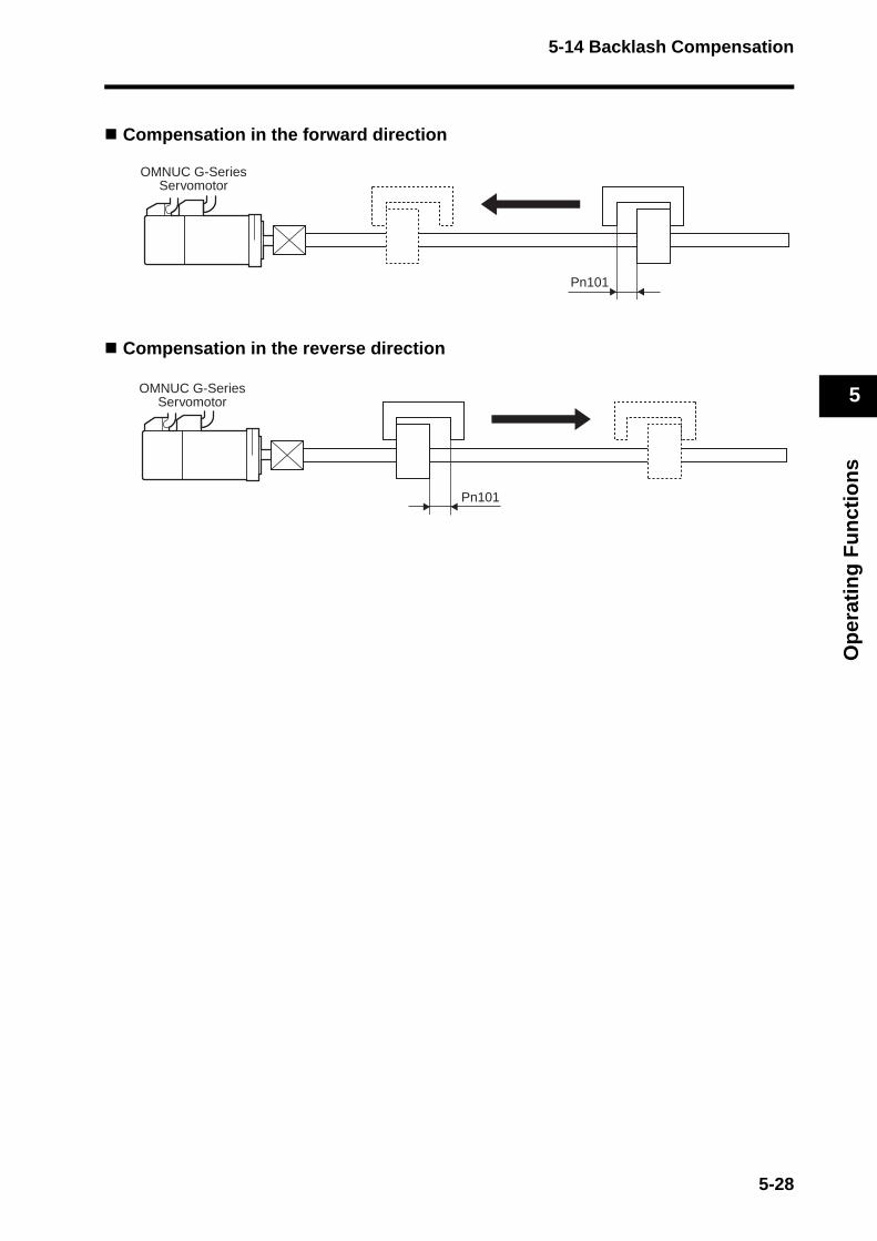
5-14 Backlash Compensation
Op
erat
ing
Fu
nct
ion
s
5
Compensation in the forward direction
Compensation in the reverse direction
Pn101
OMNUC G-SeriesServomotor
Pn101
OMNUC G-SeriesServomotor
5-28
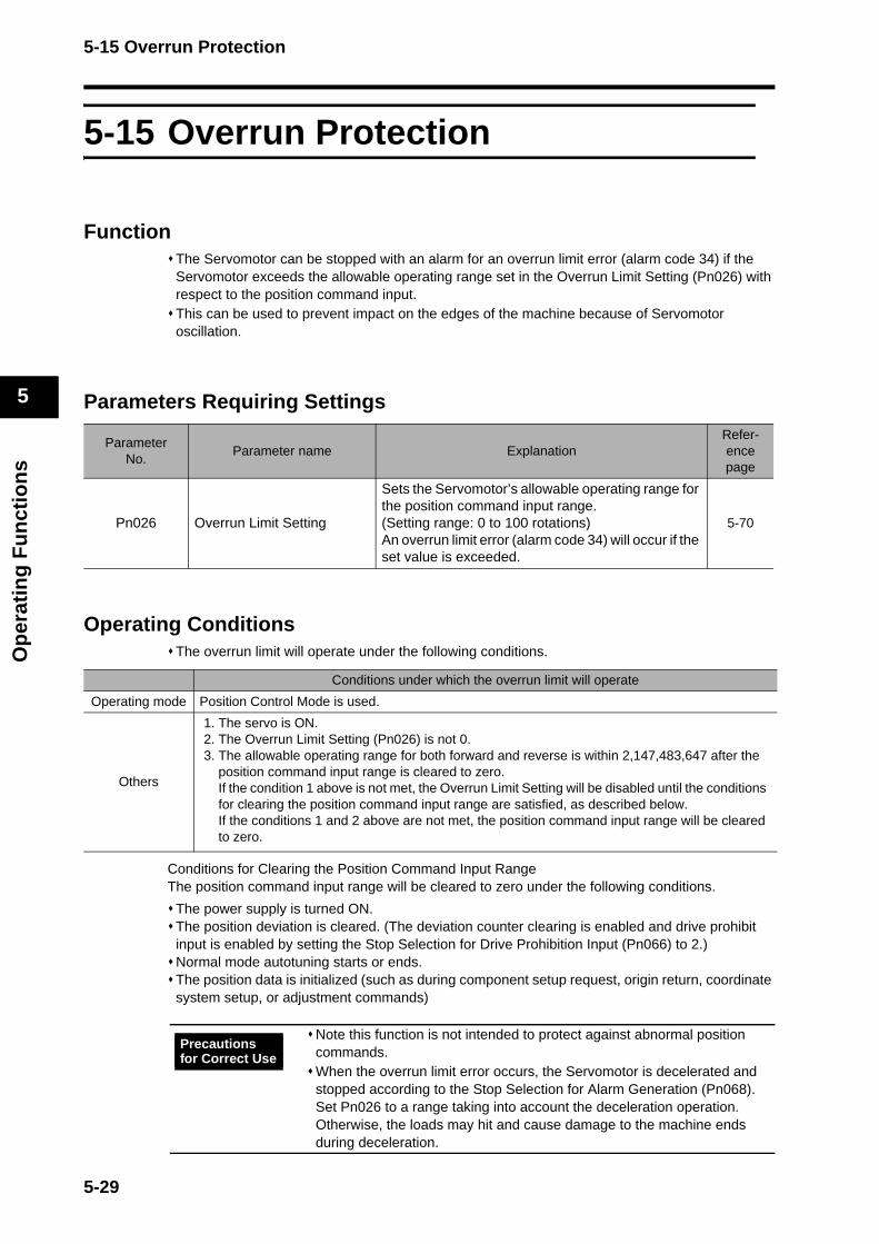
5-15 Overrun Protection
Op
erat
ing
Fu
nct
ion
s
5
5-15 Overrun Protection
FunctionThe Servomotor can be stopped with an alarm for an overrun limit error (alarm code 34) if the Servomotor exceeds the allowable operating range set in the Overrun Limit Setting (Pn026) with respect to the position command input. This can be used to prevent impact on the edges of the machine because of Servomotor oscillation.
Parameters Requiring Settings
Operating ConditionsThe overrun limit will operate under the following conditions.
Conditions for Clearing the Position Command Input RangeThe position command input range will be cleared to zero under the following conditions.
The power supply is turned ON.The position deviation is cleared. (The deviation counter clearing is enabled and drive prohibit input is enabled by setting the Stop Selection for Drive Prohibition Input (Pn066) to 2.)Normal mode autotuning starts or ends.The position data is initialized (such as during component setup request, origin return, coordinate system setup, or adjustment commands)
ParameterNo.
Parameter name ExplanationRefer-ence page
Pn026 Overrun Limit Setting
Sets the Servomotor’s allowable operating range for the position command input range. (Setting range: 0 to 100 rotations)An overrun limit error (alarm code 34) will occur if the set value is exceeded.
5-70
Conditions under which the overrun limit will operate
Operating mode Position Control Mode is used.
Others
1. The servo is ON.2. The Overrun Limit Setting (Pn026) is not 0.3. The allowable operating range for both forward and reverse is within 2,147,483,647 after the
position command input range is cleared to zero.If the condition 1 above is not met, the Overrun Limit Setting will be disabled until the conditions for clearing the position command input range are satisfied, as described below.If the conditions 1 and 2 above are not met, the position command input range will be cleared to zero.
Note this function is not intended to protect against abnormal position commands. When the overrun limit error occurs, the Servomotor is decelerated and stopped according to the Stop Selection for Alarm Generation (Pn068). Set Pn026 to a range taking into account the deceleration operation. Otherwise, the loads may hit and cause damage to the machine ends during deceleration.
Precautions for Correct Use
5-29
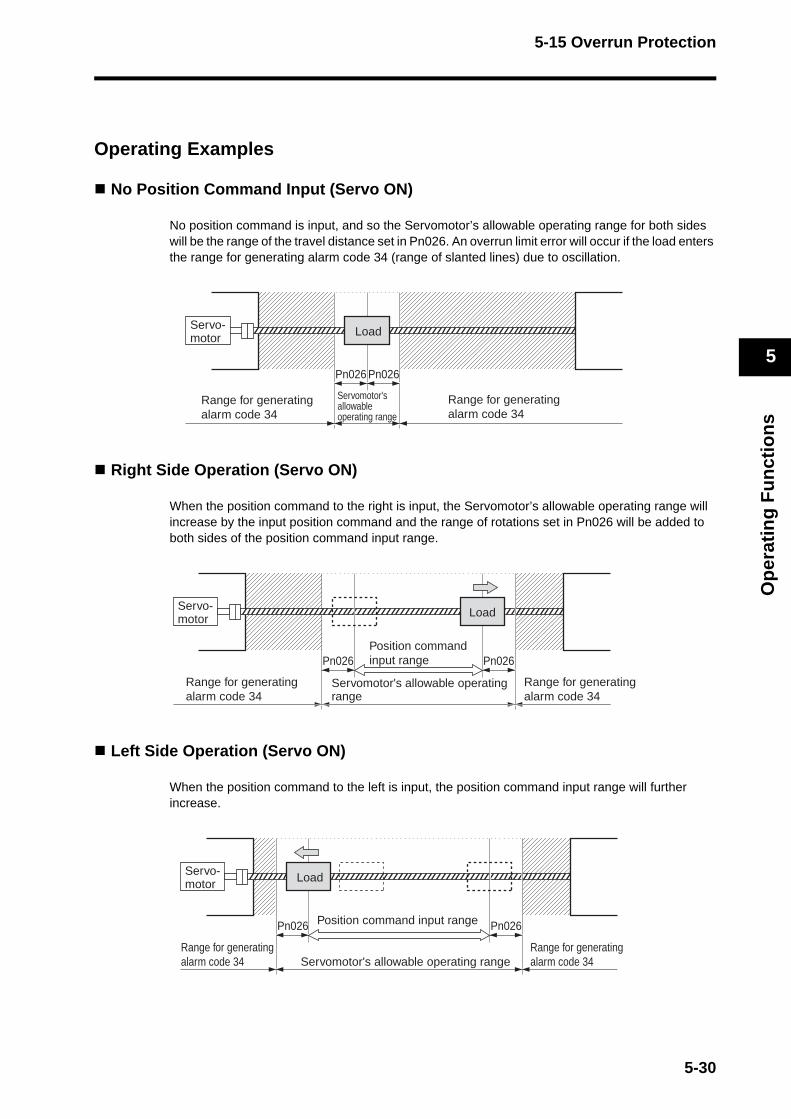
5-15 Overrun Protection
Op
erat
ing
Fu
nct
ion
s
5
Operating Examples
No Position Command Input (Servo ON)
No position command is input, and so the Servomotor’s allowable operating range for both sides will be the range of the travel distance set in Pn026. An overrun limit error will occur if the load enters the range for generating alarm code 34 (range of slanted lines) due to oscillation.
Right Side Operation (Servo ON)
When the position command to the right is input, the Servomotor’s allowable operating range will increase by the input position command and the range of rotations set in Pn026 will be added to both sides of the position command input range.
Left Side Operation (Servo ON)
When the position command to the left is input, the position command input range will further increase.
Servo-motor Load
Servomotor'sallowable operating range
Range for generatingalarm code 34
Range for generatingalarm code 34
Pn026 Pn026
Servo-motor Load
Servomotor's allowable operating range
Position command input rangePn026 Pn026
Range for generatingalarm code 34
Range for generatingalarm code 34
Servo-motor Load
Servomotor's allowable operating range
Position command input range
Range for generating alarm code 34
Range for generating alarm code 34
Pn026 Pn026
5-30

5-16 Gain Switching
Op
erat
ing
Fu
nct
ion
s
5
5-16 Gain Switching
FunctionThis function switches the position loop and speed loop gain.Select between enable or disable with the Gain Switching Operating Mode Selection (Pn030). Set the switching conditions with the Gain Switch Setting (Pn031). The control can be optimized by switching gain settings when the load inertia changes, or the responsiveness at stops and during operation needs to be changed. Gain switching is used when realtime autotuning does not work effectively in such cases as follows:
· When the load inertia fluctuates in 200 ms or less.· When the Servomotor rotation speed does not exceed 500 r/min., or the load torque does not
exceed 50% of the rated torque.· When external force is constantly applied, as with a vertical axis.
Note When gain 2 has been selected, realtime autotuning will not operate normally. If using the gain switching, set the Realtime Autotuning Mode Selection (Pn021) to 0 (disabled).
5-31

5-16 Gain Switching
Op
erat
ing
Fu
nct
ion
s
5
Parameters Requiring Settings
ParameterNo.
Parameter name Explanation Reference page
Pn030Gain Switching Operating Mode Selection
Enable or disable gain switching. 5-72
Pn031Gain SwitchSetting
Sets the condition for switching between gain 1 and gain 2.The conditions depend on the control mode.
5-72
Pn010 Position Loop Gain Sets position loop responsiveness. 5-67
Pn011 Speed Loop Gain Sets speed loop responsiveness. 5-67
Pn012Speed Loop Integration Time Constant
Adjusts the speed loop integration time constant. 5-67
Pn013Speed Feedback Filter Time Constant
Selects the speed detection filter time constant. 5-67
Pn014Torque Command Filter Time Constant
Sets the time constant for the torque command filter. 5-68
Pn018Position Loop Gain 2
Sets the 2nd position loop responsiveness. 5-68
Pn019 Speed Loop Gain 2 Sets the 2nd speed loop responsiveness. 5-68
Pn01ASpeed Loop Integration Time Constant 2
Adjusts the speed loop integration time constant 2. 5-68
Pn01BSpeed Feedback Filter Time Constant 2
Selects the speed detection filter time constant. 5-68
Pn01CTorque Command Filter Time Constant 2
Sets the time constant for the 2nd torque command filter. 5-68
Pn032Gain SwitchTime
Sets the time to return from gain 2 to gain 1. (Units: 166 μs)
5-72
Pn033Gain SwitchLevel Setting
Sets the judgment level for switching between gain 1 and gain 2.
5-72
Pn034Gain SwitchHysteresis Setting
Sets the hysteresis width for the judgment level set in the Gain Switch Level setting (Pn033).
5-73
Pn035Position Loop Gain Switching Time
Sets the number of steps to switch from low gain to high gain. (Units: 166 μs)
5-73
5-32
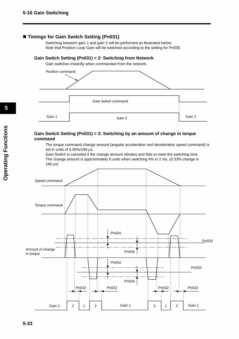
5-16 Gain Switching
Op
erat
ing
Fu
nct
ion
s
5
Timings for Gain Switch Setting (Pn031) Switching between gain 1 and gain 2 will be performed as illustrated below. Note that Position Loop Gain will be switched according to the setting for Pn035.
Gain Switch Setting (Pn031) = 2: Switching from NetworkGain switches instantly when commanded from the network.
Gain Switch Setting (Pn031) = 3: Switching by an amount of change in torque command
The torque command change amount (angular acceleration and deceleration speed command) is set in units of 0.05%/166 μs.Gain Switch is canceled if the change amount vibrates and fails to meet the switching time. The change amount is approximately 6 units when switching 4% in 2 ms. (0.33% change in 166 μs)
Gain 1 Gain 1Gain 2
Gain switch command
Position command
1 12 2 22
Pn032Pn032
Pn034
Pn034Pn033
Pn033
Pn034
Pn034
Pn032 Pn032
Speed command
Torque command
Amount of change in torque
Gain 1 Gain 1Gain 1
5-33

5-16 Gain Switching
Op
erat
ing
Fu
nct
ion
s
5
Gain Switch Setting (Pn031) = 5, 9: Switching by the Speed Command or Actual Servomotor Speed
Gain Switch Setting (Pn031) = 6: Switching by the Position DeviationSwitches the gain based on the accumulated value in the deviation counter.
Gain Switch Setting (Pn031) = 7: Switching based on position command pulses received
Switches the gain when one or more position command pulse exists.
Speed command or actual Servomotor speed
Pn034
Pn033Pn034
Pn032
Gain 1 Gain 1Gain 2
Position deviation amount
Pn034
Pn033Pn034
Pn032
Gain 1 Gain 1Gain 2
Pn032
Position command
Gain 1 Gain 1Gain 2
5-34
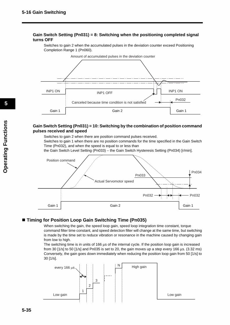
5-16 Gain Switching
Op
erat
ing
Fu
nct
ion
s
5
Gain Switch Setting (Pn031) = 8: Switching when the positioning completed signal turns OFF
Switches to gain 2 when the accumulated pulses in the deviation counter exceed Positioning Completion Range 1 (Pn060).
Gain Switch Setting (Pn031) = 10: Switching by the combination of position command pulses received and speed
Switches to gain 2 when there are position command pulses received. Switches to gain 1 when there are no position commands for the time specified in the Gain Switch Time (Pn032), and when the speed is equal to or less than the Gain Switch Level Setting (Pn033) − the Gain Switch Hysteresis Setting (Pn034) [r/min].
Timing for Position Loop Gain Switching Time (Pn035)When switching the gain, the speed loop gain, speed loop integration time constant, torque command filter time constant, and speed detection filter will change at the same time, but switching is made by the time set to reduce vibration or resonance in the machine caused by changing gain from low to high. The switching time is in units of 166 μs of the internal cycle. If the position loop gain is increased from 30 [1/s] to 50 [1/s] and Pn035 is set to 20, the gain moves up a step every 166 μs. (3.32 ms)Conversely, the gain goes down immediately when reducing the position loop gain from 50 [1/s] to 30 [1/s].
Pn032
INP1 ON INP1 ONINP1 OFF
Amount of accumulated pulses in the deviation counter
Canceled because time condition is not satisfied
Gain 1 Gain 1Gain 2
Pn032Pn032
Pn033Pn034
Actual Servomotor speed
Position command
Gain 1 Gain 1Gain 2
Low gain Low gain
every 166 μs
1
2
3
N High gain
5-35
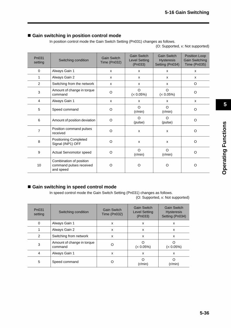
5-16 Gain Switching
Op
erat
ing
Fu
nct
ion
s
5
Gain switching in position control modeIn position control mode the Gain Switch Setting (Pn031) changes as follows.
(O: Supported, x: Not supported)
Gain switching in speed control modeIn speed control mode the Gain Switch Setting (Pn031) changes as follows.
(O: Supported, x: Not supported)
Pn031 setting
Switching conditionGain Switch
Time (Pn032)
Gain SwitchLevel Setting
(Pn033)
Gain Switch Hysteresis
Setting (Pn034)
Position Loop Gain Switching Time (Pn035)
0 Always Gain 1 x x x x
1 Always Gain 2 x x x x
2 Switching from the network x x x O
3Amount of change in torque command
OO
(× 0.05%)O
(× 0.05%)O
4 Always Gain 1 x x x x
5 Speed command OO
(r/min)O
(r/min)O
6 Amount of position deviation OO
(pulse)O
(pulse)O
7Position command pulses received
O x x O
8Positioning Completed Signal (INP1) OFF
O x x O
9 Actual Servomotor speed OO
(r/min)O
(r/min)O
10Combination of position command pulses received and speed
O O O O
Pn031 setting
Switching conditionGain Switch
Time (Pn032)
Gain SwitchLevel Setting
(Pn033)
Gain Switch Hysteresis
Setting (Pn034)
0 Always Gain 1 x x x
1 Always Gain 2 x x x
2 Switching from network x x x
3Amount of change in torque command
OO
(× 0.05%)O
(× 0.05%)
4 Always Gain 1 x x x
5 Speed command OO
(r/min)O
(r/min)
5-36
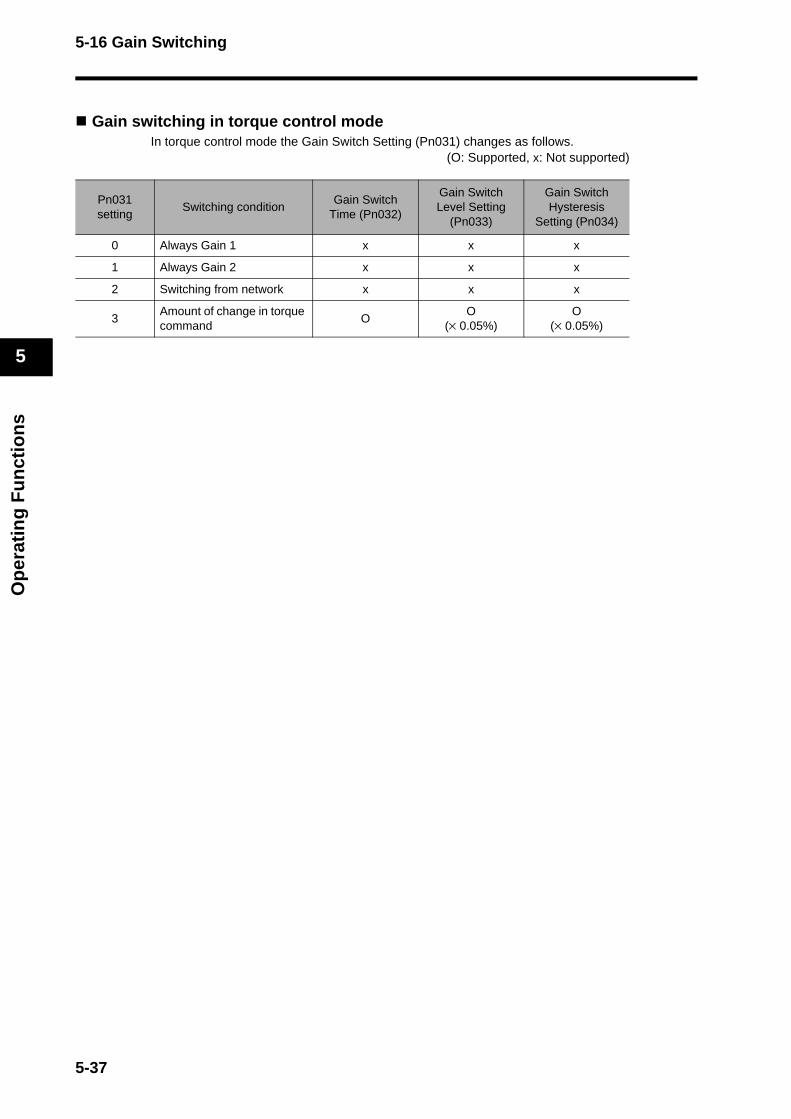
5-16 Gain Switching
Op
erat
ing
Fu
nct
ion
s
5
Gain switching in torque control modeIn torque control mode the Gain Switch Setting (Pn031) changes as follows.
(O: Supported, x: Not supported)
Pn031 setting
Switching conditionGain Switch
Time (Pn032)
Gain SwitchLevel Setting
(Pn033)
Gain Switch Hysteresis
Setting (Pn034)
0 Always Gain 1 x x x
1 Always Gain 2 x x x
2 Switching from network x x x
3Amount of change in torque command
OO
(× 0.05%)O
(× 0.05%)
5-37
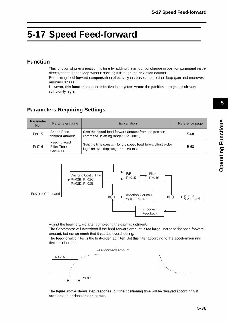
5-17 Speed Feed-forward
Op
erat
ing
Fu
nct
ion
s
5
5-17 Speed Feed-forward
FunctionThis function shortens positioning time by adding the amount of change in position command value directly to the speed loop without passing it through the deviation counter.Performing feed-forward compensation effectively increases the position loop gain and improves responsiveness.However, this function is not so effective in a system where the position loop gain is already sufficiently high.
Parameters Requiring Settings
Adjust the feed-forward after completing the gain adjustment.The Servomotor will overshoot if the feed-forward amount is too large. Increase the feed-forward amount, but not so much that it causes overshooting.The feed-forward filter is the first-order lag filter. Set this filter according to the acceleration and deceleration time.
The figure above shows step response, but the positioning time will be delayed accordingly if acceleration or deceleration occurs.
ParameterNo.
Parameter name Explanation Reference page
Pn015Speed Feed-forward Amount
Sets the speed feed-forward amount from the position command. (Setting range: 0 to 100%)
5-68
Pn016Feed-forward Filter Time Constant
Sets the time constant for the speed feed-forward first-order lag filter. (Setting range: 0 to 64 ms)
5-68
Speed Command
Position Command
Encoder Feedback
Deviation CounterPn010, Pn018
FilterPn016
Damping Control FilterPn02B, Pn02CPn02D, Pn02E
F/FPn015
Pn016
63.2%
Feed-forward amount
5-38

5-18 Torque Feed-forward
Op
erat
ing
Fu
nct
ion
s
5
5-18 Torque Feed-forward
FunctionIn speed commanded control, using the torque feed-forward command reduces the delay caused by the speed loop integration time and thereby makes acceleration and deceleration faster. For a vertical axis, torque feed-forward can compensate heavy loads to eliminate the difference (up and down) in the torque command amount by the speed command calculation.
Parameters Requiring SettingsThere are no parameters to set. This is set by command from the network.To control during acceleration and deceleration, differential operations will be required for the speed command via the host controller.
Speed Feedback
Torque Feed-forward
Current Feedback
Notch Filter
Torque CommandFilter
Torque CommandTFF[%]
TorqueLimit
Torque LimitPCL/NCL
Speed Command Unit Conversion
MECHATROLINK-II
Soft StartAcceleration/DecelerationPn058:
AccelerationPn059:
Deceleration
SpeedPI Processor
TorquePI Processor
Target Speed[r/min]
5-39
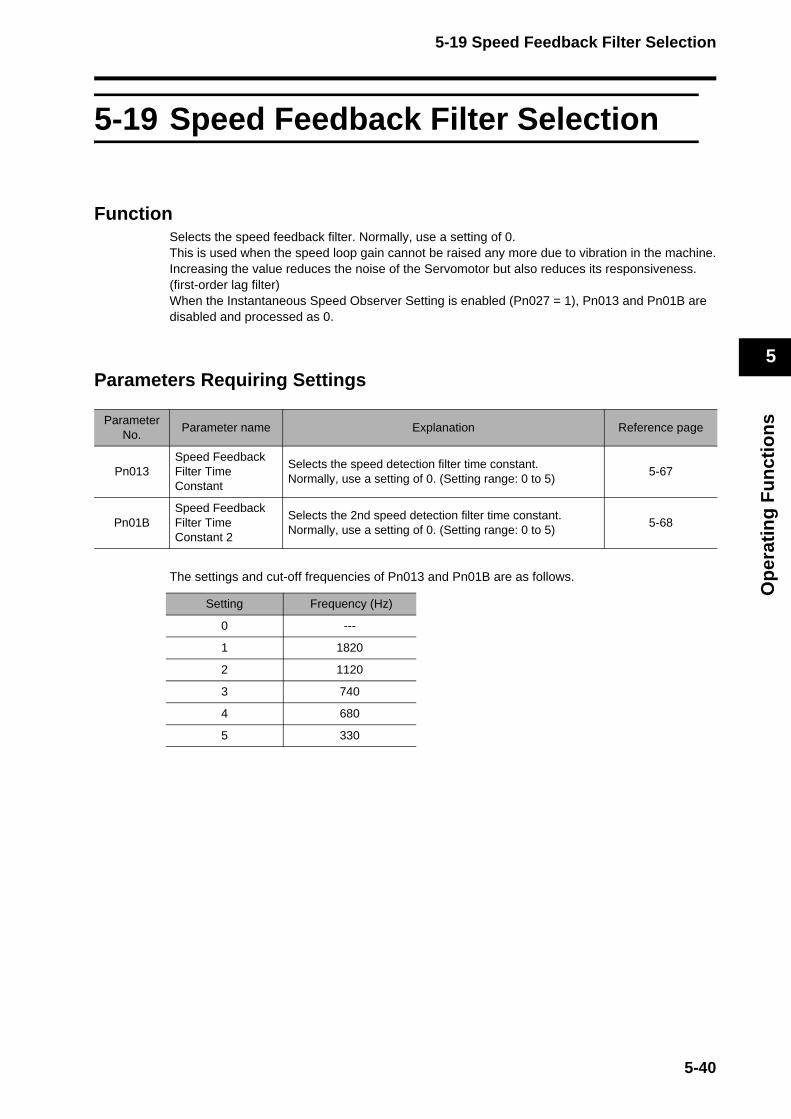
5-19 Speed Feedback Filter Selection
Op
erat
ing
Fu
nct
ion
s
5
5-19 Speed Feedback Filter Selection
FunctionSelects the speed feedback filter. Normally, use a setting of 0.This is used when the speed loop gain cannot be raised any more due to vibration in the machine.Increasing the value reduces the noise of the Servomotor but also reduces its responsiveness. (first-order lag filter)When the Instantaneous Speed Observer Setting is enabled (Pn027 = 1), Pn013 and Pn01B are disabled and processed as 0.
Parameters Requiring Settings
The settings and cut-off frequencies of Pn013 and Pn01B are as follows.
ParameterNo.
Parameter name Explanation Reference page
Pn013Speed Feedback Filter Time Constant
Selects the speed detection filter time constant. Normally, use a setting of 0. (Setting range: 0 to 5)
5-67
Pn01BSpeed Feedback Filter Time Constant 2
Selects the 2nd speed detection filter time constant. Normally, use a setting of 0. (Setting range: 0 to 5)
5-68
Setting Frequency (Hz)
0 ---
1 1820
2 1120
3 740
4 680
5 330
5-40
5-20 P Control Switching
Op
erat
ing
Fu
nct
ion
s
5
5-20 P Control Switching
FunctionThis function switches speed loop control from PI control to P control.Switching to P control reduces the servo rigidity and eliminates vibration.The absence of the integration time results in greater speed and position deviations due to external forces and load torques.
Parameters Requiring SettingsThere are no parameters to set. This is set by command from the network.
5-41
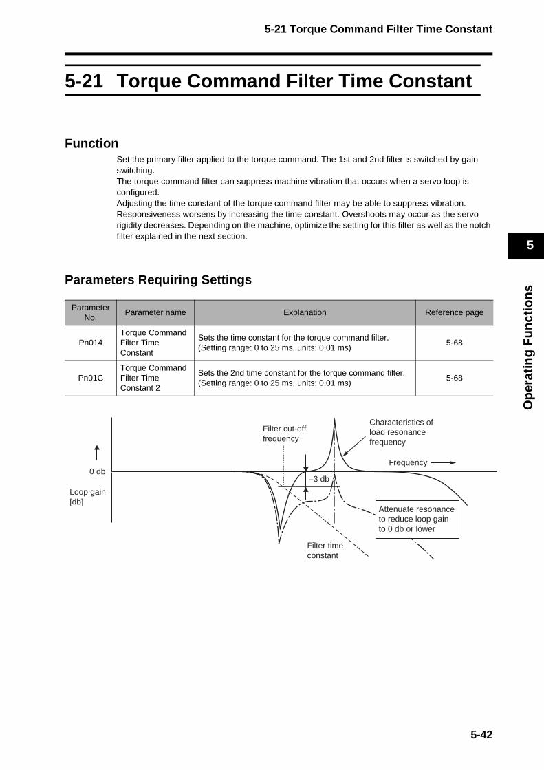
5-21 Torque Command Filter Time Constant
Op
erat
ing
Fu
nct
ion
s
5
5-21 Torque Command Filter Time Constant
FunctionSet the primary filter applied to the torque command. The 1st and 2nd filter is switched by gain switching.The torque command filter can suppress machine vibration that occurs when a servo loop is configured.Adjusting the time constant of the torque command filter may be able to suppress vibration.Responsiveness worsens by increasing the time constant. Overshoots may occur as the servo rigidity decreases. Depending on the machine, optimize the setting for this filter as well as the notch filter explained in the next section.
Parameters Requiring Settings
ParameterNo.
Parameter name Explanation Reference page
Pn014Torque CommandFilter Time Constant
Sets the time constant for the torque command filter. (Setting range: 0 to 25 ms, units: 0.01 ms)
5-68
Pn01CTorque Command Filter Time Constant 2
Sets the 2nd time constant for the torque command filter. (Setting range: 0 to 25 ms, units: 0.01 ms)
5-68
Filter time constant
Filter cut-offfrequency
Characteristics of load resonancefrequency
Frequency
−3 db
Loop gain[db]
0 db
Attenuate resonance to reduce loop gain to 0 db or lower
5-42
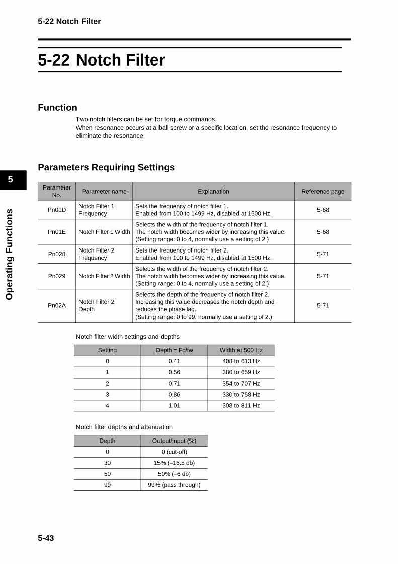
5-22 Notch Filter
Op
erat
ing
Fu
nct
ion
s
5
5-22 Notch Filter
FunctionTwo notch filters can be set for torque commands. When resonance occurs at a ball screw or a specific location, set the resonance frequency to eliminate the resonance.
Parameters Requiring Settings
Notch filter width settings and depths
Notch filter depths and attenuation
ParameterNo.
Parameter name Explanation Reference page
Pn01DNotch Filter 1Frequency
Sets the frequency of notch filter 1.Enabled from 100 to 1499 Hz, disabled at 1500 Hz.
5-68
Pn01E Notch Filter 1 WidthSelects the width of the frequency of notch filter 1.The notch width becomes wider by increasing this value.(Setting range: 0 to 4, normally use a setting of 2.)
5-68
Pn028Notch Filter 2Frequency
Sets the frequency of notch filter 2.Enabled from 100 to 1499 Hz, disabled at 1500 Hz.
5-71
Pn029 Notch Filter 2 WidthSelects the width of the frequency of notch filter 2.The notch width becomes wider by increasing this value.(Setting range: 0 to 4, normally use a setting of 2.)
5-71
Pn02ANotch Filter 2 Depth
Selects the depth of the frequency of notch filter 2.Increasing this value decreases the notch depth and reduces the phase lag.(Setting range: 0 to 99, normally use a setting of 2.)
5-71
Setting Depth = Fc/fw Width at 500 Hz
0 0.41 408 to 613 Hz
1 0.56 380 to 659 Hz
2 0.71 354 to 707 Hz
3 0.86 330 to 758 Hz
4 1.01 308 to 811 Hz
Depth Output/Input (%)
0 0 (cut-off)
30 15% (−16.5 db)
50 50% (−6 db)
99 99% (pass through)
5-43

5-22 Notch Filter
Op
erat
ing
Fu
nct
ion
s
5
A notch filter is a filter that eliminates a designated component of a frequency.
A notch filter is used to eliminate resonance occurring in a machine.
Depth = Fc/fw
Cut-off frequency FcFrequency Hz
Width fwfw
0 db
-3 db
Notch Filter 1 Notch Filter 2
Characteristicsafter filtering
Machine resonance
Notch Filter
5-44
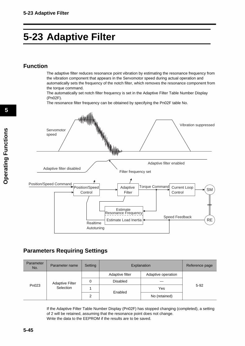
5-23 Adaptive Filter
Op
erat
ing
Fu
nct
ion
s
5
5-23 Adaptive Filter
FunctionThe adaptive filter reduces resonance point vibration by estimating the resonance frequency from the vibration component that appears in the Servomotor speed during actual operation and automatically sets the frequency of the notch filter, which removes the resonance component from the torque command.The automatically set notch filter frequency is set in the Adaptive Filter Table Number Display (Pn02F). The resonance filter frequency can be obtained by specifying the Pn02F table No.
Parameters Requiring Settings
If the Adaptive Filter Table Number Display (Pn02F) has stopped changing (completed), a setting of 2 will be retained, assuming that the resonance point does not change.Write the data to the EEPROM if the results are to be saved.
ParameterNo.
Parameter name Setting Explanation Reference page
Pn023Adaptive Filter
Selection
Adaptive filter Adaptive operation
5-920 Disabled ---
1Enabled
Yes
2 No (retained)
Servomotorspeed
Vibration suppressed
Adaptive filter disabledAdaptive filter enabled
Filter frequency set
Position/Speed Command
Speed Feedback
Position/SpeedControl
RealtimeAutotuning
Estimate Resonance Frequency
Estimate Load Inertia
Adaptive Filter
Current LoopControl
Torque CommandSM
RE
5-45
5-23 Adaptive Filter
Op
erat
ing
Fu
nct
ion
s
5
The adaptive filter may not function properly under the following conditions.
Conditions under which the adaptive filter does not function properly
Control Mode In Torque Control Mode. (Operates in position and speed control modes)
Resonating loadstatus
If the resonance frequency is 300 Hz or lower.If there are multiple points of resonance.If the resonance peak or control gain is low, and the Servomotor speed is not affected by it.
Load statusIf the Servomotor speed with high-frequency components changes due to backlash or other non-linear elements (play).
Command pattern
If the acceleration/deceleration suddenly changes, i.e. 3,000 r/min or more in 0.1 s.
Unusual noise or vibration may occur until the adaptive filter stabilizes after startup, immediately after the first servo ON, or when the Realtime Autotuning Machine Rigidity Selection (Pn022) is increased, but this is not a problem if it disappears right away. If the unusual noise or vibration, however, continues for three or more reciprocating operations, take the following measures in any order you can. Write the parameters used during normal operation to the EEPROM. Lower the Realtime Autotuning Machine Rigidity Selection (Pn022). Disable the adaptive filter by setting the Adaptive Filter Selection (Pn023) to 0. (Reset the inertia estimate and adaptive operation)
Set the notch filter manually.Once unusual noise or vibration occurs, the Inertia Ratio (Pn020) may have changed to an extreme value. In this case, also take the measures described above.The Adaptive Filter Table Number Display (Pn02F) is written to the EEPROM every 30 minutes, and when the power supply is turned OFF and turned ON again, this data is used as the initial values for the adaptive operation.
Precautions for Correct Use
Precautions for Correct Use
5-46

5-23 Adaptive Filter
Op
erat
ing
Fu
nct
ion
s
5
Disabling the Adaptive FilterThe adaptive filter function, which performs automatic tracking in response to the load resonance, can be disabled by setting the Adaptive Filter Selection (Pn023) to 0. If the adaptive filter is disabled when it is operating correctly, the resonance that has been suppressed will reappear, and noise or vibration may occur.Therefore, before disabling the adaptive filter, perform copying function to the Notch Filter 1 Frequency (Pn01D) of the Adaptive Filter Table Number Display (Pn02F) or manually set the Notch Filter 1 Frequency (Pn01D) based on the Adaptive Filter Table Number Display (Pn02F) in the following tables.
Set the Notch Filter 1 Frequency (Pn01D) to 1,500 when disabling the adaptive filter using the above table.
Pn02F Notch Filter 1 Frequency Pn02F Notch Filter 1 Frequency Pn02F Notch Filter 1 Frequency
0 (Disabled) 22 766 44 326
1 (Disabled) 23 737 45 314
2 (Disabled) 24 709 46 302
3 (Disabled) 25 682 47 290
4 (Disabled) 26 656 48 279
5 1482 27 631 49 269 (Disabled when Pn022 ≥ F)
6 1426 28 607 50 258 (Disabled when Pn022 ≥ F)
7 1372 29 584 51 248 (Disabled when Pn022 ≥ F)
8 1319 30 562 52 239 (Disabled when Pn022 ≥ F)
9 1269 31 540 53 230 (Disabled when Pn022 ≥ F)
10 1221 32 520 54 221 (Disabled when Pn022 ≥ E)
11 1174 33 500 55 213 (Disabled when Pn022 ≥ E)
12 1130 34 481 56 205 (Disabled when Pn022 ≥ E)
13 1087 35 462 57 197 (Disabled when Pn022 ≥ E)
14 1045 36 445 58 189 (Disabled when Pn022 ≥ E)
15 1005 37 428 59 182 (Disabled when Pn022 ≥ D)
16 967 38 412 60 (Disabled)
17 930 39 396 61 (Disabled)
18 895 40 381 62 (Disabled)
19 861 41 366 63 (Disabled)
20 828 42 352 64 (Disabled)
21 796 43 339
5-47
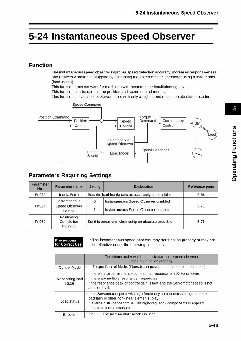
5-24 Instantaneous Speed Observer
Op
erat
ing
Fu
nct
ion
s
5
5-24 Instantaneous Speed Observer
FunctionThe instantaneous speed observer improves speed detection accuracy, increases responsiveness, and reduces vibration at stopping by estimating the speed of the Servomotor using a load model (load inertia).This function does not work for machines with resonance or insufficient rigidity. This function can be used in the position and speed control modes. This function is available for Servomotors with only a high speed resolution absolute encoder.
Parameters Requiring SettingsParameter
No.Parameter name Setting Explanation Reference page
Pn020 Inertia Ratio Sets the load inertia ratio as accurately as possible. 5-68
Pn027Instantaneous
Speed Observer Setting
0 Instantaneous Speed Observer disabled5-71
1 Instantaneous Speed Observer enabled
Pn060Positioning Completion
Range 1Set this parameter when using an absolute encoder. 5-75
The instantaneous speed observer may not function properly or may not be effective under the following conditions.
Conditions under which the instantaneous speed observer does not function properly
Control Mode In Torque Control Mode. (Operates in position and speed control modes)
Resonating loadstatus
If there’s a large resonance point at the frequency of 300 Hz or lower.If there are multiple resonance frequencies. If the resonance peak or control gain is low, and the Servomotor speed is not affected by it.
Load status
If the Servomotor speed with high-frequency components changes due to backlash or other non-linear elements (play). If a large disturbance torque with high-frequency components is applied.If the load inertia changes.
Encoder If a 2,500-p/r incremental encoder is used.
Instantaneous Speed Observer
Load Model
SM
RE
Load
Estimated Speed
Position Command
Speed Feedback
PositionControl
Current LoopControl
Torque CommandSpeed
Control
Speed Command
Precautions for Correct Use
5-48
5-24 Instantaneous Speed Observer
Op
erat
ing
Fu
nct
ion
s
5
Operating Procedure1. Set the Inertia Ratio (Pn020).
Set the inertia ratio as accurately as possible.Input the calculated inertia ratio if it has already been calculated when selecting a Servomotor. If the inertia ratio is not known, perform normal mode autotuning and set the inertia ratio. Use the Pn020 setting if the Inertia Ratio (Pn020) is obtained using realtime autotuning that can be used in normal position control.
2. Adjust the gain for the position loop and speed loop. Adjust the Position Loop Gain (Pn010), Speed Loop Gain (Pn011), Speed Loop Integration Time Constant (Pn012), and Torque Command Filter Time Constant (Pn014). Use normal mode autotuning and realtime autotuning if there are no problems in doing so.
3. Set the Instantaneous Speed Observer Setting (Pn027).Set the Instantaneous Speed Observer Setting (Pn027) to 1. The speed detection method will switch to the Instantaneous Speed Observer.If the machine operating noise or vibration becomes louder, or the torque monitor waveform fluctuates significantly, return the setting to 0 and make sure the inertia ratio and adjustment parameters are correct. If improvements are seen, such as a quieter operation, less vibration, or less fluctuation in the torque monitor waveform, make fine adjustments in the Inertia Ratio (Pn020) to find the setting that makes the least fluctuation while monitoring the position deviation waveform and the actual speed waveform.If changes are made to the Position Loop Gain (Pn010), Speed Loop Gain (Pn011), or Speed Loop Integration Time Constant (Pn012), the optimum value for the Inertia Ratio (Pn020) may have changed. Readjust the value in the Inertia Ratio (Pn020) so that the fluctuation will be minimal.
5-49
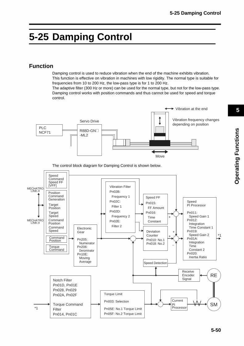
5-25 Damping Control
Op
erat
ing
Fu
nct
ion
s
5
5-25 Damping Control
FunctionDamping control is used to reduce vibration when the end of the machine exhibits vibration. This function is effective on vibration in machines with low rigidity. The normal type is suitable for frequencies from 10 to 200 Hz, the low-pass type is for 1 to 200 Hz. The adaptive filter (300 Hz or more) can be used for the normal type, but not for the low-pass type. Damping control works with position commands and thus cannot be used for speed and torque control.
The control block diagram for Damping Control is shown below.
PLCNCF71
Vibration at the end
Servo Drive
Move
Vibration frequency changes depending on position
R88D-GN@-ML2
Notch FilterPn01D, Pn01EPn028, Pn029Pn02A, Pn02F
*1SM
RE
*1+
+
+
−
MECHATROLINK-II
MECHATROLINK-II
Vibration Filter
Pn02B:
Frequency 1
Pn02C:
Filter 1
Pn02D:
Frequency 2
Pn02E:
Filter 2ElectronicGear
Pn205:Numerator
Pn206:Denominator
Pn10E:Moving Average
Speed FF
Pn015:
FF Amount
Pn016:
Time Constant
Deviation CounterPn010: No.1Pn018: No.2
Torque Command
SpeedCommandSpeed FF [VFF]
Command Position
SpeedPI Processor
Pn011: Speed Gain 1
Pn012:Integration Time Constant 1
Pn019:Speed Gain 2
Pn01A:Integration Time Constant 2
Pn020:Inertia Ratio
Speed Detection
Receive Encoder Signal
CurrentPI Processor
Torque Limit
Pn003: Selection
Pn05E: No.1 Torque Limit
Pn05F: No.2 Torque Limit
Torque Command FilterPn014, Pn01C
Position Command Generation
Target PositionTarget SpeedCommand PositionCommand Speed
5-50
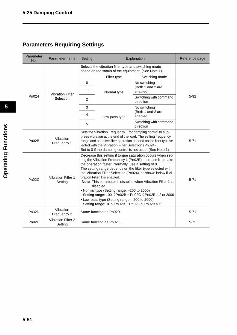
5-25 Damping Control
Op
erat
ing
Fu
nct
ion
s
5
Parameters Requiring Settings
Parameter No.
Parameter name Setting Explanation Reference page
Pn024Vibration Filter
Selection
Selects the vibration filter type and switching modebased on the status of the equipment. (See Note 1)
5-92
Filter type Switching mode
0
Normal type
No switching(Both 1 and 2 are enabled)1
2Switching with command direction
3
Low-pass type
No switching(Both 1 and 2 are enabled)4
5Switching with command direction
Pn02BVibration
Frequency 1
Sets the Vibration Frequency 1 for damping control to sup-press vibration at the end of the load. The setting frequency range and adaptive filter operation depend on the filter type se-lected with the Vibration Filter Selection (Pn024).Set to 0 if the damping control is not used. (See Note 1)
5-71
Pn02CVibration Filter 1
Setting
Decrease this setting if torque saturation occurs when set-ting the Vibration Frequency 1 (Pn02B). Increase it to make the operation faster. Normally, use a setting of 0.The setting range depends on the filter type selected with the Vibration Filter Selection (Pn024), as shown below if Vi-bration Filter 1 is enabled. Note This parameter is disabled when Vibration Filter 1 is
disabled. Normal type (Setting range: −200 to 2000)Setting range: 100 ≤ Pn02B + Pn02C ≤ Pn02B × 2 or 2000Low-pass type (Setting range: −200 to 2000)Setting range: 10 ≤ Pn02B + Pn02C ≤ Pn02B × 6
5-71
Pn02DVibration
Frequency 2Same function as Pn02B. 5-71
Pn02EVibration Filter 2
SettingSame function as Pn02C. 5-72
5-51
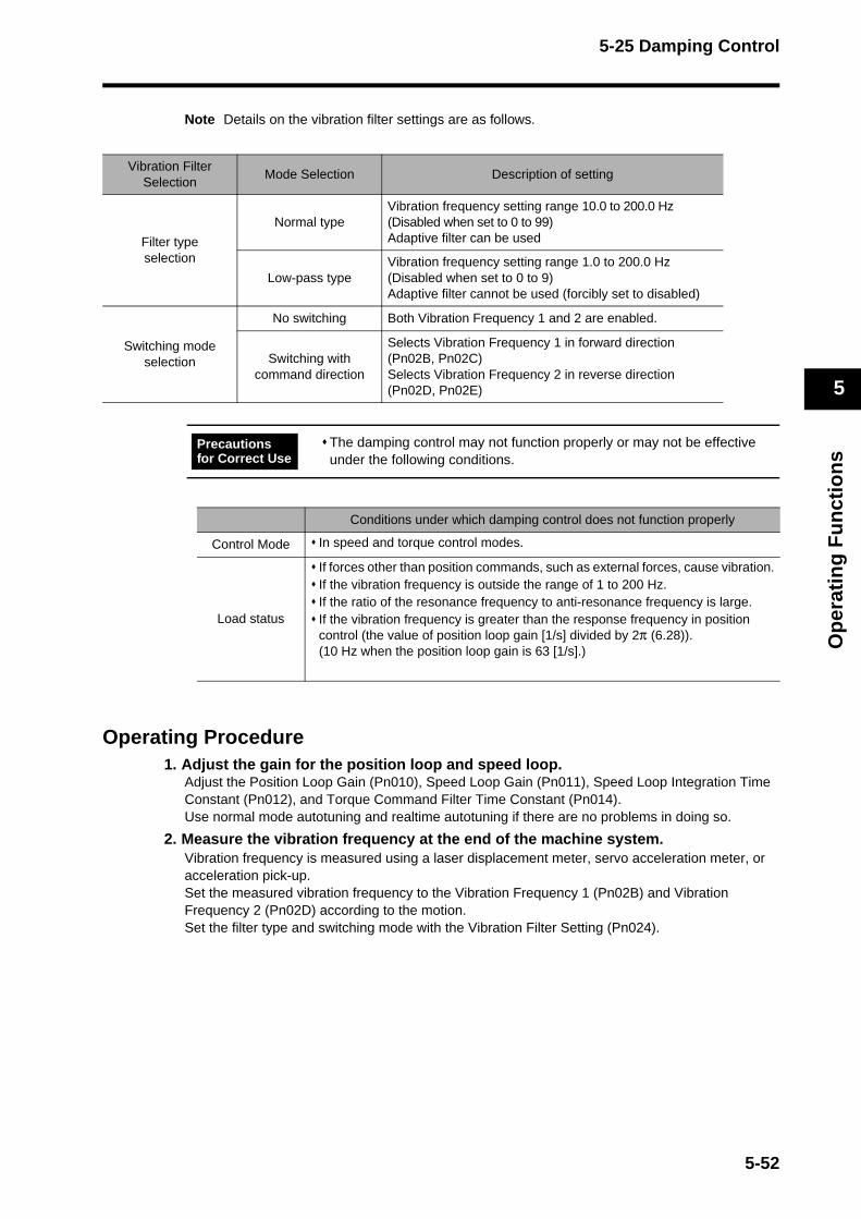
5-25 Damping Control
Op
erat
ing
Fu
nct
ion
s
5
Note Details on the vibration filter settings are as follows.
Operating Procedure1. Adjust the gain for the position loop and speed loop.
Adjust the Position Loop Gain (Pn010), Speed Loop Gain (Pn011), Speed Loop Integration Time Constant (Pn012), and Torque Command Filter Time Constant (Pn014). Use normal mode autotuning and realtime autotuning if there are no problems in doing so.
2. Measure the vibration frequency at the end of the machine system. Vibration frequency is measured using a laser displacement meter, servo acceleration meter, or acceleration pick-up. Set the measured vibration frequency to the Vibration Frequency 1 (Pn02B) and Vibration Frequency 2 (Pn02D) according to the motion. Set the filter type and switching mode with the Vibration Filter Setting (Pn024).
Vibration Filter Selection
Mode Selection Description of setting
Filter typeselection
Normal typeVibration frequency setting range 10.0 to 200.0 Hz(Disabled when set to 0 to 99)Adaptive filter can be used
Low-pass typeVibration frequency setting range 1.0 to 200.0 Hz(Disabled when set to 0 to 9)Adaptive filter cannot be used (forcibly set to disabled)
Switching mode selection
No switching Both Vibration Frequency 1 and 2 are enabled.
Switching with command direction
Selects Vibration Frequency 1 in forward direction (Pn02B, Pn02C)Selects Vibration Frequency 2 in reverse direction (Pn02D, Pn02E)
The damping control may not function properly or may not be effective under the following conditions.
Conditions under which damping control does not function properly
Control Mode In speed and torque control modes.
Load status
If forces other than position commands, such as external forces, cause vibration.If the vibration frequency is outside the range of 1 to 200 Hz.If the ratio of the resonance frequency to anti-resonance frequency is large.If the vibration frequency is greater than the response frequency in position control (the value of position loop gain [1/s] divided by 2π (6.28)).(10 Hz when the position loop gain is 63 [1/s].)
Precautions for Correct Use
5-52

5-25 Damping Control
Op
erat
ing
Fu
nct
ion
s
5
If no measurement device is available, use the CX-Drive data tracing function, and read the residual vibration frequency (Hz) from the position deviation waveform as shown in the following figure.
If the vibration does not disappear with the frequency setting, raise or lower the resonance frequency to find the frequency that can reduce vibration.
3. Set the Vibration Filter.Set Vibration Filter 1 (Pn02C) and Vibration Filter 2 (Pn02E). First, set to 0.The stabilization time can be reduced by setting a large value; however, torque ripple will increase at the command change point as shown in the following figure. Set a range that will not cause torque saturation under actual operation conditions. The effects of vibration suppression will be lost if torque saturation occurs.
Decrease this setting if torque saturation occurs when setting the Vibration Frequency 1 (Pn02B). Increase it to make the movement faster. Normally, use a setting of 0.The setting range depends on the filter type selected with the Vibration Filter Selection (Pn024), as shown below if Vibration Filter 1 is enabled.
Normal type (Setting range: −200 to 2000)Setting range: 100 ≤ Pn02B + Pn02C ≤ Pn02B × 2 or 2000Low-pass type (Setting range: −200 to 2000)Setting range: 10 ≤ Pn02B + Pn02C ≤ Pn02B × 6
Note This parameter is disabled when Vibration Filter 1 is disabled.
The following gives the vibration frequency in the figure.
Since the unit for the parameter is 0.1Hz: (Pn02B, Pn02D) = 10 × f
Example:When the vibration cycle is 100 ms and 20 ms, the vibration frequency is 10 Hz and 40 Hz, therefore set Pn02B = 100, Pn02D = 400.
Command speed
Position deviation
Calculation of vibration frequency
Vibration cycle T
1f (Hz) =
T(s)
Vibration filter setting appropriate
Torque command
Vibration filter setting too large
Torque saturation
5-53
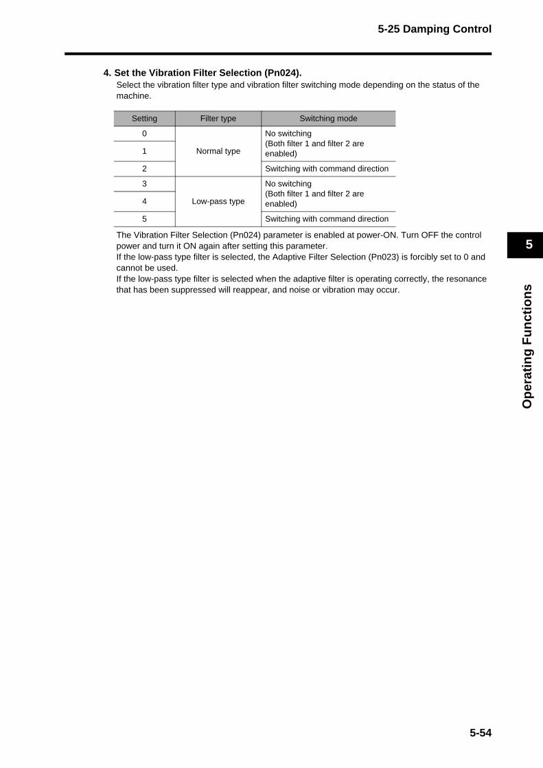
5-25 Damping Control
Op
erat
ing
Fu
nct
ion
s
5
4. Set the Vibration Filter Selection (Pn024).Select the vibration filter type and vibration filter switching mode depending on the status of the machine.
The Vibration Filter Selection (Pn024) parameter is enabled at power-ON. Turn OFF the control power and turn it ON again after setting this parameter.If the low-pass type filter is selected, the Adaptive Filter Selection (Pn023) is forcibly set to 0 and cannot be used. If the low-pass type filter is selected when the adaptive filter is operating correctly, the resonance that has been suppressed will reappear, and noise or vibration may occur.
Setting Filter type Switching mode
0
Normal type
No switching(Both filter 1 and filter 2 are enabled)1
2 Switching with command direction
3
Low-pass type
No switching(Both filter 1 and filter 2 are enabled)4
5 Switching with command direction
5-54

5-26 User Parameters
Op
erat
ing
Fu
nct
ion
s
5
5-26 User ParametersSet and check the user parameters in Parameter Setting Mode.Fully understand what the parameters mean and the setting procedures, and set the parameters according to the system.Some parameters are enabled by turning the power OFF and then ON again. After changing these parameters, turn OFF the power, confirm that the power indicator has gone OFF, and then turn ON the power again.
Setting and Checking Parameters
OverviewUse the following procedure to set or check parameters.
Go to Parameter Setting Mode. Press the key, and then press the key once.
Select the Parameter Type --- ,
Switch to the Parameter Setting Display ---
Set the parameter number (Pn@@) --- ,
Display the parameter setting ---
Change the parameter setting --- , ,
Save the changed setting to memory and return to Parameter Setting Mode ---
Operating Procedures for 16-bit Positioning Parameters
1. Displaying Parameter Setting Mode
2. Selecting the Parameter Type
Key operation
Display example Explanation
The default display is displayed.
Press the key to display Monitor Mode.
Press the key to display Parameter Setting Mode.
Key operation
Display example Explanation
Confirm that 16-bit Parameter is selected.
Uknk_k5kpkd
1k6kbkiktkp
1k6kbkiktkp
5-55
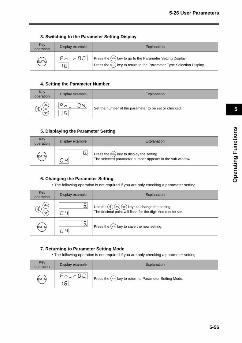
5-26 User Parameters
Op
erat
ing
Fu
nct
ion
s
5
3. Switching to the Parameter Setting Display
4. Setting the Parameter Number
5. Displaying the Parameter Setting
6. Changing the Parameter SettingThe following operation is not required if you are only checking a parameter setting.
7. Returning to Parameter Setting ModeThe following operation is not required if you are only checking a parameter setting.
Key operation
Display example Explanation
Press the key to go to the Parameter Setting Display.
Press the key to return to the Parameter Type Selection Display.
Key operation
Display example Explanation
Set the number of the parameter to be set or checked.
Key operation
Display example Explanation
Press the key to display the setting.The selected parameter number appears in the sub window.
Key operation
Display example Explanation
Use the keys to change the setting. The decimal point will flash for the digit that can be set.
Press the key to save the new setting.
Key operation
Display example Explanation
Press the key to return to Parameter Setting Mode.
pknk_krk0k0.k1k6
pknk_k k0k4.1k6
k k k k k00k4
k k k k k30k4
k k k k k30k4
pknk_krk0k0.k1k6
5-56
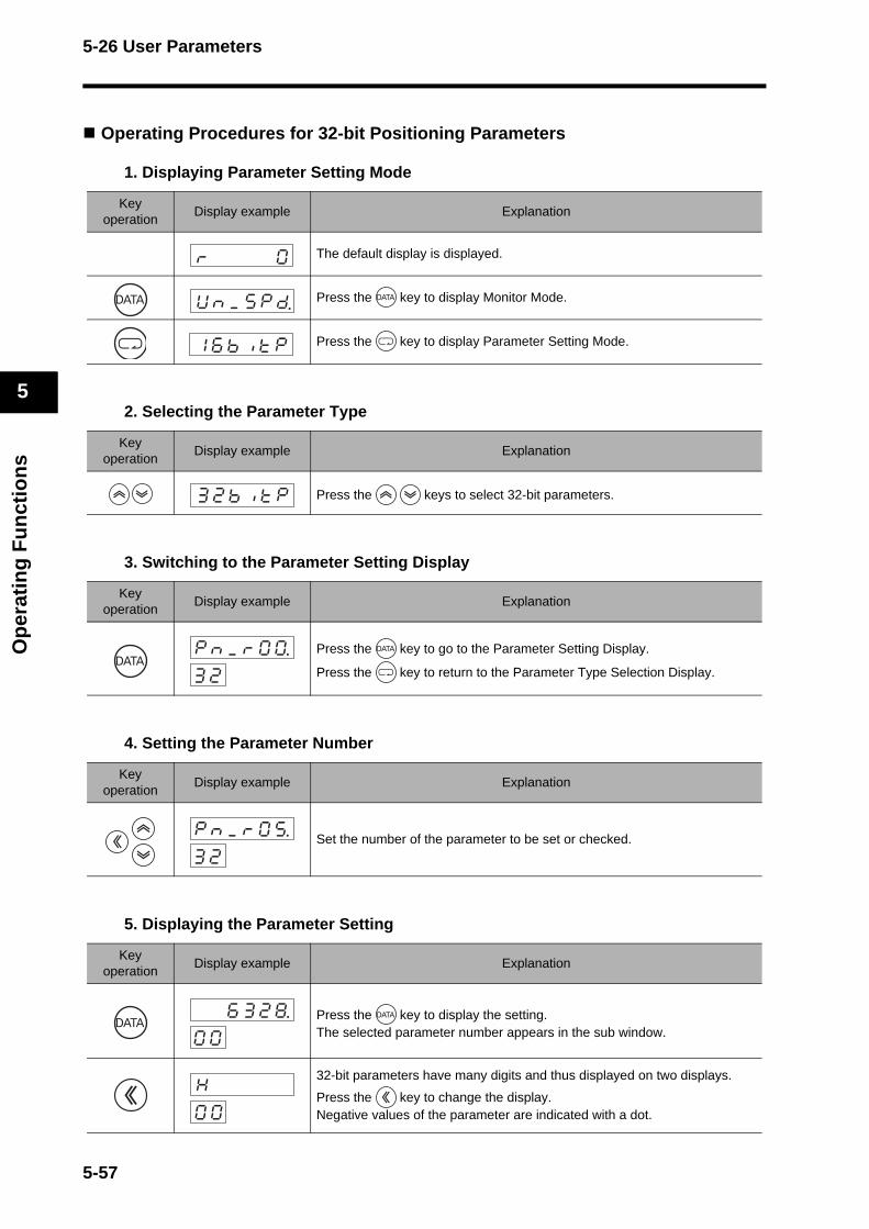
5-26 User Parameters
Op
erat
ing
Fu
nct
ion
s
5
Operating Procedures for 32-bit Positioning Parameters
1. Displaying Parameter Setting Mode
2. Selecting the Parameter Type
3. Switching to the Parameter Setting Display
4. Setting the Parameter Number
5. Displaying the Parameter Setting
Key operation
Display example Explanation
The default display is displayed.
Press the key to display Monitor Mode.
Press the key to display Parameter Setting Mode.
Key operation
Display example Explanation
Press the keys to select 32-bit parameters.
Key operation
Display example Explanation
Press the key to go to the Parameter Setting Display.
Press the key to return to the Parameter Type Selection Display.
Key operation
Display example Explanation
Set the number of the parameter to be set or checked.
Key operation
Display example Explanation
Press the key to display the setting.The selected parameter number appears in the sub window.
32-bit parameters have many digits and thus displayed on two displays.
Press the key to change the display.Negative values of the parameter are indicated with a dot.
Uknk_k5kpkd
1k6kbkiktkp
3k2kbkiktkp
pknk_krk0k0.k3k2
pknk_krk0k5.k3k2
k k6k3k2k8.0k0
Hk k k k k 0k0
5-57
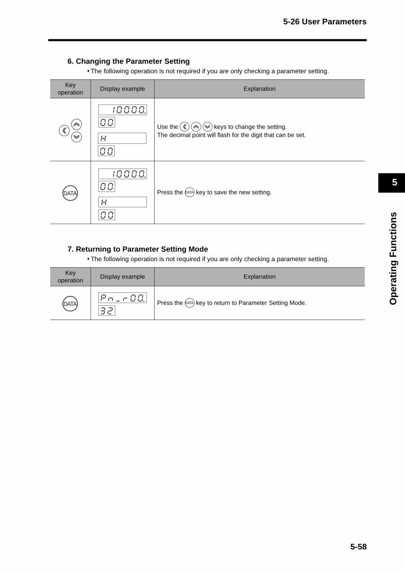
5-26 User Parameters
Op
erat
ing
Fu
nct
ion
s
5
6. Changing the Parameter SettingThe following operation is not required if you are only checking a parameter setting.
7. Returning to Parameter Setting ModeThe following operation is not required if you are only checking a parameter setting.
Key operation
Display example Explanation
Use the keys to change the setting. The decimal point will flash for the digit that can be set.
Press the key to save the new setting.
Key operation
Display example Explanation
Press the key to return to Parameter Setting Mode.
k1k0k0k0k00k0
Hk k k k k 0k0
Hk k k k k 0k0
k1k0k0k0k00k0
pknk_krk0k0.k3k2
5-58
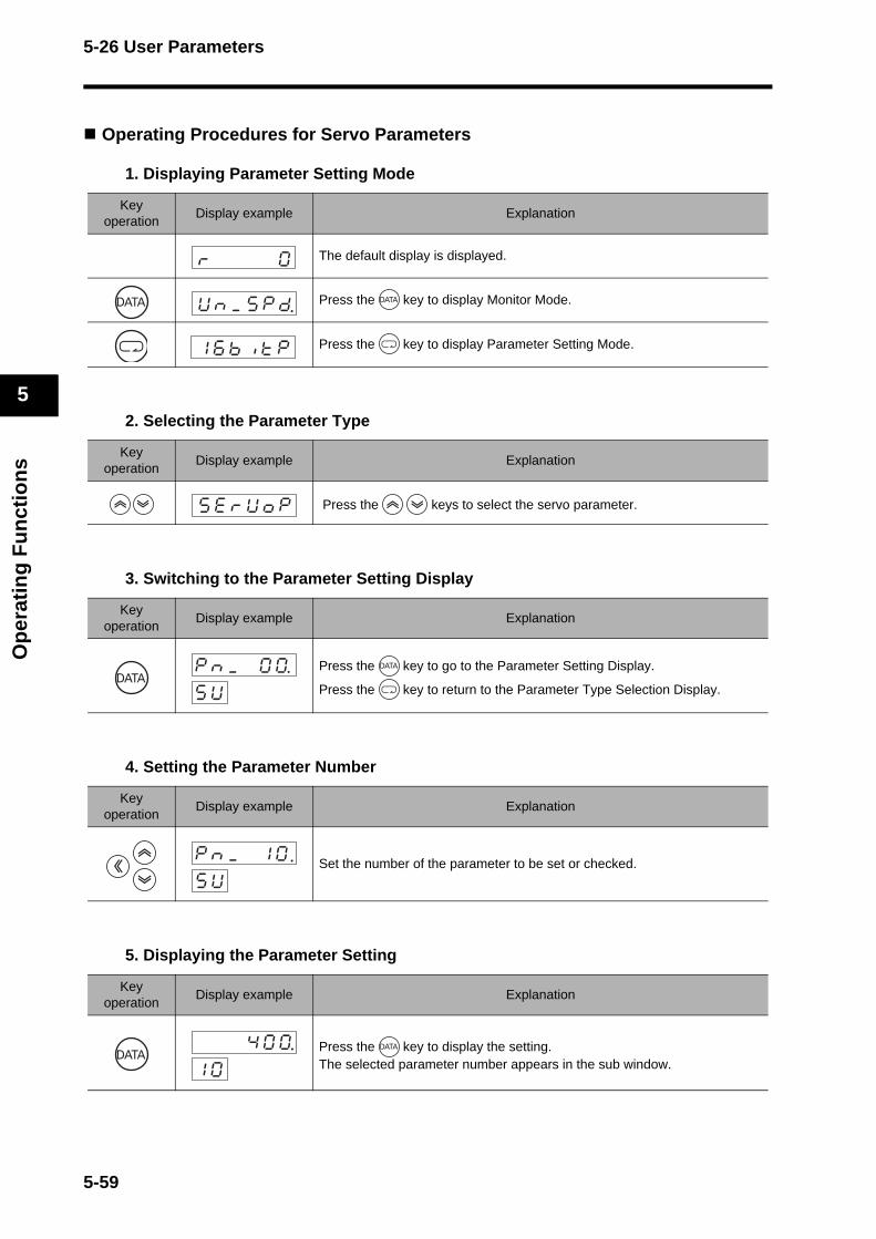
5-26 User Parameters
Op
erat
ing
Fu
nct
ion
s
5
Operating Procedures for Servo Parameters
1. Displaying Parameter Setting Mode
2. Selecting the Parameter Type
3. Switching to the Parameter Setting Display
4. Setting the Parameter Number
5. Displaying the Parameter Setting
Key operation
Display example Explanation
The default display is displayed.
Press the key to display Monitor Mode.
Press the key to display Parameter Setting Mode.
Key operation
Display example Explanation
Press the keys to select the servo parameter.
Key operation
Display example Explanation
Press the key to go to the Parameter Setting Display.
Press the key to return to the Parameter Type Selection Display.
Key operation
Display example Explanation
Set the number of the parameter to be set or checked.
Key operation
Display example Explanation
Press the key to display the setting.The selected parameter number appears in the sub window.
Uknk_k5kpkd
1k6kbkiktkp
skekrkUkokp
pknk_k k0k0.skU
pknk_k k1k0skU
k k k4k0k01k0
5-59
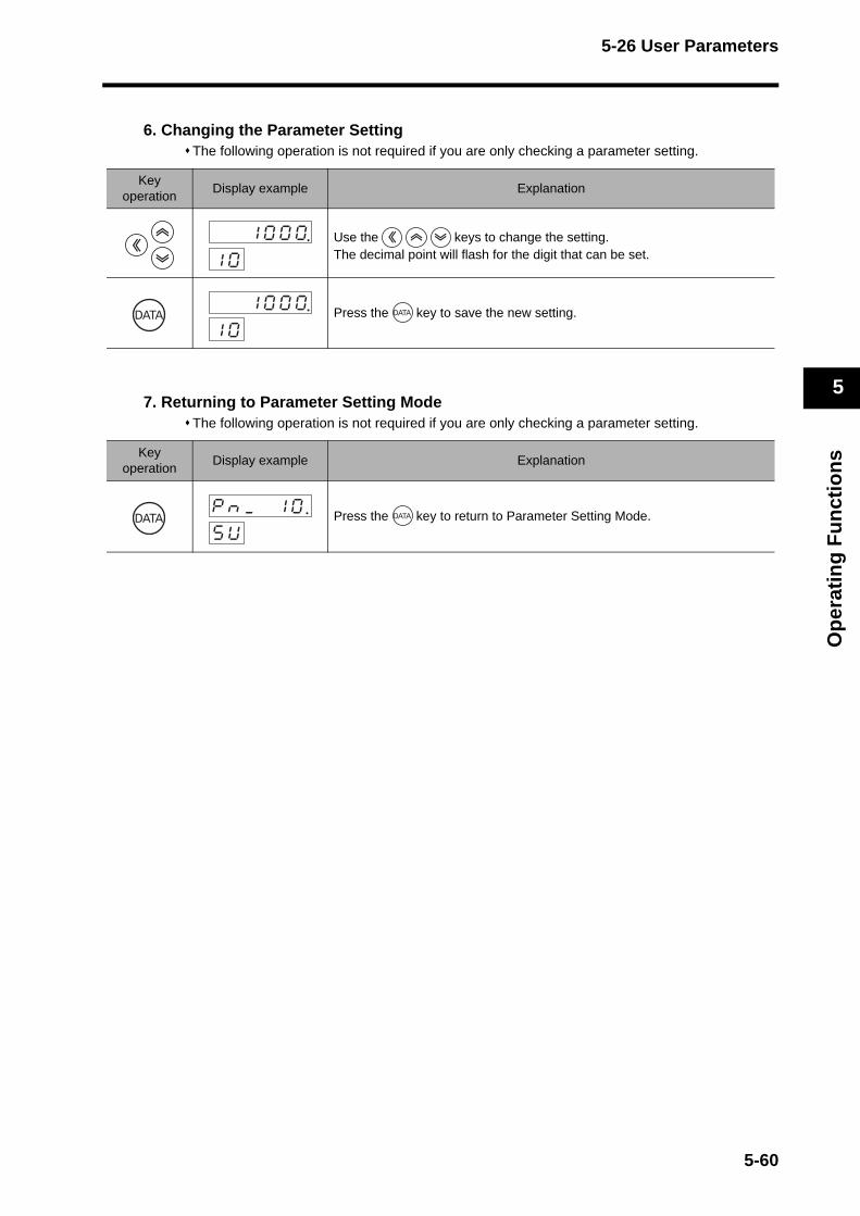
5-26 User Parameters
Op
erat
ing
Fu
nct
ion
s
5
6. Changing the Parameter SettingThe following operation is not required if you are only checking a parameter setting.
7. Returning to Parameter Setting ModeThe following operation is not required if you are only checking a parameter setting.
Key operation
Display example Explanation
Use the keys to change the setting. The decimal point will flash for the digit that can be set.
Press the key to save the new setting.
Key operation
Display example Explanation
Press the key to return to Parameter Setting Mode.
k k1k0k0k01k0
k k1k0k0k01k0
pknk_k k1k0skU
5-60
5-26 User Parameters
Op
erat
ing
Fu
nct
ion
s
5
Parameter Tables
The Servo Drive has various parameters for setting the characteristics and functions of the Servomotor. The function and purpose of each parameter is explained here. Understand the parameters to optimize the Servomotor to your operating conditions.
Servo Drive parameters are categorized by function as follows.
1. Servo ParametersThese parameters are mainly for Servomotor control such as function selection, operation settings, and gain adjustments.
2. Positioning ParametersThese parameters are for acceleration and deceleration settings and function selection related to positioning commands started by MECHATROLINK-II communications.The parameters are categorized for 16-bit positioning and 32-bit positioning depending on the setting range.
3. Reserved ParametersParameters listed as [Reserved] or unlisted parameter numbers cannot be used.Do not change the default settings of these parameters.
4. AttributesThe attribute indicates when the changed setting for the parameter will be enabled.
Note 1. Parameters marked with "(RT)" are automatically set during realtime autotuning. To set these parameters manually, disable realtime autotuning by setting the Realtime Autotuning Mode Selection (Pn021) to 0 before changing the parameter.
Note 2. Parameter No. is the number for MECHATROLINK-II communications and CX-Drive. The Parameter Unit shows only the last two digits.Parameter numbers in the 100s specify 16-bit parameters, and numbers in the 200s specify 32-bit parameters.
Note 3. A command refers to data sent from the host controller to the Servo Drive via the network (MECHATROLINK-II communications).A response refers to data sent from the Servo Drive to the host controller via the network (MECHATROLINK-II communications).
A Always enabled after change
BChange prohibited during Servomotor operation and command issuance.(It is not known when changes made during Servomotor operation and command issuance will be enabled.)
CEnabled when the control power is reset, or when a CONFIG command is executed via the network (MECHATROLINK-II communications).
R Read-only and cannot be changed.
MECHATROLINK-II Com-munications Parameter No.
Category
0@@h Servo parameter numbers
1@@h 16-bit positioning parameters
2@@h 32-bit positioning parameters
5-61
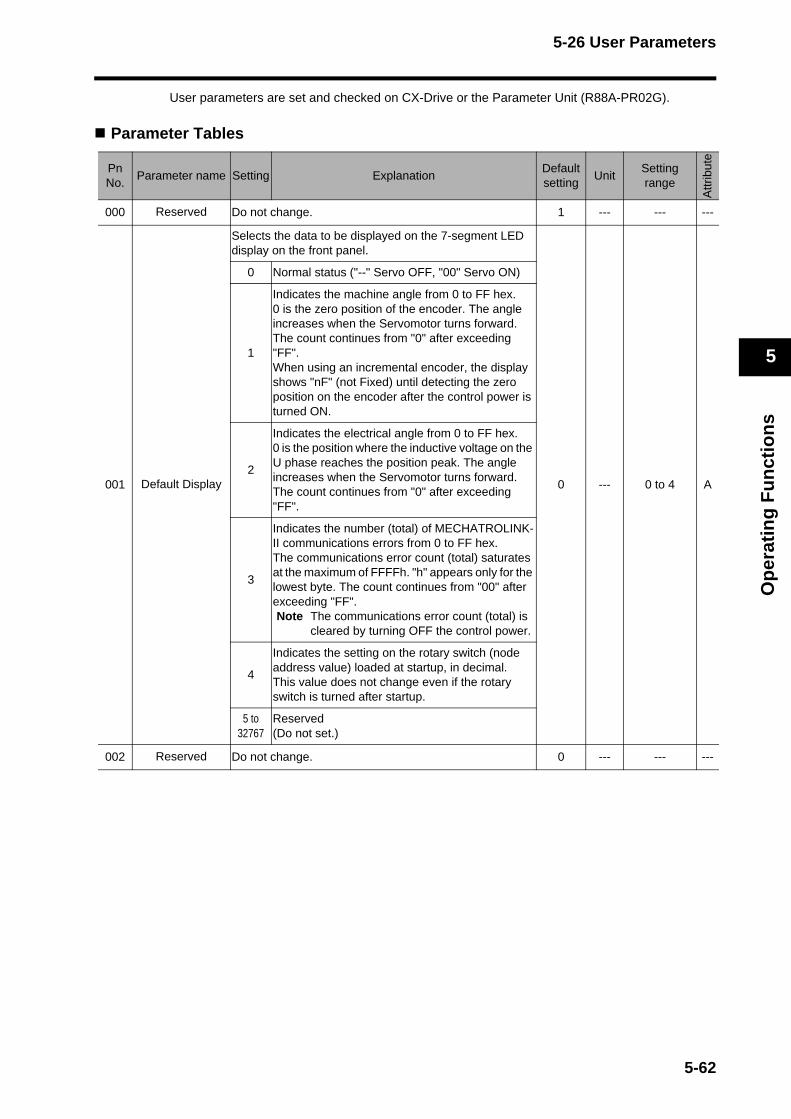
5-26 User Parameters
Op
erat
ing
Fu
nct
ion
s
5
User parameters are set and checked on CX-Drive or the Parameter Unit (R88A-PR02G).
Parameter Tables
PnNo.
Parameter name Setting ExplanationDefaultsetting
UnitSetting range
Attr
ibut
e
000 Reserved Do not change. 1 --- --- ---
001 Default Display
Selects the data to be displayed on the 7-segment LED display on the front panel.
0 --- 0 to 4 A
0 Normal status ("--" Servo OFF, "00" Servo ON)
1
Indicates the machine angle from 0 to FF hex.0 is the zero position of the encoder. The angle increases when the Servomotor turns forward.The count continues from "0" after exceeding "FF".When using an incremental encoder, the display shows "nF" (not Fixed) until detecting the zero position on the encoder after the control power is turned ON.
2
Indicates the electrical angle from 0 to FF hex.0 is the position where the inductive voltage on the U phase reaches the position peak. The angle increases when the Servomotor turns forward.The count continues from "0" after exceeding "FF".
3
Indicates the number (total) of MECHATROLINK-II communications errors from 0 to FF hex.The communications error count (total) saturates at the maximum of FFFFh. "h" appears only for the lowest byte. The count continues from "00" after exceeding "FF".Note The communications error count (total) is
cleared by turning OFF the control power.
4
Indicates the setting on the rotary switch (node address value) loaded at startup, in decimal.This value does not change even if the rotary switch is turned after startup.
5 to 32767
Reserved (Do not set.)
002 Reserved Do not change. 0 --- --- ---
5-62
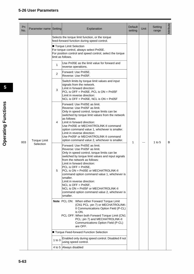
5-26 User Parameters
Op
erat
ing
Fu
nct
ion
s
5
003Torque Limit
Selection
Selects the torque limit function, or the torque feed-forward function during speed control.
1 --- 1 to 5 B
Torque Limit SelectionFor torque control, always select Pn05E.For position control and speed control, select the torque limit as follows.
1Use Pn05E as the limit value for forward and reverse operations.
2Forward: Use Pn05E.Reverse: Use Pn05F.
3
Switch limits by torque limit values and input signals from the network. Limit in forward direction:PCL is OFF = Pn05E, PCL is ON = Pn05FLimit in reverse direction: NCL is OFF = Pn05E, NCL is ON = Pn05F
4
Forward: Use Pn05E as limit.Reverse: Use Pn05F as limit.Only in speed control, torque limits can be switched by torque limit values from the network as follows:Limit in forward direction:Use Pn05E or MECHATROLINK-II command option command value 1, whichever is smaller.Limit in reverse direction:Use Pn05F or MECHATROLINK-II command option command value 2, whichever is smaller.
5
Forward: Use Pn05E as limit.Reverse: Use Pn05F as limit.Only in speed control, torque limits can be switched by torque limit values and input signals from the network as follows: Limit in forward direction: PCL is OFF = Pn05E,PCL is ON = Pn05E or MECHATROLINK-II command option command value 1, whichever is smaller.Limit in reverse direction: NCL is OFF = Pn05F, NCL is ON = Pn05F or MECHATROLINK-II command option command value 2, whichever is smaller.
Note PCL ON: When either Forward Torque Limit(CN1 PCL: pin 7) or MECHATROLINK-II Communications Option Field (P-CL) is ON.
PCL OFF: When both Forward Torque Limit (CN1 PCL: pin 7) and MECHATROLINK-II Communications Option Field (P-CL) are OFF.
Torque Feed-forward Function Selection
1 to 3Enabled only during speed control. Disabled if not using speed control.
4 to 5 Always disabled
PnNo.
Parameter name Setting ExplanationDefaultsetting
UnitSetting range
Attr
ibut
e
5-63

5-26 User Parameters
Op
erat
ing
Fu
nct
ion
s
5
004Drive Prohibit
Input Selection
Sets the function for the Forward and Reverse Drive Prohibit Inputs (CN1 POT: pin 19, NOT: pin 20)
0 --- 0 to 2 C
0
Decelerates and stops according to the sequence set in the Stop Selection for Drive Prohibition Input (Pn066) when both POT and NOT inputs are enabled.When both POT and NOT inputs are OPEN, the Drive Prohibit Input Error (alarm code 38) will occur.
1 Both POT and NOT inputs disabled.
2When either POT or NOT input becomes OPEN, the Drive Prohibit Input Error (alarm code 38) will occur.
PnNo.
Parameter name Setting ExplanationDefaultsetting
UnitSetting range
Attr
ibut
e
5-64
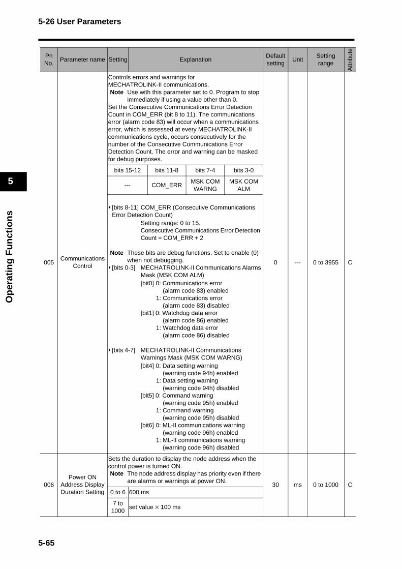
5-26 User Parameters
Op
erat
ing
Fu
nct
ion
s
5
005Communications
Control
Controls errors and warnings for MECHATROLINK-II communications.Note Use with this parameter set to 0. Program to stop
immediately if using a value other than 0.Set the Consecutive Communications Error Detection Count in COM_ERR (bit 8 to 11). The communications error (alarm code 83) will occur when a communications error, which is assessed at every MECHATROLINK-II communications cycle, occurs consecutively for the number of the Consecutive Communications Error Detection Count. The error and warning can be masked for debug purposes.
0 --- 0 to 3955 C
bits 15-12 bits 11-8 bits 7-4 bits 3-0
--- COM_ERRMSK COM WARNG
MSK COM ALM
[bits 8-11] COM_ERR (Consecutive Communications Error Detection Count)
Setting range: 0 to 15.Consecutive Communications Error Detection Count = COM_ERR + 2
Note These bits are debug functions. Set to enable (0) when not debugging.
[bits 0-3] MECHATROLINK-II Communications Alarms Mask (MSK COM ALM)[bit0] 0: Communications error
(alarm code 83) enabled1: Communications error
(alarm code 83) disabled[bit1] 0: Watchdog data error
(alarm code 86) enabled1: Watchdog data error
(alarm code 86) disabled
[bits 4-7] MECHATROLINK-II Communications Warnings Mask (MSK COM WARNG)[bit4] 0: Data setting warning
(warning code 94h) enabled1: Data setting warning
(warning code 94h) disabled[bit5] 0: Command warning
(warning code 95h) enabled1: Command warning
(warning code 95h) disabled[bit6] 0: ML-II communications warning
(warning code 96h) enabled1: ML-II communications warning
(warning code 96h) disabled
006Power ON
Address DisplayDuration Setting
Sets the duration to display the node address when the control power is turned ON.Note The node address display has priority even if there
are alarms or warnings at power ON.30 ms 0 to 1000 C
0 to 6 600 ms
7 to 1000
set value × 100 ms
PnNo.
Parameter name Setting ExplanationDefaultsetting
UnitSetting range
Attr
ibut
e
5-65
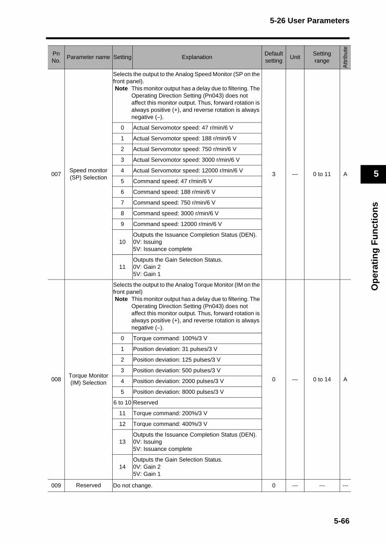
5-26 User Parameters
Op
erat
ing
Fu
nct
ion
s
5
007Speed monitor (SP) SelectionSelects the output to the Analog Speed Monitor (SP on the front panel).Note This monitor output has a delay due to filtering. The
Operating Direction Setting (Pn043) does not affect this monitor output. Thus, forward rotation is always positive (+), and reverse rotation is always negative (−).
3 --- 0 to 11 A
0 Actual Servomotor speed: 47 r/min/6 V
1 Actual Servomotor speed: 188 r/min/6 V
2 Actual Servomotor speed: 750 r/min/6 V
3 Actual Servomotor speed: 3000 r/min/6 V
4 Actual Servomotor speed: 12000 r/min/6 V
5 Command speed: 47 r/min/6 V
6 Command speed: 188 r/min/6 V
7 Command speed: 750 r/min/6 V
8 Command speed: 3000 r/min/6 V
9 Command speed: 12000 r/min/6 V
10Outputs the Issuance Completion Status (DEN).0V: Issuing5V: Issuance complete
11Outputs the Gain Selection Status.0V: Gain 25V: Gain 1
008Torque Monitor (IM) Selection
Selects the output to the Analog Torque Monitor (IM on the front panel)Note This monitor output has a delay due to filtering. The
Operating Direction Setting (Pn043) does not affect this monitor output. Thus, forward rotation is always positive (+), and reverse rotation is always negative (−).
0 --- 0 to 14 A
0 Torque command: 100%/3 V
1 Position deviation: 31 pulses/3 V
2 Position deviation: 125 pulses/3 V
3 Position deviation: 500 pulses/3 V
4 Position deviation: 2000 pulses/3 V
5 Position deviation: 8000 pulses/3 V
6 to 10 Reserved
11 Torque command: 200%/3 V
12 Torque command: 400%/3 V
13Outputs the Issuance Completion Status (DEN).0V: Issuing5V: Issuance complete
14Outputs the Gain Selection Status.0V: Gain 25V: Gain 1
009 Reserved Do not change. 0 --- --- ---
PnNo.
Parameter name Setting ExplanationDefaultsetting
UnitSetting range
Attr
ibut
e
5-66
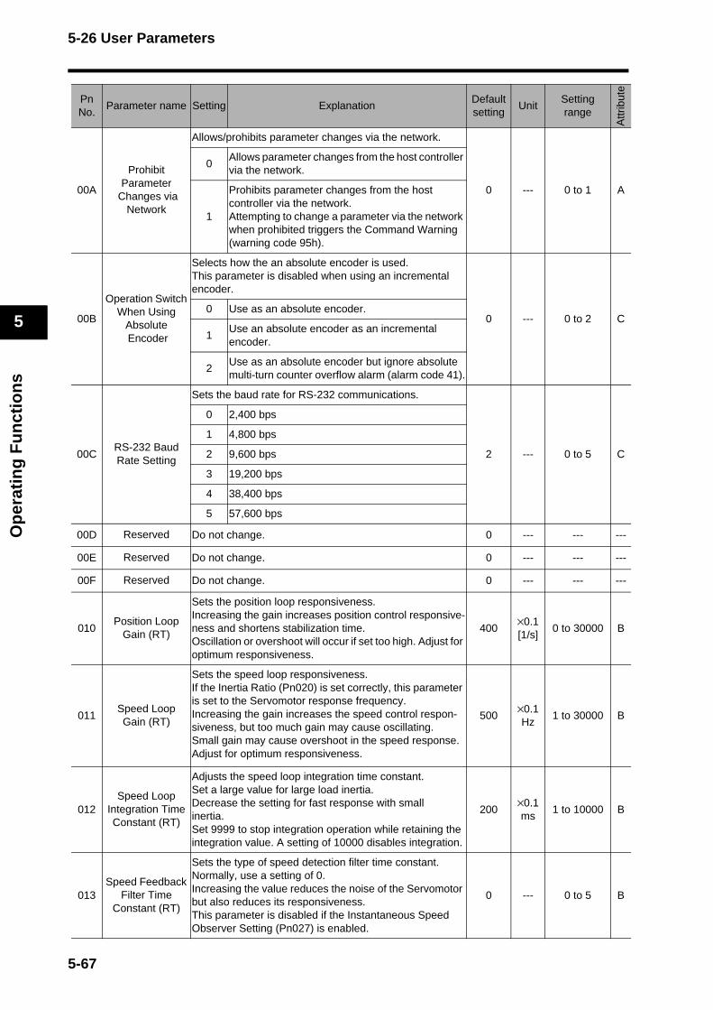
5-26 User Parameters
Op
erat
ing
Fu
nct
ion
s
5
00A
Prohibit Parameter
Changes via Network
Allows/prohibits parameter changes via the network.
0 --- 0 to 1 A
0Allows parameter changes from the host controller via the network.
1
Prohibits parameter changes from the host controller via the network.Attempting to change a parameter via the network when prohibited triggers the Command Warning (warning code 95h).
00B
Operation Switch When Using
Absolute Encoder
Selects how the an absolute encoder is used. This parameter is disabled when using an incremental encoder.
0 --- 0 to 2 C0 Use as an absolute encoder.
1Use an absolute encoder as an incremental encoder.
2Use as an absolute encoder but ignore absolute multi-turn counter overflow alarm (alarm code 41).
00CRS-232 Baud Rate Setting
Sets the baud rate for RS-232 communications.
2 --- 0 to 5 C
0 2,400 bps
1 4,800 bps
2 9,600 bps
3 19,200 bps
4 38,400 bps
5 57,600 bps
00D Reserved Do not change. 0 --- --- ---
00E Reserved Do not change. 0 --- --- ---
00F Reserved Do not change. 0 --- --- ---
010Position Loop
Gain (RT)
Sets the position loop responsiveness.Increasing the gain increases position control responsive-ness and shortens stabilization time.Oscillation or overshoot will occur if set too high. Adjust for optimum responsiveness.
400×0.1[1/s]
0 to 30000 B
011Speed LoopGain (RT)
Sets the speed loop responsiveness.If the Inertia Ratio (Pn020) is set correctly, this parameter is set to the Servomotor response frequency.Increasing the gain increases the speed control respon-siveness, but too much gain may cause oscillating. Small gain may cause overshoot in the speed response. Adjust for optimum responsiveness.
500×0.1Hz
1 to 30000 B
012Speed Loop
Integration Time Constant (RT)
Adjusts the speed loop integration time constant.Set a large value for large load inertia.Decrease the setting for fast response with small inertia. Set 9999 to stop integration operation while retaining the integration value. A setting of 10000 disables integration.
200×0.1ms
1 to 10000 B
013Speed Feedback
Filter Time Constant (RT)
Sets the type of speed detection filter time constant.Normally, use a setting of 0.Increasing the value reduces the noise of the Servomotor but also reduces its responsiveness. This parameter is disabled if the Instantaneous SpeedObserver Setting (Pn027) is enabled.
0 --- 0 to 5 B
PnNo.
Parameter name Setting ExplanationDefaultsetting
UnitSetting range
Attr
ibut
e
5-67
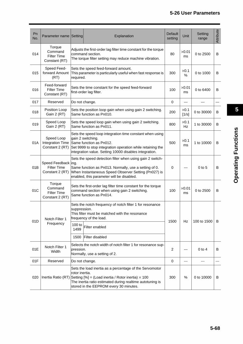
5-26 User Parameters
Op
erat
ing
Fu
nct
ion
s
5
014
Torque Command Filter Time
Constant (RT)
Adjusts the first-order lag filter time constant for the torque command section.The torque filter setting may reduce machine vibration.
80×0.01
ms0 to 2500 B
015Speed Feed-
forward Amount (RT)
Sets the speed feed-forward amount.This parameter is particularly useful when fast response is required.
300×0.1%
0 to 1000 B
016Feed-forward
Filter Time Constant (RT)
Sets the time constant for the speed feed-forward first-order lag filter.
100×0.01
ms0 to 6400 B
017 Reserved Do not change. 0 --- --- ---
018Position Loop Gain 2 (RT)
Sets the position loop gain when using gain 2 switching. Same function as Pn010.
200×0.1 [1/s]
0 to 30000 B
019Speed LoopGain 2 (RT)
Sets the speed loop gain when using gain 2 switching. Same function as Pn011.
800×0.1Hz
1 to 30000 B
01ASpeed Loop
Integration Time Constant 2 (RT)
Sets the speed loop integration time constant when using gain 2 switching. Same function as Pn012.Set 9999 to stop integration operation while retaining the integration value. Setting 10000 disables integration.
500×0.1 ms
1 to 10000 B
01BSpeed Feedback
Filter Time Constant 2 (RT)
Sets the speed detection filter when using gain 2 switch-ing. Same function as Pn013. Normally, use a setting of 0.When Instantaneous Speed Observer Setting (Pn027) is enabled, this parameter will be disabled.
0 --- 0 to 5 B
01C
Torque Command Filter Time
Constant 2 (RT)
Sets the first-order lag filter time constant for the torque command section when using gain 2 switching. Same function as Pn014.
100×0.01
ms0 to 2500 B
01DNotch Filter 1
Frequency
Sets the notch frequency of notch filter 1 for resonance suppression.This filter must be matched with the resonance frequency of the load.
1500 Hz 100 to 1500 B100 to 1499
Filter enabled
1500 Filter disabled
01ENotch Filter 1
Width
Selects the notch width of notch filter 1 for resonance sup-pression.Normally, use a setting of 2.
2 --- 0 to 4 B
01F Reserved Do not change. 0 --- --- ---
020 Inertia Ratio (RT)
Sets the load inertia as a percentage of the Servomotor rotor inertia.Setting [%] = (Load inertia / Rotor inertia) × 100The inertia ratio estimated during realtime autotuning is stored in the EEPROM every 30 minutes.
300 % 0 to 10000 B
PnNo.
Parameter name Setting ExplanationDefaultsetting
UnitSetting range
Attr
ibut
e
5-68
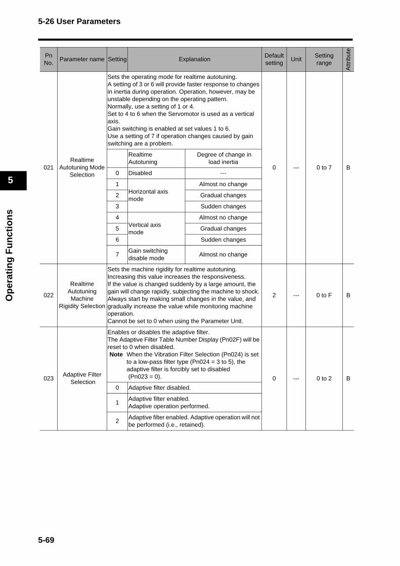
5-26 User Parameters
Op
erat
ing
Fu
nct
ion
s
5
021Realtime Autotuning Mode
Selection
Sets the operating mode for realtime autotuning.A setting of 3 or 6 will provide faster response to changes in inertia during operation. Operation, however, may be unstable depending on the operating pattern.Normally, use a setting of 1 or 4.Set to 4 to 6 when the Servomotor is used as a vertical axis.Gain switching is enabled at set values 1 to 6.Use a setting of 7 if operation changes caused by gain switching are a problem.
0 --- 0 to 7 B
Realtime Autotuning
Degree of change in load inertia
0 Disabled ---
1Horizontal axis mode
Almost no change
2 Gradual changes
3 Sudden changes
4Vertical axis mode
Almost no change
5 Gradual changes
6 Sudden changes
7Gain switching disable mode
Almost no change
022
Realtime Autotuning Machine
Rigidity Selection
Sets the machine rigidity for realtime autotuning.Increasing this value increases the responsiveness.If the value is changed suddenly by a large amount, the gain will change rapidly, subjecting the machine to shock. Always start by making small changes in the value, and gradually increase the value while monitoring machine operation.Cannot be set to 0 when using the Parameter Unit.
2 --- 0 to F B
023Adaptive Filter
Selection
Enables or disables the adaptive filter.The Adaptive Filter Table Number Display (Pn02F) will be reset to 0 when disabled.Note When the Vibration Filter Selection (Pn024) is set
to a low-pass filter type (Pn024 = 3 to 5), the adaptive filter is forcibly set to disabled (Pn023 = 0). 0 --- 0 to 2 B
0 Adaptive filter disabled.
1Adaptive filter enabled. Adaptive operation performed.
2Adaptive filter enabled. Adaptive operation will not be performed (i.e., retained).
PnNo.
Parameter name Setting ExplanationDefaultsetting
UnitSetting range
Attr
ibut
e
5-69
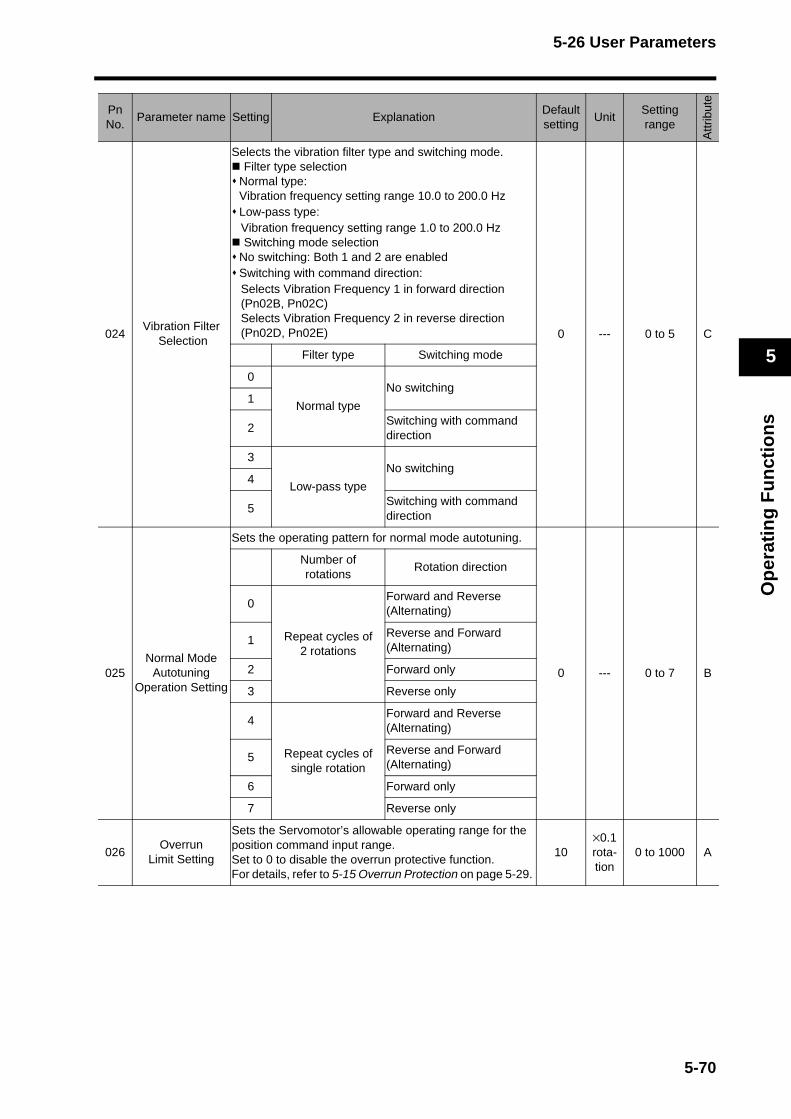
5-26 User Parameters
Op
erat
ing
Fu
nct
ion
s
5
024Vibration Filter Selection
Selects the vibration filter type and switching mode. Filter type selectionNormal type:Vibration frequency setting range 10.0 to 200.0 HzLow-pass type:Vibration frequency setting range 1.0 to 200.0 Hz Switching mode selectionNo switching: Both 1 and 2 are enabledSwitching with command direction: Selects Vibration Frequency 1 in forward direction (Pn02B, Pn02C)Selects Vibration Frequency 2 in reverse direction (Pn02D, Pn02E) 0 --- 0 to 5 C
Filter type Switching mode
0
Normal type
No switching1
2Switching with command direction
3
Low-pass type
No switching4
5Switching with command direction
025Normal Mode
Autotuning Operation Setting
Sets the operating pattern for normal mode autotuning.
0 --- 0 to 7 B
Number of rotations
Rotation direction
0
Repeat cycles of 2 rotations
Forward and Reverse (Alternating)
1Reverse and Forward(Alternating)
2 Forward only
3 Reverse only
4
Repeat cycles of single rotation
Forward and Reverse (Alternating)
5Reverse and Forward(Alternating)
6 Forward only
7 Reverse only
026Overrun
Limit Setting
Sets the Servomotor’s allowable operating range for the position command input range. Set to 0 to disable the overrun protective function.For details, refer to 5-15 Overrun Protection on page 5-29.
10×0.1rota-tion
0 to 1000 A
PnNo.
Parameter name Setting ExplanationDefaultsetting
UnitSetting range
Attr
ibut
e
5-70
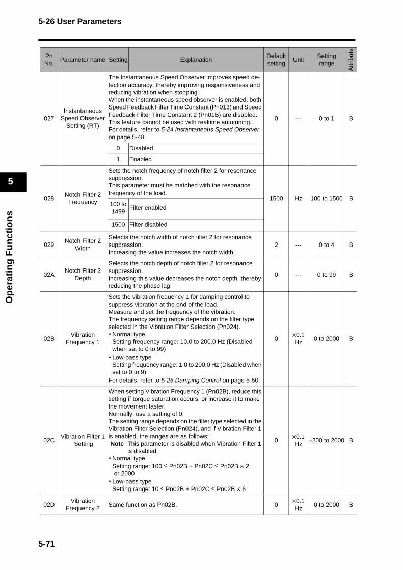
5-26 User Parameters
Op
erat
ing
Fu
nct
ion
s
5
027Instantaneous
Speed Observer Setting (RT)
The Instantaneous Speed Observer improves speed de-tection accuracy, thereby improving responsiveness and reducing vibration when stopping.When the instantaneous speed observer is enabled, both Speed Feedback Filter Time Constant (Pn013) and Speed Feedback Filter Time Constant 2 (Pn01B) are disabled.This feature cannot be used with realtime autotuning.For details, refer to 5-24 Instantaneous Speed Observer on page 5-48.
0 --- 0 to 1 B
0 Disabled
1 Enabled
028Notch Filter 2
Frequency
Sets the notch frequency of notch filter 2 for resonance suppression.This parameter must be matched with the resonance frequency of the load.
1500 Hz 100 to 1500 B100 to 1499
Filter enabled
1500 Filter disabled
029Notch Filter 2
Width
Selects the notch width of notch filter 2 for resonance suppression.Increasing the value increases the notch width.
2 --- 0 to 4 B
02ANotch Filter 2
Depth
Selects the notch depth of notch filter 2 for resonance suppression.Increasing this value decreases the notch depth, thereby reducing the phase lag.
0 --- 0 to 99 B
02BVibration
Frequency 1
Sets the vibration frequency 1 for damping control to suppress vibration at the end of the load.Measure and set the frequency of the vibration.The frequency setting range depends on the filter type selected in the Vibration Filter Selection (Pn024).
Normal typeSetting frequency range: 10.0 to 200.0 Hz (Disabled when set to 0 to 99)Low-pass typeSetting frequency range: 1.0 to 200.0 Hz (Disabled when set to 0 to 9)
For details, refer to 5-25 Damping Control on page 5-50.
0×0.1Hz
0 to 2000 B
02CVibration Filter 1
Setting
When setting Vibration Frequency 1 (Pn02B), reduce this setting if torque saturation occurs, or increase it to make the movement faster. Normally, use a setting of 0.The setting range depends on the filter type selected in the Vibration Filter Selection (Pn024), and if Vibration Filter 1 is enabled, the ranges are as follows: Note This parameter is disabled when Vibration Filter 1
is disabled. Normal typeSetting range: 100 ≤ Pn02B + Pn02C ≤ Pn02B × 2 or 2000Low-pass typeSetting range: 10 ≤ Pn02B + Pn02C ≤ Pn02B × 6
0×0.1Hz
−200 to 2000 B
02DVibration
Frequency 2Same function as Pn02B. 0
×0.1Hz
0 to 2000 B
PnNo.
Parameter name Setting ExplanationDefaultsetting
UnitSetting range
Attr
ibut
e
5-71
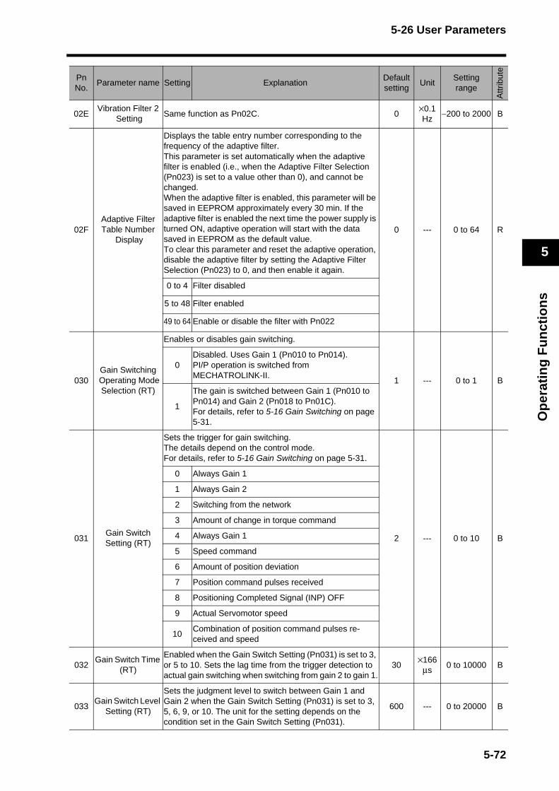
5-26 User Parameters
Op
erat
ing
Fu
nct
ion
s
5
02EVibration Filter 2
SettingSame function as Pn02C. 0
×0.1Hz
−200 to 2000 B
02FAdaptive Filter Table Number
Display
Displays the table entry number corresponding to the frequency of the adaptive filter.This parameter is set automatically when the adaptive filter is enabled (i.e., when the Adaptive Filter Selection (Pn023) is set to a value other than 0), and cannot be changed.When the adaptive filter is enabled, this parameter will be saved in EEPROM approximately every 30 min. If the adaptive filter is enabled the next time the power supply is turned ON, adaptive operation will start with the data saved in EEPROM as the default value.To clear this parameter and reset the adaptive operation, disable the adaptive filter by setting the Adaptive Filter Selection (Pn023) to 0, and then enable it again.
0 --- 0 to 64 R
0 to 4 Filter disabled
5 to 48 Filter enabled
49 to 64 Enable or disable the filter with Pn022
030Gain Switching
Operating Mode Selection (RT)
Enables or disables gain switching.
1 --- 0 to 1 B
0Disabled. Uses Gain 1 (Pn010 to Pn014).PI/P operation is switched from MECHATROLINK-II.
1
The gain is switched between Gain 1 (Pn010 to Pn014) and Gain 2 (Pn018 to Pn01C).For details, refer to 5-16 Gain Switching on page 5-31.
031Gain Switch Setting (RT)
Sets the trigger for gain switching. The details depend on the control mode.For details, refer to 5-16 Gain Switching on page 5-31.
2 --- 0 to 10 B
0 Always Gain 1
1 Always Gain 2
2 Switching from the network
3 Amount of change in torque command
4 Always Gain 1
5 Speed command
6 Amount of position deviation
7 Position command pulses received
8 Positioning Completed Signal (INP) OFF
9 Actual Servomotor speed
10Combination of position command pulses re-ceived and speed
032Gain Switch Time
(RT)
Enabled when the Gain Switch Setting (Pn031) is set to 3, or 5 to 10. Sets the lag time from the trigger detection to actual gain switching when switching from gain 2 to gain 1.
30×166
μs0 to 10000 B
033Gain Switch Level
Setting (RT)
Sets the judgment level to switch between Gain 1 and Gain 2 when the Gain Switch Setting (Pn031) is set to 3, 5, 6, 9, or 10. The unit for the setting depends on the condition set in the Gain Switch Setting (Pn031).
600 --- 0 to 20000 B
PnNo.
Parameter name Setting ExplanationDefaultsetting
UnitSetting range
Attr
ibut
e
5-72
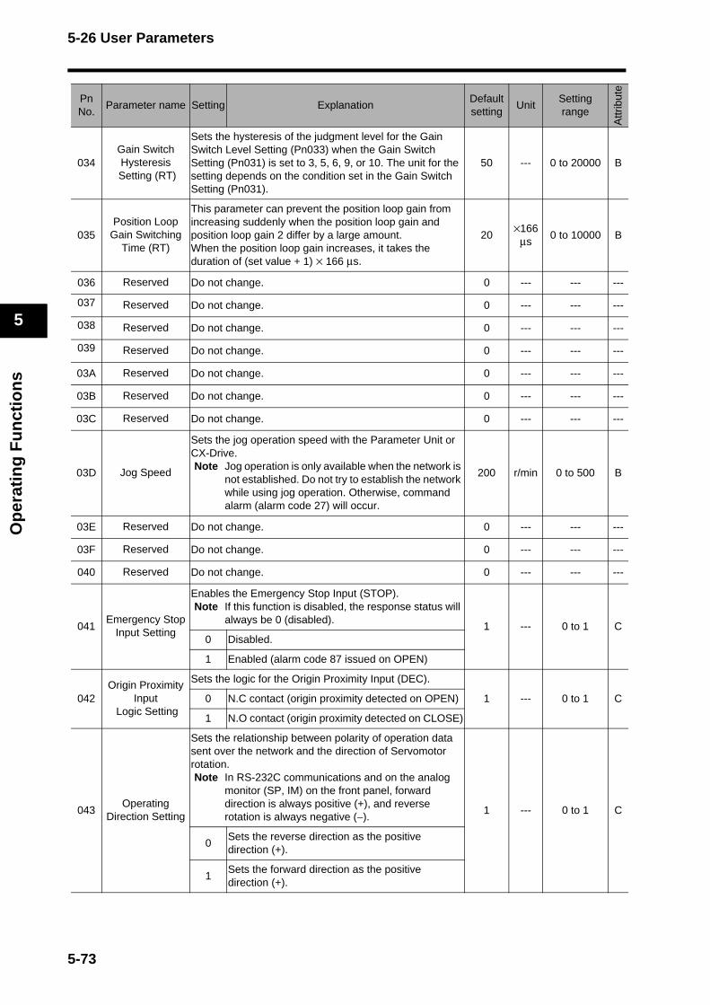
5-26 User Parameters
Op
erat
ing
Fu
nct
ion
s
5
034Gain Switch Hysteresis
Setting (RT)
Sets the hysteresis of the judgment level for the Gain Switch Level Setting (Pn033) when the Gain Switch Setting (Pn031) is set to 3, 5, 6, 9, or 10. The unit for the setting depends on the condition set in the Gain Switch Setting (Pn031).
50 --- 0 to 20000 B
035Position Loop
Gain Switching Time (RT)
This parameter can prevent the position loop gain from increasing suddenly when the position loop gain and position loop gain 2 differ by a large amount.When the position loop gain increases, it takes the duration of (set value + 1) × 166 μs.
20×166
μs0 to 10000 B
036 Reserved Do not change. 0 --- --- ---
037 Reserved Do not change. 0 --- --- ---
038 Reserved Do not change. 0 --- --- ---
039 Reserved Do not change. 0 --- --- ---
03A Reserved Do not change. 0 --- --- ---
03B Reserved Do not change. 0 --- --- ---
03C Reserved Do not change. 0 --- --- ---
03D Jog Speed
Sets the jog operation speed with the Parameter Unit or CX-Drive.Note Jog operation is only available when the network is
not established. Do not try to establish the network while using jog operation. Otherwise, command alarm (alarm code 27) will occur.
200 r/min 0 to 500 B
03E Reserved Do not change. 0 --- --- ---
03F Reserved Do not change. 0 --- --- ---
040 Reserved Do not change. 0 --- --- ---
041Emergency Stop
Input Setting
Enables the Emergency Stop Input (STOP). Note If this function is disabled, the response status will
always be 0 (disabled).1 --- 0 to 1 C
0 Disabled.
1 Enabled (alarm code 87 issued on OPEN)
042Origin Proximity
Input Logic Setting
Sets the logic for the Origin Proximity Input (DEC).
1 --- 0 to 1 C0 N.C contact (origin proximity detected on OPEN)
1 N.O contact (origin proximity detected on CLOSE)
043Operating
Direction Setting
Sets the relationship between polarity of operation data sent over the network and the direction of Servomotor rotation.Note In RS-232C communications and on the analog
monitor (SP, IM) on the front panel, forward direction is always positive (+), and reverse rotation is always negative (−).
1 --- 0 to 1 C
0Sets the reverse direction as the positive direction (+).
1Sets the forward direction as the positive direction (+).
PnNo.
Parameter name Setting ExplanationDefaultsetting
UnitSetting range
Attr
ibut
e
5-73
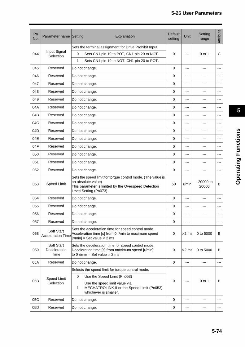
5-26 User Parameters
Op
erat
ing
Fu
nct
ion
s
5
044Input Signal
Selection
Sets the terminal assignment for Drive Prohibit Input.
0 --- 0 to 1 C0 Sets CN1 pin 19 to POT, CN1 pin 20 to NOT.
1 Sets CN1 pin 19 to NOT, CN1 pin 20 to POT.
045 Reserved Do not change. 0 --- --- ---
046 Reserved Do not change. 0 --- --- ---
047 Reserved Do not change. 0 --- --- ---
048 Reserved Do not change. 0 --- --- ---
049 Reserved Do not change. 0 --- --- ---
04A Reserved Do not change. 0 --- --- ---
04B Reserved Do not change. 0 --- --- ---
04C Reserved Do not change. 0 --- --- ---
04D Reserved Do not change. 0 --- --- ---
04E Reserved Do not change. 0 --- --- ---
04F Reserved Do not change. 0 --- --- ---
050 Reserved Do not change. 0 --- --- ---
051 Reserved Do not change. 0 --- --- ---
052 Reserved Do not change. 0 --- --- ---
053 Speed Limit
Sets the speed limit for torque control mode. (The value is an absolute value)This parameter is limited by the Overspeed Detection Level Setting (Pn073).
50 r/min−20000 to
20000B
054 Reserved Do not change. 0 --- --- ---
055 Reserved Do not change. 0 --- --- ---
056 Reserved Do not change. 0 --- --- ---
057 Reserved Do not change. 0 --- --- ---
058Soft Start
Acceleration Time
Sets the acceleration time for speed control mode.Acceleration time [s] from 0 r/min to maximum speed [r/min] = Set value × 2 ms
0 ×2 ms 0 to 5000 B
059Soft Start
Deceleration Time
Sets the deceleration time for speed control mode.Deceleration time [s] from maximum speed [r/min] to 0 r/min = Set value × 2 ms
0 ×2 ms 0 to 5000 B
05A Reserved Do not change. 0 --- --- ---
05BSpeed Limit
Selection
Selects the speed limit for torque control mode.
0 --- 0 to 1 B0 Use the Speed Limit (Pn053)
1Use the speed limit value via MECHATROLINK-II or the Speed Limit (Pn053), whichever is smaller.
05C Reserved Do not change. 0 --- --- ---
05D Reserved Do not change. 0 --- --- ---
PnNo.
Parameter name Setting ExplanationDefaultsetting
UnitSetting range
Attr
ibut
e
5-74
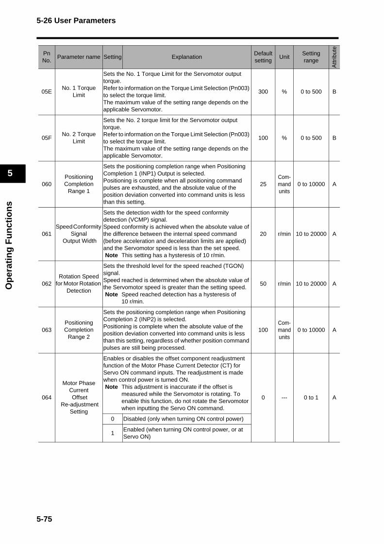
5-26 User Parameters
Op
erat
ing
Fu
nct
ion
s
5
05ENo. 1 Torque
Limit
Sets the No. 1 Torque Limit for the Servomotor output torque.Refer to information on the Torque Limit Selection (Pn003) to select the torque limit.The maximum value of the setting range depends on the applicable Servomotor.
300 % 0 to 500 B
05FNo. 2 Torque
Limit
Sets the No. 2 torque limit for the Servomotor output torque.Refer to information on the Torque Limit Selection (Pn003) to select the torque limit.The maximum value of the setting range depends on the applicable Servomotor.
100 % 0 to 500 B
060Positioning Completion
Range 1
Sets the positioning completion range when Positioning Completion 1 (INP1) Output is selected.Positioning is complete when all positioning command pulses are exhausted, and the absolute value of the position deviation converted into command units is less than this setting.
25Com-mand units
0 to 10000 A
061Speed Conformity
Signal Output Width
Sets the detection width for the speed conformity detection (VCMP) signal. Speed conformity is achieved when the absolute value of the difference between the internal speed command (before acceleration and deceleration limits are applied) and the Servomotor speed is less than the set speed. Note This setting has a hysteresis of 10 r/min.
20 r/min 10 to 20000 A
062Rotation Speed
for Motor Rotation Detection
Sets the threshold level for the speed reached (TGON) signal. Speed reached is determined when the absolute value of the Servomotor speed is greater than the setting speed.Note Speed reached detection has a hysteresis of
10 r/min.
50 r/min 10 to 20000 A
063Positioning Completion
Range 2
Sets the positioning completion range when Positioning Completion 2 (INP2) is selected.Positioning is complete when the absolute value of the position deviation converted into command units is less than this setting, regardless of whether position command pulses are still being processed.
100Com-mand units
0 to 10000 A
064
Motor Phase Current Offset
Re-adjustment Setting
Enables or disables the offset component readjustment function of the Motor Phase Current Detector (CT) for Servo ON command inputs. The readjustment is made when control power is turned ON.Note This adjustment is inaccurate if the offset is
measured while the Servomotor is rotating. To enable this function, do not rotate the Servomotor when inputting the Servo ON command.
0 --- 0 to 1 A
0 Disabled (only when turning ON control power)
1Enabled (when turning ON control power, or at Servo ON)
PnNo.
Parameter name Setting ExplanationDefaultsetting
UnitSetting range
Attr
ibut
e
5-75

5-26 User Parameters
Op
erat
ing
Fu
nct
ion
s
5
065Undervoltage
Alarm Selection
Selects whether to activate the main power supply undervoltage function (alarm code 13) when the main power supply is interrupted for the duration of the Momen-tary Hold Time (Pn06D) during Servo ON.
1 --- 0 to 1 B
0
Turns the Servo OFF according to the setting for the Stop Selection with Main Power OFF (Pn067), interrupting the positioning command generation process (positioning operation) within the Servo Drive. When the main power supply is turned back ON, Servo ON will resume. Restart the positioning operation after performing the positioning opera-tion and recovering from Servo OFF.
1
Causes an error due to main power supply undervoltage (alarm code 13).This parameter is disabled if Pn06D = 1,000.If Pn06D is set too long and the voltage between P and N in the main power supply converter drops below the specified value before a main power supply interruption is detected, a main power supply undervoltage (alarm code 13) will occur.
PnNo.
Parameter name Setting ExplanationDefaultsetting
UnitSetting range
Attr
ibut
e
5-76
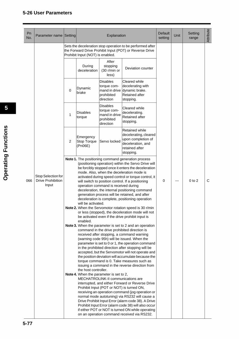
5-26 User Parameters
Op
erat
ing
Fu
nct
ion
s
5
066 Stop Selection for Drive Prohibition
Input
Sets the deceleration stop operation to be performed after the Forward Drive Prohibit Input (POT) or Reverse Drive Prohibit Input (NOT) is enabled.
0 --- 0 to 2 C
During deceleration
After stopping
(30 r/min or less)
Deviation counter
0Dynamic brake
Disables torque com-mand in drive prohibited direction
Cleared while decelerating with dynamic brake. Retained after stopping.
1Disables torque
Disables torque com-mand in drive prohibited direction
Cleared while decelerating. Retained after stopping.
2Emergency Stop Torque (Pn06E)
Servo locked
Retained while decelerating, cleared upon completion of deceleration, and retained after stopping.
Note 1. The positioning command generation process (positioning operation) within the Servo Drive will be forcibly stopped once it enters the deceleration mode. Also, when the deceleration mode is activated during speed control or torque control, it will switch to position control. If a positioning operation command is received during deceleration, the internal positioning command generation process will be retained, and after deceleration is complete, positioning operation will be activated.
Note 2. When the Servomotor rotation speed is 30 r/min or less (stopped), the deceleration mode will not be activated even if the drive prohibit input is enabled.
Note 3. When the parameter is set to 2 and an operation command in the drive prohibited direction is received after stopping, a command warning (warning code 95h) will be issued. When the parameter is set to 0 or 1, the operation command in the prohibited direction after stopping will be accepted, but the Servomotor will not operate and the position deviation will accumulate because the torque command is 0. Take measures such as issuing a command in the reverse direction from the host controller.
Note 4. When the parameter is set to 2, MECHATROLINK-II communications are interrupted, and either Forward or Reverse Drive Prohibit Input (POT or NOT) is turned ON, receiving an operation command (jog operation or normal mode autotuning) via RS232 will cause a Drive Prohibit Input Error (alarm code 38). A Drive Prohibit Input Error (alarm code 38) will also occur if either POT or NOT is turned ON while operating on an operation command received via RS232.
PnNo.
Parameter name Setting ExplanationDefaultsetting
UnitSetting range
Attr
ibut
e
5-77
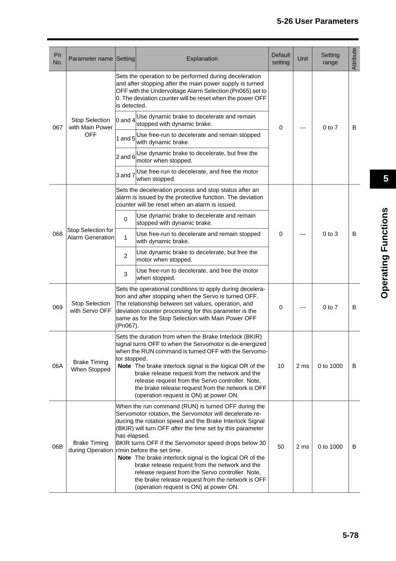
5-26 User Parameters
Op
erat
ing
Fu
nct
ion
s
5
067Stop Selection
with Main Power OFF
Sets the operation to be performed during deceleration and after stopping after the main power supply is turned OFF with the Undervoltage Alarm Selection (Pn065) set to 0. The deviation counter will be reset when the power OFF is detected.
0 --- 0 to 7 B0 and 4
Use dynamic brake to decelerate and remain stopped with dynamic brake.
1 and 5Use free-run to decelerate and remain stopped with dynamic brake.
2 and 6Use dynamic brake to decelerate, but free the motor when stopped.
3 and 7Use free-run to decelerate, and free the motor when stopped.
068Stop Selection for Alarm Generation
Sets the deceleration process and stop status after an alarm is issued by the protective function. The deviation counter will be reset when an alarm is issued.
0 --- 0 to 3 B
0Use dynamic brake to decelerate and remain stopped with dynamic brake.
1Use free-run to decelerate and remain stopped with dynamic brake.
2Use dynamic brake to decelerate, but free the motor when stopped.
3Use free-run to decelerate, and free the motor when stopped.
069Stop Selection with Servo OFF
Sets the operational conditions to apply during decelera-tion and after stopping when the Servo is turned OFF.The relationship between set values, operation, and deviation counter processing for this parameter is the same as for the Stop Selection with Main Power OFF (Pn067).
0 --- 0 to 7 B
06ABrake Timing
When Stopped
Sets the duration from when the Brake Interlock (BKIR) signal turns OFF to when the Servomotor is de-energized when the RUN command is turned OFF with the Servomo-tor stopped. Note The brake interlock signal is the logical OR of the
brake release request from the network and the release request from the Servo controller. Note, the brake release request from the network is OFF (operation request is ON) at power ON.
10 2 ms 0 to 1000 B
06BBrake Timing
during Operation
When the run command (RUN) is turned OFF during the Servomotor rotation, the Servomotor will decelerate re-ducing the rotation speed and the Brake Interlock Signal (BKIR) will turn OFF after the time set by this parameter has elapsed.BKIR turns OFF if the Servomotor speed drops below 30 r/min before the set time. Note The brake interlock signal is the logical OR of the
brake release request from the network and the release request from the Servo controller. Note, the brake release request from the network is OFF (operation request is ON) at power ON.
50 2 ms 0 to 1000 B
PnNo.
Parameter name Setting ExplanationDefaultsetting
UnitSetting range
Attr
ibut
e
5-78

5-26 User Parameters
Op
erat
ing
Fu
nct
ion
s
5
06CRegeneration
Resistor Selection
Sets the regeneration resistor operation and the regener-ation overload (alarm code 18) operation. Set this parameter to 0 if using the built-in regeneration resistor.If using an external regeneration resistor, be sure to turn OFF the main power when the built-in thermal switch is activated.
0 --- 0 to 3 C
0Sets the regeneration overload to match the built-in regeneration resistor. (regeneration load ratio below 1%)
1The regeneration overload (alarm code 18) occurs when the load ratio of the external regeneration resistor exceeds 10%.
2
The regeneration processing circuit by the external regeneration resistor is activated, but the regeneration overload (alarm code 18) does not occur.
3The regeneration processing circuit is not activat-ed. All regenerative energy is absorbed by the built-in capacitor.
06DMomentary Hold
Time
Sets the amount of time required to detect shutoff when the main power supply continues to shut off.The main power OFF detection will be disabled if this parameter is set to 1000.
35 2 ms 35 to 1000 C
06EEmergency Stop
Torque
Sets the torque limit during deceleration because of the Drive Prohibition Input when the Stop Selection for Drive Prohibition Input (Pn066) is set to 2. When this parameter is set to 0, the normal torque limit will be set.The maximum value of the setting range depends on the Servomotor.
0 % 0 to 300 B
06F Reserved Do not change. 0 --- --- ---
070 Reserved Do not change. 0 --- --- ---
071 Reserved Do not change. 0 --- --- ---
072Overload Detection
Level Setting
Sets the overload detection level.The overload detection level will be set at 115% if this parameter is set to 0.Normally, use a setting of 0, and set the level only when reducing the overload detection level.
0 % 0 to 500 A
073Overspeed Detection
Level Setting
Sets the overspeed detection level.The overspeed detection level is 1.2 times the maximum Servomotor rotation speed when the parameter is set to 0. Normally, use a setting of 0, and set the level only when reducing the overspeed detection level.Note The detection margin of error for the setting is
±3 r/min for a 7-core absolute encoder and ±36 r/min for a 5-core incremental encoder.
0 r/min 0 to 20000 A
074 Reserved Do not change. 0 --- --- ---
075 Reserved Do not change. 0 --- --- ---
076 Reserved Do not change. 0 --- --- ---
077 Reserved Do not change. 0 --- --- ---
PnNo.
Parameter name Setting ExplanationDefaultsetting
UnitSetting range
Attr
ibut
e
5-79
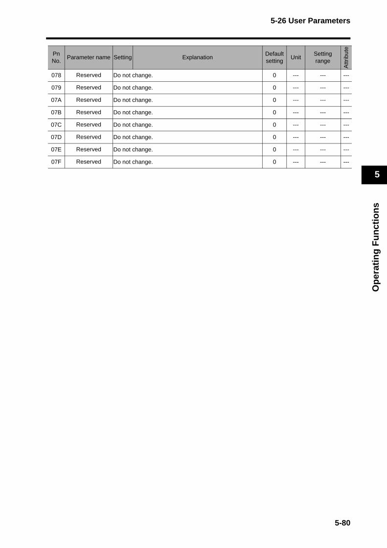
5-26 User Parameters
Op
erat
ing
Fu
nct
ion
s
5
078 Reserved Do not change. 0 --- --- ---
079 Reserved Do not change. 0 --- --- ---
07A Reserved Do not change. 0 --- --- ---
07B Reserved Do not change. 0 --- --- ---
07C Reserved Do not change. 0 --- --- ---
07D Reserved Do not change. 0 --- --- ---
07E Reserved Do not change. 0 --- --- ---
07F Reserved Do not change. 0 --- --- ---
PnNo.
Parameter name Setting ExplanationDefaultsetting
UnitSetting range
Attr
ibut
e
5-80

5-26 User Parameters
Op
erat
ing
Fu
nct
ion
s
5
16-bit Positioning Parameters: Parameter No. 100 to 13F
PnNo.
Parameter nameSet-ting
ExplanationDefaultsetting
UnitSetting range
Attr
ibut
e
100Backlash
Compensation Selection
Enables or disables the backlash compensation for position control, and sets the compensation direction.
0 --- 0 to 2 C
0 Disabled
1Compensates in the initial positive direction after the Servo ON.
2Compensates in the initial negative direction after the Servo ON.
101Backlash
CompensationSets the backlash compensation amount for position control.
0Com-mand units
−32768 to 32767
B
102Backlash
Compensation Time Constant
Sets the backlash compensation time constant for posi-tion control.
00.01 ms
0 to 6400 B
Value of Pn100
Pn101 = Positive number
Pn101 = Negative number
1
Compensates in positive direction during rotation in positive direction
Compensates in negative direction during rotation in positive direction
2
Compensates in positive direction during rotation in negative direction
Compensates in negative direction during rotation in negative direction
103 Reserved Do not change. 0 --- --- ---
104 Soft Limit
Enables or disables the soft limit.When enabled, the soft limit values are set in Forward Software Limit (Pn201) and Reverse Software Limit (Pn202).Note The response value for limit signals disabled by
this setting will be set to 0.The response value for limit signals is also set to 0 when the Servomotor does not complete its return to origin.
0 --- 0 to 3 A0
Enable both the Forward / Reverse Software Limits (Pn201 and Pn202)
1Disable the Forward Software Limit (Pn201), enable the Reverse Software Limit (Pn202)
2Enable the Forward Software Limit (Pn201), disable the Reverse Software Limit (Pn202)
3Disable both the Forward / Reverse Software Limits (Pn201 and Pn202)
105 Origin Range
Sets the threshold for detecting the origin (ZPOINT) in absolute values.ZPOINT = 1 when the return to origin completes (coordi-nate system setup is complete) and the feedback position is within the setting range of this parameter.
10Com-mand units
0 to 250 A
106 Reserved Do not change. 0 --- --- ---
5-81
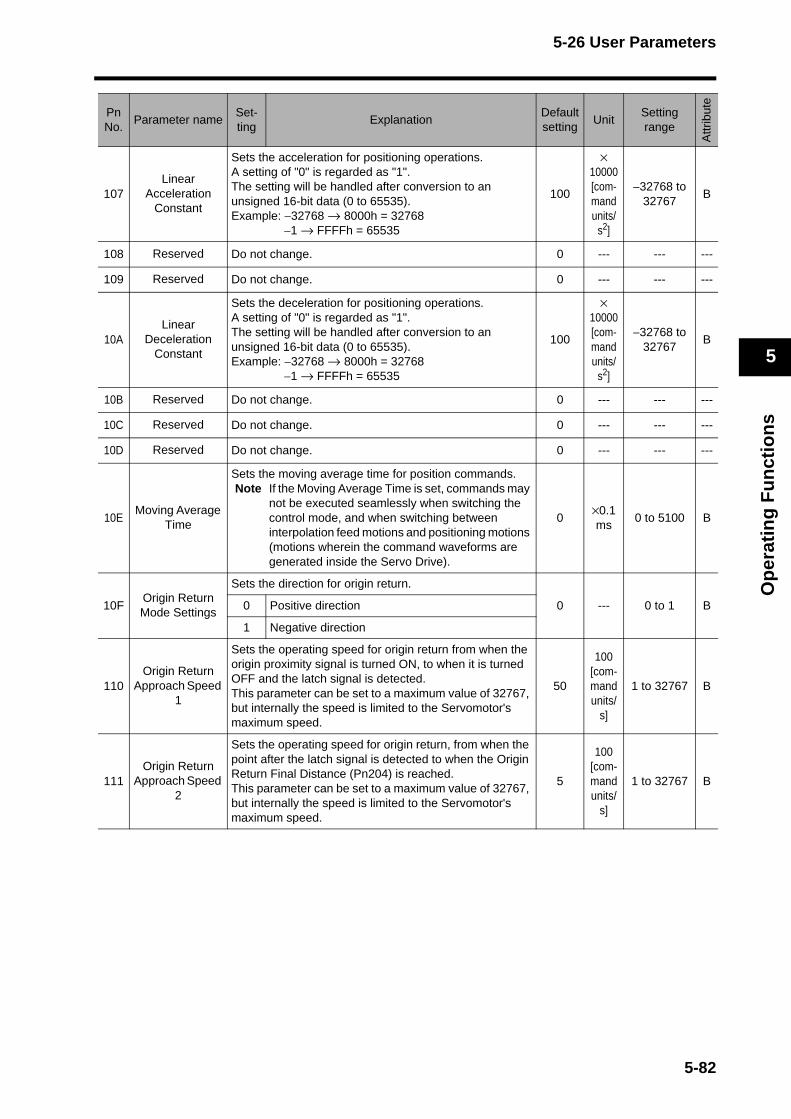
5-26 User Parameters
Op
erat
ing
Fu
nct
ion
s
5
107Linear
Acceleration Constant
Sets the acceleration for positioning operations.A setting of "0" is regarded as "1". The setting will be handled after conversion to an unsigned 16-bit data (0 to 65535). Example: −32768 → 8000h = 32768
−1 → FFFFh = 65535
100
× 10000 [com-mand units/
s2]
−32768 to 32767
B
108 Reserved Do not change. 0 --- --- ---
109 Reserved Do not change. 0 --- --- ---
10ALinear
Deceleration Constant
Sets the deceleration for positioning operations.A setting of "0" is regarded as "1". The setting will be handled after conversion to an unsigned 16-bit data (0 to 65535). Example: −32768 → 8000h = 32768
−1 → FFFFh = 65535
100
× 10000 [com-mand units/
s2]
−32768 to 32767
B
10B Reserved Do not change. 0 --- --- ---
10C Reserved Do not change. 0 --- --- ---
10D Reserved Do not change. 0 --- --- ---
10EMoving Average
Time
Sets the moving average time for position commands.Note If the Moving Average Time is set, commands may
not be executed seamlessly when switching the control mode, and when switching between interpolation feed motions and positioning motions (motions wherein the command waveforms are generated inside the Servo Drive).
0×0.1 ms
0 to 5100 B
10FOrigin Return Mode Settings
Sets the direction for origin return.
0 --- 0 to 1 B0 Positive direction
1 Negative direction
110Origin Return
Approach Speed 1
Sets the operating speed for origin return from when the origin proximity signal is turned ON, to when it is turned OFF and the latch signal is detected. This parameter can be set to a maximum value of 32767, but internally the speed is limited to the Servomotor's maximum speed.
50
100 [com-mand units/
s]
1 to 32767 B
111Origin Return
Approach Speed 2
Sets the operating speed for origin return, from when the point after the latch signal is detected to when the Origin Return Final Distance (Pn204) is reached.This parameter can be set to a maximum value of 32767, but internally the speed is limited to the Servomotor's maximum speed.
5
100 [com-mand units/
s]
1 to 32767 B
PnNo.
Parameter nameSet-ting
ExplanationDefaultsetting
UnitSetting range
Attr
ibut
e
5-82
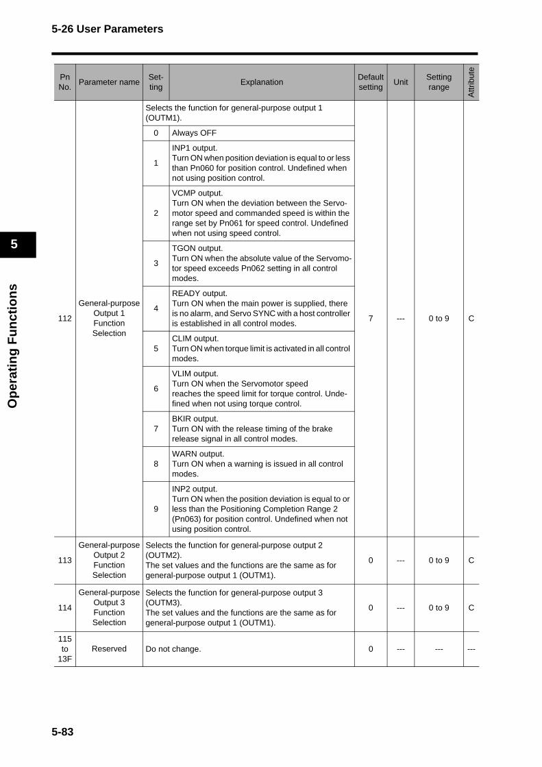
5-26 User Parameters
Op
erat
ing
Fu
nct
ion
s
5
112
General-purpose Output 1 Function Selection
Selects the function for general-purpose output 1 (OUTM1).
7 --- 0 to 9 C
0 Always OFF
1
INP1 output.Turn ON when position deviation is equal to or less than Pn060 for position control. Undefined when not using position control.
2
VCMP output.Turn ON when the deviation between the Servo-motor speed and commanded speed is within the range set by Pn061 for speed control. Undefined when not using speed control.
3
TGON output.Turn ON when the absolute value of the Servomo-tor speed exceeds Pn062 setting in all control modes.
4
READY output.Turn ON when the main power is supplied, there is no alarm, and Servo SYNC with a host controller is established in all control modes.
5CLIM output.Turn ON when torque limit is activated in all control modes.
6
VLIM output.Turn ON when the Servomotor speed reaches the speed limit for torque control. Unde-fined when not using torque control.
7BKIR output.Turn ON with the release timing of the brake release signal in all control modes.
8WARN output.Turn ON when a warning is issued in all control modes.
9
INP2 output.Turn ON when the position deviation is equal to or less than the Positioning Completion Range 2 (Pn063) for position control. Undefined when not using position control.
113
General-purpose Output 2 Function Selection
Selects the function for general-purpose output 2 (OUTM2). The set values and the functions are the same as for general-purpose output 1 (OUTM1).
0 --- 0 to 9 C
114
General-purpose Output 3 Function Selection
Selects the function for general-purpose output 3 (OUTM3). The set values and the functions are the same as for general-purpose output 1 (OUTM1).
0 --- 0 to 9 C
115 to
13FReserved Do not change. 0 --- --- ---
PnNo.
Parameter nameSet-ting
ExplanationDefaultsetting
UnitSetting range
Attr
ibut
e
5-83
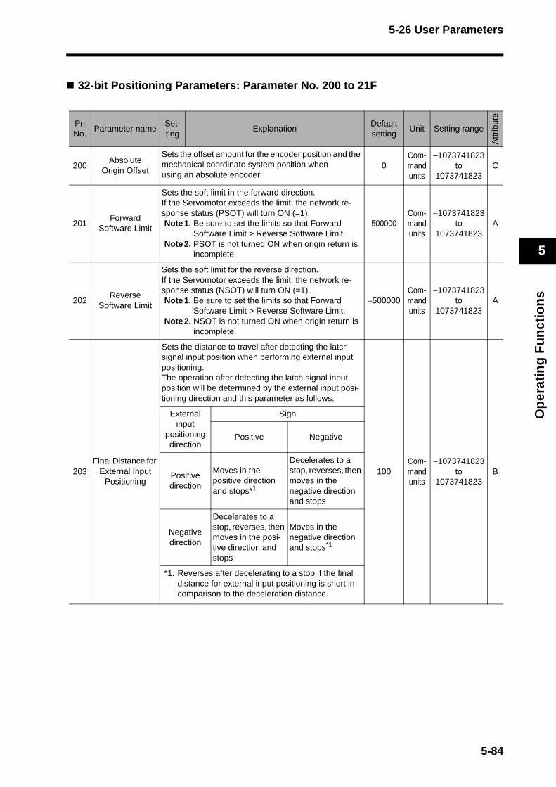
5-26 User Parameters
Op
erat
ing
Fu
nct
ion
s
5
32-bit Positioning Parameters: Parameter No. 200 to 21F
PnNo.
Parameter nameSet-ting
ExplanationDefaultsetting
Unit Setting range
Attr
ibut
e
200Absolute
Origin Offset
Sets the offset amount for the encoder position and the mechanical coordinate system position when using an absolute encoder.
0Com-mand units
−1073741823 to
1073741823C
201Forward
Software Limit
Sets the soft limit in the forward direction. If the Servomotor exceeds the limit, the network re-sponse status (PSOT) will turn ON (=1).Note1. Be sure to set the limits so that Forward
Software Limit > Reverse Software Limit.Note2. PSOT is not turned ON when origin return is
incomplete.
500000Com-mand units
−1073741823 to
1073741823A
202Reverse
Software Limit
Sets the soft limit for the reverse direction. If the Servomotor exceeds the limit, the network re-sponse status (NSOT) will turn ON (=1).Note1. Be sure to set the limits so that Forward
Software Limit > Reverse Software Limit.Note2. NSOT is not turned ON when origin return is
incomplete.
−500000Com-mand units
−1073741823 to
1073741823A
203Final Distance for
External Input Positioning
Sets the distance to travel after detecting the latch signal input position when performing external input positioning. The operation after detecting the latch signal input position will be determined by the external input posi-tioning direction and this parameter as follows.
100Com-mand units
−1073741823 to
1073741823B
External input
positioning direction
Sign
Positive Negative
Positivedirection
Moves in the positive direction and stops*1
Decelerates to a stop, reverses, then moves in the negative direction and stops
Negativedirection
Decelerates to a stop, reverses, then moves in the posi-tive direction and stops
Moves in the negative direction and stops*1
*1. Reverses after decelerating to a stop if the final distance for external input positioning is short in comparison to the deceleration distance.
5-84
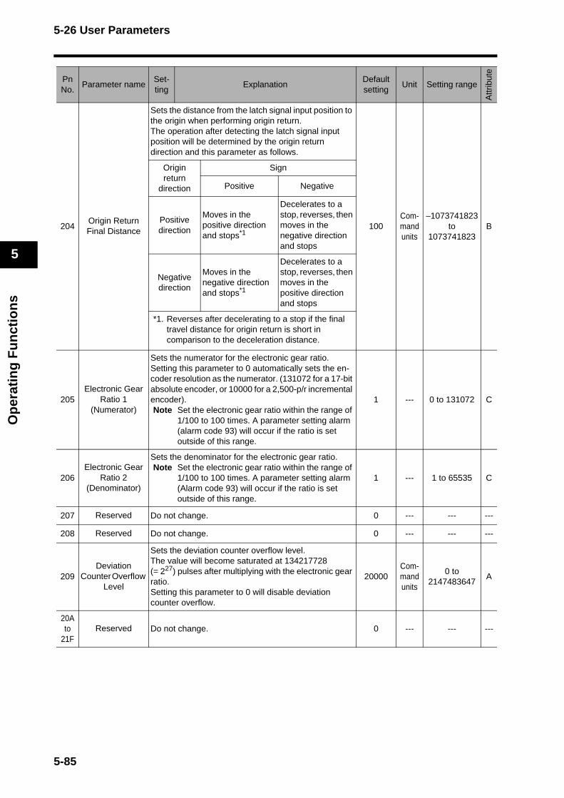
5-26 User Parameters
Op
erat
ing
Fu
nct
ion
s
5
204Origin Return Final Distance
Sets the distance from the latch signal input position to the origin when performing origin return.The operation after detecting the latch signal input position will be determined by the origin return direction and this parameter as follows.
100Com-mand units
−1073741823 to
1073741823B
Origin return
direction
Sign
Positive Negative
Positive direction
Moves in the positive direction and stops*1
Decelerates to a stop, reverses, then moves in the negative direction and stops
Negative direction
Moves in the negative direction and stops*1
Decelerates to a stop, reverses, then moves in the positive direction and stops
*1. Reverses after decelerating to a stop if the final travel distance for origin return is short in comparison to the deceleration distance.
205Electronic Gear
Ratio 1(Numerator)
Sets the numerator for the electronic gear ratio. Setting this parameter to 0 automatically sets the en-coder resolution as the numerator. (131072 for a 17-bit absolute encoder, or 10000 for a 2,500-p/r incremental encoder). Note Set the electronic gear ratio within the range of
1/100 to 100 times. A parameter setting alarm (alarm code 93) will occur if the ratio is set outside of this range.
1 --- 0 to 131072 C
206Electronic Gear
Ratio 2(Denominator)
Sets the denominator for the electronic gear ratio. Note Set the electronic gear ratio within the range of
1/100 to 100 times. A parameter setting alarm (Alarm code 93) will occur if the ratio is set outside of this range.
1 --- 1 to 65535 C
207 Reserved Do not change. 0 --- --- ---
208 Reserved Do not change. 0 --- --- ---
209Deviation
Counter Overflow Level
Sets the deviation counter overflow level.The value will become saturated at 134217728 (= 227) pulses after multiplying with the electronic gear ratio.Setting this parameter to 0 will disable deviation counter overflow.
20000Com-mand units
0 to 2147483647
A
20A to
21FReserved Do not change. 0 --- --- ---
PnNo.
Parameter nameSet-ting
ExplanationDefaultsetting
Unit Setting range
Attr
ibut
e
5-85
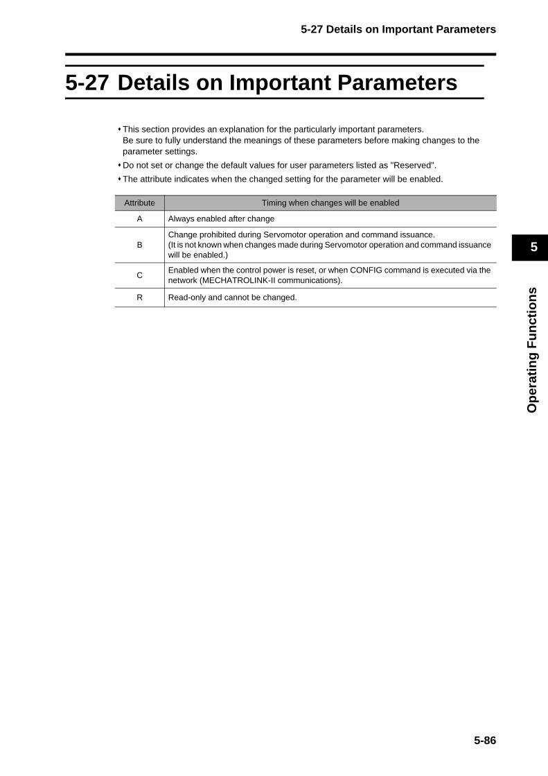
5-27 Details on Important Parameters
Op
erat
ing
Fu
nct
ion
s
5
5-27 Details on Important Parameters
This section provides an explanation for the particularly important parameters.Be sure to fully understand the meanings of these parameters before making changes to the parameter settings.
Do not set or change the default values for user parameters listed as "Reserved".
The attribute indicates when the changed setting for the parameter will be enabled.
Attribute Timing when changes will be enabled
A Always enabled after change
BChange prohibited during Servomotor operation and command issuance. (It is not known when changes made during Servomotor operation and command issuance will be enabled.)
CEnabled when the control power is reset, or when CONFIG command is executed via the network (MECHATROLINK-II communications).
R Read-only and cannot be changed.
5-86
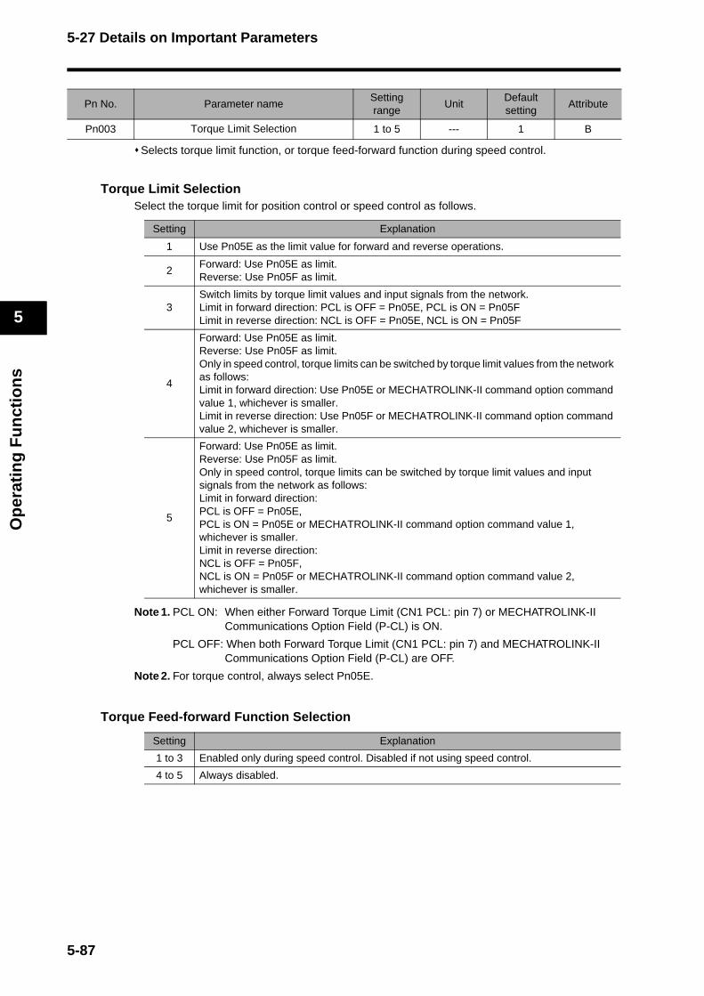
5-27 Details on Important Parameters
Op
erat
ing
Fu
nct
ion
s
5
Selects torque limit function, or torque feed-forward function during speed control.
Torque Limit SelectionSelect the torque limit for position control or speed control as follows.
Note 1. PCL ON: When either Forward Torque Limit (CN1 PCL: pin 7) or MECHATROLINK-II Communications Option Field (P-CL) is ON.
PCL OFF: When both Forward Torque Limit (CN1 PCL: pin 7) and MECHATROLINK-II Communications Option Field (P-CL) are OFF.
Note 2. For torque control, always select Pn05E.
Torque Feed-forward Function Selection
Pn No. Parameter nameSetting range
UnitDefault setting
Attribute
Pn003 Torque Limit Selection 1 to 5 --- 1 B
Setting Explanation
1 Use Pn05E as the limit value for forward and reverse operations.
2Forward: Use Pn05E as limit.Reverse: Use Pn05F as limit.
3Switch limits by torque limit values and input signals from the network. Limit in forward direction: PCL is OFF = Pn05E, PCL is ON = Pn05FLimit in reverse direction: NCL is OFF = Pn05E, NCL is ON = Pn05F
4
Forward: Use Pn05E as limit.Reverse: Use Pn05F as limit.Only in speed control, torque limits can be switched by torque limit values from the network as follows:Limit in forward direction: Use Pn05E or MECHATROLINK-II command option command value 1, whichever is smaller.Limit in reverse direction: Use Pn05F or MECHATROLINK-II command option command value 2, whichever is smaller.
5
Forward: Use Pn05E as limit.Reverse: Use Pn05F as limit.Only in speed control, torque limits can be switched by torque limit values and input signals from the network as follows: Limit in forward direction: PCL is OFF = Pn05E,PCL is ON = Pn05E or MECHATROLINK-II command option command value 1, whichever is smaller.Limit in reverse direction: NCL is OFF = Pn05F, NCL is ON = Pn05F or MECHATROLINK-II command option command value 2, whichever is smaller.
Setting Explanation
1 to 3 Enabled only during speed control. Disabled if not using speed control.
4 to 5 Always disabled.
5-87
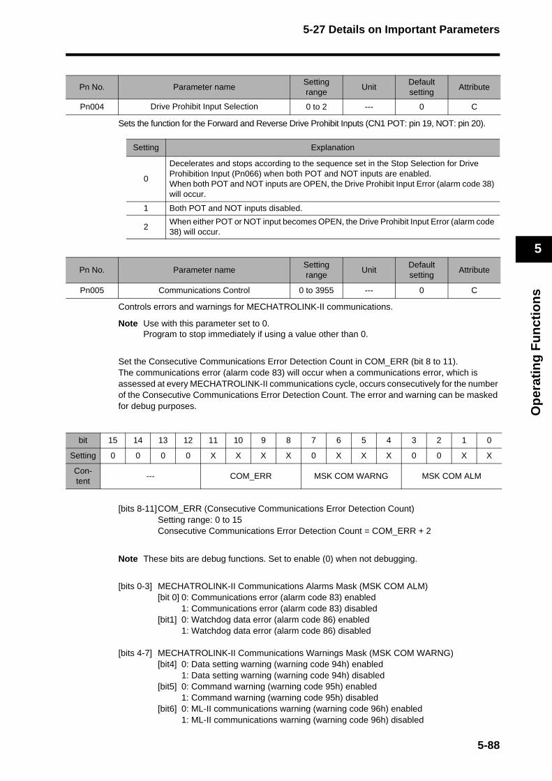
5-27 Details on Important Parameters
Op
erat
ing
Fu
nct
ion
s
5
Sets the function for the Forward and Reverse Drive Prohibit Inputs (CN1 POT: pin 19, NOT: pin 20).
Controls errors and warnings for MECHATROLINK-II communications.
Note Use with this parameter set to 0.Program to stop immediately if using a value other than 0.
Set the Consecutive Communications Error Detection Count in COM_ERR (bit 8 to 11). The communications error (alarm code 83) will occur when a communications error, which is assessed at every MECHATROLINK-II communications cycle, occurs consecutively for the number of the Consecutive Communications Error Detection Count. The error and warning can be masked for debug purposes.
[bits 8-11]COM_ERR (Consecutive Communications Error Detection Count)Setting range: 0 to 15Consecutive Communications Error Detection Count = COM_ERR + 2
Note These bits are debug functions. Set to enable (0) when not debugging.
[bits 0-3] MECHATROLINK-II Communications Alarms Mask (MSK COM ALM)[bit 0] 0: Communications error (alarm code 83) enabled
1: Communications error (alarm code 83) disabled[bit1] 0: Watchdog data error (alarm code 86) enabled
1: Watchdog data error (alarm code 86) disabled
[bits 4-7] MECHATROLINK-II Communications Warnings Mask (MSK COM WARNG)[bit4] 0: Data setting warning (warning code 94h) enabled
1: Data setting warning (warning code 94h) disabled[bit5] 0: Command warning (warning code 95h) enabled
1: Command warning (warning code 95h) disabled[bit6] 0: ML-II communications warning (warning code 96h) enabled
1: ML-II communications warning (warning code 96h) disabled
Pn No. Parameter nameSetting range
UnitDefault setting
Attribute
Pn004 Drive Prohibit Input Selection 0 to 2 --- 0 C
Setting Explanation
0
Decelerates and stops according to the sequence set in the Stop Selection for Drive Prohibition Input (Pn066) when both POT and NOT inputs are enabled.When both POT and NOT inputs are OPEN, the Drive Prohibit Input Error (alarm code 38) will occur.
1 Both POT and NOT inputs disabled.
2When either POT or NOT input becomes OPEN, the Drive Prohibit Input Error (alarm code 38) will occur.
Pn No. Parameter nameSetting range
UnitDefault setting
Attribute
Pn005 Communications Control 0 to 3955 --- 0 C
bit 15 14 13 12 11 10 9 8 7 6 5 4 3 2 1 0
Setting 0 0 0 0 X X X X 0 X X X 0 0 X X
Con-tent
--- COM_ERR MSK COM WARNG MSK COM ALM
5-88

5-27 Details on Important Parameters
Op
erat
ing
Fu
nct
ion
s
5
Sets the operating mode for realtime autotuning.A setting of 3 or 6 will provide faster response to changes in inertia during operation. Operation, however, may be unstable depending on the operating pattern.Normally, set the parameter to 1 or 4.Set to 4 to 6 when the Servomotor is used as a vertical axis.Gain switching is enabled at set values 1 to 6.Use a setting of 7 if operation changes caused by gain switching are a problem.
Sets the machine rigidity for realtime autotuning.When realtime autotuning is enabled, each parameter in the table is automatically set to the machine rigidity values in "Realtime Autotuning (RTAT) Parameter Tables" on the next page. Autotuning adjusts the response by estimating the load inertia based on these values. Thus, if the value is too large and not suitable for the load, vibration or resonance may occur. If this occurs, lower the setting.
Pn No. Parameter nameSetting range
UnitDefault setting
Attribute
Pn021Realtime Autotuning
Mode Selection0 to 7 --- 0 B
Setting Realtime Autotuning Degree of change in load inertia
0 Disabled ---
1
Horizontal axis mode
Almost no change
2 Gradual changes
3 Sudden changes
4
Vertical axis mode
Almost no change
5 Gradual changes
6 Sudden changes
7 Gain switching disable mode Almost no change
In realtime autotuning, responses to inertia changes are derived from the changes in approximately 10 s.Realtime autotuning may not be able to follow sharp changes in inertia. In this case, the vibrations may occur in the operation. Disable realtime autotuning by setting 0 when the operation has become normal.
Pn No. Parameter nameSetting range
UnitDefault setting
Attribute
Pn022Realtime Autotuning
Machine Rigidity Selection0 to F --- 2 B
Precautions for Correct Use
5-89

5-27 Details on Important Parameters
Op
erat
ing
Fu
nct
ion
s
5
Realtime Autotuning (RTAT) Parameter Tables
Parameter No.
Parameter nameAT Mode Selection
(Pn021)
AT Machine Rigidity Selection (Pn022)
0 1 2 3 4 5 6 7
Pn010 Position Loop Gain --- 120 320 390 480 630 720 900 1080
Pn011 Speed Loop Gain --- 90 180 220 270 350 400 500 600
Pn012Speed Loop Integration Time Constant
--- 620 310 250 210 160 140 120 110
Pn013Speed Feedback Filter Time Constant
--- 0 0 0 0 0 0 0 0
Pn014Torque CommandFilter Time Constant*1
--- 253 126 103 84 65 57 45 38
Pn015 Speed Feed-forward Amount --- 300 300 300 300 300 300 300 300
Pn016Feed-forward Filter Time Constant
--- 50 50 50 50 50 50 50 50
Pn017 Reserved --- 0 0 0 0 0 0 0 0
Pn018 Position Loop Gain 2 --- 190 380 460 570 730 840 1050 1260
Pn019 Speed Loop Gain 2 --- 90 180 220 270 350 400 500 600
Pn01ASpeed Loop Integration Time Constant 2
1, 2, 3, 7 1000010000 1000010000 1000010000 1000010000
4, 5, 6 9999 9999 9999 9999 9999 9999 9999 9999
Pn01BSpeed Feedback Filter Time Constant 2
--- 0 0 0 0 0 0 0 0
Pn01CTorque Command Filter Time Constant 2*1 --- 253 126 103 84 65 57 45 38
Pn020 Inertia Ratio --- Estimated load inertia ratio
Pn027Instantaneous SpeedObserver Setting
--- 0 0 0 0 0 0 0 0
Pn030Gain SwitchingOperating Mode Selection
--- 1 1 1 1 1 1 1 1
Pn031 Gain Switch Setting*31 to 6 10 10 10 10 10 10 10 10
7 0 0 0 0 0 0 0 0
Pn032 Gain Switch Time --- 30 30 30 30 30 30 30 30
Pn033 Gain Switch Level Setting --- 50 50 50 50 50 50 50 50
Pn034 Gain Switch Hysteresis Setting --- 33 33 33 33 33 33 33 33
Pn035Position Loop Gain Switching Time
--- 20 20 20 20 20 20 20 20
5-90
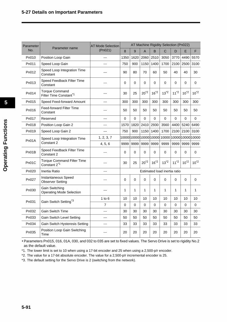
5-27 Details on Important Parameters
Op
erat
ing
Fu
nct
ion
s
5
Parameters Pn015, 016, 01A, 030, and 032 to 035 are set to fixed values. The Servo Drive is set to rigidity No.2 as the default value.
*1. The lower limit is set to 10 when using a 17-bit encoder and 25 when using a 2,500-p/r encoder. *2. The value for a 17-bit absolute encoder. The value for a 2,500-p/r incremental encoder is 25. *3. The default setting for the Servo Drive is 2 (switching from the network).
Parameter No.
Parameter nameAT Mode Selection
(Pn021)
AT Machine Rigidity Selection (Pn022)
8 9 A B C D E F
Pn010 Position Loop Gain --- 1350 1620 2060 2510 3050 3770 4490 5570
Pn011 Speed Loop Gain --- 750 900 1150 1400 1700 2100 2500 3100
Pn012Speed Loop Integration Time Constant
--- 90 80 70 60 50 40 40 30
Pn013Speed Feedback Filter Time Constant
--- 0 0 0 0 0 0 0 0
Pn014Torque CommandFilter Time Constant*1
--- 30 25 20*2 16*2 13*2 11*2 10*2 10*2
Pn015 Speed Feed-forward Amount --- 300 300 300 300 300 300 300 300
Pn016Feed-forward Filter Time Constant
--- 50 50 50 50 50 50 50 50
Pn017 Reserved --- 0 0 0 0 0 0 0 0
Pn018 Position Loop Gain 2 --- 1570 1820 2410 2930 3560 4400 5240 6490
Pn019 Speed Loop Gain 2 --- 750 900 1150 1400 1700 2100 2100 3100
Pn01ASpeed Loop Integration Time Constant 2
1, 2, 3, 7 10000100001000010000 10000 100001000010000
4, 5, 6 9999 9999 9999 9999 9999 9999 9999 9999
Pn01BSpeed Feedback Filter Time Constant 2
--- 0 0 0 0 0 0 0 0
Pn01CTorque Command Filter Time Constant 2*1 --- 30 25 20*2 16*2 13*2 11*2 10*2 10*2
Pn020 Inertia Ratio --- Estimated load inertia ratio
Pn027Instantaneous SpeedObserver Setting
--- 0 0 0 0 0 0 0 0
Pn030Gain SwitchingOperating Mode Selection
--- 1 1 1 1 1 1 1 1
Pn031 Gain Switch Setting*31 to 6 10 10 10 10 10 10 10 10
7 0 0 0 0 0 0 0 0
Pn032 Gain Switch Time --- 30 30 30 30 30 30 30 30
Pn033 Gain Switch Level Setting --- 50 50 50 50 50 50 50 50
Pn034 Gain Switch Hysteresis Setting --- 33 33 33 33 33 33 33 33
Pn035Position Loop Gain Switching Time
--- 20 20 20 20 20 20 20 20
5-91
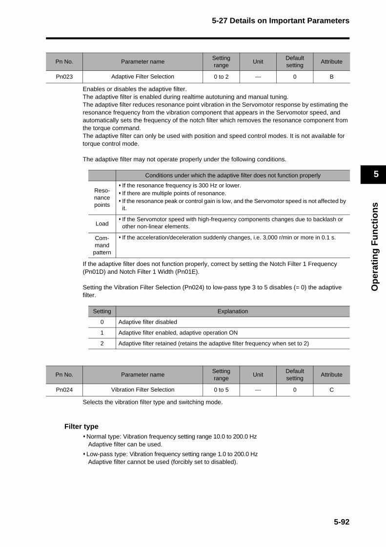
5-27 Details on Important Parameters
Op
erat
ing
Fu
nct
ion
s
5
Enables or disables the adaptive filter.The adaptive filter is enabled during realtime autotuning and manual tuning.The adaptive filter reduces resonance point vibration in the Servomotor response by estimating the resonance frequency from the vibration component that appears in the Servomotor speed, and automatically sets the frequency of the notch filter which removes the resonance component from the torque command.The adaptive filter can only be used with position and speed control modes. It is not available for torque control mode.
The adaptive filter may not operate properly under the following conditions.
If the adaptive filter does not function properly, correct by setting the Notch Filter 1 Frequency (Pn01D) and Notch Filter 1 Width (Pn01E).
Setting the Vibration Filter Selection (Pn024) to low-pass type 3 to 5 disables (= 0) the adaptive filter.
Selects the vibration filter type and switching mode.
Filter typeNormal type: Vibration frequency setting range 10.0 to 200.0 Hz Adaptive filter can be used.
Low-pass type: Vibration frequency setting range 1.0 to 200.0 Hz Adaptive filter cannot be used (forcibly set to disabled).
Pn No. Parameter nameSetting range
UnitDefault setting
Attribute
Pn023 Adaptive Filter Selection 0 to 2 --- 0 B
Conditions under which the adaptive filter does not function properly
Reso-nance points
If the resonance frequency is 300 Hz or lower.If there are multiple points of resonance.If the resonance peak or control gain is low, and the Servomotor speed is not affected by it.
LoadIf the Servomotor speed with high-frequency components changes due to backlash or other non-linear elements.
Com-mand
pattern
If the acceleration/deceleration suddenly changes, i.e. 3,000 r/min or more in 0.1 s.
Setting Explanation
0 Adaptive filter disabled
1 Adaptive filter enabled, adaptive operation ON
2 Adaptive filter retained (retains the adaptive filter frequency when set to 2)
Pn No. Parameter nameSetting range
UnitDefault setting
Attribute
Pn024 Vibration Filter Selection 0 to 5 --- 0 C
5-92
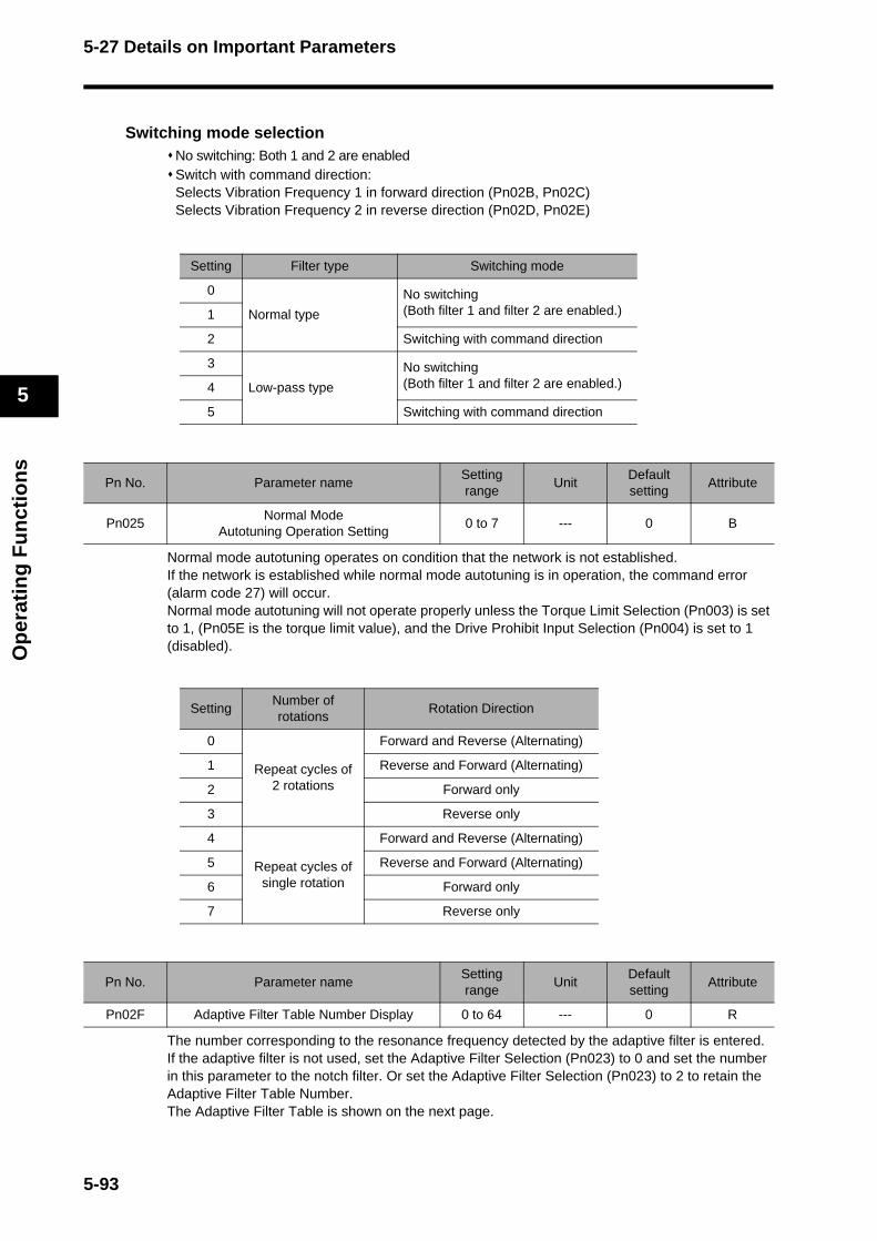
5-27 Details on Important Parameters
Op
erat
ing
Fu
nct
ion
s
5
Switching mode selectionNo switching: Both 1 and 2 are enabledSwitch with command direction: Selects Vibration Frequency 1 in forward direction (Pn02B, Pn02C)Selects Vibration Frequency 2 in reverse direction (Pn02D, Pn02E)
Normal mode autotuning operates on condition that the network is not established. If the network is established while normal mode autotuning is in operation, the command error (alarm code 27) will occur. Normal mode autotuning will not operate properly unless the Torque Limit Selection (Pn003) is set to 1, (Pn05E is the torque limit value), and the Drive Prohibit Input Selection (Pn004) is set to 1 (disabled).
The number corresponding to the resonance frequency detected by the adaptive filter is entered. If the adaptive filter is not used, set the Adaptive Filter Selection (Pn023) to 0 and set the number in this parameter to the notch filter. Or set the Adaptive Filter Selection (Pn023) to 2 to retain the Adaptive Filter Table Number.The Adaptive Filter Table is shown on the next page.
Setting Filter type Switching mode
0
Normal type
No switching(Both filter 1 and filter 2 are enabled.)1
2 Switching with command direction
3
Low-pass type
No switching(Both filter 1 and filter 2 are enabled.)4
5 Switching with command direction
Pn No. Parameter nameSetting range
UnitDefault setting
Attribute
Pn025Normal Mode
Autotuning Operation Setting0 to 7 --- 0 B
SettingNumber ofrotations
Rotation Direction
0
Repeat cycles of 2 rotations
Forward and Reverse (Alternating)
1 Reverse and Forward (Alternating)
2 Forward only
3 Reverse only
4
Repeat cycles of single rotation
Forward and Reverse (Alternating)
5 Reverse and Forward (Alternating)
6 Forward only
7 Reverse only
Pn No. Parameter nameSetting range
UnitDefault setting
Attribute
Pn02F Adaptive Filter Table Number Display 0 to 64 --- 0 R
5-93
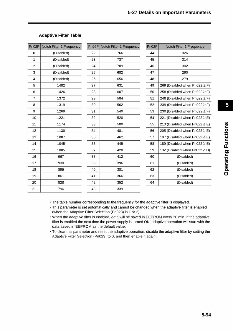
5-27 Details on Important Parameters
Op
erat
ing
Fu
nct
ion
s
5
Adaptive Filter Table
The table number corresponding to the frequency for the adaptive filter is displayed.This parameter is set automatically and cannot be changed when the adaptive filter is enabled (when the Adaptive Filter Selection (Pn023) is 1 or 2).When the adaptive filter is enabled, data will be saved in EEPROM every 30 min. If the adaptive filter is enabled the next time the power supply is turned ON, adaptive operation will start with the data saved in EEPROM as the default value.To clear this parameter and reset the adaptive operation, disable the adaptive filter by setting the Adaptive Filter Selection (Pn023) to 0, and then enable it again.
Pn02F Notch Filter 1 Frequency Pn02F Notch Filter 1 Frequency Pn02F Notch Filter 1 Frequency
0 (Disabled) 22 766 44 326
1 (Disabled) 23 737 45 314
2 (Disabled) 24 709 46 302
3 (Disabled) 25 682 47 290
4 (Disabled) 26 656 48 279
5 1482 27 631 49 269 (Disabled when Pn022 ≥ F)
6 1426 28 607 50 258 (Disabled when Pn022 ≥ F)
7 1372 29 584 51 248 (Disabled when Pn022 ≥ F)
8 1319 30 562 52 239 (Disabled when Pn022 ≥ F)
9 1269 31 540 53 230 (Disabled when Pn022 ≥ F)
10 1221 32 520 54 221 (Disabled when Pn022 ≥ E)
11 1174 33 500 55 213 (Disabled when Pn022 ≥ E)
12 1130 34 481 56 205 (Disabled when Pn022 ≥ E)
13 1087 35 462 57 197 (Disabled when Pn022 ≥ E)
14 1045 36 445 58 189 (Disabled when Pn022 ≥ E)
15 1005 37 428 59 182 (Disabled when Pn022 ≥ D)
16 967 38 412 60 (Disabled)
17 930 39 396 61 (Disabled)
18 895 40 381 62 (Disabled)
19 861 41 366 63 (Disabled)
20 828 42 352 64 (Disabled)
21 796 43 339
5-94

5-27 Details on Important Parameters
Op
erat
ing
Fu
nct
ion
s
5
Sets the deceleration stop operation to be performed after the Forward Drive Prohibit Input (POT) or Reverse Drive Prohibit Input (NOT) is enabled.
Note 1. The positioning command generation process (positioning operation) within the Servo Drive will be forcibly stopped once it enters the deceleration mode. Also, when the deceleration mode is activated during speed control or torque control, it will switch to position control. If a positioning operation command is received during deceleration, the internal positioning command generation process will be retained, and after deceleration is complete, positioning operation will be activated.
Note 2. When the Servomotor rotation speed is 30 r/min or less (stopped), the deceleration mode will not be activated even if the drive prohibit input is enabled.
Note 3. When the parameter is set to 2 and an operation command in the drive prohibited direction is received after stopping, a command warning (warning code 95h) will be issued. When the parameter is set to 0 or 1, the operation command in the prohibited direction after stopping will be accepted, but the Servomotor will not operate and the position deviation will accumulate because the torque command is 0. Take measures such as issuing a command in the reverse direction from the host controller.
Note 4. When the parameter is set to 2, MECHATROLINK-II communications are interrupted, and either Forward or Reverse Drive Prohibit Input (POT or NOT) is turned ON, receiving an operation command (jog operation or normal mode autotuning) via RS232 will cause a Drive Prohibit Input Error (alarm code 38). A Drive Prohibit Input Error (alarm code 38) will also occur if either POT or NOT is turned ON while operating on an operation command received via RS232.
Sets the operational conditions during deceleration and after stopping after the main power supply is turned OFF with the Undervoltage Alarm Selection (Pn065) set to 0.The deviation counter will be reset when the power OFF is detected.
Pn No. Parameter nameSetting range
UnitDefault setting
Attribute
Pn066 Stop Selection for Drive Prohibition Input 0 to 2 --- 0 C
Setting During decelerationAfter stopping
(30 r/min or less)Deviation counter
0 Dynamic brakeDisables torque command in drive prohibited direction
Cleared while decelerating with dynamic brake. Retained after stopping.
1 Disables torqueDisables torque command in drive prohibited direction
Cleared while decelerating. Retained after stopping.
2Emergency Stop Torque (Pn06E)
Servo locked
Retained while decelerating, cleared upon completion of deceleration, and retained after stopping.
Pn No. Parameter nameSetting range
UnitDefault setting
Attribute
Pn067 Stop Selection with Main Power OFF 0 to 7 --- 0 B
Setting Explanation
0 and 4 Use dynamic brake to decelerate and remain stopped with dynamic brake.
1 and 5 Use free-run to decelerate and remain stopped with dynamic brake.
2 and 6 Use dynamic brake to decelerate, but free the motor when stopped.
3 and 7 Use free-run to decelerate, and free the motor when stopped.
5-95

5-27 Details on Important Parameters
Op
erat
ing
Fu
nct
ion
s
5
Sets the deceleration process and stop status after an alarm is issued by the protective function. The deviation counter will be reset when an alarm is issued.
Sets the operational conditions to apply during deceleration and after stopping when the Servo is turned OFF.
Sets the regeneration resistor operation and the regeneration overload (alarm code 18) operation. Set this parameter to 0 if using the built-in regeneration resistor. If using an external regeneration resistor, be sure to turn OFF the main power when the built-in thermal switch is activated.
Pn No. Parameter nameSetting range
UnitDefault setting
Attribute
Pn068 Stop Selection for Alarm Generation 0 to 3 --- 0 B
Setting Explanation
0 Use dynamic brake to decelerate and remain stopped with dynamic brake.
1 Use free-run to decelerate and remain stopped with dynamic brake.
2 Use dynamic brake to decelerate, but free the motor when stopped.
3 Use free-run to decelerate, and free the motor when stopped.
Pn No. Parameter nameSetting range
UnitDefault setting
Attribute
Pn069 Stop Selection with Servo OFF 0 to 7 --- 0 B
Setting Explanation
0 and 4 Use dynamic brake to decelerate and remain stopped with dynamic brake.
1 and 5 Use free-run to decelerate and remain stopped with dynamic brake.
2 and 6 Use dynamic brake to decelerate, but free the motor when stopped.
3 and 7 Use free-run to decelerate, and free the motor when stopped.
Pn No. Parameter nameSetting range
UnitDefault setting
Attribute
Pn06C Regeneration Resistor Selection 0 to 3 --- 0 C
Setting Explanation
0Sets the regeneration overload to match the built-in regeneration resistor. (regeneration load ratio below 1%)
1The regeneration overload (alarm code 18) occurs when the load ratio of the external regeneration resistor exceeds 10%.
2The regeneration processing circuit by the external regeneration resistor is activated, but the regeneration overload does not occur.
3The regeneration processing circuit is not activated. All regenerative energy is absorbed by the built-in capacitor.
5-96


Chapter 6
Operation6-1 Operational Procedure ....................................... 6-1
6-2 Preparing for Operation...................................... 6-2Items to Check Before Turning ON the Power......................6-2
Turning ON Power ................................................................6-4
Checking the Displays ..........................................................6-5
Absolute Encoder Setup .......................................................6-6
6-3 Using the Parameter Unit ................................... 6-8Names of Parts and Functions..............................................6-8
6-4 Setting the Mode ................................................ 6-9Changing the Mode...............................................................6-9
Monitor Mode ........................................................................6-10
Parameter Setting Mode .......................................................6-17
Parameter Write Mode..........................................................6-23
Normal Mode Autotuning ......................................................6-24
Auxiliary Function Mode........................................................6-25
Copy Mode............................................................................6-28
6-5 Trial Operation ................................................... 6-31Preparation for Trial Operation .............................................6-31
Trial Operation with CX-Drive ...............................................6-31

6-1 Operational Procedure
Op
erat
ion
6
6-1 Operational ProcedureAfter mounting and wiring, connect a power supply, and check the operation of the Servomotor and Servo Drive individually. Then make the function settings as required according to the use of the Servomotor and Servo Drive. If the parameters are set incorrectly, there is a risk of an unpredictable Servomotor operation. Set the parameters according to the instructions in this manual.
Item Contents Reference
Mounting and installation
Install the Servomotor and Servo Drive according to the installation conditions. (Do not connect the Servomotor to the mechanical sys-tem before checking the no-load operation.)
4-1 Installation Conditions
Wiring and connections
Connect the Servomotor and Servo Drive to the power supply and peripheral devices. ·Specified installation and wiring requirements must be satisfied, particularly if conforming to the EC Directives.
4-2 Wiring
Preparation for operation
Check the necessary items and then turn ON the power supply. Check the display to see whether there are any internal errors in the Servo Drive. If using a Servomotor with an absolute encoder, first set up the ab-solute encoder.
6-2 Preparing for Operation
Setting functionsBy means of the user parameters, set the functions according to the operating conditions.
5-26 User Pa-rameters
Trial operation
First, test operation without a load connected to the motor. Then turn the power OFF and connect the mechanical system to the motor. If using a Servomotor with an absolute encoder, set up the absolute encoder and set the Motion Control Unit's initial parameters.Turn ON the power, and check to see whether protective functions, such as the emergency stop and operational limits, work properly. Check operation at both low speed and high speed using the system without a workpiece, or with dummy workpieces.
6-5 Trial Opera-tion
AdjustmentsManually adjust the gain if necessary. Further adjust the various functions to improve the control performance.
Chapter 7 Ad-justment Func-
tions
OperationOperation can now be started. If any problems should occur, refer to Chapter 8 Troubleshooting.
Chapter 8 Trou-bleshooting
6-1

6-2 Preparing for Operation
Op
erat
ion
6
6-2 Preparing for OperationThis section explains the procedure for preparing the mechanical system for operation following installation and wiring of the Servomotor and Servo Drive. It explains what you need to check both before and after turning ON the power. It also explains the setup procedure required for using a Servomotor with an absolute encoder.
Items to Check Before Turning ON the Power
Checking Power Supply VoltageCheck to be sure that the power supply voltage is within the ranges shown below.R88D-GT@L-ML2 (single-phase 100 VAC input) Main circuit power supply: Single-phase, 100 to 115 VAC (85 to 127 V), 50/60 HzControl circuit power supply: Single-phase, 100 to 115 VAC (85 to 127 V), 50/60 Hz
R88D-GN01H-ML2/02H-ML2/04H-ML2/08H-ML2/10H-ML2/15H-ML2(Single-phase or single/three-phase 200 VAC input)Main circuit power supply: Single-phase or single/three-phase, 200 to 240 VAC (170 to 264 V), 50/60 HzControl circuit power supply: Single-phase or single/three-phase, 200 to 240 VAC (170 to 264 V), 50/60 Hz
R88D-GN20H-ML2/30H-ML2/50H-ML2/75H-ML2 (three-phase 200VAC input)Main circuit power supply: Three-phase, 200 to 230 VAC (170 to 253 V), 50/60 HzControl circuit power supply: Single-phase, 200 to 230 VAC (170 to 253 V), 50/60 Hz
Checking Terminal Block WiringThe main circuit power supply inputs (L1/L3 or L1/L2/L3) must be properly connected to the terminal block. The control circuit power supply inputs (L1C/L2C) must be properly connected to the terminal block. The Servomotor's red (U), white (V), and blue (W) power lines and the green/yellow ground wire ( ) must be properly connected to the terminal block.
Checking the ServomotorThere should be no load on the Servomotor. (Do not connect the mechanical system.)The Servomotor's power lines and the power cables must be connected securely.
Checking the Encoder ConnectorsThe Encoder Cable must be connected securely to the Encoder Connector (CN2) at the Servo Drive. The Encoder Cable must be connected securely to the Encoder Connector at the Servomotor.
Checking the Control I/O ConnectorsThe Control Cable must be connected securely to the Control I/O Connector (CN1). The RUN command (RUN) must be OFF.
Checking Parameter Unit ConnectionsWhen using the Parameter Unit (R88A-PR02G), the enclosed cable must be connected securely to the CN3 connector.
6-2
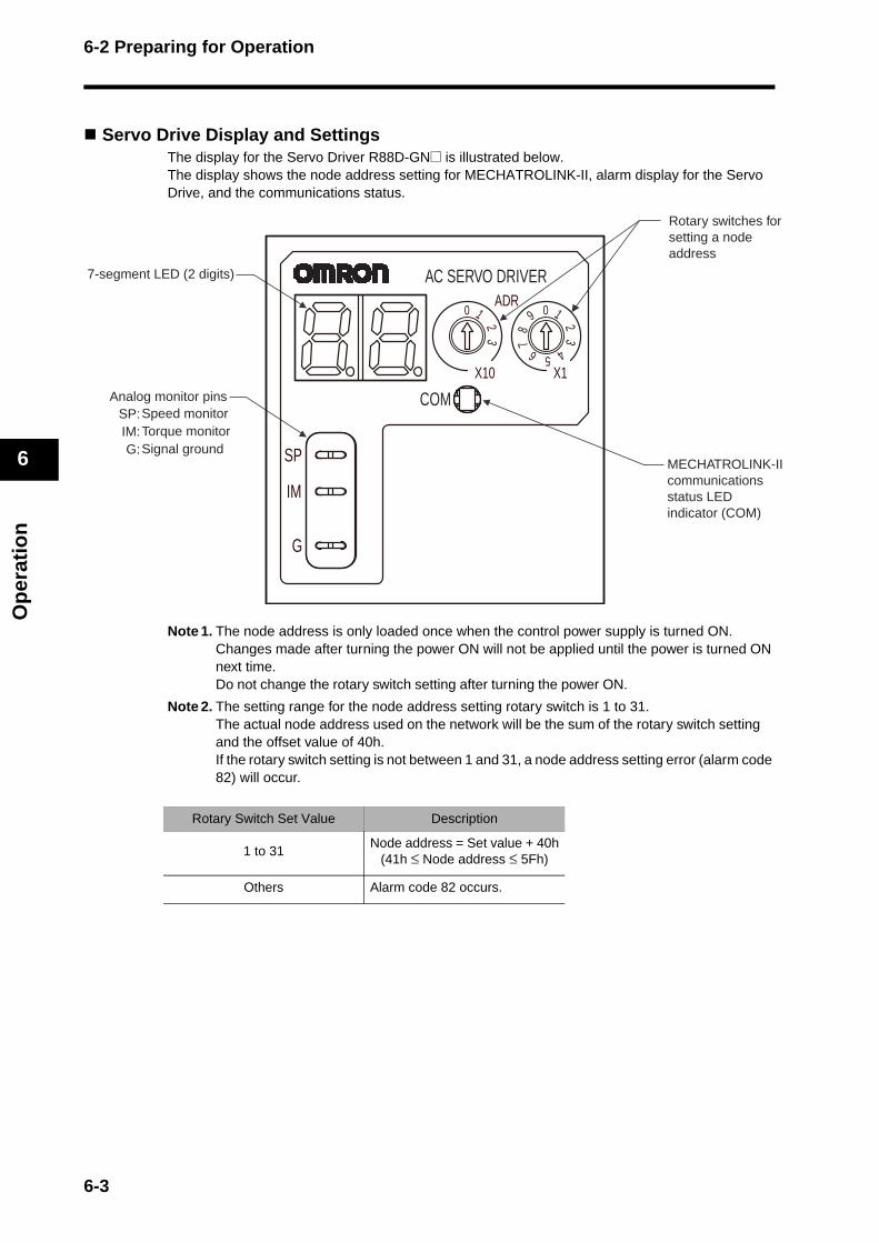
6-2 Preparing for Operation
Op
erat
ion
6
Servo Drive Display and SettingsThe display for the Servo Driver R88D-GN@ is illustrated below. The display shows the node address setting for MECHATROLINK-II, alarm display for the Servo Drive, and the communications status.
Note 1. The node address is only loaded once when the control power supply is turned ON. Changes made after turning the power ON will not be applied until the power is turned ON next time. Do not change the rotary switch setting after turning the power ON.
Note 2. The setting range for the node address setting rotary switch is 1 to 31. The actual node address used on the network will be the sum of the rotary switch setting and the offset value of 40h. If the rotary switch setting is not between 1 and 31, a node address setting error (alarm code 82) will occur.
Rotary Switch Set Value Description
1 to 31Node address = Set value + 40h
(41h ≤ Node address ≤ 5Fh)
Others Alarm code 82 occurs.
MECHATROLINK-IIcommunicationsstatus LED indicator (COM)
7-segment LED (2 digits)
Analog monitor pinsSpeed monitorTorque monitorSignal ground
SP: IM: G:
Rotary switches for setting a node address
G
IM
SP
COM
X103
2
10ADR
AC SERVO DRIVER
X1
6
78
9 0 12
3
45
6-3
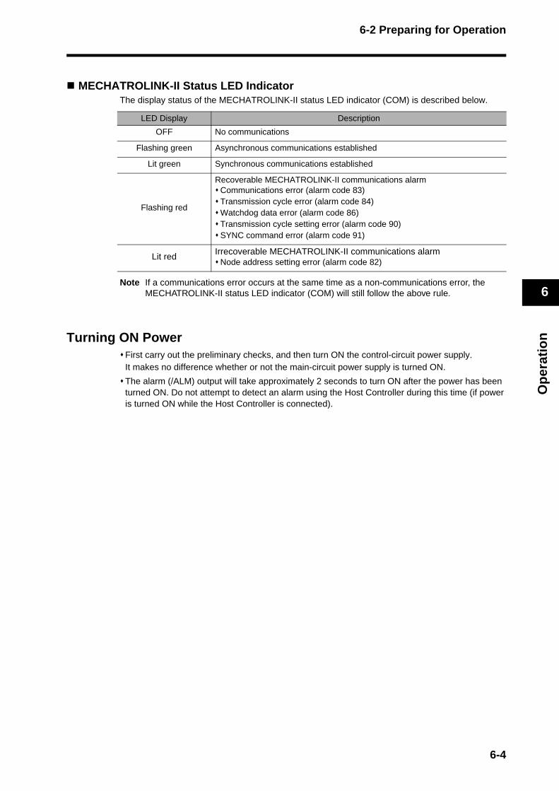
6-2 Preparing for Operation
Op
erat
ion
6
MECHATROLINK-II Status LED IndicatorThe display status of the MECHATROLINK-II status LED indicator (COM) is described below.
Note If a communications error occurs at the same time as a non-communications error, the MECHATROLINK-II status LED indicator (COM) will still follow the above rule.
Turning ON PowerFirst carry out the preliminary checks, and then turn ON the control-circuit power supply.It makes no difference whether or not the main-circuit power supply is turned ON.
The alarm (/ALM) output will take approximately 2 seconds to turn ON after the power has been turned ON. Do not attempt to detect an alarm using the Host Controller during this time (if power is turned ON while the Host Controller is connected).
LED Display Description
OFF No communications
Flashing green Asynchronous communications established
Lit green Synchronous communications established
Flashing red
Recoverable MECHATROLINK-II communications alarmCommunications error (alarm code 83)Transmission cycle error (alarm code 84)Watchdog data error (alarm code 86)Transmission cycle setting error (alarm code 90)SYNC command error (alarm code 91)
Lit red Irrecoverable MECHATROLINK-II communications alarmNode address setting error (alarm code 82)
6-4
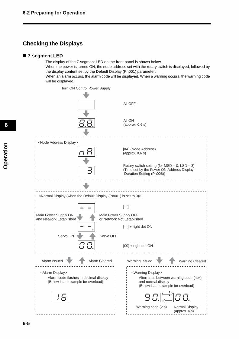
6-2 Preparing for Operation
Op
erat
ion
6
Checking the Displays
7-segment LEDThe display of the 7-segment LED on the front panel is shown below. When the power is turned ON, the node address set with the rotary switch is displayed, followed by the display content set by the Default Display (Pn001) parameter. When an alarm occurs, the alarm code will be displayed. When a warning occurs, the warning code will be displayed.
8.8.
nkak
k3k
1k6k 9k0. 0k0.
-k-k
-k-.
0k0.
Turn ON Control Power Supply
All OFF
All ON (approx. 0.6 s)
<Node Address Display>
[nA] (Node Address) (approx. 0.6 s)
Rotary switch setting (for MSD = 0, LSD = 3) (Time set by the Power ON Address Display Duration Setting (Pn006))
<Normal Display (when the Default Display (Pn001) is set to 0)>
Main Power Supply ON and Network Established
Servo ON
Alarm Issued
<Alarm Display>
Warning code (2 s) Normal Display (approx. 4 s)
Alarm code flashes in decimal display(Below is an example for overload)
Alternates between warning code (hex) and normal display (Below is an example for overload)
<Warning Display>
Warning Issued Warning ClearedAlarm Cleared
Servo OFF
[- -] + right dot ON
[00] + right dot ON
Main Power Supply OFF or Network Not Established
[- -]
6-5
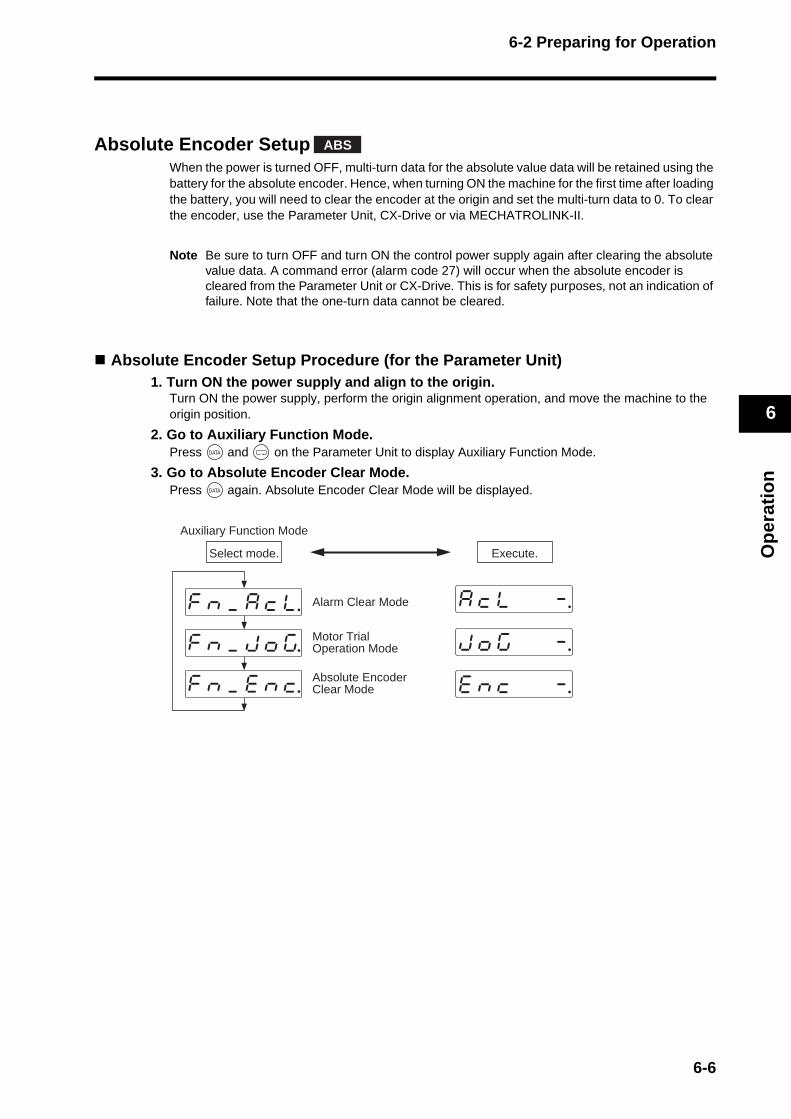
6-2 Preparing for Operation
Op
erat
ion
6
Absolute Encoder SetupWhen the power is turned OFF, multi-turn data for the absolute value data will be retained using the battery for the absolute encoder. Hence, when turning ON the machine for the first time after loading the battery, you will need to clear the encoder at the origin and set the multi-turn data to 0. To clear the encoder, use the Parameter Unit, CX-Drive or via MECHATROLINK-II.
Note Be sure to turn OFF and turn ON the control power supply again after clearing the absolute value data. A command error (alarm code 27) will occur when the absolute encoder is cleared from the Parameter Unit or CX-Drive. This is for safety purposes, not an indication of failure. Note that the one-turn data cannot be cleared.
Absolute Encoder Setup Procedure (for the Parameter Unit)1. Turn ON the power supply and align to the origin.
Turn ON the power supply, perform the origin alignment operation, and move the machine to the origin position.
2. Go to Auxiliary Function Mode. Press and on the Parameter Unit to display Auxiliary Function Mode.
3. Go to Absolute Encoder Clear Mode. Press again. Absolute Encoder Clear Mode will be displayed.
ABS
Auxiliary Function Mode
Select mode. Execute.
Alarm Clear Mode
Absolute EncoderClear Modefknk_keknkc.
fknk_kakckl.
jkokgk k k-.
akcklk k k-.
eknkck k k-.
fknk_kjkokg. Motor Trial Operation Mode
6-6
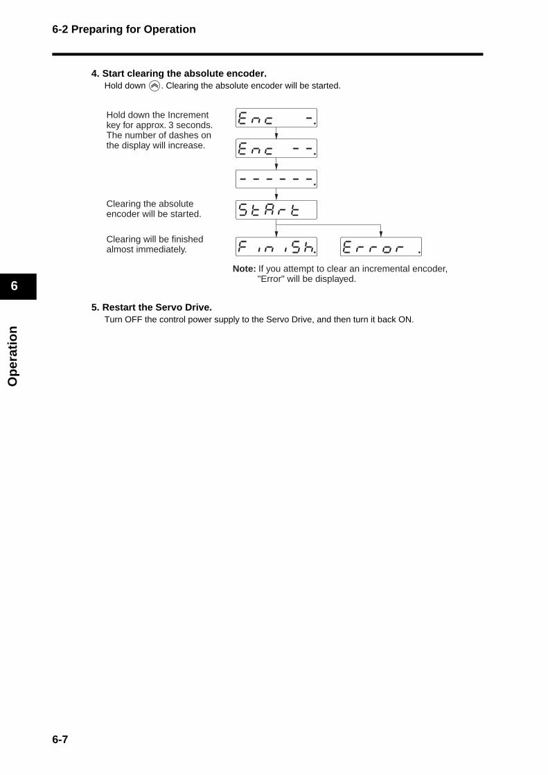
6-2 Preparing for Operation
Op
erat
ion
6
4. Start clearing the absolute encoder. Hold down . Clearing the absolute encoder will be started.
5. Restart the Servo Drive. Turn OFF the control power supply to the Servo Drive, and then turn it back ON.
ekrkrkokrk .k
sktkakrktk k
fkiknkikskh.k
-k-k-k-k-k-.k
eknkck k-k-.k
eknkck k k-.kHold down the Increment key for approx. 3 seconds. The number of dashes on the display will increase.
Clearing the absolute encoder will be started.
Clearing will be finished almost immediately.
Note: If you attempt to clear an incremental encoder, "Error" will be displayed.
6-7

6-3 Using the Parameter Unit
Op
erat
ion
6
6-3 Using the Parameter Unit
Names of Parts and Functions
Connector
Parameter Unit
Cable Display area
Operating area
8.8.8.8.8.8.
8.8
LED Display (6 Digits)If an error occurs, all digits will flash and the display will switch to the error display.
Unit No. Display (2 Digits)Displays the parameter type (servo, 16 bit, or 32 bit).In Parameter Setting Mode, displays the 2-digit parameter number.
Mode Key Switches between the following six modes.· Monitor Mode · Normal mode autotuning· Parameter Setting Mode · Auxiliary Function Mode· Parameter Write Mode · Copy Mode
Increment/Decrement KeyIncreases or decreases parameter numbers or set values.
Shift KeyShifts the digit being changed to the left.
Data Key Switches between the parameter and setting displays, saves settings, etc.
6-8
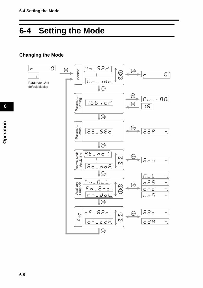
6-4 Setting the Mode
Op
erat
ion
6
6-4 Setting the Mode
Changing the Mode
pknk_krk0k0.k1k6
Parameter Unitdefault display
1k6kbkikktkp
Mon
itor
Par
amet
erS
ettin
gP
aram
eter
Writ
eN
orm
al M
ode
Auto
tuni
ngA
uxili
ary
Fun
ctio
nC
opy
6-9
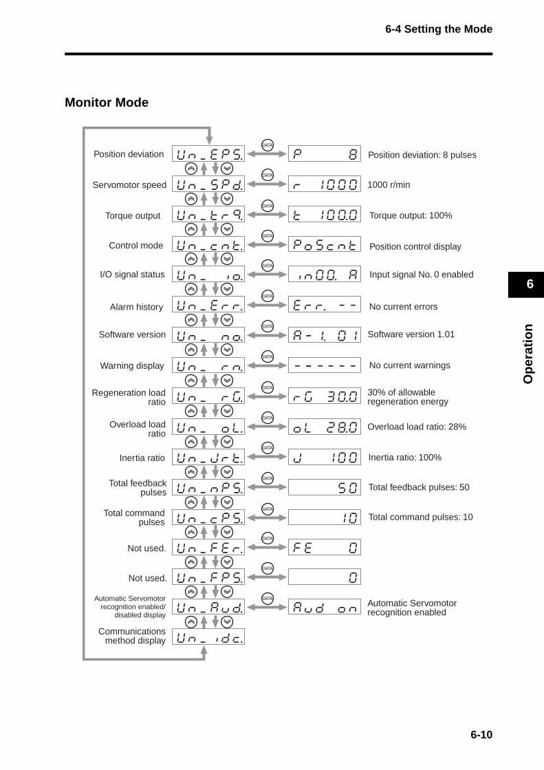
6-4 Setting the Mode
Op
erat
ion
6
Monitor Mode
Position deviation
Servomotor speed
Torque output
Control mode
I/O signal status
Alarm history
Warning display
Regeneration loadratio
Overload loadratio
Inertia ratio
Total feedbackpulses
Total commandpulses
Not used.
Not used.
Automatic Servomotorrecognition enabled/
disabled display
Communicationsmethod display
Position deviation: 8 pulses
1000 r/min
Torque output: 100%
Position control display
Input signal No. 0 enabled
No current errors
No current warnings
30% of allowable regeneration energy
Overload load ratio: 28%
Inertia ratio: 100%
Total feedback pulses: 50
Total command pulses: 10
Automatic Servomotor recognition enabled
Software version Software version 1.01
6-10
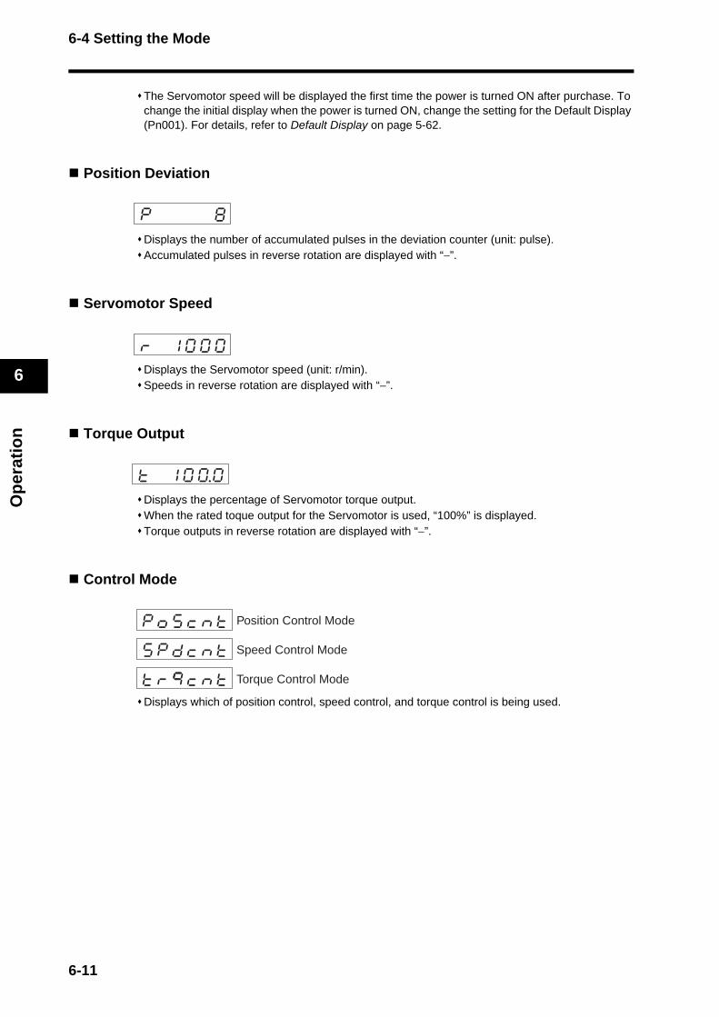
6-4 Setting the Mode
Op
erat
ion
6
The Servomotor speed will be displayed the first time the power is turned ON after purchase. To change the initial display when the power is turned ON, change the setting for the Default Display (Pn001). For details, refer to Default Display on page 5-62.
Position Deviation
Displays the number of accumulated pulses in the deviation counter (unit: pulse). Accumulated pulses in reverse rotation are displayed with “−”.
Servomotor Speed
Displays the Servomotor speed (unit: r/min). Speeds in reverse rotation are displayed with “−”.
Torque Output
Displays the percentage of Servomotor torque output. When the rated toque output for the Servomotor is used, “100%” is displayed. Torque outputs in reverse rotation are displayed with “−”.
Control Mode
Displays which of position control, speed control, and torque control is being used.
Position Control Mode
Speed Control Mode
Torque Control Mode
6-11
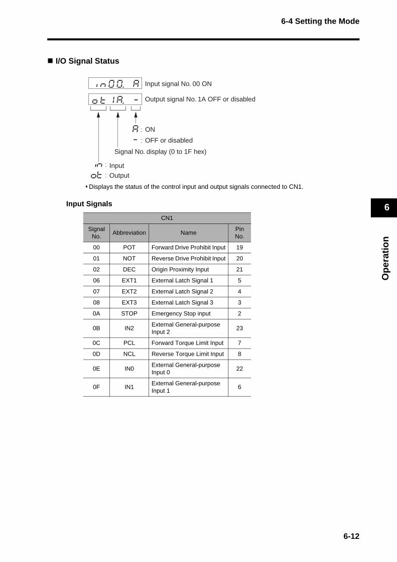
6-4 Setting the Mode
Op
erat
ion
6
I/O Signal Status
Displays the status of the control input and output signals connected to CN1.
Input Signals
CN1
Signal No.
Abbreviation NamePin No.
00 POT Forward Drive Prohibit Input 19
01 NOT Reverse Drive Prohibit Input 20
02 DEC Origin Proximity Input 21
06 EXT1 External Latch Signal 1 5
07 EXT2 External Latch Signal 2 4
08 EXT3 External Latch Signal 3 3
0A STOP Emergency Stop input 2
0B IN2External General-purpose Input 2
23
0C PCL Forward Torque Limit Input 7
0D NCL Reverse Torque Limit Input 8
0E IN0External General-purpose Input 0
22
0F IN1External General-purpose Input 1
6
Input signal No. 00 ON
Output signal No. 1A OFF or disabled
ON
OFF or disabled
Signal No. display (0 to 1F hex)
Input
Output
6-12
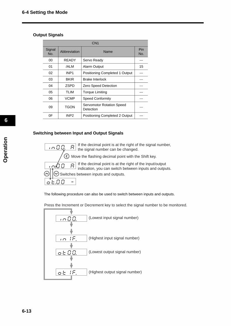
6-4 Setting the Mode
Op
erat
ion
6
Output Signals
Switching between Input and Output Signals
The following procedure can also be used to switch between inputs and outputs.
CN1
Signal No.
Abbreviation NamePin No.
00 READY Servo Ready ---
01 /ALM Alarm Output 15
02 INP1 Positioning Completed 1 Output ---
03 BKIR Brake Interlock ---
04 ZSPD Zero Speed Detection ---
05 TLIM Torque Limiting ---
06 VCMP Speed Conformity ---
09 TGONServomotor Rotation Speed Detection
---
0F INP2 Positioning Completed 2 Output ---
If the decimal point is at the right of the signal number, the signal number can be changed.
If the decimal point is at the right of the input/output indication, you can switch between inputs and outputs.
Move the flashing decimal point with the Shift key.
Switches between inputs and outputs.
Press the Increment or Decrement key to select the signal number to be monitored.
(Highest input signal number)
(Lowest input signal number)
(Lowest output signal number)
(Highest output signal number)
6-13
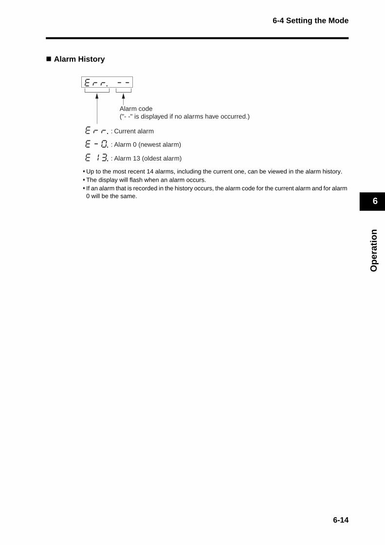
6-4 Setting the Mode
Op
erat
ion
6
Alarm History
Up to the most recent 14 alarms, including the current one, can be viewed in the alarm history. The display will flash when an alarm occurs. If an alarm that is recorded in the history occurs, the alarm code for the current alarm and for alarm 0 will be the same.
Alarm code ("- -" is displayed if no alarms have occurred.)
: Current alarm
: Alarm 0 (newest alarm)
: Alarm 13 (oldest alarm)
6-14

6-4 Setting the Mode
Op
erat
ion
6
Alarm Codes and Meanings
Note The following alarms are not recorded in the history. 11: Control power supply undervoltage13: Main power supply undervoltage36: Parameter error37: Parameter corruption38: Drive prohibit input error87: Emergency stop input error95: Servomotor non-conformity
Software Version
Displays the software version of the Servo Drive.
Alarm Codes
MeaningAlarm Codes
Meaning
11 Control power supply undervoltage 40Absolute encoder system down error
12 Overvoltage 41Absolute encoder counter overflow error
13 Main power supply undervoltage 42Absolute encoder overspeed error
14 Overcurrent 44Absolute encoder one-turn counter error
15 Servo Drive overheat 45Absolute encoder multi-turn counter error
16 Overload 47Absolute encoder status error
18 Regeneration overload 48 Encoder phase Z error
21 Encoder communications error 49 Encoder PS signal error
23 Encoder communications data error 82 Node address setting error
24 Deviation counter overflow 83 Communications error
26 Overspeed 84 Transmission cycle error
27 Command error 86 Watchdog data error
29 Internal deviation counter overflow 87 Emergency stop input error
34 Overrun limit error 90 Transmission cycle setting error
36 Parameter error 91 SYNC command error
37 Parameter corruption 93 Parameter setting error
38 Drive prohibit input error 95 Servomotor non-conformity
Others Other errors
ABS
ABS
ABS
ABS
ABS
ABS
6-15
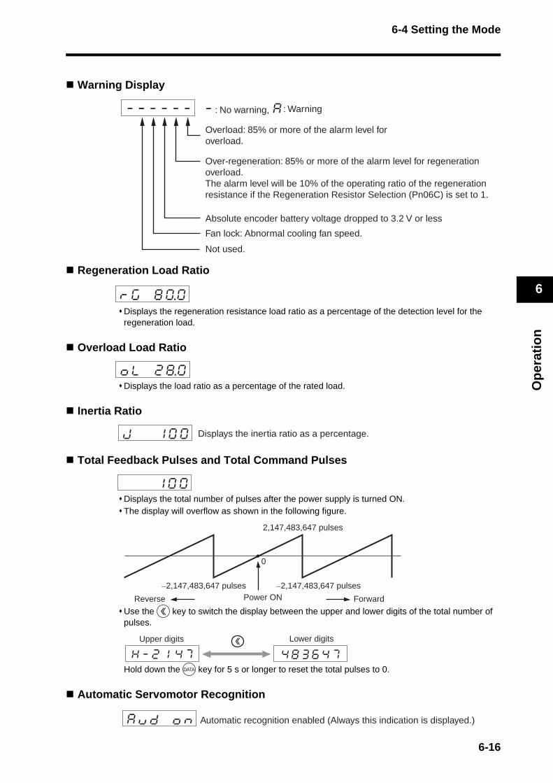
6-4 Setting the Mode
Op
erat
ion
6
Warning Display
Regeneration Load Ratio
Displays the regeneration resistance load ratio as a percentage of the detection level for the regeneration load.
Overload Load Ratio
Displays the load ratio as a percentage of the rated load.
Inertia Ratio
Total Feedback Pulses and Total Command Pulses
Displays the total number of pulses after the power supply is turned ON. The display will overflow as shown in the following figure.
Use the key to switch the display between the upper and lower digits of the total number of pulses.
Hold down the key for 5 s or longer to reset the total pulses to 0.
Automatic Servomotor Recognition
: No warning, : Warning
Overload: 85% or more of the alarm level for overload.
Absolute encoder battery voltage dropped to 3.2 V or less
Fan lock: Abnormal cooling fan speed.
Over-regeneration: 85% or more of the alarm level for regeneration overload. The alarm level will be 10% of the operating ratio of the regeneration resistance if the Regeneration Resistor Selection (Pn06C) is set to 1.
Not used.
Displays the inertia ratio as a percentage.
2,147,483,647 pulses
−2,147,483,647 pulses−2,147,483,647 pulsesPower ON
0
ForwardReverse
Upper digits Lower digits
Hk-k2k1kk4k7 4k8k3k6k4k7
Automatic recognition enabled (Always this indication is displayed.)
6-16
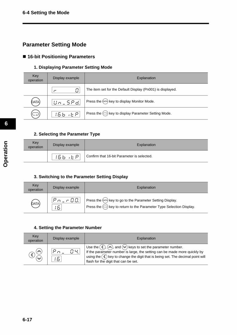
6-4 Setting the Mode
Op
erat
ion
6
Parameter Setting Mode
16-bit Positioning Parameters
1. Displaying Parameter Setting Mode
2. Selecting the Parameter Type
3. Switching to the Parameter Setting Display
4. Setting the Parameter Number
Key operation
Display example Explanation
The item set for the Default Display (Pn001) is displayed.
Press the key to display Monitor Mode.
Press the key to display Parameter Setting Mode.
Key operation
Display example Explanation
Confirm that 16-bit Parameter is selected.
Key operation
Display example Explanation
Press the key to go to the Parameter Setting Display.
Press the key to return to the Parameter Type Selection Display.
Key operation
Display example Explanation
Use the , , and keys to set the parameter number. If the parameter number is large, the setting can be made more quickly by using the key to change the digit that is being set. The decimal point will flash for the digit that can be set.
Uknk_k5kpkd
1k6kbkiktkp
1k6kbkiktkp
pknk_krk0k0.k1k6
pknk_k k0k4.1k6
6-17
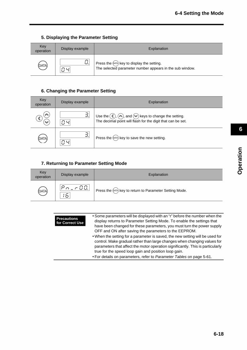
6-4 Setting the Mode
Op
erat
ion
6
5. Displaying the Parameter Setting
6. Changing the Parameter Setting
7. Returning to Parameter Setting Mode
Key operation
Display example Explanation
Press the key to display the setting. The selected parameter number appears in the sub window.
Key operation
Display example Explanation
Use the , , and keys to change the setting. The decimal point will flash for the digit that can be set.
Press the key to save the new setting.
Key operation
Display example Explanation
Press the key to return to Parameter Setting Mode.
Some parameters will be displayed with an “r” before the number when the display returns to Parameter Setting Mode. To enable the settings that have been changed for these parameters, you must turn the power supply OFF and ON after saving the parameters to the EEPROM.When the setting for a parameter is saved, the new setting will be used for control. Make gradual rather than large changes when changing values for parameters that affect the motor operation significantly. This is particularly true for the speed loop gain and position loop gain. For details on parameters, refer to Parameter Tables on page 5-61.
k k k k k00k4
k k k k k30k4
k k k k k30k4
pknk_krk0k0.k1k6
Precautions for Correct Use
6-18
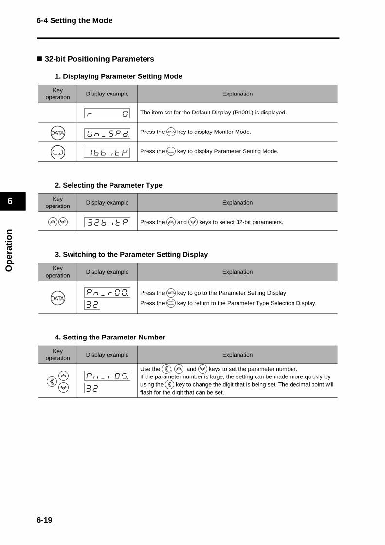
6-4 Setting the Mode
Op
erat
ion
6
32-bit Positioning Parameters
1. Displaying Parameter Setting Mode
2. Selecting the Parameter Type
3. Switching to the Parameter Setting Display
4. Setting the Parameter Number
Key operation
Display example Explanation
The item set for the Default Display (Pn001) is displayed.
Press the key to display Monitor Mode.
Press the key to display Parameter Setting Mode.
Key operation
Display example Explanation
Press the and keys to select 32-bit parameters.
Key operation
Display example Explanation
Press the key to go to the Parameter Setting Display.
Press the key to return to the Parameter Type Selection Display.
Key operation
Display example Explanation
Use the , , and keys to set the parameter number. If the parameter number is large, the setting can be made more quickly by using the key to change the digit that is being set. The decimal point will flash for the digit that can be set.
Uknk_k5kpkd
1k6kbkiktkp
3k2kbkiktkp
pknk_krk0k0.k3k2
pknk_krk0k5.k3k2
6-19
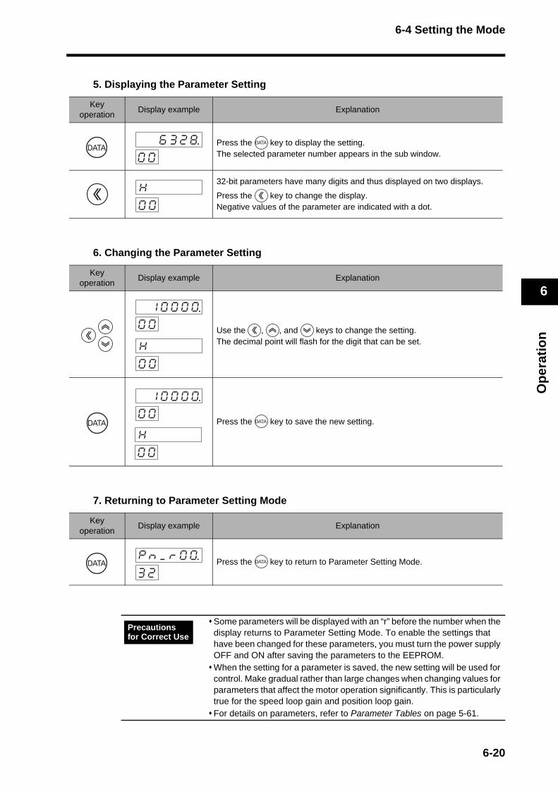
6-4 Setting the Mode
Op
erat
ion
6
5. Displaying the Parameter Setting
6. Changing the Parameter Setting
7. Returning to Parameter Setting Mode
Key operation
Display example Explanation
Press the key to display the setting. The selected parameter number appears in the sub window.
32-bit parameters have many digits and thus displayed on two displays.
Press the key to change the display.Negative values of the parameter are indicated with a dot.
Key operation
Display example Explanation
Use the , , and keys to change the setting. The decimal point will flash for the digit that can be set.
Press the key to save the new setting.
Key operation
Display example Explanation
Press the key to return to Parameter Setting Mode.
Some parameters will be displayed with an “r” before the number when the display returns to Parameter Setting Mode. To enable the settings that have been changed for these parameters, you must turn the power supply OFF and ON after saving the parameters to the EEPROM.When the setting for a parameter is saved, the new setting will be used for control. Make gradual rather than large changes when changing values for parameters that affect the motor operation significantly. This is particularly true for the speed loop gain and position loop gain. For details on parameters, refer to Parameter Tables on page 5-61.
k k6k3k2k8.0k0
Hk k k k k 0k0
k1k0k0k0k00k0
Hk k k k k 0k0
k1k0k0k0k00k0
Hk k k k k 0k0
pknk_krk0k0.k3k2
Precautions for Correct Use
6-20

6-4 Setting the Mode
Op
erat
ion
6
Servo Parameters
1. Displaying Parameter Setting Mode
2. Selecting the Parameter Type
3. Switching to the Parameter Setting Display
4. Setting the Parameter Number
Key operation
Display example Explanation
The item set for the Default Display (Pn001) is displayed.
Press the key to display Monitor Mode.
Press the key to display Parameter Setting Mode.
Key operation
Display example Explanation
Press the and keys to select the servo parameter.
Key operation
Display example Explanation
Press the key to go to the Parameter Setting Display.
Press the key to return to the Parameter Type Selection Display.
Key operation
Display example Explanation
Use the , , and keys to set the parameter number. If the parameter number is large, the setting can be made more quickly by using the key to change the digit that is being set. The decimal point will flash for the digit that can be set.
Uknk_k5kpkd
1k6kbkiktkp
skekrkUkokp
pknk_k k0k0.skU
pknk_k k1k0skU
6-21
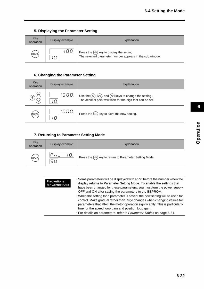
6-4 Setting the Mode
Op
erat
ion
6
5. Displaying the Parameter Setting
6. Changing the Parameter Setting
7. Returning to Parameter Setting Mode
Key operation
Display example Explanation
Press the key to display the setting. The selected parameter number appears in the sub window.
Key operation
Display example Explanation
Use the , , and keys to change the setting. The decimal point will flash for the digit that can be set.
Press the key to save the new setting.
Key operation
Display example Explanation
Press the key to return to Parameter Setting Mode.
Some parameters will be displayed with an “r” before the number when the display returns to Parameter Setting Mode. To enable the settings that have been changed for these parameters, you must turn the power supply OFF and ON after saving the parameters to the EEPROM.When the setting for a parameter is saved, the new setting will be used for control. Make gradual rather than large changes when changing values for parameters that affect the motor operation significantly. This is particularly true for the speed loop gain and position loop gain. For details on parameters, refer to Parameter Tables on page 5-61.
k k k4k0k01k0
k k1k0k0k01k0
k k1k0k0k01k0
pknk_k k1k0skU
Precautions for Correct Use
6-22
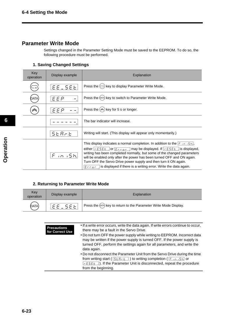
6-4 Setting the Mode
Op
erat
ion
6
Parameter Write ModeSettings changed in the Parameter Setting Mode must be saved to the EEPROM. To do so, the following procedure must be performed.
1. Saving Changed Settings
2. Returning to Parameter Write Mode
Key operation
Display example Explanation
Press the key to display Parameter Write Mode.
Press the key to switch to Parameter Write Mode.
Press the key for 5 s or longer.
The bar indicator will increase.
Writing will start. (This display will appear only momentarily.)
This display indicates a normal completion. In addition to the ,
either or may be displayed. If is displayed, writing has been completed normally, but some of the changed parameters will be enabled only after the power has been turned OFF and ON again. Turn OFF the Servo Drive power supply and then turn it ON again.
is displayed if there is a writing error. Write the data again.
Key operation
Display example Explanation
Press the key to return to the Parameter Write Mode Display.
If a write error occurs, write the data again. If write errors continue to occur, there may be a fault in the Servo Drive.Do not turn OFF the power supply while writing to EEPROM. Incorrect data may be written if the power supply is turned OFF. If the power supply is turned OFF, perform the settings again for all parameters, and write the data again.Do not disconnect the Parameter Unit from the Servo Drive during the time from writing start ( ) to writing completion ( or
). If the Parameter Unit is disconnected, repeat the procedure from the beginning.
Precautions for Correct Use
sktkakrktk k
6-23
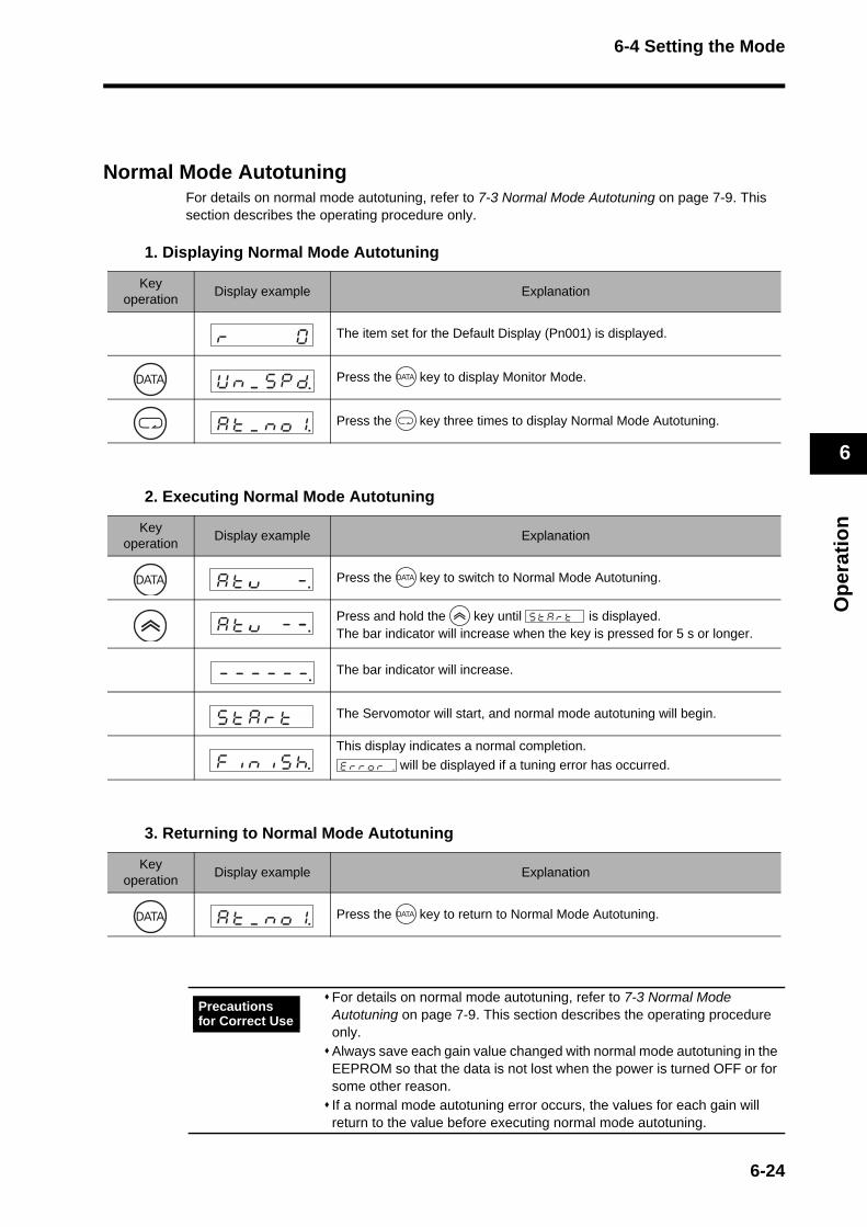
6-4 Setting the Mode
Op
erat
ion
6
Normal Mode AutotuningFor details on normal mode autotuning, refer to 7-3 Normal Mode Autotuning on page 7-9. This section describes the operating procedure only.
1. Displaying Normal Mode Autotuning
2. Executing Normal Mode Autotuning
3. Returning to Normal Mode Autotuning
Key operation
Display example Explanation
The item set for the Default Display (Pn001) is displayed.
Press the key to display Monitor Mode.
Press the key three times to display Normal Mode Autotuning.
Key operation
Display example Explanation
Press the key to switch to Normal Mode Autotuning.
Press and hold the key until is displayed. The bar indicator will increase when the key is pressed for 5 s or longer.
The bar indicator will increase.
The Servomotor will start, and normal mode autotuning will begin.
This display indicates a normal completion.
will be displayed if a tuning error has occurred.
Key operation
Display example Explanation
Press the key to return to Normal Mode Autotuning.
For details on normal mode autotuning, refer to 7-3 Normal Mode Autotuning on page 7-9. This section describes the operating procedure only. Always save each gain value changed with normal mode autotuning in the EEPROM so that the data is not lost when the power is turned OFF or for some other reason. If a normal mode autotuning error occurs, the values for each gain will return to the value before executing normal mode autotuning.
Uknk_k5kpkd
sktkakrktk k
Precautions for Correct Use
6-24

6-4 Setting the Mode
Op
erat
ion
6
Auxiliary Function ModeAuxiliary Function Mode includes alarm reset, absolute encoder reset, and jog operation.
Displaying Auxiliary Function Mode
Alarm Reset
1. Executing Alarm Reset
2. Returning to Auxiliary Function Mode
Key operation
Display example Explanation
The item set for the Default Display (Pn001) is displayed.
Press the key to display Monitor Mode.
Press the key four times to display Auxiliary Function Mode.
Key operation
Display example Explanation
Press the key to switch to Alarm Reset Mode.
Press and hold the key until is displayed. The bar indicator will increase when the key is pressed for 5 s or longer.
The bar indicator will increase.
Alarm reset will start.
This display indicates a normal completion.
will be displayed if the alarm could not be reset. Reset the power supply to clear the error.
Key operation
Display example Explanation
Press the key to return to Auxiliary Function Mode.
Uknk_k5kpkd
sktkakrktk k
6-25
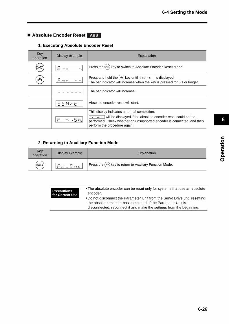
6-4 Setting the Mode
Op
erat
ion
6
Absolute Encoder Reset
1. Executing Absolute Encoder Reset
2. Returning to Auxiliary Function Mode
Key operation
Display example Explanation
Press the key to switch to Absolute Encoder Reset Mode.
Press and hold the key until is displayed. The bar indicator will increase when the key is pressed for 5 s or longer.
The bar indicator will increase.
Absolute encoder reset will start.
This display indicates a normal completion.
will be displayed if the absolute encoder reset could not be performed. Check whether an unsupported encoder is connected, and then perform the procedure again.
Key operation
Display example Explanation
Press the key to return to Auxiliary Function Mode.
The absolute encoder can be reset only for systems that use an absolute encoder.Do not disconnect the Parameter Unit from the Servo Drive until resetting the absolute encoder has completed. If the Parameter Unit is disconnected, reconnect it and make the settings from the beginning.
ABS
eknkck k k-.
eknkck k-k-.sktkakrktk k
fknk_keknkc
Precautions for Correct Use
6-26

6-4 Setting the Mode
Op
erat
ion
6
Jog Operation
1. Executing Jog Operation
2. Returning to Auxiliary Function Mode
Key operation
Display example Explanation
Press the key to display Jog Operation Mode from the alarm reset display in Auxiliary Function Mode.
Press the key to switch to Jog Operation Mode.
Press and hold the key until “Ready” is displayed. The bar indicator will increase when the key is pressed for 5 s or longer.
The bar indicator will increase.
This completes preparations for jog operation.
Press and hold the key until “Sev_on” is displayed. The decimal point will move to the left when the key is pressed for 3 s or longer.
The Servo will turn ON.
Forward operation will be performed while the key is pressed, and reverse operation will be performed while the key is pressed.
The Servomotor will stop when the key is released. The speed set for the Jog
Speed (Pn03D) will be used for jogging.
Key operation
Display example Explanation
Press the key to return to Auxiliary Function Mode. The Servo lock will be released.
6-27
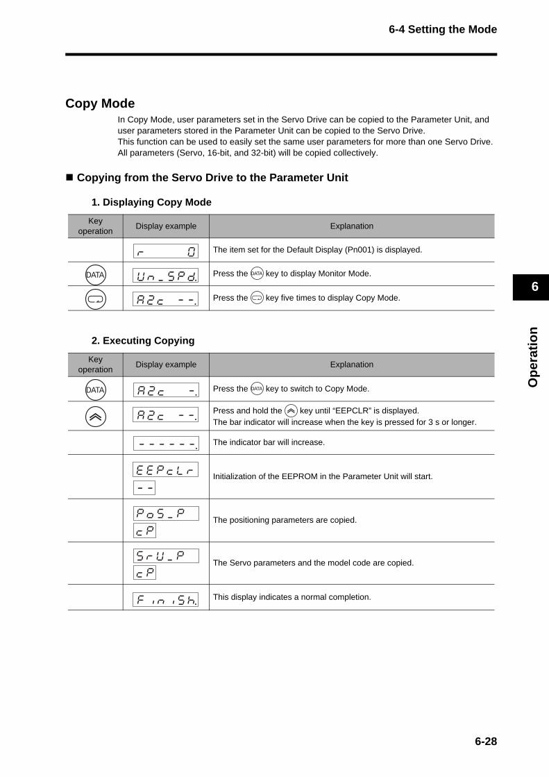
6-4 Setting the Mode
Op
erat
ion
6
Copy ModeIn Copy Mode, user parameters set in the Servo Drive can be copied to the Parameter Unit, and user parameters stored in the Parameter Unit can be copied to the Servo Drive. This function can be used to easily set the same user parameters for more than one Servo Drive. All parameters (Servo, 16-bit, and 32-bit) will be copied collectively.
Copying from the Servo Drive to the Parameter Unit
1. Displaying Copy Mode
2. Executing Copying
Key operation
Display example Explanation
The item set for the Default Display (Pn001) is displayed.
Press the key to display Monitor Mode.
Press the key five times to display Copy Mode.
Key operation
Display example Explanation
Press the key to switch to Copy Mode.
Press and hold the key until “EEPCLR” is displayed. The bar indicator will increase when the key is pressed for 3 s or longer.
The indicator bar will increase.
Initialization of the EEPROM in the Parameter Unit will start.
The positioning parameters are copied.
The Servo parameters and the model code are copied.
This display indicates a normal completion.
ekekpkcklkr-k-
pkok5k_kpckp
skrkUk_kpckp
6-28
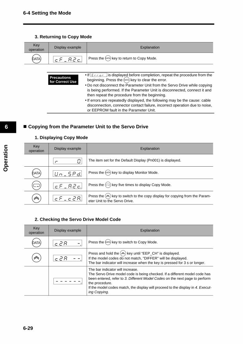
6-4 Setting the Mode
Op
erat
ion
6
3. Returning to Copy Mode
Copying from the Parameter Unit to the Servo Drive
1. Displaying Copy Mode
2. Checking the Servo Drive Model Code
Key operation
Display example Explanation
Press the key to return to Copy Mode.
If is displayed before completion, repeat the procedure from the beginning. Press the key to clear the error.Do not disconnect the Parameter Unit from the Servo Drive while copying is being performed. If the Parameter Unit is disconnected, connect it and then repeat the procedure from the beginning. If errors are repeatedly displayed, the following may be the cause: cable disconnection, connector contact failure, incorrect operation due to noise, or EEPROM fault in the Parameter Unit.
Key operation
Display example Explanation
The item set for the Default Display (Pn001) is displayed.
Press the key to display Monitor Mode.
Press the key five times to display Copy Mode.
Press the key to switch to the copy display for copying from the Param-eter Unit to the Servo Drive.
Key operation
Display example Explanation
Press the key to switch to Copy Mode.
Press and hold the key until “EEP_CH” is displayed. If the model codes do not match, "DIFFER" will be displayed. The bar indicator will increase when the key is pressed for 3 s or longer.
The bar indicator will increase. The Servo Drive model code is being checked. If a different model code has been entered, refer to 3. Different Model Codes on the next page to perform the procedure. If the model codes match, the display will proceed to the display in 4. Execut-ing Copying.
Precautions for Correct Use
6-29
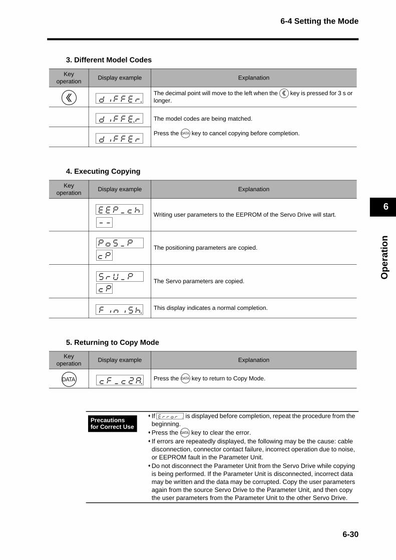
6-4 Setting the Mode
Op
erat
ion
6
3. Different Model Codes
4. Executing Copying
5. Returning to Copy Mode
Key operation
Display example Explanation
The decimal point will move to the left when the key is pressed for 3 s or longer.
The model codes are being matched.
Press the key to cancel copying before completion.
Key operation
Display example Explanation
Writing user parameters to the EEPROM of the Servo Drive will start.
The positioning parameters are copied.
The Servo parameters are copied.
This display indicates a normal completion.
Key operation
Display example Explanation
Press the key to return to Copy Mode.
If is displayed before completion, repeat the procedure from the beginning.Press the key to clear the error.If errors are repeatedly displayed, the following may be the cause: cable disconnection, connector contact failure, incorrect operation due to noise, or EEPROM fault in the Parameter Unit. Do not disconnect the Parameter Unit from the Servo Drive while copying is being performed. If the Parameter Unit is disconnected, incorrect data may be written and the data may be corrupted. Copy the user parameters again from the source Servo Drive to the Parameter Unit, and then copy the user parameters from the Parameter Unit to the other Servo Drive.
ekekpk_kckh-k-
pkok5k_kpckp
skrkUk_kpckp
Precautions for Correct Use
6-30

6-5 Trial Operation
Op
erat
ion
6
6-5 Trial OperationWhen you have finished installation, wiring, and switch settings and have confirmed that status is normal after turning ON the power supply, perform trial operation. The main purpose of trial operation is to confirm that the servo system is electrically correct.If an error occurs during the trial operation, refer to Chapter 8 Troubleshooting to eliminate the cause. Then check for safety, and then retry the trial operation.
Preparation for Trial Operation
Checks before Trial OperationCheck the following items before starting trial operation.
WiringMake sure that all wiring is correct, especially the power supply input and motor output.Make sure that there are no short-circuits. Check the ground for short-circuits as well. Make sure that there are no loose connections.
Power Supply VoltageMake sure that the voltage corresponds to the rated voltage.
Motor InstallationMake sure that the Servomotor has been securely installed.
Disconnection from Mechanical SystemIf necessary, make sure that the Servomotor has been disconnected from the mechanical system.
BrakeMake sure that the brake has been released.
Trial Operation with CX-Drive1. Connect connector CN1. 2. Input power (12 to 24 VDC) for the control signals (+24VIN, COM). 3. Turn ON the power supply to the Servo Drive. 4. Confirm that the parameters are set to the standard settings.5. Connect the Computer Communications Cable to CN3, and write parameters from
CX-Drive. 6. Write the parameters to EEPROM and then turn OFF the power supply and turn it ON
again. 7. Turn the status to Servo ON with jog operation via CX-Drive, and Servo lock the
motor. 8. Perform low speed jog operation via CX-Drive. 9. Check the Servomotor rotation speed.
6-31
Chapter 7
Adjustment Functions7-1 Gain Adjustment................................................. 7-1Purpose of the Gain Adjustment ...........................................7-1
Gain Adjustment Methods.....................................................7-1
Gain Adjustment Procedure..................................................7-2
7-2 Realtime Autotuning........................................... 7-3Realtime Autotuning Setting Method ....................................7-4
Machine Rigidity Setting Method ..........................................7-4
7-3 Normal Mode Autotuning ................................... 7-9Setting the Parameters .........................................................7-9
7-4 Manual Tuning ................................................... 7-14Basic Settings .......................................................................7-14
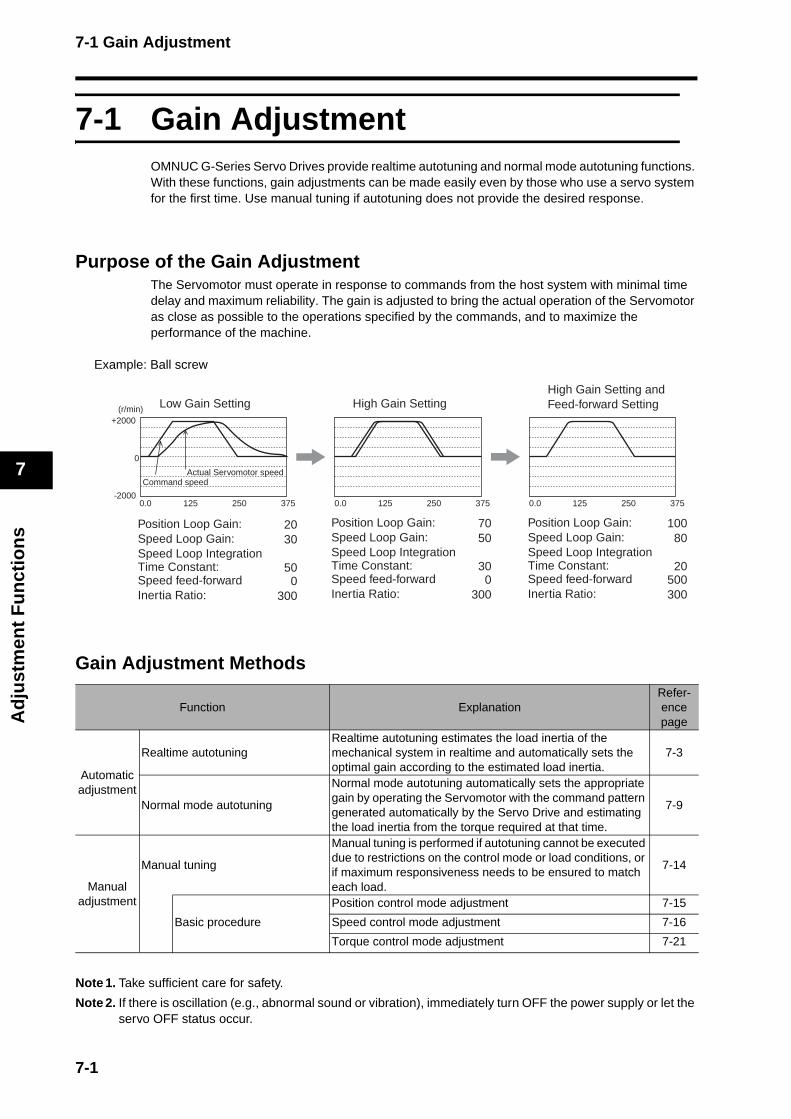
7-1 Gain Adjustment
Ad
just
men
t F
un
ctio
ns
7
7-1 Gain AdjustmentOMNUC G-Series Servo Drives provide realtime autotuning and normal mode autotuning functions. With these functions, gain adjustments can be made easily even by those who use a servo system for the first time. Use manual tuning if autotuning does not provide the desired response.
Purpose of the Gain AdjustmentThe Servomotor must operate in response to commands from the host system with minimal time delay and maximum reliability. The gain is adjusted to bring the actual operation of the Servomotor as close as possible to the operations specified by the commands, and to maximize the performance of the machine.
Example: Ball screw
Gain Adjustment Methods
Note 1. Take sufficient care for safety.
Note 2. If there is oscillation (e.g., abnormal sound or vibration), immediately turn OFF the power supply or let the servo OFF status occur.
Function ExplanationRefer-ence page
Automatic adjustment
Realtime autotuning Realtime autotuning estimates the load inertia of the mechanical system in realtime and automatically sets the optimal gain according to the estimated load inertia.
7-3
Normal mode autotuning
Normal mode autotuning automatically sets the appropriate gain by operating the Servomotor with the command pattern generated automatically by the Servo Drive and estimating the load inertia from the torque required at that time.
7-9
Manual adjustment
Manual tuning
Manual tuning is performed if autotuning cannot be executed due to restrictions on the control mode or load conditions, or if maximum responsiveness needs to be ensured to match each load.
7-14
Basic procedure
Position control mode adjustment 7-15
Speed control mode adjustment 7-16
Torque control mode adjustment 7-21
Position Loop Gain:Speed Loop Gain:Speed Loop Integration Time Constant:Speed feed-forwardInertia Ratio:
2030
500
300
7050
300
300
10080
20500300
+2000
-2000
0
0.0 375250125 0.0 375250125 0.0 375250125
(r/min)
Command speedActual Servomotor speed
Low Gain Setting High Gain SettingHigh Gain Setting and Feed-forward Setting
Position Loop Gain:
Speed Loop Integration Time Constant:Speed feed-forwardInertia Ratio:
Speed Loop Gain:Position Loop Gain:
Speed Loop Integration Time Constant:Speed feed-forwardInertia Ratio:
Speed Loop Gain:
7-1
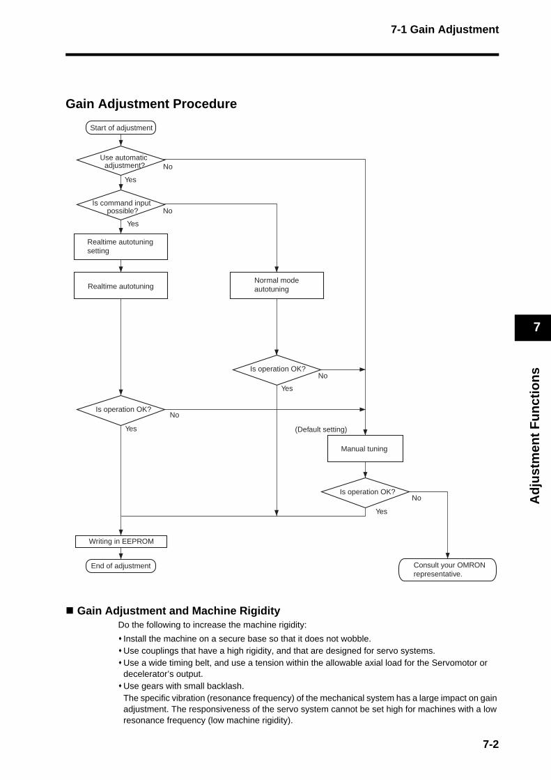
7-1 Gain Adjustment
Ad
just
men
t F
un
ctio
ns
7
Gain Adjustment Procedure
Gain Adjustment and Machine RigidityDo the following to increase the machine rigidity:
Install the machine on a secure base so that it does not wobble.Use couplings that have a high rigidity, and that are designed for servo systems.Use a wide timing belt, and use a tension within the allowable axial load for the Servomotor or decelerator’s output.Use gears with small backlash. The specific vibration (resonance frequency) of the mechanical system has a large impact on gain adjustment. The responsiveness of the servo system cannot be set high for machines with a low resonance frequency (low machine rigidity).
Start of adjustment
Yes
Yes
No
No
Realtime autotuningNormal modeautotuning
Use automatic adjustment?
Is command input possible?
Realtime autotuning setting
Is operation OK?
Is operation OK?
Yes
No
Yes
No
Is operation OK?
Yes
No
Manual tuning
End of adjustment
Writing in EEPROM
(Default setting)
Consult your OMRON representative.
7-2

7-2 Realtime Autotuning
Ad
just
men
t F
un
ctio
ns
7
7-2 Realtime Autotuning
Realtime autotuning estimates the load inertia of the mechanical system in realtime and operates the system by automatically setting the gain according to the estimated load inertia. By executing autotuning with the adaptive filter enabled, you can also reduce vibration and resonance. Realtime autotuning adjusts the PI control for the speed loop, and is thus effective for all controls.
With realtime autotuning, the parameters are fixed to the values in the machine rigidity table when the machine rigidity is set. The operating coefficients for the speed loop gain and the integration time constant are changed by estimating the load inertia based on the operating pattern. Set the estimated values gradually because setting different values for the patterns may cause vibration.
Realtime autotuning may not function properly under the conditions described in the following table. If realtime autotuning does not function properly, use normal mode autotuning or manual tuning.
Conditions under which realtime autotuning does not function properly
Load inertiaIf the load inertia is too small or too large compared with the rotor inertia (i.e., less than 3 times, more than 20 times, or more than the applicable load inertia ratio).If the load inertia changes quickly, i.e., in less than 10 seconds.
LoadIf the machine rigidity is extremely low. If there is backlash or play in the system.
Operating pattern
If the speed is continuously run at a low speed below 100 r/min.If the acceleration/deceleration gradually changes at less than 2,000 r/min in 1 s.If the acceleration/deceleration torque is too small compared with the unbalanced load and the viscous friction torque.If a speed of 100 r/min or an acceleration/deceleration of 2,000 r/min/s does not continue for at least 50 ms.
Estimate Load Inertia
SM
RE
Load
Position Command
Speed Feedback
PositionControl
Current LoopControl
Torque CommandSpeed
PI Control
Speed Command
Position Feedback
Precautions for Correct Use
7-3

7-2 Realtime Autotuning
Ad
just
men
t F
un
ctio
ns
7
Realtime Autotuning Setting Method1. Turn the servo OFF before setting realtime autotuning. 2. Set the Realtime Autotuning Mode Selection (Pn021) according to the load.
Setting the parameter to 3 or 6 will allow the system to respond faster to inertia changes during operation. However, it may also cause operation to become unstable depending on the operating pattern. Normally use a setting of 1 or 4.Use a setting of 4 to 6 when the vertical axis is used.Gain switching is enabled for a setting of 1 to 6. If change in operation due to gain switching becomes an issue, use a setting of 7.
Machine Rigidity Setting Method1. Set the Realtime Autotuning Machine Rigidity Selection (Pn022) as shown below.
Machine rigidity 0 cannot be selected for the Parameter Unit and CX-Drive. Set the machine rigidity starting with a low value and check the operation.
2. Turn the servo ON, and operate the machine with the normal pattern. To improve the response, increase the machine rigidity number, and then check the response again. If vibration occurs, enable the adaptive filter. If the filter is already enabled, lower the machine rigidity number and make adjustments.
3. If there is no problem with the operation, turn the servo OFF, and disable the Realtime Autotuning Mode Selection (Pn021) by setting it to 0. The adaptive filter can be left enabled. To disable the adaptive filter, read the frequency on the Adaptive Filter Table Number display, and set the Notch Filter 1 Frequency to the same value.
Setting Realtime autotuning Degree of change in load inertia
0 Disabled (default) ---
1
Horizontal axis mode
Almost no change
2 Gradual changes
3 Sudden changes
4
Vertical axis mode
Almost no change
5 Gradual changes
6 Sudden changes
7 Gain switching disable mode Almost no change
Mechanical Configuration / Drive SystemRealtime Autotuning
Machine Rigidity Selection (Pn022)
Ball screw direct coupling 6 to C
Ball screw and timing belt 4 to A
Timing belt 2 to 8
Gears, rack and pinion drives 2 to 8
Machines with low rigidity, etc 1 to 4
Stacker crane Tune manually.
7-4

7-2 Realtime Autotuning
Ad
just
men
t F
un
ctio
ns
7
Unusual noise or vibration may occur until the load inertia is estimated or the adaptive filter stabilizes after startup, immediately after the first servo ON, or when the Realtime Autotuning Machine Rigidity Selection (Pn022) is increased. This is not a problem if it disappears right away. If the unusual noise or vibration, however, continues for three or more reciprocating operations, take the following measures in any order you can. Write the parameters used during normal operation to the EEPROM. Lower the Realtime Autotuning Machine Rigidity Selection (Pn022). Manually set the notch filter.
Once unusual noise or vibration occurs, the Inertia Ratio (Pn020) may have changed to an extreme value. In this case, also take the measures described above. Out of the results of realtime autotuning, the Inertia Ratio (Pn020) is automatically saved to the EEPROM every 30 minutes. Realtime autotuning will use this saved data as the default value when the power is turned OFF and turned ON again.The Instantaneous Speed Observer Setting (Pn027) will automatically be disabled (0) if realtime autotuning is enabled.
Precautions for Correct Use
7-5

7-2 Realtime Autotuning
Ad
just
men
t F
un
ctio
ns
7
Operating Procedure
ekekpk k-k-.
ekek_kskekt.
rkekskektk .
ekekpk k k-.
pknk_k k2k2.
pknk_k k2k1.
pknk_k k2k1.
pknk_k k0k0.
Uknk_kskpkd.
rk k k k k0k
ekrkrkokrkkkk.fkiknkikskh.
sktkakrktk
-k-k-k-k-k-.
2.
0.
skUk k k k
skUk k k k
2k1k k k k
skUk k k k
skUk k k k
2k2k k k k
skekrkUkokpk
1k6kbkiktkp
Insert the Parameter Unit connector into CN3 of the Servo Drive and turn ON the Servo Drive power supply.
Setting Parameter Pn021
Press the key.
Press the key.
Press the key.
Press the key.
Press the key.
Press the key.
Select the number of the parameter to be set by
using the and keys.
(Pn021 is selected in this example.)
Change the value by using the and keys.
Setting Parameter Pn022
Select Pn022 by using the key.
(Default setting)Increase the value by using the key.
Decrease the value by using the key.
Writing to EEPROM
Press the key.
End
Writing will start (momentary display).
The bars as shown in the figure on the right will increase when the key is pressed down for approx. 5 s.
Writing completed. Writing error occurred.
Press the key.
Press the key.
Press the key.
7-6
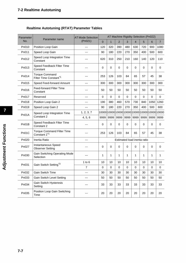
7-2 Realtime Autotuning
Ad
just
men
t F
un
ctio
ns
7
Realtime Autotuning (RTAT) Parameter Tables
Parameter No.
Parameter nameAT Mode Selection
(Pn021)
AT Machine Rigidity Selection (Pn022)
0 1 2 3 4 5 6 7
Pn010 Position Loop Gain --- 120 320 390 480 630 720 900 1080
Pn011 Speed Loop Gain --- 90 180 220 270 350 400 500 600
Pn012Speed Loop Integration Time Constant
--- 620 310 250 210 160 140 120 110
Pn013Speed Feedback Filter Time Constant
--- 0 0 0 0 0 0 0 0
Pn014Torque CommandFilter Time Constant*1
--- 253 126 103 84 65 57 45 38
Pn015 Speed Feed-forward Amount --- 300 300 300 300 300 300 300 300
Pn016Feed-forward Filter Time Constant
--- 50 50 50 50 50 50 50 50
Pn017 Reserved --- 0 0 0 0 0 0 0 0
Pn018 Position Loop Gain 2 --- 190 380 460 570 730 840 1050 1260
Pn019 Speed Loop Gain 2 --- 90 180 220 270 350 400 500 600
Pn01ASpeed Loop Integration Time Constant 2
1, 2, 3, 7 1000010000 100001000010000 1000010000 10000
4, 5, 6 9999 9999 9999 9999 9999 9999 9999 9999
Pn01BSpeed Feedback Filter Time Constant 2
--- 0 0 0 0 0 0 0 0
Pn01CTorque Command Filter Time Constant 2*1 --- 253 126 103 84 65 57 45 38
Pn020 Inertia Ratio --- Estimated load inertia ratio
Pn027Instantaneous SpeedObserver Setting
--- 0 0 0 0 0 0 0 0
Pn030Gain Switching Operating Mode Selection
--- 1 1 1 1 1 1 1 1
Pn031 Gain Switch Setting*31 to 6 10 10 10 10 10 10 10 10
7 0 0 0 0 0 0 0 0
Pn032 Gain Switch Time --- 30 30 30 30 30 30 30 30
Pn033 Gain Switch Level Setting --- 50 50 50 50 50 50 50 50
Pn034Gain Switch Hysteresis Setting
--- 33 33 33 33 33 33 33 33
Pn035Position Loop Gain Switching Time
--- 20 20 20 20 20 20 20 20
7-7
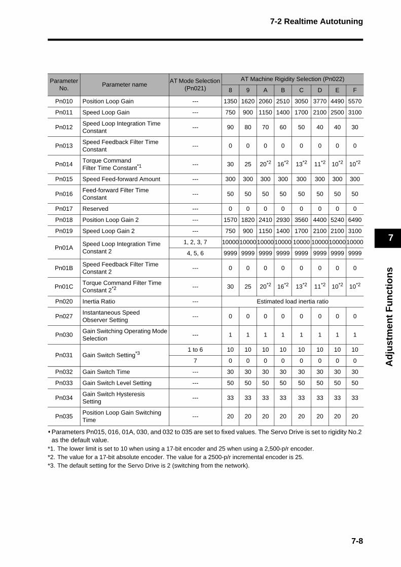
7-2 Realtime Autotuning
Ad
just
men
t F
un
ctio
ns
7
Parameters Pn015, 016, 01A, 030, and 032 to 035 are set to fixed values. The Servo Drive is set to rigidity No.2 as the default value.
*1. The lower limit is set to 10 when using a 17-bit encoder and 25 when using a 2,500-p/r encoder. *2. The value for a 17-bit absolute encoder. The value for a 2500-p/r incremental encoder is 25. *3. The default setting for the Servo Drive is 2 (switching from the network).
Parameter No.
Parameter nameAT Mode Selection
(Pn021)
AT Machine Rigidity Selection (Pn022)
8 9 A B C D E F
Pn010 Position Loop Gain --- 1350 1620 2060 2510 3050 3770 4490 5570
Pn011 Speed Loop Gain --- 750 900 1150 1400 1700 2100 2500 3100
Pn012Speed Loop Integration Time Constant
--- 90 80 70 60 50 40 40 30
Pn013Speed Feedback Filter Time Constant
--- 0 0 0 0 0 0 0 0
Pn014Torque CommandFilter Time Constant*1
--- 30 25 20*2 16*2 13*2 11*2 10*2 10*2
Pn015 Speed Feed-forward Amount --- 300 300 300 300 300 300 300 300
Pn016Feed-forward Filter Time Constant
--- 50 50 50 50 50 50 50 50
Pn017 Reserved --- 0 0 0 0 0 0 0 0
Pn018 Position Loop Gain 2 --- 1570 1820 2410 2930 3560 4400 5240 6490
Pn019 Speed Loop Gain 2 --- 750 900 1150 1400 1700 2100 2100 3100
Pn01ASpeed Loop Integration Time Constant 2
1, 2, 3, 7 10000100001000010000 10000 100001000010000
4, 5, 6 9999 9999 9999 9999 9999 9999 9999 9999
Pn01BSpeed Feedback Filter Time Constant 2
--- 0 0 0 0 0 0 0 0
Pn01CTorque Command Filter Time Constant 2*2 --- 30 25 20*2 16*2 13*2 11*2 10*2 10*2
Pn020 Inertia Ratio --- Estimated load inertia ratio
Pn027Instantaneous SpeedObserver Setting
--- 0 0 0 0 0 0 0 0
Pn030Gain Switching Operating Mode Selection
--- 1 1 1 1 1 1 1 1
Pn031 Gain Switch Setting*31 to 6 10 10 10 10 10 10 10 10
7 0 0 0 0 0 0 0 0
Pn032 Gain Switch Time --- 30 30 30 30 30 30 30 30
Pn033 Gain Switch Level Setting --- 50 50 50 50 50 50 50 50
Pn034Gain Switch Hysteresis Setting
--- 33 33 33 33 33 33 33 33
Pn035Position Loop Gain Switching Time
--- 20 20 20 20 20 20 20 20
7-8

7-3 Normal Mode Autotuning
Ad
just
men
t F
un
ctio
ns
7
7-3 Normal Mode Autotuning
Normal mode autotuning is used to estimate the load inertia of the machine. Position data generated within the Servo Drive is used to operate the machine for the estimation, thereby achieving greater accuracy in estimating the load inertia. Normal mode autotuning can be used from the Parameter Unit or CX-Drive.
Setting the Parameters1. Set the operating pattern.
Set the operating pattern using the Normal Mode Autotuning Operation Setting (Pn025).
Setting Number of rotations Direction of rotation
0
Two rotationsRepeat
Multiple Times
Forward and Reverse (Alternating)
1 Reverse and Forward (Alternating)
2 Forward only
3 Reverse only
4
One rotationRepeat
Multiple Times
Forward and Reverse (Alternating)
5 Reverse and Forward (Alternating)
6 Forward only
7 Reverse only
SM
RE
InternalPosition CommandPn025
Estimate Load Inertia
Load
PositionControl
Current LoopControl
Torque CommandSpeed
PI Control
Position Feedback Speed Feedback
Torque command
Setting ofinternal position command Pn025
Repeat
7-9

7-3 Normal Mode Autotuning
Ad
just
men
t F
un
ctio
ns
7
The following graph shows the speed operating pattern when the set value is 0.
The operating pattern starts with 3 or 4 reciprocating operations, followed by up to 3 cycles of 2 reciprocations, with each cycle accelerated twice as much as the previous cycle.The acceleration will stop changing, as it is limited by the No. 1 Torque Limit (Pn05E). This is not an indication of failure.
2. Select the machine rigidity. Set the machine rigidity number according to the rigidity of the machine. Refer to the following table for the machine rigidity values. Machine rigidity 0 cannot be selected for the Parameter Unit and CX-Drive. Set the machine rigidity starting with a low value and check the operation.
To improve the response, increase the machine rigidity number, and then check the response again. If vibration occurs, lower the machine rigidity number and make adjustments. The setting parameters are the same as in Realtime Autotuning (RTAT) Parameter Tables on page 7-7.
3. Execute normal mode autotuning. Move the load to a position where it will not interfere with the operation performed according to the operation pattern. For reciprocating movement, ±1 or ±2 rotations will be made. For one-way movement, about 20 rotations will be made.
Operating with the Parameter Unit1. Switch to the Normal Mode Autotuning display.
Servo lock is performed automatically. For details on switching to the Normal Mode Autotuning display, refer to Normal Mode Autotuning on page 6-24.
Mechanical Configuration / Drive System
Machine Rigidity
Ball screw direct coupling 6 to C
Ball screw and timing belt 4 to A
Timing belt 2 to 8
Gears, rack and pinion drives 2 to 8
Machines with low rigidity, etc. 1 to 4
Stacker crane Tune manually.
aktk_knkok1.
Machine rigidity No.
Nomal mode autotuning display
7-10
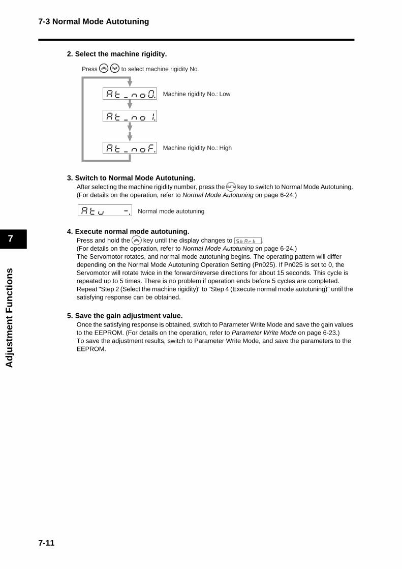
7-3 Normal Mode Autotuning
Ad
just
men
t F
un
ctio
ns
7
2. Select the machine rigidity.
3. Switch to Normal Mode Autotuning. After selecting the machine rigidity number, press the key to switch to Normal Mode Autotuning. (For details on the operation, refer to Normal Mode Autotuning on page 6-24.)
4. Execute normal mode autotuning. Press and hold the key until the display changes to . (For details on the operation, refer to Normal Mode Autotuning on page 6-24.) The Servomotor rotates, and normal mode autotuning begins. The operating pattern will differ depending on the Normal Mode Autotuning Operation Setting (Pn025). If Pn025 is set to 0, the Servomotor will rotate twice in the forward/reverse directions for about 15 seconds. This cycle is repeated up to 5 times. There is no problem if operation ends before 5 cycles are completed. Repeat "Step 2 (Select the machine rigidity)" to "Step 4 (Execute normal mode autotuning)" until the satisfying response can be obtained.
5. Save the gain adjustment value. Once the satisfying response is obtained, switch to Parameter Write Mode and save the gain values to the EEPROM. (For details on the operation, refer to Parameter Write Mode on page 6-23.) To save the adjustment results, switch to Parameter Write Mode, and save the parameters to the EEPROM.
aktk_knkok1. kk
aktk_knkok0. k
aktk_knkokf.
to select machine rigidity No.
Machine rigidity No.: Low
Press
Machine rigidity No.: High
aktkuk k k-. Normal mode autotuning
sktkakrktk k
7-11

7-3 Normal Mode Autotuning
Ad
just
men
t F
un
ctio
ns
7
When using normal mode autotuning with a Servomotor with a brake, connect the brake interlock (BKIR) output signal to allow the brake to be released. If the Positioning Completion Range 1 (Pn060) is too narrow, it will cause an error. By default, the parameter is set to 25 for an incremental encoder. When using an absolute encoder, set the parameter to 250 (ten times larger). If the Deviation Counter Overflow Level (Pn209) is too small, it will cause a deviation counter overflow.When using an absolute encoder, increase the setting from 20,000 pulses (default) to 200,000 pulses. Set the Torque Limit Selection (Pn003) to 1. If the setting is too small, it will cause an error. The maximum motor output during normal mode autotuning will be limited by the No. 1 Torque Limit (Pn05E). If the value is too small, there may be problems with the operation. Actuating the network during normal mode autotuning will cause a command error (alarm code 27). Do not actuate the network while executing normal mode autotuning. The position data is initialized after normal mode autotuning. If the load inertia is less than 3 times the rotor inertia or greater than the applicable load inertia (20 to 30 times greater), there may be problems with the operation. If the machine rigidity is extremely low, or if the backlash is extremely large, estimation cannot be performed. If an error occurs or a drive prohibition input is received during normal mode autotuning, a tuning error will occur. If normal mode autotuning is executed and the load inertia cannot be estimated, the load inertia will remain the same as it was before normal mode autotuning. Executing normal mode autotuning may not cause an error but result in vibration. Use caution to ensure safety, and promptly turn OFF the power supply if anything unusual happens.
Precautions for Correct Use
7-12

7-3 Normal Mode Autotuning
Ad
just
men
t F
un
ctio
ns
7
Normal Mode Autotuning (AT) Parameter Tables
*1. The lower limit is set to 10 when using a 17-bit encoder and 25 when using a 2,500-p/r encoder. *2. The value for a 17-bit absolute encoder. The value for a 2500-p/r incremental encoder is 25.
Parameter No.
Parameter nameAT Machine Rigidity Selection (Pn022)
0 1 2 3 4 5 6 7 8 9 A B C D E F
Pn010Position Loop Gain
120 320 390 480 630 720 900 1080 1350 1620 2060 2510 3050 3770 4490 5570
Pn011Speed Loop Gain
90 180 220 270 350 400 500 600 750 900 1150 1400 1700 2100 2500 3100
Pn012Speed Loop Integration Time Constant
620 310 250 210 160 140 120 110 90 80 70 60 50 40 40 30
Pn013Speed Feed-back Filter Time Constant
0 0 0 0 0 0 0 0 0 0 0 0 0 0 0 0
Pn014
Torque CommandFilter Time Constant*1
253 126 103 84 65 57 45 38 30 25 20*2 16*2 13*2 11*2 10*2 10*2
Pn015Speed Feed-forward Amount
300 300 300 300 300 300 300 300 300 300 300 300 300 300 300 300
Pn016Feed-forward Filter Time Constant
50 50 50 50 50 50 50 50 50 50 50 50 50 50 50 50
Pn018Position Loop Gain 2
190 380 460 570 730 840 1050 1260 1570 1820 2410 2930 3560 4400 5240 6490
Pn019Speed Loop Gain 2
90 180 220 270 350 400 500 600 750 900 1150 1400 1700 2100 2100 3100
Pn01ASpeed Loop Integration Time Constant 2
9999 9999 9999 9999 9999 9999 9999 9999 9999 9999 9999 9999 9999 9999 9999 9999
Pn01BSpeed Feed-back Filter Time Constant 2
0 0 0 0 0 0 0 0 0 0 0 0 0 0 0 0
Pn01CTorque Com-mand Filter Time Constant 2*1
253 126 103 84 65 57 45 38 30 25 20*2 16*2 13*2 11*2 10*2 10*2
Pn020 Inertia Ratio Estimated load inertia ratio
Pn027Instantaneous Speed Observer Setting
0 0 0 0 0 0 0 0 0 0 0 0 0 0 0 0
Pn030Gain Switching Operating Mode Selection
1 1 1 1 1 1 1 1 1 1 1 1 1 1 1 1
Pn031Gain SwitchSetting
10 10 10 10 10 10 10 10 10 10 10 10 10 10 10 10
Pn032Gain SwitchTime
30 30 30 30 30 30 30 30 30 30 30 30 30 30 30 30
Pn033Gain SwitchLevel Setting
50 50 50 50 50 50 50 50 50 50 50 50 50 50 50 50
Pn034Gain SwitchHysteresis Setting
33 33 33 33 33 33 33 33 33 33 33 33 33 33 33 33
Pn035Position Loop Gain Switching Time
20 20 20 20 20 20 20 20 20 20 20 20 20 20 20 20
7-13

7-4 Manual Tuning
Ad
just
men
t F
un
ctio
ns
7
7-4 Manual Tuning
Basic SettingsAs described before, the OMNUC G-Series Servo Drives have an autotuning function. Depending on load conditions or other restrictions, however, readjustment may be required if the gain cannot be properly adjusted when normal mode autotuning is performed or the optimum responsiveness or stability is required to match each load. This section describes how to perform manual tuning for each control mode and function.
Before Manual SettingThe Parameter Unit can be used to adjust the Servomotor (machine) while monitoring the operation or noise, but more reliable adjustment can be performed quickly by using waveform monitoring with the data tracing function of CX-Drive or by measuring the analog voltage waveform with the monitor function.
Analog Monitor Output The actual Servomotor speed, command speed, torque, and number of accumulated pulses can be measured in the analog voltage level using an oscilloscope or other device. Set the type of signal to be output and the output voltage level by setting the Speed Monitor (SP) Selection (Pn007) and Torque Monitor (IM) Selection (Pn008). For details, refer to Parameter Tables on page 5-61.
CX-Drive Data TracingCommands to the Servomotor and Servomotor operation (e.g., speed, torque commands, and position deviation) can be displayed on a computer as waveforms. Refer to the CX-Drive Operation Manual (Cat. No. W453).
1kΩ
1kΩ G
IM
SP
COM
X10
32
10ADR
AC SERVO DRIVE
X1
6
78
9 0 1
23
45
RS-232 connection cable
Connect to CN3.
7-14
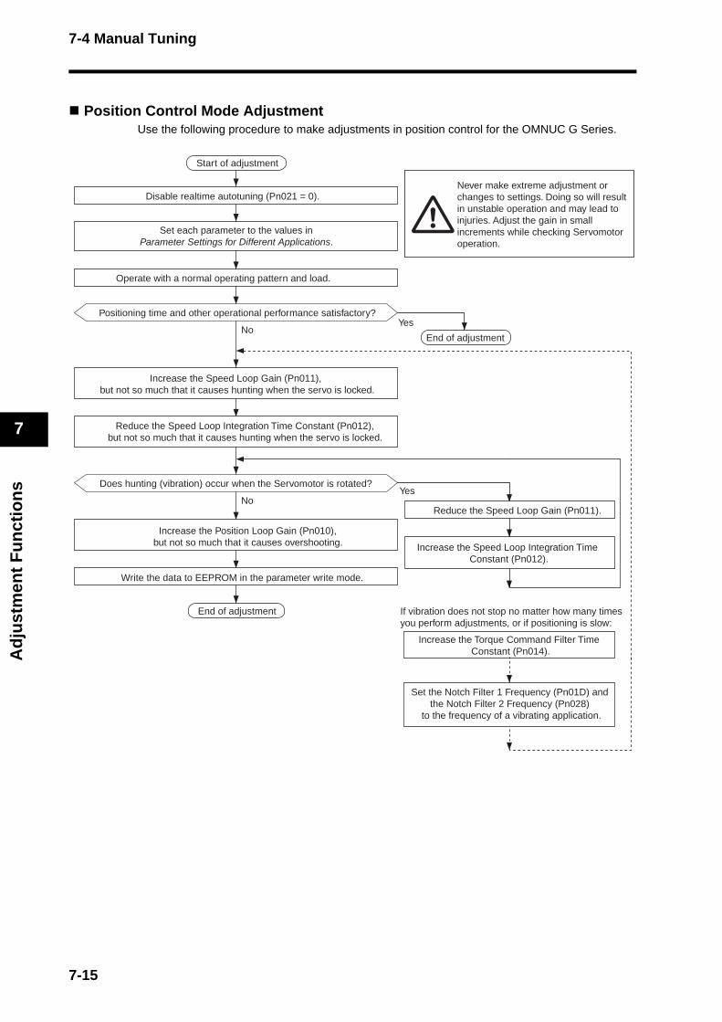
7-4 Manual Tuning
Ad
just
men
t F
un
ctio
ns
7
Position Control Mode AdjustmentUse the following procedure to make adjustments in position control for the OMNUC G Series.
Write the data to EEPROM in the parameter write mode.
Increase the Position Loop Gain (Pn010),but not so much that it causes overshooting.
Reduce the Speed Loop Gain (Pn011).
Start of adjustment
Disable realtime autotuning (Pn021 = 0).
Set each parameter to the values inParameter Settings for Different Applications.
Operate with a normal operating pattern and load.
Positioning time and other operational performance satisfactory?Yes
NoEnd of adjustment
Never make extreme adjustment orchanges to settings. Doing so will result in unstable operation and may lead to injuries. Adjust the gain in small increments while checking Servomotor operation.
Increase the Speed Loop Gain (Pn011), but not so much that it causes hunting when the servo is locked.
Reduce the Speed Loop Integration Time Constant (Pn012),but not so much that it causes hunting when the servo is locked.
YesNo
Does hunting (vibration) occur when the Servomotor is rotated?
End of adjustment
Increase the Speed Loop Integration Time Constant (Pn012).
If vibration does not stop no matter how many times you perform adjustments, or if positioning is slow:
Increase the Torque Command Filter Time Constant (Pn014).
Set the Notch Filter 1 Frequency (Pn01D) and the Notch Filter 2 Frequency (Pn028)
to the frequency of a vibrating application.
7-15
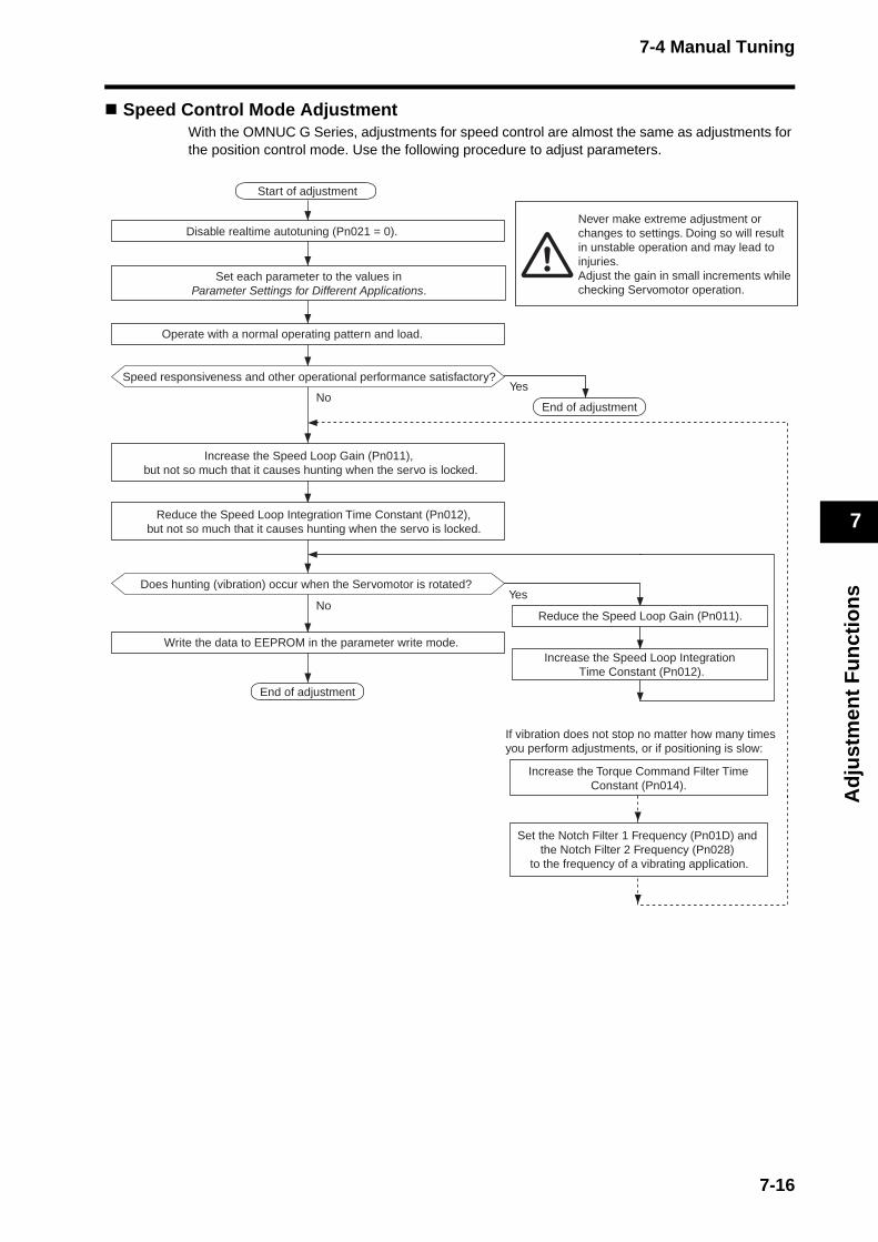
7-4 Manual Tuning
Ad
just
men
t F
un
ctio
ns
7
Speed Control Mode Adjustment With the OMNUC G Series, adjustments for speed control are almost the same as adjustments for the position control mode. Use the following procedure to adjust parameters.
Start of adjustment
Disable realtime autotuning (Pn021 = 0).
Operate with a normal operating pattern and load.
Speed responsiveness and other operational performance satisfactory?Yes
No
Increase the Speed Loop Gain (Pn011), but not so much that it causes hunting when the servo is locked.
Reduce the Speed Loop Integration Time Constant (Pn012),but not so much that it causes hunting when the servo is locked.
End of adjustment
YesNo
End of adjustment
Does hunting (vibration) occur when the Servomotor is rotated?
Reduce the Speed Loop Gain (Pn011).
Write the data to EEPROM in the parameter write mode.
Never make extreme adjustment or changes to settings. Doing so will result in unstable operation and may lead to injuries. Adjust the gain in small increments while checking Servomotor operation.
Increase the Speed Loop Integration Time Constant (Pn012).
If vibration does not stop no matter how many times you perform adjustments, or if positioning is slow:
Increase the Torque Command Filter TimeConstant (Pn014).
Set the Notch Filter 1 Frequency (Pn01D) and the Notch Filter 2 Frequency (Pn028)
to the frequency of a vibrating application.
Set each parameter to the values inParameter Settings for Different Applications.
7-16
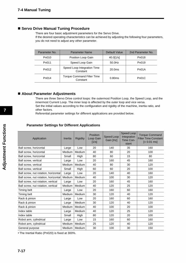
7-4 Manual Tuning
Ad
just
men
t F
un
ctio
ns
7
Servo Drive Manual Tuning ProcedureThere are four basic adjustment parameters for the Servo Drive. If the desired operating characteristics can be achieved by adjusting the following four parameters, you do not need to adjust any other parameter.
About Parameter AdjustmentsThere are three Servo Drive control loops: the outermost Position Loop, the Speed Loop, and the innermost Current Loop. The inner loop is affected by the outer loop and vice versa.Set the initial values according to the configuration and rigidity of the machine, inertia ratio, and other factors. Referential parameter settings for different applications are provided below.
Parameter Settings for Different Applications
The Inertial Ratio (Pn020) is fixed at 300%.
Parameter No. Parameter Name Default Value 2nd Parameter No.
Pn010 Position Loop Gain 40.0[1/s] Pn018
Pn011 Speed Loop Gain 50.0Hz Pn019
Pn012Speed Loop Integration Time
Constant20.0ms Pn01A
Pn014Torque Command Filter Time
Constant0.80ms Pn01C
Application Inertia RigidityPosition
Loop Gain [1/s]
Speed Loop Gain [Hz]
Speed Loop Integration Time Con-
stant
Torque Command Filter Time Constant
[× 0.01 ms]
Ball screw, horizontal Large Low 20 140 35 160
Ball screw, horizontal Medium Medium 40 80 20 100
Ball screw, horizontal Small High 80 60 15 80
Ball screw, vertical Large Low 20 160 45 160
Ball screw, vertical Medium Medium 40 80 30 120
Ball screw, vertical Small High 60 60 20 100
Ball screw, nut rotation, horizontal Large Low 20 140 40 160
Ball screw, nut rotation, horizontal Medium Medium 40 100 30 120
Ball screw, nut rotation, vertical Large Low 20 160 45 160
Ball screw, nut rotation, vertical Medium Medium 40 120 25 120
Timing belt Large Low 20 160 60 160
Timing belt Medium Medium 30 120 40 120
Rack & pinion Large Low 20 160 60 160
Rack & pinion Large Medium 30 120 40 120
Rack & pinion Medium Medium 40 100 20 100
Index table Large Medium 40 120 25 120
Index table Small High 80 120 20 100
Robot arm, cylindrical Large Low 15 160 60 160
Robot arm, cylindrical Medium Medium 25 120 40 120
General purpose Medium Medium 30 100 30 150
7-17
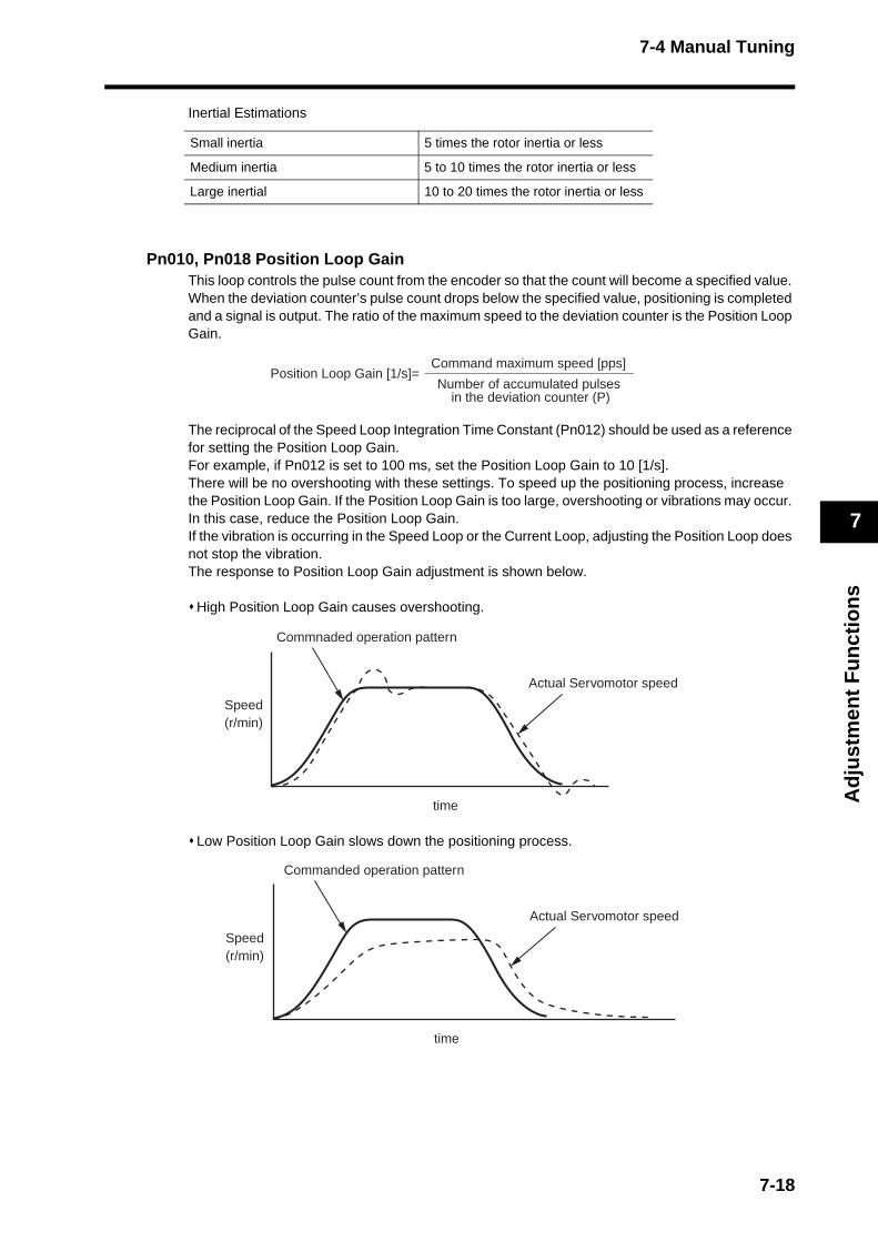
7-4 Manual Tuning
Ad
just
men
t F
un
ctio
ns
7
Inertial Estimations
Pn010, Pn018 Position Loop GainThis loop controls the pulse count from the encoder so that the count will become a specified value. When the deviation counter’s pulse count drops below the specified value, positioning is completed and a signal is output. The ratio of the maximum speed to the deviation counter is the Position Loop Gain.
The reciprocal of the Speed Loop Integration Time Constant (Pn012) should be used as a reference for setting the Position Loop Gain. For example, if Pn012 is set to 100 ms, set the Position Loop Gain to 10 [1/s]. There will be no overshooting with these settings. To speed up the positioning process, increase the Position Loop Gain. If the Position Loop Gain is too large, overshooting or vibrations may occur. In this case, reduce the Position Loop Gain. If the vibration is occurring in the Speed Loop or the Current Loop, adjusting the Position Loop does not stop the vibration. The response to Position Loop Gain adjustment is shown below.
High Position Loop Gain causes overshooting.
Low Position Loop Gain slows down the positioning process.
Small inertia 5 times the rotor inertia or less
Medium inertia 5 to 10 times the rotor inertia or less
Large inertial 10 to 20 times the rotor inertia or less
Command maximum speed [pps]
Number of accumulated pulses in the deviation counter (P)
Position Loop Gain [1/s]=
Actual Servomotor speed
Commnaded operation pattern
Speed(r/min)
time
Actual Servomotor speed
Commanded operation pattern
Speed(r/min)
time
7-18
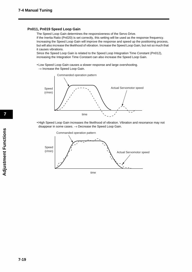
7-4 Manual Tuning
Ad
just
men
t F
un
ctio
ns
7
Pn011, Pn019 Speed Loop GainThe Speed Loop Gain determines the responsiveness of the Servo Drive. If the Inertia Ratio (Pn020) is set correctly, this setting will be used as the response frequency. Increasing the Speed Loop Gain will improve the response and speed up the positioning process, but will also increase the likelihood of vibration. Increase the Speed Loop Gain, but not so much that it causes vibrations. Since the Speed Loop Gain is related to the Speed Loop Integration Time Constant (Pn012), increasing the Integration Time Constant can also increase the Speed Loop Gain.
Low Speed Loop Gain causes a slower response and large overshooting. → Increase the Speed Loop Gain.
High Speed Loop Gain increases the likelihood of vibration. Vibration and resonance may not disappear in some cases. → Decrease the Speed Loop Gain.
Actual Servomotor speed
Commanded operation pattern
Speed(r/min)
time
Actual Servomotor speed
Commanded operation pattern
Speed(r/min)
time
7-19
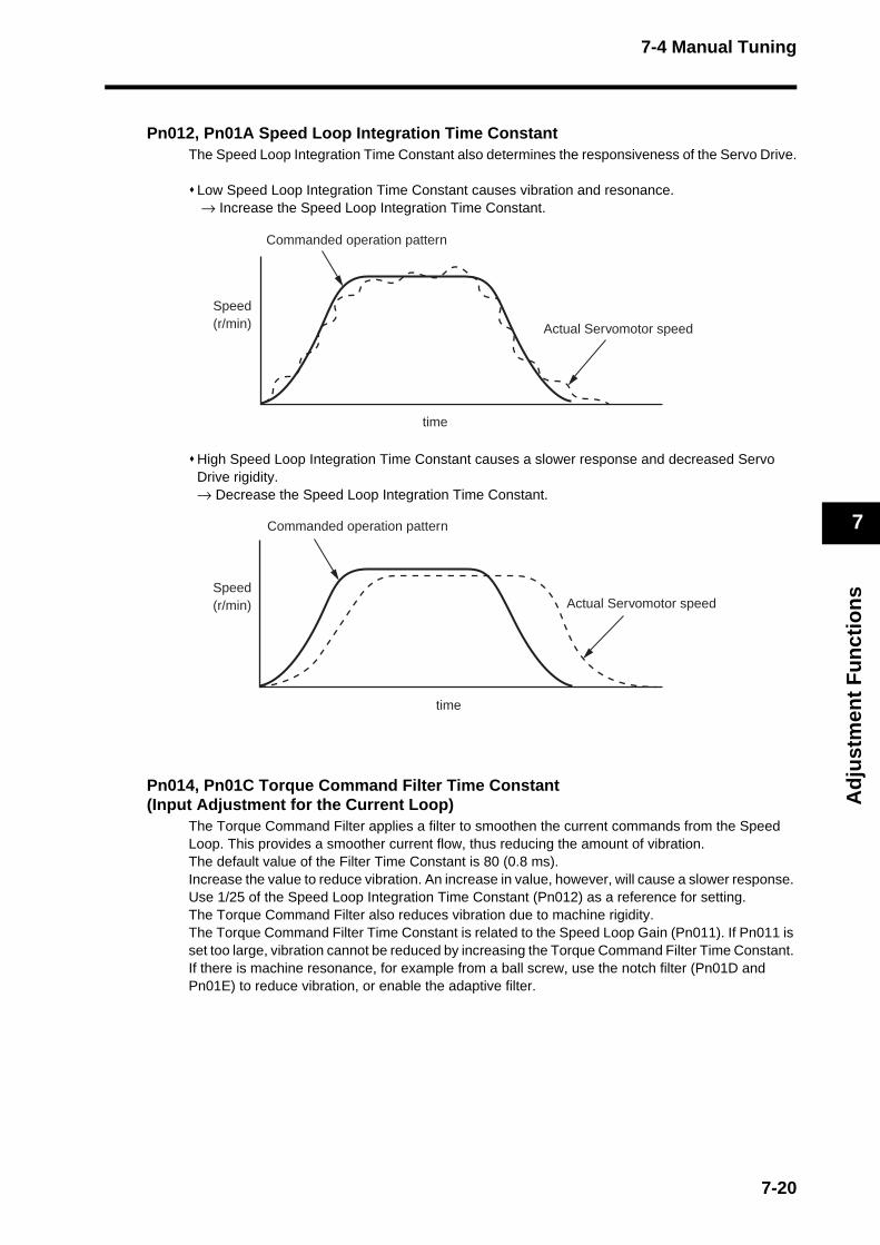
7-4 Manual Tuning
Ad
just
men
t F
un
ctio
ns
7
Pn012, Pn01A Speed Loop Integration Time ConstantThe Speed Loop Integration Time Constant also determines the responsiveness of the Servo Drive.
Low Speed Loop Integration Time Constant causes vibration and resonance. → Increase the Speed Loop Integration Time Constant.
High Speed Loop Integration Time Constant causes a slower response and decreased Servo Drive rigidity. → Decrease the Speed Loop Integration Time Constant.
Pn014, Pn01C Torque Command Filter Time Constant (Input Adjustment for the Current Loop)
The Torque Command Filter applies a filter to smoothen the current commands from the Speed Loop. This provides a smoother current flow, thus reducing the amount of vibration. The default value of the Filter Time Constant is 80 (0.8 ms). Increase the value to reduce vibration. An increase in value, however, will cause a slower response. Use 1/25 of the Speed Loop Integration Time Constant (Pn012) as a reference for setting. The Torque Command Filter also reduces vibration due to machine rigidity. The Torque Command Filter Time Constant is related to the Speed Loop Gain (Pn011). If Pn011 is set too large, vibration cannot be reduced by increasing the Torque Command Filter Time Constant. If there is machine resonance, for example from a ball screw, use the notch filter (Pn01D and Pn01E) to reduce vibration, or enable the adaptive filter.
Actual Servomotor speed
Commanded operation pattern
Speed(r/min)
time
Actual Servomotor speed
Commanded operation pattern
Speed(r/min)
time
7-20

7-4 Manual Tuning
Ad
just
men
t F
un
ctio
ns
7
Other AdjustmentsIf the Torque Loop is saturated because of short acceleration time, large load torque, or other causes, overshooting occurs in the speed response. In such a case, increase the acceleration time to prevent torque saturation.
Torque Control Mode Adjustment The torque control is based on the speed control loop using the Speed Limit (Pn053) or the speed limit value from MECHATROLINK-II as the speed limit. This section explains how to set the speed limit value.
Setting Speed Limit ValuesIf the Speed Limit Selection (Pn05B) is set to 0, the setting for the Speed Limit (Pn053) will be used as the speed limit value. If the Speed Limit Selection (Pn05B) is set to 1, the smaller of either the Speed Limit (Pn053) or the MECHATROLINK-II speed limit value will be used. When the Servomotor speed approaches the speed limit value, the control method will switch from torque control using torque commands from MECHATROLINK-II, to speed control using the speed limit value determined via MECHATROLINK-II or the Speed Limit (Pn053). To ensure the stable operation during the speed limit, parameters need to be adjusted according to Speed Control Mode Adjustment on page 7-16. If the Speed Limit (Pn053) or the speed limit value from MECHATROLINK-II is too low, the Speed Loop Gain is too low, or the Speed Loop Integration Time Constant is set to 10000 (disable), the input to the torque limiter will be small and the torque commanded via MECHATROLINK-II may not be achieved.
Commanded operation pattern
Acceleration torque required for the commanded pattern
Maximum instantaneous torque output of the Servomotor
Overshooting occurs for the amount of delay in command.
7-21
Chapter 8
Troubleshooting8-1 Error Processing ................................................ 8-1Preliminary Checks When a Problem Occurs.......................8-1
Precautions When Troubleshooting......................................8-2
Replacing the Servomotor and Servo Drive..........................8-2
8-2 Alarm Table........................................................ 8-3
8-3 Troubleshooting ................................................. 8-7Error Diagnosis Using the Displayed Alarm Codes ..............8-7
Error Diagnosis Using the Displayed Warning Codes ..........8-14
Error Diagnosis Using the Operating Status .........................8-15
8-4 Overload Characteristics (Electronic Thermal Function) ............................ 8-20
Overload Characteristics Graphs..........................................8-20
8-5 Periodic Maintenance......................................... 8-21Servomotor Service Life........................................................8-21
Servo Drive Service Life .......................................................8-22
Replacing the Absolute Encoder Battery ..............................8-23
8-1 Error Processing
Tro
ub
lesh
oo
tin
g
8
8-1 Error Processing
Preliminary Checks When a Problem OccursThis section explains the preliminary checks and analytical tools required to determine the cause of a problem.
Checking the Power Supply VoltageCheck the voltage at the power supply input terminals.
Main Circuit Power Supply Input Terminals (L1, L3)R88D-GN@L-ML2 (50 W to 400 W): Single-phase, 100 to 115 VAC (85 to 127 V), 50/60 HzR88D-GN@H-ML2 (100 W to 1.5 kW): Single-phase, 200 to 240 VAC (170 to 264 V), 50/60 Hz
Main Circuit Power Supply Input Terminals (L1, L2, L3) R88D-GN@H-ML2 (750 W to 7.5 kW): Three-phase, 200 to 240 VAC (170 to 264 V), 50/60 Hz
Control Circuit Power Supply Input Terminals (L1C, L2C)R88D-GN@L-ML2: Single-phase, 100 to 115 VAC (85 to 127 V), 50/60 HzR88D-GN@H-ML2: Single-phase, 200 to 240 VAC (170 to 264 V), 50/60 Hz
If the voltage is outside of this range, there is a risk of operation failure, so be sure that the power supply is correct.
Check the voltage of the sequence input power supply. (+24 VIN Terminal (CN1 pin 1)) Within the range of 11 to 25 VDCIf the voltage is outside of this range, there is a risk of operation failure, so be sure that the power supply is correct.
Checking Whether an Alarm Has OccurredEvaluate the problem using the 7-segment LED display on the front panel. You can also evaluate the problem by using the R88A-PR02G Parameter Unit. CX-Drive can also be used for the display. The operation status can also be monitored. Check the load status, including data trace. When an alarm has occurred:Check the alarm code that is displayed (@@) and evaluate the problem based on the alarm that is indicated.
When an alarm has not occurred:Make an analysis according to the problem.
8-1
8-1 Error Processing
Tro
ub
lesh
oo
tin
g
8
Precautions When TroubleshootingWhen checking and verifying I/O after a problem has occurred, the Servo Drive may suddenly start to operate or suddenly stop, so always take the following precautions.You should assume that anything not described in this manual is not possible with this product.
PrecautionsDisconnect the cable before checking for wire breakage. Even if you test conduction with the cable connected, test results may not be accurate due to conduction via bypassing circuit.If the encoder signal is lost, the Servomotor may run away, or an error may occur. Be sure to disconnect the Servomotor from the mechanical system before checking the encoder signal.When performing tests, first check that there are no persons in the vicinity of the equipment, and that the equipment will not be damaged even if the Servomotor runs away. Before performing the tests, verify that you can immediately stop the machine using an emergency stop even if the Servomotor runs away.
Replacing the Servomotor and Servo DriveUse the following procedure to replace the Servomotor or Servo Drive.
Replacing the Servomotor1. Replace the Servomotor. 2. Perform origin position alignment (for position control).
When the Servomotor is replaced, the Servomotor’s origin position (phase Z) may deviate, so origin alignment must be performed.Refer to the Position Controller’s manual for details on performing origin alignment.
3. Set up the absolute encoder. If a Servomotor with an absolute encoder is used, the absolute value data in the absolute encoder will be cleared when the Servomotor is replaced, so setup is again required. The rotation data will be different from before the Servomotor was replaced, so reset the initial Motion Control Unit parameters.For details, refer to Absolute Encoder Setup on page 6-6.
Replacing the Servo Drive1. Copy the parameters.
Use the Parameter Unit or CX-Drive to write down all the parameter settings or save them.
2. Replace the Servo Drive. 3. Set the parameters.
Use the Parameter Unit or CX-Drive to set all the parameters.
4. Set up the absolute encoder. If a Servomotor with an absolute encoder is used, the absolute value data in the absolute encoder will be cleared when the Servo Drive is replaced, so setup is again required. The rotation data will be different from before the Servo Drive was replaced, so reset the initial Motion Control Unit parameters.For details, refer to Absolute Encoder Setup on page 6-6.
8-2

8-2 Alarm Table
Tro
ub
lesh
oo
tin
g
8
8-2 Alarm Table
Protective FunctionsThe Servo Drive has built-in protective functions. When a protective function is activated, the Servo Drive turns OFF the alarm output signal (ALM) and switches to the Servo OFF status. The alarm code will be displayed on the front panel.
Warning FunctionThe Servo Drive issues a warning before a protective function is activated, allowing you to check overload and other status in advance. A warning is also issued for a network error, allowing you to check the network status.
Alarm type Description
---Protective function that allows the alarm to be reset, and leaves record in the alarm history.
PRProtective function that does not allow the alarm to be reset, and requires the control power supply to be turned OFF and turned ON again after resolving the problem.
X Protective function that does not leave record in the alarm history.
Alarms can be reset via the network, CX-Drive or the Parameter Unit. Overload (alarm code 16) cannot be reset for approximately 10 s after its occurrence. If "HH", "hh", or "yy" is displayed on the Alarm Number display, the built-in MPU is malfunctioning. Turn OFF the power supply.
Precautions for Correct Use
8-3
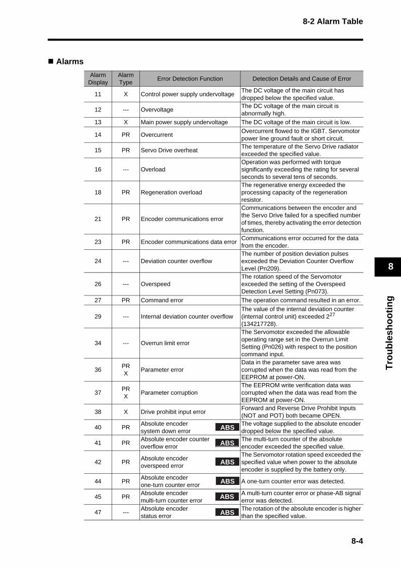
8-2 Alarm Table
Tro
ub
lesh
oo
tin
g
8
Alarms
Alarm Display
Alarm Type
Error Detection Function Detection Details and Cause of Error
11 X Control power supply undervoltageThe DC voltage of the main circuit has dropped below the specified value.
12 --- OvervoltageThe DC voltage of the main circuit is abnormally high.
13 X Main power supply undervoltage The DC voltage of the main circuit is low.
14 PR OvercurrentOvercurrent flowed to the IGBT. Servomotor power line ground fault or short circuit.
15 PR Servo Drive overheatThe temperature of the Servo Drive radiator exceeded the specified value.
16 --- OverloadOperation was performed with torque significantly exceeding the rating for several seconds to several tens of seconds.
18 PR Regeneration overloadThe regenerative energy exceeded the processing capacity of the regeneration resistor.
21 PR Encoder communications error
Communications between the encoder and the Servo Drive failed for a specified number of times, thereby activating the error detection function.
23 PR Encoder communications data errorCommunications error occurred for the data from the encoder.
24 --- Deviation counter overflowThe number of position deviation pulses exceeded the Deviation Counter Overflow Level (Pn209).
26 --- OverspeedThe rotation speed of the Servomotor exceeded the setting of the Overspeed Detection Level Setting (Pn073).
27 PR Command error The operation command resulted in an error.
29 --- Internal deviation counter overflowThe value of the internal deviation counter (internal control unit) exceeded 227 (134217728).
34 --- Overrun limit error
The Servomotor exceeded the allowable operating range set in the Overrun Limit Setting (Pn026) with respect to the position command input.
36PRX
Parameter errorData in the parameter save area was corrupted when the data was read from the EEPROM at power-ON.
37PRX
Parameter corruptionThe EEPROM write verification data was corrupted when the data was read from the EEPROM at power-ON.
38 X Drive prohibit input errorForward and Reverse Drive Prohibit Inputs (NOT and POT) both became OPEN.
40 PRAbsolute encoder system down error
The voltage supplied to the absolute encoder dropped below the specified value.
41 PRAbsolute encoder counter overflow error
The multi-turn counter of the absolute encoder exceeded the specified value.
42 PRAbsolute encoder overspeed error
The Servomotor rotation speed exceeded the specified value when power to the absolute encoder is supplied by the battery only.
44 PRAbsolute encoder one-turn counter error
A one-turn counter error was detected.
45 PRAbsolute encoder multi-turn counter error
A multi-turn counter error or phase-AB signal error was detected.
47 ---Absolute encoder status error
The rotation of the absolute encoder is higher than the specified value.
ABS
ABS
ABS
ABS
ABS
ABS
8-4

8-2 Alarm Table
Tro
ub
lesh
oo
tin
g
8
Alarm Display
Alarm Type
Error Detection Function Detection Details and Cause of Error
48 R Encoder phase Z errorA phase-Z pulse was not detected regularly.
49 R Encoder PS signal error A logic error was detected in the PS signal.
82 R Node address setting errorThe rotary switch for setting the node address of the Servo Drive was set out of range.
83 --- Communications error
Data received during each MECHATROLINK-II communications cycle repeatedly failed, exceeding the number of times set in the Communications Control (Pn005).
84 --- Transmission cycle error
While actuating MECHATROLINK-II communications, synchronization frames (SYNC) were not received according to the transmission cycle.
86 --- Watchdog data error
Synchronization data exchanged between the master and slave nodes during each MECHATROLINK-II communications cycle resulted in an error.
87 X Emergency stop input error The emergency stop input became OPEN.
90 --- Transmission cycle setting errorThe transmission cycle setting error when the MECHATROLINK-II CONNECT command is received.
91 --- SYNC command errorA SYNC-related command was issued while MECHATROLINK-II was in asynchronous communications mode.
93 R Parameter setting errorParameter setting exceeded the allowable range.
95RX
Servomotor non-conformityThe combination of the Servomotor and Servo Drive is not appropriate.
Others R Other errors
The control circuit malfunctioned due to excessive noise. An error occurred within the Servo Drive due to the activation of its self-diagnosis function.
8-5

8-2 Alarm Table
Tro
ub
lesh
oo
tin
g
8
Warnings
Note 1. All warnings are retained. After resolving the problem, clear the alarms and the warnings.
Note 2. When multiple warnings occur, the warning codes are displayed on the front panel in the order of their priority (shown above).
Note 3. Values in parenthesis indicate warning codes read from the host controller. Example: When a battery warning is issued, the display on a G-Series front panel will
alternate between "92" and "00". The warning code read by the host position control unit (CJ1W-NCF71 or CS1W-NCF71) will be "4146".
PriorityWarning
CodeWarning Detection
FunctionWarning Details
High94h (148) Data setting warning
· Command argument setting is out of the range. · Parameter write failure. · Command settings are wrong, and others.
95h (149) Command warning· Command output conditions are not satisfied. · Received unsupported command. · Subcommand output conditions are not satisfied.
96h (150)ML-II communications warning
One or more MECHATROLINK-II communications error occurred.
90h (144) Overload warning85% of the overload alarm trigger level has been exceeded.
91h (145)Regeneration overload warning
85% of the regeneration overload alarm trigger level has been exceeded.
92h (146) Battery warningVoltage of absolute encoder battery has dropped below 3.2 V.
Low93h (147) Fan lock warning The built-in cooling fan stopped, or rotated abnormally.
8-6

8-3 Troubleshooting
Tro
ub
lesh
oo
tin
g
8
8-3 TroubleshootingIf an error occurs in the machine, determine the error conditions from the alarm indicator and operating status, identify the cause of the error, and take appropriate countermeasures.
Error Diagnosis Using the Displayed Alarm Codes
Alarm code
Alarm Name Cause Countermeasure
11Control power supply
undervoltage
The voltage between P and N in the control voltage converter has dropped below the specified value. 1 The power supply voltage is low. A
momentary power failure occurred. 2 The power supply capacity is
insufficient. The inrush current at power-ON caused the power supply voltage to drop.
3 The Servo Drive has failed.
Measure the line voltage between control power supply L1C and L2C. 1 Resolve the cause of the power
supply voltage drop and/or momentary power failure.
2 Increase the power supply capacity.
3 Replace the Servo Drive.
12 Overvoltage
The voltage between P and N in the main circuit has exceeded the speci-fied value. The power supply voltage is too high. Phase advance capacitor and/or UPS (uninterruptible power supply) is causing a jump in voltage. 1 Regenerative energy cannot be
absorbed due to a disconnection of the regeneration resistor.
2 Regenerative energy cannot be absorbed due to the use of an inappropriate external regeneration resistor.
3 The Servo Drive has failed.
Measure and check the line voltages between L1, L2, and L3 of the main power supply. Input a correct voltage. Remove the phase advance capacitor. 1 Measure the resistance for the
external regeneration resistor between terminals B1 and B2 of the Servo Drive, and check that the reading is normal. Replace it if disconnected.
2 Provide the necessary regeneration resistance and wattage.
3 Replace the Servo Drive.
13Main power supply
undervoltage
With the Undervoltage Alarm Selection (Pn065) set to 1, the main power supply between L1 and L3 was interrupted for longer than the time set by Momentary Hold Time (Pn06D). Alternatively, the voltage between P and N in the main circuit dropped below the specified value while the Servo Drive was ON. 1 The power supply voltage is low. 2 A momentary power failure
occurred. 3 The power supply capacity is insuf-
ficient - The inrush current at power-ON caused the power supply voltage to drop.
4 Missing phase - A single-phase power supply was used for a three-phase Servo Drive.
5 The Servo Drive has failed.
Measure and check the line voltages between L1, L2, and L3 of the main power supply. 1 Resolve the cause of the power
supply voltage drop and/or momentary power failure.
2 Check the setting for the Momentary Hold Time (Pn06D).
3 Increase the power supply capacity. Refer to the Servo Drive specifications for the power supply capacity.
4 Correctly connect the phases (L1, L2, and L3) of the power supply. Connect single-phase 100 V and single-phase 200 V to L1 and L3.
5 Replace the Servo Drive.
8-7

8-3 Troubleshooting
Tro
ub
lesh
oo
tin
g
8
14 Overcurrent
The current on the inverter circuit exceeded the specified value. 1 The Servo Drive has failed.
(Failure of circuit, IGBT parts, etc.) 2 Short circuit on Servomotor lines U,
V, and W. 3 Ground fault on the Servomotor
lines. 4 Servomotor burnout. 5 Contact failure on the Servomotor
lines. 6 The dynamic brake relay has been
consequently welded. 7 The Servomotor is not compatible
with the Servo Drive. 8 The operation command input is
received simultaneously with or before Servo-ON.
1 If the alarm is triggered immediately when the Servo Drive is turned ON with the Servomotor lines disconnected, replace the Servo Drive.
2 Check for short circuit in the Servomotor lines U, V, and W. Connect the Servomotor lines correctly.
3 Check the insulation resistance between Servomotor lines U, V, W and the ground line. If there is insulation failure, replace the Servomotor.
4 Measure the interphase resistances of the Servomotor. If they are unbalanced, replace the Servomotor.
5 Check the connector pins for connections U, V, and W of the Servomotor. If they are loose or have come off, securely fix them.
6 Replace the Servo Drive.7 Check and match the capacity of
the Servomotor and the Servo Drive.
8 After the Servo ON, wait for at least 100 ms before inputting an operation command.
15 Servo Drive overheat
The temperature of the Servo Drive radiator or power elements exceeded the specified value. 1 The Servo Drive's ambient
temperature has exceeded the specified value. Radiation performance has dropped.
2 There is excessive load.
1 Reduce the Servo Drive's ambient temperature, and improve the cooling conditions.
2 Increase the capacity of the Servo-motor. Reduce the effective load ratio, for example with a longer acceleration / deceleration time.
16 Overload
The effective values of the torque commands have exceeded the over-load level set by the Overload Detec-tion Level Setting (Pn072). Operation is performed with reverse time charac-teristics. 1 The load is excessive, and the
effective torque has exceeded the set level and operation has been performed for a long time.
2 Oscillation, hunching, and vibration are occurring due to improper gain adjustment.
3 Servomotor phases are incorrectly wired and/or are disconnected.
4 The mechanical load is increasing. There is a problem with the mechanics.
5 The holding brake is ON. 6 The Servomotor lines are
incorrectly wired between multiple axes.
Check that the torque (current) wave-form is not oscillating, and that it is not fluctuating significantly in the vertical direction. Check the overload warning display and the load ratio. 1 Increase the capacity of the Servo
Drive and Servomotor, or reduce the load. Or increase the acceleration / deceleration time to reduce the effective torque.
2 Readjust the gain to stop oscillation and hunching.
3 Connect the Servomotor lines as specified in the wiring diagram. Replace the cables.
4 Check that the mechanics operate smoothly.
5 Measure the voltage at the brake terminal. Turn OFF the brake.
Note You cannot reset the warning for at least 10 seconds after it occurred.
Alarm code
Alarm Name Cause Countermeasure
8-8
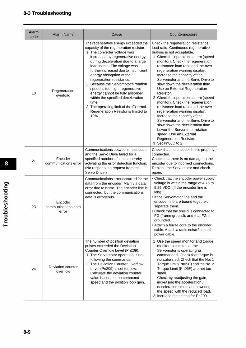
8-3 Troubleshooting
Tro
ub
lesh
oo
tin
g
8
18Regeneration
overload
The regenerative energy exceeded the capacity of the regeneration resistor. 1 The converter voltage was
increased by regenerative energy during deceleration due to a large load inertia. The voltage was further increased due to insufficient energy absorption of the regeneration resistance.
2 Because the Servomotor’s rotation speed is too high, regenerative energy cannot be fully absorbed within the specified deceleration time.
3 The operating limit of the External Regeneration Resistor is limited to 10%.
Check the regeneration resistance load ratio. Continuous regenerative braking is not acceptable. 1 Check the operation pattern (speed
monitor). Check the regeneration resistance load ratio and the over-regeneration warning display. Increase the capacity of the Servomotor and the Servo Drive to slow down the deceleration time. Use an External Regeneration Resistor.
2 Check the operation pattern (speed monitor). Check the regeneration resistance load ratio and the over-regeneration warning display. Increase the capacity of the Servomotor and the Servo Drive to slow down the deceleration time. Lower the Servomotor rotation speed. Use an External Regeneration Resistor.
3 Set Pn06C to 2.
21Encoder
communications error
Communications between the encoder and the Servo Drive failed for a specified number of times, thereby activating the error detection function. (No response to request from the Servo Drive.)
Check that the encoder line is properly connected. Check that there is no damage to the encoder due to incorrect connections. Replace the Servomotor and check again.
23Encoder
communications data error
Communications error occurred for the data from the encoder. Mainly a data error due to noise. The encoder line is connected, but the communications data is erroneous.
Check that the encoder power supply voltage is within the range of 4.75 to 5.25 VDC. (If the encoder line is long.)If the Servomotor line and the encoder line are bound together, separate them. Check that the shield is connected to FG (frame ground), and that FG is grounded. Attach a ferrite core to the encoder cable. Attach a radio noise filter to the power cable.
24Deviation counter
overflow
The number of position deviation pulses exceeded the Deviation Counter Overflow Level (Pn209). 1 The Servomotor operation is not
following the commands. 2 The Deviation Counter Overflow
Level (Pn209) is set too low. Calculate the deviation counter value based on the command speed and the position loop gain.
1 Use the speed monitor and torque monitor to check that the Servomotor is operating as commanded. Check that torque is not saturated. Check that the No. 1 Torque Limit (Pn05E) and the No. 2 Torque Limit (Pn05F) are not too small. Check by readjusting the gain, increasing the acceleration / deceleration times, and lowering the speed with the reduced load.
2 Increase the setting for Pn209.
Alarm code
Alarm Name Cause Countermeasure
8-9
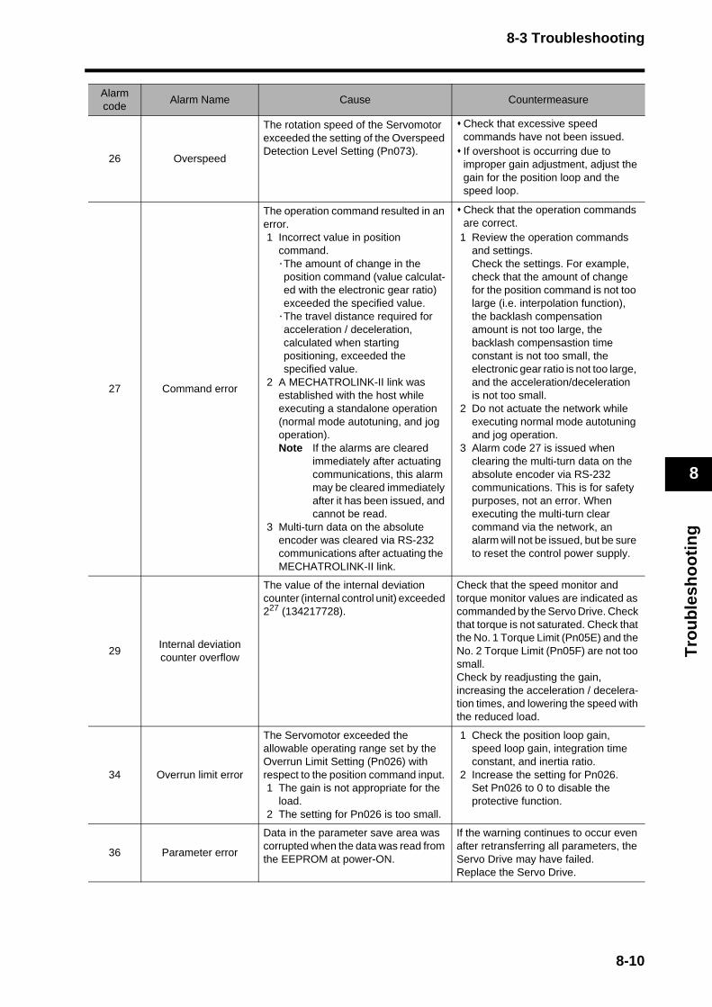
8-3 Troubleshooting
Tro
ub
lesh
oo
tin
g
8
26 Overspeed
The rotation speed of the Servomotor exceeded the setting of the Overspeed Detection Level Setting (Pn073).
Check that excessive speed commands have not been issued. If overshoot is occurring due to improper gain adjustment, adjust the gain for the position loop and the speed loop.
27 Command error
The operation command resulted in an error. 1 Incorrect value in position
command. ·The amount of change in the position command (value calculat-ed with the electronic gear ratio) exceeded the specified value.
·The travel distance required for acceleration / deceleration, calculated when starting positioning, exceeded the specified value.
2 A MECHATROLINK-II link was established with the host while executing a standalone operation (normal mode autotuning, and jog operation). Note If the alarms are cleared
immediately after actuating communications, this alarm may be cleared immediately after it has been issued, and cannot be read.
3 Multi-turn data on the absolute encoder was cleared via RS-232 communications after actuating the MECHATROLINK-II link.
Check that the operation commands are correct.
1 Review the operation commands and settings. Check the settings. For example, check that the amount of change for the position command is not too large (i.e. interpolation function), the backlash compensation amount is not too large, the backlash compensastion time constant is not too small, the electronic gear ratio is not too large, and the acceleration/deceleration is not too small.
2 Do not actuate the network while executing normal mode autotuning and jog operation.
3 Alarm code 27 is issued when clearing the multi-turn data on the absolute encoder via RS-232 communications. This is for safety purposes, not an error. When executing the multi-turn clear command via the network, an alarm will not be issued, but be sure to reset the control power supply.
29Internal deviation counter overflow
The value of the internal deviation counter (internal control unit) exceeded 227 (134217728).
Check that the speed monitor and torque monitor values are indicated as commanded by the Servo Drive. Check that torque is not saturated. Check that the No. 1 Torque Limit (Pn05E) and the No. 2 Torque Limit (Pn05F) are not too small. Check by readjusting the gain, increasing the acceleration / decelera-tion times, and lowering the speed with the reduced load.
34 Overrun limit error
The Servomotor exceeded the allowable operating range set by the Overrun Limit Setting (Pn026) with respect to the position command input. 1 The gain is not appropriate for the
load. 2 The setting for Pn026 is too small.
1 Check the position loop gain, speed loop gain, integration time constant, and inertia ratio.
2 Increase the setting for Pn026.Set Pn026 to 0 to disable the protective function.
36 Parameter error
Data in the parameter save area was corrupted when the data was read from the EEPROM at power-ON.
If the warning continues to occur even after retransferring all parameters, the Servo Drive may have failed. Replace the Servo Drive.
Alarm code
Alarm Name Cause Countermeasure
8-10
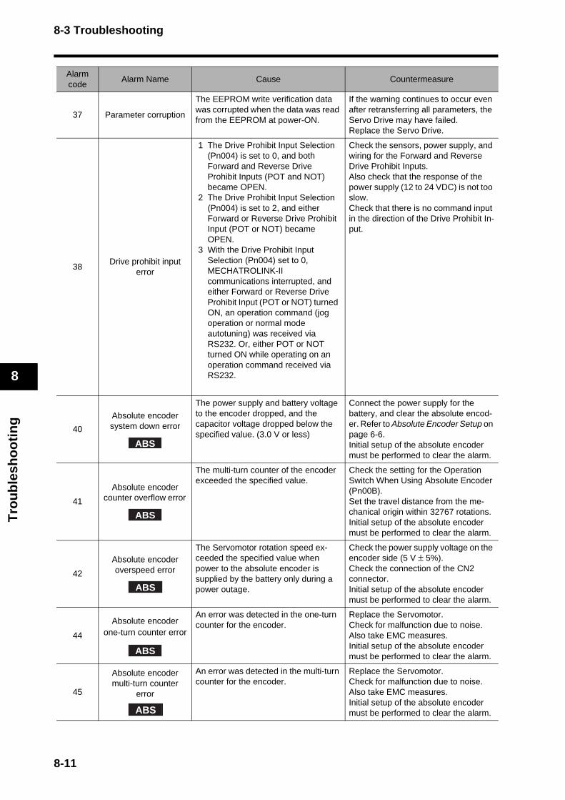
8-3 Troubleshooting
Tro
ub
lesh
oo
tin
g
8
37 Parameter corruption
The EEPROM write verification data was corrupted when the data was read from the EEPROM at power-ON.
If the warning continues to occur even after retransferring all parameters, the Servo Drive may have failed. Replace the Servo Drive.
38Drive prohibit input
error
1 The Drive Prohibit Input Selection (Pn004) is set to 0, and both Forward and Reverse Drive Prohibit Inputs (POT and NOT) became OPEN.
2 The Drive Prohibit Input Selection (Pn004) is set to 2, and either Forward or Reverse Drive Prohibit Input (POT or NOT) became OPEN.
3 With the Drive Prohibit Input Selection (Pn004) set to 0, MECHATROLINK-II communications interrupted, and either Forward or Reverse Drive Prohibit Input (POT or NOT) turned ON, an operation command (jog operation or normal mode autotuning) was received via RS232. Or, either POT or NOT turned ON while operating on an operation command received via RS232.
Check the sensors, power supply, and wiring for the Forward and Reverse Drive Prohibit Inputs. Also check that the response of the power supply (12 to 24 VDC) is not too slow. Check that there is no command input in the direction of the Drive Prohibit In-put.
40
Absolute encoder system down error
The power supply and battery voltage to the encoder dropped, and the capacitor voltage dropped below the specified value. (3.0 V or less)
Connect the power supply for the battery, and clear the absolute encod-er. Refer to Absolute Encoder Setup on page 6-6.Initial setup of the absolute encoder must be performed to clear the alarm.
41
Absolute encoder counter overflow error
The multi-turn counter of the encoder exceeded the specified value.
Check the setting for the Operation Switch When Using Absolute Encoder (Pn00B). Set the travel distance from the me-chanical origin within 32767 rotations. Initial setup of the absolute encoder must be performed to clear the alarm.
42
Absolute encoder overspeed error
The Servomotor rotation speed ex-ceeded the specified value when power to the absolute encoder is supplied by the battery only during a power outage.
Check the power supply voltage on the encoder side (5 V ± 5%). Check the connection of the CN2 connector. Initial setup of the absolute encoder must be performed to clear the alarm.
44
Absolute encoder one-turn counter error
An error was detected in the one-turn counter for the encoder.
Replace the Servomotor. Check for malfunction due to noise. Also take EMC measures. Initial setup of the absolute encoder must be performed to clear the alarm.
45
Absolute encoder multi-turn counter
error
An error was detected in the multi-turn counter for the encoder.
Replace the Servomotor. Check for malfunction due to noise. Also take EMC measures. Initial setup of the absolute encoder must be performed to clear the alarm.
Alarm code
Alarm Name Cause Countermeasure
ABS
ABS
ABS
ABS
ABS
8-11

8-3 Troubleshooting
Tro
ub
lesh
oo
tin
g
8
47
Absolute encoder status error
The encoder’s detection values were higher than the specified value at power-ON.
Do not rotate the Servomotor when the power is turned ON.
48 Encoder phase Z error
A phase-Z pulse of the 2500 p/r 5-line serial encoder was not detected regularly. The encoder has failed.
Replace the Servomotor. Check for malfunction due to noise. Also take EMC measures.
49Encoder PS signal
error
Logic error was detected in the PS signal (magnetic pole) of the 2500 p/r 5-line serial encoder. The encoder has failed.
Replace the Servomotor.
82Node address setting
error
The rotary switch for setting the node address of the Servo Drive was set out of range. (Value is read at power-ON)
Check the value of the rotary switch for setting the node address. Set the rotary switch correctly (set to 1 to 31), and then turn OFF the control power supply for the Servo Drive and turn it ON again.
83 Communications error
Data received during each MECHATROLINK-II communications cycle repeatedly failed, exceeding the number of times set by the Communi-cations Control (Pn005).
Check that commands are being sent from the master node to the slave node. Check the MECHATROLINK-II communications cable for disconnec-tion or wiring problem. Check the connection of the terminator (termination resistor). Check the MECHATROLINK-II communications cable for excessive noise, and that the cable is laid proper-ly. Also check the FG wiring for the Ser-vo Drive. Increase the consecutive communica-tions error detection count in the Com-munications Control (Pn005).
84Transmission cycle
error
While actuating MECHATROLINK-II communications, synchronization frames (SYNC) were not received according to the transmis-sion cycle.
The synchronization frames themselves were faulty. The transmission cycle of the synchronization frames was not as specified. (Includes dropped frames).
Check the transmission cycle of the synchronization frames sent from the master node, and ensure that it does not fluctuate and is as specified. Check the communications cable for disconnection or wiring problem. Check for excessive noise on the communications cable. Check the connection of the terminator (termination resistor). Check the laying of the communications cable and the FG wiring.
86 Watchdog data error
Synchronization data exchanged between the master and slave nodes during each MECHATROLINK-II com-munications cycle resulted in an error.
Check the update process for the watchdog data (MN) on the master node.
Alarm code
Alarm Name Cause Countermeasure
ABS
8-12
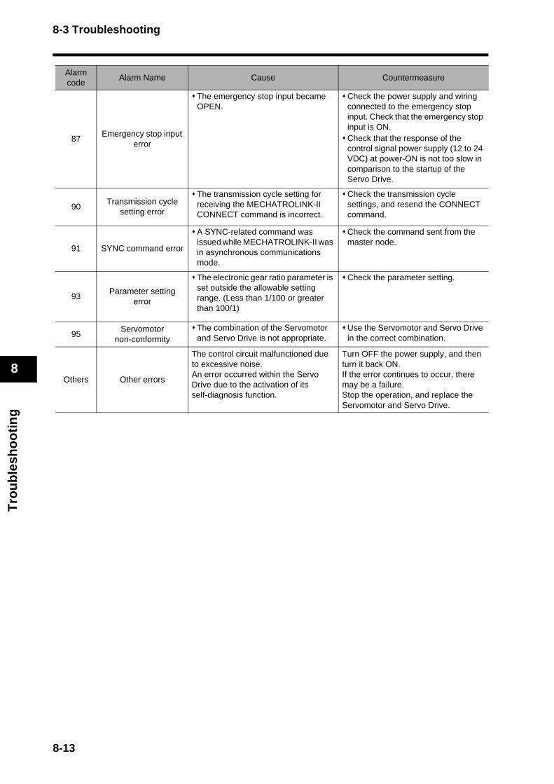
8-3 Troubleshooting
Tro
ub
lesh
oo
tin
g
8
87Emergency stop input
error
The emergency stop input became OPEN.
Check the power supply and wiring connected to the emergency stop input. Check that the emergency stop input is ON. Check that the response of the control signal power supply (12 to 24 VDC) at power-ON is not too slow in comparison to the startup of the Servo Drive.
90Transmission cycle
setting error
The transmission cycle setting for receiving the MECHATROLINK-II CONNECT command is incorrect.
Check the transmission cycle settings, and resend the CONNECT command.
91 SYNC command error
A SYNC-related command was issued while MECHATROLINK-II was in asynchronous communications mode.
Check the command sent from the master node.
93Parameter setting
error
The electronic gear ratio parameter is set outside the allowable setting range. (Less than 1/100 or greater than 100/1)
Check the parameter setting.
95Servomotor
non-conformityThe combination of the Servomotor and Servo Drive is not appropriate.
Use the Servomotor and Servo Drive in the correct combination.
Others Other errors
The control circuit malfunctioned due to excessive noise. An error occurred within the Servo Drive due to the activation of its self-diagnosis function.
Turn OFF the power supply, and then turn it back ON. If the error continues to occur, there may be a failure. Stop the operation, and replace the Servomotor and Servo Drive.
Alarm code
Alarm Name Cause Countermeasure
8-13
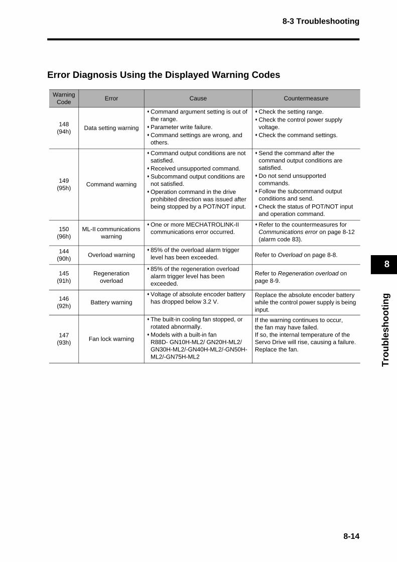
8-3 Troubleshooting
Tro
ub
lesh
oo
tin
g
8
Error Diagnosis Using the Displayed Warning Codes
Warning Code
Error Cause Countermeasure
148 (94h)
Data setting warning
Command argument setting is out of the range. Parameter write failure. Command settings are wrong, and others.
Check the setting range. Check the control power supply voltage.Check the command settings.
149 (95h)
Command warning
Command output conditions are not satisfied. Received unsupported command. Subcommand output conditions are not satisfied.Operation command in the drive prohibited direction was issued after being stopped by a POT/NOT input.
Send the command after the command output conditions are satisfied. Do not send unsupported commands. Follow the subcommand output conditions and send.Check the status of POT/NOT input and operation command.
150 (96h)
ML-II communications warning
One or more MECHATROLINK-II communications error occurred.
Refer to the countermeasures for Communications error on page 8-12 (alarm code 83).
144 (90h)
Overload warning85% of the overload alarm trigger level has been exceeded. Refer to Overload on page 8-8.
145 (91h)
Regeneration overload
85% of the regeneration overload alarm trigger level has been exceeded.
Refer to Regeneration overload on page 8-9.
146 (92h)
Battery warningVoltage of absolute encoder battery has dropped below 3.2 V.
Replace the absolute encoder battery while the control power supply is being input.
147 (93h)
Fan lock warning
The built-in cooling fan stopped, or rotated abnormally. Models with a built-in fanR88D- GN10H-ML2/ GN20H-ML2/GN30H-ML2/-GN40H-ML2/-GN50H-ML2/-GN75H-ML2
If the warning continues to occur, the fan may have failed. If so, the internal temperature of the Servo Drive will rise, causing a failure. Replace the fan.
8-14
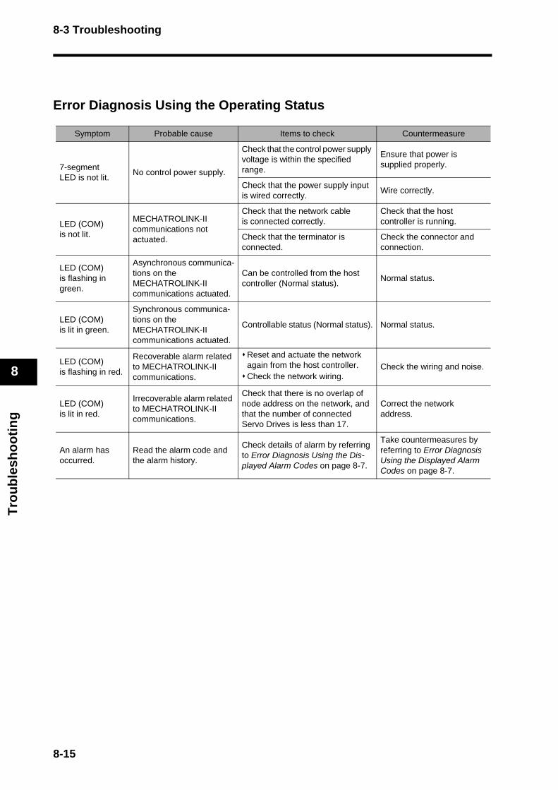
8-3 Troubleshooting
Tro
ub
lesh
oo
tin
g
8
Error Diagnosis Using the Operating Status
Symptom Probable cause Items to check Countermeasure
7-segmentLED is not lit.
No control power supply.
Check that the control power supply voltage is within the specified range.
Ensure that power is supplied properly.
Check that the power supply input is wired correctly.
Wire correctly.
LED (COM) is not lit.
MECHATROLINK-II communications not actuated.
Check that the network cable is connected correctly.
Check that the host controller is running.
Check that the terminator is connected.
Check the connector and connection.
LED (COM) is flashing in green.
Asynchronous communica-tions on the MECHATROLINK-II communications actuated.
Can be controlled from the host controller (Normal status).
Normal status.
LED (COM) is lit in green.
Synchronous communica-tions on the MECHATROLINK-II communications actuated.
Controllable status (Normal status). Normal status.
LED (COM) is flashing in red.
Recoverable alarm related to MECHATROLINK-II communications.
Reset and actuate the network again from the host controller. Check the network wiring.
Check the wiring and noise.
LED (COM) is lit in red.
Irrecoverable alarm related to MECHATROLINK-II communications.
Check that there is no overlap of node address on the network, and that the number of connected Servo Drives is less than 17.
Correct the network address.
An alarm has occurred.
Read the alarm code and the alarm history.
Check details of alarm by referring to Error Diagnosis Using the Dis-played Alarm Codes on page 8-7.
Take countermeasures by referring to Error Diagnosis Using the Displayed Alarm Codes on page 8-7.
8-15

8-3 Troubleshooting
Tro
ub
lesh
oo
tin
g
8
Does not Servo lock.
Not Servo locked.Check the response of the NCF71 Servo lock bit.
Set the Servo lock command bit on the host controller again.
The power cable is not properly connected.
Check the wiring of the Servomotor power cable.
Wire the Servomotor power cable correctly.
Servomotor power is not ON.
Check the wiring of the main circuit, and the voltage of the powersupply.
Input the main circuit power supply and voltage correctly.
The Forward and Reverse Drive Prohibit Inputs (POT and NOT) are OFF.
Check that the inputs for POT and NOT are not OFF. Check the +24 VIN input for CN1.
Turn ON POT and NOT, and input +24 VIN correctly.
Torque limit is 0. Check that torque limits Pn05E and Pn05F are not set to 0.
Set the maximum torque to be used for each.
Torque control is used for the control from the host controller, and the torque command value is set to 0.
Check the control mode and the torque command value for the host controller.
Set the control mode for the host controller to position control mode, and check Servo lock.
Servo Drive failure. --- Replace the Servo Drive.
Servo lock is ON, but Servomotor does not rotate.
No command is sent from the host controller.
For position commands, check that speed and position are not set to 0.
Input the position and speed data to start the Servomotor.
Cannot tell whether the Servomotor is rotating.
Check that the speed command from the host controller is not too slow.
Check the speed command from the host controller.
The holding brake is working.
Check the brake interlock (BKIR) signal and the +24 VDC power supply.
For a Servomotor with brake, check that its holding brake is released by Servo lock.
The No.1 and No. 2 Torque Limits (Pn05E, Pn05F) are too small.
Check that the torque limits Pn05E and Pn05F are not set to a value close to 0.
Set the maximum torque to be used for each.
Torque control is used for the control from the host controller, and the torque command value is too small.
Check the control mode and the torque command value for the host controller.
Set the control mode for the host controller to position control mode, and check Servo lock.
The Speed Limit (Pn053) is set to 0 for torque control mode.
Check the Speed Limit (Pn053) value.
Increase the value for the Speed Limit (Pn053).
Servo Drive failure. --- Replace the Servo Drive.
The Servomotor operates momentarily, but it does not oper-ate after that.
The Servomotor Power Cable is wired incorrectly.
Check the wiring of the Servomotor Power Cable phases U, V, and W.
Correctly wire the Servomo-tor Power Cable phases U, V, and W.
Not enough position com-mand data.
Check the position data, electronic gear, and others for NCF71.
Set the correct data.
Symptom Probable cause Items to check Countermeasure
8-16

8-3 Troubleshooting
Tro
ub
lesh
oo
tin
g
8
The Servomotor rotates without a command.
There is a small input for speed command mode.
Check that there is no input for speed command mode.
Set the speed command to 0, or switch to position con-trol mode.
There is a small input for torque command mode.
Check that there is no input for torque command mode.
Switch from torque control mode to position control mode.
The Servomotor rotates in the direction opposite to the command.
The Operating Direction Setting (Pn043) setting is incorrect.
Check the Operating Direction Setting (Pn043) value.
Change the Operating Direction Setting (Pn043) value.
NCF71 command is incorrect.
Set values are inappropriate for an absolute command. The polarity is incorrect for an incremental command.
Check the current and target values. Check the rotation direction.
The holding brake does not work.
Power is supplied to the holding brake.
Check whether power is supplied to the holding brake.
Check the brake interlock (BKIR) signal and the relay circuit. Check that the holding brake is not worn down.
The Servomotor is overheating.
The load is too large. Measure the torque using the front panel IM or a tool.
Slow down the acceleration/deceleration. Lower the speed and measure the load.
The heat radiation condi-tions for the Servomotor have worsened.
Check that the specified heat radiation conditions are satisfied. For a Servomotor with a brake, check the load ratio.
Improve the heat radiation conditions. Reduce the load. Improve ventilation.
The ambient temperature is too high.
Check that the ambient tempera-ture has not exceeded 40 °C.
Radiate heat and cool. Reduce the load ratio.
The Servomotor rotation is unstable.
Load and gain do not match.
Check the response waveforms for speed and torque.
Adjust the speed loop gain so that the rotation is stabilized.
Load inertia exceeds the specified range.
Calculate the load inertia.
Check if the adjustments can be made via manual tuning. Increase the capacity of the Servomotor.
Low rigidity is resulting in vibration.
Measure the vibration frequency of the load.
Enable damping control, and set the vibration filter fre-quencies.
Loose coupling with the machine, and/or large gaps.
Check coupling with the machine. Tighten the coupling with the machine.
Symptom Probable cause Items to check Countermeasure
8-17

8-3 Troubleshooting
Tro
ub
lesh
oo
tin
g
8
Machine position is misaligned.
Problem with the coupling between the Servomotor axis and the machine.
Check that the coupling of the Ser-vomotor and the machine is not misaligned.
Re-tighten the coupling. Replace with a tight coupling.
Deceleration stop command is received from the host controller.
Check the control ladder on the host controller.
Review the control on the host controller.
The Servomotor is slow to stop even if the RUN command is turned OFF while the Servomotor is rotating.
Load inertia is too large.
Check the load inertia. Dynamic brake resistor is disconnected.
Review the load inertia. Replace the Servomotor and Servo Drive with appropriate models.
Dynamic brake is disabled. Check if the dynamic brake is disabled or has failed.
If disabled, enable it. If there is a failure, or disconnection of the resistor, replace the Servomotor.
Overshoots when starting or stopping.
The Position Loop Gain (Pn010) is too large.
Review the Position Loop Gain (Pn010).
Adjust the gain to avoid overshooting.
Poor balance between the Speed Loop Integration Time Constant (Pn012) and the Speed Loop Gain (Pn011).
Review the Speed Loop Integration Time Constant (Pn012) and the Speed Loop Gain (Pn011).
Use CX-Drive and analog monitors (SP, IM) to mea-sure the response and adjust the gain.
Inappropriate machine rigidity setting by realtime autotuning.
Review the machine rigidity setting. Match the machine rigidity setting to the load rigidity.
Inertial ratio setting differs from the load.
Review the Inertial Ratio (Pn020). Match the Inertia Ratio (Pn020) to the load.
Symptom Probable cause Items to check Countermeasure
8-18
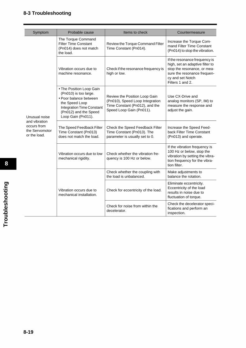
8-3 Troubleshooting
Tro
ub
lesh
oo
tin
g
8
Unusual noise and vibration occurs from the Servomotor or the load.
The Torque Command Filter Time Constant (Pn014) does not match the load.
Review the Torque Command Filter Time Constant (Pn014).
Increase the Torque Com-mand Filter Time Constant (Pn014) to stop the vibration.
Vibration occurs due to machine resonance.
Check if the resonance frequency is high or low.
If the resonance frequency is high, set an adaptive filter to stop the resonance, or mea-sure the resonance frequen-cy and set Notch Filters 1 and 2.
The Position Loop Gain (Pn010) is too large. Poor balance between the Speed Loop Integration Time Constant (Pn012) and the Speed Loop Gain (Pn011).
Review the Position Loop Gain (Pn010), Speed Loop Integration Time Constant (Pn012), and the Speed Loop Gain (Pn011).
Use CX-Drive and analog monitors (SP, IM) to measure the response and adjust the gain.
The Speed Feedback Filter Time Constant (Pn013) does not match the load.
Check the Speed Feedback Filter Time Constant (Pn013). The parameter is usually set to 0.
Increase the Speed Feed-back Filter Time Constant (Pn013) and operate.
Vibration occurs due to low mechanical rigidity.
Check whether the vibration fre-quency is 100 Hz or below.
If the vibration frequency is 100 Hz or below, stop the vibration by setting the vibra-tion frequency for the vibra-tion filter.
Vibration occurs due to mechanical installation.
Check whether the coupling with the load is unbalanced.
Make adjustments to balance the rotation.
Check for eccentricity of the load.
Eliminate eccentricity. Eccentricity of the load results in noise due to fluctuation of torque.
Check for noise from within the decelerator.
Check the decelerator speci-fications and perform an inspection.
Symptom Probable cause Items to check Countermeasure
8-19
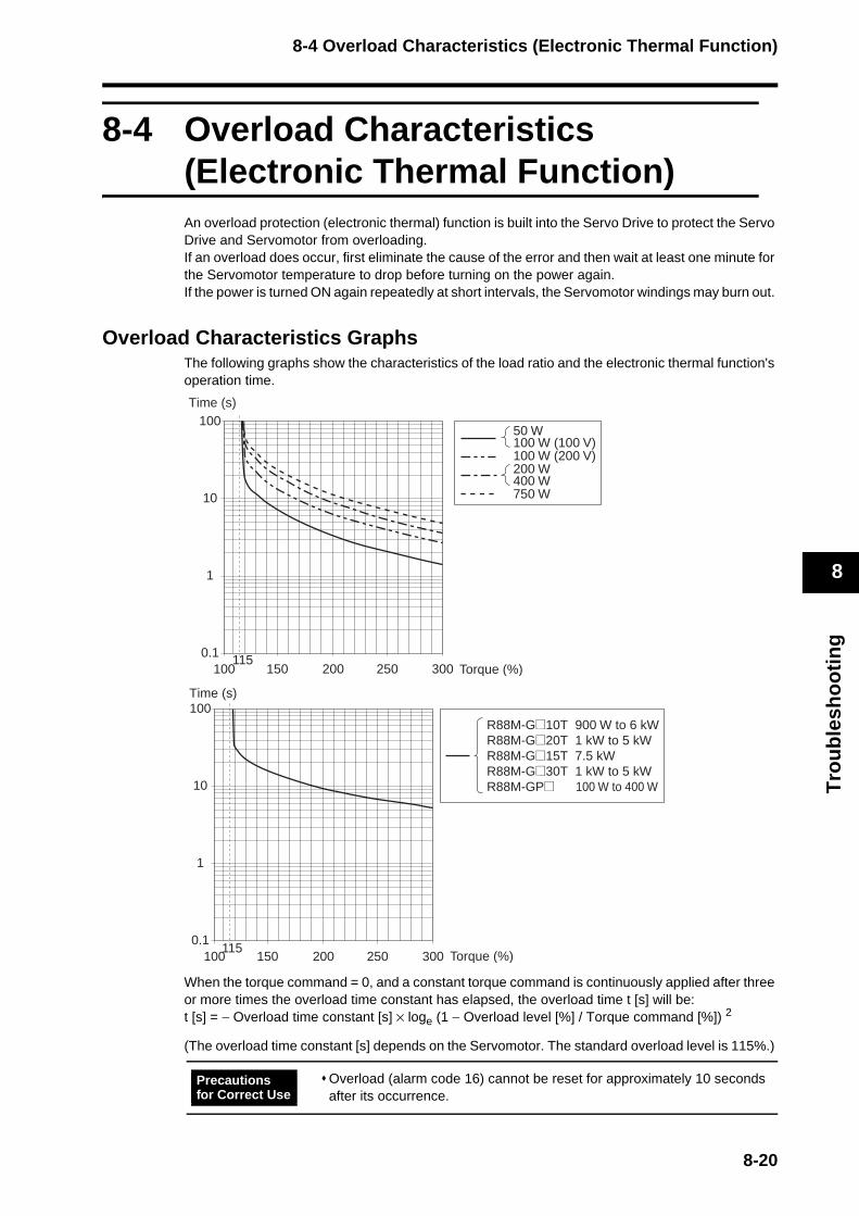
8-4 Overload Characteristics (Electronic Thermal Function)
Tro
ub
lesh
oo
tin
g
8
8-4 Overload Characteristics (Electronic Thermal Function)An overload protection (electronic thermal) function is built into the Servo Drive to protect the Servo Drive and Servomotor from overloading. If an overload does occur, first eliminate the cause of the error and then wait at least one minute for the Servomotor temperature to drop before turning on the power again. If the power is turned ON again repeatedly at short intervals, the Servomotor windings may burn out.
Overload Characteristics GraphsThe following graphs show the characteristics of the load ratio and the electronic thermal function's operation time.
When the torque command = 0, and a constant torque command is continuously applied after three or more times the overload time constant has elapsed, the overload time t [s] will be: t [s] = − Overload time constant [s] × loge (1 − Overload level [%] / Torque command [%]) 2
(The overload time constant [s] depends on the Servomotor. The standard overload level is 115%.)
Overload (alarm code 16) cannot be reset for approximately 10 seconds after its occurrence.
1000.1
1
10
100
150 200 250 300115
50 W100 W (100 V)100 W (200 V) 200 W400 W750 W
Time (s)
Torque (%)
100115
0.1
1
10
100
150 200 250 300
R88M-G@10T 900 W to 6 kWR88M-G@20T 1 kW to 5 kWR88M-G@15T 7.5 kWR88M-G@30T 1 kW to 5 kWR88M-GP@ 100 W to 400 W
Time (s)
Torque (%)
Precautions for Correct Use
8-20

8-5 Periodic Maintenance
Tro
ub
lesh
oo
tin
g
8
8-5 Periodic Maintenance
Servomotors and Servo Drives contain many components and will operate properly only when each of the individual components is operating properly.Some of the electrical and mechanical components require maintenance depending on application conditions. Periodic inspection and part replacement are necessary to ensure proper long-term operation of Servomotors and Servo Drives. (quotes from “The Recommendation for Periodic Maintenance of a General-purpose Inverter” published by JEMA)
The periodic maintenance cycle depends on the installation environment and application conditions of the Servomotor or Servo Drive.Recommended maintenance times are listed below for Servomotors and Servo Drives. Use these for reference in determining actual maintenance schedules.
Servomotor Service LifeThe service life for components is listed below.Bearings: 20,000 hoursDecelerator: 20,000 hoursOil seal: 5,000 hoursEncoder: 30,000 hoursThese values presume an ambient Servomotor operating temperature of 40°C, shaft loads within the allowable range, rated operation (rated torque and rated r/min), and proper installation as described in this manual.The oil seal can be replaced.
The radial loads during operation (rotation) on timing pulleys and other components contacting belts is twice the still load. Consult with the belt and pulley manufacturers and adjust designs and system settings so that the allowable shaft load is not exceeded even during operation. If a Servomotor is used under a shaft load exceeding the allowable limit, the Servomotor shaft can break, the bearings can burn out, and other problems can occur.
Resume operation only after transferring to the new Unit the contents of the data required for operation.Not doing so may result in equipment damage.
Do not attempt to disassemble or repair any of the products.Any attempt to do so may result in electric shock or injury.
Caution
8-21
8-5 Periodic Maintenance
Tro
ub
lesh
oo
tin
g
8
Servo Drive Service LifeDetails on the service life of the Servo Drive are provided below. Aluminum electrolytic capacitors: 28,000 hours(at an ambient Servo Drive operating temperature of 55°C, the rated operation output (rated torque), installed as described in this manual.) Axial fan: 10,000 to 30,000 hours Inrush current prevention relay: Approx. 20,000 operations (The service life depends on the operating conditions.) When using the Servo Drive in continuous operation, use fans or air conditioners to maintain an ambient operating temperature below 40°C.We recommend that ambient operating temperature and the power ON time be reduced as much as possible to lengthen the service life of the Servo Drive.The life of aluminum electrolytic capacitors is greatly affected by the ambient operating temperature. Generally speaking, an increase of 10°C in the ambient operating temperature will reduce capacitor life by 50%.The aluminum electrolytic capacitors deteriorate even when the Servo Drive is stored with no power supplied. If the Servo Drive is not used for a long time, we recommend a periodic inspection and part replacement schedule of five years.If the Servomotor or Servo Drive is not to be used for a long time, or if they are to be used under conditions worse than those described above, a periodic inspection schedule of five years is recommended.Upon request, OMRON will examine the Servo Drive and Servomotor and determine if a replacement is required.
8-22

8-5 Periodic Maintenance
Tro
ub
lesh
oo
tin
g
8
Replacing the Absolute Encoder BatteryReplace the Absolute Encoder Backup Battery if it has been used for more than three years or if an absolute encoder system down error (alarm code 40) has occurred.
Replacement Battery Model and Specifications
Mounting the Backup Battery
Mounting the Battery for the First TimeConnect the absolute encoder battery to the Servomotor, and then set up the absolute encoder. Refer to Absolute Encoder Setup on page 6-6. Once the absolute encoder battery is attached, it is recommended that the control power supply be turned ON and OFF once a day to refresh the battery. If you neglect to refresh the battery, battery errors may occur due to voltage delay in the battery.
Replacing the BatteryIf a battery alarm occurs, the absolute encoder battery must be replaced. Replace the battery with the control power supply to the Servo Drive ON. If the battery is replaced with the control power supply to the Servo Drive OFF, data held in the encoder will be lost. Once the absolute encoder battery has been replaced, clear the battery alarm. For details on clearing the alarm, refer to Alarm Reset on page 6-25.
Note If the absolute encoder is cleared, or the absolute values are cleared using communications, all error and rotation data will be lost and the absolute encoder must be set up again. For details, refer to Absolute Encoder Setup on page 6-6.
Item Specifications
Name Absolute Encoder Backup Battery
Model R88A-BAT01G
Battery model ER6V (Toshiba)
Battery voltage 3.6 V
Current capacity 2000 mA·h
ABS
8-23
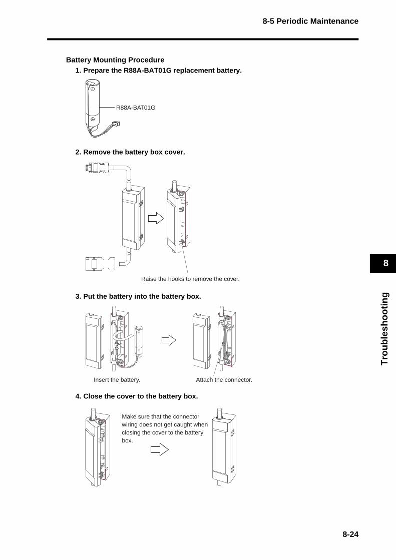
8-5 Periodic Maintenance
Tro
ub
lesh
oo
tin
g
8
Battery Mounting Procedure1. Prepare the R88A-BAT01G replacement battery.
2. Remove the battery box cover.
3. Put the battery into the battery box.
4. Close the cover to the battery box.
R88A-BAT01G
Raise the hooks to remove the cover.
Attach the connector.Insert the battery.
Make sure that the connector wiring does not get caught when closing the cover to the battery box.
8-24


Chapter 9
Appendix9-1 Parameter Tables............................................... 9-1
9-1 Parameter Tables
Ap
pen
dix
9
9-1 Parameter TablesThe attribute indicates when the changed setting for the parameter will be enabled.
Note 1. Parameters marked with "(RT)" are automatically set during realtime autotuning. To set these parameters manually, disable realtime autotuning by setting the Realtime Autotuning Mode Selection (Pn021) to 0 before changing the parameter.
Note 2. Parameter No. is the number for MECHATROLINK-II communications and CX-Drive. The Parameter Unit shows only the last two digits. Parameter numbers in the 100s specify 16-bit parameters, and numbers in the 200s specify 32-bit parameters.
A Always enabled after change
BChange prohibited during Servomotor operation and command issuance. (It is not known when changes made during Servomotor operation and command issuance will be enabled.)
CEnabled when the control power supply is reset, or when a CONFIG command is executed via the network (MECHATROLINK-II communications).
R Read-only and cannot be changed.
9-1

9-1 Parameter Tables
Ap
pen
dix
9
User parameters are set and checked on CX-Drive or the Parameter Unit (R88A-PR02G).
Parameter Tables
PnNo.
Parameter name Setting ExplanationDefault Setting
UnitSetting Range
Attr
ibut
e
Set value
000 Reserved Do not change. 1 --- --- ---
001 Default Display
Selects the data to be displayed on the 7-segment LED display on the front panel.
0 --- 0 to 4 A
0Normal status ("--" Servo OFF, "00" Servo ON)
1 Mechanical angle (0 to FF hex)
2 Electrical angle (0 to FF hex)
3Cumulative count for MECHATROLINK-II communication errors (0 to FF hex)
4Rotary switch setting (node address) loaded at startup, in decimal
5 to 32767
Reserved (Do not set.)
002 Reserved Do not change. 0 --- --- ---
9-2
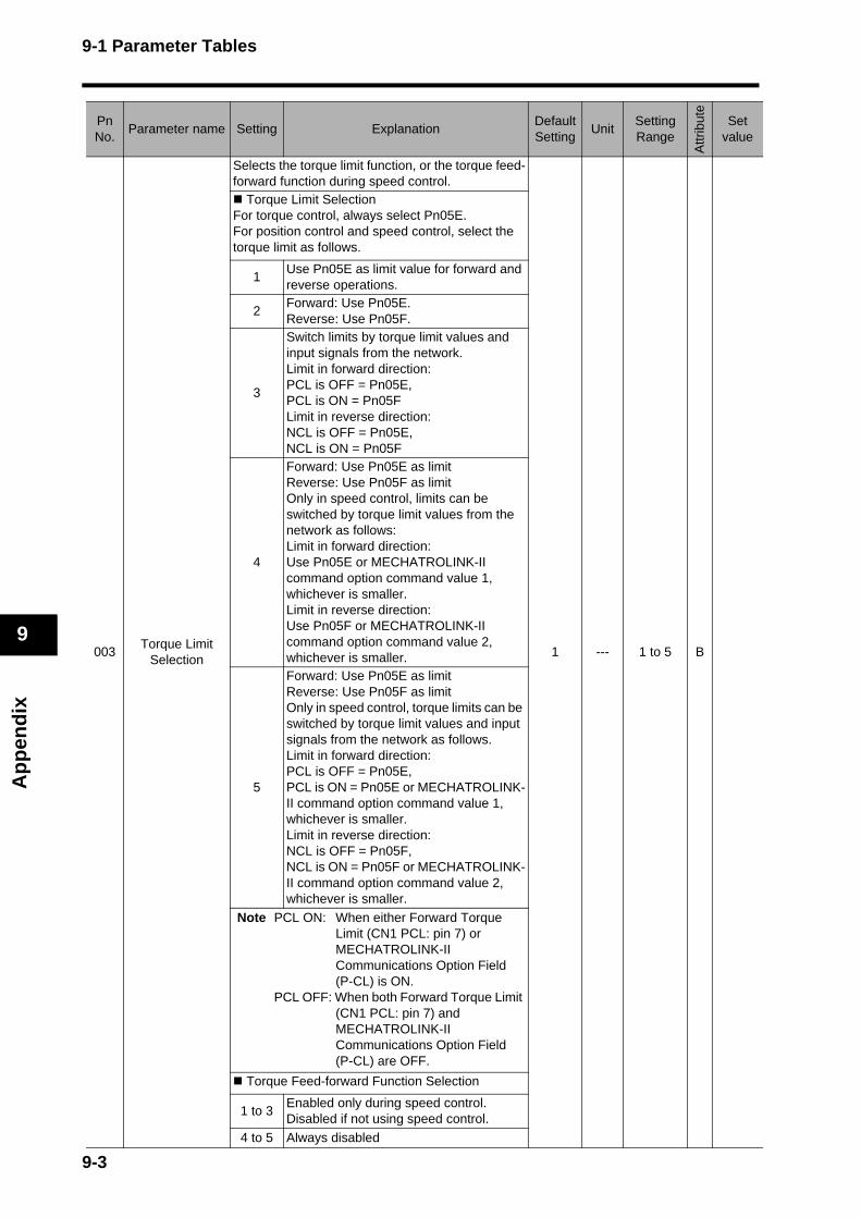
9-1 Parameter Tables
Ap
pen
dix
9
003Torque Limit Selection
Selects the torque limit function, or the torque feed-forward function during speed control.
1 --- 1 to 5 B
Torque Limit SelectionFor torque control, always select Pn05E. For position control and speed control, select the torque limit as follows.
1Use Pn05E as limit value for forward and reverse operations.
2Forward: Use Pn05E.Reverse: Use Pn05F.
3
Switch limits by torque limit values and input signals from the network. Limit in forward direction: PCL is OFF = Pn05E, PCL is ON = Pn05FLimit in reverse direction: NCL is OFF = Pn05E, NCL is ON = Pn05F
4
Forward: Use Pn05E as limitReverse: Use Pn05F as limitOnly in speed control, limits can be switched by torque limit values from the network as follows: Limit in forward direction: Use Pn05E or MECHATROLINK-II command option command value 1, whichever is smaller.Limit in reverse direction: Use Pn05F or MECHATROLINK-II command option command value 2, whichever is smaller.
5
Forward: Use Pn05E as limitReverse: Use Pn05F as limitOnly in speed control, torque limits can be switched by torque limit values and input signals from the network as follows. Limit in forward direction: PCL is OFF = Pn05E,PCL is ON = Pn05E or MECHATROLINK-II command option command value 1, whichever is smaller.Limit in reverse direction: NCL is OFF = Pn05F, NCL is ON = Pn05F or MECHATROLINK-II command option command value 2, whichever is smaller.
Note PCL ON: When either Forward Torque Limit (CN1 PCL: pin 7) or MECHATROLINK-II Communications Option Field (P-CL) is ON.
PCL OFF: When both Forward Torque Limit (CN1 PCL: pin 7) and MECHATROLINK-II Communications Option Field (P-CL) are OFF.
Torque Feed-forward Function Selection
1 to 3Enabled only during speed control. Disabled if not using speed control.
4 to 5 Always disabled
PnNo.
Parameter name Setting ExplanationDefault Setting
UnitSetting Range
Attr
ibut
e
Set value
9-3
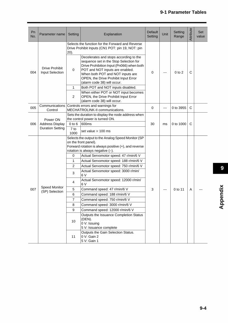
9-1 Parameter Tables
Ap
pen
dix
9
004Drive Prohibit
Input Selection
Selects the function for the Forward and Reverse Drive Prohibit Inputs (CN1 POT: pin 19, NOT: pin 20).
0 --- 0 to 2 C0
Decelerates and stops according to the sequence set in the Stop Selection for Drive Prohibition Input (Pn066) when both POT and NOT inputs are enabled.When both POT and NOT inputs are OPEN, the Drive Prohibit Input Error (alarm code 38) will occur.
1 Both POT and NOT inputs disabled.
2When either POT or NOT input becomes OPEN, the Drive Prohibit Input Error (alarm code 38) will occur.
005Communications
ControlControls errors and warnings for MECHATROLINK-II communications.
0 --- 0 to 3955 C
006Power ON
Address DisplayDuration Setting
Sets the duration to display the node address when the control power is turned ON.
30 ms 0 to 1000 C0 to 6 600ms
7 to 1000
set value × 100 ms
007Speed Monitor (SP) Selection
Selects the output to the Analog Speed Monitor (SP on the front panel). Forward rotation is always positive (+), and reverse rotation is always negative (−).
3 --- 0 to 11 A ---
0 Actual Servomotor speed: 47 r/min/6 V
1 Actual Servomotor speed: 188 r/min/6 V
2 Actual Servomotor speed: 750 r/min/6 V
3Actual Servomotor speed: 3000 r/min/6 V
4Actual Servomotor speed: 12000 r/min/6 V
5 Command speed: 47 r/min/6 V
6 Command speed: 188 r/min/6 V
7 Command speed: 750 r/min/6 V
8 Command speed: 3000 r/min/6 V
9 Command speed: 12000 r/min/6 V
10
Outputs the Issuance Completion Status (DEN). 0 V: Issuing5 V: Issuance complete
11Outputs the Gain Selection Status. 0 V: Gain 25 V: Gain 1
PnNo.
Parameter name Setting ExplanationDefault Setting
UnitSetting Range
Attr
ibut
e
Set value
9-4
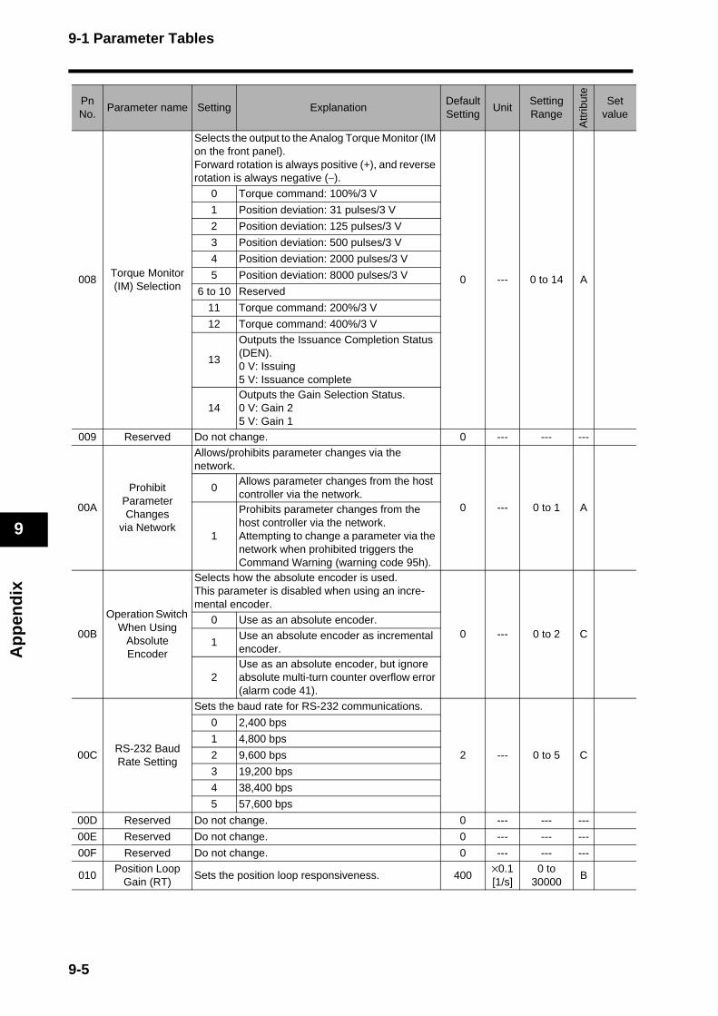
9-1 Parameter Tables
Ap
pen
dix
9
008Torque Monitor (IM) Selection
Selects the output to the Analog Torque Monitor (IM on the front panel). Forward rotation is always positive (+), and reverse rotation is always negative (−).
0 --- 0 to 14 A
0 Torque command: 100%/3 V
1 Position deviation: 31 pulses/3 V
2 Position deviation: 125 pulses/3 V
3 Position deviation: 500 pulses/3 V
4 Position deviation: 2000 pulses/3 V
5 Position deviation: 8000 pulses/3 V
6 to 10 Reserved
11 Torque command: 200%/3 V
12 Torque command: 400%/3 V
13
Outputs the Issuance Completion Status (DEN). 0 V: Issuing5 V: Issuance complete
14Outputs the Gain Selection Status. 0 V: Gain 25 V: Gain 1
009 Reserved Do not change. 0 --- --- ---
00A
ProhibitParameter Changes
via Network
Allows/prohibits parameter changes via the network.
0 --- 0 to 1 A
0Allows parameter changes from the host controller via the network.
1
Prohibits parameter changes from the host controller via the network. Attempting to change a parameter via the network when prohibited triggers the Command Warning (warning code 95h).
00B
Operation Switch When Using
Absolute Encoder
Selects how the absolute encoder is used. This parameter is disabled when using an incre-mental encoder.
0 --- 0 to 2 C0 Use as an absolute encoder.
1Use an absolute encoder as incremental encoder.
2Use as an absolute encoder, but ignore absolute multi-turn counter overflow error (alarm code 41).
00CRS-232 Baud Rate Setting
Sets the baud rate for RS-232 communications.
2 --- 0 to 5 C
0 2,400 bps
1 4,800 bps
2 9,600 bps
3 19,200 bps
4 38,400 bps
5 57,600 bps
00D Reserved Do not change. 0 --- --- ---
00E Reserved Do not change. 0 --- --- ---
00F Reserved Do not change. 0 --- --- ---
010Position Loop
Gain (RT)Sets the position loop responsiveness. 400
×0.1[1/s]
0 to 30000
B
PnNo.
Parameter name Setting ExplanationDefault Setting
UnitSetting Range
Attr
ibut
e
Set value
9-5

9-1 Parameter Tables
Ap
pen
dix
9
011Speed Loop Gain
(RT)
Sets the speed loop responsiveness. If the Inertia Ratio (Pn020) is set correctly, this parameter is set to the Servomotor response frequency.
500×0.1Hz
1 to 30000
B
012Speed Loop
Integration Time Constant (RT)
Adjusts the speed loop integration time constant. Set 9999 to stop integration operation while retaining the integration value. A Setting of 10000 disables integration.
200×0.1ms
1 to 10000
B
013
Speed Feedback Filter Time Constant
(RT)
Sets the type of speed detection filter time constant. Normally, use a setting of 0.
0 --- 0 to 5 B
014
Torque Command Filter Time
Constant (RT)
Adjusts the first-order lag filter time constant for the torque command section. The torque filter setting may reduce machine vibration.
80×0.01 ms
0 to 2500 B
015Speed Feed-
forward Amount (RT)
Sets the speed feed-forward amount. This parameter is particularly useful when fast re-sponse is required.
300×0.1%
0 to 1000 B
016Feed-forward
Filter Time Constant (RT)
Sets the time constant for the speed feed-forward first-order lag filter.
100×0.01
ms0 to 6400 B
017 Reserved Do not change. 0 --- --- ---
018Position Loop Gain 2 (RT)
Sets the position loop gain when using gain 2 switching.
200×0.1[1/s]
0 to 30000
B
019Speed Loop Gain 2 (RT)
Sets the speed loop gain when using gain 2 switch-ing.
800×0.1Hz
1 to 30000
B
01ASpeed Loop
Integration Time Constant 2 (RT)
Sets the speed loop integration time constant when using gain 2 switching. Same function as Pn012.Set 9999 to stop integration operation while retaining the integration value. Setting 10000 disables integration.
500×0.1ms
1 to 10000
B
01B
Speed Feedback Filter Time Constant 2
(RT)
Sets the speed detection filter when using gain 2 switching.Normally, use a setting of 0. When Instantaneous Speed Observer Setting (Pn027) is enabled, this parameter will be disabled.
0 --- 0 to 5 B
01C
Torque Command Filter Time Constant 2
(RT)
Sets the first-order lag filter time constant for the torque command section when using gain 2 switching.
100×0.01
ms0 to 2500 B
01DNotch Filter 1
Frequency
Sets the notch frequency of notch filter 1 for resonance suppression.
1500 Hz100 to 1500
B100 to 1499
Filter enabled
1500 Filter disabled
01ENotch Filter 1
Width
Selects the notch width of notch filter 1 for resonance suppression. Normally, use a setting of 2.
2 --- 0 to 4 B
01F Reserved Do not change. 0 --- --- ---
020 Inertia Ratio (RT)Selects the load inertia as a percentage of the Servomotor rotor inertia.
300 %0 to
10000B
PnNo.
Parameter name Setting ExplanationDefault Setting
UnitSetting Range
Attr
ibut
e
Set value
9-6
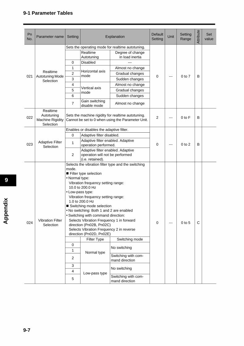
9-1 Parameter Tables
Ap
pen
dix
9
021Realtime
Autotuning Mode Selection
Sets the operating mode for realtime autotuning.
0 --- 0 to 7 B
Realtime Autotuning
Degree of change in load inertia
0 Disabled ---
1Horizontal axis mode
Almost no change
2 Gradual changes
3 Sudden changes
4Vertical axis mode
Almost no change
5 Gradual changes
6 Sudden changes
7Gain switching disable mode
Almost no change
022
Realtime Autotuning
Machine Rigidity Selection
Sets the machine rigidity for realtime autotuning. Cannot be set to 0 when using the Parameter Unit.
2 --- 0 to F B
023Adaptive Filter
Selection
Enables or disables the adaptive filter.
0 --- 0 to 2 B
0 Adaptive filter disabled.
1Adaptive filter enabled. Adaptive operation performed.
2Adaptive filter enabled. Adaptive operation will not be performed (i.e. retained).
024Vibration Filter
Selection
Selects the vibration filter type and the switching mode.
Filter type selectionNormal type: Vibration frequency setting range: 10.0 to 200.0 HzLow-pass type: Vibration frequency setting range: 1.0 to 200.0 Hz Switching mode selectionNo switching: Both 1 and 2 are enabledSwitching with command direction: Selects Vibration Frequency 1 in forward direction (Pn02B, Pn02C)Selects Vibration Frequency 2 in reverse direction (Pn02D, Pn02E)
0 --- 0 to 5 C
Filter Type Switching mode
0
Normal typeNo switching
1
2Switching with com-mand direction
3
Low-pass typeNo switching
4
5Switching with com-mand direction
PnNo.
Parameter name Setting ExplanationDefault Setting
UnitSetting Range
Attr
ibut
e
Set value
9-7
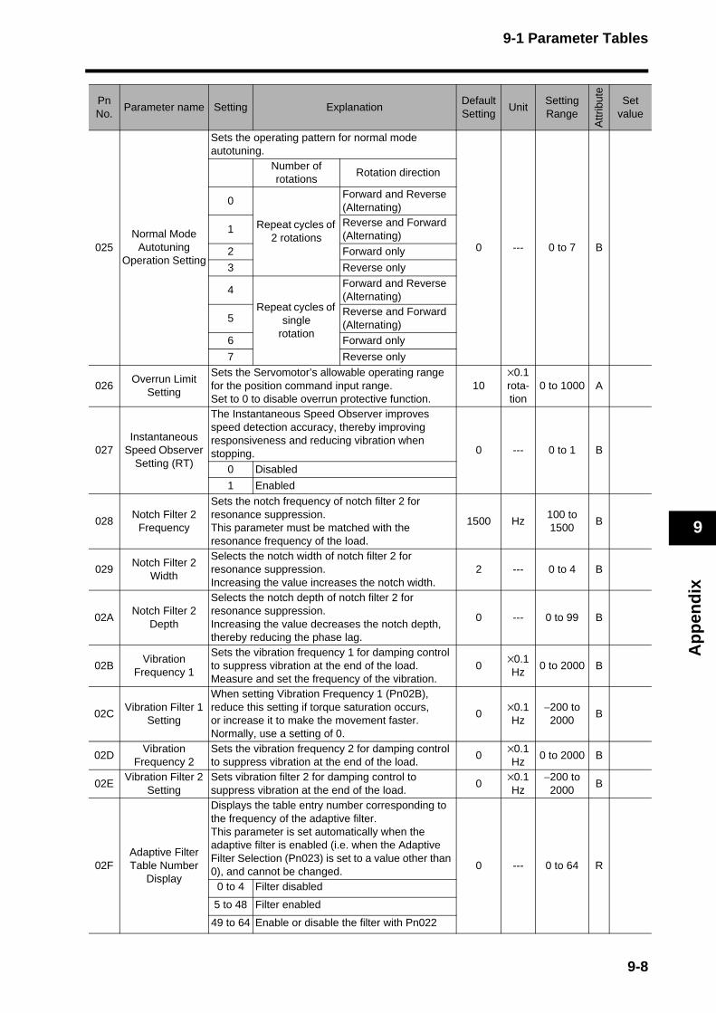
9-1 Parameter Tables
Ap
pen
dix
9
025Normal Mode
Autotuning Operation Setting
Sets the operating pattern for normal mode autotuning.
0 --- 0 to 7 B
Number of rotations
Rotation direction
0
Repeat cycles of 2 rotations
Forward and Reverse (Alternating)
1Reverse and Forward (Alternating)
2 Forward only
3 Reverse only
4
Repeat cycles of single
rotation
Forward and Reverse (Alternating)
5Reverse and Forward (Alternating)
6 Forward only
7 Reverse only
026Overrun Limit
Setting
Sets the Servomotor’s allowable operating range for the position command input range. Set to 0 to disable overrun protective function.
10×0.1rota-tion
0 to 1000 A
027Instantaneous
Speed Observer Setting (RT)
The Instantaneous Speed Observer improves speed detection accuracy, thereby improving responsiveness and reducing vibration when stopping. 0 --- 0 to 1 B
0 Disabled
1 Enabled
028Notch Filter 2
Frequency
Sets the notch frequency of notch filter 2 for resonance suppression. This parameter must be matched with the resonance frequency of the load.
1500 Hz100 to 1500
B
029Notch Filter 2
Width
Selects the notch width of notch filter 2 for resonance suppression.Increasing the value increases the notch width.
2 --- 0 to 4 B
02ANotch Filter 2
Depth
Selects the notch depth of notch filter 2 for resonance suppression. Increasing the value decreases the notch depth, thereby reducing the phase lag.
0 --- 0 to 99 B
02BVibration
Frequency 1
Sets the vibration frequency 1 for damping control to suppress vibration at the end of the load. Measure and set the frequency of the vibration.
0×0.1Hz
0 to 2000 B
02CVibration Filter 1
Setting
When setting Vibration Frequency 1 (Pn02B), reduce this setting if torque saturation occurs, or increase it to make the movement faster. Normally, use a setting of 0.
0×0.1Hz
−200 to 2000
B
02DVibration
Frequency 2Sets the vibration frequency 2 for damping control to suppress vibration at the end of the load.
0×0.1Hz
0 to 2000 B
02EVibration Filter 2
SettingSets vibration filter 2 for damping control to suppress vibration at the end of the load.
0×0.1Hz
−200 to 2000
B
02FAdaptive Filter Table Number
Display
Displays the table entry number corresponding to the frequency of the adaptive filter. This parameter is set automatically when the adaptive filter is enabled (i.e. when the Adaptive Filter Selection (Pn023) is set to a value other than 0), and cannot be changed. 0 --- 0 to 64 R
0 to 4 Filter disabled
5 to 48 Filter enabled
49 to 64 Enable or disable the filter with Pn022
PnNo.
Parameter name Setting ExplanationDefault Setting
UnitSetting Range
Attr
ibut
e
Set value
9-8
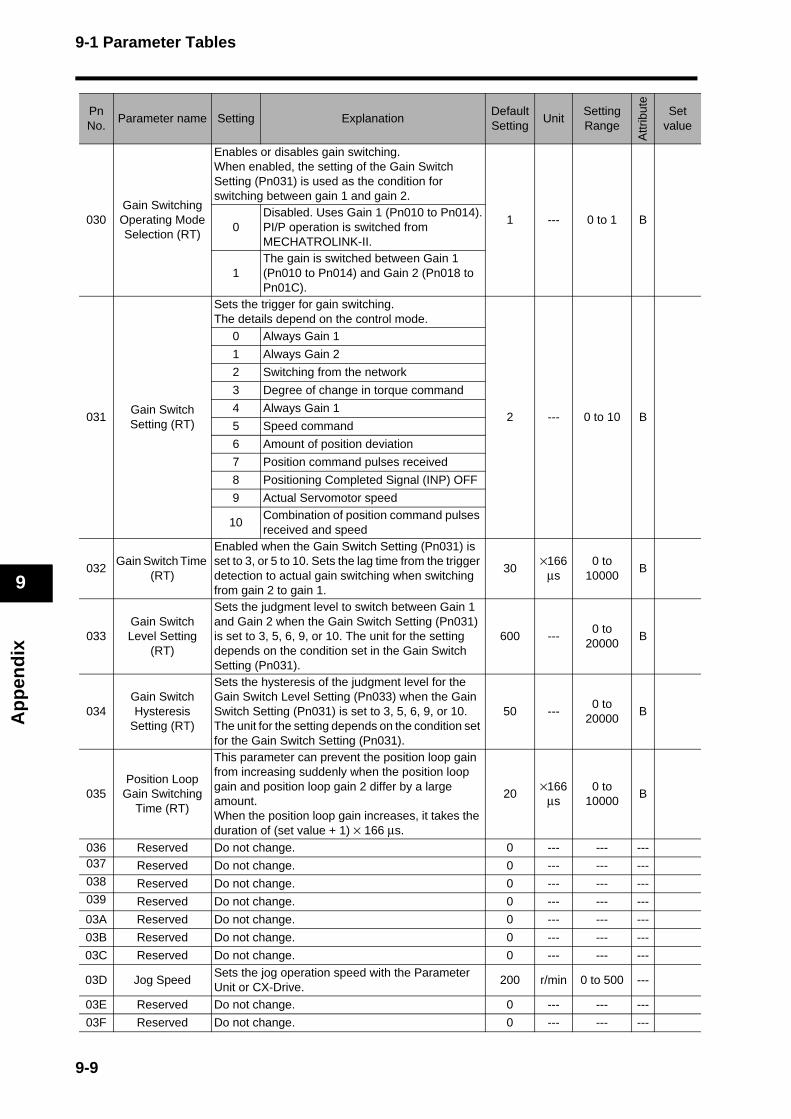
9-1 Parameter Tables
Ap
pen
dix
9
030Gain Switching Operating Mode Selection (RT)
Enables or disables gain switching. When enabled, the setting of the Gain Switch Setting (Pn031) is used as the condition for switching between gain 1 and gain 2.
1 --- 0 to 1 B0
Disabled. Uses Gain 1 (Pn010 to Pn014).PI/P operation is switched from MECHATROLINK-II.
1The gain is switched between Gain 1 (Pn010 to Pn014) and Gain 2 (Pn018 to Pn01C).
031Gain Switch Setting (RT)
Sets the trigger for gain switching. The details depend on the control mode.
2 --- 0 to 10 B
0 Always Gain 1
1 Always Gain 2
2 Switching from the network
3 Degree of change in torque command
4 Always Gain 1
5 Speed command
6 Amount of position deviation
7 Position command pulses received
8 Positioning Completed Signal (INP) OFF
9 Actual Servomotor speed
10Combination of position command pulses received and speed
032Gain Switch Time
(RT)
Enabled when the Gain Switch Setting (Pn031) is set to 3, or 5 to 10. Sets the lag time from the trigger detection to actual gain switching when switching from gain 2 to gain 1.
30×166
μs0 to
10000B
033Gain Switch Level Setting
(RT)
Sets the judgment level to switch between Gain 1 and Gain 2 when the Gain Switch Setting (Pn031) is set to 3, 5, 6, 9, or 10. The unit for the setting depends on the condition set in the Gain Switch Setting (Pn031).
600 ---0 to
20000B
034Gain Switch Hysteresis
Setting (RT)
Sets the hysteresis of the judgment level for the Gain Switch Level Setting (Pn033) when the Gain Switch Setting (Pn031) is set to 3, 5, 6, 9, or 10. The unit for the setting depends on the condition set for the Gain Switch Setting (Pn031).
50 ---0 to
20000B
035Position Loop
Gain Switching Time (RT)
This parameter can prevent the position loop gain from increasing suddenly when the position loop gain and position loop gain 2 differ by a large amount.When the position loop gain increases, it takes the duration of (set value + 1) × 166 μs.
20×166
μs0 to
10000B
036 Reserved Do not change. 0 --- --- ---037 Reserved Do not change. 0 --- --- ---038 Reserved Do not change. 0 --- --- ---039 Reserved Do not change. 0 --- --- ---
03A Reserved Do not change. 0 --- --- ---
03B Reserved Do not change. 0 --- --- ---
03C Reserved Do not change. 0 --- --- ---
03D Jog SpeedSets the jog operation speed with the Parameter Unit or CX-Drive.
200 r/min 0 to 500 ---
03E Reserved Do not change. 0 --- --- ---
03F Reserved Do not change. 0 --- --- ---
PnNo.
Parameter name Setting ExplanationDefault Setting
UnitSetting Range
Attr
ibut
e
Set value
9-9

9-1 Parameter Tables
Ap
pen
dix
9
040 Reserved Do not change. 0 --- --- ---
041Emergency Stop
Input Setting
Enables the Emergency Stop Input (STOP).
1 --- 0 to 1 C0 Disabled
1 Enabled (alarm code 87 issued on OPEN)
042Origin Proximity
Input Logic Setting
Sets the logic for the Origin Proximity Input (DEC).
1 --- 0 to 1 C0N.C contact (origin proximity detected on OPEN)
1N.O contact (origin proximity detected on CLOSE)
043Operating
Direction Setting
Sets the relationship between polarity of operation data sent over the network and the direction of Servomotor rotation.
1 --- 0 to 1 C0
Sets the reverse direction as the positive direction (+).
1Sets the forward direction as the positive direction (+).
044Input Signal
Selection
Sets the terminal assignment for Drive Prohibit Input.
0 --- 0 to 1 C0Sets CN1 pin 19 to POT, CN1 pin 20 to NOT.
1Sets CN1 pin 19 to NOT, CN1 pin 20 to POT.
045 Reserved Do not change. 0 --- --- ---
046 Reserved Do not change. 0 --- --- ---
047 Reserved Do not change. 0 --- --- ---
048 Reserved Do not change. 0 --- --- ---
049 Reserved Do not change. 0 --- --- ---
04A Reserved Do not change. 0 --- --- ---
04B Reserved Do not change. 0 --- --- ---
04C Reserved Do not change. 0 --- --- ---
04D Reserved Do not change. 0 --- --- ---
04E Reserved Do not change. 0 --- --- ---
04F Reserved Do not change. 0 --- --- ---
050 Reserved Do not change. 0 --- --- ---
051 Reserved Do not change. 0 --- --- ---
052 Reserved Do not change. 0 --- --- ---
053 Speed Limit
Sets the speed limit for torque control mode. (The value is an absolute value) This parameter is limited by the Overspeed Detection Level Setting (Pn073).
50 r/min−20000 to
20000B
054 Reserved Do not change. 0 --- --- ---
055 Reserved Do not change. 0 --- --- ---
056 Reserved Do not change. 0 --- --- ---
057 Reserved Do not change. 0 --- --- ---
058Soft Start
Acceleration Time
Sets the acceleration time for speed control mode. Acceleration time [s] from 0 r/min to maximum speed [r/min] = Set value × 2 ms
0 ×2 ms 0 to 5000 B
059Soft Start
Deceleration Time
Sets the deceleration time for speed control mode. Deceleration time [s] from maximum speed [r/min] to 0 r/min = Set value × 2 ms
0 ×2 ms 0 to 5000 B
05A Reserved Do not change. 0 --- --- ---
PnNo.
Parameter name Setting ExplanationDefault Setting
UnitSetting Range
Attr
ibut
e
Set value
9-10
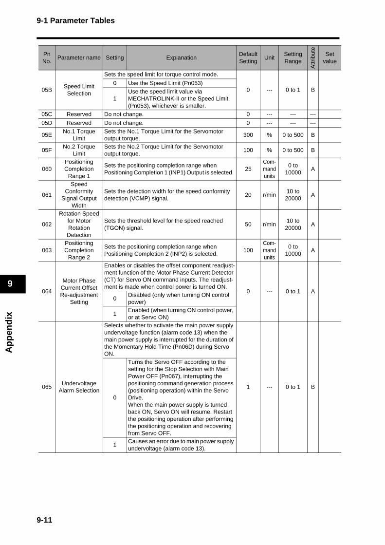
9-1 Parameter Tables
Ap
pen
dix
9
05BSpeed Limit
Selection
Sets the speed limit for torque control mode.
0 --- 0 to 1 B0 Use the Speed Limit (Pn053)
1Use the speed limit value via MECHATROLINK-II or the Speed Limit (Pn053), whichever is smaller.
05C Reserved Do not change. 0 --- --- ---
05D Reserved Do not change. 0 --- --- ---
05ENo.1 Torque
LimitSets the No.1 Torque Limit for the Servomotor output torque.
300 % 0 to 500 B
05FNo.2 Torque
LimitSets the No.2 Torque Limit for the Servomotor output torque.
100 % 0 to 500 B
060Positioning Completion
Range 1
Sets the positioning completion range when Positioning Completion 1 (INP1) Output is selected.
25Com-mand units
0 to 10000
A
061
Speed Conformity
Signal Output Width
Sets the detection width for the speed conformity detection (VCMP) signal.
20 r/min10 to 20000
A
062
Rotation Speed for Motor Rotation Detection
Sets the threshold level for the speed reached (TGON) signal.
50 r/min10 to 20000
A
063Positioning Completion
Range 2
Sets the positioning completion range when Positioning Completion 2 (INP2) is selected.
100Com-mand units
0 to 10000
A
064
Motor Phase Current Offset Re-adjustment
Setting
Enables or disables the offset component readjust-ment function of the Motor Phase Current Detector (CT) for Servo ON command inputs. The readjust-ment is made when control power is turned ON.
0 --- 0 to 1 A0
Disabled (only when turning ON control power)
1Enabled (when turning ON control power, or at Servo ON)
065Undervoltage
Alarm Selection
Selects whether to activate the main power supply undervoltage function (alarm code 13) when the main power supply is interrupted for the duration of the Momentary Hold Time (Pn06D) during Servo ON.
1 --- 0 to 1 B
0
Turns the Servo OFF according to the setting for the Stop Selection with Main Power OFF (Pn067), interrupting the positioning command generation process (positioning operation) within the Servo Drive. When the main power supply is turned back ON, Servo ON will resume. Restart the positioning operation after performing the positioning operation and recovering from Servo OFF.
1Causes an error due to main power supply undervoltage (alarm code 13).
PnNo.
Parameter name Setting ExplanationDefault Setting
UnitSetting Range
Attr
ibut
e
Set value
9-11
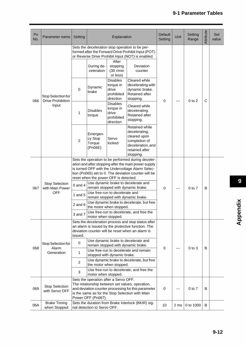
9-1 Parameter Tables
Ap
pen
dix
9
066Stop Selection for Drive Prohibition
Input
Sets the deceleration stop operation to be per-formed after the Forward Drive Prohibit Input (POT) or Reverse Drive Prohibit Input (NOT) is enabled.
0 --- 0 to 2 C
During de-celeration
After stopping(30 r/min or less)
Deviation counter
0Dynamic brake
Disables torque in drive prohibited direction
Cleared while decelerating with dynamic brake. Retained after stopping.
1Disables torque
Disables torque in drive prohibited direction
Cleared while decelerating. Retained after stopping.
2
Emergen-cy Stop Torque (Pn06E)
Servo locked
Retained while decelerating, cleared upon completion of deceleration, and retained after stopping.
067Stop Selection
with Main Power OFF
Sets the operation to be performed during deceler-ation and after stopping after the main power supply is turned OFF with the Undervoltage Alarm Selec-tion (Pn065) set to 0. The deviation counter will be reset when the power OFF is detected.
0 --- 0 to 7 B0 and 4
Use dynamic brake to decelerate and remain stopped with dynamic brake.
1 and 5Use free-run to decelerate and remain stopped with dynamic brake.
2 and 6Use dynamic brake to decelerate, but free the motor when stopped.
3 and 7Use free-run to decelerate, and free the motor when stopped.
068Stop Selection for
Alarm Generation
Sets the deceleration process and stop status after an alarm is issued by the protective function. The deviation counter will be reset when an alarm is issued.
0 --- 0 to 3 B0
Use dynamic brake to decelerate and remain stopped with dynamic brake.
1Use free-run to decelerate and remain stopped with dynamic brake.
2Use dynamic brake to decelerate, but free the motor when stopped.
3Use free-run to decelerate, and free the motor when stopped.
069Stop Selection with Servo OFF
Sets the operation after a Servo OFF. The relationship between set values, operation, and deviation counter processing for this parameter is the same as for the Stop Selection with Main Power OFF (Pn067).
0 --- 0 to 7 B
06ABrake Timing when Stopped
Sets the duration from Brake Interlock (BKIR) sig-nal detection to Servo OFF.
10 2 ms 0 to 1000 B
PnNo.
Parameter name Setting ExplanationDefault Setting
UnitSetting Range
Attr
ibut
e
Set value
9-12
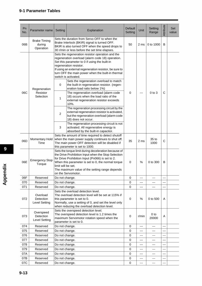
9-1 Parameter Tables
Ap
pen
dix
9
06BBrake Timing
during Operation
Sets the duration from Servo OFF to when the Brake Interlock (BKIR) signal is turned OFF. BKIR is also turned OFF when the speed drops to 30 r/min or less before the set time elapses.
50 2 ms 0 to 1000 B
06CRegeneration
Resistor Selection
Sets the regeneration resistor operation and the regeneration overload (alarm code 18) operation. Set this parameter to 0 if using the built-in regeneration resistor.If using an external regeneration resistor, be sure to turn OFF the main power when the built-in thermal switch is activated.
0 --- 0 to 3 C
0Sets the regeneration overload to match the built-in regeneration resistor. (regen-eration load ratio below 1%)
1
The regeneration overload (alarm code 18) occurs when the load ratio of the external regeneration resistor exceeds 10%.
2
The regeneration processing circuit by the external regeneration resistor is activated, but the regeneration overload (alarm code 18) does not occur.
3The regeneration processing circuit is not activated. All regenerative energy is absorbed by the built-in capacitor.
06DMomentary Hold
Time
Sets the amount of time required to detect shutoff when the main power supply continues to shut off. The main power OFF detection will be disabled if this parameter is set to 1000.
35 2 ms35 to 1000
C
06EEmergency Stop
Torque
Sets the torque limit during deceleration because of the Drive Prohibition Input when the Stop Selection for Drive Prohibition Input (Pn066) is set to 2. When this parameter is set to 0, the normal torque limit will be set.The maximum value of the setting range depends on the Servomotor.
0 % 0 to 300 B
06F Reserved Do not change. 0 --- --- ---
070 Reserved Do not change. 0 --- --- ---
071 Reserved Do not change. 0 --- --- ---
072Overload Detection
Level Setting
Sets the overload detection level.The overload detection level will be set at 115% if this parameter is set to 0.Normally, use a setting of 0, and set the level only when reducing the overload detection level.
0 % 0 to 500 A
073Overspeed Detection
Level Setting
Sets the overspeed detection level.The overspeed detection level is 1.2 times the maximum Servomotor rotation speed when the parameter is set to 0.
0 r/min0 to
20000A
074 Reserved Do not change. 0 --- --- ---
075 Reserved Do not change. 0 --- --- ---
076 Reserved Do not change. 0 --- --- ---
077 Reserved Do not change. 0 --- --- ---
078 Reserved Do not change. 0 --- --- ---
079 Reserved Do not change. 0 --- --- ---
07A Reserved Do not change. 0 --- --- ---
07B Reserved Do not change. 0 --- --- ---
07C Reserved Do not change. 0 --- --- ---
PnNo.
Parameter name Setting ExplanationDefault Setting
UnitSetting Range
Attr
ibut
e
Set value
9-13
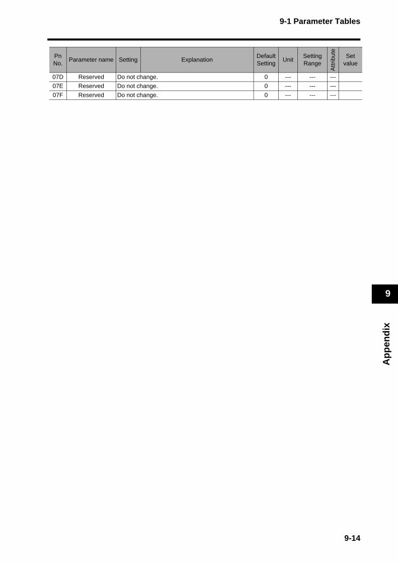
9-1 Parameter Tables
Ap
pen
dix
9
07D Reserved Do not change. 0 --- --- ---
07E Reserved Do not change. 0 --- --- ---
07F Reserved Do not change. 0 --- --- ---
PnNo.
Parameter name Setting ExplanationDefault Setting
UnitSetting Range
Attr
ibut
e
Set value
9-14
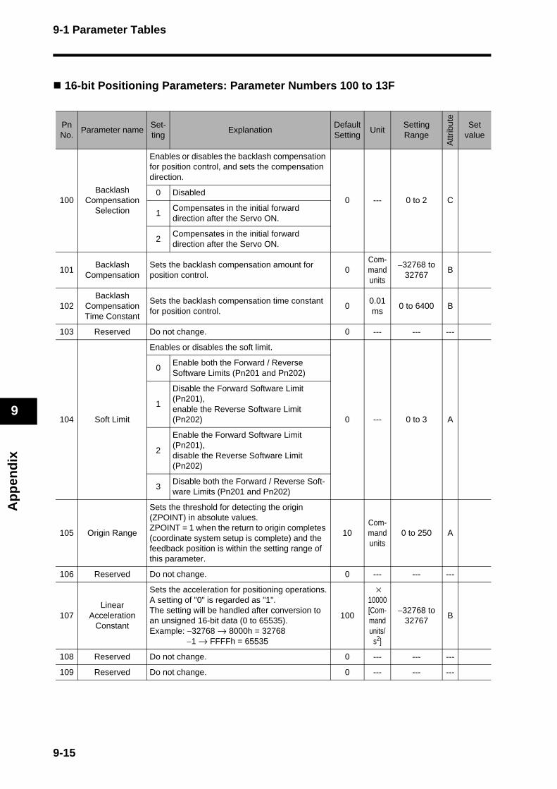
9-1 Parameter Tables
Ap
pen
dix
9
16-bit Positioning Parameters: Parameter Numbers 100 to 13F
PnNo.
Parameter nameSet-ting
ExplanationDefault Setting
UnitSetting Range
Attr
ibut
e
Set value
100Backlash
Compensation Selection
Enables or disables the backlash compensation for position control, and sets the compensation direction.
0 --- 0 to 2 C0 Disabled
1Compensates in the initial forward direction after the Servo ON.
2Compensates in the initial forward direction after the Servo ON.
101Backlash
CompensationSets the backlash compensation amount for position control.
0Com-mand units
−32768 to 32767
B
102Backlash
Compensation Time Constant
Sets the backlash compensation time constant for position control.
00.01 ms
0 to 6400 B
103 Reserved Do not change. 0 --- --- ---
104 Soft Limit
Enables or disables the soft limit.
0 --- 0 to 3 A
0Enable both the Forward / Reverse Software Limits (Pn201 and Pn202)
1
Disable the Forward Software Limit (Pn201), enable the Reverse Software Limit (Pn202)
2
Enable the Forward Software Limit (Pn201), disable the Reverse Software Limit (Pn202)
3Disable both the Forward / Reverse Soft-ware Limits (Pn201 and Pn202)
105 Origin Range
Sets the threshold for detecting the origin (ZPOINT) in absolute values. ZPOINT = 1 when the return to origin completes (coordinate system setup is complete) and the feedback position is within the setting range of this parameter.
10Com-mand units
0 to 250 A
106 Reserved Do not change. 0 --- --- ---
107Linear
Acceleration Constant
Sets the acceleration for positioning operations.A setting of "0" is regarded as "1". The setting will be handled after conversion to an unsigned 16-bit data (0 to 65535). Example: −32768 → 8000h = 32768
−1 → FFFFh = 65535
100
× 10000 [Com-mand units/
s2]
−32768 to 32767
B
108 Reserved Do not change. 0 --- --- ---
109 Reserved Do not change. 0 --- --- ---
9-15
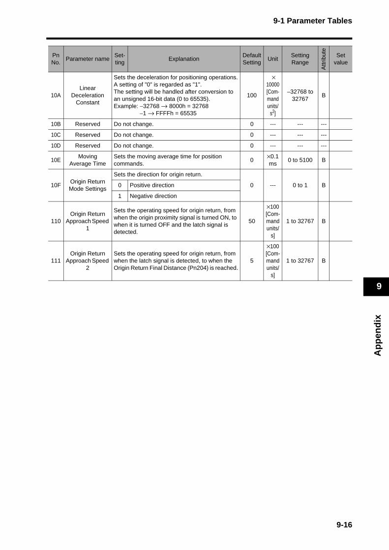
9-1 Parameter Tables
Ap
pen
dix
9
10ALinear
Deceleration Constant
Sets the deceleration for positioning operations.A setting of "0" is regarded as "1". The setting will be handled after conversion to an unsigned 16-bit data (0 to 65535). Example: −32768 → 8000h = 32768
−1 → FFFFh = 65535
100
× 10000 [Com-mand units/
s2]
−32768 to 32767
B
10B Reserved Do not change. 0 --- --- ---
10C Reserved Do not change. 0 --- --- ---
10D Reserved Do not change. 0 --- --- ---
10EMoving
Average TimeSets the moving average time for position commands.
0×0.1ms
0 to 5100 B
10FOrigin Return Mode Settings
Sets the direction for origin return.
0 --- 0 to 1 B0 Positive direction
1 Negative direction
110Origin Return
Approach Speed 1
Sets the operating speed for origin return, from when the origin proximity signal is turned ON, to when it is turned OFF and the latch signal is detected.
50
×100 [Com-mand units/
s]
1 to 32767 B
111Origin Return
Approach Speed 2
Sets the operating speed for origin return, from when the latch signal is detected, to when the Origin Return Final Distance (Pn204) is reached.
5
×100 [Com-mand units/
s]
1 to 32767 B
PnNo.
Parameter nameSet-ting
ExplanationDefault Setting
UnitSetting Range
Attr
ibut
e
Set value
9-16
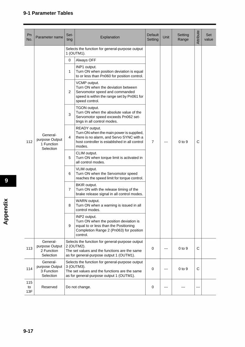
9-1 Parameter Tables
Ap
pen
dix
9
112
General-purpose Output
1 Function Selection
Selects the function for general-purpose output 1 (OUTM1).
7 --- 0 to 9 C
0 Always OFF
1INP1 output.Turn ON when position deviation is equal to or less than Pn060 for position control.
2
VCMP output. Turn ON when the deviation between Servomotor speed and commanded speed is within the range set by Pn061 for speed control.
3
TGON output.Turn ON when the absolute value of the Servomotor speed exceeds Pn062 set-tings in all control modes.
4
READY output.Turn ON when the main power is supplied, there is no alarm, and Servo SYNC with a host controller is established in all control modes.
5CLIM output.Turn ON when torque limit is activated in all control modes.
6VLIM output. Turn ON when the Servomotor speed reaches the speed limit for torque control.
7BKIR output.Turn ON with the release timing of the brake release signal in all control modes.
8WARN output.Turn ON when a warning is issued in all control modes.
9
INP2 output.Turn ON when the position deviation is equal to or less than the Positioning Completion Range 2 (Pn063) for position control.
113
General-purpose Output
2 Function Selection
Selects the function for general-purpose output 2 (OUTM2). The set values and the functions are the same as for general-purpose output 1 (OUTM1).
0 --- 0 to 9 C
114
General-purpose Output
3 Function Selection
Selects the function for general-purpose output 3 (OUTM3). The set values and the functions are the same as for general-purpose output 1 (OUTM1).
0 --- 0 to 9 C
115 to
13FReserved Do not change. 0 --- --- ---
PnNo.
Parameter nameSet-ting
ExplanationDefault Setting
UnitSetting Range
Attr
ibut
e
Set value
9-17
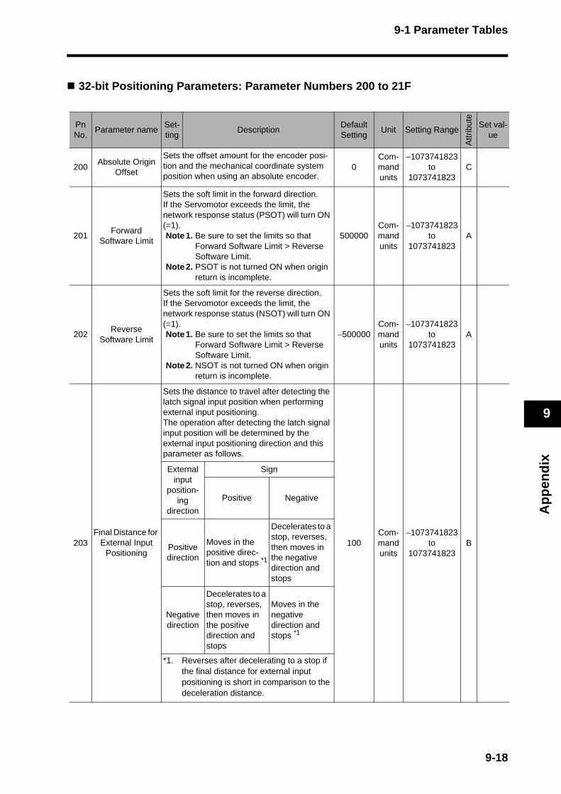
9-1 Parameter Tables
Ap
pen
dix
9
32-bit Positioning Parameters: Parameter Numbers 200 to 21F
PnNo.
Parameter nameSet-ting
DescriptionDefault Setting
Unit Setting Range
Attr
ibut
e
Set val-ue
200Absolute Origin
Offset
Sets the offset amount for the encoder posi-tion and the mechanical coordinate system position when using an absolute encoder.
0Com-mand units
−1073741823 to
1073741823C
201Forward
Software Limit
Sets the soft limit in the forward direction. If the Servomotor exceeds the limit, the network response status (PSOT) will turn ON (=1).Note1. Be sure to set the limits so that
Forward Software Limit > Reverse Software Limit.
Note2. PSOT is not turned ON when origin return is incomplete.
500000Com-mand units
−1073741823 to
1073741823A
202Reverse
Software Limit
Sets the soft limit for the reverse direction. If the Servomotor exceeds the limit, the network response status (NSOT) will turn ON (=1).Note1. Be sure to set the limits so that
Forward Software Limit > Reverse Software Limit.
Note2. NSOT is not turned ON when origin return is incomplete.
−500000Com-mand units
−1073741823 to
1073741823A
203Final Distance for
External Input Positioning
Sets the distance to travel after detecting the latch signal input position when performing external input positioning. The operation after detecting the latch signal input position will be determined by the external input positioning direction and this parameter as follows.
100Com-mand units
−1073741823 to
1073741823B
External input
position-ing
direction
Sign
Positive Negative
Positive direction
Moves in the positive direc-tion and stops *1
Decelerates to a stop, reverses, then moves in the negative direction and stops
Negative direction
Decelerates to a stop, reverses, then moves in the positive direction and stops
Moves in the negative direction and stops *1
*1. Reverses after decelerating to a stop if the final distance for external input positioning is short in comparison to the deceleration distance.
9-18
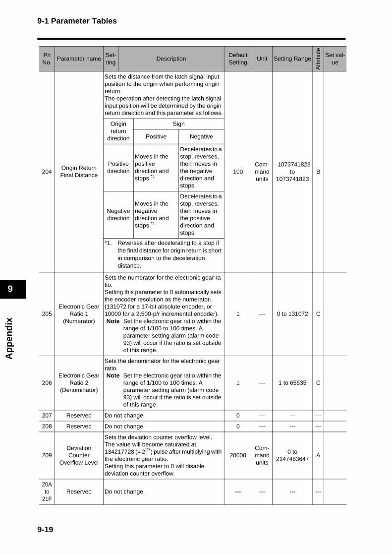
9-1 Parameter Tables
Ap
pen
dix
9
204Origin Return Final Distance
Sets the distance from the latch signal input position to the origin when performing origin return.The operation after detecting the latch signal input position will be determined by the origin return direction and this parameter as follows.
100Com-mand units
−1073741823 to
1073741823B
Origin return
direction
Sign
Positive Negative
Positive direction
Moves in the positive direction and stops *1
Decelerates to a stop, reverses, then moves in the negative direction and stops
Negative direction
Moves in the negative direction and stops *1
Decelerates to a stop, reverses, then moves in the positive direction and stops
*1. Reverses after decelerating to a stop if the final distance for origin return is short in comparison to the deceleration distance.
205Electronic Gear
Ratio 1(Numerator)
Sets the numerator for the electronic gear ra-tio. Setting this parameter to 0 automatically sets the encoder resolution as the numerator. (131072 for a 17-bit absolute encoder, or 10000 for a 2,500-p/r incremental encoder). Note Set the electronic gear ratio within the
range of 1/100 to 100 times. A parameter setting alarm (alarm code 93) will occur if the ratio is set outside of this range.
1 --- 0 to 131072 C
206Electronic Gear
Ratio 2(Denominator)
Sets the denominator for the electronic gear ratio. Note Set the electronic gear ratio within the
range of 1/100 to 100 times. A parameter setting alarm (alarm code 93) will occur if the ratio is set outside of this range.
1 --- 1 to 65535 C
207 Reserved Do not change. 0 --- --- ---
208 Reserved Do not change. 0 --- --- ---
209Deviation Counter
Overflow Level
Sets the deviation counter overflow level. The value will become saturated at 134217728 (= 227) pulse after multiplying with the electronic gear ratio. Setting this parameter to 0 will disable deviation counter overflow.
20000Com-mand units
0 to 2147483647
A
20A to
21FReserved Do not change. --- --- --- ---
PnNo.
Parameter nameSet-ting
DescriptionDefault Setting
Unit Setting Range
Attr
ibut
e
Set val-ue
9-19

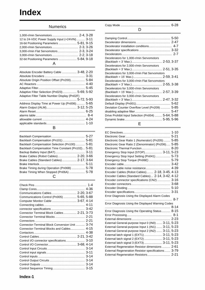
Index
Numerics
1,000-r/min Servomotors ................................ 2-4, 3-2812 to 24-VDC Power Supply Input (+24VIN) .......... 3-1116-bit Positioning Parameters ...................... 5-81, 9-152,000-r/min Servomotors ................................ 2-3, 3-263,000-r/min Flat Servomotors ......................... 2-3, 3-243,000-r/min Servomotors ................................ 2-2, 3-1832-bit Positioning Parameters ...................... 5-84, 9-18
A
Absolute Encoder Battery Cable .................. 3-48, 2-20Absolute Encoders ................................................. 3-31Absolute Origin Position Offset (Pn200)................. 5-84AC Reactors ........................................................... 4-40Adaptive Filter......................................................... 5-45Adaptive Filter Selection (Pn023) ................. 5-69, 5-92Adaptive Filter Table Number Display (Pn02F)...................................................................... 5-72, 5-93Address Display Time at Power Up (Pn006) .......... 5-65Alarm Output (/ALM)..................................... 3-12, 5-25Alarm Reset............................................................ 6-25alarms table .............................................................. 8-4allowable current .................................................... 4-24applicable standards............................................... 1-10
B
Backlash Compensation......................................... 5-27Backlash Compensation (Pn101) ........................... 5-81Backlash Compensation Selection (Pn100) ........... 5-81Backlash Compensation Time Constant (Pn102)... 5-81Backup Battery Input (BAT).................................... 3-11Brake Cables (Robot Cables)....................... 2-20, 3-66Brake Cables (Standard Cables).................. 2-17, 3-64Brake Interlock........................................................ 5-11Brake Timing during Operation (Pn06B) ................ 5-78Brake Timing When Stopped (Pn06A) ................... 5-78
C
Check Pins ............................................................... 1-4Clamp Cores........................................................... 4-36Communications Cables............................... 2-20, 3-67Communications Control (Pn005) ................ 5-65, 5-88Computer Monitor Cable .............................. 3-67, 4-14Connecting cables .................................................. 4-11connector specifications ......................................... 3-42Connector Terminal Block Cables ................ 2-21, 3-73Connector Terminal Blocks .................................... 2-21Connectors ............................................................. 2-21Connector-Terminal Block Conversion Unit ........... 3-74Connector-Terminal Blocks and Cables ................. 4-15Contactors .............................................................. 4-38Control Cables.............................................. 2-21, 3-42Control I/O connector specifications....................... 3-10Control I/O Connector................................... 3-68, 4-14Control Input Circuits .............................................. 3-14Control input signals ............................................... 3-11Control inputs ......................................................... 3-14Control Output Circuits ........................................... 3-14Control Outputs ...................................................... 3-14Control Sequence Timing ....................................... 3-15
Copy Mode ............................................................. 6-28D
Damping Control..................................................... 5-50Decelerator dimensions.......................................... 2-47Decelerator installation conditions............................ 4-7Decelerator specifications ...................................... 3-32Decelerators ............................................................. 2-7Decelerators for 1,000-r/min Servomotors (Backlash = 3’ Max.) ..................................... 2-53, 3-37Decelerators for 2,000-r/min Servomotors (Backlash = 3’ Max.) ..................................... 2-51, 3-35Decelerators for 3,000-r/min Flat Servomotors (Backlash = 15’ Max.) ................................... 2-59, 3-41Decelerators for 3,000-r/min Flat Servomotors (Backlash = 3’ Max.) ..................................... 2-55, 3-38Decelerators for 3,000-r/min Servomotors (Backlash = 15’ Max.) ................................... 2-57, 3-39Decelerators for 3,000-r/min Servomotors (Backlash = 3’ Max.) ..................................... 2-47, 3-32Default Display (Pn001).......................................... 5-62Deviation Counter Overflow Level (Pn209) ............ 5-85disabling adaptive filter ........................................... 5-47Drive Prohibit Input Selection (Pn004) ......... 5-64, 5-88Dynamic brake.............................................. 5-95, 5-96
E
EC Directives.......................................................... 1-10Electronic Gear....................................................... 5-21Electronic Gear Ratio 1 (Numerator) (Pn205) ........ 5-85Electronic Gear Ratio 2 (Denominator) (Pn206)..... 5-85Electronic Thermal Function................................... 8-20Emergency Stop Input (STOP)..................... 3-11, 5-23Emergency Stop Input Setting (Pn041) .................. 5-73Emergency Stop Torque (Pn06E) .......................... 5-79Encoder cable......................................................... 3-42Encoder cable noise resistance.............................. 4-39Encoder Cables (Robot Cables)........ 2-18, 3-45, 4-13Encoder Cables (Standard Cables)... 2-14, 3-42, 4-12Encoder connector specifications (CN2) ................ 3-16Encoder connectors................................................ 3-68Encoder Dividing .................................................... 5-10Encoder specifications............................................ 3-31Error Diagnosis Using the Displayed Alarm Codes.................................................................................. 8-7Error Diagnosis Using the Displayed Warning Codes................................................................................ 8-14Error Diagnosis Using the Operating Status........... 8-15Error Processing....................................................... 8-1External dimensions ............................................... 2-23External General-purpose Input 0 (IN0) ....... 3-11, 5-23External General-purpose Input 1 (IN1) ....... 3-11, 5-23External General-purpose Input 2 (IN2) ....... 3-11, 5-23External latch signal 1 (EXT1) ...................... 3-11, 5-23External latch signal 2 (EXT2) ...................... 3-11, 5-23External latch signal 3 (EXT3) ...................... 3-11, 5-23External Regeneration Resistor dimensions .......... 2-61External Regeneration Resistor specifications ....... 3-79External Regeneration Resistors............................ 2-21
Index-1
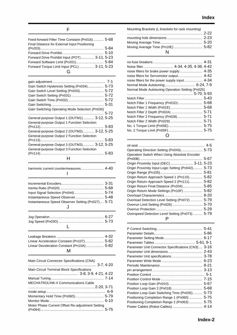
Index
F
Feed-forward Filter Time Constant (Pn016) ........... 5-68Final Distance for External Input Positioning (Pn203)................................................................... 5-84Forward Drive Prohibit............................................ 5-10Forward Drive Prohibit Input (POT) .............. 3-11, 5-23Forward Software Limit (Pn201)............................. 5-84Forward Torque Limit Input (PCL) ................ 3-11, 5-23
G
gain adjustment ........................................................ 7-1Gain Switch Hysteresis Setting (Pn034)................. 5-73Gain Switch Level Setting (Pn033)......................... 5-72Gain Switch Setting (Pn031) .................................. 5-72Gain Switch Time (Pn032)...................................... 5-72Gain Switching........................................................ 5-31Gain Switching Operating Mode Selection (Pn030)................................................................................ 5-72General-purpose Output 1 (OUTM1)............ 3-12, 5-25General-purpose Output 1 Function Selection (Pn112)................................................................... 5-83General-purpose Output 2 (OUTM2)............ 3-12, 5-25General-purpose Output 2 Function Selection (Pn113)................................................................... 5-83General-purpose Output 3 (OUTM3)............ 3-12, 5-25General-purpose Output 3 Function Selection (Pn114)................................................................... 5-83
H
harmonic current countermeasures........................ 4-40I
Incremental Encoders............................................. 3-31Inertia Ratio (Pn020) .............................................. 5-68Input Signal Selection (Pn044) ............................... 5-74Instantaneous Speed Observer.............................. 5-48Instantaneous Speed Observer Setting (Pn027).... 5-71
J
Jog Operation ......................................................... 6-27Jog Speed (Pn03D)................................................ 5-73
L
Leakage Breakers .................................................. 4-32Linear Acceleration Constant (Pn107).................... 5-82Linear Deceleration Constant (Pn10A)................... 5-82
M
Main Circuit Connector Specifications (CNA)........................................................................ 3-7, 4-20Main Circuit Terminal Block Specifications..................................................... 3-8, 3-9, 4-21, 4-22Manual Tuning........................................................ 7-14MECHATROLINK-II Communications Cable...................................................................... 2-20, 3-71mode setup............................................................... 6-9Momentary Hold Time (Pn06D).............................. 5-79Monitor Mode.......................................................... 6-10Motor Phase Current Offset Re-adjustment Setting (Pn064)................................................................... 5-75
Mounting Brackets (L brackets for rack mounting)................................................................................ 2-22mounting hole dimensions...................................... 2-23Moving Average Time............................................. 5-20Moving Average Time (Pn10E) .............................. 5-82
N
no-fuse breakers..................................................... 4-31Noise filter................................ 4-34, 4-35, 4-36, 4-42noise filters for brake power supply ........................ 4-35noise filters for Servomotor output.......................... 4-42noise filters for the power supply input ................... 4-34Normal Mode Autotuning................................ 6-24, 7-9Normal Mode Autotuning Operation Setting (Pn025)...................................................................... 5-70, 5-93Notch Filter ............................................................. 5-43Notch Filter 1 Frequency (Pn01D).......................... 5-68Notch Filter 1 Width (Pn01E).................................. 5-68Notch Filter 2 Depth (Pn02A) ................................. 5-71Notch Filter 2 Frequency (Pn028) .......................... 5-71Notch Filter 2 Width (Pn029) .................................. 5-71No. 1 Torque Limit (Pn05E).................................... 5-75No. 2 Torque Limit (Pn05F) .................................... 5-75
O
oil seal ...................................................................... 4-5Operating Direction Setting (Pn043)....................... 5-73Operation Switch When Using Absolute Encoder (Pn00B) .................................................................. 5-67Origin Proximity Input (DEC) ........................ 3-11, 5-23Origin Proximity Input Logic Setting (Pn042).......... 5-73Origin Range (Pn105)............................................. 5-81Origin Return Approach Speed 1 (Pn110).............. 5-82Origin Return Approach Speed 2 (Pn111).............. 5-82Origin Return Final Distance (Pn204)..................... 5-85Origin Return Mode Settings (Pn10F) .................... 5-82Overload Characteristics ........................................ 8-20Overload Detection Level Setting (Pn072) ............. 5-79Overrun Limit Setting (Pn026) ................................ 5-70Overrun Protection ................................................. 5-29Overspeed Detection Level Setting (Pn073) .......... 5-79
P
P Control Switching ................................................ 5-41Parameter Details................................................... 5-86Parameter Setting Mode......................................... 6-17Parameter Tables ........................................... 5-61, 9-1Parameter Unit Connector Specifications (CN3) .... 3-16Parameter Unit dimensions .................................... 2-43Parameter Unit specifications................................. 3-78Parameter Write Mode ........................................... 6-23Periodic Maintenance ............................................. 8-21pin arrangement ..................................................... 3-13Position Control ........................................................ 5-1Position Control Mode ............................................ 7-15Position Loop Gain (Pn010) ................................... 5-67Position Loop Gain 2 (Pn018) ................................ 5-68Position Loop Gain Switching Time (Pn035) .......... 5-73Positioning Completion Range 1 (Pn060) .............. 5-75Positioning Completion Range 2 (Pn063) .............. 5-75Power Cables (Robot Cables) ................................ 4-14
Index-2
Index
Power Cables (Standard Cables) ........................... 4-13Power Cables for Servomotors with Brakes (Robot Cables) ....................................................... 3-61Power Cables for Servomotors with Brakes (Standard Cables) .................................................. 3-58Power Cables for Servomotors without Brakes (Robot Cables) ....................................................... 3-54Power Cables for Servomotors without Brakes (Standard Cables) .................................................. 3-49Prohibit Parameter Changes via Network (Pn00A)................................................................................ 5-67Protective Functions ................................................. 3-5
R
radio noise filters .................................................... 4-36Reactor dimensions................................................ 2-62Reactors ............................................ 2-21, 3-80, 4-40Realtime Autotuning ................................................. 7-3Realtime Autotuning Machine Rigidity Selection (Pn022)......................................................... 5-69, 5-89Realtime Autotuning Mode Selection (Pn021)...................................................................... 5-69, 5-89Regeneration Resistor Selection (Pn06C).... 5-79, 5-96regenerative energy................................................ 4-44regenerative energy (External Regeneration Resistors)................................................................................ 4-48regenerative energy absorption.............................. 4-47Replacing the Absolute Encoder Battery................ 8-23replacing the Servo Drive ......................................... 8-2replacing the Servomotor ......................................... 8-2Reverse Drive Prohibit............................................ 5-10Reverse Drive Prohibit Input (NOT).............. 3-11, 5-23Reverse Software Limit (Pn202)............................. 5-84Reverse Torque Limit Input (NCL)................ 3-11, 5-23Rotation Speed for Motor Rotation Detection (Pn062)................................................................... 5-75rotational speed characteristics for 1,000-r/min Servomotors ........................................................... 3-29rotational speed characteristics for 2,000-r/min Servomotors ........................................................... 3-27rotational speed characteristics for 3,000-r/min Flat Servomotors .................................................... 3-25rotational speed characteristics for 3,000-r/min Servomotors ........................................................... 3-21RS-232 Baud Rate Setting (Pn00C)....................... 5-67
S
Sequence Input Signals.......................................... 5-23Sequence Output Signals....................................... 5-25Servo Drive characteristics....................................... 3-2Servo Drive dimensions.......................................... 2-23Servo Drive functions ............................................... 1-4Servo Drive General Specifications.......................... 3-1Servo Drive installation conditions............................ 4-1Servo Drive models .................................................. 2-1Servo Drive part names............................................ 1-3Servo Drive service life........................................... 8-22Servo Drive-Servomotor combinations..................... 2-5Servomotor and Decelerator Combinations ........... 2-44Servomotor characteristics ..................................... 3-18Servomotor connector specifications (CNB)... 3-7, 4-20Servomotor general specifications ......................... 3-17
Servomotor installation conditions............................ 4-3Servomotor models .................................................. 2-2Servomotor power cable......................................... 3-49Servomotor Power Cables (Robot Cables) ............ 2-19Servomotor Power Cables (Standard Cables) ....... 2-15Servomotor service life ........................................... 8-21Soft Limit (Pn104)................................................... 5-81Soft Start................................................................. 5-18Soft Start Acceleration Time (Pn058) ..................... 5-74Soft Start Deceleration Time (Pn059)..................... 5-74Speed Conformity Signal Output Width (Pn061) .... 5-75Speed Control........................................................... 5-4speed control mode adjustment ............................. 7-16Speed Feedback Filter Selection............................ 5-40Speed Feedback Filter Time Constant (Pn013) ..... 5-67Speed Feedback Filter Time Constant 2 (Pn01B).. 5-68Speed Feed-forward............................................... 5-38Speed Feed-forward Amount (Pn015).................... 5-68Speed Limit............................................................. 5-22Speed Limit (Pn053)............................................... 5-74Speed Limit Selection (Pn05B)............................... 5-74speed limit values ................................................... 7-21Speed Loop Gain (Pn011)...................................... 5-67Speed Loop Gain 2 (Pn019)................................... 5-68Speed Loop Integration Time Constant (Pn012) .... 5-67Speed Loop Integration Time Constant 2 (Pn01A) .................................................................. 5-68Speed monitor (SP) Selection (Pn007) .................. 5-66Stop Selection for Alarm Generation (Pn068)...................................................................... 5-78, 5-96Stop Selection for Drive Prohibition Input (Pn066)...................................................................... 5-77, 5-95Stop Selection with Main Power OFF (Pn067)...................................................................... 5-78, 5-95Stop Selection with Servo OFF (Pn069)....... 5-78, 5-96surge absorbers...................................................... 4-33surge suppressors .................................................. 4-38system block diagrams ............................................. 1-5system configuration................................................. 1-2
T
Terminal Block Wire Sizes...................................... 4-23Terminal Block Wiring............................................. 4-25Torque Command Filter Time Constant ................. 5-42Torque Command Filter Time Constant (Pn014) ... 5-68Torque Command Filter Time Constant 2 (Pn01C)................................................................................ 5-68Torque Control.......................................................... 5-7torque control mode adjustment ............................. 7-21Torque Feed-forward.............................................. 5-39Torque Limit.................................................. 5-16, 5-19Torque Limit Selection (Pn003) .................... 5-63, 5-87Torque Monitor (IM) Selection (Pn008) .................. 5-66Trial Operation........................................................ 6-31troubleshooting ......................................................... 8-7
U
UL and CSA standards........................................... 1-10Undervoltage Alarm Selection (Pn065) .................. 5-76user parameters ..................................................... 5-55using the parameter unit........................................... 6-8
Index-3

Index
V
Vibration Filter 1 Setting (Pn02C)........................... 5-71Vibration Filter 2 Setting (Pn02E) ........................... 5-72Vibration Filter Selection (Pn024)................. 5-70, 5-92Vibration Frequency 1 (Pn02B) .............................. 5-71Vibration Frequency 2 (Pn02D) .............................. 5-71
W
Wire Sizes .............................................................. 4-24wiring conforming to EMC Directives...................... 4-26
Index-4
R-1
Revision History
A manual revision code appears as a suffix to the catalog number on the front and back covers of the man-ual.
The following table outlines the changes made to the manual during each revision. Page numbers refer tothe previous version.
Revision code Date Revised content and pages
01 July 2008 Original production
Cat. No. I566-E1-01
Revision code


Authorized Distributor:
In the interest of product improvement,specifications are subject to change without notice.
Cat. No. I566-E1-01OMRON Industrial Automation Global: www.ia.omron.com
OMRON CorporationIndustrial Automation Company
Regional HeadquartersOMRON EUROPE B.V.Wegalaan 67-69-2132 JD HoofddorpThe NetherlandsTel: (31)2356-81-300/Fax: (31)2356-81-388
OMRON ELECTRONICS LLCOne Commerce Drive Schaumburg, IL 60173-5302 U.S.A.Tel: (1) 847-843-7900/Fax: (1) 847-843-7787
OMRON ASIA PACIFIC PTE. LTD.No. 438A Alexandra Road # 05-05/08 (Lobby 2), Alexandra Technopark, Singapore 119967Tel: (65) 6835-3011/Fax: (65) 6835-2711
OMRON (CHINA) CO., LTD.Room 2211, Bank of China Tower, 200 Yin Cheng Zhong Road, PuDong New Area, Shanghai, 200120, ChinaTel: (86) 21-5037-2222/Fax: (86) 21-5037-2200
Control Devices Division H.Q.Motion Control DepartmentShiokoji Horikawa, Shimogyo-ku,Kyoto, 600-8530 JapanTel: (81) 75-344-7173/Fax: (81) 75-344-71492-2-1 Nishikusatsu, Kusatsu-shi, Shiga, 525-0035 JapanTel: (81) 77-565-5223/Fax: (81) 77-565-5568
© OMRON Corporation 2008 All Rights Reserved.