
NH Series User's Manual - PATLITE
115
NH Series User's Manual T95100146 G
-
Upload
khangminh22 -
Category
Documents
-
view
0 -
download
0
Transcript of NH Series User's Manual - PATLITE

NH SeriesUser's Manual
T95100146 G
user
生産終了
2
Intro
1
2
3
5
6
8
9
4
7
10
IntroductionThank you for purchasing the PATLITE "NH Series" (henceforth, written as "this product") Network Monitoring Signal Tower. Be sure to read this NH Series instruction manual (henceforth, written as "this book") carefully before installation. In addition, store this manual for future reference when performing maintenance, repairs or inspections. When performing maintenance and repairs, etc., be sure to reread this book.After reading this book, if there are any questions regarding this product, contact your PATLITE Sales Representative from the contact list indicated at the end of this book.
Notice
► The copyrights of this book is owned by the PATLITE Company, Inc. (henceforth referred to as "our company"). Any reproduction, duplication, alteration, or extracting portions of this book, etc., without written permission from our company is forbidden.
► Specifications, the design, and other contents written in this book may be changed for improvements without prior notice and may result in differences from the actual product purchased.
► This product meets severe quality control and inspection requirements prior to shipment, but if some failure or defect is found, contact the place of purchase, or your PATLITE Sales Representative (indicated on the last page) to solve the issue.
► This product (software is included) is for the use of general office work, home and for personal use, it has been developed, designed and manufactured for general applications, such as for industry, and it is not designed for applications which demands high safety requirements, such as medical application equipment or systems used in connection directly, or indirectly, with human life.Understand prior to use, that no responsibility is taken at our company for damages or other disadvantages, due to customers using this product beyond the scope of its general application, or from any claims from third parties.• When using this product for applications in which equipment of higher reliability than the general
application demands, such as a computer system, etc., use suitable safety design countermeasures against system failure, etc.
► Understand that our company does not take any responsibility for damage and other disadvantages this product (software is included) has caused due to the customer using this product, or any claims from third parties.
► Due to the characteristics of the LED's, variations in brightness and color of the indicating lamps may occur.
► This product (Body only) conforms to EN standards and shows the CE Markings.
► The AC Adaptor included does not conform to the EN standards, therefore does not show CE Markings. ► To comply with UL certification for the main unit, An AC adaptor with a UL listing is required.
user
生産終了

3
Intro
1
2
3
5
6
8
9
4
7
10
FCC Compliance
This equipment has been tested and found to comply with the limits for a Class B digital device, pursuant to Part 15 of the FCC Rules. These limits are designed to provide reasonable protection against harmful interference in a residential installation. This equipment generates, uses and can radiate radio frequency energy and, if not installed and used in accordance with the instructions, may cause harmful interference to radio communications.
However, there is no guarantee that interference will not occur in a particular installation.
If this equipment does cause harmful interference to radio or television reception, which can be determined by turning the equipment off and on, the user is encouraged to try to correct the interference by one or more of the following measures:
• Reorient or relocate the receiving antenna.
• Increase the separation between the equipment and receiver.
• Connect the equipment into an outlet on a circuit different from that to which the receiver is connected.
• Consult the dealer or an experienced radio/TV technician for help.
You are cautioned that changes or modifications not expressly approved by the party responsible for compliance could void your authority to operate the equipment.
This device complies with FCC RF radiation exposure limits set forth for an uncontrolled environment. The antenna used for this transmitter is built-in, therefore, the transmitter must provide separation of at least 20cm from all persons.
For safe application, observe the following:
The following symbols classifes the following into different catagories and explains the level of harm inflicted if the cautions are disregarded.
! WARNING Indicates an imminently dangerous condition: Failure to follow the instructions may lead to death or serious injury.
! CAUTION Indicates a potentially dangerous condition: Failure to follow the instructions may lead to slight injury or property damage.
PROHIBITED This symbol indicates “Prohibited”, which should not be carried out by all means.
! ENFORCED This symbol indicates “Enforced”, which should be observed and carried out by all means.
Attention Indicates something to observe before using this product.
MEMO Notice regarding supplementary information or convenient explanation is indicated.
user
生産終了

4
Intro
1
2
3
5
6
8
9
4
7
10
Cautionary Notes
Prior to installation, read all notes and use this product correctly.
! WARNING
Prohibited
• Do not disassemble or alter the product. Failure to comply may result in fire, electric shock, or failure.
• The power supply rating is AC 100-240V. Do not allow the voltage to exceed the specified voltage tolerance. Failure to comply will result in internal circuitry damage. Moreover, there is a risk of fire.
• After attaching this product onto the machinery, do not remove the cover, hook anything onto the product or use the product as a step when climbing onto the machinery. Failure to comply will result in falling off the machinery or product damage may occur.
! Enforced
• Do not disconnect and re-insert the DC plug while the AC Adaptor is plugged in. Possible electric shock and damage may occur.
• When plugging the power cord into the power receptacle, be sure to check there is no dust accumulation on the plug, and insert into the power receptacle completely. By allowing dust to adhere to the power supply terminal, it can be the result of fire or failure from short-circuiting.
• Since dust can accumulate after a long time, and with moisture, can cause the dust to become conductive, in order to prevent the phenomenon of ignition from dust accumulation, it is best to periodically wipe the transformer and socket terminal with a damp cloth. By allowing dust to adhere to the power supply terminal, it can be the result of fire or failure from short-circuiting.
• When replacing LED units, etc., be sure to turn off the power first to prevent electric shock.
• When an unusual odor, sound or smoke comes out of the product, immediately disconnect the power, then contact your nearest PATLITE Sales Representative.
! CAUTION
! Enforced
• When moving this product, do not grasp by the Signal Tower portion of this product. Be sure to carry it from the base of the unit, to prevent any cause of failure or trouble.
• Place this product on a level surface, such as a desk etc.• When installing it in high places, such as on top of a shelf, use the rubber feet provided as an
accessory, along with adhesive tape, and a support base for the bottom of the body to prevent it from falling.
Prohibited
• Do not expose it to high temperatures, such as near a fire and do not use it in humid places. Moreover, do not use this machine in locations where corrosive or combustible gas is present.
• If foreign substances, such as water, medicine; or metals, such as copper, low carbon steel wire, fall into this product, do not use it. Possible cause of failure may occur.
• Do not disassemble or attempt to repair this product by any means. Failure to comply will result in equipment damage or fire.
• Do not bend the power supply cables or signal wires recklessly. Disconnection will result in this machine breaking down.
• Do not install or run wiring near, or where equipment (such as solenoids, etc.) generate strong electric or magnetic fields, or near any power lines. Failure to comply may result in malfunction due to inductive noise.
• Do not place any part of this product (Body, AC Adaptor, Rubber Feet) where infants can reach it. If it is swallowed accidentally, it could be detrimental. If it is suspected of being swallowed, consult an emergency medical center immediately.
Regarding the Trademarks or Registered Trademarks
• Microsoft, Windows, and Internet Explorer are registered trademark of the Microsoft Corporation of America, Japan and other countries.
• Firefox is the trademark or registered trademark of the Mozilla Foundation of America and other countries.
• "PATLITE" and "Patlite" are trademarks or registered trademarks of the Patlite Corporation of Japan.
• Other company names and brand names written in this book are trademarks or registered trademarks of each company.
user
生産終了

5
Intro
1
2
3
5
6
8
9
4
7
10
Handling Cautions
This product is for indoor use only. Do not use it outdoors.When installing this product, avoid installation in the following places:
• Where its exposed to direct sunlight• Where high temperatures, such as near fire, or in a humid place• Where drastic temperature and humidiy changes are present• Where its exposed to an environment with poor ventillation• Where its exposed to vibrations exceeding the specifications• Where its exposed to corrosive gas• Where its exposed to a salty air environment• Where its exposed to dust, iron powder, etc.• Where its exposed to high concentrations of chemicals or oil mist• Where its exposed to rain, or other types of wet environments
Maintenance and Inspection
► Cleaning• When cleaning, be sure to disconnect the power before doing so.• The cleaning of this product should be with a soft cloth and a neutral detergent (such as dish soap),
diluted with water and should be wiped lightly. Since it is easy to crack the surface of the product when wiping with too much strength, be careful.
• Do not wipe this product with volatile chemicals, or chemically treated dustcloth containing benzine, thinner etc.
• Do not wipe with a cloth containing too much moisture. If moisture gets inside the product, it can cause short circuiting, electric shock, or fire.
• Periodically remove dust from the electric socket to prevent a fire hazard. By allowing dust to adhere to the power supply terminal, it can be the result of fire or failure from short-circuiting.
► Inspection
• Check the following contents when inspecting this product.
Inspection Checklist Inspection ContentsSupplied Power Source Power Supply Voltage Tolerance Tolerable Voltage Range should be from AC 100 to 240V
Surrounding Environment
Ambient Temperature Operating Temperature Range should be from 0 to 40oCAmbient Humidity Operating Humidity Range should be 20 to 80% RHPresence of Dust No dust should be accumulated
Product Checklist
Although our company takes all possible quality control measures to ensure proper packing of this product, if there should be any missing items, refer to the last page to contact your nearest PATLITE Sales Representative.
• NH Series Main Unit (1 Body and 1 Stand)• Quick Start Operation Manual (1 Sheet)• Adhesive Seal (8 Sheets)• Rubber Feet (4 Pieces)• Support Base (1 Piece)• AC Adaptor (1 Unit)
*The AC Adaptor for NHL-3FB1N-RYG is not enclosed.
user
生産終了

6
Intro
1
2
3
5
6
8
9
4
7
10
Table of Contents
1. Product Outline 10
1.1. Outer Dimensional Drawing 10
1.2. Part Names and Functions 11
1.3. Model Number Configuration 11
1.4. General Specifications 12
1.5. AC Adaptor Specifications 12
1.6. Description of Functionality 131.6.1. Monitoring Function 131.6.2. Transmission Commands 131.6.3. Transmission Function Configuration 141.6.4. Setup and Updates 14
2. Installation Procedure and Flowchart 152.1. Network Signal Tower Flowchart 15
2.1.1. Manual Network Setup 152.1.2. Automatic Network Setup 16
2.2. Signal Tower Installation 17
2.3. LAN Connection 18
2.4. Power Supply Input 18
2.5. Network Setup 192.5.1. Logging In 192.5.2. Setting the IP Address 212.5.3. Setup Verification 22
2.6. Network Setup with the DHCP Function 222.6.1. Setup Method with the “TEST” Switch 222.6.2. Setup Method with the Web Setup Tool 22
2.7. Operation Settings 232.7.1. Setting the Clock 232.7.2. Normal Mode Settings 23
user
生産終了
7
Intro
1
2
3
5
6
8
9
4
7
10
3. Functionality Details 243.1. Signal Tower Control Functions 24
3.2. Buzzer Control Functions 24
3.3. Test Functions 253.4.1. SNMP SET Control Function for Signal Tower 263.4.2. SNMP GET Status Acquisition Function for Signal Tower 263.4.3. TRAP Reception Function 263.4.4. TRAP Transmission Function 26
3.4. SNMP Function 26
3.5. PHN Command Reception Function 27
3.6. PNS Command Reception Function 29
3.7. E-mail Sending Function 313.7.1. E-mail Message Contents 31
3.8. RSH Command Function 333.8.1. RSH Commands 333.8.2. RSH Alert Timer Reset Function 35
3.9. Ping Monitoring Function 373.9.1. Ping Monitoring Function (Nodes 1 to 12) 373.9.2. Ping Monitoring Function (Nodes 13 to 24) 383.9.3. Ping Monitoring Function (“Clear” Command Outside Sources) 39
3.10. Application Monitoring Function 40
3.11. "Clear" Control Function 41
3.12. Normal Mode Settings 41
3.13. Reinitialization Function 41
3.14. Event Log Output Function 42
3.15. Configuration Data Save/Load Setup 43
3.16. Firmware Update Function 43
3.17. SLMP Command Transceiver Function 443.17.1. SLMP Read Command Transceiver Process Flowchart 453.17.2. SLMP Read Command Transceiver Operation (During Acquision Agreement) 463.17.3. SLMP Read Command Transceiver Operation (When Error Occurs) 47
3.18. SLMP Write Command Transmission Function 48
3.19. XML Data Output Function 49
3.20. HTTP Command Control Function 503.20.1. Example 50
user
生産終了

8
Intro
1
2
3
5
6
8
9
4
7
10
4. Function Setup 514.1. System Configuration Screen 52
4.2. Clock Settings Screen 534.2.1. Synchronizing with the PC clock 544.2.2. Synchronizing with an NTP server 554.2.3. Setting the Time Zone 55
4.3. User Authorization Configuration Screen 56
4.4. SNMP Configuration Screen 574.4.1. SNMP SET/GET 574.4.2. SNMP TRAP Transmission 57
4.5. Socket Transmission Configuration Screen 58
4.6. E-Mail Settings Screen 59
4.7. E-Mail Message Settings Screen 60
4.8. RSH Command Configuration Screen 62
4.9. TRAP Reception Configuration Screen 65
4.10. Ping Monitoring Configuration Screen 684.10.1. Ping Monitoring Configuration (Screen Numbers 1 to 12) 684.10.2. Ping Monitoring Configuration (Screen Numbers 13 to 24) 70
4.11. Application Monitoring Configuration Screen 72
4.12. “Clear” Control Configuration Screen 75
4.13. Normal Mode Settings Screen 76
4.14. "Test" Switch Settings Screen 77
4.15. SLMP Read Command Configuration Screen 784.15.1. SLMP Read Command Configuration 784.15.2. Common Operation Setting at Time of SLMP Error 81
4.16. SLMP Write Command Configuration Screen 83
4.17. Signal Tower Output Control Screen 85
4.18. Reinitialize Screen 86
4.19. Reboot Screen 87
4.20. Event Log Screen 88
4.21. Configuration Data Setup Screen 89
4.22. XML Setup Screen 90
4.23. Firmware Update Screen 91
4.24. Setup Table Entry Screen 92
user
生産終了
9
Intro
1
2
3
5
6
8
9
4
7
10
5. MIB 945.1. MIB Definition List 94
5.2. PATLITE MIB SPECIFICATIONS 95
6. Replacement and Option Parts 976.1. Replacement Parts 976.2. Signal Tower Unit Color Arrangement 98
6.2.1. NHL Signal Tower Unit (Color) Rearrangement Method 98
6.3. Option Parts 99
6.3.1. Wall Mount Bracket 99
6.3.2. Partition Mounting Bracket 100
7. Troubleshooting 102
8. Freeware Terms of Agreement 1038.1. GNU GENERAL PUBLIC LICENCE 103
8.2. GNU LESSER GENERAL PUBLIC LICENSE 108
8.3. NET-SNMP 110
8.4. BSD LICENCE 114
user
生産終了

10
Intro
1
2
3
5
6
8
9
4
7
10
1. Product Outline
φ60
126
338
NHL-3FB1□-RYG
69105
1.1. Outer Dimensional Drawing
Outer Dimensional Drawing
user
生産終了

11
Intro
1
2
3
5
6
8
9
4
7
10
1.2. Part Names and Functions
Number Name1 CLEAR Switch2 RESET Switch3 TEST Switch4 Volume Level Switch5 Status LED6 Buzzer Diaphram7 Center Shaft8 Cover Seal9 LAN Connector
10 Power Outlet11 Power Cable Clamp
L E
CA
R
RX/TX
LINK
24VDC VOL.
TEST
HIGHLOWOFF
L EC A R
1
2
3
4
5
7
8
9
10
11
6
1.3. Model Number ConfigurationNHL - 3FB1□- RYG
U: AC Adaptor Included N: AC Adaptor not IncludedRYG: LED units are in order from top to bottom of red, yellow, and green
user
生産終了
12
Intro
1
2
3
5
6
8
9
4
7
10
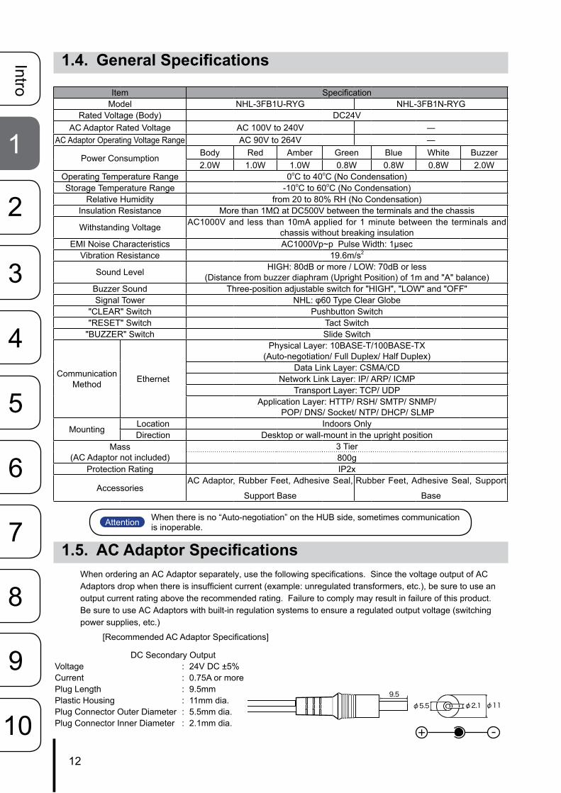
1.4. General Specifications
Item SpecificationModel NHL-3FB1U-RYG NHL-3FB1N-RYG
Rated Voltage (Body) DC24VAC Adaptor Rated Voltage AC 100V to 240V ―
AC Adaptor Operating Voltage Range AC 90V to 264V ―
Power Consumption Body Red Amber Green Blue White Buzzer2.0W 1.0W 1.0W 0.8W 0.8W 0.8W 2.0W
Operating Temperature Range 0oC to 40oC (No Condensation)Storage Temperature Range -10oC to 60oC (No Condensation)
Relative Humidity from 20 to 80% RH (No Condensation)Insulation Resistance More than 1MΩ at DC500V between the terminals and the chassis
Withstanding Voltage AC1000V and less than 10mA applied for 1 minute between the terminals and chassis without breaking insulation
EMI Noise Characteristics AC1000Vp~p Pulse Width: 1μsecVibration Resistance 19.6m/s2
Sound Level HIGH: 80dB or more / LOW: 70dB or less(Distance from buzzer diaphram (Upright Position) of 1m and "A" balance)
Buzzer Sound Three-position adjustable switch for "HIGH", "LOW" and "OFF"Signal Tower NHL: φ60 Type Clear Globe
"CLEAR" Switch Pushbutton Switch"RESET" Switch Tact Switch
"BUZZER" Switch Slide Switch
Communication Method Ethernet
Physical Layer: 10BASE-T/100BASE-TX(Auto-negotiation/ Full Duplex/ Half Duplex)
Data Link Layer: CSMA/CDNetwork Link Layer: IP/ ARP/ ICMP
Transport Layer: TCP/ UDPApplication Layer: HTTP/ RSH/ SMTP/ SNMP/
POP/ DNS/ Socket/ NTP/ DHCP/ SLMP
Mounting Location Indoors OnlyDirection Desktop or wall-mount in the upright position
Mass(AC Adaptor not included)
3 Tier800g
Protection Rating IP2x
AccessoriesAC Adaptor, Rubber Feet, Adhesive Seal,
Support Base
Rubber Feet, Adhesive Seal, Support
Base
1.5. AC Adaptor SpecificationsWhen ordering an AC Adaptor separately, use the following specifications. Since the voltage output of AC Adaptors drop when there is insufficient current (example: unregulated transformers, etc.), be sure to use an output current rating above the recommended rating. Failure to comply may result in failure of this product. Be sure to use AC Adaptors with built-in regulation systems to ensure a regulated output voltage (switching power supplies, etc.)
[Recommended AC Adaptor Specifications]
DC Secondary OutputVoltage : 24V DC ±5%Current : 0.75A or morePlug Length : 9.5mmPlastic Housing : 11mm dia.Plug Connector Outer Diameter : 5.5mm dia.Plug Connector Inner Diameter : 2.1mm dia.
9.5
φ2.1φ5.5 φ11
+ -
Attention When there is no “Auto-negotiation” on the HUB side, sometimes communication is inoperable.
user
生産終了

13
Intro
1
2
3
5
6
8
9
4
7
10
1.6. Description of FunctionalityThe following explains the functionality featured in this product.
1.6.1. Monitoring FunctionThis product can monitor the connectivity of a network device.
PING MONITOR SNMP v1v2cMonitors "keepalive" Network/Device signals Low-cost Monitor networking equipment.The Ping Monitor can monitor the connectivity for a maximum of 24 nodes with this product. If the monitor cannot obtain a response due to an abnormality in the circuit or equipment in the node, it judges an abnormal state and the Signal Tower warns a supervisor with light and sound.
A network monitor Signal Tower can tell an administrator about generated abnormalities and hindrances promptly as an SNMP command to respond with light and sound to an SNMP TRAP from the equipment (UPS, a printer, a router, a switch, etc.) via the network.
Among the 24 nodes, 12 nodes (13th to 24th) can be set up for more detailed monitoring parameters.
• It can distinguish the variable bindings.
• The registration of 16 groups (4 nodes per group) is possible.
SELF DIAGNOSISWith a user's creation of adding an application utilizing the transmission command, monitoring of the operating circumstances is possible. (Maximum of 4 nodes)
It is possible without control from the network, to instead use the test switch on the front of the product to check the functions of the Signal Tower and buzzer.
1.6.2. Transmission Commands
RSH HTTPcommand SOCKET TRANSMISSION
Controllable with General RSH protocol Controllable with HTTP Command Compatible with PHN Commands.
It is controllable by the flexible RSH protocol.With network integrated management software and various event monitoring tools, it is possible to trigger lighting, flashing, buzzer sound, and buzzer sound synchronized with the Signal Tower lights.
The Signal Tower and buzzer are controllable by a 2 byte command.* Compatible with the NHE-3 FB,
NHC-3 FB, NHM-3 FB and PHN-3FBE1.* Some functions are limited.
Event Occurance: Command Execution (Flashing Tier Lights, Buzzer Sound)PHN Example Code: 57H,17H
Event Occurance: Command Execution (Lighting Tier, Sounding Buzzer)RSH Example: rsh 192.168.10.1 -l root alert 111001
The commands are compatable with the new PNS.The Signal Tower and buzzer are controllable through the PNS command. All the different patterns are controllable.
Event Occurance: Command Execution (Lighting Tier, Sounding Buzzer)PNS Example Code: 58H,58H,53H,00H,00H,06H,01H,01H,01H,00H,00H,01H
user
生産終了

14
Intro
1
2
3
5
6
8
9
4
7
10
1.6.3. Transmission Function ConfigurationAn E-mail and TRAP transmission can be sent at the time of an event occurance.
E-mail TRANSMISSION
Send to a maximum of 8 selectable addressesA subject title and the text corresponding to the subject title can be created for the occurred event.It uses the authentication protocol for POP and SMTP.
SNMP v2cSNMP TRAP Transmission
The transmission can send an e-mail to a maximum of eight selectable addresses.
1.6.4. Setup and UpdatesWith a web setup tool, a detailed setup containing the IP Address of the product can be arranged. The firmware can also be upgraded remotely.
Fig. 1.6.1 Web Setup Tool Screen
user
生産終了

15
Intro
1
2
3
5
6
8
9
4
7
10
2. Installation Procedure and Flowchart
2.1. Network Signal Tower FlowchartThe Signal Tower offers two methods for configuring the network, "Manual Network Setup", and "Automatic Network Setup", which uses the DHCP server function.
2.1.1. Manual Network Setup
Signal Tower InstallationInstall this product on a level surface. If necessary, use the accessories (rubber foot, adhesive seal, support base) if needed when installing.
Power Supply InputConnect the AC Adaptor to this product Using the cable clamp will prevent the power cord from being unintentionally pulled out. (Refer to "2.4 Power Supply Input" on pg. 18)
LAN Connection Connect the LAN cable to this product.
Network Setup Set up the network environment configuration. Refer to "2.3 LAN Connection" on pg. 18 on how to setup the network.
Operation Settings Set up the detailed settings after the network environment has been configured
AttentionAfter completing the desired setup configuration, reboot this product by pressing the "reset" button, or removing the power for a few seconds and reapplying it for the changes to take effect.
Start-up This product is now ready to be used.
user
生産終了

16
Intro
1
2
3
5
6
8
9
4
7
10
2.1.2. Automatic Network Setup
Signal Tower InstallationInstall this product on a level surface. If necessary, use the accessories (rubber foot, adhesive seal, support base) if needed when installing.
Power Supply Input
Set the volume level switch to "LOW", then push the "TEST" switch while inserting the AC Adaptor plug into the power outlet. Use the cable clamp to prevent the power cord from being unintentionally pulled out. (Refer to "2.4 Power Supply Input" on pg. 18)
LAN Connection Connect the LAN cable to this product.
DHCP SetupIf this product is unable to connect with a DHCP Server, the Signal Tower status will start using the flashing pattern2 on all LED units, then will use the factory default network information set at the time of shipment. If that condition occurs, then either try again to connect with a DHCP Server, or manually set up the network. Refer to "2.3 LAN Connection" on pg. 18 on how to setup the network manually. If this product is able to connect to a DHCP Server, in order to know the network information, it is recommended to use Patlite's "PNS Manager" software for the NH Series.
Operation Settings Set up the detailed settings after the network environment has been configured
AttentionAfter completing the desired setup configuration, reboot this product by pressing the "reset" button, or removing the power for a few seconds and reapplying it for the changes to take effect.
Start-upThis product is now ready to be used.
MEMO Once the DHCP function is working, it will automatically start up the next time the product is turned on, or rebooted.
user
生産終了

17
Intro
1
2
3
5
6
8
9
4
7
10
2.2. Signal Tower InstallationThis product is to be intalled on a level surface. Also, use the included accessories (rubber feet, adhesive seal,
support base) when needed during installation.
Installation Example 1: Rubber Feet to prevent from sliding on a flat and slippery surface
Installation Example 2: Increasing surface area for a sturdy surface (before adding adhesive seals or rubber feet)
Attention
• When the adhesive seal is stuck on the product, it may Be difficult to remove and possibly peel off the remainder of the tape or paint. Be certain where the adhesive seals are to be placed before applying.
• Before placing the adhesive seal, remove dust, moisture, oil, etc. from the surface.
• Be sure to have the underside of the product in position, then peel the backing off the adhesive seal Before applying.
• Do not exert force to the Signal Tower area.
Attachment Area
Attachment Area[Installation]
Strip off the adhesive backing and stick the adhesive seal or rubber feet in the shaded area, indicated on the figure to the left.
Adhesive seal or rubber feet attachment area
[Installation]
1. Support Base is attached to the part indicated by the circle " ".
Support Base attachment area
2. Secure the Support Base with screws.
3. Use an M4 screw (or M4 bolt, etc.) to attach the Support Base onto the installation surface and tighten it with M4 nuts.
Adhesive seal or rubber feet attachment area
Attachment Area
Attachment Area
Clamp with 3 screws
user
生産終了

18
Intro
1
2
3
5
6
8
9
4
7
10
Installation Example 3: Permanent Surface Installation (screw-support base)
2.3. LAN ConnectionConnect the LAN cable to this product. Use either a category 5 LAN cable, or twisted-pair cable (UTP or STP) for this application.
2.4. Power Supply InputAttach the power plug for this product in accordance with the figure below. This product requires at least 30 seconds for the boot-up sequence to complete.
[Power Plug Mounting Instruction]
1. Remove the clamp for the power cable.2. Pass the power cable through the clamp.3. Insert the power plug into this product.4. Screw the clamp down to tighten it, and ensure enough slack (about 15mm) has been given to the power
cable.5. When power is supplied to this product, the lights will all turn on for about 1 second.
Fig. 2.3.1 Power Cable Mounting Diagram
! • Periodically check whether dust builds up on the electric socket and clean it if dust builds up. Ensure maintenance is performed to avoid dust build-up, because it may result in fire if too much dust is allowed to build up.
• Do not touch the electric socket with wet hands. Failure to comply will result in electric shock.Warning
[Installation]
1. Drill holes with a diameter of 4.5mm onto a flat surface to install.
2. Affix the Support Base accessory to this product.
※ Do not attach the rubber feet or adhesive seals when clamping the Support Base with screws.
3. Use an M4 screw (or M4 bolt, etc.) to attach the Support Base onto the installation surface and tighten it with M4 nuts.
125.5
100
84
74
4-φ4.5
Location for tapping 4.5mm holes
Front Direction of Product
RX/TX
LINK
24VDC
(15)mm
user
生産終了

19
Intro
1
2
3
5
6
8
9
4
7
10
2.5. Network SetupThe IP address at the time of factory shipments for this product is 192.168.10.1.
To change the IP address, first log in from a personal computer (henceforth, written as “PC”) web browser to access the settings for it.Log into the personal computer before changing the Network settings, so that the personal computer can com-municate with this product. Refer to "2.5.1 Logging In" on pg. 19 for the login method.
2.5.1. Logging InBy logging in from a web browser, access can be made to various setups for this product.In order to log in, the current IP address for this product needs to be entered into the address part of the web browser. (Refer to Fig. 2.5.1)
Fig. 2.5.1 Login Screen
<Web Browser Address Input> http://192.168.10.1/index.htm
When the login screen is displayed, go to the upper right of the screen where "Please Select Your Language" is located to select the preferred language.
Attention
• When the login screen is displayed, enter “patlite” in the password field, then click the “Logging In” button. The default password is set to “patlite”. Be sure to change the password to prevent any security breaching.
• If 10 minutes or more of no activity has elapsed after logging in, a time-out causes an automatic log out. When that occurs, log in again.
• If garbled characters occur and the screen is not displayed normally, change the character code for Unicode (UTF-8) to correct it.
• To prevent from being setup in two or more places, this product does not support double-login capabilities. To log in from another location, be sure the last computer is logged out.
MEMO The recommended browser should be equivalent to or higher than Internet Explorer 6 or Firefox 3.5.
MEMO
• If the login screen is not displayed, refer to “7. Troubleshooting”. Be sure to allow automatic page reading of Javascript by setting the browser to allow Javascript.
• Even if an address is entered, if the login screen is not displayed, changing the personal computer Network settings may Be necessary.
• When establishing a Network setting to re-connect , or to initialize it with the Web setup tool for this product, the contents are as followed:
The PC IP address is in the range of 192.168.10.2 to 254 Subnet mask is 255.255.255.0 For a default gateway direct connection, the setup is unnecessary. When connecting it to a network, be sure to check with the network administrator.
Select Language
user
生産終了
20
Intro
1
2
3
5
6
8
9
4
7
10
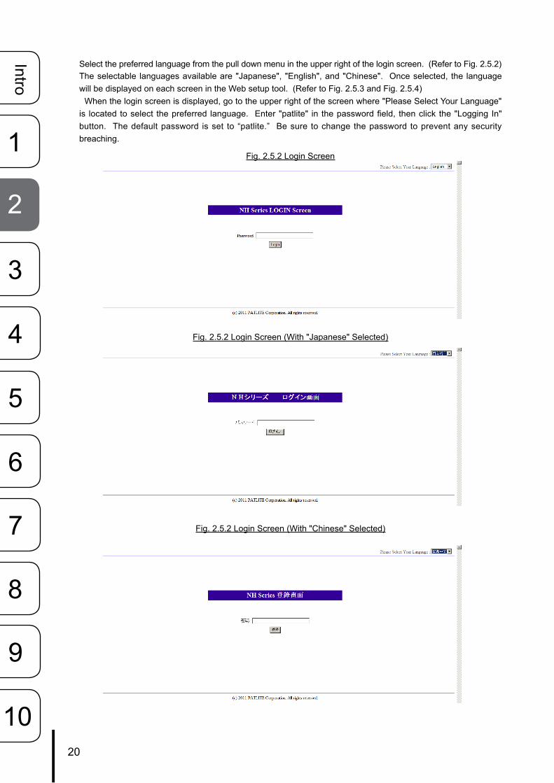
Select the preferred language from the pull down menu in the upper right of the login screen. (Refer to Fig. 2.5.2)The selectable languages available are "Japanese", "English", and "Chinese". Once selected, the language will be displayed on each screen in the Web setup tool. (Refer to Fig. 2.5.3 and Fig. 2.5.4) When the login screen is displayed, go to the upper right of the screen where "Please Select Your Language" is located to select the preferred language. Enter "patlite" in the password field, then click the "Logging In" button. The default password is set to “patlite.” Be sure to change the password to prevent any security breaching.
Fig. 2.5.2 Login Screen
Fig. 2.5.2 Login Screen (With "Japanese" Selected)
Fig. 2.5.2 Login Screen (With "Chinese" Selected)
user
生産終了

21
Intro
1
2
3
5
6
8
9
4
7
10
2.5.2. Setting the IP AddressAfter logging in, a web setup tool screen will be displayed (Refer to Fig. 2.5.2). The set up item list is displayed on the left-hand side of the screen. Click "System Configuration" to display the System Configuration screen.
Fig. 2.5.2 Web Setup Tool Screen
The network protocol can be changed on the System Configuration screen.[Setting Method]① . Select “Setup Manually” for the “IP Address Configuration Method” for this product.② . Set up the new IP address, then the net mask, default gateway, etc. if needed.③ . After the changes are completed, click the “Set” button for the changes to take effect.
Fig. 2.5.3 System Configuration Screen (for Manual Setup)
④ . After the “Set” button has been clicked, then when the Network Reboot Screen is displayed, click the “Network Reboot” button for the changes to take effect (Refer to Fig. 2.5.4).
⑤ . The execution of the network setup changes takes about 20 seconds. After the waiting time elapses, click “To the Login screen” to log back in (Refer to Fig. 2.5.1).
Fig. 2.5.4 Network Reboot Screen
④
⑤
Click "System Configuration"
①
②
②
③
user
生産終了

22
Intro
1
2
3
5
6
8
9
4
7
10
2.5.3. Setup VerificationIf the web browser address is reflecting the changed value of the IP address after clicking "To the Login screen", the setup of the new IP address has been successful. However, in cases where the preset value of other networks had been changed, be sure to enter the proper IP Address value where it was moved to in order to verify it in the System Configuration screen.
2.6. Network Setup with the DHCP FunctionThis product can access a DHCP Server to acquire network information.
2.6.1. Setup Method with the “TEST” Switch①. First, connect this product with the network environment to be used. (Refer to Fig. 2.5.3)② . Set the volume level switch to "LOW" before applying power to this product.③. Push the "TEST" Switch while inserting the power connector into the power outlet.④. The DHCP function takes effect when this product starts up.
2.6.2. Setup Method with the Web Setup Tool① . Select the IP Address Setup Method in the “System Configuration” screen as “Setup Automatically.”
(Refer to Fig. 2.6.1)② . Setup the device and host name, etc. as needed.③ .Click the “Set” button to save all changes and to activate them.④ . After the “Set” button is clicked, the Web Setup Tool changes to another screen to reboot the product;
click the “Network Reboot” icon to continue. (Refer back to Fig. 2.5.4)⑤ .Rebooting the network takes about 20 seconds.
Fig. 2.6.1 System Configuration Screen (for DHCP Automatic Setup)
Attention
If this product is unable to access a DHCP Server, it will return to the factory default network information. When the DHCP function is used, any future connections are started after the DHCP function setup is activated. When it is necessary to use the manual settings, use the Web Setup Tool and our PNS Manager software tool.
①
②
②
③
user
生産終了

23
Intro
1
2
3
5
6
8
9
4
7
10
2.7. Operation Settings2.7.1. Setting the Clock
The clock for this product can be set up. For setting the clock on this product, the following are two methods. ► Communicates with the PC clock to adjust the time when logging in. ► Communicates with an NTP server to adjust the time for this product.
Refer to "4.2 Clock Settings Screen" on pg. 53 for details on setting the time.
2.7.2. Normal Mode SettingsThe normal state of operation of this product can be displayed by using the "Normal Mode" setup. When this product is in its normal state of operation, the condition, such as the Green LED in the "ON" condtion, can be indicated on the Signal Tower, once the setup is complete. Refer to "4.13 Normal Mode Settings Screen" on pg. 76 for setting up the "Normal Mode" operating status of this product."
Attention If the power supply is not applied for more than a day and a half, the generated time may be cleared or delayed, and the clock should be reset again.
MEMO If the normal operating condition does not require any status lights to stay on, then there is no need to set this parameter up.
user
生産終了

24
Intro
1
2
3
5
6
8
9
4
7
10
3. Functionality DetailsThis section explains the available functions of this product, and their differences by the timing charts indicated below.
3.1. Signal Tower Control FunctionsThree kind of operating patterns for the LED Signal Tower is available, such as continuous lighting, flashing pattern1, and flashing pattern2.
3.2. Buzzer Control FunctionsFour kind of buzzer sounds, such as; buzzer pattern1, buzzer pattern2, buzzer pattern3, and buzzer pattern4, are available to distinguish a variety of conditions with the use of audible and visual warnings.
Buzzer Pattern 1 [Repetitive 250ms “ON”; 250ms “OFF”]
ON OFF ON OFF ON OFF ON OFF ON OFF ON OFF
Buzzer Pattern 2 [Repetitive 500ms “ON”; 500ms “OFF”]
ON OFF ON OFF ON OFF
Buzzer Pattern 3 [Repetitive 200ms “ON”, 50ms “OFF”, 200ms “ON”; 550ms “OFF”]
ON OFF ON OFF ON OFF ON OFF ON OFF ON OFF
Buzzer Pattern 4 [Continuous “ON”]
ON
Continuous “ON”
ON
Flashing Pattern 1 [Repetitive 500ms “ON”; 500ms “OFF”]
ON OFF ON OFF
Flashing Pattern 2 [Repetitive 80ms “ON”, 170ms “OFF”, 80ms “ON”, 170ms “OFF”; 500ms “OFF”]
ON OFF ON OFF ON OFF ON OFF
user
生産終了

25
Intro
1
2
3
5
6
8
9
4
7
10
3.3. Test FunctionsThe test function does a sequential check of the Signal Tower and buzzer, as well as checking other operations. The test operation lights up the tower lights and buzzer every second in steps; in the order of red, yellow, green, blue, white, and buzzer. When only a three-tiered Signal Tower is in use, a time delay between the third tier and buzzer sound will occur. Stopping the test operation can be performed 7 seconds after execution, when the buzzer test is complete (it takes about 1 second).
[Test Function Starting Method]
• When the Test Button is Depressed• When the "test" or "dotest" Commands are Received by the RSH
[Test Function Stopping Method]
• When the CLEAR Switch is Depressed• When the RSH receives a "Clear" or "Doclear" Command• From an SNMP "Clear" Command• From the Web Setup Tool of the Signal Tower Operation Screen• From a PNS Command sending a Clear Command Transmission• From the HTTP "clear" Command.
Fig. 4.3.1 Detailed View of Test Operation
Attention During the test operation, this product stops receiving everything else except the Ping monitoring application.
0 1 2 3 4 5 6 7 --- Time (sec)
Signal Tower Red
Signal Tower Amber
Signal Tower Green
Signal Tower Blue
Signal Tower Clear
Buzzer Sound Pattern 1
user
生産終了

26
Intro
1
2
3
5
6
8
9
4
7
10
3.4.1. SNMP SET Control Function for Signal TowerThe Signal Tower and buzzer are controllable through the SNMP-SET command. The following is an example to control the “on” and ”off” for the Signal Tower lighting and buzzer.
[Application Example 1] Turning the red unit on. Set it up as followed:
Object Object ID ValuecontrolLightControlState 1.3.6.1.4.1.20440.4.1.5.1.2.1.2.1 2controlLightControlTimer 1.3.6.1.4.1.20440.4.1.5.1.2.1.3.1 0
[Application Example 2] Operating the flashing pattern1 for the amber unit. Set it up as followed:
Object Object ID ValuecontrolLightControlState 1.3.6.1.4.1.20440.4.1.5.1.2.1.2.2 3controlLightControlTimer 1.3.6.1.4.1.20440.4.1.5.1.2.1.3.2 0
[Application Example 3] With the red unit flashing pattern 2, and amber flashing pattern 1, after 5 seconds, the green turns on with the buzzer synchronized with light pattern 2. Set it up as followed:
Object Object ID ValuecontrolLightControlState 1.3.6.1.4.1.20440.4.1.5.1.2.1.2.1 5controlLightControlTimer 1.3.6.1.4.1.20440.4.1.5.1.2.1.3.1 0controlLightControlState 1.3.6.1.4.1.20440.4.1.5.1.2.1.2.2 3controlLightControlTimer 1.3.6.1.4.1.20440.4.1.5.1.2.1.3.2 0controlLightControlState 1.3.6.1.4.1.20440.4.1.5.1.2.1.2.3 2controlLightControlTimer 1.3.6.1.4.1.20440.4.1.5.1.2.1.3.3 5controlLightControlState 1.3.6.1.4.1.20440.4.1.5.1.2.1.2.6 3controlLightControlTimer 1.3.6.1.4.1.20440.4.1.5.1.2.1.3.6 0
3.4.2. SNMP GET Status Acquisition Function for Signal TowerThe Signal Tower status is acquisitioned through the SNMP GET command. The following is an example of a Signal Tower status acquisition.
[Application Example 1] The red is lighting, the amber is flashing pattern 1, green is off, blue is flashing pattern 2 and white is on. The buzzer sound pattern 3 is an example of acquisitioning the Signal Tower status.
Object Object ID GET ValuecontrolLightCurrentState 1.3.6.1.4.1.20440.4.1.5.1.2.1.4.1 2controlLightCurrentState 1.3.6.1.4.1.20440.4.1.5.1.2.1.4.2 3controlLightCurrentState 1.3.6.1.4.1.20440.4.1.5.1.2.1.4.3 1controlLightCurrentState 1.3.6.1.4.1.20440.4.1.5.1.2.1.4.4 4controlLightCurrentState 1.3.6.1.4.1.20440.4.1.5.1.2.1.4.5 2controlLightCurrentState 1.3.6.1.4.1.20440.4.1.5.1.2.1.4.6 4
3.4.3. TRAP Reception FunctionWith the set-up containing the designated sender or with the OID included, the TRAP is received. When the TRAP transmission is sent, the information, e-mail transmission and time of reception according to the Signal Tower can be included. For further details on the setting method, refer to "4.9 TRAP Reception Configuration Screen" on pg. 65.
3.4.4. TRAP Transmission FunctionThe TRAP is sent to the designated sender when the TRAP Reception Configuration for this product is done. For further details on the setting method, refer to "4.4 SNMP Configuration Screen" on pg. 57.
3.4. SNMP FunctionThis product can control the Signal Tower, and acquisition the status and TRAP reception using the SNMP functions. For customers who purchased this product, download the MIB file for use with the SNMP functions. Furthermore, for details on the setting method of this product, refer to "4.4 SNMP Configuration Screen"
Attention Set the community name for the TRAP transmission of this product to “public.”
user
生産終了

27
Intro
1
2
3
5
6
8
9
4
7
10
3.5. PHN Command Reception FunctionThe Socket Transmission control protocol used with the PHN Series (ex. PHN-3FBE1) is being used to control this product. The Socket Transmissions protocol can be selected from either "TCP" or "UDP", and a port number from"10000" to "65535" can be set. The following explains the PHN commands used by the Socket Transmission function. For further details of the setting method, refer to "4.5 Socket Transmission Setup Screen" on pg. 58.
Writing CommandTransmitting the following data controls the Signal Tower and buzzer.
"W" (57H) Operation Data 8 Bits0 1 0 1 0 1 1 1 Reference of Operation Data Contents
Details of Operation Data
Signal Tower Flashing Buzzer Signal Tower Lighting
Green Amber Red Pattern 2 Pattern 1 Green Amber Red
[Example of sending the writing command transmission]
To operate the Signal Tower with a "red lighting, amber flashing, green lighting, and buzzer pattern2", enter into the operation data a "1" bit to make it turn ON and a "0" bit to make it turn OFF.
[Command]
"W" (57H) Operation Data (55H)0 1 0 1 0 1 1 1 0 1 0 1 0 1 0 1
Response from this product
Normal response (output response)
“A”(41H)
"C"(43H)
"K"(4BH)
1 Byte 1 Byte 1 Byte
Response Error (output failed)
“N”(4EH)
“A”(41H)
"K"(4BH)
1 Byte 1 Byte 1 Byte
Attention
• The following are Signal Tower Buzzer and lighting channels that are not controllable by The PHN Command for this product. When controlling, use other methods available, such as PNS Commands and RSH Commands.• Signal Tower red, yellow and green flashing pattern 2• Signal Tower blue and white lighting, flashing pattern 1 and flashing pattern 2• Buzzer Pattern 3, Buzzer Pattern 4
• In case lighting and flashing are turned on by a PHN Command, priority is given to the lighting command. Priority is given to the pattern 1 command when buzzer patterns are turned on simultaneously.
user
生産終了

28
Intro
1
2
3
5
6
8
9
4
7
10
Reading Command
The current operating status of this product is requested.
“R” (52H) 8 Bit0 1 0 1 0 0 1 0
Response from this product• Normal response (output response)
“R” (52H) 8 Bit Signal Tower Flashing Buzzer Signal Tower Lighting0 0 0 0 0 0 0 0 Green Yellow Red Pattern 1 Pattern 2 Green Yellow Red
Response from this product
Signal Tower Flashing Buzzer Signal Tower Lighting
Green Amber Red Pattern 2 Pattern 1 Green Amber Red
[Example for a data acquisition response]Signal Tower with Red/Amber Lighting: Response Data: 0000 0011 = 03H
Responding Data (03H) 8 bit0 0 0 0 0 0 1 1
Signal Tower with Green Flashing and Buzzer Pattern1 Response Data: 1000 1000 = 88HResponding Data (88H) 8 bit
1 0 0 0 1 0 0 0
• Response Error (output failed)“N”
4EH“A” 41H
“K” 4BH
1 byte 1 byte 1 byte
Attention
• The following are Signal Tower buzzer and lighting channel operating states that are not controllable from a PHN Command for this product. Use other methods, such as PNS Commands or RSH Commands to acquisition.• Signal Tower red, yellow and green flashing pattern 2• Signal Tower blue and white lighting, flashing pattern 1 and flashing pattern 2• Buzzer Pattern 3, Buzzer Pattern 4
user
生産終了

29
Intro
1
2
3
5
6
8
9
4
7
10
3.6. PNS Command Reception FunctionThe PNS command is an exclusive PATLITE command protocol, which controls the Patlite NHL Series Signal Tower and buzzer. The Socket Transmissions protocol can be selected between "TCP" and "UDP", and the communication ports are available from "10000" to "65535".
The following explains the PNS commands being used with a Socket Transmission setup.
(*) This function is not available for the NHC/NHE/NHM-3FB Models.
Writing Command
The following is the protocol used to transmit data to control the Signal Tower and buzzer. By entering the proper data, the buzzer and LED unit operation from the Signal Tower can be controlled.
Product Classification "XX”
Identifier "S" (Empty) Data Size Data Control Bits 6 bit (Refer to table below)
58H 58H 53H 00H 00H 06HSignal Tower
BuzzerRed Amber Green Blue White
Product ClassificationThe product is classified in "XX".
Identifier"S" is used.
Data Size
Capacity of data control bits (data to transmit)Data Transmission Configuration
Data Control Bits 6 bit
Signal TowerBuzzer
Red Amber Green Blue White
[Signal Tower] [Buzzer]Non-flashing 00H Stop 00H
Flashing 01H Buzzer Pattern 1 01HFlashing Pattern1 02H Buzzer Pattern 2 02HFlashing Pattern2 03H Buzzer Pattern 3 03H
No Change 09H Buzzer Pattern 4 04HNo Change 09H
[Example of sending the writing command transmission]
When writing a command for the Signal Tower to operate with "Red Lighting + Amber Flashing Pattern1+ Green Flashing Pattern2+ Buzzer Pattern4"
[Command]
Product Classification
"XX”
Identifier "S" (Empty) Data Size Data Control Bits 6 bit
58H 58H 53H 00H 00H 06H 01H 02H 03H 00H 00H 04H
user
生産終了

30
Intro
1
2
3
5
6
8
9
4
7
10
Response from this productNormal response (output response)
ACK
06H
Response Error (output failed)
NAK
15H
Reading CommandTransmitting the following data will execute the status of the Signal Tower and buzzer.
Product Classification "XX”
Identifier "G" (Empty) Data Size
58H 58H 47H 00H 00H 00H
Response from the Read Command
Data Control Bits 6 bit
Refer to "Capacity of Data Control Bits"
[Example for a data acquisition response]
Signal Tower “Red: Flashing Pattern 1, Amber: Flashing Pattern 2, Green: Lighting with no buzzer” is read, and the response from this product is indicated in the following table after the command trans-mission.
Data Control Bits 6 bit
Red Amber Green Blue White Buzzer
02H 03H 01H 00H 00H 00H
Status Condition "Clear" CommandThe change in the operating state for this product is made when setting up the "Normal Mode Settings".
Product Classification "XX”
Identifier "C" (Empty) Data Size
58H 58H 43H 00H 00H 00H
user
生産終了

31
Intro
1
2
3
5
6
8
9
4
7
10
3.7. E-mail Sending FunctionIt can transmit up to eight registered e-mail addresses. The subject and message of the transmitting mail can be registered for 16 different situations per subject title to be transmitted via e-mail to the 8 registered addresses. The user authentication method during transmission can be selected from either "SMTP Authentication", "POP Authentication", or "No Authentication". Refer to "4.6 E-Mail Settings Screen" on pg. 59 and "4.7 E-Mail Message Settings Screen" on pg. 60 for further details of the setting method.
3.7.1. E-mail Message ContentsThe registration of 16 subjects and 16 messages for transmitting mail can be selected in combination when sending an alert message of up to 8 registered E-mail addresses. The e-mail text would include the equip-ment name, its location, the sender, the message, and supplementary information indicated in table 3.7.1 be-low. The contents of the registered subject is indicated.If the 17th fixed e-mail subject title “NH-ORIGINAL” is selected, the equipment location, message transmis-sion time stamp, and event contents is indicated. If the 17th e-mail subject text is selected as “None”, nothing is indicated in the text.
[Registered subject title when selecting No. 17 is "NH-ORIGINAL"]
System Location: YY/MM/DD hh:mm Contents of the event: NameTable 3.7.1 Fixed Written Subject Contents
Generated Event Indicated Event Contents Indicated NameTRAP Reception Blank TRAP Monitor Setup Registered Group NameExecute "Clear" by pushbutton “: CLEAR-Switch” BlankExecute "Clear SNMP" “: CLEAR-SNMP” BlankExecute "Clear RSH" “: CLEAR-RSH” Blank
Ping Monitor Abnormality Detection “: PING-Error” The equipment name registered in the Ping Monitoring Configuration
Ping Monitor Recovery Detection “: PING-Recover” The equipment name registered in the Ping Monitoring Configuration
Application Monitor Abnormality Detection “: APP-Error” The equipment name registered in the Application
Monitoring ConfigurationApplication Monitor Recovery Detection “: APP-Recover” The equipment name registered in the Application
Monitoring ConfigurationExecute “RSH Command” “: RSH-Executes” Blank“TEST” button pressed “: TEST-Switch” BlankSLMP Operation “SLMP-Action” BlankSLMP Error Response “SLMP-Error” Blank
user
生産終了

32
Intro
1
2
3
5
6
8
9
4
7
10
Table 3.7.2 Mail Subject Event Contents
Generated Event Indicated Event Contents Supplementary Information Displayed
TRAP Reception TRAP was Received Group Name and Designated Sender IP Address<Group Name:> "IP Address"
Execute "Clear" by pushbutton "CLEAR " switch was pushed NoneExecute "Clear SNMP" "CLEAR" was executed by SNMP None
Execute "Clear RSH" "CLEAR" was executed by RSH Sender's IP Address"IP Address"
Ping Monitor Abnormality Detection Ping Monitor Abnormality was detected Detected device name and registration
<Device Name:>"Registration Address"Ping Monitor Recovery Detection Ping Monitor Recovery was detected Detected device name and registration
<Device Name:>"Registration Address"Application Monitor Abnormality Detection
Application Monitor Abnormality was detected
Detected device name IP Address and port number<Device Name:>"Registration Address: Port Number"
Application Monitor Recovery Detection
Application Monitor Recovery was detected
Detected device name IP Address and port number<Device Name:>"Registration Address: Port Number"
Execute “RSH Command” An “RSH Command” was executed Sender's IP Address"IP Address"
“TEST” button pressed The “TEST” button was pressed None
SLMP Operation The SLMP Operation was executed Concurring Device name and address registration<Device Name:>"Registration Address"
SLMP Error Response An SLMP Error was detected Device name and address registration of source<Device Name:>"Registration Address"
user
生産終了

33
Intro
1
2
3
5
6
8
9
4
7
10
3.8. RSH Command Function3.8.1. RSH Commands
RSH (remote shell) is a CUI program which executes a shell command from one computer to another computer via a computer network. The following explains how to control the Signal Tower via the RSH command.The command syntax which this product can receive is indicated below. For the setting method of the "RSH Command Connection Authentication /Operation after Reception", refer to "4.8 RSH Command Configuration Screen" on pg. 62.
Table 3.8.1 Receivable Commands
Command Contentsalert Controls Signal Tower/Buzzerclear / doclear Returns to Normal Modestatus Acquisitions the Signal Tower Statustest / dotest Executes a Self-test
Using the RSH CommandsCommand Input Method
rsh IP address [-l Login Name ] Command [Option]Command Input Method (when the designated sender address is inactive)
rsh IP address -l Common login name when designated sender address is inactive Command [Option]
alert Command
Contents : To control the Signal Tower and buzzer.Syntax : alert rygbcz [sec]Return Value : Status after command is executedOption : Refer to Table 3.8.2.
Table 3.8.2 RSH Command Option Explanation
Type Explanationrygbc Turning on and off of the Signal Tower LED Units and Buzzer Alarms
r r: Red (0) Light Off (1) Lighting (2) Flashing Pattern 1 (3) Flashing Pattern 2 (9) No Change
y y: Amber (0) Light Off (1) Lighting (2) Flashing Pattern 1 (3) Flashing Pattern 2 (9) No Change
g g: Green (0) Light Off (1) Lighting (2) Flashing Pattern 1 (3) Flashing Pattern 2 (9) No Change
b b: Blue (0) Light Off (1) Lighting (2) Flashing Pattern 1 (3) Flashing Pattern 2 (9) No Change
c c: White (0) Light Off (1) Lighting (2) Flashing Pattern 1 (3) Flashing Pattern 2 (9) No Change
z z: Buzzer Alarm (0) Buzzer Off (1) Pattern 1 (2) Pattern 2 (3) Pattern 3 (4) Pattern 4 (9) No Change
secRestores the Signal Tower to its previous command status. When the time exceeds the set value, it returns to the previous Signal Tower condition. The time can be set from zero to 99. The status will not return if no input or a zero has been entered.
[Command Transmission Example]
Ex. 1) A product with an IP address of [192.168.10.10] and designated sender user name of "root", with Red Lighting, Green Lighting and Buzzer Pattern2 On:
rsh 192.168.10.10 -l root alert 101002
Ex. 2) A product with an IP address of [192.168.10.10] and a common login name of "patlite", with Red Lighting and White Flashing Pattern2:
rsh 192.168.10.10 -l patlite alert 100020
MEMO
: indicates a space. [ ]: indicates an option.The use of login abbreviations for the login name is limited to when the account name and the PC are registered (in half-width alphanumeric characters) on the command reception screen which transmits the RSH command.
user
生産終了

34
Intro
1
2
3
5
6
8
9
4
7
10
[Command Transmission Example - cont.]
Ex. 3) A product with an IP address of [192.168.10.10] and a designated sender user name of "root", with the Red Lighting, Amber Flashing Pattern2, Green Lighting and Buzzer Pattern3, all on for 20 seconds:
rsh 192.168.10.10 -l root alert 131003 20
Ex. 4) A product with an IP address of [192.168.10.10] with Red Lighting, Amber Flashing Pattern2, Green Lighting, Buzzer Pattern3, all on for 20 seconds (no login name)
rsh 192.168.10.10 alert 131003 20
clear/doclear Command
Contents : To clear the Signal Tower and Buzzer, returning to the Normal Mode.Syntax : clear [-p] [-z] , doclear [-p] [-z]Return Value : Status after command is executedOption : Refer to Table 3.8.3.
Table 3.8.3 clear/doclear Command Option Explanation
Type Explanation-p Turn off all Signal Tower Lights-z Turn off Buzzer Alarm
None Return to Normal Mode
[Command Transmission Example]Ex. 1) A product with an IP address of [192.168.10.10] and a common login name of "patlite",
with all the Signal Tower Lights turned off:rsh 192.168.10.10 -l patlite clear -p
with all the Signal Tower Lights turned off (no login name):rsh 192.168.10.10 clear -p
Ex. 2) A product with an IP address of [192.168.10.10] and a designated sender user name of "root", with the Buzzer alarm turned off:
rsh 192.168.10.10 -l root doclear -z
with the Buzzer alarm turned off (no login name):rsh 192.168.10.10 clear -z
Ex. 3) A product with an IP address of [192.168.10.10] and a designated sender user name of "root", with all the Signal Tower Lights and Buzzer returned to the Normal Mode:
rsh 192.168.10.10 -l root clear
with all the Signal Tower Lights and Buzzer returned to the Normal Mode (no login name):rsh 192.168.10.10 clear
status Command
Contents : Return the present status of the Signal Tower and buzzer to Normal Mode.Syntax : statusReturn Value : Current Condition rygbcz
[Command Transmission Example]A product with an IP address of [192.168.10.10], with the condition of "Red tier flashing pattern 1, Green is
lighting and buzzer pattern 3 is on":Ex. 1) The designated sender user name for the Signal Tower status acquisition is "patlite".
rsh 192.168.10.10 -l patlite statusResponse: 201003
Ex. 2) The login name was omitted for status acquisition of the Signal Tower.rsh 192.168.10.10 status
Response: 201003
user
生産終了

35
Intro
1
2
3
5
6
8
9
4
7
10
test/dotest Command
Contents : Executes confirmation of the Signal Tower and buzzer operation in sequence order of Red, Amber, Green, Blue, White and Buzzer Pattern1.
Syntax : test , dotestReturn Value : None
[Command Transmission Example]Ex. 1) A product with an IP address of [192.168.10.10] can verify operation of the Signal Tower.
The common login name for the Signal Tower status confirmation is "patlite".rsh 192.168.10.10 -l patlite test rsh 192.168.10.10 -l patlite dotest
Signal Tower status confirmation is executed (no Login Name):rsh 192.168.10.10 test rsh 192.168.10.10 dotest
Ex. 2) A product with an IP address of [192.168.10.100] can verify operation of the Signal Tower. The designated sender user name for the Signal Tower status confirmation is "root"
rsh 192.168.10.100 -l root test rsh 192.168.10.100-l root dotest
Signal Tower status confirmation is executed (no Login Name):rsh 192.168.10.100 test rsh 192.168.10.100 dotest
3.8.2. RSH Alert Timer Reset FunctionThe RSH alert timer reset function is capable of being selected for "Shared" or "Individual" when setting up the timer function for the Signal Tower lights and buzzer control. (Refer to "4.8 RSH Command Configuration Screen" on pg. 62)
Shared : Each Signal Tower tier and buzzer are controlled by a common timer.Individual : Each Signal Tower tier and buzzer are controlled by individual timers.
user
生産終了

36
Intro
1
2
3
5
6
8
9
4
7
10
The following explains the difference in operation between the "Shared" and "Individual" selection for this product when setting up the alert timer reset function.
[Procedure]Ex. 1) Transmit the command to the products IP address [192.168.10.10]. Use the login name [root], then
execute the following commands of [Red Lighting; other colors no status change; no buzzer status change] for 10 seconds.
rsh 192.168.10.10 -l root alert 199999 10
Ex. 2) 3 seconds after "Ex.1)", transmit the command to the products IP address [192.168.10.10]. Use the login name [root], then execute the following commands of [Green Lighting; other colors no status change; no buzzer status change] for 10 seconds.
rsh 192.168.10.10 -l root alert 991999 10
Alert Timer Reset Function set for "Shared"The execution affects the influence of the timer when the command is sent.
Alert Timer Reset Function set for "Individual"The execution does not affect the influence of the timer when the command is sent.
Example 2 Operation
Example 2 Operation
10 sec0 sec 3 sec 13 sec[Elapsed Time]
10 sec0 sec 3 sec 13 sec[Elapsed Time]
Remaining time changes from 7 seconds to 10 seconds
Remaining time is 7 seconds
Red status “No Change”, Green starts at 10 seconds, with a remainder of 10 seconds
Red stays “ON” Red and Green turn “OFF”
The red LED starts at 10 seconds, with a remainder of 10 seconds
Red turns “OFF” Green turns “OFF”The red LED starts at 10 seconds, with a remainder of 10 seconds
Red status “No Change”, Green starts at 10 seconds, with a remainder of 10 seconds
Example 1 Operation
Example 1 Operation
user
生産終了

37
Intro
1
2
3
5
6
8
9
4
7
10
3.9. Ping Monitoring FunctionThe Ping Monitoring Function is used to monitor the response of a device in a network, by sending pings for up to 24 devices. Each device may be set to have a unique ping cycle and, if there is a failure in response, a unique light and buzzer status to indicate when there is a failure to respond. With a maximum of 24 devices that can be monitored, the first 12 devices include a number of 60 second ping cycles in the test. For the remaining 12 devices (13-24), the Ping Monitoring Function has a few more adjustable parameters, “Ping test cycle period” to send from 1 to 600 seconds worth of Pings for monitoring, and “Pings per test cycle” to have from 1 to 3 Pings to send for each monitoring cycle sent. Refer to "4.10 Ping Monitoring Configuration Screen" on pg. 68 for details on the setting method.
3.9.1. Ping Monitoring Function (Nodes 1 to 12)For devices numbered 1-12, one Ping is fixed to be sent every 60 seconds. If there is no Ping response during the one minute that the response exceeds the number entered in the “Cycle count Error threshold (1-30)” parameter, an “abnormality” judgement occurs, and the result causes a status change based on the Ping Monitor Settings, which could include triggering lights, buzzer and other actions.Figure 3.9.1 below shows the behaviour when the “Cycle count Error threshold (1-30)” is set to "1.”
Fig. 3.9.1 Ping Monitoring Function (For Ping Monitor Setting Screen No. 1 to 12)
Ping Monitoring Period
Judgement: Abnormal
・One count per Transmission・With the preset value set as "1",
judgement is a Ping monitor abnormality.
・Changes to Abnormality Detection Condition
When there is a Ping response during a Ping Detection Abnormality period
Judgement: Recovery
When there is a Ping response during a Ping monitoring period
Judgment: No Abnormalities
The Ping monitor starts after the
completion of the Web setup tool.
The monitoring condition continues
When there is no Ping response during a Ping monitoring period
・Monitor Recovery Condition
・Condition returns to a monitoring state
Ping Monitor Condition
Ping Monitoring Abnormal Condition Ping Monitor Condition
PingTransmission
PingReplyMonitoring
Side
NHL Side
Attention
If a “Clear” operation (Pressing the “Clear” switch, sending an RSH-PRSH “Clear” command, sending a PNS “Clear” command in accordance to the condition, transmit an SNMP Clear, execute an HTTP "clear" command, or execute a “Clear” from the Signal Tower operation screen) is executed when a monitoring detection is active, it will return to the monitoring condition from the abnormality detection status.Even with the double-push clear setting, once the clear button is pressed, the status will return to the monitoring condition.For other functions outside the “Clear” operation, because they do not control the abnormality detection condition, the Ping monitor abnormality status will remain uncleared. Any operations outside a “Clear command may be due to the Ping Monitoring Function which continues to remain active when it is in operation.
user
生産終了
38
Intro
1
2
3
5
6
8
9
4
7
10
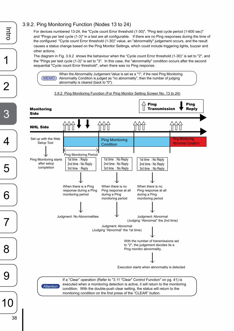
3.9.2. Ping Monitoring Function (Nodes 13 to 24)For devices numbered 13-24, the "Cycle count Error threshold (1-30)", "Ping test cycle period (1-600 sec)" and "Pings per test cycle (1-3)" in a test are all configurable. If there are no Ping responses during the time of the configured "Cycle count Error threshold (1-30)" value, an "abnormality" judgement occurs, and the result causes a status change based on the Ping Monitor Settings, which could include triggering lights, buzzer and other actions.The diagram in Fig. 3.9.2 shows the behaviour when the “Cycle count Error threshold (1-30)” is set to "2", and the "Pings per test cycle (1-3)" is set to "3". In this case, the "abnormality" condition occurs after the second sequential "Cycle count Error threshold", when there was no Ping response.
3.9.2 Ping Monitoring Function (For Ping Monitor Setting Screen No. 13 to 24)
1st time : Reply2nd time : No Reply3rd time : Reply
1st time : No Reply2nd time : No Reply3rd time : No Reply
1st time : No Reply2nd time : No Reply3rd time : No Reply
PingTransmission
PingReply
Set up with the Web Setup Tool
MonitoringSide
NHL Side
Ping Monitoring starts after setup completion
Ping MonitoringCondition
Ping Monitoring Abnormal Condition
Ping Monitoring Period
Judgment: No Abnormalities
When there is a Ping response during a Ping monitoring period
Judgment: Abnormal(Judging “Abnormal” the 2nd time)
Judgment: Abnormal(Judging “Abnormal” the 1st time)
With the number of transmissions set to "2", the judgement decides its a Ping monitor abnormality.
Execution starts when abnormality is detected
When there is no Ping response at all during a Ping monitoring period
When there is no Ping response at all during a Ping monitoring period
MEMOWhen the Abnormality Judgement Value is set as a "1", if the next Ping Monitoring Abnormality Condition is judged as "no abnormality", then the number of judging abnormality is cleared (back to "0").
Attention
If a “Clear” operation (Refer to "3.11 "Clear" Control Function" on pg. 41) is executed when a monitoring detection is active, it will return to the monitoring condition. With the double-push clear setting, the status will return to the monitoring condition on the first press of the “CLEAR” button.
user
生産終了

39
Intro
1
2
3
5
6
8
9
4
7
10
3.9.3. Ping Monitoring Function (“Clear” Command Outside Sources)(When a "Clear" execution from an outside source is requested at the time of abnormality detection)The following is an example for the procedure when an executed "Clear" command is received from an outside source while the Ping Monitoring function detects an abnormality ("Clear" command executed via the "Clear" switch, RSH "Clear" Command, PNS "Clear" command, SNMP "Clear" Command, HTTP "clear" command, or a "Clear" Command from the Web Setup Tool).
Example) When a "Clear" command is transmitted from an outside source at the time an abnormality is detected by the Ping Monitor.
1. From the monitoring condition, when a monitoring abnormality occurs, the condition of the Signal Tower changes at the time of detecting the abnormality.
2. If a "Clear" command is received during the abnormality detection, the status of abnormality detection will be cleared and it will return to its normal mode.
3. If there is a Ping response from the next Ping monitor execution, the monitoring condition will continue as normal. If there is no response, the condition will immediately return to the abnormality detection mode.
Fig. 3.9.3 Setting screen 21 to 24 operation flow-chart example
Ping Monitoring Period
Abnormality detection and judgment
Execution starts when abnormality is detected
When abnormality is detected, a "Clear" command is executed
The condition of the detected abnormality will be in the "Clear" status.
When there is a Ping response during the monitoring condition
The monitoring condition continues
MonitoringSide
NHL Side
Set up with the Web Setup Tool
Ping Monitoring starts after setup
completion
PingTransmission
When there is no Ping response during the monitoring condition
"Clear" Execution
"Clear"Execution
Condition returns to a monitoring state
If the abnormality is cleared from the "Clear" command, the "Ping Recovery" operation is not necessary
An abnormal condition will be detected
When there is no Ping response during the ping monitoring period
Ping MonitoringCondition
Ping Monitoring Abnormal Condition
Ping MonitoringCondition
Ping Monitoring ConditionPing Monitoring Abnormal Condition
Attention In cases where it returns to a monitoring condition from a "Clear" command, it will not branch to the "Ping Recovery" operation from an abnormal detection.
user
生産終了

40
Intro
1
2
3
5
6
8
9
4
7
10
3.10. Application Monitoring FunctionBy creating an additional transmission command for a customer's application, this product can monitor the response of the application by receiving the data from it.If data is not received within the monitoring cycle period, it makes a judgement that the communication has become abnormal, and at the time of the abnormality, sends a status change to the Signal Tower. After a generated event, if data is received from the monitored candidate, it will detect a recovery from the abnormal operation. Refer to "4.11 Application Monitoring Configuration Screen" on pg. 72 for details on the setting method.As an example, with a monitoring cycle of 30 seconds, the received data from the application is monitored.
1. After the setup is complete and it receives data from the address monitoring point, the monitoring will commence.
2. If data is received within the monitoring cycle of 30 seconds, it will be judged as having no abnormalities.3. However, if the data is not able to be received within the allotted cycle (30 seconds in this example), it
makes a judgment of abnormality. Once judged as abnormal, the operation at the time of the detected abnormality is carried out.
4. If data is received from the application after detecting a generated event of abnormality, it will detect a recovery from the abnormality. The operation at the time of recovery from the abnormal condition will return to its monitoring condition again.
Fig. 3.10.1 Detailed Example of Application Monitoring
Application Monitor Side
Application Monitor re-start
Application Monitoring Period
Application Monitoring lapsed time reset
When data couldn't be received during a
monitor reception period
Application Monitoring abnormal detection start
Monitoring Condition
Data Transmission
Data Response
Application Monitoring Period
Monitor Starting Point
Monitoring Abnormal Condition Monitoring Condition
When data was received during the detection of an
abnormality
Application Monitor Recovery Start Execution
Application Monitoring Period
Application Monitoring Condition
NHL Side
Attention
• If monitoring is started from the time of receiving data and the connection is cut-off, monitoring is stopped.
• Recovery from an abnormal operation can only occur if a monitored Condition was detected as abnormal.
• Transmit data to the receive port of the application Monitor function of this product by a TCP protocol.
• The same port number cannot Be set as a Socket Transmission function and an application Monitor function.
MEMO It monitors from the use of voluntary data received.
user
生産終了

41
Intro
1
2
3
5
6
8
9
4
7
10
3.11. "Clear" Control FunctionThe "Clear" operation is accessible from the following commands; "Clear" command executed via the "Clear" switch, RSH "Clear" Command, PNS "Clear" command, SNMP "Clear" Command, HTTP "Clear" command, or a "Clear" Command from the Web Setup Tool. Refer to "4.12 “Clear” Control Configuration Screen" on pg. 75 for details on the setting method.
3.12. Normal Mode SettingsThe Signal Tower can be set up to display its "normal state of operation", based on the user's preference for lights and buzzers to be on when no warning conditions occur. Refer to "4.13 Normal Mode Settings Screen" on pg. 76 for details on setting it up via the Web Setup Tool.
3.13. Reinitialization FunctionFrom the Web Setup Tool, this unit can be reinitialized to revert all settings back to the default (factory) settings, while leaving the network settings as is when resetting the other settings. Refer to "4.18 Reinitialization Setup Screen" on pg. 86 for details on the setting method.Also, it can initialize the network settings of this product to its default settings in addition to returning the other settings to their default settings.
【Method for full initialization, including the network setup】1. Set the volume level switch to the "HIGH" position.2. Turn on the power supply while simultaneously pushing the "TEST" switch.3. After the Signal Tower does an all-point lighting test, the Signal Tower lights go out. Release the switch
after all the Signal Tower lights are out.4. The Signal Tower will light up again about 1 minute after. The Signal Tower will then flash Pattern1
afterward to indicate the initialization is complete.5. Push the clear button to stop the flashing. ※ If the Ping monitor etc. are set up, an abnormal operation detection may occur.
【Method for initialization to revert the network settings back to the factory default value】1. Set the volume level switch to the "OFF" position.2. Turn on the power supply while simultaneously pushing the "CLEAR" and "TEST" switch.3. After the Signal Tower does an all-point lighting test, the buzzer will make an audible sound. Release the
switch after the buzzer sounds. 4. When the Signal Tower goes out, it indicates the completion of initilization.
Table 3.13.1 Setting after default function executed
Execution MethodWeb Setup Tool NH Unit Controls
Item "Network Reinitialized and checked
"Network Reinitialized without being checked
Only Network Settings Reinitialized
Factory Default Conditions
Network Setting Set to default value Setting is Saved Set to default value Set to default valuePassword Set to "patlite" Set to "patlite" Set to "patlite" Set to "patlite"
Setup Menu (excluding Password &
Network menu)Set to default value Set to default value Setting is Saved Set to default value
Function Set to default value Set to default value Setting is Saved Set to default valueStatus/Operation Log Erased Erased Erased Erased
Attention Do not overexert pressure to the “CLEAR” switch, “TEST” switch and volume level switch. Failure to comply may damage the unit.
MEMO "Network Setup" refers to the "IP address for this product, Net Mask, Default Gateway, DNS server address and Host Name" parameters in the System Configuration Screen.
user
生産終了
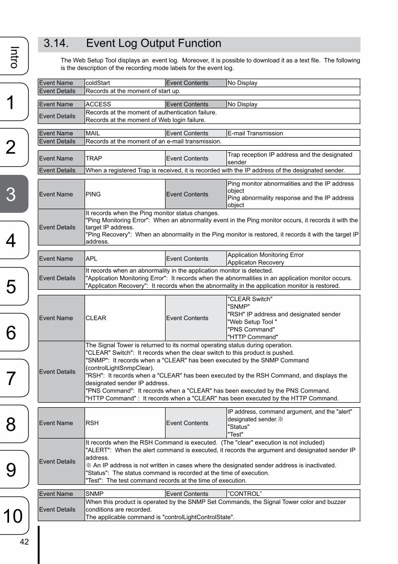
42
Intro
1
2
3
5
6
8
9
4
7
10
3.14. Event Log Output FunctionThe Web Setup Tool displays an event log. Moreover, it is possible to download it as a text file. The following is the description of the recording mode labels for the event log.
Event Name coldStart Event Contents No DisplayEvent Details Records at the moment of start up.
Event Name ACCESS Event Contents No Display
Event Details Records at the moment of authentication failure.Records at the moment of Web login failure.
Event Name MAIL Event Contents E-mail TransmissionEvent Details Records at the moment of an e-mail transmission.
Event Name TRAP Event Contents Trap reception IP address and the designated sender
Event Details When a registered Trap is received, it is recorded with the IP address of the designated sender.
Event Name PING Event Contents
Ping monitor abnormalities and the IP address objectPing abnormality response and the IP address object
Event Details
It records when the Ping monitor status changes."Ping Monitoring Error": When an abnormality event in the Ping monitor occurs, it records it with the target IP address."Ping Recovery": When an abnormality in the Ping monitor is restored, it records it with the target IP address.
Event Name APL Event Contents Application Monitoring ErrorApplicaton Recovery
Event DetailsIt records when an abnormality in the application monitor is detected."Application Monitoring Error": It records when the abnormalities in an application monitor occurs."Applicaton Recovery": It records when the abnormality in the application monitor is restored.
Event Name CLEAR Event Contents
"CLEAR Switch""SNMP""RSH" IP address and designated sender"Web Setup Tool ""PNS Command""HTTP Command"
Event Details
The Signal Tower is returned to its normal operating status during operation."CLEAR" Switch": It records when the clear switch to this product is pushed."SNMP": It records when a "CLEAR" has been executed by the SNMP Command (controlLightSnmpClear)."RSH": It records when a "CLEAR" has been executed by the RSH Command, and displays the designated sender IP address."PNS Command": It records when a "CLEAR" has been executed by the PNS Command."HTTP Command" : It records when a "CLEAR" has been executed by the HTTP Command.
Event Name RSH Event Contents
IP address, command argument, and the "alert" designated sender.※"Status""Test"
Event Details
It records when the RSH Command is executed. (The "clear" execution is not included)"ALERT": When the alert command is executed, it records the argument and designated sender IP address.※ An IP address is not written in cases where the designated sender address is inactivated."Status": The status command is recorded at the time of execution."Test": The test command records at the time of execution.
Event Name SNMP Event Contents ”CONTROL”
Event DetailsWhen this product is operated by the SNMP Set Commands, the Signal Tower color and buzzer conditions are recorded.The applicable command is "controlLightControlState".
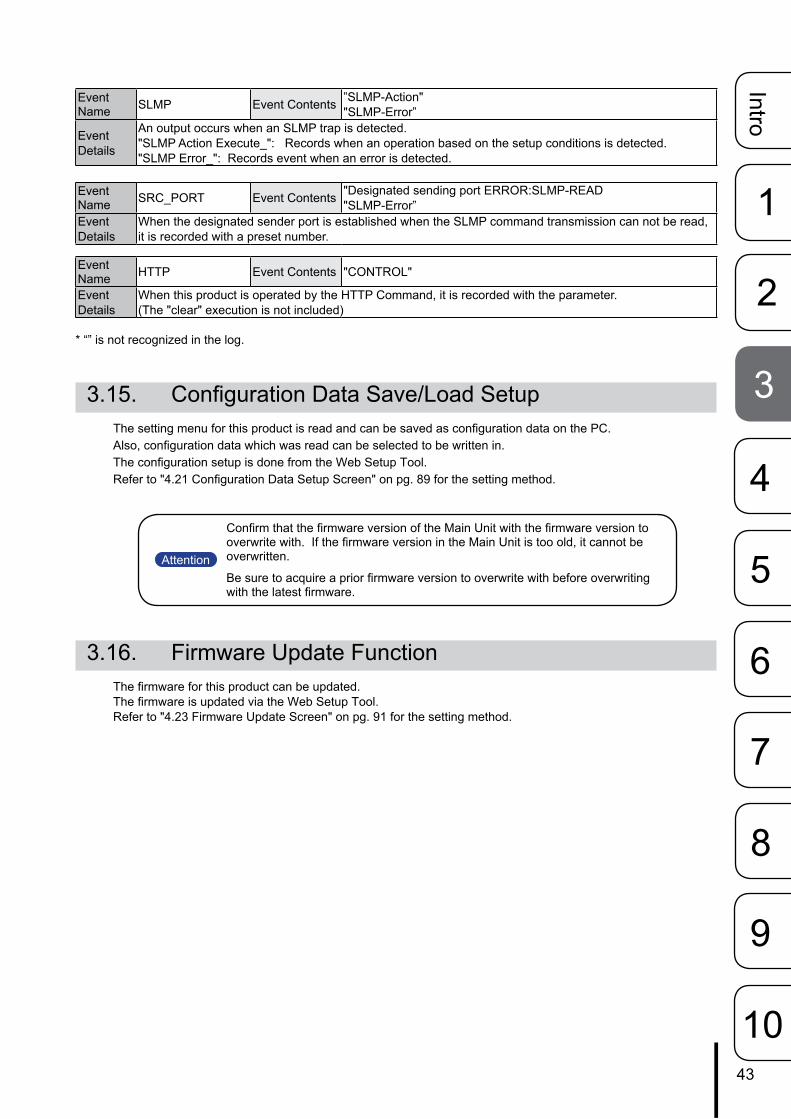
43
Intro
1
2
3
5
6
8
9
4
7
10
Event Name SLMP Event Contents ”SLMP-Action"
"SLMP-Error”
Event Details
An output occurs when an SLMP trap is detected."SLMP Action Execute_": Records when an operation based on the setup conditions is detected."SLMP Error_": Records event when an error is detected.
Event Name SRC_PORT Event Contents "Designated sending port ERROR:SLMP-READ
"SLMP-Error”Event Details
When the designated sender port is established when the SLMP command transmission can not be read, it is recorded with a preset number.
Event Name HTTP Event Contents "CONTROL"
Event Details
When this product is operated by the HTTP Command, it is recorded with the parameter. (The "clear" execution is not included)
* “” is not recognized in the log.
3.15. Configuration Data Save/Load SetupThe setting menu for this product is read and can be saved as configuration data on the PC. Also, configuration data which was read can be selected to be written in. The configuration setup is done from the Web Setup Tool. Refer to "4.21 Configuration Data Setup Screen" on pg. 89 for the setting method.
3.16. Firmware Update FunctionThe firmware for this product can be updated. The firmware is updated via the Web Setup Tool. Refer to "4.23 Firmware Update Screen" on pg. 91 for the setting method.
Attention
Confirm that the firmware version of the Main Unit with the firmware version to overwrite with. If the firmware version in the Main Unit is too old, it cannot be overwritten.
Be sure to acquire a prior firmware version to overwrite with before overwriting with the latest firmware.
user
生産終了
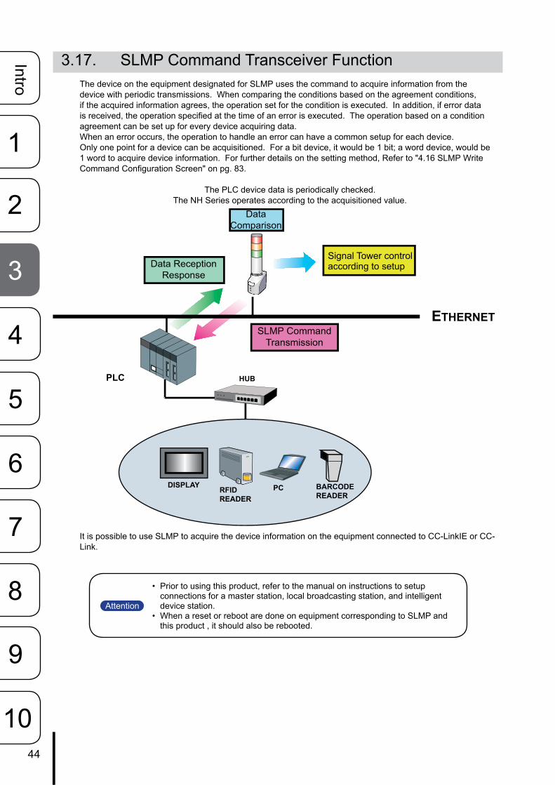
44
Intro
1
2
3
5
6
8
9
4
7
10
3.17. SLMP Command Transceiver FunctionThe device on the equipment designated for SLMP uses the command to acquire information from the device with periodic transmissions. When comparing the conditions based on the agreement conditions, if the acquired information agrees, the operation set for the condition is executed. In addition, if error data is received, the operation specified at the time of an error is executed. The operation based on a condition agreement can be set up for every device acquiring data.When an error occurs, the operation to handle an error can have a common setup for each device.Only one point for a device can be acquisitioned. For a bit device, it would be 1 bit; a word device, would be 1 word to acquire device information. For further details on the setting method, Refer to "4.16 SLMP Write Command Configuration Screen" on pg. 83.
The PLC device data is periodically checked.The NH Series operates according to the acquisitioned value.
It is possible to use SLMP to acquire the device information on the equipment connected to CC-LinkIE or CC-Link.
PLC HUB
ETHERNET
RFIDREADER
PC BARCODEREADER
DISPLAY
Signal Tower control according to setup
Data Comparison
Data Reception Response
SLMP Command Transmission
Attention
• Prior to using this product, refer to the manual on instructions to setup connections for a master station, local broadcasting station, and intelligent device station.
• When a reset or reboot are done on equipment corresponding to SLMP and this product , it should also be rebooted.
user
生産終了

45
Intro
1
2
3
5
6
8
9
4
7
10
3.17.1. SLMP Read Command Transceiver Process FlowchartThe process for the Command Transceiver is in the order from number 1 to 16. When the protocol is set as TCP, connection processing is started from the first command transmission, and only the command transceiver process is performed afterward.If changed into the following status, the established transmission interval is opened and the following number for the command transceiver process is executed.
• The response data of the command which was transmitted was received.• The response data was not able to be received within the established timeout limit.• The command addressee was not established.
The next number of the command transceiver process after No. 16 is No. 1. If a timeout occurs, the cut-off process will occur and re-connection will proceed within the set transmission interval. The transmission interval can be selected from 10 ms, 50 ms, and 100 ms.
Fig. 3.17.1 SLMP Command Transceiver Function Operational Details 1
Attention• Do not send a command transmission when the addressee and the address
port number is not established.• The shortest number of seconds for the transmission interval is set.
[Setting 1]Command Transceiver
Management
After the transmission interval setup
[Setting 2]Command Transceiver
Management
After the transmission interval setup
[Setting 15]Command Transceiver
Management
After the transmission interval setup
[Setting 16]Command Transceiver
Management
After the transmission interval setup
user
生産終了

46
Intro
1
2
3
5
6
8
9
4
7
10
SLMP Supported EquipmentSLMP CommandTransmission
Data Reception Response
“Clear” Execution
NHL Side
Set up with Web Setup Tool
Setup completion after Start SLMP Command Transmission
Data Acquisition Period
Data Acquisition Condition Data AcquisitionConditionCondition Status
No Operation
Conditionsdo not agree
Condition AgreementComparison
Condition AgreementComparison
Operation Start at time of Condition Agreement
Condition AgreementComparison
Conditionsagree
Conditionsagree
No Operation Start at time of Condition Agreement
3.17.2. SLMP Read Command Transceiver Operation (During Acquision Agree-ment)
Device information from SLMP corresponding equipment can be acquisitioned. The comparison of the set agreement conditions for the acquired information is made and the operation of the Signal Tower occurs when the condition agreement is explained.If the conditions set up are in agreement, a condition agreement status is recognized. If the conditions in the acquired data agree in the condition agreement status, the Signal Tower does not operate. The condition agreement status is cleared when entering a "Clear" operation.
Example: When it acquires device information from the equipment corresponding to SLMP and the condi-tion is in agreement
1. If the contents is set for when the data acquired from the equipment corresponding to SLMP and prod-uct are in agreement, the Signal Tower performs its operation at the time of agreement.
2. If it agrees with the data acquired in the condition agreement status, the Signal Tower does not oper-ate.
3. If a “Clear” operation is received in the condition agreement status, the condition agreement status will be cleared and it will return to its monitoring condition. If the data acquired does not agree on its conditions, it is cleared.
Fig. 3.17.2 SLMP Read Acquisition Command Transceiver Function Operation Flow
user
生産終了

47
Intro
1
2
3
5
6
8
9
4
7
10
Error Data Transmission
Operation Start at time of Condition Agreement
SLMP Supported EquipmentSLMP CommandTransmission
Data Reception Response
“Clear” Execution
NHL Side
Set up with Web Setup Tool
Setup completion after Start SLMP Command Transmission
Data Acquisition Period
Conditionsagree
Condition AgreementComparison
No Operation starts due to Error Condition
Error DataReception
Error DataReception
No Operation starts due to Error Condition
Data Acquisition Condition Data AcquisitionConditionCondition Status
Error Status
3.17.3. SLMP Read Command Transceiver Operation (When Error Occurs)The following explains the operation at the time of receiving error data from the equipment corresponding to SLMP.When acquired data information is errored, the operation of a Signal Tower can be set when the data error is received. If error data is received once, it is recognized as an error condition. If error data is acquired again in a data er-ror status, the Signal Tower does not operate. An error condition is cleared by entering a “Clear” operation.
Example: When acquiring error data from the equipment corresponding to SLMP1. If the data acquired from the equipment corresponding to SLMP has error data, the Signal Tower
operates at the time of error-data reception.2. If the error data is acquired again in a data error status, the Signal Tower does not operate.3. If a "Clear" command is received during a data error status, the data error status will be cleared and it
will return to the data acquisition status. In addition, if normal data is received during an error condition, the error condition is cleared and it returns to the data acquisition status.
Fig. 3.17.3 SLMP Read Error Command Transceiver Operation Flow
user
生産終了

48
Intro
1
2
3
5
6
8
9
4
7
10
3.18. SLMP Write Command Transmission FunctionA SLMP write command can be transmitted when generating a "Clear" event. The addressee can register a maximum of four places, and can transmit individual command ontents to each.The device can be selected to transmit from one or two points, and if the device is writing in bits, it would be a 1 or 2 bit value, and if set as a word device, one or 2 words of data can be transmitted.
Refer to "4.16 SLMP Write Command Configuration Screen" on pg. 83 for the setup method.
Table 3.18.1 XML Data Item Explanation
The“Clear”eventusedasatransmissionopportunity- When the "Clear" switch is pushed- When a "Clear" from SNMP is done- When a "Clear" command from RSH is executed
Attention If two or more addressees are established, the command transmission management selects one at a time from the low-priority in number order.
SLMP WriteCommand
Clear EventCondition
user
生産終了
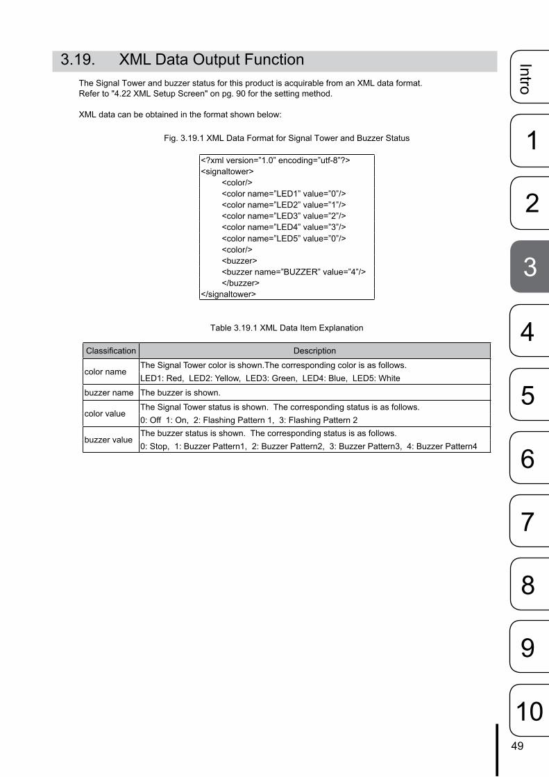
49
Intro
1
2
3
5
6
8
9
4
7
10
3.19. XML Data Output FunctionThe Signal Tower and buzzer status for this product is acquirable from an XML data format.Refer to "4.22 XML Setup Screen" on pg. 90 for the setting method.
XML data can be obtained in the format shown below:
Fig. 3.19.1 XML Data Format for Signal Tower and Buzzer Status
<?xml version=”1.0” encoding=”utf-8”?><signaltower>
<color/><color name=”LED1” value=”0”/><color name=”LED2” value=”1”/><color name=”LED3” value=”2”/><color name=”LED4” value=”3”/><color name=”LED5” value=”0”/><color/><buzzer><buzzer name=”BUZZER” value=”4”/></buzzer>
</signaltower>
Table 3.19.1 XML Data Item Explanation
Classification Description
color nameThe Signal Tower color is shown.The corresponding color is as follows.LED1: Red, LED2: Yellow, LED3: Green, LED4: Blue, LED5: White
buzzer name The buzzer is shown.
color valueThe Signal Tower status is shown. The corresponding status is as follows.0: Off 1: On, 2: Flashing Pattern 1, 3: Flashing Pattern 2
buzzer valueThe buzzer status is shown. The corresponding status is as follows.0: Stop, 1: Buzzer Pattern1, 2: Buzzer Pattern2, 3: Buzzer Pattern3, 4: Buzzer Pattern4
user
生産終了

50
Intro
1
2
3
5
6
8
9
4
7
10
3.20. HTTP Command Control FunctionThis product can be controlled by transmitting a HTTP command from the HTTP client.In the System Configuration Screen, “Active” or “Inactive” of this function can be set.
[Specification of HTTP command control]
Protocol HTTPMethod GETSyntax http://<IP address>/api/control?<parameter name>=<value>Response Success. This message is returned when the control was successful.
Error. [Error code] This message is returned when the control was unsuccessful.
Error code Description001 Unsupported Method.002 No such parameter name.003 Parameter is not specified.004 Parameter value is not specified..005 Illegal parameter values.
Parameter Values Descriptionalert=< integer value > 6 digits Control the Signal Tower LED units and buzzer.
Specify the pattern in order of [rybgcz]. r : Red, y : Amber, g : Green, b : Blue, c : White, z : Buzzer.[rygbc] 0 : Off, 1 : On, 2 : Flashing Pattern 1, 3 : Flashing Pattern 2,
9 : No Change [z] 0 : Stop, 1 : Pattern 1, 2 : Pattern 2, 3 : Pattern 3, 4 : Pattern 4,
9 : No Changeclear=< integer value > 1 Turn off the LED unit and stop the buzzer.
AttentionWhen using the HTTP Command Control function, set "HTTP Command Control Function" to "Active" on System Configuration Screen. Refer to "4.1. System Configuration Screen"
3.20.1. Example<alert>
Red : on, Amber : off, Green : on, Blue : off, White : off, Buzzer : Pattern 2 onhttp://192.168.10.1/api/control?alert=101002
Red : on, Amber : flashing pattern 1, Green, Blue and White : No Change, Buzzer : Pattern 3 onhttp://192.168.10.1/api/control?alert=129993
<clear>Turn off all the Signal Tower Lights and stop the Buzzer.http://192.168.10.1/api/control?clear=1
user
生産終了

51
Intro
1
2
3
5
6
8
9
4
7
10
4. Function SetupThe function setup is available in order to take advantage of the various functions. To access the settings, click the setup items on the left-hand side of the Web Setup Tool to open the set up screen for the various functions.
Setup Category Setup Screen Setup Contents
Setup Menu
System Configuration Sets up the network parameters.Clock Settings Sets up the time for this product.User Authorization Configuration Sets up the login password for this product.
SNMP Configuration Sets up the functions for the SNMP SET/GET and TRAP transmission.
Socket Transmission Configuration
Sets up the ports to control the PHN Command and PNS Command outputs.
E-mail Settings Setup for sending E-mail notifications.
E-Mail Message Settings Setup for writing the message contents to be transmitted by E-mail.
RSH Command Configuration Setup for receiving the rsh command and to send the E-mail when an rsh reception and TRAP transmission are executed.
Operation Settings
TRAP Reception Configuration The setup which controls the status condition when a TRAP or TRAP reception is received.
Ping Monitoring Configuration The setup of the address for the monitored equipment and the management when an abnormality is detected.
Application Monitoring Configuration
The setup is to verify whether data can be received from the monitored object.
“Clear” Control Configuration The setup for sending an E-mail when the “Clear” switch is pressed, and for the TRAP transmission setup.
Normal Mode Settings A setting, such as turning on a Green LED Unit, to indicate a normal condition.
“Test” Switch Settings The setup for sending an E-mail when the “Test” switch is pressed, and for the TRAP transmission setup.
SLMP Read Configuration Device information for the equipment supporting SLMP is set to for a condition agreement to operate when an error occurs.
SLMP Write Configuration Set up contents of the write command for when transmitting to the SLMP equipment.
NH Unit Controls
Signal Tower Output Control The Signal Tower status is controlled from the browser.Reinitialize The settings return to factory default values.
Reboot Reboots this product after settings have been changed to put them into effect.
Maintenance Functions
Event Log The event log is displayed and can be downloaded.XML Settings Set up the XML Data Output.
Configuration Data Setup The setup items can be saved as configuration data and reloaded at any time.
Firmware Update The Firmware update function can be done from this screen.
Setup Table Entries The list of items, their setup and operation contents, and the current firmware version is displayed.
Attention After the desired setup is completed, reboot this product by pressing the “reset” switch or by disconnecting the power and reconnecting it.
user
生産終了

52
Intro
1
2
3
5
6
8
9
4
7
10
4.1. System Configuration ScreenThe network parameters for this product can be setup through a browser. The default IP address is "192.168.10.1".
The parameters can be setup from the System Configuration Screen (Fig. 4.1.1 System Configuration Screen) from the default values as shown in Table 4.1.1.
Fig. 4.1.1 System Configuration Screen
Table 4.1.1 System Configuration Parameters
Item Contents Default Value Input Parameter Setting Option
Firmware Version The current Firmware version is indicated — — —
System Name The name for this product can be set. Signal Tower Full/Half-width Characters Maximum 31 Characters O
System Location The setup location of this product can be entered. Blank
Half-width alphanumeric characters and underscore “_” Maximum 31 Characters
O
Contact Address Setup the contact address. [email protected] Mail address format Maximum 63 Characters O
IP Address Configuration Method
Select between Manual or Automatic IP address configuration.
Setup Manually Select Radio Button X
IP Address Setup the IP address of this product. 192.168.10.1 IP address format XNetmask Setup the subnet mask of this product. 255.255.255.0 IP address format XDefault Gateway Setup the default gateway of this product. 0.0.0.0 IP address format ODNS Server Address Setup the DNS server of this product. 0.0.0.0 IP address format O
Host Name Setup a host name nh.patlite.jp Enter a legitimate host nameMaximum 63 Characters —
HTTP command control function
Select "Active" or "Inactive" for the HTTP command control function.
Active — —
Attention
The values for “Setting Option” in this manual has to have a valid entry, or can be left blank.
O Indicates the entry can be omissible, or any entry within the set parameters.
X Indicates the entry cannot be omissible. Enter a valid parameter. – Indicates an entry which cannot be omitted, or abbreviated. The value
has to be entered in accordance to the customer’s environment.
user
生産終了

53
Intro
1
2
3
5
6
8
9
4
7
10
4.2. Clock Settings ScreenThe Clock Settings for this product can be done through a browser. The Clock Settings can be accessed through the Clock Settings Screen (Fig. 4.2.1 Clock Settings Screen) from the default values as shown in Table 4.2.1.
Fig. 4.2.1 "Clock Settings" Screen
Table 4.2.1 Clock Settings Parameters
Item Contents Default Value Input Parameter Setting
Option
NTP Server Address Setup the NTP server address. Blank Server’s Host Name or IP address Maximum of 63 characters O
Time Calibration Interval Setup the time interval to synchronize with an NTP server. 0 Half-width numbers from 0 to 1440
(minutes) O
Time Zone Setup the time zone. UTC+9 — —
Two kind of Clock Settings methods are indicated below:• Synchronizing time with the PC clock when logging in.• Adjusting the clock in this product when synchronizing with an NTP server.
user
生産終了

54
Intro
1
2
3
5
6
8
9
4
7
10
4.2.1. Synchronizing with the PC clockClicking the "Manually Setup Clock" button will synchronize with the time on the PC which has been logged into this product.
[Setup Method]
① . Compare the columns between the “NH Monitoring Clock” and the “Host Computer Clock.”② .Click the “Manually Setup Clock” button to synchronize the time with the logged in PC.
Fig. 4.2.2 "Manually Setup Clock" Setup Screen (Before)
Fig. 4.2.3 "Manually Setup Clock" Setup Screen (After)
Attention
• In some cases, this product may not reflect the exact time as the PC, and the clock may be off by several seconds.
• When not using an NTP server, check the time of this product periodically.• This product uses a capacitor as a battery backup for the time stamp.• Depending on the charge status of the capacitor, it may last up to a half-day,
and if the power supply is not applied during the day, a gap in time or the need to reset the clock may be necessary. If an application environment requires a time entry, be sure to set up the time before the application.
• If the backup is depleted and the time entry resets, the set time will be labeled as “Jan 1, 2010.”
①
②
user
生産終了

55
Intro
1
2
3
5
6
8
9
4
7
10
4.2.2. Synchronizing with an NTP serverAn NTP server can be linked by entering the NTP server address to synchronize with the clock in this product, and the time updated by sending a request for time adjustment to that NTP server.
[Setup Method]
① . Enter the NTP server address in the “NTP Server Address” column.② . Enter a value for the calibration intervals to communicate with the NTP server in the “Time Calibration
Interval (min)” column.③ .Click the “Set” button to activate the setup.
Fig. 4.2.4 NTP Server Settings Screen
4.2.3. Setting the Time ZoneDetermine the area to be used when setting the time zone.
[Setup Method]
① . Select from the “Time Zone” column and click to set.② .Click the “Set” button to activate the setup.
Fig. 4.2.5 Time Zone Setup Screen
①
②
③
①
②
user
生産終了

56
Intro
1
2
3
5
6
8
9
4
7
10
4.3. User Authorization Configuration ScreenSetup a password to log into the Setup Screen for this product.Enter a password, then re-enter the password to verify its entry, then click the "Set" button to activate it. The next time for logging in will ask for the new password. The password entry will allow up to 16 half-width alphanumeric characters and a period.
[Setup Method]
① . Enter the password to be changed into the “Password” column.② . Enter the same password to be changed into the “Re-enter Password” column to verify the entry.③ .Click the “Set” button to activate the setup.
Log in with the new password the next time the login screen appears.
Fig. 4.3.1 User Authorization Configuration Screen
Table 4.3.1 User Authentication Configuration Parameters
Item Contents Default Value Input Parameter Setting
Option
Password Setup a new password. Blank Half-width alphanumeric character and period “.” Maximum 16 Characters X
Re-enter Password Verify the new password Blank Half-width alphanumeric character and period “.”
Maximum 16 Characters X
①
②
③
user
生産終了

57
Intro
1
2
3
5
6
8
9
4
7
10
4.4. SNMP Configuration ScreenWith an SNMP, this product can communicate outside the community name for the notification of a TRAP, using the SNMP SET/GET in reference to each item for this product, and generate the event with this product.
4.4.1. SNMP SET/GETAn SNMP SET/GET can be setup.
[Setup Method]① . Select the “Active” radio button to enable the SNMP function.② . Enter the SET/GET community parameter.
4.4.2. SNMP TRAP TransmissionAn SNMP TRAP Transmission can be setup.
[Setup Method]③ . Select the “Active” radio button to enable the TRAP transmission function.④ . Enter the TRAP Transmission community parameter and the TRAP transmission frequency.⑤ . Enter in the TRAP Address column, the IP address for sending the TRAP notification to.⑥ .Click the “Set” button to activate the setup.
TRAP command which is transmitted when the TRAP is active
OID: 1.3.6.1.4.1.20440.4.1.6.3Name: trapPatliteTrapReceived
Fig. 4.4.1 SNMP Configuration Screen
①
②
③
④
⑤
⑥
user
生産終了

58
Intro
1
2
3
5
6
8
9
4
7
10
Table 4.4.1 SNMP Configuration Parameters
Item Contents Default Value
Input Parameter
Setting Option
SNMP Function Setup to Activate/Inactivate the SNMP function. Active — —
SET Community Name
Setup the name to use when reading an SNMP Configuration value. private
Half-width alphanumeric character and underscore “_” Maximum 32 Characters
—
GET Community Name
Setup the name to use when writing an SNMP Configuration value. public
Half-width alphanumeric character and underscore “_” Maximum 32 Characters
—
TRAP Transmission Function
Setup to Activate/Inactivate the trap transmission function. Inactive — —
TRAP Transmission Community Name
Setup the community name for the trap which is transmitting. public
Half-width alphanumeric character and underscore “_” Maximum 32 Characters
—
TRAP Transmission Frequency
Setup for the number of times a trap can be transmitted 1 Half-width numbers from 1 to 10 —
TRAP IP Address to Receiver
IP address format for the destination of sending a TRAP transmission to. Blank
Characters which can be used for a server address Maximum 63 Characters
O
4.5. Socket Transmission Configuration ScreenSet up for the use of the PHN Command and PNS Command with Socket Transmission.
[Setup Method]
① . Select either “TCP” or “UDP” radio button in the “Protocol” field for the communication method.② . Enter the port to be used in the “Port Number” field.③ .Click the “Set” button to save all entries.
Fig. 4.5.1 Socket Transmission Configuration Screen
Table 4.5.1 Socket Transmission Configuration Parameters
Item Contents Default Value
Input Parameter
Setting Option
Protocol Select between TCP or UDP TCP — —Port Number Set the reception port number 10000 Half-width numbers from 10000 to 65535 —
MEMO Refer to "3.5 PHN Command Reception Function" on pg. 27 for PHN Commands.Refer to "3.6 PNS Command Reception Function" on pg. 29 for PNS Commands.
①
②
③
user
生産終了

59
Intro
1
2
3
5
6
8
9
4
7
10
4.6. E-Mail Settings ScreenThis product can be set up to send E-mail messages. The following are events which will transmit E-mail messages. When transmitting an E-mail, it is transmitted in sequence from the smaller address number to the larger address number of the recipient.
E-mail Transmitting Event
• At the time of an RSH command reception• At the time of a TRAP reception• At the time when the "CLEAR" button is pressed.• At the time when a "Clear SNMP" command is executed.• At the time when an SLMP Write Command Condition occurs.• At the time when an SLMP Write Command Error Condition occurs.• At the time of a Ping monitoring abnormality and Ping recovery event.• At the time of an application monitoring abnormality and recovery event.
[Setup Method]
① . Set up the SMTP mail server address and port number.② .When using the SMTP authentication, set up the account name and SMTP authentication password.③ .When using the POP authentication, set up the POP account name and POP authentication password.④ . Select “None” for when authentication is not necessary.⑤ . Set up in the designated sender address column the designated sender's E-mail address.⑥ . Set up the recipient's address.⑦ .Click the “Set” button to save all settings.
Fig. 4.6.1 E-Mail Settings Screen
①
②
③
④
⑤
⑥
⑦
user
生産終了

60
Intro
1
2
3
5
6
8
9
4
7
10
Table 4.6.1 E-E-Mail Settings Parameters
Item Contents Default Value Input Parameter Setting
Option
SMTP Server Address
Set the IP Address of the SMTP Server 0.0.0.0
Characters which can be used for a server address Maximum 63 Characters
—
SMTP Port Number
Set the port number of the SMTP Server 25 Half-width numbers from 1 to 65535 —
Authentication Protocol
Select among “SMTP Authentication/POP Authentication/No Authentication”.
No Authentication — —
Encrypted Connection
Select between “SSL”, “TLS” or “None”. None — —
SMTP Account Name
Set the user name for SMTP Authentication. Blank
Half-width alphanumeric characters, characters which can be used for E-mail addresses Maximum 32 characters
O
SMTP Authentication Password
Set up the password for SMTP Authentication. Blank Half-width alphanumeric characters
Maximum 32 characters O
POP3 Server Address
Set up the POP3 server IP Address. Blank
Characters which can be used for a server address Maximum 63 Characters
O
POP3 Port Number Set up the port number for the POP3 server. 110 Half-width numbers from 1 to 65535 —
Account Name Set up the user name of the POP Authentication. Blank
Half-width alphanumeric characters, characters which can be used for E-mail addresses Maximum 32 characters
O
Password Set up the password for POP Authentication Blank Half-width alphanumeric characters
Maximum 32 characters O
Source Address Set up the E-mail address for the designated sender. Blank
Characters which can be used for an E-mail address Maximum 63 Characters
O
Address of Receiver 1 through 8
Set up the destination addresses for the E-mail to be sent to. Blank
Characters which can be used for an E-mail address Maximum 63 Characters
O
4.7. E-Mail Message Settings ScreenThe following is the setup of E-mail subject titles and message contents for E-mail Sending. When sending E-mails, the contents can be personalized to match the coinciding mail notifications by entering a subject title and message content to transmit.
[Setup Method]
① . Enter in the “Subject” field a subject title to transmit by e-mail. (Use full or half-width alphanumeric characters of up to 31 characters)
② . Enter in the “Message” field a text message to transmit by e-mail. (Use full or half-width alphanumeric characters of up to 63 characters)
③ .Click the “Set” icon button to save all entries.
user
生産終了

61
Intro
1
2
3
5
6
8
9
4
7
10
Fig. 4.7.1 E-Mail Message Settings Screen
Table 4.7.1 E-Mail Message Settings Parameters
Item Contents Default Value Input Parameter Setting Option
Subject 1 to 16 Subject titles from 1 to 16 can be entered
Message from Signal Tower
Full or half-width alphanumeric characters Maximum 31 Characters O
Message 1 to 16 Messages from 1 to 16 can be entered Blank Full or half-width alphanumeric characters
Maximum 63 Characters O
②
①
③
user
生産終了

62
Intro
1
2
3
5
6
8
9
4
7
10
4.8. RSH Command Configuration ScreenRSH (remote shell) Commands can control the Signal Tower and buzzer on this product.The following explains the setup to be able to receive the RSH Commands.
[Setup Method]
RSH Server Function
① .When receiving the RSH Commands, first turn on the RSH Server function by selecting “Active.”RSH Alert Timer Reset Function
② . A timer can be implemented to control the operating timing of each tier and the buzzer with an RSH command sent to the Signal Tower. If the “Shared” function is selected, the timing control for each color can be in common. If the “Separate” function is selected, the timing control for each color is controlled individually.
E-mail Transmission
③ . To have E-mail Sending when an RSH Command has been received, and for it to make a report, select “Active”. Select “Inactive” to prevent any E-mail Sending.
When E-mail Sending is selected for "Active"
④ . Select the desired E-mail contents to transmit from the registered subject titles and the text messages after the E-mail Sending is activated. After the E-mail contents are selected, choose the E-mail recipients.
TRAP Transmission
⑤ . To have a trap transmission sent after an RSH Command, select “Active” for TRAP transmission to transmit the TRAP. If the TRAP Transmission is not utilized, select “Inactive”.
The "TRAP Command" for this product to receive when the TRAP condition occurs
OID: 1.3.6.1.4.1.20440.4.1.6.5Name: trapPatliteRshExecuted
Designated E-mail Sender Address Setup
⑥ . If address restrictions are made for sending an RSH Command to a designated recipient, select “Active” for the designated sender address. If no restrictions have been made, select “Inactive”.
When "Inactive" is selected for designated sender addressing
⑦ . Enter a common login name while the designated sender IP address is invalid. Click the “Set” button on the lower right side of the screen for the settings to be saved.
When "Active" is selected for designated sender addressing
⑧ . Enter the IP address into the designated sender IP address column to allow command execution. A maximum of 16 accounts can be registered. To allow activation for command execution, enter a login name.
⑨ .Click the “Set” icon button to initiate the setup.
Attention When using this product with the internal timer function, if the RSH Alert Timer Reset Function is changed, the timers for all the LEDs and buzzer is canceled.
user
生産終了

63
Intro
1
2
3
5
6
8
9
4
7
10
Fig. 4.8.1 RSH Command Configuration Screen
⑧
⑦
①
②
③ ④
⑤
⑥
⑨⑦
user
生産終了

64
Intro
1
2
3
5
6
8
9
4
7
10
Table 4.8.1 RSH Command Configuration Parameters
Item Contents Default Value Input Parameter Setting
OptionRSH Server
FunctionSelect Active/Inactive for the RSH server function. Active ― ―
RSH Alert Timer Reset Function
Select “Shared” or “Separate” to control the Signal Tower lights and buzzer ― ―
E-mail Transmission
Select Active/Inactive for sending an E-mail when a command is received. Inactive ― ―
Subject Select the subject title for the mail to be transmitted. 1. Message ― ―
Message Select the message text for the mail to be transmitted. 1: ― ―
E-mail Receiver Select the recipient to send E-mail to. Undefined ― ―
TRAP Transmission
Select Active/Inactive for the TRAP transmission when an RSH Command is received.
Inactive ― ―
Designated Sender Address
Setup a designated address for a sender when an RSH Command is received. Active ― ―
Invalid Designated Sender Address/
Common Login Name
When the designated sender address setup is not active, up to 16 accounts can be used to notify senders when an RSH Command is received.
BlankHalf-width alphanumeric
character, period “.”, hyphen “-” Maximum 16 Characters
O
Sender IP Address The designated IP address used when a command is executed. Blank IP Address Format O
Login Name The login name used is entered to allow command execution. Blank
Half-width alphanumeric character, period “.”, hyphen “-”
Maximum 16 CharactersO
user
生産終了

65
Intro
1
2
3
5
6
8
9
4
7
10
4.9. TRAP Reception Configuration ScreenSetup for permitting a TRAP reception and its operation after the TRAP communication is received.
[Setup Method]
① . Enter a group name.② . Enter an address name for the TRAP designated sender*1.③ . Enter the OID of the TRAP received in the TRAP number column*1.④ . Enter the OID into the variable-bindings column*1.⑤ . Set up the operation for the Signal Tower when a TRAP is received.⑥ . Select the E-mail Sending configuration when receiving a TRAP.
When the E-mail Sending is "Active"
Select the subject title and message after the E-mail Sending is activated.⑦ . Select “Active” when using the TRAP transmission.
"TRAP Command" received when a TRAP condition occurs
OID: 1.3.6.1.4.1.20440.4.1.6.3Name:. trapPatliteTrapReceived
⑧ .Click the “Set” button to save the settings.*1 Refer to the following Attention and MEMO below.
Attention
• When the trap transmission source address is entered, the “trap number” column and the “variable bindings” column can be omitted. When the TRAP “number column” and “variable bindings” columns are omitted, then all operations will be received by the TRAP transmission address, which was setup for the TRAP transmission source address.
• When a TRAP transmission source address name is omitted, the operation is determined by the TRAP number.
• For two “variable bindings”, the 1st registration can be used among the existing registered items.
• If both the “trap transmission source address” and “trap number” are omitted, even with “variable bindings” registered, it won’t operate.
• When the “GenericTrap type” TRAP Reception is 6 (enterprisespecific), add the value “0. (specific-trap value)” to the last part of the specific-trap for the TRAP Reception.
MEMO
• When the TRAP transmission source address name is omitted, the TRAP number cannot be omitted. If both the “trap transmission source address” and “trap number” are omitted, no operation after a reception will work.
• When a TRAP number has been duplicated and is registered into the group, the least significant setup number in the group is used. The following group number after that number is not used.
• Judgement can be made with the reception function where the number of “variable bindings” are 64 with one per TRAP. To receive more than 65 variable bindings, TRAP 1-64 must first be set to operate in the OID at the time of reception. Be aware that the OID after 65 does not operate, even if it is set up.
user
生産終了

66
Intro
1
2
3
5
6
8
9
4
7
10
Fig. 4.9.1 TRAP Reception Configuration Screen
⑤
⑥
⑦
⑨
⑧
①
②
③
④
user
生産終了

67
Intro
1
2
3
5
6
8
9
4
7
10
Table 4.9.1 TRAP Reception Configuration Parameters
Item Contents Default Value Input Parameter Setup
Option
Group Name Setup a group name Blank Full/Half-size Characters Maximum 32 Characters O
Trap Designated Sender
Addresses 1 to 4
Setup the designated TRAP sender addresses from 1 to 4 for a group Blank IP Address Format O
Trap Number Items 1 to 4
Setup the Object ID TRAP numbers to receive trap commands from 1 to 4 for the group Blank Integers and Period “.”
Maximum 127 Characters O
OID Items 1 to 4 (variable bindings)
Setup the TRAP command object ID with variable bindings for items 1 to 4 Blank Integers and Period “.”
Maximum 127 Characters O
Model Items 1 to 4 (variable bindings)
Setup the variable bindings object ID model to receive TRAP commands. Only integer types can be selected
Integer ― ―
Value Items 1 to 4 (variable bindings)
Setup the variable binding’s object ID to receive traps. 0 Integer (0 to 65535) ―
RedSelect from: OFF- ON- Lighting- Flashing 1- Flashing 2- No Flashing- No Change
No Change ― ―
AmberSelect from: OFF- ON- Lighting- Flashing 1- Flashing 2- No Flashing- No Change
No Change ― ―
GreenSelect from: OFF- ON- Lighting- Flashing 1- Flashing 2- No Flashing- No Change
No Change ― ―
BlueSelect from: OFF- ON- Lighting- Flashing 1- Flashing 2- No Flashing- No Change
No Change ― ―
WhiteSelect from: OFF- ON- Lighting- Flashing 1- Flashing 2- No Flashing- No Change
No Change ― ―
BuzzerSelect from: Pattern 1- Pattern 2- Pattern 3- Pattern 4- Stop- No Change
No Change ― ―
E-mail Transmission Set Active or Inactive for sending E-mail. Inactive ― ―Subject Select the E-mail subject title contents 1. Message ― ―
Message Select the E-mail text message contents 1: ― ―TRAP Transmission Set Active or Inactive for the trap transmission. Inactive ― ―
user
生産終了

68
Intro
1
2
3
5
6
8
9
4
7
10
4.10. Ping Monitoring Configuration ScreenThe Ping Monitoring Configuration Screen in the Configuration Setup Screen can be used to set up parameters for sending Pings for up to 24 devices to monitor. With a maximum of 24 devices to monitor, devices numbered from 1-12 have a set "Ping test cycle period" of 60 seconds, and devices numbered 13-24 have adjustable parameters for Ping monitoring.
4.10.1. Ping Monitoring Configuration (Screen Numbers 1 to 12)[Setup Method]
① . Select the device number (No. 1-12) to setup the Ping monitoring parameters.② . Enter the IP address or host name for the device to monitor in the “Monitoring Target Address” field.③ . Enter the device name in the “Equipment Name” field. This name is used in log events and in E-mails
configured in the "Output Control Setting".④ . Set up the number of sequential 60 second Ping monitoring periods with no ping response to determine
an "Abnormality" in the "Cycle count Error threshold (0-30)" field.⑤ . Setup the desired actions for the lights and buzzer when the abnormality occurs.⑥ . To send an E-mail when an abnormality occurs, set the E-mail Sending to “Active”, and select the
"Subject" and "Message" from the pull-down lists. The lists are configured on the "E-mail Message Settings" page in the "Setup Menu".
When the E-mail Sending is activated
⑦ . Select the recipients for the E-mail in the "E-mail Receiver" section. The choices here are determined in the "E-mail Settings" of the "Setup Menu".
⑧ . To send an SNMP TRAP, when an abnormality occurs, set the "Trap Transmission" radio button to "Active".
TRAP command transmitted when the TRAP is active
OID: 1.3.6.1.4.1.20440.4.1.6.1Name: trapPatliteAlarmAdded
Fig. 4.10.1 Ping Monitoring Configuration Screen 1
①
②
③
④
⑤
⑥
⑦
⑧
user
生産終了

69
Intro
1
2
3
5
6
8
9
4
7
10
Setting up the "Recovery from Ping" parameters
⑨ . Setup the Signal Tower actions when a recovery from a ping abnormality occurs.⑩ . To send an E-mail when an abnormality occurs, set the E-mail Sending to “Active”, and select the
"Subject" and "Message" from the pull-down lists. The lists are configured on the "E-mail Message Settings" page in the "Setup Menu".
When the E-mail Sending is activated
Register the subject and the message text to transmit. Then, select the recipient for the E-mail Sending.
⑪ . To send an SNMP TRAP, when an abnormality occurs, set the "Trap Transmission" radio button to "Active".
⑫ .When all settings on the page are correct, click on “Set” to activate the ping test for the device.TRAP Command received when TRAP condition occurs
OID: 1.3.6.1.4.1.20440.4.1.6.2Name: trapPatliteAlarmRemoved
Fig. 4.10.2 Ping Monitoring Configuration Screen 2
Table 4.10.1 Ping Monitoring Configuration Parameters
Item Contents Default Value Input Parameter Setup
OptionMonitoring Target
Address The IP address or host name for the monitoring ping. Blank IP Address or Host Name Maximum 63 Characters O
Equipment Name
The name of the equipment to send a transmission monitoring ping to. Blank Maximum 32 Characters O
Cycle count Error threshold
The number of sequential Ping monitoring cycles to send Ping requests to determine when no response is judged as an "abnormality" occurrence.
0 Integers 0 to 30 ―
Red Select from: OFF- ON- Lighting- Flashing 1- Flashing 2- No Flashing- No Change No Change ― ―
Amber Select from: OFF- ON- Lighting- Flashing 1- Flashing 2- No Flashing- No Change No Change ― ―
Green Select from: OFF- ON- Lighting- Flashing 1- Flashing 2- No Flashing- No Change No Change ― ―
Blue Select from: OFF- ON- Lighting- Flashing 1- Flashing 2- No Flashing- No Change No Change ― ―
White Select from: OFF- ON- Lighting- Flashing 1- Flashing 2- No Flashing- No Change No Change ― ―
Buzzer Select from:Pattern 1- Pattern 2- Pattern 3- Pattern 4- Stop- No Change No Change ― ―
Email Transmission Select the Active/Inactive condition for the E-mail Sending. Inactive ― ―Subject Select the E-mail subject title 1. Message ― ―
Message Select the E-mail message to text 1: ― ―
TRAP Transmission Select the Active/Inactive condition for the trap transmission. Inactive ― ―
⑨
⑩
⑪
⑫
user
生産終了

70
Intro
1
2
3
5
6
8
9
4
7
10
4.10.2. Ping Monitoring Configuration (Screen Numbers 13 to 24)[Setup Method]
① . Select the device number (No. 13-24) to setup the Ping monitoring parameters.② . Enter the IP address or host name for the device to ping in the “Monitoring Target Address” field.③ . Enter the device name in the “Equipment Name” field. This name is used in log events and in E-mails
configured in the "Output Control Setting".④ . Set up the number of sequential Ping monitoring periods with no ping response to determine an
"Abnormality" in the "Cycle count Error threshold (0-30)" field.⑤ . Setup the Ping monitoring duration in seconds in the "Ping test cycle period (1-600 sec)" field.⑥ . Set up the number of Pings to be transmitted during each Ping monitoring duration in the "Pings per test
cycle (1-3)" field.⑦ . Setup the desired actions for the lights and buzzer when the abnormality occurs. ⑧ . To send an E-mail when an abnormality occurs, set the E-mail Sending to “Active”, and select the
"Subject" and "Message" from the pull-down lists. The lists are configured on the "E-mail Message Settings" page in the "Setup Menu".
When the E-mail Sending is activated
⑨ . Select the recipients for the E-mail in the "E-mail Receiver" section. The choices here are determined in the "E-mail Settings" of the "Setup Menu".
⑩ . To send an SNMP TRAP, when an abnormality occurs, set the "Trap Transmission" radio button to "Active".
TRAP command transmitted when the TRAP is active
OID: 1.3.6.1.4.1.20440.4.1.6.1Name: trapPatliteAlarmAdded
Fig. 4.10.3 Ping Monitoring Configuration Screen 1 (Screen Numbers 13 - 24)
①
②
③
④
⑤
⑥
⑦
⑧
⑨
⑩
user
生産終了

71
Intro
1
2
3
5
6
8
9
4
7
10
Setting up the "Recovery from Ping" parameters
⑪ . Setup the Signal Tower actions when a recovery from a ping abnormality occurs.⑫ . To send an E-mail when an abnormality occurs, set the E-mail Sending to “Active”, and select the
"Subject" and "Message" from the pull-down lists. The lists are configured on the "E-mail Message Settings" page in the "Setup Menu".
When the E-mail Sending is activated
⑬ . To send an SNMP TRAP, when an abnormality occurs, set the "Trap Transmission" radio button to "Active".
TRAP Command received when TRAP condition occursOID: 1.3.6.1.4.1.20440.4.1.6.2Name: trapPatliteAlarmRemoved
⑭ .When all settings on the page are correct, click on “Set” to activate the ping test for the device.
Fig. 4.10.4 Ping Monitoring Configuration Screen 2 (Screen Numbers 13 - 24)
Table 4.10.2 Ping Monitoring Configuration Parameters (Screen Numbers 13 - 24)
Item Contents Default Value
Input Parameter
Setup Option
Cycle count Error threshold
The duration of a monitoring cycle to test and determine network response. 0 0 to 30 (Times) ―
Ping test cycle period The duration between sending a Ping response test. 60 1 to 600 (sec) ―Pings per test cycle The number of Pings to send in the test cycle. 1 1 to 3 (Pings) ―
⑭
⑪
⑫
⑬
user
生産終了

72
Intro
1
2
3
5
6
8
9
4
7
10
4.11. Application Monitoring Configuration ScreenSetup for monitoring an application. The data reception of the target is monitored.If data is not received within the monitoring interval cycle, it detects the communication as being abnormal, and generates an abnormality event. After a generated event, if data is received from the monitored candidate, it will detect a recovery from the abnormal operation.
[Setup Method]
① . Select from screen number 1 to 4 to setup an application monitor.② . Enter the address for the targeted monitor.③ . Enter the receiving port number.④ . Enter a name for the equipment.⑤ . Set up the monitoring interval cycle.
Operation Setting for Monitoring Abnormality
⑥ . Setup the condition for the Signal Tower when a monitor abnormality is detected.⑦ . To send an E-mail when a monitor abnormality occurs, select the "E-mail Sending" radio button to “Active”.
When the E-mail Sending is activated
Select the subject and text message to transmit. Then, select the recipient under "E-mail Reciever" for when sending the E-mail.⑧ . To send an SNMP TRAP, when an abnormality occurs, set the "Trap Transmission" radio button to
"Active".
Fig. 4.11.1 Application Monitoring Configuration Screen
①
⑥
⑤
④
③
②
⑦
⑧

73
Intro
1
2
3
5
6
8
9
4
7
10
TRAP Command received when TRAP condition occurs
OID: 1.3.6.1.4.1.20440.4.1.6.6Name: trapPatliteMonitorAppAlarmAdded
Output Control Setting for Monitoring Error Recovery
⑨ . Setup the condition for the Signal Tower when a monitor abnormality recovery is detected.⑩ . To send an E-mail when a monitor abnormality recovery occurs, set the E-mail Sending to “Active”.
When the E-mail Sending is activated
Select the subject and the message text to transmit. Then, select the recipient under "E-mail Reciever" for when sending the E-mail.⑪ . To send an SNMP TRAP, when an abnormality occurs, set the "Trap Transmission" radio button to
"Active".TRAP Command received when TRAP Transmission condition occurs
OID: 1.3.6.1.4.1.20440.4.1.6.7Name: trapPatliteMonitorAppAlarmRemoved
⑫ .Click the “Set” icon button to initiate the setup.
Fig. 4.11.2 Application Monitoring Configuration Screen
⑨
⑩
⑪
⑫
user
生産終了

74
Intro
1
2
3
5
6
8
9
4
7
10
Table 4.11.1 Application Monitoring Configuration Parameters
Item Contents Default Value
Input Parameter
Setup Option
Monitoring Target Address The IP address or host name for the monitoring ping. Blank IP Address Format O
Reception Port Number The reception port used to monitor the application. 0
Half-width numbers 9000-9999 (When the address column for the monitor is
blank, it is 0)
―
Equipment Name
The name of the equipment to send a transmission monitoring ping to. Blank Full/Half-width Characters
Maximum 31 Characters O
Monitoring Duration
The duration to cue when to monitor the application software. 0 Half-width alphanumeric
1 through 60000(sec) O
Red Select from: OFF- ON- Lighting- Flashing 1- Flashing 2- No Flashing- No Change No Change ― ―
Amber Select from: OFF- ON- Lighting- Flashing 1- Flashing 2- No Flashing- No Change No Change ― ―
Green Select from: OFF- ON- Lighting- Flashing 1- Flashing 2- No Flashing- No Change No Change ― ―
Blue Select from: OFF- ON- Lighting- Flashing 1- Flashing 2- No Flashing- No Change No Change ― ―
White Select from: OFF- ON- Lighting- Flashing 1- Flashing 2- No Flashing- No Change No Change ― ―
Buzzer Select from:Pattern 1- Pattern 2- Pattern 3- Pattern 4- Stop- No Change No Change ― ―
Email Transmission Select the Active/Inactive condition for the E-mail Sending. Inactive ― ―
Subject Select the E-mail subject title 1. Message ― ―Message Select the E-mail message to text 1: ― ―
TRAP Transmission
Select the Active/Inactive condition for the trap transmission. Inactive ― ―
user
生産終了

75
Intro
1
2
3
5
6
8
9
4
7
10
4.12. “Clear” Control Configuration ScreenSetup the operation to clear the status with the "CLEAR" button, or to combine with other commands to clear the Signal Tower status.Clear All : A function to clear both the Signal Tower and buzzer status and return to its normal
mode of operation.Depress twice to clear all : One press of the "CLEAR" button to stop the buzzer sound.
Pressing the "CLEAR" button a second time returns it to its normal mode of operation.
[Setup Method]
① .When using the “CLEAR” button to return to its normal mode after an E-mail Sending and TRAP trans-mission are received, select the “Active” radio button.
② .When using the “CLEAR” command from an SNMP clear execution to return to its normal mode after an E-mail Sending and TRAP transmission are received, select the “Active” radio button.
③ .When using the “CLEAR” from an RSH command execution to return to its normal mode after an E-mail Sending and TRAP transmission are received, select the “Active” radio button.
When selecting "Active" for E-mail Sending
Select the preferred E-mail subject title and text.Select the Receiver for the E-mail to be sent to.④ . Select the clear switch setup for either “Clear All” or “Depress twice to clear all”.⑤ . Select the clear switch setup for either “Clear All” or “Depress twice to clear all”.⑥ .Click the “Set” button to save the settings.
"TRAP Command" received when a TRAP condition occurs
OID: 1.3.6.1.4.1.20440.4.1.6.4
Name: trapPatliteClearExecuted
Fig. 4.12.1 "Clear" Control Configuration Screen
①
②
③
④⑤
⑥
user
生産終了

76
Intro
1
2
3
5
6
8
9
4
7
10
Table 4.12.1 "Clear" Control Configuration Parameters
Item Contents Default Value
Input Parameter
Setup Option
E-mail Sending Select the Active/Inactive condition for the E-mail Sending. Inactive ― ―Subject Select the E-mail subject title 1. Message ― ―
Message Select the E-mail message to text 1: ― ―Unassigned 1 to 8 Select from 1 to 8 Addresses to send E-mail to. Unassigned ― ―
TRAP Transmission Select the Active/Inactive condition for the TRAP Transmission. Inactive ― ―
“CLEAR” Button Setting Select the setup conditions for when the “CLEAR” button is pressed. Clear All ― ―
4.13. Normal Mode Settings ScreenSet up the status of the Signal Tower for its normal operating condition.
[Setup Method]
① . Select the desired status for the Signal Tower to be at its normal operating condition.② .Click the “Set” icon button to initiate the setup.③ . After the setup is complete, press the “Clear” switch on the body for the normal operating condition to be
displayed.
Fig. 4.13.1 Normal Mode Settings Screen
Table 4.13.1 Normal Mode Settings Parameters
Item Contents Default Value
Input Parameter
Setup Option
Signal Tower Select from: Red
LightingAmber
LightingGreen
LightingBlue
LightingWhite
LightingDo not light-up — —
AttentionWhen the “Clear” switch is deactivated, even when pressing the “Clear” switch on the main unit, the product will not clear the function. There will be no event recorded on the event log, either.
MEMO Colors other than the established Signal Tower color are switched off at the time of normal operation.
①
②
③
user
生産終了

77
Intro
1
2
3
5
6
8
9
4
7
10
4.14. "Test" Switch Settings ScreenThe following settings can be used to output an operation when the "TEST" button is pressed.
[Setup Method]
To output an E-mail Sending and TRAP transmission when the "TEST" button is pressed, select the "Active" radio button.
When sending an E-mail, select the "Active" radio button
① . Select the preferred E-mail subject title and text. Select the Receiver for the E-mail to be sent to.
The "TRAP Command" for this product to receive when the TRAP condition occurs
OID: 1.3.6.1.4.1.20440.4.1.6.8Name: trapPatliteTestSwExecuted
② .Click the “Set” button to activate the setup.
Fig. 4.14.1 Test Switch Settings Screen
Table 4.14.1 Test Switch Settings Parameters
Item Contents Default Value
Input Parameter
Setup Option
E-mail Sending Select the Active/Inactive condition for the E-mail Sending. Inactive — —Subject Select the E-mail subject title 1: Message — —
Message Select the E-mail message to text 1: — —Unassigned 1 to 8 Select from 1 to 8 Addresses to send E-mail to. Unassigned — —
Receiver Select the Address to send E-mail to Unused — —TRAP Transmission Select the Active/Inactive condition for the TRAP Transmission Inactive — —
MEMO Refer to "3.3 Test Functions" for more information on the test operation.
①
②
user
生産終了

78
Intro
1
2
3
5
6
8
9
4
7
10
4.15. SLMP Read Command Configuration ScreenThe SLMP command transmission parameters can be set up to compare the data recieved from the
corresponding equipment. Operation of the NH Signal Tower occurs when set-up conditions of the compared
data agrees.
Set up the operation for the NH Signal Tower to respond when error data is received.
4.15.1. SLMP Read Command Configuration[Setup Method]
① . Select from screen number 1 to 16 to setup an SLMP command transmission.② . Enter a device name for an object to be monitored.③ . Enter the destination address of the connection.④ . Enter the destination port of the connection.⑤ . Enter the designated sender port.⑥ . Select the protocol to be used.⑦ . Enter a time out interval.⑧ . Enter a the command configuration in points for acquisition.
⑨ . Set up the conditions for comparison.⑩ . Establish the transmission cycle for a command to execute.
Fig. 4.15.1 SLMP Read Command Configuration Screen
⑧
⑦
①
②
③④⑤⑥
⑨
⑩
user
生産終了

79
Intro
1
2
3
5
6
8
9
4
7
10
Operation Setting for Condition Agreement ⑪ . Set up the Signal Tower operation for the condition agreement.⑫ . If using the E-mail Sending option at the time of the condition agreement, set it to “Active.”<< When the “E-mail Sending” is activated>>⑬ .Register the subject and the message text to transmit. Then, select the recipient for the E-mail Sending.⑭ .When using the TRAP transmission, set to “Active”.
TRAP Command received when TRAP Transmission condition occursOID: “1.3.6.1.4.1.20440.4.1.6.9”Name: “trapPatliteSlmpAction”⑮ .Click the “Set” icon button to initiate the setup.
Fig. 4.15.2 SLMP Read Command Configuration Screen
⑭
⑮
⑪
⑫
⑬
user
生産終了
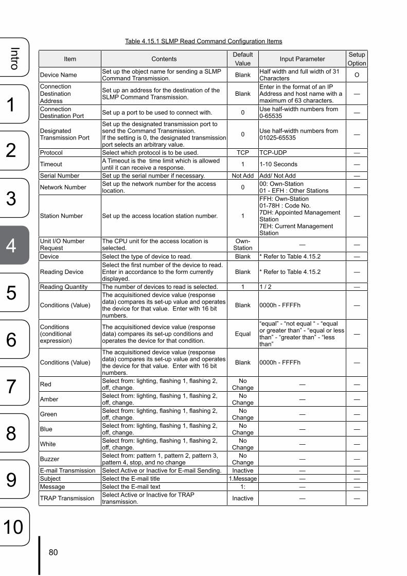
80
Intro
1
2
3
5
6
8
9
4
7
10
Table 4.15.1 SLMP Read Command Configuration Items
Item ContentsDefault Value
Input ParameterSetup Option
Device Name Set up the object name for sending a SLMP Command Transmission. Blank Half width and full width of 31
Characters O
Connection Destination Address
Set up an address for the destination of the SLMP Command Transmission. Blank
Enter in the format of an IP Address and host name with a maximum of 63 characters.
—
Connection Destination Port Set up a port to be used to connect with. 0 Use half-width numbers from
0-65535 —
Designated Transmission Port
Set up the designated transmission port to send the Command Transmission. If the setting is 0, the designated transmission port selects an arbitrary value.
0 Use half-width numbers from 01025-65535 —
Protocol Select which protocol is to be used. TCP TCP-UDP —
Timeout A Timeout is the time limit which is allowed until it can receive a response. 1 1-10 Seconds —
Serial Number Set up the serial number if necessary. Not Add Add/ Not Add —
Network Number Set up the network number for the access location. 0 00: Own-Station
01 - EFH : Other Stations —
Station Number Set up the access location station number. 1
FFH: Own-Station 01-78H : Code No. 7DH: Appointed Management Station 7EH: Current Management Station
—
Unit I/O Number Request
The CPU unit for the access location is selected.
Own-Station — —
Device Select the type of device to read. Blank * Refer to Table 4.15.2 —
Reading DeviceSelect the first number of the device to read. Enter in accordance to the form currently displayed.
Blank * Refer to Table 4.15.2 —
Reading Quantity The number of devices to read is selected. 1 1 / 2 —
Conditions (Value)
The acquisitioned device value (response data) compares its set-up value and operates the device for that value. Enter with 16 bit numbers.
Blank 0000h - FFFFh —
Conditions (conditional expression)
The acquisitioned device value (response data) compares its set-up conditions and operates the device for that condition.
Equal
“equal” - “not equal “ - “equal or greater than” - “equal or less than” - “greater than” - “less than”
—
Conditions (Value)
The acquisitioned device value (response data) compares its set-up value and operates the device for that value. Enter with 16 bit numbers.
Blank 0000h - FFFFh —
Red Select from: lighting, flashing 1, flashing 2, off, change.
No Change — —
Amber Select from: lighting, flashing 1, flashing 2, off, change.
No Change — —
Green Select from: lighting, flashing 1, flashing 2, off, change.
No Change — —
Blue Select from: lighting, flashing 1, flashing 2, off, change.
No Change — —
White Select from: lighting, flashing 1, flashing 2, off, change.
No Change — —
Buzzer Select from: pattern 1, pattern 2, pattern 3, pattern 4, stop, and no change
No Change — —
E-mail Transmission Select Active or Inactive for E-mail Sending. Inactive — —Subject Select the E-mail title 1.Message — —Message Select the E-mail text 1: — —
TRAP Transmission Select Active or Inactive for TRAP transmission. Inactive — —
user
生産終了

81
Intro
1
2
3
5
6
8
9
4
7
10
Table 4.15.2 List of Devices which can be set-up
Device Binary Code Device (ASCII) Classification Range SpecificationInput 9CH(X*)
Bit
base 16 0000 - FFFFHFor base 10, enter values
from 0-65535.
Output 9DH(Y*) base 16 0000 - FFFFHInternal Relay 90H(M*) base 10 0-65535Latch Relays 92H(L*) base 10 0-65535Annunciator 93H(F*) base 10 0-65535 For base 16,
enter values from 0000 -
FFFFh.
Edge Relay 94H(V*) base 10 0-65535Link Relay A0H(B*) base 16 0000 - FFFFHData Register ABH(D*)
Word
base 10 0-65535Link Register B4H(W*) base 16 0000 - FFFFH
Designate the range number of the device which the unit will access.
Timer C2H(TN) base 10 0-65535Addition Timer C8H(SN) base 10 0-65535Counter C5H(CN) base 10 0-65535Link Special Relay A1H(SB) Bit base 16 0000 - FFFFHLink Special Register B5H(SW) Word base 16 0000 - FFFFHDirect Input A2H(DX) Bit base 16 0000 - FFFFHDirect Output A3H(DY) base 16 0000 - FFFFHIndex Register CCH (Z*) Word base 10 0-65535
4.15.2. Common Operation Setting at Time of SLMP Error[Setup Method]
① . Select from the screen setup the common operation setting from the SLMP command transmission at the time of an error.
Fig. 4.15.3 SLMP Read Command Transmission Setup Screen
①
user
生産終了

82
Intro
1
2
3
5
6
8
9
4
7
10
② . Set up the Signal Tower operation at the time of an error.
③ .When using the E-mail Sending option at the time of an error, set it to “Active”.
When "E-mail Sending" is activated
④ .Register the subject and the message text to transmit. Then, select the recipient for the E-mail Sending.
⑤ .When using the TRAP transmission, set to “Active”.
TRAP Command received when TRAP Transmission condition occurs
OID: 1.3.6.1.4.1.20440.4.1.6.10Name: trapPatliteSlmpError
⑥ .Click the “Set” icon button to initiate the setup.
Fig. 4.15.4 Common Operation Setting screen at Time of SLMP Error.
Table 4.15.3 "Clear" Control Setup Parameters
Item Contents Default Value
Input Parameter
Setup Option
E-mail Transmission Select "Active" or "Inactive" for sending E-mail. Inactive — —Subject Select the subject title for the mail to be transmitted. 1.Message — —Message Select the message text for the mail to be transmitted. 1: — —E-mail Sending Locations 1-8 Set up the addressee parameters to send an E-mail. Unassigned — —
TRAP Transmission Select "Active" or "Inactive" for TRAP Transmission. Inactive — —
②
③
④
⑤
⑥
user
生産終了

83
Intro
1
2
3
5
6
8
9
4
7
10
4.16. SLMP Write Command Configuration ScreenThe following shows how an SLMP Write Command can be set up.
[Setup Method]
① . Select a screen number from 1 to 4 for the SLMP write command setting.② . Enter a device name of the target.③ . Enter the destination address of the target's connection.④ . Enter the destination port to connect with.⑤ . Select the protocol to be used.⑥ .Designate the device to write to.⑦ . Set up the Write data.⑧ . Push the “Set” button.
Fig. 4.16.1 SLMP Write Command Configuration Screen
②
③
④
⑤
⑥
⑦
⑧
①
user
生産終了

84
Intro
1
2
3
5
6
8
9
4
7
10
Table 4.16.1 SLMP Write Command Configuration Items
Item Contents Default Value
Input Parameter
Setup Option
Device Name Set up the name of the Command Transmission object. Blank Column half/full width Character 31 ODestination Address
Set up the target address for the command transmission to connect with. Blank Enter in the format of an IP Address and
host name with a maximum of 63 characters. ―
Destination Port Set up a port to connect with. 0 Use half-width numbers from 0-65535 ―Protocol Set up the protocol to be used. TCP ― ―Serial Number Set up the serial number if necessary. Don't add Add/Don't add ―Network Number Set up the network number for the access location. 0 00: Auto-access, 01 - EFH: Set access ―Station Number
Set up the access location station number. 1FFH: Auto-access, 01-78H : Code No. 7DH: Appointed Management Station 7EH: Current Management Station
―
Unit I/O Request Number Select the CPU unit for the access location. Own
Station ― ―
Device Select the device from the pull-down menu. Blank * Refer to Table 4.16.2 ―Write Device Set up the first number for the device’s writing location. Blank * Refer to Table 4.16.2 ―Writing Quantity Select the number of devices to write. 1 1/2 ―Write Data Set up the data to write. Blank * Refer to Table 4.16.3 ―
The following shows how an SLMP Write Command can be set up.
Table 4.16.2 SLMP Device Write Command Setup
Device Binary Code Device (ASCII) Classification Range Specification
Internal Relay 90H(M*)
Bit
base 10 0-65535For base 10, enter values
from 0-65535.Latch Relays 92H(L*) base 10 0-65535Annunciator 93H(F*) base 10 0-65535Edge Relay 94H(V*) base 10 0-65535
For base 16, enter values from 0000 - FFFFh.
Link Relay A0H(B*) base 16 0000 - FFFFHData Register ABH(D*)
Word
base 10 0-65535Link Register B4H(W*) base 16 0000 - FFFFHTimer C2H(TN) base 10 0-65535
Designate the range number of the device
which the unit will access.
Addition Timer C8H(SN) base 10 0-65535Counter C5H(CN) base 10 0-65535Link Special Relay A1H(SB) Bit base 16 0000 - FFFFHLink Special Register B5H(SW) Word base 16 0000 - FFFFHIndex Register CCH (Z*) Word base 10 0-65535
Table 4.16.3 Data Write Setup Range
Device Classification Writing Quantity Data Writing Range
Bit 1 Time (1 bit) 0, 12 Times (2 Bit) 0, 1, 2, 3
Word 1 Time (1 Word) 0- FFFFh2 Times (2 Word) 0 - FFFFFFFFh
MEMO Set the limit for the device and data to write to with the device number for access to the unit location.
user
生産終了

85
Intro
1
2
3
5
6
8
9
4
7
10
4.17. Signal Tower Output Control ScreenVerify the current operating status, and output a condition status for the Signal Tower.
[Setup Method]
① .Check the current operating condition of the Signal Tower.② . Select the desired outputs for the Signal Tower status in the “Output Control” column to operate it.③ .Click the “Execute Output” button. The Signal Tower output will reflect the setup performed in ② .④ . If the “Execute Clear” button is clicked, it will return to the “Normal Mode” status.
Fig. 4.17.1 Signal Tower Output Control Screen
Table 4.17.1 Signal Tower Output Control Parameters
Item Contents Default Value
Input Parameter
Setup Option
Red Select from: OFF- ON- Lighting- Flashing1- Flashing2- No Flashing- No Change ― ― ―Amber Select from: OFF- ON- Lighting- Flashing1- Flashing2- No Flashing- No Change ― ― ―Green Select from: OFF- ON- Lighting- Flashing1- Flashing2- No Flashing- No Change ― ― ―Blue Select from: OFF- ON- Lighting- Flashing1- Flashing2- No Flashing- No Change ― ― ―White Select from: OFF- ON- Lighting- Flashing1- Flashing2- No Flashing- No Change ― ― ―
Buzzer Select from:Pattern1- Pattern2- Pattern3- Pattern4- Stop ― ― ―
① ②
③
④
user
生産終了

86
Intro
1
2
3
5
6
8
9
4
7
10
4.18. Reinitialize ScreenThe setup parameters can be reset to their default values by initializing this product. The network setup can be selected to be excluded from initialization.If the network setup is also required to be reset to its factory defaults, it can be selected to be initialized with the rest of the setup parameters.If the "Reinitialize Network Settings" is not checked, all but the network setup is initialized.
[Setup Method]
When the initialization does not require the network setup to be included
① . Put a “Check” in the box for “Reinitialize Network Settings.”② .Click the “Reinitialize Execute” button.
When the network setup also needs to be reinitialized
③ . Just click the “Reinitialize Execute” button.
Fig. 4.18.1 Reinitialize Screen
Attention If the network setup is also initialized, since the IP address will return to its factory default value of “192.168.10.1”, the network has to be setup again.
MEMO“Network Setup” refers to the “IP address for this product, Net Mask, Default Gateway, DNS server address and Host Name” parameters in the System Configuration Screen.
①
②
user
生産終了

87
Intro
1
2
3
5
6
8
9
4
7
10
4.19. Reboot ScreenThis product can be rebooted just by clicking the "Reboot" button.
① .Once the “Reinitialize Execute” button is clicked, a new screen will display a message indicating it is re-booting.
② .Click “To the Login screen” on the new screen to log back in.
Fig. 4.19.1 Reboot Screen
Fig. 4.19.2 Login after Reboot Screen
AttentionIf this product is rebooted, because all of the event log data will be erased, it is recommended to download the event log prior to rebooting, for reloading afterwards.
②
①
user
生産終了

88
Intro
1
2
3
5
6
8
9
4
7
10
4.20. Event Log ScreenEvents from this product are logged and is shown in the event log.By clicking the "Event Log Download", an event log file can be downloaded.A maximum of 255 logged events are acquirable.
Fig. 4.20.1 Event Log Screen
Attention
The event log data will be erased if either of the following operations are executed.• Turning the power supply “OFF”• Reinitializing this product from the initialization screen.• Rebooting this product from the “Reboot Screen”.• Updating the firmware.
user
生産終了
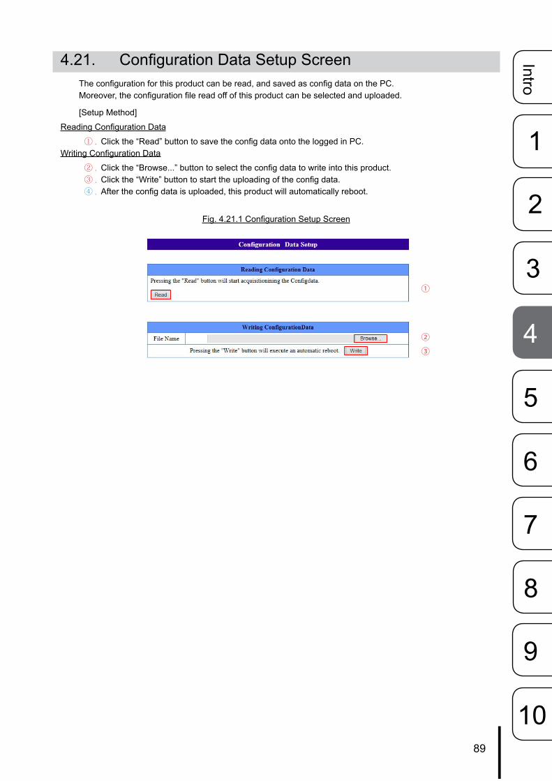
89
Intro
1
2
3
5
6
8
9
4
7
10
4.21. Configuration Data Setup ScreenThe configuration for this product can be read, and saved as config data on the PC.Moreover, the configuration file read off of this product can be selected and uploaded.
[Setup Method]
Reading Configuration Data
① .Click the “Read” button to save the config data onto the logged in PC.Writing Configuration Data
② .Click the “Browse...” button to select the config data to write into this product.③ .Click the “Write” button to start the uploading of the config data.④ . After the config data is uploaded, this product will automatically reboot.
Fig. 4.21.1 Configuration Setup Screen
①
②③
user
生産終了
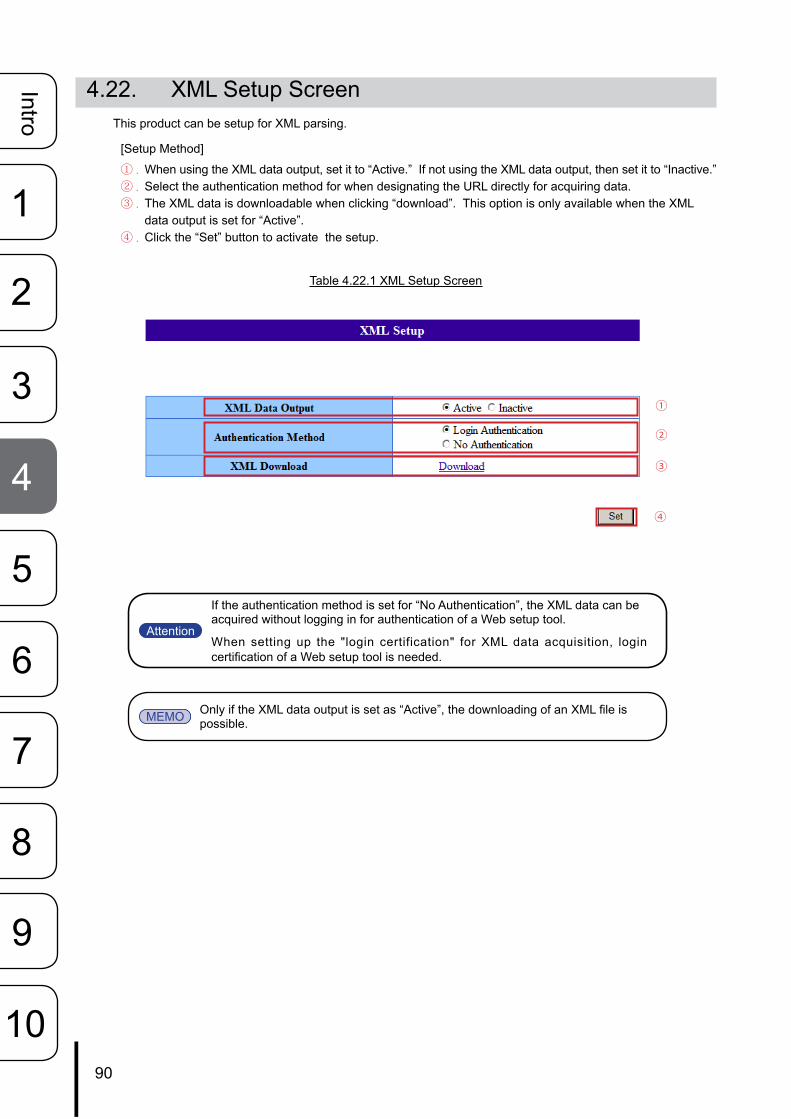
90
Intro
1
2
3
5
6
8
9
4
7
10
4.22. XML Setup ScreenThis product can be setup for XML parsing.
[Setup Method]
① .When using the XML data output, set it to “Active.” If not using the XML data output, then set it to “Inactive.”② . Select the authentication method for when designating the URL directly for acquiring data.③ . The XML data is downloadable when clicking “download”. This option is only available when the XML
data output is set for “Active”.④ .Click the “Set” button to activate the setup.
Table 4.22.1 XML Setup Screen
Attention
If the authentication method is set for “No Authentication”, the XML data can be acquired without logging in for authentication of a Web setup tool.
When setting up the "login certification" for XML data acquisition, login certification of a Web setup tool is needed.
MEMO Only if the XML data output is set as “Active”, the downloading of an XML file is possible.
①
②
③
④
user
生産終了

91
Intro
1
2
3
5
6
8
9
4
7
10
4.23. Firmware Update ScreenThe firmware for this product can be updated.After the firmware has been updated, this product automatically reboots.
[Setup Method]
① .Click the “Browse” button to designate the firmware to rewrite for this product.② .Clicking the “Update” button will start the firmware update.
Fig. 4.23.1 Firmware Update Screen
Fig. 4.23.2 Firmware Update Failure Screen
Attention Do not disconnect the power cable or LAN cable during the update. Possible cause of failure may occur.
Attention
Fig. 4.23.2 shows the type of screen in case an error occurs during the firmware update.If an error occurs during the firmware update, try again. If an error repeatedly occurs during the firmware update process, contact your nearest Patlite Sales Representative.
①
②
user
生産終了
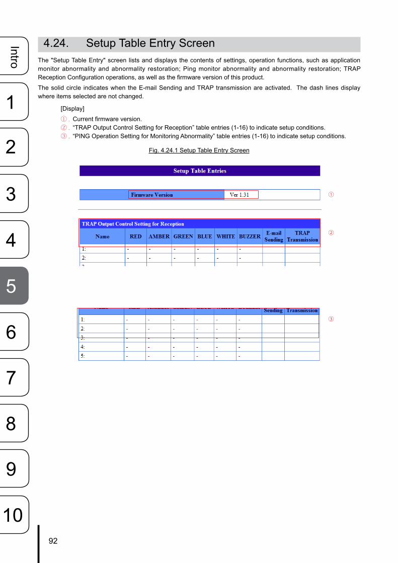
92
Intro
1
2
3
5
6
8
9
4
7
10
4.24. Setup Table Entry ScreenThe "Setup Table Entry" screen lists and displays the contents of settings, operation functions, such as application monitor abnormality and abnormality restoration; Ping monitor abnormality and abnormality restoration; TRAP Reception Configuration operations, as well as the firmware version of this product.
The solid circle indicates when the E-mail Sending and TRAP transmission are activated. The dash lines display where items selected are not changed.
[Display]
① .Current firmware version.② . “TRAP Output Control Setting for Reception” table entries (1-16) to indicate setup conditions.③ . “PING Operation Setting for Monitoring Abnormality” table entries (1-16) to indicate setup conditions.
Fig. 4.24.1 Setup Table Entry Screen
①
②
③
user
生産終了
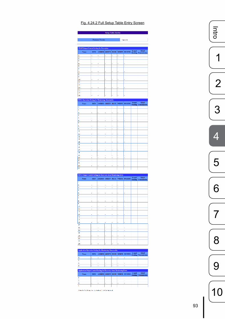
93
Intro
1
2
3
5
6
8
9
4
7
10
Fig. 4.24.2 Full Setup Table Entry Screen
user
生産終了

94
Intro
1
2
3
5
6
8
9
4
7
10
5. MIBWith this product, there is an exclusive MIB (Management Information Base) for the NH Series, and the monitor controls can be operated by the SNMP manager, etc.
5.1. MIB Definition List
MEMO Use the PRSH when acquisitioning a SNMP data log dump.
iso(1)org(3)
dod(6)internet(1)
private(4)enterprises(1)
patlite(20440)patliteModule(4)
networkSignalTower(1)ident(1)
■identSwInitVersion(1)[OCTET STRING]■identSwAgentVersion(2)[OCTET STRING]■identHwVersion(3)[OCTET STRING]
config(2)
alarm(3)
monitor(4)pingServer(1)
■pingServerNumEntries(1)[INTEGER]pingServerTable(2)
pingServerTableEntry(1)pingServerTableIndex(1)[INTEGER]pingServerName(2)[OCTET STRING]pingServerAlertValue(3)[INTEGER]pingServerIpAddress(4)[OCTET STRING]
trapCatcher(2)
logDump(3)logDumpEventLog1(1)[OBJECT IDENTIFIER]logDumpEventLog2(2)[OBJECT IDENTIFIER]logDumpEventLog3(3)[OBJECT IDENTIFIER]
user
生産終了
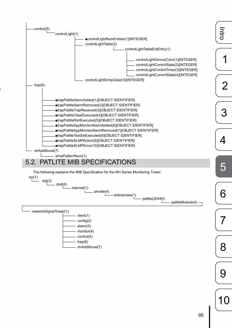
95
Intro
1
2
3
5
6
8
9
4
7
10
5.2. PATLITE MIB SPECIFICATIONSThe following explains the MIB Specification for the NH Series Monitoring Tower.
control(5)controlLight(1)
■controlLightNumEntries(1)[INTEGER]controlLightTable(2)
controlLightTableEntEntry(1)
controlLightDeviceColor(1)[INTEGER]controlLightControlState(2)[INTEGER]controlLightControlTimer(3)[INTEGER]controlLightCurrentState(4)[INTEGER]
controlLightSnmpClear(3)[INTEGER]trap(6)
■trapPatliteAlarmAdded(1)[OBJECT IDENTIFIER]■trapPatliteAlarmRemoved(2)[OBJECT IDENTIFIER]■trapPatliteTrapReceived(3)[OBJECT IDENTIFIER]■trapPatliteClearExecuted(4)[OBJECT IDENTIFIER]■trapPatliteRshExecuted(5)[OBJECT IDENTIFIER]■trapPatliteAppMonitorAlarmAdded(6)[OBJECT IDENTIFIER]■trapPatliteAppMonitorAlarmRemoved(7)[OBJECT IDENTIFIER]■trapPatliteTestSwExecuted(8)[OBJECT IDENTIFIER]■trapPatliteSLMPAction(9)[OBJECT IDENTIFIER]■trapPatliteSLMPError(10)[OBJECT IDENTIFIER]
nhAdditional(7)slmpPatternNum(1)
iso(1)org(3)
dod(6)internet(1)
private(4)enterprises(1)
patlite(20440)patliteModule(4)
networkSignalTower(1)ident(1)config(2)alarm(3)monitor(4)control(5)trap(6)nhAdditional(7)
user
生産終了

96
Intro
1
2
3
5
6
8
9
4
7
10
Table 5.2.1 MIB Specifications
OID Name Model MAX-ACCESS Comment1 ident ― ― ID Group1.1.0 identSWinitVersion String(2) read-only OS Version1.2.0 identSWAgentVersion String(3) read-only Application Version1.3.0 idensHWVersion String(3) read-only Hardware Version4 monitor ― ― Monitor Group4.1 pingServer ― ― ping monitoring setting4.1.1.0 pingServerNumEntries INTEGER read-only Ping monitoring count4.1.2.0 pingServerTable ― not-accessible ping monitoring table4.1.2.1.0 pingServerTableEntry ― not-accessible4.1.2.1.1. (index) pingServerTableIndex INTEGER read-only ping monitoring index
4.1.2.1.2. (index) pingServerName STRING(31) read-only ping monitor name
4.1.2.1.3. (index) pingServerAlertValue INTEGER{ normal(1),
occurred(2) } read-only ping monitor condition normal(1), event occurred(2)
4.1.2.1.4. (index) pingServerIpAddress STRING(63) read-only ping monitoring address
4.3 logDump ― ― log setting4.3.1.0 logDumpEventlog1 OBJECT IDENTFIER read-only event log from 1 to 854.3.2.0 logDumpEventlog2 OBJECT IDENTFIER read-only event log from 86 to 1704.3.3.0 logDumpEventlog3 OBJECT IDENTFIER read-only event log from 171 to 2555.1 controlLight ― ― signal tower control5.1.1.0 controlLightNumEntries INTEGER read-only count of control entries5.1.2.0 controlLightTable ― not-accessible signal tower table5.1.2.1.0 controlLightTableEntry ― not-accessible ―
5.1.2.1.1. (index) controlLightDeviceColor
INTEGER {red(1), amber(2), green(3), blue(4), clear(5), buzzer(6) }
read-only signal tower color R(1)/Y(2)/G(3)/B(4)/C(5)/Buz(6)
5.1.2.1.2. (index) controlLightControlState
INTEGER {turn-off(1), turn-ON(2), blinking-pattern(3), nop(4), blinking-patern2(5), sound-pattern4(6) }
read-write
Signal Tower Status: lights and buzzer off(1)/lighting and buzzer synchronized with light pattern1(2)/flashing pattern1 and buzzer synchronized with light pattern2(3)/no change(4)/flashing pattern2 and buzzer synchronized with light pattern3(5)/buzzer synchronized with light pattern 4(6). controlLightControlTimer is set by entering values above zero.
5.1.2.1.3. (index) controlLightControlTimer INTEGER(-1,99) read-write
A preset value is decremented for every second until it is 0, then it changes to the status designated by the controlLightControlState.
5.1.2.1.4. (index) controlLightCurrentState
INTEGER { off(1), on(2), blinking-pattern1(3), blinking-pattern2(4), sound-pattern4(5) }
read-only
The present status is displayed.lights and buzzer off(1)/lighting and buzzer synchronized with light pattern1(2)/flashing pattern1 and buzzer synchronized with light pattern2(3)/flashing pattern2 and buzzer synchronized with light pattern3(4)/buzzer synchronized with light pattern4(5)
5.1.3.0 controlLightSnmpClear INTEGER{ execute(1), nop(0) } read-write execute(1) setup will clear the Signal Tower
operation.6 Trap ― ― ―6.1 trapPatliteAlarmAdded OBJECT-IDENTIFIER not-accessible When an abnormality in the PING occurs6.2 trapPatliteAlarmRemoved OBJECT-IDENTIFIER not-accessible When an abnormality in the PING is restored6.3 trapPatliteTrapReceived OBJECT-IDENTIFIER not-accessible When a trap is received6.4 trapPatliteClearExecuted OBJECT-IDENTIFIER not-accessible When the clear button is pushed6.5 trapPatliteRshExecuted OBJECT-IDENTIFIER not-accessible When an RSH command is executed
6.6 trapPatliteAppMonitorAlarmAdded OBJECT-IDENTIFIER not-accessible When an abnormality in the application occurs
6.7 trapPatliteAppMonitorAlarmRemoved OBJECT-IDENTIFIER not-accessible When an abnormality in the application is restored
6.8 trapPatliteTestSwExecuted OBJECT-IDENTIFIER not-accessible When the test switch is pushed
6.9 trapPatliteSLMPError OBJECT-IDENTIFIER not-accessible When data corresponding to the SLMP con-dition is received
6.10 trapPatliteSLMPError OBJECT-IDENTIFIER not-accessible When the SLMP error data is received7 nhAdditional7.1 slmpPatternNum INTEGER(1,16) not-accessible Stores an integer based on SLMP conditions.
user
生産終了

97
Intro
1
2
3
5
6
8
9
4
7
10
6. Replacement and Option PartsThe following explains the repair and maintenance parts of this product. Signal Tower tiers can be increased or decreased by the customer by purchasing the necessary parts.
6.1. Replacement PartsThe following is the replacement part list for the NHL, NHP and NHS Series. When inquiring, ask the store where you purchased this product. Rubber feet, AC Adaptor, and adhesive seal are common accessories.
Table 6.1.1 NH Series Replacement Parts
Model Name Part Name Part Number
NHL (φ60 Type)
Head Cover B32310027-1F1Center Shaft 5 Tier S33552120-04225F1Center Shaft 4 Tier S33552120-04180F1Center Shaft 3 Tier S33552120-04140F1Center Shaft 2 Tier S33552120-04100F1Center Shaft 1 Tier S33552120-0455F1
LED Unit Red B72100207-1F1LED Unit Amber B72100207-2F1LED Unit Green B72100207-3F1LED Unit Blue B72100207-4F1LED Unit White B72100206-7F1
Table 6.1.2 Compatable Replacement Parts
Part Name Part NumberCover Seal T93190007-1F1Rubber Feet T81800007-F1Bottom Seal T93130009-F1Support Base (Screws Included) T81800019-F1
user
生産終了

98
Intro
1
2
3
5
6
8
9
4
7
10
6.2. Signal Tower Unit Color ArrangementThe following explains the method when rearranging or repairing the LED units from customer purchased parts.
6.2.1. NHL Signal Tower Unit (Color) Rearrangement Method1. Turn the power off before changing the color sequence.2. Carefully peel off the cover sticker, then loosen the center shaft and remove the head cover and shaft.
Because the upper and lower LED units are secured to each other by two snaps, carefully remove the LED unit by gently pushing the snaps inward.
3. When increasing or decreasing tiers, be sure to replace the center shaft with the proper length to match the number of tiers when changing.
4. After the center shaft is properly fixed, place the static-free cover sticker back on.
Fig. 6.2.1 NHL Signal Tower Unit (Color) Rearrangement Figure
Snaps
SnapsAlign snaps with Tabs
Align snaps with Tabs
Connectors
Attention
• Do not attempt to forcibly detach an LED unit. Failure to comply may damage the unit.
• The LED unit falling and breaking may result if the center shaft is not properly tightened.
• Overtightening the center shaft may cause damage to the threads or tapping hole, causing possible malfunction or damage to the LED units.
• Be sure to torque the center screw no more than 0.68 N-m. Failure to do so may cause damage to the unit
• Be careful of the contact pins when handling the LED unit, they may be sharp.
user
生産終了

99
Intro
1
2
3
5
6
8
9
4
7
10
6.3. Option PartsThe following explains the mounting instructions of this product for the option parts available that customers had purchased.
6.3.1. Wall Mount BracketThis product can be attached to a wall with the wall mount bracket. One wall mount bracket can be used to attach this product on either the left-side or right-side of the wall.
Fig. 6.3.1 Wall Mount Surface Bracket Figure (Figure to the left indicates the left-sided attachment; figure to the right indicates the right-sided attachment)
VOL.
RESET
TEST
HIGHLOWOFF
L E C A R
VOL.
RESET
TEST
HIGHLOWOFF
L E C A R
RX/TX
LINK
24VDC
RX/TX
LINK
24VDC
Attention The installation direction for this product is only for the front attachment direction.
user
生産終了

100
Intro
1
2
3
5
6
8
9
4
7
10
[Installation Method]
1. After deciding on the attachment direction of the wall mount bracket, assemble this product to the bracket. (Use the same installation screw enclosed for assembling the Support Base).
Fig. 6.3.2 Wall Mount Bracket Installation Diagram
2. Fix the wall mount bracket to the wall surface. Select the proper screw when installing the wall mount bracket to the customer's wall in accordance to the quality of the wall material to be mounted upon.
Option Name Part NumberWall Mounting Bracket NH-WST
6.3.2. Partition Mounting Bracket
The partition mounting bracket is an optional item for attaching to partition walls in environments which cannot be attached to walls or other positions. The partition mounting bracket is designed to be attached with the front of this product facing to the right or left when fastening it to the partition.
Fig. 6.3.3 Partition mounting bracket installation example (Left image is for the left-side and the right image is for the right-side installations)
VOL.
RESET
TEST
HIGHLOWOFF
L E C A R
VOL.
RESET
TEST
HIGHLOWOFF
L E C A RRX/TX
LINK
24VDC
RX/TX
LINK
24VDC
Bracket Mounting Location
62
79
113
4-φ670
38
16
NHL Underside View NH-WST Outside Appearance Installation Procedure
NHL Unit
NH-WST
Mounting Screws
Attention The installation direction for this product is only for the front attachment direction.
Attention
Tighten the screws between this product and the bracket with a torque of about 0.39 N-m. Failure to do so may cause damage to the unit.Verify the installation is securely clamped to ensure there is no fear of detachment and falling after installation. Apply the power after checking that it has been installed correctly.
user
生産終了

101
Intro
1
2
3
5
6
8
9
4
7
10
[Installation Method]
1. After deciding on the attachment direction of the partition mounting bracket, assemble this product to the bracket. (Use the screws include when assembling).
Fig. 6.3.4 Partition mounting bracket installation method
2. Check the width of the partition, then select the proper clamping screw to thread through the bracket. Attach the pressure plate and fittings.
Fig. 6.3.5 Installation Method 1
3. Turn the clamping screw clockwise to tighten.
Fig. 6.3.6 Installation Method 2
Option Name Part NumberPartition Mounting Bracket NH-PST
Long clamping screw application Short clamping screw application
VOL.
RESET
TEST
HIGHLOWOFF
VOL.
RESET
TEST
HIGHLOWOFF
VOL.
RESET
TEST
HIGHLOWOFFVOL.
RESET
TEST
HIGHLOWOFF
The short clamping screw is effective for thicknesses of 48 to 58mm.
The long clamping screw is effective for thicknesses of 18 to 48mm.
100
45
100
70.2
Bracket Mounting Location
NHL Underside View NH-WST Outside Appearance Installation Procedure
NHL Unit
NH-WST
Mounting Screws
Attention Tighten the screws between this product and the partition mounting bracket with a torque of about 0.39 N-m. Failure to do so may cause damage to the unit.
Attention The partition mounting bracket may break if too much torque is applied.
user
生産終了

102
Intro
1
2
3
5
6
8
9
4
7
10
7. Troubleshooting
Problem Check the following
The power does not turn on. • Check whether the AC Adaptor is connected correctly.
The Web setup tool does not display.
• Check whether the LAN connector is connected correctly.• Check the setup for the IP address on this product.• Check the setup for the IP address on the PC side.• Refer to "2.5 Network Setup" on pg. 19 for the IP address set up procedure.
The Web setup tool does not display correctly. • Make sure the browser information has been recently updated.
The Signal Tower does not turn on.
• Check whether the AC Adaptor is connected correctly.• Check the setup of the Signal Tower operation with the Web setup tool.
Refer to "4.13 Normal Mode Settings Screen" on pg. 76 for the procedure to set up for the normal operation mode.
• After any recombination of tiers to the Signal Tower has been done, check whether the Signal Tower lights up by accessing the Signal Tower Output Control screen. If the light does not turn on, it may not be installed correctly. Refer to "4.17 Signal Tower Output Control Screen" on pg. 85 for the procedure to control the Signal Tower output.
The buzzer does not sound.
• Check whether the volume switch has been set in the "OFF" position.• After each setup, check the buzzer operation.
Refer to "4.17 Signal Tower Output Control Screen" on pg. 85 for the procedure to setup the buzzer output.
Socket Transmission does not work.
• Check whether the correct communication port has been set. Refer to "4.5 Socket Transmission Setup Screen" on pg. 58 for the setup procedure of the Socket Transmission.
• Check whether the data had been sent correctly. For data transmitted by the Socket Transmission, refer to "3.5 PHN Command Reception Function" on pg. 27 and "3.6 PNS Command Reception Function" on pg. 29 .
The RSH command data is unreceivable.
• Check the command reception setup. Refer to "4.8 RSH Command Configuration Screen" on pg. 62 for the setup procedure of the command reception.
• Check whether the security settings for the PC has granted permission.The HTTP Command does not work.
• Check the HTTP command control function is set to the "Active". Refer to "4.1. System Configuration Screen"
I want to return it to the factory settings., • Refer to "3.13 Reinitialization Function" on pg. 41.
The E-mail transmission cannot be sent. • Check whether the setup for the server is correct.
The SNMP SET/GET does not work. • Check the SET Community name and GET Community name.
The status LED is flashing. • It may be in the factory-shipment inspection mode. Be sure to reboot this product.
user
生産終了

103
Intro
1
2
3
5
6
8
9
4
7
10
8. Freeware Terms of AgreementThe following chapter clearly outlines the copyrights for the freeware software used with this product.
8.1. GNU GENERAL PUBLIC LICENCEGNU GENERAL PUBLIC LICENSE
Version 2, June 1991
Copyright (C) 1989, 1991 Free Software Foundation, Inc. 675 Mass Ave, Cambridge, MA 02139, USA Everyone is permitted to copy and distribute verbatim copies of this license document, but changing it is not allowed.
Preamble
The licenses for most software are designed to take away your freedom to share and change it. By contrast, the GNU General PublicLicense is intended to guarantee your freedom to share and change freesoftware--to make sure the software is free for all its users. ThisGeneral Public License applies to most of the Free Software Foundation’s software and to any other program whose authors commit tousing it. (Some other Free Software Foundation software is covered bythe GNU Library General Public License instead.) You can apply it toyour programs, too.
When we speak of free software, we are referring to freedom, notprice. Our General Public Licenses are designed to make sure that youhave the freedom to distribute copies of free software (and charge forthis service if you wish), that you receive source code or can get it if you want it, that you can change the software or use pieces of it in new free programs; and that you know you can do these things.
To protect your rights, we need to make restrictions that forbid anyone to deny you these rights or to ask you to sur-render the rights.These restrictions translate to certain responsibilities for you if you distribute copies of the software, or if you modify it.
For example, if you distribute copies of such a program, whether gratis or for a fee, you must give the recipients all the rights that you have. You must make sure that they, too, receive or can get the source code. And you must show them these terms so they know their rights.
We protect your rights with two steps: (1) copyright the software, and (2) offer you this license which gives you legal permission to copy, distribute and/or modify the software.
Also, for each author’s protection and ours, we want to make certain that everyone understands that there is no warranty for this free software. If the software is modified by someone else and passed on, we want its recipients to know that what they have is not the original, so that any problems introduced by others will not reflect on the original authors’ reputations.
Finally, any free program is threatened constantly by software patents. We wish to avoid the danger that redistribu-tors of a free program will individually obtain patent licenses, in effect making the program proprietary. To prevent this, we have made it clear that any patent must be licensed for everyone’s free use or not licensed at all.
The precise terms and conditions for copying, distribution and modification follow.
GNU GENERAL PUBLIC LICENSETERMS AND CONDITIONS FOR COPYING, DISTRIBUTION AND MODIFICATION
0. This License applies to any program or other work which contains a notice placed by the copyright holder saying
user
生産終了

104
Intro
1
2
3
5
6
8
9
4
7
10
it may be distributed under the terms of this General Public License. The “Program”, below, refers to any such program or work, and a “work based on the Program” means either the Program or any derivative work under copyright law: that is to say, a work containing the Program or a portion of it, either verbatim or with modifications and/or translated into another language. (Hereinafter, translation is included without limitation in the term “modifi-cation”.) Each licensee is addressed as “you”.
Activities other than copying, distribution and modification are not covered by this License; they are outside its scope. The act of running the Program is not restricted, and the output from the Program is covered only if its contents con-stitute a work based on the Program (independent of having been made by running the Program). Whether that is true depends on what the Program does.
1. You may copy and distribute verbatim copies of the Program’s source code as you receive it, in any medium, provided that you conspicuously and appropriately publish on each copy an appropriate copyright notice and dis-claimer of warranty; keep intact all the notices that refer to this License and to the absence of any warranty; and give any other recipients of the Program a copy of this License along with the Program.
You may charge a fee for the physical act of transferring a copy, and you may at your option offer warranty protection in exchange for a fee.
2. You may modify your copy or copies of the Program or any portion of it, thus forming a work based on the Program, and copy and distribute such modifications or work under the terms of Section 1 above, provided that you also meet all of these conditions:
a) You must cause the modified files to carry prominent notices stating that you changed the files and the date of any change.
b) You must cause any work that you distribute or publish, that in whole or in part contains or is derived from the Program or any part thereof, to be licensed as a whole at no charge to all third parties under the terms of this License.
c) If the modified program normally reads commands interactively when run, you must cause it, when started running for such interactive use in the most ordinary way, to print or display an announcement including an appropriate copyright notice and a notice that there is no warranty (or else, saying that you provide a war-ranty) and that users may redistribute the program under these conditions, and telling the user how to view a copy of this License. (Exception: if the Program itself is interactive but does not normally print such an announcement, your work based on the Program is not required to print an announcement.)
These requirements apply to the modified work as a whole. If identifiable sections of that work are not derived from the Program, and can be reasonably considered independent and separate works in themselves, then this License, and its terms, do not apply to those sections when you distribute them as separate works. But when you distribute the same sections as part of a whole which is a work based on the Program, the distribution of the whole must be on the terms of this License, whose permissions for other licensees extend to the entire whole, and thus to each and ev-ery part regardless of who wrote it.
Thus, it is not the intent of this section to claim rights or contest your rights to work written entirely by you; rather, the intent is to exercise the right to control the distribution of derivative or collective works based on the Program.
In addition, mere aggregation of another work not based on the Program with the Program (or with a work based on the Program) on a volume of a storage or distribution medium does not bring the other work under the scope of this License. 3. You may copy and distribute the Program (or a work based on it, under Section 2) in object code or executable form under the terms of Sections 1 and 2 above provided that you also do one of the following:
a) Accompany it with the complete corresponding machine-readable source code, which must be distributed under the terms of Sections 1 and 2 above on a medium customarily used for software interchange; or,
b) Accompany it with a written offer, valid for at least three years, to give any third party, for a charge no more than your cost of physically performing source distribution, a complete machine-readable copy of the corresponding source code, to be distributed under the terms of Sections 1 and 2 above on a medium customarily used for software interchange; or,
c) Accompany it with the information you received as to the offer to distribute corresponding source code. (This
user
生産終了

105
Intro
1
2
3
5
6
8
9
4
7
10
alternative is allowed only for noncommercial distribution and only if you received the program in object code or executable form with such an offer, in accord with Subsection b above.)
The source code for a work means the preferred form of the work for making modifications to it. For an executable work, complete source code means all the source code for all modules it contains, plus any associated interface defi-nition files, plus the scripts used to control compilation and installation of the executable. However, as a special ex-ception, the source code distributed need not include anything that is normally distributed (in either source or binary form) with the major components (compiler, kernel, and so on) of the operating system on which the executable runs, unless that component itself accompanies the executable.
If distribution of executable or object code is made by offering access to copy from a designated place, then offer-ing equivalent access to copy the source code from the same place counts as distribution of the source code, even though third parties are not compelled to copy the source along with the object code.
4. You may not copy, modify, sublicense, or distribute the Program except as expressly provided under this License. Any attempt otherwise to copy, modify, sublicense or distribute the Program is void, and will automatically terminate your rights under this License. However, parties who have received copies, or rights, from you under this License will not have their licenses terminated so long as such parties remain in full compliance.
5. You are not required to accept this License, since you have not signed it. However, nothing else grants you per-mission to modify or distribute the Program or its derivative works. These actions are prohibited by law if you do not accept this License. Therefore, by modifying or distributing the Program (or any work based on the Program), you indicate your acceptance of this License to do so, and all its terms and conditions for copying, distributing or modify-ing the Program or works based on it.
6. Each time you redistribute the Program (or any work based on the Program), the recipient automatically receives a license from the original licensor to copy, distribute or modify the Program subject to these terms and conditions. You may not impose any further restrictions on the recipients’ exercise of the rights granted herein. You are not re-sponsible for enforcing compliance by third parties to this License.
7. If, as a consequence of a court judgment or allegation of patent infringement or for any other reason (not limited to patent issues), conditions are imposed on you (whether by court order, agreement or otherwise) that contradict the conditions of this License, they do not excuse you from the conditions of this License. If you cannot distribute so as to satisfy simultaneously your obligations under this License and any other pertinent obligations, then as a con-sequence you may not distribute the Program at all. For example, if a patent license would not permit royalty-free redistribution of the Program by all those who receive copies directly or indirectly through you, then the only way you could satisfy both it and this License would be to refrain entirely from distribution of the Program.If any portion of this section is held invalid or unenforceable under any particular circumstance, the balance of the section is intended to apply and the section as a whole is intended to apply in other circumstances.
It is not the purpose of this section to induce you to infringe any patents or other property right claims or to contest validity of any such claims; this section has the sole purpose of protecting the integrity of the free software distribu-tion system, which is implemented by public license practices. Many people have made generous contributions to the wide range of software distributed through that system in reliance on consistent application of that system; it is up to the author/donor to decide if he or she is willing to distribute software through any other system and a licensee cannot impose that choice.
This section is intended to make thoroughly clear what is believed to be a consequence of the rest of this License.
8. If the distribution and/or use of the Program is restricted in certain countries either by patents or by copyrighted interfaces, the original copyright holder who places the Program under this License may add an explicit geographical distribution limitation excluding those countries, so that distribution is permitted only in or among countries not thus excluded. In such case, this License incorporates the limitation as if written in the body of this License.
9. The Free Software Foundation may publish revised and/or new versions of the General Public License from time to time. Such new versions will be similar in spirit to the present version, but may differ in detail to address new
user
生産終了

106
Intro
1
2
3
5
6
8
9
4
7
10
problems or concerns.
Each version is given a distinguishing version number. If the Program specifies a version number of this License which applies to it and “any later version”, you have the option of following the terms and conditions either of that version or of any later version published by the Free Software Foundation. If the Program does not specify a version number of this License, you may choose any version ever published by the Free Software Foundation.
10. If you wish to incorporate parts of the Program into other free programs whose distribution conditions are differ-ent, write to the author to ask for permission. For software which is copyrighted by the Free Software Foundation, write to the Free Software Foundation; we sometimes make exceptions for this. Our decision will be guided by the two goals of preserving the free status of all derivatives of our free software and of promoting the sharing and reuse of software generally.
NO WARRANTY
11. BECAUSE THE PROGRAM IS LICENSED FREE OF CHARGE, THERE IS NO WARRANTY FOR THE PRO-GRAM, TO THE EXTENT PERMITTED BY APPLICABLE LAW. EXCEPT WHEN OTHERWISE STATED IN WRIT-ING THE COPYRIGHT HOLDERS AND/OR OTHER PARTIES PROVIDE THE PROGRAM “AS IS” WITHOUT WAR-RANTY OF ANY KIND, EITHER EXPRESSED OR IMPLIED, INCLUDING, BUT NOT LIMITED TO, THE IMPLIED WARRANTIES OF MERCHANTABILITY AND FITNESS FOR A PARTICULAR PURPOSE. THE ENTIRE RISK AS TO THE QUALITY AND PERFORMANCE OF THE PROGRAM IS WITH YOU. SHOULD THE PROGRAM PROVE DEFECTIVE, YOU ASSUME THE COST OF ALL NECESSARY SERVICING, REPAIR OR CORRECTION.
12. IN NO EVENT UNLESS REQUIRED BY APPLICABLE LAW OR AGREED TO IN WRITING WILL ANY COPY-RIGHT HOLDER, OR ANY OTHER PARTY WHO MAY MODIFY AND/OR REDISTRIBUTE THE PROGRAM AS PERMITTED ABOVE, BE LIABLE TO YOU FOR DAMAGES, INCLUDING ANY GENERAL, SPECIAL, INCIDEN-TAL OR CONSEQUENTIAL DAMAGES ARISING OUT OF THE USE OR INABILITY TO USE THE PROGRAM (INCLUDING BUT NOT LIMITED TO LOSS OF DATA OR DATA BEING RENDERED INACCURATE OR LOSSES SUSTAINED BY YOU OR THIRD PARTIES OR A FAILURE OF THE PROGRAM TO OPERATE WITH ANY OTHER PROGRAMS), EVEN IF SUCH HOLDER OR OTHER PARTY HAS BEEN ADVISED OF THE POSSIBILITY OF SUCH DAMAGES.
END OF TERMS AND CONDITIONS
Appendix: How to Apply These Terms to Your New Programs
If you develop a new program, and you want it to be of the greatest possible use to the public, the best way to achieve this is to make it free software which everyone can redistribute and change under these terms.
To do so, attach the following notices to the program. It is safest to attach them to the start of each source file to most effectively convey the exclusion of warranty; and each file should have at least the “copyright” line and a pointer to where the full notice is found.
<one line to give the program’s name and a brief idea of what it does.> Copyright (C) 19yy <name of author>
This program is free software; you can redistribute it and/or modify it under the terms of the GNU General Public License as published by the Free Software Foundation; either version 2 of the License, or (at your op-tion) any later version.
This program is distributed in the hope that it will be useful, but WITHOUT ANY WARRANTY; without even the implied warranty of MERCHANTABILITY or FITNESS FOR A PARTICULAR PURPOSE. See the GNU General Public License for more details.
You should have received a copy of the GNU General Public License along with this program; if not, write to the Free Software Foundation, Inc., 675 Mass Ave, Cambridge, MA 02139, USA.
user
生産終了

107
Intro
1
2
3
5
6
8
9
4
7
10
Also add information on how to contact you by electronic and paper mail.
If the program is interactive, make it output a short notice like this when it starts in an interactive mode:
Gnomovision version 69, Copyright (C) 19yy name of author Gnomovision comes with ABSOLUTELY NO WARRANTY; for details type `show w’. This is free software, and you are welcome to redistribute it under certain conditions; type `show c’ for details.
The hypothetical commands `show w’ and `show c’ should show the appropriate parts of the General Public Li-cense. Of course, the commands you use may be called something other than `show w’ and `show c’; they could even be mouse-clicks or menu items--whatever suits your program.
You should also get your employer (if you work as a programmer) or your school, if any, to sign a “copyright dis-claimer” for the program, if necessary. Here is a sample; alter the names:
Yoyodyne, Inc., hereby disclaims all copyright interest in the program `Gnomovision’ (which makes passes at compilers) written by James Hacker.
<signature of Ty Coon>, 1 April 1989 Ty Coon, President of Vice
This General Public License does not permit incorporating your program into proprietary programs. If your pro-gram is a subroutine library, you may consider it more useful to permit linking proprietary applications with thelibrary. If this is what you want to do, use the GNU Library General Public License instead of this License.
user
生産終了

108
Intro
1
2
3
5
6
8
9
4
7
10
8.2. GNU LESSER GENERAL PUBLIC LICENSEGNU LESSER GENERAL PUBLIC LICENSEVersion 3, 29 June 2007
Copyright (C) 2007 Free Software Foundation, Inc. <http://fsf.org/>
Everyone is permitted to copy and distribute verbatim copies of this license document, but changing it is not al-lowed.
This version of the GNU Lesser General Public License incorporates the terms and conditions of version 3 of the GNU General Public License, supplemented by the additional permissions listed below.
0. Additional Definitions.As used herein, “this License” refers to version 3 of the GNU Lesser General Public License, and the “GNU GPL” refers to version 3 of the GNU General Public License.
“The Library” refers to a covered work governed by this License, other than an Application or a Combined Work as defined below.
An “Application” is any work that makes use of an interface provided by the Library, but which is not otherwise based on the Library. Defining a subclass of a class defined by the Library is deemed a mode of using an inter-face provided by the Library.
A “Combined Work” is a work produced by combining or linking an Application with the Library. The particular version of the Library with which the Combined Work was made is also called the “Linked Version”.
The “Minimal Corresponding Source” for a Combined Work means the Corresponding Source for the Com-bined Work, excluding any source code for portions of the Combined Work that, considered in isolation, are based on the Application, and not on the Linked Version.
The “Corresponding Application Code” for a Combined Work means the object code and/or source code for the Application, including any data and utility programs needed for reproducing the Combined Work from the Appli-cation, but excluding the System Libraries of the Combined Work.
1. Exception to Section 3 of the GNU GPL.You may convey a covered work under sections 3 and 4 of this License without being bound by section 3 of the GNU GPL.2. Conveying Modified Versions.If you modify a copy of the Library, and, in your modifications, a facility refers to a function or data to be sup-plied by an Application that uses the facility (other than as an argument passed when the facility is invoked), then you may convey a copy of the modified version:
a) under this License, provided that you make a good faith effort to ensure that, in the event an Application does not supply the function or data, the facility still operates, and performs whatever part of its purpose remains meaningful, or
b) under the GNU GPL, with none of the additional permissions of this License applicable to that copy.3. Object Code Incorporating Material from Library Header Files.The object code form of an Application may incorporate material from a header file that is part of the Library. You may convey such object code under terms of your choice, provided that, if the incorporated material is not limited to numerical parameters, data structure layouts and accessors, or small macros, inline functions and templates (ten or fewer lines in length), you do both of the following:
a) Give prominent notice with each copy of the object code that the Library is used in it and that the Library and its use are covered by this License.
b) Accompany the object code with a copy of the GNU GPL and this license document.
user
生産終了

109
Intro
1
2
3
5
6
8
9
4
7
10
4. Combined Works.You may convey a Combined Work under terms of your choice that, taken together, effectively do not restrict modification of the portions of the Library contained in the Combined Work and reverse engineering for debugging such modifications, if you also do each of the following:
a) Give prominent notice with each copy of the Combined Work that the Library is used in it and that the Library and its use are covered by this License.
b) Accompany the Combined Work with a copy of the GNU GPL and this license document.c) For a Combined Work that displays copyright notices during execution, include the copyright notice for the
Library among these notices, as well as a reference directing the user to the copies of the GNU GPL and this license document.
d) Do one of the following: 0) Convey the Minimal Corresponding Source under the terms of this License, and the Corresponding Appli-
cation Code in a form suitable for, and under terms that permit, the user to recombine or relink the Appli-cation with a modified version of the Linked Version to produce a modified Combined Work, in the manner specified by section 6 of the GNU GPL for conveying Corresponding Source.
1) Use a suitable shared library mechanism for linking with the Library. A suitable mechanism is one that (a) uses at run time a copy of the Library already present on the user’s computer system, and (b) will operate properly with a modified version of the Library that is interface-compatible with the Linked Version.e) Provide Installation Information, but only if you would otherwise be required to provide such information
under section 6 of the GNU GPL, and only to the extent that such information is necessary to install and execute a modified version of the Combined Work produced by recombining or relinking the Appli-cation with a modified version of the Linked Version. (If you use option 4d0, the Installation Information must accompany the Minimal Corresponding Source and Corresponding Application Code. If you use option 4d1, you must provide the Installation Information in the manner specified by section 6 of the GNU GPL for conveying Corresponding Source.)
5. Combined Libraries.You may place library facilities that are a work based on the Library side by side in a single library together with other library facilities that are not Applications and are not covered by this License, and convey such a combined library under terms of your choice, if you do both of the following:
a) Accompany the combined library with a copy of the same work based on the Library, uncombined with any other library facilities, conveyed under the terms of this License.
b) Give prominent notice with the combined library that part of it is a work based on the Library, and explaining where to find the accompanying uncombined form of the same work.
6. Revised Versions of the GNU Lesser General Public License.The Free Software Foundation may publish revised and/or new versions of the GNU Lesser General Public Li-cense from time to time. Such new versions will be similar in spirit to the present version, but may differ in detail to address new problems or concerns.
Each version is given a distinguishing version number. If the Library as you received it specifies that a certain numbered version of the GNU Lesser General Public License “or any later version” applies to it, you have the op-tion of following the terms and conditions either of that published version or of any later version published by the Free Software Foundation. If the Library as you received it does not specify a version number of the GNU Lesser General Public License, you may choose any version of the GNU Lesser General Public License ever published by the Free Software Foundation.
If the Library as you received it specifies that a proxy can decide whether future versions of the GNU Lesser Gen-eral Public License shall apply, that proxy’s public statement of acceptance of any version is permanent authoriza-tion for you to choose that version for the Library.
user
生産終了

110
Intro
1
2
3
5
6
8
9
4
7
10
8.3. NET-SNMPVarious copyrights apply to this package, listed in various separate parts below. Be sure to read all the parts.
---- Part 1: CMU/UCD copyright notice: (BSD like) -----
Copyright 1989, 1991, 1992 by Carnegie Mellon University
Derivative Work - 1996, 1998-2000Copyright 1996, 1998-2000 The Regents of the University of CaliforniaAll Rights Reserved
Permission to use, copy, modify and distribute this software and its documentation for any purpose and without fee is hereby granted, provided that the above copyright notice appears in all copies and that both that copyright notice and this permission notice appear in supporting documentation, and that the name of CMU and The Re-gents of the University of California not be used in advertising or publicity pertaining to distribution of the software without specific written permission.
CMU AND THE REGENTS OF THE UNIVERSITY OF CALIFORNIA DISCLAIM ALL WARRANTIES WITH RE-GARD TO THIS SOFTWARE, INCLUDING ALL IMPLIED WARRANTIES OF MERCHANTABILITY AND FITNESS. IN NO EVENT SHALL CMU OR THE REGENTS OF THE UNIVERSITY OF CALIFORNIA BE LIABLE FOR ANY SPECIAL, INDIRECT OR CONSEQUENTIAL DAMAGES OR ANY DAMAGES WHATSOEVER RESULTING FROM THE LOSS OF USE, DATA OR PROFITS, WHETHER IN AN ACTION OF CONTRACT, NEGLIGENCE OR OTHER TORTIOUS ACTION, ARISING OUT OF OR IN CONNECTION WITH THE USE OR PERFORMANCE OF THIS SOFTWARE.
---- Part 2: Networks Associates Technology, Inc copyright notice (BSD) -----
Copyright (c) 2001-2003, Networks Associates Technology, IncAll rights reserved.
Redistribution and use in source and binary forms, with or without modification, are permitted provided that the fol-lowing conditions are met:* Redistributions of source code must retain the above copyright notice, this list of conditions and the following
disclaimer.* Redistributions in binary form must reproduce the above copyright notice, this list of conditions and the follow-
ing disclaimer in the documentation and/or other materials provided with the distribution. * Neither the name of the Networks Associates Technology, Inc nor the names of its contributors may be used to
endorse or promote products derived from this software without specific prior written permission.
THIS SOFTWARE IS PROVIDED BY THE COPYRIGHT HOLDERS AND CONTRIBUTORS ``AS IS’’ AND ANY EXPRESS OR IMPLIED WARRANTIES, INCLUDING, BUT NOT LIMITED TO, THE IMPLIED WARRANTIES OF MERCHANTABILITY AND FITNESS FOR A PARTICULAR PURPOSE ARE DISCLAIMED. IN NO EVENT SHALL THE COPYRIGHT HOLDERS OR CONTRIBUTORS BE LIABLE FOR ANY DIRECT, INDIRECT, INCIDENTAL, SPECIAL, EXEMPLARY, OR CONSEQUENTIAL DAMAGES (INCLUDING, BUT NOT LIMITED TO, PROCURE-MENT OF SUBSTITUTE GOODS OR SERVICES; LOSS OF USE, DATA, OR PROFITS; OR BUSINESS INTER-RUPTION) HOWEVER CAUSED AND ON ANY THEORY OF LIABILITY, WHETHER IN CONTRACT, STRICT LIABILITY, OR TORT (INCLUDING NEGLIGENCE OR OTHERWISE) ARISING IN ANY WAY OUT OF THE USE OF THIS SOFTWARE, EVEN IF ADVISED OF THE POSSIBILITY OF SUCH DAMAGE.
---- Part 3: Cambridge Broadband Ltd. copyright notice (BSD) -----
Portions of this code are copyright (c) 2001-2003, Cambridge Broadband Ltd. All rights reserved.
Redistribution and use in source and binary forms, with or without modification, are permitted provided that the fol-lowing conditions are met:
user
生産終了
111
Intro
1
2
3
5
6
8
9
4
7
10
* Redistributions of source code must retain the above copyright notice, this list of conditions and the following disclaimer.
* Redistributions in binary form must reproduce the above copyright notice, this list of conditions and the follow-ing disclaimer in the documentation and/or other materials provided with the distribution.
* The name of Cambridge Broadband Ltd. may not be used to endorse or promote products derived from this software without specific prior written permission.
THIS SOFTWARE IS PROVIDED BY THE COPYRIGHT HOLDER ``AS IS’’ AND ANY EXPRESS OR IMPLIED WARRANTIES, INCLUDING, BUT NOT LIMITED TO, THE IMPLIED WARRANTIES OF MERCHANTABILITY AND FITNESS FOR A PARTICULAR PURPOSE ARE DISCLAIMED. IN NO EVENT SHALL THE COPYRIGHT HOLDER BE LIABLE FOR ANY DIRECT, INDIRECT, INCIDENTAL, SPECIAL, EXEMPLARY, OR CONSEQUEN-TIAL DAMAGES (INCLUDING, BUT NOT LIMITED TO, PROCUREMENT OF SUBSTITUTE GOODS OR SER-VICES; LOSS OF USE, DATA, OR PROFITS; OR BUSINESS INTERRUPTION) HOWEVER CAUSED AND ON ANY THEORY OF LIABILITY, WHETHER IN CONTRACT, STRICT LIABILITY, OR TORT (INCLUDING NEGLI-GENCE OR OTHERWISE) ARISING IN ANY WAY OUT OF THE USE OF THIS SOFTWARE, EVEN IF ADVISED OF THE POSSIBILITY OF SUCH DAMAGE.
---- Part 4: Sun Microsystems, Inc. copyright notice (BSD) -----
Copyright <A9> 2003 Sun Microsystems, Inc., 4150 Network Circle, Santa Clara, California 95054, U.S.A. All rights reserved.
Use is subject to license terms below.
This distribution may include materials developed by third parties.
Sun, Sun Microsystems, the Sun logo and Solaris are trademarks or registered trademarks of Sun Microsystems, Inc. in the U.S. and other countries.
Redistribution and use in source and binary forms, with or without modification, are permitted provided that the fol-lowing conditions are met:* Redistributions of source code must retain the above copyright notice, this list of conditions and the following
disclaimer.* Redistributions in binary form must reproduce the above copyright notice, this list of conditions and the follow-
ing disclaimer in the documentation and/or other materials provided with the distribution.* Neither the name of the Sun Microsystems, Inc. nor the names of its contributors may be used to endorse or
promote products derived from this software without specific prior written permission.
THIS SOFTWARE IS PROVIDED BY THE COPYRIGHT HOLDERS AND CONTRIBUTORS ``AS IS’’ AND ANY EXPRESS OR IMPLIED WARRANTIES, INCLUDING, BUT NOT LIMITED TO, THE IMPLIED WARRANTIES OF MERCHANTABILITY AND FITNESS FOR A PARTICULAR PURPOSE ARE DISCLAIMED. IN NO EVENT SHALL THE COPYRIGHT HOLDERS OR CONTRIBUTORS BE LIABLE FOR ANY DIRECT, INDIRECT, INCIDENTAL, SPECIAL, EXEMPLARY, OR CONSEQUENTIAL DAMAGES (INCLUDING, BUT NOT LIMITED TO, PROCURE-MENT OF SUBSTITUTE GOODS OR SERVICES; LOSS OF USE, DATA, OR PROFITS; OR BUSINESS INTER-RUPTION) HOWEVER CAUSED AND ON ANY THEORY OF LIABILITY, WHETHER IN CONTRACT, STRICT LIABILITY, OR TORT (INCLUDING NEGLIGENCE OR OTHERWISE) ARISING IN ANY WAY OUT OF THE USE OF THIS SOFTWARE, EVEN IF ADVISED OF THE POSSIBILITY OF SUCH DAMAGE.
---- Part 5: Sparta, Inc copyright notice (BSD) -----
Copyright (c) 2003-2008, Sparta, Inc. All rights reserved.
Redistribution and use in source and binary forms, with or without modification, are permitted provided that the fol-lowing conditions are met:* Redistributions of source code must retain the above copyright notice, this list of conditions and the following
disclaimer.
user
生産終了
112
Intro
1
2
3
5
6
8
9
4
7
10
* Redistributions in binary form must reproduce the above copyright notice, this list of conditions and the follow-ing disclaimer in the documentation and/or other materials provided with the distribution.
* Neither the name of Sparta, Inc nor the names of its contributors may be used to endorse or promote products derived from this software without specific prior written permission.
THIS SOFTWARE IS PROVIDED BY THE COPYRIGHT HOLDERS AND CONTRIBUTORS ``AS IS’’ AND ANY EXPRESS OR IMPLIED WARRANTIES, INCLUDING, BUT NOT LIMITED TO, THE IMPLIED WARRANTIES OF MERCHANTABILITY AND FITNESS FOR A PARTICULAR PURPOSE ARE DISCLAIMED. IN NO EVENT SHALL THE COPYRIGHT HOLDERS OR CONTRIBUTORS BE LIABLE FOR ANY DIRECT, INDIRECT, INCIDENTAL, SPECIAL, EXEMPLARY, OR CONSEQUENTIAL DAMAGES (INCLUDING, BUT NOT LIMITED TO, PROCURE-MENT OF SUBSTITUTE GOODS OR SERVICES; LOSS OF USE, DATA, OR PROFITS; OR BUSINESS INTER-RUPTION) HOWEVER CAUSED AND ON ANY THEORY OF LIABILITY, WHETHER IN CONTRACT, STRICT LIABILITY, OR TORT (INCLUDING NEGLIGENCE OR OTHERWISE) ARISING IN ANY WAY OUT OF THE USE OF THIS SOFTWARE, EVEN IF ADVISED OF THE POSSIBILITY OF SUCH DAMAGE.
---- Part 6: Cisco/BUPTNIC copyright notice (BSD) -----
Copyright (c) 2004, Cisco, Inc and Information NetworkCenter of Beijing University of Posts and Telecommunications. All rights reserved.
Redistribution and use in source and binary forms, with or without modification, are permitted provided that the fol-lowing conditions are met:* Redistributions of source code must retain the above copyright notice, this list of conditions and the following
disclaimer.* Redistributions in binary form must reproduce the above copyright notice, this list of conditions and the follow-
ing disclaimer in the documentation and/or other materials provided with the distribution.* Neither the name of Cisco, Inc, Beijing University of Posts and Telecommunications, nor the names of their
contributors may be used to endorse or promote products derived from this software without specific prior writ-ten permission.
THIS SOFTWARE IS PROVIDED BY THE COPYRIGHT HOLDERS AND CONTRIBUTORS ``AS IS’’ AND ANY EXPRESS OR IMPLIED WARRANTIES, INCLUDING, BUT NOT LIMITED TO, THE IMPLIED WARRANTIES OF MERCHANTABILITY AND FITNESS FOR A PARTICULAR PURPOSE ARE DISCLAIMED. IN NO EVENT SHALL THE COPYRIGHT HOLDERS OR CONTRIBUTORS BE LIABLE FOR ANY DIRECT, INDIRECT, INCIDENTAL, SPECIAL, EXEMPLARY, OR CONSEQUENTIAL DAMAGES (INCLUDING, BUT NOT LIMITED TO, PROCURE-MENT OF SUBSTITUTE GOODS OR SERVICES; LOSS OF USE, DATA, OR PROFITS; OR BUSINESS INTER-RUPTION) HOWEVER CAUSED AND ON ANY THEORY OF LIABILITY, WHETHER IN CONTRACT, STRICT LIABILITY, OR TORT (INCLUDING NEGLIGENCE OR OTHERWISE) ARISING IN ANY WAY OUT OF THE USE OF THIS SOFTWARE, EVEN IF ADVISED OF THE POSSIBILITY OF SUCH DAMAGE.
---- Part 7: Fabasoft R&D Software GmbH & Co KG copyright notice (BSD) -----
Copyright (c) Fabasoft R&D Software GmbH & Co KG, [email protected]: Bernhard Penz <[email protected]>
Redistribution and use in source and binary forms, with or without modification, are permitted provided that the fol-lowing conditions are met:* Redistributions of source code must retain the above copyright notice, this list of conditions and the following
disclaimer.* Redistributions in binary form must reproduce the above copyright notice, this list of conditions and the follow-
ing disclaimer in the documentation and/or other materials provided with the distribution.* The name of Fabasoft R&D Software GmbH & Co KG or any of its subsidiaries, brand or product names may
not be used to endorse or promote products derived from this software without specific prior written permission.
THIS SOFTWARE IS PROVIDED BY THE COPYRIGHT HOLDER ``AS IS’’ AND ANY EXPRESS OR IMPLIED
user
生産終了

113
Intro
1
2
3
5
6
8
9
4
7
10
WARRANTIES, INCLUDING, BUT NOT LIMITED TO, THE IMPLIED WARRANTIES OF MERCHANTABILITY AND FITNESS FOR A PARTICULAR PURPOSE ARE DISCLAIMED. IN NO EVENT SHALL THE COPYRIGHT HOLDER BE LIABLE FOR ANY DIRECT, INDIRECT, INCIDENTAL, SPECIAL, EXEMPLARY, OR CONSEQUEN-TIAL DAMAGES (INCLUDING, BUT NOT LIMITED TO, PROCUREMENT OF SUBSTITUTE GOODS OR SER-VICES; LOSS OF USE, DATA, OR PROFITS; OR BUSINESS INTERRUPTION) HOWEVER CAUSED AND ON ANY THEORY OF LIABILITY, WHETHER IN CONTRACT, STRICT LIABILITY, OR TORT (INCLUDING NEGLI-GENCE OR OTHERWISE) ARISING IN ANY WAY OUT OF THE USE OF THIS SOFTWARE, EVEN IF ADVISED OF THE POSSIBILITY OF SUCH DAMAGE.
user
生産終了

114
Intro
1
2
3
5
6
8
9
4
7
10
8.4. BSD LICENCE Copyright (c) 1989 The Regents of the University of California. All rights reserved.
This code is derived from software contributed to Berkeley by Mike Muuss.
Redistribution and use in source and binary forms, with or without modification, are permitted provided that the following conditions are met: 1. Redistributions of source code must retain the above copyright notice, this list of conditions and the following disclaimer. 2. Redistributions in binary form must reproduce the above copyright notice, this list of conditions and the follow-ing disclaimer in the documentation and/or other materials provided with the distribution. 3. All advertising materials mentioning features or use of this software must display the following acknowledge-ment: This product includes software developed by the University of California, Berkeley and its contributors. 4. Neither the name of the University nor the names of its contributors may be used to endorse or promote prod-ucts derived from this software without specific prior written permission.
THIS SOFTWARE IS PROVIDED BY THE REGENTS AND CONTRIBUTORS ``AS IS’’ AND ANY EXPRESS OR IMPLIED WARRANTIES, INCLUDING, BUT NOT LIMITED TO, THE IMPLIED WARRANTIES OF MERCHANT-ABILITY AND FITNESS FOR A PARTICULAR PURPOSE ARE DISCLAIMED. IN NO EVENT SHALL THE RE-GENTS OR CONTRIBUTORS BE LIABLE FOR ANY DIRECT, INDIRECT, INCIDENTAL, SPECIAL, EXEMPLARY, OR CONSEQUENTIAL DAMAGES (INCLUDING, BUT NOT LIMITED TO, PROCUREMENT OF SUBSTITUTE GOODS OR SERVICES; LOSS OF USE, DATA, OR PROFITS; OR BUSINESS INTERRUPTION) HOWEVER CAUSED AND ON ANY THEORY OF LIABILITY, WHETHER IN CONTRACT, STRICT LIABILITY, OR TORT (IN-CLUDING NEGLIGENCE OR OTHERWISE) ARISING IN ANY WAY OUT OF THE USE OF THIS SOFTWARE, EVEN IF ADVISED OF THE POSSIBILITY OF SUCH DAMAGE.
user
生産終了

T95100146 G 2017.08. Web
user
生産終了