
USER'S MANUAL - Dual Function Series Operating
166
MEE-101201 USER ’ S MANUAL Dual Function Series Operating SunStar CO., LTD. •Dual Function 1x1 •Dual Function E-Series •Dual DM Series •Dual K Series
-
Upload
khangminh22 -
Category
Documents
-
view
0 -
download
0
Transcript of USER'S MANUAL - Dual Function Series Operating

MMEEEE--110011220011
USER’’S MANUALDual Function Series Operating
SSuunnSSttaarr CCOO..,, LLTTDD..
•Dual Function 1x1•Dual Function E-Series•Dual DM Series•Dual K Series


1. THIS IS AN INSTRUCTION FOR SAFE USE OF AUTOMATICEMBROIDERY MACHINES. READ THOROUGHLY BEFORE USE.
2. CONTENTS IN THIS INSTRUCTION MAY CHANGE, WITHOUTPRIOR NOTICE, FOR IMPROVEMENT OF MACHINE QUALITY ANDTHUS MAY NOT CORRESPOND TO THE MACHINE YOUPURCHASED. CONTACT YOUR SALES AGENT FOR INQUIRIES.
3. THIS IS DESIGNED AND MANUFACTURED AS AN INDUSTRIALMACHINE. IT SHOULD NOT BE USED FOR OTHER THANINDUSTRIAL PURPOSE.

Table of Contents
1.0 Dual Function Series Embroidery Machine Operation Box ........................................................................ 1-11.1 Names and Functions .................................................................................................................................... 1-11.2 LCD monitor .................................................................................................................................................. 1-3
2.0 Basic Procedures of Embroidery ......................................................................................................................... 2-12.1 Power ON ....................................................................................................................................................... 2-12.2 Basic procedures ............................................................................................................................................ 2-5
3.0 Installing Machine Operating Program .............................................................................................................. 3-13.1.0 SWF Install Program ...................................................................................................................................... 3-2
3.1.1 Install ................................................................................................................................................. 3-23.1.2 Back-up ............................................................................................................................................. 3-43.1.3 Memory ............................................................................................................................................ 3-53.1.4 System ............................................................................................................................................... 3-6
3.2.0 Changing machine setting .............................................................................................................................. 3-93.2.1 Setting embroidery specifications .................................................................................................. 3-103.2.2 Setting machine and signals ............................................................................................................ 3-13
4.0 Screen Display of Machine Operating Program ............................................................................................. 4-14.1 Embroidery display ....................................................................................................................................... 4-14.2.0 Work information display ............................................................................................................................ 4-1
4.2.1 Design information ........................................................................................................................ 4-24.2.2 Machine information ..................................................................................................................... 4-2
4.3 Left (MC1), Right (MC2) Buttons ............................................................................................................. 4-24.4 Function keys ................................................................................................................................................. 4-34.5.0 Special function keys .................................................................................................................................... 4-3
4.5.1 Machine tools ................................................................................................................................... 4-34.5.2 Needle(color) change key .............................................................................................................. 4-34.5.3 Manual trimming key .................................................................................................................... 4-34.5.4 Frame Move Button ......................................................................................................................... 4-3
4.6 Speed change key ............................................................................................................................................ 4-34.7.0 Work progress message and Clock display ................................................................................................... 4-4
4.7.1 Work progress message ................................................................................................................... 4-44.7.2 Date / Time setting .......................................................................................................................... 4-5
5.0 Function Menu before Embroidery ..................................................................................................................... 5-15.1 Menu structure before embroidery ................................................................................................................. 5-25.2.0 Machine tools .................................................................................................................................................. 5-3
5.2.1 Origin ................................................................................................................................................ 5-35.2.2 Frame Center .................................................................................................................................... 5-45.2.3 Language ........................................................................................................................................... 5-45.2.4 Same Work ........................................................................................................................................ 5-45.2.5 Hoop Select ........................................................................................................................................ 5-45.2.6 Use of All-Heads................................................................................................................................ 5-45.2.7 Needle Bar Up/Down ........................................................................................................................ 5-45.2.8 Sequin Lift / Feed (optional) ............................................................................................................. 5-45.2.9 PF Up / Down..................................................................................................................................... 5-4
5.3 Needle(color) change ..................................................................................................................................... 5-55.4 Manual trimming ........................................................................................................................................... 5-55.5 Frame Move ..................................................................................................................................................... 5-65.6 Left (MC1), Right (MC2) Buttons .................................................................................................................. 5-65.7 EMB Call .......................................................................................................................................................... 5-75.8.0 Input ............................................................................................................................................................. 5-14
5.8.1 FDD Input ......................................................................................................................................... 5-155.8.2 USB Input ........................................................................................................................................ 5-195.8.3 CF Card Input ................................................................................................................................. 5-205.8.4 Serial Input ...................................................................................................................................... 5-21
5.9.0 Setting ............................................................................................................................................................. 5-22

5.9.1 Basic setting .................................................................................................................................... 5-245.9.2 EMB parameter setting .................................................................................................................. 5-305.9.3 M/C parameter setting .................................................................................................................... 5-345.9.4 Needle setting(color setting) ........................................................................................................ 5-385.9.5 Frame offset setting .......................................................................................................................... 5-505.9.6 Option setting .................................................................................................................................. 5-525.9.7 The others setting ............................................................................................................................ 5-59
5.10.0 Ready ............................................................................................................................................................. 5-635.10.1 Position ............................................................................................................................................. 5-645.10.2 Gauge ............................................................................................................................................... 5-655.10.3 Exclude ............................................................................................................................................ 5-665.10.4 Fastview ........................................................................................................................................... 5-675.10.5 Trace ................................................................................................................................................. 5-70
5.11.0 Repeat ............................................................................................................................................................. 5-715.11.1 General repeat ................................................................................................................................. 5-725.11.2 Special repeat .................................................................................................................................. 5-805.11.3 Repeat load ...................................................................................................................................... 5-85
5.12.0 Edit ............................................................................................................................................................. 5-865.12.1 Stitch edit .......................................................................................................................................... 5-875.12.2 Stitch divide ..................................................................................................................................... 5-945.12.3 Design filtering ............................................................................................................................... 5-995.12.4 Design zoom in ............................................................................................................................... 5-100
5.13.0 Machine setting .............................................................................................................................................. 5-1025.13.1 Machine service .............................................................................................................................. 5-1035.13.2 Machine information ..................................................................................................................... 5-1035.13.3 Machine test .................................................................................................................................... 5-1045.13.4 Frame origin .................................................................................................................................... 5-1065.13.5 Error information ............................................................................................................................ 5-1075.13.6 Thread break information ............................................................................................................. 5-1075.13.7 Memory Initial ................................................................................................................................ 5-107
6.0 Function Menu during Embroidery ..................................................................................................................... 6-16.1 Menu structure during embroidery ............................................................................................................. 6-36.2 EMB Call ....................................................................................................................................................... 6-46.3 Setting ............................................................................................................................................................. 6-56.4 Float ............................................................................................................................................................. 6-66.5 Frame ............................................................................................................................................................. 6-76.6 S-Code ............................................................................................................................................................. 6-8
7.0 Troubleshooting ......................................................................................................................................................... 7-17.1.0 Error displays and troubleshooting ............................................................................................................. 7-1
7.1.1 Main shaft motor and others........................................................................................................... 7-17.1.2 X,Y motors ........................................................................................................................................ 7-17.1.3 Needle(color) change ...................................................................................................................... 7-27.1.4 Encoder ............................................................................................................................................ 7-27.1.5 Repeat ............................................................................................................................................... 7-27.1.6 Floppy disks and communication ................................................................................................ 7-37.1.7 Memory ............................................................................................................................................ 7-47.1.8 Communication Error .................................................................................................................... 7-47.1.9 USB Memory .................................................................................................................................. 7-5
7.2.0 Machine Setting and Troubleshooting (※Dual Function 1×1 Embroidery Machine) ..................... 7-67.2.1 Rear Side of Control Box ............................................................................................................... 7-67.2.2 I/O Board, X/Y Driver Board Dip Switch Setting ..................................................................... 7-77.2.3 When the Power is not Turned On ............................................................................................... 7-10
7.3.0 Machine Setting and Troubleshooting (※In case of Dual Function 2×2 or above) ................................. 7-117.3.1 Rear Side of Control Box ................................................................................................................. 7-117.3.2 I/O Board , X/Y Driver Board Dip Switch Setting.......................................................................... 7-127.3.3 Power Supply Troubleshooting......................................................................................................... 7-14
7.4.0 Machine Setting and Troubleshooting (※Dual DM Series) ........................................................................ 7-157.5 System Block Diagram..................................................................................................................................... 7-17

11--11
① LCD monitor
It is a touch screen-type color LCD monitor, which displays all information necessary for embroidery work.When desiring to perform a function, the function key can be pressed using a touch screen pen or a finger.
② Start
To start embroidery.
③ Stop
To stop embroidery.
1.1 Names and FunctionsDual Function Series Embroidery Machine is a high-performing embroidery machine, since it works as much as two
embroidery machines. It has a touch-screen type Operation Box as shown in [Fig. 1.1-1]. The OP Box can be folded and
fixed with the panel on the back. It is not required to attach the OP Box to the embroidery machine, so that it can be
placed wherever the user wants to put. The cable and ports are located on the right and rear side of the OP Box.
[Fig1.1-1]
1 DUAL Function Series Embroidery Machine Operation Box
▶Front
StartStart
Stop Stop
LCD screen

11--22
[Fig1.1-2]
[Fig1.1-3] [Fig1.1-4]
① USB Port (Master)
Designs can be uploaded to or downloaded from the USB memory through the ports.
② USB Port (Slave)
Designs can be uploaded to or downloaded from the USB memory through the ports.(This is under development.)
③ Connecting floppy drive to the cable
The portable floppy disk drive can be connected to the cable.
④ Serial Port
Serial port can be used for serial communication.
The connector cover is designed to prevent dusts and other foreign materials from gathering. When linking tothe connector, press the cover to open it.
① Keyboard Port② VGA (Monitor) Port③ Serial Port④ LAN Port for networking ⑤ Cable connection for power signal transmission
▶Right
▶Back
①② ③ ④
① ② ③ ④ ⑤

■■Refer to the following examples of the keys frequently used in the menu screen.
[Fig.1.2-2] shows a set of function menus. Each menu offers specific functions.
11--33
1.2 LCD monitorThe OP Box of Dual Embroidery Machine has a touch screen monitor.
The touch monitors are slightly different from the existing keypad-type monitors. You are simply to touch the desired menus on the screen using touch pens or your fingers. Press the menu and you willsee one or more sub menus. [Fig.1.2-1] shows the display of the operating program of the Dual Embroidery Machine.
[Fig1.2-1]
[Fig1.2-2]
[Fig1.2-3]
[Fig. 1.2-3] shows the button used to change the embroidery operation program screen.

END : End the command execution.
It closes the work window where the command is executed.
Ok, Yes : Confirm whether the command is correct or execute it.
Cancel, No : Cancel the execution of a command.
11--44
[Fig1.2-4]
You can see in [Fig.1.2-4] a scroll bar and an Up/Down key. Tosee the next screen, simply drag down the scroll bar or pressUp/Down key.
As in <Fig.1.2-1>, the button on the currently chosen screen is turned yellow, meaning that it is activated.In order to choose the operating program screen of MC2, choose the gray button, which is currently deactivated.
If the message “System Initial” still remains even after the screen is changed, the power might not be turned
on or the machine might not be initialized. Close the message window and check the machine.

22--11
2.1 Power ON
2 Basic Procedures of Embroidery
[Fig.2.1-1]
OP Box
MC2 Emergency switchMC1 Emergency switchMC2
Power switchMC1
Power switch
■ Plug in the embroidery machine and turn on the power switch of MC1. Then the LCD screen of the OPBox is turned on, and the embroidery machine operation program is displayed on the screen.
■ Plug in the embroidery machine and turn on the power switch of MC2. Then the LCD screen of the OPBox is turned on, and the embroidery machine operation program is displayed on the screen. (When either MC1 or MC2 is switched on, the OP Box will be turned on.)
■ Press the frame move button to check if the frame is moving properly. Or check the basic motions ofthe frame following the instructions in “5.13.3 Operation Check.”
[WARNING]
Make sure to turn OFF the power when repairing the machine.
※Dual Function 1×1 Embroidery Machine

22--22
※Power-on of 2×2 Embroidery Machine or Above
① Lift the NFB switch in the middle as in <Fig. 2.1-2>.
② Press the green power switch on the NFB switch.
③ If the left and right emergency switches are on, the power is supplied to the left and right sides as well. If theemergency switch is off, the LCD on the side where the emergency switch is off will not be turned on.
④ Use the frame move key to check the frame motion or check the basic motion of the frame with reference to"5.11.3 Motion Test."
[WARNING]
Make sure to turn off the NFB switch or pull out the power plug during A/S service. If only one side is turned
on and the other side is turned off, it is still required that the both sides shall be turned off for A/S service.
MC with OFF-status (unpressed status by spinning clockwise) of right/left emergency switches is onlyoperating. The MC with ON-status (pressed status) is not working.
[Fig.2.1-2]
OP Box
emergencyswitch
green power switch
NFB switch
emergency switch
[REFERENCE]
How to turn on the power when you turn off the MC1 or MC2 power by pressing emergency switch during or
before stitching (Refer to <figure 2. 1-2>)
①The power is off when you press the emergency switch of MC1 or MC2 during or before stitching.
② To turn on the MC1 or MC2 again, set the ON-status emergency switch (pressed status) to the OFF-status (unpressedstatus by spinning clockwise).
③ The power of MC1 or MC2 is on and then the exiting stitch work appears on the LCD.
④ Restart stitching after check out the readiness of stitch work.

22--33
※Power-on of Dual DM Embroidery Machine
① Lift the NFB switch in the middle as in <Fig. 2.1-3>.
② Press the green power switch on the NFB switch.
③ If the left and right emergency switches are on, the power is supplied to the left and right sides as well. If theemergency switch is off, the LCD on the side where the emergency switch is off will not be turned on.
④ Use the frame move key to check the frame motion or check the basic motion of the frame with reference to"5.11.3 Motion Test."
[WARNING]
Make sure to turn off the NFB switch or pull out the power plug during A/S service. If only one side is turned
on and the other side is turned off, it is still required that the both sides shall be turned off for A/S service.
[Fig.2.1-3]
OP Box
emergencyswitch
green power switch
NFB switch
emergency switch
[REFERENCE]
How to turn on the power when you turn off the MC1 or MC2 power by pressing emergency switch during or
before stitching (Refer to <figure 2. 1-3>)
①The power is off when you press the emergency switch of MC1 or MC2 during or before stitching.
② To turn on the MC1 or MC2 again, set the ON-status emergency switch (pressed status) to the OFF-status (unpressedstatus by spinning clockwise).
③ Press the green power switch for one second during the emergency switch off period.
④ The power of MC1 or MC2 is on and then the exiting stitch work appears on the LCD.
⑤ Restart stitching after check out the readiness of stitch work.
MC with OFF-status (unpressed status by spinning clockwise) of right/left emergency switches is onlyoperating. The MC with ON-status (pressed status) is not working.
22--44
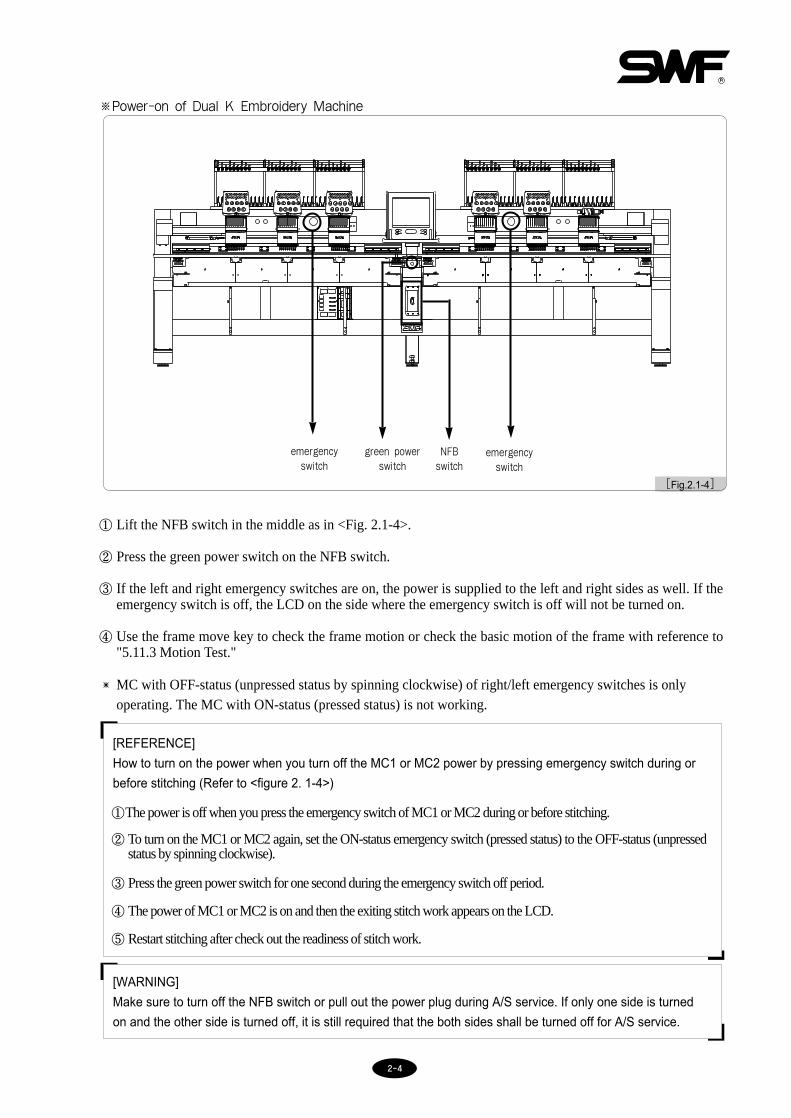
※Power-on of Dual K Embroidery Machine
① Lift the NFB switch in the middle as in <Fig. 2.1-4>.
② Press the green power switch on the NFB switch.
③ If the left and right emergency switches are on, the power is supplied to the left and right sides as well. If theemergency switch is off, the LCD on the side where the emergency switch is off will not be turned on.
④ Use the frame move key to check the frame motion or check the basic motion of the frame with reference to"5.11.3 Motion Test."
[WARNING]
Make sure to turn off the NFB switch or pull out the power plug during A/S service. If only one side is turned
on and the other side is turned off, it is still required that the both sides shall be turned off for A/S service.
[REFERENCE]
How to turn on the power when you turn off the MC1 or MC2 power by pressing emergency switch during or
before stitching (Refer to <figure 2. 1-4>)
①The power is off when you press the emergency switch of MC1 or MC2 during or before stitching.
② To turn on the MC1 or MC2 again, set the ON-status emergency switch (pressed status) to the OFF-status (unpressedstatus by spinning clockwise).
③ Press the green power switch for one second during the emergency switch off period.
④ The power of MC1 or MC2 is on and then the exiting stitch work appears on the LCD.
⑤ Restart stitching after check out the readiness of stitch work.
[Fig.2.1-4]
emergencyswitch
green power switch
NFB switch
emergency switch
MC with OFF-status (unpressed status by spinning clockwise) of right/left emergency switches is onlyoperating. The MC with ON-status (pressed status) is not working.

22--55
TURN ON THE MAIN POWER
IS THE OPERATIONG SYSTEM IN MEMORY?
IS LEFT OR RIGHT START BUTTON PRESSED? INSTALL OPERATING SYSTEM
ARE THERE DESIGNS IN MEMORY?
CALL DESIGN
SELECT NEEDLE BAR
SET-UP PARAMETERS FOR OPERATION
DO YOU WANT REPETITION?
DO YOU WANT AUXILIARY WORK (GAUGE, ETC.)
SET WORK POSITION
DO YOU WANT FRAME OFFSET?
PUSH BAR SWITCH TO START
REPETITION
AUXILIARY WORK
SET-UP FRAME OFFSET
READ DESIGN FROM DISK OR USB
ARE THERE PREVIOUSLY WORKED DESIGNS?
AUTOMATIC READ IN DESIGN
AUTOMATIC READ IN OF SETTING
CHANGE SETTING?
NO
NO
NO NO
NO
NO
NO
NO
YES
YES
YES
YES
YES
YES
YES
YES
2.2 Basic procedures

33--11
3 Installing Machine Operating Program
Program is factory-installed and set. However, you might need to change the setting or upgrade the program according
to your requirements. You can re-install the program or initialize the setting.
■Going into the SWF Install Program
1. Automatically enters if machine operating program is not installed [Fig 3.0-2].
2. Logo screen will show for 2 seconds while booting (see [Fig.3.0-1]). If you press left or right start button, you will see the
screen like [Fig.3.0-3].
3. When the touch point is not controlled properly, turn off the power and turn it on again. Press the STOP button on the left or
right side, and the screen for monitor position setup appears.
MachinePress Frame Movement on logo screenFrame Movement Key
Move to SWF Install Program
Move to set touch monitor location(refer to 3.1.4 System)
Press left or right start button
Press left or right stop button
[Fig. 3.0-3][Fig. 3.0-2]
[Fig. 3.0-1]

33--22
3.1.0 SWF Install ProgramAs illustrated in [Fig.3.0-3], SWF Install Program offers functions including setting, back-up, memory management, and
system setting.
3.1.1 InstallYou can install the machine operating system and transfer necessary data files operation box through input device
(floppy, USB).
(1) Program: Operating program
Press in [Fig.3.0-3] and you will see a screen like [Fig.3.1.1-1].
To use a floppy disk for installation, insert the floppy disk containing the machine operating program and press
. To use a USB memory for installation, insert the USB memory to the USB port and press .
To cancel installation, press .
(2) Data: Data necessary for operating system
Press in [Fig.3.0-3] and you will see a screen like [Fig.3.1.1-2].
To use a floppy disk for data importing, insert the floppy disk containing data files and press . To use a
USB memory for data importing, insert the USB memory to the USB port and press . To cancel
installation, press .
[Fig. 3.1.1-1] [Fig. 3.1.1-2]

33--33
[CAUTION]
The file system of USB memory should be FAT 16. FAT 32 cannot be used.
(3) Program: Machine Control Program
Press in <Fig. 3.0-3> and the screen in <Fig. 3.1.1-3> appears. To install the program using a floppy disk,
insert the machine control program floppy disk and press . To install the program using a USB memory,
connect the USB memory to a USB port, and press . If you want to cancel the installation, press .
[Fig. 3.1.1-3]

33--44
3.1.2 Back-upYou can back-up the operating program and the data files in use in a floppy disk in case of their loss. You cannot use
what is stored in the back-up system if you formatted the memory.
(1) Program
Press in [Fig.3.0-3] and you will go to a screen [Fig.3.1.2-1].
To back up the operating program using a floppy disk, insert an empty floppy disk and press . To back up
the operating system using a USB memory, insert the USB memory to the USB port and press . Press
to cancel the back-up process.
(2) Data
Press in [Fig.3.0-3] and you will go to a screen [Fig.3.1.2-2].
To back up the data using a floppy disk, insert an empty floppy disk and press . To back up the data using
the USB memory, insert the USB memory to the USB port and press . Press to cancel the back-
up process.
[Fig. 3.1.2-1] [Fig. 3.1.2-2]
[CAUTION]
The file system of USB memory should be FAT 16. FAT 32 cannot be used.

33--55
3.1.3 MemoryYou can format or initialize the existing settings in the memory.
(1) Format
Press in [Fig.3.0-3] and you will go to a screen [Fig.3.1.3-1]. Press and your memory space will
be formatted all your programs and data will be deleted. To cancel, press .
(2) Para Init
Press in [Fig.3.0-3] and you will go to a screen [Fig.3.1.3-2]. Press to initialize all previous
settings created using the embroidery operating program. To cancel, press .
(3) Para Set
Press in [Fig.3.0-3] and you will go to a screen [Fig.3.1.3-3]. Press and you will go to a screen
where you can initialize and newly set the machine. To cancel, press (see [Fig.3.2-1]).
[Fig. 3.1.3-3][Fig. 3.1.3-1] [Fig. 3.1.3-2]

33--66
3.1.4 SystemYou can input the Lock key and adjust the touch monitor.
(1) Lock key
The operating program offers Lock function. You can use the operating program in the lock-selected program
without problem for a certain period of time. But after the period, you will have inconvenience in using the program
due to delays.
If your Lock function is selected, you will see a logo screen like [Fig.3.1.4-1] instead of [Fig.3.0-1]. You will have
no problems with [Fig.3.1.4-1] for 10 days. You will see the logo screen for 2 seconds. But after 10 days, there will
be delays in the pop-up of the program (see [Fig.3.1.4-2]) as well as between the embroideries.
To fix the problem, you have to get a new Lock key from your agent and enter it. If you don’t fix the problem and
leave it, the delay time will become longer and you will feel more inconvenience.
[Fig. 3.1.4-1] [Fig. 3.1.4-2]
[CAUTION]
Lock keys come in two types: ones with the set usage period and others with unlimited usage period. Consult
your SWF agent for choice of the Lock keys.

33--77
[Ex.3.1-1] Re-entering Lock key
1⃞ Press START button in the screen [Fig.3.1.4-2]. You will see a screen like [Fig.3.0-3]
2⃞ Press in [Fig.3.0-3].You will move to [Fig.3.1.4-3].
3⃞ Call your SWF agent and tell them your “old code” that shows on your screen (see [Fig.3.1.4-3]) ex) 4 1 0 43 2 1 2 3
Your SWF agent will show the new Lock code.
4⃞ Enter the new Lock code using the keypad.
5⃞ Press .
[Fig. 3.1.4-3]

33--88
(2) Selecting touch monitor location
You can re-select the touch monitor screen if you find that the screen does not accurately reads your touch points.
Press in [Fig.3.0-3] or if you formatted the memory, press STOP button in the initial Logo screen. You
will see a screen like [Fig.3.1.4-5].
Press in the install menu and you will go to [Fig.3.1.4-5]. Touch point with a touch pen or with your
finger. The first location will be selected.
After the first location is selected, you will see a screen [Fig.3.1.4-6] for selecting the second location. After that you
will go to [Fig.3.1.4-7] for selecting the third location. After that you will see [Fig.3.0-2] or [Fig.3.0-3].
[Fig. 3.1.4-4] [Fig. 3.1.4-5]
[Fig. 3.1.4-6] [Fig. 3.1.4-7]

33--99
3.2.0 Changing machine setting
You can set basic embroidery specifications and machine settings.
You will see [Fig.3.2.0-1] in the following cases:
1. If you formatted memory and are installing a new program
2. When you initialized in SWF Install Program (see 3.1.3 Memory)
In the above cases (1, 2), [Fig.3.2.0-1] is the first screen you will see when turning on the main power. You can set 10
different parameters in the screen. If you press you will see a screen where you can set encoder signals etc.
according to your machine location.
Press keys on the right side in [Fig.3.2.0-1] and set each item. Or you can press to do machine setting.
After all settings are completed, press in [Fig.3.2.0-1]. You will see a screen like [Fig.3.2.0-2] to check your
setting. To change the setting, press to go back to the setting function.
To confirm the settings, press .
[Fig. 3.2.0-1] [Fig. 3.2.0-2]

33--1100
3.2.1 Setting embroidery specificationsYou can set 10 types of embroidery specifications.
[Fig. 3.2.1-1] [Fig. 3.2.1-2]
① Head Select ② Needle Select
[Fig. 3.2.1-3] [Fig. 3.2.1-4]
③ Trim System ④ Y Frame Size Setting

33--1111
[Fig. 3.2.1-5] [Fig. 3.2.1-6]
⑤ X Frame Size Setting ⑥ X Space Extension
[Fig. 3.2.1-7] [Fig. 3.2.1-8]
⑦ Wheel Type Select ⑧ Sequin Type Select

33--1122
[Fig. 3.2.1-9] [Fig. 3.2.1-10]
⑨ X Satin Default Set ⑩ Y Satin Default Set

33--1133
3.2.2 Setting machine and signals
Press in [Fig.3.2.0-1] and you will see a screen like [Fig.3.2.2-1].
(1) Main Shaft Encoder Signal Setting
Press the “Select” button. Set the machine at 100° and adjust the encoder. When the beep sound is heard, fix the
machine at the current position, when “On” is displayed. Press the “Select” button again to finish the setting.
(2) Needle Bar Position Setting
Press the “Select” button and move to the highest number needle bar (ex: 9 color → No. 9). Adjust potentiometer. When
the beep sound is heard, fix the needle bar at the current position when “On” is displayed. Press the “Start” button and
wait until the needle bar moves to the lowest number position. Press the “Select” button again to finish the setting.
(3) X, Y Limit Setting
Press the “Select” button and adjust the X, Y limit by manually adjusting the X, Y frame. Check the “On/Off”
condition of the sensor. When the setting is finished, press the “Select” button again.
(4) Wiper Signal Setting
Press the “Select” button and move the wiper manually. When the beep sound is heard, check the condition of the
sensor. When everything is fine, finish the setting by pressing the "Select" button again.
[Fig. 3.2.2-1]
[WARNING]
Incorrect settings in this function may cause machine problems. Do not change these settings unless you
have accurate knowledge and information.

44--11
[Fig.4.0-1] is the initial screen of the machine operating program. The screen consists of five main parts: (1) embroiderydisplay, (2) work information display, (3)(4) function keys, (5) short keys, and (6) speed change keys.
4.1 Embroidery displayIt shows the embroidery design you called. You will see SWF logo if you have just installed the operating program forthe first time or if you haven’t called any designs.
4.2.0 Work information displayWork information screen displays information on machine setting and the design called.
You will see 19 types of information regarding design and machine settings.
[Fig.4.0-1] Initial screen of SWF machine operating system
4 Screen display of machine operating program
(6) SpeedAdjustmentButton
(2) Workinformationscreen
(5) Special FunctionButton
(3)(4) MainFunction Button
(1) EmbroideryScreen

44--22
4.3 Left (MC1), Right (MC2) ButtonsThe left and right buttons are used to change the operation program screens the left (MC1) and right (MC2) embroiderymachine.
- Left (MC1) embroidery machine button
- Right (MC2) embroidery machine button
4.2.1 Design information
4.2.2 Machine information
Title(Ex)No. Description Ref.
152NAME(No.) Name and memory # of the selected design
12,552STITCH No. of total stitches in the selected design
137.2X(mm) X length of the selected design (mm)
116.7Y(mm) Y length of the selected design (mm)
3COLOR No. of colors in the selected design
29JUMP No. of jumps in the selected design
0ANGLE Degree of design rotation
NOMIRROR Yes/No of mirror function
100[%]X SCALE % of X-axis enlargement
100[%]Y SCALE % of Y-axis enlargement
3TOTAL WK Total no. of work plates. Number increases after each plate is done.
0X POS Current location on X axis
0Y POS Current location on Y axis
YES : Yellow NO : Green
ORIGIN It means that the frame has returned to the work starting point.
Title(Ex)No. Description Ref.
1/1NEEDLE Current needle bar / Next needle bar
2240TOTAL ST No. of stitches accumulated so far
FIXPOSFIXPOSStop position of the main axis[WARNING] Needle bar must be changed at 100°
00:00EMB_TIME Embroidery time (hour/minute)
0 / 0 %STITCH No. of stitches made/ Percentage of progress

44--33
[Fig.4.4-1]
[Fig.4.4-2]
4.4 Function keys
Seven menus related to embroidery. Select each menu to go into the sub menus.
Function menus are structured in two parts: “menu before embroidery (see [Fig.4.4-1])” and “menu when stopped duringembroidery (see [Fig.4.4-2])”.
4.5.0 Special function keys
Main screen shows the functions frequently used during embroidery for your convenience.
4.5.1 Machine tools
- This is the menu of short-cuts to 9 functions including origin, frame center, language, same work,hoop select, use of all-heads, needle bar up/down, sequin lift/feed, and PF up/down.
4.5.2 Needle(color) change key
- It is used to change needle bar to conduct embroidery with the thread of desired color and to adjustPF height by needle bar.
4.5.3 Manual trimming key
- For manual trimming (other than automatic trimming by the design code).
4.5.4 Frame Move Button
- The button enables the user to move the embroidery frame in four directions, including up, down, leftand right.
4.6 Speed change key
- Speed change key is included in the main screen for each change of embroidery speed.
- It shows the speed of current embroidery work. In order to see the previous embroidery speed, touch thespeed display window, where previous speed is displayed in blue. When the machine is not in
operation, the previous speed is displayed for two seconds. When the machine is in operation, theprevious speed is displayed for one second and shows the current embroidery speed in yellow.

44--44
4.7.0 Work progress message and clock display
Bottom part of the screen [Fig.4.7.0-1] shows message window and a clock. The message window shows informationabout the current embroidery process and the clock shows time.
4.7.1 Work progress message
[Fig.4.7.0-1]
Timeindication bar
MessageIndication bar
Messages Cause
STOP SWITCH STOP
THREAD CUTTING STOP
COLOR CHANGE STOP
FRAME LIMIT ERROR STOP
DESIGN END CODE STOP
BACKSTITCH STOP
FRAME MOVING
FRAME MOVING STOP!
OFFSET POINT STOP!
CHANGE COLOR TABLE
SELECT STITCH UNIT
START SWITCH → RUN
DESIGN DATA READING!
When the machine is stopped by STOP switch
When the machine stopped after detecting thread break
When the frame is about to exceed the limit
When the embroidery is finished
When machine stopped after backstitching
When the frame is moved
When the frame is stopped
When the machine stopped at the offset point
When the needle bar is changed
When floating
When trace is performed in test mode
When embroidery design is called

44--55
4.7.2 Date / Time settingPress the clock to change the time or date displayed on the right bottom of the screen. You will see a screen
[Fig.4.7.2-1].
Press to decrease or advance the time and date.
Press to increase or forward the time and date.
Use and keys to set the time and date and press . To cancel, press .
[Fig.4.7.2-1]
[NOTE]
You cannot set the time and date if your system is Time Lock selected.

55--11
You have to do a number of settings before starting embroidery. If the machine operating program has just been
installed, you will have to set several parameters including design call. You can work with the basic setting, but for more
sophisticated embroidery and for learning various functions, refer to the following information.
Use touch pens or your fingers to select the menus on the screen.
Machine tools
Needle(color) change key
Manual trimming
Frame movement
Embroidery call Input
Setting Ready
Repeat work Editing
Machine setting
5 Function Menu before Embroidery
Speed change
Left(MC1) embroidery key
Right(MC2) embroidery key
55--22
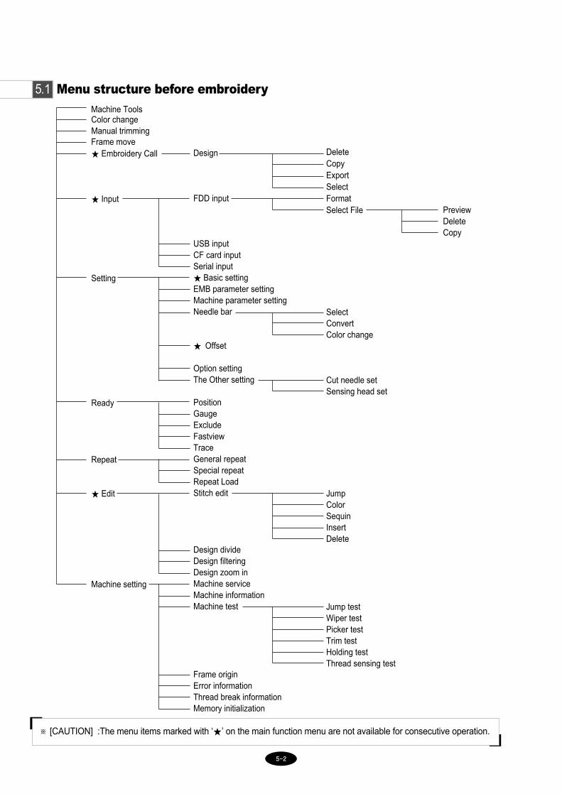
5.1 Menu structure before embroidery
Color changeManual trimming
★ Embroidery Call
★ Input
Setting
Ready
Repeat
★ Edit
Machine setting
Design
FDD input
USB inputCF card inputSerial input★ Basic settingEMB parameter settingMachine parameter settingNeedle bar
★ Offset
Option settingThe Other setting
PositionGaugeExcludeFastviewTraceGeneral repeatSpecial repeatRepeat LoadStitch edit
Design divideDesign filteringDesign zoom inMachine serviceMachine informationMachine test
Frame originError informationThread break informationMemory initialization
DeleteCopyExportSelectFormatSelect File
SelectConvertColor change
Cut needle setSensing head set
JumpColorSequinInsertDelete
Jump testWiper testPicker testTrim testHolding testThread sensing test
PreviewDeleteCopy
Frame move
Machine Tools
※ [CAUTION] :The menu items marked with ‘★’ on the main function menu are not available for consecutive operation.

55--33
5.2.0 Machine tools
- This is the menu of short-cuts to 9 functions including origin, frame center, language, same work,hoop select, use of all-heads, needle bar up/down, sequin lift/feed, and PF up/down.
When the tool box button is pressed before starting embroidery, the screen in <Fig. 5.2.0-1> is displayed. When the toolbox button is pressed in the middle of embroidery work, the screen, where the same work button is disabled, appears.The SEQUIN LIFT and SEQUIN FEED buttons can be used only when sequin devices are installed.
5.2.1 Origin
Origin is available when the machine stopped during embroidery. Its function is the same as Design Origin in
. It moves the needle bar back to the original point of the design. Press and the needle bar will
move.
[Fig.5.2.0-1]

55--44
5.2.2 Frame Center
Find the origin and move the origin to the center of the frame. When embroidery design requires embroidery workto start from the center, this function can ensure easy embroidery.
5.2.3 Language
This function allows users to choose the machine operation language. The languages supported include Korean,English, Spanish, German, Danish, Italian, Indian, Chinese, and Turkish, and the users can select one of them.
5.2.4 Same Work
The Same Work function helps the embroidery setting of one side applied to the other side, in case where the bothtubular frames (MC1, MC2) conduct the same work. When the same work button is pressed, a message windowappears. If the setting is okay, press "Yes." By selecting the same work function, all the functions are executed forMC1 and MC2 at the same time. However, in case where CAP is set for either MC1 or MC2 or only one tubularframe is in operation, the same work button is disabled. In this case, all functions should be individually executed.
5.2.5 Hoop Select
Hoop Select is a semi-automatic function. When the desired hoop size is chosen, the machine sets the virtual framelimits accordingly.
5.2.6 Use of All-Heads
In the time of thread break, it needs to conduct backward movement and press the start button. Then the concernedhead where thread break occurs only performs embroidery again. If it is desired to conduct embroidery in othernormal heads and repeat embroidery in the head of thread break at the same time, the use of all-heads can be used.
To use this function, first press the stop button for backward movement, and then press the button andstart button in order.
In addition, when head switch is turned off and then immediately turned on, the concerned head only startsconducting embroidery. Nevertheless, the 'use of all heads' is a convenient function to activate all heads at the sametime. The function can be canceled by pressing the button after applying it once.
5.2.7 Needle Bar Up/Down
To accurately set the position of the first stitch prior to beginning embroidery work, press the button
to move down the needle bar. And then use the direction keys to place the needle bar at the accurate location. Toreturn the needle bar to the original position, press the button.
5.2.8 Sequin Lift / Feed (optional)
This function tests the attached sequin device which is an optional device. When pressing the button,the sequin device moves down or moves up near to the needle plate.
And using the button, the supply status of sequins can be tested one by one with the sequin device
moving down near to the needle plate.
5.2.9 PF Up / Down
This function allows user to perform manual checkout of the presser foot (PF) or to make setup. It is activatedwhen making a selection and pressing the start key.

55--55
5.3 Needle(color) change
- You can change to the desired needle. - Select color change and you will see the menu in [Fig.5.3-1].
For instance, if you are at needle #1 and want to change to #5, press N5 for automatic change. Press after theneedle change and the needle bar setting will change to #5.
5.4 Manual trimming
- You can perform manual trimming during embroidery, other than the automatic trimming by the
design code. Select manual trimming and you will be asked, “Do you want to trim?” as shown in
[Fig.5.4-1]. Press YES and trimming will start automatically. You can perform automatic trimming
pressing START.
Press or (END) if you do not want trimming.
[Fig.5.3-1]
[Fig.5.4-1]

55--66
5.5 Frame Move
- This function enables the user to move the frame to the desired position. When “Frame Move” is
pressed, buttons appear as in Fig. 5.5-1. Press Up, Down, Left or Right button to move the frame.
Press to exit from the frame move mode.
[Fig.5.5-1]
5.6 Left (MC1), Right (MC2) Buttons
- The Dual Embroidery Machine works as two embroidery machines. It is equipped with two embroidery machines on
the left (MC1) and right (MC2) sides.
- To operate left (MC1) and right (MC2) embroidery machines, two operation programs are supposed to be displayed on
the screen. However, the OP Box’s LCD screen is able to display only one operation program at one time.
- To move between the operation program screens of the left (MC1) and right (MC2) embroidery machines, the
and buttons can be utilized.
- Press one of the buttons when it is gray. Then the OP Box screen moves to the embroidery machine operation mode.
To convert to the operation screen of the left (MC1) embroidery machine, press the button. This doesnot affect the embroidery status of the right embroidery machine. It only helps change embroidery conditionsof the left embroidery machine.
To convert to the operation screen of the right (MC2) embroidery machine, press the button. This doesnot affect the embroidery status of the left embroidery machine. It only helps change embroidery conditionsof the right embroidery machine.

55--77
- You can call a design from the memory for embroidery work. You can also copy or delete the designs orcopy them to external devices.
You will see the screen in [Fig.5.7-1] if the design is not in the memory or if you have not call any design from thememory. If you have previously called a design, it will appear on the screen([Fig.5.7-2]).
If there is no design called as in [Fig.5.7-1], a number of functions will not be available (displayed in gray color). Those
functions will become available once a design is called.
If you press in the screen [Fig.5.7-2], you will see designs stored in each memory room ([Fig.5.7-3]). You
can store total 100 designs in the memory. 20 designs will appear on one screen. Refer to an example [Fig.5.7-1] for
calling a design.
5.7 EMB Call
[Fig.5.7-1] [Fig.5.7-2]

55--88
[Ex.5.7-1] Calling the design in memory #25
1⃞ EMB CALL
Select EMB CALL and you will see designs stored in each memory room displayed as shown in [Fig.5.7-3]. Total
20 designs will be displayed along with a memory room #. In this case, you are looking for a design in memory #25,
so go to the next screen.
2⃞ Drag the scroll bar on the right or press Up/Down key.
You will see the next 20 designs as shown in [Fig.5.7-4].
3⃞ Select the design in memory#25 (see the framed box).
[Fig.5.7-3] [Fig.5.7-4]
[NOTE]
FREE STITCH shows the remaining memory space.
EmbroideryCall ScreenScroll Button

55--99
A new window will appear (see [Fig.5.7-5]). The selected design will be displayed on the left screen and the designinformation on the right. Delete, Copy, Copy to Floppy, Select, and X (END) functions are available.
4⃞ SELECT
Press SELECT and the selected design will be called. You can see the design called in the initial screen as shown in
[Fig.5.7-6].
[Fig.5.7-5] [Fig.5.7-6]
[NOTE]
is equivalent to a refresh function. You might find the embroidery call in black/white. In this case,
press RESET in color setting (under needle bar setting) and then to see the design color.
[NOTE]
OPTION NORMAL in the list of embroidery information refers to normal embroidery data. When you see
SEQUIN, it refers to embroidery designs that include sequin codes.

55--1100
[Ex.5.7-2] Copying the design from memory #25 to #64
1⃞ Do ①, ②, ③ of the previous example [Ex.5.7-1].
2⃞ Select in the screen [Fig.5.7-5].
A message will pop up ([Fig.5.7-7]) and you will see the number of remaining memory rooms along with Up/Down,
copy, and Cancel keys. Memory room number shows available space for data storage. You can Up/Down to change
the room number.
3⃞ In this case, using Up/Down key, select memory #64 among the available memory rooms.
4⃞ COPY.
Copy the design data from memory #25 to #64 and the screen will move to the room #64 as shown in [Fig.5.7-8].
[Fig.5.7-7] [Fig.5.7-8]
[NOTE]
To cancel the copy, press .

55--1111
[Ex.5.7-3] Deleting the design in memory #64
1⃞ Move to memory #64 using the scroll bar or the Up/Down key from EMB CALL.
2⃞ Select the design in memory #64.
3⃞ Select in [Fig.5.7-5].
You will see a message in [Fig.5.7-9] asking you, “Do you want to delete?”
4⃞ Select .
Compare [Fig.5.7-10] with [Fig.5.7-8] and you can see the design in memory #64 deleted.
The #64 room is not occupied and is available for use.
[NOTE]
To cancel deletion, press or (END).
[Fig.5.7-9] [Fig.5.7-10]

55--1122
[Ex.5.7-4] Copying the design in memory #25 to the floppy disk or USB in SWF method
1⃞ Do ①, ②, ③ of the example [Ex.5.7-1].
2⃞ Insert a floppy disk into the disk drive or insert a USB memory into the USB port.
3⃞ Select in [Fig.5.7-5]
The message box asking for device selection for exporting appears on the screen as in [Fig.5.7-11]. Press
to export embroidery designs into a floppy disk. Press to export the designs into a USB
memory.
4⃞ Select or
You will be asked which storage method you would like ([Fig.5.7-12]) and you will see , ,
(END) keys. Selecting to store in the floppy disk in SWF method and in Tajima
method.
[Fig.5.7-11]
[CAUTION]
Removing the disk in the middle of using it may cause deletion of the stored data or damage of the disk.
[CAUTION]
The file system of USB memory should be FAT 16. FAT32 cannot be used.

55--1133
[Fig.5.7-14] shows the floppy disk where the copies are made. To check it out, refer to ‘5.8.1 FDD Input’, which
will be described in the next chapter. When the copy is made into a floppy disk, the file name will be given as
“SWF000.SST” as default. When more than one file is copied to the floppy disk, the file names are given in such an
order of SWF000.SST, SWF001.SST ... or SWF000.DST, SWF001.DST ...
5⃞ Select .
Striped green part in [Fig.5.7-13] shows the copying progress. When the copying is completed, the green will fill
the box and the color will return to the original.
[Fig.5.7-14]
[Fig.5.7-12] [Fig.5.7-13]

55--1144
[Fig.5.8.0-1]
5.8.0 Input
- Use INPUT to bring a design from an external device to the operation box. External devices include
floppy disks, USB memory, compact flash (CF) card, and serial communication.
Select in the initial screen and you will see the sub menus of input as shown in [Fig.5.8.0-1]. The sub menus
include floppy disks, USB memory, CF card, and serial.
55--1155
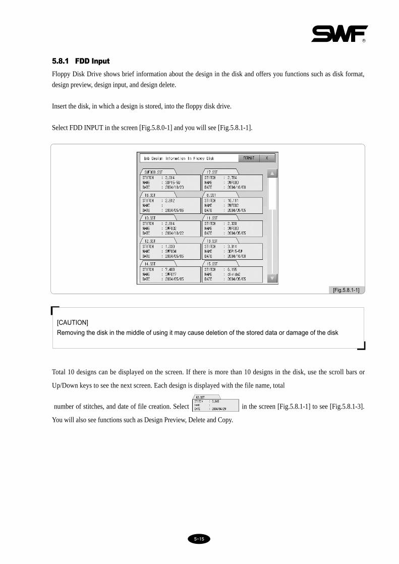
5.8.1 FDD Input
Floppy Disk Drive shows brief information about the design in the disk and offers you functions such as disk format,
design preview, design input, and design delete.
Insert the disk, in which a design is stored, into the floppy disk drive.
Select FDD INPUT in the screen [Fig.5.8.0-1] and you will see [Fig.5.8.1-1].
Total 10 designs can be displayed on the screen. If there is more than 10 designs in the disk, use the scroll bars or
Up/Down keys to see the next screen. Each design is displayed with the file name, total
number of stitches, and date of file creation. Select in the screen [Fig.5.8.1-1] to see [Fig.5.8.1-3].
You will also see functions such as Design Preview, Delete and Copy.
[CAUTION]
Removing the disk in the middle of using it may cause deletion of the stored data or damage of the disk
[Fig.5.8.1-1]

55--1166
[Ex.5.8.1-1] Previewing the design file named ‘63.SST’ from the floppy disk and copying itto the memory #12
1⃞ Select in the screen [Fig.5.8.1-2]
You will see a new window open as shown in [Fig.5.8.1-3]. The window offers , ,
, , and (END).
[Fig.5.8.1-2] [Fig.5.8.1-3]

55--1177
3⃞ Select the memory room number.
Use the keys to see the empty memory rooms in sequence. Select the desired memory room.
2⃞ Select .
A design will appear in the preview window on the left as illustrated in [Fig.5.8.1-4].
[Fig.5.8.1-4]
4⃞ Select .
The box at the top will turn partially green to display the progress of copyingas shown in [Fig.5.8.1-5]. The box will
turn fully green and the window will close when the copying is completed. You can check the design copied in the
memory #12 as shown in [Fig.5.8.1-6]. To check the design copied, refer to ‘5.7 EMB Call’.
[Fig.5.8.1-5] [Fig.5.8.1-6]

55--1188
[Ex.5.8.1-2] Deleting ‘63.SST’ file from the floppy disk
1⃞ Select in [Fig.5.8.1-2]
2⃞ Select .
You will see a screen [Fig.5.8.1-7] asking, “Do you want to delete?”. Select if you do and or
(END) if you don’t.
3⃞ In this case, select .
You can see the file is deleted ([Fig.5.8.1-8]).
[Fig.5.8.1-7] [Fig.5.8.1-8]
[Ex. 5.8.1-3] Formatting the floppy disk
1⃞ Press in [Fig.5.8.1-1].
[CAUTION]
Removing the disk in the middle of using it may cause deletion of the stored data or damage of the disk.

55--1199
5.8.2 USB Input
It enables the embroidery designs stored in a USB memory to be imported to the OP-BOX through the USB port.
Insert the USB memory containing embroidery designs into the USB port.
Press USB INPUT in [Fig.5.8.0-1], and you will see [Fig.5.8.2-1]. Press and the design files within the folder
will be displayed as in [Fig.5.8.2-2]. To move to the superior folder, press .
Press in [Fig.5.8.2-2] and you will see [Fig.5.8.2-3].
In case of USB Input, the preview function is supported. The keys for Input and Delete are also displayed. The
functions of delete and copy can be used in the same way as descried in ‘5.8.1 FDD Input’.
[Fig.5.8.2-1] [Fig.5.8.2-2]
[Fig.5.8.2-3]
[CAUTION]
The file system of USB memory should be FAT 16. FAT 32 cannot be used.

55--2200
In case of CF Card, the preview function is supported. The keys for Input and Delete are displayed as well. The
functions of delete and copy can be used in the same way as descried in 5.8.1 FDD Input.
5.8.3 CF Card Input
CF Card Input imports the embroidery designs stored in CF Card into the OP-BOX.
Link the CF CARD INPUT storing embroidery design files to the CF Card Reader, and the USB terminal of the CF
Card Reader to the OP-BOX through the USB port.
Press CF CARD INPUT in [Fig.5.8.0-1] and you will see [Fig.5.8.3-1]. Press in [Fig.5.8.3-1] and the embroidery
design files within the folders will be displayed as in [Fig.5.8.3-2]. Press to move to the superior folder.
Press in [Fig.5.8.3-2] and you will see [Fig.5.8.3-3].
[Fig.5.8.3-1] [Fig.5.8.3-2]
[Fig.5.8.3-3]

55--2211
5.8.4 Serial Input
Serial Input imports embroidery designs from embroidery design program Wings to the memory of the OP-BOX.
Link Wings to the OP-BOX through a serial cable and call designs from Wings. When the design screen appears, press
File from the menu and select Export. Select Other from the Export menu and you can see the Export Design Window.
When it is the first time to install a driver, press Add Driver. When the Add Wings I/O Driver Window appears, open
Sunstar.wio, a driver dedicated to Sunstar machines. Select the driver added to the Export Window and press OK. Select
the format you desire and press OK.
When the design exporting from Wings is completed, press Serial Input as in [Fig.5.8.0-1] and you will see [Fig.5.8.4-
1]. The preview and delete functions are not supported. Select the memory room number and press , and
you will see the screen in [Fig.5.8.4-2].
To check the copied designs after loading is completed, see ‘5.7 EMB Call’.
[Fig.5.8.4-1] [Fig.5.8.4-2]

55--2222
[Fig.5.9.0-1]
•Basic setting : For setting parameters such as scale up, scale down, and angle.
•EMB parameter setting : For setting parameters related to embroidery.
•M/C parameter setting : For setting parameters related to the machine.
•Needle setting : For setting or changing the needle bar.
•Frame offset setting : For setting offset point on the design.
•Option setting : For setting design method of sequin, cording etc.
•The others setting : For setting needle type and thread detection
5.9.0 Setting
- This function is for general setting of the embroidery. You have seven menus → basic setting, EMB
parameter setting, M/C parameter setting, needle setting, frame offset setting, option setting, and the
others setting.
Select in the initial screen and you will see [Fig.5.9.0-1]
55--2233
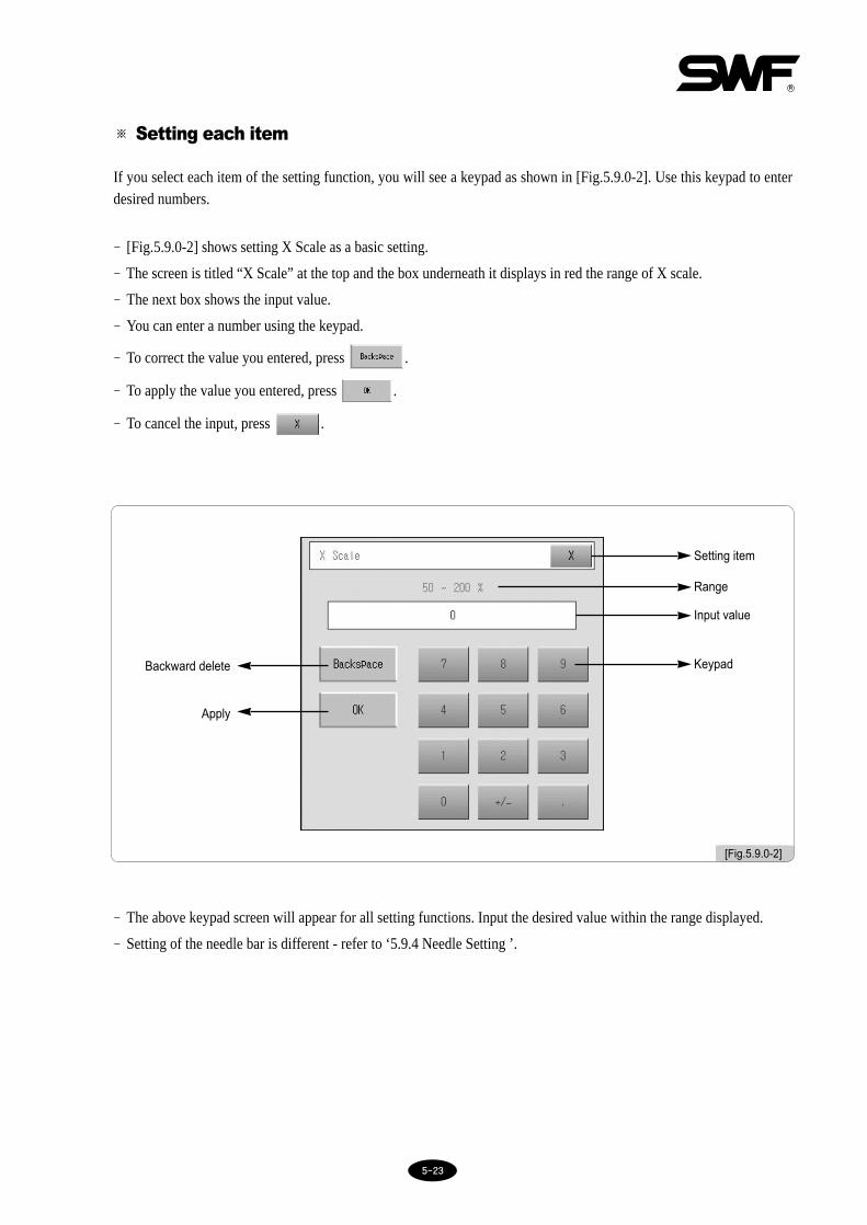
※ Setting each item
If you select each item of the setting function, you will see a keypad as shown in [Fig.5.9.0-2]. Use this keypad to enterdesired numbers.
- [Fig.5.9.0-2] shows setting X Scale as a basic setting.
- The screen is titled “X Scale” at the top and the box underneath it displays in red the range of X scale.
- The next box shows the input value.
- You can enter a number using the keypad.
- To correct the value you entered, press .
- To apply the value you entered, press .
- To cancel the input, press .
- The above keypad screen will appear for all setting functions. Input the desired value within the range displayed.
- Setting of the needle bar is different - refer to ‘5.9.4 Needle Setting ’.
[Fig.5.9.0-2]
KeypadBackward delete
Apply
Input value
Range
Setting item

55--2244
5.9.1 Basic setting
Select Basic Setting in [Fig.5.9.0-1] and you will see 9 sub items for basic setting.
(for viewing the next screen) will become active when there are over 13 items to be displayed.
changes the value to the initial value installed in the operating program.
(END) ends the function.
[Fig.5.9.1-1]

55--2255
① X Scale (Up & Down)
scales the design up or down in the X direction.
The basic setting is 100%. You can set within the range of 50-200% in the unit of 1%.
② Y Scale (Up & Down)
scales the design up or down in the Y direction.
The basic setting is 100%. You can set within the range of 50-200% in the unit of 1%.
<100%> <Set up Y 200%>
[X and Y Scale Up]
<100%> <Set up X 200%>
<100%> <200% (X and Y)>

55--2266
③ Angle
rotates the design according to the set angle.
The basic setting is 0°. You can set within the range of 0-359° in the unit of 1°.
④ Mirror
mirrors the design on the X, the Y, or the X_Y.
The basic setting is “0 (Normal)”.
<0°> <90°>
<No> <X Mirror>
<No> <Y Mirror>
<No> <X_Y Mirror>
Input Setting
0 Basic setting
1 X mirror
2 Y mirror
3 X_Y mirror
55--2277
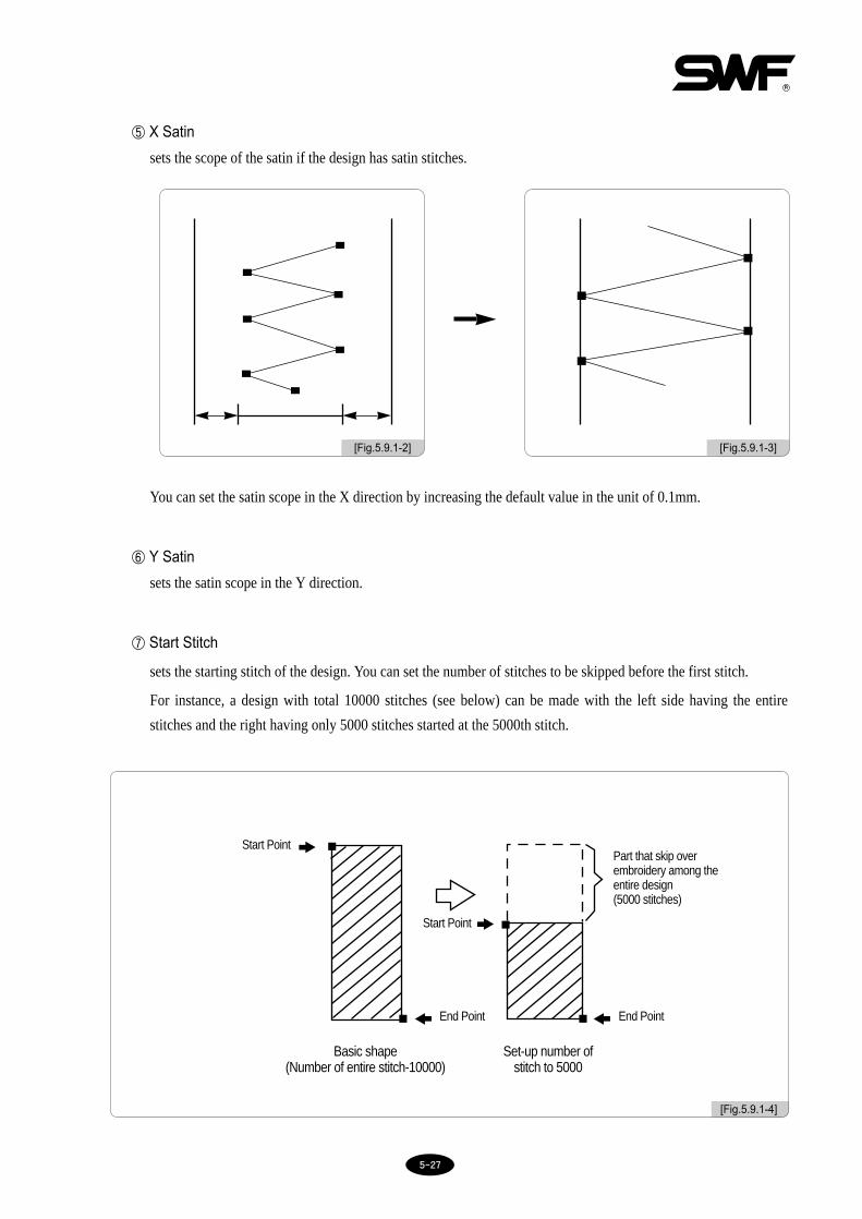
⑤ X Satin
sets the scope of the satin if the design has satin stitches.
You can set the satin scope in the X direction by increasing the default value in the unit of 0.1mm.
⑥ Y Satin
sets the satin scope in the Y direction.
⑦ Start Stitch
sets the starting stitch of the design. You can set the number of stitches to be skipped before the first stitch.
For instance, a design with total 10000 stitches (see below) can be made with the left side having the entire
stitches and the right having only 5000 stitches started at the 5000th stitch.
[Fig.5.9.1-3][Fig.5.9.1-2]
[Fig.5.9.1-4]
Start Point
Start Point
End Point
Part that skip overembroidery among theentire design(5000 stitches)
Basic shape(Number of entire stitch-10000)
Set-up number of stitch to 5000
End Point

55--2288
⑧ Offset function.
sets whether or not to use the automatic offset function.
[Fig.5.9.1-5]
★ Setting Frame Offset
1. Select YES for Offset Function in Basic Setting.
2. Go to “Setting” → “Frame Offset Setting” and set design start position and offset mid point. After finished
with the design, set stop position (offset) (5.9.5 Frame Offset Setting)
3. To use the offset function during embroidery, go to “Main Function Menu” and then to “Setting”. Input the
desired value in the setting table in the “Frame Offset Position” in 5.9.5 Frame Offset Setting.
※ You must do the above three to do frame offset.
EmbroideryStart Point
<Embroidery Start> <Embroidery End>
Frame Movement
Needle Position afterCompleting Embroidery
Frame
Frame

55--2299
⑨ Jump convert
moves the frame after trimming when you want repetition jumps in the number above the set value.
For instance, if the set jump value is 5 and you come across a repetition jump code during embroidery, up to 4
stitches will not be trimmed (jumped). But when you come across a repetition jump code of over 5 stitches, the
machine will trim first, then jump 5 stitches, and resume embroidery. Basic setting is 3 stitches and you can set in
the range of 0-10 stitches in the unit of 1 stitch.
[Fig.5.9.1-6] Setting trimming by Jump at 5 stitchs
In case the length of the stitches is 4
In case the length of the stitches is 5
( Thread connects to next design )
( More to next design after thread trim )
[CAUTION]
If you set this function at “0”, the machine will jump without trimming when you meet repetition jump codes
regardless of the number of repetition jump stitches.

55--3300
5.9.2 EMB parameter setting
[Fig.5.9.2-1] and [Fig.5.9.2-2] show setting EMB parameter setting. Use the keypad to input the desired numbers as you
did in Basic Setting.
is for going to the next screen.
[Fig.5.9.2-1] displays the first 8 menus on the first screen. Select on the upper right to see the next 8 menus
as shown in [Fig.5.9.2-2]. Press again to go back to the first screen.
changes the setting to the initial value installed in the operating program.
(END) ends the function.
[Fig.5.9.2-1] [Fig.5.9.2-2]

55--3311
① Total Stitch Clear
Total ST in ‘4.2.2 Machine Information’ shows the number of stitches accumulated since the first use or
initialization of the machine. Initializing Total Stitches will initialize this information.
② Total Work Clear
Total WK in ‘4.2.2 Machine Information’ shows the number of plates accumulated since the first use or
initialization of the machine information. Initializing Total Work Plates will initialize this information.
(To initialize, select “0” and press . To cancel initialization, press .)
③ Auto Origin Return
It brings the frame back to the start position after completing a design.
- Basic setting is “YES (1)”. To cancel this function, press NO (0) for No.
④ Jump Change Data
It sets the width of stitch that changes an ordinary code to a jump code.
- In other words, the machine will automatically change to a jump code if the frame finds the distance between
two stitches is longer than the pre-set value. Basic setting is 8.0mm and you can set within the range of 5.0-
12.7mm in the unit of 0.1mm.
⑤ Auto Backtack
It sets whether or not to use the back-tack function (making stitches at the start of embroidery) for prevention of
thread unraveling.
- Default is ‘End Backtack’ and you can select in the range of No (0), Start Backtack (1), End Backtack (2), and
All (3).
⑥ Jump Convert (Length)
If the total length of stitches of the repeated Jump Code exceeds the set value, it performs trimming first, and
then sets the maximum jump stitch value for the next work.
- Default is ‘NO’ and you can select within the range of 1-50mm in the unit of 1mm.

55--3322
⑦ Applique
If you input needle bar repeat when setting the needle bar, and if the Applique function is set YES, the machine
will not trim but automatically stop when it comes to the needle bar to be overlapped.
- Basic setting is YES.
⑧ Auto Back Stitch
It sets the number of automatic backstitches to be made when thread break is detected.
- Basic setting is 2 stitches and you can set within the range of 0-5 stitches in the unit of 1 stitch.
⑨ Auto Start After Trimming
It sets whether to automatically start the next embroidery after trimming by jump code, trimming code, or stop
code.
- Basic setting is YES. If you do not want the automatic start, press “0” for NO.
⑩ Auto Start After Frame Back
In the case where embroidery should begin after the frame is moved back from the stop point, it sets whether to
automatically start the next embroidery when it reaches the point as described in ⑫ All Head Sewing Start Point
after F, B.
- Basic setting is YES. To cancel the function, press “0” for NO.
⑪ All Head Sewing After Stitch Back
※ The menu is not available for 1×1 Machine Type.
Move the frame backward from the machine stop point, and decide whether the head with broken thread only will
operate or whether all heads will operate when embroidery work is activated by the bar switch.
- Default is "single head." To operate all heads, enter "0" to select "All."
⑫ All Head Sewing Start Point After F,B
※ The menu is not available for 1×1 Machine Type.
When all or many needle bars are operating simultaneously, problem in one needle bar might be notified later (i.e.
thread break). In this case, when the machine is stopped, back-stitch can be conducted to correct the part where
55--3333
embroidery is not properly conducted. In this case, operate the needle bar with problem only by beginning
embroidery a little bit before the problem area, and then the unwanted sewing previous made with the lower
thread can be corrected through overlapped embroidery. This function enables the setting of the relative start
position of all needle bars start compared with the machine stop position within the range of 1 to 20 stitches. The
default value is 3[stitches].
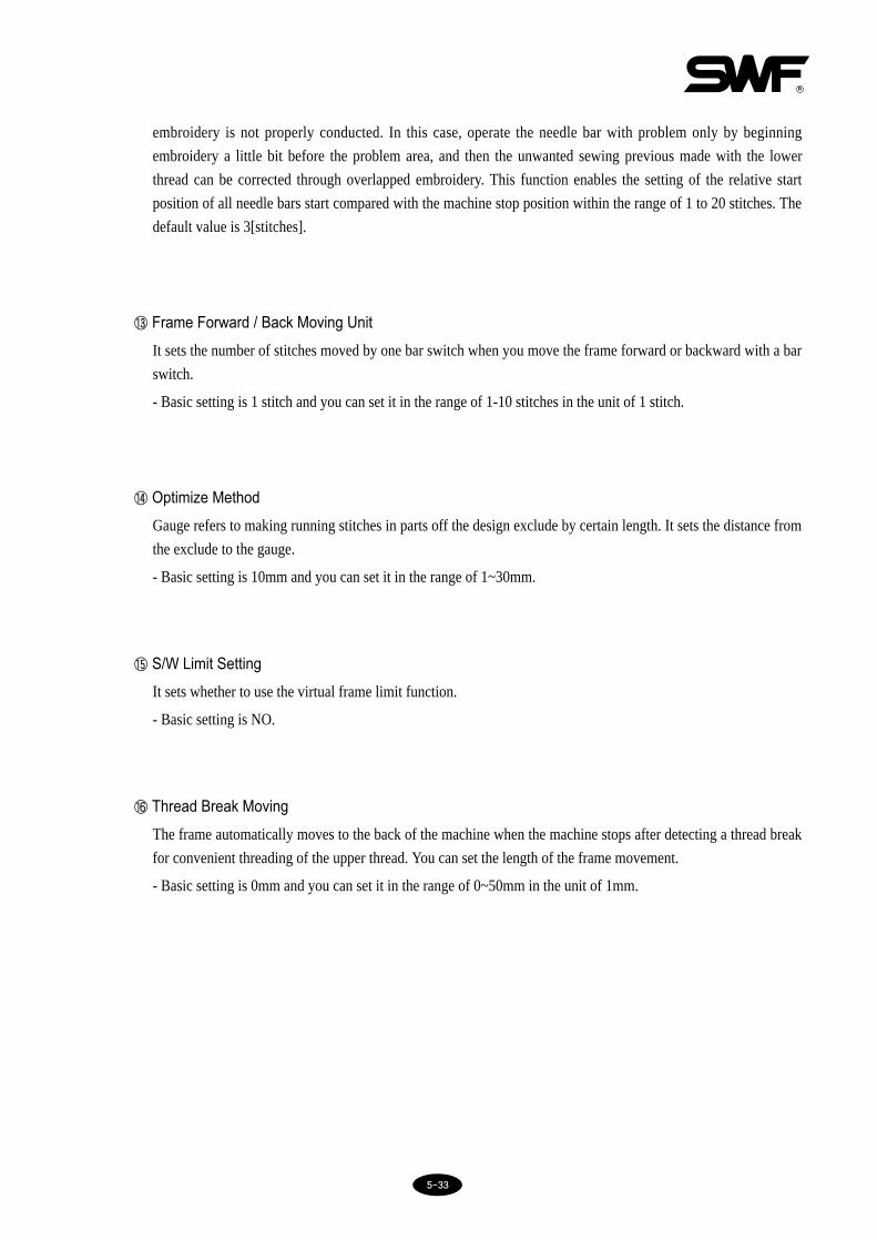
⑬ Frame Forward / Back Moving Unit
It sets the number of stitches moved by one bar switch when you move the frame forward or backward with a bar
switch.
- Basic setting is 1 stitch and you can set it in the range of 1-10 stitches in the unit of 1 stitch.
⑭ Optimize Method
Gauge refers to making running stitches in parts off the design exclude by certain length. It sets the distance from
the exclude to the gauge.
- Basic setting is 10mm and you can set it in the range of 1~30mm.
⑮ S/W Limit Setting
It sets whether to use the virtual frame limit function.
- Basic setting is NO.
⒃ Thread Break Moving
The frame automatically moves to the back of the machine when the machine stops after detecting a thread break
for convenient threading of the upper thread. You can set the length of the frame movement.
- Basic setting is 0mm and you can set it in the range of 0~50mm in the unit of 1mm.
55--3344
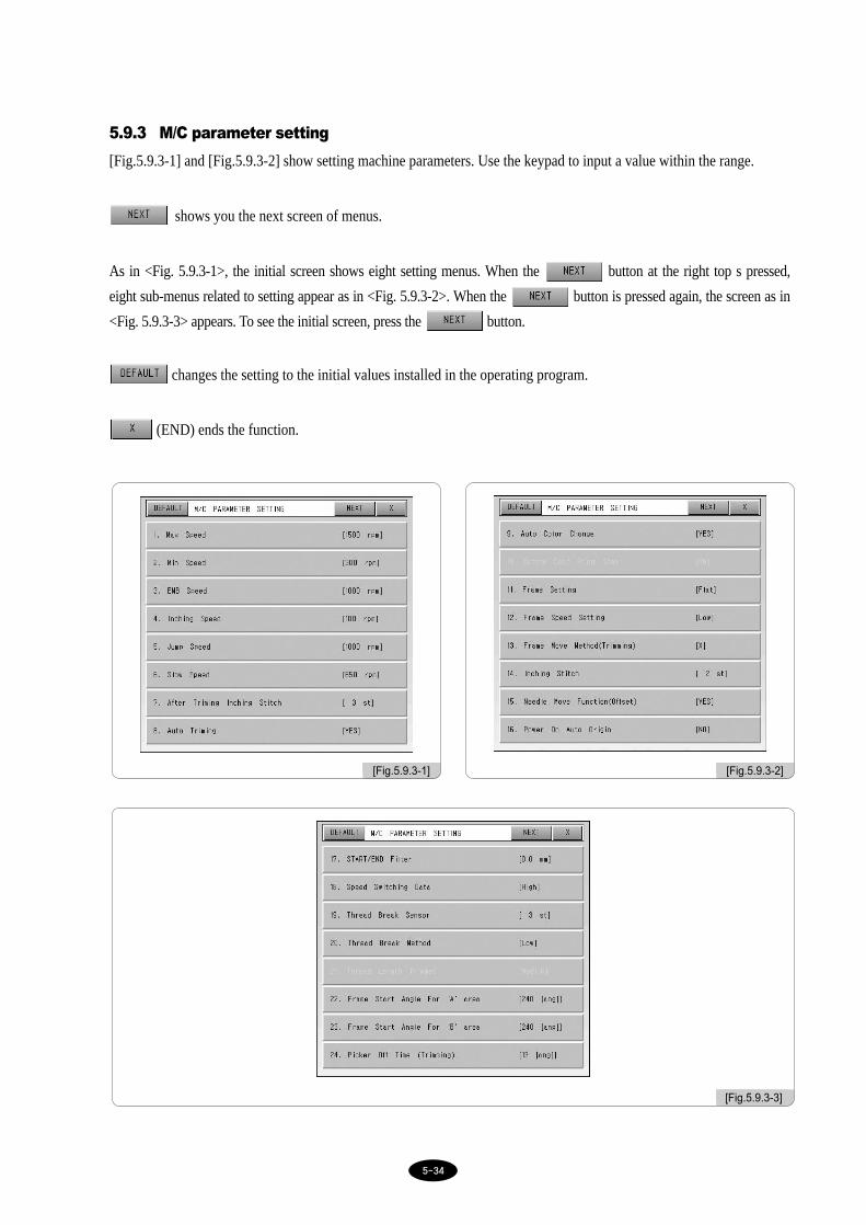
5.9.3 M/C parameter setting
[Fig.5.9.3-1] and [Fig.5.9.3-2] show setting machine parameters. Use the keypad to input a value within the range.
shows you the next screen of menus.
As in <Fig. 5.9.3-1>, the initial screen shows eight setting menus. When the button at the right top s pressed,
eight sub-menus related to setting appear as in <Fig. 5.9.3-2>. When the button is pressed again, the screen as in
<Fig. 5.9.3-3> appears. To see the initial screen, press the button.
changes the setting to the initial values installed in the operating program.
(END) ends the function.
[Fig.5.9.3-1] [Fig.5.9.3-2]
[Fig.5.9.3-3]

55--3355
① Max Speed
It sets the maximum embroidery speed
- Basic setting is 1000rpm and you can set it in the range of minimum to 1200rpm in the unit of 1rpm.
② Min Speed
It sets the minimum embroidery speed.
- Basic setting is 300rpm and you can set it in the range of 300 to maximum rpm in the unit of 1rpm.
③ EMB Speed
It sets the embroidery speed.
- Basic setting is 800rpm and you can set it in the range of minimum and maximum rpm (set in the machine
parameter) in the unit of 1rpm.
④ Inching Speed
It sets the speed of the low-speed stitching at the start of the embroidery.
- Basic setting is 180rpm and you can set it in the range of 50~200rpm in the unit of 1rpm.
⑤ Jump Speed
It sets the limit of the jump stitching (the frame moves without stitching).
- Basic setting is 750rpm and you can set it in the range of minimum to maximum speed in the unit of 1rpm.
⑥ Slow Speed
It sets the embroidery speed during slow speed.
- Basic setting is 650rpm and You can set it in the range of minimum and maximum speed in the unit of 1rpm.
⑦ After Trimming Inching Stitch
It sets the number of low-speed stitching (inching) when the machine meets a color change signal during
embroidery or when the embroidery is completed for certain design.
- Basic setting is 3 stitches and you can set it in the range of 2-10 stitches in the unit of 1 stitch.
⑧ Auto Trimming
It sets whether or not to use the automatic trimming function.
- Basic setting is YES. Select NO to turn this function off.
⑨ Auto Color Change
It sets whether or not to use the automatic color change function.
- Basic setting is YES. Select NO to turn this function off.
⑭ Optimize Method
Gauge refers to making running stitches in parts off the design exclude by certain length. It sets the distance from
the exclude to the gauge.
- Basic setting is 10mm and you can set it in the range of 1~30mm.
⑮ S/W Limit Setting
It sets whether to use the virtual frame limit function.
- Basic setting is NO.
⒃ Thread Break Moving
The frame automatically moves to the back of the machine when the machine stops after detecting a thread break
for convenient threading of the upper thread. You can set the length of the frame movement.
- Basic setting is 0mm and you can set it in the range of 0~50mm in the unit of 1mm.
⒔ Lock Stitch
It repeats back-tack in order to prevent unraveling of thread during trimming.
- Basic setting is 1 stitch and you can set it in the range of 1-5 stitches in the unit of 1, 3, or 5 stitches.

55--3366
⑩ Bottom Dead Point Stop
It sets the needle bar to stop at the lower dead stop after completing the embroidery.
- Basic setting is NO. To use this function, select “1” for YES.
⑪ Frame Setting
It sets the type of frame to be used.
- The default value is “FLAT(0)”. When trying to activate CAP, enter “1”. After CAP is activated, new design is
automatically set to have 180° revolving angle when it is called.
⑫ Frame Speed Setting
It sets the speed of frame movement such as automatic return to origin and offset movement.
- The default is “High Speed (1)”. When desiring to change it to low speed, press “0”.
⑬ Frame Move Method After (Trimming)
It sets the function, which moves the frame left and right after trimming in order to separate thread from the
embroidery material.
- Basic setting is X (1) axis. To select the direction of Y (2) axis, input “2”. If you do not want to use this
function, select NO (0).
⑭ Inching Stitch
The machine slowly inches at the start of the embroidery. It sets the number of stitches to be inched.
- Basic setting is 2 stitches and you can set it in the range of 2~10 stitches in the unit of 1 stitch.
⑮ Needle Move Function (Offset)
When the needle moves to the offset position, it activates the jump motor to lift the needle bar.
- Basic setting is YES (1) and you can select NO (0).
⒃ Power ON Auto Origin
It sets the machine to automatically return to the origin point after turning on the power.
- Default is “NO.” If you selected “YES” but do not want the automatic return function due to incorrect origin
setting or machine malfunction, you must initialize all settings. For initialization, refer to ‘3.1.3 Memory - (2)
Para Init’.
⒔ START/END Filter
It sets whether or not to use the function of automatic filtering stitches shorter than 0.5mm at the start and the end
of the embroidery for prevention of thread breaks.
- Basic setting is “0.0[mm]”and you can set it in the range of 0.1~0.5mm in the unit of 0.1mm.

55--3377
⒕ Speed Switching Data
When the fabric is too heavy, disturbing normal machine operation, it slows down the overall embroidery speed.
- The default value is “high speed(1)”. Whenever entering “low speed(0)”, the embroidery speed is reduced by
30~50rpm.
⒖ Thread Break Sensor
The machine will stop if it senses the repeated break of the upper thread in the number set in this function. This is
to prevent false detection due to sensor malfunction.
- Basic setting is 3 stitches and you can set it in the range of 0~10 stitches. If you select “0”, the thread break
function will be turned off.
⒗ Thread Break Method
It sets the sensitivity of the thread detection.
- Basic setting is LOW (0) and you can set it at HIGH (2) or MEDIUM (1).
(21) Thread Length Trimmed
It sets up the remaining length of the upper thread in the needle after automatic trimming.
- The default value is “Midium(1)”. To make it shorter, choose “Short(1)”. To make it longer, choose “Long(2)”.
(22) Frame Start Angle For ‘A’ Area
It sets the rotation angle of the main axis when the frame starts to move - if the width of the embroidery is shorter
than 1.9mm.
- Basic setting is 240° and you can set it in the range of 230-250° in the unit of 1°.
(23) Frame Start Angle For ‘B’ Area
It sets the rotation angle of the main axis when the frame starts to move - if the width of the embroidery is longer
than 2.0mm.
- Basic setting is 240° and you can set it in the range of 230-250° in the unit of 1°.
(24) Picker Off Time (Trimming)
When automatic trimming is performed, it sets the remaining length of the upper thread in the needle.
- The default is 13[ang]. If the set value is lower than the default, the length of the upper thread will get shorter.
If vice versa, the length of the upper thread after trimming will get longer. The value can be set within the range
of 0~60[ang] and adjusted by the unit of 1[ang].
[Note]
Selection of polyester yarn mode:If the frame feed starting angles (A) and (B) are set at 250。, the polyester
yarn mode will be selected and the looping, which occurs during embroidery, can be prevented.

55--3388
5.9.4 Needle Setting(Color Setting)
You can pre-set so that the needle bar is automatically changed (color is changed) when the machine meets a color
change code during embroidery. You can also change the design color displayed on the screen.
<Fig. 5.9.4-1> shows the needle bar setting menu that appears when the needle bar setting button is pressed on the
setting screen of <Fig. 5.9.0-1>. The needle bar setting is divided into needle bar select, needle bar change, and change
of presser foot height.
■To understand the above functions, let us look at the heads of a SWF multi-head embroidery machine in
shown in [Fig.5.9.4-2].
As illustrated in [Fig.5.9.4-2], a multi-head embroidery machine has each needle bar with unique numbering. Each of
those unique numbers is matched 1:1 to the reference needle bar in the menu Needle Bar Number Change shown in
[Fig.5.9.4-1]. If the changing needle bar matches the reference needle bar, the needle bar selected will also match and
the needle bar of the selected numbering will work. You can change the numbering by using the NEEDLE
CONVERT function. Refer to the following example.
•NEEDLE SELECT : It sets the order of needle bar change when the machine comes across a color change
code during embroidery. You can use maximum 300 color change codes.
•NEEDLE CONVERT : You can change the 1:1 match between tables in the reference needle bar and the
actual needle bar.
•NEEDLE COLOR : It changes the color of the needle bar displayed on the screen.
•CHANGING HEIGHT : This function changes the presser foot height.
[Fig.5.9.4-1] [Fig.5.9.4-2]
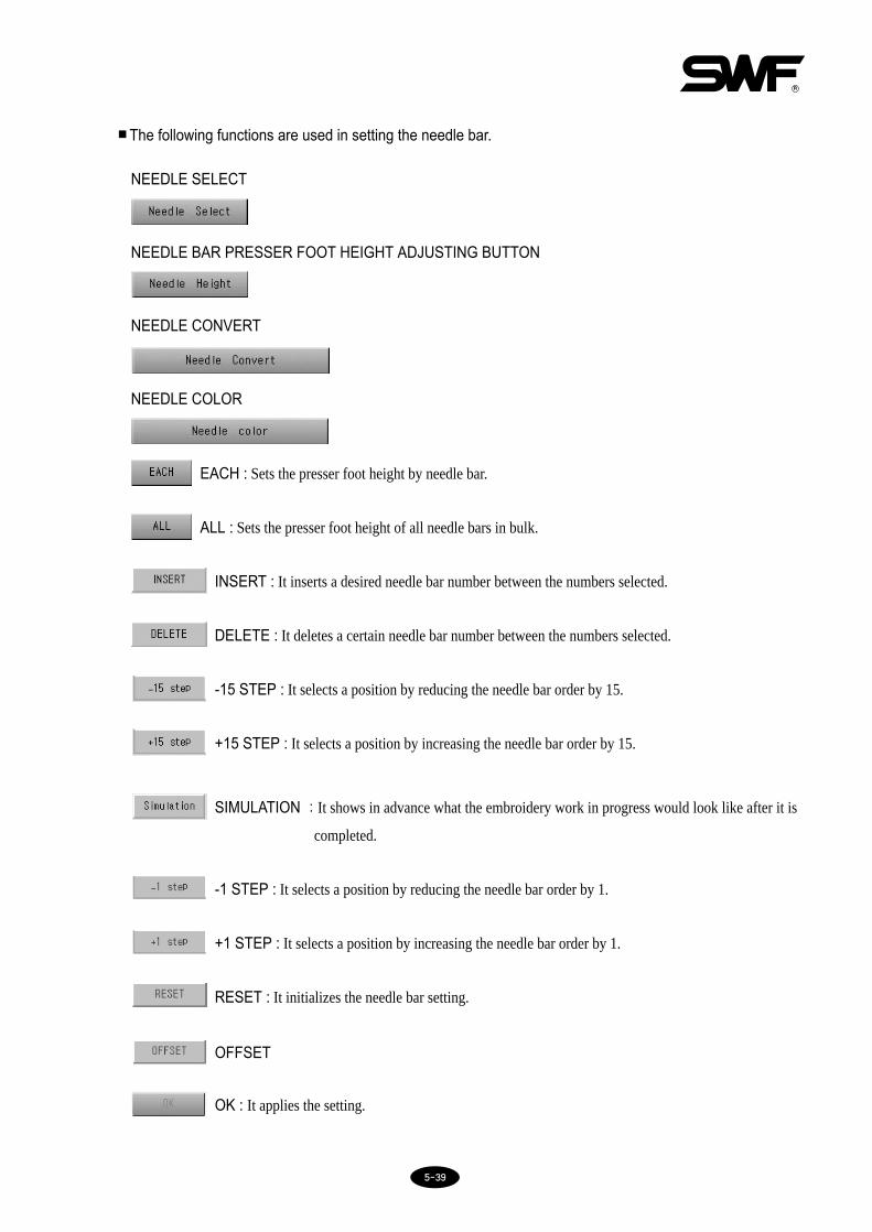
55--3399
■The following functions are used in setting the needle bar.
NEEDLE SELECT
NEEDLE BAR PRESSER FOOT HEIGHT ADJUSTING BUTTON
NEEDLE CONVERT
NEEDLE COLOR
EACH : Sets the presser foot height by needle bar.
ALL : Sets the presser foot height of all needle bars in bulk.
INSERT : It inserts a desired needle bar number between the numbers selected.
DELETE : It deletes a certain needle bar number between the numbers selected.
-15 STEP : It selects a position by reducing the needle bar order by 15.
+15 STEP : It selects a position by increasing the needle bar order by 15.
SIMULATION : It shows in advance what the embroidery work in progress would look like after it is
completed.
-1 STEP : It selects a position by reducing the needle bar order by 1.
+1 STEP : It selects a position by increasing the needle bar order by 1.
RESET : It initializes the needle bar setting.
OFFSET
OK : It applies the setting.

55--4400
Keys for selecting color for each needle bar
Keypad : You can input a needle bar number.

55--4411
(1) NEEDLE SELECT
It determines the order of the needle bars to be changed when the machine meets a color change code duringembroidery. Select NEEDLE SELECT in [Fig.5.9.4-1] and you will see keys required for selecting needle bar asshown in [Fig.5.9.4-3]. Refer to the example below.
Keys activated when you select NEEDLE SELECT
① INSERT
② DELETE
③ -15 STEP
④ +15 STEP
⑤ SIMULATION
⑥ KEYPAD
⑦ -1 STEP
⑧ +1 STEP
⑨ RESET
⑩ OFFSET
⑪ OK
Refer to the example below for their functions.
[Fig.5.9.4-3]
[NOTE]
Needle bar setting will not be initialized after turning the power off and on again. The setting will not change if
you call another design. Therefore, if you want to change the setting or if you want to work on another design,
you must do the setting again.

55--4422
[Ex.5.9.4-1] NEEDLE SELECTCalling the design in memory #25 and setting the needle bar order at 7-3-5-1-6-4-2-1
1⃞ Call the design in memory #25 as shown in [Fig.5.7-6].
(Refer to 5.7 EMB CALL for calling a design.)
2⃞ Select .
3⃞ Press NEEDLE SETTING
4⃞ Select NEEDLE SELECT
You will see sub menus activated as in [Fig.5.9.4-4] - INSERT, DELETE, -15 STEP, +15 STEP, SIMULATIONand keypad. The selection order will be at 1.
5⃞ Press 7 in the keypad.
7 will appear as shown in [Fig.5.9.4-5] and the selection order will be at 2.
6⃞ Input 3, 5, 1, 6, 4, 2, and 1 in the same way.
7⃞ Check if the order is correct and press .
[Fig.5.9.4-4] [Fig.5.9.4-5]

55--4433
3⃞ Select INSERT
6 will be copied and one more needle bar will be created as shown in [Fig.5.9.4-7]
[Ex.5.9.4-2] Inserting and DeletingInsert No.9 needle bar into the fifth place(between 1 and 6) and delete No.4needle bar from the 7th place in the needle bar order of 7-3-5-1-6-4-2-1First do [Ex.5.9.4-1].
1⃞ Press SELECT in NEEDLE SETTING
2⃞ Among the activated functions, press +1 STEP 4 times.
The cursor will blink at 6 as in [Fig.5.9.4-6].
[Fig.5.9.4-6] [Fig.5.9.4-7]

55--4444
5⃞ Press +1 STEP in the keypad and move to 4.
The cursor will blink at 4 as shown in [Fig.5.9.4-9]
6⃞ Select DELETE.
You will see a screen [Fig.5.9.4-10]
7⃞ Press to apply the new setting.
4⃞ Input 9 from the keypad.
9 is inserted as in [Fig.5.9.4-8]
[Fig.5.9.4-10]
[Fig.5.9.4-8] [Fig.5.9.4-9]

55--4455
(2) NEEDLE CONVERT
It changes the needle bar number set in [Fig.5.9.4-2].
If the needle bar order by color change is set 1-2-1-2-1-2-1-2-1-2 and if you want to change all needle bars set as 2
to 1, you will have to change make changes 5 times. However, if you use this NEEDLE CONVERT function, you
can make the correction just once. Press NEEDLE SELECT and change needle bar 2 to 1.
[Fig.5.9.4-11] shows selection of NEEDLE CONVERT.
The following functions will be activated when selecting NEEDLE CONVERT.① Keypad
② SIMULATION
③ -1 STEP
④ +1 STEP
⑤ RESET
⑥ OK
Refer to the example below for details.
[Fig.5.9.4-11]

55--4466
[Ex.5.9.4-3] NEEDLE CONVERTNeedle bars #1 has brown and #2 blue for color change. The color order is set 1-2-1-2-1-2-1-2-1-2. You want to use NEEDLE CONVERT to make all colors brown.
1⃞ Call a design
(see 5.7 EMB CALL for calling designs)
2⃞ Use SELECT to have the color order 1-2-1-2-1-2-1-2-1-2 as shown in [Fig.5.9.4-12].
(Refer to needle select example [Ex. 5.9.4-1].)
3⃞ Select NEEDLE CONVERT
4⃞ Press +1 STEP
5⃞ Input 1 in the keypad
Check the change at needle bar 2 as shown in [Fig.5.9.4-13]
6⃞ Select .
[Fig.5.9.4-12] [Fig.5.9.4-13]

55--4477
(3) NEEDLE COLOR
It shows information related to needle bar (color) change on the design by distinguishing each needle bar with a
color. The colors displayed on the screen are not the colors used in the embroidery. As illustrated in [Fig.5.9.4-14]
the colors will turn on when you press the needle bar.
Select the desired needle bar and you will see a screen where you can select a color as shown in [Fig.5.9.4-15].
Select the desired color and the color bar below will show the color of your selection. If you like the color selection,
press .
[Fig.5.9.4-14] [Fig.5.9.4-15]
(4) CHANGING NEEDLE BAR PF HEIGHT
Changing needle bar PF height is the function of adjusting the PF height at the selected needle bar (applicable toDual DM series only). Default value of a selected needle bar height is 1.0mm, and it can be adjusted in the range of 0.5mm~4.5mm.
Refer to the example below for details.
No.1 key No.2 key No.3 key No.4 key No.5 key No.6 key No.7 key No.8 key No.9 key
0.5mm 1.0mm 1.5mm 2.0mm 2.5mm 3.0mm 3.5mm 4.0mm 4.5mm
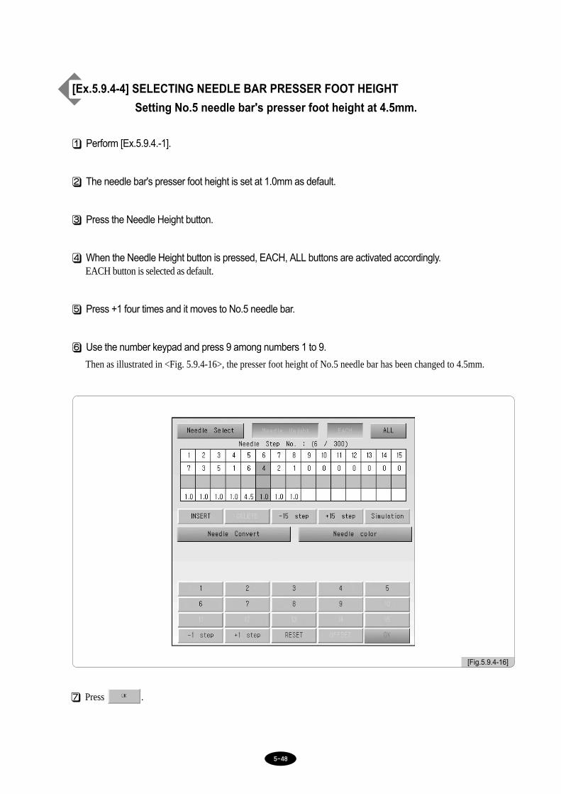
55--4488
7⃞ Press .
[Ex.5.9.4-4] SELECTING NEEDLE BAR PRESSER FOOT HEIGHT
Setting No.5 needle bar's presser foot height at 4.5mm.
1⃞ Perform [Ex.5.9.4.-1].
2⃞ The needle bar's presser foot height is set at 1.0mm as default.
3⃞ Press the Needle Height button.
4⃞ When the Needle Height button is pressed, EACH, ALL buttons are activated accordingly. EACH button is selected as default.
5⃞ Press +1 four times and it moves to No.5 needle bar.
6⃞ Use the number keypad and press 9 among numbers 1 to 9.
Then as illustrated in <Fig. 5.9.4-16>, the presser foot height of No.5 needle bar has been changed to 4.5mm.
[Fig.5.9.4-16]

7⃞ Press .
[Ex.5.9.4-5] SELECTING ALL NEEDLE BAR PRESSER FOOT HEIGHT
Setting the presser foot height of all needle bars at 2.5mm.
1⃞ Perform [Ex.5.9.4.-1]
2⃞ The needle bar's presser foot height is set at 1.0mm as default.
3⃞ Press the Needle Height button.
4⃞ When the Needle Height button is pressed, EACH, ALL buttons are activated accordingly.
EACH button is selected as default, and then press ALL.
5⃞ Use the number keypad and press 5 among numbers 1 to 9.
As illustrated in <Fig. 5.9.4-17>, the presser foot height of all needles have been changed to 2.5mm.
[Fig.5.9.4-17]
55--4499

55--5500
5.9.5 Frame offset setting
It enables you to set the design start/end positions and offset points for convenient embroidery. Press Frame Offset
Setting in the setting menu and you will see [Fig.5.9.5-1].
Sub menus of the frame offset are as follows:
[Fig.5.9.5-1]
① DESIGN START POINT : you can set the start position of the design. The frame will automatically move to
the start position from wherever it is before the embroidery to start the work.
② OFFSET MIDDLE POINT : you can set a middle position between the start and the end position of the design
so as to prevent the problems such as the needle bar touching the embroidery
material. If you don’t need this function, enter the same value as either of the start
or the end position.
③ DESIGN OFFSET POINT : you can set the frame end position or offset frame position of the design. This
function is useful for applique work, frame change, etc.
[CAUTION]
1. Make sure to select YES of the Offset Function in the basic setting menu. Otherwise the offset positions
you set will not apply to your embroidery.
2. The frame will not be able to find the offset points if the frame origin point is incorrect.

55--5511
[Ex.5.9.5-3] Design start position: X (500) Y (300)Offset middle point: X (1000) Y (1000)Design offset point: X (1500) Y (1700)
1⃞ Press Frame Offset Setting in the setting menu.
You will see [Fig.5.9.5-1].
2⃞ Press Design Start Point.
You will see the menu activated.
3⃞ Use the frame movement keys to set X and Y positions.
4⃞ Press Offset middle point and the menu will be activated.
5⃞ Use the frame movement keys to set X and Y positions.
6⃞ Press Design offset point and the menu will be activated.
7⃞ Use the frame movement keys to set X and Y positions.
8⃞ Press .

55--5522
5.9.6 Option setting
Option Setting is the function of setting optional devices of an embroidery machine. Embroidery machine's optional
devices include coding, sequin, and boring. <Fig. 5.9.6-1> shows the option setting screen.
[Fig.5.9.6-1]

55--5533
④ Input 1 (YES) in the keypad (see [Fig.5.9.6-3])
To correct the input, press . To cancel the function, press .
⑤ Press .
Setting cording has been completed.
(1) Cording
① Press in the main screen.
② Select OPTION SETTING.
③ Press “1. CORDING”
[Fig.5.9.6-2] displays the setting screen.
[Fig.5.9.6-2] [Fig.5.9.6-3]

55--5544
⑦ Use the number keypad to enter the desired speed of embroidery within the range of minimum and maximumembroidery speed.
⑧ Press .
Setting cording has been completed.
⑥ Press ‘8. CORDING RPM.’<Fig. 5.4.6-4> is the screen for speed setting.
[Fig.5.9.6-4]

55--5555
④ Use the number keypad and press 1(Yes).
To correct the input, press . To cancel the function, press .
⑤ Press .
(2) Sequin Setting
① Press the setting button from the main function menu.
② Select OPTION SETTING.
③ Choose '2. Sequin L' or '4. Sequin R.' In the case of Sequin L, the setting screen appears as in <Fig. 5.9.6-5>. Inthe case of Sequin R, the setting screen appears as in <Fig. 5.9.6-6>.
[Fig.5.9.6-5] [Fig.5.9.6-6]

55--5566
[Fig.5.9.6-7] [Fig.5.9.6-8]
⑦ Enter desired figure within the setting range using the number keys.
⑧ Press .
⑥ Press ‘3. Sequin(L) Length’ or ‘5. Sequin(R) Length.’ (The above menus are activated only when ‘2. Sequin L’ and ‘4. Sequin’ are selected.)In the case of Sequin(L) Length, the setting screen appears as in <Fig. 5.9.6-7>. In the case of Sequin(R)Length, the setting screen appears as in <Fig. 5.9.6-8>.

55--5577
⑩ Enter desired figure within the setting range using the number keys.
⑪ Press .Sequin setting has been completed.
⑨ Press ‘6. Sequin Speed.’ <Fig. 5.9.6-9> is the speed setting screen.
[Fig.5.9.6-9]

55--5588
(3) Boring Needle
① Press in the main screen.
② Select OPTION SETTING.
③ Press “7. BORING NEDDLE”[Fig.5.9.6-10] displays the setting screen.
④ Use the keypad to enter the number of the boring-installed needle bar within the range.
To correct the input, press . To cancel the function, press .
⑤ Press .
Setting boring has been completed.
[Fig.5.9.6-10]

55--5599
5.9.7 The others setting
When Others is pressed from the setting menu, the screen as in <Fig. 5.9.7-1> appears. Others has six setting sub-menus including cutting needle bar setting, thread sensing setting by head, trimming-related setting, sound volumesetting, head select setting, and thread setting.
[Fig.5.9.7-1]
(1) Cut Needle Set
Cutting function refers to cutting, instead of embroidery, the work material in the desired shape using a special
cutting needle instead of an ordinary needle. To use this function, you must turn off the functions such as thread
detection and trimming. CUT NEEDLE SET is about automatically turning off the functions unnecessary in cutting.
[Fig.5.9.7-2] shows the screen after selecting CUT NEEDLE SET in [Fig.5.9.7-1]. Pink means the needle bar is for
embroidery and bright yellow for cutting.
[Fig.5.9.7-2] [Fig.5.9.7-3]

55--6600
[Ex. Converting the needle bars #2, 3, 4 to cutting]
1⃞ Press in the main screen.
2⃞ Select The Other Setting
You will see a screen [Fig.5.9.7-1]
3⃞ Press CUT NEEDLE SET
You will see a screen [Fig.5.9.7-2]
4⃞ Select needle bars #2, 3, 4.
As illustrated in [Fig.5.9.7-3], the head #2, 3, 4 turns bright yellow meaning that it is converted for cutting function.
(2) Thread Sensor Function Setting by Head(In case of two heads or above)
This function determines the activation/deactivation of the thread sensor at each head.
As in <Fig. 5.9.7-4>, this operating program supports up to 49 heads, and it displays that currently three heads are
chosen for this function. The bright yellow indicates that the thread sensor is in operation. Currently, No. 1, 2, 3
heads' sensors are selected.
※ This function is not supported by 1×1 model.
[Ex. Turn off the No. 2 head thread sensor]
1⃞ Press on the main screen.
2⃞ Press other settings on the setting screen. Then <Fig. 5.9.7-1> appears.
3⃞ Press the thread sensor setting button by head.Then <Fig. 5.9.7-4> appears.
4⃞ Select No. 2 Head.In <Fig. 5.9.7-5>, No. 2 Head is marked in pink, which means that its thread sensor is not in operation.

55--6611
(3) Trim Set
Trim Set can be made the trimming start angle, the acceleration speed of main shaft when started, and the length of
backtack during trimming can be set.
① Trimming Start Angle
It is set to change the main shaft angle, which launches the trimming motor feeding during trimming.
- The default is one degree. The setting range is -5~5, and can be adjusted by the unit of one degree.
② Main shaft acceleration time (t) setting when turned on
It sets the time taken for the embroidery machine to accelerate from the inching speed to the embroidery speed
when turned on.
- The default is normal. It can be set as Normal (0) or Slow (1).
[Fig.5.9.7-4] [Fig.5.9.7-5]
Embroidery Speed
Inching SpeedTime
start t

55--6622
③ Backtack length setting when starting and trimming
When implementing the backtack, it sets the width of a stitch.
When using a thin fabric or wool thread, set the length at 0.8[mm]. Then it will create effects upon needle
weaving and trimming.
- The default is 0.8[mm]. The setting range is 0.6~0.8[mm], and can be adjusted by the unit of 0.1[mm].
(4) Sound Volume Setting
Sets the volume of power on/off sound or menu select sound.
- Default value is OFF(0), and the setting range is 1 to 10.
(5) Head Select Setting
Chooses the head to use among multiple heads.
(6) Thread Setting
Chooses threads depending on conditions.
- Default value is Normal(0), and if wool thread is desired, select Wool(1).

55--6633
[Fig.5.10.0-1]
•POSITION : It shows, even when not actually embroidering, if the design called touches the X or Y limits
•GAUGE : It automatically generates the gauge for the embroidery exclude according to the values set in
“Setting Embroidery Parameters” - “14) Distance between Design Exclude and Gauge”.
•EXCLUDE : It embroiders only the outer line (trace) of the design called.
•FASTVIEW : It displays on the screen virtual embroidery stitch by stitch just as if you are actually
embroidering for you to plan the direction of the work and the stages of color change.
•TRACE : It enables you to check during the embroidery if the design will step off the frame limits on the X or
Y-axis if it is worked on the current frame position.
5.10.0 Ready
- function pre-checks if the machine is well conditioned for actual embroidery. It checks 5 conditions -
position, Gauge, Exclude, Fastview, and Trace.
Press in the main screen and you will see sub menus as in [Fig.5.10.0-1].
[Fig.5.9.7-6]

55--6644
5.10.1 Position
It sets the desired position of the embroidery on the frame.
① Press Work Position in the screen [Fig.5.10.0-1] and you will see a screen like [Fig.5.10.1-1].
② Dotted lines within the frame ([Fig.5.10.1-1]) shows the maximum length of the design on X and Y axis. ‘+’
within the dotted square refers to the embroidery start position as well as the frame position where the current
needle bar will be embroidering.
③ Press a desired position within the frame and the design will move to the desired frame position. Red marks, if
any, on the design (the dotted square) means possibility of X, Y limit errors. Make sure that the dotted square
comes safely inside the frame.
Select the desired position and press . And the frame will move to make sure that embroidery design
can be created at the desired position.
[Fig.5.10.1-1]
[CAUTION]
Pushing the frame manually while the main power is off will change the frame origin. If the frame origin is
changed, the machine will not be able to accurately align the work position using the Work Position function
(refer to ‘5.13.4 Frame Origin’ about the details).
Design outline
Frame outline

55--6655
5.10.2 Gauge
It automatically generates the gauge for the embroidery exclude.
① Select GAUGE in [Fig.5.10.0-1] and you will see a screen like [Fig.5.10.2-1].
② Press in [Fig.5.10.2-1] and you will see a menu of saving a design. Select a memory room in which to
save the design and then press . The design is saved. To cancel saving, press .
automatically moves the frame (after setting the gauge) along the gauge line to check if the design
moves off the frame.
[Fig.5.10.2-1] [Fig.5.10.2-2]
[NOTE]
You can set the distance between the design called and the gauge line in 14. Optimize Method of “5.9.2
Embroidery Parameter Setting.”

55--6666
5.10.3 Exclude
It embroiders only the outer line of the design called.
① Select EXCLUDE in [Fig.5.10.0-1] and you will see a screen like [Fig.5.10.3-1].
② Press in [Fig.5.10.3-1] and you will see a menu of saving a design. Select a memory room in which
to save the design and then press . The design is saved. To cancel saving, press .
automatically moves the frame (after setting the trace) along the trace line to check if the design moves
off the frame.
[Fig.5.10.3-1] [Fig.5.10.3-2]

55--6677
5.10.4 Fastview
It displays on the screen virtual embroidering of the design called. You can see the embroidering by color, 100 stitches,
1000 stitches, low speed, and high speed.
[Fig.5.10.4-1] shows the selection of Fastview in [Fig.5.10.0-1].
As shown in [Fig.5.10.4-2], you can see the embroidering process of the design selected displayed on the screen.
■Refer to the following descriptions of each function.
RESTART : It initializes the virtual embroidering.
X (END) : It ends the Fastview.
COLOR+ : It shows the stitches of the next color.
COLOR - : It goes back the stitches to the previous color.
+100 : It shows the embroidering in the unit of 100 stitches forward.
[Fig.5.10.4-1] [Fig.5.10.4-2]

55--6688
-100 : It shows the embroidering in the unit of 100 stitches backward.
+1000 : It shows the embroidering in the unit of 1000 stitches forward.
-1000 : It shows the embroidering in the unit of 1000 stitches backward.
FAST & SLOW : It shows the embroidering fast or slow. Press FAST and the button will
display the SLOW option and vice versa. Basic setting is FAST (you
will read SLOW on the screen).
START : After setting FAST or SLOW, press this key to start the virtual embroidering.
STOP : Press this while virtual embroidering to stop the process.

55--6699
The following example is viewing the design in memory #25 by color using . This design has 9 colorchange codes.

55--7700
5.10.5 Trace
① It quickly checks if the design size falls within the frame limits on X and Y axis if the design selected is worked
on the current frame position.
② Arrows in [Fig.5.10.5-1] indicate the path of the frame movement. The frame quickly moves along the
maximum and minimum X and Y scopes to see if the design steps off the frame limit. If the frame meets the
frame limit, it will stop and you will see Frame Limit Error on the screen.
[Fig.5.10.5-1]
(3)
(2)
(1)
(6)
(5)
(4) Operation Start Point

55--7711
5.11.0 Repeat- Repeat allows you to use one or more designs repeatedly and simultaneously in one design.
[Fig.5.11.0-1] shows you selection of in the main function menu.
[Fig.5.11.0-1]
•GENERAL REPEAT : You can repeat one design up to 99 times on X and Y axis.
•SPECIAL REPEAT : You can repeat several designs in the memory and repeat them up to 64 times, freely
using functions such as angle change, X-mirror, and scale.
•REPEAT LOAD : You can call a repetition work stored in the memory.

55--7722
5.11.1 General repeat
It repeats one design in the X and Y direction. [Fig.5.11.1-1] displays selection of General Repeat in [Fig.5.11.0-1].
①X Repeat : It sets the number of repetition on the X-axis. The range is 1-99 times.
②Y Repeat : It sets the number of repetition on the Y-axis. The range is 1-99 times.
③X Design Interval : It sets the distance between the repetitions (between start points) on the X-axis. Direction of the repetition is set by ‘+’ or ‘-’.
+ : repeat in the X direction (right)- : repeat in the Y direction (left)
[Fig.5.11.1-1]
[NOTE]
Repetition range (X repeat × Y repeat) should be less than 99.
Distance +30mm Distance -30mm
(+30mm)Distance
(-30mm)Distance
Design start point
➜
↙Embroidery start point↙
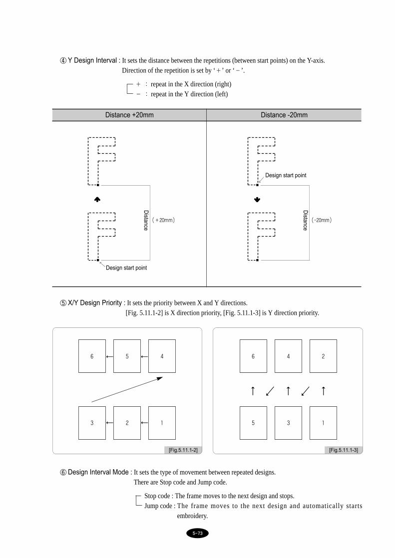
55--7733
④Y Design Interval : It sets the distance between the repetitions (between start points) on the Y-axis.Direction of the repetition is set by ‘+’ or ‘-’.
+ : repeat in the X direction (right)- : repeat in the Y direction (left)
⑤X/Y Design Priority : It sets the priority between X and Y directions.[Fig. 5.11.1-2] is X direction priority, [Fig. 5.11.1-3] is Y direction priority.
⑥Design Interval Mode : It sets the type of movement between repeated designs. There are Stop code and Jump code.
Stop code : The frame moves to the next design and stops.Jump code : The frame moves to the next design and automatically starts
embroidery.
Distance +20mm Distance -20mm
(+20mm)
Distance
Design start point
➜
↙
(-20mm)
Distance
Design start point
➜
↙
[Fig.5.11.1-2] [Fig.5.11.1-3]
6 5 4
3 2 1
← ←
← ←
6 4 2
5 3 1
← ← ←
↙ ↙

55--7744
⑦Mirror Convert : It sets design in reverse X-direction(mirror image).
Refer to the following table for keypad inputs.
(+20mm)
Distance
Design start point
➜
↙
(+20mm)
Distance
NO X
Y X Y
(+30mm)Distance
(+30mm)Distance
(+30mm)Distance
Design start point
➜ ➜
↙Design start point
↙
Design start point↙
Input Setting
0 NO
1 X
2 Y
3 X_Y

55--7755
[Ex.5.11.1-1] Calling design #25 for setting the following repetition and saving it
1⃞ Call the design in memory #25
(see ‘5.7 EMB CALL’ for calling designs).
2⃞ Press in the main function menu and select General Repetition.
You will see screen like [Fig.5.11.1-1].
3⃞ Select 1. X Repeat.
A keypad will appear as shown in [Fig.5.11.1-4].
4⃞ Input 5 using the keypad and then press .
5⃞ Select 2. Y Repeat.
A keypad will appear as shown in [Fig.5.11.1-5]
6⃞ Input 4 from the keypad and press .
•X Repeat : 5 times•Y Repeat : 4 times•X Design Interval : 200mm•Y Design Interval : -200mm•X/Y Priority : X•Design Interval Mode : Jump code•Mirror : NO•Saving Method : Data Save
[Fig.5.11.1-4] [Fig.5.11.1-5]
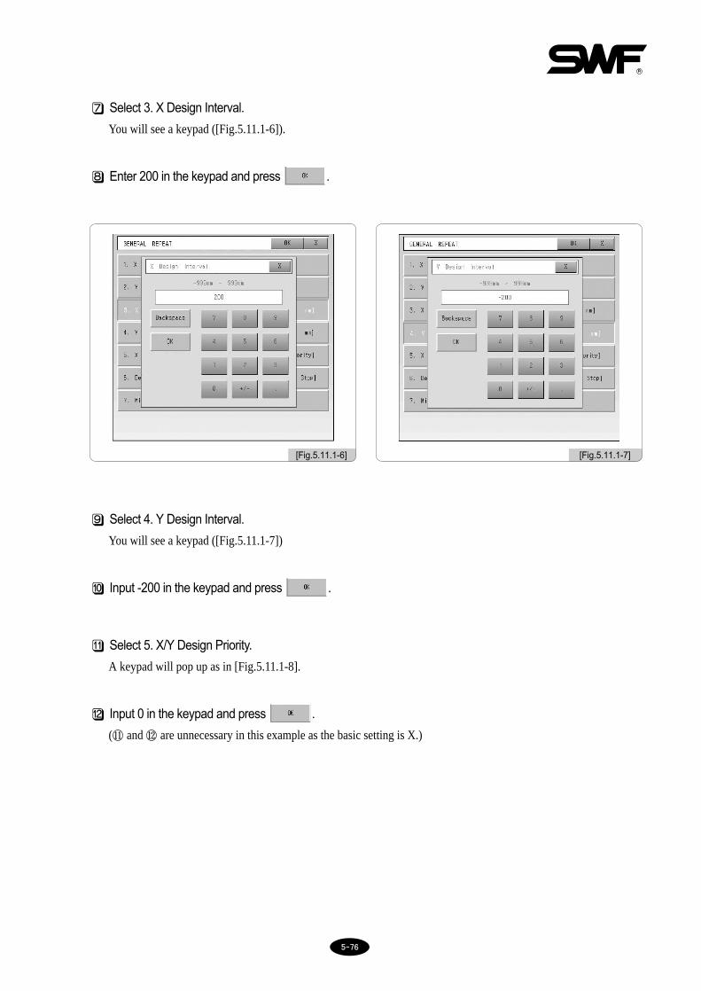
55--7766
7⃞ Select 3. X Design Interval.
You will see a keypad ([Fig.5.11.1-6]).
8⃞ Enter 200 in the keypad and press .
9⃞ Select 4. Y Design Interval.
You will see a keypad ([Fig.5.11.1-7])
[10] Input -200 in the keypad and press .
[Fig.5.11.1-6] [Fig.5.11.1-7]
[11] Select 5. X/Y Design Priority.
A keypad will pop up as in [Fig.5.11.1-8].
[12] Input 0 in the keypad and press .
(⑪ and ⑫ are unnecessary in this example as the basic setting is X.)

55--7777
[13] Select 6. Design Interval Mode.
A keypad will pop up as in [Fig.5.11.1-9].
[14] Input 1 from the keypad and press .
[15] Select 7. Mirror Convert.
you will see a keypad ([Fig.5.11.1-10]).
[Fig.5.11.1-8] [Fig.5.11.1-9]
[16] Enter 0 from the keypad and press .
(⑮ and ⒃ are unnecessary in this example as the basic setting is X.)
[17] The screen of <Fig. 5.11.1-11> illustrates all settings are completed.
[Fig.5.11.1-10] [Fig.5.11.1-11]

55--7788
[18] Check all settings and press on the upper right.
[Fig.5.11.1-12] asks you the method of saving the repetition work.
[19] Press .
[Fig.5.11.1-13] shows selection of the memory room. All of the 10 spaces are available.
[Fig.5.11.1-13]
[Fig.5.11.1-12]
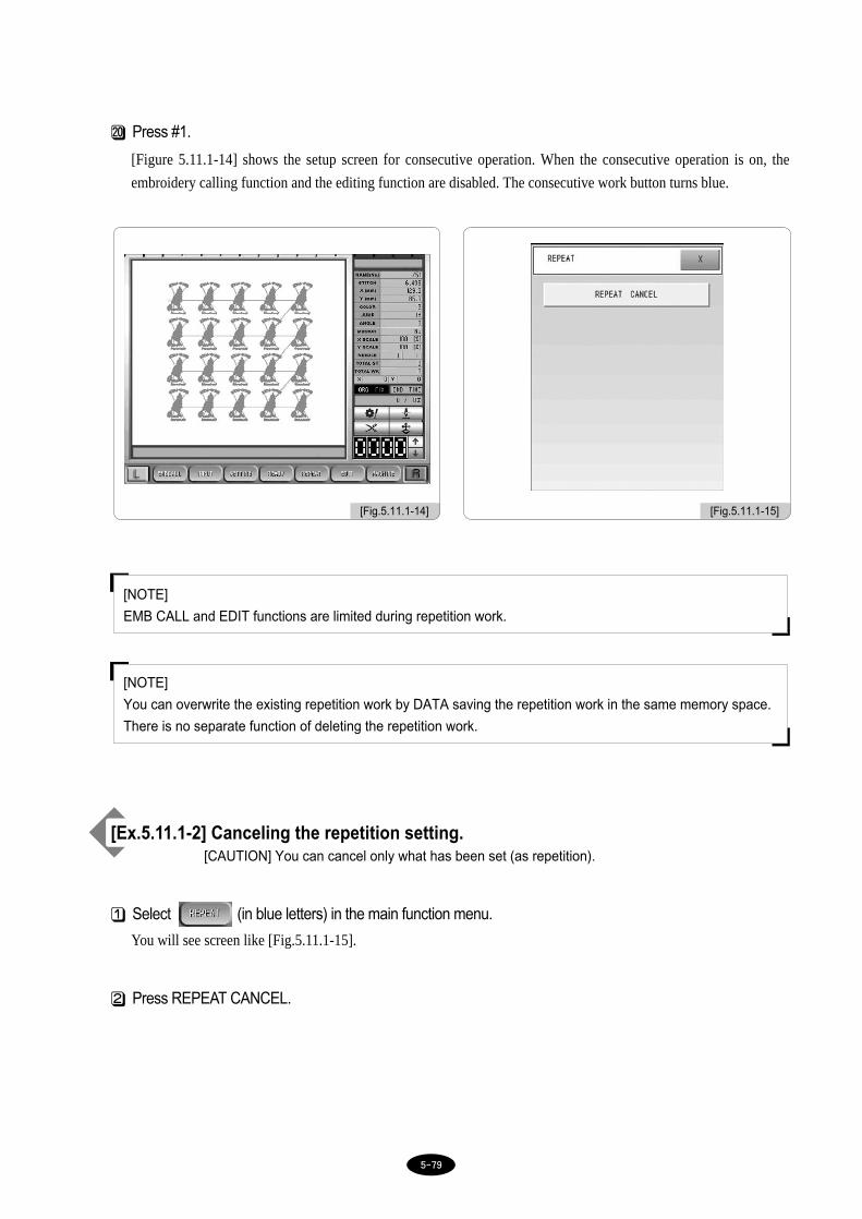
55--7799
[20] Press #1.
[Figure 5.11.1-14] shows the setup screen for consecutive operation. When the consecutive operation is on, the
embroidery calling function and the editing function are disabled. The consecutive work button turns blue.
[Ex.5.11.1-2] Canceling the repetition setting.[CAUTION] You can cancel only what has been set (as repetition).
1⃞ Select (in blue letters) in the main function menu.
You will see screen like [Fig.5.11.1-15].
2⃞ Press REPEAT CANCEL.
[NOTE]
EMB CALL and EDIT functions are limited during repetition work.
[NOTE]
You can overwrite the existing repetition work by DATA saving the repetition work in the same memory space.
There is no separate function of deleting the repetition work.
[Fig.5.11.1-14] [Fig.5.11.1-15]

55--8800
5.11.2 Special repeat
It is about putting together (merging) designs. You can put together up to 64 designs stored in the memory room in
various forms.
[Fig.5.11.2-1] shows selection of Special Repeat in the screen [Fig.5.11.0-1]. You can select 8 designs in one screen. To
select more designs, use the scroll bar or Up/Down keys. Point to the white section to see more menus for selection.
[Fig.5.11.2-1]

55--8811
[Ex.5.11.2-1] Performing special repeat on designs #47 and #48 to make [Fig.5.11.2-2]
1⃞ Press in the main function menu and select Special Repeat.
You will see screen like [Fig.5.11.2-1].
2⃞ Select 1 and you will see setting menu as in [Fig.5.11.2-1].
As in [Figure 5.11.2-3], the setup screen appears.
Design #47: X_Scale 150%, Y_Scale 150%
Design #48: X_Scale 200%, Y_Scale 200%
[Fig.5.11.2-2]
[Fig.5.11.2-3]
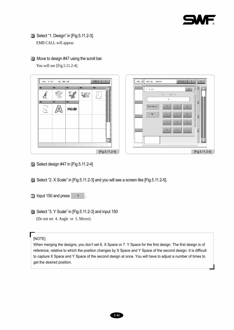
55--8822
3⃞ Select “1. Design” in [Fig.5.11.2-3].
EMB CALL will appear.
4⃞ Move to design #47 using the scroll bar.
You will see [Fig.5.11.2-4].
5⃞ Select design #47 in [Fig.5.11.2-4]
6⃞ Select “2. X Scale” in [Fig.5.11.2-3] and you will see a screen like [Fig.5.11.2-5].
7⃞ Input 150 and press .
8⃞ Select “3. Y Scale” in [Fig.5.11.2-3] and input 150
(Do not set 4. Angle or 5. Mirror).
[Fig.5.11.2-4] [Fig.5.11.2-5]
[NOTE]
When merging the designs, you don’t set 6. X Space or 7. Y Space for the first design. The first design is of
reference, relative to which the position changes by X Space and Y Space of the second design. It is difficult
to capture X Space and Y Space of the second design at once. You will have to adjust a number of times to
get the desired position.

55--8833
The first design is set as in [Fig.5.11.2-6].
9⃞ Press in the upper part in [Fig.5.11.2-6].
Setting of the first design is completed as in [Fig.5.11.2-7].
[10] Select #2 in [Fig.5.11.2-7] and you will see a menu for setting ([Fig.5.11.2-3]).
[11] Select “1. Design” and select the design #48.
[12] Set 200 for “2. X Scale.”
[13] Set 200 for “3. Y Scale”
(Do not set 4.Angle or 5.Mirror).
[14] Set 200 for “6. X Space.”
Set -200 for 7. Y Space.
[Fig.5.11.2-6] [Fig.5.11.2-7]

55--8844
The second design is set as shown in [Fig.5.11.2-8].
[15] Press in the upper part of [Fig.5.11.2-8].
The setting is complete as in [Fig.5.11.2-9].
[16] Press in the upper part of [Fig.5.11.2-9] and you will be asked about the saving method
([Fig.5.11.2-10]).
[17] Select .
The memory room # 1 in [Fig.5.11.2-11] is occupied by the general repeat design, which was made in [Ex. 5.11.1-1].
[18] Select #2 in [Fig.5.11.2-11].
A screen will appear with selection of Special Repeat work as shown in [Fig.5.11.2-2].
[Fig.5.11.2-8] [Fig.5.11.2-9]
[Fig.5.11.2-10] [Fig.5.11.2-11]

55--8855
5.11.3 Repeat Load
You can call designs, of which repeat work is stored as data.
Select call Repeat Load in [Fig.5.11.0-1] and you will see [Fig.5.11.3-1].
The screen shows two repeat works. Select the desired design and it will be called.
[Fig.5.11.3-1]

55--8866
- It is about editing designs.
[Fig.5.12.0-1] shows selection of in the main function menu.
[Fig.5.12.0-1]
•STITCH EDIT : You can change codes for each stitch or change the number of stitches looking at the stitch
data of the selected design on the screen.
•DESIGN DIVIDE : You can divide a design in the desired part and separately save them.
•DESIGN FILTERING : You can automatically delete unnecessary stitch data produced while creating designs.
•DESIGN ZOOM IN : You can enlarge the desired part of a design to check distance between stitches, etc.
5.12.0 Edit

55--8877
5.12.1 Stitch edit
It enables you to change codes for each stitch or to change the number of stitches by looking at the data of the selected
design on the screen.
[Fig.5.12.1-1] shows the initial screen of selecting Stitch Edit in [Fig.5.12.0-1].
Each line for each stitch number in [Fig.5.12.1-1] is a button. For instance, if you want to change stitch #1, press
anywhere in [Fig.5.12.1-2] and you will see an editing screen like [Fig.5.12.1-3].
[Fig.5.12.1-1]
[Fig.5.12.1-2]

55--8888
Press to edit X data or to edit Y data. You can insert, delete, and change codes.
Press in [Fig.5.12.1-3] and you will see a menu button for setting the codes ([Fig.5.12.1-4]). There are 6
different codes available. Select any of the six buttons.
Select any of the six buttons.
[Fig.5.12.1-3] [Fig.5.12.1-4]

55--8899
Press in [Fig.5.12.1-1] and you will see a menu, where you can see a list by code as shown in [Fig.5.12.1-
5]. Press and you will see the jump code only [Fig.5.12.1-6].
Press to see the color code data only as shown in [Fig.5.12.1-7]. Likewise, press to see the
sequin code only. But in the case of [Fig.5.12.1-8], the screen does not show anything because the design does not have
any sequin code data. If your selected design has sequin codes, you will see the data.
[Fig.5.12.1-5] [Fig.5.12.1-6]
[Fig.5.12.1-7] [Fig.5.12.1-8]

55--9900
[Ex.5.12.1] Calling the design #25 and editing with the following parameters
1) Deleting data of the 3000th stitch
1⃞ Select in the main function menu.
2⃞ Select STITCH EDIT in [Fig.5.12.0-1].
3⃞ Move to the 3000th stitch using the scroll bar or Down key.
You will see a screen like [Fig.5.12.1-9].
4⃞ Select 3000th line.
A keypad will pop up.
5⃞ Press .
The 3000th stitch is deleted and the next stitches have moved up in line by one stitch as shown in [Fig.5.12.1-10].
1) Deleting data of the 3000th stitch.
2) Changing the function code of the 3500th stitch to a color code.
3) Inserting X:2mm, Y:-5mm, Function code: Jump between 10000th stitch and 10001st stitch.
[Fig.5.12.1-10][Fig.5.12.1-9]

55--9911
2) Changing the function code of the 3500th stitch to a color code
1⃞ Move to the 3500th stitch using the scroll bar or Down key.
You will see a screen like [Fig.5.12.1-11].
2⃞ Select 3500th line.
A keypad will pop up (see [Fig.5.12.1-3]).
Press in [Fig.5.12.1-3] and you will see the function menu screen as in [Fig.5.12.1-4].
3⃞ Select in the function menu.
4⃞ After setting as in [Fig.5.12.1-12], press .
Function code is changed to a color code as shown in [Fig.5.12.1-13].
[Fig.5.12.1-13]
[Fig.5.12.1-11] [Fig.5.12.1-12]

55--9922
3) Inserting X:2mm, Y:-5mm, Function code: Jump between 10000th stitch and
10001st stitch
1⃞ Move to the 10000th stitch using the scroll bar or Down key.
You will see a screen like [Fig.5.12.1-14].
2⃞ Select 10001th line.
You will see a screen like [Fig.5.12.1-15].
3⃞ Select .
4⃞ Press and input 2 from the keypad.
5⃞ Press and input -5 from the keypad.
6⃞ Press in [Fig.5.12.1-15].
[Fig.5.12.1-14] [Fig.5.12.1-15]

55--9933
7⃞ Select in the function menu.
Jump code is selected as in [Fig.5.12.1-16].
8⃞ Press .
You can check the input value in the 10001st line as shown in [Fig.5.12.1-17].
[Fig.5.12.1-16] [Fig.5.12.1-17]

55--9944
5.12.2 Stitch divide
It divides a design in the desired part and saves them separately. You can divide a design by color or stitch.
[Fig.5.12.2-1] shows selection of Design Divide in the screen [Fig.5.12.0-1]. The design on the left screen shows a
design called by EMB CALL. The right screen will show the part divided from the design on the left.
STITCH : It divides a design by the number of stitches.
Add colors : It leaves one color on the left and sends the rest of the colors to the right.
(The same function as in 5.10.4 Fastview)
Remove colors : This function is available only after selecting +COLOR and offers the opposite function
from +COLOR. Press -COLOR and the colors divided from the original design will
be merged back again at one color at a time.
(The same function as in 5.10.4 Fastview.)
SELECT : It saves the two divided designs in the memory.
[Fig.5.12.2-1]

55--9955
[Ex.5.12.2-1] Dividing a design called at 5000 stitches and saving the rest separately
1) Dividing at 5000 stitches and saving separately
1⃞ Select in the main function menu.
2⃞ Select Stitch Divide in the sub menus.
3⃞ Press in [Fig.5.12.2-1] and you will see a keypad like [Fig.5.12.2-2].
4⃞ Input 5000 in the keypad.
5⃞ Press .
The design is divided at 5000 stitches and saved separately as shown in [Fig.5.12.2-3].
[Fig.5.12.2-2] [Fig.5.12.2-3]
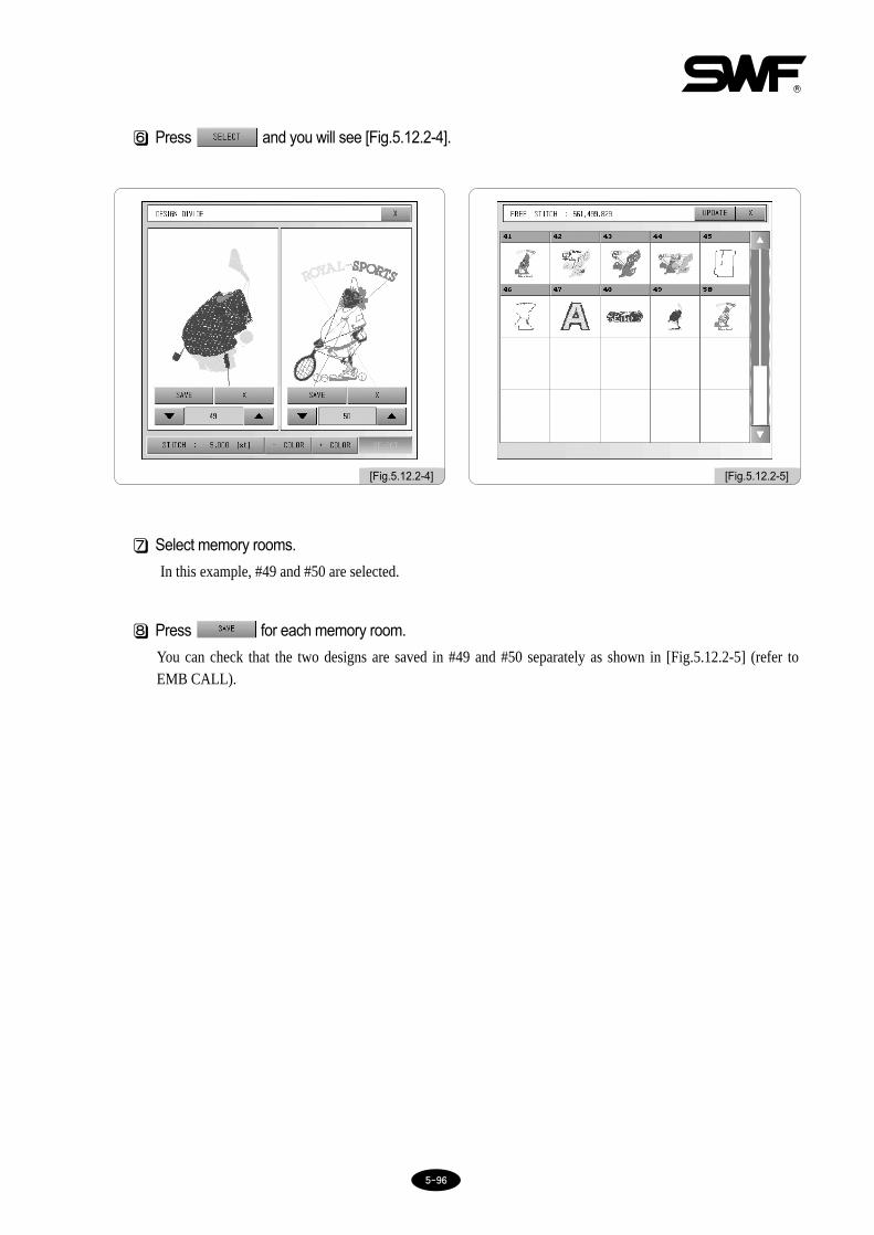
55--9966
6⃞ Press and you will see [Fig.5.12.2-4].
7⃞ Select memory rooms.
In this example, #49 and #50 are selected.
8⃞ Press for each memory room.
You can check that the two designs are saved in #49 and #50 separately as shown in [Fig.5.12.2-5] (refer toEMB CALL).
[Fig.5.12.2-4] [Fig.5.12.2-5]
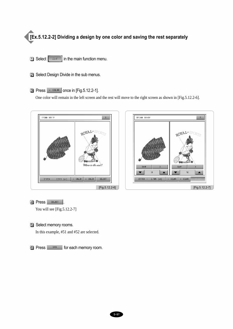
55--9977
[Ex.5.12.2-2] Dividing a design by one color and saving the rest separately
1⃞ Select in the main function menu.
2⃞ Select Design Divide in the sub menus.
3⃞ Press once in [Fig.5.12.2-1].
One color will remain in the left screen and the rest will move to the right screen as shown in [Fig.5.12.2-6].
4⃞ Press .
You will see [Fig.5.12.2-7]
5⃞ Select memory rooms.
In this example, #51 and #52 are selected.
6⃞ Press for each memory room.
[Fig.5.12.2-6] [Fig.5.12.2-7]

55--9988
You can check that the two designs are saved in separately as shown in [Fig.5.12.2-8] (refer to EMB CALL)
[Fig.5.12.2-8]

55--9999
5.12.3 Design filtering
Thread breaks can occur frequently if the distance between two stitches is too short (0.1-0.3mm). By Design Filtering,
stitches shorter than the pre-set length are merged with the immediately next stitches. This function makes all stitches in
the design longer than the pre-set length and thereby prevents thread break.
[Fig.5.12.3-1] shows selection of Design Filtering.
[Ex.5.12.3-1] Setting parameters so that stitches under 0.3mm are not made
1⃞ Select in the main function menu.
2⃞ Select Design Filtering in the sub menus.
3⃞ Check if there are any stitches under 0.3mm.
4⃞ If there is, select 0.4mm.
5⃞ Select memory room and press SAVE.
[Fig.5.12.3-2] shows checking the filtered design by calling it from the memory.
[NOTE]
Not all stitches were filtered in the example [Fig.5.12.3-2]. Design filtering is not applied to all stitches.
[Fig.5.12.3-1] [Fig.5.12.3-2]

55--110000
5.12.4 Design zoom in
[Fig.5.12.4-1] shows selection of Design Zoom In.
There are two screens: design zoom and position adjustment. Design zoom screen shows you the enlarged version of
the design. In the position adjustment screen, you can press anywhere on the screen and that part will be zoomed in.
You can also use a key to select the desired part.
You can zoom in up to 100 times in the unit of 1 time.
The screens below are *2, *3, *5, *10, *20, *30, and *50 times zoom in of the design in [Fig.5.12.4-1].
Press on the Magnification Increase/Decrease Button, and you will see the design enlarged.
[Fig.5.12.4-1]
DesignEnlargementScreen
AdjustmentPosition Button
AdjustmentPosition Screen
Magnification Indication
MagnificationIncrease/Decrease Button

55--110011
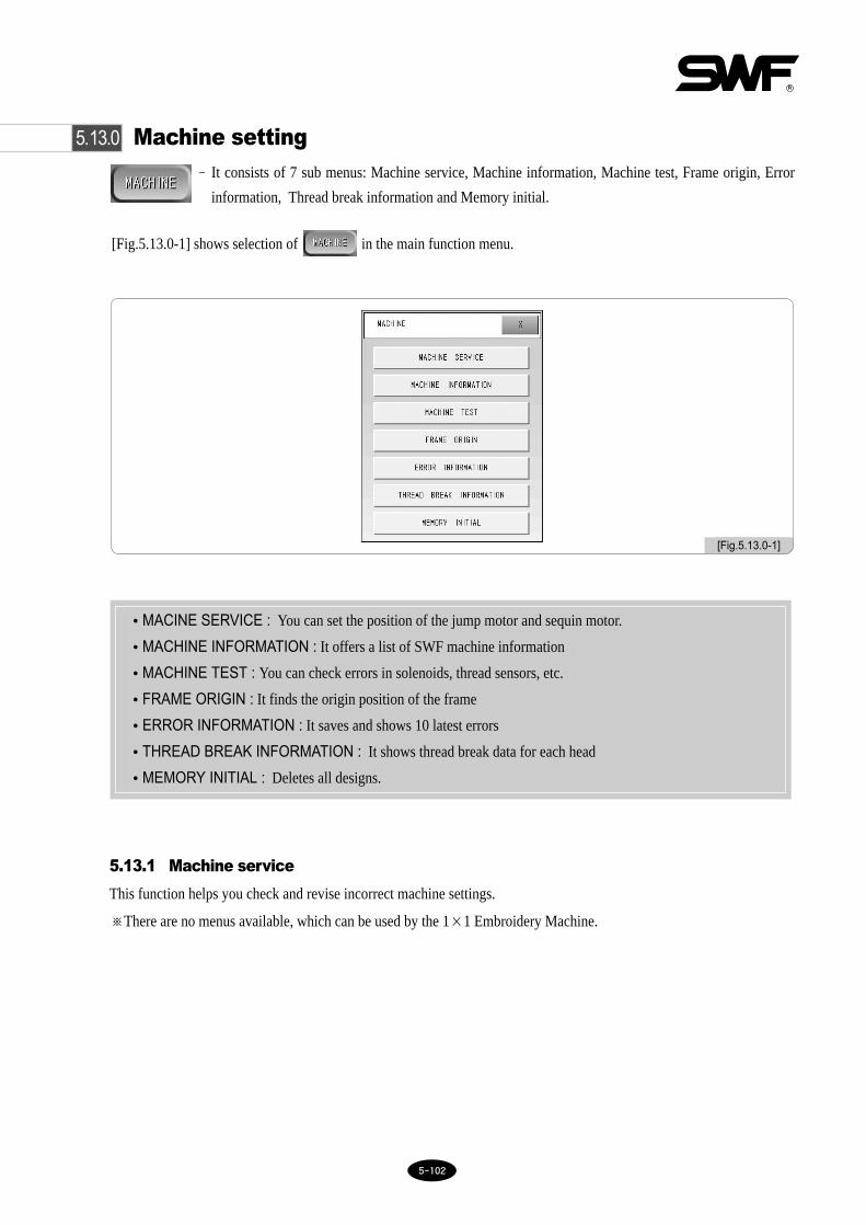
55--110022
5.13.0 Machine setting- It consists of 7 sub menus: Machine service, Machine information, Machine test, Frame origin, Error
information, Thread break information and Memory initial.
[Fig.5.13.0-1] shows selection of in the main function menu.
[Fig.5.13.0-1]
•MACINE SERVICE : You can set the position of the jump motor and sequin motor.
•MACHINE INFORMATION : It offers a list of SWF machine information
•MACHINE TEST : You can check errors in solenoids, thread sensors, etc.
•FRAME ORIGIN : It finds the origin position of the frame
•ERROR INFORMATION : It saves and shows 10 latest errors
•THREAD BREAK INFORMATION : It shows thread break data for each head
•MEMORY INITIAL : Deletes all designs.
5.13.1 Machine service
This function helps you check and revise incorrect machine settings.
※There are no menus available, which can be used by the 1×1 Embroidery Machine.

55--110033
5.13.2 Machine information
It shows the machine information set at the time of initial installation of the operating program (refer to ‘3.2 Change
Machine Setting’ for settings in program installation).
[Fig.5.13.2-1]

55--110044
5.13.3 Machine test
It tests the machine by part to check if the machine is in normal condition.
[Fig.5.13.3-1] shows selection of Machine Test in [Fig.5.13.0-1].
•JUMP TEST : Checks the motion of the jump motor.
•WIPER TEST : It tests the wiper motor
•PICKER TEST : It tests the picker solenoid
•TRIM TEST : It tests the trimmer solenoid
•HOLDING TEST : This is used to check whether the main-shaft holding solenoid and the holding solenoid
attached to each head are moving properly.
•THREAD SENSING TEST : It tests the upper thread detecting sensor
•SEQUIN MOTION : Checks sequin motion (optional).
•SEQUIN LIFT UP/DOWN : Checks sequin device motion (optional).
[Fig.5.13.3-1]

55--110055
※※ Dual Function 1××1 Embroidery Machine's motion test
① Jump Test
Select Jump Test in [Fig.5.13.3-1]. Press JUMP TEST button. The jump solenoid on each head will run foraround 0.5 seconds.
② Wiper Test
Select Wiper Test in [Fig.5.13.3-1]. Press WIPER TEST button. The wiper motor on the heads switched on willrun for around 0.5 seconds.
③ Picker Test
Select Picker Test in [Fig.5.13.3-1]. Press PICKER TEST button. The picker solenoid installed around the hookwill run for around 0.5 seconds.
④ Trimmer Test
Select Trimmer Test in [Fig.5.13.3-1]. Press TRIM TEST button. The trimmer solenoid installed on the trimmercam will run for around 0.5 seconds.
⑤ Holding Test
Select Holding Test in [Fig.5.13.3-1]. Press HOLDING TEST button. The holding solenoids of the main shaftinstalled on the upper shaft will run for around 0.5 seconds.
⑥ Upper Thread Sensor Test
Select Thread Sensing Test in [Fig.5.13.3-1]. Press THREAD SENSING TEST button. The thread detectingsensors on the thread tension adjustment plates on the heads switched on will run. The heads that touch the threaddetecting plate and the thread detecting spring will blink, while the heads that do not touch the plate and thespring will not blink.
※※ Motion test of Dual Function E Series and Dual DM Series
① Jump Test
Press the jump test button in <Fig. 5.13.3-1> and press the start button. Then, the jump motor attached to eachhead begins operating. If other motion testing button is pressed, the concerned test will be conducted after thejump test is finished.
② Wiper Test
Press the wiper test button in <Fig. 5.13.3-1> and press the start button. Then, it operates the wiper motor once.
③ Picker Test
Press the picker test button in <Fig. 5.13.3-1> and press the start button. Then, the picker solenoid attachedaround the hook begins operating for some 0.5 seconds.

55--110066
④ Trimmer Test
Press the trimmer test button in <Fig. 5.13.3-1> and press the start button. Then, the trimmer solenoid attached tothe trimmer cam begins operating for some 0.5 seconds.
⑤ Holding Test
Press the holding test in <Fig. 5.13.3-1> and press the start button. Then, the holding solenoid attached to eachhead begins operating for some 0.5 seconds.
⑥ Upper Thread Sensor Test
Press the upper thread sensor button in <Fig. 5.13.3-1> and press the start button. Then a beep sound is issued.When turning the thread break sensor at the current needle bar position, the lamp blinks. To end the test, press the"thread sensor test" button again. This will end the beep sound and conclude the test.
⑦ Sequin Motion
Press Sequin Motion as in <Fig. 5.13.3-1> and press the start button. This activates the sequin motor.
⑧ Sequin Lift Up/Down
Press Sequin Lift Up/Down as in <Fig. 5.13.3-1>, and press the start button. This pulls down the sequin devicelocated above. Pressing the start button again lifts up the sequin device from below.
5.13.4 Frame origin
Select Frame Origin in the screen [Fig.5.13.0-1] and the frame will automatically move back to the origin point. Seen
from the front, the frame moves to the very front and to the left end, finds the origin point, and moves to the opposite to
find the X and Y limits. Finding all the points, the frame goes back to the point where this function started. Press STOP
during this function and you will be asked if you would like to stop or start the frame movement (see [Fig.5.13.4-1]). To
stop the frame, press CANCEL.
[Fig.5.13.4-1]
[CAUTION]
As the frame moves the entire table, objects on the table may fall off. As shown on the screen during the
frame movement, you can push the bar switch to the left to stop the frame movement. To start the frame
again, push the bar switch to the right.

55--110077
5.13.5 Error information
5.13.6 Thread break information
It shows you the accumulated statistics of the thread sensor by each head.
5.13.7 Memory initial
To delete all embroidery designs stored.
The SWF system automatically stores up to 10 errors that occurred during machine operation. Error Information
displays the stored list of errors. You can easily find the cause of the errors by reading the information.
[Fig.5.13.5-1]

66--11
[Fig.6.0-1] appears when you stop the machine during embroidery. The menu structure is basically the same as the
menus before you start the embroidery. The difference is that “Ready”, “Repeat Work”, and “Edit” are replaced by
“Float”, “Frame”, and “S-Code” in the main function menu. Few functions are also limited in the setting menu as well.
Although you must have done settings before the embroidery, you might want to change the setting for better work.
Now, let’s look at the functions during embroidery (machine stop).
The following describes only those menus that are different from the ones before the embroidery - “EMB CALL”,“SETTING”, “FLOAT”, “FRAME”, and “S-CODE”.
6 Function Menu during Embroidery
[Fig.6.0-1]
[NOTE]
To perform floating at the start using menus during embroidery, press STOP and you will go to the function
menus during embroidery.

66--22
※ Changes in the main function menu
EMB CALL: slightly different from before embroidery
INPUT: same as before embroidery
SETTING: same as before embroidery except Basic Setting and Option Setting
FLOAT : new menu
FRAME : new menu
S-CODE : new menu
MACHINE: same as before embroidery

66--33
6.1 Menu structure during embroidery
Color change
Manual trimming
Embroidery Call
Input
Setting
Float
Frame
S-code
Machine setting
DesignEmbroidery finished
FDD input
USB inputCF card inputSerial input
Basic setting (only two functions are available)EMB parameter settingMachine parameter settingNeedle bar
Offset
The Other setting
HighLowReset
Machine serviceMachine informationMachine test
Frame originError informationThread break informationMemory initialization
DeleteCopyExport
FormatFile Select
SelectConvertColor change
Cut needle setSensing head set
Jump testWiper testPicker testTrim testHolding testThread sensing test
PreviewDeleteCopy
Frame move
Machine Tools

66--44
Press during embroidery (during machine stop) and you will be asked, “Do you want to cancel DATA SET?”
as shown in [Fig.6.2-1]. Press to stop the embroidery and the main function menu will change to the menu
before embroidery. Press not to end embroidery - you will see EMB CALL, the same as before embroidery
as shown in [Fig.6.2-2]. Deleting and selecting of the design called as well as selecting other designs will not be
available. But you can output the design. This is a new function, which enables you to copy designs during embroidery
- you don’t have to wait until the embroidery is finished to copy the design.
Use of the function is the same as before embroidery.
6.2 EMB CALL
[Fig.6.2-1] [Fig.6.2-2]
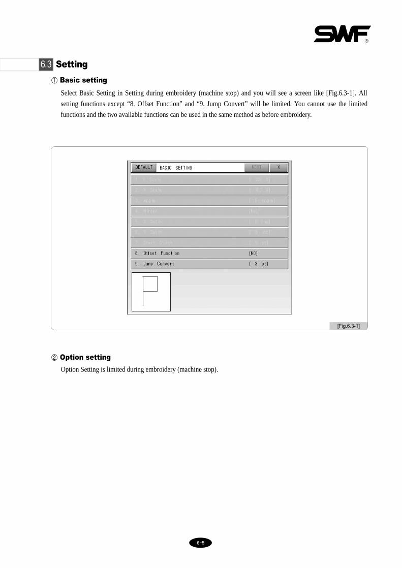
66--55
① Basic setting
Select Basic Setting in Setting during embroidery (machine stop) and you will see a screen like [Fig.6.3-1]. All
setting functions except “8. Offset Function” and “9. Jump Convert” will be limited. You cannot use the limited
functions and the two available functions can be used in the same method as before embroidery.
② Option setting
Option Setting is limited during embroidery (machine stop).
[Fig.6.3-1]
6.3 Setting

66--66
※ Using floating functions
① Press .
② Check the current stitch and select the desired number of stitches for floating.
③ Press button.
The machine will float the set number of stitches.
To cancel the function, press .
6.4 Float
You can float the desired length of the embroidery.
[Fig.6.4-1] shows selection of in [Fig.6.0-1].
You can input the desired stitches for floating using the keypad as shown in [Fig.6.4-2] or using the buttons ±1, ±100,
±1000, ±10000, ±COLOR.
[Fig.6.4-1] [Fig.6.4-2]

66--77
[Fig.6.5-1]
① Data Origin
The machine remembers the last frame location when it stopped during embroidery. When you want to re-start theembroidery after you finished other work or after you moved the frame using the frame movement keys, you canuse this function to automatically move the fame to the previous location.
② Design Origin
The machine returns to the start point of embroidery.
③ Power Origin
The machine remembers the last location of embroidery when the power is turned off during embroidery. Whenyou select this function after turning the power back on, the machine finds and moves to the location. Thisfunction is only available if you set the frame origin point before starting the embroidery.
Press the desired functions above and the machine will automatically start moving.
6.5 Frame
- You can have the machine memorize the location of the frame so that it can move back to the previouslocation in the case of machine stop (by STOP switch, thread break, etc.) frame movement, or poweroutage.
When the machine stops during embroidery you will see Frame menu. Press and you will see [Fig.6.5-1].

66--88
6.6 S-Code
If you desire to change the embroidery speed from high to low at a particular place, S-Code enables you to apply the low
speed to the desired area. The embroidery work will slow down when it reaches the area programmed to make slow-
speed embroidery at the beginning. To set the low-speed embroidery, see ⑥ Slow Speed of 5.9.3 M/C Parameter Setting.
① Low Speed
It changes the speed from high to low during embroidery. Stop the high-speed embroidery work and press .
You will see [Fig.6.6-1]. Press Low Speed and START. The embroidery work will slow down.
② High Speed
It changes the speed from low to high during embroidery. Stop the low-speed embroidery work and press .
You will see [Fig.6.6-2]. Press High Speed and START. The embroidery work will get faster.
③ Reset
It initializes the speeds set for particular parts.
[Fig.6.6-1] [Fig.6.6-2]

77--11
7 Troubleshooting
7.1.0 Error displays and troubleshooting
7.1.1 Main shaft motor and others
7.1.2 X,Y motors
100 Wrong position of main shaft stop Main shaft didn’t stop at 100°Use a lever to adjust the shaftangle at 100°
103 Trimmer sensor return failureTrimming sensor does not returnafter trimming
Check the trimming unit.
104 Error in start switchSTART is pressed when thepower is turned on
Check if START touches theconnector
105 Error in stop switchSTOP is pressed when the poweris turned on
Check if STOP touches theconnector
108 Air pressure errorError occurs when air pressure isbelow the threshold(Sequin)
110 AC Line errorThis error occurs when the jointboard has problems
Replace the joint board
102 Main shaft overloadThread tangle around hook,Needle controller malfunction,Thread tangle when trimming
Check the hooks on all heads andturn the main switch OFF and ONagain.
101 Error in main shaft motor driver Error in main shaft motor driver Turn the main switch OFF and ON again.
No. ERROR TYPE ERROR CORRECTION
107 Valve failure Error occurs when valve opens
200 +X limit detection failure Frame reached +X limit.Move the frame in the -Xdirection.
201 -X limit detection failure Frame reached -X limit.Move the frame in the +Xdirection.
202 +Y limit detection failure Frame reached +Y limit.Move the frame in the -Ydirection.
203 -Y limit detection failure Frame reached -Y limit.Move the frame in the +Ydirection.
204 Error in X-axis driver Error in X-axis driverTurn main switch OFF and ONagain
205 Error in Y-axis driver Error in Y-axis driverTurn main switch OFF and ONagain
No. ERROR TYPE ERROR CORRECTION
206 Wiper return failure Wiper motor does not return Repair wiper mechanism
207 Error in trimmer return Trimmer solenoid does not return Repair trimmer mechanism

77--22
7.1.3 Needle(color) change
7.1.4 Encoder
7.1.5 Repeat
300 Needle position errorNeedle does not come to thecorrect position when changed
Manually turn the needle bar,check the load, and locate it in theright position.
No. ERROR TYPE ERROR CORRECTION
501 Error in repeat settingOff the repeat setting limit (X repeat×Y repeat >99)
Adjust the repeat setting so that X repeat×Y repeat <99
No. ERROR TYPE ERROR CORRECTION
400 Error in A of main shaft encoderError in A signal of the mainshaft encoder.
Check cable connection. Turn themain power OFF and ON again.
401 Error in Z of main shaft encoderError in Z signal of the mainshaft encoder.
Check cable connection. Turn themain power OFF and ON again.
No. ERROR TYPE ERROR CORRECTION

77--33
7.1.6 Floppy disks and communication
600 No disk No disk in the drive. Insert the disk in the drive.
601 No disk sectorDisk is unformatted or a differentformat.
Format or change the disk.
602 No design in diskNo embroidery design in thedisk.
Change the disk.
603 Remove tab Disk is write-protected. Remove the protection tab.
604 Disk damaged Damaged disk. Format or change the disk.
605 No space in disk No space in the disk for copying. Change the disk.
606 Disk outDisk was removed duringoperation
Insert the disk and re-work.
607Floppy disk sector error whenreading
Bad sectors in the disk. Format or change the disk.
608Floppy disk sector error whenwriting
Bad sectors in the disk. Format or change the disk.
609 Unknown disk errorUnknown disk error duringoperation.
Format or change the disk.
610 Disk errorWhen the floppy disk develops errorsduring operation with the causes
disk re-formatting or diskreplacement is required.
640 Error in network device Network device is not connectedCheck connection of networkdevice
650 Error in USB USB Driver is not readyCheck whether the file system ofUSB memory is FAT 16.
614Errors in installing machineoperating program.
In case your machine operatingprogram has no or incorrect filenames
The file name is swf_tb.bin.Change the extensions to “bin” ifyours read “exe (swf_tb.exe).”
630 Error in data read Error in data read via tape reader Re-input via tape reader
611 ZSK design error
612 BARUDAN design error
613 Bad sector
No. ERROR TYPE ERROR CORRECTION

77--44
7.1.7 Memory
700 No data in memoryNo embroidery data in thememory.
Save data in memory using disk ortape.
703 Error in design memory systemError during copying/deletion inmemory.
Reset or turn the power OFF andON again.
701 Memory insufficientNot enough memory space fordata storage.
Delete unnecessary data.
702 Memory full Memory rooms are full. Delete unnecessary data.
704 Memory battery failure
The battery, which makes the memorysave embroidery data, is completelydischarged during blackout. The data storage regarding thenumber of stitches and X,Ypositions is unstable.
Contact the nearest SWF dealerand replace it.(If it frequently occurs, replace theCPU board.)
No. ERROR TYPE ERROR CORRECTION
7.1.8 Communication Error
Communication Error 0
Communication Error 1
Communication Error 2
Communication Error 3
Communication Error 4
Communication Error 5
Communication Error 6
Communication Error 7
Communication Error 8
Communication Error 9
Communication Error 10
Communication Error 11
Communication Error 12
Communication Error 13
Communication Error 14
Communication Error 15
900
901
902
903
904
905
906
907
908
909
910
911
912
913
914
915
CAN Communication Error
CAN Communication Error
CAN Communication Error
CAN Communication Error
CAN Communication Error
CAN Communication Error
CAN Communication Error
CAN Communication Error
CAN Communication Error
CAN Communication Error
CAN Communication Error
CAN Communication Error
CAN Communication Error
CAN Communication Error
CAN Communication Error
CAN Communication Error
Power On/Off
Power On/Off
Power On/Off
Power On/Off
Power On/Off
Power On/Off
Power On/Off
Power On/Off
Power On/Off
Power On/Off
Power On/Off
Power On/Off
Power On/Off
Power On/Off
Power On/Off
Power On/Off
No. ERROR TYPE ERROR CORRECTION

77--55
7.1.9 USB Memory
■ FAQ about USB memory recognition problem
[CAUTION]
Please call our nearest office or SWF CS center when continuous problems with USB occur.
1. Did you insert the USB into USB port on the side of the OP Box properly? ① The USB can be inserted in reverse when connecting it by force. Moreover, the quality of the connecting pin contact
condition on the input port is depreciated due to the frequent insert into the USB port. Check out the USB LED lightafter inserting.
2. Do you use an USB extension cable or hub? ① An USB extension cable or an USB hub can reduced the standard voltage(DC +5V) of the USB port. In this case, the
USB cannot work normally.
3. Please run a virus-check.① Some viruses interrupt the recognition of the exterior device. Use various vaccination programs to treat viruses not use
one program.
4. Recommended the use of our company's suggested USB makers ① There are many USB manufacturers. The USB is fitted with the controller that is different depending on the
manufacturers. Therefore, recognition problem can occur due to the quality differences depending on themanufacturers. You can solve this problem by using the common manufacturer’s USB. We recommend you use theSAMSUNG, LG, SANDISK, TRANSAND’s USB. However, an error rate of recommended makers does notguarantee 100% flawless USB.
Q. USB device is not recognized.
4pin USBPlug connector (User) Jack connector (User)
Connecting Pin

77--66
7.2.0 Machine Setting and Troubleshooting (※※Dual Function 1××1 Embroidery Machine)
7.2.1 Rear Side of Control Box
<Fig. 7.2.1-1> shows the rear side of the Control Box.
① MC1 Main Driver
② MC2 Main Driver
③ MC1 I/O Board, XY Driver
④ MC2 I/O Board, XY Driver
[Fig.7.2.1-1]
① ② ③ ④

77--77
7.2.2 I/O Board, X/Y Driver Board Dip Switch Setting
<Fig. 7.2.2-1> shows the I/O, XY Driver Board of MC1 and MC2. For more information on the location of the board,
see “7.2.1 Rear Side of Control Box”.
① XY Driver Board
② I/O Board
③ I/O Board Dip Switch
[Fig.7.2.2-1]
④ X Driver Board Dip SW
① XY Driver Board
② I/O Board
⑥ X Driver Board Rotary SW1
⑦ X Driver Board Rotary SW2⑧ X Driver Board Rotary SW3
⑤ Y Driver Board Dip SW
⑨ Y Driver Board Rotary SW4
⑩ Y Driver Board Rotary SW5
⑪ Y Driver Board Rotary SW6
③ I/O Board Dip SW
ON
OFF1 2 3 4
Functions OFF ON
CAN I/D Setting
Reserved
Reserved
Reserved
MC1
–
–
–
MC2
–
–
–

77--88
④ X Driver Board Dip Switch Setting
ON
OFF1 2 3 4 5 6 7 8
Functions OFF ON
Reserved
Reserved
Reserved
Reserved
Reserved
Motor Setting
SELFTEST MODE
M/C Select
–
–
–
–
–
X Motor
Not in Use
1×1
–
–
–
–
–
Y Motor
In Use
Chenille
⑤ Y Driver Board Dip Switch Setting
ON
OFF1 2 3 4 5 6 7 8
Functions OFF ON
Reserved
Reserved
Reserved
Reserved
Reserved
Motor Setting
SELFTEST MODE
M/C Select
–
–
–
–
–
X Motor
Not in Use
1×1
–
–
–
–
–
Y Motor
In Use
Chenille
Select Dip Switch No. 1 depending on machine type (in the current machine type, it should be set at “Off”.)

77--99
⑥ Rotary Switch 1
– Default value: 0 – Offsetting of X-Driver D Gain (D gain earned, when Dual Gain is applied)
⑦ Rotary Switch 2
– Default value: 0 – Offsetting of X-Driver I Gain (I gain earned, when Dual Gain is applied)
⑧ Rotary Switch 3
– Default value: 0 – Offsetting of X-Driver P Gain (P gain earned, when Dual Gain is applied)
⑨ Rotary Switch 4
– Default value: 0 – Offsetting of Y-Driver D Gain (D gain earned, when Dual Gain is applied)
⑩ Rotary Switch 5
– Default value: 0 – Offsetting of Y-Driver I Gain (I gain earned, when Dual Gain is applied)
⑪ Rotary Switch 6
– Default value: 0 – Offsetting of Y-Driver P Gain (P gain earned, when Dual Gain is applied)

77--1100
7.2.3 When the Power is not Turned On
Insert the machine's electronic plug into the outlet and press the power switch of either MC1 or MC2. If the power is not
turned on, take corrective measures based on the following.
Open the cover marked as in <Fig. 7.2.3-1>. Check the location of fuse and replace it with a new fuse in the fuse case.
While power of MC1 or MC2 is turned off, it is still possible that users can be electrified. Therefore, when it is
necessary to replace a board or during A/S service, make sure that the machine is plugged out.
[Fig.7.2.3-1]
Fuse in Use : AC250V, 4A

77--1111
7.3.0 Machine Setting and Troubleshooting (※※In case of Dual Function 2××2 or above)
7.3.1 Rear Side of Control Box <Fig. 7.3.1-1> is the rear side of Control Box.
① MC1 Main Driver ② MC1 XY Driver③ MC2 XY Driver ④ MC2 Main Driver ⑤ IO Ass'y⑥ LAMP Ass'y
[Fig.7.3.1-1]
① MC1(L)Main Driver ⑤ IO Ass'y
⑥ LAMP Ass'y
② MC1(L)XY Driver
③ MC2(R)XY Driver
④ MC2(R)Main Driver

77--1122
7.3.2 I/O Board , X/Y Driver Board Dip Switch SettingAs in <Fig. 7.3.1-1>, the locations of board and driver can be checked from the rear side of Control Box.
(1) I/O Board's Dip Switch Setting- Switch Location on I/O Board
- Dip Switch (SW1) Setting The upper board is MC1, and there is no need to make particular setting for I/O Board.
Dip Switch
CN4
CN1
CN3 SW1
ON
OFF1 2 3 4
Functions OFF ON
Reserved
Reserved
Reserved
Reserved
-
-
-
-
-
-
-
-

77--1133
(2) Main and XY Driver's Dip Switch Setting
① Main Driver's Dip Switch (SW1) Setting- Main Driver Board's switch location
- Dip switch setting
② XY Driver's Rotary Switch Setting- X Driver : Set it at 3.5A, and set the rotary switch at “6”- Y Driver : Set it at 3.5A and set the rotary switch at “A”
Dip Switch
SW1
J5
J6
J7
ON
OFF1 2 3 4 5 6 7 8
S/W OFF ON
8
7
6
5
4
3
2
1
○
○
○
○
○
MC1(L)
○
MC2(R)
○
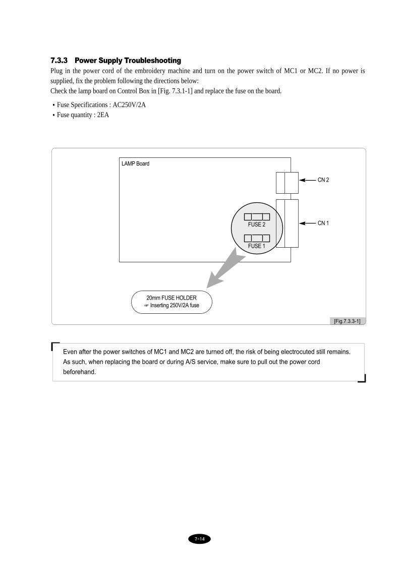
77--1144
7.3.3 Power Supply Troubleshooting Plug in the power cord of the embroidery machine and turn on the power switch of MC1 or MC2. If no power issupplied, fix the problem following the directions below:Check the lamp board on Control Box in [Fig. 7.3.1-1] and replace the fuse on the board.
•Fuse Specifications : AC250V/2A•Fuse quantity : 2EA
[Fig.7.3.3-1]
LAMP Board
FUSE 2
FUSE 1
CN 2
CN 1
20mm FUSE HOLDER☞ Inserting 250V/2A fuse
Even after the power switches of MC1 and MC2 are turned off, the risk of being electrocuted still remains.
As such, when replacing the board or during A/S service, make sure to pull out the power cord
beforehand.

77--1155
7.4.0 Machine Setting and Troubleshooting (※Dual DM Series)
After power cord connection, if power is not supplied after switch-on, troubleshooting actions need to be taken withreference to the following. Check the location of fuses as in <Fig. 7.4.1-1> and <Fig. 7.4.1-2> and change fuses.
(1) Power Fuse (based on 3-phase)
[Fig.7.4-1]
< Front side of Control Box >
▶ Fuse specifications: 250V , 30A , 31.8mm
▶ Fuse quantity : 3EA

77--1166
(2) OUT LET FUSE
[Fig.7.4-2]
< Outlet Fuse >
▶ Fuse specifications : 250V, 1A, 31.8mm
▶ Fuse quantity : 1EA

77--1177
[Fig.7.5-1]
Dual Function 1×
1 Em
broidery M
achine B
lock D
iagram
7.5 System Block Diagram
※※ Dual Function 1××1 Embroidery Machine

77--1188
[Fig.7.5-2]
※※ Dual Function E Series

77--1199
[Fig.7.5-3]
※※ Dual DM Series
Block diagram of DM-SeriesEmbroidery Machine