Vigor2926 Series Dual-WAN Security Router User's Guide
991
i
-
Upload
khangminh22 -
Category
Documents
-
view
0 -
download
0
Transcript of Vigor2926 Series Dual-WAN Security Router User's Guide

i
Vigor2926 Series User’s Guide ii
Vigor2926 Series Dual-WAN Security Router
User’s Guide
Version: 1.2
Firmware Version: V3.8.9.1
(For future update, please visit DrayTek web site)
Date: July 19, 2018

Vigor2926 Series User’s Guide iii
Copyrights
© All rights reserved. This publication contains information that is protected by copyright. No part may be reproduced, transmitted, transcribed, stored in a retrieval system, or translated into any language without written permission from the copyright holders.
Trademarks
The following trademarks are used in this document:
Microsoft is a registered trademark of Microsoft Corp.
Windows, Windows 95, 98, Me, NT, 2000, XP, Vista, 7 and Explorer are trademarks of Microsoft Corp.
Apple and Mac OS are registered trademarks of Apple Inc.
Other products may be trademarks or registered trademarks of their respective manufacturers.
Safety Instructions
Read the installation guide thoroughly before you set up the router.
The router is a complicated electronic unit that may be repaired only be authorized and qualified personnel. Do not try to open or repair the router yourself.
Do not place the router in a damp or humid place, e.g. a bathroom.
The router should be used in a sheltered area, within a temperature range of +5 to +40 Celsius.
Do not expose the router to direct sunlight or other heat sources. The housing and electronic components may be damaged by direct sunlight or heat sources.
Do not deploy the cable for LAN connection outdoor to prevent electronic shock hazards.
Keep the package out of reach of children.
When you want to dispose of the router, please follow local regulations on conservation of the environment.
Warranty
We warrant to the original end user (purchaser) that the router will be free from any defects in workmanship or materials for a period of two (2) years from the date of purchase from the dealer. Please keep your purchase receipt in a safe place as it serves as proof of date of purchase. During the warranty period, and upon proof of purchase, should the product have indications of failure due to faulty workmanship and/or materials, we will, at our discretion, repair or replace the defective products or components, without charge for either parts or labor, to whatever extent we deem necessary tore-store the product to proper operating condition. Any replacement will consist of a new or re-manufactured functionally equivalent product of equal value, and will be offered solely at our discretion. This warranty will not apply if the product is modified, misused, tampered with, damaged by an act of God, or subjected to abnormal working conditions. The warranty does not cover the bundled or licensed software of other vendors. Defects which do not significantly affect the usability of the product will not be covered by the warranty. We reserve the right to revise the manual and online documentation and to make changes from time to time in the contents hereof without obligation to notify any person of such revision or changes.
Be a Registered Owner
Web registration is preferred. You can register your Vigor router via http://www.DrayTek.com.
Firmware & Tools Updates
Due to the continuous evolution of DrayTek technology, all routers will be regularly upgraded. Please consult the DrayTek web site for more information on newest firmware, tools and documents.
http://www.DrayTek.com

Vigor2926 Series User’s Guide iv

Vigor2926 Series User’s Guide v
TTaabbllee ooff CCoonntteennttss
Part I Installation.................................................................................................................i
I-1 Introduction ................................................................................................................................... 1
I-1-1 Indicators and Connectors .................................................................................................. 2 I-1-1-1 For Vigor2926 / Vigor2926L .............................................................. 2 I-1-1-2 For Vigor2926n / Vigor2926ac / Vigor2926Lac / Vigor2926Ln...................... 4 I-1-1-3 For Vigor2926Vac .......................................................................... 8
I-1-2 Notes for Antenna Installation (for “L” model) ................................................................... 10
I-2 Hardware Installation .................................................................................................................. 12
I-2-1 Installing Vigor Router ....................................................................................................... 12
I-2-2 Wall-Mounted Installation .................................................................................................. 13
I-2-3 Installing USB Printer to Vigor Router ............................................................................... 14
I-3 Accessing Web Page .................................................................................................................. 21
I-4 Changing Password.................................................................................................................... 23
I-5 Dashboard................................................................................................................................... 24
I-5-1 Virtual Panel ...................................................................................................................... 25
I-5-2 Name with a Link ............................................................................................................... 25
I-5-3 Status for LTE.................................................................................................................... 26
I-5-4 Quick Access for Common Used Menu ............................................................................ 26
I-5-5 GUI Map ............................................................................................................................ 27
I-5-6 Web Console ..................................................................................................................... 28
I-5-7 Config Backup ................................................................................................................... 29
I-5-8 Logout................................................................................................................................ 29
I-5-9 Online Status ..................................................................................................................... 30 I-5-9-1 Physical Connection ......................................................................30 I-5-9-2 Virtual WAN ...............................................................................32
I-6 Quick Start Wizard ...................................................................................................................... 33
I-6-1 For WAN1/WAN2 (Ethernet) ............................................................................................. 34
I-6-2 For WAN3/WAN4 (USB).................................................................................................... 42
I-6-3 For LTE WAN .................................................................................................................... 44
I-7 Service Activation Wizard ........................................................................................................... 46
I-8 Registering Vigor Router............................................................................................................. 48
Part II Connectivity ..........................................................................................................51
II-1 WAN........................................................................................................................................... 52
Web User Interface .................................................................................................................... 54
II-1-1 General Setup .................................................................................................................. 54 II-1-1-1 WAN1/WAN2 with Ethernet ............................................................56 II-1-1-2 WAN3/WAN4 (USB).......................................................................58
II-1-2 Internet Access................................................................................................................. 60 II-1-2-1 Details Page for PPPoE in WAN1/WAN2 (Physical Mode: Ethernet) .............63 II-1-2-2 Details Page for Static or Dynamic IP in WAN1/WAN2 (Physical Mode: Ethernet).......................................................................................................66

Vigor2926 Series User’s Guide vi
II-1-2-3 Details Page for PPTP/L2TP in WAN1/WAN2 (Physical Mode: Ethernet) .......69 II-1-2-4 Details Page for 3G/4G USB Modem (PPP mode) in WAN3/WAN4................71 II-1-2-5 Details Page for 3G/4G USB Modem (DHCP mode) in WAN3/WAN4..............73 II-1-2-6 Details Page for 3G/4G USB Modem (DHCP mode) in LTE WAN ..................75 II-1-2-7 Details Page for IPv6 – Offline in WAN1/WAN2/WAN3/WAN4 ....................77 II-1-2-8 Details Page for IPv6 – PPP in WAN1/WAN2 .........................................78 II-1-2-9 Details Page for IPv6 – TSPC in WAN1/WAN2/WAN3/WAN4.......................79 II-1-2-10 Details Page for IPv6 – AICCU in WAN1/WAN2/WAN3/WAN4....................81 II-1-2-11 Details Page for IPv6 – DHCPv6 Client in WAN1/WAN2...........................83 II-1-2-12 Details Page for IPv6 – Static IPv6 in WAN1/WAN2 ...............................84 II-1-2-13 Details Page for IPv6 – 6in4 Static Tunnel in WAN1/WAN2 ......................86 II-1-2-14 Details Page for IPv6 – 6rd in WAN1/WAN2 ........................................87
II-1-3 Multi-VLAN ....................................................................................................................... 89
II-1-4 WAN Budget..................................................................................................................... 94 II-1-4-1 General Setup ............................................................................94 II-1-4-2 Status ......................................................................................96
Application Notes ....................................................................................................................... 98 A-1 How to set up Multi-VLAN for triple play deployment? ................................98 A-2 Load Balancing and Failover for multi-WAN Vigor Routers.......................... 103
II-2 LAN .......................................................................................................................................... 105
Web User Interface .................................................................................................................. 107
II-2-1 General Setup ................................................................................................................ 107 II-2-1-1 Details Page for LAN1 – Ethernet TCP/IP and DHCP Setup ...................... 109 II-2-1-2 Details Page for LAN2 ~ LAN8 and DMZ ............................................ 113 II-2-1-3 Details Page for IP Routed Subnet .................................................. 115 II-2-1-4 Details Page for LAN IPv6 Setup..................................................... 116 II-2-1-5 Advanced DHCP Options .............................................................. 120
Application Notes ..................................................................................................................... 122 A-1 Multi-subnet Application - How to utilize Vigor router with non-NAT? ........... 122
II-2-2 VLAN .............................................................................................................................. 125
II-2-3 Bind IP to MAC............................................................................................................... 130
II-2-4 LAN Port Mirror............................................................................................................... 133
II-2-5 Wired 802.1x .................................................................................................................. 134
II-3 Hardware Acceleration............................................................................................................. 135
II-3-1 Setup .............................................................................................................................. 135
II-4 NAT .......................................................................................................................................... 138
Web User Interface .................................................................................................................. 139
II-4-1 Port Redirection.............................................................................................................. 139
II-4-2 DMZ Host ....................................................................................................................... 143
II-4-3 Open Ports ..................................................................................................................... 146
II-4-4 Port Triggering................................................................................................................ 148
II-4-5 ALG................................................................................................................................. 150
II-5 Applications .............................................................................................................................. 151
Web User Interface .................................................................................................................. 153
II-5-1 Dynamic DNS................................................................................................................. 153
II-5-2 LAN DNS / DNS Forwarding .......................................................................................... 159
II-5-3 DNS Security .................................................................................................................. 162

Vigor2926 Series User’s Guide vii
II-5-3-1 General Setup .......................................................................... 162 II-5-3-2 Domain Diagnose ....................................................................... 163
II-5-4 Schedule......................................................................................................................... 164
II-5-5 RADIUS/TACACS+ ........................................................................................................ 166 II-5-5-1 External RADIUS........................................................................ 166 II-5-5-2 Internal RADIUS ........................................................................ 167 II-5-5-3 External TACACS+...................................................................... 170
II-5-6 Active Directory/LDAP.................................................................................................... 171 II-5-6-1 General Setup .......................................................................... 171 II-5-6-2 Active Directory / LDAP Profiles .................................................... 172
II-5-7 UPnP .............................................................................................................................. 174
II-5-8 IGMP............................................................................................................................... 175 II-5-8-1 General Setting ........................................................................ 175 II-5-8-2 Working Groups ........................................................................ 176
II-5-9 Wake on LAN ................................................................................................................. 177
II-5-10 SMS / Mail Alert Service............................................................................................... 178 II-5-10-1 SMS Alert............................................................................... 178 II-5-10-2 Mail Alert .............................................................................. 179
II-5-11 Bonjour ......................................................................................................................... 180
II-5-12 High Availability ............................................................................................................ 183 II-5-12-1 General Setup......................................................................... 184 II-5-12-2 Config Sync ............................................................................ 186
II-5-13 Local 802.1X General Setup ........................................................................................ 188
Application Notes ..................................................................................................................... 190 A-1 How to use High Availability?............................................................. 190 A-2 How to use DrayDDNS? ..................................................................... 198 A-3 How to Configure Customized DDNS?.................................................... 203 A-4 How to Implement the LDAP/AD Authentication for User Management? ......... 207
II-6 Routing..................................................................................................................................... 210
Web User Interface .................................................................................................................. 211
II-6-1 Static Route .................................................................................................................... 211
II-6-2 Load-Balance /Route Policy ........................................................................................... 217 II-6-2-1 General Setup .......................................................................... 217 II-6-2-2 Diagnose ................................................................................. 222
II-6-3 BGP ................................................................................................................................ 225 II-6-3-1 Basic Settings ........................................................................... 225 II-6-3-1 Static Network ......................................................................... 226
Application Notes ..................................................................................................................... 227 A-1 How to set up Address Mapping with Route Policy? .................................. 227 A-2 How to use destination domain name in a route policy?............................. 229 A-3 How to use a Public IP on LAN............................................................ 231 A-4 Introduction to Load Balance/Route Policy ............................................ 237
II-7 LTE........................................................................................................................................... 240
Web User Interface .................................................................................................................. 241
II-7-1 General Settings............................................................................................................. 241 II-7-1-1 SMS Quota............................................................................... 241 II-7-1-2 SMS Inbox/Outbox Policy ............................................................. 242
II-7-2 SMS Inbox ...................................................................................................................... 243

Vigor2926 Series User’s Guide viii
II-7-3 Send SMS ...................................................................................................................... 246
II-7-4 Router Commands ......................................................................................................... 247
II-7-5 Status ............................................................................................................................. 249
Part III Wireless LAN......................................................................................................251
III-1 Wireless LAN (2.4GHz/5GHz) ................................................................................................ 252
Web User Interface .................................................................................................................. 255
III-1-1 Wireless Wizard............................................................................................................. 255
III-1-2 General Setup ............................................................................................................... 259
III-1-3 Security.......................................................................................................................... 262
III-1-4 Access Control .............................................................................................................. 264
III-1-5 WPS............................................................................................................................... 265
III-1-6 WDS .............................................................................................................................. 268
III-1-7 Advanced Setting .......................................................................................................... 272
III-1-8 Station Control............................................................................................................... 274
III-1-9 Bandwidth Management................................................................................................ 275
III-1-10 AP Discovery ............................................................................................................... 276
III-1-11 Airtime Fairness........................................................................................................... 277
III-1-12 Band Steering.............................................................................................................. 279
III-1-13 Roaming ...................................................................................................................... 283
III-1-14 Station List................................................................................................................... 284
Part IV VoIP.....................................................................................................................285
IV-1 VoIP ........................................................................................................................................ 286
Web User Interface .................................................................................................................. 288
IV-1-1 VoIP Wizard .................................................................................................................. 288
IV-1-2 General Settings ........................................................................................................... 290
IV-1-3 SIP Accounts................................................................................................................. 293
IV-1-4 DialPlan......................................................................................................................... 298 IV-1-4-1 Phone Book............................................................................. 298 IV-1-4-2 Digit Map ............................................................................... 300 IV-1-4-3 Call Barring ............................................................................ 302 IV-1-4-4 Regional ................................................................................ 304 IV-1-4-5 PSTN Setup ............................................................................. 305
IV-1-5 Phone Settings.............................................................................................................. 306
IV-1-6 Status ............................................................................................................................ 310
IV-1-7 Diagnostics.................................................................................................................... 312 IV-1-7-1 Caller ID ................................................................................ 312 IV-1-7-2 Tone ..................................................................................... 312
Part V VPN......................................................................................................................313
V-1 VPN and Remote Access ........................................................................................................ 314
Web User Interface .................................................................................................................. 315
V-1-1 VPN Client Wizard ......................................................................................................... 315
Vigor2926 Series User’s Guide ix
V-1-2 VPN Server Wizard........................................................................................................ 322
V-1-3 Remote Access Control ................................................................................................. 326
V-1-4 PPP General Setup........................................................................................................ 327
V-1-5 IPsec General Setup...................................................................................................... 329
V-1-6 IPsec Peer Identity ......................................................................................................... 330
V-1-7 Remote Dial-in User....................................................................................................... 332
V-1-8 LAN to LAN .................................................................................................................... 335
V-1-9 VPN Trunk Management ............................................................................................... 346
V-1-10 Connection Management............................................................................................. 355
Application Notes ..................................................................................................................... 357 A-1 How to Build a LAN-to-LAN VPN Between Remote Office and Headquarter via IPsec Tunnel (Main Mode) ............................................................................. 357
V-2 SSL VPN.................................................................................................................................. 362
Web User Interface .................................................................................................................. 363
V-2-1 General Setup ................................................................................................................ 363
V-2-2 User Account.................................................................................................................. 364
V-2-3 User Group..................................................................................................................... 368
V-2-6 Online User Status ......................................................................................................... 370
V-3 Certificate Management........................................................................................................... 371
Web User Interface .................................................................................................................. 372
V-3-1 Local Certificate ............................................................................................................. 372
V-3-2 Trusted CA Certificate.................................................................................................... 376
V-3-3 Certificate Backup.......................................................................................................... 378
Part VI Security ..............................................................................................................379
VI-1 Firewall ................................................................................................................................... 380
Web User Interface .................................................................................................................. 382
VI-1-1 General Setup ............................................................................................................... 382
VI-1-2 Filter Setup.................................................................................................................... 387
VI-1-3 DoS Defense................................................................................................................. 397
VI-1-4 Diagnose ....................................................................................................................... 400
Application Notes ..................................................................................................................... 403 A-1 How to Configure Certain Computers Accessing to Internet ........................ 403
VI-2 Central Security Management (CSM) .................................................................................... 407
Web User Interface .................................................................................................................. 408
VI-2-1 APP Enforcement Profile .............................................................................................. 408
VI-2-2 APPE Signature Upgrade ............................................................................................. 412
VI-2-3 URL Content Filter Profile ............................................................................................. 414
VI-2-4 Web Content Filter Profile............................................................................................. 418
VI-2-5 DNS Filter Profile .......................................................................................................... 422
Application Notes ..................................................................................................................... 424 A-1 How to Create an Account for MyVigor ................................................. 424
Vigor2926 Series User’s Guide x
A-2 How to Block Facebook Service Accessed by the Users via Web Content Filter / URL Content Filter .................................................................................... 432
Part VII Management .....................................................................................................439
VII-1 System Maintenance ............................................................................................................. 440
Web User Interface .................................................................................................................. 441
VII-1-1 System Status .............................................................................................................. 442
VII-1-2 TR-069 ......................................................................................................................... 444
VII-1-3 Administrator Password ............................................................................................... 447
VII-1-4 User Password............................................................................................................. 449
VII-1-5 Login Page Greeting .................................................................................................... 452
VII-1-6 Configuration Backup................................................................................................... 454
VII-1-7 Syslog/Mail Alert .......................................................................................................... 457
VII-1-8 Time and Date.............................................................................................................. 460
VII-1-9 SNMP........................................................................................................................... 461
VII-1-10 Management .............................................................................................................. 463
VII-1-11 Panel Control ............................................................................................................. 467
VII-1-12 Self-Signed Certificate ............................................................................................... 470
VII-1-13 Reboot System........................................................................................................... 472
VII-1-14 Firmware Upgrade ..................................................................................................... 473
VII-1-15 Firmware Backup ....................................................................................................... 474
VII-1-16 Activation.................................................................................................................... 475
VII-1-17 Internal Service User List........................................................................................... 477
VII-2 Bandwidth Management........................................................................................................ 478
Web User Interface .................................................................................................................. 480
VII-2-1 Sessions Limit .............................................................................................................. 480
VII-2-2 Bandwidth Limit............................................................................................................ 482
VII-2-3 Quality of Service ......................................................................................................... 484
VII-2-4 APP QoS...................................................................................................................... 491
Application Notes ..................................................................................................................... 493 A-1 How to Optimize the Bandwidth through QoS Technology .......................... 493 A-2 QoS Setting Example ....................................................................... 497
VII-3 User Management ................................................................................................................. 502
Web User Interface .................................................................................................................. 503
VII-3-1 General Setup .............................................................................................................. 503
VII-3-2 User Profile .................................................................................................................. 505
VII-3-3 User Group................................................................................................................... 510
VII-3-4 User Online Status....................................................................................................... 511
Application Notes ..................................................................................................................... 513 A-1 How to authenticate clients via User Management................................... 513 A-2 How to use Landing Page Feature ....................................................... 522
VII-4 Hotspot Web Portal................................................................................................................ 526

Vigor2926 Series User’s Guide xi
Web User Interface .................................................................................................................. 526
VII-4-1 Profile Setup................................................................................................................. 526 VII-4-1-1 Login Modes ........................................................................... 527 VII-4-1-2 Steps for Configuring a Web Portal Profile ...................................... 529
VII-4-2 User Information........................................................................................................... 542 VII-4-2-1 User Info ............................................................................... 542 VII-4-2-2 Database Setup ....................................................................... 544
Application Notes ..................................................................................................................... 545 A-1 How to create Facebook APP for Web Portal Authentication? ...................... 545 A-2 How to create Google APP for Web Portal Authentication? ......................... 551
VII-5 Central Management (VPN) .................................................................................................. 553
Web User Interface .................................................................................................................. 554
VII-5-1 General Setup .............................................................................................................. 554 VII-5-1-1 General Settings...................................................................... 554 VII-5-1-2 IPsec VPN Settings.................................................................... 555
VII-5-2 CPE Management........................................................................................................ 556 VII-5-2-1 Managed Device List ................................................................. 556 VII-5-2-2 CPE Maintenance ..................................................................... 559 VII-5-2-3 Google Map............................................................................ 562
VII-5-3 VPN Management........................................................................................................ 563
VII-5-4 Log & Alert ................................................................................................................... 564
Application Notes ..................................................................................................................... 565 A-1 CVM Application - How to manage the CPE (router) through Vigor2926 series? . 565 A-2 CVM Application - How to build the VPN between remote devices and Vigor2926 series? ............................................................................................. 569 A-3 CVM Application - How to upgrade CPE firmware through Vigor2926 series? .... 571
VII-6 Central Management (AP)..................................................................................................... 574
Web User Interface .................................................................................................................. 575
VII-6-1 Dashboard.................................................................................................................... 575
VII-6-2 Status ........................................................................................................................... 576
VII-6-3 WLAN Profile................................................................................................................ 577
VII-6-4 AP Maintenance........................................................................................................... 582
VII-6-5 AP Map ........................................................................................................................ 583
VII-6-6 Traffic Graph ................................................................................................................ 586
VII-6-7 Rogue AP Detection..................................................................................................... 587
VII-6-8 Event Log ..................................................................................................................... 590
VII-6-9 Total Traffic .................................................................................................................. 590
VII-6-10 Station Number .......................................................................................................... 591
VII-6-11 Load Balance ............................................................................................................. 591
VII-6-12 Function Support List ................................................................................................. 592
Application Notes ..................................................................................................................... 594 A-1 How to use AP Management function (in Vigor2926) to check AP status and deploy WLAN profile ..................................................................................... 594
VII-7 Central Management (Switch) ............................................................................................... 597
VII-7-1 Status ........................................................................................................................... 597

Vigor2926 Series User’s Guide xii
VII-7-1-1 Switch Status.......................................................................... 597 VII-7-1-2 Switch Hierarchy ..................................................................... 600
VII-7-2 Profile ........................................................................................................................... 601
VII-7-3 Group ........................................................................................................................... 604
VII-7-4 Maintenance................................................................................................................. 606
VII-7-5 Alert and Log................................................................................................................ 607 VII-7-5-1 Alert Setup ............................................................................ 607 VII-7-5-2 Switch and Port Setup ............................................................... 608 VII-7-5-3 Alert Logs.............................................................................. 610
VII-7-6 Database Setup ........................................................................................................... 611
VII-7-7 Support List .................................................................................................................. 612
VII-8 Central Management (External Devices) .............................................................................. 613
VII-8-1 All Devices ................................................................................................................... 613
Part VIII Others...............................................................................................................615
VIII-1 Objects Settings.................................................................................................................... 616
Web User Interface .................................................................................................................. 617
VIII-1-1 IP Object ..................................................................................................................... 617
VIII-1-2 IP Group...................................................................................................................... 621
VIII-1-3 IPv6 Object.................................................................................................................. 622
VIII-1-4 IPv6 Group .................................................................................................................. 624
VIII-1-5 Service Type Object.................................................................................................... 625
VIII-1-6 Service Type Group .................................................................................................... 627
VIII-1-7 Keyword Object........................................................................................................... 629
VIII-1-8 Keyword Group ........................................................................................................... 631
VIII-1-9 File Extension Object .................................................................................................. 632
VIII-1-10 SMS/Mail Service Object .......................................................................................... 634
VIII-1-11 Notification Object ..................................................................................................... 639
VIII-1-12 String Object ............................................................................................................. 641
VIII-1-13 Country Object .......................................................................................................... 642
Application Notes ..................................................................................................................... 644 A-1 How to Send a Notification to Specified Phone Number via SMS Service in WAN Disconnection .................................................................................... 644
VIII-2 USB Application.................................................................................................................... 648
Web User Interface .................................................................................................................. 649
VIII-2-1 USB General Settings................................................................................................. 649
VIII-2-2 USB User Management .............................................................................................. 650
VIII-2-3 File Explorer ................................................................................................................ 652
VIII-2-4 USB Device Status...................................................................................................... 653
VIII-2-5 Temperature Sensor ................................................................................................... 654
VIII-2-6 Modem Support List .................................................................................................... 656
VIII-2-7 SMB Client Support List .............................................................................................. 657
Application Notes ..................................................................................................................... 658

Vigor2926 Series User’s Guide xiii
A-1 How can I get the files from USB storage device connecting to Vigor router? ... 658
Part IX Troubleshooting ................................................................................................661
IX-1Diagnostics .............................................................................................................................. 662
Web User Interface .................................................................................................................. 663
IX-1-1 Dial-out Triggering......................................................................................................... 663
IX-1-2 Routing Table................................................................................................................ 664
IX-1-3 ARP Cache Table ......................................................................................................... 665
IX-1-4 IPv6 Neighbour Table ................................................................................................... 666
IX-1-5 DHCP Table .................................................................................................................. 667
IX-1-6 NAT Sessions Table ..................................................................................................... 668
IX-1-7 DNS Cache Table ......................................................................................................... 669
IX-1-8 Ping Diagnosis .............................................................................................................. 670
IX-1-9 Data Flow Monitor ......................................................................................................... 671
IX-1-10 Traffic Graph ............................................................................................................... 674
IX-1-11 VPN Graph.................................................................................................................. 675
IX-1-12 Trace Route ................................................................................................................ 676
IX-1-13 Syslog Explorer ........................................................................................................... 677
IX-1-14 IPv6 TSPC Status ....................................................................................................... 678
IX-1-15 High Availability Status ............................................................................................... 679
IX-1-16 Authentication Information .......................................................................................... 682
IX-1-17 DoS Flood Table ......................................................................................................... 683
IX-1-18 Route Policy Diagnosis ............................................................................................... 685
IX-2 Checking If the Hardware Status Is OK or Not ....................................................................... 687
IX-3 Checking If the Network Connection Settings on Your Computer Is OK or Not..................... 688
IX-4 Pinging the Router from Your Computer ................................................................................ 691
IX-5 Checking If the ISP Settings are OK or Not............................................................................ 693
IX-6 Problems for 3G/4G Network Connection .............................................................................. 694
IX-7 Backing to Factory Default Setting If Necessary .................................................................... 695
IX-8 Contacting DrayTek ................................................................................................................ 697
Appendix I: VLAN Applications on Vigor Router ............................................................................ 698
Part X Telnet Commands...............................................................................................707
Accessing Telnet of Vigor2926....................................................................................................... 708
Index ...............................................................................................................................967


PPaarrtt II IInnssttaallllaattiioonn
This part will introduce Vigor router and guide to install the device in hardware and software.


Vigor2926 Series User’s Guide 1
II--11 IInnttrroodduuccttiioonn
TThhiiss iiss aa ggeenneerriicc IInntteerrnnaattiioonnaall vveerrssiioonn ooff tthhee uusseerr gguuiiddee.. SSppeecciiffiiccaattiioonn,, ccoommppaattiibbiilliittyy aanndd ffeeaattuurreess vvaarryy bbyy rreeggiioonn.. FFoorr ssppeecciiffiicc uusseerr gguuiiddeess ssuuiittaabbllee ffoorr yyoouurr rreeggiioonn oorr pprroodduucctt,, pplleeaassee ccoonnttaacctt llooccaall ddiissttrriibbuuttoorr..
Vigor2926 series integrates IP layer QoS, NAT session/bandwidth management to help users control works well with large bandwidth.
By adopting hardware-based VPN platform and hardware encryption of AES/DES/3DES, the router increases the performance of VPN greatly, and offers several protocols (such as IPSec/PPTP/L2TP) with VPN tunnels.
The object-based design used in SPI (Stateful Packet Inspection) firewall allows users to set firewall policy with ease. CSM (Content Security Management) provides users control and management in IM (Instant Messenger) and P2P (Peer to Peer) more efficiency than before. By the way, DoS/DDoS prevention and URL/Web content filter strengthen the security outside and control inside. Object-based firewall is flexible and allows your network be safe.
User Management implemented on your router firmware can allow you to prevent any computer from accessing your Internet connection without a username or password. You can also allocate time budgets to your employees within office network.
With the 6-port Gigabit switch on the LAN side provides extremely high speed connectivity for the highest speed local data transfer of any server or local PCs. The tagged VLANs (IEEE802.1Q) can mark data with a VLAN identifier. This identifier can be carried through an onward Ethernet switch to specific ports. The specific VLAN clients can also pick up this identifier as it is just passed to the LAN. You can set the priorities for LAN-side QoS. You can assign each of VLANs to each of the different IP subnets that the router may also be operating, to provide even more isolation. The said functionality is tag-based Multi-subnet (Multiple-Private LAN Subnets).
On the Wireless-equipped models (Vigor2926n/n-plus/Vn/Vn-plus/ac/Vac) each of the wireless SSIDs can also be grouped within one of the VLANs.
In addition, Vigor2926 series supports USB interface for connecting USB printer to share printing function or 3G USB modem for network connection.
Vigor2926 series provides two-level management to simplify the configuration of network connection. The user mode allows user accessing into WEB interface via simple configuration. However, if users want to have advanced configurations, they can access into WEB interface through admin mode.
Vigor2926 Series User’s Guide 2
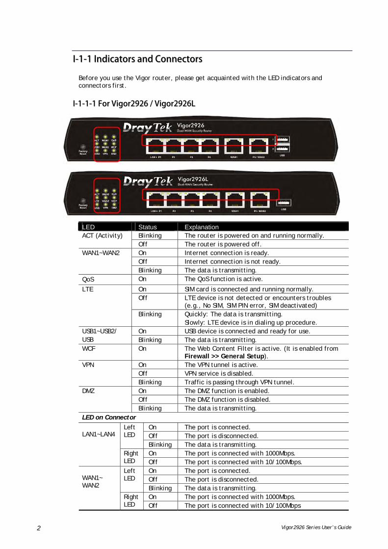
II--11--11 IInnddiiccaattoorrss aanndd CCoonnnneeccttoorrss
Before you use the Vigor router, please get acquainted with the LED indicators and connectors first.
II--11--11--11 FFoorr VViiggoorr22992266 // VViiggoorr22992266LL
LED Status Explanation Blinking The router is powered on and running normally. ACT (Activity) Off The router is powered off. On Internet connection is ready. Off Internet connection is not ready.
WAN1~WAN2
Blinking The data is transmitting. QoS On The QoS function is active.
On SIM card is connected and running normally. Off LTE device is not detected or encounters troubles
(e.g., No SIM, SIM PIN error, SIM deactivated)
LTE
Blinking Quickly: The data is transmitting. Slowly: LTE device is in dialing up procedure.
On USB device is connected and ready for use. USB1~USB2/ USB Blinking The data is transmitting. WCF On The Web Content Filter is active. (It is enabled from
Firewall >> General Setup). On The VPN tunnel is active. Off VPN service is disabled.
VPN
Blinking Traffic is passing through VPN tunnel. On The DMZ function is enabled. Off The DMZ function is disabled.
DMZ
Blinking The data is transmitting. LED on Connector
On The port is connected. Off The port is disconnected.
Left LED
Blinking The data is transmitting. On The port is connected with 1000Mbps.
LAN1~LAN4
Right LED Off The port is connected with 10/100Mbps.
On The port is connected. Off The port is disconnected.
Left LED
Blinking The data is transmitting. On The port is connected with 1000Mbps.
WAN1~ WAN2
Right LED Off The port is connected with 10/100Mbps
Vigor2926 Series User’s Guide 3
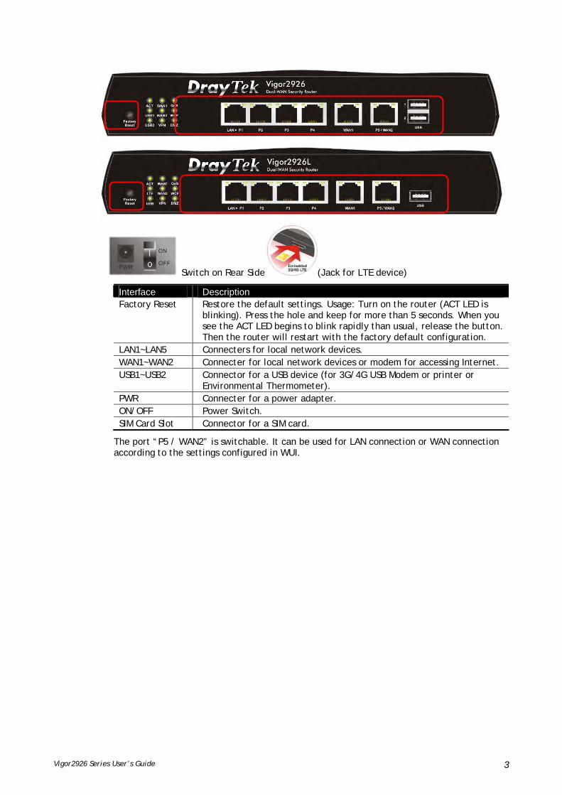
Switch on Rear Side (Jack for LTE device)
Interface Description Factory Reset Restore the default settings. Usage: Turn on the router (ACT LED is
blinking). Press the hole and keep for more than 5 seconds. When you see the ACT LED begins to blink rapidly than usual, release the button. Then the router will restart with the factory default configuration.
LAN1~LAN5 Connecters for local network devices. WAN1~WAN2 Connecter for local network devices or modem for accessing Internet. USB1~USB2 Connector for a USB device (for 3G/4G USB Modem or printer or
Environmental Thermometer). PWR Connecter for a power adapter. ON/OFF Power Switch. SIM Card Slot Connector for a SIM card.
The port “P5 / WAN2” is switchable. It can be used for LAN connection or WAN connection according to the settings configured in WUI.

Vigor2926 Series User’s Guide 4
II--11--11--22 FFoorr VViiggoorr22992266nn // VViiggoorr22992266aacc // VViiggoorr22992266LLaacc // VViiggoorr22992266LLnn
LED Status Explanation Blinking The router is powered on and running normally. ACT (Activity) Off The router is powered off. On Internet connection is ready. Off Internet connection is not ready.
WAN1~WAN2
Blinking The data is transmitting. QoS On The QoS function is active.
On SIM card is connected and running normally. Off LTE device is not detected or encounters troubles
(e.g., No SIM, SIM PIN error, SIM deactivated)
LTE
Blinking Quickly: The data is transmitting. Slowly: LTE device is in dialing up procedure.
On USB device is connected and ready for use. USB Blinking The data is transmitting.
WCF On The Web Content Filter is active. (It is enabled from Firewall >> General Setup).
On 2.4G/5G: Wireless access point with bandwidth of 2.4GHz/5GHz is ready. WLAN: Wireless access point is ready.
2.4G/5G/WLAN
Blinking It will blink slowly while wireless traffic goes through. ACT and WLAN LEDs blink quickly and simultaneously when WPS is working, and will return to normal condition after two minutes. (You need to setup WPS within 2 minutes.)
On The DMZ function is enabled. DMZ Off The DMZ function is disabled.

Vigor2926 Series User’s Guide 5
Blinking The data is transmitting. LED on Connector
On The port is connected. Off The port is disconnected.
Left LED
Blinking The data is transmitting. On The port is connected with 1000Mbps.
LAN1~ LAN4
Right LED Off The port is connected with 10/100Mbps
On The port is connected. Off The port is disconnected.
Left LED
Blinking The data is transmitting. On The port is connected with 1000Mbps.
WAN1~ WAN2
Right LED Off The port is connected with 10/100Mbps
The port “P5 / WAN2” is switchable. It can be used for LAN connection or WAN connection according to the settings configured in WUI.
Vigor2926 Series User’s Guide 6
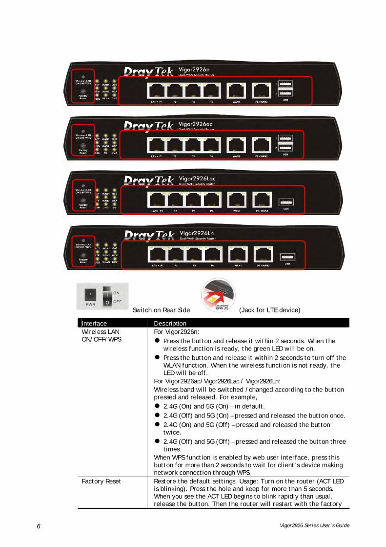
Switch on Rear Side (Jack for LTE device)
Interface Description Wireless LAN ON/OFF/WPS
For Vigor2926n: Press the button and release it within 2 seconds. When the
wireless function is ready, the green LED will be on. Press the button and release it within 2 seconds to turn off the
WLAN function. When the wireless function is not ready, the LED will be off.
For Vigor2926ac/Vigor2926Lac / Vigor2926Ln: Wireless band will be switched /changed according to the button pressed and released. For example, 2.4G (On) and 5G (On) – in default. 2.4G (Off) and 5G (On) – pressed and released the button once. 2.4G (On) and 5G (Off) – pressed and released the button
twice. 2.4G (Off) and 5G (Off) – pressed and released the button three
times. When WPS function is enabled by web user interface, press this button for more than 2 seconds to wait for client’s device making network connection through WPS.
Factory Reset Restore the default settings. Usage: Turn on the router (ACT LED is blinking). Press the hole and keep for more than 5 seconds. When you see the ACT LED begins to blink rapidly than usual, release the button. Then the router will restart with the factory

Vigor2926 Series User’s Guide 7
default configuration. LAN1~LAN4 Connecters for local network devices. WAN1~WAN2 Connecter for local network devices or modem for accessing
Internet. USB1~2 / USB Connecter for a USB device (for 3G/4G USB Modem or printer or
thermometer). PWR Connecter for a power adapter. ON/OFF Power Switch. SIM Card Slot Connector for a SIM card.

Vigor2926 Series User’s Guide 8
II--11--11--33 FFoorr VViiggoorr22992266VVaacc
LED Status Explanation Blinking The router is powered on and running normally. ACT (Activity) Off The router is powered off. On Internet connection is ready. Off Internet connection is not ready.
WAN1~ WAN2
Blinking The data is transmitting. On A PSTN phone call comes (in and out). However, when
the phone call is disconnected, the LED will be off. Line
Off There is no PSTN phone call. On USB device is connected and ready for use. USB Blinking The data is transmitting. On The phone connected to this port is off-hook. Off The phone connected to this port is on-hook.
Phone1/Phone2
Blinking A phone call comes.
On Wireless access point with bandwidth of 2.4GHz/5GHz is ready.
2.4G/5G
Blinking It will blink slowly while wireless traffic goes through. ACT and WLAN LEDs blink quickly and simultaneously when WPS is working, and will return to normal condition after two minutes. (You need to setup WPS within 2 minutes.)
LED on Connector
On The port is connected. Off The port is disconnected.
Left LED
Blinking The data is transmitting. On The port is connected with 1000Mbps.
LAN1~ LAN4
Right LED Off The port is connected with 10/100Mbps
On The port is connected. Off The port is disconnected.
Left LED
Blinking The data is transmitting. On The port is connected with 1000Mbps.
WAN1~ WAN2
Right LED Off The port is connected with 10/100Mbps
The port “P5 / WAN2” is switchable. It can be used for LAN connection or WAN connection according to the settings configured in WUI.

Vigor2926 Series User’s Guide 9
Interface Description Wireless LAN ON/OFF/WPS
Wireless band will be switched /changed according to the button pressed and released. For example, 2.4G (On) and 5G (On) – in default. 2.4G (Off) and 5G (On) – pressed and released the button
once. 2.4G (On) and 5G (Off) – pressed and released the button
twice. 2.4G (Off) and 5G (Off) – pressed and released the button
three times. When WPS function is enabled by web user interface, press this button for more than 2 seconds to wait for client’s device making network connection through WPS.
Factory Reset Restore the default settings. Usage: Turn on the router (ACT LED is blinking). Press the hole and keep for more than 5 seconds. When you see the ACT LED begins to blink rapidly than usual, release the button. Then the router will restart with the factory default configuration.
USB1~USB2 Connecter for a USB device (for 3G/4G USB Modem or printer or Environmental Thermometer).
LAN1~LAN4 Connecters for local network devices. WAN1~WAN2 Connecter for local network devices or modem for accessing
Internet. Phone 1/2 Connecter for analog phone(s). Line Connector for PSTN life line. PWR Connecter for a power adapter.
ON/OFF Power Switch.

Vigor2926 Series User’s Guide 10
II--11--22 NNootteess ffoorr AAnntteennnnaa IInnssttaallllaattiioonn ((ffoorr ““LL”” mmooddeell))
Magnetic antenna must be installed on the extension base before connecting to Vigor router.
There are two mounting holes for installing antennas with extension base on Vigor router. Please install them as shown below.
Note, if only one antenna shall be installed, please use the mounting hole (major signal transmitted hole) near to the SIM card slot.
Extension Base
Extension Base
SIM Card Slot
Major Signal Transmitted Hole

Vigor2926 Series User’s Guide 11
While installing the SIM card into the card slot, note that back plate of the SIM card slot must be removed first and the direction of card notch must be on the left side.
There are two types of antennas provided for Vigor2926Ln/Vigor2926Lac, which must be installed in different locations carefully and correctly. Wrong installation might cause bad signal of wireless connection. Therefore, pay attention to the installation of antennas by referring to the following illustration.
SMA jack for WLANAntenna
SMA jack for LTE Antenna (withextension base)

Vigor2926 Series User’s Guide 12
II--22 HHaarrddwwaarree IInnssttaallllaattiioonn
II--22--11 IInnssttaalllliinngg VViiggoorr RRoouutteerr
Before starting to configure the router, you have to connect your devices correctly. In this section, Vigor2926n is taken as an example.
1. Connect the cable Modem/DSL Modem/Media Converter to any WAN port of router with Ethernet cable (RJ-45).
2. Connect one end of an Ethernet cable (RJ-45) to one of the LAN ports of the router and the other end of the cable (RJ-45) into the Ethernet port on your computer.
3. Connect one end of the power adapter to the router’s power port on the rear panel, and the other side into a wall outlet.
4. Power on the device by pressing down the power switch on the rear panel.
5. The system starts to initiate. After completing the system test, the ACT LED will light up and start blinking.
Vigor2926 Series User’s Guide 13
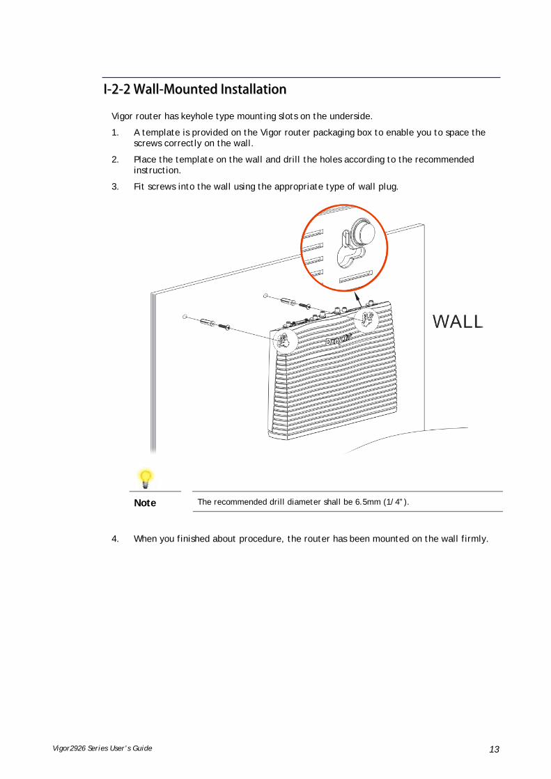
II--22--22 WWaallll--MMoouunntteedd IInnssttaallllaattiioonn
Vigor router has keyhole type mounting slots on the underside.
1. A template is provided on the Vigor router packaging box to enable you to space the screws correctly on the wall.
2. Place the template on the wall and drill the holes according to the recommended instruction.
3. Fit screws into the wall using the appropriate type of wall plug.
Note
The recommended drill diameter shall be 6.5mm (1/4”).
4. When you finished about procedure, the router has been mounted on the wall firmly.

Vigor2926 Series User’s Guide 14
II--22--33 IInnssttaalllliinngg UUSSBB PPrriinntteerr ttoo VViiggoorr RRoouutteerr
You can install a printer onto the router for sharing printing. All the PCs connected this router can print documents via the router. The example provided here is made based on Windows 7. For other Windows system, please visit www.DrayTek.com.
Before using it, please follow the steps below to configure settings for connected computers (or wireless clients).
1. Connect the printer with the router through USB/parallel port.
2. Open All Programs>>Getting Started>>Devices and Printers.
3. Click Add a printer.

Vigor2926 Series User’s Guide 15
4. A dialog will appear. Click Add a local printer and click Next.
5. In this dialog, choose Create a new port. In the field of Type of port, use the drop down list to select Standard TCP/IP Port. Then, click Next.

Vigor2926 Series User’s Guide 16
6. In the following dialog, type 192.168.1.1 (router’s LAN IP) in the field of Hostname or IP Address and type 192.168.1.1 as the Port name. Then, click Next.
7. Click Standard and choose Generic Network Card.

Vigor2926 Series User’s Guide 17
8. Now, your system will ask you to choose right name of the printer that you installed onto the router. Such step can make correct driver loaded onto your PC. When you finish the selection, click Next.
9. Type a name for the chosen printer. Click Next.

Vigor2926 Series User’s Guide 18
10. Choose Do not share this printer and click Next.
11. Then, in the following dialog, click Finish.

Vigor2926 Series User’s Guide 19
12. The new printer has been added and displayed under Printers and Faxes. Click the new printer icon and click Printer server properties.
13. Edit the property of the new printer you have added by clicking Configure Port.

Vigor2926 Series User’s Guide 20
14. Select "LPR" on Protocol, type p1 (number 1) as Queue Name. Then click OK. Next please refer to the red rectangle for choosing the correct protocol and LPR name.
The printer can be used for printing now. Most of the printers with different manufacturers are compatible with vigor router.
Info
Some printers with the fax/scanning or other additional functions are not supported. Vigor router supports printing request from computers via LAN ports but not WAN port.

Vigor2926 Series User’s Guide 21
II--33 AAcccceessssiinngg WWeebb PPaaggee
1. Make sure your PC connects to the router correctly.
You may either simply set up your computer to get IP dynamically from the router or set up the IP address of the computer to be the same subnet as the default IP address of Vigor router 192.168.1.1. For the detailed information, please refer to the later section - Trouble Shooting of the guide.
2. Open a web browser on your PC and type http://192.168.1.1. The following window will be open to ask for username and password.
3. Please type “admin/admin” as the Username/Password and click Login.
Info
If you fail to access to the web configuration, please go to “Trouble Shooting” for detecting and solving your problem.

Vigor2926 Series User’s Guide 22
4. Now, the Main Screen will appear. Take Vigor2926ac as as example.
Info
The home page will be different slightly in accordance with the type of the router you have.
5. The web page can be logged out according to the chosen condition. The default setting is Auto Logout, which means the web configuration system will logout after 5 minutes without any operation. Change the setting for your necessity.

Vigor2926 Series User’s Guide 23
II--44 CChhaannggiinngg PPaasssswwoorrdd
Please change the password for the original security of the router.
1. Open a web browser on your PC and type http://192.168.1.1. A pop-up window will open to ask for username and password.
2. Please type “admin/admin” as Username/Password for accessing into the web user interface with admin mode.
3. Go to System Maintenance page and choose Administrator Password.
4. Enter the login password (the default is “admin”) on the field of Old Password. Type New Password and Confirm Password. Then click OK to continue.
Info
The maximum length of the password you can set is 23 characters.
5. Now, the password has been changed. Next time, use the new password to access the Web user interface for this router.
Info
Even the password is changed, the Username for logging onto the web user interface is still “admin”.

Vigor2926 Series User’s Guide 24
II--55 DDaasshhbbooaarrdd
Dashboard shows the connection status including System Information, IPv4 Internet Access, IPv6 Internet Access, Interface (physical connection), Security and Quick Access.
Click Dashboard from the main menu on the left side of the main page.
A web page with default selections will be displayed on the screen. Refer to the following figure:
Vigor2926 Series User’s Guide 25
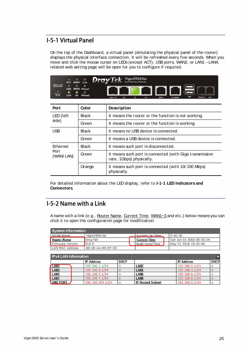
II--55--11 VViirrttuuaall PPaanneell
On the top of the Dashboard, a virtual panel (simulating the physical panel of the router) displays the physical interface connection. It will be refreshed every five seconds. When you move and click the mouse cursor on LEDs (except ACT), USB ports, WAN2, or LAN1 – LAN4, related web setting page will be open for you to configure if required.
Port Color Description
Black It means the router or the function is not working. LED (left side)
Green It means the router or the function is working.
Black It means no USB device is connected. USB
Green It means a USB device is connected.
Black It means such port is disconnected.
Green It means such port is connected (with Giga transmission rate, 1Gbps) physically.
Ethernet Port (WAN/LAN)
Orange It means such port is connected (with 10/100 Mbps) physically.
For detailed information about the LED display, refer to I-1-1 LED Indicators and Connectors.
II--55--22 NNaammee wwiitthh aa LLiinnkk
A name with a link (e.g., Router Name, Current Time, WAN1~3 and etc.) below means you can click it to open the configuration page for modification.
Vigor2926 Series User’s Guide 26
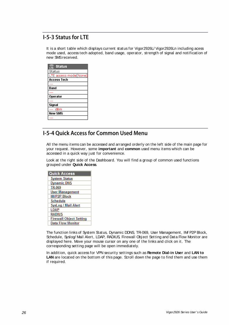
II--55--33 SSttaattuuss ffoorr LLTTEE
It is a short table which displays current status for Vigor2926L/Vigor2926Ln including acess mode used, access tech adopted, band usage, operator, strength of signal and notification of new SMS received.
II--55--44 QQuuiicckk AAcccceessss ffoorr CCoommmmoonn UUsseedd MMeennuu
All the menu items can be accessed and arranged orderly on the left side of the main page for your request. However, some important and common used menu items which can be accessed in a quick way just for convenience.
Look at the right side of the Dashboard. You will find a group of common used functions grouped under Quick Access.
The function links of System Status, Dynamic DDNS, TR-069, User Management, IM/P2P Block, Schedule, Syslog/Mail Alert, LDAP, RADIUS, Firewall Object Setting and Data Flow Monitor are displayed here. Move your mouse cursor on any one of the links and click on it. The corresponding setting page will be open immediately.
In addition, quick access for VPN security settings such as Remote Dial-in User and LAN to LAN are located on the bottom of this page. Scroll down the page to find them and use them if required.

Vigor2926 Series User’s Guide 27
Note that there is a plus ( ) icon located on the left side of LAN/WLAN/VPN/MyVigor. Click it to review the LAN/WLAN/VPN/MyVigor connection(s) used presently.
Host connected physically to the router via LAN port(s) will be displayed with green circles in the field of Connected.
All of the hosts (including wireless clients) displayed with Host ID, IP Address and MAC address indicates that the traffic would be transmitted through LAN port(s) and then the WAN port. The purpose is to perform the traffic monitor of the host(s).
II--55--55 GGUUII MMaapp
All the functions the router supports are listed with table clearly in this page. Users can click the function link to access into the setting page of the function for detailed configuration. Click the icon on the top of the main screen to display all the functions.

Vigor2926 Series User’s Guide 28
II--55--66 WWeebb CCoonnssoollee
It is not necessary to use the telnet command via DOS prompt. The changes made by using web console have the same effects as modified through web user interface. The functions/settings modified under Web Console also can be reviewed on the web user interface.
Click the Web Console icon on the top of the main screen to open the following screen.

Vigor2926 Series User’s Guide 29
II--55--77 CCoonnffiigg BBaacckkuupp
There is one way to store current used settings quickly by clicking the Config Backup icon. It allows you to backup current settings as a file. Such configuration file can be restored by using System Maintenance>>Configuration Backup.
Simply click the icon on the top of the main screen and a pop up dialog will appear.
Click Save to store the setting.
II--55--88 LLooggoouutt
Click this icon to exit the web user interface.

Vigor2926 Series User’s Guide 30
II--55--99 OOnnlliinnee SSttaattuuss
II--55--99--11 PPhhyyssiiccaall CCoonnnneeccttiioonn
Such page displays the physical connection status such as LAN connection status, WAN connection status, ADSL information, and so on.
PPhhyyssiiccaall CCoonnnneeccttiioonn ffoorr IIPPvv44 PPrroottooccooll

Vigor2926 Series User’s Guide 31
PPhhyyssiiccaall CCoonnnneeccttiioonn ffoorr IIPPvv66 PPrroottooccooll
Detailed explanation (for IPv4) is shown below:
Item Description
LAN Status Primary DNS-Displays the primary DNS server address for WAN interface.
Secondary DNS -Displays the secondary DNS server address for WAN interface.
IP Address-Displays the IP address of the LAN interface.
TX Packets-Displays the total transmitted packets at the LAN interface.
RX Packets-Displays the total received packets at the LAN interface.
WAN1/WAN2/WAN3 /WAN4 Status
Enable – Yes in red means such interface is available but not enabled. Yes in green means such interface is enabled.
Line – Displays the physical connection (VDSL, ADSL, Ethernet, or USB) of this interface.
Name – Display the name of the router.
Mode - Displays the type of WAN connection (e.g., PPPoE).
Up Time - Displays the total uptime of the interface.
IP - Displays the IP address of the WAN interface.
GW IP - Displays the IP address of the default gateway.

Vigor2926 Series User’s Guide 32
Item Description
TX Packets - Displays the total transmitted packets at the WAN interface.
TX Rate - Displays the speed of transmitted octets at the WAN interface.
RX Packets - Displays the total number of received packets at the WAN interface.
RX Rate - Displays the speed of received octets at the WAN interface.
Detailed explanation (for IPv6) is shown below:
Item Description
LAN Status IP Address- Displays the IPv6 address of the LAN interface..
TX Packets-Displays the total transmitted packets at the LAN interface.
RX Packets-Displays the total received packets at the LAN interface.
TX Bytes - Displays the speed of transmitted octets at the LAN interface.
RX Bytes - Displays the speed of received octets at the LAN interface.
WAN IPv6 Status Enable – No in red means such interface is available but not enabled. Yes in green means such interface is enabled. No in red means such interface is not available.
Mode - Displays the type of WAN connection (e.g., TSPC).
Up Time - Displays the total uptime of the interface.
IP - Displays the IP address of the WAN interface.
Gateway IP - Displays the IP address of the default gateway.
Info
The words in green mean that the WAN connection of that interface is ready for accessing Internet; the words in red mean that the WAN connection of that interface is not ready for accessing Internet.
II--55--99--22 VViirrttuuaall WWAANN
Such page displays the virtual WAN connection information.
Virtual WAN are used by TR-069 management, VoIP service and so on.
The field of Application will list the purpose of such WAN connection.
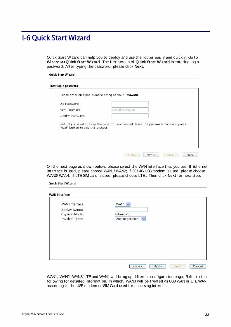
Vigor2926 Series User’s Guide 33
II--66 QQuuiicckk SSttaarrtt WWiizzaarrdd
Quick Start Wizard can help you to deploy and use the router easily and quickly. Go to Wizards>>Quick Start Wizard. The first screen of Quick Start Wizard is entering login password. After typing the password, please click Next.
On the next page as shown below, please select the WAN interface that you use. If Ethernet interface is used, please choose WAN1/WAN2; if 3G/4G USB modem is used, please choose WAN3/WAN4; if LTE SIM card is used, please choose LTE.. Then click Next for next step.
WAN1, WAN2, WAN3/LTE and WAN4 will bring up different configuration page. Refer to the following for detailed information. In which, WAN3 will be treated as USB WAN or LTE WAN according to the USB modem or SIM Card used for accessing Internet.

Vigor2926 Series User’s Guide 34
II--66--11 FFoorr WWAANN11//WWAANN22 ((EEtthheerrnneett))
WAN1/WAN2 is dedicated to physical mode in Ethernet. If you choose WAN1/WAN2, please specify physical type. Then, click Next.
On the next page as shown below, please select the appropriate Internet access type according to the information from your ISP. For example, you should select PPPoE mode if the ISP provides you PPPoE interface. Then click Next for next step.
PPPPPPooEE
1. Choose WAN1/WAN2 as the WAN Interface and click the Next button. The following page will be open for you to specify Internet Access Type.

Vigor2926 Series User’s Guide 35
2. Click PPPoE as the Internet Access Type. Then click Next to continue.
Available settings are explained as follows:
Item Description
Service Name (Optional)
Enter the description of the specific network service.
Username Assign a specific valid user name provided by the ISP.
Note: The maximum length of the user name you can set is 63 characters.
Password Assign a valid password provided by the ISP.
Note: The maximum length of the password you can set is 62 characters.
Confirm Password Retype the password.
Back Click it to return to previous setting page.
Next Click it to get into the next setting page.
Cancel Click it to give up the quick start wizard.

Vigor2926 Series User’s Guide 36
3. Please manually enter the Username/Password provided by your ISP. Click Next for viewing summary of such connection.
4. Click Finish. A page of Quick Start Wizard Setup OK!!! will appear. Then, the system status of this protocol will be shown.
5. Now, you can enjoy surfing on the Internet.

Vigor2926 Series User’s Guide 37
PPPPTTPP//LL22TTPP
1. Choose WAN1/WAN2 as the WAN Interface and click the Next button. The following page will be open for you to specify Internet Access Type.
2. Click PPTP/L2TP as the Internet Access Type. Then click Next to continue.
Available settings are explained as follows:
Item Description
Username Assign a specific valid user name provided by the ISP.
Note: The maximum length of the user name you can set is 63 characters.
Password Assign a valid password provided by the ISP.
Note: The maximum length of the password you can set is 62

Vigor2926 Series User’s Guide 38
characters.
Confirm Password Retype the password.
WAN IP Configuration Obtain an IP address automatically – the router will get an IP address automatically from DHCP server.
Specify an IP address – you have to type relational settings manually.
IP Address - Type the IP address.
Subnet Mask –Type the subnet mask.
Gateway – Type the IP address of the gateway.
Primary DNS / Second DNS – Type the IP address of the DNS server.
PPTP Server / L2TP Server
Type the IP address of the server.
Back Click it to return to previous setting page.
Next Click it to get into the next setting page.
Cancel Click it to give up the quick start wizard.
3. Please type in the IP address/mask/gateway information originally provided by your ISP. Then click Next for viewing summary of such connection.
4. Click Finish. A page of Quick Start Wizard Setup OK!!! will appear. Then, the system status of this protocol will be shown.
5. Now, you can enjoy surfing on the Internet.
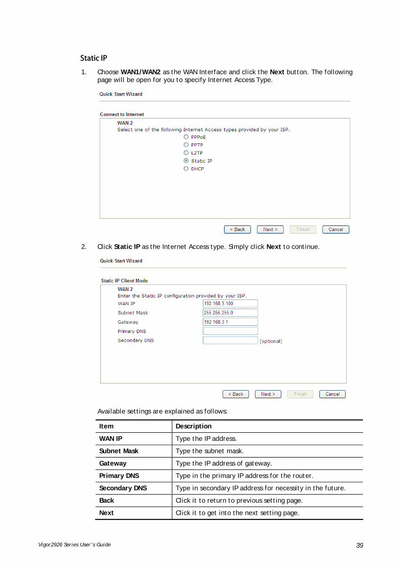
Vigor2926 Series User’s Guide 39
SSttaattiicc IIPP
1. Choose WAN1/WAN2 as the WAN Interface and click the Next button. The following page will be open for you to specify Internet Access Type.
2. Click Static IP as the Internet Access type. Simply click Next to continue.
Available settings are explained as follows:
Item Description
WAN IP Type the IP address.
Subnet Mask Type the subnet mask.
Gateway Type the IP address of gateway.
Primary DNS Type in the primary IP address for the router.
Secondary DNS Type in secondary IP address for necessity in the future.
Back Click it to return to previous setting page.
Next Click it to get into the next setting page.

Vigor2926 Series User’s Guide 40
Cancel Click it to give up the quick start wizard.
3. Please type in the IP address information originally provided by your ISP. Then click Next for next step.
4. Click Finish. A page of Quick Start Wizard Setup OK!!! will appear. Then, the system status of this protocol will be shown.
5. Now, you can enjoy surfing on the Internet.
DDHHCCPP
1. Choose WAN2 as the WAN Interface and choose Ethernet as the Physical Mode. Click the Next button. The following page will be open for you to specify Internet Access Type.
2. Click DHCP as the Internet Access type. Simply click Next to continue.

Vigor2926 Series User’s Guide 41
Available settings are explained as follows:
Item Description
Host Name Type the name of the host.
Note: The maximum length of the host name you can set is 39 characters.
MAC Some Cable service providers specify a specific MAC address for access authentication. In such cases you need to enter the MAC address.
Back Click it to return to previous setting page.
Next Click it to get into the next setting page.
Cancel Click it to give up the quick start wizard.
3. After finished the settings above, click Next for viewing summary of such connection.

Vigor2926 Series User’s Guide 42
4. Click Finish. A page of Quick Start Wizard Setup OK!!! will appear. Then, the system status of this protocol will be shown.
5. Now, you can enjoy surfing on the Internet.
II--66--22 FFoorr WWAANN33//WWAANN44 ((UUSSBB))
WAN3/WAN4 is dedicated to physical mode in USB.
1. Choose WAN3/WAN4 as WAN Interface.
2. Then, click Next for getting the following page.
Available settings are explained as follows:
Item Description
Internet Access Choose one of the selections as the protocol of accessing the internet.

Vigor2926 Series User’s Guide 43
3G/4G USB Modem (PPP mode)
SIM Pin code –Type PIN code of the SIM card that will be used to access Internet. The maximum length of the pin code you can set is 15 characters.
Modem Initial String – Such value is used to initialize USB modem. Please use the default value. If you have any question, please contact to your ISP. The maximum length of the string you can set is 47 characters.
APN Name – APN means Access Point Name which is provided and required by some ISPs. Type the name and click Apply.
3G/4G USB Modem (DHCP mode)
SIM Pin code – Type PIN code of the SIM card that will be used to access Internet.
Network Mode – Force Vigor router to connect Internet with the mode specified here. If you choose 4G/3G/2G as network mode, the router will choose a suitable one according to the actual wireless signal automatically.
APN Name – APN means Access Point Name which is provided and required by some ISPs.
3. Then, click Next for viewing summary of such connection.
4. Click Finish. A page of Quick Start Wizard Setup OK!!! will appear. Then, the system status of this protocol will be shown.
5. Now, you can enjoy surfing on the Internet.

Vigor2926 Series User’s Guide 44
II--66--33 FFoorr LLTTEE WWAANN
1. Choose LTE as WAN Interface.
2. Then, click Next for getting the following page.
Available settings are explained as follows:
Item Description
Internet Access Now, DHCP mode is the only choice for LTE WAN.
3G/4G USB Modem (DHCP mode)
SIM Pin code – Type PIN code of the SIM card that will be used to access Internet.
Network Mode – Force Vigor router to connect Internet with the mode specified here. If you choose 4G/3G/2G as network mode, the router will choose a suitable one according to the actual wireless signal automatically.
APN Name – APN means Access Point Name which is provided and required by some ISPs.

Vigor2926 Series User’s Guide 45
3. Please type in required information originally provided by your ISP. Then, click Next for viewing summary of such connection.
4. Click Finish. A page of Quick Start Wizard Setup OK!!! will appear. Then, the system status of this protocol will be shown.
5. Now, you can enjoy surfing on the Internet.

Vigor2926 Series User’s Guide 46
II--77 SSeerrvviiccee AAccttiivvaattiioonn WWiizzaarrdd
Service Activation Wizard can guide you to activate WCF service (Web Content Filter) with a quick and easy way. For the Service Activation Wizard is only available for admin operation, therefore, please type “admin/admin” on Username/Password while Logging into the web user interface.
Service Activation Wizard is a tool which allows you to use trial version of WCF directly without accessing into the server (MyVigor) located on http://myvigor.draytek.com. For using Web Content Filter Profile, please refer to later section Web Content Filter Profile for detailed information.
Now, follow the steps listed below to activate WCF feature for your router.
Info
Such function is available only for Admin Mode.
1. Open Wizards>>Service Activation Wizard.
2. In the following page, you can activate the Web content filter services and APP Enforcement service at the same time or individually. When you finish the selection, please click Next.
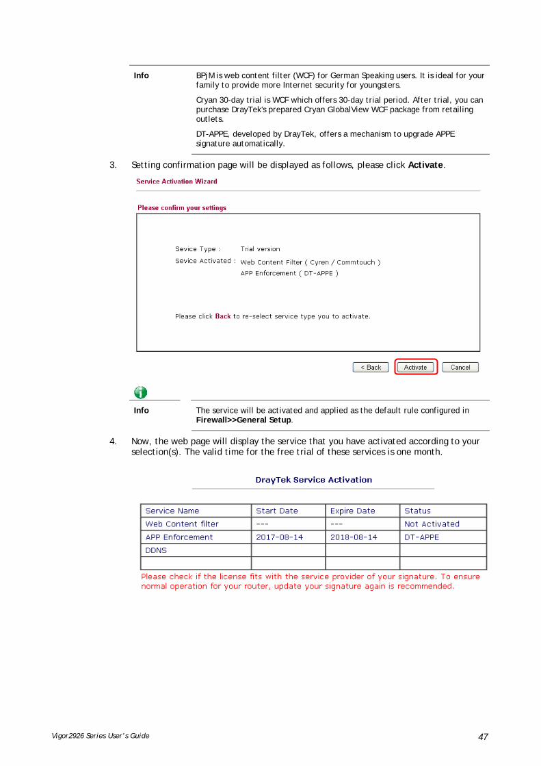
Vigor2926 Series User’s Guide 47
Info BPjM is web content filter (WCF) for German Speaking users. It is ideal for your family to provide more Internet security for youngsters.
Cryan 30-day trial is WCF which offers 30-day trial period. After trial, you can purchase DrayTek's prepared Cryan GlobalView WCF package from retailing outlets.
DT-APPE, developed by DrayTek, offers a mechanism to upgrade APPE signature automatically.
3. Setting confirmation page will be displayed as follows, please click Activate.
Info
The service will be activated and applied as the default rule configured in Firewall>>General Setup.
4. Now, the web page will display the service that you have activated according to your selection(s). The valid time for the free trial of these services is one month.

Vigor2926 Series User’s Guide 48
II--88 RReeggiisstteerriinngg VViiggoorr RRoouutteerr
You have finished the configuration of Quick Start Wizard and you can surf the Internet at any time. Now it is the time to register your Vigor router to MyVigor website for getting more service. Please follow the steps below to finish the router registration.
1 Please login the web configuration interface of Vigor router by typing “admin/admin” as User Name / Password.
2 Click Support Area>>Production Registration from the home page.
3 A Login page will be shown on the screen. Please type the account and password that you created previously. And click Login.
Info
If you haven’t an accessing account, please refer to section Creating an Account for MyVigor to create your own one. Please read the articles on the Agreement regarding user rights carefully while creating a user account.

Vigor2926 Series User’s Guide 49
4 The following page will be displayed after you logging in MyVigor. Type a nickname for the router, then click Add.
5 When the following page appears, your router information has been added to the database.
6 After clicking OK, you will see the following page. Your router has been registered to myvigor website successfully.

Vigor2926 Series User’s Guide 50
This page is left blank.

Vigor2926 Series User’s Guide 51
PPaarrtt IIII CCoonnnneeccttiivviittyy
It means wide area network. Public IP will be used in WAN.
It means local area network. Private IP will be used in LAN. Local Area Network (LAN) is a group of subnets regulated and ruled by router. The design of network structure is related to what type of public IP addresses coming from your ISP.
When the data flow passing through, the Network Address Translation (NAT) function of the router will dedicate to translate public/private addresses, and the packets will be delivered to the correct host PC in the local area network.
DDNS, LAN DNS, IGMP, LDAP, UPnP, WOL, RADIUS, SMS, Bonjour, HA, Local 802.1X
Static Route, Load-Balance/Route Policy, BGP

Vigor2926 Series User’s Guide 52
IIII--11 WWAANN
It allows users to access Internet.
BBaassiiccss ooff IInntteerrnneett PPrroottooccooll ((IIPP)) NNeettwwoorrkk
IP means Internet Protocol. Every device in an IP-based Network including routers, print server, and host PCs, needs an IP address to identify its location on the network. To avoid address conflicts, IP addresses are publicly registered with the Network Information Centre (NIC). Having a unique IP address is mandatory for those devices participated in the public network but not in the private TCP/IP local area networks (LANs), such as host PCs under the management of a router since they do not need to be accessed by the public. Hence, the NIC has reserved certain addresses that will never be registered publicly. These are known as private IP addresses, and are listed in the following ranges:
From 10.0.0.0 to 10.255.255.255 From 172.16.0.0 to 172.31.255.255 From 192.168.0.0 to 192.168.255.255
WWhhaatt aarree PPuubblliicc IIPP AAddddrreessss aanndd PPrriivvaattee IIPP AAddddrreessss
As the router plays a role to manage and further protect its LAN, it interconnects groups of host PCs. Each of them has a private IP address assigned by the built-in DHCP server of the Vigor router. The router itself will also use the default private IP address: 192.168.1.1 to communicate with the local hosts. Meanwhile, Vigor router will communicate with other network devices through a public IP address. When the data flow passing through, the Network Address Translation (NAT) function of the router will dedicate to translate public/private addresses, and the packets will be delivered to the correct host PC in the local area network. Thus, all the host PCs can share a common Internet connection.
GGeett YYoouurr PPuubblliicc IIPP AAddddrreessss ffrroomm IISSPP
In ADSL deployment, the PPP (Point to Point)-style authentication and authorization is required for bridging customer premises equipment (CPE). Point to Point Protocol over Ethernet (PPPoE) connects a network of hosts via an access device to a remote access concentrator or aggregation concentrator. This implementation provides users with significant ease of use. Meanwhile it provides access control, billing, and type of service according to user requirement.
When a router begins to connect to your ISP, a serial of discovery process will occur to ask for a connection. Then a session will be created. Your user ID and password is authenticated via PAP or CHAP with RADIUS authentication system. And your IP address, DNS server, and other related information will usually be assigned by your ISP.
NNeettwwoorrkk CCoonnnneeccttiioonn bbyy 33GG//44GG UUSSBB MMooddeemm
For 3G/4G mobile communication through Access Point is popular more and more, Vigor2926 adds the function of 3G/4G network connection for such purpose. By connecting 3G USB Modem to the USB port of Vigor2926, it can support HSDPA/UMTS/EDGE/GPRS/GSM and the future 3G/4G standard (HSUPA, etc). Vigor2926n with 3G/4G USB Modem allows you to receive 3G signals at any place such as your car or certain location holding outdoor activity and share the bandwidth for using by more people. Users can use four LAN ports on the router to access Internet. Also, they can access Internet via 802.11n wireless function of Vigor2926n, and enjoy the powerful firewall, bandwidth management, VPN features of Vigor2926n series.

Vigor2926 Series User’s Guide 53
After connecting into the router, 3G/4G USB Modem will be regarded as the third WAN port. However, the original WAN1 and WAN2 still can be used and Load-Balance can be done in the router. Besides, 3G/4G USB Modem in WAN3 also can be used as backup device. Therefore, when WAN1 and WAN2 are not available, the router will use 3.5G for supporting automatically. The supported 3G/4G USB Modem will be listed on DrayTek web site. Please visit www.draytek.com for more detailed information.
LLTTEE AApppplliiccaattiioonn

Vigor2926 Series User’s Guide 54
WWeebb UUsseerr IInntteerrffaaccee
IIII--11--11 GGeenneerraall SSeettuupp
This section will introduce some general settings of Internet and explain the connection modes for WAN1, WAN2, WAN3 (or LTE) and WAN4 in details.
This router supports multiple-WAN function. It allows users to access Internet and combine the bandwidth of the multiple WANs to speed up the transmission through the network. Each WAN port can connect to different ISPs, Even if the ISPs use different technology to provide telecommunication service (such as DSL, Cable modem, etc.). If any connection problem occurred on one of the ISP connections, all the traffic will be guided and switched to the normal communication port for proper operation. Please configure WAN1, WAN2, WAN3 (or LTE) and WAN4 settings.
This webpage allows you to set general setup for WAN1, WAN2, WAN3 (or LTE) and WAN4 respectively.
For all of the routers except for Vigor2926L and Vigor2926Ln---
For Vigor2926L and Vigor2926Ln----

Vigor2926 Series User’s Guide 55
Available settings are explained as follows:
Item Description
Load Balance Mode This option is available for multiple-WAN for getting enough bandwidth for each WAN port. If you know the practical bandwidth for your WAN interface, please choose the setting of According to Line Speed. Otherwise, please choose Auto Weight to let the router reach the best load balance.
IP Based - The same source / destination IP pair will select the same WAN interface as policy. It is the default setting.
Sesseion Based- All of the WAN interfaces will be used (as out-going WAN) for passing through new sessions to get better transmission speed. Though good speed test result for throughput might be reached; however, some web site may not open smoothly, especially the site need authentication, e.g., FTP.
If you have no strong demand about speed test result, keep default settings as IP based.
Index Click the WAN interface link under Index to access into the WAN configuration page.
Enable V means such WAN interface is enabled and ready to be used.
Physical Mode / Type Display the physical mode and physical type of such WAN interface.
Line Speed(Kbps)
DownLink/UpLink
Display the downstream and upstream rate of such WAN interface.
Active Mode Display whether such WAN interface is Active device or backup device.
Info
In default, each WAN port is enabled.
After finished the above settings, click OK to save the settings.

Vigor2926 Series User’s Guide 56
IIII--11--11--11 WWAANN11//WWAANN22 wwiitthh EEtthheerrnneett
WAN1/WAN2 is fixed with physical mode of Ethernet.
Available settings are explained as follows:
Item Description
Enable Choose Yes to invoke the settings for this WAN interface. Choose No to disable the settings for this WAN interface.
Display Name Type the description for such WAN interface.
Physical Mode Display the physical mode of such WAN interface.
Physical Type You can change the physical type for WAN2 or choose Auto negotiation for determined by the system.
Line Speed If your choose According to Line Speed as the Load Balance Mode, please type the line speed for downloading and uploading for such WAN interface. The unit is kbps.
Active Mode Choose Always On to make the WAN connection be activated always.

Vigor2926 Series User’s Guide 57
Load Balance: Check this box to enable auto load balance function for such WAN interface.
When the data traffic is large, the WAN interface with the function enabled will balance the data transmission automatically among all of the WAN interfaces in connection status.
Failover – Choose it to make the WAN connection as a backup connection.
WAN Failure – When the active WAN failed, such WAN will be activated as the main network connection.
Traffic Threshold – When the data traffic of active WAN reaches the traffic threshold (specified here), the failover WAN will be enabled automatically to share the overloaded data traffic.
Active When If you choose Failover as the Active Mode, Active When will appear. Please specify which WAN will be the Backup interface.
Any of the selected WAN disconnect – Such backup WAN will be activated when any master WAN interface disconnects.
All of the selected WAN disconnect – Such backup WAN will be activated only when all master WAN interfaces disconnect.
VLAN Tag insertion Such feature is offered to the user with the environment supporting IEEE_802.1ad. In which, service is used for outer tag; customer is used for inner tag.
Enable – Enable the function of VLAN with tag.
The router will add specific VLAN number to all packets on the WAN while sending them out.
Please type the tag value and specify the priority for the packets sending by WAN interface.
Disable – Disable the function of VLAN with tag.
Tag value – Type the value as the VLAN ID number. The range is from 0 to 4095.
Priority – Type the packet priority number for such VLAN. The range is from 0 to 7.
After finished the above settings, click OK to save the settings.

Vigor2926 Series User’s Guide 58
IIII--11--11--22 WWAANN33//WWAANN44 ((UUSSBB))
To use 3G/4G network connection through 3G/4G USB Modem, please configure WAN3 or WAN4 interface.
Or (LTE model)
Available settings are explained as follows:
Item Description
Enable Choose Yes to invoke the settings for this WAN interface. Choose No to disable the settings for this WAN interface.
Display Name Type the description for such WAN interface.
Physical Mode Display the physical mode of such WAN interface.
Line Speed If your choose According to Line Speed as the Load Balance Mode, please type the line speed for downloading and uploading for such WAN interface. The unit is kbps.

Vigor2926 Series User’s Guide 59
Active Mode Choose Always On to make the WAN2 connection being activated always.
Load Balance: Check this box to enable auto load balance function for such WAN interface.
When the data traffic is large, the WAN interface with the function enabled will balance the data transmission automatically among all of the WAN interfaces in connection status.
Failover – Choose it to make the WAN connection as a backup connection.
WAN Failure – When the active WAN failed, such WAN will be activated as the main network connection.
Traffic Threshold – When the data traffic of active WAN reaches the traffic threshold (specified here), the failover WAN will be enabled automatically to share the overloaded data traffic.
Active When If you choose Failover as the Active Mode, Active When will appear. Please specify which WAN will be the Backup interface.
Any of the selected WAN disconnect – Such backup WAN will be activated when any master WAN interface disconnects.
All of the selected WAN disconnect – Such backup WAN will be activated only when all master WAN interfaces disconnect.
After finished the above settings, click OK to save the settings.

Vigor2926 Series User’s Guide 60
IIII--11--22 IInntteerrnneett AAcccceessss
For the router supports multi-WAN function, the users can set different WAN settings (for WAN1/WAN2/WAN3 or LTE/WAN4) for Internet Access. Due to different Physical Mode for WAN interface, the Access Mode for these connections also varies. Refer to the following figures for examples.
Access Mode for Etherenet,
Access Mode for USB,
Access Mode for LTE (for L model only),

Vigor2926 Series User’s Guide 61
Available settings are explained as follows:
Item Description
Index Display the WAN interface.
Display Name It shows the name of the WAN1/WAN2/WAN3 or LTE/WAN4 that entered in general setup.
Physical Mode It shows the physical connection for WAN1/WAN2 (Ethernet) /WAN3 or LTE /WAN4 (USB) according to the real network connection.
Access Mode Use the drop down list to choose a proper access mode. The details page of that mode will be popped up. If not, click Details Page for accessing the page to configure the settings.
Details Page This button will open different web page (based on IPv4) according to the access mode that you choose in WAN interface.
IPv6 This button will open different web page (based on Physical Mode) to setup IPv6 Internet Access Mode for WAN interface.
If IPv6 service is active on this WAN interface, the color of “IPv6” will become green.
DHCP Client Option This button allows you to configure DHCP client options.
DHCP packets can be processed by adding option number and data information when such function is enabled and configured.
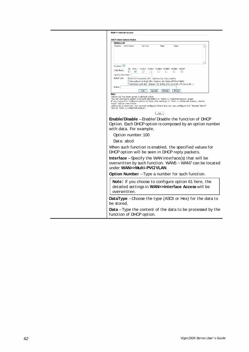
Vigor2926 Series User’s Guide 62
Enable/Disable – Enable/Disable the function of DHCP Option. Each DHCP option is composed by an option number with data. For example,
Option number:100
Data: abcd
When such function is enabled, the specified values for DHCP option will be seen in DHCP reply packets.
Interface – Specify the WAN interface(s) that will be overwritten by such function. WAN5 ~ WAN7 can be located under WAN>>Multi-PVC/VLAN.
Option Number – Type a number for such function.
Note: If you choose to configure option 61 here, the detailed settings in WAN>>Interface Access will be overwritten.
DataType – Choose the type (ASCII or Hex) for the data to be stored.
Data – Type the content of the data to be processed by the function of DHCP option.
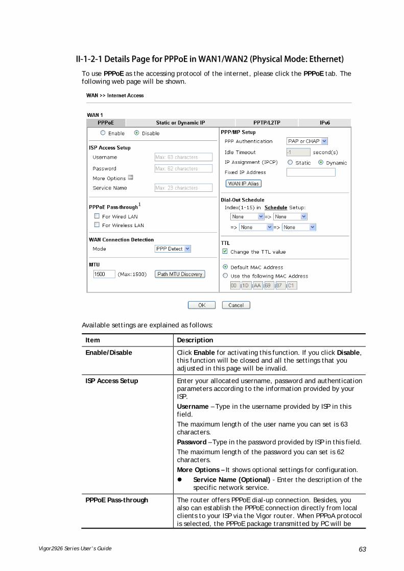
Vigor2926 Series User’s Guide 63
IIII--11--22--11 DDeettaaiillss PPaaggee ffoorr PPPPPPooEE iinn WWAANN11//WWAANN22 ((PPhhyyssiiccaall MMooddee:: EEtthheerrnneett))
To use PPPoE as the accessing protocol of the internet, please click the PPPoE tab. The following web page will be shown.
Available settings are explained as follows:
Item Description
Enable/Disable Click Enable for activating this function. If you click Disable, this function will be closed and all the settings that you adjusted in this page will be invalid.
ISP Access Setup Enter your allocated username, password and authentication parameters according to the information provided by your ISP.
Username – Type in the username provided by ISP in this field.
The maximum length of the user name you can set is 63 characters.
Password – Type in the password provided by ISP in this field.
The maximum length of the password you can set is 62 characters.
More Options – It shows optional settings for configuration.
Service Name (Optional) - Enter the description of the specific network service.
PPPoE Pass-through The router offers PPPoE dial-up connection. Besides, you also can establish the PPPoE connection directly from local clients to your ISP via the Vigor router. When PPPoA protocol is selected, the PPPoE package transmitted by PC will be
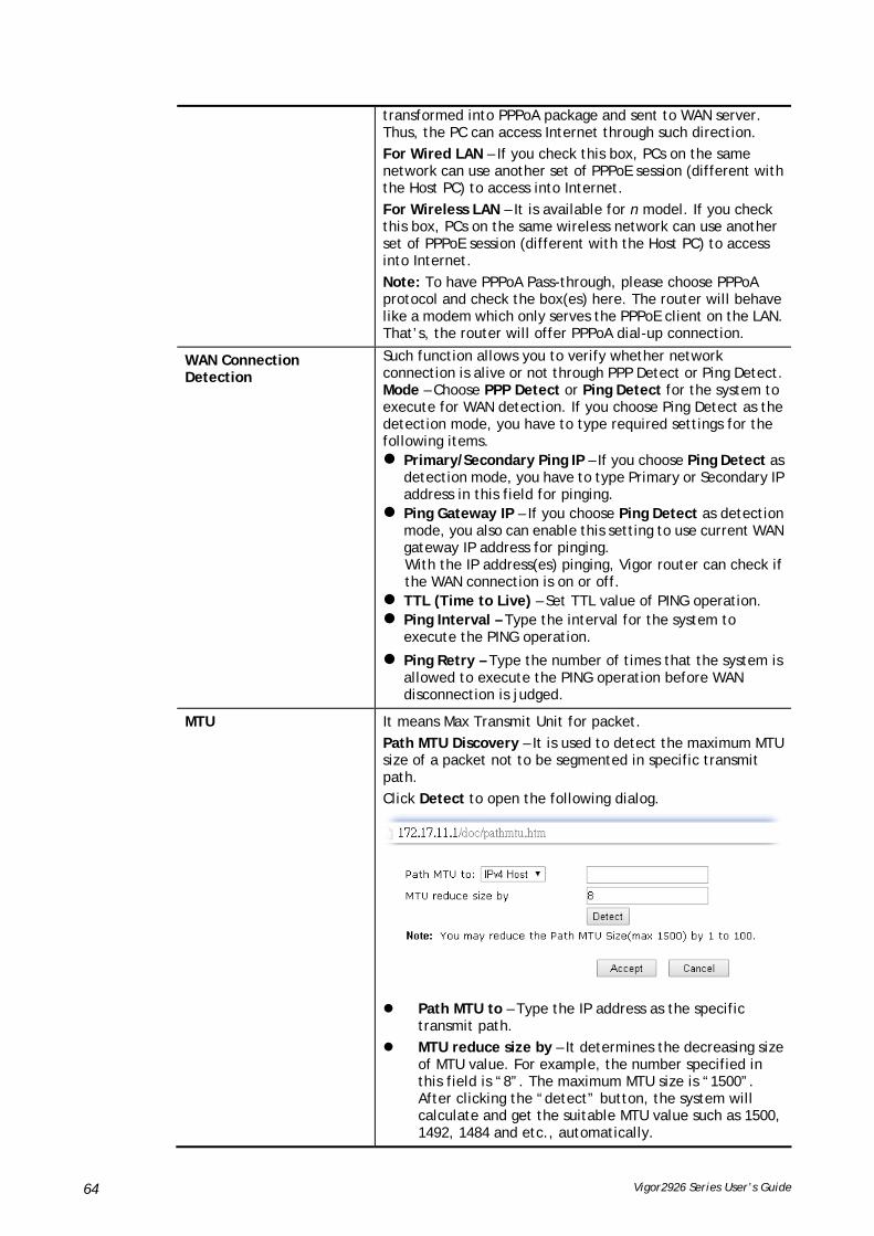
Vigor2926 Series User’s Guide 64
transformed into PPPoA package and sent to WAN server. Thus, the PC can access Internet through such direction.
For Wired LAN – If you check this box, PCs on the same network can use another set of PPPoE session (different with the Host PC) to access into Internet.
For Wireless LAN – It is available for n model. If you check this box, PCs on the same wireless network can use another set of PPPoE session (different with the Host PC) to access into Internet.
Note: To have PPPoA Pass-through, please choose PPPoA protocol and check the box(es) here. The router will behave like a modem which only serves the PPPoE client on the LAN. That’s, the router will offer PPPoA dial-up connection.
WAN Connection Detection
Such function allows you to verify whether network connection is alive or not through PPP Detect or Ping Detect. Mode – Choose PPP Detect or Ping Detect for the system to execute for WAN detection. If you choose Ping Detect as the detection mode, you have to type required settings for the following items. Primary/Secondary Ping IP – If you choose Ping Detect as
detection mode, you have to type Primary or Secondary IP address in this field for pinging.
Ping Gateway IP – If you choose Ping Detect as detection mode, you also can enable this setting to use current WAN gateway IP address for pinging. With the IP address(es) pinging, Vigor router can check if the WAN connection is on or off.
TTL (Time to Live) – Set TTL value of PING operation. Ping Interval – Type the interval for the system to
execute the PING operation.
Ping Retry – Type the number of times that the system is allowed to execute the PING operation before WAN disconnection is judged.
MTU It means Max Transmit Unit for packet.
Path MTU Discovery – It is used to detect the maximum MTU size of a packet not to be segmented in specific transmit path.
Click Detect to open the following dialog.
Path MTU to – Type the IP address as the specific
transmit path.
MTU reduce size by – It determines the decreasing size of MTU value. For example, the number specified in this field is “8”. The maximum MTU size is “1500”. After clicking the “detect” button, the system will calculate and get the suitable MTU value such as 1500, 1492, 1484 and etc., automatically.

Vigor2926 Series User’s Guide 65
Detect – Click it to detect a suitable MTU value
Accept – After clicking it, the detected value will be displayed in the field of MTU.
PPP/MP Setup PPP Authentication – Select PAP only or PAP or CHAP for PPP.
Idle Timeout – Set the timeout for breaking down the Internet after passing through the time without any action.
IP Assignment (IPCP) - Usually ISP dynamically assigns IP address to you each time you connect to it and request. In some case, your ISP provides service to always assign you the same IP address whenever you request. In this case, you can fill in this IP address in the Fixed IP field. Please contact your ISP before you want to use this function.
Fixed IP – Click Yes to use this function and type in a fixed IP address in the box of Fixed IP Address.
WAN IP Alias - If you have multiple public IP addresses and would like to utilize them on the WAN interface, please use WAN IP Alias. You can set up to 32 public IP addresses other than the current one you are using. Type the additional WAN IP address and check the Enable box. Then click OK to exit the dialog.
Dial-Out Schedule Index (1-15) in Schedule Setup - You can type in four sets of time schedule for your request. All the schedules can be set previously in Application >> Schedule web page and you can use the number that you have set in that web page.
TTL Change the TTL value – Enable or disable the TTL (Time to Live) for a packet transmitted through Vigor router.
If enabled - TTL value will be reduced (-1) when it passess through Vigor router. It will cause the client, accessing Internet through Vigor router, be blocked by certain ISP when TTL value becomes “0”.
If disabled – TTL value will not be reduced. Then, when a packet passes through Vigor router, it will not be cancelled. That is, the client who sends out the packet will not be blocked by ISP.
Default MAC Address – You can use Default MAC Address or specify another MAC address by typing on the boxes of MAC Address for the router.
Specify a MAC Address – Type the MAC address for the router manually.
After finishing all the settings here, please click OK to activate them.

Vigor2926 Series User’s Guide 66
IIII--11--22--22 DDeettaaiillss PPaaggee ffoorr SSttaattiicc oorr DDyynnaammiicc IIPP iinn WWAANN11//WWAANN22 ((PPhhyyssiiccaall MMooddee::
EEtthheerrnneett))
For static IP mode, you usually receive a fixed public IP address or a public subnet, namely multiple public IP addresses from your DSL or Cable ISP service providers. In most cases, a Cable service provider will offer a fixed public IP, while a DSL service provider will offer a public subnet. If you have a public subnet, you could assign an IP address or many IP address to the WAN interface.
To use Static or Dynamic IP as the accessing protocol of the internet, please click the Static or Dynamic IP tab. The following web page will be shown.
Available settings are explained as follows:
Item Description
Enable / Disable Click Enable for activating this function. If you click Disable, this function will be closed and all the settings that you adjusted in this page will be invalid.
IP Network Settings This group allows you to obtain an IP address automatically and allows you type in IP address manually.
Obtain an IP address automatically – Click this button to obtain the IP address automatically if you want to use Dynamic IP mode.
More Options - It shows optional settings for configuration.

Vigor2926 Series User’s Guide 67
Router Name: Type in the router name provided by ISP.
Domain Name: Type in the domain name that you have assigned.
Enable DHCP Client Identifier: Check the box to specify username and password as the DHCP client identifier for some ISP.
Username: Type a name as username. The maximum length of the user name you can set is 63 characters.
Password: Type a password. The maximum length of the password you can set is 62 characters.
Specify an IP address – Click this radio button to specify some data if you want to use Static IP mode.
IP Address: Type the IP address.
Subnet Mask: Type the subnet mask.
Gateway IP Address: Type the gateway IP address.
WAN IP Alias - If you have multiple public IP addresses and would like to utilize them on the WAN interface, please use WAN IP Alias. You can set up to 32 public IP addresses other than the current one you are using.
DNS Server IP Address Type in the primary IP address for the router if you want to use Static IP mode. If necessary, type in secondary IP address for necessity in the future.
WAN Connection Detection
Such function allows you to verify whether network connection is alive or not through ARP Detect or Ping Detect.
Mode – Choose ARP Detect, Ping Detect or Always On for the system to execute for WAN detection. If you choose Ping Detect as the detection mode, you have to type required settings for the following items.
Primary/Secondary Ping IP – If you choose Ping Detect as detection mode, you have to type Primary or Secondary IP address in this field for pinging.
Ping Gateway IP – If you choose Ping Detect as detection mode, you also can enable this setting to use current WAN gateway IP address for pinging. With the IP address(es) pinging, Vigor router can check if the WAN connection is on or off.
TTL (Time to Live) – Set TTL value of PING operation. Ping Interval – Type the interval for the system to
execute the PING operation.
Ping Retry – Type the number of times that the system is allowed to execute the PING operation before WAN disconnection is judged.
MTU It means Max Transmit Unit for packet.
Path MTU Discovery – It is used to detect the maximum MTU size of a packet not to be segmented in specific transmit path.
Click Detect to open the following dialog.

Vigor2926 Series User’s Guide 68
Path MTU to – Type the IP address as the specific
transmit path.
MTU reduce size by – It determines the decreasing size of MTU value. For example, the number specified in this field is “8”. The maximum MTU size is “1500”. After clicking the “detect” button, the system will calculate and get the suitable MTU value such as 1500, 1492, 1484 and etc., automatically.
Detect – Click it to detect a suitable MTU value
Accept – After clicking it, the detected value will be displayed in the field of MTU.
Keep WAN Connection Normally, this function is designed for Dynamic IP environments because some ISPs will drop connections if there is no traffic within certain periods of time. Check Enable PING to keep alive box to activate this function.
PING to the IP - If you enable the PING function, please specify the IP address for the system to PING it for keeping alive.
PING Interval - Enter the interval for the system to execute the PING operation.
TTL Change the TTL value – Enable or disable the TTL (Time to Live) for a packet transmitted through Vigor router.
If enabled - TTL value will be reduced (-1) when it passess through Vigor router. It will cause the client, accessing Internet through Vigor router, be blocked by certain ISP when TTL value becomes “0”.
If disabled – TTL value will not be reduced. Then, when a packet passes through Vigor router, it will not be cancelled. That is, the client who sends out the packet will not be blocked by ISP.
RIP Protocol Routing Information Protocol is abbreviated as RIP(RFC1058)specifying how routers exchange routing tables information. Click Enable RIP for activating this function.
Bridge Mode Enable Bridge Mode - If the function is enabled, the router will work as a bridge modem.
Enable Firewall – It is available when Bridge Mode is enabled. When both Bridge Mode and Firewall check boxes are enabled, the settings configured (user profiles) under User Management will be ignored. And all of the filter rules defined and enabled in Firewall menu will be activated.
Bridge Subnet – Make a bridge between the selected LAN subnet and such WAN interface.
MAC Address Default MAC Address: Click this radio button to use default MAC address for the router.
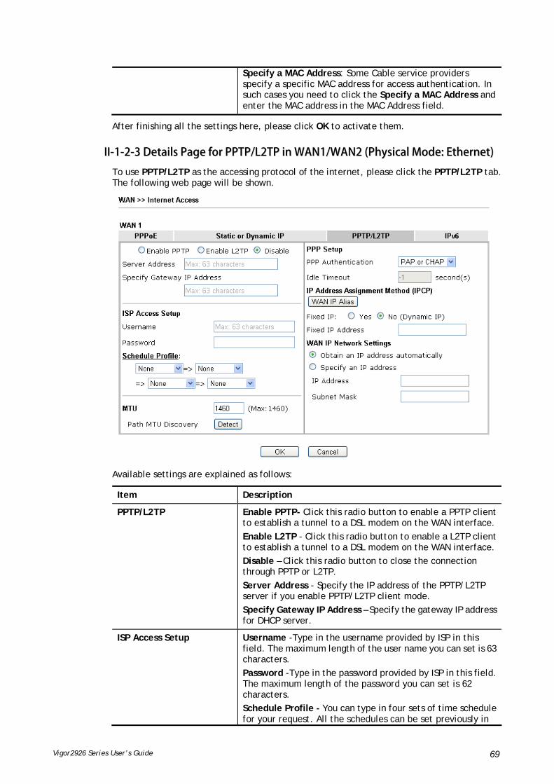
Vigor2926 Series User’s Guide 69
Specify a MAC Address: Some Cable service providers specify a specific MAC address for access authentication. In such cases you need to click the Specify a MAC Address and enter the MAC address in the MAC Address field.
After finishing all the settings here, please click OK to activate them.
IIII--11--22--33 DDeettaaiillss PPaaggee ffoorr PPPPTTPP//LL22TTPP iinn WWAANN11//WWAANN22 ((PPhhyyssiiccaall MMooddee:: EEtthheerrnneett))
To use PPTP/L2TP as the accessing protocol of the internet, please click the PPTP/L2TP tab. The following web page will be shown.
Available settings are explained as follows:
Item Description
PPTP/L2TP Enable PPTP- Click this radio button to enable a PPTP client to establish a tunnel to a DSL modem on the WAN interface.
Enable L2TP - Click this radio button to enable a L2TP client to establish a tunnel to a DSL modem on the WAN interface.
Disable – Click this radio button to close the connection through PPTP or L2TP.
Server Address - Specify the IP address of the PPTP/L2TP server if you enable PPTP/L2TP client mode.
Specify Gateway IP Address – Specify the gateway IP address for DHCP server.
ISP Access Setup Username -Type in the username provided by ISP in this field. The maximum length of the user name you can set is 63 characters.
Password -Type in the password provided by ISP in this field. The maximum length of the password you can set is 62 characters.
Schedule Profile - You can type in four sets of time schedule for your request. All the schedules can be set previously in

Vigor2926 Series User’s Guide 70
Application >> Schedule web page and you can use the number that you have set in that web page.
MTU It means Max Transmit Unit for packet.
Path MTU Discovery – It is used to detect the maximum MTU size of a packet not to be segmented in specific transmit path.
Click Detect to open the following dialog.
Path MTU to – Type the IP address as the specific
transmit path.
MTU reduce size by– It determines the decreasing size of MTU value. For example, the number specified in this field is “8”. The maximum MTU size is “1500”. After clicking the “detect” button, the system will calculate and get the suitable MTU value such as 1500, 1492, 1484 and etc., automatically.
Detect – Click it to detect a suitable MTU value
Accept – After clicking it, the detected value will be displayed in the field of MTU.
PPP Setup PPP Authentication - Select PAP only or PAP or CHAP for PPP.
Idle Timeout - Set the timeout for breaking down the Internet after passing through the time without any action.
IP Address Assignment Method(IPCP)
WAN IP Alias - If you have multiple public IP addresses and would like to utilize them on the WAN interface, please use WAN IP Alias. You can set up to 32 public IP addresses other than the current one you are using.
Fixed IP - Usually ISP dynamically assigns IP address to you each time you connect to it and request. In some case, your ISP provides service to always assign you the same IP address whenever you request. In this case, you can fill in this IP address in the Fixed IP field. Please contact your ISP before you want to use this function. Click Yes to use this function and type in a fixed IP address in the box.
Fixed IP Address -Type a fixed IP address.
WAN IP Network Settings Obtain an IP address automatically – Click this button to obtain the IP address automatically.
Specify an IP address – Click this radio button to specify some data.
IP Address – Type the IP address.
Subnet Mask – Type the subnet mask.
After finishing all the settings here, please click OK to activate them.

Vigor2926 Series User’s Guide 71
IIII--11--22--44 DDeettaaiillss PPaaggee ffoorr 33GG//44GG UUSSBB MMooddeemm ((PPPPPP mmooddee)) iinn WWAANN33//WWAANN44
To use 3G/4G USB Modem (PPP mode) as the accessing protocol of the internet, please choose Internet Access from WAN menu. Then, select 3G/4G USB Modem (PPP mode) for WAN3. The following web page will be shown.
Available settings are explained as follows:
Item Description
Modem Support List It lists all of the modems supported by such router.
3G /4G USB Modem (PPP mode)
Click Enable for activating this function. If you click Disable, this function will be closed and all the settings that you adjusted in this page will be invalid.
SIM PIN code Type PIN code of the SIM card that will be used to access

Vigor2926 Series User’s Guide 72
Internet.
The maximum length of the PIN code you can set is 15 characters.
Modem Initial String Such value is used to initialize USB modem. Please use the default value. If you have any question, please contact to your ISP.
The maximum length of the string you can set is 47 characters.
APN Name APN means Access Point Name which is provided and required by some ISPs. Type the name and click Apply.
The maximum length of the name you can set is 43 characters.
Modem Initial String2 The initial string 1 is shared with APN.
In some cases, user may need another initial AT command to restrict 3G band or do any special settings.
The maximum length of the string you can set is 47 characters.
Modem Dial String Such value is used to dial through USB mode. Please use the default value. If you have any question, please contact to your ISP.
The maximum length of the string you can set is 31 characters.
Service Name Enter the description of the specific network service.
PPP Username Type the PPP username (optional). The maximum length of the name you can set is 63 characters.
PPP Password Type the PPP password (optional). The maximum length of the password you can set is 62 characters.
PPP Authentication Select PAP only or PAP or CHAP for PPP.
Index (1-15) in Schedule Setup
You can type in four sets of time schedule for your request. All the schedules can be set previously in Application >> Schedule web page and you can use the number that you have set in that web page
WAN Connection Detection
Such function allows you to verify whether network connection is alive or not through PPP Detect or Ping Detect.
Mode – Choose PPP Detect or Ping Detect for the system to execute for WAN detection. If you choose Ping Detect as the detection mode, you have to type required settings for the following items.
Primary/Secondary Ping IP – If you choose Ping Detect as detection mode, you have to type Primary or Secondary IP address in this field for pinging.
Ping Gateway IP – If you choose Ping Detect as detection mode, you also can enable this setting to use current WAN gateway IP address for pinging.
With the IP address(es) pinging, Vigor router can check if the WAN connection is on or off.
TTL (Time to Live) – Set TTL value of PING operation.
Ping Interval – Type the interval for the system to execute the PING operation.
Ping Retry – Type the number of times that the system is allowed to execute the PING operation before WAN

Vigor2926 Series User’s Guide 73
disconnection is judged.
After finishing all the settings here, please click OK to activate them.
IIII--11--22--55 DDeettaaiillss PPaaggee ffoorr 33GG//44GG UUSSBB MMooddeemm ((DDHHCCPP mmooddee)) iinn WWAANN33//WWAANN44
To use 3G/4G USB Modem (DHCP mode) as the accessing protocol of the internet, please choose Internet Access from WAN menu. Then, select 3G/4G USB Modem (DHCP mode) for WAN3/WAN4. The following web page will be shown.
Available settings are explained as follows:
Item Description
Modem Support List It lists all of the modems supported by such router.
3G/4G USB Modem (DHCP mode)
Click Enable for activating this function. If you click Disable, this function will be closed and all the settings that you adjusted in this page will be invalid.
SIM PIN code Type PIN code of the SIM card that will be used to access Internet.
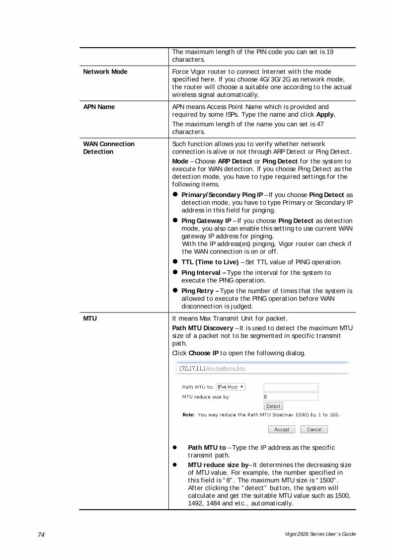
Vigor2926 Series User’s Guide 74
The maximum length of the PIN code you can set is 19 characters.
Network Mode Force Vigor router to connect Internet with the mode specified here. If you choose 4G/3G/2G as network mode, the router will choose a suitable one according to the actual wireless signal automatically.
APN Name APN means Access Point Name which is provided and required by some ISPs. Type the name and click Apply.
The maximum length of the name you can set is 47 characters.
WAN Connection Detection
Such function allows you to verify whether network connection is alive or not through ARP Detect or Ping Detect.
Mode – Choose ARP Detect or Ping Detect for the system to execute for WAN detection. If you choose Ping Detect as the detection mode, you have to type required settings for the following items.
Primary/Secondary Ping IP – If you choose Ping Detect as detection mode, you have to type Primary or Secondary IP address in this field for pinging.
Ping Gateway IP – If you choose Ping Detect as detection mode, you also can enable this setting to use current WAN gateway IP address for pinging. With the IP address(es) pinging, Vigor router can check if the WAN connection is on or off.
TTL (Time to Live) – Set TTL value of PING operation.
Ping Interval – Type the interval for the system to execute the PING operation.
Ping Retry – Type the number of times that the system is allowed to execute the PING operation before WAN disconnection is judged.
MTU It means Max Transmit Unit for packet.
Path MTU Discovery – It is used to detect the maximum MTU size of a packet not to be segmented in specific transmit path.
Click Choose IP to open the following dialog.
Path MTU to – Type the IP address as the specific
transmit path.
MTU reduce size by– It determines the decreasing size of MTU value. For example, the number specified in this field is “8”. The maximum MTU size is “1500”. After clicking the “detect” button, the system will calculate and get the suitable MTU value such as 1500, 1492, 1484 and etc., automatically.
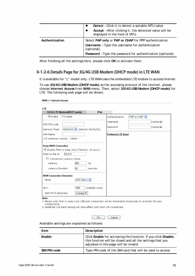
Vigor2926 Series User’s Guide 75
Detect – Click it to detect a suitable MTU value
Accept – After clicking it, the detected value will be displayed in the field of MTU.
Authentication Select PAP only or PAP or CHAP for PPP authentication.
Username – Type the username for authentication (optional).
Password – Type the password for authentication (optional).
After finishing all the settings here, please click OK to activate them.
IIII--11--22--66 DDeettaaiillss PPaaggee ffoorr 33GG//44GG UUSSBB MMooddeemm ((DDHHCCPP mmooddee)) iinn LLTTEE WWAANN
It is available for “L” model only. LTE WAN uses the embedded LTE module to access internet.
To use 3G/4G USB Modem (DHCP mode) as the accessing protocol of the internet, please choose Internet Access from WAN menu. Then, select 3G/4G USB Modem (DHCP mode) for LTE. The following web page will be shown.
Available settings are explained as follows:
Item Description
Enable Click Enable for activating this function. If you click Disable, this function will be closed and all the settings that you adjusted in this page will be invalid.
SIM PIN code Type PIN code of the SIM card that will be used to access

Vigor2926 Series User’s Guide 76
Internet.
The maximum length of the PIN code you can set is 19 characters.
Network Mode Force Vigor router to connect Internet with the mode specified here. If you choose 4G/3G/2G as network mode, the router will choose a suitable one according to the actual wireless signal automatically.
APN Name APN means Access Point Name which is provided and required by some ISPs. Type the name and click Apply.
The maximum length of the name you can set is 47 characters.
Keep WAN Connection Normally, this function is designed for Dynamic IP environments because some ISPs will drop connections if there is no traffic within certain periods of time. Check Enable PING to keep alive box to activate this function.
Enable PING to Keep alive – If you enable the PING function, please specify an IP address for the system to PING it for keeping alive. Vigor system will send a packet per second to the specified IP address. If the system does not receive any reply from that IP within 10 seconds, Vigor system will reboot LTE module until successfully set LTE connection.
PING to the IP – Enter an IP address.
Connection Latency Check - Enable the latency time setting for packet reply. If it is enabled (checked), Vigor system will wait for the packet reply from the specified IP address. When the time of waiting packet reply reaches the time threshold (defined in Latency) and continues for a period of time (defined in Latency Duration), Vigor system will reboot LTE module until successfully set LTE connection.
Latency – Set a time threshold for packet reply. Default value is 800 (unit: micro-second).
Latency Duration – Set a time period. Default value is 60 (unit: second).
MTU It means Max Transmit Unit for packet.
Path MTU Discovery – It is used to detect the maximum MTU size of a packet not to be segmented in specific transmit path.
Click Choose IP to open the following dialog.
Path MTU to – Type the IP address as the specific
transmit path.
MTU reduce size by – It determines the decreasing size of MTU value. For example, the number specified in this field is “8”. The maximum MTU size is “1500”. After clicking the “detect” button, the system will

Vigor2926 Series User’s Guide 77
calculate and get the suitable MTU value such as 1500, 1492, 1484 and etc., automatically.
Detect – Click it to detect a suitable MTU value.
Accept – After clicking it, the detected value will be displayed in the field of MTU.
LTE hardware version The hardware version of the embedded LTE module.
WAN Connection Detection
Such function allows you to verify whether network connection is alive or not through ARP Detect or Ping Detect.
Mode – Choose ARP Detect or Ping Detect for the system to execute for WAN detection. If you choose Ping Detect as the detection mode, you have to type required settings for the following items.
Primary/Secondary Ping IP – If you choose Ping Detect as detection mode, you have to type Primary or Secondary IP address in this field for pinging.
Ping Gateway IP – If you choose Ping Detect as detection mode, you also can enable this setting to use current WAN gateway IP address for pinging. With the IP address(es) pinging, Vigor router can check if the WAN connection is on or off.
TTL (Time to Live) – Set TTL value of PING operation.
Ping Interval – Type the interval for the system to execute the PING operation.
Ping Retry – Type the number of times that the system is allowed to execute the PING operation before WAN disconnection is judged.
Authentication Select None or PAP or CHAP.
UserName Type the username (optional). The maximum length of the name you can set is 47 characters.
Password Type the password (optional). The maximum length of the password you can set is 62 characters.
After finishing all the settings here, please click OK to activate them.
IIII--11--22--77 DDeettaaiillss PPaaggee ffoorr IIPPvv66 –– OOfffflliinnee iinn WWAANN11//WWAANN22//WWAANN33//WWAANN44
When Offline is selected, the IPv6 connection will be disabled.

Vigor2926 Series User’s Guide 78
IIII--11--22--88 DDeettaaiillss PPaaggee ffoorr IIPPvv66 –– PPPPPP iinn WWAANN11//WWAANN22
During the procedure of IPv4 PPPoE connection, we can get the IPv6 Link Local Address between the gateway and Vigor router through IPv6CP. Later, use DHCPv6 or accept RA to acquire the IPv6 prefix address (such as: 2001:B010:7300:200::/64) offered by the ISP. In addition, PCs under LAN also can have the public IPv6 address for Internet access by means of the generated prefix.
No need to type any other information for PPP mode.
Available settings are explained as follows:
Item Description
WAN Connection Detection
Such function allows you to verify whether network connection is alive or not through Ping Detect.
Mode – Choose Always On or Ping Detect for the system to execute for WAN detection. Always On means no detection will be executed. The network connection will be on always.
Ping IP/Hostname – If you choose Ping Detect as detection mode, you have to type IP address in this field for pinging.
TTL (Time to Live) –If you choose Ping Detect as detection mode, you have to type TTL value.
RIPng Protocol RIPng (RIP next generation) offers the same functions and benefits as IPv4 RIP v2.
Below shows an example for successful IPv6 connection based on PPP mode.

Vigor2926 Series User’s Guide 79
Info
At present, the IPv6 prefix can be acquired via the PPPoE mode connection which is available for the areas such as Taiwan (hinet), the Netherlands, Australia and UK.
IIII--11--22--99 DDeettaaiillss PPaaggee ffoorr IIPPvv66 –– TTSSPPCC iinn WWAANN11//WWAANN22//WWAANN33//WWAANN44
Tunnel setup protocol client (TSPC) is an application which could help you to connect to IPv6 network easily.
Please make sure your IPv4 WAN connection is OK and apply one free account from hexago (http://gogonet.gogo6.com/page/freenet6-account ) before you try to use TSPC for network connection. TSPC would connect to tunnel broker and requests a tunnel according to the specifications inside the configuration file. It gets a public IPv6 IP address and an IPv6 prefix from the tunnel broker and then monitors the state of the tunnel in background.
After getting the IPv6 prefix and starting router advertisement daemon (RADVD), the PC behind this router can directly connect to IPv6 the Internet.

Vigor2926 Series User’s Guide 80
Available settings are explained as follows:
Item Description
Username Type the name obtained from the broker. It is suggested for you to apply another username and password for http://gogonet.gogo6.com/page/freenet6-account.
The maximum length of the name you can set is 63 characters.
Password Type the password assigned with the user name.
The maximum length of the name you can set is 19 characters.
Tunnel Broker Type the address for the tunnel broker IP, FQDN or an optional port number.
WAN Connection Detection
Such function allows you to verify whether network connection is alive or not through Ping Detect.
Mode – Choose Always On or Ping Detect for the system to execute for WAN detection. Always On means no detection will be executed. The network connection will be on always.
Ping IP/Hostname – If you choose Ping Detect as detection mode, you have to type IP address in this field for pinging.
TTL (Time to Live) –If you choose Ping Detect as detection mode, you have to type TTL value.
After finished the above settings, click OK to save the settings.

Vigor2926 Series User’s Guide 81
IIII--11--22--1100 DDeettaaiillss PPaaggee ffoorr IIPPvv66 –– AAIICCCCUU iinn WWAANN11//WWAANN22//WWAANN33//WWAANN44
Available settings are explained as follows:
Item Description
Always On Check this box to keep the network connection always.
Username Type the name obtained from the broker. Please apply new account at http://www.sixxs.net/. It is suggested for you to apply another username and password.
The maximum length of the name you can set is 19 characters.
Password Type the password assigned with the user name.
The maximum length of the password you can set is 19 characters.
Tunnel Broker It means a server of AICCU. The server can provide IPv6 tunnels to sites or end users over IPv4.
Type the address for the tunnel broker IP, FQDN or an optional port number.
Tunnel ID One user account may have several tunnels. And, each tunnel shall have one specified tunnel ID (e.g., T115394). Type the ID offered by Tunnel Broker.
Subnet Prefix Type the subnet prefix address obtained from service provider.
The maximum length of the prefix you can set is 128 characters.

Vigor2926 Series User’s Guide 82
WAN Connection Detection
Such function allows you to verify whether network connection is alive or not through Ping Detect.
Mode – Choose Always On or Ping Detect for the system to execute for WAN detection.
Ping IP/Hostname – If you choose Ping Detect as detection mode, you have to type IP address in this field for pinging.
TTL (Time to Live) –If you choose Ping Detect as detection mode, you have to type TTL value.
After finished the above settings, click OK to save the settings.
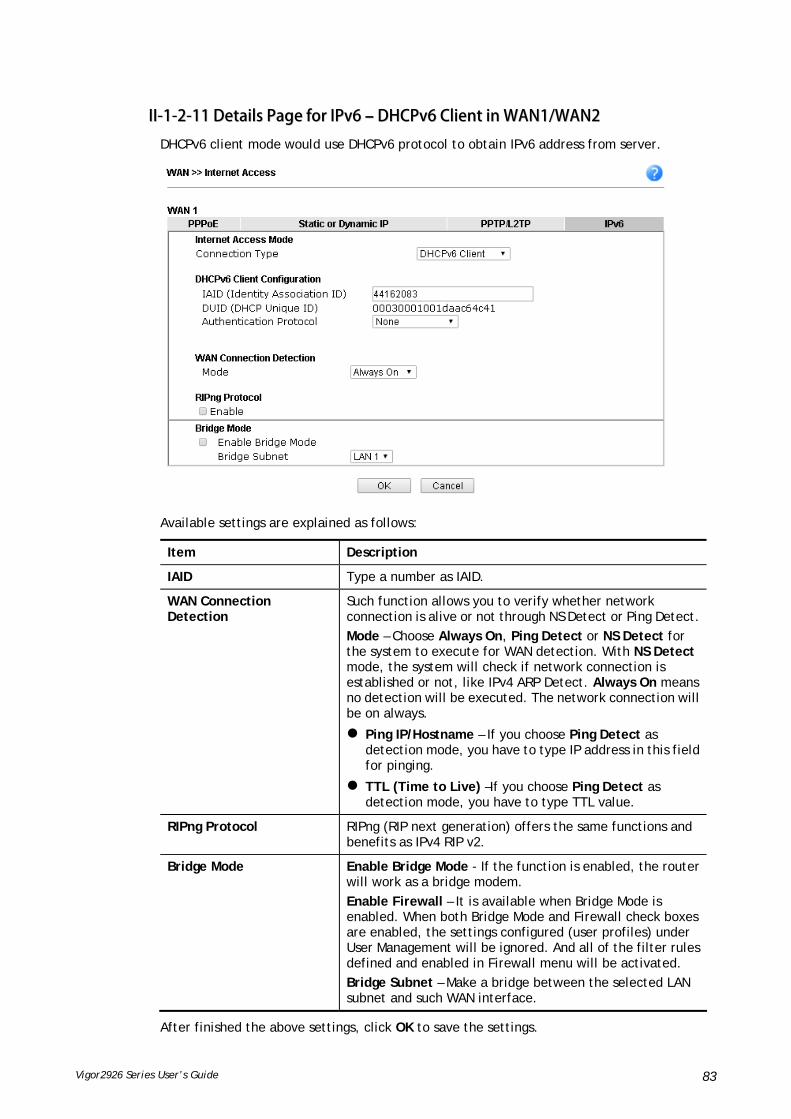
Vigor2926 Series User’s Guide 83
IIII--11--22--1111 DDeettaaiillss PPaaggee ffoorr IIPPvv66 –– DDHHCCPPvv66 CClliieenntt iinn WWAANN11//WWAANN22
DHCPv6 client mode would use DHCPv6 protocol to obtain IPv6 address from server.
Available settings are explained as follows:
Item Description
IAID Type a number as IAID.
WAN Connection Detection
Such function allows you to verify whether network connection is alive or not through NS Detect or Ping Detect.
Mode – Choose Always On, Ping Detect or NS Detect for the system to execute for WAN detection. With NS Detect mode, the system will check if network connection is established or not, like IPv4 ARP Detect. Always On means no detection will be executed. The network connection will be on always.
Ping IP/Hostname – If you choose Ping Detect as detection mode, you have to type IP address in this field for pinging.
TTL (Time to Live) –If you choose Ping Detect as detection mode, you have to type TTL value.
RIPng Protocol RIPng (RIP next generation) offers the same functions and benefits as IPv4 RIP v2.
Bridge Mode Enable Bridge Mode - If the function is enabled, the router will work as a bridge modem.
Enable Firewall – It is available when Bridge Mode is enabled. When both Bridge Mode and Firewall check boxes are enabled, the settings configured (user profiles) under User Management will be ignored. And all of the filter rules defined and enabled in Firewall menu will be activated.
Bridge Subnet – Make a bridge between the selected LAN subnet and such WAN interface.
After finished the above settings, click OK to save the settings.

Vigor2926 Series User’s Guide 84
IIII--11--22--1122 DDeettaaiillss PPaaggee ffoorr IIPPvv66 –– SSttaattiicc IIPPvv66 iinn WWAANN11//WWAANN22
This type allows you to setup static IPv6 address for WAN interface.
Available settings are explained as follows:
Item Description
Static IPv6 Address configuration
IPv6 Address – Type the IPv6 Static IP Address.
Prefix Length – Type the fixed value for prefix length.
Add – Click it to add a new entry.
Update – Click it to modify an existed entry.
Delete – Click it to remove an existed entry.
Current IPv6 Address Table
Display current interface IPv6 address.
Static IPv6 Gateway Configuration
IPv6 Gateway Address - Type your IPv6 gateway address here.
WAN Connection Detection
Such function allows you to verify whether network connection is alive or not through Ping Detect.
Mode – Choose Always On or Ping Detect for the system to execute for WAN detection. Always On means no detection will be executed. The network connection will be on always.

Vigor2926 Series User’s Guide 85
Ping IP/Hostname – If you choose Ping Detect as detection mode, you have to type IP address in this field for pinging.
TTL (Time to Live) –If you choose Ping Detect as detection mode, you have to type TTL value.
Bridge Mode Enable Bridge Mode - If the function is enabled, the router will work as a bridge modem.
Enable Firewall – It is available when Bridge Mode is enabled. When both Bridge Mode and Firewall check boxes are enabled, the settings configured (user profiles) under User Management will be ignored. And all of the filter rules defined and enabled in Firewall menu will be activated.
Bridge Subnet – Make a bridge between the selected LAN subnet and such WAN interface.
After finished the above settings, click OK to save the settings.

Vigor2926 Series User’s Guide 86
IIII--11--22--1133 DDeettaaiillss PPaaggee ffoorr IIPPvv66 –– 66iinn44 SSttaattiicc TTuunnnneell iinn WWAANN11//WWAANN22
This type allows you to setup 6in4 Static Tunnel for WAN interface.
Such mode allows the router to access IPv6 network through IPv4 network.
However, 6in4 offers a prefix outside of 2002::0/16. So, you can use a fixed endpoint rather than anycast endpoint. The mode has more reliability.
Available settings are explained as follows:
Item Description
Remote Endpoint IPv4 Address
Type the static IPv4 address for the remote server.
6in4 IPv6 Address Type the static IPv6 address for IPv4 tunnel with the value for prefix length.
LAN Routed Prefix Type the static IPv6 address for LAN routing with the value for prefix length.
Tunnel TTL Type the number for the data lifetime in tunnel.
WAN Connection Detection
Such function allows you to verify whether network connection is alive or not through Ping Detect.
Mode – Choose Always On or Ping Detect for the system to execute for WAN detection. Always On means no detection will be executed. The network connection will be on always.
Ping IP/Hostname – If you choose Ping Detect as detection mode, you have to type IP address in this field for pinging.
TTL (Time to Live) –If you choose Ping Detect as detection mode, you have to type TTL value.
After finished the above settings, click OK to save the settings.

Vigor2926 Series User’s Guide 87
Below shows an example for successful IPv6 connection based on 6in4 Static Tunnel mode.
IIII--11--22--1144 DDeettaaiillss PPaaggee ffoorr IIPPvv66 –– 66rrdd iinn WWAANN11//WWAANN22
This type allows you to setup 6rd for WAN interface.
Available settings are explained as follows:
Item Description
6rd Mode Auto 6rd – Retrieve 6rd prefix automatically from 6rd service provider. The IPv4 WAN must be set as "DHCP".
Static 6rd - Set 6rd options manually.

Vigor2926 Series User’s Guide 88
IPv4 Border Relay Type the IPv4 addresses of the 6rd Border Relay for a given 6rd domain.
IPv4 Mask Length Type a number of high-order bits that are identical across all CE IPv4 addresses within a given 6rd domain.
It may be any value between 0 and 32.
6rd Prefix Type the 6rd IPv6 address.
6rd Prefix Length Type the IPv6 prefix length for the 6rd IPv6 prefix in number of bits.
WAN Connection Detection
Such function allows you to verify whether network connection is alive or not through Ping Detect.
Mode – Choose Always On or Ping Detect for the system to execute for WAN detection. Always On means no detection will be executed. The network connection will be on always.
Ping IP/Hostname – If you choose Ping Detect as detection mode, you have to type IP address in this field for pinging.
TTL (Time to Live) –If you choose Ping Detect as detection mode, you have to type TTL value.
After finished the above settings, click OK to save the settings.
Below shows an example for successful IPv6 connection based on 6rd mode.

Vigor2926 Series User’s Guide 89
IIII--11--33 MMuullttii--VVLLAANN
Multi-VLAN allows users to create profiles for specific WAN interface and bridge connections for user applications that require very high network throughput. Simply go to WAN and select Multi-VLAN.
Channel 1 to 4 have the following fixed assignments and cannot be altered.
Channel 1: Ethernet on WAN1.
Channel 2: Fiber on WAN2 / Ethernet on WAN2 (based on the model)
Channel 3/4: USB1 (WAN3) and USB2 (WAN4), respectively.
Channels 5 through 10 can be bridged to one or more of the 3 LAN ports P2 through P4. In addition, Channels 5 through 7 can be configured as virtual WANs (WAN5 through WAN7).
GGeenneerraall
This page shows the basic configurations used by every channel.
Available settings are explained as follows:
Item Description
Channel Display the number of each channel.
Channels 1 and 2 are used by the Internet Access web user interface and can not be configured here.
Channels 5 ~ 10 are configurable.
Enable Display whether the settings in this channel are enabled (Yes) or not (No).
WAN Type Displays the physical medium that the channel will use.
VLAN Tag Displays the VLAN tag value that will be used for the packets traveling on this channel.

Vigor2926 Series User’s Guide 90
Port-based Bridge The network traffic flowing on each channel will be identified by the system via their VLAN Tags. Channels using the same WAN type may not configure the same VLAN tag value.
Enable - Check this box to enable the port-based bridge function on this channel.
P1 ~ P4 – Check the box(es) to build bridge connection on LAN.
To configure a PVC channel, click its channel number.
WAN links for Channel 5, 6 and 7 are provided for router-borne application such as TR-069. The settings must be applied and obtained from your ISP. For your special request, please contact with your ISP and then click WAN link of Channel 5, 6 or 7 to configure your router.
Available settings are explained as follows:
Item Description

Vigor2926 Series User’s Guide 91
Enable Channel 5/6/7 Check it to enable this channel.
WAN Type Specify a WAN type of the PVC Channel/VLAN.
General Settings VLAN Tag – Type the value as the VLAN ID number. Valid settings are in the range from 1 to 4095. The network traffic flowing on each channel will be identified by the system via their VLAN Tags. Channels using the same WAN type may not configure the same VLAN tag value.
Priority – Choose the number to determine the packet priority for such VLAN. The range is from 0 to 7.
Service Tag Value – Such value varies depending on the setting configured in WAN>>General Setup. If required, click Modify to open WAN>>General Setup. Then, enable VLAN Tag insertion for service (outer tag) and specify the value as the VLAN ID number. Or, disable it.
Open Port-based Bridge Connection for this Channel
The settings here will create a bridge between the LAN ports selected and the WAN. The WAN interface of the bridge connection will be built upon the WAN type selected using the VLAN tag configured.
Physical Members – Group the physical ports by checking the corresponding check box(es) for applying the port-based bridge connection.
Note: LAN port P1 is reserved for NAT use and cannot be selected for bridging.
Open WAN Interface for this Channel
Check the box to enable relating function.
WAN Application - Management can be specified for general management (Web configuration/telnet/TR069). If you choose Management, the configuration for this VLAN will be effective for Web configuration/telnet/TR069.
IPTV - The IPTV configuration will allow the WAN interface to send IGMP packets to IPTV servers.
WAN Setup – Choose PPPoE/PPPoA or Static or Dynamic IP to determine what WAN settings must be configured.
ISP Access Setup Enter your allocated username, password and authentication parameters according to the information provided by your ISP.
ISP Name – PPP Service Name. Enter if your ISP requires this setting; otherwise leave blank.
Username – Name provided by the ISP for PPPoE/PPPoA authentication. Maximum length is 62 characters.
Password – Password provided by the ISP for PPPoE/PPPoA authentication. Maximum length is 62 characters.
PPP Authentication –The protocol used for PPP

Vigor2926 Series User’s Guide 92
authentication.
PAP only- Only PAP (Password Authentication Protocol) is used.
PAP or CHAP- Both PAP and CHAP (Challenge-Handshake Authentication Protocol) can be used for PPP authentication. Router negotiates with the PPTP or L2TP server to determine which protocol to use.
Always On – If selected, the router will maintain the PPPoE/PPPoA connection.
Idle Timeout – Maximum length of time, in seconds, of idling allowed (no traffic) before the connection is dropped.
IP Address From ISP - Specifies how the WAN IP address of the channel configured.
Fixed IP
Yes - IP address entered in the Fixed IP Address field will be used as the IP address of the virtual WAN.
No - Virtual WAN IP address will be assigned by the ISP’s PPPoE/PPPoA server.
WAN IP Network Settings Obtain an IP address automatically – Select this option if the router is to receive IP configuration information from a DHCP server.
Router Name – Sets the value of DHCP Option 12, which is used by some ISPs.
Domain Name – Sets the value of DHCP Option 15, which is used by some ISPs.
Specify an IP address – Select this option to manually enter the IP address.
IP Address – Type in the IP address.
Subnet Mask – Type in the subnet mask.
Gateway IP Address – Type in gateway IP address.
DNS Server IP Address - Type in the primary IP address for the router if you want to use Static IP mode. If necessary, type in secondary IP address for necessity in the future.
After finished the above settings, click OK to save the settings and return to previous page.
Click any index (8, 9 and 10) to get the following web page:

Vigor2926 Series User’s Guide 93
Available settings are explained as follows:
Item Description
Enable Channel 8/9/10 Click it to enable the configuration of this channel.
WAN Type The connections and interfaces created in every channel may select a specific WAN type to be built upon. In the Multi-VLAN application, only the Ethernet WAN type is available. The user will be able to select the physical WAN interface the channel shall use here.
General Settings VLAN Tag – Type the value as the VLAN ID number. Valid settings are in the range from 1 to 4095. The network traffic flowing on each channel will be identified by the system via their VLAN Tags. Channels using the same WAN type may not configure the same VLAN tag value.
Priority – Choose the number to determine the packet priority for such VLAN. The range is from 0 to 7.
Bridge mode Enable – Click it to enable Bridge mode for such channel.
Physical Members – Group the physical ports by checking the corresponding check box(es) for applying the bridge connection.
Note: LAN port P1 is reserved for NAT use and cannot be selected for bridging.
After finished the above settings, click OK to save the settings.

Vigor2926 Series User’s Guide 94
IIII--11--44 WWAANN BBuuddggeett
This function is used to determine the data traffic volume for each WAN interface respectively to prevent from overcharges for data transmission by the ISP. Please note that the Quota Limit and Billing cycle day of month settings will need to be configured correctly first in order for some period calculations to be performed correctly.
IIII--11--44--11 GGeenneerraall SSeettuupp
Or,
Item Description
Index The WAN port.
Click to configure WAN Budget for a particular WAN.
Enable v - WAN Budget is enabled on this WAN.
x - WAN Budget is disabled on this WAN.
Quota The current cycle’s Internet usage is expressed as x/y where x is the cumulative usage and y is the upper limit. For example, 100MB/200MB means the usage thus far in this cycle is 100MB, and the upper limit is 200MB.
When quota exceeded Actions to be taken once the quota is reached.
Shutdown – WAN will be disabled.
Mail Alert – Email will be sent to the administrator.
Time cycle Reset frequency of the usage data.
Monthly – The Monthly option in the Criterion and Action
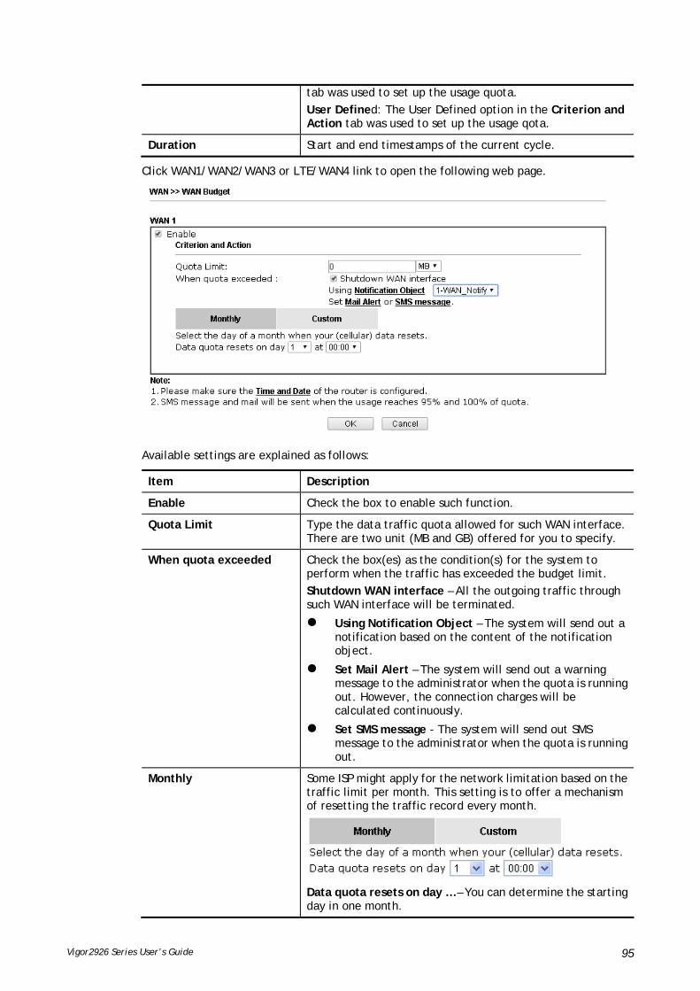
Vigor2926 Series User’s Guide 95
tab was used to set up the usage quota.
User Defined: The User Defined option in the Criterion and Action tab was used to set up the usage qota.
Duration Start and end timestamps of the current cycle.
Click WAN1/WAN2/WAN3 or LTE/WAN4 link to open the following web page.
Available settings are explained as follows:
Item Description
Enable Check the box to enable such function.
Quota Limit Type the data traffic quota allowed for such WAN interface. There are two unit (MB and GB) offered for you to specify.
When quota exceeded Check the box(es) as the condition(s) for the system to perform when the traffic has exceeded the budget limit.
Shutdown WAN interface – All the outgoing traffic through such WAN interface will be terminated.
Using Notification Object – The system will send out a notification based on the content of the notification object.
Set Mail Alert – The system will send out a warning message to the administrator when the quota is running out. However, the connection charges will be calculated continuously.
Set SMS message - The system will send out SMS message to the administrator when the quota is running out.
Monthly Some ISP might apply for the network limitation based on the traffic limit per month. This setting is to offer a mechanism of resetting the traffic record every month.
Data quota resets on day … – You can determine the starting day in one month.
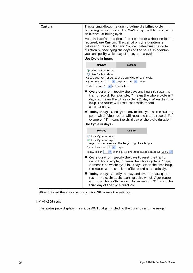
Vigor2926 Series User’s Guide 96
Custom This setting allows the user to define the billing cycle according to his request. The WAN budget will be reset with an interval of billing cycle.
Monthly is default setting. If long period or a short period is required, use Custom. The period of cycle duration is between 1 day and 60 days. You can determine the cycle duration by specifying the days and the hours. In addition, you can specify which day of today is in a cycle.
Use Cycle in hours –
Cycle duration: Specify the days and hours to reset the
traffic record. For example, 7 means the whole cycle is 7 days; 20 means the whole cycle is 20 days. When the time is up, the router will reset the traffic record automatically.
Today is day – Specify the day in the cycle as the starting point which Vigor router will reset the traffic record. For example, “3” means the third day of the cycle duration.
Use Cycle in days -
Cycle duration: Specify the days to reset the traffic
record. For example, 7 means the whole cycle is 7 days; 20 means the whole cycle is 20 days. When the time is up, the router will reset the traffic record automatically.
Today is day – Specify the day and time for data quota rest in the cycle as the starting point which Vigor router will reset the traffic record. For example, “3” means the third day of the cycle duration.
After finished the above settings, click OK to save the settings.
IIII--11--44--22 SSttaattuuss
The status page displays the status WAN budget, including the duration and the usage.

Vigor2926 Series User’s Guide 97
If the WAN budget is exhausted, a lock will be displayed on the page if Shutdown WAN interface is selected. Which means no data transmission will be carried out. Moreover, the system will send out a warning message to the administrator if Mail Alert is selected. Or, the system will send out SMS message to the administrator if SMS message is selected.
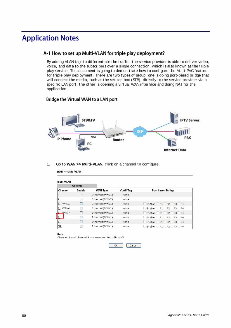
Vigor2926 Series User’s Guide 98
AApppplliiccaattiioonn NNootteess
AA--11 HHooww ttoo sseett uupp MMuullttii--VVLLAANN ffoorr ttrriippllee ppllaayy ddeeppllooyymmeenntt??
By adding VLAN tags to differentiate the traffic, the service provider is able to deliver video, voice, and data to the subscribers over a single connection, which is also known as the triple play service. This document is going to demonstrate how to configure the Multi-PVC feature for triple play deployment. There are two types of setup, one is doing port-based bridge that will connect the media, such as the set-top box (STB), directly to the service provider via a specific LAN port; the other is opening a virtual WAN interface and doing NAT for the application.
BBrriiddggee tthhee VViirrttuuaall WWAANN ttoo aa LLAANN ppoorrtt
1. Go to WAN >> Multi-VLAN, click on a channel to configure.
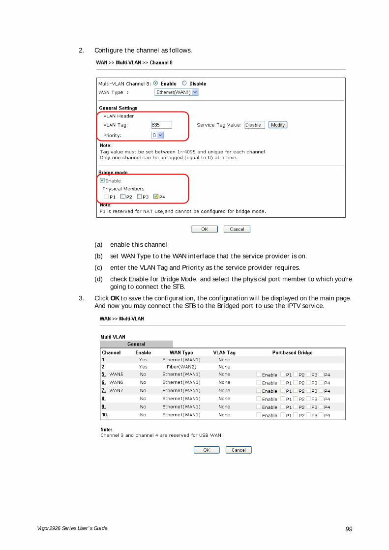
Vigor2926 Series User’s Guide 99
2. Configure the channel as follows,
(a) enable this channel
(b) set WAN Type to the WAN interface that the service provider is on.
(c) enter the VLAN Tag and Priority as the service provider requires.
(d) check Enable for Bridge Mode, and select the physical port member to which you're going to connect the STB.
3. Click OK to save the configuration, the configuration will be displayed on the main page. And now you may connect the STB to the Bridged port to use the IPTV service.

Vigor2926 Series User’s Guide 100
Open a Virtual WAN Interface
1. Go to WAN >> Multi-VLAN, click on channel 5, 6 or 7 to configure.

Vigor2926 Series User’s Guide 101
2. Configure the channel as follows,
(a) enable this channel.
(b) set WAN Type to the WAN interface that the service provider is on.
(c) enter the VLAN Tag and Priority as the service provider requires.
(d) enable "Open WAN Interface for this Channel", and select the kind of Application will be used on this channel. (Note: this option is only available on channel 5-7)
(e) set up the Internet Access type as the ISP requires.
3. Click OK to save the profile and reboot the router to apply the settings. After the router restart, go to Online Status >> Virtual WAN to make sure the WAN interface is up and has obtained an IP address.
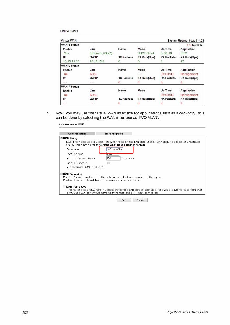
Vigor2926 Series User’s Guide 102
4. Now, you may use the virtual WAN interface for applications such as IGMP Proxy, this can be done by selecting the WAN interface as "PVC/VLAN".

Vigor2926 Series User’s Guide 103
AA--22 LLooaadd BBaallaanncciinngg aanndd FFaaiilloovveerr ffoorr mmuullttii--WWAANN VViiggoorr RRoouutteerrss
Network Administrator may set up multiple Internet connection to share the traffic load, or add a redundant Internet connection to the router and gives a higher reliability to the network connection.
LLooaadd BBaallaanncciinngg
By default, all the active WAN interfaces will join the load balance pool when they are connected, and the outgoing traffic will take either of the active WAN as their path, therefore the traffic load is shared across the WAN interfaces. For newer models which support "Session-based" Load Balance, the router can also do WAN aggregation, which means the speed that LAN clients could experience will be the combination of all the active WAN's bandwidth (click here to learn more).
To ensure that a WAN interface is in the load balance pool, go to WAN >> General Setup, click on the index, set Active Mode to "Always On" and make sure Load Balance is enabled.
The default load balance weight is determined based on the peak bandwidth detected on each WAN interface, but Network Administrator may also use "According to Line Speed Mode" to define the maximum bandwidth which will affect the weight (click here to learn more). Furthermore, Network Administrator would like to specify an outgoing path for some traffic while there are multiple WAN interfaces, Route Policy will be the solution, click here for an instruction of how to designate a WAN interface for LAN clients by Route Policy.

Vigor2926 Series User’s Guide 104
FFaaiilloovveerr
When configured in Failover mode, the WAN interface will only be active when the primary WAN disconnects, and will be down again when the primary WAN resume its service.
To configure a WAN interface in Failover mode, go to WAN >> General Setup, click on the index which you would like to configure to Failover Mode, set Active Mode to "Failover", and for Active When, choose the conditions about when should this interface be activated.
Info
Router determines if a WAN is disconnected or not according to "WAN Connection Detection" settings in WAN >> Internet Access.

Vigor2926 Series User’s Guide 105
IIII--22 LLAANN
Local Area Network (LAN) is a group of subnets regulated and ruled by router. The design of network structure is related to what type of public IP addresses coming from your ISP.
The most generic function of Vigor router is NAT. It creates a private subnet of your own. As mentioned previously, the router will talk to other public hosts on the Internet by using public IP address and talking to local hosts by using its private IP address. What NAT does is to translate the packets from public IP address to private IP address to forward the right packets to the right host and vice versa. Besides, Vigor router has a built-in DHCP server that assigns private IP address to each local host. See the following diagram for a briefly understanding.
In some special case, you may have a public IP subnet from your ISP such as 220.135.240.0/24. This means that you can set up a public subnet or call second subnet that each host is equipped with a public IP address. As a part of the public subnet, the Vigor router will serve for IP routing to help hosts in the public subnet to communicate with other public hosts or servers outside. Therefore, the router should be set as the gateway for public hosts.

Vigor2926 Series User’s Guide 106
WWhhaatt iiss RRoouuttiinngg IInnffoorrmmaattiioonn PPrroottooccooll ((RRIIPP))
Vigor router will exchange routing information with neighboring routers using the RIP to accomplish IP routing. This allows users to change the information of the router such as IP address and the routers will automatically inform for each other.
WWhhaatt iiss SSttaattiicc RRoouuttee
When you have several subnets in your LAN, sometimes a more effective and quicker way for connection is the Static routes function rather than other method. You may simply set rules to forward data from one specified subnet to another specified subnet without the presence of RIP.
WWhhaatt aarree VViirrttuuaall LLAANNss aanndd RRaattee CCoonnttrrooll
You can group local hosts by physical ports and create up to 8 virtual LANs. To manage the communication between different groups, please set up rules in Virtual LAN (VLAN) function and the rate of each.

Vigor2926 Series User’s Guide 107
WWeebb UUsseerr IInntteerrffaaccee
A LAN comprises a collection of LAN clients, which are networked devices on your premises. A LAN client can be a computer, a printer, a Voice-over-IP (VoIP) phone, a mobile phone, a gaming console, an Internet Protocol Television (IPTV), etc, and can have either a wired (using Ethernet cabling) or wireless (using Wi-Fi) network connection.
LAN clients within the same LAN are normally able to communicate with one another directly, as they are peers to one another, unless measures, such as firewalls or VLANs, have been put in place to restrict such access. Nowadays the most common LAN firewalls are implemented on the LAN client itself. For example, Microsoft Windows since Windows XP and Apple OS X have built-in firewalls that can be configured to restrict traffic coming in and going out of the computer. VLANs, on the other hand, are usually set up using network switches or routers, such as the Vigor2926.
To communicate with the hosts outside of the LAN, LAN clients have to go through a network gateway, which in most cases is a router (such as the Vigor 2926) that sits between the LAN and the ISP network, which is the WAN. The router acts as a director to ensure traffic between the LAN and the WAN reach their intended destinations.
IIII--22--11 GGeenneerraall SSeettuupp
This page provides you the general settings for LAN. Click LAN to open the LAN settings page and choose General Setup.
There are four subnets provided by the router which allow users to divide groups into different subnets (LAN1 – LAN5). In addition, different subnets can link for each other by configuring Inter-LAN Routing. At present, LAN1 setting is fixed with NAT mode only. LAN2 – LAN8 can be operated under NAT or Route mode. IP Routed Subnet can be operated under Route mode.

Vigor2926 Series User’s Guide 108
Available settings are explained as follows:
Item Description
General Setup Allow to configure settings for each subnet respectively.
Index - Display all of the LAN items.
Status- Basically, LAN1 status is enabled in default. LAN2 –LAN5 and IP Routed Subnet can be observed by checking the box of Status.
DHCP- LAN1 is configured with DHCP in default. If required, please check the DHCP box for each LAN.
IP Address - Display the IP address for each LAN item. Such information is set in default and you can not modify it.
Details Page - Click it to access into the setting page. Each LAN will have different LAN configuration page. Each LAN must be configured in different subnet.
IPv6 – Click it to access into the settings page of IPv6.
DHCP Server Option DHCP packets can be processed by adding option number and data information when such function is enabled.

Vigor2926 Series User’s Guide 109
For detailed information, refer to later section.
Force router to use “DNS server IP address …..”
Force Vigor router to use DNS servers configured in LAN1/LAN2/LAN3/LAN4/LAN5/LAN6/LAN7/LAN8/DMZ Port instead of DNS servers given by the Internet Access server (PPPoE, PPTP, L2TP or DHCP server).
Inter-LAN Routing Check the box to link two or more different subnets (LAN and LAN).
Inter-LAN Routing allows different LAN subnets to be interconnected or isolated.
It is only available when the VLAN functionality is enabled. Refer to section II-2-2 VLAN on how to set up VLANs.
In the Inter-LAN Routing matrix, a selected checkbox means that the 2 intersecting LANs can communicate with each other.
When you finish the configuration, please click OK to save.
Info
To configure a subnet, select its Detials Page button to bring up the LAN Details Page.
IIII--22--11--11 DDeettaaiillss PPaaggee ffoorr LLAANN11 –– EEtthheerrnneett TTCCPP//IIPP aanndd DDHHCCPP SSeettuupp
There are two configuration pages for LAN1, Ethernet TCP/IP and DHCP Setup (based on IPv4) and IPv6 Setup. Click the tab for each type and refer to the following explanations for detailed information.
Available settings are explained as follows:
Item Description
Network Configuration For NAT Usage,
IP Address - This is the IP address of the router. (Default: 192.168.1.1).

Vigor2926 Series User’s Guide 110
Subnet Mask - The subnet mask, together with the IP Address field, indicates the maximum number of clients allowed on the subnet. (Default: 255.255.255.0/ 24).
LAN IP Alias –Such feature allows specifying multiple gateways (under a switch) with different WAN interfaces for accessing the Internet via the Vigor router.
RIP Protocol Control,
Enable – When Enabled, the router will attempt to exchange routing information with neighbouring routers using the Routing Information Protocol.
DHCP Server Configuration
DHCP stands for Dynamic Host Configuration Protocol. The router by factory default acts a DHCP server for your network so it automatically dispatches related IP settings to any local user configured as a DHCP client. It is highly recommended that you leave the router enabled as a DHCP server if you do not have a DHCP server for your network.
If you want to use another DHCP server in the network other than the Vigor Router’s, you can let Relay Agent help you to redirect the DHCP request to the specified location.
Disable Server – Let you manually assign IP address to every host in the LAN.
Enable Server - Let the router assign IP address to every host in the LAN.
Start IP Address - The beginning LAN IP address that is given out to LAN DHCP clients.
IP Pool Counts - The maximum number of IP addresses to be handed out by DHCP. The default value is 200. Valid range is between 1 and 1021. The actual number of IP addresses available for assignment is the IP Pool Counts, or 1021 minus the last octet of the Start IP Address, whichever is smaller.
Gateway IP Address - The IP address of the gateway, which is the host on the LAN that relays all traffic coming into and going out of the LAN. The gateway is normally the router, and therefore the Gateway IP Address should be identical to the IP Address in the

Vigor2926 Series User’s Guide 111
Network Configuration section above.
Lease Time - The maximum duration DHCP-issued IP addresses can be used before they have to be renewed.
Clear DHCP lease for inactive clients periodically - If selected, the router sends ARP requests recycles IP addresses previously assigned to inactive DHCP clients to prevent exhaustion of the IP address pool.
Note: When Clear DHCP lease for inactive clients periodically is enabled, router will do the following:
Check activities of DHCP clients by ARP requests every minute when the available DHCP IP addresses are less than 30
Clear DHCP lease when the client is not responding ARP replies.
Enable Relay Agent – When selected, all DHCP requests are forwarded to a DHCP server outside of the LAN subnet, and whose address is specified in the DHCP Server IP Address field.
DHCP Server IP Address – It is available when Enable Relay Agent is checked. Set the IP address of the DHCP server you are going to use so the Relay Agent can help to forward the DHCP request to the DHCP server.
DNS Server IP Address DNS stands for Domain Name System. Every Internet host must have a unique IP address, also they may have a human-friendly, easy to remember name such as www.yahoo.com. The DNS server converts the user-friendly name into its equivalent IP address.
Primary IP Address -You must specify a DNS server IP address here because your ISP should provide you with usually more than one DNS Server.
Secondary IP Address - You can specify secondary DNS server IP address here because your ISP often provides you more than one DNS Server.
The default DNS Server IP address can be found via Online Status:
If both the Primary IP and Secondary IP Address fields are left empty, the router will assign its own IP address to local users as a DNS proxy server and maintain a DNS cache.
If the IP address of a domain name is already in the DNS cache, the router will resolve the domain name immediately. Otherwise, the router forwards the DNS query packet to the external DNS server by establishing a WAN (e.g. DSL/Cable) connection.
When you finish the configuration, please click OK to save and exit this page.
Private IP addresses can be assigned automatically to LAN clients using Dynamic Host Configuration Protocol (DHCP), or manually assigned. The DHCP server can either be the router (the most common case), or a separate server, that hands out IP addresses to DHCP clients.

Vigor2926 Series User’s Guide 112
Alternatively, static IP addresses can be manually configured on LAN clients as part of their network settings. No matter how IP addresses are configured, it is important that no two devices get the same IP address. If both DHCP and static assignment are used on a network, it is important to exclude the static IP addresses from the DHCP IP pool. For example, if your LAN uses the 192.168.1.x subnet and you have 20 DHCP clients and 20 static IP clients, you could configure 192.168.1.10 as the Start IP Address, 50 as the IP Pool Counts (enough for the current number of DHCP clients, plus room for future expansion), and use addresses greater than 192.168.1.100 for static assignment.
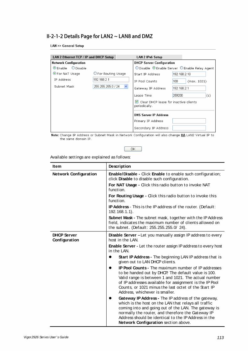
Vigor2926 Series User’s Guide 113
IIII--22--11--22 DDeettaaiillss PPaaggee ffoorr LLAANN22 ~~ LLAANN88 aanndd DDMMZZ
Available settings are explained as follows:
Item Description
Network Configuration Enable/Disable - Click Enable to enable such configuration; click Disable to disable such configuration.
For NAT Usage - Click this radio button to invoke NAT function.
For Routing Usage - Click this radio button to invoke this function.
IP Address - This is the IP address of the router. (Default: 192.168.1.1).
Subnet Mask - The subnet mask, together with the IP Address field, indicates the maximum number of clients allowed on the subnet. (Default: 255.255.255.0/ 24).
DHCP Server Configuration
Disable Server – Let you manually assign IP address to every host in the LAN.
Enable Server - Let the router assign IP address to every host in the LAN.
Start IP Address - The beginning LAN IP address that is given out to LAN DHCP clients.
IP Pool Counts - The maximum number of IP addresses to be handed out by DHCP. The default value is 100. Valid range is between 1 and 1021. The actual number of IP addresses available for assignment is the IP Pool Counts, or 1021 minus the last octet of the Start IP Address, whichever is smaller.
Gateway IP Address - The IP address of the gateway, which is the host on the LAN that relays all traffic coming into and going out of the LAN. The gateway is normally the router, and therefore the Gateway IP Address should be identical to the IP Address in the Network Configuration section above.

Vigor2926 Series User’s Guide 114
Lease Time - The maximum duration DHCP-issued IP addresses can be used before they have to be renewed.
Clear DHCP lease for inactive clients periodically - If selected, the router sends ARP requests recycles IP addresses previously assigned to inactive DHCP clients to prevent exhaustion of the IP address pool.
Note: When Clear DHCP lease for inactive clients periodically is enabled, router will do the following:
Check activities of DHCP clients by ARP requests every minute when the available DHCP IP addresses are less than 30
Clear DHCP lease when the client is not responding ARP replies.
Enable Relay Agent – When selected, all DHCP requests are forwarded to a DHCP server outside of the LAN subnet, and whose address is specified in the DHCP Server IP Address field.
DHCP Server IP Address – It is available when Enable Relay Agent is checked. Set the IP address of the DHCP server you are going to use so the Relay Agent can help to forward the DHCP request to the DHCP server.
DNS Server IP Address DNS stands for Domain Name System. Every Internet host must have a unique IP address, also they may have a human-friendly, easy to remember name such as www.yahoo.com. The DNS server converts the user-friendly name into its equivalent IP address.
Primary IP Address -You must specify a DNS server IP address here because your ISP should provide you with usually more than one DNS Server.
Secondary IP Address - You can specify secondary DNS server IP address here because your ISP often provides you more than one DNS Server.
The default DNS Server IP address can be found via Online Status:
If both the Primary IP and Secondary IP Address fields are left empty, the router will assign its own IP address to local users as a DNS proxy server and maintain a DNS cache.
If the IP address of a domain name is already in the DNS cache, the router will resolve the domain name immediately. Otherwise, the router forwards the DNS query packet to the external DNS server by establishing a WAN (e.g. DSL/Cable) connection.
When you finish the configuration, please click OK to save and exit this page.

Vigor2926 Series User’s Guide 115
IIII--22--11--33 DDeettaaiillss PPaaggee ffoorr IIPP RRoouutteedd SSuubbnneett
Available settings are explained as follows:
Item Description
Network Configuration Enable/Disable - Click Enable to enable such configuration; click Disable to disable such configuration.
For Routing Usage,
IP Address - This is the IP address of the router. (Default: 192.168.1.1).
Subnet Mask - The subnet mask, together with the IP Address field, indicates the maximum number of clients allowed on the subnet. (Default: 255.255.255.0/ 24).
RIP Protocol Control,
Enable – When Enabled, the router will attempt to exchange routing information with neighbouring routers using the Routing Information Protocol.
DHCP Server Configuration
DHCP stands for Dynamic Host Configuration Protocol. The router by factory default acts a DHCP server for your network so it automatically dispatch related IP settings to any local user configured as a DHCP client. It is highly recommended that you leave the router enabled as a DHCP server if you do not have a DHCP server for your network.
If you want to use another DHCP server in the network other than the Vigor Router’s, you can let Relay Agent help you to redirect the DHCP request to the specified location.
Start IP Address - Enter a value of the IP address pool for the DHCP server to start with when issuing IP addresses. If the 1st IP address of your router is 192.168.1.1, the starting IP address must be 192.168.1.2 or greater, but smaller than 192.168.1.254.
IP Pool Counts - Enter the maximum number of PCs that you want the DHCP server to assign IP addresses to. The default is

Vigor2926 Series User’s Guide 116
50 and the maximum is 253.
Lease Time - Enter the time to determine how long the IP address assigned by DHCP server can be used.
Use LAN Port – Specify an IP for IP Route Subnet. If it is enabled, DHCP server will assign IP address automatically for the clients coming from P1 and/or P2. Please check the box of P1 and P2.
Use MAC Address - Check such box to specify MAC address.
MAC Address: Enter the MAC Address of the host one by one and click Add to create a list of hosts which can be assigned, deleted or edited from above pool. Set a list of MAC Address for 2nd DHCP server will help router to assign the correct IP address of the correct subnet to the correct host. So those hosts in 2nd subnet won’t get an IP address belonging to 1st subnet.
Add – Type the MAC address in the boxes and click this button to add.
Delete – Click it to delete the selected MAC address.
Edit – Click it to edit the selected MAC address.
Cancel – Click it to cancel the job of adding, deleting and editing.
When you finish the configuration, please click OK to save and exit this page.
IIII--22--11--44 DDeettaaiillss PPaaggee ffoorr LLAANN IIPPvv66 SSeettuupp
There are two configuration pages for LAN1/LAN2/LAN3/LAN4/LAN5/LAN6/DMZ Port, Ethernet TCP/IP and DHCP Setup (based on IPv4) and IPv6 Setup. Click the tab for each type and refer to the following explanations for detailed information. Below shows the settings page for IPv6.

Vigor2926 Series User’s Guide 117
It provides 2 daemons for LAN side IPv6 address configuration. One is SLAAC(stateless) and the other is DHCPv6 (Stateful) server.
Available settings are explained as follows:
Item Description
Enable IPv6 Check the box to enable the configuration of LAN 1 IPv6 Setup.
WAN Primary Interface Use the drop down list to specify a WAN interface for IPv6.
Static IPv6 Address configuration
IPv6 Address –Type static IPv6 address for LAN.
Prefix Length – Type the fixed value for prefix length.
Add – Click it to add a new entry.

Vigor2926 Series User’s Guide 118
Delete – Click it to remove an existed entry.
Unique Local Address (ULA) configuration
Unique Local Addresses (ULAs) are private IPv6 addresses assigned to LAN clients.
Off - ULA is disabled.
Manually ULA Prefix - LAN clients will be assigned ULAs generated based on the prefix manually entered.
Auto ULA Prefix - LAN clients will be assigned ULAs using an automatically-determined prefix.
Current IPv6 Address Table
Display current used IPv6 addresses.
DNS Server IPv6 Address Deploy when WAN is up – The RA (router advertisement) packets will be sent to LAN PC with DNS server information only when network connection by any one of WAN interfaces is up.
Enable – The RA (router advertisement) packets will be sent to LAN PC with DNS server information no matter WAN connection is up or not.
Primary DNS Sever – Type the IPv6 address for Primary DNS server.
Secondary DNS Server –Type another IPv6 address for DNS server if required.
Disable – DNS server will not be used.
Management Configures the Managed Address Configuration flag (M-bit) in Route Advertisements.
Off - No configuration information is sent using Route Advertisements.
SLAAC(stateless) - M-bit is unset.
DHCPv6(stateful) - M-bit is set, which indicates to LAN clients that they should acquire all IPv6 configuration information from a DHCPv6 server. The DHCPv6 server can either be the one built into the Vigor router, or a separate DHCPv6 server.
Other Option (O-bit) - Check this box to enable the O-bit for obtaining additional information (e.g., DNS) from DHCPv6.
When selected, the Other Configuration flag is set, which indicates to LAN clients that IPv6 configuration information besides LAN IPv6 addresses is available from a DHCPv6 server.
Setting the M-bit (see Management above) has the same effect as implicitly setting the O-bit, as DHCPv6 supplies all IPv6 configuration information, including what is indicated as available when the O-bit is set.
DHCPv6 Server Enable Server –Click it to enable DHCPv6 server. DHCPv6 Server could assign IPv6 address to PC according to the

Vigor2926 Series User’s Guide 119
Start/End IPv6 address configuration.
Disable Server –Click it to disable DHCPv6 server.
Auto IPv6 range – After check the box, Vigor router will assign the IPv6 range automatically.
Start IPv6 Address / End IPv6 Address –Type the start and end address for IPv6 server.
Advance setting – Click the Edit button to configure advanced IPv6 settings for DHCPv6 server.
Advance setting The Advanced Settings page has additional settings for Router Advertisement and enabling multiple WANs for IPv6 traffic.
Router Advertisement Configuration – Click Enable to enable router advertisement server. The router advertisement daemon sends Router Advertisement messages, specified by RFC 2461, to a local Ethernet LAN periodically and when requested by a node sending a Router Solicitation message. These messages are required for IPv6 stateless auto-configuration.
Disable – Click it to disable router advertisement server.
Hop Limit – The value is required for the device behind the router when IPv6 is in use.
Min/Max Interval Time (sec) – It defines the interval (between minimum time and maximum time) for sending RA (Router Advertisement) packets.

Vigor2926 Series User’s Guide 120
Default Lifetime (sec) –Within such period of time, Vigor2926 can be treated as the default gateway.
Default Preference – It determines the priority of the host behind the router when RA (Router Advertisement) packets are transmitted.
MTU – It means Max Transmit Unit for packet. If Auto is selected, the router will determine the MTU value for LAN.
RIPng Protocol –RIPng (RIP next generation) offers the same functions and benefits as IPv4 RIP v2.
Extension WAN – In addition to the default WAN used for IPv6 traffic specified in the WAN Primary Interface in the LAN IPv6 Setup page, additional WANs can be selected to carry IPv6 traffic by enabling them in the Extension WAN section.
Available WAN – Additional WANs available but not currently selected to carry IPv6 traffic.
Selected WAN – Additional WANs selected to carry IPv6 traffic.
After making changes on the Advance setting page, click the OK button to retain the changes and return to the LAN IPv6 Setup page. Be sure to click OK on the LAN IPv6 Setup page or else changes made on the Advance setting page will not be saved.
IIII--22--11--55 AAddvvaanncceedd DDHHCCPP OOppttiioonnss
DHCP Options can be configured by clicking the DHCP Server Option button on the LAN General Setup screen.
Available settings are explained as follows:
Item Description

Vigor2926 Series User’s Guide 121
Customized List Shows all the DHCP options that have been configured in the system.
Enable If selected, DHCP option entry is enabled.
If unselected, DHCP option entry is disabled.
Interface LAN interface(s) to which this entry is applicable.
Next Server IP Address/SIAddr
Overrides the DHCP Next Server IP address (DHCP Option 66) supplied by the DHCP server.
Option Number DHCP option number (e.g., 100).
DataType Type of data in the Data field:
ASCII Character - A text string. Example: /path.
Hexadecimal Digit - A hexadecimal string. Valid characters are from 0 to 9 and from a to f. Example: 2f70617468.
Address List - One or more IPv4 addresses, delimited by commas.
Data Data of this DHCP option.
To add a DHCP option entry from scratch, clear the data entry fields (Enable, Interface, Option Number, DataType and Data) by clicking Reset. After filling in the values, click Add to create the new entry.
To add a DHCP option entry modeled after an existing entry, click the model entry in Customized List. The data entry fields will be populated with values from the model entry. After making all necessary changes for the new entry, click Add to create it.
To modify an existing DHCP option entry, click on it in Customized List. The data entry fields will be populated with the current values from the entry. After making all necessary changes, click Update to save the changes.
To delete a DHCP option entry, click on it in Customized List, and then click Delete.

Vigor2926 Series User’s Guide 122
AApppplliiccaattiioonn NNootteess
AA--11 MMuullttii--ssuubbnneett AApppplliiccaattiioonn -- HHooww ttoo uuttiilliizzee VViiggoorr rroouutteerr wwiitthh nnoonn--NNAATT??
1. Open LAN>>General Setup. Click the Details Page button of LAN1.
2. In the setting page, type the settings as follows and click OK to save the settings. Note that LAN1 is always for NAT usage.
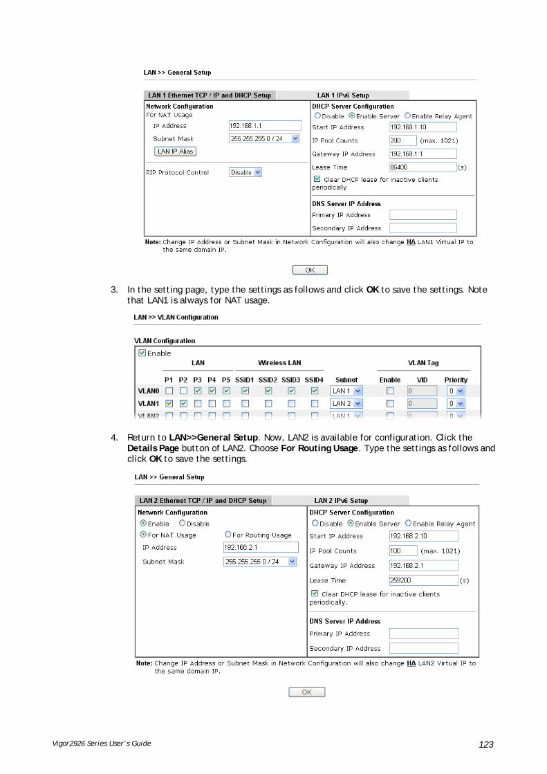
Vigor2926 Series User’s Guide 123
3. In the setting page, type the settings as follows and click OK to save the settings. Note that LAN1 is always for NAT usage.
4. Return to LAN>>General Setup. Now, LAN2 is available for configuration. Click the Details Page button of LAN2. Choose For Routing Usage. Type the settings as follows and click OK to save the settings.

Vigor2926 Series User’s Guide 124
5. Open WAN>>Internet Access. Choose Static or Dynamic IP as Access Mode. Then click Details Page.
6. In the configuration web page, type the settings as follows and click OK to save the settings.
7. Now, a network connection via MPLS (Multiprotocol Label Switching) between LAN2 user and the Branch user is established successfully. Internet is not required for them.

Vigor2926 Series User’s Guide 125
IIII--22--22 VVLLAANN
Virtual Local Area Networks (VLANs) allow you to subdivide your LAN to facilitate management or to improve network security.
Select LAN>>VLAN from the menu bar of the Web UI to bring up the VLAN Configuration page.
TTaaggggeedd VVLLAANN
The tagged VLANs (802.1q) can mark data with a VLAN identifier. This identifier can be carried through an onward Ethernet switch to specific ports. The specific VLAN clients can also pick up this identifier as it is just passed to the LAN. You can set the priorities for LAN-side QoS. You can assign each of VLANs to each of the different IP subnets that the router may also be operating, to provide even more isolation. The said functionality is tag-based multi-subnet.
PPoorrtt--BBaasseedd VVLLAANN
Relative to tag-based VLAN which groups clients with an identifier, port-based VLAN uses physical ports (P1 ~ P4) to separate the clients into different VLAN group.
Virtual LAN function provides you a very convenient way to manage hosts by grouping them based on the physical port. The multi-subnet can let a small businesses have much better isolation for multi-occupancy applications. Go to LAN page and select VLAN. The following page will appear. Click Enable to invoke VLAN function.
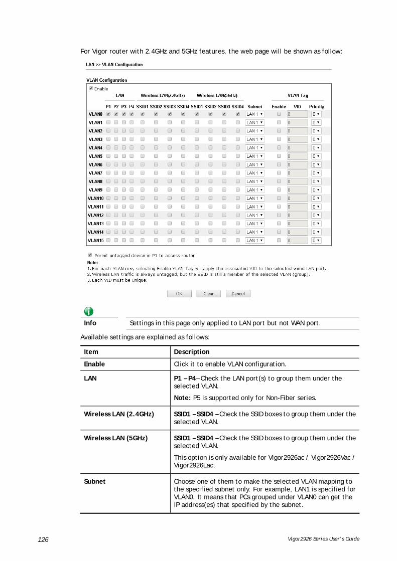
Vigor2926 Series User’s Guide 126
For Vigor router with 2.4GHz and 5GHz features, the web page will be shown as follow:
Info
Settings in this page only applied to LAN port but not WAN port.
Available settings are explained as follows:
Item Description
Enable Click it to enable VLAN configuration.
LAN P1 – P4– Check the LAN port(s) to group them under the selected VLAN.
Note: P5 is supported only for Non-Fiber series.
Wireless LAN (2.4GHz) SSID1 – SSID4 – Check the SSID boxes to group them under the selected VLAN.
Wireless LAN (5GHz) SSID1 – SSID4 – Check the SSID boxes to group them under the selected VLAN.
This option is only available for Vigor2926ac / Vigor2926Vac / Vigor2926Lac.
Subnet Choose one of them to make the selected VLAN mapping to the specified subnet only. For example, LAN1 is specified for VLAN0. It means that PCs grouped under VLAN0 can get the IP address(es) that specified by the subnet.
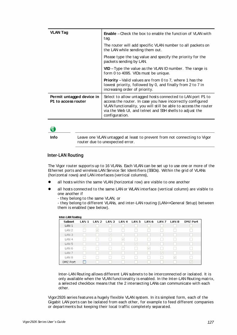
Vigor2926 Series User’s Guide 127
VLAN Tag Enable – Check the box to enable the function of VLAN with tag.
The router will add specific VLAN number to all packets on the LAN while sending them out.
Please type the tag value and specify the priority for the packets sending by LAN.
VID – Type the value as the VLAN ID number. The range is form 0 to 4095. VIDs must be unique.
Priority – Valid values are from 0 to 7, where 1 has the lowest priority, followed by 0, and finally from 2 to 7 in increasing order of priority.
Permit untagged device in P1 to access router
Select to allow untagged hosts connected to LAN port P1 to access the router. In case you have incorrectly configured VLAN functionality, you will still be able to access the router via the Web UI, and telnet and SSH shells to adjust the configuration.
Info
Leave one VLAN untagged at least to prevent from not connecting to Vigor router due to unexpected error.
IInntteerr--LLAANN RRoouuttiinngg
The Vigor router supports up to 16 VLANs. Each VLAN can be set up to use one or more of the Ethernet ports and wireless LAN Service Set Identifiers (SSIDs). Within the grid of VLANs (horizontal rows) and LAN interfaces (vertical columns),
all hosts within the same VLAN (horizontal row) are visible to one another
all hosts connected to the same LAN or WLAN interface (vertical column) are visible to one another if - they belong to the same VLAN, or - they belong to different VLANs, and inter-LAN routing (LAN>>General Setup) between them is enabled (see below).
Inter-LAN Routing allows different LAN subnets to be interconnected or isolated. It is only available when the VLAN functionality is enabled. In the Inter-LAN Routing matrix, a selected checkbox means that the 2 intersecting LANs can communicate with each other.
Vigor2926 series features a hugely flexible VLAN system. In its simplest form, each of the Gigabit LAN ports can be isolated from each other, for example to feed different companies or departments but keeping their local traffic completely separated.

Vigor2926 Series User’s Guide 128
CCoonnffiigguurriinngg ppoorrtt--bbaasseedd VVLLAANN ffoorr wwiirreelleessss aanndd nnoonn--wwiirreelleessss cclliieennttss
1. All the wire network clients are categorized to group VLAN0 in subnet 192.168.1.0/24 (LAN1).
2. All the wireless network clients are categorized to group VLAN1 in subnet 192.168.2.0/24 (LAN2).
3. Open LAN>>VLAN Configuration. Check the boxes according to the statement in step 1 and Step 2.
4. Click OK.
5. Open LAN>>General Setup. If you want to let the clients in both groups communicate with each other, simply activate Inter-LAN Routing by checking the box between LAN1 and LAN2.
Vigor router supports up to six private IP subnets on LAN. Each can be independent (isolated) or common (able to communicate with each other). This is ideal for departmental or multi-occupancy applications.

Vigor2926 Series User’s Guide 129
Info As for the VLAN applications, refer to “Appendix I: VLAN Application on Vigor Router” for more detailed information.
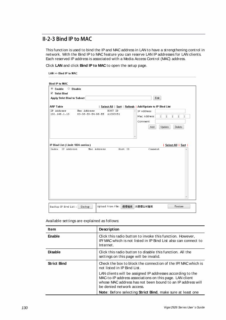
Vigor2926 Series User’s Guide 130
IIII--22--33 BBiinndd IIPP ttoo MMAACC
This function is used to bind the IP and MAC address in LAN to have a strengthening control in network. With the Bind IP to MAC feature you can reserve LAN IP addresses for LAN clients. Each reserved IP address is associated with a Media Access Control (MAC) address.
Click LAN and click Bind IP to MAC to open the setup page.
Available settings are explained as follows:
Item Description
Enable Click this radio button to invoke this function. However, IP/MAC which is not listed in IP Bind List also can connect to Internet.
Disable Click this radio button to disable this function. All the settings on this page will be invalid.
Strict Bind Check the box to block the connection of the IP/MAC which is not listed in IP Bind List.
LAN clients will be assigned IP addresses according to the MAC-to-IP address associations on this page. LAN client whose MAC address has not been bound to an IP address will be denied network access.
Note: Before selecting Strict Bind, make sure at least one

Vigor2926 Series User’s Guide 131
valid MAC address has been bound to an IP address. Otherwise no LAN clients will have network access, and it will not be possible to connect to the router to make changes to its configuration.
Apply Strict Bind to Subnet – Choose the subnet(s) for applying the rules of Bind IP to MAC.
ARP Table This table is the LAN ARP table of this router. The information for IP and MAC will be displayed in this field. Each pair of IP and MAC address listed in ARP table can be selected and added to IP Bind List by clicking Add below.
Select All Select all entries in the ARP Table for manipulation.
Sort Reorder the entry based on the IP address.
Refresh Refresh the ARP table listed below to obtain the newest ARP table information.
Add/Update to IP Bind List IP Address – Type the IP address to be associated with a MAC address.
Mac Address – Type the MAC address of the LAN client’s network interface.
Comment – Type a brief description for the entry.
Add It allows you to add the one you choose from the ARP table or the IP/MAC address typed in Add and Edit to the table of IP Bind List.
Update It allows you to edit and modify the selected IP address and MAC address that you create before.
Delete You can remove any item listed in IP Bind List. Simply click and select the one, and click Delete. The selected item will be removed from the IP Bind List.
IP Bind List It displays a list for the IP bind to MAC information.
Backup IP Bind List Click Backup and enter a filename to back up IP Bind List to a file.
Upload From File Click Browse… to select an IP Bind List backup file. Click Restore to restore the backup and overwrite the existing list.

Vigor2926 Series User’s Guide 132
Info
Before you select Strict Bind, you have to bind one set of IP/MAC address for one PC. If not, no one of the PCs can access into Internet. And the web user interface of the router might not be accessed.
When you finish the configuration, click OK to save the settings.
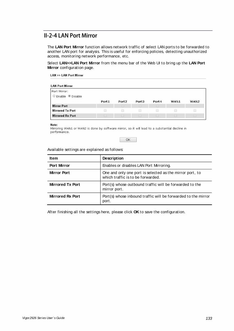
Vigor2926 Series User’s Guide 133
IIII--22--44 LLAANN PPoorrtt MMiirrrroorr
The LAN Port Mirror function allows network traffic of select LAN ports to be forwarded to another LAN port for analysis. This is useful for enforcing policies, detecting unauthorized access, monitoring network performance, etc.
Select LAN>>LAN Port Mirror from the menu bar of the Web UI to bring up the LAN Port Mirror configuration page.
Available settings are explained as follows:
Item Description
Port Mirror Enables or disables LAN Port Mirroring.
Mirror Port One and only one port is selected as the mirror port, to which traffic is to be forwarded.
Mirrored Tx Port Port(s) whose outbound traffic will be forwarded to the mirror port.
Mirrored Rx Port Port(s) whose inbound traffic will be forwarded to the mirror port.
After finishing all the settings here, please click OK to save the configuration.
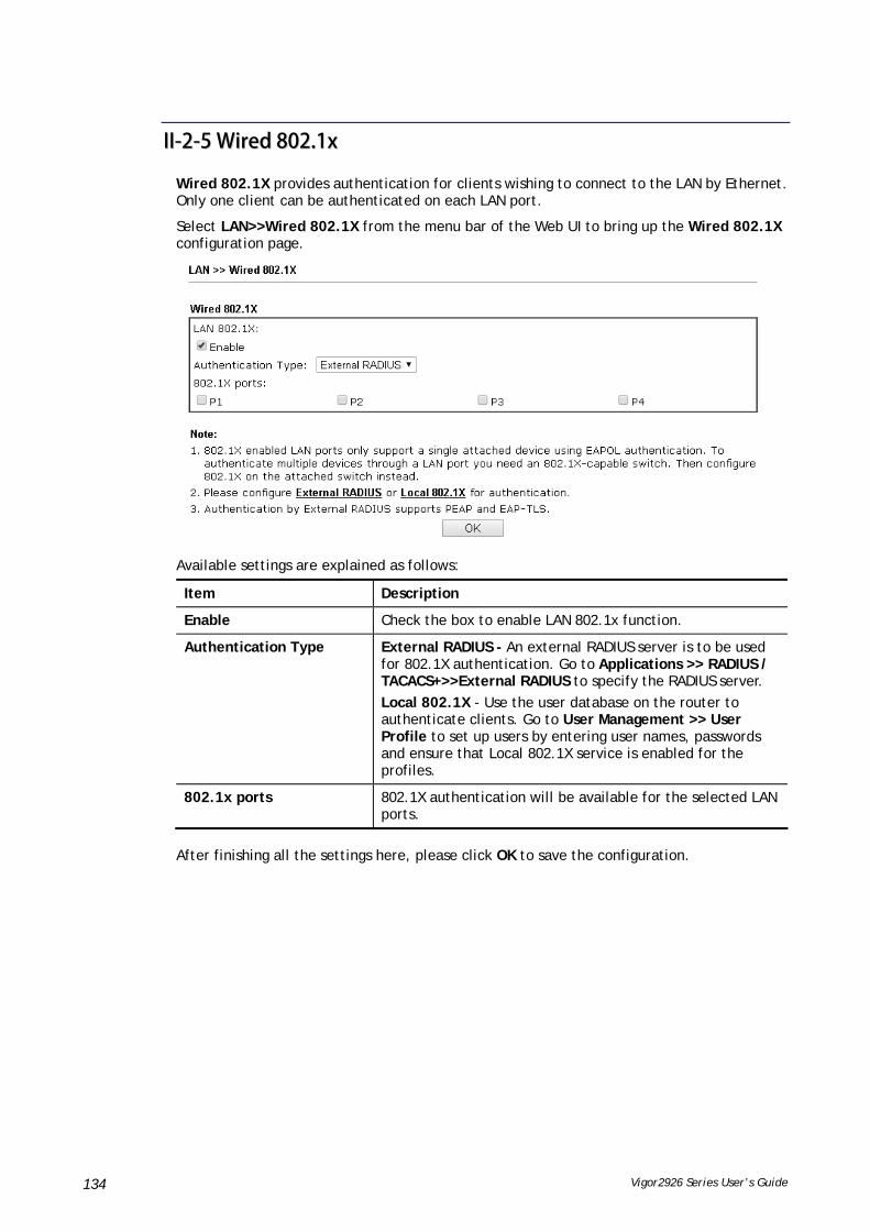
Vigor2926 Series User’s Guide 134
IIII--22--55 WWiirreedd 880022..11xx
Wired 802.1X provides authentication for clients wishing to connect to the LAN by Ethernet. Only one client can be authenticated on each LAN port.
Select LAN>>Wired 802.1X from the menu bar of the Web UI to bring up the Wired 802.1X configuration page.
Available settings are explained as follows:
Item Description
Enable Check the box to enable LAN 802.1x function.
Authentication Type External RADIUS - An external RADIUS server is to be used for 802.1X authentication. Go to Applications >> RADIUS / TACACS+>>External RADIUS to specify the RADIUS server.
Local 802.1X - Use the user database on the router to authenticate clients. Go to User Management >> User Profile to set up users by entering user names, passwords and ensure that Local 802.1X service is enabled for the profiles.
802.1x ports 802.1X authentication will be available for the selected LAN ports.
After finishing all the settings here, please click OK to save the configuration.

Vigor2926 Series User’s Guide 135
IIII--33 HHaarrddwwaarree AAcccceelleerraattiioonn
Hardware Acceleration is also called PPA in DrayTek for it is based on Protocol Processing Engine (PPE) of Infineon. It can only support 128 sessions for network traffic (IN & OUT) with implementing three kinds of modes - Disable, Auto and Manual.
IIII--33--11 SSeettuupp
When the data traffic is heavy and data transmission is getting slowly and slowly, you can configure this page to accelerate the data streaming by hardware itself. Open Hardware Acceleration to access into the following page:
Available settings are explained as follows:
Item Description
Mode Disable – The default setting.
Auto - When the hardware acceleration is configured with the Auto mode, the sessions with the heaviest loading and the lower latency traffic will be added into PPA. However, the Auto mode does not support UDP protocol by designed.
Manual - The Manual mode implements three sub-items-- Accelerate most heavy traffic sessions, Apply the Class Rule in Quality of Service, and Specific Hosts. Each of these sub-items can support TCP and UDP protocol.

Vigor2926 Series User’s Guide 136
Protocol There are two types supported by this function, TCP and UDP.
Option Accelerate heaviest traffic sessions – Such option is available in Auto Mode, too. But the UDP protocol is only supported in this sub-item.
Apply the Class Rule in Quality of Service – Users can apply the information provided by QoS in this sub-item.
Please visit our website for referring the detailed configuration of QoS.
Specific Hosts – This sub-item provides 5 hosts for adding NAT sessions into the PPA. For the PPA only supports 128 sessions, these hosts will share these sessions. Therefore, the performance will be lower than only one host.
Choose this option to specify certain PCs on LAN to apply the hardware acceleration.
Enable – Check the box to make PC(s) specified in the selected index entry to be applied.
Dest Port Start – Type the starting port for the PC(s) in LAN.
Dest Port End – Type the ending port for the PC(s) in LAN.
Private IP/Choose PC – Type the IP address as the selected host. Or click the Choose PC button to specify one IP address from the pop-up window.
Checking the PPA status
For checking whether the rule of PPA is working or not, a user can login to Vigor2926 series by using telnet. User can view how many sessions are transferring in each direction of PPA table after entering “ppa –v”.

Vigor2926 Series User’s Guide 137

Vigor2926 Series User’s Guide 138
IIII--44 NNAATT
Usually, the router serves as an NAT (Network Address Translation) router. NAT is a mechanism that one or more private IP addresses can be mapped into a single public one. Public IP address is usually assigned by your ISP, for which you may get charged. Private IP addresses are recognized only among internal hosts.
When the outgoing packets destined to some public server on the Internet reach the NAT router, the router will change its source address into the public IP address of the router, select the available public port, and then forward it. At the same time, the router shall list an entry in a table to memorize this address/port-mapping relationship. When the public server response, the incoming traffic, of course, is destined to the router’s public IP address and the router will do the inversion based on its table. Therefore, the internal host can communicate with external host smoothly.
The benefit of the NAT includes:
Save cost on applying public IP address and apply efficient usage of IP address. NAT allows the internal IP addresses of local hosts to be translated into one public IP address, thus you can have only one IP address on behalf of the entire internal hosts.
Enhance security of the internal network by obscuring the IP address. There are many attacks aiming victims based on the IP address. Since the attacker cannot be aware of any private IP addresses, the NAT function can protect the internal network.
Info
On NAT page, you will see the private IP address defined in RFC-1918. Usually we use the 192.168.1.0/24 subnet for the router. As stated before, the NAT facility can map one or more IP addresses and/or service ports into different specified services. In other words, the NAT function can be achieved by using port mapping methods.

Vigor2926 Series User’s Guide 139
WWeebb UUsseerr IInntteerrffaaccee
IIII--44--11 PPoorrtt RReeddiirreeccttiioonn
Port Redirection is usually set up for server related service inside the local network (LAN), such as web servers, FTP servers, E-mail servers etc. Most of the case, you need a public IP address for each server and this public IP address/domain name are recognized by all users. Since the server is actually located inside the LAN, the network well protected by NAT of the router, and identified by its private IP address/port, the goal of Port Redirection function is to forward all access request with public IP address from external users to the mapping private IP address/port of the server.
The port redirection can only apply to incoming traffic.
To use this function, please go to NAT page and choose Port Redirection web page. The Port Redirection Table provides 40 port-mapping entries for the internal hosts.

Vigor2926 Series User’s Guide 140
Each item is explained as follows:
Item Description
Index Display the number of the profile.
Enable Check the box to enable the port redirection profile.
Service Name Display the description of the specific network service.
WAN Interface Display the WAN IP address used by the profile.
Protocol Display the transport layer protocol (TCP or UDP).
Public Port Display the port number which will be redirected to the specified Private IP and Port of the internal host.
Source IP Display the IP object of the source IP.
Private IP Display the IP address of the internal host providing the service.
Press any number under Index to access into next page for configuring port redirection.
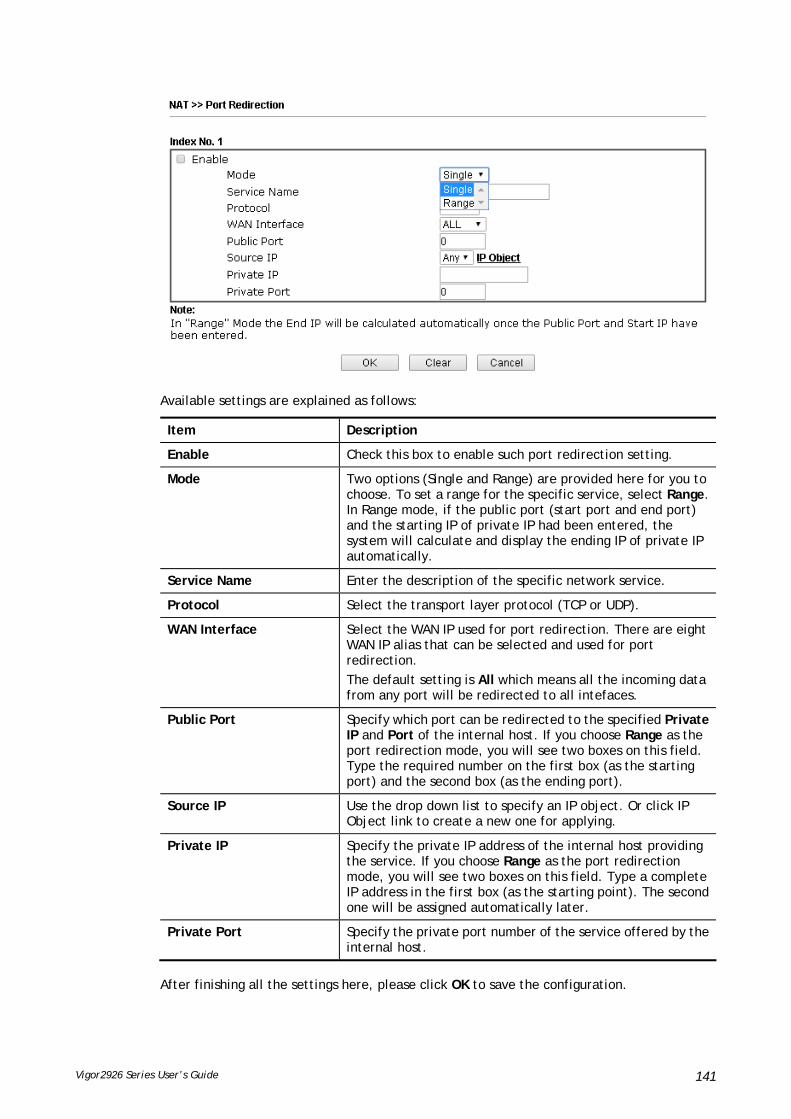
Vigor2926 Series User’s Guide 141
Available settings are explained as follows:
Item Description
Enable Check this box to enable such port redirection setting.
Mode Two options (Single and Range) are provided here for you to choose. To set a range for the specific service, select Range. In Range mode, if the public port (start port and end port) and the starting IP of private IP had been entered, the system will calculate and display the ending IP of private IP automatically.
Service Name Enter the description of the specific network service.
Protocol Select the transport layer protocol (TCP or UDP).
WAN Interface Select the WAN IP used for port redirection. There are eight WAN IP alias that can be selected and used for port redirection.
The default setting is All which means all the incoming data from any port will be redirected to all intefaces.
Public Port Specify which port can be redirected to the specified Private IP and Port of the internal host. If you choose Range as the port redirection mode, you will see two boxes on this field. Type the required number on the first box (as the starting port) and the second box (as the ending port).
Source IP Use the drop down list to specify an IP object. Or click IP Object link to create a new one for applying.
Private IP Specify the private IP address of the internal host providing the service. If you choose Range as the port redirection mode, you will see two boxes on this field. Type a complete IP address in the first box (as the starting point). The second one will be assigned automatically later.
Private Port Specify the private port number of the service offered by the internal host.
After finishing all the settings here, please click OK to save the configuration.

Vigor2926 Series User’s Guide 142
Note that the router has its own built-in services (servers) such as Telnet, HTTP and FTP etc. Since the common port numbers of these services (servers) are all the same, you may need to reset the router in order to avoid confliction.
For example, the built-in web user interface in the router is with default port 80, which may conflict with the web server in the local network, http://192.168.1.13:80. Therefore, you need to change the router’s http port to any one other than the default port 80 to avoid conflict, such as 8080. This can be set in the System Maintenance >>Management Setup. You then will access the admin screen of by suffixing the IP address with 8080, e.g., http://192.168.1.1:8080 instead of port 80.

Vigor2926 Series User’s Guide 143
IIII--44--22 DDMMZZ HHoosstt
As mentioned above, Port Redirection can redirect incoming TCP/UDP or other traffic on particular ports to the specific private IP address/port of host in the LAN. However, other IP protocols, for example Protocols 50 (ESP) and 51 (AH), do not travel on a fixed port. Vigor router provides a facility DMZ Host that maps ALL unsolicited data on any protocol to a single host in the LAN. Regular web surfing and other such Internet activities from other clients will continue to work without inappropriate interruption. DMZ Host allows a defined internal user to be totally exposed to the Internet, which usually helps some special applications such as Netmeeting or Internet Games etc.
The security properties of NAT are somewhat bypassed if you set up DMZ host. We suggest you to add additional filter rules or a secondary firewall.
Click DMZ Host to open the following page. You can set different DMZ host for each WAN interface. Click the WAN tab to switch into the configuration page for that WAN.

Vigor2926 Series User’s Guide 144
Available settings are explained as follows:
Item Description
WAN1 Choose Private IP or None first.
Private IP Enter the private IP address of the DMZ host, or click Choose IP to select one.
Choose IP Click this button and then a window will automatically pop up, as depicted below. The window consists of a list of private IP addresses of all hosts in your LAN network. Select one private IP address in the list to be the DMZ host.
When you have selected one private IP from the above dialog, the IP address will be shown on the following screen. Click OK to save the setting.
DMZ Host for WAN2, WAN3, LTE or WAN4 is slightly different with WAN1.
See the following figure.
If you previously have set up WAN Alias for PPPoE or Static or Dynamic IP mode in WAN2 interface, you will find them in Aux. WAN IP for your selection.

Vigor2926 Series User’s Guide 145
Available settings are explained as follows:
Item Description
Enable Check to enable the DMZ Host function.
Private IP Enter the private IP address of the DMZ host, or click Choose IP to select one.
Choose IP Click this button and then a window will automatically pop up, as depicted below. The window consists of a list of private IP addresses of all hosts in your LAN network. Select one private IP address in the list to be the DMZ host.
When you have selected one private IP from the above dialog, the IP address will be shown on the screen. Click OK to save the setting.
After finishing all the settings here, please click OK to save the configuration.

Vigor2926 Series User’s Guide 146
IIII--44--33 OOppeenn PPoorrttss
Open Ports allows you to open a range of ports for the traffic of special applications.
Common application of Open Ports includes P2P application (e.g., BT, KaZaA, Gnutella, WinMX, eMule and others), Internet Camera etc. Ensure that you keep the application involved up-to-date to avoid falling victim to any security exploits.
Click Open Ports to open the following page:
Available settings are explained as follows:
Item Description
Index Indicate the relative number for the particular entry that you want to offer service in a local host. You should click the appropriate index number to edit or clear the corresponding entry.
Enable Check the box to enable the open port profile.
Comment Specify the name for the defined network service.
WAN Interface Display the WAN interface used by such index.
Aux. WAN IP Display the IP alias setting used by such index. If no IP alias setting exists, such field will not appear.
Source IP Display the IP object of the source IP.
Local IP Address Display the private IP address of the local host offering the service.
Status Display the state for the corresponding entry. X or V is to represent the Inactive or Active state.
To add or edit port settings, click one index number on the page. The index entry setup page will pop up. In each index entry, you can specify 10 port ranges for diverse services.

Vigor2926 Series User’s Guide 147
Available settings are explained as follows:
Item Description
Enable Open Ports Check to enable this entry.
Comment Make a name for the defined network application/service.
WAN Interface Specify the WAN interface that will be used for this entry.
Source IP Use the drop down list to specify an IP object. Or click IP Object link to create a new one for applying.
WAN IP Specify the WAN IP address that will be used for this entry. This setting is available when WAN IP Alias is configured.
Private IP Enter the private IP address of the local host or click Choose IP to select one.
Choose IP - Click this button and, subsequently, a window having a list of private IP addresses of local hosts will automatically pop up. Select the appropriate IP address of the local host in the list.
Protocol Specify the transport layer protocol. It could be TCP, UDP, or ----- (none) for selection.
Start Port Specify the starting port number of the service offered by the local host.
End Port Specify the ending port number of the service offered by the local host.

Vigor2926 Series User’s Guide 148
After finishing all the settings here, please click OK to save the configuration.
IIII--44--44 PPoorrtt TTrriiggggeerriinngg
Port Triggering is a variation of open ports function.
The key difference between "open port" and "port triggering" is:
Once the OK button is clicked and the configuration has taken effect, "open port" keeps the ports opened forever.
Once the OK button is clicked and the configuration has taken effect, "port triggering" will only attempt to open the ports once the triggering conditions are met.
The duration that these ports are opened depends on the type of protocol used. The "default" durations are shown below and these duration values can be modified via telnet commands.
TCP: 86400 sec.
UDP: 180 sec.
IGMP: 10 sec.
TCP WWW: 60 sec.
TCP SYN: 60 sec.
Available settings are explained as follows:

Vigor2926 Series User’s Guide 149
Item Description
Index Indicate the relative number for the port triggering profile. You should click the appropriate index number to edit or clear the corresponding entry.
Enable Check the box to enable the Port Triggering profile.
Comment Display the text which memorizes the application of this rule.
Triggering Protocol Display the protocol of the triggering packets.
Triggering Port Display the port of the triggering packets.
Source IP Display the name of the IP object.
Incoming Protocol Display the protocol for the incoming data of such triggering profile.
Incoming Port Display the port for the incoming data of such triggering profile.
Click the index number link to open the configuration page.
Available settings are explained as follows:
Item Description
Enable Check to enable this entry.
Service Choose the predefined service to apply for such trigger profile.
Comment Type the text to memorize the application of this rule.
Source IP Use the drop down list to specify an IP object. Or click IP

Vigor2926 Series User’s Guide 150
Object link to create a new one for applying.
Triggering Protocol Select the protocol (TCP, UDP or TCP/UDP) for such triggering profile.
Triggering Port Type the port or port range for such triggering profile.
Incoming Protocol When the triggering packets received, it is expected the incoming packets will use the selected protocol. Select the protocol (TCP, UDP or TCP/UDP) for the incoming data of such triggering profile.
Incoming Port Type the port or port range for the incoming packets.
After finishing all the settings here, please click OK to save the configuration.
IIII--44--55 AALLGG
ALG means Application Layer Gateway. There are two methods provided by Vigor router, RTSP (Real Time Streaming Protocol) ALG and SIP (Session Initiation Protocol) ALG, for processing the packets of voice and video.
RTSP ALG makes RTSP message, RTCP message, and RTP packets of voice and video be transmitted and received correctly via NAT by Vigor router.
However, SIP ALG makes SIP message and RTP packets of voice be transmitted and received correctly via NAT by Vigor router.
Available settings are explained as follows:
Item Description
Enable ALG Check to enable such function.
Listen Port Type a port number for SIP or RTSP protocol.
TCP Check the box to make correspond protocol message packet from TCP transmit and receive via NAT.
UDP Check the box to make correspond protocol message packet from UDP transmit and receive via NAT.

Vigor2926 Series User’s Guide 151
IIII--55 AApppplliiccaattiioonnss
DDyynnaammiicc DDNNSS
The ISP often provides you with a dynamic IP address when you connect to the Internet via your ISP. It means that the public IP address assigned to your router changes each time you access the Internet. The Dynamic DNS feature lets you assign a domain name to a dynamic WAN IP address. It allows the router to update its online WAN IP address mappings on the specified Dynamic DNS server. Once the router is online, you will be able to use the registered domain name to access the router or internal virtual servers from the Internet. It is particularly helpful if you host a web server, FTP server, or other server behind the router.
Before you use the Dynamic DNS feature, you have to apply for free DDNS service to the DDNS service providers. The router provides up to three accounts from three different DDNS service providers. Basically, Vigor routers are compatible with the DDNS services supplied by most popular DDNS service providers such as www.dyndns.org, www.no-ip.com, www.dtdns.com, www.changeip.com, www.dynamic- nameserver.com. You should visit their websites to register your own domain name for the router.
LLAANN DDNNSS // DDNNSS FFoorrwwaarrddiinngg
The LAN DNS lets the network administrators host servers with privacy and security. When the network administrators of your office set up FTP, Mail or Web server inside LAN, you can specify specific private IP address (es) to correspondent servers. Thus, even the remote PC is adopting public DNS as the DNS server, the LAN DNS resolution on Vigor2926 series will respond the specified private IP address.
SScchheedduullee
The Vigor router has a built-in clock which can update itself manually or automatically by means of Network Time Protocols (NTP). As a result, you can not only schedule the router to dialup to the Internet at a specified time, but also restrict Internet access to certain hours so that users can connect to the Internet only during certain hours, say, business hours. The schedule is also applicable to other functions.
RRAADDIIUUSS//TTAACCAACCSS++
Remote Authentication Dial-In User Service (RADIUS) is a security authentication client/server protocol that supports authentication, authorization and accounting, which is widely used by Internet service providers. It is the most common method of authenticating and authorizing dial-up and tunneled network users.
The built-in RADIUS client feature enables the router to assist the remote dial-in user or a wireless station and the RADIUS server in performing mutual authentication. It enables centralized remote access authentication for network management.
LLDDAAPP //AAccttiivvee DDiirreeccttoorryy SSeettuupp
Lightweight Directory Access Protocol (LDAP) is a communication protocol for using in TCP/IP network. It defines the methods to access distributing directory server by clients, work on directory and share the information in the directory by clients. The LDAP standard is established by the work team of Internet Engineering Task Force (IETF).
As the name described, LDAP is designed as an effect way to access directory service without the complexity of other directory service protocols. For LDAP is defined to perform, inquire and modify the information within the directory, and acquire the data in the directory securely, therefore users can apply LDAP to search or list the directory object, inquire or manage the active directory.

Vigor2926 Series User’s Guide 152
UUPPnnPP
The UPnP (Universal Plug and Play) protocol is supported to bring to network connected devices the ease of installation and configuration which is already available for directly connected PC peripherals with the existing Windows 'Plug and Play' system. For NAT routers, the major feature of UPnP on the router is “NAT Traversal”. This enables applications inside the firewall to automatically open the ports that they need to pass through a router.
WWaakkee oonn LLAANN
A PC client on LAN can be woken up by the router it connects. When a user wants to wake up a specified PC through the router, he/she must type correct MAC address of the specified PC on this web page of Wake on LAN (WOL) of this router.
In addition, such PC must have installed a network card supporting WOL function. By the way, WOL function must be set as “Enable” on the BIOS setting.
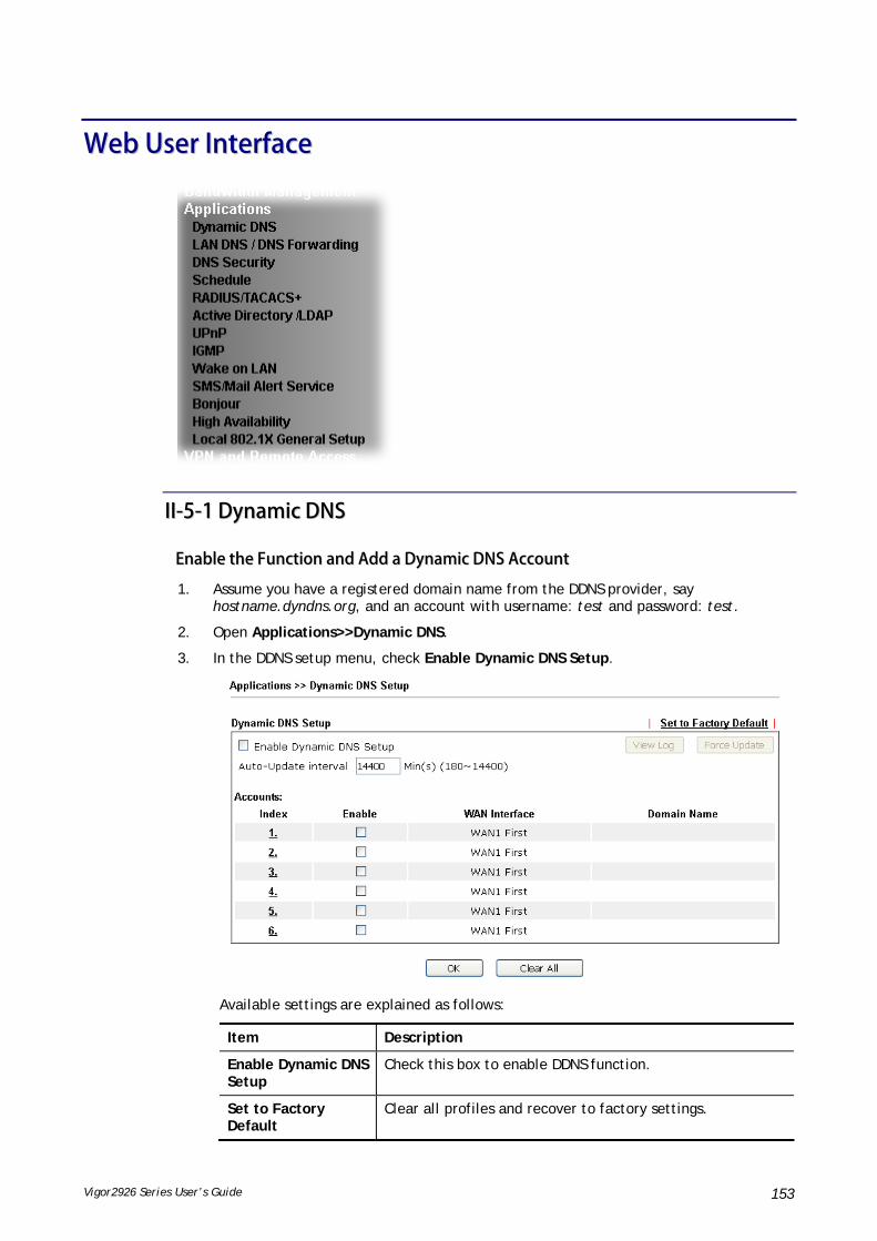
Vigor2926 Series User’s Guide 153
WWeebb UUsseerr IInntteerrffaaccee
IIII--55--11 DDyynnaammiicc DDNNSS
EEnnaabbllee tthhee FFuunnccttiioonn aanndd AAdddd aa DDyynnaammiicc DDNNSS AAccccoouunntt
1. Assume you have a registered domain name from the DDNS provider, say hostname.dyndns.org, and an account with username: test and password: test.
2. Open Applications>>Dynamic DNS.
3. In the DDNS setup menu, check Enable Dynamic DNS Setup.
Available settings are explained as follows:
Item Description
Enable Dynamic DNS Setup
Check this box to enable DDNS function.
Set to Factory Default
Clear all profiles and recover to factory settings.

Vigor2926 Series User’s Guide 154
View Log Display DDNS log status.
Force Update Force the router updates its information to DDNS server.
Auto-Update interval
Set the time for the router to perform auto update for DDNS service.
Index Click the number below Index to access into the setting page of DDNS setup to set account(s).
Enable Check the box to enable such account.
WAN Interface Display the WAN interface used.
Domain Name Display the domain name that you set on the setting page of DDNS setup.
4. Select Index number 1 to add an account for the router. Check Enable Dynamic DNS Account, and choose correct Service Provider: dyndns.org, type the registered hostname: hostname and domain name suffix: dyndns.org in the Domain Name block. The following two blocks should be typed your account Login Name: test and Password: test.
If User-Defined is specified as the service provider, the web page will be changed slightly as follows:
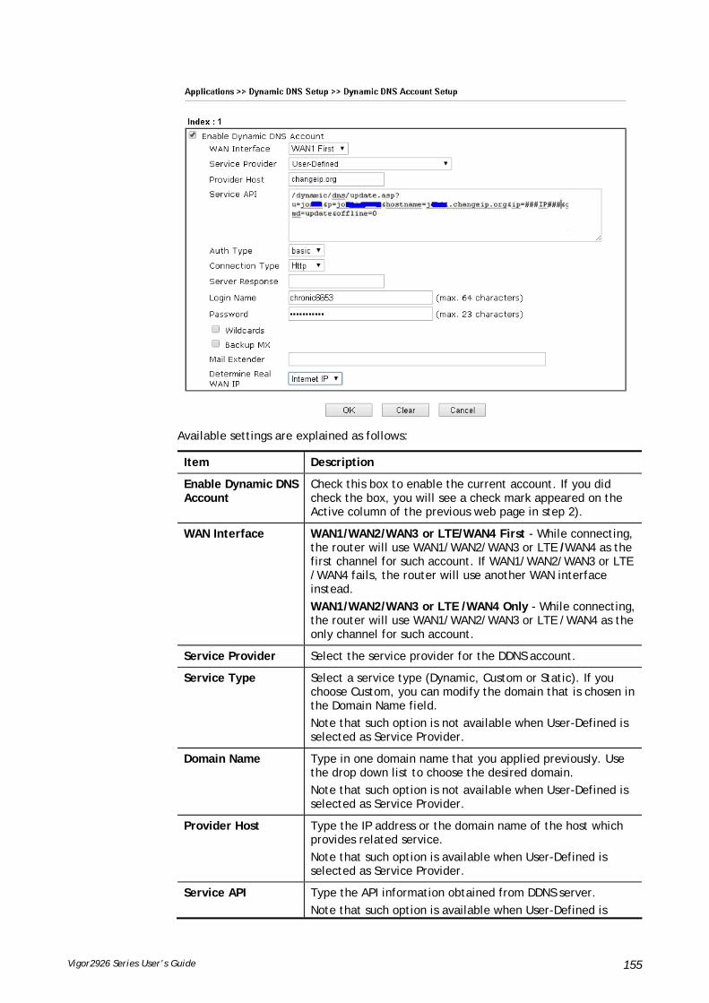
Vigor2926 Series User’s Guide 155
Available settings are explained as follows:
Item Description
Enable Dynamic DNS Account
Check this box to enable the current account. If you did check the box, you will see a check mark appeared on the Active column of the previous web page in step 2).
WAN Interface WAN1/WAN2/WAN3 or LTE/WAN4 First - While connecting, the router will use WAN1/WAN2/WAN3 or LTE /WAN4 as the first channel for such account. If WAN1/WAN2/WAN3 or LTE /WAN4 fails, the router will use another WAN interface instead.
WAN1/WAN2/WAN3 or LTE /WAN4 Only - While connecting, the router will use WAN1/WAN2/WAN3 or LTE /WAN4 as the only channel for such account.
Service Provider Select the service provider for the DDNS account.
Service Type Select a service type (Dynamic, Custom or Static). If you choose Custom, you can modify the domain that is chosen in the Domain Name field.
Note that such option is not available when User-Defined is selected as Service Provider.
Domain Name Type in one domain name that you applied previously. Use the drop down list to choose the desired domain.
Note that such option is not available when User-Defined is selected as Service Provider.
Provider Host Type the IP address or the domain name of the host which provides related service.
Note that such option is available when User-Defined is selected as Service Provider.
Service API Type the API information obtained from DDNS server.
Note that such option is available when User-Defined is
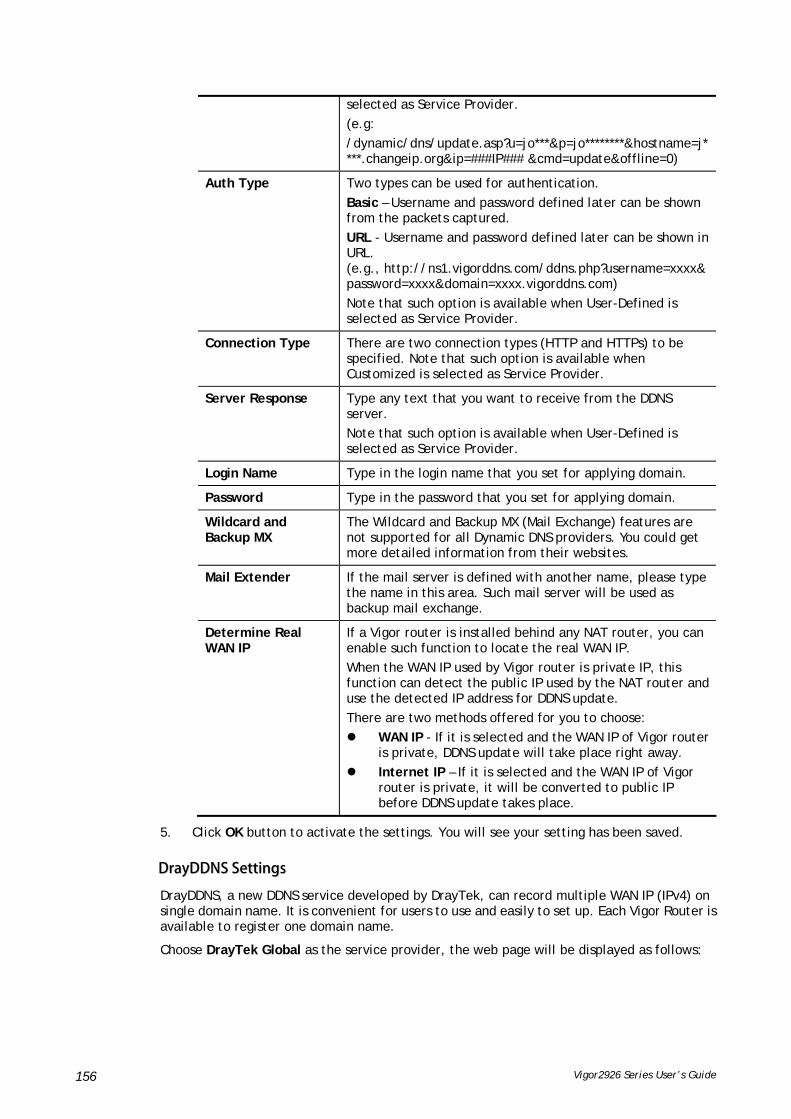
Vigor2926 Series User’s Guide 156
selected as Service Provider.
(e.g:
/dynamic/dns/update.asp?u=jo***&p=jo********&hostname=j****.changeip.org&ip=###IP### &cmd=update&offline=0)
Auth Type Two types can be used for authentication.
Basic – Username and password defined later can be shown from the packets captured.
URL - Username and password defined later can be shown in URL. (e.g., http://ns1.vigorddns.com/ddns.php?username=xxxx&password=xxxx&domain=xxxx.vigorddns.com)
Note that such option is available when User-Defined is selected as Service Provider.
Connection Type There are two connection types (HTTP and HTTPs) to be specified. Note that such option is available when Customized is selected as Service Provider.
Server Response Type any text that you want to receive from the DDNS server.
Note that such option is available when User-Defined is selected as Service Provider.
Login Name Type in the login name that you set for applying domain.
Password Type in the password that you set for applying domain.
Wildcard and Backup MX
The Wildcard and Backup MX (Mail Exchange) features are not supported for all Dynamic DNS providers. You could get more detailed information from their websites.
Mail Extender If the mail server is defined with another name, please type the name in this area. Such mail server will be used as backup mail exchange.
Determine Real WAN IP
If a Vigor router is installed behind any NAT router, you can enable such function to locate the real WAN IP.
When the WAN IP used by Vigor router is private IP, this function can detect the public IP used by the NAT router and use the detected IP address for DDNS update.
There are two methods offered for you to choose:
WAN IP - If it is selected and the WAN IP of Vigor router is private, DDNS update will take place right away.
Internet IP – If it is selected and the WAN IP of Vigor router is private, it will be converted to public IP before DDNS update takes place.
5. Click OK button to activate the settings. You will see your setting has been saved.
DDrraayyDDDDNNSS SSeettttiinnggss
DrayDDNS, a new DDNS service developed by DrayTek, can record multiple WAN IP (IPv4) on single domain name. It is convenient for users to use and easily to set up. Each Vigor Router is available to register one domain name.
Choose DrayTek Global as the service provider, the web page will be displayed as follows:

Vigor2926 Series User’s Guide 157
Available settings are explained as follows:
Item Description
Enable Dynamic DNS Account
Check this box to enable the current account. If you did check the box, you will see a check mark appeared on the Active column of the previous web page in step 2).
Service Provider Choose DrayTek Global as the service provider.
Wizard – This button is available when DrayTek Global is selected as Service Provider. To activate the DrayTek’s DDNS service, click it to enable license issued by DrayTek through Wizards>>Service Activation Wizard.
Refer to secion A-1 How to use DrayDDNS? for detailed information.
Status Display if the license is actvtaed or not.
Determine WAN IP If a Vigor router is installed behind any NAT router, you can enable such function to locate the real WAN IP.
When the WAN IP used by Vigor router is private IP, this function can detect the public IP used by the NAT router and use the detected IP address for DDNS update.
There are two methods offered for you to choose:
WAN IP - If it is selected and the WAN IP of Vigor router is private, DDNS update will take place right away.
Internet IP – If it is selected and the WAN IP of Vigor router is private, it will be converted to public IP before DDNS update takes place.
WAN Interfaces WAN1/WAN2/WAN3 or LTE/WAN4 First - While connecting, the router will use WAN1/WAN2/WAN3 or LTE /WAN4 as the first channel for such account. If WAN1/WAN2/WAN3 or LTE /WAN4 fails, the router will use another WAN interface instead.
WAN1/WAN2/WAN3 or LTE /WAN4 Only - While connecting, the router will use WAN1/WAN2/WAN3 or LTE /WAN4 as the only channel for such account.
DDiissaabbllee tthhee FFuunnccttiioonn aanndd CClleeaarr aallll DDyynnaammiicc DDNNSS AAccccoouunnttss
Uncheck Enable Dynamic DNS Setup, and click Clear All button to disable the function and clear all accounts from the router.
DDeelleettee aa DDyynnaammiicc DDNNSS AAccccoouunntt

Vigor2926 Series User’s Guide 158
Click the Index number you want to delete and then click Clear All button to delete the account.

Vigor2926 Series User’s Guide 159
IIII--55--22 LLAANN DDNNSS // DDNNSS FFoorrwwaarrddiinngg
The LAN DNS lets the network administrators host servers with privacy and security. When the network administrators of your office set up FTP, Mail or Web server inside LAN, you can specify specific private IP address (es) to correspondent servers. Thus, even the remote PC is adopting public DNS as the DNS server, the LAN DNS resolution on Vigor2926 series will respond the specified private IP address.
Simply click Application>>LAN DNS / DNS Forwarding to open the following page.
Each item is explained as follows:
Item Description
Set to Factory Default Clear all profiles and recover to factory settings.
Index Click the number below Index to access into the setting page.
Enable Check the box to enable the selected profile.

Vigor2926 Series User’s Guide 160
Profile Display the name of the LAN DNS profile.
Domain Name Display the domain name of the LAN DNS profile.
Forwarding Display that such profile is conditional DNS forwarding or not.
DNS Server Display the IP addres of the DNS Server.
To create a LAN DNS profile:
1. Click any index, say Index No. 1.
2. The detailed settings with index 1 are shown below.
Available settings are explained as follows:
Item Description
Enable Check this box to enable such profile.
Profile Type a name for such profile.
Note: If you type a name here for LAN DNS and click OK to save the configuration, the name also will be applied to conditional DNS forwarding automatically.
Domain Name Type the domain name for such profile.
IP Address List The IP address listed here will be used for mapping with the domain name specified above. In general, one domain name maps with one IP address. If required, you can configure two IP addresses mapping with the same domain name. Add – Click it to open a dialog to type the host’s IP address.
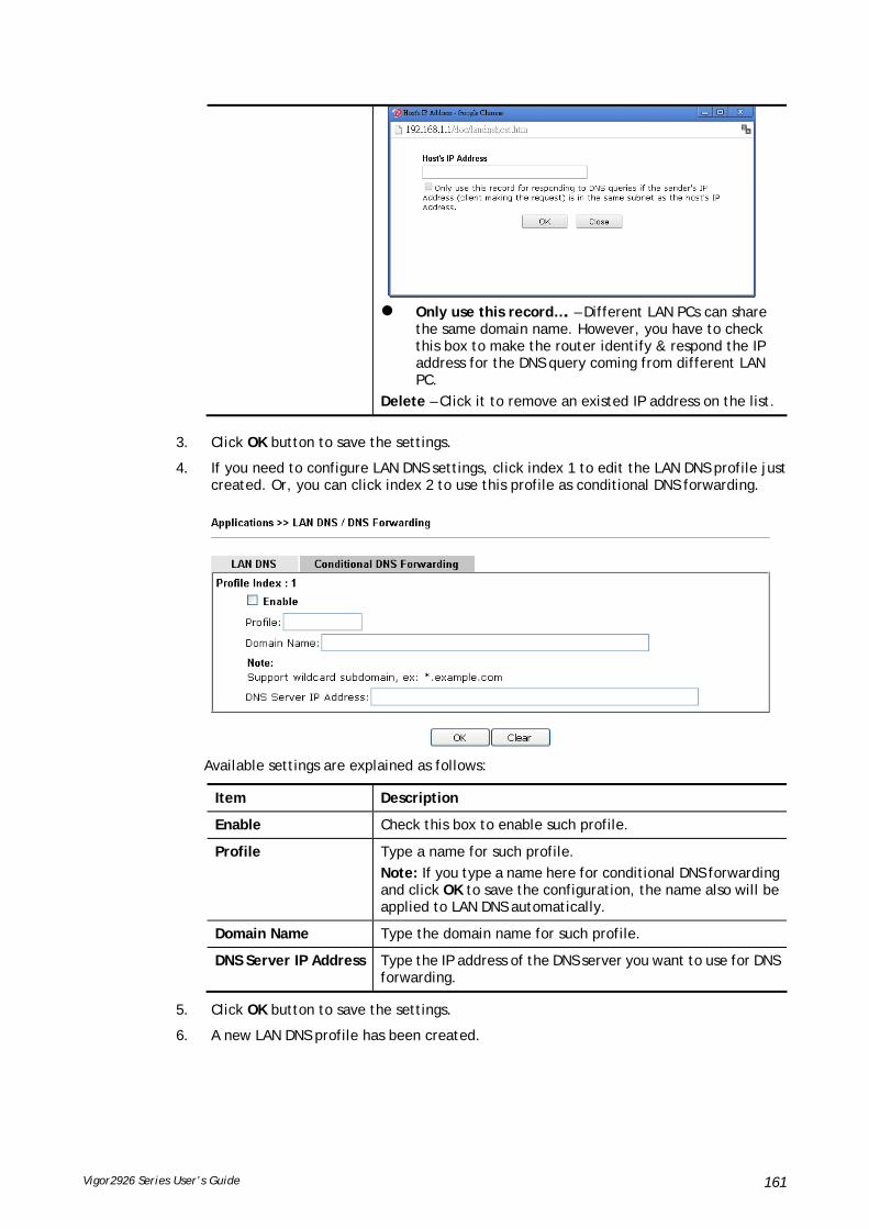
Vigor2926 Series User’s Guide 161
Only use this record…. – Different LAN PCs can share
the same domain name. However, you have to check this box to make the router identify & respond the IP address for the DNS query coming from different LAN PC.
Delete – Click it to remove an existed IP address on the list.
3. Click OK button to save the settings.
4. If you need to configure LAN DNS settings, click index 1 to edit the LAN DNS profile just created. Or, you can click index 2 to use this profile as conditional DNS forwarding.
Available settings are explained as follows:
Item Description
Enable Check this box to enable such profile.
Profile Type a name for such profile.
Note: If you type a name here for conditional DNS forwarding and click OK to save the configuration, the name also will be applied to LAN DNS automatically.
Domain Name Type the domain name for such profile.
DNS Server IP Address Type the IP address of the DNS server you want to use for DNS forwarding.
5. Click OK button to save the settings.
6. A new LAN DNS profile has been created.

Vigor2926 Series User’s Guide 162
IIII--55--33 DDNNSS SSeeccuurriittyy
DNS security is able to ensure that the incoming data is not falsified and the source of the data is secure and correct to prevent from DNS attack by someone.
IIII--55--33--11 GGeenneerraall SSeettuupp
All of WAN interfaces of Vigor router can be configured with DNS Security enabled respectively.
Available settings are explained as follows:
Item Description
Interface There are four WAN interfaces allowed to be set with DNS security enabled.
Enable Check the box to enable the DNS security management.
Primary DNS Display the IP address of primary DNS obtained from DHCP server or specified by Static WAN.
Secondary DNS Display the IP address of secondary DNS obtained from DHCP server or specified by Static WAN.
Bogus DNS Reply Sometime, Vigor router might encounter packets from bogus DNS inquiry. There are two ways to reply such DNS inquiry.
Drop – Discard the packets.
Pass – Accept the packets and let them pass through Vigor router.

Vigor2926 Series User’s Guide 163
IIII--55--33--22 DDoommaaiinn DDiiaaggnnoossee
This page is used to configure settings for manually detecting if the domain is secure not.
Available settings are explained as follows:
Item Description
Domain Type the domain name or IP address (IPv4/IPv6) that you want to query.
Interface Specify the interface required for executing diagnose.
DNS Server Type the IP address of the DNS Server which will diagnose the domain specified above.
Diagnose Click it to perform the diagnosis for the domain.
Result The diagnosed information will be displayed on such field.

Vigor2926 Series User’s Guide 164
IIII--55--44 SScchheedduullee
The Vigor router has a built-in clock which can update itself manually or automatically by means of Network Time Protocols (NTP). As a result, you can not only schedule the router to dialup to the Internet at a specified time, but also restrict Internet access to certain hours so that users can connect to the Internet only during certain hours, say, business hours. The schedule is also applicable to other functions.
You have to set your time before set schedule. In System Maintenance>> Time and Date menu, press Inquire Time button to set the Vigor router’s clock to current time of your PC. The clock will reset once if you power down or reset the router. There is another way to set up time. You can inquiry an NTP server (a time server) on the Internet to synchronize the router’s clock. This method can only be applied when the WAN connection has been built up.
Available settings are explained as follows:
Item Description
Current System Time Display the time Vigor router used.
System time set Click it to acess into the time setup page (System Maintenance>>Time and Date).
Set to Factory Default Clear all profiles and recover to factory settings.
Index Click the index number link to access into the setting page of schedule.
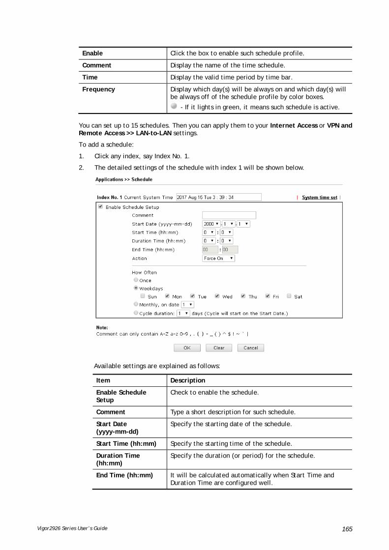
Vigor2926 Series User’s Guide 165
Enable Click the box to enable such schedule profile.
Comment Display the name of the time schedule.
Time Display the valid time period by time bar.
Frequency Display which day(s) will be always on and which day(s) will be always off of the schedule profile by color boxes.
- If it lights in green, it means such schedule is active.
You can set up to 15 schedules. Then you can apply them to your Internet Access or VPN and Remote Access >> LAN-to-LAN settings.
To add a schedule:
1. Click any index, say Index No. 1.
2. The detailed settings of the schedule with index 1 will be shown below.
Available settings are explained as follows:
Item Description
Enable Schedule Setup
Check to enable the schedule.
Comment Type a short description for such schedule.
Start Date (yyyy-mm-dd)
Specify the starting date of the schedule.
Start Time (hh:mm) Specify the starting time of the schedule.
Duration Time (hh:mm)
Specify the duration (or period) for the schedule.
End Time (hh:mm) It will be calculated automatically when Start Time and Duration Time are configured well.

Vigor2926 Series User’s Guide 166
Action Specify which action should be applied during the period of the schedule.
Force On -Force the connection to be always on.
Force Down -Force the connection to be always down.
How Often Specify how often the schedule will be applied.
Once -The schedule will be applied just once
Weekdays -Specify which days in one week should perform the schedule.
Cycle duration Specify the days to reset the traffic record. For example, 7 means the whole cycle is 7 days; 20 means the whole cycle is 20 days. When the time is up, the router will reset the traffic record automatically.
3. Click OK button to save the settings.
Example
Suppose you want to control the PPPoE Internet access connection to be always on (Force On) from 9:00 to 18:00 for whole week. Other time the Internet access connection should be disconnected (Force Down).
Office Hour:
(Force On)
Mon - Sun 9:00 am to 6:00 pm
1. Make sure the PPPoE connection and Time Setup is working properly.
2. Configure the PPPoE always on from 9:00 to 18:00 for whole week.
3. Configure the Force Down from 18:00 to next day 9:00 for whole week.
4. Assign these two profiles to the PPPoE Internet access profile. Now, the PPPoE Internet
connection will follow the schedule order to perform Force On or Force Down action
according to the time plan that has been pre-defined in the schedule profiles.
IIII--55--55 RRAADDIIUUSS//TTAACCAACCSS++
Remote Authentication Dial-In User Service (RADIUS) is a security authentication client/server protocol that supports authentication, authorization and accounting, which is widely used by Internet service providers. It is the most common method of authenticating and authorizing dial-up and tunneled network users.
IIII--55--55--11 EExxtteerrnnaall RRAADDIIUUSS
The built-in RADIUS client feature enables the router to assist the remote dial-in user or a wireless station and the RADIUS server in performing mutual authentication. It enables centralized remote access authentication for network management.
Vigor router can be operated as a RADIUS client. Therefore, this page is used to configure settings for external RADIUS server. Then LAN user of Vigor router will be authenticated by such server for network application.
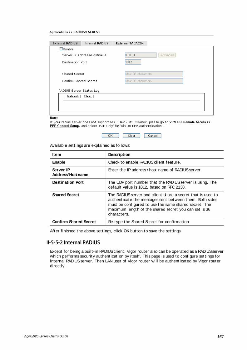
Vigor2926 Series User’s Guide 167
Available settings are explained as follows:
Item Description
Enable Check to enable RADIUS client feature.
Server IP Address/Hostname
Enter the IP address /host name of RADIUS server.
Destination Port The UDP port number that the RADIUS server is using. The default value is 1812, based on RFC 2138.
Shared Secret The RADIUS server and client share a secret that is used to authenticate the messages sent between them. Both sides must be configured to use the same shared secret. The maximum length of the shared secret you can set is 36 characters.
Confirm Shared Secret Re-type the Shared Secret for confirmation.
After finished the above settings, click OK button to save the settings.
IIII--55--55--22 IInntteerrnnaall RRAADDIIUUSS
Except for being a built-in RADIUS client, Vigor router also can be operated as a RADIUS server which performs security authentication by itself. This page is used to configure settings for internal RADIUS server. Then LAN user of Vigor router will be authenticated by Vigor router directly.

Vigor2926 Series User’s Guide 168
Available settings are explained as follows:
Item Description
Enable Check to enable internal RADIUS client feature.
Authentication Port Set a port number for internal RADIUS server.
RADIUS Client Access List Allow to configure that clients under specified domain (IPv4 and IPv6) must be authenticated with the specified shared secret.
Enable - Check to enable RADIUS client feature.

Vigor2926 Series User’s Guide 169
Shared Secret - The RADIUS server and client share a secret that is used to authenticate the messages sent between them. Both sides must be configured to use the same shared secret. The maximum length of the shared secret you can set is 36 characters.
IP Address – Type the IP addres of the wired/wireless client.
IP Mask – Type the subnet mask required for the IP address.
IPv6 Address – Type the IPv6 address of the wired/wireless client.
IPv6 Length - Type the prefix length required for the IPv6 address.
Authentication Specify the way to authenticate the wireless client.
PAP Only / PAP/CHAP/MS-CHAP/MS-CHAPv2 – Choose PAP Only. Or choose the one which supports PAP, CHAP, MS-CHAP and MS-CHAPv2.
Support 802.1X Method – The built in RADIUS server offered by Vigor router can act as the AAA server. Check the box to enable the function of authentication mechanism.
User Profile During the process of security authentication, user account and user password will be required for identity authentication. Before configuring such page, create at least one user profile in User Management>>User Profile first.
Select All – Click it to select all of the user profiles in Available List.
Clear All- Click to remove all of the user profiles in Available List.
Available List – User profiles that have not been added to the authentication list.
Authentication List – User profiles that have not been added to the authentication list.
Synchronize Internal RADIUS user list to Local 802.1X user list
Users can be authenticated by RADIUS server and local 802.1X to get certain network service. It is not necessary to create new user profiles (containing user accounts and user passwords) for RADIUS and local 802.1X respectively.
Simply check this box; all of the user profiles (prepared for RADIUS server authentication) listed in Authentication List will be synchronized for local 802.1X user authentication.
After finished the above settings, click OK button to save the settings.

Vigor2926 Series User’s Guide 170
IIII--55--55--33 EExxtteerrnnaall TTAACCAACCSS++
It means Terminal Access Controller Access-Control System Plus. It works like RADIUS does. Click the External TACACS+ tab to open the following page:
Available settings are explained as follows:
Item Description
Enable Check to enable TACACS+ feature.
Server IP Address Enter the IP address of TACACS+ server.
Destination Port The UDP port number that the TACACS+ server is using.
Shared Secret The TACACS+ server and client share a secret that is used to authenticate the messages sent between them. Both sides must be configured to use the same shared secret.
Confirm Shared Secret Re-type the Shared Secret for confirmation.
After finished the above settings, click OK button to save the settings.

Vigor2926 Series User’s Guide 171
IIII--55--66 AAccttiivvee DDiirreeccttoorryy//LLDDAAPP
Lightweight Directory Access Protocol (LDAP) is a communication protocol for using in TCP/IP network. It defines the methods to access distributing directory server by clients, work on directory and share the information in the directory by clients. The LDAP standard is established by the work team of Internet Engineering Task Force (IETF).
As the name described, LDAP is designed as an effect way to access directory service without the complexity of other directory service protocols. For LDAP is defined to perform, inquire and modify the information within the directory, and acquire the data in the directory securely, therefore users can apply LDAP to search or list the directory object, inquire or manage the active directory.
IIII--55--66--11 GGeenneerraall SSeettuupp
This page allows you to enable the function and specify general settings for LDAP server.
Available settings are explained as follows:
Item Description
Enable Check to enable such function.
Bind Type There are three types of bind type supported.
Simple Mode – Just simply do the bind authentication without any search action.
Anonymous – Perform a search action first with Anonymous account then do the bind authentication.
Regular Mode– Mostly it is the same with anonymous mode. The different is that, the server will firstly check if you have the search authority.
For the regular mode, you’ll need to type in the Regular DN
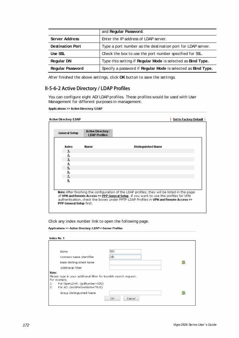
Vigor2926 Series User’s Guide 172
and Regular Password.
Server Address Enter the IP address of LDAP server.
Destination Port Type a port number as the destination port for LDAP server.
Use SSL Check the box to use the port number specified for SSL.
Regular DN Type this setting if Regular Mode is selected as Bind Type.
Regular Password Specify a password if Regular Mode is selected as Bind Type.
After finished the above settings, click OK button to save the settings.
IIII--55--66--22 AAccttiivvee DDiirreeccttoorryy // LLDDAAPP PPrrooffiilleess
You can configure eight AD/LDAP profiles. These profiles would be used with User Management for different purposes in management.
Click any index number link to open the following page.

Vigor2926 Series User’s Guide 173
Available settings are explained as follows:
Item Description
Name Type a name for such profile. The length of the user name is limited to 19 characters.
Common Name Identifier Type or edit the common name identifier for the LDAP server. The common name identifier for most LDAP server is “cn”.
Additional Filter Type the condition for additional filter.
Base Distinguished Name / Group Distinguished Name
Type or edit the distinguished name used to look up entries on the LDAP server.
Sometimes, you may forget the Distinguished Name since it’s
too long. Then you may click the button to list all the account information on the AD/LDAP Server to assist you finish the setup.
After finished the above settings, click OK to save and exit this page. A new profile has been created.

Vigor2926 Series User’s Guide 174
IIII--55--77 UUPPnnPP
The UPnP (Universal Plug and Play) protocol is supported to bring to network connected devices the ease of installation and configuration which is already available for directly connected PC peripherals with the existing Windows 'Plug and Play' system. For NAT routers, the major feature of UPnP on the router is “NAT Traversal”. This enables applications inside the firewall to automatically open the ports that they need to pass through a router.
Info
UPnP is required for some applications such as PPS, Skype, eMule...and etc. If you are not familiar with UPnP, it is suggested to turn off this function for security.
Available settings are explained as follows:
Item Description
Enable UPNP Service Accordingly, you can enable either the Connection Control Service or Connection Status Service.
Default WAN It is used to specify the WAN interface for applying such function.
The reminder as regards concern about Firewall and UPnP:
Can't work with Firewall Software
Enabling firewall applications on your PC may cause the UPnP function not working properly. This is because these applications will block the accessing ability of some network ports.
Security Considerations
Activating the UPnP function on your network may incur some security threats. You should consider carefully these risks before activating the UPnP function.
Some Microsoft operating systems have found out the UPnP weaknesses and hence you need to ensure that you have applied the latest service packs and patches.
Non-privileged users can control some router functions, including removing and adding port mappings.
The UPnP function dynamically adds port mappings on behalf of some UPnP-aware applications. When the applications terminate abnormally, these mappings may not be removed.

Vigor2926 Series User’s Guide 175
IIII--55--88 IIGGMMPP
IGMP is the abbreviation of Internet Group Management Protocol. It is a communication protocol which is mainly used for managing the membership of Internet Protocol multicast groups.
IIII--55--88--11 GGeenneerraall SSeettttiinngg
Available settings are explained as follows:
Item Description
IGMP Proxy Check this box to enable this function. The application of multicast will be executed through WAN /PVC/VLAN port. In addition, such function is available in NAT mode.
Interface – Specify an interface for packets passing through.
IGMP version – At present, two versions (v2 and v3) are supported by Vigor router. Choose the correct version based on the IPTV service you subscribe.
General Query Interval – Vigor router will periodically check which IP obtaining IPTV service by sending query. It might cause inconvenience for client. Therefore, set a suitable time (unit: second) as the query interval to limit the frequency of query sent by Vigor router.
Add PPP header – Check this box if the interface type for IGMP is PPPoE. It depends on the specifications regulated by each ISP. If you have no idea to enable or disable, simply contact your ISP providers.
IGMP Snooping Check this box to enable this function. Multicast traffic will be forwarded to ports that have members of that group. Disabling IGMP snooping will make multicast traffic treated in the same manner as broadcast traffic.

Vigor2926 Series User’s Guide 176
IGMP Fast Leave Check this box to make the router stop forwarding multicast traffic to a LAN port as soon as it receives a leave message from that port. Each LAN port should have one IGMP host connected.
After finishing all the settings here, please click OK to save the configuration.
IIII--55--88--22 WWoorrkkiinngg GGrroouuppss
Available settings are explained as follows:
Item Description
Refresh Click this link to renew the working multicast group status.
Group ID This field displays the ID port for the multicast group. The available range for IGMP starts from 224.0.0.0 to 239.255.255.254.
P1 to P4 It indicates the LAN port used for the multicast group.

Vigor2926 Series User’s Guide 177
IIII--55--99 WWaakkee oonn LLAANN
A PC client on LAN can be woken up by the router it connects. When a user wants to wake up a specified PC through the router, he/she must type correct MAC address of the specified PC on this web page of Wake on LAN (WOL) of this router.
In addition, such PC must have installed a network card supporting WOL function. By the way, WOL function must be set as “Enable” on the BIOS setting.
Available settings are explained as follows:
Item Description
Wake by Two types provide for you to wake up the binded IP.
If you choose Wake by MAC Address, you have to type the correct MAC address of the host in MAC Address boxes.
If you choose Wake by IP Address, you have to choose the correct IP address.
IP Address The IP addresses that have been configured in Firewall>>Bind IP to MAC will be shown in this drop down list. Choose the IP address from the drop down list that you want to wake up.
MAC Address Type any one of the MAC address of the bound PCs.
Wake Up Click this button to wake up the selected IP. See the following figure. The result will be shown on the box.

Vigor2926 Series User’s Guide 178
IIII--55--1100 SSMMSS // MMaaiill AAlleerrtt SSeerrvviiccee
The function of SMS (Short Message Service)/Mail Alert is that Vigor router sends a message to user’s mobile or e-mail box through specified service provider to assist the user knowing the real-time abnormal situations.
Vigor router allows you to set up to 10 SMS profiles which will be sent out according to different conditions.
IIII--55--1100--11 SSMMSS AAlleerrtt
This page allows you to specify SMS provider, who will get the SMS, what the content is and when the SMS will be sent.
Available settings are explained as follows:
Item Description
Enable Check the box to enable such profile.
SMS Provider Use the drop down list to choose SMS service provider.
You can click SMS Provider link to define the SMS server.
Recipient Number Type the phone number of the one who will receive the SMS.
Notify Profile Use the drop down list to choose a message profile. The recipient will get the content stated in the message profile.
You can click the Notify Profile link to define the content of the SMS.
Schedule (1-15) Type the schedule number that the SMS will be sent out.
You can click the Schedule(1-15) link to define the schedule.
After finishing all the settings here, please click OK to save the configuration.
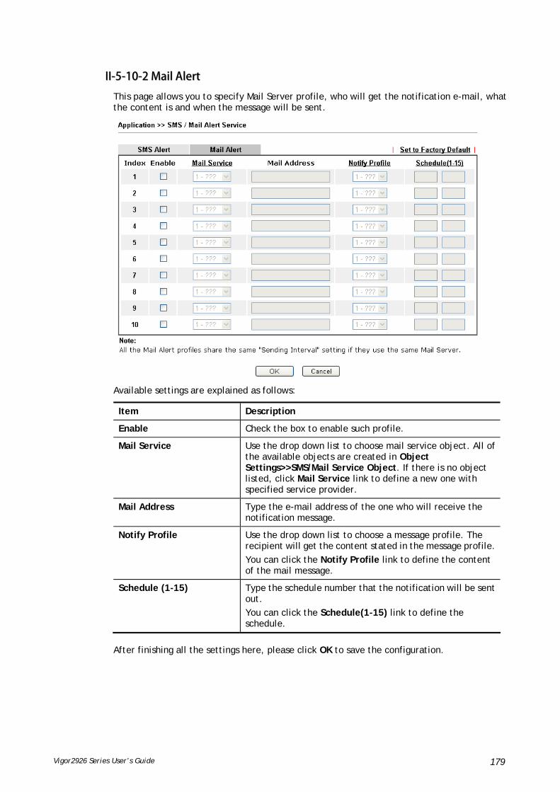
Vigor2926 Series User’s Guide 179
IIII--55--1100--22 MMaaiill AAlleerrtt
This page allows you to specify Mail Server profile, who will get the notification e-mail, what the content is and when the message will be sent.
Available settings are explained as follows:
Item Description
Enable Check the box to enable such profile.
Mail Service Use the drop down list to choose mail service object. All of the available objects are created in Object Settings>>SMS/Mail Service Object. If there is no object listed, click Mail Service link to define a new one with specified service provider.
Mail Address Type the e-mail address of the one who will receive the notification message.
Notify Profile Use the drop down list to choose a message profile. The recipient will get the content stated in the message profile.
You can click the Notify Profile link to define the content of the mail message.
Schedule (1-15) Type the schedule number that the notification will be sent out.
You can click the Schedule(1-15) link to define the schedule.
After finishing all the settings here, please click OK to save the configuration.

Vigor2926 Series User’s Guide 180
IIII--55--1111 BBoonnjjoouurr
Bonjour is a service discovery protocol which is a built-in service in Mac OS X; for Windows or Linux platform, there is correspondent software to enable this function for free.
Usually, users have to configure the router or personal computers to use above services. Sometimes, the configuration (e.g., IP settings, port number) is complicated and not easy to complete. The purpose of Bonjour is to decrease the settings configuration (e.g., IP setting). If the host and user’s computer have the plug-in bonjour driver install, they can utilize the service offered by the router by clicking the router name icon. In short, what the Clients/users need to know is the name of the router only.
To enable the Bonjour service, click Application>>Bonjour to open the following page. Check the box(es) of the server service(s) that you want to share to the LAN clients.
Below shows an example for applying the bonjour feature that Vigor router can be used as the FTP server.
1. Here, we use Firefox and DNSSD to discover the service in such case. Therefore, just ensure the Bonjour client program and DNSSD for Firefox have been installed on the computer.

Vigor2926 Series User’s Guide 181
2. Open the web browse, Firefox. If Bonjour and DNSSD have been installed, you can open the web page (DNSSD) and see the following results.
3. Open System Maintenance>>Management. Type a name as the Router Name and click OK.
4. Next, open Applications>>Bonjour. Check the service that you want to use via Bonjour.
5. Open the DNSSD page again. The available items will be changed as the follows. It means the Vigor router (based on Bonjour protocol) is ready to be used as a printer server, FTP server, SSH Server, Telnet Server, and HTTP Server.

Vigor2926 Series User’s Guide 182
6. Now, any page or document can be printed out through Vigor router (installed with a printer).

Vigor2926 Series User’s Guide 183
IIII--55--1122 HHiigghh AAvvaaiillaabbiilliittyy
The High Availability (HA) feature of the router provides redundancy of network resources, and reduces downtime in case of component failure. The level of sophistication of HA is determined by availability requirements and tolerance of system interruptions. Systems that provide near full-time availability typically have redundant hardware and software.
The HA of the Vigor2926 Series is designed to avoid single points-of-failure. When failures occur, the failover process transfers the network load handled by the failed component (the primary router) to the backup component (the secondary router), and the availability of network resources are preserved and partially failed transactions are recovered. In a matter of seconds the system returns to normal operation.
In order to set up High Availability, at least 2 DrayTek routers have to be configured in the following manner:
Enable High Availability on both the primary and secondary routers.
Set a high priority ID on the primary router, and a lower priority ID on the secondary router.
Configure identical redundancy methods, group IDs, and authentication keys on both routers.
Set the management interface of both routers to the same subnet.
Enable virtual IP on both routers for each subnet in use. Make sure the virtual IPs are identical on both routers.

Vigor2926 Series User’s Guide 184
IIII--55--1122--11 GGeenneerraall SSeettuupp
Open Applications>>High Availability to get the following page.
Available settings are explained as follows:
Item Description
Enable High Abailablity Check this box to enable HA function.
Redundancy Method Select the redundancy method for high availability.
Hot-Standby -
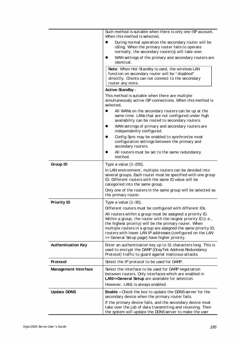
Vigor2926 Series User’s Guide 185
Such method is suitable when there is only one ISP account. When this method is selected,
During normal operation the secondary router will be idling. When the primary router fails to operate normally, the secondary router(s) will take over.
WAN settings of the primary and secondary routers are identical.
Note: When Hot-Standby is used, the wireless LAN function on secondary router will be “disabled” directlly. Clients can not connect to the secondary router any more.
Active-Standby -
This method is suitable when there are multiple simultaneously active ISP connections. When this method is selected,
All WANs on the secondary routers can be up at the same time. LANs that are not configured under high availability can be routed to secondary routers.
WAN settings of primary and secondary routers are independently configured.
Config Sync may be enabled to synchronize most configuration settings between the primary and secondary routers.
All routers must be set to the same redundancy method.
Group ID Type a value (1~255).
In LAN environment, multiple routers can be devided into several groups. Each router must be specified with one group ID. Different routers with the same ID value will be categoried into the same group.
Only one of the routers in the same group will be selected as the primary router.
Priority ID Type a value (1~30).
Different routers must be configured with different IDs.
All routers within a group must be assigned a priority ID. Within a group, the router with the largest priority ID (i.e., the highest priority) will be the primary router. When multiple routers in a group are assigned the same priority ID, routers with lower LAN IP addresses (configured on the LAN >> General Setup page) have higher priority.
Authentication Key Enter an authentication key up to 31 characters long. This is used to encrypt the DARP (DrayTek Address Redundancy Protocol) traffic to guard against malicious attacks.
Protocol Select the IP protocol to be used for DARP.
Management Interface Select the interface to be used for DARP negotiation between routers. Only interfaces which are enabled in LAN>>General Setup are available for selection.
However, LAN1 is always enabled.
Update DDNS Enable – Check the box to update the DDNS server for the secondary device when the primary router fails.
If the primary device fails, and the secondary device must take over the job of data transmitting and receiving. Then the system will update the DDNS server to make the user
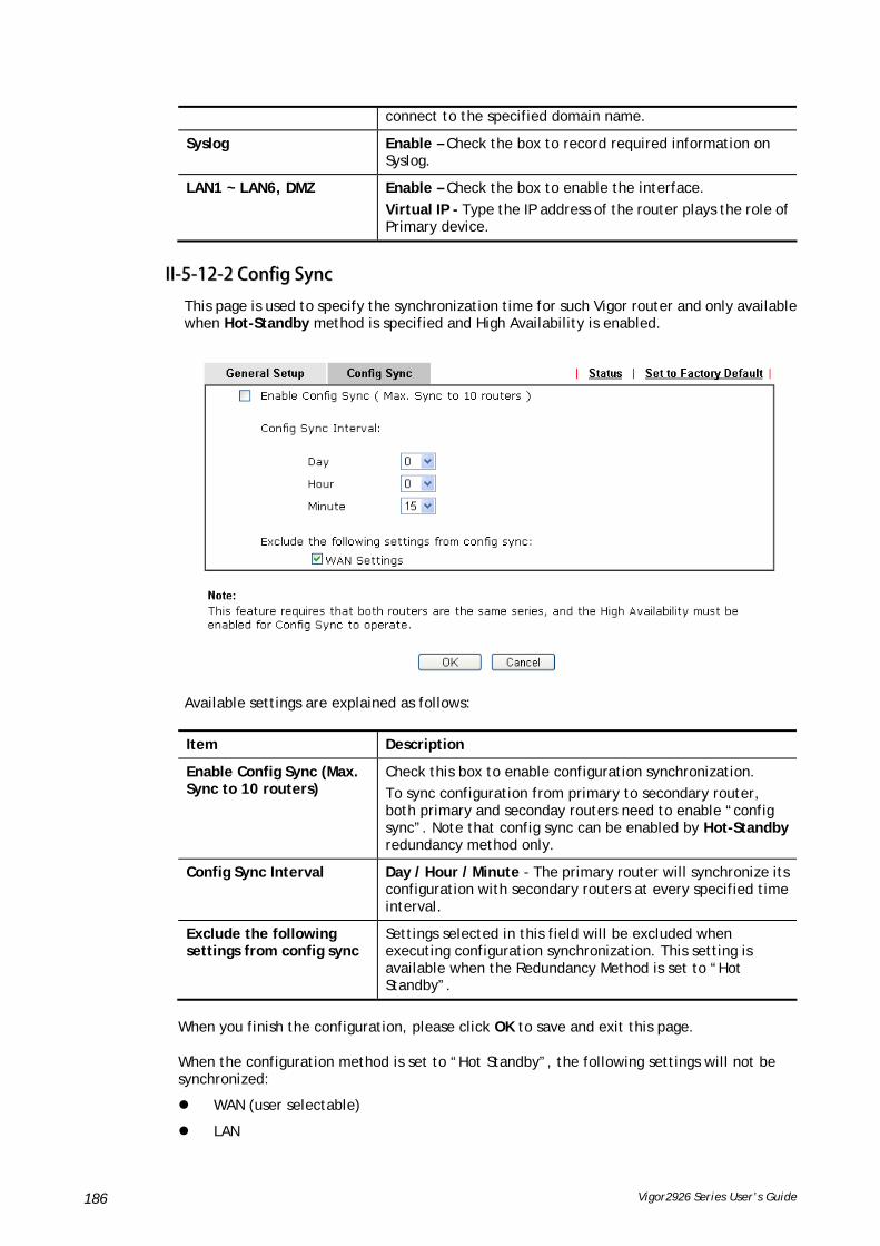
Vigor2926 Series User’s Guide 186
connect to the specified domain name.
Syslog Enable – Check the box to record required information on Syslog.
LAN1 ~ LAN6, DMZ Enable – Check the box to enable the interface.
Virtual IP - Type the IP address of the router plays the role of Primary device.
IIII--55--1122--22 CCoonnffiigg SSyynncc
This page is used to specify the synchronization time for such Vigor router and only available when Hot-Standby method is specified and High Availability is enabled.
Available settings are explained as follows:
Item Description
Enable Config Sync (Max. Sync to 10 routers)
Check this box to enable configuration synchronization.
To sync configuration from primary to secondary router, both primary and seconday routers need to enable “config sync”. Note that config sync can be enabled by Hot-Standby redundancy method only.
Config Sync Interval Day / Hour / Minute - The primary router will synchronize its configuration with secondary routers at every specified time interval.
Exclude the following settings from config sync
Settings selected in this field will be excluded when executing configuration synchronization. This setting is available when the Redundancy Method is set to “Hot Standby”.
When you finish the configuration, please click OK to save and exit this page.
When the configuration method is set to “Hot Standby”, the following settings will not be synchronized:
WAN (user selectable)
LAN

Vigor2926 Series User’s Guide 187
LAN IPv6
router name
admin and user passwords.
EExxaammppllee::
Take the following picture as an example. The upper Vigor2926 is regarded as primary device, the lower Vigor2926 is regarded as secondary device. When primary Vigor2926 Series is broken down, the secondary device could replace the primary role to take over all jobs as soon as possible. However, once the primary device is working again, the secondary device would be changed to original role to stand by.

Vigor2926 Series User’s Guide 188
IIII--55--1133 LLooccaall 880022..11XX GGeenneerraall SSeettuupp
Such page allows you to configure general settings for Local 802.1X server built in Vigor router. The local 802.X server can be used to authenticate wired and wireless LAN clients.
Available settings are explained as follows:
Item Description
Enable Click it to enable the built-in 802.1X server.
At present, such feature can be used for wireless and wired 802.1x authentication.
User Profile Select All – Click to add all User Profiles to the 802.1X server. All profiles will appear under the Authentication List.
Clear All – Remove all user profiles from the 802.1X server. All profiles will appear under Available List.
Sync User Profile …. Make the enabling/disabling setting for both Internal RADIUS and Local 802.1X synchronize for all of the user profiles (User Management>>User Profile).
For example, if Local 802.1x is configured as Enabled (checked), the Internal RADIUS will be configured as Enabled too.

Vigor2926 Series User’s Guide 189
If Local 802.1X is configured as Disabled (unchecked), the Internal RADIUS will be changed as Disabled too, even if it is enabled previously.
OK Click it to save the settings.
Clear Click it to remove previous setting configuration.
Cancel Click it to give up all settings configuration.
When you finish the configuration, please click OK to save and exit this page.

Vigor2926 Series User’s Guide 190
AApppplliiccaattiioonn NNootteess
AA--11 HHooww ttoo uussee HHiigghh AAvvaaiillaabbiilliittyy??
High Availability provides hardware redundancy to the LAN clients. DrayTek Router has two modes for High Availability feature: Hot-Standby and Active-Standby.
In Hot-Standby Mode, Primary and Secondary router share the same WAN source. Usually, only the Primary is online. When Primary goes down, Secondary comes up and use the same WAN line to dial up, and continue to provide Internet service to LAN clients.
Active-Standby mode is almost same as Hot-Standby mode, only that in the Active-Standby mode, the Primary and Secondary connect to the different WAN sources; also, the Secondary will always be online.
1. On the primary router, choose Redundancy Method you would like to use, then set the following configurations:
(a) Group ID is used to identify who are the group members, enter the same ID on all the members. The default value is 1, we may leave it as default here.
(b) Priority ID is used to decide which router should be the primary one, and 30 is the highest. If 2 or more routers are having the same Priority ID, their LAN IP addresses

Vigor2926 Series User’s Guide 191
(for management Interface) will be considered, e.g., 192.168.1.2 has higher priority than 192.168.1.3…, etc.
(c) Authentication Key: enter the same authentication key on all the members.
(d) Management Interface: the packets for communication (including deciding the primary, configuration sync, and some maintenance…,etc) between members will be sent in the management interface, in other word, clients in other LAN subnet won't be able to see these packets. In order to have best communication and for security purpose, we recommend to choose an interface that is less possible to have interruption for the communication (loop/broadcast storm from other LAN clients…). In our scenario, we reserve LAN 1 for High Availability only, and put all other LAN clients in LAN2~LAN5.
(e) Update DDNS: for dynamic WAN IP users, enable this function so once the secondary router becomes primary and dials up the WAN, it will also update its new WAN IP address to the same DDNS profile, so your network will be accessible with the same DDNS domain.
(f) Syslog: enable to show all the High Availability related logs in syslog.
(g) Enable the LAN Subnet to join High Availability. Any existing LAN without joining High Availability will not be served with hardware redundancy.
Virtual IP: name the virtual IP here, please note that the virtual IP can NOT be the same with any member LAN IP.
2. Enable Configuration Sync and set the Sync Interval. Default is every 15 minutes.
3. Configure High Availability on the secondary router. Mind that the Priority should be lower than the primary router. Besides priority, all other settings should be the same.

Vigor2926 Series User’s Guide 192
4. Configuring LAN on the primary router.
(a) Set up the LAN IP address, it has to be different from the Virtual IP and the LAN IP of secondary router. Again, for any routers with the same Priority ID, their IP addresses will be compared, so we suggest to use a IP with lower number on the Primary one.
(b) Gateway IP is the same with LAN IP, and the note in parentheses indicates that the gateway IP provided to LAN clients will be replaced by the Virtual IP.

Vigor2926 Series User’s Guide 193
5. Configure LAN on the secondary router. Mind that the IP should be different and larger than it on the primary router.
Info
If you have more than one LAN, you should set all the LAN IP of each LAN on Primary and Secondary routers to different IP addresses to avoid IP conflict. Here is the example, there are several LAN and all of them are under the protection of hardware redundancy:
6. We have setup High Availability on both routers, and before we link up both routers, it's time to setup all other functions on the primary router so later we can see the configuration sync taking place. If your primary router is already settled please proceed to the next step. Here we configure the WAN as the representative example.

Vigor2926 Series User’s Guide 194
Then confirm the WAN setup by seeing WAN online.
7. After all the functions are set properly on the primary router, we link up the management interface LAN so both routers can start detecting each other, deciding which one should be the primary and syncing the configuration. Since the routers will communicate via the Management Interface, it's required to use the ports that belong to the Management Interface LAN (LAN1 in this scenario). We can check for this information in LAN >> VLAN. In this scenario we can use the port 5 on both routers, so we use an Ethernet cable to wire up LAN port 5 on both routers.
8. We may check the High Availability status by visiting the Status page.
For the first time the two routers link up, we can see they are syncing the configuration from the primary to the secondary (showing "Progressing" on the secondary router):

Vigor2926 Series User’s Guide 195
Note: The "Cached Time" indicates the time that router has got the information from the other router ago. Click "Renew" to update the information of remote router, click "Refresh" to update the information of local router.
When a sync is finished or the routers are already having the same configuration, it will show the "Equal" result:
Note that the router will check if there's any un-synced modification when it reaches the time interval we set in step 2. We may force to sync by clicking the "Sync" button. The secondary router will reboot after the config sync.
9. Now we may inspect if the secondary router received the configuration from the primary router. In this scenario we check the secondary router online status.
Before syncing we didn't configure the WAN, now seeing WAN1 and WAN2 having "Static IP" indicates it did receive the corresponding configurations. And the "Disconnected-HA" means this router is not dialing up the WAN due to the primary router in the High Availability group is working, so as a secondary router it doesn't need to be online now. You may also check other configurations on your secondary router.
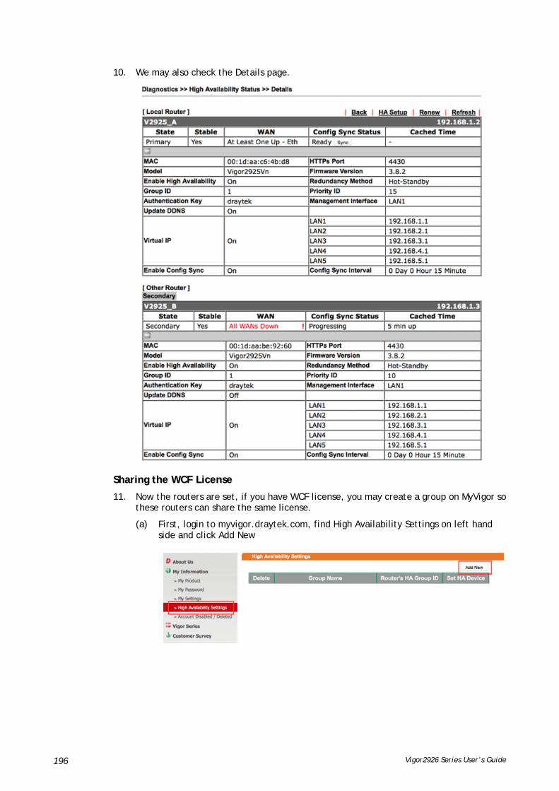
Vigor2926 Series User’s Guide 196
10. We may also check the Details page.
SShhaarriinngg tthhee WWCCFF LLiicceennssee
11. Now the routers are set, if you have WCF license, you may create a group on MyVigor so these routers can share the same license.
(a) First, login to myvigor.draytek.com, find High Availability Settings on left hand side and click Add New

Vigor2926 Series User’s Guide 197
(b) Give a Group Name, select an HA unused Group ID, and select the member routers in the HA Device drop-down menu:
Note that the drop-down menu only lists out the devices that are registered under this MyVigor account. If you don't find the router you are using, please find out which account this device is registered under.
(c) Save the profile, and we can see the group entry:
SSeenndd tthhee NNoottiiffiiccaattiioonn ttoo NNeettwwoorrkk AAddmmiinniissttrraattoorr
We can set Vigor Router to notify the network administrator by sending email or SMS when the following events occur:
1. Failover Occurred: the WAN of the primary router goes down and the secondary router takes over,
2. Configuration Sync Failed: the configuration sync between primary and secondary router fails,
3. Router Unstable: one of the routers becomes unstable.

Vigor2926 Series User’s Guide 198
AA--22 HHooww ttoo uussee DDrraayyDDDDNNSS??
Vigor router supports various DDNS service providers, user can set up user-defined profile to update the DDNS even the service provider is not on the list. Now, DrayTek starts to support our own DDNS service - DrayDDNS. We will provide a domain name for each Vigor Router, this single domain name can record IP addresses of all WAN.
AAccttiivvaattee DDrraayyDDDDNNSS LLiicceennssee
1. Go to Wizards >> Service Activation Wizard, wait for the router to connect to MyVigor server, then tick DT-DDNS and I have read and accept the above Agreement, click Next.
2. Confirm the information, then click Activate.
3. MyVigor server will reply with the service activation information.
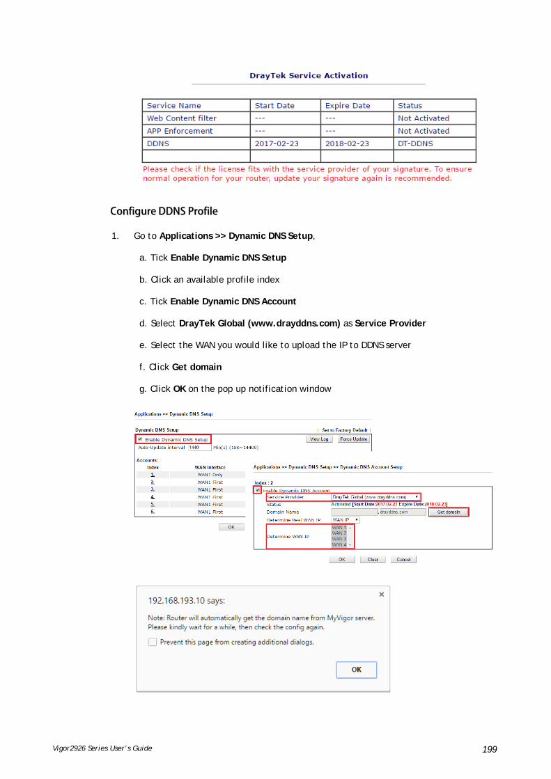
Vigor2926 Series User’s Guide 199
CCoonnffiigguurree DDDDNNSS PPrrooffiillee
1. Go to Applications >> Dynamic DNS Setup,
a. Tick Enable Dynamic DNS Setup
b. Click an available profile index
c. Tick Enable Dynamic DNS Account
d. Select DrayTek Global (www.drayddns.com) as Service Provider
e. Select the WAN you would like to upload the IP to DDNS server
f. Click Get domain
g. Click OK on the pop up notification window

Vigor2926 Series User’s Guide 200
2. Wait few seconds for router to get the domain name, then, we can click the profile to check the information of license and domain name.
MMooddiiffyy DDoommaaiinn NNaammee
Currently, only the domain name is allowed to be modified MyVigor website. We will need to register the router to MyVigor server, and log in to MyVigor website to modify it.
1. Please visit https://myvigor.draytek.com/ or go to Applications >> Dynamic DNS Setup >> DrayDDNS profile and click Edit domain.
2. Log in to MyVigor Website, choose the profile, then click Edit DDNS settings.

Vigor2926 Series User’s Guide 201
3. Input the desired Domain name (e.g., XXXX25) and click Update.
4. Vigor router will get the modified domain name when the it performs next DDNS updating. We can click Sync domain to accelerate this process.
After few seconds, the router will get the new domain name and print it on the profiles list.
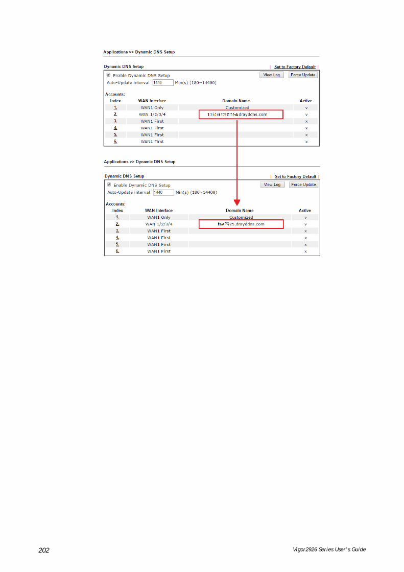
Vigor2926 Series User’s Guide 202

Vigor2926 Series User’s Guide 203
AA--33 HHooww ttoo CCoonnffiigguurree CCuussttoommiizzeedd DDDDNNSS??
This article describes how to configure customized DDNS on Vigor routers to update your IP to the DDNS server. We will take “Changeip.org” and “3322.net” as example. Before setting, please make sure that the WAN connection is up.
PPaarrtt AA :: CChhaannggeeiipp..oorrgg
Note that,
Username: jo***
Password: jo********
Host name: j*****.changeip.org
WAN IP address: 1.169.185.242
Following is the screenshot of editing the HTML script on the browser to update your IP to the DDNS server.

Vigor2926 Series User’s Guide 204
Now we have to configure the router so it can do the same job for us automatically.
1. Please go to Applications >> Dynamic DNS to create a profile for Customized DDNS client.
2. Set the Service Provider as Customized.
3. Set the Service API as: /dynamic/dns/update.asp?u=jo***&p=jo********&hostname=j****.changeip.org&ip=###IP### &cmd=update&offline=0
In which, ###IP### is a value which will be replaced with the current interface IP address automatically when DDNS service is running. In this case the IP will be 1.169.185.242.
4. After setting, the Customized DDNS service will be up, and our IP will be updated to the DDNS server.
PPaarrtt BB :: 33332222..nneett
Username: bi*******
Password: 88********
Host name: bi*******.3322.org

Vigor2926 Series User’s Guide 205
WAN IP address: 111.243.178.53
To update the IP to the DDNS server via editing the HTML script, we can type the following script on the browser:
“good 111.243.178.53” means our IP has been updated to the server successfully.
Now we have to configure the router so it can do the same job for us automatically.
1. Please go to Applications >> Dynamic DNS to create a profile for Customized DDNS client.
2. Set the Service Provider as Customized.
3. Set the Provider Host as member.3322.net.
4. Set the Service API as: /dyndns/update?hostname=yourhost.3322.org&myip=###IP###&wildcard=OFF&mx=mail.exchanger.ext&backmx=NO&offline=NO
5. Enter your account and password.
6. After the setting, the Customized DDNS service will be up, and our IP will be updated to the DDNS server automatically.
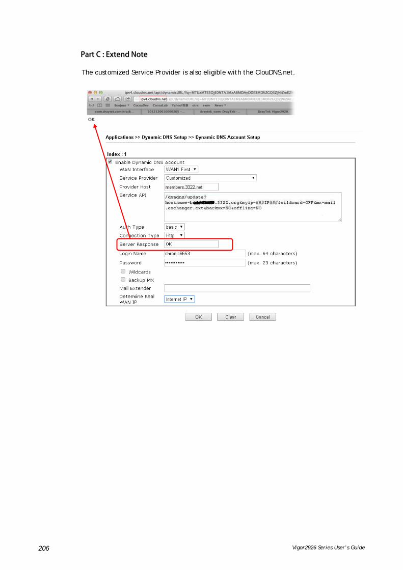
Vigor2926 Series User’s Guide 206
PPaarrtt CC :: EExxtteenndd NNoottee
The customized Service Provider is also eligible with the ClouDNS.net.

Vigor2926 Series User’s Guide 207
AA--44 HHooww ttoo IImmpplleemmeenntt tthhee LLDDAAPP//AADD AAuutthheennttiiccaattiioonn ffoorr UUsseerr MMaannaaggeemmeenntt??
For simplifying the configuration of LDAP authentication for User Access Management, we implement “Group” feature.
There is no need to pre-configure user profile for each user on Vigor router anymore. We only need to configure the Groups DN, then the Vigor router (e.g., Vigor 2926 series) can pass the authentication to LDAP server with the pre-defined Group path.
Below shows the configuration steps:
1. Access into the web user interface of the Vigor router.
2. Open Applications>>Active Directory /LDAP to get the following page for configuring LDAP related settings.
There are three types of bind type supported:
Simple Mode – Just simply do the bind authentication without any search action.
Anonymous – Perform a search action first with Anonymous account then do the bind authentication.
Regular Mode– Mostly it is the same with anonymous mode. The different is that, the server will firstly check if you have the search authority. For the regular mode, you’ll need to type in the Regular DN and Regular Password.
3. Create LDAP server profiles. Click the Active Directory /LDAP tab to open the profile web page and click any one of the index number link.
If we have two groups “RD1” and “SHRD” on LDAP server, we can configure two LDAP server profiles with different Group Distinguished Name.

Vigor2926 Series User’s Guide 208
and
4. Click OK to save the settings above.
5. Open User Management>>General Setup. Select User-Based as the Mode option.

Vigor2926 Series User’s Guide 209
6. Then open VPN and Remote Access>>PPP General Setup to check the profile(s) that will be authenticated with LDAP server.
After above configurations, users belong to either “rd1” or “shrd” group can access Internet after inputting their credentials on LDAP server.
Vigor2926 Series User’s Guide 210
IIII--66 RRoouuttiinngg
Route Policy (also well known as PBR, policy-based routing) is a feature where you may need to get a strategy for routing. The packets will be directed to the specified interface if they match one of the policies. You can setup route policies in various reasons such as load balance, security, routing decision, and etc.
Through protocol, IP address, port number and interface configuration, Route Policy can be used to configure any routing rules to fit actual request. In general, Route Policy can easily reach the following purposes:
Load Balance
You may manually create policies to balance the traffic across network interface.
Specify Interface
Through dedicated interface (WAN/LAN/VPN), the data can be sent from the source IP to the destination IP.
Address Mapping
Allows you specify the outgoing WAN IP address (es) for an internal private IP address or a range of internal private IP addresses.
Priority
The router will determine which policy will be adopted for transmitting the packet according to the priority of Static Route and Route Policy.
Failover to/Failback
Packets will be sent through another Interface or follow another Policy when the original interface goes down (Failover to). Once the original interface resumes service (Failback), the packets will be returned to it immediately.
Other routing
Specify routing policy to determine the direction of the data transmission.
Info
For more detailed information about using policy route, refer to Support >>FAQ/Application Notes on www.draytek.com.

Vigor2926 Series User’s Guide 211
WWeebb UUsseerr IInntteerrffaaccee
IIII--66--11 SSttaattiicc RRoouuttee
Static routing is an alternative to dynamic routing. It is a process that the system network administrator can configure network routers with all the required information for packet forwarding.
Go to Routing >> Static Route. The router offers IPv4 and IPv6 for you to configure the static route. Both protocols bring different web pages.
SSttaattiicc RRoouuttee ffoorr IIPPvv44
Available settings are explained as follows:
Item Description
Index The number (1 to 40) under Index allows you to open next page to set up static route.
Enable Check the box to enable the static route profile.
Destination Address Displays the destination address of the static route.
Set to Factory Default Clear all of the settings and return to factory default settings.

Vigor2926 Series User’s Guide 212
Viewing Routing Table Displays the routing table for your reference.
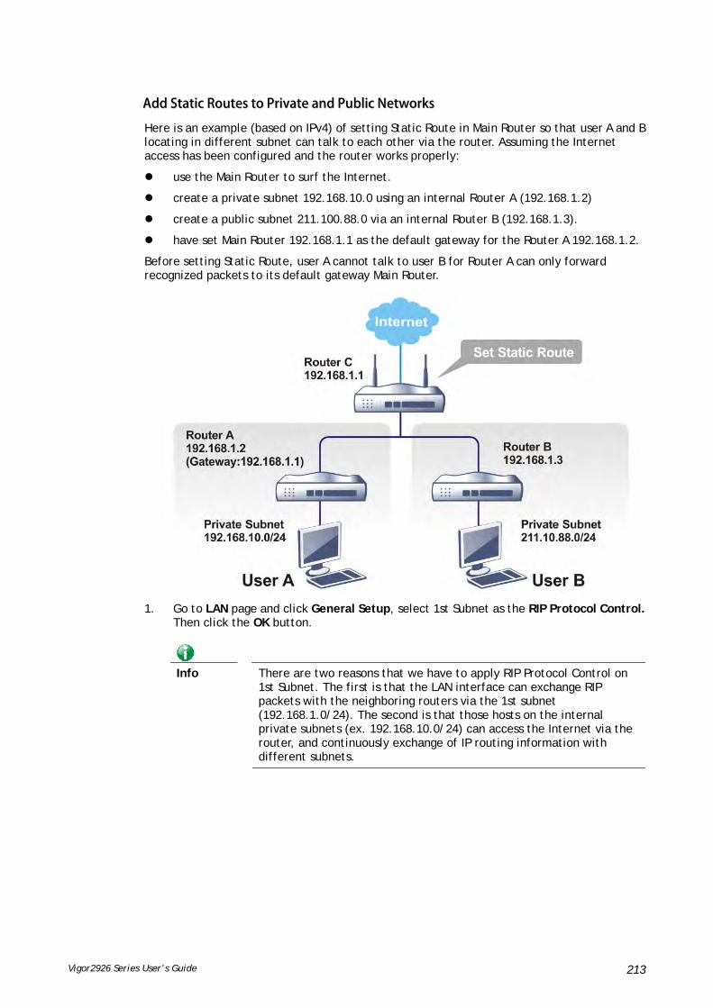
Vigor2926 Series User’s Guide 213
AAdddd SSttaattiicc RRoouutteess ttoo PPrriivvaattee aanndd PPuubblliicc NNeettwwoorrkkss
Here is an example (based on IPv4) of setting Static Route in Main Router so that user A and B locating in different subnet can talk to each other via the router. Assuming the Internet access has been configured and the router works properly:
use the Main Router to surf the Internet.
create a private subnet 192.168.10.0 using an internal Router A (192.168.1.2)
create a public subnet 211.100.88.0 via an internal Router B (192.168.1.3).
have set Main Router 192.168.1.1 as the default gateway for the Router A 192.168.1.2.
Before setting Static Route, user A cannot talk to user B for Router A can only forward recognized packets to its default gateway Main Router.
1. Go to LAN page and click General Setup, select 1st Subnet as the RIP Protocol Control. Then click the OK button.
Info
There are two reasons that we have to apply RIP Protocol Control on 1st Subnet. The first is that the LAN interface can exchange RIP packets with the neighboring routers via the 1st subnet (192.168.1.0/24). The second is that those hosts on the internal private subnets (ex. 192.168.10.0/24) can access the Internet via the router, and continuously exchange of IP routing information with different subnets.

Vigor2926 Series User’s Guide 214
2. Click the Routing >> Static Route and click on the Index Number 1. Check the Enable box. Please add a static route as shown below, which regulates all packets destined to 192.168.10.0 will be forwarded to 192.168.1.2. Click OK.
Available settings are explained as follows:
Item Description
Enable Click it to enable this profile.
Destination IP Address
Type an IP address as the destination of such static route.
Subnet Mask Type the subnet mask for such static route.
Network Interface Use the drop down list to specify an interface for such static route.
3. Return to Static Route Setup page. Click on another Index Number to add another static route as show below, which regulates all packets destined to 211.100.88.0 will be forwarded to 192.168.1.3. Click OK.
4. Go to Diagnostics and choose Routing Table to verify current routing table.

Vigor2926 Series User’s Guide 215
SSttaattiicc RRoouuttee ffoorr IIPPvv66
You can set up to 40 profiles for IPv6 static route. Click the IPv6 tab to open the following page:
Available settings are explained as follows:
Item Description
Index The number (1 to 40) under Index allows you to open next page to set up static route.
Destination Address Displays the destination address of the static route.
Status Displays the status of the static route.
Set to Factory Default Clear all of the settings and return to factory default settings.
Viewing IPv6 Routing Table
Displays the routing table for your reference.
Click any underline of index number to get the following page.
Available settings are explained as follows:
Item Description
Enable Click it to enable this profile.
Destination IPv6 Address / Prefix Len
Type the IP address with the prefix length for this entry.
Gateway IPv6 Address Type the gateway address for this entry.

Vigor2926 Series User’s Guide 216
Network Interface Use the drop down list to specify an interface for this static route.
When you finish the configuration, please click OK to save and exit this page.

Vigor2926 Series User’s Guide 217
IIII--66--22 LLooaadd--BBaallaannccee //RRoouuttee PPoolliiccyy
IIII--66--22--11 GGeenneerraall SSeettuupp
Available settings are explained as follows:
Item Description
Index Click the number of index to access into the configuration web page.
Enable Check this box to enable this policy.
Protocol Display the protocol used for this policy.
Interface Display the interface to send packets to once the policy is matched.
Priority Display the priority value for such route policy profile.
Src IP Start Display the IP address for the start of the source IP.
Src IP End Display the IP address for the end of the source IP.
Dest IP Start Display the IP address for the start of the destination IP.
Dest IP End Display the IP address for the end of the destination IP.
Dest Port Start Display the IP address for the start of the destination port.
Dest Port End Display the IP address for the end of the destination port.
Move UP/Move Down Use Up or Down link to move the order of the policy.
Wizard Mode Allow to configure frequently used settings of route policy via three setting pages
Advance Mode Allow to configure detailed settings of route policy.
To use Wizard Mode, simple do the following steps:
1. Click the Wizard Mode radio button.

Vigor2926 Series User’s Guide 218
2. Click Index 1. The setting page will appear as follows:
Available settings are explained as follows:
Item Description
Source IP Any – Any IP can be treated as the source IP.
Src IP Start - Type the source IP start for the specified WAN interface.
Src IP End - Type the source IP end for the specified WAN interface. If this field is blank, it means that all the source IPs inside the LAN will be passed through the WAN interface.
Destination IP Any – Any IP can be treated as the destination IP.
Dest IP Start- Type the destination IP start for the specified WAN interface.
Dest IP End - Type the destination IP end for the specified WAN interface. If this field is blank, it means that all the destination IPs will be passed through the WAN interface.
Country Object - Specify a country object. All the IPs coming from the country (countries) specified in the object will be passed through the WAN interface.
3. Click Next to get the following page.
Available settings are explained as follows:
Item Description
Interface Use the drop down list to choose a WAN or LAN interface or VPN profile. Packets match with the above criteria will be transferred to the interface chosen here.

Vigor2926 Series User’s Guide 219
4. After specifying the interface, click Next to get the following page.
Available settings are explained as follows:
Item Description
Force NAT /Force Routing
It determines which mechanism that the router will use to forward the packet to WAN.
5. After choosing the mechanism, click Next to get the summary page for reference.
6. If there is no error, click Finish to complete wizard setting.

Vigor2926 Series User’s Guide 220
To use Advance Mode, do the following steps:
1. Click the Advance Mode radio button.
2. Click any Index number link (e.g., 1 in this case) to access into the following page.
Available settings are explained as follows:
Item Description
Enable Check this box to enable this policy.
Comment Type a brief explanation for such profile.
Protocol Use the drop-down menu to choose a proper protocol for the WAN interface.

Vigor2926 Series User’s Guide 221
Source Any – Any IP can be treated as the source IP.
IP Range – Define a range of IP address as source IP addresses.
Start - Type an address as the starting IP for such profile.
End - Type an address as the ending IP for such profile.
IP Subnet – Define a subnet containing IP address and mask address.
Network – Type an IP address here.
Mask – Use the drop down list to choose a suitable mask for the network.
IP Object / IP Group– Use the drop down list to choose a preconfigured IP object/group.
Destination Any – Any IP can be treated as the destination IP.
IP Range – Define a range of IP address as destination IP addresses.
Start - Type an address as the starting IP for such profile.
End - Type an address as the ending IP for such profile.
IP Subnet – Define a subnet containing IP address and mask address.
Network – Type an IP address here.
Mask – Use the drop down list to choose a suitable mask for the network.
Domain Name – Specify a domain name as the destination.
Select – Click it to choose an existing domain name defined in Objects Setting>>String Object.
Delete – Remove current used domain name.
Add – Create a new domain name as the destination.
IP Object / IP Group– Use the drop down list to choose a preconfigured IP object/group.
Country Object – Use the drop dwon list to choose a preconfigured object. Then all IPs within that country will be treated as the destination IP.
Destination Port Any – Any port number can be treated as the destination port.
Dest Port Range –
Start - Type the destination port start for the destination IP.
End - Type the destination port end for the destination IP. If this field is blank, it means that all the destination ports will be passed through the WAN interface.
Send to if criteria matched
Interface – Use the drop down list to choose a WAN or LAN interface or VPN profile. Packets match with the above criteria will be transferred to the interface chosen here.
Gateway IP – Specific gateway is used only when you want to forward the packets to the desired gateway. Usually, Default Gateway is selected in default.
Packet Forwarding to WAN via – When you choose WAN (e.g., WAN1) as the Interface for packet transmission, you have to specify the way the packet forwarded to. Choose
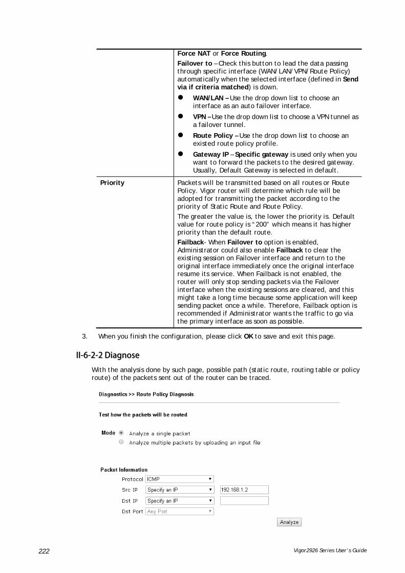
Vigor2926 Series User’s Guide 222
Force NAT or Force Routing.
Failover to – Check this button to lead the data passing through specific interface (WAN/LAN/VPN/Route Policy) automatically when the selected interface (defined in Send via if criteria matched) is down.
WAN/LAN – Use the drop down list to choose an interface as an auto failover interface.
VPN – Use the drop down list to choose a VPN tunnel as a failover tunnel.
Route Policy – Use the drop down list to choose an existed route policy profile.
Gateway IP – Specific gateway is used only when you want to forward the packets to the desired gateway. Usually, Default Gateway is selected in default.
Priority Packets will be transmitted based on all routes or Route Policy. Vigor router will determine which rule will be adopted for transmitting the packet according to the priority of Static Route and Route Policy.
The greater the value is, the lower the priority is. Default value for route policy is “200” which means it has higher priority than the default route.
Failback- When Failover to option is enabled, Administrator could also enable Failback to clear the existing session on Failover interface and return to the original interface immediately once the original interface resume its service. When Failback is not enabled, the router will only stop sending packets via the Failover interface when the existing sessions are cleared, and this might take a long time because some application will keep sending packet once a while. Therefore, Failback option is recommended if Administrator wants the traffic to go via the primary interface as soon as possible.
3. When you finish the configuration, please click OK to save and exit this page.
IIII--66--22--22 DDiiaaggnnoossee
With the analysis done by such page, possible path (static route, routing table or policy route) of the packets sent out of the router can be traced.

Vigor2926 Series User’s Guide 223
or
Available settings are explained as follows:
Item Description
Mode Analyze a single packet – Choose such mode to make Vigor router analyze how a single packet will be sent by a route policy.
Analyze multiple packets… - Choose such mode to make Vigor router analyze how multiple packets in a specified file will be sent by a route policy.
Packet Information Specify the nature of the packets to be analyzed by Vigor router.
ICMP/UDP/TCP/ANY- Specify a protocol for diagnosis.
Src IP – Type an IP address as the source IP.
Dst IP – Type an IP address as the destination IP.
Dst Port – Use the drop down list to specify the destination port.
Analyze – Click it to perform the job of analyzing. The analyzed result will be shown on the page. If required, click export analysis to export the result as a file.
Input File Select – Click the download link to get a blank example file. Then, click such button to select that blank “.csv” file for saving the result of analysis.
Analyze – Click it to perform the job of analyzing. The analyzed result will be shown on the page. If required, click export analysis to export the result as a file.

Vigor2926 Series User’s Guide 224
Note that the analysis was based on the current "load-balance/route policy" settings, we do not guarantee it will be 100% the same as the real case.
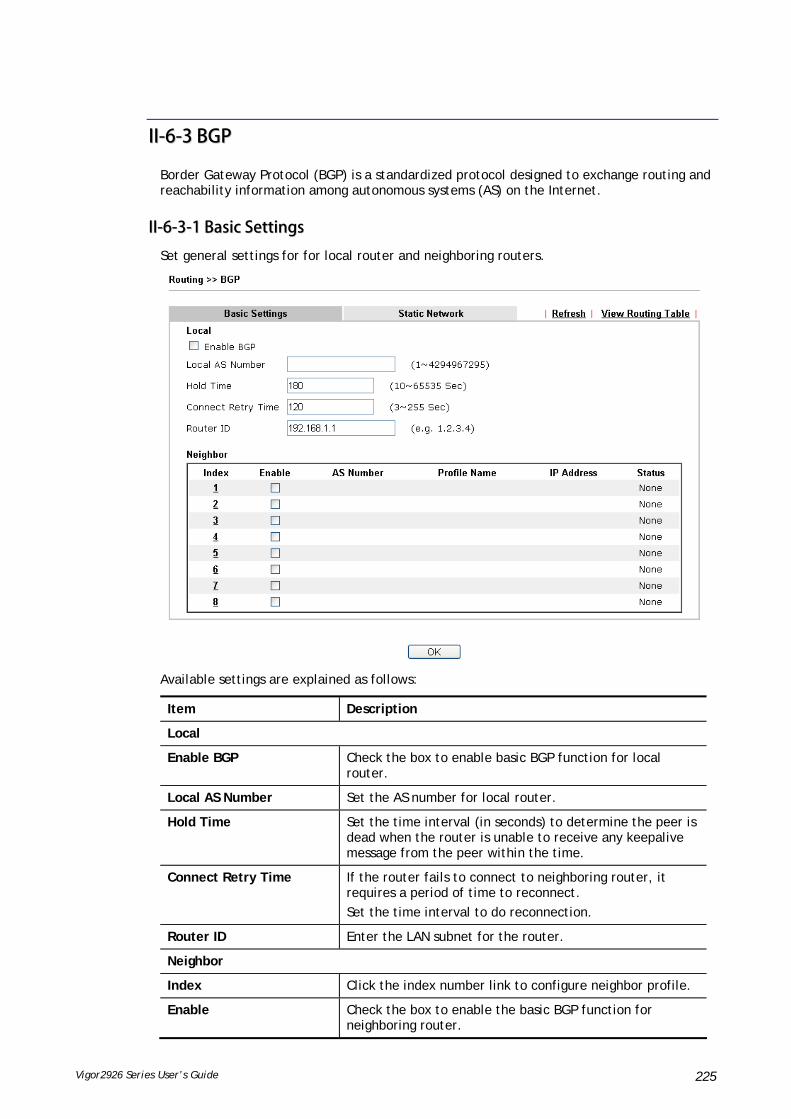
Vigor2926 Series User’s Guide 225
IIII--66--33 BBGGPP
Border Gateway Protocol (BGP) is a standardized protocol designed to exchange routing and reachability information among autonomous systems (AS) on the Internet.
IIII--66--33--11 BBaassiicc SSeettttiinnggss
Set general settings for for local router and neighboring routers.
Available settings are explained as follows:
Item Description
Local
Enable BGP Check the box to enable basic BGP function for local router.
Local AS Number Set the AS number for local router.
Hold Time Set the time interval (in seconds) to determine the peer is dead when the router is unable to receive any keepalive message from the peer within the time.
Connect Retry Time If the router fails to connect to neighboring router, it requires a period of time to reconnect.
Set the time interval to do reconnection.
Router ID Enter the LAN subnet for the router.
Neighbor
Index Click the index number link to configure neighbor profile.
Enable Check the box to enable the basic BGP function for neighboring router.

Vigor2926 Series User’s Guide 226
AS Number Display the AS Number for neighboring router.
Profile Name Display the name of the neighboring profile.
IP Address Display the IP address specified for the neighboring profile.
Status Display the connection status for local router and neighboring router.
IIII--66--33--11 SSttaattiicc NNeettwwoorrkk
This page allows you to configure up to eight neighboring routers for exchanging the routing information with the local router.
Available settings are explained as follows:
Item Description
Select Check the box to enable the configuration for the selected index entry.
IP Address Type the IP address for a router.
Subnet Mask Use the drop down list to specify a subnet mask for the IP address.

Vigor2926 Series User’s Guide 227
AApppplliiccaattiioonn NNootteess
AA--11 HHooww ttoo sseett uupp AAddddrreessss MMaappppiinngg wwiitthh RRoouuttee PPoolliiccyy??
Address Mapping is used to map a specified private IP or a range of private IPs of NAT subnet into a specified WAN IP (or WAN IP alias IP). Refer to the following figure.
This document introduces how to set up address mapping with Route Policy. When a WAN interface has multiple public IP addresses, Administrator may specify the outgoing IP for certain internal IP address by a Route Policy.
1. Set up WAN IP Alias. Go to WAN >> Internet Access >> Details Page, and click on WAN IP Alias button.
a. Check Enable.
b. Enter the WAN IP address.
c. Click OK to save.
After setting up the WAN IP Alias, the IP addresses will be shown in the drop-down list of Interface in Route Policy setting.

Vigor2926 Series User’s Guide 228
2. Go to Routing>>Load Balance/Route policy. Create a Route Policy for specific IP address to send from specific WAN IP Address.
a. Enable this policy.
b. Enter Source IP as the range of private IP address.
c. Leave the Destination IP and Port as Any.
d. Select Interface as WAN, and then select Interface address from the drop-down list. (The List can be edited in WAN IP Alias setting.)
e. Enable Failover to other WAN so the traffic will be sent via other Interface when the path fails. But do not enable this option if you want the traffic only to use a designated IP address.
f. Click OK to save.
3. After the above configuration, packet source from the range between 192.168.1.20 and 192.168.1.30 sent to the Internet will use the public IP 172.17.1.1.

Vigor2926 Series User’s Guide 229
AA--22 HHooww ttoo uussee ddeessttiinnaattiioonn ddoommaaiinn nnaammee iinn aa rroouuttee ppoolliiccyy??
Route Policy supports using a domain name as destination criteria. It provides a more direct way to set up route polices if the network administrator is trying to specify the gateway for the traffic that destined for a certain website.
To use a destination domain name as criteria, just select Domain Name as Destination in Criteria, and enter the domain name in the empty field.
Or you may click Select, and use a string that is pre-defined in Objects Settings >> String Object as the domain name.
Click Add too add more domain names, we can set up to 5 domain names in one route policy.

Vigor2926 Series User’s Guide 230
AAuuttoo--ccrreeaattee SSttrriinngg OObbjjeeccttss
If you manually enter the domain name in a route policy, after clicking OK to apply the route policy, those domain names will be given a number.
That means the router has automatically created string objects for those domain names, so that they can be used in other route policies or other functions.
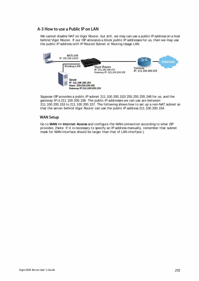
Vigor2926 Series User’s Guide 231
AA--33 HHooww ttoo uussee aa PPuubblliicc IIPP oonn LLAANN
We cannot disable NAT on Vigor Router, but still, we may can use a public IP address on a host behind Vigor Router. If our ISP allocates a block public IP addresses for us, then we may use the public IP address with IP Routed Subnet or Routing Usage LAN.
Suppose ISP provides a public IP subnet 211.100.200.152/255.255.255.248 for us, and the gateway IP is 211.100.200.158. The public IP addresses we can use are between 211.100.200.153 to 211.100.200.157. The following shows how to set up a non-NAT subnet so that the server behind Vigor Router can use the public IP address 211.100.200.154.
WWAANN SSeettuupp
Go to WAN >> Internet Access and configure the WAN connection according to what ISP provides. (Note: If it is necessary to specify an IP address manually, remember that subnet mask for WAN interface should be larger than that of LAN interface.)

Vigor2926 Series User’s Guide 232
Now we have two methods to configure it
IP Routed LAN
Routing Usage LAN
IIPP RRoouutteedd LLAANN SSeettuupp
1. Go to LAN >> General Setup, click on Details Page for IP Routed Subnet.
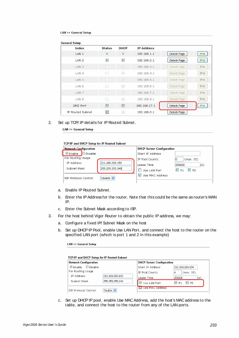
Vigor2926 Series User’s Guide 233
2. Set up TCP/IP details for IP Routed Subnet.
a. Enable IP Routed Subnet.
b. Enter the IP Address for the router. Note that this could be the same as router's WAN IP.
c. Enter the Subnet Mask according to ISP.
3. For the host behind Vigor Router to obtain the public IP address, we may:
a. Configure a fixed IP/Subnet Mask on the host
b. Set up DHCP IP Pool, enable Use LAN Port, and connect the host to the router on the specified LAN port (which is port 1 and 2 in this example)
c. Set up DHCP IP pool, enable Use MAC Address, add the host's MAC address to the table, and connect the host to the router from any of the LAN ports.

Vigor2926 Series User’s Guide 234
After finishing above configurations, host with a public IP 211.100.200.154/ mask 255.255.255.248/ Gateway IP 211.100.200.153 will be able to access Internet through Vigor Router.
RRoouuttiinngg UUssaaggee LLAANN
We may also create a LAN subnet for routing usage. Here we take LAN 2 for example.
1. Go to LAN >> VLAN,
a. Enable VLAN Configuration.
b. Set up a VLAN for LAN2 Subnet.
c. Specify the LAN ports that belongs to LAN2 subnet (which is port 5 and 6 in this example), note that these are the ports to which the host should connect.
2. Go to LAN >> General Setup, click on Details Page for LAN 2.

Vigor2926 Series User’s Guide 235
3. Set up TCP/IP details for LAN 2,
a. Enable LAN2.
b. Select For Routing Usage.
c. Enter the IP Address for the router. Note that this could be the same as router's WAN IP.
d. Enter the Subnet Mask according to ISP.
4. For DHCP Server Configuration, we may either:
Disable DHCP Server, and manually set a fixed IP/Subnet Mask on the host.
Enable DHCP Server, and set up the DHCP IP pool according to IP range which the ISP provides.
After finishing the above configurations, PC or Server that connects to Port 5 or Port 6 with IP settings as IP 211.100.200.154/ mask 255.255.255.252/ Gateway IP 211.100.200.153 will be able to access Internet through Vigor Router.
TTrroouubbllee--sshhoooottiinngg
If PC with public IP address setting cannot access Internet after above configuration, please check:

Vigor2926 Series User’s Guide 236
If the public IP address has been used by another device.
If the router's WAN Access Mode is "Static or Dynamic IP", make sure the subnet mask of WAN interface is larger than that of LAN interface.
If none of the above helps, please change the host's Gateway IP from Vigor Router's IP (211.100.200.153) to the IP Gateway IP (211.100.200.158), and connect the PC to the ISP Modem directly and see if it can work.

Vigor2926 Series User’s Guide 237
AA--44 IInnttrroodduuccttiioonn ttoo LLooaadd BBaallaannccee//RRoouuttee PPoolliiccyy
This document introduces the Load-Balance/Route Policy. This feature allows network administrator to manage the outbound traffic more specifically.
The Policy set in Load-Balance/Route Policy always has higher priority than Default Route and Auto Load Balance set in WAN >> General Setup, and always has lower priority than the Firewall Rules. Administrator may also define a priority to this policy.
To configure Route Policy, go to Routing>>Load-Balance/Route Policy. The following image is a screen-shot of Load-Balance/Route policy page. It lists all the policies and shows whether the policy is enabled, what are the criteria to match, and through which the interface should the traffic to go if the criteria are matched, and also its priority.
To set up a Route Policy, just click on an Index number. At the bottom of the page, there are two configuration modes could be choose: the Wizard Mode provides a simple and basic configuration; while Advance Mode allows more options.
1. First, set the criteria of the packets to apply this policy.
a. Select a Protocol.
b. Enter the Source IP address range, the Source IP could be a single address if the Start and End are the same.
c. Enter the Destination IP address range.
d. Select the Destination Port.
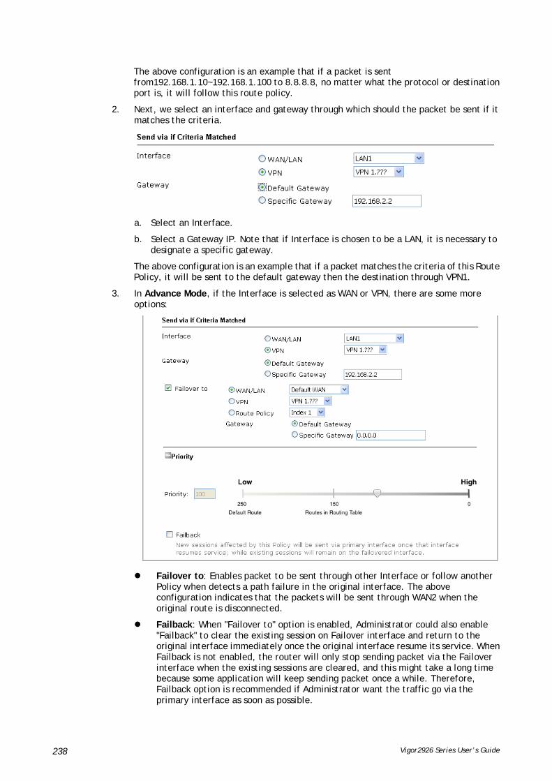
Vigor2926 Series User’s Guide 238
The above configuration is an example that if a packet is sent from192.168.1.10~192.168.1.100 to 8.8.8.8, no matter what the protocol or destination port is, it will follow this route policy.
2. Next, we select an interface and gateway through which should the packet be sent if it matches the criteria.
a. Select an Interface.
b. Select a Gateway IP. Note that if Interface is chosen to be a LAN, it is necessary to designate a specific gateway.
The above configuration is an example that if a packet matches the criteria of this Route Policy, it will be sent to the default gateway then the destination through VPN1.
3. In Advance Mode, if the Interface is selected as WAN or VPN, there are some more options:
Failover to: Enables packet to be sent through other Interface or follow another Policy when detects a path failure in the original interface. The above configuration indicates that the packets will be sent through WAN2 when the original route is disconnected.
Failback: When "Failover to" option is enabled, Administrator could also enable "Failback" to clear the existing session on Failover interface and return to the original interface immediately once the original interface resume its service. When Failback is not enabled, the router will only stop sending packet via the Failover interface when the existing sessions are cleared, and this might take a long time because some application will keep sending packet once a while. Therefore, Failback option is recommended if Administrator want the traffic go via the primary interface as soon as possible.

Vigor2926 Series User’s Guide 239
Priority: Administrator may set priority between 1 and 249 for this Route policy, where smaller number indicates higher priority. When two policies are having the same priority, the first (according to the policy index order) matched policy will be implemented.

Vigor2926 Series User’s Guide 240
IIII--77 LLTTEE
LTE WAN with SIM card can provide convinent Internet access for Vigor router. However, we can't stop thinking about what can Vigor router utilize this SIM card to provide more useful functions for user? Now, we have developed some useful functions for user, such as sending SMS from a router to report router status, rebooting router remotely via SMS with taking security into consideration, and so on.
This section can guide you to use the SIM card in LTE WAN to perform SMS related operations.
Info
This function is used for “L” models only.

Vigor2926 Series User’s Guide 241
WWeebb UUsseerr IInntteerrffaaccee
IIII--77--11 GGeenneerraall SSeettttiinnggss
IIII--77--11--11 SSMMSS QQuuoottaa
This page allows you to configure general settings for LTE. When SMS Quota Limit is enabled, you can specify the number of SMS quota, actions to perform when quota exceeded, and the period of resetting SMS quota used.
Available settings are explained as follows:
Item Description
Enable SMS Quota Limit Check the box to enable such feature.
Quota Limit Specify the maximum number of sending SMS for LTE.
When quota exceeded There are two actions to be performed when the quota limit is expired.
Stop sending SMS – If it is checked, no SMS for LTE will be sent after the quota limit is expired.
Send Mail Alert to Administrator – If it is checkd, a mail alert will be sent to the administrator when the quota limit is expired.
Monthly This setting is to offer a mechanism of resetting the number of SMS sent record every month.
SMS quota resets on day XX at XX … –You can determine the starting day in one month. The number of SMS sent will be

Vigor2926 Series User’s Guide 242
reset.
Custom This setting allows the user to define the billing cycle according to his request.
The number of SMS sent will be reset with an interval of cycle duration.
Custom – Monthly is default setting. If long period or a short period is required, use Custom. The period of reset is between 1 day and 60 days. You can determine the cycle duration by specifying the days and the hours.
Cycle duration: Specify the days to reset the number of SMS sent. For example, 7 means the whole cycle is 7 days; 20 means the whole cycle is 20 days. When the time is up, the router will reset the number of SMS sent automatically.
Today is day XX in the cycle –Specify the day in the cycle duration as the starting point which Vigor router will reset the number of SMS sent. For example, 3 means the third day of the duration cycle.
IIII--77--11--22 SSMMSS IInnbbooxx//OOuuttbbooxx PPoolliiccyy
This page lists policies for SMS inbox and outbox. Simple choose the one(s) you want.
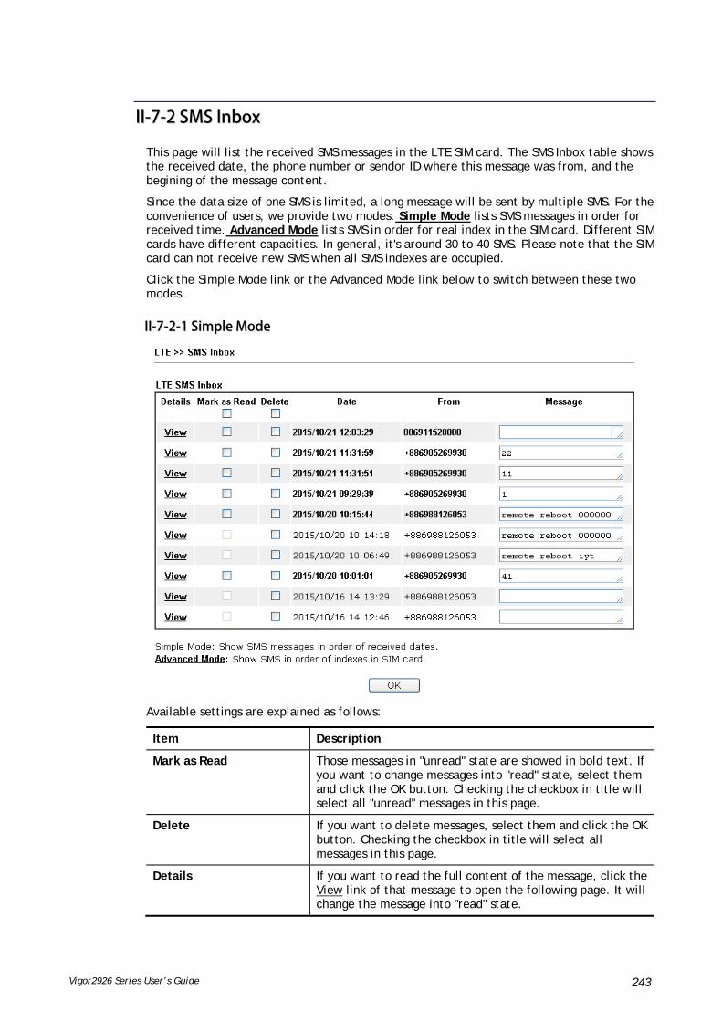
Vigor2926 Series User’s Guide 243
IIII--77--22 SSMMSS IInnbbooxx
This page will list the received SMS messages in the LTE SIM card. The SMS Inbox table shows the received date, the phone number or sendor ID where this message was from, and the begining of the message content.
Since the data size of one SMS is limited, a long message will be sent by multiple SMS. For the convenience of users, we provide two modes. Simple Mode lists SMS messages in order for received time. Advanced Mode lists SMS in order for real index in the SIM card. Different SIM cards have different capacities. In general, it's around 30 to 40 SMS. Please note that the SIM card can not receive new SMS when all SMS indexes are occupied.
Click the Simple Mode link or the Advanced Mode link below to switch between these two modes.
IIII--77--22--11 SSiimmppllee MMooddee
Available settings are explained as follows:
Item Description
Mark as Read Those messages in "unread" state are showed in bold text. If you want to change messages into "read" state, select them and click the OK button. Checking the checkbox in title will select all "unread" messages in this page.
Delete If you want to delete messages, select them and click the OK button. Checking the checkbox in title will select all messages in this page.
Details If you want to read the full content of the message, click the View link of that message to open the following page. It will change the message into "read" state.

Vigor2926 Series User’s Guide 244
Message Content - Display the full content of the
message.
OK - Return to previous page.
Delete - Click it to delete this message and return to previous page.
Next - Click it to see the content of next message.
IIII--77--22--11 AAddvvaanncceedd MMooddee
Available settings are explained as follows:
Item Description
Mark as Read Those SMS in "unread" state are shown in bold text. If you want to change SMS into "read" state, select them and click the OK button. Checking the checkbox in title will select all "unread" SMS in this page.
Delete If you want to delete SMS, select them and click the OK button. Checking the checkbox in title will select all SMS in this page.
Index If you want to read the full content of the message of the SMS, click the index link of that SMS to open the following page. It will change all SMS of the message into "read" state.

Vigor2926 Series User’s Guide 245
Message Content - Display the full content of the message.
OK - Return to previous page.
Delete - Click it to delete all SMS of this message and return to previous page.
Next - Click it to see the content of next SMS index.

Vigor2926 Series User’s Guide 246
IIII--77--33 SSeenndd SSMMSS
This page is used to send SMS messages by the LTE SIM card. It also displays the number of SMS required to send the message.
Available settings are explained as follows:
Item Description
Recipient Number Type the phone number of the recipient.
The format can be an international phone number ( +8869123455678) or a general phone number(0912345678).
Data Coding Scheme The router will automatically select a suitable Data Coding Scheme according to the current content in Message. GSM 7-bit and UCS-2 are supported.
Message Type in the message content to send.
The total number of characters that you can type in this field is 1024.
Send Message Click it to send this SMS message to the recipient immediately.
View SMS Outbox Cache Display the record of SMS messages sent from the Router.

Vigor2926 Series User’s Guide 247
IIII--77--44 RRoouutteerr CCoommmmaannddss
This page allows the user to set function to reboot Vigor router remotely and get the router status via SMS.
Go to LTE>>Router Commands to get the following page.
Available settings are explained as follows:
Item Description
Reboot on SMS Message
Enable with Password / PIN
To reboot Vigor router remotely via SMS, please check such box and type the password/PIN number (treated as
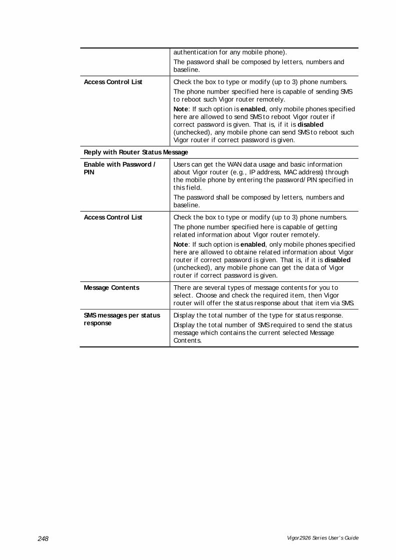
Vigor2926 Series User’s Guide 248
authentication for any mobile phone).
The password shall be composed by letters, numbers and baseline.
Access Control List Check the box to type or modify (up to 3) phone numbers.
The phone number specified here is capable of sending SMS to reboot such Vigor router remotely.
Note: If such option is enabled, only mobile phones specified here are allowed to send SMS to reboot Vigor router if correct password is given. That is, if it is disabled (unchecked), any mobile phone can send SMS to reboot such Vigor router if correct password is given.
Reply with Router Status Message
Enable with Password / PIN
Users can get the WAN data usage and basic information about Vigor router (e.g., IP address, MAC address) through the mobile phone by entering the password/PIN specified in this field.
The password shall be composed by letters, numbers and baseline.
Access Control List Check the box to type or modify (up to 3) phone numbers.
The phone number specified here is capable of getting related information about Vigor router remotely.
Note: If such option is enabled, only mobile phones specified here are allowed to obtaine related information about Vigor router if correct password is given. That is, if it is disabled (unchecked), any mobile phone can get the data of Vigor router if correct password is given.
Message Contents There are several types of message contents for you to select. Choose and check the required item, then Vigor router will offer the status response about that item via SMS.
SMS messages per status response
Display the total number of the type for status response.
Display the total number of SMS required to send the status message which contains the current selected Message Contents.

Vigor2926 Series User’s Guide 249
IIII--77--55 SSttaattuuss
Vigor router with LTE function is capable of accessing into Internet and able to send SMS to specified mobile phone.
This page will display basic information about the embedded LTE module and the current LTE connection.
Each item is explained as follows:
Item Description
Status LTE WAN status.
IMEI International Mobile Equipment Identity of the embedded LTE module.
IMSI International Mobile Subscripber Identity of the LTE SIM card.
Access Tech Type of LTE connection (CDMA/GSM/WCDMA/LTE/TD-SCDMA).
Band Band of LTE connection.
Operator ISP name of LTE connection.
Mobile Country Code / Mobile Network Code / Location Area Code / Cell ID :
Base station information.
Signal Signal strength of LTE connection.
Active Channel Frequency of LTE connection.
Interference with 2.4GHz Whether the current LTE frequency causes interference with 2.4G wireless. If Yes, the interfered 2.4G wireless channels

Vigor2926 Series User’s Guide 250
WLAN will be indicated.
Max Channel TX Rate / Max Channel RX Rate
Maximum TX/RX link rate of LTE connection.
SMS Centre Number The phone number for SMS service of the LTE SIM card.
SMS Service status Whether the SMS service of the LTE SIM card is ready.
SMS Loading Whether the received SMS messages in the LTE SIM card have been loaded to the Router.
New SMS The number of unread SMS in SMS Inbox.

Vigor2926 Series User’s Guide 251
PPaarrtt IIIIII WWiirreelleessss LLAANN
Wireless LAN enables high mobility so WLAN users can simultaneously access all LAN facilities just like on a wired LAN as well as Internet access.

Vigor2926 Series User’s Guide 252
IIIIII--11 WWiirreelleessss LLAANN ((22..44GGHHzz//55GGHHzz))
This function is used for “n”and “ac” models only.
Over recent years, the market for wireless communications has enjoyed tremendous growth. Wireless technology now reaches or is capable of reaching virtually every location on the surface of the earth. Hundreds of millions of people exchange information every day via wireless communication products. The Vigor2926 wireless series router (with “n”, “n-plus” or “ac” in model name) is designed for maximum flexibility and efficiency of a small office/home. Any authorized staff can bring a built-in WLAN client PDA or notebook into a meeting room for conference without laying a clot of LAN cable or drilling holes everywhere. Wireless LAN enables high mobility so WLAN users can simultaneously access all LAN facilities just like on a wired LAN as well as Internet access.
The Vigor wireless routers are equipped with a wireless LAN interface compliant with the standard IEEE 802.11n draft 2 protocol. To boost its performance further, the Vigor Router is also loaded with advanced wireless technology to lift up data rate up to 300 Mbps*. Hence, you can finally smoothly enjoy stream music and video.
Vigor2926 wireless router is a highly integrated wireless local area network (WLAN) for 5 GHz 802.11ac or 2.4/5 GHz 802.11n WLAN applications. It supports channel operations of 20/40 MHz at 2.4 GHz and 20/40/80 MHz at 5 GHz. Vigor2926 “ac” series router can support data rates up to 1.3 Gbps in 802.11ac 80 MHz channels. Vigor2926 “n” series router supports 802.11n up to 300 Mbps for 40 MHz channel operations.
Info
The actual data throughput will vary according to the network conditions and environmental factors, including volume of network traffic, network overhead and building materials.
In an Infrastructure Mode of wireless network, Vigor wireless router plays a role as an Access Point (AP) connecting to lots of wireless clients or Stations (STA). All the STAs will share the same Internet connection via Vigor wireless router. The General Settings will set up the information of this wireless network, including its SSID as identification, located channel etc.
MMuullttiippllee SSSSIIDDss

Vigor2926 Series User’s Guide 253
Vigor router supports four SSID settings for wireless connections. Each SSID can be defined with different name and download/upload rate for selecting by stations connected to the router wirelessly.
RReeaall--ttiimmee HHaarrddwwaarree EEnnccrryyppttiioonn
Vigor Router is equipped with a hardware AES encryption engine so it can apply the highest protection to your data without influencing user experience.
CCoommpplleettee SSeeccuurriittyy SSttaannddaarrdd SSeelleeccttiioonn
To ensure the security and privacy of your wireless communication, we provide several prevailing standards on market.
WEP (Wired Equivalent Privacy) is a legacy method to encrypt each frame transmitted via radio using either a 64-bit or 128-bit key. Usually access point will preset a set of four keys and it will communicate with each station using only one out of the four keys.
WPA (Wi-Fi Protected Access), the most dominating security mechanism in industry, is separated into two categories: WPA-personal or called WPA Pre-Share Key (WPA/PSK), and WPA-Enterprise or called WPA/802.1x.
In WPA-Personal, a pre-defined key is used for encryption during data transmission. WPA applies Temporal Key Integrity Protocol (TKIP) for data encryption while WPA2 applies AES. The WPA-Enterprise combines not only encryption but also authentication.
Since WEP has been proved vulnerable, you may consider using WPA for the most secure connection. You should select the appropriate security mechanism according to your needs. No matter which security suite you select, they all will enhance the over-the-air data protection and /or privacy on your wireless network. The Vigor wireless router is very flexible and can support multiple secure connections with both WEP and WPA at the same time.
Info
The password (PSK) of default security mode is provided and stated on the label pasted on the bottom of the router. For the wireless client who wants to access into Internet through such router, please input the default PSK value for connection.
SSeeppaarraattee tthhee WWiirreelleessss aanndd tthhee WWiirreedd LLAANN-- WWLLAANN IIssoollaattiioonn
It enables you to isolate your wireless LAN from wired LAN for either quarantine or limit access reasons. To isolate means neither of the parties can access each other. To elaborate an example for business use, you may set up a wireless LAN for visitors only so they can connect to Internet without hassle of the confidential information leakage. For a more flexible deployment, you may add filters of MAC addresses to isolate users’ access from wired LAN.
MMaannaaggee WWiirreelleessss SSttaattiioonnss -- SSttaattiioonn LLiisstt

Vigor2926 Series User’s Guide 254
It will display all the stations in your wireless network and the status of their connection.
DDFFSS RReessttrriiccttiioonnss
Some of 5GHz channels are DFS channels which are governed radars. Without passing DFS certificate test, we can not open those DFS channels in Vigor router. We are working on DFS certification in Europe and open those channels by releasing new firmware once we receive DFS certification. According to DFS certificate in Europe, we will open channels 52, 56, 60, 64, 100, 104, 108, 112, 116, 120, 124, 128, 132, and 136.
At present, we will not open DFS channels in the USA because we do not have plan for DFS certification in the USA. Channels 52, 56, 60, 64, 100, 104, 108, 112, 116, 120, 124, 128, 132, and 136 will be restricted in the USA.
In some countries, there are restrictions on DFS channels as well. We will implement country code to restrict uncertified channels.
Below shows the menu items for Wireless LAN (2.4Ghz) and Wireless LAN(5GHz).
WWPPSS
WPS (Wi-Fi Protected Setup) provides easy procedure to make network connection between wireless station and wireless access point (vigor router) with the encryption of WPA and WPA2.

Vigor2926 Series User’s Guide 255
WWeebb UUsseerr IInntteerrffaaccee
IIIIII--11--11 WWiirreelleessss WWiizzaarrdd
The wireless wizard allows you to configure settings specified for a host AP (for home use or internal use for a company) and specified for a guest AP (for any wireless clients accessing into Internet).
Follow the steps listed below:
1. Open Wizards>>Wireless Wizard.
2. The screen of wireless wizard will be shown as follows. This page will be used for internal users in a company or your home. Besides, the settings will change based on different model of Vigor2926 series. In this case, Vigor2926ac is used as an example.
Available settings are explained as follows:

Vigor2926 Series User’s Guide 256
Item Description
Wireless 2.4GHz Settings
Name Type the SSID name of this router for wireless 2.4GHz. The default name is defined with DrayTek. Change the name if required.
Mode At present, the router can connect to 11n Only, 11g Only, Mixed (11b+11g), Mixed (11a+11n), Mixed (11g+11n), and Mixed (11b+11g+11n) stations simultaneously. Simply choose Mix (11b+11g+11n) mode.
Channel Means the channel of frequency of the wireless LAN. The default channel is 6. You may switch channel if the selected channel is under serious interference. If you have no idea of choosing the frequency, please select Auto to let system determine for you.
Security Key The wireless mode offered by this wizard is WPA2/PSK.
The WPA encrypts each frame transmitted from the radio using the key, which either PSK (Pre-Shared Key) entered manually in this field below or automatically negotiated via 802.1x authentication.
Either 8~63 ASCII characters, such as 012345678(or 64 Hexadecimal digits leading by 0x, such as “0x321253abcde…”).
Wireless 5GHz Settings – Such part is available when your Vigor router supports wireless 5GHz.
Use the same SSID and Security Key as above
Check the box to use the same settings configured above.
Name Type the SSID name of this router for wireless 5GHz.
Mode At present, the router can connect to 11a Only, 11n Only (5GHz), Mixed (11a+11n) and Mixed (11a+11n+11ac) stations simultaneously.
Channel Means the channel of frequency of the wireless LAN. The default channel is 36. You may switch channel if the selected channel is under serious interference. If you have no idea of choosing the frequency, please select Auto to let system determine for you.
Security Key The wireless mode offered by this wizard is WPA2/PSK.
The WPA encrypts each frame transmitted from the radio using the key, which either PSK (Pre-Shared Key) entered manually in this field below or automatically negotiated via 802.1x authentication.
Either 8~63 ASCII characters, such as 012345678(or 64 Hexadecimal digits leading by 0x, such as "0x321253abcde...").

Vigor2926 Series User’s Guide 257
Next Click it to get into the next setting page.
Cancel Exit the wireless wizard without saving any changes.
3. After typing the required information, click Next. The settings in the page limit the wireless station (guest) accessing into Internet but not being allowed to share the LAN network and VPN connection.
Available settings are explained as follows:
Item Description
Wireless 2.4GHz Settings
Enable/Disable Click it to enable or disable settings in this page.
SSID Type the SSID name of this router. (SSID1)
Security Key The wireless mode offered by this wizard is WPA2/PSK.
The WPA encrypts each frame transmitted from the radio using the key, which either PSK (Pre-Shared Key) entered manually in this field below or automatically negotiated via 802.1x authentication.
Either 8~63 ASCII characters, such as 012345678(or 64 Hexadecimal digits leading by 0x, such as "0x321253abcde...").
Bandwidth Limit Enable – Check the box to set the bandwidth limit for data transmission in upload and download.
It controls the data transmission rate through wireless connection.
Total Upload – Check Enable and type the transmitting rate for data upload. Default value is 30,000 kbps.
Total Download – Type the transmitting rate for data download. Default value is 30,000 kbps.
Wireless 5GHz Settings
Enable/Disable Click it to enable or disable settings in this page.
Use the same SSID and Security Key as
Check the box to use the same settings configured above.

Vigor2926 Series User’s Guide 258
above
SSID Type the SSID name of this router. (SSID2)
Security Key The wireless mode offered by this wizard is WPA2/PSK.
The WPA encrypts each frame transmitted from the radio using the key, which either PSK (Pre-Shared Key) entered manually in this field below or automatically negotiated via 802.1x authentication.
Either 8~63 ASCII characters, such as 012345678(or 64 Hexadecimal digits leading by 0x, such as "0x321253abcde...").
Next Click it to get into the next setting page.
Cancel Exit the wireless wizard without saving any changes.
4. After typing the required information, click Next.
5. The following page will display the configuration summary for wireless setting.
6. Click Finish to complete the wireless settings configuration.

Vigor2926 Series User’s Guide 259
IIIIII--11--22 GGeenneerraall SSeettuupp
By clicking the Wireless LAN>>General Setup, a new web page will appear so that you could configure the SSID and the wireless channel. Please refer to the following figure for more information.
Available settings are explained as follows:
Item Description
Enable Wireless LAN Check the box to enable wireless function.
Mode 2.4GHz in “n” and “ac” model:
At present, the router can connect to 11g Only, 11n Only(2.4 GHz), Mixed (11b+11g), Mixed (11g+11n), and Mixed (11b+11g+11n) stations simultaneously. Simply choose Mixed (11b+11g+11n) mode.

Vigor2926 Series User’s Guide 260
5 GHz in “n” model:
At present, the router can connect to 11a Only, 11n Only (5 GHz), Mixed (11a+11n) stations simultaneously. Simply choose Mixed (11a+11n) mode.
5 GHz in “ac” model:
At present, the router can connect to 11a Only, 11n Only (5 GHz), Mixed (11a+11n) and Mixed (11a+11n+11ac) stations simultaneously. Simply choose Mixed (11a+11n+11ac) mode.
Note: 802.11b/g operates on 2.4G band, 802.11a operates on 5G band, 802.11n operates on either 2.4G or 5G band, and 802.11ac operates on 5G band only.
Channel Means the channel of frequency of the wireless LAN. The default channel is 6. You may switch channel if the selected channel is under serious interference. If you have no idea of choosing the frequency, please select Auto to let system determine for you.
2.4GHz in “n” and “ac” model:
For 5 GHz in “n” model:

Vigor2926 Series User’s Guide 261
5 GHz in “ac” model:
Note: For the restricted channels on DFS, please refer to 4.18.1 Basic Concepts for more detailed information.
Hide SSID Check it to prevent from wireless sniffing and make it harder for unauthorized clients or STAs to join your wireless LAN. Depending on the wireless utility, the user may only see the information except SSID or just cannot see any thing about Vigor wireless router while site surveying. The system allows you to set four sets of SSID for different usage. In default, the first set of SSID will be enabled. You can hide it for your necessity.
SSID Means the identification of the wireless LAN. SSID can be any text numbers or various special characters.
Isolate Member –Check this box to make the wireless clients (stations) with the same SSID not accessing for each other.
VPN – Check this box to make the wireless clients (stations) with different VPN not accessing for each other.
Schedule Profiles Set the wireless LAN to work at certain time interval only. You may choose up to 4 schedules out of the 15 schedules pre-defined in Applications >> Schedule setup. The default setting of this field is blank and the function will always work.
Enable Special SSID Schedule Profiles
Selected SSID (2 /3 /4) will be forced up /down based on the schedule profile used.
After finishing all the settings here, please click OK to save the configuration.

Vigor2926 Series User’s Guide 262
IIIIII--11--33 SSeeccuurriittyy
This page allows you to set security with different modes for SSID 1, 2, 3 and 4 respectively. After configuring the correct settings, please click OK to save and invoke it.
The password (PSK) of default security mode is provided and stated on the label pasted on the bottom of the router. For the wireless client who wants to access into Internet through such router, please input the default PSK value for connection.
By clicking the Wireless LAN>>Security Settings, a new web page will appear so that you could configure the settings of WPA and WEP.
Available settings are explained as follows:
Item Description
Mode There are several modes provided for you to choose.

Vigor2926 Series User’s Guide 263
Info
You should also set Wireless LAN(2.4GHz) 802.1X Setting simultaneously if 802.1x mode is selected.
Disable - Turn off the encryption mechanism.
WEP-Accepts only WEP clients and the encryption key should be entered in WEP Key.
WEP/802.1x Only - Accepts only WEP clients and the encryption key is obtained dynamically from RADIUS server with 802.1X protocol.
WPA/802.1x Only- Accepts only WPA clients and the encryption key is obtained dynamically from RADIUS server with 802.1X protocol.
WPA2/802.1x Only- Accepts only WPA2 clients and the encryption key is obtained dynamically from RADIUS server with 802.1X protocol.
Mixed (WPA+WPA2/802.1x only) - Accepts WPA and WPA2 clients simultaneously and the encryption key is obtained dynamically from RADIUS server with 802.1X protocol.
WPA/PSK-Accepts only WPA clients and the encryption key should be entered in PSK.
WPA2/PSK-Accepts only WPA2 clients and the encryption key should be entered in PSK.
Mixed (WPA+ WPA2)/PSK - Accepts WPA and WPA2 clients simultaneously and the encryption key should be entered in PSK.
WPA The WPA encrypts each frame transmitted from the radio using the key, which either PSK (Pre-Shared Key) entered manually in this field below or automatically negotiated via 802.1x authentication. Either 8~63 ASCII characters, such as 012345678(or 64 Hexadecimal digits leading by 0x, such as "0x321253abcde...").
Pre-Shared Key (PSK) - Either 8~63 ASCII characters, such as 012345678..(or 64 Hexadecimal digits leading by 0x, such as "0x321253abcde...").
Password Strength – The system will display the password strength (represented with the word of weak, medium or strong) of the PSK specified above.
WEP 64-Bit - For 64 bits WEP key, either 5 ASCII characters, such as 12345 (or 10 hexadecimal digitals leading by 0x, such as 0x4142434445.)

Vigor2926 Series User’s Guide 264
128-Bit - For 128 bits WEP key, either 13 ASCII characters, such as ABCDEFGHIJKLM (or 26 hexadecimal digits leading by 0x, such as 0x4142434445464748494A4B4C4D).
All wireless devices must support the same WEP encryption bit size and have the same key. Four keys can be entered here, but only one key can be selected at a time. The keys can be entered in ASCII or Hexadecimal. Check the key you wish to use.
After finishing all the settings here, please click OK to save the configuration.
IIIIII--11--44 AAcccceessss CCoonnttrrooll
In the Access Control, the router may restrict wireless access to certain wireless clients only by locking their MAC address into a black or white list. The user may block wireless clients by inserting their MAC addresses into a black list, or only let them be able to connect by inserting their MAC addresses into a white list.
In the Access Control web page, users may configure the white/black list modes used by each SSID and the MAC addresses applied to their lists.
Available settings are explained as follows:
Item Description
Enable Mac Address Filter Select to enable the MAC Address filter for wireless LAN identified with SSID 1 to 4 respectively. All the clients

Vigor2926 Series User’s Guide 265
(expressed by MAC addresses) listed in the box can be grouped under different wireless LAN. For example, they can be grouped under SSID 1 and SSID 2 at the same time if you check SSID 1 and SSID 2.
MAC Address Filter Display all MAC addresses that are edited before.
Client’s MAC Address Manually enter the MAC address of wireless client.
Apply SSID After entering the client’s MAC address, check the box of the SSIDs desired to insert this MAC address into their access control list.
Attribute s: Isolate the station from LAN - select to isolate the wireless connection of the wireless client of the MAC address from LAN.
Comment Type a brief description for the specified client’s MAC address.
Add Add a new MAC address into the list.
Delete Delete the selected MAC address in the list.
Edit Edit the selected MAC address in the list.
Cancel Give up the access control set up.
OK Click it to save the access control list.
Clear All Clean all entries in the MAC address list.
Backup Access Control Settings on this web page can be saved as a file which can be restored in the future by this device or other device.
Upload From File Restore wireless access control settings and applied onto this device.
After finishing all the settings here, please click OK to save the configuration.
IIIIII--11--55 WWPPSS
WPS (Wi-Fi Protected Setup) provides easy procedure to make network connection between wireless station and wireless access point (vigor router) with the encryption of WPA and WPA2.

Vigor2926 Series User’s Guide 266
Info
WPS is available for the wireless station with WPS supported.
It is the simplest way to build connection between wireless network clients and vigor router. Users do not need to select any encryption mode and type any long encryption passphrase to setup a wireless client every time. He/she only needs to press a button on wireless client, and WPS will connect for client and router automatically.
There are two methods to do network connection through WPS between AP and Stations: pressing the Start PBC button or using PIN Code.
On the side of Vigor2926 series which served as an AP, press WPS button once on the front panel of the router or click Start PBC on web configuration interface. On the side of a station with network card installed, press Start PBC button of network card.
If you want to use PIN code, you have to know the PIN code specified in wireless client. Then provide the PIN code of the wireless client you wish to connect to the vigor router.
For WPS is supported in WPA-PSK or WPA2-PSK mode, if you do not choose such mode in Wireless LAN>>Security, you will see the following message box.
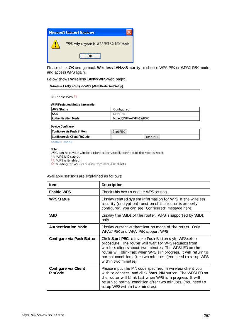
Vigor2926 Series User’s Guide 267
Please click OK and go back Wireless LAN>>Security to choose WPA-PSK or WPA2-PSK mode and access WPS again.
Below shows Wireless LAN>>WPS web page:
Available settings are explained as follows:
Item Description
Enable WPS Check this box to enable WPS setting.
WPS Status Display related system information for WPS. If the wireless security (encryption) function of the router is properly configured, you can see ‘Configured’ message here.
SSID Display the SSID1 of the router. WPS is supported by SSID1 only.
Authentication Mode Display current authentication mode of the router. Only WPA2/PSK and WPA/PSK support WPS.
Configure via Push Button Click Start PBC to invoke Push-Button style WPS setup procedure. The router will wait for WPS requests from wireless clients about two minutes. The WPS LED on the router will blink fast when WPS is in progress. It will return to normal condition after two minutes. (You need to setup WPS within two minutes)
Configure via Client PinCode
Please input the PIN code specified in wireless client you wish to connect, and click Start PIN button. The WPS LED on the router will blink fast when WPS is in progress. It will return to normal condition after two minutes. (You need to setup WPS within two minutes)

Vigor2926 Series User’s Guide 268
IIIIII--11--66 WWDDSS
WDS means Wireless Distribution System. It is a protocol for connecting two access points (AP) wirelessly. Usually, it can be used for the following application:
Provide bridge traffic between two LANs through the air.
Extend the coverage range of a WLAN.
Refer to the following table:
WDS Mode Wireless Signal
Comparisons
Bridge
Limited
Wireless stations (clients) within the effective range of wireless signal can access into Internet through the router /AP.
Wireless stations (clients) out of the effective range of wireless signal cannot access into Internet through the router /AP with Bridge mode configured.
The packets received from a WDS link will only be forwarded to local wired or wireless hosts.
Repeater
Extended
Wireless stations (clients) within the effective range of wireless signal can access into Internet through the router /AP.
Wireless stations (clients) out of the effective range of wireless signal can access into Internet through the router /AP with Repeater mode configured.
The packets received from one Vigor router can be repeated to another AP (remotely) through WDS links.
Only Repeater mode can do WDS-to-WDS packet forwarding.
To meet the above requirement, two WDS modes are implemented in Vigor router. One is Bridge, the other is Repeater. Below shows the function of WDS-bridge interface:
The application for the WDS-Repeater mode is depicted as below:
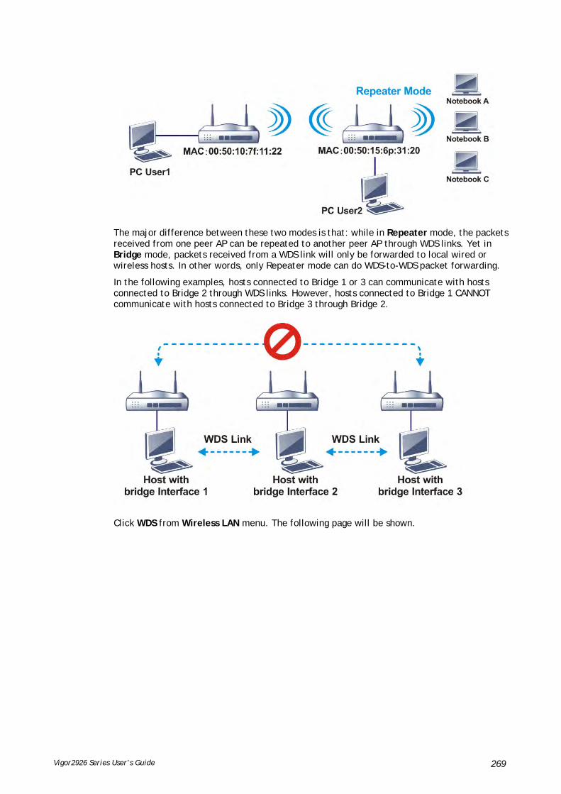
Vigor2926 Series User’s Guide 269
The major difference between these two modes is that: while in Repeater mode, the packets received from one peer AP can be repeated to another peer AP through WDS links. Yet in Bridge mode, packets received from a WDS link will only be forwarded to local wired or wireless hosts. In other words, only Repeater mode can do WDS-to-WDS packet forwarding.
In the following examples, hosts connected to Bridge 1 or 3 can communicate with hosts connected to Bridge 2 through WDS links. However, hosts connected to Bridge 1 CANNOT communicate with hosts connected to Bridge 3 through Bridge 2.
Click WDS from Wireless LAN menu. The following page will be shown.
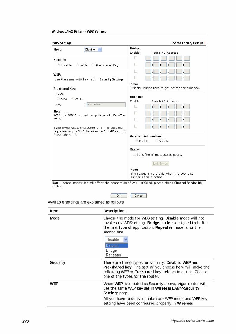
Vigor2926 Series User’s Guide 270
Available settings are explained as follows:
Item Description
Mode Choose the mode for WDS setting. Disable mode will not invoke any WDS setting. Bridge mode is designed to fulfill the first type of application. Repeater mode is for the second one.
Security There are three types for security, Disable, WEP and Pre-shared key. The setting you choose here will make the following WEP or Pre-shared key field valid or not. Choose one of the types for the router.
WEP When WEP is selected as Security above, Vigor router will use the same WEP key set in Wireless LAN>>Security Settings page.
All you have to do is to make sure WEP mode and WEP key setting have been configured properly in Wireless

Vigor2926 Series User’s Guide 271
LAN>>Security Settings.
Note: If Security mode configured in Wireless LAN>>Security Settings page is not the same as the security mode set here, a warning message will appear and ask you to make the same configuration.
Pre-shared Key When Pre-Shared Key is selected as Security above, configure the following settings if required.
Type – There are some types for you to choose. WPA and WPA2 are used for WDS devices (e.g.2925n wireless router, you can set the encryption mode as WPA or WPA2 to establish your WDS system between AP and the router.
Key – Set the encryption key in this field. Type 8 ~ 63 ASCII characters or 64 hexadecimal digits leading by “0x”.
Bridge If you choose Bridge as the connecting mode, please type in the peer MAC address (of VigorAP/Vigor router required to make connection with such Vigor router) in these fields.
Four peer MAC addresses are allowed to be entered in this page at one time. Yet please disable the unused link to get better performance. If you want to invoke the peer MAC address, remember to check Enable box in the front of the MAC address after typing.
Repeater If you choose Repeater as the connecting mode, please type in the peer MAC address (of VigorAP/Vigor router required to make connection with such Vigor router and used to extend the wireless signal) in these fields.
Four peer MAC addresses are allowed to be entered in this page at one time. Similarly, if you want to invoke the peer MAC address, remember to check Enable box in the front of the MAC address after typing.
Access Point Function Click Enable to make this router serve as an access point. When Repeater is set as WDS Mode, click Enable to use such function.
Click Disable if Bridge is set as WDS Mode.
Status It allows user to send “hello” message to peers. Yet, it is valid only when the peer also supports this function.
After finishing all the settings here, please click OK to save the configuration.

Vigor2926 Series User’s Guide 272
IIIIII--11--77 AAddvvaanncceedd SSeettttiinngg
This page allows users to set advanced settings such as operation mode, channel bandwidth, guard interval, and aggregation MSDU for wireless data transmission.
For “n, ac” model ---
Available settings are explained as follows:
Item Description
Operation Mode Mixed Mode – the router can transmit data with the ways supported in both 802.11a/b/g and 802.11n standards. However, the entire wireless transmission will be slowed down if 802.11g or 802.11b wireless client is connected.
Green Field – to get the highest throughput, please choose such mode. Such mode can make the data transmission happen between 11n systems only. In addition, it does not have protection mechanism to avoid the conflict with neighboring devices of 802.11a/b/g.
Channel Bandwidth 20- the router will use 20Mhz for data transmission and receiving between the AP and the stations.
40- the router will use 40Mhz for data transmission and receiving between the AP and the stations.
20/40 – Vigor Router will scan for nearby wireless AP, and then use 20MHz if the number of AP is more than 10, or use 40MHz if it's not.
Guard Interval It is to assure the safety of propagation delays and reflections for the sensitive digital data. If you choose auto as guard interval, the AP router will choose short guard interval (increasing the wireless performance) or long guard interval for data transmit based on the station capability.
Aggregation MSDU Aggregation MSDU can combine frames with different sizes. It is used for improving MAC layer’s performance for some brand’s clients. The default setting is Enable.
Long Preamble This option is to define the length of the sync field in an 802.11 packet. Most modern wireless network uses short
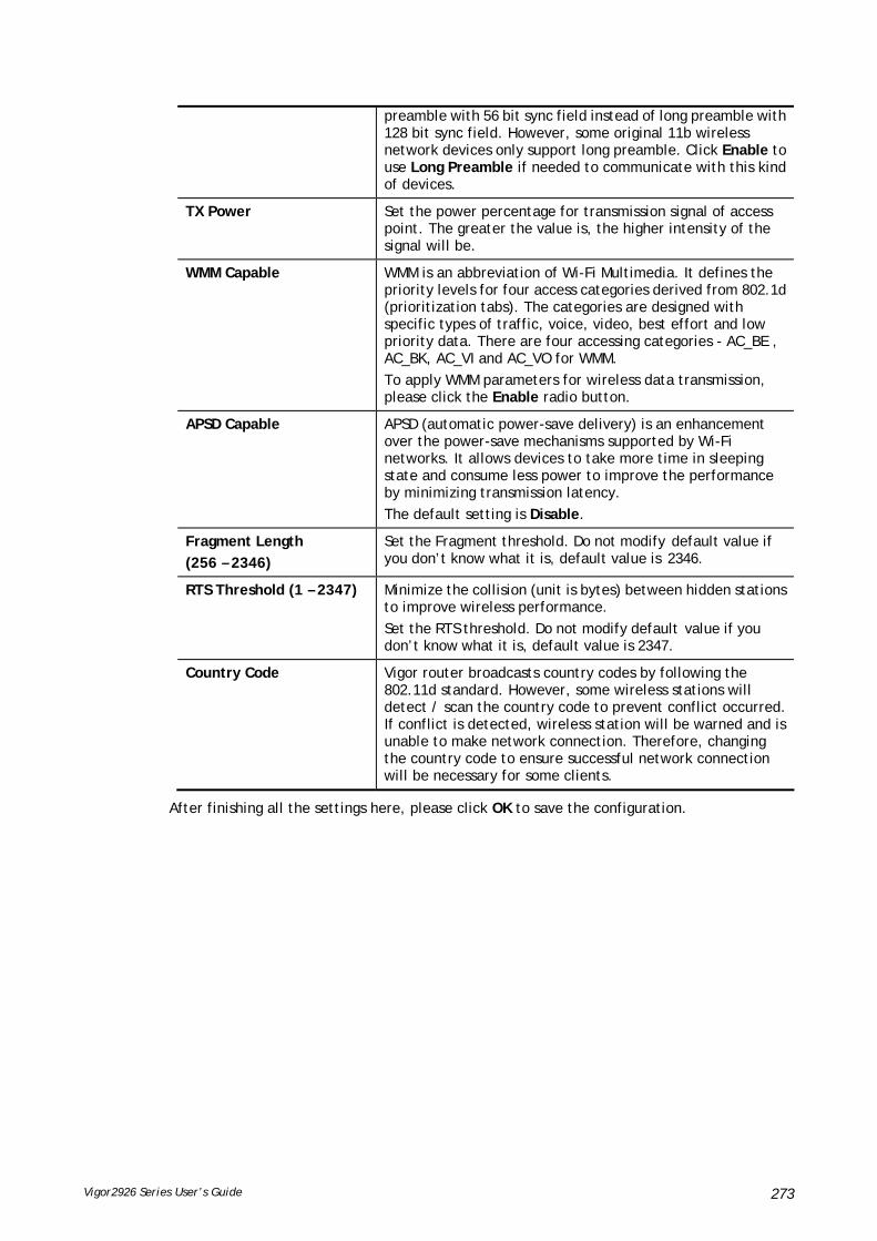
Vigor2926 Series User’s Guide 273
preamble with 56 bit sync field instead of long preamble with 128 bit sync field. However, some original 11b wireless network devices only support long preamble. Click Enable to use Long Preamble if needed to communicate with this kind of devices.
TX Power Set the power percentage for transmission signal of access point. The greater the value is, the higher intensity of the signal will be.
WMM Capable WMM is an abbreviation of Wi-Fi Multimedia. It defines the priority levels for four access categories derived from 802.1d (prioritization tabs). The categories are designed with specific types of traffic, voice, video, best effort and low priority data. There are four accessing categories - AC_BE , AC_BK, AC_VI and AC_VO for WMM.
To apply WMM parameters for wireless data transmission, please click the Enable radio button.
APSD Capable APSD (automatic power-save delivery) is an enhancement over the power-save mechanisms supported by Wi-Fi networks. It allows devices to take more time in sleeping state and consume less power to improve the performance by minimizing transmission latency.
The default setting is Disable.
Fragment Length
(256 – 2346)
Set the Fragment threshold. Do not modify default value if you don’t know what it is, default value is 2346.
RTS Threshold (1 – 2347) Minimize the collision (unit is bytes) between hidden stations to improve wireless performance.
Set the RTS threshold. Do not modify default value if you don’t know what it is, default value is 2347.
Country Code Vigor router broadcasts country codes by following the 802.11d standard. However, some wireless stations will detect / scan the country code to prevent conflict occurred. If conflict is detected, wireless station will be warned and is unable to make network connection. Therefore, changing the country code to ensure successful network connection will be necessary for some clients.
After finishing all the settings here, please click OK to save the configuration.

Vigor2926 Series User’s Guide 274
IIIIII--11--88 SSttaattiioonn CCoonnttrrooll
Station Control is used to specify the duration for the wireless client to connect and reconnect Vigor router. If such function is not enabled, the wireless client can connect Vigor router until the router shuts down.
Such feature is especially useful for free Wi-Fi service. For example, a coffee shop offers free Wi-Fi service for its guests for one hour every day. Then, the connection time can be set as “1 hour” and reconnection time can be set as “1 day”. Thus, the guest can finish his job within one hour and will not occupy the wireless network for a long time.
Available settings are explained as follows:
Item Description
SSID Display the SSID that the wireless station will use it to connect with Vigor router.
Enable Check the box to enable the station control function.
Connection Time / Reconnection Time
Use the drop down list to choose the duration for the wireless client connecting /reconnecting to Vigor router. Or, type the duration manually when you choose User defined.
Display All Station Control List
All the wireless stations connecting to Vigor router by using such SSID will be listed on Station Control List.
Hotspot Web Portal Click it to access in to Hotspot Web Portal page for modifying the settings if required.
After finishing all the settings here, please click OK to save the configuration.

Vigor2926 Series User’s Guide 275
IIIIII--11--99 BBaannddwwiiddtthh MMaannaaggeemmeenntt
The downstream or upstream from FTP, HTTP or some P2P applications will occupy large of bandwidth and affect the applications for other programs. Please use Bandwidth Management to make the bandwidth usage more efficient.
Available settings are explained as follows:
Item Description
SSID Display the specific SSID name.
Enable Check this box to enable the bandwidth management for clients.
Bandwidth Limit Type Auto Adjustment - Bandwidth limit is determined by the system automatically.
Per Station Limit – Bandwidth limit is determined according to the limitation of the wireless client.
Total Upload Limit It is available when Auto Adjustment is selected.
Type a value to define the maximum data traffic (uploading) for all of the wireless clients connecting to Vigor2926.
Total Download Limit It is available when Auto Adjustment is selected.
Type a value to define the maximum data clientstations connecting to Vigor2926.
Upload Limit It is available when Per Station Limit is selected.
Type a value to define the maximum data traffic (uploading) for each wireless client connecting to Vigor2926.
Download Limit It is available when Per Station Limit is selected
Type a value to define the maximum data traffic (downloading) for each wireless client connecting to Vigor2926.
After finishing this web page configuration, please click OK to save the settings.

Vigor2926 Series User’s Guide 276
IIIIII--11--1100 AAPP DDiissccoovveerryy
Vigor router can scan all regulatory channels and find working APs in the neighborhood. Based on the scanning result, users will know which channel is clean for usage. Also, it can be used to facilitate finding an AP for a WDS link. Notice that during the scanning process (about 5 seconds), no client is allowed to connect to Vigor.
This page is used to scan the existence of the APs on the wireless LAN. Yet, only the AP which is in the same channel of this router can be found. Please click Scan to discover all the connected APs.
Available settings are explained as follows:
Item Description
Scan It is used to discover all the connected AP. The results will be shown on the box above this button.
Statistics It displays the statistics for the channels used by APs.
Add to If you want the found AP applying the WDS settings, please type in the AP’s MAC address on the bottom of the page and click Bridge or Repeater. Next, click Add to. Later, the MAC address of the AP will be added to Bridge or Repeater field of WDS settings page.

Vigor2926 Series User’s Guide 277
IIIIII--11--1111 AAiirrttiimmee FFaaiirrnneessss
Airtime fairness is essential in wireless networks that must support critical enterprise applications.
Most of the applications are either symmetric or require more downlink than uplink capacity; telephony and email send the same amount of data in each direction, while video streaming and web surfing involve more traffic sent from access points to clients than the other way around. This is essential for ensuring predictable performance and quality-of-service, as well as allowing 802.11n and legacy clients to coexist on the same network. Without airtime fairness, offices using mixed mode networks risk having legacy clients slow down the entire network or letting the fastest client(s) crowd out other users.
With airtime fairness, every client at a given quality-of-service level has equal access to the network's airtime.
The wireless channel can be accessed by only one wireless station at the same time.
The principle behind the IEEE802.11 channel access mechanisms is that each station has equal probability to access the channel. When wireless stations have similar data rate, this principle leads to a fair result. In this case, stations get similar channel access time which is called airtime.
However, when stations have various data rate (e.g., 11g, 11n), the result is not fair. The slow stations (11g) work in their slow data rate and occupy too much airtime, whereas the fast stations (11n) become much slower.
Take the following figure as an example, both Station A(11g) and Station B(11n) transmit data packets through Vigor router. Although they have equal probability to access the wireless channel, Station B(11n) gets only a little airtime and waits too much because Station A(11g) spends longer time to send one packet. In other words, Station B(fast rate) is obstructed by Station A(slow rate).
To improve this problem, Airtime Fairness is added for Vigor router. Airtime Fairness function tries to assign similar airtime to each station (A/B) by controlling TX traffic. In the following figure, Station B(11n) has higher probability to send data packets than Station A(11g). By this way, Station B(fast rate) gets fair airtime and it's speed is not limited by Station A(slow rate).

Vigor2926 Series User’s Guide 278
It is similar to automatic Bandwidth Limit. The dynamic bandwidth limit of each station depends on instant active station number and airtime assignment. Please note that Airtime Fairness of 2.4GHz and 5GHz are independent. But stations of different SSIDs function together, because they all use the same wireless channel. IN SPECIFIC ENVIRONMENTS, this function can reduce the bad influence of slow wireless devices and improve the overall wireless performance.
Suitable environment:
(1) Many wireless stations.
(2) All stations mainly use download traffic.
(3) The performance bottleneck is wireless connection.
Available settings are explained as follows:
Item Description
Enable Airtime Fairness Try to assign similar airtime to each wireless station by controlling TX traffic.
Airtime Fairness – Click the link to display the following screen of airtime fairness note.
Triggering Client Number –Airtime Fairness function is applied only when active station number achieves this number.
After finishing this web page configuration, please click OK to save the settings.
Info
Airtime Fairness function and Bandwidth Limit function should be mutually exclusive. So their webs have extra actions to ensure these two functions are not enabled simultaneously.

Vigor2926 Series User’s Guide 279
IIIIII--11--1122 BBaanndd SStteeeerriinngg
Band Steering detects if the wireless clients are capable of 5GHz operation, and steers them to that frequency. It helps to leave 2.4GHz band available for legacy clients, and improves users experience by reducing channel utilization.
If dual-band is detected, the AP will let the wireless client connect to less congested wireless LAN, such as 5GHz to prevent from network congestion.
Info
To make Band Steering work successfully, SSID and security on 2.4GHz also MUST be broadcasted on 5GHz.

Vigor2926 Series User’s Guide 280
Open Wireless LAN (2.4GHz)>>Band Steering to get the following web page:
Available settings are explained as follows:
Item Description
Enable Band Steering If it is enabled, Vigor router will detect if the wireless client is capable of dual-band or not within the time limit.
Check Time…. – If the wireless station does not have the capability of 5GHz network connection, the system shall wait and check for several seconds (15 seconds, in default) to make the 2.4GHz network connection. Specify the time limit for Vigor router to detect the wireless client.
After finishing this web page configuration, please click OK to save the settings.
Below shows how Band Steering works.

Vigor2926 Series User’s Guide 281
How to Use Band Steering?
1. Open Wireless LAN(2.4GHz)>>Band Steering.
2. Check the box of Enable Band Steering and use the default value (15) for check time setting.
3. Click OK to save the settings.
4. Open Wireless LAN (2.4GHz)>>General Setup and Wireless LAN (5GHz)>> General Setup. Configure SSID as DrayTek2925_BandSteering for both pages. Click OK to save the settings.
Same value for 2.4GHz and 5GHz

Vigor2926 Series User’s Guide 282
5. Open Wireless LAN (2.4GHz)>>Security and Wireless LAN (5GHz)>>Security. Configure Security as 12345678 for both pages. Click OK to save the settings.
6. Now, Vigor router will let the wireless clients connect to less congested wireless LAN, such as 5GHz to prevent from network congestion.
Same value for 2.4GHz and 5GHz
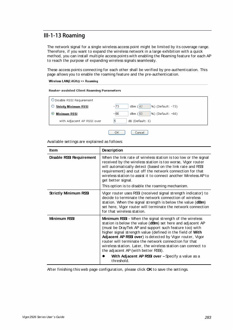
Vigor2926 Series User’s Guide 283
IIIIII--11--1133 RRooaammiinngg
The network signal for a single wireless access point might be limited by its coverage range. Therefore, if you want to expand the wireless network in a large exhibition with a quick method, you can install multiple access points with enabling the Roaming feature for each AP to reach the purpose of expanding wireless signals seamlessly.
These access points connecting for each other shall be verified by pre-authentication. This page allows you to enable the roaming feature and the pre-authentication.
Available settings are explained as follows:
Item Description
Disable RSSI Requirement When the link rate of wireless station is too low or the signal received by the wireless station is too worse, Vigor router will automatically detect (based on the link rate and RSSI requirement) and cut off the network connection for that wireless station to assist it to connect another Wireless AP to get better signal.
This option is to disable the roaming mechanism.
Strictly Minimum RSSI Vigor router uses RSSI (received signal strength indicator) to decide to terminate the network connection of wireless station. When the signal strength is below the value (dBm) set here, Vigor router will terminate the network connection for that wireless station.
Minimum RSSI Minimum RSSI - When the signal strength of the wireless station is below the value (dBm) set here and adjacent AP (must be DrayTek AP and support such feature too) with higher signal strength value (defined in the field of With Adjacent AP RSSI over) is detected by Vigor router, Vigor router will terminate the network connection for that wireless station. Later, the wireless station can connect to the adjacent AP (with better RSSI).
With Adjacent AP RSSI over – Specify a value as a threshold.
After finishing this web page configuration, please click OK to save the settings.

Vigor2926 Series User’s Guide 284
IIIIII--11--1144 SSttaattiioonn LLiisstt
Station List provides the knowledge of connecting wireless clients now along with its status code. There is a code summary below for explanation. For convenient Access Control, you can select a WLAN station and click Add to Access Control below.
Available settings are explained as follows:
Item Description
Refresh Click this button to refresh the status of station list.
Add Click this button to add current typed MAC address into Access Control.

Vigor2926 Series User’s Guide 285
PPaarrtt IIVV VVooIIPP
Voice over IP network (VoIP) enables you to use your broadband Internet connection to make toll quality voice calls over the Internet.
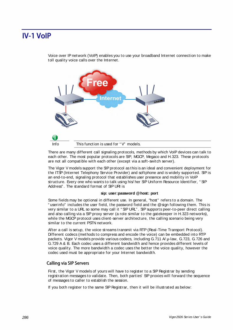
Vigor2926 Series User’s Guide 286
IIVV--11 VVooIIPP
Voice over IP network (VoIP) enables you to use your broadband Internet connection to make toll quality voice calls over the Internet.
Info
This function is used for “V” models.
There are many different call signaling protocols, methods by which VoIP devices can talk to each other. The most popular protocols are SIP, MGCP, Megaco and H.323. These protocols are not all compatible with each other (except via a soft-switch server).
The Vigor V models support the SIP protocol as this is an ideal and convenient deployment for the ITSP (Internet Telephony Service Provider) and softphone and is widely supported. SIP is an end-to-end, signaling protocol that establishes user presence and mobility in VoIP structure. Every one who wants to talk using his/her SIP Uniform Resource Identifier, “SIP Address”. The standard format of SIP URI is
sip: user:password @ host: port
Some fields may be optional in different use. In general, "host” refers to a domain. The “userinfo” includes the user field, the password field and the @ sign following them. This is very similar to a URL so some may call it “SIP URL”. SIP supports peer-to-peer direct calling and also calling via a SIP proxy server (a role similar to the gatekeeper in H.323 networks), while the MGCP protocol uses client-server architecture, the calling scenario being very similar to the current PSTN network.
After a call is setup, the voice streams transmit via RTP (Real-Time Transport Protocol). Different codecs (methods to compress and encode the voice) can be embedded into RTP packets. Vigor V models provide various codecs, including G.711 A/μ-law, G.723, G.726 and G.729 A & B. Each codec uses a different bandwidth and hence provides different levels of voice quality. The more bandwidth a codec uses the better the voice quality, however the codec used must be appropriate for your Internet bandwidth.
CCaalllliinngg vviiaa SSIIPP SSeerrvveerrss
First, the Vigor V models of yours will have to register to a SIP Registrar by sending registration messages to validate. Then, both parties’ SIP proxies will forward the sequence of messages to caller to establish the session.
If you both register to the same SIP Registrar, then it will be illustrated as below:

Vigor2926 Series User’s Guide 287
The major benefit of this mode is that you don’t have to memorize your friend’s IP address, which might change very frequently if it’s dynamic. Instead of that, you will only have to using dial plan or directly dial your friend’s account name if you are with the same SIP Registrar.
PPeeeerr--ttoo--PPeeeerr
Before calling, you have to know your friend’s IP Address. The Vigor VoIP Routers will build connection between each other.
Vigor V models firstly apply efficient codecs designed to make the best use of available bandwidth, but Vigor V models also equip with automatic QoS assurance. QoS Assurance assists to assign high priority to voice traffic via Internet. You will always have the required inbound and outbound bandwidth that is prioritized exclusively for Voice traffic over Internet but you just get your data a little slower and it is tolerable for data traffic.
Our Vigor V models firstly apply efficient codecs designed to make the best use of available bandwidth, but Vigor V models also equip with automatic QoS assurance. QoS Assurance assists to assign high priority to voice traffic via Internet. You will always have the required inbound and outbound bandwidth that is prioritized exclusively for Voice traffic over Internet but you just get your data a little slower and it is tolerable for data traffic.

Vigor2926 Series User’s Guide 288
WWeebb UUsseerr IInntteerrffaaccee
IIVV--11--11 VVooIIPP WWiizzaarrdd
Vigor router offers a quick method to configure settings for VoIP application. Follow the steps listed below.
Info
This wizard is available for “V” model only.
1. Open Wizards>>VoIP Wizard.
2. The screen of VoIP Wizard will be shown as follows.
Available settings are explained as follows:
Item Description
Set VoIP service provider domain
VoIP service provider - Use the drop down list to choose the ISP which offers the VoIP service for your router.
SIP Port – Use the default setting (5060).
Set Account quickly Account Number/Name – Type the account number/name registered to your ISP.
Password – Type the password for the account registered to

Vigor2926 Series User’s Guide 289
your ISP.
Use the same Account as phone 1 – If you don’t need to configure Phone 2 settings, simply check this box.
Next Click it to get into the next setting page.
Cancel Click it to give up the VoIP wizard.
3. After finished the settings above, click Next for viewing summary of such connection.
4. Click Finish. A page of VoIP Wizard Setup OK!!! will appear.

Vigor2926 Series User’s Guide 290
IIVV--11--22 GGeenneerraall SSeettttiinnggss
Open VoIP>>General Settings. The following page will appear. Check the box of Enable VoIP and click OK to open the configuration page. If not, no settings will be displayed.
After checking the box and click OK, the following page appears for you to configure secure phone, IP call; and set NAT Traversal Setting, RTP for the VoIP function.
Available settings are explained as follows:
Item Description
Secure Phone Enable Secure Phone - It allows users to have encrypted RTP stream with the peer side using the same protocol (ZRTP+SRTP). Check this box to have secure call.
Enable SAS Voice Prompt - If it is enabled, SAS prompt will be heard for both ends every time. If it is disabled, no SAS prompt will be heard any more.

Vigor2926 Series User’s Guide 291
NAT Traversal Setting STUN Server - Type in the IP address or domain of the STUN server.
External IP - Type in the gateway IP address.
SIP PING interval - The default value is 150 (sec). It is useful for a Nortel server NAT Traversal Support.
RTP Symmetric RTP – Check this box to invoke the function. To make the data transmission going through on both ends of local router and remote router not misleading due to IP lost (for example, sending data from the public IP of remote router to the private IP of local router), you can check this box to solve this problem.
Dynamic RTP Port Start - Specifies the start port for RTP stream. The default value is 10050.
Dynamic RTP Port End - Specifies the end port for RTP stream. The default value is 15000.
RTP TOS – It decides the level of VoIP package. Use the drop down list to choose any one of them.
IP Call Enable IP Call – It allows that a user could dial outgoing IP Calls; and Vigor router could receive the incoming IP Calls.
AApppplliiccaattiioonn ffoorr SSeeccuurree PPhhoonnee
Enable SAS Voice Prompt, for ex: if vigor router A calls vigor router B with checking Enable Secure Phone and Enable SAS Voice Prompt, then:
1. After the connection established, vigor router A will send SAS voice prompt to A and vigor router B will send the SAS voice prompt to B.
2. Then the RTP traffic is secured until the call ends.
3. If vigor router A wants to call vigor router B again next time, both A and B will not hear any voice prompt again even checking Enable SAS Voice Prompt on web UI. It means only the first call between them will have voice prompt.
Enable SAS Voice Prompt, for ex: if vigor router A calls vigor router B with checking Enable Secure Phone but not Enable SAS Voice Prompt, then:
1. After the connection established, vigor router A will NOT send SAS voice prompt to vigor router A and vigor router B will NOT send the SAS voice prompt to vigor router B.
2. Even no voice prompt, but the RTP traffic is still secured until the call ends.

Vigor2926 Series User’s Guide 292
Info
If the incoming or outgoing calls do not match any entry on the phonebook, the router will try to make the call "being protected". But, if the call ends up "unprotected"(e.g. peer side does not support ZRTP+SRTP), the router will not play out a warning message.

Vigor2926 Series User’s Guide 293
IIVV--11--33 SSIIPP AAccccoouunnttss
In this section, you set up your own SIP settings. When you apply for an account, your SIP service provider will give you an Account Name or user name, SIP Registrar, Proxy, and Domain name. (The last three might be the same in some case). Then you can tell your folks your SIP Address as in Account Name@ Domain name
As Vigor VoIP Router is turned on, it will first register with Registrar using AuthorizationUser@Domain/Realm. After that, your call will be bypassed by SIP Proxy to the destination using AccountName@Domain/Realm as identity.
Info
Selection items for Ring Port will differ according to the router you have.
Available settings are explained as follows:
Item Description
Index Click this link to access into next page for setting SIP account.
Profile Display the profile name of the account.
Domain/Realm Display the domain name or IP address of the SIP registrar server.
Proxy Display the domain name or IP address of the SIP proxy server.
Account Name Display the account name of SIP address before @.
Codec Display the codec type for the account.
Ring Port Specify which port will ring when receiving a phone call.
Status Show the status for the corresponding SIP account. R means such account is registered on SIP server successfully. – means
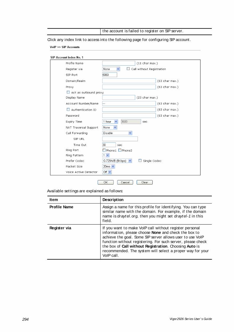
Vigor2926 Series User’s Guide 294
the account is failed to register on SIP server.
Click any index link to access into the following page for configuring SIP account.
Available settings are explained as follows:
Item Description
Profile Name Assign a name for this profile for identifying. You can type similar name with the domain. For example, if the domain name is draytel.org, then you might set draytel-1 in this field.
Register via If you want to make VoIP call without register personal information, please choose None and check the box to achieve the goal. Some SIP server allows user to use VoIP function without registering. For such server, please check the box of Call without Registration. Choosing Auto is recommended. The system will select a proper way for your VoIP call.

Vigor2926 Series User’s Guide 295
SIP Port Set the port number for sending/receiving SIP message for building a session. The default value is 5060. Your peer must set the same value in his/her Registrar.
Domain/Realm Set the domain name or IP address of the SIP Registrar server.
Proxy Set domain name or IP address of SIP proxy server. By the time you can type :port number after the domain name to specify that port as the destination of data transmission (e.g., nat.draytel.org:5065)
Act as Outbound Proxy Check this box to make the proxy acting as outbound proxy.
Display Name The caller-ID that you want to be displayed on your friend’s screen.
Account Number/Name Enter your account name of SIP Address, e.g. every text before @.
Authentication ID Check the box to invoke this function and enter the name or number used for SIP Authorization with SIP Registrar. If this setting value is the same as Account Name, it is not necessary for you to check the box and set any value in this field.
Password The password provided to you when you registered with a SIP service.
Expiry Time The time duration that your SIP Registrar server keeps your registration record. Before the time expires, the router will send another register request to SIP Registrar again.
NAT Traversal Support If the router (e.g., broadband router) you use connects to internet by other device, you have to set this function for your necessity.
None – Disable this function.
Stun – Choose this option if there is Stun server provided for your router.
Manual – Choose this option if you want to specify an external IP address as the NAT transversal support.
Nortel – If the soft-switch that you use supports Nortel

Vigor2926 Series User’s Guide 296
solution, you can choose this option.
Call Forwarding There are four options for you to choose. Disable is to close call forwarding function. Always means all the incoming calls will be forwarded into SIP URL without any reason. Busy means the incoming calls will be forwarded into SIP URL only when the local system is busy. No Answer means if the incoming calls do not receive any response, they will be forwarded to the SIP URL by the time out.
SIP URL – Type in the SIP URL (e.g., [email protected] or [email protected]) as the site for call forwarded.
Time Out – Set the time out for the call forwarding. The default setting is 30 sec.
Ring Port Set Phone 1 and/or Phone 2 as the default ring port(s) for this SIP account.
Ring Pattern Choose a ring tone type for the VoIP phone call.
Prefer Codec Select one of five codecs as the default for your VoIP calls. The codec used for each call will be negotiated with the peer party before each session, and so may not be your default choice. The default codec is G.729A/B; it occupies little bandwidth while maintaining good voice quality.
If your upstream speed is only 64Kbps, do not use G.711 codec. It is better for you to have at least 256Kbps upstream if you would like to use G.711.
Single Codec – If the box is checked, only the selected Codec will be applied.
Packet Size The amount of data contained in a single packet. The default value is 20 ms, which means the data packet will contain 20 ms voice information.

Vigor2926 Series User’s Guide 297
Voice Active Detector This function can detect if the voice on both sides is active or not. If not, the router will do something to save the bandwidth for other using. Click On to invoke this function; click off to close the function.
After finishing all the settings here, please click OK to save the configuration.

Vigor2926 Series User’s Guide 298
IIVV--11--44 DDiiaallPPllaann
This page allows you to set phone book, digit map, call barring, regional settings and PSTN setup for the VoIP function. Click the links on this page to access into next pages for detailed settings.
IIVV--11--44--11 PPhhoonnee BBooookk
In this section, you can set your VoIP contacts in the “phonebook”. It can help you to make calls quickly and easily by using “speed-dial” Phone Number. There are total 60 index entries in the phonebook for you to store all your friends and family members’ SIP addresses. Loop through and Backup Phone Number will be displayed if you are using Vigor2926 series for setting the phone book.
Click any index number to display the dial plan setup page.

Vigor2926 Series User’s Guide 299
Available settings are explained as follows:
Item Description
Enable Click this to enable this entry.
Phone Number The speed-dial number of this index. This can be any number you choose, using digits 0-9 and * .
Display Name The Caller-ID that you want to be displayed on your friend’s screen. This let your friend can easily know who’s calling without memorizing lots of SIP URL Address.
SIP URL Enter your friend’s SIP Address.
Dial Out Account Choose one of the SIP accounts for this profile to dial out. It is useful for both sides (caller and callee) that registered to different SIP Registrar servers. If caller and callee do not use the same SIP server, sometimes, the VoIP phone call connection may not succeed. By using the specified dial out account, the successful connection can be assured.
Loop through Choose PSTN to enable loop through function.
Backup Phone Number When the VoIP phone obstructs or the Internet breaks down for some reasons, the backup phone will be dialed out to replace the VoIP phone number. At this time, the phone call will be changed from VoIP phone into PSTN call according to the loop through direction chosen. Note that, during the phone switch, the blare of phone will appear for a short time. And when the VoIP phone is switched into the PSTN phone, the telecom co. might charge you for the connection fee. Please type in backup phone number for this VoIP phone setting.
Secure Phone ZRTP+SRTP - It allows users to have encrypted RTP stream with the peer side using the same protocol (ZRTP+SRTP). Check this box to have secure call.
Cancel Return to previous web page.
After finishing all the settings here, please click OK to save the configuration.
Info
If the incoming or outgoing calls do not match any entry on the phonebook, the router will try to make the call "being protected". But, if the call ends up "unprotected"(e.g. peer side does not support ZRTP+SRTP), the router will not play out a warning message.

Vigor2926 Series User’s Guide 300
IIVV--11--44--22 DDiiggiitt MMaapp
For the convenience of user, this page allows users to edit prefix number for the SIP account with adding number, stripping number or replacing number. It is used to help user have a quick and easy way to dial out through VoIP interface.
Available settings are explained as follows:
Item Description
Enable Check this box to invoke this setting.
Match Prefix It is used to match with the number you dialed and may be modified by the action (add, strip or replace) with the OP Number.
Mode None - No action.
Add - When you choose this mode, the OP number will be added before the match prefix number for calling out through the specific route.
Strip - When you choose this mode, the partial or whole match prefix number will be deleted according to the OP number. Take the above picture (Prefix Table Setup web page) as an example, the OP number of 886 will be deleted completely for the match prefix number is set with 886.
Replace - When you choose this mode, the OP number will be replaced by the prefix number for calling out through the specific VoIP interface. Take the above picture (Prefix Table Setup web page) as an example, the prefix number of 03 will be replaced by 8863. For example: dial number of “031111111” will be changed to “88631111111” and sent to SIP server.
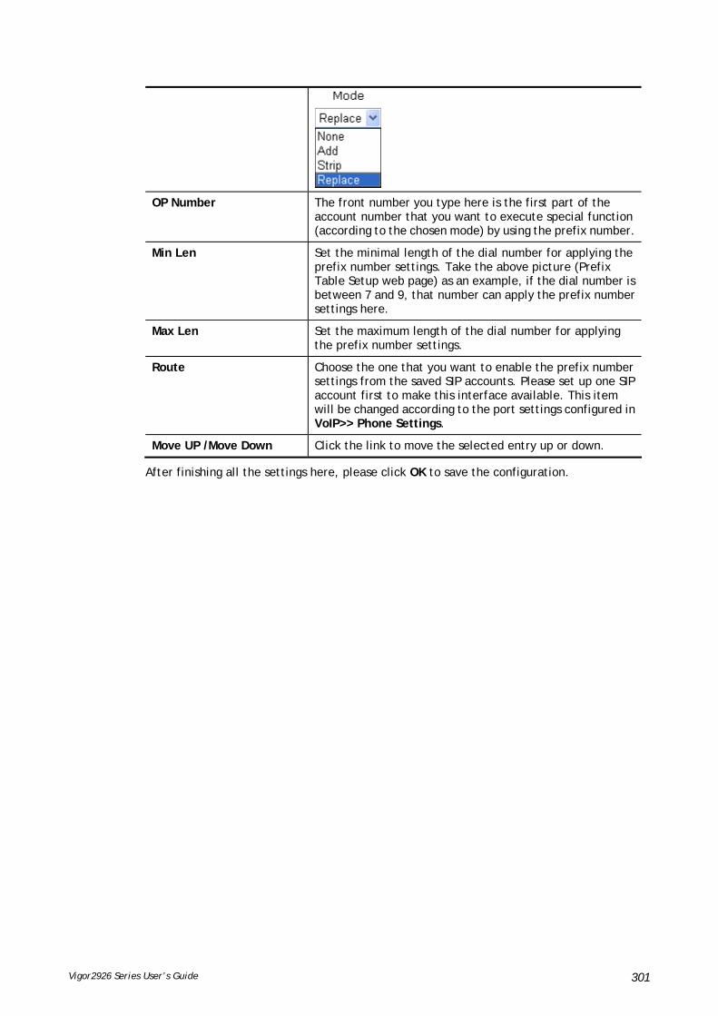
Vigor2926 Series User’s Guide 301
OP Number The front number you type here is the first part of the account number that you want to execute special function (according to the chosen mode) by using the prefix number.
Min Len Set the minimal length of the dial number for applying the prefix number settings. Take the above picture (Prefix Table Setup web page) as an example, if the dial number is between 7 and 9, that number can apply the prefix number settings here.
Max Len Set the maximum length of the dial number for applying the prefix number settings.
Route Choose the one that you want to enable the prefix number settings from the saved SIP accounts. Please set up one SIP account first to make this interface available. This item will be changed according to the port settings configured in VoIP>> Phone Settings.
Move UP /Move Down Click the link to move the selected entry up or down.
After finishing all the settings here, please click OK to save the configuration.

Vigor2926 Series User’s Guide 302
IIVV--11--44--33 CCaallll BBaarrrriinngg
Call barring is used to block phone calls coming from the one that is not welcomed.
Additionally, you can set advanced settings for call barring such as Block Anonymous, Block Unknown Domain or Block IP Address.
For Block Anonymous – this function can block the incoming calls without caller ID on the interface (Phone port) specified in the following window. Such control also can be done based on preconfigured schedules.
For Block Unknown Domain – this function can block incoming calls (through Phone port) from unrecognized domain that is not specified in SIP accounts. Such control also can be done based on preconfigured schedules.
For Block IP Address – this function can block incoming calls (through Phone port) coming from IP address. Such control also can be done based on preconfigured schedules.

Vigor2926 Series User’s Guide 303
Click any index number to display the call barring setup page.
Available settings are explained as follows:
Item Description
Enable Check it to enable this entry.
Call Direction Determine the direction for the phone call, IN – incoming call, OUT-outgoing call, IN & OUT – both incoming and outgoing calls.
Barring Type Determine the type of the VoIP phone call, URI/URL or number.
Specific URI/URL or Specific Number
This field will be changed based on the type you selected for barring Type.
Route All means all the phone calls will be blocked with such mechanism.
Index (1-15) in Schedule Enter the index of schedule profiles to control the call barring according to the preconfigured schedules. Refer to section Applications>>Schedule for detailed configuration.

Vigor2926 Series User’s Guide 304
IIVV--11--44--44 RReeggiioonnaall
This page allows you to process incoming or outgoing phone calls by regional. Default values (common used in most areas) will be shown on this web page. You can change the number based on the region that the router is placed.
Available settings are explained as follows:
Item Description
Enable Regional Check this box to enable this function.
Last Call Return [Miss] Sometimes, people might miss some phone calls. Please dial number typed in this field to know where the last phone call comes from and call back to that one.
Last Call Return [In] You have finished an incoming phone call, however you want to call back again for some reason. Please dial number typed in this field to call back to that one.
Last Call Return [Out] Dial the number typed in this field to call the previous outgoing phone call again.
Call Forward [All][Act] Dial the number typed in this field to forward all the incoming calls to the specified place.
Call Forward [Deact] Dial the number typed in this field to release the call forward function.
Call Forward [Busy][Act] Dial the number typed in this field to forward all the incoming calls to the specified place while the phone is busy.
Call Forward [No Ans][Act]
Dial the number typed in this field to forward all the incoming calls to the specified place while there is no answer of the connected phone.
Do Not Disturb [Act] Dial the number typed in this field to invoke the function of DND.
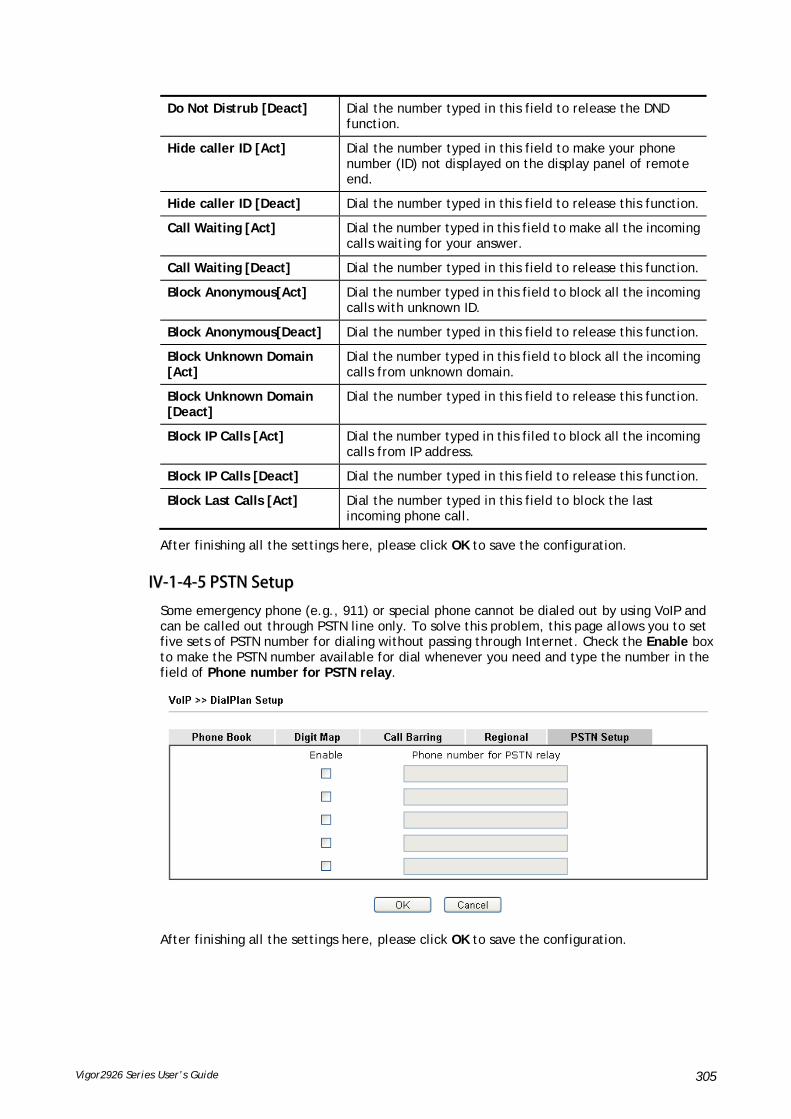
Vigor2926 Series User’s Guide 305
Do Not Distrub [Deact] Dial the number typed in this field to release the DND function.
Hide caller ID [Act] Dial the number typed in this field to make your phone number (ID) not displayed on the display panel of remote end.
Hide caller ID [Deact] Dial the number typed in this field to release this function.
Call Waiting [Act] Dial the number typed in this field to make all the incoming calls waiting for your answer.
Call Waiting [Deact] Dial the number typed in this field to release this function.
Block Anonymous[Act] Dial the number typed in this field to block all the incoming calls with unknown ID.
Block Anonymous[Deact] Dial the number typed in this field to release this function.
Block Unknown Domain [Act]
Dial the number typed in this field to block all the incoming calls from unknown domain.
Block Unknown Domain [Deact]
Dial the number typed in this field to release this function.
Block IP Calls [Act] Dial the number typed in this filed to block all the incoming calls from IP address.
Block IP Calls [Deact] Dial the number typed in this field to release this function.
Block Last Calls [Act] Dial the number typed in this field to block the last incoming phone call.
After finishing all the settings here, please click OK to save the configuration.
IIVV--11--44--55 PPSSTTNN SSeettuupp
Some emergency phone (e.g., 911) or special phone cannot be dialed out by using VoIP and can be called out through PSTN line only. To solve this problem, this page allows you to set five sets of PSTN number for dialing without passing through Internet. Check the Enable box to make the PSTN number available for dial whenever you need and type the number in the field of Phone number for PSTN relay.
After finishing all the settings here, please click OK to save the configuration.

Vigor2926 Series User’s Guide 306
IIVV--11--55 PPhhoonnee SSeettttiinnggss
This page allows user to set phone settings for Phone 1 and Phone 2 respectively. However, it changes slightly according to different model you have.
Available settings are explained as follows:
Item Description
Phone Setting Port – there are two phone ports provided here for you to configure. Phone1/Phone2 allows you to set general settings for PSTN phones.
Call Feature – A brief description for call feature will be shown in this field for your reference.
Tone - Display the tone settings that configured in the advanced settings page of Phone Index.
Gain - Display the volume gain settings for Mic/Speaker that configured in the advanced settings page of Phone Index.
Default SIP Account – “draytel_1” is the default SIP account. You can click the number below the Index field to change SIP account for each phone port.
DTMF Relay – Display DTMF mode that configured in the advanced settings page of Phone Index.
After finishing all the settings here, please click OK to save the configuration.
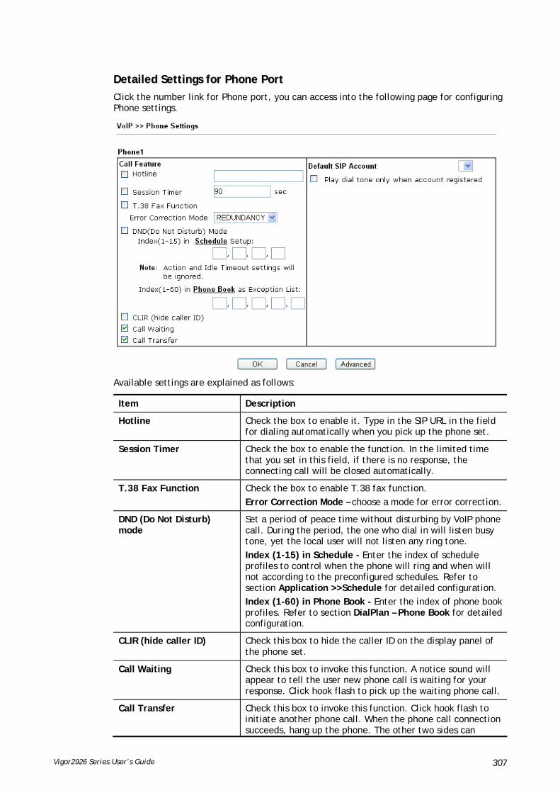
Vigor2926 Series User’s Guide 307
DDeettaaiilleedd SSeettttiinnggss ffoorr PPhhoonnee PPoorrtt
Click the number link for Phone port, you can access into the following page for configuring Phone settings.
Available settings are explained as follows:
Item Description
Hotline Check the box to enable it. Type in the SIP URL in the field for dialing automatically when you pick up the phone set.
Session Timer Check the box to enable the function. In the limited time that you set in this field, if there is no response, the connecting call will be closed automatically.
T.38 Fax Function Check the box to enable T.38 fax function.
Error Correction Mode – choose a mode for error correction.
DND (Do Not Disturb) mode
Set a period of peace time without disturbing by VoIP phone call. During the period, the one who dial in will listen busy tone, yet the local user will not listen any ring tone.
Index (1-15) in Schedule - Enter the index of schedule profiles to control when the phone will ring and when will not according to the preconfigured schedules. Refer to section Application >>Schedule for detailed configuration.
Index (1-60) in Phone Book - Enter the index of phone book profiles. Refer to section DialPlan – Phone Book for detailed configuration.
CLIR (hide caller ID) Check this box to hide the caller ID on the display panel of the phone set.
Call Waiting Check this box to invoke this function. A notice sound will appear to tell the user new phone call is waiting for your response. Click hook flash to pick up the waiting phone call.
Call Transfer Check this box to invoke this function. Click hook flash to initiate another phone call. When the phone call connection succeeds, hang up the phone. The other two sides can

Vigor2926 Series User’s Guide 308
communicate, then.
Default SIP Account You can set SIP accounts (up to six groups) on SIP Account page. Use the drop down list to choose one of the profile names for the accounts as the default one for this phone setting.
Play dial tone only when account registered - Check this box to invoke the function.
In addition, you can press the Advanced button to configure tone settings, volume gain, MISC and DTMF mode. Advanced setting is provided for fitting the telecommunication custom for the local area of the router installed. Wrong tone settings might cause inconvenience for users. To set the sound pattern of the phone set, simply choose a proper region to let the system find out the preset tone settings and caller ID type automatically. Or you can adjust tone settings manually if you choose User Defined. TOn1, TOff1, TOn2 and TOff2 mean the cadence of the tone pattern. TOn1 and TOn2 represent sound-on; TOff1 and TOff2 represent the sound-off.
Available settings are explained as follows:
Item Description
Region Select the proper region which you are located. The common settings of Caller ID Type, Dial tone, Ringing tone, Busy tone and Congestion tone will be shown automatically on the page. If you cannot find out a suitable one, please choose User Defined and fill out the corresponding values for dial tone, ringing tone, busy tone, congestion tone by yourself for VoIP phone.

Vigor2926 Series User’s Guide 309
Also, you can specify each field for your necessity. It is recommended for you to use the default settings for VoIP communication.
Volume Gain Mic Gain (1-10)/Speaker Gain (1-10) - Adjust the volume of microphone and speaker by entering number from 1- 10. The larger of the number, the louder the volume is.
MISC Dial Tone Power Level - This setting is used to adjust the loudness of the dial tone. The smaller the number is, the louder the dial tone is. It is recommended for you to use the default setting.
Call Waiting Tone Power Level - This setting is used to adjust the loudness of the call waiting tone. The smaller the number is, the louder the tone is. It is recommended for you to use the default setting.
Interdigit Timeout –Type a value in this field to specify time limit for interdigit.
DTMF DTMF Mode – There are four DTMF modes for you to choose.
InBand - Choose this one then the Vigor will send the
DTMF tone as audio directly when you press the keypad on the phone.
OutBand - Choose this one then the Vigor will capture the keypad number you pressed and transform it to digital form then send to the other side; the receiver will generate the tone according to the digital form it receive. This function is very useful when the network traffic congestion occurs and it still can remain the accuracy of DTMF tone.
SIP INFO- Choose this one then the Vigor will capture

Vigor2926 Series User’s Guide 310
the DTMF tone and transfer it into SIP form. Then it will be sent to the remote end with SIP message.
Payload Type (rfc2833) - Type a number from 96 to 127, the default value was 101. This setting is available for the OutBand (RFC2833) mode.
Replace + digit in caller ID to - For international phone call, the phone number could add a '+' sign, for example, +8865972727. However, the caller ID (DTMF type especially) can not display '+' at all.
Therefore, this function can be enabled to give another number to replace the plus sign, for example, “+” can be replaced by “00”. Then the above phone number will become 008865972727. When the callee receives such number, he can use re-dial function to dial back to the caller.
IIVV--11--66 SSttaattuuss
From this page, you can find codec, connection and other important call status for each port.
Available settings are explained as follows:
Item Description
Refresh Seconds Specify the interval of refresh time to obtain the latest VoIP calling information. The information will update immediately when the Refresh button is clicked.
Port It shows current connection status for Phone(s) ports.
Status It shows the VoIP connection status.

Vigor2926 Series User’s Guide 311
IDLE - Indicates that the VoIP function is idle.
HANG_UP - Indicates that the connection is not established (busy tone).
CONNECTING - Indicates that the user is calling out.
WAIT_ANS - Indicates that a connection is launched and waiting for remote user’s answer.
ALERTING - Indicates that a call is coming.
ACTIVE-Indicates that the VoIP connection is launched.
Codec Indicates the voice codec employed by present channel.
PeerID The present in-call or out-call peer ID (the format may be IP or Domain).
Elapse(hh:mm:ss) The format is represented as hours:minutes:seconds.
Tx Pkts Total number of transmitted voice packets during this connection session.
Rx Pkts Total number of received voice packets during this connection session.
Rx Losts Total number of lost packets during this connection session.
Rx Jitter The jitter of received voice packets.
In Calls Accumulation for the times of in call.
Out Calls Accumulation for the times of out call.
Miss Calls Accumulation for the times of missing call.
Speaker Gain The volume of present call.
Log Display logs of VoIP calls.

Vigor2926 Series User’s Guide 312
IIVV--11--77 DDiiaaggnnoossttiiccss
VoIP Diagnostics is used for diagnosing if VoIP phone failure is caused by different tone or caller ID.
IIVV--11--77--11 CCaalllleerr IIDD
IIVV--11--77--22 TToonnee
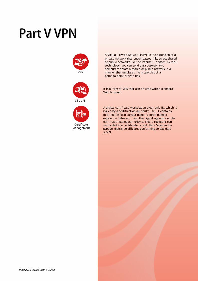
Vigor2926 Series User’s Guide 313
PPaarrtt VV VVPPNN
A Virtual Private Network (VPN) is the extension of a private network that encompasses links across shared or public networks like the Internet. In short, by VPN technology, you can send data between two computers across a shared or public network in a manner that emulates the properties of a point-to-point private link.
It is a form of VPN that can be used with a standard Web browser.
A digital certificate works as an electronic ID, which is issued by a certification authority (CA). It contains information such as your name, a serial number, expiration dates etc., and the digital signature of the certificate-issuing authority so that a recipient can verify that the certificate is real. Here Vigor router support digital certificates conforming to standard X.509.

Vigor2926 Series User’s Guide 314
VV--11 VVPPNN aanndd RReemmoottee AAcccceessss
A Virtual Private Network (VPN) is the extension of a private network that encompasses links across shared or public networks like the Internet. In short, by VPN technology, you can send data between two computers across a shared or public network in a manner that emulates the properties of a point-to-point private link.
The VPN built is suitable for:
Communication between home office and customer
Secure connection between Teleworker, staff on business trip and main office
Exchange data between remote office and main office
POS between chain store and headquarters
SSiittee--ttoo--SSiittee ((LLAANN--ttoo--LLAANN))
A connection between two router's LAN networks.
Allows employees in branch offices and head office to share the same network resources.
RReemmoottee AAcccceessss ((RReemmoottee DDiiaall--iinn))
A connection between the remote host and router's LAN network. The host will use an IP address in the local subnet.
Allows employees to access the company's internal resources when they are traveling.

Vigor2926 Series User’s Guide 315
WWeebb UUsseerr IInntteerrffaaccee
VV--11--11 VVPPNN CClliieenntt WWiizzaarrdd
Such wizard is used to configure VPN settings for VPN client. Such wizard will guide to set the LAN-to-LAN profile for VPN dial out connection (from server to client) step by step.
1. Open Wizards>>VPN Client Wizard. The following page will appear.
Available settings are explained as follows:
Item Description
LAN-to-LAN Client Mode Selection
Choose the client mode.
Route Mode/NAT Mode – If the remote network only allows you to dial in with single IP, please choose NAT mode, otherwise please choose Route Mode.

Vigor2926 Series User’s Guide 316
Please choose a LAN-to-LAN Profile
There are 32 VPN profiles for users to set.
2. When you finish the mode and profile selection, please click Next to open the following page.
In this page, you have to select suitable VPN type for the VPN client profile. There are six types provided here. Different type will lead to different configuration page. After making the choices for the client profile, please click Next. You will see different configurations based on the selection(s) you made.
Info
The following descriptions for VPN Type are based on the Route Mode specified in LAN-to-LAN Client Mode Selection.
When you choose PPTP (None Encryption) or PPTP (Encryption), you will see the following graphic:

Vigor2926 Series User’s Guide 317
When you choose IPsec, you will see the following graphic:
When you choose SSL, you will see the following graphic:

Vigor2926 Series User’s Guide 318
When you choose L2TP over IPsec (Nice to Have) or L2TP over IPsec (Must), you will see the following graphic:
Available settings are explained as follows:
Item Description
Profile Name Type a name for such profile. The length of the file is limited to 10 characters.

Vigor2926 Series User’s Guide 319
VPN Dial-Out Through Use the drop down menu to choose a proper WAN interface for this profile. This setting is useful for dial-out only.
Or,
WAN1 First/ WAN2 First /WAN3 First (or LTE First) /WAN4 First- While connecting, the router will use WAN1/WAN2/WAN3(or LTE) /WAN4 as the first channel for VPN connection. If WAN1/WAN2/WAN3 (or LTE) /WAN4 fails, the router will use another WAN interface instead.
WAN1 Only /WAN2 Only/WAN3 Only(or LTE Only) /WAN4 Only - While connecting, the router will use WAN1/WAN2/WAN3(or LTE)/WAN4 as the only channel for VPN connection.
WAN1 Only: Only establish VPN if WAN2 down - If WAN2 failed, the router will use WAN1 for VPN connection.
WAN2 Only: Only establish VPN if WAN1 down - If WAN1 failed, the router will use WAN2 for VPN connection.
Always On Check to enable router always keep VPN connection.
Server IP/Host Name for VPN
Type the IP address of the server or type the host name for such VPN profile.
IKE Authentication Method
IKE Authentication Method usually applies to those are remote dial-in user or node (LAN to LAN) which uses dynamic IP address and IPsec-related VPN connections such as L2TP over IPsec and IPsec tunnel.
Pre-Shared Key- Specify a key for IKE authentication.
Confirm Pre-Shared Key-Confirm the pre-shared key.
Digital Signature (X.509)
Click Digital Signature to invoke this function.
Peer ID – Choose the peer ID selection from the drop down list.
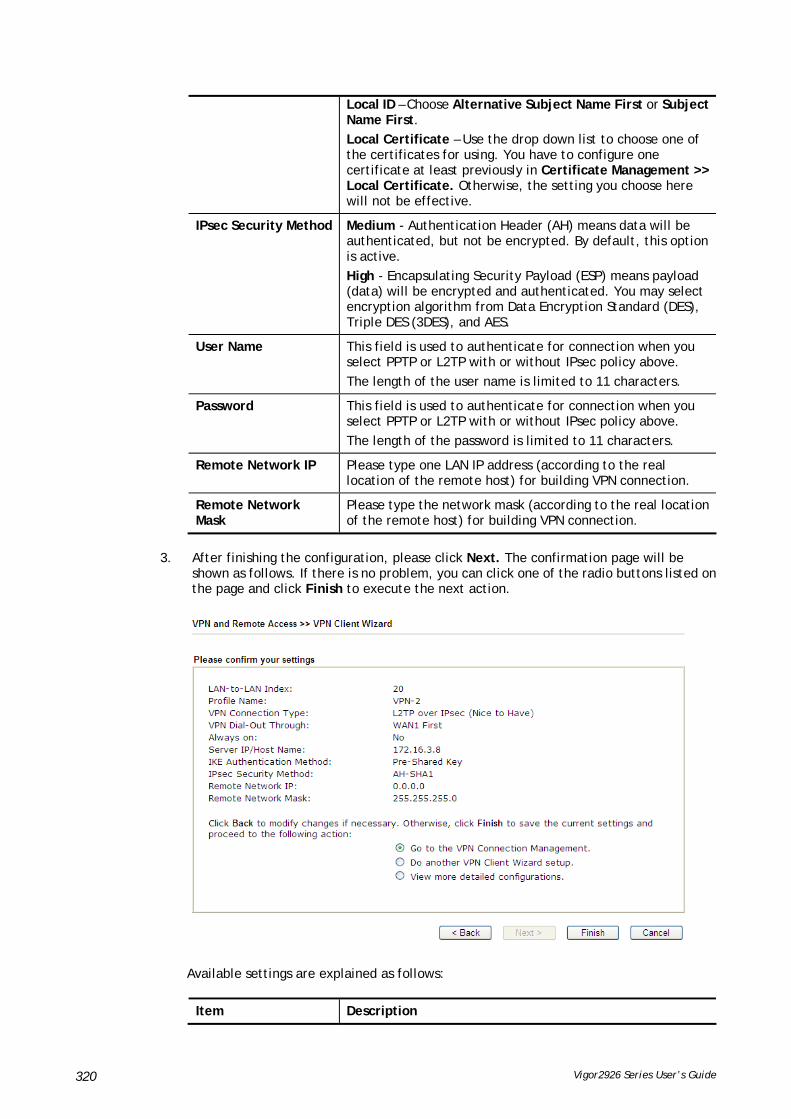
Vigor2926 Series User’s Guide 320
Local ID – Choose Alternative Subject Name First or Subject Name First.
Local Certificate – Use the drop down list to choose one of the certificates for using. You have to configure one certificate at least previously in Certificate Management >> Local Certificate. Otherwise, the setting you choose here will not be effective.
IPsec Security Method Medium - Authentication Header (AH) means data will be authenticated, but not be encrypted. By default, this option is active.
High - Encapsulating Security Payload (ESP) means payload (data) will be encrypted and authenticated. You may select encryption algorithm from Data Encryption Standard (DES), Triple DES (3DES), and AES.
User Name This field is used to authenticate for connection when you select PPTP or L2TP with or without IPsec policy above.
The length of the user name is limited to 11 characters.
Password This field is used to authenticate for connection when you select PPTP or L2TP with or without IPsec policy above.
The length of the password is limited to 11 characters.
Remote Network IP Please type one LAN IP address (according to the real location of the remote host) for building VPN connection.
Remote Network Mask
Please type the network mask (according to the real location of the remote host) for building VPN connection.
3. After finishing the configuration, please click Next. The confirmation page will be shown as follows. If there is no problem, you can click one of the radio buttons listed on the page and click Finish to execute the next action.
Available settings are explained as follows:
Item Description

Vigor2926 Series User’s Guide 321
Go to the VPN Connection Management
Click this radio button to access VPN and Remote Access>>Connection Management for viewing VPN Connection status.
Do another VPN Server Wizard Setup
Click this radio button to set another profile of VPN Server through VPN Server Wizard.
View more detailed configuration
Click this radio button to access VPN and Remote Access>>LAN to LAN for viewing detailed configuration.

Vigor2926 Series User’s Guide 322
VV--11--22 VVPPNN SSeerrvveerr WWiizzaarrdd
Such wizard is used to configure VPN settings for VPN server. Such wizard will guide to set the LAN-to-LAN profile for VPN dial in connection (from client to server) step by step.
1. Open Wizards>>VPN Server Wizard. The following page will appear.
Available settings are explained as follows:
Item Description
VPN Server Mode Selection
Choose the direction for the VPN server.
Site to Site VPN – To set a LAN-to-LAN profile automatically, please choose Site to Site VPN.
Remote Dial-in User –You can manage remote access by maintaining a table of remote user profile, so that users can be authenticated to dial-in via VPN connection.
Please choose a LAN-to-LAN Profile
This item is available when you choose Site to Site VPN (LAN-to-LAN) as VPN server mode. There are 32 VPN profiles for users to set.
Please choose a Dial-in User Accounts
This item is available when you choose Remote Dial-in User (Teleworker) as VPN server mode. There are 32 VPN tunnels for users to set.
Allowed Dial-in Type This item is available after you choose any one of dial-in user account profiles. Next, you have to select suitable dial-in type for the VPN server profile. There are several types provided here (similar to VPN Client Wizard).

Vigor2926 Series User’s Guide 323
Different Dial-in Type will lead to different configuration page. In addition, adjustable items for each dial-in type will be changed according to the VPN Server Mode (Site to Site VPN and Remote Dial-in User) selected.
2. After making the choices for the server profile, please click Next. You will see different configurations based on the selection you made. Here we take the examples of choosing Site-to-Site VPN as the VPN Server Mode.
When you check PPTP/SSL, you will see the following graphic:
When you check PPTP & IPsec & L2TP (three types) or PPTP & IPsec (two types) or L2TP with Policy (Nice to Have/Must), you will see the following graphic:

Vigor2926 Series User’s Guide 324
When you check IPsec, you will see the following graphic:
Available settings are explained as follows:
Item Description
Profile Name Type a name for such profile. The length of the file is limited to 10 characters.
User Name This field is used to authenticate for connection when you select PPTP or L2TP with or without IPsec policy above.
The length of the name is limited to 11 characters.
Password This field is used to authenticate for connection when you select PPTP or L2TP with or without IPsec policy above.
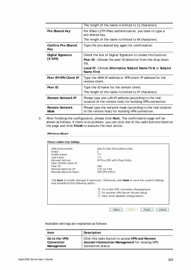
Vigor2926 Series User’s Guide 325
The length of the name is limited to 11 characters.
Pre-Shared Key For IPsec/L2TP IPsec authentication, you have to type a pre-shared key.
The length of the name is limited to 64 characters.
Confirm Pre-Shared Key
Type the pre-shared key again for confirmation.
Digital Signature (X.509)
Check the box of Digital Signature to invoke this function.
Peer ID – Choose the peer ID selection from the drop down list.
Local ID – Choose Alternative Subject Name First or Subject Name First.
Peer IP/VPN Client IP Type the WAN IP address or VPN client IP address for the remote client.
Peer ID Type the ID name for the remote client.
The length of the name is limited to 47 characters.
Remote Network IP Please type one LAN IP address (according to the real location of the remote host) for building VPN connection.
Remote Network Mask
Please type the network mask (according to the real location of the remote host) for building VPN connection.
3. After finishing the configuration, please click Next. The confirmation page will be shown as follows. If there is no problem, you can click one of the radio buttons listed on the page and click Finish to execute the next action.
Available settings are explained as follows:
Item Description
Go to the VPN Connection Management
Click this radio button to access VPN and Remote Access>>Connection Management for viewing VPN Connection status.

Vigor2926 Series User’s Guide 326
Do another VPN Server Wizard Setup
Click this radio button to set another profile of VPN Server through VPN Server Wizard.
View more detailed
configuration
Click this radio button to access VPN and Remote Access>>LAN to LAN for viewing detailed configuration.
VV--11--33 RReemmoottee AAcccceessss CCoonnttrrooll
Enable the necessary VPN service as you need. If you intend to run a VPN server inside your LAN, you should disable the VPN service of Vigor Router to allow VPN tunnel pass through, as well as the appropriate NAT settings, such as DMZ or open port.
Open VPN and Remote Access>>Remote Access Control.
After finishing all the settings here, please click OK to save the configuration.

Vigor2926 Series User’s Guide 327
VV--11--44 PPPPPP GGeenneerraall SSeettuupp
This submenu only applies to PPP-related VPN connections, such as PPTP, L2TP, L2TP over IPsec.
Available settings are explained as follows:
Item Description
Dial-In PPP Authentication PAP Only - elect this option to force the router to authenticate dial-in users with the PAP protocol.
PAP/CHAP/MS-CHAP/MS-CHAPv2 - Selecting this option means the router will attempt to authenticate dial-in users with the CHAP protocol first. If the dial-in user does not support this protocol, it will fall back to use the PAP protocol for authentication.
Dial-In PPP Encryption (MPPE)
Optional MPPE - This option represents that the MPPE encryption method will be optionally employed in the router for the remote dial-in user. If the remote dial-in user does not support the MPPE encryption algorithm, the router will transmit “no MPPE encrypted packets”. Otherwise, the MPPE encryption scheme will be used to encrypt the data.
Require MPPE (40/128bits) - Selecting this option will force the router to encrypt packets by using the MPPE encryption algorithm. In addition, the remote dial-in user will use 40-bit to perform encryption prior to using 128-bit for encryption. In other words, if 128-bit MPPE
Vigor2926 Series User’s Guide 328
encryption method is not available, then 40-bit encryption scheme will be applied to encrypt the data.
Maximum MPPE - This option indicates that the router will use the MPPE encryption scheme with maximum bits (128-bit) to encrypt the data.
Mutual Authentication (PAP)
The Mutual Authentication function is mainly used to communicate with other routers or clients who need bi-directional authentication in order to provide stronger security, for example, Cisco routers. So you should enable this function when your peer router requires mutual authentication. You should further specify the User Name and Password of the mutual authentication peer.
The length of the name/password is limited to 23/19 characters.
IP Address Assignment for Dial-In Users (when DHCP Disable set)
Enter a start IP address for the dial-in PPP connection for LAN1.
LAN2 ~ LAN6 will be available if it is enabled. Refer to LAN>>General Setup for enabling the LAN interface.
PPP Authentication Methods
Select the method(s) to be used for authentication in PPP connection.
PPTP LDAP Profile Configured LDAP profiles will be listed under such item. Simply check the one you want to enable the PPP authentication by LDAP server profiles.
However, if there is no profile listed, simply click the link of PPTP LDAP Profile to create/add some new LDAP profiles you want.
While using Radius or LDAP Authentication
If PPP connection will be authenticated via RADIUS server or LDAP profiles, it is necessary to specify the LAN profile for the dial-in user to get IP from.

Vigor2926 Series User’s Guide 329
VV--11--55 IIPPsseecc GGeenneerraall SSeettuupp
In IPsec General Setup, there are two major parts of configuration.
There are two phases of IPsec.
Phase 1: negotiation of IKE parameters including encryption, hash, Diffie-Hellman parameter values, and lifetime to protect the following IKE exchange, authentication of both peers using either a Pre-Shared Key or Digital Signature (x.509). The peer that starts the negotiation proposes all its policies to the remote peer and then remote peer tries to find a highest-priority match with its policies. Eventually to set up a secure tunnel for IKE Phase 2.
Phase 2: negotiation IPsec security methods including Authentication Header (AH) or Encapsulating Security Payload (ESP) for the following IKE exchange and mutual examination of the secure tunnel establishment.
There are two encapsulation methods used in IPsec, Transport and Tunnel. The Transport mode will add the AH/ESP payload and use original IP header to encapsulate the data payload only. It can just apply to local packet, e.g., L2TP over IPsec. The Tunnel mode will not only add the AH/ESP payload but also use a new IP header (Tunneled IP header) to encapsulate the whole original IP packet.
Authentication Header (AH) provides data authentication and integrity for IP packets passed between VPN peers. This is achieved by a keyed one-way hash function to the packet to create a message digest. This digest will be put in the AH and transmitted along with packets. On the receiving side, the peer will perform the same one-way hash on the packet and compare the value with the one in the AH it receives.
Encapsulating Security Payload (ESP) is a security protocol that provides data confidentiality and protection with optional authentication and replay detection service.
Available settings are explained as follows:
Item Description
IKE Authentication Method
This usually applies to those are remote dial-in user or node (LAN-to-LAN) which uses dynamic IP address and IPsec-related VPN connections such as L2TP over IPsec and IPsec tunnel. There are two methods offered by Vigor router for you to authenticate the incoming data coming from remote dial-in user, Certificate (X.509) and Pre-Shared

Vigor2926 Series User’s Guide 330
Key.
Certificate for Dial-in –Choose one of the local certificates from the drop down list.
Pre-Shared Key- Specify a key for IKE authentication.
Confirm Pre-Shared Key- Retype the characters to confirm the pre-shared key.
Note: Any packets from the remote dial-in user which does not match the rule defined in VPN and Remote Access>>Remote Dial-In User will be applied with the method specified here.
IPsec Security Method Medium - Authentication Header (AH) means data will be authenticated, but not be encrypted. By default, this option is active.
High (ESP) - Encapsulating Security Payload (ESP) means payload (data) will be encrypted and authenticated. You may select encryption algorithm from Data Encryption Standard (DES), Triple DES (3DES), and AES.
After finishing all the settings here, please click OK to save the configuration.
VV--11--66 IIPPsseecc PPeeeerr IIddeennttiittyy
To use digital certificate for peer authentication in either LAN-to-LAN connection or Remote User Dial-In connection, here you may edit a table of peer certificate for selection. As shown below, the router provides 32 entries of digital certificates for peer dial-in users.
Available settings are explained as follows:
Item Description
Set to Factory Default Click it to clear all indexes.
Index Click the number below Index to access into the setting page
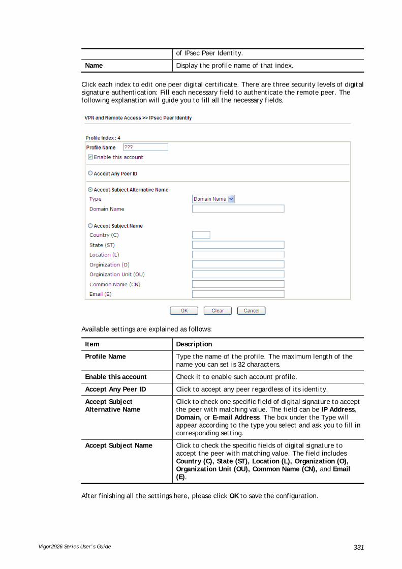
Vigor2926 Series User’s Guide 331
of IPsec Peer Identity.
Name Display the profile name of that index.
Click each index to edit one peer digital certificate. There are three security levels of digital signature authentication: Fill each necessary field to authenticate the remote peer. The following explanation will guide you to fill all the necessary fields.
Available settings are explained as follows:
Item Description
Profile Name Type the name of the profile. The maximum length of the name you can set is 32 characters.
Enable this account Check it to enable such account profile.
Accept Any Peer ID Click to accept any peer regardless of its identity.
Accept Subject Alternative Name
Click to check one specific field of digital signature to accept the peer with matching value. The field can be IP Address, Domain, or E-mail Address. The box under the Type will appear according to the type you select and ask you to fill in corresponding setting.
Accept Subject Name Click to check the specific fields of digital signature to accept the peer with matching value. The field includes Country (C), State (ST), Location (L), Organization (O), Organization Unit (OU), Common Name (CN), and Email (E).
After finishing all the settings here, please click OK to save the configuration.

Vigor2926 Series User’s Guide 332
VV--11--77 RReemmoottee DDiiaall--iinn UUsseerr
You can manage remote access by maintaining a table of remote user profile, so that users can be authenticated to dial-in via VPN connection. You may set parameters including specified connection peer ID, connection type (VPN connection - including PPTP, IPsec Tunnel, and L2TP by itself or over IPsec) and corresponding security methods, etc.
The router provides 64 access accounts for dial-in users. Besides, you can extend the user accounts to the RADIUS server through the built-in RADIUS client function. The following figure shows the summary table.
Available settings are explained as follows:
Item Description
Set to Factory Default Click to clear all indexes.
View All – Click it to display the all of the user accounts.
Online – Click it to display the online user accounts.
Offline – Click it to display the offline user accounts.
Index Click the number below Index to access into the setting page of Remote Dial-in User.
User Display the username for the specific dial-in user of the LAN-to-LAN profile. The symbol ??? represents that the profile is empty.
Active Check the box to activate such profile.

Vigor2926 Series User’s Guide 333
Status Display the access state of the specific dial-in user. The symbol V and X represent the specific dial-in user to be active and inactive, respectively.
Click each index to edit one remote user profile. Each Dial-In Type requires you to fill the different corresponding fields on the right. If the fields gray out, it means you may leave it untouched. The following explanation will guide you to fill all the necessary fields.
Available settings are explained as follows:
Item Description
User account and Authentication
Enable this account - Check the box to enable this function.
Idle Timeout- If the dial-in user is idle over the limitation of the timer, the router will drop this connection. By default, the Idle Timeout is set to 300 seconds.
Allowed Dial-In Type PPTP - Allow the remote dial-in user to make a PPTP VPN connection through the Internet. You should set the User Name and Password of remote dial-in user below.
IPsec Tunnel - Allow the remote dial-in user to make an IPsec VPN connection through Internet.
L2TP with IPsec Policy - Allow the remote dial-in user to make a L2TP VPN connection through the Internet. You can select to use L2TP alone or with IPsec. Select from below:
None - Do not apply the IPsec policy. Accordingly, the VPN connection employed the L2TP without IPsec policy can be viewed as one pure L2TP connection.
Nice to Have - Apply the IPsec policy first, if it is applicable during negotiation. Otherwise, the dial-in VPN connection becomes one pure L2TP connection.
Must -Specify the IPsec policy to be definitely applied

Vigor2926 Series User’s Guide 334
on the L2TP connection.
SSL Tunnel – Allow the remote dial-in user to make an SSL VPN connection through Internet.
Specify Remote Node -You can specify the IP address of the remote dial-in user, ISDN number or peer ID (used in IKE aggressive mode).
Uncheck the checkbox means the connection type you select above will apply the authentication methods and security methods in the general settings.
Netbios Naming Packet -
Pass – Click it to have an inquiry for data transmission between the hosts located on both sides of VPN Tunnel while connecting.
Block – When there is conflict occurred between the hosts on both sides of VPN Tunnel in connecting, such function can block data transmission of Netbios Naming Packet inside the tunnel.
Multicast via VPN - Some programs might send multicast packets via VPN connection.
Pass – Click this button to let multicast packets pass through the router.
Block – This is default setting. Click this button to let multicast packets be blocked by the router.
User Name - This field is applicable when you select PPTP or L2TP with or without IPsec policy above. The length of the name is limited to 23 characters.
Password - This field is applicable when you select PPTP or L2TP with or without IPsec policy above. The length of the password is limited to 19 characters.
Enable Mobile One-Time Passwords (mOTP) - Check this box to make the authentication with mOTP function.
PIN Code – Type the code for authentication (e.g, 1234).
Secret – Use the 32 digit-secret number generated by mOTP in the mobile phone (e.g., e759bb6f0e94c7ab4fe6).
Subnet Chose one of the subnet selections for such VPN profile.
Assign Static IP Address – Please type a static IP address for the subnet you specified.
IKE Authentication Method
This group of fields is applicable for IPsec Tunnels and L2TP with IPsec Policy when you specify the IP address of the remote node. The only exception is Digital Signature (X.509) can be set when you select IPsec tunnel either with or without specifying the IP address of the remote node.
Pre-Shared Key - Check the box of Pre-Shared Key to invoke this function and type in the required characters (1-63) as the pre-shared key.
Digital Signature (X.509) – Check the box of Digital Signature to invoke this function and Select one predefined Profiles set in the VPN and Remote Access >>IPsec Peer Identity.
IPsec Security Method This group of fields is a must for IPsec Tunnels and L2TP with IPsec Policy when you specify the remote node. Check the Medium, DES, 3DES or AES box as the security method. Medium-Authentication Header (AH) means data will be authenticated, but not be encrypted. By default, this option is invoked. You can uncheck it to disable it.

Vigor2926 Series User’s Guide 335
High-Encapsulating Security Payload (ESP) means payload (data) will be encrypted and authenticated. You may select encryption algorithm from Data Encryption Standard (DES), Triple DES (3DES), and AES.
Local ID (Optional)- Specify a local ID to be used for Dial-in setting in the LAN-to-LAN Profile setup. This item is optional and can be used only in IKE aggressive mode.
After finishing all the settings here, please click OK to save the configuration.
VV--11--88 LLAANN ttoo LLAANN
Here you can manage LAN-to-LAN connections by maintaining a table of connection profiles. You may set parameters including specified connection direction (dial-in or dial-out), connection peer ID, connection type (VPN connection - including PPTP, IPsec Tunnel, and L2TP by itself or over IPsec) and corresponding security methods, etc.
The router supports up to 50 VPN tunnels simultaneously. The following figure shows the summary table.
The following figure shows the summary table according to the item (All/Trunk) selected for View.
The following shows profiles joined into VPN Load Balance and VPN Backup mechanism.

Vigor2926 Series User’s Guide 336
Available settings are explained as follows:
Item Description
View All – Click it to display the LAN to LAN profiles.
Online – Click it to display the online profiles.
Offline – Click it to display the offline profiles.
Trunk – Click it to display the Trunk profiles.
Set to Factory Default Click to clear all indexes.
Name Indicate the name of the LAN-to-LAN profile. The symbol ??? represents that the profile is empty.
Active V – means the profile has been enabled.
X – means the profile has not been enabled.
Status Online – means such LAN to LAN profile is in use.
Offline – means such LAN to LAN profile isn’t in use even if the profile has been enabled.
To edit each profile:
1. Click each index to edit each profile and you will get the following page. Each LAN-to-LAN profile includes 4 subgroups. If the fields gray out, it means you may leave it untouched. The following explanations will guide you to fill all the necessary fields.

Vigor2926 Series User’s Guide 337
Available settings are explained as follows:
Item Description
Common Settings Profile Name – Specify a name for the profile of the LAN-to-LAN connection.
Enable this profile - Check here to activate this profile.
VPN Dial-Out Through - Use the drop down menu to choose a proper WAN interface for this profile. This setting is useful for dial-out only.
WAN1 First/ WAN2 First/ WAN3 First or LTE First/WAN4 First- While connecting, the router will use WAN1/WAN2/WAN3 or LTE/WAN4 as the first channel for VPN connection. If WAN1/WAN2/WAN3 or LTE /WAN4 fails, the router will use another WAN interface instead.
WAN1 Only /WAN2 Only/WAN 3 Only or LTE Only /WAN 4 Only- While connecting, the router will use WAN1/WAN2/WAN3 or LTE /WAN4 as the only channel for VPN connection.
WAN1 Only: Only establish VPN if WAN2 down - If WAN2 failed, the router will use WAN1 for VPN
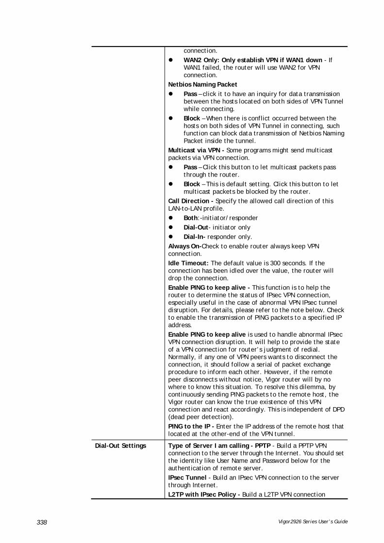
Vigor2926 Series User’s Guide 338
connection.
WAN2 Only: Only establish VPN if WAN1 down - If WAN1 failed, the router will use WAN2 for VPN connection.
Netbios Naming Packet
Pass – click it to have an inquiry for data transmission between the hosts located on both sides of VPN Tunnel while connecting.
Block – When there is conflict occurred between the hosts on both sides of VPN Tunnel in connecting, such function can block data transmission of Netbios Naming Packet inside the tunnel.
Multicast via VPN - Some programs might send multicast packets via VPN connection.
Pass – Click this button to let multicast packets pass through the router.
Block – This is default setting. Click this button to let multicast packets be blocked by the router.
Call Direction - Specify the allowed call direction of this LAN-to-LAN profile.
Both:-initiator/responder
Dial-Out- initiator only
Dial-In- responder only.
Always On-Check to enable router always keep VPN connection.
Idle Timeout: The default value is 300 seconds. If the connection has been idled over the value, the router will drop the connection.
Enable PING to keep alive - This function is to help the router to determine the status of IPsec VPN connection, especially useful in the case of abnormal VPN IPsec tunnel disruption. For details, please refer to the note below. Check to enable the transmission of PING packets to a specified IP address.
Enable PING to keep alive is used to handle abnormal IPsec VPN connection disruption. It will help to provide the state of a VPN connection for router’s judgment of redial. Normally, if any one of VPN peers wants to disconnect the connection, it should follow a serial of packet exchange procedure to inform each other. However, if the remote peer disconnects without notice, Vigor router will by no where to know this situation. To resolve this dilemma, by continuously sending PING packets to the remote host, the Vigor router can know the true existence of this VPN connection and react accordingly. This is independent of DPD (dead peer detection).
PING to the IP - Enter the IP address of the remote host that located at the other-end of the VPN tunnel.
Dial-Out Settings Type of Server I am calling - PPTP - Build a PPTP VPN connection to the server through the Internet. You should set the identity like User Name and Password below for the authentication of remote server.
IPsec Tunnel - Build an IPsec VPN connection to the server through Internet.
L2TP with IPsec Policy - Build a L2TP VPN connection
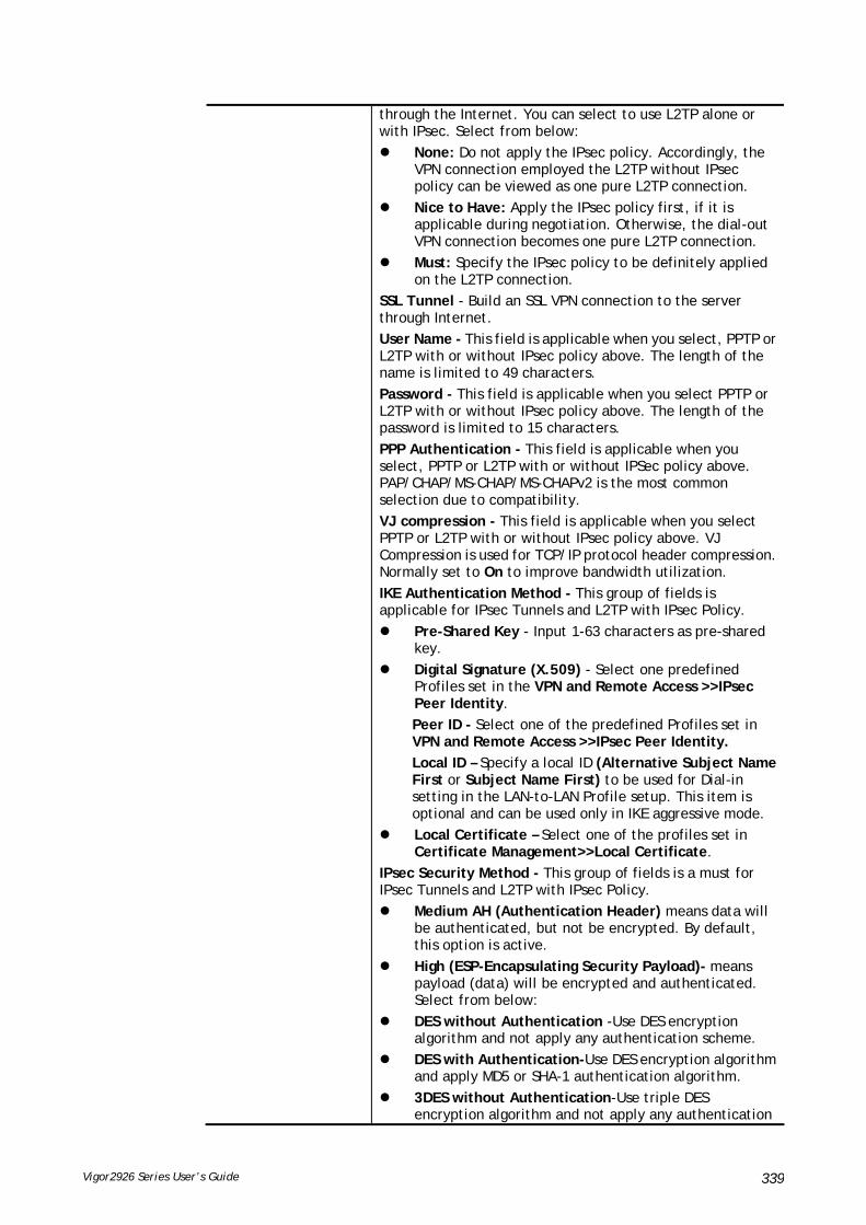
Vigor2926 Series User’s Guide 339
through the Internet. You can select to use L2TP alone or with IPsec. Select from below:
None: Do not apply the IPsec policy. Accordingly, the VPN connection employed the L2TP without IPsec policy can be viewed as one pure L2TP connection.
Nice to Have: Apply the IPsec policy first, if it is applicable during negotiation. Otherwise, the dial-out VPN connection becomes one pure L2TP connection.
Must: Specify the IPsec policy to be definitely applied on the L2TP connection.
SSL Tunnel - Build an SSL VPN connection to the server through Internet.
User Name - This field is applicable when you select, PPTP or L2TP with or without IPsec policy above. The length of the name is limited to 49 characters.
Password - This field is applicable when you select PPTP or L2TP with or without IPsec policy above. The length of the password is limited to 15 characters.
PPP Authentication - This field is applicable when you select, PPTP or L2TP with or without IPSec policy above. PAP/CHAP/MS-CHAP/MS-CHAPv2 is the most common selection due to compatibility.
VJ compression - This field is applicable when you select PPTP or L2TP with or without IPsec policy above. VJ Compression is used for TCP/IP protocol header compression. Normally set to On to improve bandwidth utilization.
IKE Authentication Method - This group of fields is applicable for IPsec Tunnels and L2TP with IPsec Policy.
Pre-Shared Key - Input 1-63 characters as pre-shared key.
Digital Signature (X.509) - Select one predefined Profiles set in the VPN and Remote Access >>IPsec Peer Identity.
Peer ID - Select one of the predefined Profiles set in VPN and Remote Access >>IPsec Peer Identity.
Local ID – Specify a local ID (Alternative Subject Name First or Subject Name First) to be used for Dial-in setting in the LAN-to-LAN Profile setup. This item is optional and can be used only in IKE aggressive mode.
Local Certificate – Select one of the profiles set in Certificate Management>>Local Certificate.
IPsec Security Method - This group of fields is a must for IPsec Tunnels and L2TP with IPsec Policy.
Medium AH (Authentication Header) means data will be authenticated, but not be encrypted. By default, this option is active.
High (ESP-Encapsulating Security Payload)- means payload (data) will be encrypted and authenticated. Select from below:
DES without Authentication -Use DES encryption algorithm and not apply any authentication scheme.
DES with Authentication-Use DES encryption algorithm and apply MD5 or SHA-1 authentication algorithm.
3DES without Authentication-Use triple DES encryption algorithm and not apply any authentication

Vigor2926 Series User’s Guide 340
scheme.
3DES with Authentication-Use triple DES encryption algorithm and apply MD5 or SHA-1 authentication algorithm.
AES without Authentication-Use AES encryption algorithm and not apply any authentication scheme.
AES with Authentication-Use AES encryption algorithm and apply MD5 or SHA-1 authentication algorithm.
Advanced - Specify mode, proposal and key life of each IKE phase, Gateway, etc.
The window of advance setup is shown as below:
IKE phase 1 mode -Select from Main mode and Aggressive mode. The ultimate outcome is to exchange security proposals to create a protected secure channel. Main mode is more secure than Aggressive mode since more exchanges are done in a secure channel to set up the IPsec session. However, the Aggressive mode is faster. The default value in Vigor router is Main mode.
IKE phase 1 proposal-To propose the local available authentication schemes and encryption algorithms to the VPN peers, and get its feedback to find a match. Two combinations are available for Aggressive mode and nine for Main mode. We suggest you select the combination that covers the most schemes.
IKE phase 2 proposal-To propose the local available algorithms to the VPN peers, and get its feedback to find a match. Three combinations are available for both modes. We suggest you select the combination that covers the most algorithms.
IKE phase 1 key lifetime-For security reason, the lifetime of key should be defined. The default value is 28800 seconds. You may specify a value in between 900 and 86400 seconds.
IKE phase 2 key lifetime-For security reason, the lifetime of key should be defined. The default value is 3600 seconds. You may specify a value in between 600 and 86400 seconds.
Perfect Forward Secret (PFS)-The IKE Phase 1 key will be reused to avoid the computation complexity in phase 2. The default value is inactive this function.
Local ID-In Aggressive mode, Local ID is on behalf of the IP address while identity authenticating with remote VPN server. The length of the ID is limited to 47 characters.
Index(1-15) - Set the wireless LAN to work at certain time interval only. You may choose up to 4 schedules out of the 15 schedules pre-defined in Applications >> Schedule setup. The default setting of this field is blank and the function will always work.

Vigor2926 Series User’s Guide 341
Available settings are explained as follows:
Item Description
Dial-In Settings Allowed Dial-In Type - Determine the dial-in connection with different types.
PPTP - Allow the remote dial-in user to make a PPTP VPN connection through the Internet. You should set the User Name and Password of remote dial-in user below.
IPsec Tunnel- Allow the remote dial-in user to trigger an IPsec VPN connection through Internet.
L2TP with IPsec Policy - Allow the remote dial-in user to make a L2TP VPN connection through the Internet. You can select to use L2TP alone or with IPsec. Select from below:
None - Do not apply the IPsec policy. Accordingly, the VPN connection employed the L2TP without IPsec policy can be viewed as one pure L2TP connection.
Nice to Have - Apply the IPsec policy first, if it is applicable during negotiation. Otherwise, the dial-in VPN connection becomes one pure L2TP connection.
Must - Specify the IPsec policy to be definitely applied on the L2TP connection.
SSL Tunnel- Allow the remote dial-in user to trigger an SSL VPN connection through Internet.

Vigor2926 Series User’s Guide 342
Specify Remote VPN Gateway - You can specify the IP address of the remote dial-in user or peer ID (should be the same with the ID setting in dial-in type) by checking the box. Also, you should further specify the corresponding security methods on the right side.
If you uncheck the checkbox, the connection type you select above will apply the authentication methods and security methods in the general settings.
Username - This field is applicable when you select PPTP or L2TP with or without IPsec policy above. The length of the name is limited to 11 characters.
Password - This field is applicable when you select PPTP or L2TP with or without IPsec policy above. The length of the password is limited to 11 characters.
VJ Compression - VJ Compression is used for TCP/IP protocol header compression. This field is applicable when you select PPTP or L2TP with or without IPsec policy above.
IKE Authentication Method - This group of fields is applicable for IPsec Tunnels and L2TP with IPsec Policy when you specify the IP address of the remote node. The only exception is Digital Signature (X.509) can be set when you select IPsec tunnel either with or without specify the IP address of the remote node.
Pre-Shared Key - Check the box of Pre-Shared Key to invoke this function and type in the required characters (1-63) as the pre-shared key.
Digital Signature (X.509) –Check the box of Digital Signature to invoke this function and select one predefined Profiles set in the VPN and Remote Access >>IPsec Peer Identity.
Local ID – Specify which one will be inspected first.
Alternative Subject Name First – The alternative subject name (configured in Certificate Management>>Local Certificate) will be inspected first.
Subject Name First – The subject name (configured in Certificate Management>>Local Certificate) will be inspected first.
IPsec Security Method - This group of fields is a must for IPsec Tunnels and L2TP with IPsec Policy when you specify the remote node.
Medium- Authentication Header (AH) means data will be authenticated, but not be encrypted. By default, this option is active.
High- Encapsulating Security Payload (ESP) means payload (data) will be encrypted and authenticated. You may select encryption algorithm from Data Encryption Standard (DES), Triple DES (3DES), and AES.
GRE over IPsec Settings
Enable IPsec Dial-Out function GRE over IPsec: Check this box to verify data and transmit data in encryption with GRE over IPsec packet after configuring IPsec Dial-Out setting. Both ends must match for each other by setting same virtual IP address for communication.
Logical Traffic: Such technique comes from RFC2890. Define logical traffic for data transmission between both sides of

Vigor2926 Series User’s Guide 343
VPN tunnel by using the characteristic of GRE. Even hacker can decipher IPsec encryption, he/she still cannot ask LAN site to do data transmission with any information. Such function can ensure the data transmitted on VPN tunnel is really sent out from both sides. This is an optional function. However, if one side wants to use it, the peer must enable it, too.
My GRE IP: Type the virtual IP for router itself for verified by peer.
Peer GRE IP: Type the virtual IP of peer host for verified by router.
TCP/IP Network Settings
My WAN IP –This field is only applicable when you select PPTP or L2TP with or without IPsec policy above. The default value is 0.0.0.0, which means the Vigor router will get a PPP IP address from the remote router during the IPCP negotiation phase. If the PPP IP address is fixed by remote side, specify the fixed IP address here. Do not change the default value if you do not select PPTP or L2TP.
Remote Gateway IP - This field is only applicable when you select PPTP or L2TP with or without IPsec policy above. The default value is 0.0.0.0, which means the Vigor router will get a remote Gateway PPP IP address from the remote router during the IPCP negotiation phase. If the PPP IP address is fixed by remote side, specify the fixed IP address here. Do not change the default value if you do not select PPTP or L2TP.
Remote Network IP/ Remote Network Mask - Add a static route to direct all traffic destined to this Remote Network IP Address/Remote Network Mask through the VPN connection. For IPsec, this is the destination clients IDs of phase 2 quick mode.
Local Network IP / Local Network Mask - Display the local network IP and mask for TCP / IP configuration. You can modify the settings if required.
More - Add a static route to direct all traffic destined to more Remote Network IP Addresses/ Remote Network Masks through the VPN connection. This is usually used when you find there are several subnets behind the remote VPN router.
RIP Direction - The option specifies the direction of RIP (Routing Information Protocol) packets. You can

Vigor2926 Series User’s Guide 344
enable/disable one of direction here. Herein, we provide four options: TX/RX Both, TX Only, RX Only, and Disable.
From first subnet to remote network, you have to do - If the remote network only allows you to dial in with single IP, please choose NAT, otherwise choose Route.
Change default route to this VPN tunnel - Check this box to change the default route with this VPN tunnel.
IPSec VPN with the Same subnet
For both ends (e.g., different sections in a company) are within the same subnet, there is a function which allows you to build Virtual IP mapping between two ends. Thus, when VPN connection established, the router will change the IP address according to the settings configured here and block sessions which are not coming from the IP address defined in the Virtual IP Mapping list.
After checking the box of IPSec VPN with the Same subnet, the options under TCP/IP Network Settings will be changed as shown below:
Remote Network IP/ Remote Network Mask - Add a static route to direct all traffic destined to this Remote Network IP Address/Remote Network Mask through the VPN connection. For IPSec, this is the destination clients IDs of phase 2 quick mode.
Translated Local Network – This function is enabled in default. Use the drop down list to specify a LAN port as the transferred direction. Then specify an IP address. Click Advanced to configure detailed settings if required.
Advanced – Add a static route to direct all traffic destined to more Remote Network IP Addresses/ Remote Network Mask through the VPN connection. This is usually used when you find there are several subnets behind the remote VPN router.
Translated Type – There are two types for you to choose.

Vigor2926 Series User’s Guide 345
Whole Subnet
Specific IP Address
Virtual IP Mapping – A pop up dialog will appear for you to specify the local IP address and the mapping virtual IP address.
2. After finishing all the settings here, please click OK to save the configuration.

Vigor2926 Series User’s Guide 346
VV--11--99 VVPPNN TTrruunnkk MMaannaaggeemmeenntt
VPN trunk includes four features - VPN Backup, VPN load balance, GRE over IPsec, and Binding tunnel policy.
FFeeaattuurreess ooff VVPPNN TTRRUUNNKK –– VVPPNN BBaacckkuupp MMeecchhaanniissmm
VPN TRUNK Management is a backup mechanism which can set multiple VPN tunnels as backup tunnel. It can assure the network connection not to be cut off due to network environment blocked by any reason.
VPN TRUNK-VPN Backup mechanism can judge abnormal situation for the environment of VPN server and correct it to complete the backup of VPN Tunnel in real-time.
VPN TRUNK-VPN Backup mechanism is compliant with all WAN modes (single/multi)
Dial-out connection types contain IPsec, PPTP, L2TP, L2TP over IPsec and ISDN (depends on hardware specification)
The web page is simple to understand and easy to configure
Fully compliant with VPN Server LAN Site Single/Multi Network
Mail Alert support, please refer to System Maintenance >> SysLog / Mail Alert for detailed configuration
Syslog support, please refer to System Maintenance >> SysLog / Mail Alert for detailed configuration
Specific ERD (Environment Recovery Detection) mechanism which can be operated by using Telnet command
VPN TRUNK-VPN Backup mechanism profile will be activated when initial connection of single VPN tunnel is off-line. Before setting VPN TRUNK -VPN Backup mechanism backup profile, please configure at least two sets of LAN-to-LAN profiles (with fully configured dial-out settings) first, otherwise you will not have selections for grouping Member1 and Member2.
FFeeaattuurreess ooff VVPPNN TTRRUUNNKK –– VVPPNN LLooaadd BBaallaannccee MMeecchhaanniissmm
VPN Load Balance Mechanism can set multiple VPN tunnels for using as traffic load balance tunnel. It can assist users to do effective load sharing for multiple VPN tunnels according to real line bandwidth. Moreover, it offers three types of algorithms for load balancing and binding tunnel policy mechanism to let the administrator manage the network more flexibly.
Three types of load sharing algorithm offered, Round Robin, Weighted Round Robin and Fastest
Binding Tunnel Policy mechanism allows users to encrypt the data in transmission or specified service function in transmission and define specified VPN Tunnel for having effective bandwidth management
Dial-out connection types contain IPsec, PPTP, L2TP, L2TP over IPsec and GRE over IPsec
The web page is simple to understand and easy to configure
The TCP Session transmitted by using VPN TRUNK-VPN Load Balance mechanism will not be lost due to one of VPN Tunnels disconnected. Users do not need to reconnect with setting TCP/UDP Service Port again. The VPN Load Balance function can keep the transmission for internal data on tunnel stably

Vigor2926 Series User’s Guide 347
Available settings are explained as follows:
Item Description
Backup Profile List Set to Factory Default - Click to clear all VPN TRUNK-VPN Backup mechanism profile.
No – The order of VPN TRUNK-VPN Backup mechanism profile.
Status - “v” means such profile is enabled; “x” means such profile is disabled.
Name - Display the name of VPN TRUNK-VPN Backup mechanism profile.
Member1 - Display the dial-out profile selected from the Member1 drop down list below.
Active - “Yes” means normal condition. “No” means the state might be disabled or that profile currently is set with Dial-in mode (for call direction) in LAN-to-LAN.
Type - Display the connection type for that profile, such as IPsec, PPTP, L2TP, L2TP over IPsec (NICE), L2TP over IPsec(MUST) and so on.
Member2 - Display the dial-out profile selected from the Member2 drop down list below.
Advanced – This button is available only when LAN to LAN profile (or more) is created.

Vigor2926 Series User’s Guide 348
Detailed information for this dialog, see later section - Advanced Load Balance and Backup.
Load Balance Profile List Set to Factory Default - Click to clear all VPN TRUNK-VPN Load Balance mechanism profile.
No - The order of VPN TRUNK-VPN Load Balance mechanism profile.
Status - “v” means such profile is enabled; “x” means such profile is disabled.
Name - Display the name of VPN TRUNK-VPN Load Balance mechanism profile.
Member1 - Display the dial-out profile selected from the Member1 drop down list below.
Active - “Yes” means normal condition. “No” means the state might be disabled or that profile currently is set with Dial-in mode (for call direction) in LAN-to-LAN.
Type - Display the connection type for that profile, such as IPsec, PPTP, L2TP, L2TP over IPsec (NICE), L2TP over IPsec(MUST) and so on.
Member2 - Display the dial-out profile selected from the Member2 drop down list below.
Advanced – This button is only available when there is one or more profiles created in this page.
Detailed information for this dialog, see later section - Advanced Load Balance and Backup.
Vigor2926 Series User’s Guide 349
General Setup Status- After choosing one of the profile listed above, please click Enable to activate this profile. If you click Disable, the selected or current used VPN TRUNK-Backup/Load Balance mechanism profile will not have any effect for VPN tunnel.
Profile Name- Type a name for VPN TRUNK profile. Each profile can group two VPN connections set in LAN-to-LAN. The saved VPN profiles in LAN-to-LAN will be shown on Member1 and Member2 fields. The length of the name is limited to 11 characters.
Member 1/Member2 - Display the selection for LAN-to-LAN dial-out profiles (configured in VPN and Remote Access >> LAN-to-LAN) for you to choose for grouping under certain VPN TRUNK-VPN Backup/Load Balance mechanism profile.
No - Index number of LAN-to-LAN dial-out profile.
Name - Profile name of LAN-to-LAN dial-out profile.
Connection Type - Connection type of LAN-to-LAN dial-out profile.
VPN ServerIP (Private Network) - VPN Server IP of LAN-to-LAN dial-out profiles.
Active Mode - Display available mode for you to choose. Choose Backup or Load Balance for your router.
Add - Add and save new profile to the backup profile list. The corresponding members (LAN-to-LAN profiles) grouped in such new VPN TRUNK – VPN Backup mechanism profile will be locked. The profiles in LAN-to-LAN will be displayed in red. VPN TRUNK – VPN Load Balance mechanism profile will be locked. The profiles in LAN-to-LAN will be displayed in blue.
Update - Click this button to save the changes to the Status (Enable or Disable), profile name, member1 or member2.
Delete - Click this button to delete the selected VPN TRUNK profile. The corresponding members (LAN-to-LAN profiles) grouped in the deleted VPN TRUNK profile will be released and that profiles in LAN-to-LAN will be displayed in black.
TTiimmee ffoorr aaccttiivvaattiinngg VVPPNN TTRRUUNNKK –– VVPPNN BBaacckkuupp mmeecchhaanniissmm pprrooffiillee
VPN TRUNK – VPN Backup mechanism will be activated automatically after the initial connection of single VPN Tunnel off-line. The content in Member1/2 within VPN TRUNK – VPN Backup mechanism backup profile is similar to dial-out profile configured in LAN-to-LAN web page. VPN TRUNK – VPN Backup mechanism backup profile will process and handle everything unless it is off-line once it is activated.
TTiimmee ffoorr aaccttiivvaattiinngg VVPPNN TTRRUUNNKK –– VVPPNN LLooaadd BBaallaannccee mmeecchhaanniissmm pprrooffiillee
After finishing the connection for one tunnel, the other tunnel will dial out automatically within two seconds. Therefore, you can choose any one of members under VPN Load Balance for dialing out.
TTiimmee ffoorr aaccttiivvaattiinngg VVPPNN TTRRUUNNKK ––DDiiaall--oouutt wwhheenn VVPPNN LLooaadd BBaallaannccee DDiissccoonnnneecctteedd
For there is one Tunnel created and connected successfully, to keep the load balance effect between two tunnels, auto-dial will be executed within two seconds.
To close two tunnels of load balance after connecting, please click Disable for Status in General Setup field.

Vigor2926 Series User’s Guide 350
HHooww ccaann yyoouu sseett aa VVPPNN TTRRUUNNKK--VVPPNN BBaacckkuupp//LLooaadd BBaallaannccee mmeecchhaanniissmm pprrooffiillee??
1. First of all, go to VPN and Remote Access>>LAN-to-LAN. Set two or more LAN-to-LAN profiles first that will be used for Member1 and Member2. If you do not set enough LAN-to-LAN profiles, you cannot operate VPN TRUNK – VPN Backup /Load Balance mechanism profile management well.
2. Access into VPN and Remote Access>>VPN TRUNK Management.
3. Set one group of VPN TRUNK – VPN Backup/Load Balance mechanism backup profile by choosing Enable radio button; type a name for such profile (e.g., 071023); choose one of the LAN-to-LAN profiles from Member1 drop down list; choose one of the LAN-to-LAN profiles from Member2 drop down list; and click Add at last.
4. Take a look for LAN-to-LAN profiles. Index 1 is chosen as Member1; index 2 is chosen as Member2. For such reason, LAN-to-LAN profiles of 1 and 2 will be expressed in red to indicate that they are fixed. If you delete the VPN TRUNK – VPN Backup/Load Balance mechanism profile, the selected LAN-to-LAN profiles will be released and expressed in black.
HHooww ccaann yyoouu sseett aa GGRREE oovveerr IIPPsseecc pprrooffiillee??
1. Please go to LAN to LAN to set a profile with IPsec.
2. If the router will be used as the VPN Server (i.e., with virtual address 192.168.50.200). Please type 192.168.50.200 in the field of My GRE IP. Type IP address (192.168.50.100) of the client in the field of Peer GRE IP. See the following graphic for an example.

Vigor2926 Series User’s Guide 351
3. Later, on peer side (as VPN Client): please type 192.168.50.100 in the field of My GRE IP and type IP address of the server (192.168.50.200) in the field of Peer GRE IP.
AAddvvaanncceedd LLooaadd BBaallaannccee aanndd BBaacckkuupp
After setting profiles for load balance, you can choose any one of them and click Advance for more detailed configuration. The windows for advanced load balance and backup are different. Refer to the following explanation:

Vigor2926 Series User’s Guide 352
AAddvvaanncceedd LLooaadd BBaallaannccee
Available settings are explained as follows:
Item Description
Profile Name List the load balance profile name.
Load Balance Algorithm Round Robin – Based on packet base, both tunnels will send the packet alternatively. Such method can reach the balance of packet transmission with fixed rate.
Weighted Round Robin –Such method can reach the balance of packet transmission with flexible rate. It can be divided into Auto Weighted and According to Speed Ratio. Auto Weighted can detect the device speed (10Mbps/100Mbps) and switch with fixed value ratio (3:7) for packet transmission. If the transmission rate for packets on both sides of the tunnels is the same, the value of Auto Weighted should be 5.5. According to Speed Ratio allows user to adjust suitable rate manually. There are 100 groups of rate ratio for Member1:Member2 (range from 1:99 to 99:1).
VPN Load Balance Policy Below shows the algorithm for Load Balance.
Edit – Click this radio button for assign a blank table for configuring Binding Tunnel.
Insert after – Click this radio button to adding a new binding tunnel table.

Vigor2926 Series User’s Guide 353
Tunnel Bind Table Index- 128 Binding tunnel tables are provided by this device. Specify the number of the tunnel for such Load Balance profile.
Active – In-active/Delete can delete this binding tunnel table. Active can activate this binding tunnel table.
Binding Dial Out Index – Specify connection type for transmission by choosing the index (LAN to LAN Profile Index) for such binding tunnel table.
Scr IP Start /End– Specify source IP addresses as starting point and ending point.
Dest IP Start/End – Specify destination IP addresses as starting point and ending point.
Dest Port Start /End– Specify destination service port as starting point and ending point.
Protocol – Any means when the source IP, destination IP, destination port and fragment conditions match with the settings specified here, such binding tunnel table can be established for TCP Service Port/UDP Service Port/ICMP/IGMP specified here.
TCP means when the source IP, destination IP, destination port and fragment conditions match with the settings specified here and TCP Service Port also fits the number here, such binding tunnel table can be established. UDP means when the source IP, destination IP, destination port and fragment conditions match with the settings specified here and UDP Service Port also fits the number here, such binding tunnel table can be established. TCP/UPD means when the source IP, destination IP, destination port and fragment conditions match with the settings specified here and TCP/UDP Service Port also fits the number here, such binding tunnel table can be established. ICMP means when the source IP, destination IP, destination port and fragment conditions match with the settings specified here and ICMP Service Port also fits the number here, such binding tunnel table can be established. IGMP means when the source IP, destination IP, destination port and fragment conditions match with the settings specified here and IGMP Service Port also fits the number here, such binding tunnel table can be established. Other means when the source IP, destination IP, destination port and fragment conditions match with the settings specified here with different TCP Service Port/UDP Service Port/ICMP/IGMP, such binding tunnel table can be established.
Detail Information This field will display detailed information for Binding Tunnel Policy. Below shows a successful binding tunnel policy for load balance:
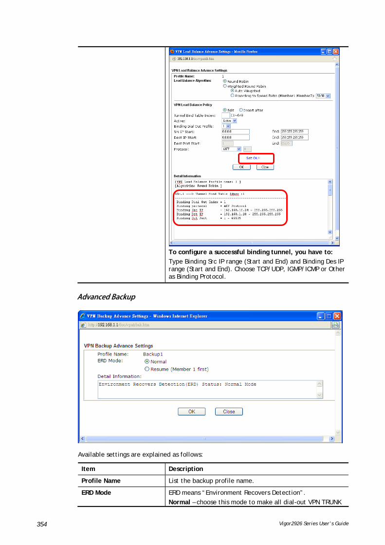
Vigor2926 Series User’s Guide 354
To configure a successful binding tunnel, you have to:
Type Binding Src IP range (Start and End) and Binding Des IP range (Start and End). Choose TCP/UDP, IGMP/ICMP or Other as Binding Protocol.
AAddvvaanncceedd BBaacckkuupp
Available settings are explained as follows:
Item Description
Profile Name List the backup profile name.
ERD Mode ERD means “Environment Recovers Detection”.
Normal – choose this mode to make all dial-out VPN TRUNK

Vigor2926 Series User’s Guide 355
backup profiles being activated alternatively.
Resume – when VPN connection breaks down or disconnects, Member 1 will be the top priority for the system to do VPN connection.
Detail Information This field will display detailed information for Environment Recovers Detection.
VV--11--1100 CCoonnnneeccttiioonn MMaannaaggeemmeenntt
You can find the summary table of all VPN connections. You may disconnect any VPN connection by clicking Drop button. You may also aggressively Dial-out by using Dial-out Tool and clicking Dial button.
Available settings are explained as follows:
Item Description
Dial-out Tool General Mode - This filed displays the profile configured in LAN-to-LAN (with Index number and VPN Server IP address). The VPN connection built by General Mode does not support VPN backup function.
Backup Mode - This filed displays the profile name saved in VPN TRUNK Management (with Index number and VPN Server IP address). The VPN connection built by Backup Mode supports VPN backup function.

Vigor2926 Series User’s Guide 356
Dial - Click this button to execute dial out function.
Refresh Seconds - Choose the time for refresh the dial information among 5, 10, and 30.
Refresh - Click this button to refresh the whole connection status.

Vigor2926 Series User’s Guide 357
AApppplliiccaattiioonn NNootteess
AA--11 HHooww ttoo BBuuiilldd aa LLAANN--ttoo--LLAANN VVPPNN BBeettwweeeenn RReemmoottee OOffffiiccee aanndd HHeeaaddqquuaarrtteerr
vviiaa IIPPsseecc TTuunnnneell ((MMaaiinn MMooddee))
CCoonnffiigguurraattiioonn oonn VViiggoorr RRoouutteerr ffoorr HHeeaadd OOffffiiccee
1. Log into the web user interface of Vigor router.
2. Open VPN and Remote Access>>LAN to LAN to create a LAN-to-LAN profile. The following settings are for a permanent VPN connection.
3. Click any index number to open the configuration page. Type a name which is easy for identification for such profile (in this case, type VPN Server), and check the box of Enable This Profile. For Vigor router will be set as a server, the call direction shall be set as Dial-in and set 0 as Idle Timeout.

Vigor2926 Series User’s Guide 358
4. Now navigate to the next section, Dial-In Settings to check PPTP, IPsec Tunnel and L2TP boxes. Check the box of Specify Remote… and type the Peer VPN Server IP (e.g., 218.242.130.19 in this case). Press the IKE Pre-Shared Key button to set the PSK; and select Medium (AH) or High (ESP) as the security method.
5. Continue to navigate to the TCP/IP Network Settings for setting the LAN IP for remote side.
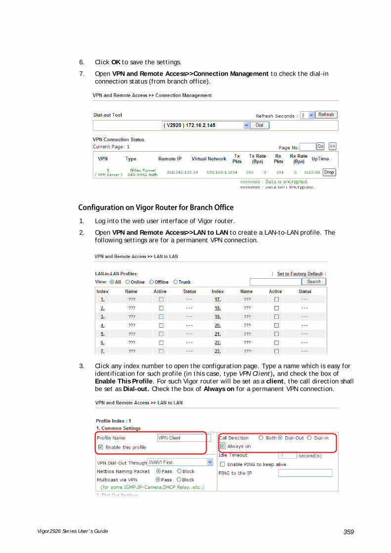
Vigor2926 Series User’s Guide 359
6. Click OK to save the settings.
7. Open VPN and Remote Access>>Connection Management to check the dial-in connection status (from branch office).
CCoonnffiigguurraattiioonn oonn VViiggoorr RRoouutteerr ffoorr BBrraanncchh OOffffiiccee
1. Log into the web user interface of Vigor router.
2. Open VPN and Remote Access>>LAN to LAN to create a LAN-to-LAN profile. The following settings are for a permanent VPN connection.
3. Click any index number to open the configuration page. Type a name which is easy for identification for such profile (in this case, type VPN Client), and check the box of Enable This Profile. For such Vigor router will be set as a client, the call direction shall be set as Dial-out. Check the box of Always on for a permanent VPN connection.

Vigor2926 Series User’s Guide 360
4. Now navigate to the next section, Dial-Out Settings to select the IPsec Tunnel service and type the remote server IP/host name (e.g., 218.242.133.91, in this case). Press the IKE Pre-Shared Key button to set the PSK; and select Medium (AH) or High (ESP) as the security method.
5. Continue to navigate to the TCP/IP Network Settings for setting the LAN IP for the remote side.
6. Click OK to save the settings.

Vigor2926 Series User’s Guide 361
7. Open VPN and Remote Access>>Connection Management to check the dial-in connection status (from head office).

Vigor2926 Series User’s Guide 362
VV--22 SSSSLL VVPPNN
An SSL VPN (Secure Sockets Layer virtual private network) is a form of VPN that can be used with a standard Web browser.
There are two benefits that SSL VPN provides:
It is not necessary for users to preinstall VPN client software for executing SSL VPN connection.
There are less restrictions for the data encrypted through SSL VPN in comparing with traditional VPN.

Vigor2926 Series User’s Guide 363
WWeebb UUsseerr IInntteerrffaaccee
VV--22--11 GGeenneerraall SSeettuupp
This page determines the general configuration for SSL VPN Server and SSL Tunnel.
Available settings are explained as follows:
Item Description
Bind to WAN Choose and check WAN interface(s) for SSL VPN tunnel establishment.
Port Such port is set for SSL VPN server. It will not affect the HTTPS Port configuration set in System Maintenance>>Management. In general, the default setting is 443.
Server Certificate When the client does not set any certificate, default certificate will be used for HTTPS and SSL VPN server. Choose any one of the user-defined certificates from the drop down list if users set several certificates previously. Otherwise, choose Self-signed to use the router’s built-in default certificate. The default certificate can be used in SSL VPN server and HTTPS Web Proxy.
After finishing all the settings here, please click OK to save the configuration.
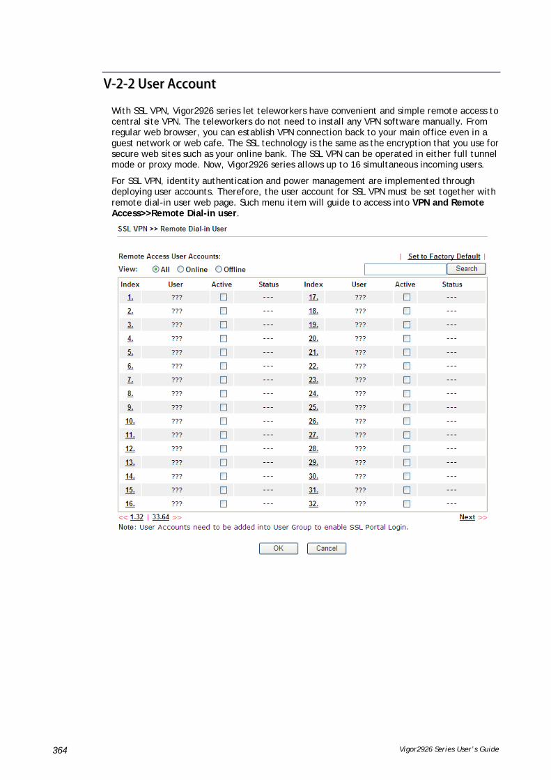
Vigor2926 Series User’s Guide 364
VV--22--22 UUsseerr AAccccoouunntt
With SSL VPN, Vigor2926 series let teleworkers have convenient and simple remote access to central site VPN. The teleworkers do not need to install any VPN software manually. From regular web browser, you can establish VPN connection back to your main office even in a guest network or web cafe. The SSL technology is the same as the encryption that you use for secure web sites such as your online bank. The SSL VPN can be operated in either full tunnel mode or proxy mode. Now, Vigor2926 series allows up to 16 simultaneous incoming users.
For SSL VPN, identity authentication and power management are implemented through deploying user accounts. Therefore, the user account for SSL VPN must be set together with remote dial-in user web page. Such menu item will guide to access into VPN and Remote Access>>Remote Dial-in user.

Vigor2926 Series User’s Guide 365
Click each index to edit one remote user profile.
Available settings are explained as follows:
Item Description
User account and Authentication
Enable this account - Check the box to enable this function.
Idle Timeout- If the dial-in user is idle over the limitation of the timer, the router will drop this connection. By default, the Idle Timeout is set to 300 seconds.
User Name - This field is applicable when you select PPTP or L2TP with or without IPsec policy above. The length of the name/password is limited to 23 characters.
Password - This field is applicable when you select PPTP or L2TP with or without IPsec policy above. The length of the name/password is limited to 19 characters.
Enable Mobile One-Time Passwords (mOTP) - Check this box to make the authentication with mOTP function.
PIN Code – Type the code for authentication (e.g, 1234).
Secret – Use the 32 digit-secret number generated by mOTP in the mobile phone (e.g., e759bb6f0e94c7ab4fe6).
Allowed Dial-In Type PPTP - Allow the remote dial-in user to make a PPTP VPN connection through the Internet. You should set the User Name and Password of remote dial-in user below.
IPSec Tunnel - Allow the remote dial-in user to make an IPSec VPN connection through Internet.
L2TP with IPSec Policy - Allow the remote dial-in user to

Vigor2926 Series User’s Guide 366
Item Description
make a L2TP VPN connection through the Internet. You can select to use L2TP alone or with IPSec. Select from below:
None - Do not apply the IPSec policy. Accordingly, the VPN connection employed the L2TP without IPSec policy can be viewed as one pure L2TP connection.
Nice to Have - Apply the IPSec policy first, if it is applicable during negotiation. Otherwise, the dial-in VPN connection becomes one pure L2TP connection.
Must -Specify the IPSec policy to be definitely applied on the L2TP connection.
SSL Tunnel - It allows the remote dial-in user to make an SSL VPN Tunnel connection through Internet, suitable for the application through network accessing (e.g., PPTP/L2TP/IPSec)
If you check this box, the function of SSL Tunnel for this account will be activated immediately.
Specify Remote Node - Check the checkbox to specify the IP address of the remote dial-in user, ISDN number or peer ID (used in IKE aggressive mode). If you uncheck the checkbox, the connection type you select above will apply the authentication methods and security methods in the general settings.
Netbios Naming Packet
Pass – Click it to have an inquiry for data transmission between the hosts located on both sides of VPN Tunnel while connecting.
Block – When there is conflict occurred between the hosts on both sides of VPN Tunnel in connecting, such function can block data transmission of Netbios Naming Packet inside the tunnel.
Multicast via VPN - Some programs might send multicast packets via VPN connection.
Pass – Click this button to let multicast packets pass through the router.
Block – This is default setting. Click this button to let multicast packets be blocked by the router.
Subnet Chose one of the subnet selections for such VPN profile.
Assign Static IP Address – Please type a static IP address for the subnet you specified.
IKE Authentication Method
This group of fields is applicable for IPSec Tunnels and L2TP with IPSec Policy when you specify the IP address of the remote node. The only exception is Digital Signature (X.509) can be set when you select IPSec tunnel either with or without specify the IP address of the remote node.
Pre-Shared Key - Check the box of Pre-Shared Key to invoke this function and type in the required characters (1-63) as the pre-shared key.
Digital Signature (X.509) – Check the box of Digital Signature to invoke this function and Select one predefined Profiles set in the VPN and Remote Access >>IPSec Peer Identity.
IPSec Security Method This group of fields is a must for IPSec Tunnels and L2TP with IPSec Policy when you specify the remote node. Check the Medium, DES, 3DES or AES box as the security method.

Vigor2926 Series User’s Guide 367
Item Description
Medium-Authentication Header (AH) means data will be authenticated, but not be encrypted. By default, this option is invoked. You can uncheck it to disable it.
High-Encapsulating Security Payload (ESP) means payload (data) will be encrypted and authenticated. You may select encryption algorithm from Data Encryption Standard (DES), Triple DES (3DES), and AES.
Local ID - Specify a local ID to be used for Dial-in setting in the LAN-to-LAN Profile setup. This item is optional and can be used only in IKE aggressive mode.
After finishing all the settings here, please click OK to save the configuration.

Vigor2926 Series User’s Guide 368
VV--22--33 UUsseerr GGrroouupp
There are 10 user group profiles which can be created for authentication by LDAP server. Such profiles will be used by applications such as User Management, VPN and etc.
Each item is explained as follows:
Item Description
Set to Factory Default Click to clear all indexes.
Index Display the number of the client which connecting to FTP server.
Name Display the name of the group profile.
Click any index number link to open the following page for detailed configuration.
Available settings are explained as follows:

Vigor2926 Series User’s Guide 369
Item Description
Enable Check this box to enable such profile.
Group Name Type a name for such profile. The length of the name is limited to 23 characters.
Authentication Methods It can determine the authentication method used for such profile.
Local User DataBase – The system will do the authentication by using the user defined account profiles (in VPN and Remote Access>>Remote Dial-In User). The enabled profiles will be listed in the Available User Account on the left box. To add a profile into a group, simply choose the one from the left box and click the >> button. It will be displayed in the Selected User Account on the right box. For detailed information about configuring the profile setting, refer to Objects Setting>>IP Group.
RADIUS – The RADIUS server will do the authentication by using the username and password
TACACS+ - The TACACS+ will do the authentication by using the username and password.
LDAP / Active Directory - If it is checked, the LDAP / AD server will do the authentication by using the username, password, information stated on the selected profiles.
If the above three options are enabled, the system will do the authentication based on them in sequence.
After finishing all the settings here, please click OK to save the configuration.

Vigor2926 Series User’s Guide 370
VV--22--66 OOnnlliinnee UUsseerr SSttaattuuss
If you have finished the configuration of SSL Web Proxy (server), users can find out corresponding settings when they access into DrayTek SSL VPN portal interface.
Next, users can open SSL VPN>> Online Status to view logging status of SSL VPN.
Available settings are explained as follows:
Item Description
Active User Display current user who visits SSL VPN server.
Host IP Display the IP address for the host.
Time out Display the time remaining for logging out.
Action You can click Drop to drop certain login user from the router's SSL Portal UI.

Vigor2926 Series User’s Guide 371
VV--33 CCeerrttiiffiiccaattee MMaannaaggeemmeenntt
A digital certificate works as an electronic ID, which is issued by a certification authority (CA). It contains information such as your name, a serial number, expiration dates etc., and the digital signature of the certificate-issuing authority so that a recipient can verify that the certificate is real. Here Vigor router support digital certificates conforming to standard X.509.
Any entity wants to utilize digital certificates should first request a certificate issued by a CA server. It should also retrieve certificates of other trusted CA servers so it can authenticate the peer with certificates issued by those trusted CA servers.
Here you can manage generate and manage the local digital certificates, and set trusted CA certificates. Remember to adjust the time of Vigor router before using the certificate so that you can get the correct valid period of certificate.
Below shows the menu items for Certificate Management.

Vigor2926 Series User’s Guide 372
WWeebb UUsseerr IInntteerrffaaccee
VV--33--11 LLooccaall CCeerrttiiffiiccaattee
Available settings are explained as follows:
Item Description
Generate Click this button to open Generate Certificate Request window.
Type in all the information that the window requests. Then click Generate again.
Import Click this button to import a saved file as the certification information.
Refresh Click this button to refresh the information listed below.
View Click this button to view the detailed settings for certificate request.
Delete Click this button to delete selected name with certification information.
GGEENNEERRAATTEE
Click this button to open Generate Certificate Signing Request window. Type in all the information that the window request such as certifcate name (used for identifying different certificate), subject alternative name type and relational settings for subject name. Then click GENERATE again.

Vigor2926 Series User’s Guide 373
Info
Please be noted that “Common Name” must be configured with router’s WAN IP or domain name.
After clicking GENERATE, the generated information will be displayed on the window below:
IIMMPPOORRTT
Vigor router allows you to generate a certificate request and submit it the CA server, then import it as “Local Certificate”. If you have already gotten a certificate from a third party, you may import it directly. The supported types are PKCS12 Certificate and Certificate with a private key.
Click this button to import a saved file as the certification information. There are three types of local certificate supported by Vigor router.

Vigor2926 Series User’s Guide 374
Available settings are explained as follows:
Item Description
Upload Local Certificate It allows users to import the certificate which is generated by Vigor router and signed by CA server.
If you have done well in certificate generation, the Status of the certificate will be shown as “OK”.
Upload PKCS12 Certificate
It allows users to import the certificate whose extensions are usually .pfx or .p12. And these certificates usually need passwords.
Note that PKCS12 is a standard for storing private keys and certificates securely. It is used in (among other things) Netscape and Microsoft Internet Explorer with their import and export options.
Upload Certificate and Private Key
It is useful when users have separated certificates and private keys. And the password is needed if the private key is encrypted.
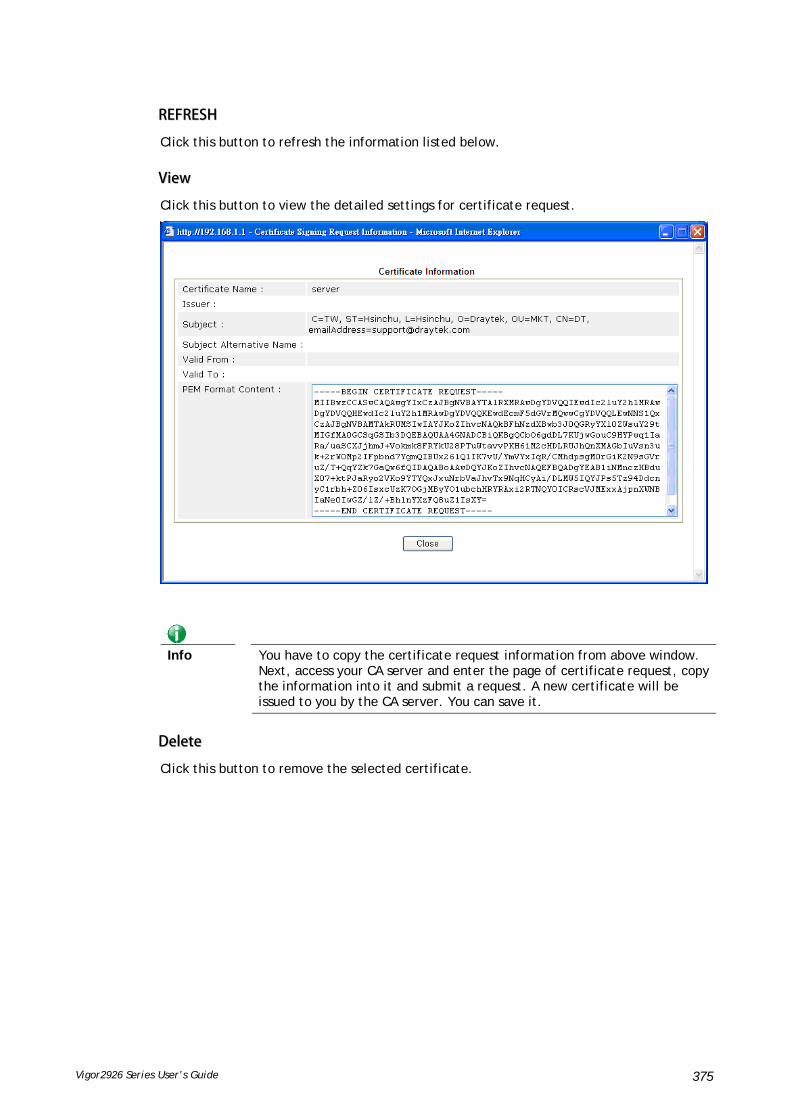
Vigor2926 Series User’s Guide 375
RREEFFRREESSHH
Click this button to refresh the information listed below.
VViieeww
Click this button to view the detailed settings for certificate request.
Info
You have to copy the certificate request information from above window. Next, access your CA server and enter the page of certificate request, copy the information into it and submit a request. A new certificate will be issued to you by the CA server. You can save it.
DDeelleettee
Click this button to remove the selected certificate.

Vigor2926 Series User’s Guide 376
VV--33--22 TTrruusstteedd CCAA CCeerrttiiffiiccaattee
Trusted CA certificate lists three sets of trusted CA certificate. In addition, you can build a RootCA certificate if required.
When the local client and remote client are required to make certificate authentication (e.g., IPsec X.509) for data passing through SSL tunnel and avoiding the attack of MITM, a trusted root certificate authority (Root CA) will be used to authenticate the digital certificates offered by both ends.
However, the procedure of applying digital certificate from a trusted root certificate authority is complicated and time-consuming. Therefore, Vigor router offers a mechanism which allows you to generate root CA to save time and provide convenience for general user. Later, such root CA generated by DrayTek server can perform the issuing of local certificate.
Info
Root CA can be deleted but not edited. If you want to modify the settings for a Root CA, please delete the one and create another one by clicking Create Root CA.
CCrreeaattiinngg aa RRoooott CCAA
Click Create to open the following page. Type in all the information that the window request such as certifcate name (used for identifying different certificate), subject alternative name type and relational settings for subject name. Then click Generate again.

Vigor2926 Series User’s Guide 377
IImmppoorrttiinngg aa TTrruusstteedd CCAA
To import a pre-saved trusted CA certificate, please click IMPORT to open the following window. Use Browse… to find out the saved text file. Then click Import. The one you imported will be listed on the Trusted CA Certificate window.
For viewing each trusted CA certificate, click View to open the certificate detail information window. If you want to delete a CA certificate, choose the one and click Delete to remove all the certificate information.

Vigor2926 Series User’s Guide 378
VV--33--33 CCeerrttiiffiiccaattee BBaacckkuupp
Local certificate and Trusted CA certificate for this router can be saved within one file. Please click Backup on the following screen to save them. If you want to set encryption password for these certificates, please type characters in both fields of Encrypt password and Confirm password.
Also, you can use Restore to retrieve these two settings to the router whenever you want.

Vigor2926 Series User’s Guide 379
PPaarrtt VVII SSeeccuurriittyy
While the broadband users demand more bandwidth for multimedia, interactive applications, or distance learning, security has been always the most concerned. The firewall of the Vigor router helps to protect your local network against attack from unauthorized outsiders. It also restricts users in the local network from accessing the Internet.
CSM is an abbreviation of Central Security Management which is used to control IM/P2P usage, filter the web content and URL content to reach a goal of security management.
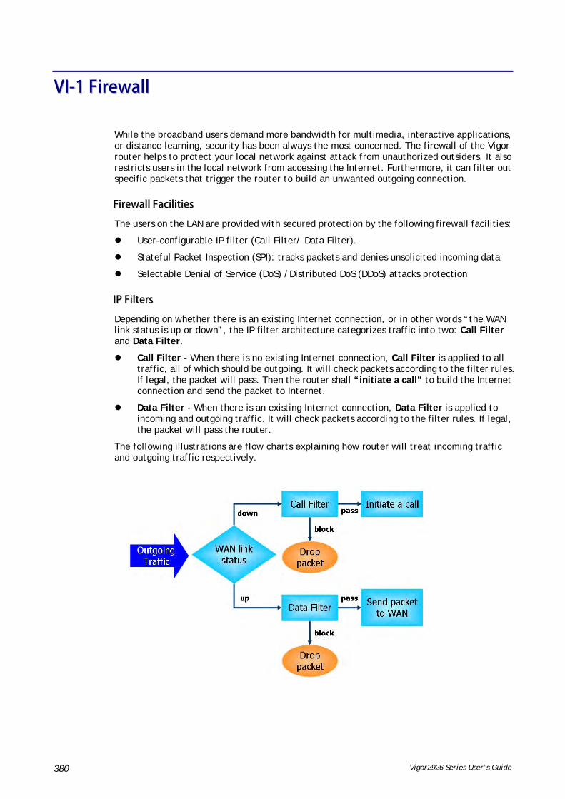
Vigor2926 Series User’s Guide 380
VVII--11 FFiirreewwaallll
While the broadband users demand more bandwidth for multimedia, interactive applications, or distance learning, security has been always the most concerned. The firewall of the Vigor router helps to protect your local network against attack from unauthorized outsiders. It also restricts users in the local network from accessing the Internet. Furthermore, it can filter out specific packets that trigger the router to build an unwanted outgoing connection.
FFiirreewwaallll FFaacciilliittiieess
The users on the LAN are provided with secured protection by the following firewall facilities:
User-configurable IP filter (Call Filter/ Data Filter).
Stateful Packet Inspection (SPI): tracks packets and denies unsolicited incoming data
Selectable Denial of Service (DoS) /Distributed DoS (DDoS) attacks protection
IIPP FFiilltteerrss
Depending on whether there is an existing Internet connection, or in other words “the WAN link status is up or down”, the IP filter architecture categorizes traffic into two: Call Filter and Data Filter.
Call Filter - When there is no existing Internet connection, Call Filter is applied to all traffic, all of which should be outgoing. It will check packets according to the filter rules. If legal, the packet will pass. Then the router shall “initiate a call” to build the Internet connection and send the packet to Internet.
Data Filter - When there is an existing Internet connection, Data Filter is applied to incoming and outgoing traffic. It will check packets according to the filter rules. If legal, the packet will pass the router.
The following illustrations are flow charts explaining how router will treat incoming traffic and outgoing traffic respectively.
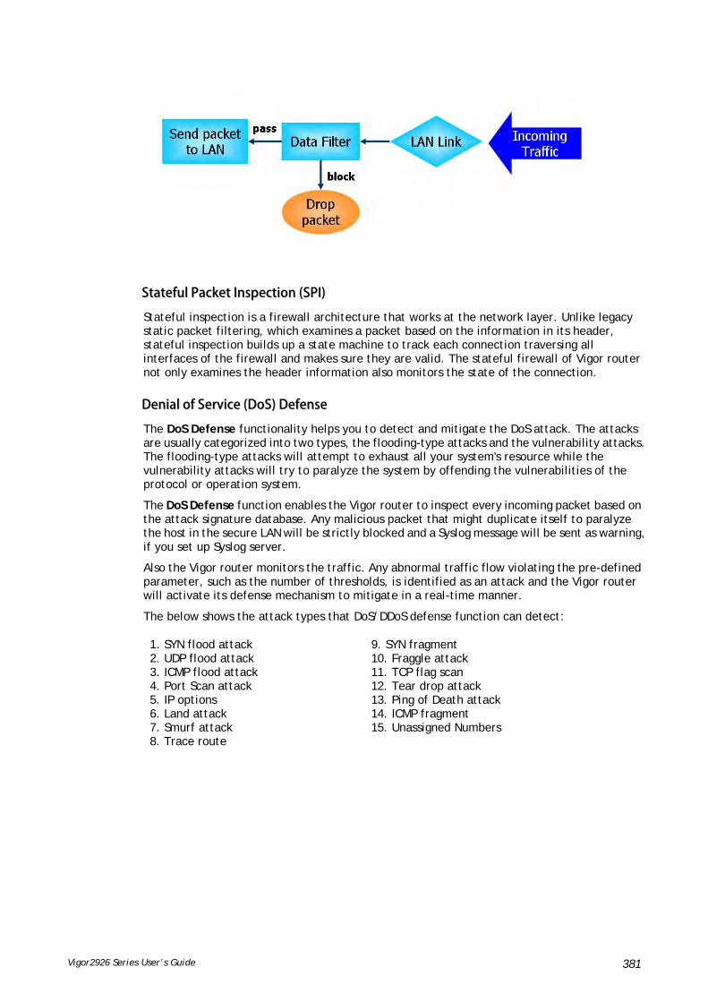
Vigor2926 Series User’s Guide 381
SSttaatteeffuull PPaacckkeett IInnssppeeccttiioonn ((SSPPII))
Stateful inspection is a firewall architecture that works at the network layer. Unlike legacy static packet filtering, which examines a packet based on the information in its header, stateful inspection builds up a state machine to track each connection traversing all interfaces of the firewall and makes sure they are valid. The stateful firewall of Vigor router not only examines the header information also monitors the state of the connection.
DDeenniiaall ooff SSeerrvviiccee ((DDooSS)) DDeeffeennssee
The DoS Defense functionality helps you to detect and mitigate the DoS attack. The attacks are usually categorized into two types, the flooding-type attacks and the vulnerability attacks. The flooding-type attacks will attempt to exhaust all your system's resource while the vulnerability attacks will try to paralyze the system by offending the vulnerabilities of the protocol or operation system.
The DoS Defense function enables the Vigor router to inspect every incoming packet based on the attack signature database. Any malicious packet that might duplicate itself to paralyze the host in the secure LAN will be strictly blocked and a Syslog message will be sent as warning, if you set up Syslog server.
Also the Vigor router monitors the traffic. Any abnormal traffic flow violating the pre-defined parameter, such as the number of thresholds, is identified as an attack and the Vigor router will activate its defense mechanism to mitigate in a real-time manner.
The below shows the attack types that DoS/DDoS defense function can detect:
1. SYN flood attack 2. UDP flood attack 3. ICMP flood attack 4. Port Scan attack 5. IP options 6. Land attack 7. Smurf attack 8. Trace route
9. SYN fragment 10. Fraggle attack 11. TCP flag scan 12. Tear drop attack 13. Ping of Death attack 14. ICMP fragment 15. Unassigned Numbers

Vigor2926 Series User’s Guide 382
WWeebb UUsseerr IInntteerrffaaccee
Below shows the menu items for Firewall.
VVII--11--11 GGeenneerraall SSeettuupp
General Setup allows you to adjust settings of IP Filter and common options. Here you can enable or disable the Call Filter or Data Filter. Under some circumstance, your filter set can be linked to work in a serial manner. So here you assign the Start Filter Set only. Also you can configure the Log Flag settings, Apply IP filter to VPN incoming packets, and Accept incoming fragmented UDP packets.
Click Firewall and click General Setup to open the general setup page.
GGeenneerraall SSeettuupp PPaaggee
Such page allows you to enable / disable Call Filter and Data Filter, determine general rule for filtering the incoming and outgoing data.
Available settings are explained as follows:
Item Description
Call Filter Check Enable to activate the Call Filter function. Assign a start filter set for the Call Filter.

Vigor2926 Series User’s Guide 383
Data Filter Check Enable to activate the Data Filter function. Assign a start filter set for the Data Filter.
Always pass inbound fragmented large packets…
Some on-line games (for example: Half Life) will use lots of fragmented UDP packets to transfer game data. Instinctively as a secure firewall, Vigor router will reject these fragmented packets to prevent attack unless you enable “Always pass inbound fragmented large packets…”. By checking this box, you can play these kinds of on-line games. If security concern is in higher priority, you cannot enable “Always pass inbound fragmented large packets…”.
Enable Strict Security Firewall
For the sake of security, the router will execute strict security checking for data transmission.
Such feature is enabled in default. All the packets, while transmitting through Vigor router, will be filtered by firewall. If the firewall system (e.g., content filter server) does not make any response (pass or block) for these packets, then the router’s firewall will block the packets directly.
Block connections initiated from WAN
Usually, IPv6 network sessions/traffic from WAN to LAN will be accepted by IPv6 firewall in default.
IPv6 - To prevent remote client accessing into the PCs on LAN, check the box to make the packets (routed from WAN to LAN) via IPv6 being blocked by such router. It is effective only for the packets routed but not for packets translated by NAT.
IPv4 - To prevent remote client accessing into the PCs on LAN, check the box to make the incoming packets via IPv4 being blocked by such router. It is effective only for the packets routed but not for packets translated by NAT.
Backup Firewall Click Backup to save the firewall configuration.
Restore Firewall Click Select to choose a firewall configuration file. Then click Restore to apply the file.

Vigor2926 Series User’s Guide 384
DDeeffaauulltt RRuullee PPaaggee
Such page allows you to choose filtering profiles including QoS, Load-Balance policy, WCF, APP Enforcement, URL Content Filter, for data transmission via Vigor router.
Available settings are explained as follows:
Item Description
Filter Select Pass or Block for the packets that do not match with the filter rules.
Sessions Control The number typed here is the total sessions of the packets that do not match the filter rule configured in this page. The default setting is 50000.
Quality of Service Choose one of the QoS rules to be applied as firewall rule. For detailed information of setting QoS, please refer to the related section later.

Vigor2926 Series User’s Guide 385
User Management Such item is available only when Rule-Based is selected in User Management>>General Setup. The general firewall rule will be applied to the user/user group/all users specified here.
When there is no user profile or group profile existed, Create New User or Create New Group item will appear for you to click to create a new one.
APP Enforcement Select an APP Enforcement profile for global IM/P2P application blocking. If there is no profile for you to select, please choose [Create New] from the drop down list in this page to create a new profile. All the hosts in LAN must follow the standard configured in the APP Enforcement profile selected here. For detailed information, refer to the section of APP Enforcement profile setup. For troubleshooting needs, you can specify to record information for IM/P2P by checking the Log box. It will be sent to Syslog server. Please refer to section Syslog/Mail Alert for more detailed information.
URL Content Filter Select one of the URL Content Filter profile settings (created in CSM>> URL Content Filter) for applying with this router. Please set at least one profile for choosing in CSM>> URL Content Filter web page first. Or choose [Create New] from the drop down list in this page to create a new profile. For troubleshooting needs, you can specify to record information for URL Content Filter by checking the Log box. It will be sent to Syslog server. Please refer to section Syslog/Mail Alert for more detailed information.
Web Content Filter Select one of the Web Content Filter profile settings (created in CSM>> Web Content Filter) for applying with this router. Please set at least one profile for anti-virus in CSM>> Web Content Filter web page first. Or choose [Create New] from the drop down list in this page to create a new profile. For troubleshooting needs, you can specify to record information for Web Content Filter by checking the Log box. It will be sent to Syslog server. Please refer to section Syslog/Mail Alert for more detailed information.
DNS Filter Select one of the DNS Filter profile settings (created in CSM>>DNS Filter) for applying with this router. Please set at least one profile in CSM>> Web Content Filter web page first. Or click the DNS Filter link in this page to create a new profile.
Advance Setting Click Edit to open the following window. However, it is strongly recommended to use the default settings here.

Vigor2926 Series User’s Guide 386
Codepage - This function is used to compare the characters among different languages. Choose correct codepage can help the system obtain correct ASCII after decoding data from URL and enhance the correctness of URL Content Filter. The default value for this setting is ANSI 1252 Latin I. If you do not choose any codepage, no decoding job of URL will be processed. Please use the drop-down list to choose a codepage.
If you do not have any idea of choosing suitable codepage, please open Syslog. From Codepage Information of Setup dialog, you will see the recommended codepage listed on the dialog box.
Window size – It determines the size of TCP protocol (0~65535). The more the value is, the better the performance will be. However, if the network is not stable, small value will be proper.
Session timeout – Setting timeout for sessions can make the best utilization of network resources.
After finishing all the settings here, please click OK to save the configuration.

Vigor2926 Series User’s Guide 387
VVII--11--22 FFiilltteerr SSeettuupp
Click Firewall and click Filter Setup to open the setup page.
To edit or add a filter, click on the set number to edit the individual set. The following page will be shown. Each filter set contains up to 7 rules. Click on the rule number button to edit each rule. Check Active to enable the rule.
Available settings are explained as follows:
Item Description
Filter Rule Click a button numbered (1 ~ 7) to edit the filter rule. Click the button will open Edit Filter Rule web page. For the detailed information, refer to the following page.
Active Enable or disable the filter rule.
Comment Enter filter set comments/description. Maximum length is 23–character long.
Direction Display the direction of packet.
Src IP / Dst IP Display the IP address of source /destination.
Service Type Display the type and port number of the packet.

Vigor2926 Series User’s Guide 388
Action Display the packets to be passed /blocked.
CSM Display the content security managed
Move Up/Down Use Up or Down link to move the order of the filter rules.
Next Filter Set Set the link to the next filter set to be executed after the current filter run. Do not make a loop with many filter sets.
Wizard Mode Allow to configure frequently used settings for filter rule via several setting pages.
Advance Mode Allow to configure detailed settings of filter rule.
To use Wizard Mode, simple do the following steps:
1. Click the Wizard Mode radio button.
2. Click Index 1. The setting page will appear as follows:
Available settings are explained as follows:
Item Description
Comments Enter filter set comments/description. Maximum length is 14- character long.
Direction Set the direction of packet flow. It is for Data Filter only. For the Call Filter, this setting is not available since Call Filter is only applied to outgoing traffic.
Note: RT means routing domain for 2nd subnet or other LAN.

Vigor2926 Series User’s Guide 389
Source IP / Destination IP
To set the IP address manually, please choose Any Address/Single Address/Range Address/Subnet Address as the Address Type and type them in this dialog.
Protocol Specify the protocol(s) which this filter rule will apply to.
Source Port / Destination Port
(=) – when the first and last value are the same, it indicates one port; when the first and last values are different, it indicates a range for the port and available for this service type.
(!=) – when the first and last value are the same, it indicates all the ports except the port defined here; when the first and last values are different, it indicates that all the ports except the range defined here are available for this service type.
(>) – the port number greater than this value is available.
(<) – the port number less than this value is available for this profile.
3. Click Next to get the following page.
Available settings are explained as follows:
Item Description
Pass Immediately Packets matching the rule will be passed immediately.
APP Enforcement - Select an APP Enforcement profile for global IM/P2P application blocking. If there is no profile for you to select, please choose [Create New] from the drop down list in this page to create a new profile. All the hosts in LAN must follow the standard configured in the APP Enforcement profile selected here. For detailed information, refer to the section of APP Enforcement profile setup. For troubleshooting needs, you can specify to record information for IM/P2P by checking the Log box. It will be sent to Syslog server. Please refer to section Syslog/Mail Alert for more detailed information.

Vigor2926 Series User’s Guide 390
URL Content Filter - Select one of the URL Content Filter profile settings (created in CSM>> URL Content Filter) for applying with this router. Please set at least one profile for choosing in CSM>> URL Content Filter web page first. Or choose [Create New] from the drop down list in this page to create a new profile. For troubleshooting needs, you can specify to record information for URL Content Filter by checking the Log box. It will be sent to Syslog server. Please refer to section Syslog/Mail Alert for more detailed information.
Web Content Filter - Select one of the Web Content Filter profile settings (created in CSM>> Web Content Filter) for applying with this router. Please set at least one profile for anti-virus in CSM>> Web Content Filter web page first. Or choose [Create New] from the drop down list in this page to create a new profile. For troubleshooting needs, you can specify to record information for Web Content Filter by checking the Log box. It will be sent to Syslog server. Please refer to section Syslog/Mail Alert for more detailed information.
DNS Filter - Select one of the DNS Filter profile settings (created in CSM>>DNS Filter) for applying with this router. Please set at least one profile in CSM>> Web Content Filter web page first. Or click the DNS Filter link from the drop down list in this page to create a new profile.
Block Immediately Packets matching the rule will be dropped immediately.
4. After choosing the mechanism, click Next to get the summary page for reference.
5. If there is no error, click Finish to complete wizard setting.

Vigor2926 Series User’s Guide 391
To use Advance Mode, do the following steps:
1. Click the Advance Mode radio button.
2. Click Index 1 to access into the following page.
Available settings are explained as follows:
Item Description
Check to enable the Filter Rule
Check this box to enable the filter rule.
Comments Enter filter set comments/description. Maximum length is 14- character long.
Index(1-15) Set PCs on LAN to work at certain time interval only. You may choose up to 4 schedules out of the 15 schedules pre-defined in Applications >> Schedule setup. The default setting of this field is blank and the function will always work.
Clear sessions when schedule ON
Check this box to clear the sessions when the above schedule profiles are applied.
Direction Set the direction of packet flow. It is for Data Filter only. For the Call Filter, this setting is not available since Call Filter is only applied to outgoing traffic.

Vigor2926 Series User’s Guide 392
Note: RT means routing domain for 2nd subnet or other LAN.
Source IP/ Country
and
Destination IP / Country
Click Edit to access into the following dialog to choose the IP object or country object as source IP or destination IP.
To set the IP address manually, please choose Any Address/Single Address/Range Address/Subnet Address as the Address Type and type them in this dialog. In addition, if you want to use the IP range from defined groups or objects or any IP in a country, please choose Group and Objects or Country Object as the Address Type.
From the IP Group drop down list, choose the one that you want to apply. Or use the IP Object drop down list to choose the object that you want.
Service Type Click Edit to access into the following dialog to choose a suitable service type.

Vigor2926 Series User’s Guide 393
To set the service type manually, please choose User defined as the Service Type and type them in this dialog. In addition, if you want to use the service type from defined groups or objects, please choose Group and Objects as the Service Type.
Protocol - Specify the protocol(s) which this filter rule will apply to.
Source/Destination Port –
(=) – when the first and last value are the same, it indicates one port; when the first and last values are different, it indicates a range for the port and available for this service type.
(!=) – when the first and last value are the same, it indicates all the ports except the port defined here; when the first and last values are different, it indicates that all the ports except the range defined here are available for this service type.
(>) – the port number greater than this value is available.
(<) – the port number less than this value is available for this profile. Service Group/Object - Use the drop down list to choose the one that you want.
Fragments Specify the action for fragmented packets. And it is used for Data Filter only.
Don’t care -No action will be taken towards fragmented packets.
Unfragmented -Apply the rule to unfragmented packets.
Fragmented - Apply the rule to fragmented packets.
Too Short - Apply the rule only to packets that are too short to contain a complete header.
Filter Specifies the action to be taken when packets match the rule.
Block Immediately - Packets matching the rule will be dropped immediately.
Pass Immediately - Packets matching the rule will be passed immediately.
Block If No Further Match - A packet matching the rule, and that does not match further rules, will be dropped.

Vigor2926 Series User’s Guide 394
Pass If No Further Match - A packet matching the rule, and that does not match further rules, will be passed through.
Branch to other Filter Set
If the packet matches the filter rule, the next filter rule will branch to the specified filter set. Select next filter rule to branch from the drop-down menu. Be aware that the router will apply the specified filter rule for ever and will not return to previous filter rule any more.
Sessions Control The number typed here is the total sessions of the packets that do not match the filter rule configured in this page. The default setting is 60000.
MAC Bind IP Strict –Make the MAC address and IP address settings configured in IP Object for Source IP and Destination IP are bound for applying such filter rule.
No-Strict - no limitation.
Quality of Service Choose one of the QoS rules to be applied as firewall rule. For detailed information of setting QoS, please refer to the related section later.
User Management Such item is available only when Rule-Based is selected in User Management>>General Setup. The general firewall rule will be applied to the user/user group/all users specified here.
Note: When there is no user profile or group profile existed, Create New User or Create New Group item will appear for you to click to create a new one.
APP Enforcement Select an APP Enforcement profile for global IM/P2P application blocking. If there is no profile for you to select, please choose [Create New] from the drop down list in this page to create a new profile. All the hosts in LAN must follow the standard configured in the APP Enforcement profile selected here. For detailed information, refer to the section of APP Enforcement profile setup. For troubleshooting needs, you can specify to record information for IM/P2P by checking the Log box. It will be sent to Syslog server. Please refer to section Syslog/Mail Alert for more detailed information.
URL Content Filter Select one of the URL Content Filter profile settings (created in CSM>> URL Content Filter) for applying with this router. Please set at least one profile for choosing in CSM>> URL Content Filter web page first. Or choose [Create New] from the drop down list in this page to create a new profile. For troubleshooting needs, you can specify to

Vigor2926 Series User’s Guide 395
record information for URL Content Filter by checking the Log box. It will be sent to Syslog server. Please refer to section Syslog/Mail Alert for more detailed information.
Web Content Filter Select one of the Web Content Filter profile settings (created in CSM>> Web Content Filter) for applying with this router. Please set at least one profile for anti-virus in CSM>> Web Content Filter web page first. Or choose [Create New] from the drop down list in this page to create a new profile. For troubleshooting needs, you can specify to record information for Web Content Filter by checking the Log box. It will be sent to Syslog server. Please refer to section Syslog/Mail Alert for more detailed information.
DNS Filter Select one of the DNS Filter profile settings (created in CSM>>DNS Filter) for applying with this router. Please set at least one profile in CSM>> Web Content Filter web page first. Or click the DNS Filter link from the drop down list in this page to create a new profile.
Advance Setting Click Edit to open the following window. However, it is strongly recommended to use the default settings here.
Codepage - This function is used to compare the characters among different languages. Choose correct codepage can help the system obtaining correct ASCII after decoding data from URL and enhance the correctness of URL Content Filter. The default value for this setting is ANSI 1252 Latin I. If you do not choose any codepage, no decoding job of URL will be processed. Please use the drop-down list to choose a codepage.
If you do not have any idea of choosing suitable codepage, please open Syslog. From Codepage Information of Setup dialog, you will see the recommended codepage listed on the dialog box.

Vigor2926 Series User’s Guide 396
Window size – It determines the size of TCP protocol (0~65535). The more the value is, the better the performance will be. However, if the network is not stable, small value will be proper.
Session timeout–Setting timeout for sessions can make the best utilization of network resources. However, Queue timeout is configured for TCP protocol only; session timeout is configured for the data flow which matched with the firewall rule.
DrayTek Banner – Please uncheck this box and the following screen will not be shown for the unreachable web page. The default setting is Enabled.
Strict Security Checking - All the packets, while transmitting through Vigor router, will be filtered by firewall settings configured by Vigor router. When the resource is inadequate, the packets will be blocked if Strict Security Checking is enabled. If Strict Security Checking is not enabled, then the packets will pass through the router.
3. When you finish the configuration, please click OK to save and exit this page.
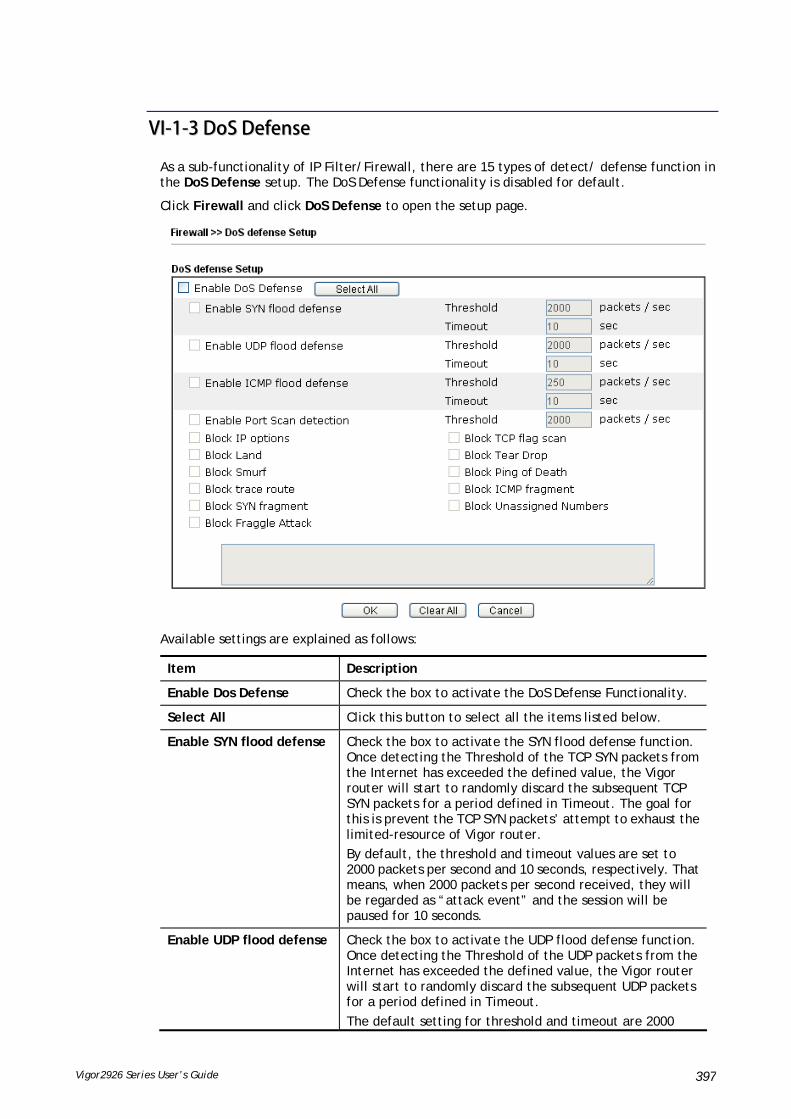
Vigor2926 Series User’s Guide 397
VVII--11--33 DDooSS DDeeffeennssee
As a sub-functionality of IP Filter/Firewall, there are 15 types of detect/ defense function in the DoS Defense setup. The DoS Defense functionality is disabled for default.
Click Firewall and click DoS Defense to open the setup page.
Available settings are explained as follows:
Item Description
Enable Dos Defense Check the box to activate the DoS Defense Functionality.
Select All Click this button to select all the items listed below.
Enable SYN flood defense Check the box to activate the SYN flood defense function. Once detecting the Threshold of the TCP SYN packets from the Internet has exceeded the defined value, the Vigor router will start to randomly discard the subsequent TCP SYN packets for a period defined in Timeout. The goal for this is prevent the TCP SYN packets’ attempt to exhaust the limited-resource of Vigor router.
By default, the threshold and timeout values are set to 2000 packets per second and 10 seconds, respectively. That means, when 2000 packets per second received, they will be regarded as “attack event” and the session will be paused for 10 seconds.
Enable UDP flood defense Check the box to activate the UDP flood defense function. Once detecting the Threshold of the UDP packets from the Internet has exceeded the defined value, the Vigor router will start to randomly discard the subsequent UDP packets for a period defined in Timeout.
The default setting for threshold and timeout are 2000
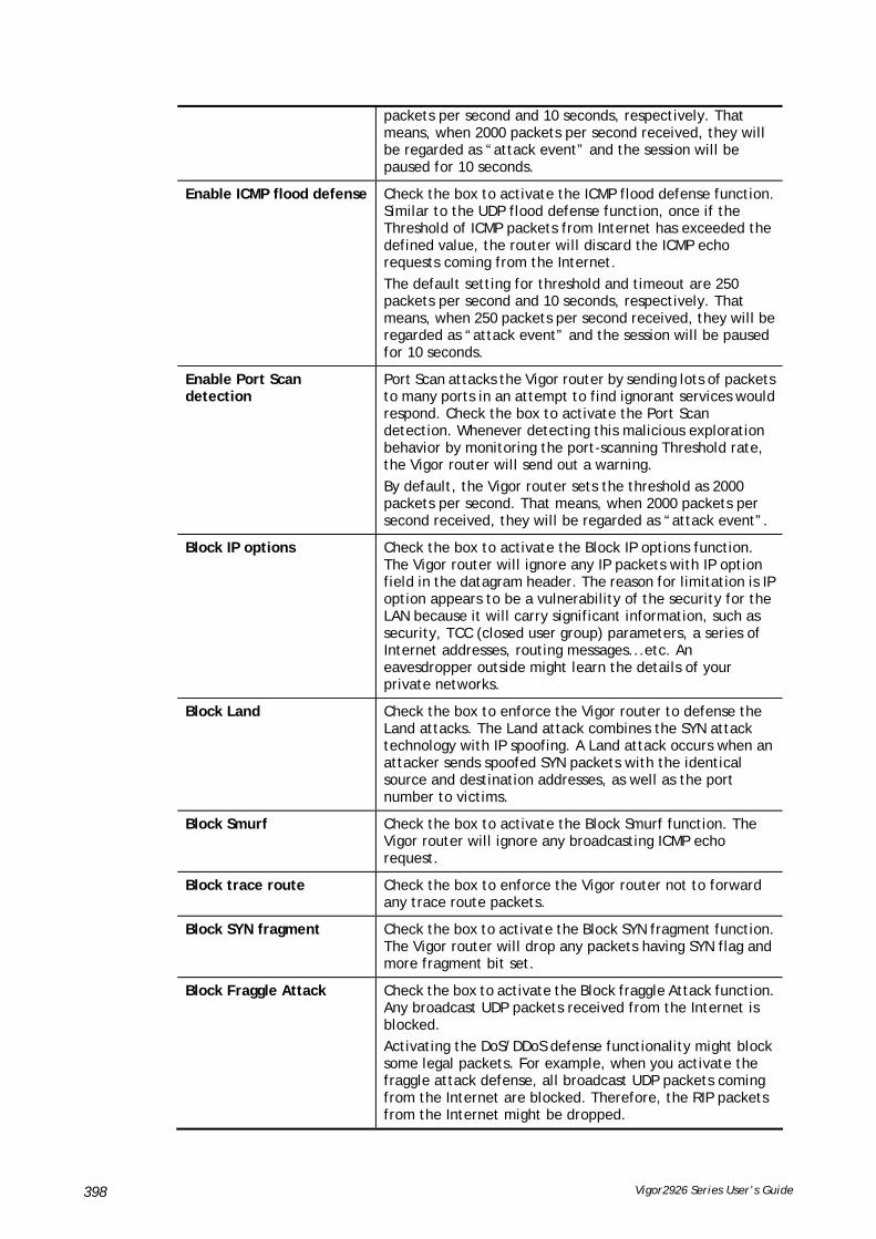
Vigor2926 Series User’s Guide 398
packets per second and 10 seconds, respectively. That means, when 2000 packets per second received, they will be regarded as “attack event” and the session will be paused for 10 seconds.
Enable ICMP flood defense Check the box to activate the ICMP flood defense function. Similar to the UDP flood defense function, once if the Threshold of ICMP packets from Internet has exceeded the defined value, the router will discard the ICMP echo requests coming from the Internet.
The default setting for threshold and timeout are 250 packets per second and 10 seconds, respectively. That means, when 250 packets per second received, they will be regarded as “attack event” and the session will be paused for 10 seconds.
Enable Port Scan detection
Port Scan attacks the Vigor router by sending lots of packets to many ports in an attempt to find ignorant services would respond. Check the box to activate the Port Scan detection. Whenever detecting this malicious exploration behavior by monitoring the port-scanning Threshold rate, the Vigor router will send out a warning.
By default, the Vigor router sets the threshold as 2000 packets per second. That means, when 2000 packets per second received, they will be regarded as “attack event”.
Block IP options Check the box to activate the Block IP options function. The Vigor router will ignore any IP packets with IP option field in the datagram header. The reason for limitation is IP option appears to be a vulnerability of the security for the LAN because it will carry significant information, such as security, TCC (closed user group) parameters, a series of Internet addresses, routing messages...etc. An eavesdropper outside might learn the details of your private networks.
Block Land Check the box to enforce the Vigor router to defense the Land attacks. The Land attack combines the SYN attack technology with IP spoofing. A Land attack occurs when an attacker sends spoofed SYN packets with the identical source and destination addresses, as well as the port number to victims.
Block Smurf Check the box to activate the Block Smurf function. The Vigor router will ignore any broadcasting ICMP echo request.
Block trace route Check the box to enforce the Vigor router not to forward any trace route packets.
Block SYN fragment Check the box to activate the Block SYN fragment function. The Vigor router will drop any packets having SYN flag and more fragment bit set.
Block Fraggle Attack Check the box to activate the Block fraggle Attack function. Any broadcast UDP packets received from the Internet is blocked.
Activating the DoS/DDoS defense functionality might block some legal packets. For example, when you activate the fraggle attack defense, all broadcast UDP packets coming from the Internet are blocked. Therefore, the RIP packets from the Internet might be dropped.

Vigor2926 Series User’s Guide 399
Block TCP flag scan Check the box to activate the Block TCP flag scan function. Any TCP packet with anomaly flag setting is dropped. Those scanning activities include no flag scan, FIN without ACK scan, SYN FINscan, Xmas scan and full Xmas scan.
Block Tear Drop Check the box to activate the Block Tear Drop function. Many machines may crash when receiving ICMP datagrams (packets) that exceed the maximum length. To avoid this type of attack, the Vigor router is designed to be capable of discarding any fragmented ICMP packets with a length greater than 1024 octets.
Block Ping of Death Check the box to activate the Block Ping of Death function. This attack involves the perpetrator sending overlapping packets to the target hosts so that those target hosts will hang once they re-construct the packets. The Vigor routers will block any packets realizing this attacking activity.
Block ICMP Fragment Check the box to activate the Block ICMP fragment function. Any ICMP packets with more fragment bit set are dropped.
Block Unassigned Numbers Check the box to activate the Block Unknown Protocol function. Individual IP packet has a protocol field in the datagram header to indicate the protocol type running over the upper layer. However, the protocol types greater than 100 are reserved and undefined at this time. Therefore, the router should have ability to detect and reject this kind of packets.
Warning Messages We provide Syslog function for user to retrieve message from Vigor router. The user, as a Syslog Server, shall receive the report sending from Vigor router which is a Syslog Client.
All the warning messages related to DoS Defense will be sent to user and user can review it through Syslog daemon. Look for the keyword DoS in the message, followed by a name to indicate what kind of attacks is detected.

Vigor2926 Series User’s Guide 400
VVII--11--44 DDiiaaggnnoossee
The purpose of this function is to test when the router receiving incoming packet, which firewall rule will be applied to that packet. The test result, including firewall rule profile, IP address translation in packet transmission, state of the firewall fuctions and etc., also will be shown on this page.
Info
The result obtained by using Diagnose is offered for RD debug. It will be different according to actual state such as netework connection, LAN/WAN settings and so on.
Available settings are explained as follows:
Item Description

Vigor2926 Series User’s Guide 401
Mode To have a firewall rule test, specify the service type (ICMP, UDP, TCP) of the packet and type of the IP address (IPv4/IPv6).
Direction Set the way (from WAN or from LAN) that Vigor router receives the first packet for test. Different way means the firewall will process the connection initiated from LAN or from WAN.
Test View This is a dynamic display page.
According to the direction specified, test view will display the figure to guide you typing IP address, port number, and MAC address.
Later, after clicking the Analyze button, the information for the firewall rule profile and address translation will be shown on this page.
Src IP Type the IPv4/IPv6 address of the packet’s source.
Src Port Type the port number of the packet’s source.
Src MAC Type the MAC address of the packet’s source.
Dst IP Type the IPv4/IPv6 address of the packet’s destination.
Dst Port Type the port number of the packet’s destination.
Packet & Payload In firewall diagnose, two packets belong to one connection. In general, two packets are enough for Vigor router to perform this test.
Enable – Check the box to send out the test packet.
Direction – The first packet of the firewall test will follow the direction specified above. However, the direction for the second packet might be different. Simply choose the direction (from Computer A to B or from the B to A) for the second packet.
Protocol – It displays the mode selected above and the sate. If required, click the mode link to configure advanced setting. The common service type (Customize, Ping, Trace Route / Customize, DNS, Trace Route / Customize, Http(GET) related to that mode (ICMP / UDP / TCP) will be shown on the following dialog box.
Type – Choose Customize, Ping, Trace Route /
Customize, DNS, Trace Route / Customize, Http (GET).
Payload – It is available when Customzie is selected. Simply type 16 HEX characters which represent certain packet (e.g., DNS packet) if you want to set the data transfered with protocol (ICMP/UDP/TCP)

Vigor2926 Series User’s Guide 402
which is different to Type setting.
Analyze Execute the test and analyze the result.
The following figure shows the test result after clicking Analyze. Processing state for the fuctions (MAC Filter, QoS, User management, etc.,) related to the firewall will be displayed by green or red LED.

Vigor2926 Series User’s Guide 403
AApppplliiccaattiioonn NNootteess
AA--11 HHooww ttoo CCoonnffiigguurree CCeerrttaaiinn CCoommppuutteerrss AAcccceessssiinngg ttoo IInntteerrnneett
We can specify certain computers (e.g., 192.168.1.10 ~ 192.168.1.20) accessing to Internet through Vigor router. Others (e.g., 192.168.1.31 and 192.168.1.32) outside the range can get the source from LAN only.
The way we can use is to set two rules under Firewall. For Rule 1 of Set 2 under Firewall>>Filter Setup is used as the default setting, we have to create a new rule starting from Filter Rule 2 of Set 2.
1. Access into the web user interface of Vigor router.
2. Open Firewall>>Filter Setup. Click the Set 2 link, choose Advance Mode and choose the Filter Rule 2 button.
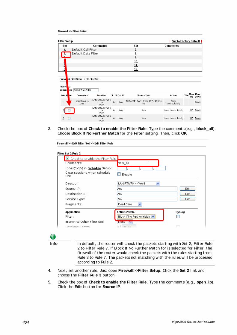
Vigor2926 Series User’s Guide 404
3. Check the box of Check to enable the Filter Rule. Type the comments (e.g., block_all). Choose Block If No Further Match for the Filter setting. Then, click OK.
Info
In default, the router will check the packets starting with Set 2, Filter Rule 2 to Filter Rule 7. If Block If No Further Match for is selected for Filter, the firewall of the router would check the packets with the rules starting from Rule 3 to Rule 7. The packets not matching with the rules will be processed according to Rule 2.
4. Next, set another rule. Just open Firewall>>Filter Setup. Click the Set 2 link and choose the Filter Rule 3 button.
5. Check the box of Check to enable the Filter Rule. Type the comments (e.g., open_ip). Click the Edit button for Source IP.

Vigor2926 Series User’s Guide 405
6. A dialog box will be popped up. Choose Range Address as Address Type by using the drop down list. Type 192.168.1.10 in the field of Start IP, and type 192.168.1.20 in the field of End IP. Then, click OK to save the settings. The computers within the range can access into the Internet.
7. Now, check the content of Source IP is correct or not. The action for Filter shall be set with Pass Immediately. Then, click OK to save the settings.

Vigor2926 Series User’s Guide 406
8. Both filter rules have been created. Click OK.
Now, all the settings are configured well. Only the computers with the IP addresses within 192.168.1.10 ~ 192.168.1.20 can access to Internet.

Vigor2926 Series User’s Guide 407
VVII--22 CCeennttrraall SSeeccuurriittyy MMaannaaggeemmeenntt ((CCSSMM))
CSM is an abbreviation of Central Security Management which is used to control IM/P2P usage, filter the web content and URL content to reach a goal of security management.
AAPPPP EEnnffoorrcceemmeenntt FFiilltteerr
As the popularity of all kinds of instant messenger application arises, communication cannot become much easier. Nevertheless, while some industry may leverage this as a great tool to connect with their customers, some industry may take reserved attitude in order to reduce employee misusage during office hour or prevent unknown security leak. It is similar situation for corporation towards peer-to-peer applications since file-sharing can be convenient but insecure at the same time. To address these needs, we provide CSM functionality.
UURRLL CCoonntteenntt FFiilltteerr
To provide an appropriate cyberspace to users, Vigor router equips with URL Content Filter not only to limit illegal traffic from/to the inappropriate web sites but also prohibit other web feature where malicious code may conceal.
Once a user type in or click on an URL with objectionable keywords, URL keyword blocking facility will decline the HTTP request to that web page thus can limit user’s access to the website. You may imagine URL Content Filter as a well-trained convenience-store clerk who won’t sell adult magazines to teenagers. At office, URL Content Filter can also provide a job-related only environment hence to increase the employee work efficiency. How can URL Content Filter work better than traditional firewall in the field of filtering? Because it checks the URL strings or some of HTTP data hiding in the payload of TCP packets while legacy firewall inspects packets based on the fields of TCP/IP headers only.
On the other hand, Vigor router can prevent user from accidentally downloading malicious codes from web pages. It’s very common that malicious codes conceal in the executable objects, such as ActiveX, Java Applet, compressed files, and other executable files. Once downloading these types of files from websites, you may risk bringing threat to your system. For example, an ActiveX control object is usually used for providing interactive web feature. If malicious code hides inside, it may occupy user’s system.
WWeebb CCoonntteenntt FFiilltteerr
We all know that the content on the Internet just like other types of media may be inappropriate sometimes. As a responsible parent or employer, you should protect those in your trust against the hazards. With Web filtering service of the Vigor router, you can protect your business from common primary threats, such as productivity, legal liability, network and security threats. For parents, you can protect your children from viewing adult websites or chat rooms.
Once you have activated your Web Filtering service in Vigor router and chosen the categories of website you wish to restrict, each URL address requested (e.g.www.bbc.co.uk) will be checked against our server database. This database is updated as frequent as daily by a global team of Internet researchers. The server will look up the URL and return a category to your router. Your Vigor router will then decide whether to allow access to this site according to the categories you have selected. Please note that this action will not introduce any delay in your Web surfing because each of multiple load balanced database servers can handle millions of requests for categorization.
Info
The priority of URL Content Filter is higher than Web Content Filter.

Vigor2926 Series User’s Guide 408
WWeebb UUsseerr IInntteerrffaaccee
VVII--22--11 AAPPPP EEnnffoorrcceemmeenntt PPrrooffiillee
You can define policy profiles for IM (Instant Messenger)/P2P (Peer to Peer)/Protocol/Misc application. This page allows you to set 32 profiles for different requirements. The APP Enforcement Profile will be applied in Default Rule of Firewall>>General Setup for filtering.
Available settings are explained as follows:
Item Description
Set to Factory Default Clear all profiles.
Profile Display the number of the profile which allows you to click to set different policy.
Name Display the name of the APP Enforcement Profile.
Click the number under Index column for settings in detail.
There are four tabs IM, P2P, Protocol and Others displayed on this page. Each tab will bring out different items with supported versions that you can choose to disallow people using.
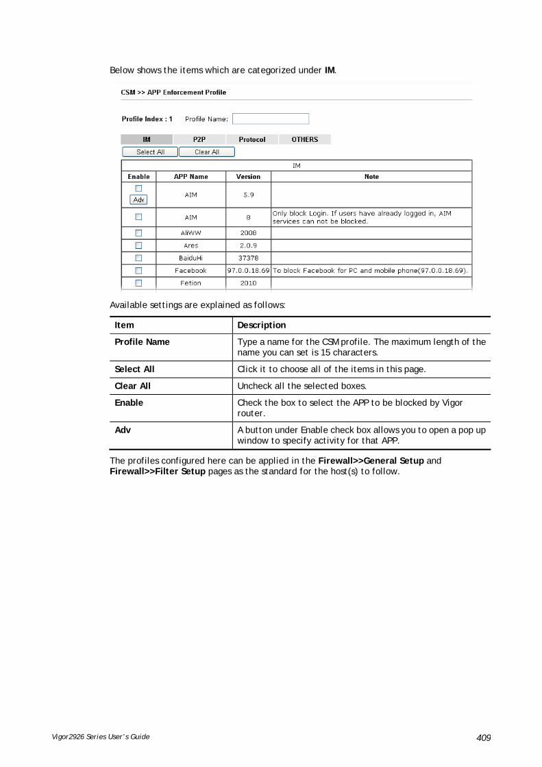
Vigor2926 Series User’s Guide 409
Below shows the items which are categorized under IM.
Available settings are explained as follows:
Item Description
Profile Name Type a name for the CSM profile. The maximum length of the name you can set is 15 characters.
Select All Click it to choose all of the items in this page.
Clear All Uncheck all the selected boxes.
Enable Check the box to select the APP to be blocked by Vigor router.
Adv A button under Enable check box allows you to open a pop up window to specify activity for that APP.
The profiles configured here can be applied in the Firewall>>General Setup and Firewall>>Filter Setup pages as the standard for the host(s) to follow.

Vigor2926 Series User’s Guide 410
Below shows the items which are categorized under Protocol.
The items categorized under P2P -----

Vigor2926 Series User’s Guide 411
The items categorized under OTHERS-----

Vigor2926 Series User’s Guide 412
VVII--22--22 AAPPPPEE SSiiggnnaattuurree UUppggrraaddee
The APPE Enforcement Profile adopted by Vigor router will be treated as the APPE signature. DrayTek will periodically upgrade versions for all of the APPs supported by Vigor router. However, it might be inconvenient for users to upgrade the APP version one by one. This feature is specially designed to offer a quick method to execute APP version upgrade. Users can perform the APPE signature upgrade manually or configure the settings on this page to make Vigor router performing the APPE signature automatically.
Available settings are explained as follows:
Item Description
Upgrade Setting APPE Module Version – Display current version status of APPE signature.
New version from the Internet – Download button is available only when Vigor router detects new APPE version. After clicking it, a dialog will appear with information added to such new version. Click OK to exit the dialog and start the signature upgrade.
Upgrade via interface – Choose one of the WAN interfaces as a channel for APPE signature upgrade.
Setup Download Server Specify the download server by typing the URL of the server located. Or you can click Find more link to search the one you want.
Signature authentication/download message – Display the status of APPE Signature Upgrade.
Upgrade Manually Import – Click this button to open the following page. Press Choose File to locate the signature file which downloaded
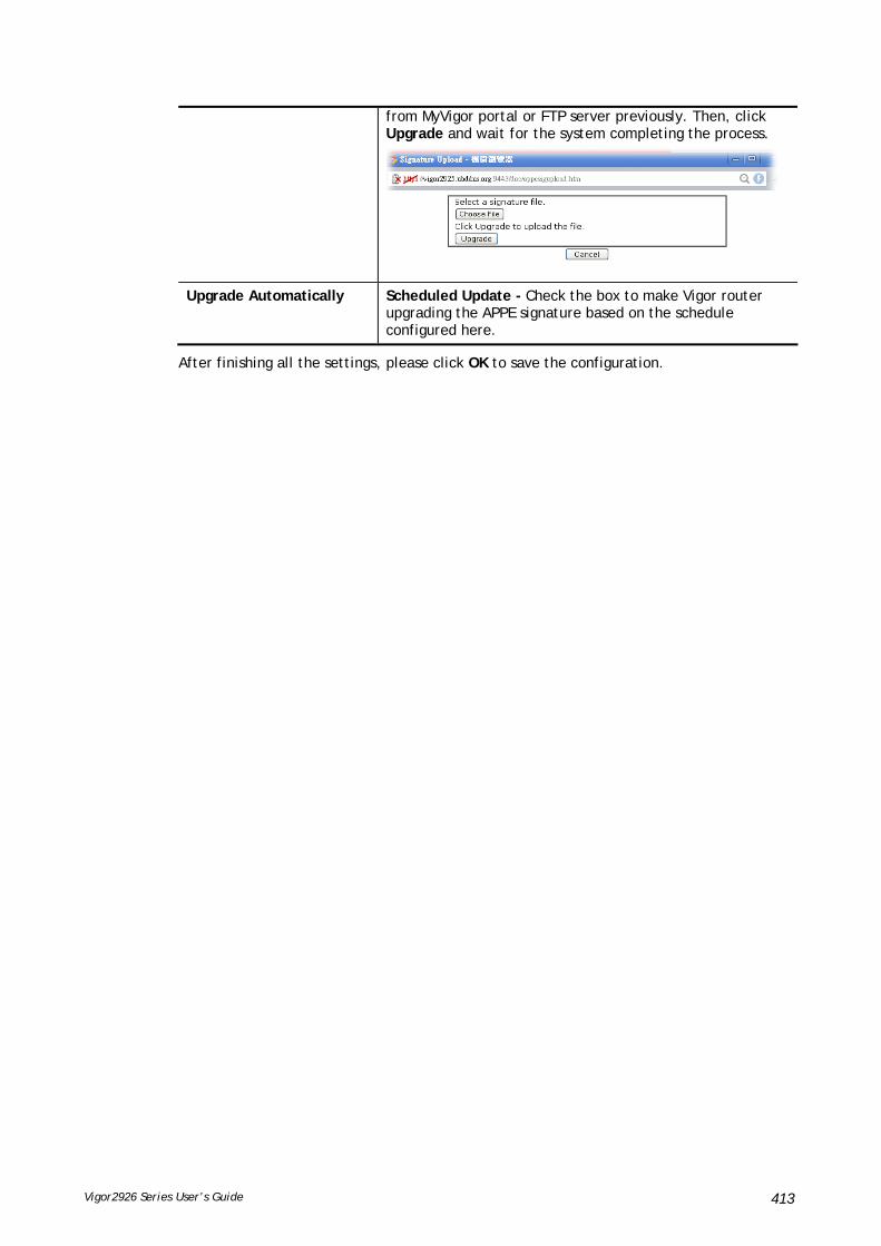
Vigor2926 Series User’s Guide 413
from MyVigor portal or FTP server previously. Then, click Upgrade and wait for the system completing the process.
Upgrade Automatically Scheduled Update - Check the box to make Vigor router upgrading the APPE signature based on the schedule configured here.
After finishing all the settings, please click OK to save the configuration.

Vigor2926 Series User’s Guide 414
VVII--22--33 UURRLL CCoonntteenntt FFiilltteerr PPrrooffiillee
To provide an appropriate cyberspace to users, Vigor router equips with URL Content Filter not only to limit illegal traffic from/to the inappropriate web sites but also prohibit other web feature where malicious code may conceal.
Once a user type in or click on an URL with objectionable keywords, URL keyword blocking facility will decline the HTTP request to that web page thus can limit user’s access to the website. You may imagine URL Content Filter as a well-trained convenience-store clerk who won’t sell adult magazines to teenagers. At office, URL Content Filter can also provide a job-related only environment hence to increase the employee work efficiency. How can URL Content Filter work better than traditional firewall in the field of filtering? Because it checks the URL strings or some of HTTP data hiding in the payload of TCP packets while legacy firewall inspects packets based on the fields of TCP/IP headers only.
On the other hand, Vigor router can prevent user from accidentally downloading malicious codes from web pages. It’s very common that malicious codes conceal in the executable objects, such as ActiveX, Java Applet, compressed files, and other executable files. Once downloading these types of files from websites, you may risk bringing threat to your system. For example, an ActiveX control object is usually used for providing interactive web feature. If malicious code hides inside, it may occupy user’s system.
For example, if you add key words such as “sex”, Vigor router will limit web access to web sites or web pages such as “www.sex.com”, ”www.backdoor.net/images/sex/p_386.html”. Or you may simply specify the full or partial URL such as “www.sex.com” or “sex.com”.
Also the Vigor router will discard any request that tries to retrieve the malicious code.
Click CSM and click URL Content Filter Profile to open the profile setting page.
Each item is explained as follows:
Item Description
Set to Factory Default Clear all profiles.
Profile Display the number of the profile which allows you to click to set different policy.
Name Display the name of the URL Content Filter Profile.
Administration Message You can type the message manually for your necessity.
Default Message - You can type the message manually for your necessity or click this button to get the default message which will be displayed on the field of Administration Message.
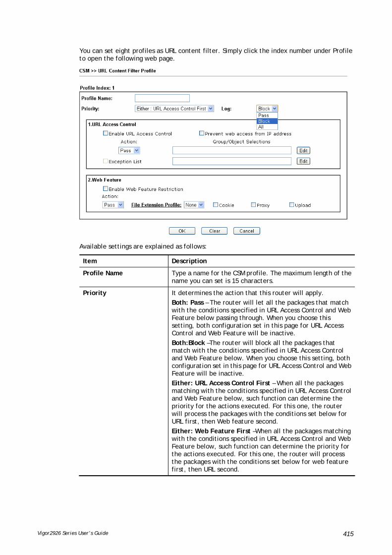
Vigor2926 Series User’s Guide 415
You can set eight profiles as URL content filter. Simply click the index number under Profile to open the following web page.
Available settings are explained as follows:
Item Description
Profile Name Type a name for the CSM profile. The maximum length of the name you can set is 15 characters.
Priority It determines the action that this router will apply.
Both: Pass – The router will let all the packages that match with the conditions specified in URL Access Control and Web Feature below passing through. When you choose this setting, both configuration set in this page for URL Access Control and Web Feature will be inactive.
Both:Block –The router will block all the packages that match with the conditions specified in URL Access Control and Web Feature below. When you choose this setting, both configuration set in this page for URL Access Control and Web Feature will be inactive.
Either: URL Access Control First – When all the packages matching with the conditions specified in URL Access Control and Web Feature below, such function can determine the priority for the actions executed. For this one, the router will process the packages with the conditions set below for URL first, then Web feature second.
Either: Web Feature First –When all the packages matching with the conditions specified in URL Access Control and Web Feature below, such function can determine the priority for the actions executed. For this one, the router will process the packages with the conditions set below for web feature first, then URL second.
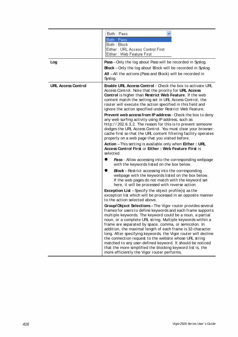
Vigor2926 Series User’s Guide 416
Log Pass – Only the log about Pass will be recorded in Syslog.
Block – Only the log about Block will be recorded in Syslog.
All – All the actions (Pass and Block) will be recorded in Syslog.
URL Access Control Enable URL Access Control - Check the box to activate URL Access Control. Note that the priority for URL Access Control is higher than Restrict Web Feature. If the web content match the setting set in URL Access Control, the router will execute the action specified in this field and ignore the action specified under Restrict Web Feature.
Prevent web access from IP address - Check the box to deny any web surfing activity using IP address, such as http://202.6.3.2. The reason for this is to prevent someone dodges the URL Access Control. You must clear your browser cache first so that the URL content filtering facility operates properly on a web page that you visited before.
Action – This setting is available only when Either : URL Access Control First or Either : Web Feature First is selected.
Pass - Allow accessing into the corresponding webpage with the keywords listed on the box below.
Block - Restrict accessing into the corresponding webpage with the keywords listed on the box below. If the web pages do not match with the keyword set here, it will be processed with reverse action.
Exception List – Specify the object profile(s) as the exception list which will be processed in an opposite manner to the action selected above.
Group/Object Selections – The Vigor router provides several frames for users to define keywords and each frame supports multiple keywords. The keyword could be a noun, a partial noun, or a complete URL string. Multiple keywords within a frame are separated by space, comma, or semicolon. In addition, the maximal length of each frame is 32-character long. After specifying keywords, the Vigor router will decline the connection request to the website whose URL string matched to any user-defined keyword. It should be noticed that the more simplified the blocking keyword list is, the more efficiently the Vigor router performs.

Vigor2926 Series User’s Guide 417
Web Feature Enable Web Feature Restriction - Check this box to make the keyword being blocked or passed.
Action - This setting is available only when Either: URL Access Control First or Either: Web Feature First is selected. Pass - Allow accessing into the corresponding webpage with the keywords listed on the box below.
Block - Restrict accessing into the corresponding webpage with the keywords listed on the box below. If the web pages do not match with the specified feature set here, it will be processed with reverse action.
File Extension Profile – Choose one of the profiles that you configured in Object Setting>> File Extension Objects previously for passing or blocking the file downloading.
Cookie - Check the box to filter out the cookie transmission from inside to outside world to protect the local user's privacy.
Proxy - Check the box to reject any proxy transmission. To control efficiently the limited-bandwidth usage, it will be of great value to provide the blocking mechanism that filters out the multimedia files downloading from web pages.
Upload – Check the box to block the file upload by way of web page.
After finishing all the settings, please click OK to save the configuration.

Vigor2926 Series User’s Guide 418
VVII--22--44 WWeebb CCoonntteenntt FFiilltteerr PPrrooffiillee
There are three ways to activate WCF on vigor router, using Service Activation Wizard, by means of CSM>>Web Content Filter Profile or via System Maintenance>>Activation.
Service Activation Wizard allows you to use trial version of WCF directly without accessing into the server (MyVigor) located on http://myvigor.draytek.com.
However, if you use the Web Content Filter Profile page to activate WCF feature, it is necessary for you to access into the server (MyVigor) located on http://myvigor.draytek.com. Therefore, you need to register an account on http://myvigor.draytek.com for using corresponding service. Please refer to section of creating MyVigor account.
WCF adopts the mechanism developed and offered by certain service provider (e.g., DrayTek). No matter activating WCF feature or getting a new license for web content filter, you have to click Activate to satisfy your request. Be aware that service provider matching with Vigor router currently offers a period of time for trial version for users to experiment. If you want to purchase a formal edition, simply contact with the channel partner or your dealer.
Click CSM and click Web Content Filter Profile to open the profile setting page. The default setting for Setup Query Server /Setup Test Server is auto-selected. You can choose another server for your necessity by clicking Find more to open http://myvigor.draytek.com for searching another qualified and suitable one.
Info 1
Web Content Filter (WCF) is not a built-in service of Vigor router but a service powered by Commtouch. If you want to use such service (trial or formal edition), you have to perform the procedure of activation first. For the service of formal edition, please contact with your dealer/distributor for detailed information.
Info 2 Commtouch is merged by Cyren, and GlobalView services will be continued to deliver powerful cloud-based information security solutions! Refer to:
http://www.prnewswire.com/news-releases/commtouch-is-now-cyren-239025151.html

Vigor2926 Series User’s Guide 419
Available settings are explained as follows:
Item Description
Activate Click it to access into MyVigor for activating WCF service.
Setup Query Server It is recommended for you to use the default setting, auto-selected. You need to specify a server for categorize searching when you type URL in browser based on the web content filter profile.
Setup Test Server It is recommended for you to use the default setting, auto-selected.
Find more Click it to open http://myvigor.draytek.com for searching another qualified and suitable server.
Test a site to verify whether it is categorized
Click this link to do the verification.
Set to Factory Default Click this link to retrieve the factory settings.
Administration Message You can type the message manually for your necessity or click Default Message button to get the default text displayed on the field of Administration Message.
Cache None – the router will check the URL that the user wants to access via WCF precisely, however, the processing rate is normal. Such item can provide the most accurate URL matching.
L1 – the router will check the URL that the user wants to access via WCF. If the URL has been accessed previously, it will be stored in the router to be accessed quickly if

Vigor2926 Series User’s Guide 420
required. Such item can provide accurate URL matching with faster rate.
L2 – the router will check the URL that the user wants to access via WCF. If the data has been accessed previously, the IP addresses of source and destination IDs will be memorized for a short time (about 1 second) in the router. When the user tries to access the same destination ID, the router will check it by comparing the record stored. If it matches, the page will be retrieved quickly. Such item can provide URL matching with the fastest rate.
L1+L2 Cache – the router will check the URL with fast processing rate combining the feature of L1 and L2.
Eight profiles are provided here as Web content filters. Simply click the index number under Profile to open the following web page. The items listed in Categories will be changed according to the different service providers. If you have and activate another web content filter license, the items will be changed simultaneously. All of the configuration made for web content filter will be deleted automatically. Therefore, please backup your data before you change the web content filter license.
Available settings are explained as follows:
Item Description
Profile Name Type a name for the CSM profile. The maximum length of the name you can set is 15 characters.
Black/White List Enable – Activate white/black list function for such profile. Group/Object Selections – Click Edit to choose the group or

Vigor2926 Series User’s Guide 421
object profile as the content of white/black list.
Pass - allow accessing into the corresponding webpage with the characters listed on Group/Object Selections. If the web pages do not match with the specified feature set here, they will be processed with the categories listed on the box below.
Block - restrict accessing into the corresponding webpage with the characters listed on Group/Object Selections. If the web pages do not match with the specified feature set here, they will be processed with the categories listed on the box below.
Action Pass - allow accessing into the corresponding webpage with the categories listed on the box below.
Block - restrict accessing into the corresponding webpage with the categories listed on the box below.
If the web pages do not match with the specified feature set here, it will be processed with reverse action.
Log None – There is no log file will be recorded for this profile.
Pass – Only the log about Pass will be recorded in Syslog.
Block – Only the log about Block will be recorded in Syslog.
All – All the actions (Pass and Block) will be recorded in Syslog.
After finishing all the settings, please click OK to save the configuration.

Vigor2926 Series User’s Guide 422
VVII--22--55 DDNNSS FFiilltteerr PPrrooffiillee
The DNS Filter monitors DNS queries on UDP port 53 and will pass the DNS query information to the WCF to help with categorizing HTTPS URL's.
DNS can be specified in LAN>>General Setup by using the server (e.g., 168.95.1.1) on router or external DNS server (e.g., 8.8.8.8). If the router server is used, DNS Filter General Setting will be applied to DNS query from clients on LAN. However, if the external DNS server is used, DNS Filter Profile will be applied to DNS query coming from clients on LAN.
Info
For DNS filter must use the WCF service profile to filter the packets, therefore WCF license must be activated first. Otherwise, DNS filter does not have any effect on packets.
Available settings are explained as follows:
Item Description
DNS Filter Profile Table It displays a list of different DNS filter profiles (with

Vigor2926 Series User’s Guide 423
specified WCF and UCF).
Click the profile link to open the following page. Then, type the name of the profile and specify WCF/UCF based on your requirement.
DNS Filter Local Setting DNS Filter Local Setting will be applied to DNS query from clients on LAN when router’s DNS server is used.
DNS Filter - Check Enable to enable such feature.
Syslog - The filtering result can be recorded according to the setting selected for Syslog.
None – There is no log file will be recorded for this profile.
Pass – Only the log about Pass will be recorded in Syslog.
Block – Only the log about Block will be recorded in Syslog.
All – All the actions (Pass and Block) will be recorded in Syslog.
WCF- Set the filtering conditions.
UCF - Set the filtering conditions.
Black/White List – Specify IP address, subnet mask, IP object, or IP group as a black list or white list for DNS packets passing through or blocked by Vigor router.
Administration Message Type the words or sentences which will be displayed when a web page is blocked by Vigor router. You can type the message manually for your necessity or click Default Message button to get the default text displayed on the field of Administration Message.
After finishing all the settings, please click OK to save the configuration.

Vigor2926 Series User’s Guide 424
AApppplliiccaattiioonn NNootteess
AA--11 HHooww ttoo CCrreeaattee aann AAccccoouunntt ffoorr MMyyVViiggoorr
The website of MyVigor (a server located on http://myvigor.draytek.com) provides several useful services (such as Anti-Spam, Web Content Filter, Anti-Intrusion, and etc.) to filtering the web pages for the sake of protecting your system.
To access into MyVigor for getting more information, please create an account for MyVigor.
CCrreeaattee aann AAccccoouunntt vviiaa VViiggoorr RRoouutteerr
1. Click CSM>> Web Content Filter Profile. The following page will appear.
Or
Click System Maintenance>>Activation to open the following page.

Vigor2926 Series User’s Guide 425
2. Click the Activate link. A login page for MyVigor web site will pop up automatically.
3. Click the link of Create an account now.
4. Check to confirm that you accept the Agreement and click Accept.

Vigor2926 Series User’s Guide 426
5. Type your personal information in this page and then click Continue.
6. Choose proper selection for your computer and click Continue.

Vigor2926 Series User’s Guide 427
7. Now you have created an account successfully. Click START.
8. Check to see the confirmation email with the title of New Account Confirmation Letter from myvigor.draytek.com.
9. Click the Activate my Account link to enable the account that you created. The following screen will be shown to verify the register process is finished. Please click Login.

Vigor2926 Series User’s Guide 428
10. When you see the following page, please type in the account and password (that you just created) in the fields of UserName and Password.
11. Now, click Login. Your account has been activated. You can access into MyVigor server to activate the service (e.g., WCF) that you want.
CCrreeaattee aann AAccccoouunntt vviiaa MMyyVViiggoorr WWeebb SSiittee
1. Access into http://myvigor.draytek.com. Find the line of Not registered yet?. Then, click the link Click here! to access into next page.

Vigor2926 Series User’s Guide 429
2. Check to confirm that you accept the Agreement and click Accept.
3. Type your personal information in this page and then click Continue.
4. Choose proper selection for your computer and click Continue.
5. Now you have created an account successfully. Click START.

Vigor2926 Series User’s Guide 430
6. Check to see the confirmation email with the title of New Account Confirmation Letter from myvigor.draytek.com.
7. Click the Activate my Account link to enable the account that you created. The following
screen will be shown to verify the register process is finished. Please click Login.

Vigor2926 Series User’s Guide 431
8. When you see the following page, please type in the account and password (that you just created) in the fields of UserName and Password. Then type the code in the box of Auth Code according to the value displayed on the right side of it.
Now, click Login. Your account has been activated. You can access into MyVigor server to activate the service (e.g., WCF) that you want.

Vigor2926 Series User’s Guide 432
AA--22 HHooww ttoo BBlloocckk FFaacceebbooookk SSeerrvviiccee AAcccceesssseedd bbyy tthhee UUsseerrss vviiaa WWeebb CCoonntteenntt
FFiilltteerr // UURRLL CCoonntteenntt FFiilltteerr
There are two ways to block the facebook service, Web Content Filter and URL Content Filter.
Web Content Filter,
Benefits: Easily and quickly implement the category/website that you want to block.
Note: License is required.
URL Content Filter,
Benefits: Free, flexible for customize webpage.
Note: Manual setting (e.g., one keyword for one website.)
II.. VViiaa WWeebb CCoonntteenntt FFiilltteerr
1. Make sure the Web Content Filter (powered by Commtouch) license is valid.

Vigor2926 Series User’s Guide 433
2. Open CSM >> Web Content Filter Profile to create a WCF profile. Check Social Networking with Action, Block.
3. Enable this profile in Firewall>>General Setup>>Default Rule.

Vigor2926 Series User’s Guide 434
4. Next time when someone accesses facebook via this router, the web page would be blocked and the following message would be displayed instead.
II. Via URL Content Filter
A. Block the web page containing the word of “Facebook”
1. Open Object Settings>>Keyword Object. Click an index number to open the setting page.
2. In the field of Contents, please type facebook. Configure the settings as the following figure.
3. Open CSM>>URL Content Filter Profile. Click an index number to open the setting page.
4. Configure the settings as the following figure.
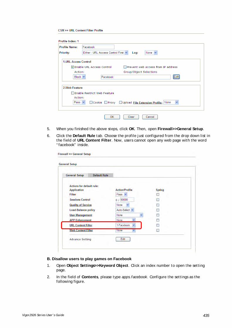
Vigor2926 Series User’s Guide 435
5. When you finished the above steps, click OK. Then, open Firewall>>General Setup.
6. Click the Default Rule tab. Choose the profile just configured from the drop down list in the field of URL Content Filter. Now, users cannot open any web page with the word “facebook” inside.
B. Disallow users to play games on Facebook
1. Open Object Settings>>Keyword Object. Click an index number to open the setting page.
2. In the field of Contents, please type apps.facebook. Configure the settings as the following figure.

Vigor2926 Series User’s Guide 436
3. Open CSM>>URL Content Filter Profile. Click an index number to open the setting page.
4. Configure the settings as the following figure.
5. When you finished the above steps, please open Firewall>>General Setup.
6. Click the Default Rule tab. Choose the profile just configured from the drop down list in the field of URL Content Filter. Now, users cannot open any web page with the word “facebook” inside.

Vigor2926 Series User’s Guide 437

Vigor2926 Series User’s Guide 438
This page is left blank.

Vigor2926 Series User’s Guide 439
PPaarrtt VVIIII MMaannaaggeemmeenntt
There are several items offered for the Vigor router system setup: System Status, TR-069, Administrator Password, User Password, Login Page Greeting, Configuration Backup, Syslog /Mail Alert, Time and Date, Management, Reboot System, Firmware Upgrade and Activation.
It is used to control the bandwith of data transmission through configuration of Sessions Limit, Bandwidth Limit, and Quality of Servie (QoS).
It is a security feature which disallows any IP traffic (except DHCP-related packets) from a particular host until that host has correctly supplied a valid username and password.

Vigor2926 Series User’s Guide 440
VVIIII--11 SSyysstteemm MMaaiinntteennaannccee
For the system setup, there are several items that you have to know the way of configuration: System Status, TR-069, Administrator Password, User Password, Login Page Greeting, Configuration Backup, Syslog /Mail Alert, Time and Date, Management, Reboot System, Firmware Upgrade and Activation.

Vigor2926 Series User’s Guide 441
WWeebb UUsseerr IInntteerrffaaccee
Below shows the menu items for System Maintenance.

Vigor2926 Series User’s Guide 442
VVIIII--11--11 SSyysstteemm SSttaattuuss
The System Status provides basic network settings of Vigor router. It includes LAN and WAN interface information. Also, you could get the current running firmware version or firmware related information from this presentation.
Available settings are explained as follows:
Item Description
Model Name Display the model name of the router.
Firmware Version Display the firmware version of the router.
Build Date/Time Display the date and time of the current firmware build.
LAN MAC Address
- Display the MAC address of the LAN Interface.
IP Address
- Display the IP address of the LAN interface.
Subnet Mask
- Display the subnet mask address of the LAN interface.
DHCP Server
- Display the current status of DHCP server of the LAN interface
DNS
- Display the assigned IP address of the primary DNS.
WAN Link Status
- Display current connection status.

Vigor2926 Series User’s Guide 443
MAC Address
- Display the MAC address of the WAN Interface.
Connection
- Display the connection type.
IP Address
- Display the IP address of the WAN interface.
Default Gateway
- Display the assigned IP address of the default gateway.
IPv6 Address - Display the IPv6 address for LAN.
Scope - Display the scope of IPv6 address. For example, IPv6 Link Local could only be used for direct IPv6 link. It can't be used for IPv6 internet.
Internet Access Mode – Display the connection mode chosen for accessing into Internet.

Vigor2926 Series User’s Guide 444
VVIIII--11--22 TTRR--006699
This device supports TR-069 standard. It is very convenient for an administrator to manage a TR-069 device through an Auto Configuration Server, e.g., VigorACS.
Available settings are explained as follows:

Vigor2926 Series User’s Guide 445
Item Description
ACS Server On Choose the interface for the router connecting to ACS server.
ACS Server URL/Username/Password – Such data must be typed according to the ACS (Auto Configuration Server) you want to link. Please refer to Auto Configuration Server user’s manual for detailed information.
Test With Inform – Click it to send a message based on the event code selection to test if such CPE is able to communicate with VigorACS SI server.
Event Code – Use the drop down menu to specify an event to perform the test.
Last Inform Response Time – Display the time that VigorACS server made a response while receiving Inform message from CPE last time.
CPE Client Such information is useful for Auto Configuration Server.
Enable/Disable – Allow/Deny the CPE Client to connect with Auto Configuration Server.
Port – Sometimes, port conflict might be occurred. To solve such problem, you might change port number for CPE.
Username and Password – Type the username and password that VigorACS can use to access into such CPE.
Periodic Inform Settings The default setting is Enable. Please set interval time or schedule time for the router to send notification to CPE. Or click Disable to close the mechanism of notification.
STUN Settings The default is Disable. If you click Enable, please type the relational settings listed below:
Server IP – Type the IP address of the STUN server.
Server Port – Type the port number of the STUN server.
Minimum Keep Alive Period – If STUN is enabled, the CPE must send binding request to the server for the purpose of maintaining the binding in the Gateway. Please type a number as the minimum period. The default setting is “60 seconds”.
Maximum Keep Alive Period – If STUN is enabled, the CPE must send binding request to the server for the purpose of maintaining the binding in the Gateway. Please type a number as the maximum period. A value of “-1” indicates that no maximum period is specified.
Apply Settings to APs This feature is able to apply TR-069 settings (including STUN and ACS server settings) to all of APs managed by Vigor2926 at the same time.
Disable – Related settings will not be applied to VigorAP.
Enable – Above STUN settings will be applied to VigorAP after clicking OK. If such feature is enabled, you have to type the password for accessing VigorAP.
AP Password – Type the password of the VigorAP that you want to apply Vigor2926’s TR-069 settings.
Apply Specific STUN Settings to APs – After clicking the Enable radio button for Apply Settings to APs, if you want to apply specific STUN settings (not the STUN Settings configured for Vigor2926) to VigorAPs to meet specific requirements, simply check this box. Then, type the server IP address, server port, minimum keep alive period and

Vigor2926 Series User’s Guide 446
maxmum keep alive period respectively.
Bandwidth Utilisation Notification Settings
To administrator, this feature is useful to monitor the bandwidth utilization of CPE(s). When the bandwidth used is over the threshold level (percentage defined in medium and high fields), a notification will be sent to VigorACS. After a long time observation, the administrator can determine if it is necessary to increase the bandwidth setting for that CPE or not.
Enable – Click it to enable such feature.
Time Period – Choose the time interval (15 mins, 30 mins, 1hour, 3 hours, or 6 hours) for CPE to send a notification of bandwidth utilization to VigorACS.
WAN – Choose the WAN interface for applying the bandwidth utilization notification mechanism.
Threshold Level – Set the percentage of bandwidth in transmission and receiving data as threshold values for CPE to detect bandwidth utilization.
Line Speed – Set the transmission rate and receiving rate for specified WAN interface.
After finishing all the settings here, please click OK to save the configuration.

Vigor2926 Series User’s Guide 447
VVIIII--11--33 AAddmmiinniissttrraattoorr PPaasssswwoorrdd
This page allows you to set new password.
Available settings are explained as follows:
Item Description
Administrator Password Old Password - Type in the old password. The factory default setting for password is “admin”.
New Password -Type in new password in this field. The length of the password is limited to 23 characters.
Confirm Password -Type in the new password again.
Administrator Local User The administrator can login web user interface of Vigor router to modify all of the settings to fit the requirements. This feature allows other user in LAN who can access into the web user interface with the same privilege of the administrator.
Local User – Check the box to enable the local user configuration.
Local User List – It displays the username of the local user.

Vigor2926 Series User’s Guide 448
User Name – Give a user name for the local user.
Password – Type the password for the local user.
Confirm Password – Type the password again for confirmation.
Add – After typing the user name and password above, simply click it to create a new local user. The new one will be shown on the Local User List immediately.
Edit – If the username listed on the box above is not satisfied, simply click the username and modify it on the field of User Name. Later, click Edit to update the information.
Delete – If the local user listed on the box above is not satisfied, simply click the username and click Delete to remove it.
Enable ‘admin’ account login to Web UI from the Internet – It can ensure any user accessing into web user interface of Vigor router through Internet by username/password of “admin/admin”.
Administrator LDAP Setting
Enable LDAP/AD login for admin users – If it is enabled, any user can access into the web user interface of Vigor router through the LDAP server authentication.
Enable ‘admin’ account login to Web UI from the Internet – The default setting is enabled. It can ensure any user accessing into web user interface of Vigor router through Internet by username/password of “admin/admin”.
LDAP Server Profiles – Available profiles will be displayed here under the link of LDAP Profile Setup.
LDAP Profile Setup – It allows you to create a new LDAP profile.
After finishing all the settings here, please click OK to save the configuration. After logging out the webuser interface, please use the new password to access into the web user interface again.

Vigor2926 Series User’s Guide 449
VVIIII--11--44 UUsseerr PPaasssswwoorrdd
This page allows you to set new password for user operation.
Available settings are explained as follows:
Item Description
Enable User Mode for simple web configuration
After checking this box, you can access into the web user interface with the password typed here for simple web configuration.
The settings on simple web user interface will be different with full web user interface accessed by using the administrator password.
Password Type in new password in this field. The length of the password is limited to 31 characters.
Confirm Password Type in the new password again.
Password Strength Display the security strength of the password specified above.
Set to Factory Default Click to return to the factory default setting.
When you click OK, the login window will appear. Please use the new password to access into the web user interface again. Below shows an example for accessing into User Operation with User Password.
1. Open System Maintenance>>User Password.
2. Check the box of Enable User Mode for simple web configuration to enable user mode operation. Type a new password in the field of New Password and click OK.
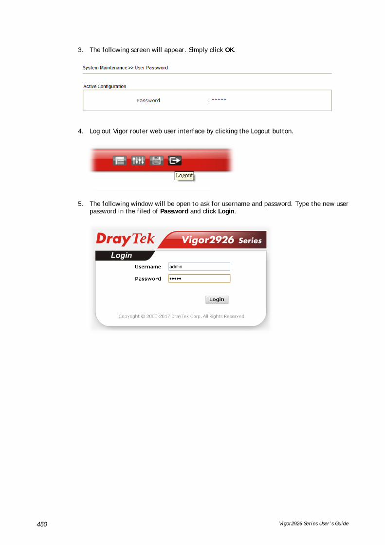
Vigor2926 Series User’s Guide 450
3. The following screen will appear. Simply click OK.
4. Log out Vigor router web user interface by clicking the Logout button.
5. The following window will be open to ask for username and password. Type the new user password in the filed of Password and click Login.

Vigor2926 Series User’s Guide 451
6. The main screen with User Mode will be shown as follows.
Settings to be configured in User Mode will be less than settings in Admin Mode. Only basic configuration settings will be available in User Mode.
Info
Setting in User Mode can be configured as same as in Admin Mode.
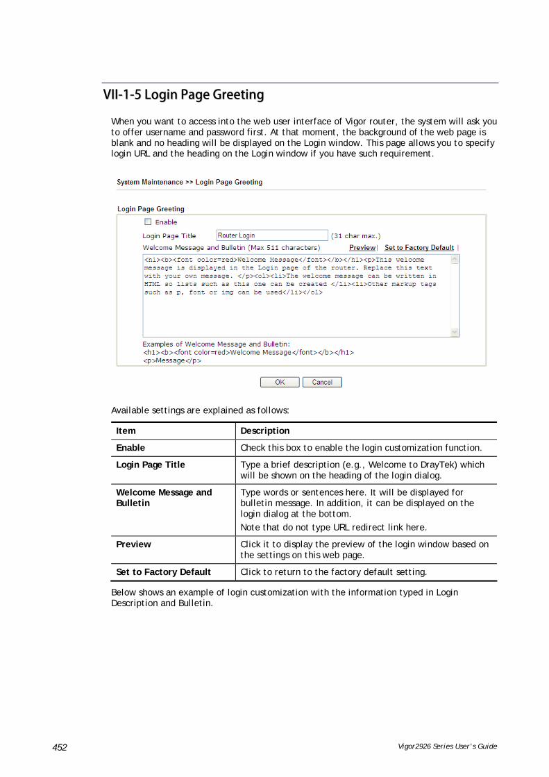
Vigor2926 Series User’s Guide 452
VVIIII--11--55 LLooggiinn PPaaggee GGrreeeettiinngg
When you want to access into the web user interface of Vigor router, the system will ask you to offer username and password first. At that moment, the background of the web page is blank and no heading will be displayed on the Login window. This page allows you to specify login URL and the heading on the Login window if you have such requirement.
Available settings are explained as follows:
Item Description
Enable Check this box to enable the login customization function.
Login Page Title Type a brief description (e.g., Welcome to DrayTek) which will be shown on the heading of the login dialog.
Welcome Message and Bulletin
Type words or sentences here. It will be displayed for bulletin message. In addition, it can be displayed on the login dialog at the bottom.
Note that do not type URL redirect link here.
Preview Click it to display the preview of the login window based on the settings on this web page.
Set to Factory Default Click to return to the factory default setting.
Below shows an example of login customization with the information typed in Login Description and Bulletin.

Vigor2926 Series User’s Guide 453

Vigor2926 Series User’s Guide 454
VVIIII--11--66 CCoonnffiigguurraattiioonn BBaacckkuupp
Such function can be used to apply the router settings configured by Vigor2925 to Vigor2926.
BBaacckkuupp tthhee CCoonnffiigguurraattiioonn
Follow the steps below to backup your configuration.
1. Go to System Maintenance >> Configuration Backup. The following page will be popped-up, as shown below.
Available settings are explained as follows:
Item Description
Restore Choose File /USB Storage – Click it to specify a file to be restored.
Restore configuration except the login password - If the password settings shall not be restored and applied to Vigor2926, simply check this box to get rid of password settings.
Click Restore to restore the configuration. If the file is encrypted, the system will ask you to type the password to decrypt the configuration file.
Backup Click it to perform the configuration backup of this router.
Protect with password- For the sake of security, the configuration file for the router can be encrypted.

Vigor2926 Series User’s Guide 455
Password – Type several characters as the password for
encrypting the configuration file.
Confirm Password – Type the password again for confirmation.
Auto Backup to USB storage
The configuration can be stored to a USB connecting to Vigor router as a backup.
Backup folder – Set the path for downloading.
Periodicity backup – Set the circle duration for backup.
Backup after change configuration – Backup will be executed whenever the configuration is changed.
Support Model List Web configuration file from other Vigor router can be applied to Vigor2926 series. At present, only the configuration file of Vigor2925 is accepted for Vigor2926.
This field displays model name(s) and firmware which web configuration file saved can be used by such router.
2. Click Backup button to get into the following dialog. Click Save button to open another dialog for saving configuration as a file.
3. In Save As dialog, the default filename is config.cfg. You could give it another name by yourself.

Vigor2926 Series User’s Guide 456
4. Click Save button, the configuration will download automatically to your computer as a file named config.cfg.
The above example is using Windows platform for demonstrating examples. The Mac or Linux platform will appear different windows, but the backup function is still available.
Info
Backup for Certification must be done independently. The Configuration Backup does not include information of Certificate.
RReessttoorree CCoonnffiigguurraattiioonn
1. Go to System Maintenance >> Configuration Backup. The following windows will be popped-up, as shown below.

Vigor2926 Series User’s Guide 457
2. Click Choose File button to choose the correct configuration file for uploading to the router.
3. Click Restore button and wait for few seconds.
VVIIII--11--77 SSyysslloogg//MMaaiill AAlleerrtt
SysLog function is provided for users to monitor router.
Available settings are explained as follows:
Item Description
SysLog Access Setup Enable - Check Enable to activate function of syslog.
Syslog Save to – Check Syslog Server to save the log to Syslog server.
Check USB Disk to save the log to the attached USB storage disk.
Router Name Display the name for such router configured in System Maintenance>>Management.
If there is no name here, simply lick the link to access into System Maintenance>>Management to set the router name.
Server IP Address / Hostname -The IP address of the Syslog server.
Destination Port - Assign a port for the Syslog protocol.
Mail Syslog – Check the box to recode the mail event on Syslog.
Enable syslog message - Check the box listed on this web page to send the corresponding message of firewall, VPN, User Access, Call, WAN, Router/DSL information to Syslog.

Vigor2926 Series User’s Guide 458
Mail Alert Setup Check Enable to activate function of mail alert.
Send a test e-mail - Make a simple test for the e-mail address specified in this page. Please assign the mail address first and click this button to execute a test for verify the mail address is available or not.
SMTP Server/SMTP Port - The IP address/Port number of the SMTP server.
Mail To - Assign a mail address for sending mails out.
Return-Path - Assign a path for receiving the mail from outside.
Use SSL - Check this box to use port 465 for SMTP server for some e-mail server uses https as the transmission method.
Authentication - Check this box to activate this function while using e-mail application.
User Name - Type the user name for authentication.
Password - Type the password for authentication.
Enable E-mail Alert - Check the box to send alert message to the e-mail box while the router detecting the item(s) you specify here.
Click OK to save these settings.
For viewing the Syslog, please do the following:
1. Just set your monitor PC’s IP address in the field of Server IP Address
2. Install the Router Tools in the Utility within provided CD. After installation, click on the Router Tools>>Syslog from program menu.

Vigor2926 Series User’s Guide 459
3. From the Syslog screen, select the router you want to monitor. Be reminded that in Network Information, select the network adapter used to connect to the router. Otherwise, you won’t succeed in retrieving information from the router.

Vigor2926 Series User’s Guide 460
VVIIII--11--88 TTiimmee aanndd DDaattee
It allows you to specify where the time of the router should be inquired from.
Available settings are explained as follows:
Item Description
Current System Time Click Inquire Time to get the current time.
Use Browser Time Select this option to use the browser time from the remote administrator PC host as router’s system time.
Use Internet Time Select to inquire time information from Time Server on the Internet using assigned protocol.
Time Server Type the web site of the time server.
Priority Choose Auto or IPv6 First as the priority.
Time Zone Select the time zone where the router is located.
Enable Daylight Saving Check the box to enable the daylight saving. Such feature is available for certain area.
Advanced – Click it to open a pop up dialog.
Use the default time setting or set user defined time for your requirement.
Automatically Update Interval
Select a time interval for updating from the NTP server.

Vigor2926 Series User’s Guide 461
Send NTP Request Through
Specify a WAN interface to send NTP request for time synchronization.
Click OK to save these settings.
VVIIII--11--99 SSNNMMPP
This page allows you to configure settings for SNMP and SNMPV3 services.
The SNMPv3 is more secure than SNMP through the encryption method (support AES and DES) and authentication method (support MD5 and SHA) for the management needs.
Available settings are explained as follows:
Item Description
Enable SNMP Agent Check it to enable this function.
Get Community Set the name for getting community by typing a proper character. The default setting is public.
The maximum length of the text is limited to 23 characters.
Set Community Set community by typing a proper name. The default setting

Vigor2926 Series User’s Guide 462
is private.
The maximum length of the text is limited to 23 characters.
Manager Host IP (IPv4) Set one host as the manager to execute SNMP function. Please type in IPv4 address to specify certain host.
Manager Host IP (IPv6) Set one host as the manager to execute SNMP function. Please type in IPv6 address to specify certain host.
Trap Community Set trap community by typing a proper name. The default setting is public.
The maximum length of the text is limited to 23 characters.
Notification Host IP (IPv4) Set the IPv4 address of the host that will receive the trap community.
Notification Host IP (IPv6) Set the IPv6 address of the host that will receive the trap community.
Trap Timeout The default setting is 10 seconds.
Enable SNMPV3 Agent Check it to enable this function.
USM User USM means user-based security mode.
Type a username which will be used for authentication. The maximum length of the text is limited to 23 characters.
Auth Algorithm Choose one of the encryption methods listed below as the authentication algorithm.
Auth Password Type a password for authentication. The maximum length of the text is limited to 23 characters.
Privacy Algorithm Choose one of the methods listed below as the privacy algorithm.
Privacy Password Type a password for privacy. The maximum length of the text is limited to 23 characters.
Click OK to save these settings.

Vigor2926 Series User’s Guide 463
VVIIII--11--1100 MMaannaaggeemmeenntt
This page allows you to manage the settings for Internet/LAN Access Control, Access List from Internet, Management Port Setup, TLS/SSL Encryption Setup, CVM Access Control and Device Management.
The management pages for IPv4 and IPv6 protocols are different.
FFoorr IIPPvv44
Available settings are explained as follows:
Item Description
Router Name Type in the router name provided by ISP.
Default: Disable Auto-Logout
If it is enabled, the function of auto-logout for web user interface will be disabled.

Vigor2926 Series User’s Guide 464
The web user interface will be open until you click the Logout icon manually.
Enable Validation Code in Internet/LAN Access
If it is enabled, the mechanism of validation code will be offered by Vigor router. That is, the client must type validation code while accessing into Internet or web user interface of Vigor router.
Internet Access Control Allow management from the Internet - Enable the checkbox to allow system administrators to login from the Internet. There are several servers provided by the system to allow you managing the router from Internet. Check the box(es) to specify.
Disable PING from the Internet - Check the checkbox to reject all PING packets from the Internet. For security issue, this function is enabled by default.
Access List from the Internet
You could specify that the system administrator can only login from a specific host or network defined in the list. A maximum of three IPs/subnet masks is allowed.
List index in IP Object- Type the index number of the IP object profile. Related IP with Subnet Mask will appear automatically.
Management Port Setup User Define Ports - Check to specify user-defined port numbers for the Telnet, HTTP, HTTPS, FTP, TR-069 and SSH servers.
Default Ports - Check to use standard port numbers for the Telnet and HTTP servers.
Brute Force Protection Any client trying to access into Internet via Vigor router will be asked for passing through user authentication. Such feature can prevent Vigor router from attacks when a hacker tries every possible combination of letters, numbers and symbols until find out the correct combination of password.
Enable brute force login protection – Enable the protection mechanism.
Maximum login failure – Specify the maximum number of wrong password that client can try for logging to Vigor router.
Penalty period – Set a period of time to block the IP address which is used (by user or hacker) for passing through the user authentication again and again but failed always. When the time is up, Vigor system will unblock that IP and allow it to access into Vigor router again.
Blocked IP List – Open another web page which displays current blocked IPs.
TLS/SSL Encryption Setup Enable SSL 3.0 and / or TLS 1.0/1.1/1.2 – Check the box to enable the function of SSL 3.0 and / or TLS 1.0/1.1/1.2 if

Vigor2926 Series User’s Guide 465
required.
Due to security consideration, the built-in HTTPS and SSL VPN server of the router had upgraded to TLS1.x protocol. If you are using old browser(eg. IE6.0) or old SmartVPN Client, you may still need to enable SSL 3.0 to make sure you can connect, however, it's not recommended.
CVM Access Control CVM Port – Check the box to enable such port setting.
CVM SSL Port – Check the box to enable such port setting.
AP Management Enable AP Management – Check it to enable the function of Central Management>>AP. If unchecked, menu items related to Central Management>>AP will be hidden.
Device Management Check the box to enable the device management function for Vigor2926.
Respond to external device – If it is enabled, Vigor2926 will be regarded as slave device. When the external device (master device) sends request packet to Vigor2926, Vigor2926 would send back information to respond the request coming from the external device which is able to manage Vigor2926.
After finished the above settings, click OK to save the configuration.
FFoorr IIPPvv66
Available settings are explained as follows:
Item Description

Vigor2926 Series User’s Guide 466
Management Access Control
Allow management from the Internet - Enable the checkbox to allow system administrators to login from the Internet. There are several servers provided by the system to allow you managing the router from Internet. Check the box(es) to specify.
Disable PING from the Internet - Check the checkbox to disable all PING packets from the Internet. For security issue, this function is enabled by default.
Access List You could specify that the system administrator can only login from a specific host or network defined in the list. A maximum of three IPs/subnet masks is allowed.
Index in IPv6 Object- Type the index number of the IP object profile. Related IP address will appear automatically.
After finished the above settings, click OK to save the configuration.
FFoorr LLAANN
Available settings are explained as follows:
Item Description
Allow management from LAN
Enable the checkbox to allow system administrators to login from LAN interface. There are several servers provided by the system which allow you to manage the router from LAN interface. Check the box(es) to specify.
Apply To Subnet Check the LAN interface for the administrator to use for accessing into web user interface of Vigor router.
Index in IP Object- Type the index number of the IP object profile. Related IP address will appear automatically.

Vigor2926 Series User’s Guide 467
After finished the above settings, click OK to save the configuration.
VVIIII--11--1111 PPaanneell CCoonnttrrooll
The behavior of the LEDs, buttons, USB ports and LAN ports on the front panel of the Vigor router can be customized as desired.
FFoorr LLEEDD
By default, the LEDs are enabled, and will illuminate or blink continuously to show the status of the various functions in the router. However, they can be configured to remain off at all times, or remain off until a button is pressed to wake them up.
Available settings are explained as follows:
Item Description
Refresh Click to refresh the page to display the latest information.
Enable LED Select to enable front panel LEDs.
Enable Sleep Mode/Turn off LED after _ minutes – Available when Enable LED is selected. Select this option to turn off the LEDs after the specified number of minutes.
When sleep mode is enabled, LEDs can be woken up by pressing either the Wireless LAN ON/OFF/WPS button or the Factory Reset button on the front panel, or by clicking the Wake up LED button on this page. When LEDs are lit, they can be put to sleep by briefly pressing the Factory Reset button, or by clicking the LED sleep immediately button on this page.

Vigor2926 Series User’s Guide 468
Status Shows the status of the LEDs:
– LEDs are in sleep mode. To wake them up, do one of the following:
press the Wake up LED button on this page press the Wireless On/Off/WPS button on the front
panel press the Factory Reset button on the front panel.
– LEDs are awake. To put them to sleep immediately
press the LED sleep immediately button on this page press the Factory Reset button on the front panel for 1
second.
After finished the above settings, click OK to save the configuration.
FFoorr BBuuttttoonn
The Factory Reset and Wireless ON/OFF/WPS buttons on the front panel are enabled by default and can be enabled or disabled if required. Disabling the Factory Reset button will prevent tampering by unauthorized parties, or to avoid accidental triggering of a router reset when being used wake up LEDs. Disabling the wireless button will prevent changing the wireless setting when LED Sleep Mode is enabled, and the buttons are primarily used to turn the LEDs on and off.
Click the Button tab to get the following page.
Available settings are explained as follows:
Item Description
Refresh Click to refresh the page to display the latest information.
Enable Factory Reset Button
The default value is Enabled.
Deselect to disable the reset function of the factory reset

Vigor2926 Series User’s Guide 469
button.
Disabling the Factory Reset button only prevents it from being used to reboot Vigor router with default settings. It can still be used to wake up the LEDs when LED sleep mode is enabled.
Enable Wireless Button The default value is Enabled.
Deselect to disable the ability of the Wireless button to control WLAN and WPS functions.
Disabling the wireless button only prevents it from being used to control WLAN functions. It can still be used to wake up the LEDs when LED sleep mode is enabled.
After finished the above settings, click OK to save the configuration.
FFoorr UUSSBB
The USB ports can be individually enabled or disabled. When a USB port is disabled, attached devices will not be recognized by the router.
Available settings are explained as follows:
Item Description
Refresh Click to refresh the page to display the latest information.
Port The number corresponds to the USB port number shown on the front panel.
Enable Deselect to disable the USB port. The default value is enabled.
Status Shows the status of the USB port.
No device – no USB device is connected to the port.
Connected – a USB device is connected to the port.
--- – the USB port is disabled.
After finished the above settings, click OK to save the configuration.
FFoorr LLAANN PPoorrtt
The 4 LAN ports can be individually enabled or disabled. When a LAN port is disabled, attached devices will not be recognized by the router.

Vigor2926 Series User’s Guide 470
Available settings are explained as follows:
Item Description
Refresh Click to refresh the page to display the latest information.
Port The number corresponds to the LAN port number shown on the front panel.
Enable Deselect to disable the LAN port. The default value is enabled.
Status Shows the status of the LAN port.
Link Up – An active Ethernet device is connected to the port.
Link Down – No active Ethernet device is detected.
--- – The LAN port is disabled.
Speed Shows the negotiated speed of the LAN port.
1000Mbps – Negotiated speed of the LAN port is 1000 Mbps.
100Mbps – Negotiated speed of the LAN port is 100 Mbps.
10Mpbs – Negotiated speed of the LAN port is 10 Mbps.
--- – The LAN port is disabled or there is no active device connected.
After finished the above settings, click OK to save the configuration.
VVIIII--11--1122 SSeellff--SSiiggnneedd CCeerrttiiffiiccaattee
A self-signed certificate is a unique identification for the device (e.g., Vigor router) which generates the certificate by itself to ensure the router security. Such self-signed certificate is signed with its own private key.
The self-signed certificate will be applied in SSL VPN, HTTPS, and so on. In addition, it can be created for free by using a wide variety of tools.
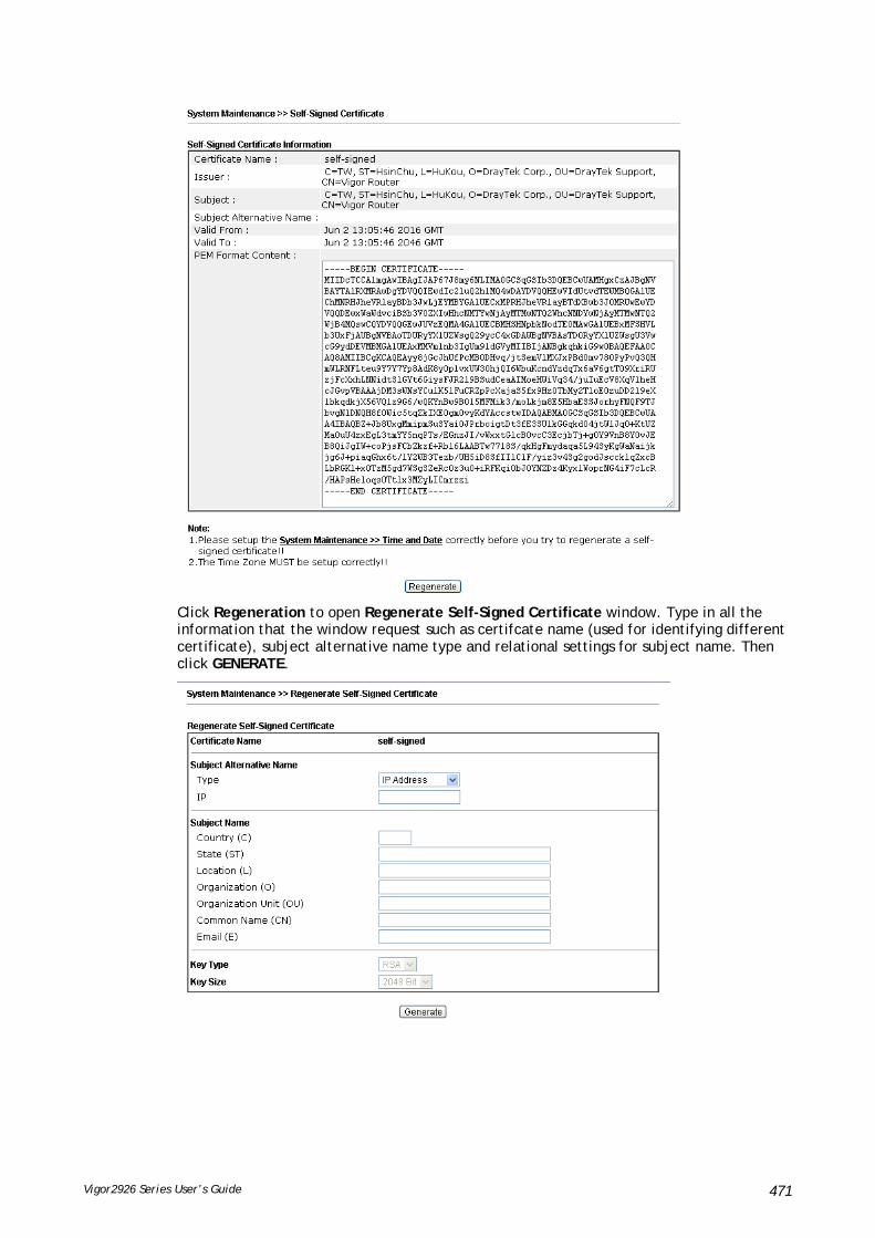
Vigor2926 Series User’s Guide 471
Click Regeneration to open Regenerate Self-Signed Certificate window. Type in all the information that the window request such as certifcate name (used for identifying different certificate), subject alternative name type and relational settings for subject name. Then click GENERATE.

Vigor2926 Series User’s Guide 472
VVIIII--11--1133 RReebboooott SSyysstteemm
The Web user interface may be used to restart your router. Click Reboot System from System Maintenance to open the following page.
Index (1-15) in Schedule Setup - You can type in four sets of time schedule for performing system reboot. All the schedules can be set previously in Applications >> Schedule web page and you can use the number that you have set in that web page.
If you want to reboot the router using the current configuration, check Using current configuration and click Reboot Now. To reset the router settings to default values, check Using factory default configuration and click Reboot Now. The router will take 5 seconds to reboot the system.
Info
When the system pops up Reboot System web page after you configure web settings, please click Reboot Now to reboot your router for ensuring normal operation and preventing unexpected errors of the router in the future.

Vigor2926 Series User’s Guide 473
VVIIII--11--1144 FFiirrmmwwaarree UUppggrraaddee
Click System Maintenance>> Firmware Upgrade to proceed to firmware upgrade.
Click the button of Check The Latest Firmware to open a pop up window displaying the newest firmware version released for such Vigor router.
Choose the one you need and click Download. After that, click Select to specify the one you just download. Then, click Upgrade. The system will upgrade the firmware of the router automatically.

Vigor2926 Series User’s Guide 474
VVIIII--11--1155 FFiirrmmwwaarree BBaacckkuupp
The firware for Vigor router can be saved on the host as a backup firmware. After that, if the router crashes due to the firmware error, the backup firmware will be applied to make the router run normally.
Simply specify the condition to run the firmware backup and click OK to save the settings.

Vigor2926 Series User’s Guide 475
VVIIII--11--1166 AAccttiivvaattiioonn
There are three ways to activate WCF on vigor router, using Service Activation Wizard, by means of CSM>>Web Content Filter Profile or via System Maintenance>>Activation.
After you have finished the setting profiles for WCF (refer to Web Content Filter Profile), it is the time to activate the mechanism for your computer.
Click System Maintenance>>Activation to open the following page for accessing http://myvigor.draytek.com.
Available settings are explained as follows:
Item Description
Activate via Interface Choose WAN interface used by such device for activating Web Content Filter.
Activate The Activate link brings you accessing into www.vigorpro.com to finish the activation of the account and the router.
Authentication Message As for authentication information of web filter, the process of authenticating will be displayed on this field for your reference.
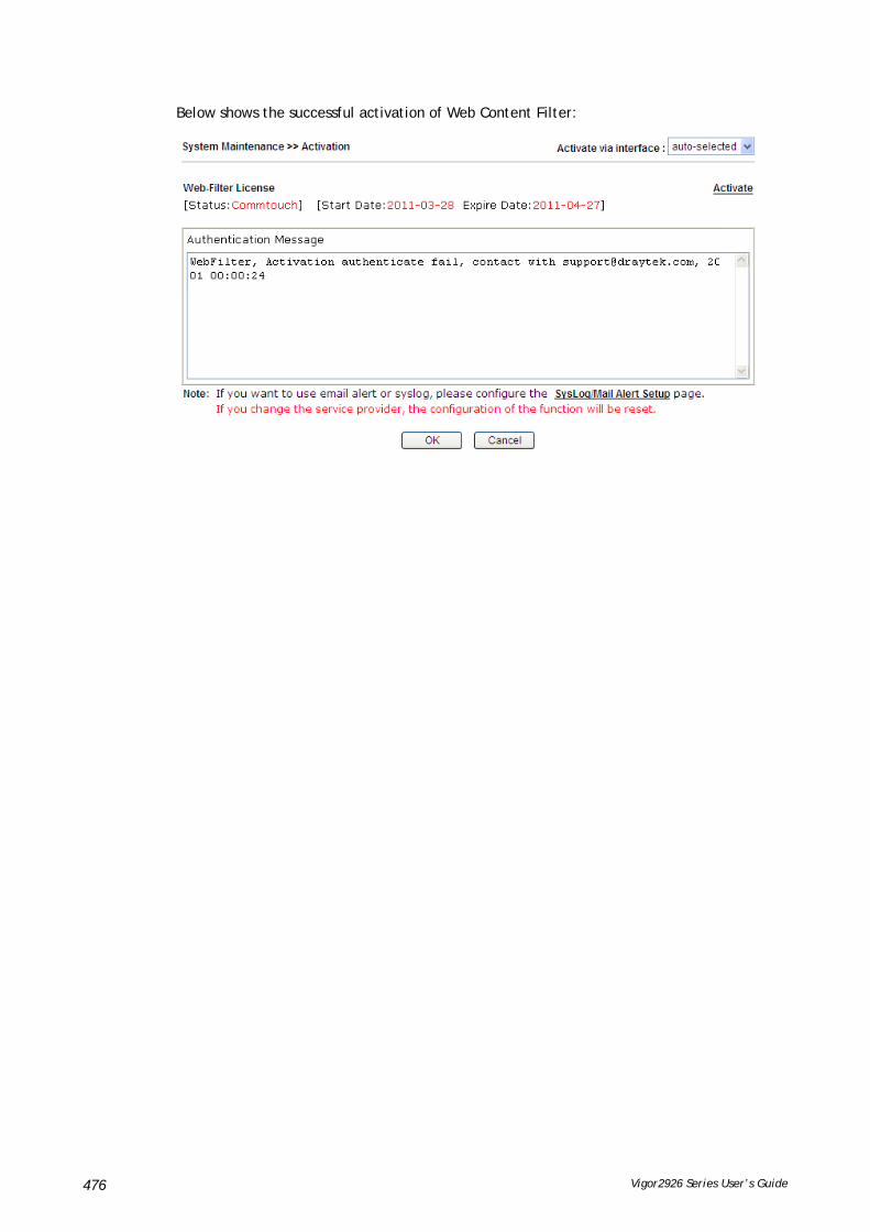
Vigor2926 Series User’s Guide 476
Below shows the successful activation of Web Content Filter:

Vigor2926 Series User’s Guide 477
VVIIII--11--1177 IInntteerrnnaall SSeerrvviiccee UUsseerr LLiisstt
User profiles (clients) defined and enabled in User Management>>User Profile will be displayed in this page.
Such page allows you to turn on or turn off security authentication service (offered by inernal RADIUS and/or Local 802.1X) for each user profile without accessing into the User Management configuration page.
Available settings are explained as follows:
Item Description
User Name Display the name of the existed user profile. To modify the detailed settings, simply click the user name link to access into the web page for modification.
Radius Check the box to turn on the security authentication service offered by internal RADIUS server for the user profile.
Uncheck the box to turn off ecurity authentication service offered by internal RADIUS server for the user profile.
If you check the box next to such item, all of the user profiles listed in this page will be enabled with RADIUS service enabled vice versa.
Local 802.1X Check the box to turn on the security authentication service offered by Local 802.1X server for the user profile.
Uncheck the box to turn off ecurity authentication service offered by Local 802.1X server for the user profile.
If you check the box next to such item, all of the user profiles listed in this page will be enabled with Local 802.1X service enabled; vice versa.
Info
For the detailed setting (such as IP address, port number) configuration of internal RADIUS, refer to Applications>>RADIUS/TACACS+.
For the detailed setting (such as IP address, port number) configuration of Local 802.1X, refer to LAN>>Wired 802.1X and Wireless LAN>>Security.

Vigor2926 Series User’s Guide 478
VVIIII--22 BBaannddwwiiddtthh MMaannaaggeemmeenntt
SSeessssiioonnss LLiimmiitt
A PC with private IP address can access to the Internet via NAT router. The router will generate the records of NAT sessions for such connection. The P2P (Peer to Peer) applications (e.g., BitTorrent) always need many sessions for procession and also they will occupy over resources which might result in important accesses impacted. To solve the problem, you can use limit session to limit the session procession for specified Hosts.
BBaannddwwiiddtthh LLiimmiitt
The downstream or upstream from FTP, HTTP or some P2P applications will occupy large of bandwidth and affect the applications for other programs. Please use Limit Bandwidth to make the bandwidth usage more efficient.
QQuuaalliittyy ooff SSeerrvviiccee ((QQooSS))
Deploying QoS (Quality of Service) management to guarantee that all applications receive the service levels required and sufficient bandwidth to meet performance expectations is indeed one important aspect of modern enterprise network.
One reason for QoS is that numerous TCP-based applications tend to continually increase their transmission rate and consume all available bandwidth, which is called TCP slow start. If other applications are not protected by QoS, it will detract much from their performance in the overcrowded network. This is especially essential to those are low tolerant of loss, delay or jitter (delay variation).
Another reason is due to congestions at network intersections where speeds of interconnected circuits mismatch or traffic aggregates, packets will queue up and traffic can be throttled back to a lower speed. If there’s no defined priority to specify which packets should be discarded (or in another term “dropped”) from an overflowing queue, packets of sensitive applications mentioned above might be the ones to drop off. How this will affect application performance?
There are two components within Primary configuration of QoS deployment:
Classification: Identifying low-latency or crucial applications and marking them for high-priority service level enforcement throughout the network.

Vigor2926 Series User’s Guide 479
Scheduling: Based on classification of service level to assign packets to queues and associated service types
The basic QoS implementation in Vigor routers is to classify and schedule packets based on the service type information in the IP header. For instance, to ensure the connection with the headquarter, a teleworker may enforce an index of QoS Control to reserve bandwidth for HTTPS connection while using lots of application at the same time.
One more larger-scale implementation of QoS network is to apply DSCP (Differentiated Service Code Point) and IP Precedence disciplines at Layer 3. Compared with legacy IP Precedence that uses Type of Service (ToS) field in the IP header to define 8 service classes, DSCP is a successor creating 64 classes possible with backward IP Precedence compatibility. In a QoS-enabled network, or Differentiated Service (DiffServ or DS) framework, a DS domain owner should sign a Service License Agreement (SLA) with other DS domain owners to define the service level provided toward traffic from different domains. Then each DS node in these domains will perform the priority treatment. This is called per-hop-behavior (PHB). The definition of PHB includes Expedited Forwarding (EF), Assured Forwarding (AF), and Best Effort (BE). AF defines the four classes of delivery (or forwarding) classes and three levels of drop precedence in each class.
Vigor routers as edge routers of DS domain shall check the marked DSCP value in the IP header of bypassing traffic, to allocate certain amount of resource execute appropriate policing, classification or scheduling. The core routers in the backbone will do the same checking before executing treatments in order to ensure service-level consistency throughout the whole QoS-enabled network.
However, each node may take different attitude toward packets with high priority marking since it may bind with the business deal of SLA among different DS domain owners. It’s not easy to achieve deterministic and consistent high-priority QoS traffic throughout the whole network with merely Vigor router’s effort.

Vigor2926 Series User’s Guide 480
WWeebb UUsseerr IInntteerrffaaccee
Below shows the menu items for Bandwidth Management.
VVIIII--22--11 SSeessssiioonnss LLiimmiitt
In the Bandwidth Management menu, click Sessions Limit to open the web page.
To activate the function of limit session, simply click Enable and set the default session limit.
Available settings are explained as follows:
Item Description
Session Limit Enable - Click this button to activate the function of limit session.
Disable - Click this button to close the function of limit session.
Default session limit - Defines the default session number
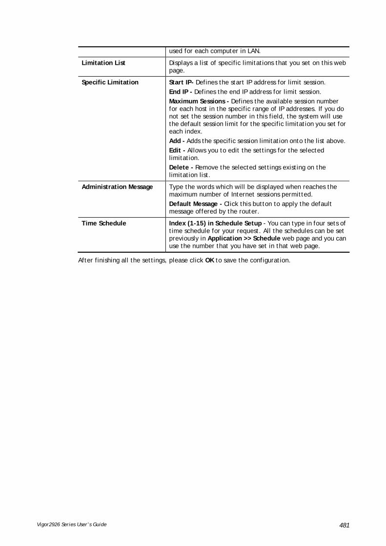
Vigor2926 Series User’s Guide 481
used for each computer in LAN.
Limitation List Displays a list of specific limitations that you set on this web page.
Specific Limitation Start IP- Defines the start IP address for limit session.
End IP - Defines the end IP address for limit session.
Maximum Sessions - Defines the available session number for each host in the specific range of IP addresses. If you do not set the session number in this field, the system will use the default session limit for the specific limitation you set for each index.
Add - Adds the specific session limitation onto the list above.
Edit - Allows you to edit the settings for the selected limitation.
Delete - Remove the selected settings existing on the limitation list.
Administration Message Type the words which will be displayed when reaches the maximum number of Internet sessions permitted.
Default Message - Click this button to apply the default message offered by the router.
Time Schedule Index (1-15) in Schedule Setup - You can type in four sets of time schedule for your request. All the schedules can be set previously in Application >> Schedule web page and you can use the number that you have set in that web page.
After finishing all the settings, please click OK to save the configuration.

Vigor2926 Series User’s Guide 482
VVIIII--22--22 BBaannddwwiiddtthh LLiimmiitt
In the Bandwidth Management menu, click Bandwidth Limit to open the web page.
To activate the function of limit bandwidth, simply click Enable and set the default upstream and downstream limit.
Available settings are explained as follows:
Item Description
Enable Click this button to activate the function of limit bandwidth.
IP Routed Subnet – Check this box to apply the bandwidth limit to the second subnet specified in LAN>>General Setup. It is available for IPv4 settings only.
Default TX limit - Define the default speed of the upstream for each computer in LAN.
Default RX limit - Define the default speed of the downstream for each computer in LAN.
Disable Click this button to close the function of limit bandwidth.
Limitation List Display a list of specific limitations that you set on this web page.

Vigor2926 Series User’s Guide 483
Specific Limitation IP – All the IPs within the range defined will be restricted by bandwidth limit defined by TX Limit and RX Limit below.
Start IP - Define the start IP address for limit bandwidth.
End IP - Define the end IP address for limit bandwidth.
Object – All the IPs specified by the selected IP object or IP group will be restricted by bandwith limit defined by TX Limit and RX Limit below.
IP Group – Specify an IP group by using the drop down list.
IP Object - Specify an IP object by using the drop down list.
Each / Shared - Select Each to make each IP within the range of Start IP and End IP having the same speed defined in TX limit and RX limit fields; select Shared to make all the IPs within the range of Start IP and End IP share the speed defined in TX limit and RX limit fields.
TX limit - Define the limitation for the speed of the upstream. If you do not set the limit in this field, the system will use the default speed for the specific limitation you set for each index.
RX limit - Define the limitation for the speed of the downstream. If you do not set the limit in this field, the system will use the default speed for the specific limitation you set for each index.
Add - Add the specific speed limitation onto the list above.
Edit - Allow you to edit the settings for the selected limitation.
Delete - Remove the selected settings existing on the limitation list.
Allow auto adjustment to assign available …
Check this box to make the best utilization of available bandwidth.
Smart Bandwidth Limit Check this box to have the bandwidth limit determined by the system automatically.
TX limit - Define the limitation for the speed of the upstream. If you do not set the limit in this field, the system will use the default speed for the specific limitation you set for each index.
RX limit - Define the limitation for the speed of the downstream. If you do not set the limit in this field, the system will use the default speed for the specific limitation you set for each index.
Time Schedule Index (1-15) in Schedule Setup - You can type in four sets of time schedule for your request. All the schedules can be set previously in Application >> Schedule web page and you can use the number that you have set in that web page.

Vigor2926 Series User’s Guide 484
VVIIII--22--33 QQuuaalliittyy ooff SSeerrvviiccee
In the Bandwidth Management menu, click Quality of Service to open the web page.
Available settings are explained as follows:
Item Description
General Setup Index – Display the WAN/LTE interface number that you can edit.
Status – Display if the WAN interface is available for such function or not.
Bandwidth – Display the inbound and outbound bandwidth setting for the WAN interface.
Direction – Display which direction that such function will influence.
Class 1/Class2/Class 3/Others – Display the bandwidth percentage for each class.
UDP Bandwidth Control –Display the UDP bandwidth control is enabled or not.
Online Statistics –Display an online statistics for quality of service for your reference.
Setup – Allow to configure general QoS setting for WAN interface.
Class Rule Index – Display the class number that you can edit.
Name – Display the name of the class.
Rule – Allow to configure detailed settings for the selected Class.
Service Type – Allow to configure detailed settings for the service type.
Enable the First Priority for VoIP SIP/RTP
When this feature is enabled, the VoIP SIP/UDP packets will be sent with highest priority.
SIP UDP Port – Set a port number used for SIP.

Vigor2926 Series User’s Guide 485
This page displays the QoS settings result of the WAN interface. Click the Setup link to access into next page for the general setup of WAN interface. As to class rule, simply click the Edit link to access into next for configuration.
You can configure general setup for the WAN interface, edit the Class Rule, and edit the Service Type for the Class Rule for your request.
OOnnlliinnee SSttaattiissttiiccss
Display an online statistics for quality of service for your reference. This feature is available only when the Quality of Service for WAN interface is enabled.
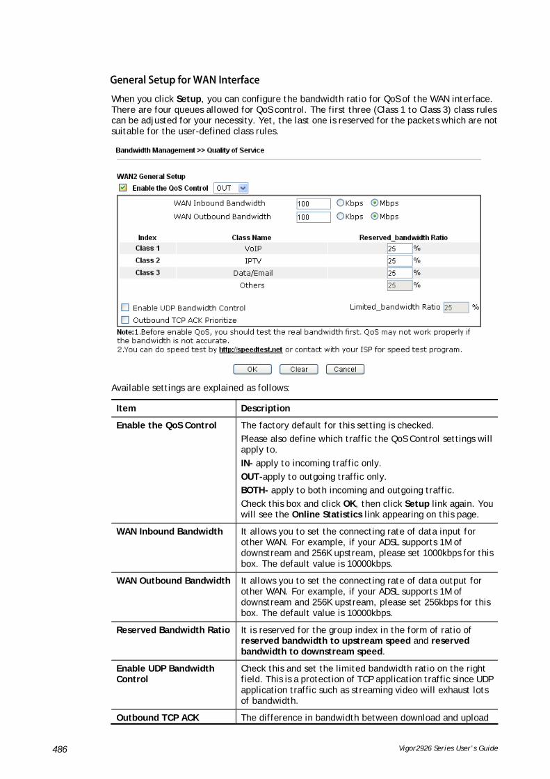
Vigor2926 Series User’s Guide 486
GGeenneerraall SSeettuupp ffoorr WWAANN IInntteerrffaaccee
When you click Setup, you can configure the bandwidth ratio for QoS of the WAN interface. There are four queues allowed for QoS control. The first three (Class 1 to Class 3) class rules can be adjusted for your necessity. Yet, the last one is reserved for the packets which are not suitable for the user-defined class rules.
Available settings are explained as follows:
Item Description
Enable the QoS Control The factory default for this setting is checked.
Please also define which traffic the QoS Control settings will apply to.
IN- apply to incoming traffic only.
OUT-apply to outgoing traffic only.
BOTH- apply to both incoming and outgoing traffic.
Check this box and click OK, then click Setup link again. You will see the Online Statistics link appearing on this page.
WAN Inbound Bandwidth It allows you to set the connecting rate of data input for other WAN. For example, if your ADSL supports 1M of downstream and 256K upstream, please set 1000kbps for this box. The default value is 10000kbps.
WAN Outbound Bandwidth It allows you to set the connecting rate of data output for other WAN. For example, if your ADSL supports 1M of downstream and 256K upstream, please set 256kbps for this box. The default value is 10000kbps.
Reserved Bandwidth Ratio It is reserved for the group index in the form of ratio of reserved bandwidth to upstream speed and reserved bandwidth to downstream speed.
Enable UDP Bandwidth Control
Check this and set the limited bandwidth ratio on the right field. This is a protection of TCP application traffic since UDP application traffic such as streaming video will exhaust lots of bandwidth.
Outbound TCP ACK The difference in bandwidth between download and upload

Vigor2926 Series User’s Guide 487
Prioritize are great in ADSL2+ environment. For the download speed might be impacted by the uploading TCP ACK, you can check this box to push ACK of upload faster to speed the network traffic.
Limited_bandwidth Ratio The ratio typed here is reserved for limited bandwidth of UDP application.
Info
The rate of outbound/inbound must be smaller than the real bandwidth to ensure correct calculation of QoS. It is suggested to set the bandwidth value for inbound/outbound as 80% - 85% of physical network speed provided by ISP to maximize the QoS performance.
EEddiitt tthhee CCllaassss RRuullee ffoorr QQooSS
1. The first three (Class 1 to Class 3) class rules can be adjusted for your necessity. To add, edit or delete the class rule, please click the Edit link of that one.
2. After you click the Edit link, you will see the following page. Now you can define the name for that Class. In this case, “Test” is used as the name of Class Index #1.
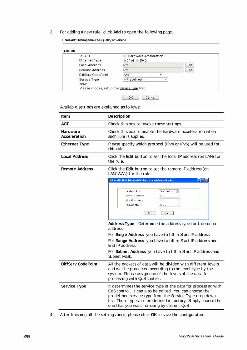
Vigor2926 Series User’s Guide 488
3. For adding a new rule, click Add to open the following page.
Available settings are explained as follows:
Item Description
ACT Check this box to invoke these settings.
Hardware Acceleration
Check this box to enable the hardware acceleration when such rule is applied.
Ethernet Type Please specify which protocol (IPv4 or IPv6) will be used for this rule.
Local Address Click the Edit button to set the local IP address (on LAN) for the rule.
Remote Address Click the Edit button to set the remote IP address (on LAN/WAN) for the rule.
Address Type – Determine the address type for the source address.
For Single Address, you have to fill in Start IP address.
For Range Address, you have to fill in Start IP address and End IP address.
For Subnet Address, you have to fill in Start IP address and Subnet Mask.
DiffServ CodePoint All the packets of data will be divided with different levels and will be processed according to the level type by the system. Please assign one of the levels of the data for processing with QoS control.
Service Type It determines the service type of the data for processing with QoS control. It can also be edited. You can choose the predefined service type from the Service Type drop down list. Those types are predefined in factory. Simply choose the one that you want for using by current QoS.
4. After finishing all the settings here, please click OK to save the configuration.

Vigor2926 Series User’s Guide 489
By the way, you can set up to 20 rules for one Class. If you want to edit an existed rule, please select the radio button of that one and click Edit to open the rule edit page for modification.
EEddiitt tthhee SSeerrvviiccee TTyyppee ffoorr CCllaassss RRuullee
1. To add a new service type, edit or delete an existed service type, please click the Edit link under Service Type field.
2. After you click the Edit link, you will see the following page.

Vigor2926 Series User’s Guide 490
3. For adding a new service type, click Add to open the following page.
Available settings are explained as follows:
Item Description
Service Name Type in a new service for your request. The maximum length of the name you can set is 11 characters.
Service Type Choose the type (TCP, UDP or TCP/UDP or other) for the new service.
Port Configuration Type - Click Single or Range as the Type. If you select Range, you have to type in the starting port number and the end porting number on the boxes below.
Port Number – Type in the starting port number and the end porting number here if you choose Range as the type.
5. After finishing all the settings here, please click OK to save the configuration.
By the way, you can set up to 10 service types. If you want to edit/delete an existed service type, please select the radio button of that one and click Edit for modification.
RReettaagg tthhee PPaacckkeettss ffoorr IIddeennttiiffiiccaattiioonn
Packets coming from LAN IP can be retagged through QoS setting. When the packets sent out through WAN interface, all of them will be tagged with certain header and that will be easily to be identified by server on ISP.
For example, in the following illustration, the VoIP packets in LAN go into Vigor router without any header. However, when they go forward to the Server on ISP through Vigor router, all of the packets are tagged with AF (configured in Bandwidth >>QoS>>Class) automatically.

Vigor2926 Series User’s Guide 491
VVIIII--22--44 AAPPPP QQooSS
The QoS function is used to do bandwidth management for the services with certain IP or port number. However, there is no effect of bandwidth management on the service such as VNC or PPTV without fixed IP or port number.
APP QoS employs the function of APP Enforcement to detect the types of software in application layer. By combining the function of QoS (adjustment on Inbound/Outbond bandwidth and bandwidth ratio), Vigor router can perform the bandwidth management for the protocols, streaming, remote control, web HD and so on.
Click Bandwidth Management>>APP QoS to open the following page.
Available settings are explained as follows:
Item Description
Enable/Disable Click Enable to activate APP QoS function.
Click Disable to deactivate APP QoS function.
Traceable The protocol listed below is traceable by Vigor router.
Each tab offers different types of protocols to fit your

Vigor2926 Series User’s Guide 492
request.
Untraceable The protocol listed below is not easy to be traced by Vigor router.
Each tab offers different types of protocols to fit your request.
Select All Click it to select all of the protocols.
Clear All Click it to de-select all of the protocols.
Apply to all Choose one of the actions from the drop down list. It is prepared for applying to all protocols.
Apply – Click it to make the selected action be applied all of the selected protocols immediately.
Action There are many protocols which can be specified with different QoS Class.

Vigor2926 Series User’s Guide 493
AApppplliiccaattiioonn NNootteess
AA--11 HHooww ttoo OOppttiimmiizzee tthhee BBaannddwwiiddtthh tthhrroouugghh QQooSS TTeecchhnnoollooggyy
Have you ever gotten any problems in uploading/downloading files (Voice, video or email/data only) with the narrow/districted bandwidth you may share from the common Internet connection line? The advanced bandwidth management technology-QoS (Quality of Service) helps you to well allocate the bandwidth upon your demand of Voice, Video, or Data transferring. Let's see how to get the optimum bandwidth per your request by using DrayTek Vigor router as below.
Scenario: The Internet connection you got from ISP line is 2MB/512Kb. There are VoIP telephony network, IPTV set top box and data server at your home. Assume you want to allocate 30% of the bandwidth you got to VoIP demand, 50% for IPTV, 15% for mail/data, 5% for others. Let's see how easily it is to do the setting as below:
1. Open Bandwidth Management>> Quality of Service.
2. You will get the following page. Click the Edit link for Class 1.
3. In the following page, type a name (e.g., VoIP) for such class and click Add.
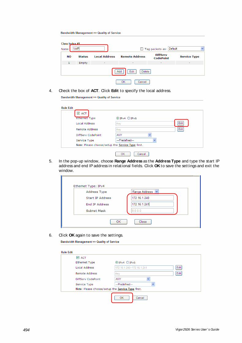
Vigor2926 Series User’s Guide 494
4. Check the box of ACT. Click Edit to specify the local address.
5. In the pop-up window, choose Range Address as the Address Type and type the start IP address and end IP address in relational fields. Click OK to save the settings and exit the window.
6. Click OK again to save the settings.

Vigor2926 Series User’s Guide 495
7. The class rule for VoIP has been set. Click OK to return to previous page.
8. Do the same steps to add class rules for IPTV and Data/Email with IP addresses as shown below.
and

Vigor2926 Series User’s Guide 496
9. Assuming you get 2MB/512Kb Internet line. You can click the Setup link of WAN1 to set up the bandwidth for different groups among VoIP, IPTV and Data/Email.
10. In the Setup page, check the box of Enable the QoS Control. Type 30, 50 and 15 in the boxes for VoIP, IPTV and Data/Email respectively. Check the box of Enable UDP Bandwidth Control.
11. Click OK to save the settings. The class rules for WAN1 are defined as shown below.
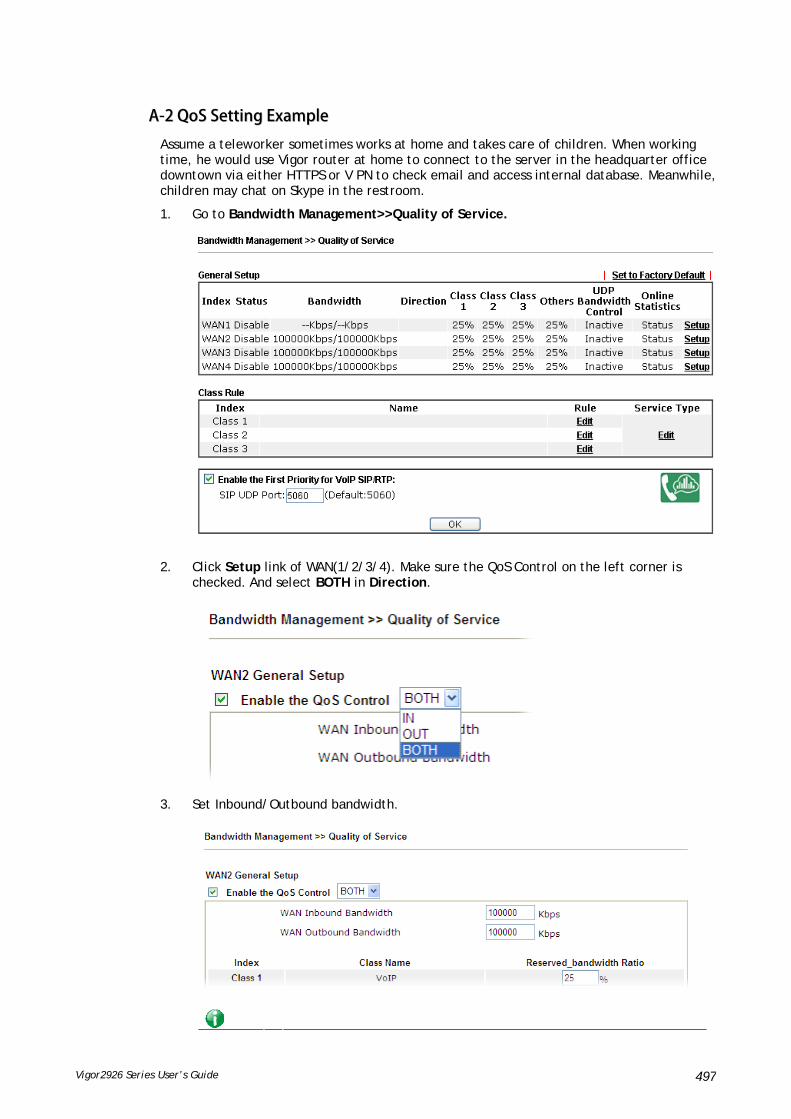
Vigor2926 Series User’s Guide 497
AA--22 QQooSS SSeettttiinngg EExxaammppllee
Assume a teleworker sometimes works at home and takes care of children. When working time, he would use Vigor router at home to connect to the server in the headquarter office downtown via either HTTPS or V PN to check email and access internal database. Meanwhile, children may chat on Skype in the restroom.
1. Go to Bandwidth Management>>Quality of Service.
2. Click Setup link of WAN(1/2/3/4). Make sure the QoS Control on the left corner is checked. And select BOTH in Direction.
3. Set Inbound/Outbound bandwidth.
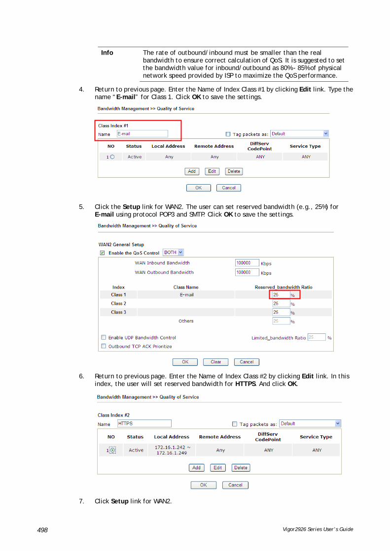
Vigor2926 Series User’s Guide 498
Info The rate of outbound/inbound must be smaller than the real bandwidth to ensure correct calculation of QoS. It is suggested to set the bandwidth value for inbound/outbound as 80% - 85% of physical network speed provided by ISP to maximize the QoS performance.
4. Return to previous page. Enter the Name of Index Class #1 by clicking Edit link. Type the name “E-mail” for Class 1. Click OK to save the settings.
5. Click the Setup link for WAN2. The user can set reserved bandwidth (e.g., 25%) for E-mail using protocol POP3 and SMTP. Click OK to save the settings.
6. Return to previous page. Enter the Name of Index Class #2 by clicking Edit link. In this index, the user will set reserved bandwidth for HTTPS. And click OK.
7. Click Setup link for WAN2.

Vigor2926 Series User’s Guide 499
8. Check Enable UDP Bandwidth Control on the bottom to prevent enormous UDP traffic influence other application. Click OK.
9. If the worker has connected to the headquarter using host to host VPN tunnel. (Please refer to Chapter 3 VPN for detail instruction), he may set up an index for it. Enter the

Vigor2926 Series User’s Guide 500
Class Name of Index 3. In this index, he will set reserved bandwidth for 1 VPN tunnel.
10. Click Edit for Class 3 to open a new window. In this index, the user will set reserved bandwidth for VPN.
11. Click Add to open the following window. Check the ACT box, first.

Vigor2926 Series User’s Guide 501
12. Then click Edit of Local Address to set a worker’s subnet address. Click Edit of Remote Address to set headquarter’s IP address. Leave other fields and click OK.

Vigor2926 Series User’s Guide 502
VVIIII--33 UUsseerr MMaannaaggeemmeenntt
User Management is a security feature which disallows any IP traffic (except DHCP-related packets) from a particular host until that host has correctly supplied a valid username and password. Instead of managing with IP address/MAC address, User Management function manages hosts with user account. Network administrator can give different firewall policies or rules for different hosts with different User Management accounts. This is more flexible and convenient for network management. Not only offering the basic checking for Internet access, User Management also provides additional firewall rules, e.g. CSM checking for protecting hosts.
Info
Filter rules configured under Firewall usually are applied to the host (the one that the router installed) only. With user management, the rules can be applied to every user connected to the router with customized profiles.

Vigor2926 Series User’s Guide 503
WWeebb UUsseerr IInntteerrffaaccee
VVIIII--33--11 GGeenneerraall SSeettuupp
General Setup can determine the standard (rule-based or user-based) for the users controlled by User Management. The mode (standard) selected here will influence the contents of the filter rule(s) applied to every user.
Available settings are explained as follows:
Item Description
Mode There are two modes offered here for you to choose. Each mode will bring different filtering effect to the users involved.
User-Based - If you choose such mode, the router will apply the filter rules configured in User Management>>User Profile to the users.
Rule-Based –If you choose such mode, the router will apply

Vigor2926 Series User’s Guide 504
the filter rules configured in Firewall>>General Setup and Filter Rule to the users.
Authentication page Web Authentication - Choose the protocol for web authentication.
Login Page Logo – A logo which can be used as an identification of enterprise can be uploaded and displayed on the login page. You can use the default one, blank page or upload other image files (the size no mare than 524 × 352 pixel) to have an image of enterprise or have the effect of advertisement.
Login Page Greeting - Such link allows you to access into the setting page for login greeting. For detailed information, refer to System Maintenance>>Login Page Greeting.
Display IP Address on … – Check the box to display the IP address of the client on the tracking window.
Landing Page Type the information to be displayed on the first web page when the LAN user accessing into Internet via such router.
After finishing all the settings here, please click OK to save the configuration.
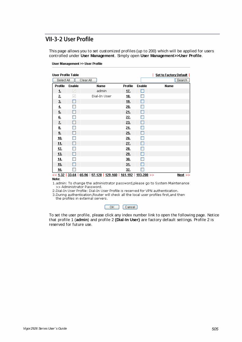
Vigor2926 Series User’s Guide 505
VVIIII--33--22 UUsseerr PPrrooffiillee
This page allows you to set customized profiles (up to 200) which will be applied for users controlled under User Management. Simply open User Management>>User Profile.
To set the user profile, please click any index number link to open the following page. Notice that profile 1 (admin) and profile 2 (Dial-In User) are factory default settings. Profile 2 is reserved for future use.

Vigor2926 Series User’s Guide 506
Available settings are explained as follows:
Item Description
Enable this account Check this box to enable such user profile.
User Name Type a name for such user profile (e.g., LAN_User_Group_1, WLAN_User_Group_A, WLAN_User_Group_B, etc). When a user tries to access Internet through this router, an authentication step must be performed first. The user has to type the User Name specified here to pass the authentication. When the user passes the authentication, he/she can access Internet via this router. However the accessing operation will be restricted with the conditions configured in this user profile.
The maximum length of the name you can set is 24 characters.
Password Type a password for such profile (e.g., lug123, wug123,wug456, etc). When a user tries to access Internet through this router, an authentication step must be performed first. The user has to type the password specified here to pass the authentication. When the user passes the authentication, he/she can access Internet via this router

Vigor2926 Series User’s Guide 507
with the limitation configured in this user profile.
The maximum length of the password you can set is 24 characters.
Confirm Password Type the password again for confirmation.
Idle Timeout If the user is idle over the limitation of the timer, the network connection will be stopped for such user. By default, the Idle Timeout is set to 10 minutes.
Max User Login Such profile can be used by many users. You can set the limitation for the number of users accessing Internet with the conditions of such profile. The default setting is 0 which means no limitation in the number of users.
Policy It is available only when User-Based mode selected in User Management>>General Setup.
Default – If you choose such item, the filter rules pre-configured in Firewall can be adopted for such user profile.
Create New Policy – If you choose such item, the following page will be popped up for you to define another filter rule as a new policy.
For the detailed configuration, simply refer to Firewall>>Filter Rule. The firewall filter rules that are not selected in Firewall>>General>>Default rule can be available for use in User Management>>User Profile.
External Service Authentication
The router will authenticate the dial-in user by itself or by external service such as LDAP server or Radius server or TACACS+ server. If LDAP, Radius or TACACS+ is selected here, it is not necessary to configure the password setting above.
Log Time of login/log out, block/unblock for the user(s) can be sent to and displayed in Syslog. Please choose any one of the log items to take down relational records for the user(s).

Vigor2926 Series User’s Guide 508
Pop Browser Tracking Window
If such function is enabled, a pop up window will be displayed on the screen with time remaining for connection if Idle Timeout is set. However, the system will update the time periodically to keep the connection always on. Thus, Idle Timeout will not interrupt the network connection.
Authentication Any user (from LAN side or WLAN side) tries to connect to Internet via Vigor router must be authenticated by the router first. There are three ways offered by the router for the user to choose for authentication.
Web – If it is selected, the user can type the URL of the router from any browser. Then, a login window will be popped up and ask the user to type the user name and password for authentication. If succeed, a Welcome Message (configured in User Management >> General Setup) will be displayed. After authentication, the destination URL (if requested by the user) will be guided automatically by the router.
Alert Tool – If it is selected, the user can open Alert Tool and type the user name and password for authentication. A window with remaining time of connection for such user will be displayed. Next, the user can access Internet through any browser on Windows. Note that Alert Tool can be downloaded from DrayTek web site.
Telnet – If it is selected, the user can use Telnet command to perform the authentication job.
Landing Page When a user tries to access into the web user interface of Vigor router series with the user name and password specified in this profile, he/she will be lead into the web page configured in Landing Page field in User Management>>General Setup.
Check this box to enable such function.
Login Permission Schedule (Index: 1-15)
You can type in four sets of time schedule for your request. All the schedules can be set previously in Application >> Schedule web page and you can use the number that you have set in that web page.
Enable Time Quota Time quota means the total connection time allowed by the router for the user with such profile. Check the box to enable the function of time quota. The first box displays the remaining time of the network connection. The second box allows to type the number of time (unit is minute) which is available for the user (using such profile) to access Internet.
– Click this box to set and increase the time quota for such profile.
– Click this box to decrease the time quota for such profile.
Note: A dialog will be popped up to notify how many time remained when a user accesses into Internet through Vigor router successfully.

Vigor2926 Series User’s Guide 509
When the time is up, all the connection jobs including network, IM, social media, facebook, and etc. will be terminated.
Enable Data Quota Data Quota means the total amount for data transmission allowed for the user. The unit is MB/GB.
– Click this box to set and increase the data quota for such profile.
– Click this box to decrease the data quota for such profile.
Reset quota automatically Set default time quota and data quota for such profile. When the scheduling time is up, the router will use the default quota settings automatically.
Enable – Check it to use the default setting for time quota and data quota.
Default Time Quota – Type the value for the time manually.
Default Data Quota – Type the value for the data manually.
Internal RADIUS Check the box to enable security authenticated via RADIUS server.
Local 802.1X Check the box to enable security authenticated via 802.1X server.
After finishing all the settings here, please click OK to save the configuration.

Vigor2926 Series User’s Guide 510
VVIIII--33--33 UUsseerr GGrroouupp
This page allows you to bind several user profiles into one group. These groups will be used in Firewall>>General Setup as part of filter rules.
Please click any index number link to open the following page.
Available settings are explained as follows:
Item Description
Name Type a name for this user group.
Available User Objects You can gather user profiles (objects) from User Profile page within one user group. All the available user objects that you have created will be shown in this box. Notice that user object, Admin and Dial-In User are factory settings. User defined profiles will be numbered with 3, 4, 5 and so on.

Vigor2926 Series User’s Guide 511
Selected Keyword Objects Click button to add the selected user objects in this box.
After finishing all the settings here, please click OK to save the configuration.
VVIIII--33--44 UUsseerr OOnnlliinnee SSttaattuuss
This page displays the user(s) connected to the router and refreshes the connection status in an interval of several seconds.
Available settings are explained as follows:
Item Description
Refresh Seconds Use the drop down list to choose the time interval of refreshing data flow that will be done by the system automatically.
Refresh Click this link to refresh this page manually.
Index Display the number of the data flow.
User Display the users which connect to Vigor router currently. You can click the link under the username to open the user profile setting page for that user.
IP Address Display the IP address of the device.
Profile Display the authority of the account.
Last Login Time Display the login time that such user connects to the router last time.
Expired Time Display the expired time of the network connection for the user.

Vigor2926 Series User’s Guide 512
Data Quota Display the quota for data transmission.
Idle Time Display the idle timeout setting for such profile.
Action Block - can avoid specified user accessing into Internet.
Unblock – allow the user to access into Internet.
Logout – the user will be logged out forcefully.

Vigor2926 Series User’s Guide 513
AApppplliiccaattiioonn NNootteess
AA--11 HHooww ttoo aauutthheennttiiccaattee cclliieennttss vviiaa UUsseerr MMaannaaggeemmeenntt
Before using the function of User Management, please make sure User-Based has been selected as the Mode in the User Management>>General Setup page.
With User Management authentication function, before a valid username and password have been correctly supplied, a particular client will not be allowed to access Internet through the router. There are three ways for authentication: Web, Telnet and Alert Tool.
AAuutthheennttiiccaattiioonn vviiaa WWeebb

Vigor2926 Series User’s Guide 514
If a LAN client who hasn’t passed the authentication opens an external web site in his browser, he will be redirected to the router’s Web authentication interface first. Then, the client is trying to access http://www.draytek.com and but brought to the Vigor router. Since this is an SSL connection, some web browsers will display warning messages.
With Microsoft Internet Explorer, you may get the following warning message. Please press Continue to this website (not recommended).
With Mozilla Firefox, you may get the following warning message. Select I Understand the Risks.

Vigor2926 Series User’s Guide 515
With Chrome browser, you may get the following warning. Click Proceed anyway.
After that, the web authentication window will appear. Input the user name and the password for your account (defined in User Management) and click Login.
If the authentication is successful, the client will be redirected to the original web site that he tried to access. In this example, it is http://www.draytek.com . Furthermore, you will get a popped up window as the following. Then you can access the Internet.

Vigor2926 Series User’s Guide 516
Note, if you block the web browser to pop up any window, you will not see such window.
If the authentication is failed, you will get the error message, The username or password you entered is incorrect. Please login again.
In above description, you access an external web site to trigger the authentication. You may also directly access the router’s Web UI for authentication. Both HTTP and HTTPS are supported, for example http://192.168.1.1 or https://192.168.1.1 . Replace 192.168.1.1 with your router’s real IP address, and add the port number if the default management port has been modified.
If the authentication is successful, you will get the Welcome Message that is set in the User Management >> General Setup page.

Vigor2926 Series User’s Guide 517
With the default setup <body stats=1><script language='javascript'> window.location='http://www.draytek.com'</script></body>, you will be redirected to http://www.draytek.com . You may change it if you want. For example, you will get the following welcome message if you enter Login Successful in the Welcome Message table.
Also you will get a Tracking Window if you don’t block the pop-up window.
Don’t setup a user profile in User Management and a VPN Remote Dial-in user profile with the same Username. Otherwise, you may get unexpected result. It is because the
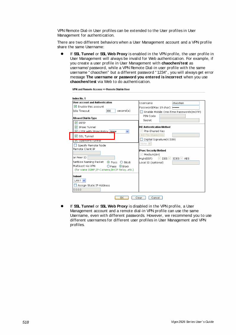
Vigor2926 Series User’s Guide 518
VPN Remote Dial-in User profiles can be extended to the User profiles in User Management for authentication.
There are two different behaviors when a User Management account and a VPN profile share the same Username:
If SSL Tunnel or SSL Web Proxy is enabled in the VPN profile, the user profile in User Management will always be invalid for Web authentication. For example, if you create a user profile in User Management with chaochen/test as username/password, while a VPN Remote Dial-in user profile with the same username “chaochen” but a different password “1234”, you will always get error message The username or password you entered is incorrect when you use chaochen/test via Web to do authentication.
If SSL Tunnel or SSL Web Proxy is disabled in the VPN profile, a User Management account and a remote dial-in VPN profile can use the same Username, even with different passwords. However, we recommend you to use different usernames for different user profiles in User Management and VPN profiles.
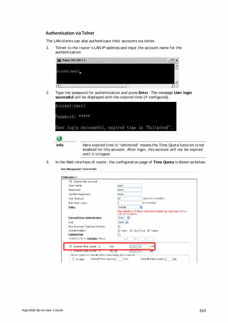
Vigor2926 Series User’s Guide 519
AAuutthheennttiiccaattiioonn vviiaa TTeellnneett
The LAN clients can also authenticate their accounts via telnet.
1. Telnet to the router’s LAN IP address and input the account name for the authentication:
2. Type the password for authentication and press Enter. The message User login successful will be displayed with the expired time (if configured).
Info
Here expired time is “Unlimited” means the Time Quota function is not enabled for this account. After login, this account will not be expired until it is logout.
3. In the Web interface of router, the configuration page of Time Quota is shown as below.

Vigor2926 Series User’s Guide 520
4. If the Time Quota is set with “0” minute, you will get the following message which means this account has no time quota.
If the Time Quota is enabled and time is not 0 minute,
You will get the following message. The expired time is shown after you login.
After you run out the available time, you can’t use this account any more until the administrator manually adds additional time for you.

Vigor2926 Series User’s Guide 521
AAuutthheennttiiccaattiioonn vviiaa VViiggoorrPPrroo AAlleerrtt NNoottiiccee TTooooll
Authentication via Web or Telnet is convenient for users; however, it has some limitations. The most advantage with VigorPro Alert Notice Tool to operate the authentication is the ability to do auto login. If the timeout value set on the router for the user account has been reached, the router will stop the client computer from accessing the Internet until it does an authentication again. Authentication via VigorPro Alert Notice Tool allows user to setup the re-authentication interval so that the utility will send authentication requests periodically. This will keep the client hosts from having to manually authenticate again and again.
The configuration of the VigorPro Alert Notice Tool is as follows:
1. Click Authenticate Now!! to start the authentication immediately.
2. You may get the VigorPro Alert Notice Tool from the following link: http://www.draytek.com/user/SupportDLUtility.php
Info 1
Any modification to the Firewall policy will break down the connections of all current users. They all have to authenticate again for Internet access.
Info 2 The administrator may check the current users from User Online Status page.

Vigor2926 Series User’s Guide 522
AA--22 HHooww ttoo uussee LLaannddiinngg PPaaggee FFeeaattuurree
Landing Page is a special feature configured under User Management. It can specify the message, content to be seen or specify which website to be accessed into when users try to access into the Internet by passing the authentication. Here, we take Vigor2926 series router as an example.
EExxaammppllee 11::UUsseerrss ccaann sseeee tthhee mmeessssaaggee ffoorr llaannddiinngg ppaaggee aafftteerr llooggggiinngg iinnttoo IInntteerrnneett
ssuucccceessssffuullllyy
1. Open the web user interface of Vigor2926.
2. Open User Management -> General Setup to get the following page. In the field of Landing Page, please type the words of “Login Success”. Please note that the maximum number of characters to be typed here is 255.
3. Now you can enable the Landing Page function. Open User Management -> User Profile and click one of the index number (e.g., index number 3) links.

Vigor2926 Series User’s Guide 523
4. In the following page, check the box of Landing page and click OK to save the settings.
5. Open any browser (e.g., FireFox, Internet Explorer). The logging page will appear and asks for username and password. Please type the correct username and password.
6. Click Login. If the logging is successful, you will see the message of Login Success from the browser you use.

Vigor2926 Series User’s Guide 524
EExxaammppllee 22::TThhee ssyysstteemm wwiillll ccoonnnneecctt ttoo hhttttpp::////wwwwww..ddrraayytteekk..ccoomm aauuttoommaattiiccaallllyy aafftteerr
llooggggiinngg iinnttoo IInntteerrnneett ssuucccceessssffuullllyy
1. In the field of Landing Page, please type the words as below:
“ <body stats=1><script language='javascript'>
window.location='http://www.draytek.com'</script></body>”
2. Next, enable the Landing Page function. Open User Management -> User Profile and click one of the index number (e.g., index number 3) links.
3. In the following page, check the box of Landing page and click OK to save the settings.

Vigor2926 Series User’s Guide 525
4. Open any browser (e.g., FireFox, Internet Explorer). The logging page will appear and asks for username and password. Please type the correct username and password.
5. Click Login. If the logging is successful, you will be directed into the website of www.draytek.com.
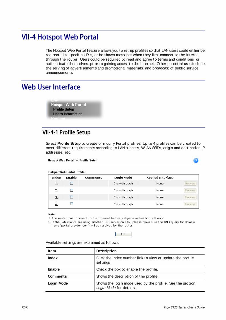
Vigor2926 Series User’s Guide 526
VVIIII--44 HHoottssppoott WWeebb PPoorrttaall
The Hotspot Web Portal feature allows you to set up profiles so that LAN users could either be redirected to specific URLs, or be shown messages when they first connect to the Internet through the router. Users could be required to read and agree to terms and conditions, or authenticate themselves, prior to gaining access to the Internet. Other potential uses include the serving of advertisements and promotional materials, and broadcast of public service announcements.
WWeebb UUsseerr IInntteerrffaaccee
VVIIII--44--11 PPrrooffiillee SSeettuupp
Select Profile Setup to create or modify Portal profiles. Up to 4 profiles can be created to meet different requirements according to LAN subnets, WLAN SSIDs, origin and destination IP addresses, etc.
Available settings are explained as follows:
Item Description
Index Click the index number link to view or update the profile settings.
Enable Check the box to enable the profile.
Comments Shows the description of the profile.
Login Mode Shows the login mode used by the profile. See the section Login Mode for details.

Vigor2926 Series User’s Guide 527
Applied Interface Shows the interfaces to which this profile applies.
Preview Click this button to preview the Hotspot Web Portal page that will be displayed to users.
VVIIII--44--11--11 LLooggiinn MMooddeess
There are five login modes to choose from for authenticating network clients: Skip Login, Click Through, Social Login, PIN Login, and Social or PIN Login. Each login mode will present a different web page to users when they connect to the network.
SSkkiipp LLooggiinn
This mode does not perform any authentication. The user will be redirected to the landing page. The user can then leave the landing page to visit other websites.
CClliicckk--tthhrroouugghh
The following page will be shown to the users when they first attempt to access the Internet through the router. After clicking Accept on the page, users will be directed to the landing page and be granted access to the Internet.
SSoocciiaall LLooggiinn
The following page will appear when users attempt to access the Internet for the first time via the router. After authenticating themselves using either a Facebook or Google account, they will be directed to the landing page and be granted access to the Internet.

Vigor2926 Series User’s Guide 528
PPIINN CCooddee LLooggiinn
When users attempt to connect to the Internet for the first time, they will be prompted to enter a mobile number to receive a PIN by SMS. After they have authenticated themselves by entering the PIN, they will be redirected to the landing page, indicating that they have been granted Internet access.
SSoocciiaall oorr PPIINN LLooggiinn
This login mode presents both Social Login and PIN Code Login modes to the users, and allows them to select their preferred mode of authentication.

Vigor2926 Series User’s Guide 529
VVIIII--44--11--22 SStteeppss ffoorr CCoonnffiigguurriinngg aa WWeebb PPoorrttaall PPrrooffiillee
11.. LLooggiinn MMeetthhoodd
Click the index link (e.g., #1) of the selected profile to display the following page.
Available settings are explained as follows:
Item Description
Enable this profile Check to enable this profile.
Comments Enter a brief description to identify this profile.
Choose Login Select the desired Login Mode.

Vigor2926 Series User’s Guide 530
Method
Save and Next Click to save the configuration on this page and proceed to the next page.
Cancel Click to discard the configuration on this page and return to previous page.
If you have chosen Skip Login as the Login Mode, skip to step 4 Whitelisting below.
Otherwise, proceed to configure the login page by following steps 2 and 3.
22.. BBaacckkggrroouunndd
If you have selected a Login Mode that requires authentication, select a background for the login page.
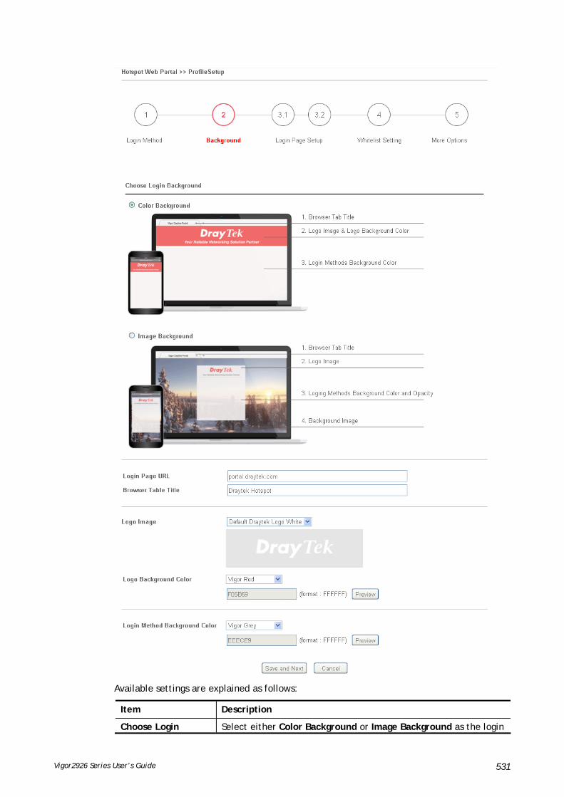
Vigor2926 Series User’s Guide 531
Available settings are explained as follows:
Item Description
Choose Login Select either Color Background or Image Background as the login

Vigor2926 Series User’s Guide 532
Background page background scheme.
Login Page URL Enter the URL for the login page.
Browser Tab Title Enter the text to be shown as the webpage title in the browser.
Logo Image The DrayTek Logo will be displayed by default. However, you can enter HTML text or upload an image to replace the default logo.
Logo Background Color
Select the background color of the logo from the predefined color list, or select Customize Color and enter the RGB values. Click Preview to preview the selected color.
Login Method Background Color
Select the background color of the login panel from the predefined color list, or select Customize Color and enter the RGB value. Click Preview to preview the selected color.
Opacity (10 ~ 100) Available when Image Background is selected. Set the opacity of the background image.
Background Image Available when Image Background is selected. Click Browse… to select an image file (.JPG or .PNG format), then click Upload to upload it to the router.
Save and Next Click to save the configuration on this page and proceed to the next page.
Cancel Click to abort the configuration process and return to the profile summary page.
If you have selected Skip Login as the Login Mode, proceed to Step 4 Whitelist Setting; otherwise, continue to Step 3 Login Page Setup.
33.. LLooggiinn PPaaggee SSeettuupp
In this step you can configure settings for the login page.
Click Through
This section describes the Login Page setup if you have selected Click Through as the Login Mode.

Vigor2926 Series User’s Guide 533
Available settings are explained as follows:
Item Description
Welcome Message Enter the text to be displayed as the welcome message.
Terms and Conditions Description
Enter the text to be displayed as the Terms and Conditions hyperlink text.
Terms and Conditions Content
Enter the text to be displayed in the Terms and Conditions pop-up window.
Accept Button Description
Enter the text to be displayed on the accept button
Accept Button Color Select the color of the accept button from the predefined color list, or select Customize Color and enter the RGB value. Click Preview to preview the selected color.
Save and Next Click to save the configuration on this page and proceed to the next page.
Cancel Click to abort the configuration process and return to the profile summary page.

Vigor2926 Series User’s Guide 534
Social Login and PIN Login
This section describes the Login Page setup step if you have selected PIN Login and/or Social Login as the Login Mode. You will see only settings that are relevant to the selected login mode(s).
Settings that are common to Facebook, Google and PIN authentication are:
Item Description
Welcome Message Enter the text to be displayed as the welcome message.
Terms and Conditions Description
Enter the text to be displayed as the Terms and Conditions hyperlink text.
Terms and Conditions Content
Enter the text to be displayed in the Terms and Conditions pop-up window.

Vigor2926 Series User’s Guide 535
If you have selected Facebook login, these settings will appear:
Item Description
Facebook Login Description
Enter the text to be displayed on the Facebook login button.
Facebook APP ID Enter a valid Facebook developer app ID.
If you do not already have an app ID, refer to section A-1 How to create a Facebook App ID for Web Portal Authentication for instructions on obtaining an APP ID.
Facebook APP Secret
Enter the secret configured for the APP ID entered above.
Refer to section A-1 How to create a Facebook App ID for Web Portal Authentication for details.
If you have selected Google login, these settings will appear:
Item Description
Google Login Description
Enter the text to be displayed on the Google login button.
Google App ID Enter a valid Google app ID.
If you do not already have an app ID, refer to section A-2 How to create a Google App ID for Web Portal Authentication for instructions on obtaining an APP ID.
Google App Secret Enter the secret configured for the APP ID entered above.
Refer to section A-2 How to create a Google APP ID for Web Portal Authentication for details.
If you have selected PIN login, these settings will appear:

Vigor2926 Series User’s Guide 536
Item Description
Hint Message Enter the text used to suggest users to choose SMS authentication.
Receiving PIN via SMS Description
Enter the text to be displayed on the button that the user clicks to receive an SMS PIN.
Receiving PIN via SMS Content
Enter the message to be sent by SMS to inform the user of the PIN. The PIN variable is specified by <PIN> within the message.
Receiving PIN via SMS Provider
Select the SMS Provider used to send PIN notifications SMS providers are configured in Objects Setting >> SMS / Mail Service Object.
Enter PIN Description
Enter message to be displayed in the PIN textbox to prompt the user to enter the PIN.
Submit Button Description
Enter the text to be displayed on the submit PIN button
Submit Button Color Select the color of the submit button from the predefined color list, or select Customize Color and enter the RGB value. Click Preview to preview the selected color.
And finally, the save and cancel buttons are always displayed.
Item Description
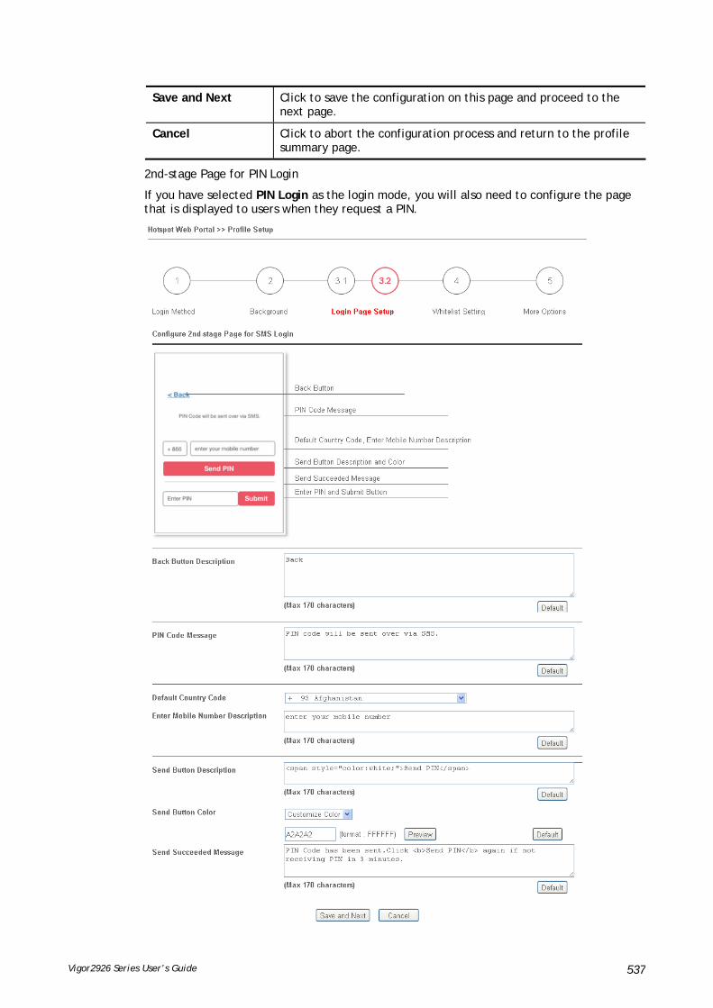
Vigor2926 Series User’s Guide 537
Save and Next Click to save the configuration on this page and proceed to the next page.
Cancel Click to abort the configuration process and return to the profile summary page.
2nd-stage Page for PIN Login
If you have selected PIN Login as the login mode, you will also need to configure the page that is displayed to users when they request a PIN.

Vigor2926 Series User’s Guide 538
Available settings are explained as follows:
Item Description
Back Button Description
Enter text for the label of the hyperlink to return to the previous page.
PIN Code Message Enter text to be displayed as the body text on the page.
Default Country Code
Select the default country code to be displayed using the dropdown menu.
Enter Mobile Number Description
Enter message to be displayed in the mobile number textbox to prompt the user to enter the mobile number.
Send Button Description
Enter the label text of the send button.
Send Button Color Select the color of the send button from the predefined color list, or select Customize Color and enter the RGB value. Click Preview to preview the selected color.
Send Succeeded Message
Enter text to be displayed to notify the user after the PIN has been sent.
Save and Next Click to save the configuration on this page and proceed to the next page.
Cancel Click to abort the configuration process and return to the profile summary page.
44.. WWhhiitteelliisstt SSeettttiinngg
In this step you can configure the whitelist settings. Users are allowed to send and receive traffic that satisfies whitelist settings.
Available settings are explained as follows:
Item Description
NAT Rules To prevent web portal settings from conflicting with NAT rules resulting in unexpected behavior, select the NAT rules that are allowed to bypass the web portal. Hosts listed in selected NAT rules can always access the Internet without being intercepted by the web portal.
Vigor2926 Series User’s Guide 539
Dest Domain Enter up to 30 destination domains that are allowed to be accessed.
Dest IP Enter up to 30 destination IP addresses that are allowed to be accessed.
Dest Port Enter up to 30 destination protocols and ports that are allowed through the router.
Source IP Enter up to 30 source IP addresses that are allowed through the router.
Save and Next Click to save the configuration on this page and proceed to the next page.
Cancel Click to abort the configuration process and return to the profile summary page.
55.. MMoorree OOppttiioonnss
In this step you can configure advanced options for the Hotspot Web Portal.

Vigor2926 Series User’s Guide 540
Available settings are explained as follows:
Item Description
Expired Time After Activation
Enter the time duration that users are allowed to have Internet access after logging in.
HTTPS Redirection If this option is selected, unauthenticated clients accessing HTTPS websites will be redirected to the login page, but the browser may alert the user of certificate errors. If this option is not selected, attempts to access to HTTPS website will time out without

Vigor2926 Series User’s Guide 541
redirection.
Captive Portal Detection
If this option is selected, the web portal page is triggered automatically when an unauthenticated client tries to access the Internet. This function is not available when the Login Mode is Social Login, as the web portal page may not be shown correctly due to the limitations of the operating system’s built-in Captive Portal Detection.
Landing Page After Authentication
Specifies the webpage that will be displayed after the user has successfully authenticated.
Fixed URL – The user will be redirected to the specified URL. This could be used for displaying advertisements to users, such as guests requesting wireless Internet access in a hotel.
User Requested URL – The user will be redirected to the URL they initially requested.
Bulletin Message –The message configured here will be briefly shown for a few seconds to the user.
Default Message – This button is enabled when Bulletin Message is selected. Click to load the default text into the bulletin message textbox.
Applied Interfaces Subnet – The current Hotspot Web Portal profile will be in effect for the selected subnets.
WLAN – The current Hotspot Web Portal profile will be in effect for the selected WLAN SSIDs.
Cancel Click to abort the configuration process and return to the profile summary page.
Finish Click to complete the configuration.
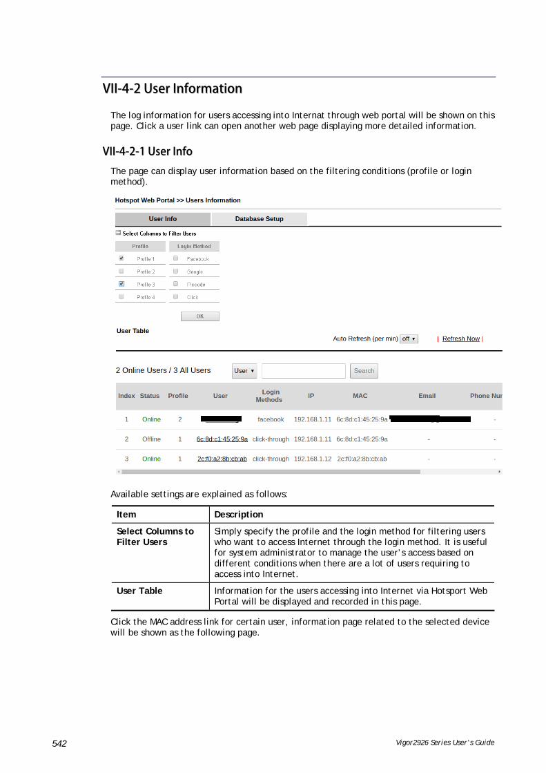
Vigor2926 Series User’s Guide 542
VVIIII--44--22 UUsseerr IInnffoorrmmaattiioonn
The log information for users accessing into Internat through web portal will be shown on this page. Click a user link can open another web page displaying more detailed information.
VVIIII--44--22--11 UUsseerr IInnffoo
The page can display user information based on the filtering conditions (profile or login method).
Available settings are explained as follows:
Item Description
Select Columns to Filter Users
Simply specify the profile and the login method for filtering users who want to access Internet through the login method. It is useful for system administrator to manage the user’s access based on different conditions when there are a lot of users requiring to access into Internet.
User Table Information for the users accessing into Internet via Hotsport Web Portal will be displayed and recorded in this page.
Click the MAC address link for certain user, information page related to the selected device will be shown as the following page.

Vigor2926 Series User’s Guide 543
Basic information for the device will be shown on the field of Login Info; online/offline status for the device can be send on the field of Devices; and historical information for device login will be shown on the field of Login History. In addition, to forcefully log out a selected device, simply check the one you want to logout and click the Log Out Device button.

Vigor2926 Series User’s Guide 544
VVIIII--44--22--22 DDaattaabbaassee SSeettuupp
This page allows the user to configure settings for database on USB disk.
Available settings are explained as follows:
Item Description
Enable database to record user information
Check the box to record user information on router’s database.
Before checking this box, insert a USB disk with adequate storage space, first.
File Path If a USB disk has been inserted into the USB port of Vigor router, the file path will be shown in this area.
Database Usage Display the usage and remaining space on the database.
Clear User Info – The user information will be displayed on the page of User Info. You can delete the information by clicking this button.
Notification and Action when Storage Exceeded
Notification Don’t send notification – Vigor router system will not send any notification to any receipient.
Send notification - Vigor router system will send a notification e-mail to specified receipient(s) that selected from Email Notification Object and SMS Notification Object.
Action Stop recording user information – Vigor router system will stop to record the user information onto USB disk.
Backup and clean up all user info, and start a new record – Vigor router system will backup all existed information on the USB disk onto the host and clean up the information from USB disk. Later, it will start a new record.

Vigor2926 Series User’s Guide 545
AApppplliiccaattiioonn NNootteess
AA--11 HHooww ttoo ccrreeaattee FFaacceebbooookk AAPPPP ffoorr WWeebb PPoorrttaall AAuutthheennttiiccaattiioonn??
The new web portal feature support social login as authentication method, and allows network administrator to authenticate LAN clients by their Google or Facebook account. This document introduces how to create Facebook APP, and generate the APP ID and APP secret that can be used in Web Portal setup.
1. Register as FB Developer: Go to https://developers.facebook.com/ and login the FB account.
2. Register the Facebook account as a Developer (If the account has been verified previously, this step can be skipped.)
3. Click My Apps then choose Register as Developer.
4. Switch to YES then click Next on pop-up window.
5. Choose country then type phone number, click Send as Text in Get Confirmation Code. Wait confirmation code message received then enter the confirmation code. Click Register to finish the register process.
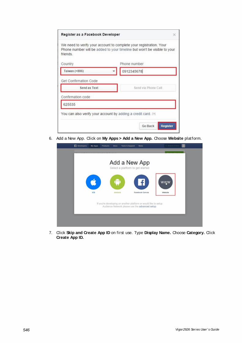
Vigor2926 Series User’s Guide 546
6. Add a New App. Click on My Apps > Add a New App. Choose Website platform.
7. Click Skip and Create App ID on first use. Type Display Name. Choose Category. Click Create App ID.
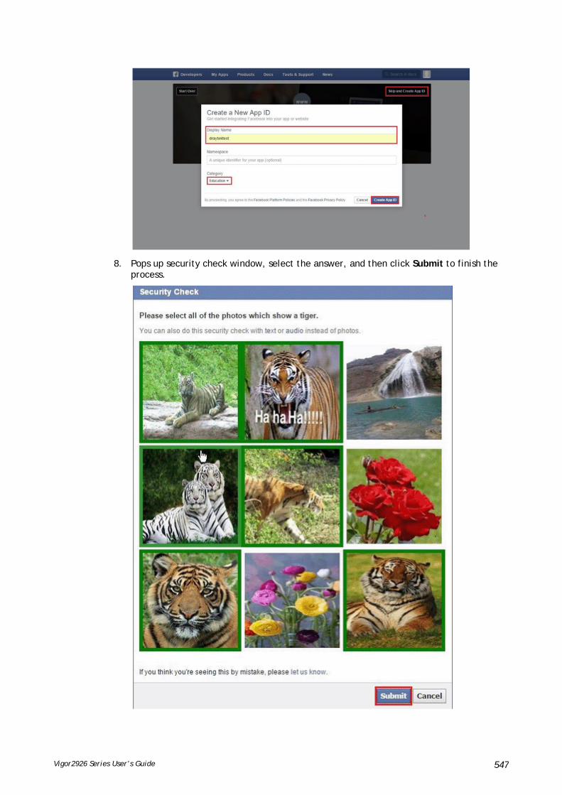
Vigor2926 Series User’s Guide 547
8. Pops up security check window, select the answer, and then click Submit to finish the process.

Vigor2926 Series User’s Guide 548
9. On Dashboard, user can get App ID and App Secret, these information will be used in Vigor Router's Web Portal Setup.
10. Add Platform on My Apps. Go to Settings then click Add Platform.
11. Choose Website in Select Platform window.
12. Enter the Site URL as http://portal.draytek.com. (Note: If you change http port in the vigor, please add http port in URLs. For example, we use 8080 as http port and we'll put http://portal.draytek.com:8080). Enter the Contact Email. And click Save Change.

Vigor2926 Series User’s Guide 549
13. Set up Client OAuth. Go to Settings >> Advanced >>Client OAuth Settings, enter "http://portal.draytek.com" in Valid OAuth redirect URIs, and save changes.
14. Go to My Apps>>Status & Review, and switch available status to YES to activate the APP.

Vigor2926 Series User’s Guide 550

Vigor2926 Series User’s Guide 551
AA--22 HHooww ttoo ccrreeaattee GGooooggllee AAPPPP ffoorr WWeebb PPoorrttaall AAuutthheennttiiccaattiioonn??
The new web portal feature support social login as authentication method, and allows network administrator to authenticate LAN clients by their Google or Facebook account. This document introduces how to create Facebook APP, and generate the APP ID and APP secret that can be used in Web Portal setup.
1. Create Developer project. Go to https://code.google.com/apis/console, login with a Google account then click Create project. Type project name then click Create.
2. On Dashboard, choose Use Google APIs.
3. Edit Auth Consent screen. Go to Credentials > Auth consent screen. Enter your email, product name and other optional item then click on Save.

Vigor2926 Series User’s Guide 552
4. Create Client ID. Click Credentials and Click Add credentials > OAuth2.0 client ID.
5. Choose Web application as Application Type, then enter name. Set Authorized JavaScript origins and Authorized redirect URLs as http://portal.draytek.com, and click Create. (Note: If you change http port in the vigor, please add http port in URLs. For example, we use 8080 as http port and we'll put http://portal.draytek.com:8080).
6. Get client ID and client secret. Such information will be used in Vigor Router's Web Portal Setup page.

Vigor2926 Series User’s Guide 553
VVIIII--55 CCeennttrraall MMaannaaggeemmeenntt ((VVPPNN))
Vigor2926 can build virtual private network (VPN) between itself and any other TR-069 CPE by the function of central VPN management. In addition, it can be treated as a server (called CVM server) which can manage TR-069 CPE for periodical firmware upgrade, configuration backup and restoring configuration.

Vigor2926 Series User’s Guide 554
WWeebb UUsseerr IInntteerrffaaccee
Central VPN Management menu can manage the CPE connected through WAN only.
VVIIII--55--11 GGeenneerraall SSeettuupp
This page is used to configure settings which will be used by the clients to register to such Vigor router. Click General Settings and IPsec VPN Settings to configure the basic settings for CVM mechanism.
VVIIII--55--11--11 GGeenneerraall SSeettttiinnggss
To enable the CVM feature, the first thing you have to do is enabling CVM port or CVM SSL Port.
Available settings are explained as follows:
Item Description
CVM SSL Port Check the box to enable the port setting.
Type the port number in the box.
CVM Port Check the box to enable the port setting.
Type the port number in the box.
WAN IP for Remote Connection
For Vigor router can manage only the client from WAN interface, therefore you have to specify which interface will be used for such function. If you choose MANUALLY, you have to specify WAN IP address.

Vigor2926 Series User’s Guide 555
Username Type a username which will be used by any CPE trying to connect to Vigor router.
Password Type the password for the user.
Polling Interval Type the time value (unit is second). The range is from 60 ~ 86400.
After finishing all the settings here, please click OK to save the configuration.
VVIIII--55--11--22 IIPPsseecc VVPPNN SSeettttiinnggss
Central VPN management is operated through IPsec VPN connection.
Available settings are explained as follows:
Item Description
IPsec Mode Choose Aggressive or Main as the IPsec Mode.
Security Method Choose one of the following methods (AH or ESP) for the security of data transmission. For example, choose AH to specify the IPsec protocol for the Authentication Header protocol. The data will be authenticated but not be encrypted.
Encryption Type Choose one of the selections as the encryption type.
Local Subnet Type the IP address and subnet mask of local host.
After finishing all the settings here, please click OK to save the configuration.

Vigor2926 Series User’s Guide 556
VVIIII--55--22 CCPPEE MMaannaaggeemmeenntt
All the CPEs managed by Vigor2926 series can be seen with icons from this page.
Before using such feature, make sure the CVM port has been enabled and configured properly.
VVIIII--55--22--11 MMaannaaggeedd DDeevviiccee LLiisstt
This page allows you to manage the CPEs connected to Vigor2926 series.
PPaaggee wwiitthhoouutt CCPPEE ccoonnnneecctteedd

Vigor2926 Series User’s Guide 557
PPaaggee wwiitthh CCPPEE ccoonnnneecctteedd
Available settings are explained as follows:
Item Description
Managed Devices List This area displays device icons (up to 8) for the CPE managed by Vigor2926 series.
Edit – To modify the name and location of specific CPE, click the one you want and click the Edit button. A pop up window will appear. Simply change the name and/or location manually.
Delete – To disconnect the management of any CPE, click the CPE icon you want and click the Delete button.
Double-clicking the CPE icon also can pop up the Managed Device Detail window. However, you cannot modify any data on the window.

Vigor2926 Series User’s Guide 558
Unmanaged Devices List Any device (CPE) which follows the standard of TR-069 can be configured and can be detected by Vigor2926 series automatically.
Only eight remote devices can be managed by Vigor2926 at one time. Therefore, other remote devices detected by Vigor2926 series might not be displayed in such field.
Add – Move the selected device from Unmanaged Devices List to Managed Devices List.
IP Address – Display the IP address of the remote device.
Mac Address – Display the MAC address of the remote device.
Device Model – Display the model name of the remote device.
Description Name – Define the name or type the additional description of CPE for identification in VPN management and CPE management.
Location – Type the location (address) of the CPE to be displayed by Google Map.
Refresh Click it to refresh current web page.

Vigor2926 Series User’s Guide 559
VVIIII--55--22--22 CCPPEE MMaaiinntteennaannccee
This area displays all the profiles which are created for applying to the managed device. This page can help the administrator to do maintenance jobs like firmware upgrade, configuration backup, configuration restoration and etc.
Available settings are explained as follows:
Item Description
Refresh Click it to refresh current page.
USB Disk - It means a USB disk connecting to
Vigor2926.
- It means no USB disk connecting to Vigor2926.
Disk Usage - When a USB disk connects
to Vigor2926, the disk usage and the disk capacity will be displayed in such field.
- When there is no USB disk connecting to Vigor2926, such message will be displayed in this field.
Click the icon to see the content inside the USB disk.
Set to Factory Default Click to clear all indexes.
Index Display the number of the profile that you can edit.
Profile Name Display the name of the maintenance profile.

Vigor2926 Series User’s Guide 560
Device Name Display the name of the managed CPE that the maintenance profile will apply to.
Action Display the action that managed CPE shall accept.
Schedule Display the schedule profiles selected for such profile.
Now The action will be performed for the selected CPE immediately.
HHooww ttoo aadddd aa nneeww MMaaiinntteennaannccee PPrrooffiillee
Follow the steps below to create a new maintenance profile.
1. Click any index number link, e.g., Index 1.
2. The Maintenance dialog appears.
Info
When restoring configuration to a CPE, make sure the configuration file you selected was backup from this CPE before. Because restoring from another device's configuration file may cause serious problem (e.g., Both devices have different ISP username/ password. Restoring configuration from one CPE to the other will cause Internet connection not being online).
Available parameters are listed as follows:
Item Description
Profile Name Type the name of the maintenance profile.
Enable Check it to enable such profile.
Only Run Once Check it to activate such profile running for once.
Device Name The drop down list will display all the CPE devices detected by Vigor2926 series. Choose the one which will be applied with such new created profile.
Router Name / Router Model
It displays the name and model of Vigor router.
Action Type There are three actions for you to choose for such profile.
Config Backup – It means such profile will be used for

Vigor2926 Series User’s Guide 561
configuration backup of the selected CPE.
Config Restore – It means such profile will be used for restoring the configuration of the selected CPE.
Info
When restoring configuration to a CPE, make sure the configuration file you selected was backup from this CPE before. Because restoring from another device's configuration file may cause serious problem (e.g., Both devices have different ISP username/ password. Restoring configuration from one CPE to the other will cause Internet connection not being online).
Firmware Upgrade – It means such profile will be used for firmware upgrade.
File/Path Click Select to locate the file you want to save, restore or upgrade for CPE.
Index in Schedule Vigor2926 series will perform the specified action to the selected CPE based on the schedule configured here.
Specify one or two schedule profiles (represented by number) here.
3. Enter all the settings and click OK.
4. A new maintenance profile has been created.

Vigor2926 Series User’s Guide 562
VVIIII--55--22--33 GGooooggllee MMaapp
To display the location of the managed CPE with a bird’s eye view, open Central VPN Management>>CPE Management and click the tab of Google Map.

Vigor2926 Series User’s Guide 563
VVIIII--55--33 VVPPNN MMaannaaggeemmeenntt
An easy and quick method is offered to configure VPN settings for building VPN connection automatically between Vigor2926 series (treated as VPN server) and other Vigor router (treated as CPE device, i.e., VPN client).
Available parameters are listed as follows:
Item Description
CPE VPN Connection List
VPN Display the name of the LAN-to-LAN profile.
It is generated automatically when you click the PPTP/IPsec/Advanced button to build the VPN connection between Vigor2926 and remote CPE.
Type Display the dial-in type and the authentication method.
Remote IP Display the IP address of the remote CPE and the interface.
Virtual Network Display the IP address and subnet mask of Vigor2926 series.
Tx Pkts Display the number of the transmitted packets.
Tx Rate(Bps) Display the number of the transmitted rate.
Rx Pkts Display the number of the received packets.
Rx Rate(Bps) Display the number of the received rate.
Up Time Display the connection time of such VPN.
Once the device is managed (controlled) by Vigor2926 series, it will be displayed on such screen automatically. If not, refer to sections “How to manage the CPE (router) through Vigor2926?” for more detailed information.

Vigor2926 Series User’s Guide 564
VVIIII--55--44 LLoogg && AAlleerrtt
This page offers brief information to identify the CPE connected to Vigor2926 series.
Available settings are explained as follows:
Item Description
Display Mode Choose the mode you want to display the related information on the following table.
Stop record when fulls – when the capacity of CVM log is full, the system will stop recording.
Always record the new event – only the newest events will be recorded by the system.
Device Name Display the name of the managed CPE.
Description Name Display the brief explanation for the managed CPE.
Time & date Display the time and date that the managed CPE scanned by Vigor2926 series.
Action Type Display the action that Vigor2926 series will perform for the managed CPE.
Message Display the information for each event.
The Alert page offers brief information to identify the CPE connected to Vigor2926 series.

Vigor2926 Series User’s Guide 565
AApppplliiccaattiioonn NNootteess
AA--11 CCVVMM AApppplliiccaattiioonn -- HHooww ttoo mmaannaaggee tthhee CCPPEE ((rroouutteerr)) tthhrroouugghh VViiggoorr22992266
sseerriieess??
To manage CPEs through Vigor2926 series, you have to set URL on CPE first and set username and password for Vigor2926 series. For this section, we use Vigor2850 series as the example. All the CPE configuration will be done through Vigor2850 series.
CCoonnffiigguurree CCVVMM SSeettttiinnggss oonn VViiggoorr22992266 sseerriieess
1. Access into the web user interface of Vigor2926 series.
2. Open Central Management>> VPN >>General Setup.
3. In the following page, check the boxes for CVM Port and CVM SSL Port to enable the port setting. Type the values for CVM Port, CVM SSL Port, Username, and Password respectively. Remember the values configured in this page.
4. Click OK to save the settings.

Vigor2926 Series User’s Guide 566
CCoonnffiigguurree SSeettttiinnggss oonn CCPPEE
1. In the end of the CPE, access into the web user interface of the CPE (e.g., Vigor2850 series). Open a web browser (for example, IE, Mozilla Firefox or Netscape) and type http://192.168.1.1.
2. Open System Maintenance >> TR-069.
3. In the field of ACS Server, type the URL (IP address with port number) of Vigor2926 series and type the same Username and Password defined on the page of Central Management>> VPN >>General Setup in Vigor2926 series. Then, click Enable for CPE Client and then click OK to save the settings.
4. Open System Maintenance>>Management Setup.

Vigor2926 Series User’s Guide 567
5. Check Allow management from the Internet to set management access control and click OK.
6. Open WAN>>Internet Access. Use the drop down list of Access Mode on WAN1 to select MPoA (RFC1483/2684). Then, click Details Page.
7. Click Specify an IP address. Type correct WAN IP address, subnet mask and gateway IP address for your CPE. Then click OK.

Vigor2926 Series User’s Guide 568
Info
Reboot the CPE device and re-log into Vigor2926 series. CPE which has registered to Vigor2926 series will be captured and displayed on the page of Central Management>>VPN>>CPE Management.
CChheecckk CCPPEE MMaaiinntteennaannccee PPaaggee
1. Return to the web user interface of Vigor2926 series.
2. Open Central Management>>VPN>>VPN Management. Now there is one CPE displayed on the field of Unmanaged Devices List.
3. Choose the one (Vigor2850) from Unmanaged Devices List and click Add. The following dialog will be popped up. Type the name and the location of the router respectively. Click OK to save the configuration.
4. The selected CPE will be moved and displayed on Managed Devices List which means it is controlled / managed by Vigor2926 series from now on.

Vigor2926 Series User’s Guide 569
AA--22 CCVVMM AApppplliiccaattiioonn -- HHooww ttoo bbuuiilldd tthhee VVPPNN bbeettwweeeenn rreemmoottee ddeevviicceess aanndd
VViiggoorr22992266 sseerriieess??
When a remote device is managed by Vigor2926 series, it is easy to build VPN between these two devices.
1. Access into the web user interface of Vigor2926 series.
2. Open Central Management>> VPN >>CPE Management.
3. Click the device icon (marked with ) and click the PPTP/IPsec button.
4. Wait for a moment. If VPN is built successfully, related information will be displayed on CPE VPN Connection List.

Vigor2926 Series User’s Guide 570
5. A LAN to LAN profile for such VPN will be generated automatically. You can access into VPN and Remote Access>>LAN to LAN of the remote device for viewing the detailed information.
Note: The profile name is created automatically by the system. Do not modify any value in such page to avoid VPN error.

Vigor2926 Series User’s Guide 571
AA--33 CCVVMM AApppplliiccaattiioonn -- HHooww ttoo uuppggrraaddee CCPPEE ffiirrmmwwaarree tthhrroouugghh VViiggoorr22992266
sseerriieess??
Download the newest firmware from your Draytek website to USB Storage Disk for the device (e.g., Vigor2850) managed by Vigor2926 series.
Vigor2850, as an example, is chosen for Vigor2926 to perform the CPE firmware upgrade remotely in this case.
1. Plug in USB storage disk onto Vigor2926 series via USB interface. Make sure the USB disk has been installed correctly, otherwise, the firmware upgrade will not be successful.
2. Access into web user interface of Vigor2926 series. Open Central Management>>VPN>>CPE Management and click the CPE Maintenance tab.
3. Click any index number link, e.g., Index 1.

Vigor2926 Series User’s Guide 572
4. The Maintenance profile dialog appears.
In the field of Profile Name, type a name for such maintenance profile; check Enable; and choose the one you want to perform firmware upgrade from Device Name drop down list. From the Action Type, choose Firmware Upgrade. Type the file/path of the newest firmware or click Select to locate it. Specify the Schedule profile. At last, click OK.
5. Now, a new maintenance profile has been created.
6. Click Now to perform the firmware upgrade immediately for Vigor2850.
7. Wait for several minutes for firmware upgrade.

Vigor2926 Series User’s Guide 573
8. Then check the device information for the managed device if the firmware upgrade is successful or not. Click Managed Devices List.
Click the icon of Vigor2850 and click Edit and view the software version. Another way to check if the firmware upgrade is completed or not, simply open Central Management>>VPN>>Log & Alert.

Vigor2926 Series User’s Guide 574
VVIIII--66 CCeennttrraall MMaannaaggeemmeenntt ((AAPP))
Vigor2926 can manage the access points supporting AP management via Central AP Management.
AAPP MMaapp
AP Map is helpful to determine the best location for VigorAP in a room. A floor plan of a room is required to be uploaded first. By dragging and dropping available VigorAP icon from the list to the floor plan, the placement with the best wireless coverage will be clearly indicated through simulated signal strength
AAPP MMaaiinntteennaannccee
Vigor router can execute configuration backup, configuration restoration, firmware upgrade and remote reboot for the APs managed by the router. It is very convenient for the administrator to process maintenance without accessing into the web user interface of the access point.
LLooaadd BBaallaannccee ffoorr AAPP
The parameters configured for Load Balance can help to distribute the traffic for all of the access points registered to Vigor router. Thus, the bandwidth will not be occupied by certain access points.

Vigor2926 Series User’s Guide 575
WWeebb UUsseerr IInntteerrffaaccee
VVIIII--66--11 DDaasshhbbooaarrdd
This page shows VigorAP’s information about Status, Event Log, Total Traffic or Station Number by displaying VigorAP icon, text and histogram. Just move and click your mouse cursor on Status, Event Log, Total Traffic or Station Number. Corresponding web pages will be open immediately.

Vigor2926 Series User’s Guide 576
To access into the web user interface of VigorAP, simply move your mouse cursor on the VigorAP icon and click it. The system will guide you to access into the web user interface of VigorAP.
VVIIII--66--22 SSttaattuuss
This page displays current status (online, offline or SSID hidden, IP address, encryption, channel, version, password and etc.) of the access points managed by Vigor router. Please open Central Management>>AP>>Function Support List to check what AP Models are supported.
Available settings are explained as follows:
Item Description
Index Click the index number link for viewing the settings summary of the access point.
Device Name The name of the AP managed by Vigor router will be displayed here.
IP Address Display the true IP address of the access point.
SSID Display the SSID configured for the access point(s) connected to Vigor2926.
Ch. Display the channel used by the access point.
STA List Display the number of wireless clients (stations) connecting to the access point.
In which, 0/64 means that up to 64 clients are allowed to connect to the access point. But, now no one connects to the access point.
The number displayed on the left side means 2.4GHz; and the number displayed on the right side means 5GHz.
AP List Display the number of the AP around the device.
Uptime Display the duration of the AP powered up.
Version Display the firmware version used by the access point.
Password Vigor2926 can get related information of the access point by accessing into the web user interface of the access point.
This button is used to modify the logging password of the connected access point.

Vigor2926 Series User’s Guide 577
VVIIII--66--33 WWLLAANN PPrrooffiillee
WLAN profile is used to apply to a selected access point. It is very convenient for the administrator to configure the setting for access point without opening the web user interface of the access point.
Click the number link of the selected profile to modify the content of the profile. Available settings are explained as follows:
Item Description
Profile Display the link of the profile.
Name Display the name of the profile.
The default profile cannot be renamed.
Main SSID Display the SSID configured by such wireless profile.
Security Display the security mode selected by such wireless profile.
Multi-SSID Enable means multiple SSIDs (more than one) are active.
Disable means only SSID1 is active.
WLAN ACL Display the name of the access control list.
Rate Ctrl Display the upload and/or download transmission rate.
Clone It can copy settings from an existing WLAN profile to another WLAN profile.
First, you have to check the box of the existing profile as the original profile. Second, click Clone. The following dialog will appear.
Third, choose the profile index to accept the settings from the original profile. Forth, type a new name in the field of Renamed as. Last, click Apply to save the settings on this dialog.
The new profile has been created with the settings coming from the original profile.
To AP Click it to apply the selected wireless profile to the specified Access Point.

Vigor2926 Series User’s Guide 578
Simply choose the device you want from Existing Device field. Click >> to move the device to Selected Device field. Then, click OK.
The selected WLAN profile will be applied to the selected access point immediately. Later the access point will reboot.
To Local WLAN Profile configured in this page is specified for VigorAP connected to Vigor router.
If required, these settings also can be applied to Vigor router. Select and check one of wireless profiles and click this button to apply the settings onto the WI-Fi wireless settings configured for such Vigor router.
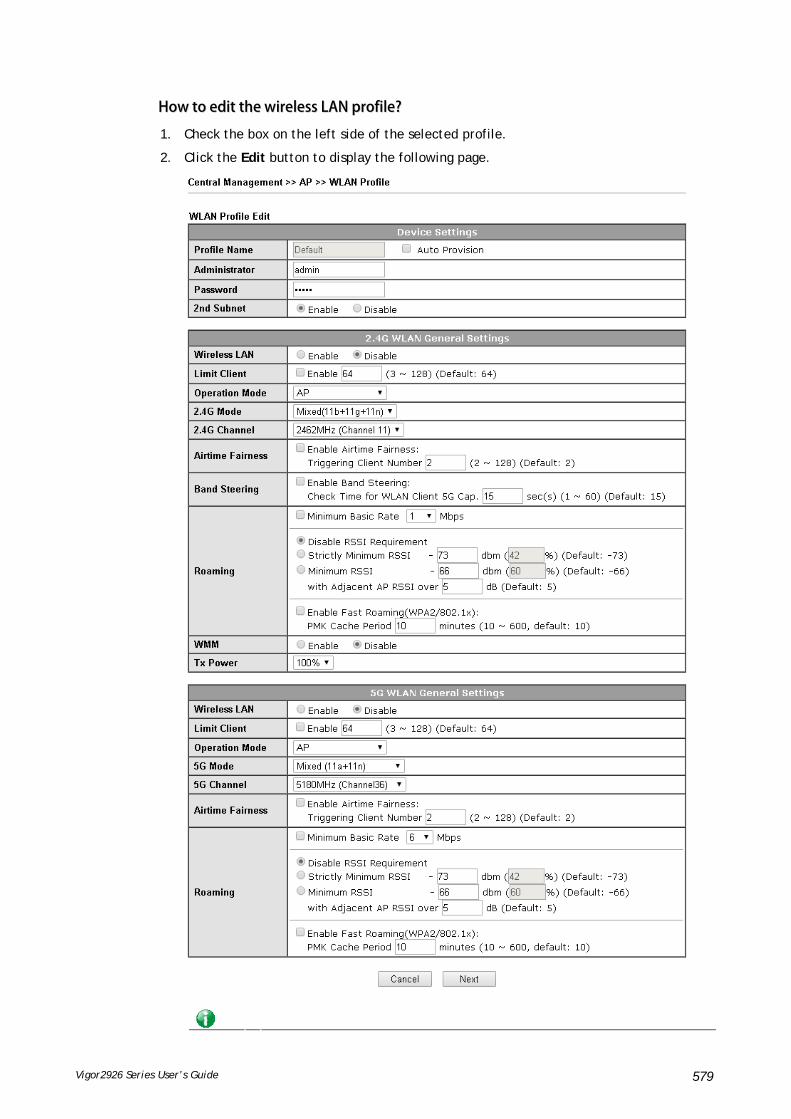
Vigor2926 Series User’s Guide 579
HHooww ttoo eeddiitt tthhee wwiirreelleessss LLAANN pprrooffiillee??
1. Check the box on the left side of the selected profile.
2. Click the Edit button to display the following page.

Vigor2926 Series User’s Guide 580
Info The function of Auto Provision is available for the default WLAN profile.
3. After finished the general settings configuration, click Next to open the following page for 2.4G wireless security settings.

Vigor2926 Series User’s Guide 581
4. After finished the above web page configuration, click Next to open the following page for 5G wireless security settings.
5. When you finished the above web page configuration, click Finish to exit and return to the first page. The modified WLAN profile will be shown on the web page.

Vigor2926 Series User’s Guide 582
VVIIII--66--44 AAPP MMaaiinntteennaannccee
Vigor router can execute configuration backup, configuration restoration, firmware upgrade and remote reboot for the APs managed by the router. It is very convenient for the administrator to process maintenance without accessing into the web user interface of the access point.
Info
Config Backup can be performed to one AP at one time. Others functions (e.g., Config Restore, Firmware Upgrade, Remote Reboot can be performed to more than one AP at one time by using Vigor2926.
Available settings are explained as follows:
Item Description
Action There are four actions provided by Vigor router to manage the access points.
Vigor router can backup the configuration of the selected AP, restore the configuration for the selected AP, perform the firmware upgrade of the selected AP, reboot the selected AP remotely and perform the factory reset for the selected AP.
File/Path Specify the file and the path which will be used to perform Config Restore or Firmware Upgrade.
Select Device Display all the available access points managed by Vigor router. Simply click << or >> to move the device(s) between

Vigor2926 Series User’s Guide 583
Select Device and Selected Device areas.
Selected Device Display the access points that will be applied by such function after clicking OK.
After finishing all the settings here, please click OK to perform the action.
VVIIII--66--55 AAPP MMaapp
This function is helpful to determine the best location for VigorAP in a room. A floor plan of a room is required to be uploaded first. By dragging and dropping available VigorAP icon from the list to the floor plan, the placement with the best wireless coverage will be clearly indicated through simulated signal strength.
Available settings are explained as follows:
Item Description
Set to Factory Default Click the link to clear current page configuration.
Profile Click the link to to view or edit the AP Map.
Location Display a brief description (e.g., ground, roof) of the AP Map.
Online APs Display the number of VigorAP configured and powered up.
Total APs Display the total number of VigorAP configured.
Clients Display the number of clients accessing Internet through the VigorAP.
Dimension(m) Display the width and length of the AP map.
View Click it to review the layout for the selected AP map.

Vigor2926 Series User’s Guide 584
CCrreeaattiinngg //EEddiittiinngg tthhee AAPP MMaapp PPrrooffiillee
1. Select a number index and click Edit to open the following web page.
Available settings are explained as follows:
Item Description
Location (Profile Name) Type a name (e.g., groudfloor) for the AP map profile.
Upload Map Click the Select button to choose an image file (only JPG and PNG are supported) for floor plan.
Cancel Click it to cancel the configuration.
Next Click it to go to the next configuration page.
2. Click Next. The dimension page of the floor plan will be shown as follows.

Vigor2926 Series User’s Guide 585
3. Click Next to get the configuration page. Drag and drop an AP icon from AP list to the map on the bottom.
4. Check the box of Show AP Coverage on.. to determine the wireless signal. Then, choose 2.4GHz or 5GHz for the AP.
5. Adjust the AP on the map to find out which place can have the best wireless coverage. At last, click Save.

Vigor2926 Series User’s Guide 586
VVIIII--66--66 TTrraaffffiicc GGrraapphh
Click Traffic Graph to open the web page. Choose one of the managed Access Points, LAN-A or LAN-B, daily or weekly for viewing data transmission chart. Click Refresh to renew the graph at any time.
The horizontal axis represents time; the vertical axis represents the transmission rate (in kbps).
Info
Enabling/Disabling such function will also enable/disable the External Devices function.

Vigor2926 Series User’s Guide 587
VVIIII--66--77 RRoogguuee AAPP DDeetteeccttiioonn
It displays the access point scanned by Vigor router. In which, the APs will be classified with friendly APs, rogue APs and unknown APs in different colors.
Below shows the detected APs by clicking OK.
Available settings are explained as follows:
Item Description
Enable Neighbor AP Detection – The access point(s) registered to Vigor2926 will be used to detect other access points and send the scanned results to Vigor2926. Later, the scanned result

Vigor2926 Series User’s Guide 588
will be displayed on this page. Local WLAN Detection – The router will detect all the access points through wireless LAN connection.
Specify the access points which are classified under each type.
Refresh Min(s) Use the drop down list to specify the time to refresh the web page.
Refresh Click such link to refresh the web page immediately.
Ch Display the channel used by the detected access point.
SSID Display the SSID specified for the detected access point.
Mode Display the mode (AP or Ad Hoc) used by the detected access point.
BSSID Display the MAC address of the detected access point.
Security Display the encryption mode used by the access point.
Signal (%) Display the signal strength (represented by percentage) sent by the access point.
Beacon Period Display the period (time) of the beacon. The beacon signal will be sent out periodically.
Last Detected Display the date and time that such access point was detected by Vigor router.
All the APs detected by Vigor router will be treated as unknown APs. You have to specify which AP is friendly and which one is Rogue respectively. Follow the steps below to perform the classification of access points.
1. Click the radio button on one of the access points. In this case, DrayTek-LAN-A is selected.
2. Later, some options will appear on the bottom of the page.
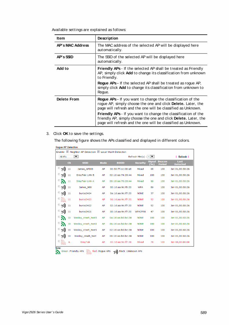
Vigor2926 Series User’s Guide 589
Available settings are explained as follows:
Item Description
AP’s MAC Address The MAC address of the selected AP will be displayed here automatically.
AP’s SSID The SSID of the selected AP will be displayed here automatically.
Add to Friendly APs - If the selected AP shall be treated as Friendly AP, simply click Add to change its classification from unknown to Friendly.
Rogue APs - If the selected AP shall be treated as rogue AP, simply click Add to change its classification from unknown to Rogue.
Delete From Rogue APs - If you want to change the classification of the rogue AP, simply choose the one and click Delete. Later, the page will refresh and the one will be classified as Unknown.
Friendly APs - If you want to change the classification of the friendly AP, simply choose the one and click Delete. Later, the page will refresh and the one will be classified as Unknown.
3. Click OK to save the settings.
The following figure shows the APs classified and displayed in different colors.

Vigor2926 Series User’s Guide 590
VVIIII--66--88 EEvveenntt LLoogg
Time and event log for all of the APs managed by Vigor router will be shown on this page. It is userful for troubleshooting if required.
VVIIII--66--99 TToottaall TTrraaffffiicc
Such page will display the total traffic of data receiving and data transmitting for VigorAPs managed by Vigor router.

Vigor2926 Series User’s Guide 591
VVIIII--66--1100 SSttaattiioonn NNuummbbeerr
The total number of the wireless clients will be shown on this page, no matter what mode of wireless connection (2.4G WLAN or 5G WLAN) used by wireless clients to access into Internet through VigorAP.
VVIIII--66--1111 LLooaadd BBaallaannccee
The parameters configured for Load Balance can help to distribute the traffic for all of the access points registered to Vigor router. Thus, the bandwidth will not be occupied by certain access points.
Available settings are explained as follows:
Item Description
AP Load Balance It is used to determine the operation mode when the system detects overload between access points.
Disable – Disable the function of AP load balance.

Vigor2926 Series User’s Guide 592
By Station Number –The operation of load balance will be executed based on the station number configured in this page. It is used to limit the allowed number for the station connecting to the access point. The purpose is to prevent lots of stations connecting to access point at the same time and causing traffic unbalanced. Please define the required station number for WLAN (2.4GHz) and WLAN (5GHz) separately. By Traffic – The operation of load balance will executed according to the traffic configuration in this page.
By Station Number or Traffic - The operation of load balance will be executed based on the station number or the traffic configuration.
Station Number Threshold
Set the number of stations as a threshold to activate AP load balance.
Traffic Threshold Upload Limit –Use the drop down list to specify the traffic limit for uploading.
Download Limit – Use the drop down list to specify the traffic limit for downloading.
Action When Threshold Exceeded
Stop accepting new connections – When the number of stations or the traffic reaches the threshold defined in this web page, Vigor router will stop any new connection asked by other access point.
Dissociate existing station by longest idel time - When the access point is overload (e.g., reaching the limit of station number or limit of network traffic), it will terminate the network connection of the client’s station which is idle for a longest time.
Dissociate existing station by worst signal strength if it is less than - When the access point is overload (e.g., reaching the limit of station number or limit of network traffic), it will terminate the network connection of the client’s station with the weakest signal.
After finishing all the settings here, please click OK to save the configuration.
VVIIII--66--1122 FFuunnccttiioonn SSuuppppoorrtt LLiisstt
Click the Client tab to list the AP management functions that the Access Points support under different firmware versions.
Click the Server tab to list the AP management functions that Vigor router supports under different firmware versions.

Vigor2926 Series User’s Guide 593

Vigor2926 Series User’s Guide 594
AApppplliiccaattiioonn NNootteess
AA--11 HHooww ttoo uussee AAPP MMaannaaggeemmeenntt ffuunnccttiioonn ((iinn VViiggoorr22992266)) ttoo cchheecckk AAPP ssttaattuuss
aanndd ddeeppllooyy WWLLAANN pprrooffiillee
The administrator can manage the access points linked to Vigor2926.
1. Open External Devices>>Access Point Devices. Vigor2926 will detect the AP connecting to the router automatically and display as below:
In this case, a device named with AP800_00507F6EE4980 has been detected by Vigor router.
2. Click the WLAN Profile tab to get the following page. Check the box of the default profile to make the Edit button be available. Then, click the Edit button.
3. When the following configuration page appears, make the changes you want and check Apply to All APs. Then, click Next to access into the next page.

Vigor2926 Series User’s Guide 595
Info
Apply to All APs can automatically apply the settings on Default profile to all of the access points registered to Vigor2926 later. Hence, it is not necessary for you to manually apply wireless profiles for APs respectively. Such feature will be convenient for people who want to quickly deploy multiple Vigor APs in a large exhibition to reach the goal of “plug and play” and “zero-configuration”.
4. The following page allows you to modify related settings for 2.4G SSID of managed AP. Make the changes you want for 2.4G SSID. Click Next for next page.

Vigor2926 Series User’s Guide 596
5. The following page is offered for you to modify related settings for 5G SSID of managed AP. Continue to make any changes you want. After finished all of the changes, simply click Finish.
6. Now, the AP (represented with AP800_00507F6EE4980) detected by Vigor router will be applied with the settings modified by Vigor router.

Vigor2926 Series User’s Guide 597
VVIIII--77 CCeennttrraall MMaannaaggeemmeenntt ((SSwwiittcchh))
Vigor router can manage lots of VigorSwitch devices connected to it. Through profile and group settings, the administrator can execute firmware/configuration backup, restore for VigorSwitch device, reboot the device or return to factory default settings of VigorSwitch at one time.
VVIIII--77--11 SSttaattuuss
VVIIII--77--11--11 SSwwiittcchh SSttaattuuss
Such page displays information, including Group, Switch name, IP address, model, System Up Time, Port in Use, Clients, and Firmware Version of VigorSwitch connected to Vigor2926 series.
Before checking the switch status, go to Central Management>>External Device to enable External Device Auto Discovery. Wait for the system to display available device(s).
Later, open Central Management>>Switch>>Status. Available VigorSwitch to be managed by such router will be listed under the New Switch List.

Vigor2926 Series User’s Guide 598
VigorSwitch listed below Status means the switch is managed by Viogr router; VigorSwitch listed below New Switch List means it is not managed by Vigor router yet.
Available settings are explained as follows:
Item Description
Group Display the name link of the group.
You can click the link to modify the group settings if required.
Switch Name Display the name link of VigorSwitch.
You can click the name link to access into the switch profile.
IP Address Display the IP address of VigorSwitch.
Model Display the model name of VigorSwitch.
System Up Time Display the time accumulated since this Vigorwitch is powered up.
Port in Use Display how many devices connected to VigorSwitch.
Clients Display the number of LAN ports used in VigorSwitch.
Firmware Version Display the firmware version that VigorSwitch current used.
Add New Such button will appear only when there is more than one switch connected to Vigor2926.
The one under New Switch List is allowed to be managed under current used group. Simply click Add New.

Vigor2926 Series User’s Guide 599
It will be better to group VigorSwitch devices with the same model.

Vigor2926 Series User’s Guide 600
VVIIII--77--11--22 SSwwiittcchh HHiieerraarrcchhyy
Such page displays the hierarchy of VigorSwitch(es) managed under Vigor2926.
Please note that, Shutdown Port is available for LAN port of VigorSwitch connects to a LAN device. When it is checked, after clicking OK, the network connection between that device and VigorSwitch will be terminated.
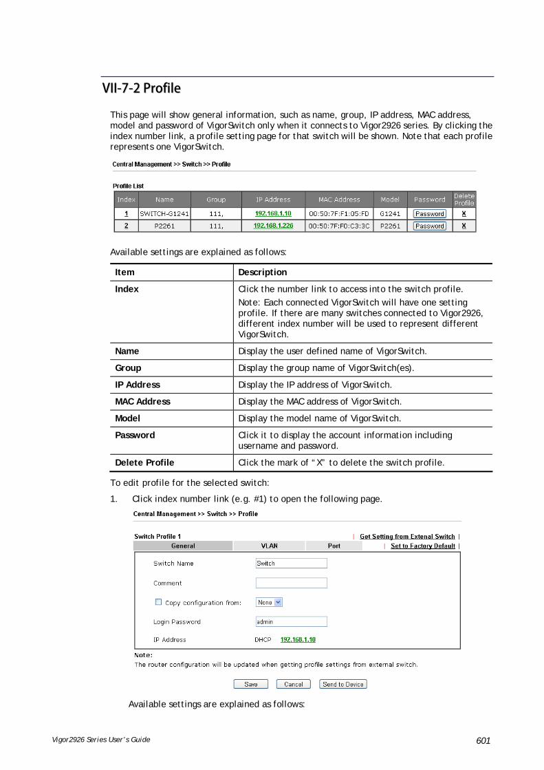
Vigor2926 Series User’s Guide 601
VVIIII--77--22 PPrrooffiillee
This page will show general information, such as name, group, IP address, MAC address, model and password of VigorSwitch only when it connects to Vigor2926 series. By clicking the index number link, a profile setting page for that switch will be shown. Note that each profile represents one VigorSwitch.
Available settings are explained as follows:
Item Description
Index Click the number link to access into the switch profile.
Note: Each connected VigorSwitch will have one setting profile. If there are many switches connected to Vigor2926, different index number will be used to represent different VigorSwitch.
Name Display the user defined name of VigorSwitch.
Group Display the group name of VigorSwitch(es).
IP Address Display the IP address of VigorSwitch.
MAC Address Display the MAC address of VigorSwitch.
Model Display the model name of VigorSwitch.
Password Click it to display the account information including username and password.
Delete Profile Click the mark of “X” to delete the switch profile.
To edit profile for the selected switch:
1. Click index number link (e.g. #1) to open the following page.
Available settings are explained as follows:

Vigor2926 Series User’s Guide 602
Item Description
Switch Name Type a name for the Switch. The purpose of name is used for identification.
It is useful when there are many VigorSwitch (same modes) devices connecting to Vigor2926 seres.
Comment Type the text in such field if additional explanation for the switch is required.
Copy configuration from
Check the box to copy configuration from other device. Use the drop down list to choose the one you need.
Note, if there is only one VigorSwitch connected and managed by Vigor2926 series, then such field is unavailable.
Login Password Display the original login password for the VigorSwitch.
However, if Group Password (in Central Management >>Switch>>Group) is configured with other string, then such field is not allowed to type any other password. And only the group password will be shown, instead.
IP Address Display the dynamic IP address (of the connected switch) assigned by Vigor2926.
Save Click it to save the settings.
Cancel Click it to return to previous web page without saving the setting changes.
Send to Device Click it to transfer the configuration change (e.g, login password, switch name, etc.) to the VigorSwitch immediately.
2. After finished the settings, click VLAN tab to open following page.
Blank page due to LAN>>VLAN not configured previously:
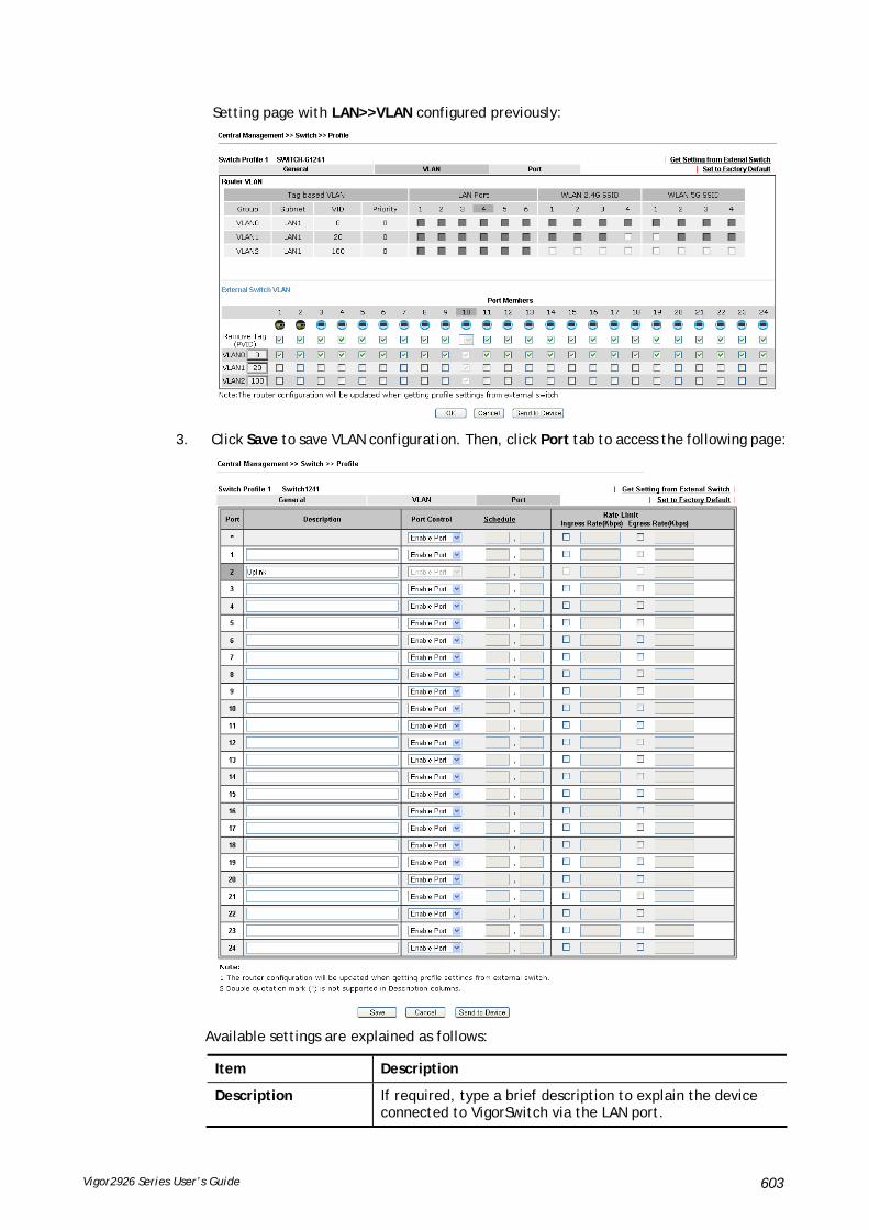
Vigor2926 Series User’s Guide 603
Setting page with LAN>>VLAN configured previously:
3. Click Save to save VLAN configuration. Then, click Port tab to access the following page:
Available settings are explained as follows:
Item Description
Description If required, type a brief description to explain the device connected to VigorSwitch via the LAN port.
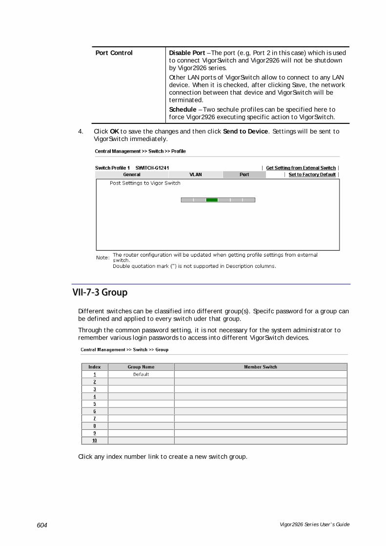
Vigor2926 Series User’s Guide 604
Port Control Disable Port – The port (e.g, Port 2 in this case) which is used to connect VigorSwitch and Vigor2926 will not be shutdown by Vigor2926 series.
Other LAN ports of VigorSwitch allow to connect to any LAN device. When it is checked, after clicking Save, the network connection between that device and VigorSwitch will be terminated.
Schedule – Two sechule profiles can be specified here to force Vigor2926 executing specific action to VigorSwitch.
4. Click OK to save the changes and then click Send to Device. Settings will be sent to VigorSwitch immediately.
VVIIII--77--33 GGrroouupp
Different switches can be classified into different group(s). Specifc password for a group can be defined and applied to every switch uder that group.
Through the common password setting, it is not necessary for the system administrator to remember various login passwords to access into different VigorSwitch devices.
Click any index number link to create a new switch group.

Vigor2926 Series User’s Guide 605
Available settings are explained as follows:
Item Description
Group Name Type a name as the group name. Different switches can be classified within a group.
Group Password Type a password that administrator can use to access into the managed VigorSwitch connecting to Vigor2926 series. All of the switches under the same group can be accessed into via such group password.
Existing Switch Display all of the VigorSwitch devices connecting to Vigor2926.
Member Switch Choose the switches you want to group and click the button “>>” to move the selected devices onto the field of Member Switch. Devices under Member Switch will be grouped under such group profile.
OK Click it to save the configuration.
Cancel Click it to exit the setting page without saving any change.

Vigor2926 Series User’s Guide 606
VVIIII--77--44 MMaaiinntteennaannccee
Such feature can execute configuration backup, restore of selected VigorSwitch device(s) or reboot the VigorSwitch devices remotely or reset the VigorSwitch devices with factory default settings, without accessing into the web user interface of VigorSwitch respectively. It is convenient for system administrator to manage VigorSwitch devices.
Available settings are explained as follows:
Item Description
Selection Action Action Type – Four actions including configuration backup, configuration restore, remote reboot and factory reset are offered by Vigor2926 to perform on VigorSwitch.
File/Path – Click the button to find out the required file.
Select Device Existing Device –Display all of the VigorSwitch devices connecting to Vigor2926.
Selected Device - Choose the switches you want to group and click the button “>>” to move the existing devices onto the field of Selected Device. Devices under Selected Device will be applied with the action
OK Click it to immediately perform the action (configuration backup, configuration restore, remote reboot and factory reset) on the device(s) listed in Selected Device.
Cancel Click it to cancel the setting changes.

Vigor2926 Series User’s Guide 607
VVIIII--77--55 AAlleerrtt aanndd LLoogg
Alert and Log is helpful for the user to understand the abnormal situation occurred in VigorSwitch quickly. When the system detects an error, information of abnormal condition will be recorded to the database; or the system will send an alert to the specified device (via e-mail or SMS) to warn the user.
VVIIII--77--55--11 AAlleerrtt SSeettuupp
This page is used to define the name of alert, level of alert (in color), and determine to record the data in the database, or send a notification message to the user based on the level.
Available settings are explained as follows:
Item Description

Vigor2926 Series User’s Guide 608
Alert and Log Check it to enable this feature.
Alert Levels and Action Level Name – Define names for representing the severity of alert event. The default names for index 1 to index 4 will be shown on each setting box. Index 5 to index 8 are reserved for user-defined.
Color – Define the color for each level of alert. However, the color of index 1 is No color and unable to be changed.
Create Log – Check the box to create log of alert. Such log will be seen on Alert Logs page. Note that No Log for index 1; and log for index 2 is enabled in default.
Send Notification – If it is checked, Vigor router’s system will send notification to specified phone number via SMS. SMS/Email Service Object – Choose the SMS object which will get the SMS from Vigor router. Up to 4 objects can be selected at one time.
VVIIII--77--55--22 SSwwiittcchh aanndd PPoorrtt SSeettuupp
This page defines enabling switch alert and/or port alert for each switch.
Available settings are explained as follows:
Item Description
Switch Alert Enable – Check it to enable alert mechanism for VigorSwitch.
Port Alert Enable - Check it to enable alert mechanism for each port of VigorSwitch.
Click the Switch Name link (e.g., G2260 in this case) to get detailed settings.
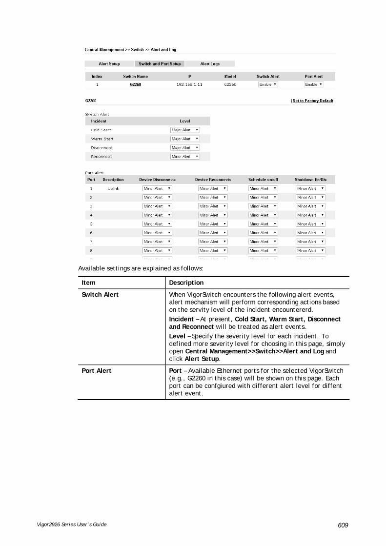
Vigor2926 Series User’s Guide 609
Available settings are explained as follows:
Item Description
Switch Alert When VigorSwitch encounters the following alert events, alert mechanism will perform corresponding actions based on the servity level of the incident encountererd.
Incident – At present, Cold Start, Warm Start, Disconnect and Reconnect will be treated as alert events.
Level – Specify the severity level for each incident. To defined more severity level for choosing in this page, simply open Central Management>>Switch>>Alert and Log and click Alert Setup.
Port Alert Port – Available Ethernet ports for the selected VigorSwitch (e.g., G2260 in this case) will be shown on this page. Each port can be confgiured with different alert level for diffent alert event.

Vigor2926 Series User’s Guide 610
VVIIII--77--55--33 AAlleerrtt LLooggss
The user can get the information by filtering the collective information based on the conditions specified in this page.
Available settings are explained as follows:
Item Description
Select Columns to Filter Logs
Level – The alert can be divided into four levels, No Alert, Minor Alert, Moderate Alert and Major Alert. Check the one(s) you want to check in Alert Logs list.
Type – Check the type (switch / port) of the log to be displayed in Alert Logs list.
Switch – Switch(es) connecting to Vigor router will be shown in this area. Click the one you need.
OK – Click it to save the configuration.
Log related to the items selected above will be shown in Alert Logs list.
Alert Logs This area displays logs (level name, time, type, switch, port, and incident) related to VigorSwitch managed by Vigor router.

Vigor2926 Series User’s Guide 611
VVIIII--77--66 DDaattaabbaassee SSeettuupp
The database of switch can be used to record alert logs and traffic history. This page is used to determine if it is necessary for the user information to be recorded in the database of switch.
Available settings are explained as follows:
Item Description
Enable Database to Record alert logs and traffic history
Check the box to make the database (in USB disk) to record the alert logs and traffic history.
Notification and Action when Storage Exceeded
Notification Don’t send notification – No notification will be sent out when there is no capacity for storage in USB.
Send notification – A notification will be sent out when there is no capacity for storage in USB.
Action Stop recording user information – When the capacity of log is full, the system will stop recording.
Backup and clean up all user infor, and start a new record - Only the newest events will be recorded by the system.
After finished the settings, click OK to save the configuration.

Vigor2926 Series User’s Guide 612
VVIIII--77--77 SSuuppppoorrtt LLiisstt
This page lists all models of VigorSwitch which can be managed by Vigor2926 via Central Management>>Switch.

Vigor2926 Series User’s Guide 613
VVIIII--88 CCeennttrraall MMaannaaggeemmeenntt ((EExxtteerrnnaall DDeevviicceess))
Vigor router can be used to connect with many types of external devices. In order to control or manage the external devices conveniently, open External Devices to make detailed configuration.
VVIIII--88--11 AAllll DDeevviicceess
Available settings are explained as follows:
Item Description
External Device Syslog Check this box to display information of the detected device on Syslog.
External Device Auto Discovery
Check this box to detect the external device automatically and display on this page.
From this web page, check the box of External Device Auto Discovery. Later, all the available devices will be displayed in this page with icons and corresponding information. You can change the device name if required or remove the information for off-line device whenever you want.

Vigor2926 Series User’s Guide 614
When you finished the configuration, click OK to save it.
Info
Only DrayTek products can be detected by this function.

Vigor2926 Series User’s Guide 615
PPaarrtt VVIIIIII OOtthheerrss
Define objects such as IP address, service type, keyword, file extension and others. These pre-defined objects can be applied in CSM.
USB device connected on Vigor router can be regarded as a server or WAN interface. By way of Vigor router, clients on LAN can access, write and read data stored in USB storage disk with different applications.

Vigor2926 Series User’s Guide 616
VVIIIIII--11 OObbjjeeccttss SSeettttiinnggss
Define objects such as IP address, service type, keyword, file extension and others. These pre-defined objects can be applied in CSM.
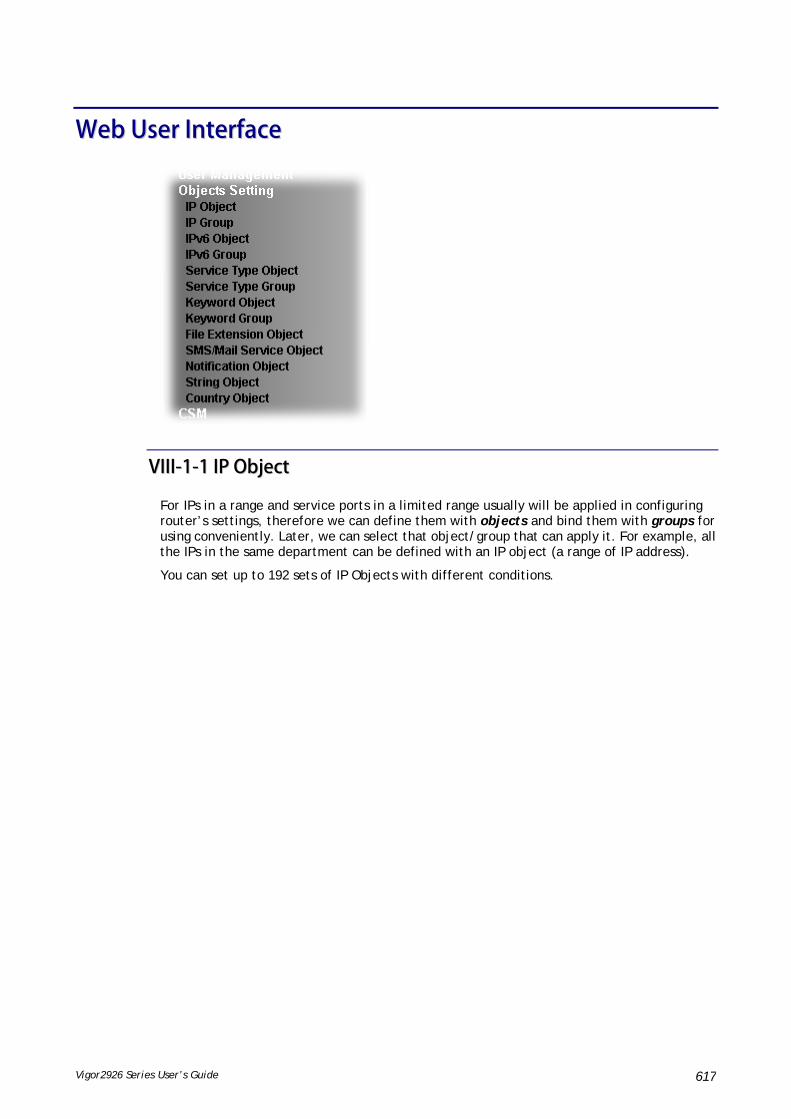
Vigor2926 Series User’s Guide 617
WWeebb UUsseerr IInntteerrffaaccee
VVIIIIII--11--11 IIPP OObbjjeecctt
For IPs in a range and service ports in a limited range usually will be applied in configuring router’s settings, therefore we can define them with objects and bind them with groups for using conveniently. Later, we can select that object/group that can apply it. For example, all the IPs in the same department can be defined with an IP object (a range of IP address).
You can set up to 192 sets of IP Objects with different conditions.

Vigor2926 Series User’s Guide 618
Available settings are explained as follows:
Item Description
View Use the drop down list to choose a type (Single Address, Range Address, Subnet Address, Mac Address or all) that IP object with the selected type will be shown on this page.
Set to Factory Default Clear all profiles.
Search Type a string of the IP object that you want to search.
Index Display the profile number that you can configure.
Name Display the name of the object profile.
Address Display the IP address configured for the object profile.
Export IP Object Usually, the IP objects can be created one by one through the web page of Objects>>IP Object. However, to a user who wants to save more time in bulk creating IP objects, a quick method is offered by Vigor router to modify the IP objects with a single file, a CSV file.
All of the IP objects (or the template) can be exported as a file by clicking Download. Then the user can open the CSV file through Microsoft Excel and modify all the IP objects at the same time.
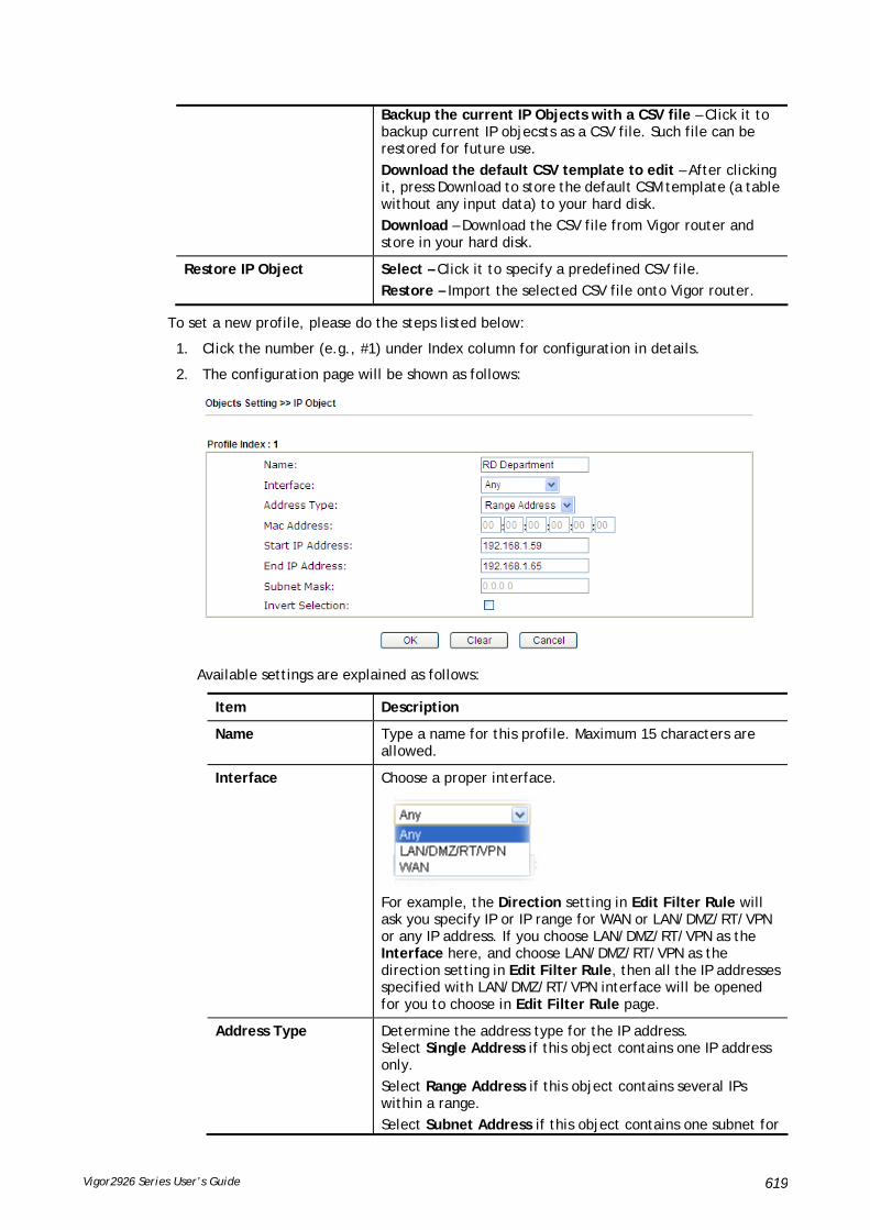
Vigor2926 Series User’s Guide 619
Backup the current IP Objects with a CSV file – Click it to backup current IP objecsts as a CSV file. Such file can be restored for future use.
Download the default CSV template to edit – After clicking it, press Download to store the default CSM template (a table without any input data) to your hard disk.
Download – Download the CSV file from Vigor router and store in your hard disk.
Restore IP Object Select – Click it to specify a predefined CSV file.
Restore – Import the selected CSV file onto Vigor router.
To set a new profile, please do the steps listed below:
1. Click the number (e.g., #1) under Index column for configuration in details.
2. The configuration page will be shown as follows:
Available settings are explained as follows:
Item Description
Name Type a name for this profile. Maximum 15 characters are allowed.
Interface Choose a proper interface.
For example, the Direction setting in Edit Filter Rule will ask you specify IP or IP range for WAN or LAN/DMZ/RT/VPN or any IP address. If you choose LAN/DMZ/RT/VPN as the Interface here, and choose LAN/DMZ/RT/VPN as the direction setting in Edit Filter Rule, then all the IP addresses specified with LAN/DMZ/RT/VPN interface will be opened for you to choose in Edit Filter Rule page.
Address Type Determine the address type for the IP address. Select Single Address if this object contains one IP address only.
Select Range Address if this object contains several IPs within a range.
Select Subnet Address if this object contains one subnet for

Vigor2926 Series User’s Guide 620
IP address.
Select Any Address if this object contains any IP address.
Select Mac Address if this object contains Mac address.
MAC Address Type the MAC address of the network card which will be controlled.
Start IP Address Type the start IP address for Single Address type.
End IP Address Type the end IP address if the Range Address type is selected.
Subnet Mask Type the subnet mask if the Subnet Address type is selected.
Invert Selection If it is checked, all the IP addresses except the ones listed above will be applied later while it is chosen.
4. After finishing all the settings here, please click OK to save the configuration. Below is an example of IP objects settings.

Vigor2926 Series User’s Guide 621
VVIIIIII--11--22 IIPP GGrroouupp
This page allows you to bind several IP objects into one IP group.
Available settings are explained as follows:
Item Description
Set to Factory Default Clear all profiles.
Index Display the profile number that you can configure.
Name Display the name of the group profile.
To set a new profile, please do the steps listed below:
1. Click the number (e.g., #1) under Index column for configuration in details.
2. The configuration page will be shown as follows:

Vigor2926 Series User’s Guide 622
Available settings are explained as follows:
Item Description
Name Type a name for this profile. Maximum 15 characters are allowed.
Interface Choose WAN, LAN or Any to display all the available IP objects with the specified interface.
Available IP Objects All the available IP objects with the specified interface chosen above will be shown in this box.
Selected IP Objects Click >> button to add the selected IP objects in this box.
3. After finishing all the settings here, please click OK to save the configuration.
VVIIIIII--11--33 IIPPvv66 OObbjjeecctt
You can set up to 64 sets of IPv6 Objects with different conditions.
Available settings are explained as follows:
Item Description
Set to Factory Default Clear all profiles.
Index Display the profile number that you can configure.
Name Display the name of the object profile.

Vigor2926 Series User’s Guide 623
To set a new profile, please do the steps listed below:
1. Click the number (e.g., #1) under Index column for configuration in details.
2. The configuration page will be shown as follows:
Available settings are explained as follows:
Item Description
Name Type a name for this profile. Maximum 15 characters are allowed.
Address Type Determine the address type for the IPv6 address. Select Single Address if this object contains one IPv6 address only.
Select Range Address if this object contains several IPv6s within a range.
Select Subnet Address if this object contains one subnet for IPv6 address.
Select Any Address if this object contains any IPv6 address.
Select Mac Address if this object contains Mac address.
Mac Address Type the MAC address of the network card which will be controlled.
Start IP Address Type the start IP address for Single Address type. Or, click Select to specify an IP address.
End IP Address Type the end IP address if the Range Address type is selected. Or, click Select to specify an IP address.
Prefix Length Type the number (e.g., 64) for the prefix length of IPv6 address.
Invert Selection If it is checked, all the IPv6 addresses except the ones listed above will be applied later while it is chosen.
3. After finishing all the settings, please click OK to save the configuration.

Vigor2926 Series User’s Guide 624
VVIIIIII--11--44 IIPPvv66 GGrroouupp
This page allows you to bind several IPv6 objects into one IPv6 group.
Available settings are explained as follows:
Item Description
Set to Factory Default Clear all profiles.
Index Display the profile number that you can configure.
Name Display the name of the group profile.
To set a new profile, please do the steps listed below:
1. Click the number (e.g., #1) under Index column for configuration in details.
2. The configuration page will be shown as follows:

Vigor2926 Series User’s Guide 625
Available settings are explained as follows:
Item Description
Name Type a name for this profile. Maximum 15 characters are allowed.
Available IPv6 Objects
All the available IPv6 objects with the specified interface chosen above will be shown in this box.
Selected IPv6 Objects Click >> button to add the selected IPv6 objects in this box.
3. After finishing all the settings, please click OK to save the configuration.
VVIIIIII--11--55 SSeerrvviiccee TTyyppee OObbjjeecctt
You can set up to 96 sets of Service Type Objects with different conditions.
Available settings are explained as follows:
Item Description
Set to Factory Default Clear all profiles.
Index Display the profile number that you can configure.
Name Display the name of the object profile.

Vigor2926 Series User’s Guide 626
To set a new profile, please do the steps listed below:
1. Click the number (e.g., #1) under Index column for configuration in details.
2. The configuration page will be shown as follows:
Available settings are explained as follows:
Item Description
Name Type a name for this profile. Maximum 15 characters are allowed.
Protocol Specify the protocol(s) which this profile will apply to.
Source/Destination Port
Source Port and the Destination Port columns are available for TCP/UDP protocol. It can be ignored for other protocols. The filter rule will filter out any port number.
(=) – when the first and last value are the same, it indicates one port; when the first and last values are different, it indicates a range for the port and available for this profile.
(!=) – when the first and last value are the same, it indicates all the ports except the port defined here; when the first and last values are different, it indicates that all the ports except the range defined here are available for this service type.
(>) – the port number greater than this value is available.
(<) – the port number less than this value is available for this profile.

Vigor2926 Series User’s Guide 627
3. After finishing all the settings, please click OK to save the configuration.
VVIIIIII--11--66 SSeerrvviiccee TTyyppee GGrroouupp
This page allows you to bind several service types into one group.
Available settings are explained as follows:
Item Description
Set to Factory Default Clear all profiles.
Index Display the profile number that you can configure.
Name Display the name of the group profile.
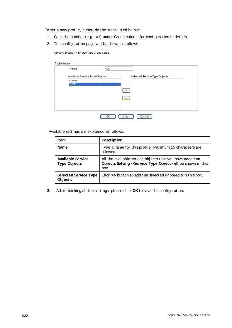
Vigor2926 Series User’s Guide 628
To set a new profile, please do the steps listed below:
1. Click the number (e.g., #1) under Group column for configuration in details.
2. The configuration page will be shown as follows:
Available settings are explained as follows:
Item Description
Name Type a name for this profile. Maximum 15 characters are allowed.
Available Service Type Objects
All the available service objects that you have added on Objects Setting>>Service Type Object will be shown in this box.
Selected Service Type Objects
Click >> button to add the selected IP objects in this box.
3. After finishing all the settings, please click OK to save the configuration.

Vigor2926 Series User’s Guide 629
VVIIIIII--11--77 KKeeyywwoorrdd OObbjjeecctt
You can set 200 keyword object profiles for choosing as black /white list in CSM >>URL Web Content Filter Profile.
Available settings are explained as follows:
Item Description
Set to Factory Default Clear all profiles.
Index Display the profile number that you can configure.
Name Display the name of the object profile.

Vigor2926 Series User’s Guide 630
To set a new profile, please do the steps listed below:
1. Click the number (e.g., #1) under Index column for configuration in details.
2. The configuration page will be shown as follows:
Available settings are explained as follows:
Item Description
Name Type a name for this profile, e.g., game. Maximum 15 characters are allowed.
Contents Type the content for such profile. For example, type gambling as Contents. When you browse the webpage, the page with gambling information will be watched out and be passed/blocked based on the configuration on Firewall settings.
3. After finishing all the settings, please click OK to save the configuration.

Vigor2926 Series User’s Guide 631
VVIIIIII--11--88 KKeeyywwoorrdd GGrroouupp
This page allows you to bind several keyword objects into one group. The keyword groups set here will be chosen as black /white list in CSM >>URL /Web Content Filter Profile.
Available settings are explained as follows:
Item Description
Set to Factory Default Clear all profiles.
Index Display the profile number that you can configure.
Name Display the name of the group profile.
To set a new profile, please do the steps listed below:
1. Click the number (e.g., #1) under Index column for configuration in details.
2. The configuration page will be shown as follows:

Vigor2926 Series User’s Guide 632
Available settings are explained as follows:
Item Description
Name Type a name for this group. Maximum 15 characters are allowed.
Available Keyword Objects
You can gather keyword objects from Keyword Object page within one keyword group. All the available Keyword objects that you have created will be shown in this box.
Selected Keyword Objects Click button to add the selected Keyword objects in
this box.
3. After finishing all the settings, please click OK to save the configuration.
VVIIIIII--11--99 FFiillee EExxtteennssiioonn OObbjjeecctt
This page allows you to set eight profiles which will be applied in CSM>>URL Content Filter. All the files with the extension names specified in these profiles will be processed according to the chosen action.
Available settings are explained as follows:
Item Description
Set to Factory Default Clear all profiles.
Index Display the profile number that you can configure.
Name Display the name of the object profile.

Vigor2926 Series User’s Guide 633
To set a new profile, please do the steps listed below:
1. Click the number (e.g., #1) under Profile column for configuration in details.
2. The configuration page will be shown as follows:
Available settings are explained as follows:
Item Description
Profile Name Type a name for this profile. The maximum length of the name you can set is 7 characters.
3. Type a name for such profile and check all the items of file extension that will be processed in the router. Finally, click OK to save this profile.
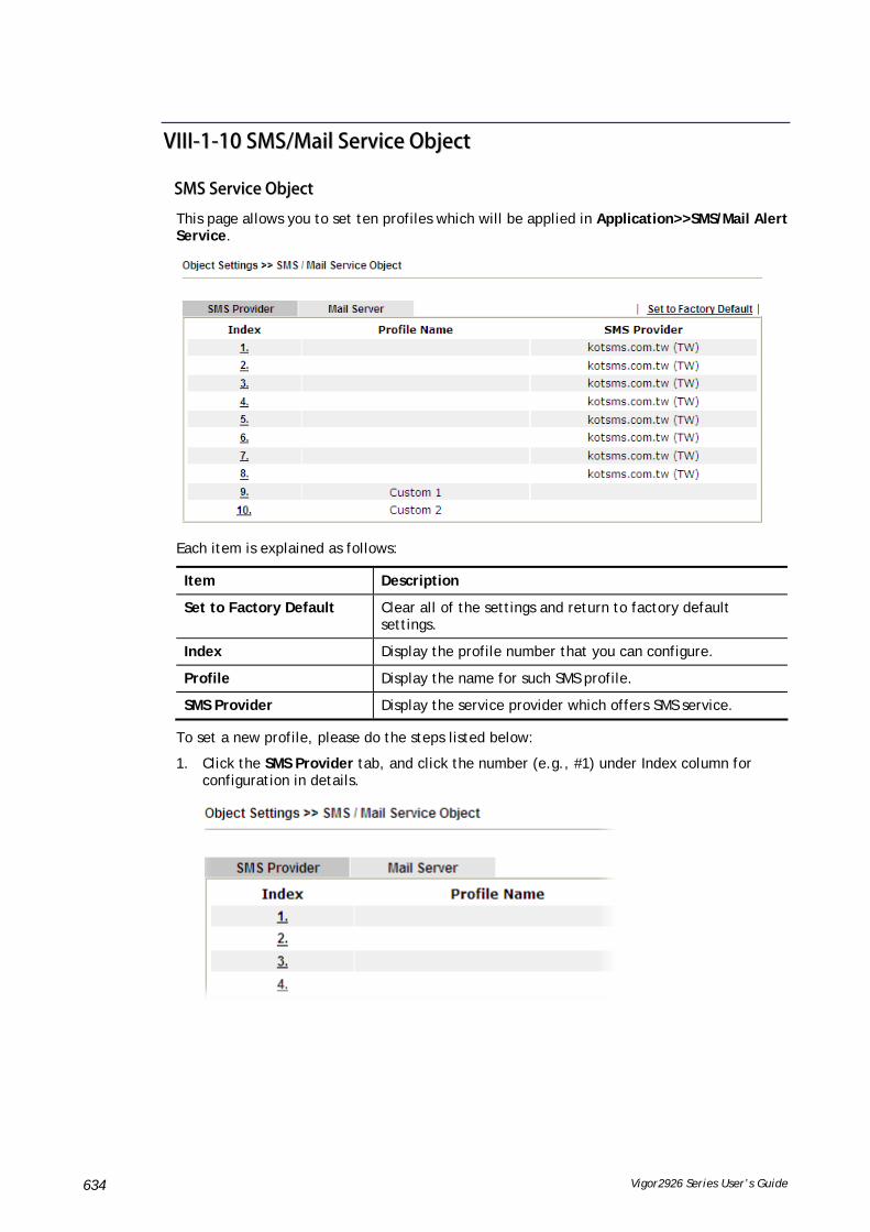
Vigor2926 Series User’s Guide 634
VVIIIIII--11--1100 SSMMSS//MMaaiill SSeerrvviiccee OObbjjeecctt
SSMMSS SSeerrvviiccee OObbjjeecctt
This page allows you to set ten profiles which will be applied in Application>>SMS/Mail Alert Service.
Each item is explained as follows:
Item Description
Set to Factory Default Clear all of the settings and return to factory default settings.
Index Display the profile number that you can configure.
Profile Display the name for such SMS profile.
SMS Provider Display the service provider which offers SMS service.
To set a new profile, please do the steps listed below:
1. Click the SMS Provider tab, and click the number (e.g., #1) under Index column for configuration in details.

Vigor2926 Series User’s Guide 635
2. The configuration page will be shown as follows:
Available settings are explained as follows:
Item Description
Profile Name Type a name for such SMS profile. The maximum length of the name you can set is 31 characters.
Service Provider Use the drop down list to specify the service provider which offers SMS service.
Username Type a user name that the sender can use to register to selected SMS provider.
The maximum length of the name you can set is 31 characters.
Password Type a password that the sender can use to register to selected SMS provider.
The maximum length of the password you can set is 31 characters.
Quota Type the number of the credit that you purchase from the service provider chosen above.
Note that one credit equals to one SMS text message on the standard route.
Sending Interval To avoid quota being exhausted soon, type time interval for sending the SMS.
3. After finishing all the settings here, please click OK to save the configuration.
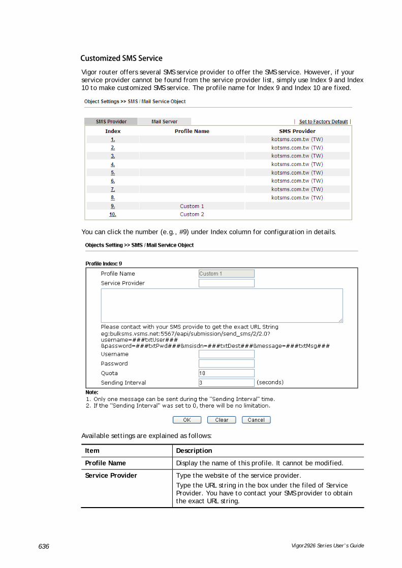
Vigor2926 Series User’s Guide 636
CCuussttoommiizzeedd SSMMSS SSeerrvviiccee
Vigor router offers several SMS service provider to offer the SMS service. However, if your service provider cannot be found from the service provider list, simply use Index 9 and Index 10 to make customized SMS service. The profile name for Index 9 and Index 10 are fixed.
You can click the number (e.g., #9) under Index column for configuration in details.
Available settings are explained as follows:
Item Description
Profile Name Display the name of this profile. It cannot be modified.
Service Provider Type the website of the service provider.
Type the URL string in the box under the filed of Service Provider. You have to contact your SMS provider to obtain the exact URL string.

Vigor2926 Series User’s Guide 637
Username Type a user name that the sender can use to register to selected SMS provider.
The maximum length of the name you can set is 31 characters.
Password Type a password that the sender can use to register to selected SMS provider.
The maximum length of the password you can set is 31 characters.
Quota Type the total number of the messages that the router will send out.
Sending Interval Type the shortest time interval for the system to send SMS.
After finishing all the settings here, please click OK to save the configuration.
MMaaiill SSeerrvviiccee OObbjjeecctt
This page allows you to set ten profiles which will be applied in Application>>SMS/Mail Alert Service.
Each item is explained as follows:
Item Description
Set to Factory Default Clear all of the settings and return to factory default settings.
Index Display the profile number that you can configure.
Profile Display the name for such mail server profile.

Vigor2926 Series User’s Guide 638
To set a new profile, please do the steps listed below:
1. Click the Mail Server tab, and click the number (e.g., #1) under Index column for configuration in details.
2. The configuration page will be shown as follows:
Available settings are explained as follows:
Item Description
Profile Name Type a name for such mail service profile. The maximum length of the name you can set is 31 characters.
SMTP Server Type the IP address of the mail server.
SMTP Port Type the port number for SMTP server.
Sender Address Type the e-mail address of the sender.
Use SSL Check this box to use port 465 for SMTP server for some e-mail server uses https as the transmission method.
Authentication The mail server must be authenticated with the correct username and password to have the right of sending message out. Check the box to enable the function.
Username – Type a name for authentication. The maximum length of the name you can set is 31 characters.
Password – Type a password for authentication. The maximum length of the password you can set is 31 characters.

Vigor2926 Series User’s Guide 639
Sending Interval Define the interval for the system to send the SMS out.
3. After finishing all the settings here, please click OK to save the configuration.
VVIIIIII--11--1111 NNoottiiffiiccaattiioonn OObbjjeecctt
This page allows you to set ten profiles which will be applied in Application>>SMS/Mail Alert Service.
You can set an object with different monitoring situation.
To set a new profile, please do the steps listed below:
1. Open Object Setting>>Notification Object, and click the number (e.g., #1) under Index column for configuration in details.

Vigor2926 Series User’s Guide 640
2. The configuration page will be shown as follows:
Available settings are explained as follows:
Item Description
Profile Name Type a name for such notification profile. The maximum length of the name you can set is 15 characters.
Category Display the types that will be monitored.
Status Display the status for the category. You can check the box to be monitored.
For example, the check box of CPE firmware upgrade fail under the category of Central VPN Management is checked. Once such profile is enabled, Vigor router system will send out notification to the recipient via SMS.
3. After finishing all the settings here, please click OK to save the configuration.
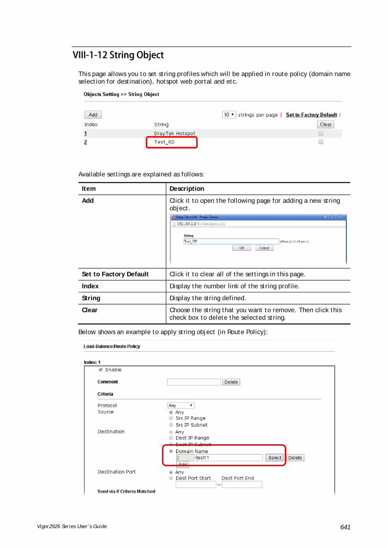
Vigor2926 Series User’s Guide 641
VVIIIIII--11--1122 SSttrriinngg OObbjjeecctt
This page allows you to set string profiles which will be applied in route policy (domain name selection for destination), hotspot web portal and etc.
Available settings are explained as follows:
Item Description
Add Click it to open the following page for adding a new string object.
Set to Factory Default Click it to clear all of the settings in this page.
Index Display the number link of the string profile.
String Display the string defined.
Clear Choose the string that you want to remove. Then click this check box to delete the selected string.
Below shows an example to apply string object (in Route Policy):

Vigor2926 Series User’s Guide 642
VVIIIIII--11--1133 CCoouunnttrryy OObbjjeecctt
The country object profile can determine which country/countries shall be blocked by the Vigor router’s Firewall.
The country object, by grouping IP addresses for multiple countries, can be applied by other functions such as router policy destination (refer to the following figure for example).
To set a new profile, please do the steps listed below:
1. Open Object Setting>>Country Object, and click the number (e.g., #1) under Index column for configuration in details.

Vigor2926 Series User’s Guide 643
2. The configuration page will be shown as follows:
Available settings are explained as follows:
Item Description
Name Type a name for such profile. The maximum length of the name you can set is 15 characters.
Countries Check the box(es) for the country/countries to be blocked by Firewall.
Note that one country profile can contain 1 up to 16 countries.
3. After finishing all the settings here, please click OK to save the configuration.

Vigor2926 Series User’s Guide 644
AApppplliiccaattiioonn NNootteess
AA--11 HHooww ttoo SSeenndd aa NNoottiiffiiccaattiioonn ttoo SSppeecciiffiieedd PPhhoonnee NNuummbbeerr vviiaa SSMMSS SSeerrvviiccee iinn
WWAANN DDiissccoonnnneeccttiioonn
Follow the steps listed below:
1. Log into the web user interface of Vigor router.
2. Configure relational objects first. Open Object Settings>>SMS/Mail Server Object to get the following page.
Index 1 to Index 8 allows you to choose the built-in SMS service provider. If the SMS service provider is not on the list, you can configure Index 9 and Index 10 to add the new service provider to Vigor router.
3. Choose any index number (e.g., Index 1 in this case) to configure the SMS Provider setting. In the following page, type the username and password and set the quota that the router can send the message out.

Vigor2926 Series User’s Guide 645
4. After finished the settings, click OK to return to previous page. Now you have finished the configuration of the SMS Provider profile setting.
5. Open Object Settings>>Notification Object to configure the event conditions of the notification.
6. Choose any index number (e.g., Index 1 in this case) to configure conditions for sending the SMS. In the following page, type the name of the profile and check the Disconnected and Reconnected boxes for WAN to work in concert with the topic of this paper.

Vigor2926 Series User’s Guide 646
7. After finished the settings, click OK to return to previous page. You have finished the configuration of the notification object profile setting.
8. Now, open Application >> SMS / Mail Alert Service. Use the drop down list to choose SMS Provider and the Notify Profile (specify the time of sending SMS). Then, type the phone number in the field of Recipient (the one who will receive the SMS).
9. Click OK to save the settings. Later, if one of the WAN connections fails in your router, the system will send out SMS to the phone number specified. If the router has only one WAN interface, the system will send out SMS to the phone number while reconnecting the WAN interface successfully.

Vigor2926 Series User’s Guide 647
RReemmaarrkk:: HHooww tthhee ccuussttoommiizzee tthhee SSMMSS PPrroovviiddeerr
Choose one of the Index numbers (9 or 10) allowing you to customize the SMS Provider. In the web page, type the URL string of the SMS provider and type the username and password. After clicking OK, the new added SMS provider will be added and will be available for you to specify for sending SMS out.

Vigor2926 Series User’s Guide 648
VVIIIIII--22 UUSSBB AApppplliiccaattiioonn
USB device connected on Vigor router can be regarded as a server or WAN interface. By way of Vigor router, clients on LAN can access, write and read data stored in USB storage disk with different applications. After setting the configuration in USB Application, you can type the IP address of the Vigor router and username/password created in USB Application>>USB User Management on the client software. Then, the client can use the FTP site (USB storage disk) or share the SMB service through Vigor router.
Info
USB ports on Vigor router are allowed to connect to USB modem. Models of the modems supported by Vigor router can be seen from USB Application>>Modem Support List. For network connection via USB modem, refer to WAN>>Internet Access and WAN>>General Setup for detailed information.
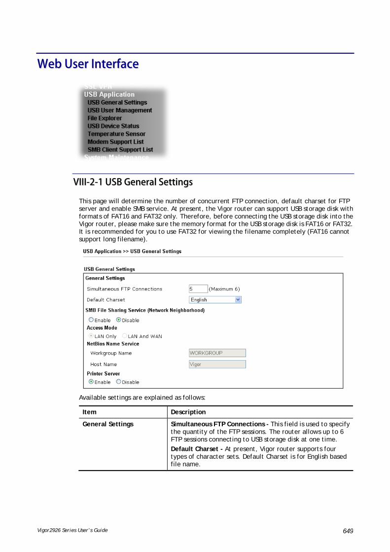
Vigor2926 Series User’s Guide 649
WWeebb UUsseerr IInntteerrffaaccee
VVIIIIII--22--11 UUSSBB GGeenneerraall SSeettttiinnggss
This page will determine the number of concurrent FTP connection, default charset for FTP server and enable SMB service. At present, the Vigor router can support USB storage disk with formats of FAT16 and FAT32 only. Therefore, before connecting the USB storage disk into the Vigor router, please make sure the memory format for the USB storage disk is FAT16 or FAT32. It is recommended for you to use FAT32 for viewing the filename completely (FAT16 cannot support long filename).
Available settings are explained as follows:
Item Description
General Settings Simultaneous FTP Connections - This field is used to specify the quantity of the FTP sessions. The router allows up to 6 FTP sessions connecting to USB storage disk at one time.
Default Charset - At present, Vigor router supports four types of character sets. Default Charset is for English based file name.

Vigor2926 Series User’s Guide 650
SMB File Sharing Service Click Enable to invoke SMB service (file sharing) via the router.
Access Mode LAN Only – Users coming from internet cannot connect to the SMB server of the router.
LAN And WAN - Both LAN and WAN users can access SMB server of the router.
NetBios Name Service For the NetBios service of USB storage disk, you have to specify a workgroup name and a host name. A workgroup name must not be the same as the host name. The workgroup name can have as many as 15 characters and the host name can have as many as 23 characters. Both them cannot contain any of the following--- ; : " < > * + = \ | ?.
Workgroup Name – Type a name for the workgroup.
Host Name – Type the host name for the router.
Printer Server Enable – Click it to make Vigor router act as a printer server (with USB printer attached).
After finishing all the settings here, please click OK to save the configuration.
VVIIIIII--22--22 UUSSBB UUsseerr MMaannaaggeemmeenntt
This page allows you to set profiles for FTP/SMB users. Any user who wants to access into the USB storage disk must type the same username and password configured in this page. Before adding or modifying settings in this page, please insert a USB storage disk first. Otherwise, an error message will appear to warn you.
Click index number to access into configuration page.

Vigor2926 Series User’s Guide 651
Available settings are explained as follows:
Item Description
FTP/SMB User Enable – Click this button to activate this profile (account) for FTP service or SMB User service. Later, the user can use the username specified in this page to login into FTP server.
Disable – Click this button to disable such profile.
Username Type the username for FTP/SMB users for accessing into FTP server (USB storage disk). Be aware that users cannot access into USB storage disk in anonymity. Later, you can open FTP client software and type the username specified here for accessing into USB storage disk. The length of the name is limited to 11 characters.
Note: “Admin” could not be typed here as username, for the word is specified for accessing into web pages of Vigor router only. Also, it is reserved for FTP firmware upgrade usage.
Note: FTP Passive mode is not supported by Vigor Router.
Please disable the mode on the FTP client.
Password Type the password for FTP/SMB users for accessing FTP server. Later, you can open FTP client software and type the password specified here for accessing into USB storage disk. The length of the password is limited to 11 characters.
Confirm Password Type the password again to make confirmation.
Home Folder It determines the folder for the client to access into. The user can enter a directory name in this field. Then, after clicking OK, the router will create the specific/new folder in the USB storage disk. In addition, if the user types “/” here, he/she can access into all of the disk folders and files in USB storage disk.
Note: When write protect status for the USB storage disk is ON, you cannot type any new folder name in this field. Only “/” can be used in such case.
You can click to open the following dialog to add any new folder which can be specified as the Home Folder.
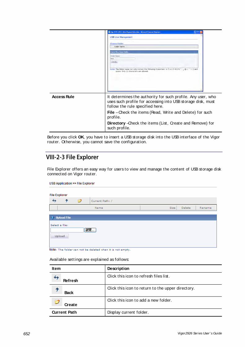
Vigor2926 Series User’s Guide 652
Access Rule It determines the authority for such profile. Any user, who uses such profile for accessing into USB storage disk, must follow the rule specified here.
File – Check the items (Read, Write and Delete) for such profile.
Directory –Check the items (List, Create and Remove) for such profile.
Before you click OK, you have to insert a USB storage disk into the USB interface of the Vigor router. Otherwise, you cannot save the configuration.
VVIIIIII--22--33 FFiillee EExxpplloorreerr
File Explorer offers an easy way for users to view and manage the content of USB storage disk connected on Vigor router.
Available settings are explained as follows:
Item Description
Refresh Click this icon to refresh files list.
Back Click this icon to return to the upper directory.
Create Click this icon to add a new folder.
Current Path Display current folder.
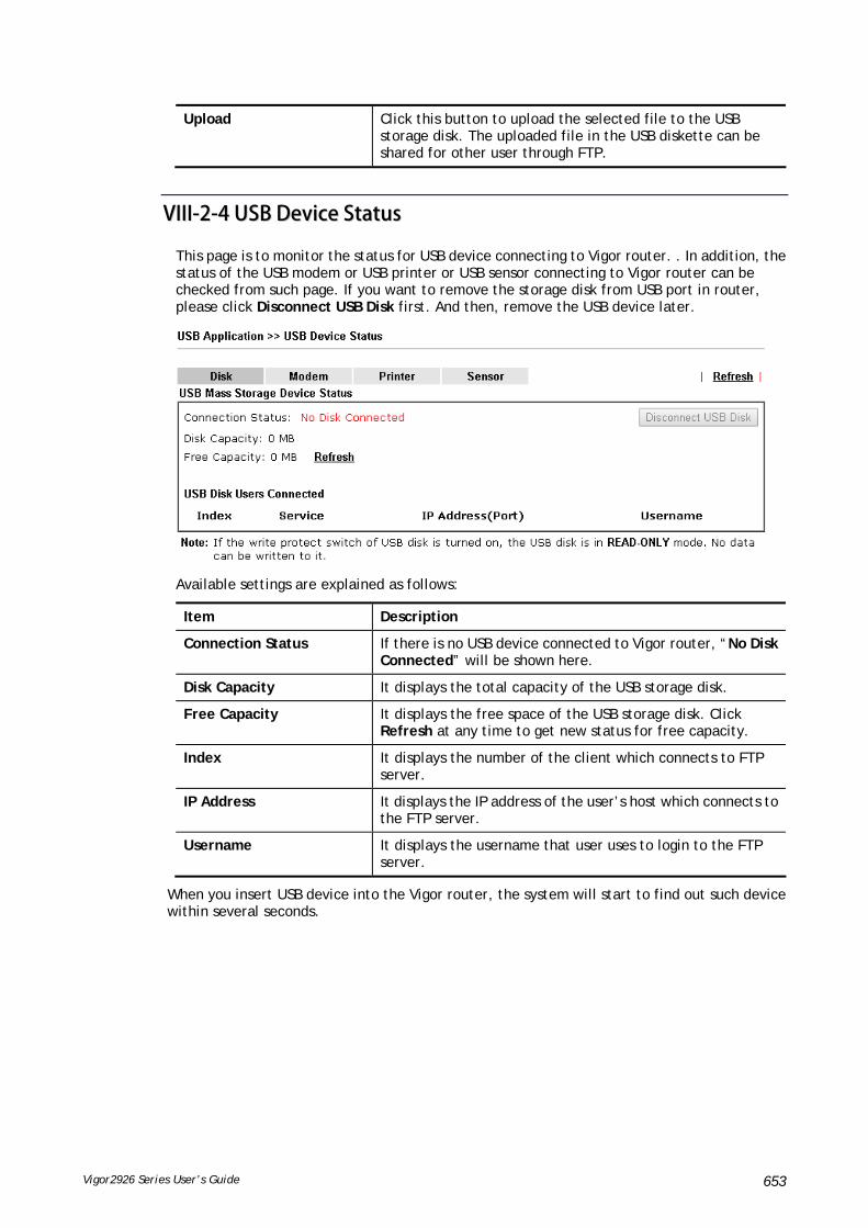
Vigor2926 Series User’s Guide 653
Upload Click this button to upload the selected file to the USB storage disk. The uploaded file in the USB diskette can be shared for other user through FTP.
VVIIIIII--22--44 UUSSBB DDeevviiccee SSttaattuuss
This page is to monitor the status for USB device connecting to Vigor router. . In addition, the status of the USB modem or USB printer or USB sensor connecting to Vigor router can be checked from such page. If you want to remove the storage disk from USB port in router, please click Disconnect USB Disk first. And then, remove the USB device later.
Available settings are explained as follows:
Item Description
Connection Status If there is no USB device connected to Vigor router, “No Disk Connected” will be shown here.
Disk Capacity It displays the total capacity of the USB storage disk.
Free Capacity It displays the free space of the USB storage disk. Click Refresh at any time to get new status for free capacity.
Index It displays the number of the client which connects to FTP server.
IP Address It displays the IP address of the user’s host which connects to the FTP server.
Username It displays the username that user uses to login to the FTP server.
When you insert USB device into the Vigor router, the system will start to find out such device within several seconds.
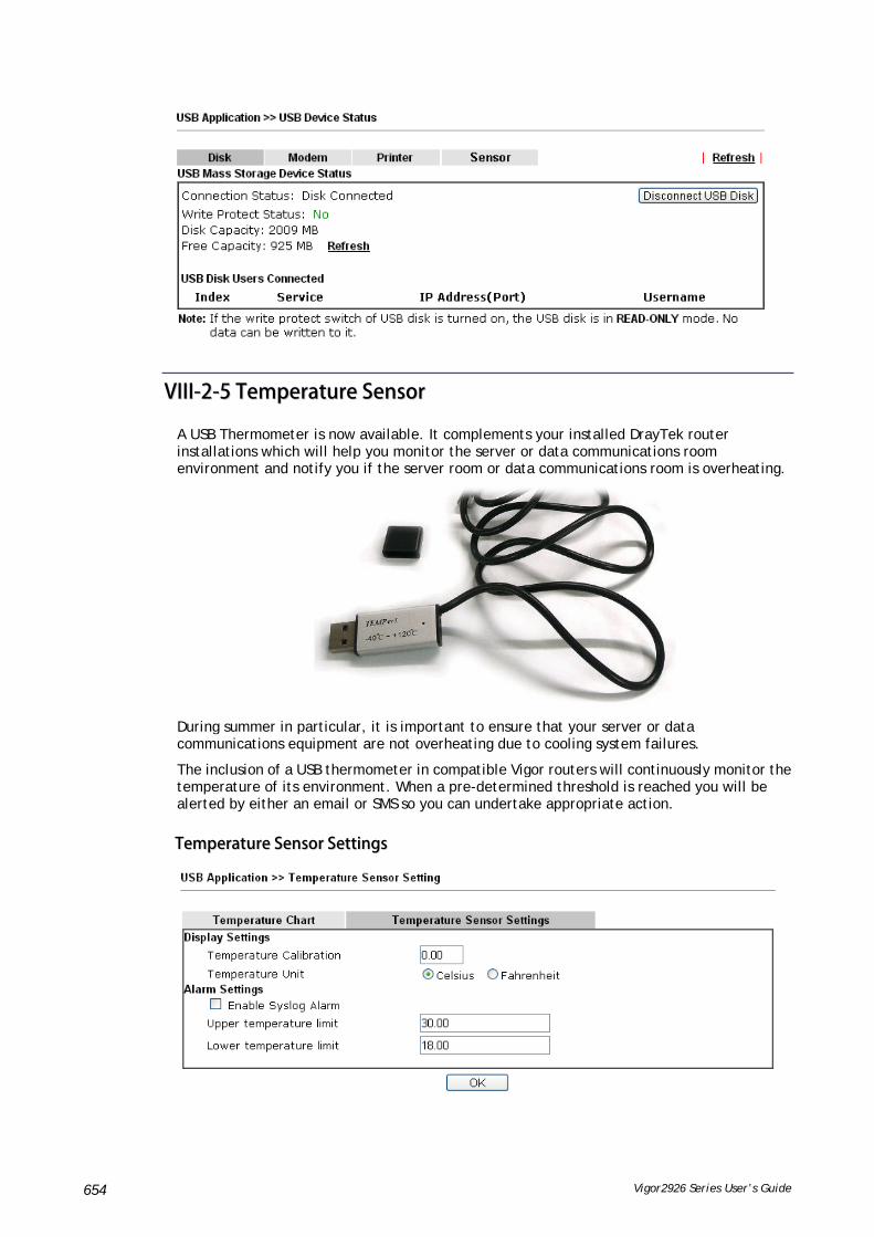
Vigor2926 Series User’s Guide 654
VVIIIIII--22--55 TTeemmppeerraattuurree SSeennssoorr
A USB Thermometer is now available. It complements your installed DrayTek router installations which will help you monitor the server or data communications room environment and notify you if the server room or data communications room is overheating.
During summer in particular, it is important to ensure that your server or data communications equipment are not overheating due to cooling system failures.
The inclusion of a USB thermometer in compatible Vigor routers will continuously monitor the temperature of its environment. When a pre-determined threshold is reached you will be alerted by either an email or SMS so you can undertake appropriate action.
TTeemmppeerraattuurree SSeennssoorr SSeettttiinnggss

Vigor2926 Series User’s Guide 655
Available settings are explained as follows:
Item Description
Display Settings Temperature Calibration - Type a value used for correcting the temperature error.
Temperature Unit - Choose the display unit of the temperature. There are two types for you to choose.
Alarm Settings Enable Syslog Alarm - The temperature log will be recorded on Syslog if it is enabled.
Upper temperature limit/Lower temperature limit - Type the upper limit and lower limit for the system to send out temperature alert.
TTeemmppeerraattuurree CChhaarrtt
Below shows an example of temperature graph:
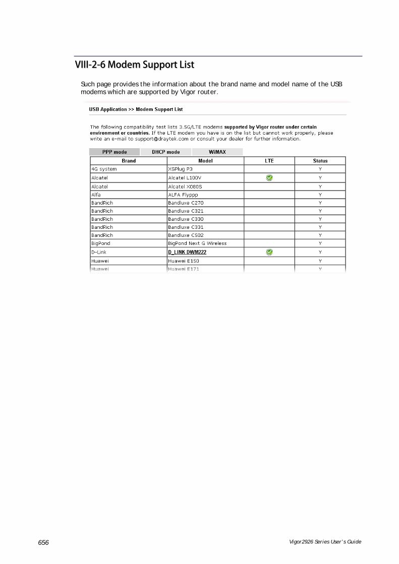
Vigor2926 Series User’s Guide 656
VVIIIIII--22--66 MMooddeemm SSuuppppoorrtt LLiisstt
Such page provides the information about the brand name and model name of the USB modems which are supported by Vigor router.

Vigor2926 Series User’s Guide 657
VVIIIIII--22--77 SSMMBB CClliieenntt SSuuppppoorrtt LLiisstt
SMB Client Support List provides the test status information for applications with file sharing operated under different platforms.

Vigor2926 Series User’s Guide 658
AApppplliiccaattiioonn NNootteess
AA--11 HHooww ccaann II ggeett tthhee ffiilleess ffrroomm UUSSBB ssttoorraaggee ddeevviiccee ccoonnnneeccttiinngg ttoo VViiggoorr
rroouutteerr??
Files on USB storage device can be reviewed by opening USB Applicaiton>>File Explorer. If it is necessary for you to delete, copy files on the device or write, paste files to the devcie, it must be done through SMB server or FTP server.
SMB service is based on the original USB FTP service. You will need to setup USB FTP first. We would like to give brief instructions on USB FTP setup here.
1. Plug the USB device to the USB port on the router. Make sure Disk Connected appears on the Connection Status as the figure shown below:
2. Then, please open USB Application >> USB General Settings to enable SMB service.

Vigor2926 Series User’s Guide 659
3. Setup a user account for the FTP service by using USB Application >>USB User Management. Click Enable to enable FTP/SMB User account. Here we add a new account "user1" and assign authorities “Read”, “Write” and “List” to it.
4. Click OK to save the configuration.
5. Make sure the FTP service is running properly. Please open a browser and type ftp://192.168.1.1. Use the account "user1" to login.
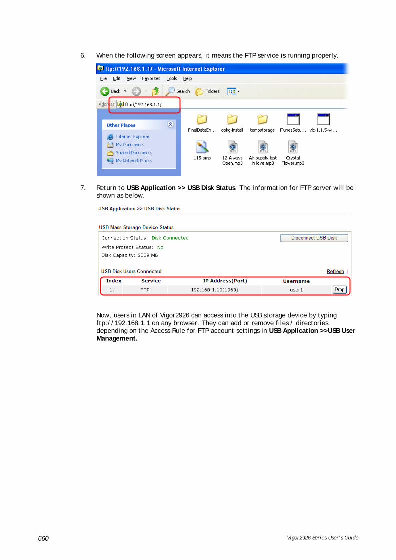
Vigor2926 Series User’s Guide 660
6. When the following screen appears, it means the FTP service is running properly.
7. Return to USB Application >> USB Disk Status. The information for FTP server will be shown as below.
Now, users in LAN of Vigor2926 can access into the USB storage device by typing ftp://192.168.1.1 on any browser. They can add or remove files / directories, depending on the Access Rule for FTP account settings in USB Application >>USB User Management.

Vigor2926 Series User’s Guide 661
PPaarrtt IIXX TTrroouubblleesshhoooottiinngg
This part will guide you to solve abnormal situations if you cannot access into the Internet after installing the router and finishing the web configuration.
Vigor2926 Series User’s Guide 662
IIXX--11DDiiaaggnnoossttiiccss
This section will guide you to solve abnormal situations if you cannot access into the Internet after installing the router and finishing the web configuration. Please follow sections below to check your basic installation status stage by stage.
Checking if the hardware status is OK or not.
Checking if the network connection settings on your computer are OK or not.
Pinging the router from your computer.
Checking if the ISP settings are OK or not.
Backing to factory default setting if necessary.
If all above stages are done and the router still cannot run normally, it is the time for you to contact your dealer or DrayTek technical support for advanced help.

Vigor2926 Series User’s Guide 663
WWeebb UUsseerr IInntteerrffaaccee
Fisrt, take a look at the menu items under Diagnostics. Diagnostic Tools provide a useful way to view or diagnose the status of your Vigor router.
IIXX--11--11 DDiiaall--oouutt TTrriiggggeerriinngg
Click Diagnostics and click Dial-out Triggering to open the web page. The internet connection (e.g., PPPoE) is triggered by a package sending from the source IP address.
Available settings are explained as follows:
Item Description
Decoded Format It shows the source IP address (local), destination IP (remote) address, the protocol and length of the package.
Refresh Click it to reload the page.

Vigor2926 Series User’s Guide 664
IIXX--11--22 RRoouuttiinngg TTaabbllee
Click Diagnostics and click Routing Table to open the web page.
Available settings are explained as follows:
Item Description
Refresh Click it to reload the page.

Vigor2926 Series User’s Guide 665
IIXX--11--33 AARRPP CCaacchhee TTaabbllee
Click Diagnostics and click ARP Cache Table to view the content of the ARP (Address Resolution Protocol) cache held in the router. The table shows a mapping between an Ethernet hardware address (MAC Address) and an IP address.
Available settings are explained as follows:
Item Description
Show Specify LAN and VLAN to display related information.
In default, this page will display all of the information about LAN and VLAN.
Refresh Click it to reload the page.

Vigor2926 Series User’s Guide 666
IIXX--11--44 IIPPvv66 NNeeiigghhbboouurr TTaabbllee
The table shows a mapping between an Ethernet hardware address (MAC Address) and an IPv6 address. This information is helpful in diagnosing network problems, such as IP address conflicts, etc.
Click Diagnostics and click IPv6 Neighbour Table to open the web page.
Available settings are explained as follows:
Item Description
Refresh Click it to reload the page.
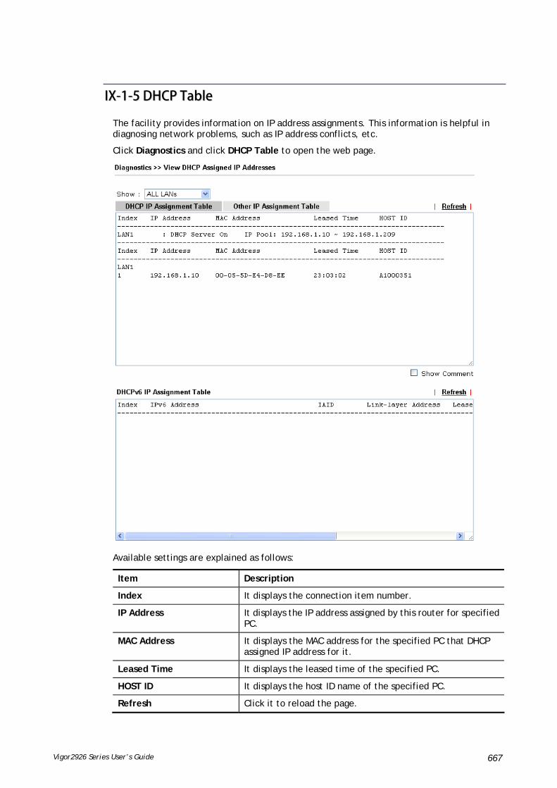
Vigor2926 Series User’s Guide 667
IIXX--11--55 DDHHCCPP TTaabbllee
The facility provides information on IP address assignments. This information is helpful in diagnosing network problems, such as IP address conflicts, etc.
Click Diagnostics and click DHCP Table to open the web page.
Available settings are explained as follows:
Item Description
Index It displays the connection item number.
IP Address It displays the IP address assigned by this router for specified PC.
MAC Address It displays the MAC address for the specified PC that DHCP assigned IP address for it.
Leased Time It displays the leased time of the specified PC.
HOST ID It displays the host ID name of the specified PC.
Refresh Click it to reload the page.
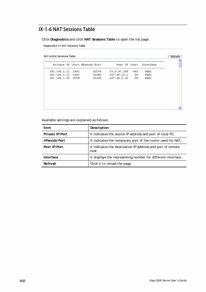
Vigor2926 Series User’s Guide 668
IIXX--11--66 NNAATT SSeessssiioonnss TTaabbllee
Click Diagnostics and click NAT Sessions Table to open the list page.
Available settings are explained as follows:
Item Description
Private IP:Port It indicates the source IP address and port of local PC.
#Pseudo Port It indicates the temporary port of the router used for NAT.
Peer IP:Port It indicates the destination IP address and port of remote host.
Interface It displays the representing number for different interface.
Refresh Click it to reload the page.
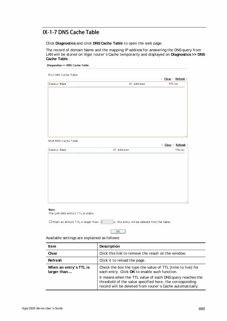
Vigor2926 Series User’s Guide 669
IIXX--11--77 DDNNSS CCaacchhee TTaabbllee
Click Diagnostics and click DNS Cache Table to open the web page.
The record of domain Name and the mapping IP address for answering the DNS query from LAN will be stored on Vigor router’s Cache temporarily and displayed on Diagnostics >> DNS Cache Table.
Available settings are explained as follows:
Item Description
Clear Click this link to remove the result on the window.
Refresh Click it to reload the page.
When an entry’s TTL is larger than….
Check the box the type the value of TTL (time to live) for each entry. Click OK to enable such function.
It means when the TTL value of each DNS query reaches the threshold of the value specified here, the corresponding record will be deleted from router’s Cache automatically.
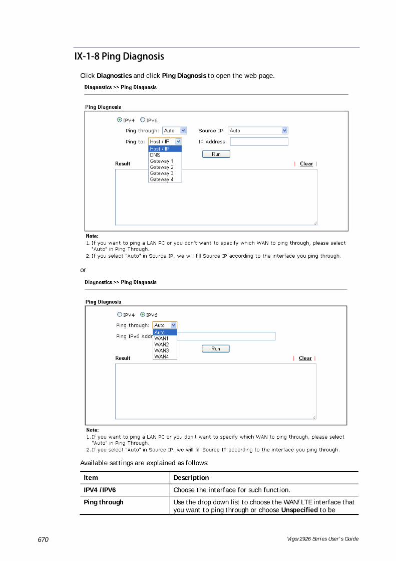
Vigor2926 Series User’s Guide 670
IIXX--11--88 PPiinngg DDiiaaggnnoossiiss
Click Diagnostics and click Ping Diagnosis to open the web page.
or
Available settings are explained as follows:
Item Description
IPV4 /IPV6 Choose the interface for such function.
Ping through Use the drop down list to choose the WAN/LTE interface that you want to ping through or choose Unspecified to be

Vigor2926 Series User’s Guide 671
determined by the router automatically.
Ping to Use the drop down list to choose the destination that you want to ping.
IP Address Type the IP address of the Host/IP that you want to ping.
Ping IPv6 Address Type the IPv6 address that you want to ping.
Run Click this button to start the ping work. The result will be displayed on the screen.
Clear Click this link to remove the result on the window.
IIXX--11--99 DDaattaa FFllooww MMoonniittoorr
This page displays the running procedure for the IP address monitored and refreshes the data in an interval of several seconds. The IP address listed here is configured in Bandwidth Management. You have to enable IP bandwidth limit and IP session limit before invoking Data Flow Monitor. If not, a notification dialog box will appear to remind you enabling it.
Click Diagnostics and click Data Flow Monitor to open the web page. You can click IP Address, TX rate, RX rate or Session link for arranging the data display.

Vigor2926 Series User’s Guide 672
Available settings are explained as follows:
Item Description
Enable Data Flow Monitor Check this box to enable this function.
Refresh Seconds Use the drop down list to choose the time interval of refreshing data flow that will be done by the system automatically.
Refresh Click this link to refresh this page manually.
Index Display the number of the data flow.
IP Address Display the IP address of the monitored device.
TX rate (kbps) Display the transmission speed of the monitored device.
RX rate (kbps) Display the receiving speed of the monitored device.
Sessions Display the session number that you specified in Limit Session web page.
Action Block - can prevent specified PC accessing into Internet within 5 minutes.

Vigor2926 Series User’s Guide 673
Unblock –The device with the IP address will be blocked for five minutes. The remaining time will be shown on the session column. Click it to cancel the IP address blocking.
APP QoS Use the drop down list to change the priority in data transmission for the specified IP address (host).
Current /Peak/Speed Current means current transmission rate and receiving rate for WAN interface.
Peak means the highest peak value detected by the router in data transmission.
Speed means line speed specified in WAN>>General Setup. If you do not specify any rate at that page, here will display Auto for instead.

Vigor2926 Series User’s Guide 674
IIXX--11--1100 TTrraaffffiicc GGrraapphh
Click Diagnostics and click Traffic Graph to open the web page. Choose WAN1/WAN2/WAN3/WAN4 Bandwidth, Sessions, Ping Detect, daily or weekly for viewing different traffic graph. Click Reset to zero the accumulated RX/TX (received and transmitted) data of WAN. Click Refresh to renew the graph at any time.
The horizontal axis represents time. Yet the vertical axis has different meanings. For WAN1/WAN2/WAN3/LTE/WAN4 Bandwidth chart, the numbers displayed on vertical axis represent the numbers of the transmitted and received packets in the past.
For Sessions chart, the numbers displayed on vertical axis represent the numbers of the NAT sessions during the past.

Vigor2926 Series User’s Guide 675
IIXX--11--1111 VVPPNN GGrraapphh
Click Diagnostics and click VPN Graph to open the web page.

Vigor2926 Series User’s Guide 676
IIXX--11--1122 TTrraaccee RRoouuttee
Click Diagnostics and click Trace Route to open the web page. This page allows you to trace the routes from router to the host. Simply type the IP address of the host in the box and click Run. The result of route trace will be shown on the screen.
or
Available settings are explained as follows:
Item Description
IPv4 / IPv6 Click one of them to display corresponding information for it.
Trace through Use the drop down list to choose the interface that you want to ping through.

Vigor2926 Series User’s Guide 677
Protocol Use the drop down list to choose the protocol that you want to ping through.
Host/IP Address It indicates the IP address of the host.
Trace Host/IP Address It indicates the IPv6 address of the host.
Run Click this button to start route tracing work.
Clear Click this link to remove the result on the window.
IIXX--11--1133 SSyysslloogg EExxpplloorreerr
Such page provides real-time syslog and displays the information on the screen.
FFoorr WWeebb SSyysslloogg
This page displays the time and message for User/Firewall/call/WAN/VPN settings. You can check Enable Web Syslog, specify the type of Syslog and choose the display mode you want. Later, the event of Syslog with specified type will be shown for your reference.
Available settings are explained as follows:
Item Description
Enable Web Syslog Check this box to enable the function of Web Syslog.
Syslog Type Use the drop down list to specify a type of Syslog to be displayed.

Vigor2926 Series User’s Guide 678
Export Click this link to save the data as a file.
Refresh Click this link to refresh this page manually.
Clear Click this link to clear information on this page.
Display Mode There are two modes for you to choose.
Stop record when fulls – when the capacity of syslog is full, the system will stop recording.
Always record the new event – only the newest events will be recorded by the system.
Time Display the time of the event occurred.
Message Display the information for each event.
FFoorr UUSSBB SSyysslloogg
This page displays the syslog recorded on the USB storage disk.
Available settings are explained as follows:
Item Description
Time Display the time of the event occurred.
Log Type Display the type of the record.
Message Display the information for each event.
IIXX--11--1144 IIPPvv66 TTSSPPCC SSttaattuuss
IPv6 TSPC status web page could help you to diagnose the connection status of TSPC.
If TSPC has configured properly, the router will display the following page when the user connects to tunnel broker successfully.

Vigor2926 Series User’s Guide 679
Available settings are explained as follows:
Item Description
Refresh Click this link to refresh this page manually.
IIXX--11--1155 HHiigghh AAvvaaiillaabbiilliittyy SSttaattuuss
All of the routers under the same DARP (DrayTek Address resolution Protocol) group can be viewed in such page. However, only partial information of the router status will be displayed.
Vigor routers with the following condtions will be treated as the same DARP group:
HA enabled
the same Redundancy method
the same Group ID
the same Authentication Key
the same Management Interface
Open Diagnostics>>High Availablity Status.
Available settings are explained as follows:
Item Description
Details/Back Details – Click it to display detailed status about HA configuration for the selected router.
Back – Return to previous page.
HA Setup Click it to open Applications>>High Availability for modifying the configuration.
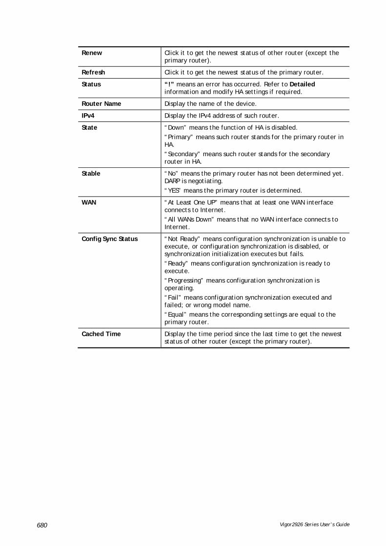
Vigor2926 Series User’s Guide 680
Renew Click it to get the newest status of other router (except the primary router).
Refresh Click it to get the newest status of the primary router.
Status “!” means an error has occurred. Refer to Detailed information and modify HA settings if required.
Router Name Display the name of the device.
IPv4 Display the IPv4 address of such router.
State “Down” means the function of HA is disabled.
“Primary” means such router stands for the primary router in HA.
“Secondary” means such router stands for the secondary router in HA.
Stable “No” means the primary router has not been determined yet. DARP is negotiating.
“YES” means the primary router is determined.
WAN “At Least One UP” means that at least one WAN interface connects to Internet.
“All WANs Down” means that no WAN interface connects to Internet.
Config Sync Status “Not Ready” means configuration synchronization is unable to execute, or configuration synchronization is disabled, or synchronization initialization executes but fails.
“Ready” means configuration synchronization is ready to execute.
“Progressing” means configuration synchronization is operating.
“Fail” means configuration synchronization executed and failed; or wrong model name.
“Equal” means the corresponding settings are equal to the primary router.
Cached Time Display the time period since the last time to get the newest status of other router (except the primary router).

Vigor2926 Series User’s Guide 681
Cick the link of Status, Router Name, IPv4 or Details, the following page will be displayed on the screen.

Vigor2926 Series User’s Guide 682
IIXX--11--1166 AAuutthheennttiiccaattiioonn IInnffoorrmmaattiioonn
AAuutthheennttiiccaattiioonn UUsseerr LLiisstt
Such page displays authentication jobs made by Internal RADIUS or Local 802.1X.
When the mouse cursor moves to the name link under User Name, the connection message (including authentication failed information) about internal RADIUS or local 802.1X service will be shown by a popped up dialog box.
AAuutthheennttiiccaattiioonn IInnffoorrmmaattiioonn LLoogg
This page will display the complete authentication log information.
Available settings are explained as follows:
Item Description
Enable Check the box to enable such function.
Refresh Click it to update current page.
Clear Click it to remove all of the records.
Syslog Type Specify RADIUS, 802.1X or All to display related authentication information log.
Display Mode Choose the mode you want to display the related information on the following table.
Stop record when fulls – when the capacity of CVM log is full, the system will stop recording.
Always record the new event – only the newest events will be recorded by the system.
Time Display the time the user authenticated by Vigor2926 series.
Message Display authentication information done by Vigor2926 series.

Vigor2926 Series User’s Guide 683
IIXX--11--1177 DDooSS FFlloooodd TTaabbllee
This page can display content of IP connection detected by DoS Flooding Defense mechanism. It is useful and convenient for network engineers (e.g., MIS engineer) to inspect the network environment to find out if there is any abnormal connection.
Information of IP traced and destination port used for SYN Flood, UDP Flood and ICMP Flood attacks will be detected and shown respectively on different pages.
Moreover, IP address detected and suspected to attack the network system can be blocked shortly by clicking the Block button shown on pages of SYN Flood, UDP Flood and ICMP Flood.
Info
The icon - - means there is something wrong (e.g., attacking the system) with that IP address.

Vigor2926 Series User’s Guide 684
However, if an IP address is comfirmed to be blocked due to its abnormal behavior, click the Blocking IP List tab to block it forever. For example, IP address “192.168.1.123” (displayed on the following web page) will be blocked forever.
Available settings are explained as follows:
Item Description
Blocking IP Type the IP address in this field and click add. It will be added to the IP List and appear in the right frame.
IP list in the right frame will be blocked by Vigor system permanatly.
Remove – It is used to remove selected IP address from the Blocking IP List.
Refresh Click this link to refresh current page.

Vigor2926 Series User’s Guide 685
IIXX--11--1188 RRoouuttee PPoolliiccyy DDiiaaggnnoossiiss
With the analysis done by such page, possible path (static route, routing table or policy route) of the packets sent out of the router can be traced.
Available settings are explained as follows:
Item Description
Mode Analyze a single packet – Choose such mode to make Vigor router analyze how a single packet will be sent by a route policy.
Analyze multiple packets… - Choose such mode to make Vigor router analyze how multiple packets in a specified file will be sent by a route policy.
Packet Information Specify the nature of the packets to be analyzed by Vigor router.
ICMP/UDP/TCP/ANY- Specify a protocol for diagnosis.
Src IP – Type an IP address as the source IP.
Dst IP – Type an IP address as the destination IP.
Dst Port – Use the drop down list to specify the destination port.
Analyze – Click it to perform the job of analyzing. The analyzed result will be shown on the page..
Input File It is available when Analyze multiple packets.. is selected as Mode.
Select – Click the download link to get a blank example file. Then, click such button to select that blank “.csv” file for saving the result of analysis.

Vigor2926 Series User’s Guide 686
Analyze – Click it to perform the job of analyzing. The analyzed result will be shown on the page. If required, click export analysis to export the result as a file.
Note that the analysis was based on the current "load-balance/route policy" settings, we do not guarantee it will be 100% the same as the real case.

Vigor2926 Series User’s Guide 687
IIXX--22 CChheecckkiinngg IIff tthhee HHaarrddwwaarree SSttaattuuss IIss OOKK oorr NNoott
Follow the steps below to verify the hardware status.
1. Check the power line and WLAN/LAN cable connections. Refer to “I-2 Hardware Installation” for details.
2. Turn on the router. Make sure the ACT LED blink once per second and the correspondent LAN LED is bright.
3. If not, it means that there is something wrong with the hardware status. Simply back to “I-2 Hardware Installation” to execute the hardware installation again. And then, try again.

Vigor2926 Series User’s Guide 688
IIXX--33 CChheecckkiinngg IIff tthhee NNeettwwoorrkk CCoonnnneeccttiioonn SSeettttiinnggss oonn YYoouurr
CCoommppuutteerr IIss OOKK oorr NNoott
Sometimes the link failure occurs due to the wrong network connection settings. After trying the above section, if the link is stilled failed, please do the steps listed below to make sure the network connection settings is OK.
FFoorr WWiinnddoowwss
Info
The example is based on Windows 7. As to the examples for other operation systems, please refer to the similar steps or find support notes in www.DrayTek.com.
1. Open All Programs>>Getting Started>>Control Panel. Click Network and Sharing Center.
2. In the following window, click Change adapter settings.
3. Icons of network connection will be shown on the window. Right-click on Local Area Connection and click on Properties.

Vigor2926 Series User’s Guide 689
4. Select Internet Protocol Version 4 (TCP/IP) and then click Properties.
5. Select Obtain an IP address automatically and Obtain DNS server address automatically. Finally, click OK.

Vigor2926 Series User’s Guide 690
FFoorr MMaacc OOSS
1. Double click on the current used Mac OS on the desktop.
2. Open the Application folder and get into Network.
3. On the Network screen, select Using DHCP from the drop down list of Configure IPv4.

Vigor2926 Series User’s Guide 691
IIXX--44 PPiinnggiinngg tthhee RRoouutteerr ffrroomm YYoouurr CCoommppuutteerr
The default gateway IP address of the router is 192.168.1.1. For some reason, you might need to use “ping” command to check the link status of the router. The most important thing is that the computer will receive a reply from 192.168.1.1. If not, please check the IP address of your computer. We suggest you setting the network connection as get IP automatically. (Please refer to the previous section IX-3)
Please follow the steps below to ping the router correctly.
FFoorr WWiinnddoowwss
1. Open the Command Prompt window (from Start menu> Run).
2. Type command (for Windows 95/98/ME) or cmd (for Windows NT/ 2000/XP/Vista/7). The DOS command dialog will appear.
3. Type ping 192.168.1.1 and press [Enter]. If the link is OK, the line of “Reply from 192.168.1.1:bytes=32 time<1ms TTL=255” will appear.
4. If the line does not appear, please check the IP address setting of your computer.
FFoorr MMaacc OOSS ((TTeerrmmiinnaall))
1. Double click on the current used MacOs on the desktop.
2. Open the Application folder and get into Utilities.
3. Double click Terminal. The Terminal window will appear.
4. Type ping 192.168.1.1 and press [Enter]. If the link is OK, the line of “64 bytes from 192.168.1.1: icmp_seq=0 ttl=255 time=xxxx ms” will appear.

Vigor2926 Series User’s Guide 692

Vigor2926 Series User’s Guide 693
IIXX--55 CChheecckkiinngg IIff tthhee IISSPP SSeettttiinnggss aarree OOKK oorr NNoott
If WAN connection cannot be up, check if the LEDs (according to the LED explanations listed on section 1.2) are correct or not. If the LEDs are off, please:
Change the Physical Type from Auto negotiation to other values (e.g., 100M full duplex).
Next, change the physical type of modem (e.g., DSL/FTTX(GPON)/Cable modem) offered by ISP with the same value configured in Vigor router. Check if the LEDs on Vigor router are on or not.
If not, please install an additional switch for connecting both Vigor router and the modem offered by ISP. Then, check if the LEDs on Vigor router are on or not.
If the problem of LEDs cannot be solved by the above measures, please contact with the nearest reseller, or send an e-mail to DrayTek FAE for technical support.
Check if the settings offered by ISP are configured well or not.
When the LEDs are on and correct, yet the WAN connection still cannot be up, please:
Open WAN >> Internet Access page and then check whether the ISP settings are set correctly. Click Details Page of WAN1~WAN4 to review the settings that you configured previously.

Vigor2926 Series User’s Guide 694
IIXX--66 PPrroobblleemmss ffoorr 33GG//44GG NNeettwwoorrkk CCoonnnneeccttiioonn
When you have trouble in using 3G/4G network transmission, please check the following:
CChheecckk iiff UUSSBB LLEEDD lliigghhttss oonn oorr ooffff
You have to wait about 15 seconds after inserting 3G/4G USB Modem into your Vigor2926. Later, the USB LED will light on which means the installation of USB Modem is successful. If the USB LED does not light on, please remove and reinsert the modem again. If it still fails, restart Vigor2926.
UUSSBB LLEEDD lliigghhttss oonn bbuutt tthhee nneettwwoorrkk ccoonnnneeccttiioonn ddooeess nnoott wwoorrkk
Check the PIN Code of SIM card is disabled or not. Please use the utility of 3G/4G USB Modem to disable PIN code and try again. If it still fails, it might be the compliance problem of system. Please open DrayTek Syslog Tool to capture the connection information (WAN Log) and send the page (similar to the following graphic) to the service center of DrayTek.
TTrraannssmmiissssiioonn RRaattee iiss nnoott ffaasstt eennoouugghh
Please connect your Notebook with 3G/4G USB Modem to test the connection speed to verify if the problem is caused by Vigor2926. In addition, please refer to the manual of 3G/4G USB Modem for LED Status to make sure if the modem connects to Internet via HSDPA mode. If you want to use the modem indoors, please put it on the place near the window to obtain better signal receiving.
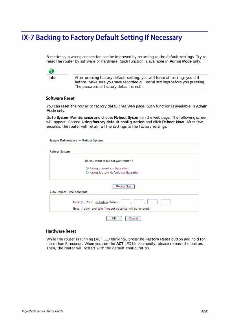
Vigor2926 Series User’s Guide 695
IIXX--77 BBaacckkiinngg ttoo FFaaccttoorryy DDeeffaauulltt SSeettttiinngg IIff NNeecceessssaarryy
Sometimes, a wrong connection can be improved by returning to the default settings. Try to reset the router by software or hardware. Such function is available in Admin Mode only.
Info
After pressing factory default setting, you will loose all settings you did before. Make sure you have recorded all useful settings before you pressing. The password of factory default is null.
SSooffttwwaarree RReesseett
You can reset the router to factory default via Web page. Such function is available in Admin Mode only.
Go to System Maintenance and choose Reboot System on the web page. The following screen will appear. Choose Using factory default configuration and click Reboot Now. After few seconds, the router will return all the settings to the factory settings.
HHaarrddwwaarree RReesseett
While the router is running (ACT LED blinking), press the Factory Reset button and hold for more than 5 seconds. When you see the ACT LED blinks rapidly, please release the button. Then, the router will restart with the default configuration.

Vigor2926 Series User’s Guide 696
After restore the factory default setting, you can configure the settings for the router again to fit your personal request.

Vigor2926 Series User’s Guide 697
IIXX--88 CCoonnttaaccttiinngg DDrraayyTTeekk
If the router still cannot work correctly after trying many efforts, please contact your dealer for further help right away. For any questions, please feel free to send e-mail to [email protected].

Vigor2926 Series User’s Guide 698
AAppppeennddiixx II:: VVLLAANN AApppplliiccaattiioonnss oonn VViiggoorr RRoouutteerr
Virtual Local Area Network is so-called VLAN. It offers the logical grouping technique to separate the physical ports of Ethernet switches, thus we can manage our local network easier, more flexible and secure. For instance, you’re a networking administrator in your company and you’re planning to isolate the visitors’ traffics from your private network for security considerations because you cannot ensure that visitors’ computer is clean. Or you want to separate your private network into several parts by divisions because there are too many computers in the same network segment and it results in the local traffics heavily. VLAN helps you to solve these situations, and DrayTek’s products support bellow two popular types:
PPoorrtt--bbaasseedd
It uses a matrix table of the physical ports to define the traffics how to exchange between each port, and the traffics will be isolated from the ports are not being ticked in the same line. It is the easiest way to setup an isolate network, but not a flexible way to maintain a growing network. Because the idea of port-based VLAN is grouping by physical ports, but the difficulty is how to handle the traffics between two or more Ethernet switches. Thus, VLAN is suitable for some circumstances, for example, the rental apartment, SOHO office…and so on. These clients may need two or three isolated networks only and setup a network in a simple way.
TTaagg--bbaasseedd
The idea of tag-based VLAN is to identify a virtual LAN with a specific ID, therefore, VLAN ID introduced by tag-based VLAN. Through VLAN ID, ports with different VID (VLAN ID) will be identified as in different LANs, so the traffics also will be isolated from each of VLANs. Many administrators who manage an enterprise network or even the internet service providers (ISP) adopt Tag-based VLAN popularly because it is convenient to maintain and manage a distributed network. Setting a large-scale network is easy by giving each of them with different VID and isolating the traffics at the same time. Besides the VLAN ID, there is another feature, Trunk, introduced. While the role of a port on an Ethernet switch is setup as a Trunk port, it means the VLAN ID will be kept while forwarding the packets between switches. By this feature, VLANs are able to distribute over two or more Ethernet switches easily, moreover design a large and secured network is possible through Trunk port. When VLAN is being enabled on Vigor routers, the LAN ports are being turned into Trunk mode automatically. Therefore, a VLAN supported switch, like VigorSwitch G2260/P2261, or VigorSwitch G1240, is needed.

Vigor2926 Series User’s Guide 699
Vigor routers [Note] support Tag-based feature both on LAN and WAN interfaces. The next we’ll demonstrate our web design and how to configure the settings by introducing the functionalities of Vigor router.
[Note]
Broadband router: Vigor2920/Vigor3200/Vigor2926/Vigo2960/Vigor3900
Modem router: Vigor2850/Vigor2926
VVLLAANN PPaacckkeettss oonn VViiggoorr rroouutteerrss
Trunk mode of LAN
Trunk Port can carry the packets with VID but replace the Non-VID packet as the VID of Trunk port while forwarding the packets to another switch.
Bridge mode of WAN
P1 and P2 are doing NAT flow to access to the internet, but P3 and P4 will forward the packets between WAN and LAN ports directly.
WWeebb UUsseerr IInntteerrffaaccee
So far, there are two kinds of open system on Vigor router. One is DrayOS, which is DrayTek owned, and another is Linux-like which customized by DrayTek from OpenWRT. Here DrayOS system is going to be introduced to you because it is the most stable and superfast booting system in DrayTek products. If the UI style of yours is different from the following. It may not DrayOS system with new web style or maybe the Linux-like model.
WAN

Vigor2926 Series User’s Guide 700

Vigor2926 Series User’s Guide 701
LAN
VVLLAANN aapppplliiccaattiioonnss oonn VViiggoorr rroouutteerr
Multi Subnet (VLAN of LAN)

Vigor2926 Series User’s Guide 702
Port-based mode
Tag-based mode
By above settings, there are four private networks will be created and computers attached with each of LAN ports or SSIDs which are able to obtain a private IP address from each DHCP server (LAN1/LAN2/LAN3/LAN4). However, the traffics of the LAN port or SSID that are NOT being grouped in the same VLAN are unable to forward to each other. The benefit of Port-based is able to extend the wired ports by installing a cheaper dumb switch as many as you need, but Tag-based offers you a flexible and well-managed network. The networks are isolated, secured and reduce the broadcasting storm effectively in each of networks with VLAN.
Guest Network

Vigor2926 Series User’s Guide 703
Port-based mode
Tag-based mode
To deploy a guest network, which serves your guests the internet accessibility, but the traffics have to be isolated from your private network due to the security considerations, it can be done by above settings. However, a switch support VLAN function is need if VLAN Tag enabled.
Triple Play (Multi-WAN)
NAT mode with VLAN
Following settings, the set-top box (STB) is able to attach with any LAN port. Video streaming which your ISP provided will be played on your monitor.

Vigor2926 Series User’s Guide 704

Vigor2926 Series User’s Guide 705
Bridge mode with VLAN
Set-top box (STB) or the other kinds of media devices are able to attach with Port4 or Port5 of LAN. Those devices that attached with Port4 or Port5 are able to access the services network directly which your ISP provided.

Vigor2926 Series User’s Guide 706
This page is left blank.

Vigor2926 Series User’s Guide 707
PPaarrtt XX TTeellnneett CCoommmmaannddss
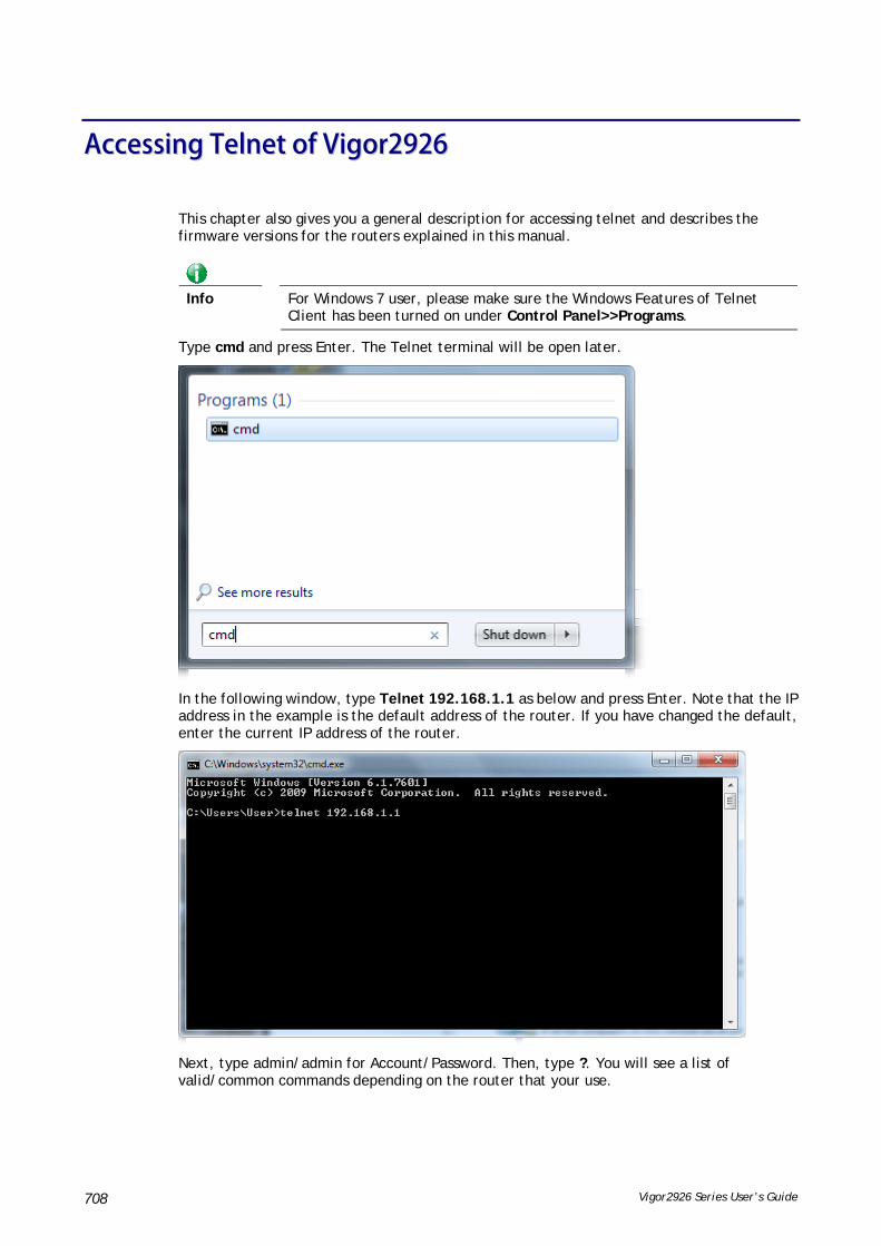
Vigor2926 Series User’s Guide 708
AAcccceessssiinngg TTeellnneett ooff VViiggoorr22992266
This chapter also gives you a general description for accessing telnet and describes the firmware versions for the routers explained in this manual.
Info
For Windows 7 user, please make sure the Windows Features of Telnet Client has been turned on under Control Panel>>Programs.
Type cmd and press Enter. The Telnet terminal will be open later.
In the following window, type Telnet 192.168.1.1 as below and press Enter. Note that the IP address in the example is the default address of the router. If you have changed the default, enter the current IP address of the router.
Next, type admin/admin for Account/Password. Then, type ?. You will see a list of valid/common commands depending on the router that your use.

Vigor2926 Series User’s Guide 709
For users using previous Windows system (e.g., 2000/XP), simply click Start >> Run and type Telnet 192.168.1.1 in the Open box as below. Next, type admin/admin for Account/Password. And, type ? to get a list of valid/common commands.

Vigor2926 Series User’s Guide 710
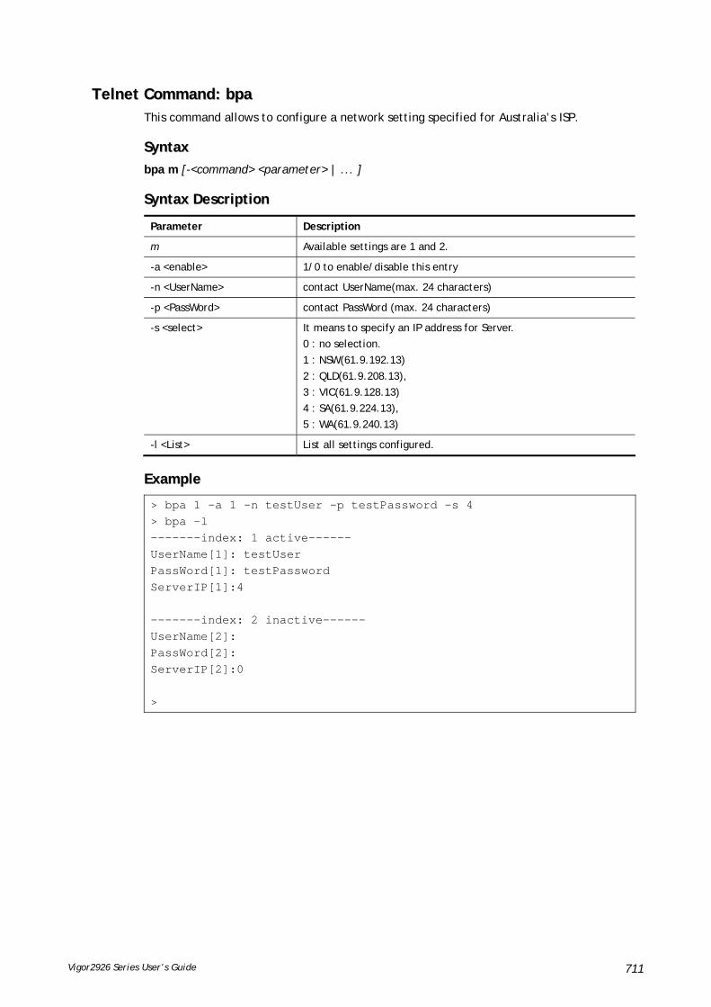
Vigor2926 Series User’s Guide 711
TTeellnneett CCoommmmaanndd:: bbppaa This command allows to configure a network setting specified for Australia’s ISP.
SSyynnttaaxx
bpa m [-<command> <parameter> | ... ]
SSyynnttaaxx DDeessccrriippttiioonn
Parameter Description
m Available settings are 1 and 2.
-a <enable> 1/0 to enable/disable this entry
-n <UserName> contact UserName(max. 24 characters)
-p <PassWord> contact PassWord (max. 24 characters)
-s <select> It means to specify an IP address for Server.
0 : no selection.
1 : NSW(61.9.192.13)
2 : QLD(61.9.208.13),
3 : VIC(61.9.128.13)
4 : SA(61.9.224.13),
5 : WA(61.9.240.13)
-l <List> List all settings configured.
EExxaammppllee
> bpa 1 -a 1 -n testUser -p testPassword -s 4 > bpa -l -------index: 1 active------ UserName[1]: testUser PassWord[1]: testPassword ServerIP[1]:4 -------index: 2 inactive------ UserName[2]: PassWord[2]: ServerIP[2]:0 >

Vigor2926 Series User’s Guide 712
TTeellnneett CCoommmmaanndd:: ccssmm aappppee pprrooff Commands under CSM allow you to set CSM profile to define policy profiles for different policy of IM (Instant Messenger)/P2P (Peer to Peer) application.
“csm appe prof “ is used to configure the APP Enforcement Profile name. Such profile will be applied in Default Rule of Firewall>>General Setup for filtering.
SSyynnttaaxx
csm appe prof -i INDEX [-v | -n NAME|setdefault]
SSyynnttaaxx DDeessccrriippttiioonn
Parameter Description
INDEX It means to specify the index number of CSM profile, from 1 to 32.
- v It means to view the configuration of the CSM profile.
- n It means to set a name for the CSM profile.
NAME It means to specify a name for the CSM profile, less then 15 characters.
setdefault Reset to default settings.
EExxaammppllee
> csm appe prof -i 1 -n games The name of APPE Profile 1 was setted.
TTeellnneett CCoommmmaanndd:: ccssmm aappppee sseett It is used to configure group settings for IM/P2P/Protocol and Others in APP Enforcement Profile.
csm appe set -i INDEX [-v GROUP| -e AP_IDX | -d AP_IDX]
SSyynnttaaxx DDeessccrriippttiioonn
Parameter Description
INDEX Specify the index number of CSM profile, from 1 to 32.
- v View the IM/P2P/Protocol and Others configuration of the CSM profile.
-e Enable to block specific application.
-d Disable to block specific application.
GROUP Specify the category of the application. Available options are: IM, P2P, Protocol and Others.
AP_IDX Each application has independent index number for identification in CLI command.
Specify the index number of the application here. If you have no idea of the inex number, do the following (Take IM as an example):
Type “csm appe set –I 1 –v IM”, the system will list all of the index numbers of the applications categorized under IM.
EExxaammppllee
> Vigor> csm appe set -i 1 -e 1 Profile 1 - : AIM is enabled.

Vigor2926 Series User’s Guide 713
TTeellnneett CCoommmmaanndd:: ccssmm aappppee sshhooww It is used to display group (IM/P2P/Protocol and Others) information APP Enforcement Profile.
csm appe show [-a|-i|-p|-t|-m]
SSyynnttaaxx DDeessccrriippttiioonn
Parameter Description
-a View the configuration status for All groups.
-i View the configuration status of IM group.
-p View the configuration status of P2P group.
-t View the configuration status of protocol group.
-m View the configuration status of Others group.
EExxaammppllee
>csm appe show -t
Type Index Name Version Advance
Advanced Option: (M)essage, (F)ile Transfer, (G)ame, (C)onference, and (O)ther
Activities
-------------------------------------------------------------
PROTOCOL 52 DB2
PROTOCOL 53 DNS
PROTOCOL 54 FTP
PROTOCOL 55 HTTP 1.1
PROTOCOL 56 IMAP 4.1
PROTOCOL 57 IMAP STARTTLS 4.1
PROTOCOL 58 IRC 2.4.0 …………
TTeellnneett CCoommmmaanndd:: ccssmm aappppee ccoonnffiigg It is used to display the configuration status (enabled or disabled) for IM/P2P/Protocol/Other applications.
csm appe config -v INDEX [-i|-p|-t|-m]
SSyynnttaaxx DDeessccrriippttiioonn
Parameter Description
INDEX Specify the index number of CSM profile, from 1 to 32.
-i View the configuration status of IM group.
-p View the configuration status of P2P group.
-t View the configuration status of protocol group.
-m View the configuration status of Others group.
EExxaammppllee > csm appe config -v 1 -m Group Type Index Name Enable A vance Enable Advance abbreviation: Message, File Transfer, Game, Conference, and Other Advance abbreviation: : M, F, G, C, and O ------------------------------------------------------------------- OTHERS TUNNEL 75 DNSCrypt Disable OTHERS TUNNEL 76 DynaPass Disable OTHERS TUNNEL 77 FreeU Disable

Vigor2926 Series User’s Guide 714
OTHERS TUNNEL 78 HTTP Proxy Disable OTHERS TUNNEL 79 HTTP Tunnel Disable OTHERS TUNNEL 80 Hamachi Disable OTHERS TUNNEL 81 Hotspot Shield Disable OTHERS TUNNEL 82 MS Teredo Disable OTHERS TUNNEL 83 PGPNet Disable OTHERS TUNNEL 84 Ping Tunnel Disable . . . ------------------------------------------------------------------ Total 66 APPs >
TTeellnneett CCoommmmaanndd:: ccssmm aappppee iinntteerrffaaccee It is used to configure APPE signature download interface.
csm appe interface [AUTO/WAN#]
SSyynnttaaxx DDeessccrriippttiioonn
PPaarraammeetteerr DDeessccrriippttiioonn
AUTO Vigor router specifies WAN interface automatically.
WAN Specify the WAN interface for signature downloading.
EExxaammppllee
> csm appe interface wan1 Download interface is set as "WAN1" now. > csm appe interface auto Download interface is set as "auto-selected" now.

Vigor2926 Series User’s Guide 715
TTeellnneett CCoommmmaanndd:: ccssmm aappppee eemmaaiill It is used to set notification e-mail for APPE signature based on the settings configured in System Maintenance>>SysLog/Mail Alert Setup (in which, the box of APPE Signature is checkd under Enable E-Mail Alert).
csm appe email [-e|-d|-s]
SSyynnttaaxx DDeessccrriippttiioonn
PPaarraammeetteerr DDeessccrriippttiioonn
-e Enable notification e-mail mechanism.
-d Disable notification e-mail mechanism.
-s Send an example e-mail.
EExxaammppllee
> csm appe email -e Enable APPE email.
TTeellnneett CCoommmmaanndd:: ccssmm uuccff It is used to configure settings for URL control filter profile.
SSyynnttaaxx
csm ucf show
csm ucf setdefault
csm ucf msg MSG
csm ucf obj INDEX [-n PROFILE_NAME | -l [P|B|A|N] | uac | wf ]
csm ucf obj INDEX -n PROFILE_NAME
csm ucf obj INDEX -p VALUE
csm ucf obj INDEX -l P|B|A|N
csm ucf obj INDEX uac
csm ucf obj INDEX wf
SSyynnttaaxx DDeessccrriippttiioonn
PPaarraammeetteerr DDeessccrriippttiioonn
show It means to display all of the profiles.
setdefault It means to return to default settings for all of the profile.
msg MSG It means de set the administration message.
MSG means the content (less than 255 characters) of the message itself.
obj It means to specify the object for the profile.
INDEX It means to specify the index number of CSM profile, from 1 to 8.
-n It means to set the profile name.
PROFILE_NAME It means to specify the name of the profile (less than 16 characters)
-p Set the priority (defined by the number specified in VALUE) for the profile.

Vigor2926 Series User’s Guide 716
VALUE Number 0 to 3 represent different conditions.
0: It means Bundle: Pass.
1: It means Bundle: Block.
2: It means Either: URL Access Control First.
3: It means Either: Web Feature First.
-l It means the log type of the profile. They are:
P: Pass,
B: Block,
A: All,
N: None
MSG It means to specify the Administration Message, less then 255 characters
uac It means to set URL Access Control part.
wf It means to set Web Feature part.
EExxaammppllee
> csm ucf obj 1 -n game -l B Profile Index: 1 Profile Name:[game] Log:[none] Priority Select : [Bundle : Pass] [ ]Enable URL Access Control Action:[pass] [ ]Prevent web access from IP address. No Obj NO. Object Name --- -------- --------------------------------- No Grp NO. Group Name --- -------- ---------------------------------
TTeellnneett CCoommmmaanndd:: ccssmm uuccff oobbjj IINNDDEEXX uuaacc It means to configure the settings regarding to URL Access Control (uac).
SSyynnttaaxx
csm ucf obj INDEX uac -v
csm ucf obj INDEX uac -e
csm ucf obj INDEX uac -d
csm ucf obj INDEX uac -a P|B
csm ucf obj INDEX uac -i E|D
csm ucf obj INDEX uac -o KEY_WORD_Object_Index
csm ucf obj INDEX uac -g KEY_WORD_Group_Index
SSyynnttaaxx DDeessccrriippttiioonn
Parameter Description
INDEX It means to specify the index number of CSM profile, from 1 to 8.

Vigor2926 Series User’s Guide 717
- v It means to view the protocol configuration of the CSM profile.
-e It means to enable the function of URL Access Control.
-d It means to disable the function of URL Access Control.
-a Set the action of specific application, P or B.
B: Block. The web access meets the URL Access Control will be blocked.
P: Pass. The web access meets the URL Access Control will be passed.
-i Prevent the web access from any IP address.
E: Enable the function. The Internet access from any IP address will be blocked.
D: Disable the function.
-o Set the keyword object.
KEY_WORD_Object_Index Specify the index number of the object profile.
-g Set the keyword group.
KEY_WORD_Group_Index Specify the index number of the group profile.
EExxaammppllee
> csm ucf obj 1 uac -i E Profile Index: 1 Profile Name:[game] Log:[none] Priority Select : [Bundle : Pass] [ ]Enable URL Access Control Action:[pass] [v]Prevent web access from IP address. No Obj NO. Object Name --- -------- --------------------------------- No Grp NO. Group Name --- -------- --------------------------------- > csm ucf obj 1 uac -a B Profile Index: 1 Profile Name:[game] Log:[none] Priority Select : [Bundle : Pass] [ ]Enable URL Access Control Action:[block] [v]Prevent web access from IP address. No Obj NO. Object Name --- -------- --------------------------------- No Grp NO. Group Name --- -------- ---------------------------------

Vigor2926 Series User’s Guide 718
TTeellnneett CCoommmmaanndd:: ccssmm uuccff oobbjj IINNDDEEXX wwff It means to configure the settings regarding to Web Feature (wf).
SSyynnttaaxx
csm ucf obj INDEX wf -v
csm ucf obj INDEX wf -e
csm ucf obj INDEX wf -d
csm ucf obj INDEX wf -a P|B
csm ucf obj INDEX wf -s WEB_FEATURE
csm ucf obj INDEX wf -u WEB_FEATURE
csm ucf obj INDEX wf -f File_Extension_Object_index
SSyynnttaaxx DDeessccrriippttiioonn
Parameter Description
INDEX It means to specify the index number of CSM profile, from 1 to 8.
- v It means to view the protocol configuration of the CSM profile.
-e It means to enable the restriction of web feature.
-d It means to disable the restriction of web feature.
-a Set the action of web feature, P or B.
B: Block. The web access meets the web feature will be blocked.
P: Pass. The web access meets the web feature will be passed.
-s It means to enable the the Web Feature configuration.
Features available for configuration are:
c: Cookie
p: Proxy
u: Upload
-u It means to cancel the web feature configuration.
-f It means to set the file extension object index number.
File_Extension_Object_index
Type the index number (1 to 8) for the file extension object.
EExxaammppllee
> csm ucf obj 1 wf -s c Profile Index: 1 Profile Name:[game] Log:[none] Priority Select : [Bundle : Pass] [ ]Enable URL Access Control Action:[block] [v] Prevent web access from IP address. No Obj NO. Object Name --- -------- --------------------------------- No Grp NO. Group Name --- -------- ---------------------------------

Vigor2926 Series User’s Guide 719
[ ]Enable Restrict Web Feature Action:[pass] File Extension Object Index : [0] Profile Name : [] [V] Cookie [ ] Proxy [ ] Upload
TTeellnneett CCoommmmaanndd:: ccssmm wwccff It means to configure the settings regarding to web control filter (wcf).
SSyynnttaaxx
csm wcf show
csm wcf look
csm wcf cache
csm wcf server WCF_SERVER
csm wcf msg MSG
csm wcf setdefault
csm wcf obj INDEX -v
csm wcf obj INDEX -a P|B
csm wcf obj INDEX -n PROFILE_NAME
csm wcf obj INDEX -l N|P|B|A
csm wcf obj INDEX -o KEY_WORD Object Index
csm wcf obj INDEX -g KEY_WORD Group Index
csm wcf obj INDEX -w E|D|P|B
csm wcf obj INDEX -s CATEGORY|WEB_GROUP
csm wcf obj INDEX -u CATEGORY|WEB_GROUP
SSyynnttaaxx DDeessccrriippttiioonn
Parameter Description
show It means to display the web content filter profiles.
Look It means to display the license information of WCF.
Cache It means to set the cache level for the profile.
Server WCF_SERVER It means to set web content filter server.
Msg MSG It means de set the administration message.
MSG means the content (less than 255 characters) of the message itself.
setdefault It means to return to default settings for all of the profile.
obj It means to specify the object profile.
INDEX It means to specify the index number of web content filter profile, from 1 to 8.
- v It means to view the web content filter profile.
-a Set the action of web content filter profile, P or B.
B: Block. The web access meets the web feature will be blocked.
P: Pass. The web access meets the web feature will be passed.
-n It means to set the profile name.
PROFILE_NAME It means to specify the name of the profile (less than 16 characters)
-l It means the log type of the profile. They are:

Vigor2926 Series User’s Guide 720
P: Pass,
B: Block,
A: All,
N: None
-o Set the keyword object.
KEY_WORD_Object_Index Specify the index number of the object profile.
-g Set the keyword group.
KEY_WORD_Group_Index Specify the index number of the group profile.
-w It means to set the action for the black and white list.
E:Enable,
D:Disable,
P:Pass,
B:Block
-s It means to choose the items under CATEGORY or WEB_GROUP.
-u It means to discard items under CATEGORY or WEB_GROUP.
WEB_GROUP Child_Protection, Leisure, Business, Chating, Computer Internet, Other
CATEGORY Includes:
Alcohol & Tobacco, Criminal Activity, Gambling, Hate & Intoleranc, Illegal Drug, Nudity, Pornography/Sexually Explicit, Weapons, Violence, School Cheating,Sex Education, Tasteless, Child Abuse Imges, Entertainment, Games, Sports, Travel, Leisure & Recreation, Fashin & Beauty, Business, Job Search, Web-based Emai, Chat, Instant Messaging, Anonymizers, Forums & Newsgroups, Computers & Technology, Download Sites, Streaming Media & Downloads, Phishing & Fraud, Search Engines & Portals, Social Networking, Spam Sites,Malware, Botnets, Hacking, Illegal Software, Information Security,Peer-to-eer, Advertisements & Pop-Ups, Arts, Transportation, Compromised, Dating & Personals, , Education, Finance, Government,Health & Medcine, News, Non-profits & NGOs, Personal Sites,Politics, Real Estate, Rligion, Restaurants & Dining,Shopping, Translators, General, Cults,Greetig cards, Image Sharing, Network Errors, Parked Domains, Private IP Addresses)

Vigor2926 Series User’s Guide 721
EExxaammppllee
> csm wcf obj 1 -n test_wcf Profile Index: 1 Profile Name:[test_wcf] []White/Black list Action:[block] No Obj NO. Object Name --- -------- --------------------------------- No Grp NO. Group Name --- -------- --------------------------------- Action:[block]
Log:[block] -------------------------------------------------------------------------------
child Protection Group:
[v]Alcohol & Tobacco [v]Criminal & Activity [v]Gambling
[v]Hate & Intolerance [v]Illegal Drug [v]Nudity
[v]Pornography & Sexually explicit [v]Violence [v]Weapons
[v]School Cheating [v]Sex Education [v]Tasteless
[v]Child Abuse Images ------------------------------------------------------------------------------- leisure Group: [ ]Entertainment [ ]Games [ ]Sports [ ]Travel [ ]Leisure & Recreation [ ]Fashion & Beauty. . >
TTeellnneett CCoommmmaanndd:: ccssmm ddnnssff It means to configure the settings regarding to DNS filter.
csm dnsf enable ON|OFF
csm dnsf syslog N|P|B|A
csm dnsf service WCF_PROFILE
csm dnsf service_ucf UCF_PROFILE
csm dnsf time CACHE_TIME
csm dnsf blockpage show/on/off
csm dnsf profile_show
csm dnsf profile_edit INDEX
csm dnsf profile_edit INDEX -n PROFILE_NAME
csm dnsf profile_edit INDEX -l N|P|B|A
csm dnsf profile_edit INDEX -w WCF_PROFILE
csm dnsf profile_edit INDEX -u UCF_PROFILE

Vigor2926 Series User’s Guide 722
csm dnsf profile_edit INDEX -c CACHE_TIME
SSyynnttaaxx DDeessccrriippttiioonn
Parameter Description
enable Enable or disable DNS Filter.
ON: enable.
OFF: disable.
syslog Determine the content of records transmitting to Syslog.
P: Pass. Records for the packets passing through DNS filter will be sent to Syslog.
B: Block. Records for the packets blocked by DNS filter will be sent to Syslog.
A: All. Records for the packets passing through or blocked by DNS filter will be sent to Syslog.
N: None. No record will be sent to Syslog.
service WCF_PROFILE WCF_PROFILE: Specify a WCF profile as the base of DNS filtering. Type a number to indicate the index number of WCF profile (1 is first profile, 2 is second profile, and so on ...).
time CACHE_TIME CACHE_TIME: It means to set the time for cache to live (available values are 1 to 24; 1 is one hour, 2 is two hours, and so on ...) for DNS filter.
blockpage DNS sends block page for redirect port. When a web page is blocked by DNS filter, the router system will send a message page to describe that the page is not allowed to be visisted.
ON: Enable the function of displaying message page.
OFF: Disable the function of displaying message page.
SHOW: Display the function of displaying message page is ON or OFF.
profile_show Display the table of the DNS filter profile.
profile_edit Modify the content of the DNS filter profile.
-n PROFILE_NAME PROFILE_NAME: Type the name of the DNS filter profile that you want to modify.
-l N|P|B|A Specify the log type of the profile.
P: Pass.
B: Block.
A: All.
N: None.
-w WCF_PROFILE WCF_PROFILE: Type the index number of the WCF profile.
-u UCF_PROFILE UCF_PROFILE: Type the index number of the UCF profile.
-c CACHE_TIME -c means to set the cache time for DNS filter.
CACHE_TIME: It means to set the time for cache to live (available values are 1 to 24; 1 is one hour, 2 is two hours, and so on ...) for DNS filter.
EExxaammppllee
> csm dnsf service 2 dns service set up!!! >csm dnsf service 3 wcf profile 3 is empty..... >csm dnsf cachetime 1 dns cache time set up!!!

Vigor2926 Series User’s Guide 723
TTeellnneett CCoommmmaanndd:: ddddnnss eennaabbllee This command allows users to enable or disable the DDNS service.
SSyynnttaaxx
ddns enable [0/1]
SSyynnttaaxx DDeessccrriippttiioonn
Parameter Description
0/1 0 – Disable the DDNS service.
1 – Enable the DDNS service.
EExxaammppllee
> ddns enable 1 Enable Dynamic DNS Setup >
TTeellnneett CCoommmmaanndd:: ddddnnss sseett This command allows users to set Dynamica DNS account.
SSyynnttaaxx
ddns set [option]
ddns set -i [account index] -S [service provider] -T [service type] -D [hostname] -L [username] -P [password]
SSyynnttaaxx DDeessccrriippttiioonn
Parameter Description
-i [value] It means index number of Dynamic DNS Account.
value: 1-6
-E [value] It means to enable /disable Dynamic DNS Account.
value: 0: Disable, 1:Enable
-W [value] It means to specify WAN Interface.
[value]: Must be between 1-8
1: WAN1 First
2: WAN1 Only
3: WAN2 First
4: WAN2 Only
example: To set WAN Interface: WAN1 First
-L [value] It means to type Login Name.
[value]: limit up to 64 characters
-P [value] It means to type Password.
[value]: limit up to 24 characters
-C [value] It means to enable /disable Wildcards.
[value]: 0: Disable, 1:Enable
-B [value] It means to enable / disable Backup MX.
[value]: 0: Disable, 1:Enable
-M [value] It means to type Mail Extender.
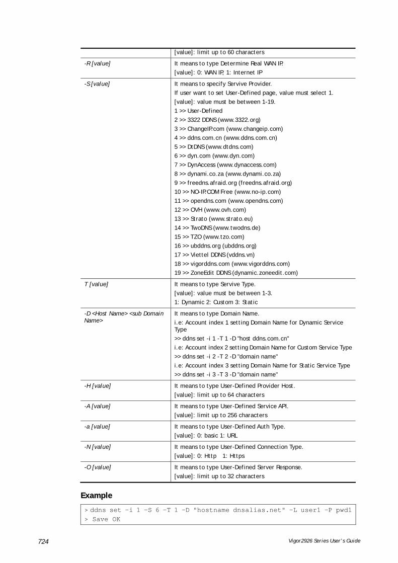
Vigor2926 Series User’s Guide 724
[value]: limit up to 60 characters
-R [value] It means to type Determine Real WAN IP.
[value]: 0: WAN IP, 1: Internet IP
-S [value] It means to specify Servive Provider.
If user want to set User-Defined page, value must select 1.
[value]: value must be between 1-19.
1 >> User-Defined
2 >> 3322 DDNS (www.3322.org)
3 >> ChangeIP.com (www.changeip.com)
4 >> ddns.com.cn (www.ddns.com.cn)
5 >> DtDNS (www.dtdns.com)
6 >> dyn.com (www.dyn.com)
7 >> DynAccess (www.dynaccess.com)
8 >> dynami.co.za (www.dynami.co.za)
9 >> freedns.afraid.org (freedns.afraid.org)
10 >> NO-IP.COM Free (www.no-ip.com)
11 >> opendns.com (www.opendns.com)
12 >> OVH (www.ovh.com)
13 >> Strato (www.strato.eu)
14 >> TwoDNS (www.twodns.de)
15 >> TZO (www.tzo.com)
16 >> ubddns.org (ubddns.org)
17 >> Viettel DDNS (vddns.vn)
18 >> vigorddns.com (www.vigorddns.com)
19 >> ZoneEdit DDNS (dynamic.zoneedit.com)
T [value] It means to type Servive Type.
[value]: value must be between 1-3.
1: Dynamic 2: Custom 3: Static
-D <Host Name> <sub Domain Name>
It means to type Domain Name.
i.e: Account index 1 setting Domain Name for Dynamic Service Type
>> ddns set -i 1 -T 1 -D "host ddns.com.cn"
i.e: Account index 2 setting Domain Name for Custom Service Type
>> ddns set -i 2 -T 2 -D "domain name"
i.e: Account index 3 setting Domain Name for Static Service Type
>> ddns set -i 3 -T 3 -D "domain name"
-H [value] It means to type User-Defined Provider Host.
[value]: limit up to 64 characters
-A [value] It means to type User-Defined Service API.
[value]: limit up to 256 characters
-a [value] It means to type User-Defined Auth Type.
[value]: 0: basic 1: URL
-N [value] It means to type User-Defined Connection Type.
[value]: 0: Http 1: Https
-O [value] It means to type User-Defined Server Response.
[value]: limit up to 32 characters
EExxaammppllee
> ddns set -i 1 -S 6 -T 1 -D "hostname dnsalias.net" -L user1 -P pwd1> Save OK
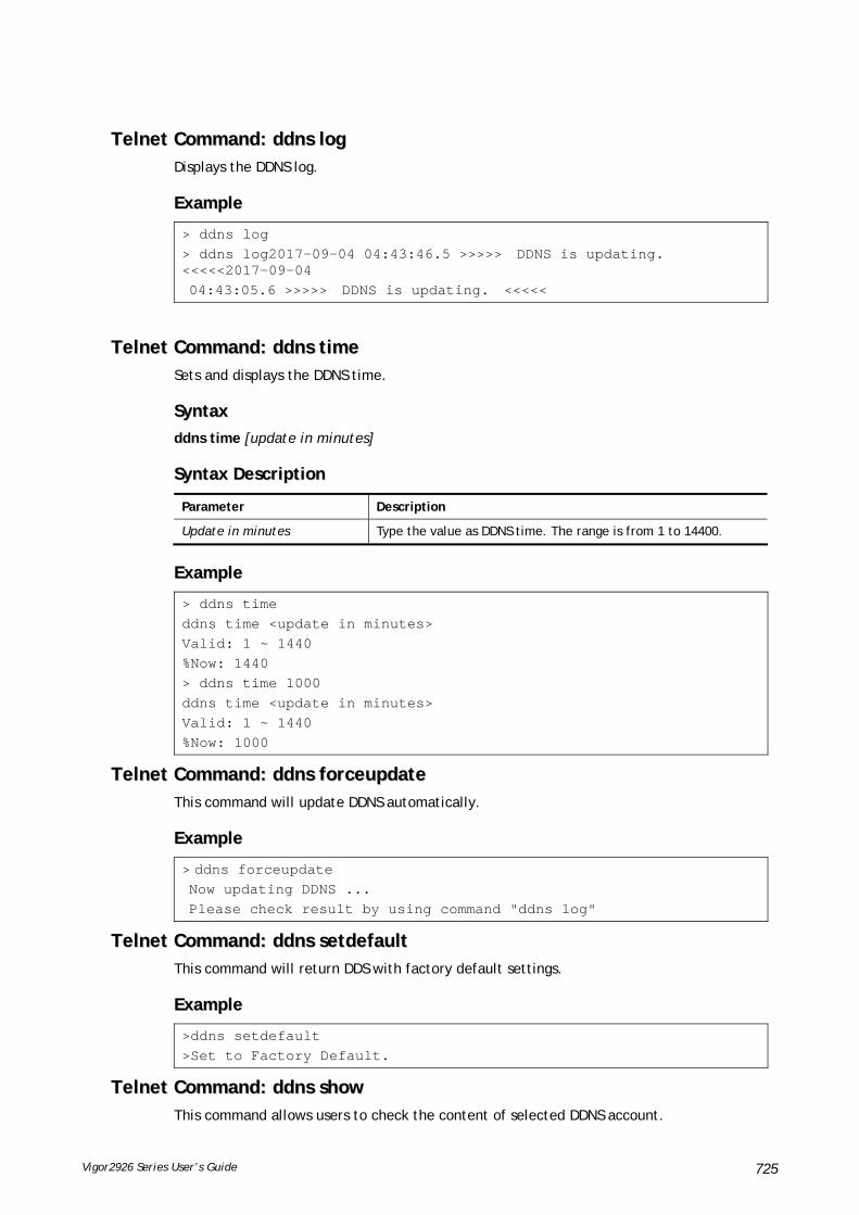
Vigor2926 Series User’s Guide 725
TTeellnneett CCoommmmaanndd:: ddddnnss lloogg Displays the DDNS log.
EExxaammppllee
> ddns log > ddns log2017-09-04 04:43:46.5 >>>>> DDNS is updating. <<<<<2017-09-04 04:43:05.6 >>>>> DDNS is updating. <<<<<
TTeellnneett CCoommmmaanndd:: ddddnnss ttiimmee Sets and displays the DDNS time.
SSyynnttaaxx
ddns time [update in minutes]
SSyynnttaaxx DDeessccrriippttiioonn
Parameter Description
Update in minutes Type the value as DDNS time. The range is from 1 to 14400.
EExxaammppllee
> ddns time ddns time <update in minutes> Valid: 1 ~ 1440 %Now: 1440 > ddns time 1000 ddns time <update in minutes> Valid: 1 ~ 1440 %Now: 1000
TTeellnneett CCoommmmaanndd:: ddddnnss ffoorrcceeuuppddaattee This command will update DDNS automatically.
EExxaammppllee
> ddns forceupdate Now updating DDNS ... Please check result by using command "ddns log"
TTeellnneett CCoommmmaanndd:: ddddnnss sseettddeeffaauulltt This command will return DDS with factory default settings.
EExxaammppllee
>ddns setdefault >Set to Factory Default.
TTeellnneett CCoommmmaanndd:: ddddnnss sshhooww This command allows users to check the content of selected DDNS account.

Vigor2926 Series User’s Guide 726
SSyynnttaaxx
ddns show -i [value]
SSyynnttaaxx DDeessccrriippttiioonn
Parameter Description
-I [value] Display the content of selected DDNS account.
[value]: value must be between 1-6
EExxaammppllee
> ddns show -i 1 -------------------------------------------------- Index: 1 [ ] Enable Dynamic DNS Account WAN Interface: WAN1 First Service Provider: dyn.com (www.dyn.com) Service Type: Dynamic Domain Name: [].[] Login Name: [ ] Wildcards [ ] Backup MX Mail Extender: Determine Real WAN IP: WAN IP DrayTek>
TTeellnneett CCoommmmaanndd:: ddooss This command allows users to configure the settings for DoS defense system.
SSyynnttaaxx
dos [-V | D | A]
dos [-s ATTACK_F [THRESHOLD][ TIMEOUT]]
dos [-a | e [ATTACK_F][ATTACK_0] | d [ATTACK_F][ATTACK_0]]
SSyynnttaaxx DDeessccrriippttiioonn
Parameter Description
-V It means to view the configuration of DoS defense system.
-D It means to deactivate the DoS defense system.
-A It means to activate the DoS defense system.
-s It means to enable the defense function for a specific attack and set its parameter(s).
ATTACK_F It means to specify the name of flooding attack(s) or portscan, e.g., synflood, udpflood, icmpflood, or postscan.
THRESHOLD It means the packet rate (packet/second) that a flooding attack will be detected. Set a value larger than 20.
TIMEOUT It means the time (seconds) that a flooding attack will be blocked. Set a value larger than 5.
-a It means to enable the defense function for all attacks listed in ATTACK_0.
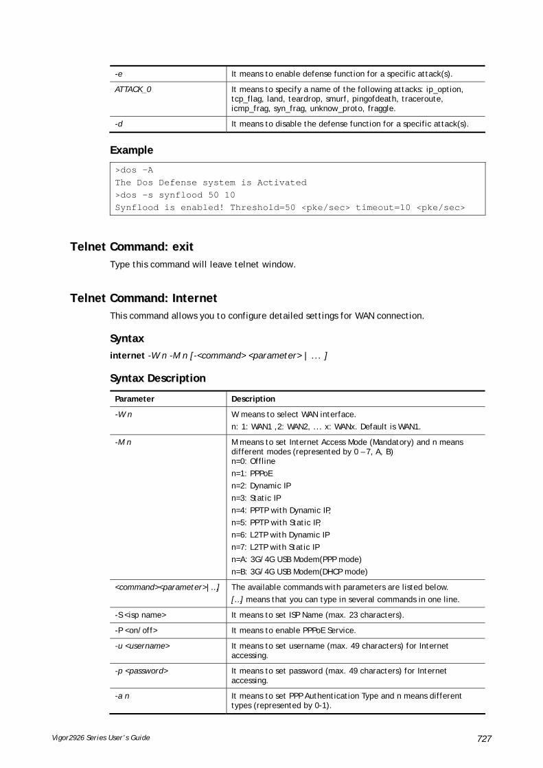
Vigor2926 Series User’s Guide 727
-e It means to enable defense function for a specific attack(s).
ATTACK_0 It means to specify a name of the following attacks: ip_option, tcp_flag, land, teardrop, smurf, pingofdeath, traceroute, icmp_frag, syn_frag, unknow_proto, fraggle.
-d It means to disable the defense function for a specific attack(s).
EExxaammppllee
>dos –A The Dos Defense system is Activated >dos –s synflood 50 10 Synflood is enabled! Threshold=50 <pke/sec> timeout=10 <pke/sec>
TTeellnneett CCoommmmaanndd:: eexxiitt Type this command will leave telnet window.
TTeellnneett CCoommmmaanndd:: IInntteerrnneett This command allows you to configure detailed settings for WAN connection.
SSyynnttaaxx
internet -W n -M n [-<command> <parameter> | ... ]
SSyynnttaaxx DDeessccrriippttiioonn
Parameter Description
-W n W means to select WAN interface.
n: 1: WAN1 ,2: WAN2, ... x: WANx. Default is WAN1.
-M n M means to set Internet Access Mode (Mandatory) and n means different modes (represented by 0 – 7, A, B) n=0: Offline
n=1: PPPoE
n=2: Dynamic IP
n=3: Static IP
n=4: PPTP with Dynamic IP,
n=5: PPTP with Static IP,
n=6: L2TP with Dynamic IP
n=7: L2TP with Static IP
n=A: 3G/4G USB Modem(PPP mode)
n=B: 3G/4G USB Modem(DHCP mode)
<command><parameter>|…] The available commands with parameters are listed below.
[…] means that you can type in several commands in one line.
-S <isp name> It means to set ISP Name (max. 23 characters).
-P <on/off> It means to enable PPPoE Service.
-u <username> It means to set username (max. 49 characters) for Internet accessing.
-p <password> It means to set password (max. 49 characters) for Internet accessing.
-a n It means to set PPP Authentication Type and n means different types (represented by 0-1).

Vigor2926 Series User’s Guide 728
n=0: PAP/CHAP (this is default setting)
n=1: PAP Only
-t n It means to set connection duration and n means different conditions.
n=-1: Always-on
n=1 ~ 999: Idle time for offline (default 180 seconds)
-i <ip address> It means that PPPoE server will assign an IP address specified here for CPE (PPPoE client). If you type 0.0.0.0 as the <ip address>, ISP will assign suitable IP address for you. However, if you type an IP address here, the router will use that one as a fixed IP.
-w <ip address> It means to assign WAN IP address for such connection. Please type an IP address here for WAN port.
-n <netmask> It means to assign netmask for WAN connection. You have to type 255.255.255.xxx (x is changeable) as the netmask for WAN port.
-g <gateway> It means to assign gateway IP for such WAN connection.
-s <server ip> It means to set PPTP/L2TP Server IP.
<server ip>= ppp.qqq.rrr.sss: PPTP/L2TP server IP
-A <idx> Set to Always On mode, and <idx> as backup WAN#.
-B <mode> Set to Backup mode.
<mode> 0: When any WAN disconnect; 1: When all WAN disconnect.
-V It means to view Internet Access profile.
-C <sim pin code> Set (PPP mode) SIM PIN code (max. 15 characters) for 3G/4G USB Modem.
-O <init string> Set (PPP mode) Modem Initial String (max. 47 characters) for 3G/4G USB Modem.
-T <init string2> Set (PPP mode) Modem Initial String2 (max. 47 characters) for 3G/4G USB Modem.
-D <dial string> Set (PPP mode) Modem Dial String (max. 31 characters) for 3G/4G USB Modem.
-v <service name> Set (PPP mode) Service Name (max. 23 characters) for 3G/4G USB Modem.
-m <ppp username> Set (PPP mode) PPP Username (max. 63 characters) for 3G/4G USB Modem.
-o <ppp password> Set (PPP mode) PPP Password (max. 62 characters) for 3G/4G USB Modem.
-e n Set (PPP mode) PPP Authentication Type for 3G/4G USB Modem.
n= 0: PAP/CHAP (default),
1: PAP Only
-q n (PPP mode) Index(1-15) in Schedule Setup-One
-x n (PPP mode) Index(1-15) in Schedule Setup-Two
-y n (PPP mode) Index(1-15) in Schedule Setup-Three
-z n (PPP mode) Index(1-15) in Schedule Setup-Four
-Q <mode> Set (PPP mode or DHCP mode) WAN Connection Detection Mode.
<mode>
0: ARP Detect;
1: Ping Detect
-I <ping ip> Set (PPP mode or DHCP mode) WAN Connection Detection Ping IP.
<ping ip>= ppp.qqq.rrr.sss: WAN Connection Detection Ping IP

Vigor2926 Series User’s Guide 729
-L n Set (PPP mode) WAN Connection Detection TTL (1-255) value.
-E <sim pin code> Set (DHCP mode) SIM PIN code (max. 19 characters).
-G <mode> Set (DHCP mode) Network Mode.
<mode>
0: 4G/3G/2G;
1: 4G Only;
2: 3G Only;
3: 2G Only
-N <apn name> Set (DHCP mode) APN Name (max. 47 characters)
-U n (DHCP mode) MTU(1000-1440)
EExxaammppllee
>internet -M 1 -S tcom -u username -p password -a 0 -t -1 -i 0.0.0.0 WAN1 Internet Mode set to PPPoE/PPPoA WAN1 ISP Name set to tcom WAN1 Username set to username WAN1 Password set successful WAN1 PPP Authentication Type set to PAP/CHAP WAN1 Idle timeout set to always-on WAN1 Gateway IP set to 0.0.0.0 > internet -V WAN1 Internet Mode:PPPoE ISP Name: tcom Username: username Authentication: PAP/CHAP Idle Timeout: -1 WAN IP: Dynamic IP > internet -M 1 -u link1 -p link1 -a 0 WAN1 Internet Mode set to PPPoE/PPPoA WAN1 Username set to link1 WAN1 Password set successful WAN1 PPP Authentication Type set to PAP/CHAP
TTeellnneett CCoommmmaanndd:: iipp ppuubbssuubbnneett This command allows users to enable or disable the public subnet for your router.
SSyynnttaaxx
ip pubsubnet <Enable/Disable>
SSyynnttaaxx DDeessccrriippttiioonn
Parameter Description
Enable Enable the function.
Disable Disable the function.
EExxaammppllee
> ip pubsubnet enable public subnet enabled!

Vigor2926 Series User’s Guide 730
TTeellnneett CCoommmmaanndd:: iipp ppuubbaaddddrr This command allows to set the IP routed subnet for the router.
SSyynnttaaxx
ip pubaddr ?
ip pubaddr <public subnet IP address>
SSyynnttaaxx DDeessccrriippttiioonn
Parameter Description
? Display an IP address which allows users set as the public subnet IP address.
public subnet IP address Specify an IP address. The system will set the one that you specified as the public subnet IP address.
EExxaammppllee
> ip pubaddr ? % ip addr <public subnet IP address> % Now: 192.168.0.1 > ip pubaddr 192.168.2.5 % Set public subnet IP address done !!!
TTeellnneett CCoommmmaanndd:: iipp ppuubbmmaasskk This command allows users to set the mask for IP routed subnet of your router.
SSyynnttaaxx
ip pubmask ?
ip pubmask <public subnet mask>
SSyynnttaaxx DDeessccrriippttiioonn
Parameter Description
? Display an IP address which allows users set as the public subnet mask.
public subnet IP address Specify a subnet mask. The system will set the one that you specified as the public subnet mask.
EExxaammppllee
> ip pubmask ? % ip pubmask <public subnet mask> % Now: 255.255.255.0 > ip pubmask 255.255.0.0 % Set public subnet mask done !!!
TTeellnneett CCoommmmaanndd:: iipp aauuxx This command is used for configuring WAN IP Alias.
SSyynnttaaxx

Vigor2926 Series User’s Guide 731
ip aux add [IP] [Join to NAT Pool][wanX]
ip aux remove [index]
SSyynnttaaxx DDeessccrriippttiioonn
Parameter Description
add It means to create a new WAN IP address.
remove It means to delete an existed WAN IP address.
IP It means the auxiliary WAN IP address.
Join to NAT Pool 0 (disable) or 1 (enable).
wanX Add or remove an address for WAN interface.
index Type the index number of the table displayed on your screen.
EExxaammppllee
> ip aux add 192.168.1.65 1 % 192.168.1.65 has added in index 2. > ip aux ?%% ip aux add [IP] [Join to NAT Pool] %% ip aux remove [Index] %% Where IP = Auxiliary WAN IP Address. %% Join to NAT Pool = 0 or 1. %% Index = The Index number of table. Now auxiliary WAN1 IP Address table: Index no. Status IP address NAT IP pool ---------------------------------------------------- 1 Disable 0.0.0.0 Yes 2 Enable 192.168.1.65 Yes
When you type ip aux?, the current auxiliary WAN IP Address table will be shown as the following:
Index no. Status IP address IP pool ---------------------------------------------- 1 Enable 172.16.3.229 Yes 2 Enable 172.16.3.56 No 3 Enable 172.16.3.113 No
TTeellnneett CCoommmmaanndd:: iipp aaddddrr This command allows users to set/add a specified LAN IP your router.
SSyynnttaaxx
ip addr [IP address]
SSyynnttaaxx DDeessccrriippttiioonn
Parameter Description
IP address It means the LAN IP address.

Vigor2926 Series User’s Guide 732
EExxaammppllee
>ip addr 192.168.50.1 % Set IP address OK !!!
Info
When the LAN IP address is changed, the start IP address of DHCP server are still the same. To make the IP assignment of the DHCP server being consistent with this new IP address (they should be in the same network segment), the IP address of the PC must be fixed with the same LAN IP address (network segment) set by this command for accessing into the web user interface of the router. Later, modify the start addresses for the DHCP server.
TTeellnneett CCoommmmaanndd:: iipp nnmmaasskk This command allows users to set/add a specified netmask for your router.
SSyynnttaaxx
ip nmask [IP netmask]
SSyynnttaaxx DDeessccrriippttiioonn
Parameter Description
IP netmask It means the netmask of LAN IP.
EExxaammppllee
> ip nmask 255.255.0.0 % Set IP netmask OK !!!
TTeellnneett CCoommmmaanndd:: iipp aarrpp ARP displays the matching condition for IP and MAC address.
SSyynnttaaxx
ip arp add [IP address] [MAC address] [LAN or WAN]
ip arp del [IP address] [LAN or WAN]
ip arp flush
ip arp status
ip arp accept [0/1/2/3/4/5/status]
ip arp setCacheLife [time]
In which, arp add allows users to add a new IP address into the ARP table; arp del allows users to remove an IP address; arp flush allows users to clear arp cache; arp status allows users to review current status for the arp table; arp accept allows to accept or reject the source /destination MAC address; arp setCacheLife allows users to configure the duration in which ARP caches can be stored on the system. If ip arp setCacheLife is set with “60”, it means you have an ARP cache at 0 second. Sixty seconds later without any ARP messages received, the system will think such ARP cache is expired. The system will issue a few ARP request to see if this cache is still valid.
SSyynnttaaxx DDeessccrriippttiioonn

Vigor2926 Series User’s Guide 733
Parameter Description
IP address It means the LAN IP address.
MAC address It means the MAC address of your router.
LAN or WAN It indicates the direction for the arp function.
0/1/2/3/4/5 0: disable to accept illegal source mac address
1: enable to accept illegal source mac address
2: disable to accept illegal dest mac address
3: enable to accept illegal dest mac address
4: Decline VRRP mac into arp table
5: Accept VRRP mac into arp table
status: display the setting status.
Time Available settings will be 10, 20, 30,....2550 seconds.
EExxaammppllee
> ip arp accept status Accept illegal source mac arp: disable Accept illegal dest mac arp: disable Accept VRRP mac into arp table: disable > ip arp status [ARP Table] Index IP Address MAC Address Netbios Name 1 192.168.1.113 00-05-5D-E4-D8-EE A1000351
TTeellnneett CCoommmmaanndd:: iipp ddhhccppcc This command is available for WAN DHCP.
SSyynnttaaxx
ip dhcpc option
ip dhcpc option -h|l
ip dhcpc option -d [idx]
ip dhcpc option -e [1 or 0] -w [wan unmber] -c [option number] -v [option value]
ip dhcpc option -e [1 or 0] -w [wan unmber] -c [option number] -x "[option value]"
ip dhcpc option -u [idx unmber]
ip dhcpc release [wan number]
ip dhcpc renew [wan number]
ip dhcpc status
SSyynnttaaxx DDeessccrriippttiioonn
Parameter Description
option It is an optional setting for DHCP server.
-h: display usage
-l: list all custom set DHCP options
-d: delete custom dhcp client option by index number
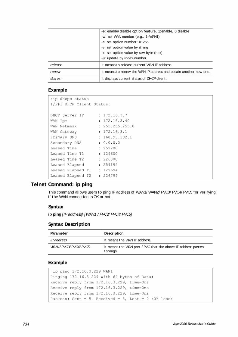
Vigor2926 Series User’s Guide 734
-e: enable/disable option feature, 1:enable, 0:disable
-w: set WAN number (e.g., 1=WAN1)
-c: set option number: 0~255
-v: set option value by string
-x: set option value by raw byte (hex)
-u: update by index number
release It means to release current WAN IP address.
renew It means to renew the WAN IP address and obtain another new one.
status It displays current status of DHCP client.
EExxaammppllee
>ip dhcpc status I/F#3 DHCP Client Status: DHCP Server IP : 172.16.3.7 WAN Ipm : 172.16.3.40 WAN Netmask : 255.255.255.0 WAN Gateway : 172.16.3.1 Primary DNS : 168.95.192.1 Secondary DNS : 0.0.0.0 Leased Time : 259200 Leased Time T1 : 129600 Leased Time T2 : 226800 Leased Elapsed : 259194 Leased Elapsed T1 : 129594 Leased Elapsed T2 : 226794
TTeellnneett CCoommmmaanndd:: iipp ppiinngg This command allows users to ping IP address of WAN1/WAN2/PVC3/PVC4/PVC5 for verifying if the WAN connection is OK or not.
SSyynnttaaxx
ip ping [IP address] [WAN1 /PVC3/PVC4/PVC5]
SSyynnttaaxx DDeessccrriippttiioonn
Parameter Description
IP address It means the WAN IP address.
WAN1/PVC3/PVC4/PVC5 It means the WAN port /PVC that the above IP address passes through.
EExxaammppllee
>ip ping 172.16.3.229 WAN1 Pinging 172.16.3.229 with 64 bytes of Data: Receive reply from 172.16.3.229, time=0ms Receive reply from 172.16.3.229, time=0ms Receive reply from 172.16.3.229, time=0ms Packets: Sent = 5, Received = 5, Lost = 0 <0% loss>

Vigor2926 Series User’s Guide 735
TTeellnneett CCoommmmaanndd:: iipp ttrraacceerrtt This command allows users to trace the routes from the router to the host.
SSyynnttaaxx
ip tracert [Host/IP address] [WAN1/WAN2] [Udp/Icmp]
SSyynnttaaxx DDeessccrriippttiioonn
Parameter Description
IP address It means the target IP address.
WAN1/WAN2 It means the WAN port that the above IP address passes through.
Udp/Icmp It means the UDP or ICMP.
EExxaammppllee
>ip tracert 22.128.2.62 WAN1 Traceroute to 22.128.2.62, 30 hops max 1 172.16.3.7 10ms 2 172.16.1.2 10ms 3 Request Time out. 4 168.95.90.66 50ms 5 211.22.38.134 50ms 6 220.128.2.62 50ms Trace complete
TTeellnneett CCoommmmaanndd:: iipp tteellnneett This command allows users to access specified device by telnet.
SSyynnttaaxx
ip telnet [IP address][Port]
SSyynnttaaxx DDeessccrriippttiioonn
Parameter Description
IP address Type the WAN or LAN IP address of the remote device.
Port Type a port number (e.g., 23).
Available settings: 0 ~65535.
EExxaammppllee
> ip telnet 172.17.3.252 23 >
TTeellnneett CCoommmmaanndd:: iipp rriipp This command allows users to set the RIP (routing information protocol) of IP.
SSyynnttaaxx
ip rip [0/1/2]
SSyynnttaaxx DDeessccrriippttiioonn

Vigor2926 Series User’s Guide 736
Parameter Description
0/1/2 0 means disable; 1 means first subnet and 2 means second subnet.
EExxaammppllee
> ip rip 1 %% Set RIP 1st subnet.

Vigor2926 Series User’s Guide 737
TTeellnneett CCoommmmaanndd:: iipp wwaannrriipp This command allows users to set the RIP (routing information protocol) of WAN IP.
SSyynnttaaxx
ip wanrip [ifno] -e [0/1]
SSyynnttaaxx DDeessccrriippttiioonn
Parameter Description
ifno It means the connection interface.
1: WAN1,2: WAN2, 3: PVC3,4: PVC4,5: PVC5
Note: PVC3 ~PVC5 are virtual WANs.
-e It means to disable or enable RIP setting for specified WAN interface.
1: Enable the function of setting RIP of WAN IP.
0: Disable the function.
EExxaammppllee
> ip wanrip ? Valid ex:ip wanrip <ifno> -e <0/1> <ifno> 1: WAN1,2: WAN2 3: PVC3,4: PVC4,5: PVC5 -e <0/1> 0: disable, 1: enable Now status: WAN[1] Rip Protocol disable WAN[2] Rip Protocol disable WAN[3] Rip Protocol disable WAN[4] Rip Protocol disable WAN[5] Rip Protocol disable > ip wanrip 5 -e 1 > ip wanrip ? Valid ex:ip wanrip <ifno> -e <0/1> <ifno> 1: WAN1,2: WAN2 3: PVC3,4: PVC4,5: PVC5 -e <0/1> 0: disable, 1: enable Now status: WAN[1] Rip Protocol disable WAN[2] Rip Protocol disable WAN[3] Rip Protocol disable WAN[4] Rip Protocol disable WAN[5] Rip Protocol enable
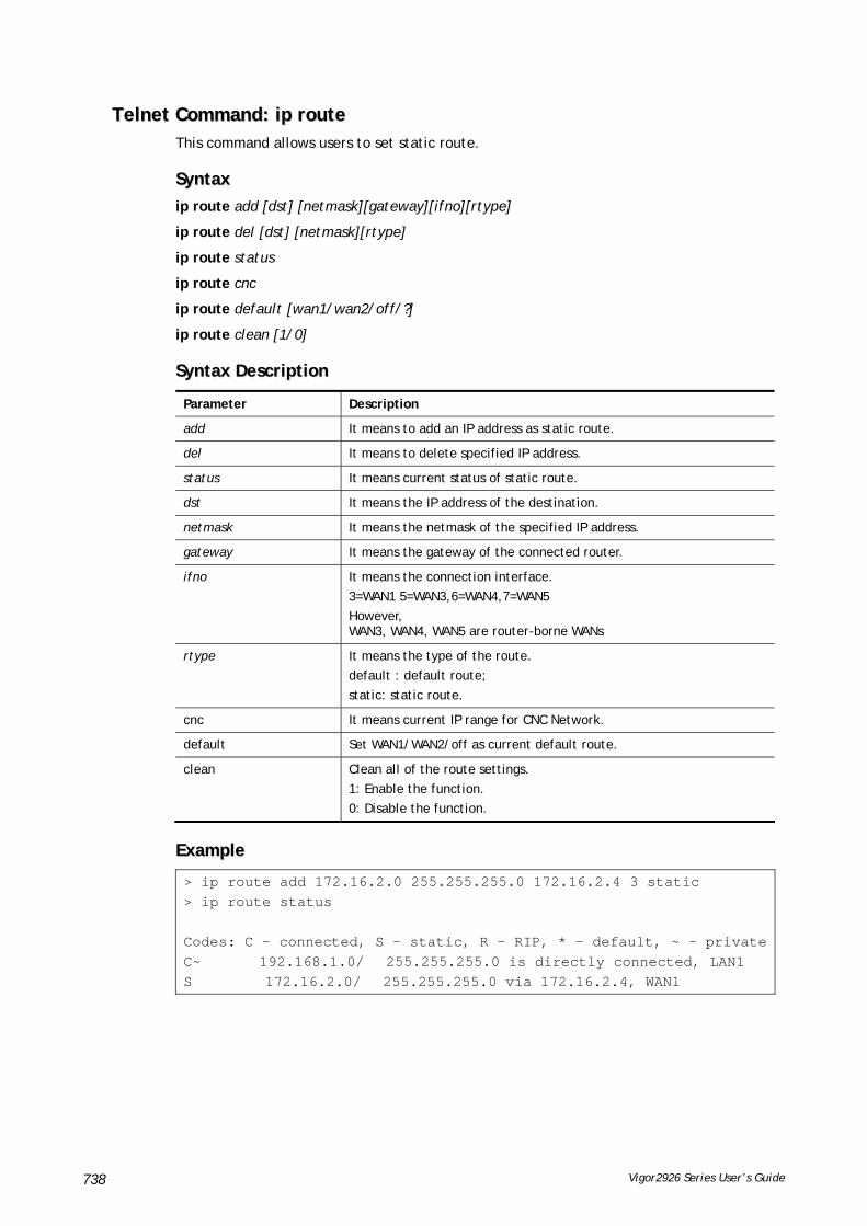
Vigor2926 Series User’s Guide 738
TTeellnneett CCoommmmaanndd:: iipp rroouuttee This command allows users to set static route.
SSyynnttaaxx
ip route add [dst] [netmask][gateway][ifno][rtype]
ip route del [dst] [netmask][rtype]
ip route status
ip route cnc
ip route default [wan1/wan2/off/?]
ip route clean [1/0]
SSyynnttaaxx DDeessccrriippttiioonn
Parameter Description
add It means to add an IP address as static route.
del It means to delete specified IP address.
status It means current status of static route.
dst It means the IP address of the destination.
netmask It means the netmask of the specified IP address.
gateway It means the gateway of the connected router.
ifno It means the connection interface.
3=WAN1 5=WAN3,6=WAN4,7=WAN5
However, WAN3, WAN4, WAN5 are router-borne WANs
rtype It means the type of the route.
default : default route;
static: static route.
cnc It means current IP range for CNC Network.
default Set WAN1/WAN2/off as current default route.
clean Clean all of the route settings.
1: Enable the function.
0: Disable the function.
EExxaammppllee
> ip route add 172.16.2.0 255.255.255.0 172.16.2.4 3 static > ip route status Codes: C - connected, S - static, R - RIP, * - default, ~ - privateC~ 192.168.1.0/ 255.255.255.0 is directly connected, LAN1 S 172.16.2.0/ 255.255.255.0 via 172.16.2.4, WAN1
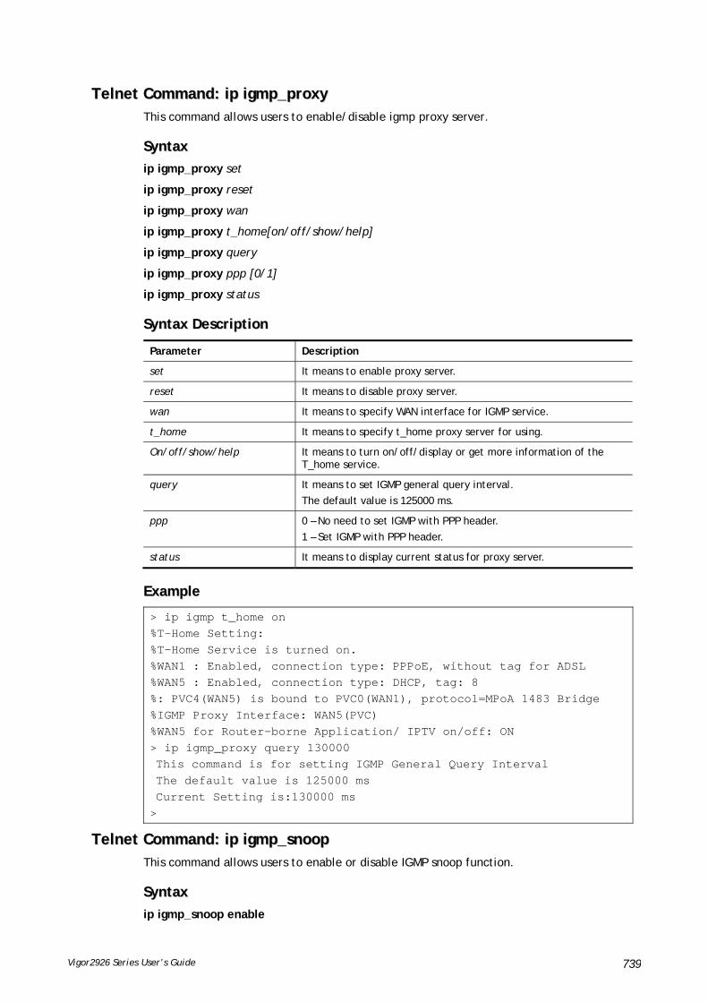
Vigor2926 Series User’s Guide 739
TTeellnneett CCoommmmaanndd:: iipp iiggmmpp__pprrooxxyy This command allows users to enable/disable igmp proxy server.
SSyynnttaaxx
ip igmp_proxy set
ip igmp_proxy reset
ip igmp_proxy wan
ip igmp_proxy t_home[on/off/show/help]
ip igmp_proxy query
ip igmp_proxy ppp [0/1]
ip igmp_proxy status
SSyynnttaaxx DDeessccrriippttiioonn
Parameter Description
set It means to enable proxy server.
reset It means to disable proxy server.
wan It means to specify WAN interface for IGMP service.
t_home It means to specify t_home proxy server for using.
On/off/show/help It means to turn on/off/display or get more information of the T_home service.
query It means to set IGMP general query interval.
The default value is 125000 ms.
ppp 0 – No need to set IGMP with PPP header.
1 – Set IGMP with PPP header.
status It means to display current status for proxy server.
EExxaammppllee
> ip igmp t_home on %T-Home Setting: %T-Home Service is turned on. %WAN1 : Enabled, connection type: PPPoE, without tag for ADSL %WAN5 : Enabled, connection type: DHCP, tag: 8 %: PVC4(WAN5) is bound to PVC0(WAN1), protocol=MPoA 1483 Bridge %IGMP Proxy Interface: WAN5(PVC) %WAN5 for Router-borne Application/ IPTV on/off: ON > ip igmp_proxy query 130000 This command is for setting IGMP General Query Interval The default value is 125000 ms Current Setting is:130000 ms >
TTeellnneett CCoommmmaanndd:: iipp iiggmmpp__ssnnoooopp This command allows users to enable or disable IGMP snoop function.
SSyynnttaaxx
ip igmp_snoop enable
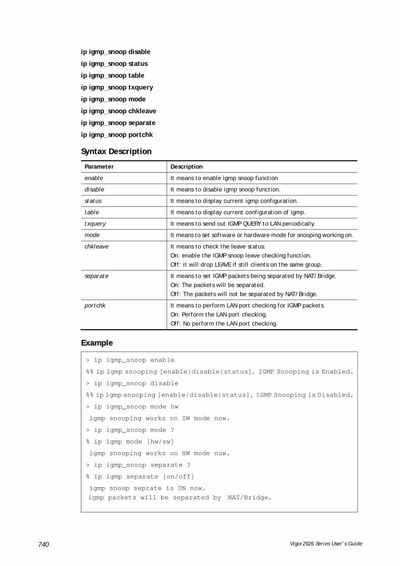
Vigor2926 Series User’s Guide 740
ip igmp_snoop disable
ip igmp_snoop status
ip igmp_snoop table
ip igmp_snoop txquery
ip igmp_snoop mode
ip igmp_snoop chkleave
ip igmp_snoop separate
ip igmp_snoop portchk
SSyynnttaaxx DDeessccrriippttiioonn
Parameter Description
enable It means to enable igmp snoop function
disable It means to disable igmp snoop function.
status It means to display current igmp configuration.
table It means to display current configuration of igmp.
txquery It means to send out IGMP QUERY to LAN periodically.
mode It means to set software or hardware mode for snooping working on.
chkleave It means to check the leave status.
On: enable the IGMP snoop leave checking function.
Off: it will drop LEAVE if still clients on the same group.
separate It means to set IGMP packets being separated by NAT/Bridge.
On: The packets will be separated.
Off: The packets will not be separated by NAT/Bridge.
portchk It means to perform LAN port checking for IGMP packets.
On: Perform the LAN port checking.
Off: No perform the LAN port checking.
EExxaammppllee
> ip igmp_snoop enable
%% ip igmp snooping [enable|disable|status], IGMP Snooping is Enabled.
> ip igmp_snoop disable
%% ip igmp snooping [enable|disable|status], IGMP Snooping is Disabled.
> ip igmp_snoop mode hw
igmp snooping works on SW mode now.
> ip igmp_snoop mode ?
% ip igmp mode [hw/sw]
igmp snooping works on HW mode now.
> ip igmp_snoop separate ?
% ip igmp separate [on/off]
igmp snoop seprate is ON now. igmp packets will be separated by NAT/Bridge.

Vigor2926 Series User’s Guide 741
TTeellnneett CCoommmmaanndd:: iipp iiggmmpp__ffll This command allows users to activate IGMP fast leave and display current status for IGMP fast leave.
SSyynnttaaxx
ip igmp_fl enable
ip igmp_fl disable
ip igmp_fl status
SSyynnttaaxx DDeessccrriippttiioonn
Parameter Description
enable / disable It means to enable / disable the function of IGMP fast leave.
status It menas to show current status of IGMP fast leave.
EExxaammppllee
> ip igmp_snoop enable
%% ip igmp snooping [enable|disable|status], IGMP Snooping is Enabled.> ip igmp_fl enable %% ip igmp_fl [enable|disable|status], IGMP Fast Leave is Enabled.
> ip igmp_fl status %% ip igmp_fl [enable|disable|status], IGMP Fast Leave is Disabled.
TTeellnneett CCoommmmaanndd:: iipp ddmmzz Specify MAC address of certain device as the DMZ host.
SSyynnttaaxx
ip dmz [mac]
SSyynnttaaxx DDeessccrriippttiioonn
Parameter Description
mac It means the MAC address of the device that you want to specify
EExxaammppllee
>ip dmz ? % ip dmz <mac>, now : 00-00-00-00-00-00 > ip dmz 11-22-33-44-55-66 > ip dmz ? % ip dmz <mac>, now : 11-22-33-44-55-66 >
TTeellnneett CCoommmmaanndd:: iipp ddmmzzsswwiittcchh This command allows users to set DMZ mode.
ip dmzswitch off
ip dmzswitch private

Vigor2926 Series User’s Guide 742
ip dmzswitch trueip
ip dmzswitch active_trueip
SSyynnttaaxx DDeessccrriippttiioonn
Parameter Description
off It means to turn off DMZ function.
private It means to set DMZ with private IP.
trueip It means to set DMZ with true IP.
active_trueip It means to set the DMZ with active true IP.
EExxaammppllee
>ip ip dmzswitch off >
TTeellnneett CCoommmmaanndd:: iipp sseessssiioonn This command allows users to set maximum session limit number for the specified IP; set message for exceeding session limit and set how many seconds the IP session block works.
SSyynnttaaxx
ip session on
ip session off
ip session default [num]
ip session defaultp2p [num]
ip session status
ip session show
ip session timer [num]
ip session [block/unblock][IP]
ip session [add/del][IP1-IP2][num][p2pnum]
SSyynnttaaxx DDeessccrriippttiioonn
Parameter Description
on It means to turn on session limit for each IP.
off It means to turn off session limit for each IP.
default [num] It means to set the default number of session num limit.
Defautlp2p [num] It means to set the default number of session num limit for p2p.
status It means to display the current settings.
show It means to display all session limit settings in the IP range.
timer [num] It means to set when the IP session block works.
The unit is second.
[block/unblock][IP] It means to block/unblock the specified IP address.
Block: The IP cannot access Internet through the router.
Unblock: The specified IP can access Internet through the router.
add It means to add the session limits in an IP range.
del It means to delete the session limits in an IP range.

Vigor2926 Series User’s Guide 743
IP1-IP2 It means the range of IP address specified for this command.
num It means the number of the session limits, e.g., 100.
p2pnum It means the number of the session limits, e.g., 50 for P2P.
EExxaammppllee
>ip session default 100 > ip session add 192.168.1.5-192.168.1.100 100 50 > ip session on > ip session status IP range: 192.168.1.5 - 192.168.1.100 : 100 Current ip session limit is turn on Current default session number is 100
TTeellnneett CCoommmmaanndd:: iipp bbaannddwwiiddtthh This command allows users to set maximum bandwidth limit number for the specified IP.
SSyynnttaaxx
ip bandwidth on
ip bandwidth off
ip bandwidth default [tx_rate][rx_rate]
ip bandwidth status
ip bandwidth show
ip bandwidth [add/del] [IP1-IP2][tx][rx][shared]
SSyynnttaaxx DDeessccrriippttiioonn
Parameter Description
on It means to turn on the IP bandwidth limit.
off It means to turn off the IP bandwidth limit.
default [tx_rate][rx_rate] It means to set default tx and rx rate of bandwidth limit. The range is from 0 – 65535 Kpbs.
status It means to display the current settings.
show It means to display all the bandwidth limits settings within the IP range.
add It means to add the bandwidth within the IP range.
del It means to delete the bandwidth within the IP range.
IP1-IP2 It means the range of IP address specified for this command.
tx It means to set transmission rate for bandwidth limit.
rx It means to set receiving rate for bandwidth limit.
shared It means that the bandwidth will be shared for the IP range.
EExxaammppllee
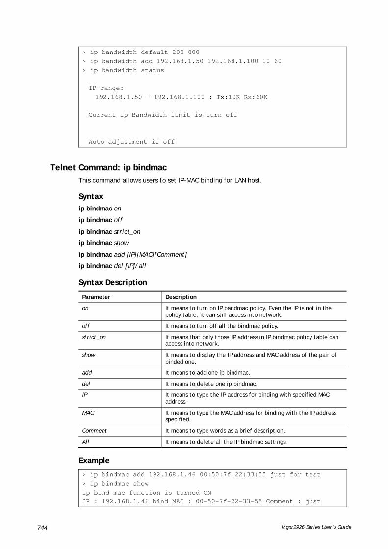
Vigor2926 Series User’s Guide 744
> ip bandwidth default 200 800 > ip bandwidth add 192.168.1.50-192.168.1.100 10 60 > ip bandwidth status IP range: 192.168.1.50 - 192.168.1.100 : Tx:10K Rx:60K Current ip Bandwidth limit is turn off Auto adjustment is off
TTeellnneett CCoommmmaanndd:: iipp bbiinnddmmaacc This command allows users to set IP-MAC binding for LAN host.
SSyynnttaaxx
ip bindmac on
ip bindmac off
ip bindmac strict_on
ip bindmac show
ip bindmac add [IP][MAC][Comment]
ip bindmac del [IP]/all
SSyynnttaaxx DDeessccrriippttiioonn
Parameter Description
on It means to turn on IP bandmac policy. Even the IP is not in the policy table, it can still access into network.
off It means to turn off all the bindmac policy.
strict_on It means that only those IP address in IP bindmac policy table can access into network.
show It means to display the IP address and MAC address of the pair of binded one.
add It means to add one ip bindmac.
del It means to delete one ip bindmac.
IP It means to type the IP address for binding with specified MAC address.
MAC It means to type the MAC address for binding with the IP address specified.
Comment It means to type words as a brief description.
All It means to delete all the IP bindmac settings.
EExxaammppllee
> ip bindmac add 192.168.1.46 00:50:7f:22:33:55 just for test > ip bindmac show ip bind mac function is turned ON IP : 192.168.1.46 bind MAC : 00-50-7f-22-33-55 Comment : just

Vigor2926 Series User’s Guide 745
TTeellnneett CCoommmmaanndd:: iipp bbggpp This command allows users to configure settings for BGP.
SSyynnttaaxx
ip bgp mode [0/1]
ip bgp as [value]
ip bgp hold [value]
ip bgp retry [value]
ip bgp id [value]
ip bgp show
ip bgp neighbor [idx] mode [0/1]
ip bgp neighbor [idx] name [max len: 20]
ip bgp neighbor [idx] ip [x.x.x.x]
ip bgp neighbor [idx] as [1~4294967295]
ip bgp neighbor [idx] show
ip bgp neighbor show all
ip bgp static [sidx][ip][<netmask]
ip bgp static [sidx] delete
ip bgp static show
SSyynnttaaxx DDeessccrriippttiioonn
Parameter Description
mode <0/1> It means to enable / disable BGP mode.
0: disable
1: enable
as <value> It means to set the AS number for local router.
<value>: Available number is between 0 and 4294967295.
hold <value> It means to set the time interval to determine the peer is dead when the router is unable to receive any keepalive message from the peer within the time.
<value>: Available number is between 10 and 65535 (unit: second). The default is 180 (seconds).
retry <value> It means to set a period of time to reconnect if the router fails to connect to the neighboring router.
<value>: Available number is between 3 and 255 (unit: second). The default is 120 (seconds).
id <value> It means to specify the LAN subnet <1~16> as router ID.
<value>: Available number is between 1 and 16.
show It means to display information related to BGP settings.
neighbor <idx> mode <0/1> It means to enable / disable the basic BGP function for neighboring router.
<idx>: Available profile number is between 1 and 8.
<0/1>: 0- disable; 1- enable
neighbor <idx> name <max len: 20>
It means to define a profile name for neighboring router.
<idx>: Available profile number is between 1 and 8.
<max len>: The maximum name length shall not be over 20

Vigor2926 Series User’s Guide 746
characters.
neighbor <idx> ip <x.x.x.x> It means to set the IP address specified for the neighboring router.
<idx>: Available profile number is between 1 and 8.
<x.x.x.x>: Type the IP address, e.g., 100.100.100.100.
neighbor <idx> as <1~4294967295>
It means to set the AS number for the neightboring router.
<idx>: Available profile number is between 1 and 8.
<value>: Available number is between 1 and 4294967295.
neighbor <idx> show It means to display information for the specified profile.
<idx>: Available profile number is between 1 and 8.
neighbor show all It means to display information for all neighboring routers.
static <sidx> <ip> <netmask> It means to configure the neighboring router(s) for exchanging the routing information with the local router.
<sidx>: Available profile number is between 1 and 6.
<ip>: Type the IP address, e.g., 100.100.100.200.
<netmask>: Type the subnet mask for the neighboring router, e.g., 255.255.255.0.
static <sidx> delete It means to delete static network settings for neighboring router.
<sidx>: Available profile number is between 1 and 6.
static show It means to display setting information for exchanging the routing information with the local router.
EExxaammppllee
> ip bgp static 1 192.168.2.56 255.255.255.0 Set static network index: 1 IP addr: 192.168.2.56 Net mask: 255.255.255.0 > ip bgp static show BGP static networks: Index: 1, IP addr: 192.168.2.56, mask: 255.255.255.0

Vigor2926 Series User’s Guide 747
TTeellnneett CCoommmmaanndd:: iipp mmaaxxnnaattuusseerr This command is used to set the maximum number of NAT users.
SSyynnttaaxx
ip maxnatuser user no
SSyynnttaaxx DDeessccrriippttiioonn
Parameter Description
User no A number specified here means the total NAT users that Vigor router supports.
0 – It means no limitation.
EExxaammppllee
> ip maxnatuser 100 % Max NAT user = 100
TTeellnneett CCoommmmaanndd:: iipp ppoolliiccyy__rrtt This command is used to set the IP policy route profile.
SSyynnttaaxx
ip policy_rt [-<command> <parameter> | ... ]
SSyynnttaaxx DDeessccrriippttiioonn
Parameter Description
<command><parameter>|…] The available commands with parameters are listed below.
[…] means that you can type in several commands in one line.
General Setup for Policy Route
-i [value] Specify an index number for setting policy route profile.
Value: 1 to 60. “-1” means to get a free policy index automatically.
-e [0/1] 0: Disable the selected policy route profile.
1: Enable the selected policy route profile.
-o [value] Determine the operation of the policy route.
Value:
add – Create a new policy rotue profile.
del – Remove an existed policy route profile.
edit – Modify an existed policy route profile.
flush – Reset policy route to default setting.
-1 [any/range] Specify the source IP mode.
Range: Indicate a range of IP addresses.
Any: It means any IP address will be treated as source IP address.
-2 [any/ip_range/ip_subnet/domain]
Specify the destination IP mode.
Any: No need to specify an IP address for any IP address will be treated as destination IP address.
ip_range: Indicates a range of IP addresses.
ip_subnet: Indicates the IP subnet.
domain: Indicates the domain name.
-3 [any/range] Specify the destination port mode.
Range: Indicate a range of port number.

Vigor2926 Series User’s Guide 748
Any: It means any port number can be used as destination port.
-G [default/specific] Specify the gateway mode.
-L [default/specific] Specify the failover gateway mode.
-s [value] Indicate the source IP start.
Value: The type format shall be “xxx.xxx.xxx.xxx”. (e.g, 192.168.1.0)
-S [value] Indicate the source IP end.
Value: The type format shall be “xxx.xxx.xxx.xxx”. (e.g, 192.168.1.100)
-d [value] Indicate the destination IP start.
Value: The type format shall be “xxx.xxx.xxx.xxx”. (e.g, 192.168.2.0)
-D [value] Indicate the destination IP end.
Value: The type format shall be “xxx.xxx.xxx.xxx”. (e.g, 192.168.2.100)
-p [value] Indicate the destination port start.
Value: Type a number (1 ~ 65535) as the port start (e.g., 1000).
-P [value] Indicate the destination port end.
Value: Type a number (1 ~ 65535) as the port end (e.g., 2000).
-y [value] Indicate the priority of the policy route profile. Value: Type a number (0 ~ 250). The default value is “150”.
-I [value] Indicate the interface specified for the policy route profile. Value: Available interfaces include, LAN1 ~ LAN8, IP_Routed_Subnet, DMZ_Subnet, WAN1 ~ WAN5, VPN_PROFILE_1 ~ VPN_PROFILE_100, WAN_1_IP_ALIAS_1 ~ WAN_4_IP_ALIAS_8
-g [value] Indicate the gateway IP address. Value: The type format shall be “xxx.xxx.xxx.xxx”. (e.g, 192.168.3.1)
-l [value] Indicate the failover IP address. Value: The type format shall be “xxx.xxx.xxx.xxx”. (e.g, 192.168.4.1)
-t [value] It means “protocol”.
Value: Available settings include “TCP”, “UDP”, “TCP/UDP”, “ICMP” and “Any”.
-n [0/1] Indicates the function of “Force NAT”.
0: Disable the function.
1: Enable the function.
-a [0/1] Indicates to enable the function of failover.
0: Disable the function.
1: Enable the function.
-f [value] It means to specify the interface for failover.
Value: Avaialbe interfaces include, NO_FAILOVER, Default_WAN, Policy1 ~ Policy60 LAN1 ~ LAN8 IP_Routed_Subnet, DMZ_Subnet, WAN1 ~ WAN5, VPN_PROFILE_1 ~ VPN_PROFILE_100,
WAN_1_IP_ALIAS_1 ~ WAN_4_IP_ALIAS_8
-b [value] It means “failback”.
Value: Available settings include,
0: Disable the function of “failback”.

Vigor2926 Series User’s Guide 749
1: Enable the function of “failback”.
-v: View current failback setting.
Diagnose for Policy Route
-s [value] It means “source IP”.
Value: Available settings include:
Any: It indicates any IP address can be used as source IP address.
“xxx.xxx.xxx.xxx”: The type format (e.g, 192.168.1.0).
-d [value] It means “destination IP”.
Value : Available settings include:
Any: It indicates any IP address can be used as destination IP address.
“xxx.xxx.xxx.xxx”: Specify an IP address.
-p [value] It means “destination port”.
Value: Specify a number or type Any (indicating any number).
-t [value] It means “protocol”.
Value: Available settings include “ICMP”, “TCP”, “UDP” and “Any”.
EExxaammppllee
> ip policy_rt diagnose -s 192.168.1.100 -d any -p any -t ICMP ------------------------------------------------- Matched Route (Priority) ------------------------------------------------- * No_Match ------------------------------------------------- Matched Policy (Priority) ------------------------------------------------- * Policy_1 (200) * Conclusion:The packet was dropped because the send-to interface of the mat ched policy "policy 1" was inactive and there was no failover setting> ip policy_rt -i -1 -o add -1 range -s 192.168.1.10 -S 192.168.1.20 -2 ip_range –d 202.211.100.10 -D 202.211.100.20 -g 202.211.100.1 -I WAN2
TTeellnneett CCoommmmaanndd:: iipp llaannDDNNSSRReess This command is used to set LAN DNS profiles. With such feature, the user can configure some services (such as ftp, www or database) with domain name which is easy to be accessed.
SSyynnttaaxx
ip lanDNSRes [-<command> <parameter> | ... ]
Parameter Description
-a <IP Address> It is used to configure IP address mapping (IPv4/IPv6 Address or multiple subnet addresses).
IP Address: type the IP address (e.g., 192.168.1.56).
-d <address mapping index number>
It means to delete index number with address mapping configured.
address mapping index number : type the index number which represents the address mapping profile.
-e <0/1> It means to enable or disable the function of LAN DNS or DNS Forwarding Profile.

Vigor2926 Series User’s Guide 750
0: disable
1: enable
-i <profile setting index number>
It means to create LAN DNS profile with specified domain name.
profile setting index number : type the index number which represents the profile with domain name configured.
-l It means to list detailed information of profile configuration.
> ip lanDNSRes -l % % Idx: 7 % State: Enable % Profile: DrayTekFTP % Domain Name: ftp.draytek.com % -------- Address Mapping Table -------- % Idx ReplyOnlySameSubnet IP Address % 1 Yes 172.16.2.10 % 2 Yes 172.16.3.10 % 3 Yes 172.16.4.10
-n<domain name> It means to specify a domain name to be accessed.
-p<profile name> It means to set name of the LAN DNS profile.
-r It means to clear specified domain name profile and the address mapping setting.
-s<0/1> It means to determine all subnet packets or only the packets with the same subnet will be replied for address mapping profile.
0: reply all subnet packets.
1: reply only same subnet packet.
-z It means to update LAN DNS configuration to DNS cache.
EExxaammppllee
> ip lanDNSRes -i 1 -n ftp.drayTek.com % Configure Set1's DomainName:ftp.drayTek.com > ip lanDNSRes -i 1 -n ftp.drayTek.com > ip lanDNSRes -i 1 -a 172.16.2.10 -s 1 > ip lanDNSRes -i 1 -a 172.16.3.10 -s 1 > ip lanDNSRes -i 1 -a 172.16.4.10 -s 1 > ip lanDNSRes -l % % Idx: 7 % State: Enable % Profile: DrayTekFTP % Domain Name: ftp.draytek.com % -------- Address Mapping Table -------- % Idx ReplyOnlySameSubnet IP Address % 1 Yes 172.16.2.10 % 2 Yes 172.16.3.10 % 3 Yes 172.16.4.10
TTeellnneett CCoommmmaanndd:: iipp ddnnssffoorrwwaarrdd This command is used to set LAN DNS profile for conditional DNS forwarding.
ip dnsforward [-<command> <parameter> | ... ]
SSyynnttaaxx DDeessccrriippttiioonn
Parameter Description
[<command> The available commands with parameters are listed below.

Vigor2926 Series User’s Guide 751
<parameter>|…] […] means that you can type in several commands in one line.
-a <IP Address> Set forwarded DNS server IP Address.
-d <DNS server mapping index number>
Delete the selected LAN DNS profile.
-e <0/1> 0: disable such function.
1: enable such function.
-i <profile setting index number>
Type the index number of the profile.
-l List the content of LAN DNS profile (including domain name, IP address and message).
-n <domain name> Set domain name.
-p <profile name> Set profile name for LAN DNS.
-r Reset the settings for selected profile.
EExxaammppllee
> ip dnsforward -i 1 -n ftp.drayTek.com % Configure Set1's DomainName:ftp.drayTek.com > ip dnsforward -i 1 -a 172.16.1.1 % Configure Set1's IP:172.16.1.1 > ip dnsforward -i 1 -l % Idx: 1 % State: Disable % Profile: test % Domain Name: ftp.drayTek.com % DNS Server IP: 172.16.1.1 >
TTeellnneett CCoommmmaanndd:: iipp66 aaddddrr This command allows users to set the IPv6 address for your router.
SSyynnttaaxx
ip6 addr -s [prefix] [prefix-length] [LAN|WAN1|WAN2|iface#]
ip6 addr -d [prefix] [prefix-length] [LAN|WAN1|WAN2|iface#]
ip6 addr -a [LAN|WAN1|WAN2|iface#]
SSyynnttaaxx DDeessccrriippttiioonn
Parameter Description
-s It means to add a static ipv6 address.
-d It means to delete an ipv6 address.
-a It means to show current address(es) status.
-u It means to show only unicast addresses.
prefix It means to type the prefix number of IPv6 address.
prefix-length It means to type a fixed value as the length of the prefix.
LAN|WAN1|WAN2|iface# It means to specify LAN or WAN interface for such address.

Vigor2926 Series User’s Guide 752
EExxaammppllee
> ip6 addr -a LAN Unicast Address: FE80::250:7FFF:FE00:0/64 (Link) Multicast Address: FF02::2 FF02::1:FF00:0 FF02::1
TTeellnneett CCoommmmaanndd:: iipp66 ddhhccpp rreeqq__oopptt This command is used to configure option-request settings for DHCPv6 client.
SSyynnttaaxx
ip6 dhcp req_opt [LAN|WAN1|WAN2|iface#] [-<command> <parameter>| ... ]
SSyynnttaaxx DDeessccrriippttiioonn
Parameter Description
req_opt It means option-request.
LAN|WAN1|WAN2|iface# It means to specify LAN or WAN interface for such address.
[<command> <parameter>|…]
The available commands with parameters are listed below.
[…] means that you can type in several commands in one line.
-a It means to show current DHCPv6 status.
-s It means to ask the SIP.
-S It means to ask the SIP name.
-d It means to ask the DNS setting.
-D It means to ask the DNS name.
-n It means to ask NTP.
-i It means to ask NIS.
-I It means to ask NIS name.
-p It means to ask NISP.
-P It means to ask NISP name.
-b It means to ask BCMCS.
-B It means to ask BCMCS name.
-r It means to ask refresh time.
Parameter 1: the parameter related to the request will be displayed.
0: the parameter related to the request will not be displayed.
EExxaammppllee
> ip6 dhcp req_opt WAN2 -S 1 > ip6 dhcp req_opt WAN2 -r 1 > ip6 dhcp req_opt WAN2 -a % Interface WAN2 is set to request following DHCPv6 options: % sip name

Vigor2926 Series User’s Guide 753
>
TTeellnneett CCoommmmaanndd:: iipp66 ddhhccpp cclliieenntt This command allows you to use DHCPv6 protocol to obtain IPv6 address from server.
SSyynnttaaxx
ip6 dhcp client [WAN1|WAN2|iface#] [-<command> <parameter>| ... ]
SSyynnttaaxx DDeessccrriippttiioonn
Parameter Description
client It means the dhcp client settings.
[<command> <parameter>|…]
The available commands with parameters are listed below.
[…] means that you can type in several commands in one line.
-a It means to show current DHCPv6 status.
-p [IAID] It means to request identity association ID for Prefix Delegation.
-n [IAID] It means to request identity association ID for Non-temporary Address.
-c [parameter] It means to send rapid commit to server.
-i [parameter] It means to send information request to server.
-e[parameter] It means to enable or disable the DHCPv6 client.
1: Enable
0: Disable
EExxaammppllee
> ip6 dhcp client WAN2 –p 2008::1 > ip6 dhcp client WAN2 –a Interface WAN2 has following DHCPv6 client settings: DHCPv6 client enabled request IA_PD whose IAID equals to 2008 > ip6 dhcp client WAN2 –n 1023456 > ip6 dhcp client WAN2 –a Interface WAN2 has following DHCPv6 client settings: DHCPv6 client enabled request IA_NA whose IAID equals to 2008 > system reboot
TTeellnneett CCoommmmaanndd:: iipp66 ddhhccpp sseerrvveerr This command allows you to configure DHCPv6 server.
SSyynnttaaxx
ip6 dhcp server [-<command> <parameter>| ... ]
SSyynnttaaxx DDeessccrriippttiioonn
Parameter Description
server It means the dhcp server settings.
[<command> <parameter>|…]
The available commands with parameters are listed below.
[…] means that you can type in several commands in one line.

Vigor2926 Series User’s Guide 754
-a It means to show current DHCPv6 status.
-i<pool_min_addr> It means to set the start IPv6 address of the address pool.
-x<pool_max_addr> It means to set the end IPv6 address of the address pool.
-d<addr> It means to set the first DNS IPv6 address.
-D<addr> It means to set the second DNS IPv6 address.
-c<parameter> It means to send rapid commit to server.
1: Enable
0: Disable
-e<parameter> It means to enable or disable the DHCPv6 server.
1: Enable
0: Disable
EExxaammppllee
> ip6 dhcp server -d FF02::1 > ip6 dhcp server -i ff02::1 > ip6 dhcp server -x ff02::3 > ip6 dhcp server -a % Interface LAN has following DHCPv6 server settings: % DHCPv6 server disabled % maximum address of the pool: FF02::3 % minimum address of the pool: FF02::1 % 1st DNS IPv6 Addr: FF02::1
TTeellnneett CCoommmmaanndd:: iipp66 iinntteerrnneett This command allows you to configure settings for accessing Internet.
SSyynnttaaxx
ip6 internet -W n -M n [-<command> <parameter> | ... ]
SSyynnttaaxx DDeessccrriippttiioonn
Parameter Description
-W n W means to set WAN interface and n means different selections. Default is WAN1.
n=1: WAN1
n=2: WAN2
n=3: WAN3
.
.
n=X: WANx
-M n M means to set Internet Access Mode (Mandatory) and n means different modes (represented by 0 – 5)
n= 0: Offline,
n=1: PPP,
n=2: TSPC,
n=3: AICCU,
n=4: DHCPv6,
n=5: Static
n=6:6in4-Static

Vigor2926 Series User’s Guide 755
n=7:6rd
[<command> <parameter>|…]
The available commands with parameters are listed below.
[…] means that you can type in several commands in one line.
-m n It means to set IPv6 MTU.
N = any value (0 means “unspecified”).
-u <username> It means to set Username.
<username>= type a name as the username (maximum 63 characters).
-p <password> It means to set Password.
<password> = type a password (maximum 63 characters).
-s <server> It means to set Tunnel Server IP.
<server>= IPv4 address or URL (maximum 63 characters).
-d <server> It means to set the primary DNS Server IP.
<server>= type an IPv6 address for first DNS server.
-D <server> It means to set the secondary DNS Server IP.
<server>= type an IPv6 address for second DNS server.
-t <dhcp/ra/none> It means to set IPv6 PPP WAN test mode for DHCP or RADVD. <dhcp/ra/none>= type IPv6 address.
-V It means to view IPv6 Internet Access Profile.
-o It means to set AICCU always on.
1=On,
0=Off
EExxaammppllee
> ip6 internet -W 2 -M 2 -u 88886666 -p draytek123456 –s amsterdam.freenet6.net This setting will take effect after rebooting. Please use "sys reboot" command to reboot the router. > system reboot

Vigor2926 Series User’s Guide 756
TTeellnneett CCoommmmaanndd:: iipp66 nneeiigghh This command allows you to display IPv6 neighbour table.
SSyynnttaaxx
ip6 neigh -s[ inet6_addr] [eth_addr] [LAN|WAN1|WAN2]
ip6 neigh -d [inet6_addr] [LAN|WAN1|WAN2]
ip6 neigh -a [inet6_addr] [-N LAN|WAN1|WAN2]
SSyynnttaaxx DDeessccrriippttiioonn
Parameter Description
-s It means to add a neighbour.
-d It means to delete a neighbour.
-a It means to show neighbour status.
inet6_addr Type an IPv6 address
eth_addr Type submask address.
LAN|WAN1|WAN2 Specify an interface for the neighbor.
EExxaammppllee
> ip6 neigh -s 2001:2222:3333::1111 00:50:7F:11:ac:22:WAN2 Neighbour 2001:2222:3333::1111 successfully added! > ip6 neigh -a I/F ADDR MAC STATE ------------------------------------------------------------------------- LAN FF02::1 33-33-00-00-00-01 CONNECTED WAN2 2001:5C0:1400:B::10B8 00-00-00-00-00-00 CONNECTED WAN2 2001:2222:3333::1111 00-00-00-00-00-00 CONNECTED WAN2 2001:2222:6666::1111 00-00-00-00-00-00 CONNECTED WAN2 :: 00-00-00-00-00-00 CONNECTED LAN :: NONE >

Vigor2926 Series User’s Guide 757
TTeellnneett CCoommmmaanndd:: iipp66 ppnneeiigghh This command allows you to add a proxy neighbour.
SSyynnttaaxx
ip6 pneigh -s inet6_addr [LAN|WAN1|WAN2]
ip6 pneigh -d inet6_addr [LAN|WAN1|WAN2]
ip6 pneigh -a [inet6_addr] [-N LAN|WAN1|WAN2]
SSyynnttaaxx DDeessccrriippttiioonn
Parameter Description
-s It means to add a proxy neighbour.
-d It means to delete a proxy neighbour.
-a It means to show proxy neighbour status.
inet6_addr Type an IPv6 address
LAN|WAN1|WAN2 Specify an interface for the proxy neighbor.
EExxaammppllee
> ip6 neigh -s FE80::250:7FFF:FE12:300 LAN % Neighbour FE80::250:7FFF:FE12:300 successfully added!
TTeellnneett CCoommmmaanndd:: iipp66 rroouuttee This command allows you to
SSyynnttaaxx
ip6 route -s [prefix] [prefix-length] [gateway] [LAN|WAN1|WAN2|iface#> [-D]
ip6 route -d [prefix] [prefix-length]
ip6 route -a [LAN|WAN1|WAN2|iface#]
SSyynnttaaxx DDeessccrriippttiioonn
Parameter Description
-s It means to add a route.
-d It means to delete a route.
-a It means to show the route status.
-D It means that such route will be treated as the default route.
prefix It means to type the prefix number of IPv6 address.
prefix-length It means to type a fixed value as the length of the prefix.
gateway It means the gateway of the router.
LAN|WAN1|WAN2|iface# It means to specify LAN or WAN interface for such address.
EExxaammppllee
> ip6 route -s FE80::250:7FFF:FE12:500 16 FE80::250:7FFF:FE12:100 LAN % Route FE80::250:7FFF:FE12:500/16 successfully added! > ip6 route -a LAN

Vigor2926 Series User’s Guide 758
PREFIX/PREFIX-LEN _EXPIRES_ _NEXT-HOP_ I/F METRIC STATE FLAGS
------------------------------------------------------------------------
FE80::/128 LAN 0 UNICAST U
0 ::
FE80::250:7FFF:FE00:0/128 LAN 0 UNICAST U
0 ::
FE80::/64 LAN 256 UNICAST U
0
FE80::/16 LAN 1024 UNICAST UGA
0 FE80::250:7FFF:FE12:100
FF02::1/128 LAN 0 UNICAST UC
0 FF02::1
FF00::/8 LAN 256 UNICAST U
0
::/0 LAN -1 UNREACHABLE !
0
TTeellnneett CCoommmmaanndd:: iipp66 ppiinngg This command allows you to pin an IPv6 address or a host.
SSyynnttaaxx
ip6 ping [IPV6 address/Host] [LAN/WAN1/WAN2]
SSyynnttaaxx DDeessccrriippttiioonn
Parameter Description
IPV6 address/Host It means to specify the IPv6 address or host for ping.
LAN/WAN1/WAN2 It means to specify LAN or WAN interface for such address.
EExxaammppllee
> ip6 ping 2001:4860:4860::8888 WAN2 Pinging 2001:4860:4860::8888 with 64 bytes of Data: Receive reply from 2001:4860:4860::8888, time=330ms Receive reply from 2001:4860:4860::8888, time=330ms Receive reply from 2001:4860:4860::8888, time=330ms Receive reply from 2001:4860:4860::8888, time=330ms Receive reply from 2001:4860:4860::8888, time=330ms Packets: Sent = 5, Received = 5, Lost = 0 <% loss> >

Vigor2926 Series User’s Guide 759
TTeellnneett CCoommmmaanndd:: iipp66 ttrraacceerrtt This command allows you to trace the routes from the router to the host.
SSyynnttaaxx
ip6 tracert [IPV6 address/Host]
SSyynnttaaxx DDeessccrriippttiioonn
Parameter Description
IPV6 address/Host It means to specify the IPv6 address or host for ping.
EExxaammppllee
> ip6 tracert 2001:4860:4860::8888 traceroute to 2001:4860:4860::8888, 30 hops max through protocol ICMP 1 2001:5C0:1400:B::10B8 340 ms 2 2001:4DE0:1000:A22::1 330 ms 3 2001:4DE0:A::1 330 ms 4 2001:4DE0:1000:34::1 340 ms 5 2001:7F8:1: :A501:5169:1 330 ms 6 2001:4860::1:0:4B3 350 ms 7 2001:4860::8:0:2DAF 330 ms 8 2001:4860::2:0:66E 340 ms 9 Request timed out. * 10 2001:4860:4860::8888 350 ms Trace complete. >
TTeellnneett CCoommmmaanndd:: iipp66 ttssppcc This command allows you to display TSPC status.
SSyynnttaaxx
ip6 tspc [ifno]
SSyynnttaaxx DDeessccrriippttiioonn
Parameter Description
ifno It means the connection interface.
Ifno=1 (means WAN1)
Info=2 (means WAN2)
EExxaammppllee
> ip6 tspc 2 Local Endpoint v4 Address : 111.243.177.223 Local Endpoint v6 Address : 2001:05c0:1400:000b:0000:0000:0000:10b9Router DNS name : 8886666.broker.freenet6.net Remote Endpoint v4 Address :81.171.72.11 Remote Endpoint v6 Address : 2001:05c0:1400:000b:0000:0000:0000:10b8Tspc Prefixlen : 56 Tunnel Broker: Amsterdam.freenet.net

Vigor2926 Series User’s Guide 760
Status: Connected >
TTeellnneett CCoommmmaanndd:: iipp66 rraaddvvdd This command allows you to enable or disable RADVD server.
SSyynnttaaxx
Ip6 radvd –s [1|0] [lifetime]
ip6 radvd –V
SSyynnttaaxx DDeessccrriippttiioonn
Parameter Description
-s It means to enable or disable the default lifetime of the RADVD server.
1: Enable the RADVD server.
0: Disable the RADVD server.
Lifetime It means to set the lifetime.
The lifetime associated with the default router in units of seconds. It’s used to control the lifetime of the prefix. The maximum value corresponds to 18.2 hours. A lifetime of 0 indicates that the router is not a default router and should not appear on the default router list.
Type the number (unit: second) you want.
-V It means to show the RADVD configuration.
-r It means RA default test.
-r [num] It means RA test for item [num].
EExxaammppllee
> ip6 radvd -s 1 1800 > ip6 radvd -V % IPv6 Radvd Config: Radvd : Enable, Default Lifetime : 1800 seconds
TTeellnneett CCoommmmaanndd:: iipp66 mmnnggtt This command allows you to manage the settings for access list.
SSyynnttaaxx
ip6 mngt list
ip6 mngt list [add<index> <prefix> <prefix-length>|remove <index>|flush]
ip6 mngt status
ip6 mngt [http|telnet|ping|https|ssh] [on|off]
SSyynnttaaxx DDeessccrriippttiioonn
Parameter Description
list It means to show the setting information of the access list.
status It means to show the status of IPv6 management.

Vigor2926 Series User’s Guide 761
add It means to add an IPv6 address which can be used to execute management through Internet.
index It means the number (1, 2 and 3) allowed to be configured for IPv6 management.
prefix It means to type the IPv6 address which will be used for accessing Internet.
prefix-length It means to type a fixed value as the length of the prefix.
remove It means to remove (delete) the specified index number with IPv6 settings.
flush It means to clear the IPv6 access table.
http|telnet|ping|https|ssh These protocols are used for accessing Internet.
on|off It means to enable (on) or disable (off) the Internet accessing through http/telnet/ping.
EExxaammppllee
> ip6 mngt list add 1 FE80::250:7FFF:FE12:1010 128 > ip6 mngt list add 2 FE80::250:7FFF:FE12:1020 128 > ip6 mngt list add 3 FE80::250:7FFF:FE12:2080 128 > ip6 mngt list % IPv6 Access List : Index IPv6 Prefix Prefix Length ======================================== 1 FE80::250:7FFF:FE12:1010 128 2 FE80::250:7FFF:FE12:1020 128 3 FE80::250:7FFF:FE12:2080 128 > ip6 mngt status % IPv6 Remote Management : telnet : off, http : off, ping : off
TTeellnneett CCoommmmaanndd:: iipp66 oonnlliinnee This command allows you to check the online status of IPv6 LAN /WAN.
SSyynnttaaxx
ip6 online [ifno]
SSyynnttaaxx DDeessccrriippttiioonn
Parameter Description
ifno It means the connection interface.
0=LAN1
1=WAN1
2=WAN2
EExxaammppllee
> ip6 online 0 % LAN 1 online status : % Interface : UP % IPv6 DNS Server: :: Static % IPv6 DNS Server: :: Static

Vigor2926 Series User’s Guide 762
% IPv6 DNS Server: :: Static % Tx packets = 408, Tx bytes = 32160, Rx packets = 428, Rx bytes = 33636 > ip6 online 1 % WAN 1 online status : % IPv6 WAN1 Disabled % Default Gateway : :: % UpTime : 0:00:00 % Interface : DOWN % IPv6 DNS Server: :: Static % IPv6 DNS Server: :: Static % IPv6 DNS Server: :: Static % Tx packets = 0, Tx bytes = 0, Rx packets = 0, Rx bytes = 0
TTeellnneett CCoommmmaanndd:: iipp66 aaiiccccuu This command allows you to set IPv6 settings for WAN interface with connection type of AICCU.
SSyynnttaaxx
ip6 aiccu [ifno]
ip6 aiccu subnet [add <ifno> <prefix> <prefix-length>|remove <ifno>|show <info>]
SSyynnttaaxx DDeessccrriippttiioonn
Parameter Description
ifno It means the connection interface.
1=WAN1
2=WAN2
add It means to add an IPv6 address which can be used to execute management through Internet.
prefix It means to type the IPv6 address which will be used for accessing Internet.
prefix-length It means to type a fixed value as the length of the prefix.
remove It means to remove (delete) the specified index number with IPv6 settings.
show It means to display the AICCU status.
EExxaammppllee
> ip6 aiccu subnet add 2 2001:1111:0000::1111 64 > ip6 aiccu 2 Status: Connecting >ip6 aiccu subnet show 2 IPv6 WAN2 AICCU Subnet Prefix Config: 2001:1111::1111/64 >
TTeellnneett CCoommmmaanndd:: iipp66 nnttpp This command allows you to set IPv6 settings for NTP (Network Time Protocols) server.

Vigor2926 Series User’s Guide 763
SSyynnttaaxx
ip6 ntp –h
ip6 ntp –v
ip6 ntp –p [0/1]
SSyynnttaaxx DDeessccrriippttiioonn
Parameter Description
–h It is used to display the usage of such command.
-v It is used to show the NTP state.
-p <0/1> It is used to specify NTP server for IPv6.
0 – Auto
1 – First Query IPv6 NTP Server.
EExxaammppllee
> ip6 ntp -p 1 % Set NTP Priority: IPv6 First
TTeellnneett CCoommmmaanndd:: iipp66 llaann This command allows you to set IPv6 settings for LAN interface.
SSyynnttaaxx
ip6 lan -l n [-<l:w:d:D:m:o:s> <parameter> | ... ]
SSyynnttaaxx DDeessccrriippttiioonn
Parameter Description
–h It is used to display the usage of such command.
-l n It means to selete LAN interface to be set.
n= 1: LAN1
n= 2: LAN2, ... x: LANx. Default is LAN1
-w n It means to selete WAN interface to be primary interface.
n= 0: None,
n=1: WAN1 ,
n=2: WAN2, ... x: WANx.
-d <server> It means to set 1st DNS Server IP.
<server>= IPv6 Address
-D <server> It means to set 2nd DNS Server IP.
<server>= IPv6 Address
-m n It means to set ipv6 LAN management.
n=0:OFF
n=1:SLAAC. Default is SLAAC
n=2:DHCPv6
-o n It means to enable Other option(O-bit) flag. (O-bit is redundant

Vigor2926 Series User’s Guide 764
when management is DHCPv6)
n=0: Disable
n=1: Enable.
-e n It means to add an extension WAN.
n: 1: WAN1, 2: WAN2, ... x: WANx.
-E n It means to delete an extension WAN.
n: 1: WAN1 ,2: WAN2, ... x: WANx.
-b map It means to set bit map(decimal) for extension WAN.
map:
bit 0: WAN1
bit 1: WAN2, ... bit n: WAN(n+1).
-f n It means to disable IPv6.
n= 1: Disable IPv6,
n=0: Enable IPv6.
-R n It means to enable /disable RIPng.
n=1: Enable RIPng,
n=0: Disable RIPng.
-s n It means to show IPv6 LAN setting.
n=0:show all. Default is show all.
n=1: LAN1
n=2: LAN2, ... 4: LAN4,
n=5: DMZ.
EExxaammppllee
> ip6 lan -l 1 -w 1 -d 2001:4860:4860::8888 -o 1 -f 0 -s 2 % Set primary WAN1! % Set 1st DNS server 2001:4860:4860::8888 % Set Other Option Enable! % [LAN1] support ipv6! This setting will take effect after rebooting. Please use "sys reboot" command to reboot the router. % [LAN2] setting: % Primary WAN : WAN1 % Management : SLAAC % Other Option : Disable % WAN Exten : None % Subnet ID : 2 % Static IP(0) : ::/0 % [ifno: 0, enable: 0] % Static IP(1) : ::/0

Vigor2926 Series User’s Guide 765
% [ifno: 0, enable: 0] % Static IP(2) : ::/0 % [ifno: 0, enable: 0] % Static IP(3) : ::/0 % [ifno: 0, enable: 0] % DNS1 : 2001:4860:4860::8888 % DNS2 : 2001:4860:4860::8844 % ULA Type : OFF % RIPng : Enable
TTeellnneett CCoommmmaanndd:: iipp66 sseessssiioonn This command allows you to set sessions limit for IPv6 address.
SSyynnttaaxx
ip6 session [on/off/default num/status/show]
ip6 session [add/del] [IP1-IP2] [num]
SSyynnttaaxx DDeessccrriippttiioonn
Parameter Description
on It means to turn on session limit for each IP.
off It means to turn off session limit for each IP.
default <num> It means to set the default number of session num limit.
status It means to display the current settings.
show It means to display all IP range session limit settings.
add It means to add the session limit for an IPv6 range.
<IP1-IP2> - Specify a range for IPv6 addresses.
del It means to delete the session limit for an IPv6 range by first IP (IP1) or 'del all'.
EExxaammppllee
> ip6 session on > ip6 session add 2100:ABCD::2-2100:ABCD::10 100 > ip6 session status IPv6 range: 2100:ABCD::2 - 2100:ABCD::10 : 100 Current ip6 session limit is turn on Current default session number is 100
TTeellnneett CCoommmmaanndd:: iipp66 bbaannddwwiiddtthh This command allows you to set IPv6 settings
SSyynnttaaxx
ip6 Bandwidth [on/off/default tx_rate rx_rate/status/show]
ip6 Bandwidth [add/del] [IP1-IP2] [tx][rx][shared]
SSyynnttaaxx DDeessccrriippttiioonn

Vigor2926 Series User’s Guide 766
Parameter Description
on It means to turn on bandwidth limit for each IP.
off It means to turn off bandwidth limit for each IP.
default <tx> <rx> It means to set the default transmission (tx), receiving (rx) rate of bandwidth limit (0-30000 Kbps/Mbps).
status It means to display the current settings.
show It means to display all IP range bandwidth limit settings.
add It means to add the bandwidth limit for an IPv6 range.
<IP1-IP2> - Specify a range for IPv6 addresses.
del It means to delete the bandwidth limit for an IPv6 range by first IP (IP1) or 'del all'.
EExxaammppllee
> ip6 bandwidth on > ip6 bandwidth add 2001:ABCD::2-2001:ABCD::10 512 5M shared > ip6 bandwidth status IPv6 range: 2001:ABCD::2 - 2001:ABCD::10 : Tx:512K Rx:5M shared Current ip6 Bandwidth limit is turn on Current default ip6 Bandwidth rate is Tx:2000K Rx:8000K bps
TTeellnneett CCoommmmaanndd:: iippff vviieeww IPF users to view the version of the IP filter, to view/set the log flag, to view the running IP filter rules.
SSyynnttaaxx
ipf view [-VcdhrtzZ]
SSyynnttaaxx DDeessccrriippttiioonn
Parameter Description
-V It means to show the version of this IP filter.
-c It means to show the running call filter rules.
-d It means to show the running data filter rules.
-h It means to show the hit-number of the filter rules.
-r It means to show the running call and data filter rules.
-t It means to display all the information at one time.
-z It means to clear a filter rule’s statistics.
-Z It means to clear IP filter’s gross statistics.
EExxaammppllee
> ipf view -V -c -d ipf: IP Filter: v3.3.1 (1824)

Vigor2926 Series User’s Guide 767
Kernel: IP Filter: v3.3.1 Running: yes Log Flags: 0x80947278 = nonip Default: pass all, Logging: available
TTeellnneett CCoommmmaanndd:: iippff sseett This command is used to set general rule for firewall.
SSyynnttaaxx
ipf set [Options]
ipf set [SET_NO] rule [RULE_NO] [Options]
SSyynnttaaxx DDeessccrriippttiioonn
Parameter Description
Options There are several options provided here, such as -v, -c [SET_NO], -d [SET_NO],… and etc.
SET_NO It means to specify the index number (from 1 to 12) of filter set.
RULE_NO It means to specify the index number (from 1 to 7) of filter rule set.
-v Type “-v” to view the configuration of general set.
-c [SET_NO] It means to setup Call Filter, e.g., -c 2. The range for the index number you can type is “0” to “12” (0 means “disable).
-d [SET_NO] It means to setup Data Filter, e.g., -d 3. The range for the index number you can type is “0” to “12” (0 means “disable).
-l [VALUE] It means to setup Log Flag, e.g., -l 2
Type “0” to disable the log flag.
Type “1” to display the log of passed packet.
Type “2” to display the log of blocked packet.
Type “3” to display the log of non-matching packet.
- p [VALUE] It means to setup actions for packet not matching any rule, e.g., -p 1
Type “0” to let all the packets pass;
Type “1” to block all the packets.
-M [P2P_NO] It means to configure IM/P2P for the packets not matching with any rule, e.g., -M 1
Type “0” to let all the packets pass;
Type “1” to block all the packets.
-U [URL_NO] It means to configure URL content filter for the packets not matching with any rule, e.g., -U 1
Type “0” to let all the packets pass;
Type “1” to block all the packets.
-a [AD_SET] It means to configure the advanced settings.
-f [VALUE] It means to accept large incoming fragmented UDP or ICMP packets.
-E [VALUE] It means to set the maximum count for session limitation.
-F [VALUE] It means to configure the load-balance policy.
-Q [VALUE] It means to set the QoS class.
EExxaammppllee
> ipf set -c 1 #set call filter start from set 1

Vigor2926 Series User’s Guide 768
Setting saved. > ipf set -d 2 #set data filter start from set 2 Setting saved. > ipf set -v Call Filter: Enable (Start Filter Set = 1) Data Filter: Enable (Start Filter Set = 2) Log Flag : None Actions for packet not matching any rule: Pass or Block : Pass CodePage : ANSI(1252)-Latin I Max Sessions Limit: 60000 Current Sessions : 0 Mac Bind IP : Non-Strict QOS Class : None APP Enforcement : None URL Content Filter: None Load-Balance policy : Auto-select -------------------------------------------------------------- CodePage : ANSI(1252)-Latin I Window size : 65535 Session timeout : 1440 DrayTek Banner : Enable --------------------------------------------------------------- Apply IP filter to VPN incoming packets : Enable Accept large incoming fragmented UDP or ICMP packets: Enable ---------------------------------------------------------------- Strict Security Checking [ ]APP Enforcement >
TTeellnneett CCoommmmaanndd:: iippff rruullee This command is used to set filter rule for firewall.
SSyynnttaaxx
ipf rule s r [-<command> <parameter> | ...
ipf rule s r -v
SSyynnttaaxx DDeessccrriippttiioonn
Parameter Description
s Such word means Filter Set, range form 1~12.
r Such word means Filter Rule, range from 1~7.
<Command><parameter> The following lists all of the available commands with parameters.
-e It means to enable or disable the rule setting.
0- disable
1- enable
-s o:g <obj> It means to specify source IP object and IP group.
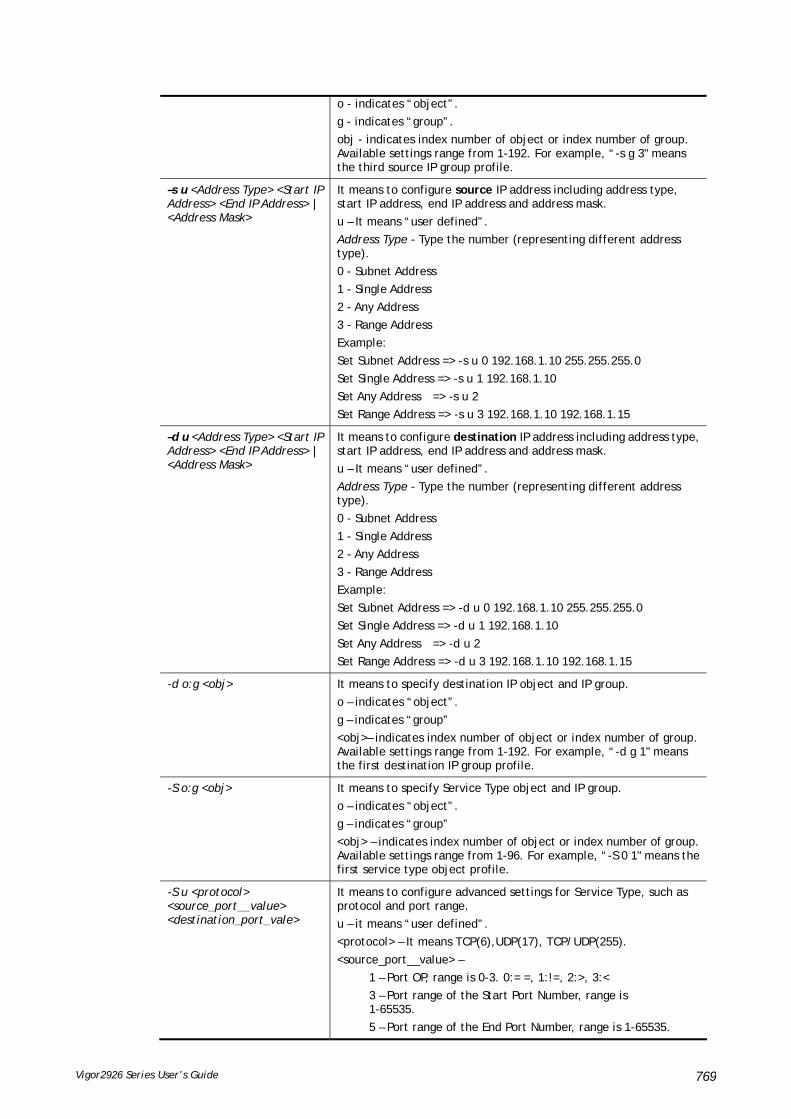
Vigor2926 Series User’s Guide 769
o - indicates “object”.
g - indicates “group”.
obj - indicates index number of object or index number of group. Available settings range from 1-192. For example, “-s g 3" means the third source IP group profile.
–s u <Address Type> <Start IP Address> <End IP Address> | <Address Mask>
It means to configure source IP address including address type, start IP address, end IP address and address mask.
u – It means “user defined”.
Address Type - Type the number (representing different address type).
0 - Subnet Address
1 - Single Address
2 - Any Address
3 - Range Address
Example:
Set Subnet Address => -s u 0 192.168.1.10 255.255.255.0
Set Single Address => -s u 1 192.168.1.10
Set Any Address => -s u 2
Set Range Address => -s u 3 192.168.1.10 192.168.1.15
–d u <Address Type> <Start IP Address> <End IP Address> | <Address Mask>
It means to configure destination IP address including address type, start IP address, end IP address and address mask.
u – It means “user defined”.
Address Type - Type the number (representing different address type).
0 - Subnet Address
1 - Single Address
2 - Any Address
3 - Range Address
Example:
Set Subnet Address => -d u 0 192.168.1.10 255.255.255.0
Set Single Address => -d u 1 192.168.1.10
Set Any Address => -d u 2
Set Range Address => -d u 3 192.168.1.10 192.168.1.15
-d o:g <obj> It means to specify destination IP object and IP group.
o – indicates “object”.
g – indicates “group”
<obj>– indicates index number of object or index number of group. Available settings range from 1-192. For example, “-d g 1" means the first destination IP group profile.
-S o:g <obj> It means to specify Service Type object and IP group.
o – indicates “object”.
g – indicates “group”
<obj> – indicates index number of object or index number of group. Available settings range from 1-96. For example, “-S 0 1" means the first service type object profile.
-S u <protocol> <source_port__value> <destination_port_vale>
It means to configure advanced settings for Service Type, such as protocol and port range.
u – it means “user defined”.
<protocol> – It means TCP(6),UDP(17), TCP/UDP(255).
<source_port__value> –
1 – Port OP, range is 0-3. 0:= =, 1:!=, 2:>, 3:<
3 – Port range of the Start Port Number, range is 1-65535.
5 – Port range of the End Port Number, range is 1-65535.
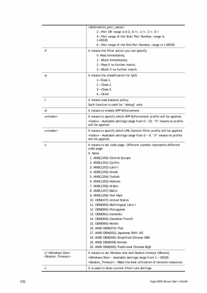
Vigor2926 Series User’s Guide 770
<destination_port_value>:
2 – Port OP, range is 0-3, 0:==, 1:!=, 2:>, 3:<
4 – Port range of the Start Port Number, range is 1-65535.
6 – Port range of the End Port Number, range is 1-65535.
-F It means the Filter action you can specify.
0 –Pass Immediately,
1 – Block Immediately,
2 – Pass if no further match,
3 – Block if no further match.
-q It means the classification for QoS.
1– Class 1,
2 – Class 2,
3 – Class 3,
4 – Other
-l It means load balance policy.
Such function is used for “debug” only.
-E It means to enable APP Enforcement.
-a<index> It means to specify which APP Enforcement profile will be applied.
<index> – Available settings range from 0 ~ 32. “0” means no profile will be applied.
-u<index> It means to specify which URL Content Filter profile will be applied.
<index> – Available settings range from 0 ~ 8. “0” means no profile will be applied.
-c It means to set code page. Different number represents different code page.
0. None
1. ANSI(1250)-Central Europe
2. ANSI(1251)-Cyrillic
3. ANSI(1252)-Latin I
4. ANSI(1253)-Greek
5. ANSI(1254)-Turkish
6. ANSI(1255)-Hebrew
7. ANSI(1256)-Arabic
8. ANSI(1257)-Baltic
9. ANSI(1258)-Viet Nam
10. OEM(437)-United States
11. OEM(850)-Multilingual Latin I
12. OEM(860)-Portuguese
13. OEM(861)-Icelandic
14. OEM(863)-Canadian French
15. OEM(865)-Nordic
16. ANSI/OEM(874)-Thai
17. ANSI/OEM(932)-Japanese Shift-JIS
18. ANSI/OEM(936)-Simplified Chinese GBK
19. ANSI/OEM(949)-Korean
20. ANSI/OEM(950)-Traditional Chinese Big5
-C <Windows Size> <Session_Timeout>
It means to set Window size and Session timeout (Minute).
<Windows Size> - Available settings range from 1 ~ 65535.
<Session_Timeout> - Make the best utilization of network resources.
-v It is used to show current filter/rule settings.
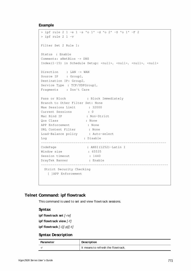
Vigor2926 Series User’s Guide 771
EExxaammppllee
> ipf rule 2 1 -e 1 -s "o 1" -d "o 2" -S "o 1" -F 2 > ipf rule 2 1 -v Filter Set 2 Rule 1: Status : Enable Comments: xNetBios -> DNS Index(1-15) in Schedule Setup: <null>, <null>, <null>, <null> Direction : LAN -> WAN Source IP : Group1, Destination IP: Group2, Service Type : TCP/UDPGroup1, Fragments : Don't Care Pass or Block : Block Immediately Branch to Other Filter Set: None Max Sessions Limit : 32000 Current Sessions : 0 Mac Bind IP : Non-Strict Qos Class : None APP Enforcement : None URL Content Filter : None Load-Balance policy : Auto-select Log : Disable ----------------------------------------------------------------- CodePage : ANSI(1252)-Latin I Window size : 65535 Session timeout : 1440 DrayTek Banner : Enable ------------------------------------------------------------------ Strict Security Checking [ ]APP Enforcement
TTeellnneett CCoommmmaanndd:: iippff fflloowwttrraacckk This command is used to set and view flowtrack sessions.
SSyynnttaaxx
ipf flowtrack set [-re]
ipf flowtrack view [-f]
ipf flowtrack [-i][-p][-t]
SSyynnttaaxx DDeessccrriippttiioonn
Parameter Description
-r It means to refresh the flowtrack.

Vigor2926 Series User’s Guide 772
-e It means to enable or disable the flowtrack.
-f It means to show the sessions state of flowtrack. If you do not specify any IP address, then all the session state of flowtrack will be displayed.
-b It means to show all of IP sessions state.
- i [IP address] It means to specify IP address (e.g,, -i 192.168.2.55).
-p[value] It means to type a port number (e.g., -p 1024).
Available settings are 0 ~ 65535.
-t [value] It means to specify a protocol (e.g., -t tcp).
Available settings include:
tcp
udp
icmp
EExxaammppllee
>ipf flowtrack set -r Refresh the flowstate ok > ipf flowtrack view -f Start to show the flowtrack sessions state: ORIGIN>> 192.168.1.11:59939 -> 8.8.8.8: 53 ,ifno=0 REPLY >> 8.8.8.8: 53 -> 192.168.1.11:59939 ,ifno=3 proto=17, age=93023180(3920), flag=203 ORIGIN>> 192.168.1.11:15073 -> 8.8.8.8: 53 ,ifno=0 REPLY >> 8.8.8.8: 53 -> 192.168.1.11:15073 ,ifno=3 proto=17, age=93025100(2000), flag=203 ORIGIN>> 192.168.1.11: 7247 -> 8.8.8.8: 53 ,ifno=0 REPLY >> 8.8.8.8: 53 -> 192.168.1.11: 7247 ,ifno=3 proto=17, age=93020100(7000), flag=203 End to show the flowtrack sessions state > ipf flowtrack set -e Current flow_enable=0 > ipf flowtrack set -e Curretn flow_enable=1
TTeellnneett CCoommmmaanndd:: iippff fflloowwtteesstt This command is used to for RD debug in firewall diagnose.
SSyynnttaaxx
ipf flowtest mode [<command><parameter>|…]
ipf flowtest set [index][option]
ipf flowtest send
ipf flowtest view
ipf flowtest reset
SSyynnttaaxx DDeessccrriippttiioonn
Parameter Description
mode

Vigor2926 Series User’s Guide 773
[<command> <parameter>|…]
The available commands with parameters are listed below.
[…] means that you can type in several commands in one line.
-m [value] It means to set ICMP, UDP or TCP as flowtest mode.
Value – 1, 2 or 3. In which,
1: ICMP
2: UDP
3: TCP
-d [value] It means to set the original direction
Value – 1 or 2. In which,
1: LAN to WAN
2: WAN to LAN
-v [value] It means to choose IP version.
Value – 4 or 6. In which,
4: IPv4
6: IPv6
-i [value] It means to specify IPv4 address of LAN device (e.g., 192.168.1.10).
-j [value] It means to specify IPv4 address of WAN divice (e.g., 8.8.8.8).
-l [value] It means to specify IPv6 address of LAN device (e.g., 2001:5678:0000:0000:1319:8a2e:0370:7343).
-w [value] It means to specify IPv6 address of WAN divice (e.g., 2001:1234:0000:0000:1319:8a2e:0370:7344).
-p [value] It means to set port number of LAN device (e.g., 65535)
-q [value] It means to set port number of WAN device (e.g., 53).
-e [value] It means to set MAC address of LAN device (e.g., AA:BB:CC:11:22:33).
set
[index] Index: 1 to 5.
-e [value] It means to enable /disable the test packet.
Value – 1 or 0. In which,
1: enable
0: disable
-w [value] It means to set direction of this packet.
Value – 1 or 2. In which,
1: LAN to WAN
2: WAN to LAN
-y [value] It means to set the payload type of this packet.
Value – 1 to 7. In which,
1: Customize
2: Echo Request
3: Echo Reply
4: Destination Unreachable
5: Ping Request
6: Pin Reply

Vigor2926 Series User’s Guide 774
7: Traceroute
8: DNS Query
9: Http Get
-a [value] It means set payload data depending to payload type.
Value – host name (e.g, www.draytek.com) or hex. stream (e.g., “6162636465666768696a6b6c6d6e6f70”)
-f [value] It means to set TCP flag of this packet.
Value – SYN ACK PSH FIN RST URG
send It means to start a test by sending each packet out.
view It means to view the test information and the test result.
reset It means to clear all configuration for flowtest.
EExxaammppllee
> ipf flowtest mode -m 2 -v 4 -d 1 -i 192.168.1.111 -j 8.8.8.8 -p 57005-q 53 -e 60:E3:27:02:CB:B1 > ipf flowtest set 1 -e 1 -w 1 -y 8 -a www.draytek.com > ipf flowtest send Send TEST Packet > > ipf flowtest view Test Info Mode:UDP Direction:LAN->WAN LAN>> IP:192.168.1.111 Port:57005 WAN>> IP:8.8.8.8 Port:53 LAN MAC 60:E3:27:02:CB:B1 Test Result ORIGIN>> 192.168.1.111:57005 -> 8.8.8.8: 53 ,ifno=0 nat=49969 td_state=1 REPLY >> 8.8.8.8: 53 -> 192.168.200.104:38445 ,ifno=3 nat=49969 td_state=1 Status:Pass Packet:2 Set:13 Rule:1 all_app_flag:1f7f8 send_out:2 wan_num:3 Packet:1 Status:Pass dir:LAN->WAN is_p:17 flowflag:9 appflag:80 accflag:1e5b8 fr_flags:2 set:13 rule:1 > ipf flowtest reset Reset TEST
TTeellnneett CCoommmmaanndd:: LLoogg This command allows users to view log for WAN interface such as call log, IP filter log, flush log buffer, etc.
SSyynnttaaxx
log [-cfhiptwx?] [-F a| c | f | w]

Vigor2926 Series User’s Guide 775
SSyynnttaaxx DDeessccrriippttiioonn
Parameter Description
-c It means to show the latest call log.
-f It means to show the IP filter log.
-F It means to show the flush log buffer.
a: flush all logs
c: flush the call log
f: flush the IP filter log
w: flush the WAN log
-h It means to show this usage help.
-p It means to show PPP/MP log.
-t It means to show all logs saved in the log buffer.
-w It means to show WAN log.
-x It means to show packet body hex dump.
EExxaammppllee
> log -w 25:36:25.580 ---->DHCP (WAN-5) Len = 548XID = 0x7880fdd4 Client IP = 0.0.0.0 Your IP = 0.0.0.0 Next server IP = 0.0.0.0 Relay agent IP = 0.0.0.0 25:36:33.580 ---->DHCP (WAN-5) Len = 548XID = 0x7880fdd4 Client IP = 0.0.0.0 Your IP = 0.0.0.0 Next server IP = 0.0.0.0 Relay agent IP = 0.0.0.0 25:36:41.580 ---->DHCP (WAN-5) Len = 548XID = 0x7880fdd4 Client IP = 0.0.0.0 Your IP = 0.0.0.0 Next server IP = 0.0.0.0 Relay agent IP = 0.0.0.0 25:36:49.580 ---->DHCP (WAN-5) Len = 548XID = 0x7880fdd4 Client IP = 0.0.0.0 Your IP = 0.0.0.0 Next server IP = 0.0.0.0 Relay agent IP = 0.0.0.0 25:36:57.580 ---->DHCP (WAN-5) Len = 548XID = 0x7880fdd4 Client IP = 0.0.0.0 Your IP = 0.0.0.0 --- MORE --- ['q': Quit, 'Enter': New Lines, 'Space Bar': Next Page] ---
TTeellnneett CCoommmmaanndd:: llddaapp uusseerr This command is used to configure the LDAP profile.
SSyynnttaaxx
ldap user [INDEX][OPTION]

Vigor2926 Series User’s Guide 776
SSyynnttaaxx DDeessccrriippttiioonn
Parameter Description
INDEX Specify the index number (1 to 8) of the LDAP profile.
OPTION
-n VALUE Setup Profile Name.
-b VALUE Setup Base Distinguished Name.
-a VALUE If you have added containers to be published, you may need to specify additional LDAP filters for each class of objects included in these containers.
Creating LDAP filters is a fairly complex task that should be performed by advanced users only. LDAP filters must be RFC2254-compliant.
For example, to exclude from publication all users who either belong to the HR department of your company or are members of the HR Group. For example:
>ldap user 1 -a "(!(|(department=HR)(memberOf=CN=HRGroup,OU=Groups, DC=acme,DC=com)))"
Additional Filter has been updated.
-g VALUE Setup Group Distinguished Name.
-c VALUE Setup Common Name Identifier.
-v View detail information of the LDAP profile.
EExxaammppllee >ldap user 1 -n LD_user_test1 Profile Name has been updated! > ldap user 1 -v Profile Index:1 Profile Name:LD_user_test1 Common Name Identifier: Base Distinguished Name: Additional Filter: Group distinguished Name: >ldap user 1 -b ou=People,dc=example,dc=com
TTeellnneett CCoommmmaanndd:: llddaapp sseett This command is used to set general settings (e.g., IP address, port number) for LDAP server.
SSyynnttaaxx
ldap set [Options][Value]
SSyynnttaaxx DDeessccrriippttiioonn
Parameter Description
enable [0-1] Enable or disable LDAP function.
0 – Disable the function.
1 – Enable the function.
type [0-2] Set the bind type as Simple(0),Anonymous(1), and Regular(2).
ssl [0-1] Enable or disable LDAP function via SSL tunnel.
0 – Disable the function.
1 – Enable the function.

Vigor2926 Series User’s Guide 777
IP <VALUE> Set IP address for LDAP server.
port <VALUE> Set port number for LDAP server.
dn <VALUE> Set Regular DN value
PWD <VALUE> Set Regular password value.
EExxaammppllee >ldap set enable 1 >ldap enabled. > ldap set ssl 1 LDAP with SSL has been enabled! > ldap set IP 192.168.100.155 LDAP Server IP has been setting. > ldap set port 389 LDAP Server Port has been setting. > ldap set dn dc=example,dc=com LDAP Regular DN has been setting. > ldap set PWD 123456 LDAP Regular Password has been setting.
TTeellnneett CCoommmmaanndd:: llddaapp vviieeww This command is used to check current status of LDAP settings configuration.
SSyynnttaaxx
ldap view
EExxaammppllee > ldap view ? LDAP Enable:Disabled. LDAP Bind Type:Simple LDAP with SSL:Disabled LDAP Regular DN: LDAP Regular Password: LDAP Server IP: LDAP Server Port:389
TTeellnneett CCoommmmaanndd:: ttaaccaaccsspplluuss sseett This command allows users to configure general settings for TACACS+ server
SSyynnttaaxx
tacacspluse set [Options][Value]
SSyynnttaaxx DDeessccrriippttiioonn
Parameter Description
enable [0-1] Disable (0)/enable(1) the TACACS+ server.
IP <VALUE> Set the IP address of TACACS+ server.
port <VALUE> Set the port number of TACACS+ server.
shared_secret <VALUE> Set the Shared Secret value of TACACS+ Server.
EExxaammppllee

Vigor2926 Series User’s Guide 778
> tacacsplus set enable 1 TACACS+ enabled! This setting will take effect after rebooting. Please use "sys reboot" command to reboot the router. > tacacsplus set IP 192.168.1.59 TACACS+ Server IP has been setting. This setting will take effect after rebooting. Please use "sys reboot" command to reboot the router. > tacacsplus view TACACS+ Enable:Enable. TACACS+ Server IP:192.168.1.59 TACACS+ Server Port:49 TACACS+ Type:ASCII TACACS+ Shared Secret:
TTeellnneett CCoommmmaanndd:: ttaaccaaccsspplluuss vviieeww This command allows users to check the general settings for TACACS+ server
SSyynnttaaxx
tacacspluse view
EExxaammppllee > tacacsplus view TACACS+ Enable:Enable. TACACS+ Server IP:192.168.1.59 TACACS+ Server Port:49 TACACS+ Type:ASCII TACACS+ Shared Secret:
TTeellnneett CCoommmmaanndd:: mmnnggtt ffttppppoorrtt This command allows users to set FTP port for management.
SSyynnttaaxx
mngt ftpport [FTP port]
SSyynnttaaxx DDeessccrriippttiioonn
Parameter Description
FTP port It means to type the number for FTP port. The default setting is 21.
EExxaammppllee > mngt ftpport 21 % Set FTP server port to 21 done.
TTeellnneett CCoommmmaanndd:: mmnnggtt hhttttppppoorrtt This command allows users to set HTTP port for management.
SSyynnttaaxx

Vigor2926 Series User’s Guide 779
mngt httpport [Http port]
SSyynnttaaxx DDeessccrriippttiioonn
Parameter Description
Http port It means to enter the number for HTTP port. The default setting is 80.
EExxaammppllee > mngt httpport 80
% Set web server port to 80 done.
TTeellnneett CCoommmmaanndd:: mmnnggtt hhttttppssppoorrtt This command allows users to set HTTPS port for management.
SSyynnttaaxx
mngt httpsport [Https port]
SSyynnttaaxx DDeessccrriippttiioonn
Parameter Description
Https port It means to type the number for HTTPS port. The default setting is 443.
EExxaammppllee > mngt httpsport 443 % Set web server port to 443 done.
TTeellnneett CCoommmmaanndd:: mmnnggtt tteellnneettppoorrtt This command allows users to set telnet port for management.
SSyynnttaaxx
mngt telnetport [Telnet port]
SSyynnttaaxx DDeessccrriippttiioonn
Parameter Description
Telnet port It means to type the number for telnet port. The default setting is 23.
EExxaammppllee
> mngt telnetport 23 % Set Telnet server port to 23 done.
TTeellnneett CCoommmmaanndd:: mmnnggtt sssshhppoorrtt This command allows users to set SSH port for management.
SSyynnttaaxx
mngt sshport [ssh port]

Vigor2926 Series User’s Guide 780
SSyynnttaaxx DDeessccrriippttiioonn
Parameter Description
ssh port It means to type the number for SSH port. The default setting is 22.
EExxaammppllee
> mngt sshport 23 % Set ssh port to 23 done.
TTeellnneett CCoommmmaanndd:: mmnnggtt nnooppiinngg This command is used to pass or block Ping from LAN PC to the internet.
SSyynnttaaxx
mngt noping [on]
mngt noping [off]
mngt noping [viewlog]
mngt noping [clearlog]
SSyynnttaaxx DDeessccrriippttiioonn
Parameter Description
on All PING packets will be forwarded from LAN PC to Internet.
off All PING packets will be blocked from LAN PC to Internet.
viewlog It means to display a log of ping action, including source MAC and source IP.
clearlog It means to clear the log of ping action.
EExxaammppllee
> mngt noping off No Ping Packet Out is OFF!!
TTeellnneett CCoommmmaanndd:: mmnnggtt ddeeffeennsseewwoorrmm This command can block specified port for passing through the router.
SSyynnttaaxx
mngt defenseworm [on]
mngt defenseworm [off]
mngt defenseworm [add port]
mngt defenseworm [del port]
mngt defenseworm [viewlog]
mngt defenseworm [clearlog]
SSyynnttaaxx DDeessccrriippttiioonn
Parameter Description

Vigor2926 Series User’s Guide 781
on It means to activate the function of defense worm packet out.
off It means to inactivate the function of defense worm packet out.
add port It means to add a new TCP port for block.
del port It means to delete a TCP port for block.
viewlog It means to display a log of defense worm packet, including source MAC and source IP.
clearlog It means to remove the log of defense worm packet.
EExxaammppllee
> mngt defenseworm add 21 Add TCP port 21 Block TCP port list: 135, 137, 138, 139, 445, 21 > mngt defenseworm del 21 Delete TCP port 21 Block TCP port list: 135, 137, 138, 139, 445
TTeellnneett CCoommmmaanndd:: mmnnggtt rrmmttccffgg This command can allow the system administrators to login from the Internet. By default, it is not allowed.
SSyynnttaaxx
mngt rmtcfg [status]
mngt rmtcfg [enable]
mngt rmtcfg [disable]
mngt rmtcfg [http/https/ftp/telnet/ssh/tr069] [on/off]
SSyynnttaaxx DDeessccrriippttiioonn
Parameter Description
status It means to display current setting for your reference.
enable It means to allow the system administrators to login from the Internet.
disable It means to deny the system administrators to login from the Internet.
http/https/ftp/telnet/ssh/tr069
It means to specify one of the servers/protocols for enabling or disabling.
on/off on – enable the function.
off – disable the function.
EExxaammppllee
> mngt rmtcfg ftp on Enable server fail Remote configure function has been disabled please enable by enter mngt rmtcfg enable > mngt rmtcfg enable %% Remote configure function has been enabled. > mngt rmtcfg ftp on

Vigor2926 Series User’s Guide 782
%% FTP server has been enabled.

Vigor2926 Series User’s Guide 783
TTeellnneett CCoommmmaanndd:: mmnnggtt llaannaacccceessss This command allows users to manage accessing into Vigor router through LAN port.
SSyynnttaaxx
mngt lanaccess -e [0/1] –s [value] –i [value]
mngt lanaccess –f
mngt lanaccess –d
mngt lanaccess –v
mngt lanaccess –h
SSyynnttaaxx DDeessccrriippttiioonn
Parameter Description
-e[0/1] It means to enable/disable the function.
0-disable the function.
1-enable the function.
-s[value] It means to specify service offered.
Available values include:
FTP, HTTP, HTTPS, TELNET, SSH, None, All
-i[value] It means the interface which is allowed to access.
Available values include:
LAN2~LAN6, DMZ, IP Routed Subnet, None, All
Note: LAN1 is always allowed for accessing into the router.
-f It means to flush all of the settings.
-d It means to restore the factory default settings.
-v It means to view current settings.
-h It means to get the usage of such command.
EExxaammppllee
> mngt lanaccess -e 1 > mngt lanaccess -s FTP,TELNET > mngt lanaccess -i LAN3 > > mngt lanaccess -v Current LAN Access Control Setting: * Enable:Yes * Service: - FTP:Yes - HTTP:No - HTTPS:No - TELNET:Yes - SSH:No * Subnet: - LAN 2: disabled - LAN 3: enabled - LAN 4: disabled - LAN 5: disabled - LAN 6: disabled - DMZ: disabled
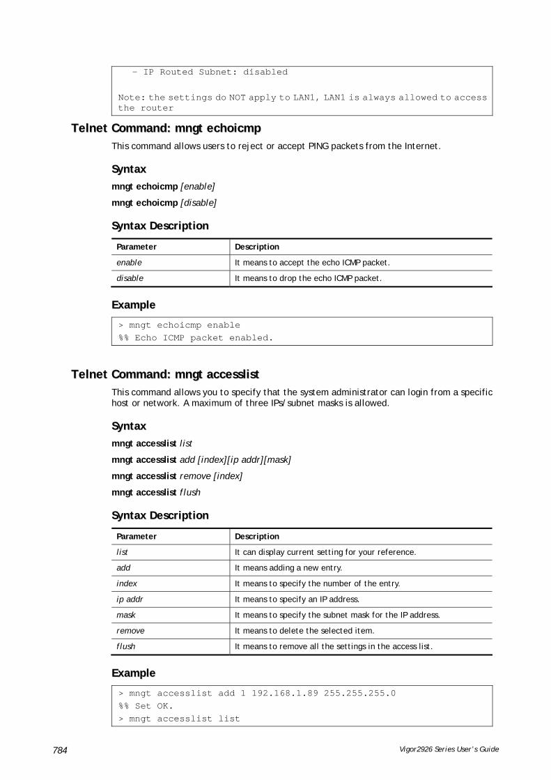
Vigor2926 Series User’s Guide 784
- IP Routed Subnet: disabled Note: the settings do NOT apply to LAN1, LAN1 is always allowed to access the router
TTeellnneett CCoommmmaanndd:: mmnnggtt eecchhooiiccmmpp This command allows users to reject or accept PING packets from the Internet.
SSyynnttaaxx
mngt echoicmp [enable]
mngt echoicmp [disable]
SSyynnttaaxx DDeessccrriippttiioonn
Parameter Description
enable It means to accept the echo ICMP packet.
disable It means to drop the echo ICMP packet.
EExxaammppllee
> mngt echoicmp enable %% Echo ICMP packet enabled.
TTeellnneett CCoommmmaanndd:: mmnnggtt aacccceesssslliisstt This command allows you to specify that the system administrator can login from a specific host or network. A maximum of three IPs/subnet masks is allowed.
SSyynnttaaxx
mngt accesslist list
mngt accesslist add [index][ip addr][mask]
mngt accesslist remove [index]
mngt accesslist flush
SSyynnttaaxx DDeessccrriippttiioonn
Parameter Description
list It can display current setting for your reference.
add It means adding a new entry.
index It means to specify the number of the entry.
ip addr It means to specify an IP address.
mask It means to specify the subnet mask for the IP address.
remove It means to delete the selected item.
flush It means to remove all the settings in the access list.
EExxaammppllee
> mngt accesslist add 1 192.168.1.89 255.255.255.0 %% Set OK. > mngt accesslist list

Vigor2926 Series User’s Guide 785
%% Access list : Index IP address Subnet mask ========================================== 1 192.168.1.89 255.255.255.0
TTeellnneett CCoommmmaanndd:: mmnnggtt ssnnmmpp This command allows you to configure SNMP for management.
SSyynnttaaxx
mngt snmp [-<command> <parameter> | ... ]
SSyynnttaaxx DDeessccrriippttiioonn
Parameter Description
[<command> <parameter>|…]
The available commands with parameters are listed below.
[…] means that you can type in several commands in one line.
-e <1/2> 1: Enable the SNMP function.
2: Disable the SNMP function.
-g<Community name> It means to set the name for getting community by typing a proper character. (max. 23 characters)
-s <Community name> It means to set community by typing a proper name. (max. 23 characters)
-m <IP address> It means to set one host as the manager to execute SNMP function. Please type in IPv4 address to specify certain host.
-t <Community name> It means to set trap community by typing a proper name. (max. 23 characters)
-n <IP address> It means to set the IPv4 address of the host that will receive the trap community.
-T <seconds> It means to set the trap timeout <0~999>.
-V It means to list SNMP setting.
EExxaammppllee
> mngt snmp -e 1 -g draytek -s DK -m 192.168.1.1 -t trapcom -n 10.20.3.40 -T 88 SNMP Agent Turn on!!! Get Community set to draytek Set Community set to DK Manager Host IP set to 192.168.1.1 Trap Community set to trapcom Notification Host IP set to 10.20.3.40 Trap Timeout set to 88 seconds
TTeellnneett CCoommmmaanndd:: mmnnggtt bbffpp This command allows you to configure brute force protect (BFP) for system management.
SSyynnttaaxx
mngt bfp [<command><parameter>|…]
SSyynnttaaxx DDeessccrriippttiioonn
Parameter Description

Vigor2926 Series User’s Guide 786
[<command> <parameter>|…]
The available commands with parameters are listed below.
[…] means that you can type in several commands in one line.
-e 0/1 Enable / disable the BFP function.
0 – Disable
1 – Enable
-s [service] It means to enable different service.
service - Available types are FTP, HTTP, HTTPS, TELNET, TR069, SSH, None and All.
-l [failure] It means to set login failure retry times.
failure - Available number is from 1 to 255.
-p [penalty] It means to set penalty time for BFP. The unit is sec.
-v It means to view current settings.
EExxaammppllee
> mngt bfp -e 1 > mngt bfp -s FTP > mngt bfp -l 10 > mngt bfp -v Current Brute Force Protection Setting: * Enable: yes * Service: - FTP: yes - HTTP: no - HTTPS: no - TELNET: no - TR069: no - SSH: no * Maximum login failures: 10 * Penalty period: 0
TTeellnneett CCoommmmaanndd:: mmssuubbnneett sswwiittcchh This command is used to configure multi-subnet.
SSyynnttaaxx
msubnet switch [2/3/4/5][On/Off]
SSyynnttaaxx DDeessccrriippttiioonn
Parameter Description
2/3/4/5 It means LAN interface.
2=LAN2
3=LAN3
4=LAN4
5=LAN5
On/Off On means turning on the subnet for the specified LAN interface.
Off means turning off the subnet.
EExxaammppllee
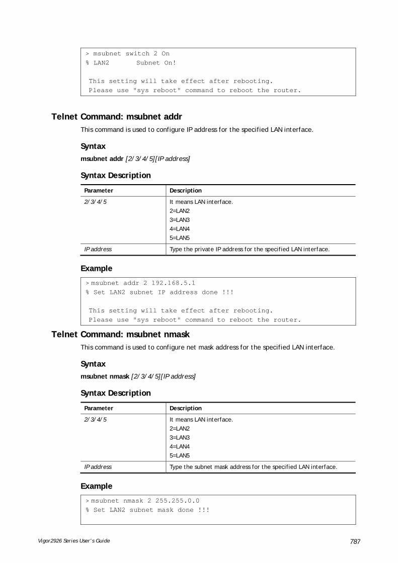
Vigor2926 Series User’s Guide 787
> msubnet switch 2 On % LAN2 Subnet On! This setting will take effect after rebooting. Please use "sys reboot" command to reboot the router.
TTeellnneett CCoommmmaanndd:: mmssuubbnneett aaddddrr This command is used to configure IP address for the specified LAN interface.
SSyynnttaaxx
msubnet addr [2/3/4/5][IP address]
SSyynnttaaxx DDeessccrriippttiioonn
Parameter Description
2/3/4/5 It means LAN interface.
2=LAN2
3=LAN3
4=LAN4
5=LAN5
IP address Type the private IP address for the specified LAN interface.
EExxaammppllee
> msubnet addr 2 192.168.5.1 % Set LAN2 subnet IP address done !!! This setting will take effect after rebooting. Please use "sys reboot" command to reboot the router.
TTeellnneett CCoommmmaanndd:: mmssuubbnneett nnmmaasskk This command is used to configure net mask address for the specified LAN interface.
SSyynnttaaxx
msubnet nmask [2/3/4/5][IP address]
SSyynnttaaxx DDeessccrriippttiioonn
Parameter Description
2/3/4/5 It means LAN interface.
2=LAN2
3=LAN3
4=LAN4
5=LAN5
IP address Type the subnet mask address for the specified LAN interface.
EExxaammppllee
> msubnet nmask 2 255.255.0.0 % Set LAN2 subnet mask done !!!

Vigor2926 Series User’s Guide 788
This setting will take effect after rebooting. Please use "sys reboot" command to reboot the router.
TTeellnneett CCoommmmaanndd:: mmssuubbnneett ssttaattuuss This command is used to display current status of subnet.
SSyynnttaaxx
msubnet status [2/3/4/5]
SSyynnttaaxx DDeessccrriippttiioonn
Parameter Description
2/3/4/5 It means LAN interface.
2=LAN2
3=LAN3
4=LAN4
5=LAN5
EExxaammppllee
> msubnet status 2 % LAN2 Off: 0.0.0.0/0.0.0.0, PPP Start IP: 0.0.0.60 % DHCP server: Off % Dhcp Gateway: 0.0.0.0, Start IP: 0.0.0.10, Pool Count: 50
TTeellnneett CCoommmmaanndd:: mmssuubbnneett ddhhccppss This command allows you to enable or disable DHCP server for the subnet.
SSyynnttaaxx
msubnet dhcps [2/3/4/5][On/Off]
SSyynnttaaxx DDeessccrriippttiioonn
Parameter Description
2/3/4/5 It means LAN interface.
2=LAN2
3=LAN3
4=LAN4
5=LAN5
On/Off On means enabling the DHCP server for the specified LAN interface.
Off means disabling the DHCP server.
EExxaammppllee
> msubnet dhcps 3 off % LAN3 Subnet DHCP Server disabled! This setting will take effect after rebooting. Please use "sys reboot" command to reboot the router.

Vigor2926 Series User’s Guide 789
TTeellnneett CCoommmmaanndd:: mmssuubbnneett nnaatt This command is used to configure the subnet for NAT or Routing usage.
SSyynnttaaxx
msubnet nat [2/3/4/5] [On/Off]
SSyynnttaaxx DDeessccrriippttiioonn
Parameter Description
2/3/4/5 It means LAN interface.
2=LAN2
3=LAN3
4=LAN4
5=LAN5
On/Off On – It means the subnet will be configured for NAT usage.
Off - It means the subnet will be configured for Routing usage.
EExxaammppllee
> > msubnet nat 2 off % LAN2 Subnet is for Routing usage! %Note: If you have multiple WAN connections, please be reminded to setup a Load-Balance policy so that packets from this subnet will be forwarded to the right WAN interface! This setting will take effect after rebooting. Please use "sys reboot" command to reboot the router.
TTeellnneett CCoommmmaanndd:: mmssuubbnneett ggaatteewwaayy This command is used to configure an IP address as the gateway used for subnet.
SSyynnttaaxx
msubnet gateway [2/3/4/5] [Gateway IP]
SSyynnttaaxx DDeessccrriippttiioonn
Parameter Description
2/3/4/5 It means LAN interface.
2=LAN2
3=LAN3
4=LAN4
5=LAN5
Gateway IP Specify an IP address as the gateway IP.
EExxaammppllee
> msubnet gateway 2 192.168.1.13 % Set LAN2 Dhcp Gateway IP done !!! This setting will take effect after rebooting. Please use "sys reboot" command to reboot the router.

Vigor2926 Series User’s Guide 790
TTeellnneett CCoommmmaanndd:: mmssuubbnneett iippccnntt This command is used to defined the total number allowed for each LAN interface.
SSyynnttaaxx
msubnet ipcnt [2/3/4/5] [IP counts]
SSyynnttaaxx DDeessccrriippttiioonn
Parameter Description
2/3/4/5 It means LAN interface.
2=LAN2
3=LAN3
4=LAN4
5=LAN5
IP counts Specify a total number of IP address allowed for each LAN interface.
The available range is from 0 to 220.
EExxaammppllee
> msubnet ipcnt 2 15 This setting will take effect after rebooting. Please use "sys reboot" command to reboot the router.
TTeellnneett CCoommmmaanndd:: mmssuubbnneett ttaallkk This command is used to establish a route between two LAN interfaces.
SSyynnttaaxx
msubnet talk [1/2/3/4/5] [1/2/3/4/5] [On/Off]
SSyynnttaaxx DDeessccrriippttiioonn
Parameter Description
1/2/3/4/5 It means LAN interface.
1=LAN1
2=LAN2
3=LAN3
4=LAN4
5=LAN5
On/Off On – It means
Off - It means
EExxaammppllee
> msubnet talk 1 2 on % Enable routing between LAN1 and LAN2 ! This setting will take effect after rebooting. Please use "sys reboot" command to reboot the router. > msubnet talk ? % msubnet talk <1/2/3/4/5> <1/2/3/4/5> <On/Off> % where 1:LAN1, 2:LAN2, 3:LAN3, 4:LAN4, 5:LAN5 % Now:
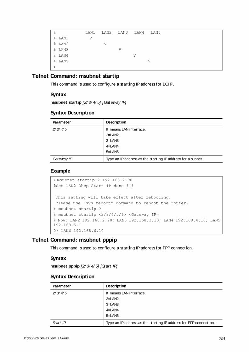
Vigor2926 Series User’s Guide 791
% LAN1 LAN2 LAN3 LAN4 LAN5 % LAN1 V % LAN2 V % LAN3 V % LAN4 V % LAN5 V >
TTeellnneett CCoommmmaanndd:: mmssuubbnneett ssttaarrttiipp This command is used to configure a starting IP address for DCHP.
SSyynnttaaxx
msubnet startip [2/3/4/5] [Gateway IP]
SSyynnttaaxx DDeessccrriippttiioonn
Parameter Description
2/3/4/5 It means LAN interface.
2=LAN2
3=LAN3
4=LAN4
5=LAN5
Gateway IP Type an IP address as the starting IP address for a subnet.
EExxaammppllee
> msubnet startip 2 192.168.2.90 %Set LAN2 Dhcp Start IP done !!! This setting will take effect after rebooting. Please use "sys reboot" command to reboot the router. > msubnet startip ? % msubnet startip <2/3/4/5/6> <Gateway IP> % Now: LAN2 192.168.2.90; LAN3 192.168.3.10; LAN4 192.168.4.10; LAN5 192.168.5.1 0; LAN6 192.168.6.10
TTeellnneett CCoommmmaanndd:: mmssuubbnneett ppppppiipp This command is used to configure a starting IP address for PPP connection.
SSyynnttaaxx
msubnet pppip [2/3/4/5] [Start IP]
SSyynnttaaxx DDeessccrriippttiioonn
Parameter Description
2/3/4/5 It means LAN interface.
2=LAN2
3=LAN3
4=LAN4
5=LAN5
Start IP Type an IP address as the starting IP address for PPP connection.

Vigor2926 Series User’s Guide 792
EExxaammppllee
> msubnet pppip 2 192.168.2.250 % Set LAN2 PPP(IPCP) Start IP done !!! This setting will take effect after rebooting. Please use "sys reboot" command to reboot the router. > msubnet pppip ? % msubnet pppip <2/3/4/5/6> <Start IP> % Now: LAN2 192.168.2.250; LAN3 192.168.3.200; LAN4 192.168.4.200; LAN5 192.168.5.200; LAN6 192.168.6.200
TTeellnneett CCoommmmaanndd:: mmssuubbnneett nnooddeettyyppee This command is used to specify the type for node which is required by DHCP option.
SSyynnttaaxx
msubnet nodetype [2/3/4/5][count]
SSyynnttaaxx DDeessccrriippttiioonn
Parameter Description
2/3/4/5 It means LAN interface.
2=LAN2
3=LAN3
4=LAN4
5=LAN5
count Choose the following number for specifying different node type.
1= B-node
2= P-node
4= M-node
8= H-node
0= Not specify any type for node.
EExxaammppllee
> msubnet nodetype ? % msubnet nodetype <2/3/4/5> <count> % Now: LAN2 0; LAN3 0; LAN4 0; LAN5 0 % count: 1. B-node 2. P-node 4. M-node 8. H-node > msubnet nodetype 2 1 % Set LAN2 Dhcp Node Type done !!! > msubnet nodetype ? % msubnet nodetype <2/3/4/5> <count> % Now: LAN2 1; LAN3 0; LAN4 0; LAN5 0 % count: 1. B-node 2. P-node 4. M-node 8. H-node
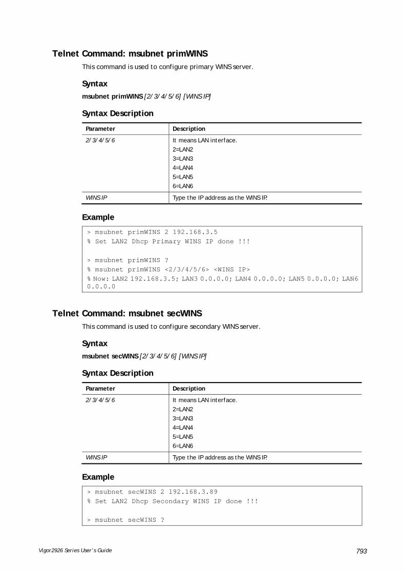
Vigor2926 Series User’s Guide 793
TTeellnneett CCoommmmaanndd:: mmssuubbnneett pprriimmWWIINNSS This command is used to configure primary WINS server.
SSyynnttaaxx
msubnet primWINS [2/3/4/5/6] [WINS IP]
SSyynnttaaxx DDeessccrriippttiioonn
Parameter Description
2/3/4/5/6 It means LAN interface.
2=LAN2
3=LAN3
4=LAN4
5=LAN5
6=LAN6
WINS IP Type the IP address as the WINS IP.
EExxaammppllee
> msubnet primWINS 2 192.168.3.5 % Set LAN2 Dhcp Primary WINS IP done !!! > msubnet primWINS ? % msubnet primWINS <2/3/4/5/6> <WINS IP> % Now: LAN2 192.168.3.5; LAN3 0.0.0.0; LAN4 0.0.0.0; LAN5 0.0.0.0; LAN6 0.0.0.0
TTeellnneett CCoommmmaanndd:: mmssuubbnneett sseeccWWIINNSS This command is used to configure secondary WINS server.
SSyynnttaaxx
msubnet secWINS [2/3/4/5/6] [WINS IP]
SSyynnttaaxx DDeessccrriippttiioonn
Parameter Description
2/3/4/5/6 It means LAN interface.
2=LAN2
3=LAN3
4=LAN4
5=LAN5
6=LAN6
WINS IP Type the IP address as the WINS IP.
EExxaammppllee
> msubnet secWINS 2 192.168.3.89 % Set LAN2 Dhcp Secondary WINS IP done !!! > msubnet secWINS ?

Vigor2926 Series User’s Guide 794
% % msubnet secWINS <2/3/4/5/6> <WINS IP> % Now: LAN2 192.168.3.89; LAN3 0.0.0.0; LAN4 0.0.0.0; LAN5 0.0.0.0; LAN6 0.0.0.0
TTeellnneett CCoommmmaanndd:: mmssuubbnneett ttffttpp This command is used to set TFTP server for multi-subnet.
SSyynnttaaxx
msubnet tftp [2/3/4/5] [TFTP server name]
SSyynnttaaxx DDeessccrriippttiioonn
Parameter Description
2/3/4/5 It means LAN interface.
2=LAN2
3=LAN3
4=LAN4
5=LAN5
TFTP server name Type a name to indicate the TFTP server.
EExxaammppllee
> msubnet tftp ? % msubnet tftp <2/3/4/5> <TFTP server name> % Now: LAN2 LAN3 LAN4 LAN5 LAN6 > msubnet tftp 2 publish % Set LAN2 TFTP Server Name done !!! > msubnet tftp ? % msubnet tftp <2/3/4/5> <TFTP server name> % Now: LAN2 publish LAN3 LAN4 LAN5
TTeellnneett CCoommmmaanndd:: mmssuubbnneett mmttuu This command allows you to configure MTU value for LAN/DMZ/IP Routed Subnet.
SSyynnttaaxx
msubnet mtu [interface][value]
SSyynnttaaxx DDeessccrriippttiioonn
Parameter Description
interface Available settings include LAN1~LAN6, IP_Routed_Subnet, and DMZ.
value 1000 ~ 1508 (Bytes), default: 1500 (Bytes)

Vigor2926 Series User’s Guide 795
EExxaammppllee
> msubnet mtu ? Usage: >msubnet mtu <interface> <value> <interface>: LAN1~LAN5,IP_Routed_Subnet,DMZ <value>: 1000 ~ 1496 (Bytes), default: 1500 (Bytes) e.x: >msubnet mtu LAN1 1492 Current Settings: LAN1 MTU: 1500 (Bytes) LAN2 MTU: 1500 (Bytes) LAN3 MTU: 1500 (Bytes) LAN4 MTU: 1500 (Bytes) LAN5 MTU: 1500 (Bytes) DMZ MTU: 1500 (Bytes) IP Routed Subnet MTU: 1500 (Bytes)
TTeellnneett CCoommmmaanndd:: mmssuubbnneett lleeaasseettiimmee This command allows you to set leasetime for DHCP server. It is helpful to manage the IP address(es) assigned by DHCP server.
SSyynnttaaxx
msubnet leasetime [1/2/3/4/5/6/dmz][Lease Time (sec.)]
SSyynnttaaxx DDeessccrriippttiioonn
Parameter Description
[1/2/3/4/5/6/dmz] 1 – 6 represent LAN1 to LAN6.
Lease Time (sec.) Range from 1 to 259200.
If no value specified here, Vigor router system will use the maximum value, 259200, as the leasetime.
EExxaammppllee
> msubnet leasetime 1 80800 Set LAN1 lease time: 80800 > msubnet leasetime 1 % Set LAN1 lease time: 259200
TTeellnneett CCoommmmaanndd:: oobbjjeecctt iipp oobbjj This command is used to create an IP object profile.
SSyynnttaaxx
object ip obj setdefault
object ip obj INDEX -v
object ip obj INDEX -n NAME

Vigor2926 Series User’s Guide 796
object ip obj INDEX -i INTERFACE
object ip obj INDEX -s INVERT
object ip obj INDEX -a TYPE [START_IP] [END/MASK_IP]
SSyynnttaaxx DDeessccrriippttiioonn
Parameter Description
setdefault It means to return to default settings for all profiles.
INDEX It means the index number of the specified object profile.
-v It means to view the information of the specified object profile.
Example: object ip obj 1 -v
-n NAME It means to define a name for the IP object.
NAME: Type a name with less than 15 characters.
Example: object ip obj 9 -n bruce
-i INTERFACE It means to define an interface for the IP object.
INTERFACE=0, means any
INTERFACE=1, means LAN
INTERFACE=3, means WAN
Example: object ip obj 8 -i 0
-s INVERT It means to set invert seletion for the object profile.
INVERT=0, means disableing the function.
INVERT=1, means enabling the function.
Example: object ip obj 3 -s 1
-a TYPE It means to set the address type and IP for the IP object profile.
TYPE=0, means Mask
TYPE=1, means Single
TYPE=2, means Any
TYPE=3, means Rang
Example: object ip obj 3 -a 2
[START_IP] When the TYPE is set with 2, you have to type an IP address as a starting point and another IP address as end point.
Type an IP address.
[END/MASK_IP] Type an IP address (different with START_IP) as the end IP address.
EExxaammppllee
> object ip obj 1 -n marketing > object ip obj 1 -a 1 192.168.1.45 > object ip obj 1 -v IP Object Profile 1 Name :[marketing] Interface:[Any] Address type:[single] Start ip address:[192.168.1.45] End/Mask ip address:[0.0.0.0] Invert Selection:[0]

Vigor2926 Series User’s Guide 797
TTeellnneett CCoommmmaanndd:: oobbjjeecctt iipp ggrrpp This command is used to integrate several IP objects under an IP group profile.
SSyynnttaaxx
object ip grp setdefault
object ip grp INDEX -v
object ip grp INDEX -n NAME
object ip grp INDEX -i INTERFACE
object ip grp INDEX -a IP_OBJ_INDEX
SSyynnttaaxx DDeessccrriippttiioonn
Parameter Description
setdefault It means to return to default settings for all profiles.
INDEX It means the index number of the specified group profile.
-v It means to view the information of the specified group profile.
Example: object ip grp 1 -v
-n NAME It means to define a name for the IP group.
NAME: Type a name with less than 15 characters.
Example: object ip grp 8 -n bruce
-i INTERFACE It means to define an interface for the IP group.
INTERFACE=0, means any
INTERFACE=1, means LAN
INTERFACE=2, means WAN
Example: object ip grp 3 -i 0
-a IP_OBJ_INDEX It means to specify IP object profiles for the group profile.
Example: :object ip grp 3 -a 1 2 3 4 5 The IP object profiles with index number 1,2,3,4 and 5 will be group under such profile.
EExxaammppllee
> object ip grp 2 -n First IP Group Profile 2 Name :[First] Interface:[Any] Included ip object index: [0:][0] [1:][0] [2:][0] [3:][0] [4:][0] [5:][0] [6:][0] [7:][0] > object ip grp 2 -i 1 > object ip grp 2 -a 1 2 IP Group Profile 2

Vigor2926 Series User’s Guide 798
Name :[First] Interface:[Lan] Included ip object index: [0:][1] [1:][2] [2:][0] [3:][0] [4:][0] [5:][0] [6:][0] [7:][0]
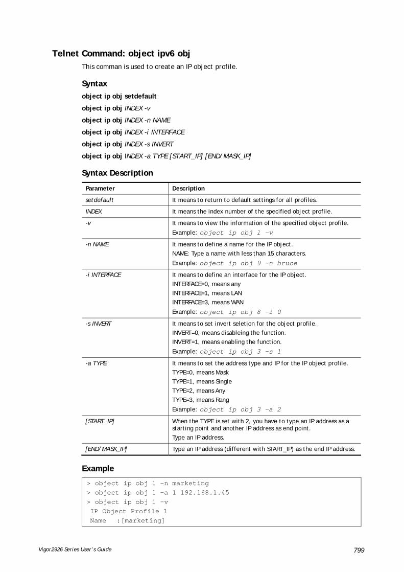
Vigor2926 Series User’s Guide 799
TTeellnneett CCoommmmaanndd:: oobbjjeecctt iippvv66 oobbjj This comman is used to create an IP object profile.
SSyynnttaaxx
object ip obj setdefault
object ip obj INDEX -v
object ip obj INDEX -n NAME
object ip obj INDEX -i INTERFACE
object ip obj INDEX -s INVERT
object ip obj INDEX -a TYPE [START_IP] [END/MASK_IP]
SSyynnttaaxx DDeessccrriippttiioonn
Parameter Description
setdefault It means to return to default settings for all profiles.
INDEX It means the index number of the specified object profile.
-v It means to view the information of the specified object profile.
Example: object ip obj 1 -v
-n NAME It means to define a name for the IP object.
NAME: Type a name with less than 15 characters.
Example: object ip obj 9 -n bruce
-i INTERFACE It means to define an interface for the IP object.
INTERFACE=0, means any
INTERFACE=1, means LAN
INTERFACE=3, means WAN
Example: object ip obj 8 -i 0
-s INVERT It means to set invert seletion for the object profile.
INVERT=0, means disableing the function.
INVERT=1, means enabling the function.
Example: object ip obj 3 -s 1
-a TYPE It means to set the address type and IP for the IP object profile.
TYPE=0, means Mask
TYPE=1, means Single
TYPE=2, means Any
TYPE=3, means Rang
Example: object ip obj 3 -a 2
[START_IP] When the TYPE is set with 2, you have to type an IP address as a starting point and another IP address as end point.
Type an IP address.
[END/MASK_IP] Type an IP address (different with START_IP) as the end IP address.
EExxaammppllee
> object ip obj 1 -n marketing > object ip obj 1 -a 1 192.168.1.45 > object ip obj 1 -v IP Object Profile 1 Name :[marketing]

Vigor2926 Series User’s Guide 800
Interface:[Any] Address type:[single] Start ip address:[192.168.1.45] End/Mask ip address:[0.0.0.0] Invert Selection:[0]
TTeellnneett CCoommmmaanndd:: oobbjjeecctt iippvv66 ggrrpp This command is used to integrate several IP objects under an IP group profile.
SSyynnttaaxx
object ip grp setdefault
object ip grp INDEX -v
object ip grp INDEX -n NAME
object ip grp INDEX -i INTERFACE
object ip grp INDEX -a IP_OBJ_INDEX
SSyynnttaaxx DDeessccrriippttiioonn
Parameter Description
setdefault It means to return to default settings for all profiles.
INDEX It means the index number of the specified group profile.
-v It means to view the information of the specified group profile.
Example: object ip grp 1 -v
-n NAME It means to define a name for the IP group.
NAME: Type a name with less than 15 characters.
Example: object ip grp 8 -n bruce
-i INTERFACE It means to define an interface for the IP group.
INTERFACE=0, means any
INTERFACE=1, means LAN
INTERFACE=2, means WAN
Example: object ip grp 3 -i 0
-a IP_OBJ_INDEX It means to specify IP object profiles for the group profile.
Example: :object ip grp 3 -a 1 2 3 4 5 The IP object profiles with index number 1,2,3,4 and 5 will be group under such profile.
EExxaammppllee
> > object ip grp 2 -n First IP Group Profile 2 Name :[First] Interface:[Any] Included ip object index: [0:][0] [1:][0] [2:][0] [3:][0] [4:][0] [5:][0] [6:][0]

Vigor2926 Series User’s Guide 801
[7:][0] [8:][0] [9:][0] [10:][0] [11:][0] Set ok!
TTeellnneett CCoommmmaanndd:: oobbjjeecctt sseerrvviiccee oobbjj This command is used to create service object profile.
SSyynnttaaxx
object service obj setdefault
object service obj INDEX -v
object service obj INDEX -n NAME
object service obj INDEX -p PROTOCOL
object service obj INDEX -s CHK [START_P] [END_P]
object service obj INDEX -d CHK [START_P] [END_P]
SSyynnttaaxx DDeessccrriippttiioonn
Parameter Description
setdefault It means to return to default settings for all profiles.
INDEX It means the index number of the specified service object profile.
-v It means to view the information of the specified service object profile.
Example: object service obj 1 -v
-n NAME It means to define a name for the IP object.
NAME: Type a name with less than 15 characters.
Example: object service obj 9 -n bruce
-i PROTOCOL It means to define a PROTOCOL for the service object profile.
PROTOCOL =0, means any
PROTOCOL =1, means ICMP
PROTOCOL =2, means IGMP
PROTOCOL =6, means TCP PROTOCOL =17, means UDP
PROTOCOL =255, means TCP/UDP
Other values mean other protocols.
Example: object service obj 8 -i 0
CHK It means the check action for the port setting.
0=equal(=), when the starting port and ending port values are the same, it indicates one port; when the starting port and ending port values are different, it indicates a range for the port and available for this service type.
1=not equal(!=), when the starting port and ending port values are the same, it indicates all the ports except the port defined here; when the starting port and ending port values are different, it indicates that all the ports except the range defined here are available for this service type.
2=larger(>), the port number greater than this value is available..
3=less(<), the port number less than this value is available for this

Vigor2926 Series User’s Guide 802
profile.
-s CHK [START_P] [END_P] It means to set souce port check and configure port range (1~65565) for TCP/UDP.
END_P, type a port number to indicate source port.
Example: object service obj 3 -s 0 100 200
-d CHK [START_P] [END_P] It means to set destination port check and configure port range (1~65565) for TCP/UDP.
END_P, type a port number to indicate destination port.
Example: object service obj 3 -d 1 100 200
EExxaammppllee
> object service obj 1 -n limit > object service obj 1 -p 255 > object service obj 1 -s 1 120 240 > object service obj 1 -d 1 200 220 > object service obj 1 -v Service Object Profile 1 Name :[limit] Protocol:[255] Source port check action:[!=] Source port range:[120~240] Destination port check action:[!=] Destination port range:[200~220]
TTeellnneett CCoommmmaanndd:: oobbjjeecctt sseerrvviiccee ggrrpp This command is used to integrate several service objects under a service group profile.
SSyynnttaaxx
object service grp setdefault
object service grp INDEX -v
object service grp INDEX -n NAME
object service grp INDEX -a SER_OBJ_INDEX
SSyynnttaaxx DDeessccrriippttiioonn
Parameter Description
setdefault It means to return to default settings for all profiles.
INDEX It means the index number of the specified group profile.
-v It means to view the information of the specified group profile.
Example: object service grp 1 -v
-n NAME It means to define a name for the service group.
NAME: Type a name with less than 15 characters.
Example: object service grp 8 -n bruce
-a SER_OBJ_INDEX It means to specify service object profiles for the group profile.
Example: :object service grp 3 -a 1 2 3 4 5 The service object profiles with index number 1,2,3,4 and 5 will be group under such profile.

Vigor2926 Series User’s Guide 803
EExxaammppllee
>object service grp 1 -n Grope_1 Service Group Profile 1 Name :[Grope_1] Included service object index: [0:][0] [1:][0] [2:][0] [3:][0] [4:][0] [5:][0] [6:][0] [7:][0] > object service grp 1 -a 1 2 Service Group Profile 1 Name :[Grope_1] Included service object index: [0:][1] [1:][2] [2:][0] [3:][0] [4:][0] [5:][0] [6:][0] [7:][0]
TTeellnneett CCoommmmaanndd:: oobbjjeecctt kkww This command is used to create keyword profile.
SSyynnttaaxx
object kw obj setdefault
object kw obj show PAGE
object kw obj INDEX -v
object kw obj INDEX -n NAME
object kw obj INDEX -a CONTENTS
SSyynnttaaxx DDeessccrriippttiioonn
Parameter Description
setdefault It means to return to default settings for all profiles.
show PAGE It means to show the contents of the specified profile.
PAGE: type the page number.
show It means to show the contents for all of the profiles.
INDEX It means the index number of the specified keyword profile.
-v It means to view the information of the specified keyword profile.
-n NAME It means to define a name for the keyword profile.
NAME: Type a name with less than 15 characters.

Vigor2926 Series User’s Guide 804
-a CONTENTS It means to set the contents for the keyword profile.
Example: object kw obj 40 -a test
EExxaammppllee
> object kw obj 1 -n children Profile 1 Name :[children] Content:[] > object kw obj 1 -a gambling Profile 1 Name :[children] Content:[gambling] > object kw obj 1 -v Profile 1 Name :[children] Content:[gambling]
TTeellnneett CCoommmmaanndd:: oobbjjeecctt ffee This command is used to create File Extension Object profile.
SSyynnttaaxx
object fe show
object fe setdefault
object fe obj INDEX -v
object fe obj INDEX -n NAME
object fe obj INDEX -e CATEGORY|FILE_EXTENSION
object fe obj INDEX -d CATEGORY|FILE_EXTENSION
SSyynnttaaxx DDeessccrriippttiioonn
Parameter Description
show It means to show the contents for all of the profiles.
setdefault It means to return to default settings for all profiles.
INDEX It means the index number (from 1 to 8) of the specified file extension object profile.
-v It means to view the information of the specified file extension object profile.
-n NAME It means to define a name for the file extension object profile.
NAME: Type a name with less than 15 characters.
-e It means to enable the specific CATEGORY or FILE_EXTENSION.
-d It means to disable the specific CATEGORY or FILE_EXTENSION
CATEGORY|FILE_EXTENSION CATEGORY:
Image, Video, Audio, Java, ActiveX, Compression, Executation
Example: object fe obj 1 -e Image
FILE_EXTENSION:
".bmp", ".dib", ".gif", ".jpeg", ".jpg", ".jpg2", ".jp2", ".pct",
".pcx", ".pic", ".pict", ".png", ".tif", ".tiff", ".asf", ".avi",

Vigor2926 Series User’s Guide 805
".mov", ".mpe", ".mpeg", ".mpg", ".mp4", ".qt", ".rm", ".wmv",
".3gp", ".3gpp", ".3gpp2", ".3g2", ".aac", ".aiff", ".au", ".mp3",
".m4a", ".m4p", ".ogg", ".ra", ".ram", ".vox", ".wav", ".wma",
".class", ".jad", ".jar", ".jav", ".java", ".jcm", ".js", ".jse",
".jsp", ".jtk", ".alx", ".apb", ".axs", ".ocx", ".olb", ".ole",
".tlb", ".viv", ".vrm", ".ace", ".arj", ".bzip2", ".bz2", ".cab",
".gz", ".gzip", ".rar", ".sit", ".zip", ".bas", ".bat", ".com",
".exe", ".inf", ".pif", ".reg", ".scr"
Example: object fe obj 1 -e .bmp
EExxaammppllee
> object fe obj 1 -n music > object fe obj 1 -e Audio > object fe obj 1 -v Profile Index: 1 Profile Name:[music] ------------------------------------------------------------------------- Image category: [ ].bmp [ ].dib [ ].gif [ ].jpeg [ ].jpg [ ].jpg2 [ ].jp2 [ ].pct [ ].pcx [ ].pic [ ].pict [ ].png [ ].tif [ ].tiff ------------------------------------------------------------------------- Video category: [ ].asf [ ].avi [ ].mov [ ].mpe [ ].mpeg [ ].mpg [v].mp4 [ ].qt [ ].rm [v].wmv [ ].3gp [ ].3gpp [ ].3gpp2 [ ].3g2 ------------------------------------------------------------------------- Audio category: [v].aac [v].aiff [v].au [v].mp3 [v].m4a [v].m4p [v].ogg [v].ra [v].ram [v].vox [v].wav [v].wma ------------------------------------------------------------------------- Java category: [ ].class [ ].jad [ ].jar [ ].jav [ ].java [ ].jcm [ ].js [ ].jse [ ].jsp [ ].jtk ------------------------------------------------------------------------- ActiveX category: [ ].alx [ ].apb [ ].axs [ ].ocx [ ].olb [ ].ole [ ].tlb [ ].viv [ ].vrm ------------------------------------------------------------------------- Compression category: [ ].ace [ ].arj [ ].bzip2 [ ].bz2 [ ].cab [ ].gz [ ].gzip [ ].rar [ ].sit [ ].zip ------------------------------------------------------------------------- Executation category: [ ].bas [ ].bat [ ].com [ ].exe [ ].inf [ ].pif [ ].reg [ ].scr
TTeellnneett CCoommmmaanndd:: oobbjjeecctt ssmmss This command is used to create short message object profile.
SSyynnttaaxx object sms show object sms setdefault object sms obj INDEX -v object sms obj INDEX -n NAME object sms obj INDEX -s Service Provider object sms obj INDEX -u Username

Vigor2926 Series User’s Guide 806
object sms obj INDEX -p Password object sms obj INDEX -q Quota object sms obj INDEX -i Interval object sms obj INDEX -l URL
SSyynnttaaxx DDeessccrriippttiioonn
Parameter Description show It means to show the contents for all of the profiles. setdefault It means to return to default settings for all profiles. [INDEX] It means the index number (from 1 to 10) of the specified SMS
object profile. -v It means to view the information of the specified SMS object
profile. -n [NAME] It means to define a name for the SMS object profile.
NAME: Type a name with less than 15 characters. -s [Service Provider] It means to specify the number of the service provider which offers
the service of SMS. Different numbers represent different service provider. 0 : kotsms.com.tw (TW)
2 : textmarketer.co.uk (UK) 4 : messagemedia.co.uk (UK) 5 : bulksms.com (INT) 6 : bulksms.co.uk (UK) 7 : bulksms.2way.co.za (ZA) 8 : bulksms.com.es (ES) 9 : usa.bulksms.com (US) 10 : bulksms.de (DE) 11 : www.pswin.com (EU) 12 : www.messagebird.com (EU) 13 : www.lusosms.com (EU) 14 : www.vibeactivemedia.com (UK)
-u [Username] It means to define a user name for the SMS object profile. Type a user name that the sender can use to register to selected SMS provider.
-p [Password] It means to define a password for the SMS object profile. Type a password that the sender can use to register to selected SMS provider.
-q [Quota] Type the number of the credit that you purchase from the service provider.
Note that one credit equals to one SMS text message on the standard route.
-I [Interval] It means to set the sending interval for the SMS to be delivered. Type the shortest time interval for the system to send SMS.
-l [URL] It means to set the URL for Custom 1 and Custom 2 profiles. The profile name for Custom 1 and Custom 2 are defined in default and can not be changed.
EExxaammppllee
> object sms obj 1 –n CTC > object sms obj 1 -n CTC > object sms obj 1 -s 0 > object sms obj 1 -u carrie > object sms obj 1 -p 19971125cm > object sms obj 1 -q 2 > object sms obj 1 -i 50 > object sms obj 1 -v Profile Index: 1 Profile Name:[CTC] SMS Provider:[kotsms.com.tw (TW)] Username:[carrie] Password:[******] Quota:[2] Sending Interval:[50(seconds)]
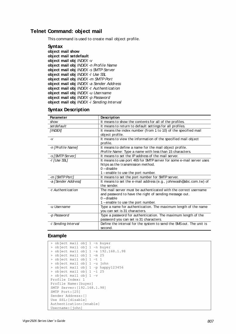
Vigor2926 Series User’s Guide 807
TTeellnneett CCoommmmaanndd:: oobbjjeecctt mmaaiill This command is used to create mail object profile.
SSyynnttaaxx object mail show object mail setdefault object mail obj INDEX -v object mail obj INDEX -n Profile Name object mail obj INDEX -s SMTP Server object mail obj INDEX -l Use SSL object mail obj INDEX -m SMTP Port object mail obj INDEX -a Sender Address object mail obj INDEX -t Authentication object mail obj INDEX -u Username object mail obj INDEX -p Password object mail obj INDEX -i Sending Interval
SSyynnttaaxx DDeessccrriippttiioonn
Parameter Description show It means to show the contents for all of the profiles. setdefault It means to return to default settings for all profiles. [INDEX] It means the index number (from 1 to 10) of the specified mail
object profile. -v It means to view the information of the specified mail object
profile. -n [Profile Name] It means to define a name for the mail object profile.
Profile Name: Type a name with less than 15 characters. -s [SMTP Server] It means to set the IP address of the mail server. -l [Use SSL] It means to use port 465 for SMTP server for some e-mail server uses
https as the transmission method. 0 – disable 1 – enable to use the port number.
-m [SMTP Port] It means to set the port number for SMTP server. -a [Sender Address] It means to set the e-mail address (e.g., [email protected]) of
the sender. -t Authentication The mail server must be authenticated with the correct username
and password to have the right of sending message out. 0 – disable 1 – enable to use the port number.
-u Username Type a name for authentication. The maximum length of the name you can set is 31 characters.
-p Password Type a password for authentication. The maximum length of the password you can set is 31 characters.
-i Sending Interval Define the interval for the system to send the SMS out. The unit is second.
EExxaammppllee > object mail obj 1 –n buyer > object mail obj 1 -n buyer > object mail obj 1 -s 192.168.1.98 > object mail obj 1 -m 25 > object mail obj 1 -t 1 > object mail obj 1 -u john > object mail obj 1 -p happy123456 > object mail obj 1 -i 25 > object mail obj 1 -v Profile Index: 1 Profile Name:[buyer] SMTP Server:[192.168.1.98] SMTP Port:[25] Sender Address:[] Use SSL:[disable] Authentication:[enable] Username:[john]
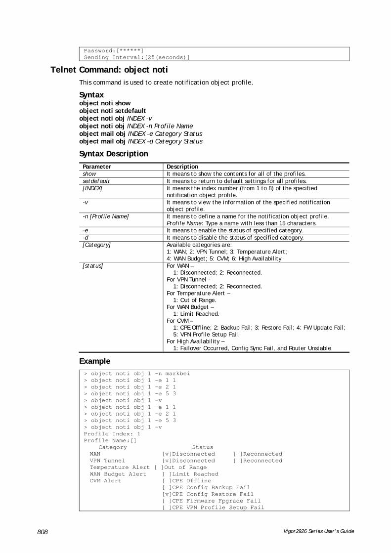
Vigor2926 Series User’s Guide 808
Password:[******] Sending Interval:[25(seconds)]
TTeellnneett CCoommmmaanndd:: oobbjjeecctt nnoottii This command is used to create notification object profile.
SSyynnttaaxx object noti show object noti setdefault object noti obj INDEX -v object noti obj INDEX -n Profile Name object mail obj INDEX –e Category Status object mail obj INDEX –d Category Status
SSyynnttaaxx DDeessccrriippttiioonn
Parameter Description show It means to show the contents for all of the profiles. setdefault It means to return to default settings for all profiles. [INDEX] It means the index number (from 1 to 8) of the specified
notification object profile. -v It means to view the information of the specified notification
object profile. -n [Profile Name] It means to define a name for the notification object profile.
Profile Name: Type a name with less than 15 characters. –e It means to enable the status of specified category. -d It means to disable the status of specified category. [Category] Available categories are:
1: WAN; 2: VPN Tunnel; 3: Temperature Alert; 4: WAN Budget; 5: CVM; 6: High Availability
[status] For WAN – 1: Disconnected; 2: Reconnected.
For VPN Tunnel - 1: Disconnected; 2: Reconnected.
For Temperature Alert – 1: Out of Range.
For WAN Budget – 1: Limit Reached.
For CVM – 1: CPE Offline; 2: Backup Fail; 3: Restore Fail; 4: FW Update Fail; 5: VPN Profile Setup Fail.
For High Availability – 1: Failover Occurred, Config Sync Fail, and Router Unstable
EExxaammppllee > object noti obj 1 –n markbei > object noti obj 1 –e 1 1 > object noti obj 1 –e 2 1 > object noti obj 1 –e 5 3 > object noti obj 1 –v > object noti obj 1 -e 1 1 > object noti obj 1 -e 2 1 > object noti obj 1 -e 5 3 > object noti obj 1 -v Profile Index: 1 Profile Name:[] Category Status WAN [v]Disconnected [ ]Reconnected VPN Tunnel [v]Disconnected [ ]Reconnected Temperature Alert [ ]Out of Range WAN Budget Alert [ ]Limit Reached CVM Alert [ ]CPE Offline [ ]CPE Config Backup Fail [v]CPE Config Restore Fail [ ]CPE Firmware Fpgrade Fail [ ]CPE VPN Profile Setup Fail

Vigor2926 Series User’s Guide 809
High Availability [ ]Failover Occurred Config Sync Fail Router Unstable
TTeellnneett CCoommmmaanndd:: oobbjjeecctt sscchheedduullee This command is used to create schedule object profile.
SSyynnttaaxx object schedule set INDEX option object schedule view object schedule setdefault
SSyynnttaaxx DDeessccrriippttiioonn
Parameter Description set It means to set the schedule profile. [INDEX] It means the index number (from 1 to 15) of the specified object
profile. option Available options for schedule includes:
-e -e [value] It means to enable the schedule setup.
0 – disable 1 – enable
-c [comment] It means to set brief description for the specified profile. The length range of the comment: 1 ~ 32 characters.
-D [year][month][day] It means to set the starting date of the profile. [year] – Must be between 2000-2049. [month] - Must be between 1-12. [day] - Must be between 1-31. For example: To set Start Date 2015/10/6, type
> object schedule set 1 -D "2015 10 6" -T [hour][minute] It means to set the starting time of the profile.
[hour] - Must be between 0-23. [minute] - Must be between 0-59. For example: To set Start Time 10:20, type > object schedule set 1 -T "10 20"
-d [hour][minute] It means to set the duration time of the profile. [hour] - Must be between 0-23. [minute] - Must be between 0-59. For example: To set Duration Time 3:30, type > object schedule set 1 -d "3 30"
-a [value] It means to set the action used for the profile. [value] – 0:Force On, 1:Force Down, 2:Enable Dial-On-Demand, 3:Disable Dial-On-Demand
-I [value] It means to set idle time. [value] – Must be between 0-255(minute). The default is 0.
-h [option] [day] Set how often the schedule will be applied. [option] – 0: Once, 1: Weekdays [day] – Sun, Mon, Tue, Wed, Thu, Fri, Sat If the [option] set Weekdays, then must select which days of Week. example: To select Sunday, Monday, Thursday, type
> object schedule set 1 -h “1 Sun Mon Thu” view [INDEX] It means to show the content of the profile. setdefault It means to return to default settings for all profiles.
EExxaammppllee > object schedule set 1 –e 1 > object schedule set 1 –c Working > object schedule set 1 –D “2016 11 8” > object schedule set 1 –T “8 1” > object schedule set 1 –d “2 30” > object schedule set 1 –a 0 > object schedule set 1 –h “1 Mon Wed”

Vigor2926 Series User’s Guide 810
> object schedule view 1 Index No.1 -------------------------------------------------- [v] Enable Schedule Setup Comment [ Working ] Start Date (yyyy-mm-dd) [ 2016 ]-[ 11 ]-[ 8 ] Start Time (hh:mm) [ 8 ]:[ 1 ] Duration Time (hh:mm) [ 2 ]:[ 30 ] Action [ Force On ] Idle Timeout [ 0 ] minute(s).(max. 255, 0 for default) ---------------------------------------------------------------- How Often [ ] Once [v] Weekdays [ ]Sun [v]Mon [ ]Tue [v]Wed [ ]Thu [ ]Fri [ ]Sat >
TTeellnneett CCoommmmaanndd:: ppoorrtt This command allows users to set the speed for specific port of the router.
SSyynnttaaxx
port [1, 2, 3, 4, wan1, wan2, all] [AN, 1000F, 100F, 100H, 10F, 10H, status]
port[enable,disable] [1, 2, 3, 4, all] [
port status
port sniff [on,off,port,txrx,restart,status]
port 802.1x[enable,disable,status,addport,delport]
port jumbo
port wanfc
port spoof [on, off, stat]
port mac_flush
SSyynnttaaxx DDeessccrriippttiioonn
Parameter Description
1, 2, 3, 4, 5, wan1, wan2, all It means the number of LAN port and WAN port.
AN… 10H It means the physical type for the specific port.
AN: auto-negotiate.
1000F: 1000M Full Duplex.
100F: 100M Full Duplex.
100H: 100M Half Duplex.
10F: 10M Full Duplex.
10H: 10M Half Duplex.
status It means to view the Ethernet port status.
wanfc It means to set WAN flow control.
spoof It means to enable /disable spoofing detection.
Stat – Display current spoofing status (on or off).
EExxaammppllee
> port 1 100F

Vigor2926 Series User’s Guide 811
%Set Port 1 Force speed 100 Full duplex OK !!!
TTeellnneett CCoommmmaanndd:: ppoorrttmmaappttiimmee This command allows you to set a time of keeping the session connection for specified protocol.
SSyynnttaaxx
portmaptime [-<command> <parameter> | ... ]
SSyynnttaaxx DDeessccrriippttiioonn
Parameter Description
[<command> <parameter>|…]
The available commands with parameters are listed below.
[…] means that you can type in several commands in one line.
-t <sec> It means “TCP” protocol.
<sec>: Type a number to set the TCP session timeout.
-u <sec> It means “UDP” protocol.
<sec>: Type a number to set the UDP session timeout.
-i <sec> It means “IGMP” protocol.
<sec>: Type a number to set the IGMP session timeout.
-w <sec> It means “TCP WWW” protocol.
<sec>: Type a number to set the TCP WWW session timeout.
-s <sec> It means “TCP SYN” protocol.
<sec>: Type a number to set the TCP SYN session timeout.
-f It means to flush all portmaps (useful for diagnostics).
-l <List> List all settings.
EExxaammppllee
> portmaptime -t 86400 -u 300 -i 10 > portmaptime -l ------ Current setting ------ TCP Timeout : 86400 sec. UDP Timeout : 300 sec. IGMP Timeout : 10 sec. TCP WWW Timeout: 60 sec. TCP SYN Timeout: 60 sec.
TTeellnneett CCoommmmaanndd:: ppppaa This command allows you to configure PPA mode.
ppa [-<command> <parameter> | ... ]
ppa n [-<command> <parameter> | ... ]
SSyynnttaaxx DDeessccrriippttiioonn
Parameter Description
[<command> <parameter>|…]
The available commands with parameters are listed below.
[…] means that you can type in several commands in one line.
-m <mode> Specify a mode.

Vigor2926 Series User’s Guide 812
1=auto
2=manual(traffic)
3=manual(qos)
4=manual(specific hosts)
0=disable
-p <proto> Specify a protocol.
proto - 1-TCP; 2-UDP; 3-Both.
-b 1/0 Enable/disable TWO-way hardware acceleration.
-M enable/disable Enable/disable the multicast hardware acceleration.
-v Show PPA_WAN_Table and PPA_LAN_Table for reference.
-c Clean all settings.
ppa n – used in QoS or specific host
-l <rule> Specify an index number of rule profile for QoS mode.
-h <host> Type an IP address for Specific Host mode.
-s <start port> Specify a starting port number for Specific Host mode.
-e <end port> Specify an ending port number for Specific Host mode
EExxaammppllee
> ppa -m 1 -p 1 -b 0 Set ok! The PPA mode is Auto % You need to set the Manual mode first ! %TWO way accleration is disable > ppa -v % PPA mode is Auto %PPA Protocol TCP 1, UDP 0 %PPA two way disable %PPA time is 10 %PPA range is 192 %PPA LAN entries 0 %PPA WAN entries 0
TTeellnneett CCoommmmaanndd:: pprrnn This command allows you to view current status (interface and driver) of USB printer.
SSyynnttaaxx
prn status
prn debug
EExxaammppllee
> prn status Interface: USB bus 2.0 Printer: NotReady > prn debug conn[0] :

Vigor2926 Series User’s Guide 813
none conn[1] : none conn[2] : none conn[3] : none LPD_data_total=0 usblp_ptr=0 UsbPrintReady=0, UsbIsPrinting=0
TTeellnneett CCoommmmaanndd:: qqooss sseettuupp This command allows user to set general settings for QoS.
SSyynnttaaxx
qos setup [-<command> <parameter> | ... ]
SSyynnttaaxx DDeessccrriippttiioonn
Parameter Description
[<command> <parameter>|…]
The available commands with parameters are listed below.
[…] means that you can type in several commands in one line.
-h Type it to display the usage of this command.
-m <mode> It means to define which traffic the QoS control settings will apply to and eable QoS control.
0: disable.
1: in, apply to incoming traffic only.
2: out, apply to outgoing traffic only.
3: both, apply to both incoming and outgoing traffic.
Default is enable (for outgoing traffic).
-i <bandwidth> It means to set inbound bandwidth in kbps (Ethernet WAN only) The available setting is from 1 to 100000.
-o <bandwidth> It means to set outbound bandwidth in kbps (Ethernet WAN only). The available setting is from 1 to 100000.
-r <index:ratio> It means to set ratio for class index, in %.
-u <mode> It means to enable bandwidth control for UDP. 0: disable
1: enable
Default is disable.
-p <ratio> It means to enable bandwidth limit ratio for UDP.
-t <mode> It means to enable/disable Outbound TCP ACK Prioritize.
0: disable
1: enable
-V Show all the settings.
-D Set all to factory default (for all WANs).
[…] It means that you can type in several commands in one line.

Vigor2926 Series User’s Guide 814
EExxaammppllee
> qos setup -m 3 -i 9500 -o 8500 -r 3:20 -u 1 -p 50 -t 1 WAN1 QOS mode is both Wan 1 is XDSL model ,don,t need to set up Wan 1 is XDSL model ,don,t need to set up WAN1 class 3 ratio set to 20 WAN1 udp bandwidth control set to enable WAN1 udp bandwidth limit ratio set to 50 WAN1 Outbound TCP ACK Prioritizel set to enable QoS WAN1 set complete; restart QoS >
TTeellnneett CCoommmmaanndd:: qqooss ccllaassss This command allows user to set QoS class.
SSyynnttaaxx
qos class -c [no] –[a|e|d] [no][-<command> <parameter> | ... ]
SSyynnttaaxx DDeessccrriippttiioonn
Parameter Description
[<command> <parameter>|…]
The available commands with parameters are listed below.
[…] means that you can type in several commands in one line.
-h Type it to display the usage of this command.
-c <no> Specify the inde number for the class.
Available value for <no> contains 1, 2 and 3. The default setting is class 1.
-n <name> It means to type a name for the class.
-a It means to add rule for specified class.
-e <no> It means to edit specified rule.
<no>: type the index number for the rule.
-d <no> It means to delete specified rule.
<no>: type the index number for the rule.
-m <mode> It means to enable or disable the specified rule.
0: disable,
1: enable
-l <addr> Set the local address.
Addr1 – It means Single address. Please specify the IP address directly, for example, “-l 172.16.3.9”.
addr1:addr2 – It means Range address. Please specify the IP addresses, for example, “-l 172.16.3.9: 172.16.3.50.”
addr1:subnet – It means the subnet address with start IP address. Please type the subnet and the IP address, for example, “-l 172.16.3.9:255.255.0.0”.0
any – It means Any address. Simple type “-l” to specify any address for this command.
-r <addr> Set the remote address.
addr1 – It means Single address. Please specify the IP address

Vigor2926 Series User’s Guide 815
directly, for example, “-l 172.16.3.9”.
addr1:addr2 – It means Range address. Please specify the IP addresses, for example, “-l 172.16.3.9: 172.16.3.50.”
addr1:subnet – It means the subnet address with start IP address. Please type the subnet and the IP address, for example, “-l 172.16.3.9:255.255.0.0”.0
any – It means Any address. Simple type “-l” to specify any address for this command.
-p <DSCP id> Specify the ID.
-s <Service type> Specify the service type by typing the number. The available types are listed as below:
1:ANY 2:DNS 3:FTP 4:GRE 5:H.323 6:HTTP 7:HTTPS 8:IKE 9:IPSEC-AH 10:IPSEC-ESP 11:IRC 12:L2TP 13:NEWS 14:NFS 15:NNTP 16:PING 17:POP3 18:PPTP 19:REAL-AUDIO 20:RTSP 21:SFTP 22:SIP 23:SMTP 24:SNMP 25:SNMP-TRAPS 26:SQL-NET 27:SSH 28:SYSLOG 29:TELNET 30:TFTP
-S <d/s> Show the content for specified DSCP ID/Service type.
-V <1/2/3> Show the rule in the specified class.
[…] It means that you can type in several commands in one line.
EExxaammppllee
> qos class -c 2 -n draytek -a -m 1 -l 192.168.1.50:192.168.1.80 Following setting will set in the class2 class 2 name set to draytek Add a rule in class2 Class2 the 1 rule enabled Set local address type to Range, 192.168.1.50:192.168.1.80
TTeellnneett CCoommmmaanndd:: qqooss ttyyppee This command allows user to configure protocol type and port number for QoS.
SSyynnttaaxx
qos type [-a <service name> | -e <no> | -d <no>].
SSyynnttaaxx DDeessccrriippttiioonn
Parameter Description
-a <name> It means to add rule.
-e <no> It means to edit user defined service type. “no” means the index number. Available numbers are 1~40.
-d <no> It means to delete user defined service type. “no” means the index number. Available numbers are 1~40.
-n <name> It means the name of the service.
-t <type> It means protocol type.
6: tcp(default)
17: udp
0: tcp/udp
<1~254>: other
-p <port> It means service port. The typing format must be [start:end] (ex., 510:330).

Vigor2926 Series User’s Guide 816
-l List user defined types. “no” means the index number. Available numbers are 1~40.
EExxaammppllee
> qos type -a draytek -t 6 -p 510:1330 service name set to draytek service type set to 6:TCP Port type set to Range Service Port set to 510 ~ 1330 >
TTeellnneett CCoommmmaanndd:: qqooss vvooiipp This command allows user to enable or disable the QoS for VoIP and RTP.
SSyynnttaaxx
qos voip [on/off]
SSyynnttaaxx DDeessccrriippttiioonn
Parameter Description
on/off On – Enable the QoS for VoIP.
Off – Disable th QoS for VoIP.
EExxaammppllee
> qos voip off QoS for VoIP: Disable; SIP Port: 5060
TTeellnneett CCoommmmaanndd:: qquuiitt This command can exit the telnet command screen.
TTeellnneett CCoommmmaanndd:: sshhooww llaann This command displays current status of LAN IP address settings.
EExxaammppllee
> show lan The LAN settings: ip mask dhcp star_ip pool gateway ------------------------------------------------------------------------------ [V]LAN1 192.168.1.1 255.255.255.0 [V] 192.168.1.10 200 192.168.1.1 [X]LAN2 192.168.2.1 255.255.255.0 [V] 192.168.2.10 100 192.168.2.1 [X]LAN3 192.168.3.1 255.255.255.0 [V] 192.168.3.10 100 192.168.3.1 [X]LAN4 192.168.4.1 255.255.255.0 [V] 192.168.4.10 100 192.168.4.1 [X]LAN5 192.168.5.1 255.255.255.0 [V] 192.168.5.10 100 192.168.5.1 [X]LAN6 192.168.6.1 255.255.255.0 [V] 192.168.6.10 100

Vigor2926 Series User’s Guide 817
192.168.6.1 [X]Route 192.168.0.1 255.255.255.0 [V] 0.0.0.0 0 192.168.0.1
TTeellnneett CCoommmmaanndd:: sshhooww ddmmzz This command displays current status of DMZ host.
EExxaammppllee
> show dmz % WAN1 DMZ mapping status: Index Status WAN1 aux IP Private IP ---------------------------------------------------- 1 Disable 172.16.3.221 2 Disable 192.168.1.65
TTeellnneett CCoommmmaanndd:: sshhooww ddnnss This command displays current status of DNS setting
EExxaammppllee
> show dns %% Domain name server settings: % Primary DNS: [Not set] % Secondary DNS: [Not set]
TTeellnneett CCoommmmaanndd:: sshhooww ooppeennppoorrtt This command displays current status of open port setting.
EExxaammppllee
> show openport %% Openport settings: Index Status Comment Local IP Address ******************************************************** No data entry.
TTeellnneett CCoommmmaanndd:: sshhooww nnaatt This command displays current status of NAT.
EExxaammppllee
> show nat Port Redirection Running Table: Index Protocol Public Port Private IP Private Port 1 0 0 0.0.0.0 0 2 0 0 0.0.0.0 0 3 0 0 0.0.0.0 0 4 0 0 0.0.0.0 0 5 0 0 0.0.0.0 0 6 0 0 0.0.0.0 0 7 0 0 0.0.0.0 0 8 0 0 0.0.0.0 0
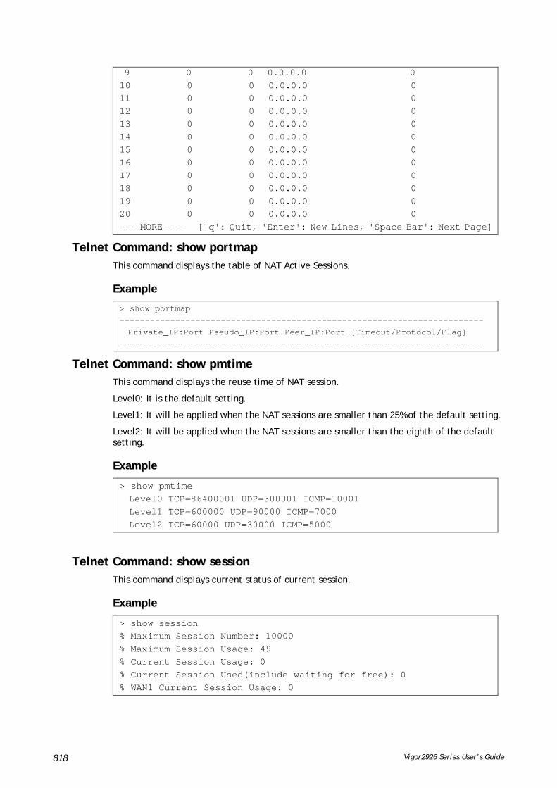
Vigor2926 Series User’s Guide 818
9 0 0 0.0.0.0 0 10 0 0 0.0.0.0 0 11 0 0 0.0.0.0 0 12 0 0 0.0.0.0 0 13 0 0 0.0.0.0 0 14 0 0 0.0.0.0 0 15 0 0 0.0.0.0 0 16 0 0 0.0.0.0 0 17 0 0 0.0.0.0 0 18 0 0 0.0.0.0 0 19 0 0 0.0.0.0 0 20 0 0 0.0.0.0 0 --- MORE --- ['q': Quit, 'Enter': New Lines, 'Space Bar': Next Page]
TTeellnneett CCoommmmaanndd:: sshhooww ppoorrttmmaapp This command displays the table of NAT Active Sessions.
EExxaammppllee
> show portmap ------------------------------------------------------------------------ Private_IP:Port Pseudo_IP:Port Peer_IP:Port [Timeout/Protocol/Flag] ------------------------------------------------------------------------
TTeellnneett CCoommmmaanndd:: sshhooww ppmmttiimmee This command displays the reuse time of NAT session.
Level0: It is the default setting.
Level1: It will be applied when the NAT sessions are smaller than 25% of the default setting.
Level2: It will be applied when the NAT sessions are smaller than the eighth of the default setting.
EExxaammppllee
> show pmtime Level0 TCP=86400001 UDP=300001 ICMP=10001 Level1 TCP=600000 UDP=90000 ICMP=7000 Level2 TCP=60000 UDP=30000 ICMP=5000
TTeellnneett CCoommmmaanndd:: sshhooww sseessssiioonn This command displays current status of current session.
EExxaammppllee
> show session % Maximum Session Number: 10000 % Maximum Session Usage: 49 % Current Session Usage: 0 % Current Session Used(include waiting for free): 0 % WAN1 Current Session Usage: 0
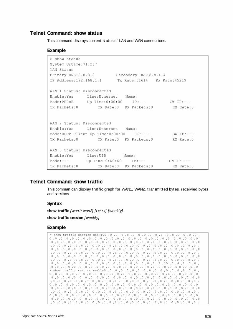
Vigor2926 Series User’s Guide 819
TTeellnneett CCoommmmaanndd:: sshhooww ssttaattuuss This command displays current status of LAN and WAN connections.
EExxaammppllee
> show status System Uptime:71:2:7 LAN Status Primary DNS:8.8.8.8 Secondary DNS:8.8.4.4 IP Address:192.168.1.1 Tx Rate:61614 Rx Rate:45219 WAN 1 Status: Disconnected Enable:Yes Line:Ethernet Name: Mode:PPPoE Up Time:0:00:00 IP:--- GW IP:--- TX Packets:0 TX Rate:0 RX Packets:0 RX Rate:0 WAN 2 Status: Disconnected Enable:Yes Line:Ethernet Name: Mode:DHCP Client Up Time:0:00:00 IP:--- GW IP:--- TX Packets:0 TX Rate:0 RX Packets:0 RX Rate:0 WAN 3 Status: Disconnected Enable:Yes Line:USB Name: Mode:--- Up Time:0:00:00 IP:--- GW IP:--- TX Packets:0 TX Rate:0 RX Packets:0 RX Rate:0
TTeellnneett CCoommmmaanndd:: sshhooww ttrraaffffiicc This comman can display traffic graph for WAN1, WAN2, transmitted bytes, receivied bytes and sessions.
SSyynnttaaxx
show traffic [wan1/wan2] [tx/rx] [weekly]
show traffic session [weekly]
EExxaammppllee
> show traffic session weekly0 ,0 ,0 ,0 ,0 ,0 ,0 ,0 ,0 ,0 ,0 ,0 ,0 ,0 ,0 ,0 ,0 , 0 ,0 ,0 ,0 ,0 ,0 ,0 ,0 ,0 ,0 ,0 ,0 ,0 ,0 ,0 ,0 ,0 ,0 ,0 ,0 ,0 ,0 ,0 ,0 ,0 ,0 ,0 ,0 ,0 ,0 ,0 ,0 ,0 ,0 ,0 ,0 ,0 ,0 ,0 ,0 ,0 ,0 ,0 ,0 ,0 ,0 ,0 ,0 ,0 ,0 ,0 ,0 ,0 ,0 ,0 ,0 ,0 ,0 ,0 ,0 ,0 ,0 ,0 ,0 ,0 ,0 ,0 ,0 ,0 ,0 ,0 ,0 ,0 ,0 ,0 ,0 ,0 ,0 ,0 ,0 , ,0 ,0 ,0 ,0 ,0 ,0 ,0 ,0 ,0 ,0 ,0 ,0 ,0 ,0 ,0 ,0 ,0 ,0 ,0 ,0 ,0 ,0 ,0 ,0 ,0 ,0 ,0 ,0 ,0 ,0 ,0 ,0 ,0 ,0 ,0 ,0 ,0 ,0 ,0 ,0 ,0 ,0 ,0 ,0 ,0 ,0 ,0 ,0 ,0 ,0 ,0 ,0 ,0 , ,0 ,0 ,0 ,0 ,0 ,0 ,0 ,0 ,0 ,0 ,0 ,0 ,0 ,0 ,0 ,0 ,0 ,0 ,0 ,0 ,0 ,0 ,0 ,0 ,0 ,0 ,0 ,0 ,0 ,0 ,0 ,0 ,0 ,0 ,0 ,0 ,0 ,0 ,0 ,0 ,0 ,0 ,0 ,0 ,2 ,1 ,0 ,0 ,0 ,0 ,0 ,0 ,0 , ,0 ,0 ,0 ,0 ,0 ,0 ,0 ,0 ,0 ,0 ,0 ,0 ,1 ,3 ,0 ,0 ,0 ,0 ,0 ,2 ,15 ,5 ,4 ,1 ,0 ,0 , ,0 ,0 ,0 ,0 ,0 ,0 ,0 ,0 ,0 ,0 ,0 ,0 ,0 ,0 ,0 ,0 ,0 ,0 ,0 ,0 ,0 ,0 ,0 0 ,0 ,0 ,0 > show traffic wan1 tx weekly0 ,0 ,0 ,0 ,0 ,0 ,0 ,0 ,0 ,0 ,0 ,0 ,0 ,0 ,0 ,0 ,0 , 0 ,0 ,0 ,0 ,0 ,0 ,0 ,0 ,0 ,0 ,0 ,0 ,0 ,0 ,0 ,0 ,0 ,0 ,0 ,0 ,0 ,0 ,0 ,0 ,0 ,0 ,0 ,0 ,0 ,0 ,0 ,0 ,0 ,0 ,0 ,0 ,0 ,0 ,0 ,0 ,0 ,0 ,0 ,0 ,0 ,0 ,0 ,0 ,0 ,0 ,0 ,0 ,0 ,0 ,0 ,0 ,0 ,0 ,0 ,0 ,0 ,0 ,0 ,0 ,0 ,0 ,0 ,0 ,0 ,0 ,0 ,0 ,0 ,0 ,0 ,0 ,0 ,0 ,0 ,0 , 0 ,0 ,0 ,0 ,0 ,0 ,0 ,0 ,0 ,0 ,0 ,0 ,0 ,0 ,0 ,0 ,0 ,0 ,0 ,0 ,0 ,0 ,0 ,0 ,0 ,0 ,0 ,0 ,0 ,0 ,0 ,0 ,0 ,0 ,0 ,0 ,0 ,0 ,0 ,0 ,0 ,0 ,0 ,0 ,0 ,0 ,0 ,0 ,0 ,0 ,0 ,0 ,0 ,0 ,0 ,0 ,0 ,0 ,0 ,0 ,0 ,0 ,0 ,0 ,0 ,0 ,0 ,0 ,0 ,0 ,0 ,0 ,0 ,0 ,0 ,0 ,0 ,0 ,0 ,0 , 0 ,0 ,0 ,0 ,0 ,0 ,0 ,0 ,0 ,0 ,0 ,0 ,0 ,0 ,0 ,0 ,0 ,0 ,0 ,0 ,0 ,0 ,0 ,0 ,0 ,0 ,0 ,0 ,0 ,0 ,0 ,0 ,0 ,0 ,0 ,0 ,0 ,0 ,0 ,0 ,0 ,0 ,0 ,0 ,0 ,0 ,0 ,0 ,0 ,0 ,0 ,0 ,0 ,0 ,0 ,0 ,0 ,0 ,0 ,0 ,0 ,0 ,0 ,0 ,0 ,0 ,0 ,0 ,0 ,0 ,0 ,0 ,0 ,0 ,0 ,0 ,0 ,0 ,0 ,0 ,

Vigor2926 Series User’s Guide 820
,0 ,0 ,0 ,0 ,0 ,0 ,0 ,0 ,0 ,0 ,0 ,0 ,0 ,0 ,0 ,0 ,0 ,0 ,0 ,0 ,0 ,0 ,0 ,0 ,0 ,0 ,0 ,0 ,0 ,0 ,0 ,0 ,0 ,0 ,0 ,0 ,0 ,0 ,0 ,0 ,0 ,0 ,0 ,0 ,0 ,0 ,0 ,0 ,0 ,0 ,0 ,0 ,0 , 0 ,0 ,0 ,0 ,0 ,0 ,0 ,0 ,0 ,0 ,0 ,0 ,0 ,0 ,0 ,0 ,0 ,0 ,0 ,0 ,0 ,0 ,0
TTeellnneett CCoommmmaanndd:: sshhooww cclliieennttttrraaffffiicc This command displays packet information for specified external device.
SSyynnttaaxx
show clienttraffic [device index] [wan# or lan#] [tx/rx] [weekly]
SSyynnttaaxx DDeessccrriippttiioonn
Parameter Description
[device index] Enter the device index (01 – 30) in double-digit (ex: 01, 02) for external device.
Use “switch list” to check which VigorSwitch connects to this router. Then, type the index number of this VigorSwitch in this field.
[wan# or lan#] wan# - Specify WAN interface (WAN1 to WAN2) for Vigor router.
lan#- Specify LAN interface (LANA / LANB) for VigorAP.
[tx/rx] Tx – Inidcate transmitted data.
Rx – Indicate receivied data.
[weekly] Display the transmitted data or receivied data collected weekly.
EExxaammppllee
> show clienttraffic 01 lana tx weekly 0 ,0 ,0 ,0 ,0 ,0 ,0 ,0 ,0 ,0 ,0 ,0 ,0 ,0 ,0 ,0 ,0 ,0 ,0 ,0 ,0 ,0 ,0 ,0 ,0 ,0 ,0 ,0 ,0 ,0 ,0 ,0 ,0 ,0 ,0 ,0 ,0 , 0 ,0 ,0 ,0 ,0 ,0 ,0 ,0 ,0 ,0 ,0 ,0 ,0 ,0 ,0 ,0 ,0 ,0 ,0 ,0 ,0 ,0 ,0 ,0 ,0 ,0 ,0 ,0 ,0 ,0 ,0 ,0 ,0 ,0 ,0 ,0 ,0 , 0 ,0 ,0 ,0 ,0 ,0 ,0 ,0 ,0 ,0 ,0 ,0 ,0 ,0 ,0 ,0 ,0 ,0 ,0 ,0 ,0 ,0 ,0 ,0 ,0 ,0 ,0 ,0 ,0 ,0 ,0 ,0 ,0 ,0 ,0 ,0 ,0 , 0 ,0 ,0 ,0 ,0 ,0 ,0 ,0 ,0 ,0 ,0 ,0 ,0 ,0 ,0 ,0 ,0 ,0 ,0 ,0 ,0 ,0 ,0 ,0 ,0 ,0 ,0 ,0 ,0 ,0 ,0 ,0 ,0 ,0 ,0 ,0 ,0 , 0 ,0 ,0 ,0 ,0 ,0 ,0 ,0 ,0 ,0 ,0 ,0 ,0 ,0 ,0 ,0 ,0 ,0 ,0 ,0 ,0 ,0 ,0 ,0 ,0 ,0 ,0 ,0 ,0 ,0 ,0 ,0 ,0 ,0 ,0 ,0 ,0 , 0 ,0 ,0 ,0 ,0 ,0 ,0 ,0 ,0 ,0 ,0 ,0 ,0 ,0 ,0 ,0 ,0 ,0 ,0 ,0 ,0 ,0 ,0 ,0 ,0 ,0 ,0 ,0 ,0 ,0 ,0 ,0 ,0 ,0 ,0 ,0 ,0 , 0 ,0 ,0 ,0 ,0 ,0 ,0 ,0 ,0 ,0 ,0 ,0 ,0 ,0 ,0 ,0 ,0 ,0 ,0 ,0 ,0 ,0 ,0 ,0 ,0 ,0 ,0 ,0 ,0 ,0 ,0 ,0 ,0 ,0 ,0 ,0 ,0 , 0 ,0 ,0 ,0 ,0 ,0 ,0 ,0 ,0 ,0 ,0 ,0 ,0 ,0 ,0 ,0 ,0 ,0 ,0 ,0 ,0 ,0 ,0 ,0 ,0 ,0 ,0 ,0 ,0 ,0 ,0 ,0 ,0 ,0 ,0 ,0 ,0 , 0 ,0 ,0 ,0 ,0 ,0 ,0 ,0 ,0 ,0 ,0 ,0 ,0 ,0 ,0 ,0 ,0 ,0 ,0 ,0 ,0 ,0 ,0 ,0 ,0 ,0 ,0 ,0 ,0 ,0 ,0 ,0 ,0 ,0 ,0 ,0 ,0 , 0 ,0 ,0 ,0 ,0 ,0 ,0 ,0 ,0 ,0 ,0 ,0 ,0 ,0 ,0 ,0 ,0 ,0 ,0 ,0 ,0 ,0 ,0 ,0 ,0 ,0 ,0
TTeellnneett CCoommmmaanndd:: sshhooww tteemmppeerraattuurree This command displays data for temperature sensor. The data for the sensor will be recorded per miniute. Up to 24 hours of senser data can be reviewed by using this command.
SSyynnttaaxx
show temperture
EExxaammppllee
> show temperature
show temperature 0, 0, 0, 0, 0, 0, 0, 0, 0, 0, 0, 0, 0, 0, 0, 0, 0, 0, 0, 0, 0, 0, 0, 0, 0, 0, 0, 0, 0, 0, 0, 0, 0, 0, 0, 0, 0, 0, 0, 0, 0, 0, 0, 0, 0, 0, 0, 0, 0, 0, 0, 0, 0, 0, 0, 0, 0, 0, 0, 0, 0, 0, 0, 0, 0, 0, 0, 0, 0, 0, 0, 0, 0, 0, 0, 0, 0, 0, 0, 0, 0, 0, 0, 0, 0, 0, 0, 0, 0, 0, 0, 0, 0, 0, 0, 0, 0, 0, 0, 0, 0, 0, 0, 0, 0, 0, 0, 0, 0, 0, 0, 0, 0, 0, 0, 0, 0, 0, 0, 0, 0, 0, 0, 0, 0, 0, 0, 0, 0, 0, 0, 0, 0, 0, 0, 0, 0, 0, 0, 0, 0, 0, 0, 0, 0, 0, 0, 0, 0, 0, 0, 0, 0, 0, 0, 0, 0, 0, 0, 0, 0, 0, 0, 0, 0, 0, 0, 0, 0, 0, 0, 0, 0, 0, 0, 0, 0, 0, 0, 0, 0, 0, 0, 0, 0, 0, 0, 0, 0, 0, 0, 0, 0, 0, 0, 0, 0, 0, 0, 0, 0, 0, 0, 0, 0, 0, 0, 0, 0, 0, 0, 0, 0, 0, 0, 0, 0, 0, 0, 0, 0, 0, 0, 0, 0, 0, 0, 0, 0, 0, 0, 0, 0, 0, 0, 0, 0, 0, 0, 0, 0, 0, 0, 0, 0, 0, 0, 0, 0, 0, 0, 0, 0, 0, 0, 0, 0, 0, 0, 0, 0, 0, 0, 0, 0, 0, 0, 0, 0, 0, 0, 0, 0, 0, 0, 0, 0, 0, 0, 0, 0, 0, 0, 0, 0, 0, 0, 0, 0, 0, 0, 0, 0, 0, 0, 0, 0, 0, 0, 0, 0,

Vigor2926 Series User’s Guide 821
0, 0, 0, 0, 0, 0, 0, 0, 0, 0, 0, 0, 0, 0, 0, 0, 0, 0, 0, 0, 0, 0, 0, 0, 0, 0, 0, 0, 0, 0, 0, 0, 0, 0, 0, 0, 0, 0, 0, 0, 0, 0, 0, 0, 0, 0, 0, 0, 0, 0, 0, 0, 0, 0, 0, 0, 0, 0, 0, 0, 0, 0, 0, 0, 0, 0, 0, 0, 0, 0, 0, 0, 0, 0, 0, 0, 0, 0, 0, 0, 0, 0, 0, 0, 0, 0, 0, 0, 0, 0, 0, 0, 0, 0, 0, 0, 0, 0, 0, 0, 0, 0, 0, 0, 0, 0, 0, 0, 0, 0, 0, 0, 0, 0, 0, 0, 0, 0, 0, 0, 0, 0, 0, 0, 0, 0, 0, 0, 0, 0, 0, 0, 0, 0, 0, 0, 0, 0, 0, 0, 0, 0, 0, 0, 0, 0, 0, 0, 0, 0, 0, 0, 0, 0, 0, 0, 0, 0, 0, 0, 0, 0, 0, 0, 0, 0, 0, 0, 0, 0, 0, 0, 0, 0, 0, 0, 0, 0, 0, 0, 0, 0, 0, 0, 0, 0, 0, 0, 0, 0, 0, 0, 0, 0, 0, 0, 0, 0, 0, 0, 0, 0, 0, 0, 0, 0, 0, 0, 0, 0, 0, 0, 0, 0, 0, 0, 0, 0, 0, 0, 0, 0, 0, 0, 0, 0, 0, 0, 0, 0, 0, 0, 0, 0, 0, 0, 0, 0, 0, 0, 0, 0, 0, 0, 0, 0, 0, 0, 0, 0, 0, 0, 0, 0, 0, 0, 0, 0, 0, 0, 0, 0, 0, 0, 0, 0, 0, 0, 0, 0, 0, 0, 0, 0, 0, 0, 0, 0, 0, 0, 0, 0, 0, 0, 0, 0, 0, 0, 0, 0, 0, 0, 0, 0, 0, 0, 0, 0, 0, 0, 0, 0, 0, 0, 0, 0, 0, 0, 0, 0, 0, 0, 0, 0, 0, 0, 0, 0, 0, 0, 0, 0, 0, 0, 0, 0, 0, 0, 0, 0, 0, 0, 0, 0, 0, 0, 0, 0, 0, 0, 0, 0, 0, 0, 0, 0, 0, 0, 0, 0, 0, 0, 0, 0, 0, 0, 0, 0, 0, 0, 0, 0, 0, 0, 0, 0, 0, 0, 0, 0, 0, 0, 0, 0, 0, 0, 0, 0, 0, 0, 0, 0, 0, 0, 0, 0, 0, 0, 0, 0, 0, 0, 0, 0, 0, 0, 0, 0, 0, 0, 0, 0, 0, 0, 0, 0, 0, 0, 0, 0, 0, 0, 0, 0, 0, 0, 0, 0, 0, 0, 0, 0, 0, 0, 0, 0, 0, 0, 0, 0, 0, 0, 0, 0, 0, 0, 0, 0, 0, 0, 0, 0, 0, 0, 0, 0, 0, 0, 0, 0, 0, 0, 0, 0, 0, 0, 0, 0, 0, 0, 0, 0, 0, 0, 0, 0, 0, 0, 0, 0, 0, 0, 0, 0, 0, 0, 0, 0, 0, 0, 0, 0, 0, 0, 0, 0, 0, 0, 0, 0, 0, 0, 0, 0, 0, 0, 0, 0, 0, 0, 0, 0, 0, 0, 0, 0, 0, 0, 0, 0, 0, 0, 0, 0, 0, 0, 0, 0, 0, 0, 0, 0, 0, 0, 0, 0, 0, 0, 0, 0, 0, 0, 0, 0, 0, 0, 0, 0, 0, 0, 0, 0, 0, 0, 0, 0, 0, 0, 0, 0, 0, 0, 0, 0, 0, 0, 0, 0, 0, 0, 0, 0, 0, 0, 0, 0, 0, 0, 0, 0, 0, 0, 0, 0, 0, 0, 0, 0, 0, 0, 0, 0, 0, 0, 0, 0, 0, 0, 0, 0, 0, 0, 0, 0, 0, 0, 0, 0, 0, 0, 0, 0, 0, 0, 0, 0, 0, 0, 0, 0, 0, 0, 0, 0, 0, 0, 0, 0, 0, 0, 0, 0, 0, 0, 0, 0, 0, 0, 0, 0, 0, 0, 0, 0, 0, 0, 0, 0, 0, 0, 0, 0, 0, 0, 0, 0, 0, 0, 0, 0, 0, 0, 0, 0, 0, 0, 0, 0, 0, 0, 0, 0, 0, 0, 0, 0, 0, 0, 0, 0, 0, 0, 0, 0, 0, 0, 0, 0, 0, 0, 0, 0, 0, 0, 0, 0, 0, 0, 0, 0, 0, 0, 0, 0, 0, 0, 0, 0, 0, 0, 0, 0, 0, 0, 0, 0, 0, 0, 0, 0, 0, 0, 0, 0, 0, 0, 0, 0, 0, 0, 0, 0, 0, 0, 0, 0, 0, 0, 0, 0, 0, 0, 0, 0, 0, 0, 0, 0, 0, 0, 0, 0, 0, 0, 0, 0, 0, 0, 0, 0, 0, 0, 0, 0, 0, 0, 0, 0, 0, 0, 0, 0, 0, 0, 0, 0, 0, 0, 0, 0, 0, 0, 0, 0, 0, 0, 0, 0, 0, 0, 0, 0, 0, 0, 0, 0, 0, 0, 0, 0, 0, 0, 0, 0, 0, 0, 0, 0, 0, 0, 0, 0, 0, 0, 0, 0, 0, 0, 0, 0, 0, 0, 0, 0, 0, 0, 0, 0, 0, 0, 0, 0, 0, 0, 0, 0, 0, 0, 0, 0, 0, 0, 0, 0, 0, 0, 0, 0, 0, 0, 0, 0, 0, 0, 0, 0, 0, 0, 0, 0, 0, 0, 0, 0, 0, 0, 0, 0, 0, 0, 0, 0, 0, 0, 0, 0, 0, 0, 0, 0, 0, 0, 0, 0, 0, 0, 0, 0, 0, 0, 0, 0, 0, 0, 0, 0, 0, 0, 0, 0, 0, 0, 0, 0, 0, 0, 0, 0, 0, 0, 0, 0, 0, 0, 0, 0, 0, 0, 0, 0, 0, 0, 0, 0, 0, 0, 0, 0, 0, 0, 0, 0, 0, 0, 0, 0, 0, 0, 0, 0, 0, 0, 0, 0, 0, 0, 0, 0, 0, 0, 0, 0, 0, 0, 0, 0, 0, 0, 0, 0, 0, 0, 0, 0, 0, 0, 0, 0, 0, 0, 0, 0, 0, 0, 0, 0, 0, 0, 0, 0, 0, 0, 0, 0, 0, 0, 0, 0, 0, 0, 0, 0, 0, 0, 0, 0, 0, 0, 0, 0, 0, 0, 0, 0, 0, 0, 0, 0, 0, 0, 0, 0, 0, 0, 0, 0, 0, 0, 0, 0, 0, 0, 0, 0, 0, 0, 0, 0, 0, 0, 0, 0, 0, 0, 0, 0, 0, 0, 0, 0, 0, 0, 0, 0, 0, 0, 0, 0, 0, 0, 0, 0, 0, 0, 0, 0, 0, 0, 0, 0, 0, 0, 0, 0, 0, 0, 0, 0, 0, 0, 0, 0, 0, 0, 0, 0, 0, 0, 0, 0, 0, 0, 0, 0, 0, 0, 0, 0, 0, 0, 0, 0, 0, 0, 0, 0, 0, 0, 0, 0, 0, 0, 0, 0, 0, 0, 0, 0, 0, 0, 0, 0, 0, 0, 0, 0, 0, 0, 0, 0, 0, 0, 0, 0, 0, 0, 0, 0, 0, 0, 0, 0, 0, 0, 6682, 6425, 6425, 6168, 5911, 5911, 5911, 5911, 5911, 5911, 5911, 5911, 5911, 5911, 5911

Vigor2926 Series User’s Guide 822
TTeellnneett CCoommmmaanndd:: sshhooww ssttaattiissttiicc This command displays statistics for WAN interface.
SSyynnttaaxx
show statistic
show statistic reset [interface]
SSyynnttaaxx DDeessccrriippttiioonn
Parameter Description
reset It means to reset the transmitted/received bytes to Zero.
interface It means to specify WAN1 ~WAN5 (including multi-PVC) interface for displaying related statistics.
EExxaammppllee
> show statistic WAN1 total TX: 0 Bytes ,RX: 0 Bytes WAN2 total TX: 0 Bytes ,RX: 0 Bytes WAN3 total TX: 0 Bytes ,RX: 0 Bytes WAN4 total TX: 0 Bytes ,RX: 0 Bytes WAN5 total TX: 0 Bytes ,RX: 0 Bytes >
TTeellnneett CCoommmmaanndd:: ssmmbb sseettttiinngg This command is used to configure file sharing settings for SMB server.
SSyynnttaaxx
smb setting [enable/disable]
smb setting show status
smb setting set workgroup [Workgroup name]
smb setting set host [host name]
smb setting set access [LAN or LANWAN]
SSyynnttaaxx DDeessccrriippttiioonn
Parameter Description
enable/disable Enable or disable the SMB service.
show status Display current status of SMB service.
Set workgroup [Workgroup name]
Set a name of workgroup for SMB service.
set host [host name] Set a name of the host for SMB service.
set access [LAN or LANWAN] Allow to access into SMB server by LAN or borth LAN and WAN.
EExxaammppllee
> smb setting enable SMB service is enabled. > smb setting set access LAN

Vigor2926 Series User’s Guide 823
Allow SMB access from LAN only. >
TTeellnneett CCoommmmaanndd:: ssrrvv ddhhccpp ddhhccpp22 This command is used to enable DCHP2 server.
SSyynnttaaxx
srv dhcp dhcp2 [-<command> <parameter> | ... ]
SSyynnttaaxx DDeessccrriippttiioonn
Parameter Description
[<command> <parameter>|…]
The available commands with parameters are listed below.
[…] means that you can type in several commands in one line.
-l<enable> It menas to enable the LAN port to public DHCP.
0: Disenable
1: Enable
-m<enable> It menas to enable MAC address to public DHCP.
0: Disenable
1: Enable
-e<id> It menas to turn on the flag of LAN port 1/2/3/4.
-d<id> It menas to turn off the flag of LAN port 1/2/3/4.
-v It menas to view current status.
EExxaammppllee
> srv dhcp dhcp2 -l 1 -e 1 > srv dhcp dhcp2 -v 2nd DHCP server flag status -- Server works on specified MAC address: ON Server works on specified LAN port: ON Port 1 flag: ON Port 2 flag: ON Port 3 flag: OFF Port 4 flag: OFF
TTeellnneett CCoommmmaanndd:: ssrrvv ddhhccpp ppuubblliicc This command allows users to configure DHCP server for second subnet.
SSyynnttaaxx
srv dhcp public start [IP address]
srv dhcp public cnt [IP counts]
srv dhcp public status
srv dhcp public add [MAC Addr XX-XX-XX-XX-XX-XX]
srv dhcp public del [MAC Addr XX-XX-XX-XX-XX-XX/all/ALL]
SSyynnttaaxx DDeessccrriippttiioonn
Parameter Description
start It means the starting point of the IP address pool for the DHCP

Vigor2926 Series User’s Guide 824
server.
IP address It means to specify an IP address as the starting point in the IP address pool.
cnt It means the IP count number.
IP counts It means to specify the number of IP addresses in the pool. The maximum is 10.
status It means the execution result of this command.
add It means creating a list of hosts to be assigned.
del It means removing the selected MAC address.
MAC Addr It means to specify MAC Address of the host.
all/ALL It means all of the MAC addresses.
EExxaammppllee
Vigor> ip route add 192.168.1.56 255.255.255.0 192.168.1.12 3 default
Vigor> srv dhcp public status
Index MAC Address

Vigor2926 Series User’s Guide 825
TTeellnneett CCoommmmaanndd:: ssrrvv ddhhccpp ddnnss11 This command allows users to set Primary IP Address for DNS Server in LAN.
SSyynnttaaxx
srv dhcp dns1 [?]
srv dhcp dns1 [DNS IP address]
SSyynnttaaxx DDeessccrriippttiioonn
Parameter Description
? It means to display current IP address of DNS 1 for the DHCP server.
DNS IP address It means the IP address that you want to use as DNS1.
Note: The IP Routed Subnet DNS must be the same as NAT Subnet DNS).
EExxaammppllee
> srv dhcp dns1 168.95.1.1 % srv dhcp dns1 <DNS IP address> % Now: 168.95.1.1 (IP Routed Subnet dns same as NAT Subnet dns)
TTeellnneett CCoommmmaanndd:: ssrrvv ddhhccpp ddnnss22 This command allows users to set Secondary IP Address for DNS Server in LAN.
SSyynnttaaxx
srv dhcp dns2 [?]
srv dhcp dns2 [DNS IP address]
SSyynnttaaxx DDeessccrriippttiioonn
Parameter Description
? It means to display current IP address of DNS 2 for the DHCP server.
DNS IP address It means the IP address that you want to use as DNS2.
Note: The IP Routed Subnet DNS must be the same as NAT Subnet DNS).
EExxaammppllee
> srv dhcp dns2 10.1.1.1 % srv dhcp dns2 <DNS IP address> % Now: 10.1.1.1 (IP Routed Subnet dns same as NAT Subnet dns)

Vigor2926 Series User’s Guide 826
TTeellnneett CCoommmmaanndd:: ssrrvv ddhhccpp ffrrccddnnssmmaannll This command can force the router to invoke DNS Server IP address.
SSyynnttaaxx
srv dhcp frcdnsmanl [on]
srv dhcp frcdnsmanl [off]
SSyynnttaaxx DDeessccrriippttiioonn
Parameter Description
? It means to display the current status.
on It means to use manual setting for DNS setting.
Off It means to use auto settings acquired from ISP.
EExxaammppllee
> srv dhcp frcdnsmanl on
% Domain name server now is using manual settings!
> srv dhcp frcdnsmanl off
% Domain name server now is using auto settings!
TTeellnneett CCoommmmaanndd:: ssrrvv ddhhccpp ggaatteewwaayy This command allows users to specify gateway address for DHCP server.
SSyynnttaaxx
srv dhcp gateway [?]
srv dhcp gateway [Gateway IP]
SSyynnttaaxx DDeessccrriippttiioonn
Parameter Description
? It means to display current gateway that you can use.
Gateway IP It means to specify a gateway address used for DHCP server.
EExxaammppllee
> srv dhcp gateway 192.168.2.1 This setting will take effect after rebooting. Please use "sys reboot" command to reboot the router.

Vigor2926 Series User’s Guide 827
TTeellnneett CCoommmmaanndd:: ssrrvv ddhhccpp iippccnntt This command allows users to specify IP counts for DHCP server.
SSyynnttaaxx
srv dhcp ipcnt [?]
srv dhcp ipcnt [IP counts]
SSyynnttaaxx DDeessccrriippttiioonn
Parameter Description
? It means to display current used IP count number.
IP counts It means the number that you have to specify for the DHCP server.
EExxaammppllee
> srv dhcp ipcnt ? % srv dhcp ipcnt <IP counts> % Now: 150
TTeellnneett CCoommmmaanndd:: ssrrvv ddhhccpp ooffff This function allows users to turn off DHCP server. It needs rebooting router, please type "sys reboot" command to reboot router.
TTeellnneett CCoommmmaanndd:: ssrrvv ddhhccpp oonn This function allows users to turn on DHCP server. It needs rebooting router, please type "sys reboot" command to reboot router.
TTeellnneett CCoommmmaanndd:: ssrrvv ddhhccpp rreellaayy This command allows users to set DHCP relay setting.
SSyynnttaaxx
srv dhcp relay servip [server ip]
srv dhcp relay subnet [index]
SSyynnttaaxx DDeessccrriippttiioonn
Parameter Description
server ip It means the IP address that you want to used as DHCP server.
Index It means subnet 1 or 2. Please type 1 or 2. The router will invoke this function according to the subnet 1 or 2 specified here.
EExxaammppllee
> srv dhcp relay servip 192.168.1.46 > srv dhcp relay subnet 2 > srv dhcp relay servip ? % srv dhcp relay servip <server ip> % Now: 192.168.1.46

Vigor2926 Series User’s Guide 828
TTeellnneett CCoommmmaanndd:: ssrrvv ddhhccpp ssttaarrttiipp
SSyynnttaaxx
srv dhcp startip [?]
srv dhcp startip [IP address]
SSyynnttaaxx DDeessccrriippttiioonn
Parameter Description
? It means to display current used start IP address.
IP address It means the IP address that you can specify for the DHCP server as the starting point.
EExxaammppllee
> srv dhcp startip 192.168.1.53 This setting will take effect after rebooting. Please use "sys reboot" command to reboot the router.
TTeellnneett CCoommmmaanndd:: ssrrvv ddhhccpp ssttaattuuss This command can display general information for the DHCP server, such as IP address, MAC address, leased time, host ID and so on.
EExxaammppllee
> srv dhcp status DHCP server: Relay Agent Default gateway: 192.168.1.1 Index IP Address MAC Address Leased Time HOST ID 1 192.168.1.113 00-05-5D-E4-D8-EE 17:20:08 A1000351
TTeellnneett CCoommmmaanndd:: ssrrvv ddhhccpp lleeaasseettiimmee This command can set the lease time for the DHCP server.
SSyynnttaaxx
srv dhcp leasetime [?]
srv dhcp leasetime [Lease Time (sec)]
SSyynnttaaxx DDeessccrriippttiioonn
Parameter Description
? It means to display current leasetime used for the DHCP server.
Lease Time (sec) It means the lease time that DHCP server can use. The unit is second.
EExxaammppllee
> srv dhcp leasetime ? % srv dhcp leasetime <Lease Time (sec.)> % Now: 86400 >

Vigor2926 Series User’s Guide 829
TTeellnneett CCoommmmaanndd:: ssrrvv ddhhccpp nnooddeettyyppee This command can set the node type for the DHCP server.
SSyynnttaaxx
srv dhcp nodetype <count>
SSyynnttaaxx DDeessccrriippttiioonn
Parameter Description
count It means to specify a type for node.
1. B-node
2. P-node
4. M-node
8. H-node
EExxaammppllee
> srv dhcp nodetype 1 > srv dhcp nodetype ? %% srv dhcp nodetype <count> %% 1. B-node 2. P-node 4. M-node 8. H-node % Now: 1
TTeellnneett CCoommmmaanndd:: ssrrvv ddhhccpp pprriimmWWIINNSS This command can set the primary IP address for the DHCP server.
SSyynnttaaxx
srv dhcp primWINS [WINS IP address]
srv dhcp primWINS clear
SSyynnttaaxx DDeessccrriippttiioonn
Parameter Description
WINS IP address It means the IP address of primary WINS server.
clear It means to remove the IP address settings of primary WINS server.
EExxaammppllee
> srv dhcp primWINS 192.168.1.88 > srv dhcp primWINS ? %% srv dhcp primWINS <WINS IP address> %% srv dhcp primWINS clear % Now: 192.168.1.88

Vigor2926 Series User’s Guide 830
TTeellnneett CCoommmmaanndd:: ssrrvv ddhhccpp sseeccWWIINNSS This command can set the secondary IP address for the DHCP server.
SSyynnttaaxx
srv dhcp secWINS [WINS IP address]
srv dhcp secWINS clear
SSyynnttaaxx DDeessccrriippttiioonn
Parameter Description
WINS IP address It means the IP address of secondary WINS server.
clear It means to remove the IP address settings of second WINS server.
EExxaammppllee
> srv dhcp secWINS 192.168.1.180 > srv dhcp secWINS ? %% srv dhcp secWINS <WINS IP address> %% srv dhcp secWINS clear % Now: 192.168.1.180
TTeellnneett CCoommmmaanndd:: ssrrvv ddhhccpp eexxppiirreedd__RReeccyycclleeIIPP This command can set the time to check if the IP address can be assigned again by DHCP server or not.
SSyynnttaaxx
srv dhcp expRecycleIP <sec time>
SSyynnttaaxx DDeessccrriippttiioonn
Parameter Description
sec time It means to set the time (5~300 seconds) for checking if the IP can be assigned again or not.
EExxaammppllee
Vigor> srv dhcp expRecycleIP 250 % DHCP expired_RecycleIP = 250
TTeellnneett CCoommmmaanndd:: ssrrvv ddhhccpp ttffttpp This command can set the TFTP server as the DHCP server.
SSyynnttaaxx
srv dhcp tftp <TFTP server name>
SSyynnttaaxx DDeessccrriippttiioonn
Parameter Description
TFTP server name It means to type the name of TFTP server.

Vigor2926 Series User’s Guide 831
EExxaammppllee
> srv dhcp tftp TF123 > srv dhcp tftp ? %% srv dhcp tftp <TFTP server name> % Now: TF123
TTeellnneett CCoommmmaanndd:: ssrrvv ddhhccpp ttffttppddeell This command can remove the name defined for the TFTP server.
SSyynnttaaxx
srv dhcp tftpdel
EExxaammppllee
> srv dhcp tftp TF123 > srv dhcp tftp ? %% srv dhcp tftp <TFTP server name> % Now: TF123 > srv dhcp tftpdel % The TFTP Server Name had been deleted !!!
TTeellnneett CCoommmmaanndd:: ssrrvv ddhhccpp ooppttiioonn This command can set the custom option for the DHCP server.
SSyynnttaaxx
srv dhcp option -h
srv dhcp option -l
srv dhcp option -d [idx]
srv dhcp option -e [1 or 0] -c [option number] -v [option value]
srv dhcp option -e [1 or 0] -c [option number] -a [option value]
srv dhcp option -e [1 or 0] -c [option number] -x [option value]
srv dhcp option -u [idx unmber]
SSyynnttaaxx DDeessccrriippttiioonn
Parameter Description
-h It means to display usage of this command.
-l It means to display all the user defined DHCP options.
-d[idx] It means to delete the option number by specifying its index number.
-e [1 or 0] It means to enable/disable custom option feature.
1:enable
0:disable
-c It means to set option number. Available number ranges from 0 to 255.
-v It means to set option number by typing string.
-a It means to set the option value by specifying the IP address.
-x It means to set option number with the format of Hexadecimal characters.
-u It means to update the option value of the sepecified index.

Vigor2926 Series User’s Guide 832
idx number It means the index number of the option value.
EExxaammppllee
> srv dhcp option -e 1 -c 18 -v /path > srv dhcp option -l % state idx interface opt type data % enable 1 ALL LAN 18 ASCII /path
TTeellnneett CCoommmmaanndd:: ssrrvv nnaatt ddmmzz This command allows users to set DMZ host. Before using this command, please set WAN IP Alias first.
SSyynnttaaxx
srv nat dmz n m [-<command> <parameter> | … ]
SSyynnttaaxx DDeessccrriippttiioonn
Parameter Description
n It means to map selected WAN IP to certain host.
1: wan1
2: wan2
m It means the index number of the DMZ host.
Default setting is “1” (WAN 1). It is only available for Static IP mode. If you use other mode, you can set 1 ~ 8 in this field. If WAN IP alias has been configured, then the number of DMZ host can be added more.
[<command> <parameter>|…]
The available commands with parameters are listed below.
[…] means that you can type in several commands in one line.
-e It means to enable/disable such feature.
1:enable
0:disable
-i It means to specify the private IP address of the DMZ host.
-r It means to remove DMZ host setting.
-v It means to display current status.
EExxaammppllee
> srv nat dmz 1 1 -i 192.168.1.96 > srv nat dmz -v % WAN1 DMZ mapping status: Index Status WAN1 aux IP Private IP ---------------------------------------------------- 1 Disable 0.0.0.0 192.168.1.96

Vigor2926 Series User’s Guide 833
TTeellnneett CCoommmmaanndd:: ssrrvv nnaatt iippsseeccppaassss This command allows users to enable or disable IPSec ESP tunnel passthrough and IKE source port (500) preservation.
SSyynnttaaxx
srv nat ipsecpass [options]
SSyynnttaaxx DDeessccrriippttiioonn
Parameter Description
[options] The available commands with parameters are listed below.
on It means to enable IPSec ESP tunnel passthrough and IKE source port (500) preservation.
off It means to disable IPSec ESP tunnel passthrough and IKE source port (500) preservation.
status It means to display current status for checking.
EExxaammppllee
> srv nat ipsecpass status %% Status: IPsec ESP pass-thru and IKE src_port:500 preservation is OFF.
TTeellnneett CCoommmmaanndd:: ssrrvv nnaatt ooppeennppoorrtt This command allows users to set open port settings for NAT server.
SSyynnttaaxx
srv nat openport n m [-<command> <parameter> | … ]
SSyynnttaaxx DDeessccrriippttiioonn
Parameter Description
n It means the index number for the profiles. The range is from 1 to 20.
m It means to specify the sub-item number for this profile. The range is from 1 to 10.
[<command> <parameter>|…]
The available commands with parameters are listed below.
[…] means that you can type in several commands in one line.
-a <enable> It means to enable or disable the open port rule profile.
0: disable
1:enable
-c <comment> It means to type the description (less than 23 characters) for the defined network service.
-i <local ip> It means to set the IP address for local computer.
Local ip: Type an IP address in this field.
-w <idx> It means to specify the public IP.
1: WAN1 Default,
2: WAN1 Alias 1,
…and so on.
-p <protocol> Specify the transport layer protocol.
Available values are TCP, UDP and ALL.

Vigor2926 Series User’s Guide 834
-s<start port> It means to specify the starting port number of the service offered by the local host. The range is from 0 to 65535.
-e<end port> It means to specify the ending port number of the service offered by the local host.
The range is from 0 to 65535.
-v It means to display current settings.
-r <remove> It means to delete the specified open port setting.
remove: Type the index number of the profile.
-f <flush> It means to return to factory settings for all the open ports profiles.
EExxaammppllee
> srv nat openport 1 1 -a 1 -c games -i 192.168.1.100 -w 1 -p TCP -s 23 -e 83 > srv nat openport -v %% Status: Enable %% Comment: games %% Private IP address: 192.168.1.100 Index Protocal Start Port End Port ***************************************************************** 1. TCP 23 83 %% Status: Disable %% Comment: %% Private IP address: 0.0.0.0 Index Protocal Start Port End Port ***************************************************************** %% Status: Disable %% Comment: %% Private IP address: 0.0.0.0 Index Protocal Start Port End Port ***************************************************************** >
TTeellnneett CCoommmmaanndd:: ssrrvv nnaatt ppoorrttmmaapp This command allows users to set port redirection table for NAT server.
SSyynnttaaxx
srv nat portmap add [idx][serv name][proto][pub port][pri ip][pri port][wan1/wan2]
srv nat portmap del [idx]
srv nat portmap disable [idx]
srv nat portmap enable [idx] [proto]
srv nat portmap flush
srv nat portmap table
SSyynnttaaxx DDeessccrriippttiioonn
Parameter Description
Add[idx] It means to add a new port redirection table with an index number.

Vigor2926 Series User’s Guide 835
Available index number is from 1 to 10.
serv name It means to type one name as service name.
proto It means to specify TCP or UDP as the protocol.
pub port It means to specify which port can be redirected to the specified Private IP and Port of the internal host.
pri ip It means to specify the private IP address of the internal host providing the service.
pri port It means to specify the private port number of the service offered by the internal host.
wan1/wan2 It means to specify WAN interface for the port redirection.
del [idx] It means to remove the selected port redirection setting.
disable [idx] It means to inactivate the selected port redirection setting.
enable [idx] It means to activate the selected port redirection setting.
flush It means to clear all the port mapping settings.
table It means to display Port Redirection Configuration Table.
EExxaammppllee
> srv nat portmap add 1 game tcp 80 192.168.1.11 100 wan1 > srv nat portmap table NAT Port Redirection Configuration Table: Index Service Name Protocol Public Port Private IP Private Port ifno 1 game 6 80 192.168.1.11 100 -1 2 0 0 0 -2 3 0 0 0 -2 4 0 0 0 -2 5 0 0 0 -2 6 0 0 0 -2 7 0 0 0 -2 8 0 0 0 -2 9 0 0 0 -2 10 0 0 0 -2 11 0 0 0 -2 12 0 0 0 -2 13 0 0 0 -2 14 0 0 0 -2 15 0 0 0 -2 16 0 0 0 -2 17 0 0 0 -2 18 0 0 0 -2 19 0 0 0 -2 20 0 0 0 -2

Vigor2926 Series User’s Guide 836
Protocol: 0 = Disable, 6 = TCP, 17 = UDP
TTeellnneett CCoommmmaanndd:: ssrrvv nnaatt ssttaattuuss This command allows users to view NAT Port Redirection Running Table.
EExxaammppllee
> srv nat status NAT Port Redirection Running Table: Index Protocol Public Port Private IP Private Port 1 6 80 192.168.1.11 100 2 0 0 0.0.0.0 0 3 0 0 0.0.0.0 0 4 0 0 0.0.0.0 0 5 0 0 0.0.0.0 0 6 0 0 0.0.0.0 0 7 0 0 0.0.0.0 0 8 0 0 0.0.0.0 0 9 0 0 0.0.0.0 0 10 0 0 0.0.0.0 0 11 0 0 0.0.0.0 0 12 0 0 0.0.0.0 0 13 0 0 0.0.0.0 0 14 0 0 0.0.0.0 0 15 0 0 0.0.0.0 0 16 0 0 0.0.0.0 0 17 0 0 0.0.0.0 0 18 0 0 0.0.0.0 0 19 0 0 0.0.0.0 0 20 0 0 0.0.0.0 0 --- MORE --- ['q': Quit, 'Enter': New Lines, 'Space Bar': Next Page] ---
TTeellnneett CCoommmmaanndd:: ssrrvv nnaatt sshhoowwaallll This command allows users to view a summary of NAT port redirection setting, open port and DMZ settings.
EExxaammppllee
> srv nat showall ? Index Proto WAN IP:Port Private IP:Port Act ***************************************************************************** R01 TCP 0.0.0.0:80 192.168.1.11:100 Y O01 TCP 0.0.0.0:23~83 192.168.1.100:23~83 Y D01 All 0.0.0.0 192.168.1.96 Y R:Port Redirection, O:Open Ports, D:DMZ

Vigor2926 Series User’s Guide 837
TTeellnneett CCoommmmaanndd:: sswwiittcchh --ii This command is used to obtain the TX (transmitted) or RX (received) data for each connected switch.
SSyynnttaaxx
switch -i [switch idx_no] [option]
SSyynnttaaxx DDeessccrriippttiioonn
Parameter Description
switch idx_no It means the index number of the switch profile.
option The available commands with parameters are listed below.
cmd
acc
traffic [on/off/status/tx/rx]
cmd It means to send command to the client.
acc It means to set the client authentication account and password.
traffic [on/off/status/tx/rx]
It means to turn on/off or display the data transmission from the client.
EExxaammppllee
> switch -i 1 traffic on External Device NO. 1 traffic statistic function is enable
TTeellnneett CCoommmmaanndd:: sswwiittcchh ssttaattuuss This command is used to display current status for external devices.
EExxaammppllee
> switch status
External Device auto discovery status : Disable
No Respond to External Device : Enable
TTeellnneett CCoommmmaanndd:: sswwiittcchh nnoott__rreessppoonndd This command is used to detect the external device automatically and display on this page.
SSyynnttaaxx
switch not_respond 0
switch not_respond 1
SSyynnttaaxx DDeessccrriippttiioonn
Parameter Description
0 Disable the option of "No Respond to External Device packets".
1 Enable the option of "No Respond to External Device packets".

Vigor2926 Series User’s Guide 838
EExxaammppllee
> switch not_respond 1 slave not respond! >
TTeellnneett CCoommmmaanndd:: sswwiittcchh oonn This command is used to turn on the auto discovery for external devices.
EExxaammppllee
> switch on Enable Extrnal Device auto discovery!
TTeellnneett CCoommmmaanndd:: sswwiittcchh ooffff This command is used to turn off the auto discovery for external devices.
EExxaammppllee
> switch off Disable External Device auto discovery!
TTeellnneett CCoommmmaanndd:: sswwiittcchh lliisstt This command is used to display the connection status of the switch.
EExxaammppllee
> switch list? No. Mac IP status Dur Time Model_Name --------------------------------------------------------------------------- [1] 00-50-7f-cd-07-48 192.168.1.3 On-Line 00:01:01 Vigor2920 Series
TTeellnneett CCoommmmaanndd:: sswwiittcchh cclleeaarr This command is used to reset the switch table and reboot the router.
SSyynnttaaxx
switch clear [idx]
SSyynnttaaxx DDeessccrriippttiioonn
Parameter Description
idx It means the index number of each item shown on the table.
The range is from 1 to 8.
-f It means to clear all of the data.
EExxaammppllee
> switch clear 1 Switch Data clear successful > switch clear -f Switch Data clear successful
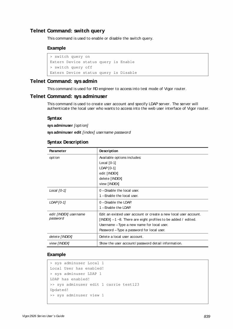
Vigor2926 Series User’s Guide 839
TTeellnneett CCoommmmaanndd:: sswwiittcchh qquueerryy This command is used to enable or disable the switch query.
EExxaammppllee
> switch query on Extern Device status query is Enable > switch query off Extern Device status query is Disable
TTeellnneett CCoommmmaanndd:: ssyyss aaddmmiinn This command is used for RD engineer to access into test mode of Vigor router.
TTeellnneett CCoommmmaanndd:: ssyyss aaddmmiinnuusseerr This command is used to create user account and specify LDAP server. The server will authenticate the local user who wants to access into the web user interface of Vigor router.
SSyynnttaaxx
sys adminuser [option]
sys adminuser edit [index] username password
SSyynnttaaxx DDeessccrriippttiioonn
Parameter Description
option Available options includes:
Local [0-1]
LDAP [0-1]
edit [INDEX]
delete [INDEX]
view [INDEX]
Local [0-1] 0 – Disable the local user.
1 – Enable the local user.
LDAP [0-1] 0 – Disable the LDAP.
1 – Enable the LDAP.
edit [INDEX] username password
Edit an existed user account or create a new local user account.
[INDEX] – 1 ~8. There are eight profiles to be added / edited.
Username – Type a new name for local user.
Password – Type a password for local user.
delete [INDEX] Delete a local user account.
view [INDEX] Show the user account/password detail information.
EExxaammppllee
> sys adminuser Local 1 Local User has enabled! > sys adminuser LDAP 1 LDAP has enabled! >> sys adminuser edit 1 carrie test123 Updated! >> sys adminuser view 1

Vigor2926 Series User’s Guide 840
Index:1 User Name:carrie User Password:test123
TTeellnneett CCoommmmaanndd:: ssyyss bbooaarrdd This command is used to turn on or turn off the function of physical factory reset button, WLAN button, LEDs, and / or the USB ports on Vigor router.
SSyynnttaaxx
sys board button def [on/off]
sys board button wlan [on/off]
sys board led control [on/off]
sys board led sleepMode [on/off]
sys board led sleepMode time [minute]
sys board usb p1/p2 [on/off]
SSyynnttaaxx DDeessccrriippttiioonn
Parameter Description
button def [on/off] on – It is the default value (Enabled).
off – Disable the reset function of the factory reset button.
button wlan [on/off] on – It is the default value (Enabled).
off - Disable the ability of the Wireless button to control WLAN and WPS functions.
led control [on/off] on – It is the default value (Enabled). The LEDs on the front panel is always on.
off – The LEDs on the front panel is always off.
led sleepMode [on/off] The function of SleepMode will be available only when LED control is set to “On”.
on – Enable the function of sleep mode.
off – Disable the function of sleep mode.
led sleepMode time [minute] Set the countdown time for the LEDs to sleep.
[minute] – Enter a value (e.g., 1, 2, 3 and etc.)
usb p1/p2 [on/off] on – It is the default value (Enabled).
off – Disable the USB port 1 or 2.
EExxaammppllee
> sys board button ? sys board button [def/wlan [on/off]] The button will be invalid after turn it off. - default button is on now. - wlan button is on now. > sys board button def off default button is off now. > sys board button def on default button is on now. > sys board usb p2 off USB port2 power is off now. > sys board led sleepMode ?

Vigor2926 Series User’s Guide 841
Usage: sys board led sleepMode [on/off] [time] [minute] Current Setting: LEDs Sleep Mode is off now. Sleep Countdown Time : 1 minute(s) > sys board led sleepMode on LEDs Sleep Mode is on now. > sys board led sleepMode time 3 Sleep Countdown Time set as 3 minute(s).
TTeellnneett CCoommmmaanndd:: ssyyss bboonnjjoouurr This command is used to disable/enable and configure the Bonjour service.
SSyynnttaaxx
sys bonjour [-<command> <parameter> | ... ]
SSyynnttaaxx DDeessccrriippttiioonn
Parameter Description
-e <enable> It is used to disable/enable bonjour service (0: disable, 1: enable).
-h <enable> It is used to disable/enable http (web) service (0: disable, 1: enable).
-t <enable> It is used to disable/enable telnet service (0: disable, 1: enable).
-f <enable> It is used to disable/enable FTP service (0: disable, 1: enable).
-s <enable> It is used to disable/enable SSH service (0: disable, 1: enable).
-p <enable> It is used to disable/enable printer service (0: disable, 1: enable).
-6 <enable> It is used to disable/enable IPv6 (0: disable, 1: enable).
EExxaammppllee
> sys bonjour -s 1 >
TTeellnneett CCoommmmaanndd:: ssyyss ccffgg This command reset the router with factory default settings. When a user types this command, all the configuration will be reset to default setting.
SSyynnttaaxx
sys cfg default
sys cfg status
SSyynnttaaxx DDeessccrriippttiioonn
Parameter Description
default It means to reset current settings with default values.
status It means to display current profile version and status.
EExxaammppllee

Vigor2926 Series User’s Guide 842
> sys cfg status Profile version: 3.0.0 Status: 1 (0x491e5e6c) > sys cfg default >
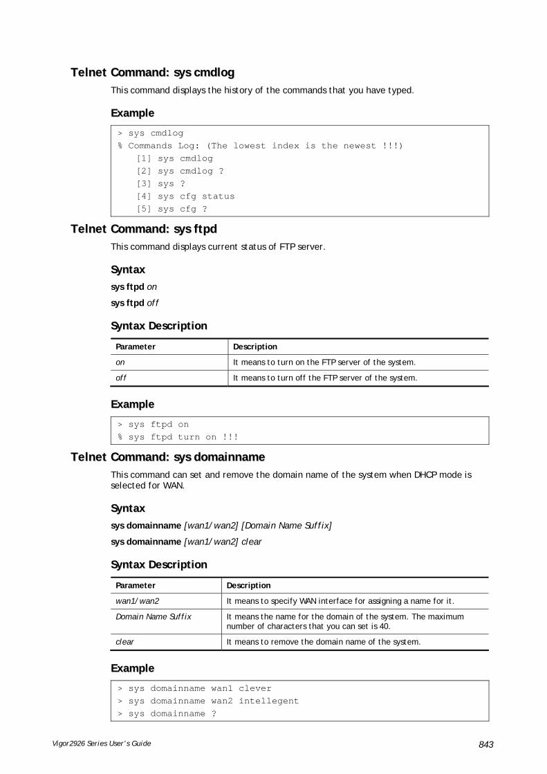
Vigor2926 Series User’s Guide 843
TTeellnneett CCoommmmaanndd:: ssyyss ccmmddlloogg This command displays the history of the commands that you have typed.
EExxaammppllee
> sys cmdlog % Commands Log: (The lowest index is the newest !!!) [1] sys cmdlog [2] sys cmdlog ? [3] sys ? [4] sys cfg status [5] sys cfg ?
TTeellnneett CCoommmmaanndd:: ssyyss ffttppdd This command displays current status of FTP server.
SSyynnttaaxx
sys ftpd on
sys ftpd off
SSyynnttaaxx DDeessccrriippttiioonn
Parameter Description
on It means to turn on the FTP server of the system.
off It means to turn off the FTP server of the system.
EExxaammppllee
> sys ftpd on % sys ftpd turn on !!!
TTeellnneett CCoommmmaanndd:: ssyyss ddoommaaiinnnnaammee This command can set and remove the domain name of the system when DHCP mode is selected for WAN.
SSyynnttaaxx
sys domainname [wan1/wan2] [Domain Name Suffix]
sys domainname [wan1/wan2] clear
SSyynnttaaxx DDeessccrriippttiioonn
Parameter Description
wan1/wan2 It means to specify WAN interface for assigning a name for it.
Domain Name Suffix It means the name for the domain of the system. The maximum number of characters that you can set is 40.
clear It means to remove the domain name of the system.
EExxaammppllee
> sys domainname wan1 clever > sys domainname wan2 intellegent > sys domainname ?

Vigor2926 Series User’s Guide 844
% sys domainname <wan1/wan2> <Domain Name Suffix (max. 40 characters)>% sys domainname <wan1/wan2> clear % Now: wan1 == clever, wan2 ==intelligent >
TTeellnneett CCoommmmaanndd:: ssyyss iiffaaccee This command displays the current interface connection status (UP or Down) with IP address, MAC address and Netmask for the router.
EExxaammppllee
> sys iface Interface 0 Ethernet: Status: UP IP Address: 192.168.1.1 Netmask: 0xFFFFFF00 (Private) IP Address: 0.0.0.0 Netmask: 0xFFFFFFFF MAC: 00-50-7F-00-00-00 Interface 4 Ethernet: Status: DOWN IP Address: 0.0.0.0 Netmask: 0x00000000 MAC: 00-50-7F-00-00-02 Interface 5 Ethernet: Status: DOWN IP Address: 0.0.0.0 Netmask: 0x00000000 MAC: 00-50-7F-00-00-03 Interface 6 Ethernet: Status: DOWN IP Address: 0.0.0.0 Netmask: 0x00000000 MAC: 00-50-7F-00-00-04 Interface 7 Ethernet: Status: DOWN IP Address: 0.0.0.0 Netmask: 0x00000000 MAC: 00-50-7F-00-00-05 Interface 8 Ethernet: Status: DOWN IP Address: 0.0.0.0 Netmask: 0x00000000 MAC: 00-50-7F-00-00-06 Interface 9 Ethernet: Status: DOWN IP Address: 0.0.0.0 Netmask: 0x00000000 MAC: 00-50-7F-00-00-07 --- MORE --- ['q': Quit, 'Enter': New Lines, 'Space Bar': Next Page] --- >

Vigor2926 Series User’s Guide 845
TTeellnneett CCoommmmaanndd:: ssyyss nnaammee This command can set and remove the name for the router when DHCP mode is selected for WAN.
SSyynnttaaxx
sys name [wan1] [ASCII string]
sys name [wan1] clear
SSyynnttaaxx DDeessccrriippttiioonn
Parameter Description
wan1 It means to specify WAN interface for assigning a name for it.
ASCII string It means the name for router. The maximum character that you can set is 20.
EExxaammppllee
> sys name wan1 drayrouter > sys name ? % sys name <wan1/wan2> <ASCII string (max. 20 characters)> % sys name <wan1/wan2> clear % Now: wan1 == drayrouter, wan2 ==
Note: Such name can be used to recognize router’s identification in SysLog dialog.
TTeellnneett CCoommmmaanndd:: ssyyss ppaasssswwdd This command allows users to set password for the administrator.
sys passwd [ASCII string]
SSyynnttaaxx DDeessccrriippttiioonn
Parameter Description
ASCII string It means the password for administrator. The maximum character that you can set is 23.
EExxaammppllee
> sys passwd admin123 >
TTeellnneett CCoommmmaanndd:: ssyyss rreebboooott This command allows users to restart the router immediately.
EExxaammppllee
> sys reboot >
TTeellnneett CCoommmmaanndd:: ssyyss aauuttoorreebboooott This command allows users to restart the router automatically within a certain time.
SSyynnttaaxx
sys autoreboot [on/off/hour(s)]

Vigor2926 Series User’s Guide 846
SSyynnttaaxx DDeessccrriippttiioonn
Parameter Description
on/off On – It means to enable the function of auto-reboot.
Off – It means to disable the function of auto-reboot.
hours It means to set the time schedule for router reboot.
For example, if you type “2” in this field, the router will reboot with an interval of two hours.
EExxaammppllee
> sys autoreboot on autoreboot is ON > sys autoreboot 2 autoreboot is ON autoreboot time is 2 hour(s)
TTeellnneett CCoommmmaanndd:: ssyyss ccoommmmiitt This command allows users to save current settings to FLASH. Usually, current settings will be saved in SRAM. Yet, this command will save the file to FLASH.
EExxaammppllee
> sys commit >
TTeellnneett CCoommmmaanndd:: ssyyss ttffttppdd This command can turn on TFTP server for upgrading the firmware.
EExxaammppllee
> sys tftpd % TFTP server enabled !!!
TTeellnneett CCoommmmaanndd:: ssyyss vveerrssiioonn This command can display current version for the system.
EExxaammppllee
> sys version Router Model: Vigor2926Vn+ Version: 3.7.4.1 English Profile version: 3.0.0 Status: 1 (0x49165e6c) Router IP: 192.168.1.1 Netmask: 255.255.255.0 Firmware Build Date/Time: Mar 20 2014 14:09:50 Router Name: drayrouter Revision: 40055 2860_374 VDSL2 Firmware Version: 05-04-08-00-00-06

Vigor2926 Series User’s Guide 847
TTeellnneett CCoommmmaanndd:: ssyyss qqrryybbuuff This command can display the system memory status and leakage list.
EExxaammppllee
> sys qrybuf System Memory Status and Leakage List Buf sk_buff ( 200B), used#: 1647, cached#: 30 Buf KMC4088 (4088B), used#: 0, cached#: 8 Buf KMC2552 (2552B), used#: 1641, cached#: 42 Buf KMC1016 (1016B), used#: 7, cached#: 1 Buf KMC504 ( 504B), used#: 8, cached#: 8 Buf KMC248 ( 248B), used#: 26, cached#: 22 Buf KMC120 ( 120B), used#: 67, cached#: 61 Buf KMC56 ( 56B), used#: 20, cached#: 44 Buf KMC24 ( 24B), used#: 58, cached#: 70 Dynamic memory: 13107200B; 4573168B used; 190480B/0B in level 1/2 cache. FLOWTRACK Memory Status # of free = 12000 # of maximum = 0 # of flowstate = 12000 # of lost by siganture = 0 # of lost by list = 0
TTeellnneett CCoommmmaanndd:: ssyyss ppoollllbbuuff This command can turn on or turn off polling buffer for the router.
SSyynnttaaxx
sys pollbuf [on]
sys pollbuf [off]
SSyynnttaaxx DDeessccrriippttiioonn
Parameter Description
on It means to turn on pulling buffer.
off It means to turn off pulling buffer.
EExxaammppllee
> sys pollbuf on % Buffer polling is on! > sys pollbuf off % Buffer polling is off!

Vigor2926 Series User’s Guide 848
TTeellnneett CCoommmmaanndd:: ssyyss bbrriittaasskk This command can improve triple play quality.
SSyynnttaaxx
sys britask [on]
sys britask [off]
SSyynnttaaxx DDeessccrriippttiioonn
Parameter Description
on It means to turn on the bridge task for improving the triple play quality.
off It means to turn off the bridge task.
EExxaammppllee
> sys britask on % bridge task is ON, now
TTeellnneett CCoommmmaanndd:: ssyyss ttrr006699 This command can set CPE settings for applying in VigorACS.
SSyynnttaaxx
sys tr069 get [parm] [option]
sys tr069 set [parm] [value]
sys tr069 getnoti [parm]
sys tr069 setnoti [parm] [value]
sys tr069 log
sys tr069 debug [on/off]
sys tr069 save
sys tr069 inform [event code]
sys tr069 port [port num]
sys tr069 cert_auth [on/off]
SSyynnttaaxx DDeessccrriippttiioonn
Parameter Description
get [parm] [option] It means to get parameters for tr-069.
option=<nextlevel>: only gets nextlevel for GetParameterNames.
set [parm] [value] It means to set parameters for tr-069.
getnoti [parm] It means to get parameter notification value.
setnoti [parm] [value] It means to set parameter notification value.
log It means to display the TR-069 log.
debug [on/off] on: turn on the function of sending debug message to syslog.
off: turn off the function of sending debug message to syslog.
save It means to save the parameters to the flash memory of the router.
Inform [event code] It means to inform parameters for tr069 with different event codes.

Vigor2926 Series User’s Guide 849
[event code] includes:
0-"0 BOOTSTRAP",
1-"1 BOOT",
2-"2 PERIODIC",
3-"3 SCHEDULED",
4-"4 VALUE CHANGE",
5-"5 KICKED",
6-"6 CONNECTION REQUEST",
7-"7 TRANSFER COMPLETE",
8-"8 DIAGNOSTICS COMPLETE",
9-"M Reboot"
port [port num] It means to change tr069 listen port number.
cert_auth [on/off] on: turn on certificate-based authentication.
off: turn off certificate-based authentication.
EExxaammppllee
> sys tr069 get Int. nextlevel Total number of parameter is 24 Total content length of parameter is 915 InternetGatewayDevice.LANDeviceNumberOfEntries InternetGatewayDevice.WANDeviceNumberOfEntries InternetGatewayDevice.DeviceInfo. InternetGatewayDevice.ManagementServer. InternetGatewayDevice.Time. InternetGatewayDevice.Layer3Forwarding. InternetGatewayDevice.LANDevice. InternetGatewayDevice.WANDevice. InternetGatewayDevice.Services. InternetGatewayDevice.X_00507F_InternetAcc. InternetGatewayDevice.X_00507F_LAN. InternetGatewayDevice.X_00507F_NAT. InternetGatewayDevice.X_00507F_Firewall. InternetGatewayDevice.X_00507F_Bandwidth. InternetGatewayDevice.X_00507F_Applications. InternetGatewayDevice.X_00507F_VPN. InternetGatewayDevice.X_00507F_VoIP. InternetGatewayDevice.X_00507F_WirelessLAN. InternetGatewayDevice.X_00507F_System. InternetGatewayDevice.X_00507F_Status. InternetGatewayDevice.X_00507F_Diagnostics. --- MORE --- ['q': Quit, 'Enter': New Lines, 'Space Bar': Next Page] ---

Vigor2926 Series User’s Guide 850
TTeellnneett CCoommmmaanndd:: ssyyss ssiipp__aallgg This command can turn on/off SIP ALG (Application Layer Gateway) for traversal.
SSyynnttaaxx
sys sip_alg [1]
sys sip_alg [0]
SSyynnttaaxx DDeessccrriippttiioonn
Parameter Description
1 It means to turn on SIP ALG.
0 It means to turn off SIP ALG.
EExxaammppllee
> sys sip_alg ? usage: sys sip_alg [value] 0 - disable SIP ALG 1 - enable SIP ALG current SIP ALG is disabled
TTeellnneett CCoommmmaanndd:: ssyyss rrttsspp__aallgg This command is used to configure settings (e.g., listen port) for ALG with the protocol of RTSP.
SSyynnttaaxx
sys rtsp_alg [<command> <parameter>]
SSyynnttaaxx DDeessccrriippttiioonn
Parameter Description
-e [1/0] Enable / disable the function of RTSP ALG.
0 – Disable.
1 – Enable.
-p [value] Set your listening port for RTSP ALG.
-u [1/0] Enable / disable listen along UDP path.
0 – Disable.
1 – Enable.
-t [1/0] Enable / disable listen along TCP path.
0 – Disable.
1 – Enable.
-v Display RTP and RTSP portmap information of RTSP ALG.
EExxaammppllee
> sys rtsp_alg -e 1 Auto enable ALG Master Switch Enable RTSP ALG > sys rtsp_alg -p 375

Vigor2926 Series User’s Guide 851
Current listening RTSP Port: 375 > sys rtsp_alg -v Current Open PortMap Number of RTSP ALG: 0
TTeellnneett CCoommmmaanndd:: ssyyss lliicceennssee This command can process the system license.
SSyynnttaaxx
sys license licmsg
sys license licauth
sys license regser
sys license licera
sys license licifno
sys license lic_wiz [set/reg/qry]
sys license dev_chg
sys license dev_key
SSyynnttaaxx DDeessccrriippttiioonn
Parameter Description
licmsg It means to display license message.
licauth It means the license authentication time setting.
regser It means the license register server setting.
licera It means to erase license setting.
licifno It means license and signature download interface setting.
lic_wiz [set/reg/qry] It means the license wizard setting.
qry: query service support status
set [idx] [trial] [service type] [sp_id] [start_date] [License Key]
reg: register service in portal
dev_chg It means to change the device key.
dev_key It means to show device key.
EExxaammppllee
> sys license licifno License and Signature download interface setting: licifno [AUTO/WAN#] Ex: licifno wan1 Download interface is "auto-selected" now.

Vigor2926 Series User’s Guide 852
TTeellnneett CCoommmmaanndd:: ssyyss ffrr__lloogg This command is used for displaying log information related to web syslog.
SSyynnttaaxx
sys fr_log
EExxaammppllee
> sys fr_log ? ----------------------------------------------------------------- Note: This command shows the same log information with Diagnostics>>Syslog Explo rer. If you don't see any log information, go to the Web Interface and make sure Diagnostics>>Syslog Explorer is enabled.
TTeellnneett CCoommmmaanndd:: ssyyss ddiiaagg__lloogg This command is used for RD debug.
SSyynnttaaxx
sys diag_log [status| enable| disable| flush| lineno [w] | level [x] | feature [on|off] [y]| log]
SSyynnttaaxx DDeessccrriippttiioonn
Parameter Description
status It means to show the status of diagnostic log.
enable It means to enable the function of diag_log.
disable It means to disenable the function of diag_log.
flush It means the flush log buffer.
lineno [w] It means the total lines for displaying message.
w - Available value ranges from 100 to 50000.
level[x] It determines the level of data displayed.
x – Available value ranges from 0 to 12. The larger the number is, the detailed the data is displayed.
feature [on/off][y] It is used to specify the function of the log. Supported features include SYS and DSL (Case-Insensitive). Default setting is “on” for “DSL”.
voip_feature [on/off][vf_name]
It means VoIP feature. Type on to enable the feature or type off to disable the feature.
vf_name: available settings include DRVTAPI, DRVVMMC, DRVMPS, DRVFXO, DRVHAL, PSMPHONE, PSMSUPP, PSM, FXO, PSMISDN, DTMFPSER, CALLERID (Case-Insensitive).
log It means the dump log buffer.
EExxaammppllee
> sys diag_log status Status:

Vigor2926 Series User’s Guide 853
diag_log is Enabled. lineno : 10000. level : 3. Enabled feature: SYS DSL > sys diag_log log 0:00:02 [DSL] Current modem firmware: AnnexA_548006_544401 0:00:02 [DSL] Modem firmware feature: 5, ADSL_A, VDSL2 0:00:02 [DSL] xtseCfg=04 00 04 00 0c 01 00 07 0:00:02 [DSL] don't have last showtime mode!! set next mode to VDSL!!0:00:02 [DSL] Status has changed: Stopped(0) -> FwWait(3) 0:00:02 [DSL] Status has changed: FwWait(3) -> Starting(1) 0:00:02 [DSL] Status has changed: Starting(1) -> Running(2) 0:00:02 [DSL] Status was switched: firmwareReady(3) to Init(5) 0:00:02 [DSL] Status was switched: Init(5) to Restart(10) 0:00:02 [DSL] Status was switched: Restart(10) to FirmwareRequest(1) 0:00:02 [DSL] Line state has changed: 00000000 -> 000000FF 0:00:02 [DSL] Entering VDSL2 mode 0:00:03 [DSL] modem code: [05-04-08-00-00-06] 0:00:05 [DSL] Status was switched: FirmwareRequest(1) to firmwareReady(3) 0:00:05 [DSL] Status was switched: firmwareReady(3) to Init(5) 0:00:05 [DSL] >> nXtseA=0d, nXtseB=00, nXtseV=07, nFwFeatures=5 0:00:05 [DSL] >> nHsToneGroupMode=0, nHsToneGroup=106, nToneSet=43, nCamState =2 0:00:05 [DSL] Line state has changed: 000000FF -> 00000100 0:00:05 [DSL] Line state has changed: 00000100 -> 00000200 0:00:05 [DSL] Status was switched: Init(5) to Train(6)
TTeellnneett CCoommmmaanndd:: ssyyss aarrpp__AAuuttooRReeqq This command is used to enable / disable the function that Vigor router sends ARP request to the connected device(s) periodically.
SSyynnttaaxx
sys arp_AutoReq –d [value]
SSyynnttaaxx DDeessccrriippttiioonn
Parameter Description
-d [value] Disable the function of ARP auto request.
0 – Enable
1 – Disable
EExxaammppllee
> sys arp_AutoReq -d 0 Arp auto-request enable.

Vigor2926 Series User’s Guide 854
TTeellnneett CCoommmmaanndd:: ssyyss ddaayylliigghhttssaavvee This command is used to configure daylight save setting.
SSyynnttaaxx
sys daylightsave [-<command> <parameter> | ... ]
SSyynnttaaxx DDeessccrriippttiioonn
Parameter Description
[<command><parameter>|…]
The available commands with parameters are listed below.
[…] means that you can type in several commands in one line.
-v Display the daylight saving settings.
-r Set to factory default setting.
-e [1/0] Enable (1) / disable (0) daylight saving.
-t [0/1/2] Specify the saving type for daylight setting.
0 – Default
1 – Time range
2 - Yearly
-s <year> <month> <day> <hour>
Set the detailed settings of the starting day for time range type.
year – must be the year after 2013.
month - 1 ~ 12
day – 1 ~ 31
hour – 0 ~ 23
e.g., sys daylightsave -s 2014 3 10 12
-d <year> <month> <day> <hour>
Set the detailed settings of the ending day for time range type.
year – After 2013.
month - 1 ~ 12
day – 1 ~ 31
hour – 0 ~ 23
e.g., sys daylightsave -d 2014 9 10 12
-y <month> <th weekday> <day in week> <hour>
Set the detailed settings of the starting day for yearly type.
month - 1 ~ 12
th weekday – 1 ~ 5, 9: last week
day in week - 0:Sun, 1:Mon, 2:Tue, 3:Wed, 4:Thu, 5: Fri, 6:Sat
hour – 0 ~ 23
e.g, sys daylightsave -y 9 1 0 14
-z <month> <th weekday> <day in week> <hour>
Set the detailed settings of the ending day for yearly type.
month - 1 ~ 12
th weekday – 1 ~ 5, 9: last week
day in week - 0:Sun, 1:Mon, 2:Tue, 3:Wed, 4:Thu, 5: Fri, 6:Sat
hour – 0 ~ 23
e.g, sys daylightsave -z 3 1 6 14
EExxaammppllee
> sys daylightsave -y 9 1 0 14 % Start: Yearly on Sep 1th Sun 14:00

Vigor2926 Series User’s Guide 855
TTeellnneett CCoommmmaanndd:: ssyyss ddnnssCCaacchheeTTbbll This command is used to configure TTL settings which will be displayed in DNS Cache table.
SSyynnttaaxx
sys dnsCacheTbl [<command><parameter>|…]
SSyynnttaaxx DDeessccrriippttiioonn
Parameter Description
[<command><parameter>|…]
The available commands with parameters are listed below.
[…] means that you can type in several commands in one line.
-l Display DNS IPv4 entry in the DNS cache table.
-s Display DNS IPv6 entry in the DNS cache table.
-v Display the TTL limit value in the DNS cache table.
-t < 0/n > Set the TTL limit value in the DNS cache table.
0- No limit
N – Greater than or equal to 5.
-c Clear the DNS cache table.
EExxaammppllee
> sys dnsCacheTbl -l %DNS Cache Table List > sys dnsCacheTbl -t 65 % Set TTL limit: 65 seconds. % When TTL larger than 65s , delete the DNS entry in the router's DNS cache tabl e. >
TTeellnneett CCoommmmaanndd:: ssyyss ssyysslloogg This command is used to configure
SSyynnttaaxx
sys syslog -a <enable> [-<command> <parameter> | ... ]
SSyynnttaaxx DDeessccrriippttiioonn
Parameter Description
[<command><parameter>|…]
The available commands with parameters are listed below.
[…] means that you can type in several commands in one line.
-a <1/0> Enable (1) or disable (0) Syslog Access Setup.
-s <1/0> Enable (1) or disable (0) Syslog Save to Syslog Server.
-i <IP address> Define the IP address of the Syslog server.
-d <port number> Define the port number (1 ~ 65535) as the destination port.
-u <1/0> Enable (1) or disable (0) Syslog Save to USB Disk.
-m <1/0> Enable (1) or disable (0) Mail Syslog.
-f <1/0> Enable (1) or disable (0) Filewall Log.
-v <1/0> Enable (1) or disable (0) VPN Log.

Vigor2926 Series User’s Guide 856
-e <1/0> Enable (1) or disable (0) User Access Log.
-c <1/0> Enable (1) or disable (0) Call Log.
-w <1/0> Enable (1) or disable (0) WAN Log.
-r <1/0> Enable (1) or disable (0) Router/DSL Information.
-t <1/0> Enable (1) or disable (0) AlertLog Setup.
-o <port number> Define the port number (1 ~ 65535) for AlertLog.
EExxaammppllee
> sys syslog -a 1 -s 1 -i 192.168.1.25 -d 514 >
TTeellnneett CCoommmmaanndd:: ssyyss mmaaiillaalleerrtt This command is used to configure settings for syslog mail alert.
SSyynnttaaxx
sys mailalert [-<command> <parameter>]
SSyynnttaaxx DDeessccrriippttiioonn
Parameter Description
[<command><parameter>] The available commands with parameters are listed below.
-e [0/1] Enable/disable Mail Alert. 0 – Disable. 1 – Enable.
-i [SMTP Server IP] Set IP Address for SMTP server.
-o [SMTP Server Port] Set port number for SMTP server..
-a [Mail Address] Set E-maiil address for alert mail reciver.
-r [Mail Address] Set E-mail Address for mail return.
-s [0/1] Enable/disable the function of Use SSL. 0 – Disable. 1 – Enable.
-h [0/1] Enable/disable SMTP Authentication. 0 – Disable. 1 – Enable.
-u [Username] Set username for SMTP Authentication.
-p [Password] Set password for SMTP Authentication.
-l [type][0/1] Enable / disable mail alert for different types. Number 0 ~ 6 represent different types. "0 <0/1>" : Enable/Disable Mail Alert of the DoS Attack. "1 <0/1>" : Enable/Disable Mail Alert of the APPE. "2 <0/1>" : nable/Disable Mail Alert of the VPN Log. "3 <0/1>" : Enable/Disable Mail Alert of the APPE Signature. "6 <0/1>" : Enable/Disable Mail Alert of the Reboot Debug Log. In which, 0 – Disable. 1 – Enable.
-f Reset Mail Alert setting to factory default.
-v Show current Mail Alert setting.
-R [0/1] Set Mail Alert Reboot debug log mode. 0: Limited Mode 1: Unlimited Mode.
EExxaammppllee

Vigor2926 Series User’s Guide 857
> sys mailalert -e 1 Set Enable Mail Alert. > sys mailalert -v ------ Current setting for Mail Alert ------ Mail Alert: Enable SMTP Server IP Address: 0.0.0.0 SMTP Server Port: 25 Alert Mail Reciver E-maiil Address: Mail Return E-mail Address: Use SSL: Disable SMTP Authentication: Disable Username for SMTP Authentication: Password for SMTP Authentication: Mail Alert for DoS Attack: Enable. Mail Alert for APPE: Enable. Mail Alert for VPN Log: Enable. Mail Alert for APPE Signature: Disable. Mail Alert for Reboot Debug Log: Disable, Mode: Limited. ---------------------------------------------
TTeellnneett CCoommmmaanndd:: ssyyss ttiimmee This command is used to configure system time and date.
SSyynnttaaxx
sys time server [domain]
sys time inquire
sys time show
sys time zone [index]
SSyynnttaaxx DDeessccrriippttiioonn
Parameter Description
domain Type the domain name of the time server. The maximum length is 39 characters.
index Different number means different time zone. 1 - GMT-12:00 Eniwetok, Kwajalein 2 - GMT-11:00 Midway Island, Samoa 3 - GMT-10:00 Hawaii 4 - GMT-09:00 Alaska 5 - GMT-08:00 Pacific Time (US & Canada) 6 - GMT-08:00 Tijuana 7 - GMT-07:00 Mountain Time (US & Canada) 8 - GMT-07:00 Arizona 9 - GMT-06:00 Central Time (US & Canada) 10 - GMT-06:00 Saskatchewan 11 - GMT-06:00 Mexico City, Tegucigalpa 12 - GMT-05:00 Eastern Time (US & Canada) 13 - GMT-05:00 Indiana (East) 14 - GMT-05:00 Bogota, Lima, Quito 15 - GMT-04:00 Atlantic Time (Canada) 16 - GMT-04:00 Caracas, La Paz 17 - GMT-04:00 Santiago 18 - GMT-03:30 Newfoundland 19 - GMT-03:00 Brasilia 20 - GMT-03:00 Buenos Aires, Georgetown 21 - GMT-02:00 Mid-Atlantic
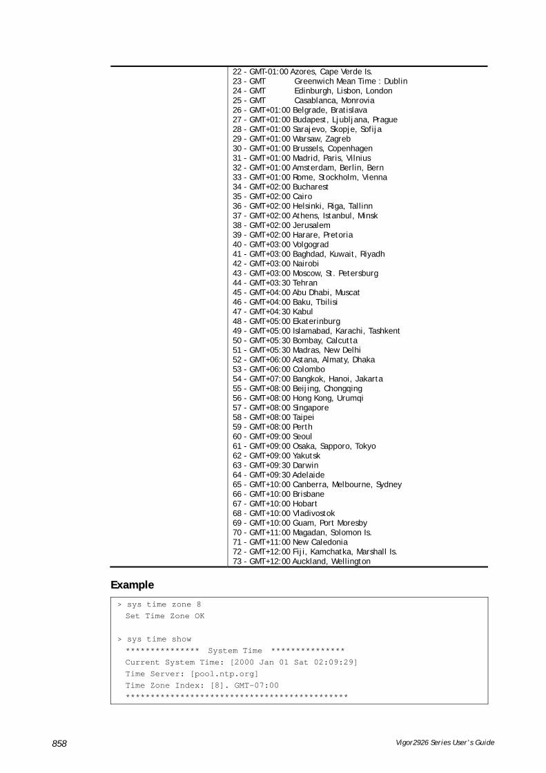
Vigor2926 Series User’s Guide 858
22 - GMT-01:00 Azores, Cape Verde Is. 23 - GMT Greenwich Mean Time : Dublin 24 - GMT Edinburgh, Lisbon, London 25 - GMT Casablanca, Monrovia 26 - GMT+01:00 Belgrade, Bratislava 27 - GMT+01:00 Budapest, Ljubljana, Prague 28 - GMT+01:00 Sarajevo, Skopje, Sofija 29 - GMT+01:00 Warsaw, Zagreb 30 - GMT+01:00 Brussels, Copenhagen 31 - GMT+01:00 Madrid, Paris, Vilnius 32 - GMT+01:00 Amsterdam, Berlin, Bern 33 - GMT+01:00 Rome, Stockholm, Vienna 34 - GMT+02:00 Bucharest 35 - GMT+02:00 Cairo 36 - GMT+02:00 Helsinki, Riga, Tallinn 37 - GMT+02:00 Athens, Istanbul, Minsk 38 - GMT+02:00 Jerusalem 39 - GMT+02:00 Harare, Pretoria 40 - GMT+03:00 Volgograd 41 - GMT+03:00 Baghdad, Kuwait, Riyadh 42 - GMT+03:00 Nairobi 43 - GMT+03:00 Moscow, St. Petersburg 44 - GMT+03:30 Tehran 45 - GMT+04:00 Abu Dhabi, Muscat 46 - GMT+04:00 Baku, Tbilisi 47 - GMT+04:30 Kabul 48 - GMT+05:00 Ekaterinburg 49 - GMT+05:00 Islamabad, Karachi, Tashkent 50 - GMT+05:30 Bombay, Calcutta 51 - GMT+05:30 Madras, New Delhi 52 - GMT+06:00 Astana, Almaty, Dhaka 53 - GMT+06:00 Colombo 54 - GMT+07:00 Bangkok, Hanoi, Jakarta 55 - GMT+08:00 Beijing, Chongqing 56 - GMT+08:00 Hong Kong, Urumqi 57 - GMT+08:00 Singapore 58 - GMT+08:00 Taipei 59 - GMT+08:00 Perth 60 - GMT+09:00 Seoul 61 - GMT+09:00 Osaka, Sapporo, Tokyo 62 - GMT+09:00 Yakutsk 63 - GMT+09:30 Darwin 64 - GMT+09:30 Adelaide 65 - GMT+10:00 Canberra, Melbourne, Sydney 66 - GMT+10:00 Brisbane 67 - GMT+10:00 Hobart 68 - GMT+10:00 Vladivostok 69 - GMT+10:00 Guam, Port Moresby 70 - GMT+11:00 Magadan, Solomon Is. 71 - GMT+11:00 New Caledonia 72 - GMT+12:00 Fiji, Kamchatka, Marshall Is. 73 - GMT+12:00 Auckland, Wellington
EExxaammppllee
> sys time zone 8 Set Time Zone OK > sys time show *************** System Time *************** Current System Time: [2000 Jan 01 Sat 02:09:29] Time Server: [pool.ntp.org] Time Zone Index: [8]. GMT-07:00 *********************************************

Vigor2926 Series User’s Guide 859
TTeellnneett CCoommmmaanndd:: ssyyss eeaapp__ttllss This command is used to disable or enable EAP-TLS.
You might have to enable EAP-TLS compatibility to avoid compatibility issues with some operating systems. But, please note that enabling EAP-TLS compatibility will lower down the connection security level.
SSyynnttaaxx
sys eap_tls set [0/1]
SSyynnttaaxx DDeessccrriippttiioonn
Parameter Description
0 Disable EAP-TLS compatibility!
1 Enable EAP-TLS compatibility!
EExxaammppllee
> sys eap_tls set 1 Enable EAP_TLS compatibility!
TTeellnneett CCoommmmaanndd:: ssyyss ddaasshhbbooaarrdd This command is used to display / hide items (such as System Information, Interface…) on dashboard.
SSyynnttaaxx
sys dashboard [-<command> <value> | ... ]
sys dashboard show
SSyynnttaaxx DDeessccrriippttiioonn
Parameter Description
[<command> <value>|…]
The available commands with parameters are listed below. […] means that you can type in several parameters in one line.
<command> “0 ~ 9” and “a” represent different sections to be displayed on the dashboard.
0 : Front Panel
1 : System Information
2 : IPv4 LAN Information
3 : IPv4 Internet Access
4 : IPv6 Internet Access
5 : Interface
6 : Security
7 : System Resource
8 : LTE Status
9 : Quick Access
a : VoIP
<value> 1 : Enable
0 : Disable
show Display current status (enabled /disabled) for each item.

Vigor2926 Series User’s Guide 860
EExxaammppllee
> sys dashboard -0 1 Front Panel enabled > sys dashboard show Front Panel enabled System Information enabled IPv4 LAN Information enabled IPv4 Internet Access enabled IPv6 Internet Access enabled Interface enabled Security enabled System Resource enabled LTE Status enabled Quick Access enabled VoIP enabled
TTeellnneett CCoommmmaanndd:: tteessttmmaaiill This command is used to display current settings for sending test mail.
EExxaammppllee
> testmail Send out test mail Mail Alert:[Disable] SMTP_Server:[0.0.0.0] Mail to:[] Return-Path:[]
TTeellnneett CCoommmmaanndd:: uuppnnpp ooffff This command can close UPnP function.
EExxaammppllee
>upnp off UPNP say bye-bye
TTeellnneett CCoommmmaanndd:: uuppnnpp oonn This command can enable UPnP function.
EExxaammppllee
>upnp on UPNP start.
TTeellnneett CCoommmmaanndd:: uuppnnpp nnaatt This command can display IGD NAT status.
EExxaammppllee
> upnp nat ? ****************** IGD NAT Status ****************

Vigor2926 Series User’s Guide 861
((0)) InternalClient >>192.168.1.10<<, RemoteHost >>0.0.0.0<< InternalPort >>21<<, ExternalPort >>21<< PortMapProtocol >>TCP<< The tmpvirtual server index >>0<< PortMapLeaseDuration >>0<<, PortMapEnabled >>0<< Ftp Example [MICROSOFT] ((1)) InternalClient >>0.0.0.0<<, RemoteHost >>0.0.0.0<< InternalPort >>0<<, ExternalPort >>0<< PortMapProtocol >><NULL><< The tmpvirtual server index >>0<< PortMapLeaseDuration >>0<<, PortMapEnabled >>0<< PortMapProtocol >><NULL><< The tmpvirtual server index >>0<< PortMapLeaseDuration >>0<<, PortMapEnabled >>0<< 0<< --- MORE --- ['q': Quit, 'Enter': New Lines, 'Space Bar': Next Page] ---
TTeellnneett CCoommmmaanndd:: uuppnnpp sseerrvviiccee This command can display the information of the UPnP service. UPnP service must be enabled first.
EExxaammppllee
> upnp on UPNP start. > upnp service >>>>> SERVICE TABLE1 <<<<< serviceType urn:schemas-microsoft-com:service:OSInfo:1 serviceId urn:microsoft-com:serviceId:OSInfo1 SCPDURL /upnp/OSInfo.xml controlURL /OSInfo1 eventURL /OSInfoEvent1 UDN uuid:774e9bbe-7386-4128-b627-001daa843464 >>>>> SERVICE TABLE2 <<<<< serviceType urn:schemas-upnp-org:service:WANCommonInterfaceConfig:1 serviceId urn:upnp-org:serviceId:WANCommonIFC1 SCPDURL /upnp/WComIFCX.xml controlURL /upnp?control=WANCommonIFC1 eventURL /upnp?event=WANCommonIFC1 UDN uuid:2608d902-03e2-46a5-9968-4a54ca499148 . . .

Vigor2926 Series User’s Guide 862
TTeellnneett CCoommmmaanndd:: uuppnnpp ssuubbssccrriibbee This command can show all UPnP services subscribed.
EExxaammppllee
> upnp on UPNP start. > upnp subscribe Vigor> upnp subscribe >>>> (1) serviceType urn:schemas-microsoft-com:service:OSInfo:1 ----- Subscribtion1 ------- sid = 7a2bbdd0-0047-4fc8-b870-4597b34da7fb eventKey =1, ToSendEventKey = 1 expireTime =6926 active =1 DeliveryURLs =<http://192.168.1.113:2869/upnp/eventing/twtnpnsiun> >>>> (2) serviceType urn:schemas-upnp-org:service:WANCommonInterfaceConfig:1 ----- Subscribtion1 ------- sid = d9cd47a5-d9c9-4d3d-8043-d03a82f27983 eventKey =1, ToSendEventKey = 1 . . .
TTeellnneett CCoommmmaanndd:: uuppnnpp ttmmppvvss This command can display current status of temp Virtual Server of your router.
EExxaammppllee
Vigor> upnp tmpvs ****************** Temp virtual server status **************** ((0)) real_addr >>192.168.1.10<<, pseudo_addr >>172.16.3.229<< real_port >>0<<, pseudo_port >>0<< hit_portmap_index >>0<< The protocol >>TCP<< time >>0<< ((1))

Vigor2926 Series User’s Guide 863
real_addr >>0.0.0.0<<, pseudo_addr >>0.0.0.0<< real_port >>0<<, pseudo_port >>0<< hit_portmap_index >>0<< The protocol >>0<< time >>0<< --- MORE --- ['q': Quit, 'Enter': New Lines, 'Space Bar': Next Page] ---
TTeellnneett CCoommmmaanndd:: uuppnnpp wwaann This command is used to specify WAN interface to apply UPnP.
SSyynnttaaxx
upnp wan [n]
SSyynnttaaxx DDeessccrriippttiioonn
Parameter Description
n It means to specify WAN interface to apply UPnP.
n=0, it means to auto-select WAN interface.
n=1, WAN1
n=2, WAN2 ……….
EExxaammppllee
> upnp wan 1 use wan1 now.
TTeellnneett CCoommmmaanndd:: uussbb lliisstt This command is use to display the information about the brand name and model name of the USB modems which are supported by Vigor router.
EExxaammppllee
> usb list ? Brand Module Standard ------------------------ -------- Aiko Aiko 83D 3.5G Y BandRich Bandluxe C170 3.5G Y BandRich Bandluxe C270 3.5G Y BandRich Bandluxe C321 3.5G Y BandRich Bandluxe C330 3.5G Y BandRich Bandluxe C331 3.5G Y BandRich Bandluxe C502 3.5G Y Huawei Huawei E169u 3.5G Y Huawei Huawei E220 3.5G Y Huawei Huawei E303D 3.5G Y Huawei Huawei E392 3.5G Y Huawei Huawei E398 3.5G Y Sony Erics Sony Ericsson MD30 3.5G Y TP-LINK TP-LINK MA180 3.5G Y TP-LINK TP-LINK MA260 3.5G Y Vodafone Vodafone K3765-Z 3.5G Y

Vigor2926 Series User’s Guide 864
Vodafone Vodafone K4605 3.5G Y ZTE ZTE MF626 3.5G Y ZTE ZTE MF627 plus 3.5G Y ZTE ZTE MF633 3.5G Y ZTE ZTE MF636 3.5G Y SpinCom SpinCom GPRS Modem 3.5G Y - MORE - ['q': Quit, 'Enter': New Lines, 'Space Bar': Next Page] -
TTeellnneett CCoommmmaanndd:: uussbb uusseerr This command is used to set profiles for FTP/SMB users.
SSyynnttaaxx DDeessccrriippttiioonn
usb user add [Index] [Username] [Password] [Permission] [Home path]
usb user rm [Index]
usb user enable [Index]
usb user disable [Index]
usb user list
SSyynnttaaxx DDeessccrriippttiioonn
Parameter Description
add Add a new user profile.
Rm Delete an existed user profile.
enable Enable a user profile.
disable Disable a user profile.
list Display all of the user profile.
index It means the index number of the user profile. There are 16 profiles allowed to be configured. So the range of such option is 1 ~ 16.
Username Type a text (maximum 11 characters) as the username for the user profile.
Password Type a text (maximum 11 characters) as the password for the user profile.
Permission Specify the action (RWDLCR) permitted. If one of the actions is not allowed, simple type “-” instead.
R – Read File.
W – Write File.
D – Delete File.
L – List directory.
C – Create directory.
R – Remove selected directory.
Home path Set the path (maximum 159 characters) for the USB user profile.
EExxaammppllee
> usb user add 1 root 1234 R-DLCR /usr

Vigor2926 Series User’s Guide 865
TTeellnneett CCoommmmaanndd:: vviiggbbrrgg sseett This command is to configure specified WAN as bridge mode.
SSyynnttaaxx DDeessccrriippttiioonn
vigbrg set -v [IP version] -w [WAN_idx] -l [LAN_idx] -e [0/1] -f [0/1]
SSyynnttaaxx DDeessccrriippttiioonn
Parameter Description
-v [IP version] Indicate the IP version for the IP address.
4 – IPv4.
6 – IPv6.
-w [WAN_idx] WAN_idx – Indicate the WAN interface.
1 – WAN1
2 – WAN2
3 – WAN3
4 – WAN4
-l [LAN_idx] LAN_idx – Indicate the LAN interface.
1 – LAN1
2 – LAN2
3 – LAN3
4 – LAN4
e [0/1] Enable (1) or disable (0) the Vigor Bridge for WAN or/and LAN.
f [0/1] Enable (1) or disable (0) the firewall functions.
EExxaammppllee
> vigbrg set -v 4 -w 1 -l 1 -e 1 [WAN1] IPv4 bridge is enable. Set subnet[LAN1]
TTeellnneett CCoommmmaanndd:: vviiggbbrrgg ssttaattuuss This command can show whether the Vigor Bridge Function is enabled or disabled.
EExxaammppllee
> vigbrg status %Vigor Bridge Function is enable! %Wan1 management is disable!

Vigor2926 Series User’s Guide 866
TTeellnneett CCoommmmaanndd:: vviiggbbrrgg ccffggiipp This command allows users to transfer a bridge modem into ADSL router by accessing into and adjusting specified IP address. Users can access into Web UI of the router to manage the router through the IP address configured here.
SSyynnttaaxx
vigbrg cfgip [IP Address]
SSyynnttaaxx DDeessccrriippttiioonn
Parameter Description
IP Address It means to type an IP address for users to manage the router.
EExxaammppllee
> vigbrg cfgip 192.168.1.15 > vigbrg cfgip ? % Vigor Bridge Config IP, % Now: 192.168.1.15
TTeellnneett CCoommmmaanndd:: vviiggbbrrgg wwaannssttaattuuss This command can display the existed WAN connection status for the modem (change from ADSL router into bridge modem), including index number, MAC address, Stamp Time, PVC, VLAN port for Vigor Bridge Function..
EExxaammppllee
> vigbrg wanstatus Vigor Bridge: Running WAN mac table: Index MAC Address Stamp Time PVC VLan Port
TTeellnneett CCoommmmaanndd:: vviiggbbrrgg wwllaannssttaattuuss This command can display the existed WLAN connection status for the modem (change from router into bridge modem), including index number, MAC address, Stamp Time, PVC, VLAN port for Vigor Bridge Function.
EExxaammppllee
> vigbrg wlanstatus Vigor Bridge: Running WAN mac table: Index MAC Address Stamp Time PVC VLan Port
TTeellnneett CCoommmmaanndd:: vvllaann ggrroouupp
This command allows you to set VLAN group. You can set four VLAN groups. Please run vlan restart command after you change any settings.
SSyynnttaaxx
vlan group id [set/set_ex] [p1/p2/p3/p4/s1/s2/s3/s4
SSyynnttaaxx DDeessccrriippttiioonn

Vigor2926 Series User’s Guide 867
Parameter Description
id It means the group 0 to 7 for VLAN.
set It indicates each port can join more than one VLAN group.
set_ex It indicates each port can join one VLAN group at one time.
p1/p2/p3/p4 It indicates LAN port 1 to LAN port 4. To group LAN1, LAN2, LAN3 and/or LAN4 under one VLAN group, please type the port number(s) you want.
s1/s2/s3/s4 It is only available for WALN models.
EExxaammppllee
> vlan group 3 set p1 s3 s4 VLAN p1 p2 p3 p4 s1 s2 s3 s4 ----------------------------------------------- 3 V V V >
TTeellnneett CCoommmmaanndd:: vvllaann ooffff This command allows you to disable VLAN function.
SSyynnttaaxx
vlan off
EExxaammppllee
> vlan off VLAN is Disable! Force subnet LAN2/3/4 to be disabled!!
TTeellnneett CCoommmmaanndd:: vvllaann oonn This command allows you to enable VLAN function.
SSyynnttaaxx
vlan on
EExxaammppllee
> vlan on VLAN is Enable!
TTeellnneett CCoommmmaanndd:: vvllaann pprrii This command is used to define the priority for each VLAN profile setting.
SSyynnttaaxx
vlan pri n pri_no
SSyynnttaaxx DDeessccrriippttiioonn
Parameter Description
n It means VLAN ID number.
n=VLAN ID number (from 0 to 7).
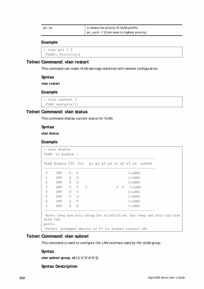
Vigor2926 Series User’s Guide 868
pri_no It means the priority of VLAN profile.
pri_no=0 ~7 (from none to highest priority).
EExxaammppllee
> vlan pri 1 2 VLAN1: Priority=2
TTeellnneett CCoommmmaanndd:: vvllaann rreessttaarrtt This command can make VLAN settings restarted with newest configuration.
SSyynnttaaxx
vlan restart
EExxaammppllee
> vlan restart ? VLAN restarts!!!
TTeellnneett CCoommmmaanndd:: vvllaann ssttaattuuss This command display current status for VLAN.
SSyynnttaaxx
vlan status
EExxaammppllee
> vlan status VLAN is Enable : ------------------------------------------------------ VLAN Enable VID Pri p1 p2 p3 p4 s1 s2 s3 s4 subnet ------------------------------------------------------ 0 OFF 0 0 1:LAN1 1 OFF 0 2 1:LAN1 2 OFF 0 0 1:LAN1 3 OFF 0 0 V V V 1:LAN1 4 OFF 0 0 1:LAN1 5 OFF 0 0 1:LAN1 6 OFF 0 0 1:LAN1 7 OFF 0 0 1:LAN1 ------------------------------------------------------ Note: they are only untag for s1/s2/s3/s4, but they can join tag vlan with lan ports. Permit untagged device in P1 to access router: ON.
TTeellnneett CCoommmmaanndd:: vvllaann ssuubbnneett This command is used to configure the LAN interface used by the VLAN group.
SSyynnttaaxx
vlan subnet group_id [1/2/3/4/5/6]
SSyynnttaaxx DDeessccrriippttiioonn

Vigor2926 Series User’s Guide 869
Parameter Description
[1/2/3/4/5/6] It means interfaces, LAN1 ~ LAN4.
EExxaammppllee
> vlan subnet group_id 2 % Vlan Group-0 using LAN2 ! This setting will take effect after rebooting. Please use "sys reboot" command to reboot the router.
TTeellnneett CCoommmmaanndd:: vvllaann ssuubbmmooddee This command changes the VLAN encapsulation mechanisms in the LAN driver.
SSyynnttaaxx
vlan submode [on|off|status]
SSyynnttaaxx DDeessccrriippttiioonn
Parameter Description
on It means to enable the promiscuous mode.
off It means to enable the normal mode.
status It means to display if submode is normal mode or promiscuous mode.
EExxaammppllee
> vlan submode status % vlan subnet mode : normal mode > vlan submode on % vlan subnet mode modified to promiscuous mode. > vlan submode status % vlan subnet mode : promiscuous mode
TTeellnneett CCoommmmaanndd:: vvllaann ttaaggggeedd This command is used to enable or disable the incoming of untagged packets.
SSyynnttaaxx
vlan tagged [n] [on/off]
vlan tagged [unlimited] [on/off]
vlan tagged [p1_untag] [on/off]
SSyynnttaaxx DDeessccrriippttiioonn
Parameter Description
n It means VLAN channel.
The ranage is from 0 to 7.
on/off It means to enable/disable the tagged VLAN.
[unlimited] [on/off] unlimited on: It allows the incoming of untagged packets even all VLAN are tagged.
unlimited off: It does not allows the incoming of untagged packets.
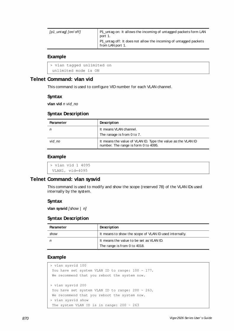
Vigor2926 Series User’s Guide 870
[p1_untag] [on/off] P1_untag on: It allows the incoming of untagged packets form LAN port 1.
P1_untag off: It does not allow the incoming of untagged packets from LAN port 1.
EExxaammppllee
> vlan tagged unlimited on unlimited mode is ON
TTeellnneett CCoommmmaanndd:: vvllaann vviidd This command is used to configure VID number for each VLAN channel.
SSyynnttaaxx
vlan vid n vid_no
SSyynnttaaxx DDeessccrriippttiioonn
Parameter Description
n It means VLAN channel.
The ranage is from 0 to 7.
vid_no It means the value of VLAN ID. Type the value as the VLAN ID number. The range is form 0 to 4095.
EExxaammppllee
> vlan vid 1 4095 VLAN1, vid=4095
TTeellnneett CCoommmmaanndd:: vvllaann ssyyssvviidd This command is used to modify and show the scope (reserved 78) of the VLAN IDs used internally by the system.
SSyynnttaaxx
vlan sysvid [show | n]
SSyynnttaaxx DDeessccrriippttiioonn
Parameter Description
show It means to show the scope of VLAN ID used internally.
n It means the value to be set as VLAN ID.
The range is from 0 to 4018.
EExxaammppllee
> vlan sysvid 100 You have set system VLAN ID to range: 100 ~ 177, We recommend that you reboot the system now. > vlan sysvid 200 You have set system VLAN ID to range: 200 ~ 263, We recommend that you reboot the system now. > vlan sysvid show The system VLAN ID is in range: 200 ~ 263

Vigor2926 Series User’s Guide 871
TTeellnneett CCoommmmaanndd:: vvooiipp ddeebbuugg This command can display debug message on the screen.
SSyynnttaaxx
voip debug [flush]
voip debug [showmsg]
SSyynnttaaxx DDeessccrriippttiioonn
Parameter Description
flush It means to clear current log.
showmsg It means to show current log.
EExxaammppllee
> voip debug showmsg -->Send Message to 192.168.1.2:5060 <02:35:16> INVITE sip:192.168.1.2 SIP/2.0 Via: SIP/2.0/UDP 192.168.1.1:5060;branch=z9hG4bK-YMa-3630;rport From: <sip:[email protected]>;tag=WLJ-11782 To: <sip:192.168.1.2> Call-ID: [email protected] CSeq: 1 INVITE Contact: <sip:[email protected]> Max-Forwards: 70 supported: 100rel, replaces User-Agent: DrayTek UA-1.2.3 DrayTek Vigor2910 Allow: INVITE, ACK, CANCEL, OPTIONS, BYE, INFO, REFER, NOTIFY, PRACK Content-Type: application/sdp Content-Length: 264 v=0 o=change_me 5972727 56415 IN IP4 192.168.1.1
TTeellnneett CCoommmmaanndd:: vvooiipp ddiiaallppllaann This command allows users to set phone book settings.
SSyynnttaaxx
voip dialplan block n [-<command><parameter>]
voip dialplan phonebook n [-<command><parameter>]
voip dialplan region [-<command><parameter>]
voip dialplan local [1/0]
SSyynnttaaxx DDeessccrriippttiioonn
Parameter Description
voip dialplan block
n It means the index number of the VoIP settings.
n=1 ~ 20
-<command><parameter> The available commands with parameters are listed below.
-m 0/1 It means to enable or disable the block mode.

Vigor2926 Series User’s Guide 872
0 – Disable
1 - Enable
-p <path> Determines the block path.
1:in_url,
2:in_number
3:out_url,
4:out_number
5:(in & out)_url,
6:(in & out)_number) )
-n <number> Determines the block number (maximum 29 characters).
-d <domain> Block the specified domain.
-i <inf> Block the specified interface(s) or All interfaces.
-s <Schedule> Specify schedule profiles by indicating the index number of the schedule profile. Four schedule profiles can be used at one time.
-w Delete the selected entry. N=null (clear all)
-v List current settings.
voip dialplan phonebook
n It means the index number of the VoIP settings.
n=1 ~ 60
-<command><parameter> The available commands with parameters are listed below.
-d <number> Specify the speed dial number.
-c <url> Contact SIP URL l(max. 59 characters)
-n <name> Contact name (max. 23 characters)
-a <enable> Enable/disable the specify entry.
-m <mode> Specify backup number mode.
0 – none
2 - PSTN
-b <number> Spedify the backup number.
-o <acc num> Specify the dial out account.
0 – default
1 - acc1, 2 - acc2... ~ 12:=acc12
-z <enable> Enable/disable ZRTP/SRTP VoIP security.
1 – enable
0 - disable
-l Delete the specify entry.
-V List current VoIP settings.
voip dialplan region
-e Dnable or disable the regional function.
1 – enable
0 - disable
-m <number> Return the last miss call.
-I <number> Return the last incoming call.
-o <number> Return the last outgoing call.
-F <number> Hotkey to enable call forwarding (all) function.
-f <number> Hotkey to enable call forwarding (busy) function.

Vigor2926 Series User’s Guide 873
-C <number> Hotkey to enable call forwarding (no answer) function.
-c <number> Hotkey to disable call forwarding function.
-W <number> Hotkey to enable call waiting function.
-w <number> Hotkey to disable call waiting function.
-H <number> Hotkey to enable hide caller ID function.
-h <number> Hotkey to disable hide caller ID function.
-D <number> Hotkey to enable DND function.
-d <number> Hotkey to disable DND function.
-A <number> Hotkey to enable block anonymous calls function.
-a <number> Hotkey to disable block anonymous calls function.
-U <number> Hotkey to enable block unknow domain calls function.
-u <number> Hotkey to disable block unknow domain calls function.
-P <number> Hotkey to disable block IP calls function.
-p <number> Hotkey to disable block IP calls function.
-l <number> Hotkey to block last incoming call.
-v List current status for Regional settings.
voip dialplan local
enable/disable Enable or disable the local calls.
1 – enable
0 - disable
EExxaammppllee
> voip dialplan phonebook 1 -d 1125 > voip dialplan region -l 8 > voip dialplan region -v Your Setting for Regional Regional Function is: Enable Return the Last Miss Call: 20 Return the Last Incoming Call: *12 Return the Last Outgoing Call: 1 Hotkey to enable call forwarding (all) function: 0 Hotkey to enable call forwarding (busy) function: *90 Hotkey to enable call forwarding (no answer) function: *92 Hotkey to disable call forwarding function: 12 Hotkey to Enable Call Waiting Function: *56 Hotkey to Disable Call Waiting Function: *57 Hotkey to Enable Hide Caller ID Function: *67 Hotkey to Disable Hide Caller ID Function: *68 Hotkey to Enable DND Function: *78 Hotkey to Disable DND Function: *79 Hotkey to Enable Block Anonymous Calls Function: *77 Hotkey to Disable Block Anonymous Calls Function: *87 Hotkey to Enable Block Unknow Domain Calls Function: *40 Hotkey to Disable Block Unknow Domain Calls Function: *04 Hotkey to Enable Block IP Calls Function: *50 Hotkey to Disable Block IP Calls Function: *05 Hotkey to Disable Block The Last Incoming Call Function: 8

Vigor2926 Series User’s Guide 874
TTeellnneett CCoommmmaanndd:: vvooiipp ddsspp
SSyynnttaaxx
voip dsp countrytone [channel] [value]
voip dsp dialtonepwr [channel] [AbsoluteValue]
voip dsp EchoCanceller [type] [w_size] [nlp]
voip dsp cidtype [channel] [value]
voip dsp micgain [channel] [value/(1~10)]
voip dsp spkgain [channel] [value/(1~10)]
voip dsp jitterBuffer [port] [mode] [value]
voip dsp dtmfDetset [nLevel] [nTwist]
voip dsp dtmftonepwr [Level]
voip dsp cwtonepwr [ch] [value]
voip dsp pstnringfxs [1|2] [on|off]
voip dsp relaydbounce [on|off]
voip dsp setRingPat [ring_pattern_index] [patten_num]
voip dsp setDtmfCidlevel –l [value]
voip dsp setDtmfCidlevel –h [value]
voip dsp setDtmfCidlevel –r 0
voip dsp cidplusdigit [1/0] [channel] [value]
SSyynnttaaxx DDeessccrriippttiioonn
Parameter Description
voip dsp countrytone
[channel] [value] This command allows users to set the region for the tone settings. Different regions usually need different tone settings.
Channel – 1 or 2.
Value – displayed as follows:
[2] UK, [3] USA, [4] Denmark, [5] Italy, [6] Germany,
[7] Netherlands, [8] Portugal, [9] Sweden, [10] Australia,
[11] Slovenia, [12] Czech, [13] Slovakia, [14] Hungary,
[15] Switzerland , [16] France , [17] Malta
voip dsp dialtonepwr
channel This setting is used to adjust the loudness of the dial tone. The smaller the number is, the louder the dial tone is. It is recommended for you to use the default setting.
Channel - Available channel number: 1 – 2
AbsoluteValue AbsoluteValue - In -1 dB increments, with 1 corresponding to 6 dBm.
Range - 1 to 30
voip dsp EchoCanceler
type This command is used to set the type of echo reduction.
0 - Disable the LEC processing.
1 - Cancel using the fixed window.
2 - Cancel using the fixed and moving window.
3 - Cancel using fixed window + Echo Suppressor.
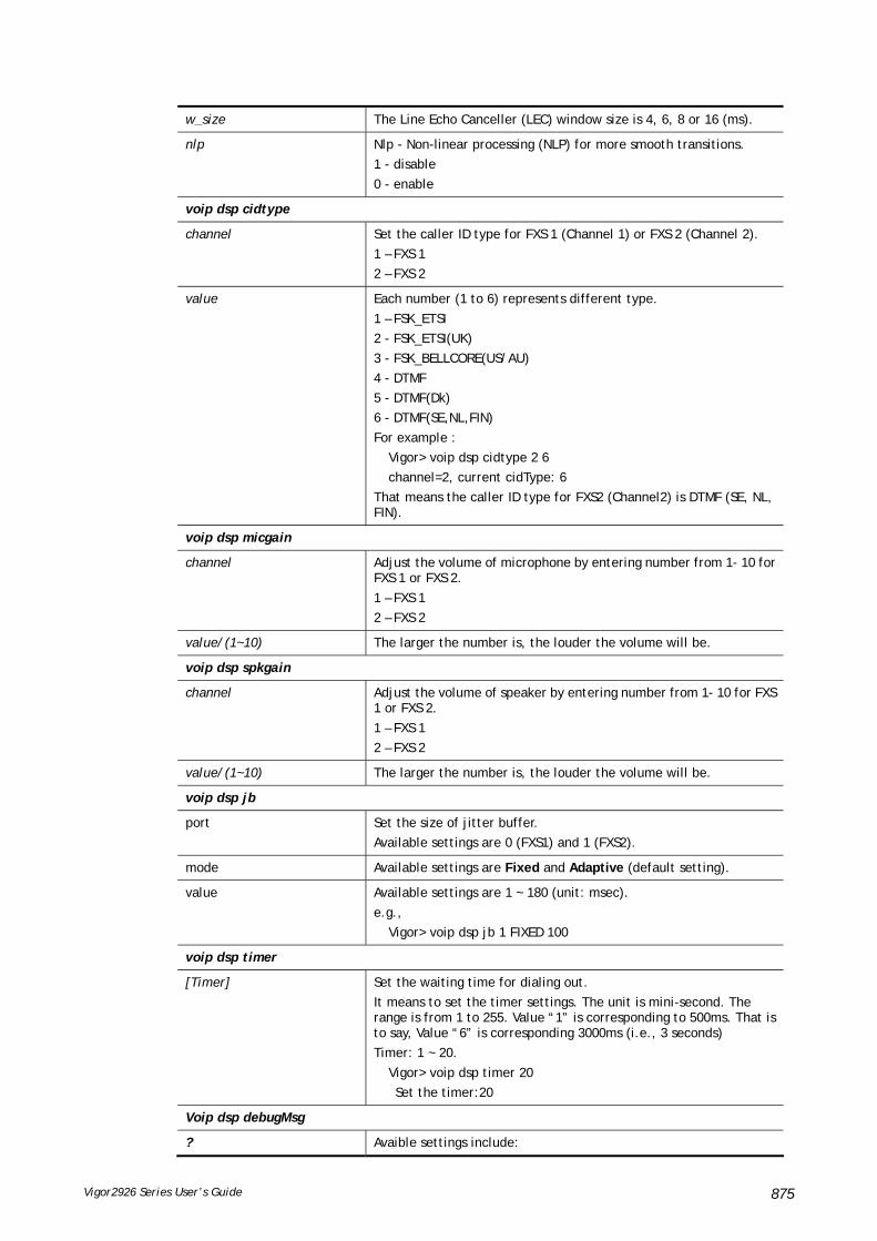
Vigor2926 Series User’s Guide 875
w_size The Line Echo Canceller (LEC) window size is 4, 6, 8 or 16 (ms).
nlp Nlp - Non-linear processing (NLP) for more smooth transitions.
1 - disable
0 - enable
voip dsp cidtype
channel Set the caller ID type for FXS 1 (Channel 1) or FXS 2 (Channel 2).
1 – FXS 1
2 – FXS 2
value Each number (1 to 6) represents different type.
1 – FSK_ETSI
2 - FSK_ETSI(UK)
3 - FSK_BELLCORE(US/AU)
4 - DTMF
5 - DTMF(Dk)
6 - DTMF(SE,NL,FIN)
For example :
Vigor> voip dsp cidtype 2 6
channel=2, current cidType: 6
That means the caller ID type for FXS2 (Channel2) is DTMF (SE, NL, FIN).
voip dsp micgain
channel Adjust the volume of microphone by entering number from 1- 10 for FXS 1 or FXS 2.
1 – FXS 1
2 – FXS 2
value/(1~10) The larger the number is, the louder the volume will be.
voip dsp spkgain
channel Adjust the volume of speaker by entering number from 1- 10 for FXS 1 or FXS 2.
1 – FXS 1
2 – FXS 2
value/(1~10) The larger the number is, the louder the volume will be.
voip dsp jb
port Set the size of jitter buffer.
Available settings are 0 (FXS1) and 1 (FXS2).
mode Available settings are Fixed and Adaptive (default setting).
value Available settings are 1 ~ 180 (unit: msec).
e.g.,
Vigor> voip dsp jb 1 FIXED 100
voip dsp timer
[Timer] Set the waiting time for dialing out.
It means to set the timer settings. The unit is mini-second. The range is from 1 to 255. Value “1” is corresponding to 500ms. That is to say, Value “6” is corresponding 3000ms (i.e., 3 seconds)
Timer: 1 ~ 20.
Vigor> voip dsp timer 20
Set the timer:20
Voip dsp debugMsg
? Avaible settings include:

Vigor2926 Series User’s Guide 876
clrev - clear phone hook status.
getev - get phone hook status.
clrfskcid - clear fsk data for caller-ID from PSTN line.
getfskcid - get fsk data for caller-ID from PSTN line.
clrdtmfcid - clear dtmf data for caller-ID from PSTN line.
getdtmfcid - get dtmf data for caller-ID from PSTN line.
voicebuf - get message for available voice buffer pool.
clrint - clear status for interrupt.
getint - get status for interrupt.
Vigor> voip dsp debugMsg getint
the interrupt status for ad0 = 21
the interrupt status for ad1 = 0
the interrupt status for vc = 0
voip dsp dtmfDetset
nLevel Set minimal signal level in dB, for DTMF detection.
Range – (-96 ~ -1)
nTwist Maximum allowed signal twist in dB, for DTMF detection.
Range – (0 ~ 12)
voip dsp dtmftonepwr
Level Set power level for DTMF frequency.
Level – 0 ~ 100. Power level for dtmf frequency in 0.3 dB steps.
0 map to 0dB
1 map to -0.3dB .... 100 map to -30dB
voip dsp cwtonepwr
ch Set the call waiting tone power level.
1 – FXS 1
2 – FXS 2.
value 1 ~ 30, in -1 dB increments, with 1 corresponding to 8 dBm.
voip dsp pstnringfxs
1|2 Enable or disable PSTN ring on FXS 1/FXS 2.
1 meansFXS1; 2 means FXS2.
on|off On means enable; off means disable.
voip dsp relaydbounce
on|off on: Enable relay filter noise. But it maybe ignore the caller-id!!!
off: Disable relay filter noise. But the noise will cause the relay to switch to PSTN!!!
voip dsp setRingPat
ring_pattern_index This command can change the ring pattern at Index(2)~Index(6).
ring_pattern_index – Index (1) was locked for your country.
patten_num It's the ring pattern number (1~12) for a country.
--------------------------------------------
patten_num=1 Australia Ring Pattern:
cadenceOneOn=400, cadenceOneOff=200
cadenceTwoOn=400, cadenceTwoOff=2000
patten_num=2 Denmark Ring Pattern:
cadenceOneOn=1000, cadenceOneOff=4000
………………………………
voip dsp setFaxECmode -s

Vigor2926 Series User’s Guide 877
ch Set the FAX error correction mode.
ch : range (0 ~ 1)
mode mode : EC(error correction) ch(x) mode(0) : REDUNDANCY
EC(error correction) ch(x) mode(1) : FEC
voip dsp setDtmfCidlevel –l / voip dsp setDtmfCidlevel –h [value]
voip dsp setDtmfCidlevel –r 0
value “setDtmfCidLevel” is used to configure the signal strength for transferring to FXS DTMF caller ID.
value - 0 ~ 64
voip dsp setDtmfCidLevel -l [value]
voip dsp setDtmfCidLevel -h [value]
voip dsp setDtmfCidLevel -r 0/1
r - reset low/high DTNF level to default setting. 0 means Disable; 1 means Enable.
Note: This function is supported only by special mode.
voip dsp setfxoCY
value It is used to apply FXO country settings. 0: "use system country" 1: "Taiwan" 2: "Germany" 3: "Sweden" 4: "France" 5: "Switzerland" 6: "Holland" 7: "Finland" 8: "Denmark" 9: "UK" 10: "Australia" 12: "Italy" 14: "Red_China" 15: "Singapore" 17: "Spain" 18: "Portugal" 20: "Poland" 21: "Czech" 22: "Hungary" 23: "Slovenia" 25: "Slovakia" 37: "Brasil" 61: "US"
voip dsp setfxoringl
value It is used to configure detection ring voltage threshold to apply to FXO.
Available setting include:
0 : use driver default value
1 : Minimum voltage threshold: 25V
2 : Minimum voltage threshold: 35V
3 : Minimum voltage threshold: 45V
Note: This function is supported only by special mode.
voip dsp setfxoCid
value Set FXO detect caller ID type.
It is available only for the model with FXO port.
voip dsp cidplusdigit
[1/0] [channel] [value] Set the substitution (0~9) for '+' digit in caller ID.
1 – enable the substitution.
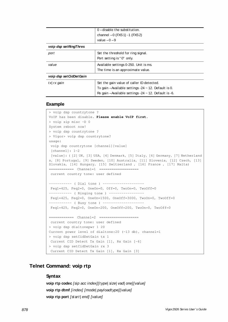
Vigor2926 Series User’s Guide 878
0 – disable the substitution.
channel – 0 (FXS 1) -1 (FXS 2)
value – 0 – 9
voip dsp setRingThres
port Set the threshold for ring signal.
Port setting is “0” only.
value Available settings 0-250. Unit is ms.
The time is an approximate value.
voip dsp setCidDetGain
tx|rx gain Set the gain value of caller ID detected.
Tx gain – Available settings -24 ~ 12. Default is 0.
Rx gain – Available settings -24 ~ 12. Default is -6.
EExxaammppllee
> voip dsp countrytone ? VoIP has been disable. Please enable VoIP first.
> voip sip misc –D 0 System reboot now! > voip dsp countrytone ? > Vigor> voip dsp countrytone? usage: voip dsp countrytone [channel][value] [channel]: 1-2 [value]: ( [2] UK, [3] USA, [4] Denmark, [5] Italy, [6] Germany, [7] Netherlands, [8] Portugal, [9] Sweden, [10] Australia, [11] Slovenia, [12] Czech, [13] Slovakia, [14] Hungary, [15] Switzerland , [16] France , [17] Malta) ============ Channel=1 =================== current country tone: user defined ----------- ( Dial tone ) -------------------- Feq1=425, Feq2=0, OneOn=0, Off=0, TwoOn=0, TwoOff=0 ----------- ( Ringing tone ) ----------------- Feq1=425, Feq2=0, OneOn=1500, OneOff=3000, TwoOn=0, TwoOff=0 ----------- ( Busy tone ) -------------------- Feq1=425, Feq2=0, OneOn=200, OneOff=200, TwoOn=0, TwoOff=0 ============ Channel=2 =================== current country tone: user defined > voip dsp dialtonepwr 1 20 Current power level of dialtone:20 (-13 db), channel=1 > voip dsp setCidDetGain tx 1 Current CID Detect Tx Gain [1], Rx Gain [-6] > voip dsp setCidDetGain rx 3 Current CID Detect Tx Gain [1], Rx Gain [3]
TTeellnneett CCoommmmaanndd:: vvooiipp rrttpp
SSyynnttaaxx
voip rtp codec [sip acc index][type|size|vad|one][value]
voip rtp dtmf [index] [mode|payloadtype][value]
voip rtp port [start|end] [value]

Vigor2926 Series User’s Guide 879
voip rtp symmetric [value]
voip rtp tos ?
SSyynnttaaxx DDeessccrriippttiioonn
Parameter Description
voip rtp codec
[sip acc index][type|size|vad|one][value]
Set the voice coding.
sip acc index –SIP account index number. Available number, 1 ~ 12.
type – Available settings include
0. G.711MU
1. G.711A
2. G.729A/B
3. G.723
4. G.726_32
size - Five options,
0 means 10ms
1 means 20ms
2 means 30ms
3 means 40ms
5 means 60ms
Vad - 0 means to Disable the function of Voice Active Detector (vad); 1 means to Enable the function of Voice Active Detector (vad).
One – 0 means to Disable the function of single codec; 1 means to Enable the function of single codec.
voip rtp dtmf
[index] [mode | payloadtype][value]
Set the DTMF mode and Payload type for DTMF.
Index – SIP account index number. Available number, 1 ~ 12.
Mode – Four options to be selected.
0. Inband
1. Outband
2. SIP INFO (cisco)
3. SIP INFO (nortel)
Payloadtype – Available settings 96~127.
Value – Type 0~3 or 96~127 based on the mode specified.
For example,
> voip rtp dtmf 1 mode 1
voip rtp port
start|end Specifies the start/end port for RTP stream.
value The default value is 10050/15000.
voip rtp symmetric
value Make the data transmission going through on both ends of local router and remote router not misleading due to IP lost.
1 – Enable
0 - Disable
voip rtp tos
value Set the type of service (TOS) setting for RTP packets.
For example,
> voip rtp tos 0x899
Set TOS: 0x899

Vigor2926 Series User’s Guide 880
EExxaammppllee
> voip rtp codec 1 type 3 > voip rtp dtmf 2 mode 3 > voip rtp port start 10070 end 14400 Set start port: 10070 > voip rtp port end 14400 Set end port: 14400 > voip rtp symmetric 1 Set symmetric rtp to Enable
TTeellnneett CCoommmmaanndd:: vvooiipp ssiipp This command allows users to set SIP account.
SSyynnttaaxx
voip sip acc n [-<command> <parameter> | ... ]
voip sip calllog
voip sip ep n [-<command> <parameter> | ... ]
voip sip misc[-<command> <parameter> | ... ]
voip sip nat [-<command> <parameter> | ... ]
SSyynnttaaxx DDeessccrriippttiioonn
Parameter Description
voip sip acc - Allows users to set SIP account.
n n = 1 to 12
It means the index number of the VoIP settings.
-P [profile] It means the name of the account profile (maximum 11 characters).
-r [reg mode] Set registration mode for SIP account.
0 – none 1 – auto 2 - wan1 only 3 - wan2 only 4 - lan/vpn 5 – PVC 6 - wan3 only 7 - wan4 only 8 - wan1 first 9 - wan2 first 10 - wan3 first 11 - wan4 first
-o [port] Set the port number for sending/receiving SIP message for building a session. The default value is 5060.
-d [domain] Set the domain name or IP address of the SIP Registrar server. The maximum is 63 characters.
-y [proxy] Set domain name or IP address of SIP proxy server. The maximum is 63 characters.
-b [enable] Enable / disable outbound proxy by SIP account.
0 – disable
1 - enable
-s [enable] Enable / disable to locate SIP server (rfc 3263).

Vigor2926 Series User’s Guide 881
0 – disable
1 - enable
-N [name] Set SIP account display name.
Name - max. 23 characters.
-n [number] Set SIP account number.
Number - max. 63 characters.
-a [id] Set SIP authentication ID.
Id - max. 63 characters.
-A [enable] Enable /disable to use SIP authentication ID.
0 – disable
1 - enable
-p [passwd] Set SIP account password (max. 63 characters).
-e [sec] Set expiry time (default 3600) for SIP account.
-w [enable] Enable to make phone call without registering.
-m [mode] Set NAT traversal mode.
0 – disable
1 – stun
2 – manual
3 - nortel
-F [mode] Set call forwarding mode.
0 – disable
1 – always
2 – busy
3 - no answer
4 - busy or no answer
-u [url] Set SIP URL for call forwarding (max. 63 characters).
-t [sec] Set call forwarding timer. For example,
voip sip acc 1 –t 30
-g [port] Set the ring port for incoming call. For example,
Port - r1 means FXS1; r2 means FXS2.
-z [pattern] Set account ring pattern (1 ~ 6).
-i [enable] Remove all bindings while they are un-registered. 0 means Disable; and 1 means Enable.
-B <enable> Enable / disable the function of Broadsoft Call Control.
0 – disable
1 - enable
-S [idx] Enable and use alias IP to register.
idx - 1 to 31. If 0 is used, such function will be disabled.
-k [num1 num2...] Set backup wan list (first wan, second wan...).
range: 1 to 4.
-v View current status for account settings.
Voip sip calllog Display current status for SIP call log.
voip sip ep
n The index number of the VoIP settings.
n – 1, 2.
-o [acc] Available dial out account (1 ~ 12).
-L [url] Set SIP URL (max. 63 characters) for hot line.
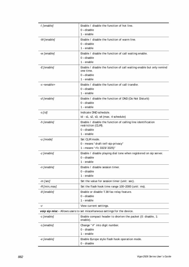
Vigor2926 Series User’s Guide 882
-l [enable] Enable / disable the function of hot line.
0 – disable
1 - enable
-W [enable] Enable / disable the function of warm line.
0 – disable
1 - enable
-w [enable] Enable / disable the function of call waiting enable.
0 – disable
1 - enable
-E [enable] Enable / disable the function of call waiting enable but only remind one time.
0 – disable
1 - enable
-x <enable> Enable / disable the function of call transfer.
0 – disable
1 - enable
-d [enable] Enable / disable the function of DND (Do Not Disturb)
0 – disable
1 - enable
-s [id] Indicate DND schedule.
Id - s1, s2, s3, s4 (max. 4 schedule)
-h [enable] Enable / disable the function of calling line identification restriction (CLIR).
0 – disable
1 - enable
-u [mode] Set CLIR mode.
0 - means “draft-ietf-sip-privacy”
1 – means “rfc 3323/3325)”
-z [enable] Enable / disable playing dial tone when registered on sip server.
0 – disable
1 - enable
-n [enable] Enable / disable session timer.
0 – disable
1 - enable
-m [sec] Set the value for session timer (unit: sec).
-R [min,max] Set the flash hook time range 100~2000 (unit: ms).
-8 [enable] Enable or disable T.38 fax relay feature.
0 – disable
1 - enable
-v View current settings.
voip sip misc - Allows users to set miscellaneous settings for the device.
-c [enable] Enable compact header to shorten the packet (0: disable, 1: enable).
-s [enable] Change “#” into digit number.
0 - disable
1 - enable
-e [enable] Enable Europe style flash hook operation mode.
0 - disable

Vigor2926 Series User’s Guide 883
1 - enable
-h [enable] Enable/disable call hold mode based on protocol RFC2543 (0: disable, 1:enable).
-i [enable] Enable CODEC change without Re-INVITE.
0 - disable
1 - enable
-p [enable] Enable PRACK message.
0 – Not support PRACK.
1 – Support PRACK.
-P [enable] Enable IP Call.
0 – Disable IP call.
1 – Enable IP call.
-H [enable] SIP INFO packet will be sent out when encounting hook flash event.
0 - disable
1 - enable
-t [val] Set the mode of User-Agent (e.g., phone, software, and device) for SIP packet.
0 - Hide SIP header "User-Agent".
1 - Show SIP header "User-Agent".
2 - Use default "User-Agent" value.
3 - Use user-defined "User-Agent" value.
-u UAValue For every SIP user agent identifies itself with a string, this command allows you to set the value (e.g, IP address, phone number, e-mail address) of User-Agent. The length of the string must be less than 64 characters.
-D [disable] Disable VoIP Service.
1 – disable VoIP service.
0 – enable VoIP service.
System will automatic reboot to activate voip service
-v View current status for miscellaneous settings.
voip sip nat - Allows users to set NAT Traversal Setting.
-s [server] Set the IP address for STUN server.
-t [sec] Set ping interval for SIP account.
Sec – 6 ~ 600
-i [ip] Indicate external IP address.
-v View current settings for SIP NAT.
EExxaammppllee
> voip sip misc -t 1 includes User-Agent header > voip sip misc -u 91704688carrie user-defined User-Agent:91704688carrie > voip sip acc 1 -P carrie_1 -r 1 -d 172.16.3.133 > voip sip acc 1 -t 30 > voip sip misc -h 1 > voip sip acc 1 -v index : 1 profile : carrie_1

Vigor2926 Series User’s Guide 884
reg mode : 1 | reg. [No] alias_ip_idx : 0 backup list : domain : 172.16.3.133 proxy : | outbound [No] | DNS-SRV [No] noreg call : No disp. Name : acc number : --- auth. ID : | [disable] expiry : 3600 NAT mode : 0 ring ports : 0 ring pat. : 1 call fwd mode : 0 call fwd url : call fwd timer : 30 Broadsoft : disable Italian ITSP modification: disable
TTeellnneett CCoommmmaanndd:: vvooiipp sseeccuurree This command allows users to enable or disable secure phone feature, and SAS voice prompt.
SSyynnttaaxx
voip secure general [-<command> <parameter> | ... ]
SSyynnttaaxx DDeessccrriippttiioonn
Parameter Description
voip secure general -e Enable / disable secure phone feature.
0 - disable
1 - enable
voip secure general -p Enable /disable SAS voice prompt.
0 - disable
1 - enable
voip secure general -v view only secure phone general settings
EExxaammppllee
> voip secure general -v secure phone feature is disabled SAS voice prompt is enabled > voip secure general -p 0 SAS voice prompt is disabled
TTeellnneett CCoommmmaanndd:: vvppnn ll22llsseett This command allows users to set advanced parameters for LAN to LAN function.
SSyynnttaaxx
vpn l2lset [list index] peerid [peerid]

Vigor2926 Series User’s Guide 885
vpn l2lset [list index] localid [localid]
vpn l2lset [list index]main [auto/proposal index]
vpn l2lset [list index] aggressive [g1/g2]
vpn l2lset [list index]pfs [on/off]
vpn l2lset [list index] phase1[lifetime]
vpn l2lset [list index] phase2[lifetime]
SSyynnttaaxx DDeessccrriippttiioonn
Parameter Description
list index It means the index number of L2L (LAN to LAN) profile.
peerid It means the peer identity for aggressive mode.
localid It means the local identity for aggressive mode.
main It means to choose proposal for main mode.
auto index It means to choose default proposals.
proposal index It means to choose specified proposal.
aggressive It means the chosen DH group for aggressive mode
pfs It means “perfect forward secrete”.
on/off It means to turn on or off the PFS function.
phase1 It means phase 1 of IKE.
lifetime It means the lifetime value (in second) for phase 1 and phase 2.
phase2 It means phase 2 of IKE.
EExxaammppllee
> VPN l2lset 1 peerid 10226
TTeellnneett CCoommmmaanndd:: vvppnn ddiinnsseett This command allows users to configure setting for remote dial-in VPN profile.
SSyynnttaaxx
vpn dinset <list index>
vpn dinset <list index> <on/off>
vpn dinset <list index> motp <on/off>
vpn dinset <list index> pin_secret <pin> <secret>
SSyynnttaaxx DDeessccrriippttiioonn
Parameter Description
<list index> It means the index number of the profile.
<on/off> It means to enable or disable the profile.
on – Enable.
off – Disable.
motp <on/off> It means to enable or disable the authentication with mOTP function.
on – Enable.
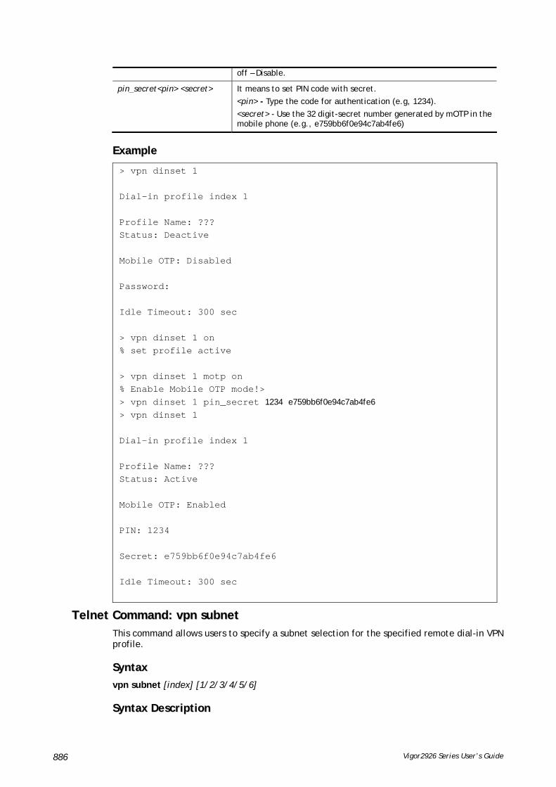
Vigor2926 Series User’s Guide 886
off – Disable.
pin_secret<pin> <secret> It means to set PIN code with secret.
<pin> - Type the code for authentication (e.g, 1234).
<secret> - Use the 32 digit-secret number generated by mOTP in the mobile phone (e.g., e759bb6f0e94c7ab4fe6)
EExxaammppllee
> vpn dinset 1 Dial-in profile index 1 Profile Name: ??? Status: Deactive Mobile OTP: Disabled Password: Idle Timeout: 300 sec > vpn dinset 1 on % set profile active > vpn dinset 1 motp on % Enable Mobile OTP mode!> > vpn dinset 1 pin_secret 1234 e759bb6f0e94c7ab4fe6 > vpn dinset 1 Dial-in profile index 1 Profile Name: ??? Status: Active Mobile OTP: Enabled PIN: 1234 Secret: e759bb6f0e94c7ab4fe6 Idle Timeout: 300 sec
TTeellnneett CCoommmmaanndd:: vvppnn ssuubbnneett This command allows users to specify a subnet selection for the specified remote dial-in VPN profile.
SSyynnttaaxx
vpn subnet [index] [1/2/3/4/5/6]
SSyynnttaaxx DDeessccrriippttiioonn

Vigor2926 Series User’s Guide 887
Parameter Description
<index> It means the index number of the VPN profile.
<1/2/3/4/5/6> 1 – it means LAN1
2 – it means LAN2.
3 – it means LAN3
4 – it means LAN4.
5 – it means LAN5.
6 – it means LAN6.
EExxaammppllee
> vpn subnet 1 2 >
TTeellnneett CCoommmmaanndd:: vvppnn sseettuupp This command allows users to setup VPN for different types.
SSyynnttaaxx
Command of PPTP Dial-Out
vpn setup <index> <name> pptp_out <ip> <usr> <pwd> <nip> <nmask>
Command of IPSec Dial-Out
vpn setup <index> <name> ipsec_out <ip> <key> <nip> <nmask>
Command of L2Tp Dial-Out
vpn setup <index> <name> l2tp_out <ip> <usr> <pwd> <nip> <nmask>
Command of Dial-In
vpn setup <index> <name> dialin <ip> <usr> <pwd> <key> <nip> <nmask>
SSyynnttaaxx DDeessccrriippttiioonn
Parameter Description
For PPTP Dial-Out
<index> It means the index number of the profile.
<name> It means the name of the profile.
<ip> It means the IP address to dial to.
<usr> <pwd> It means the user and the password required for the PPTP connection.
<nip> <nmask> It means the remote network IP and the mask.
e.g.,
vpn setup 1 name1 pptp_out 1.2.3.4 vigor 1234 192.168.1.0 255.255.255.0
For IPsec Dial-Out
<index> It means the index number of the profile.
<name> It means the name of the profile.
<ip> It means the IP address to dial to.
<key> It means the value of IPsec Pre-Shared Key.
<nip> <nmask> It means the remote network IP and the mask.
e.g.,

Vigor2926 Series User’s Guide 888
vpn setup 1 name1 ipsec_out 1.2.3.4 1234 192.168.1.0 255.255.255.0
For L2TP Dial-Out
<index> It means the index number of the profile.
<name> It means the name of the profile.
<ip> It means the IP address to dial to.
<usr> <pwd> It means the user and the password required for the L2TP connection.
<nip> <nmask> It means the remote network IP and the mask.
e.g.,,
vpn setup 1 name1 l2tp_out 1.2.3.4 vigor 1234 192.168.1.0 255.255.255.0
For Dial-In
<index> It means the index number of the profile.
<name> It means the name of the profile.
<ip> It means the IP address allowed to dial in.
<usr> <pwd> It means the user and the password required for the PPTP/L2TP connection.
<key> It means the value of IPsec Pre-Shared Key.
<nip> <nmask> It means the remote network IP and the mask.
e.g.,
vpn setup 1 name1 dialin 1.2.3.4 vigor 1234 abc 192.168.1.0 255.255.255.0
EExxaammppllee
> vpn setup 1 name1 dialin 1.2.3.4 vigor 1234 abc 192.168.1.0 255.255.255.0 % Profile Change Log ... % Profile Index : 1 % Profile Name : name1 % Username : vigor % Password : 1234 % Pre-share Key : abc % Call Direction : Dial-In % Type of Server : ISDN PPTP IPSec L2TP % Dial from : 1.2.3.4 % Remote NEtwork IP : 192.168.1.0 % Remote NEtwork Mask : 255.255.255.0 >
TTeellnneett CCoommmmaanndd:: vvppnn ooppttiioonn This command allows users to configure settings for LAN to LAN profile.
SSyynnttaaxx
vpn option <index> <cmd1>=<param1> [<cmd2>=<para2> | ... ]
SSyynnttaaxx DDeessccrriippttiioonn

Vigor2926 Series User’s Guide 889
Parameter Description
<index> It means the index number of the profile.
Available index numbers:
1 ~ 32
For Common Settings
<index> It means the index number of the profile.
pname It means the name of the profile.
ena It means to enable or disable the profile.
on – Enable
off - Disable
thr It means the way that VPN connection passes through. Available settings are wlf, wlo, w2f, and w2o.
w1f – WAN1 First.
w1o – WAN1 Only.
w2f – WAN2 First.
w2o – WAN2 Only.
nnpkt It means the NetBios Naming Packet.
on – Enable the function to pass the packet.
off – Disable the function to block the packet.
dir It means the call direction. Available settings are b, o and i.
b – Both
o – Dial-Out
i – Dial-In.
idle=[value] It means Always on and Idle Time out.
Available values include:
-1 – it means always on for dial-out.
0 – it means always on for dial-in.
Other numbers (e.g., idle=200, idle=300, idle=500) mean the router will be idle after the interval (seconds) configured here.
palive It means to enable PING to keep alive.
-1 – disable the function.
1,2,3,4 – Enable the function and PING IP 1.2.3.4 to keep alive.
For Dial-Out Settings
ctype It means “Type of Server I am calling”.
“ctype=t” means PPTP.
“ctype=s” means IPSec.
“ctype= l” means L2TP(IPSec Policy None).
“ctype= l1” means L2TP(IPSec Policy Nice to Have).
“ctype= l2” means L2TP(IPSec Policy Must).
dialto It means Server IP/Host Name for VPN. (such as draytek.com or 123.45.67.89).
ltype It means Link Type.
“ltype=0” means “Disable”.
“ltype=1” means “64kbps”.
“ltype=2” means “128kbps”.
“ltype=3” means “BOD”.
oname It means Dial-Out Username.
“oname=admin” means to set Username = admin.
opwd It means Dial-Out Password

Vigor2926 Series User’s Guide 890
“opwd=1234” means to set Password = 1234.
pauth It means PPP Authentication.
“pauth=pc” means to set PPP Authentication = PAP&CHAP.
“pauth=p” means to set PPP Authentication = PAP Only
ovj It means VJ Compression.
“ovj=on/off” means to enable/disable VJ Compression.
okey It means IKE Pre-Shared Key.
“okey=abcd” means to set IKE Pre-Shared Key = abcd.
ometh It means IPSec Security Method.
“ometh=ah/” means AH.
“ometh=espd/espda/” means ESP DES without/with Authentication.
“ometh=esp3/esp3a/” means ESP 3DES without/with Authentication.
“ometh=espa/espaa” means ESP AES without/with Authentication.
sch It means Index(1-15) in Schedule Setup.
sch=1,3,5,7 Set schedule 1->3->5->7
rcallb It means Require Remote to Callback.
“rcallb=on/off” means to enable/disable Set Require Remote to Callback.
ikeid It means IKE Local ID.
“ikeid=vigor” means Set Local ID = vigor.
For Dial-In Settings
itype It means Allowed Dial-In Type. Available settings include:
“itype=t” means PPTP.
“itype=s” means IPSec.
“itype=L1”means L2TP (None).
“itype=L1” means L2TP(Nice to Have).
“itype=l2” means L2TP(Must).
peer It means specify Peer VPN Server IP for Remote VPN Gateway.
Type “203.12.23.48” means to allow VPN dial-in with IP address of 203.12.23.48.
Type “off” means any remote IP is allowed to dial in.
peerid It means the peer ID for Remote VPN Gateway.
Type “draytek” means the word is used as local ID.
iname It means Dial-in Username.
“iname=admin” means to set username as “admin”.
ipwd It means Dial-in Password.
“ipwd=1234” means to set password as “1234”.
ivj It means VJ Compression.
“ivj=on/off” means to enable /disable VJ Compression.
ikey It means IKE Pre-Shared Key.
“ikey=abcd” means to set IKE Pre-Shared Key = abcd.
imeth It means IPSec Security Method
“imeth=h” means “Allow AH”.
“imeth=d” means “Allow DES”.
“imeth=3” means “Allow 3DES”.
“imeth=a” means “Allow AES.
For TCP/IP Settings

Vigor2926 Series User’s Guide 891
mywip It means My WAN IP.
“mywip=1.2.3.4” means to set My WAN IP as “1.2.3.4”.
rgip It means Remote Gateway IP.
“rgip=1.2.3.4” means to set Remote Gateway IP as “1.2.3.4”.
rnip It means Remote Network IP.
“rnip=1.2.3.0” means to set Remote Network IP as “1.2.3.0”.
rnmask It means Remote Network Mask.
“rnmask=255.255.255.0” means to set Remote Network Mask as “255.255.255.0”.
rip It means RIP Direction.
“rip=d” means to set RIP Direction as “Disable”.
“rip=t” means to set RIP Direction as “TX”.
“rip=r” means to set RIP Direction as “RX”.
“rip=b” means to set RIP Direction as “Both”.
mode It means the option of “From first subnet to remote network, you have to do”.
“mode=r” means to set Route mode.
“mode=n” means to set NAT mode.
droute It means to Change default route to this VPN tunnel ( Only single WAN supports this).
droute=on/off means to enable/disable the function.
EExxaammppllee
> vpn option 1 idle=250 % Change Log.. % Idle Timeout = 250
TTeellnneett CCoommmmaanndd:: vvppnn mmrroouuttee This command allows users to list, add or delete static routes for a certain LAN to LAN VPN profile.
SSyynnttaaxx
vpn mroute <index> list
vpn mroute <index> add <network ip>/<mask>
vpn mroute <index> del <network ip>/<mask>
SSyynnttaaxx DDeessccrriippttiioonn
Parameter Description
list It means to display all of the route settings.
add It means to add a new route.
del It means to delete specified route.
<index> It means the index number of the profile.
Available index numbers:
1 ~ 32
<network ip>/<mask> Type the IP address with the network mask address.
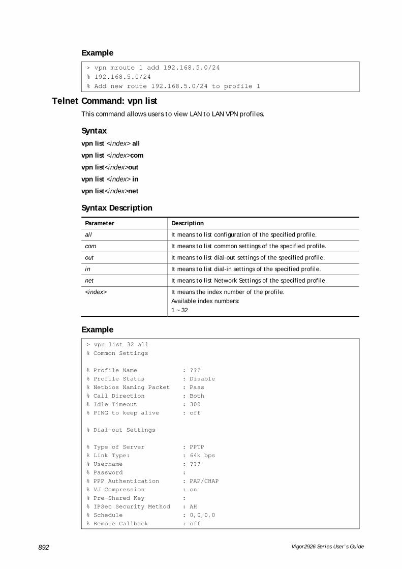
Vigor2926 Series User’s Guide 892
EExxaammppllee
> vpn mroute 1 add 192.168.5.0/24 % 192.168.5.0/24 % Add new route 192.168.5.0/24 to profile 1
TTeellnneett CCoommmmaanndd:: vvppnn lliisstt This command allows users to view LAN to LAN VPN profiles.
SSyynnttaaxx
vpn list <index> all
vpn list <index>com
vpn list<index>out
vpn list <index> in
vpn list<index>net
SSyynnttaaxx DDeessccrriippttiioonn
Parameter Description
all It means to list configuration of the specified profile.
com It means to list common settings of the specified profile.
out It means to list dial-out settings of the specified profile.
in It means to list dial-in settings of the specified profile.
net It means to list Network Settings of the specified profile.
<index> It means the index number of the profile.
Available index numbers:
1 ~ 32
EExxaammppllee
> vpn list 32 all % Common Settings % Profile Name : ??? % Profile Status : Disable % Netbios Naming Packet : Pass % Call Direction : Both % Idle Timeout : 300 % PING to keep alive : off % Dial-out Settings % Type of Server : PPTP % Link Type: : 64k bps % Username : ??? % Password : % PPP Authentication : PAP/CHAP % VJ Compression : on % Pre-Shared Key : % IPSec Security Method : AH % Schedule : 0,0,0,0 % Remote Callback : off

Vigor2926 Series User’s Guide 893
% Provide ISDN Number : off % IKE phase 1 mode : Main mode % IKE Local ID : % Dial-In Settings --- MORE --- ['q': Quit, 'Enter': New Lines, 'Space Bar': Next Page] ---
> vpn list 1 com % Common Settings % Profile Name : ??? % Profile Status : Disable % Netbios Naming Packet : Pass % Call Direction : Both % Idle Timeout : 300 % PING to keep alive : off >
TTeellnneett CCoommmmaanndd:: vvppnn rreemmoottee This command allows users to enable or disable PPTP/IPSec/L2TP VPN service.
SSyynnttaaxx
vpn remote [PPTP/IPSec/L2TP] [on/off]
SSyynnttaaxx DDeessccrriippttiioonn
Parameter Description
PPTP/IPSec/L2TP There are four types to be selected.
on/off on – enable VPN remote setting.
off – disable VPN remote setting.
EExxaammppllee
> vpn remote PPTP on Set PPTP VPN Service : On Please restart the router!!
TTeellnneett CCoommmmaanndd:: vvppnn 22nnddssuubbnneett This command allows users to enable second subnet IP as VPN server IP.
SSyynnttaaxx
vpn 2ndsubnet on
vpn 2ndsubnet off
SSyynnttaaxx DDeessccrriippttiioonn
Parameter Description
on/off It means to enable or disable second subnet.

Vigor2926 Series User’s Guide 894
EExxaammppllee
> vpn 2ndsubnet on %Enable second subnet IP as VPN server IP!
TTeellnneett CCoommmmaanndd:: vvppnn ttrruunnkk This command allows users to configure VPN Backup, VPN load balance, GRE over IPsec, and Binding tunnel policy.
vpn trunk show_usable
vpn trunk backup <add/del> <name> <Member#1> <Member#2>
vpn trunk backup more_syslog <ON/OFF>
vpn trunk backup ERD <name> <Normal/Recover/Resume><second>
vpn trunk lb <add/del> <name> <Member#1> <Member#2>
vpn trunk lb more_syslog <ON/OFF>
vpn trunk lb algorithm <name> <RR>
vpn trunk lb algorithm <name><W-RR><Auto> <AccordingRatio> <Member1:Member2>
vpn trunk lb algorithm <name><Fastest>
vpn trunk bind usage <BindIndex>
vpn trunk bind show <LoadBalanceName>
vpn trunk bind reset_default
vpn trunk bind more_syslog <ON/OFF>
vpn trunk bind set <BindIndex> <ACT> <TrunkName> <Member> <SrcIp:A~B> <DstI p:A~B> <DstPort:A~B> <Proto> <Frag>
vpn trunk bind insert <After_BindIndex> <ACT> <TrunkName> <Member> <SrcIp:A~B> <DstIp:A~B> <DstPort:A~B> <Proto> <Frag>
vpn trunk SetGre show <Dialout_Index>
vpn trunk SetGre <Active/In-active><Dialout_Index><GRE_MyIP><GRE_PeerIP><Logical_Traffic>
vpn trunk An_Gre GreIPsecAnalyze <ON/OFF>
SSyynnttaaxx DDeessccrriippttiioonn
Parameter Description
show_usable Display a list of LAN to LAN dial out profiles.
backup <add/del> <name> <Member#1> <Member#2>
Set multiple VPN tunnels (LAN to LAN profiles) as backup tunnel.
add/del - Add or delete a profile for used in VPN Trunk.
name – Specify the name of the VPN trunk.
Member#1 – Indicate the first LAN to LAN profile.
Member#2 – Indicate the second LAN to LAN profile.
backup more_syslog <ON/OFF>
lb more_syslog <ON/OFF>
bind more_syslog <ON/OFF>
These commands are used for RD debug.
backup ERD <name> <Normal/Recover/Resume><second>
ERD means Environment Recovers Detection.
name – Specify the name of the VPN trunk.
Normal – Indicate the Normal mode. All dial-out VPN TRUNK backup

Vigor2926 Series User’s Guide 895
profiles will be activated alternatively.
Recover – Indicate the duration of VPN backup operation.
Resume – When VPN connection breaks down or disconnects, Member 1 will be the top priority for the system to do VPN connection.
Second – “0” means to dial each six seconds automatically. “60 ~ 2147483647” means to early handle for less than 30 seconds within designated time.
lb <add/del> <name> <Member#1> <Member#2>
It means to create VPN trunk with load balance.
add/del - Add or delete a profile for used in VPN Trunk.
name – Specify the name of the VPN trunk.
Member#1 – Indicate the first LAN to LAN profile.
Member#2 – Indicate the second LAN to LAN profile.
lb algorithm <name> <RR/W-RR/Fastest>
Set multiple VPN tunnels for using as traffic load balance tunnel.
Such command is to configure the algorithm (with round robin mode) of Load Balance.
name – Specify the name of the VPN trunk.
RR – It means round robin mode. All of the dial-out profiles will be taken turns equally.
lb algorithm <name><W-RR><Auto> <AccordingRatio> <Member1:Member2>
Such command is to configure the algorithm (with round robin mode) of Load Balance.
name – Specify the name of the VPN trunk.
W-RR – It means weighted round robin mod based on speed ratio.
Auto - the speed must be based on Lay2.
AccordingRatio – the speed must be based on given ratio.
Member#1 – Inidcate the first LAN to LAN profile.
Member#2 – Indicate the second LAN to LAN proifle.
lb algorithm <name><Fastest>
Such command is to configure the algorithm (with fastest mode) of Load Balance. Most of traffics will be led to the channel with the fastest connection.
name – Specify the name of the VPN trunk.
bind usage <BindIndex> Display detailed information for VPN Load Balance Tunnel Bind.
BindIndex – Indicate the index number of the tunnle bind.
bind show <LoadBalanceName>
Display the bind information for VPN Load Balance profile.
LoadBalanceName – type the name of VPN Load Balance profile
bind reset_default Reset the bind tunnel for VPN load balance to factory reset settings.
bind set <BindIndex> <ACT> <TrunkName> <Member> <SrcIp:A~B> <DstI p:A~B> <DstPort:A~B> <Proto> <Frag>
Set the binding tunnel policy.
BindIndex – Indicate the index number (1 ~ 64) for the tunnel to be bound.
vpn trunk bind set 1 y vpnlb 1 192.168.10.1~192.168.10.2 192.168.99.1~192.168.99.254 1~65535 0 OFF
ACT – Specify the action. “y” means active; “n” means inactive or delete.
TrunkName - TrunkName - Specify the name of the VPN trunk created by using “vpn trunk lb” command.
Member – Specify the index number of the LAN to LAN (dial-out) profile to be bound.
SrcIp:A~B – Specify the source IP range (e.g., 192.168.10.0~192.168.10.255.
DstI p:A~B - Specify the destination IP range (e.g., 192.168.1.0~192.168.1.255.
DstPort:A~B – Specify the destination port range (1~65535).
Proto – Specify the protocol.

Vigor2926 Series User’s Guide 896
0 – any
1 – ICMP
2 – IGMP
6 – TCP
17 – UDP
255 – TCP/UDP
Frag – “ON” means to bind the fragmented packet; “OFF” means not to care. It is the default setting.
bind insert <After_BindIndex> <ACT> <TrunkName> <Member> <SrcIp:A~B> <DstIp:A~B> <DstPort:A~B> <Proto> <Frag>
It is used to insert additional load balance policy into an existing policy.
After_BindIndex – Specify an index number that new additional policy should be inserted before. See the following example:
vpn trunk bind insert 1 y vpnlb 2 192.168.10.3~192.168.10.200 192.168.99.200~192.168.99.200 80~80 TCP OFF
ACT – Specify the action. “y” means active; “n” means inactive or delete.
TrunkName - Specify the name of the VPN trunk.
Member – Specify the index number of the LAN to LAN (dial-out) profile to be bound.
SrcIp:A~B – Specify the source IP range (e.g., 192.168.10.0~192.168.10.255.
DstI p:A~B - Specify the destination IP range (e.g., 192.168.1.0~192.168.1.255.
DstPort:A~B – Specify the destination port range (1~65535).
Proto – Specify the protocol.
0 – any
1 – ICMP
2 – IGMP
6 – TCP
17 – UDP
255 – TCP/UDP
Frag – “ON” means to bind the fragmented packet; “OFF” means not to care. It is the default setting.
SetGre show <Dialout_Index>
Display the GRE over IPSec settings in specified LAN to LAN profile.
Dialout_Index – Index number of the LAN to LAN (dial-out) profile.
SetGre <Active/In-active><Dialout_Index><GRE_MyIP><GRE_PeerIP><Logical_Traffic>
Active/In-active - Specify the action. “y” means active; “n” means inactive.
Dialout_Index – Index number of the LAN to LAN (dial-out) profile.
GRE_MyIP –Type the virtual IP for router itself for verified by peer.
GRE_PeerIP –Type the virtual IP of peer host for verified by router.
Logical_Traffic - Specify the action for RFC2890. “y” means active; “n” means inactive.
An_Gre GreIPsecAnalyze <ON/OFF>
These commands are used for RD debug.
EExxaammppllee
> vpn setup 1 name1 pptp_out 1.2.3.4 vigor 1234 192.168.1.0 255.255.255.0 % Profile Change Log ... % Profile Index : 1 % Profile Name : name1j % Username : vigor % Password : 1234 % Call Direction : Dial-Out % Type of Server : PPTP

Vigor2926 Series User’s Guide 897
% Dial to : 1.2.3.4 % Remote NEtwork IP : 192.168.1.0 % Remote NEtwork Mask : 255.255.255.0 > vpn setup 2 market pptp_out 5.6.7.8 vigor 5678 192.168.1.31 255.255.255.0% Profile Change Log ... % Profile Index : 2 % Profile Name : market % Username : vigor % Password : 5678 % Call Direction : Dial-Out % Type of Server : PPTP % Dial to : 5.6.7.8 % Remote NEtwork IP : 192.168.1.31 % Remote NEtwork Mask : 255.255.255.0 > vpn trunk lb add comp 1 2 %% Combination VPN Load Balance profile list : <Index> < Name > < Member1(Active)Type > < Member2(Act ive)Type > 1 comp 1(YES)PPTP 2(YES)P PTP %% Note: <Active: NO> The LAN-to-LAN Profile is disable or under Dial-In(Call Di rection) at present. ==================================================================== % Setting OK. > vpn trunk bind set 1 y comp 2 192.168.10.1~192.168.10.2 192.168.99.1~192.168.99.254 1~65535 0 OFF % VPN Load Balance Tunnel Bind Table Index[1] detail: =========================================================== Action = ACTIVE Trunk Profile(000) Name= comp Binding Dial Out Index = 2 Binding Src IP = 192.168.10.1 ~ 192.168.10.2 Binding Dest IP = 192.168.99.1 ~ 192.168.99.254 Binding Dest Port = 1 ~ 65535 Binding Fragmented = NO Binding Protocol = ANY Protocol >
TTeellnneett CCoommmmaanndd:: vvppnn NNeettBBiiooss This command allows users to enable or disable NetBios for Remote Access User Accounts or LAN-to-LAN Profile.
SSyynnttaaxx
vpn NetBios set <H2l/L2l> <index> <Block/Pass>
SSyynnttaaxx DDeessccrriippttiioonn
Parameter Description
<H2l/L2l> H2l means Remote Access User Accounts.
L2l means LAN-to-LAN Profile.
Specify which one will be applied by NetBios.
<index> The index number of the profile.
<Block/Pass> Pass – Have an inquiry for data transmission between the hosts located on both sides of VPN Tunnel while connecting.
Block – When there is conflict occurred between the hosts on both

Vigor2926 Series User’s Guide 898
sides of VPN Tunnel in connecting, set it block data transmission of Netbios Naming Packet inside the tunnel.
EExxaammppllee
> vpn NetBios set H2l 1 Pass % Remote Dial In Profile Index [1] : % NetBios Block/Pass: [PASS]
TTeellnneett CCoommmmaanndd:: vvppnn mmssss This command allows users to configure the maximum segment size (MSS) for different TCP types.
SSyynnttaaxx
vpn mss show
vpn mss default
vpn mss set <connection type> <TCP maximum segment size range>
SSyynnttaaxx DDeessccrriippttiioonn
Parameter Description
show It means to display current setting status.
default TCP maximum segment size for all the VPN connection will be set as 1360 bytes.
set Use it to specify the connection type and value of MSS.
<connection type> 1~4 represent various type.
1 – PPTP
2 – L2TP
3 – IPSec
4 – L2TP over IPSec
<TCP maximum segment size range>
Each type has different segment size range.
PPTP – 1 ~ 1412
L2TP – 1 ~ 1408
IPSec – 1 ~ 1381
L2TP over IPSec – 1 ~ 1361
EExxaammppllee
>vpn mss set 1 1400 % VPN TCP maximum segment size (MSS) : PPTP = 1400 L2TP = 1360 IPSec = 1360 L2TP over IPSec = 1360 >vpn mss show VPN TCP maximum segment size (MSS) : PPTP = 1400 L2TP = 1360 IPSec = 1360 L2TP over IPSec = 1360

Vigor2926 Series User’s Guide 899
TTeellnneett CCoommmmaanndd:: vvppnn iikkee This command is used to display IKE memory status and leakage list.
SSyynnttaaxx
vpn ike -q
EExxaammppllee
> vpn ike -q IKE Memory Status and Leakage List # of free L-Buffer=95, minimum=94, leak=1 # of free M-Buffer=529, minimum=529 leak=3 # of free S-Buffer=1199, minimum=1198, leak=1 # of free Msgid-Buffer=1024, minimum=1024
TTeellnneett CCoommmmaanndd:: vvppnn MMuullttiiccaasstt This command allows users to pass or block the multi-cast packet via VPN.
SSyynnttaaxx
vpn Multicast set <H2l/L2l> <index> <Block/Pass>
SSyynnttaaxx DDeessccrriippttiioonn
Parameter Description
<H2l/L2l> H2l means Host to LAN (Remote Access User Accounts).
L2l means LAN-to-LAN Profile.
<index> The index number of the profile.
<Block/Pass> Set Block/Pass the Multicast Packets.
The default is Block.
EExxaammppllee
> vpn Multicast set L2l 1 Pass % Lan to Lan Profile Index [1] : % Status Block/Pass: [PASS]
TTeellnneett CCoommmmaanndd:: vvppnn ppaassss22nndd This command allows users to determine if the packets coming from the second subnet passing through current used VPN tunnel.
SSyynnttaaxx
vpn pass2nd[on]
vpn pass2nd [off]
SSyynnttaaxx DDeessccrriippttiioonn
Parameter Description
on/off on – the packets can pass through NAT.

Vigor2926 Series User’s Guide 900
off – the packets cannot pass through NAT.
EExxaammppllee
> vpn pass2nd on % 2nd subnet is allowed to pass VPN tunnel!
TTeellnneett CCoommmmaanndd:: vvppnn ppaassss22nnaatt This command allows users to determine if the packets passing through by NAT or not when the VPN tunnel disconnects.
SSyynnttaaxx
vpn pass2nat [on]
vpn pass2nat [off]
SSyynnttaaxx DDeessccrriippttiioonn
Parameter Description
on/off on – the packets can pass through NAT.
off – the packets cannot pass through NAT.
EExxaammppllee
> vpn pass2nat on % Packets would go through by NAT when VPN disconnect!!
TTeellnneett CCoommmmaanndd:: vvppnn ssaammeeSSuubbnneett This command allows users to build VPN between clients via virtual subnet.
SSyynnttaaxx
vpn sameSubnet -i [value]
vpn sameSubnet –E [0/1]
vpn sameSubnet –e[value]
vpn sameSubnet-I [xxx.xxx.xxx.xxx]
vpn sameSubnet -o [add/del]
vpn sameSubnet -v
SSyynnttaaxx DDeessccrriippttiioonn
Parameter Description
-i [value] Specify the index number of VPN profile.
–E [0/1]] Enable or disable the IPsec with the same subnet.
1 – enable.
0 – disable.
-e [value] Translate specified LAN to virtual subnet.
1 – LAN1
2 – LAN2

Vigor2926 Series User’s Guide 901
3 – LAN3 …
-I [xxx.xxx.xxx.xxx] Set the virtual subnet (e.g., 172.16.3.250).
-v Display current status of virtual subnet.
EExxaammppllee
> vpn sameS -i 1 -e 1 -E 1 -e 1 -I 10.10.10.0 -o add > vpn sameS -v IPsec with the same subnet: VPN profile 1 enable, % translated LAN1 to Virtual subnet: 10.10.10.0
TTeellnneett CCoommmmaanndd:: wwaann pppppp__mmrruu
This command allows users to adjust the size of PPP LCP MRU. It is used for specific network.
SSyynnttaaxx
wan ppp_mru <WAN interface number> <MRU size >
SSyynnttaaxx DDeessccrriippttiioonn
Parameter Description
<WAN interface number> Type a number to represent the physical interface. For Vigor130, the number is 1 (which means WAN1).
<MRU size > It means the number of PPP LCP MRU. The available range is from 1400 to 1600.
EExxaammppllee
>wan ppp_mru 1 ? % Now: 1492 > wan ppp_mru 1 1490 > > wan ppp_mru 1 ? % Now: 1490 > wan ppp_mru 1 1492 > wan ppp_mru 1 ? % Now: 1492
TTeellnneett CCoommmmaanndd:: wwaann mmttuu // wwaann mmttuu22
This command allows users to adjust the size of MTU for WAN1/WAN2.
SSyynnttaaxx
wan mtu [value]
wan mtu2 [value]
SSyynnttaaxx DDeessccrriippttiioonn
Parameter Description
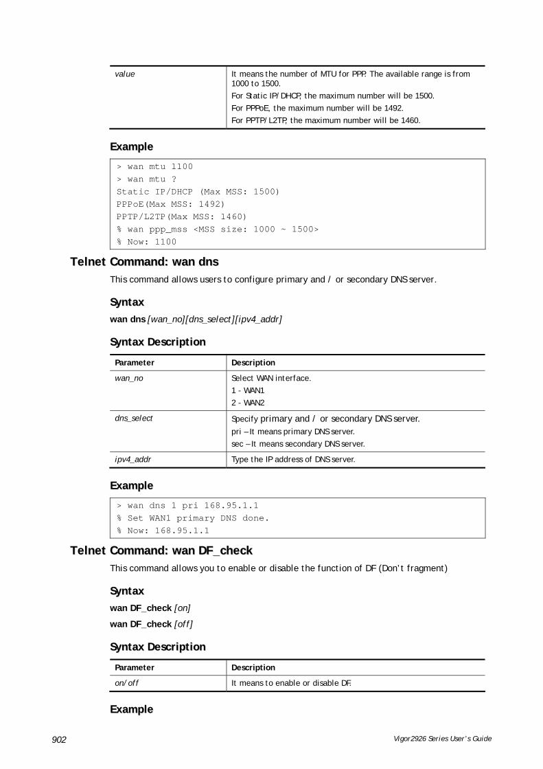
Vigor2926 Series User’s Guide 902
value It means the number of MTU for PPP. The available range is from 1000 to 1500.
For Static IP/DHCP, the maximum number will be 1500.
For PPPoE, the maximum number will be 1492.
For PPTP/L2TP, the maximum number will be 1460.
EExxaammppllee
> wan mtu 1100 > wan mtu ? Static IP/DHCP (Max MSS: 1500) PPPoE(Max MSS: 1492) PPTP/L2TP(Max MSS: 1460) % wan ppp_mss <MSS size: 1000 ~ 1500> % Now: 1100
TTeellnneett CCoommmmaanndd:: wwaann ddnnss This command allows users to configure primary and / or secondary DNS server.
SSyynnttaaxx
wan dns [wan_no][dns_select][ipv4_addr]
SSyynnttaaxx DDeessccrriippttiioonn
Parameter Description
wan_no Select WAN interface.
1 - WAN1
2 - WAN2
dns_select Specify primary and / or secondary DNS server. pri – It means primary DNS server.
sec – It means secondary DNS server.
ipv4_addr Type the IP address of DNS server.
EExxaammppllee
> wan dns 1 pri 168.95.1.1 % Set WAN1 primary DNS done. % Now: 168.95.1.1
TTeellnneett CCoommmmaanndd:: wwaann DDFF__cchheecckk This command allows you to enable or disable the function of DF (Don’t fragment)
SSyynnttaaxx
wan DF_check [on]
wan DF_check [off]
SSyynnttaaxx DDeessccrriippttiioonn
Parameter Description
on/off It means to enable or disable DF.
EExxaammppllee
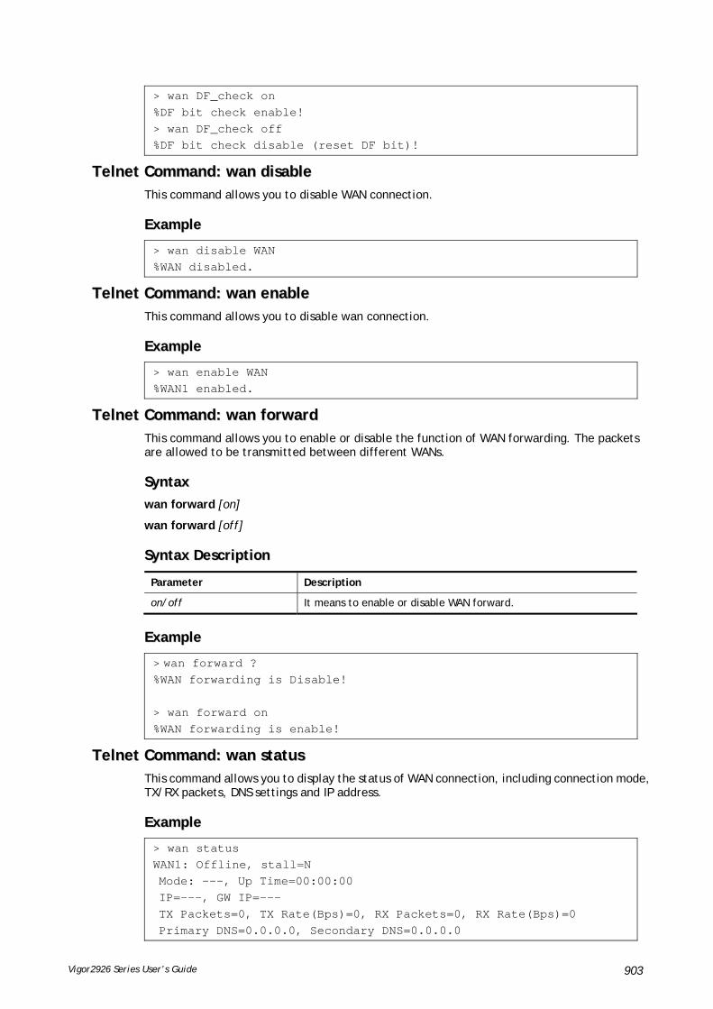
Vigor2926 Series User’s Guide 903
> wan DF_check on %DF bit check enable! > wan DF_check off %DF bit check disable (reset DF bit)!
TTeellnneett CCoommmmaanndd:: wwaann ddiissaabbllee This command allows you to disable WAN connection.
EExxaammppllee
> wan disable WAN %WAN disabled.
TTeellnneett CCoommmmaanndd:: wwaann eennaabbllee This command allows you to disable wan connection.
EExxaammppllee
> wan enable WAN %WAN1 enabled.
TTeellnneett CCoommmmaanndd:: wwaann ffoorrwwaarrdd This command allows you to enable or disable the function of WAN forwarding. The packets are allowed to be transmitted between different WANs.
SSyynnttaaxx
wan forward [on]
wan forward [off]
SSyynnttaaxx DDeessccrriippttiioonn
Parameter Description
on/off It means to enable or disable WAN forward.
EExxaammppllee
> wan forward ? %WAN forwarding is Disable! > wan forward on %WAN forwarding is enable!
TTeellnneett CCoommmmaanndd:: wwaann ssttaattuuss This command allows you to display the status of WAN connection, including connection mode, TX/RX packets, DNS settings and IP address.
EExxaammppllee
> wan status WAN1: Offline, stall=N Mode: ---, Up Time=00:00:00 IP=---, GW IP=--- TX Packets=0, TX Rate(Bps)=0, RX Packets=0, RX Rate(Bps)=0 Primary DNS=0.0.0.0, Secondary DNS=0.0.0.0

Vigor2926 Series User’s Guide 904
PVC_WAN3: Offline, stall=N Mode: ---, Up Time=00:00:00 IP=---, GW IP=--- TX Packets=0, TX Rate(Bps)=0, RX Packets=0, RX Rate(Bps)=0 PVC_WAN4: Offline, stall=N Mode: ---, Up Time=00:00:00 IP=---, GW IP=--- TX Packets=0, TX Rate(Bps)=0, RX Packets=0, RX Rate(Bps)=0 PVC_WAN5: Offline, stall=N Mode: ---, Up Time=00:00:00 IP=---, GW IP=--- TX Packets=0, TX Rate(Bps)=0, RX Packets=0, RX Rate(Bps)=0
TTeellnneett CCoommmmaanndd:: wwaann mmooddeemm // wwaann mmooddeemm22 This command, wan modem, allows you to configure 3G/4G USB Modem (PPP mode) of WAN3.
The command, wan modem2, allows you to configure 3G/4G USB Modem (PPP mode) of WAN4.
SSyynnttaaxx
wan modem [init/init2/dial/pin][string]
wan modem paponly [on/off]
wan modem backup_wait [value]
wan modem pipe [Int][Din][Dout] (for USB WAN3 only)
wan modem wakeup [on/off/value] (for USB WAN3 only)
wan modem vid [id]
wan modem pid [id]
wan modem status
SSyynnttaaxx DDeessccrriippttiioonn
Parameter Description
init Set initial modem AT command (default value is “AT&FE0V1X1&D2&C1S0=0”).
Init2 Set the second initial modem AT command.
dial Set dial modem AT command (default value is “ATDT*99#”).
pin Set PIN code for SIM card.
“0”:disable
paponly It means PAP Only. Set the PPP authentication of the USB WAN.
on: None.
off: PAP or CHAP.
backup_wait Set waiting time after boot if USB WAN is in backup mode. This waiting time is reserved for the dial of main WANs so that the backup USB WAN will not go up first.
Available setting is from 1 to 255. Unit is second.
pipe It is for RD debug only. Please don’t use it without our advice.

Vigor2926 Series User’s Guide 905
wakeup [on/off] It is for RD debug only. Please don’t use it without our advice.
vid Set VID of VID/PID match to bind the USB modem to specify WAN interface. By default, this match is not set (0x0/0x0) and the router specifies WAN interface by USB port.
pid Set PID of VID/PID match to bind the USB modem to specify WAN interface. By default, this match is not set (0x0/0x0) and the router specifies WAN interface by USB port.
status Display current status of USB modem.
EExxaammppllee
> wan modem pin 0000 > wan modem status Modem Link Speed=0 Current Signal Strength=0 Last Fail Message: Current Connect Stage:
TTeellnneett CCoommmmaanndd:: wwaann wwiimmaaxx This command allows you to enable or disable WAN 3G/4G DHCP mode for Vigor router.
SSyynnttaaxx
wan wimax [on/off]
SSyynnttaaxx DDeessccrriippttiioonn
Parameter Description
On It means to enable WAN 3G/4G DHCP mode.
off It means to disable WAN 3G/4G DHCP mode.
EExxaammppllee
> wan wimax ? Current status is wimax OFF
> wan wimax on >
TTeellnneett CCoommmmaanndd:: wwaann llttee This command allows you to configure LTE WAN (for L model only).
SSyynnttaaxx
wan lte auth [0/1]
wan lte band
wan lte del [index #/all]
wan lte pass [string]
wan lte quota [-<command><parameter>l…]
wan lte read [index #/all]
wan lte reboot [-<command><parameter>l…]
wan lte reply [-<command><parameter>l…]

Vigor2926 Series User’s Guide 906
wan lte send [number][message]
wan lte stus
wan lte tag [index #/all]
wan lte user [string]
wan lte wms [send[cdma/gwpp]/recv[cdma/gwgw]/setting]
SSyynnttaaxx DDeessccrriippttiioonn
Parameter Description
auth [0/1] Set PPP authentication of LTE WAN.
0: None.
1: PAP or CHAP.
band Display working band information for LTE network connection.
del [index #/all] Delete an SMS from the LTE SIM card by specifying the index number. Use “all” to delete all.
pass Set the password of LTE WAN.
quota [-<command><parameter>l…]
Set settings of SMS Quota Limit function.
Available commands with parameter are listed below:
[...] means that you can type in several commands in one line.
-a <0/1>: Set whether to send an e-mail alert when SMS quota exceeded. (0: no 1: yes)
-c <cycle>: Set the order of today in refresh cycle.
-d <day>: Set the refresh day.
-e <0/1>: Enable or disable SMS Quota Limit function. (0: disable 1: enable)
-h <hour>: Set the refresh hour.
-m <0/1/2>: Set SMS quota refresh mode. (0: None 1: monthly 2: periodically)
-n <number>: Set SMS quota. The avaible number is between 1 and 1000000.
-s <0/1>: Set whether to stop sending SMS after SMS quota exceeded. (0: no 1: yes)
read Display information of an SMS in the LTE SIM card by specifying the index number. Use "all" to display all.
reboot Set settings of Reboot on SMS Message function.
<command> <parameter> | ...
The available commands with parameters are listed below.
[...] means that you can type in several commands in one line.
-a <0/1>: Enable or disable Access Control List. (0: disable 1: enable)
-e <0/1>: Enable or disable Reboot on SMS Message function. (0: disable 1: enable)
-p <password>: Set the Password / PIN. This setting is necessary if this function is enabled.
-x <number>: Set the first phone number in Access Control List.
-y <number>: Set the second phone number in Access Control List.
-z <number>: Set the third phone number in Access Control List.
reply Set settings of Reply with Router Status Message function.
<command> <parameter> | ...
The available commands with parameters are listed below.
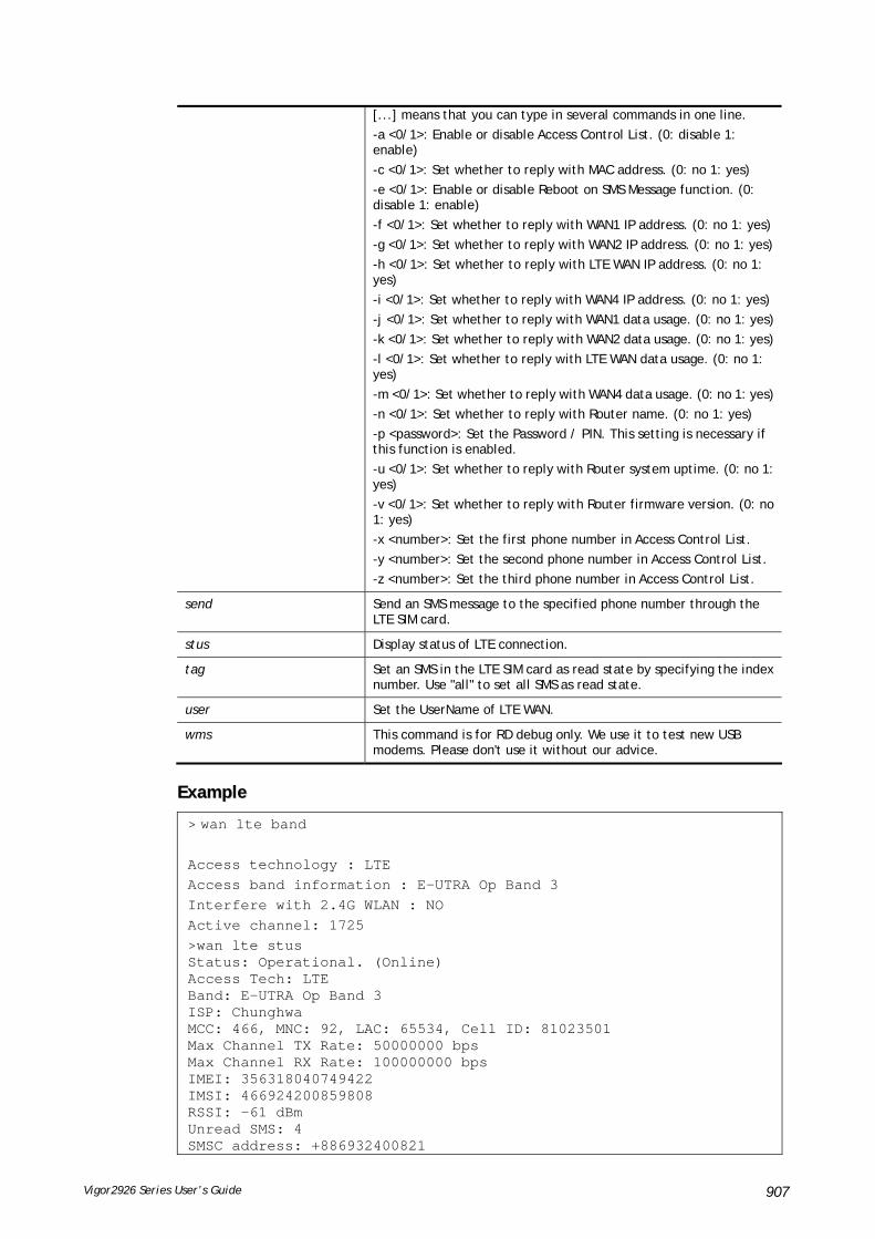
Vigor2926 Series User’s Guide 907
[...] means that you can type in several commands in one line.
-a <0/1>: Enable or disable Access Control List. (0: disable 1: enable)
-c <0/1>: Set whether to reply with MAC address. (0: no 1: yes)
-e <0/1>: Enable or disable Reboot on SMS Message function. (0: disable 1: enable)
-f <0/1>: Set whether to reply with WAN1 IP address. (0: no 1: yes)
-g <0/1>: Set whether to reply with WAN2 IP address. (0: no 1: yes)
-h <0/1>: Set whether to reply with LTE WAN IP address. (0: no 1: yes)
-i <0/1>: Set whether to reply with WAN4 IP address. (0: no 1: yes)
-j <0/1>: Set whether to reply with WAN1 data usage. (0: no 1: yes)
-k <0/1>: Set whether to reply with WAN2 data usage. (0: no 1: yes)
-l <0/1>: Set whether to reply with LTE WAN data usage. (0: no 1: yes)
-m <0/1>: Set whether to reply with WAN4 data usage. (0: no 1: yes)
-n <0/1>: Set whether to reply with Router name. (0: no 1: yes)
-p <password>: Set the Password / PIN. This setting is necessary if this function is enabled.
-u <0/1>: Set whether to reply with Router system uptime. (0: no 1: yes)
-v <0/1>: Set whether to reply with Router firmware version. (0: no 1: yes)
-x <number>: Set the first phone number in Access Control List.
-y <number>: Set the second phone number in Access Control List.
-z <number>: Set the third phone number in Access Control List.
send Send an SMS message to the specified phone number through the LTE SIM card.
stus Display status of LTE connection.
tag Set an SMS in the LTE SIM card as read state by specifying the index number. Use "all" to set all SMS as read state.
user Set the UserName of LTE WAN.
wms This command is for RD debug only. We use it to test new USB modems. Please don't use it without our advice.
EExxaammppllee
> wan lte band Access technology : LTE Access band information : E-UTRA Op Band 3 Interfere with 2.4G WLAN : NO Active channel: 1725 >wan lte stus Status: Operational. (Online) Access Tech: LTE Band: E-UTRA Op Band 3 ISP: Chunghwa MCC: 466, MNC: 92, LAC: 65534, Cell ID: 81023501 Max Channel TX Rate: 50000000 bps Max Channel RX Rate: 100000000 bps IMEI: 356318040749422 IMSI: 466924200859808 RSSI: -61 dBm Unread SMS: 4 SMSC address: +886932400821

Vigor2926 Series User’s Guide 908
SMS service status : Ready Number of SMS sent : 0
TTeellnneett CCoommmmaanndd:: wwaann ddeetteecctt This command allows you to configure WAN connection detection. When Ping Detection is enabled (for Static IP or DHCP or PPPoE mode), Router pings specified IP addresses to detect the WAN connection.
SSyynnttaaxx
wan detect [wan1/wan2][on/off/always_on]
wan detect [wan1/wan2] target [ip addr]
wan detect [wan1/wan2] target2[ip addr]
wan detect [wan1/wan2] target_gw [1/0]
wan detect [wan1/wan2] ttl [value]
wan detect [wan1/wan2] interval [interval]
wan detect [wan1/wan2] retry [retry]
wan detect status
SSyynnttaaxx DDeessccrriippttiioonn
Parameter Description
on Enable ping detection. The IP address of the target shall be set.
off Enable ARP detection (default).
always_on Disable link detect, always connected(only support static IP)
target Set the ping target.
Target2 Set the secondary ping target.
Target_gw Set whether to use gateway as ping target. (1: yes 0: no)
Note that USB WAN (PPP mode) cannot support PING gateway
ip addr It means the IP address used for detection. Type an IP address in this field.
ttl It means to set the ping TTL value (work as trace route)
If you do not set any value for ttl here or just type 0 here, the system will use default setting (255) as the ttl value.
interval [interval] Set the interval between each ping operation. Available setting is between 1 and 3600. The unit is second.
[interval]: Type a value.
retry [retry] Set how many ping operations are retried before the Router judges that the WAN connection is disconnected. Available setting is between 1 and 255. The unit is times.
[retry] : Type a number.
status It means to show the current status.
EExxaammppllee
> wan detect status WAN1: always on WAN2: off WAN3: off

Vigor2926 Series User’s Guide 909
WAN4: off WAN5: off > wan detect wan1 target 192.168.1.78 Set OK > wan detect wan1 on Set OK > wan detect status WAN1: on, Target=192.168.1.78, TTL=255 WAN2: off WAN3: off WAN4: off WAN5: off >
TTeellnneett CCoommmmaanndd:: wwaann llbb This command allows you to Enable/Disable for each WAN to join auto load balance member.
SSyynnttaaxx
wan lb [wan1/wan2/…] on
wan lb [wan1/wan2/…] off
wan lb status
SSyynnttaaxx DDeessccrriippttiioonn
Parameter Description
wan1/wan2 Specify which WAN will be applied with load balance.
on Make WAN interface as the member of load balance.
off Cancel WAN interface as the member of load balance.
status Show the current status.
EExxaammppllee
> wan lb status
WAN1: on
WAN2: on
WAN3: on
WAN4: on
WAN5: on
WAN6: on
WAN7: on

Vigor2926 Series User’s Guide 910
TTeellnneett CCoommmmaanndd:: wwaann mmvvllaann This command allows you to configure multi-VLAN for WAN and LAN. It supports pure bridge mode (modem mode) between Ethernet WAN and LAN port 2~4.
SSyynnttaaxx
wan mvlan [pvc_no/status/save/enable/disable] [on/off/clear/tag tag_no] [service type/vlan priority] [px ... ]
wan mvlan keeptag[pvc_no][on/off]
SSyynnttaaxx DDeessccrriippttiioonn
Parameter Description
pvc_no It means index number of PVC. There are 10 PVC, 0(Channel-1) to 9(Channel-9) allowed to be configured.
However, bridge mode can be set on PVC number 2 to 9.
status It means to display the whole Bridge status.
save It means to save the configuration into flash of Vigor router.
enable/disable It means to enable/disable the Multi-VLAN function.
on/off It means to turn on/off bridge mode for the specific channel.
clear It means to turn off/clear the port.
tag tag_no It means to tag a number for the VLAN.
-1: No need to add tag number.
1-4095: Available setting numbers used as tagged number.
service type It means to specify the service type for VLAN.
0: Normal.
1: IGMP.
vlan priority It means to specify the priority for the VALN setting.
Range is from 0 to 7.
px It means LAN port. Available setting number is from 2 to 4. Port number 1 is locked for NAT usage.
keeptag It means Multi-VLAN packets will keep their VLAN headers to LAN.
EExxaammppllee
PVC 7 will map to LAN port 2/3/4 in bridge mode; service type is Normal. No tag added.
> > wan mvlan 7 on p2 p3 p4 PVC Bridge p1 p2 p3 p4 p5 p6 Service Type Tag Priority Keep Tag ------------------------------------------------------------------ 7 ON 0 0 1 1 0 0 Normal 0(OFF) 0 OFF >
TTeellnneett CCoommmmaanndd:: wwaann mmuullttiiffnnoo This command allows you to specify a channel (in Multi-PVC/VLAN) to make bridge connection to a specified WAN interface.
SSyynnttaaxx
wan multifno [channel #] [WAN interface #]
wan multifno status
SSyynnttaaxx DDeessccrriippttiioonn

Vigor2926 Series User’s Guide 911
Parameter Description
channel # There are 4 (?) channels including VLAN and PVC.
Available settings are:
1=Channel 1
3=Channel 3
4=Channel 4
5=Channel 5
WAN interface # Type a number to indicate the WAN interface.
1=WAN1
2=WAN2
status It means to display current bridge status.
EExxaammppllee
> wan multifno 5 1 % Configured channel 5 uplink to WAN1 > wan multifno status > wan multifno status % Channel 5 uplink ifno: 3 % Channel 6 uplink ifno: 3 % Channel 7 uplink ifno: 3 % Channel 8 uplink ifno: 3 % Channel 9 uplink ifno: 3 >
TTeellnneett CCoommmmaanndd:: wwaann vvllaann This command allows you to configure the VLAN tag of WAN1 or WAN2.
SSyynnttaaxx
wan vlan wan [#] tag [value]
wan vlan wan [#] [enable/disable]
wan vlan stat
SSyynnttaaxx DDeessccrriippttiioonn
Parameter Description
wan [#] Specify which WAN interface will be tagged.
tag [value] Type a number for tagging on WAN interface.
enable/disable Enable: Specified WAN interface will be tagged.
Disable: Disable the function of tagging on WAN interface.
stat Display current VLAN status.
EExxaammppllee
> wan vlan stat % Interface Pri Tag Enabled % ====================================== % WAN1 (ADSL) 0 0 % WAN1 (VDSL) 0 0 % WAN2 0 0

Vigor2926 Series User’s Guide 912
TTeellnneett CCoommmmaanndd:: wwaann pphhyyvvllaann This command is used to set VLAN tag insertion for outer tag (service) for WAN interface.
WAN interfaces must be configured first before setting VLAN encapsulation.
SSyynnttaaxx
wan phyvlan wan [#] tag [value]
wan phyvlan wan [#] pri [value]
wan phyvlan wan [#] [enable|disable]
wan phyvlan stat
SSyynnttaaxx DDeessccrriippttiioonn
Parameter Description
[#] It means WAN interface.
1 – WAN1
2 – WAN2
tag [value] It means to tag a value onto the selected WAN interface.
pri [value] It means to set value for priority for such VLAN tag.
[enable|disable] It means to enable / disable the VLAN tag.
stat Display the setting status.
EExxaammppllee
> wan phyvlan wan 1 tag 22 % Set physical port tag to 22 for WAN1 % Set physical port tag to 22 for WAN1 % You need to reboot router making config effective DrayTek> wan phyvlan stat ? % Interface Pri Tag Enabled % ====================================== % WAN1 0 22 % WAN2 0 0
TTeellnneett CCoommmmaanndd:: wwaann bbuuddggeett This command allows you determine the data traffic volume for each WAN interface respectively to prevent from overcharges for data transmission by the ISP.
SSyynnttaaxx
wan budget wan [#] rdate [day] [hour]
wan budget wan [#] [enable|disable]
wan budget wan [#] thres [budget limit (MB)]
wan budget wan [#] gthres [budget limit (GB)]
wan budget wan [#] mode [monthly|periodic|none]
wan budget wan [#] psday [th day in periodic]
wan budget wan [#] action [action bitmap]
wan budget status
SSyynnttaaxx DDeessccrriippttiioonn
Parameter Description

Vigor2926 Series User’s Guide 913
wan[#] Specify the WAN interface.
rdate Specify the WAN budget refresh time.
day – Available settings are from 1 to 30.
hour – Available settings are from 1 to 23.
E.g., wan budget wan 1 rdate 5 10
If monthy mode is selected: WAN budget will be refreshed on 5th day at 10:00 in each month
If periodic mode is selected: WAN budget will be refreshed every 5 days and 10 hours
enable/disable enable - Enable the function of wan budget. disable - Disable the function of wan budget.
thres [budget limit (MB)] Specify the maximum value for WAN budget limit. (Unit: MB) budget limit – Type a number.
gthres [budget limit (GB)] Specify the maximum value of wan budget limit. (Unit: GB) budget limit – Type a number.
mode [monthly|periodic|none]
Specify the calculation mode (monthly, periodically, or none) for WAN budget.
psday [th day in periodic] It is used only when mode is set with “periodic”. Specify the order of “today” in the cycle.
E.g., wan budget wan 5 psday It means “today” is the 5th day in the billing cycle.
action [action bitmap] Determine the action to be performed when it reaches the WAN budget limit. action bitmap – Type a total number of actions to be executed. Different numbers represent different actions.
1: shotdown wan 2: send mail alert 4: send sms alert
For example, if you type “5” (5=1+4), the system will send SMS alert when WAN shotdown is detected.
status Display current configuration status of WAN budget.
EExxaammppllee
> wan budget wan 1 action 5 % WAN 1 budget action set to 5 > wan budget wan 1 gthres 10 % WAN 1 budget limit set to 10 GB
TTeellnneett CCoommmmaanndd:: wwaann ddeetteecctt__mmttuu This command allows you to run a WAN MTU Discovery. The user can specify an IPv4 target to ping and find the suitable MTU size of the WAN interface.
SSyynnttaaxx
wan detect_mtu -w [number] -i [Host/IP address] -s [base_size] -d [decrease_size] (-c [count])
SSyynnttaaxx DDeessccrriippttiioonn
Parameter Description
-w [number] Specify the WAN interface. Value: Type the number of WAN interface. 1: WAN1; 2:WAN2….and etc.
-I [Host/IP address] Specify the IPv4 target to detect. If can be an IPv4 address or domain name. Host/IP address: Type the IP address/domain name of the target.
-s [base_size] Set the MTU size base for Discovery. base_size: Available setting is 1000 ~ 1500.
-d [decrease size] Set the MTU size to decrease between detections. decrease size: Available setting is 1 ~ 100.
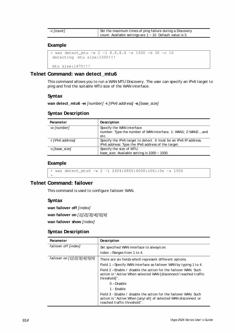
Vigor2926 Series User’s Guide 914
-c [count] Set the maximum times of ping failure during a Discovery. count: Available settings are 1 ~ 10. Default value is 3.
EExxaammppllee
> wan detect_mtu -w 2 -i 8.8.8.8 -s 1500 -d 30 -c 10 detecting mtu size:1500!!! mtu size:1470!!!
TTeellnneett CCoommmmaanndd:: wwaann ddeetteecctt__mmttuu66 This command allows you to run a WAN MTU Discovery. The user can specify an IPv6 target to ping and find the suitable MTU size of the WAN interface.
SSyynnttaaxx
wan detect_mtu6 –w [number] –i [IPv6 address] –s [base_size]
SSyynnttaaxx DDeessccrriippttiioonn
Parameter Description
-w [number] Specify the WAN interface number: Type the number of WAN interface. 1: WAN1; 2:WAN2….and etc.
-I [IPv6 address] Specify the IPv6 target to detect. It must be an IPv6 IP address. IPv6 address: Type the IPv6 address of the target.
-s [base_size] Specify the size of MTU. base_size: Available setting is 1000 ~ 1500.
EExxaammppllee
> wan detect_mtu6 -w 2 -i 2404:6800:4008:c06::5e -s 1500 >
TTeellnneett CCoommmmaanndd:: ffaaiilloovveerr This command is used to configure failover WAN.
SSyynnttaaxx
wan failover off [index]
wan failover on [1][2][3][4][5][6]
wan failover show [index]
SSyynnttaaxx DDeessccrriippttiioonn
Parameter Description
failover off [index] Set specified WAN interface to always on.
index – Ranges from 1 to 4.
failover on [1][2][3][4][5][6] There are six fields which represent different options.
Field 1 – Specify WAN interface as failover WAN by typing 1 to 4.
Field 2 – Enable / disable the action for the failover WAN. Such action is “Active When selected WAN [disconnect/reached traffic threshold]”.
0 – Disable
1 - Enable
Field 3 - Enable / disable the action for the failover WAN. Such action is “Active When [any/all] of selected WAN disconnect or reached traffic threshold”.

Vigor2926 Series User’s Guide 915
0 – Disable
1 - Enable
Field 4 – Specify main WAN by typing 1 to 4. The main WAN will be set to always on.
Field 5 – Specify traffic threshold [Download threshold(Kbps)].
Field 6 - Specify traffic threshold [Upload threshold (Kbps)].
For example, WAN 2 will be set as failover, and will be active when any of selected WANs has reached traffic threshold. WAN 4 is the selected WAN. Download threshold : 50 Kbpsl; Upload threshold : 20 Kbps. You can type as follows:
wan failover on 2 1 0 4 50 20
show [index] Display parameters settings for WAN interface.
index – Ranges from 1 to 4.
EExxaammppllee
> wan failover on 2 1 0 4 50 20 > wan failover show 2 wan2 Active Mode : Failover Active when : Any of the selected WANs reached the Traffic Threshold Traffic Download Threshold : 50 Kbps Traffic Upload Threshold : 20 Kbps > wan failover show 3 wan3 Active Mode : Always ON.
TTeellnneett CCoommmmaanndd:: hhssppoorrttaall sseettuupp This command is used to configure a profile (Hotspot Web Portal) with specified URL for accessing into or display a message when a wireless/LAN user connects to Internet through this router.
SSyynnttaaxx
hsportal -p <profile> [-l <lan>] [-s <ssid>] ...
hsportal -p <profile> -c
SSyynnttaaxx DDeessccrriippttiioonn
Parameter Description
-p Indicate available profile to be configured. Number of profile: 1 /2 /3 / 4.
-l Apply to LAN interfaces. E.g., apply LAN1 and LAN2: -l 1, 2.
-s Apply to WLAN interfaces. E.g., apply SSID1 and SSID2: -s 1, 2.
-a Apply to WLAN5G interfaces. E.g., apply SSID1 and SSID2: -s 1, 2.
-m Select login mode. 0:skip 1:click 2:social 3:pin 4:social or pin
-f Configure facebook login. 0: disable. 1: enable.
-g Configure google login. 0: disable. 1: enable.
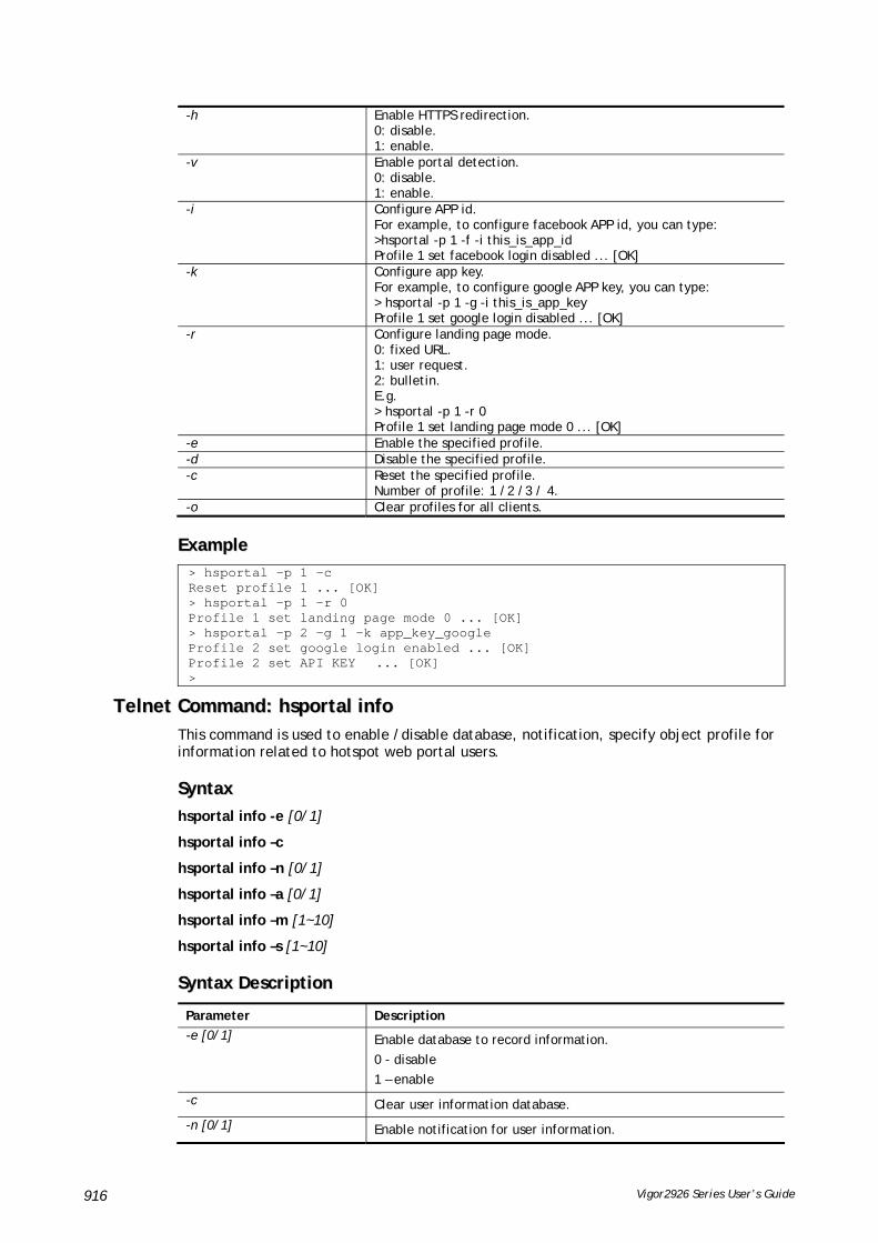
Vigor2926 Series User’s Guide 916
-h Enable HTTPS redirection. 0: disable. 1: enable.
-v Enable portal detection. 0: disable. 1: enable.
-i Configure APP id. For example, to configure facebook APP id, you can type: >hsportal -p 1 -f -i this_is_app_id Profile 1 set facebook login disabled ... [OK]
-k Configure app key. For example, to configure google APP key, you can type: > hsportal -p 1 -g -i this_is_app_key Profile 1 set google login disabled ... [OK]
-r Configure landing page mode. 0: fixed URL. 1: user request. 2: bulletin. E.g. > hsportal -p 1 -r 0 Profile 1 set landing page mode 0 ... [OK]
-e Enable the specified profile. -d Disable the specified profile. -c Reset the specified profile.
Number of profile: 1 /2 /3 / 4. -o Clear profiles for all clients.
EExxaammppllee > hsportal -p 1 -c Reset profile 1 ... [OK] > hsportal -p 1 -r 0 Profile 1 set landing page mode 0 ... [OK] > hsportal -p 2 -g 1 -k app_key_google Profile 2 set google login enabled ... [OK] Profile 2 set API KEY ... [OK] >
TTeellnneett CCoommmmaanndd:: hhssppoorrttaall iinnffoo This command is used to enable /disable database, notification, specify object profile for information related to hotspot web portal users.
SSyynnttaaxx
hsportal info -e [0/1]
hsportal info –c
hsportal info –n [0/1]
hsportal info –a [0/1]
hsportal info –m [1~10]
hsportal info –s [1~10]
SSyynnttaaxx DDeessccrriippttiioonn
Parameter Description
-e [0/1] Enable database to record information.
0 - disable
1 – enable
-c Clear user information database.
-n [0/1] Enable notification for user information.

Vigor2926 Series User’s Guide 917
0 - disable
1 – enable
-a [0/1] Enable auto backup and start a new record for user information.
0 - disable
1 – enable
-m [1~10] Set email notigication object.
[1~10]- Index number of object profile.
-s [1~10] Set SMS notigication object.
[1~10]- Index number of object profile.
EExxaammppllee
> hsportal info -e 1 Enabled database to record information ... [OK] > hsportal info -a 1 Enabled auto backup and start a new record for user information ... [OK]
TTeellnneett CCoommmmaanndd:: wwll aaccll This command allows the user to configure wireless access control settings.
SSyynnttaaxx
wl acl enable [ssid1 ssid2 ssid3 ssid4]
wl acl disable [ssid1 ssid2 ssid3 ssid4]
wl acl add [MAC] [ssid1 ssid2 ssid3 ssid4] [isolate]
wl acl del [MAC]
wl acl mode [ssid1 ssid2 ssid3 ssid4] [white/black]
wl acl show
wl acl showmode
wl acl clean
SSyynnttaaxx DDeessccrriippttiioonn
Parameter Description
enable [ssid1 ssid2 ssid3 ssid4]
It means to enable the settings for SSID1, SSID2, SSID3 and SSID4.
disable [ssid1 ssid2 ssid3 ssid4]
It means to disable the settings for SSID1, SSID2, SSID3 and SSID4.
add [MAC] [ssid1 ssid2 ssid3 ssid4] [isolate]
It means to associate a MAC address to certain SSID interfaces' access control settings. The isolate setting will limit the wireless client's network capabilities to accessing the wireless LAN only.
[MAC] format: xx-xx-xx-xx-xx-xx
or xx:xx:xx:xx:xx:xx
or xx.xx.xx.xx.xx.xx
del [MAC] It means to delete a MAC address entry defined in the access control list.
mode [ssid1 ssid2 ssid3 ssid4] [white/black]
It means to set white/black list for each SSID.
wl acl show It means to show access control status.
wl acl showmode It means to show the mode for each SSID.

Vigor2926 Series User’s Guide 918
wl acl clean It means to clean all access control setting.
EExxaammppllee
> > wl acl showmode ssid1: none ssid2: none ssid3: none ssid4: none > wl acl add 00-50-70-ff-12-70 Set Done !! > wl acl add 00-50-70-ff-12-70 ssid1 ssid2 isolate Set Done !! > wl acl show ----------Enable Mac Address Filter--------- ssid1: dis ssid2: dis ssid3: dis ssid4: dis ----------MAC Address Filter---------- Index Attribute MAC Address Associated SSIDs 0 00:50:70:ff:12:70 ssid1 ssid2 ssid3 ssid4 1 s 00:50:70:ff:12:70 ssid1 ssid2 s: Isolate the station from LAN >
TTeellnneett CCoommmmaanndd:: wwll ccoonnffiigg This command allows users to configure general settings and security settings for wireless connection.
SSyynnttaaxx
wl config mode [value]
wl config mode show
wl config channel [number]
wl config preamble [enable]
wl config txburst [enable]
wl config ssid [ssid_num enable ssid_name [hidden_ssid]]
wl config security [SSID_NUMBER] [mode]
wl config ratectl [ssid_num enable upload download ]
wl config isolate [ssid_num lan member]
SSyynnttaaxx DDeessccrriippttiioonn
Parameter Description
mode[value] It means to select connection mode for wireless connection.
Available settings are: "11bgn", "11gn", "11n", "11bg", "11g", or "11b".
mode show It means to display what the current wireless mode is.
channel [number] It means the channel of frequency of the wireless LAN.
The available settings are 0,1,2,3,4,5,6,7,8,9,10,11,12 and 13.
number=0, means Auto
number=1, means Channel 1

Vigor2926 Series User’s Guide 919
….
number=13, means Channel 13.
preamble [enable] It means to define the length of the sync field in an 802.11 packet.
Most modern wireless network uses short preamble with 56 bit sync field instead of long preamble with 128 bit sync field. However, some original 11b wireless network devices only support long preamble.
0: disable to use long preamble.
1: enable to use long preamble.
txburst [enable] It means to enhance the performance in data transmission about 40%* more (by enabling Tx Burst). It is active only when both sides of Access Point and Station (in wireless client) invoke this function at the same time.
0: disable the function.
1: enable the funciton.
ssid[ssid_num enable ssid_name [hidden_ssid]]
It means to set the name of the SSID, hide the SSID if required.
ssid_num: Type 1, 2, 3 or 4 to specify SSID1, SSID2, SSID3 or SSID4.
ssid_name: Give a name for the specified SSID.
hidden_ssid: Type 0 to hide the SSID or 1 to display the SSID
Security [SSID_NUMBER] [mode][key][index]
It means to configure security settings for the wirelesss connection.
SSID_NUMBER: Type 1, 2, 3 or 4 to specify SSID1, SSID2, SSID3 or SSID4.
mode: Available settings are:
disable: No security.
wpa1x: WPA/802.1x Only
wpa21x: WPA2/802.1x Only
wpamix1x: Mixed (WPA+WPA2/802.1x only)
wep1x: WEP/802.1x Only
wpapsk: WPA/PSK
wpa2psk: WPA2/PSK
wpamixpsk: Mixed (WPA+WPA2)/PSK
wep: WEP
key, index: Moreover, you have to add keys for wpapsk, wpa2psk, wpamixpsk and wep, and specify index number of schedule profiles to be followed by the wireless connection.
WEP keys must be in 5/13 ASCII text string or 10/26 Hexadecimal digit format; WPA keys must be in 8~63 ASCII text string or 64 Hexadecimal digit format.
ratectl [ssid_num enable upload download]
It means to set the rate control for the specified SSID.
ssid_num: Choose 1, 2, 3 or 4 to specify SSID1, SSID2, SSID3 or SSID4.
enable: It means to enable the function of the rate control for the specified SSID. 0: disable and 1:enable.
upload: It means to configure the rate control for data upload. The unit is kbps.
download: It means to configure the rate control for data download. The unit is kbps.
isolate [ssid_num lan member]
It means to isolate the wireless connection for LAN and/or Member.
lan – It can make the wireless clients (stations) with remote-dial and LAN to LAN users not accessing for each other.
member – It can make the wireless clients (stations) with the same SSID not accessing for each other.
EExxaammppllee
> wl config mode 11bgn

Vigor2926 Series User’s Guide 920
Current mode is 11bgn % <Note> Please restart wireless after you set the channel > wl config channel 13 Current channel is 13 % <Note> Please restart wireless after you set the channel. > wl config preamble 1 Long preamble is enabled % <Note> Please restart wireless after you set the parameters. > wl config ssid 1 enable dray SSID Enable Hide_SSID Name 1 1 0 dray % <Note> Please restart wireless after you set the parameters. > wl config security 1 wpa1x %% Configured Wlan Security Setting: % SSID1 %% Mode: wpa1x %% Wireless card must be reset for configurations to take effect %% (Telnet Command: wl restart)
TTeellnneett CCoommmmaanndd:: wwll sseett This command allows users to configure basic wireless settings.
SSyynnttaaxx
wl set [SSID] [CHAN[En]]
wl set txburst [enable]
SSyynnttaaxx DDeessccrriippttiioonn
Parameter Description
SSID It means to type the SSID for the router. The maximum character that you can use is 32.
CHAN[En] It means to specify required channel for the router.
CHAN: The range for the number is between 1 ~ 13.
En: type on to enable the function; type off to disable the function.
txburst [enable] It means to enhance the performance in data transmission about 40%* more (by enabling Tx Burst). It is active only when both sides of Access Point and Station (in wireless client) invoke this function at the same time.
0: disable the function.
1: enable the function.
EExxaammppllee
> wl set MKT 2 on % New Wlan Setting is: % SSID=MKT % Chan=2 % Wl is Enable

Vigor2926 Series User’s Guide 921
TTeellnneett CCoommmmaanndd:: wwll aacctt This command allows users to activate wireless settings.
SSyynnttaaxx
wl act [En]
SSyynnttaaxx DDeessccrriippttiioonn
Parameter Description
En It means to enable or disable the function of VPN isolation.
0: diable
1: enable
EExxaammppllee
> wl act on % Set Wlan to Enable.
TTeellnneett CCoommmmaanndd:: wwll ssccaann This command allows users to perform AP scanning.
SSyynnttaaxx
wl scan [start]
wl scan set [wlist/blist/stime][MAC]
wl scan del [wlist/blist] [MAC]
wl scan filter [ssid/channel/mac]
wl scan show [0/1/2/3]
SSyynnttaaxx DDeessccrriippttiioonn
Parameter Description
start It means to start AP scanning.
set [wlist/blist/stime] [MAC]
Set white list/block list/scan time.
wlist – It means to set white list for passing. MAC address must be added in the end.
e.g., wl scan set wlist 001122aabbcc
blist – It means to set black list for blocking. MAC address must be added in the end.
stime – It means to set scanning time. Time value (2~5 second) must be added in the end.
e.g., wl scan set time 5
del Remove white list/block list.
e.g., wl scan del wlist 001122aabbcc
filter Set which filter you want.
ssid – scanning the AP based on SSID setting.
channel - scanning the AP based on channel setting.
mac - scanning the AP based on MAC address setting..
show [0/1/2/3] It is used to show AP list.
0 - display white list
1 - display block list,

Vigor2926 Series User’s Guide 922
2 - display gray/unknown list,
3 - display all list
EExxaammppllee
> wl scan set wlist 001122aabbcc > wl scan start > wl scan show 3 >
TTeellnneett CCoommmmaanndd:: wwll ssttaammggtt This command is used to configure connection time and reconnection time for each SSID that wireless client used for accessing into Internet.
SSyynnttaaxx
wl stamgt [enable/disable] [ssid_num].
wl stamgt [show] [ssid_num].
wl stamgt set [ssid_num] [c] [r]
wl stamgt reset [ssid_num].
SSyynnttaaxx DDeessccrriippttiioonn
Parameter Description
enable/disable It means to enable/disable the station management control.
ssid_num It means channel selection.
Available channel for 2.4G: 0/1/2/3
Available channel for 5G: 4/5/6/7.
show It means to display status or configuration of the selected channel.
c It means connection time. The unit is minute.
r It means reconnection time. The unit is minute.
EExxaammppllee
> wl stamgt enable 1 % Station Management Status: enabled > wl stamgt set 1 60 60 > wl stamgt show 1 NO. SSID BSSID Connect time Reconnect time 1. Draytek 00:11:22:aa:bb:cc 0d:0:58:26 0d:0:0
TTeellnneett CCoommmmaanndd:: wwll iissoo__vvppnn This command allows users to activate the function of VPN isolation.
SSyynnttaaxx
wl iso_vpn [ssid] [En]
SSyynnttaaxx DDeessccrriippttiioonn
Parameter Description
ssid It means the number of SSID.

Vigor2926 Series User’s Guide 923
1: SSID1
2: SSID2
3: SSID3
4: SSID4
En It means to enable or disable the function of VPN isolation.
0: disable
1: enable
EExxaammppllee
> wl iso_vpn 1 on % ssid: 1 isolate vpn on :1
TTeellnneett CCoommmmaanndd:: wwll wwppaa This command allows you to configure WPA wireless settings.
SSyynnttaaxx
wl wpa 1/2/3
SSyynnttaaxx DDeessccrriippttiioonn
Parameter Description
wl wpa Type 1/2/3 to represent different WPA modes.
1 – means WPA+WPA2
2 – means WPA2 Only
3 – means WPA Only
EExxaammppllee
> wl wpa 1 >
TTeellnneett CCoommmmaanndd:: wwll wwmmmm This command allows users to set WMM for wireless connection. It defines the priority levels for four access categories derived from 802.1d (prioritization tabs).
SSyynnttaaxx
wl wmm ap QueIdx Aifsn Cwmin Cwmax Txop ACM
wl wmm bss QueIdx Aifsn Cwmin Cwmax Txop ACM
wl wmm ack Que0_Ack Que1_Ack Que2_Ack Que3_Ack
wl wmm enable SSID0 SSID1 SSID2 SSID3
wl wmm apsd value
wl wmm show
SSyynnttaaxx DDeessccrriippttiioonn
Parameter Description
ap It means to set WMM for access point.
bss It means to set WMM for wireless clients.
ack It means to map to the Ack policy settings of AP WMM.
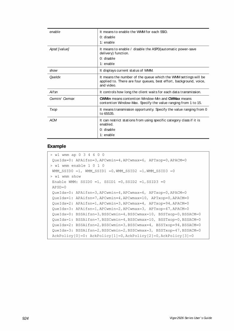
Vigor2926 Series User’s Guide 924
enable It means to enable the WMM for each SSID.
0: disable
1: enable
Apsd [value] It means to enable / disable the ASPD(automatic power-save delivery) function.
0: disable
1: enable
show It displays current status of WMM.
QueIdx It means the number of the queue which the WMM settings will be applied to. There are four queues, best effort, background, voice, and video.
Aifsn It controls how long the client waits for each data transmission.
Cwmin/ Cwmax CWMin means contention Window-Min and CWMax means contention Window-Max. Specify the value ranging from 1 to 15.
Txop It means transmission opportunity. Specify the value ranging from 0 to 65535.
ACM It can restrict stations from using specific category class if it is enabled.
0: disable
1: enable
EExxaammppllee
> wl wmm ap 0 3 4 6 0 0 QueIdx=0: APAifsn=3,APCwmin=4,APCwmax=6, APTxop=0,APACM=0 > wl wmm enable 1 0 1 0 WMM_SSID0 =1, WMM_SSID1 =0,WMM_SSID2 =1,WMM_SSID3 =0 > wl wmm show Enable WMM: SSID0 =1, SSID1 =0,SSID2 =1,SSID3 =0 APSD=0 QueIdx=0: APAifsn=3,APCwmin=4,APCwmax=6, APTxop=0,APACM=0 QueIdx=1: APAifsn=7,APCwmin=4,APCwmax=10, APTxop=0,APACM=0 QueIdx=2: APAifsn=1,APCwmin=3,APCwmax=4, APTxop=94,APACM=0 QueIdx=3: APAifsn=1,APCwmin=2,APCwmax=3, APTxop=47,APACM=0 QueIdx=0: BSSAifsn=3,BSSCwmin=4,BSSCwmax=10, BSSTxop=0,BSSACM=0 QueIdx=1: BSSAifsn=7,BSSCwmin=4,BSSCwmax=10, BSSTxop=0,BSSACM=0 QueIdx=2: BSSAifsn=2,BSSCwmin=3,BSSCwmax=4, BSSTxop=94,BSSACM=0 QueIdx=3: BSSAifsn=2,BSSCwmin=2,BSSCwmax=3, BSSTxop=47,BSSACM=0 AckPolicy[0]=0: AckPolicy[1]=0,AckPolicy[2]=0,AckPolicy[3]=0

Vigor2926 Series User’s Guide 925
TTeellnneett CCoommmmaanndd:: wwll hhtt This command allows you to configure wireless settings.
SSyynnttaaxx
wl ht bw value
wl ht gi value
wl ht badecline value
wl ht autoba value
wl ht rdg value
wl ht msdu value
wl ht txpower value
wl ht antenna value
wl ht greenfield value
SSyynnttaaxx DDeessccrriippttiioonn
Parameter Description
wl ht bw value The value you can type is 0 (for BW_20) and 1 (for BW_40).
wl ht gi value The value you can type is 0 (for GI_800) and 1 (for GI_4001)
wl ht badecline value The value you can type is 0 (for disabling) and 1 (for enabling).
wl ht autoba value The value you can type is 0 (for disabling) and 1 (for enabling).
wl ht rdg value The value you can type is 0 (for disabling) and 1 (for enabling).
wl ht msdu value The value you can type is 0 (for disabling) and 1 (for enabling).
wl ht txpower value The value you can type ranges from 1 – 6 (level).
wl ht antenna value The value you can type ranges from 0-3.
0: 2T3R
1: 2T2R
2: 1T2R
3: 1T1R
wl ht greenfield value The value you can type is 0 (for mixed mode) and 1 (for green field).
EExxaammppllee
> wl ht bw value 1 BW=0 <Note> Please restart wireless after you set new parameters. > wl restart Wireless restart................

Vigor2926 Series User’s Guide 926
TTeellnneett CCoommmmaanndd:: wwll rreessttaarrtt This command allows you to restart wireless setting.
EExxaammppllee
> wl restart Wireless restart................
TTeellnneett CCoommmmaanndd:: wwll wwddss This command allows you to configure WDS settings.
SSyynnttaaxx
wl wds mode [value]
wl wds security [value]
wl wds ap [value]
wl wds hello [value]
wl wds status
wl wds show
wl wds mac [value]
wl wds flush
SSyynnttaaxx DDeessccrriippttiioonn
Parameter Description
mode [value] It means to specify connection mode for WDS.
[value]: Available settings are :
d: Disable
b: Bridge
r: Repeapter
security [value] It means to configure security mode with encrypted keys for WDS.
mode: Available settings are:
disable: No security.
wep: WEP
wpapsk [key]: WPA/PSK
wpa2psk [key]: WPA2/PSK
key: Moreover, you have to add keys for wpapsk, wpa2psk, and wep, and specify index number of schedule profiles to be followed by the wireless connection.
WEP keys must be in 5/13 ASCII text string or 10/26 Hexadecimal digit format; WPA keys must be in 8~63 ASCII text string or 64 Hexadecimal digit format.
e.g.,
wl dual wds security disable
wl dual wds security wep 12345
wl dual wds security wpa2psk 12345678
ap [value] It means to enable or disable the AP function.
Value: 1 – enable the function.
0 – disable the function.
hello [value] It means to send hello message to remote end (peer).
Value: 1 – enable the function.

Vigor2926 Series User’s Guide 927
0 – disable the function.
status It means to display WDS link status for 2.4GHz connection.
show It means to display current WDS settings.
mac add [index addr] add [index addr] – Add the peer MAC entry in Repeater/Bridge WDS MAC table.
mac clear/disable/enable [index/all]
clear/disable/enable [index/all]- Clear, disable, enable the specifed or all MAC entries in Repeater/Bridge WDS MAC table. e.g,
wl dual wds mac enable 1
flush It means to reset all WDS setting.
EExxaammppllee
> wl wds status Please enable WDS hello function first. > wl wds hello 1 % <Note> Please restart router after you set the parameters. > wl wds status
TTeellnneett CCoommmmaanndd:: wwll aappccllii This command allows users to configure AP client mode for wireless connection (2.4GHz).
SSyynnttaaxx
wl apcli show
wl apcli enable [1/0]
wl apcli security [mode]
wl apcli ssid [ssid_name]
wl apcli bssid [mac address]
SSyynnttaaxx DDeessccrriippttiioonn
Parameter Description
show Display current status of wireless AP client.
enable [1/0] It means to enable wireless 2.4GHz AP client mode.
1 – enable
0 – disable
security [mode] There are several modes to be selected:
Disable – disable the security settings.
wpapsk [key] – WPA Pre-shared Key will be used. Keys must start with 0x to be identified as a Hexadecimal number key. WPA keys must be in 8~63 ASCII string or 64 Hexadecimal digit format.
wpa2psk [key] – WPA2 Pre-shared Key will be used. Keys must start with 0x to be identified as a Hexadecimal number key. WPA keys must be in 8~63 ASCII string or 64 Hexadecimal digit format.
wpamixpsk [key] – WPA Mixed Pre-shared Key will be used. Keys must start with 0x to be identified as a Hexadecimal number key. WPA keys must be in 8~63 ASCII string or 64 Hexadecimal digit format.
wep [key] [index] – WEP key will be used. You need to type the key

Vigor2926 Series User’s Guide 928
string and specify the index number of the profile to be applied.
WEP keys must be in 5/13 ASCII string or 10/26 Hexadecimal digit format.
ssid [ssid_name] Specify the SSID for wireless 2.4GHz AP client.
bssid Type the MAC address for wireless 2.4GHz AP client.
EExxaammppllee
> wl apcli enable 1 Wireless AP-Clinet is enabled > wl apcli show % Wireless AP-Clinet is enabled % Current SSID is test %% Security Mode: disable % Wireless client is disconnected %% data rate=---, mode=---, signal=0%
TTeellnneett CCoommmmaanndd:: wwll bbttnnccttll This command allows you to enable or disable wireless button control.
SSyynnttaaxx
wl btnctl [value]
SSyynnttaaxx DDeessccrriippttiioonn
Parameter Description
value 0: disable
1: enable
EExxaammppllee
> wl btnctl 1 Enable wireless botton control Current wireless botton control is on >
TTeellnneett CCoommmmaanndd:: wwll iiwwpprriivv These command is reserved for RD debug. Do not use it.
TTeellnneett CCoommmmaanndd:: wwll ssttaalliisstt This command is used to display the wireless station which accessing Internet via Vigor router.
SSyynnttaaxx
wl stalist
EExxaammppllee
> wl stalist wl stalist show : show station list wl stalist num : show number of stations wl stalist neighbor : show neighbor station list

Vigor2926 Series User’s Guide 929
TTeellnneett CCoommmmaanndd:: wwll sseett88002211xx This command allows you to configure the external or internal server used by Vigor router for wireless authentication.
SSyynnttaaxx
wl set8021x –t [0/1]
wl set8021x –v
SSyynnttaaxx DDeessccrriippttiioonn
Parameter Description
-t Specify the type (external or internal) of wireless authentication server.
0 – Indicate the external RADIUS server.
1- Indicate the local 802.1x server.
-v View the settings of 802.1x.
EExxaammppllee
> wl set8021x -t 1 % <Note> Please restart wireless after you set the parameters. > wl set8021x -v 802.1X type is : Local 802.1X >
TTeellnneett CCoommmmaanndd:: wwll bbnnddssttrrgg This command allows users to configure settings for Band Steering (2.4GHz).
SSyynnttaaxx
wl bndstrg show
wl bndstrg enable [1/0]
wl bndstrg chk_time [value]
SSyynnttaaxx DDeessccrriippttiioonn
Parameter Description
show Display current status for Band Steering function.
enable [1/0] It means to enable wireless 2.4GHz AP client mode.
1 – enable
0 – disable
chk_time [value] If the wireless station does not have the capability of 5GHz network connection, the system shall wait and check for several seconds (15 seconds, in default) to make the 2.4GHz network connection. Specify the time limit for Vigor router to detect the wireless client.
[value] – 1 to 60 seconds.
EExxaammppllee
> wl bndstrg show band steering: disable chk_time: 15 sec

Vigor2926 Series User’s Guide 930
> wl bndstrg chk_time 50 30 argv[0]:chk_time, argv[1]:50, argv[2]:30 %% Wireless card must be reset for configurations to take effect %% (Telnet Command: wl restart)
TTeellnneett CCoommmmaanndd:: wwll aarrttffnnss This command allows users to configure airtime fairness function for wireless (2.4GHz) connection.
SSyynnttaaxx
wl artfns enable [value]
wl artfns trg_num [value]
wl artfns show
SSyynnttaaxx DDeessccrriippttiioonn
Parameter Description
enable [value] It means to enable wireless airtime fairness function.
1 – enable
0 – disable
Trg_num [value] Set a threshold when the active station number achieves this number, the airtime fairness function will be applied.
Available values will be 2 to 64.
show Display current status (enable or disable) and triggering client number for airtime fairness function.
EExxaammppllee
> wl artfns enable 1 > wl artfns trg_num 3 > wl artfns show airtime fairness: enable trg_num: 3 >
TTeellnneett CCoommmmaanndd:: wwll ddrraayyrrss This command allows the user to configure settings for Roaming for wireless clients.
SSyynnttaaxx
wl drayrs set [mode] [rs_low] [rs_low_security] [delta]
wl drayrs restart
wl drayrs show
SSyynnttaaxx DDeessccrriippttiioonn
Parameter Description
set [mode] [rs_low] [rs_low_security] [delta]
Select a mode for roaming.
0 - disable
1 - Strictly Minimum RSSI
2 - Minimum RSSI

Vigor2926 Series User’s Guide 931
rs_low – Set a value of Strictly Minimum RSSI (62~86).
rs_low_security – Set a value of Minimum RSSI (62~86).
delta – Set a value of Adjacent AP RSSI (1~20).
restart Restart to activate roaming function.
show Dispaly current configuration of roaming function.
EExxaammppllee
> wl drayrs show % Mode : Disable % rs_low : -73 % rs_low_secure : -66 % delta : 5 >
TTeellnneett CCoommmmaanndd:: wwll__dduuaall aaccll This command allows the user to configure wireless (5GHz) access control settings.
SSyynnttaaxx
wl dual acl enable [ssid1 ssid2 ssid3 ssid4]
wl dual acl disable[ssid1 ssid2 ssid3 ssid4]
wl dual acl add [MAC][ssid1 ssid2 ssid3 ssid4][isolate]
wl dual acl del [MAC]
wl dual acl mode [ssid1 ssid2 ssid3 ssid4] [white/black]
wl dual acl show
wl dual acl showmode
wl dual acl clear
SSyynnttaaxx DDeessccrriippttiioonn
Parameter Description
enable [ssid1 ssid2 ssid3 ssid4]
It means to enable the settings for SSID1, SSID2, SSID3 and SSID4.
disable [ssid1 ssid2 ssid3 ssid4]
It means to disable the settings for SSID1, SSID2, SSID3 and SSID4.
add [MAC] [ssid1 ssid2 ssid3 ssid4] [isolate]
It means to associate a MAC address to certain SSID interfaces' access control settings. The isolate setting will limit the wireless client's network capabilities to accessing the wireless LAN only.
[MAC] format: xx-xx-xx-xx-xx-xx
or xx:xx:xx:xx:xx:xx
or xx.xx.xx.xx.xx.xx
isolate It means to isolate the wireless connection of the wireless client (identified with the MAC address) from LAN.
del[MAC] It means to delete a MAC address entry defined in the access control list.
[MAC] format: xx-xx-xx-xx-xx-xx
or xx:xx:xx:xx:xx:xx
or xx.xx.xx.xx.xx.xx
mode [ssid1 ssid2 ssid3 ssid4] [white/black]
It means to set white/black list for each SSID.

Vigor2926 Series User’s Guide 932
show It means to display current status of access control.
showmode It means to show the mode for each SSID.
clear It means to clear all of the access control settings.
EExxaammppllee
> wl_dual acl showmode SSID1: None SSID2: None SSID3: None SSID4: None > wl_dual acl add 00-50-70-ff-12-80 > wl_acl add 00-50-70-ff-12-80 ssid1 ssid2 isolate Set Done !! > wl_acl show ----------Enable Mac Address Filter--------- ssid1: dis ssid2: dis ssid3: dis ssid4: dis ----------MAC Address Filter---------- Index Attribute MAC Address Associated SSIDs 0 s 00:50:70:ff:12:80 ssid1 ssid2 s: Isolate the station from LAN
TTeellnneett CCoommmmaanndd:: wwll__dduuaall aappssccaann This command is used to scan Access Point installed near the location of Vigor router.
SSyynnttaaxx
wl_dual apscan start
wl_dual apscan show
SSyynnttaaxx DDeessccrriippttiioonn
Parameter Description
start It means to execute the AP scanning.
show It means to display the content of the AP list.
EExxaammppllee
> wl_dual apscan start > wl_dual apscan show AP scan is ongoing. > wl_dual apscan ? % wl_dual apscan [start/show] % start: do AP scan % show: show AP list > wl_dual apscan show 5G Access Point List : BSSID Channel SSID

Vigor2926 Series User’s Guide 933
TTeellnneett CCoommmmaanndd:: wwll__dduuaall ccaarrddmmaacc
EExxaammppllee
> wl_dual cardmac Card MAC: 54:2a:a2:37:00:ef
TTeellnneett CCoommmmaanndd:: wwll__dduuaall ccoonnffiigg This command allows users to configure general settings and security settings for wireless connection (5GHz).
wl_dual config enable [value]
wl dual config enable show
wl_dual config mode [value]
wl_dual config mode show
wl_dual config channel [number]
wl_dual config channel show
wl_dual config preamble [enable]
wl_dual config preamble show
wl_dual config ssid [ssid_num enable ssid_name]
wl_dual config ssid hide [ssid_num enable]
wl_dual config ssid show
wl_dual config ratectl [ssid_num enable upload download]
wl_dual config ratectl show
wl_dual config isolate lan [ssid_num enable]
wl_dual config isolate member [ssid_num enable]
wl_dual config isolate vpn [ssid_num enable]
wl_dual config isolate show
SSyynnttaaxx DDeessccrriippttiioonn
Parameter Description
enable[value] It means to enable/disable the 5GHz wireless function.
1: enable
0: disable
show It means to display if 5G wireless function is enabled or not.
mode[value] It means to select connection mode for wireless connection.
Available settings are: "11a", "11n_5g", "11n" and "11an".
mode show It means to display what the current wireless mode is.
channel [number] It means the channel of frequency of the wireless LAN.
The available settings are: 36, 40, 44, 48, 52, 56, 60, 64, 100, 104, 108, 112, 116, 120, 124, 128, 132, 136 and 140.
number=0, means Auto
number=36, means Channel 36
….
Number=52, means Channel 52.
channel show It means to display what the current channel is.

Vigor2926 Series User’s Guide 934
preamble [enable] It means to define the length of the sync field in an 802.11 packet.
Most modern wireless network uses short preamble with 56 bit sync field instead of long preamble with 128 bit sync field. However, some original 11b wireless network devices only support long preamble.
0: disable to use long preamble.
1: enable to use long preamble.
preamble show It means to display if preamble is enabled or not.
ssid[ssid_num enable ssid_name]
It means to set the name of the SSID, hide the SSID if required.
ssid_num: Type 1, 2, 3 or 4 to specify SSID1, SSID2, SSID3 or SSID4.
ssid_name: Give a name for the specified SSID.
ssid hide [ssid_num enab le] It means to hide the name of the SSID if required.
ssid_num: Type 1, 2, 3 or 4 to specify SSID1, SSID2, SSID3 or SSID4.
enable: Type 0 to hide the SSID or 1 to display the SSID.
ssid show It means to display a table of SSID configuration.
ratectl [ssid_num enable upload download]
It means to set the rate control for the specified SSID.
ssid_num: Choose 1, 2, 3 or 4 to specify SSID1, SSID2, SSID3 or SSID4.
enable: It means to enable the function of the rate control for the specified SSID. 0: disable and 1:enable.
upload: It means to configure the rate control for data upload. The unit is kbps.
download: It means to configure the rate control for data download. The unit is kbps.
(example: wl dual config ratectl 1 1 25 25)
ratectl show It means to display the data transmission rate (upload and download) for SSID1, SSID2, SSID3 and SSID4.
isolate lan [ssid_num enable]
It means to isolate the wireless connection from LAN.
It can make the wireless clients (stations) with remote-dial and LAN to LAN users not accessing for each other.
ssid_num: Choose 1, 2, 3 or 4 to specify SSID1, SSID2, SSID3 or SSID4.
enable: It means to enable such function.
0: disable and 1:enable
isolate member [ssid_num enable]
It means to isolate the wireless connection from Member.
It can make the wireless clients (stations) with the same SSID not accessing for each other.
ssid_num: Choose 1, 2, 3 or 4 to specify SSID1, SSID2, SSID3 or SSID4.
enable: It means to enable such function.
0: disable and 1:enable.
isolate vpn [ssid_num enable]
It means to isolate the wireless connection from VPN.
ssid_num: Choose 1, 2, 3 or 4 to specify SSID1, SSID2, SSID3 or SSID4.
enable: It means to enable such function.
0: disable and 1:enable.
isolate show It means to display the status of wireless isolation.
EExxaammppllee
> wl_dual config mode 11a Current mode is 11a % <Note> Please restart 5G wireless after you set the channel > wl_dual config channel 60 Current channel is 60 % <Note> Please restart 5G wireless after you set the channel.

Vigor2926 Series User’s Guide 935
> wl_dual config preamble 1 Long preamble is enabled % <Note> Please restart 5G wireless after you set the parameters. > wl_dual config ssid 1 enable dray SSID Enable Hide_SSID Name 1 1 0 dray % <Note> Please restart 5G wireless after you set the parameters. > wl_dual config ssid show SSID Enable Hide_SSID Name 1 1 0 dray 2 0 0 DrayTek_5G_Guest 3 0 0 4 0 0
TTeellnneett CCoommmmaanndd:: wwll__dduuaall rreessttaarrtt This command allows you to restart wireless setting (5GHz).
EExxaammppllee
> wl_dual restart 5G wireless restart................
TTeellnneett CCoommmmaanndd:: wwll__dduuaall sseeccuurriittyy This command allows users to configure security settings for the wireless connection (5GHz).
SSyynnttaaxx
wl_dual security[SSID_NUMBER] [mode][key][index]
wl_dual security show
SSyynnttaaxx DDeessccrriippttiioonn
Parameter Description
Security [SSID_NUMBER] [mode][key][index]
SSID_NUMBER: Type 1, 2, 3 or 4 to specify SSID1, SSID2, SSID3 or SSID4.
mode: Available settings are:
disable: No security.
wpa1x: WPA/802.1x Only
wpa21x: WPA2/802.1x Only
wpamix1x: Mixed (WPA+WPA2/802.1x only)
wep1x: WEP/802.1x Only
wpapsk: WPA/PSK
wpa2psk: WPA2/PSK
wpamixpsk: Mixed (WPA+WPA2)/PSK
wep: WEP
key, index: Moreover, you have to add keys for wpapsk, wpa2psk, wpamixpsk and wep, and specify index number of schedule profiles to be followed by the wireless connection.
WEP keys must be in 5/13 ASCII text string or 10/26 Hexadecimal digit format; WPA keys must be in 8~63 ASCII text string or 64 Hexadecimal digit format.
show It means to display current mode selection for each SSID.

Vigor2926 Series User’s Guide 936
EExxaammppllee
> wl_dual security 1 wpa2psk 123456789e % <Note> Please restart 5G wireless after you set the parameters. > wl_dual security show %% 5G Wireless LAN Security Settings: % SSID1 %% Mode: WPA2/PSK % SSID2 %% Mode: Disable % SSID3 %% Mode: Disable % SSID4 %% Mode: Disable
TTeellnneett CCoommmmaanndd:: wwll__dduuaall ssttaalliisstt This command is used to display the wireless station which accessing Internet via Vigor router.
SSyynnttaaxx
wl dual stalist
EExxaammppllee
> wl_dual stalist 5G Wireless Station List : Index Status IP Address MAC Address Associated with Status Codes : C: Connected, No encryption. E: Connected, WEP. P: Connected, WPA. A: Connected, WPA2. B: Blocked by Access Control. N: Connecting. F: Fail to pass WPA/PSK authentication.
TTeellnneett CCoommmmaanndd:: wwll__dduuaall wwddss This command allows users to configure WDS for wireless connection (5GHz).
SSyynnttaaxx
wl_dual wds mode [value]
wl_dual wds security [value]
wl_dual wds ap [value]
wl_dual wds hello [value]
wl_dual wds status

Vigor2926 Series User’s Guide 937
wl_dual wds show
wl_dual wds mac add [index addr]
wl_dual wds mac clear/disable/enable [index/all]
wl_dual wds flush
SSyynnttaaxx DDeessccrriippttiioonn
Parameter Description
mode [value] It means to specify connection mode for WDS.
[value]: Available settings are :
d: Disable
b: Bridge
r: Repeapter
security [value] It means to configure security mode with encrypted keys for WDS.
mode: Available settings are:
disable: No security.
wep: WEP
wpapsk [key]: WPA/PSK
wpa2psk [key]: WPA2/PSK
key: Moreover, you have to add keys for wpapsk, wpa2psk, and wep, and specify index number of schedule profiles to be followed by the wireless connection.
WEP keys must be in 5/13 ASCII text string or 10/26 Hexadecimal digit format; WPA keys must be in 8~63 ASCII text string or 64 Hexadecimal digit format.
e.g.,
wl_dual wds security disable
wl_dual wds security wep 12345
wl_dual wds security wpa2psk 12345678
ap [value] It means to enable or disable the AP function.
Value: 1 – enable the function.
0 – disable the function.
hello [value] It means to send hello message to remote end (peer).
Value: 1 – enable the function.
0 – disable the function.
status It means to display WDS link status for 5GHz connection.
show It means to display current WDS settings.
mac add [index addr] add [index addr] – Add the peer MAC entry in Repeater/Bridge WDS MAC table.
mac clear/disable/enable [index/all]
clear/disable/enable [index/all]- Clear, disable, enable the specifed or all MAC entries in Repeater/Bridge WDS MAC table. e.g,
wl_dual wds mac enable 1
flush It means to reset all WDS setting.
EExxaammppllee
> wl_dual wds status Please enable WDS hello function first. > wl_dual wds hello 1 % <Note> Please restart router after you set the parameters.

Vigor2926 Series User’s Guide 938
> wl dual wds mode b > wl dual wds security wep > > > wl_dual wds show 5G Wireless WDS Setting Mode : Bridge Security : WEP AP Function : Enable Send Hello Function : Enable Bridge : Index Enable MAC Address 1 0 00:00:00:00:00:00 2 0 00:00:00:00:00:00 3 0 00:00:00:00:00:00 4 0 00:00:00:00:00:00 Repeater : Index Enable MAC Address 5 0 00:00:00:00:00:00 6 0 00:00:00:00:00:00 7 0 00:00:00:00:00:00 8 0 00:00:00:00:00:00 > wl_dual wds wep 12345 % <Note> Please restart router after you set the parameters.
TTeellnneett CCoommmmaanndd:: wwll__dduuaall wwppss This command allows users to configure WPS for wireless connection (5GHz).
SSyynnttaaxx
wl_dual wps enable [value]
wl dual wps pbc
wl_dual wps pin [code]
wl_dual wps show
SSyynnttaaxx DDeessccrriippttiioonn
Parameter Description
enable [value] It means to enable WPS.
1 – enable
0 – disable
pbc It means to start WPS by pressing the WLAN ON/OFF WPS button on Vigor router.
pin [code] It means to start WPS by using client PIN code.
[code]: Client PIN code (digit number).
show It means to display current WPS settings.
EExxaammppllee

Vigor2926 Series User’s Guide 939
> wl_dual wps enable 1 WPS is enabled. > wl_dual wps pin 88563337 WPS has triggered by PIN code. The AP will wait for WPS request from your client for 2 minutes...
TTeellnneett CCoommmmaanndd:: wwll__dduuaall sseett88002211xx This command allows you to configure the external or internal server used by Vigor router for wireless authentication (5GHz).
SSyynnttaaxx
wl_dual set8021x –t [0/1]
wWl_dual set8021x –v
SSyynnttaaxx DDeessccrriippttiioonn
Parameter Description
-t Specify the type (external or internal) of wireless authentication server.
0 – Indicate the external RADIUS server.
1- Indicate the local 802.1x server.
-v View the settings of 802.1x.
EExxaammppllee
> wl_dual set8021x -t 1 % <Note> Please restart 5G wireless after you set the parameters. > wl_dual set8021x -v 802.1X type is : Local 802.1X >
TTeellnneett CCoommmmaanndd:: wwll__dduuaall aappccllii This command allows users to configure AP client mode for wireless connection (5GHz).
SSyynnttaaxx
wl_dual apcli show
wl_dual apcli enable [value]
wl_dual apcli security [mode]
wl_dual apcli ssid [ssid_name]
wl_dual apcli bssid
SSyynnttaaxx DDeessccrriippttiioonn
Parameter Description
show Display current status of wireless AP client.
enable [value] It means to enable wireless 5GHz AP client mode.
1 – enable
0 – disable
Security [mode] There are several modes to be selected:

Vigor2926 Series User’s Guide 940
Disable – disable the security settings.
wpapsk [key] – WPA Pre-shared Key will be used. Keys must start with 0x to be identified as a Hexadecimal number key. WPA keys must be in 8~63 ASCII string or 64 Hexadecimal digit format.
wpa2psk [key] – WPA2 Pre-shared Key will be used. Keys must start with 0x to be identified as a Hexadecimal number key. WPA keys must be in 8~63 ASCII string or 64 Hexadecimal digit format.
wpamixpsk [key] – WPA Mixed Pre-shared Key will be used. Keys must start with 0x to be identified as a Hexadecimal number key. WPA keys must be in 8~63 ASCII string or 64 Hexadecimal digit format.
wep [key] [index] – WEP key will be used. You need to type the key string and specify the index number of the profile to be applied.
WEP keys must be in 5/13 ASCII string or 10/26 Hexadecimal digit format.
ssid [ssid_name] Specify the SSID for wireless 5GHz AP client.
bssid Type the MAC address for wireless 5GHz AP client.
EExxaammppllee
> wl_dual apcli enable 1 Wireless 5G AP-Clinet is enabled Vigor> wl_dual apcli show % Wireless 5G AP-Clinet is enabled % Current SSID is %% Security Mode: disable % Wireless 5G client is disconnected %% data rate=---, mode=---, signal=0% > wl_dual apcli ssid carrie % <Note> Please restart wireless 5g after you set the parameters. Current SSID is carrie
TTeellnneett CCoommmmaanndd:: wwll__dduuaall aarrttffnnss This command allows users to configure airtime fairness function for wireless (5GHz) connection.
SSyynnttaaxx
wl_dual artfns enable [value]
wl_dual artfns trg_num [value]
wl_dual artfns show
wl_dual artfns status
SSyynnttaaxx DDeessccrriippttiioonn
Parameter Description
enable [value] It means to enable wireless airtime fairness function.
1 – enable
0 – disable
Trg_num [value] Set a threshold when the active station number achieves this number, the airtime fairness function will be applied.
Available values will be 2 to 64.

Vigor2926 Series User’s Guide 941
show Display current status (enable or disable) and triggering client number for airtime fairness function.
status Display whether the function of airtime fairness is enabled or disabled.
EExxaammppllee
> wl_dual artfns show
airtime fairness for 5G: disable
trg_num: 2
> wl_dual artfns status
airtime fairness for 5G is disabled !!!
> wl_dual artfns enable 0
> wl_dual artfns trg_num 2
> wl_dual artfns show
airtime fairness for 5G: disable
trg_num: 2
> wl_dual artfns status
airtime fairness for 5G is disabled !!!
TTeellnneett CCoommmmaanndd:: wwll__dduuaall ddrraayyrrss This command allows the user to configure settings for Roaming for wireless clients.
SSyynnttaaxx
wl_dual drayrs set [mode] [rs_low] [rs_low_security] [delta]
wl_dual drayrs restart
wl_dual drayrs show
SSyynnttaaxx DDeessccrriippttiioonn
Parameter Description
set [mode] [rs_low] [rs_low_security] [delta]
Select a mode for roaming.
0 - disable
1 - Strictly Minimum RSSI
2 - Minimum RSSI
rs_low – Set a value of Strictly Minimum RSSI (62~86).
rs_low_security – Set a value of Minimum RSSI (62~86).
delta – Set a value of Adjacent AP RSSI (1~20).
restart Restart to activate roaming function.
show Dispaly current configuration of roaming function.
EExxaammppllee
> wl_dual drayrs show % Mode : Disable % rs_low : -73 % rs_low_secure : -66 % delta : 5 > wl_dual drayrs set 1 68 66 2

Vigor2926 Series User’s Guide 942
> wl_dual drayrs show % Mode : Strictly Minimun RSSI % rs_low : -68 % rs_low_secure : -66 % delta : 2
TTeellnneett CCoommmmaanndd:: rraaddiiuuss This command allows you to configure detailed settings for RADIUS server
SSyynnttaaxx
radius enable [0/1]
radius authport [port number]
radius set_auth_method [method idx]
radius client [add] [idx] -i [address] -m [mask] -p [prefix] -l [length] -s [secret]
radius client [del] [idx]
radius show
radius set_dot1x_phase1 -e [method_idx]
radius set_dot1x_phase1 -d [method_idx]
radius set_dot1x_phase2 -e [method_idx]
radius set_dot1x_phase2 -d [method_idx]
SSyynnttaaxx DDeessccrriippttiioonn
Parameter Description
enable[0/1] Enable (1) or disable (0) the RADIUS server.
authport [port number] Configure the port number for authentication.
Port number: Available range is from 0 to 65535.
Default value is “1812”.
set_auth_method [method idx]
Specify which method will be used for authentication.
Method idx: “0” is “Only PAP”; “1” is “PAP/CHAP/MS-CHAP/MS-CHAPv2”.
client add Specify a client to be authenticated by RADIUS server by typing required information as follows:
-i [address]: client IPv4 address(domain) -m [mask]: client IPv4 mask -p [prefix]: client IPv6 prefix -l [length]: client IPv6 prefix length -s [secret]: shared secret ex: radius client add 1 -i 192.168.1.1 -m 255.255.255.0 -s 123
client [del] [idx] del - Delete related settings for selected client.
Idx - Specify the index number of client profiles.
show Display the status of RADIUS server.
enable_dot1x [0/1] Enable (1) or disable (0) the 802.1X Authentication function of RADIUS Server. Default is disabled.
set_dot1x_phase1 [method_idx]
Set the phase1 method for 802.1X authentication of RADIUS server.
method_idx - Specify which method will be used.
At present, dot1x_phase1 can only support PEAP now. So only “1” can be used for it.
set_dot1x_phase2 Set the phase2 method for 802.1X authentication of RADIUS server.

Vigor2926 Series User’s Guide 943
[method_idx] method_idx - Specify which method will be used.
Dot1x_phase2 can only support MS-CHAPv2 now. So only “1” can be used for it.
-e Set method for dot1x_phase1 or dot1x_phase2.
-d Delete method for dot1x_phase1 or dot1x_phase2.
EExxaammppllee
> radius client add 1 -i 192.168.1.1 -m 255.255.255.0 -s 123
This setting will take effect after rebooting.
Please use "sys reboot" command to reboot the router.
TTeellnneett CCoommmmaanndd:: llooccaall__88002211xx The command is used to configure general settings for Local 802.1X server built in Vigor router.
SSyynnttaaxx
local_8021x enable [0/1]
local_8021x set_localdot1x_phase1 options...
local_8021x set_localdot1x_phase2 options...
local_8021x show
SSyynnttaaxx DDeessccrriippttiioonn
Parameter Description
enable Enable or disable the configuration. 0: disable. 1: enable.
set_localdot1x_phase1 Only support PEAP now. The method_idx for such phase1 is “1”.
set_localdot1x_phase2 Only support MS-CHAPv2 now. The method_idx for such phase2 is “1”.
options -e [method_idx]: set method. e.g, local_8021x set_localdot1x_phase1 -e 1 -d: delete mehod. e.g, local_8021x set_localdot1x_phase1 -d
show Display current settings of local 802.1x server.
EExxaammppllee
> local_8021x show
% Local 802.1X enable: enable
% phase1 support method: [PEAP]
% phase2 support method: [None]

Vigor2926 Series User’s Guide 944
TTeellnneett CCoommmmaanndd:: wwooll This command allows Administrator to set the white list of WAN IP addresses/Subnets, that the magic packet from these IP addresses/Subnets will be eligible to pass through NAT and wake up the LAN client. You also need to set NAT rule for LAN client.
SSyynnttaaxx
wol up [MAC Address]/[IP Address]
wol fromWan [on/off/any]
wol fromWan_Setting [idx][ip address][mask]
SSyynnttaaxx DDeessccrriippttiioonn
Parameter Description
MAC Address It means the MAC address of the host.
IP address It means the LAN IP address of the host. If you want to wake up LAN host by using IP address, be sure that that IP address has been bound with the MAC address (IP BindMAC).
on/off/any It means to enable or disable the function of WOL from WAN.
on: enable
off: disable
any: It means any source IP address can pass through NAT and wake up the LAN client.
This command will allow the user to choose whether WoL packets can be passed from the Internet to the LAN network from a specific WAN interface.
[idx][ip address] [mask] It means the index number (from 1 to 4).
These commands will allow the user to configure the LAN clients that the user may wake up from the Internet through the use of the WoL packet.
ip address - It means the WAN IP address.
mask - It means the mask of the IP address.
EExxaammppllee
> wol fromWan on > wol fromWan_Setting 1 192.168.1.45 255.255.255.0 >

Vigor2926 Series User’s Guide 945
TTeellnneett CCoommmmaanndd:: uusseerr The command is used to create new user account profiles.
SSyynnttaaxx
sser set [-e|-d|-c|-l|-o|-a|-r|-b]
user edit [PROFILE_IDX] [-e|-d|-n|-p|-t|-u|-i|-q|-r|-w|-s|-m|-x|-v]
user account [USER_NAME] [-t|-d|-q|-r|-w]
SSyynnttaaxx DDeessccrriippttiioonn
Parameter Description
set It means to configure general setup for the user management.
edit It means to modify the selected user profile.
account It means to set time and data quota for specified user account.
User Set
-e Enable User management function.
-d Disable User management function.
-a[Profile idx][User name][IP_Address]
It means to pass an IP Address.
Profile idx- type the index number of the selected profile.
User name- type the user name that you want it to pass.
IP_Address- type the IP address that you want it to pass.
-l all
-l userl
-l ip
Show online user.
all – all of the users will be displayed on the screen.
user name – type the user name that you want to view on the screen.
ip – type the IP address that you want to view on the screen.
-o It means to show user account information.
e.g.,-o
-c[user name]
-c all
Clear the user record.
user name – type the user name that you want to get clear corresponding record.
all – all of the records will be removed.
-buser [user name]
-b ip [ ip address]
Block specifies user or IP address.
user name – type the user name that you want to block.
ip address –– type the IP address that you want to block.
-u user [user name]
-u ip [ ip address]
Unblock specifies user or IP address.
user name – type the user name that you want to unblock.
ip address –– type the IP address that you want to unblock.
-r [user name | all] Remove the user record.
user name – type the name of the user profile.
all – all of the user profile settings will be removed.
-q It means to trigger the alert tool to do authentication.
-s It means to set login service.
0:HTTPS
1:HTTP
e.g.,-s 1
User edit

Vigor2926 Series User’s Guide 946
PROFILE_IDX Type the index number of the profile that you want to edit.
-e Enable User profile function.
-d Disable User profile function.
-n It means to set a user name for a profile.
e.g.,-n fortest
-p It means to configure user password.
e.g., -p 60fortest
-t It means to enable /disable time quota limitation for user profile
0:Disable
1:Enable
-u It means to enable /disable data quota limitation for user profile
0:Disable
1:Enable
-i It means to set idle time.
e.g., -i 60
-q set time quota
It means to set time quota of the user profile.
e.g., -q 200
-r It means to set data quota.
e.g., -r 1000
-w It means to specify the data quota unit (MB/GB).
e.g., -w MB
-s It means to set schedule index. Available settings are” sch_idx1,sch_idx2,sch_idx3, and sch_idx4.
-m It means to set the maximum login user number.
e.g., -m 200
-x It means to set external server authentication
0: None
1: LDAP
2: Radius
3: TACAS
e.g., -x 2
-v It means to view user profile(s).
User account
USER_NAME It means to type a name of the user account.
-d It means to enable /disable data quota limitation for user account.
0:Disable
1:Enable
-q It means to set account time quota.
e.g., -q 200
-r It means to set account data quota.
e.g., -r 1000
-t It means to enable /disable time quota limitation for user account.
0:Disable
1:Enable
-w It means to set data quota unit (MB/GB).

Vigor2926 Series User’s Guide 947
EExxaammppllee
> user account admin -d 1 Enable the [admin] data quota limited
TTeellnneett CCoommmmaanndd:: aappppqqooss The command is used to configure QoS for APP.
SSyynnttaaxx
appqos view
appqos enable [0/1]
appqos traceable [-v | -e AP_INDEX CLASS | -d AP_INDEX]
appqos untraceable [-v | -e AP_INDEX CLASS | -d AP_INDEX]
SSyynnttaaxx DDeessccrriippttiioonn
Parameter Description
view It means to display current status of APP QoS.
enable[0/1] It means to enable or disable the function of APP QoS.
traceable/ untraceable The APPs are divided into traceable and untraceable based on their properties.
-v It means to view the content of all traceable APs. Use “appqos traceable –v” to display all of the traceable APS with speficed index number. Use “appqos untraceable –v” to display all of the untraceable APS with speficed index number.
-e It menas to enable QoS for application(s) and assign QoS class.
AP_INDEX Each index number represents one application. Index number: 50, 51, 52, 53, 54, 58, 60, 62, 63, 64, 65, 66, 68 are used for 13 traceabel APPs. Index number: 0~49, 55~59, 61, 67, 69, and 70~123 are used for 125 untraceable AP.
CLASS Specifies the QoS class of the application, from 1 to 4 1:Class 1, 2:Class 2, 3:Class 3, 4:Other Class
-d It means to disable QoS for application(s).
EExxaammppllee
> appqos enable 1 APP QoS set to Enable. > appqos traceable -e 68 2 TELNET: ENABLED, QoS Class 2.

Vigor2926 Series User’s Guide 948
TTeellnneett CCoommmmaanndd:: nnaanndd bbaadd //nnaanndd uussaaggee “NAND usage” is used to display NAND Flash usage; “nand bad” is used to display NAND Flash bad blocks.
SSyynnttaaxx
nand bad
nand usage
EExxaammppllee
>nand usage Show NAND Flash Usage: Partition Total Used Available Use% cfg 4194304 7920 4186384 0% bin_web 33554432 11869493 21684939 35% cfg-bak 4194304 7920 4186384 0% bin_web-bak 33554432 11869493 21684939 35% > nand bad Show NAND Flash Bad Blocks: Block Address Partition 1020 0x07f80000 unused 1021 0x07fa0000 unused 1022 0x07fc0000 unused 1023 0x07fe0000 unused
TTeellnneett CCoommmmaanndd:: aappmm eennaabbllee // ddiissaabbllee// sshhooww //cclleeaarr//ddiissccoovveerr//qquueerryy The apm command(s) is use to display, remove, discover or query the information of VigorAP registered to Vigor2926.
SSyynnttaaxx
apm enable
apm disable
apm show
apm clear
apm discover
apm query
SSyynnttaaxx DDeessccrriippttiioonn
Parameter Description
enable/disable Enable /disable APM function.
show It displays current information of APM profile.
clear It is used to remove all of the APM profile.
discover It is used to search VigorAP on LAN.
query It is used to query any VigorAP which has been registered to APM (Central AP Management) in Vigor2926. Information related to the registered AP will be send back to Vigor2926 for updating the web page of Central AP Management.

Vigor2926 Series User’s Guide 949
EExxaammppllee
> apm clear ? Clear all clients ... done
TTeellnneett CCoommmmaanndd:: aappmm pprrooffiillee This command allows to configure wireless profiles to be used in Central AP Management.
SSyynnttaaxx
apm profile clone [from index][to index][[new name]
apm profile del [index]
apm profile reset
apm profile summary
apm profile [show [profile index]]
apm profile apply [profile index] [client index1 [index2 .. index5]]
SSyynnttaaxx DDeessccrriippttiioonn
Parameter Description
clone It is used to copy the same parameters settings from one profile to another APM profile.
del It is used to delete a specified APM profile. The default (index #1) should not be deleted.
reset It is used to reset to factory settings for WLAN profile.
summary It is used to list all of the APM profiles with required information.
show It is used to display specified APM profile.
apply It is used to apply the selected APM profile onto specified VigorAP.
from index Type an index number in this field. It is the original APM profile to be cloned to other APM profile.
to index Type an index number in this file. It is the target profile which will clone the parameters settings from an existed APM profile.
new name Type a name for a new APM profile.
profile index Type the index number of existed profile.
client index1/2/3/4/5 It is useful for applying the selected APM profile to the specified VigorAP.
EExxaammppllee
> apm profile clone 1 2 forcarrie (Done) > apm profile summary # Name SSID Security ACL RateCtrl(U/D) - ---------------- ---------------- ------------ ------- ------ 0 Default DrayTek-LAN-A WPA+WPA2/PSK x - / - DrayTek-LAN-B WPA+WPA2/PSK x - / - 1 - - - - - 2 forcarrie DrayTek Disable x - / -

Vigor2926 Series User’s Guide 950
3 - - - - - 4 - - - - -
TTeellnneett CCoommmmaanndd:: aappmm ccaacchhee This command is used to display or remove the information of registered VigorAP, including MAC address, name, and authentication. Up to 30 entries of registered information can be stored and displayed.
SSyynnttaaxx
apm cache [show]
apm cache clear
SSyynnttaaxx DDeessccrriippttiioonn
Parameter Description
show It means to display the information related to VigorAP registered Vigor2926.
clear It means to remove the information related to VigorAP registered Vigor2926.
EExxaammppllee
> apm cache show MAC Name Auth ------------ -------------------- -------------------- >
TTeellnneett CCoommmmaanndd:: aappmm llbbccffgg This command allows to set parameters related to AP management control.
SSyynnttaaxx
apm lbcfg [set] [value]
apm lbcfg[show]
SSyynnttaaxx DDeessccrriippttiioonn
Parameter Description
set It means to set the load balance configuration file for APM.
Show It shows the configuration value.
[value] You need to type 10 numbers in this field. Each number represents different setting value.
[1] – The first number means the load balance function. Type
1 – enable load balance,
0 – disable load balance.
[2] – The second number means the station limit function. Type
1 –enable station limit,
0 – disable station limit.
[3] – The third number means the traffic limit function. Type
1 – enable traffic limit,
0 – disable traffic limit.
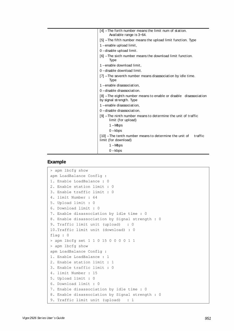
Vigor2926 Series User’s Guide 951
[4] – The forth number means the limit num of station. Available range is 3~64.
[5] – The fifth number means the upload limit function. Type
1 – enable upload limit,
0 – disable upload limit.
[6] – The sixth number means the download limit function. Type
1 – enable download limit,
0 – disable download limit.
[7] – The seventh number means disassociation by idle time. Type
1 – enable disassociation,
0 – disable disassociation.
[8] – The eighth number means to enable or disable disassociation by signal strength. Type
1 – enable disassociation,
0 – disable disassociation.
[9] – The ninth number means to determine the unit of traffic limit (for upload)
1 – Mbps
0 – kbps
[10] – The tenth number means to determine the unit of traffic limit (for download)
1 – Mbps
0 – kbps
EExxaammppllee
> apm lbcfg show apm LoadBalance Config : 1. Enable LoadBalance : 0 2. Enable station limit : 0 3. Enable traffic limit : 0 4. limit Number : 64 5. Upload limit : 0 6. Download limit : 0 7. Enable disassociation by idle time : 0 8. Enable disassociation by Signal strength : 0 9. Traffic limit unit (upload) : 0 10.Traffic limit unit (download) : 0 flag : 0 > apm lbcfg set 1 1 0 15 0 0 0 0 1 1 > apm lbcfg show apm LoadBalance Config : 1. Enable LoadBalance : 1 2. Enable station limit : 1 3. Enable traffic limit : 0 4. limit Number : 15 5. Upload limit : 0 6. Download limit : 0 7. Enable disassociation by idle time : 0 8. Enable disassociation by Signal strength : 0 9. Traffic limit unit (upload) : 1

Vigor2926 Series User’s Guide 952
10.Traffic limit unit (download) : 1 flag : 49
TTeellnneett CCoommmmaanndd:: aappmm aappddeetteecctt This command is used to enable/disable AP detection function.
SSyynnttaaxx
apm apdetect [get]
apm apdetect [set] [enable/disable AP Detection 1/0][Refresh Time].
SSyynnttaaxx DDeessccrriippttiioonn
Parameter Description
get It is used to get AP detection data from VigorAP (e.g., AP900).
set It allows to set detect configuration to VigorAP.
enable/disable AP Detection 1/0
It is used to enable or disable the AP detection function.
0 – disable the function.
1 – enable the function.
Refresh Time Available values are 1, 3 or 5 (minutes).
EExxaammppllee
Note: To check the scanning result of AP detection, use the command of “wl scan show”.
> apm napdetect set 1 1 > wl scan show 3 Sta Ch SSID BSSID BssType Security Siganl(%) Beacon Period First Detected Last Detected
11 DrayTek-LAN-B 02:1d:aa:4c:bd:a8 AP Mixed 26 100
11 DrayTek-LAN-A 00:1d:aa:4f:bd:a8 AP Mixed 42 100 Dec 09,10:35:44 Dec 09,10:35:44
TTeellnneett CCoommmmaanndd:: aappmm aappssyysslloogg This command is used to display the AP syslog data coming form VigorAP.
SSyynnttaaxx
apm apsyslog [AP_Index]
SSyynnttaaxx DDeessccrriippttiioonn
Parameter Description
AP_Index Specify the index number which represents VigorAP.
EExxaammppllee
> apm apsyslog 1 8d 02:46:09 syslog: [APM] Send Rogue AP Detection data. 8d 02:53:04 syslog: [APM] Run AP Detection / Discovery. 8d 02:56:09 syslog: [APM] Send Rogue AP Detection data. 8d 03:00:42 kernel: 60:fa:cd:55:f5:ea had disassociated. 8d 03:03:12 syslog: [APM] Run AP Detection / Discovery. 8d 03:06:09 syslog: [APM] Send Rogue AP Detection data. 8d 03:13:21 syslog: [APM] Run AP Detection / Discovery.
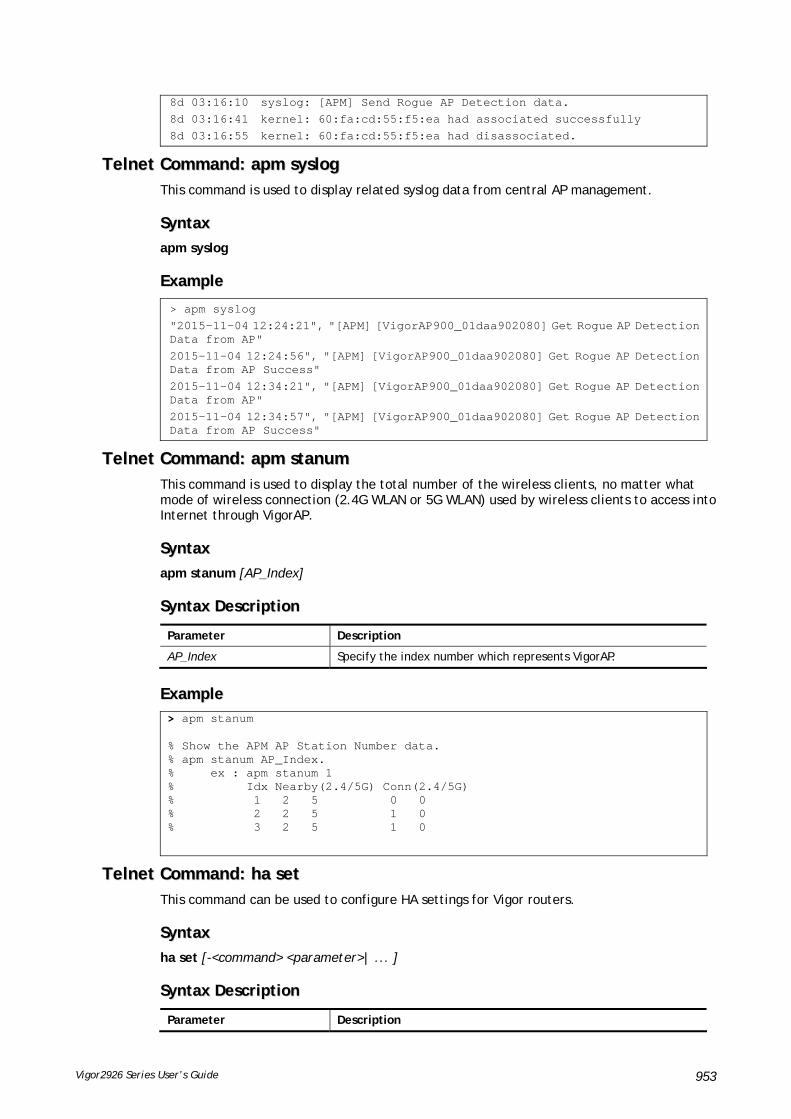
Vigor2926 Series User’s Guide 953
8d 03:16:10 syslog: [APM] Send Rogue AP Detection data. 8d 03:16:41 kernel: 60:fa:cd:55:f5:ea had associated successfully 8d 03:16:55 kernel: 60:fa:cd:55:f5:ea had disassociated.
TTeellnneett CCoommmmaanndd:: aappmm ssyysslloogg This command is used to display related syslog data from central AP management.
SSyynnttaaxx
apm syslog
EExxaammppllee
> apm syslog "2015-11-04 12:24:21", "[APM] [VigorAP900_01daa902080] Get Rogue AP Detection Data from AP" 2015-11-04 12:24:56", "[APM] [VigorAP900_01daa902080] Get Rogue AP Detection Data from AP Success" 2015-11-04 12:34:21", "[APM] [VigorAP900_01daa902080] Get Rogue AP Detection Data from AP" 2015-11-04 12:34:57", "[APM] [VigorAP900_01daa902080] Get Rogue AP Detection Data from AP Success"
TTeellnneett CCoommmmaanndd:: aappmm ssttaannuumm This command is used to display the total number of the wireless clients, no matter what mode of wireless connection (2.4G WLAN or 5G WLAN) used by wireless clients to access into Internet through VigorAP.
SSyynnttaaxx
apm stanum [AP_Index]
SSyynnttaaxx DDeessccrriippttiioonn
Parameter Description
AP_Index Specify the index number which represents VigorAP.
EExxaammppllee > apm stanum % Show the APM AP Station Number data. % apm stanum AP_Index. % ex : apm stanum 1 % Idx Nearby(2.4/5G) Conn(2.4/5G) % 1 2 5 0 0 % 2 2 5 1 0 % 3 2 5 1 0
TTeellnneett CCoommmmaanndd:: hhaa sseett This command can be used to configure HA settings for Vigor routers.
SSyynnttaaxx
ha set [-<command> <parameter>| ... ]
SSyynnttaaxx DDeessccrriippttiioonn
Parameter Description

Vigor2926 Series User’s Guide 954
[<command> <parameter>|…]
The available commands with parameters are listed below. […] means that you can type in several parameters in one line.
-e <1/0> 1: Enable the function of High Availability (HA). 0: Disable the function of High Availability (HA).
-l <1/0> 1: Enable the function of recording the operation record of HA in Syslog. 0: Disable the function of recording the operation record of HA in Syslog.
-M <1/0> Specify the Redundancy Method for HA. 1: Active-Standby 0: Hot-Standby
-v <1-255> Specify the group ID (VHID) 1- 255: Setting range.
-R Set HA settings to Factory Default.
-p <1-30> Specify the Priority ID. 1-30: Setting range.
-k <key> Specify the Authentication Key. Key: Max. 31 Characters.
-u <1/0> Enable or disable the function of Update DDNS. 1: Enable. When a router changes HA status to primary, it will update DDNS automatically. 0: Disable.
-m <interface> Specify the management interface. Interface: LAN1 ~ LAN6, DMZ.
-s It means to get the newest status of other router (except the local router).
-y It means sync local config to other router. Primary can executes this command. Secondary can not execute this commad.
-c <1/0> Enable or disable the function of Config Sync. 1: Enable. 0: Disable.
-I -[M|H|D] <interval> Set the Config Sync Interval for HA. Minimum interval is 15 minutes. -M: Minute. Setting range is 0/15/30/45. (e.g., ha set -I -M 30) -H: Hour. Setting range is from 0 to 23. (e.g., ha set -I -H 12) -D: Day. Setting range is from 0 to 30. (e.g., ha set -I -D 15)
-h -<4/6><Subnet> [<Virtual IP>]
Enable and set virtual IP to the subnet. 4: IPv4; 6: IPv6. Subnet: LAN1 to LAN6, DMZ. Virtual IP: The type format shall be “xxx.xxx.xxx.xxx”. (e.g, 192.168.1.0) For example, to enable a virtual IP to the sunet, simply type: ha set –h LAN1 192.168.1.5
-d -<4/6><Subnet> Disable a virtual IP to the subnet. 4: IPv4; 6: IPv6. Subnet: LAN1 to LAN6, DMZ. For example, to disable a virtual IP to the subnet, just type: ha set –h LAN1
-o <1/0> Run DARP protocol on IPv4 or IPv6. 0: IPv4 1: IPv6
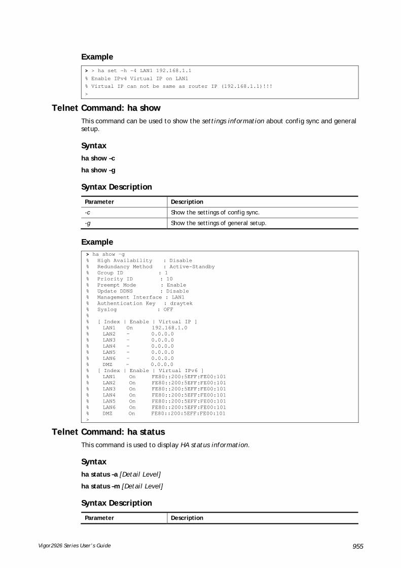
Vigor2926 Series User’s Guide 955
EExxaammppllee
> > ha set -h -4 LAN1 192.168.1.1
% Enable IPv4 Virtual IP on LAN1
% Virtual IP can not be same as router IP (192.168.1.1)!!!
>
TTeellnneett CCoommmmaanndd:: hhaa sshhooww This command can be used to show the settings information about config sync and general setup.
SSyynnttaaxx
ha show –c
ha show –g
SSyynnttaaxx DDeessccrriippttiioonn
Parameter Description
-c Show the settings of config sync.
-g Show the settings of general setup.
EExxaammppllee > ha show -g % High Availability : Disable % Redundancy Method : Active-Standby % Group ID : 1 % Priority ID : 10 % Preempt Mode : Enable % Update DDNS : Disable % Management Interface : LAN1 % Authentication Key : draytek % Syslog : OFF % % [ Index | Enable | Virtual IP ] % LAN1 On 192.168.1.0 % LAN2 - 0.0.0.0 % LAN3 - 0.0.0.0 % LAN4 - 0.0.0.0 % LAN5 - 0.0.0.0 % LAN6 - 0.0.0.0 % DMZ - 0.0.0.0 % [ Index | Enable | Virtual IPv6 ] % LAN1 On FE80::200:5EFF:FE00:101 % LAN2 On FE80::200:5EFF:FE00:101 % LAN3 On FE80::200:5EFF:FE00:101 % LAN4 On FE80::200:5EFF:FE00:101 % LAN5 On FE80::200:5EFF:FE00:101 % LAN6 On FE80::200:5EFF:FE00:101 % DMZ On FE80::200:5EFF:FE00:101 >
TTeellnneett CCoommmmaanndd:: hhaa ssttaattuuss This command is used to display HA status information.
SSyynnttaaxx
ha status –a [Detail Level]
ha status –m [Detail Level]
SSyynnttaaxx DDeessccrriippttiioonn
Parameter Description

Vigor2926 Series User’s Guide 956
-a Show the status for all of the routers in HA group.
-m Show the status of local router only.
Detail Level 0: Important status. 1: Important status, plus some information. 2: Show settings
EExxaammppllee > ha status -m 2 % [Local Router] DrayTek % IP : 192.168.1.1 (FE80::21D:AAFF:FEC6:4C50) % Status : ! % High Availability : ! Disable % Redundancy Method : Active-Standby % Group ID : 1 % Priority ID : 10 % Update DDNS : Disable % Protocol : IPv4 % Management Interface: LAN1 % Authentication Key : draytek % Virtual IP: (Max. 7 Virtual IPs) % ON LAN1 192.168.1.0 % Virtual IPv6: (Max. 7 Virtual IPv6s) % ON LAN1 FE80::200:5EFF:FE00:101 % ON LAN2 FE80::200:5EFF:FE00:101 % ON LAN3 FE80::200:5EFF:FE00:101 % ON LAN4 FE80::200:5EFF:FE00:101 % ON LAN5 FE80::200:5EFF:FE00:101 % ON LAN6 FE80::200:5EFF:FE00:101 % ON DMZ FE80::200:5EFF:FE00:101 % Config Sync : Disable % Config Sync Interval : 0 Day 0 Hour 15 Minute % Cached Time : 0 (s) >
TTeellnneett CCoommmmaanndd:: sswwmm sshhooww This command is used to display general setting of of VigorSwitch which connecting to Vigor router in LAN.
SSyynnttaaxx
swm show [LAN_port]
SSyynnttaaxx DDeessccrriippttiioonn
Parameter Description
LAN_port Specify the LAN port number (1 to 5).
EExxaammppllee > swm show ** If you connected a VigorSwitch but does not display here. ** Please check the LLDP is enabled and VLAN ID is matched on VigorSwitch. ***************************************************************************** LAN Port Model Name MAC IP Address Con Port -------- ---------------- ------------ --------------- --------- 1 G1241 00507FF105FD 192.168.1.10 23 ----------------------------------------------------------------------------- Internal VLAN is [Enable] Only show P1 related VLAN settings here. VLAN Subn Tag VID Pri LAN WLAN(2.4G) WLAN(5G) ---- ---- --- ---- --- ------------------ ------------ ------------ 0 LAN1 Off 0 0 P1,P2,P3,P4,P5,P6 none none 1 LAN1 On 20 0 P1,P2,P3,P4,P5,P6 none none 2 LAN1 On 100 0 P1,P2,P3,P4,P5,P6 none none

Vigor2926 Series User’s Guide 957
TTeellnneett CCoommmmaanndd:: sswwmm ggeett This command is used to get configuration information of VigorSwitch which connecting to Vigor router in LAN. Before using such command, make sure VigorSwitch has been managed under Vigor router (refer to Telnet Command: swm profile for adding a VigorSwitch device onto Vigor router).
SSyynnttaaxx
swm get [MAC]
SSyynnttaaxx DDeessccrriippttiioonn
Parameter Description
MAC Specify the MAC address of the switch.
EExxaammppllee
> swm get 00507ff0c33c
Start get cfg from 00507ff0c33c external switch
Please wait a few seconds...
Result: [OK].
TTeellnneett CCoommmmaanndd:: sswwmm ppoosstt This command is used to transfer switch configuration to VigorSwitch which connecting to Vigor router in LAN.
SSyynnttaaxx
swm post [MAC]
SSyynnttaaxx DDeessccrriippttiioonn
Parameter Description
MAC Specify the MAC address of the switch.
EExxaammppllee
> swm post 00507ff0c33c
Start post cfg to 00507ff0c33c external switch with correct settings.
Please wait a few seconds...
Result: [OK].>
TTeellnneett CCoommmmaanndd:: sswwmm aauutthh This command is used to display or remove the authentication record for external switch.
SSyynnttaaxx
swm auth [show/clear]
SSyynnttaaxx DDeessccrriippttiioonn
Parameter Description
show Display recorded external switch MAC address list.
clear Clear specific index of authentication record table.

Vigor2926 Series User’s Guide 958
Index range: (1 - 30)
EExxaammppllee > swm auth show ===== SWM Auth Records List===== Index Model Mac ----- ------ -------------- 1 G2261 00507ff0c33c ================================
TTeellnneett CCoommmmaanndd:: sswwmm eexxttvvllaann This command is used to configure port VLAN of VigorSwitch. Before using such command, make sure you have configured VLAN settings well.
SSyynnttaaxx
swm extvlan [LAN_Port][VLAN_idx][Port_Description]
SSyynnttaaxx DDeessccrriippttiioonn
Parameter Description
LAN_Port Setting range is from 1 to 5. VLAN_idx Type the enabled internal VLAN number.
Index number range for VLAN is from 0 to 7. Port_Description Setting range is from 1 to 24.
EExxaammppllee > swm extvlan 1 1 13 Set OK. > swm post 1 Start post cfg to LAN (1) external switch with currect settings.//post cfg Please wait a few seconds... Result: [OK].
System will cover the original VLAN settings on your VigorSwitch. Please backup the configuration file before you run this function.
System also will select the physical connect port as trunk port and let it join each VLAN group.
Before using such command, please use [swm show] to check valid VLAN index firstly.
TTeellnneett CCoommmmaanndd:: sswwmm eennaabbllee This command is used to enable central management for VigorSwitch.
SSyynnttaaxx
swm enable
TTeellnneett CCoommmmaanndd:: sswwmm ddiissaabbllee This command is used to disable central management for VigorSwitch.
SSyynnttaaxx
swm disable
TTeellnneett CCoommmmaanndd:: sswwmm ggrroouupp This command is used to gather several VigorSwitch devices as a group.
SSyynnttaaxx
swm group set [IDX][NAME][1][PASSWD]

Vigor2926 Series User’s Guide 959
swm group set [IDX][NAME][0]
swm group show
swm group add [IDX][MAC]
swm group delete [IDX][MAC]
SSyynnttaaxx DDeessccrriippttiioonn
Parameter Description
IDX Type the number to specify the index number of the group profile.
NAME Type a name for VigorSwitch group.
PASSWD Specify a password.
1,0 1 – Set group name and password. 0 - Set group name without password.
MAC Type the MAC address of the VigorSwitch.
add/delete Add – Make the selected switch (by specifying MAC address) to be grouped as VLAN.
EExxaammppllee
> swm group set 1 switchvlan 1 123456
> swm group show
Index Group Name Passwd Flag Member Switch
-------- -------------------- ----------- -------------------------------------
1 switchvlan 1 P2261(192.168.1.226),
2 0
3 0
4 0
5 0
6 0
7 0
8 0
9 0
10 0
Name IP Address MAC
---------------- ---------------- ------------
P2261 192.168.1.226 00507ff0c33c
>
TTeellnneett CCoommmmaanndd:: sswwmm pprrooffiillee This command is used to set switch profile for adding it to be managed by Vigor router, or removing it from Vigor router.
SSyynnttaaxx
swm profile add/delete [MAC]
swm profile show
swm profile enable_all/disable_all [MAC]
SSyynnttaaxx DDeessccrriippttiioonn
Parameter Description
Add Make the specified switch to be managed by Vigor router by typing the MAC address.
delete Remove the specified switch from Vigor router by typing the MAC address.

Vigor2926 Series User’s Guide 960
show Display all the switch devices managed under Vigor router.
Enable_all Enable all of the switch devices.
Disable_all Disable all of the switch devices.
MAC Type the MAC address of the VigorSwitch.
EExxaammppllee
> swm profile show
Name IP Address MAC Model Group
---------------- ---------------- ------------ ------ -------------------------
P2261 192.168.1.226 00507ff0c33c P2261 switchvlan,
IP Address MAC Model
---------------- ------------ ------
TTeellnneett CCoommmmaanndd:: sswwmm ddeettaaiill This command is used to configure detailed information for VigorSwitch.
SSyynnttaaxx
swm detail comment [MAC][COMMENT]
swm detail name [MAC][NAME]
swm detail passwd [MAC][PASSWD]
swm detail config [MAC][config]
swm detail show
swm detail port show [MAC]
swm detail port [MAC][PORT][FLAG][SCHED1][SCHED2][DESCRIPTION]
SSyynnttaaxx DDeessccrriippttiioonn
Parameter Description
[MAC][COMMENT] Modify the comment of VigorSwitch. MAC - Type the MAC address of the switch. COMMENT – Type a description for the switch.
[MAC]{NAME} Modify the name of VigorSwitch. MAC - Type the MAC address of the switch. NAME – Type a name for the switch.
[MAC][PASSWD] Modify the password of VigorSwitch. MAC - Type the MAC address of the switch. PASSWD – Type the password for the switch.
[MAC][config] Modify the config file of VigorSwitch. MAC - Type the MAC address of the switch. config – Type the config name of the switch.
show Display all of the switches’ status.
[MAC][PORT][FLAG][SCHED1][SCHED2][DESCRIPTION]
Modify the port description for specific switch.
EExxaammppllee
> swm detail show
Idx Name MAC Comment Config Status
---- ---------------- ------------ ---------------- ------------ --------
1 P2261 00507ff0c33c justfortest 1 None Connect
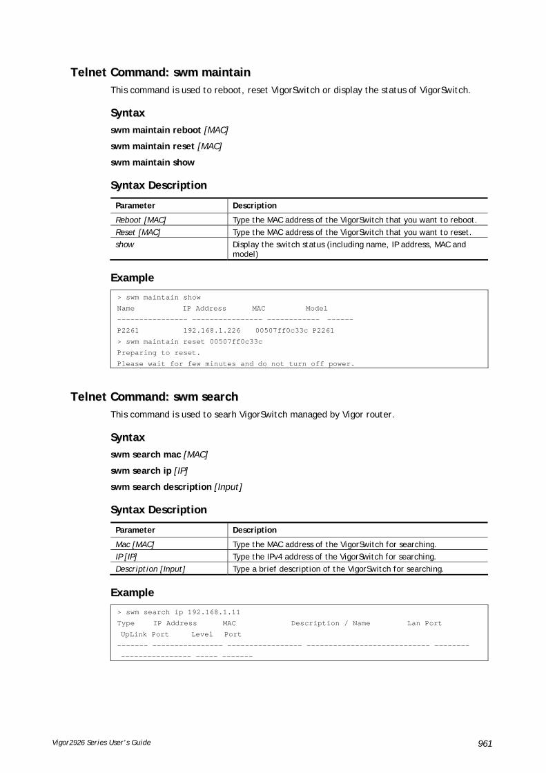
Vigor2926 Series User’s Guide 961
TTeellnneett CCoommmmaanndd:: sswwmm mmaaiinnttaaiinn This command is used to reboot, reset VigorSwitch or display the status of VigorSwitch.
SSyynnttaaxx
swm maintain reboot [MAC]
swm maintain reset [MAC]
swm maintain show
SSyynnttaaxx DDeessccrriippttiioonn
Parameter Description
Reboot [MAC] Type the MAC address of the VigorSwitch that you want to reboot.
Reset [MAC] Type the MAC address of the VigorSwitch that you want to reset.
show Display the switch status (including name, IP address, MAC and model)
EExxaammppllee
> swm maintain show
Name IP Address MAC Model
---------------- ---------------- ------------ ------
P2261 192.168.1.226 00507ff0c33c P2261
> swm maintain reset 00507ff0c33c
Preparing to reset.
Please wait for few minutes and do not turn off power.
TTeellnneett CCoommmmaanndd:: sswwmm sseeaarrcchh This command is used to searh VigorSwitch managed by Vigor router.
SSyynnttaaxx
swm search mac [MAC]
swm search ip [IP]
swm search description [Input]
SSyynnttaaxx DDeessccrriippttiioonn
Parameter Description
Mac [MAC] Type the MAC address of the VigorSwitch for searching.
IP [IP] Type the IPv4 address of the VigorSwitch for searching.
Description [Input] Type a brief description of the VigorSwitch for searching.
EExxaammppllee
> swm search ip 192.168.1.11
Type IP Address MAC Description / Name Lan Port
UpLink Port Level Port
------- ---------------- ----------------- ---------------------------- --------
---------------- ----- -------

Vigor2926 Series User’s Guide 962
TTeellnneett CCoommmmaanndd:: sswwmm ddbb This command is used to set corresponding actions (for database) while encountering alert event.
SSyynnttaaxx
swm db ctl en /dis
swm db ctl show
swm db alert notify [N/S]
swm db alert action [S/B]
swm db alert sms [IDX]
swm db alert mail [IDX]
SSyynnttaaxx DDeessccrriippttiioonn
Parameter Description
ctl en / dis It means to enable / disable the database for recording switch management information.
ctl show It means to display the database control status.
alert notify [N/S] It means to send notification or take no action for database while ecountering alert event. N - Don't send notification S - Send notification
alert action [S/B] Set the action for (stop or backup) database while ecountering alert event. S - Stop recording urser information. B - Backup and clean up all user info, and start a new record.
alert sms [IDX] Set object for SMS alert notification. IDX – It menas the index number of availabe object profile. Range is 1 ~ 64.
alert mail [IDX] Set object for mail alert notification. IDX – It menas the index number of availabe object profile. Range is 1 ~ 64.
EExxaammppllee
> swm db ctl en
Enable database to recoard SWM information.
DrayTek> swm db ctl show
Record SWM information: Enable.
Notification :
Dont't send notification.
action : Stop recording user information.
TTeellnneett CCoommmmaanndd:: sswwmm aalleerrtt This command is used to configure settings for alert and log for VigorSwitch management.
SSyynnttaaxx
swm alert enable/disable
swm alert show
swm alert en/dis [Idx]

Vigor2926 Series User’s Guide 963
swm alert set [Idx] log [e/d]
swm alert set [Idx] name [name]
swm alert set [Idx] color [O/R/N]
swm alert set [Idx] notif [e/d]
swm alert set [Idx] obj [object idx] [object value]
swm alert display
swm alert en/dis [sw/port] [mac]
swm alert sw show [mac]
swm alert set sw [mac] [incident idx] [level idx]
swm alert port show [mac]
swm alert set port [mac] [port num][incident idx] [level idx]
SSyynnttaaxx DDeessccrriippttiioonn
Parameter Description
enable/disable Enable/disable alert mechanism.
show Display all alert setup information.
en/dis [Idx] Enable/disable alert action for certain profile. Idx – Indicate profile to be configured; available range: 1 – 8.
set [idx] log [e/d] Enable/disable log action for certain profile. Idx – Indicate profile to be configured; available range: 1 – 8. 8. e/d – Enable/disable the profile.
set [idx] name [name] Set level name which can represent different severiy level. Idx – Indicate profile to be configured; available range: 1 – 8. name – Type a string to indicate the severity level.
set [idx] color [O/R/N] Set color for alert for certain profile. Idx – Indicate profile to be configured; available range: 1 – 8. O/R/N – O means orange; R means red; N means white
set [idx] notif [e/d] Enable/disable the notification action for certain profile. Idx – Indicate profile to be configured; available range: 1 – 8. e/d - Enable/disable the mechanism for sending the notification.
set [idx] obj [object idx] [object value]
Set notifiction by SMS or E-mail thorugh the object profile selelcted for specified profile. Idx – Indicate profile to be configured; available range: 1 – 8. object idx - Available range: 1 – 4 object value – Available range: 1 – 20
swm alert display Display all switch and port alert state.
en/dis [sw/port][mac] Enable/disable Switch/Port Action. sw/port – Type a port number for VigorSwitch. mac – Type MAC address of the VigorSwitch.
sw show [mac] Display VigorSwitch Incident Alert
set sw [mac] [incident idx] [level idx]
Set incident alert for VigorSwitch. mac- Type MAC address of the VigorSwitch. level idx – Available range: 1 – 8. Each number represents different severity level.
port show [mac] Display the incident alert setting for all LAN ports of certain VigorSwitch (specified by MAC address). Mac – Type the MAC address of the VigorSwitch.
set port [mac] [port num][incident idx][level idx]
Set incident alert for each Ethernet port of VigorSwitch. mac- Type MAC address of the VigorSwitch. port num – Type a port number for VigorSwitch.

Vigor2926 Series User’s Guide 964
Incident id – Type an index number of the incident. level idx – Available range: 1 – 8. Each number represents different severity level.
EExxaammppllee
> swm alert set 5 obj 1 > swm alert display Name IP Address Model Sw-Alert Port-Alert ---------------- ---------------- ------ -------- ---------- G2260 192.168.1.11 G2260 En En > DrayTek> swm alert set port 000854123456 5 1 2 DrayTek> swm alert port show 000854123456 Port (1)Reconnect (2)Disconnect (3)Schedule on/off (4)Shutdown En/Dis-------- ---------------- ----------------- ------------------ ------------------1 No Alert No Alert No Alert No Alert 2 No Alert No Alert No Alert No Alert 3 No Alert No Alert No Alert No Alert 4 No Alert No Alert No Alert No Alert 5 Minor Alert No Alert No Alert No Alert 6 No Alert No Alert No Alert No Alert 7 No Alert No Alert No Alert No Alert 8 No Alert No Alert No Alert No Alert 9 No Alert No Alert No Alert No Alert 10 No Alert No Alert No Alert No Alert DrayTek> swm alert sw show 000854123456 Idx En/Dis Level Color Create Log Send Notification(1-4) ----- ------ ------------ -------- ------------ ---------------------- 1 En No Alert No Color Disable Disable 0 , 0 , 0 , 0 2 En Minor Alert No Color Enable Disable 0 , 0 , 0 , 0 3 En Moderate Alert Orange Enable Disable 1 , 1 , 1 , 1 4 En Major Alert Red Enable Disable 1 , 1 , 1 , 1 5 Dis No Color Disable Disable 1 , 1 , 1 , 1 6 Dis No Color Disable Disable 1 , 1 , 1 , 1 7 Dis No Color Disable Disable 1 , 1 , 1 , 1 8 Dis No Color Enable Disable 1 , 1 , 1 , 1 Name IP Address ---------------- ---------------- Switch 192.168.1.11 Index Incident Type ----- -------------------- ---------------- 1 Cold Start Major Alert 2 Warm Start Major Alert 3 Disconnect Major Alert
TTeellnneett CCoommmmaanndd:: sswwmm lloogg This command is used to configure settings for VigorSwitch and display VigorSwitch’s log,
SSyynnttaaxx
swm log show filter
swm log show day
swm log show week
swm log set level [idx] on/off
swm log set type [idx] on/off
swm log set switch [mac] on/off
SSyynnttaaxx DDeessccrriippttiioonn
Parameter Description
show filter Display log settings including index number, on /off status, alert level, enabling / disabling, alert type, device name, MAC address and etc. for VigorSwitch.

Vigor2926 Series User’s Guide 965
show day Display day Log for VigorSwitch.
show week Display week Log for VigorSwitch.
set level [idx] on/off Enable / disable the alert with different severity. Idx- Range 1 to 4. 1 means No Alert; 2 means Minor Alert; 3 means Moderate Alert; 4 means Major Alert. On – Enable Off - Disable
set type [idx] on/off Enable / disable the Port Alert / Switch Alert. Idx- 1 means Port Alart; 2 means Switch Alert. On – Enable Off - Disable
set switch [mac] on/off Enable (on) or disable (off) the log recorded mechanism for specified VigorSwitch. mac- Type MAC address of the VigorSwitch.
EExxaammppllee
> swm log set type 1 on
> swm log set level 1 on
> swm log show weekTotal Logs:0
> swm log show filter
Index Status Level En/Dis
----- ------ --------------- --------
1 on No Alert En
2 off Minor Alert En
3 off Moderate Alert En
4 off Major Alert En
5 off Dis
6 off Dis
7 off Dis
8 off Dis
Index Status Type
----- ------ -------------
1 on Port Alert
2 off Switch Alert
Index Status Switch Name Model Mac Address
----- ------ --------------- ------ --------------
TTeellnneett CCoommmmaanndd:: sswwmm ssnnmmpp This command is used to display information about SNMP.
SSyynnttaaxx
swm snmp sys [MAC]
swm snmp iftbl [MAC][port_num]
swm snmp poe [MAC]
SSyynnttaaxx DDeessccrriippttiioonn
Parameter Description
sys [MAC] Type the MAC address of the VigorSwitch to display the SNMP system information.

Vigor2926 Series User’s Guide 966
Iftbl[MAC][port_num] Type the MAC address and the port number of the VigorSwitch to display SNMP port interface information.
EExxaammppllee
> swm snmp sys 00507ff0c33c
sysDescr:20-Port 10/100/1000Base-T + 4 TP/(100/1G) SFP Combo + 2 (100/1G) SFP Po
E+ L2 Plus Managed Switch
sysObjectID:1.3.6.1.4.1.5205.2.61
sysUpTime:24 hr 8 m 46 s
sysContact:
sysName:P2261
sysLocation:
sysServices:3
ifNumber:26

Vigor2926 Series User’s Guide 967
IInnddeexx 3
3G/4G USB Modem, 52
3G/4G USB Modem (DHCP mode), 72, 74
6
6rd Mode, 85
6rd Prefix, 86
6rd Prefix Length, 86
8
802.1x ports, 129
A
Accelerate heaviest traffic sessions, 131
Access Control, 258
Access List, 460
Access Mode, 61
Access Mode - Ethernet, 60
Access Mode - LTE, 60
Access Mode - USB, 60
Access Tech, 243
Account Number, 288
Activation, 469
Active Directory/LDAP, 166
Active Mode, 55, 56
Active When, 57, 59
Active-Standby, 179
Additional Filter, 168
Address Mapping, 205, 222
Administrator Password, 441
Advance Mode, 382
Advanced Mode, 238
Advanced Setting, 266
Aggregation MSDU, 266
AH, 328
Airtime Fairness, 271
Always On, 59, 66, 76, 78, 79, 80, 81, 82, 84, 86, 89
Analyze, 396
Anonymous, 166
Antenna Installation, 3
AP Discovery, 270
AP Maintenance, 568, 576
AP Map, 568, 577
APN Name, 71, 73, 74
APP Enforcement, 379
APP Enforcement Filter, 401
APP Enforcement Profile, 402
APP QoS, 485
APPE Module Version, 406
APPE Signature Upgrade, 406
Applications, 146
Apply the Class Rule, 131
APSD Capable, 267
ARP Cache Table, 659
ARP Detect, 63, 66, 71, 73, 75
ARP Table, 126
Auth Type, 151
Authentication, 75, 164
Authentication Information, 676
Authentication Key, 180
Authentication Mode, 261
Authentication Port, 163
Authentication Type, 129
Auto Adjustment, 269
Auto Logout, 22
Auto Weight, 55
Auto-Update interval, 149
Aux. WAN IP, 141
B
Backup, 126
Backup Mode, 349
Backup MX, 151
Backup Phone Number, 292
Band Steering, 273
Bandwidth Limit, 472, 476

Vigor2926 Series User’s Guide 968
Bandwidth Management, 269
Barring Type, 296
Base Distinguished Name / Group Distinguished Name, 168
Beacon Period, 582
Bind IP to MAC, 125
Bind to WAN, 357
Bind Type, 166
Block Anonymous, 298
Block IP Calls, 298
Block Unknown Domain, 298
Bogus DNS Reply, 157
Bonjour, 175
Bridge, 262, 265
Bridge mode, 91
Bridge Mode, 66, 81, 83
Bridge Subnet, 66, 83
Brute Force Protection, 458
C
Cache, 413
Call Barring, 295
Call Direction, 296, 331
Call Filter, 374
Call Forward, 297
Call Forwarding, 289
Call Transfer, 300
Call Waiting, 298
Certificate Backup, 372
Certificate Management, 365
Change the TTL value, 64, 67
Channel, 87, 250, 254
Channel Bandwidth, 266
Choose IP, 139
CLIR, 300
Codepage, 379
Comment, 126, 141
Common Name Identifier, 168
Config Backup, 29
Config Sync, 180
Configuration Backup, 448
Configure via Client PinCode, 261
Configure via Push Button, 261
Connection Management, 349
Connection Type, 151
Connectivity, 51
Country Code, 267
CPE Management, 550
CSM, 401
CSV file, 612, 615
Current System Time, 159
D
Dashboard, 24, 569
Data Coding Scheme, 240
Data Filter, 374
Data Flow Monitor, 665
Data Quota, 503
DataType, 61
Daylight Saving, 454
Days in a week, 160
Default Lifetime, 115
Default MAC Address, 64, 67
Default Preference, 115
Default Rule, 378
Destination IP, 213
Destination Port, 162
Details - PPPoE, 62
Details Page, 61
Details-3G/4G USB Modem (DHCP mode), 74
Details-3G/4G USB Modem(PPP mode), 70
Details-IP Routed Subnet, 110
Details-IPv6-6in4 Static Tunnel, 84
Details-IPv6-6rd, 85
Details-Ipv6-AICCU, 79
Details-IPv6-DHCPv6 Client, 81
Details-IPv6-Offline, 76
Details-IPv6-PPP, 76
Details-IPv6-Static IPv6, 82
Details-IPv6-TSPC, 77
Details-LAN-DMZ, 108
Details-LAN-Ethernet, 106
Details-PPTP/L2TP, 68
Details-Static IP or Dynamic IP, 65
Determine Real WAN IP, 151
DFS Restrictions, 248

Vigor2926 Series User’s Guide 969
DHCP, 40
DHCP Client Identifier, 67
DHCP Server Configuration, 107, 109, 111
DHCP Server IP Address, 107, 109
DHCP Table, 661
DHCPv6 (Stateful), 113
DHCPv6 Server, 114
Diagnose, 158, 217
Diagnostics, 656, 657
Dial-out Triggering, 657
DialPlan, 291
Digit Map, 293
Digital Signature, 313, 328
Display Name, 56, 58, 61
DMZ Host, 138
DNS Cache Table, 663
DNS Filter, 379
DNS Filter Profile, 416
DNS Security, 157
DNS Server, 158
DNS Server IP Address, 67, 107, 110
DNS Server IPv6 Address, 114
Do Not Disturb, 297
Domain, 158
Domain Diagnose, 158
Domain Name, 67, 150, 216
DoS Defense, 375, 391
DoS Flood Table, 677, 679
Download Limit, 269
DrayTek Banner, 389
DTMF, 302
Dynamic DNS, 146, 148
Dynamic DNS Account, 150, 152
E
Each / Shared, 477
Enable PING to keep alive, 65
End IPv6 Address, 114
End Port, 142
ESP, 328
Event Code, 439
Event Log, 584
Extension WAN, 115
External Devices, 607
External RADIUS, 161
External TACACS+, 164
F
Failover, 56, 59
Failover to/Failback, 205
File Explorer, 646
File Extension Object, 626
Filter Setup, 381
Firewall, 374
Firmware Upgrade, 467
Fixed IP, 64, 69, 89
Force NAT /Force Routing, 214
Force Update, 149
Fragment Length, 267
Function Support List, 586
G
Gateway IP Address, 67, 107, 109
General Mode, 349
General Setup, 54
Get Community, 455
Google Map, 556
GRE, 336
Green Field, 266
Group, 598
Group ID, 171, 180
Guard Interval, 266
GUI Map, 27
H
Hardware Acceleration, 130
Hardware Installation, 12
Hide caller ID, 298
Hide SSID, 255
High Availability, 178
High Availability Status, 673
Host Name, 41
Hot-Standby, 179

Vigor2926 Series User’s Guide 970
I
IAID, 81
ICMP, 346
Idle Timeout, 64, 89, 327
IGMP, 170
IGMP Proxy, 170
IGMP Snooping, 170
IKE Authentication Method, 335
IM, 403
Incoming Port, 145
Incoming Protocol, 144
Indicators and Connectors, 2, 10
Installation, i
Inter-LAN Routing, 106
Internal RADIUS, 162
Internal Service User List, 471
Internet Access, 60
Internet Access - Advanced, 61
IP (Internet Protocol), 52
IP Address, 67, 69, 106, 109, 111
IP Address Assignment Method (IPCP), 64
IP Address Assignment Method(IPCP), 69
IP Address List, 155
IP Based, 55
IP Bind List, 126
IP Call, 285
IP Filters, 374
IP Object, 611
IP Pool Counts, 107, 109, 111
IP Routed Subnet, 476
IPsec General Setup, 323
IPsec Tunnel, 327
IPsec VPN Settings, 549
IPTV, 89
IPv4 Border Relay, 86
IPv4 Mask Length, 86
IPv6 Address, 82
IPv6 Gateway Address, 82
IPv6 Group, 618
IPv6 Neighbour Table, 660
IPv6 Object, 616
IPv6 TSPC Status, 672
Isolate, 255
ISP Access Setup, 62, 68
ISP Name, 89
K
keep alive, 331
Keep Alive Period, 439
Keep WAN Connection, 65
Keyword Group, 625
Keyword Object, 623
L
LAN, 102
LAN DNS / DNS Forwarding, 146, 154
LAN- General Setup, 104
LAN Port Mirror, 128
LAN Routed Prefix, 84
LAN to LAN, 329
Landing Page, 498, 502
Last Call Return, 297
LDAP, 166
LDAP /Active Directory Setup, 146
Lease Time, 107, 109, 111
Line Speed, 55, 56, 58
Load Balance, 59, 585
Load Balance for AP, 568
Load Balance Mode, 55
Load-Balance, 220
Load-Balance /Route Policy, 212
Local 802.1X, 471
Local 802.1X General Setup, 183
Local Certificate, 313, 366
Local ID, 328
Local IP Address, 141
Log, 410
Log & Alert, 558
Login, 48
Login Name, 151
Login Page Greeting, 446
Login Page Logo, 498
Login Password, 596
Logout, 29
Long Preamble, 266

Vigor2926 Series User’s Guide 971
Loop through, 292
LTE, 44, 234
LTE hardware version, 75
LTE Status, 243
M
Mail Alert, 174
Mail Extender, 151
Mail Service, 174
Main Screen, 22
Maintenance, 600
Management, 433, 457
Management Interface, 180
Max User Login, 501
Mic Gain, 302
Min/Max Interval Time, 115
Mirror Port, 128
Mode, 250, 256
Modem Code Upgrade, 468
Modem Dial String, 71
Modem Initial String, 71
Modem Initial String2, 71
Modem Support List, 70, 72, 650
mOTP, 327, 359
MPPE, 321
MTU, 63, 66, 68, 73, 75, 115
Multicast via VPN, 327, 359
Multiple SSID, 246
multiple-WAN, 54
Multi-VLAN, 87
MyVigor, 46, 412
N
Name Link, 25
NAT, 133
NAT Sessions Table, 662
NAT Traversal, 169, 284, 288
Neighbor AP Detection, 581
NetBios Name Service, 644
Netbios Naming Packet, 327
Network Configuration, 106, 109, 111
Network Interface, 211
Network Mode, 73, 74
Notification Object, 633
NS Detect, 81
O
Objects Settings, 610
Online Statistics, 479
OP Number, 294
Open Ports, 141
Operation Mode, 266
Option Number, 61
P
P2P, 404
PAP, 322
Password, 62, 67, 68, 75, 78, 79, 89
Password Strength, 257, 443
Path MTU Discovery, 63, 66, 68, 73, 75
Peer ID, 319
Peer-to-Peer, 281
Per Station Limit, 269
Phone Book, 291
Phone Settings, 299
Physical Connection, 30
Physical Members, 91
Physical Mode, 55, 56, 58, 61
Physical Type, 55, 56
PIN Code, 359
Ping Detect, 63, 66, 71, 73, 76, 78, 80, 81, 82, 84, 86
Ping Diagnosis, 664
Ping Gateway IP, 63, 66, 71, 73, 75
Ping Interval, 63, 66, 71, 73, 75
PING Interval, 65
Ping IP/Hostname, 76, 78, 80, 81, 82, 84, 86
Ping Retry, 63, 66, 71, 73, 75
Policy, 501
Polling Interval, 549
Port Redirection, 134
Port Triggering, 143, 145
Port-based Bridge, 88
Port-Based VLAN, 121
PPP Authentication, 64, 69, 71, 89

Vigor2926 Series User’s Guide 972
PPP General Setup, 321
PPP Password, 71
PPP Setup, 69
PPP Username, 71
PPP/MP Setup, 64
PPPoE, 34
PPPoE Pass-through, 63
PPTP, 327
PPTP/L2TP, 37
Prefer Codec, 289
Prefix Len, 210
Prefix Length, 82
Pre-shared Key, 265
Pre-Shared Key (PSK), 257
Primary DNS Sever, 114
Primary IP Address, 107, 110
Primary/Secondary Ping IP, 63, 66, 71, 73, 75
Printer Server, 644
Priority, 57, 91, 123, 205, 217
Priority ID, 180
Private IP, 136
Private IP Address, 52
Private Port, 136
Production Registration, 48
Protocol, 180, 404
Protocol Processing Engine (PPE), 130
Provider Host, 150
Psec Peer Identity, 324
PSTN Setup, 298
Public IP Adderss, 52
Public Port, 136
Q
QoS Setting Example, 491
Quality of Service, 472, 478
Quick Access, 26
Quick Start Wizard, 33
Quota Limit, 93
R
RADIUS/TACACS+, 146, 161
Rate Control, 103
Reboot System, 466
Recipient, 173
Recipient Number, 240
Redundancy Method, 179
Regional, 297
Registering Vigor Router, 48
Regular DN, 167
Regular Mode, 166
Regular Password, 167
Relay Agent, 107, 109
Remote Access Control, 320
Remote Dial-in User, 326
Remote Endpoint IPv4 Address, 84
Repeater, 262, 265
Replace, 293
Restore, 126
Ring Pattern, 289
Ring Port, 289
RIP Protocol, 66
RIPng Protocol, 77, 81, 115
Rogue AP Detection, 581
Rogue APs, 583
Root CA, 370
Route Policy, 205
Router Advertisement Configuration, 115
Router Commands, 241
Router Name, 67, 451
Routing, 205
Routing Information Protocol, 103
Routing Table, 658
RTP, 284
RTP TOS, 284
RTS Threshold, 267
Rule-Based, 497
S
SAS Voice Prompt, 284
Scan, 270
Schedule, 146, 159, 255
Secondary DNS Server, 114
Secondary IP Address, 107, 110
Secure Phone, 284
Security, 256, 373

Vigor2926 Series User’s Guide 973
Security Key, 250
Self-signed, 357
Self-Signed Certificate, 464
Send SMS, 240
Sensor, 648
Server Address, 68
Server Certificate, 357
Server IP Address, 162
Server Response, 151
Service, 144
Service Activation Wizard, 46
Service API, 150
Service Name, 71, 136
Service Provider, 150, 152, 629
Service Type, 150
Service Type Group, 621
Service Type Object, 619
Sesseion Based, 55
Sessions Control, 378
Sessions Limit, 472, 474
Set Community, 455
Set to Factory Default, 148, 159, 206
Setup Query Server, 413
Shared Secret, 162, 163, 165
SIM card, 234
SIM PIN code, 70, 74
Simple Mode, 166, 237
SIP, 280
SIP Accounts, 286
SLAAC(stateless), 113
Smart Bandwidth Limit, 477
SMB, 644, 645
SMB Client Support List, 651
SMS / Mail Alert Service, 173
SMS Alert, 173
SMS Inbox, 237
SMS Provider, 173
SMS Quota Limit, 235
SMS/Mail Service Object, 628
SNMP, 455
Source IP, 136, 142, 144, 213
Speaker Gain, 302
Specific Hosts, 131
Specify Remote Node, 327
SPI, 375
SSID, 251
SSL Tunnel, 327
SSL VPN, 356
Start IP Address, 107, 109, 111
Start IPv6 Address, 114
Start Port, 142
Static IP, 39
Static Route, 103, 206
Static Route for IPv6, 210
Station Control, 268
Station List, 247, 277, 278
Station Number, 585
Stations (STA), 246
Status, 570
Strict Bind, 125
Strict Security Checking, 389
Strict Security Firewall, 377
String Object, 635, 636
Strip, 293
STUN Settings, 439
Subnet, 122
Subnet Mask, 67, 69, 106, 109, 111
Subnet Prefix, 79
Support List, 601, 605, 606
Switch, 591
Switch Hierarchy, 594
Switch Status, 591
Sync User Profile, 183
Syslog Alarm, 649
Syslog Explorer, 671
Syslog/Mail Alert, 451
System Maintenance, 434
System Status, 436
System time set, 159
T
T.38 Fax, 300
TACACS+, 363
Tag value, 57
Tagged VLAN, 121
TCP, 346

Vigor2926 Series User’s Guide 974
Temperature Sensor, 648
Time and Date, 454
Time Quota, 502
Time Schedule, 477
Time Server, 454
Time Zone, 454
Tone Power Level, 302
Total Traffic, 584
TR-069, 438
Trace Route, 670
Traceable, 485
Traffic Graph, 580, 668
Traffic Threshold, 56, 59
Trap Community, 456
Triggering Port, 144
Triggering Protocol, 144
Troubleshooting, 655
Trusted CA, 371
Trusted CA Certificate, 370
TSPC, 77
TTL (Time to Live), 63, 66, 73, 75, 76, 78, 80, 81, 82, 84, 86
Tunnel Broker, 78, 79
Tunnel ID, 79
Tunnel TTL, 84
TX Power, 267
U
UDP, 346
Unique Local Address (ULA), 113
Update DDNS, 180
Upload Limit, 269
UPnP, 147, 169
URL Access Control, 410
URL Content Filter, 379, 401
URL Content Filter Profile, 408
USB, 42
USB Application, 642
USB Device Status, 647
USB General Settings, 643
USB User Management, 644
User Account, 358
User Group, 362, 504
User Management, 496
User Online Status, 505
User Password, 443
User Profile, 164, 183, 499
User-Based, 497
Username, 62, 67, 68, 78, 79, 89
UserName, 75
V
VID, 123
View SMS Outbox Cache, 240
Virtual LAN, 103
Virtual Panel, 25
Virtual WAN, 32
VLAN, 121
VLAN Applications, 692
VLAN Configuration, 124
VLAN Tag, 87, 91, 123
VLAN Tag insertion, 57
Voice Active Detector, 290
VoIP, 279
VoIP Wizard, 282
Volume Gain, 302
VPN, 307, 547
VPN and Remote Access, 308
VPN Backup, 340
VPN Client Wizard, 309
VPN Dial-Out Through, 313
VPN Graph, 669
VPN Load Balance, 340
VPN Management, 557
VPN Server Wizard, 316
VPN Trunk Management, 340
W
Wake by IP Address, 172
Wake on LAN, 147, 172
WAN, 52
WAN Budget, 92
WAN Budget-Custom, 93
WAN Budget-Cycle duration, 93
WAN Budget-Status, 94

Vigor2926 Series User’s Guide 975
WAN Connection Detection, 63, 66, 71, 73, 75, 76, 78, 80, 81, 82, 84, 86
WAN Failure, 56
WAN Inbound Bandwidth, 480
WAN Interface, 136, 141, 150, 152
WAN IP Alias, 64, 67, 69
WAN IP Network Settings, 67, 69
WAN Outbound Bandwidth, 480
WAN Setup, 89
WAN Type, 87, 89, 91
WCF, 2
WDS, 262
Web Console, 28
Web Content Filter, 379, 401
Web Content Filter Profile, 412
Web Feature, 411
WEP, 247, 257
white/black list, 258
Wildcard, 151
Wired 802.1x, 129
Wireless LAN, 245
Wireless Wizard, 249
Wizard Mode, 382
WLAN Isolation, 247
WLAN Profile, 571
WMM Capable, 267
WPA, 247, 257
WPS, 248, 259
Z
ZRTP+SRTP, 292