iVIEW-100 Series user's Manual, 2014, v3.0 - ICP DAS
186
iVIEW-100 Series user’s Manual, 2014, v3.0 ----- 1 iVIEW-100 Series iVIEW-100-40/iVIEW-100 Handheld Controller User’s Manual Ver 3.0 / 2014/04
-
Upload
khangminh22 -
Category
Documents
-
view
0 -
download
0
Transcript of iVIEW-100 Series user's Manual, 2014, v3.0 - ICP DAS

iVIEW-100 Series user’s Manual, 2014, v3.0 ----- 1
iVIEW-100 Series
iVIEW-100-40/iVIEW-100
Handheld Controller
User’s Manual
Ver 3.0 / 2014/04

iVIEW-100 Series user’s Manual, 2014, v3.0 ----- 2
iVIEW-100 Series
iVIEW-100-40/iVIEW-100
Handheld Controller
User’s Manual
Warranty
All products manufactured by ICP DAS are warranted against defective materials for a period of one year from the date of delivery to the original purchaser.
Warning
ICP DAS assumes no liability for damages consequent to the use of this product. ICP DAS reserves the right to change this manual at any time without notice. The information furnished by ICP DAS is believed to be accurate and reliable. However, no responsibility is assumed by ICP DAS for its use, nor for any infringements of patents or other rights of third parties resulting from its use.
Copyright
Copyright© 2002~2014 by ICP DAS. All rights are reserved.
Trademark
The names used for identification only maybe registered trademarks of their respective companies.

iVIEW-100 Series user’s Manual, 2014, v3.0 ----- 3
Table of Contents Reference Guide 6
CHAPTER 1. INTRODUCTION ................................................................... 7
1.1 PACKAGE LIST .......................................................................................................................................................... 7
1.2 IVIEW-100 SERIES .................................................................................................................................................. 8
1.3 FEATURES................................................................................................................................................................. 9
1.4 SPECIFICATIONS ......................................................................................................................................................11
1.5 CONTENTS OF CD ....................................................................................................................................................12
CHAPTER 2. HARDWARE INFORMATION .......................................... 13
2.1 VIEW OF IVIEW-100 .............................................................................................................................................13
2.1.1 Front view ..........................................................................................................................................................13
2.1.2 Bottom view........................................................................................................................................................13
2.2 EXPANDED PICTURE OF IVIEW-100 ........................................................................................................................14
2.3 BLOCK DIAGRAM OF IVIEW-100 ............................................................................................................................15
2.4 PIN ASSIGNMENT OF IVIEW-100 .............................................................................................................................16
2.4.1 Pin assignment of Mini-DIN Connector ............................................................................................................16
2.4.2 Pin assignment of DB-15 Female Connector .....................................................................................................17
2.5 PIN ASSIGNMENT OF CABLES ...................................................................................................................................18
2.5.1 Pin assignment of CA-M910 cable.....................................................................................................................18
2.5.2 Pin assignment of CA-1509 cable ......................................................................................................................19
2.6 WIRING DIAGRAMS FOR APPLICATION .....................................................................................................................21
2.6.1 Connecting the COM1 (DB-9 Female connector of CA-1509) of iVIEW-100 to PC .........................................21
2.6.2 Connecting COM2 (DB-9 Male connector of CA-1509) to PC .........................................................................22
2.6.3 Connect COM2 (DB-9 Male connector of CA-1509) to the COM1 Port of I-8000 series .................................23
2.6.4 Connecting COM1 (DB-9 Female connector of CA-1509) to RS-232 Device ...................................................24
2.6.5 Connect COM2 (DB-9 Male of CA-1509) to RS-232 Device .............................................................................25
2.6.6 Connect COM2:RS-485 (DB-9 Male of CA-1509) to I-7000 & I-87K Remote I/O ..........................................26
2.7 DI/DO OPERATING PRINCIPLE .................................................................................................................................27
2.7.1 Digital inputs byte definition & wiring ..............................................................................................................28
2.7.2 Digital output definition & wiring: 2 Relay Outputs (default) ...........................................................................29
2.7.3 Digital output definition & wiring: 4 digital outputs .........................................................................................30
2.7.4 DI/DO operating method ...................................................................................................................................32
2.8 I/O EXPANSION BUS & ODM PROJECT .....................................................................................................................34
2.9 COMPARISON TABLE ...............................................................................................................................................35
CHAPTER 3. GETTING START ................................................................ 36
3.1 CONNECT TO POWER SUPPLY & HOST-PC ...............................................................................................................36

iVIEW-100 Series user’s Manual, 2014, v3.0 ----- 4
3.2 INSERT CD & INSTALL THE SOFTWARE ................................................................................................................... 38
3.3 DOWNLOAD PROGRAM TO IVIEW-100 ................................................................................................................... 40
3.4 EXECUTE PROGRAM FROM PC. ................................................................................................................................ 43
3.5 EXECUTE PROGRAM IN IVIEW-100 ........................................................................................................................ 46
3.5.1 Keypad usage .................................................................................................................................................... 46
3.5.2 Download program and execute in iVIEW-100 ................................................................................................ 51
3.6 AUTO-EXECUTE PROGRAM IN IVIEW-100 .............................................................................................................. 53
CHAPTER 4. OPERATING SYSTEM - MINIOS7 .................................. 54
4.1 DEMO PROGRAMS OF MINIOS7 ............................................................................................................................... 54
4.2 MINIOS7 UTILITY ................................................................................................................................................... 55
4.2.1 Make MiniOS7 command .................................................................................................................................. 56
4.2.2 Toolbar and hot keys ......................................................................................................................................... 57
4.3 TYPICAL COMMANDS OF MINIOS7 ......................................................................................................................... 58
4.4 UPGRADE MINIOS7 ................................................................................................................................................ 59
4.5 7188XW.EXE UTILITY ............................................................................................................................................. 60
4.5.1 7188xw.exe commands & hot key ...................................................................................................................... 61
CHAPTER 5. LIBRARIES & COMPILER ............................................... 63
5.1 LIBRARIES............................................................................................................................................................... 63
5.1.1 iVIEWL.lib ......................................................................................................................................................... 64
5.1.2 LCD library: mmi100.lib ................................................................................................................................... 65
5.2 COMPILER & LINKER............................................................................................................................................... 66
5.2.1 Special settings and libraries information......................................................................................................... 66
5.2.2 Using Turbo C ................................................................................................................................................... 67
5.2.3 Using Turbo C++ ............................................................................................................................................. 70
CHAPTER 6. DEMO PROGRAMS ............................................................ 77
6.1 DEMO PROGRAMS LIST ............................................................................................................................................ 77
6.2 DETAIL EXPLANATION FOR SOME DEMO PROGRAMS ............................................................................................... 80
6.2.1 Demo Keypad & LCD: Keypres.c ..................................................................................................................... 80
6.2.2 Demo all LCD functions: tsmi.c ........................................................................................................................ 82
6.2.3 Demo how to connect to I-7000 module: ts7065d3.c ........................................................................................ 86
6.3 LOCAL LANGUAGE BITMAP SOLUTION .................................................................................................................... 91
CHAPTER 7. OPERATION PRINCIPLES ............................................... 94
7.1 SYSTEM MAPPING ................................................................................................................................................... 94
7.2 DOWNLOAD/DEBUG PROGRAM WITH COM1 ........................................................................................................... 96
7.3 USING COM1 AS A COM PORT .............................................................................................................................. 97
7.4 USING COM2 FOR RS-232 APPLICATION ............................................................................................................... 98

iVIEW-100 Series user’s Manual, 2014, v3.0 ----- 5
7.5 USING COM2 FOR RS-485 APPLICATION ................................................................................................................99
7.6 COM PORT COMPARISON: IVIEW-100 & PC ........................................................................................................100
7.7 HOW TO USE COM1/2 ..........................................................................................................................................101
7.7.1 How to use COM ..............................................................................................................................................101
7.7.2 How to print COM ...........................................................................................................................................103
7.7.3 How to send command to I-7000 .....................................................................................................................104
7.8 HOW TO USE FLASH MEMORY ................................................................................................................................105
7.9 RTC & NVSRAM .................................................................................................................................................106
7.10 USE EEPROM.......................................................................................................................................................107
7.11 WATCHDOG TIMER ................................................................................................................................................108
APPENDIX A. USER FUNCTION ............................................................ 110
A.1. PAGE INDEX FOR USER FUNCTION .........................................................................................................................110
A.2. IVIEWL.LIB ..........................................................................................................................................................112
A.2.1 Type 1: Standard IO.........................................................................................................................................113
A.2.2 Type 2: COM port ............................................................................................................................................117
A.2.3 Type 3: EEPROM ............................................................................................................................................121
A.2.4 Type 4: NVRAM & RTC ...................................................................................................................................124
A.2.5 Type 5: Flash Memory .....................................................................................................................................127
A.2.6 Type 6: Timer & Watchdog Timer ...................................................................................................................129
A.2.7 Type 7: file .......................................................................................................................................................138
A.2.8 Type 8: Connect to I-7000/I-87K series ...........................................................................................................141
A.3. MMI100.LIB ...........................................................................................................................................................144
A.3.1 Type 1: Initial & close LCD .............................................................................................................................145
A.3.2 Type 2: Draw & BMP picture (pixel) ..............................................................................................................147
A.3.3 Type 3: Text & icon (character) ......................................................................................................................149
A.3.4 Type 4: Cursor .................................................................................................................................................152
A.3.5 Type 5: Page & bright .....................................................................................................................................154
APPENDIX B. IVIEW.H & MMI100.H .................................................... 156
B.1. IVIEW.H...............................................................................................................................................................156
B.2. MMI100.H ..............................................................................................................................................................181
APPENDIX C. DIMENSIONS ................................................................... 184
C.1. DIMENSIONS OF IVIEW-100..................................................................................................................................184
C.2. DIMENSIONS OF LCD ............................................................................................................................................185
C.3. DIMENSIONS OF DAUGHTER BOARD .......................................................................................................................186
C.4. DIMENSIONS OF CPU BOARD .................................................................................................................................187
iVIEW-100 Series user’s Manual, 2014, v3.0 ----- 6
Reference Guide MiniOS7 Operating Description
CD-ROM: \Napdos\MiniOS7\MiniOS7_2.0\”minios7.txt”
I-7000 Series IO Module Selection Guide http://www.icpdas.com/products/Remote_IO/i-7000/i-7000_list.htm
7000 Series User’s manual http://www.icpdas.com/download/7000/manual.htm
7188XA/B/C & 7521/2/3 Series User’s Manual CD-ROM: \nopdos\7188XABC\7188XA/B/C\document\usermanual
8000 Series User’s manual CD-ROM: \nopdos\8000\”8000manual.pdf”
8K & 87K Series IO Module Selection Guide http://www.icpdas.com/products/PAC/i-8000/8000_IO_modules.htm
All the reference information is given in our website listed below: http://www.icpdas.com/
http://www.icpdas.com/download/download-list.htm
iVIEW-100 Series user’s Manual, 2014, v3.0 ----- 7
Chapter 1. Introduction
1.1 Package List
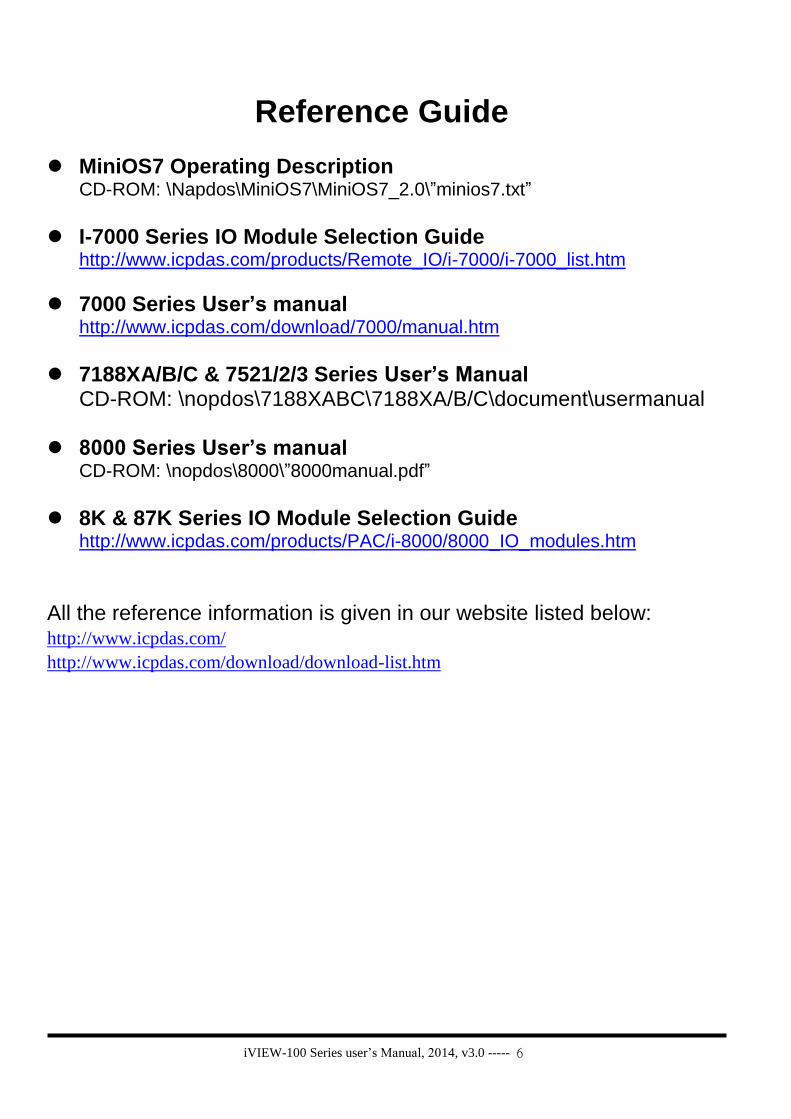
Package List
The all-in-one pack of iVIEW-100 series includes the following items:
One iVIEW-100 series handheld controller
One CA-M910 cable with 4 Di / 2 relay Do
One CA-1509 cable with one RS-232 port, one RS-232/485 port, and
one power connect line
One user’s manual (this manual)
One utility CD with Software drivers, demo programs & User’s Manual
Note
If any of these items are missing or damaged, contact the local distributors for more
information. Save the shipping materials and cartons in case you want to ship in the
future.
It is recommended to read README.TXT first. The README.TXT is given in the
napdos/iview100 of CD. Some important information is provided in README.TXT.
Ordering Information
iVIEW-100 Series Handheld Controller
iVIEW-100-40 CPU: 40MHz, Flash: 512k, SRAM: 512k
iVIEW-100 CPU: 20MHz, Flash: 512k, SRAM: 512k
Optional Accessories for iVIEW-100 Series
S-512 / S-256 512/256K battery backup SRAM Module
DP-640 24V / 1.7 A DIN-Rail mounting power supply
CA-1509 / CA-M910 cables for iVIEW-100 series
Call distributor or check web site: www.icpdas.com for more information.
iVIEW-100 Series user’s Manual, 2014, v3.0 ----- 8
1.2 iVIEW-100 Series
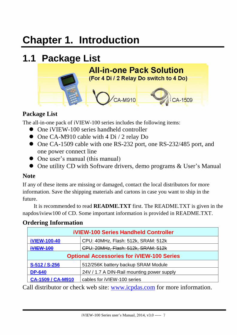
The iVIEW-100 series is a compact handheld controller with low cost / high performance
text/graphic LCD display, specially designed for industrial environment that requires
high reliability and PC-compatibility.
The iVIEW-100 series, an all-in-one pack controller, can work independently with its
own CPU, I/O Board, full keys Keypad, Text/Graphic LCD, inside buzzer and in-packed
connecting cables to monitor and control the Data Inputs and Outputs.
The iVIEW-100-40, the representation of iVIEW-100 series, is powered by an 80188-40
CPU with 512K bytes of SRAM and 512K bytes of flash memory, and built in MiniOS7,
RTC, NVSRAM and EEPROM. It supports optional battery backup memory for
retaining more data. There are 4 DI, 4 DO (or 2 relay), 2 COM for RS232 / RS485
communication.
The iVIEW-100 series can be also used as a HMI device for our I-7188 and I-8000 series
embedded controller. Since the basic hardware design of iVIEW-100 series is similar to
that of I-7188 series, all our available software can be used in iVIEW-100 series. User
can design iVIEW-100 series application with C Language. We will provide iVIEW-
100E with a 10/100 mega Ethernet port for internet.
iVIEW-100 Series
iVIEW-100 Handheld Controller, CPU:20MHz, Flash:512k, SRAM:512k
iVIEW-100-40 Handheld Controller, CPU:40MHz, Flash:512k, SRAM:512k
iVIEW-100E Handheld Controller, CPU:40MHz, Flash:512k, SRAM:512k
Ethernet port:10/100m (available soon)

iVIEW-100 Series user’s Manual, 2014, v3.0 ----- 9
1.3 Features
LCD display
Provides 128x64 dots, 16x8 characters, 72x40 mm view area, STN, Yellow-
Green Backlight LCD
Shows text, number, real, Boolean icon, BMP graphic in the same page
Draws pixel, line, box, Lamp icon
Max to 48 pages.
Membrane keypad
Full numeric membrane keypad with number, character, direction, shift, enter,
BS, ESC, function keys
Handheld controller
Embedded CPU, 80188, 40MHz(for iVIEW-100-40) or 20MHz(for iVIEW-100)
512K SRAM & 512K Flash ROM
MiniOS7 inside, support RTC time & date
Built-in RTC, NVSRAM & EEPROM
One buzzer inside
C programmable
64-bit hardware unique serial number
Equipped with a 64-bit unique hardware serial number, each serial number is
distinct and individual. The application program can check this number for
illegal copies. It is a low cost protection mechanism.
DI/O
Default has 4 digital inputs and 2 relay outputs connected with a Mini-DIN
connector (CA-M910).
Jumper selected to switch the output from 2 relay to 4 open collector output
channels via the internal jumper.
COM: RS232 & RS485
Built-in COM1:RS232, COM2:RS232/RS485 port, Max Speed up to 115200,
COM driver support interrupt & 1K QUEUE input buffer

iVIEW-100 Series user’s Manual, 2014, v3.0 ----- 10
Allows C programming which can be downloaded from PC through COM1 via
its in packed cable (CA-1509).
Connects up to 64 numbers of remote I/O modules, and combines host PC, and
power supply via its CA-1509 cable with one 5-wire RS-232 port, one RS-
232/485 port, and one power connect line.
Real Time Clock
Supports Real time clock with time & date. RTC leap year compensation from
1980 to 2079.
Watchdog
Built-in watchdog timer for harsh environment. When iVIEW-100 is power-up,
the watchdog is enabled. It can reset the controller in 0.8 seconds.
Protection
Built-in power and RS-485 network protection circuit.
A wide temperature endurance ranged from -30℃ up to +85℃ for the storage
temperature, and from -15℃ up to +60℃ for operating temperature.
Application
Provides particular C programming Libraries so that user can easily call the
functions to design their applications, such as using LCD, keypad, R/W COM
port, EEPROM, RTC, I/O, FLASH memory, timer, watchdog, getting file
system & connecting to I-7000…
Provides several solutions combined with our I-7188 and I-8000 controller to
control more DI/O even with different protocol.
ODM project
Supports user adding battery backup memory (S-256/ S-512) to retain more data.
Customized I/O Expansion Boards can be ordered through ODM project for
user’s special need.

iVIEW-100 Series user’s Manual, 2014, v3.0 ----- 11
1.4 Specifications Power supply
Power requirements 10 to 30 VDC power, Consumption: 3.0 W
Protection Built-in power protection and RS-485 network protection circuit
General environment
Operating temperature -15°C to +60°C
Storage temperature -35°C to +85°C
Humidity 5 to 90 %
System
CPU 80188, iVIEW-100-40: 40M Hz, iVIEW-100: 20M Hz
SRAM 512K bytes
Flash Memory 512K bytes, Erase unit is 64K bytes, 100,000 erase/write cycles
OS MiniOS7 of ICP DAS (64K bytes)
NVSRAM 31 bytes, battery backup, data valid up to 10 years
EEPROM 2048 bytes, data retention > 100 years. 1,000,000 erase/write cycles
Real time clock Gives time(sec, min, hour) & date, leap year compensation from 1980 to 2079
Watchdog timer Yes,
Serial ports
COM1 RS232 (5 pins): TXD,RXD,RTS,CTS,GND, Program download port.
Speed: 115200 bps max. Double buffer
COM2 RS232 (5 pins) / RS485 self-tuner, Speed: 115200 bps max.
RS232: TXD,RXD,RTS,CTS,GND, RS485: Data+, Data-
Ethernet 10M/100M bps, provides in iVIEW-100E only
DIO channel
Input 4 digital input channels for 3.5V~30V
Output 2 relay outputs (default) for contact rating: 30 VDC/ 1A to 125 VDC/ 0.5A or
4 open collector outputs (jumper selected) for 30V / 100mA maxi load / per channel
HMI interface
LCD display 128x64dots, 16x8 character, text / BMP graphic, STN, yellow-green back light LCD, View
area: 72 X 40mm
Keypad Full numeric membrane keypad with number, character, direction, shift, enter, BS, ESC,
function keys
buzzer One internal buzzer
Development tool
C programming
Supports compilers TC 1.0~3.0/TC++ 1.0~3.0/BC 2.0/BC++ 3.1~5.02/MSC 8.00c/MSVC++
1.52. Provides C Lib functions for LCD, keypad, COM port, EEPROM, FLASH Memory,
timer, watchdog, I/O, NVRAM, RTC, getting file system, connecting to I-7000…
Program downloaded from PC via COM1
Protocols
Remote I/O Supports I-7000 I/O modules & (I-87K base + I-87K serial I/O boards) as remote I/O.
Max. 64 remote I/O module for one controller
User defined protocol User can write his own protocol applied at COM1, COM2
Battery backup SRAM
S-256 / S-512 Supports S-256:256K bytes and S-512:512K bytes optional battery backup SRAM for
retaining data
Case
Dimensions 181mm X 116mm X 42mm
Weight 550g (375g when cables not included)

iVIEW-100 Series user’s Manual, 2014, v3.0 ----- 12
1.5 Contents of CD You can find all the iVIEW-100 series driver, manual & data files in the folder of
CD\Napdos\iVIEW100, or you can reach to our FTP web site to find newly released
information.
Web site: http://www.icpdas.com/download/iVIEW-100_series.htm.
CD : MiniOS7: driver, demo programs, utility software
iVIEW-100 library files
Source code of demo programs
iVIEW-100 User’s Manual
References are given in ReadMe.txt in the CD and page 6 of this manual.

iVIEW-100 Series user’s Manual, 2014, v3.0 ----- 13
Chapter 2. Hardware Information
2.1 View of iVIEW-100 Series
2.1.1 Front view
2.1.2 Bottom view
Mini-DIN Connector
1
6
11
5
10
15
DB-15 Female ConnectorMini-DIN Connector
1
6
11
5
10
15
1
6
11
5
10
15
DB-15 Female Connector
iVIEW-100 Series user’s Manual, 2014, v3.0 ----- 14
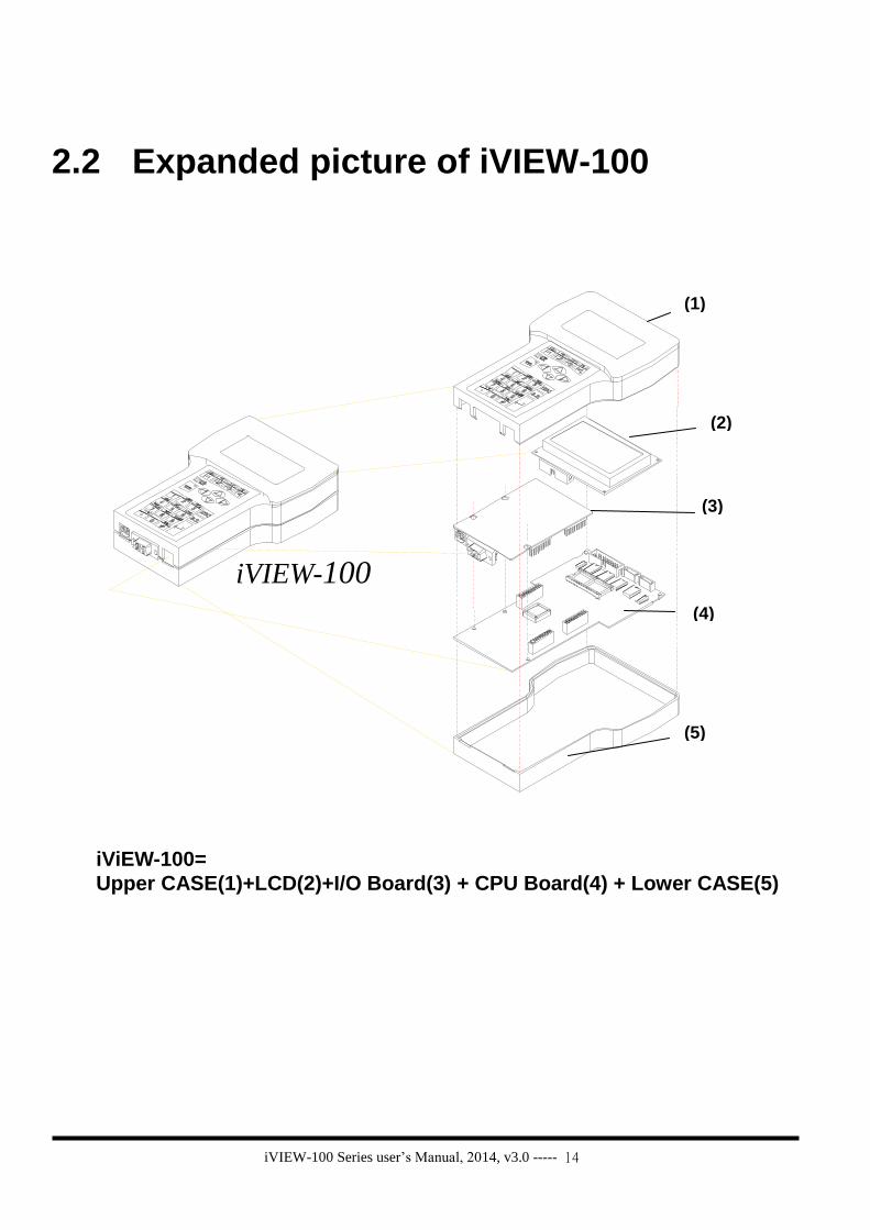
2.2 Expanded picture of iVIEW-100
iVIEW-100
iViEW-100=
Upper CASE(1)+LCD(2)+I/O Board(3) + CPU Board(4) + Lower CASE(5)
(1)
(2)
(3)
(4)
(5)

iVIEW-100 Series user’s Manual, 2014, v3.0 ----- 15
2.3 Block Diagram of iVIEW-100
80188-40
Watchdog timer
16 bits timer
RTC &
NVSRAM
512K SRAM
512K Flash-ROM
COM1
RS-232
COM2
RS-232/RS-485 EEPROM
(2K)
LCD
+10V to +30V
Power converter
D/I,D/O
Circuitry
Membrane
Keypad

iVIEW-100 Series user’s Manual, 2014, v3.0 ----- 16
2.4 Pin assignment of iVIEW-100
2.4.1 Pin assignment of Mini-DIN Connector
12
6
9
8 5
4
3
7
Mini-DIN Connector
Pin assignment of Mini-DIN connector:
Pin Name Description
1 DI1 Digital Input,3.5V~30V,channel1
2 DI2 Digital Input,3.5V~30V,channel2
3 DI3 Digital Input,3.5V~30V,channel3
4 DI4 Digital Input,3.5V~30V,channel4
5 DO PWR Input Pin of external power supply for open
collector output
Note: no need for relay output
6 Relay1+ DO1
Relay 1 Output (default setting) N.O.
Digital Output 1 (jumper setting)
7 Relay1- DO2
Relay 1 Output (default setting) N.O.
Digital Output 2 (jumper setting)
8 Relay2+ DO3
Relay 2 Output (default setting) N.O.
Digital Output 3 (jumper setting)
9 Relay2- DO4
Relay 2 Output (default setting) N.O.
Digital Output 4 (jumper setting)

iVIEW-100 Series user’s Manual, 2014, v3.0 ----- 17
2.4.2 Pin assignment of DB-15 Female Connector
1
6
11
5
10
15
1
6
11
5
10
15
DB-15 Female Connector
Pin assignment of DB-15 Female Connector:
Pin Name Description
1 N/C
2 TXD1 TXD pin of COM1 (RS-232)
3 DATA+ DATA+ pin of COM2 (RS-485)
4 TXD2 TXD pin of COM2 (RS-232)
5 +VS V+ of power supply (+10 to +30VDC unregulated)
6 INIT* Initial pin for ROM-DISK download
7 CTS1 CTS of COM1 (RS-232)
8 RTS1 RTS of COM1 (RS-232)
9 CTS2 CTS of COM2 (RS-232)
10 RTS2 RTS of COM2 (RS-232)
11 GND GND of power supply and COM1
12 RXD1 RXD pin of COM1 (RS-232)
13 DATA- DATA- pin of COM2 (RS-485)
14 RXD2 RXD pin of COM2 (RS-232)
15 GND GND of COM2
Note 1: COM1 ( DB-9 Female connector of CA-1518A)
Note 2: COM2 ( DB-9 Male connector of CA-1518A)

iVIEW-100 Series user’s Manual, 2014, v3.0 ----- 18
2.5 Pin assignment of cables
2.5.1 Pin assignment of CA-M910 cable
21
5
3
7
4
8
6
9
21
5
3
7
4
8
6
9
1 White2 Gray3 Yellow4 Brown5 Green6 Black7 Light Blue8 Red9 Blue
10 Cable Shelding
1 White2 Gray3 Yellow4 Brown5 Green6 Black7 Light Blue8 Red9 Blue
10 Cable Shelding
Pin Name Color Description
1 DI1 White Digital Input,3.5V~30V,channel1
2 DI2 Gray Digital Input,3.5V~30V,channel2
3 DI3 Yellow Digital Input,3.5V~30V,channel3
4 DI4 Brown Digital Input,3.5V~30V,channel4
5 DO PWR Green Input Pin of external power supply for
open collector output
Note: no need for relay output
6 Relay1+ DO1
Black Relay 1 Output (default setting) N.O.
Digital Output 1 (jumper setting)
7 Relay1- DO2
Light Blue
Relay 1 Output (default setting) N.O.
Digital Output 2 (jumper setting)
8 Relay2+ DO3
Red Relay 2 Output (default setting) N.O.
Digital Output 3 (jumper setting)
9 Relay2- DO4
Blue Relay 2 Output (default setting) N.O.
Digital Output 4 (jumper setting)
Wiring: Signal Ground: All digital inputs and outputs (except relay outputs) signal grounds are the same as the grounds of power used by the module.
Shielding

iVIEW-100 Series user’s Manual, 2014, v3.0 ----- 19
2.5.2 Pin assignment of CA-1509 cable
CA-1509 cable
DB-9 Female
Connector
DB-15 Male
Connector
DB-9 Male
Connector
Red (24V+)
Black (24V-)
White (*Init)
Com2:RS232/RS485
Connect to
iVIEW-100
Com1:RS232
Connect to host-PC
1
5
3
6
72
8
94
95
1
73
84
62
12345
678910
1112131415
GND
RXD1
TXD1
RTS1
CTS1
RTS2
CTS2
DATA+
DATA-
TXD1
RXD2
GND
INIT *24V+24C-
DB9-Female
(COM1)
DB9-Male
(COM2)
DB15-Male
1
5
3
6
72
8
94
1
5
3
6
72
8
94
95
1
73
84
62
95
1
73
84
62
12345
678910
1112131415
12345
678910
1112131415
12345
678910
1112131415
GND
RXD1
TXD1
RTS1
CTS1
RTS2
CTS2
DATA+
DATA-
TXD1
RXD2
GND
INIT *24V+24C-
DB9-Female
(COM1)
DB9-Male
(COM2)
DB15-Male

iVIEW-100 Series user’s Manual, 2014, v3.0 ----- 20
Pin assignment of COM1 connector (DB-9 Female connector of CA-1509):
Pin Name Description
1 N/C
2 TXD Transmit Data
3 RXD Receive Data
4 N/C
5 GND Signal ground
6 N/C
7 CTS Clear To Send
8 RTS Request To Send
9 N/C
Pin assignment of COM2 connector (DB-9 Male connector of CA-1509):
Pin Name Description
1 DATA+ DATA+ pin
2 RXD Receive Data
3 TXD Transmit Data
4 N/C
5 GND Signal ground
6 N/C
7 RTS Request To Send
8 CTS Clear To Send
9 DATA+ DATA- pin

iVIEW-100 Series user’s Manual, 2014, v3.0 ----- 21
2.6 Wiring diagrams for application
2.6.1 Connecting the COM1 (DB-9 Female connector of CA-1509) of iVIEW-100 to PC
Note: The CA-1509 cable has a female DB-9 connector, a male DB-9 connector,
and a power cable. The iVIEW-100 needs external power via power cable. Refer to Sec.2.5 for more information about the pin assignment of cable. Connect the female DB-9 connector to COM1/2 port of PC for downloading
an application program from PC.
+10V~+30VDCPOWER SUPPLY
HOST COMPUTER
COM1/2 of
CA-1509
DB-15 Male Connector
DB-9 Male Connector
Connctor
Shift
F4F8F5
RUNPWR
F1F7F6
F3F2
B.S.654
+ - * /
PQRS
7$ % ~
0 #
8
TUV
9
WXYZ
8
1GHI
2JKL
ABC
3MNO
DEF
ESC DB-9 Female
Download Application Program
from PC to iVIEW-100
+10V~+30VDCPOWER SUPPLY
HOST COMPUTER
COM1/2 of
CA-1509
DB-15 Male Connector
DB-9 Male Connector
Connctor
Shift
F4F8F5
RUNPWR
F1F7F6
F3F2
B.S.654
+ - * /
PQRS
7$ % ~
0 #
8
TUV
9
WXYZ
8
1GHI
2JKL
ABC
3MNO
DEF
ESC DB-9 Female
+10V~+30VDCPOWER SUPPLY+10V~+30VDCPOWER SUPPLY
HOST COMPUTERHOST COMPUTER
COM1/2 of
CA-1509
DB-15 Male Connector
DB-9 Male Connector
Connctor
Shift
F4F8F5
RUNPWR
F1F7F6
F3
COM1/2 of
CA-1509
DB-15 Male Connector
DB-9 Male Connector
Connctor
Shift
F4F8F5
RUNPWR
F1F7F6
F3F2
B.S.654
+ - * /
PQRS
7$ % ~
0 #
8
TUV
9
WXYZ
8
1GHI
2JKL
ABC
3MNO
DEF
ESC DB-9 Female
F2
B.S.654
+ - * /
PQRS
7$ % ~
0 #
8
TUV
9
WXYZ
8
1GHI
2JKL
ABC
3MNO
DEF
ESC DB-9 Female
Download Application Program
from PC to iVIEW-100
COM2
COM1

iVIEW-100 Series user’s Manual, 2014, v3.0 ----- 22
2.6.2 Connecting COM2 (DB-9 Male connector of CA-1509)
to PC
Note: The CA-1509 cable has a female connector, a male DB-9 connector, and a
power cable. The iVIEW-100 needs external power via power cable. Refer to Sec.2.5 for more information about the pin-assignment of cable Using a female-to-female cable as a bridge between PC and COM2 of CA-
1509, the lines of communication are as follows:
+10V~+30VDC
POWER SUPPLY
HOST COMPUTER
COM1/2 of
CA-1518A
Shift
F4
F8F5
RUNPWR
F1
F7F6
F3F2
B.S.654
+ - * /
PQRS
7$ % ~
0 #
8
TUV
9
WXYZ
1GHI
2JKL
ABC
3MNO
DEF
ESC
DB-15 Male
DB-15 Female
DB-9 Male DB-9 Female
Connector
DB-9 Female
ConnectorConnector
Connector
ConnectorCA-1509 DB-9
DB-9 DB-9 COM2
COM1
TxD(3)
RxD(2)
DTR(4)
DSR(6)
GND(5)
TxD(3)
RxD(2)
DTR(4)
DSR(6)
GND(5)

iVIEW-100 Series user’s Manual, 2014, v3.0 ----- 23
2.6.3 Connect COM2 (DB-9 Male connector of CA-1509)
to the COM1 Port of I-8000 series
Note: The CA-1509 cable has a female DB-9 connector, a male DB-9 connector,
and a power cable. The iVIEW-100 needs external power via power cable. Refer to Sec.2.5 for more information about the pin-assignment of cable.
Using a female-to-female cable as a bridge between 8000 series’ COM1 port and COM2 of CA1509, the lines of communication are as follows:
+10V~+30VDC
POWER SUPPLY
CA-1518A
Shift
F4
F8F5
RUNPWR
F1
F7F6
F3F2
B.S.654
+ - * /
PQRS
7$ % ~
0 #
8
TUV
9
WXYZ
1GHI
2JKL
ABC
3MNO
DEF
ESC
DB15 Male
DB15 Female
DB9 Male DB9 Female
Connector
COM1(RS-232)of 8000 series
841X/881X
DB9 Female
Connector
Connector
ConnectorConnector
CA-1509 DB-9
DB-9 DB-9
COM1
COM2
TxD(3)
RxD(2)
DTR(4)
DSR(6)
GND(5)
TxD(3)
RxD(2)
DTR(4)
DSR(6)
GND(5)

iVIEW-100 Series user’s Manual, 2014, v3.0 ----- 24
2.6.4 Connecting COM1 (DB-9 Female connector of CA-
1509) to RS-232 Device
Note: The CA-1509 cable has a female DB-9 connector, a male DB-9 connector,
and a power cable. The iVIEW-100 needs external power via power cable. Refer to Sec.2.5 for more information about the pin assignment of cable.
Connect the DB-9 Female to COM port of RS-232 devices
+10V~+30VDC
POWER SUPPLY
CA-1518A
DB-15 Male
Connector
Connector
Shift
F4
F8F5
RUNPWR
F1
F7F6
F3F2
B.S.654
+ - * /
PQRS
7$ % ~
0 #
8
TUV
9
WXYZ
1GHI
2JKL
ABC
3MNO
DEF
ESC
DEVICERS-232DB-9 Female
Connector
DB-9 Male
CA-1509
COM1
COM2

iVIEW-100 Series user’s Manual, 2014, v3.0 ----- 25
2.6.5 Connect COM2 (DB-9 Male of CA-1509) to RS-232
Device
Note: The CA-1509 cable has a female DB-9 connector, a male DB-9 connector,
and a power cable. The iVIEW-100 needs external power via power cable. Refer to Sec.2.5 for more information about the pin assignment of cable. Using a female-to-female cable as a bridge between RS-232 device’s COM
port and COM2 of CA-1509, the lines of communications are as follows:
+10V~+30VDC
POWER SUPPLY
CA-1518A
Shift
F4
F8F5
RUNPWR
F1
F7F6
F3F2
B.S.654
+ - * /
PQRS
7$ % ~
0 #
8
TUV
9
WXYZ
1GHI
2JKL
ABC
3MNO
DEF
ESC
DB-15 Male
DB-15 Female
DB-9 Male DB-9 Female
Connector
RS-232DEVICE
DB-9 Female
Connector
Connector
Connector Connector
CA-1509 DB-9
COM2
COM1
TxD(3)
RxD(2)
DTR(4)
DSR(6)
GND(5)
TxD(3)
RxD(2)
DTR(4)
DSR(6)
GND(5)

iVIEW-100 Series user’s Manual, 2014, v3.0 ----- 26
2.6.6 Connect COM2:RS-485 (DB-9 Male of CA-1509) to
I-7000 & I-87K Remote I/O
Note: The CA-1509 cable has a female DB-9 connector, a male DB-9 connector,
and a power cable. The iVIEW-100 needs external power via power cable. Refer to Sec.2.5 for more information about the pin assignment of cable. Connect iVIEW-100 Pin 1 & 9 to the Data+ & Data- of I-7000 or I-87K remote
I/O. The communication of lines is as follow:
iVIEW-100 I-7000 I-87K IO
Pin1 Data+ Data+
Pin9 Data- Data-
I-87K Remote I/O
F5 F2 F6
F3 F7 F4 F8
1 F1
2 ABC ESC 3 DEF
MNO 6 5 JKL
4 GHI B.S.
7 PQRS . + - * /
0 # $ % ~ WXYZ 9 8 TUV
RUN PWR
CA-1509
DB-9 Female, COM1
iVIEW-100
DB-15 Male
DB-9 Male
COM2
Red(24V+)
Black(24V-)
White(*Init) I-7000
iVIEW-100 Pin 1 & 9
to Data+ & Data-
I-87K4

iVIEW-100 Series user’s Manual, 2014, v3.0 ----- 27
2.7 DI/DO operating principle
The iVIEW-100 has 4 digital inputs and 4 digital outputs. The 4 digital outputs can be configured as 2 relay outputs by pin assignment. The default setting is relay type. Here is the pin configuration:
6 8 5 3
7
1
9 4
28:9:Relay 2 output6:7:Relay 1 output5:VCC4:DI43:DI32:DI21:DI1
If it is configured as a 4 digital outputs, pin configuration will be:
6 8 5 3
7
1
9 4
28:9:Relay 2 output6:7:Relay 1 output5:VCC4:DI43:DI32:DI21:DI1
Wiring:
Signal Ground: All digital inputs and outputs (except relay outputs) signal grounds are the same as the grounds of power used by the module.
9:DO4 8:DO3 7:DO2 6:DO1 5:VCC 4: DI 4 3: DI 3 2: DI 2 1: DI 1

iVIEW-100 Series user’s Manual, 2014, v3.0 ----- 28
2.7.1 Digital inputs byte definition & wiring DI byte definition is as follows:
Bit 8 Bit 7 Bit 6 Bit 5 Bit 4 Bit 3 Bit 2 Bit 1
DI1
DI2
DI3
DI4
Relay 1 output state
Relay 2 output state
Test7: signal from outport bit 7
Test8: signal from outport bit 8
Wiring:
Signal Ground: All digital inputs and outputs (except relay outputs) signal grounds are the same as the grounds of power used by the module.
+5V
iVIEW-100
DI
block diagram
If Pin 1,2,3, or 4 is float ( without connect any line), then input value is “1”. If pin is connected to ground, the input value is “0”.

iVIEW-100 Series user’s Manual, 2014, v3.0 ----- 29
2.7.2 Digital output definition & wiring: 2 Relay Outputs
(default)
DO byte definition:
Bit 8 Bit 7 Bit 6 Bit 5 Bit 4 Bit 3 Bit 2 Bit 1
X
X
X
X
Relay 1
Relay 2
Test 7
Test 8
Wiring
iVIEW-100
block diagram
relay 1
relay 2
6
7
8
9
N.O.

iVIEW-100 Series user’s Manual, 2014, v3.0 ----- 30
2.7.3 Digital output definition & wiring: 4 digital outputs DO byte definition:
Bit 8 Bit 7 Bit 6 Bit 5 Bit 4 Bit 3 Bit 2 Bit 1DO1
DO2DO3
DO4X
XTest 7
Test 8
Wiring: Signal Ground: All digital inputs and outputs (except relay output) signal grounds are the same as the Power ground. Jumper setting: This kind of DO needs to re-config jumper setting. Please change jumper settings to the following (default setting is 1-2 short for relay output):
J12 J11 J10 J9 J8
1

iVIEW-100 Series user’s Manual, 2014, v3.0 ----- 31
5
6
7
8
9
iVIEW-100
VCC
DO1
DO2
DO3
DO4
External power suply

iVIEW-100 Series user’s Manual, 2014, v3.0 ----- 32
2.7.4 DI/DO operating method
You can make commands in MiniOS7 Utility to test DI and DO. Please refer to
Chapter 3 & 4 (especially section 3.4 & 4.3) to see how to use MiniOS7 Utility.
The commands for testing DI & DO are listed below:
Type Command Description
DI i port Read data from the address of hardware port ( 0x104 )
DO o port value Output data value to the address of hardware port (0x105)
Ex1: Make command i 0x104 to get DI value as below.
Ex2: Make command o 0x105 DOvalue to set DO value as below.
The value will show the DI/DO byte value, please see the bits definition from
section 2.7.1 to 2.7.3.
Get value: 3F => 00111111 (DI4 => DI1 : 1111)
When DI changed, get value again: 76 => 01110110 (DI4 => DI1 : 0110)
If pin is float (without connect to any line), input value is “1”. If pin is connected to ground, the input value is “0”.
Set value: 1F => 00011111 (Bit 8 => Bit 5 : 0001) (Relay 1 active)
Set value again, the DO will change: 2F => 00101111 (Bit 8 => Bit 5 : 0010) (Relay 2 active)

iVIEW-100 Series user’s Manual, 2014, v3.0 ----- 33
When user writes program for DI/DO, please use the following statements to get
or set DI/DO value.
For MSVC compiler:
int DI=_inp(0x104);
int DI=_inp(0x104) &0x0f; //to get Bit 1 to Bit 4 only
_outp(0x105, DOvalue); //DOvalue:0x1f, 0x2f, 0x3f… for 2 relay output
//DOvalue:0x01, 0x02, 0x04, 0x08… for 4 DO
For Turbo C or Turbo C++ compilers:
int DI=inportb(0x104);
int DI=inportb(0x104) &0x0f; /*to get Bit 1 to Bit 4 only*/
outportb(0x105, DOvalue);
/*DOvalue:0x1f, 0x2f, 0x3f… for 2 relay output*/
/*DOvalue:0x01, 0x02, 0x04, 0x08… for 4 DO*/
For more demo programs, please refer to demo files in the “COM” folder of CD :
dim.c, dom.c, do4o.c, dido.c …….

iVIEW-100 Series user’s Manual, 2014, v3.0 ----- 34
2.8 I/O expansion bus & ODM project
The iVIEW-100 supports an I/O expansion bus. The I/O expansion bus can be used to implement various I/O functions such as D/I, D/O, A/D, D/A, Timer/Counter, UART, flash memory, battery backup SRAM, AsicKey & other I/O functions. Nearly all kinds of I/O functions can be implemented with this bus. Users can design their own I/O expansion board for their expansion bus. Each I/O expansion bus supports one expansion board only. For convenience, if user has I/O expansion board requirement, please contact us for ODM service. The I/O Expansion Boards can be ordered through customized ODM project.

iVIEW-100 Series user’s Manual, 2014, v3.0 ----- 35
2.9 Comparison Table
iVIEW-100-40 7188EX(D)
Module name Embedded Controller Internet Communication
Controller
CPU 80188, 40M 80188, 40M
RAM 512K 512K
Flash ROM 512K 512K
Watch Dog CKT Yes Yes
RTC Yes Yes
EEPROM 2K bytes 2K bytes
Hardware Serial number
Yes Yes
I/O expansion bus
Yes Yes
COM1 RS-232 5-wire RS-232, 3-wire
COM2 RS-232 or
RS-485(non-isolated),
self-tuner ASIC inside
RS-485, non-isolated, self-
tuner ASIC inside
Ethernet 10M No Yes
OS MiniOS7 MiniOS7
Program Download
Yes Yes
Display LCD 7-Seg LED
7-Seg LED No 5-digit for 7188EXD
iVIEW-100: Embedded Controller 7188(D): Embedded Controller 7188XA/XB/XC (D): Expandable Controller 7521/22/23/25/27(D): Addressable Communication Controller 7188E1/2/3/4/5/8(D): Internet Communication Controller 7188E2X/EX/EA (D): Embedded Internet/Ethernet Controller 8000 Series: Compact Distributed Embedded Controller 7000 Series: Network Data Acquisition & Control Modules

iVIEW-100 Series user’s Manual, 2014, v3.0 ----- 36
Chapter 3. Getting Start
Step 1: Connect to power supply & Host-PC. Step 2: Insert companion CD & install the software. Step 3: Download program to iVIEW-100. Step 4: Execute program from PC. Step 5: Execute program in iVIEW-100. Step 6: Auto-execute program in iVIEW-100.
3.1 Connect to power supply & Host-PC
Step 1: Connect to power supply. User can connect to his own power supply or optional order from both our website and local agent. The DP-640 is a good choice for iVIEW-100. You can also looking for the detail information to choose the suitable power supply from our website: http://www.icpdas.com/products/Accessories/power_supply/power_list.htm
DP-640
Step 2: Power off the iVIEW-100 from power supply. Step 3: Connect INIT* to GND. Step 4: Power on iVIEW-100 from power supply.

iVIEW-100 Series user’s Manual, 2014, v3.0 ----- 37
Step 5: Connect COM of PC to iVIEW-100.
F5 F2 F6
F3 F7 F4 F8
1 F1
2 ABC ESC 3 DEF
MNO 6 5 JKL
4 GHI B.S.
7 PQRS . + - * /
0 # $ % ~ WXYZ 9 8 TUV
RUN PWR
CA-1509
Connector
DB-9 Female
Connector
iVIEW -100
DB-15 Male
Connector
DB-9 Male
Connector
Red(24V+)
Black(24V-)
White(*Init)
PC
Connect to COM1 or
COM2 of host-PC

iVIEW-100 Series user’s Manual, 2014, v3.0 ----- 38
3.2 Insert CD & install the software
Step: 1. Insert the companion CD. It will execute automatically.
Step: 2. Click Toolkits (Softwares) / Manuals
Step 3: Click iVIEW-100 Software & Libraries

iVIEW-100 Series user’s Manual, 2014, v3.0 ----- 39
Step 4: Copy all directories and files to the working directory of your disk driver. Or copy whole iVIEW100 directory to your disk.
Step 5: Install MiniOS7 Utility. Double click the install file in the folder of minios7, follow the steps to install MiniOS7 Utility.
Note: The download utility, MiniOS7 Utility, is used as a bridge between iVIEW-
100 & Host-PC. It can be used in the Microsoft Windows environment for the
essential configuration and the programs download. The utility is similar to the
7188xw.exe(Windows console for Win32). Users can optional install the MiniOS7
utility or 7188xw.exe or both. Our manual will show the instruction and direction
via MiniOS7 Utility.

iVIEW-100 Series user’s Manual, 2014, v3.0 ----- 40
3.3 Download program to iVIEW-100
Step 1: Execute MiniOS7 Utility. If you have not done the steps of 3.1, follow the MiniOS7 Utility’s steps to connect iVIEW-100 to power supply and Host-PC.
Step 2: Select the COM port that connected with Host-PC and the Baud rate.
The iVIEW-100 use COM1 to download program from PC. The default Baud rate of iVIEW-100 is 115200.

iVIEW-100 Series user’s Manual, 2014, v3.0 ----- 41
Step 3: The left ListView shows the files in the Host-PC. The right ListView shows the files in the iVIEW-100. Select disk name from the Disk-Directory ComboBox. Select the folder and file from the left ListView below
the Disk-Directory ComboBox. Example: C:\iview100\iviewapp\hello\

iVIEW-100 Series user’s Manual, 2014, v3.0 ----- 42
Step 4: After choose a file from PC, click to download the file to iVIEW-100.
When finish the access, the file will be shown in the right ListView.
Example: C:\iview100\iviewapp\hello\hello.exe

iVIEW-100 Series user’s Manual, 2014, v3.0 ----- 43
3.4 Execute program from PC.
Step 1: Double click the file name in the right ListView or select the file and then
click the icon to run the program.
User can also type the command in the MiniOS7 command line to access the
program and see the result at the bottom of the window.
Example: type hello, then press the Enter key to access the program. In this
example, you can see the PC screen and the LCD of iVIEW-100 both show the
word “Hello”.
hello

iVIEW-100 Series user’s Manual, 2014, v3.0 ----- 44
Here is the content of Hello.c:
#include "iVIEW.H"
#include "mmi100.H"
int main()
{
InitLib();
Print("\n\rHello");
if(InitLCD()>0) Print("\n\rLCD wrong");
else
{
ClrScrn();
LcdPrintfAt(2,2,"Hello");
}
return 0;
}
�
Include these two headers to use
iVIEW-100’s user functions.
Initial iVIEW libaries.
Print “Hello” on PC screen.
Clear LCD screen first.
Initial iVIEW LCD, if fail,
print “LCD wrong” on PC.
Print “Hello” on LCD (2,2).
iVIEW-100’s LCD is a 16
characters(X) wide, 8 lines(Y)
high screen. (1,1) is on the left
top spot.

iVIEW-100 Series user’s Manual, 2014, v3.0 ----- 45
If the program does not work or user wants to modify the program, after finish the
modification, downloads the file again. iVIEW-100 will keep all the files until user
deletes the files.
When user wants to delete the files in iVIEW-100, please clicks the icon
to delete all the files in iVIEW-100.
Note: MiniOS7 provide the function to delete all existing files only.

iVIEW-100 Series user’s Manual, 2014, v3.0 ----- 46
3.5 Execute program in iVIEW-100
iVIEW-100 support user to run the program in the iVIEW-100 directly. iVIEW-100
has its own LCD display and full numeric membrane Keypad. After the program
downloaded from PC, iVIEW-100 can access the program independently. This
design makes the iVIEW-100 more suitable for harsh industrial environment.
Before we execute program in iVIEW-100, we will introduce the keypad usage of
iVIEW-100 to know how to use the keypad buttons to access the program.
3.5.1 Keypad usage
View of Keypad

iVIEW-100 Series user’s Manual, 2014, v3.0 ----- 47
Usage of keypad for numbers and functions
Keys are designed to input various characters like a mobile phone. Each key is divided into upper (blue) and lower (white) parts. The number value is in white. The Alphabet is in blue. For example:
This key will be called Key “2” for convenience.
White part Blue part
F1 F5
F2 F6
F3 F7
F4 F8
1 ,.: (not print)
2 ABC
3 DEF
4 GHI
5 JKL
6 MNO
7 PQRS
8 TUV
9 WXYZ
. +-*/
0 [Space]
# $%~
Use “Shift” Key to shift between White part and Blue part.

iVIEW-100 Series user’s Manual, 2014, v3.0 ----- 48
Here are some examples of number, Alphabet, or function key inputs:
Example 1: Input “6”. This “character” is on the white part:
Step 1: Make sure that LED light on the ‘Shift’ key is off. If on, press once to turn off.
Step 2: Press “6” key once, LCD will show “6”. Example2: Input “S”. This letter is on the blue part of the “7” key of
your console.
Step 1: Press “Shift” key once to light-up the green LED on the “Shift” button. If the LED is already on, there is no need to press again.

iVIEW-100 Series user’s Manual, 2014, v3.0 ----- 49
Step 2: Press “7” key. The red LED on the “F1” button lights.
Step 3: Press “7” key continously until the red LED of “F4” lights. (Push 3 times more.)
Step 4: Press “F4” key or wait for 1 second to return “S” on the LCD.
Step 5: Press “Shift” key. The green LED turns off. If you
want to input other characters from the blue block, don’t press “Shift” key. Go to step 2.

iVIEW-100 Series user’s Manual, 2014, v3.0 ----- 50
Example 3: Input “F1”. Press “F1” key directly to return it’s value(0x81). Example 4: Input “F8”. This key is in the blue part of the “F4” key.
Step 1: Press “Shift” key to light-up the green LED of “Shift” key.
Step 2: Press “F4” to return 0x88. Step 3: Press “Shift” key to turns off the green LED.
Note: The LED on F1~F4 won’t light in this situation. Example 5: input “space”(0x20). Press “Shift”. The green LED turns
on. Press “0” to return 0x20. Press “Shift”. The green LED turn off.

iVIEW-100 Series user’s Manual, 2014, v3.0 ----- 51
3.5.2 Download program and execute in iVIEW-100
Step: 1. Download the file \iview100\iviewapp\LCD\LCD.exe from PC to iVIEW-100.
Step: 2. Use keypad key in “LCD” to run LCD program.
Press “Shift” key to light-up the green LED of “Shift” key. Press 3 times of “5” key to return the letter “L” onto LCD.
Press 3 times of “2” key to return “C”, and 1 time of “3” key to return “D”.
Press “Shift” key to turn off the green LED of “shift” key.
Then press “Enter” key. The LCD display of iVIEW-100 will show the picture below, you can press “1” or “2” to access this program.
CHOOSE:
1. LCD 2. QUIT

iVIEW-100 Series user’s Manual, 2014, v3.0 ----- 52
Here is the content of LCD.c:
#include <iVIEW.H>
#include <mmi100.H>
void main()
{
int quit=0;
char c;
InitLib();
InitLCD();
TextOutAt(5,3, "CHOOSE:");
TextOutAt(5,5, "1.LCD");
TextOutAt(5,6, "2.QUIT");
while(!quit)
{
c=Getch();
switch(c)
{
case '1':
LCDSetToPage (2);
ClrScrn();
TextOutAt(3,4, "* welcome *");
TextOutAt(1,8, "any key to back");
Getch(); break;
case '2':
quit=1; break;
}
LCDSetToPage (1);
}
ClrScrn();
CloseLCD();
}
Include these two headers to use
iVIEW-100’s user functions.
Initail libraries & iVIEW LCD.
Print “CHOOSE” on LCD (5,3),
“1.LCD” on (5,5), “2.QUIT” on (5,6)
from LCD left top. This menu display
is stored in page 1 by default.
Wait for key press to get char c. Both
iVIEW keypad and PC key board can
access this program.
Set LCD to page 2. From this line, the
LCD will store display to page 2.
Clear LCD.
Print “welcome” message on LCD
(3,4) & (1,8). This is page 2.
Call page 1 back as the main menu.

iVIEW-100 Series user’s Manual, 2014, v3.0 ----- 53
3.6 Auto-execute program in iVIEW-100
When developing software application, user can set the main program to auto-execute when the iVIEW-100 is powered up. The method is the same as in PC to set one autoexec.bat file. Step 1: Set the autoexec.bat file.
Example: want to run LCD.exe menu when iVIEW-100 power up. The autoexec.bat file can just have one line include the file you want to call or more commands or files to access. But this file name has to be “autoexec.bat”. The content of autoexec.bat: LCD.exe
Step 2: Download the autoexec.bat file to iVIEW-100.
Step 3: Power off iVIEW-100, then power on iVIEW-100 again. The iVIEW-100 will execute autoexec.bat automatically and then enter the main menu of LCD.exe.
CHOOSE:
3. LCD 4. QUIT

iVIEW-100 Series user’s Manual, 2014, v3.0 ----- 54
Chapter 4. Operating System - MiniOS7
The iVIEW-100 is a handheld controller with build-in MiniOS7 as its operating system. The MiniOS7 is an embedded Operating System designed for the iVIEW-100 series, I-7188/E/X series and I-8000 series. It is developed by ICP DAS Co. Ltd.
Various companies have created several brands of DOS(Disk Operating System). In all cases, DOS (whether PC-DOS, MS-DOS, or ROM-DOS) is a set of commands or codes which tells the computer how to process information. DOS runs programs, manages files, controls information processing, directs input and output, and performs many other related functions. The MiniOS7 will provide equivalent functions of ROM-DOS and provide some special functions.
4.1 Demo programs of MiniOS7
Refer to the companion CD for the source code of demo programs.
Program Description
Datetime Reads the date and time of RTC per second and prints it on monitor (user can set the date and time).Press ‘ q ’ to quit program.
Demo6 Writes, read and show the EEPROM data for checking.
Eeprom Writes a value to EEPROM and show it on monitor.
Eeprom-r Reads the data you wrote to EEPROM
Eeprom-w Inputs a value to write to EEPROM block 1 peer address
(value will auto-plus 1).
Flash Reads the value that is written to the flash memory.
Press ‘ q ’ to quit program.
Flash-r Read, write and erases Flash memory.
Flash-w Inputs a value written in flash memory (value will auto-plus 1.)
Press ‘ q ’ to quit program.
Hello Prints “Hello” on both screen of PC and iVIEW-100
Runprog Uses Ungetch() to run another program.
Press ‘ q ’ to quit program.
Scanf Shows how to write a function for inputting data.
Watchdog If system is reset by watchdog timer, then load this file and run it.
More…… Refer to the Manual of MiniOS7 or our website…….

iVIEW-100 Series user’s Manual, 2014, v3.0 ----- 55
4.2 MiniOS7 Utility
The MiniOS7 utility is used for the essential configuration and program download
to the products embedded in the ICPDAS MiniOS7. The utility is similar to the
7188xw.exe (Windows console for Win32). However it can be used in the
Microsoft Windows environment, rather than a window console environment.
User can use MiniOS7 Utility to make command for MiniOS7. For larger screen
mode, click the icon for switching between the large and small screen modes
to see the result of the command.

iVIEW-100 Series user’s Manual, 2014, v3.0 ----- 56
4.2.1 Make MiniOS7 command
To make MiniOS7 command, user just types command in the “MiniOS7
command Line” of MiniOS7 Utility.
Example 1: type “date” to show the current date of RTC. Type “date mm/dd/yyyy”
to set the date of RTC.
Example 2: type “baud 115200” to set the baud rate to 115200.
Example 3: type “dir” to show the information of all files downloaded in the Flash-
Memory.
Example 4: type “hello” to run hello.exe program or type “run” to run the last file.

iVIEW-100 Series user’s Manual, 2014, v3.0 ----- 57
4.2.2 Toolbar and hot keys
Toolbar There is one toolbar for MiniOS7 command line. It is at the left hand side of the
command line.
1. : ASCII/HEX mode switch icon.
2. : Normal mode and line key-in mode switch icon. In Line mode, all
characters-pressed will not send to COM until the ENTER is
pressed. It is designed for testing the 7000 series.
3. : Run 7188xw.exe icon.
4. : Edit font icon. For changing the font, size and color of words in
the screen.
5. : Edit color icon. For changing the color of screen.
Hot keys
You can click the right mouse on the screen to show the hot keys table.

iVIEW-100 Series user’s Manual, 2014, v3.0 ----- 58
4.3 Typical commands of MiniOS7
Command Description
USE NVRAM The service routine for read/write NVARM.
USE EEPROM The service routine of read/write EEPROM.
USE Flash The service routine of read/write Flash-ROM.
USE COM2 /option The service routine of send/receive to/from COM2 (RS-485).
DATE mm/dd/yyyy] Sets the date of RTC.
TIME [hh:mm:ss] Sets the time of RTC.
MCB Tests current memory block.
UPLOAD The first step to update the MiniOs7.
BIOS1 The last step to update the MiniOs7.
LOAD Downloads the user program into the Flash-Memory.
DIR [/crc] Shows the information of all files download in the Flash-
Memory.
RUN [fileno] Runs the file with file-number=fileno, no filenethe last file.
Name Runs the file with file-name=name.
DELETE (or DEL) Deletes all files stored in the Flash-Memory. It will delete all
files.
RESET Resets the CPU.
DIAG [option] Hardware Diagnostic.
BAUD baudrate Sets the new value of communication-baudrate to baudrate.
TYPE filename [/b] Lists content of the file.
REP [/#] command Repeats executing the same command # times.
RESERVE [n] Reserves n Flash Memory sectors for USER's programs.
LOADR Downloads a file into SRAM.
RUNR [param1
[param2...]]
Runs a program saved into SRAM (downloaded by command
LOADR).
I/INP/IW/INPW port Reads data from the hardware PORT.
O/OUTP/OW/OUTP
W port value
Outputs to hardware PORT.
… more … … more …
Note: Refer to companion CD 8000CD\Napdos\7188e\MiniOS7\doc\index.html
for more information about MiniOS7. The MiniOS7 is also designed for 7188
/7188X/7188E/8000 family, so you will find some additional information unrelated
to iVIEW-100.

iVIEW-100 Series user’s Manual, 2014, v3.0 ----- 59
4.4 Upgrade MiniOS7
We will add more & more features to upgrade the MiniOS7. Please refer to our
website to see if there any new version available.
The MiniOS7 Utility provides an easy way to upgrade MiniOS7.
Step 1: Please download the newest version of MiniOS7 file from website if necessary. And then decompress to the image file. The website is Http://ftp.icpdas.com.tw/pub/cd/8000cd/napdos/minios7/.
The format of image file name is given as TTYYMMDD.img
TT TYPE of product “i4”=iVIEW-100-40, “i-“=iVIEW-100, “8k”=8000…
YY Year of this image released
MM Month of this image released
DD Day of this image released
Step 2: Execute the MiniOS7 Utility. Click the icon to update.
Step 4: After the update, it will auto reset. If not, please power off and then power on again. Use command “ver” to check on the new OS.

iVIEW-100 Series user’s Manual, 2014, v3.0 ----- 60
4.5 7188xw.exe Utility
There is one more PC side utility program for MiniOS7--7188xw.exe. The
7188xw.exe is the Win32 Windows console programs for MiniOS7.
7188xw.exe supports RS-232 COM ports using USB and PCMCIA interfaces on
Win32 systems. It link to the modules via RS-232 port of PC to access MiniOS7.
7188xw.exe basically is a terminal program. It sends out the data that user key-in
to COM port, and show the data received from COM port on the screen of PC.
The main function for 7188xw.exe is to DOWNLOAD files to the MiniOS7 system.
In operating, Compare to MiniOS7 Utility, the 7188xw.exe has no any icon for
user to run functions. Users have to type MiniOS7 command by themselves to
access the MiniOS7.
For example, when download the program from PC to iVIEW-100, type “load”,
press “Enter”, after message, press “ALT_E”, and then type file full name, press
“Enter”. After those steps, the file will be downloaded from PC to iVIEW-100
memory. User can type the file name to run the file program.
iVIEW-100 Series user’s Manual, 2014, v3.0 ----- 61
4.5.1 7188xw.exe commands & hot key
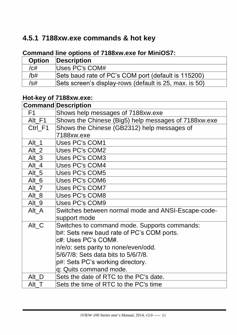
Command line options of 7188xw.exe for MiniOS7:
Option Description
/c# Uses PC's COM#
/b# Sets baud rate of PC’s COM port (default is 115200)
/s# Sets screen’s display-rows (default is 25, max. is 50)
Hot-key of 7188xw.exe:
Command Description
F1 Shows help messages of 7188xw.exe
Alt_F1 Shows the Chinese (Big5) help messages of 7188xw.exe
Ctrl_F1 Shows the Chinese (GB2312) help messages of 7188xw.exe
Alt_1 Uses PC's COM1
Alt_2 Uses PC's COM2
Alt_3 Uses PC's COM3
Alt_4 Uses PC's COM4
Alt_5 Uses PC's COM5
Alt_6 Uses PC's COM6
Alt_7 Uses PC's COM7
Alt_8 Uses PC's COM8
Alt_9 Uses PC's COM9
Alt_A Switches between normal mode and ANSI-Escape-code-support mode
Alt_C Switches to command mode. Supports commands: b#: Sets new baud rate of PC’s COM ports. c#: Uses PC’s COM#. n/e/o: sets parity to none/even/odd. 5/6/7/8: Sets data bits to 5/6/7/8. p#: Sets PC’s working directory. q: Quits command mode.
Alt_D Sets the date of RTC to the PC's date.
Alt_T Sets the time of RTC to the PC's time

iVIEW-100 Series user’s Manual, 2014, v3.0 ----- 62
Alt_E For downloading files into memory. Only after the message “Press ALT_E to download file!” is shown on screen, users can press Alt_E.
Alt_H Toggles Hex/ASCII display mode.
Alt_L Toggles normal/line mode. In line-mode, all characters-pressed will not send to COM until the ENTER is pressed. It is designed for testing the 7000 series.
Alt_X Quits the 7188X.EXE.
F2 Sets the file name for download (without download operation).
F5 Runs the program specified by F2 and arguments set by F6.
Alt_F5 Runs the program stored in SRAM.
F6 Sets the arguments of the execution file set by F2. (10 arguments maximum. If set to less than 10 arguments, add ‘*’ to end).
Ctrl_F6 Clears screen.
F8 F8=F9+F5.
F9 Downloads the file specified by F2 into FLASH memory.
Alt_F9 Downloads all files specified by ALT_F2 into FLASH memory.
F10 Downloads the file specified by F2 into SRAM and execute it.
Alt_F10 Downloads the file specified by F2 into SRAM memory.
Ctrl_B Sends a BREAK signal to the PC’s COM port that is used by 7188xw.exe.
more … … more …

iVIEW-100 Series user’s Manual, 2014, v3.0 ----- 63
Chapter 5. Libraries & compiler User must use C language to develop the application program for iVIEW-100-40 and iVIEW-100. We provide hundreds of functions in the libraries for user to call for C programming. When compile and link your programs, you can use TC 1.0~3.0, TC++
1.0~3.0, BC 2.0, BC++ 3.1~5.02, MSC 8.00c or MSVC++ 1.52. You can download the freeware, TC 2.01 and the TC++ 1.01, from the website of Borland company: http://community.borland.com/museum.
5.1 Libraries
There are two libraries for iVIEW-100-40 & iVIEW-100 programming:
(1) iVIEWL.lib: for normal functions program. (LARGE MODEL)
(2) mmi100.lib: specially for LCD display functions. (LARGE MODEL)
All the function declarations are described in iVIEW.h and mmi100.h. The
application program has to add “iVIEWL.lib” and “mmi100.lib” into the project to
implement the user functions, and include the following headers to the start of
the code.
#include "iVIEW.h"
#include "mmi100.h"

iVIEW-100 Series user’s Manual, 2014, v3.0 ----- 64
5.1.1 iVIEWL.lib
There are hundreds of functions supported in iVIEWL.lib. You can see all their declarations in iVIEW.h. Here will list the most frequently used functions below.
No Type Function
1 Standard IO
Kbhit, Getch, Ungetch, Putch, Puts, Scanf, Print, ReadInitPin, LineInput….……... more ……………..
2 COM port InstallCom, InstallCom1, InstallCom2, InstallCom3…… RestallCom, RestallCom1, RestallCom2…… IsCom, IsCom1, IsCom2……, ReadCom, ReadCom1…… ClearCom, ClearCom1…, ToCom, ToCom1, ToCom2...... PrintCom, PrintCom1, PrintCom2…………more…………
3 EEPROM EnableEEP, WriteEEP, ProtectEEP, ReadEEP, InitEEPROM...
4 NVRAM & RTC
ReadNVRAM, WriteNVRAM, GetTime, SetTime, GetDate, SetDate, GetWeekDay……………
5 Flash Memory FlashReadId, FlashErase, FlashWrite, FlashRead………
6 Timer & Watchdog Timer
TimerOpen, TimerClose, TimerResetValue, TimerReadValue DelayMs, Delay, Dealy_1, Delay_2, StopWatchStart, StopWatchReset, StopWatchStop, StopWatchPause, StopWatchCountine, StopWatchReadValue, CountDownTimerStart, CountDownTimerReadValue, InstallUserTimer, InstallUserTimer1C EnableWDT, DisableWDT, RefreshWDT…………
7 File GeFileNo, GetFileName, GetFilePositionByNo, GetFileInfoByNo, GetFileInfoByName…………
8 Connect to 7000
SendCmdTo7000, ReceiveResponseFrom7000, ascii_to_hex, hex_to_ascii……
9 Others ……….………………..more …………………………..
Refer to CD\napdos\7188\minios7\manual\index.html for more detail description and information.
For more detail description and demo programs information please see the Appendix A: User function.

iVIEW-100 Series user’s Manual, 2014, v3.0 ----- 65
5.1.2 LCD library: mmi100.lib Please refer to mmi100.h to see the function declarations. All the LCD demo programs are in the folder of LCD. For more detail description and demo programs information please see the Appendix A: User function.
Type Function Description
initial & close InitLCD Initial LCD in the beginning, return 0 for true
CloseLCD Close LCD when finish, return 0 for true
ClrScrn Clear all display in LCD
Draw & BMP picture (pixel) (X,Y) : X=1~128 Y=1~64
Pixel Give (X,Y) to draw a dot
VLine Give 1X, 2Y to draw a vertical line
HLine Give 2X, 1Y to draw a horizontal line
Line Give 2 points to draw a line
Box Give 2 points to draw a box
BmpShowAt Give a beginning point & a BMP filename to show the BMP picture
Text & icon (character) (X,Y) : X=1~16 Y=1~8
UnderLine Give a begging point & length to print underline
TextOutAt Give (X,Y) to print char text
DrawText Give (X,Y) to print unsigned char text
LcdPrintfAt Give (X,Y) to print char text
IntOutAt Give (X,Y) & length to print integer number
RealOutAt Give (X,Y), length, decimal, float to print real number
lamp Give (X,Y) to print lamp icon, color: 1= , 0=
Cursor (X,Y) : X=1~16 Y=1~8
SetCursorLine Set cursor’s thick from 0 to 8, 0=cursor off
SetCursorAt Set cursor to (X,Y)
GetCursorAt Get cursor position (X,Y)
Page & bright
LCDBright Set LCD bright from 0 to 7, 0=light off
LCDSetToPage Set LCD pages from 1 to 8, default=1
GetLCDPage Get LCD page set number
iVIEW-100 Series user’s Manual, 2014, v3.0 ----- 66
5.2 Compiler & linker
When compile and link your programs, you can use TC 1.0~3.0, TC++
1.0~3.0, BC 2.0, BC++ 3.1~5.02, MSC 8.00c or MSVC++ 1.52. User can download the freeware, TC 2.01 and the TC++ 1.01, from the website of Borland company: http://community.borland.com/museum.
5.2.1 Special settings and libraries information Please take care of the following items:
1. Generate a standard DOS executable program.
2. Select CPU=80188/80186
3. Select EMULATION if the floating-point computation is required. (Cannot
select 8087)
4. Remove DEBUG INFORMATION to reduce program size. (MiniOS7 does not
support it)
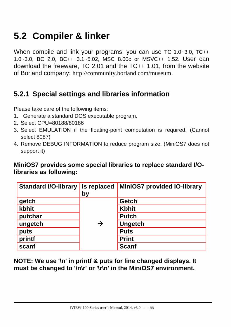
MiniOS7 provides some special libraries to replace standard I/O-libraries as following:
Standard I/O-library is replaced by
MiniOS7 provided IO-library
getch
Getch
kbhit Kbhit
putchar Putch
ungetch Ungetch
puts Puts
printf Print
scanf Scanf
NOTE: We use '\n' in printf & puts for line changed displays. It must be changed to '\n\r' or '\r\n' in the MiniOS7 environment.

iVIEW-100 Series user’s Manual, 2014, v3.0 ----- 67
5.2.2 Using Turbo C User can download Turbo C version 2.01 from the community website of Borland
company: http://community.borland.com/article/0,1410,20841,00.html. Here are the working steps to use TC 2.01. Step 1: Copy the lib files, iviewL.lib & mmi100.lib, of iVIEW-100 to the
“lib” folder of TC. Ex: Copy iviewL.lib & mmi100.lib to c:\tc\lib.
Step 2: Copy the .h files, iview.h & mmi100.h, of iVIEW-100 to the
“include” folder of TC. Ex: Copy iview.h & mmi100.h to c:\tc\include.
Step 3: Set the file directory of TC to your working file directory. Ex: File\Change dir\YOUR working directory.
Step 4: Edit the main program. Or you can copy the “HELLO1.C” file in CD (…\iview100\iviewapp\TC\ ) to your working directory.

iVIEW-100 Series user’s Manual, 2014, v3.0 ----- 68
Step 5: Edit a new file as its project file. Ex: The “HELLO1.PRJ” for the program “HELLO1.C”. The content of HELLO1.PRJ is as following: Hello1.c C:\tc\lib\iviewl.lib C:\tc\lib\mmi100.lib
Step 6: Set the project name as following:
Step 7: The setting of compiler model and options are given as following:

iVIEW-100 Series user’s Manual, 2014, v3.0 ----- 69
Step 8: Disable source debugging in the DEBUG field.
Step 9: Compile and Make to generate “HELLO1.EXE”. Or you can press F9 key to do the same job.

iVIEW-100 Series user’s Manual, 2014, v3.0 ----- 70
5.2.3 Using Turbo C++ User can download Turbo C++ version 1.01 from the community website of
Borland company: http://community.borland.com/article/0,1410,21751,00.html.
Here are the working steps to use TC++ 1.01. Step 1: Copy the lib files, iviewL.lib & mmi100.lib, of iVIEW-100 to the
“lib” folder of TC++ (Ex:TCPP). Ex: Copy iviewL.lib & mmi100.lib to c:\tcpp\lib.
Step 2: Copy the iview.h & mmi100.h files of iVIEW-100 from CD to the
“include” folder of TC++. Ex: Copy iview.h & mmi100.h to c:\tcpp\include.
Step 3: Edit the main program. Or you can copy the “HELLO2.C” file from CD to c:\TCPP. CD: \iview100\iviewapp\TCPP\hello2.c

iVIEW-100 Series user’s Manual, 2014, v3.0 ----- 71
Step 4: Open a new project file.
Ex: A new “HELLO2.PRJ” for the program “HELLO2.C”. Click the function menu of “Project\Open project…”, then type the project name “HELLO2.PRJ” in the same directory of “HELLO2.c”, then click “OK”.

iVIEW-100 Series user’s Manual, 2014, v3.0 ----- 72
Step 5: Add library files into the project. Click the project area, then select “Project\Add Item…”, click
“HELLO2.C” and then click “Add” to add “HELLO2.c” into the project.
Use the same method to add “TCPP\LIB\iVIEWL.LIB” and
“TCPP\LIB\MMI100.LIB” into the “HELLO2.PRJ”.

iVIEW-100 Series user’s Manual, 2014, v3.0 ----- 73
Step 6: Set the “Options\Compiler\Code generation…” as following:
Click “More” to set “Advanced Code Generation” as following:

iVIEW-100 Series user’s Manual, 2014, v3.0 ----- 74
Step 7: Set the “Options\Debugger” as following:
Step 8: Select “Options\Save…” to save options.
iVIEW-100 Series user’s Manual, 2014, v3.0 ----- 75
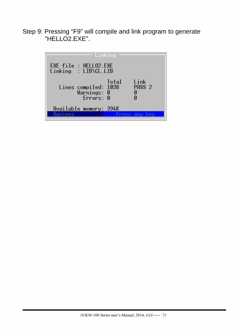
Step 9: Pressing “F9” will compile and link program to generate “HELLO2.EXE”.

iVIEW-100 Series user’s Manual, 2014, v3.0 ----- 77
Chapter 6. Demo programs
6.1 Demo programs list There are many demo programs given in iview100\iviewapp\*.* as follows: No Execution file Folder Function Short explanation
1 Hello.exe Hello For beginning Shows “hello” on PC & LCD screen (MSC compiler)
2 Hello1.exe TC For beginning Shows “hello” on PC & LCD screen (TC compiler)
3 Hello2.exe TCPP For beginning Shows “hello” on PC & LCD screen (TC++ compiler)
4 Stdio.exe Stdio Standard IO Uses standard IO functions to show letter’s ASCII code
5 Keypres.exe Keypad Keypad Inputs by keypad or PC keyboard, shows ASCII code & LCD (X,Y) location
6 Cal.exe Keypad Keypad: calculate
To calculate(+,-,*,/) via keypad, press “Enter” to get the answer, allow using backspace
7 Stdio2.exe Pin PIN Reads initial PIN
8 Rtc Time Time Shows how to get time, set time.
9 Tmr.exe Timer Timer Shows how to set, read timer and delay.
10 Sdwh.exe Timer Timer Shows how to control stop watch timer and delay
11 Codn.exe Timer Timer Test countdown timer
12 Ustm.exe Timer Timer Shows how to use user defined timer, and flashes lamp by timer on LCD.
13 Wchdog.exe Wdt Watchdog timer
Shows how to use watchdog timer functions.
14 Di.exe Io COM: DI Digital input
15 Dii.exe COM COM: DI DI signal test(use CA-M910 mini DIN cable)
16 Dido.exe COM COM: DIO DI/O signal test(use CA-M910 mini DIN cable for DI test)
17 Dim.exe COM COM: DIO DI/O signal test for relay output(use CA-M910 mini DIN cable for DI test)
18 4dor.exe Io COM: DO Digital output
19 Rilay.exe Io COM: DO Relay output
20 Do4o.exe COM COM: DO 4 DO signal test
21 Dom.exe COM COM: DO 2 DO signal test (relay output)

iVIEW-100 Series user’s Manual, 2014, v3.0 ----- 78
No Execution file Folder Function Short explanation
22 Comt.exe COM COM Show how to use COM functions, ‘Q’ to quit.
23 Comt1.exe COM COM Shows how to use COM1 functions, ‘q’ to quit.
24 Icom2.exe COM COM Shows how to use COM fuctions
25 Comts.exe COM COM Shows iVIEW-100 how to communicate with Windows Hyper Terminal of PC. Both can type and receive message.
26 Lcdin.exe Lcd LCD: initial Shows how to initial and test LCD
27 Vlnts.exe Lcd LCD: draw Draws vertical line on LCD.
28 Hln.exe Lcd LCD: Draw Draws horizotal line on LCD
29 Lcddraw.exe Lcd LCD: draw Shows how to use LCD “draw” function(pixel, line, V/H line, box, BMP)
30 Drawing.exe Drawing LCD: draw Draws lines and box on LCD.
31 Ln.exe Lcd LCD: draw Shows drawing line on LCD
32 Pixts.exe Lcd LCD: draw Shows how to draw by using pixel()
33 Bmpts Lcd LCD: (X,Y) location
Shows BMP file(e.bmp) to test the (X,Y) location on LCD
34 Showbmp.exe Showbmp LCD: bmp Shows black-and-white BMP picture on LCD display.
35 Bmp.exe Lcd LCD: bmp Shows text & BMP files (a.bmp, c.bmp,d.bmp) on LCD
36 Lcd.exe Lcd LCD: bright Shows LCD page & bright control
37 Bl.exe Bl LCD: bright Changes the LCD light bright intensity
38 Cursor.exe Lcd LCD: cursor Shows how to set & get cursor
39 Lcdxt.exe Lcd LCD: text, icon Shows how to use LCD “text & icon” function (char, uchar text; integer, real number; lamp icon)
40 Tsmi.exe Lcd LCD: mix Uses menu to show many LCD function (text, draw, BMP picture, flash, page, bright...). for running this program, user has to load bmp files(c, d, ee, i, kb.bmp)
41 Shled.exe Led LED light Shows how to set Led light(1=>F1.F5, 2=>F2.F6, 3=>F3.F7, 4=>F4.F8, 9=>quit)
42 Showled.exe Showled LED light Shows how to manipulate LED on iVIEW keypad.
43 File.exe File File Shows all files information (number, name, address, date, time, size…) in the iVIEW-100
44 Ftopc.exe Send2pc File: sends file contents to PC.
Reads existing file contents in iVIEW-100, & sends it to PC via 232 port.
45 Eep.exe Eeprom EEPROM Shows how to use EEPROM function.
46 Flashm.exe Flash Flash Shows how to read/write data from/to Flash
47 Nvr.exe Nvram NVRAM Shows how to use NVRAM function.
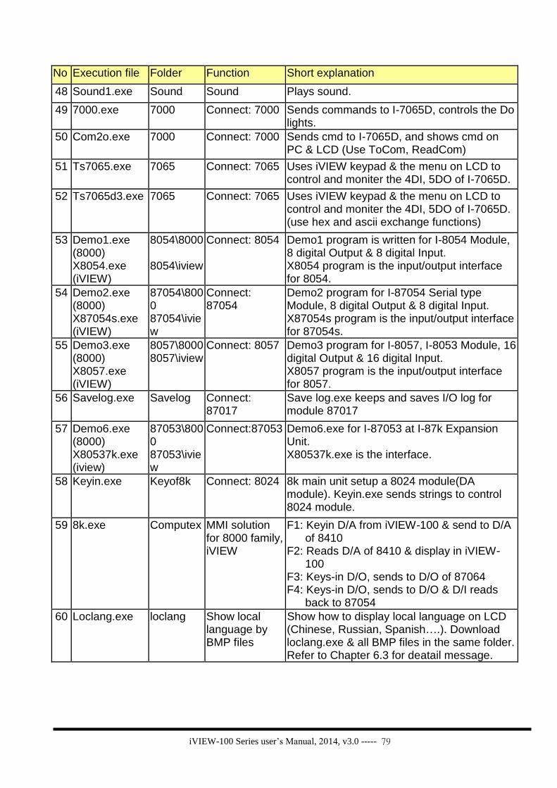
iVIEW-100 Series user’s Manual, 2014, v3.0 ----- 79
No Execution file Folder Function Short explanation
48 Sound1.exe Sound Sound Plays sound.
49 7000.exe 7000 Connect: 7000 Sends commands to I-7065D, controls the Do lights.
50 Com2o.exe 7000 Connect: 7000 Sends cmd to I-7065D, and shows cmd on PC & LCD (Use ToCom, ReadCom)
51 Ts7065.exe 7065 Connect: 7065 Uses iVIEW keypad & the menu on LCD to control and moniter the 4DI, 5DO of I-7065D.
52 Ts7065d3.exe 7065 Connect: 7065 Uses iVIEW keypad & the menu on LCD to control and moniter the 4DI, 5DO of I-7065D. (use hex and ascii exchange functions)
53 Demo1.exe (8000) X8054.exe (iVIEW)
8054\8000 8054\iview
Connect: 8054 Demo1 program is written for I-8054 Module, 8 digital Output & 8 digital Input. X8054 program is the input/output interface for 8054.
54 Demo2.exe (8000) X87054s.exe (iVIEW)
87054\8000 87054\iview
Connect: 87054
Demo2 program for I-87054 Serial type Module, 8 digital Output & 8 digital Input. X87054s program is the input/output interface for 87054s.
55 Demo3.exe (8000) X8057.exe (iVIEW)
8057\8000 8057\iview
Connect: 8057 Demo3 program for I-8057, I-8053 Module, 16 digital Output & 16 digital Input. X8057 program is the input/output interface for 8057.
56 Savelog.exe Savelog Connect: 87017
Save log.exe keeps and saves I/O log for module 87017
57 Demo6.exe (8000) X80537k.exe (iview)
87053\8000 87053\iview
Connect:87053 Demo6.exe for I-87053 at I-87k Expansion Unit. X80537k.exe is the interface.
58 Keyin.exe Keyof8k Connect: 8024 8k main unit setup a 8024 module(DA module). Keyin.exe sends strings to control 8024 module.
59 8k.exe Computex MMI solution for 8000 family, iVIEW
F1: Keyin D/A from iVIEW-100 & send to D/A of 8410
F2: Reads D/A of 8410 & display in iVIEW-100
F3: Keys-in D/O, sends to D/O of 87064 F4: Keys-in D/O, sends to D/O & D/I reads
back to 87054
60 Loclang.exe loclang Show local language by BMP files
Show how to display local language on LCD (Chinese, Russian, Spanish….). Download loclang.exe & all BMP files in the same folder. Refer to Chapter 6.3 for deatail message.

iVIEW-100 Series user’s Manual, 2014, v3.0 ----- 80
6.2 Detail explanation for some demo
programs
6.2.1 Demo Keypad & LCD: Keypres.c
Purpose: This demo program shows how to control iVIEW-100 keypad &
LCD display, and show keypad’s ASCII code for future
programming control.
Lib included:
iVIEW.h & mmi100.h
Variables:
Name Type Default Description
quit int 0 When quit=1, quit this program.
chr int For the input key value(ASCII code)
x int 1 Trace the X character position of LCD. X must
between 1 and 16.
y int 1 Trace the Y line position of LCD. Y must
between 1 and 8.
j int 0 Counter for data[j] array. j must <10
data[10] char Array for storing input value.
Program :
#include <iVIEW.H>
#include <mmi100.H>
void main()
{
int quit=0;
int chr;
int x=1;
int y=1;
int j=0;
char data[10];
InitLib(); /* initial LIB */

iVIEW-100 Series user’s Manual, 2014, v3.0 ----- 81
InitLCD(); /* initial LCD */
LcdSetCursorOn(); /* Display cursor */
while(!quit)
{
chr=Getch();
if(y==9) { /*LCD line(y)<=8*/
ClrScrn(); y=1;
}
if(chr=='q') quit=1; /*if input ‘q’, quit the program*/
else if(chr<0x80) Print("%c",chr); /*print input letter*/
Print("[%d]",chr); /*print ASCII code*/
if (j==10) j=0; /*count input to make sure 0<=j<10*/
data[j]=(char)chr;
Print(" %c @LCD(%d,%d) [%d]\r\n",data[j],x,y,j+1); //print (x,y) LCD location
j=j+1;
if (chr==8) { // backspace control
x=x-1;
TextOutAt(x, y, (char *)&chr); //print one space back on LCD
x=x-1;
}
else
TextOutAt(x, y, (char *)&chr); //print on LCD
x=x+1;
if(x==17) { //LCD wide(x)<=16
x=1; //print to first spot of next line
y=y+1;
}
} //end of while loop
CloseLCD();
}
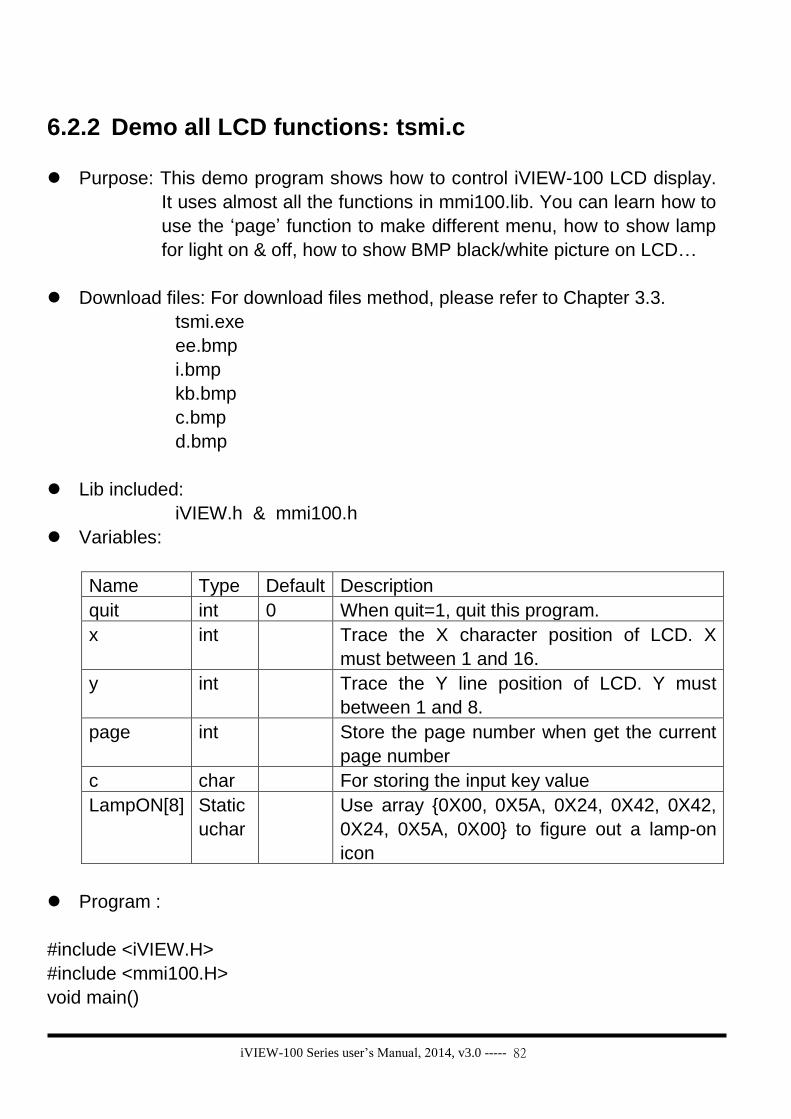
iVIEW-100 Series user’s Manual, 2014, v3.0 ----- 82
6.2.2 Demo all LCD functions: tsmi.c
Purpose: This demo program shows how to control iVIEW-100 LCD display.
It uses almost all the functions in mmi100.lib. You can learn how to
use the ‘page’ function to make different menu, how to show lamp
for light on & off, how to show BMP black/white picture on LCD…
Download files: For download files method, please refer to Chapter 3.3.
tsmi.exe
ee.bmp
i.bmp
kb.bmp
c.bmp
d.bmp
Lib included:
iVIEW.h & mmi100.h
Variables:
Name Type Default Description
quit int 0 When quit=1, quit this program.
x int Trace the X character position of LCD. X
must between 1 and 16.
y int Trace the Y line position of LCD. Y must
between 1 and 8.
page int Store the page number when get the current
page number
c char For storing the input key value
LampON[8] Static
uchar
Use array {0X00, 0X5A, 0X24, 0X42, 0X42,
0X24, 0X5A, 0X00} to figure out a lamp-on
icon
Program :
#include <iVIEW.H>
#include <mmi100.H>
void main()

iVIEW-100 Series user’s Manual, 2014, v3.0 ----- 83
{
int quit=0;
int x, y, page;
char c;
static uchar LampON[8] ={0X00, 0X5A, 0X24, 0X42, 0X42, 0X24, 0X5A,
0X00};
InitLib(); /*initial Lib*/
InitLCD(); /*initial LCD*/
Box(10, 10, 118, 54, 1); /*draw a box on LCD*/
DrawText(13, 3, LampON); /*draw the icon ‘LampON’ on LCD*/
LCDBright (5); /*set LCD bright to ‘5’,bright=0~7*/
SetCursorLine(8); /*set cursor thick to ‘8’ line,line=0~8*/
SetCursorAt(13, 3); /*set cursor position to (13,3) */
GetCursorAt(&x, &y); /*get cursor position to (x,y) */
UnderLine(x,y, 1,1); /*draw an underline*/
TextOutAt(3,3, "CHOOSEone:");
TextOutAt(3,4, "a.TEXT b.BMP");
TextOutAt(3,5, "c.FLASH");
TextOutAt(3,6, "q.QUIT");
page=GetLCDPage(); /* get the current page number */
TextOutAt(1,8, "page=");
IntOutAt(6, 8, 1, page ); /* show page number on LCD */
while(!quit)
{
c=Getch(); /* get input key value to c*/
switch(c)
{
case 'a':
case 'A':
LCDSetToPage (2);
ClrScrn();
LCDBright (0);
TextOutAt(4,6, "LCD BR=1");
TextOutAt(4,3, "ICPDAS");
TextOutAt(4,4, "EVA");
RealOutAt(8,4, 4,2 ,(float)1.1 );
Make a menu for choice.
When input ‘a’ or ‘A’, set LCD
bright to ‘0’(dark). Show text,
number on LCD.

iVIEW-100 Series user’s Manual, 2014, v3.0 ----- 84
TextOutAt(4,5,"TEST MMI");
lamp (13,3,1);
TextOutAt(1,7, "any key to back");
page=GetLCDPage();
TextOutAt(1,8, "page=a=");
IntOutAt(8, 8, 1, page );
Getch();
break;
case 'b':
case 'B':
LCDSetToPage (3);
ClrScrn();
LCDBright (7);
page=GetLCDPage();
SetCursorLine(0);
TextOutAt(3,1, "8 LINES LCD");
TextOutAt(2,2, "48 PAGES");
TextOutAt(3,3, "8 BRIGHT SETS");
TextOutAt(1,6, "SHOW:");
TextOutAt(1,7, "1.icon: ");
DrawText( 9,7, LampON);
TextOutAt(1,8, "2.graphic:");
BmpShowAt(13, 26, "ee.bmp" ,1);
BmpShowAt(33, 28, "i.bmp" ,1);
BmpShowAt(45, 38, "kb.bmp" ,1);
Getch();
break;
case 'c':
case 'C':
LCDSetToPage (4);
ClrScrn();
LCDBright (7);
LcdPrintfAt(1,7, "any key to back");
page=GetLCDPage();
TextOutAt(1,8, "page=c=");
TextOutAt(4,6, "LCD BR=1~7");
IntOutAt(8, 8, 1, page );
When input ‘b’ or ‘B’, set LCD
bright number to ‘7’ (very bright).
Show text, number, LampON icon
& 3 BMP picture on LCD.
Press any key to back to page 1.
Show text & lamp icon on LCD.
Press any key to back to page 1.
When input ‘c’ or ‘C’, set page
number to ‘4’, and LCD bright
number to ‘7’ (very bright).

iVIEW-100 Series user’s Manual, 2014, v3.0 ----- 85
while(!Kbhit())
{
LCDBright (1);
BmpShowAt(20, 10, "c.bmp" ,1);
LCDBright (7);
BmpShowAt(20, 10, "d.bmp" ,1);
}
break;
case 'q': //press ‘q’ or ‘Q’ to quit this program
case 'Q':
quit=1; break;
}
LCDSetToPage (1); //back to LCD page 1
}
ClrScrn(); //Clear LCD screen
CloseLCD(); //close LCD
}
Show 2 BMP picture
alternately on LCD. Using the
similar pictures & contrasted
bright seting to mke an
animation effect.
Press any key to back to page 1.

iVIEW-100 Series user’s Manual, 2014, v3.0 ----- 86
6.2.3 Demo how to connect to I-7000 module: ts7065d3.c
Purpose: This demo program shows how to connect iVIEW-100 and I-7000
I/O module. Using iVIEW’s keypad moniter the Di & control the Do
of I-7065D(with 4 Di, 5 Do display light).
Lib included:
iVIEW.h & mmi100.h
Variables:
Name Type Default Description
port int 2 Set port 2 to connect to I-7000 module.
x int Trace the X position on LCD screen.
y int Trace the Y position on LCD screen.
i int Counter for For loop.
j int 0 Counter for Di read: DiR[6].
n int Temporary storage for ascii_to_hex()
c int To store the keypad input value
check int To check the Di value, ‘&’ with DiCT to
decide which Di lamp is ON or OFF.
color int 1 Di lamp color. If color=1, Di lamp ON.
If color=0, Di lamp OFF.
coloro int 0 Do lamp color. If coloro=1, Do lamp
ON.
If coloro=0, Do lamp OFF.
quit int 0 When key in ‘q’ or ‘Q’, quit=1, quit this
program.
Dotemp int Temporary storage for Do lights value.
For sum’s calculation.
DiCT[4] int DiCT[4]={1, 2, 4, 8}, for ‘&’ with Di Read
value to decide which Di light is ON or
OFF.
DoCT[5] int DoCT[5]={1,2,4,8,16}, for calculating
with doON value to decide which Do
light is ON or OFF.
doON[5] int {0,0,0,0,0} Store the Do lights current ON or OFF
situation. Default is all lights ON.

iVIEW-100 Series user’s Manual, 2014, v3.0 ----- 87
diR[6] char To store the Di Read respond value.
For ‘&’ with DiCT value to decide which
Di light is ON or OFF.
doT[7] char To store the command send to control
the Do lights.
tt char A temporary storage for Di respond
value when use ReadCom command.
Program :
#include <iVIEW.H>
#include <mmi100.H>
void main()
{
int port=2;
int x, y,i,j=0,n,c,check,color=1,coloro=0;
int quit=0,Dotemp;
int DiCT[4] = {1, 2, 4, 8};
int DoCT[5]= {1,2,4,8,16},doON[5]={0,0,0,0,0}; /*initial the Do light all OFF*/
char diR[6], tt;
char doT[7]="@0100\r"; /*initial to sned the Do light all OFF command*/
InitLib(); /*initial Lib*/
InitLCD(); /*initial LCD*/
//draw manu
Line(12,28,118,28,1);
Box( 12,12,118,44,1);
SetCursorLine(2);
SetCursorAt(7, 5);
GetCursorAt(&x, &y);
TextOutAt(1,1, "i-7065D q:quit");
TextOutAt(3,3, "Di:");
TextOutAt(3,5, "Do:");
TextOutAt(1,7, " >:right ^:on");
TextOutAt(1,8, " <:left v:off");
for (i=0;i<4;i++)
lamp(7+i,3,color);
for(i=0;i<5;i++)
lamp(7+i,5,coloro);
Draw menu, set cursor, draw Di lamps
ON, and draw Do lamps OFF for the
initial LCD screen. Control method:
Enter q to quit.
> (right arrow key) to right.
< (left arrow key) to left.
^ (up arrow key) to set light ON
v (down arrow key) to set light OFF

iVIEW-100 Series user’s Manual, 2014, v3.0 ----- 88
InstallCom(port,115200L,8,0,1); //install COM port 2, baud rate:115200
ClearCom(port); //clear Com before read or send to Com
SendCmdTo7000(port, "@0100",0); //send Do all off command
ClearCom(port);
SendCmdTo7000(port, "@01",0); //send Di read command
//show Di
while(!quit)
{
while (IsCom(port) ) //while COM has any data, begin to decode
{
tt=ReadCom(port);
if(tt == '>' || diR[0] =='>' ) //the first data of available respond is ‘>’
{
if(tt=='>') j=0;
diR[j]=tt;
j++;
if (tt == 0x0D && j==6) //the last data of respond is 0x0D
{
n=ascii_to_hex(diR[4]);
for(i=0;i<4;i++)
{
check=n & DiCT[i];
if (check==0) color=0;
else color=1;
lamp(7+i,3,color);
}//end Di lamp draw
ClearCom(port);
SendCmdTo7000(port, "@01",0); //send read Di command
}//end if 0xd
}//end if Di right
else
{
ClearCom(port);
Print("Di wrong rspns '%c' or too long(%d rspns)\r\n",tt,j);
Print("Do you want to quit");
Getch();
quit=1;
If data is available respond, store them
to diR[j]
The 4th data of respond is about light
ON/OFF, transfer it to hex. Please refer
to I-7000 DIO user’s manual for detail.
Analyse Di respond, set the ON/OFF
situation to LCD screen.
If Com port respond wrong data, print
wrong msg, and quit program.
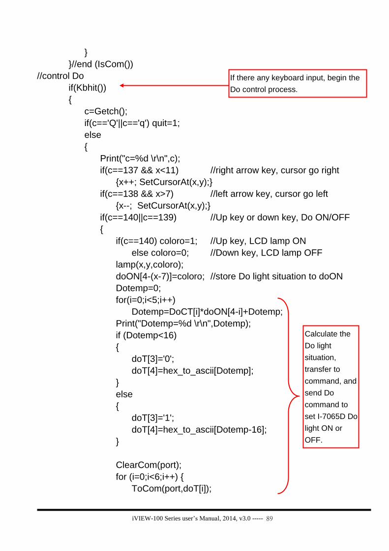
iVIEW-100 Series user’s Manual, 2014, v3.0 ----- 89
}
}//end (IsCom())
//control Do
if(Kbhit())
{
c=Getch();
if(c=='Q'||c=='q') quit=1;
else
{
Print("c=%d \r\n",c);
if(c==137 && x<11) //right arrow key, cursor go right
{x++; SetCursorAt(x,y);}
if(c==138 && x>7) //left arrow key, cursor go left
{x--; SetCursorAt(x,y);}
if(c==140||c==139) //Up key or down key, Do ON/OFF
{
if(c==140) coloro=1; //Up key, LCD lamp ON
else coloro=0; //Down key, LCD lamp OFF
lamp(x,y,coloro);
doON[4-(x-7)]=coloro; //store Do light situation to doON
Dotemp=0;
for(i=0;i<5;i++)
Dotemp=DoCT[i]*doON[4-i]+Dotemp;
Print("Dotemp=%d \r\n",Dotemp);
if (Dotemp<16)
{
doT[3]='0';
doT[4]=hex_to_ascii[Dotemp];
}
else
{
doT[3]='1';
doT[4]=hex_to_ascii[Dotemp-16];
}
ClearCom(port);
for (i=0;i<6;i++) {
ToCom(port,doT[i]);
If there any keyboard input, begin the
Do control process.
Calculate the
Do light
situation,
transfer to
command, and
send Do
command to
set I-7065D Do
light ON or
OFF.

iVIEW-100 Series user’s Manual, 2014, v3.0 ----- 90
Print("do= %c \r\n", doT[i]);
}
ClearCom(port);
SendCmdTo7000(port, "@01",0);
}//end if up & down Key
}// if quit!=1
}//end if Kbhit()
}//while loop
ClrScrn();
CloseLCD();
}

iVIEW-100 Series user’s Manual, 2014, v3.0 ----- 91
6.3 Local language Bitmap solution
The iVIEW-100 series can show any local language via the BMP graphic solution.
Any language, such as Japanese, French, Russian, Italian, Chinese, Indian…,
can be shown in bitmap graphic files, can be shown on iVIEW-100 series’ LCD.
How to show local language on the LCD of iVIEW-100? Please follow the steps:
Step 1: Prepare the local language text into bipmat graphic files.
The graphics must be black/white, bitmap format (BMP), and not larger than 128x64 pixel.
You can use the Windows software - Microsort Paint to prepare the text
BMP file. Please start up the Microsoft Paint.
Please refer to the BMP files in the folder ‘Loclang’ of CD for deatail setting and
more examples for different language such as German, Russian, French,
Spanish, Korean, Chinese… etc.
1 Click the menu bar of
‘Image / Attributes…’.
Set the ‘Pixels’ of ‘Units’
and set ‘Colors’ to be
‘Black and white’.
1
2
2
Click on to type the text you want to show on LCD.
Save the file as Monochrome Bitmap file type.
3
4

iVIEW-100 Series user’s Manual, 2014, v3.0 ----- 92
Step 2: Write a program to call the BMP files.
The user function to call BMP file is:
BmpShowAt(int X, int Y, “BMP_File_Name.bmp”, color);
Please refer to ‘Appendix A.2.2 Type2: Draw & BMP picture (pixel)’
for detail usage.
Compile and link your program to generate the execution file (.exe).
Ex: Loclang.c (The loclang.exe is in the folder ‘Loclang’ of CD)
#include <iVIEW.H>
#include <mmi100.H>
void main()
{
InitLib();
InitLCD();
TextOutAt(2,1, "LOCAL LANGUAGE");
UnderLine(2,1,14,1);
BmpShowAt(8,10,"bmpch1.bmp",1); /*call Tranditional Chinese BMP file*/
BmpShowAt(8,23,"bmprus.bmp",1); /*call Russian text BMP file*/
BmpShowAt(8,35,"bmpkor.bmp",1); /*call Korean text BMP file*/
BmpShowAt(8,48,"bmpspa.bmp",1); /*call Spanish text BMP file*/
BmpShowAt(64,10,"bmpch2.bmp",1); /*call Simplified Chinese BMP file*/
BmpShowAt(64,23,"bmpger.bmp",1); /*call German text BMP file*/
BmpShowAt(64,35,"bmptm1.bmp",1); /*call Thai text BMP file*/
BmpShowAt(64,48,"bmpfre.bmp",1); /*call French text BMP file*/
Getch();
ClrScrn();
CloseLCD();
}

iVIEW-100 Series user’s Manual, 2014, v3.0 ----- 93
Step 3: Download the execution file and all BMP files into iVIEW-100.
The files you need to download include the execution program file and
all the BMP files that will be called by the execution file.
You can download files to iVIEW-100 by using MiniOS7 Utility or
7188xw.exe Utility. Please refer to Chapter 3.5.2 (for MiniOS7 Utility) or
Chapter 4.5 (for 7188xw.exe Utility) for ‘how to download program and
execute program in iVIEW-100’.
Ex: Please download all the files in the folder ‘loclang’ of CD. The files are
loclang.exe, bmpCh1.bmp, bmpCh2.bmp, bmpRus.bmp, bmpGer.bmp,
bmpKor.bmp, bmpTm1.bmp, bmpSpa.bmp & bmpFre.bmp.
After executing loclang.exe, the iVIEW-100 LCD will show as below:
LOCAL LANGUAGE

iVIEW-100 Series user’s Manual, 2014, v3.0 ----- 94
Chapter 7. Operation Principles
7.1 System Mapping
Device Address mapping
SRAM From 0000:0000 to 7000:FFFF
Flash ROM From 8000:0000 to F000: FFFF
COM1 BASE 0x200
COM2 BASE 0x100
Interrupt No. Interrupt mapping
0 Divided by zero
1 Trace
2 NMI
3 Break point
4 Detected overflow exception
5 Array bounds exception
6 Unused opcode exception
7 ESC opcode exception
8 Timer 0
9 Reserved
0A DMA-0
0B DMA-1
INT0 COM1
INT1 COM2
0E-10 Reserved
12 Timer 1
13 Timer 2

iVIEW-100 Series user’s Manual, 2014, v3.0 ----- 95
Two independent COM port:
Port Description
COM1 For general purpose 3-wire RS-232 application
UART-0 of 80188
COM2 Direct control 7000 series modules
For general purpose 3-wire RS-232 application
For general purpose 2-wire RS-485 application
UART-1 of 80188
WARNING 1: The COM2 is not isolated to CPU. If there is large noise in the RS-485 network, the iVIEW-100 may be damaged. It is recommended to add an I-7510 repeater between the COM2 & external RS-485 network for harsh environments.
NOTE: The I-7510 can be used to isolate the iVIEW-100 from the noisy RS-485
network. The I-7510 can be used to extend the RS-485 network distance more than
1.2Km.
The I-7510 can be used to extend the 7000 modules to more than 256 modules.

iVIEW-100 Series user’s Manual, 2014, v3.0 ----- 96
7.2 Download/debug program with COM1
The COM1 of iVIEW-100 has three major functions. The first function is to download program from PC. The second function is to link PC for program debug. The last function is as a general-purpose COM port.
When the iVIEW-100 is powered-up, it initializes COM1 to the following configuration:
Start-bit=1, data-bit=8, stop-bit=1, no parity Baud rate = 115200
Then the iVIEW-100 will check the state of INIT*-pin. If the INIT*-pin is shorted to GND, iVIEW-100 will send the version number of MiniOS7 to COM1 & enter console mode for user’s download/debug program. If the INIIT*-pin is open, iVIEW-100 will search AUTOEXEC.BAT, If AUTOEXEC.BAT is present, iVIEW-100 will execute AUTOEXEC.BAT. If no AUTOEXEC.BAT, iVIEW-100 will enter console mode for user’s download/debug program. After the power-on stage, the iVIEW-100 will use the COM1 as its standard input/output. The standard output of iVIEW-100 will be shown on PC’s monitor. If you press any key, this key will be echoed to iVIEW-100 as standard input. Therefore the keyboard & monitor of PC can be used as standard input & output of iVIEW-100 as follows:
Use MiniOS7 Utility or 7188xw.exe as a bridge between iVIEW-
100 & PC. Run MiniOS7 Utility or 7188xw.exe in PC to setup this bridge. Keyboard of PC standard input of iVIEW-100. Monitor of PC standard output of iVIEW-100.
In this way, the iVIEW-100 can read some data from keyboard & show some information in monitor. So the program debug will become more easy & effective. Note: MiniOS7 Utility & 7188xw.exe are given in the companion CD.
Please refer to Chapter 3.3 ~ 3.5 for download program & 2.6.1 for wire
connection.

iVIEW-100 Series user’s Manual, 2014, v3.0 ----- 97
7.3 Using COM1 as a COM Port The user can use COM1 as a general purpose RS-232 port as follows:
Download user’s program & autoexec.bat to iVIEW-100 first.
Power off iVIEW-100 & remove the download cable from PC.
Disconnect the INIT*-pin from GND-pin of iVIEW-100 if they are connected
Power on iVIEW-100 (no standard input, no standard output, no debug information)
Install the download cable between new RS-232 device & COM1 of iVIEW-100
Initializes the COM1 to new configuration.
The COM1 of iVIEW-100 is now a general purpose RS-232 port.

iVIEW-100 Series user’s Manual, 2014, v3.0 ----- 98
7.4 Using COM2 for RS-232 Application The COM2 is a 5-wire RS-232 port. It includes the following 5 pins:
GND: signal ground
TXD2: transmit data to external RS-232 device
RXD2: receive data from external RS-232 device
RTS2: request to send
CTS2: clear to send
Refer to Chapter 2.6.2 for wire connection

iVIEW-100 Series user’s Manual, 2014, v3.0 ----- 99
7.5 Using COM2 for RS-485 Application
The COM2 is a 2-wire RS-485 port. It includes the following 2 pins:
Pin1(D2+) : connect to DATA+ of RS-485 network Pin9(D2- ) : connect to DATA- of RS-485 network
The COM2 is a half-duplex 2-wire RS-485 network. It cannot be used in the full-duplex 4-wire RS-485 application. It is designed to directly drive I-7000 series modules.
The working steps for I-7000 related applications are given as follows:
1. iVIEW-100 send command string to I-7000 modules 2. Destination I-7000 module execute this command 3. Destination I-7000 module delay 1 byte for settling time 4. Destination I-7000 module echo back the result string to iVIEW-100
NOTE: The delay time in step 3 is only 1 byte.

iVIEW-100 Series user’s Manual, 2014, v3.0 ----- 100
7.6 COM port Comparison: iVIEW-100 & PC
The COM ports of iVIEW-100 are as following:
COM port Hardware
COM1 UART-0 of 80188
COM2 UART-1 of 80188
The programming of 16C550 is very different to 80188’s UART. The interrupt handling of 80188 is also very different to PC’s 8259. Therefore if user downloads the PC’s RS-232 application program into iVIEW-100, it will not work.
The software driver of iVIEW-100 is an interrupt driven library, which provide 1K QUEUE buffer for every COM port. The software is well designed & easy to use.
The software driver provides the same interface for all these 2 COM ports. User can use these COM ports in the same way without any difficulty.

iVIEW-100 Series user’s Manual, 2014, v3.0 ----- 101
7.7 How to Use COM1/2 The iVIEW-100 has 2 communication ports.
COM1 is an RS-232 port.
COM2 can be used as an RS-232 or RS-485 port.
7.7.1 How to use COM
Before using the COM port, user must call “InstallCom” (or InstallCom1/2) to install the driver for the COM port. Before exiting the program, user must call “RestoreCom” (or RestoreCom1/2) to un-install the driver. After calling “InstallCom”, the user could read COM data, send data to COM, print COM data, and so on. Before read data from COM, user should use “IsCom” to check if there any data is already come in COM port. If yes, then use “ReadCom” to read data from input buffer. Before send data to COM, user could use “ClearCom” to make sure the COM is cleared, then use “ToCom” to send data to COM port. For example, to echo the data back to the COM1:RS232 port, the code is shown below.
int port=1; /* for use COM1 */ int quit=0,data; InstallCom(port,57600L,8,0,1); /* install COM driver */ while(!quit){
if(IsCom(port)) { /*check if any data is in from com-port*/ data=ReadCom(port); /* read data from com-port */ ToCom(data); /* send data to com-port */ If(data==’q’) quit=1; /* if receive ‘q’, exit the program */
} } ………… /* here is for user’s program code*/ RestoreCom(port); /* un-install COM driver */

iVIEW-100 Series user’s Manual, 2014, v3.0 ----- 102
Use the variable port to change from using COM1 to using COM2, just change port=1; to port=2.(see Note below) If the program is fixed to use COM1, the code can be altered as follows.
int quit=0,data; InstallCom1(115200L,8,0); /* install COM1 driver */ while(!quit){
if(IsCom1()) { /* check if is data in */ data=ReadCom1(); /* read data from COM1 input buffer*/ ToCom1(data); /* send data out */ If(data==’q’) quit=1; /* if data=‘q’, then quit */
} } ………… /* here is for user’s program code*/ RestoreCom1(); /* un-install COM1 driver */
Note: this “echo back” sample is for COM1:RS-232 and
COM2:RS-232 only, because they are full duplex transmission network. This sample cannot be used for half-duplex transmission. COM2:RS-485 is a half-duplex transmission network. Please refer to demo program “ts7065d3.exe” for detail method.
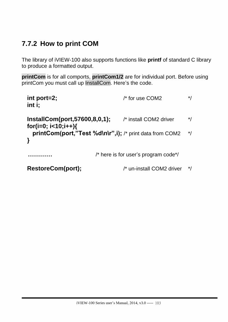
iVIEW-100 Series user’s Manual, 2014, v3.0 ----- 103
7.7.2 How to print COM
The library of iVIEW-100 also supports functions like printf of standard C library to produce a formatted output.
printCom is for all comports, printCom1/2 are for individual port. Before using printCom you must call up InstallCom. Here’s the code.
int port=2; /* for use COM2 */ int i; InstallCom(port,57600,8,0,1); /* install COM2 driver */ for(i=0; i<10;i++){
printCom(port,”Test %d\n\r”,i); /* print data from COM2 */ } ………… /* here is for user’s program code*/ RestoreCom(port); /* un-install COM2 driver */

iVIEW-100 Series user’s Manual, 2014, v3.0 ----- 104
7.7.3 How to send command to I-7000
The RS-485 (COM2) is designed to directly drive I-7000 series modules. The commands for I-7000 series modules are very different from those of iVIEW-100, but we can send the command from iVIEW-100 to I-7000 by using “ToCom”.
The example code for sending command to COM2 (RS-485) is listed below.
int port=2; /* for use COM2 */ int i; char data[5]=”$01M\r”; /* command for read module name */ InstallCom(port,9600,8,0,1); /* install COM driver */ for(i=0;i<5;i++) ToCom(port,data[i]); /* send command to I-7000 */
………… /* here is for user’s program code*/ RestoreCom(port); /* un-install COM driver */
The SendCmdTo7000 can send command to I-7000 series modules also. For more and detail user functions and demo programs information, please see Chapter 6 and Appendix A. For more I-7000 commands please refer to the “user’s manual for 7000 DIO”.
After all COM using processes, please use RestoreCom(port) to un-install COM
driver. That will let COM back to the initial setting.

iVIEW-100 Series user’s Manual, 2014, v3.0 ----- 105
7.8 How to use Flash memory The iVIEW-100 series module has 512K Flash of memory. It contains the MiniOS7 and the ROM-DISK. MiniOS7 occupies segment 0xF000 (the last segment). The ROM-DISK occupies the first segment, such as 0x8000 for 512K memories. So iVIEW-100 will occupy at least two segments. The user can use non-used segments to store data. With 512K memory, there is a maximum 384K of memory left to store data.
Flash memory can be written from 1 to 0 only and can’t be written from 0 to 1. The only way to change the data bit from 0 to 1 is to call “EraseFlash“ to erase a block of Flash Memory (64K bytes). The user should decide whether to write or to erase it.
For example: The current value is 0x55, and you want to write to 0x57. The original data bit is 0, and want to write it to 1. That means write bit 1 from 0 to 1.
If the user wants to write an integer to flash memory on segment 0xD000, offset 0x1234, the code can be as follows.
int data=0xAA55, data2; char *dataptr; int *dataptr2; dataptr=(char *)&data; FlashWrite(0xd000,0x1234,*dataptr++); FlashWrite(0xd000,0x1235,*dataptr); /* read data from Flash memory method 1 */
dataptr=(char *)&data2; *dataptr=FlashRead(0xd000,0x1234); *(dataptr+1)=FlashRead(0xd000,0x1235); /* read data from Flash memory method 2 */
dataptr2=(int far *)_MK_FP(0xd000,0x1234); data2=*dataptr2; /* or just write */
data2=*(int far *)_MK_FP(0xd000,0x1234);
Reading data from Flash Memory is somewhat like reading data from SRAM. The user should make a far pointer point to the memory location first, and then use the pointer to access the memory. Before writing data to Flash Memory, the user must call “FlashWrite” first. Then check if the data can be written to it or not. After calling “EraseFlash”, any data can be written to that segment.

iVIEW-100 Series user’s Manual, 2014, v3.0 ----- 106
7.9 RTC & NVSRAM The RTC & NVSRAM are located on the same chip. There is a Li-battery to backup the RTC & NVSRAM for 10 years. The features of RTC are given as follows: Year 2000 Compliance BIOS support RTC time & date MiniOS7 support RTC time & date Seconds, minutes, hours, date of the month Month, day of week, year, (Leap year valid up to 2079) NVSRAM: 31 bytes The NVSRAM can be read/write any number of times. The features of NVSRAM are given as follows: Data Valid: 10 years Read/write cycles: without limit Total 31 bytes
The user can use ReadNVRAM to read one byte data from NVRAM and use WriteNVRAM to write one byte data to NVRAM. For writing data to NVRAM address 0, the program is shown below.
int data=0x55,data2; WriteNVRAM(0,data); data2=ReadNVRAM(0); /* now data2=data=0x55 */
To write an integer (two bytes) to NVRAM, the program is shown below:
int data=0xAA55,data2; char *dataptr=(char *)&data; WriteNVRAM(0,*dataptr); /* write the low byte */ WriteNVRAM(1,*(dataptr+1) ); /* write the high byte */ dataptr=(char *)&data2; *dataptr=ReadNVRAM(0); /* read the low byte */ *(dataptr+1)=ReadNVRAM(1); /* read the high byte */ /* now data2=0xAA55 */

iVIEW-100 Series user’s Manual, 2014, v3.0 ----- 107
7.10 Use EEPROM The EEPROM is designed to store infrequently changed data.
For example:
Module ID configuration settings
COM port configuration settings
Small data base
The erase/write cycle of EEPROM is limited (1,000,000 erase/write cycles), user should not change the EEPROM frequently for testing. The EEPROM can erase/write onto a single byte, so it is very useful in real world applications.
The iVIEW-100 has 2K bytes of EEPROM. The EEPROM contains 8 blocks and each block has 256 bytes. It totally has 2048 bytes of EEPROM. Normally, EEPROM is default in protection mode. In this mode, the user can’t write any data into EEPROM. Call on “EnableEEP” to UN-protect it before writing data.
For example: To write data to EEPROM block 1, address 10, user has to call
EnableEEP first. The program is shown below.
int data=0x55,data2;
EnableEEP(); /* enable EEPROM to unprotect mode */
WriteEEP(1,10,data); /* write data to EEPROM */
ProtectEEP(); /* set EEPROM to protect mode */
Data2=ReadEEP(1,10); /* read EEPROM data2=data=0x55 */
NOTE: To write an integer to EEPROM, you must call “WriteEEP” twice, just like
writing data to NVRAM.

iVIEW-100 Series user’s Manual, 2014, v3.0 ----- 108
7.11 Watchdog timer The watchdog timer of iVIEW-100 is fixed at 0.8 second. User can call watchdog function in user program. The user program tell the MiniOS7 to refresh the watchdog timer, and then the user program can stop & return to the prompt of MiniOS7.
If the iVIEW-100 does not refresh watchdog timer in 0.8 second, the watchdog will RESET the iVIEW-100.
The MiniOS7 of iVIEW-100 will automatically refresh the watchdog after first power on. The user program can call the software driver to tell MiniOS7 to refresh the watchdog timer in 0.8 seconds. If the user program does not refresh the watchdog timer in 0.8 seconds, the watchdog timer will RESET the iVIEW-100.
The Watchdog Timer is default fixed on 0.8 seconds. The user can use “EnableWDT” to enable it or use “DisableWDT” to disable it. After watchdog is enabled, the program should call “RefreshWDT” before the timer count up to 0.8 seconds. Otherwise, it will reset iVIEW-100. The code can be as follows:
EnableWDT(); /* enable Watchdog timer */ while(!quit){
RefleshWDT(); /* refresh Watchdog timer */ User_function(); /* here is for user’s program code*/ } DisableWDT(); /* disable Watchdog timer */

iVIEW-100 Series user’s Manual, 2014, v3.0 ----- 109
The function IsResetByWatchDogTimer is used to check whether the iVIEW-100 has been reset by WatchDog Timer. This function must be inserted on the beginning of program. The code can be as follows.
main() { if(IsResetByWatchDogTimer()){ /*check if iVIEW reset by watchdog*/ /* here do something to check the system */
} quit=0; EnableWDT(); /* enable Watchdog timer */ while(!quit){ RefleshWDT() /* refresh Watchdog timer */; User_function(); /* here is for user’s program code*/ } DisableWDT() /* disable Watchdog timer */; }

iVIEW-100 Series user’s Manual, 2014, v3.0 ----- 110
Appendix A. User function
A.1. Page index for User Function
A
ascii_to_hex, 143
B
BmpShowAt, 148 Box, 148
C
ClearCom, 120 ClearCom1, 120 CloseLCD, 146 ClrScrn, 146 CountDownTimerReadValue, 134 CountDownTimerStart, 134
D
Delay, 131 Delay_1, 132 Delay_2, 132 DelayMs, 131 DisableWDT, 137 DrawText, 150
E
EnableEEP, 122 EnableWDT, 136
F
FlashErase, 127 FlashRead, 128
FlashReadId, 127 FlashWrite, 128
G
Getch, 114 GetCursorAt, 153 GetDate, 125 GetFileInfoByName, 140 GetFileInfoByNo, 140 GetFileName, 138 GetFileNo, 138 GetFilePositionByNo, 139 GetLCDPage, 155 GetTime, 125 GetWeekDay, 126
H
hex_to_ascii, 143 HLine, 148
I
InitEEPROM, 123 InitLCD, 145 InstallCom, 118 InstallCom1, 118 InstallUserTimer, 135 InstallUserTimer1C, 136 IntOutAt, 150 IsCom, 119 IsCom1, 119 IsResetByWatchDogTime, 137

iVIEW-100 Series user’s Manual, 2014, v3.0 ----- 111
K
Kbhit, 114
L
lamp, 151 LCDBright, 154 LcdPrintfAt, 150 LCDSetToPage, 155 Line, 148 LineInput, 116
P
Pixel, 147 Print, 115 printCom, 120 printCom1, 120 ProtectEEP, 122 Putch, 115 Puts, 115
R
ReadCom, 119 ReadCom1, 119 ReadEEP, 123 ReadInitPin, 116 ReadNVRAM, 124 RealOutAt, 151 ReceiveResponseFrom7000, 143 RefreshWDT, 137 RestoreCom, 119 RestoreCom1, 119
S
Scanf, 115 SendCmdTo7000, 142 SetCursorAt, 153 SetCursorLine, 152 SetDate, 126 SetTime, 125 StopWatchContinue, 133 StopWatchPause, 133 StopWatchReadValue, 134 StopWatchReset, 133 StopWatchStart, 132 StopWatchStop, 133
T
TextOutAt, 150 TimerClose, 131 TimerOpen, 130 TimerReadValue, 131 TimerResetValue, 131 ToCom, 120 ToCom1, 120
U
UnderLine, 149 Ungetch, 114
V
VLine, 147
W
WriteEEP, 122 WriteNVRAM, 125

iVIEW-100 Series user’s Manual, 2014, v3.0 ----- 112
A.2. iVIEWL.lib
“iVIEWL.lib” is the main user function library for iVIEW-100. It contains most of
the iVIEW-100 functions. The other user function, “mmi100.lib”, specially focuses
on LCD usage. Please include the header files “iVIEW.h” & “mmi100.h”, and add
“iVIEWL.lib” & “mmi100.lib” into the project to implement the user function.
No Type Function
1 Standard IO
Kbhit, Getch, Ungetch, Putch, Puts, Scanf, Print, ReadInitPin, LineInput….……... more ……………..
2 COM port InstallCom, InstallCom1, InstallCom2, InstallCom3…… RestallCom, RestallCom1, RestallCom2…… IsCom, IsCom1, IsCom2……, ReadCom, ReadCom1…… ClearCom, ClearCom1…, ToCom, ToCom1, ToCom2...... PrintCom, PrintCom1, PrintCom2…………more…………
3 EEPROM EnableEEP, WriteEEP, ProtectEEP, ReadEEP, InitEEPROM...
4 NVRAM & RTC
ReadNVRAM, WriteNVRAM, GetTime, SetTime, GetDate, SetDate, GetWeekDay……………
5 Flash Memory FlashReadId, FlashErase, FlashWrite, FlashRead………
6 Timer & Watchdog Timer
TimerOpen, TimerClose, TimerResetValue, TimerReadValue DelayMs, Delay, Dealy_1, Delay_2, StopWatchStart, StopWatchReset, StopWatchStop, StopWatchPause, StopWatchCountine, StopWatchReadValue, CountDownTimerStart, CountDownTimerReadValue, InstallUserTimer, InstallUserTimer1C EnableWDT, DisableWDT, RefreshWDT…………
7 File GeFileNo, GetFileName, GetFilePositionByNo, GetFileInfoByNo, GetFileInfoByName…………
8 Connect to 7000
SendCmdTo7000, ReceiveResponseFrom7000, ascii_to_hex, hex_to_ascii……
9 Others ……….………………..more …………………………..

iVIEW-100 Series user’s Manual, 2014, v3.0 ----- 113
A.2.1 Type 1: Standard IO
Function Description
Kbhit Checks if any key board hit data is currently available in the input buffer of COM1.
Getch Wait until get one character from key board hit.
Ungetch Put one character back to COM1's input buffer.
Putch Send one character to COM1.
Puts Send a string to COM1.
Scanf Get a formatted data like C's scanf. ( cannot used on MSC / VC++, just TC/BC only)
Print Print a formatted data like C’s printf.
ReadInitPin Read the status of INIT* pin.
LineInput Input one line from StdInput.
……more……
There are more user function for Standard IO, please refer to Appendix C iVIEW.h and CD\ Napdos\7188\miniOS7\manual\index.html for more detail information.

iVIEW-100 Series user’s Manual, 2014, v3.0 ----- 114
Kbhit()
Func.: Checks if any key board hit data is currently available in the input buffer.
Syntax: int Kbhit(void); Header: #include ”mmi100.h” Description: Checks if any data is currently available in the input buffer.
Return 0 : for no data input. Return Others : Has data in input buffer, and the return value is the next data in buffer, if the next data is '\0' it will return -1(0xFFFF).
Example: (stdio.c)
#include <iVIEW.H> #include <mmi100.h> void main() { int quit=0,data; InitLib(); Puts("\n\rPress any key to show ASCII('Q' to quit):\n\r"); while(!quit){ if(Kbhit()){ data=Getch(); if(data=='Q') quit=1; Putch(data); Print(" ASCII is: %d\n\r", data); Puts("\n\rPress any key to show ASCII('Q' to quit):\n\r"); } } }
Getch()
Func.: Wait until get one character from key board hit. Syntax: int Getch(void); Header: #include ”mmi100.h” Description: Read one character from input buffer. If there is no any input in data
buffer, the function will wait until inpur buffer receive any data. Return Value: 0 to 255.
Example: Please refer to “Kbhit()” for example.
Ungetch()
Func.: Put one character back to input buffer. Syntax: int Ungetch(int data); Header: #include ”mmi100.h” Description: If there is no data in the input buffer when call Ungetch, next time call
Getch() will return the data. data:0 to 255. If data > 255, only the low byte will be send out. Return Value: On success return NoError, on fail (the buffer is full) return 1.
Example: Please refer to “Kbhit()” for example of Getch().

iVIEW-100 Series user’s Manual, 2014, v3.0 ----- 115
Putch()
Func.: Send one character on screen. Syntax: void Putch(int data); Header: #include ”mmi100.h” Description: data: 0 to 255.
If data > 255, only the low byte will be send out. Example: Please refer to “Kbhit()” for example.
Puts()
Func.: Send a string on screen. Syntax: void Puts(char *str); Header: #include ”mmi100.h” Description: Puts will call Putch to send the string.
str: The pointer to the string to be send. Example: Please refer to “Kbhit()” for example.
Scanf()
Func.: Scan character from input. Like C's scanf. ( cannot used on MSC / VC++) Syntax: int Scanf(char *fmt, ...); Header: #include ”mmi100.h” Description: Return the number of input fields successfully scanned, converted, and
stored. The return value does not include scanned fields that were not stored. Return value = 0 if no fields were stored. Return value = EOF if attempts to read at end-of-string.
Example: Napdos\7188\miniOS7\Demo\MSc\Scanf.c
Print()
Func.: Print formatted character to screen. Like C's printf. Syntax: int Print(char *fmt,...); Header: #include ”mmi100.h” Description: This function is used to instead of printf, and the only difference between
Print and printf is Print do not transfer '\n' to '\n'+'\r'. That is '\n' only send out the code 0x0A, not 0x0A+0x0D. User has to use ‘\n\r’ for ‘new line and return’. The printed message is send out to COM1. (default use 115200,N,8,1) Input Parameter: Please refer to C's standard function printf. Return Value: The character number to be sent out.
Example: Please refer to “Kbhit()” for example.

iVIEW-100 Series user’s Manual, 2014, v3.0 ----- 116
LineInput()
Func.: Input one line from StdInput. Syntax: int LineInput(char *buf, int maxlen); Header: #include ”mmi100.h” Description: buf: The buffer to store the input data.
maxlen: (size of the buffer)-1. Return Value: The input character number.
Example:
ReadInitPin()
Func.: Read the status of INIT* pin. Syntax: int ReadInitPin(void); Header: #include ”mmi100.h” Description: Return: 0= Init* pin is floatting or connect to VCC.
Return: 1= Init* pin is connect to GND. Example:
(stdio2.c) #include <iview.h>
#include <mmi100.h> void main() { int InitPin; InitLib(); InitPin=ReadInitPin(); Print("Init Pin= %d\n\r",InitPin); }

iVIEW-100 Series user’s Manual, 2014, v3.0 ----- 117
A.2.2 Type 2: COM port
Function Description
InstallCom Install COM driver, COM number is not fixed
InstallCom1 Install COM1 driver, fix on COM1
InstallCom2… Install COM2 driver, fix on COM2 InstallCom3, InstallCom4…are similar
RestallCom Un-install COM driver, COM number is not fixed
RestallCom1 Un-install COM1 driver, fix on COM1 RestallCom2, …are similar
IsCom Check if Com has data, COM number is not fixed
IsCom1 Check if Com1 has data, fix on COM1
IsCom2… Check if Com2 has data, fix on COM2 IsCom3, IsCom4…are similar
ClearCom Clear all the data in COM, COM number is not fixed
ClearCom1 Clear all the data in COM1, fix on COM1
ClearCom2 Clear all the data in COM2, fix on COM2 ClearCom3, ClearCom4…are similar
ReadCom Read data from COM, COM number is not fixed
ReadCom1 Read data to COM1, fix on COM1
ReadCom2 Read data to COM2, fix on COM2 ReadCom3, ReadCom4…are similar
ToCom Send data to COM, COM number is not fixed
ToCom1 Send data to COM1, fix on COM1
ToCom2 Send data to COM2, fix on COM2 ToCom3, ToCom4…are similar
printCom Print the data in COM, COM number is not fixed
printCom1 Print out the data in COM1, fix on COM1
printCom2 Print out the data in COM2, fix on COM2 printCom3, printCom4…are similar
……more……
There are more user function for COM port, please refer to Appendix C iVIEW.h and CD\Napdos\7188 \miniOS7\manual\index.html for more detail information.

iVIEW-100 Series user’s Manual, 2014, v3.0 ----- 118
InstallCom ()
Func.: Install COM driver Syntax: int InstallCom(int port, unsigned long baud, int data, int parity, int stop); Header: #include ”iVIEW.h” Description: Install driver to COM, COM number is not fixed
port: assigning for COM port number, different “port”different COM baud: baud rate, iVIEW-100 default baud rate=115200
Example: (comt.c)
#include <iVIEW.H> #include <mmi100.H> void main() { int quit=0,data, i, port=1; /* port=1, use COM1*/ InitLib(); InstallCom(port,115200,8,0,1); /* install COM driver */ for(i=0; i<10; i++) printCom(port,"Test %d\n\r",i); /*print data to COM*/ while(!quit) { if(IsCom(port)) { /*check if any data has in COM*/ data=ReadCom(port); /*read data from COM*/ ToCom(port,data); /*send data to COM*/ ClearCom(port); /*clear all the data in COM*/ if(data=='Q') quit=1; /*if receive 'Q', exit program*/ } } RestoreCom(port); /*un-install COM driver */ }
InstallCom1()
Func.: Install COM1 driver Syntax: int InstallCom1(unsigned long baud, int data, int parity, int stop); Header: #include ”iVIEW.h” Description: Install driver to COM1, fix on COM1
baud: baud rate, iVIEW-100 default baud rate=115200 Example:
(comt1.c) #include <iVIEW.H>
#include <mmi100.H> void main() { int quit=0,data; InitLib(); InstallCom1(115200,8,0,1); /* install COM1 driver */ while(!quit) { if(IsCom1()) { /*check if any data has in COM1*/ data=ReadCom1(); /*read data from COM1*/ ToCom1(data); /*send data to COM1*/ if(data==’q’) quit=1; /*if receive ‘q’, exit program*/ } } RestoreCom1(); /* un-install COM1 driver */ }

iVIEW-100 Series user’s Manual, 2014, v3.0 ----- 119
RestoreCom()
Func.: Un-install COM driver, COM number is not fixed Syntax: int RestoreCom(int port); Header: #include ”iVIEW.h” Description: Un-install COM driver, COM number is not fixed
port: assigning for COM port number Example: Please refer to “InstallCom()” for example.
RestoreCom1()
Func.: Un-install COM1 driver, fix on COM1 Syntax: int RestoreCom1(void); Header: #include ”iVIEW.h” Description: Un-install COM1 driver, fix on COM1 Example: Please refer to “InstallCom1()” for example.
IsCom()
Func.: Check if COM has data, COM number is not fixed Syntax: int IsCom(int port); Header: #include ”iVIEW.h” Description: Check if Com has data, COM number is not fixed
port: assigning for COM port number Example: Please refer to “InstallCom()” for example.
IsCom1()
Func.: Check if COM1 has data, fix on COM1 Syntax: int IsCom1(void); Header: #include ”iVIEW.h” Description: Check if COM1 has data, fix on COM1 Example: Please refer to “InstallCom1()” for example.
ReadCom()
Func.: Read the data in COM, COM number is not fixed Syntax: int ReadCom(int port); Header: #include ”iVIEW.h” Description: Read the data in COM, COM number is not fixed Example: Please refer to “InstallCom()” for example.
ReadCom1()
Func.: Read the data in COM1, fix on COM1 Syntax: int ReadCom1(void); Header: #include ”iVIEW.h” Description: Read the data in COM1, fix on COM1 Example: Please refer to “InstallCom1()” for example.
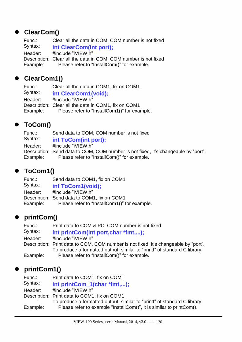
iVIEW-100 Series user’s Manual, 2014, v3.0 ----- 120
ClearCom()
Func.: Clear all the data in COM, COM number is not fixed Syntax: int ClearCom(int port); Header: #include ”iVIEW.h” Description: Clear all the data in COM, COM number is not fixed Example: Please refer to “InstallCom()” for example.
ClearCom1()
Func.: Clear all the data in COM1, fix on COM1 Syntax: int ClearCom1(void); Header: #include ”iVIEW.h” Description: Clear all the data in COM1, fix on COM1 Example: Please refer to “InstallCom1()” for example.
ToCom()
Func.: Send data to COM, COM number is not fixed Syntax: int ToCom(int port); Header: #include ”iVIEW.h” Description: Send data to COM, COM number is not fixed, it’s changeable by “port”. Example: Please refer to “InstallCom()” for example.
ToCom1()
Func.: Send data to COM1, fix on COM1 Syntax: int ToCom1(void); Header: #include ”iVIEW.h” Description: Send data to COM1, fix on COM1 Example: Please refer to “InstallCom1()” for example.
printCom()
Func.: Print data to COM & PC, COM number is not fixed Syntax: int printCom(int port,char *fmt,...); Header: #include ”iVIEW.h” Description: Print data to COM, COM number is not fixed, it’s changeable by “port”.
To produce a formatted output, similar to “printf” of standard C library. Example: Please refer to “InstallCom()” for example.
printCom1()
Func.: Print data to COM1, fix on COM1 Syntax: int printCom_1(char *fmt,...); Header: #include ”iVIEW.h” Description: Print data to COM1, fix on COM1
To produce a formatted output, similar to “printf” of standard C library. Example: Please refer to example “InstallCom()”, it is similar to printCom().

iVIEW-100 Series user’s Manual, 2014, v3.0 ----- 121
A.2.3 Type 3: EEPROM
Function Description
EnableEEP Enable EEPROM to write-enable mode
WriteEEP Write data to EEPROM
ProtectEEP Set EEPROM to write-protect mode
ReadEEP Read data from EEPROM
InitEEPROM Before calling external EEPROM function, have to call InitEEPROM() first.
……more……
There are more user function for EEPROM, please refer to Appendix C iVIEW.h and CD\Napdos\7188 \miniOS7\manual\index.html for more detail information.
Note: There are two types of EEPROM for iVIEW-100, 24LC16 & 24LC1024.
User can type “diag” in MiniOS7 command line of MiniOS7 Utility to see the
system information of iVIEW-100. The functions introduced in this section are
available for both types. There are more functions about EEPROM, some are
used just for one type. Please type “diag” to check the type before calling those
functions.

iVIEW-100 Series user’s Manual, 2014, v3.0 ----- 122
EnableEEP()
Func.: Enable EEPROM to write-enable mode Syntax: void EnableEEP(void); Header: #include ”iVIEW.h” Description: Enable EEPROM to write-enable mode
EEPROM is default in write-protect mode, must call EnableEEP() before writing data to EEPROM.
Example: (eep.c)
#include <iVIEW.H> #include <mmi100.H> void main() { Int data=55, data2; InitLib(); EnableEEP(); WriteEEP(1,10,data); ProtectEEP(); data2=ReadEEP(1,10); Print("data=%d, Data2=%d",data,data2); }
WriteEEP()
Func.: Write data to EEPROM Syntax: int WriteEEP(int block, int addr, int data); Header: #include ”iVIEW.h” Description: Write one byte data to EEPROM.
block: 0 to 7 (total 8 blocks). addr: 0 to 255 (every block has 256 bytes). data: 0 to 255 (8-bit data). Return Value: On success return NoError. On fail return Error code. BlockError(-10) or AddrError(-9) or WriteError(-11).
Example: Please refer to “EnableEEP()” for example.
ProtectEEP()
Func.: Set EEPROM to write-protect mode Syntax: void ProtectEEP(void); Header: #include ”iVIEW.h” Description: Set EEPROM back to write-protect mode. EEPROM is default in write-protect
mode. Before writing data to EEPROM, user have to call EnableEEP(). After writing data, user had better call ProtectEEP() to set back to write-protect mode.
Example: Please refer to “EnableEEP()” for example.

iVIEW-100 Series user’s Manual, 2014, v3.0 ----- 123
ReadEEP()
Func.: Read data from EEPROM Syntax: int ReadEEP(int block, int addr); Header: #include ”iVIEW.h” Description: Read one byte data from EEPROM.
block: 0 to 7 (total 8 blocks). addr: 0 to 255 (every block has 256 bytes). Return Value: On success return the value on EEPROM(0 to 255). On fail return Error code. BlockError(-10) or AddrError(-9) or (-101,-102 for read error)..
Example: Please refer to “EnableEEP()” for example.
InitEEPROM()
Func.: Initial EEPROM before calling external EEPROM user function. Syntax: void InitEEPROM(void); Header: #include ”iVIEW.h” Description: There are some external EEPROM user functions. Before calling those
external EEPROM user function, user has to call InitEEPROM() first. Example: Please refer to iVIEW.h for detail information.

iVIEW-100 Series user’s Manual, 2014, v3.0 ----- 124
A.2.4 Type 4: NVRAM & RTC
Function Description
ReadNVRAM Read data from NVRAM.
WriteNVRAM Write data to NVRAM.
GetTime Get the system time from the RTC.
SetTime Set the system time to the RTC
GetDate Get the system date from the RTC
SetDate Set the system date to the RTC
GetWeekDay Get the weekday to the RTC.
……more……
There are more user function for NVRAM & RTC, please refer to Appendix C iVIEW.h and CD\Napdos\7188 \miniOS7\manual\index.html for more detail information.
ReadNVRAM()
Func.: Read data from NVRAM. Syntax: int ReadNVRAM(int addr); Header: #include ”iVIEW.h” Description: Read one byte data from NVRAM.
addr: 0 to 30, total 31 bytes. Return Value: On success return data (0-255) stored on that address. On fail return AddrError(-9).
Example: (nvr.c)
#include <iVIEW.H> #include <mmi100.H> void main() { int data=55, data2; InitLib(); WriteNVRAM(0,data); data2=ReadNVRAM(0); /* now data2=data=55 */ Print("data=%d, data2=%d",data,data2); }

iVIEW-100 Series user’s Manual, 2014, v3.0 ----- 125
WriteNVRAM()
Func.: Write data to NVRAM. Syntax: int WriteNVRAM(int addr, int data); Header: #include ”iVIEW.h” Description: Write one byte data to NVRAM.
addr: 0-30. data: One byte data (0-255). If data>255, only the low byte will be write to NVRAM. Return Value: On success return NoError. On fail return AddrError(-9).
Example: Please refer to “ReadNVRAM()” for detail information.
GetTime()
Func.: Get the system time from the RTC. Syntax: void GetTime(int *hour, int *minute, int *sec); Header: #include ”iVIEW.h” Description: hour: The address to save hour(0-23).
minute: The address to save minute(0-59). sec: The address to save second(0-59).
Example: (rtc.c)
#include <iVIEW.H> #include <mmi100.H> void main() { int year, month, day, hour, min, sec, wday; InitLib(); SetDate(2006,1,12); /*set the system date for RTC*/ SetTime(15,35,50); /*set the system time for RTC*/ SetWeekDay(4); /*set the system weekday for RTC*/ GetDate(&year,&month,&day); /*get the system date from RTC*/ GetTime(&hour,&min,&sec); /*get the system time from RTC*/ wday=GetWeekDay(); Print("Date=%02d/%02d/%04d(%d) Time=%02d:%02d:%02d\n\r", month,day,year,wday,hour,min,sec); }
SetTime()
Func.: Set the system time to the RTC Syntax: int SetTime(int hour,int minute,int sec); Header: #include ”iVIEW.h” Description: hour: 0-23.
minute: 0-59. sec: 0-59. Return Value: On success return NoError. On fail return TimeError(-19).
Example: Please refer to “GetTime()” for detail information.
GetDate()

iVIEW-100 Series user’s Manual, 2014, v3.0 ----- 126
Func.: Read the system date from the RTC Syntax: void GetDate(int *year,int *month,int *day); Header: #include ”iVIEW.h” Description: year: 2000-2080
month: 1-12 day: 1-31
Example: Please refer to “GetTime()” for detail information.
SetDate()
Func.: Set the system date to the RTC Syntax: int SetDate(int year,int month,int day); Header: #include ”iVIEW.h” Description: year: 2000-2080
month: 1-12 day: 1-31 Return Value: On success return NoError. On fail return DateError(-18).
Example: Please refer to “GetTime()” for detail information.
GetWeekDay()
Func.: Read the weekday from the RTC. Syntax: int GetWeekDay(void); Header: #include ”iVIEW.h” Description: Return Value: 0=>Sunday, 1-6=>Monday to Saturday.
Note: GetWeekDay() does not check the weekday is right or not, just read from RTC. When use MiniOS7 command "date" to set date, MiniOS7 will calculate the right weekday and set to RTC. If user call SetDate(), it also will calculate the right weekday and set to RTC. But if user call SetWeekDay( ) need to calculate the right weekday himself.
Example: Please refer to “GetTime()” for detail information.

iVIEW-100 Series user’s Manual, 2014, v3.0 ----- 127
A.2.5 Type 5: Flash Memory
Function Description
FlashReadId Get the information about FLASH.
FlashErase ERASE one sector of flash.
FlashWrite Write one byte data to FLASH.
FlashRead Read one byte data from FLASH.
……more……
There are more user function for Flash Memory, please refer to Appendix C iVIEW.h and CD\ Napdos\7188\miniOS7 \manual\index.html for more information.
The size of the Flash Memory used on iVIEW-100 series is 512K bytes. MiniOs7 will use the last 64K bytes, and others are used to store user's program or data. User's program can use functions to write data to Flash Memory. When writes data to Flash Memory, user only can write from "1" to "0", can not write data from "0" to "1". So, before write data to FLASH, erase it first. The erase process will make all data to 0xFF, that is, all data bit is "1". Then can write data to it. The function FlashErase() is used to erase the FLASH, every time one sector (64K bytes).
FlashReadId()
Func.: Get the information about FLASH. Syntax: int FlashReadId(void); Header: #include ”iVIEW.h” Description: Read Flash memory device code(high byte) and manufacture code(low byte).
Return Value: 0xA4C2 (MXIC 29f040), 0xA401 (AMD 29f040) Example: Please refer to “demo\flash\flash.c” for detail information.
FlashErase()
Func.: ERASE one sector of flash. Syntax: int FlashErase(unsigned seg); Header: #include ”iVIEW.h” Description: Erase one sector (64K bytes) of Flash Memory, all data on that sector will
become 0xFF. seg: 0x8000, 0x9000, 0xA000, 0xB000, 0xC000, 0xD000 or 0xE000. Return Value: On success return NoError(0). On fail return TimeOut(-5). Note: the segment 0xF000 is used for MiniOs7, if seg=0xF000 FlashErase will do nothing.
Example: Please refer to “demo\flash\flash.c” for detail information.

iVIEW-100 Series user’s Manual, 2014, v3.0 ----- 128
FlashWrite()
Func.: Write one byte data to FLASH. Syntax: int FlashWrite(unsigned int seg, unsigned int offset, char data); Header: #include ”iVIEW.h” Description: seg: 0x8000, 0x9000, 0xA000, 0xB000, 0xC000, 0xD000 or 0xE000.
offset: 0 to 65535(0xffff). data: 0 to 255(8-bit data). Return NoError(0) on success. Return TimeOut(-5) or SegmentError(-12) on fail. Note: When write data to Flash Memory, data bit only can be changed from 1 to 0. So if data in the position of 0xff, you can write any data to it. But if data in the position of 0x01, you can only write 0x00 to it. FlashWrite do not check it, and just write it. When you want to change data from 0 to 1, you will get TimeoutError. After call FlashErase you can write any data to it again.
Example: (flashm.c)
#include <iVIEW.H> #include <mmi100.H> void main() { int data=0xAA55, data2; char *dataptr; InitLib(); dataptr=(char *)&data; //write data to Flash memory FlashWrite(0xd000,0x1234, *dataptr++); FlashWrite(0xd000,0x1235, *dataptr); //read data from Flash memory dataptr=(char *)&data2; *dataptr=FlashRead(0xd000, 0x1234); *(dataptr+1)=FlashRead(0xd000, 0x1235); }
FlashRead()
Func.: Read one byte data from FLASH. Syntax: int FlashRead(unsigned int seg, unsigned int offset); Header: #include ”iVIEW.h” Description: seg: 0-65535(0xffff).
offset: 0 to 65535(0xffff). Return Value: FlashRead just return the value on address seg:offset. The address can be on SRAM, Flash memory or other address (generally return 0xff).
Example: Please refer to “FlashWrite()” for detail information.

iVIEW-100 Series user’s Manual, 2014, v3.0 ----- 129
A.2.6 Type 6: Timer & Watchdog Timer
Function Description
TimerOpen Open timer function usage.
TimerClose Stop timer function.
TimerResetValue Reset timer to 0.
TimerReadValue Read main time ticks.
DelayMs Delay some time interval. The time unit is ms, use system timeticks.
Delay Delay some time interval. The time unit is ms, use CPU Timer 1.
Delay_1 Delay some time interval.The time unit is 0.1 ms, use CPU Timer 1.
Delay_2 Delay some time interval.The time unit is 0.01 ms, use CPU Timer 1.
StopWatchStart Start to use a StopWatch channel.
StopWatchReset Reset the StopWatch value to 0.
StopWatchStop Disable the StopWatch channel.
StopWatchPause Pause the StopWatch.
StopWatchContinue Continue the StopWatch.
StopWatchReadValue Read current StopWatch value.
CountDownTimerStart Start to use CountDownTimer.
CountDownTimerReadValue Read current CountDownTimer value
InstallUserTimer Install user's timer function. User's timer function will be called every 1 ms.
InstallUserTimer1C Install user's timer function on interrupt 0x1c. System timer will call int 0x1c every 55 ms.
EnableWDT Enable Watch dog timer
DisableWDT Disable Watch dog timer
RefreshWDT Refresh Watch dog timer
…………more…………
There are more user function for Timer & Watchdog Timer, please refer to Appendix C iVIEW.h and CD\Napdos\7188\miniOS7\manual\index.html for more information.
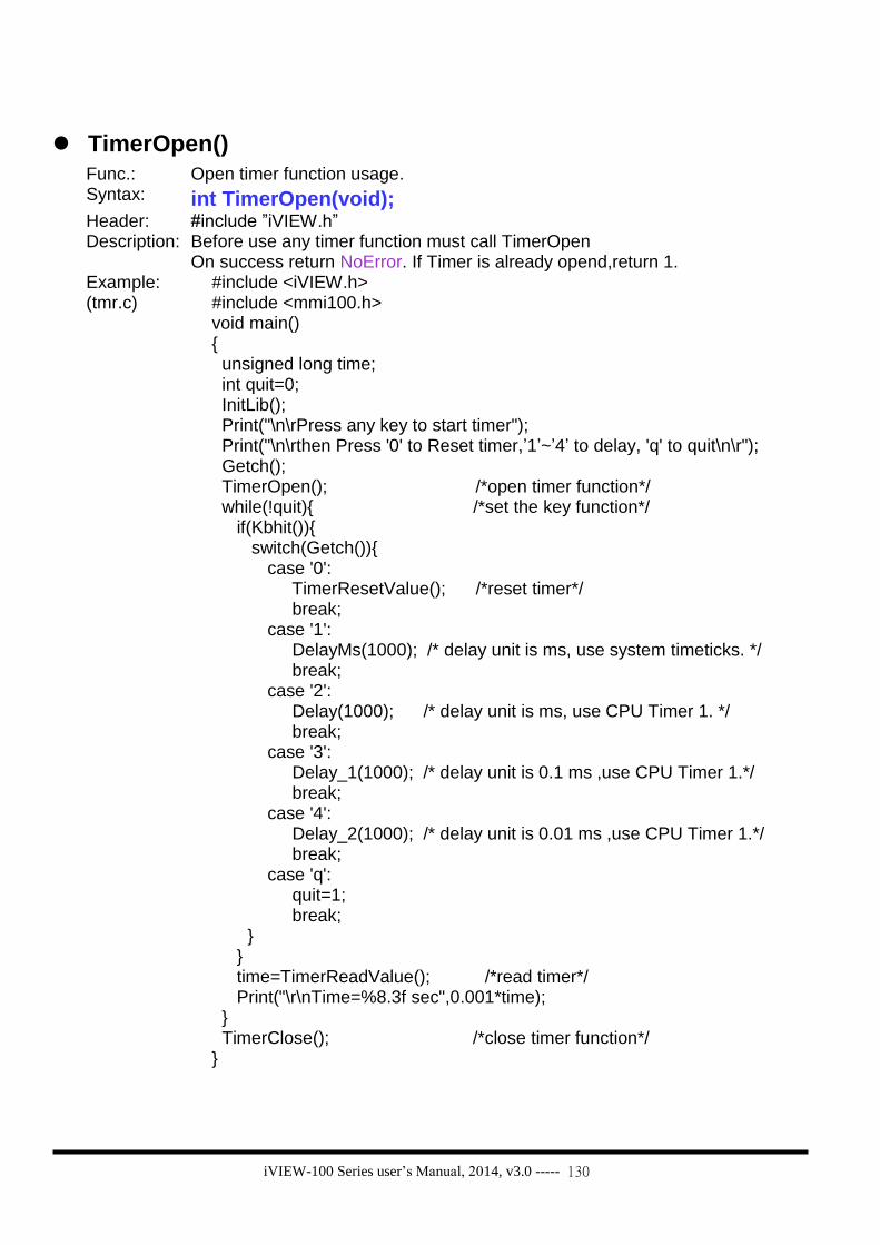
iVIEW-100 Series user’s Manual, 2014, v3.0 ----- 130
TimerOpen()
Func.: Open timer function usage. Syntax: int TimerOpen(void); Header: #include ”iVIEW.h” Description: Before use any timer function must call TimerOpen
On success return NoError. If Timer is already opend,return 1. Example:
(tmr.c) #include <iVIEW.h>
#include <mmi100.h> void main() { unsigned long time; int quit=0; InitLib(); Print("\n\rPress any key to start timer"); Print("\n\rthen Press '0' to Reset timer,’1’~’4’ to delay, 'q' to quit\n\r"); Getch(); TimerOpen(); /*open timer function*/ while(!quit){ /*set the key function*/ if(Kbhit()){ switch(Getch()){ case '0': TimerResetValue(); /*reset timer*/ break; case '1': DelayMs(1000); /* delay unit is ms, use system timeticks. */ break; case '2': Delay(1000); /* delay unit is ms, use CPU Timer 1. */ break; case '3': Delay_1(1000); /* delay unit is 0.1 ms ,use CPU Timer 1.*/ break; case '4': Delay_2(1000); /* delay unit is 0.01 ms ,use CPU Timer 1.*/ break; case 'q': quit=1; break; } } time=TimerReadValue(); /*read timer*/ Print("\r\nTime=%8.3f sec",0.001*time); } TimerClose(); /*close timer function*/ }

iVIEW-100 Series user’s Manual, 2014, v3.0 ----- 131
TimerClose()
Func.: Stop timer function. Syntax: int TimerClose(void); Header: #include ”iVIEW.h” Description: If the program has call OpenTimer, it must call TimerClose before exiting.
Always return NoError. Example: Please refer to “TimerOpen()” for detail information.
TimerResetValue()
Func.: reset timer to 0. Syntax: void TimerResetValue(void); Header: #include ”iVIEW.h” Description: Reset the main time ticks to 0. Example: Please refer to “TimerOpen()” for detail information.
TimerReadValue()
Func.: Read main time ticks. Syntax: unsigned long TimerReadValue(void); Header: #include ”iVIEW.h” Description: Read main time ticks. The time unit for ticks is 1 ms. When TimerOpen or call
TimerReset will reset the valuse to 0. Example: Please refer to “TimerOpen()” for detail information.
DelayMs()
Func.: Delay some time interval; the time unit is ms, use system timeticks. Syntax: void DelayMs(unsigned t); Header: #include ”iVIEW.h” Description: Delay unit is ms,
t: the time want to delay. Example: Please refer to “TimerOpen()” for detail information.
Delay()
Func.: Delay some time interval; the time unit is ms, use CPU Timer 1. Syntax: void Delay(unsigned ms); Header: #include ”iVIEW.h” Description: Delay some time interval. Delay unit is ms, use CPU Timer 1.
ms: the time want to delay. Example: Please refer to “TimerOpen()” for detail information.

iVIEW-100 Series user’s Manual, 2014, v3.0 ----- 132
Delay_1()
Func.: Delay some time interval; the time unit is 0.1 ms, use CPU Timer 1. Syntax: void Delay_1(unsigned ms); Header: #include ”iVIEW.h” Description: Delay some time interval. Delay unit is .01 ms, use CPU Timer 1.
ms: the time want to delay. Example: Please refer to “TimerOpen()” for detail information.
Delay_2()
Func.: Delay some time interval; the time unit is 0.01 ms, use CPU Timer 1. Syntax: void Delay_2(unsigned ms); Header: #include ”iVIEW.h” Description: Delay some time interval. Delay unit is 0.01 ms, use CPU Timer 1.
ms: the time want to delay. Example: Please refer to “TimerOpen()” for detail information.
StopWatchStart()
Func.: Start to use a StopWatch channel, and reset the StopWatch value to 0. Syntax: int StopWatchStart(int channel); Header: #include ”iVIEW.h” Description: The system timer ISR will increment the StopWatch value by 1 every 1 ms.
channel: 0-7, total 8 channels. If channel is out of range return ChannelError(-15). On success return NoError.
Example: (sdwh.c)
#include <iVIEW.h> #include <mmi100.h> void main(void) { unsigned long value; int quit=0; InitLib(); Print("\n\rTest StopWatch ... Press 'q' to quit\n\r "); TimerOpen(); StopWatchStart(0); /*to use the StopWatchStart function*/ while(!quit){ if(Kbhit()){ switch(Getch()){ case 'q': quit=1; break; } } StopWatchReadValue(0,&value); Print("SWatch=%d \r",value); if(value==2000){ StopWatchPause(0); DelayMs(2000); StopWatchContinue(0); } if(value==4000){ StopWatchStop(0); DelayMs(2000); StopWatchReset(0); StopWatchStart(0); } } TimerClose(); }

iVIEW-100 Series user’s Manual, 2014, v3.0 ----- 133
StopWatchReset()
Func.: Reset the StopWatch value to 0. Syntax: int StopWatchReset(int channel); Header: #include ”iVIEW.h” Description: channel:0-7, total 8 channels.
If channel is out of range return ChannelError(-15). On success return NoError.
Example: Please refer to “StopWatchStart()” for detail information.
StopWatchStop()
Func.: Disable the StopWatch channel. Syntax: int StopWatchStop(int channel); Header: #include ”iVIEW.h” Description: The system timer ISR will stop to increment the StopWatch value.
channel: 0-7, total 8 channels If channel is out of range return ChannelError(-15). On success return NoError.
Example: Please refer to “StopWatchStart ()” for detail information.
StopWatchPause()
Func.: Pause the StopWatch. Syntax: int StopWatchPause(int channel); Header: #include ”iVIEW.h” Description: After call StopWatchPause can call StopWatchContinue to continue count
time. channel:0-7, total 8 channels If channel is out of range return ChannelError(-15). On success return NoError.
Example: Please refer to “StopWatchStart ()” for detail information.
StopWatchContinue()
Func.: Continue the StopWatch. Syntax: int StopWatchContinue(int channel); Header: #include ”iVIEW.h” Description: channel:0-7, total 8 channels
If channel is out of range return ChannelError(-15). If success return NoError. Example: Please refer to “StopWatchStart ()” for detail information.
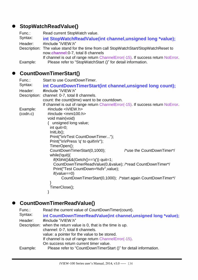
iVIEW-100 Series user’s Manual, 2014, v3.0 ----- 134
StopWatchReadValue()
Func.: Read current StopWatch value. Syntax: int StopWatchReadValue(int channel,unsigned long *value); Header: #include ”iVIEW.h” Description: The value stand for the time from call StopWatchStart/StopWatchReset to
now.channel:0-7, total 8 channels If channel is out of range return ChannelError(-15). If success return NoError.
Example: Please refer to “StopWatchStart ()” for detail information.
CountDownTimerStart()
Func.: Start to use CountDownTimer. Syntax: int CountDownTimerStart(int channel,unsigned long count); Header: #include ”iVIEW.h” Description: channel: 0-7, total 8 channels.
count: the count(time) want to be countdown. If channel is out of range return ChannelError(-15). If success return NoError.
Example: (codn.c)
#include <iVIEW.h> #include <mmi100.h> void main(void) { unsigned long value; int quit=0; InitLib(); Print("\n\rTest CountDownTimer..."); Print("\n\rPress 'q' to quit\n\r"); TimerOpen(); CountDownTimerStart(0,1000); /*use the CountDownTimer*/ while(!quit){ if(Kbhit()&&(Getch()=='q')) quit=1; CountDownTimerReadValue(0,&value); /*read CountDownTimer*/ Print("Test CountDown=%d\r",value); if(value==0) CountDownTimerStart(0,1000); /*start again CountDownTimer*/ } TimerClose(); }
CountDownTimerReadValue()
Func.: Read the current value of CountDownTimer(count). Syntax: int CountDownTimerReadValue(int channel,unsigned long *value); Header: #include ”iVIEW.h” Description: when the return value is 0, that is the time is up.
channel: 0-7, total 8 channels. value: a pointer for the value to be stored. If channel is out of range return ChannelError(-15). On success return current timer value.
Example: Please refer to “CountDownTimerStart ()” for detail information.

iVIEW-100 Series user’s Manual, 2014, v3.0 ----- 135
InstallUserTimer()
Func.: Install user's timer function. User's timer function will be called every 1 ms. Syntax: void InstallUserTimer(void (*fun)(void)); Header: #include ”iVIEW.h” Description: fun: The user's function pointer. The function cannot use input agument, and
can not return value. Example:
(ustm.c for 5 lamps)
#include <iVIEW.h> #include <mmi100.h> int Data[3]={0,0,0}; void MyTimerFun(void) /*user timer function*/ { static int count[3]={0,0,0}; int i; for(i=0;i<3;i++){ Print("count[%d]=%d\r",i,count[i]); count[i]++; } if(count[0]>=200){ /*LCD lamp1 blink per 200 units*/ count[0]=0; if (Data[0]==0) Data[0]=1; else Data[0]=0; lamp(1,1,Data[0]); } if(count[1]>=500){ /*LCD lamp2 blink per 500 units*/ count[1]=0; if (Data[1]==0) Data[1]=1; else Data[1]=0; lamp(2,1,Data[1]); } if(count[2]>=1000){ /*LCD lamp3 blink per 1000 units*/ count[2]=0; if (Data[2]==0) Data[2]=1; else Data[2]=0; lamp(3,1,Data[2]); } } void main(void) { int quit=0; Print("\n\rtest LCD lamp blink by UserTimer "); Print("\n\rPress 'q' to quit\n\r"); InitLib(); InitLCD(); /*initial Lib & LCD*/ ClrScrn(); /*clear LCD screen*/ TimerOpen(); /*open timer function*/ InstallUserTimer(MyTimerFun); /*install & call user timer */ while(!quit){ if(Kbhit() && Getch()=='q') quit=1; } TimerClose(); }

iVIEW-100 Series user’s Manual, 2014, v3.0 ----- 136
InstallUserTimer1C()
Func.: Install user's timer function on interrupt 0x1c. System timer will call int 0x1c every 55 ms.
Syntax: void InstallUserTimer1C(void (*fun)(void)); Header: #include ”iVIEW.h” Description: fun: The user's function pointer. The function cannot use input agument, and
can not return value. Example: Please refer to “InstallUserTimer()” for silimar information.
EnableWDT()
Func.: Enable the Watchdog timer. Syntax: void EnableWDT(void); Header: #include ”iVIEW.h” Description: The WatchDog Timer(WDT) is always enable, and the system Timer ISR will
refresh it. When user's program call EnableWDT(), the system timer ISR will stop to refresh WDT, and user's program must do it by call RefreshWDT(). Otherwise, the system will be reset by WDT. The timeout period of WDT is 0.8 seconds.
Example: (wchdog.c)
#include"iview.h" #include"mmi100.h" void main(void) { int quit=0,k; InitLib(); if(IsResetByWatchDogTimer()) /*test if reset by WDT*/ Print("reset by WatchDog timer\n\r"); EnableWDT(); /*after call EnableWDT, must call refresh in 0.8s*/ while(!quit){ if(Kbhit()) { k=Getch(); if(k=='q') { Print("quit program\r\n"); quit=1; /*quit the program*/ } else { Print("over 0.8s, Reset system\r\n"); Delay(1000); /*delay over 0.8s, reset system*/ } } RefreshWDT(); /*must call refresh WDT in 0.8s*/ Print("call Refresh WDT\n\r"); } DisableWDT(); /*disable WDT, system will refresh WDT*/ Print("call DisableWDT\n\r"); }

iVIEW-100 Series user’s Manual, 2014, v3.0 ----- 137
DisableWDT()
Func.: Disable the Watchdog timer. Syntax: void DisableWDT(void); Header: #include ”iVIEW.h” Description: See the Description of EnableSDT(). Example: Please refer to “EnableWDT ()” for deatil information.
RefreshWDT()
Func.: Refresh the Watchdog timer. Syntax: void RefreshWDT(void); Header: #include ”iVIEW.h” Description: See the Description of EnableSDT(). Example: Please refer to “EnableWDT ()” for deatil information.
IsResetByWatchDogTime()
Func.: Check if system reset by Watchdog Timer Syntax: int IsResetByWatchDogTime(void); Header: #include ”iVIEW.h” Description: Return 0 when true. Example: Please refer to “EnableWDT ()” for deatil information.

iVIEW-100 Series user’s Manual, 2014, v3.0 ----- 138
A.2.7 Type 7: file
Function Description
GetFileNo Get total number of files stored in Flash Memory.
GetFileName Use file index to get file name.
GetFilePositionByNo Use file number to get file position.
GetFileInfoByNo Use file number to get file information.
GetFileInfoByName Use file name to get file information.
…………more…………
There are more user function for file, please refer to Appendix C iVIEW.h and CD\Napdos\7188\miniOS7\manual\index.html for more information.
Note: The file system for MiniOS7 support user's program to read files, but not support user's program
to write files.
GetFileNo()
Func.: Get total number of files stored in Flash Memory. Syntax: int GetFileNo(void); Header: #include ”iVIEW.h” Description: Return The file number. Example: Please refer to “GetFilePositionByNo ()” for deatil information.
GetFileName()
Func.: Use file index to get file name. Syntax: int GetFileName(int no,char *fname); Header: #include ”iVIEW.h” Description: no: The file index (The first file is index 0).
fname: Buffer to store file name. On success return NoError, and store the filename to fname. On fail return -1, and do not save any data to fname.
Example: Please refer to “GetFilePositionByNo ()” for deatil information.

iVIEW-100 Series user’s Manual, 2014, v3.0 ----- 139
GetFilePositionByNo()
Func.: Use file number to get file position. Syntax: char far *GetFilePositionByNo(int no); Header: #include ”iVIEW.h” Description: User can use the address to get file data.
no: The file index (The first file is index 0). On success return the start address of the file.On fail return NULL. Note: If file size > 64K-16, must use a huge pointer(char huge *) to get file data for offset >64K-16
Example: (file.c)
static FILE_DATA far *fdata; /*file_data structure, please see the file.c*/ char far *fp_no; void main() { int fileno,i; char fname[13]; InitLib(); /*Initial Lib*/ fileno=GetFileNo(); /*get file number*/ Print("Total file number=%d\n\r",fileno); fname[12]=0; for(i=0;i<fileno;i++){ fdata=GetFileInfoByNo(i); /*get file information by number*/ if(fdata) { GetFileName(i,fname); /*get file name*/ Print("[%02d]:%-12s start at %Fp " "%02d/%02d/%04d %02d:%02d:%02d size=%lu\n\r", i,fname, fdata->addr,fdata->month,fdata->day,(fdata->year)+1980, fdata->hour,fdata->minute,fdata->sec*2,fdata->size); } } for(i=0;i<fileno;i++){ fp_no=(char far *)GetFilePositionByNo(i); /*get file position*/ if(fp_no){ GetFileName(i,fname); Print("file %d [%-12s] position: [ %Fp ]\r\n",i,fname,fp_no); } } }

iVIEW-100 Series user’s Manual, 2014, v3.0 ----- 140
GetFileInfoByNo()
Func.: Use file number index to get file information. Syntax: FILE_DATA far *GetFileInfoByNo(int no); Header: #include ”iVIEW.h” Description: no: The file index (The first file is index 0).
On success return the start address of the file information.On fail return NULL. Example: Please refer to “GetFilePositionByNo ()” for deatil information.
GetFileInfoByName()
Func.: Use file name to get file information. Syntax: char far *GetFileInfoByName(char *fname); Header: #include ”iVIEW.h” Description: fname: file name.
On success return the start address of the file information.On fail return NULL. Example: Please refer to “GetFilePositionByNo ()” for deatil information.

iVIEW-100 Series user’s Manual, 2014, v3.0 ----- 141
A.2.8 Type 8: Connect to I-7000/I-87K series
Function Description
SendCmdTo7000 Send command to I-7000/I-87K series
ReceiveResponseFrom7000 Get the response from I-7000/I-87K series
ascii_to_hex Change ASCII code to hexadecimal value.
hex_to_ascii Change hexadecimal value to ASCII code.
…………more…………
There are more user function for Connect to I-7000/I-87K series, please refer to Appendix C iVIEW.h and CD\Napdos\7188\miniOS7\manual\index.html for more information.

iVIEW-100 Series user’s Manual, 2014, v3.0 ----- 142
SendCmdTo7000()
Func.: Send command to I-7000 series. Syntax: int SendCmdTo7000(int iPort, unsigned char *cCmd, int iChksum); Header: #include ”iVIEW.h” Description: If checksum is ‘enable’, the function will add 2 bytes checksum on the end of
command. iPort: 0/1/2/3/4 for COM0/1/2/3/4.
cCmd: Command to be send out (DON'T add '\r' at the end of cCmd, SendCmdTo7000() will add check sum(if needed) & '\r' after cCmd .).
iChecksum: 1 for enable checksum, 0 for disable checksum. On success return NoError. On fail return Error code (refer to 7000 series).
Example: (7000.c)
#include <iVIEW.H> #include <mmi100.H> void main() { int port=2,quit=0,x; char k; InitLib(); InitLCD(); InstallCom(port,115200L,8,0,1); /*install COM for I-7065D*/ ClearCom(port); SendCmdTo7000(port, "@0100", 0); /*send cmd to Do, all off*/ if(ReceiveResponseFrom7000(port,"@0100",1500,0)) Print("I-7065D is not available\r\n"); while(!quit) /*control Do*/ { Print("\n\r enter 1~5 to set [Do] on...'9' to quit\n\r"); k=Getch(); x=ascii_to_hex(k); /*change ASCII code to hex*/ ClearCom(port); switch(x) { /*send command to set I-7065D Do1~5 light on*/ case 1: /*for detail command refer to “I-7000 DIO manual”*/ SendCmdTo7000(port, "@0101", 0);Print("[%x]=ON",x);break; case 2: SendCmdTo7000(port, "@0102", 0); Print("[%x]=ON",x);break; case 3: SendCmdTo7000(port, "@0104", 0); Print("[%x]=ON",x);break; case 4: SendCmdTo7000(port, "@0108", 0); Print("[%x]=ON",x);break; case 5: SendCmdTo7000(port, "@0110", 0); Print("[%x]=ON",x);break; case 9: quit=1; Print("*quit*");break; }//end of switch }//end of while loop CloseLCD(); }

iVIEW-100 Series user’s Manual, 2014, v3.0 ----- 143
ReceiveResponseFrom7000()
Func.: Get the response from I-7000. Syntax: int ReceiveResponseFrom7000(int iPort, unsigned char *cCmd, long
lTimeout, int iChksum); Header: #include ”iVIEW.h” Description: After call SendCmdTo7000(), user must call ReceiveResponseFrom7000()
except the command without response. iPort: 1 for COM1, 3 for COM3…… cCmd: Response received from 7000. If checksum is ‘enable’, the function will
check and remove the checksum. The CR is removed. lTimeout: Set the timeout, unit is check comport times. (unit is ms.) iChecksum: 1 for enable checksum, 0 for disable checksum. On success return NoError. On fail return Error code(refer to 7000 series).
Example: Please refer to “SendCmdTo7000()” for deatil information.
ascii_to_hex()
Func.: Change ASCII code to hexadecimal value. Syntax: int ascii_to_hex(char ascii); Header: #include ”iVIEW.h” Description: Ascii: ASCII code char
Return interger. Example: Please refer to “SendCmdTo7000()” for deatil information.
hex_to_ascii()
Func.: Change hexadecimal value to ASCII code. Syntax: extern char hex_to_ascii[16]; Header: #include ”iVIEW.h” Description: iPort: 1 for COM1, 2 for COM2.
cCmd: Response received from 7000. If checksum is enable, the function will check and remove the checksum. The CR is removed. lTimeout: Set the timeout, unit is check comport times. iChecksum: 1 for enable checksum, 0 for disable checksum. On success return NoError. On fail return Error code(refer to 7000 series).
Example: Please refer to demo program “ts7065d3.c” for function usage.

iVIEW-100 Series user’s Manual, 2014, v3.0 ----- 144
A.3. mmi100.lib “mmi100.lib” is the special LCD user function library for iVIEW-100. Please
include the header file “mmi100.h”, and add “mmi100.lib” into the project to
implement the LCD function.
No. Type Function Description
1
initial & close LCD
InitLCD Initial LCD in the beginning, return 0 for true
CloseLCD Close LCD when finish, return 0 for true
ClrScrn Clear all display in LCD
2
Draw & BMP picture (pixel)
Pixel Give (X,Y) to draw a dot
VLine Give 1X, 2Y to draw a vertical line
HLine Give 2X, 1Y to draw a horizontal line
Line Give 2 points to draw a line
Box Give 2 points to draw a box
BmpShowAt Give a beginning point & a BMP filename to show the BMP picture
3
Text & icon (character)
UnderLine Give a begging point & length to print underline
TextOutAt Give (X,Y) to print char text
DrawText Give (X,Y) to print unsigned char text
LcdPrintfAt Give (X,Y) to print char text
IntOutAt Give (X,Y) & length to print integer number
RealOutAt Give (X,Y), length, decimal, float to print real number
lamp Give (X,Y) to print lamp icon, color: 1= , 0=
4
Cursor
SetCursorLine Set cursor’s thick from 0 to 8, 0=cursor off
SetCursorAt Set cursor to (X,Y)
GetCursorAt Get cursor position (X,Y)
5
Page & bright
LCDBright Set LCD bright from 0 to 7, 0=light off
LCDSetToPage Set LCD pages from 1 to 8, default=1
GetLCDPage Get LCD page set number

iVIEW-100 Series user’s Manual, 2014, v3.0 ----- 145
A.3.1 Type 1: Initial & close LCD
Function Description
InitLCD Initial LCD in the beginning, return 0 for true
CloseLCD Close LCD when finish, return 0 for true
ClrScrn Clear all display in LCD
InitLCD()
Func.: Initializing LCD Syntax: int InitLCD(void); Header: #include ”mmi100.h” Description: This function enables LCD with default setting. Shows text and graph simultaneously Text : 16 characters a line by 8 lines (X=1~16, Y=1~8) Graphic : 128 by 64 dots (X=1~128, Y=1~64) 1-line cursor Return 0 for true Example:
(Lcdin.c) #include "mmi100.h"
#include "iview.h" int main() { if(InitLCD()>0) /* initial LCD */ Print("\nSomething wrong"); else { Print("\r\nAfterLCDINIt"); ClrScrn(); /* clear all LCD display */ Print("\n\rAfterClearLCDscreen"); } CloseLCD(); /* close LCD */ return 0; }

iVIEW-100 Series user’s Manual, 2014, v3.0 ----- 146
CloseLCD()
Func.: Closes all buffers and data for LCD. Syntax: void CloseLCD(void)
Header: #include ”mmi100.h” Description: If InitLCD() has ever been called, call this function before
terminating the program. Otherwise, memory leakage will happen.
Example: Please see the example of “InitLCD()”.
ClrScrn ()
Func.: Clears all display on LCD. Syntax: int ClrScrn(void);
Header: #include ”mmi100.h” Description: Clears all characters and picture display on LCD. Example: Please see the example of “InitLCD()”.
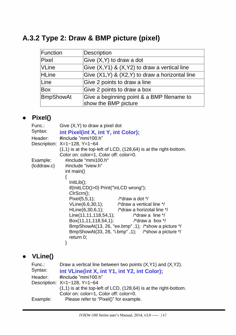
iVIEW-100 Series user’s Manual, 2014, v3.0 ----- 147
A.3.2 Type 2: Draw & BMP picture (pixel)
Function Description
Pixel Give (X,Y) to draw a dot
VLine Give (X,Y1) & (X,Y2) to draw a vertical line
HLine Give (X1,Y) & (X2,Y) to draw a horizontal line
Line Give 2 points to draw a line
Box Give 2 points to draw a box
BmpShowAt Give a beginning point & a BMP filename to show the BMP picture
Pixel()
Func.: Give (X,Y) to draw a pixel dot Syntax: int Pixel(int X, int Y, int Color); Header: #include ”mmi100.h” Description: X=1~128, Y=1~64
(1,1) is at the top-left of LCD, (128,64) is at the right-bottom. Color on: color=1, Color off: color=0.
Example: (lcddraw.c)
#include "mmi100.h" #include "iview.h" int main() { InitLib(); if(InitLCD()>0) Print("\nLCD wrong"); ClrScrn(); Pixel(5,5,1); /*draw a dot */ VLine(6,6,30,1); /*draw a vertical line */ HLine(6,30,6,1); /*draw a horizotal line */ Line(11,11,118,54,1); /*draw a line */ Box(11,11,118,54,1); /*draw a box */ BmpShowAt(13, 26, "ee.bmp" ,1); /*show a picture */ BmpShowAt(33, 28, "i.bmp" ,1); /*show a picture */ return 0; }
VLine()
Func.: Draw a vertical line between two points (X,Y1) and (X,Y2). Syntax: int VLine(int X, int Y1, int Y2, int Color); Header: #include ”mmi100.h” Description: X=1~128, Y=1~64
(1,1) is at the top-left of LCD, (128,64) is at the right-bottom. Color on: color=1, Color off: color=0.
Example: Please refer to “Pixel()” for example.

iVIEW-100 Series user’s Manual, 2014, v3.0 ----- 148
HLine()
Func.: Draw a horizontal line between (X1,Y) and (X2,Y). Syntax: int HLine(int X1, int X2, int Y, int Color); Header: #include ”mmi100.h” Description: X=1~128, Y=1~64
(1,1) is at the top-left of LCD, (128,64) is at the right-bottom. Color on: color=1, Color off: color=0.
Example: Please refer to “Pixel()” for example.
Line()
Func.: Draws a line between two points. Syntax: int Line(int X1,int Y1,int X2,int Y2,int Color); Header: #include ”mmi100.h” Description: Draws a line between (X1,Y1) and (X2,Y2)
X=1~128, Y=1~64 (1,1) is at the top-left of LCD, (128,64) is at the right-bottom. Color on: color=1, Color off: color=0.
Example: Please refer to “Pixel()” for example.
Box()
Func.: Draws a box between two points. Syntax: int Box(int X1, int Y1, int X2, int Y2, int Color); Header: #include ”mmi100.h” Description: Draws a box between (X1,Y1) and (X2,Y2)
X=1~128, Y=1~64 (1,1) is at the top-left of LCD, (128,64) is at the right-bottom. Color on: color=1, Color off: color=0.
Example: Please refer to “Pixel()” for example.
BmpShowAt()
Func.: Give a beginning point (X,Y) & a BMP filename to show the BMP picture on LCD
Syntax: int BmpShowAt(int X, int Y, char *fname ,int Color); Header: #include ”mmi100.h” Description: X=1~128, Y=1~64
(1,1) is at the top-left of LCD, (128,64) is at the right-bottom. Color on: color=1, Color off: color=0. fname: BMP picture file name, not longer than 8 characters Picture: Bitmap file, black & white, pixel: 128x64 max User has to download all the program file & BMP file(s) to iVIEW-100.
Example: Please refer to “Pixel()” for example.

iVIEW-100 Series user’s Manual, 2014, v3.0 ----- 149
A.3.3 Type 3: Text & icon (character)
Function Description
UnderLine Give a begin point & length to print underline
TextOutAt Give (X,Y) to print char text
DrawText Give (X,Y) to print unsigned char text
LcdPrintfAt Give (X,Y) to print char text
IntOutAt Give (X,Y) & length to print integer number
RealOutAt Give (X,Y), length, decimal, float to print real number
lamp Give (X,Y) to print lamp icon, color: 1= , 0=
UnderLine()
Func.: Give a begin point (X,Y) & length to print underline Syntax: int UnderLine(int X, int Y, int Len, int Color); Header: #include ”mmi100.h” Description: X=1~16, Y=1~8 (character)
(1,1) is at the top-left of LCD, (16,8) is at the right-bottom. Color on: color=1, Color off: color=0. Length: Len=1~16 (character) Note: X position plus length should not longer than 16+1
Example: (lcdxt.c)
#include "mmi100.h" #include "iview.h" int main() { static uchar LampON[8] = {0X00, 0X5A, 0X24, 0X42, 0X42, 0X24, 0X5A, 0X00}; InitLib(); if(InitLCD()>0) Print("\nLCD wrong"); ClrScrn(); UnderLine(6, 2, 6, 1); /*underline the "ICPDAS"*/ TextOutAt(6, 2, "ICPDAS"); /*show char text*/ DrawText(6, 4, LampON); /*show unsigned char text*/ LcdPrintfAt(8, 4,"Hello"); /*show char text*/ IntOutAt(5, 5, 4, 2006 ); /*show inter number*/ RealOutAt(10,5, 4, 2 ,(float)2.0 ); /*show real number*/ lamp(8, 6, 1); /*show icon lamp, color=1*/ lamp(10, 6, 0); /*show icon lamp, color=0*/ return 0; }

iVIEW-100 Series user’s Manual, 2014, v3.0 ----- 150
TextOutAt()
Func.: Give (X,Y) to print char text Syntax: int TextOutAt(int X, int Y, char *Str); Header: #include ”mmi100.h” Description: X=1~16, Y=1~8 (character)
(1,1) is at the top-left of LCD, (16,8) is at the right-bottom. Str: string Note: X position plus string length should not longer than 16+1
Example: Please refer to “UnderLine()” for example.
DrawText()
Func.: Give (X,Y) to print text (unsigned character) Syntax: int DrawText(int X, int Y, unsigned char *Text); Header: #include ”mmi100.h” Description: X=1~16, Y=1~8 (character)
(1,1) is at the top-left of LCD, (16,8) is at the right-bottom. Note: X position plus text length should not longer than 16+1
Example: Please refer to “UnderLine()” for example.
LcdPrintfAt()
Func.: Give (X,Y) to print text Syntax: int LcdPrintfAt(int X, int Y, char *FormatStr, ...); Header: #include ”mmi100.h” Description: X=1~16, Y=1~8 (character)
(1,1) is at the top-left of LCD, (16,8) is at the right-bottom. Note: X position plus text length should not longer than 16+1
Example: Please refer to “UnderLine()” for example.
IntOutAt()
Func.: Give (X,Y) & length to print integer number Syntax: int IntOutAt(int X, int Y, int Len, int32 Value ); Header: #include ”mmi100.h” Description: X=1~16, Y=1~8 (character)
(1,1) is at the top-left of LCD, (16,8) is at the right-bottom. Len: integer length Note: X position plus length should not longer than 16+1
Example: Please refer to “UnderLine()” for example.

iVIEW-100 Series user’s Manual, 2014, v3.0 ----- 151
RealOutAt()
Func.: Give (X,Y) & length to print real number Syntax: int RealOutAt(int X, int Y, int Len, int Decimal ,float Value ); Header: #include ”mmi100.h” Description: X=1~16, Y=1~8, (X,Y): the beginning position to print
(1,1) is at the top-left of LCD, (16,8) is at the right-bottom. Len: total length of real number, decimal point need one character length Decimal: decimal length of real number Value: real number value Note: X position plus length should not longer than 16+1
Example: 1. Please refer to “UnderLine()” for example. 2. RealOutAt(1,1,8,4,(float)123.5678) =>show 123.5678 RealOutAt(1,1,8,2,(float)123.5678) =>show 123.56
lamp()
Func.: Give (X,Y) to print lamp icon Syntax: int lamp (int X, int Y,int Color); Header: #include ”mmi100.h” Description: X=1~16, Y=1~8 (character)
(1,1) is at the top-left of LCD, (16,8) is at the right-bottom.
color: 1= , 0= Example: Please refer to “UnderLine()” for example.

iVIEW-100 Series user’s Manual, 2014, v3.0 ----- 152
A.3.4 Type 4: Cursor
Function Description
SetCursorLine Set the thick style of cursor line
SetCursorAt Set cursor to (X,Y)
GetCursorAt Get cursor position (X,Y)
SetCursorLine()
Func.: Set the thick style of cursor line Syntax: int SetCursorLine(int Line); Header: #include ”mmi100.h” Description: Set cursor line’s thick
Thick style: Line= 0 ~ 8, 0=cursor off Example:
(cursor.c) #include "mmi100.h"
#include "iview.h" void main() { int x, y, c, quit=0; if(InitLCD()>0) Print("\nLCD wrong"); ClrScrn(); TextOutAt(3,3, "CHOOSEone:"); SetCursorLine(8); SetCursorAt(13, 3); GetCursorAt (&x, &y); TextOutAt(3,4, "1. again"); TextOutAt(3,5, "2. quit"); while(!quit) { c=Getch(); if (c==’2’) quit=1; } ClrScrn(); CloseLCD(); }

iVIEW-100 Series user’s Manual, 2014, v3.0 ----- 153
SetCursorAt()
Func.: Set cursor to (X,Y) Syntax: int SetCursorAt(int X, int Y); Header: #include ”mmi100.h” Description: X=1~16, Y=1~8 (character) Example: Please refer to “SetCursorLine()” for example.
GetCursorAt()
Func.: Get cursor position (X,Y) Syntax: void GetCursorAt(int *X, int *Y); Header: #include ”mmi100.h” Description: X=1~16, Y=1~8 (character) Example: Please refer to “SetCursorLine()” for example.

iVIEW-100 Series user’s Manual, 2014, v3.0 ----- 154
A.3.5 Type 5: Page & bright
Function Description
LCDBright Set LCD bright from 0 to 7, 0=light off
LCDSetToPage Set LCD pages from 1 to 8, default=1
GetLCDPage Get LCD page setting number
LCDBright()
Func.: Set LCD bright Syntax: void LCDBright (int bright); Header: #include ”mmi100.h” Description: Set LCD bright
Bright=0 ~ 7, 0=light off Example:
(LCD.c) #include <iVIEW.H>
#include <mmi100.H> void main() { int quit=0; char c; InitLib(); InitLCD(); LCDBright(7); TextOutAt(5,3, "CHOOSE:"); TextOutAt(5,5, "1.LCD"); TextOutAt(5,6, "2.QUIT"); while(!quit) { c=Getch(); switch(c) { case '1': LCDSetToPage(2); ClrScrn(); LCDBright(2); TextOutAt(3,4, "* welcome *"); TextOutAt(1,8, "any key to back"); Getch(); break; case '2': quit=1; break; } LCDSetToPage (1); } ClrScrn(); CloseLCD(); }

iVIEW-100 Series user’s Manual, 2014, v3.0 ----- 155
LCDSetToPage()
Func.: Set LCD page Syntax: int LCDSetToPage (int Page); Header: #include ”mmi100.h” Description: Set LCD page number, system will set the first screen to page
number 1 automatically page=1 ~ 8, default=1
Example: Please refer to “LCDBright()” for example.
GetLCDPage ()
Func.: Get LCD page setting number Syntax: int GetLCDPage(void); Header: #include ”mmi100.h” Description: Get LCD page setting number, return Page number (inter).
Page number=1 ~ 8 Example: Please refer to “LCDBright()” for example.

iVIEW-100 Series user’s Manual, 2014, v3.0 ----- 156
Appendix B. iVIEW.h & mmi100.h
B.1. iVIEW.h
#define _NO_LED5_
#ifndef __MINIOS7__
#define __MINIOS7__
typedef unsigned int uint;
typedef unsigned int WORD;
typedef unsigned char uchar;
typedef unsigned char BYTE;
typedef unsigned long ulong;
typedef unsigned long DWORD;
#ifdef __TURBOC__
#if (__TURBOC__ < 0x0300)
#define inpw inport
#define outpw outport
#endif
#endif
#define NoError 0
#define InitPinIsOpen 0
#define InitPinIsNotopen 1
#define QueueIsEmpty 0
#define QueueIsNotEmpty 1
#define PortError -1
#define DataError -2
#define ParityError -3
#define StopError -4
#define TimeOut -5
#define QueueEmpty -6
#define QueueOverflow -7
#define PosError -8

iVIEW-100 Series user’s Manual, 2014, v3.0 ----- 157
#define AddrError -9
#define BlockError -10
#define WriteError -11
#define SegmentError -12
#define BaudRateError -13
#define CheckSumError -14
#define ChannelError -15
#define BaudrateError -16
#define TriggerLevelError -17
#define DateError -18
#define TimeError -19
#define TimeIsUp 1
#ifdef __cplusplus
extern "C" {
#endif
/* FOR WDT */
void EnableWDT(void);
void DisableWDT(void);
void RefreshWDT(void);
/* FOR INIT* pin */
int ReadInitPin(void);
/* For SCLK pin */
void ClockHigh(void);
void ClockHighLow(void);
void ClockLow(void);
/* For red LED */
void LedOn(void);
void LedOff(void);
void LedToggle(void);
/* For STDIO */
void Putch(int data);
void Puts(char *str);

iVIEW-100 Series user’s Manual, 2014, v3.0 ----- 158
int Getch(void);
int Gets(char *str);
int Kbhit(void);
int LineInput(char *buf,int maxlen);
void ResetScanBuffer(void);
void SetScanBuffer(unsigned char *buf,int len);
int Scanf(char *fmt, ...); /* for TC/BC only */
int Print(const char *fmt, ...);
int _Printf(const char *fmt, ...); /* for TC/BC only */
int UngetchI(int key);
int Ungetch(int key);
/* For RTC/NVRAM */
void GetTime(int *hour,int *minute,int *sec);
void GetDate(int *year,int *month,int *day);
int SetDate(int year,int month,int day);
int SetTime(int hour,int minute,int sec);
void SetWeekDay(int day);
int GetWeekDay(void);
/* for weekday:
0: Sun.
1: Mon.
...
6: Sat.
*/
int ReadNVRAM(int addr);
int WriteNVRAM(int addr, int data);
/* for Timer */
extern const unsigned long far *TimeTicks;
/* For old version EEPROM functions compatible */
#define WriteEEP EE_RandomWrite
#define ReadEEP EE_RandomRead
#define EnableEEP EE_WriteEnable
#define ProtectEEP EE_WriteProtect
/* for EEPROM(24LC16/1024)*/

iVIEW-100 Series user’s Manual, 2014, v3.0 ----- 159
void EE_WriteProtect(void);
void EE_WriteEnable(void);
/* for 24LC16 use */
unsigned char EE_RandomRead(int Block,unsigned Addr);
unsigned char EE_ReadNext(int Block);
int EE_MultiRead(int StartBlock,unsigned StartAddr,int no,char *databuf);
int EE_RandomWrite(int Block,unsigned Addr,int Data);
int EE_MultiWrite(int Block,unsigned Addr,int no,char *Data);
int EE_MultiWrite_A(int Block,unsigned Addr,unsigned no,char *Data);
int EE_MultiWrite_A(int Block,unsigned Addr,unsigned no,char *Data);
int EE_MultiWrite_L(unsigned address,unsigned no,char *Data);
int EE_MultiRead_L(unsigned address,unsigned no,char *Data);
/* for 24LC1024 (only when 24LC16 is replaced by 24LC1024 can be used)*/
unsigned char EE1024_RandomRead(int Block,unsigned Addr);
unsigned char EE1024_ReadNext(int Block);
int EE1024_MultiRead(int StartBlock,unsigned StartAddr,int no,char *databuf);
int EE1024_RandomWrite(int Block,unsigned Addr,int Data);
int EE1024_MultiWrite(int Block,unsigned Addr,int no,char *Data);
/* for 24LC16 or 24LC1024 use, NEED call InitEEPROM() first.*/
extern int EepType; /* 1024:24LC1024,16:24LC16; */
extern int EepBlockOffset;
extern unsigned EepAddrOffset;
void InitEEPROM(void);
extern unsigned char (*EE1_RandomRead)(int Block,unsigned Addr);
extern unsigned char (*EE1_ReadNext)(int Block);
extern int (*EE1_MultiRead)(int StartBlock,unsigned StartAddr,int no,char *databuf);
extern int (*EE1_RandomWrite)(int Block,unsigned Addr,int Data);
extern int (*EE1_MultiWrite)(int Block,unsigned Addr,int no,char *Data);
/* for system */
extern unsigned long far *IntVect;
int IsMiniOS7(void);
#define IsiView(void);
int IsiView40(void); /* for iView 100(40M) only */
int IsResetByPowerOn(void);
int IsResetByWatchDogTimer(void);

iVIEW-100 Series user’s Manual, 2014, v3.0 ----- 160
/* for FLASH MEMORY */
int FlashReadId(void);
int FlashErase(unsigned int FlashSeg);
int FlashWrite(unsigned int seg, unsigned int offset, char data);
#define FlashRead FlashReadB
unsigned char FlashReadB(unsigned seg, unsigned offset);
unsigned FlashReadI(unsigned seg, unsigned offset);
unsigned long FlashReadL(unsigned seg, unsigned offset);
void far *_MK_FP_(unsigned s,unsigned off);
/* Timer functions */
int TimerOpen(void);
int TimerClose(void);
void TimerResetValue(void);
unsigned long TimerReadValue(void);
int StopWatchReset(int channel);
int StopWatchStart(int channel);
int StopWatchStop(int channel);
int StopWatchPause(int channel);
int StopWatchContinue(int channel);
int StopWatchReadValue(int channel,unsigned long *value);
int CountDownTimerStart(int channel,unsigned long count);
int CountDownTimerReadValue(int channel,unsigned long *value);
void InstallUserTimer(void (*fun)(void));
void InstallUserTimer1C(void (*fun)(void));
/* StopWatch [counter] */
#ifndef _T_STOPWATCH_
#define _T_STOPWATCH_
typedef struct {
ulong ulStart,ulPauseTime;
uint uMode; /* 0: pause, 1:run(start) */
} STOPWATCH;
#endif
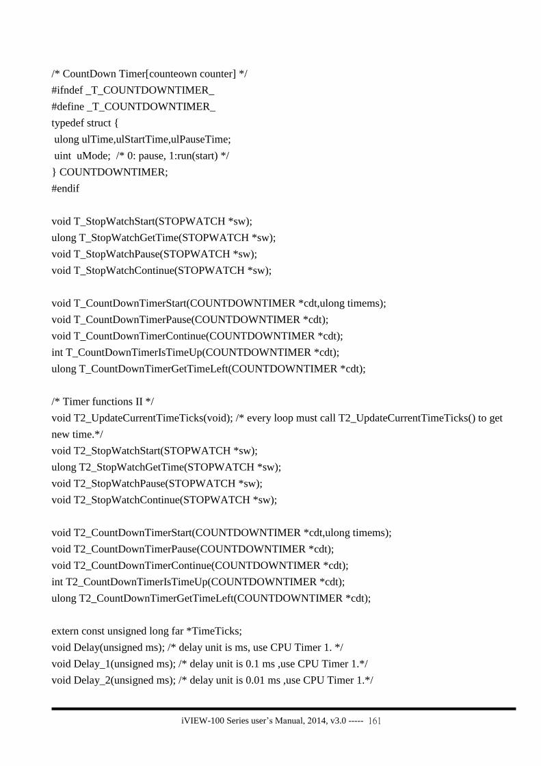
iVIEW-100 Series user’s Manual, 2014, v3.0 ----- 161
/* CountDown Timer[counteown counter] */
#ifndef _T_COUNTDOWNTIMER_
#define _T_COUNTDOWNTIMER_
typedef struct {
ulong ulTime,ulStartTime,ulPauseTime;
uint uMode; /* 0: pause, 1:run(start) */
} COUNTDOWNTIMER;
#endif
void T_StopWatchStart(STOPWATCH *sw);
ulong T_StopWatchGetTime(STOPWATCH *sw);
void T_StopWatchPause(STOPWATCH *sw);
void T_StopWatchContinue(STOPWATCH *sw);
void T_CountDownTimerStart(COUNTDOWNTIMER *cdt,ulong timems);
void T_CountDownTimerPause(COUNTDOWNTIMER *cdt);
void T_CountDownTimerContinue(COUNTDOWNTIMER *cdt);
int T_CountDownTimerIsTimeUp(COUNTDOWNTIMER *cdt);
ulong T_CountDownTimerGetTimeLeft(COUNTDOWNTIMER *cdt);
/* Timer functions II */
void T2_UpdateCurrentTimeTicks(void); /* every loop must call T2_UpdateCurrentTimeTicks() to get
new time.*/
void T2_StopWatchStart(STOPWATCH *sw);
ulong T2_StopWatchGetTime(STOPWATCH *sw);
void T2_StopWatchPause(STOPWATCH *sw);
void T2_StopWatchContinue(STOPWATCH *sw);
void T2_CountDownTimerStart(COUNTDOWNTIMER *cdt,ulong timems);
void T2_CountDownTimerPause(COUNTDOWNTIMER *cdt);
void T2_CountDownTimerContinue(COUNTDOWNTIMER *cdt);
int T2_CountDownTimerIsTimeUp(COUNTDOWNTIMER *cdt);
ulong T2_CountDownTimerGetTimeLeft(COUNTDOWNTIMER *cdt);
extern const unsigned long far *TimeTicks;
void Delay(unsigned ms); /* delay unit is ms, use CPU Timer 1. */
void Delay_1(unsigned ms); /* delay unit is 0.1 ms ,use CPU Timer 1.*/
void Delay_2(unsigned ms); /* delay unit is 0.01 ms ,use CPU Timer 1.*/

iVIEW-100 Series user’s Manual, 2014, v3.0 ----- 162
void DelayMs(unsigned t);/* delay unit is ms, use system timeticks. */
/* for MiniOS7 FLASH file system */
#ifndef __FILE_DATA__
#define __FILE_DATA__
typedef struct {
unsigned mark; /* 0x7188 -> is file */
unsigned char fname[12];
unsigned char year;
unsigned char month;
unsigned char day;
unsigned char hour;
unsigned char minute;
unsigned char sec;
unsigned long size;
char far *addr;
unsigned CRC;
unsigned CRC32;
} FILE_DATA;
#endif
#ifndef _DISK_AB_
#define _DISK_AB_
typedef struct {
unsigned sizeA:3;
unsigned sizeB:3;
unsigned sizeC:3;
unsigned sum:7;
} SIZE_AB;
#endif
extern SIZE_AB SizeAB;
extern FILE_DATA far *fdata;
#define DISKA 0
#define DISKB 1

iVIEW-100 Series user’s Manual, 2014, v3.0 ----- 163
/* int GetFileNo(void); */
#define GetFileNo() GetFileNo_AB(DISKA)
/* int GetFileName(int no,char *fname); */
#define GetFileName(no,fname) GetFileName_AB(DISKA,no,fname)
/* FILE_DATA far * GetFileInfoByNo(int no) */
#define GetFileInfoByNo(no) GetFileInfoByNo_AB(DISKA,no)
/* FILE_DATA far * GetFileInfoByName(char *fname) */
#define GetFileInfoByName(fname) GetFileInfoByName_AB(DISKA,fname)
/* char far * GetFilePositionByNo(int no) */
#define GetFilePositionByNo(no) GetFilePositionByNo_AB(DISKA,no)
/* char far * GetFilePositionByName(char *fname) */
#define GetFilePositionByName(fname) GetFilePositionByName_AB(DISKA,fname)
int GetFileNo_AB(int disk);
int GetFileName_AB(int disk,int no,char *fname);
FILE_DATA far * GetFileInfoByNo_AB(int disk,int no);
FILE_DATA far *GetFileInfoByName_AB(int disk,char *fname);
char far * GetFilePositionByNo_AB(int disk,int no);
char far * GetFilePositionByName_AB(int disk,char *fname);
#define COM1 0
#define COM2 1
#define COM3 2
#define COM4 3
#define FLOW_CONTROL_DISABLE 0
#define FLOW_CONTROL_ENABLE 1
#define FLOW_CONTROL_AUTO_BY_HW 2
#define FLOW_CONTROL_AUTO_BY_SW 3
/* for COM1 */
/* WITH CTS & RTS control */

iVIEW-100 Series user’s Manual, 2014, v3.0 ----- 164
#define ClearTxBuffer1 ClearTxBuffer_1
#define GetTxBufferFreeSize1 GetTxBufferFreeSize_1
#define PushDataToCom1 PushDataToCom_1
#define CheckInputBufSize1 CheckInputBufSize_1
#define InstallCom1 InstallCom_1
#define RestoreCom1 RestoreCom_1
#define SetBaudrate1 SetBaudrate_1
#define SetDataFormat1 SetDataFormat_1
#define ClearCom1 ClearCom_1
#define DataSizeInCom1 DataSizeInCom_1
#define IsCom1 IsCom_1
#define IsCom1OutBufEmpty IsComOutBufEmpty_1
#define ReadCom1 ReadCom_1
#define ToCom1Bufn ToComBufn_1
#define ToCom1Str ToComStr_1
#define SetCom1Timeout SetComTimeout_1
#define ToCom1 ToCom_1
#define IsTxBufEmpty1 IsTxBufEmpty_1
#define WaitTransmitOver1 WaitTransmitOver_1
#define ReadCom1n ReadComn_1
#define printCom1 printCom_1
#define SetBreakMode1 SetBreakMode_1
#define SendBreak1 SendBreak_1
#define IsDetectBreak1 IsDetectBreak_1
#define SetRtsActive1 SetRtsActive_1
#define SetRtsInactive1 SetRtsInactive_1
#define GetCtsStatus1 GetCtsStatus_1
#define SetCtsControlMode1 SetCtsControlMode_1
#define SetRtsControlMode1 SetRtsControlMode_1
#define DataSizeInCom1_DMA DataSizeInCom_DMA_1
#define ReadCom1n_DMA ReadComn_DMA_1
#define InstallCom1_DMA InstallCom_DMA_1
#define ClearCom1_DMA ClearCom_DMA_1
#define IsCom1_DMA IsCom_DMA_1
#define DataSizeInCom1_DMA DataSizeInCom_DMA_1

iVIEW-100 Series user’s Manual, 2014, v3.0 ----- 165
#define ReadCom1_DMA ReadCom_DMA_1
void ClearTxBuffer_1(void);
int GetTxBufferFreeSize_1(void);
int PushDataToCom_1(int data);
void CheckInputBufSize_1(void);
int InstallCom_1(unsigned long baud, int data, int parity,int stop);
int RestoreCom_1(void);
int SetBaudrate_1(unsigned long baud);
int SetDataFormat_1(int databit,int parity,int stopbit);
int ClearCom_1(void);
int ClearCom_DMA_1(void);
int DataSizeInCom_1(void);
int IsCom_1(void);
int IsComOutBufEmpty_1(void);
int ReadCom_1(void);
int ToComBufn_1(char *buf,int no);
int ToComStr_1(char *str);
void SetComTimeout_1(unsigned t);
int ToCom_1(int data);
int IsTxBufEmpty_1(void);
int WaitTransmitOver_1(void);
int ReadComn_1(unsigned char *buf,int no);
int printCom_1(char *fmt,...);
int DataSizeInCom_DMA_1(void);
int ReadComn_DMA_1(unsigned char *buf,int maxsize);
int InstallCom_DMA_1(unsigned long baud, int data, int parity,int stop);
int ClearCom_DMA_1(void);
int IsCom_DMA_1(void);
int DataSizeInCom_DMA_1(void);
int ReadCom_DMA_1(void);
void SetBreakMode_1(int mode);
void SendBreak_1(unsigned TimeMs);
int IsDetectBreak_1(void);
void SetRtsActive_1(void);

iVIEW-100 Series user’s Manual, 2014, v3.0 ----- 166
void SetRtsInactive_1(void);
int GetCtsStatus_1(void);
void CheckCtsStatus_1(void);
void SetCtsControlMode_1(int mode);
void SetRtsControlMode_1(int mode);
void SetComPortBufferSize_1(int in_size,int out_size);
#define bCtsChanged1 bCtsChanged_1
extern int bCtsChanged_1;
#define CurCTS1 CurCTS_1
extern int CurCTS_1;
#define CurRTS1 CurRTS_1
extern int CurRTS_1;
#define fCtsControlMode1 fCtsControlMode_1
extern int fCtsControlMode_1;
#define fRtsControlMode1 fRtsControlMode_1
extern int fRtsControlMode_1;
/* for COM2 (in normal RS-485)*/
/* WITHOUT CTS & RTS control */
#define ClearTxBuffer2 ClearTxBuffer_2
#define GetTxBufferFreeSize2 GetTxBufferFreeSize_2
#define PushDataToCom2 PushDataToCom_2
#define CheckInputBufSize2 CheckInputBufSize_2
#define InstallCom2 InstallCom_2
#define RestoreCom2 RestoreCom_2
#define SetBaudrate2 SetBaudrate_2
#define SetDataFormat2 SetDataFormat_2
#define ClearCom2 ClearCom_2
#define DataSizeInCom2 DataSizeInCom_2
#define IsCom2 IsCom_2
#define IsCom2OutBufEmpty IsComOutBufEmpty_2

iVIEW-100 Series user’s Manual, 2014, v3.0 ----- 167
#define ReadCom2 ReadCom_2
#define ToCom2Bufn ToComBufn_2
#define ToCom2Str ToComStr_2
#define SetCom2Timeout SetComTimeout_2
#define ToCom2 ToCom_2
#define IsTxBufEmpty2 IsTxBufEmpty_2
#define WaitTransmitOver2 WaitTransmitOver_2
#define ReadCom2n ReadComn_2
#define printCom2 printCom_2
#define SetBreakMode2 SetBreakMode_2
#define SendBreak2 SendBreak_2
#define IsDetectBreak2 IsDetectBreak_2
#define DataSizeInCom2_DMA DataSizeInCom_DMA_2
#define ReadCom2n_DMA ReadComn_DMA_2
#define InstallCom2_DMA InstallCom_DMA_2
#define ClearCom2_DMA ClearCom_DMA_2
#define IsCom2_DMA IsCom_DMA_2
#define DataSizeInCom2_DMA DataSizeInCom_DMA_2
#define ReadCom2_DMA ReadCom_DMA_2
void ClearTxBuffer_2(void);
int GetTxBufferFreeSize_2(void);
int PushDataToCom_2(int data);
void CheckInputBufSize_2(void);
int InstallCom_2(unsigned long baud, int data, int parity,int stop);
int RestoreCom_2(void);
int SetBaudrate_2(unsigned long baud);
int SetDataFormat_2(int databit,int parity,int stopbit);
int ClearCom_2(void);
int ClearCom_DMA_2(void);
int DataSizeInCom_2(void);
int IsCom_2(void);
int IsComOutBufEmpty_2(void);
int ReadCom_2(void);
int ToComBufn_2(char *buf,int no);
int ToComStr_2(char *str);
void SetComTimeout_2(unsigned t);

iVIEW-100 Series user’s Manual, 2014, v3.0 ----- 168
int ToCom_2(int data);
int IsTxBufEmpty_2(void);
int WaitTransmitOver_2(void);
int ReadComn_2(unsigned char *buf,int no);
int printCom_2(char *fmt,...);
int DataSizeInCom_DMA_2(void);
int ReadComn_DMA_2(unsigned char *buf,int maxsize);
int InstallCom_DMA_2(unsigned long baud, int data, int parity,int stop);
int ClearCom_DMA_2(void);
int IsCom_DMA_2(void);
int DataSizeInCom_DMA_2(void);
int ReadCom_DMA_2(void);
void SetBreakMode_2(int mode);
void SendBreak_2(unsigned TimeMs);
int IsDetectBreak_2(void);
void SetComPortBufferSize_2(int in_size,int out_size);
/*
For Send command to I-7000/I-87K series.
*/
extern char hex_to_ascii[16];
int ascii_to_hex(char ascii);
int SendCmdTo7000(int iPort, unsigned char *cCmd, int iChksum);
/*
(INPUT)iPort:can be 0,1,3,4.
(INPUT)lTimeout: unit is ms.
(INPUT) cCmd: cmd for send to COM port(I-7000/I-87K).
DON'T add '\r' at the end of cCmd, SendCmdTo7000() will add check sum(if needed) & '\r'
after cCmd .
(INPUT) iChksum: 0: disable, 1: enable.
*/
int ReceiveResponseFrom7000(int iPort, unsigned char *cCmd, long lTimeout, int iChksum);
/*
(INPUT)iPort:can be 0,1,3,4.

iVIEW-100 Series user’s Manual, 2014, v3.0 ----- 169
(INPUT)lTimeout: unit is ms. (*****)
(OUTPUT) cCmd: response from COM port(I-7000/I-87K).
(INPUT) iChksum: 0: disable, 1: enable.
*/
/* for ALL COM PORT */
int printCom(int port,char *fmt,...);
int IsDetectBreak(int port);
int SendBreak(int port,unsigned timems);
int SetBreakMode(int port,int mode);
int ClearCom(int port);
int ClearTxBuffer(int port);
int InstallCom(int port, unsigned long baud, int data, int parity,int stop);
int ToComBufn(int port,char *buf,int no);
int RestoreCom(int port);
int ToComStr(int port,char *str);
int DataSizeInCom(int port);
int IsCom(int port);
int ReadComn(int port,unsigned char *buf,int n);
int ReadCom(int port);
int SetBaudrate(int port,unsigned long baud);
int ToCom(int port,int data);
int IsTxBufEmpty(int port);
int GetTxBufferFreeSize(int port);
int WaitTransmitOver(int port);
int SetRtsActive(int port);
int SetRtsInactive(int port);
int GetCtsStatus(int port);
/* function table for up functions except printCom */
/*
For example if want to call:
if(IsCom(port)){
data=ReadCom(port);
}
also can use :
if(IsCom_[port]()){
data=ReadCom_[port]();

iVIEW-100 Series user’s Manual, 2014, v3.0 ----- 170
}
IsCom(port)/ReadCom(port) just for backword compatible, it also will call
IsCom_[port]()/ReadCom_[port]()
and so on.
*/
extern int (*IsDetectBreak_[3])(void);
extern void (*SendBreak_[3])(unsigned timems);
extern void (*SetBreakMode_[3])(int mode);
extern int (*ClearCom_[3])(void);
extern void (*ClearTxBuffer_[3])(void);
extern int (*InstallCom_[3])(unsigned long baud, int data, int parity,int stop);
extern int (*ToComBufn_[3])(char *buf,int no);
extern int (*RestoreCom_[3])(void);
extern int (*ToComStr_[3])(char *str);
extern int (*DataSizeInCom_[3])(void);
extern int (*IsCom_[3])(void);
extern int (*ReadComn_[3])(unsigned char *buf,int n);
extern int (*ReadCom_[3])(void);
extern int (*SetBaudrate_[3])(unsigned long baud);
extern int (*ToCom_[3])(int data);
extern int (*IsTxBufEmpty_[3])(void);
extern int (*GetTxBufferFreeSize_[3])(void);
extern int (*WaitTransmitOver_[3])(void);
extern void (*SetRtsActive_[3])(void);
extern void (*SetRtsInactive_[3])(void);
extern int (*GetCtsStatus_[3])(void);
int GetComportNumber(void);
extern int TriggerLevel[2];
void InitLib(void);
/*
for I-7188XC, InitLib() do nothing.
*/
void GetLibDate(char *date);
unsigned GetLibVersion(void);

iVIEW-100 Series user’s Manual, 2014, v3.0 ----- 171
/*
Current version is 2.01 (return 0x0201)
*/
/* For KEY & LED */
#define KEY_SHIFT 0x80
#define KEY_F1 0x81
#define KEY_F2 0x82
#define KEY_F3 0x83
#define KEY_F4 0x84
#define KEY_F5 0x85
#define KEY_F6 0x86
#define KEY_F7 0x87
#define KEY_F8 0x88
#define KEY_UP 0x8C
#define KEY_DOWN 0x8B
#define KEY_LEFT 0x8A
#define KEY_RIGHT 0x89
#define SHIFT_UP 0xCC
#define SHIFT_DOWN 0xCB
#define SHIFT_LEFT 0xCA
#define SHIFT_RIGHT 0xC9
#define SHIFT_BS 0xCF
#define SHIFT_ESC 0xCE
#define SHIFT_CR 0xCD
#define KEY_UP_IDX 0
#define KEY_1_IDX 1
#define KEY_2_IDX 2
#define KEY_RIGHT_IDX 3
#define KEY_3_IDX 4
#define KEY_F1_IDX 5
#define KEY_7_IDX 6
#define KEY_8_IDX 7
#define KEY_BS_IDX 8
#define KEY_9_IDX 9

iVIEW-100 Series user’s Manual, 2014, v3.0 ----- 172
#define KEY_F2_IDX 10
#define KEY_DOT_IDX 11
#define KEY_0_IDX 12
#define KEY_CR_IDX 13
#define KEY_SHARP_IDX 14
#define KEY_SHIFT_IDX 16
#define KEY_LEFT_IDX 17
#define KEY_F4_IDX 18
#define KEY_DOWN_IDX 19
#define KEY_F3_IDX 20
#define KEY_4_IDX 21
#define KEY_5_IDX 22
#define KEY_ESC_IDX 23
#define KEY_6_IDX 24
int IsKeyUp(int key);
#define IsKeyDown(key) (!IsKeyUp(key))
#define LED_F1 0x01
#define LED_F2 0x02
#define LED_F3 0x04
#define LED_F4 0x08
#define LED_PWR 0x10
#define LED_RUN 0x20
#define LED_SHIFT 0x40
#define LED_PORT 0x103
extern unsigned far *SoundFreq;
extern unsigned far *SoundPeriod;
extern unsigned char far *Port100;
extern unsigned char far *SerialNumber;
extern unsigned char far *ResetMode;
extern unsigned char far *LedData;
extern unsigned char far *LcdMode;

iVIEW-100 Series user’s Manual, 2014, v3.0 ----- 173
extern unsigned char far *bScanKey; /*=(unsigned char far *)0x00400031; */
extern unsigned char far *LcdTextCurPage; /*=(unsigned char far *)0x00400032; */
extern unsigned char far *LcdTextCurX; /*=(unsigned char far *)0x00400033; */
extern unsigned char far *LcdTextCurY; /*=(unsigned char far *)0x00400034; */
extern unsigned char far *LcdShowKey; /*=(unsigned char far *)0x00400035; */
extern unsigned char far *bSoundFlag; /* =(unsigned char far *)0x00400036;*/
extern unsigned char far *LcdShowCursor; /*=(unsigned char far *)0x00400037; */
extern unsigned far *LcdTextCurHomeAddr;/*=(unsigned far *)0x00400038; */
/* for LCD text mode functions */
#define CMD_TEXT_HOME 0x40 /* set text home address */
#define CMD_TEXT_AREA 0x41 /* set text area */
#define CMD_GRAPHIC_HOME 0x42
#define CMD_GRAPHIC_AREA 0x43
#define CMD_OFFSET_REGISTER_SET 0x22
#define CMD_ADDRESS_POINTER_SET 0x24
#define CMD_ENABLE_DATA_AUTO_WRITE 0xb0
#define CMD_DISABLE_DATA_AUTO_RW 0xb2
#define CMD_ENABLE_DATA_AUTO_READ 0xb1
#define DATA_READ 0xc5
#define DATA_WRITE 0xc4
#define DATA_READ_ 0xc1
#define DATA_WRITE_INC 0xc0
#define CMD_SET_CURSOR_POINT 0x21
#define CMD_CURSOR_ON 0x97
#define CMD_CURSOR_OFF 0x95
#define LCD_CMD_PORT 0x201 /* for command, C/D=1 (A0=1)*/
#define LCD_DATA_PORT 0x200 /* for data, C/D=0 (A0=0)*/
#define LCD_STATUS_PORT 0x201 /* for command, C/D=1 (A0=1)*/
#define STA0 0x01
#define STA1 0x02
#define STA2 0x04
#define STA3 0x08

iVIEW-100 Series user’s Manual, 2014, v3.0 ----- 174
#define TEXTMODEOR 0x80
#define STA01ERROR 3
#define STA03ERROR 8
#define TEXT_HOME_ADDRESS 0x1000
#define GRAPHIC_HOME_ADDRESS 0x0
#define CGRAMADDRESS 0x1C00
#define OVERXYRANGE 16
#define LCD_TextNX 16
#define LCD_TextNY 8
#define LCD_GraphicNX 16
#define LCD_GraphicNY 64
#define LCD_TextBufsize 128
extern unsigned char sbuf[LCD_TextBufsize];
/* function for communicatio with LCD driver(T6963C) */
int LcdWaitReady10(void);
int LcdWaitAutoReadReady(void);
int LcdWaitAutoWriteReady(void);
int LcdAutoWriteData(int data);
int LcdAutoReadData(void);
int LcdAutoWriteCommand(int cmd);
int LcdSendCmd_0(int cmd);
int LcdSendData(int data);
int LcdSendCmd_1(int cmd,int data);
int LcdSendCmd_2(int cmd,int data);
/* Set LCD to TEXT mode */
int LcdSetToTextMode(void);
#define LcdTextInitLcdSetToTextMode
int LcdInit(void); /* TEXT ON/GRAPHICS ON and clear TEXT/GRAPHICS screen */
/* function for cursor */
int LcdSetCursorOn(void); /* Display cursor */
int LcdSetCursorOff(void);/* Hide cursor */
int LcdGotoXY_0(void); /* Set cursor to (*LcdTextCurX,*LcdTextCurY),LcdPutch() will call this
function. */

iVIEW-100 Series user’s Manual, 2014, v3.0 ----- 175
int LcdGotoXY(int x,int y);/* move cursor to (x,y) */
int LcdGotoXY_1(void);/* Set cursor to (*LcdTextCurX,*LcdTextCurY), and set data pointer to that
position. */
/* Clear TEXT screen, and move cursor to (0,0) */
int LcdClearTextScreen(void);
/* From current cursor position, Clear to end of line. Cursor position is not changed. */
int LcdClearToEndOfLine(void);
/* Output n BYTES text */
int LcdPutText(unsigned char *buf,int no);
int LcdPutTextXY(int x,int y,unsigned char *buf,int no);
int LcdGetTextXY(int x,int y,unsigned char *buf,int no);
/* Output 1 character */
int LcdPutch(unsigned data);
int LcdPutch0(unsigned data);
int LcdPutch1(unsigned data);
int LcdPutchXY(unsigned x,unsigned y,unsigned data);
/* Output string */
int LcdPuts(unsigned char *str);
int LcdPuts0(unsigned char *str);
int LcdPutsXY(int x,int y,unsigned char *str);
int LcdPutsXY0(int x,int y,unsigned char *str);
/* format output */
int LcdPrint(char *fmt,...);
int LcdPrint0(char *fmt,...);
int LcdPrintXY(int x,int y,char *fmt,...);
int LcdPrintXY0(int x,int y,char *fmt,...);
/* Move the screen up n lines. */
int LcdTextMoveUp(unsigned lineno);
/*
All the function name with "XY" means output to the position (x,y).

iVIEW-100 Series user’s Manual, 2014, v3.0 ----- 176
x :range 0-15 (0 is left most,15 is right most.)
y :range 0-7 (0 is upper most,7 is lower most.)
ALl function name end with '0'(for example:"LcdPutch0"), will process '\r' & '\n'.
for '\r' just move the cursor to left most.
for '\n' just move the cursor to next line,if the cursor on the last line,
it will croll the screen up one line.
LcdPutch1() will show the character, but does not move the cursor to the next position.
*/
/* [11/06/2003] add Software flow control(Xon/Xoff) for COM1/2
*/
void SetXonXoffControlMode_1(int mode);
void SetXonXoffControlMode_2(int mode);
/*
mode=0 --> disable Xon/Xoff control
mode=1 --> enable Xon/Xoff control
*/
/*
[2003/12/01]
Add function for debug, using STDIO COM PORT.
Even after all InstallCom_1() also can use these 3 functions to send message to STDIO COM port.
*/
void pascal _dPutch(int data1);
void _dPuts(char *str);
int _dPrint(char *fmt,...);
/*
[2003/12/10]
Add function for read system timeticks.
*/
long GetTimeTicks(void);
long GetTimeTicks_ISR(void); /* use this one in ISR */
/*
The return value is *TimeTicks.
*/

iVIEW-100 Series user’s Manual, 2014, v3.0 ----- 177
int InstallUserTimerFunction_us(unsigned time,void (*fun)(void));
/*
time unit is 0.1 us.
for example:
If want timer generate interrupt for every 0.5ms(500 us=5000*0.1us)
(That is to say system will call your function once every 0.5 ms)
just use
void fun(void)
{
...
}
...
InstallUserTimerFunction_us(5000,fun);
*/
int InstallUserTimerFunction_ms(unsigned time,void (*fun)(void));
/*
time unit is ms.
for example:
If want timer generate interrupt for every 1 second(1 sec=1000 ms)
(That is to say system will call your function once every 1 sec.)
just use
void fun(void)
{
...
}
...
InstallUserTimerFunction_ms(1000,fun);
*/
void StopUserTimerFun(void);
/* For PIO pins on I/O expansion BUS */

iVIEW-100 Series user’s Manual, 2014, v3.0 ----- 178
void SetDio4Dir(int dir);
void SetDio4High(void);
void SetDio4Low(void);
int GetDio4(void);
void SetDio9Dir(int dir);
void SetDio9High(void);
void SetDio9Low(void);
int GetDio9(void);
void SetDio14Dir(int dir);
void SetDio14High(void);
void SetDio14Low(void);
int GetDio14(void);
void SetTi0Dir(int dir);
void SetTi0High(void);
void SetTi0Low(void);
int GetTi0(void);
void SetTi1Dir(int dir);
void SetTi1High(void);
void SetTi1Low(void);
int GetTi1(void);
void SetTo0Dir(int dir);
void SetTo0High(void);
void SetTo0Low(void);
int GetTo0(void);
void SetTo1Dir(int dir);
void SetTo1High(void);
void SetTo1Low(void);
int GetTo1(void);
/* general purpose functions for all PIO pins
Please be carefully for using these 3 functions.
!!! NOT ALL 32 PIO pins can use used by user. !!!

iVIEW-100 Series user’s Manual, 2014, v3.0 ----- 179
*/
void SetPioDir(unsigned pin,int dir);
void SetPio(int pin,int mode);
int GetPio(int pin);
/*
input:
pin : 0~31.
mode: 0 or 1
dir:
0: set the PIO pin to normal mode
1: set the PIO pin to input with pull high(for some pin is pull low.)
2: set the PIO pin to output mode
3: set the PIO pin to input without pull high/low.
output for GetPio():
0: for input mode: the input is low.
for output mode: current output is low.
non zero: for input mode: the input is high.
for output mode: current output is high.
*/
/* 2004/02/26 add function usr burst mode to read date/time from RTC chip(DS-1302) */
typedef struct {
int year;
char month,day,weekday;
char hour,minute,sec;
}TIME_DATE;
void GetTimeDate(TIME_DATE *timedate);
int SetTimeDate(TIME_DATE *timedate);
/*
when call SetTimeDate(), need set the right year,month,day and the function
will auto set the weekday.
*/
extern const unsigned char far * const SystemSerialNumber;
int GetSerialNumber(char *Serial);
/*

iVIEW-100 Series user’s Manual, 2014, v3.0 ----- 180
[2004/10/13] Add
GetSerialNumber() is used to read system serial number from hardware.
on sucess return 0, and the serial number store to Serial.
on fail return -1: cannot find the hardware IC
return -2: CRC error
*/
/*[2005/03/14] for IP/MASK/GATEWAY/MAC */
void GetIp(unsigned char *ip);
#define GetMac GetEid
void GetEid(unsigned char *id);
void GetMask(unsigned char *mask);
void GetGateway(unsigned char *gate);
void SetIp(unsigned char *ip);
#define SetMac SetEid
void SetEid(unsigned char *id);
void SetMask(unsigned char *mask);
void SetGateway(unsigned char *gate);
#ifdef __cplusplus
}
#endif
#endif
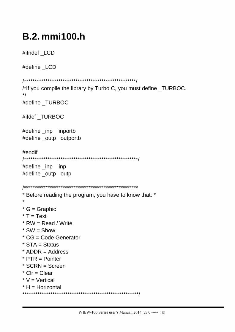
iVIEW-100 Series user’s Manual, 2014, v3.0 ----- 181
B.2. mmi100.h
#ifndef _LCD
#define _LCD
/****************************************************/
/*If you compile the library by Turbo C, you must define _TURBOC.
*/
#define _TURBOC
#ifdef _TURBOC
#define _inp inportb
#define _outp outportb
#endif
/*****************************************************/
#define _inp inp
#define _outp outp
/*****************************************************
* Before reading the program, you have to know that: *
*
* G = Graphic
* T = Text
* RW = Read / Write
* SW = Show
* CG = Code Generator
* STA = Status
* ADDR = Address
* PTR = Pointer
* SCRN = Screen
* Clr = Clear
* V = Vertical
* H = Horizontal
******************************************************/

iVIEW-100 Series user’s Manual, 2014, v3.0 ----- 182
/*typedef unsigned int uint;*/
/*typedef unsigned char uchar;*/
typedef unsigned long ulong;
typedef unsigned long DWORD;
typedef short int16;
typedef unsigned short uint16;
typedef long int32;
typedef unsigned long uint32;
#define lcd_bright LCDBright
#define show_lcd_page LCDSetToPage
/*Functions Return: If success -> return 0, else if fail -->return nonzero.
*/
#ifdef __cplusplus
extern "C" {
#endif
/* ********************* */
/* * * * Initial.C * * * */
/* ********************* */
int InitLCD(void);
int ClrScrn(void); /*Clear GraphicSW_Page and TextSW_Page.*/
void CloseLCD(void);
/*********************** Functions ********************************/
int Pixel(int X,int Y, int Color);
int VLine(int X, int Y1, int Y2, int Color);
int HLine(int X1, int X2, int Y, int Color);
int Line(int X1,int Y1,int X2,int Y2,int Color);
int DrawText(int X, int Y, unsigned char *Text);
int Box(int X1, int Y1, int X2, int Y2, int Color);
int SetCursorLine(int Line);
int SetCursorAt(int X, int Y);

iVIEW-100 Series user’s Manual, 2014, v3.0 ----- 183
void GetCursorAt(int *X, int *Y);
int UnderLine(int X, int Y, int Len,int Color);
int TextOutAt(int X, int Y, char *Str);
int LcdPrintfAt(int X, int Y, char *FormatStr, ...);
int lamp (int X, int Y,int Color);
void LCDBright (int bright);
int LCDSetToPage (int Page);
int GetLCDPage(void);
int IntOutAt(int X, int Y, int Len, int32 Value );
int RealOutAt(int X, int Y, int Len,int Decimal ,float Value );
int BmpShowAt(int X, int Y, char *fname ,int Color);
int TextOutAt_len(int X, int Y, char *Str,int len);
#ifdef __cplusplus
}
#endif
#endif

iVIEW-100 Series user’s Manual, 2014, v3.0 ----- 184
Appendix C. Dimensions
C.1. Dimensions of iVIEW-100
Shift
F4
F8F5
RUNPWR
F1
F7F6
F3F2
B.S.654
+ - * /
PQRS
7$ % ~
0 #
8
TUV
9
WXYZ
1GHI
2JKL
ABC
3MNO
DEF
ESC

iVIEW-100 Series user’s Manual, 2014, v3.0 ----- 185
C.2. Dimensions of LCD

iVIEW-100 Series user’s Manual, 2014, v3.0 ----- 186
C.3. Dimensions of daughter board

iVIEW-100 Series user’s Manual, 2014, v3.0 ----- 187
C.4. Dimensions of CPU board