
PDF Tutorial V3.0 - Adeept
299
-
Upload
khangminh22 -
Category
Documents
-
view
2 -
download
0
Transcript of PDF Tutorial V3.0 - Adeept


About AdeeptAdeept is a technical service team of open source software and hardware.
Dedicated to applying the Internet and the latest industrial technology in open source
area, we strive to provide best hardware support and software service for general
makers and electronic enthusiasts around the world. We aim to create infinite
possibilities with sharing. No matter what field you are in, we can lead you into the
electronic world and bring your ideas into reality.
Technical Support: [email protected]
Customer Service: [email protected]


ContentsLearn the Raspberry Pi and GPIO.......................................................................................................1Installing the Raspberry Pi System to the SD Card Under Windows...............................................13Downloading the Course Experiment Code from GitHub............................................................... 37Lesson 1 Blinking LED.....................................................................................................................40Lesson 2 Active Buzzer.....................................................................................................................61Lesson 3 Passive Buzzer................................................................................................................... 71Lesson 4 Tilt Switch..........................................................................................................................82Lesson 5 Controlling LED By Button.............................................................................................. 85Lesson 6 Relay.................................................................................................................................. 96Lesson 7 LED Flowing Lights..........................................................................................................99Lesson 8 Breathing LED.................................................................................................................111Lesson 9 Controlling an RGB LED with PWM............................................................................. 126Lesson 10 7-segment display..........................................................................................................135Lesson 11 4-Digit 7-Segment Display............................................................................................144Lesson 12 LCD1602....................................................................................................................... 154Lesson 13 Matrix Keyboard............................................................................................................159Lesson 14 Measure the distance......................................................................................................171Lesson 15 Temperature & Humidity Sensor—DHT-11................................................................. 181Lesson 16 Dot-matrix display.........................................................................................................193Lesson 17 Photoresistor.................................................................................................................. 198Lesson 18 Thermistor......................................................................................................................202Lesson 19 RFID.............................................................................................................................. 205Lesson 20 LED Bar Graph..............................................................................................................222Lesson 21 Controlling an LED Through LAN............................................................................... 225Lesson 22 DC Motor.......................................................................................................................230Lesson 23 Controlling a Stepper Motor..........................................................................................235Lesson 24 Acceleration Sensor ADXL345..................................................................................... 238Lesson 25 PS2 Joystick...................................................................................................................243Lesson 26 A Simple Access Control System.................................................................................. 246Lesson 27 Making the Game Snake................................................................................................259Lesson 28 Making the Game Flippy Bird.......................................................................................267Lesson 29 Making the Game Named Play Bricks..........................................................................275Lesson 30 Making a Calculator...................................................................................................... 283

1
Learn the Raspberry Pi and GPIO
1. Introduction to Raspberry Pi
(1) Raspberry Pi
Raspberry Pi (Raspberry Pi, RasPi/RPi) is developed by the British charity
organization "Raspberry Pi Foundation", based on ARM microcomputer motherboard,
only the size of a credit card, but has the basic functions of a personal computer. The
original purpose of the Foundation’s development of the Raspberry Pi was to improve
the teaching level of the school’s computer science and related disciplines, and
cultivate the youth’s computer programming interest and ability. Nowadays, most
people use the Raspberry Pi for embedded development, which is mostly used in the
Internet of Things, smart home and artificial intelligence.
(2) Raspberry Pi motherboard
In our lessons, we will use the Raspberry Pi 4 motherboard. Let's take a look at
the structure of the Raspberry Pi 4 motherboard. As shown in the following figure:

2
The following contents will briefly explain the main structure ports of the
Raspberry Pi 4 motherboard:
(1) GPIO 40-PIN pin:
The General Purpose Input Output (GPIO) is designed as a slot with two rows of
pins on the Raspberry Pi motherboard. GPIO can be used to connect various
peripheral electronic devices and sensors to control or monitor these devices through
input/output level signals. For example, you can use GPIO to control the speed of a
DC motor, or read the measured distance of an ultrasonic sensor. These functional
characteristics of GPIO make the Raspberry Pi different from ordinary computer
motherboards because it gives developers the freedom to operate manually. We will
further introduce GPIO in the subsequent chapters and use them extensively.
(2) Gigabit Ethernet port:
The Ethernet interface allows the Raspberry Pi to connect to the computer
network in a wired manner, which allows us to easily access the Internet or log in to
the Raspberry Pi remotely. The Raspberry Pi's Ethernet interface is implemented
using a USB bus, and data is transferred through the USB bus. Most models of
Raspberry Pi provide an Ethernet interface
(3) Micro HDMI port:
High-definition multimedia interface (High Definition Multimedia Interface,
HDMI) is a fully digital video and sound transmission interface, used to transmit
uncompressed audio and video signals. By connecting it to a display (or TV) equipped
with an HDMI interface, the content of the Raspberry Pi can be displayed. The HDMI
interface can transmit video and audio signals at the same time, so when we use it, we
don't need to connect speakers to the audio interface of the Raspberry Pi. If we really
need to play sound through the audio interface, we need to modify the operating
system configuration accordingly.
(4) USB2.0/3.0 port:
The Universal Serial Bus (USB) interface is the most common interface on a

3
computer. You can use it to connect devices such as keyboards, mice, USB flash
drives, and wireless network cards. When the number of USB ports is not enough, we
can also increase the number of USB ports through a USB hub.
(5) Audio port:
Audio interface (3.5mm headphone jack) When HDMI connection is not used,
you can use the standard 3.5mm headphone jack speakers or headphones to play audio.
At the same time, the interface also integrates a composite video interface with a
composite audio and video output function, which is generally used to connect to old
models of TVs, and is currently rarely used.
(6) MIPI CSI camera port:
The CSI interface can be used to connect the CSI camera to the Raspberry Pi via
a ribbon cable for easy video recording and image capture. Compared with the USB
camera, this camera module has better performance.
(7) USB-C 5V/3A power supply port:
The Micro USB power supply interface is one of the main power supply methods
of the Raspberry Pi. The rated voltage is 5V. The standard current requirements of
different versions of the Raspberry Pi are slightly different. For example: the 1B type
only needs 700mA, and the 3B+ type requires 2.5A. The chargers of many Android
mobile phones can provide the necessary voltage and current for the Raspberry Pi.
The current demand of the Raspberry Pi is also related to the connected external
device. It is recommended that it should be calculated in advance when using it.
Choose a suitable current (power) power supply for the Raspberry Pi. When the
external device has a large power, an independent power supply should be used Power
supply for external devices.
(8) Micro SD card slot:
The SD card slot is located on the back of the Raspberry Pi motherboard. The
SD/MicroSD card is an essential storage part of the Raspberry Pi. It is used to install
the operating system and store data. The capacity of the SD card should be above

4
2GB. In order to have a better experience, it is recommended to equip your Raspberry
Pi with a large-capacity (above 16G) high-speed (Class10 or above) SD card.
(9) Bluetooth port:
The Bluetooth function allows the Raspberry Pi to connect with
Bluetooth-enabled devices (such as a mouse, keyboard, and handle).
(10) PoE HAT port:
Active Ethernet (Power Over Ethernet, PoE) refers to a technology that uses
Ethernet for power transmission. On the basis of the original Micro USB and GPIO
power supply, the Raspberry Pi 3B+ type adds a new power supply method over
Ethernet. Users can use the network cable to supply power to the Raspberry Pi
without the need to configure an additional power supply, which is convenient for
certain application scenarios.
(11) MIPI DSI display port:
You can connect the LCD display to the Raspberry Pi, which is generally used
for embedded product development. Under normal circumstances, the HDMI
interface can already meet the demand.
(3)Operating system
The Raspberry Pi supports a variety of operating systems, mainly based on Liunx
and Windows, and most of them can be found on the official website of the Raspberry
Pi Foundation (www.raspberrypi.org). The following briefly introduces two
representative operating systems.
(1) Raspbian
Raspbian is the official operating system of the Raspberry Pi Foundation. It is
customized based on Debian GNU/Linux and can run on all versions of the Raspberry
Pi motherboard. According to the experience, Raspbian and Raspberry Pi combine the
best, stable operation, powerful, easy to use, can basically meet various application
needs, so it is strongly recommended to use Raspbian as the preferred operating
system for Raspberry Pi. In the following chapters, we will further introduce the use

5
of Raspbian in detail, and develop various applications on it.
(2) Windows 10 IoT Core
Windows 10 IoT Core is an operating system specifically created by Microsoft
for the Internet of Things ecosystem. Windows 10 IoT Core is the core version of the
Windows 10 IoT operating system. It has relatively simple functions and can run on
the Raspberry Pi of type 2B or above. The installation and use of Windows 10 IoT
Core will not be described in detail here. If you are interested, you can visit
Microsoft's website for more information.
In addition to the two operating systems described above, there are several
operating systems that support the Raspberry Pi, such as Ubuntu MATE, OSMC,
LibreELEC, PiNet, RISC OS, etc. As for which one to choose, it depends on whether
you want to use Raspberry What to do. If you want to use the Raspberry Pi as an
ordinary computer or for electronic project development, then Raspbian is a very
good choice. If you plan to use the Raspberry Pi as a media center, you can consider
using OSMC or LibreELEC.
(4)Programming language
For the Raspberry Pi, there are many programming languages available. In fact,
any language that can be compiled for the ARM architecture (such as the C language)
can be used for the Raspberry Pi. The most popular language should be Python. In
fact, the Pi in the name of the Raspberry Pi was inspired by the word Python. Python
is an interpretive, object-oriented, and dynamic data type high-level programming
language with powerful functions, good compatibility, and high reliability. Python
programs are easy to write and read. At present, there are two major versions of
Python: Python 2 and Python 3. Both versions have been updated and maintained, but
people still have disputes about which version to use. You can visit Python's official
website (www.python.org) to understand more related content, in the future we will
mainly use Python 3 for development introduction. In addition, because the
compatibility of the Raspberry Pi is splendid, the program we wrote on the 3B+

6
model can be run on the Zero W model with little modification.
2. Introduction to GPIO
(1) What is GPIO
GPIO (General Purpose I/O Ports) are general-purpose input/output ports. In
layman's terms, they are some pins with two rows of pins. They can be used to output
high and low levels or to read the state of the pins-whether it is high or low. Users can
interact with the hardware through the GPIO port (such as UART), control the work
of the hardware (such as LED, buzzer, etc.), read the working status signal of the
hardware (such as interrupt signal), etc.
(2) Introduction of GPIO pins
(1) GPIO pin comparison table

7
【Form description】:
(1) Three naming (coding) methods for Raspberry Pi pins
Three ways to name the Raspberry Pi pins:
The WiringPi number is the pin number of the functional wiring (such as TXD,
PWM0, etc.); the BCM number is the Broadcom pin number, also known as GPIO;
the physical number is the number corresponding to the physical location of the pin
on the Raspberry Pi motherboard (1 ~40).
(2) 3.3V/5V pin and GND pin

8
3.3V/5V pin and GND pin are commonly known as power and ground pins. The
power and ground pins allow your Raspberry Pi to power some external components,
such as LED lights. It should be noted that before using these pins to power any
external modules or components, care should be taken. Excessive operating current or
peak voltage may damage the Raspberry Pi. Do not use voltages greater than 5V!
(3) SDA and SCL pins
The SDA and SCL pins constitute the I2C interface. I2C is a simple, bidirectional
two-wire synchronous serial bus developed by Philips. It only requires two wires to
transfer information between devices connected to the bus. The Raspberry Pi can
control multiple sensors and components through the I2C interface. Their
communication is done through SDA (data pin) and SCL (clock speed pin). Each
slave device has a unique address, allowing rapid communication with many devices.
The ID_EEPROM pin is also an I2C protocol, which is used to communicate with
HATs.
(4) SCLK, MOSI and MISO pins
SCLK, MOSI and MISO pins form the SPI interface. SPI is a serial peripheral
interface, used to control components with a master-slave relationship, and works in a
slave-in, master-out and master-in-slave manner. The SPI on the Raspberry Pi consists
of SCLK, MOSI, and MISO interfaces, and SCLK is used for controlling data speed,
MOSI sends data from the Raspberry Pi to the connected device, while MISO does
the opposite.
(5) TXD and RXD pins
TXD and RXD form a UART interface. TXD is a pin to send data, and RXD is a
pin to receive data. A friend who uses Arduino must have heard of UART or Serial.
The Universal Asynchronous Receiver/Transmitter interface is used to connect the
Arduino to the computer for which it is programmed. It is also used for
communication between other devices and the RX and TX pins. If the Raspberry Pi
has a serial terminal enabled in raspi-config, you can use these pins to control the

9
Raspberry Pi through a computer or directly to control the Arduino.
3. The use of Breadboard (breadboard) in the circuit
Breadboard is a commonly used plug-in board with porous sockets in circuit
experiments. When conducting circuit experiments, you can insert pins and wires of
electronic components into the corresponding holes according to the circuit
connection requirements to make it flexible with the holes. The contact springs are in
contact and thus connected into the required experimental circuit.

10
The internal circuit connectivity of the Breadboard:
(1) In the number 1 area in the figure, only the five holes from left to right are
connected, and the red line is drawn. The upper and lower holes are not connected.
(2) In area 2 in the figure, only the five holes from top to bottom are connected,
and the red line is drawn. Left and right are not connected.
(3) In area 3, only the five holes from top to bottom are connected, and the red
line is drawn. Left and right are not connected.
(4) In area 4 in the figure, only the five holes from left to right are connected, and
the red line is drawn. The upper and lower holes are not connected.
【Note】
Zone 1, zone 2, zone 3 and zone 4 are not connected to each other.
4. The GPIO Extension Board
(1) The introduction of the GPIO Extension Board
When we use the Raspberry Pi as an experimental project, it is best to use the
GPIO expansion board, which can more easily extend all GPIO pin ports on the
Raspberry Pi motherboard directly to the breadboard, the GPIO serial number of the
expansion board is the same as the serial number of the GPIO pin on the Raspberry Pi
motherboard.

11
(2)The application of the GPIO Extension Board
When doing experimental projects, we need to connect it to the breadboard in the
following way.

12

13
Installing the Raspberry Pi System to the SD Card
Under Windows
1. Preparation(1) When studying this lesson, you need to prepare the following components
first:
One SD card that has been formatted (we recommend using an SD card with
memory above 16G), 1 card reader, Raspberry Pi development board.
(2) You need to insert the SD card into the card reader first, and then connect the
card reader to the computer.
2. Downloading the Raspberry Pi system RaspbianRaspbian is the official operating system of the Raspberry Pi Foundation. It is
customized based on Debian GNU/Linux and can run on all versions of the Raspberry
Pi motherboard. According to the experience, Raspbian combines Raspberry Pi the
best. It is stable, powerful, and easy to use. It can basically meet the needs of various
applications. This course uses Raspbian as the preferred operating system for the
Raspberry Pi. Next, we will teach you how to download the Raspberry Pi system
Raspbian.
(1) First, visit the official website of the Raspberry Pi through a browser to
download Raspbian:
https://www.raspberrypi.org/downloads/
After logging in to the official website, click on the location shown below:

14
(2) We need to find out the Raspberry Pi OS (32-bit) with desktop and
recommended software. It contains a complete desktop system and recommended
software packages.

15
(3) Choose to download the ".ZIP" file and wait for the download to complete:

16
(4) Find the ".ZIP" file you just downloaded, double-click to open it, and extract
it. The uncompressed file format of the file is ".img". Pay attention, you must name
the path of the uncompressed .img file all English letters without special
characters.
3. Burning the downloaded Raspberry Pi system to
the SD cardWe recommend using the Raspberry Pi Imager tool officially provided by the
Raspberry Pi. Raspberry Pi Imager is a new image burning tool launched by the
Raspberry Pi Foundation. Users can download and run this tool on Windows, macOS
and Ubuntu to burn the system image for the Raspberry Pi. Its usage is similar to
Etcher and win32diskimager.
(1) Downloading Raspberry Pi Imager
(1) Visit the official website of Raspberry Pi to download through a browser:
https://www.raspberrypi.org/downloads/.
Click "Raspberry Pi Imager for Windows" to download. Wait for the download
to complete.

17
(2) Open the downloaded file "imager.exe" and click "Install".
(3) Then click "Finish".

18
(4) The software interface after opening is as shown below:
(2) Burning Raspberry Pi system to SD card with Raspberry Pi

19
Imager
(1) Click "CHOOSE OS" on the opened Raspberry Pi Imager software
interface.
(2) Click "Use custom" and select a custom ".img" file from your computer,
which is the ".img" file of the Raspberry Pi system that we downloaded and
decompressed before.

20
(3) Find the ".img" file of the Raspberry Pi system that we downloaded and
decompressed before. Click "Open".
(4) Select the ".img" file and click "Open".

21
(5) Then on the interface of Raspberry Pi Imager, the ".img" file of our selected
Raspberry Pi system will appear.
(6) Click "CHOOSE SD".

22
(7) Then select the SD card we need to burn.
(8) Click "WRITE" to write it to the SD card. Wait for the burn to complete.

23
(9) After the burning is completed, the following message will be prompted,
indicating that the burning is finished, click "CONTINUE".
【Pay Attention】
Don't remove the SD card after burning! After the Raspberry Pi Imager is burned,

24
the memory card will be ejected in the program. This will cause the subsequent copy
operation to prompt that the SD card has not been found. You can unplug the card
reader from the computer and then plug it into the computer again.
4. Starting the Raspberry Pi SSH service
SSH is a protocol designed to provide security for remote login sessions and other
network services. Through the SSH service, you can remotely use the command line
of the Raspberry Pi on another machine. In the subsequent operations and the process
of using the Raspberry Pi, you can control the Raspberry Pi through another machine
in the same local area network without connecting the mouse, keyboard and monitor
to the Raspberry Pi. After 2016, Raspbian distributions disable the SSH service by
default, so we need to manually enable it.
(1) We first enter the driver D of the computer, click "View" in the upper left
corner, and select "File Extension", as shown below:
(2) Right-click on the blank space of the D drive, select "New", and select "Text
File".

25
(3) Name the file "ssh", as shown below:
(4) Then delete the suffix ".txt". We will get an ssh file without any extension. As
shown below:
(5) Copy this ssh file to the root directory of the SD card of the Raspberry Pi
system. When the Raspberry Pi starts, it will automatically find this ssh file. If it is
found, it will start SSH. This method only needs to be used once. After that, every
time you start the Raspberry Pi, it will automatically start SSH without repeating the
above operations. Copy the ssh file to the Raspberry Pi as shown below:Copy the ssh
file to the Raspberry Pi as shown below:
5. Setting up Raspberry Pi WIFI wireless connection
Next, we also need to set up a WIFI wireless connection for the Raspberry Pi.
(1) Create a new file named wpa_supplicant.conf in the root directory of the D
driver of the
computer.
(2) Click to select the wpa_supplicant.conf file, right-click the mouse, and select
"Open Mode (H)".

26
(3) Select "Notepad" to open it.
(4) Write the following contents:
country=US
ctrl_interface=DIR=/var/run/wpa_supplicant GROUP=netdev
update_config=1
network={
ssid="WIFI"
psk="PASSWORD"
key_mgmt=WPA-PSK

27
priority=1
}
"Country" is your country code, do not modify it, the default is US; "ssid" needs
to be changed to the name of the WIFI you want to connect; "psk" needs to be
changed to the password of the WIFI you want to connect; other parts do not need to
do any modifications.
For example, our company's WIFI name is Adeept, WIFI password is 123456, and
the modified wpa_supplicant.conf file is as shown below:
(5) Save the set wpa_supplicant.conf file, and then copy it to the root directory of
the SD card of the Raspberry Pi system. As shown below:

28
(6) Now we can take out the SD card and put it into the "MICRO SD CARD"
card slot on the Raspberry Pi development board, and use the Type-C data cable to
supply power to the Raspberry Pi. And then the Raspberry Pi will start up and
run.
6. Remotely logging in to the Raspberry Pi system
(1) Download and install MobaXterm software
MobaXterm is a terminal tool software that can be used to remotely control the

29
Raspberry Pi.
(1) Log in to the official website through a browser to download:
https://mobaxterm.mobatek.net/download.html. Select Free version to
download.
(2) Download the Portable edition of MobaXterm Home Edition (current
version):
(3) Find the downloaded file MobaXterm_Portable_v20.2.zip, double-click to
open it, extract it to get a new file

30
.
(4) Open the unzipped folder, there is a file
MobaXterm_Personal_20.2.exe.
(5) Double-click to open MobaXterm_Personal_20.2.exe to directly open the
MobaXterm software. The interface is as shown
below:
(2) Obtaining the IP address of the Raspberry Pi
We provide a simple and fast way to get the Raspberry Pi IP address. You need to
prepare the following components:
(1) One Type-C data cable: used to supply power to the Raspberry Pi.

31
(2) One HDMI cable: used to connect the monitor.
(3) One mouse: used to operate.
(4) One monitor
(5) One Raspberry Pi
Connect the HDMI cable to the HDMI port of the monitor:

32
Turn on the monitor switch, and connect the mouse to the USB port of the
Raspberry Pi, supply power to the Raspberry Pi with the Type-C data cable, then the
Raspberry Pi starts. After entering the system interface, we move the mouse cursor to
the " " in the upper right corner, then it will display the IP address of the Raspberry Pi:
192.168.3.157 (the IP address of each Raspberry Pi is different). It is necessary for
you to record this IP address for it is needed to log in to the Raspberry Pi system later.
(3) Remotely logging in to the Raspberry Pi system

33
(1) Open the software on the desktop, as shown below:
(2) Click "Session" in the upper left corner.
(3) Click "SSH".

34
(4) Enter the IP address of the Raspberry Pi previously queried: 192.168.3.157,
and confirm with "OK".

35
(5) Enter the default account of Raspberry Pi: pi, then press Enter, and then enter
the default password of Raspberry Pi: raspberry. Press Enter to log in to the Raspberry
Pi system.
(6) After successfully logging into the Raspberry Pi system, the following
interface will appear as shown below:
(7) The red box in the figure below is the command window, where you can
control the Raspberry Pi by entering commands.

36
(8) When we close the MobaXterm software and then open it to connect to the
Raspberry Pi, we can double-click the IP address under the "User sessions" on the left:
192.168.3.157, enter the account name: pi. Then the Raspberry Pi will be directly
connected.

37
Downloading the Course Experiment Code from
GitHub
1. Downloading the course experiment code from
GitHubIn all the following course experiment projects, we upload all the C and Python
code associated with the course experiment to GitHub, so that everyone can directly
download and use it when learning.
The name of this folder is: Adeept_RFID_Learning_Kit_Code_for_RPi. Now
let’s learn how to download it.
(1) Open the software on the desktop and connect to the Raspberry Pi.
After successful connection, it is as shown in the following figure:
(2) Enter the download command in the command window and press the Enter
button, it is as shown below:
sudo git clone
https://github.com/adeept/Adeept_RFID_Learning_Kit_Code_for_RPi.git

38
(3) Click in the upper right corner to view the downloaded course experiment
code, it is as shown below:
(4) We use a command to enter the course experiment code directory:
cd Adeept_RFID_Learning_Kit_Code_for_RPi
(5) Enter the command to display the contents of the current directory:
ls
The files that appear in the list are our course experiments code files. For example,
the folder 01_blinkingLed corresponds to our Lesson1 course. It contains the code of
the Lesson1 course. In the following courses, we will teach you how to use them.

39
【Tips for MobaXterm】
How to implement copy and paste commands between Windows and
MobaXterm?
First copy the used commands in Windows, then move the mouse in the command
window of MobaXterm, and click the right key of mouse to realize the paste.

40
Lesson 1 Blinking LED
In this lesson, we will learn how to light the LED lights.
1. Components used in this courseComponents Quantity Picture
Raspberry Pi 1
Led 1
Resistor (220Ω) 1
Male to Male Jumper Wire Several
Breadboard 1
GPIO Extension Board 1
GPIO Cable 1
2. The LED Light-Emitting Diode
(1)What is the Diode?
1. Definition:
A diode is an electronic device made of semiconductor materials (silicon,
selenium, germanium, etc.). It has unidirectional conductivity. In the circuit, current
(voltage) is allowed to flow in a single direction, and it will prevent current and
voltage from passing in the opposite direction. Therefore, the diode has positive and
negative poles (anode and cathode). When a positive voltage is applied to the anode
and cathode of the diode, the diode conducts. When a reverse voltage is applied to the

41
anode and cathode, the diode is turned off. Therefore, the turning on and off of the
diode is equivalent to the turning on and off of the switch.
2. Structure of a diode:
A diode is made up of a PN junction plus corresponding electrode leads and
package.
PN junction: P-type semiconductor and N-type semiconductor are made on the
same semiconductor (usually silicon or germanium) substrate, and a space charge
region formed at their interface is called PN junction. The electrode drawn from the P
area is called the anode, and the electrode drawn from the N area is called the cathode.
Because of the unidirectional conductivity of the PN junction, the direction of the
current when the diode is turned on is from the anode to the cathode through the
inside of the tube. The following picture is a common diode:
Picture 1-1
(2)Anode (Positive Electrode) and Cathode (Negative Electrode)
of Common Diodes:
1. The positive and negative electrodes of ordinary diodes are shown in the

42
picture:
Picture 1-2
2. The positive and negative poles of the light-emitting diode are shown in the
picture: the long pin is the positive pole, and the short pin is the negative pole.
Picture 1-3
(3)What is a Light-Emitting Diode?
1. Definition
Light-emitting diode is short as LED. The light-emitting diode is a type of diode,
composed of a PN junction. With the characteristics of a diode, it has unidirectional
conductivity like a diode. In the circuit, current can only flow in from the anode of the

43
diode and out of the cathode. The difference between a light emitting diode and a
diode is that it can emit light, red light, green light, blue light, yellow light, etc.
2. Why do LEDs emit light?
(1) The reason why the light-emitting diode emits light is that its core
light-emitting part is a chip. The chip in the light-emitting diode is a compound
gallium nitride, which has a property: it emits light when low current passes, mainly
to convert electrical energy into light energy.
(2) The principle of light emitting diode:
The principle of light emission is mainly a combination of N (-: negative)
semiconductors with many electrons (negatively charged) and P (+: positive)
semiconductors with many holes (positively charged). When the semiconductor is
applied with a forward voltage, electrons and holes will move and combine again at
the junction. It is during the junction that a lot of energy is generated, and this energy
is released in the form of light. As shown below:
Picture 1-4
Light-emitting diodes have a wide range of uses in modern society, such as
lighting, displays, medical devices, circuits and instruments as indicator lights.
(3) Classification of light-emitting diodes
Light-emitting diodes can also be divided into ordinary monochrome

44
light-emitting diodes, high-brightness light-emitting diodes, ultra-high-brightness
light-emitting diodes, color-changing light-emitting diodes, flashing light-emitting
diodes, voltage-controlled light-emitting diodes, infrared light-emitting diodes, and
negative resistance light-emitting diodes.
(4) How to wire (connect) the LED in the circuit
1. The LED has positive and negative poles. When connecting to the circuit, we
need to connect the positive pole of the LED to the positive pole of the power supply,
and the negative pole to the negative pole of the power supply. The light emitting
diode cannot be directly connected to the power supply, which can damage the
components. In the circuit using LED light-emitting diodes, a resistor with a certain
resistance value must be connected in series.
2. Calculation formula of LED current limiting resistor:
Limit Resistance (R) =
The limit current I of the LED light-emitting diode in our course is 5-20mA, and
the limit voltage U is 3.3V, so our limit resistance R is:
R =IU =
)20~5(3.3mAV = 165Ω ~ 660Ω
In the experiment, when we choose the connecting resistance, we can only choose
between 165Ω ~ 660Ω.
3. The circuit diagram of the LED light-emitting diode is as follows:

45
Picture 1-5
4.Two ways to connect LED and GPIO
The first method is as shown in the picture below: The positive pole of the
LED is connected to the positive pole of VCC (+ 3.3V), and the negative pole of
the LED is connected to the Raspberry Pi GPIO. When GPIO outputs a low level,
the LED lights up because of a potential difference between VCC and GPIO;
when GPIO outputs a high level, because the potential difference between VCC
and GPIO does not form, the LED turns off.
The second method is as follows: the positive pole of the LED is connected
to GPIO, and the negative pole of the LED is connected to GND (0V). When the
GPIO outputs a high level, the LED lights up because of the potential difference
between GPIO and GND; when the GPIO outputs a low level, because the
potential difference between the GPIO and GND does not form, the LED lights
are off.

46
(5) Main parameters and precautions of Light-emitting Diodes
(1) Allowable power consumption (Pm): Maximum value of the product of the
forward DC voltage applied to both ends of the LED and the current flowing through
it. If this value is exceeded, the LED will become hot or damaged.
(2) Maximum forward DC current (IFm): Maximum forward DC current allowed
to be added. Exceeding this value can damage the diode.
(3) Maximum reverse voltage (VRm): Maximum reverse voltage allowed to be
applied. Above this value, the light emitting diode may be damaged by breakdown.
(4) Working environment (topm): Ambient temperature range where the LED can
work normally. Below or above this temperature range, the LED will not work
properly and the efficiency will be greatly reduced.
【Remarks】
1. LED cannot be directly connected to the power supply, which can damage the
components. In the circuit using LED light-emitting diodes, a resistor with a certain
resistance value must be connected in series.
3. How to light the LED
(1)Wiring diagram (Circuit diagram)
In this course, we used a LED Module and a Breadboard. Before the experiment,
we connected them in the circuit as shown in the following figure. When connecting
the circuit, we should pay attention to the difference between positive and negative
electrodes, as shown in the following figure:

47
(2) Programming and controlling the LED in C language on the
Raspberry Pi
For learners who have learned the C language, let us introduce how to program
and control the LED in C language on the Raspberry Pi:
Here are the processes:
1. Open the MobaXterm software.

48
2. Click the corresponding IP under "User sessions" on the left and connect to
our Raspberry Pi.
3. Enter the account name and password in the command line to log in, after
successful login, the interface is as shown in the following figure:
In the previous chapter, we introduced how to download the associated code
used in the project from github. The downloaded file will be saved in our user
directory. When you use it, you can directly go to the directory to find the
corresponding course code. As shown below, enter the command to display the
contents of the current directory:
We found that the file Adeept_RFID_Learning_Kit_Code_for_RPi downloaded

49
from github exists in the directory. However, the code programs associated with the
courses in this section are stored in the folder:
Adeept_RFID_Learning_Kit_Code_for_RPi.
During the experiment, you need to find the code of the corresponding course in
this folder. After compiling and running, you can test our experiment.
(1) Compile and run the code program of this course
1.The associated code corresponding to each of our course experiments is stored
in the:
Adeept_RFID_Learning_Kit_Code_for_RPi
Our lesson is Lesson1 Blinking LED, just go to this folder and find the
corresponding code to run. We need to enter the:
Adeept_RFID_Learning_Kit_Code_for_RPi directory, and enter the command in
the command line:
cd Adeept_RFID_Learning_Kit_Code_for_RPi
As shown in the following figure:
2. Then we check which course files are in the:
Adeept_RFID_Learning_Kit_Code_for_RPi file directory
And enter the command to display the contents of the current directory:
ls
As shown in the following figure
3. We find the course directory name 01_blinkingLed of this lesson in the picture,
and enter the command to enter the course directory below:
cd 01_blinkingLed

50
As shown in the following figure:
4.Let' s check what files are in the code directory, and enter the command to
display the contents of the current directory:
ls
As shown in the following figure
5.There are two folders "c" and "python" under this directory. The "c" folder is
used to store the C code associated with our courses, and "python" is the Python code
associated with our courses. If you are good at C language, when you are doing
experiments, and you need to use the corresponding code of the corresponding course,
you can go to the "C" folder directory to compile and run the corresponding program;
if you are good at Python language, when you are doing the experiment, and you need
to use the corresponding code of the corresponding course, you can go to the
"Python" folder directory to compile and run the corresponding program.
6. Now we are using C language to light the LED, so we first enter the "C" folder
to find the experiment related code of the first lesson, and enter the command to enter
the "C" file:
cd c
7. Enter the command to display the contents of the current directory:
ls
As shown in the following figure:
8. It can be found that there is a blinkingLed.c compile-able file in this directory.

51
This file is the associated code we need for this lesson. We need to use it. Compile it
first, and enter the command:
sudo gcc blinkingLed.c -lwiringPi
As shown in the following figure:
9.At this time, we also need to check whether the program has been run. The
successfully compiled program will generate an "a.out" file and enter the command to
display the contents of the current directory:
ls
As shown in the following figure:
10. Finally, we run the "a.out" file and enter the command:
./a.out
The results are as follows:
[Note]When we enter the command:
./a.out
When you can't test the blinking light, we need to try it using the following
command:
sudo ./a.out.
11. When you are running, pay attention to observe the status of the LED lamp. If
the lamp continuously flashes, it means that our experimental test was successful.

52
12. "led on ..... led off" appears as shown in the picture. But we will find that the
program cannot be stopped. At this time, there is a little trick to teach you how to
terminate the running program. We only need to press and hold the shortcut key on
the keyboard: Ctrl + C as shown below:
(2) The main code program to control the LED flashing
After the above practical operation, everyone must be very curious to know how
we control the LED flashing in C language on the Raspberry Pi. Below we will
introduce how our main code is implemented:
1. First we need to initialize wiringPi:

53
2. Then set the pin of our LED: set LedPin as output:
3. Finally, we can set the blinking of the LED light through digitalWrite ():
First of all, we control the LED light through digitalWrite (LedPin, LOW).
When (LOW) is low, we control the LED light to turn on (open), and use delay (500)
to control it to keep on (open) for 500ms, as shown in the following picture:
Then we control the LED lights to turn off (extinguish). Control the LED lights
through digitalWrite (LedPin, HIGH) at (HIGH) high level, we control the LED
lights to turn off (extinguish), and use delay (500) to control it Close 500ms, as
shown below:
Finally, the above program is connected to run together, it will control the LED
light generation: after 500ms on, and 500ms off, this flashing phenomenon is very
short, which is not conducive to our observation, so we need to execute this
program loop, we use while () to achieve, so that the program will always run, as
shown in the following picture:

54
(3)Programming and controlling the LED in Python language on
Raspberry Pi
For learners who have learned the Python language, let us introduce how to
program and control the LED in Python language on Raspberry Pi:
Here are the processes:
1. Open the MobaXterm software.
2. Click the corresponding IP under "User sessions" on the left and connect to our
Raspberry Pi.
3. Enter the account name and password in the command line to log in, after
successful login, the interface is as shown in the following figure:

55
In the previous chapter, we introduced how to download the associated code used
in the project from github. The downloaded file will be saved in our user directory.
When you use it, you can directly go to the directory to find the corresponding
course code. As shown below, enter the command to display the contents of the
current directory:
ls
We found that the file Adeept_RFID_Learning_Kit_Code_for_RPi downloaded
from github exists in the directory. However, the code programs associated with the
courses in this section are stored in the folder:
Adeept_RFID_Learning_Kit_Code_for_RPi.
During the experiment, you need to find the code of the corresponding course in
this folder. After compiling and running, you can test our experiment.

56
(1) Compile and run the code program of this course
1. The associated code corresponding to each of our course experiments is
stored in the Adeept_RFID_Learning_Kit_Code_for_RPi folder. Our lesson in this
lesson is 01_blinkingLed. Enter this folder and find the corresponding code to run.
We need to enter the Adeept_RFID_Learning_Kit_Code_for_RPi directory and
enter the command in the command line:
cd Adeept_RFID_Learning_Kit_Code_for_RPi
As shown in the following figure:
2. Then we check which course files are in the
Adeept_RFID_Learning_Kit_Code_for_RPi file directory, and enter the command to
display the contents of the current directory:
ls
As shown in the following figure:
3. We find the course directory name 01_blinkingLed of this lesson in the picture,

57
and enter the command to enter the course directory below:
cd 01_blinkingLed
As shown in the following figure:
4. Let's check what files are in the code directory, and enter the command to
display the contents of the current directory
1s
As shown in the following figure:
5. There are two folders "c" and "python" under this directory. The "c" folder is
used to store the C language code associated with our courses, and "python" is the
Python code associated with our courses. If you are good at C language, when you are
doing experiments, and you need to use the corresponding code of the corresponding
course, you can go to the "C" folder directory to compile and run the corresponding
program; if you are good at Python language, when you are doing the experiment, and
you need to use the corresponding code of the corresponding course, you can go to the
"Python" folder directory to compile and run the corresponding program.
6. Now we are using the Python language to light LED, so we first enter the
"Python" folder to find the experiment related code of the first lesson, then we enter
the command to enter the "Python" file:
cd python
7.Enter the command to display the contents of the current directory:
ls
As shown in the following figure:
8.It can be found that there is a Lesson1_BlinkingLed.py compile-able file in this

58
directory. This file is the associated code we need for this lesson. We need to use it.
For the python.py program, enter the command to run it:
sudo python3 01_blinkingLed.py
As shown in the following figure:
9. We found "Led on .... Led off" indicates that the program runs successfully.
As shown in the following figure:
10. When you are running, pay attention to observe the status of the LED
light-emitting diode lamp. If the lamp continuously flashes, it means that our
experimental test was successful.
(2) Main code program to control the LED flashing
After the above practical operation, everyone must be very curious to know how
we program the LED flash in Python on the Raspberry Pi. Below we will introduce

59
how our main code is implemented:
1. Set the LED pin number to 11: LedPin = 11; set the GPIO pin code type to
BOARD through GPIO.setmode: GPIO.setmode (GPIO.BOARD); as shown in the
following picture:
2. Use GPIO.setup (LedPin, GPIO.OUT) to set the LedPin pin (that is, No. 11)
as the output mode; then set the state of the pin LedPin through GPIO.output
(LedPin, GPIO.HIGH) at high level, and the LED light turns off. As shown below:
3. The next step is to control our LED lights to flash. We set the pin LedPin (No.
11) to a low level state through GPIO.output(LedPin, GPIO.LOW). When it is at a
low level, the LED light is on, and then the time of the sleep. ; Finally, we also need
to use GPIO.output(LedPin, GPIO.HIGH) to set the state of the pin LedPin (No. 11)
to a high level, at this time the LED light is turned off, then use time.sleep(0.5) to
control the LED The time the lights are off. As shown below:
4. The above program code cannot realize the LED light blinking, because the
program code is only executed once, so we also need to add a while loop to repeat the
execution of the program code. As shown below:

60
4.【Conclusion】This section of the course is over. In this course, we introduced the principles and
functions of diodes and LED diodes in detail. In the following courses, we will not
repeat the working principles and functions of diodes and LED diodes, but we will
introduce new knowledge in detail. By making an experiment that lights up LED
lights, everyone can grasp and understand how our LED lights are connected and used,
and how we use C language and Python language to program and control LED lights
on the Raspberry Pi. In the following experimental courses, we will continue to
introduce many interesting and fun experiments.

61
Lesson 2 Active Buzzer
In this lesson, we will study the application of the Active Buzzer.
1. Components used in this courseComponents Quantity Picture
Raspberry Pi 1
Breadboard 1
GPIO Extension Board 1
GPIO Cable 1
Male to Male Jumper Wire Several
Active buzzer 1
Resistor(220Ω) 1
NPN Transistor(8050) 1
2. The introduction of the Buzzer
(1) The Buzzer
The Buzzer is an electronic sounder with an integrated structure. It is powered by
DC voltage and is widely used as a sounding device in electronic products such as
computers, printers, copiers, alarms, electronic toys, automotive electronic equipment,
telephones, timers, and other electronic products. . There are two types of buzzer:
active buzzer and passive buzzer. As shown in the figure below, the left is the active
buzzer (the two pins have different lengths), and the right is the passive buzzer (the
two pins have the same length).

62
(2) Working principle of the Buzzer
The sounding principle of buzzer is composed of vibration device and
resonance device, and buzzer is divided into passive buzzer and active buzzer. The
working sounding principle of passive buzzer is: square wave signal input resonant
device is converted into sound signal output; the working sounding principle of active
buzzer is: DC power input is generated by the amplification sampling circuit of the
oscillation system under the action of the resonance device Sound signal. Our course
in this section uses an active buzzer. As long as the power is on, the active buzzer will
sound. We can program the Raspberry Pi output high and low alternately, so that the
active buzzer will sound.
(3) Two kinds of Transistors (S8050 and S8550)
To make the active buzzer sound, a large current is required. However, the output
current of Raspberry Pi GPIO is very weak, so we need a transistor S8050 or S8550 to
drive the active buzzer. The main function of the transistor S8050 (S8550) is to
amplify the voltage or current, and it can also be used to control the conduction or
cut-off time of the circuit.
There are two kinds of transistors, one is NPN, such as the transistor S8050 used
in our course; the other is a PNP transistor, such as the other S8550 we provide. The
pin structure of the two transistors we use is the same. Their pin structure is as shown
in the figure below. In the circuit, Emitter is abbreviated as e, Base is abbreviated as b,
and Collector is abbreviated as c.

63
The S8050 and S8550 transistors provided by our course are as shown below.
The letter H is S8050, and the letter H is S8550.
The transistors S8050 and S8550 and the buzzer are connected in the circuit as
shown below:

64
Figure1:
Set the Raspberry Pi GPIO as a high level, the transistor S8050 will conduct, and
then the buzzer will sound; set the Raspberry Pi GPIO as low level, the transistor
S8050 will cut off, then the buzzer will stop.
Figure2:
Set the Raspberry Pi GPIO as low level, the transistor S8550 will conduct, and
the buzzer will sound; set the Raspberry Pi GPIO as a high level, the transistor S8550
will cut off, then the buzzer will stop.
3. The application of the Active Buzzer
(1) Wiring diagram (Circuit diagram)
In this course, we used an active buzzer and a NPN transistor (8050). Before the
experiment, we connected them in the circuit as shown in the following figure. When
connecting the circuit, we should pay attention to the difference between positive and
negative electrodes, as shown in the following figure:

65
(2) Programming and controlling the Active Buzzer in C
language on Raspberry Pi
The code program used in this lesson is stored in the folder:
Adeept_RFID_Learning_Kit_Code_for_RPi
During the experiment, we need to go to this folder to find the corresponding

66
code of the course, and then compile and run it before we can test our experiment.
(1) Compile and run the code program of this course
1. First, we opened the software , logged in and connected to ourRaspberry Pi (for the second login, we only need to enter the user name, and pay
attention to the correctness of the user name). After successfully logging in, as
shown in the following figure:
2. In the previous experiment operation, we have already introduced that the
corresponding experiment correlation code of each class is stored in the
Adeept_RFID_Learning_Kit_Code_for_RPi.
Our lesson is 02_activeBuzzer, so just go to this folder and find the
corresponding code to run. Now let's enter the C language code program file and enter
the following command:
cd Adeept_RFID_Learning_Kit_Code_for_RPi/02_activeBuzzer/c
3. Enter the command to display the contents of the current directory:
ls

67
4. This code program file is the one we will use in this lesson. For C language, at
first, compile and enter the command:
sudo gcc buzzer.c -lwiringPi
5. The "a.out" file will be generated after successful compilation. Enter the
command:
./a.out
6. After running the program, the buzzer will sound the program settings.The
physical connection of the experiment is as follows:
(2)The core code program for controlling the Active Buzzer in C language
After the above hands-on operation, you must be very interested to know how we
control the Active Buzzer in C language. We will introduce how our core code can be
achieved:
Use the digtalWrite() function to control the buzzer to sound, set the pin low to
start the Buzzer (buzzer), and set the pin high to turn off the Buzzer.

68
(3) Programming and controlling the Active Buzzer in
Python language on Raspberry PiThe code program used in this lesson is stored in the folder:
Adeept_RFID_Learning_Kit_Code_for_RPi
During the experiment, we need to go to this folder to find the corresponding
code of the course, and then compile and run it before we can test our experiment.
(1) Compile and run the code program of this course
1. First, we opened the software , logged in and connected to our
Raspberry Pi (for the second login, we only need to enter the user name, and pay
attention to the correctness of the user name). After successfully logging in, as shown
in the following figure:

69
2. In the previous experiment operation, we have already introduced that the
corresponding experiment correlation code of each class is stored in the
Adeept_RFID_Learning_Kit_Code_for_RPi folder.
Our lesson is 02_activeBuzzer, so just go to this folder and find the
corresponding code to run. Let's go to the python program file and enter the following
command:
cd Adeept_RFID_Learning_Kit_Code_for_RPi/02_activeBuzzer/python
3. Enter the command to display the contents of the current directory:
ls
4. This code program file is the one we will use in this lesson. For the Python
language, directly enter the run command:
sudo python3 02_activeBuzzer.py
5. After running the program, the buzzer sounds the program settings. The
physical connection of the experiment is as follows:

70
(2) The core code program for controlling the Active Buzzer in Python language
After the above hands-on operation, you must be very interested to know how we
control the Active Buzzer in Python language. We will introduce how our core code
can be achieved:Start the Buzzer by setting the pin to a low electrical level, and turn it
off by setting the pin to a high electrical level.
4.【Conclusion】In this lesson, we learned about the Active Buzzer and the working principle of it.
We also learned how to connect the Active Buzzer to a circuit. We programmed and
controlled the Active Buzzer in C language and Python language and further studied
the programming logic and algorithm of the code program.

71
Lesson 3 Passive Buzzer
In this lesson, we will learn the application of the Passive Buzzer.
1. Components used in this courseComponents Quantity Picture
Raspberry Pi 1
Breadboard 1
GPIO Extension Board 1
GPIO Cable 1
Male to Male Jumper Wire Several
Passive Buzzer 1
Resistor(220Ω) 1
NPN Transistor(8050) 1
2. The introduction of the Buzzer
(1)The Buzzer
The Buzzer is an electronic sounder with an integrated structure. It is powered by
DC voltage and is widely used as a sounding device in electronic products such as
computers, printers, copiers, alarms, electronic toys, automotive electronic equipment,
telephones, timers, and other electronic products. . There are two types of buzzer:
active buzzer and passive buzzer. As shown in the figure below, the left is the active
buzzer (the two pins have different lengths), and the right is the passive buzzer (the
two pins have the same length).

72
(2)Working principle of the Buzzer
The sounding principle of buzzer is composed of vibration device and
resonance device, and buzzer is divided into passive buzzer and active buzzer. The
working sounding principle of passive buzzer is: square wave signal input resonant
device is converted into sound signal output; the working sounding principle of active
buzzer is: DC power input is generated by the amplification sampling circuit of the
oscillation system under the action of the resonance device Sound signal. Our course
in this section uses an active buzzer. We can program the Raspberry Pi output high
and low alternately, so that the active buzzer will sound.
(3) Two kinds of Transistors (S8050 and S8550)
To make the active buzzer sound, a large current is required. However, the output
current of Raspberry Pi GPIO is very weak, so we need a transistor S8050 or S8550 to
drive the active buzzer. The main function of the transistor S8050 (S8550) is to
amplify the voltage or current, and it can also be used to control the conduction or
cut-off time of the circuit.
There are two kinds of transistors, one is NPN, such as the transistor S8050 used
in our course; the other is a PNP transistor, such as the other S8550 we provide. The
pin structure of the two transistors we use is the same. Their pin structure is as shown
in the figure below. In the circuit, Emitter is abbreviated as e, Base is abbreviated as b,
and Collector is abbreviated as c.

73
The S8050 and S8550 transistors provided by our course are as shown below.
The letter H is S8050, and the letter H is S8550.
The two transistors S8050 and S8550 and the buzzer are connected in the circuit
as shown below:

74
Figure1:
Set the Raspberry Pi GPIO as a high level, the transistor S8050 will conduct, and
then the buzzer will sound; set the Raspberry Pi GPIO as low level, the transistor
S8050 will cut off, then the buzzer will stop.
Figure2:
Set the Raspberry Pi GPIO as low level, the transistor S8550 will conduct, and
the buzzer will sound; set the Raspberry Pi GPIO as a high level, the transistor S8550
will cut off, then the buzzer will stop.
3. The application of the Passive Buzzer
(1)Wiring diagram (Circuit diagram)
In this course, we used a Passive Buzzer and a Triode S8050. Before the
experiment, we connected them in the circuit as shown in the following figure. When
connecting the circuit, we should pay attention to the difference between positive and
negative electrodes, as shown in the following figure:

75
(2) Programming and controlling the Passive Buzzer in C
language on Raspberry Pi
The code program used in this lesson is stored in the folder:

76
Adeept_RFID_Learning_Kit_Code_for_RPi
During the experiment, we need to go to this folder to find the corresponding
code of the course, and then compile and run it before we can test our experiment.
(1) Compile and run the code program of this course
1. First, we opened the software , logged in and connected to ourRaspberry Pi (for the second login, we only need to enter the user name, and pay
attention to the correctness of the user name). After successfully logging in, as
shown in the following figure:
2. In the previous experiment operation, we have already introduced that the
corresponding experiment correlation code of each class is stored in the
Adeept_RFID_Learning_Kit_Code_for_RPi.
Our lesson is 03_passiveBuzzer, so just go to this folder and find the
corresponding code to run. Now let's enter the C language code program file and enter
the following command:
cd Adeept_RFID_Learning_Kit_Code_for_RPi/03_passiveBuzzer/c
3. Enter the command to display the contents of the current directory:
ls

77
4. This code program file is the one we will use in this lesson. For C language, at
first, compile and enter the command:
sudo gcc passiveBuzzer.c -lwiringPi
5. The "a.out" file will be generated after successful compilation. Enter the
command:
./a.out
6. After successful operation, the passive buzzer will emit sounds of different
frequencies according to the program settings.
(2) The core code program for controlling the Passive Buzzer in C language
After the hands-on operation above, you must be very interested to know how we
control the Passive Buzzer in C language. Below we will introduce how our main
code is implemented:
C language controls the Passive Buzzer to generate sounds of different frequency
by softToneWrite (A software-driven sound processing program that can output a
simple tone square wave signal on any GPIO pin of the Raspberry Pi. softToneWrite

78
directly transfers different audio frequency values to the specified pin, 0 means no
sound.
(3) Programming and controlling the Passive Buzzer in Python
language on Raspberry Pi
The code program used in this lesson is stored in the folder:
Adeept_RFID_Learning_Kit_Code_for_RPi
During the experiment, we need to go to this folder to find the corresponding
code of the course, and then compile and run it before we can test our experiment.
(1) Compile and run the code program of this course
1. First, we opened the software , logged in and connected to our
Raspberry Pi (for the second login, we only need to enter the user name, and pay
attention to the correctness of the user name). After successfully logging in, as shown
in the following figure:

79
2. In the previous experiment operation, we have already introduced that the
corresponding experiment correlation code of each class is stored in the
Adeept_RFID_Learning_Kit_Code_for_RPi folder.
Our lesson is 03_passiveBuzzer,, so just go to this folder and find the
corresponding code to run. Let's go to the python program file and enter the following
command:
cd Adeept_RFID_Learning_Kit_Code_for_RPi/03_passiveBuzzer/python
3. Enter the command to display the contents of the current directory:
ls
4. This code program file is the one we will use in this lesson. For the Python
language, directly enter the run command:
sudo python3 03_passiveBuzzer.py
5. After the successfully run, the passive buzzer will emit different frequencies
according to the program settings.

80
(2) The core code program for controlling the Passive Buzzer in Python
language
After the hands-on operation above, you must be very interested to know how we
control the Passive Buzzer in Python language. Below we will introduce how our
main code is implemented:
Python changes the frequency of pwm to control the generation of difference
sounds of Passive Buzzer. for f in range(100, 2000, 100): Increasing the frequency of
change from 100 to 1900Hz in steps of 100 to control the Passive Buzzer to emit
different sounds. for f in range(2000, 100, -100): Decreasing the frequency of
change from 1900 to 100Hz in steps of 100 to control the Passive Buzzer to emit
different sounds.
4.【Conclusion】

81
In this lesson, we learned about the Passive Buzzer and the principles of it. We
also learned how to connect the Passive Buzzer in the circuit. We programed and
controlled the Passive Buzzer in C language and Python languages and further studied
the programming logic and algorithm of the code program.

82
Lesson 4 Tilt Switch
OverviewIn this lesson, we will learn how to use the tilt switch and change the status of an
LED by changing the tilt angle of the tilt switch.
Components- 1* Raspberry Pi
- 1* Tilt switch
- 1* LED
- 1* 220Ω Resistor
- 1* Breadboard
- Several Jumper wires
PrincipleThe tilt switch is also called ball switch. When the switch is tilted at a specific
angle, the contacts will be connected, while tilting the switch back will cause the
metallic ball to move away from that set of contacts, thus breaking the circuit.
Procedures1. Build the circuit

83
2. Program
For C language users:
2.1 Edit and save the code with vim or nano.
(Code path: /home/Adeept_RFID_Learning_Kit_C_Code_for_RPi/04_tiltSwitch/tiltSwitch.c)
2.2 Compile
$ gcc tiltSwitch.c -o tiltSwitch -lwiringPi
2.3 Run
$ sudo ./tiltSwitch
For Python users:
2.1 Edit and save the code with vim or nano.
(Code path: /home/Adeept_RFID_Learning_Kit_Python_Code_for_RPi/04_tiltSwitch.py)
2.2 Run
$ sudo python 04_tiltSwitch.py
Now, tilt the breadboard at a certain angle, and you will see the state of LEDchanged.

84
SummaryIn this lesson, we have learned the principle and application of the tilt switch. It is
a very simple electronic component, but simple devices can often make interesting
things. Try to make your own works!

85
Lesson 5 Controlling LED By Button
In this lesson, we will learn how to control LED with Button.
1. Components used in this courseComponents Quantity Picture
Raspberry Pi 1
Led 1
Resistor (220Ω) 2
Male to Male Jumper Wire Several
Breadboard 1
GPIO Extension Board 1
GPIO Cable 1
Button 1
2. Experimental principle of Button controlling to
LED
(1) What is a Button
Button is one of the most common input devices. There are two non-touching
touch pieces inside a common Button. When the Button is pressed by external force,
the two touch pieces are connected together and the circuit is connected. After the
external force is released, it returns to the disconnected state, that is, the circuit is
disconnected. Many functions can be achieved when used in conjunction with other
components. Its operation is intuitive and effective, and many operations need to be

86
controlled by Button. Almost all electronic devices have the design of Button reserved.
Let's learn how to realize simple Button operation on raspberry pie.
The Button used in this lesson is as following figure:
(2) Experimental principles
We control the state of the LED by judging the state of the GPIO port connected
to the Button. Since the raspberry PI IO port can be used as output mode to light up
the light, it can also be used as input mode to detect the high and low level of the IO
port. Here, when we detect the Button pressed, we give the raspberry PI IO port a low
level, indicating that the Button has been pressed, then we will light the LED. When
we detect the release of the Button, we give the raspberry PI IO port a high level,

87
which means that the Button has been released, and then we will turn off the LED.
(3) Dealing with Button jitter
The button jitter must be happen in the process of using. The jitter waveform is as
the flowing:
Each time you press the button, the Raspberry Pi will think you have pressed the
button many times due to the jitter of the button. We must to deal with the jitter of
buttons before we use the button. We can remove the jitter of buttons through the
software programming. Besides, we can use a capacitance to remove the jitter of
buttons. Here we introduce the software method. First, we detect whether the level of
button interface is low level or high level. When the level we detected is low level,
5~10 MS delay is needed, and then detect whether the level of button interface is low
or high. If the signal is low, we can confirm that the button is pressed once. You can
also use a 0.1uF capacitance to clean up the jitter of buttons. The schematic diagram
is shown in below.
3. Controlling the LED through Button

88
(1) Wiring diagram (Circuit diagram)
In this course, we used an LED. Before the experiment, we connected the LED
to the circuit as shown in the figure below. When connecting the circuit, we should
pay attention to the difference between positive and negative electrodes, as shown in
the figure below

89
(2) Programming the Button to control the LED in C language
on Raspberry Pi
The code program used in this lesson is stored in the folder:
Adeept_RFID_Learning_Kit_Code_for_RPi
During the experiment, we need to go to this folder to find the corresponding
code of the course, and then compile and run it before we can test our experiment.
(1) Compile and run the code program of this course
1. First, we opened the software , logged in and connected to ourRaspberry Pi (for the second login, we only need to enter the user name, and pay
attention to the correctness of the user name). After successfully logging in, as
shown in the following figure:

90
2. In the previous experiment operation, we have already introduced that the
corresponding experiment correlation code of each class is stored in the
Adeept_RFID_Learning_Kit_Code_for_RPi.
Our lesson is 05_btnAndLed, so just go to this folder and find the corresponding
code to run. Now let's enter the C language code program file and enter the following
command:
cd Adeept_RFID_Learning_Kit_Code_for_RPi/05_btnAndLed/c
3. Enter the command to display the contents of the current directory:
ls
4. This code program file is the one we will use in this lesson. For C language, at
first, compile and enter the command:
sudo gcc btnAndLed.c -lwiringPi
5. The "a.out" file will be generated after successful compilation. Enter the
command:

91
./a.out
6. Observe the experiment. The LED lights up when we press the button, and the
LED turns off when released, indicating that our experiment was successful.
(2)Core code program for controlling the LED with Button in C language
After the above hands-on operation, you must be very curious to know how we
control the LED with Button in C language, and now we will introduce how our core
code is implemented:
1.If digitalRead(ButtonPin)==LOW, the LED light is controlled by
digitalWrite(LedPin, LOW).
When the (LOW) level is LOW, that is, when the Button is pressed, we control
the LED light to light up (open); On the contrary, the LED is controlled by
digitalWrite(LedPin, HIGH). When the LED is at a HIGH level, that is, when the
Button is released, we control the LED to turn off (off).

92
(3) Programming the Button to control the LED in Python
language on Raspberry Pi
The code program used in this lesson is stored in the folder:
Adeept_RFID_Learning_Kit_Code_for_RPi
During the experiment, we need to go to this folder to find the corresponding
code of the course, and then compile and run it before we can test our experiment.
(1) Compile and run the code program of this course
1. First, we opened the software , logged in and connected to our
Raspberry Pi (for the second login, we only need to enter the user name, and pay
attention to the correctness of the user name). After successfully logging in, as shown
in the following figure:
2. In the previous experiment operation, we have already introduced that the

93
corresponding experiment correlation code of each class is stored in the
Adeept_RFID_Learning_Kit_Code_for_RPi folder.
Our lesson is 05_btnAndLed, so just go to this folder and find the corresponding
code to run. Let's go to the python program file and enter the following command:
cd Adeept_RFID_Learning_Kit_Code_for_RPi/05_btnAndLed/python
3. Enter the command to display the contents of the current directory:
ls
4. This code program file is the one we will use in this lesson. For the Python
language, directly enter the run command:
sudo python3 05_btnAndLed.py
5. After pressing the Enter key to run the program, we pay attention to pressing
our Button. When the Button is pressed, the LED lights up; when the Button is
released, the LED goes out, indicating that the experiment was successful. The
physical connection of the experiment is as follows:

94
(2) Core code program for controlling the LED with Button in Python language
After the above hands-on operation, you must be very curious to know how we
control the LED with Button in Python language, and now we will introduce how our
core code is implemented:
The core code for controlling LED with Button is as shown below: if a low level
is detected at the pin end, that is, the Button is pressed, then we will control the LED
to light up; When the Button is released, the LED is put out.

95
4.【Conclusion】Through this lesson, we learned what Button is and the experimental principle of
Button controlling to LED. We controlled the state of the LED by judging the state of
the GPIO port connected to the Button. When we detect that the Button is pressed, we
give the Raspberry Pi IO port a low level, which mean that the Button has been
pressed, and then we light the LED. When we detect the release of the Button, we
give the raspberry PI IO port a high level, which mean that the Button has been
released, and then we will turn off the LED. In the actual operation, we controlled the
LED with Button in C language and Python language on Raspberry Pi.

96
Lesson 6 Relay
Overview
In this lesson, we will learn how to control a relay to break or connect a circuit.
Components
- 1* Raspberry Pi
- 1* Relay
- 1* NPN Transistor (S8050)
- 1* Diode (1N4001)
- 1* 1KΩ Resistor
- 1* Breadboard
- Several jumper wires
Principle
A relay is an electrically operated switch. It is generally used in automatic control
circuit. Actually, it is an "automatic switch" which uses low current to control high
current. It plays a role of automatic regulation, security protection and circuit switch.
When an electric current is passed through the coil it generates a magnetic field that
activates the armature, and the consequent movement of the movable contact (s)
either makes or breaks (depending upon construction) a connection with a fixed
contact. If the set of contacts was closed when the relay was de-energized, then the
movement opens the contacts and breaks the connection, and vice versa if the contacts
were open. When the current to the coil is switched off, the armature is returned by a
force, approximately half as strong as the magnetic force, to its relaxed position.
Usually this force is provided by a spring, but gravity is also used commonly in
industrial motor starters. Most relays are manufactured to operate quickly. In a
low-voltage application this reduces noise; in a high voltage or current application it
reduces arcing.
When the coil is energized with direct current, a diode is often placed across the

97
coil to dissipate the energy from the collapsing magnetic field at deactivation, which
would otherwise generate a voltage spike dangerous to semiconductor circuit
components.
Procedures
1. Build the circuit
2. Program
For C language users:
2.1 Edit and save the code with vim or nano.
(Code path: /home/Adeept_RFID_Learning_Kit_C_Code_for_RPi/06_relay/relay.c)
2.2 Compile
$ gcc relay.c -o relay -lwiringPi
2.3 Run
$ sudo ./relay

98
For Python users:
2.1 Edit and save the code with vim or nano.
(Code path: /home/Adeept_RFID_Learning_Kit_Python_Code_for_RPi/06_relay.py)
2.2 Run
$ sudo python 06_relay.py
Now you can hear tick-tocks, which are the sounds of relay toggling.

99
Lesson 7 LED Flowing Lights
In this lesson, we'll learn how to produce the variety of blinking effects through
lighting eight LED lights as you want, which is also known as the Flowing Light
effect.
1. Components used in this courseComponents Quantity Picture
Raspberry Pi 1
Led 8
Resistor (220Ω) 8
Male to Male Jumper Wire Several
Breadboard 1
GPIO Extension Board 1
GPIO Cable 1
2. The introduction of the Flowing Light
(1) What is a Flowing Light
Flowing lights refer to lights that are on and off in sequence according to the set
order and time under the control of the microcomputer, visually feeling flowing of the
lights. It is widely used in the decoration of architecture, interior and advertising
signs.
(2) The experimental principle of the Flowing Light
We programmed GPIO pin number 7,11,12,13,15,16,18,22. Pin no. 1 is

100
connected to LED positive pole, while pin no. 7,11,12,13,15,16,18,22 is connected to
LED negative pole. During program design, by controlling their lighting sequence and
delay time, from left to right, and then from right to left, making 8 LEDs flash out of
the effect of Flowing Lights.
3. Making a Flowing Light
(1) Wiring diagram (circuit diagram)
In this course, we used eight led lights to make Flowing Lights. Before the
experiment, we connected 8 led lights into the circuit as shown in the following figure.
When connecting the circuit, we should pay attention to the difference between
positive and negative electrodes, as shown in the figure below:

101
(2) Programming and controlling the Flowing Light in C
language on Raspberry Pi
The code program used in this lesson is stored in the folder:
Adeept_RFID_Learning_Kit_Code_for_RPi
During the experiment, we need to go to this folder to find the corresponding
code of the course, and then compile and run it before we can test our experiment.
(1) Compile and rung the code program of this course
1. First, we opened the software , logged in and connected to our
Raspberry Pi (for the second login, we only need to enter the user name, and pay
attention to the correctness of the user name). After successfully logging in, as shown
in the following figure:

102
2. We first enter the Adeept_RFID_Learning_Kit_Code_for_RPi, enter the
command:
cd Adeept_RFID_Learning_Kit_Code_for_RPi
3. After entering the folder, we take a look at the directory have our class
(07_flowingLed) files. Input command:
ls
As shown in the following figure:
4. We found 07_flowingLed directory under the existence of this lesson folder,
the folder is the associated code for our class, in front of the class, we have explained,
the corresponding code of course all in code folder, it contains the C language and the
Python code inside, we enter commands into the code directory:
cd 07_flowingLed
As shown in the following figure:
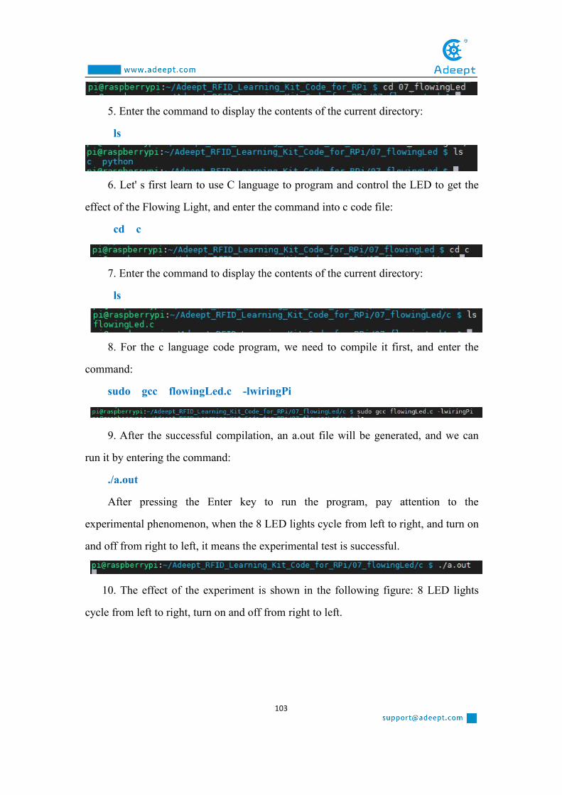
103
5. Enter the command to display the contents of the current directory:
ls
6. Let' s first learn to use C language to program and control the LED to get the
effect of the Flowing Light, and enter the command into c code file:
cd c
7. Enter the command to display the contents of the current directory:
ls
8. For the c language code program, we need to compile it first, and enter the
command:
sudo gcc flowingLed.c -lwiringPi
9. After the successful compilation, an a.out file will be generated, and we can
run it by entering the command:
./a.out
After pressing the Enter key to run the program, pay attention to the
experimental phenomenon, when the 8 LED lights cycle from left to right, and turn on
and off from right to left, it means the experimental test is successful.
10. The effect of the experiment is shown in the following figure: 8 LED lights
cycle from left to right, turn on and off from right to left.

104
(2) Core code program for making the Flowing Light in C language
After the hands-on operation above, you must be very interested to know how we
achieve the effect of Flowing Light in C language on the Raspberry Pi. Below we will
introduce how our main code is implemented:
1. First of all, led_on () is used to control LED lighting:
digitalWrite(LedPin,LOW) controls the LED light.
When it is at LOW level, we control the LED light to light up (turn on); Led_off ()
method is used to control the LED light off: digitalWrite(LedPin,HIGH) is used to
control the LED light. When it is at HIGH level, we control the LED light to turn off
(off), as shown below:

105
2. We use for (I =0; I < 8; I ++) cycle control 8 LED lights turn on from left to
right at a interval of 300us, and then turn off, that is, when I =0, the first light turns on
300us, then turn off, then when I =1, the second light turns on 300us, and then turn
off... ; For (I =8; I > = 0; I --) cycle control 8 LED lights turn on from right to left at
an interval of 300us, then turn off; That is, when I =0, the first light will turn on 300us,
and then turn off. Then when I =1, the second light will turn on 300us, and then turn
off... Until I =7 the eighth light turns on, turns off, and the loop ends. This creates the
effect of our Flowing Light. As shown below

106
(3) Programming and controlling the Flowing Light in Python
language on Raspberry Pi
The code program used in this lesson is stored in the folder:
Adeept_RFID_Learning_Kit_Code_for_RPi
During the experiment, we need to go to this folder to find the corresponding
code of the course, and then compile and run it before we can test our experiment.
(1) Compile and run the code program of this course
1. First, we opened the software , logged in and connected to ourRaspberry Pi (for the second login, we only need to enter the user name, and pay
attention to the correctness of the user name). After successfully logging in, as shown
in the following figure:

107
2. We first enter the Adeept_RFID_Learning_Kit_Code_for_RPi, enter the
command:
cd Adeept_RFID_Learning_Kit_Code_for_RPi
3. After entering the folder, we take a look at the directory have our class
(07_flowingLed) files. Input command:
ls
As shown in the following figure:
4. We found 07_flowingLed directory under the existence of this lesson folder,
the folder is the associated code for our class, in front of the class, we have explained,
the corresponding code of course all in code folder, it contains the C language and the
Python code inside, we enter commands into the code directory:
cd 07_flowingLed/code
As shown in the following figure:
5. Enter the command to display the contents of the current directory:
ls

108
6. Let’ s learn how to program and make a Flowing Light in Python language on
Raspberry Pi, and enter the command into the Python code file:
cd python
7. Enter the command to display the contents of the current directory:
ls
8. Enter the command and run our python code program:
sudo python3 07_flowingLed.py
After pressing the Enter key, pay attention to observe the experimental
phenomenon of the LED and find that the LED lights up in sequence like a water
flow.

109
(2) Core code program for making the Flowing Light in Python language
After the hands-on operation above, you must be very interested to know how we
make the Flowing Light in Python language. Below we will introduce how our main
code is implemented:
1. First, we set the pin number: 7,11,12,13,15,16,18,22; Gpio.setmode
(gpio.board) is used to set the encoding mode of GPIO as BOARD. Gpio.setup (pin,
gpio.out) is used to set the mode of all pins as output.
Turn off when setting all pin HIGH levels through gpio.output (pin,
gpio.high).
2. Through the cycle for pin in pins for 8 times, when each cycle is completed,
the LED light shall be switched on successively: gpio.output (pin, gpio.low), and then
turned off LED: gpio.output (pin, gpio.high) after 0.5s. Finally we form the effect of
the Flowing Lights.
4.【Conclusion】

110
Through this lesson, we learned what the Flowing Light is and the experimental
principle of it. The working principle of the Flowing Light is mainly under the control
of the microcomputer, which lights up and turns off in turn according to the set order
and time. The visual sense of the light is flowing, thus forming the Flowing Light. In
the actual operation, we achieve the effect of the Flowing Light in C language and
Python language on Raspberry Pi.

111
Lesson 8 Breathing LED
In this lesson, we will learn how to make a Breathing LED.
1. Components used in this courseComponents Quantity Picture
Raspberry Pi 1
Led 1
Resistor (220Ω) 1
Male to Male Jumper Wire Several
Breadboard 1
GPIO Extension Board 1
GPIO Cable 1
2. The working principle of the Breathing Light
(1) What is a Breathing Light
Breathing Light is a light that changes gradually from light to dark under the
control of a microcomputer. It feels as if a person is breathing. It is widely used in
mobile phones and has become one of the selling points of new mobile phones of
major brands, serving as a notification and reminder.

112
(2) The working principle of the breathing light
(1)The working principle of the breathing light
How does our breathing light achieve a similar lighting effect? The breath light
controls the brightness of the LED by controlling the frequency (time) of the light
flashing, and this process is repeated over and over again to create the effect of
"breathing".
How to control the frequency (time) of LED flashing? It is through PWM (pulse
width modulation) principle to achieve. We will introduce the principle of PWM as
follow.
(2) Pulse width modulation (PWM)
1. Definition of pulse width modulation:
Pulse width modulation is an analog control method, which modulates the bias of
the transistor base or MOS gate according to the change of the corresponding load to
realize the change of the transistor or MOS tube conduction time, so as to realize the
change of the output of the switching voltage stabilized power supply. This method
can make the output voltage of the power supply remain constant when the working
conditions change, and it is a very effective technique to control the analog circuit
with the digital signal of the microprocessor. Pulse width modulation is a very

113
effective technique for controlling analog circuits with the digital output of
microprocessors. It is widely used in many fields, from measurement and
communication to power control and transformation.
2. Principle of pulse width modulation
The control mode is to control the on-off of the inverter circuit switching device,
so that the output end can get a series of pulses with the same amplitude, and use
these pulses to replace the sine wave or the required waveform. In other words,
multiple pulses are generated in the half period of the output waveform, so that the
equivalent voltage of each pulse is a sinusoidal waveform, so that the output obtained
is smooth and has fewer low-order harmonics. The width of each pulse can be
modulated according to certain rules, which can not only change the output voltage of
the inverter circuit, but also change the output frequency.
The above method may not be easy for you to understand, but you can
understand it through the following sentence:
In the range of 0-1s: the lighting time of led lamp between 0-1ms is 0us; Light

114
1us in 1-2ms, light 2us in 2-3ms... Bright 999us in 999-1000ms.
3. Change duty cycle to realize breathing light:
The lighting and extinguishing of LED is the result of the level change, which
can be regarded as a cycle. Each cycle will be shown as LED flicker. When the cycle
is very short, that is, when the frequency is very high, this flicker will not be
recognized by the naked eye, which will make people have the sense of continuous
LED glow. In one cycle, the ratio between the duration of high level and the duration
of one cycle is called duty cycle ratio. The higher the duty cycle is, the larger the
current passing through the LED will be, and the brighter the visual perception will be.
Now, you should have the train of thought that makes breathing light, namely change
duty cycle! If the duty cycle is slightly stepped up, there will be a sense of brightening
of LED. Otherwise it will get dark.
3. Making a Breathing Light
(1) Wiring diagram (circuit diagram)
In this course, we used LED to make the breathing light. Before the experiment,
we connected our LED to the circuit as shown in the following figure. When
connecting the circuit, we should pay attention to the difference between positive and
negative electrodes, as shown in the following figure:

115
(2) Programming the Breathing Light in C language on
Raspberry Pi
The code program used in this lesson is stored in the folder:
Adeept_RFID_Learning_Kit_Code_for_RPi
During the experiment, we need to go to this folder to find the corresponding
code of the course, and then compile and run it before we can test our experiment.
(1) Compile and run the code program of this course
1. We first opened the software , logged in and connected to our
Raspberry Pi (for the second login. We only need to enter the user name, and pay

116
attention to the correctness of the user name). After successfully logging in, as shown
in the following figure:
2. We first enter the Adeept_RFID_Learning_Kit_Code_for_RPi, enter the
command:
cd Adeept_RFID_Learning_Kit_Code_for_RPi
【Linux tip】when we enter an existing file path, we just need to type letter A ,
hold down Tab, and it will be automatically filled, which will save us time and avoid
errors when we enter the path.
3.After entering this folder, let's check whether there are files of this lesson
(08_breathingLed) in this directory. Enter the command to display the contents of the
current directory:
ls
As shown in the following figure:
4. We found that the folder 08_breathingLed of this lesson exists under the
directory, this file is to store the code associated with our lesson; we enter the

117
command to the directory:
cd 08_breathingLed
5. Enter the command to display the contents of the current directory:
ls
6. There are C and Python folders. The C folder holds the code programs we
operate with the C language, while the Python folder holds the code programs
controlled by the Python language. Now let's learn the C language operation part,
enter the command into the C language code file:
cd c
7. Enter the command to display the contents of the current directory:
ls
8. The breathingLed.c is what we need to compile the program code. If you want
to run this code program, we need to compile it. Enter the command:
sudo gcc breathingLed.c -lwiringPi
9. After compiling, we need to check whether the compilation is successful. If the
compilation is successful, we will generate an "a.out" file. Enter the command to
display the contents of the current directory:
ls
10. At this point, we can run the program we just compiled and type the command:
./a.out
After entering, we need to observe whether our LED lamp achieves the effect of the

118
breathing light. If the breathing light effect is realized, it means that our experiment is
successful.
11. The experimental results are as follows:
【Tips】How to view the source code of our experiment?
We can use the Nano command to do this. For example, we enter the view
associated with this class C language source code, can be in the current code
Lesson2_BreatheLed. C directory, type the command: sudo nano
Lesson2_BreatheLed. C enter after to get into view source interface, the following
figure:
After entering, we do not make any modification or press any button! When you
need to quit, \press Ctrl + X on the keyboard, then press and hold the letter Y, and
finally press the Enter key to exit.

119
(2)Core code program for making the Breathing Light in C language
After the above hands-on operation, everyone must be very curious to know how
we make the Breathing Light in C language. Below we will introduce how our code is
implemented:
1. First, we need to set the pin coding mode of the LED to wiringPi, and set the
pin number under the wiringPi coding mode to 1, which corresponds to the pin
number on the GPIO to 12.
As shown in the figure:
2. Next, we initialize wiringPi:
3. Create a software-controlled PWM pin and set the PWM range between 0 and

120
100:
4. At this time, the control LED is dimmed, and the PWM value on the given pin
is updated first. Check this value in the range of 0~100, and pins that have not been
previously initialized by softPwmCreate will be ignored. Through the for loop, the
lights are gradually dimmed, with a delay of 20us each time, as shown in the
figure:
5. Similarly, we control the lights to turn on. First update the PWM value on the
given pin. Check the value to be within the range of 100~0, and the pins that have not
been initialized by softPwmCreate before will be ignored. Through the ‘for’loop, the
lights are controlled to light up step by step, with a delay of 20us each time. As shown
in the figure:
(3) Programming and controlling the Breathing Light in Python
language on Raspberry Pi
The code program used in this lesson is stored in the folder
Adeept_RFID_Learning_Kit_Code_for_RPi
During the experiment, we need to go to this folder to find the corresponding
code of the course, and then compile and run it before we can test our experiment.

121
(1) Compile and run the code program of this course
1. We first opened the software , logged in and connected to ourRaspberry Pi (for the second login. We only need to enter the user name, and pay
attention to the correctness of the user name). After successfully logging in, as shown
in the following figure:
2. We first enter the Adeept_RFID_Learning_Kit_Code_for_RPi, enter the
command:
cd Adeept_RFID_Learning_Kit_Code_for_RPi
【Linux tip】when we enter an existing file path, we just need to type letter A,
hold down Tab, and it will be automatically filled, which will save us time and avoid
errors when we enter the path.
3. After entering the folder, we take a look at the directory have our class
(08_breathingLed) files. Enter the command to display the contents of the current
directory:
ls
As shown in the following figure:

122
4. We found that the folder 08_breathingLed of this lesson exists under the
directory, this file is to store the code associated with our lesson; we enter the
command to the directory:
cd 08_breathingLed
5. Enter the command to display the contents of the current directory:
ls
6. There are C and Python folders. The C folder holds the code programs we
operate with the C language, while the Python folder holds the code programs
controlled by the Python language. Now let's learn the Python language operation part,
enter the command into the Python language code file:
cd python
7. After entering the python code file, let's see if there is any code we need to use
in it. Enter the command to display the contents of the current directory:
ls
As shown in the following figure:
8. This code program is the program we are related to in this lesson, and the code
in it is to control the realization of our breathing light (we will explain this program in
detail later). After we run this code program, we can observe the phenomenon of
breathing light. Input and run the command:
sudo python3 08_breathingLed.py
After entering the car, we should pay attention to the LED light to see if it lights

123
up like breathing.
As shown in the following figure:
9. When our LED achieves the effect of "breathing light", it means that our
experiment is successful. When we terminate the program, we can directly enter the
command:
Ctrl+C
(2) Core code program for making the Breathing Light in Python language
After the above hands-on operation, you must be very interested to know how to
make the Breathing Light in Python language, and we will introduce how our code is
implemented in the following contents:
1. First, we need to set GPIO pin number of LED to be 12: LedPin=12; Set GPIO
pin encoding type as BOARD through gpio. setmode: GPIO.setmode
(GPIO.BOARD); as shown below:
2. Then, we need to use GPIO.setup (LedPin, GPIO.OUT) to set the LedPin pin

124
(that is, number 12) as the output mode; and then set the state of the pin LedPin
through GPIO.output (LedPin, GPIO.LOW) into a low level. As shown below
3. Next, we need to create a PWM instance p,p = GPIO. The first parameter
LedPin of PWM(LedPin, 1000) represents the port number 12 of GPIO, and the
second parameter 1000 represents the frequency. The higher the frequency is, the
LED light will not flash, but the higher the performance requirements of the
corresponding CPU will be. After creating the instance, we need to start PWM
through p.separt (0). Parameter 0 represents duty cycle, and range 0.0<= duty
cycle >=100. The larger the value is, the darker the light will be.
4. After PWM is started, the principle of PWM is used to control the size of the
duty cycle of the LED to achieve the effect of breathing light at an interval. First, we
set the duty cycle to be between 0 and 100, and change it in increments of 4 each time
until it increases to close to 100. The larger the duty cycle, the darker the lamp.
Change the duty cycle through p.ChangeDutyCycle(dc), and set the time for each
change to be bright for 0.05 seconds through time.sleep(0.05). When the duty cycle is
closest to 100, that is, when the lamp is darkest, We control the light to dim for 1
second: time.sleep(1).
As shown in the following figure:

125
5. Similarly, as long as we control the reduction of duty cycle in a descending
way, we can realize the slow extinction of LED. Through for dc in range (100, -1, -4),
the duty cycle is reduced by 4 from 100 to 0, and the duty cycle is changed through
p.chhangedutycycle (dc). The interval of each time is 0.05 seconds: time. Control the
light to last for 1 second at the last turn off time. sleep (1), as shown in the figure:
6. Finally, we need to turn off PWM through p.top (), turn off LED light through
gpio.output (LedPin, gpio.high), and finally cleanup and release GPIO port through
gpio.cleanup (), so as to avoid being occupied.
4.【Conclusion】Through this lesson, we learned what the Breathing Light is and the working
principle of making the Breathing Light. The production of the Breathing Light is
mainly achieved by pulse width modulation. In actual operation, we achieved the
effect of the Breathing Light in C language and Python language on the Raspberry Pi.

126
Lesson 9 Controlling an RGB LED with PWM
In this lesson, we will learn the application of the RGB LED.
1. Components used in this courseComponents Quantity Picture
Raspberry Pi 1
Breadboard 1
GPIO Extension Board 1
GPIO Cable 1
Male to Male Jumper Wire Several
RGB LED 1
Resistor(220Ω) 3
2. The introduction of the RGB LED
(1)The RGB LED
RGB LED modules are commonly known as three primary colors (red, green and
blue) light-emitting diodes. Commonly have four pins, a common terminal and three
colors (one red, one green, one blue) control terminal. Any combination of the three
colors can produce other colors. The longest pin is connected to the positive electrode.
A four-wire connection with a common lead (anode or cathode) is usually used. These
LED lights may have a common anode lead or a common cathode lead. In this lesson,
common anode RGB LED lights are used. The longest pin is the common anode of
the three LED lights. This pin is connected to the + 3.3V pin of the Raspberry Pi, and
the remaining three pins are connected to the pin11, pin12, and pin13 of the

127
Raspberry Pi through current limiting resistors.
(2)Working principle of the RGB LED
RGB LED light imaging principle: RGB lights are combined with three primary
colors to form an image, and there are also blue LED lights with yellow phosphors,
and ultraviolet LED lights with RGB phosphors. Overall, both types have their
imaging principles, but the attenuation problem and the impact of ultraviolet light on
the human body are both It is a problem that is difficult to solve in the short term, so
although it can meet the needs of white light, it has different results.
RGB LED lamp color changing principle: When two LED lights are lit by three
primary color LED lights, it can emit yellow, purple, and cyan (such as red and blue
LED lights emit purple light when lit); if red, green, and blue When the LED lights up
at the same time, it produces white light. If there is a circuit that can make the red,
green, and blue LED lights light up two by two, individually, and the three primary
colors simultaneously, then he can emit seven different colors of light.
We used ordinary anode RGB LED lights in this experiment. The longest pin is
the common anode of the three LED lights. This pin is connected to the +3.3V pin of
the Raspberry Pi, and the remaining three pins are connected to the pin11, pin12, and
pin13 of the Raspberry Pi through current limiting resistors. In this way, we can
control the color of RGB LED through 3 PWM signals.

128
3. The application of the RGB LED
(1)Wiring diagram (Circuit diagram)
In this course, we used a RGB LED. Before the experiment, we connected it in the
circuit as shown in the following figure. When connecting the circuit, we should pay
attention to the difference between positive and negative electrodes, as shown in the
following figure:

129
(2) Programming and controlling the RGB LED in C language
on Raspberry Pi
The code program used in this lesson is stored in the folder:
Adeept_RFID_Learning_Kit_Code_for_RPi
During the experiment, we need to go to this folder to find the corresponding
code of the course, and then compile and run it before we can test our experiment.
(1) Compile and run the code program of this course
1. First, we opened the software , logged in and connected to ourRaspberry Pi (for the second login, we only need to enter the user name, and pay

130
attention to the correctness of the user name). After successfully logging in, as
shown in the following figure:
2. In the previous experiment operation, we have already introduced that the
corresponding experiment correlation code of each class is stored in the
Adeept_RFID_Learning_Kit_Code_for_RPi.
Our lesson is 09_rgbLed, so just go to this folder and find the corresponding
code to run. Now let's enter the C language code program file and enter the following
command:
cd Adeept_RFID_Learning_Kit_Code_for_RPi/09_rgbLed/c
3. Enter the command to display the contents of the current directory:
ls
4. This code program file is the one we will use in this lesson. For C language, at
first, compile and enter the command:
sudo gcc rgbLed.c -lwiringPi -lpthread
5. The "a.out" file will be generated after successful compilation. Enter the

131
command:
./a.out
6. After the successfully run, the color of the RGB LED will change. As shown in
the following figure:
(2) The core code program for programming and controlling the RGB LED
in C language
After the hands-on operation above, you must be very interested to know how we
program and control the RGB LED in C language. Below we will introduce how our
main code is implemented:
1. Set the PWM, the range is between 0 ~ 100Hz.
2. Use softPwmWrite () to set the RGB LED color.

132
(3) Programming and controlling the RGB LED in Python
language on Raspberry Pi
The code program used in this lesson is stored in the folder:
Adeept_RFID_Learning_Kit_Code_for_RPi
During the experiment, we need to go to this folder to find the corresponding
code of the course, and then compile and run it before we can test our experiment.
(1) Compile and run the code program of this course
1. First, we opened the software , logged in and connected to our
Raspberry Pi (for the second login, we only need to enter the user name, and pay
attention to the correctness of the user name). After successfully logging in, as shown
in the following figure:

133
2. In the previous experiment operation, we have already introduced that the
corresponding experiment correlation code of each class is stored in the
Adeept_RFID_Learning_Kit_Code_for_RPi folder.
Our lesson is 09_rgbLed, so just go to this folder and find the corresponding
code to run. Let's go to the python program file and enter the following command:
cd Adeept_RFID_Learning_Kit_Code_for_RPi/09_rgbLed/python
3. Enter the command to display the contents of the current directory:
ls
4. This code program file is the one we will use in this lesson. For the Python
language, directly enter the run command:
sudo python3 09_rgbLed.py
5. After successful operation, the color of RGB LED will change. As shown in
the following figure:
(2) The core code program for programming and controlling the RGB LED

134
in Python language
After the hands-on operation above, you must be very interested to know how we
program and control the RGB LED in Python language. Below we will introduce how
our main code is implemented:
1. Change the PWM frequency.
2. Change the duty cycle through ChangeDutyCycle (), and then change the RGB
color.
4.【Conclusion】In this lesson, we learned about the RGB LED the principles of it. We also
learned how to connect the RGB LED in the circuit. We programmed and controlled
the RGB LED in C language and Python language and further studied the
programming logic and algorithm of the code program.

135
Lesson 10 7-segment display
In this lesson, we will learn the application of the 7-segment Display.
1. Components used in this courseComponents Quantity Picture
Raspberry Pi 1
Breadboard 1
GPIO Extension Board 1
GPIO Cable 1
Male to Male Jumper Wire Several
7-Segment display 1
Resistor(220Ω) 1
2. The introduction of the 7-segment Display
(1)The 7-segment Display
The 7-segment display is also called the 7-segment LED display. It is a type of
LED display, using 7 LED lights to form the font "8", and another dot LED to display
the decimal point, which means that there are 8 LED lights in total to form the font of
"8."
According to the connection form, it can be divided into common anode display
and common cathode display. By controlling the display mode of semiconductor light
emitting diodes, LED display panel (LED panel) is used to display information such
as text, graphics, images, animations, quotes, videos, video signals, etc. The
7-segment display module is used to display numbers from decimal 0 to 9 and

136
decimal point, and can also display English letters, including English A to F in
hexadecimal (b and d are lowercase, others are uppercase)
(2)Working principle of the 7-segment Display
The 7-segment display module is packaged by multiple LED light-emitting
diodes. Each LED is called a segment. In addition to the seven-segment strokes
necessary for displaying numbers, a decimal point is also provided in the display. It
has 8 pins with numbers from a to g. By forward installing the appropriate pins of the
LED segments in a specific order, some segments will be bright and others will be
dark, allowing the desired character pattern of the numbers generated on the display.
Then each of the ten decimal digits 0 to 9 can be displayed on the same 7-segment
display.
The segment display can be divided into common anode and common cathode
segment display by internal connections.
When using a common anode LED, the common anode should to be connected to
the power supply (VCC); when using a common cathode LED, the common cathode
should be connected to the ground (GND).
Each segment of a segment display is composed of LED, so a resistor is needed
for protecting the LED.
3. The application of the 7-segment Display

137
(1)Wiring diagram (Circuit diagram)
In this course, we used a 7-segment Display. Before the experiment, we
connected them in the circuit as shown in the following figure. When connecting the
circuit, we should pay attention to the difference between positive and negative
electrodes, as shown in the following figure:

138
(2) Programming and controlling the 7-segment Display in C
language on Raspberry Pi
The code program used in this lesson is stored in the folder:
Adeept_RFID_Learning_Kit_Code_for_RPi
During the experiment, we need to go to this folder to find the corresponding
code of the course, and then compile and run it before we can test our experiment.
(1) Compile and run the code program of this course
1. First, we opened the software , logged in and connected to ourRaspberry Pi (for the second login, we only need to enter the user name, and pay

139
attention to the correctness of the user name). After successfully logging in, as shown
in the following figure:
2. In the previous experiment operation, we have already introduced that the
corresponding experiment correlation code of each class is stored in the
Adeept_RFID_Learning_Kit_Code_for_RPi.
Our lesson is 10_segment, so just go to this folder and find the corresponding
code to run. Now let's enter the C language code program file and enter the following
command:
cd Adeept_RFID_Learning_Kit_Code_for_RPi/10_segment/c
3. Enter the command to display the contents of the current directory:
ls
4. This code program file is the one we will use in this lesson. For C language, at
first, compile and enter the command:
sudo gcc segment.c -lwiringPi
5. The "a.out" file will be generated after successful compilation. Enter the

140
command:
./a.out
6. After the successfully run, the 7-segment display module will sequentially
display the numbers 0-9. The connection diagram of the experiment is as follows:
(2) The core code program for programming and controlling the 7-segment
Display in C language
After the hands-on operation above, you must be very interested to know how we
control the 7-segment Display in C language. Below we will introduce how our main
code is implemented:
As long as you control the high and low levels of a-g 7 pins (high level is bright,
low level is dark), you can display different numbers and letters. In the c language, the
hexadecimal in the SegCode[17] array can be written with digitalWrite() through the
‘for’loop.

141
(3) Programming and controlling the 7-segment Display in
Python language on Raspberry Pi
The code program used in this lesson is stored in the folder:
Adeept_RFID_Learning_Kit_Code_for_RPi
During the experiment, we need to go to this folder to find the corresponding
code of the course, and then compile and run it before we can test our experiment.
(1) Compile and run the code program of this course
1. First, we opened the software , logged in and connected to ourRaspberry Pi (for the second login, we only need to enter the user name, and pay
attention to the correctness of the user name). After successfully logging in, as shown
in the following figure:

142
2. In the previous experiment operation, we have already introduced that the
corresponding experiment correlation code of each class is stored in the
Adeept_RFID_Learning_Kit_Code_for_RPi folder.
Our lesson is 10_segment, so just go to this folder and find the corresponding
code to run. Let's go to the python program file and enter the following command:
cd Adeept_RFID_Learning_Kit_Code_for_RPi/10_segment/python
3. Enter the command to display the contents of the current directory:
ls
4. This code program file is the one we will use in this lesson. For the Python
language, directly enter the run command:
sudo python3 10_segment.py
5. After successful operation, the numbers of 0-9 will be displayed on the
7-segment display module. The physical connection diagram of the experiment is as
follows:
(2) The core code program for programming and controlling the 7-segment

143
Display in Python language
After the hands-on operation above, you must be very interested to know how we
control the 7-segment Display in Python language. Below we will introduce how our
main code is implemented:
As long as you control the high and low electrical levels of a-g 7 pins (high level
is bright, low level is dark), the 7-segment display can display different numbers and
letters. In the Python language, you need to use bit operations to get the value of each
bit and then write it to the corresponding pin.
4.【Conclusion】In this lesson, we learned about the 7-segment Display and the working principles
of it. We also learned how to connect the 7-segment Display in the circuit. We
programmed and controlled the 7-segment Display in C language and Python
language and further studied the programming logic and algorithm of the code
program.

144
Lesson 11 4-Digit 7-Segment Display
In this lesson, we will learn the application of the 4-digit 7-segment Display.
1. Components used in this courseComponents Quantity Picture
Raspberry Pi 1
Breadboard 1
GPIO Extension Board 1
GPIO Cable 1
Male to Male Jumper Wire Several
4-digit 7-segment display 1
Resistor(220Ω) 4
2. The introduction of the 4-digit 7-segment Display
(1)The 4-digit 7-segment Display
The 4-digit 7-segment display module is also a kind of LED display screen, and
can be divided into a common positive display and a common negative display
according to its connection form. LED display panel (LED panel) is a display screen
used to display information. Such as text, graphics, images, animations, quotes,
videos, video signals, etc. by controlling the display mode of semiconductor light
emitting diodes. It consists of a 12-pin 4-digit 7-segment common anode digital tube
and a control chip TM1637. A 4 * 8 shape LED display device composed of 32 LEDs
(including four decimal points), these segments are named a, b, c, d, e, f, g, h, dig1,
dig2, dig3, dig4.

145
(2)Working principle of the 4-digit 7-segment Display
Since all the segment selection lines are connected to the same I / O in parallel, it
is controlled by this I/O port. Therefore, if all 4-digit 7-segment LEDs are selected,
the 4-digit 7-segment LED will display the same characters. To make the 7-segment
LED of each bit display different characters, you must use dynamic scanning method
to turn on each 7-segment LED in turn, that is, only one 7-segment LED is selected to
display individual characters at each instant. During this lighting period, the segment
selection control I / O port outputs the segment selection code of the corresponding
character to be displayed, and the bit selection control I / O port outputs the bit
selection signal, sending the strobe level to the bit to be displayed (The common
cathode sends a low level, and the common anode sends a high level), so that the
corresponding character is displayed. In this way, the four-digit 7-segment LEDs are
turned on in turn, so that each digit displays the character that the digit should display.
Since the visual retention time of the human eye is 0.1 seconds, when the interval of
each display does not exceed 33ms, and it is maintained until the next display during
the display, the eye looks like 4 due to the visual retention effect of the human eye Bit
7 segment LED lights are all lit. When designing, pay attention to the interval time of
each display. Because the extinguishing time of one 7-segment LED cannot exceed
100ms, that is to say, the time used to light up other bits cannot exceed 100ms. When

146
displaying, the time t of each bit interval must meet the following formula: t≦ 100ms
/ (N-1)
For example, if 4 bits are used now, that is, N = 4, then t ≦ 33ms can be
calculated from the formula, that is, the interval between each bit cannot exceed 33ms.
Of course, the time can also be set shorter, such as 5ms or 1ms. As shown in the
following figure:
3. The application of the 4-digit 7-segment Display
(1)Wiring diagram (Circuit diagram)
In this course, we used a 4-digit 7-segment Display. Before the experiment, we
connected it in the circuit as shown in the following figure. When connecting the
circuit, we should pay attention to the difference between positive and negative
electrodes. The resistance is 220Ω,as shown in the following figure:

147
(2) Programming and controlling the 4-digit 7-segment Display
in C language on Raspberry Pi
The code program used in this lesson is stored in the folder:
Adeept_RFID_Learning_Kit_Code_for_RPi
During the experiment, we need to go to this folder to find the corresponding
code of the course, and then compile and run it before we can test our experiment.
(1) Compile and run the code program of this course

148
1. First, we opened the software , logged in and connected to ourRaspberry Pi (for the second login, we only need to enter the user name, and pay
attention to the correctness of the user name). After successfully logging in, as shown
in the following figure:
2. In the previous experiment operation, we have already introduced that the
corresponding experiment correlation code of each class is stored in the
Adeept_RFID_Learning_Kit_Code_for_RPi.
Our lesson is 11_4bitSegment, so just go to this folder and find the corresponding
code to run. Now let's enter the C language code program file and enter the following
command:
cd Adeept_RFID_Learning_Kit_Code_for_RPi/11_4bitSegment/c
3. Enter the command to display the contents of the current directory:
ls
4. This code program file is the one we will use in this lesson. For C language, at
first, compile and enter the command:
sudo gcc fourBitSegment.c -lwiringPi

149
5.The "a.out" file will be generated after successful compilation. Enter the
command:
6. After the successfully run, the 4-digit 7-segment display module will display
the numbers.
(2) The core code program for programming and controlling the 4-digit
7-segment Display in C language
After the hands-on operation above, you must be very interested to know how we
control the 4-digit 7-segment Display in C language. Below we will introduce how
our main code is implemented:
Only need to control the high and low level of the pin (high level is bright, low
level is dark), you can display different numbers and letters. In the C language, the
hexadecimal in the SegCode [10] array can be written with digitalWriteByte (DatBuf
[i]) through the ‘for’ loop.

150
(3) Programming and controlling the 4-digit 7-segment Display
in Python language on Raspberry Pi
The code program used in this lesson is stored in the folder:
Adeept_RFID_Learning_Kit_Code_for_RPi
During the experiment, we need to go to this folder to find the corresponding
code of the course, and then compile and run it before we can test our experiment.
(1) Compile and run the code program of this course
1. First, we opened the software , logged in and connected to ourRaspberry Pi (for the second login, we only need to enter the user name, and pay
attention to the correctness of the user name). After successfully logging in, as shown
in the following figure:

151
2. In the previous experiment operation, we have already introduced that the
corresponding experiment correlation code of each class is stored in the
Adeept_RFID_Learning_Kit_Code_for_RPi folder.
Our lesson is 11_4bitSegment, so just go to this folder and find the corresponding
code to run. Let's go to the python program file and enter the following command:
cd Adeept_RFID_Learning_Kit_Code_for_RPi/11_4bitSegment/python
3.Enter the command to display the contents of the current directory:
ls
4.This code program file is the one we will use in this lesson. For the Python
language, directly enter the run command:
sudo python3 11_fourBitSegment.py
5. After the program runs successfully, the 4-digit 7-segment display module will
show the numbers.

152
(2) The core code program for programming and controlling the 4-digit
7-segment Display in Python language
After the hands-on operation above, you must be very interested to know how we
control the 4-digit 7-segment Display in Python language. Below we will introduce
how our main code is implemented:
As long as the high and low levels of the control pin (high level is bright, low
level is dark), different numbers and letters can be displayed. In the Python language,
you need to use bit operations to get the value of each bit, and then write it to the
corresponding pin through digitalWriteByte (segCode [bi]).

153
4.【Conclusion】In this lesson, we learned about the 4-digit 7-segment Display and the working
principles of it. We also learned how to connect the 4-digit 7-segment Display in the
circuit. We programmed and controlled the 4-digit 7-segment Display in C language
and Python languages and further studied the programming logic and algorithm of the
code program.

154
Lesson 12 LCD1602
Overview
In this lesson, we will learn how to use a character display device - LCD1602 on
the Raspberry Pi platform. We first make the LCD1602 display a string "Hello
Geeks!" scrolling, and then display“Adeept”and“www.adeept.com”statically.
Components
- 1* Raspberry Pi
- 1* LCD1602
- 1* 10KΩ Potentiometer
- 1* Breadboard
- Several Jumper wires
Principle
LCD1602 is a kind of character LCD display. The LCD has a parallel interface,
meaning that the microcontroller has to manipulate several interface pins at once to
control the display. The interface consists of the following pins:
● A register select (RS) pin that controls where in the LCD's memory you're writing
data to. You can select either the data register, which holds what goes on the screen, or
an instruction register, which is where the LCD's controller looks for instructions on
what to do next.
● ARead/Write (R/W) pin that selects reading mode or writing mode
● An Enable pin that enables writing to the registers
● 8 data pins (D0-D7). The status of these pins (high or low) is the bits that you're
writing to a register when you write, or the values when you read.
● There are also a display contrast pin (Vo), power supply pins (+5V and Gnd) and
LED Backlight (Bklt+ and BKlt-) pins that you can use to power the LCD, control the

155
display contrast, and turn on or off the LED backlight respectively.
The process of controlling the display involves putting the data that form the
image of what you want to display into the data registers, then putting instructions in
the instruction register. The wiringPiDev Library simplifies this for you, so you don't
need to know the low-level instructions.
The Hitachi-compatible LCDs can be controlled in two modes: 4-bit or 8-bit. The
4-bit mode requires six I/O pins from the Raspberry Pi, while the 8-bit mode requires
10 pins. For displaying text on the screen, you can do most everything in 4-bit mode,
so example shows how to control a 2x16 LCD in 4-bit mode.
A potentiometer, informally a pot, is a three-terminal resistor with a sliding or
rotating contact that forms an adjustable voltage divider. If only two terminals are
used, one end and the wiper, it acts as a variable resistor or rheostat.
Key functions:
● int lcdInit (int rows, int cols, int bits, int rs, int strb, int d0, int d1, int d2, int
d3, int d4, int d5, int d6, int d7)
This is the main initialisation function and must be called before you use any
other LCD functions.
Rows and cols are the rows and columns on the display (e.g. 2, 16 or 4,20). Bits
is the number of bits wide on the interface (4 or 8). The rs and strb represent the pin
numbers of the displays RS pin and Strobe (E) pin. The parameters d0 through d7 are
the pin numbers of the 8 data pins connected from the Pi to the display. Only the first
4 are used if you are running the display in 4-bit mode.
The return value is the ‘handle’ to be used for all subsequent calls to the lcd
library when dealing with that LCD, or -1 to indicate a fault. (Usually incorrect
parameters)
● lcdPosition (int handle, int x, int y)
Set the position of the cursor for subsequent text entry. x is the column and 0 is

156
the left-most edge. y is the line and 0 is the top line.
● lcdPuts (int handle, const char *string)
● lcdPrintf (int handle, const char *message,)
● lcdPutchar (int handle, unsigned char data)
These output a single ASCII character, a string or a formatted string using the
usual printf formatting commands.
At the moment, there is no clever scrolling of the screen, but long lines will wrap
to the next line, if necessary.
Procedures
1. Build the circuit

157
2. Program
For C language users:
2.1 Edit and save the code with vim or nano.
(Code path: /home/Adeept_RFID_Learning_Kit_C_Code_for_RPi/12_lcd1602/lcd1602_2.c)
2.2 Compile
$ gcc lcd1602_2.c -o lcd1602_2 -lwiringPi -lwiringPiDev
2.3 Run
$ sudo ./lcd1602_2
Python users:
2.1 Edit and save the code with vim or nano.
(Code path: /home/Adeept_RFID_Learning_Kit_Python_Code_for_RPi/12_lcd1602.py)
2.2 Run
$ sudo python 12_lcd1602.py
Now, you can see the string "Hello Geeks!" shown on the LCD1602 scrolling,
and then the string "Adeept" and "www.adeept.com" displayed statically.

158
Summary
After learning the experiment, you should have already mastered the driver of the
LCD1602. Now you can make something more interesting based on this lesson and
the previous lessons learned.

159
Lesson 13 Matrix Keyboard
In this lesson, we will learn about the application of the 4*4 Matrix Keyboard.
1. Components used in this courseComponents Quantity Picture
Raspberry Pi 1
Breadboard 1
GPIO Extension Board 1
GPIO Cable 1
Male to Male Jumper Wire Several
Resistor(10kΩ) 8
4*4 Matrix Keyboard 1
2. The introduction of 4*4 matrix keyboard
(1) The 4*4 Matrix Keyboard
4*4 Matrix Keyboard is a matrix-like keyboard set used in Raspberry Pi
peripherals. In a 4*4 matrix keyboard, each horizontal and vertical line is not
connected directly at the intersection, but is connected by a single key. In this way, a
port (such as port P1) can form 4*4=16 keys, which is twice as much as using port
line for keyboard directly. Moreover, the more lines, the more obvious the difference
is. For example, one more line can form a 20-key keyboard, while using port line can
only create one more key (9 keys). Thus it can be seen that it is reasonable to use the
matrix method to make the keyboard when the number of keys needed is large.

160
(2) The working principle of the 4*4 Matrix Keyboard
The key is set at the intersection of the line and the line, and the line and the line
are respectively connected to the two ends of the key switch. When the key is not
pressed, all input terminals are at high levels, representing keyless pressing. The line
output is low. Once a key is pressed, the input line will be pulled down. Thus, the state
of the input line can be read in to know whether a key is pressed or not. The line is
connected to the +5V power supply through the pull-up resistance.
Make sure the keyboard Key Heis pressed on a matrix to introduce a "line scan".
In the first step, make the line the input line of programming and the column line
the output line, pull down all the column lines, and judge the change of the line. If
there is a key pressed, the corresponding line pressed will be pulled down, otherwise
all the line lines will be at high level.
In the second step, after the first step is judged to have a key pressed, the

161
mechanical jitter will be eliminated after a delay of 10ms, and the row value will be
read again. If the line is still at a low level, the next step will be entered; otherwise,
the first step will be returned to re-judge.
Step 3: start scanning the position of the key, and use line by line scanning.
Every 1ms interval, pull down the first column, the second column, the third column
and the fourth column respectively. No matter which column you lower, the other
three columns are at high level. Read the row value to find the location of the key and
store the row and column values in it.
Step 4: find the row value and the column value from the register and combine
them to get the key value, which is coded from the first row to the fourth row from the
first row to the fourth row, from "0000" to "1111", and then display Decode. Finally,
the key number is displayed. Principle of dynamic scanning of digital tube: the 7
segments and the decimal point of the digital tube are all composed of LED blocks,
and the display mode is divided into static display and dynamic display. When the
digital tube is displayed in static mode, the bit selection signals of its total positive
tube are all low level, and the common segment selection lines of the four digital
tubes a, b, c, d, e, f, g and dp are respectively connected with the 8 I/O port lines of
CPLD. When the digital tube is displayed, only the low level should be sent to the
corresponding segment selection line. Dynamic display of digital tube in the way,
there can be only one at a time to light the digital tube display digital, the rest is in a
state of the gate, a selected code port signal changes, port signal segment code also
should make corresponding change. The stay time of each Character is usually 1-5 ms,
using visual inertia, one eye can see fairly stable on the digital tube digital display.

162
3. The application of the 4*4 Matrix Keyboard
(1) Wiring diagram (Circuit diagram)
In this course, we used a 4*4 Matrix Keyboard. Before the experiment, we
connected our LED to the circuit as shown in the following figure. When connecting
the circuit, we should pay attention to the difference between positive and negative
electrodes, as shown in the following figure:

163
(2) Programming and controlling the 4*4 Matrix Keyboard in C
language on Raspberry Pi
The code program used in this lesson is stored in the folder:
Adeept_RFID_Learning_Kit_Code_for_RPi
During the experiment, we need to go to this folder to find the corresponding

164
code of the course, and then compile and run it before we can test our experiment.
(1) Compile and run the code program of this course
1. First, we opened the software , logged in and connected to ourRaspberry Pi (for the second login, we only need to enter the user name, and pay
attention to the correctness of the user name). After successfully logging in, as shown
in the following figure:
2. In the previous experiment operation, we have already introduced that the
corresponding experiment correlation code of each class is stored in the
Adeept_RFID_Learning_Kit_Code_for_RPi folder.
Our lesson is 13_matrixKeyboard, so just go to this folder and find the
corresponding code to run. Now let's enter the C language code program file and enter
the following command:
cd Adeept_RFID_Learning_Kit_Code_for_RPi/13_matrixKeyboard/c
3. Enter the command to display the contents of the current directory:
ls

165
4. This code program file is the one we will use in this lesson. For C language, at
first, compile and enter the command:
sudo gcc matrixKeyboard.c -lwiringPi
5. The "a.out" file will be generated after successful compilation. Enter the
command:
./a.out
6. After successful operation, press different keys on the keys, and the
corresponding characters will appear.
7. The physical connection of the experiment is as follows:

166
(2)The core code program for programming and controlling the 4*4
Matrix Keyboard in C language
After the above hands-on operation, you must be very interested to know how we
program and control the 4*4 Matrix Keyboard in C language. We will introduce how
our core code can be achieved:
In the program, to read to the row and column data can determine which button to
press the, read the row and column is the same logic, first of all, we through the
getKey (void) reads the key, read the row, first column for the low level, and pulled
on the line as input mode (signal capture "press"), through the for loop iterates
through all the rows, determine which key is pressed, digitalRead (), the return value
is zero, the column is the same logic.

167
(3) Programming and controlling the 4*4 Matrix Keyboard in
Python language on Raspberry Pi
The code program used in this lesson is stored in the folder:
Adeept_RFID_Learning_Kit_Code_for_RPi
During the experiment, we need to go to this folder to find the corresponding
code of the course, and then compile and run it before we can test our experiment.
(1) Compile and run the code program of this course
1. First, we opened the software , logged in and connected to ourRaspberry Pi (for the second login, we only need to enter the user name, and pay
attention to the correctness of the user name). After successfully logging in, as shown
in the following figure:

168
2. In the previous experiment operation, we have already introduced that the
corresponding experiment correlation code of each class is stored in the
Adeept_RFID_Learning_Kit_Code_for_RPi folder.
Our lesson is 13_matrixKeyboard,so just go to this folder and find the
corresponding code to run. Let's go to the python program file and enter the following
command:
cd Adeept_RFID_Learning_Kit_Code_for_RPi/13_matrixKeyboard/python
3. Enter the command to display the contents of the current directory:
ls
4. This code program file is the one we will use in this lesson. For the python
language, directly enter the run command:
sudo python3 13_matrixKeyboard.py
5. After running, press the button and the corresponding characters will appear in
the command window.

169
6. The physical connection of the experiment is as follows:
(2) The core code program for programming and controlling the 4*4 Matrix
Keyboard in C language
After the above hands-on operation, you must be very interested to know how we
program and control the 4*4 Matrix Keyboard in C language. We will introduce how
our core code can be achieved:
In the program, to read to the row and column data can determine which button to
press the, read the row and column is the same logic, first of all, we through the
getKey (self) to read the key, read the row, first column for the low level, and pulled

170
on the line as input mode (signal capture "press"), through to iterate over all the rows,
determine which key is pressed
4.【Conclusion】In this lesson, we learned about the 4*4 Matrix Keyboard and the principle of it.
We also learned how to connect the 4 4*4 Matrix Keyboard to a circuit. We
programmed and controlled the d 4*4 Matrix Keyboard in C language and Python
language and further understood the implementation logic of the code program.

171
Lesson 14 Measure the distance
In this lesson, we will learn the application of the HC-SR04 Ultrasonic Distance
Sensor.
1. Components used in this courseComponents Quantity Picture
Raspberry Pi 1
4pin jumper wire 1
Male to Male Jumper Wire Several
Breadboard 1
GPIO Extension Board 1
GPIO Cable 1
Ultrasonic Distance Sensor
Module
1
2. The application of the Ultrasonic Distance Sensor
(1) Ultrasonic Distance Sensor
The model of the ultrasonic distance sensor we use is hc-sr04, it is mainly
composed of two left and right probes, looking like our human eyes. One probe is
responsible for transmitting sound waves for detection, and the other probe is
responsible for receiving sound waves for return. It has 4 pins, which are VCC; Trig
(control end - trigger signal input); Echo (receiver - recovery signal output);
Gnd(ground).

172
(2) The working principle of the Ultrasonic Distance Sensor
The method of detecting distance of ultrasonic wave is called echo detection
method,which ultrasonic emitter emits to a certain direction, in the moment of timer
timing starts at the same time, the ultrasonic wave in air, run into obstacles on the way
your face (objects) block was reflected immediately, ultrasonic receiver received the
ultrasonic reflected back to immediately stop timing. The propagation speed of
ultrasonic wave in the air is 340m/s. According to the time t recorded by the timer, the
distance s from the launch point to the obstacle surface can be calculated, that is,
s=340t/2. Under this principle of ultrasound, ultrasonic ranging module is widely used
in practical applications, such as car reversing radar, uav, and intelligent car.

173
3. The application of the Ultrasonic Distance Sensor
(1) Wiring diagram (Circuit diagram)
In this course, we used an hc-sr04 ultrasonic distance sensor module. Before the
experiment, we connected the ultrasonic distance sensor module to the circuit as
shown in the following figure. When connecting the circuit, we should pay attention
to the difference between positive and negative electrodes, as shown in the following
figure:

174
(2) Programming and controlling the Ultrasonic Distance Sensor
in C language on Raspberry Pi
The code program used in this lesson is stored in the folder:
Adeept_RFID_Learning_Kit_Code_for_RPi
During the experiment, we need to go to this folder to find the corresponding
code of the course, and then compile and run it before we can test our experiment.
(1) Compile and run the code program of this course
1. First, we opened the software , logged in and connected to ourRaspberry Pi (for the second login, we only need to enter the user name, and pay
attention to the correctness of the user name). After successfully logging in, as shown
in the following figure:

175
2. In the previous experiment operation, we have already introduced that the
corresponding experiment correlation code of each class is stored in the
Adeept_RFID_Learning_Kit_Code_for_RPi folder.
Our lesson is 14_ultrasonicSensor, so just go to this folder and find the
corresponding code to run. Now let's enter the C language code program file and enter
the following command:
cd Adeept_RFID_Learning_Kit_Code_for_RPi/14_ultrasonicSensor/c
3. Enter the command to display the contents of the current directory:
ls
4. This code program file is the one we will use in this lesson. For C language, at
first, compile and enter the command:
sudo gcc distance.c -lwiringPi
5. The "a.out" file will be generated after successful compilation. Enter the
command:

176
./a.out
6. After successfully running the program, notice that the command window will
print out the value of Distance. Our experiment tested successfully. If the Distance is
not displayed, you need to wait a while or check if the circuit is connected correctly.
7. You can use some objects to put in front of the ultrasonic sensor, and observe
the information printed out in the command window.
(2)Core code program for reading data of the Ultrasonic Distance Sensor in
C language
After the above hands-on operation, you must be very interested to know how
we program for reading data of the Ultrasonic Distance Sensor in C language and
read its value. Now we will introduce how our core code is implemented:
We start our first timer tv1 with gettimeofday(&tv1, NULL); Time tv2 at the
end of gettimeofday(&tv2, NULL); Then, start = tv1.tv_sec * 1000000 + tv1.tv_usec
is used to calculate the start time difference. Then, stop = tv2.tv_sec * 1000000 +
tv2.tv_usec is used to calculate the end time difference of stop; Finally, the distance
is calculated by combining the formula s=340t/2: dis = (float)(stop-start) / 1,000,000

177
* 34,000/2.
(3) Programming and controlling the Ultrasonic Distance Sensor
in Python language on Raspberry Pi
The code program used in this lesson is stored in the folder:
Adeept_RFID_Learning_Kit_Code_for_RPi.
During the experiment, we need to go to this folder to find the corresponding
code of the course, and then compile and run it before we can test our experiment.
(1) Compile and run the code program of this course
1. First, we opened the software , logged in and connected to ourRaspberry Pi (for the second login, we only need to enter the user name, and pay
attention to the correctness of the user name). After successfully logging in, as shown
in the following figure:

178
2. In the previous experiment operation, we have already introduced that the
corresponding experiment correlation code of each class is stored in the
Adeept_RFID_Learning_Kit_Code_for_RPi folder.
Our lesson is 14_ultrasonicSensor, so just go to this folder and find the
corresponding code to run. Now, go to the python program file and enter the
following command:
cd Adeept_RFID_Learning_Kit_Code_for_RPi/14_ultrasonicSensor/python
3. Enter the command to display the contents of the current directory:
ls
4. This code program file is the one we are using in this lesson. For the python
language, run it by the direct input command:
sudo python3 14_distance.py
5.After successfully running the program, we noticed that the value of Distance
was detected in the command window. We could place the object in front of the
ultrasonic distance sensor and test it in different positions.

179
6. You can use some objects to put in front of the ultrasonic sensor and observe
the information printed in the command window. The physical connection diagram of
the experiment is as follows:
(2) Core code program for reading data of the Ultrasonic Distance Sensor in
Python language
After the above hands-on operation, you must be very interested to know how we
program for reading data of the Ultrasonic Distance Sensor in Python language and
read its value. Now we will introduce how our core code is implemented:
Get the starting time t1 through t1 = time.time(); Then t2 = time.time() to get the
end time t2; Finally, the distance of the detected object is calculated by combining the
formula s=340t/2: (t2-t1)*340/2 .
4.【Conclusion】

180
In this lesson, we learned about the HC-SR04 Ultrasonic Distance Sensor and
learned the principle of HC-SR04 Ultrasonic Ranging Sensor to detect obstacles. In
addition, we also learned how to connect the HC-SR04 Ultrasonic Ranging Sensor in
the circuit. We programmed and read the data of the HC-SR04 Ultrasonic Ranging
Sensor in C language and Python language and further understood the implementation
logic of the code program.

181
Lesson 15 Temperature & Humidity
Sensor—DHT-11
In this lesson, we will learn the application of the DHT-11(Digital Temperature
& Humidity Sensor).
1. Components used in this courseComponents Quantity Picture
Raspberry Pi 1
3pin jumper wire 1
Male to Male Jumper Wire Several
Breadboard 1
GPIO Extension Board 1
GPIO Cable 1
DHT-11 1
2. The introduction of the DHT-11
(1) What is the DHT-11(Digital Temperature & Humidity
Sensor)
DHT11 is a temperature and humidity sensor with calibrated digital signal output.
It can be used to measure humidity and temperature, its precision humidity +-5%RH,
temperature +-2℃, range humidity 20-90%RH, temperature 0~50℃. It uses special
digital module acquisition technology and temperature and humidity sensing

182
technology to ensure the product has high reliability and excellent long-term stability.
The sensor consists of a resistive moisture sensing element and an NTC temperature
measuring element, and is connected to a high-performance 8-bit MCU. Therefore,
this product has the advantages of excellent quality, meteoric response, strong
anti-interference ability and high cost performance. Each DHT11 sensor is calibrated
in a highly accurate humidity calibration chamber. Calibration coefficients are stored
in the OTP memory in the form of a program, and these calibration coefficients are
called by the sensor during the processing of the detection signal. Single-wire serial
interface makes system integration easy and fast. Its ultra-small size and very low
power consumption make it the best choice for this kind of applications in demanding
applications.
Notes
(1) Avoid the use of condensation.
(2) Long-term storage conditions: temperature 10-40℃, humidity below 60%
(2) The features of DHT-11(Digital Temperature & Humidity
Sensor)
DHT11 uses the single bus protocol, which transmits 40 bits of data at a time, i.e.,
40 bits of data. Every time the data of DHT11 is read, it should be read 40 times at a
time, i.e., read 40 bits. Data format : 40bit data = 8-bit humidity integer + 8-bit
humidity decimal + 8-bit temperature integer + 8-bit temperature decimal + 8-bit
calibration. The first 16 bits of data are related to humidity, the middle 16 bits are

183
related to temperature, and the last eight bits are used for calibration.
(3) Principle of reading data of DHT-11(Digital Temperature &
Humidity Sensor)
The DHT-11(Digital Temperature & Humidity Sensor) we use in this lesson only
has 3 pins, and the 3 pins are used as VCC (+), GND (-), and DATA (out), respectively.
Since only high and low levels are transmitted to Raspberry Pi GPIO, how can we
read the temperature and humidity Numbers? With fewer pins, it needs a sequence
signal of high and low variation to express the value, as well as other signals such as
the start signal and so on. Let's first understand the timing signal of DHT11:
(1) Data frame format
DHT11 will send 40 bits (5 bytes) of data to the host. The first and second bytes
of data represent the temperature value. 3,4 bytes of data represent the humidity value;
The fifth byte data is the check code: data format :40bit data =8 bit humidity integer
+8 bit humidity decimal +8 bit temperature integer +8 bit temperature decimal +8 bit
check. If the data is correct, the sum of the first four bytes equals the last checksum.
(2) Handshake stage
By default, the DATA (out) foot is at a high level, and the host GPIO sends the
start signal. First, pull down the DATA foot at least 18ms, and then pull up the DATA
foot 20-40us to wait for the DHT11 response signal. Once DHT11 receives the start
signal, DHT11 will send a response signal to the host, at the same time, pull the
DATA foot down 80us as the response, and then DHT11 will pull up the DATA foot

184
80us, shake hands.
(3) Data transmission stage
For sending humidity and temperature data once, DHT11 needs to send 40bits of
data. Each bit of data starts with a 50us low level, followed by a high-level timing
signal. A continuous 26us-28us means that this bit is 0, a continuous 70us means that
this bit is 1, and then continues with a 50us low level, followed by a high level of the
next bit.
Data "0" :
Data "1" :

185
(4) Data reception and verification
The 40bit data sent is encoded as follows:
In order to ensure the accuracy of the received data, it is necessary to verify the
data. If byte1+byte2+byte3+byte4 == byte0, the received data will be correct. But the
DHT11 decimal doesn't work, so you just have to worry about byte2 plus byte4. After
successful verification, we will verify that the temperature and humidity data reading
result is correct this time, and then the data will be read out.
3. The application of the DHT11
(1) Wiring diagram (Circuit diagram)
In this course, we used a DHT11 module. Before the experiment, we connected
the DHT11 module into the circuit as shown in the figure below. When connecting the
circuit, we should pay attention to the difference between positive and negative poles,
as shown in the figure below:

186
(2) Programming and reading the data of the DHT11 in C
language on Raspberry Pi
The code program used in this lesson is stored in the folder:
Adeept_RFID_Learning_Kit_Code_for_RPi.
During the experiment, we need to go to this folder to find the corresponding
code of the course, and then compile and run it before we can test our experiment.
(1) Compile and run the code program of this course
1. First, we opened the software , logged in and connected to our

187
Raspberry Pi (for the second login, we only need to enter the user name, and pay
attention to the correctness of the user name). After successfully logging in, as shown
in the following figure:
2. In the previous experiment operation, we have already introduced that the
corresponding experiment correlation code of each class is stored in the
Adeept_RFID_Learning_Kit_Code_for_RPi folder.
Our lesson is 15_DHT11, so just go to this folder and find the corresponding code
to run. Now let's enter the C language code program file and enter the following
command:
cd Adeept_RFID_Learning_Kit_Code_for_RPi/15_DHT11/c
3. Enter the command to display the contents of the current directory:
ls
4. This code program file is the one we will use in this lesson. For C language, at
first, compile and enter the command:
sudo gcc dht11.c -lwiringPi

188
5. The "a.out" file will be generated after successful compilation. Enter the
command:
./a.out
6. After successfully running the program, we notice that there are two situations
in the command window: the first is that it will prompt ‘Data not good, skip’. At this
time, it means that the data we verified is incorrect and it is not read; the second case,
if the verified data is correct, Humidity (Temperature) and Temperature (Temperature)
data will be read.
7. The physical connection of the experiment is as follows:
(2)The core code program for reading data of the DHT11 in C language
After the above hands-on operation, you must be very interested to know how we
program for reading data of the DHT11 in C language and read its value. Now we will
introduce how our core code is implemented:

189
When the sent data has been successfully verified, it will be read out. The process
of verification is: the sum of the first four bytes equals the fifth check code.
Dht11_dat [4] == dht11_dat[0] + dht11_dat[1] + dht11_dat[2] + dht11_dat[3]. If the
Data validation is unsuccessful, then "Data not good, skip "is printed
(3) Programming and reading the data of the DHT11 in Python
language on Raspberry Pi
The code program used in this lesson is stored in the folder:
Adeept_RFID_Learning_Kit_Code_for_RPi
During the experiment, we need to go to this folder to find the corresponding code
of the course, and then compile and run it before we can test our experiment.
(1) Compile and run the code program of this course
1. First, we opened the software , logged in and connected to our
Raspberry Pi (for the second login, we only need to enter the user name, and pay
attention to the correctness of the user name). After successfully logging in, as shown
in the following figure:

190
2. In the previous experiment operation, we have already introduced that the
corresponding experiment correlation code of each class is stored in the
Adeept_RFID_Learning_Kit_Code_for_RPi folder.
Our lesson is 15_DHT11, so just go to this folder and find the corresponding
code to run. Let's go to the python program file and enter the following command:
cd Adeept_RFID_Learning_Kit_Code_for_RPi/15_DHT11/python
3. Enter the command to display the contents of the current directory:
ls
4. This code program file is the one we are using in this lesson. For the python
language, run it by the direct input command:
sudo python3 15_dht11.py
5. After successfully running the program, we observe that the command window
has two types of data printout, Temperature and Humidity, which print out the
detected data every 2 seconds or so.

191
6. The physical connection of the experiment is as follows:
(2) The core code program for reading data of the DHT11 in Python language
After the above practical operation, everyone must be very curious to know
how we control the DHT11 and read its value in Python language on the Raspberry Pi.
Below we will introduce how our main code is implemented:
First initialize GPIO, set the encoding method to BORAD; set the pin to read
data to 7; obtain the data detected by DHT11, use if to determine whether the obtained
data is correct, and print the data out if it is correct.

192
4.【Conclusion】In this lesson, we learned about the DHT-11(Digital Temperature & Humidity
Sensor) and the characteristics and the principle of reading data of it: time series
signal diagram. In addition, we also learned how to connect the DHT11 in the circuit.
We programmed and read the data of the DHT-11 in C language and Python language
and further understood the implementation logic of the code program.

193
Lesson 16 Dot-matrix display
Overview
In this lesson, we will program to control an 8*8 dot-matrix display to display the
graphs and numbers as we want to.
Components
- 1* Raspberry Pi
- 1* 8*8 Dot-matrix display
- 2* 74HC595
- 1* Breadboard
- Several jumper wires
Principle
1. Dot-matrix display
A dot-matrix display is a display device used to display information on machines,
clocks, railway departure indicators and many other devices requiring a simple
display device of limited resolution.
The display consists of a dot-matrix of lights or mechanical indicators arranged in
a rectangular configuration (other shapes are also possible, although not common)
such that by switching on or off selected lights, text or graphics can be displayed. A
dot-matrix controller converts instructions from a processor into signals which turns
on or off lights in the matrix so that the required display is produced.
The internal structure and appearance of the dot-matrix display is as shown
below:

194
An 8*8 dot-matrix display consists of 64 LEDs, and each LED is placed at the
intersection of the lines and columns. When the corresponding row is set as high level
and the column as low level, the LED will be lit.
A certain drive current is required for the dot-matrix display. In addition, more
pins are needed for connecting the dot-matrix display with a controller. Thus, to save
the Raspberry Pi’s GPIOs, the driver IC 74HC595 is used in this experiment.
2. 74HC595
The 74HC595 is an 8-stage serial shift register with a storage register and 3-state
outputs. The shift register and storage register have separate clocks. Data is shifted on
the positive-going transitions of the SH_CP input. The data in each register is
transferred to the storage register on a positive-going transition of the ST_CP input.
The shift register has a serial input (DS) and a serial standard output (Q7’) for
cascading. It is also provided with asynchronous reset (active LOW) for all 8 shift
register stages. The storage register has 8 parallel 3-state bus driver outputs. Data in
the storage register appears at the output whenever the output enable input (OE) is
LOW.
In this experiment, only 3 pins of the Raspberry Pi are used for controlling the
dot-matrix display thanks to the 74HC595.

195
The function of each pin:
DS: Serial data input
Q0-Q7: 8-bit parallel data output
Q7’: Series data output pin, always connected to DS pin of the next 74HC595
OE: Output enable pin, effective at low level, connected to the ground directly
MR: Reset pin, effective at low level, directly connected to 5V high level in practical
applications
SH_CP: Shift register clock input
ST_CP: storage register clock input
Procedures
1. Build the circuit (Make sure that the circuit connection is correct and then
power on, otherwise it may cause the chips burned.)

196
2. Program
For C language users:
2.1 Edit and save the code with vim or nano.
(Code path: /home/Adeept_RFID_Learning_Kit_C_Code_for_RPi/16_ledMatrix/ledMatrix.c)
2.2 Compile
$ gcc ledMatrix.c -o ledMatrix -lwiringPi
2.3 Run
$ sudo ./ledMatrix
For Python users:
2.1 Edit and save the code with vim or nano.
(Code path: /home/Adeept_RFID_Learning_Kit_Python_Code_for_RPi/16_ledMatrix.py)

197
2.2 Run
$ sudo python 16_ledMatrix.py
Now, you can see a rolling character “Adeept” displayed on the dot-matrix
display.
Summary
In this experiment, we have not only learned how to use a dot-matrix display to
display numbers and letters, but also learned the basic usage of 74HC595. Next you
can try utilizing the dot-matrix display to show more effects.

198
Lesson 17 Photoresistor
Overview
In this lesson, we will learn how to measure the light intensity by photoresistor
and display the measurement result on the screen.
Components
- 1* Raspberry Pi
- 1* ADC0832
- 1* Photoresistor
- 1* 10KΩ Resistor
- 1* Breadboard
- Several jumper wires
Principle
A photoresistor is a light-controlled variable resistor. The resistance of a
photoresistor decreases with the increasing incident light intensity; in other words, it
exhibits photoconductivity. A photoresistor can be applied in light-sensitive detector
circuits.
A photoresistor is made of a high resistance semiconductor. In the dark, it can
show a resistance as high as a few megohms (MΩ), while in the light, its resistance
can be as low as a few hundred ohms. If the incident light on a photoresistor exceeds a
certain frequency, photons absorbed by the semiconductor will give bound electrons
enough energy to jump into the conduction band. The resulting free electrons (and
their hole partners) conduct electricity, thereby lowering the resistance. The resistance
range and sensitivity of a photoresistor can substantially differ among dissimilar
devices. Moreover, unique photoresistors may react substantially differently to
photons within certain wavelength bands.
The schematic diagram of this experiment is as shown below:

199
With the increase of the light intensity, the resistance of the photoresistor will
decrease. The voltage of the GPIO port in the above figure will become high.
Procedures
1. Build the circuit
2. Program
For C language users:
2.1 Edit and save the code with vim or nano.
(Code path: /home/Adeept_RFID_Learning_Kit_C_Code_for_RPi/17_photoresistor/photoresistor.c)

200
2.2 Compile
$ gcc photoresistor.c -o photoresistor -lwiringPi
2.3 Run
$ sudo ./photoresistor
For Python users:
2.1 Edit and save the code with vim or nano.
(Code path: /home/Adeept_RFID_Learning_Kit_Python_Code_for_RPi/17_photoresistor.py)
2.2 Run
$ sudo python 17_photoresistor.py
Now, when you try to cover the photoresistor, you will find that the value
displayed on the screen decreasing. On the contrary, when you shine the photoresistor
with strong light, the value displayed will increase.

201
Summary
By learning this lesson, you should have learned how to detect the ambient light
intensity with the photoresistor. You can take full advantage of your own wisdom and
make more original works based on your gains in this and previous experiments.

202
Lesson 18 Thermistor
OverviewIn this lesson, we will learn how to use a thermistor to collect the temperature
data by programming the Raspberry Pi and ADC0832.
Components- 1* Raspberry Pi
- 1* ADC0832
- 1* Thermistor
- 1* 10KΩ Resistor
- 1* Breadboard
- Several jumper wires
Principle
A thermistor is a type of resistor whose resistance varies significantly with
temperature, more so than in standard resistors. When the temperature increases, the
thermistor resistance decreases; when the temperature decreases, the thermistor
resistance increases. It can detect the ambient temperature changes in real time. In the
experiment, we need an analog-digital converter ADC0832 to convert analog signal
into digital signal.
Procedures1. Build the circuit

203
2. Program
For C language users:
2.1 Edit and save the code with vim or nano.
(Code path: /home/Adeept_RFID_Learning_Kit_C_Code_for_RPi/18_thermistor/thermistor.c)
2.2 Compile
$ gcc thermistor.c -o thermistor -lwiringPi
2.3 Run
$ sudo ./thermistor
For Python users:
2.1 Edit and save the code with vim or nano.
(Code path: /home/Adeept_RFID_Learning_Kit_Python_Code_for_RPi/18_thermistor.py)
2.2 Run

204
$ sudo python3 18_thermistor.py
Now, touch the thermistor and you can see the current temperature value
displayed on the screen, which changes accordingly.

205
Lesson 19 RFID
In this lesson, we will learn how to use an RFID Module. We program the
Raspberry Pi to read the data acquired by the RFID module, and then display the ID
data on the terminal.
1. Components used in this courseComponents Quantity Picture
Raspberry Pi 1
Male to Female Jumper Wires Several
Male to Male Jumper Wire Several
Breadboard 1
GPIO Extension Board 1
GPIO Cable 1
RC522 RFID Module 1
Special-shaped ID Card 1
ID Card 1
2. The introduction of the RFIDThe RFID technology is used for a wide variety of applications including access
control, package identification, warehouse stock control, point-of-sale scanning, retail
antitheft systems, toll-road passes, surgical instrument inventory, and even for
identifying individual sheets of paper placed on a desk. RFID tags are embedded in

206
name badges, shipping labels, library books, product tags and boxes; installed in
aircraft; hidden inside car keys; and implanted under the skin of animals or even
people. RFID systems work on a wide range of frequencies, have a variety of
modulation and encoding schemes, and vary from low-power passive devices with
range of only a few millimeters to active systems that work for hundreds of
kilometers.
However, all RFID systems have the same basic two-part architecture: a reader
and a transponder. The reader is an active device that sends out a signal and listens for
responses, and the transponder (the part generally called the “tag”) detects the signal
from a reader and automatically sends back a response containing its identity code.
A reader can be like this:
A transponder:

207
Different types of RFID tags fall into one of the three broad categories: active,
passive, and battery-assisted passive.
Active tags are physically large because they require their own power supply
such as a battery. They can also have a very long range because the availability of
local power allows them to send high-powered responses that can travel from tens of
meters to hundreds of kilometers. An active tag is essentially a combination of a radio
receiver to detect the challenge, some logic to formulate a response, and a radio
transmitter to send back the response. They can even have the challenge and response
signals operate on totally different frequencies. The downsides are the size of the tag,
a high manufacturing cost due to the number of parts required, and the reliance on a
battery that will go flat eventually.
Passive tags can be much smaller and cheaper than active tags because they don’t
require a local power supply and have much simpler circuitry. Instead of supplying
their own power, they leach all the power they need from the signal sent by the reader.
Early passive tags operated on the “Wiegand effect,” which uses a specially formed
wire to convert received electromagnetic energy into radio-wave pulses. Some early
passive RFID tags actually consisted of nothing more than a number of very carefully
formed wires made from a combination of cobalt, iron, and vanadium, with no other
parts at all.
Modern passive tags use a clever technique that uses current induced in their
antenna coil to power the electronics required to generate the response. The response

208
is then sent by modulating the reader’s own field, and the reader detects the
modulation as a tiny fluctuation in the voltage across the transmitter coil. The result is
that passive tags can be incredibly small and extremely inexpensive: the antenna can
be a simple piece of metal foil, and the microchips are produced in such large
quantities that a complete RFID-enabled product label could cost only a few cents and
be no thicker than a normal paper label. Passive tags can theoretically last indefinitely
because they don’t contain a battery to go flat, but their disadvantage is a very short
operational range due to the requirement to leach power from the reader’s signal, and
lack of an actively powered transmitter to send back the response.
Passive tags typically operate over a range of a few millimeters up to a few
meters.
Tags can also have a variety of different modulation schemes, including AM, PSK,
and ASK, and different encoding systems. With so many incompatible variations, it’s
sometimes hard to know if specific tags and readers are compatible. Generally
speaking, each type of tag will only function on one specific frequency, modulation
scheme, and communications protocol. Readers, on the other hand, are far more
flexible and will often support a range of modulation schemes and comms protocols,
but are usually still limited to just one frequency due to the tuning requirements of the
coil.
Apart from the specific requirements for communicating with them, tags can also
have a number of different features. The most common passive tags simply contain a
hard-coded unique serial number and when interrogated by a reader they
automatically respond with their ID code. Most tags are read-only so you can’t change
the value they return, but some types of tags are read/write and contain a tiny amount
of rewritable storage so you can insert data into them using a reader and retrieve it
later. However, most uses of RFID don’t rely on any storage within the tag, and
merely use the ID code of the tag as a reference number to look up information about
it in an external database or other system.
RFID tags are produced in a wide variety of physical form factors to suit different
deployment requirements. The most commonly seen form factor is a flat plastic card

209
the same size as a credit card, often used as an access control pass to gain access to
office buildings or other secure areas. The most common form by sheer number
produced, even though you might not notice them, is RFID-enabled stickers that are
commonly placed on boxes, packages, and products. Key fob tags are also quite
common, designed to be attached to a keyring so they’re always handy for operating
access control systems.
3.How to use RFID
(1) Wiring diagram (Circuit diagram)
In this course,When connecting the circuit, we should pay attention to the
difference between positive and negative poles, as shown in the figure below:

210
(2) Programming and making the Pedometer in C language on
Raspberry Pi
The code program used in this lesson is stored in the folder:
Adeept_RFID_Learning_Kit_Code_for_RPi
During the experiment, we need to go to this folder to find the corresponding code
of the course, and then compile and run it before we can test our experiment.
(1) Compile and run the code program of this course
1. First, we opened the software , logged in and connected to ourRaspberry Pi (for the second login, we only need to enter the user name, and pay
attention to the correctness of the user name). After successfully logging in, as shown

211
in the following figure:
2. In the previous experiment operation, we have already introduced that the
corresponding experiment correlation code of each class is stored in the
Adeept_RFID_Learning_Kit_Code_for_RPi folder.
Our lesson is 19_RFID, so just go to this folder and find the corresponding code to
run. Now let's enter the C language code program file and enter the following
command:
cd Adeept_RFID_Learning_Kit_Code_for_RPi/19_RFID/c
3. Enter the command to display the contents of the current directory:
ls
4. Before compiling and running, we need to configure SPI and enter raspi-config
to set up and start, enter the command:
sudo raspi-config
5. Press the Enter key to confirm and enter the raspi-config configuration interface
as follows. We can operate through the up, down, left and right keys on the keyboard.

212
Through the up and down keys, we select item 5: Interfacing Options (connection
options): configure the connection of peripheral devices. Through the left and right
keys, we click "<select>" and press the Enter key to confirm.
6. Then continue to enter the setting interface, we select "P4 SPI" in item 7, select
"<select>" with the left and right keys, and press Enter key to confirm.
7. Then the following picture will pop up, we click "<Yes>" through the left and
right keys:

213
8. Select "<Yes>" and press the Enter key to confirm, a selection box will pop up,
continue to press the Enter key to confirm:
9. After confirming, it will jump back to the main interface again. We select
“<Finish>” with the left and right keys and press the Enter key to confirm. It returns
to our command window after completing the settings.

214
10. After returning to the command window, the following figure is as shown:
11. After setting, we need to enter the command to confirm whether the device is
effective:
ls /dev/spi*
sudo chmod +x rfid_testsudo ./rfid_test
12.Enter the command “scan”, and then place the ID Card on the RC522 RFID
Module. The card number of the ID Card will be displayed.

215
13. The physical connection of the experiment is as shown in the following
figure:
(3) Programming and making the Pedometer in Python language
on Raspberry Pi
The code program used in this lesson is stored in the folder:
Adeept_RFID_Learning_Kit_Code_for_RPi
During the experiment, we need to go to this folder to find the corresponding code
of the course, and then compile and run it before we can test our experiment.
(1) Compile and run the code program of this course
1. First, we opened the software , logged in and connected to our
Raspberry Pi (for the second login, we only need to enter the user name, and pay

216
attention to the correctness of the user name). After successfully logging in, as shown
in the following figure:
2. In the previous experiment operation, we have already introduced that the
corresponding experiment correlation code of each class is stored in the
Adeept_RFID_Learning_Kit_Code_for_RPi folder.
Our lesson is 19_RFID, so just go to this folder and find the corresponding code
to run. Let's go to the python program file and enter the following command:
cd Adeept_RFID_Learning_Kit_Code_for_RPi/19_RFID/python
3. Enter the command to display the contents of the current directory:
ls
4.Before running the program, we need to download the python-dev python3-dev,
enter the command:
sudo apt-get install python-dev python3-dev

217
5.Install SPI-Py library, enter the command:
sudo git clone https://github.com/lthiery/SPI-Py.git
6.enter the command:
sudo raspi-config
7. Press the Enter key to confirm and enter the raspi-config configuration interface
as follows. We can operate through the up, down, left and right keys on the keyboard.
Through the up and down keys, we select item 5: Interfacing Options (connection
options): configure the connection of peripheral devices. Through the left and right
keys, we click "<select>" and press the Enter key to confirm.
7. Then continue to enter the setting interface, we select "P4 SPI" in item 7, select
"<select>" with the left and right keys, and press Enter key to confirm.

218
8. Then the following picture will pop up, we click "<Yes>" through the left and
right keys:
9. Select "<Yes>" and press the Enter key to confirm, a selection box will pop up,
continue to press the Enter key to confirm:

219
10. After confirming, it will jump back to the main interface again. We select
“<Finish>” with the left and right keys and press the Enter key to confirm. It returns
to our command window after completing the settings.
11. After returning to the command window, the following figure is as shown:
12.Enter the command to display the contents of the current directory:
ls
13. enter the command:
cd SPI-Py

220
ls
14. enter the command:
sudo python setup.py install
15.Enter the command to display the contents of the current directory:
ls
16. Enter the command to return to the previous file directory, that is, the python
directory:
cd ..
17.enter the command:
sudo python3 19_RFID.py
18. The physical connection of the experiment is as shown in the following figure:

221

222
Lesson 20 LED Bar Graph
Overview
In this lesson, we will learn how to control an LED bar graph by programming
the Raspberry Pi.
Components
- 1* Raspberry Pi
- 1* ADC0832
- 1* LED bar graph
- 10* 220Ω Resistor
- 1* 10KΩ Potentiometer
- 1* Breadboard
- Several jumper wires
Principle
The bar graph - a series of LEDs in a line, such as you see on an audio display - is
a common hardware display for analog sensors. It's made up of a series of LEDs in a
row, an analog input like a potentiometer, and a little code in between. You can buy
multi-LED bar graph displays fairly cheaply. This tutorial demonstrates how to
control a series of LEDs in a row, but can be applied to any series of digital outputs.
This tutorial borrows from the For Loop and Arrays tutorial as well as the Analog
Input tutorial.
The sketch works like this: first read the analog value. Map the value to the
output range which is 0-10 in this case since ten LEDs are used. As the analog value
changes, LEDs in a corresponding number will light up on the bar – the bigger the

223
value is, the more LEDs will be turned on.
Procedures
1. Build the circuit
For C language users:
2.1 Edit and save the code with vim or nano.
(Code path: /home/Adeept_RFID_Learning_Kit_C_Code_for_RPi/20_ledBar/ledBar.c)
2.2 Compile
$ gcc ledBar.c -o ledBar -lwiringPi
2.3 Run
$ sudo ./ledBar
For Python users:
2.1 Edit and save the code with vim or nano.

224
(Code path: /home/Adeept_RFID_Learning_Kit_Python_Code_for_RPi/20_ledBar/ledBar.py)
2.2 Run
$ sudo python ledBar.py
Now, when you turn the shaft of the potentiometer, you will see that the number
of LEDs lit in the LED bar graph changing.

225
Lesson 21 Controlling an LED Through LAN
OverviewIn this lesson, we will introduce TCP and socket, and then how to program the
Raspberry Pi to control an LED through the local area network (LAN).
Components- 1* Raspberry Pi
- 1* LED
- 1* 220Ω Resistor
- 1* Breadboard
- Several jumper wires
Principle
1. TCP
The Transmission Control Protocol (TCP) is a core protocol of the Internet
Protocol Suite. It originated in the initial network implementation in which it
complemented the Internet Protocol (IP). Therefore, the entire suite is commonly
referred to as TCP/IP. TCP provides reliable, ordered, and error-checked delivery of a
stream of octets between applications running on hosts communicating over an IP
network. TCP is the protocol that major Internet applications such as the World Wide
Web, email, remote administration and file transfer rely on. Applications that do not
require reliable data stream service may use the User Datagram Protocol (UDP),
which provides a connectionless datagram service that emphasizes reduced latency
over reliability.
2. Socket
A network socket is an endpoint of an inter-process communication across a
computer network. Today, most communication between computers is based on the
Internet Protocol; therefore most network sockets are Internet sockets.
A socket API is an application programming interface (API), usually provided by the

226
operating system, that allows application programs to control and use network sockets.
Internet socket APIs are usually based on the Berkeley sockets standard.
A socket address is the combination of an IP address and a port number, much
like one end of a telephone connection is the combination of a phone number and a
particular extension. Based on this address, internet sockets deliver incoming data
packets to the appropriate application process or thread.
Several Internet socket types are available:
1. Datagram sockets, also known as connectionless sockets, which use User
Datagram Protocol (UDP).
2. Stream sockets, also known as connection-oriented sockets, which use
Transmission Control Protocol (TCP) or Stream Control Transmission Protocol
(SCTP).
3. Raw sockets (or Raw IP sockets), typically available in routers and other
network equipment. Here the transport layer is bypassed, and the packet headers are
made accessible to the application.
In this experiment, our program is based on stream socket, and the program is
divided into two parts, the client and the server. The server routine is run on the
Raspberry Pi, and the client routine is run on the PC. So you can send command to the
server through the client, and then control the LED connected to the Raspberry Pi.
Procedures
1. Build the circuit

227
2. Program
For C language users:
2.1 Edit and save the server code with vim or nano on the Raspberry Pi.
(Code path: /home/Adeept_RFID_Learning_Kit_C_Code_for_RPi/21_TCPCtrlLed/ledServer.c)
2.2 Compile(On Raspberry Pi)
$ gcc ledServer.c -o ledServer -lwiringPi
2.3 Edit and save the client code with vim or nano on the PC.
(Code path: /home/Adeept_RFID_Learning_Kit_C_Code_for_RPi/21_TCPCtrlLed/client.c)
2.4 Compile (On Linux PC)
$ gcc ledClient.c -o ledClient
2.5 Run
$ sudo ./ledServer (On Raspberry Pi)
$ ./ledClient 192.168.3.157 (On PC, modify the IP Address to your Raspberry

228
Pi’s IPAddress)
Now, input “ON” in the terminal and then press Enter. The LED connected to the
Raspberry Pi will light up; input “OFF” and the LED goes out.
For Python users:
2.1 Edit and save the server code with vim or nano on the Raspberry Pi.
(Code path: /home/Adeept_RFID_Learning_Kit_Python_Code_for_RPi/21_TCPCtrlLed/ledServer.py)
2.2 Edit and save the client code with vim or nano on the PC.
(Code path: /home/Adeept_RFID_Learning_Kit_Python_Code_for_RPi/12_TCPCtrlLed/ledClient.py)
2.3 Run
$ sudo python ledServer.py (On Raspberry Pi)
$ python ledClient.py (On PC)
Now, input “ON” in the terminal and then press Enter. The LED connected to the
Raspberry Pi will light up; input “OFF” and the LED goes out.

229
Summary
By learning this lesson, you should have mastered the basic principles of
inter-computer communication. This lesson can help you open the door to learn the
Internet of Things (IoT).

230
Lesson 22 DC Motor
OverviewIn this comprehensive experiment, we will learn how to control the state of a DC
motor with Raspberry Pi. The state of DC motors includes its forward, reverse,
acceleration, deceleration and stop.
Components- 1* Raspberry Pi
- 1* L9110 DC Motor Driver
- 1* DC motor
- 4* Button
- 1* LED
- 1* 220Ω Resistor
- 1* Capacitor (104, 0.1uF)
- 1* Breadboard
- Several jumper wires
Principle1. DC motor
A DC motor is any of a class of electrical machines that converts direct current
electrical power into mechanical power. The most common types rely on the forces
produced by magnetic fields. Nearly all types of DC motors have some internal
mechanism, either electromechanical or electronic, to periodically change the
direction of current flow in part of the motor. Most types produce rotary motion; a
linear motor directly produces force and motion in a straight line.

231
DC motors were the first type widely used, since they could be powered from
existing direct-current lighting power distribution systems. A DC motor's speed can be
controlled over a wide range, using either a variable supply voltage or by changing
the strength of current in its field windings. Small DC motors are used in tools, toys,
and appliances. The universal motor can operate on direct current but is a lightweight
motor used for portable power tools and appliances.
2. L9110
L9110 is a driver chip which is used to control and drive motor. The chip has two
TTL/CMOS compatible input terminals, and possesses the property of
anti-interference: it has high current driving capability, two output terminals that can
directly drive DC motor, each output port can provide 750~800mA dynamic current,
and its peak current can reach 1.5~2.0A; L9110 is widely applied to various motor
drives, such as toy cars, stepper motor, power switches and other electric circuits.

232
OA, OB: These are used to connect the DC motor.
VCC: Power supply (+5V)
GND: The cathode of the power supply (Ground).
IA, IB: The input terminal of drive signal.
Procedures1. Build the circuit
2. Program
For C language users:

233
2.1 Edit and save the code with vim or nano.
(Code path: /home/Adeept_RFID_Learning_Kit_C_Code_for_RPi/22_motor/motor.c)
2.2 Compile
$ gcc motor.c -o motor -lwiringPi -lpthread
2.3 Run
$ sudo ./motor
For Python users:
2.1 Edit and save the code with vim or nano.
(Code path: /home/Adeept_RFID_Learning_Kit_Python_Code_for_RPi/22_motor.py)
2.2 Run
$ sudo python 22_motor.py
Press button 1 to stop or run the DC motor; press button 2 to make the DC motor
move forward or reverse; press button 3 to accelerate the DC motor; press button 4 to
decelerate the DC motor. When the motor is running, the LED will light up.
Otherwise, the LED will stay off.

234
SummaryAfter learning, you must have grasped the basic theory and programming of the
DC motor. You can not only make it move forward and reverse, but also regulate its
speed. Besides, you can do some interesting applications with what you've got in this
lesson and the knowledge acquired previously.

235
Lesson 23 Controlling a Stepper Motor
OverviewIn this lesson, we will introduce a new electronic device stepper motor and you
can also learn how to control it with Raspberry Pi.
Components- 1* Raspberry Pi
- 1* Stepper motor
- 1* ULN2003 stepper motor driver module
- Several jumper wires
Principle1. Stepper motor
Stepper motors, due to their unique design, can be controlled to a high degree of
accuracy without any feedback mechanisms. The shaft of a stepper, mounted with a
series of magnets, is controlled by a series of electromagnetic coils that are charged
positively and negatively in a specific sequence, precisely moving it forward or
backward in small "steps".
There are two types of steppers, Unipolars and Bipolars, and it is very important
to know which type you are working with. In this experiment, we will use a Unipolar
stepper.
2. ULN2003 driver module

236
The Raspberry Pi’s GPIO cannot directly drive a stepper motor due to the weak
current. Therefore, a driver circuit is necessary for controlling a stepper motor. What
we used in this experiment is a ULN2003-based driver module. There are four LEDs
on the module. The white socket in the middle is to connect a stepper motor. IN1, IN2,
IN3, IN4 are to connect with the Raspberry Pi.
Procedures1. Build the circuit

237
2. Program
For C language users:
2.1 Edit and save the code with vim or nano.
(Code path: /home/Adeept_RFID_Learning_Kit_C_Code_for_RPi/23_stepperMotor/stepperMotor.c)
2.2 Compile
$ gcc stepperMotor.c -o stepperMotor -lwiringPi
2.3 Run
$ sudo ./stepperMotor
For Python users:
2.1 Edit and save the code with vim or nano.
(Code path: /home/Adeept_RFID_Learning_Kit_Python_Code_for_RPi/23_stepperMotor.py)
2.2 Run
$ sudo python 23_stepperMotor.py
Now you should see that the stepper motor spinning.

238
Lesson 24 Acceleration Sensor ADXL345
OverviewIn this lesson, we will learn how to use an acceleration sensor ADXL345 to get
the acceleration data.
Components- 1* Raspberry Pi
- 1* ADXL345 module
- Several jumper wires
Principle1. ADXL345
The ADXL345 is a small, thin, ultralow power, 3-axis accelerometer with high
resolution (13-bit) measurement at up to ±16g. Digital output data is formatted as
16-bit twos complement and is accessible through either a SPI (3-wire or 4-wire) or
I2C digital interface. The ADXL345 is well suited for mobile device applications. It
measures the static acceleration of gravity in tilt-sensing applications, as well as
dynamic acceleration resulting from motion or shock. Its high resolution (3.9 mg/LSB)
enables measurement of inclination changes less than 1.0°.
Low power modes enable intelligent motion-based power management with
threshold sensing and active acceleration measurement at extremely low power
dissipation.
2. Key functions
● int wiringPiI2CSetup (int devId)
This initialises the I2C system with your given device identifier. The ID is the
I2C number of the device and you can use the i2cdetect program to find this out.
wiringPiI2CSetup() will work out which revision Raspberry Pi you have and open the
appropriate device in /dev.

239
The return value is the standard Linux filehandle, or -1 if any error – in which
case, you can consult errno as usual.
● int wiringPiI2CRead (int fd)
Simple device read. Some devices present data when you read them without
having to do any register transactions.
● int wiringPiI2CWriteReg8 (int fd, int reg, int data)
● int wiringPiI2CWriteReg16 (int fd, int reg, int data)
These write an 8 or 16-bit data value into the device register indicated.
● int wiringPiI2CReadReg8 (int fd, int reg)
● int wiringPiI2CReadReg16 (int fd, int reg)
These read an 8 or 16-bit value from the device register indicated.
Procedures1. Build the circuit

240
2. Program
NOTE:
The following program uses an I2C interface. Before running the program, please
make sure the I2C driver module of Raspberry Pi has loaded normally.

241
For C language users:
2.1 Edit and save the code with vim or nano.
(Code path: /home/Adeept_RFID_Learning_Kit_C_Code_for_RPi/24_ADXL345/adxl345.c)
2.2 Compile
$ gcc adxl345.c -o adxl345 -lwiringPi
2.3 Run
$ sudo ./adxl345
For Python users:
2.1 Edit and save the code with vim or nano.
(Code path: /home/Adeept_RFID_Learning_Kit_Code_for_RPi/24_ADXL345/python/Adafruit_ADXL345/ADXL345.py)
2.2 Run
Step1:Install the required tools and libraries.
$ sudo apt-get install build-essential libi2c-dev i2c-tools python-dev libffi-dev
Step2:
$ sudo apt-get install python-smbus
Step3:Install ADXL345 libraries

242
$ cd/home/Adeept_RFID_Learning_Kit_Code_for_RPi/24_ADXL345/python
$ sudo python setup.py install
Step4:
$ cd examples
Step5:Run
$ sudo python3 simpletest.py
Now you should see the acceleration data displayed on the terminal.

243
Lesson 25 PS2 Joystick
OverviewIn this lesson, we will learn the usage of joystick. We program the Raspberry Pi
to detect the state of the joystick.
Components- 1* Raspberry Pi
- 1* ADC0832
- 1* PS2 Joystick
- 1* Breadboard
- Several jumper wires
PrincipleA joystick is an input device consisting of a stick that pivots on a base and reports
its angle or direction to the device it is controlling. A joystick, also known as the
control column, is the principal control device in the cockpit of many civilian and
military aircraft, either as a center stick or side-stick. It often has supplementary
switches to control various aspects of the aircraft's flight.
Joysticks are often used to control video games, and usually have one or more
push-buttons whose state can also be read by the computer. A popular variation of the
joystick used on modern video game consoles is the analog stick. Joysticks are also
used for controlling machines such as cranes, trucks, underwater unmanned vehicles,
wheelchairs, surveillance cameras, and zero turning radius lawn mowers. Miniature

244
finger-operated joysticks have been adopted as input devices for smaller electronic
equipment such as mobile phones.
Procedures1. Build the circuit
2. Program
For C language users:
2.1 Edit and save the code with vim or nano.
(Code path: /home/Adeept_RFID_Learning_Kit_C_Code_for_RPi/25_ps2Joystick/joystick.c)
2.2 Compile
$ gcc joystick.c -o joystick -lwiringPi
2.3 Run
$ sudo ./joystick

245
For Python users:
2.1 Edit and save the code with vim or nano.
(Code path: /home/Adeept_RFID_Learning_Kit_Python_Code_for_RPi/25_joystick.py)
2.2 Run
$ sudo python 25_joystick.py
Now you should see the joystick state information displayed on the terminal.

246
Lesson 26 A Simple Access Control System
Overview
In this lesson, we will learn how to make a simple access control system based on
the Raspberry Pi and the RC522-based RFID module.
Components
- 1* Raspberry Pi
- 1* RFID module
- 1* RFID ID Card
- 1* Special-shaped RFID ID Card
- 1* Active buzzer
- 1* LED
- 1* 220Ω Resistor
- 1* 1KΩ Resistor
- 1* NPN Transistor (S8050)
- 1* Breadboard
- Several jumper wires
PrincipleIt is a comprehensive experiment which contains many devices. For more
information about RFID and RC522, please refer to lesson 19 in this kit.
In this experiment, we program the Raspberry Pi to read the RFID ID card
through the RC522 RFID module. If you get the same ID number as previously input,
the LED will light up. In addition, when the RFID ID card approaches the reader, the
buzzer will make sounds.
Procedures
(1)Build the circuit

247
(2) Programming and making the Pedometer in C language on
Raspberry Pi
The code program used in this lesson is stored in the folder:
Adeept_RFID_Learning_Kit_Code_for_RPi
During the experiment, we need to go to this folder to find the corresponding code
of the course, and then compile and run it before we can test our experiment.
(1) Compile and run the code program of this course
1. First, we opened the software , logged in and connected to our
Raspberry Pi (for the second login, we only need to enter the user name, and pay
attention to the correctness of the user name). After successfully logging in, as shown
in the following figure:

248
2. In the previous experiment operation, we have already introduced that the
corresponding experiment correlation code of each class is stored in the
Adeept_RFID_Learning_Kit_Code_for_RPi folder.
Our lesson is 26_AccessCtrlSystem, so just go to this folder and find the
corresponding code to run. Now let's enter the C language code program file and enter
the following command:
cd Adeept_RFID_Learning_Kit_Code_for_RPi/26_AccessCtrlSystem/c
3. Enter the command to display the contents of the current directory:
ls
4. Before compiling and running, we need to configure SPI and enter raspi-config
to set up and start, enter the command:
sudo raspi-config
5. Press the Enter key to confirm and enter the raspi-config configuration interface
as follows. We can operate through the up, down, left and right keys on the keyboard.
Through the up and down keys, we select item 5: Interfacing Options (connection

249
options): configure the connection of peripheral devices. Through the left and right
keys, we click "<select>" and press the Enter key to confirm.
6. Then continue to enter the setting interface, we select "P4 SPI" in item 7, select
"<select>" with the left and right keys, and press Enter key to confirm.
7. Then the following picture will pop up, we click "<Yes>" through the left and
right keys:

250
8. Select "<Yes>" and press the Enter key to confirm, a selection box will pop up,
continue to press the Enter key to confirm:
9. After confirming, it will jump back to the main interface again. We select
“<Finish>” with the left and right keys and press the Enter key to confirm. It returns
to our command window after completing the settings.

251
10. After returning to the command window, the following figure is as shown:
11. After setting, we need to enter the command to confirm whether the device is
effective:
ls /dev/spi*
12.enter the command:sudo gcc *.c -lm -lwiringPi
13.enter the command:
./a.out
14.Enter the command “scan”, and then place the ID Card on the RC522 RFID
Module. The card number of the ID Card will be displayed.
15. The physical connection of the experiment is as shown in the following

252
figure:
(3) Programming and making the Pedometer in Python language
on Raspberry Pi
The code program used in this lesson is stored in the folder:
Adeept_RFID_Learning_Kit_Code_for_RPi
During the experiment, we need to go to this folder to find the corresponding code
of the course, and then compile and run it before we can test our experiment.
(1) Compile and run the code program of this course
1. First, we opened the software , logged in and connected to our
Raspberry Pi (for the second login, we only need to enter the user name, and pay
attention to the correctness of the user name). After successfully logging in, as shown
in the following figure:
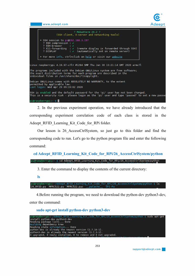
253
2. In the previous experiment operation, we have already introduced that the
corresponding experiment correlation code of each class is stored in the
Adeept_RFID_Learning_Kit_Code_for_RPi folder.
Our lesson is 26_AccessCtrlSystem, so just go to this folder and find the
corresponding code to run. Let's go to the python program file and enter the following
command:
cd Adeept_RFID_Learning_Kit_Code_for_RPi/26_AccessCtrlSystem/python
3. Enter the command to display the contents of the current directory:
ls
4.Before running the program, we need to download the python-dev python3-dev,
enter the command:
sudo apt-get install python-dev python3-dev

254
5.Install SPI-Py library, enter the command:
sudo git clone https://github.com/lthiery/SPI-Py.git
6.enter the command:
sudo raspi-config
7. Press the Enter key to confirm and enter the raspi-config configuration interface
as follows. We can operate through the up, down, left and right keys on the keyboard.
Through the up and down keys, we select item 5: Interfacing Options (connection
options): configure the connection of peripheral devices. Through the left and right
keys, we click "<select>" and press the Enter key to confirm.
8. Then continue to enter the setting interface, we select "P4 SPI" in item 7, select
"<select>" with the left and right keys, and press Enter key to confirm.

255
9. Then the following picture will pop up, we click "<Yes>" through the left and
right keys:
10. Select "<Yes>" and press the Enter key to confirm, a selection box will pop up,
continue to press the Enter key to confirm:

256
11. After confirming, it will jump back to the main interface again. We select
“<Finish>” with the left and right keys and press the Enter key to confirm. It returns
to our command window after completing the settings.
12. After returning to the command window, the following figure is as shown:
13.Enter the command to display the contents of the current directory:
ls
14. enter the command:
cd SPI-Py

257
ls
15. enter the command:
sudo python setup.py install
16.Enter the command to display the contents of the current directory:
ls
17. Enter the command to return to the previous file directory, that is, the python
directory:
cd ..
18.enter the command:
sudo python3 26_RFID.py
Now you should see the joystick state information displayed on the terminal.Now
put the RFID ID card close to the reader and the buzzer will beep. At the same time,
the LED lights up.
19. The physical connection of the experiment is as shown in the following figure:

258

259
Lesson 27 Making the Game Snake
After studying the previous course, everyone is familiar with the use of our
various components. In this lesson, we will teach you to make a particularly fun game
named Snake. We will use two important components containing a PCF8591 and a
PS2 Joystick.
1. Components used in this courseComponents Quantity Picture
Raspberry Pi 1
Breadboard 1
GPIO Extension Board 1
GPIO Cable 1
Male to Male Jumper Wire Several
Male to Female Jumper Wires Several
3 pin jumper wire 1
4 pin jumper wire 1
PS2 Joystick Module 1
PCF8591 1
2. The introduction of the PCF8591 and the PS2
Joystick
(1)The PCF8591 and the working principle of it

260
Please refer to Lesson 23, for we have introduced the PCF8591 in detail in Lesson
23.
(2)The PS2 Joystick and the working principle of it
Please refer to Lesson 25, for we have introduced the PS2 Joystick in detail in
Lesson 25.
3. Making the Game Snake
(1)Wiring diagram (Circuit diagram)
In this course, we used a PCF8591 and a PS2 Joystick. Before the experiment,
we connected them in the circuit as shown in the following figure. When connecting
the circuit, we should pay attention to the difference between positive and negative
electrodes, as shown in the following figure:

261
(2)Making the Game Snake in Python language
The code program used in this lesson is stored in the folder:
Adeept_RFID_Learning_Kit_Code_for_RPi
During the experiment, we need to go to this folder to find the corresponding code
of the course, and then compile and run it before we can test our experiment.
(1) Compile and run the code program of this course
1. First, we opened the software , logged in and connected to ourRaspberry Pi (for the second login, we only need to enter the user name, and pay

262
attention to the correctness of the user name). After successfully logging in, as shown
in the following figure:
2. In the previous experiment operation, we have already introduced that the
corresponding experiment correlation code of each class is stored in the
Adeept_RFID_Learning_Kit_Code_for_RPi folder.
Our lesson is Lesson27_Web_Snake, so just go to this folder and find the
corresponding code to run. Let's go to the python program file and enter the following
command:
cd Adeept_RFID_Learning_Kit_Code_for_RPi/27_Web_Snake/python
3. Enter the command to display the contents of the current directory:
ls
4. Before running the game, we need to install and download flask and
flask-socketio, enter the command:
sudo pip3 install flask flask-socketio
After downloading, as shown in the following figure:

263
5. We need to check the IP address of this machine. We need to use it when we
log in to the web site in a while, enter the command:
ip addr
The inet "192.168.3.157" is the IP address of this machine. This IP address is
different for each machine.
6. Enter the run command:
sudo python3 server.py
The following figure appears to indicate successful operation:
7. Then we need to open the browser and enter the IP address you queried in step
5: http://192.168.3.157:8080
Note: Port 8080 must be entered. After the input is correct, it will jump to the
game interface, as shown below:

264
8. At this time, observe the command window, the following message will appear:
9. Click the START button, and then control the "snake" by swinging the PS2
joystick to find the green dot. When you swing the PS2 joystick in different directions,
the "snake" in the game will also move in the corresponding direction.
10. The physical connection of the experiment is as shown in the following figure:

265
(2) The main code program for making the Game Snake in Python language
on Raspberry Pi
After the hands-on operation above, you must be very interested to know how we
make the Game Snake in Python language on Raspberry Pi. Below we will introduce
how our main code is implemented:
Get the key directions of the PS2 joystick: up, down, left, and right, and then
control the movement of the "snake".

266
4.【Conclusion】In this lesson, we learned about the PCF8591 and the PS2 Joystick. We also
learned how to connect them to a circuit. We made the Game Snake in Python
language on Raspberry Pi, and further studied the programming logic and algorithm
of the code program.

267
Lesson 28 Making the Game Flippy Bird
After studying the previous course, everyone is familiar with the use of our
various components. In this lesson, we will teach you to make a particularly fun game
named Flippy Bird. We will use two important components containing a PCF8591 and
a PS2 Joystick
1. Components used in this courseComponents Quantity Picture
Raspberry Pi 1
Male to Male Jumper Wire Several
Breadboard 1
GPIO Extension Board 1
GPIO Cable 1
Button 1
2. The introduction of the Button
(1) The Button and the working principle of it
Please refer to Lesson 4, for we have introduced the Button in detail in Lesson 4.
3. Making the Game Flippy Bird
(1)Wiring diagram (Circuit diagram)
In this course, we used a Button. Before the experiment, we connected them in the
circuit as shown in the following figure. When connecting the circuit, we should pay
attention to the difference between positive and negative electrodes, as shown in the

268
following figure:
(2)Making the Game Flippy Bird in Python languageThe code program used in this lesson is stored in the folder:

269
Adeept_RFID_Learning_Kit_Code_for_RPi
During the experiment, we need to go to this folder to find the corresponding code
of the course, and then compile and run it before we can test our experiment.
(1) Compile and run the code program of this course
1. First, we opened the software , logged in and connected to ourRaspberry Pi (for the second login, we only need to enter the user name, and pay
attention to the correctness of the user name). After successfully logging in, as shown
in the following figure:
2. In the previous experiment operation, we have already introduced that the
corresponding experiment correlation code of each class is stored in the
Adeept_RFID_Learning_Kit_Code_for_RPi folder.
Our lessonis 28_Web_Flippy_bird, so just go to this folder and find the
corresponding code to run. Let's go to the python program file and enter the following
command:
cd Adeept_RFID_Learning_Kit_Code_for_RPi/28_Web_Flippy_bird/python
3. Enter the command to display the contents of the current directory:

270
ls
4. Before running the game, we need to install and download flask and
flask-socketio, enter the command:
sudo pip3 install flask flask-socketio
After downloading, as shown in the following figure:
5. We need to check the IP address of this machine. We need to use it when we
log in to the web site in a while, enter the command:
ip addr
The inet "192.168.3.157" is the IP address of this machine. This IP address is
different for each machine.
6. Enter the run command:
sudo python3 server.py
The following figure appears to indicate successful operation:

271
7. Then we need to open the browser and enter the IP address you queried in step
5: http://192.168.3.157:8080
Note: Port 8080 must be entered. After the input is correct, it will jump to the
game interface, as shown below:

272
8. At this time, observe the command window, the following message will appear:

273
9. Try to press the Button, you can operate our game. The physical connection of
the experiment is as shown in the following figure:
(2) The main code program for making the Game Flippy Bird in Python
language on Raspberry Pi
After the hands-on operation above, you must be very interested to know how we
make the Game Flippy Bird in Python language on Raspberry Pi. Below we will
introduce how our main code is implemented:
Determine the state of the Button, when it is pressed, you can control the
movement of the game bird.
4.【Conclusion】

274
In this lesson, we learned about the Button module. We also learned how to
connect it to a circuit. We made the Game Flippy Bird with Button in C language and
Python language, and further studied the programming logic and algorithm of the
code program.

275
Lesson 29 Making the Game Named Play Bricks
After studying the previous course, everyone is familiar with the use of our
various components. In this lesson, we will teach you to make a particularly fun game
named Play Bricks. We will use two important components containing a PCF8591 and
a PS2 Joystick
1. Components used in this courseComponents Quantity Picture
Raspberry Pi 1
Breadboard 1
GPIO Extension Board 1
GPIO Cable 1
Male to Male Jumper Wire Several
3 pin jumper wire 1
4 pin jumper wire 1
PS2 Joystick Module 1
PCF8591 1
2. The introduction of the PCF8591 and the PS2
Joystick
(1)The PCF8591 and the working principle of it
Please refer to Lesson 23, for we have introduced the PCF8591 in detail in Lesson

276
23.
(2)The PS2 Joystick and the working principle of it
Please refer to Lesson 25, for we have introduced the PS2 Joystick in detail in
Lesson 25.
3. Making the Game Named Play Bricks
(1)Wiring diagram (Circuit diagram)
In this course, we used a PCF8591 and a PS2 Joystick. Before the experiment,
we connected them in the circuit as shown in the following figure. When connecting
the circuit, we should pay attention to the difference between positive and negative
electrodes, as shown in the following figure:

277
(2)Making the Game Named Play Bricks in Python language
【Note】
This lesson is special. We need to use an HDMI cable to connect the monitor via
the HDMI pin on the Raspberry Pi, and then supply power to the Raspberry Pi,
connect the mouse and keyboard, so that we can carry out the following experiment.

278
The code program used in this lesson is stored in the folder:
Adeept_RFID_Learning_Kit_Code_for_RPi
During the experiment, we need to go to this folder to find the corresponding code
of the course, and then compile and run it before we can test our experiment.
(1) Compile and run the code program of this course
1. After successfully connecting the monitor, the interface for the first connection is
as shown in the following figure, and then we click the icon shown by the arrow.

279
2. After clicking, a command window will pop up, we enter the directory of the
corresponding course in the command. In the previous experiment operation, we have
already introduced that the corresponding experiment correlation code of each class is
stored in the Adeept_RFID_Learning_Kit_Code_for_RPi folder.
Our lesson is 29_Web_PlayBricks, so just go to this folder and find the
corresponding code to run. Let's go to the python program file and enter the following
command:
cd Adeept_RFID_Learning_Kit_Code_for_RPi /29_Web_PlayBricks/python

280
3. Enter the command to display the contents of the current directory:
ls
sudo python3 main.py
4. The following picture appears to indicate successful operation, and then we
can control our game running through the PS2 Joystick.

281
5. The physical connection of the experiment is as shown in the following figure:
(2) Main code program for making the game in Python language on Raspberry
Pi
After the hands-on operation above, you must be very interested to know how we
make the game in Python language on Raspberry Pi. Below we will introduce how
our main code is implemented:
1. Test keyboard keys to judge and control the movement of the game.

282
2. Detect the collision and related operations of the game, and judge the progress
and end of the game.
4.【Conclusion】In this lesson, we learned about the PCF8591 and the PS2 Joystick. We also
learned how to connect them to a circuit. We made the Game Play Bricks in C
language and Python language, and further studied the programming logic and
algorithm of the code program.

283
Lesson 30 Making a Calculator
After studying the previous course, everyone is familiar with the use of our
various components. In this lesson, we will teach you to make a particularly fun
calculator. We will use two important components containing a 4x4 Matrix Keyboard
and a LCD1602.
1. Components used in this courseComponents Quantity Picture
Raspberry Pi 1
Breadboard 1
GPIO Extension Board 1
GPIO Cable 1
Male to Male Jumper Wire Several
jumper wire Several
4 pin jumper wire 1
4*4 Matrix Keyboard 1
LCD1602 + I2C 1
2. The introduction of the 4x4 Matrix Keyboard and
the LCD1602
(1) The 4x4 Matrix Keyboard and the working principle of it

284
Please refer to Lesson 11, for we have introduced the 4x4 Matrix Keyboard in
detail in Lesson 11.
【Note】
We know that there are no operation symbols on the 4*4 Matrix Keyboard, so we
need to use some symbols as operators. As shown in the following table:
Original symbol Function
A +
B -
C *
D /
# =
* delete
(2) The LCD1602 and the working principle of it
Please refer to Lesson 18, for we have introduced the LCD1602 in detail in Lesson
18.
3. Making a calculator
(1)Wiring diagram (Circuit diagram)
In this course, we used a LCD1602 Module and a 4x4 Matrix Keyboard. Before
the experiment, we connected them in the circuit as shown in the following figure.
When connecting the circuit, we should pay attention to the difference between
positive and negative electrodes, as shown in the following figure:

285

286
(2)Making a calculator in Python language
The code program used in this lesson is stored in the folder:
Adeept_RFID_Learning_Kit_Code_for_RPi
During the experiment, we need to go to this folder to find the corresponding code
of the course, and then compile and run it before we can test our experiment.
(1) Compile and run the code program of this course
1. First, we opened the software , logged in and connected to ourRaspberry Pi (for the second login, we only need to enter the user name, and pay
attention to the correctness of the user name). After successfully logging in, as shown
in the following figure:

287
2. In the previous experiment operation, we have already introduced that the
corresponding experiment correlation code of each class is stored in the
Adeept_RFID_Learning_Kit_Code_for_RPi folder.
Our lesson is 30_Simple_calculator, so just go to this folder and find the
corresponding code to run. Let's go to the python program file and enter the following
command:
cd Adeept_RFID_Learning_Kit_Code_for_RPi/30_Simple_calculator/python
3. Enter the command to display the contents of the current directory:
ls
4. Enter the run command:
sudo python3 30_Simple_calculator.py
We press 1 on the button, then press ‘A’ for +, then press 2, and finally press ‘#’
for equal. The results as shown in the figure below indicate successful operation:

288
5. The physical connection of the experiment is as shown in the following figure:
(2)The main code program for making a calculator in Python language on
Raspberry Pi
After the hands-on operation above, you must be very interested to know how we
make a calculator in Python language on Raspberry Pi. Below we will introduce how
our main code is implemented:
Scan and judge the keys/buttons pressed and make corresponding calculations.

289
4.【Conclusion】In this lesson, we learned about the 4x4 Matrix Keyboard and the LCD1602. We
also learned how to connect them to a circuit. We programmed and made a calculator
in C language and Python language on Raspberry Pi, and further studied the
programming logic and algorithm of the code program.

290