Ultima® X Series Gas Monitors
142
Installation & Maintenance Instructions Ultima® X Series Gas Monitors Reading Tel: +44 (0)118 9311188 | Email: [email protected] Aberdeen Tel: +44 (0)1224 725999 | Email: [email protected] Registered Address ABLE Instruments & Controls Ltd Cutbush Park, Danehill, Lower Earley, Reading, Berkshire, RG6 4UT. UK. Web able.co.uk E-commerce 247able.com
-
Upload
khangminh22 -
Category
Documents
-
view
0 -
download
0
Transcript of Ultima® X Series Gas Monitors

Installation & Maintenance Instructions
Ultima® X Series Gas Monitors
ReadingTel: +44 (0)118 9311188 | Email: [email protected]
AberdeenTel: +44 (0)1224 725999 | Email: [email protected]
Registered AddressABLE Instruments & Controls LtdCutbush Park, Danehill, Lower Earley, Reading, Berkshire, RG6 4UT. UK.
Webable.co.uk
E-commerce247able.com

Ultima® X SeriesGas MonitorsInstruction Manual
In North America, to contact your nearest stocking location, dial toll-free 1-800-MSA-INST.
To contact MSA International, dial (724) 776-8626.
Inquiries can also be e-mailed to [email protected].
© MSA 2014 - All Rights Reserved
This manual is available on the internet at www.msaSafety.com
Manufactured by
MSA NORTH AMERICA1000 Cranberry Woods Drive, Cranberry Township, PA 16066
(L) -Y Rev 9 10036101

THIS MANUAL MUST BE CAREFULLY READ BY ALL INDIVIDUALS WHO HAVE OR WILL
HAVE THE RESPONSIBILITY FOR USING OR SERVICING THE PRODUCT. Like any piece
of complex equipment, this instrument will perform as designed only if it is used and serv-
iced in accordance with the manufacturer’s instructions. OTHERWISE, IT COULD FAIL TO
PERFORM AS DESIGNED AND PERSONS WHO RELY ON THIS PRODUCT FOR THEIR
SAFETY COULD SUSTAIN SEVERE PERSONAL INJURY OR LOSS OF LIFE.
The warranties made by Mine Safety Appliances Company with respect to the product are
voided if the product is not used and serviced in accordance with the instructions in this
manual. Please protect yourself and others by following them. We encourage our cus-
tomers to write or call regarding this equipment prior to use or for any additional infor-
mation relative to use or service.
MSA Instrument Warranty1. Warranty- Seller warrants that this product will be free from
mechanical defect or faulty workmanship for the following periods:
• Gas Monitor: eighteen (18) months from date of shipment orone (1) year from installation, whichever occurs first
• Oxygen, Toxic or Catalytic Combustible Sensor: eighteen (18)months from date of shipment or one (1) year from installation,whichever occurs first
• IR Sensor source: ten (10) years from date of shipment.All other IR components: two (2) years from date of shipment.
This warranty is applicable provided the product is maintained andused in accordance with Seller's instructions and/orrecommendations. This warranty does not apply to expendable orconsumable parts whose normal life expectancy is less than one(1) year. The Seller shall be released from all obligations under thiswarranty in the event repairs or modifications are made by personsother than its own or authorized service personnel or if thewarranty claim results from physical abuse or misuse of theproduct. No agent, employee or representative of the Seller hasany authority to bind the Seller to any affirmation, representation orwarranty concerning the goods sold under this contract. Sellermakes no warranty concerning components or accessories notmanufactured by the Seller, but will pass on to the Purchaser allwarranties of manufacturers of such components. THISWARRANTY IS IN LIEU OF ALL OTHER WARRANTIES,EXPRESSED, IMPLIED OR STATUTORY, AND IS STRICTLYLIMITED TO THE TERMS HEREOF. SELLER SPECIFICALLYDISCLAIMS ANY WARRANTY OF MERCHANTABILITY OR OFFITNESS FOR A PARTICULAR PURPOSE.
"! WARNING

NOTE: This equipment has been tested and found to comply withthe limits for a Class A digital device, pursuant to part 15 ofthe FCC Rules. These limits are designed to provide rea-sonable protection against harmful interference when theequipment is operated in a commercial environment. Thisequipment generates, uses, and can radiate radio frequen-cy energy and, if not installed and used in accordance withthe instruction manual, may cause harmful interference toradio communications. Operation of this equipment in aresidential area is likely to cause harmful interference, inwhich case the user will be required to correct the interfer-ence at his own expense.
This is a class A product in accordance with CISPR 22. In adomestic environment, this product may cause radio inter-ference, in which case the user may be required to take ade-quate measures.
2. Exclusive Remedy- It is expressly agreed that Purchaser's soleand exclusive remedy for breach of the above warranty, for anytortious conduct of Seller, or for any other cause of action, shall bethe repair and/or replacement at Seller's option, of any equipmentor parts thereof, which after examination by Seller is proven to bedefective. Replacement equipment and/or parts will be provided atno cost to Purchaser, F.O.B. Seller's Plant. Failure of Seller tosuccessfully repair any nonconforming product shall not cause theremedy established hereby to fail of its essential purpose.
3. Exclusion of Consequential Damage- Purchaser specificallyunderstands and agrees that under no circumstances will seller beliable to purchaser for economic, special, incidental orconsequential damages or losses of any kind whatsoever, includingbut not limited to, loss of anticipated profits and any other losscaused by reason of nonoperation of the goods. This exclusion isapplicable to claims for breach of warranty, tortious conduct or anyother cause of action against seller.
" WARNING
i

General Warnings and Cautions
1. The Ultima X Series Gas Monitors described in this manual mustbe installed, operated and maintained in strict accordance withtheir labels, cautions, warnings, instructions, and within limitationsstated. Verify that the class, group, and temperature ratings of theequipment agree with the actual classification of the location.
2. The Ultima X Series Gas Monitor is designed to detect gases orvapors in air. It cannot measure the concentration of gases orvapors in steam or inert or oxygen-deficient atmospheres. Theoxygen sensor can measure oxygen-deficient atmospheres.
3. Electrochemical sensors are sealed units which contain a corrosiveelectrolyte. Should a sensor develop leakage, it must beimmediately removed from service; then, remove it from thesensing head and discard it properly. Caution must be exercised sothat the electrolyte does not contact skin, eyes, clothing or circuitry;otherwise, serious personal injury (burns) and/or equipmentdamage may result.
4. Use only genuine MSA replacement parts when performing anymaintenance procedures provided in this manual. Failure to do somay seriously impair instrument performance. Repair or alterationof the Ultima X Series Gas Monitor, beyond the scope of thesemaintenance instructions or by anyone other than an authorizedMSA service personnel, could cause the product to fail to performas designed and persons who rely on this product for their safetycould sustain serious personal injury or loss of life.
5. Do not locate the general-purpose enclosure models in an areawhich may contain a flammable mixture of gas and air; otherwise,an explosion may occur. The general-purpose Ultima X Series GasMonitors can be a source of ignition and must not be mounted inan area where a flammable mixture of combustible gas and airmay become present; otherwise, an explosion may occur. If such alocation must be monitored, use an explosion-proof Ultima XSeries Gas Monitor model.
6. The Ultima XIR Infrared combustible gas monitor detects thepresence of most combustible gases by identifying the difference inthe amount of infrared light energy absorbed during the presenceof these gases. This monitor, however, does NOT detect thepresence of hydrogen gas and must never be used to monitor forhydrogen gas.
7. The standard Ultima XIR Infrared Combustible Gas Monitor does
" WARNING
ii

not detect the presence of acetylene gas and the presence ofacetylene gas will degrade sensor performance. Custom-builtacetylene sensors are available through your MSA representative.
8. Gas detectors depend on an unimpeded gas flow for properoperation. In environments where contamination is possible,ensure that the flow remains unobstructed at the sensor. Failure tofollow this may prevent gas detection and generate inaccuratereadings.
9. CSA performance Certification to standard C22.2 No. 152 is validonly when the instrument is calibrated on methane per theinstruction manual.
10. Install Product in accordance with all markings and the regulationsof the country in use.
11. Product components may have different hazardous locationratings. Ensure all components are suitable for the area ofinstallation and protection technique.
Failure to follow the above can result in serious personal injury or loss of life.
1. As with all gas monitors of these types, high levels of, or longexposure to, certain compounds in the tested atmosphere couldcontaminate the sensors. In atmospheres where an Ultima XSeries Gas Monitor may be exposed to such materials, calibrationmust be performed frequently to ensure that operation isdependable and display indications are accurate.
2. The Ultima X Series Gas Monitor must not be painted. If painting isdone in an area where a Monitor is located, care must beexercised to ensure that paint is not deposited on the sintered,metal flashback arrestor in the inlet fitting of the Ultima X SeriesGas Monitor, if so equipped. Such paint deposits would interferewith the diffusion process, whereby a sample of the atmospherebeing monitored diffuses into the Monitor.
3. The only absolute method to ensure proper overall operation of anUltima X Series Monitor is to check it with a known concentrationof the gas for which it has been calibrated. Consequently,calibration checks must be included as part of the routineinspection of the system.
4. Protect the Ultima X Series Gas Monitor from extreme vibration.Do not mount the sensing head in direct sunlight as this may causeoverheating of the sensor.
Failure to follow the above can result in injury, product damage and/or an unsafecondition.
" CAUTION
iii

Table of Contents
Chapter 1, Installation . . . . . . . . . . . . . . . . . . . . . . . . . . . . . .1-1
General Description . . . . . . . . . . . . . . . . . . . . . . . . . . . . . . . . .1-1
Identifying Your Unit . . . . . . . . . . . . . . . . . . . . . . . . . . . . . . . .1-1
Installing Your Gas Monitor . . . . . . . . . . . . . . . . . . . . . . . . . . .1-5
Installing the Ultima XA Gas Monitor . . . . . . . . . . . . . .1-6
Installing the Ultima XE Gas Monitor . . . . . . . . . . . . . .1-6
Installing the Ultima XIR Gas Monitor . . . . . . . . . . . . .1-8
Electrical Connections for Ultima X Gas Monitors . . . . . . . . .1-9
Wiring for all Models . . . . . . . . . . . . . . . . . . . . . . . . .1-10
Use of External Controllers . . . . . . . . . . . . . . . . . . . . . . . . . .1-12
Identify PCB Configuration . . . . . . . . . . . . . . . . . . . . . . . . . .1-13
Installing the Ultima X Remote Sensor Module . . . . . . . . . .1-20
Electrical Connections for Remote Sensors . . . . . . . . . . . . .1-21
Chapter 2, Start-up and Calibration . . . . . . . . . . . . . . . . . . .2-1
Initial Start-up . . . . . . . . . . . . . . . . . . . . . . . . . . . . . . . . . . . . . .2-1
Calibration Basics . . . . . . . . . . . . . . . . . . . . . . . . . . . . . . . . . .2-4
Ultima Calibrator . . . . . . . . . . . . . . . . . . . . . . . . . . . . .2-6
Ultima Controller . . . . . . . . . . . . . . . . . . . . . . . . . . . . .2-6
Calibration Output Signal . . . . . . . . . . . . . . . . . . . . . . .2-6
Calibration Kit . . . . . . . . . . . . . . . . . . . . . . . . . . . . . . .2-7
Ultima X Series Gas Monitor Calibration Procedure . . . . . . . .2-7
Equipment Required . . . . . . . . . . . . . . . . . . . . . . . . . .2-8
Span Gas Values . . . . . . . . . . . . . . . . . . . . . . . . . . . . .2-9
INITIAL Calibration . . . . . . . . . . . . . . . . . . . . . . . . . . .2-12
Standard Calibration . . . . . . . . . . . . . . . . . . . . . . . . .2-13
OXYGEN Calibration . . . . . . . . . . . . . . . . . . . . . . . . .2-18
XIR Calibration . . . . . . . . . . . . . . . . . . . . . . . . . . . . . .2-18
iv

Chapter 3,Specifications . . . . . . . . . . . . . . . . . . . . . . . . . . . .3-1
Chapter 4, Maintenance . . . . . . . . . . . . . . . . . . . .4-1
General . . . . . . . . . . . . . . . . . . . . . . . . . . . . . . . . . . . . . . .4-1
Ultima XIR Cleaning Procedure . . . . . . . . . . . . . . . . . . . . . . .4-4
Replacing an Ultima XE or Ultima XA Sensor . . . . . . . . . . . .4-5
Obtaining Replacement Parts . . . . . . . . . . . . . . . . . . . . . . . . .4-8
Appendix A,Optional Features . . . . . . . . . . . . . . . . . . . . . . . .A-1
1) Internal Relays . . . . . . . . . . . . . . . . . . . . . . . . . . . . . . . . . .A-1
General Information . . . . . . . . . . . . . . . . . . . . . . . . . . .A-1
Unpacking, Mounting and Wiring . . . . . . . . . . . . . . . .A-1
Ultima X Series Gas Monitor Internal Relays . . . . . . .A-2
Relay Specifications . . . . . . . . . . . . . . . . . . . . . . . . . .A-2
Alarm Relays . . . . . . . . . . . . . . . . . . . . . . . . . . . . . . . .A-3
Fault Relay or Trouble . . . . . . . . . . . . . . . . . . . . . . . . .A-4
Relay Connections . . . . . . . . . . . . . . . . . . . . . . . . . . .A-5
2) Optional RESET Push-button . . . . . . . . . . . . . . . . . . . . . . .A-7
General . . . . . . . . . . . . . . . . . . . . . . . . . . . . . . . . . . . .A-7
RESET Button Selection . . . . . . . . . . . . . . . . . . . . . . .A-7
Optional Push-button Calibration . . . . . . . . . . . . . . . .A-8
3) Optional Horn Relay Software . . . . . . . . . . . . . . . . . . . . . .A-9
To Activate the Horn Relay . . . . . . . . . . . . . . . . . . . . .A-9
To Reset the Horn Relay . . . . . . . . . . . . . . . . . . . . . . .A-9
Appendix B,Calibration Guide for Additional XIR/XI Gases .B-1
Appendix C,General Certification Information . . . . . . . . . . .C-1
v

Appendix D,HART Specific Information . . . . . . . . . . . . . . . . .D-1
HART Field Device Specification . . . . . . . . . . . . . . . . . . . . . .D-1
Host Interface . . . . . . . . . . . . . . . . . . . . . . . . . . . . . . .D-2
Status Information . . . . . . . . . . . . . . . . . . . . . . . . . . . .D-3
Extended Device Status . . . . . . . . . . . . . . . . . . . . . . .D-3
Universal Commands . . . . . . . . . . . . . . . . . . . . . . . . .D-5
Common-Practice Commands . . . . . . . . . . . . . . . . . .D-5
Burst Mode . . . . . . . . . . . . . . . . . . . . . . . . . . . . . . . . .D-6
Catch Device Variable . . . . . . . . . . . . . . . . . . . . . . . . .D-6
Command #129: Read Sensor Gas Type . . . . . . . . . .D-7
Command #130: Read Device Real Time Clock . . . .D-7
Command #131: Read Alarm Setpoints . . . . . . . . . . .D-8
Command #132: Read Alarm Control Actions . . . . . .D-9
Command #133: Read Min, Max, Avg Values . . . . . .D-9
Command #134: Read Last Cal Date . . . . . . . . . . . .D-10
Command #135: Read Gas Table . . . . . . . . . . . . . . .D-10
Command #136: Read Input Voltage Value . . . . . . .D-10
Command #137: Read Auto Zero Comp Value . . . .D-11
Command #139: Read Sensor Status message . . . .D-11
Command #140: Read Swap Delay Status . . . . . . .D-11
Command #141: Read Cal Signal Status . . . . . . . . .D-12
Command #142: Read Alert Option Status . . . . . . . .D-12
Command #143: Read Sensor Temperature . . . . . .D-13
Command #144: Read Relay Normal State . . . . . . .D-13
Command #173: Write RTC . . . . . . . . . . . . . . . . . . .D-14
Command #174: Write Alarm Setpoints . . . . . . . . . .D-15
Command #175: Write Alarm Setpoint
Control Actions . . . . . . . . . . . . . . . . . . . . . . . . . . . . .D-16
Command #176: Write Average Interval . . . . . . . . . .D-17
Command #177: Write Upper Trim Point . . . . . . . . .D-18
Command #178: Write Gas Table . . . . . . . . . . . . . . .D-19
Command #179: Write Sensor Data Sheet
Reset Control . . . . . . . . . . . . . . . . . . . . . . . . . . . . . .D-20
Command #180: Write Sensor Swap Delay Enable .D-21
Command #181: Write Cal Signal Enable . . . . . . . .D-22
Command #182: Write Calibration Mode . . . . . . . . .D-23
Command #183: Write Calibration Abort . . . . . . . . .D-24
Command #184: Write Calibration Step . . . . . . . . . .D-25
vi

Command #185: Write Alarm Acknowledge . . . . . . .D-26
Command #186: Write Protect Mode . . . . . . . . . . . .D-27
Command #187: Write Alert Option . . . . . . . . . . . . .D-28
Command #188: Write Relay Normal State . . . . . . .D-29
Performance . . . . . . . . . . . . . . . . . . . . . . . . . . . . . . .D-32
Power-Up . . . . . . . . . . . . . . . . . . . . . . . . . . . . . . . . .D-32
Reset . . . . . . . . . . . . . . . . . . . . . . . . . . . . . . . . . . . . .D-32
Self-Test . . . . . . . . . . . . . . . . . . . . . . . . . . . . . . . . . .D-32
Busy and Delayed-Response . . . . . . . . . . . . . . . . . .D-33
Long Messages . . . . . . . . . . . . . . . . . . . . . . . . . . . . .D-33
Non-Volatile Memory . . . . . . . . . . . . . . . . . . . . . . . . .D-33
Modes . . . . . . . . . . . . . . . . . . . . . . . . . . . . . . . . . . . .D-34
Write Protection . . . . . . . . . . . . . . . . . . . . . . . . . . . . .D-34
Damping . . . . . . . . . . . . . . . . . . . . . . . . . . . . . . . . . .D-34
Capability Checklist . . . . . . . . . . . . . . . . . . . . . . . . . . . . . . . .D-34
Default Configuration . . . . . . . . . . . . . . . . . . . . . . . . . . . . . .D-35
Calibration Using a HART® Communicator . . . . . . . . . . . . .D-35
Sensor Zero Selection Menu . . . . . . . . . . . . . . . . . .D-35
Standard Zero/Span Calibration Selection Menu . . .D-37
Initial Calibration Procedures . . . . . . . . . . . . . . . . . .D-40
User Calibration Selection Menu . . . . . . . . . . . . . . .D-40
Troubleshooting . . . . . . . . . . . . . . . . . . . . . . . . . . . . . . . . . .D-54
Span Fault . . . . . . . . . . . . . . . . . . . . . . . . . . . . . . . . .D-54
Zero Fault . . . . . . . . . . . . . . . . . . . . . . . . . . . . . . . . .D-57
vii

List of Figures
Figure 1-1. General-Purpose Ultima XA Monitor . . . . . . . . . .1-1
Figure 1-2. -Proof Ultima XE Monitor . . . . . . . . . . . . . . . . . . .1-2
Figure 1-3. Explosion-Proof Ultima XIR Monitor . . . . . . . . . . .1-2
Figure 1-4. General-Purpose XA Remote Sensor Module . . .1-3
Figure 1-5. Explosion-Proof XE Remote Sensor Module . . . .1-3
Figure 1-6. Explosion-Proof XIR Remote Sensor Module . . .1-4
Figure 1-7. Ultima XE and XIR Mounting Bracket . . . . . . . . .1-7
Figure 1-8. Ultima XIR . . . . . . . . . . . . . . . . . . . . . . . . . . . . . . .1-8
Figure 1-9. Ultima XE Grounding Terminals . . . . . . . . . . . . . .1-9
Figure 1-10. General-Purpose Two-Wire Operation . . . . . . .1-14
Figure 1-11. Explosion-Proof Two-Wire Operation . . . . . . . .1-14
Figure 1-12. General-Purpose Three-Wire Operation . . . . . .1-15
Figure 1-13. Explosion-Proof Three-Wire Operation . . . . . . .1-15
Figure 1-14. Two-Wire Printed Circuit Board
(no HART Protocol) . . . . . . . . . . . . . . . . . . . . . .1-16
Figure 1-15. Two-Wire Printed Circuit Board
(with HART Protocol) . . . . . . . . . . . . . . . . . . . . .1-17
Figure 1-16. Three-Wire Printed Circuit Board
(no HART Protocol) . . . . . . . . . . . . . . . . . . . . . .1-18
Figure 1-17. Three-Wire Printed Circuit Board
(with HART Protocol) . . . . . . . . . . . . . . . . . . . . .1-19
Figure 1-18. Remote Module General-Purpose
Ultima X Series Wiring . . . . . . . . . . . . . . . . . . . .1-20
Figure 1-19. Remote Module Explosion-Proof
Ultima X Series Wiring . . . . . . . . . . . . . . . . . . . .1-20
Figure 2-1. LCD Gas Concentration Display . . . . . . . . . . . . . .2-1
Figure 2-2. Ultima Calibrator . . . . . . . . . . . . . . . . . . . . . . . . . .2-5
Figure 2-3. Ultima Controller . . . . . . . . . . . . . . . . . . . . . . . . . .2-5
Figure 2-4. Ultima X Optional Push-button Calibrator . . . . . . .2-5
Figure 2-5. Apply ZERO Gas Flag . . . . . . . . . . . . . . . . . . . .2-14
Figure 2-6. Apply SPAN Gas Flag . . . . . . . . . . . . . . . . . . . . .2-15
Figure 2-7. Calibration End Display . . . . . . . . . . . . . . . . . . .2-17
Figure 4-1. "Change Sensor" Scrolls Across the Display . . . .4-6
Figure 4-2. Sensor Assembly and Sensor Guard
for General-Purpose Model . . . . . . . . . . . . . . . . .4-7
Figure A-1. Relay Contacts . . . . . . . . . . . . . . . . . . . . . . . . . . .A-4
Figure A-2. Relay Printed Circuit Board . . . . . . . . . . . . . . . . .A-6
Figure D-1. Zero cal step screen . . . . . . . . . . . . . . . . . . . . .D-41
viii
Figure D-2. Span cal step screen . . . . . . . . . . . . . . . . . . . . .D-41
Figure D-3. Select Sensor Calibration
from the Sensor Trim Menu . . . . . . . . . . . . . . . .D-42
Figure D-4. First Warning screen . . . . . . . . . . . . . . . . . . . . .D-43
Figure D-5. Second Warning screen . . . . . . . . . . . . . . . . . .D-44
Figure D-6. Standard Calibration function select screen . . .D-45
Figure D-7. Calibration initiated screen . . . . . . . . . . . . . . . .D-46
Figure D-8. Selection Confirmation screen . . . . . . . . . . . . . .D-47
Figure D-9. Sensor Zero Countdown screen . . . . . . . . . . . .D-48
Figure D-10. Zero Adjustment screen . . . . . . . . . . . . . . . . . .D-49
Figure D-11. Span Countdown screen . . . . . . . . . . . . . . . . .D-50
Figure D-12. Adjusting Span screen . . . . . . . . . . . . . . . . . . .D-51
Figure D-13. Calibration Completion message . . . . . . . . . . .D-52
Figure D-14. Calibration Gas Reminder screen . . . . . . . . . .D-53
Figure D-15. Loop Control Reminder message . . . . . . . . . .D-54
Figure D-16. Calibration Status screen . . . . . . . . . . . . . . . . .D-55
Figure D-17. Sensor Trim Point screen . . . . . . . . . . . . . . . .D-56
Figure D-18. Additional Sensor Status screen . . . . . . . . . . .D-57
Figure D-19. Device Status screen . . . . . . . . . . . . . . . . . . . .D-58
ix

List of TablesTable 1-1. Installation Outline Drawing List . . . . . . . . . . . . . .1-10
Table 1-2. Cable Length and Wire Size for Units without
Internal Relays . . . . . . . . . . . . . . . . . . . . . . . . . .1-11
Table 1-3. Installation Outline Drawings
for Ultima X Power Supplies . . . . . . . . . . . . . . .1-12
Table 1-4. Remote Module Wiring and Placement . . . . . . . .1-22
Table 1-5. Remote Sensor Wiring Cable . . . . . . . . . . . . . . . .1-22
Table 1-6. Low Temperature Wiring Cable . . . . . . . . . . . . . .1-22
Table 2-1. Instrument Operation . . . . . . . . . . . . . . . . . . . . . . .2-2
Table 2-2. Factory-set Span Values . . . . . . . . . . . . . . . . . . . .2-9
Table 2-3. Calibration Guide for Combustible Gas Sensor . .2-11
Table 3-1. Performance Specifications . . . . . . . . . . . . . . . . . .3-1
Table 3-2. Sensor Response to Interferants . . . . . . . . . . . . . .3-4
Table 4-1. Operational Display Messages . . . . . . . . . . . . . . . .4-1
Table 4-2. Configuration Display Messages . . . . . . . . . . . . . .4-2
Table 4-3. Troubleshooting Guidelines . . . . . . . . . . . . . . . . . .4-2
Table 4-4. Replacement Parts . . . . . . . . . . . . . . . . . . . . . . . . .4-8
Table A-1. Power Cable Distances for the Ultima X
Series Gas Monitor with Internal Relays . . . . . .A-2
Table A-2. Relay Specifications . . . . . . . . . . . . . . . . . . . . . . . .A-2
Table A-3. Push-button Calibration . . . . . . . . . . . . . . . . . . . . .A-8
Table D-1. Device Identification . . . . . . . . . . . . . . . . . . . . . . .D-1
Table D-2. Current Values . . . . . . . . . . . . . . . . . . . . . . . . . . . .D-2
Table D-3. Device Variables Exposed by the Ultima Monitor .D-3
Table D-4. Dynamic Variable implemented by Ultima Monitor D-3
Table D-5. Additional Device Status (Command #48) . . . . . .D-4
Table D-6. Supported Commands . . . . . . . . . . . . . . . . . . . . .D-6
Table D-7. Device-Specific Commands . . . . . . . . . . . . . . . . .D-7
Table D-8. Gas Type Descriptions . . . . . . . . . . . . . . . . . . . .D-30
Table D-9. Alarm Control Actions . . . . . . . . . . . . . . . . . . . . .D-30
Table D-10. Gas Table Values . . . . . . . . . . . . . . . . . . . . . . .D-30
Table D-11. Calibration Modes . . . . . . . . . . . . . . . . . . . . . . .D-31
Table D-12. Sensor Status Codes . . . . . . . . . . . . . . . . . . . .D-31
Table D-13. Sampling Rates . . . . . . . . . . . . . . . . . . . . . . . . .D-32
Table D-14. Command Response Times . . . . . . . . . . . . . . .D-33
Table D-15. Capability Checklist . . . . . . . . . . . . . . . . . . . . . .D-34
Table D-16. Default Configuration . . . . . . . . . . . . . . . . . . . .D-35
x

1-1
Chapter 1, Installation
General Description
The Ultima X Series Gas Monitor is designed to sample theenvironment where mounted and alert you to potentially dangerouslevels of your target gas, depending on your particular model. TheUltima X Series device uses various detection methods, depending onthe gas of interest. Detection methods can be electrochemical, infrared,pellement or other technologies. The Ultima XE Gas Monitor is anexplosion-proof device suitable for installation in hazardous locations.The Ultima XA Gas Monitor is a general-purpose version in a plasticenclosure for use in nonexplosive atmospheres only. The Ultima X GasMonitor can be ordered with the standard 4 to 20 mA analog output orwith an optional HART (Highway Addressable Remote Transducer)protocol, which is superimposed on the 4 to 20 mA signal. The unit isfactory-calibrated and shipped ready for installation.
The main sensor input is provided via a five-terminal interface thatprovides a digital interface for 3 VDC or 5 VDC sensor modules. Manydifferent sensor modules are available, providing sensing capability for alarge variety of gases. The operating range varies with the type of cell(e.g., electrochemical, pellistor or infrared combustible, etc.).
Identifying Your Unit
The Ultima XA Gas Monitor is housed in a rugged, plastic general-purpose enclosure (FIGURE 1-1).
Figure 1-1. General-Purpose Ultima XA Monitor

The Ultima XE Gas Monitor is housed in a 316 stainless steelexplosion-proof enclosure (FIGURE 1-2 shows the Ultima XE with the optional explosion-proof HART port).
.
The Ultima XIR Gas Monitor is housed in a 316 stainless steelexplosion-proof enclosure (FIGURE 1-3).
If your application requires the sensor head to be located separatelyfrom the control unit, all models are available with Remote SensorModules (shown in FIGURES 1-4, 1-5 and 1-6).
Figure 1-3. Explosion-Proof Ultima XIR Monitor
Figure 1-2. Explosion-Proof Ultima XE Monitor
1-2

Figure 1-5. Explosion-Proof XE Remote Sensor Module
Figure 1-4. General-Purpose XA Remote Sensor Module
1-3

To determine your sensor type and options, check the shipping carton.Checked items are included in the carton. The carton label identifies:
• Type of unit supplied (Gas Monitor, Gas Monitor Less Sensor, orRemote Sensor Module)
• Type of gas (combustible gas, toxic gas or oxygen)
• Range [% LEL, PPM (parts per million), or %]
• Output (2- or 3-wire, 4 to 20 mA, or 4 to 20 mA with HART)
• Any options such as internal relays and/or LEDs.
• If your unit contains internal relays, see Appendix A.
Also check the sensor ID label located on the inside of the sensor. Thiscan be viewed by unscrewing the lower portion of the sensor. Ifperforming this while the unit is powered, see the following Warning.The sensor ID label identifies the detectable gas and the gas range.
For Ultima XE sensors marked Class I, Groups A, B, C and Dand not used in Class II areas, unscrew sensor cap at leastthree full turns (but no more than four full turns from itstightly-closed position), wait 10 seconds, and then removecap completely. Failure to follow this warning can result inthe ignition of a hazardous atmosphere.
For the Ultima XE Sensor marked Class II Groups F and G,atmosphere must be free of dust and the power removedfrom the unit before the sensor cap can be removed from thehousing. Failure to follow this warning can result in the igni-tion of a hazardous atmosphere.
" WARNING
Figure 1-6. Explosion-Proof XIR Remote Sensor Module
1-4

Your Ultima XE Series Gas Monitor may also include a separate HARTModule if you ordered the following optional accessories:
1). Internal Power Supply and explosion-proof HART Port
2). External RESET Push-button and explosion-proof HART Port.
Installing Your Gas Monitor
NOTE: Reference installation outline drawings listed in TABLE 1-1.
Generally, the Ultima X Series Gas Monitors or remote sensing module should be mounted close to the area where a leak is likely tooccur or where the gas is expected. Install the Ultima X Series GasMonitors or the remote sensing module at a high level (ceiling) or lowlevel (floor), depending on the density of the gas most likely to befound. Install the unit so that the front display of the unit is not blockedor hidden from view.
Mount the Ultima XE or XA Gas Monitor or remote sensingmodule with the sensor inlet fitting (FIGURE 1-1, 1-2, 1-4 or1-5) pointed downward; otherwise, the inlet may becomeclogged with particulate matter or liquids.
Mount the Ultima XIR Gas Monitor or XIR Remote SensingModule with the sensor inlet fitting extended horizontallyfrom the main enclosure (FIGURE 1-3 and 1-6) to prevent thebuild-up of particulate or liquid matter on the monitor's opti-cal surfaces.
Do not paint the Ultima X Series Gas Monitors. If painting isdone in an area where a sensor is located, exercise CAU-TION to ensure paint is not deposited on the sensor inlet fit-ting. Such paint deposits would interfere with the diffusionprocess, whereby a sample of the monitored atmospherediffuses into the sensor. In addition, solvents in the paintmay cause an alarm condition to occur.
Protect the Ultima X Series Gas Monitors from extremevibration. Do not mount sensing head in direct sunlight asthis may cause overheating of the sensor.
" CAUTION
1-5

Do not locate the general-purpose enclosure models in anarea which may contain a flammable mixture of gas and air;otherwise, an explosion may occur. The general-purposeUltima X Series Gas Monitors can be a source of ignition andmust not be mounted in an area where a flammable mixtureof combustible gas and air may become present; otherwise,an explosion may occur. If such a location must be moni-tored, use an explosion-proof gas monitor.
Installing the Ultima XA Gas Monitor
Remove lid and drill enclosure for power, signal and optional relay cableentry. Use one of the following methods to mount the general-purposeUltima XA Gas Monitor/Less Sensor or the Ultima XA Gas Monitor.
• Using customer-installed wiring holes, install the Ultima XA GasMonitor to the end of rigid conduit.
• Use mounting holes in the corners of the Ultima XA enclosure tomount directly to a wall.
• Use mounting holes in the corners of the Ultima XA enclosure tomount to the optional Mounting Kit (P/N 10047561); see FIGURE 1-7.
• The Ultima XA gas sensor is not shipped attached to the mainenclosure. Ensure the sensor wiring harness is through the entryand the sensor is pointed downward.
Installing the Ultima XE Gas Monitor
• The optional Mounting Bracket Kit (P/N 10047561) can be attachedto the rear holes of the Ultima XE Gas Monitor (FIGURE 1-7).
• The Ultima XE Gas Monitor main enclosure can be rotated 360°and mounted to ensure easy access to any of the four entryways.The electronics assembly inside the metal enclosure can berepositioned in any of the four self-aligning interior holes to ensurethe display is properly oriented.
• The Ultima XE Gas Monitor sensor is not shipped attached to themain enclosure. Ensure the sensor wiring harness is through theentry and the sensor is pointing downward. Tighten with a strapwrench.
" WARNING
1-6

.
Figure 1-7. Ultima XE and XIR Mounting Bracket
1-7

Installing the Ultima XIR Gas Monitor
The Ultima XIR Gas Monitor contains no user- or field-serv-iceable parts and must be returned to the factory for repair.Any attempt to open the monitor will damage the unit andvoid the warranty.
Under no circumstances should a wrench or pry-bar beapplied to the two legs that support the unit's reflectors dur-ing installation or removal of the sensor (FIGURE 1-8).Applying force to the legs can permanently damage themonitor.
It is recommended that the monitor's environmental guardbe installed on the unit at all times. If the monitor is to beoperated without the guard, frequent checks should bemade to ensure particulate or liquid matter has not collectedon the windows.
• The optional Mounting Bracket (P/N 10047561) can be attached tothe rear holes of the Ultima XE Gas Monitor (FIGURE 1-7).
• The Ultima XIR Gas Sensor is factory-installed on the stainlesssteel gas monitor. The Ultima XIR Monitor must be installed withthe XIR sensor in a horizontal position (see FIGURE 1-3) toprevent the build-up of particulate or liquid matter on the monitoroptical surface.
• The Ultima XIR Gas Sensor is intended for use only on metal enclosures.
.
Figure 1-8. Ultima XIR
" CAUTION
" WARNING
1-8

Electrical Connections for Ultima X Gas Monitors
Before wiring the Ultima X Series Gas Monitors, disconnectpower source supplying the monitor; otherwise, electricalshock or ignition of hazardous atmospheres could occur.
For Ultima XE and XIR installations, the internal groundingterminal (located on the interior bottom of the Ultima XEmain enclosure) must be used for equipment grounding. Theexternal grounding terminal is only to be used as a supple-mental bonding connection where local authorities permit orrequire such a connection. See FIGURE 1-9 for location ofgrounding terminals.
.
NOTE: For Ultima X Series units with internal relays, see Appendix A.
This assembly is marked to identify power, ground and signalconnections.
• A two-wire connection is possible for certain:
• Toxic Gas models
• Oxygen models
• A three-wire connection is required for all:
• Combustible Gas models
• Toxic and Oxygen models with internal relays.
Figure 1-9. Ultima XE Grounding Terminals
" WARNING
1-9

Wiring for all Models
Install wiring in accordance with the electrical code of the country in useand UL 61010-A1 or CSA C22.2 No. 1010.1, as applicable. In theseinstallations, twisted-pair, instrument quality cable is recommended.Shielded cable is recommended for cable runs where interferences fromradio frequency interference (RFI), electromagnetic interference (EMI)or other noise sources exist (such as motors, welding equipment,heaters, etc.).
NOTE: See Installation Outline Drawings for wiring details as specifiedin TABLE 1-1.
Table 1-1. Installation Outline Drawing List
MODEL TYPE DOCUMENT NO.
Ultima XA Gas Monitor SK3015-1027
Ultima XE Gas Monitor SK3015-1025
Ultima XIR Gas Monitor SK3015-1026
Conduit may also be needed in areas where large amounts of electricalnoise is expected.
Use caution when selecting a cable size. TABLE 1-2 expresses themaximum cable length when only using the Ultima X Series GasMonitors. Ultima X Series options may take additional power whichrequires a heavier cable or a short cable run. Cable distances for unitswith internal relays are specified in Appendix A, TABLE A-1.
When selecting cable size, consider future needs (i.e., addition ofsensors and/or options available with the Ultima X Series GasMonitors). See Chapter 3, TABLE 3-1, "Performance Specifications" for proper input voltage.
Ensure that water and dirt are not able to enter the unit via the wire orconduit. If the unit is installed in a location known to be wet or damp, itis good practice to loop or bend the entry into the unit that preventswater incursion.
All cable shields should be terminated to earth ground at one end only.
1-10

Table 1-2. Cable Length and Wire Size for Units Without Internal Relays
GAS SENSOR DC WIRE MAXIMUM MAXIMUMTYPE OUTPUT VOLTAGE SIZE CABLE LENGTH LOAD
SUPPLY (AWG) WITHOUT HART RESISTANCE(FEET) (METERS) (OHMS)
Oxygen or Toxic 2 Wire 12 VDC 22 4000 1219 100
900(w/HART) 274 (w/HART) 50 (w/HART)
24 VDC 22 7,000 2134 500
Oxygen or Toxic 3 Wire 24 VDC 22 10,000 3048 500
Combustible 3 Wire 12 VDC 18 900 274 250
16 1,400 427 250
12 3,600 1097 250
Combustible 3 Wire 24 VDC 18 2,500 762 500
16 4,200 1280 500
12 10,000 3048 500
XIR 3 wire 12 VDC 18 300 91 250
16 500 152 250
12 900 274 250
XIR 3 wire 24 VDC 18 2,000 610 500
16 3,500 1067 500
12 5,000 1524 500
An external power supply is required to supply 8-30 VDC to the Ultima XSeries Gas Monitor (For power requirements, see Chapter 3,"Specifications"). All connections should be made by following appropriatewire code procedures.
For proper installation of an AC power supply used with an Ultima X Seriestransmitter, refer to the following drawings for detailed information. Optional12 VDC or 24 VDC internal and external power supplies can be orderedwith the Ultima X Series Gas Monitors.
1-11

Table 1-3. Installation Outline Drawings for Ultima X Power Supplies
MODEL POWER POWER SUPPLY POWER INSTALLATION OUTLINESUPPLY OUTPUT VOLTAGE SPECIFICATION DRAWING NUMBER
XA External 12 VDC 1.25 Amps, 15 W 10000020129
External 24 VDC 0.46 Amps, 11 W 10000020127
Internal 12 or 24 VDC see above SK3015-1027
XE External 12 VDC 1.25 Amps, 15 W 10000020130
External 24 VDC 0.46 Amps, 11 W 10000020128
Internal 12 or 24 VDC see above SK3015-1025 (XE) orSK3015-1026 (XIR)
Use of External Controllers
The Ultima X Series Gas Monitors may be connected to any devicecapable of accepting 4-20 mA analog signals, such as:
• Suprema Controller
• Model 9010/9020 Controller
• GasGard family controllers
• Quad Gas Controller
• Programmable Controllers
• DCS’s, etc.
When using any of the the Ultima X Series accessories (suchas relays) with the 4 to 20 mA output Ultima X Series GasMonitor, a three-wire connection must be used. Failure touse a three-wire connection could damage the electronicswithin the Ultima X Series Gas Monitor which can result inserious personal injury or loss of life.
Be sure to install your Ultima X Series Gas Monitor accord-ing to National Electrical and local procedural codes. Failureto do so can result in an unsafe condition.
" WARNING
1-12

Identify PCB Configuration
• Identify the main pc board as a two-wire or a three-wire unit:
• For XA Gas Monitors:
while looking at the main pc board, locate the identifying labelon the underside of the lid:
• A-ULTX-PCB-A-1 is a two-wire unit, 4-20 mA output
• A-ULTX-PCB-A-2 is a two-wire unit with HART protocol onthe 4-20 mA output
• A-ULTX-PCB-A-3 is a three-wire unit, 4-20 mA output
• A-ULTX-PCB-A-4 is a three-wire unit with HART protocolon the 4-20 mA output
• For XE and XIR Gas Monitors:
locate the identifying label on the side of the plastic shroud forthe main pc board:
• A-ULTX-PCB-E-1 is a two-wire unit, 4-20 mA output
• A-ULTX-PCB-E-2 is a two-wire unit with HART protocol onthe 4-20 mA output
• A-ULTX-PCB-E-3 is a three-wire unit, 4-20 mA output
• A-ULTX-PCB-E-4 is a three-wire unit with HART protocolon the 4-20 mA output.
1-13

• Two-wire 4 to 20 mA Ultima X Series Monitors operate in thecurrent loop mode (FIGURE 1-10 for general-purpose)(FIGURE1-11 for explosion-proof).
.
.
Figure 1-11. Explosion-Proof Two-Wire Operation
Figure 1-10. General-Purpose Two-Wire Operation
1-14

• Three-wire Ultima X Series Monitors operate in the current sourcemode (see FIGURE 1-12 for general-purpose) (FIGURE 1-13 forexplosion-proof).
.
.
Figure 1-13. Explosion-Proof Three-Wire Operation
Figure 1-12. General-Purpose Three-Wire Operation
1-15

Installation of Two-Wire, 4-20 mA Output (no HART Protocol)
1. Connect 8-30 VDC power lead to J8-1 (see FIGURE 1-14)
2. Connect J8-2 to the 4-20 mA output on the remote system.
3. Connect the sensor module to main pc board connector J-1.
4. Assemble lid on the enclosure.
Figure 1-14. Two-Wire Printed Circuit Board (no HART Protocol)
1-16

Installation of Two-Wire, 4-20 mA Output with HART Protocol
1. Connect 12-30 VDC power lead to J8-1 (see FIGURE 1-15).
NOTE: The HART signal is not available below 12 VDC on the two-wire pc board.
2. Connect J8-2 to the 4-20 mA input on the remote system.
3. Terminate the 4-20 mA line with 230-500 Ohms of resistance.
4. Connect sensor module to main pc board connector J-1.
5. Assemble lid on the enclosure.
Figure 1-15. Two-Wire Printed Circuit Board (with HART Protocol)
1-17

Installation of Three-Wire, 4-20 mA Output (no HART Protocol)
1. Connect 8-30 VDC power lead to J8-1 (see FIGURE 1-16)
2. Connect J8-2 to the 4-20 mA output on the remote system.
3. For three-wire operation, connect the signal ground to J8-3.
4. Connect the sensor module to main pc board connector J-1.
5. Wire for optional relays, if applicable (see Appendix A).
6. Assemble lid on the enclosure.
Figure 1-16. Three-Wire Printed Circuit Board (no HART Protocol)
1-18

Installation of Three-Wire, 4-20 mA Output with HART Protocol
1. Connect 8-30 VDC power lead to J8-1 (see FIGURE 1-17)
2. Connect J8-2 to the 4-20 mA input on the remote system.
3. Terminate the 4-20 mA line with 230-500 Ohms of resistance.
4. For three-wire operation, connect the signal ground to J8-3.
5. Connect the sensor module to main pc board connector J-1.
6. Wire for optional relays, if applicable (see Appendix A).
7. Assemble lid on the enclosure.
Figure 1-17. Three-Wire Printed Circuit Board (with HART Protocol)
1-19

Installing the Ultima X Remote Sensor Module
The Remote Sensor Module is used with the Ultima X Gas Monitor forinstallations requiring remote placement of the gas sensor.
FIGURES 1-18 and 1-19 show the general-purpose and explosion-proofconfigurations.
Figure 1-19. Remote Module Explosion-Proof Ultima X Series Wiring
Figure 1-18. Remote Module General-Purpose Ultima X Series Wiring
1-20

The Remote Sensor Module should be mounted in a manner similar tothe Ultima X (see Chapter 1, "Installing Your Gas Monitor") and at amaximum distance outlined in TABLE 1-6.
Permanently connect 1/4" ID tubing to the post on the windguard. Routethis tubing to the Ultima X Gas Monitor, ensuring that there are nokinks, leaks or other obstructions. Secure this tubing near the monitor; itis used to deliver check gas to the sensor module during calibration.
Electrical Connections for Remote Sensors
Before wiring the Ultima X Series Remote Sensor Module,disconnect the power source feeding the Remote SensorModule and the Ultima X Series Gas Monitor/Less Sensor;otherwise, electrical shock or ignition of hazardous atmos-pheres could occur.
When installing an Ultima X Series Remote Sensor Modulewith its mating Ultima X Series Gas Monitor/Less Sensor, fol-low National Electrical and local procedural Codes; failure todo so can result in an unsafe condition.
Five conductors are required for the Ultima XE and Ultima XA RemoteSensor Modules. Four conductors are required for the Ultima XIRRemote Sensor Module. The Ultima X Series Monitor has a five-wireterminal to accommodate up to #16 AWG conductors. For wiring details,see the applicable Installation Outline Drawing listed in TABLE 1-1.
Some installations require metal pipe or metallic conduit. In thesecases, separate conductors or unshielded cable may be used.
For open wiring, shielded wire or cable should be used to minimize thepossibility of noise interference and contact with other voltages.Selection of this shielded cable must comply with local requirements.
" WARNING
" WARNING
1-21

Table 1-4. Remote Module Wiring and Placement
GAS TYPE MINIMUM WIRE SIZE MAXIMUM DISTANCE
Toxic and Oxygen 20 AWG 100 feet (30m)
Catalytic Combustible 18 AWG 50 feet (15 m)16 AWG 100 feet (30 m)
*IR Combustible 16 AWG 50 feet (15 m)12 AWG 100 fee (30 m)
TABLES 1-7 and 1-8 show suggested cables for Ultima X Seriesinstallations; other cables are available which are also adequate.
Table 1-5. Remote Sensor Wiring Cable
SUPPLIER CATALOG NUMBER DESCRIPTION
Alpha Wire Corp 5525 5 cond., shielded, 18 AWG
5535 5 cond., shielded, 16 AWG
5514 4 cond., shielded, 20 AWG
Table 1-6. Low Temperature Wiring Cable
SUPPLIER CATALOG NUMBER DESCRIPTION
Alpha Wire Corp 45525 5 cond., shielded, 18 AWG
45366 6 cond., shielded, 16 AWG
45545 5 cond., shielded, 14 AWG
At the Ultima X Series Remote Sensor Location:
1. Open the Ultima X Series Remote Sensor cover by removing lid.
2. For the Ultima XA Gas Monitor, route the power and signal cablefrom the Gas Monitor through a customer-created opening in theenclosure and wire it to the appropriately labeled connection on theterminal block (FIGURE 1-4).
For the Ultima XE or XIR Gas Monitor, route the cable from theGas Monitor through a wire entry hole in the enclosure and wire itto the appropriately labeled connection on the terminal block(FIGURE 1-5).
3. Verify the sensor connector is firmly seated on the terminal board.
4. Re-install the cover of the Ultima X Series Remote Sensor.
1-22

NOTES:
Grounding
• Incoming power and signal cable shield should be earth groundedat the power source.
• Connect power and remote sensor cable shields to shield terminalson main pc board.
• Provide shield terminations inside the sensor housing as indicatedon Installation Outline Drawings for Remote Sensor. SeeTABLE 1-1 for Installation Outline Drawing document numbers.
Cable Size
• Cables larger than #16 AWG will require a splice of smaller cableto fit the connector.
1-23

2-1
Chapter 2, Start-up and Calibration
Initial Start-up
• The Ultima X Series Gas Monitors are factory-calibrated and readyfor immediate use.
• Once power is applied to the unit, the LCD shows a test of alldisplay words. The software version number displays; then, a 30-second (self-check) countdown for sensor stability begins.
• During the 30-second countdown, the output signal is the same asthe calibration signal when enabled during a normal calibration.This is described later in this chapter under "Ultima X Series GasMonitor Calibration Output Signal".
• For units with LEDs, the Alert red LED will be solid ON during the30-second countdown.
• After the 30-second countdown, observe that the gas type and gasconcentration (ppm, % Gas, or % LEL) alternately flash (FIGURE 2-1).
• For units with LEDs, the Normal green LED will be solid ON afterthe 30-second countdown.
• A complete listing of instrument operation features can be found inTABLE 2-1.
During normal operation, the Ultima X Monitor displays the gasconcentration of the surrounding environment. The correspondingoutput signal can be transmitted to a controller or read directly from theoptional HART port with an HCF-approved communicator (such as theEmerson 375 HART Communicator, or equivalent).
.
Figure 2-1. LCD Gas Concentration Display

2-2
NOTE: The catalytic combustible model of the Ultima X Series GasMonitors is capable of detecting concentrations of certain com-bustible gases above 100% LEL. When exposed to these con-centrations, the Ultima X Series Gas Monitors will display oneof two modes:
• +LOC % LEL - The Ultima X Series Gas Monitor has beenexposed to a high concentration of gas (above the LEL) and itis possible that the over-range condition may still exist.
• OVER % LEL - The Ultima X Series Gas Monitor has beenexposed to a high concentration of gas (above the LEL) andthe over-range condition definitely still exists.
In either mode, correct the condition causing the excessivegas level and vent or purge the area before attempting thefollowing.
In the +LOC % LEL mode, the output signal will also be locked at full-scale. If this condition occurs, the Ultima X Series Gas Monitor must be unlocked by performing a "Zero Function" with the Ultima X Series Gas MonitorCalibrator or Controller. The Ultima X Series Gas Monitor will not revert to a normal condition until a successful zerooperation has been performed. This is an exclusive safetyfeature of the Ultima X Series Gas Monitor which pre-emptsthe possibility of ambiguous readings when the sensor isexposed to concentration of gas above 100% LEL
In the OVER % LEL mode, the combustible gas is overthe100%LEL range. It returns to normal operation when gas concentration level falls below 100%LEL.
Table 2-1. Instrument Operation
NOTES:1 ALERT option causes the 4-20 mA output to be set to 3.75 mA during O2 sensor
calibration (if the Cal Signal Option is also enabled). If the ALERT option is disabled andthe Cal Signal enabled, the output is set to 21 mA during the O2 sensor calibration.
2 Swap Delay timeout is 60 seconds if enabled; 0 seconds otherwise.3 The Swap Delay feature enables a one-minute hold-off of the Sensor Missing Fault,
allowing the user to "Swap" or change sensors without having the 4-20 mA set to a fault condition.
4 Alarming operation are followed if the alarms are enabled.
" CAUTION

2-3
OPERATION LEDs 4 to 20 mA FAULT RELAYGREEN RED
NORMAL ON OFF Gas value Energizedsteady
ALARMING OFF Flashing Gas value Energized
FAULT OFF ON 3.0 mA De-energizedsteady
POWER OFF ON <3.75 mA De-energizedUP (HART steadyVersion)
POWER OFF ON <3.1 mA De-energizedUP steady(Non-HARTVersion)
COUNT OFF ON steady ALERT option1 disabled; Energized DOWN (All 21.0 mA for O2; if ALERT option disabledVersions) 3.75 mA for others
ALERT option1 enabled: De-energized 3.75 mA for all if ALERT option enabled3
SENSOR OFF ON steady 3.0 mA if Swap Delay De-energized if Swap Delay MISSING/ timeout2 expired, timeout2 expired, Swap COUNT- Swap Delay3 disabled Delay3 disabled or FAULT DOWN or FAULT
Previous gas value Energized if Swap Delay3
if Swap Delay3 enabled enabled and Swap Delayand Swap Delay timeout2 timeout2 not expirednot expired
SENSOR OFF ON steady 3.75 mA if cal signal Energized if ALERTCAL enabled and ALERT option disabled
option1 enabled; gas value if cal signal disabled
21.0 mA for O2 if De-energized if ALERT cal signal enabled and option enabled1
ALERT option1 disabled
CAL OFF ON steady 4 mA if 4 mA calibration Energized if ALERT option 4-20 selected disabled
20 mA if 20 mA De-energized if ALERTcalibration selected option enabled1
CAL FAULT OFF ON steady Gas value De-energized two seconds every minute
UNDER- OFF ON steady 3.0 mA if gas value De-energizedRANGE 0 or less;
gas value otherwise
OVER- ON OFF4 21.0 mA EnergizedRANGE/ steady4
LOC

2-4
Calibration Basics
While the Ultima X Series Gas Monitor is factory-calibrated, it is good practice to calibrate the unit once it is installed in its finalenvironmental destination.
As with any type of gas monitor, the only true check of its performanceis to apply gas directly to the sensor. The frequency of the calibrationgas tests depends on the operating time and chemical exposures of the sensors. New sensors should be calibrated more often until thecalibration records prove sensor stability. The calibration frequency can then be reduced to the schedule set by the safety officer or plant manager.
Catalytic Combustible sensors located in areas where non-combustiblechemicals may leak, particularly ones known to reduce the sensitivity(see following list) should be calibrated after such exposures.
• Silanes, Silicates, Silicones and Halides (compounds containingFluorine, Chlorine, Iodine or Bromine)
• TABLE 3-2 in Chapter 3 lists interferants for electrochemical sensors.
Before calibrating, the Ultima X Series Gas Monitor must be powered for a minimum of one hour to allow the sensor to settle into itsnew environment.
Before attempting a calibration, power the unit at least onefull hour.
To ensure a fully functional sensor, perform a calibrationcheck and adjustments at initial start-up and at regular intervals.
When it is determined that calibration adjustments are required, theUltima X Series Gas Monitor provides a one-man, non-intrusive methodof adjustment at the unit.
To calibrate the unit, one of the following accessories is necessary:
• Ultima Calibrator P/N 809997 (FIGURE 2-2)
• Ultima Controller P/N 809086(FIGURE 2-3)
• Optional Push-button Calibration (FIGURE 2-4). Instructions foruse of the optional push-button are given in Appendix A.
" CAUTION

2-5
• HART®-compatible communications interface with DeviceDescription Language capability (DDL) or generic HART interfacewith Manufacturer Specific Command capability. This hand-heldHART Communicator must be HART revision 7 compliant and canbe obtained from a HART-authorized supplier. See Appendix D forcommand definitions.
.
.
.
Figure 2-4. Ultima X Optional Push-button Calibrator
Figure 2-3. Ultima Controller
Figure 2-2. Ultima Calibrator

Ultima Calibrator
The Ultima Calibrator allows the following functions:
• Zero
• Calibration (zero and span)
• Changing address for some models.
Ultima Controller
The Ultima Controller also provides the above functions, plus access tothe following features:
• Three levels of alarm and relays
• Date of last successful calibration
• Maximum gas readings over selected time periods
• Average gas readings over selected time periods
• Changing span gas value from factory-set value
• Access to real-time clock for time and date
• Changing of full scale value.
NOTE: See Ultima Controller/Calibrator manual (P/N 813379) for full functionality.
NOTE: When an Ultima X Series Gas Monitor has an active latchedalarm (indicated by a flashing alarm display):
• An infrared (IR) remote device (such as the UltimaCalibrator or Controller) may be used to reset this alarm.
• The next IR command it receives from a calibration devicewill reset the latched alarm (if it is not beyond the alarmthreshold). The intended IR command will be ignored andinterpreted as an 'alarm reset.' When the latching alarmfunction is inactive, other valid IR commands may be used.
Calibration Output Signal
The Ultima X Series Gas Monitor is shipped with the calibration outputsignal DISABLED so the output signal will track the gas concentrationvalue during the calibration process. In some applications, it may bedesirable to disable or lock the output to a pre-determined output valueto prevent activation of alarm devices. The calibration signal can beENABLED using the Ultima Controller or a HART controller with DDL-or manufacturer-specific command capability. When the calibration
2-6

2-7
signal is enabled, the output signal is 3.75 milliamps for the 4 to 20milliamp output models.
NOTE: For oxygen sensors, the calibration signal will be 21 mA.Oxygen can be set to a 3.75 mA calibration signal by turningON the ALERT option as described in the Ultima Controllermanual.
Calibration Kit
Calibration Kits are available for the Ultima X Gas Monitors. For therecommended calibration kit, see Ultima Controller/Calibrator manual(P/N 813379).
Ultima X Series Gas Monitor Calibration Procedure
Read all calibration instructions before attempting an actual calibration.Also, identify and become familiar with all of the calibration components.During the calibration, it is necessary to quickly apply the span gas tothe unit. Prior connection of the calibration components will aid in theease of unit calibration.
The only true check of any gas monitor's performance is to apply gasdirectly to the sensor. The calibration procedure must be performedregularly.
NOTES:
• If this is the first calibration or, if the sensor element has beenchanged or replaced, see Chapter 2, "Initial Calibration."
• If this is an oxygen sensor, see subsequent section, "OxygenCalibration."
• If this is an XIR sensor, see subsequent section, "XIR Calibration."
• Apply power to the unit at least 1 hour before calibrating.
• Due to the unstable nature of Chlorine Dioxide (ClO2), Chlorinegas is used as a calibration simulant. If using the MSA calibrationsystem and gas cylinder (P/N 710331), the response ratio is 2:1. Inother words, the 2 ppm sample of Chlorine should be set to read 1ppm of ClO2. The default value for the calibration gas on the ClO2Ultima X Series Gas Monitor is 1 ppm.
• For Cl2 and ClO2 calibration, do not mix regulators. Use only oneregulator for each of these gases. They will not work properly ifone regulator is used for multiple gases.

2-8
• Due to the reactivity of HCL with flow system components, the flowcontrol regulator must only be used for HCL gas. HCL gas must berun through the flow control regulator and tubing for five minutesbefore attempting a calibration. After a successful calibration, flushthe flow control regulator and tubing with 100% Nitrogen for fiveminutes. Store the flow control regulator in the desiccated bagincluded in Calibration Kit 54 or equivalent dry container.
Equipment Required
Three calibration kits (numbered 40, 41, and 54) are available fromMSA for diffusion Ultima X Series Gas Monitors. Kit 40, 41, and 54 arehoused in a convenient carrying case and contain all items necessary(less gas) for a complete and accurate calibration.
These Kits do not calibrate Ultima X Series units equipped with a flowcap.
NOTE: The calibration procedure for the sample draw Ultima XE/XAMonitor is the same as the procedure for the diffusion version,except calibration gas is applied to the calibration entry port ofthe inlet flow block and the cal kit for pumped units provides aflow matching regulator.
The check or calibration gases can also be carried in the case. SeeTABLE 2-2 for the appropriate zero and span gas cylinders for yourUltima X Series Gas Monitor.
TABLE 2-2 shows the recommended calibration kit for Ultima X SeriesGas Monitors. Typically, Cal Kit 41 uses 0.25 LPM regulator and acalibration cap to contain the calibration gas. Cal Kits 40 and 54 use a1.5 LPM regulator and no calibration cap. If Cal Kit 41 is recommendedand the application is such that the calibration cap cannot be used(such as for a remote sensor application), Cal Kit 40 may be used.However, any time Cal Kit 40 is used, ambient wind conditions must beminimized to avoid a calibration with increased sensitivity.
NOTE: The Ultima XIR uses Cal Kit 40 and does require a calibrationcap. This calibration cap (P/N 10041533) is shipped with theproduct.

2-9
These calibration kits contain zero caps to use in place ofzero calibration gas. These caps can only be used when theambient air does not contain the gas the monitor is detect-ing. If there is any doubt, use zero gas when zeroing theUltima X Monitor; otherwise, improper calibration couldoccur.
Span Gas Values
The Ultima X Series Gas Monitor is factory-shipped with a preset spangas value (TABLE 2-2). This span gas value can be changed via theUltima Controller or a HART controller; otherwise, the span gas mustcorrespond to preset concentrations. See Section 3 of theController/Calibrator Manual (P/N 813379) to change the span gasvalue. See Appendix D for the equivalent HART command
The span gas value of Ultima X Gas Monitor catalytic combustiblemodels are pre-set to one of the broad categories shown in TABLE 2-2.Specific span gas values for all combustible models are listed undereach category given in TABLE 2-3.
Always calibrate for the least sensitive gas or vapor (highernumber category) expected to be measured (TABLE 2-3);otherwise, instrument readings may be incorrect.
Table 2-2. Factory-set Span Values
GAS TYPE RANGE SPAN GAS RP CAL WARM-UPPRESET CYLINDER KIT TIMEVALUES P/N
CARBON 0-100 PPM 60 PPM 710882 40 15 minutesMONOXIDE 0-500 PPM 300 PPM 10027938
0-1000 PPM 400 PPM 10028048
SULFUR 0-25 PPM 10 PPM 10028070 40 15 minutesDIOXIDE 0-100 PPM 10 PPM 808978
HYDROGEN 0-10 PPM 5 PPM 710414 40 15 minutesSULFIDE 0-50 PPM 40 PPM 10028062
0-100 PPM 40 PPM 100280620-500 PPM 250 PPM 10089547
NITRIC OXIDE 0-100 PPM 50 PPM 10028074 40 15 minutes
NITROGEN 0-10 PPM 5 PPM 710332 41 41 30 minutesDIOXIDE
" WARNING
" WARNING

2-10
GAS TYPE RANGE SPAN GAS RP CAL WARM-UPPRESET CYLINDER KIT TIMEVALUES P/N
CHLORINE 0-5 PPM 2 PPM 710331 41 30 minutes0-10 PPM 2 PPM 30 minutes0-20 PPM 10 PPM 10028066 30 minutes
HYDROGEN 0-50 PPM 10 PPM 10028072 41 30 minutesCYANIDE
HYDROGEN 0-10 PPM 8 PPM 10028070 41 30 minutesFLUORIDE(7)
CHLORINE 0-3 PPM 1 PPM 710331 41 30 minutesDIOXIDE(4)
OXYGEN 0-10% 5% 493580 40 15 minutes0-25% 20.8% 10028028(2) 15 minutes
NATURAL GAS(3) 0-100% LEL 25% LEL(1) 10028034 40 15 minutes
PETROLEUM 0-100% LEL 40% LEL(1) 10028034 40 15 minutesVAPORS(3)
(GASOLINE)
GENERAL 0-100% LEL 55% LEL(1) 10028034 40 15 minutesSOLVENTS(3)
NON- 0-100% LEL 29% LEL(1) 10028034 40 - - -METHANE IR
METHANE IR 0-100% LEL 50% LEL(5) 10028032 40 - - -
PHOSPHINE 2.0 PPM 0.5 PPM 710533 41 24 hours
ARSINE 2.0 PPM 1.0 PPM 710533 41 24 hours
SILANE 25 PPM 5 PPM 10014897 41 4 hours
DIBORANE 50 PPM 15 PPM 10014897 41 30 minutes
FLUORINE 5.0 PPM 4.0 PPM 710331 41 30 minutes
BROMINE 5.0 PPM 2.5 PPM 710331 41 30 minutes
AMMONIA 100 PPM 25 PPM 10028076 40 30 minutes0-1000 PPM 300 PPM 10044014 40 30 minutes
HYDROGEN 0-1000 PPM 500 PPM 10022386 40 30 minutes
ETHYLENE(6) 0-10 PPM 4.0 PPM 10028070 40 24 hoursOXIDE
CARBON 0-5000 PPM 2000 PPM 479266 40 - - -DIOXIDE IR 0-2% 1.5% 807386
0-5% 2.5% 479265
HYDROGEN CHLORIDE 0-50 PPM 40 PPM 10028078 41 30 minutes
NOTES:1 Calibrated with Propane (.6% gas by volume)2 Not required for standard calibration procedure3 For combustible gas, it is good practice to calibrate unit with gas to be detected4 ClO2 is calibrated with Cl2 or use ClO2 Calibrator Kit (P/N 710420)5 Methane IR is calibrated with 50% LEL Methane6 ETO is calibrated with SO2.7 Hydrogen Fluoride (HF) is calibrated with Sulfur Dioxide (SO2).
10 ppm SO2 equals 8 ppm HF.

2-11
Table 2-3. Calibration Guide for Combustible Gas Sensor
CATEGORY 31: FOR CATALYTIC TYPE 1S NATURAL GAS
To detect the following gases, recalibrate with 0.6% propane & set span gas value accordingly
Acetaldehyde 23 Hydrogen 16
Acetylene 24 MAPP Gas 20
Butadiene, 1, 3 25 Methane 20
Carbon Monoxide 20 Methanol 20
Ethane 24 Methylene Chloride 24
Ethylene 25 Monomethyl Amine 22
Ethylene Dichloride 22 Trigonox B 22
CATEGORY 32: FOR CATALYTIC TYPE 1S PETROLEUM VAPORS
To detect the following gases, recalibrate with 0.6% propane & set span gas value accordingly
1, 1, 1-Trichloroethane 32 Ethylene Oxide 36
Acetic Acid 28 Freon 152A 28
Acetone 37 Gasoline 35
Acrolein 28 Hexane 40
Acrylonitrile 26 Isoprene 33
Allyl chloride 30 Methyl Acetate 34
Benzene 37 Methyl Chloride 32
Butane (n) 36 Methyl Propene (2) 29
Butane (iso) 32 Methyl t-Butyl Ether 35
Butanol (iso) 38 Pentane (n) 36
Butene-1 34 Pentane (iso) 36
Butene-2 37 Pentene 35
Butyl Acetate (n) 28 Propane 29
Butylene 33 Propanol (n) 36
Butyraldehyde 30 Propanol (iso) 37
Chlorobenzene 38 Propylene 33
Cyclohexane 37 Propylene Oxide 33
Dimethoxyethane 26 Tetrahydrofuran 30
Dioxane, 1, 4 39 Toluene 39
Epichlorhydrin 33 Trichloroethylene 35
Ethanol 30 Triethylamine 38
Ether, Diethyl 37 Vinyl Acetate 34
Ether, Dimethyl 30 Vinyl Chloride 32
CATEGORY 33: FOR CATALYTIC TYPE 1S GENERAL SOLVENTS
To detect the following gases, recalibrate with 0.6% propane & set span gas value accordingly
Amyl alcohol 43 JP-4 41
Butanol (n) 48 Methyl Cellosolve 49
Butyl Acrylate 46 Methyl Ethyl Ketone 52
Cellosolve 42 Methyl Isobutyl Ketone 53
Di isopropylamine 42 Methyl Methacrylate 40
Diethylamine 41 Naphtha, VM&P 53
Ethyl Acetate 43 Octane (iso) 52
Ethyl Acrylate 52 Propyl Acetate 45
Ethyl Benzene 41 Styrene 42
Heptane 42 Xylene 50
Hexene 42

2-12
CATEGORY 38: ULTIMA XIR METHANE
To detect the following gases, recalibrate with 2.5% methane & set span gas valueaccordingly
Methane 50
CATEGORY 39: ULTIMA XIR NON-METHANE
To detect non-methane gases, recalibrate with stated % propane & set span gas value as given in Appendix B
For additional gases for the Ultima XIR, see Appendix B.
INITIAL Calibration
When the unit is powered up for the first time, or when a new sensormodule is placed in the unit, an INITIAL Calibration is recommended.This procedure enables the unit to gather data about the sensor tomake accurate decisions for the CHANGE SENSOR function and theCAL FAULT function to work properly. During normal use, INITIALcalibration should only be used when a standard calibration will notclear a fault condition due to use of incorrect calibration gas or anothersimilar situation.
The INITIAL calibration is accomplished by:
• simultaneously pressing the ZERO and CALIBRATE buttons of theUltima Calibrator or
• pressing and holding SPAN button on the Ultima Controller or
• using the optional push-button calibration as outlined in AppendixA, "Optional Push-button Calibration"
• using the HART Communicator as described in Appendix D.
After starting the INITIAL calibration:
• The display should show "APPLY ZERO GAS"
• The word "ICAL" on the display distinguishes an INITIALCalibration from a regular calibration. If "ICAL" does not appear,abort the calibration; then, retry the above procedure.
NOTE: The zero or calibration process can be aborted at any time sim-ply by pressing any button during the 30-second countdown onthe Calibrator while aiming at the unit or by pressing and releas-ing the push-button if push-button calibration is available.
• The remainder of the procedure is now the same as that for aregular calibration, as described in the following procedure.

2-13
Standard Calibration
A standard calibration includes a "zero" and "span" procedure asdescribed in the following procedures. If the user chooses to onlyperform a "zero" procedure, they may do so by pressing the ZERObutton on the Calibrator or Controller instead of the CALIBRATE buttonas described as follows, or by using the optional push-button calibrationas outlined in Appendix A, "Optional Push-button Calibration". Both the"zero" and the "span" functions are available on the HART Controllerand are described in Appendix D.
Zeroing
1. If Using the zero cap:
If the ambient air is suitable, with no traces of the gas of interest,place the appropriate Calibration Kit zero cap over the SensorGardinlet and wait two minutes; otherwise, use zero gas.
2. If Using zero gas cylinder:
a. Locate the zero gas cylinder and the Calibration Kit FlowController.
b. Screw the Flow Controller onto the top of the zero gas cylinder.
c. Locate the Tube Assembly from the cal kit.
d. Push the smaller end of the Tube Assembly over the FlowController gas outlet and ensure tubing completely covers thegas outlet.
e. When using Cal Kit 40, connect the other end of the tubingover the SensorGard inlet.
When using Cal Kit 41, locate the cal cap (with hole for tubing)and push the tubing through the hole in the bottom of the cap.Then, connect the end of the tubing over the sensor inlet andpush the calibration cap over the entire sensor inlet.
f. Turn on zero gas flow by turning knob on the flow controller.
3. Point the Calibrator or Controller at the Ultima X Series Monitordisplay; press the CALIBRATE button.
NOTE: The zero or calibration process can be aborted at anytimeduring the 30-second countdown interval; simply press anybutton on the Calibrator or Controller while aiming it at theunit or by pressing and releasing the push-button if push-button calibration is available.
NOTE: The 30-second countdown interval is omitted for oxygenunits; it is electronically zeroed.

2-14
The display shows:
• A countdown from 30 to 0 seconds
• APPLY ZERO GAS (FIGURE 2-5).
.
4. After the 30 second countdown:
• The display alternates between "CAL" and a value. This valueis the actual reading of the gas concentration the sensor isdetecting.
• Once the gas value on the display is stable, the alternatingdisplay stops. If the calibration is successful, the display willshow END.
a. If using the zero cap: remove it.
b. If using a zero gas cylinder:
1) Turn OFF the gas flow by turning the flow controller knob.
2) Remove the tubing from the SensorGard.
• If the calibration output signal is enabled duringcalibration, it will be held at the lockout value for anadditional two minutes or until after the span routineif performing a full calibration.
c. If CAL FAULT appears on the display, this indicates:
• An unsuccessful attempt to zero or calibrate the Ultima XSeries Monitor
• The Ultima X Series Monitor is operating with thecalibration parameters defined before the calibration was attempted.
Figure 2-5. Apply ZERO Gas Flag

2-15
• See Troubleshooting Guidelines found in Chapter 4.
To extinguish the CAL FAULT, a complete, successfulcalibration procedure must be performed.
The Ultima X Series Gas Monitor allows automatic zeroadjustment only within a pre-defined range. It cannot makecorrections outside this range, such as when an empty orwrong cylinder of gas is applied or failure to begin gas flowwithin the allotted 30-second countdown occurs.
• If only a ZERO was performed, the procedure is complete and theuser should return the calibration equipment to the cal kit. If a CALwas performed, the gas monitor will continue to the "span"sequence as described in the following section.
Spanning
5. During a regular calibration, the Ultima X Series Gas Monitorautomatically begins the span countdown after a successfulzeroing of the unit. The span countdown is 30 seconds (FIGURE 2-6).
NOTE: The span process can be aborted at any time during thecountdown by simply pressing any button on the Calibratorwhile aiming it at the unit or by pressing and releasing thepush-button if push-button calibration is available.
.
Figure 2-6. Apply SPAN Gas Flag

2-16
6. Locate the span gas cylinder and the Calibration Kit FlowController.
7. Screw the Flow Controller onto the top of the span gas cylinder.
8. Locate the Tube Assembly from the cal kit.
9. Push the smaller end of the Tube Assembly over the gas outlet ofthe Flow Controller and ensure that the tubing completely coversthe gas outlet.
10.When using Cal Kit 40, connect the other end of the tubing overthe SensorGard inlet.
When using Cal Kit 41, locate the cal cap (with hole for tubing) andpush the tubing through the hole in the bottom of the cap. Then,connect the end of the tubing over the sensor inlet and push thecalibration cap over the entire sensor inlet.
11.Turn ON the gas flow by turning the flow controller knob.
• It is good practice to have all calibration componentspreviously assembled.
• Ensure that any calibration gases are applied during the 30-second count down period.
• If a CAL FAULT indication is on the Ultima X Series GasMonitor display before the user is able to apply the gas, asteady state gas condition was reached, causing the unit touse a wrong reading as a span indication.
• It is necessary to restart the calibration process to clear thiscondition.
12. After the 30 second countdown:
• The display alternates between "CAL" and a value. This valueis the actual reading of the gas concentration the sensor isdetecting.
• Once the gas value on the display is stable, the alternatingdisplay stops. If the calibration is successful, the display willshow END for approximately two seconds. (FIGURE 2-7).
• No user adjustments are necessary.
• The display will show the span gas value while the span gas isflowing to the unit.
13.Turn OFF the gas flow by turning the knob on the flow controller.

2-17
• If the calibration output signal is enabled during calibration, it willbe held at the lockout value for two additional minutes after END is displayed.
• When the span gas is removed from the sensor, the sensorreading should change to show an ambient condition.
• If a CAL FAULT appears on the display, this indicates:
• An unsuccessful attempt to calibrate the Ultima X Series Gas Monitor
• The Ultima X Series Gas Monitor is operating with thecalibration parameters defined before the calibration wasattempted.
To extinguish the CAL FAULT flag, a complete calibrationprocedure must be performed.
The Ultima X Series Gas Monitor allows automatic zero and spanadjustments within a pre-defined range. It cannot make correctionsoutside this range, such as when an empty or wrong cylinder ofgas is applied or failure to begin gas flow within the allotted 30-second countdown occurs.
14. After a successful calibration, remove the tubing from the FlowController and remove the Flow Controller from the cylinder; returnall items to their appropriate location in the Calibration Kit.
Figure 2-7. Calibration End Display

2-18
OXYGEN Calibration
NOTE: If this is the first calibration after the sensor element is replaced,perform an "Initial Calibration."
Oxygen calibration is slightly different from other gases. When theZERO function is performed, the 30-second countdown is omittedbecause the Ultima/Ultima X Series unit performs the zeroelectronically. No calibration cap or zero gas is necessary.
To meet the specification stated, it is necessary to span the oxygenUltima/Ultima X Series Gas Monitor with the Calibration Kit and anoxygen cylinder. The concentration of oxygen in air varies slightly due tochanging relative humidity and pressure levels. These variations inoxygen levels are detected by the oxygen Ultima/Ultima X Series GasMonitor. To meet the reproducibility specification, it is necessary to usea calibration gas cylinder. This ensures the same concentration ofoxygen for every calibration.
25% Oxygen Ultima/Ultima X Series Gas Monitor
For the SPAN function, ambient air is generally adequate for the 25%oxygen Ultima/Ultima X Series Gas Monitor as the expected defaultspan value is 20.8%. Therefore, when the display prompts "APPLYSPAN GAS" it would be adequate to simply allow the countdown tooccur without applying gas.
NOTE: If the sensor is located in an area of normally low or enrichedoxygen, then a 20.8% oxygen sample must be applied whenthe display prompts: "APPLY SPAN GAS".
XIR Calibration
Although a full calibration (zero and span) can be performed on theUltima XIR Gas Monitor, a no-gas calibration is sufficient to properlycalibrate the monitor. Typically, a zero adjustment is all that is requiredfor a full calibration. Normally, any degradation of the sensor'sperformance is associated with slight drifts in its zero response which, inturn, will adversely affect its span performance. Restoring the sensor'szero is typically sufficient to restore its span performance.
A zero adjustment is performed by one of the following methods:
• pressing the ZERO button on the Calibrator or Controller
• using the optional push-button calibration as outlined in AppendixA, "Optional Push-button Calibration"
• using the HART Controller or DCS, as described in Appendix D.

2-19
Follow the "Zeroing" instructions given earlier in this chapter. Aftercompleting the zeroing function, perform a span check to ensure properoperation. If the span check is unsuccessful, perform a full calibration.
NOTE: For calibration of an XIR sensor operating with a Flow Cap,temporarily replace the Flow Cap with the Environmental Guard (packaged with the instrument) and perform the calibration procedure.
The Calibration Cap must be removed from the XIR environ-mental guard after completing the Zeroing and/or Spanningprocedure; otherwise, the sensor cannot perform properly.
Calibration Documentation
The Ultima X Series Monitor records the date of the last successfulcalibration. This date can then be displayed on the front-panel LCD(with the use of the Controller or via the HART Controller).
" WARNING

3-1
Chapter 3,Specifications
Table 3-1. Performance Specifications
GAS TYPES Combustibles, Oxygen & Toxics
TEMPERATURE TOXICS & OPERATING 0 to 40°C (32 to +104°F)RANGE OXYGEN RANGE
*EXTENDED -20 to +50°C (-4 to +122°F)RANGE
OPERATING 0 to +30°C (32 to +86°F)RANGE NH3
*EXTENDED -10 to +40°C (+14 to +104°F)RANGE NH3, Cl2, ClO2
Calibrate within operating range
CATALYTIC SINGLE & -40 to +60°C (-40 to +140°F)COMBUSTIBLES DUAL
MODULES
IR SINGLE & -40 to +60°C (-40 to +140°F)COMBUSTIBLES DUAL
MODULES
STORAGE -40 to +70°C (-40 to +158°F)TEMPERATURE or limits of the sensorRANGE
DRIFT ZERO DRIFT Less than 5%/year, typically SPAN DRIFT Less than 10%/year, typically
NOISE Less than 1% FS
*Extended Range = The sensor may not meet all of the accuracy parameters listed.

3-2
ACCURACY
GAS LINEARITY REPEATABILITY
CARBON MONOXIDE +2% FS +1% FS or 2 ppm
OXYGEN +2% FS +1% FS
HYDROGEN SULFIDE +10% FS or 2 ppm +1% FS or 2 ppm
CHLORINE +10% FS or 2 ppm +5% FS or 1 ppm
SULFUR DIOXIDE +10% FS or 2 ppm +1% FS or 2 ppm
NITRIC OXIDE +10% FS or 2 ppm +1% FS or 2 ppm
NITROGEN DIOXIDE +10% FS or 2 ppm +4% FS or 1 ppm
HYDROGEN CYANIDE +10% FS or 2 ppm +4% FS or 2 ppm
HYDROGEN CHLORIDE +10% FS or 2 ppm +10% FS or 2 ppm
CATALYTIC <50% LEL +3% FS +1% FS
COMBUSTIBLE GAS >50% LEL +5% FS +1% FS
IR COMBUSTIBLE <50% LEL - +2% +2% FSGAS: METHANE, PROPANE >50% LEL - +5% +2% FS
CHLORINE DIOXIDE +10% FS or 2 ppm +5% FS or 1 ppm
ETHYLENE OXIDE +10% FS +5% FS
AMMONIA +10% FS +5% FS
HYDROGEN +5% FS +5% FS
PHOSPHINE +10% FS +10% FS
ARSINE +10% FS +10% FS
SILANE +10% FS or 2 ppm +1% FS or 2 ppm
DIBORANE +10% FS or 2 ppm +1% FS or 2 ppm
FLUORINE +10% FS or 2 ppm +5% FS or 1 ppm
HYDROGEN FLUORIDE +10% FS +10% FS
BROMINE +10% FS or 2 ppm +5% FS or 1 ppm

3-3
STEP TIME TO REACH Less than 12 seconds (typically 6 seconds)CHANGE 20% OF SCALE- Less than 20 seconds (ETO)RESPONSE OXYGEN & TOXICS
TIME TO REACH Less than 30 seconds (typically 12 seconds)50% OF SCALE- Less than 45 seconds (ETO)OXYGEN & TOXICS
TIME TO REACH Less than 10 seconds50% OF SCALE- COMBUSTIBLES
TIME TO REACH Less than 30 seconds90% OF SCALE- COMBUSTIBLES
HUMIDITY 15 to 95% RH, non-condensing, 24 hours or less
15 to 60% RH (SO2**)
35 to 95% RH, long term
SENSOR CATALYTIC 3 years, typicallyLIFE COMBUSTIBLES
OXYGEN & TOXICS 2 years, typically
AMMONIA ***
FULL REPLACEMENT 1 year from installation; 10 years for IR WARRANTY Sensor source (see "MSA Instrument
Warranty" in this manual for complete details)
WIRING OXYGEN 2-wire or 3-wireREQUIRE- & TOXICSMENTS
COMBUSTIBLES 3-wire
RELAYS 3-wire
**SO2 sensor should not be used in dirty or humid environments.
***0-100 ppm NH3 sensor is consumable at a rate of 10% for every 200 ppm/hours of exposure.0-1000 ppm NH3 sensor is consumable at a rate of 10% for every 1500 ppm/hours of exposure.

3-4
POWER CON- OXYGEN & TOXICS 8 VDC 250 mA maxSUMPTION * 12 VDC 175 mA max(TOTAL UNIT 24 VDC 100 mA maxWITH RELAYS)
CATALYTIC 8 VDC 600 mA maxCOMBUSTIBLES 12 VDC 400 mA max
24 VDC 210 mA max
IR COMBUSTIBLES 8 VDC 870 mA max12 VDC 550 mA max24 VDC 290 mA max
SIGNAL COMBUSTIBLES 3-wire current source OUTPUT
OXYGEN 2-wire current sink& TOXICS 3-wire current source
XA SIZE 9.423" H x 5.125" W x 3" D
PHYSICAL (239.34 mm x 130 mm x 76 mm)
WEIGHT 1.5 pounds (0.7 kilograms)
XE SIZE 10.280" H x 6.312" W x 3.911" D inchesPHYSICAL (261.11 mm x 160.33 mm x 99.34 mm)
WEIGHT 10.4 pounds (4.72 kilograms)
* The HART output signal is not available below 12 VDC on the two-wire pc board.
Table 3-2. Sensor Response to Interferants
If your readings are higher or lower than expected, it could be due to the presence of an interferant gas.
• The gas listed in column 1 is presented to the sensor.
• Column 2 indicates the concentration of that gas presented to the sensor.
• The remaining columns indicate the respective responses by the sensors to each particular gas.
For Example: Scan column 1 until you locate "hydrogen". Column 2 shows that 500 ppm ofhydrogen was presented to the sensor. Column 3 shows that a CO (filtered)sensor gave an equivalent response of 200 ppm. Column 4 shows that an H2Ssensor gave an equivalent response of 0.5 ppm, etc.

3-5
ND = No Data
INTER- CONCEN- CO H2S Cl2 SO2 NO NO2 HCN HCLFERANT TRATION filtered filtered
(PPM)
Acetone 1000 0 0 0 0 ND 0 ND ND
Acetylene 12000 0 0 0 0 ND ND ND ND
Ammonia 25 0 0 0 0 ND 0 0 0
Arsine 1 0 0 0 0 0 ND ND 1
Benzene 20 0 0 0 0 ND ND 0 ND
Bromine 2 0 0 2.5 ND 0 0 0 ND
Carbon Dioxide 5000 0 0 0 0 0 0 0 0
Carbon Disulfide 15 0 0 0 0 0 ND 0.1 0
Carbon Monoxide 100 100 0.3 0 0.2 ND 0 0 0
Chlorine 5 0 -3 5 0 0 0 -0.2 0
Diborane 20 0 0 0 0 ND ND ND 0
Ethylene 50 100 0.1 0 0 ND 0 -0.3 ND
Ethyl Alcohol 100 115 0 0 0 ND ND 0 ND
Ethylene Oxide 10 ND ND ND 0 ND ND ND ND
Ether 400 3 0 0 0 ND 0 ND ND
Fluorine 5 0 0 2.5 0 0 ND 0 0
Freon 12 1000 0 0 0 0 0 0 0 0
Germane 1 0 0 0 0 0 ND ND 1
Hexane 500 0 0 0 0 ND 0 0 ND
Hydrogen 500 200 0.5 0 15 ND -10 0 0
Hydrogen Chloride 50 0 0 0 0 4 0 ND 50
Hydrogen Cyanide 10 0 0 0 0 0 0 10 0
Hydrogen Fluoride 10 0 0 0 0 ND ND ND 6.5
Hydrogen Sulfide 10 1 10 -0.1 0 1 -8 50 40
MEK 200 0 0 0 0 0 0 ND ND
Mercaptan (Methyl) 5 0 4.5 -0.1 0 1 ND 6 ND
Methane 5000 0 0 0 0 0 0 0 0
Nitric Oxide 100 0 2 0 2 100 ND -3 40
Nitrogen Dioxide 5 -1 -4 0.5 -5 1.5 5 ND 0
Phosphine 0.5 ND 0 0 ND 0 ND ND 2
Silane 5 0 0 0 0 0 ND ND 7
Sulfur Dioxide 10 0 0.3 0 10 0.5 ND -0.3 0
Tichloro-ethylene 1000 0 0 0 0 0 ND ND ND

3-6
ND = No Data
INTER- CONCEN- ClO2 HF PH3 ASH4 SiH4 GeH3 B2H6 Br2FERANT TRATION
(PPM)
Acetone 1000 0 0 ND ND ND ND ND 0
Acetylene 12000 0 0.1 ND ND ND ND ND 0
Ammonia 25 0 0 ND ND ND ND ND 0
Arsine 1 0 ND 0.7 1 1 1 5 0
Benzene 20 0 ND ND ND ND ND ND 0
Bromine 2 1 ND ND ND ND ND ND 2
Carbon Dioxide 5000 0 0 ND ND ND ND ND 0
Carbon Disulfide 15 0 ND 0 0 0 0 0 0
Carbon Monoxide 100 0 0 0 1 0 0 0 0
Chlorine 5 2.5 5 ND ND ND ND ND 4
Diborane 20 0 ND 3.5 5 4 5 20 0
Ethylene 50 0 0 0.5 1 1 1 2 0
Ethyl Alcohol 100 0 0 ND ND ND ND ND 0
Ethylene Oxide 10 0 ND ND ND ND ND ND ND
Ether 400 0 0 ND ND ND ND ND 0
Fluorine 5 1 ND ND ND ND ND ND 2
Freon 12 1000 0 0 0 0 0 0 0 0
Germane 1 0 ND 0.7 1 1 1 5 0
Hexane 500 0 0 ND ND ND ND ND 0
Hydrogen 500 0 0 0 0 0 0 0 0
Hydrogen Chloride 50 0 30 ND ND ND ND ND 0
Hydrogen Cyanide 10 0 0 ND ND ND ND ND 0
Hydrogen Fluoride 10 0 10 ND ND ND ND ND 0
Hydrogen Sulfide 10 0 3 ND ND ND ND ND 0
MEK 200 0 ND ND ND ND ND ND 0
Mercaptan (Methyl) 5 0 ND ND ND ND ND ND 0
Methane 5000 0 0 ND ND ND ND ND 0
Nitric Oxide 100 0 2 ND ND ND ND ND 0
Nitrogen Dioxide 5 0.2 2.5 ND ND ND 0.5 ND 0.4
Phosphine 0.5 0 0 0.5 1 0.7 1 3 0
Silane 5 0 ND 0.1 0.2 5 0.2 15 0
Sulfur Dioxide 10 0 8 ND 1 2 3 6 0
Tichloro-ethylene 1000 0 0 ND ND ND ND ND 0

ND = No Data
INTER- CONCEN- F2 NH3 H2 EtO FERANT TRATION
(PPM)
Acetone 1000 0 ND ND ND
Acetylene 12000 0 ND ND ND
Ammonia 25 0 25 ND 0
Arsine 1 0 ND ND ND
Benzene 20 0 ND ND ND
Bromine 2 12 ND ND ND
Carbon Dioxide 5000 0 0 0 ND
Carbon Disulfide 15 0 ND ND ND
Carbon Monoxide 100 0 0 2 ND
Chlorine 5 10 0 0 0
Diborane 20 0 ND ND ND
Ethylene 50 0 0 40 ND
Ethyl Alcohol 100 0 ND ND 10
Ethylene Oxide 10 ND ND ND 10
Ether 400 0 ND ND ND
Fluorine 5 5 ND ND ND
Freon 12 1000 0 0 0 0
Germane 1 0 ND ND ND
Hexane 500 0 ND ND ND
Hydrogen 500 0 ND 500 ND
Hydrogen Chloride 50 0 0 0 ND
Hydrogen Cyanide 10 0 0 3 0
HydrogenFluoride 10 0 ND ND ND
Hydrogen Sulfide 10 -0.2 0.5 1 ND
MEK 200 0 0 ND 3
Mercaptan (Methyl) 5 -0.2 ND ND ND
Methane 5000 0 ND ND ND
Nitric Oxide 100 0 0 3 ND
NitrogenDioxide 5 1 ND ND 0
Phosphine 0.5 0 0 0 0
Silane 5 0 ND ND ND
Sulfur Dioxide 10 0 0 0 ND
Tichloro-ethylene 1000 0 ND ND ND
3-7

4-1
Chapter 4, Maintenance
General
The Ultima X Gas Monitor is constantly performing a self-check. Whena problem is found, it displays the appropriate error message(TABLE 4-3, "Troubleshooting Guidelines"). When a critical error isdetected within the unit, the 4-20 mA output signal goes to a faultcondition of 3.0 mA
The "Sensor Warning" indication is not an error and does not affect the output. TABLES 4-1 and 4-2 describe the messages that users may see.
Table 4-1. Operational Display Messages
MESSAGE INDICATES
MM/DD/YY Format for date scrolling
VER Software version level will display next
TIME Time will display next
DATE Date will display next
MIN MIN value for this interval will display next
MAX MAX value for this interval will display next
AVG AVG value for this interval will display next
Adr Instrument's address will display next
End End of calibration cycle
Err An Error code will display next
HR Special case indicates hours (two characters or less)
OVER Gas value is greater than the set range

4-2
Table 4-2. Configuration Display Messages
MESSAGE INDICATES
CAL SIG ON Instrument will output the calibration signal during calibration
CAL SIG OFF Instrument will output gas value during calibration
LTCH/ Latching relay operations
UNLTCH/ Non-latching relay operations
INCR/ Increasing Alarm relay operations
DECR/ Decreasing Alarm relay operations
ENER Energized relay operations
DENER De-energized relay operations
CAL Normal calibration or 4-20 calibration cycle
iCAL Initial calibration cycle
OFF Alarm is OFF
ON Alarm is ON
RNGE Instrument's operational full-scale will display next
PCAL Instrument's previous calibration date will display next
TBLE Instrument gas table selection (if applicable)
ALERT OP ON Instrument output will follow ALERT mode
ALERT OP OFF Instrument output will not follow ALERT mode
SWAP DELAY ON 60-second delay after sensor missing before fault
SWAP DELAY OFF Fault occurs at sensor missing condition
Table 4-3. Troubleshooting Guidelines (In priority order)
MESSAGE INDICATES ACTION
MN FLASH Program memory on the Replace main pc boardFAULT main PCBA is invalid
MN RAM Defective RAM memory location Replace main pc boardFAULT was found on the main PCBA
MN EEPROM EEPROM on the main PCBA Replace main pc boardFAULT is invalid
SENSOR Instrument has lost communica- Connect or replace sensorMISSING tion with the sensor module
SNSR FLASH Sensor module program memory Replace sensor moduleFAULT is invalid
SNSR RAM Sensor module has a defective Replace sensor moduleFAULT RAM location
SNSR DATA Sensor module datasheet is Send reset data sheet command FAULT invalid from the controller; if error persists,
replace sensor
INVALID Attached sensor module is not Replace with correct sensor typeSENSOR compatible with main instrument

4-3
MN SUPPLY Power supply on main PCBA Check sensor wiring FAULT is out of range or replace main pc board
RELAY Error with the internal relays Cycle power to the unit FAULT has occurred or replace main pc board
SNSR POWER Power at the sensor module Correct wiring error, replace mainFAULT is out of range pc board, or replace sensor module
IR SOURCE IR source failure Replace or consult factoryFAULT
FIXED 4-20 mA is at a set level Exit Fixed Current ModeCURRENT and will not change when using the HART MODE Controller gas is applied or
under fault conditions
- SUPPLY The negative supply sensor Check wiring or FAULT module is out of range replace sensor module
REF SIG IR reference detector failure Replace or consult factoryFAULT
ANA SIG IR analytical detector failure Replace or consult factoryFAULT
LOW SIGNAL Low IR signal Clean optics or replace sensor module. If in cleaning mode,no action required
PARAM FAULT An operational parameter is Restart; replace, if necessaryout of range or sensor failedinternal check
CONFIG Main EEPROM memory Use Controller to reset all RESET was reset configurations (e.g., alarm levels,
calibration signals ON or OFF, etc)
CHANGE Sensor is at its end of life Replace sensorSENSOR
ZERO CAL Instrument did not Repeat calibration; check for properFAULT calibrate successfully calibration gas; check for blockageOR SPAN in the flow systemCAL FAULT
SENSOR Sensor approaching end of life Prepare to replace sensor moduleWARNING
CHECK CAL Calibration should be verified Perform bump test or calibration
+LOC Instrument is locked in Recalibrate or reset sensorover-range condition
OVER % LEL Sensor is exposed to a The instrument will return to normalgas concentration above the LEL operation when the gas concentra-
tion drops below 100% LEL
und Under-range condition - quick Recalibrate or replace sensor
Und Under-range condition - slow Recalibrate or replace sensor
The highest priority message is displayed first. Lower priority messages are output onlyafter the highest priority message is cleared. A manual selected scanning of low-prioritymessages is not possible.

Ultima XIR Cleaning Procedure
The presence of particulate matter, oil films, liquid water, or the residuefrom water drops on the two monitor windows can adversely affect itsperformance. The environmental guard is designed to prevent foreignsolids or liquids from reaching the monitor's optical system. Additionally,heating elements are incorporated into the unit to prevent watercondensation. Under severe conditions, however, some material maycollect on these surfaces and it may be necessary to occasionally checkand clean the windows.
1. Remove the environmental or flow cap.
2. Place an opaque object (piece of paper, end of wrench handle,etc.) between the light source window and the mirror to completelyobscure the light path for two to three seconds.
• The Ultima XIR/Ultima XI Monitor enters the Cleaning Mode for two minutes.
NOTE: While in the Cleaning Mode, the sensor will notrespond to the presence of gas.
• The analog current output is 3.0 mA during this time.
• The display indicates 'low signal'’.
3. While both windows are made of a highly durable material that isnot easily scratched, avoid excessive pressure when cleaningthem. Clean, cotton-tipped applicators are the most convenient toolto remove material collected on the windows.
• Use a dry applicator or one moistened with distilled water towipe the window and remove dust.
• Use an additional clean, dry applicator to remove any residualwater.
• Use an applicator moistened with isopropyl alcohol to removeheavy deposits of solids, liquids or oil films. Clean the windowagain with a second applicator moistened with distilled water;then, dry the window with a final applicator.
• Avoid using excessive amounts of water or alcohol in thecleaning procedure, and inspect the window to ensure that theentire surface is clean.
• The unit remains in the Cleaning Mode for a minimum oftwo minutes. If active cleaning is still in progress at the endof this period, the sensor detects the motion of this objectin its light path and automatically extends the Cleaning
4-4

4-5
Mode for 15 seconds. Further 15-second Cleaning Modeextensions continue until no motion is detected.
NOTE: When the cleaning process is complete, be sure toremove all objects from the light path.
4. When exiting the Cleaning Mode, the unit returns to normaloperation. If water or isopropyl alcohol was used, allow the unit to operate for 15 minutes to completely dry beforereplacing the environmental guard and continuing to monitor for combustible gas.
5. Replace the environmental or flow cap.
6. After cleaning the windows, it is advisable to check the sensor’sresponse to both zero and calibration gas.
Do not place foreign objects in the sensor's analytical region(except per the "Ultima XIR Cleaning Procedure" asdescribed above); otherwise, the infrared beam can be par-tially blocked, causing the sensor to generate false read-ings. All objects must be removed from the sensor's analyt-ical region for it to function properly. Similarly, if water orisopropyl alcohol is used to clean the sensor's windows,any residue from the cleaning procedure must be complete-ly dissipated before returning the unit to service. Checkingthe sensor's response to zero gas is the best way to purgeresidual cleaning materials from the sensor and to makesure that sensor's reading is stable before zeroing or cali-brating the sensor (see Chapter 2, "Start-up andCalibration").
Replacing an Ultima XE or Ultima XA Sensor
The only routine maintenance item is the sensing element itself, whichhas a limited lifetime. When the Ultima X Series Gas Monitor's read-outindicates that the sensor must be changed, there is very little sensorlifetime remaining. It is good practice to obtain a replacement sensingelement before the sensing element within your unit becomesinoperative. Typically, the Ultima X Series Monitor LCD display shows amaintenance message when the sensor is due for replacement(FIGURE 4-1).
" CAUTION

4-6
Electrochemical sensors are sealed units which contain acorrosive electrolyte. If electrolyte is leaking from the sen-sor, exercise CAUTION to ensure the electrolyte does notcontact skin, eyes or clothing, thus avoiding burns. If con-tact occurs, rinse the area immediately with a large quantityof water. In case of contact with eyes, immediately flusheyes with plenty of water for at least 15 minutes. Call aphysician.
Do not install a leaking sensor in the sensing head assem-bly. The leaking sensor must be disposed of in accordancewith local, state and federal laws. To obtain a replacementsensor, contact MSA at the address given under "ObtainingReplacement Parts."
1. There is no need to open the main enclosure; simply unscrew thesensor assembly located on the bottom of the Ultima X Series GasMonitor main assembly (FIGURE 4-2).
For Ultima XE sensors marked Class I, Groups A, B, C and Dand not used in Class II areas, unscrew sensor cap at leastthree full turns (but no more than four full turns from itstightly-closed position), wait 10 seconds, and then removecap completely. Failure to follow this warning can result inthe ignition of a hazardous atmosphere.
" WARNING
" CAUTION
" WARNING
Figure 4-1. "Change Sensor" Scrolls Across the Display

4-7
For the Ultima XE Sensor marked Class II Groups F and G,atmosphere must be free of dust and the power removedfrom the unit before the sensor cap can be removed from thehousing. Failure to follow this warning can result in the igni-tion of a hazardous atmosphere.
2. Identify the sensor assembly needed via the A-ULTX-SENS codeon the interior sensor label and obtain the appropriate sensorassembly; replace sensor assembly.
NOTE: Alarm setpoints and relay functions (energized/de-energized, latching/unlatching, and upscale/downscale) willnot change when changing a sensor module from itscurrent gas type to the same gas type (e.g., carbonmonoxide to carbon monoxide). Alarm setpoints and theupscale/downscale relay function will change to the newsensor's default settings when changing a sensor modulefrom its current gas type to a different gas type (e.g.,carbon monoxide to oxygen).
3. The Ultima X Series Gas Monitor is shipped with the Sensor SwapDelay enabled. This means that the 4-20 mA output signal and theFAULT relay will hold off a fault indication for 60 seconds after thesensor missing indication is displayed on the instrument. Thissetting allows the operator to exchange sensor modules without aFAULT indication.
4. Refer to Chapter 2, "Calibration" to calibrate with the new sensor.
It is recommended that all other maintenance be performed at an MSAfactory-authorized service center.
Figure 4-2. Sensor Assembly and Sensor Guard for General-Purpose Model

4-8
Obtaining Replacement Parts
See TABLE 4-4 for replacement sensor kits. To obtain a replacementsensor, address the order or inquiry to:
Mine Safety Appliances Company1000 Cranberry Woods DriveCranberry Township, PA 16066
or call, toll-free, 1-800-MSA-INST. Inquiries can also be e-mailed [email protected].
Use only genuine MSA replacement parts when performingany maintenance procedures provided in this manual.Failure to do so may seriously impair sensor and gas moni-toring performance. Repair or alteration of the Ultima XSeries Gas Monitor, beyond the scope of these maintenanceinstructions or by anyone other than authorized MSA serv-ice personnel, could cause the product to fail to perform asdesigned and persons who rely on this product for theirsafety could sustain serious personal injury or loss of life.
Table 4-4. Replacement Parts
GAS SELECTION SENSOR KIT PART NO.
GENERAL- EXPLOSION- GENERAL-PURPOSE PROOF PURPOSEPLASTIC MODEL E STAINLESS MODEL A MODEL G
Carbon Monoxide, 100 ppm A-ULTX-SENS-11-0... A-ULTX-SENS-11-1... A-ULTX-SENS-11-6...
Carbon Monoxide, 500 ppm A-ULTX-SENS-12-0... A-ULTX-SENS-12-1... A-ULTX-SENS-12-6...
Oxygen, 10% - compensated A-ULTX-SENS-13-0... A-ULTX-SENS-13-1... A-ULTX-SENS-13-6...
Oxygen, 25% - compensated A-ULTX-SENS-14-0... A-ULTX-SENS-14-1... A-ULTX-SENS-14-6...
Hydrogen Sulfide, 10 ppm A-ULTX-SENS-15-0... A-ULTX-SENS-15-1... A-ULTX-SENS-15-6...
Hydrogen Sulfide, 50 ppm A-ULTX-SENS-16-0... A-ULTX-SENS-16-1... A-ULTX-SENS-16-6...
Hydrogen Sulfide, 100 ppm A-ULTX-SENS-17-0... A-ULTX-SENS-17-1... A-ULTX-SENS-17-6...
Chlorine, 5 ppm A-ULTX-SENS-18-0 not available A-ULTX-SENS-18-6...
Sulfur Dioxide, 25 ppm A-ULTX-SENS-70-0... A-ULTX-SENS-70-1... A-ULTX-SENS-70-6...
Nitric Oxide, 100 ppm A-ULTX-SENS-20-0... A-ULTX-SENS-20-1... A-ULTX-SENS-20-6...
Nitrogen Dioxide, 10 ppm A-ULTX-SENS-72-0... A-ULTX-SENS-72-1... A-ULTX-SENS-72-6...
Hydrogen Cyanide, 50 ppm A-ULTX-SENS-22-0... A-ULTX-SENS-22-1... A-ULTX-SENS-22-6...
Sulfur Dioxide, 100 ppm A-ULTX-SENS-71-0... A-ULTX-SENS-71-1... A-ULTX-SENS-71-6...
" WARNING

4-9
GAS SELECTION SENSOR KIT PART NO.
GENERAL- EXPLOSION- GENERAL-PURPOSE PROOF PURPOSEPLASTIC MODEL E STAINLESS MODEL A MODEL G
Hydrogen Chloride, 50 ppm A-ULTX-SENS-23-0... not available A-ULTX-SENS-23-6...
Chlorine Dioxide, 3 ppm A-ULTX-SENS-24-0... not available A-ULTX-SENS-24-6...
Combustible Gas, 100% LEL A-ULTX-SENS-31-0... A-ULTX-SENS-31-1... A-ULTX-SENS-31-6...
Natural Gas and H2, 5% CH4
Combustible Gas, 100% LEL A-ULTX-SENS-32-0... A-ULTX-SENS-32-1... A-ULTX-SENS-32-6...
Petroleum Vapors,
2.1% Propane
Combustible Gas, 100% LEL A-ULTX-SENS-33-0... A-ULTX-SENS-33-1... A-ULTX-SENS-33-6...Solvents, 2.1% Propane
Comb Gas IR - Methane, not available A-ULTX-SENS-38-1... not available5% CH4
Comb Gas IR - Non Methane, not available A-ULTX-SENS-39-1... not available
2.1% Propane
Phosphine, 2 ppm A-ULTX-SENS-41-0... A-ULTX-SENS-41-1... A-ULTX-SENS-41-6...
Arsine, 2 ppm A-ULTX-SENS-42-0... A-ULTX-SENS-42-1... A-ULTX-SENS-42-6...
Silane, 25 ppm A-ULTX-SENS-43-0... A-ULTX-SENS-43-1... A-ULTX-SENS-43-6...
Germane, 3 ppm A-ULTX-SENS-44-0... A-ULTX-SENS-44-1... A-ULTX-SENS-44-6...
Diborane, 50 ppm A-ULTX-SENS-45-0... not available A-ULTX-SENS-45-6...
Bromine, 5 ppm A-ULTX-SENS-46-0... not available A-ULTX-SENS-46-6...
Fluorine, 5 ppm A-ULTX-SENS-47-0... not available A-ULTX-SENS-47-6...
Ammonia, 100 ppm A-ULTX-SENS-48-0... not available A-ULTX-SENS-48-6...
Hydrogen, 1000 ppm A-ULTX-SENS-49-0... A-ULTX-SENS-49-1... A-ULTX-SENS-49-6...
ETO, 10 ppm A-ULTX-SENS-50-0... not available A-ULTX-SENS-50-6...
Ammonia, 0-1000 PPM A-ULTX-SENS-54-0... not available A-ULTX-SENS-54-6...
Oxygen-Solvent Tolerant, not available A-ULTX-SENS-55-1... not available0-25%
Carbon Monoxide, A-ULTX-SENS-57-0... A-ULTX-SENS-57-1... A-ULTX-SENS-57-6...0-1000 PPM
Chlorine, 0-20 PPM A-ULTX-SENS-61-0... not available A-ULTX-SENS-61-6...
Oxygen-Solv & CO2 Tolerant, not available A-ULTX-SENS-62-1... not available0-25%
Oxygen-Low, 0-25% not available A-ULTX-SENS-63-1... not available
Oxygen-Low, Solv Tolerant, not available A-ULTX-SENS-64-1... not available0-25%
SENSOR REPLACEMENT PARTS
PART PART NO.
XE Sensor Guard 10028904
XIR Sensor Guard 10041265
XIR Flow Cap 10042600

A-1
Appendix A,Optional Features
1) Internal Relays
General Information
The internal relays are designed to enable Ultima X Series GasMonitors to control other equipment. There are four relays within theUltima X Series Gas Monitor's module:
• three alarm relays
• one fault relay.
Once configured, the relays activate when the Ultima X Gas Monitordetects an alarm condition. Similarly, the fault relay de-energizes whena fault condition is detected.
The alarm relays are enabled in the non-latching, de-energized mode atthe factory.
• To disable or configure the alarms, you need the Ultima Controller(P/N 809086) or a HART Communicator.
• The fault relay is normally-energized so the relay de-activates intoa fail-safe condition if a fault or power outage occurs. See "FaultRelay" later in this Appendix.
To prevent false alarms in the following instances,alarms/relays are temporarily disabled:
1) During the first minute from power-up
2) During calibration
3) For two minutes after calibration.
4) For one minute after the sensor missing indication displays (if the Delay feature is enabled).
Unpacking, Mounting and Wiring
Unpack, mount and wire the Ultima X Series Gas Monitor according toChapter 1, "Installation". All electrical connections to the Ultima X Series Gas Monitor can be made via the clearly marked board-mountedconnections.
" CAUTION

A-2
NOTE: To avoid electrical noise problems, do not run AC lines fromrelays in the same conduit or cable tray as the DC Signal lines.
See Ultima Controller and Calibrator Manual (P/N 813379) for completerelay configuration information.
Power cable wiring lengths for the Ultima X Series Gas Monitor withinternal relays differ from models without internal relays (TABLE A-1).
Table A-1. Cable Length and Wire Size for Units With Internal Relays
GAS SENSOR DC WIRE MAXIMUM MAXIMUMTYPE OUTPUT VOLTAGE SIZE CABLE LENGTH LOAD
SUPPLY (AWG) WITHOUT HART RESISTANCE(FEET) (METERS) (OHMS)
Oxygen or Toxic 3 Wire 12 VDC 16 2,500 762 250
24 VDC 16 8,000 2,438 500
Combustible 3 Wire 12 VDC 16 900 274 250
24 VDC 16 3,000 914 500
XIR 3 wire 12 VDC 16 400 152 250
24 VDC 16 2,500 762 500
• In all installations, twisted instrument-quality cable isrecommended.
• Shielded cable is recommended in situations where radiofrequency interference (RFI), electro-magnetic interference (EMI)or other electrical noise sources exist or are anticipated.
Ultima X Series Gas Monitor Internal RelaysRelay Specifications
Table A-2. Relay Specifications
TEMPERATURE -40 to +60°C (-40 to +140°F)RANGE
HUMIDITY 15 to 95% RH, non-condensing
RELAYS 3 ALARMS SPDT FAULT (Single pole, double throw)(NORMALLY-ENERGIZED) SPDT (Single pole, double throw)
RELAY At 125 or 250 VOLTS AC, 5.0 Amps or 5 Amps @ 1/10 HpRATINGS NON-INDUCTIVE
At 30 Volts DC, 5.0 Amps or 5 Amps @ 1/10 HpNON-INDUCTIVE

A-3
Alarm Relays
There are three alarm relays and one fault relay in the Ultima X SeriesGas Monitors. The three alarm relays:
• Activate when the Monitor detects a gas concentration level thatexceeds setpoints
• Alarms 1, 2 and 3 generally default to 10%, 20% and 30% ofthe full-scale reading and are set when the gas reading isabove these values.
• The Oxygen Model is a special case where:
• Alarm 1 is set to 19% oxygen and activatesbelow this setpoint
• Alarm 2 is set to 18% oxygen and activates below this setpoint
• Alarm 3 is set to 22% oxygen and activates above this setpoint.
• These default setpoints can be changed or verified via the Ultima X Controller.
• See Ultima/Ultima X Controller and Calibrator manual (P/N813379).
• The Controller can also enable the latching alarm function.
• Are factory-set to a de-energized position.
• All relay connections have a normally-open set of contacts anda normally-closed set of contacts. These contacts are labeledas NCD (normally-closed, de-energized) or NCE (normally-closed, energized).
• The units are shipped with alarm relays factory-set to the de-energized (non-alarm) position and the trouble relay set to theenergized (non-fault) position.
• Upon activation, the relay contacts change state and remainchanged for as long as:
• The alarm condition exists within the Ultima X Series GasMonitor or
• The latching mode is selected (see "Note on ResettingLatched alarms with Controller or Calibrator" in Chapter 2).
• These defaults can be changed or verified via the Ultima XController.

A-4
Fault Relay or Trouble
• It is a normally-energized, single-pole, double-throw (SPDT) relay.
• During normal operation, the relay contacts are normally closed(NC) and normally open (NO) as shown in FIGURE A-1.
NOTE: FIGURE A-1 depicts the version of the printed circuit boardassembly without HART components. FIGURE 1-17 is theequivalent HART version.
• When a fault is detected or power is cut or turned OFF, thesecontacts change as follows:
• normally-closed contacts open
• normally-open contacts close.
• Provides an electrical path for fail-safe relay operation. In the event of any failure, including power loss, the relay willchange to a fault condition.
The Fault Relay can remain STEADY ON or PULSED. These twodifferent modes can communicate different information to any PLC orDCS connected to the fault relay:
• Fault Relay STEADY ON indicates:
• Ultima X Series sensor is not connected properly or
• Ultima X Series Gas Monitor internal fault or
• An inoperative relay.
Figure A-1. Relay Contacts

• Fault Relay PULSED (once per minute) indicates:
• Improper calibration of the Ultima X Series Gas Monitor or
• Ultima X Series Gas Monitor CHECK CAL or CAL FAULT displayed.
Relay Connections
All electrical connections to internal relays can be made directly on thepc board (see FIGURE A-1).
If you are connecting the relays to motors, fluorescent lighting or otherinductive loads, it is necessary to suppress any sparks or inductivefeedback that may occur at the relay contact. These effects may renderthe unit inoperative. One way to reduce these effects is to install a*Quencharc® across the load being switched. This device is availablefrom MSA as (P/N 630413).
Before wiring the Ultima X Series Gas Monitors, disconnectpower source supplying the monitor; otherwise, electricalshock or ignition of hazardous gases could occur.
• The Ultima X Series Gas Monitor must be disassembled forrelay wiring. The following procedure must be performed:
1. Remove the Ultima X Series Gas Monitor cover.
2. Pull on the wiring plugs to disconnect the connectors on theexposed board.
NOTE: Observe connector locations for later re-insertion.
3. Route customer-supplied cable into the enclosure and connectto the appropriate wiring plugs.
4. Identify each conductor of the cable to enable properconnection at the control equipment.
5. If installing a RESET push-button:
a. Route a two-conductor cable to terminal block J10 (FIGURE A-2).
" WARNING
A-5

• Route this cable with DC power to avoid noise interferencefrom relay wiring.
b. Connect the two-conductor cable to the two positions ofterminal block J10.
c. Identify the cable to enable proper connection at thebutton.
d. Route cable to the push-button location; wire the button.
6. Re-install the wiring plugs.
• Ensure that wiring plugs are firmly seated into their mates.
7. Pull the cable away from the unit to relieve any excess slack.
• It is important not to have excess wire or cable within themodule to avoid unwanted AC noise.
8. Re-install the cover of the Ultima X Series Gas Monitor.
Figure A-2. Relay Printed Circuit Board
A-6

2) Optional RESET Push-button
• If you are going to specify a switch to use with the Ultima X series,it should have, as a minimum, an equivalent (or better) approvalsclassification. The MSA provided pushbutton (P/N 10046923) isexplosion-proof for Class I, Groups B, C, and D only. When reliedupon for an explosion-proof capacity, do not install on equipmentmounted or intended to be mounted in any other hazardouslocation.
This pushbutton has been approved for use in Group A with theUltima X Series when the protection technique is Nonincendiveand the hazardous location is Division 2. Check product labels forprotection technique.
When the pushbutton is used in conjunction with the UltimaXE Gas Monitor, the highest classification rating for the sys-tem is reduced to Class I, Div. 1, Groups B, C, & D. See MSAP/N 10048833 for installation instructions. Misuse can resultin ignition of hazardous gases.
General
A RESET button is an optional feature to allow latching relays to bereset at the sensor location.
• This may silence any alarm horns or turn OFF any equipmentconnected to the relays.
• Latching relays can be configured on the Ultima X Series GasMonitor via the Ultima Controller.
• In a latching configuration: when the RESET button is pushedand any alarm is latched and not in its active alarm state, thealarm will reset.
NOTE: An IR command can mimic the RESET button perController and Calibrator manual (P/N 813379).
• In a non-latching configuration: the RESET button has no affecton the alarms.
RESET Button Selection
The RESET push-button can be acquired locally and wired to the UltimaX Series Gas Monitor during unit installation.
" WARNING
A-7

• The RESET push-button must be a normally-open type with amomentary contact when pushed.
• The electrical ratings must be at least 1 amp at 250 volts AC.
• Specific push-buttons may be sourced by manufacturers such asAppleton Electric and Crouse Hindes, Inc.
Optional Push-button Calibration
The following procedure is used to enter the calibration by using thepush-button.
1. Press and hold the push-button until the ♥ heart is displayed.
2. Release the push-button.
• At this time, any recoverable alarms will be acknowledged.
3. Press and hold the push-button within three seconds of the push-button release.
4. Release the push-button when the desired calibration is displayed.See TABLE A-3.
Table A-3. Push-button Calibration
CALIBRATION DISPLAYED PUSH-BUTTON TYPE DATA HOLD TIME
Zero Calibration CAL ZERO 5 seconds
Span Calibration CAL SPAN 10 seconds
ICAL iCAL 20 seconds
• Refer to Chapter 2, "Startup and Calibration" for moreinformation on calibration.
5. The calibration can be aborted during the 30-second countdown bypressing the push-button until the ♥ is displayed.
• When the push-button is released, the calibration will beaborted.
A-8

3) Optional Horn Relay Software
The Ultima X Series Gas Monitor is available with optional Horn RelaySoftware to allow an audible horn to be used with Relay 1. Thefollowing describes the use and functionality of this optional feature.
Relay 1 is considered the Horn Relay. It does not function directly withAlarm 1 as in the standard software. To configure, note that:
• Alarm 1 function is still active on the display
• Alarm 1 display has its own latching/non-latching configuration setting
• Horn Relay is configured as normally energized/de-energized viathe Alarm 1 configuration setting; this is the only Alarm 1configuration setting that uniquely controls the Horn Relay.
• Alarm/Relay 2 and Alarm/Relay 3 action remains unchanged.
NOTE: All relays, including Horn Relay hardware, have NO (normallyopen) and NC (normally closed) terminals.
To Activate the Horn Relay
The Horn Relay is initially active when any alarm (1, 2, or 3) condition isactive. Once Horn Relay is reset, it is set again if the gas level:
• clears below or above the active setpoint and then moves backthrough the setpoint or
• continues to move through the next alarm set point.
To Reset the Horn Relay
The Horn Relay is reset by momentary contact closure using thepushbutton or by IR communications, regardless of whether or not thealarm has cleared.
• The Horn Relay automatically resets if all alarms are clear (such aswhen all alarms are unlatched and fall below or rise above theirsetpoints for negative acting alarms).
• If any alarm remains latched after the gas value moves out of thealarm range, the Horn Relay remains active until reset by the user.
Clearing latched alarms is done by using the optional pushbutton or theIR Controller.
A-9

B-1
Appendix B, Calibration Guide for Additional XIR/XI Gases

B-2

C-1
Appendix C, General Certification Information

C-2

Appendix D, HART Specific Information
HART Field Device Specification
The Ultima X Series Gas Monitor is available with an optional HART(Highway Addressable Remote Transducer) output communicationsprotocol. With this option, the Ultima X Series Gas Monitor complieswith HART Protocol Revision 7 and uses the 16-bit manufacturer anddevice codes. This document specifies all the device specific featuresand documents HART Protocol implementation details (e.g., theEngineering Unit Codes supported). These specifications assume the reader is somewhat familiar with HART Protocol requirements and terminology.
This specification is a technical reference for HART-capable HOSTApplication Developers, System Integrators and knowledgeable EndUsers. It also provides functional specifications (e.g., commands,enumerations and performance requirements) used during Field Devicedeployment, maintenance, testing, and operations. It is recommendedthat the 4-20 mA output be the primary gas monitoring signal. TheHART signal can be the secondary method.
NOTE: The two-wire units’ HART protocol does not comply fully with Immunity Standards EN61000-4-3 (2006) and EN61000-4-6 (2007).
Table D-1. Device Identification
MANUFACTURER NAME MSA MODEL NAME(S) ULTIMA
Manufacture ID Code 0x6008 Device Type Code 0xE09F
HART Protocol Revision 7.0 Device Revision 1
Number of Device Variables 1 Notes:
Physical Layers Supported FSK, 4-20 mA
Physical Device Category Current Output
D-1

Host Interface
Analog Output
The three-wire 4-20 mA current loop is connected on terminals marked8-30 VDC(1), 4-20 mA OUT(2), and GND (3-wire)(3). The two-wire 4-20mA current loop is connected on the 8-30 VDC(1) and 4-20 mA OUT(2)terminals. Refer to the installation outline drawings shown in Chapter 1,TABLE 1-1 for details.
This is the main output from this transmitter, representing the processgas measurement, linearized and scaled according to the configuredinstrument range. This output corresponds to the Primary Variable (PV).HART communications are supported on this loop. This device has aCapacitance Number (CN) of 1.
An inoperative device can be indicated by down-scale or up-scalecurrent, depending on the sensor type. Current values are shown inTABLE D-2.
Table D-2. Current Values
DIRECTION VALUES VALUES (% OF RANGE) (MA OR V)
Linear over-range Down 0% 4.00 mAUp +105.0% +1.0% 20.64 to 20.96 mA
Device malfunction indication Down: less than 3.5 mA
Up: greater than 20.96 mA
Maximum current 22.0 mA
Multi-drop Current draw 3.5 mA
Lift-off voltage, 3-wire PCBA 8 VDC
Lift-off voltage, 2-wire PCBA 13 VDC @ 250 Ohms
D-2

Table D-3. Device Variables Exposed by the Ultima Monitor
VARIABLE DESCRIPTION VARIABLE DESCRIPTION
Gas Type Sensor gas type description Last Cal Date Date sensor was last calibrated
Alarm Gas value at which an Auto Zero comp Amount of compensated Setpoints alarm status bit is set below zero drift
Alarm Action increasing or decreasing Alert option status See next sectionalarm type, latching or non latching
Alarm Status Indication of alarm setpoint Swap Delay status See next sectionexceeded
Input Voltage Device input voltage level
Min/Max/Avg Minimum, maximum and Sensor Temp
avg. value of PV over time
Avg Interval Time interval for min, max, Sensor Status Status returned by avg (1,8 or 24 hr) sensor
Gas Table Linerization table selection Relay EN/De-eng Relay EN/De-eng
RTC Date Device real time clock date Cal Sig Cal Signal Status
RTC Min Device real time clock minutes
RTC Hrs Device real time clock hours
Table D-4. Dynamic Variable implemented by Ultima Monitor
MEANING UNITS
PV Gas Value %, %LEL, PPM
Status Information
Device Status
Bit 4 ("More Status Available") is set when any failure is detected.Command #48 gives further details.
Extended Device Status
The Ultima Monitor can predict when certain maintenance will berequired. This bit is set if a sensor fault or maintenance warning isdetected. "Device Variable Alert" is set if the PV is out of limit.
D-3

Table D-5. Additional Device Status (Command #48)
Command #48 returns 5 bytes of data, with the following status information:
BYTE BIT MEANING CLASS DEVICE STATUS BITS SET
0 0 Configuration Reset Error 4,7
1 Main ram fault Error 4,7
2 Main flash fault Error 4,7
3 EEprom write error Error 4,7
4 Incompatible sensor Error 4,7
5 Sensor quick under range Error 4,7
6 Sensor UNDer range Error 4,7
7 Calibration fault Error 4,7
1 0 Sensor Missing Error 4,7
1 Sensor Overrange Warning
2 Overrange Lock Warning
3 Parameter Fault Error 4,7
4 Sensor Warm up Warning
5 Sensor Config Reset Warning
6 Sensor Power Fault Error
7 5V Power Fault Error
2 0 Zero Countdown Info
1 Apply Zero Gas Info
2 Span Countdown Info
3 Apply Span Gas Info
4 Cal Aborted Info
5 Zero Fault Info
6 Span Fault Info
7 Cal OK Info
D-4

BYTE BIT MEANING CLASS DEVICE STATUS BITS SET
3 0 End of Life Warning Warning 4,7
1 Sensor Swap Delay Info
2 Change Sensor Fault Error
3 Sensor Power Fault Error 4,7
4 Internal Comm Fault Error
5 Cal Sig Enable Info
6 Alert Option Enable Info
7 Relay Fault Error
4 0 Alarm 1 Set Warning
1 Alarm 2 Set Warning
2 Alarm 3 Set Warning
3
4
5
6
7
"Not used" bits are always set to 0.
Some bits used in this transmitter indicate device or sensor failure and, therefore, also set bit 7 and bit 4 of the Device Status byte.
These bits are set or cleared by the self-test executed at power up, or following a reset.They are also set (but not cleared) by any failure detected during continuous background self-testing.
D-5

Universal Commands
All Universal commands have been implemented in the Ultima GasMonitor. The Ultima Gas Monitor returns a 7 in the Universal rev toindicate the device is using the expanded 16-bit manufacturer anddevice codes.
Common-Practice Commands
The following Common Practice commands have been implemented inthe Ultima X device:
Table D-6. Supported Commands
COMMAND # DESCRIPTION
35 Write Range Values
38 Reset “Configuration Changed” flag
40 Enter/Exit Fixed Current Mode (See the following Warning)
42 Perform Master Reset
45 Trim DAC Zero
46 Trim DAC Gain
48 Read Additional Device Status
59 Write Number of Response Preambles
71 Lock Device
72 Squawk
80 Read Device Variable Trim Point
The gas monitor will NOT register gas concentrationchanges on the 4-20 mA signal line if the operator places theunit in Fixed Current Mode. Implement alternate protectionmeasures when the unit is placed in this mode. Make surethe unit is returned to Standard Operational Mode prior touse for gas detection. Failure to follow this warning canresult in serious personal injury or loss of life.
Burst Mode
This device supports burst mode.
Catch Device Variable
This Field Device does not support Catch Device Variable.
" WARNING
D-6

Table D-7. Device-Specific Commands
The following device-specific commands are implemented in the Ultima Monitor:
COMMAND # DESCRIPTION
129 Read Sensor Gas Type
130 Read Device RTC
131 Read Alarm Setpoints
132 Read Alarm Control Actions
133 Read Min/Max/Average Values
134 Read Last Cal Date
135 Read Gas Table
136 Read Input Voltage
137 Read Auto Zero Comp
139 Read Sensor Status
140 Read Swap Delay Status
141 Read Cal Signal Status
142 Read Alert Option Status
143 Read Sensor Temperature
144 Read Relay Normal State
173 Write Device RTC
174 Write Alarm Setpoints
175 Write Alarm Control Actions
176 Write Average Interval
177 Write Upper Trim Point
178 Write Gas Table
179 Write Sensor Data sheet Reset
180 Write Sensor Swap Delay Enable
181 Write Cal Signal Enable
182 Write Calibration Mode
183 Write Calibration Abort
184 Write Calibration Step
185 Write Alarm Acknowledge
186 Write Protect Mode
187 Write Alert Option
188 Write Relay Normal State
Command #129: Read Sensor Gas Type
Reads the Gas Type of the sensor currently connected to the UltimaGas Monitor.
D-7

Request Data Bytes
None.
Response Data Bytes
BYTE FORMAT DESCRIPTION
0-3 ASCII Sensor gas type description
(see TABLE D-8)
Command #130: Read Device Real Time Clock
Reads the Real Time clock hours and minutes from the Ultima X GasMonitor.
Request Data Bytes
None.
Response Data Bytes
BYTE FORMAT DESCRIPTION
0 Unsigned RTC Hours
1 Unsigned RTC Minutes
Command #131: Read Alarm Setpoints
Reads the Ultima X Alarm Setpoint values.
Request Data Bytes
None.
Response Data Bytes
BYTE FORMAT DESCRIPTION
0-3 Float Alarm 1 Setpoint Value
4-7 Float Alarm 2 Setpoint Value
8-11 Float Alarm 3 Setpoint Value
D-8

Command #132: Read Alarm Control Actions
Reads the Ultima X Alarm Control Actions.
Request Data Bytes
None.
Response Data Bytes
BYTE FORMAT DESCRIPTION
0 Bit Enum Alarm 1 Control Actions (see TABLE D-9)
1 Bit Enum Alarm 2 Control Actions (see TABLE D-9)
2 Bit Enum Alarm 3 Control Actions (see TABLE D-9)
Command #133: Read Min, Max, Avg Values
Returns the Ultima minimum, maximum and average values recordedover an average interval. The average interval can be a value of 1 , 8,or 24 hours. For a one-hour interval, the value is updated at the top ofeach hour. For an eight-hour interval, the values are updated at 800,1600 and 2400 hours.
Request Data Bytes
None.
Response Data Bytes
BYTE FORMAT DESCRIPTION
0-3 Float Minimum Value
4-7 Float Maximum Value
8-11 Float Average Value
12 Unsigned Average interval (1, 8, or 24)
D-9

Command #134: Read Last Cal Date
Returns the Ultima last calibration date of the currently connectedsensor.
Request Data Bytes
None.
Response Data Bytes
BYTE FORMAT DESCRIPTION
0-2 Unsigned Last sensor calibration date
Command #135: Read Gas Table
This command returns the Ultima sensor Gas Table currently in use.The Gas Tables are linearization reference tables used with certainsensors to provide accurate response for different gases from the same sensor.
Request Data Bytes
None.
Response Data Bytes
BYTE FORMAT DESCRIPTION
0 Unsigned Gas Table Number (see TABLE D-10)
Command #136: Read Input Voltage Value
Returns the Ultima input supply voltage value. This number should be inthe range of 8-30 volts DC.
Request Data Bytes
None.
Response Data Bytes
BYTE FORMAT DESCRIPTION
0-3 Float Input Voltage Value
D-10

Command #137: Read Auto Zero Comp Value
Returns the Ultima Automatic Zero Compensation value. This value isaccumulated by the device when the sensor reading attempts to driftbelow zero. This value is used to compensate the actual Zerocalibration. The device will attempt to compensate up to 10 counts(display units) before setting the under-range bit.
Command #139: Read Sensor Status message
Returns the Ultima X sensor status message. This is a single bytecontaining hex codes. This byte is sent from the sensor module to themain processor and passed to the HART communications processor.
Request Data Bytes
BYTE FORMAT DESCRIPTION
None
Response Data Bytes
BYTE FORMAT DESCRIPTION
0 Enum Sensor Status message (See TABLE D-12)
Command #140: Read Swap Delay Status
This command returns the Ultima X sensor swap delay status. This is asingle byte containing a 0 if disabled or 1 if enabled. If enabled, theswap delay will hold off a sensor missing error for 1 minute. This hold-off allows a sensor module to be swapped out with a calibrated sensormodule without triggering a "sensor missing" alarm and dropping the 4-20 mA to the trouble level.
Request Data Bytes
BYTE FORMAT DESCRIPTION
None
Response Data Bytes
BYTE FORMAT DESCRIPTION
0 Enum Sensor Swap Delay Status (0 –disabled, 1 - enabled)
D-11

Command #141: Read Cal Signal Status
This command returns the Ultima X Cal Signal status. This is a singlebyte containing a 0 if disabled or 1 if enabled. If enabled, the output willbe set to 3.75 mA during calibration (21 mA for oxygen). If disabled, theoutput will track the gas concentration.
Request Data Bytes
BYTE FORMAT DESCRIPTION
None
Response Data Bytes
BYTE FORMAT DESCRIPTION
0 Enum Sensor Cal Signal Status (0 –disabled, 1 - enabled)
Command #142: Read Alert Option Status
This command returns the Ultima X Alert Option Status status. This is asingle byte containing a 0 if disabled or 1 if enabled. If enabled, theAlert Option will cause the 4-20 mA to be set to 3.75 mA duringcalibration of an Oxygen sensor (if the Cal Signal Option is alsoenabled). If the Alert Option is disabled and the Cal Signal enabled, theoutput will be set to 21 mA during Oxygen sensor calibration.
Request Data Bytes
BYTE FORMAT DESCRIPTION
None
Response Data Bytes
BYTE FORMAT DESCRIPTION
0 Enum Alert Option Status (0 - disabled, 1 - enabled)
D-12

Command #143: Read Sensor Temperature
This command returns the Ultima X Sensor Temperature. This is asingle byte containing an integer value representing the temperaturereturned by the gas sensor. Not all gas sensors have an on-boardtemperature.
Request Data Bytes
BYTE FORMAT DESCRIPTION
None
Response Data Bytes
BYTE FORMAT DESCRIPTION
0 Unsigned Sensor temperature (°C)
Command #144: Read Relay Normal State
This command returns the Ultima X to the Normal relay state. This is asingle byte containing a bit map of the three alarm relays’ non alarmstates. Not all gas sensors have on-board relays.
Request Data Bytes
BYTE FORMAT DESCRIPTION
None
Response Data Bytes
BYTE FORMAT DESCRIPTION
0 Bit 0 Alarm #1 0 = normally de-energized, 1 = normally energized
0 Bit 1 Alarm #2 0 = normally de-energized, 1 = normally energized
0 Bit 2 Alarm #3 0 = normally de-energized, 1 = normally energized
D-13

Command #173: Write RTC
Writes the Ultima Real Time Clock hours and minutes values.The realtime clock is used to compute the minimum, maximum and averagevalues and to date stamp the last sensor calibration date.
Request Data Bytes
BYTE FORMAT DESCRIPTION
0 Unsigned RTC hours (0-23)
1 Unsigned RTC minutes (0-59)
Response Data Bytes
BYTE FORMAT DESCRIPTION
0 Unsigned RTC hours (0-23)
1 Unsigned RTC minutes (0-59)
Command-Specific Response Codes
CODE CLASS DESCRIPTION
0 Success No Command-Specific Errors
1-2 Undefined
3 Error Parameter too large
4 Undefined
5 Error Too few data bytes
6 Undefined
7 Error In write protect mode
8-15 Undefined
16 Error Access Restricted
17-31 Undefined
32 Error Busy
33-127 Undefined
D-14

Command #174: Write Alarm Setpoints
Writes the Ultima Alarm Setpoint values. The Ultima Gas Monitor usesalarm setpoint values to set alarm status bits in the device. The alarmscan be enabled or disabled, set to increasing or decreasing and can beset to latching (see "Command 175: Write Alarm Setpoint ControlActions"). The adjustment range is greater than zero and less than full -scale.
Request Data Bytes
BYTE FORMAT DESCRIPTION
0 Unsigned Alarm Number (1, 2, or 3)
1-4 Float Alarm Setpoint Value
Response Data Bytes
BYTE FORMAT DESCRIPTION
0 Unsigned Alarm Number (1, 2 or 3)
1-4 Float Alarm Setpoint Value
Command-Specific Response Codes
CODE CLASS DESCRIPTION
0 Success No Command-Specific Errors
1-2 Undefined
3 Error Parameter too large
4 Error Parameter too small
5 Error Too few data bytes
6 Undefined
7 Error In write protect mode
8-15 Undefined
16 Error Access Restricted
17-18 Undefined
19 Error Invalid device variable index
20-31 Undefined
32 Error Busy
33-127 Undefined
D-15

Command #175: Write Alarm Setpoint Control Actions
Writes the Ultima X Alarm Setpoint Control Actions. The Ultima X GasMonitor uses alarm setpoint Control Actions to enabled or disabled, setto increasing or decreasing and to set the alarm to latching or nonlatching.
Request Data Bytes
BYTE FORMAT DESCRIPTION
0 Unsigned Alarm Number (1, 2, or 3)
1 Bit Enum Alarm Control Action Value (see TABLE D-9)
Response Data Bytes
BYTE FORMAT DESCRIPTION
0 Unsigned Alarm Number (1, 2, or 3)
1 Bit Enum Alarm Control Action Value (see TABLE D-9)
Command-Specific Response Codes
CODE CLASS DESCRIPTION
0 Success No Command-Specific Errors
1-4 Undefined
5 Error Too few data bytes
6 Undefined
7 Error In write protect mode
8-15 Undefined
16 Error Access Restricted
17-18 Undefined
19 Error Invalid device variable index
20-31 Undefined
32 Error Busy
33-127 Undefined
D-16

Command #176: Write Average Interval
Writes the Ultima Average Interval. This interval is in hours and is usedby the device to determine the collection interval for Minimum,Maximum and Average values. The Average collection interval can befor 1, 8 or 24 hours.
Request Data Bytes
BYTE FORMAT DESCRIPTION
0 Unsigned Average Interval
Response Data Bytes
BYTE FORMAT DESCRIPTION
0 Unsigned Average Interval
Command-Specific Response Codes
CODE CLASS DESCRIPTION
0 Success No Command-Specific Errors
1 Undefined
2 Error Invalid Selection
3-4 Undefined
5 Error Too few data bytes
6 Undefined
7 Error In write protect mode
8-15 Undefined
16 Error Access Restricted
17-31 Undefined
32 Error Busy
33-127 Undefined
D-17

Command #177: Write Upper Trim Point
Writes the Ultima X Upper Trim or Span point value. The Ultima GasMonitor uses the Upper trim point value to perform Span calibration.When a Span calibration is performed, the device automatically sets thehighest reading obtained to this Span value. The adjustment range onthe Upper Trim Point is one display unit to the full-scale limit.
Request Data Bytes
BYTE FORMAT DESCRIPTION
0-3 Float Upper Trim Point (Span) Value
Response Data Bytes
BYTE FORMAT DESCRIPTION
0-3 Float Upper Trim Point (Span) Value
Command-Specific Response Codes
CODE CLASS DESCRIPTION
0 Success No Command-Specific Errors
1-2 Undefined
3 Error Parameter too large
4 Error Parameter too small
5 Error Too few data bytes
6 Undefined
7 Error In write protect mode
8-15 Undefined
16 Error Access Restricted
17-31 Undefined
32 Error Busy
33-127 Undefined
D-18

Command #178: Write Gas Table
Writes the Ultima X Gas Table selection. The Ultima Gas Monitor usesthe Gas Table value to select a reference table of linearization valuesfor certain sensors.
Request Data Bytes
BYTE FORMAT DESCRIPTION
0 Unsigned Gas Table selection number (see TABLE D-10)
Response Data Bytes
BYTE FORMAT DESCRIPTION
0 Unsigned Gas Table selection number
Command-Specific Response Codes
CODE CLASS DESCRIPTION
0 Success No Command-Specific Errors
1-2 Undefined
3 Error Parameter too large
4 Error Parameter too small
5 Error Too few data bytes
6 Undefined
7 Error In write protect mode
8-15 Undefined
16 Error Access Restricted
17-31 Undefined
32 Error Busy
33-127 Undefined
D-19

Command #179: Write Sensor Data Sheet Reset Control
Writes a data sheet reset command to Ultima X Gas Monitor. Thiscommand causes the Ultima Monitor to reset the current sensor datasheet to factory default settings. This command will set certain devicewarning status bits and require the user to re-calibrate the sensor. Atcurrent, the only valid number for this command is 1.
Request Data Bytes
BYTE FORMAT DESCRIPTION
0 Unsigned Sensor reset control
Response Data Bytes
BYTE FORMAT DESCRIPTION
0 Unsigned Sensor reset control
Command-Specific Response Codes
CODE CLASS DESCRIPTION
0 Success No Command-Specific Errors
1-2 Undefined
3 Error Parameter too large
4 Error Parameter too small
5 Error Too few data bytes
6 Undefined
7 Error In write protect mode
8-15 Undefined
16 Error Access Restricted
17-31 Undefined
32 Error Busy
33-127 Undefined
D-20

Command #180: Write Sensor Swap Delay Enable
This command writes command number to the Ultima X Gas Monitor toenable or disable the two-minute swap delay feature. This devicefeature enables a two-minute hold-off of the sensor missing fault,allowing the user to “Swap” or change sensor modules without havingthe 4-20 mA set to the fault condition. The configuration change bit willbe set, and the configuration change counter will be incremented.
Request Data Bytes
BYTE FORMAT DESCRIPTION
0 Enum Swap Delay 1 = Enable 0 = Disable
Response Data Bytes
BYTE FORMAT DESCRIPTION
0 Enum Swap Delay 1 = Enable 0 = Disable
Command-Specific Response Codes
CODE CLASS DESCRIPTION
0 Success No Command-Specific Errors
1-2 Undefined
3 Error Parameter too large
4 Undefined
5 Error Too few data bytes
6 Undefined
7 Error In write protect mode
8-15 Undefined
16 Error Access Restricted
17-31 Undefined
32 Error Busy
33-127 Undefined
D-21

Command #181: Write Cal Signal Enable
This command writes command number to the Ultima X Gas Monitor toenable or disable the Cal signal output. Without the Cal Signal enabled,the 4-20 mA output will follow the gas reading during calibration. Withthe Cal Signal enabled, the 4-20 mA output will be set to 3.75 ma duringcalibration and be held there for one minute after calibration has endedto allow the sensor to re-stabilize. Status group 3 indicates the currentsetting of this mode.
Request Data Bytes
BYTE FORMAT DESCRIPTION
0 Enum Cal Signal 1 = Enable 0 = Disable
Response Data Bytes
BYTE FORMAT DESCRIPTION
0 Enum Cal Signal 1 = Enable 0 = Disable
Command-Specific Response Codes
CODE CLASS DESCRIPTION
0 Success No Command-Specific Errors
1-2 Undefined
3 Error Parameter too large
4 Undefined
5 Error Too few data bytes
6 Undefined
7 Error In write protect mode
8-15 Undefined
16 Error Access Restricted
17-31 Undefined
32 Error Busy
33-127 Undefined
D-22

Command #182: Write Calibration Mode
This command writes a calibration mode number to the Ultima GasMonitor. The mode commands initiate a calibration sequence in thedevice. Device status byte 2 can be monitored to determine theprogress of the calibration.
Request Data Bytes
BYTE FORMAT DESCRIPTION
0 Enum Calibration Mode Number (see TABLE D-11)
Response Data Bytes
BYTE FORMAT DESCRIPTION
0 Enum Calibration Mode Number (see TABLE D-11)
Command-Specific Response Codes
CODE CLASS DESCRIPTION
0 Success No Command-Specific Errors
1-2 Undefined
3 Error Parameter too large
4 Undefined
5 Error Too few data bytes
6 Undefined
7 Error In write protect mode
8-15 Undefined
16 Error Access Restricted
17-31 Undefined
32 Error Busy
33-127 Undefined
D-23

Command #183: Write Calibration Abort
This command writes a calibration Abort command to the Ultima GasMonitor. The calibration abort command instructs the device to suspendthe calibration sequence initiated by the calibration mode command.Valid number for this command is 1.
Request Data Bytes
BYTE FORMAT DESCRIPTION
0 Unsigned Calibration Abort Command number
Response Data Bytes
BYTE FORMAT DESCRIPTION
0 Float Calibration Abort Command number
Command-Specific Response Codes
CODE CLASS DESCRIPTION
0 Success No Command-Specific Errors
1-2 Undefined
3 Error Parameter too large
4 Error Parameter too small
5 Error Too few data bytes
6 Undefined
7 Error In write protect mode
8-15 Undefined
16 Error Access Restricted
17-31 Undefined
32 Error Busy
33-127 Undefined
D-24

Command #184: Write Calibration Step
This command writes a calibration Step Command to the Ultima GasMonitor. The Step command instructs the device to advance to the nextstep during a manual calibration sequence. Device status byte 2 can bemonitored to determine the progress of the calibration. Valid number forthis command is 1.
Request Data Bytes
BYTE FORMAT DESCRIPTION
0 Unsigned Calibration Step Number
Response Data Bytes
BYTE FORMAT DESCRIPTION
0 Float Calibration Step Number
Command-Specific Response Codes
CODE CLASS DESCRIPTION
0 Success No Command-Specific Errors
1-2 Undefined
3 Error Parameter too large
4 Error Parameter too small
5 Error Too few data bytes
6 Undefined
7 Error In write protect mode
8-15 Undefined
16 Error Access Restricted
17-31 Undefined
32 Error Busy
33-127 Undefined
D-25

Command #185: Write Alarm Acknowledge
This command writes an Alarm Acknowledge command to the Ultima XGas Monitor. The alarm acknowledge command instructs the device toclear any latched alarms in the device, provided the setpoint level forthe alarm has receded. Valid command number is on 1.
Request Data Bytes
BYTE FORMAT DESCRIPTION
0 Unsigned Alarm Acknowledge command number
Response Data Bytes
BYTE FORMAT DESCRIPTION
0 Float Alarm Acknowledge command number
Command-Specific Response Codes
CODE CLASS DESCRIPTION
0 Success No Command-Specific Errors
1-2 Undefined
3 Error Parameter too large
4 Error Parameter too small
5 Error Too few data bytes
6-15 Undefined
16 Error Access Restricted
17-31 Undefined
32 Error Busy
33-127 Undefined
D-26

Command #186: Write Protect Mode
This command sends a single, unsigned byte to the device. Sending aone puts the device in write protect mode. In write protect mode, allwrites and commands are ignored except a command to disable thewrite protect. Only reads to the device can be made. Sending a disable,releases the device from write protect mode. During write protect mode,all local (Pushbutton) controls are locked out as well.
Request Data Bytes
BYTE FORMAT DESCRIPTION
0 Enum Write protect Mode (0 = disable, 1 = Enable)
Response Data Bytes
BYTE FORMAT DESCRIPTION
0 Enum Write protect Mode (0 = disable, 1 = Enable)
Command-Specific Response Codes
CODE CLASS DESCRIPTION
0 Success No Command-Specific Errors
2 Error Invalid selection
3-4 Undefined
5 Error Too few data bytes
6 Undefined
7 Error In write protect mode
8-15 Undefined
16 Error Access Restricted
17-31 Undefined
32 Error Busy
33-127 Undefined
D-27

Command #187: Write Alert Option
This command disables or enables the Alert Option on the Ultima Xunit. This is a single byte containing a 0 if disabled or 1 if enabled. Ifenabled, the Alert Option will cause the 4-20 mA to be set to 3.75 mAduring calibration of an Oxygen sensor (if the Cal Signal Option is alsoenabled). If the Alert Option is disabled and the Cal Signal enabled, theoutput will be set to 21 mA during Oxygen sensor calibration.
Alert Options
ON OFF
Calibration Alert relay de-energized Alert relay energized
Power on RESET Alert relay de-energized Alert relay energized(Countdown)
4 - 20 CAL mA 3.75 mA 21 mA(Oxygen)
4 -20 POR mA (Oxygen) 3.75 mA 21 mA
Request Data Bytes
BYTE FORMAT DESCRIPTION
0 Enum Alert Option Mode (0 - disabled, 1 - enabled)
Response Data Bytes
BYTE FORMAT DESCRIPTION
0 Enum Alert Option Mode (0 - disabled, 1 - enabled)
Command-Specific Response Codes
CODE CLASS DESCRIPTION
0 Success No Command-Specific Errors
2 Undefined
3 Error Parameter too large
4 Undefined
5 Error Too few data bytes
6 Undefined
7 Error In write protect mode
8-15 Undefined
16 Error Access Restricted
17-31 Undefined
32 Error Busy
33-127 Undefined
D-28

Command #188: Write Relay Normal State
This command sets the Ultima X Normal relay state. This is a singlebyte containing a bit map of the three alarm relays’ non alarm states.Not all gas sensors have on-board relays.
Request Data Bytes
BYTE FORMAT DESCRIPTION
0 Bit 0 Alarm #1 0 = normally de-energized, 1 = normally energized
0 Bit 1 Alarm #2 0 = normally de-energized, 1 = normally energized
0 Bit 2 Alarm #3 0 = normally de-energized, 1 = normally energized
Response Data Bytes
BYTE FORMAT DESCRIPTION
0 Bit 0 Alarm #1 0 = normally de-energized, 1 = normally energized
0 Bit 1 Alarm #2 0 = normally de-energized, 1 = normally energized
0 Bit 2 Alarm #3 0 = normally de-energized, 1 = normally energized
Command-Specific Response Codes
CODE CLASS DESCRIPTION
0 Success No Command-Specific Errors
1-4 Undefined
5 Error Too few data bytes
6 Undefined
7 Error In write protect mode
8-15 Undefined
16 Error Access Restricted
17-31 Undefined
32 Error Busy
33-127 Undefined
D-29

Table D-8. Gas Type Descriptions
GAS TYPE DESCRIPTION GAS TYPE DESCRIPTION
CO Carbon Monoxide Performance verified to ANSI/ISA-92.00.01 by FM Approvals
O2 Oxygen
COMB Combustible-pellistor
XiIR Infrared Combustible
H2S Hydrogen Sulfide Performance verified to ANSI/ISA-92.00.01
by FM Approvals
Cl Chlorine
Cl2 Chlorine Dioxide
NH3 Ammonia
Table D-9. Alarm Control Actions
Bit0 Alarm Enable 1 = enabled, 0 = disabled
Bit1 Alarm Direction 1 = increasing, 0 = decreasing
Bit2 Alarm Latch Status 1 = latching , 0 = non-latching
Bit3-7 Unused
Table D-10. Gas Table Values
TABLE DESCRIPTION
1 Methane
2 Propane
3 Ethane
4 n-Butane
5 n-Pentane
6 n-Hexane
7 Cyclopentane
8 Ethylene
21 Acetylene
47 5000 PPM CO2
48 5% CO2
49 2% CO2
50 Custom
250 Unused
D-30

Table D-11. Calibration Modes
MODE # DESCRIPTION
0 Initiate Zero Sensor sequence
1 Initiate Standard calibration sequence
2 Initiate Initial calibration sequence
3 Initiate Manual (stepped) calibration sequence
Table D-12. Sensor Status Codes
CODE DESCRIPTION
0x01 Flash Fault
0x05 Ram Fault
0x07 Pellement Fault
0x0A Data Sheet Fault
0x1E Power Fault
0x1F IR Factory Mode
0x20 IR Lamp Fault
0x28 EEPROM R/W Fault
0x2D EEPROM Checksum Fault
0x2F Sensor Missing Fault
0x3A Negative Power Supply Fault
0x3B IR Reference Fault
0x3C Temperature Fault
0x3D IR Analyte Fault
0x3E IR Low Signal Fault
0x3F IR Parameter Fault
0X40 Calibration Fault
0x41 Zero Mode
0x42 Span Mode
0x7C Sleep Mode
0x7D Warm Up Mode
0x7E Power On Reset Mode
0x7F Sensor OK
D-31

Performance
Typical sampling rates are shown in the following table.
Table D-13. Sampling Rates
Gas Samples 4 per second
PV digital value calculation 5 per second
Analog output update 5 per second
Power-Up
On power-up, the transmitter goes through a self-test procedure (see Chapter 2, "Initial Start-up"), and a sensor warm up andinitialization period which takes approximately 30 seconds. During thisperiod, the device will not respond to HART commands, and the analogoutput is set at 3.75 mA.
When the self-test is satisfactorily completed, and the sensor initialized,the PV value is set, and the analog output moves to a valuerepresenting the measurement. The rate of this calculation is limited byan internal filter damping time. Only after the PV and SV are correctlyset, will the device respond to HART commands.
If the self-test fails, all live measurement data (PV, current and percentof range) are set to "Not A Number", and the analog output is set to theconfigured malfunction-indicating current. The device will attempt torespond to HART commands.
Fixed-current mode is cancelled by power loss.
Reset
Command 42 ("Device Reset") causes the device to reset itsmicroprocessor. The resulting restart is identical to the normal power-upsequence. (See Chapter 2, "Initial Start-up".)
Self-Test
The self-test procedure is executed at power-up or following Command42 ("Device Reset"). Some self-test procedures are continuously run ina background mode. The self-test includes:
• Microprocessor
• RAM
D-32

• Program ROM
• Configuration storage EEPROM
• Sensor communications
• Data sheet integrity
• Internal communications.
This self-test takes about 10 seconds. During self-test, following power-up or reset, the analog output is set to 3.75 mA and the device does notrespond to HART commands.
During self-test run in background mode, the analog output updatescontinuously and the device responds normally to HART commands.
Continuous self-testing is part of the normal device operation. The samechecks are made, but over a longer period between measurementfunction cycles.
Table D-14. Command Response Times
Minimum 20 ms
Typical 50 ms
Maximum 100 ms *
* During self-test following a power up reset or reset command, the device may take up
to 10 sec to respond.
Busy and Delayed-Response
The transmitter may respond with "busy" status if a further command isreceived while self-test or certain command functions are underway.
Delayed-response is not used.
Long Messages
The largest data field used is in the response to Command 21: 34 bytesincluding the two status bytes.
Non-Volatile Memory
EEPROM is used to hold the device’s configuration parameters. Boththe main board and sensor module contain EEPROM devices. Newdata is written to this memory on execution of certain write commands,during calibration operations and during normal operation.
D-33

Modes
Fixed current mode is implemented, using Command 40. This mode iscleared by power loss or reset.
Write Protection
Write-protection is provided by command 186. When in the WriteProtect mode, all read commands are available, no "write" or"command" commands are accepted.
Damping
Damping is internally-fixed, affecting only the PV and the loop currentsignal. There is no user-settable damping control.
Capability ChecklistTable D-15. Capability Checklist
Manufacturer, model and revision MSA , Ultima, rev. 2
Device type Transmitter
HART revision 7
Device Description available Yes
Number and type of sensors 1
Number and type of actuators 0
Number and type of host side signals 1: 4 - 20mA analog
Number of Device Variables 13
Number of Dynamic Variables 1
Mappable Dynamic Variables? No
Number of common-practice commands 11
Number of device-specific commands 31
Bits of additional device status 32
Alternative operating modes? No
Burst mode? Yes
Write-protection? Yes
D-34

Default ConfigurationTable D-16. Default Configuration
PARAMETER DEFAULT VALUE
Lower Range Value 0
Upper Range Value Sensor dependent
PV Units Sensor dependent
Sensor type various
Number of wires 3
Damping time constant N/A
Fault-indication jumper Sensor dependent
Write-protect mode write enabled
Number of response preambles 5
Alarms Enabled
Calibration Using a HART®
Communicator
Sensor Zero Selection Menu
Select Sensor Calibration from the "Sensor Trim" Menu
Sensor calibration or “trim” functions are available from severallocations in the menu structure. See FIGURE D-8 for a view of thisselection menu.
First warning screen
Once the sensor calibration feature is selected, a warning messagedisplays to indicate that the 4-20 mA output should be disabled fromany automatic control loop to prevent false action during calibration. The user must acknowledge this screen to continue. See FIGURE D-9for a view of this warning screen. Optionally, the user may abort theprocess at this screen.
Second warning screen
After acknowledgement of the control loop message, a second warningmessage displays, informing the user that sensor calibration will bechanged. The user can abort the procedure at this time or acknowledgethe screen to proceed. See FIGURE D-10 for a view of this screen.
Zero Sensor function select screen
Upon acknowledgement of the calibration change warning screen, acalibration function selection screen appears. To zero the sensor, select
D-35

the “Sensor Zero” function and acknowledge the screen. See FIGURED-11 for a view of this screen.
Calibration initiated screen
Once a calibration selection function is selected, the command is sentto the device. A status messages is then returned to indicate theprogress. The first status message should indicate that the calibrationsequence has started. This screen also shows the sensor value, unitsand type information. No action is required as it is only a five-secondinformation screen and advances automatically. The user may abort theprocess at this time. See FIGURE D-12 for a view of this screen.
Selection confirmation screen
After the initiating screen displays for five seconds, a secondinformation screen displays. This screen displays for five seconds andprovides the user confirmation of the current calibration selection. Noaction is required at this screen, but the user may press the ABORTbutton to stop the process. See FIGURE D-13 for a view of this screen.
Sensor Zero countdown screen
Once the information screens are displayed, the device should startsending back a status byte to indicate calibration progress. The firststatus message should be the 30-second device countdown message.This message prompts user to start applying Zero gas if necessary. Thisscreen also displays the current gas reading from the sensor.(Thisscreen is skipped for the Oxygen sensor as it uses an electronic Zero).This message displays during the 30-second countdown and the usercan abort the process at any time. See FIGURE D-14 for a view of thisscreen message.
Zero Adjustment screen
After the 30-second countdown screen (or the selection confirmationscreen for an Oxygen sensor), the device should send back a statusmessage indicating that the device is attempting to adjust the internalcalibration. The user is instructed to apply Zero gas (or room air) at thistime. The device waits for a stable reading to occur and then saves thezero calibration data automatically. The user can abort the process atany time by selecting the ABORT button. See FIGURE D-15 for a viewof this screen.
Calibration completion message
Following a successful zero calibration, an information screen displays,indicating the calibration process has completed. This is a five-second,timed message and requires no user input. See FIGURE D-18 for asample view of this information screen.
D-36

Calibration gas reminder screen
Once the device has performed a successful Zero function and storedthe calibration information, it returns a calibration OK message. Thiscauses a series of calibration closure messages to appear. The firstclosure message is a reminder to disconnect any calibration gases fromthe device. See FIGURE D-19 for a sample view of this messagescreen. The user can abort this screen, but the only affect at this timewould be that the last information screen will not display.
Loop control reminder message
The final information screen following a calibration procedure is areminder to return the loop to automatic control. See FIGURE D-20 fora sample of this screen.
Standard Calibration Procedures
Standard Zero/Span Calibration Selection Menu
Select Sensor Calibration from the Sensor Trim Menu
Sensor calibration or “trim” functions are available from severallocations in the menu structure. See FIGURE D-6 for a view of thisselection menu.
First warning screen
Once the sensor calibration feature is selected, a warning messagedisplays to indicate that the 4-20 mA output should be disabled fromany automatic control loop to prevent false action during calibration. The user must acknowledge this screen to continue. See sectionFIGURE D-7 for a view of this warning screen. Optionally, the user mayabort the process at this screen.
Second warning screen
After acknowledgement of the control loop message, a second warningmessage displays indicating that sensor calibration is changed. Theuser can abort the procedure at this time or acknowledge the screen toproceed. See FIGURE D-8 for a view of this screen.
Standard Calibration function select screen
Upon acknowledgement of the calibration change warning screen, theuser is presented with a calibration function selection screen. Toperform a standard Zero/Span of the sensor, select the “Zero/Span”function and acknowledge the screen. See FIGURE D-9 for a view ofthis screen.
D-37

Calibration initiated screen
Once a calibration selection function is selected, the command is sentto the device. A status message is then returned to indicate theprogress. The first status message should indicate that the calibrationsequence has started. This screen also shows the sensor value, unitsand type information. No action is required for this screen as it is only afive-second information screen and will advance automatically. The usermay abort the process at this time. See FIGURE D-10 for a view of thisscreen. The red and green LEDs on the main board blink momentarilyto indicate the device has begun the procedure.
Selection Confirmation Screen
After the initiating screen displays for five seconds, a secondinformation screen displays. This screen also displays for five secondsand provides confirmation of the current calibration selection. No actionis required at this screen, but the user may press the ABORT button tostop the process. See FIGURE D-11 for a view of this screen.
Sensor Zero Countdown screen
Once the information screens are displayed, the device should startsending back a status byte to indicate the progress of the calibration.The first status message should be the 30-second device countdownmessage prompting the user to start applying Zero gas if necessary.This screen also displays the current gas reading from the sensor. (Thisscreen is skipped for the Oxygen sensor, as it uses an electronic Zero).This message displays during the 30-second countdown; the user canabort the process at any time. See FIGURE D-12 for a view of thisscreen message. The red LED is OFF and the green LED is blinking onthe main circuit board to indicate the start of the Zero procedure.
Zero Adjustment screen
After the 30-second countdown screen (or the selection confirmationscreen for an Oxygen sensor), the device should send back a statusmessage indicating that the device is attempting to adjust the internalcalibration. The user is prompted to apply Zero gas (or room air) at thistime. The device waits for a stable reading to occur and then saves thezero calibration data automatically. The user can abort the process atany time by selecting the ABORT button. See FIGURE D-13 for a viewof this screen.
Sensor Span countdown screen
After successful completion of the sensor Zero procedure, the deviceautomatically steps to the Span routine and displays an informationscreen indicating the Span procedure has started. This is a 30-second
D-38

countdown wait for gas connection and transport. The user is promptedto start applying the Span calibration gas at this time. (For a 0-25%Oxygen sensor, the sensor can be spanned using room air.) SeeFIGURE D-14 for a sample view of this screen. The red LED is ONsolid and the green LED is blinking on the main board to indicate thestart of the Span procedure.
Adjusting Span screen
After the 30-second Span initialization, a Span adjustment screendisplays and continually updates with the gas (PV) reading, units andtype information. Once the device detects a stable reading, the data isstored automatically and the user is notified of the completion status.See FIGURE D-15 for a sample view of the Span adjustment screen. The user can abort the procedure at any time and the prior calibrationdata is restored.
Calibration completion message
Upon successful completion of the SPAN procedure, an informationscreen displays. See FIGURE D-16 for a sample completion screen.This is a five-second information screen; no user action is required.
Calibration gas reminder screen
Following the Calibration completion screen, another information screenis presented to inform the user to disconnect any calibration gas fromthe device. This is a five-second timed message; no useracknowledgement is required. See FIGURE D-17 for a view of thisinformation screen.
Loop control reminder message
The final calibration screen is an information screen prompting the userto reconnect the sensor output to any automatic control process thatwas disconnected at the start of the procedure. The user is required toacknowledge this screen. See FIGURE D-18 for a sample view of this screen.
D-39

Initial Calibration Procedures
Initial Calibration Selection Menu
Initial calibration is selected in a manner similar to the standardZero/Span calibration procedure and the steps are similar (except thefunction selection should be “Initial Cal”). Initial calibration should be runwhen a new sensor is connected to the unit or when a standardZero/Span procedure will not clear a fault condition (such as when thewrong Span gas is used). The Initial Calibration function allows thedevice to make accurate decisions for the CHANGE SENSOR and CALFAULT functions.
Initial Calibration function select screen
Upon acknowledgement of the calibration change warning screen (see"Second warning screen" earlier in this chapter), a calibration functionselection screen appears. To perform an Initial Calibration of the sensor,select the “Initial Cal” function and acknowledge the screen. SeeFIGURE D-4 for a view of this screen. Refer back to "StandardCalibration Procedures" for the complete calibration procedure.
User (Stepped) Calibration Procedures
User Calibration Selection Menu
User calibration is selected in a manner similar to the standardZero/Span calibration procedure; the steps are similar, except thefunction selection should be “User Cal”. Normal calibrations areperformed and stepped automatically by the device while prompting theuser to apply the required calibration gas.
This is a timed function and, if the calibration gas is not applied in timeor the reading does not stabilize within the given timeout period (windyconditions, duct mount, high sensitivity sensor modules, extended gassample lines, etc.), it will timeout and send a “Cal Fault” status. Usercalibration allows the user to manually step through the Zero and Spancalibrations and decide when the reading has reached optimum stability.
User Calibration step screens
User calibration is similar to the standard procedures provided earlierunder "Standard Calibration Procedures", except that the automaticadjustment screens described in "Zero Adjustment screen" and"Adjusting Span screen" sections are replaced with a Step/Refreshscreen allowing the user to review the readings and decide when toadvance the procedure (see FIGURES D-1 and D-2).
D-40

Zero cal step screen
Span cal step screen
Figure D-1. Zero cal step screen
Figure D-2. Span cal step screen
D-41

Sample Calibration Display Screens
HART DDL-based calibration display screens
Select Sensor Calibration from the Sensor Trim Menu
Figure D-3. Select Sensor Calibration from the Sensor Trim Menu
D-42
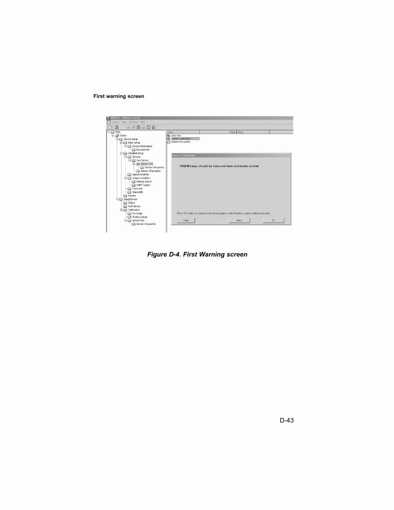
First warning screen
Figure D-4. First Warning screen
D-43

Second warning screen
Figure D-5. Second Warning screen
D-44

Standard Calibration function select screen
Figure D-6. Standard Calibration function select screen
D-45

Calibration initiated screen
Figure D-7. Calibration initiated screen
D-46

Selection Confirmation Screen
Figure D-8. Selection Confirmation screen
D-47

Sensor Zero Countdown screen
Figure D-9. Sensor Zero Countdown screen
D-48

Zero Adjustment screen
Figure D-10. Zero Adjustment screen
D-49

Span countdown screen
Figure D-11. Span Countdown screen
D-50

Adjusting Span screen
Figure D-12. Adjusting Span screen
D-51

Calibration completion message
Figure D-13. Calibration Completion message
D-52

Calibration gas reminder screen
Figure D-14. Calibration Gas Reminder screen
D-53

Loop control reminder message
Troubleshooting
Fault indications
Span Fault
This fault can occur if the sensor is in cal mode and the required SPANgas is not applied to the sensor at the indicated time or within thetimeout period. The 4-20 mA returns the measured gas value basedupon the last successful calibration parameters. This fault sets severalstatus flags in the digital output to indicate that an error has occurred.The current calibration status can be observed by right-clicking onstatus group 2 to expand it as shown in FIGURE D-16.
Other possible cause for a Span Fault could be the use of an incorrectSpan gas or improperly set PV Upper Trim point (Span) setting. TheTrim (calibration) point information can be viewed from the sensor trimpoints menu as shown in FIGURE D-17.
Figure D-15. Loop Control Reminder message
D-54

Span faults can also be caused by a bad sensor, sensor at end-of-life,or a sensor that is too far out of calibration for the Standard Zero/ Spanprocedure to make the adjustment. An attempt to Initial Cal the sensormay be able to correct the calibration; otherwise, the sensor must bereplaced. Additional sensor status can be obtained by right-clicking onstatus group 3 to expand it as shown in FIGURE D-18.
Calibration status screen
Figure D-16. Calibration Status screen
D-55

Sensor trim point screen
Figure D-17. Sensor Trim Point screen
D-56

Additional Sensor status screen
Zero Fault
The Zero Fault can be caused by a faulty sensor, calibration out of theStandard Zero/Span calibration range, sensor in change, sensor fault orattempting to zero the sensor with Span gas applied. The application ofZero gas should be checked and the sensor status (as defined inFIGURES D-16 and D-18) verified if this fault occurs.
Figure D-18. Additional Sensor Status screen
D-57

Calibration Aborted
User calibration abort or sensor calibration faults can cause acalibration process to abort. Status group 2 as shown in FIGURE D-16 can be viewed to determine if the abort was caused by a cal fault. Status group 2 can be expanded by right-clicking theselection as shown in FIGURE D-19 to provide additional information(also see FIGURE D-16).
Device status screen
Figure D-19. Device Status screen
D-58