Performance evaluation of a new routing strategy for irregular networks with source routing
International Journal of Engineering Sciences, 2(2) February 2013, Pages: 49-61
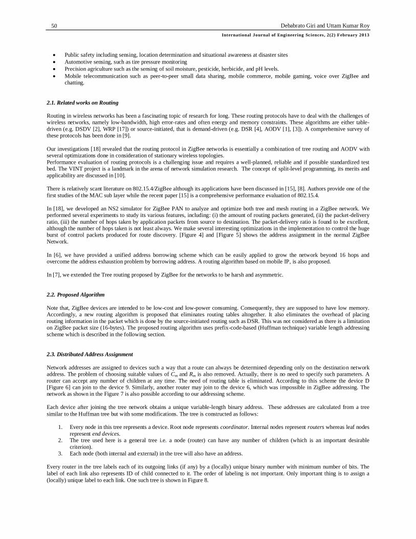
TI Journals
International Journal of Engineering Sciences www.waprogramming.com
ISSN 2306-6474
* Corresponding author. Email address: [email protected], [email protected]
WPAN Routing Using Huffman Technique
Debabrato Giri 1, Uttam Kumar Roy 2 1,2 Jadavpur University, India.
A R T I C L E I N F O A B S T R A C T
Keywords: Tree Networks Routing Prefix-codes Address PAN ZigBee Routing
IEEE 802.15.4 is a standard for low-cost, low power-consumption and low data-rate WPANs. To use this standard in a multi-hop network, ZigBee [19 20 21] proposed a Tree routing algorithm, which has several limitations.
In this paper, we have proposed a new tree routing algorithm, together with a prefix-code-based, flexible, variable-length addressing scheme. Devices using this routing algorithm need not have any routing table. Route to a destination can still be determined using some simple mathematical and/or logical calculations. Proposed addressing scheme allows devices to have variable number of child devices. Analytical results show that this flexible mechanism exhibits very low overhead and can be used in multi-hop, large, highly asymmetric networks.
© 2013 Int. j. eng. sci. All rights reserved for TI Journals.
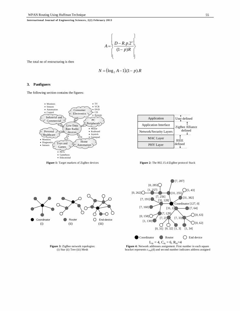
1. Introduction In recent past there has been a steady rise in wireless networking. Standards like IEEE 802.11[11] (Wi-Fi) and IEEE 802.15.1 [13] (12) have come into existence. IEEE 802.11 targets high data rate, mains powered, high cost and relatively long range applications. Bluetooth is one of the first standards designed for low range, low power devices. As a result more and more low-cost high-quality devices appear in the market; short-range low-rate wireless personal area networks are poised to take the world in a way observed never before. IEEE 802.15.4 [19] (henceforth referred to as 802.15.4) is a landmark in the attempt to bring ubiquitous networking [Figure 1] into our lives. Designed uniquely for energy-conscious low data rate appliances, it specifies the PHYsical (PHY) layer and MAC sub-layer of the protocol stack. The ZigBee Alliance [19 20 21] has defined the specification [Figure 2] for the network (NWK), security and application profile layers for an 802.15.4-based system. Network layer supports three topologies Star, Tree and Mesh [Figure. 3]. For tree networks, ZigBee specifies a static address allocation method and a routing scheme based on some mathematical equations. The basic intention of using mathematical equations is to eliminate routing tables altogether and also to make routing decision simple. This is because ZigBee devices are low-cost devices and consequently they are supposed to have very low memory and limited computing capacity. Unfortunately, this scheme has several limitations that are explained later in detail. In this paper, we have provided a new routing algorithm and a prefix-code based variable-length addressing scheme for 802.15.4-based tree networks. The proposed scheme eliminates some of the existing problems. There are no limitations on the maximum number of children (Cm), and maximum number of router children (Rm), a router capable device may have. The value of Cm and Rm can have different values for different nodes depending upon the situation. They are not even fixed and can change from time to time as nodes join to and leave from the network. A routing algorithm has also been proposed. It is a routing table free algorithm and it can determine route to a destination using only some mathematical and/or logical calculations. We have shown theoretically that the proposed scheme exhibit little overhead. 2. Routing in PAN With ZigBee devices on the horizon, ubiquitous networking looks elusive no more. It is not too distant a future one may chance to have one’s home-appliances wedded together in a smart and cooperative network that allows them to talk to each other seamlessly. Sensors and actuators will communicate without barrier. They can be deployed pervasively in disaster-hit areas to monitor the situation to provide situational awareness and automatically take appropriate actions. Some of its major application areas [Figure 1] are: Home automation Industrial control and monitoring Personal health-care
Debabrato Giri and Uttam Kumar Roy International Journal of Engi neering Sciences, 2(2) February 2013
50
Public safety including sensing, location determination and situational awareness at disaster sites Automotive sensing, such as tire pressure monitoring Precision agriculture such as the sensing of soil moisture, pesticide, herbicide, and pH levels. Mobile telecommunication such as peer-to-peer small data sharing, mobile commerce, mobile gaming, voice over ZigBee and
chatting. 2.1. Related works on Routing Routing in wireless networks has been a fascinating topic of research for long. These routing protocols have to deal with the challenges of wireless networks, namely low-bandwidth, high error-rates and often energy and memory constraints. These algorithms are either table-driven (e.g. DSDV [2], WRP [17]) or source-initiated, that is demand-driven (e.g. DSR [4], AODV [1], [3]). A comprehensive survey of these protocols has been done in [9]. Our investigations [18] revealed that the routing protocol in ZigBee networks is essentially a combination of tree routing and AODV with several optimizations done in consideration of stationary wireless topologies. Performance evaluation of routing protocols is a challenging issue and requires a well-planned, reliable and if possible standardized test bed. The VINT project is a landmark in the arena of network simulation research. The concept of split-level programming, its merits and applicability are discussed in [10]. There is relatively scant literature on 802.15.4/ZigBee although its applications have been discussed in [15], [8]. Authors provide one of the first studies of the MAC sub layer while the recent paper [15] is a comprehensive performance evaluation of 802.15.4. In [18], we developed an NS2 simulator for ZigBee PAN to analyze and optimize both tree and mesh routing in a ZigBee network. We performed several experiments to study its various features, including: (i) the amount of routing packets generated, (ii) the packet-delivery ratio, (iii) the number of hops taken by application packets from source to destination. The packet-delivery ratio is found to be excellent, although the number of hops taken is not least always. We make several interesting optimizations in the implementation to control the huge burst of control packets produced for route discovery. [Figure 4] and [Figure 5] shows the address assignment in the normal ZigBee Network. In [6], we have provided a unified address borrowing scheme which can be easily applied to grow the network beyond 16 hops and overcome the address exhaustion problem by borrowing address. A routing algorithm based on mobile IP, is also proposed. In [7], we extended the Tree routing proposed by ZigBee for the networks to be harsh and asymmetric. 2.2. Proposed Algorithm Note that, ZigBee devices are intended to be low-cost and low-power consuming. Consequently, they are supposed to have low memory. Accordingly, a new routing algorithm is proposed that eliminates routing tables altogether. It also eliminates the overhead of placing routing information in the packet which is done by the source-initiated routing such as DSR. This was not considered as there is a limitation on ZigBee packet size (16-bytes). The proposed routing algorithm uses prefix-code-based (Huffman technique) variable length addressing scheme which is described in the following section. 2.3. Distributed Address Assignment Network addresses are assigned to devices such a way that a route can always be determined depending only on the destination network address. The problem of choosing suitable values of Cm and Rm is also removed. Actually, there is no need to specify such parameters. A router can accept any number of children at any time. The need of routing table is eliminated. According to this scheme the device D [Figure 6] can join to the device 9. Similarly, another router may join to the device 6, which was impossible in ZigBee addressing. The network as shown in the Figure 7 is also possible according to our addressing scheme. Each device after joining the tree network obtains a unique variable-length binary address. These addresses are calculated from a tree similar to the Huffman tree but with some modifications. The tree is constructed as follows:
1. Every node in this tree represents a device. Root node represents coordinator. Internal nodes represent routers whereas leaf nodes represent end devices.
2. The tree used here is a general tree i.e. a node (router) can have any number of children (which is an important desirable criterion).
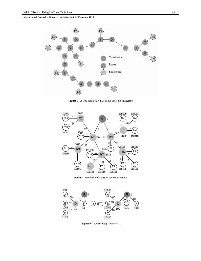
3. Each node (both internal and external) in the tree will also have an address. Every router in the tree labels each of its outgoing links (if any) by a (locally) unique binary number with minimum number of bits. The label of each link also represents ID of child connected to it. The order of labeling is not important. Only important thing is to assign a (locally) unique label to each link. One such tree is shown in Figure 8.

WPAN Routing Using Huffman Technique Internat ional Journal of Engineeri ng Sciences, 2(2) February 2013
51
If a router R has CR number of children, minimum number of bits N(CR) required to label each outgoing link of R is given by the following equation:
1)lg(
10)(
RR
RRRR CifC
CorCifCCN
(1)
The unique binary address of each node in the tree is then calculated as follows: The address of root (coordinator) is always 1. Address AD of any other device D is obtained by concatenating parent address and its id (label of the link). For example, the addresses of the routers R8 in Figure 8 is:
idaddressparent
RA 0110118
Here, 1011 is the address of its parent R7 and 01 is the label of the link from R7 to R8. The address of R7 is calculated using same procedure. Similarly, addresses of end devices E6 and E12 are 110100 and 1001 respectively. Addresses of other end devices are obtained using the same procedure. Link labels may change from time to time as devices join to or leave from the network. Let us take a concrete example to explain this. In Figure. 9, the number of children CR of router R is two. So, number of bits N(CR) required to label each link is 1. Now if another device X joins to R, N(CR) will become 2. Such a case, each of the outgoing links (including the new link) must be labeled by 2 bits. This implies that a new address has to be assigned to all existing descendants of R. We call this procedure as “restructuring” [Figure 9]. Restructuring, no doubt, is an overhead. But, we shall show analytically that restructuring will occur infrequently in section 5. The addressing scheme described above has following important properties:
1. The address, a node obtains, is always unique. 2. Address of a leaf node can never be a prefix of another leaf node (prefix property for leaf nodes). 3. Siblings have common prefix (parent’s address). 4. The address of every node has ancestor’s address as its prefix.
Last property is very interesting and can be used to route a packet to a destination by performing simple mathematical/logical calculations. This way routing algorithm cleverly avoids the need of routing table. The detail usage of this property has been described in the next section. 2.4. Routing Algorithm Each router R that has joined to the network maintains a variable CR (≥0) whose value, at any instant, represents the number of children of the router R at that instant. CR is incremented or decremented as devices join to and leave from this router R. The minimum number of bits required to represent CR at any time is calculated according to the equation 6. Each router also maintains a table (we call it Translation
table) having )(2 RCN
number of entries of the following form: [Used/Unused (U): H/W address (H)] Note that ZigBee specified one such table similar to ARP table for network address to MAC address translation as there is no provision to use Address Resolution Protocol (ARP). We are just making use of this table.
The Translation table is indexed by )(2 RCN
possible binary labels/IDs to be assigned to )(2 RCN
links/children. The purpose of U and H fields are as follows:
otherwisenullTRUEisUifchildtheofaddressWH
H
otherwiseFALSEchildatoassignedisIDifTRUE
U
,,/
,,
(2)
Debabrato Giri and Uttam Kumar Roy International Journal of Engi neering Sciences, 2(2) February 2013
52
The U bit of each entry i is set to FALSE initially and is changed to TRUE if the binary number i is used to level a link to a child. The network address of this child is calculated and allocated to the child. The H/W (MAC) address of the child device is also stored in corresponding H field. This MAC address is used by the underlying MAC protocol to send MAC packets. In the following section, we shall describe how this prefix-based address can be used to find a route to a target device. The following notations are used:
Ai : Network Address of device i, Bi : Number of bits in Ai, Ci : Number of children of router i, IDi : Local address of device i (Except root node)
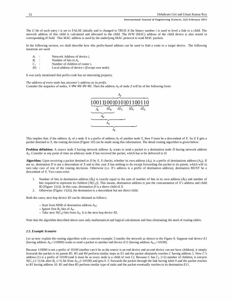
It was early mentioned that prefix-code has an interesting property. The address of every node has ancestor’s address as its prefix. Consider the sequence of nodes, VWXYZ. Then the address AZ of node Z will be of the following form:
Z
Z
Y
Y
X
X
W
WV
A
ID
A
ID
A
ID
A
IDA
011001100101100110011
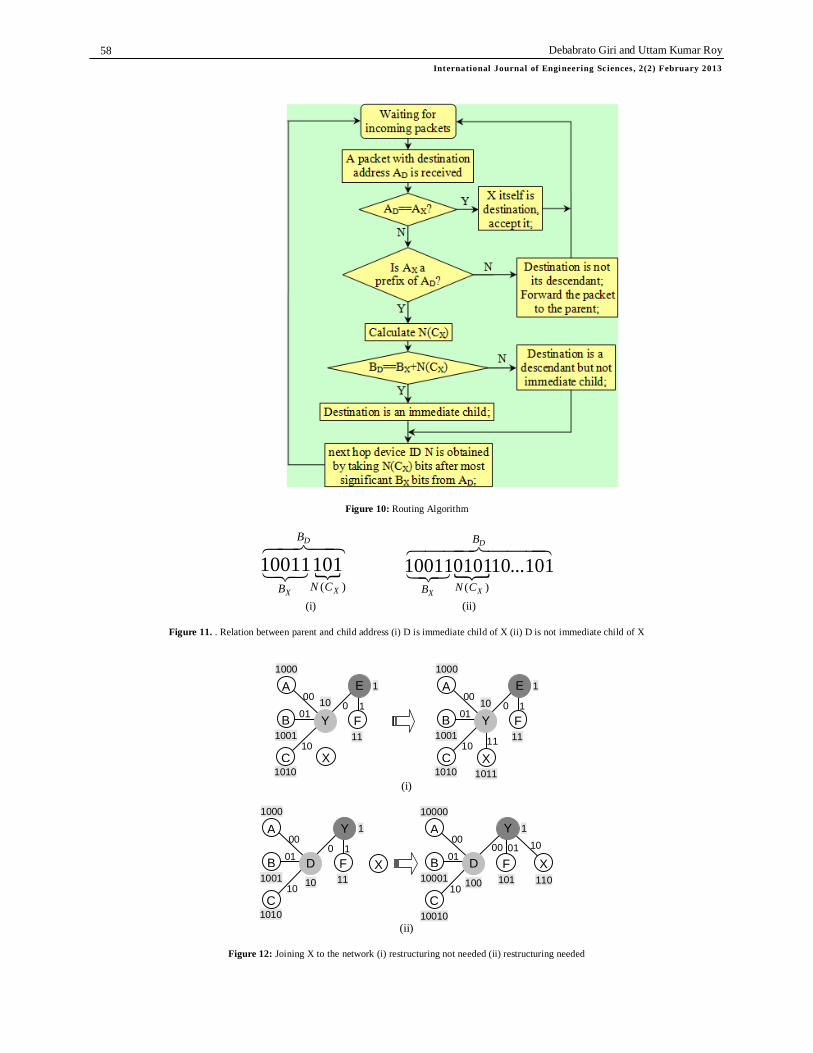
This implies that, if the address AX of a node X is a prefix of address AY of another node Y, then Y must be a descendant of X. So if X gets a packet destined to Y, the routing decision [Figure 10] can be made using this information. The detail routing algorithm is given below: Problem definition: A source node S having network address AS wants to send a packet to a destination node D having network address AD. Consider at any point of time an arbitrary node X has received the packet, which has to be delivered to D. Algorithm: Upon receiving a packet destined to D by X, X checks, whether its own address (AX), is a prefix of destinations address (AD). If not so, destination D is not a descendant of X and in this case X has nothing to do except forwarding the packet to its parent, which will in turn take care of rest of the routing decisions. Otherwise (i.e. X’s address is a prefix of destination address), destination MUST be a descendant of X. Two cases exist:
1. Number of bits in destination address (BD) is exactly equal to the sum of number of bits in its own address (BX) and number of bits required to represent its children [N(CX)]. This means, destination address is just the concatenation of X’s address and child ID [Figure 11(i)]. In this case, destination D is a direct child of X.
2. Otherwise [Figure 11(ii)], the destination is a descendant but not direct child. Both the cases, next hop device ID can be obtained as follows: -- Start from MSB of destination address AD; -- Ignore first BX bits of AD. -- Take next N(CX) bits from AD. It is the next hop device ID. Note that the algorithm described above uses only mathematical and logical calculations and thus eliminating the need of routing tables. 2.5. Example Scenario Let us now explain the routing algorithm with a concrete example. Consider the network as shown in the Figure 8. Suppose end device E1 (having address AE1=110000) wants to send a packet to another end device E11 (having address AE11=10100). Because 110000 is not a prefix of 10100 (neither can it be as the source is an end device and an end device can not have children), it simply forwards the packet to its parent R5. R5 and R4 perform similar steps as E1 and the packet ultimately reaches C having address 1. Now C’s address (1) is a prefix of 10100 (and it must be as every node is a child of root C). Because C has CC (=2) number of children, it extracts N(CC) (=1) bit after BC (=1) bit from AE11(=10100) and gets 0. C forwards the packet through the link having label 0 and the packet reaches to R1 having address 10. R1 and then R3 perform similar type of tasks and the packet eventually reaches to its destination E11.

WPAN Routing Using Huffman Technique Internat ional Journal of Engineeri ng Sciences, 2(2) February 2013
53
2.6. Network Maintenance In this section, we shall show how devices will join to and leave from the network and what is the impact on network address assignment. According to the ZigBee specification, the coordinator initiates the network by sending BEACON messages periodically. Every router capable device that has joined to the network also starts broadcasting BEACON messages periodically. 1. Joining a node to the network If a device X wants to join to the network, it first receives for one or more BEACON messages and decides which device should be accepted as a parent. Call this device Y. The device X then sends a JOIN_REQUEST message to Y. At node Y, two cases exist:
Case I: N(CY + 1) = N(CY)
In this case [Figure 12(i)], same number of bits is sufficient to label links to Y’s children. The only task of Y is then assigning an unused address to X. -- Lookup Translation table and find an entry i such that U bit is 0 (unused); -- Set T[i].U to TRUE (mark it used);
-- Put H/W address of X (obtained from JOIN_REQUEST message) in T[i].H. This H/W address will be used to forward packet (if any) to X subsequently;
-- CY = CY + 1; -- Calculate X’s address by concatenating its own address (i.e. AY) and i represented
by N(CY) number of bits; -- Create a JOIN_REPLY packet, put this address in it and send it back to X;
Upon receiving JOIN_REPLY packet, X knows its network address;
Case II: N(CY + 1) = N(CY) + 1 In this case [Figure 12(ii)], adding one more child to Y requires one more bit to label links to its children and hence reassigning addresses to all of its existing descendants is needed. -- If BY + N(CY) + 1 > 16, number of bits are exhausted (remember ZigBee uses 16-bit network address) and no further child
can be accepted. Otherwise do the following:
-- Increase the size of the translation table from)(2 YCN to
1)(2 YCN
-- CY = CY + 1 -- Calculate new address of each of its immediate children (U bit set TRUE in the Translation table) and inform them to update their addresses. This procedure is repeated each of the direct or indirect children subsequently;
-- Calculate X’s address by concatenating its own address (i.e. AY) and )(2 YCN represented by N(CY) number of bits;
-- Create a JOIN_REPLY packet, put this address in it and send it back to X; Upon receiving JOIN_REPLY packet, X knows its network address; 2. Leaving a node from the network Leaving from the network is happens in similar way. If a device X having id IDX wants to leave from a network, it sends DISCONNECT_REQUEST to its parent Y indicating its child id IDX. Two cases exist again:
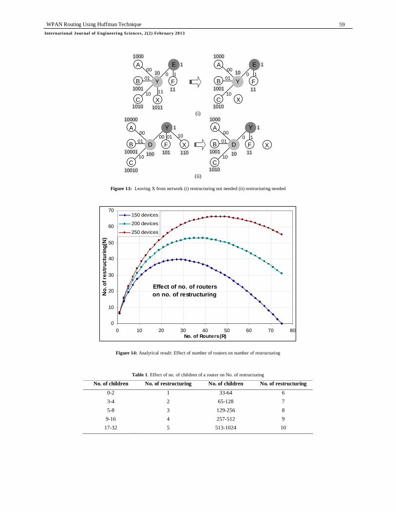
Case I: N(CY - 1) = N(CY) In this case [Figure 13(i)], same number of bits is sufficient to label links to its children. -- Set T[IDX].U to FLASE; (mark it unused) -- CY = CY – 1
Case II: N(CY - 1) = N(CY) - 1
In this case [Figure 13(ii)], deleting one child requires one less bit to label links to its children and hence reassigning addresses to all of its direct and indirect children, is needed. -- Set T[IDX].U to FALSE; (mark it unused) -- CY = CY - 1
-- Calculate new address of each of its immediate children (U bit set TRUE in the Translation table) and inform them to update their addresses. This procedure is repeated each of the direct or indirect children subsequently;
After finishing the restructuring procedure, Y responds X with a DISCONNECT_REPLY message.
Debabrato Giri and Uttam Kumar Roy International Journal of Engi neering Sciences, 2(2) February 2013
54
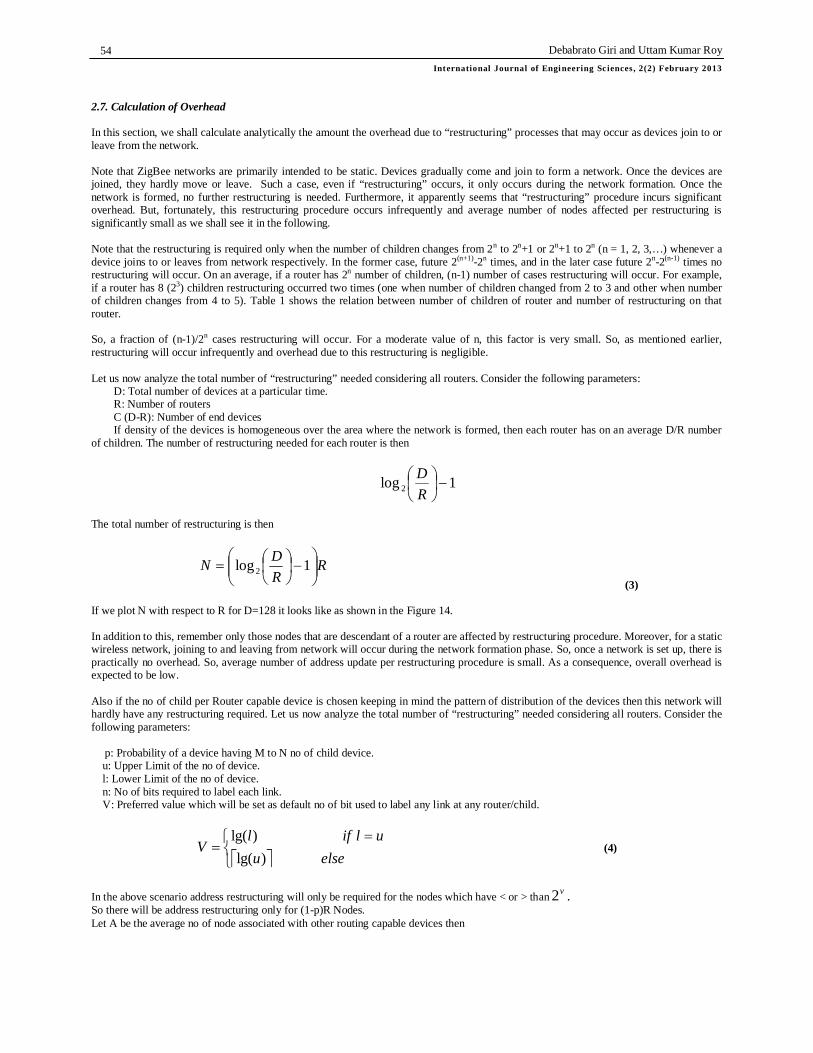
2.7. Calculation of Overhead In this section, we shall calculate analytically the amount the overhead due to “restructuring” processes that may occur as devices join to or leave from the network. Note that ZigBee networks are primarily intended to be static. Devices gradually come and join to form a network. Once the devices are joined, they hardly move or leave. Such a case, even if “restructuring” occurs, it only occurs during the network formation. Once the network is formed, no further restructuring is needed. Furthermore, it apparently seems that “restructuring” procedure incurs significant overhead. But, fortunately, this restructuring procedure occurs infrequently and average number of nodes affected per restructuring is significantly small as we shall see it in the following. Note that the restructuring is required only when the number of children changes from 2n to 2n+1 or 2n+1 to 2n (n = 1, 2, 3,…) whenever a device joins to or leaves from network respectively. In the former case, future 2(n+1)-2n times, and in the later case future 2n-2(n-1) times no restructuring will occur. On an average, if a router has 2n number of children, (n-1) number of cases restructuring will occur. For example, if a router has 8 (23) children restructuring occurred two times (one when number of children changed from 2 to 3 and other when number of children changes from 4 to 5). Table 1 shows the relation between number of children of router and number of restructuring on that router. So, a fraction of (n-1)/2n cases restructuring will occur. For a moderate value of n, this factor is very small. So, as mentioned earlier, restructuring will occur infrequently and overhead due to this restructuring is negligible. Let us now analyze the total number of “restructuring” needed considering all routers. Consider the following parameters:
D: Total number of devices at a particular time. R: Number of routers C (D-R): Number of end devices If density of the devices is homogeneous over the area where the network is formed, then each router has on an average D/R number
of children. The number of restructuring needed for each router is then
1log 2
RD
The total number of restructuring is then
RRDN
1log 2
(3) If we plot N with respect to R for D=128 it looks like as shown in the Figure 14. In addition to this, remember only those nodes that are descendant of a router are affected by restructuring procedure. Moreover, for a static wireless network, joining to and leaving from network will occur during the network formation phase. So, once a network is set up, there is practically no overhead. So, average number of address update per restructuring procedure is small. As a consequence, overall overhead is expected to be low. Also if the no of child per Router capable device is chosen keeping in mind the pattern of distribution of the devices then this network will hardly have any restructuring required. Let us now analyze the total number of “restructuring” needed considering all routers. Consider the following parameters:
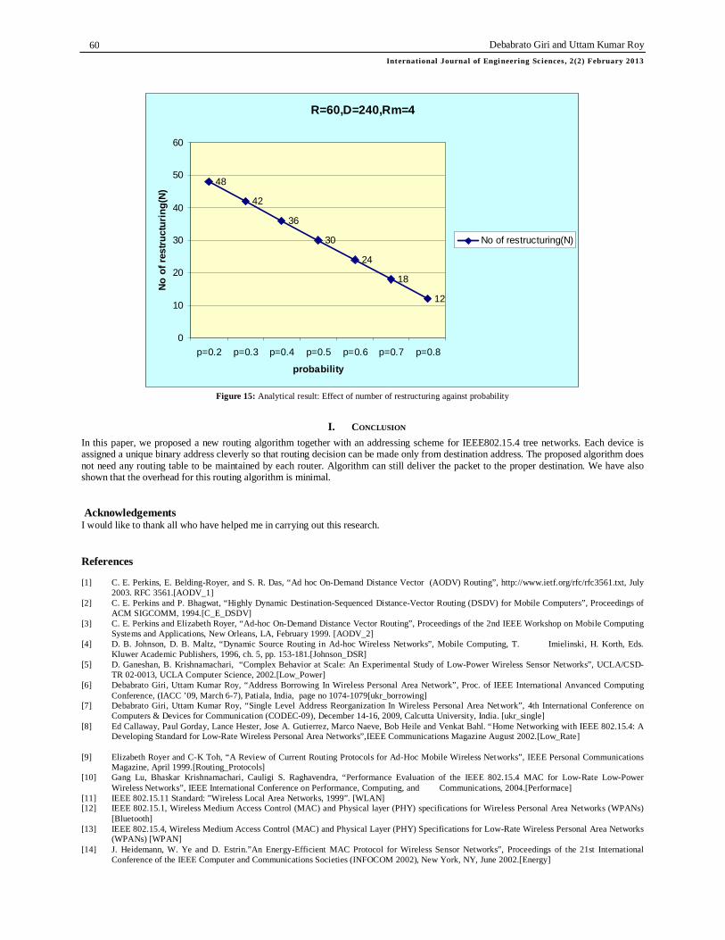
p: Probability of a device having M to N no of child device. u: Upper Limit of the no of device. l: Lower Limit of the no of device. n: No of bits required to label each link. V: Preferred value which will be set as default no of bit used to label any link at any router/child.
elseu
uliflV
)lg()lg(
(4)
In the above scenario address restructuring will only be required for the nodes which have < or > than v2 . So there will be address restructuring only for (1-p)R Nodes. Let A be the average no of node associated with other routing capable devices then
WPAN Routing Using Huffman Technique Internat ional Journal of Engineeri ng Sciences, 2(2) February 2013
55
Rp
pRDAv
)1(2..
The total no of restructuring is then
RpAN ).1.(1log 2 3. Panfiguers The following section contains the figures:
Mouse Keyboard Joystick Gamepad
PETs Gameboys Educational
Monitors Diagnostics Sensors
Monitors Sensors Automation Control
TV VCR DVD CD Remote
Low Data Rate Radio
devices
PC Peripherals
Industrial and Commercial
Consumer Electronics
Personal Healthcare
Toys and Games
Home Automation
Application
Application Interface
Network/Security Layers
MAC Layer
PHY Layer IEEE
defined
ZigBee Alliance defined
User defined
Figure 1: Target markets of ZigBee devices
Figure 2: The 802.15.4/ZigBee protocol Stack
Coordinator Router End-device (i) (ii) (iii)
[7, 256] [31, 255]
[31, 382]
[7, 33] [7, 2] [7, 129]
Coordinator [127, 0] [31, 128]
[31, 1]
[0, 31]
[7, 287]
Lm = 4, Cm = 6, Rm=4
[7, 160]
[7, 191]
[7, 64]
[0, 32]
[0, 63]
[0, 62]
[5, 43]
[1, 34] [1, 3]
[1, 130] [0, 158]
[0, 285] [1, 257]
[0, 262]
Coordinator Router End device
Figure 3: ZigBee network topologies:
(i) Star (ii) Tree (iii) Mesh Figure 4: Network addresses assignment. First number in each square
bracket represents cskip(d) and second number indicates address assigned

Debabrato Giri and Uttam Kumar Roy International Journal of Engi neering Sciences, 2(2) February 2013
56
Figure 5: Problem of ZigBee Network addresses assignment.
Figure 6: Limitation on maximum depth for ZigBee tree networks
WPAN Routing Using Huffman Technique Internat ional Journal of Engineeri ng Sciences, 2(2) February 2013
57
Figure 7: A tree network which is not possible in ZigBee
110000
00 01
10
110010
110110
110101 110100 101111 101110 101101
101100
10101
10100
10001
10000
1010
1011
1110 1101
1100 11 10
1001
1
1 0 00
01
11 10
00
1000
R1
C
R5
R4
R6
R2
R3
R7
E8
E14
E7
E10
E1
E3
E2
E5 E6
E11
E10
E13
E12
E9 E4
00 01
10 00
01 10 11
10
1
0
01
0
1
110001
R8
Figure 8: Modified prefix tree for address allocation.
10 01
101
10000
10010
100 10
00 00 01
A
C
1 R
F B D 10001
X 110
01
11
1000
1010
10 10
00 0 1
A
C
1 R
F B D 1001
X
Figure 9: “Restructuring” addresses.
Debabrato Giri and Uttam Kumar Roy International Journal of Engi neering Sciences, 2(2) February 2013
58
Figure 10: Routing Algorithm
D
XX
B
CNB )(
10110011
D
XX
B
CNB
101...10010110011)(
(i) (ii)
Figure 11. . Relation between parent and child address (i) D is immediate child of X (ii) D is not immediate child of X
11
01
11
1000
1010
10
10
00 0 1
A
C
1 E
F B Y 1001
X 1011
01
11
1000
1010
10
10
00 0 1
A
C
1 E
F B Y 1001
X
(i)
10 01
101
10000
10010
100 10
00 00 01
A
C
1 Y
F B D 10001
X 110
01
11
1000
1010
10 10
00 0 1
A
C
1 Y
F B D 1001
X
(ii)
Figure 12: Joining X to the network (i) restructuring not needed (ii) restructuring needed
WPAN Routing Using Huffman Technique Internat ional Journal of Engineeri ng Sciences, 2(2) February 2013
59
11
01
11
1000
1010
10
10
00 0 1
A
C
1 E
F B Y 1001
X 1011
01
11
1000
1010
10
10
00 0 1
A
C
1 E
F B Y 1001
X
(i)
10 01
101
10000
10010
100 10
00 00 01
A
C
1 Y
F B D 10001
X 110
01
11
1000
1010
10 10
00 0 1
A
C
1 Y
F B D 1001
X
(ii)
Figure 13: Leaving X from network (i) restructuring not needed (ii) restructuring needed
Effect of no. of routers on no. of restructuring
0
10
20
30
40
50
60
70
0 10 20 30 40 50 60 70 80No. of Routers(R)
No.
of r
estr
uctu
ring(
N)
150 devices
200 devices
250 devices
Figure 14: Analytical result: Effect of number of routers on number of restructuring
Table 1. Effect of no. of children of a router on No. of restructuring
No. of children No. of restructuring No. of children No. of restructuring 0-2 1 33-64 6 3-4 2 65-128 7 5-8 3 129-256 8
9-16 4 257-512 9 17-32 5 513-1024 10
Debabrato Giri and Uttam Kumar Roy International Journal of Engi neering Sciences, 2(2) February 2013
60
R=60,D=240,Rm=4
48
42
36
30
24
18
12
0
10
20
30
40
50
60
p=0.2 p=0.3 p=0.4 p=0.5 p=0.6 p=0.7 p=0.8
probability
No
of r
estru
ctur
ing(
N)
No of restructuring(N)
Figure 15: Analytical result: Effect of number of restructuring against probability
I. CONCLUSION In this paper, we proposed a new routing algorithm together with an addressing scheme for IEEE802.15.4 tree networks. Each device is assigned a unique binary address cleverly so that routing decision can be made only from destination address. The proposed algorithm does not need any routing table to be maintained by each router. Algorithm can still deliver the packet to the proper destination. We have also shown that the overhead for this routing algorithm is minimal. Acknowledgements I would like to thank all who have helped me in carrying out this research. References [1] C. E. Perkins, E. Belding-Royer, and S. R. Das, “Ad hoc On-Demand Distance Vector (AODV) Routing”, http://www.ietf.org/rfc/rfc3561.txt, July
2003. RFC 3561.[AODV_1] [2] C. E. Perkins and P. Bhagwat, “Highly Dynamic Destination-Sequenced Distance-Vector Routing (DSDV) for Mobile Computers”, Proceedings of
ACM SIGCOMM, 1994.[C_E_DSDV] [3] C. E. Perkins and Elizabeth Royer, “Ad-hoc On-Demand Distance Vector Routing”, Proceedings of the 2nd IEEE Workshop on Mobile Computing
Systems and Applications, New Orleans, LA, February 1999. [AODV_2] [4] D. B. Johnson, D. B. Maltz, “Dynamic Source Routing in Ad-hoc Wireless Networks”, Mobile Computing, T. Imielinski, H. Korth, Eds.
Kluwer Academic Publishers, 1996, ch. 5, pp. 153-181.[Johnson_DSR] [5] D. Ganeshan, B. Krishnamachari, “Complex Behavior at Scale: An Experimental Study of Low-Power Wireless Sensor Networks”, UCLA/CSD-
TR 02-0013, UCLA Computer Science, 2002.[Low_Power] [6] Debabrato Giri, Uttam Kumar Roy, “Address Borrowing In Wireless Personal Area Network”, Proc. of IEEE International Anvanced Computing
Conference, (IACC ’09, March 6-7), Patiala, India, page no 1074-1079[ukr_borrowing] [7] Debabrato Giri, Uttam Kumar Roy, “Single Level Address Reorganization In Wireless Personal Area Network”, 4th International Conference on
Computers & Devices for Communication (CODEC-09), December 14-16, 2009, Calcutta University, India. [ukr_single] [8] Ed Callaway, Paul Gorday, Lance Hester, Jose A. Gutierrez, Marco Naeve, Bob Heile and Venkat Bahl. “Home Networking with IEEE 802.15.4: A
Developing Standard for Low-Rate Wireless Personal Area Networks”,IEEE Communications Magazine August 2002.[Low_Rate]
[9] Elizabeth Royer and C-K Toh, “A Review of Current Routing Protocols for Ad-Hoc Mobile Wireless Networks”, IEEE Personal Communications Magazine, April 1999.[Routing_Protocols]
[10] Gang Lu, Bhaskar Krishnamachari, Cauligi S. Raghavendra, “Performance Evaluation of the IEEE 802.15.4 MAC for Low-Rate Low-Power Wireless Networks”, IEEE International Conference on Performance, Computing, and Communications, 2004.[Performace]
[11] IEEE 802.15.11 Standard: ”Wireless Local Area Networks, 1999”. [WLAN] [12] IEEE 802.15.1, Wireless Medium Access Control (MAC) and Physical layer (PHY) specifications for Wireless Personal Area Networks (WPANs)
[Bluetooth] [13] IEEE 802.15.4, Wireless Medium Access Control (MAC) and Physical Layer (PHY) Specifications for Low-Rate Wireless Personal Area Networks
(WPANs) [WPAN] [14] J. Heidemann, W. Ye and D. Estrin.”An Energy-Efficient MAC Protocol for Wireless Sensor Networks”, Proceedings of the 21st International
Conference of the IEEE Computer and Communications Societies (INFOCOM 2002), New York, NY, June 2002.[Energy]
WPAN Routing Using Huffman Technique Internat ional Journal of Engineeri ng Sciences, 2(2) February 2013
61
[15] Jianliang Zheng and Myung J. Lee. “A Comprehensive Performance Study of IEEE 802.15.4”, http://www-ee.ccny.edu/zheng/pub, 2004. [Comprehensive]
[16] C. Schurgers, S. Park and M. B. Srivastava, “Energy-Aware Wireless Microsensor Networks”, IEEE Signal Processing Magazine, Volume: 19, Issue: 2, March 2002.[Aware]
[17] Shree Murthy, J. J. Garcia-Luna-Aceves, “An Efficient Routing Protocol for Wireless Networks”, Mobile Networks and Applications, 1996.[Efficient]
[18] Uttam Kumar Roy, Debarshi Kumar Sanyal, Sudeepta Ray, "Analysis and Optimization of Routing Protocols in IEEE802.15.4" (Asian International Mobile Computing Conference (AMOC 2006), Jadavpur University, Kolkata, India [UKR_AMOC]
[19] ZigBee Alliance (ZigBee Document 02130r7) Draft Version 0.90: Network Specification, July 2004.[ZigBee] [20] ZigBee Alliance (ZigBee Document 075307r07) Version 1.0: Telecom Applications Profile Specification, April 2010.[ZigBee Telecom] [21] ZigBee Alliance (ZigBee Document 053516r12) Version 1.0: ZigBee Building Automation Application Profile, May 2011.[ZigBee Building
Automation]
Copyright © 2022 FDOKUMEN