D.E.R. Dynamic Escape Routing
64
Sicherheitstechnik GmbH D.E.R. Dynamic Escape Routing
-
Upload
khangminh22 -
Category
Documents
-
view
1 -
download
0
Transcript of D.E.R. Dynamic Escape Routing

Sicherheitstechnik GmbH
D.E.R.Dynamic Escape Routing

The D.E.R.-system for dynamic escape route guidance
Connection diagrams
FS 1100 FS 2000 FS 7000 FS 804.1 Floor- and wall luminaires with run light function
FL 1530 FL 7188 / 7288 FL 808 / 828 FL 5103 / 5203 FL 5105 FL 3100 Dynamic emergency exit luminaires
FB 5000 24V FB 5000 WE Flashing lights
Interface and control modules SEV
Change-over devices and BUS substation D.E.R. Controller PSU Control / Monitoring / Power supply
INOView INOWeb SVPCn Monitoring software
w w w . i n o t e c - l i c h t . d ew w w . i n o t e c - l i c h t . d e
Contents

The D.E.R.-system for dynamic escape route guidance
Connection diagrams
FS 1100 FS 2000 FS 7000 FS 804.1 Floor- and wall luminaires with run light function
FL 1530 FL 7188 / 7288 FL 808 / 828 FL 5103 / 5203 FL 5105 FL 3100 Dynamic emergency exit luminaires
FB 5000 24V FB 5000 WE Flashing lights
Interface and control modules SEV
Change-over devices and BUS substation D.E.R. Controller PSU Control / Monitoring / Power supply
INOView INOWeb SVPCn Monitoring software
SEV
INOTEC
N L + -
INOTECSicherheitstechnik GmbHAm Buschgarten 17D-59469 Ense
U : 230 V ~ 50/60 HzU : 183,5 - 260 V I : 0,38 AU : 48 VI : 1 AJ : -5...+45°C
D.E.RPower Supply
PSU 48
OUTPUTINPUT
ON
P/N : 965300
E
E
E
A
A
SEV-Modulmit Netzteil
S2000-Modul S2000-Modul S2024-Modul
LSA 8.1
3
5
5
5
2
2
55
1
2
F
F
5 AT50
Netz
Ladeteil 220V/7,5A
Ein
10AT16AT
Batterie
1
2
3
4
CP 4x2A
F3,15 A
= BL / NM
= DL / M
F3,15 A
F3,15 A
F3,15 A
1
2
3
4
CP 4x2A
F3,15 A
= BL / NM
= DL / M
F3,15 A
F3,15 A
F3,15 A
1
2
3
4
CP 4x2A
F3,15 A
= BL / NM
= DL / M
F3,15 A
F3,15 A
F3,15 A
1
2
3
4
CP 4x2A
F3,15 A
= BL / NM
= DL / M
F3,15 A
F3,15 A
F3,15 A
1
2
3
4
CP 4x2A
F3,15 A
= BL / NM
= DL / M
F3,15 A
F3,15 A
F3,15 A
1
2
3
4
CP 4x2A
F3,15 A
= BL / NM
= DL / M
F3,15 A
F3,15 A
F3,15 A
1
2
3
4
CP 4x2A
F3,15 A
= BL / NM
= DL / M
F3,15 A
F3,15 A
F3,15 A
1
2
3
4
CP 4x2A
F3,15 A
= BL / NM
= DL / M
F3,15 A
F3,15 A
F3,15 A
1
2
3
4
CP 4x2A
F3,15 A
= BL / NM
= DL / M
F3,15 A
F3,15 A
F3,15 A
1
2
3
4
CP 4x2A
F3,15 A
= BL / NM
= DL / M
F3,15 A
F3,15 A
F3,15 A
1
2
3
4
CP 4x2A
F3,15 A
= BL / NM
= DL / M
F3,15 A
F3,15 A
F3,15 A
1
2
3
4
CP 4x2A
F3,15 A
= BL / NM
= DL / M
F3,15 A
F3,15 A
F3,15 A
1
2
3
4
CP 4x2A
F3,15 A
= BL / NM
= DL / M
F3,15 A
F3,15 A
F3,15 A
1
2
3
4
CP 4x2A
F3,15 A
= BL / NM
= DL / M
F3,15 A
F3,15 A
F3,15 A
1
2
3
4
CP 4x2A
F3,15 A
= BL / NM
= DL / M
F3,15 A
F3,15 A
F3,15 A
1
2
3
4
CP 4x2A
F3,15 A
= BL / NM
= DL / M
F3,15 A
F3,15 A
F3,15 A
CPS 220 / 64
2,5A 2
2
1
2
F
F
5 AT50
max. 20 Adr.pro Str.-Kr.
max. 20 Adr.pro Str.-Kr.
max. 20 Adr.pro Str.-Kr.
Zentral- Batterie SystemCPS 64 SV
Fremdleuchteohne Überwachung
Fremdleuchteohne Überwachung
RZ oder Sicherheitsleuchte 24V mit Überwachungund Blinkfunktion
24V -Einschub
230V -Einschub
CPUSB 24V
FS-Serie mit Lauflichtfunktion
FL-Serie 24V
FL-Serie 24V
FL-Serie 230V
Signal 24V über pot.freie Kontakte z.B. einer BMA
Sicherheitstechnik GmbH

w w w . i n o t e c - l i c h t . d e4
Sicherheitstechnik GmbH
w w w . i n o t e c - l i c h t . d e
Sicherheitstechnik GmbH
4
Copyright: INOTEC Sicherheitstechnik GmbH, EnsePublications and copies, even partial, only with manufacturers permission.
Subject to technical changes.
INOTEC Sicherheitstechnik GmbHInnovative Emergency Lighting Technology
INOTEC Sicherheitstechnik GmbH is an innovative medium-sized company in Ense-Höingen, Westphalia with its own R&D department, production and a national and international sales and distribution.
A competent team ensures the reliable support in all questions concerning products, planning, service and standards with �exible and committed employees.
Since the foundation in 1995 the INOTEC Sicherheit-stechnik GmbH developed into a globally operating company with over 230 employees. Additional jobs were created with the numerous partners within Europe and Middle East. The production, storage and administration buildings increased in Germany on up to 14.000 m².
Nowadays INOTEC Sicherheitstechnik GmbH is one of the leading producers of emergency and safety lighting. Modern, innovative and high-quality products „Made in Germany“ set new standards world-wide, such as the decentralised emergency lighting system CLS 24, the central battery units with JOKER-technology and the dynamic escape route guidance system D.E.R. .

Sicherheitstechnik GmbH
Do you have any objection to a higher level of safety? INOTEC Sicherheitstechnik GmbH has addressed the problem of smoke-�lled escape routes by complementing static, in�exible escape route signage with dynamic escape route guidance. A dynamic system has to satisfy two core objectives: �rstly, to prevent people escaping into an area that is already �lled with smoke and, secondly, to enable people who are already in a smoke-�lled area to �nd a clear escape route.The solution is Dynamic Escape Routing (D.E.R.). Emergency exit luminaires with integrated LED matrix or separate backlit compartments not only provide static escape route signage but can also be used to indicate an alternative escape route. In this way, smoke-�lled areas or escape routes can be visually closed o� with a red LED cross. Why should an escape route still be signposted when it is full of smoke and therefore no longer usable?Luminaires are installed in the �oor or at a short distance above it so that people are able to orientate themselves in a smoke-�lled area. They are installed close to the �oor because hot smoke rises, covering emergency exit luminaires set high in the walls. In case of �re, the direction indicator with run-light func-tion of these low-location luminaires indicates the way to the escape door.If a building needs to be evacuated for some other reason than �re, the D.E.R. system can be used as a support, for instance with its �ashing function.
Are escape routes always safe escape routes?Emergency exit luminaires with �xed directional signs are used to identify escape routes and have the task of guiding people to places of safety in the event of a power failure or if an evacuation is necessary.But what happens if �re and smoke are blocking the closest escape route? What should you do if thick smoke is already making it impossible to work out where you are? How can you �nd the escape route if the escape route signage is no longer visible?
5w w w . i n o t e c - l i c h t . d ew w w . i n o t e c - l i c h t . d e
Why D.E.R.?

w w w . i n o t e c - l i c h t . d e6
Sicherheitstechnik GmbH
w w w . i n o t e c - l i c h t . d e6
Sicherheitstechnik GmbH
Functionality of the D.E.R.- systemThe D.E.R. system communicates with the building’s existing �re alarm system. Volt-free contacts, controlled by the �re alarm system, activate an input at the D.E.R. interface. The D.E.R. control system interprets the messages received from the �re alarm system and activates one of the pre-programmed escape route directional patterns. This automatically activates the D.E.R. luminaires, which indicate the safest escape route with a run light. Green LED arrows are used to indicate the direction. At the same time, the escape doors that can no longer be used are visually closed o� with a �ashing red LED cross. Low-location �ash lights in the vicinity of escape doors further identify the escape routes, so that these remain clear in the presence of smoke. The D.E.R. system can also react to the �re and/or smoke spreading further by activating other escape route patterns and consequently illuminating alternate routings. Even really small systems, as small as a single luminaire, can be implemented, with a reduced function, by actuating the lumi-naire directly via a �re alarm system’s volt-free contact.The D.E.R. system’s great �exibility is characterised not only by this dynamism but also by the fact that it can be connected either to an INOTEC emergency system or to any other secure electrical network (AC/DC) with an appropriate voltage level.
w w w . i n o t e c - l i c h t . d ew w w . i n o t e c - l i c h t . d ew w w . i n o t e c - l i c h t . d e6
Why D.E.R.?

Sicherheitstechnik GmbH
RegulationsIn the Technical Rules for Workplaces ASR A3.4/3 of May 2009, ‘Emergency escape lighting, optical safety guidance systems’, the German Committee for Workplaces (ASTA) describes in detail the implementation and operation of visual safety guid-ance systems for workplaces. In them, reference is made to ASR A2.3, which de�nes the conditions under which a visual safety guidance system is required for escape routes. This is the case where a heightened risk exists due to local or operational conditions. A heightened risk may exist, for example, in large interconnecting or multi-storey building complexes, where a signi�cant percentage of the persons present are not familiar with the surroundings or where a large percentage of persons present have limited mobility (clinics, nursing homes, etc.). Such circumstances may require a safety guidance system that responds to any danger and indicates the best escape route (Dynamic Escape Routing).
In EN 50172 of January 2005, safety guidance systems are de�ned as systems that can increase e�ciency when used in conjunction with the existing safety luminaires in escape routes.
Independently of the current regulations in force, additional applications for dynamic escape route guidance have emerged. For instance, a system of this kind may be used to compensate for inadequate constructional or technical �re safety measures.
7w w w . i n o t e c - l i c h t . d ew w w . i n o t e c - l i c h t . d e

w w w . i n o t e c - l i c h t . d e8
Sicherheitstechnik GmbH
Made in GermanyOne-stop quality
At INOTEC, you can ful�l all your emergency lighting require-ments from a single source- and with the quality that comes from being made in Germany. We choose Germany as a busi-ness location not only for the development and design of our products but also for their manufacture.To meet our own high demands and those of our customers, we focus on:
� Customer-oriented development� Latest technologies � Constant optimisation and development of our products � Quality suppliers
At the same time, the safety our products stand for is one of our most important quality features. INOTEC also means innovative luminaire design and high-quality workmanship.Because of the high level of responsibility placed on our prod-ucts, quality assurance is a particular priority for INOTEC. Thanks to our intensive quality management, we are able to guarantee the optimum safety and long-lasting, problem-free functionality of our products.

Sicherheitstechnik GmbH
The �oor plan displayed above shows the �rst �oor of a build-ing. In this case the staircases do not directly lead outside, but lead outside via a corridor or via an opened foyer at the right staircase. The normal mode is displayed here without a �re. The shortest escape routes via the staircase are marked, which can also be used in case of a power failure. The emergency balcony should not be used normally. This is why it is not marked or blocked visually (red cross). The recessed �oor luminaires are turned o� in normal mode.
To achieve a continuous routing function with the D.E.R. system for persons inside and outside a smoke-�lled building area, designers need to specify a combination of dynamic emergency exit luminaires (FL range) and low-location escape route seg-ment luminaires with run-light function and direction indicators (FS range).The dynamic emergency exit luminaires display a red cross to indicate that the related escape door can no longer be used. This prevents people being guided into a smoke-�lled area. The low-location escape-route segment luminaires form route markings for people who are already inside a smoke-�lled area. The run-light function is used to indicate the shortest escape route. The run-light function also facilitates evacuation of a building from areas that are not �lled with smoke.
BibliothekLibrary
FluchtbalkonEmergency balcony
BüroO�ce
BüroO�ce
BüroO�ce
BüroO�ce
BüroO�ce
LaborLaboratory
LaborLaboratory
BüroO�ce
Treppenhaus 1Staircase 1
Treppenhaus 2Staircase 2
WC
WC
WC
WC
Normal state
9w w w . i n o t e c - l i c h t . d ew w w . i n o t e c - l i c h t . d e
Case study

w w w . i n o t e c - l i c h t . d e10
Sicherheitstechnik GmbH
BibliothekLibrary
FluchtbalkonEmergency balcony
BüroO�ce
BüroO�ce
BüroO�ce
BüroO�ce
BüroO�ce
LaborLaboratory
LaborLaboratory
BüroO�ce
Treppenhaus 1Staircase 1
Treppenhaus 2Staircase 2
WC
WC
WC
WC
BibliothekLibrary
FluchtbalkonEmergency balcony
BüroO�ce
BüroO�ce
BüroO�ce
BüroO�ce
BüroO�ce
LaborLaboratory
LaborLaboratory
BüroO�ce
Treppenhaus 1Staircase 1
Treppenhaus 2Staircase 2
WC
WC
WC
WC
Fire case 1 represents the left-hand staircase and / or the contin-uation of the escape route on the ground �oor being �lled with smoke, so that this escape route can no longer be used. The �oor luminaires come on throughout the building and indicate the safe, smoke-free escape route. In the left-hand o�ce area, the second escape route is signposted, through an o�ce and across the escape balcony. The staircase access points from the left-hand o�ce area and the library in the middle are visually closed o� with a red cross. In the library, the route across the escape balcony is enabled.
Fire case 2 represents the right-hand staircase and / or the con-tinuation of the escape route on the ground �oor being �lled with smoke, so that this escape route can no longer be used. Here, too, the �oor luminaires come on throughout the building and indicated the safe, smoke-free escape route. The second escape route across the escape balcony is now signposted in the right-hand o�ce area and the library. All three access points to the smoke-�lled staircase are visually closed o� with red crosses.
Fire case 1
Fire case 2
Case study

Sicherheitstechnik GmbH
BibliothekLibrary
FluchtbalkonEmergency balcony
BüroO�ce
BüroO�ce
BüroO�ce
BüroO�ce
BüroO�ce
LaborLaboratory
LaborLaboratory
BüroO�ce
Treppenhaus 1Staircase 1
Treppenhaus 2Staircase 2
WC
WC
WC
WC
Fire case 3 represents both escape staircases and/or the contin-uation of the escape route on the ground �oor being �lled with smoke, so that only the escape balcony can be used. In the case study, this situation is possible because both staircases may be a�ected by smoke from an event in the building’s entrance area. In this case all the access points to both staircases are visu-ally closed o� with red crosses. Both the �oor luminaires with run-light function and the dynamic emergency exit luminaires indicate only the escape route across the escape balcony.
If the corridors and/or library are �lled with smoke, the �oor luminaires allow people to orient themselves, so that they can still �nd the safe escape doors.
Fire case 3
Dynamic emergency exit luminaires: depending on the �re event, the dynamic emergency exit luminaires
in the FL range serve to signpost and/or change the escape routes with a green directional arrow, or to close them o� with a red cross.
Escape-route segment luminaires: the FS range of in-�oor luminaires indicate the safe route in the event of
a �re. The integrated direction indicator and the additional run-light function facilitate a building evacuation. The low location of the FS luminaires enables orientation in smoke-�lled areas.
Smoke detector (red background means �re detection)
11w w w . i n o t e c - l i c h t . d ew w w . i n o t e c - l i c h t . d e

w w w . i n o t e c - l i c h t . d e
Sicherheitstechnik GmbH

SEV
INOTEC
N L + -
INOTECSicherheitstechnik GmbHAm Buschgarten 17D-59469 Ense
U : 230 V ~ 50/60 HzU : 183,5 - 260 V I : 0,38 AU : 48 VI : 1 AJ : -5...+45°C
D.E.RPower Supply
PSU 48
OUTPUTINPUT
ON
P/N : 965300
E
E
E
A
A
SEV-Modulmit Netzteil
S2000-Modul S2000-Modul S2024-Modul
LSA 8.1
3
5
5
5
2
2
55
1
2
F
F
5 AT50
Netz
Ladeteil 220V/7,5A
Ein
10AT16AT
Batterie
1
2
3
4
CP 4x2A
F3,15 A
= BL / NM
= DL / M
F3,15 A
F3,15 A
F3,15 A
1
2
3
4
CP 4x2A
F3,15 A
= BL / NM
= DL / M
F3,15 A
F3,15 A
F3,15 A
1
2
3
4
CP 4x2A
F3,15 A
= BL / NM
= DL / M
F3,15 A
F3,15 A
F3,15 A
1
2
3
4
CP 4x2A
F3,15 A
= BL / NM
= DL / M
F3,15 A
F3,15 A
F3,15 A
1
2
3
4
CP 4x2A
F3,15 A
= BL / NM
= DL / M
F3,15 A
F3,15 A
F3,15 A
1
2
3
4
CP 4x2A
F3,15 A
= BL / NM
= DL / M
F3,15 A
F3,15 A
F3,15 A
1
2
3
4
CP 4x2A
F3,15 A
= BL / NM
= DL / M
F3,15 A
F3,15 A
F3,15 A
1
2
3
4
CP 4x2A
F3,15 A
= BL / NM
= DL / M
F3,15 A
F3,15 A
F3,15 A
1
2
3
4
CP 4x2A
F3,15 A
= BL / NM
= DL / M
F3,15 A
F3,15 A
F3,15 A
1
2
3
4
CP 4x2A
F3,15 A
= BL / NM
= DL / M
F3,15 A
F3,15 A
F3,15 A
1
2
3
4
CP 4x2A
F3,15 A
= BL / NM
= DL / M
F3,15 A
F3,15 A
F3,15 A
1
2
3
4
CP 4x2A
F3,15 A
= BL / NM
= DL / M
F3,15 A
F3,15 A
F3,15 A
1
2
3
4
CP 4x2A
F3,15 A
= BL / NM
= DL / M
F3,15 A
F3,15 A
F3,15 A
1
2
3
4
CP 4x2A
F3,15 A
= BL / NM
= DL / M
F3,15 A
F3,15 A
F3,15 A
1
2
3
4
CP 4x2A
F3,15 A
= BL / NM
= DL / M
F3,15 A
F3,15 A
F3,15 A
1
2
3
4
CP 4x2A
F3,15 A
= BL / NM
= DL / M
F3,15 A
F3,15 A
F3,15 A
CPS 220 / 64
2,5A 2
2
1
2
F
F
5 AT50
max. 20 Adr.pro Str.-Kr.
max. 20 Adr.pro Str.-Kr.
max. 20 Adr.pro Str.-Kr.
Zentral- Batterie SystemCPS 64 SV
Fremdleuchteohne Überwachung
Fremdleuchteohne Überwachung
RZ oder Sicherheitsleuchte 24V mit Überwachungund Blinkfunktion
24V -Einschub
230V -Einschub
CPUSB 24V
FS-Serie mit Lauflichtfunktion
FL-Serie 24V
FL-Serie 24V
FL-Serie 230V
Signal 24V über pot.freie Kontakte z.B. einer BMA
13w w w . i n o t e c - l i c h t . d e
Sicherheitstechnik GmbH
D.E.R. luminaires from INOTEC can be used anywhere. Any kind of implementation is possible, from connection to an INOTEC CLS decentralised emergency system and CPS 220/64/20 central battery system, with 24V or 230V supply voltage, right through to operation in pre-existing systems (e.g. emergency power systems).
1. Connection to CPS 220/64/20 SV2. Connection to CLS 243. Connection to SEV/A4. Connection to D.E.R.-Controller
Connection diagram

w w w . i n o t e c - l i c h t . d e14
Connection to CPS 220/64 SV or CPS 220/20 SV Power supply, monitoring and rerouting are all managed centrally by the central battery system.Each luminaire, each SEV and each S-module can have max. 8 switching commands assigned to it.
SEV
INOTEC
N L + -
INOTECSicherheitstechnik GmbHAm Buschgarten 17D-59469 Ense
U : 230 V ~ 50/60 HzU : 183,5 - 260 V I : 0,38 AU : 48 VI : 1 AJ : -5...+45°C
D.E.RPower Supply
PSU 48
OUTPUTINPUT
ON
P/N : 965300
E
E
E
A
A
SEV-Modulmit Netzteil
S2000-Modul S2000-Modul S2024-Modul
LSA 8.1
3
5
5
5
2
2
55
1
2
F
F
5 AT50
Netz
Ladeteil 220V/7,5A
Ein
10AT16AT
Batterie
1
2
3
4
CP 4x2A
F3,15 A
= BL / NM
= DL / M
F3,15 A
F3,15 A
F3,15 A
1
2
3
4
CP 4x2A
F3,15 A
= BL / NM
= DL / M
F3,15 A
F3,15 A
F3,15 A
1
2
3
4
CP 4x2A
F3,15 A
= BL / NM
= DL / M
F3,15 A
F3,15 A
F3,15 A
1
2
3
4
CP 4x2A
F3,15 A
= BL / NM
= DL / M
F3,15 A
F3,15 A
F3,15 A
1
2
3
4
CP 4x2A
F3,15 A
= BL / NM
= DL / M
F3,15 A
F3,15 A
F3,15 A
1
2
3
4
CP 4x2A
F3,15 A
= BL / NM
= DL / M
F3,15 A
F3,15 A
F3,15 A
1
2
3
4
CP 4x2A
F3,15 A
= BL / NM
= DL / M
F3,15 A
F3,15 A
F3,15 A
1
2
3
4
CP 4x2A
F3,15 A
= BL / NM
= DL / M
F3,15 A
F3,15 A
F3,15 A
1
2
3
4
CP 4x2A
F3,15 A
= BL / NM
= DL / M
F3,15 A
F3,15 A
F3,15 A
1
2
3
4
CP 4x2A
F3,15 A
= BL / NM
= DL / M
F3,15 A
F3,15 A
F3,15 A
1
2
3
4
CP 4x2A
F3,15 A
= BL / NM
= DL / M
F3,15 A
F3,15 A
F3,15 A
1
2
3
4
CP 4x2A
F3,15 A
= BL / NM
= DL / M
F3,15 A
F3,15 A
F3,15 A
1
2
3
4
CP 4x2A
F3,15 A
= BL / NM
= DL / M
F3,15 A
F3,15 A
F3,15 A
1
2
3
4
CP 4x2A
F3,15 A
= BL / NM
= DL / M
F3,15 A
F3,15 A
F3,15 A
1
2
3
4
CP 4x2A
F3,15 A
= BL / NM
= DL / M
F3,15 A
F3,15 A
F3,15 A
1
2
3
4
CP 4x2A
F3,15 A
= BL / NM
= DL / M
F3,15 A
F3,15 A
F3,15 A
CPS 220 / 64
2,5A 2
2
1
2
F
F
5 AT50
max. 20 Adr.pro Str.-Kr.
max. 20 Adr.pro Str.-Kr.
max. 20 Adr.pro Str.-Kr.
Zentral- Batterie SystemCPS 64 SV
Fremdleuchteohne Überwachung
Fremdleuchteohne Überwachung
RZ oder Sicherheitsleuchte 24V mit Überwachungund Blinkfunktion
24V -Einschub
230V -Einschub
CPUSB 24V
FS-Serie mit Lauflichtfunktion
FL-Serie 24V
FL-Serie 24V
FL-Serie 230V
Signal 24V über pot.freie Kontakte z.B. einer BMA
Sicherheitstechnik GmbH
Connection to CLS 24 Luminaire power supply and monitoring are managed by the CLS.The luminaires are activated via the internal input switches.
2 2
4 4 4
Steuerspannung 8V aus der Leuchte über pot.freie Kontakte z.B. einer BMA (max. 3 Stk.)Leitungslänge max. 10m
Steuerspannung 8V aus der Leuchte über pot.freie Kontakte z.B. einer BMA (max. 3 Stk.)Leitungslänge max. 10m
Steuerspannung 8V aus der Leuchte über pot.freie Kontakte z.B. einer BMA (max. 3 Stk.)Leitungslänge max. 10m
max. 20 Adr.pro Str.-Kr.
FL-Serie 24V
CLS 24V / SV
Connection diagrams

SEV-Modulmit Netzteil
3
3
2
SEV
INOTEC
N L + -
INOTECSicherheitstechnik GmbHAm Buschgarten 17D-59469 Ense
U : 230 V ~ 50/60 HzU : 183,5 - 260 V I : 0,38 AU : 48 VI : 1 AJ : -5...+45°C
D.E.RPower Supply
PSU 48
OUTPUTINPUT
ON
P/N : 965300
E
E
E
A
A
SEV-Modulmit Netzteil
FS-Serie mit Lauflichtfunktion
max. 96 Adr.je SEV-Modul
Gesichertes Netz 230Vz.B. Batterie oder Generator
Störmeldekontaktpot. -frei
Signal 48V oder 24V über pot. -freien Kontakt z.B. einer BMA
Connection to D.E.R. Controller The power supply for all the connected components can come from any secured 230V AC or DC network. The controller can be equipped with max. 11 bus cards (incl. extension module). The components are activated and monitored by the controller. Switching commands, from a �re alarm system, for instance, are processed by the LSA8.1 interface (max. 3 parts).
Connection to SEV/A The 48V power supply for the FS range of luminaires and the SEV/A module comes from a controlled power supply such as a PSU48, connected to any fused 230V network (AC or DC). Moni-toring and programming are managed via the SEV/A module. The luminaires and the module are rerouted via a volt-free contact, for instance from a �re alarm system. There is a group alarm contact for malfunction messages.
Sicherheitstechnik GmbH
T T T T T T
R R R R R R
Betrieb Betrieb Betrieb Betrieb Betrieb Betrieb
Störung Störung Störung Störung Störung Störung
FW99 FW99 FW99 FW99 FW99 FW99
Test Test Test Test Test Test
INOTEC
Key-Board
Fluchtweg. Bel.
Betrieb
Dienstag Muster
27.03 12:00 Menue
Montag Muster
Fluchtweg. Bel.Betrieb
27.03. 11:30 Menue
LadeStörung
Netz-Ausfall
Störung
Betrieb
Drucker Centronics
SEV-Modulmit Netzteil
LSA 8.1
3
2
3
3
2
3
2
3
2
3
2
2
SEV
INOTEC
N L + -
INOTECSicherheitstechnik GmbHAm Buschgarten 17D-59469 Ense
U : 230 V ~ 50/60 HzU : 183,5 - 260 V I : 0,38 AU : 48 VI : 1 AJ : -5...+45°C
D.E.RPower Supply
PSU 48
OUTPUTINPUT
ON
P/N : 965300
E
E
E
A
A
S2000-Modul
SEV-Modulmit Netzteil
max. 99 Adr.je Buskarte
max. 96 Adr.je SEV-Modul
Gesichertes Netz 230Vz.B. Batterie oder GeneratorSignal 24V über
pot.freie Kontakte z.B. einer BMA
D.E.R.-Controller
BUS
15w w w . i n o t e c - l i c h t . d ew w w . i n o t e c - l i c h t . d e

w w w . i n o t e c - l i c h t . d e
Sicherheitstechnik GmbH

Sicherheitstechnik GmbH
17w w w . i n o t e c - l i c h t . d e 17w w w . i n o t e c - l i c h t . d e
FS 1100 18
FS 2000 19
FS 7000 20
FS 804.1 21
Sicherheitstechnik GmbH
Dynamic escape-route segment luminairesFS range
The low-location escape-route segment luminaires in the FS range indicate the safe route in the event of a �re. The inte-grated direction indicator and the additional run-light function facilitate a building evacuation. Thanks to their low location and division into di�erent light strings (segments), the FS lumi-naires enable orientation even in smoke-�lled areas. Depend-ing on the model, the luminaires can be installed in either the �oor or the wall.

Sicherheitstechnik GmbH
w w w . i n o t e c - l i c h t . d e18
FS 1100 BE/TE LED 48V
Recessed �oor luminaires Control by segment controller SEV, SEV/A or SEV / CP D.E.R. 230V
Dynamic Escape Route luminaire for �oor installation to display the safe escape route depending on the smoke situation inside a building via run light functionality. Power supply by a PSU 48.
Technical data
Material : Stainless steel A4 brushed (panel)
Illuminant : LEDsNominal voltage DC : 48V ± 10%Nominal current batt.: 35 mA
Terminals : 1.5 mm² for feed-through wiring
Temperature ta : -15°C... +40°CProtection category : IP65Protection class : IIIacc. to DIN EN 1838, EN 60598-2-22 and DIN EN 55015
Colour of the inboard panel freely selectable.
Colours: Art. No. Colour code
White aluminium (RAL 9006) ... L10Slate grey (RAL 7015) ... L16Special colours ... L99
Add colour code to the arti-cle number e.g. 800 014 LXX
Art. Nr. 800 161FS 1100 BE LED 48V Recessed �oor mounting
50,3
10,2
ø12
0
44,3
73,5
Art. Nr. 800 160FS 1100 TE LED 48V Carpet mounting
50,3
73,5
1,6
O13
6
51,5

Sicherheitstechnik GmbH
19w w w . i n o t e c - l i c h t . d ew w w . i n o t e c - l i c h t . d e
FS 2000 LED 48V
Escape-route segment-luminaire
control by segment controller SEV, SEV/A or SEV / CP D.E.R. 230V
Dynamic Escape Route luminaire for segmental use, including run light functionality, for indication of the safe escape route, depending on the location of detec-ted smoke or fire. Made of stainless steel with a high protection category.
Technical data
Material : Stainless steel A4 brushed
Illuminant : LEDs
Nominal voltage DC : 48V ± 10%
Nominal current : 200 mA
Terminals : 2.5 mm² for feed-through wiring
Temperature ta : -15°C... +40°C
Protection category : IP54
Protection class : III
acc. to DIN EN 60598-1, DIN EN 60598-2-22, DIN 4844-1 and DIN EN 1838
Art. no. 800 030
FS 2000 LED 48V Wall mounting
309 50
185

Sicherheitstechnik GmbH
w w w . i n o t e c - l i c h t . d e20
FS 7000 LED 48V
Escape-route segment-luminaire
control by segment controller SEV, SEV/A or SEV / CP D.E.R. 230V
Dynamic Escape Route luminaire for segmental use, including run light functionality, for indication of the safe escape route, depending on the location of detec-ted smoke or fire. Made of stainless steel with a high protection category.
Technical data
Material : Stainless steel A4 brushed
Illuminant : LEDs
Nominal voltage DC : 48V ± 10%
Nominal current : 63 mA
Terminals : 2.5 mm² for feed-through wiring
Temperature ta : -15°C... +40°C
Protection category : IP54
Protection class : III
acc. to DIN EN 60598-1, DIN EN 60598-2-22, DIN 4844-1 and DIN EN 1838
Art. no. 800 170
FS 7000 LED 48V Wall mounting
56
300
110
Sicherheitstechnik GmbH
21w w w . i n o t e c - l i c h t . d ew w w . i n o t e c - l i c h t . d e
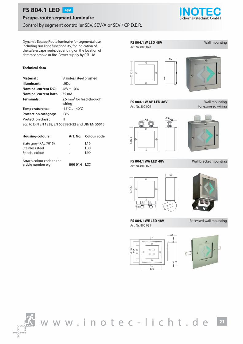
FS 804.1 LED 48V
Escape-route segment-luminaire Control by segment controller SEV, SEV/A or SEV / CP D.E.R.
Dynamic Escape Route luminaire for segmental use, including run light functionality, for indication of the safe escape route, depending on the location of detected smoke or �re. Power supply by PSU 48.
Technical data
Material : Stainless steel brushed Illuminant: LEDsNominal current DC : 48V ± 10%Nominal current batt. : 35 mATerminals : 2.5 mm² for feed-through
wiring Temperature ta : -15°C... +40°CProtection category: IP65Protection class : IIIacc. to DIN EN 1838, EN 60598-2-22 and DIN EN 55015
Housing-colours Art. No. Colour code
Slate grey (RAL 7015) ... L16Stainless steel ... L30Special colour ... L99
Attach colour code to the article number e.g. 800 014 LXX
Art. Nr. 800 028FS 804.1 W LED 48V Wall mounting
60
12
0
40
30
70
Art. Nr. 800 029FS 804.1 W AP LED 48V Wall mounting
for exposed wiring
6025
50
12
0
Art. Nr. 800 027FS 804.1 WA LED 48V Wall bracket mounting
60
q 1
20
Art. Nr. 800 031FS 804.1 WE LED 48V Recessed wall mounting
62
137
124
q 1
60
q 8
5

w w w . i n o t e c - l i c h t . d e
Sicherheitstechnik GmbH

23w w w . i n o t e c - l i c h t . d e
Sicherheitstechnik GmbH
FL 1530 24
FL 7188 / 7288 28
FL 808 / 828 32
FL 5103 / 5203 36
FL 5105 40
FL 3100 42
23w w w . i n o t e c - l i c h t . d e
With the dynamic emergency exit luminaires from the FL range, escape routes can be signposted, closed o� or changed, depending on the �re event.Luminaires FL 1530, FL 7188 and FL 808 are particularly suitable for use in a mix of dynamic and static emergency exit lumi-naires in a building, as these luminaire types are also available as static luminaires. In place of the static direction indicator, an arrow matrix indi-cates the safe route in the event of a �re, or closes o� a smoke-�lled area.
The FL range o�ers luminaires for almost every application – from robust stainless-steel luminaires with a high protection rating right through to state-of-the-art, elegantly designed luminaires from the ‘Straight Line’ range.
Dynamic emergency exit luminaires FL-Series

Sicherheitstechnik GmbH
w w w . i n o t e c - l i c h t . d e24
FL 1530 LED 230V
Straight-Line
for connection to D.E.R.-controller or CP D.E.R. 230V
Single-sided dynamic Straight-Line emergency exit luminaire made of high quality aluminium. Ideal to display the safe escape route depending on the smoke situation inside a building.
Technical data
Viewing distance : 30 m
Material : Aluminum powder-coated
Illuminant : LEDs
Nominal voltage AC : 230V ± 10%, 50/60Hz
Nominal voltage DC : 220V ± 20%
Nominal current : 33 mA
Power consumption : 14.3 VA
Terminals : 2.5 mm² for feed-through wiring
Temperature ta : -15°C... +40°C
Protection category : IP40
Protection class : I
acc. to DIN EN 60598-1, DIN EN 60598-2-22, DIN 4844-1 and DIN EN 1838
Pictograms exchangeable without tools
Housing-colours Part.no. Colour code
White (RAL 9016) ... L04Special colours ... L99
Attach the colour code to part number e.g. 800 014 LXX
Art. no. 800 141V
FL 1530 PM LED 230V Parallel to wall mounting
187
150
163
80
66
313
250
30
337
ø5
Art. no. 800 143V
FL 1530 WE LED 230V Recessed wall mounting
187
150
162
5048
31330 15
337
163
80
250
30ø5

Sicherheitstechnik GmbH
25w w w . i n o t e c - l i c h t . d ew w w . i n o t e c - l i c h t . d e
FL 1530 LED 24V
Straight-Line
for connection to D.E.R.-controller, CP 24V 2x2,5A or CLS 24 SV
Single-sided dynamic Straight-Line emergency exit luminaire made of high quality aluminium. Ideal to display the safe escape route depending on the smoke situation inside a building.
Technical data
Viewing distance : 30 m
Material : Aluminum powder-coated
Illuminant : LEDs
Nominal voltage DC : 24V ± 20%
Nominal current : 200 mA
Terminals : 2.5 mm² for feed-through wiring
Temperature ta : -15°C... +40°C
Protection category : IP40
Protection class : III
acc. to DIN EN 60598-1, DIN EN 60598-2-22, DIN 4844-1 and DIN EN 1838
Pictograms exchangeable without tools
Housing-colours Part.no. Colour code
White (RAL 9016) ... L04Special colours ... L99
Attach the colour code to part number e.g. 800 014 LXX
Art. no. 800 140V
FL 1530 PM LED 24V Parallel to wall mounting
187
150
163
80
66
313
250
30
337
ø5
Art. no. 800 142V
FL 1530 WE LED 24V Recessed wall mounting
187
150
162
5048
31330 15
337
163
80
250
30ø5

Sicherheitstechnik GmbH
w w w . i n o t e c - l i c h t . d e26
FL 1530 LED 230V
Straight-Line
for connection to D.E.R.-controller or CP D.E.R. 230V
Double-sided dynamic Straight-Line emergency exit luminaire made of high quality aluminium. Ideal to display the safe escape route depending on the smoke situation inside a building.
Technical data
Viewing distance : 30 m
Material : Aluminum powder-coated
Illuminant : LEDs
Nominal voltage AC : 230V ± 10%, 50/60Hz
Nominal voltage DC : 220V ± 20%
Nominal current : 33 mA (single-sided)66 mA (double-sided)
Power consumption : 14.3 VA (single-sided)28.6 VA (double-sided)
Terminals : 2.5 mm² for feed-through wiring
Temperature ta : -15°C... +40°C
Protection category : IP40
Protection class : I
acc. to DIN EN 60598-1, DIN EN 60598-2-22, DIN 4844-1 and DIN EN 1838
Pictograms exchangeable without tools
Housing-colours Part.no. Colour code
White (RAL 9016) ... L04Special colours ... L99
Attach the colour code to part number e.g. 800 014 LXX
Art. no. 800 147V
FL 1530 D LED 230V Ceiling mounting
187
222
150
20 50
80
25
300337
280
313 50
ø5
Art. no. 800 145V
FL 1530 P LED 230V Pendulum mounting
187
150
80300
220
337
308 46
56
0,5m
Art. no. 800 149V
FL 1530 WA LED 230V Wall bracket mounting
187222
150
8030
033
7
313
50

Sicherheitstechnik GmbH
27w w w . i n o t e c - l i c h t . d ew w w . i n o t e c - l i c h t . d e
FL 1530 LED 24V
Straight-Line
for connection to D.E.R.-controller, CP 24V 2x2,5A or CLS 24 SV
Double-sided dynamic Straight-Line emergency exit luminaire made of high quality aluminium. Ideal to display the safe escape route depending on the smoke situation inside a building.
Technical data
Viewing distance : 30 m
Material : Aluminum powder-coated
Illuminant : LEDs
Nominal voltage DC : 24V ± 20%
Nominal current : 200 mA (single-sided)400 mA (double-sided)
Terminals : 2.5 mm² for feed-through wiring
Temperature ta : -15°C... +40°C
Protection category : IP40
Protection class : III
acc. to DIN EN 60598-1, DIN EN 60598-2-22, DIN 4844-1 and DIN EN 1838
Pictograms exchangeable without tools
Housing-colours Part.no. Colour code
White (RAL 9016) ... L04Special colours ... L99
Attach the colour code to part number e.g. 800 014 LXX
Art. no. 800 146V
FL 1530 D LED 24V Ceiling mounting
187
222
150
20 50
80
25
300337
280
313 50
ø5
Art. no. 800 144V
FL 1530 P LED 24V Pendulum mounting
187
150
80300
220
337
308 46
56
0,5m
Art. no. 800 148V
FL 1530 WA LED 24V Wall bracket mounting
187222
150
8030
033
7
313
50
Sicherheitstechnik GmbH
w w w . i n o t e c - l i c h t . d e28
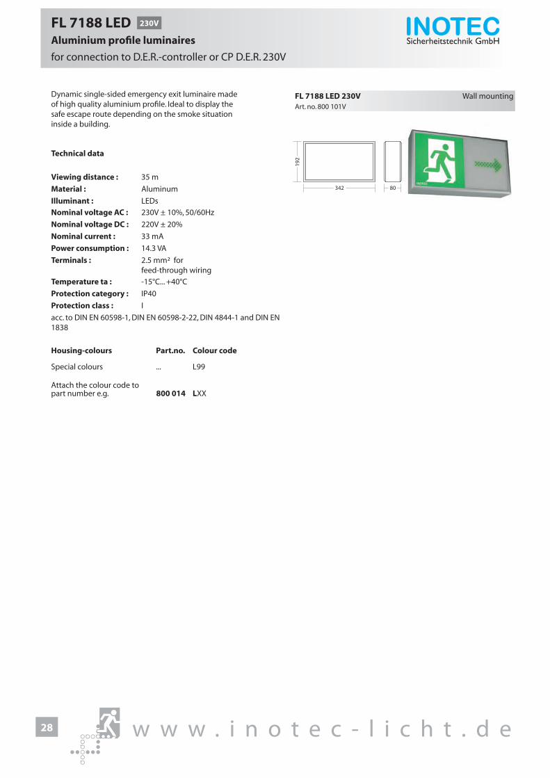
FL 7188 LED 230V
Aluminium profile luminaires
for connection to D.E.R.-controller or CP D.E.R. 230V
Dynamic single-sided emergency exit luminaire made of high quality aluminium profile. Ideal to display the safe escape route depending on the smoke situation inside a building.
Technical data
Viewing distance : 35 m
Material : Aluminum
Illuminant : LEDs
Nominal voltage AC : 230V ± 10%, 50/60Hz
Nominal voltage DC : 220V ± 20%
Nominal current : 33 mA
Power consumption : 14.3 VA
Terminals : 2.5 mm² for feed-through wiring
Temperature ta : -15°C... +40°C
Protection category : IP40
Protection class : I
acc. to DIN EN 60598-1, DIN EN 60598-2-22, DIN 4844-1 and DIN EN 1838
Housing-colours Part.no. Colour code
Special colours ... L99
Attach the colour code to part number e.g. 800 014 LXX
Art. no. 800 101V
FL 7188 LED 230V Wall mounting
192
342 80

Sicherheitstechnik GmbH
29w w w . i n o t e c - l i c h t . d ew w w . i n o t e c - l i c h t . d e
FL 7188 LED 24V
Aluminium profile luminaires
for connection to D.E.R.-controller, CP 24V 2x2,5A or CLS 24 SV
Dynamic single-sided emergency exit luminaire made of high quality aluminium profile. Ideal to display the safe escape route depending on the smoke situation inside a building.
Technical data
Viewing distance : 35 m
Material : Aluminum
Illuminant : LEDs
Nominal voltage DC : 24V ± 20%
Nominal current : 200 mA
Terminals : 2.5 mm² for feed-through wiring
Temperature ta : -15°C... +40°C
Protection category : IP40
Protection class : III
acc. to DIN EN 60598-1, DIN EN 60598-2-22, DIN 4844-1 and DIN EN 1838
Housing-colours Part.no. Colour code
Special colours ... L99
Attach the colour code to part number e.g. 800 014 LXX
Art. no. 800 100V
FL 7188 LED 24V Wall mounting
192
342 80

Sicherheitstechnik GmbH
w w w . i n o t e c - l i c h t . d e30
FL 7288 LED 230V
Aluminium profile luminaires
for connection to D.E.R.-controller or CP D.E.R. 230V
Dynamic double-sided emergency exit luminaire made of high quality aluminium profile. Ideal to display the safe escape route depending on the smoke situation inside a building.
Technical data
Viewing distance : 35 m
Material : Aluminum
Illuminant : LEDs
Nominal voltage AC : 230V ± 10%, 50/60Hz
Nominal voltage DC : 220V ± 20%
Nominal current : 33 mA (single-sided)66 mA (double-sided)
Power consumption : 14.3 VA (single-sided)28.6 VA (double-sided)
Terminals : 2.5 mm² for feed-through wiring
Temperature ta : -15°C... +40°C
Protection category : IP40
Protection class : I
acc. to DIN EN 60598-1, DIN EN 60598-2-22, DIN 4844-1 and DIN EN 1838
Housing-colours Part.no. Colour code
Special colours ... L99
Attach the colour code to part number e.g. 800 014 LXX
Art. no. 800 103V
FL 7288 D LED 230V Ceiling mounting
192
25
342 80
260
Art. no. 800 107V
FL 7288 P LED 230V Pendulum mounting
192
342 80
500
220
Art. no. 800 105V
FL 7288 WA LED 230V Wall bracket mounting
2019
2
342 80
20
Art. no. 800 109V
FL 7288 K LED 230V Chain mounting
192
342 80
246

Sicherheitstechnik GmbH
31w w w . i n o t e c - l i c h t . d ew w w . i n o t e c - l i c h t . d e
FL 7288 LED 24V
Aluminium profile luminaires
for connection to D.E.R.-controller, CP 24V 2x2,5A or CLS 24 SV
Dynamic double-sided emergency exit luminaire made of high quality aluminium profile. Ideal to display the safe escape route depending on the smoke situation inside a building.
Technical data
Viewing distance : 35 m
Material : Aluminum
Illuminant : LEDs
Nominal voltage DC : 24V ± 20%
Nominal current : 200 mA (single-sided)400 mA (double-sided)
Terminals : 2.5 mm² for feed-through wiring
Temperature ta : -15°C... +40°C
Protection category : IP40
Protection class : III
acc. to DIN EN 60598-1, DIN EN 60598-2-22, DIN 4844-1 and DIN EN 1838
Housing-colours Part.no. Colour code
Special colours ... L99
Attach the colour code to part number e.g. 800 014 LXX
Art. no. 800 102V
FL 7288 D LED 24V Ceiling mounting
192
25
342 80
260
Art. no. 800 106V
FL 7288 P LED 24V Pendulum mounting
192
342 80
500
220
Art. no. 800 104V
FL 7288 WA LED 24V Wall bracket mounting
2019
2
342 80
20
Art. no. 800 108V
FL 7288 K LED 24V Chain mounting
192
342 80
246

Sicherheitstechnik GmbH
w w w . i n o t e c - l i c h t . d e32
FL 808 LED 230V
Stainless steel luminaires
for connection to D.E.R.-controller or CP D.E.R. 230V
Dynamic single-sided emergency exit luminaire made of robust stainless steel with high protection category. Ideal to display the safe escape route depending on the smoke situation inside a building.
Technical data
Viewing distance : 30 m
Material : Stainless steel A4 brushed
Illuminant : LEDs
Nominal voltage AC : 230V ± 10%, 50/60Hz
Nominal voltage DC : 220V ± 20%
Nominal current : 33 mA
Power consumption : 14.3 VA
Terminals : 2.5 mm² for feed-through wiring
Temperature ta : -15°C... +40°C
Protection category : IP65
Protection class : I
acc. to DIN EN 60598-1, DIN EN 60598-2-22, DIN 4844-1 and DIN EN 1838
Housing-colours Part.no. Colour code
White (RAL 9016) ... L04Dark grey (RAL 7015) ... L16Special colours ... L99
Attach the colour code to part number e.g. 800 014 LXX
Art. no. 800 181V
FL 808 LED 230V Wall mounting
348
75
198

Sicherheitstechnik GmbH
33w w w . i n o t e c - l i c h t . d ew w w . i n o t e c - l i c h t . d e
FL 808 LED 24V
Stainless steel luminaires
for connection to D.E.R.-controller, CP 24V 2x2,5A or CLS 24 SV
Dynamic single-sided emergency exit luminaire made of robust stainless steel with high protection category. Ideal to display the safe escape route depending on the smoke situation inside a building.
Technical data
Viewing distance : 30 m
Material : Stainless steel A4 brushed
Illuminant : LEDs
Nominal voltage DC : 24V ± 20%
Nominal current : 200 mA
Terminals : 2.5 mm² for feed-through wiring
Temperature ta : -15°C... +40°C
Protection category : IP65
Protection class : III
acc. to DIN EN 60598-1, DIN EN 60598-2-22, DIN 4844-1 and DIN EN 1838
Housing-colours Part.no. Colour code
White (RAL 9016) ... L04Dark grey (RAL 7015) ... L16Special colours ... L99
Attach the colour code to part number e.g. 800 014 LXX
Art. no. 800 180V
FL 808 LED 24V Wall mounting
348
75
198

Dynamic double-sided emergency exit luminaire made of robust stainless steel with high protection category. Ideal to display the safe escape route depending on the smoke situation inside a building.
Technical data
Viewing distance : 30 m
Material : Stainless steel A4 brushed
Illuminant : LEDs
Nominal voltage AC : 230V ± 10%, 50/60Hz
Nominal voltage DC : 220V ± 20%
Nominal current : 33 mA (single-sided)66 mA (double-sided)
Power consumption : 14.3 VA (single-sided)28.6 VA (double-sided)
Terminals : 2.5 mm² for feed-through wiring
Temperature ta : -15°C... +40°C
Protection category : IP65
Protection class : I
acc. to DIN EN 60598-1, DIN EN 60598-2-22, DIN 4844-1 and DIN EN 1838
Housing-colours Part.no. Colour code
White (RAL 9016) ... L04Dark grey (RAL 7015) ... L16Special colours ... L99
Attach the colour code to part number e.g. 800 014 LXX
Art. no. 800 183V
FL 828 K LED 230V Chain mounting
348
78
198
Art. no. 800 185V
FL 828 WA LED 230V Wall bracket mounting
348398
82
198
160
Sicherheitstechnik GmbH
w w w . i n o t e c - l i c h t . d e34
FL 828 LED 230V
Stainless steel luminaires
for connection to D.E.R.-controller or CP D.E.R. 230V

Dynamic double-sided emergency exit luminaire made of robust stainless steel with high protection category. Ideal to display the safe escape route depending on the smoke situation inside a building.
Technical data
Viewing distance : 30 m
Material : Stainless steel A4 brushed
Illuminant : LEDs
Nominal voltage DC : 24V ± 20%
Nominal current : 200 mA (single-sided)400 mA (double-sided)
Terminals : 2.5 mm² for feed-through wiring
Temperature ta : -15°C... +40°C
Protection category : IP65
Protection class : III
acc. to DIN EN 60598-1, DIN EN 60598-2-22, DIN 4844-1 and DIN EN 1838
Housing-colours Part.no. Colour code
White (RAL 9016) ... L04Dark grey (RAL 7015) ... L16Special colours ... L99
Attach the colour code to part number e.g. 800 014 LXX
Art. no. 800 182V
FL 828 K LED 24V Chain mounting
348
78
198
Art. no. 800 184V
FL 828 WA LED 24V Wall bracket mounting
348398
82
198
160
Sicherheitstechnik GmbH
35w w w . i n o t e c - l i c h t . d ew w w . i n o t e c - l i c h t . d e
FL 828 LED 24V
Stainless steel luminaires
for connection to D.E.R.-controller, CP 24V 2x2,5A or CLS 24 SV

Sicherheitstechnik GmbH
w w w . i n o t e c - l i c h t . d e36
FL 5103 LED 230V
Straight line for connection to D.E.R.-Controller or CP D.E.R. 230V
Single-sided emergency exit luminaires in modular design with freely selectable equipping. Displaying the escape route depending on the smoke situation inside a building.
Technical data
Viewing distance : 20 mMaterial : Sheet steel powder-coatedIlluminant : LEDsNominal voltage AC : 230V ± 10%, 50Hz/60HzNominal voltage DC : 220V ± 20%Nominal current batt : 9 mA per module
(white+green LEDs)or 18 mA (red LEDs)
Apparent power : 2.0 VA per module (white+green LEDs)or 4.0 VA (red LEDs)
Terminals : 2.5 mm² for feed-through wiring
Temperature ta : -15°C... +40°CProtection category : IP40Protection class : Iacc. to DIN EN 60598-1, DIN EN 60598-2-22, DIN 4844-1 and DIN EN 1838
Housing-colours Art. No. Colour code
White (RAL 9016) ... L04Slate grey (RAL 7015) ... L16Special colour ... L99
Attach colour code to the article number e.g. 800 014 LXX
Art. Nr. 800 018VFL 5103 LED 230V Wall mounting
400 61
130
Art. Nr. 800 019VFL 5103 WE LED 230V Recessed wall mounting
400 60 6
130
39315
5

Sicherheitstechnik GmbH
FL 5103 LED 24V
Straight linefor connection to D.E.R.-Controller, CP 24V 2x2.5A or CLS 24 SV
Single-sided emergency escape luminaires in modular design with freely selectable equipping. Displaying the escape route depending on the smoke situation inside a building.
Technical data
Viewing distance : 20 mMaterial : Sheet steel powder-coatedIlluminant : LEDsNominal voltage DC : 24V ± 20%Nominal voltage batt : 63 mA per module
(white+green LEDs)or 150 mA (red LEDs)
Terminals : 2.5 mm² for feed-throughwiring
Temperatur ta : -15°C... +40°CProtection category : IP40Protection class : IIIacc. to DIN EN 60598-1, DIN EN 60598-2-22, DIN 4844-1 and DIN EN 1838
Housing-colours Art. No. Colour Code
White (RAL 9016) ... L04Slate grey (RAL 7015) ... L16Special colour ... L99
Attach colour code to the article number e.g 800 014 LXX
Art. Nr. 800 012VFL 5103 LED 24V Wall mounting
400 61
130
Art. Nr. 800 013VFL 5103 WE LED 24V Recessed wall mounting
400 60 6
130
39315
5
37w w w . i n o t e c - l i c h t . d ew w w . i n o t e c - l i c h t . d e

Sicherheitstechnik GmbH
w w w . i n o t e c - l i c h t . d e38
FL 5203 LED 230V
Modul luminaires for connection to D.E.R.-Controller or CP D.E.R. 230V
Single- or double-sided emergency exit luminaire in modular design with freely selectable equipping. Displaying the escape route depending on the smoke situation inside a building.
Technical data
Viewing distance : 20 mMaterial : Steel sheet powder-coated Illuminant : LEDsNominal voltage AC : 230V ± 10%, 50Hz/60HzNominal voltage DC : 220V ± 20%Nominal current batt : 9 mA per module
(white+green LEDs)or 18 mA (red LEDs)
Apparent power : 2.0 VA per module (white+green LEDs)or 4.0 VA (red LEDs)
Terminals : 2.5 mm² for feed-through wiring
Temperature ta : -15°C... +40°CProtection category : IP40Protection class : Iacc. to DIN EN 60598-1, DIN EN 60598-2-22, DIN 4844-1 and DIN EN 1838
Housing colour Art. No. Colour code
White (RAL 9016) ... L04Slate grey (RAL 7015) ... L16Special colour ... L99
Attach colour code to the article number e.g. 800 014 LXX
Art. Nr. 800 300VFL 5203 D LED 230V Ceiling mounting
280
84
131
400
36
Art. Nr. 800 300V
Art. Nr. 800 304V
FL 5203 WA LED 230V
FL 5203 P LED 230V
Wall bracket mounting
Pendulum mounting
280
84131
400
36
280
84
131
400
300
36

Sicherheitstechnik GmbH
FL 5203 LED 24V
Modul luminairesfor connection to D.E.R.-Controller, CP 24V 2x2.5A or CLS 24 SV
Single- or double-sided emergency exit luminaire in modular design with freely selectable equipping. Displaying the escape route depending on the smoke situation inside a building.
Technical data
Viewing distance : 20 mMaterial : Steel sheet powder-coatedIlluminant : LEDsNominal voltage DC : 24V ± 20%Nominal current batt : 63mA per module
(white+green LEDs)or 150 mA (red LEDs)
Terminals : 2.5 mm² for feed-throughwiring
Temperature ta : -15°C... +40°CProtection category : IP40Protection class : IIIacc. to DIN EN 60598-1, DIN EN 60598-2-22, DIN 4844-1 and DIN EN 1838
Housing colour Art. No. Colour code
White (RAL 9016) ... L04Slate grey (RAL 7015) ... L16Special colour ... L99
Attach colour code to the article number e.g. 800 014 LXX
Art. Nr. 800 302VFL 5203 D LED 24V Celing mounting
280
84
131
400
36
Art. Nr. 800 302V
Art. Nr. 800 306V
FL 5203 WA LED 24V
FL 5203 P LED 24V
Wall bracket mounting
Pendulum mounting
280
84131
400
36
280
84
131
400
300
36
39w w w . i n o t e c - l i c h t . d ew w w . i n o t e c - l i c h t . d e

Sicherheitstechnik GmbH
w w w . i n o t e c - l i c h t . d e40
FL 5105 LED 230V
Modul luminaires for connection to D.E.R.-Controller or CP D.E.R. 230V
Single-sided dynamic emergency exit luminaire in modular design with freely selectable equipping. Displaying the escape route depending on the develop-ment of the smoke.
Technical data
Viewing distance : 20 mMaterial : Steel sheet powder-coatedIlluminant : LEDsNominal voltage AC : 230V ± 10%, 50Hz/60HzNominal voltage DC : 220V ± 20%Nominal current batt : 9 mA per module
(white+green LEDs)or 18 mA (red LEDs)
Apparent power : 2.0 VA per module (white+green LEDs)or 4.0 VA (red LEDs)
Terminals : 2.5 mm² for feed-through wiring
Temperatur ta : -15°C... +40°CProtection category : IP40Protection class : Iacc. to DIN EN 60598-1, DIN EN 60598-2-22, DIN 4844-1 and DIN EN 1838
Housing colours Art. No. Colour code
White (RAL 9016) ... L04Slate grey (RAL 7015) ... L16Special colour ... L99
Attach colour code to the article number e.g. 800 014 LXX
Art. Nr. 800 022VFL 5105 LED 230V Wall mounting
640 53
130
Art. Nr. 800 023VFL 5105 WE LED 230V Recessed wall mounting
633 60 613
0
64015
5

Sicherheitstechnik GmbH
FL 5105 LED 24V
Modul luminairesfor connection to D.E.R.-Controller, CP 24V 2x2.5A or CLS 24 SV
Single-sided dynamic emergency exit luminaire in mod-ular design with freely selectable equipping. Displaying the escape route depending on the development of the smoke of the �re.
Technical data
Viewing distance : 20 mMaterial : Steel sheet powder-coated Illuminant : LEDsNominal voltage DC : 24V ± 20%Nominal current batt : 63 mA per module
(white+green LEDs)or 150 mA (red LEDs)
Terminals : 2.5 mm² for feed-through wiring
Temperature ta : -15°C... +40°CProtection category : IP40Protection class : IIIacc. to DIN EN 60598-1, DIN EN 60598-2-22, DIN 4844-1 and DIN EN 1838
Housing colours Art. No. Colour code
White (RAL 9016) ... L04Slate grey (RAL 7015) ... L16Special colour ... L99
Attach colour code to the article number e.g. 800 014 LXX
Art. Nr. 800 014VFL 5105 LED 24V Wall mounting
640 53
130
Art. Nr. 800 015VFL 5105 WE LED 24V Recessed wall mounting
633 60 613
0
64015
5
41w w w . i n o t e c - l i c h t . d ew w w . i n o t e c - l i c h t . d e

Sicherheitstechnik GmbH
w w w . i n o t e c - l i c h t . d e42
FL 3100 WE LED 230V
Modulleuchtenfor connection to D.E.R.-Controller or CP D.E.R. 230V
Dynamic modular luminaire with freely selectable equipping. Displaying the escape route depending on the smoke situation inside a building. With integrated LED safety luminaire.
Technical data
Material : Steel sheet powder-coated Illuminant: LEDsNominal voltage AC : 230V ± 10%, 50Hz/60HzNominal voltage DC : 220V ± 20%Nominal current batt. : 9 mA per module
(white+green LEDs)Apparent power : 2.0 VA per module
(white+green LEDs)Terminals : 2.5 mm² for feed-through
wiringTemperature ta : -15°C... +40°CProtection category : IP40Protection class : Iacc. to DIN EN 60598-1, DIN EN 60598-2-22, DIN 4844-1 and DIN EN 1838
Housing-colours Art. No. Colour code
White (RAL 9016) ... L04Slate grey (RAL 7015) ... L16Special colour ... L99
Attach colour code to the article number e.g. 800 014 LXX
Art. Nr. 800 152VFL 3100 WE LED 230V Recessed wall mounting
313,5 59
213,
5
184
Art. Nr. 800 152VFL 3100 WE_S LED 230V Recessed wall mounting
313,5 55
213,
5

Sicherheitstechnik GmbH
43w w w . i n o t e c - l i c h t . d ew w w . i n o t e c - l i c h t . d e
FL 3100 WE LED 24V
Modulleuchtenfor connection to D.E.R.-Controller, CP 24V 2x2.5A or CLS 24 SV
Dynamic modular luminaire with freely selectable equipping. Displaying the escape route depending on the smoke situation inside a building. With integrated LED safety luminaire.
Technical data
Material : Stahlblech pulverbeschichtetIlluminant : LEDsNominal voltage DC : 24V ± 20%Nominal current batt. : pro Modul 63 mA
(weiße+grüne LEDs)Terminals : 2,5 mm² für Durchgangs-
verdrahtungTemperature ta : -15°C... +40°CProtection category : IP40Protection class : IIIacc. to DIN EN 60598-1, DIN EN 60598-2-22, DIN 4844-1 and DIN EN 1838
Housing-colours Art.Nr. Farbcode
White (RAL 9016) ... L04Slate grey (RAL 7015) ... L16Special colour ... L99
Attach colour code to the article number e.g. 800 014 LXX
Art. Nr. 800 151VFL 3100 WE LED 24V Recessed wall mounting
313,5 59
213,
5
184
Art. Nr. 800 151VFL 3100 WE_S LED 24V Recessed wall mounting
313,5 55
213,
5

w w w . i n o t e c - l i c h t . d e
Sicherheitstechnik GmbH

45w w w . i n o t e c - l i c h t . d e
Sicherheitstechnik GmbH
FB 5000 24V 46
FB 5000 WE 47
Sicherheitstechnik GmbH
Flash lightsFB series
Flash lights are ideal as additional identi�cation marking for escape doors. The luminaires are equipped with a bright xenon light source. In the event of a �re, the luminaires are activated and clearly indicate a safe escape door with a bright xenon light illuminant.

Sicherheitstechnik GmbH
w w w . i n o t e c - l i c h t . d e46
FB 5000 24V
Flashing luminaire
for connection to S2024-Modul in conjunction with D.E.R.-controller
Xenon-flash luminaire for surface mounting to display the safe escape route.
Technical data
Material : Polycarbonate
Illuminant : Xenon flashing lamp
Nominal voltage DC : 24V ± 20%
Nominal current : 117 mA
Terminals : 1.5mm²
Temperature ta : -15°C... +40°C
Protection category : IP67
Protection class : III
acc. to DIN EN 60598-1, DIN EN 60598-2-22, DIN 4844-1 and DIN EN 1838
Art. no. 800 021
FB 5000 24V Wall or ceiling mounting
55
ø81
55
ø81

Sicherheitstechnik GmbH
47w w w . i n o t e c - l i c h t . d ew w w . i n o t e c - l i c h t . d e
FB 5000 WE 230V
Flashing luminaire
for connection to S2000-Modul in conjunction with D.E.R.-controller
Xenon-flash luminaire designed for mounting in 68mm switch-box to display the safe escape route.
Technical data
Material : Stainless steel A4 brushed
Illuminant : Xenon flashing lamp
Nominal voltage AC : 230V ± 10%, 50/60Hz
Nominal voltage DC : 220V ± 20%
Nominal current : 20 mA
Power consumption : 7.3 VA
Terminals : 1.5mm²
Temperature ta : -15°C... +40°C
Protection category : IP20
Protection class : I
acc. to DIN EN 60598-1, DIN EN 60598-2-22, DIN 4844-1 and DIN EN 1838
Art. no. 800 130
FB 5000 WE 230V Recessed wall mounting
ø74
50
6,5
ø90
ø
58

w w w . i n o t e c - l i c h t . d e
Sicherheitstechnik GmbH

49w w w . i n o t e c - l i c h t . d e
Sicherheitstechnik GmbH
Interface and control module 50
SEV 51
Change-over devices and BUS sub-station 53
D.E.R.-Controller 54
PSU 55
INOTEC o�ers a wide range of control and monitoring sys-tems. Modules for controlling third-party luminaires, system-independent control units and SKUs for INOTEC central power systems provide the right solution for every type of application. Di�erent power supply units ensure a controlled power supply for the FS luminaires, or create a control voltage.
ControlMonitoringPower supply

Sicherheitstechnik GmbH
w w w . i n o t e c - l i c h t . d e50
LSA 8.1 24VArt. Nr. 850 007
S 2000Art. Nr. 851 012Art. Nr. 851 048
for FW 99 cardfor CP D.E.R. 2x2.5A 230V
S 2024Art. Nr. 851 037Art. Nr. 851 047
for FW 99 cardfor CP D.E.R. 2x2.5A 230V
90
3040
9071,5
59
90
3040
Monitoring, supply and control module for 1–6 power LEDs for connection to the FW99 card of a D.E.R. controller (bus), and a secured power supply system e.g. CP D.E.R. 2x2.5A 230V change-over device for the INOTEC central battery system CPS 220/64/20 (consider the acc. part no).Flashing function, on-/o�-switching for connected LEDs.2-pin header for connecting LEDs.Also suitable for powering and controlling the 24V �ash light FB 5000 24V.
Interface for connection to D.E.R. controller (max. 3 per control-ler). Pre-programmed escape route patterns can be activated in the D.E.R. controller via 8 input switches. The input voltage of the LSA 8.1 channels may be 15V–30V DC. It is switched via volt-free contacts, those of a �re alarm system, for instance.
Function-monitored control module for connection to FW99 card and a secured power supply system e.g. CPS D.E.R. 2x2.5A 230V change-over device for the INOTEC central battery system CPS 220/64/20 (consider the according part no.). The module can be used to switch loads of up to 120W.
Technical data
Housing material: Polycarbonate UL V0Input voltage: 230V 50 Hz /60 Hz, 220V +/- 20% DCOutput voltage: 24V DCAmb. temp. range: - 15°C...+ 50°CProtection class: ILeiteranschluss: 2,5mm² eindrähtig oder 1,5mm² Litze
mit Aderendhülse
Technical data
Housing material: Polycarbonate UL V0Input voltage: 230V 50 Hz /60 Hz, 220V +/- 20% DCOutput voltage: 230V 50 Hz /60 Hz, 220V +/- 20% DCAmb. temp. range: - 15°C...+ 50°CProtection class: ILeiteranschluss: 2,5mm² eindrähtig oder 1,5mm² Litze
mit Aderendhülse
Interface and control module

Sicherheitstechnik GmbH
SEV/CP D.E.R.Art. Nr.
9071,5
59
Module for programming, controlling, managing and testing up to 96 FS luminaires.Connection to CP D.E.R. change-over device for central bat-tery systems CPS 220/64 and CPS 220/20. Two-line display, programming and testing buttons,red LED for fault indication. Input voltage of 48V via a controlled power supply such as PSU 48.
Technical data
Housing material: Polycarbonate DIN rail housingInput voltage: 48VOutput voltage: 48VAddress range: SEV 01-99
Luminaires 01-96Terminals: Twin terminal 1.5mm²Amb. temp. range: - 15°C...+ 50°CPower consumption: max. 1.7WProtection category: IP 20Maße: 90mm x 70mm x 58mm (HxBxT)
SEVArt. Nr. 990 053Module for programming, controlling
managing and testing up to 96 FS luminaires. Connection to D.E.R.-controller via 2-wire bus line.Two-line display, programming and testing buttons, red LED for fault indication. Input voltage of 48V via a controlled power supply such as PSU 48.
9071,5
59
Technical data
Housing material: Polycarbonate DIN rail housingInput voltage: 48VOutput voltage: 48VAddress range: SEV 01-99
Luminaires 01-96Terminals: Twin terminal 1.5mm²Amb. temp. range: - 15°C...+ 50°CPower consumption: max. 1.7WProtection category: IP 20Dimensions: 90mm x 70mm x 58mm (HxWxD)
SEV / CP D.E.R. and SEVSegment controller for controlling and monitoring FS-luminaires for connection to CPS 220/64, CPS 220/20 or D.E.R.-Controller
51w w w . i n o t e c - l i c h t . d ew w w . i n o t e c - l i c h t . d e

Sicherheitstechnik GmbH
w w w . i n o t e c - l i c h t . d e52
SEV/AArt. Nr. 990 065Stand alone module for programming, controlling,
managing and testing up to 96 FS luminaires.Two-line display, programming and testing buttons,red LED for fault indication. Wide voltage input (24V to 48V DC) for creating scenarios. Two scenarios can be programmed. Automatic function test.Volt-free fault-signalling contacts (NO-contacts) 48V input voltage via a controlled power supply such as PSU 48.
9071,5
59
Technical data
Housing material: Polycarbonate DIN rail housingInput voltage: 48VOutput voltage: 48VAddress range: SEV 01-99
Luminaires 01-96Terminals: Twin terminal 1.5mm²Amb. temp. range: - 15°C...+ 50°CPower consumption: max. 1.7WProtection category: IP 20Dimensions: 90mm x 70mm x 58mm (HxWxD)
SEV / ASegment controller for controlling and monitoring FS luminaires for stand-alone use

Sicherheitstechnik GmbH
CP D.E.R. 2x2,5A 230VArt. Nr. 979 010
CP 24V 2x2,5AArt. Nr. 979 009
CPUSB 220/64/1-2,5/24VArt. Nr. 922 261
24V change-over device with 2 circuits for central battery systems CPS 220/64 and CPS 220/20 in combination with TFT control unit for powering, controlling and monitoring 24V D.E.R. luminaires (FL Series). Mixed operation within a circuit with 24V INOTEC LED-sys-tem luminaires.- 2-pole fusing for each circuit - individual luminaire control and monitoring - max. 20 luminaires per circuit- controlling and monitoring without data line - luminaires can be individually programmed and addressed - 2 output circuits in protection class III (SELV) @ 2.5A- every luminaire can have 8 input switches freely assigned to it
Bus sub-station CPUSB with 2 circuits for connection to central battery system CPS 220/64 in combination with TFT control unit for powering, controlling and monitoring 24V D.E.R. luminaires (FL Series). Mixed operation withina circuit with 24V INOTEC LED-system luminaires- 2-pole fusing per circuit - individual luminaire control and monitoring - max. 20 luminaires per circuit - controlling and monitoring without data line - luminaires can be individually programmed and addressed - 2 output circuits in protection class lll (SELV) @ 2,5A - every luminaire can have 8 input switches freely assigned to it
230V change-over device for central battery systems CPS 220/64 and CPS 220/20 in combination with TFT control unit for powering, controlling and monitoring 230V D.E.R. luminaires (FL Series), S modules and FS luminaires (FS luminaires only in combination with SEV/CP D.E.R. and PSU 48). - 2 circuits, each with 2-pole fusing- one bus per change-over device- individual luminaire control and monitoring - max. 20 luminaires per circuit- 5-core circuit wiring- every luminaire (every device address) can have 8 input
switches freely assigned to it
Change-over devices and BUS substation for central battery system CPS 220/64 and CPS 220/20
181
378
53w w w . i n o t e c - l i c h t . d ew w w . i n o t e c - l i c h t . d e

Sicherheitstechnik GmbH
w w w . i n o t e c - l i c h t . d e54
D.E.R.-ControllerArt. Nr. 869 011
Expansion module D.E.R.-ControllerArt. Nr. 851 008
FW 99 moduleArt. Nr. 851 011
Visu-Modul INOLanArt. Nr. 851 024 Art. Nr. 990 063
Fully automated microprocessor-controlled testing device for mon-itoring max. 1584 addresses in combination with INOTEC FS Series luminaires, S2000 or S2024 modules and SEV segment controllers. Suitable for max. 6 cards (FW99 and Visu).Serial data bus via a 2-core unshielded data line, e.g. YR 2 x 0.8.Freely programmable auto function test for all connected lumi-naires, modules and segment controllers. Error messages:
- defective luminaire- communication failure- device failure
The following functions are available as standard: - all the test results of the past two years are automatically saved
and can be retrieved at any time (up to 2000 events) - printer interface for maintaining the required logbook as per
DIN VDE 0108- volt-free group alarm contact
Options:The controller can be expanded with expansion modules (max. 16 cards per controller).
240
85
355
240
Technical data
Housing material: PolycarbonateNominal voltage: 230 V AC ± 10 %, 50 Hz /60 Hz
220 V DC ± 20 %Protection class: IIProtection category: IP30
Accessories
FW 99 moduleCard for D.E.R. controller for controlling, managing and testing up to 99 bus nodes such as luminaires in the FL range, SEV segment controllers, or an S 2000 or S 2024 module.
Visu module Card for D.E.R. controller as interface for data transmission to a PC with SVPCn software in association with an InoLan module for visualising a D.E.R. system.
INOLan moduleConverter between Ethernet and serial INOTEC-RTG data bus or RS 232.
240
85
255
240
D.E.R.-ControllerCentral control and monitoring module with accessories

Sicherheitstechnik GmbH
PSU 24 Power supply unitArt. Nr. 965 301
PSU 48-1 Power supply unitArt. Nr. 965 300
PSU 48-1,6 Power supply unitArt. Nr. 146 012
PSU 48-5 Power supply unitArt. Nr. 146 013
Controlled power supply with mains and overload indication using LED (only PSU 24 and 48-1).Output electrically isolated in accordance with EN 60950 (Low Volt-age Directive). Suitable for switchboard installation on DIN rails. Various models are available with di�erent output currents to power SEV segment controllers with luminaires in the FS range (48V) and the LAS8 interface (24V).
90
45
70
60
Technical speci�cations (PSU 24 and 48-1)
Housing material: Thermoplastic (depending on the ver-sion)
Input voltage: 230 V +/- 15% AC, 184V - 260V DCOutput voltage: 24V (PSU 24) or 48V (PSU 48-1)Output current: 1.5A (PSU 24) and 1A (PSU 48-1)Overload capacity: Short-circuit proofAmb. temp. range: -20°C ... +55°CProtection category: IP20 (terminal)Protection class: I
Technical speci�cations (PSU 48-1.6 and 48-5)
Housing material: AluminiumInput voltage: 230V AC, 120V - 370V DCOutput voltage: 48V DCOutput current: 1.6A (PSU 48-1.6) and 5A (PSU 48-5)Overload capacity: Short-circuit proofAmb. temp. range: -10°C ... +60°CProtection category: IP20 (terminal)Protection class: I
90
45
70
60
55,5100
125,
2
125,5100
125,
2
PSU 24 / 48Controlled power supply
55w w w . i n o t e c - l i c h t . d ew w w . i n o t e c - l i c h t . d e

w w w . i n o t e c - l i c h t . d e
Sicherheitstechnik GmbH

INOView 58
INOWeb / INOWeb-Control 61
SVPCn 62
57w w w . i n o t e c - l i c h t . d e
Sicherheitstechnik GmbHSicherheitstechnik GmbH
The convenient solution for centrally monitoring the D.E.R. system from your PC via a bus line and/or a network connec-tion
Monitoring software

w w w . i n o t e c - l i c h t . d e58
Sicherheitstechnik GmbH
Clear and easy to use
The customisable user interface makes it easy to quickly locate a fault. The detailed view is key to its use. The outline view on the left is used to select the entry to be displayed in the detailed view. With the INOView software, multiple detailed views can be opened at the same time. In this way, for instance, the status of a central power system can be displayed in one detailed view, while another shows the information about the battery.The right-hand mouse button calls up a context menu with more functions. A list of the faulty systems shows immediately where action is needed. A double click opens the corresponding emergency system in the detailed view.
1 Menu bar
2 Tree view of the registered emergency systems
3 Opened detailed views
4 Detailed view
5 List of faulty emergency lighting systems
6 Status bar
7 Context menu
8 Navigation path
9 System status
Central monitoring
the detailed view. With the INOView software, multiple 1
action is needed. A double click opens the corresponding 2
5
7
6

Sicherheitstechnik GmbH
8
9
INOView ease of use
3
4
59w w w . i n o t e c - l i c h t . d ew w w . i n o t e c - l i c h t . d e

w w w . i n o t e c - l i c h t . d e60
Sicherheitstechnik GmbH
State-of-the-art client / server architecture State-of-the-art client / server architecture means that this is a secure, future-proof investment. Multiple users on the network can access the information in the INOView software simultaneously, via the clients. Integrated user administration protects the software against unauthorised access.
Powerful and easy to use With INOView, your emergency lighting systems are clearly laid out and ‘at your �ngertips’. Intuitive user menus are simple and easy to use, and you can tailor how the informa-tion is displayed for maximum transparency. INOView grows with its challenge. Whether a school or an airport, with state of the art technology responds to the individual customer´s requirements.
INOView is the main monitoring solution for all INOTEC emergency lighting systems. This software is used wherever a �exible application is required that can grow with the pro-ject. The devices are monitored via a 3-core RTG bus and/or a network connection.
Everything at a glance for personal safety in the buildings The ease of use was the main focus when developing the vis-ualisation software INOView. Hereby the intuitive user inter-face was created with clearly structured system overviews and description texts. At just a glance, the user recognises the overall condition of the emergency lighting systems and may optionally quickly take measures to guarantee the safety of people in the building. The INOView software ensures transparency and provides comprehensive and detailed information on the overall and detailed system status.
INOView - �exible monitoring
InoViewClient
InoViewServer
RTGCOM Port 1
RTGCOM Port 2
max. 32 Geräte
max. 32 Geräte
InoViewClient
InoViewClient
InoViewClient

Sicherheitstechnik GmbH
The emergency lighting systems are monitored by accessing the controller’s INOWeb functionality via a web browser. The status of each system, circuit and luminaire can be checked from the (optionally) password-protected website. With an existing connection to the Internet, it is also possible to use a PC with internet access for monitoring. Please contact your regional technical sales team for a demonstration.
Functions � Starting a function test/ battery duration test � Blocking /releasing � Failure printout� Linking �les / websites by circuit
Using the INOWeb-Control software, com-plex installations with di�erent system types can be monitored from a central loca-tion. The devices just have to be integrated into the existing network.
INOWeb function for centrally monitoring the CPS 220/64 and CPS 220/20 central battery systems, together with the CLS decentralised emergency system over an intranet or the Internet. Connection has to be done to an existing network.
1 UG Verteilerraum Betrieb Systemfehler: keinerEG Verteilerraum Test Systemfehler1OG Verteilerraum Störung Störung Stromkreis[kein Zielort vergeben] blockiert [DL und NL]
Internet
Router
Switch
Switch
CLS
CPS
CLS CPS
Intranet / Firmennetzwerk
INOWeb-Control functionalities :� Monitoring up to 32 INOTEC emergency lighting systems � Automatic function/ battery duration test programmable � Logbook function for all connected systems � Automatic email transmission, at user-de�ned intervals, in
case of test or failure � Overall status of all systems is indicated by a symbol in the
taskbar
INOWeb
61w w w . i n o t e c - l i c h t . d ew w w . i n o t e c - l i c h t . d e

w w w . i n o t e c - l i c h t . d e62
Sicherheitstechnik GmbH
Functionality� Monitoring up to 32 D.E.R. controllers � Individual reporting from up to 47,520 device addresses � Automatic function test � Zoomable �oor plan view (DXF �les) � Logbook can be accessed and printed from the
controllers � Each individual luminaire can be programmed from the
user interface � Transmission via the existing Ethernet � Programming can be password protected against unau-
thorised access
Central, PC-based monitor-ing is advisable, especially in case of complex installa-tions. INOTEC SVPCn software supports you both when commissioning and program-ming your installations and when carrying out the tests and logging required in their day-to-day operation. The speci�c project requirements will determine what is used for connecting to the PC: the INOTEC-speci�c RTG bus, an existing network or the Internet.
System requirements Operating system: Win98/2000/XP/Vista/7
Business/Vista EnterpriseScreen: VGA (640x480), 256 colours
and more Interface: INOLan module via the
RJ45 connection RS 232 / USB
SVPCnSoftware
INOLan
Ethernet
D.E.R.
D.E.R.
R R R R R R
T T T T T T
Betrieb Betrieb Betrieb Betrieb Betrieb Betrieb
Störung Störung Störung Störung Störung Störung
NE99 NE99 NE99 NE99 NE99 NE99
Test Test Test Test Test Test
Betrieb
NE-SV-Überwachung
Menue ->
01.07.08 8:30
Betrieb
Batt.-Betrieb
Störung
Ladestörung
R T
Key-boardDrucker Cetronics
INOTEC
R R R R R R
T T T T T T
Betrieb Betrieb Betrieb Betrieb Betrieb Betrieb
Störung Störung Störung Störung Störung Störung
FW99 FW99 FW99 FW99 FW99 FW99
Test Test Test Test Test Test
Betrieb
NE-SV-Überwachung
Menue ->
01.07.08 8:30
Betrieb
Batt.-Betrieb
Störung
Ladestörung
R T
Key-boardDrucker Cetronics
INOTEC
RS 232/RTG
SVPCnCentral monitoring and data backup

Sicherheitstechnik GmbH
Detailed status information is available for each luminaire. The user interface also displays their precise location reference from the controller. Every setting can be programmed in the controller or from the PC.
Red = faulty bus node
The use of DXF �les for the floor plan view means the diagram can be zoomed in and out. The luminaire status is highlighted in colour.
SVPCnSoftware
INOLan
Ethernet
D.E.R.
D.E.R.
R R R R R R
T T T T T T
Betrieb Betrieb Betrieb Betrieb Betrieb Betrieb
Störung Störung Störung Störung Störung Störung
NE99 NE99 NE99 NE99 NE99 NE99
Test Test Test Test Test Test
Betrieb
NE-SV-Überwachung
Menue ->
01.07.08 8:30
Betrieb
Batt.-Betrieb
Störung
Ladestörung
R T
Key-boardDrucker Cetronics
INOTEC
R R R R R R
T T T T T T
Betrieb Betrieb Betrieb Betrieb Betrieb Betrieb
Störung Störung Störung Störung Störung Störung
FW99 FW99 FW99 FW99 FW99 FW99
Test Test Test Test Test Test
Betrieb
NE-SV-Überwachung
Menue ->
01.07.08 8:30
Betrieb
Batt.-Betrieb
Störung
Ladestörung
R T
Key-boardDrucker Cetronics
INOTEC
RS 232/RTG
Green = normal operation
w w w . i n o t e c - l i c h t . d ew w w . i n o t e c - l i c h t . d e 63

INOTEC Sicherheitstechnik GmbHAm Buschgarten 17
D - 59 469 Ense
Tel +49 29 38/97 30-0 Fax +49 29 38/97 30-29
Sicherheitstechnik GmbH
707
021
C
09/
2016