World of Automation - constel
101
Chapter 1: General information World of Automation www.hiquel.com
-
Upload
khangminh22 -
Category
Documents
-
view
4 -
download
0
Transcript of World of Automation - constel
Chapter 1: General information
World of Automation
www.hiquel.com

1:00
new dimension in time ...
HIGH QUALITY ELECTRONICS
HIGH QUALITY ELECTRONICS
All drawings, plans, sketches, specifications and other documents and materials relating to
Goods produced by or for use are our property. All intellectual property rights in or relating to
the Goods (including without limitation copyright and patents) belong to and are reserved by us
and neither the Buyer nor any other person, firm or corporation shall have any right or licence to
reproduce or use the same for the repair of the Goods for any other purpose whatsoever without
our prior written consent. All information relating to the Goods (other than information in the
public domain) is confidential and any disclosure to any third party requires our prior written
consent.
The editors and publishers accept no responsibility for any inadvertent omission of entries or for
typographical or other errors.
We shall not be liable for any delay or failure in performing any obligation through any
circumstances beyond our control.
We reserve the right to alter specifications in the interests of technical progress.
2009HIQUELX01.00
cata
logue
guid
e
1:01
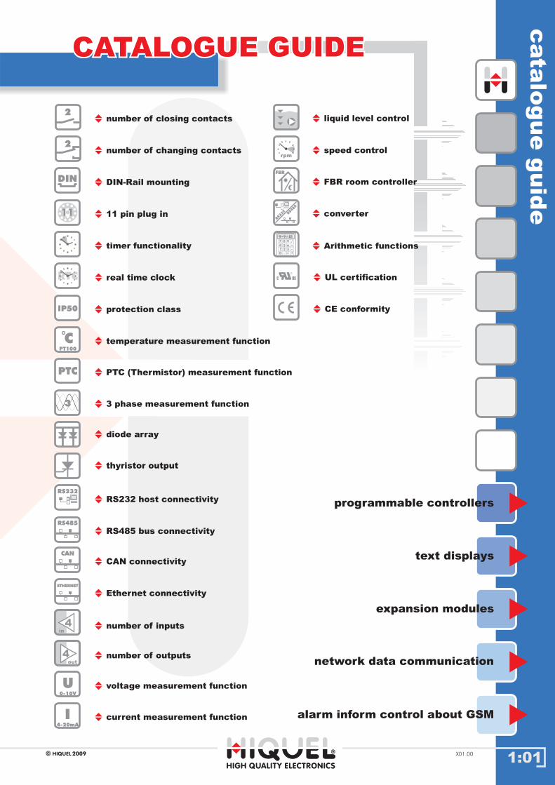
CATALOGUE GUIDECATALOGUE GUIDE
programmable controllers
text displays
expansion modules
network data communication
alarm inform control about GSM
HIGH QUALITY ELECTRONICS
4
2
number of closing contacts
number of changing contacts
DIN-Rail mounting
11 pin plug in
timer functionality
real time clock
protection class
temperature measurement function
voltage measurement function
current measurement function
PTC (Thermistor) measurement function
3 phase measurement function
thyristor output
diode array
RS232 host connectivity
RS485 bus connectivity
number of inputs
number of outputs
11
DIN
2
IP50
CPT100
U0-10V
I4-20mA
PTC
RTC
RS485
RS232
4
in
out
3
liquid level control
speed controlrpm
FBR room controller
converter
FBR
RS232
RS485
Arithmetic functions
189 9=*
7
4
1
0
8
5
2
.
9
6
3
=
/
*-
+
2009HIQUEL X01.00
CAN connectivity
Ethernet connectivity
CAN
ETHERNET
CE conformity
UL certificationC US

housin
gty
pes
1:02
housing typeshousing types
HIGH QUALITY ELECTRONICS
X01.00 2009HIQUEL
35,0075,00
66
,00
G
11,25
60,0
0
41,50
60,00
60,0
0
16,0
0
O
45,00
85,00
65,0
0
38,5
0 A, C, E
67,5045,00
C
22,50
75,0
0
A E
22,50
75,0
0
DB F
45,00 67,50
65
,00
65,00
38
,50 B, D, F
85,00
23,00
101,0
0
101,00
70,0
0
I
93
,50
76,00
all dimensions in mm
DIN-railterminals: IP20
housing: IP50
50
,00
49,00
39,50
69,0
0
18,00
74,0
0
80,0
0
J
25,00
K

Chapter 2: SLS-500 Series
World of Automation
www.hiquel.com

IND
EX
2:00
22Chapter 2: SLS-500 Series
HIGH QUALITY ELECTRONICS
2009HIQUEL X01.00
INFO automation with SLS-500
INFO control-regulate with SLS-500
INFO SLS-500 series
INFO programming
INFO programmable controllers
INFO SLS-500-Configurator
INFO remote control with SLS-500
INFO compact with SLS-500
INFO module overview SLS-500
SLS-510/SLS-520 Starter Kits
SiConfig - Software
SLS-8207
.05.05
.04.04
.03.03
.02.02
.01.01
.06.06
.07.07
.08.08
.09.09
.10.10
.15.15
.16.16
.17.17
INDEXINDEX
.11.11
.12.12
.13.13
SLS-510/SLS-520 compact controls
SLS-500-CAN / SLS-500 Starter Kits
SLS-500-CAN base module
.14.14 SLS-500 base module
TERM4
2:01
build
ing
/in
dustria
lauto
matio
n
DIN
RS485
RS232
RTC
in
out
U0-10V
189 9=*
7
4
1
0
8
5
2
.
9
6
3
=
/
*-
+
Structured controlStructured control
SLS-500 Series: complete bit, analogue and text processing
2009HIQUEL X01.00
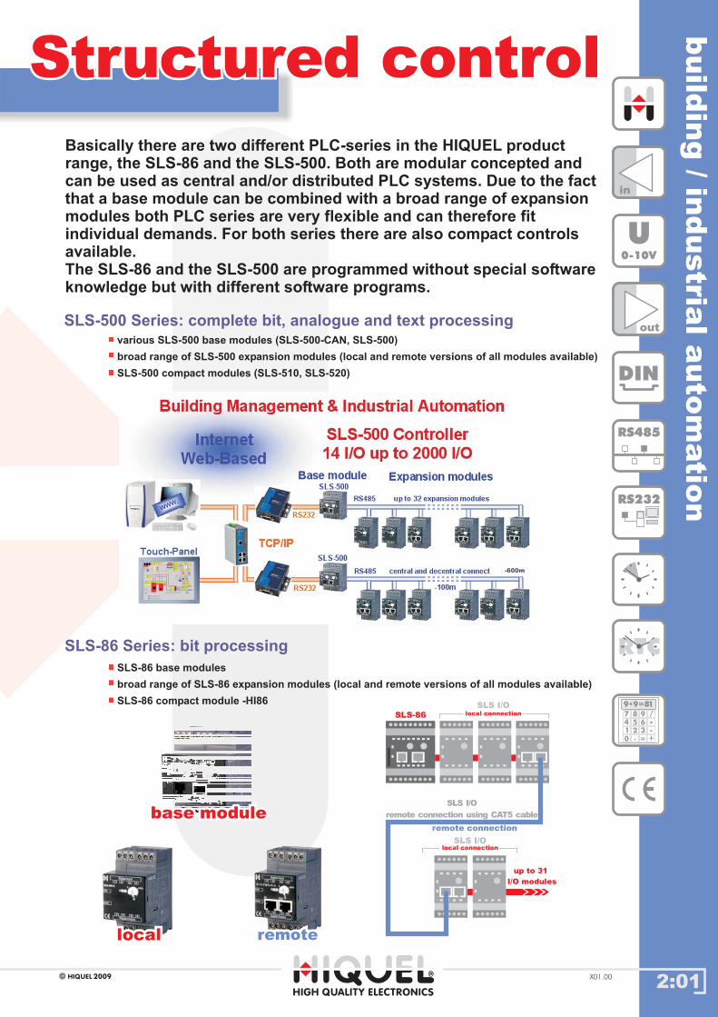
Basically there are two different PLC-series in the HIQUEL productrange, the SLS-86 and the SLS-500. Both are modular concepted andcan be used as central and/or distributed PLC systems. Due to the factthat a base module can be combined with a broad range of expansionmodules both PLC series are very flexible and can therefore fitindividual demands. For both series there are also compact controlsavailable.The SLS-86 and the SLS-500 are programmed without special softwareknowledge but with different software programs.
various SLS-500 base modules (SLS-500-CAN, SLS-500)
broad range of SLS-500 expansion modules (local and remote versions of all modules available)
SLS-500 compact modules (SLS-510, SLS-520)
SLS-86 Series: bit processing
SLS-86 base modules
broad range of SLS-86 expansion modules (local and remote versions of all modules available)
SLS-86 compact module -HI86
SLS-86
SLS I/Olocal connection
SLS I/Olocal connection
remote connection
up to 31
I/O modules
SLS I/O
remote connection using CAT5 cable
locallocal remoteremote
base modulebase module
HIGH QUALITY ELECTRONICS
-600m
SLS
-500-C
onfi
gura
tor
/S
oft
wir
eP
LU
S
2:02
SoftwirePLUS/SoftWIRE
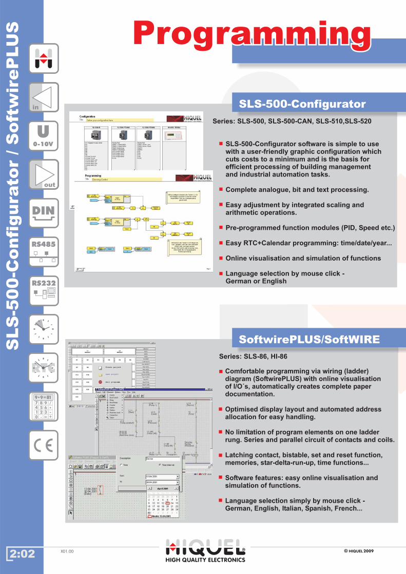
SLS-500-Configurator
SLS-500-Configurator is simple to usewith a user-friendly graphic configuration whichcuts costs to a minimum and is the basis forefficient processing of building managementand industrial automation tasks.
Complete analogue, bit and text processing.
asy adjustment by integrated scaling andarithmetic operations.
Pre-programmed function modules (PID, Speed etc.)
software
E
Easy RTC+Calendar programming: time/date/year...
Online visualisation and simulation of functions
Language selection by mouse click -German or English
in
out
DIN
RS485
RS232
RTC
U0-10V
189 9=*
7
4
1
0
8
5
2
.
9
6
3
=
/
*-
+
2009HIQUELX01.00
ProgrammingProgramming
Comfortable programming via wiring (ladder)diagram (SoftwirePLUS) with online visualisationof I/O´s, automatically creates complete paperdocumentation.
Optimised display layout and automated addressallocation for easy handling.
No limitation of program elements on one ladderrung. Series and parallel circuit of contacts and coils.
Latching contact, bistable, set and reset function,memories, star-delta-run-up, time functions...
Software features: easy online visualisation andsimulation of functions.
Language selection simply by mouse click -German, English, Italian, Spanish, French...
Series: SLS-86, HI-86
Series: SLS-500, SLS-500-CAN, SLS-510,SLS-520
HIGH QUALITY ELECTRONICS

2:03
build
ing
/in
dustria
lauto
matio
n
DIN
RS485
RS232
RTC
in
out
U0-10V
189 9=*
7
4
1
0
8
5
2
.
9
6
3
=
/
*-
+
possible connections:
Modbus
Area of use:
� industrial automation
� process technology
�
� air conditioning
� window, door andgate control
� material handling
� lighting control
� liquid level control in tanksand pumping systems
� bespoke systems
digital output modules, relays, transistor or
photomos
analogue I/O modules 0-10V or 0-20mA
lighting dimmer module with 1 dimmed output 230V~
PT1000 sensors
open protocol RS232/RS485 interface modules
SLS-500 SeriesSLS-500 SeriesComplete bit, analogue and text processing
2009HIQUEL X01.00
SLS-500 expansion modulesSLS-500 base modules
digital input modules 24Vdc or 100-240Vac
temperature detection modules for Pt100- and
interface modules for GSM (text messaging) modem
building management
Connection: local and remote versionsof all modules available
room temperature detection modules with 4 inputs
room temperature controller
The base module allows easy and cost-effective communication with up to 32 different expansionmodules over a bus length of up to 600m. The modules can be connected either by recessed sideconnectors for side by side DIN rail mounting or via CAT5 cable.
locallyremotely
The PLC-series SLS-500 is a central and/or distributed PLC systemwith modular concept. The SLS-510 and the SLS-520 are compactcontrols of the SLS-500 series.
SLS-500-CAN
SLS-500
base modulebase module local (C)local (C) remote (D)remote (D)
SLS-500 compactmodules
SLS-510
SLS-520
HIGH QUALITY ELECTRONICS
incremental encoder input with prescaled output pulses
16bit analogue input modules; 0-10V or 0-20mA
2:04
Control - RegulateControl - Regulate
DIN
RS485
RS232
RTC
in
out
U0-10V
189 9=*
7
4
1
0
8
5
2
.
9
6
3
=
/
*-
+
2009HIQUELX01.00
buildin
gand
facilit
ym
ana
gem
ent
syste
ms
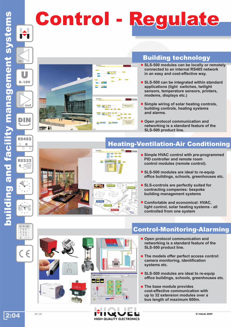
SLS-500 modules can be locally or remotelyconnected to an internal RS485 networkin an easy and cost-effective way.
integrated within standardapplications (light switches, twilightsensors, temperature sensors, printers,modems, displays etc.)
Simple wiring of solar heating controls,building controls, heating systemsand alarms.
Open protocol communication andnetworking is a standard feature of theSLS-500 product line.
can beSLS-500
Open protocol communication andnetworking is a standard feature of theSLS-500 product line.
The models offer perfect access control:camera monitoring, identificationsystems etc.
-
The base module providescost-effective communication withup to 32 extension modules over abus length of maximum 600m.
SLS-500 modules are ideal to re equipoffice buildings, schools, greenhouses etc.
L1.DI1L1.DI1
TIMER
Recycler Hi
TIMER
Recycler Hi
InIn OutOut
ResetReset
Time1Time1
Time2Time2
TIMER
Recycler Hi
TIMER
Recycler Hi
InIn OutOut
ResetReset
Time1Time1
Time2Time2
L1.DO1L1.DO1
11
In �In �
ValueValueZeit2Zeit2
COUNT SETCOUNT SET
In �In �
ValueValueZeit2Zeit2
COUNT SETCOUNT SET
In �In �
ValueValueZeit2Zeit2
COUNT SETCOUNT SET
In �In �
ValueValueZeit2Zeit2
COUNT SETCOUNT SET
11
55
Zeit2Zeit2
L1.DO2L1.DO2^̂
� Second� Second
L1.DO2L1.DO2
L1.DI4L1.DI4
L1.DI5L1.DI5
Title:
ProgrammingTimer mit variabler Zeit
HIGH QUALITY ELECTRONICS
Building technology
Heating-Ventilation-Air Conditioning
Simple HVAC control with pre-programmedPID controller and remote roomcontrol modules (remote control).
SLS-500 modules are ideal to re-equipoffice buildings, schools, greenhouses etc.
SLS-controls are perfectly suited forcontracting companies: bespokebuilding management systems
Comfortable and economical: HVAC,light control, solar heating systems - allcontrolled from one system
Control-Monitoring-Alarming
HIGH QUALITY ELECTRONICS

industria
lauto
matio
nte
chnolo
gy
2:05
AutomationAutomation
in
out
DIN
RS485
RS232
RTC
U0-10V
189 9=*
7
4
1
0
8
5
2
.
9
6
3
=
/
*-
+
2009HIQUEL X01.00
Process technology
The modular structure allows systemchanges to suit alterations.
rocess control with complexfunctions processing large data volumes,e.g. analogue values, nominal values,meter readings or time parameters.
: printers, scanners, barcodescanners, identification systems,measuring systems, encoder modules…
application
Suitable for p
Integration
SLS-500 modules are suited to display,compare and calculate analogue valuesand texts.
arameters or required values are changeddirectly on the text display or via PC.
nstallation in low profile control boxesand switch boxes within the machine ispossible through the modular concept.
P
I
Flexible program exchange by externalmemory card.
SLS-500 modules can be combined to fitvarious requirements for digital thermostatsGSM modems, scanners, accesssystems…
Eighly cost-efficient.
Assembly of large networks is possiblewith SLS-Controller.
Open protocol communication andnetworking is standard.
lectrical wiring installations ofSLS-Controllers are h
Machine control
BMS applications
HIGH QUALITY ELECTRONICS
pro
gra
mm
ing
wit
hS
LS
-500-C
onfi
gura
tor
2:06
in
out
DIN
RS485
RS232
RTC
U0-10V
189 9=*
7
4
1
0
8
5
2
.
9
6
3
=
/
*-
+
2009HIQUELX01.00
ProgrammingProgramming
Series: SLS-500, SLS-500-CAN, SLS-510, SLS-520
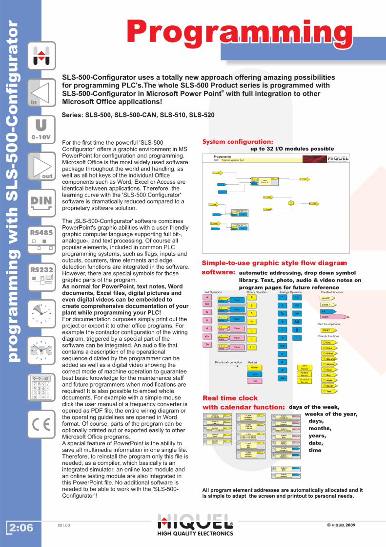
Real time clock
with calendar function: days of the week,
weeks of the year,
days,
months,
years,
date,
time
CLOCK
HH:MM:SS
CLOCK
HH:MM:SS� OutOutCLOCK
HH:MM:SS
CLOCK
HH:MM:SS� OutOut
CLOCK
TT.MM.YY
CLOCK
TT.MM.YY� OutOutCLOCK
TT.MM.YY
CLOCK
TT.MM.YY� OutOut
CLOCK
TT.MM.YY HH:MM:SS
CLOCK
TT.MM.YY HH:MM:SS� OutOutCLOCK
TT.MM.YY HH:MM:SS
CLOCK
TT.MM.YY HH:MM:SS� OutOut
CLOCK
DDD
CLOCK
DDD� OutOutCLOCK
DDD
CLOCK
DDD� OutOut
CLOCK
WEEKxx
CLOCK
WEEKxx� OutOutCLOCK
WEEKxx
CLOCK
WEEKxx� OutOut
CLOCK
HH:MM:SS
HH:MM:SS
CLOCK
HH:MM:SS
HH:MM:SS
� OutOutCLOCK
HH:MM:SS
HH:MM:SS
CLOCK
HH:MM:SS
HH:MM:SS
� OutOut
CLOCK
TT.MM.YY
TT.MM.YY
CLOCK
TT.MM.YY
TT.MM.YY
� OutOutCLOCK
TT.MM.YY
TT.MM.YY
CLOCK
TT.MM.YY
TT.MM.YY
� OutOut
CLOCK
TT.MM.YY HH:MM:SS
TT.MM.YY HH:MM:SS
CLOCK
TT.MM.YY HH:MM:SS
TT.MM.YY HH:MM:SS
� OutOutCLOCK
TT.MM.YY HH:MM:SS
TT.MM.YY HH:MM:SS
CLOCK
TT.MM.YY HH:MM:SS
TT.MM.YY HH:MM:SS
� OutOut
CLOCK
DDD
DDD
CLOCK
DDD
DDD
� OutOutCLOCK
DDD
DDD
CLOCK
DDD
DDD
� OutOut
CLOCK
WEEKxx
WEEKxx
CLOCK
WEEKxx
WEEKxx
� OutOutCLOCK
WEEKxx
WEEKxx
CLOCK
WEEKxx
WEEKxx
� OutOut
CLOCK
HH:MM:SS
CLOCK
HH:MM:SS� OutOutCLOCK
HH:MM:SS
CLOCK
HH:MM:SS� OutOut
CLOCK
TT.MM.YY
CLOCK
TT.MM.YY� OutOutCLOCK
TT.MM.YY
CLOCK
TT.MM.YY� OutOut
CLOCK
TT.MM.YY HH:MM:SS
CLOCK
TT.MM.YY HH:MM:SS� OutOutCLOCK
TT.MM.YY HH:MM:SS
CLOCK
TT.MM.YY HH:MM:SS� OutOut
CLOCK
DDD
CLOCK
DDD� OutOutCLOCK
DDD
CLOCK
DDD� OutOut
CLOCK
WEEKxx
CLOCK
WEEKxx� OutOutCLOCK
WEEKxx
CLOCK
WEEKxx� OutOut
CLOCK
HH:MM:SS
CLOCK
HH:MM:SS� OutOutCLOCK
HH:MM:SS
CLOCK
HH:MM:SS� OutOut
CLOCK
TT.MM.YY
CLOCK
TT.MM.YY� OutOutCLOCK
TT.MM.YY
CLOCK
TT.MM.YY� OutOut
CLOCK
DDD
CLOCK
DDD� OutOutCLOCK
DDD
CLOCK
DDD� OutOut
CLOCK
WEEKxx
CLOCK
WEEKxx� OutOutCLOCK
WEEKxx
CLOCK
WEEKxx� OutOut
L1.DI1L1.DI1
TIMER
Recycler Hi
TIMER
Recycler Hi
InIn OutOut
ResetReset
Time1Time1
Time2Time2
TIMER
Recycler Hi
TIMER
Recycler Hi
InIn OutOut
ResetReset
Time1Time1
Time2Time2
L1.DO1L1.DO1
11
In �In �
ValueValueZeit2Zeit2
COUNT SETCOUNT SET
In �In �
ValueValueZeit2Zeit2
COUNT SETCOUNT SET
In �In �
ValueValueZeit2Zeit2
COUNT SETCOUNT SET
In �In �
ValueValueZeit2Zeit2
COUNT SETCOUNT SET
11
55
Zeit2Zeit2
L1.DO2L1.DO2^̂
� Second� Second
L1.DO2L1.DO2
L1.DI4L1.DI4
L1.DI5L1.DI5
Title:
ProgrammingTimer mit variabler Zeit
HIGH QUALITY ELECTRONICS
Simple-to-use graphic style flow diagram
software: automatic addressing, drop down symbol
library. Text, photo, audio & video notes on
program pages for future reference
||
&&
^̂
Directional connection
Binary Operation
~~
//
**
%%
Analoge Operation
++
--
-()-()
>=>=
>>
==
<<
<=<=
!=!=
<<<<
>>>>
&&&&
||||
!!
��
��
� �� �
MerkerMarker
Markers
ValueValue
const 0const 0
Constant functions
const 1const 1
0.00.0
TextText
AlarmAlarm
Start the application
STARTSTART
SET
Mr
SET
Marker
RESET
Merker
RESET
Marker
TOGGLE
Merker
TOGGLE
Marker
Periodic functions
� 1ms� 1ms
� 10ms� 10ms
� 100ms� 100ms
� Second� Second
� Hour� Hour
� Day� Day
� Week� Week
� Month� Month
� Year� Year
� Minute� Minute
++
Text Operation
>=>=
>>
==
<<
<=<=
!=!=
In �In �
ValueValueValueValue
In �In �
ValueValueValueValue
In �In �
ValueValueValueValue
In �In �
ValueValueValueValue
In � �In � �
ValueValueValueValue
In � �In � �
ValueValueValueValue
In �In �
ValueValueValueValue
In �In �
ValueValueValueValue
In �In �
ValueValueValueValue
In �In �
ValueValueValueValue
In � �In � �
ValueValueValueValue
In � �In � �
ValueValueValueValue
System configuration:
up to 32 I/O modules possibleFor the first time the powerful 'SLS-500
Configurator' offers a graphic environment in MS
PowerPoint for configuration and programming.
Microsoft Office is the most widely used software
package throughout the world and handling, as
well as all hot keys of the individual Office
components such as Word, Excel or Access are
identical between applications. Therefore, the
learning curve with the 'SLS-500 Configurator'
software is dramatically reduced compared to a
proprietary software solution.
The ‚SLS-500-Configurator' software combines
PowerPoint's graphic abilities with a user-friendly
graphic computer language supporting full bit-,
analogue-, and text processing. Of course all
popular elements, included in common PLC
programming systems, such as flags, inputs and
outputs, counters, time elements and edge
detection functions are integrated in the software.
However, there are special symbols for those
graphic parts of the program.
For documentation purposes simply print out the
project or export it to other office programs. For
example the contactor configuration of the wiring
diagram, triggered by a special part of the
software can be integrated. An audio file that
contains a description of the operational
sequence dictated by the programmer can be
added as well as a digital video showing the
correct mode of machine operation to guarantee
best basic knowledge for the maintenance staff
and future programmers when modifications are
required! It is also possible to embed whole
documents. For example with a simple mouse
click the user manual of a frequency converter is
opened as PDF file, the entire wiring diagram or
the operating guidelines are opened in Word
format. Of course, parts of the program can be
optionally printed out or exported easily to other
Microsoft Office programs.
A special feature of PowerPoint is the ability to
save all multimedia information in one single file.
Therefore, to reinstall the program only this file is
needed, as a compiler, which basically is an
integrated simulator, an online load module and
an online testing module are also integrated in
this PowerPoint file. No additional software is
needed to be able to work with the 'SLS-500-
Configurator'!
As normal for PowerPoint, text notes, Worddocuments, Excel files, digital pictures andeven digital videos can be embedded tocreate comprehensive documentation of yourplant while programming your PLC!
SLS-500-Configurator uses a totally new approach offering amazing possibilitiesfor programming PLC's.The whole SLS-500 Product series is programmed with
SLS-500-Configurator in Microsoft Power Point with full integration to otherMicrosoft Office applications!
®
All program element addresses are automatically allocated and itis simple to adapt the screen and printout to personal needs.
HIGH QUALITY ELECTRONICS
2:07
rem
ote
contro
land
rem
ote
report
DIN
RS485
RS232
RTC
in
out
U0-10V
189 9=*
7
4
1
0
8
5
2
.
9
6
3
=
/
*-
+
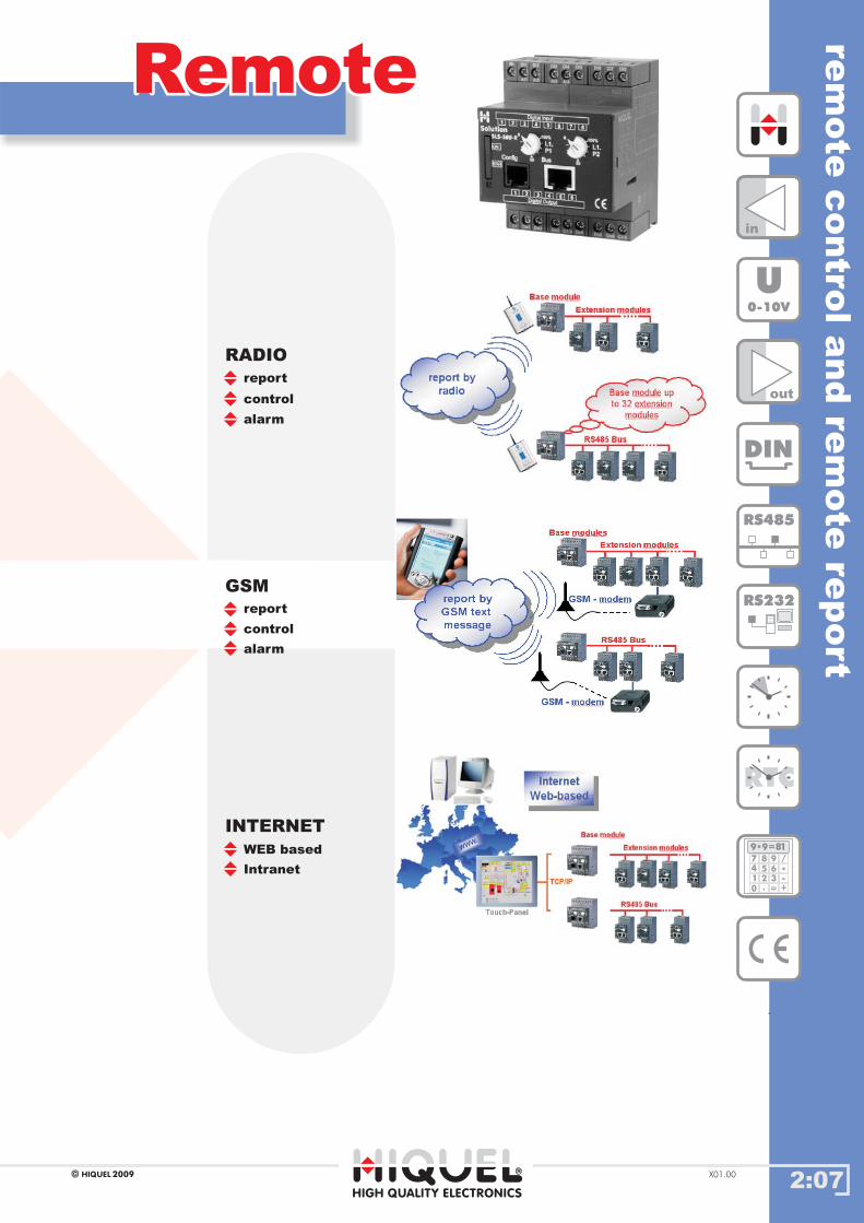
RemoteRemoteoverview
control
report
RADIO
alarm
report
GSM
control
alarm
WEB based
INTERNET
Intranet
-
HIGH QUALITY ELECTRONICS
2009HIQUEL X01.00

com
pact
module
s
2:08
Compact modulesCompact modulesSLS-510 and SLS-520SLS-510 and SLS-520
8in
6out
DIN
RS485
RTC
U0-10V
189 9=*
7
4
1
0
8
5
2
.
9
6
3
=
/
*-
+
2009HIQUELX01.00
SLS-520 20-250Vac/dc
For AC and DC supply
Complete bit and text processing.
No limitation of circuits or functionblocks.
Easy program exchange with memorycard (SLS520).
Manual settings on the module by meansof potentiometers on the front-plate.
Simple combination of all time data,e.g. RTC time, period, weekdays, calendarweek, days, months, years, date and time.
SLS-510 100-250VacIdeal in buildings for lighting and HVACsystems, and in industrial applicationssuch as conveyor belts, hydraulic systems,pumping systems, waste handling...
10A relay outputs
Latching contacts, bi-stable, set andreset functions, memories etc.
(SLS510) 5A (SLS520)
The software offers easy onlinevisualisation and simulation of functions.
Simple documentation (printing).
HIGH QUALITY ELECTRONICS

2:09
base
and
expansio
nm
odule
sS
LS
-500
/S
LS
-500-C
AN
DIN
RS485
RS232
RTC
8in
6out
U0-10V
189 9=*
7
4
1
0
8
5
2
.
9
6
3
=
/
*-
+
2009HIQUEL X01.00
SLS-500 modulesSLS-500 modulesoverview
HIGH QUALITY ELECTRONICS

2:10
in
out
DIN
RS485
RS232
RTC
U0-10V
189 9=*
7
4
1
0
8
5
2
.
9
6
3
=
/
*-
+
2009HIQUEL X01.00
com
pact
contro
lS
LS
-510
and
SLS
-520
sta
rte
rkits
overview
Starter KitsStarter KitsSLS-510, SLS-520SLS-510, SLS-520
SLS-510-R 100-250 Vac 10A
serial interface cable
(programming cable)
CD-ROM Automation Software
input simulator
manual
Programming without special software knowledge, suitable for small 8/4 I/O applications.
SLS-510 SLS-520SLS-520
SLS-510 SLS-520 programmed with SLS-500-Configurator
Real Time Clock (RTC)
complete paper documentation.
The has 8 digital inputs and 4 relay outputs, the has 8 digital inputs and 6 relay outputs. The user
program memory for both modules is 16 kB. The additionally features a SIM Card for easy program exchange
as well as module to module data transfers.
as well as are in Microsoft PowerPoint, with full integration
to other Microsoft Office applications. For more detailed information please refer to page 1:06.
The can be easily programmed for point of time switching, (to perform a function at a fixed
time/date) or time interval switching, (to perform a function between two times, dates, weeks, years etc). Days of the
week, weeks of the year, days, months, years, date and time can be easily combined.
Analogue values can be set using the external potentiometers on the front plate or by PC.
The analogue functions are used to and evaluate different levels, pressures or temperatures. With the analogue
outputs you can control the rpm of a motor or the climate of a room and perform many other functions.
SLS-500-Configurator features on-line monitoring, simulation & status display of all I/O’s and internal program elements
on the PC. Programs can be simulated without a module connected.
It also automatically creates
All program element addresses are automatically allocated and it is simple to change the screen and printout.
The and are compact programmable (intelligent) relays that can be used in many fields including
and and
SLS-510 SLS-520industrial control automation, machinery control.
monitor
Ordering information
part no
SLS-510-R-Starter Kit SLS-510-R +Automation Software + download cable + manual + input simulator
SLS-520-R-Starter Kit SLS-520-R + Automation Software + download cable + manual + input simulator + SIM Card
all you need to get you going - a starter kit:
SLS-510 SLS-520
SLS-520-R 20-250Vac/dc
serial interface cable
(programming cable)
CD-ROM Automation Software
input simulator
manual
SIM-Card (memory card)
includes:
Programming with SLS-500-Configurator:
includes:
HIGH QUALITY ELECTRONICS
Automation Software
Automation Software
Automation Software
Automation Software
2:11
overview
SLS-510, SLS-520SLS-510, SLS-520
2009HIQUELX01.00
com
pact
contr
ol
SLS
-510
,S
LS
-520
SLS-520:
DIN
RS232
RTC
8in
4/6out
U100-250V
189 9=*
7
4
1
0
8
5
2
.
9
6
3
=
/
*-
+
* measurement input galvanically isolated from the power supply
SLS-520-R 6x SPNO8x 20-240V~= no yes E20-250V~=
SLS-Std-RS232 download cable
SLS-510-R 4x SPNO8x 100-250V~ no yes E100-250V~
SLS-Std-RS232 download cable
part no inputsupply inp. galv. iso. * outp. galv. iso.*output housing types
supply voltage SLS-510 100-250V~
Ue/Ie AC-15
expected life time
input specification
program memory
protection class
screws
screw tightening torque
weight
dimensions
120V/5A 240V/4A
24V/4A
SLS-510 100-250V~
16kB
0,6..0,8 Nm
67.5 x 85 x 75mm
1 x 10⁷
operations
1 x 10⁵
operations
terminals
housing
IP20
IP50
pozidrive 1
210g
mechanical
SPNO
electrical
Ue/Ie DC-13
ordering information
specification
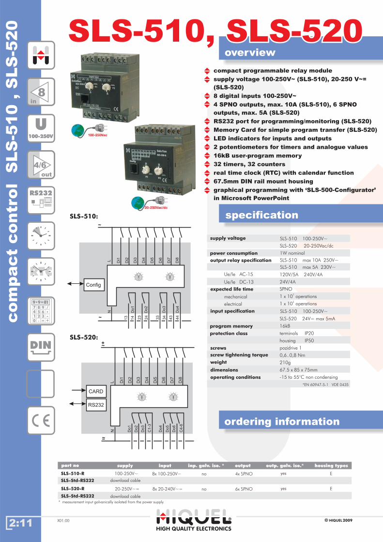
compact programmable relay module
supply voltage 100-250V~ (SLS-510), 20-250 V~=
(SLS-520)
8 digital inputs 100-250V~
4 SPNO outputs, max. 10A (SLS-510), 6 SPNO
outputs, max. 5A (SLS-520)
RS232 port for programming/monitoring (SLS-520)
Memory Card for simple program transfer (SLS-520)
LED indicators for inputs and outputs
2 potentiometers for timers and analogue values
16kB user-program memory
32 timers, 32 counters
real time clock (RTC) with calendar function
67.5mm DIN rail mount housing
graphical programming with ‘SLS-500-Configurator’
in Microsoft PowerPoint
L Di1
Di2
Di3
Di4
Di5
Di6
Di7
Di8
~
Do
1
Do
4
Do
3
Do
6
~
N
CARD
RS232
+
-
C1
-3
C4
-6
Do
2
Do
5
L Di1
Di2
Di3
Di4
Di5
Di6
Di7
Di8
~
Do
1
Do
3
Do
2
Do
4
~
N
13
14
23
24
33
34
43
44
Config
SLS-510:
SLS-520 20-250Vac/dc
power consumption 1W nominal
output relay specification
SLS-510 max 5A 230V~
SLS-520 24V= max 5mA
SLS-510 max 10A 250V~
HIGH QUALITY ELECTRONICS
operating conditions -15 to 55°C non condensing
*EN 60947-5-1 VDE 0435
2:12
in
out
DIN
RS485
RS232
RTC
U0-10V
189 9=*
7
4
1
0
8
5
2
.
9
6
3
=
/
*-
+
2009HIQUEL X01.00
SLS
-500,S
LS
-500
CA
Nsta
rte
rkits
overview
Starter KitsStarter KitsSLS-500-CAN,
SLS-500
SLS-500-CAN,
SLS-500
ordering information
part no
all you need to get you going - a starter kit:
Programming with SLS-500-Configurator:
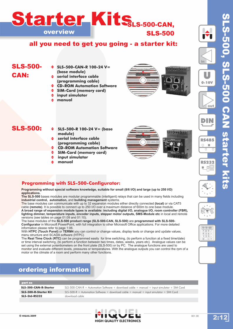
SLS-500-CAN-R 100-24 V=
(base module)
serial interface cable
(programming cable)
CD-ROM Automation Software
SIM-Card (memory card)
input simulator
manual
SLS-500-
CAN:
SLS-500-R 100-24 V= (base
module)
serial interface cable
(programming cable)
CD-ROM Automation Software
SIM-Card (memory card)
input simulator
manual
SLS-500:
SLS-500-CAN-R-Starter SLS-500-CAN-R + Automation Software + download cable + manual + input simulator + SIM Card
SLS-Std-RS232 download cable
Programming without special software knowledge, suitable for small (8/6 I/O) and large (up to 250 I/O)applications.The SLS-500industrial control, automation, building management
(local)(remote)
A broad range of expansion module types is available: including digital I/O, analogue I/O, room controller (FBR),lighting dimmer, temperature inputs, encoder inputs, stepper motor outputs, SMS-Module etc
SLS-500 product range (SLS-500-CAN, SLS-500) programmed with SLS-500-Configurator
HTPC (Touch Panel) TERM4
Real Time Clock (RTC)
bases modules are modular programmable (intelligent) relays that can be used in many fields including
and systems.
The base modules can communicate with up to 32 expansion modules either directly connected or via CAT5
cable . It is possible to connect up to 250 I/O over a maximum distance of 600m to one base module.
in local and remote
versions (see tables on page 01:09 and 01:10).
The base modules of the are
in Microsoft PowerPoint, with full integration to other Microsoft Office applications. For more detailed
information please refer to page 1:06.
With or you can control or change values, display texts or change and update values,
menu structure and SCADA software (HTPC)
The can be programmed easily for time switching, (to perform a function at a fixed time/date)
or time interval switching, (to perform a function between two times, dates, weeks, years etc). Analogue values can be
set using the external potentiometers on the front plate (SLS-500) or by PC. The analogue functions are used to
and evaluate different levels, pressures or temperatures. With the analogue outputs you can control the rpm of a
motor or the climate of a room and perform many other functions.
monitor
HIGH QUALITY ELECTRONICS
SLS-500-R-Starter Kit SLS-500-R + Automation Software + download cable + manual + input simulator + SIM Card
Automation Software
Automation Software
Automation Software
Automation Software
SLS
-500-C
AN
maste
rcontro
ller
2:13
overview
ordering information
SLS-500-CANSLS-500-CAN
specification
2009HIQUEL X01.00
SLS-500-CAN-R
SLS-500-CAN-S
SLS-500-SIM
6x SPNO
3x SPNO
3x SPNO
3x SPNO
3x SPNO
6x Photomos
8x 24V=
8x 24V=
SLS-500-BUS
no
no
no
no
no
no
yes
yes
yes
yes
yes
yes
E
E
E
E
E
E
SIM-Card memory 64kB
bus termination for external I/O modules
part no inputsupply inp. galv. iso.* outp. galv. iso.*output housing types
SLS-500-CAN-R-4AiU-3AoU
SLS-500-CAN-R-4AiU-3AoI
SLS-500-CAN-R-4AiI-3AoU
SLS-500-CAN-R-4AiI-3AoI
24V=
24V=
24V=
24V=
24V=
24V=
4x 24V=
4x 24V=
4x 24V=
4x 24V=
* measurement input galvanically isolated from the power supply
rem
ote
connecti
on
M-
Do
1
DI1
/Ai1
DI2
/Ai2
DI3
/Ai3
DI4
/Ai4
Di5
Di6
Di7
Di8
Do
1
Do
2
Do
5
Do
3
Do
6
C1
-3L
L
N
L L L L L
C4
-6
+
-
+
L+
RS232
CAN
RS485
CARD
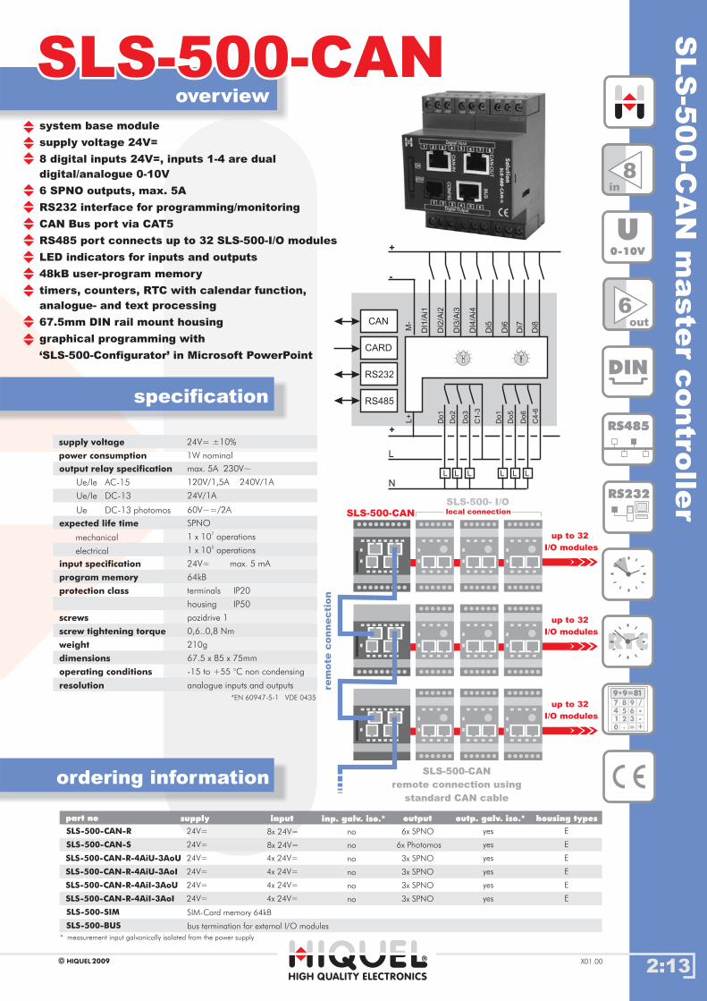
SLS-500-CAN
SLS-500- I/Olocal connection
8in
6out
DIN
RS485
RS232
RTC
U0-10V
189 9=*
7
4
1
0
8
5
2
.
9
6
3
=
/
*-
+
supply voltage
power consumption
24V= ±10%
1W nominal
output relay specification
Ue/Ie AC-15
expected life time
input specification
program memory
protection class
screws
screw tightening torque
weight
dimensions
operating conditions
max. 5A 230V~
120V/1,5A 240V/1A
24V/1A
60V~=/2A
*EN 60947-5-1 VDE 0435
24V=
64kB
0,6..0,8 Nm
67.5 x 85 x 75mm
-15 to +55 °C non condensing
1 x 10⁷
operations
1 x 10⁵
operations
max. 5 mA
terminals
housing
IP20
IP50
pozidrive 1
210g
mechanical
SPNO
electrical
Ue/Ie DC-13
Ue DC-13 photomos
SLS-500-CAN
remote connection using
standard CAN cable
up to 32
I/O modules
up to 32
I/O modules
up to 32
I/O modules
system base module
supply voltage 24V=
8 digital inputs 24V=, inputs 1-4 are dual
digital/analogue 0-10V
6 SPNO outputs, max. 5A
RS232 interface for programming/monitoring
CAN Bus port via CAT5
RS485 port connects up to 32 SLS-500-I/O modules
LED indicators for inputs and outputs
48kB user-program memory
timers, counters, RTC with calendar function,
analogue- and text processing
67.5mm DIN rail mount housing
graphical programming with
‘SLS-500-Configurator’ in Microsoft PowerPoint
HIGH QUALITY ELECTRONICS
resolution analogue inputs and outputs

2:14
overview
ordering information
SLS-500SLS-500
specification
2009HIQUELX01.00
Gehäusetypenpart no
SLS-500-R
SLS-500-S
SLS-500-SIM
inputsupply
SIM-Card memory 64kB
6x SPNO
6x SPNO
6x SPNO
6x SPNO
6x SPNO
6x Photomos
8x 24V=
8x 24V=
SLS-500-BUS bus termination for external I/O modules
inp. galv. iso. * outp. galv. iso.*output housing types
*measurement input is galvanically isolated from the power supply
no
no
no
no
no
no
yes
yes
yes
yes
yes
yes
E
E
E
E
E
E
supply voltage
power consumption
24V= ±10%
1W nominal
output relay specification
expected life time
input specification
program memory
protection class
screws
screw tightening torque
weight
dimensions
operating conditions
max. 5A 230V~
120V/1,5A 240V/1A
24V/1A
60V=/2A
24V=
16kB
0,6..0,8 Nm
67.5 x 85 x 75mm
-15 to +55°C non condensing
1 x 10⁷
operations
1 x 10⁵
operations
max. 5 mA
terminals
housing
IP20
IP50
pozidrive 1
210g
mechanical
SPNO
electrical
SLS
-500
maste
rcontr
oller
SLS-500
SLS-500 I/Olocal connection
SLS-500 I/Olocal connection
remote connection
up to 32
I/O modules
SLS-500 I/O
remote connection using
standard CAT5 cable
8in
6out
DIN
RS485
RS232
RTC
U0-10V
189 9=*
7
4
1
0
8
5
2
.
9
6
3
=
/
*-
+
SLS-500-R-4AiU-3AoU
SLS-500-R-4AiU-3AoI
SLS-500-R-4AiI-3AoU
SLS-500-R-4AiI-3AoI
24V=
24V=
24V=
24V=
24V=
24V=
4x 24V=
4x 24V=
4x 24V=
4x 24V=
Ue/Ie AC-15
Ue/Ie DC-13
Ue DC-13 Photomos
M-
Do
1
DI1
/Ai1
DI2
/Ai2
DI3
/Ai3
DI4
/Ai4
Di5
Di6
Di7
Di8
Do
4
Do
2
Do
5
Do
3
Do
6
C1
-3
L
L
N
L L L L L
C4
-6
+
-
+
L+
RS232
RS485
CARD
system base module
supply voltage 24V=
8 digital inputs 24V=, inputs 1-4 are dual
digital/analogue 0-10V
6 SPNO outputs, max. 5A
RS232 interface for programming/monitoring
RS485 port connects up to 32 SLS-500-I/O modules
LED indicators for inputs and outputs
2 potentiometers
16kB user-program memory
timers, counters, RTC with calendar function,
analogue- and text processing
67.5mm DIN rail mount housing
graphical programming with
‘SLS-500-Configurator’ in Microsoft PowerPoint
HIGH QUALITY ELECTRONICS
*EN 60947-5-1 VDE 0435
SLS
-500-S
iConfig
com
munic
atio
nsoftw
are
2:15
overview
ordering information
SLS-500-SiConfigSLS-500-SiConfig
2009HIQUEL X01.00
RS485
RS232
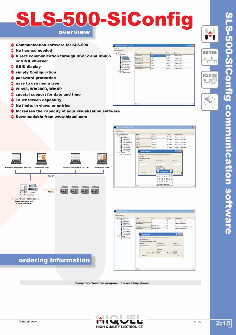
Communication software for SLS-500
No licence needed
Direct communication through RS232 and RS485
or SIVIEWServer
GRID display
simply Configuration
password protection
easy to use menu tree
Win98, Win2000, WinXP
special support for date and time
Touchscreen capability
No limits in views or entries
Increases the capacity of your visualisation software
Downloadable from www.hiquel.com
HIGH QUALITY ELECTRONICS
SLS-500-Configurator on PC#1 SiConfig on PC#2 SLS-500 Configurator on PC#3 SiConfig on PC#4
Server PC with HIQUEL-SiView
Server software and
a serial interface
TCP/IP
RS232
Please download this program from www.hiquel.com

TE
RM
4te
xt
dis
pla
y
2:16
overview
ordering information
TERM4TERM4
specification
HIGH QUALITY ELECTRONICS
2009HIQUEL X01.00
supply voltage
duty cycle
operating conditions
nominal voltage +10% / -15%
100%
-20 to +40°C non condensing
Gehäusetypenpart no inputsupply inp. galv. iso.* outp. galv. iso.*output housing types
TERM4 --24V= 2W - special-
type
-
The text display is designed
for low-end visualisation applications and control
tasks within the field of industrial automation.
A compact, robust case has a liquid crystal display
with 4 lines and 20 characters on each line plus
a key pad with 9 keys. Each key has a unique
symbol. is designed for monitoring alarms,
displaying parameters, changing menu structures
and displaying messages.
Drivers, and an easy to read manual describing
all functions are supplied. is very easily
connected to all host systems such as PLCs or
PC´s.
is suited for use with both our SLS-86
and SLS-500 systems. With the text
display it is easy to change the date, time and
other settings, without PC, independently of the
software.
HIQUELTERM4
TERM4
TERM4
TERM4
TERM4
RS232
dimensions
195mm
110mm
40mm
width
height
depth
protection class
weight
IP54 (front side)
660g
LC backlit display
4 lines with 20 characters each line
character size 3x5mm
9 control keys with symbols
integrated RS232 interface
error tolerant protocol for
data transmission
front panel mounting 195x110mm
25mm deep
* measurement input galvanically isolated from the power supply
2:17HIGH QUALITY ELECTRONICS
2009HIQUELX01.00
SLS
-8207
pow
er
supply
2A SLS-8207SLS-8207
overview
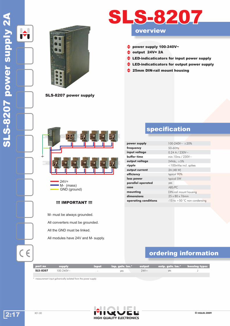
power supply 100-240V~
output 24V= 2A
LED-indicaticators for output power supply
LED-indicaticators for input power supply
25mm DIN-rail mount housing
SLS-8207 power supply
must be always grounded.
All converters must be grounded.
All the GND must be linked.
All modules have 24V and supply.
M-
M-
24V=
M- (mass)
GND (ground)
!!! IMPORTANT !!!
ordering information
SLS-8207 24V=100-240V~ yes J-
Gehäusetypenpart no inputsupply inp. galv. iso.* outp. galv. iso.*output housing types
yes
* measurement input galvanically isolated from the power supply
0.24 A / 230V~
min.10ms / 230V~
100-240V~ ±20%
50-60Hz
ABS/PC
DIN-rail mount housing
25 x 80 x 76mm
<100mVss incl. spikes
typical 90%
input voltage
power supply
output voltage
buffer time
frequency
case
mounting
dimensions
24Vdc, 5%±
ripple
output current
efficiency
loss power
parallel operated yes
2A (48 W)
typical 5W
operating conditions -15 to +50 °C non condensing
specification
Chapter 3: SLS-500 Extension
World of Automation
www.hiquel.com
Index
3:00
33Chapter 3: SLS-500 Extension
HIGH QUALITY ELECTRONICS
2009HIQUEL X01.00
SLS-500-8DI
SLS-500-DVR
SLS-500-DBI-16A
SLS-500-D..-16A
SLS-500-D
SLS-500-8D
SLS-500-FBR
FBR - remote room control unit
SLS-500-DIM
SLS-500-PT100
SLS-500-AI-AI
SLS-500-AU-AI
.05.05
.04.04
.03.03
.02.02
.01.01
.06.06
.07.07
.08.08
.09.09
.10.10
.15.15
.16.16
.17.17
IndexIndex
.11.11
.12.12
.13.13
SLS-500-PT1000
SLS-500-AU
SLS-500-AI
.14.14 SLS-500-AU-AU
SLS-500-AI-AU
SLS-500-SIO.18.18
SLS-500-SMS.19.19
SLS-500-GW.20.20
SLS-500-T1.21.21
SLS-500-MBUS.22.22
SLS-500-Modbus.23.23
Accessories - sensors.24.24
SLS
-500-D
dig
italI/O
module
3:01
overview
ordering information
SLS-500-DSLS-500-D
specification
HIGH QUALITY ELECTRONICS
2009HIQUEL X01.00
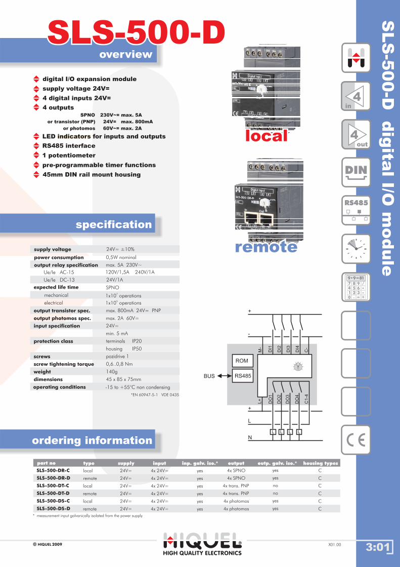
supply voltage 24V=
digital I/O expansion module
4 digital inputs 24V=
4 outputsSPNO 230V~= max. 5A
or transistor (PNP) 24V= max. 800mA
or photomos 60V~= max. 2A
LED for inputs and outputsindicators
1 potentiometer
pre-programmable timer functions
45mm DIN rail mount housing
RS485 interface
supply voltage
power consumption
output relay specification
output transistor spec.
output photomos spec.
Ue/Ie AC-15
expected life time
input specification
protection class
screws
screw tightening torque
weight
dimensions
operating conditions
0,5W nominal
max. 5A 230V~
max. 800mA 24V= PNP
max. 2A 60V=
120V/1,5A 240V/1A
24V/1A
*EN 60947-5-1 VDE 0435
24V=
0,6..0,8 Nm
45 x 85 x 75mm
-15 to +55°C non condensing
min. 5 mA
terminals
housing
IP20
IP50
pozidrive 1
140g
SPNO
1x10⁷
operationsmechanical
1x10⁵
operationselectrical
Ue/Ie DC-13
SLS-500-DR-C
SLS-500-DR-D
SLS-500-DT-C
remote
local
local
local
4x SPNO
4x SPNO
4x trans. PNP
4x trans. PNP
4x photomos
4x photomos
4x 24V=
4x 24V=
4x 24V=
4x 24V=
4x 24V=
4x 24V=
SLS-500-DT-D
SLS-500-DS-C
SLS-500-DS-D
remote
remote
* measurement input from the power supplygalvanically isolated
yes
yes
yes
yes
yes
yes
yes
yes
yes
yes
no
no
C
C
C
C
C
C
24V=
24V=
24V=
24V=
24V=
24V=
locallocal
remoteremote
4in
4out
DIN
RS485
189 9=*
7
4
1
0
8
5
2
.
9
6
3
=
/
*-
+
part no inputsupply inp. galv. iso.* outp. galv. iso.*output housing typestype
DO
1D
I1
DI2
DI3
DI4
DO
2
DO
3
DO
4
C1
-4
L
L
+
+
-
N
L L L
RS485
ROM
BUS
C-
M-
L+
24V= ±10%
3:02
overview
ordering information
SLS-500-D..-16ASLS-500-D..-16A
specification
HIGH QUALITY ELECTRONICS
SLS-500-DRR-16A-C
SLS-500-DRR-16A-D remote
local 4x SPNO
4x SPNO
4x 230V~
4x 230V~
* measurement input galvanically isolated from the power supply
yes
yes
yes
yes
E
E
2009HIQUELX01.00
24V=
24V=
part no inputsupply inp. galv. iso.* outp. galv. iso.*output housing typestype
SLS
-500-D
..-1
6A
dig
italI/O
module
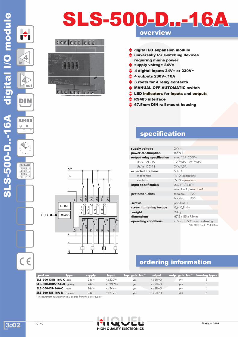
supply voltage 24V=
digital I/O expansion module
4 digital inputs 24V= or 230V~
4 outputs 230V~/16A
LED for andindicators inputs outputs
67.5mm DIN rail mount housing
RS485 interface
supply voltage
power consumption
output relay specification
Ue/Ie AC-15
expected life time
input specification
protection class
screws
screw tightening torque
weight
dimensions
operating conditions
0,5W l
max. 16A 250V~
120V/3A 240V/3A
24V/1,5A
230V~ / 24V=
0,6..0,8 Nm
67,5 x 85 x 75mm
-15 to +55°C non condensing
min. 1 mA / min. 3 mA
terminals
housing
IP20
IP50
pozidrive 1
230g
SPNO
1x10⁷
operationsmechanical
7x10⁴
operationselectrical
Ue/Ie DC-13
4in
4out
DIN
RS485
189 9=*
7
4
1
0
8
5
2
.
9
6
3
=
/
*-
+
24V=
SLS-500-DR-16A-C
SLS-500-DR-16A-D remote
local 4x SPNO
4x SPNO
4x 24V~
4x 24V~
yes
yes
yes
yes
E
E
24V=
24V=
14
Di1
C1
-2
Di2
Di3
13
/23
24
33
34
43
44
L
L
+
-
N
L L L
RS485
ROM
BUS
C3
-4
Di4
M-
L+
-/~
+/~
K1 K2 K3 K4
I
O
A
K1
I
O
A
K2
I
O
A
K3
I
O
A
K4
MANUAL-OFF-AUTOMATIC switch
*EN 60947-5-1 VDE 0435
universally for switching devices
requiring mains power
3 roots for 4 relay contacts

SLS
-500-D
BI-1
6A
dig
italin
put
module
overview
ordering information
specification
HIGH QUALITY ELECTRONICS
2009HIQUEL X01.00
SLS-500-DBI-16ASLS-500-DBI-16A
supply voltage 24V=
4 digital inputs
LED indicators for inputs and outputs
pre-programmable timer functions
67.5mm DIN rail mount housing
RS485 interface
manuel of automatic switch
4 outputs / bistable SPNO max. 16A
supply voltage
power consumption
output relay specification
Only for resistive and capacitive
expected life time
input specification
protection class
screws
screw tightening torque
weight
dimensions
24V=
0,5W
max. 16A 230V~
230V~
0,6..0,8 Nm
67,5 x 85 x 75mm
min. 1mA
terminals
housing
IP20
IP50
pozidrive 1
230g
SPNO
3x10 operations6
mechanical
3x10 operations4
electrical
t< 20ms max. 165A
t 200µms max. 800A<
SLS-500-DBI-16A-C
SLS-500-DBI-16A-D remote
local 4x SPNO
4x SPNO
4x 230V~
4x 230V~
yes
yes
yes
yes
E
E
part no inputsupply inp. galv.iso.* outp. galv. iso.*output housing typestype
24V=
24V=
* measurement input galvanically isolated from the power supply
*EN 60947-5-1 VDE 0435
loads suited
operating conditions -15 to +55°C non condensing
14
Di1
C1
-2
Di2
Di3
13
/23
24
33
34
43
44
+
-
RS485
ROM
BUS
C3
-4
Di4
M-
L+
N
L
K1 K2 K3 K4
I
O
A
K1
I
O
A
K2
I
O
A
K3
I
O
A
K4
16A
Fuse
L
N
C - Last
RS485
189 9=*
7
4
1
0
8
5
2
.
9
6
3
=
/
*-
+
DIN
4in
4out
3:03
3:04
overview
ordering information
SLS-500-DVRSLS-500-DVR
specification
HIGH QUALITY ELECTRONICS
2009HIQUELX01.00
4
DIN
RS485
189 9=*
7
4
1
0
8
5
2
.
9
6
3
=
/
*-
+
in
3out
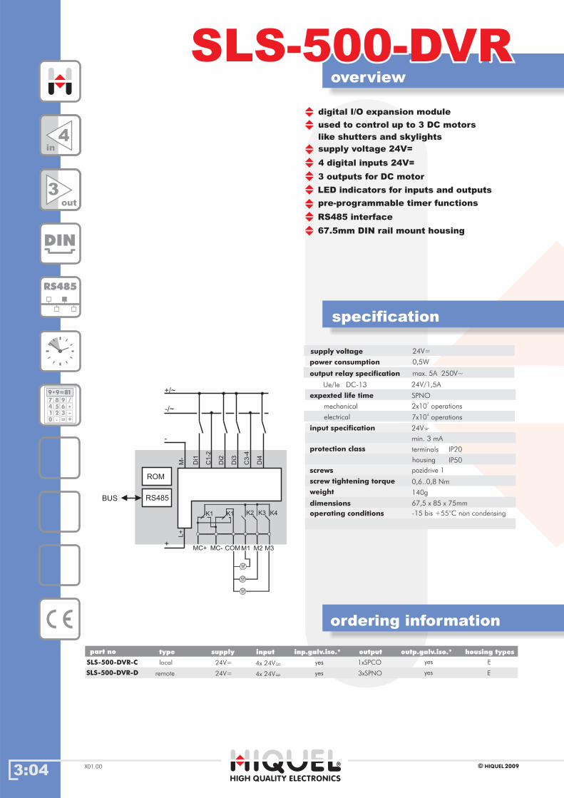
supply voltage 24V=
digital I/O expansion module
4 digital inputs 24V=
3 outputs for DC motor
LED indicators for inputs and outputs
67.5mm DIN rail mount housing
RS485 interface
supply voltage
power consumption
output relay specification
expexted life time
input specification
protection class
screws
screw tightening torque
weight
dimensions
operating conditions
0,5W
max. 5A 250V~
24V/1,5A
24V~
0,6..0,8 Nm
67,5 x 85 x 75mm
-15 bis +55°C non condensing
min. 3 mA
terminals
housing
IP20
IP50
pozidrive 1
140g
SPNO
2x10 operations7
mechanical
7x10 operations4
electrical
Ue/Ie DC-13
24V=
-
Di1
C1
-2
Di2
Di3
+
-
RS485
ROM
BUS
C3
-4
Di4
M-
L+
+/~
-/~
M
COM M1 M2 M3MC-
M
M
K1K1
MC+
K2 K3 K4
part no inputsupply inp.galv.iso.* outp.galv.iso.*output housing typestype
SLS-500-DVR-C
SLS-500-DVR-D remote
local 1xSPCO
3xSPNO
4x 24V~
4x 24V~
yes
yes
yes
yes
E
E
24V=
24V=
-
-
pre-programmable timer functions
used to control up to 3 DC motors
like shutters and skylights
SLS
-500-8
DI
dig
italin
put
module
3:05
overview
ordering information
SLS-500-8DISLS-500-8DI
specification
HIGH QUALITY ELECTRONICS
2009HIQUEL X01.00
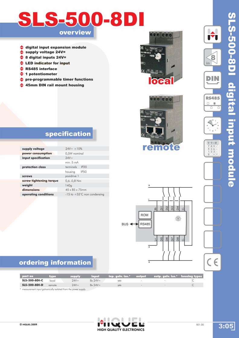
supply voltage 24V=
digital input expansion module
8 digital inputs 24V=
LED forindicator input
1 potentiometer
pre-programmable timer functions
45mm DIN rail mount housing
RS485 interface
supply voltage
power consumption
input specification
protection class
screws
screw tightening torque
weight
dimensions
0,5W nominal
24V=
0,6..0,8 Nm
45 x 85 x 75mm
min. 5 mA
terminals
housing
IP20
IP50
pozidrive 1
140g
remote
local
* measurement input galvanically isolated from the power supply
locallocal
remoteremote
SLS-500-8DI-C
SLS-500-8DI-D
-
-
8x 24V=
8x 24V=
yes
yes
-
-
C
C
24V=
24V=
Gehäusetypenpart no inputsupply inp. galv. iso.* outp. galv. iso.*output housing typestype
8in
RS485
189 9=*
7
4
1
0
8
5
2
.
9
6
3
=
/
*-
+
DIN
Di1
Di2
Di3
Di4
+
+
-
RS485
ROM
BUS
C-
M-
Di5
Di6
Di7
Di8
C-
L+
+
operating conditions -15 to +55°C non condensing
24V= ±10%
3:06
overview
ordering information
SLS-500-8DSLS-500-8D
specification
HIGH QUALITY ELECTRONICS
remote
remote
remote
local
local
local
2009HIQUELX01.00
part no inputsupply inp. galv. iso.* outp. galv. iso.*output housing typestype
SLS
-500-8
Ddig
italoutp
ut
module
locallocal
remoteremote
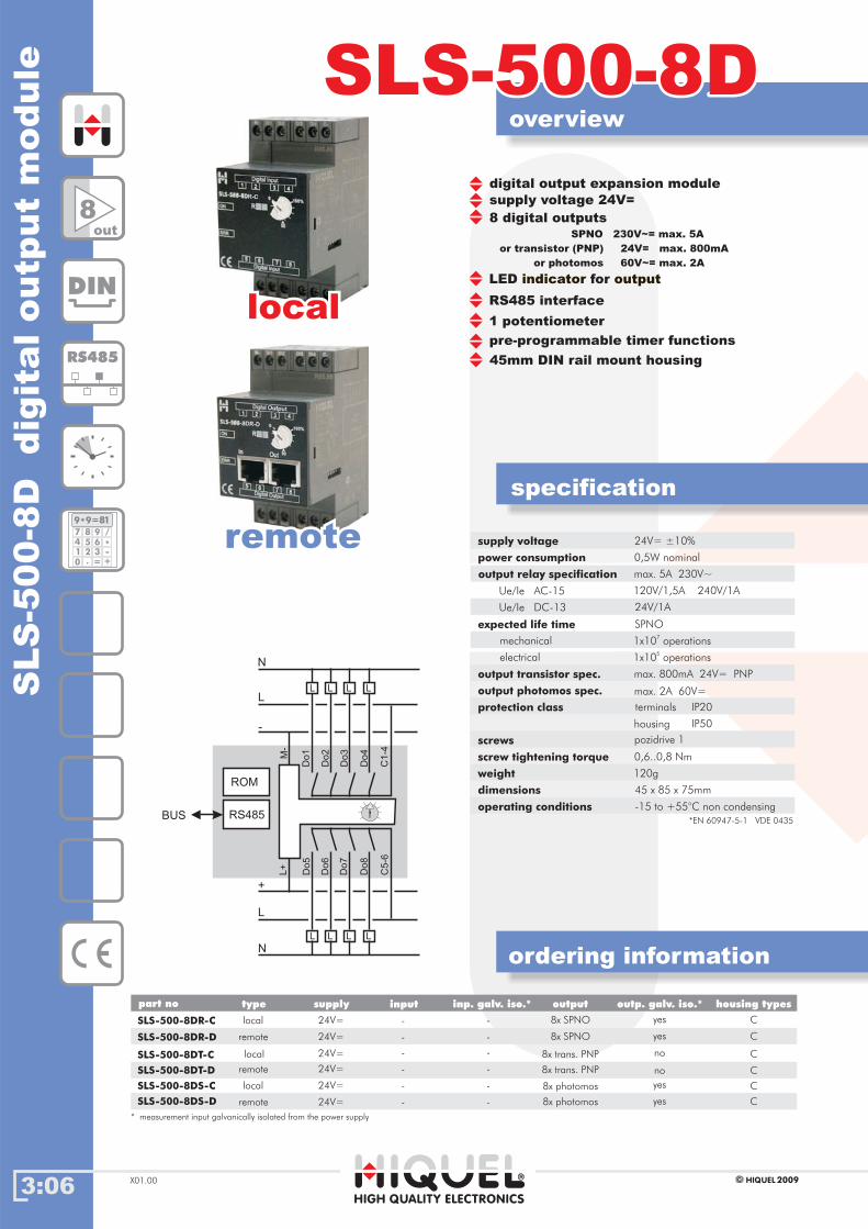
supply voltage 24V=
digital output expansion module
8 digital outputsSPNO 230V~= max. 5A
or transistor (PNP) 24V= max. 800mA
or photomos 60V~= max. 2A
LED forindicator output
1 potentiometer
pre-programmable timer functions
45mm DIN rail mount housing
RS485 interface
supply voltage
power consumption
output relay specification
output transistor spec.
output photomos spec.
Ue/Ie AC-15
expected life time
protection class
screws
screw tightening torque
weight
dimensions
0,5W nominal
max. 5A 230V~
max. 800mA 24V= PNP
max. 2A 60V=
120V/1,5A 240V/1A
24V/1A
0,6..0,8 Nm
45 x 85 x 75mm
terminals
housing
IP20
IP50
pozidrive 1
120g
SPNO
1x10⁷
operationsmechanical
1x10⁵
operationselectrical
Ue/Ie DC-13
SLS-500-8DR-C
SLS-500-8DR-D
8x SPNO
8x SPNO
8x trans. PNP
8x trans. PNP
8x photomos
8x photomos
-
-
-
-
-
-
-
-
-
-
-
-
yes
yes
no
no
yes
yes
C
C
C
C
C
C
24V=
24V=
24V=
24V=
24V=
24V=
8out
DIN
RS485
189 9=*
7
4
1
0
8
5
2
.
9
6
3
=
/
*-
+
SLS-500-8DT-C
SLS-500-8DS-C
SLS-500-8DT-D
SLS-500-8DS-D
Do
5
Do
2
Do
3
Do
4
Do
6
Do
7
Do
8
C5
-6
L
L
L
N
+
-
N
L
L
L
L
L
L
L
RS485
ROM
BUS
M-
L+
Do
1
C1
-4
operating conditions -15 to +55°C non condensing
24V= ±10%
* measurement input from the power supplygalvanically isolated
*EN 60947-5-1 VDE 0435
SLS
-500-F
BR
dig
italro
om
contro
ller
module
3:07
overview
ordering information
Gehäusetypen
SLS-500-FBRSLS-500-FBR
specification
part no inputsupply
HIGH QUALITY ELECTRONICS
inp. galv. iso.* outp. galv. iso.*output housing types
2009HIQUEL X01.00
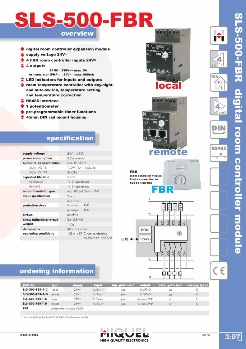
supply voltage 24V=
digital room controller expansion module
4 FBR room controller inputs 24V=
4 outputsSPNO 230V~= max. 5A
or transistor (PNP) 24V= max. 800mA
LED for andindicators inputs outputs
room temperature controller with day/night-
and auto-switch, temperature setting
and temperature correction
1 potentiometer
pre-programmable timer functions
45mm DIN rail mount housing
RS485 interface
supply voltage
power consumption
output relay specification
Ue/Ie AC-15
expected life time
input specification
output transistor spec.
protection class
screws
screw tightening torque
weight
dimensions
0,5W nominal
max. 5A 230V~
120V/1,5A 240V/1A
24V/1A
*EN 60947-5-1 VDE 0435
24V=
max. 800mA 24V= PNP
0,6..0,8 Nm
45 x 85 x 75mm
min. 5 mA
terminals
package
IP20
IP50
pozidrive 1
140g
SPNO
1x10⁷
operationsmechanical
1x10⁵
operationselectrical
Ue/Ie DC-13
FBR
4x SPNO
4x SPNO
4x trans. PNP
4x trans. PNP
4x 24V=
4x 24V=
4x 24V=
4x 24V=
SLS-500-FBR-R-C
SLS-500-FBR-R-D
24V=
24V=
24V=
24V=
yes
yes
yes
yes
C
C
C
C
please refer to page 03:08
local
local
remote
remote
type
yes
yes
no
no
FBRroom controller module
2-wire connection to
SLS-FBR module
locallocal
remoteremote
4in
DIN
RS485
4out
FBR
SLS-500-FBR-T-C
SLS-500-FBR-T-D
DO
1D
I1
DI2
DI3
DI4
DO
2
DO
3
DO
4
C1
-4
L
L
+
+
-
N
L L L
RS485
ROM
BUS
C-
M-
L+
FB
R
FB
R
FB
R
FB
R
operating conditions -15 to +55°C non condensing
24V= ±10%
* measurement input from the power supplygalvanically isolated
FBRFBR
3:08HIGH QUALITY ELECTRONICS
2009HIQUELX01.00
FBR-room controlFBR-room controlFB
R-r
em
ote
room
contr
olunit
Gehäusetypenpart no
FBR
potentiometer button LED right red housing typedigital switch LED left green
FBR-DS-PO-S -1
1
1 -
-
special1
1
FBR-PO
Bestellinformationenordering information
Title:
Programming
SLS-500-FBR
R1.DAY1Day
R1.DAY1Day FBR_DAYFBR_DAY
R1.AUTO1Auto
R1.AUTO1Auto FBR_AutoFBR_Auto
R1.NIGHT1Night
R1.NIGHT1Night FBR_NightFBR_Night
R1.OPEN1Open
R1.OPEN1Open FBR_OpenFBR_Open
R1.TEMP1Temp
R1.TEMP1Temp FBR_TempFBR_Temp
R1.CORR1Corr
R1.CORR1Corr FBR_CorrFBR_Corr
Digital switch of the FBR
Temperatue of the FBR
Potentiometer of the FBR
specification
operating conditions
dimensions
-20 bis +40°C
supply voltage
duty cycle
24Vdc -+ 10%
100%
85mm
85mm
25mm
width
height
depth
temperature range -5 to +40°C
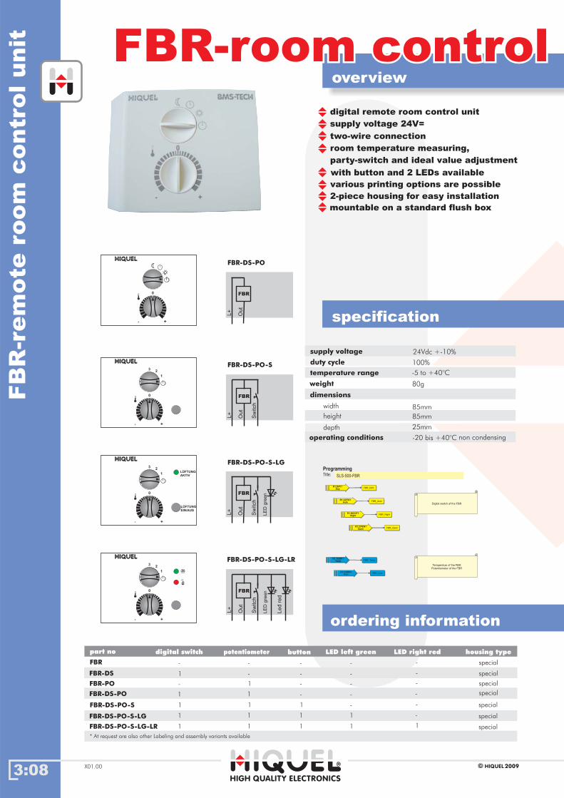
supply voltage 24V=
two-wire connection
room temperature measuring,
party-switch and ideal value adjustment
with button and 2 LEDs available
various printing options are possible
2-piece housing for easy installation
mountable on a standard flush box
digital remote room control unit
L+
Out
Sw
itch
FBR
- +
0
L+
Out
FBR
L+
Out
Sw
itch
LE
Dgre
enFBR
3
1
2
L+
Out
Sw
itch
LE
Dgre
en
Led
red
FBR
FBR-DS-PO
FBR-DS-PO-S
FBR-DS-PO-S-LG
FBR-DS-PO-S-LG-LR
non condensing
weight 80g
* At request are also other Labeling and assembly variants available
overview
FBR-DS
FBR-DS-PO
FBR-DS-PO-S
FBR-DS-PO-S-LG
FBR-DS-PO-S-LG-LR
--
11 1 - special1
-- - - special-
-- - - special1
-1 - - special-
-1 1 -1 special
11 1 1 special1
special
- +
0
3
1
2
- +
0
3
1
2
- +
0
LÜFTUNGEIN/AUS
LÜFTUNGAKTIV

3:09
overview
ordering information
specification
HIGH QUALITY ELECTRONICS
2009HIQUEL X01.00
SLS-500-DIMSLS-500-DIMS
LS
-500-D
IMlig
htin
gdim
mer
module
remoteremote
locallocal
supply voltage 24V=
lighting dimmer expansion module
1 dimmed output 600Watt 230V~
pre-programmable timer functions
45mm DIN rail mount housing
RS485 interface
supply voltage
power consumption
mains voltage
0,5W nominal
230 Vac
24V= ±10%
RS485
ROM
+
-
M-
L+
X
N LPE
LA
PE
L
N
1out
DIN
RS485
189 9=*
7
4
1
0
8
5
2
.
9
6
3
=
/
*-
+
remote
local
* measurement input galvanically isolated from the power supply
part no inputsupply inp. galv. iso.* outp. galv. iso.*output housing typestype
SLS-500-DIM-C
SLS-500-DIM-D
1x dimmer
1x dimmer
-
-
-
-
yes
yes
C
C
24V=
24V=
protection class
screws
screw tightening torque
weight
dimensions
0,6..0,8 Nm
45 x 85 x 75mm
terminals
housing
IP20
IP50
pozidrive 1
155g
operating conditions -15 to +55°C non condensing
rated output 600 VA
rated current 2,5 A
load type ohmic, inductice, automatic
control type phase control
resolution 1%
leakage current < 1mA (OFF-State)
load detection
3:10
overview
ordering information
SLS-500-PT100SLS-500-PT100
specification
HIGH QUALITY ELECTRONICS
2009HIQUELX01.00
SLS
-500-P
T100
tem
pera
ture
input
module
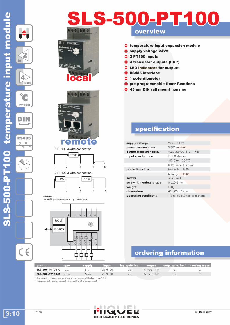
supply voltage 24V=
temperature input expansion module
2 PT100 inputs
4 transistor outputs (PNP)
LED for outputsindicators
1 potentiometer
pre-programmable timer functions
45mm DIN rail mount housing
RS485 interface
supply voltage
power consumption
output transistor spec.
input specification
protection class
screws
screw tightening torque
weight
dimensions
0,5W nominal
max. 800mA 24V= PNP
PT100 element
0,6..0,8 Nm
45 x 85 x 75mm
-50°C to +300°C
0,1°C repeat accuracy
terminals
housing
IP20
IP50
pozidrive 1
120g
Gehäusetypenpart no inputsupply inp. galv. iso.* outp. galv. iso.*output housing types
SLS-500-PT100-C 4x trans. PNP
4x trans. PNP
2x PT100
2x PT100SLS-500-PT100-D
24V=
24V=
no
no
C
Cremote
local
type
no
no
* measurement input galvanically isolated from the power supply
locallocal
remoteremote
DIN
RS485
CPT100
2in
4out
1 2 3 4 5
PT100
1 PT100 4-wire connection
1 2 3 4 5
PT100PT100
2 PT100 3-wire connection
DO
1
L+
1M-
2 3 4 5
DO
2
DO
3
DO
4
C1
-4
L
T
+
-
-
L
T
L
T
L
T
RS485
ROM
Remark:Unused inputs are replaced by connections.
operating conditions -15 to +55°C non condensing
24V= ±10%
* The ordering information for various sensors you will find on page 03:23

SLS
-500-P
T1000
tem
pera
ture
input
module
3:11
overview
ordering information
SLS-500-PT1000SLS-500-PT1000
specification
HIGH QUALITY ELECTRONICS
2009HIQUEL X01.00
supply voltage 24V=
temperature input expansion module
up to 4 PT1000 inputs
4 transistor outputs (PNP)
LED for outputsindicators
1 potentiometer
pre-programmable timer functions
45mm DIN rail mount housing
RS485 interface
supply voltage
power consumption
output transistor spec.
input specification
protection class
screws
screw tightening torque
weight
dimensions
0,5W nominal
max. 800mA 24V= PNP
PT1000 element
0,6..0,8 Nm
45 x 85 x 75mm
-50°C to +300°C
0,1°C repeat accuracy
terminals
housing
IP20
IP50
pozidrive 1
120g
SLS-500-PT1000-C local 4x trans. PNP
4x trans. PNP
4x PT1000
4x PT1000SLS-500-PT1000-D remote
no
no
no
no
C
C
24V=
24V=
part no inputsupply inp. galv. iso.* outp. galv. iso.*output housing typestype
* measurement input galvanically isolated from the power supply
locallocal
remoteremote
DIN
RS485
CPT1000
4in
4out
1 2 3 4 5
PT1000PT1000PT1000PT1000
4 PT1000 2-wire connection
DO
1
L+
1M-
2 3 4 5
DO
2
DO
3
DO
4
C1
-4
L
T
+
-
-
L
T
L
T
L
T
RS485
ROM
Remark:Unused inputs are replaced by connections.
operating conditions -15 to +55°C non condensing
24V= ±10%
* The ordering information for various sensors you will find on page 03:23
3:12
overview
ordering information
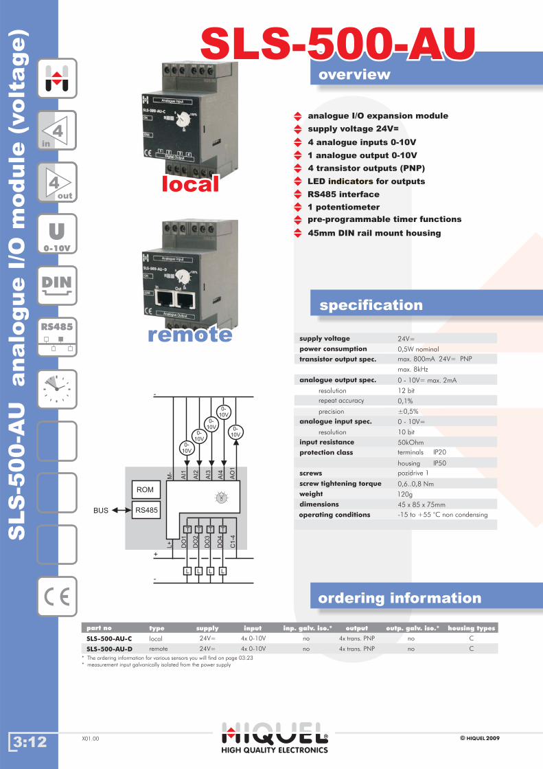
SLS-500-AUSLS-500-AU
specification
HIGH QUALITY ELECTRONICS
2009HIQUELX01.00
SLS
-500-A
Uanalo
gue
I/O
module
(volt
age)
supply voltage 24V=
analogue I/O expansion module
4 analogue inputs 0-10V
4 transistor outputs (PNP)
LED for outputsindicators
1 potentiometer
pre-programmable timer functions
45mm DIN rail mount housing
RS485 interface
1 analogue output 0-10V
supply voltage
power consumption
transistor output spec.
analogue input spec.
analogue output spec.
protection class
screws
screw tightening torque
weight
dimensions
24V=
0,5W nominal
max. 800mA 24V= PNP
max. 8kHz
0 - 10V=
0 - 10V= max. 2mA
0,6..0,8 Nm
45 x 85 x 75mm
10 bit
12 bit
resolution
resolution
repeat accuracy
precision
50kOhm
0,1%
±0,5%
terminals
housing
IP20
IP50
pozidrive 1
120g
input resistance
Gehäusetypenpart no inputsupply inp. galv. iso.* outp. galv. iso.*output housing types
SLS-500-AU-C 4x trans. PNP
4x trans. PNP
4x 0-10V
4x 0-10VSLS-500-AU-D
24V=
24V=
no
no
C
Cremote
local
type
no
no
* measurement input galvanically isolated from the power supply
locallocalD
O1
L+
AI1
M-
AI2
AI3
AI4
AO
1
DO
2
DO
3
DO
4
C1
-4
L
T
+
-
-
L
T
L
T
L
T
RS485
ROM
BUS
0-
10V
0-
10V
0-
10V
0-
10V
0-
10V
DIN
RS485
U0-10V
4in
4out
remoteremote
operating conditions -15 to +55 °C non condensing
* The ordering information for various sensors you will find on page 03:23
SLS
-500-A
Ianalo
gue
I/Om
odule
(curre
nt)
3:13
overview
ordering information
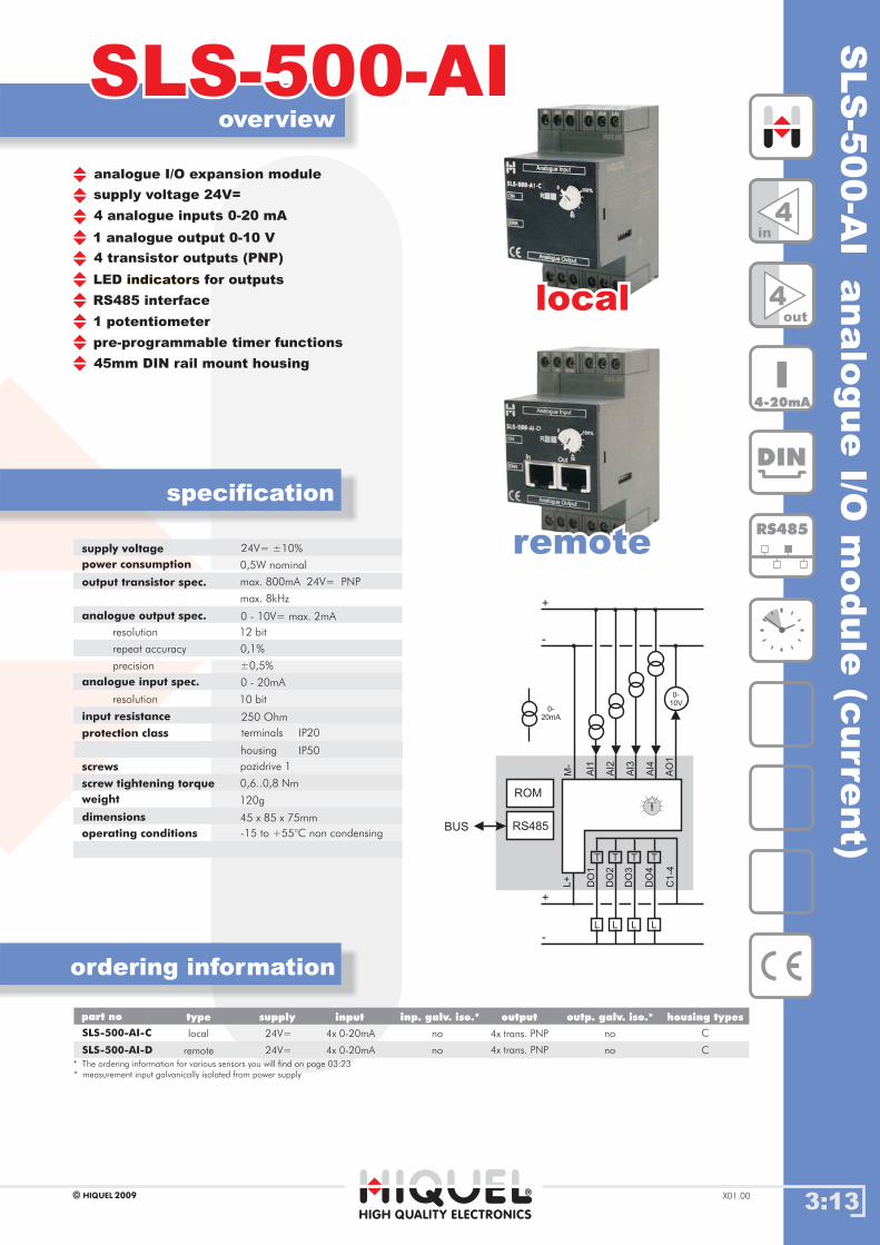
SLS-500-AISLS-500-AI
specification
HIGH QUALITY ELECTRONICS
2009HIQUEL X01.00
supply voltage 24V=
analogue I/O expansion module
4 analogue inputs 0-20 mA
4 transistor outputs (PNP)
LED for outputsindicators
1 potentiometer
pre-programmable timer functions
45mm DIN rail mount housing
RS485 interface
1 analogue output 0-10 V
supply voltage
power consumption
output transistor spec.
analogue input spec.
analogue output spec.
protection class
screws
screw tightening torque
weight
dimensions
0,5W nominal
max. 800mA 24V= PNP
max. 8kHz
0 - 20mA
0 - 10V= max. 2mA
0,6..0,8 Nm
45 x 85 x 75mm
10 bit
12 bit
resolution
resolution
repeat accuracy
precision
250 Ohm
0,1%
±0,5%
terminals
housing
IP20
IP50
pozidrive 1
120g
input resistance
SLS-500-AI-C local 4x trans. PNP
4x trans. PNP
4x 0-20mA
4x 0-20mASLS-500-AI-D remote
no
no
C
C
24V=
24V=
part no inputsupply inp. galv. iso.* outp. galv. iso.*output housing typestype
* measurement input galvanically isolated from power supply
no
no
locallocal
remoteremoteD
O1
L+
AI1
M-
AI2
AI3
AI4
AO
1
DO
2
DO
3
DO
4
C1
-4
L
T
+
-
+
-
L
T
L
T
L
T
RS485
ROM
BUS
0-
20mA
0-
10V
DIN
RS485
I4-20mA
4in
4out
operating conditions -15 to +55°C non condensing
24V= ±10%
* The ordering information for various sensors you will find on page 03:23

3:14
overview
ordering information
SLS-500-AU-AUSLS-500-AU-AU
specification
HIGH QUALITY ELECTRONICS
2009HIQUELX01.00
SLS
-500-A
U-A
Uanalo
gue
I/O
module
(volt
age)
supply voltage 24V=
analogue I/O expansion module
4 analogue inputs 0-10V
1 potentiometer
pre-programmable timer functions
45mm DIN rail mount housing
RS485 interface
4 analogue output 0-10Vs
supply voltage
power consumption
analogue input spec.
analogue output spec.
protection class
screws
screw tightening torque
weight
dimensions
0,5W nominal
0 - 10V=
0 - 10V= max. 2mA
0,6..0,8 Nm
45 x 85 x 75mm
10 bit
12 bit
resolution
resolution
repeat accuracy
precision
50kOhm
0,1%
±0,5%
terminals
housing
IP20
IP50
pozidrive 1
120g
input resistance
Gehäusetypenpart no inputsupply inp. galv. iso.* outp. galv. iso.*output housing types
SLS-500-AU-AU-C 4x 0-10V
4x 0-10V
4x 0-10V
4x 0-10VSLS-500-AU-AU-D
24V=
24V=
no
no
C
Cremote
local
type
no
no
* measurement input galvanically isolated from the power supply
locallocal
remoteremote
L+
AI1
M-
AI2
AI3
AI4 A
i
T
+
-
RS485
ROM
BUS
VA
VA
VA
VA
Ao
T
VA
VA
VA
VA
AO
1
AO
2
AO
3
AO
4
DIN
RS485
U0-10V
4in
4out
operating conditions -15 to +55°C non condensing
24V= ±10%
* The ordering information for various sensors you will find on page 03:23

SLS
-500-A
I-AI
analo
gue
I/Om
odule
(curre
nt)
3:15
overview
ordering information
SLS-500-AI-AISLS-500-AI-AI
specification
HIGH QUALITY ELECTRONICS
2009HIQUEL X01.00
supply voltage 24V=
analogue I/O expansion module
4 analogue inputs 0-20mA
1 potentiometer
pre-programmable timer functions
45mm DIN rail mount housing
RS485 interface
4 analogue output 0-20mAs
supply voltage
power consumption
analogue input spec.
analogue output spec.
protection class
screws
screw tightening torque
weight
dimensions
0,5W nominal
0 - 20mA
0 - 10V= max. 2mA
0,6..0,8 Nm
45 x 85 x 75mm
12 bit
10 bit
resolution
resolution
repeat accuracy
precision
250 Ohm
0,1%
±0,5%
terminals
housing
IP20
IP50
pozidrive 1
120g
input resistance
SLS-500-AI-AI-C local 4x 0-20mA
4x 0-20mA
4x 0-20mA
4x 0-20mASLS-500-AI-AI-D remote
no
no
C
C
24V=
24V=
part no inputsupply inp. galv. iso.* outp. galv. iso.*output housing typestype
* measurement input galvanically isolated from the power supply
no
no
locallocal
remoteremoteL
+
AI1
M-
AI2
AI3
AI4 A
i
T
+
-
RS485
ROM
BUS
VA
VA
VA
VA
Ao
T
VA
VA
VA
VA
AO
1
AO
2
AO
3
AO
4
DIN
RS485
I4-20mA
4in
4out
operating conditions -15 to +55°C non condensing
24V= ±10%
* The ordering information for various sensors you will find on page 03:23

3:16
overview
ordering information
SLS-500-AI-AUSLS-500-AI-AU
specification
HIGH QUALITY ELECTRONICS
2009HIQUELX01.00
SLS
-500-A
I-A
Uanalo
gue
I/O
module
supply voltage 24V=
analogue I/O expansion module
4 analogue inputs 0-20mA
1 potentiometer
pre-programmable timer functions
45mm DIN rail mount housing
RS485 interface
4 analogue output 0-10Vs
supply voltage
power consumption
analogue input spec.
analogue output spec.
protection class
screws
screw tightening torque
weight
dimensions
0,5W nominal
0 - 10V=
0 - 10V= max. 2mA
0,6..0,8 Nm
45 x 85 x 75mm
12 bit
10 bit
resolution
resolution
repeat accuracy
precision
250 Ohm
0,1%
±0,5%
terminals
housing
IP20
IP50
pozidrive 1
120g
input resistance
Gehäusetypenpart no inputsupply inp. galv. iso.* outp. galv. iso.*output housing types
SLS-500-AI-AU-C 4x 0-10V
4x 0-10V
4x 0-20mA
4x 0-20mASLS-500-AI-AU-D
24V=
24V=
no
no
C
Cremote
local
type
no
no
* measurement input galvanically isolated from the power supply
locallocal
remoteremote
L+
AI1
M-
AI2
AI3
AI4 A
i
T
+
-
RS485
ROM
BUS
VA
VA
VA
VA
Ao
T
VA
VA
VA
VA
AO
1
AO
2
AO
3
AO
4
DIN
RS485
U0-10V
4in
4out
I4-20mA
operating conditions -15 to +55°C non condensing
24V= ±10%
* The ordering information for various sensors you will find on page 03:23

SLS
-500-A
U-A
Ianalo
gue
I/Om
odule
3:17
overview
ordering information
SLS-500-AU-AISLS-500-AU-AI
specification
HIGH QUALITY ELECTRONICS
2009HIQUEL X01.00
supply voltage 24V=
analogue I/O expansion module
4 analogue inputs 0-10V
1 potentiometer
pre-programmable timer functions
45mm DIN rail mount housing
RS485 interface
4 analogue output 0-20mAs
supply voltage
power consumption
analogue input spec.
analogue output spec.
protection class
screws
screw tightening torque
weight
dimensions
0,5W nominal
0 - 20mA
0 - 10V= max. 2mA
0,6..0,8 Nm
45 x 85 x 75mm
12 bit
10 bit
resolution
resolution
repeat accuracy
precision
50 kOhm
0,1%
±0,5%
terminals
housing
IP20
IP50
pozidrive 1
120g
input resistance
SLS-500-AU-AI-C local 4x 0-20mA
4x 0-20mA
4x 0-10V
4x 0-10VSLS-500-AU-AI-D remote
no
no
C
C
24V=
24V=
part no inputsupply inp. galv. iso.* outp. galv. iso.*output housing typestype
* measurement input galvanically isolated from the power supply
no
no
locallocal
remoteremoteL
+
AI1
M-
AI2
AI3
AI4 A
i
T
+
-
RS485
ROM
BUS
VA
VA
VA
VA
Ao
T
VA
VA
VA
VA
AO
1
AO
2
AO
3
AO
4
4in
4out
operating conditions -15 to +55°C non condensing
U0-10V
DIN
RS485
I4-20mA
24V= ±10%
* The ordering information for various sensors you will find on page 03:23
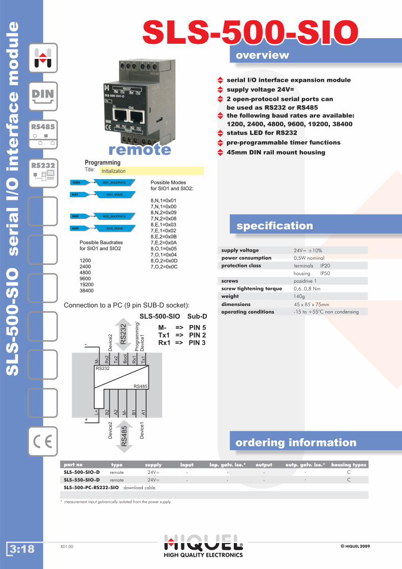
3:18
overview
ordering information
SLS-500-SIOSLS-500-SIO
specification
HIGH QUALITY ELECTRONICS
2009HIQUELX01.00
SLS
-500-S
IOseri
alI/O
inte
rface
module
supply voltage 24V=
serial I/O interface expansion module
2 open-protocol serial ports can
be used as RS232 or RS485
status LED for RS232
the following baud rates are available:
1200, 2400, 4800, 9600, 19200, 38400
pre-programmable timer functions
45mm DIN rail mount housing
supply voltage
power consumption
protection class
screws
screw tightening torque
weight
dimensions
0,5W nominal
0,6..0,8 Nm
45 x 85 x 75mm
terminals
housing
IP20
IP50
pozidrive 1
140g
SLS-500-SIO-D
SLS-550-SIO-D
SLS-500-PC-RS232-SIO
remote
remote
download cable
24V=
24V=
* measurement input galvanically isolated from the power supply
-
-
-
-
C
C
Gehäusetypenpart no inputsupply inp. galv. iso.* outp. galv. iso.*output housing typestype
-
-
-
-
remoteremote
DIN
RS485
RS232
operating conditions -15 to +55°C non condensing
24V= ±10%
Connection to a PC (9 pin SUB-D socket):
B2
Rx2
Tx2
Bo
ot
Rx1
A2
M-
B1
A1
+
-
Tx1
M-
L+
RS
232 M- => PIN 5
Tx1 => PIN 2Rx1 => PIN 3
Sub-DSLS-500-SIO
RS
485
Pro
gra
mm
ing/
Devic
e1
Devic
e2
RS232
RS485
Devic
e2
Devic
e1
Title:
Programming
Initialization
SIO1_MODESIO1_MODE0x010x01
Possible Baudrates
for SIO1 and SIO2SIO1 and SIO2
1200
2400
4800
9600
19200
38400
Possible Modes
for SIO1 and SIO2:SIO1 and SIO2:
8,N,1=0x01
7,N,1=0x00
8,N,2=0x09
7,N,2=0x08
8,E,1=0x03
7,E,1=0x02
8,E,2=0x0B
7,E,2=0x0A
8,O,1=0x05
7,O,1=0x04
8,O,2=0x0D
7,O,2=0x0C
SIO1_BAUDRATESIO1_BAUDRATE1920019200
SIO2_MODESIO2_MODE0x0B0x0B
SIO2_BAUDRATESIO2_BAUDRATE96009600
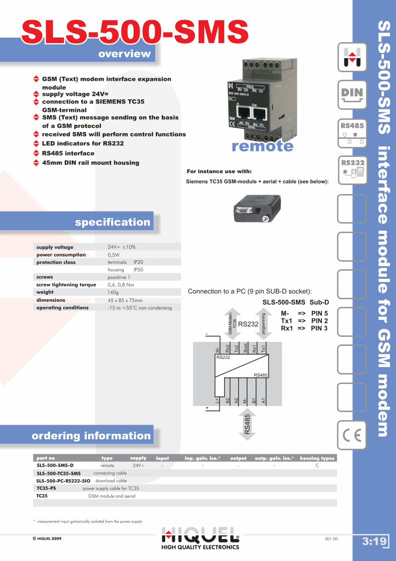
SLS
-500-S
MS
inte
rface
module
for
GS
Mm
odem
3:19
overview
ordering information
SLS-500-SMSSLS-500-SMS
specification
HIGH QUALITY ELECTRONICS
2009HIQUEL X01.00
supply voltage 24V=
connection to a SIEMENS TC35
GSM-terminal
SMS (Text) message sending on the basis
of a GSM protocol
received SMS will perform control functions
LED indicators for RS232
45mm DIN rail mount housing
RS485 interface
supply voltage
power consumption
protection class
screws
screw tightening torque
weight
dimensions
24V= 10%±
0,5W
0,6..0,8 Nm
45 x 85 x 75mm
terminals
housing
IP20
IP50
pozidrive 1
140g
SLS-500-SMS-D
SLS-500-TC35-SMS
remote
connecting cable
--
* measurement input galvanically isolated from the power supply
- - C24V=
part no inputsupply inp. galv. iso.* outp. galv. iso.*output housing typestype
remoteremote
Connection to a PC (9 pin SUB-D socket):
M- => PIN 5Tx1 => PIN 2Rx1 => PIN 3
Sub-DSLS-500-SMS
B2
Rx2
Tx2
Bo
ot
Rx1
A2
M-
B1
A1
+
-
Tx1
M-
L+
RS
485
GS
M-M
odem
TC
35
pro
gra
mm
ing
RS232
DIN
RS485
RS232
RS232
RS485
GSM (Text) modem interface expansion
module
operating conditions -15 to +55°C non condensing
For instance use with:
Siemens TC35 GSM-module + aerial + cable (see below):
TC35-PS power supply cable for TC35
SLS-500-PC-RS232-SIO download cable
TC35 GSM module and aerial
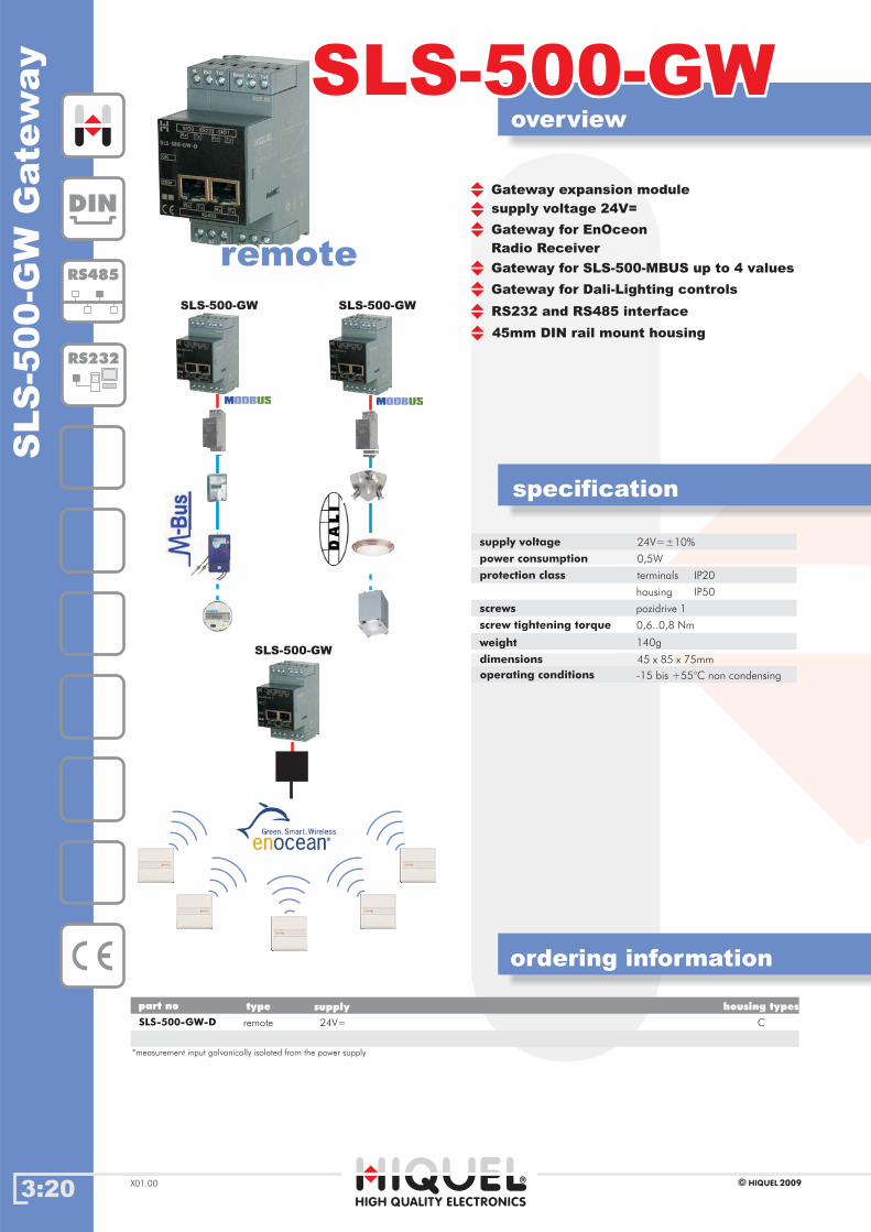
SLS
-500-G
WG
ate
way
3:20
overview
ordering information
SLS-500-GWSLS-500-GW
specification
2009HIQUELX01.00
DIN
RS485
RS232
supply voltage
power consumption
protection class
screws
screw tightening torque
weight
dimensions
24V=±10%
0,5W
0,6..0,8 Nm
45 x 85 x 75mm
terminals
housing
IP20
IP50
pozidrive 1
140g
operating conditions -15 bis +55°C non condensing
supply voltage 24V=
45mm DIN rail mount housing
Gateway expansion module
Gateway for EnOceon
Radio Receiver
Gateway for SLS-500-MBUS up to 4 values
Gateway for Dali-Lighting controls
RS232 and RS485 interfaceSLS-500-GW SLS-500-GW
SLS-500-GW
SLS-500-GW-D remote
*measurement input galvanically isolated from the power supply
C
part no supply housing typestype
24V=
remoteremote
HIGH QUALITY ELECTRONICS
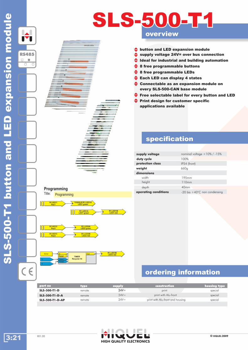
3:21HIGH QUALITY ELECTRONICS
2009HIQUELX01.00
SLS-500-T1SLS-500-T1S
LS
-500-T
1butt
on
and
LE
Dexpansio
nm
odule
ordering information
specification
operating conditions
dimensions
-20 bis +40°C
supply voltage
duty cycle
nominal voltage 15+10% / - %
100%
195mm
110mm
40mm
width
height
depth
weight 660g
overview
Ideal for industrial and building automation
8 free programmable buttons
8 free programmable LEDs
Each LED can display 4 states
Connectable as an expansion module on
every SLS-500-CAN base module
Free selectable label for every button and LED
Print design for customer specific
applications available
Gehäusetypenpart no
SLS-500-T1-D
supply housing type
special
type
SLS-500-T1-D-A
SLS-500-T1-D-AP
special
special
remote 24V=
remote
remote
24V=
24V=
24V=
construction
print with Alu-front
print with Alu-front and housing
RS485
Title:
Programming
Programming
R1.KEY1Key1
R1.KEY1Key1
TOGGLE:R1.LED1ALED1 green
TOGGLE:R1.LED1ALED1 green
R1.LED1ALED1 green
R1.LED1ALED1 green
R1.LED1BLED1 red
R1.LED1BLED1 red
R1.LED2ALED2 green
R1.LED2ALED2 green
R1.KEY2Key2
R1.KEY2Key2
R1.LED2BLED2 red
R1.LED2BLED2 red
R1.KEY3Key3
R1.KEY3Key3
R1.LED3BLED3 red
R1.LED3BLED3 red
TIMER
Recycler Hi
TIMER
Recycler Hi
InIn OutOut
ResetReset
Time1Time1
Time2Time2
TIMER
Recycler Hi
TIMER
Recycler Hi
InIn OutOut
ResetReset
Time1Time1
Time2Time2
ErrorError
11
11
protection class IP54 (front)
supply voltage 24V= over bus connection
button and LED expansion module
non condensing
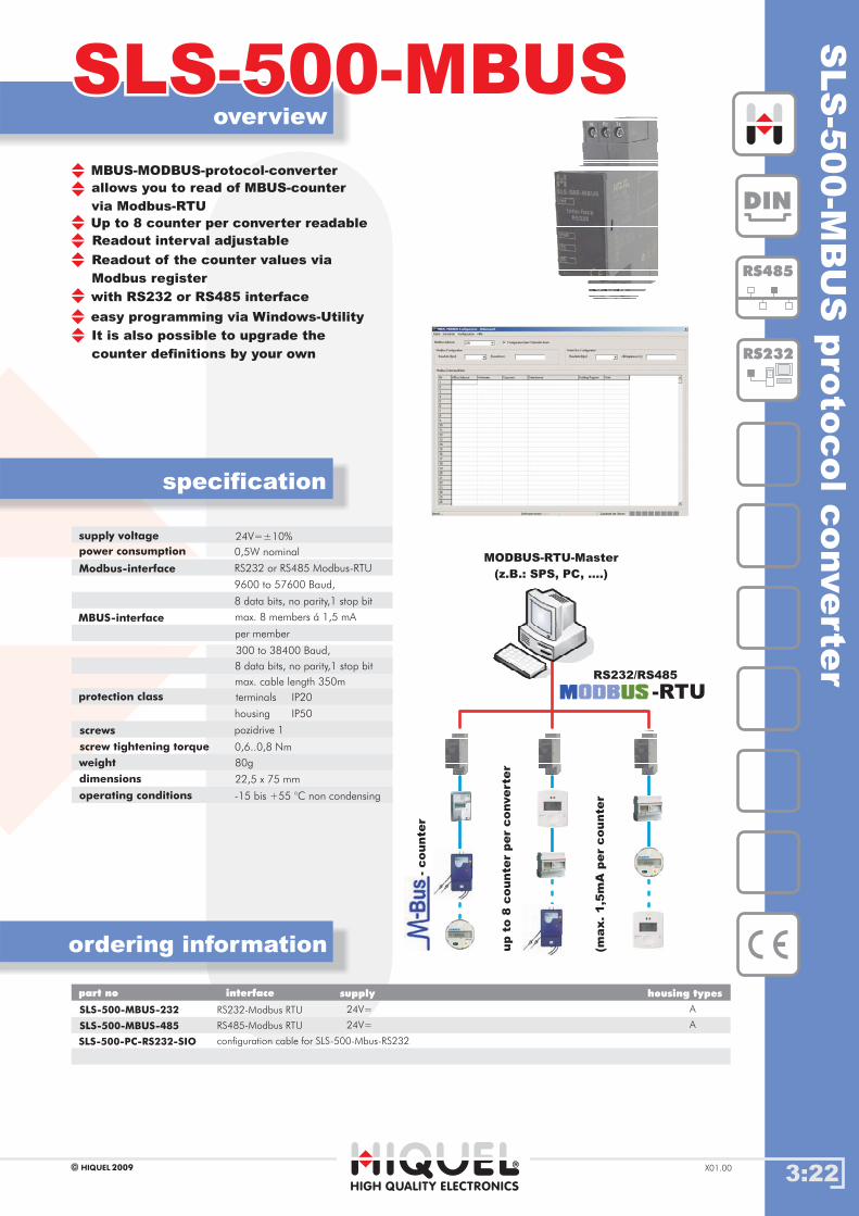
3:22HIGH QUALITY ELECTRONICS
2009HIQUEL X01.00
Gehäusetype
SLS
-500-M
BU
Spro
tocolconverte
r
SLS-500-MBUSSLS-500-MBUSoverview
specification
RS232/RS485
MODBUS-RTU-Master
(z.B.: SPS, PC, ....)
-counte
r
up
to8
counte
rper
converte
r
(max.1,5
mA
per
counte
r
-RTU
DIN
RS485
RS232
Gehäusetype
SLS-500-MBUS-232
SLS-500-MBUS-485
RS232-Modbus RTU A
part no supply housing typesinterface
24V=
RS485-Modbus RTU 24V= A
ordering information
supply voltage
power consumption
Modbus-interface
MBUS-interface
24V=±10%
0,5W nominal
8 data bits, no parity,1 stop bit
RS232 or RS485 Modbus-RTU
9600 to 57600 Baud,
protection class
screws
screw tightening torque
weight
dimensions
0,6..0,8 Nm
22,5 x 75 mm
terminals
housing
IP20
IP50
pozidrive 1
80g
operating conditions -15 bis +55 °C non condensing
8 data bits, no parity,1 stop bit
300 to 38400 Baud,
max. 8 members á 1,5 mA
per member
max. cable length 350m
allows you to read of MBUS-counter
via Modbus-RTU
Up to 8 counter per converter readable
with RS232 or RS485 interface
easy programming via Windows-Utility
It is also possible to upgrade the
counter definitions by your own
Readout of the counter values via
Modbus register
Readout interval adjustable
MBUS-MODBUS-protocol-converter
SLS-500-PC-RS232-SIO configuration cable for SLS-500-Mbus-RS232
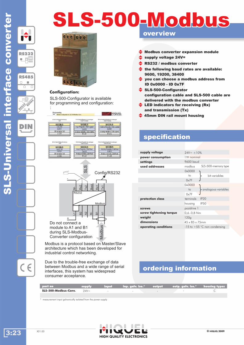
3:23
overview
ordering information
SLS-500-ModbusSLS-500-Modbus
specification
HIGH QUALITY ELECTRONICS
2009HIQUELX01.00
SLS
-Univ
ers
alin
terf
ace
converte
r
DIN
RS232
RS485
RS232
RS485
supply voltage 24V=
Modbus converter expansion module
RS232 / modbus converter
the following baud rates are available:
9600, 19200, 38400
you can choose a modbus address from
ID 0x0000 - ID 0x7F
SLS-500-Configurator
configuration cable and SLS-500 cable are
delivered with the modbus converter
LED indicators for receiving (Rx)
and transmission (Tx)
45mm DIN rail mount housing
Do not connect a
module to A1 and B1
during SLS-Modbus-
Converter configuration
Configuration:
Modbus is a protocol based on Master/Slave
architecture which has been developed for
industrial control networking.
Due to the trouble-free exchange of data
between Modbus and a wide range of serial
interfaces, this system has widespread
consumer acceptance.
supply voltage
power consumption 1W nominal
protection class
screws
screw tightening torque
weight
dimensions
0,6..0,8 Nm
45 x 85 x 75mm
terminals
housing
IP20
IP50
pozidrive 1
120g
settings
used addresses
9600 baud
modbus
0x0000
to
to
0x7F
0x0000
0x7F
SLS-500-memory type
bit-variables
analogous-variables}
}
operating conditions -15 to +55 °C non condensing
24V= ±10%
* measurement input galvanically isolated from the power supply
Gehäusetypenpart no inputsupply inp. galv. iso.* outp. galv. iso.*output housing types
SLS-500-Modbus-Conv. 24V= -- - - C
SLS-500-Configurator is available
for programming and configuration:
:
B2
Rx2
Tx2
Bo
ot
Rx1
A2
M-
B1
A1
+
-
Tx1
M-
L+
RS232
Modbus
Config/RS232
Modbus
SLS
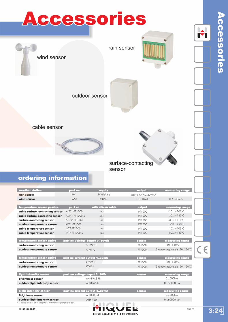
3:24
AccessoriesAccessories
HIGH QUALITY ELECTRONICS
2009HIQUEL X01.00
Accessorie
s
ordering information
rain sensor
wind sensor
surface-contacting
sensor
outdoor sensor
cable sensor
rain sensor
wind sensor 0,7...40m/s
RM1
WS1
weather station
relay NO/NC 30V/4A
0...10Vdc
part no supply output measuring range
24Vdc/Vac
24Vdc
cable surface -contacting sensor
cable surface-contacting sensor
ALTF1-PT1000
temperature sensor passive
PT1000
part no with silicon cable output measuring range
no
yes
-10...+105°C
ALTF1-PT1000-S PT1000 -30...+180°C
surface-contacting sensor
outdoor temperature sensor
ALTF2-PT1000 PT1000no
no
-30...+110°C
ATF1-PT1000 PT1000 -50...+90°C
cable temperature sensor
cable temperature sensor
HTF-PT1000 PT1000no
yes
-10...+105°C
HTF-PT1000-S PT1000 -50...+180°C
surface-contacting sensor
outdoor temperature sensor 5 ranges adjustable -50..150°C
ALTM2-U
ATM1-U
temperature sensor active
PT1000
PT1000
part no voltage output 0..10Vdc sensor measuring range
-50..+50°C
surface-contacting sensor
outdoor temperature sensor 5 ranges adjustable -50..150°C
ALTM2-I
ATM1-I
temperature sensor active
PT1000
PT1000
part no current output 4..20mA sensor measuring range
-50..+50°C
Brightness sensor
outdoor light intensity sensor 0...60000 Lux
AHKF-0,5-U
AHKF-60-U
light intensity sensor part no voltage ouput 0..10Vc sensor measuring range
0...500Lux
Brightness sensor
outdoor light intensity sensor 0...60000 Lux
AHKF-0,5-I
AHKF-60-I
Light intensity sensor part no current output 4..20mA sensor measuring range
0...500Lux
* At request are also other sensor types and measuring ranges available

Chapter 4: Network Data Communication
World of Automation
www.hiquel.com
Index
4:00
44Chapter 4: Networking
HIGH QUALITY ELECTRONICS
2009HIQUEL X01.00
EDS-316/308/305
COMport Repeater
COMport Converter
USBport 12xx
USBport 11xx
EDS-316/308/305 Part 2
Nport 51xx
Nport 52xx
.05.05
.04.04
.03.03
.02.02
.01.01
.06.06
.07.07
.08.08
IndexIndex
.09.09 Surge Guard

4:01
overview
ordering information
specification
HIGH QUALITY ELECTRONICS
2009HIQUELX01.00
1-p
ort
RS
-232
and
RS
-422/4
85
US
B-t
o-s
eri
alconverte
rs
1-port RS-232 and RS-422/485 USB-to-
serial converters
Compatible with USB 2.0
12Mbps USB data rate
921.6 Kbps maximum baudrate for super
fast data transmission
Drivers provided for Windows
(including Vista), WinCE 5.0, and Linux
DB9 male connector for RS-232, terminal
block adaptor for RS-422/485
LEDs for indicating USB and
TxD/RxD activity
15KV ESD protection for all serial ports
2 KV optical isolation protection
(USBport 1150I)
USB 1.0/1.1 compliant
SERIAL INTERFACE
USB
Serial Standards
compliance
USBport 1110: RS-232
USBport 1130: RS-422/485
connectors
Stop bits
DB9 male
1, 1.5, 2
Data bits
Parity None, Even, Odd, Space, Mark
5, 6, 7, 8
Baudrate
Uport-1110
part no
DIN
RS485
USB
RS232
USBport 11xxUSBport 11xx
USBport
1110/1130
1150
Terminal Block
Adaptor for
USBport 1130,
1150, 1150I
USBport 1150: RS-232/422/485
SERIAL COMMUNICATE PARAMETERS
50bps to 921.6 Kbps
Dimensions 52 x 80 x 22mm (USBport 1150I)
Weight
WinCE 5.0, Linux 2.6
Operating systems
DRIVER SUPPORT
Windows (2000, XP, 2003, Vista,
Flow Control RTS/CTS, XON/XOFF
Operating humidity 5 to 95% RH
Operating temperature 0 to 55°C
85g
USB 2.0 compatible
Uport-1130
Uport-1150
Uport-1150I
C US
The USB-to-serial converters allow you to
connect 1 RS-232/422/485 device to your
laptop or workstation through the USB
(Universal Serial Bus) port. These plug & play
USB solutions are Instant Plug & Play
compatible with both new and legacy
RS-232/422/485 devices, and are
perfect for mobile, instrumentation,
and point-of sale applications.
RS-232 RS-422 RS-485 optical isolation protection housing types
1
1
1 1
1
1 1
1
1 yes
no
no
no
special
special
special
special
DK-35A Mounting Kit for 35mm DIN-Rail
PHYSICAL CHARACTERISTICS
USBport
1150I
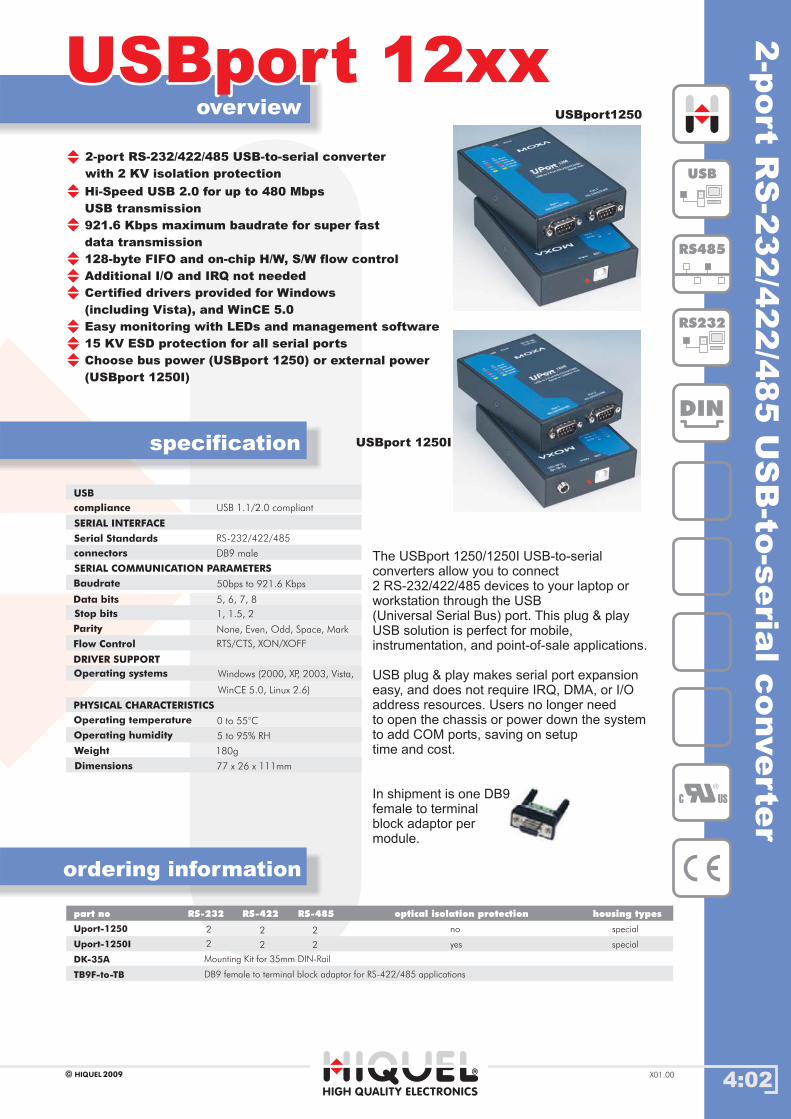
4:02
overview
ordering information
specification
HIGH QUALITY ELECTRONICS
2009HIQUEL X01.00
2-port RS-232/422/485 USB-to-serial converter
with 2 KV isolation protection
USBport 12xxUSBport 12xx2-p
ort
RS
-232/4
22/4
85
US
B-to
-seria
lconverte
r
Hi-Speed USB 2.0 for up to 480 Mbps
USB transmission
921.6 Kbps maximum baudrate for super fast
data transmission
128-byte FIFO and on-chip H/W, S/W flow control
Additional I/O and IRQ not needed
Certified drivers provided for Windows
(including Vista), and WinCE 5.0
Easy monitoring with LEDs and management software
15 KV ESD protection for all serial ports
Choose bus power (USBport 1250) or external power
(USBport 1250I)
USB 1.1/2.0 compliant
SERIAL INTERFACE
USB
Serial Standards
compliance
RS-232/422/485
Stop bits 1, 1.5, 2
Data bits
Parity None, Even, Odd, Space, Mark
5, 6, 7, 8
Baudrate
SERIAL COMMUNICATION PARAMETERS
50bps to 921.6 Kbps
Dimensions 77 x 26 x 111mm
Weight
WinCE 5.0, Linux 2.6)
Operating systems
DRIVER SUPPORT
Windows (2000, XP, 2003, Vista,
Flow Control RTS/CTS, XON/XOFF
Operating humidity 5 to 95% RH
Operating temperature 0 to 55°C
180g
connectors DB9 male
USBport 1250I
The USBport 1250/1250I USB-to-serial
converters allow you to connect
2 RS-232/422/485 devices to your laptop or
workstation through the USB
(Universal Serial Bus) port. This plug & play
USB solution is perfect for mobile,
instrumentation, and point-of-sale applications.
USB plug & play makes serial port expansion
easy, and does not require IRQ, DMA, or I/O
address resources. Users no longer need
to open the chassis or power down the system
to add COM ports, saving on setup
time and cost.
In shipment is one DB9
female to terminal
block adaptor per
module.
DIN
RS485
USB
RS232
C US
Uport-1250
part no
Uport-1250I
RS-232 RS-422 RS-485 optical isolation protection housing types
2
yes
no
special
special2 2
2 2 2
DK-35A Mounting Kit for 35mm DIN-Rail
TB9F-to-TB DB9 female to terminal block adaptor for RS-422/485 applications
USBport1250
PHYSICAL CHARACTERISTICS
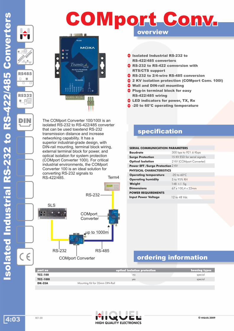
4:03
overview
ordering information
specification
HIGH QUALITY ELECTRONICS
2009HIQUELX01.00
Isola
ted
Industr
ialR
S-2
32
toR
S-4
22/4
85
Converte
rs
Isolated Industrial RS-232 to
RS-422/485 converters
RS-232 to RS-422 conversion with
RTS/CTS support
RS-232 to 2/4-wire RS-485 conversion
2 KV isolation protection (COMport Conv. 100I)
Wall and DIN-rail mounting
Plug-in terminal block for easy
RS-422/485 wiring
LED indicators for power, TX, Rx
-20 to 60°C operating temperature
300 bps to 921.6 Kbps
Optical Isolation
SERIAL COMMUNICATION PARAMETERS
Power EFT /Surge Protection
Baudrate
2 KV
Input Power Voltage 12 to 48 Vdc
POWER REQUIREMENTS
Operating humidity
TCC-100
part no
DIN
RS485
RS232
COMport Conv.COMport Conv.
Operating temperature
5 to 95% RH
Weight 148 +/- 5g
15 KV ESD for serial signals
TCC-100I
The COMport Converter 100/100I is an
isolated RS-232 to RS-422/485 converter
that can be used toextend RS-232
transmission distance and increase
networking capability. It has a
superior industrial-grade design, with
DIN-rail mounting, terminal block wiring,
external terminal block for power, and
optical isolation for system protection
(COMport Converter 100I). For critical
industrial environments, the COMport
Converter 100 is an ideal solution for
converting RS-232 signals to
RS-422/485.
housing types
Surge Protection
2 KV (COMport Converter)
-20 to 60°C
RS232
RS485
optical isolation protection
yes
no
special
special
DK-35A Mounting Kit for 35mm DIN-Rail
RS-485RS-232
COMport Converter
COMport
Converter
Term4
RS-232
SLS
PHYSICAL CHARACTERISTICS
Dimensions 67 x 100,4 x 22mm
up to 1000m
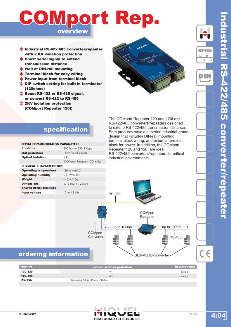
4:04
overview
ordering information
specification
HIGH QUALITY ELECTRONICS
2009HIQUEL X01.00
Industrial RS-422/485 converter/repeater
with 2 KV isolation protection
Boost serial signal to extend
transmission distance
Wall or DIN-rail mounting
Terminal block for easy wiring
Power input from terminal block
DIP switch setting for built-in terminator
(120ohms)
Boost RS-422 or RS-485 signal,
or convert RS-422 to RS-485
2KV isolation protection
(COMport Repeater 120I)
TCC-120
TCC-120I
special
special
part no housing types
COMport Rep.COMport Rep.In
dustria
lR
S-4
22/4
85
converte
r/repeate
r
300 bps to 230.4 Kbps
ESD protection
SERIAL COMMUNICATION PARAMETERS
Optical isolation
Baudrate
2 KV
Dimensions
Operating temperature -20 to +60°C
67 x 100.4 x 22mm
Weight
PHYSICAL CHARACTERISTICS
148 +/- 5g
Input voltage
POWER REQUIREMENTS
12 to 48 Vdc
Operating humidity 5 to 95% RH
(COMport Repeater 120I only)
The COMport Repeater 120 and 120I are
RS-422/485 converters/repeaters designed
to extend RS-422/485 transmission distance.
Both products have a superior industrial-grade
design that includes DIN-rail mounting,
terminal block wiring, and external terminal
block for power. In addition, the COMport
Repeater 120 and 120I are ideal
RS-422/485 converters/repeaters for critical
industrial environments.
DIN
RS485
15KV for all signals
optical isolation protection
yes
no
DK-35A Mounting Kit for 35mm DIN-Rail
up to 1000m up to 1000m
SLS-MBUS-Converter
COMport
Converter
COMport
Repeater
RS-232
RS-485
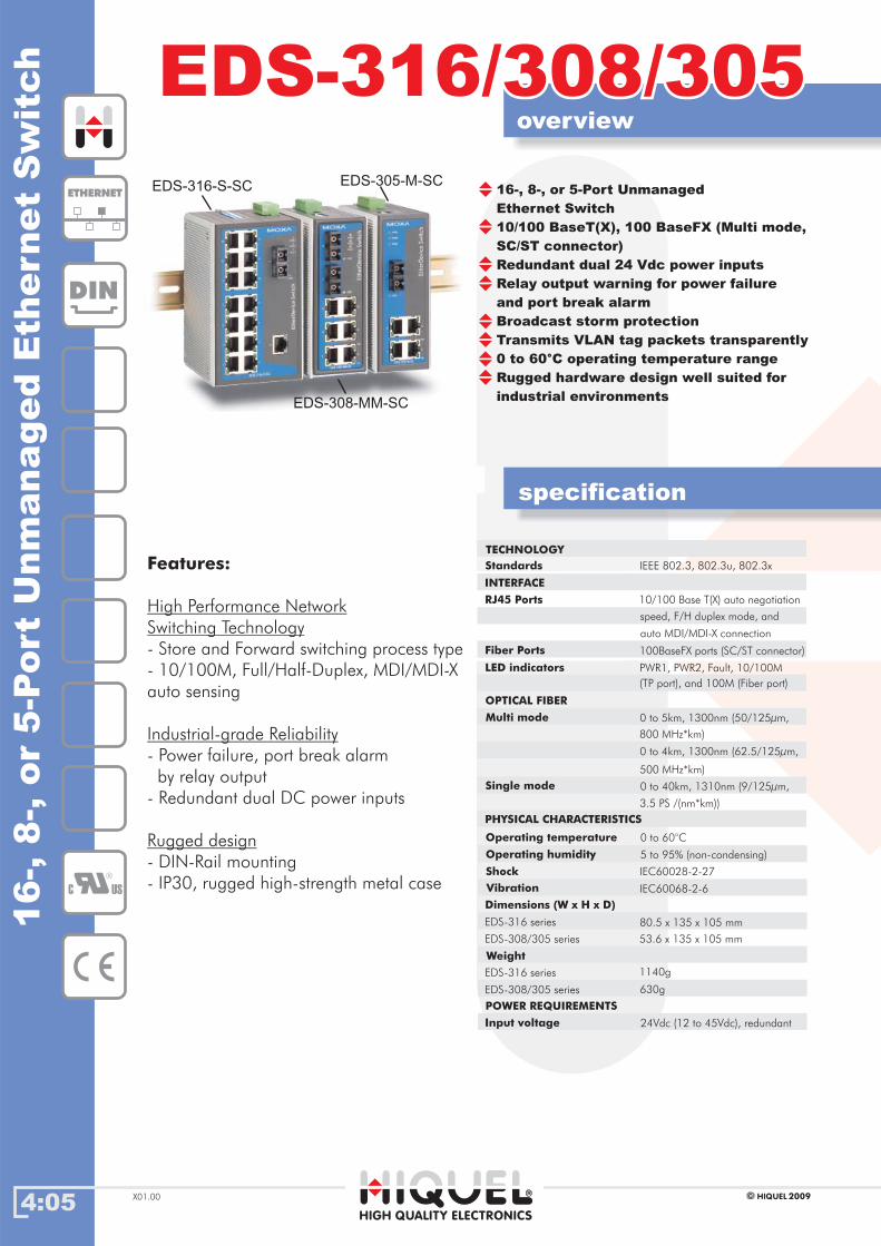
4:05
overview
specification
HIGH QUALITY ELECTRONICS
2009HIQUELX01.00
16-,
8-,
or
5-P
ort
Unm
ana
ged
Eth
ernet
Sw
itch
16-, 8-, or 5-Port Unmanaged
Ethernet Switch
10/100 BaseT(X), 100 BaseFX (Multi mode,
SC/ST connector)
Redundant dual 24 Vdc power inputs
Relay output warning for power failure
and port break alarm
Broadcast storm protection
Transmits VLAN tag packets transparently
0 to 60°C operating temperature range
Rugged hardware design well suited for
industrial environments
DIN
EDS-316/308/305EDS-316/308/305
C US
IEEE 802.3, 802.3u, 802.3x
RJ45 Ports
TECHNOLOGY
Standards
speed, F/H duplex mode, and
auto MDI/MDI-X connection
LED indicators PWR1, PWR2, Fault, 10/100M
800 MHz*km)
Multi mode
0 to 4km, 1300nm (62.5/125µm,
0 to 5km, 1300nm (50/125µm,
OPTICAL FIBER
Single mode
3.5 PS /(nm*km))
500 MHz*km)
INTERFACE
10/100 Base T(X) auto negotiation
Fiber Ports 100BaseFX ports (SC/ST connector)
(TP port), and 100M (Fiber port)
0 to 40km, 1310nm (9/125µm,
PHYSICAL CHARACTERISTICS
Dimensions (W x H x D)
IEC60068-2-6
Shock IEC60028-2-27
Operating humidity
EDS-316 series
53.6 x 135 x 105 mm
80.5 x 135 x 105 mm
EDS-308/305 series
Weight
EDS-316 series
630g
1140g
EDS-308/305 series
Operating temperature 0 to 60°C
5 to 95% (non-condensing)
Vibration
Features:
- Store and Forward switching process type
- 10/100M, Full/Half-Duplex, MDI/MDI-X
auto sensing
- Power failure, port break alarm
by relay output
- Redundant dual DC power inputs
- DIN-Rail mounting
- IP30, rugged high-strength metal case
High Performance Network
Switching Technology
Industrial-grade Reliability
Rugged design
ETHERNET
Input voltage 24Vdc (12 to 45Vdc), redundant
POWER REQUIREMENTS
EDS-316-S-SC
EDS-308-MM-SC
EDS-305-M-SC

4:06
overview
ordering information
HIGH QUALITY ELECTRONICS
2009HIQUEL X01.00
EDS-316
EDS-316-M-SC
-
-
-
1
special
special
16
15
part no housing types
EDS-316/308/305EDS-316/308/30516-,
8-,
or
5-P
ort
Unm
ana
ged
Eth
ernet
Sw
itch
EDS-316-MM-SC
EDS-316-M-ST
-
1
2
-
special
special
14
15
C US
The EDS-316/308/305 series includes 16, 8, and 5 port Ethernet switches that provide
an economical solution for your industrial Ethernet connection, and the built-in relay
warning function alerts maintainers when power failures or port breaks occur.
These switches have been designed for harsh industrial environments, such as in hazardous
locations that comply with FCC, TÜV, UL and CE standards. These model pass
through a 100% burn-in test to ensure that they fulfill the special needs of
industrial automation control.
DIN
ETHERNET
EDS-316-MM-ST
EDS-316-S-SC
2
-
-
1
special
special
14
15
EDS-316-SS-SC 2 special14
EDS-308 -- special8
EDS-308-M-SC
EDS-308-MM-SC
-
-
1
2
special
special
7
6
EDS-308-MM-ST 2- special6
EDS-308-S-SC
EDS-308-SS-SC
-
-
1
2
special7
6
EDS-305
EDS-305-M-SC
-
-
-
1
special
special
5
4
EDS-305-M-ST 1- special4
EDS-305-S-SC -1 special4
RJ45-Port
EDS-316-MS-SC 14 special
LWL-Port SC Connector LWL-Port ST Connector LWL type
special
-
-2
-
multi mode
multi mode
multi mode
multi mode
-
1x multi mode / 1x single mode
multi mode
multi mode
multi mode
multi mode
multi mode
-
single mode
single mode
single mode
single mode
single mode
Touch Panel
SLS-500 Series
NPort 5210
EDS-305-M-SC
DSL-Router
IP-Camera
NPort 5130
SLS Mbus ConverterBar-Code
Scanner
PC
EDS-308-M-SC
RS232
RS485
Ethernet
LWL
up to 40km
EDS-309-3M-SC -3 special6
EDS-309-3M-ST 3- special6
multi mode
multi mode
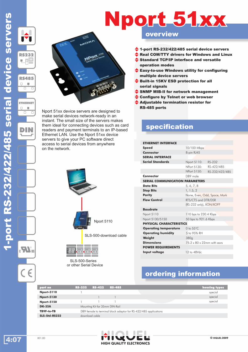
4:07
overview
specification
HIGH QUALITY ELECTRONICS
2009HIQUELX01.00
1-p
ort
RS
-232/4
22/4
85
seri
aldevic
eservers
1-port RS-232/422/485 serial device servers
Real COM/TTY drivers for Windows and Linux
Standard TCP/IP interface and versatile
operation modes
Easy-to-use Windows utility for configuring
multiple device servers
Built-in 15KV ESD protection for all
serial signals
SNMP MIB-II for network management
Configure by Telnet or web browser
Adjustable termination resistor for
RS-485 ports
Nport 51xxNport 51xx
Nport 51xx device servers are designed to
make serial devices network-ready in an
instant. The small size of the servers makes
them ideal for connecting devices such as card
readers and payment terminals to an IP-based
Ethernet LAN. Use the Nport 51xx device
servers to give your PC software direct
access to serial devices from anywhere
on the network.
RTS/CTS and DTR/DSR
Baudrate
Parity
Flow Control
110 bps to 230.4 Kbps
50 bps to 921.6 Kbps
0 to 55°COperating temperature
12 to 48Vdc
PHYSICAL CHARACTERISTICS
ETHERNET INTERFACE
Speed
1, 1.5, 2
Data Bits 5, 6, 7, 8
SERIAL COMMUNICATION PARAMETERS
Connector 8-pin RJ45
SERIAL INTERFACE
Serial Standards Nport 5110:
RS-422/485
RS-232
NPort 5130:
Connector DB9 male
Stop Bits
10/100 Mbps
RS-232/422/485NPort 5150:
None, Even, Odd, Space, Mark
(RS-232 only), XON/XOFF
Nport 5110
Nport 5130/5150
POWER REQUIREMENTS
Input voltage
Nport-5110
part no
Nport-5130
Nport-5150
RS-232 RS-422 RS-485 housing types
1
1 1
1 1
1
ordering information
RS485
C US
ETHERNET
special
special
special
RS232
DIN
Operating humidity 5 to 95% RH
DK-35A Mounting Kit for 35mm DIN-Rail
Nport 5110
SLS-500-Series
or other Serial Device
TB9F-to-TB DB9 female to terminal block adaptor for RS-422/485 applications
Weight 380g
75.2 x 80 x 22mm with earsDimensions
SLS-500-download cable
SLS-Std-RS232 download cable
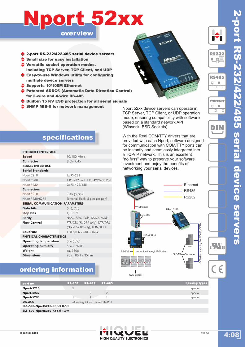
4:08
overview
ordering information
specifications
HIGH QUALITY ELECTRONICS
2009HIQUEL X01.00
2-port RS-232/422/485 serial device servers
Nport-5210
Nport-5232
special
special
part no housing types
Nport 52xxNport 52xx2-p
ort
RS
-232/4
22/4
85
seria
ldevic
eservers
10/100 Mbps
ETHERNET INTERFACE
SERIAL INTERFACE
Speed
Connectors
RJ45 (8 pins)
2x RS-422/485
1 RS-232 Port, 1 RS-422/485 Port
Flow Control RTS/CTS (RS-232 only), DTR/DRS
Parity
1, 1.5, 2
Data bits
SERIAL COMMUNICATION PARAMETERS
5, 6, 7, 8
Terminal Block (5 pins per port)
Baudrate 110 bps bis 230.3 Kbps
None, Even, Odd, Space, Mark
Serial Standards
Nport-5230 special
Nport 52xx device servers can operate in
TCP Server, TCP Client, or UDP operation
mode, ensuring compatibility with software
based on a standard network API
(Winsock, BSD Sockets).
With the Real COM/TTY drivers that are
provided with each Nport, software designed
for communication with COM/TTY ports can
be instantly and seamlessly integrated into
a TCP/IP network. This is an excellent
"no fuss" way to preserve your software
investment and enjoy the benefits of
networking your serial devices.
Small size for easy installation
Versatile socket operation modes,
including TCP Server, TCP Client, and UDP
Easy-to-use Windows utility for configuring
multiple device servers
Supports 10/100M Ethernet
Patented ADDC® (Automatic Data Direction Control)
for 2-wire and 4-wire RS-485
Built-in 15 KV ESD protection for all serial signals
SNMP MIB-II for network management
Connector 8-pin RJ45
Nport 5210
Nport 5230
Nport 5232
2x RS-232
Nport 5210
Nport 5230/5232
Stop bits
(Nport 5210 only), XON/XOFF
Operating humidity 5 to 95% RH
Operating temperature 0 to 55°C
RS485
C US
ETHERNET
DIN
RS232
RS-232 RS-422 RS-485
2
1 1
2 2
1
DK-35A Mounting Kit for 35mm DIN-Rail
Ethernet
RS-232
SLS-Series
SLS-Mbus-Converter
NPort 5230
EDS-305
N-Port 5210
CO
M-P
ort
ma
pp
ing
f.e
.C
OM
3,
CO
M4
connection through IP-SocketWeight ca. 380g
Dimensions 90 x 100.4 x 35mm
PHYSICAL CHARACTERISTICS
RS232
RS485
Ethernet
SLS-500-Nport5210-Kabel 0,5m
SLS-500-Nport5210-Kabel 1,0m

4:09
overview
specification
HIGH QUALITY ELECTRONICS
2009HIQUELX01.00
Surg
eG
uard
symmetrical and asymmetrical voltage
protection
DIN rail mounting
for cable (IDC-Connector 110+Krone type)
and modular-jack-wiring
as a interface between single wiring
to modular-jack-wiring
more options for a PoE wiring
Surge GuardSurge Guard
Line to line voltages
Stand off voltage
Shield : GND
Break down voltage > 6,8V @ 1mA
max. current
max. power 200W @ tp= 8/20µs
< 6V
Surge Guard
part no housing types
ordering information
ETHERNET
special
DIN
85m
m
72mm
1:2, 3:6, 4:5, 7:8
-
-
100A @ tp= 8/20µs
Line to earth (GND) volt. (1+2) : GND
(3+6) : GND
(4+5) : GND
(7+8) : GND
1 1
2 2
3 3
4 4
5 5
6 6
7 7
8 8
+ - + -
Shield ShieldTerminal Terminal
1M
IDC/MOD-PLUGIDC/MOD-PLUG
electrical wiring diagram:
mechanical dimensions:
110 Vdc
Impulse break down volt.
Stand off voltage
Break down voltage
70 Vdc
< 450V @ 100V/µs Impulse
< 500V @ 1000V/µs Impulse
Please note:After a disturbance t
to be reviewed or appropriate exchanged.
The full effect can only be
with a properly connected PE conductor.
he module have
guaranteed

Chapter 5: Human Machine Interfaces
World of Automation
www.hiquel.com
Index
5:00
55Chapter 5: Human Machine Interfaces
HIGH QUALITY ELECTRONICS
2009HIQUEL X01.00
Histar Series
SCADA Software
WEB-Studio
.03.03
.02.02
.01.01
IndexIndex
Histar Frames.04.04
Histar Audio, Histar MU.05.05
Histar system overview.06.06
HTPC-670S.07.07
HPC-600S.08.08
HTPC-870E.09.09
HPC-870E.10.10
Histar-870E.11.11
HTPC-850E.12.12
HPC-850E.13.13
Histar-850E.14.14
Histar-200.15.15
HM-200.16.16
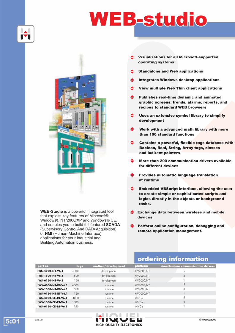
5:01HIGH QUALITY ELECTRONICS
2009HIQUELX01.00
WEB-studioWEB-studio
Visualizations for all Microsoft-supported
operating systems
Standalone and Web applications
Integrates Windows desktop applications
View multiple Web Thin client applications
Publishes real-time dynamic and animated
graphic screens, trends, alarms, reports, and
recipes to standard WEB browsers
Uses an extensive symbol library to simplify
development
Work with a advanced math library with more
than 100 standard functions
Contains a powerful, flexible tags database with
Boolean, Real, String, Array tags, classes
and indirect pointers
More than 200 communication drivers available
for different devices
Provides automatic language translation
at runtime
Embedded VBScript interface, allowing the user
to create simple or sophisticated scripts and
logics directly in the objects or background
tasks.
IWS-0150-NT-V6.1
IWS-4000-NT-RT-V6.1
IWS-4000-NT-V6.1
IWS-1500-NT-V6.1
part no runtime/developmenttags simultaneous communication drivers
ordering informationplatform
Exchange data between wireless and mobile
devices
Perform online configuration, debugging and
remote application management.
IWS-1500-NT-RT-V6.1
IWS-0150-NT-RT-V6.1
IWS-4000-CE-RT-V6.1
IWS-1500-CE-RT-V6.1
IWS-0150-CE-RT-V6.1
4000
1500
150
4000
1500
150
4000
1500
150
development
development
development
runtime
runtime
runtime
runtime
runtime
runtime
XP/2000/NT
XP/2000/NT
XP/2000/NT
XP/2000/NT
XP/2000/NT
XP/2000/NT
WinCe
WinCe
WinCe
5
3
1
5
3
1
5
3
1
WEB-Studio
SCADA
HMI
is a powerful, integrated tool
that exploits key features of Microsoft®
Windows® NT/2000/XP and Windows® CE,
and enables you to build full featured
(Supervisory Control And DATA Acquisition)
or (Human-Machine Interface)
applications for your Industrial and
Building Automation business.

5:02HIGH QUALITY ELECTRONICS
2009HIQUEL X01.00
SCADASCADA
ordering information
Gehäusetypenpart no
IWS-002-WS
WEB Solution
Develop the application just once and
access the screens from the Server
station or from any remote
Web Thin Client during the
runtime.
IWS-008-WS
IWS-032-WS
IWS-004-WS
IWS-016-WS
IWS-064-WS
IWS-128-WS
total concurrent web session
2
4
8
16
32
64
128
Web Thin Client 2
Web Thin Client n
Ethernet
Ethernet
Ethernet
IWS Server
(Touchpanel, IPC)
Ethernet,
RS232,
RS485,...
Web Thin Client 1
PLC, Converter, Machine,..
Multi-Platform Runtime
Build your application just once
and run it under any platform
from Windows CE up to
Windows Server 2003
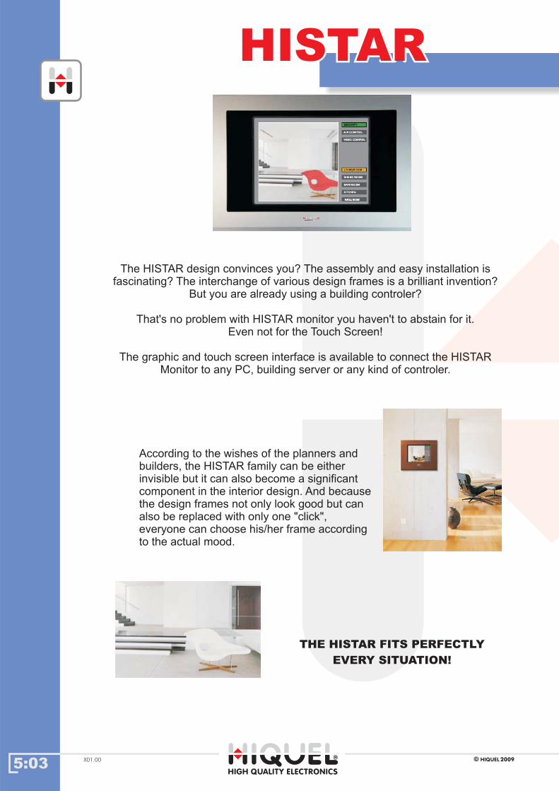
5:03HIGH QUALITY ELECTRONICS
2009HIQUELX01.00
HISTARHISTAR
The HISTAR design convinces you? The assembly and easy installation is
fascinating? The interchange of various design frames is a brilliant invention?
But you are already using a building controler?
That's no problem with HISTAR monitor you haven't to abstain for it.
Even not for the Touch Screen!
The graphic and touch screen interface is available to connect the HISTAR
Monitor to any PC, building server or any kind of controler.
According to the wishes of the planners and
builders, the HISTAR family can be either
invisible but it can also become a significant
component in the interior design. And because
the design frames not only look good but can
also be replaced with only one "click",
everyone can choose his/her frame according
to the actual mood.
THE HISTAR FITS PERFECTLY
EVERY SITUATION!

5:04HIGH QUALITY ELECTRONICS
2009HIQUEL X01.00
FramesFrames
ordering information
The colourful design frames are looking really beautiful. And to exchange them is
done in a moment! For that reason everybody will select his own frame for its
ambient or its individual room situation.
The design frame is made of high quality Perspex or anodized aluminium. Even
polished or matt, the surfaces are refined and prepared for a long term usage.
The installation box MU integrates
the HISTAR products. The wall
mounting guarantees that the
HISTAR will have a maximum distance
of 25mm to the surface of the wall.
This gives to the HISTAR the look of a
picture on the wall.
The mounting is so simple:
mounting the in-wall box, fitting HISTAR
and adding the frame.
READY!
roughly
aluminium anodised
bronze
antique RAL8025
silvermetallic
smoke-green
anthracite
milk-white
night-black
frost-red
zinc-yellow
black-green
black-blue
ultramarine-blue
aluminium
aluminium
aluminium
aluminium
Perspex
Perspex
Perspex
Perspex
Perspex
Perspex
Perspex
Perspex
Perspex
Perspex
Farbe Material
FR15-16
FR15-5
FR15-8
FR15-9
FR15-1
FR15-3
FR15-4
FR15-15
FR15-2
FR15-10
FR15-11
FR15-12
FR15-13
FR15-14
15"
FR19-16
FR19-5
FR19-8
FR19-9
FR19-1
FR19-3
FR19-4
FR19-15
FR19-2
FR19-10
FR19-11
FR19-12
FR19-13
FR19-14
19"
EX
CL
US
IVE
TO
PH
OM
E
AUDIO FRxx-xx option: Speaker and microphone integrated in the front. Your order code: Add “M” on the end of the product code you choosed. ex: FR15-3-M
AL
U+
GL
AS
S wide white anodized aluminium + glass
19”
wide black anodized aluminium + glass
anodized aluminium + glasswide mint-green
white glass
black glass
mint-green glass
Farbe Material
FRgw15-W
FRgw15-B
FRgw15-G
FRg15-W
15"
FRg19-W
19"19”
FRg15-B FRg19-B
FRg15-G FRg19-G
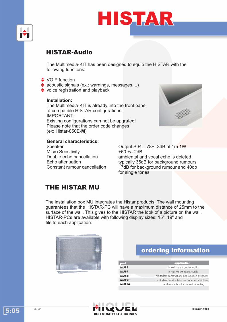
5:05HIGH QUALITY ELECTRONICS
2009HIQUELX01.00
HISTARHISTAR
The Multimedia-KIT has been designed to equip the HISTAR with the
following functions:
VOIP function
acoustic signals (ex.: warnings, messages,...)
voice registration and playback
The Multimedia-KIT is already into the front panel
of compatible HISTAR configurations.
IMPORTANT:
Existing configurations can not be upgrated!
Please note that the order code changes
(ex: Histar-850E- )
Speaker
Micro Sensitivity
Double echo cancellation
Echo attenuation
Constant rumour cancellation
Installation:
M
General characteristics:
The installation box MU integrates the Histar products. The wall mounting
guarantees that the HISTAR-PC will have a maximum distance of 25mm to the
surface of the wall. This gives to the HISTAR the look of a picture on the wall.
HISTAR-PCs are available with following display sizes: 15", 19" and
fits to each application.
HISTAR-Audio
THE HISTAR MU
ordering information
Output S.P.L. 78+- 3dB at 1m 1W
+60 +/- 2dB
ambiental and vocal echo is deleted
typically 35dB for background rumours
17dB for background rumour and 40db
for single tones
MU15
part
MU19
MU15T
MU19T
application
in wall mount box for walls
in wall mount box for walls
mortarless constructions and wooden structures
mortarless constructions and wooden structures
MU15A wall mount box for on wall mounting
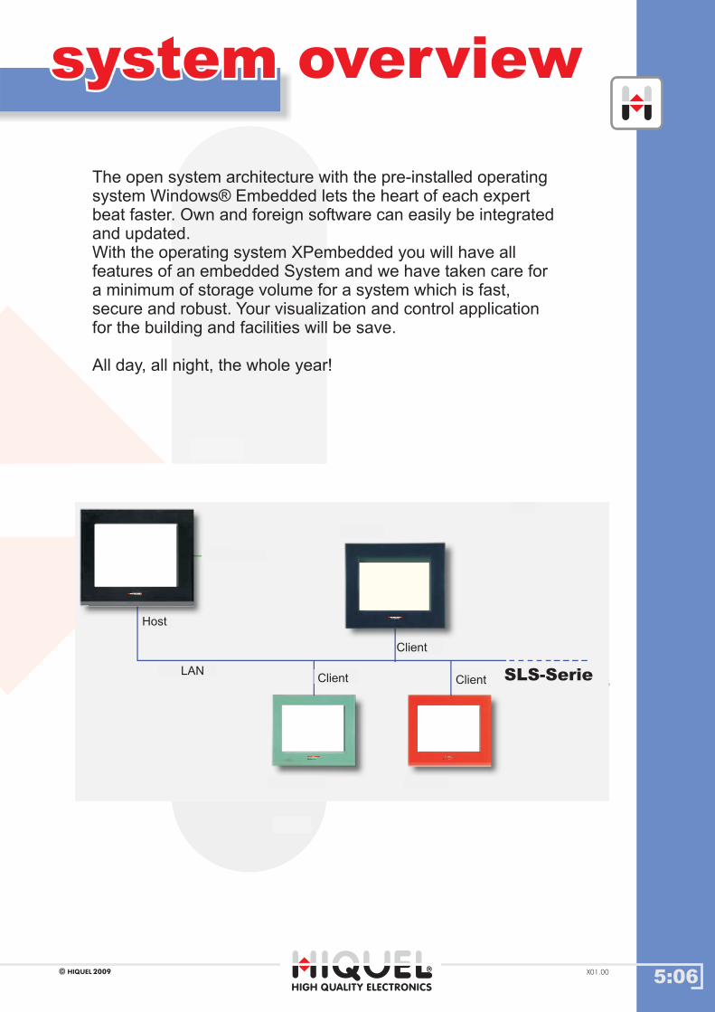
5:06HIGH QUALITY ELECTRONICS
2009HIQUEL X01.00
system overviewsystem overview
The open system architecture with the pre-installed operating
system Windows® Embedded lets the heart of each expert
beat faster. Own and foreign software can easily be integrated
and updated.
With the operating system XPembedded you will have all
features of an embedded System and we have taken care for
a minimum of storage volume for a system which is fast,
secure and robust. Your visualization and control application
for the building and facilities will be save.
All day, all night, the whole year!
SLS-SeriesSLS-Serie
Client
ClientClientLAN
Host
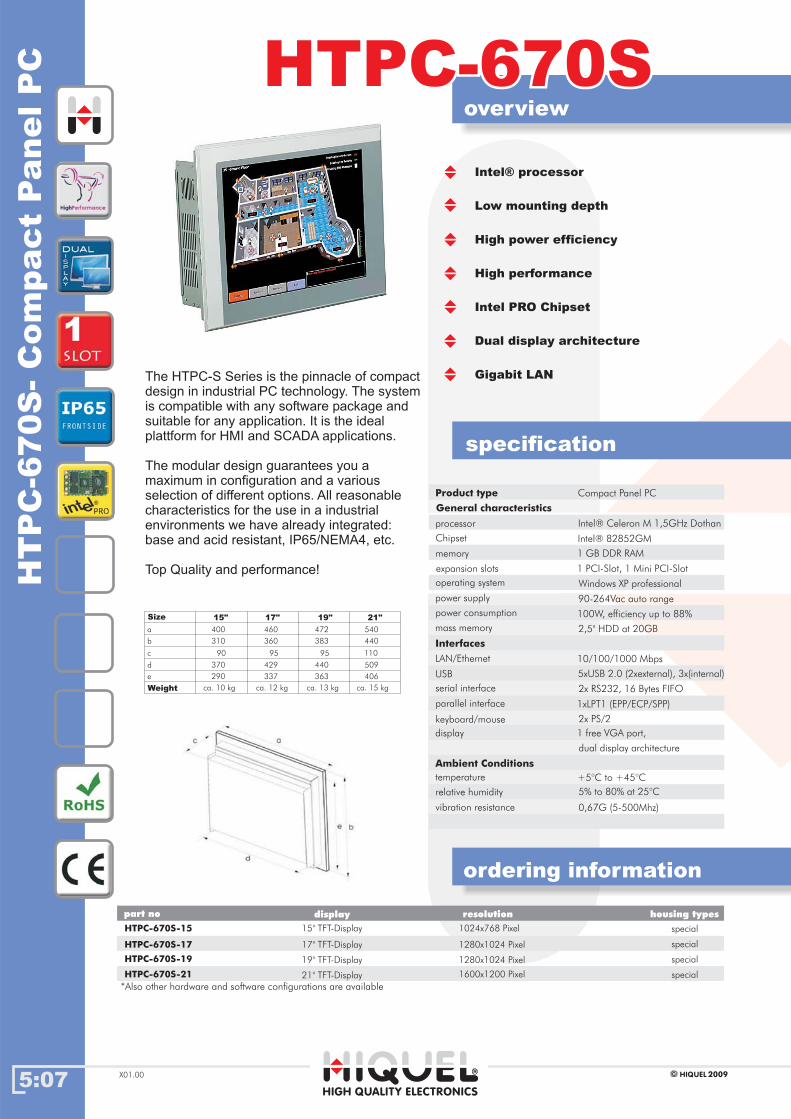
5:07
overview
ordering information
HTPC-670SHTPC-670S
HIGH QUALITY ELECTRONICS
2009HIQUELX01.00
HTPC-670S-15 15" TFT-Display special
part no resolution housing typesdisplay
HT
PC
-670S
-C
om
pact
PanelP
C
Intel® processor
Low mounting depth
High power efficiency
High performance
Intel PRO Chipset
Dual display architecture
Gigabit LAN
Product type
General characteristics
processor
power consumption
mass memory
LAN/Ethernet
USB
Ambient Conditions
serial interface
relative humidity
memory
Chipset
Compact Panel PC
Intel® Celeron M 1,5GHz Dothan
90-264Vac auto range
100W, efficiency up to 88%
2,5" HDD at 20GB
10/100/1000 Mbps
5xUSB 2.0 (2xexternal), 3x(internal)
+5°C to +45°C
2x RS232, 16 Bytes FIFO
5% to 80% at 25°C
1 GB DDR RAM
1 PCI-Slot, 1 Mini PCI-Slot
Intel® 82852GM
keyboard/mouse 2x PS/2
1 free VGA port,display
specification
expansion slots
operating system Windows XP professional
power supply
Interfaces
parallel interface 1xLPT1 (EPP/ECP/SPP)
temperature
vibration resistance 0,67G (5-500Mhz)
Size
Weight
15" 17" 19" 21"
400
310
90
370
290
ca. 10 kg
460
360
95
429
337
ca. 12 kg
472
383
95
440
363
ca. 13 kg
540
440
110
509
406
ca. 15 kg
1024x768 Pixel
HTPC-670S-17 17" TFT-Display 1280x1024 Pixel
1280x1024 Pixel19" TFT-Display
21" TFT-Display
HTPC-670S-19
HTPC-670S-21 1600x1200 Pixel
special
special
special
a
b
c
d
e
The HTPC-S Series is the pinnacle of compact
design in industrial PC technology. The system
is compatible with any software package and
suitable for any application. It is the ideal
plattform for HMI and SCADA applications.
The modular design guarantees you a
maximum in configuration and a various
selection of different options. All reasonable
characteristics for the use in a industrial
environments we have already integrated:
base and acid resistant, IP65/NEMA4, etc.
Top Quality and performance!
*Also other hardware and software configurations are available
dual display architecture

5:08
overview
ordering information
HPC-600SHPC-600S
specification
HIGH QUALITY ELECTRONICS
2009HIQUEL X01.00
HP
C-6
00S
Com
pact
box
PC
Long term availability
High performance
Low mounting depth
High configuration flexibility
High grade industrial components
PCI-Slot for expansions
Product type
General characteristics
processor
power consumption
mass memory
LAN/Ethernet
USB
Ambient Conditions
serial interface
relative humidity
memory
chipset
Compact box PC
Intel® Pentium 4 > 2,0GHz
115/230Vac switchable
220W
2,5" HDD at 20GB
10/100 Mbps
6xUSB 2.0 (2x ext., 4x int.)
+5°C to +45°C
2x RS232 (1x ext., 1x int.)
5% to 80% at 25°C
1 GB DDR RAM
1 PCI-Slot
Intel® FW82845GV
keyboard/mouse 2x PS/2
expansion slots
operating systems Windows XP professional
power supply
Interfaces
temperature
optical drives CD-Rom
HPC-600S special
part no housing types
*Also other hardware and software configurations are available
Dimensions
Weight
368
289
85
ca. 7 kg
a
b
c
parallel interface 1xLPT1 (EPP/ECC)
vibration resistance 0,67G (5-500Mhz)
video interface 1xVGA
The demand for qualities of industrial PC's are
as various as their application. In an application
is a system without fan a "must" in the others
maximum performance belongs. How the
entitlement to benefits design and flexibillity also
belong so. Therefore, HIQUEL in its modular
concept has moved the " front UNIT " from the
" PC UNIT " as a separable system.
Every " PC UNIT " can act as an
independent unity.
Display unities like the HM-200 or the
Histar-200 can be connected in different sizes.
Not only ergonomic operator
panels can be thereby generated, also damages
can be turned away from the PC UNIT already
in the approach.
HPC is called the solution if the industrial PC
in the switch cabinet should be mounted.
The HPC leaves open no wishes
in the design and configuration!
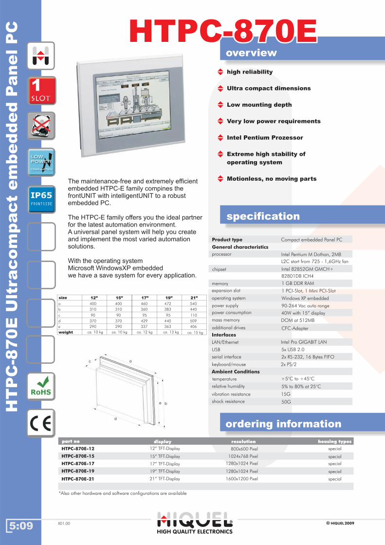
5:09
overview
ordering information
HTPC-870EHTPC-870E
specification
HIGH QUALITY ELECTRONICS
2009HIQUELX01.00
HT
PC
-870E
Ult
racom
pact
em
bed
ded
PanelP
C
size
weight
12” 15”
400
310
90
370
290
ca. 10 kg
400
310
90
370
290
ca. 10 kg
a
b
c
d
e
special
Gehäusetypenpart no housing types
HTPC-870E-12 12” TFT-Display
resolutiondisplay
800x600 Pixel
*Also other hardware and software configurations are available
special15” TFT-Display 1024x768 PixelHTPC-870E-15
Product type
General characteristics
processor
power consumption
mass memory
LAN/Ethernet
USB
Ambient Conditions
serial interface
relative humidity
memory
chipset
Compact embedded Panel PC
Intel Pentium M Dothan, 2MB
90-264 Vac auto range
40W with 15” display
DOM at 512MB
Intel Pro GIGABIT LAN
5x USB 2.0
+5°C to +45°C
2x RS-232, 16 Bytes FIFO
5% to 80% at 25°C
1 GB DDR RAM
Intel 82852GM GMCH+
keyboard/mouse 2x PS/2
power supply
Interfaces
temperature
vibration resistance
additional drives CFC-Adapter
15G
high reliability
Ultra compact dimensions
Low mounting depth
Very low power requirements
Intel Pentium Prozessor
Extreme high stability of
operating system
Motionless, no moving parts
operating system Windows XP embedded
The maintenance-free and extremely efficient
embedded HTPC-E family compines the
frontUNIT with intelligentUNIT to a robust
embedded PC.
The HTPC-E family offers you the ideal partner
for the latest automation environment.
A universal panel system will help you create
and implement the most varied automation
solutions.
With the operating system
Microsoft WindowsXP
we have a save system for every application.
embedded
L2C start from 725 - 1,6GHz fan
82801DB ICH4
expansion slot 1 PCI-Slot, 1 Mini PCI-Slot
50Gshock resistance
19” 21”
472
383
95
440
363
ca. 13 kg
540
440
110
509
406
ca. 15 kg
17”
460
360
95
429
337
ca. 12 kg
specialHTPC-870E-17 17” TFT-Display 1280x1024 Pixel
special19” TFT-Display 1280x1024 PixelHTPC-870E-19
specialHTPC-870E-21 21” TFT-Display 1600x1200 Pixel

5:10
overview
ordering information
HPC-870EHPC-870E
specification
HIGH QUALITY ELECTRONICS
2009HIQUEL X01.00
HP
C-8
70E
Ultra
com
pact
em
bed
ded
Box
PC
High reliability
Ultra compact dimensions
Low mounting depth
Very low power requirements
AMD Geode™ processors
Embedded system
Extreme high stability of
operating system
HPC-870E special
part no housing types
*Also other hardware and software configurations are available
Dimensions
Weight
368
289
55
ca. 6 kg
a
b
c
product type
General characteristics
processor
power consumption
mass memory
LAN/Ethernet
USB
Ambient Conditions
serial interface
relative humidity
memory
chipset
Compact embedded Box PC
Intel Pentium M Dothan, 2MB L2C
90-264 Vac auto range
25W
DOM at 512MB
Intel Pro GIGABIT LAN
6x USB 2.0
+5°C to +45°C
2x RS-232, 16 Bytes FIFO
5% to 80% at 25°C
1 GB DDR RAM
Intel 82852 GM GMCH+
keyboard/mouse 2x PS/2
power supply
Interfaces
temperature
50G
additional drives CFC-Adapter
shock resistance
operating system Windows XP embedded
The demand for qualities of industrial PC's are
as various as their application. In an application
is a system without fan a "must" in the others
maximum performance belongs. How the
entitlement to benefits design and flexibillity also
belong so. Therefore, HIQUEL in its modular
concept has moved the " front UNIT " from the
" PC UNIT " as a separable system.
Every " PC UNIT " can act as an
independent unity.
Display unities like the HM-200 or the
Histar-200 can be connected in different sizes.
Not only ergonomic operator
panels can be thereby generated, also damages
can be turned away from the PC UNIT already
in the approach.
HPC is called the solution if the industrial PC
in the switch cabinet should be mounted.
The HPC leaves open no wishes
in the design and configuration!
video interface 1x VGA Port
start from 725 - 1,6 GHz fan
82801DB ICH4
1 PCI-Slot, 1 Mini PCI-Slotexpansion slot
vibration resistance 15G

5:11
overview
ordering information
Histar-870EHistar-870E
specification
HIGH QUALITY ELECTRONICS
2009HIQUELX01.00
special
part no housing types
Histar-870E-15
His
tar-
870E
em
bed
ded
PC
for
wall
mount
*Also other hardware and software configurations are available
*Delivery without frame.
display
15” TFT-Display
19” TFT-Display
resolution
1024x768 Pixel
1280x1024 Pixel specialHistar-870E-19
Size 15” 19"
Cut-Out MUxx 399x336x90 472x410x90
Outside with frame 425x365x25 497x435x25
ca. 9 kg ca. 11 kgWeight
HIQUEL offers with the product family HISTAR
various products. With HISTAR PC-Touch you
will have all advantages of the HISTAR product
range and the boundaryless freedom to integrate
your own software ideas.
With the operating system WindowsXP embedded
you willhave all features of an embedded System
and we have taken care for a minimum of storage
volume for a system which is fast, secure
and robust.
Your visualization and control application for the
building and facilities will be save.
All day, all night, the whole year!
Home PC with industrial hardware
Easy assembly and installation
Interchange of various design frames
Graphic and touch screen interface
Various connectable
High performance with Windows XP
embedded
specialHistar-870E-15-M 15” TFT-Display
19” TFT-Display
1024x768 Pixel
1280x1024 Pixel specialHistar-870E-19-M
Histar-Audio
yes
yes
no
no
Ordering information of the frames you can find on page 1:51.
product type
General characteristics
processor
power consumption
mass memory
LAN/Ethernet
USB
Ambient Conditions
serial interface
relative humidity
memory
chipset
Compact embedded Box PC
Intel Pentium M Dothan, 2MB L2C
90-264 Vac auto range
25W
DOM at 512MB
Intel Pro GIGABIT LAN
6x USB 2.0
+5°C to +45°C
2x RS-232, 16 Bytes FIFO
5% to 80% at 25°C
1 GB DDR RAM
Intel 82852 GM GMCH+
keyboard/mouse 2x PS/2
power supply
Interfaces
temperature
50G
additional drives CFC-Adapter
shock resistance
operating system Windows XP embedded
video interface 1x VGA Port
start from 725 - 1,6 GHz fan
82801DB ICH4
1 PCI-Slot, 1 Mini PCI-Slotexpansion slot
vibration resistance 15G
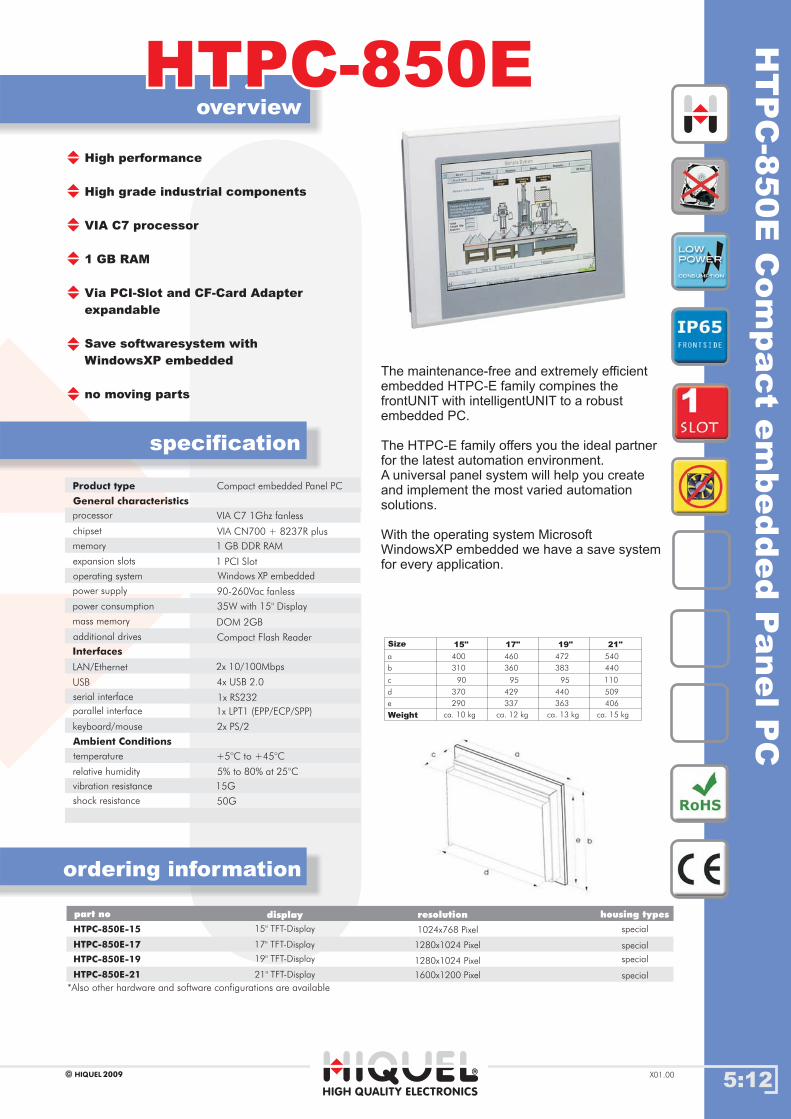
5:12
overview
ordering information
specification
HIGH QUALITY ELECTRONICS
2009HIQUEL X01.00
HTPC-850EHTPC-850EH
TP
C-8
50E
Com
pact
em
bed
ded
PanelP
C
special
Gehäusetypenpart no housing types
HTPC-850E-15 15" TFT-Display
resolutiondisplay
1024x768 Pixel
special17" TFT-Display 1280x1024 PixelHTPC-850E-17
specialHTPC-850E-19 19" TFT-Display 1280x1024 Pixel
special21" TFT-Display 1600x1200 PixelHTPC-850E-21
Product type
General characteristics
Compact embedded Panel PC
Size
Weight
15" 17" 19" 21"
400
310
90
370
290
ca. 10 kg
460
360
95
429
337
ca. 12 kg
472
383
95
440
363
ca. 13 kg
540
440
110
509
406
ca. 15 kg
a
b
c
d
e
*Also other hardware and software configurations are available
The maintenance-free and extremely efficient
embedded HTPC-E family compines the
frontUNIT with intelligentUNIT to a robust
embedded PC.
The HTPC-E family offers you the ideal partner
for the latest automation environment.
A universal panel system will help you create
and implement the most varied automation
solutions.
With the operating system Microsoft
WindowsXP we have a save system
for every application.
embedded
High performance
High grade industrial components
VIA C7 processor
1 GB RAM
Via PCI-Slot and CF-Card Adapter
expandable
Save softwaresystem with
WindowsXP embedded
no moving parts
processor
power consumption
mass memory
LAN/Ethernet
USB
Ambient Conditions
serial interface
relative humidity
memory
chipset
VIA C7 1Ghz fanless
90-260Vac fanless
35W with 15" Display
DOM 2GB
2x 10/100Mbps
4x USB 2.0
+5°C to +45°C
1x RS232
5% to 80% at 25°C
1 GB DDR RAM
VIA CN700 + 8237R plus
keyboard/mouse 2x PS/2
power supply
Interfaces
temperature
vibration resistance
50G
additional drives Compact Flash Reader
15G
shock resistance
expansion slots 1 PCI Slot
operating system
parallel interface 1x LPT1 (EPP/ECP/SPP)
Windows XP embedded
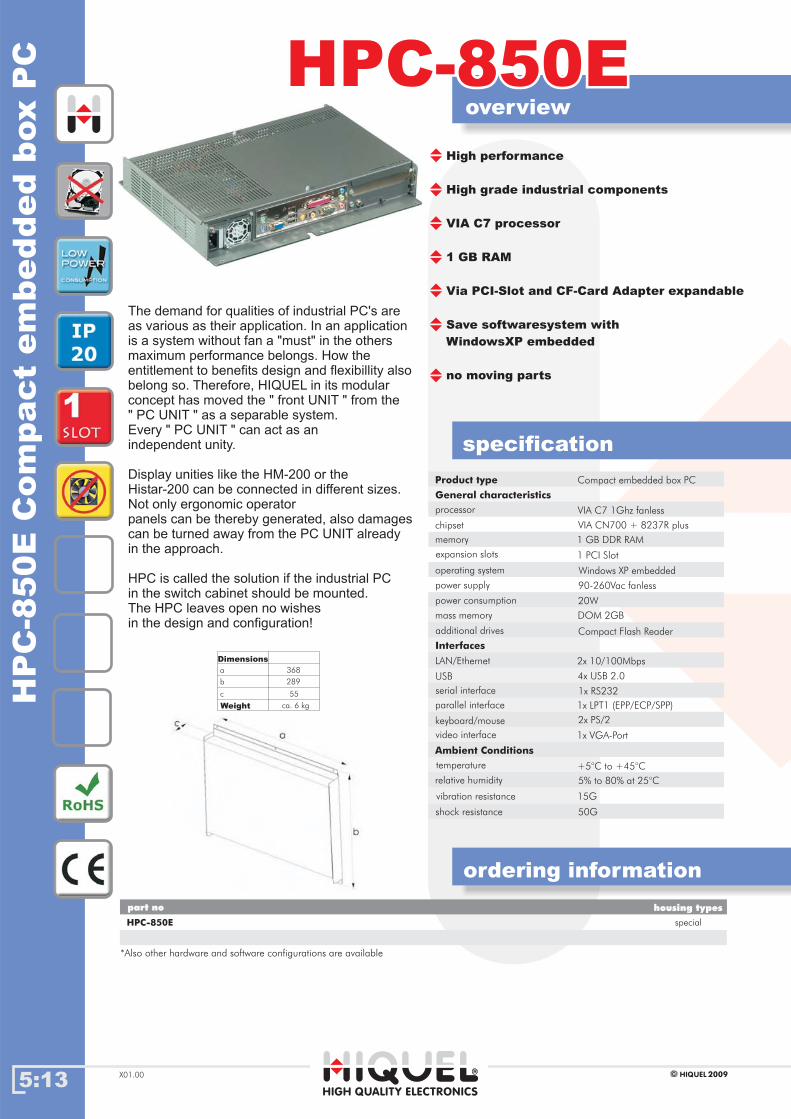
5:13
ordering information
HPC-850EHPC-850E
specification
HIGH QUALITY ELECTRONICS
2009HIQUELX01.00
High performance
High grade industrial components
VIA C7 processor
1 GB RAM
Via PCI-Slot and CF-Card Adapter expandable
Save softwaresystem with
WindowsXP embedded
no moving parts
HP
C-8
50E
Com
pact
em
bed
ded
box
PC
overview
Product type
General characteristics
processor
power consumption
mass memory
LAN/Ethernet
USB
Ambient Conditions
serial interface
relative humidity
memory
chipset
Compact embedded box PC
VIA C7 1Ghz fanless
90-260Vac fanless
20W
DOM 2GB
2x 10/100Mbps
4x USB 2.0
+5°C to +45°C
1x RS232
5% to 80% at 25°C
1 GB DDR RAM
VIA CN700 + 8237R plus
keyboard/mouse 2x PS/2
power supply
Interfaces
temperature
vibration resistance
additional drives Compact Flash Reader
15G
expansion slots 1 PCI Slot
operating system Windows XP embedded
parallel interface 1x LPT1 (EPP/ECP/SPP)
special
part no housing types
HPC-850E
The demand for qualities of industrial PC's are
as various as their application. In an application
is a system without fan a "must" in the others
maximum performance belongs. How the
entitlement to benefits design and flexibillity also
belong so. Therefore, HIQUEL in its modular
concept has moved the " front UNIT " from the
" PC UNIT " as a separable system.
Every " PC UNIT " can act as an
independent unity.
Display unities like the HM-200 or the
Histar-200 can be connected in different sizes.
Not only ergonomic operator
panels can be thereby generated, also damages
can be turned away from the PC UNIT already
in the approach.
HPC is called the solution if the industrial PC
in the switch cabinet should be mounted.
The HPC leaves open no wishes
in the design and configuration!
Dimensions
Weight
368
289
55
ca. 6 kg
a
b
c
*Also other hardware and software configurations are available
50Gshock resistance
video interface 1x VGA-Port

5:14
overview
ordering information
Histar-850EHistar-850E
specification
HIGH QUALITY ELECTRONICS
2009HIQUEL X01.00
Histar-850E-15 special
part no housing types
His
tar-8
50E
em
bed
ded
PC
for
wall
mount
Product type
General characteristics
embedded PC for wall mount
Histar-850E-19
display
15" TFT-Display
19" TFT-Display
resolution
1024x768 Pixel
1280x1024 Pixel special
*Also other hardware and software configurations are available
*Delivery without frame.
Size 15" 19"
Cut-Out MUxx 399x336x90 472x410x90
Outside with frame 425x365x25 497x435x25
ca. 9 kg ca. 11 kgWeight
HIQUEL offers with the product family HISTAR
various products. With HISTAR PC-Touch you
will have all advantages of the HISTAR product
range and the boundaryless freedom to integrate
your own software ideas.
With the operating system WindowsXP embedded
you will have all features of an embedded System
and we have taken care for a minimum of storage
volume for a system which is fast, secure
and robust.
Your visualization and control application for the
building and facilities will be save.
All day, all night, the whole year!
Home PC with industrial hardware
Easy assembly and installation
Interchange of various design frames
Graphic and touch screen interface
Various connectable
High performance with Windows XP
embedded
no moving parts
processor
power consumption
mass memory
LAN/Ethernet
USB
Ambient Conditions
serial interface
memory
Chipset
VIA C7 1Ghz fanless
90-260Vac fanless
35W with 15" Display
DOM 2GB
10/100Mbps
7x USB 2.0 (1x ext., 4x int.
+5°C to +45°C
2x RS232 (1x ext., 1x int.)
1 GB DDR RAM
VIA CN700 + 8237R plus
keyboard/mouse 2x PS/2
power supply
Interfaces
temperature
vibration resistance
50G
additional drives Compact Flash Reader
15G
shock resistance
expansion slots 1 PCI Slot
operating system
parallel interface 1x LPT1 (EPP/ECP/SPP)
Histar-850E-15-M special
Histar-850E-19-M
15" TFT-Display
19" TFT-Display
1024x768 Pixel
1280x1024 Pixel special
relative humidity 5% to 80% at 25°C
2x front accessible)
Histar-Audio
no
no
yes
yes
Windows XP embedded
Ordering information you can find on page 1:51.
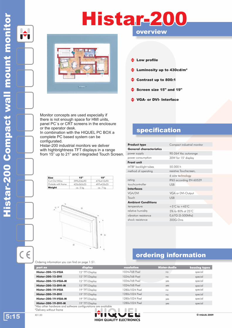
5:15
overview
ordering information
Histar-200Histar-200
specification
HIGH QUALITY ELECTRONICS
2009HIQUELX01.00
His
tar-
200
Com
pact
wall
mount
monit
or
Low profile
Luminosity up to 430cd/m²
Contrast up to 800:1
Screen size 15" and 19"
VGA- or DVI- Interface
Monitor concepts are used especially if
there is not enough space for HMI units,
panel PC´s or CRT screens in the enclosure
or the operator desk.
In combination with the HIQUEL PC BOX a
complete PC based system can be
configurated.
Histar-200 industrial monitors we deliver
with highbrightness TFT displays in a range
from 15” up to 21” and integraded Touch Screen.
Histar-200-15-VGA special
part no housing types
Histar-200-15-DVI
display resolution
15" TFT-Display
15" TFT-Display
1024x768 Pixel
special
*Also other hardware and software configurations are available
*Delivery without frame
Size 15" 19"
Cut-Out MUxx 399x336x90 472x410x90
Outside with frame 425x365x25 497x435x25
ca. 5 kg ca. 7 kgWeight
Product type
General characteristics
power supply
touchcontroller
VGA/DVI
Touch
Ambient Conditions
relative humidity
Front unit
power consumption
Compact industrial monitor
90-264 Vac autorange
USB
VGA or DVI-Output
USB
+5°C to +45°C
5% to 80% at 25°C
50.000 h
30W for 15" display
MTBF backlight tubes
method of operating resistive Touchscreen,
Interfaces
temperature
vibration resistance 0,67G (5-500Mhz)
6 wire technology
rating IP65 according EN 60529
shock resistance 300G/2ms
Histar-200-15-VGA-M special
Histar-200-15-DVI-M
15" TFT-Display
15" TFT-Display
1024x768 Pixel
special
Histar-200-19-VGA special
Histar-200-19-DVI
19" TFT-Display
19" TFT-Display 1280x1024 Pixel special
Histar-200-19-VGA-M special
Histar-200-19-DVI-M
19" TFT-Display
19" TFT-Display 1280x1024 Pixel special
1024x768 Pixel
1024x768 Pixel
1280x1024 Pixel
1280x1024 Pixel
Histar-Audio
no
yes
no
yes
no
yes
no
yes
Ordering information you can find on page 1:51.
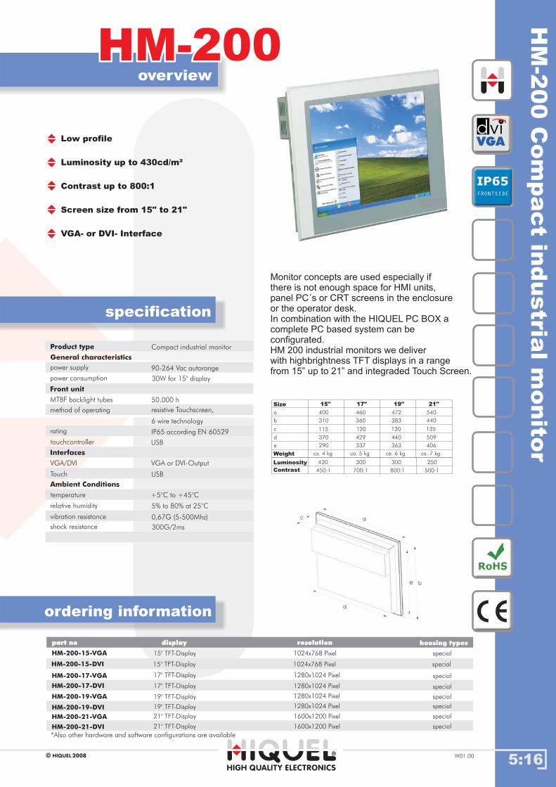
5:16
overview
ordering information
HM-200HM-200
specification
HIGH QUALITY ELECTRONICS
2008HIQUEL W01.00
Low profile
Luminosity up to 430cd/m²
Contrast up to 800:1
Screen size from 15" to 21"
VGA- or DVI- Interface
HM-200-15-VGA special
part no housing types
HM
-200
Com
pact
industria
lm
onito
r
Product type
General characteristics
power supply
touchcontroller
VGA/DVI
Touch
Ambient Conditions
relative humidity
Front unit
power consumption
Compact industrial monitor
90-264 Vac autorange
USB
VGA or DVI-Output
USB
+5°C to +45°C
5% to 80% at 25°C
50.000 h
30W for 15" display
MTBF backlight tubes
method of operating resistive Touchscreen,
Interfaces
temperature
vibration resistance 0,67G (5-500Mhz)
6 wire technology
rating IP65 according EN 60529
shock resistance 300G/2ms
Size
Weight
15" 17" 19" 21"
400
310
115
370
290
ca. 4 kg
460
360
120
429
337
ca. 5 kg
472
383
120
440
363
ca. 6 kg
540
440
135
509
406
ca. 7 kg
a
b
c
d
e
Monitor concepts are used especially if
there is not enough space for HMI units,
panel PC´s or CRT screens in the enclosure
or the operator desk.
In combination with the HIQUEL PC BOX a
complete PC based system can be
configurated.
HM 200 industrial monitors we deliver
with highbrightness TFT displays in a range
from 15” up to 21” and integraded Touch Screen.
Luminosity 430 300 300 250
Contrast 450:1 700:1 800:1 500:1
HM-200-17-VGA
display resolution
HM-200-17-DVI
HM-200-19-VGA
15" TFT-Display
17" TFT-Display
17" TFT-Display
1024x768 Pixel
1280x1024 Pixel
1280x1024 Pixel
special
special
special
HM-200-15-DVI 15" TFT-Display 1024x768 Pixel special
HM-200-19-DVI
HM-200-21-VGA 21" TFT-Display 1600x1200 Pixel special
HM-200-21-DVI 21" TFT-Display 1600x1200 Pixel special
19" TFT-Display
19" TFT-Display
1280x1024 Pixel
1280x1024 Pixel special
*Also other hardware and software configurations are available

Chapter 6: Alarming
World of Automation
www.hiquel.com
Index
6:00
66Chapter 6: Alarming
HIGH QUALITY ELECTRONICS
2009HIQUEL X01.00
SMS-Master and SMS-Mini Master
base modules
SMS-Master Starter Kits & programming
INFO SMS-Master
.03.03
.02.02
.01.01
IndexIndex

ala
rm
,in
form
,contro
lw
ithS
MS
-Maste
r
6:01
SMS-MasterSMS-Master
HIGH QUALITY ELECTRONICS
2009HIQUEL X01.00
Uninterruptable power supply
Monitor and Control via SMSThe SMS-Master Controller offers a low cost solution for monitoring and
controlling systems via SMS. Using digital, analogue or time events the
SMS-Master sends pre-configured messages to mobile phone/s
informing about operating states of machines, heating system,
or other installations.
Power failure alarm with UPS24Power failure alarm with UPS24
UPS24, uninterruptible power supply with battery-pack
Output 24V= / 110mAh
Power failure alarm with UPS24 / Battery-Pack
Power for 4 hours with UPS24 / Battery-Pack
LED indicators for power supply
and actual state of wiring.
Applications:�
�
�
�
�
�
�
�
�
�
�
�
�
machine controlengineer call-outliquid level controlpump controlpressure controlheating or coolingsystem controlirrigation controlstorage controllighting controltraffic light controlaccess controlholiday house control
etc...
Monitor and check your facility!
�
�
�
�
�
analogue inputs with realunit scalingsingle user alertgroup user alertwith or without reportvia SMS (text), fax or e-mail
!! ALARM !!
SMS-MASTER:
Siren
17:45
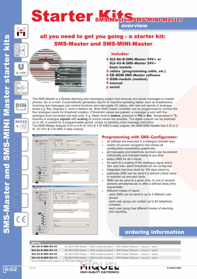
SM
S-M
aste
rand
SM
S-M
INI
Maste
rsta
rte
rkit
s
overviewStarter KitsStarter KitsSMS-Master, SMS-MINI-MasterSMS-Master, SMS-MINI-Master
ordering information
part no
SLS-86-R-SMS-Kit-24 SLS-86-R-SMS-Master + GSM-module (modem) + SMS-Master-Software + manual + aerial
SLS-86-R-SMS-Kit-12 SLS-86-R-SMS-Master + GSM-module (modem) + SMS-Master-Software + manual + aerial
SLS-43-R-SMS-Kit-24 SLS-86-R-SMS-Master + GSM-module (modem) + SMS-Master-Software + manual + aerial
SLS-43-R-SMS-Kit-12 SLS-86-R-SMS-Master + GSM-module (modem) + SMS-Master-Software + manual + aerial
all you need to get you going - a starter kit:
SMS-Master and SMS-MINI-Master
includes:
SLS-86-R-SMS-Master 24V= or
SLS-43-R-SMS-Master 24V=
basic module
cables (programming cable, etc.)
CD-ROM SMS-Master software
GSM-module (modem)
manual
aerial
The SMS-Master is a flexible alarming and messaging system that receives and sends messages to mobile-
phones, fax or e-mail. It automatically generates reports of machine operating states, such as breakdowns.
Incoming text messages can control functions and interrogate I/O status, with real unit reports of analogue
levels e.g. Bar, Degrees C, level in Meters etc. Both SMS master controller can be programmed to monitor the
four analogue inputs for threshold violation. If threshold values are passed, a message is sent with the
analogue level converted into real units. E.g. Water level in , pressure in or Temperature in
Queries of analogue with of current values are possible. The digital outputs can be switched
on or off, or pulsed for a programmable period simply by sending a text message instruction.
The SMS-Master features 8 DI or 4 AI (0-10V) & 4 DI AND 6 relay outputs, the SMS-MINI-Master has 4 DI or 2
AI (0-10V) & 2 DI AND 3 relay outputs.
meters PSI Bar, C.signals scaling
0
.
�
�
�
�
�
�
�
�
�
all settings are executed in a dialogue oriented way
clearly structured navigation tree shows all
configuration possibilities graphically
all messages and telephone numbers can be entered
individually and changed easily at any time
status SMS for all 4 inputs
for each AI a scaling of the analogue signal and a
min. and max. alarm threshold can be configured
integrated real time clock for 100 days stand by
optionally SMS can be send if a defined critical value
is reached via pre-paid cards
SMS can be send at a given time, to one or several
persons simultaneously or after a defined delay time
sequentially
different modes of report:
each SMS can be send to up to 4 different user
groups
each user group can contain up to 64 telephone
numbers
each user group has different modes of alarming
and reporting
Programming with SMS-Configurator:
6:02 2009HIQUELX01.00
The water level is below 250cm.The water level is below 250cm.
The water level is OK again. .
Frontdoor
Frontdoor was opened.The door is at the moment #Di1#!
8/4in
6/3
out
DIN
RS232
U0-10V
HIGH QUALITY ELECTRONICS
Automation Software
Automation Software
* recommended power supply unit TPS3 (see catalogue 01:30)
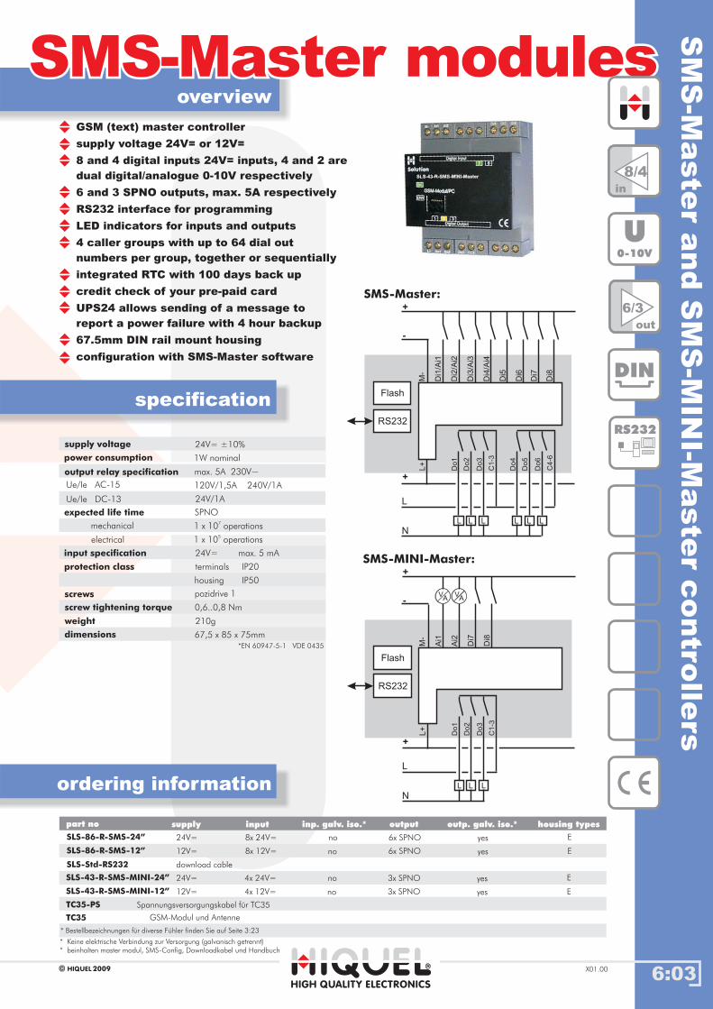
SM
S-M
aste
rand
SM
S-M
INI-M
aste
rcontro
llers
6:03
overview
ordering information
SMS-Master modulesSMS-Master modules
specification
2009HIQUEL X01.00
8/4in
6/3
out
DIN
RS232
U0-10V
M-
Do
1
Ai1
Ai2
Di7
Di8
Do
2
Do
3
C1
-3
L
L
N
L L
+
-
+
L+
RS232
Flash
VA
VA
supply voltage
power consumption
24V= ±10%
1W nominal
output relay specification
Ue/Ie AC-15
expected life time
input specification
protection class
screws
screw tightening torque
weight
dimensions
max. 5A 230V~
120V/1,5A 240V/1A
24V/1A
*EN 60947-5-1 VDE 0435
24V=
0,6..0,8 Nm
67,5 x 85 x 75mm
1 x 10⁷
operations
1 x 10⁵
operations
max. 5 mA
terminals
housing
IP20
IP50
pozidrive 1
210g
mechanical
SPNO
electrical
Ue/Ie DC-13
Gehäusetypenpart no inputsupply inp. galv. iso.* outp. galv. iso.*output housing types
SLS-43-R-SMS-MINI-24”
SLS-43-R-SMS-MINI-12”
24V=
12V=
3x SPNO
3x SPNO
4x 24V=
4x 12V=
no
no
E
E
yes
yes
SLS-86-R-SMS-24”
SLS-86-R-SMS-12”
SLS-Std-RS232
24V=
12V=
download cable
6x SPNO
6x SPNO
8x 24V=
8x 12V=
no
no
E
E
yes
yes
GSM (text) master controller
supply voltage 24V= or 12V=
8 and 4 digital inputs 24V= inputs, 4 and 2 are
dual digital/analogue 0-10V respectively
6 and 3 SPNO outputs, max. 5A respectively
RS232 interface for programming
LED indicators for inputs and outputs
4 caller groups with up to 64 dial out
numbers per group, together or sequentially
integrated RTC with 100 days back up
credit check of your pre-paid card
UPS24 allows sending of a message to
report a power failure with 4 hour backup
67.5mm DIN rail mount housing
configuration with SMS-Master software
SMS-MINI-Master:
M-
Do
1
Di1
/Ai1
Di2
/Ai2
Di3
/Ai3
Di4
/Ai4
Di5
Di6
Di7
Di8
Do
4
Do
2
Do
5
Do
3
Do
6
C1
-3
L
L
N
L L L L L
C4
-6
+
-
+
L+
RS232
Flash
SMS-Master:
HIGH QUALITY ELECTRONICS
* Keine elektrische Verbindung zur Versorgung (galvanisch getrennt)
“ beinhalten master modul, SMS-Config, Downloadkabel und Handbuch
TC35-PS Spannungsversorgungskabel für TC35
TC35 GSM-Modul und Antenne
* Bestellbezeichnungen f r diverse F hler finden Sie auf Seite 3 23ü ü :
Chapter 7: SLS-86 Series
World of Automation
www.hiquel.com
Index
7:00
77Chapter 7: SLS-86 Series
HIGH QUALITY ELECTRONICS
2009HIQUEL X01.00
INFO bit processing
INFO SLS-86 programming
INFO SLS-86 series
.03.03
.02.02
.01.01
IndexIndex
INFO overview compact modules HI-86.04.04
HI-86 Starter Kit & minimodule.05.05
SLS-86-R Starter Kit & base module.06.06
SLS-D.07.07
SLS-D..-16A.08.08
SLS-8DI.09.09
SLS-8D.10.10
SLS-FBR.11.11
SLS-PTC.12.12
SLS-PT100.13.13
SLS-PT1000.14.14
SLS-AU.15.15
SLS-AI.16.16

7:01
SLS-86 SeriesSLS-86 Series
DIN
RS485
RS232
RTC
6out
8in
U0-10V
2009HIQUELX01.00
buildin
g/in
dustr
ialauto
mati
on
Applications:
� industrial automation
� process control
�
� transport system
� machine control
� pump control
digital output modules, relays, transistoror photomos
analogue I/O modules 0-10V or 0-20mA
Bit processing
16bit analogue input modules;0-10V or 0-20mA
SLS-86 expansion modulesSLS-86 base module
digital input modules 24Vdc or 100-240Vac
temperature detection modules for PTC,Pt100- and PT1000 sensors
building automation
Connection: local and remote versionsof all modules available
room temperature detection moduleswith 4 inputs
room temperature controller
The base module allows easy and cost-effective communication with up to 31 different expansionmodules over a bus length of up to 600m. The modules can be connected either by recessedside connectors for side by side DIN rail mounting or via CAT5 cable.
locallyremotely
The PLC-series SLS-86 is a central and/or distributed PLC system witha modular concept. HI-86 is the compact control of the SLS-86 series.
lighting control
heating control
hydraulic systems
bespoke systems
�
�
�
�
is a modular programmable
(intelligent) relay that can be used in many fields including
and
The has 8 digital inputs (4 dual digital
or analogue), and 6 relay outputs.
The user program memory is 8kB with 64kB internal flash and
a SIM-card for program copy and module to module data
transfer.
A range of (digital, analogue, PTC,
PT100, PT1000, FBR) is available. Output types are relay,
photomos (solid state) or transistor.
The base module can communicate with up to 31 extension
modules via recessed side connectors for side by side DIN
rail mounting or via CAT5 cable ). Up to 250
I/O can be distributed over a maximum distance of 600m.
Analogue values can be set by potentiometers located on the
front plate or by PC. Communication with HIQUEL TERM4 is
possible using the host switches and host relay functions.
is a compact programmable (intelligent) relay that
can be used in many fields.
The has 8 digital inputs (20-250Vac/dc)
and 6 relay outputs (5Amp). The user program memory is
8kB. The RS 232 interface can be used for programming and
monitoring. The HI-86 also features a SIM-card for easy
program copy and module to module data transfer.
Programming without special software knowledge,suitable for small (8/6 I/O) and medium sized (up to 250I/O) applications.The SOLUTION SLS86
industrial control, automation, building management.base module SLS 86
extension modules
(local) (remote
The HI-86
minimodule HI-86
SLS-86
SLS I/Olocal connection
SLS I/Olocal connection
remote connection
up to 31
I/O modules
SLS I/O
remote connection using CAT5 cable
HIGH QUALITY ELECTRONICS
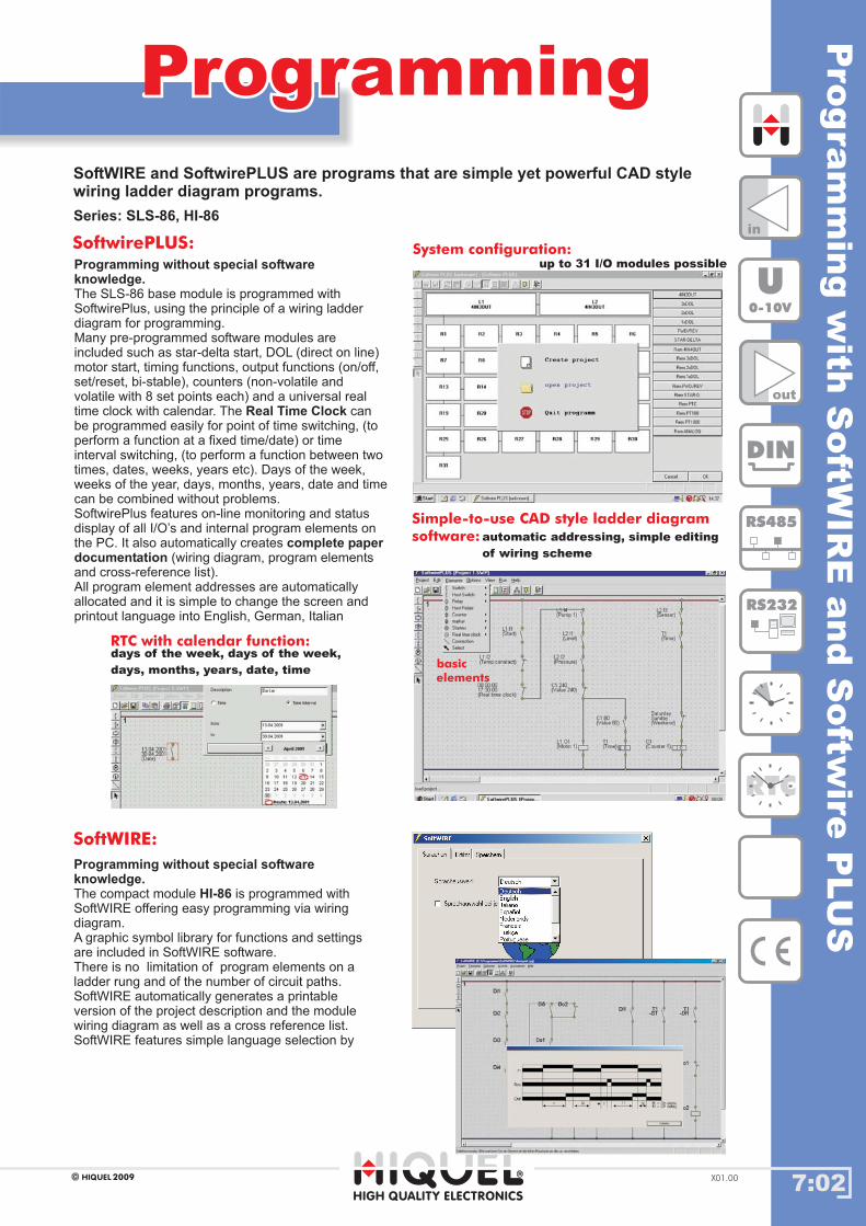
7:02
ProgrammingProgramming
HIGH QUALITY ELECTRONICS
2009HIQUEL X01.00
Series: SLS-86, HI-86
SoftWIRE and SoftwirePLUS are programs that are simple yet powerful CAD stylewiring ladder diagram programs.
Programming without special softwareknowledge.
Real Time Clock
complete paperdocumentation
The SLS-86 base module is programmed with
SoftwirePlus, using the principle of a wiring ladder
diagram for programming.
Many pre-programmed software modules are
included such as star-delta start, DOL (direct on line)
motor start, timing functions, output functions (on/off,
set/reset, bi-stable), counters (non-volatile and
volatile with 8 set points each) and a universal real
time clock with calendar. The can
be programmed easily for point of time switching, (to
perform a function at a fixed time/date) or time
interval switching, (to perform a function between two
times, dates, weeks, years etc). Days of the week,
weeks of the year, days, months, years, date and time
can be combined without problems.
SoftwirePlus features on-line monitoring and status
display of all I/O’s and internal program elements on
the PC. It also automatically creates
(wiring diagram, program elements
and cross-reference list).
All program element addresses are automatically
allocated and it is simple to change the screen and
printout language into English, German, Italian
Programming without special softwareknowledge.
HI-86The compact module is programmed with
SoftWIRE offering easy programming via wiring
diagram.
A graphic symbol l
There is no limitation of program elements on a
ladder rung and of the number of circuit paths.
ibrary for functions and settings
are included in SoftWIRE software.
SoftWIRE automatically generates a printable
version of the project description and the module
wiring diagram as well as a cross reference list.
SoftWIRE features simple language selection by
SoftWIRE:
SoftwirePLUS:
days of the week, days of the week,
days, months, years, date, time
System configuration:
Simple-to-use CAD style ladder diagram
software:
RTC with calendar function:
basic
elements
up to 31 I/O modules possible
automatic addressing, simple editing
of wiring scheme
in
out
DIN
RS485
RS232
RTC
U0-10V
Pro
gra
mm
ing
with
SoftW
IRE
and
Softw
ireP
LU
S
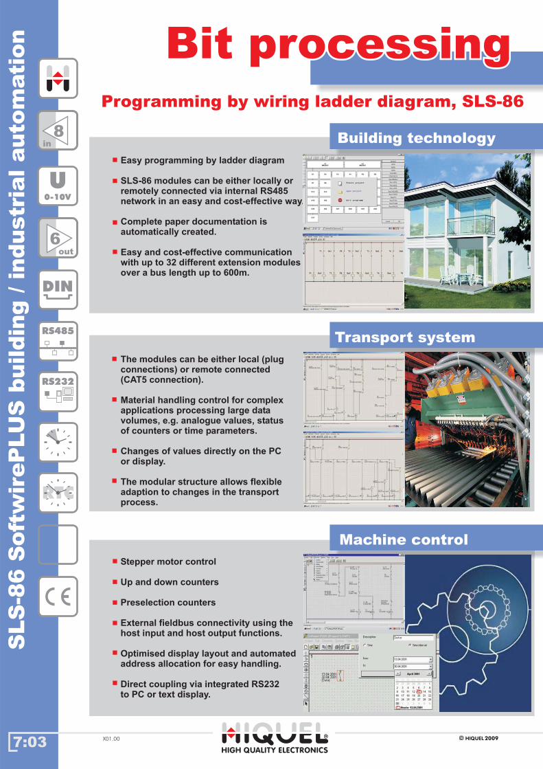
7:03
Bit processingBit processing
DIN
RS485
RS232
RTC
6out
8in
U0-10V
2009HIQUELX01.00
SLS
-86
Soft
wir
eP
LU
Sbuildin
g/in
dustr
ialauto
mati
on
Programming by wiring ladder diagram, SLS-86Programming by wiring ladder diagram, SLS-86
Transport system
Building technology
Machine control
Stepper motor control
Up and down counters
Preselection counters
External fieldbus connectivity using thehost input and host output functions.
Optimised display layout and automatedaddress allocation for easy handling.
Direct coupling via integrated RS232to PC or text display.
The modules can be either local (plugconnections) or remote connected(CAT5 connection).
Material handling control for complexapplications processing large datavolumes, e.g. analogue values, statusof counters or time parameters.
Changes of values directly on the PCor display.
The modular structure allows flexibleadaption to changes in the transportprocess.
Easy programming by ladder diagram
Complete paper documentation isautomatically created.
SLS-86 modules can be either locally orremotely connected via internal RS485network in an easy and cost-effective way.
Easy and cost-effective communicationwith up to 32 different extension modulesover a bus length up to 600m.
HIGH QUALITY ELECTRONICS
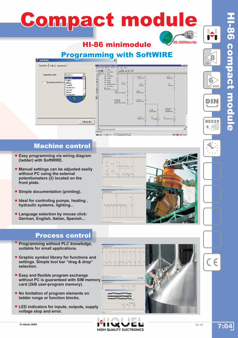
HI-8
6com
pact
module
7:04
Compact moduleCompact module
2009HIQUEL X01.00
HI-86 minimodule
Programming with SoftWIRE
HI-86 minimodule
Programming with SoftWIRE
Easy programming via wiring diagram(ladder) with SoftWIRE.
Manual settings can be adjusted easilywithout PC using the externalpotentiometers (2) located on thefront plate.
Simple documentation (printing).
Ideal for controling pumps, heating ,hydraulic systems, lighting...
Language selection by mouse click:German, English, Italian, Spanish...
Machine control
Programming without PLC knowledge,suitable for small applications.
Graphic symbol library for functions andsettings. Simple tool bar “drag & drop”selection.
LED indicators for inputs, outputs, supplyvoltage stop and error.
Easy and flexible program exchangewithout PC is guaranteed with SIM memorycard (2kB user-program memory).
No limitation of program elements onladder rungs or function blocks.
Process control
DIN
8in
6out
RS232
HIGH QUALITY ELECTRONICS
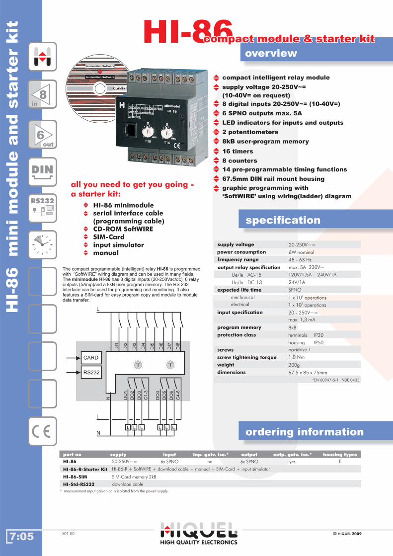
overviewstarter kitstarter kit
overview
7:05
HI-86HI-86
2009HIQUELX01.00
HI-
86
min
im
odule
and
sta
rte
rkit
HI-86 minimodule
serial interface cable
(programming cable)
CD-ROM SoftWIRE
SIM-Card
input simulator
manual
all you need to get you going -
a starter kit:
ordering information
DIN
RS232
6out
8in
ordering information
* measurement input galvanically isolated from the power supply
Gehäusetypenpart no inputsupply inp. galv. iso.* outp. galv. iso.*output housing types
HI-86
HI-86-R-Starter Kit
HI-86-SIM
HI-Std-RS232
20-250V~=
HI-86-R + SoftWIRE + download cable + manual + SIM-Card + input simulator
SIM-Card memory 2kB
download cable
6x SPNO6x SPNO yes Eno
specification
8 digital inputs 20-250V~= (10-40V=)
6 SPNO outputs max. 5A
LED indicators for inputs and outputs
2 potentiometers
8kB user-program memory
16 timers
8 counters
14 pre-programmable timing functions
67.5mm DIN rail mount housing
graphic programming with
‘SoftWIRE’ using wiring(ladder) diagram
supply voltage
power consumption
frequency range
output relay specification
Ue/Ie AC-15
expected life time
input specification
program memory
protection class
screws
screw tightening torque
weight
dimensions
20-250V~=
6W nominal
48 - 63 Hz
max. 5A 230V~
120V/1,5A 240V/1A
24V/1A
20 - 250V~=
8kB
1,0 Nm
67.5 x 85 x 75mm
1 x 10⁷
operations
1 x 10⁵
operations
max. 1,3 mA
terminals
housing
IP20
IP50
pozidrive 1
200g
mechanical
SPNO
electrical
Ue/Ie DC-13
DO
1
N
DI1
L DI2
DI3
DI4
DI5
DI6
DI7
DI8
DO
4
DO
2
DO
5
DO
3
DO
6
C1
-3
L
L
L
N
L L L L L
C4
-6
RS232
CARD
supply voltage 20-250V~=
(10-40V= on request)
compact intelligent relay module
The compact programmable (intelligent) relay is programmed
with can be used in many fields.
The has 8 digital inputs (20-250Vac/dc), 6 relay
outputs (5Amp)and a 8kB user program memory. The RS 232
interface can be used for programming and monitoring. It also
features a SIM-card for easy program copy and module to module
data transfer.
HI-86
minimodule HI-86“SoftWIRE” wiring diagram and
compact module & starter kitcompact module & starter kit
HIGH QUALITY ELECTRONICS
Automation Software
Automation Software
*EN 60947-5-1 VDE 0435
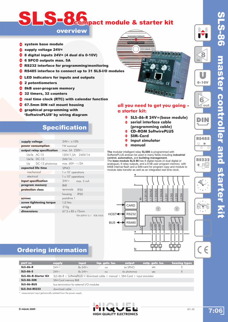
SLS
-86
maste
rcontro
ller
and
sta
rte
rkit
7:06
overview
Ordering information
Gehäusetypen
SLS-86SLS-86
supply voltage 24V=
8 digital inputs 24V= (4 dual d/a 0-10V)
6 SPCO outputs max. 5A
RS232 interface for programming/monitoring
RS485 interface to connect up to 31 SLS-I/O modules
LED indicators for inputs and outputs
2 potentiometers
8kB user-program memory
32 timers, 32 counters
real time clock (RTC) with calendar function
67.5mm DIN rail mount housing
graphical programming with
‘SoftwirePLUS’ by wiring diagram
Specification
supply voltage
power consumption
output relay specification
Ue/Ie AC-15
expected life time
input specification
program memory
protection class
screws
screw tightening torque
weight
dimensions
24V= ±10%
1W nominal
max. 5A 230V~
120V/1,5A 240V/1A
24V/1A
24V=
8kB
1,0 Nm
67.5 x 85 x 75mm
1 x 10⁷
operations
1 x 10⁵
operations
max. 5 mA
terminals
housing
IP20
IP50
pozidrive 1
210g
mechanical
SPNO
electrical
part no
SLS-86-R
SLS-86-S
SLS-86-SIM
inputsupply
24V=
24V=
SIM-Card memory 8kB
6x SPNO
6x photomos
8x 24V=
8x 24V=
Ue/Ie DC-13
Ue DC-13 photomos max. 60V~=/2A
SLS-86-BUS bus termination for external I/O modules
M-
L1
.DO
1
L1
.DI1
/Ai1
L1
.DI2
/Ai2
L1
.DI3
/Ai3
L1
.DI4
/Ai4
L2
.DI1
L2
.DI2
L2
.DI3
L2
.DI4
L2
.DO
1
L1
.DO
2
L2
.DO
2
L1
.DO
3
L2
.DO
3
L1
.C
L
L
N
L L L L L
L2
.C
+
-
+
L+
RS232
CARD
RS485BUS
HOST
DIN
RS485
RS232
RTC
6out
8in
U0-10V
inp. galv. iso. outp. galv. iso.output housing types
* measurement input galvanically isolated from the power supply
no
no
yes
yes
E
E
2009HIQUEL X01.00
SLS-Std-RS232 download cable
system base module
SLS-86-R 24V=(base module)
serial interface cable
(programming cable)
CD-ROM SoftwirePLUS
SIM-Card
input simulator
manual
all you need to get you going -
a starter kit:
compact module & starter kitcompact module & starter kit
SLS-86-R-Starter Kit SLS-86-R + SoftwirePLUS + download cable + manual + SIM-Card + input simulator
The SLS86industrial
control, automation, building management.base module SLS 86
modular intelligent relay is programmed with
SoftwirePLUS andcan be used in many fields including
and
The has 8 digital inputs (4 dual digital or
analogue), 6 relay outputs, and a 8 kB user program memory with
64kB internal flash and a SIM-card for program copy and module to
module data transfer as well as an integrated real time clock.
HIGH QUALITY ELECTRONICS
Automation Software
Automation Software
*EN 60947-5-1 VDE 0435
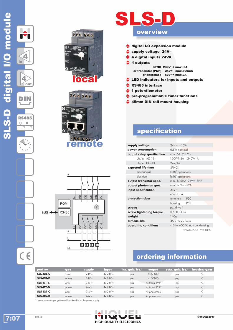
7:07
overview
ordering information
SLS-DSLS-D
specification
HIGH QUALITY ELECTRONICS
* measurement input galvanically isolated from the power supply
2009HIQUELX01.00
part no inputsupply inp. galv. iso.* outp. galv. iso.*output housing typestype
SLS
-Ddig
italI/O
module
supply voltage 24V=
4 digital inputs 24V=
4 outputsSPNO 230V~= max. 5A
or transistor (PNP) 24V= max.800mA
or photomos 60V~= max.2A
LED indicators for inputs and outputs
1 potentiometer
pre-programmable timer functions
45mm DIN rail mount housing
RS485 interface
supply voltage
power consumption
output relay specification
output transistor spec.
output photomos spec.
Ue/Ie AC-15
expected life time
input specification
protection class
screws
screw tightening torque
weight
dimensions
0,5W nominal
max. 5A 230V~
max. 800mA 24V= PNP
max. 60V~=/2A
120V/1,5A 240V/1A
24V/1A
*EN 60947-5-1 VDE 0435
24V=
0,6..0,8 Nm
45 x 85 x 75mm
min. 5 mA
terminals
housing
IP20
IP50
pozidrive 1
140g
SPNO
1x10⁷
operationsmechanical
1x10⁵
operationselectrical
Ue/Ie DC-13
SLS-DR-C
SLS-DR-D
SLS-DT-C
SLS-DT-D
4x SPNO
4x SPNO
4x trans. PNP
4x trans. PNP
4x photomos
4x photomos
4x 24V=
4x 24V=
4x 24V=
4x 24V=
4x 24V=
4x 24V=
SLS-DS-C
SLS-DS-D
24V=
24V=
24V=
24V=
24V=
24V=
yes
yes
yes
yes
yes
yes
C
C
C
C
C
C
remote
remote
remote
local
local
local
yes
yes
no
no
yes
yes
locallocal
remoteremote
DIN
RS485
4in
4out
DO
1D
I1
DI2
DI3
DI4
DO
2
DO
3
DO
4
C1
-4
L
L
+
+
-
N
L L L
RS485
ROM
BUS
C-
M-
L+ operating conditions -10 to +55 °C non condensing
24V= ±10%
digital I/O expansion module
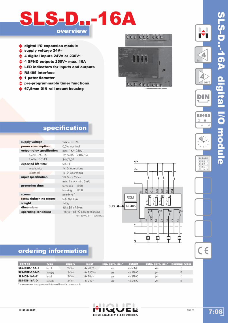
SLS
-D..-1
6A
dig
italI/O
module
7:08
overview
ordering information
SLS-D..-16ASLS-D..-16A
specification
supply voltage 24V=
4 digital inputs 24V= or 230V~
4 SPNO outputs 250V~ max. 16A
LED indicators for inputs and outputs
1 potentiometer
pre-programmable timer functions
67,5mm DIN rail mount housing
RS485 interface
supply voltage
power consumption
output relay specification
Ue/Ie AC-15
expected life time
input specification
protection class
screws
screw tightening torque
weight
dimensions
0,5W nominal
max. 16A 250V~
120V/3A 240V/3A
24V/1,5A
230V~ / 24V=
0,6..0,8 Nm
45 x 85 x 75mm
min. 1 mA / min. 3mA
terminals
housing
IP20
IP50
pozidrive 1
140g
SPNO
1x10⁷
operationsmechanical
1x10⁴
operationselectrical
Ue/Ie DC-13
4in
4out
DIN
RS485
189 9=*
7
4
1
0
8
5
2
.
9
6
3
=
/
*-
+
HIGH QUALITY ELECTRONICS
2009HIQUEL X01.00
operating conditions -15 to +55 °C non condensing
24V= ±10%
digital I/O expansion module
14
Di1
C1
-2
Di2
Di3
13
/23
24
33
34
43
44
L
L
+
-
N
L L L
RS485
ROM
BUS
C3
-4
Di4
M-
L+
-/~
+/~
K1 K2 K3 K4
I
O
A
K1
I
O
A
K2
I
O
A
K3
I
O
A
K4
SLS-DRR-16A-C
SLS-DRR-16A-D remote
local 4x SPNO
4x SPNO
4x 230V~
4x 230V~
* measurement input galvanically isolated from the power supply
yes
yes
yes
yes
E
E
24V=
24V=
part no inputsupply inp. galv. iso.* outp. galv. iso.*output housing typestype
SLS-DR-16A-C
SLS-DR-16A-D remote
local 4x SPNO
4x SPNO
4x 24V=
4x 24V=
yes
yes
yes
yes
E
E
24V=
24V=
*EN 60947-5-1 VDE 0435

7:09
overview
ordering information
SLS-8DISLS-8DI
specification
HIGH QUALITY ELECTRONICS
* measurement input galvanically isolated from the power supply
2009HIQUELX01.00
part no inputsupply inp. galv. iso.* outp. galv. iso.*output housing typestype
SLS
-8D
Idig
italin
put
module
locallocal
remoteremote
supply voltage 24V=
8 digital inputs 24V=
LED indicators for inputs
1 potentiometer
pre-programmable timer functions
45mm DIN rail mount housing
RS485 interface
supply voltage
power consumption
input specification
protection class
screws
screw tightening torque
weight
dimensions
0,5W nominal
24V=
0,6..0,8 Nm
45 x 85 x 75mm
min. 5 mA
terminals
housing
IP20
IP50
pozidrive 1
140g
remote
localSLS-8DI-C
SLS-8DI-D
-
-
8x 24V=
8x 24V=
yes
yes
-
-
C
C
24V=
24V=
8in
RS485
189 9=*
7
4
1
0
8
5
2
.
9
6
3
=
/
*-
+
DIND
i1
Di2
Di3
Di4
+
+
-
-
RS485
ROM
BUS
C-
M-
Di5
Di6
Di7
Di8
C-
L+
operating conditions -10 to +55 °C non condensing
24V= ±10%
digital input expansion module

SLS
-8D
dig
italoutp
ut
module
7:10
overview
ordering information
SLS-8DSLS-8D
specification
HIGH QUALITY ELECTRONICS
2009HIQUEL X01.00
remote
remote
remote
local
local
local
* measurement input galvanically isolated from the power supply
locallocal
remoteremote
SLS-8DR-C
SLS-8DT-C
SLS-8DS-C
SLS-8DR-D
SLS-8DT-D
SLS-8DS-D
-
-
-
-
-
-
-
-
-
-
-
-
yes
no
no
yes
yes
yes
C
C
C
C
C
C
24V=
24V=
24V=
24V=
24V=
24V=
Gehäusetypenpart no inputsupply inp. galv. iso.* outp. galv. iso.*output housing typestype
supply voltage 24V=
8 outputsSPNO 230V~= max. 5A
or transistor (PNP) 24V= max. 800mA
or photomos 60V~= max. 2A
LED indicators for inputs and outputs
1 potentiometer
pre-programmable timer functions
45mm DIN rail mount housing
RS485 interface
supply voltage
power consumption
output relay specification
output transistor spec.
output photomos spec.
Ue/Ie AC-15
expected life time
protection class
screws
screw tightening torque
weight
dimensions
0,5W nominal
max. 5A 230V~
max. 800mA 24V= PNP
max. 60V~=/2A
120V/1,5A 240V/1A
24V/1A
*EN 60947-5-1 VDE 0435
1,0 Nm
45 x 85 x 75mm
terminals
housing
IP20
IP50
pozidrive 1
140g
SPNO
1x10⁷
operationsmechanical
1x10⁵
operationselectrical
Ue/Ie DC-13
8x SPNO
8x trans. PNP
8x photomos
8x SPNO
8x trans. PNP
8x photomos
8out
DIN
RS485
189 9=*
7
4
1
0
8
5
2
.
9
6
3
=
/
*-
+
Do
5
Do
2
Do
3
Do
4
Do
6
Do
7
Do
8
C5-8
L
L
L
L
+
-
N
N
L
L
L
L
L
L
RS485
ROM
BUS
M-
L+
Do
1
C1-4
operating conditions -15 to +55 °C non condensing
24V= ±10%
digital output expansion module

FBRroom controller module
2- wire connection to
SLS-FBR module
7:11
overview
ordering information
SLS-FBRSLS-FBR
specification
HIGH QUALITY ELECTRONICS
* measurement input galvanically isolated from the power supply
2009HIQUELX01.00
part no inputsupply inp. galv. iso.* outp. galv. iso.*output housing typestype
SLS
-FB
Rdig
italro
om
contr
oller
module
supply voltage 24V=
4 FBR inputs 24V=
4 outputs
SPNO 230V~= max. 5mA
or transistor (PNP) 24V= max. 500A
LED indicators for inputs and outputs
room temperature controller with day / night-
and auto-switch, temperature registration and
temperature correction
1 potentiometer
pre-programmable timer functions
45mm DIN rail mount housing
RS485 interface
supply voltage
power consumption
output relay specification
Ue/Ie AC-15
expected life time
input specification
output transistor spec.
protection class
screws
screw tightening torque
weight
dimensions
0,5W nominal
max. 5A 230V~
120V/1,5A 240V/1A
24V/1A
*EN 60947-5-1 VDE 0435
24V=
max. 500mA 24V= PNP
0,6..0,8 Nm
45 x 85 x 75mm
min. 5 mA
terminals
housing
IP20
IP50
pozidrive 1
140g
SPNO
1x10⁷
operationsmechanical
1x10⁵
operationselectrical
Ue/Ie DC-13
SLS-FBR-R-C
SLS-FBR-T-C
SLS-FBR-R-D
SLS-FBR-T-D
FBR
4x SPNO
4x trans. PNP
4x SPNO
4x trans. PNP
4x 24V=
4x 24V=
4x 24V=
4x 24V=
24V=
24V=
24V=
24V=
C
C
C
C
remote
remote
please refer to page 03:08
local
local
yes
yes
no
no
locallocal
remoteremote
4in
DIN
RS485
4out
FBR
yes
yes
yes
yes
DO
1D
I1
DI2
DI3
DI4
DO
2
DO
3
DO
4
C1
-4
L
L
+
+
-
N
L L L
RS485
ROM
BUS
C-
M-
L+
FB
R
FB
R
FB
R
FB
R
operating conditions -15 to +55 °C non condensing
24V= ±10%
digital room controller expansion module
FBRFBR
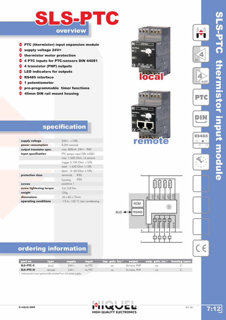
SLS
-PT
Cth
erm
isto
rin
put
module
7:12
overview
ordering information
SLS-PTCSLS-PTC
specification
HIGH QUALITY ELECTRONICS
* measurement input galvanically isolated from the power supply
2009HIQUEL X01.00
Gehäusetypenpart no inputsupply inp. galv. iso.* outp. galv. iso.*output housing typestype
supply voltage 24V=
thermistor motor protection
4 PTC inputs for PTC-sensors DIN 44081
4 transistor (PNP) outputs
LED indicators for outputs
1 potentiometer
pre-programmable timer functions
45mm DIN rail mount housing
RS485 interface
supply voltage
power consumption
output transistor spec.
input specification
protection class
screws
screw tightening torque
weight
dimensions
0,5W nominal
max. 800mA 24V= PNP
PTC sensor input DIN 44081
0,6..0,8 Nm
45 x 85 x 75mm
max. 1.500 Ohm / 6 sensors
trigger 3.100 Ohm ±10%
reset 1.650 Ohm ±10%
short 0 -20 Ohm ±10%
terminals
housing
IP20
IP50
pozidrive 1
120g
SLS-PTC-C
SLS-PTC-D remote
local 4x trans. PNP
4x trans. PNP
4x PTC
4x PTC
no
no
C
C
24V=
24V=
locallocal
remoteremote
DIN
RS485
PTC
4in
4out
no
no
DO
1
L+
M-
1T
1
2T
1
3T
1
4T
1
CT
2
DO
2
DO
3
DO
4
C1
-4
L
PT
C
PT
C
PT
C
PT
C
T
+
-
-
L
T
L
T
L
T
RS485
ROM
BUS
operating conditions -15 to +55 °C non condensing
24V= ±10%
PTC (thermistor) input expansion module
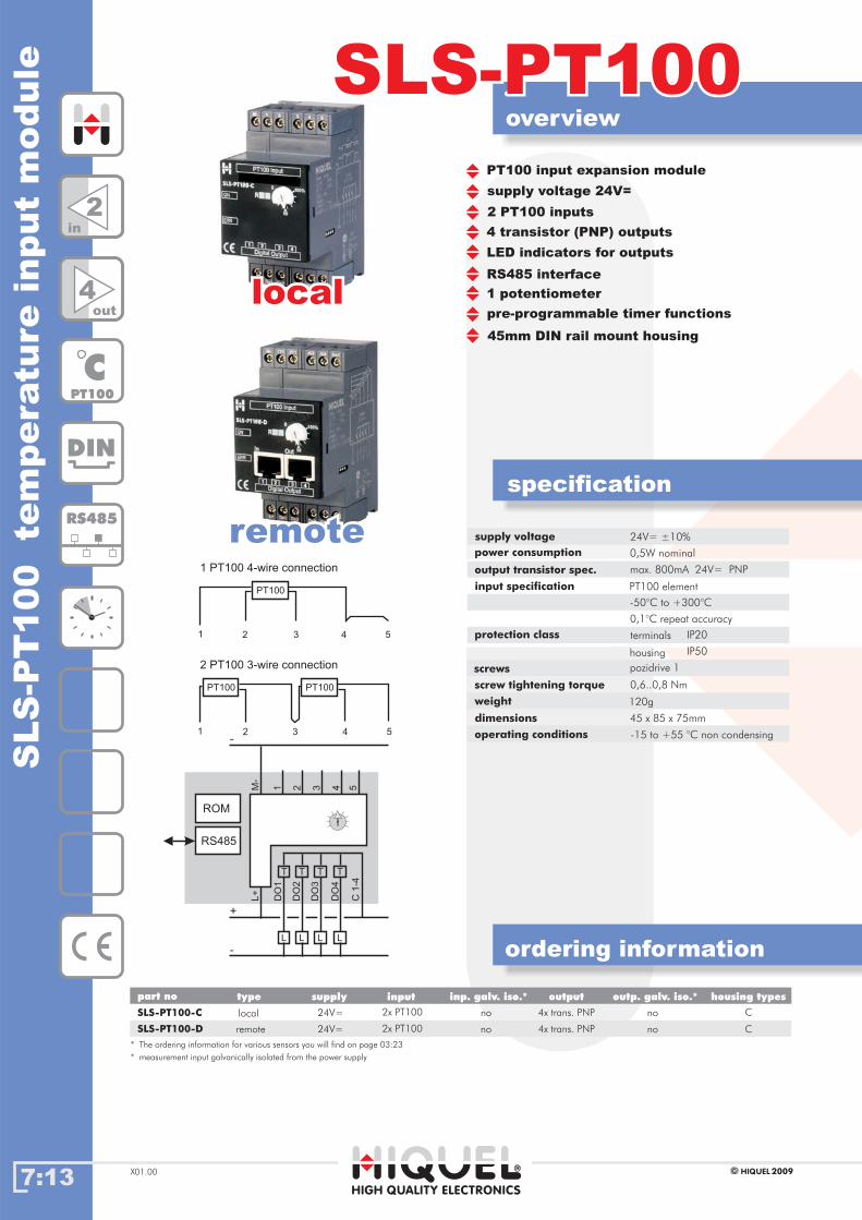
7:13
overview
ordering information
SLS-PT100SLS-PT100
specification
HIGH QUALITY ELECTRONICS
* The ordering information for various sensors you will find on page 03:23
2009HIQUELX01.00
part no inputsupply inp. galv. iso.* outp. galv. iso.*output housing typestype
SLS
-PT
100
tem
pera
ture
input
module
supply voltage 24V=
2 PT100 inputs
4 transistor (PNP) outputs
LED indicators for outputs
1 potentiometer
pre-programmable timer functions
45mm DIN rail mount housing
RS485 interface
supply voltage
power consumption
output transistor spec.
input specification
protection class
screws
screw tightening torque
weight
dimensions
0,5W nominal
max. 800mA 24V= PNP
PT100 element
0,6..0,8 Nm
45 x 85 x 75mm
-50°C to +300°C
0,1°C repeat accuracy
terminals
housing
IP20
IP50
pozidrive 1
120g
SLS-PT100-C
SLS-PT100-D
4x trans. PNP
4x trans. PNP
2x PT100
2x PT100
24V=
24V=
no
no
C
Cremote
local no
no
1
1
2
2
3
3
4
4
5
5
PT100
PT100
PT100
2 PT100 3-wire connection
1 PT100 4-wire connection
locallocal
remoteremote
DIN
RS485
CPT100
2in
4out
DO
1
L+
1M-
2 3 4 5
DO
2
DO
3
DO
4
C1
-4
L
T
+
-
-
L
T
L
T
L
T
RS485
ROM
operating conditions -15 to +55 °C non condensing
24V= ±10%
PT100 input expansion module
* measurement input galvanically isolated from the power supply
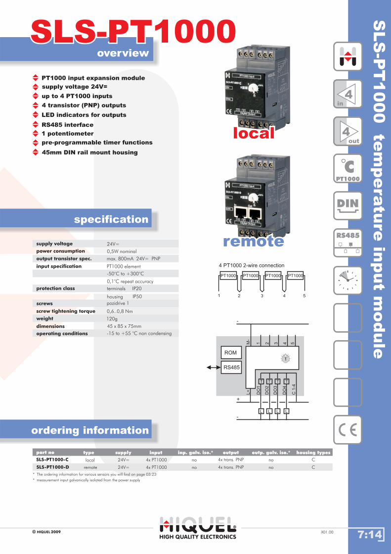
SLS
-PT
1000
tem
pera
ture
input
module
7:14
overview
ordering information
SLS-PT1000SLS-PT1000
specification
HIGH QUALITY ELECTRONICS
* The ordering information for various sensors you will find on page 03:23
2009HIQUEL X01.00
supply voltage 24V=
up to 4 PT1000 inputs
4 transistor (PNP) outputs
LED indicators for outputs
1 potentiometer
pre-programmable timer functions
45mm DIN rail mount housing
RS485 interface
supply voltage
power consumption
output transistor spec.
input specification
protection class
screws
screw tightening torque
weight
dimensions
24V=
0,5W nominal
max. 800mA 24V= PNP
PT1000 element
0,6..0,8 Nm
45 x 85 x 75mm
-50°C to +300°C
0,1°C repeat accuracy
terminals
housing
IP20
IP50
pozidrive 1
120g
Gehäusetypenpart no inputsupply inp. galv. iso.* outp. galv. iso.*output housing typestype
SLS-PT1000-C
SLS-PT1000-D remote
local 4x trans. PNP
4x trans. PNP
4x PT1000
4x PT1000
no
no
C
C
24V=
24V=
1 2 3 4 5
PT1000PT1000PT1000PT1000
4 PT1000 2-wire connection
locallocal
remoteremote
DIN
RS485
CPT1000
4in
4out
no
no
DO
1
L+
1M-
2 3 4 5
DO
2
DO
3
DO
4
C1
-4
L
T
+
-
-
L
T
L
T
L
T
RS485
ROM
operating conditions -15 to +55 °C non condensing
PT1000 input expansion module
* measurement input galvanically isolated from the power supply

7:15
overview
ordering information
SLS-AUSLS-AU
specification
HIGH QUALITY ELECTRONICS
* The ordering information for various sensors you will find on page 03:23
2009HIQUELX01.00
part no inputsupply inp. galv. iso.* outp. galv. iso.*output housing typestype
SLS
-AU
analo
gue
I/O
module
(volt
age)
supply voltage 24V=
4 analogue inputs 0-10V
4 transistor (PNP) outputs
LED indicators for outputs
1 potentiometer
pre-programmable timer functions
45mm DIN rail mount housing
RS485 interface
1 analogue output 0-10V
supply voltage
power consumption
transistor output spec.
analogue input spec.
analogue output spec.
protection class
screws
screw tightening torque
weight
dimensions
24V=
0,5W nominal
max. 800mA 24V= PNP
max. 8kHz
0 - 10V=
0 - 10V= max. 2mA
0,6..0,8 Nm
45 x 85 x 75mm
12 bit
10 bit
resolution
resolution
repeat accuracy
precision
50kOhm
0,1%
±0,5%
terminals
housing
IP20
IP50
pozidrive 1
120g
input resistance
SLS-AU-C
SLS-AU-D
4x trans. PNP
4x trans. PNP
4x 0-10V
4x 0-10V
24V=
24V=
no
no
C
Cremote
local no
no
locallocal
remoteremote
DIN
RS485
U0-10V
4in
4out
DO
1
L+
AI1
M-
AI2
AI3
AI4
AO
1
DO
2
DO
3
DO
4
C1
-4
L
T
+
-
-
L
T
L
T
L
T
RS485
ROM
BUS
0-
10V
0-
10V
0-
10V
0-
10V
0-
10V
operating conditions -15 to +55 °C non condensing
analogue I/O expansion module
* measurement input galvanically isolated from the power supply

SLS
-AI
analo
gue
I/Om
odule
(curre
nt)
7:16
overview
ordering information
SLS-AISLS-AI
specification
HIGH QUALITY ELECTRONICS
* The ordering information for various sensors you will find on page 03:23.
2009HIQUEL X01.00
supply voltage 24V=
4 analogue inputs 0-20mA
4 transistor (PNP) outputs
LED indicators for outputs
1 potentiometer
pre-programmable timer functions
45mm DIN rail mount housing
RS485 interface
1 analogue output 0-10V
supply voltage
power consumption
output transistor spec.
analogue input spec.
analogue output spec.
protection class
screws
screw tightening torque
weight
dimensions
24V=
0,5W nominal
max. 800mA 24V= PNP
max. 8kHz
0 - 20mA
0 - 10V= max. 2mA
0,6..0,8 Nm
45 x 85 x 75mm
12 bit
10 bit
resolution
resolution
repeat accuracy
precision
250 Ohm
0,1%
±0,5%
terminals
housing
IP20
IP50
pozidrive 1
120g
input resistance
Gehäusetypenpart no inputsupply inp. galv. iso.* outp. galv. iso.*output housing typestype
SLS-AI-C
SLS-AI-D remote
local 4x trans. PNP
4x trans. PNP
4x 0-20mA
4x 0-20mA
no
no
C
C
24V=
24V=
locallocal
remoteremote
DIN
RS485
I4-20mA
4in
4out
no
no
DO
1
L+
AI1
M-
AI2
AI3
AI4
AO
1
DO
2
DO
3
DO
4
C1
-4
L
T
+
-
+
-
L
T
L
T
L
T
RS485
ROM
BUS
0-
20mA
0-
10V
operating conditions -15 to +55 °C non condensing
analogue I/O expansion module
* measurement input galvanically isolated from the power supply