Working and Operating Principle of DC Motor
40
Working and Operating Principle of DC Motor A DC motor in simple words is a device that converts direct current (electrical energy) into mechanical energy. It’s of vital importance for the industry today, and is equally imp ortant for engineers to look into the working principle of DC motor in details that has been discussed in this article. In order to understand the operating principle of dc motor we need to first look into its constructional feature. The very basic construction of a dc motor contains a current carrying armature which is connected to the supply end through commutator segments and brushes and placed within the north south poles of a permanent or an electro-magnet as shown in the diagram below. Now to go into the details of the operating principle of DC motor its important that we have a clear understanding of Fleming’s left hand rule to determine the direction of force acting on the armature conductors of dc motor.
-
Upload
khangminh22 -
Category
Documents
-
view
0 -
download
0
Transcript of Working and Operating Principle of DC Motor
Working and Operating Principle of DC Motor
A DC motor in simple words is a device that converts direct current (electrical energy) into mechanical energy. It’s of vital importance for the industry today, and is equally important for
engineers to look into the working principle of DC motor in details that has been discussed in this article. In order to understand the operating principle of dc motor we need to first look into
its constructional feature.
The very basic construction of a dc motor contains a current carrying armature which is connected to the supply end through commutator segments and brushes and placed within the
north south poles of a permanent or an electro-magnet as shown in the diagram below. Now to go into the details of the operating principle of DC motor its important that we have a clear
understanding of Fleming’s left hand rule to determine the direction of force acting on the
armature conductors of dc motor.
Fleming’s left hand rule says that if we extend the index finger, middle finger and thumb of our left hand in such a way that the current carrying conductor is placed in a magnetic field
(represented by the index finger) is perpendicular to the direction of current (represented by the middle finger), then the conductor experiences a force in the direction (represented by the
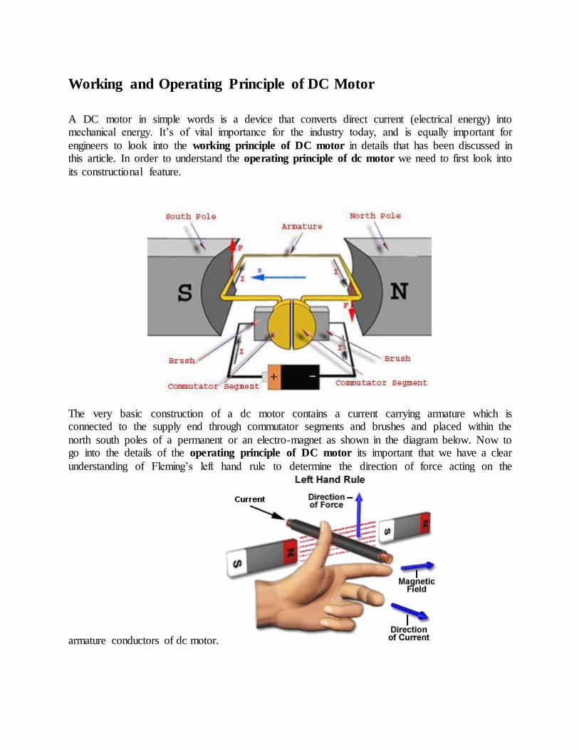
thumb) mutually perpendicular to both the direction of field and the current in the conductor. For clear understanding the principle of DC motor we have to determine the magnitude of the force, by considering the diagram below. We know that when an infinitely small charge dq is
made to flow at a velocity ‘v’ under the influence of an electric field E, and a magnetic field B, then the Lorentz Force dF experienced by the charge is given by:-
For the operation of dc motor, considering E = 0
i.e. it’s the cross product of dq v and magnetic field B.
Where dL is the length of the conductor carrying charge q.
From the 1st diagram we can see that the construction of a DC motor is such that the direction of
current through the armature conductor at all instance is perpendicular to the field. Hence the force acts on the armature conductor in the direction perpendicular to the both uniform field and
current is constant.

So if we take the current in the left hand side of the armature conductor to be I, and current at right hand side of the armature conductor to be − I, because they are flowing in the opposite
direction with respect to each other.
Then the force on the left hand side armature conductor,
Similarly force on the right hand side conductor
∴ we can see that at that position the force on either side is equal in magnitude but opposite in
direction. And since the two conductors are separated by some distance w = width of the armature turn, the two opposite forces produces a rotational force or a torque that results in the rotation of the armature conductor.
Now let's examine the expression of torque when the armature turn crate an angle of α with its initial position.
The torque produced is given by,
Where α is the angle between the plane of the armature turn and the plane of reference or the initial position of the armature which is here along the direction of magnetic field. The presence of the term cosα in the torque equation very well signifies that unlike force the
torque at all position is not the same. It in fact varies with the variation of the angle α. To explain the variation of torque and the principle behind rotation of the motor let us do a step wise
analysis.
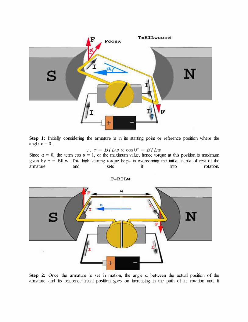
Step 1: Initially considering the armature is in its starting point or reference position where the angle α = 0.
Since α = 0, the term cos α = 1, or the maximum value, hence torque at this position is maximum
given by τ = BILw. This high starting torque helps in overcoming the initial inertia of rest of the armature and sets it into rotation.
Step 2: Once the armature is set in motion, the angle α between the actual position of the armature and its reference initial position goes on increasing in the path of its rotation until it

becomes 90° from its initial position. Consequently the term cosα decreases and also the value of torque.
The torque in this case is given by τ = BILwcosα which is less than BIL w when α is greater than 0°.
Step 3: In the path of the rotation of the armature a point is reached where the actual position of the rotor is exactly perpendicular to its initial position, i.e. α = 90°, and as a result the term cosα = 0.
The torque acting on the conductor at this position is given by,
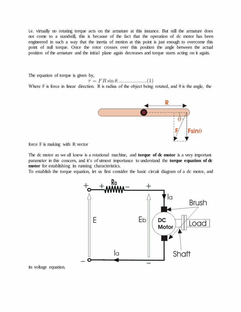
i.e. virtually no rotating torque acts on the armature at this instance. But still the armature does not come to a standstill, this is because of the fact that the operation of dc motor has been
engineered in such a way that the inertia of motion at this point is just enough to overcome this point of null torque. Once the rotor crosses over this position the angle between the actual
position of the armature and the initial plane again decreases and torque starts acting on it again.
The equation of torque is given by,
Where F is force in linear direction. R is radius of the object being rotated, and θ is the angle, the
force F is making with R vector The dc motor as we all know is a rotational machine, and torque of dc motor is a very important
parameter in this concern, and it’s of utmost importance to understand the torque equation of dc
motor for establishing its running characteristics.
To establish the torque equation, let us first consider the basic circuit diagram of a dc motor, and
its voltage equation.

Referring to the diagram beside, we can see, that if E is the supply voltage, Eb is the back emf produced and Ia, Ra are the armature current and armature resistance respectively then the voltage
equation is given by,
But keeping in mind that our purpose is to derive the torque equation of dc motor we multiply both sides of equation (2) by Ia.
Now Ia
2.Ra is the power loss due to heating of the armature coil, and the true effective
mechanical power that is required to produce the desired torque of dc machine is given by,
The mechanical power Pm is related to the electromagnetic torque Tg as,
Where ω is speed in rad/sec.
Now equating equation (4) & (5) we get,
Now for simplifying the torque equation of dc motor we substitute.
Where, P is no of poles, φ is flux per pole, Z is no. of conductors, A is no. of parallel paths, and N is the speed of the D.C. motor.
Substituting equation (6) and (7) in equation (4), we get:
The torque we so obtain, is known as the electromagnetic torque of dc motor, and subtracting the mechanical and rotational losses from it we get the mechanical torque. Therefore, Tm = Tg - mechanical losses. This is the torque equation of dc motor. It can be further simplified as:
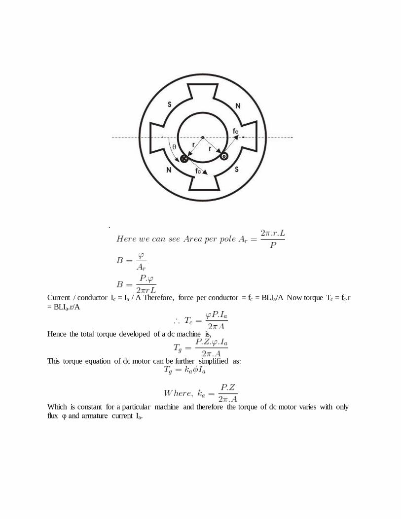
Which is constant for a particular machine and therefore the torque of dc motor varies with only flux φ and armature current Ia. The Torque equation of a dc motor can also be explained
considering the figure below
.
Current / conductor Ic = Ia / A Therefore, force per conductor = fc = BLIa/A Now torque Tc = fc.r
= BLIa.r/A
Hence the total torque developed of a dc machine is,
This torque equation of dc motor can be further simplified as:
Which is constant for a particular machine and therefore the torque of dc motor varies with only flux φ and armature current Ia.

EMF Equation of DC Generator
The derivation of EMF equation for DC generator has two parts:
1. Induced EMF of one conductor
2. Induced EMF of the generator Derivation for Induced EMF of One Armature Conductor
For one revolution of the conductor, Let Φ = Flux produced by each pole in weber (Wb) and P = number of poles in the DC generator therefore, Total flux produced by all the poles
And, Time taken to complete one revolution
Where, N = speed of the armature conductor in rpm Now,according to Faraday’s law of
induction, the induced emf of the armature conductor is denoted by “e” which is equal to rate of cutting the flux. Therefore,
Induced emf of one conductor is
Derivation for Induced EMF for DC Generator
Let us suppose there are Z total numbers of conductor in a generator, and arranged in such a manner that all parallel paths are always in series. Here, Z = total numbers of conductor A =
number of parallel paths Then, Z/A = number of conductors connected in series We know that induced emf in each path is same across the line Therefore, Induced emf of DC generator E =
emf of one conductor × number of conductor connected in series.
Induced emf of DC generator is
Simple wave wound generator Numbers of parallel paths are only 2 = A Therefore, Induced emf
for wave type of winding generator is
Simple lap-wound generator Here, number of parallel paths is equal to number of conductors in
one path i.e. P = A Therefore, Induced emf for lap-wound generator is
Construction of DC Motor | Yoke Poles Armature Field Winding
Commutator Brushes of DC Motor
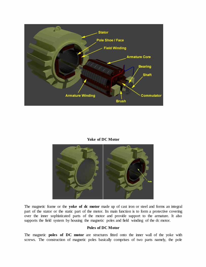
A DC motor like we all know is a device that deals in the conversion of electrical energy to mechanical energy and this is essentially brought about by two major parts required for the construction of dc motor, namely. 1) Stator – The static part that houses the field windings and
receives the supply and,
2) Rotor – The rotating part that brings about the mechanical rotations.
Other than that there are several subsidiary parts namely the 3) Yoke of dc motor.
4) Poles of dc motor. 5) Field winding of dc motor.
6) Armature winding of dc motor. 7) Commutator of dc motor. 8) Brushes of dc motor.
All these parts put together configures the total construction of a dc motor. Now let’s do a detailed discussion about all the essential parts of dc motor.
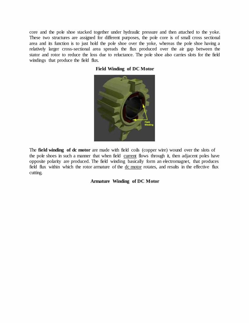
Yoke of DC Motor
The magnetic frame or the yoke of dc motor made up of cast iron or steel and forms an integral
part of the stator or the static part of the motor. Its main function is to form a protective covering over the inner sophisticated parts of the motor and provide support to the armature. It also supports the field system by housing the magnetic poles and field winding of the dc motor.
Poles of DC Motor
The magnetic poles of DC motor are structures fitted onto the inner wall of the yoke with
screws. The construction of magnetic poles basically comprises of two parts namely, the pole
core and the pole shoe stacked together under hydraulic pressure and then attached to the yoke. These two structures are assigned for different purposes, the pole core is of small cross sectional
area and its function is to just hold the pole shoe over the yoke, whereas the pole shoe having a relatively larger cross-sectional area spreads the flux produced over the air gap between the
stator and rotor to reduce the loss due to reluctance. The pole shoe also carries slots for the field windings that produce the field flux.
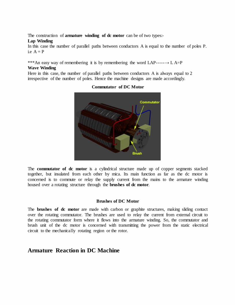
Field Winding of DC Motor
The field winding of dc motor are made with field coils (copper wire) wound over the slots of
the pole shoes in such a manner that when field current flows through it, then adjacent poles have opposite polarity are produced. The field winding basically form an electromagnet, that produces field flux within which the rotor armature of the dc motor rotates, and results in the effective flux
cutting.
Armature Winding of DC Motor

The armature winding of dc motor is attached to the rotor, or the rotating part of the machine,
and as a result is subjected to altering magnetic field in the path of its rotation which directly results in magnetic losses. For this reason the rotor is made of armature core, that’s made with several low-hysteresis silicon steel lamination, to reduce the magnetic losses like hysteresis and
eddy current loss respectively. These laminated steel sheets are stacked together to form the cylindrical structure of the armature core.
The armature core are provided with slots made of the same material as the core to which the armature winding made with several turns of copper wire distributed uniformly over the entire periphery of the core. The slot openings a shut with fibrous wedges to prevent the conductor
from plying out due to the high centrifugal force produced during the rotation of the armature, in presence of supply current and field.
The construction of armature winding of dc motor can be of two types:-
Lap Winding
In this case the number of parallel paths between conductors A is equal to the number of poles P.
i.e A = P
***An easy way of remembering it is by remembering the word LAP-----→ L A=P Wave Winding
Here in this case, the number of parallel paths between conductors A is always equal to 2 irrespective of the number of poles. Hence the machine designs are made accordingly.
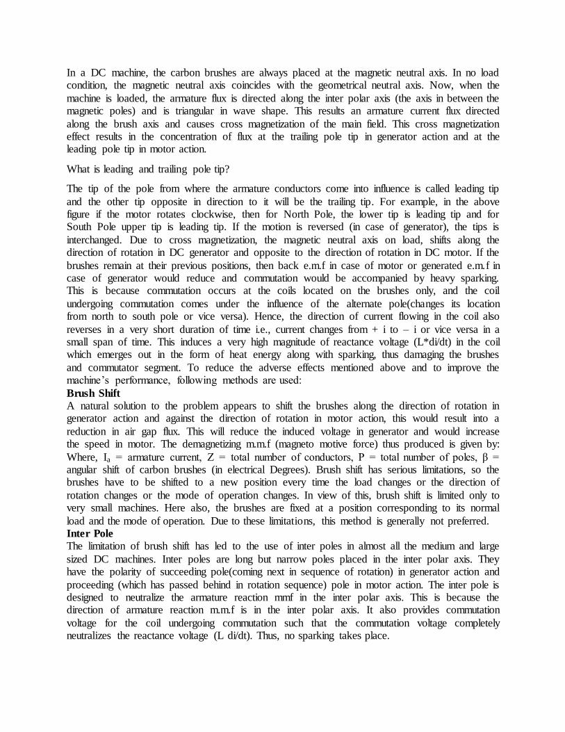
Commutator of DC Motor
The commutator of dc motor is a cylindrical structure made up of copper segments stacked together, but insulated from each other by mica. Its main function as far as the dc motor is
concerned is to commute or relay the supply current from the mains to the armature winding housed over a rotating structure through the brushes of dc motor.
Brushes of DC Motor
The brushes of dc motor are made with carbon or graphite structures, making sliding contact
over the rotating commutator. The brushes are used to relay the current from external circuit to the rotating commutator form where it flows into the armature winding. So, the commutator and brush unit of the dc motor is concerned with transmitting the power from the static electrical
circuit to the mechanically rotating region or the rotor.
Armature Reaction in DC Machine
In a DC machine, the carbon brushes are always placed at the magnetic neutral axis. In no load condition, the magnetic neutral axis coincides with the geometrical neutral axis. Now, when the
machine is loaded, the armature flux is directed along the inter polar axis (the axis in between the magnetic poles) and is triangular in wave shape. This results an armature current flux directed
along the brush axis and causes cross magnetization of the main field. This cross magnetization effect results in the concentration of flux at the trailing pole tip in generator action and at the leading pole tip in motor action.
What is leading and trailing pole tip?
The tip of the pole from where the armature conductors come into influence is called leading tip
and the other tip opposite in direction to it will be the trailing tip. For example, in the above figure if the motor rotates clockwise, then for North Pole, the lower tip is leading tip and for South Pole upper tip is leading tip. If the motion is reversed (in case of generator), the tips is
interchanged. Due to cross magnetization, the magnetic neutral axis on load, shifts along the direction of rotation in DC generator and opposite to the direction of rotation in DC motor. If the
brushes remain at their previous positions, then back e.m.f in case of motor or generated e.m.f in case of generator would reduce and commutation would be accompanied by heavy sparking. This is because commutation occurs at the coils located on the brushes only, and the coil
undergoing commutation comes under the influence of the alternate pole(changes its location from north to south pole or vice versa). Hence, the direction of current flowing in the coil also
reverses in a very short duration of time i.e., current changes from + i to – i or vice versa in a small span of time. This induces a very high magnitude of reactance voltage (L*di/dt) in the coil which emerges out in the form of heat energy along with sparking, thus damaging the brushes
and commutator segment. To reduce the adverse effects mentioned above and to improve the machine’s performance, following methods are used:
Brush Shift
A natural solution to the problem appears to shift the brushes along the direction of rotation in generator action and against the direction of rotation in motor action, this would result into a
reduction in air gap flux. This will reduce the induced voltage in generator and would increase the speed in motor. The demagnetizing m.m.f (magneto motive force) thus produced is given by:
Where, Ia = armature current, Z = total number of conductors, P = total number of poles, β = angular shift of carbon brushes (in electrical Degrees). Brush shift has serious limitations, so the brushes have to be shifted to a new position every time the load changes or the direction of
rotation changes or the mode of operation changes. In view of this, brush shift is limited only to very small machines. Here also, the brushes are fixed at a position corresponding to its normal
load and the mode of operation. Due to these limitations, this method is generally not preferred. Inter Pole
The limitation of brush shift has led to the use of inter poles in almost all the medium and large
sized DC machines. Inter poles are long but narrow poles placed in the inter polar axis. They have the polarity of succeeding pole(coming next in sequence of rotation) in generator action and
proceeding (which has passed behind in rotation sequence) pole in motor action. The inter pole is designed to neutralize the armature reaction mmf in the inter polar axis. This is because the direction of armature reaction m.m.f is in the inter polar axis. It also provides commutation
voltage for the coil undergoing commutation such that the commutation voltage completely neutralizes the reactance voltage (L di/dt). Thus, no sparking takes place.

Inter polar windings are always kept in series with armature, so inter polar winding carries the armature current ; therefore works satisfactorily irrespective of load, the direction of rotation or
the mode of operation. Inter poles are made narrower to ensure that they influence only the coil undergoing commutation and its effect does not spread to the other coils. The base of the inter
poles is made wider to avoid saturation and to improve response. Compensating Winding
Commutation problem is not the only problem in DC machines. At heavy loads, the cross
magnetizing armature reaction may cause very high flux density in the trailing pole tip in generator action and leading pole tip in the motor action.
Consequently, the coil under this tip may develop induced voltage high enough to cause a flashover between the associated adjacent commutator segments particularly, because this coil is physically close to the commutation zone (at the brushes) where the air temperature might be
already high due to commutation process. This flashover may spread to the neighboring commutator segments, leading ultimately to a
complete fire over the commutator surface from brush to brush. Also, when the machine is subjected to rapidly fluctuating loads, then the voltage L* di/dt, that appears across the adjacent commutator segments may reach a value high enough to cause flashover between the adjacent
commutator segments. This would start from the centre of pole as the coil below it possesses the maximum inductance. This may again cause a similar fire as described above. This problem is
more acute while the load is decreasing in generating action and increasing in motor action as then, the induced e.m.f and voltage L* di/dt will support each other. The above problems are solved by use of compensating winding.
Compensating winding consists of conductors embedded in the pole face that run parallel to the shaft and carry an armature current in a direction opposite to the direction of current in the
armature conductors under that pole arc. With complete compensation the main field is restored. This also reduces armature circuit’s inductor and improves system response.Compensating winding functions satisfactorily irrespective of the load, direction of rotation and mode of
operation. Obviously it is help in commutation as the inter polar winding gets relieved from its duty to compensate for the armature m.m.f under the pole arc.
NOTE:
1. The cross magnetizing armature reaction effect is mainly caused by armature
conductors which are located under the pole arc. At high loads, this effect of armature
reaction may cause excessive flux density in the trailing pole tip (in generator) and
leading pole tip (in motor). Due to saturation in the pole shoe, the increase in flux
density may be less than the reduction in the flux density in remaining section of the
pole shoe. This would ultimately result into a net reduction in flux per pole. This
phenomenon is thus known as the demagnetizing effect of cross magnetizing armature
reaction, which is further compensated by the use of compensating windings.
2. Inter polar winding and compensating windings are connected in series with the
armature winding but on the opposite sides with respect to armature.
3. The primary duty of inter polar winding is to improve the commutation process, and
that of the compensating winding is to compensate for the increase or decrease in the
net air gap flux i.e., to maintain its constant value.

Types of DC Motor Separately Excited Shunt Series Compound DC
Motor
The direct current motor or the DC motor has a lot of application in today’s field of engineering and technology. Starting from an electric shaver to parts of automobiles, in all small or medium
sized motoring applications DC motors come handy. And because of its wide range of application different functional types of dc motor are available in the market for specific
requirements. The types of DC motor can be listed as follows
• DC motor • Permanent Magnet DC Motor
• Separately Excited DC Motor • Self Excited DC Motor • Shunt Wound DC Motor
• Series Wound DC Motor • Compound Wound DC Motor
• Cumulative compound DC motor • Short shunt DC Motor • Long shunt DC Motor
• Differential Compound DC Motor • Short Shunt DC Motor
• Long Shunt DC Motor
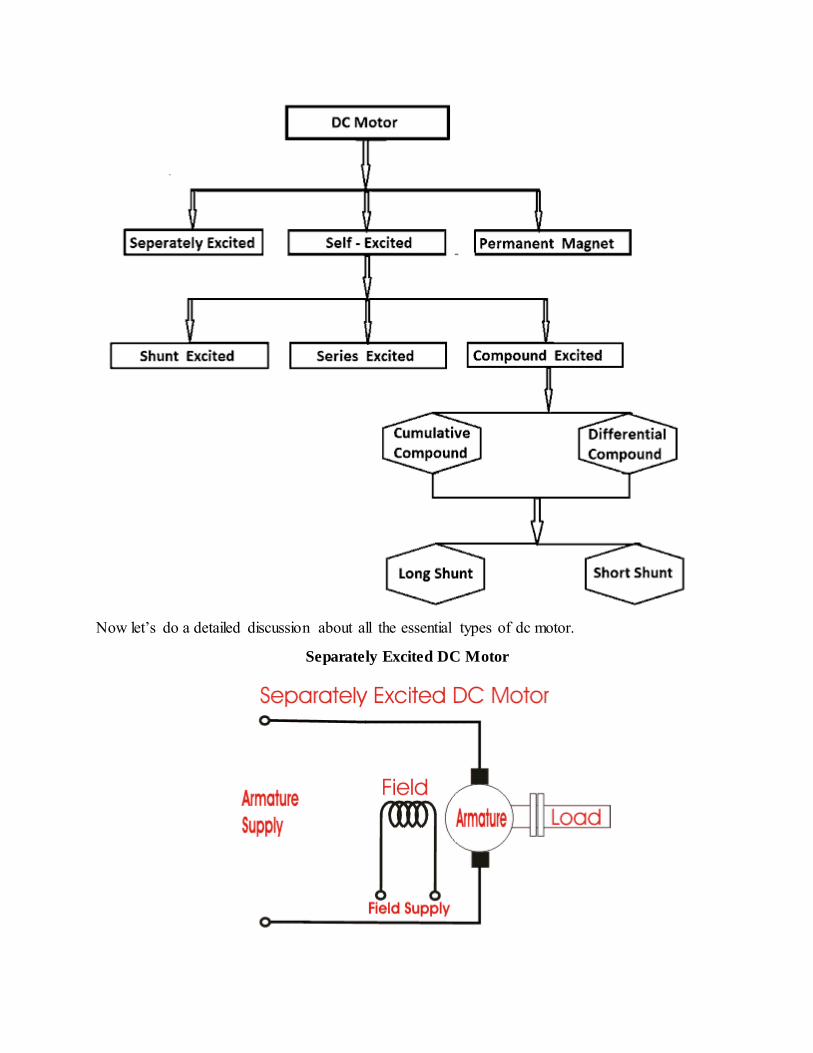
Now let’s do a detailed discussion about all the essential types of dc motor.
Separately Excited DC Motor

As the name suggests, in case of a separately excited DC motor the supply is given separately to the field and armature windings. The main distinguishing fact in these types of dc motor is that,
the armature current does not flow through the field windings, as the field winding is energized from a separate external source of dc current as shown in the figure beside.
From the torque equation of dc motor we know Tg = Ka φ Ia So the torque in this case can be varied by varying field flux φ, independent of the armature current Ia.
Permanent Magnet DC Motor
The permanent magnet DC motor consists of an armature winding as in case of an usual motor, but does not necessarily contain the field windings. The construction of these types of DC
motor are such that, radially magnetized permanent magnets are mounted on the inner periphery of the stator core to produce the field flux. The rotor on the other hand has a conventional dc armature with commutator segments and brushes. The diagrammatic representation of a
permanent magnet dc motor is given below. The torque equation of dc motor suggests Tg = Ka φ Ia. Here φ is always constant, as permanent magnets of required flux density are chosen at the
time of construction and can’t be changed there after. For a permanent magnet dc motor Tg = Ka1Ia Where Ka1 = Ka.φ which is another constant. In this case the torque of DC Motor can only be
changed by controlling armature supply.
Self Excited DC Motor
In case of self excited dc motor, the field winding is connected either in series or in parallel or partly in series, partly in parallel to the armature winding, and on this basis its further classified as:-
1. Shunt wound DC motor. 2. Series wound DC motor. 3. Compound wound DC motor.
Let’s now go into the details of these types of self excited dc motor.

Shunt Wound DC Motor
In case of a shunt wound dc motor or more specifically shunt wound self excited dc motor, the field windings are exposed to the entire terminal voltage as they are connected in parallel to the
armature winding as shown in the figure below. To understand the characteristic of these types of DC motor, lets consider the basic voltage
equation given by,
[Where E, Eb, Ia, Ra are the supply voltage, back emf, armature current and armature resistance
respectively]
[since back emf increases with flux φ and angular speed ωω] Now substituting Eb from equation (2) to equation (1) we get,
The torque equation of a dc motor resembles,
This is similar to the equation of a straight line, and we can graphically representing the torque
speed characteristic of a shunt wound self excited dc motor as
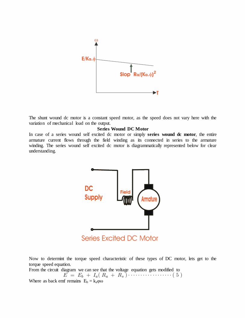
The shunt wound dc motor is a constant speed motor, as the speed does not vary here with the variation of mechanical load on the output.
Series Wound DC Motor
In case of a series wound self excited dc motor or simply series wound dc motor, the entire
armature current flows through the field winding as its connected in series to the armature winding. The series wound self excited dc motor is diagrammatically represented below for clear understanding.
Now to determint the torque speed characteristic of these types of DC motor, lets get to the
torque speed equation. From the circuit diagram we can see that the voltage equation gets modified to
Where as back emf remains Eb = kaφω
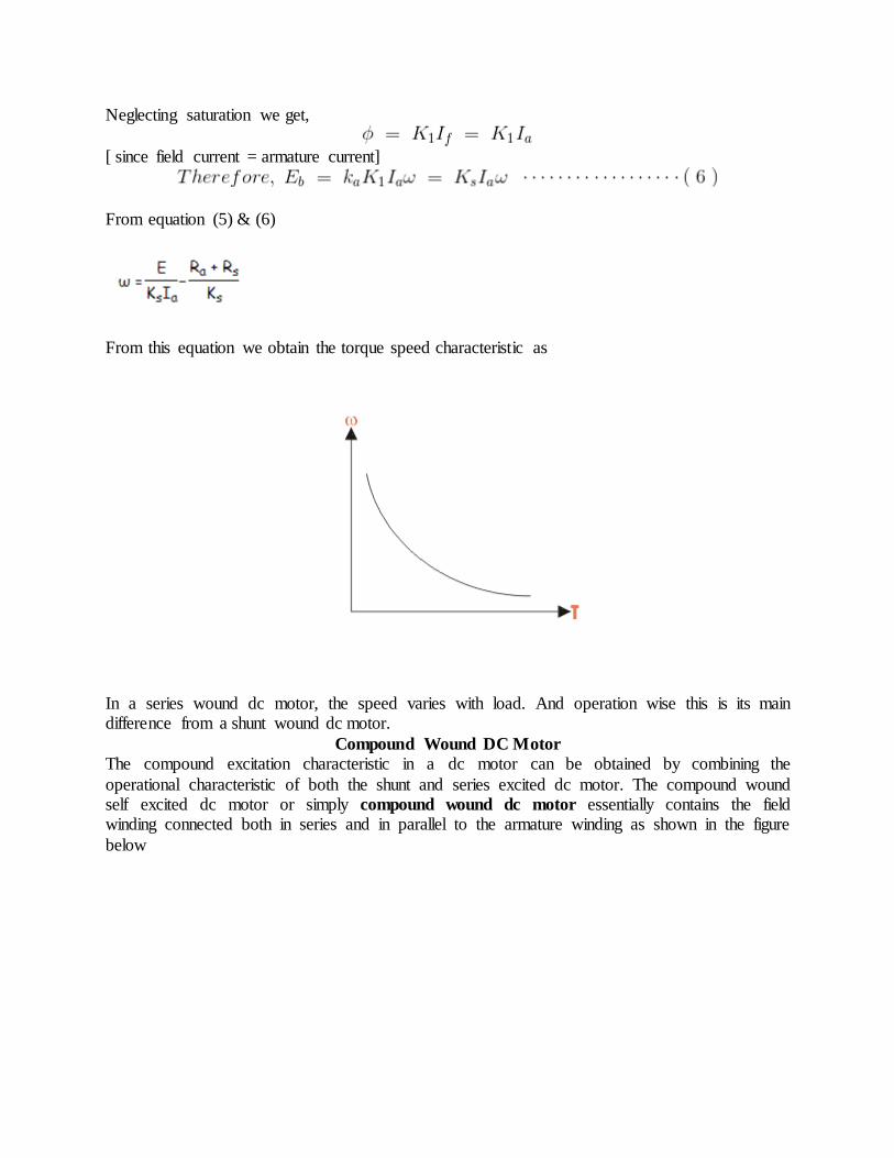
Neglecting saturation we get,
[ since field current = armature current]
From equation (5) & (6)
From this equation we obtain the torque speed characteristic as
In a series wound dc motor, the speed varies with load. And operation wise this is its main difference from a shunt wound dc motor.
Compound Wound DC Motor
The compound excitation characteristic in a dc motor can be obtained by combining the
operational characteristic of both the shunt and series excited dc motor. The compound wound self excited dc motor or simply compound wound dc motor essentially contains the field winding connected both in series and in parallel to the armature winding as shown in the figure
below

:
The excitation of compound wound dc motor can be of two types depending on the nature of compounding.
Cumulative Compound DC Motor
When the shunt field flux assists the main field flux, produced by the main field connected in series to the armature winding then its called cumulative compound dc motor.
Differential Compound DC Motor
In case of a differentially compounded self excited dc motor i.e. differential compound dc motor, the arrangement of shunt and series winding is such that the field flux produced by the shunt
field winding diminishes the effect of flux by the main series field winding.
The net flux produced in this case is lesser than the original flux and hence does not find much of a practical application.
The compounding characteristic of the self excited dc motor is shown in the figure below.
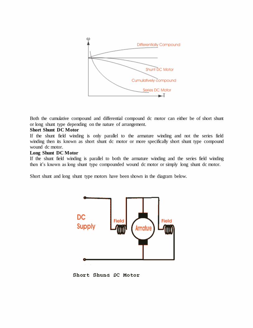
Both the cumulative compound and differential compound dc motor can either be of short shunt
or long shunt type depending on the nature of arrangement. Short Shunt DC Motor
If the shunt field winding is only parallel to the armature winding and not the series field winding then its known as short shunt dc motor or more specifically short shunt type compound wound dc motor.
Long Shunt DC Motor
If the shunt field winding is parallel to both the armature winding and the series field winding
then it’s known as long shunt type compounded wound dc motor or simply long shunt dc motor.
Short shunt and long shunt type motors have been shown in the diagram below.

Characteristics Of DC Motors
Generally, three characteristic curves are considered for DC motors which are, (i) Torque vs. armature current (Ta - Ia), (ii) Speed vs. armature current and (iii) Speed vs. torque. These are explained below for each type of DC motor. These characteristics are determined by keeping
following two relations in mind. Ta α Φ.Ia and N α Eb/Φ
Characteristics Of DC Series Motors
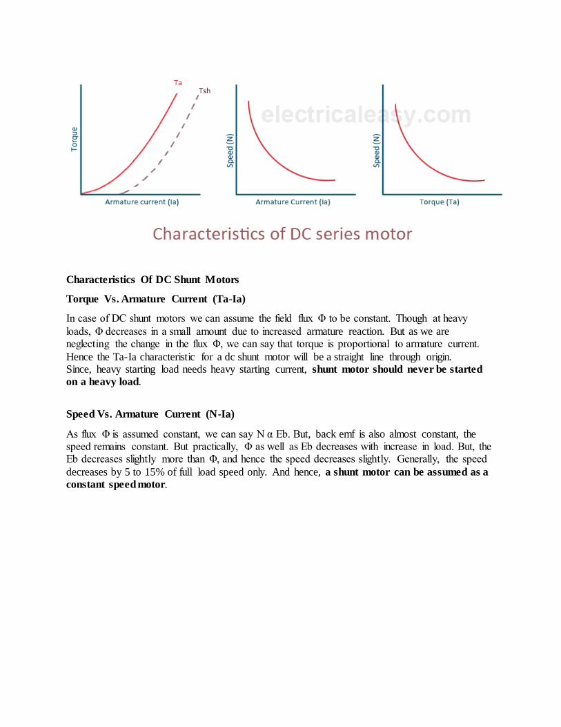
Torque Vs. Armature Current (Ta-Ia)
This characteristic is also known as electrical characteristic. We know that torque is directly proportional to armature current and flux, Ta α Φ.Ia. In DC series motors, field winding is
connected in series with armature. Thus, before magnetic saturation of the field, flux Φ is directly proportional to Ia. Therefore, before magnetic saturation Ta α Ia2. At light loads, Ia as well as Φ is small and hence the torque increases as the square of the armature current.
Therefore, the Ta-Ia curve is parabola for smaller values of Ia. After magnetic saturation of the field winding, flux Φ is independent of armature current Ia.
Therefore, the torque varies proportional to Ia only, T α Ia.Therefore, after magnetic saturation, Ta-Ia curve becomes straight line. The shaft torque (Tsh) is less than armature torque (Ta) due to stray losses.
In DC series motors, (prior to magnetic saturation) torque increases as the square of armature current, these motors are used where high starting torque is required
Speed Vs. Armature Current (N-Ia)
We know the relation, N α Eb/Φ
For small load current (and hence for small armature current) change in back emf Eb is small and it may be neglected. Thus, for small currents speed is inversely proportional to Φ. As we know, flux is directly proportional to Ia, speed is also inversely proportional to Ia.
When armature current is very small the speed becomes dangerously high. That is why a series
motor should never be started without some mechanical load.
But, at heavy loads, armature current Ia is large. And hence speed is low which results in decreased back emf Eb. Due to decreased Eb, more armature current is allowed.
Speed Vs. Torque (N-Ta)
This characteristic is also called as mechanical characteristic. From the above two
characteristics of DC series motor, it can be found that when speed is high, torque is low and vice versa.
Characteristics Of DC Shunt Motors
Torque Vs. Armature Current (Ta-Ia)
In case of DC shunt motors we can assume the field flux Φ to be constant. Though at heavy
loads, Φ decreases in a small amount due to increased armature reaction. But as we are neglecting the change in the flux Φ, we can say that torque is proportional to armature current.
Hence the Ta-Ia characteristic for a dc shunt motor will be a straight line through origin. Since, heavy starting load needs heavy starting current, shunt motor should never be started
on a heavy load.
Speed Vs. Armature Current (N-Ia)
As flux Φ is assumed constant, we can say N α Eb. But, back emf is also almost constant, the speed remains constant. But practically, Φ as well as Eb decreases with increase in load. But, the Eb decreases slightly more than Φ, and hence the speed decreases slightly. Generally, the speed
decreases by 5 to 15% of full load speed only. And hence, a shunt motor can be assumed as a
constant speed motor.

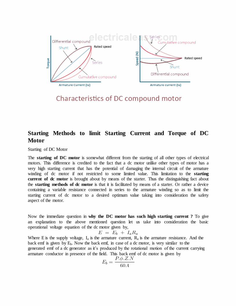
Characteristics Of DC Compound Motor
DC compound motors have both series as well as shunt windings. In a compound motor series and shunt windings are connected such that series flux is in direction with shunt flux then the motor is said to be cumulatively compounded. And if series flux is opposite direction as that of
the shunt flux, then the motor is said to be differentially compounded. Characteristics of both these types are explained below.
(a) Cumulative compound motor Cumulative compound motors are used where series characteristics are required but the load is likely to be removed completely. Series winding takes care of the heavy load, whereas the shunt
winding prevents the motor from running at dangerously high speed when the load is suddenly removed. These motors are generally employed a flywheel, where sudden and temporary loads
are applied like in rolling mills. (b) Differential compound motor Since in differential field motors, series flux opposes shunt flux, the total flux decreases with
increase in load. Due to this, the speed remains almost constant or even it may increase slightly with increase in load. Differential compound motors are not commonly use, but they find limited
applications in experimental and research work.
Starting Methods to limit Starting Current and Torque of DC
Motor
Starting of DC Motor
The starting of DC motor is somewhat different from the starting of all other types of electrical motors. This difference is credited to the fact that a dc motor unlike other types of motor has a
very high starting current that has the potential of damaging the internal circuit of the armature winding of dc motor if not restricted to some limited value. This limitation to the starting
current of dc motor is brought about by means of the starter. Thus the distinguishing fact about
the starting methods of dc motor is that it is facilitated by means of a starter. Or rather a device containing a variable resistance connected in series to the armature winding so as to limit the
starting current of dc motor to a desired optimum value taking into consideration the safety aspect of the motor.
Now the immediate question in why the DC motor has such high starting current ? To give
an explanation to the above mentioned question let us take into consideration the basic operational voltage equation of the dc motor given by,
Where E is the supply voltage, Ia is the armature current, Ra is the armature resistance. And the back emf is given by Eb. Now the back emf, in case of a dc motor, is very similar to the generated emf of a dc generator as it’s produced by the rotational motion of the current carrying
armature conductor in presence of the field. This back emf of dc motor is given by

and has a major role to play in case of the starting of dc motor. From this equation we can see that Eb is directly proportional to the speed N of the motor. Now since at starting N = 0, Eb is
also zero, and under this circumstance the voltage equation is modified to
For all practical practices to obtain optimum operation of the motor the armature resistance is kept very small usually of the order of 0.5 Ω and the bare minimum supply voltage being 220
volts. Even under these circumstance the starting current, Ia is as high as 220/0.5 amp = 440 amp. Such high starting current of dc motor creates two major problems. 1) Firstly, current of the
order of 400 A has the potential of damaging the internal circuit of the armature winding of dc motor at the very onset. 2) Secondly, since the torque equation of dc motor is given by
Very high electromagnetic starting torque of DC motor is produced by virtue of the high
starting current, which has the potential of producing huge centrifugal force capable of flying off the rotor winding from the slots.
Starting Methods of DC Motor
As a direct consequence of the two above mentioned facts i.e high starting current and high starting torque of DC motor, the entire motoring system can undergo a total disarray and lead
towards into an engineering massacre and non-functionality. To prevent such an incidence from occurring several starting methods of dc motor has been adopted. The main principal of this
being the addition of external electrical resistance Rext to the armature winding, so as to increase the effective resistance to Ra + Rext, thus limiting the armature current to the rated value. The new value of starting armature current is desirably low and is given by.
Now as the motor continues to run and gather speed, the back emf successively develops and increases, countering the supply voltage, resulting in the decrease of the net working voltage.
Thus now,

At this moment to maintain the armature current to its rated value, Rext is progressively decreased unless its made zero, when the back emf produced is at its maximum. This regulation of the
external electrical resistance in case of the starting of dc motor is facilitated by means of the starter.
Starters can be of several types and requires a great deal of explanation and some intricate level understanding. But on a brief over-view the main types of starters used in the industry today can be illustrated as:-
1) 3 point starter. 2) 4 point starter.
Used for the starting of shunt wound DC motor and compound wound DC motor.

3 Point Starter | Working Principle and Construction of Three Point
Starter
A 3 point starter in simple words is a device that helps in the starting and running of a shunt
wound DC motor or compound wound DC motor. Now the question is why these types of DC motors require the assistance of the starter in the first case. The only explanation to that is given
by the presence of back emf Eb, which plays a critical role in governing the operation of the motor. The back emf, develops as the motor armature starts to rotate in presence of the magnetic field, by generating action and counters the supply voltage. This also essentially means, that the
back emf at the starting is zero, and develops gradually as the motor gathers speed.
The general motor emf equation E = Eb + Ia.Ra, at starting is modified to E = Ia.Ra as at starting Eb = 0.
Thus we can well understand from the above equation that the current will be dangerously high at starting (as armature resistance Ra is small) and hence its important that we make use of a
device like the 3 point starter to limit the starting current to an allowable lower value. Let us now look into the construction and working of three point starter to understand how the
starting current is restricted to the desired value. For that let’s consider the diagram given below

showing all essential parts of the three point starter.
Construction of 3 Point Starter
Construction wise a starter is a variable resistance, integrated into number of sections as shown
in the figure beside. The contact points of these sections are called studs and are shown separately as OFF, 1, 2,3,4,5, RUN. Other than that there are 3 main points, referred to as 1. 'L' Line terminal. (Connected to positive of supply.) 2. 'A' Armature terminal. (Connected to the
armature winding.) 3. 'F' Field terminal. (Connected to the field winding.) And from there it gets the name 3 point starter. Now studying the construction of 3 point starter in further details
reveals that, the point 'L' is connected to an electromagnet called overload release (OLR) as shown in the figure. The other end of 'OLR' is connected to the lower end of conducting lever of starter handle where a spring is also attached with it and the starter handle contains also a soft
iron piece housed on it. This handle is free to move to the other side RUN against the force of the spring. This spring brings back the handle to its original OFF position under the influence of its
own force. Another parallel path is derived from the stud '1', given to the another electromagnet called No Volt Coil (NVC) which is further connected to terminal 'F'. The starting resistance at starting is entirely in series with the armature. The OLR and NVC acts as the two protecting
devices of the starter.
Working of Three Point Starter
Having studied its construction, let us now go into the working of the 3 point starter. To start with the handle is in the OFF position when the supply to the DC motor is switched on. Then
handle is slowly moved against the spring force to make a contact with stud No. 1. At this point, field winding of the shunt or the compound motor gets supply through the parallel path provided
to starting resistance, through No Voltage Coil. While entire starting resistance comes in series with the armature. The high starting armature current thus gets limited as the current equation at this stage becomes Ia = E/(Ra+Rst). As the handle is moved further, it goes on making contact
with studs 2, 3, 4 etc., thus gradually cutting off the series resistance from the armature circuit as the motor gathers speed. Finally when the starter handle is in 'RUN' position, the entire starting
resistance is eliminated and the motor runs with normal speed. This is because back emf is developed consequently with speed to counter the supply voltage and reduce the armature current. So the external electrical resistance is not required anymore, and is removed for
optimum operation. The handle is moved manually from OFF to the RUN position with development of speed. Now the obvious question is once the handle is taken to the RUN position
how is it supposed to stay there, as long as motor is running ? To find the answer to this question let us look into the working of No Voltage Coil.
Working of No Voltage Coil of 3 Point Starter
The supply to the field winding is derived through no voltage coil. So when field current flows, the NVC is magnetized. Now when the handle is in the 'RUN' position, soft iron piece connected to the handle and gets attracted by the magnetic force produced by NVC, because of flow of
current through it. The NVC is designed in such a way that it holds the handle in 'RUN' position against the force of the spring as long as supply is given to the motor. Thus NVC holds the
handle in the 'RUN' position and hence also called hold on coil. Now when there is any kind of supply failure, the current flow through NVC is affected and it immediately looses its magnetic property and is unable to keep the soft iron piece on the handle,
attracted. At this point under the action of the spring force, the handle comes back to OFF position, opening the circuit and thus switching off the motor. So due to the combination of NVC
and the spring, the starter handle always comes back to OFF position whenever there is any supply problems. Thus it also acts as a protective device safeguarding the motor from any kind of abnormality.
Speed Regulation of DC Motor
On application of load the speed of a dc motor decreases gradually. This is not at all desirable.
So the difference between no load and full load speed should be very less. The motor capable of maintaining a nearly constant speed for varying load is said to have good speed regulation i.e the
difference between no load and full load speed is quite less. The speed regulation of a permanent magnet DC motor is good ranging from 10 - 15% whereas for dc shunt motor it is somewhat less than 10 %. DC series motor has poor value of regulation. In case of compound DC motor the
speed regulation for dc cumulative compound is around 25 % while differential compound has its excellent value of 5 %.

Speed of a DC Motor
The emf equation of DC motor is given by
Here N = speed of rotation in rpm. P = number of poles. A = number of parallel paths. Z = total no. conductors in armature.
Hence, speed of a DC motor is directly proportional to emf of rotation (E) and inversely
proportional to flux per pole (φ).
Speed Regulation of a DC Motor
The speed regulation is defined as the change in speed from no load to full load, expressed as a fraction or percentage of full load speed. Therefore, as per definition per unit (p.u) speed
regulation of DC motor is given as,
Similarly, percentage (%) speed regulation is given as,
Where Nno load = no load speed and Nfull lod = full load speed of DC motor. Therefore, Percent speed regulation = Per unit (p.u) speed regulation X 100 %. A motor which has nearly constant speed at all load below full rated load, have good speed regulation.
Speed Control of DC Motor
Speed control means intentional change of the drive speed to a value required for performing the specific work process. Speed control is a different concept from speed regulation where there is
natural change in speed due change in load on the shaft. Speed control is either done manually by the operator or by means of some automatic control device.
One of the important features of dc motor is that its speed can be controlled with relative ease. We know that the expression of speed control dc motor is given as,
Therefore speed (N ) of 3 types of dc motor – SERIES, SHUNT AND COMPOUND can be controlled by changing the quantities on RHS of the expression. So speed can be varied by
changing (i) terminal voltage of the armature V , (ii) external resistance in armature circuit R and (iii) flux per pole φ . The first two cases involve change that affects armature circuit and the third
one involves change in magnetic field. Therefore speed control of dc motor is classified as 1) armature control methods and 2) field control methods.
Speed Control of DC Series Motor
Speed control of dc series motor can be done either by armature control or by field control. Armature Control of DC Series Motor
Speed adjustment of dc series motor by armature control may be done by any one of the methods that follow,
1. Armature resistance control method: This is the most common method employed. Here the controlling resistance is connected directly in series with the supply to the motor as shown in the fig. diagram The power loss in the control resistance of dc series motor can be neglected because
this control method is utilized for a large portion of time for reducing the speed under light load condition. This method of speed control is most economical for constant torque. This method of
speed control is employed for dc series motor driving cranes, hoists, trains etc. 2. Shunted armature control: The combination of a rheostat shunting the armature and a rheostat in series with the armature is involved in this method of speed control. The voltage applied to the
armature is varies by varying series rheostat R 1. The exciting current can be varied by varying the armature shunting resistance R2. This method of speed control is not economical due to
considerable power losses in speed controlling resistances. Here speed control is obtained over wide range but below normal speed. Diagram : 3. Armature terminal voltage control: The speed control of dc series motor can be accomplished
by supplying the power to the motor from a separate variable voltage supply. This method involves high cost so it rarely used.
Field Control of DC Series Motor
The speed of dc motor can be controlled by this method by any one of the following ways – 1. Field diverter method: This method uses a diverter. Here the field flux can be reduced by
shunting a portion of motor current around the series field. Lesser the diverter resistance less is the field current, less flux therefore more speed. This method gives speed above
normal and the method is used in electric drives in which speed should rise sharply as soon as load is decreased.
2. Tapped Field control: This is another method of increasing the speed by reducing the flux
and it is done by lowering number of turns of field winding through which current flows. In this method a number of tapping from field winding are brought outside . This method
is employed in electric traction.
Speed Control of DC Shunt Motor
Speed of dc shunt motor is controlled by the factors stated below Field Control of DC Shunt Motor
By this method speed control is obtained by any one of the following means –

1. Field rheostat control of DC Shunt Motor: In this method, speed variation is accomplished by means of a variable resistance inserted in series with the shunt field. An increase in controlling
resistances reduces the field current with a reduction in flux and an increase in speed. This method of speed control is independent of load on the motor. Power wasted in controlling
resistance is very less as field current is a small value. This method of speed control is also used in DC compound motor.
Limitations of this method of speed control:
A. Creeping speeds cannot be obtained.
B. Top speeds only obtained at reduced torque
C. The speed is maximum at minimum value of flux, which is governed by the demagnetizing effect of armature reaction on the field.
2. Field voltage control: This method requires a variable voltage supply for the field circuit which is separated from the main power supply to which the armature is connected. Such a
variable supply can be obtained by an electronic rectifier. Armature Control of DC Shunt Motor
Speed control by this method involves two ways . These are : 1. Armature resistance control : In this method armature circuit is provided with a variable resistance. Field is directly connected across the supply so flux is not changed due to variation of
series resistance. This is applied for dc shunt motor. This method is used in printing press, cranes, hoists where speeds lower than rated is used for a short period only.
2. Armature voltage control: This method of speed control needs a variable source of voltage separated from the source supplying the field current. This method avoids disadvantages of poor speed regulation and low efficiency of armature-resistance control methods. The basic adjustable
armature voltage control method of speed d control is accomplished by means of an adjustable voltage generator is called Ward Leonard system. This method involves using a motor –
generator (M-G) set. This method is best suited for steel rolling mills, paper machines, elevators, mine hoists, etc.
Advantages of this method –
A. Very fine speed control over whole range in both directions
B. Uniform acceleration is obtained
C. Good speed regulation
Disadvantages –

A. Costly arrangement is needed , floor space required is more
B. Low efficiency at light loads
Ward Leonard Method of Speed Control
Ward Leonard control system is introduced by Henry Ward Leonard in 1891. Ward Leonard method of speed control is used for controlling the speed of a DC motor. It is a basic armature
control method. This control system is consisting of a dc motor M_1 and powered by a DC generator G. In this method the speed of the dc motor (M_1) is controlled by applying variable
voltage across its armature. This variable voltage is obtained using a motor-generator set which consists of a motor M_2(either ac or dc motor) directly coupled with the generator G. It is a very widely used method of speed control of DC motor.
Principle of Ward Leonard Method
Basic connection diagram of the Ward Leonard speed control system is shown in the figure below.
The speed of motor M1 is to be controlled which is powered by the generator G. The shunt field of the motor M1 is connected across the dc supply lines. Now, generator G is driven by the motor
M2. The speed of the motor M2 is constant. When the output voltage of the generator is fed to the motor M1 then the motor starts to rotate. When the output voltage of the generator varies then the speed of the motor also varies. Now controlling the output voltage of the generator the speed of
motor can also be controlled. For this purpose of controlling the output voltage, a field regulator is connected across the generator with the dc supply lines to control the field excitation. The

direction of rotation of the motor M1 can be reversed by excitation current of the generator and it can be done with the help of the reversing switch R.S. But the motor-generator set must run in
the same direction.
Advantages of Ward Leonard System
1. It is a very smooth speed control system over a very wide range (from zero to normal speed of the motor).
2. The speed can be controlled in both the direction of rotation of the motor easily.
3. The motor can run with a uniform acceleration. 4. Speed regulation of DC motor in this ward Leonard system is very good.
Disadvantages of Ward Leonard System
1. The system is very costly because two extra machines (motor-generator set) are required. 2. Overall efficiency of the system is not sufficient especially it is lightly loaded.
Application of Ward Leonard System
This Ward Leonard method of speed control system is used where a very wide and very sensitive
speed control is of a DC motor in both the direction of rotation is required. This speed control system is mainly used in colliery winders, cranes, electric excavators, mine hoists, elevators, steel rolling mills and paper machines etc.
Losses in DC Machine
As we know “Energy neither can be created nor it can be destroyed, it can only be transferred from one form to another”. In DC machine, mechanical energy is converted into the electrical
energy. During this process, the total input power is not transformed into output power. Some part of input power gets wasted in various forms. The foam of this loss may vary from machine to machine. These losses give in rise in temperature of machine and reduce the efficiency of the
machine. In DC Machine, there are broadly four main categories of energy loss.
Copper Losses or Electrical Losses in DC Machine
The copper losses are the winding losses taking place during the current flowing through the
winding. These losses occur due to the resistance in the winding. In DC machine, there are only two winding, armature and field winding. Thus copper losses categories in three parts; armature loss, field winding loss, and brush contact resistance loss. The copper losses are proportional to
square of the current flowing through the winding. Armature Copper Loss in DC Machine
Armature copper loss = Ia2Ra Where, Ia is armature current and Ra is armature resistance. These
losses are about 30% of the total losses. Field Winding Copper Loss in DC Machine
Field winding copper loss = If2Rf Where, If is field current and Rf is field resistance. These losses
are about 25% theoretically, but practically it is constant.

Brush Contact Resistance Loss in DC Machine
Brush contact loss attributes to resistance between the surface of brush and commutator. It is not
a loss which could be calculated separately as it is a part of variable losses. Generally, it contributes in both the types of copper losses. So, they are factor in the calculation of above
losses.
Core Losses or Iron Losses in DC Machine
As iron core of the armature is rotating in magnetic field, some losses occurred in the core which
is called core losses. Normally, machines are operated with constant speed, so these losses are almost constant. These losses are categorized in two form; Hysteresis loss and Eddy current loss.
Hysteresis Loss in DC Machine
Hysteresis losses occur in the armature winding due to reversal of magnetization of the core. When the core of the armature exposed to magnetic field, it undergoes one complete rotation of
magnetic reversal. The portion of armature which is under S-pole, after completing half electrical revolution, the same piece will be under the N-pole, and the magnetic lines are reversed in order
to overturn the magnetism within the core. The constant process of magnetic reversal in the armature, consume some amount of energy which is called hysteresis loss. The percentage of loss depends upon the quality and volume of the iron.
The Frequency of Magnetic Reversal
Where, P = Number of poles N = Speed in rpm
Steinmetz Formula
The Steinmetz formula is for the calculation of hysteresis loss.
Where, η = Steinmetz hysteresis co-efficient Bmax = Maximum flux Density in armature winding F = Frequency of magnetic reversals V = Volume of armature in m3.
Eddy Current Loss in DC Machine
According to Faraday’s law of electromagnetic induction, when an iron core rotates in the
magnetic field, an emf is also induced in the core. Similarly, when armature rotates in magnetic field, small amount of emf induced in the core which allows flow of charge in the body due to conductivity of the core. This current is useless for the machine. This loss of current is called
eddy current. This loss is almost constant for the DC machines. It could be minimized by selecting the laminated core.
Mechanical Losses in DC Machine
The losses associated with mechanical friction of the machine are called mechanical losses. These losses occur due to friction in the moving parts of the machine like bearing, brushes etc,
and windage losses occurs due to the air inside the rotating coil of the machine. These losses are usually very small about 15% of full load loss.

Stray Load Losses in DC Machine
There are some more losses other than the losses which have been discussed above. These losses
are called stray-load losses. These miscellaneous losses are due to the short-circuit current in the coil undergoing commutation, distortion of flux due to armature and many more losses which are
difficult to find. However, they are taken as 1 % of the whole load power output.