WO 2010/074827 A2
55
(12) INTERNATIONAL APPLICATION PUBLISHED UNDER THE PATENT COOPERATION TREATY (PCT) (19) World Intellectual Property Organization International Bureau (10) International Publication Number (43) International Publication Date 1 July 2010 (01.07.2010) WO 2010/074827 A2 (51) International Patent Classification: (74) Agents: RESNICK, David, S. et al; Nixon Peabody A61F 2/02 (2006.01) A61L 27/36 (2006.01) LLP, 100 Summer Street, Boston, Massachusetts 021 10-213 1 (US). (21) International Application Number: PCT/US2009/063717 (81) Designated States (unless otherwise indicated, for every kind of national protection available): AE, AG, AL, AM, (22) International Filing Date: AO, AT, AU, AZ, BA, BB, BG, BH, BR, BW, BY, BZ, 9 November 2009 (09.1 1.2009) CA, CH, CL, CN, CO, CR, CU, CZ, DE, DK, DM, DO, (25) Filing Language: English DZ, EC, EE, EG, ES, FI, GB, GD, GE, GH, GM, GT, HN, HR, HU, ID, IL, IN, IS, JP, KE, KG, KM, KN, KP, (26) Publication Language: English KR, KZ, LA, LC, LK, LR, LS, LT, LU, LY, MA, MD, (30) Priority Data: ME, MG, MK, MN, MW, MX, MY, MZ, NA, NG, NI, 61/122,520 15 December 2008 (15.12.2008) US NO, NZ, OM, PE, PG, PH, PL, PT, RO, RS, RU, SC, SD, SE, SG, SK, SL, SM, ST, SV, SY, TJ, TM, TN, TR, TT, (71) Applicant (for all designated States except US): SERI- TZ, UA, UG, US, UZ, VC, VN, ZA, ZM, ZW. CA TECHNOLOGIES, INC. [US/US]; 200 Boston Av enue, Suite 3700, Medford, Massachusetts 02155 (US). (84) Designated States (unless otherwise indicated, for every kind of regional protection available): ARIPO (BW, GH, (72) Inventor; and GM, KE, LS, MW, MZ, NA, SD, SL, SZ, TZ, UG, ZM, (75) Inventor/Applicant (for US only): MORTARINO, En¬ ZW), Eurasian (AM, AZ, BY, KG, KZ, MD, RU, TJ, rico [IT/US]; 341 8th Street N.W., Hickory, North Caroli TM), European (AT, BE, BG, CH, CY, CZ, DE, DK, EE, na 28601 (US). ES, FI, FR, GB, GR, HR, HU, IE, IS, IT, LT, LU, LV, [Continued on next page] (54) Title: A PROSTHETIC DEVICE AND METHOD OF MANUFACTURING THE SAME (57) Abstract: A biocompatible surgical silk mesh prosthetic device employs a knit pattern that substan tially prevents unraveling and preserves the stability of the mesh device, especially when the mesh device is cut. An example prosthetic device employs a knitted mesh including at least two yarns laid in a knit direc tion and engaging each other to define a plurality of nodes. The at least two yarns include a first yarn and a second yarn extending between and forming loops about two nodes. The second yarn has a higher tension at the two nodes than the first yarn the second yarn substantially prevents the first yarn from moving at the two nodes and substantially prevents the knitted mesh from unraveling at the nodes.
-
Upload
khangminh22 -
Category
Documents
-
view
5 -
download
0
Transcript of WO 2010/074827 A2

(12) INTERNATIONAL APPLICATION PUBLISHED UNDER THE PATENT COOPERATION TREATY (PCT)
(19) World Intellectual Property OrganizationInternational Bureau
(10) International Publication Number(43) International Publication Date
1 July 2010 (01.07.2010) WO 2010/074827 A2
(51) International Patent Classification: (74) Agents: RESNICK, David, S. et al; Nixon PeabodyA61F 2/02 (2006.01) A61L 27/36 (2006.01) LLP, 100 Summer Street, Boston, Massachusetts
021 10-213 1 (US).(21) International Application Number:
PCT/US2009/063717 (81) Designated States (unless otherwise indicated, for everykind of national protection available): AE, AG, AL, AM,
(22) International Filing Date: AO, AT, AU, AZ, BA, BB, BG, BH, BR, BW, BY, BZ,9 November 2009 (09.1 1.2009) CA, CH, CL, CN, CO, CR, CU, CZ, DE, DK, DM, DO,
(25) Filing Language: English DZ, EC, EE, EG, ES, FI, GB, GD, GE, GH, GM, GT,HN, HR, HU, ID, IL, IN, IS, JP, KE, KG, KM, KN, KP,
(26) Publication Language: English KR, KZ, LA, LC, LK, LR, LS, LT, LU, LY, MA, MD,
(30) Priority Data: ME, MG, MK, MN, MW, MX, MY, MZ, NA, NG, NI,
61/122,520 15 December 2008 (15.12.2008) US NO, NZ, OM, PE, PG, PH, PL, PT, RO, RS, RU, SC, SD,SE, SG, SK, SL, SM, ST, SV, SY, TJ, TM, TN, TR, TT,
(71) Applicant (for all designated States except US): SERI- TZ, UA, UG, US, UZ, VC, VN, ZA, ZM, ZW.CA TECHNOLOGIES, INC. [US/US]; 200 Boston Avenue, Suite 3700, Medford, Massachusetts 02155 (US). (84) Designated States (unless otherwise indicated, for every
kind of regional protection available): ARIPO (BW, GH,(72) Inventor; and GM, KE, LS, MW, MZ, NA, SD, SL, SZ, TZ, UG, ZM,(75) Inventor/Applicant (for US only): MORTARINO, En¬ ZW), Eurasian (AM, AZ, BY, KG, KZ, MD, RU, TJ,
rico [IT/US]; 341 8th Street N.W., Hickory, North Caroli TM), European (AT, BE, BG, CH, CY, CZ, DE, DK, EE,na 28601 (US). ES, FI, FR, GB, GR, HR, HU, IE, IS, IT, LT, LU, LV,
[Continued on next page]
(54) Title: A PROSTHETIC DEVICE AND METHOD OF MANUFACTURING THE SAME
(57) Abstract: A biocompatible surgical silk meshprosthetic device employs a knit pattern that substantially prevents unraveling and preserves the stability ofthe mesh device, especially when the mesh device iscut. An example prosthetic device employs a knittedmesh including at least two yarns laid in a knit direction and engaging each other to define a plurality ofnodes. The at least two yarns include a first yarn and asecond yarn extending between and forming loopsabout two nodes. The second yarn has a higher tensionat the two nodes than the first yarn the second yarnsubstantially prevents the first yarn from moving at thetwo nodes and substantially prevents the knitted meshfrom unraveling at the nodes.

MC, MK, MT, NL, NO, PL, PT, RO, SE, SI, SK, SM, Published:TR), OAPI (BF, BJ, CF, CG, CI, CM, GA, GN, GQ, GW, _ without international search report and to be republishedML, MR, NE, SN, TD, TG). upon receipt of that report (Rule 48.2(g))
Declarations under Rule 4.17:
— as to applicant's entitlement to apply for and be granteda patent (Rule 4.17(H))

A PROSTHETIC DEVICE ANDMETHOD OF MANUFACTURING THE SAME
CROSS-REFERENCE TO RELATED APPLICATIONS
[0001] This application claims priority to U.S. Provisional Patent Application No.
61/122,520, filed December 15, 2008, the contents of which are incorporated entirely herein
by reference.
BACKGROUND OF THE INVENTION
FIELD OF THE INVENTION
[0002] The present invention generally relates to a prosthetic device for tissue repair, and,
more particularly, to a surgical silk mesh device employing a stable knit structure.
DESCRIPTION OF RELATED ART
[0003] Surgical mesh initially used for hernia and abdominal wall defects are now being
used for other types of tissue repair, such as rotator cuff repair, pelvic floor dysfunction, and
reconstructive or cosmetic surgeries. It is projected that in 2010, there will be more than 8
million hernia procedures, 800,000 rotator cuff repairs, 3 million pelvic prolapse repairs,
600,000 urinary incontinence repairs, and 1.5 million reconstructive or aesthetic plastic
surgeries. Most of these procedures will likely employ implantable surgical mesh devices
currently on the market, including: Bard Mesh (polypropylene) by C. R. Bard; Dexon
(polyglycolic acid) by Synecture/US Surgical; Gore-Tex (polytetraflouroethylene) by W.L.
Gore; Prolene (polypropylene), Prolene Soft (polypropylene), Mersilene Mesh (polyester),
Gynemesh (polypropylene), Vicryl Knitted Mesh (polyglactin 910), TVT (polypropylene) by
Ethicon; Sparc tape (polypropylene) by American Medical Systems; and IVS tape
(polypropylene) by TYCO Healthcare International.
[0004] Surgical mesh devices are typically biocompatible and may be formed from
bioresorbable materials and/or non-bioresorbable materials. For example, polypropylene,
polyester, and polytetraflouroethylene (PTFE) are biocompatible and non-bioresorbable,
while polyglactin 910 and polyglycolic acid are biocompatible and bioresorbable.
[0005] Though current surgical mesh devices may be formed from different materials,
they have various similar physical and mechanical characteristics beneficial for tissue repair.

However, despite the benefits provided by current surgical mesh devices, their use may be
accompanied by a variety of complications. Such complications, for example, may include
scar encapsulation and tissue erosion, persistent infection, pain, and difficulties associated
with revision surgery. In addition, the use of an absorbable material may result in
reoccurrence due to rapid resorption of the implant material and loss of strength.
[0006] Although polypropylene monofilament may be a highly regarded material for
surgical mesh devices, polypropylene mesh devices can induce intense scar formations and
create a chronic foreign body reaction with the formation of a fibrous capsule, even years
after implantation. Minor complaints of seromas, discomfort, and decreased wall mobility
are frequent and observed in about half of the patients implanted with polypropylene mesh
devices. Moreover, polypropylene generally cannot be placed next to the bowel due to the
propensity of adhesion formation.
[0007] Although the use of multifilament polyester may improve conformity with the
abdominal wall, it is also associated with a variety of disadvantages. For example, higher
incidences of infection, enterocutaneous fistula formation, and small bowel obstruction have
been reported with the use of multifilament polyester compared to other materials. Indeed,
the small interstices of the multifilament yarn make it more susceptible to the occurrence of
infection, and thus multifilament polyester is not commonly used within the United States.
[0008] The use of polytetraflouroethylene (PTFE) may be advantageous in minimizing
adhesions to the bowel. However, the host tissue encapsulates the PTFE mesh, resulting in
weak in-growth in the abdominal wall and weaker hernia repair. This material, though not a
good mesh material on its own, has found its place as an adhesion barrier.
[0009] Absorbable materials, such as Vicryl and Dexon, used for hernia repair have the
advantage of being placed in direct contact with the bowel without adhesion or fistula
formation. A study has observed that Vicryl has comparable burst strength to nonabsorbable
mesh at three weeks but is significantly weaker at twelve weeks due to a quick absorption
rate. Meanwhile, the same study observed that Dexon has more in-growth at twelve weeks
with less absorption of the mesh. The concern with absorbable meshes is that the rate of
absorption is variable, possibly leading to hernia recurrence if the proper amount of new
tissue is not there to withstand the physiologic stresses placed on the hernia defect.
[0010] A significant characteristic of a biomaterial is its porosity, because porosity is the
main determinant for tissue reaction. Pore sizes of >500-600 µm permit in-growth of soft

tissue; pore sizes of >200-300 µm favor neo-vascularisation and allow mono-morphological
restitution of bony defects; pore sizes of <200 µm are considered to be almost watertight,
hindering liquid circulation at physiological pressures; and pores of <100 µm only lead to in
growth of single cell types instead of building new tissues. Finally, a pore size of <10 µm
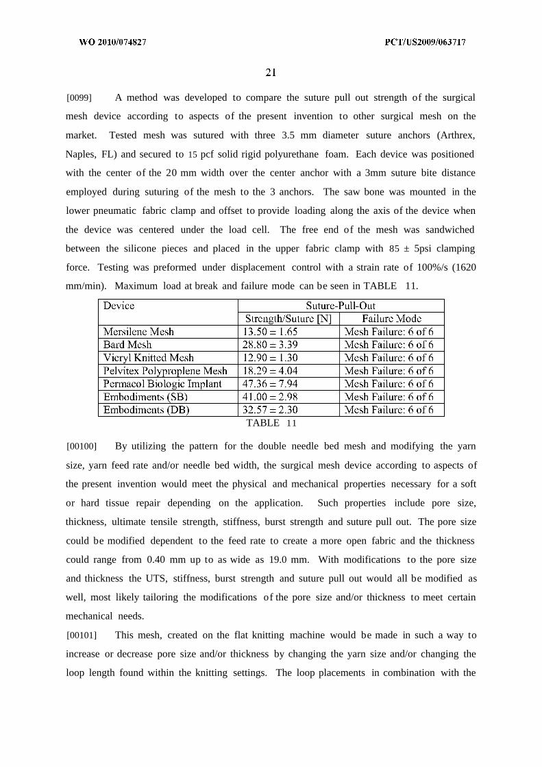
hinders any in-growth and increases the chance of infection, sinus tract formation, and
encapsulation of the mesh. Bacteria averaging 1 µm in size can hide in the small interstices
of the mesh and proliferate while protected from neutrophilic granulocytes averaging 10-
15 µm.
[0011] Other important physical characteristics for surgical mesh devices include
thickness, burst strength, and material stiffness. The thickness of surgical mesh devices vary
according to the particular repair procedure. For example, current surgical mesh device
hernia, pelvic floor dysfunction, and reconstructive/cosmetic procedures range in thickness
from approximately 0.635 mm to 1.1 mm. For rotator cuff repair, a thickness of 0.4 mm to
5 mm is typically employed.
[0012] Intra-abdominal pressures of 10-16 N, with a mean distension of 11-32% results
in the need for a surgical mesh with a burst strength that can resist the stress of the inner
abdomen before healthy tissue comes into being.
[0013] Material stiffness is an important mechanical characteristic for surgical mesh,
especially when used for pelvic floor dysfunction, because material stiffness has been
associated with the likelihood of tissue erosion. Surgical mesh devices formed from TVT,
IVS, Mersilene, Prolene, Gynemesh, Sparc tape, for example, currently have an ultimate
tensile strength (UTS) that exceeds the forces exerted by intra-abdominal pressures of 10-
16 N . With the low force in the abdomen, the initial stiffness of the material is an important
consideration. Moreover, the stiffness may exhibit non-linear behavior most likely due to
changes in the fabric structure, e.g., unraveling of the knit, weave, etc. A surgical mesh
device of lesser stiffness may help reduce tissue erosion and may conform to the contours of
the body more effectively.
SUMMARY OF THE INVENTION
[0014] In view of the disadvantages of current surgical mesh devices, there continues to
be a need for a surgical mesh that is biocompatible and absorbable, has the ability to
withstand the physiological stresses placed on the host collagen, and minimizes tissue
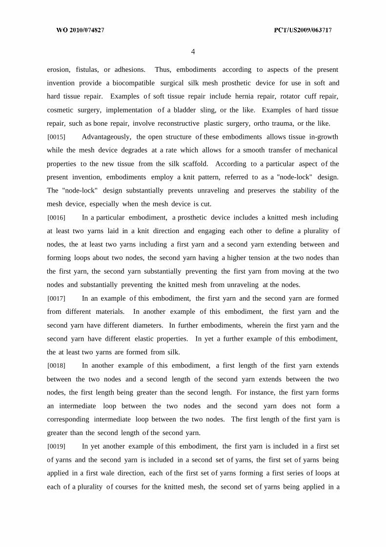
erosion, fistulas, or adhesions. Thus, embodiments according to aspects of the present
invention provide a biocompatible surgical silk mesh prosthetic device for use in soft and
hard tissue repair. Examples of soft tissue repair include hernia repair, rotator cuff repair,
cosmetic surgery, implementation of a bladder sling, or the like. Examples of hard tissue
repair, such as bone repair, involve reconstructive plastic surgery, ortho trauma, or the like.
[0015] Advantageously, the open structure of these embodiments allows tissue in-growth
while the mesh device degrades at a rate which allows for a smooth transfer of mechanical
properties to the new tissue from the silk scaffold. According to a particular aspect of the
present invention, embodiments employ a knit pattern, referred to as a "node-lock" design.
The "node-lock" design substantially prevents unraveling and preserves the stability of the
mesh device, especially when the mesh device is cut.
[0016] In a particular embodiment, a prosthetic device includes a knitted mesh including
at least two yarns laid in a knit direction and engaging each other to define a plurality of
nodes, the at least two yarns including a first yarn and a second yarn extending between and
forming loops about two nodes, the second yarn having a higher tension at the two nodes than
the first yarn, the second yarn substantially preventing the first yarn from moving at the two
nodes and substantially preventing the knitted mesh from unraveling at the nodes.
[0017] In an example of this embodiment, the first yarn and the second yarn are formed
from different materials. In another example of this embodiment, the first yarn and the
second yarn have different diameters. In further embodiments, wherein the first yarn and the
second yarn have different elastic properties. In yet a further example of this embodiment,
the at least two yarns are formed from silk.
[0018] In another example of this embodiment, a first length of the first yarn extends
between the two nodes and a second length of the second yarn extends between the two
nodes, the first length being greater than the second length. For instance, the first yarn forms
an intermediate loop between the two nodes and the second yarn does not form a
corresponding intermediate loop between the two nodes. The first length of the first yarn is
greater than the second length of the second yarn.
[0019] In yet another example of this embodiment, the first yarn is included in a first set
of yarns and the second yarn is included in a second set of yarns, the first set of yarns being
applied in a first wale direction, each of the first set of yarns forming a first series of loops at
each of a plurality of courses for the knitted mesh, the second set of yarns being applied in a

second wale direction, the second wale direction being opposite from the first wale direction,
each of the second set of yarns forming a second series of loops at every other of the plurality
of courses for the knitted mesh, the first set of yarns interlacing with the second set of yarns
at the every other course to define the nodes for the knitted mesh, the second set of yarns
having a greater tension than the first set of yarns, the difference in tension substantially
preventing the knitted mesh from unraveling at the nodes.
[0020] In a further example of this embodiment, the first yarn is included in a first set of
yarns and the second yarn is included in a second set of yarns, the first set of yarns and the
second set of yarns being alternately applied in a wale direction to form staggered loops, the
first set of yarns interlacing with the second set of yarns to define the nodes for the knitted
mesh, the alternating application of the first set of yarns and the second set of yarns causing
the first set of yarns to have different tensions relative to the second set of yarns at the nodes,
the difference in tension substantially preventing the knitted mesh from unraveling at the
nodes.
[0021] In yet a further example of this embodiment, the first yarn is included in a first set
of yarns and the second yarn is included in a second set of yarns, the first set of yarns forming
a series of jersey loops along each of a first set of courses for a knitted mesh, the second set
of yarns forming a second series of alternating tucked loops and jersey loops along each of a
second set of courses for the knitted mesh, the second set of courses alternating with the first
set of courses, the second set of yarns having a greater tension than the first set of yarns, the
tucked loops of the second set of yarns engaging the jersey loops of the first set of yarns to
define nodes for the knitted mesh, the tucked loops substantially preventing the knitted mesh
from unraveling at the nodes.
[0022] In another particular embodiment, a method for making a knitted mesh for a
prosthetic device, includes: applying a first set of yarns in a first wale direction on a single
needle bed machine, each of the first set of yarns forming a first series of loops at each of a
plurality of courses for a knitted mesh; applying a second set of yarns in a second wale
direction on the single needle bed machine, the second wale direction being opposite from the
first wale direction, each of the second set of yarns forming a second series of loops at every
other of the plurality of courses for the knitted mesh; and applying a third set of yarns in
every predetermined number of courses for the knitted mesh, the application of the third set
of yarns defining openings in the knitted mesh, wherein the first set of yarns interlaces with
the second set of yarns at the every other course to define nodes for the knitted mesh, and the
second set of yarns has a greater tension than the first set of yarns, the difference in tension
substantially preventing the knitted mesh from unraveling at the nodes.
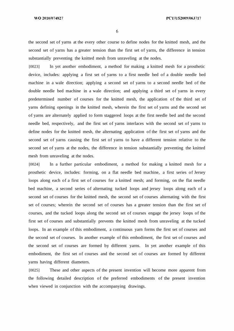
[0023] In yet another embodiment, a method for making a knitted mesh for a prosthetic
device, includes: applying a first set of yarns to a first needle bed of a double needle bed
machine in a wale direction; applying a second set of yarns to a second needle bed of the
double needle bed machine in a wale direction; and applying a third set of yarns in every
predetermined number of courses for the knitted mesh, the application of the third set of
yarns defining openings in the knitted mesh, wherein the first set of yarns and the second set
of yarns are alternately applied to form staggered loops at the first needle bed and the second
needle bed, respectively, and the first set of yarns interlaces with the second set of yarns to
define nodes for the knitted mesh, the alternating application of the first set of yarns and the
second set of yarns causing the first set of yarns to have a different tension relative to the
second set of yarns at the nodes, the difference in tension substantially preventing the knitted
mesh from unraveling at the nodes.
[0024] In a further particular embodiment, a method for making a knitted mesh for a
prosthetic device, includes: forming, on a flat needle bed machine, a first series of Jersey
loops along each of a first set of courses for a knitted mesh; and forming, on the flat needle
bed machine, a second series of alternating tucked loops and jersey loops along each of a
second set of courses for the knitted mesh, the second set of courses alternating with the first
set of courses; wherein the second set of courses has a greater tension than the first set of
courses, and the tucked loops along the second set of courses engage the jersey loops of the
first set of courses and substantially prevents the knitted mesh from unraveling at the tucked
loops. In an example of this embodiment, a continuous yarn forms the first set of courses and
the second set of courses. In another example of this embodiment, the first set of courses and
the second set of courses are formed by different yarns. In yet another example of this
embodiment, the first set of courses and the second set of courses are formed by different
yarns having different diameters.
[0025] These and other aspects of the present invention will become more apparent from
the following detailed description of the preferred embodiments of the present invention
when viewed in conjunction with the accompanying drawings.

BRIEF DESCRIPTION OF THE DRAWINGS
[0026] FIG. IA illustrates the technical back of an example mesh produced on a single
needle bed warp knitting machine according to aspects of the present invention.
[0027] FIG. IB illustrates the technical front of the example mesh illustrated in FIG. IA.
[0028] FIG. 2 illustrates an example mesh produced on a double needle bed warp knitting
machine according to aspects of the present invention.
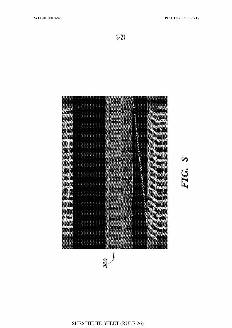
[0029] FIG. 3 illustrates an example mesh produced with single filament silk yarn
according to aspects of the present invention.
[0030] FIG. 4 illustrates an example mesh produced on a single needle bed warp knitting
machine according to aspects of the present invention.
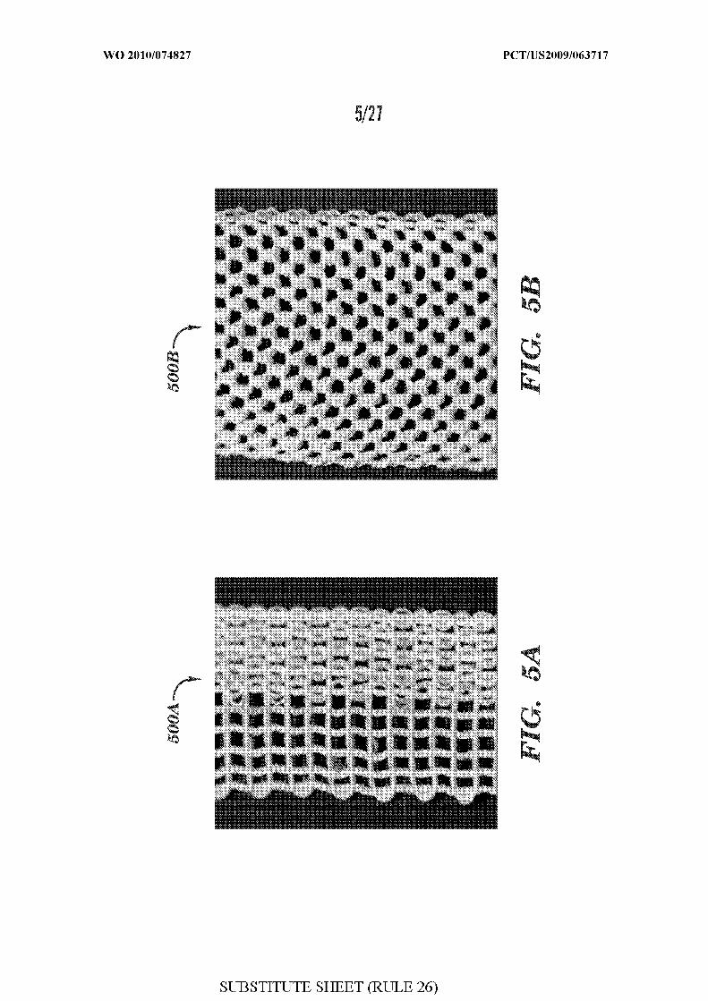
[0031] FIG. 5A illustrates an example mesh produced on a double needle bed warp
knitting machine, the example mesh having a parallelepiped pore with a section
demonstrating a plush design according to aspects of the present invention.
[0032] FIG. 5B illustrates an example mesh produced on a double needle bed warp
knitting machine, the example mesh having a hexagonal pore according to aspects of the
present invention.
[0033] FIG. 6 illustrates example narrow mesh fabrics of varying stitch densities
incorporating a plush variation according to aspects of the present invention.
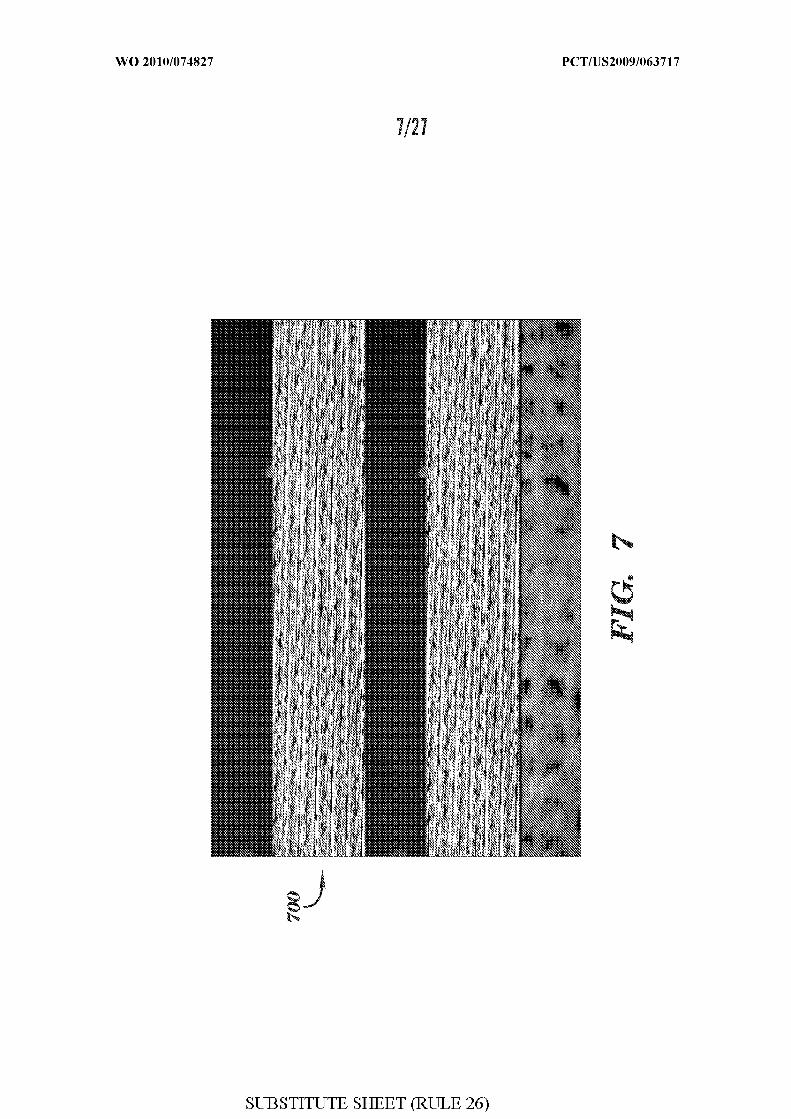
[0034] FIG. 7 illustrates an example mesh incorporating loop pile according to aspects of
the present invention.
[0035] FIG. 8 illustrates an example narrow mesh fabric with pore design achieved
through variation in the yarn feed rate according to aspects of the present invention.
[0036] FIG. 9A illustrates an example collapsed mesh fabric with hexagonal shaped pores
according to aspects of the present invention.
[0037] FIG. 9B illustrates an example opened mesh fabric with hexagonal shaped pores
according to aspects of the present invention.
[0038] FIG. 10 illustrates an example of a stable, non-collapsible, hexagonal-shaped
porous mesh fabric according to aspects of the present invention.
[0039] FIG. H A illustrates an example of a three-dimensional mesh with the same
technical front and technical back according to aspects of the present invention.

[0040] FIG. H B illustrates the 2.55 mm thickness of the example three-dimensional
mesh of FIG. HA.
[0041] FIG. 12 illustrates an example of a three-dimensional mesh with a thickness of
3.28 mm according to aspects of the present invention.
[0042] FIG. 13A illustrates the technical front of an example non-porous mesh according
to aspects of the present invention.
[0043] FIG. 13B illustrates the technical back of the example non-porous mesh of FIG.
13A.
[0044] FIG. 13C illustrates the 5.87 mm thickness of the example non-porous mesh of
FIG. 13A.
[0045] FIG. 14A illustrates an example of a three-dimensional mesh with the same
technical front and technical back according to aspects of the present invention.
[0046] FIG. 14B illustrates the 5.36 mm thickness of the example three-dimensional
mesh of FIG. 14A.
[0047] FIG. 15A illustrates the technical front of an example three-dimensional mesh
fabric according to aspects of the present invention.
[0048] FIG. 15B illustrates the technical back of the example three-dimensional mesh
fabric of FIG. 15A.
[0049] FIG. 16 illustrates an example mesh produced on a double needle bed weft
knitting machine demonstrating shaping of the mesh for a breast support application
according to aspects of the present invention.
[0050] FIGS. 17 illustrates another example mesh produced on a double needle bed weft
knitting machine demonstrating shaping of the mesh for a breast support application
according to aspects of the present invention.
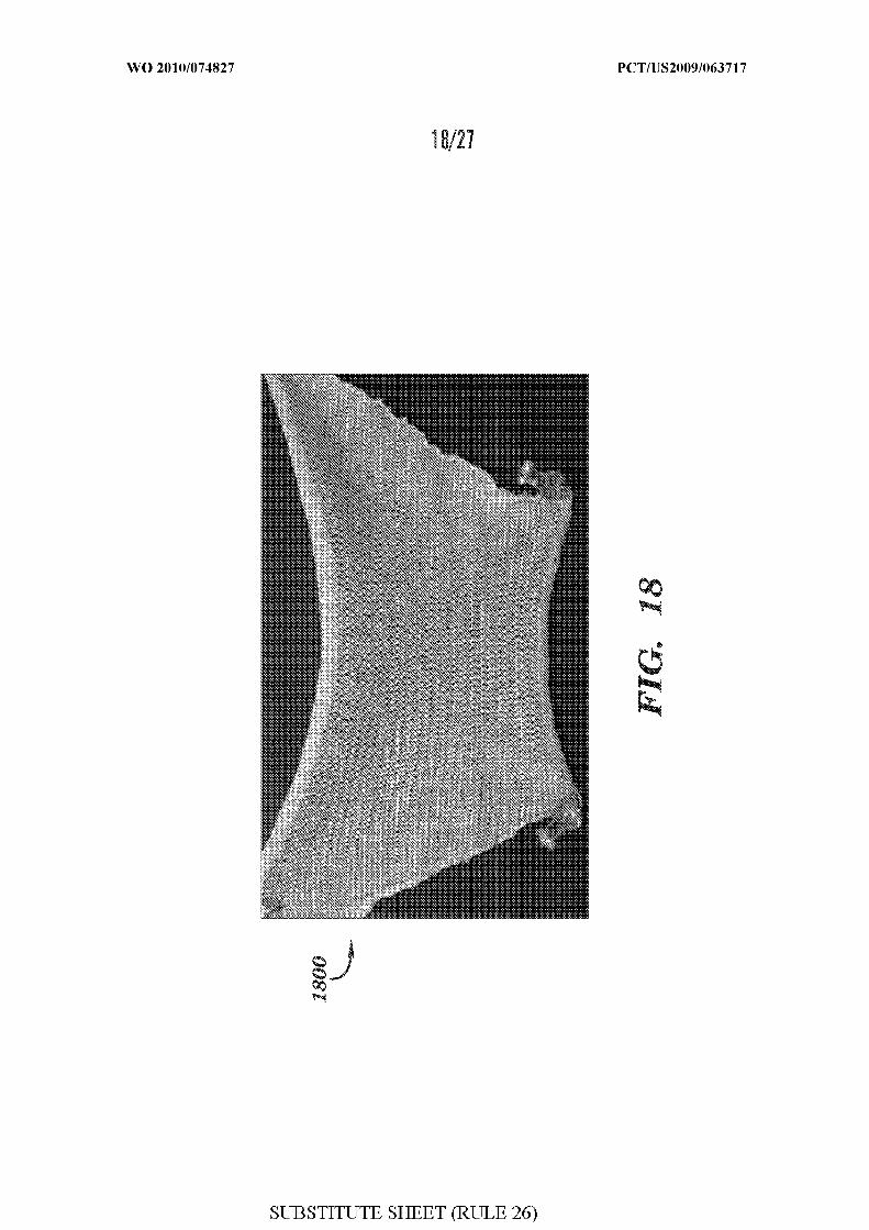
[0051] FIG. 18 illustrates yet another example mesh produced on a double needle bed
weft knitting machine demonstrating shaping of the mesh for a breast support application
according to aspects of the present invention.
[0052] FIG. 19 illustrates a further mesh produced on a double needle bed weft knitting
machine demonstrating shaping of the mesh for a breast support application according to
aspects of the present invention.

[0053] FIG. 20 illustrates another example mesh produced on a double needle bed weft
knitting machine demonstrating shaping of the mesh for a breast support application
according to aspects of the present invention.
[0054] FIG. 2 1A illustrates a full-thickness rat abdominal defect created using a custom
designed 1-cm stainless steel punch, the defect appearing oval in shape due to body wall
tension applied.
[0055] FIG. 2 IB illustrates a 4 cm x 4 cm example implant centered on top of the open
defect of FIG. 2 IA, and held in place with single interrupted polypropylene sutures (arrow)
through the implant and muscle.
[0056] FIG. 21C illustrates an explanted specimen 94 days post implantation as shown in
FIG. 21B.
[0057] FIG. 2 ID illustrates ball burst testing performed with a 1-cm diameter ball pushed
through the defect site reinforced with the mesh according to aspects of the present invention.
[0058] FIG. 22 illustrates an example pattern layout for a single needle bed mesh
according to aspects of the present invention.
[0059] FIG. 23 illustrates an example pattern layout for a single needle bed mesh
according to aspects of the present invention.
[0060] FIG. 24 illustrates an example pattern layout for a single needle bed mesh
according to aspects of the present invention.
[0061] FIG. 25 illustrates an example pattern layout for the single needle bed mesh
according to aspects of the present invention..
[0062] FIG. 26 illustrates an example pattern layout of the double needle bed mesh
according to aspects of the present invention.
[0063] FIG. 27 illustrates an example pattern layout for the double needle bed weft
knitting machine according to aspects of the present invention.
DETAILED DESCRIPTION
[0064] Embodiments according to aspects of the present invention provide a
biocompatible surgical silk mesh device for use in soft or hard tissue repair. Examples of soft
tissue repair include hernia repair, rotator cuff repair, cosmetic surgery, implementation of a
bladder sling, or the like. Examples of hard tissue repair, such as bone repair, involve
reconstructive plastic surgery, ortho trauma, or the like.

[0065] Advantageously, the open structure of these embodiments allows tissue in-growth
while the mesh bioresorbs at a rate which allows for a smooth transfer of mechanical
properties to the new tissue from the silk scaffold. Furthermore, embodiments employ a knit
pattern that substantially prevents unraveling, especially when the mesh device is cut. In
particular, embodiments may preserve the stability of the mesh device by employing a knit
pattern that takes advantage of variations in tension between at least two yarns laid in a knit
direction. For example, a first yarn and a second yarn may be laid in a knit direction to form
"nodes" for a mesh device. The knit direction for the at least two yarns, for example, may be
vertical during warp knitting or horizontal during weft knitting. The nodes of a mesh device,
also known as intermesh loops, refer to intersections in the mesh device where the two yarns
form a loop around a knitting needle. In some embodiments, the first yarn is applied to
include greater slack than the second yarn, so that, when a load is applied to the mesh device,
the first yarn is under a lower tension than the second device. A load that places the at least
two yarns under tension may result, for example, when the mesh device is sutured or if there
is pulling on the mesh device. The slack in the first yarn causes the first yarn to be
effectively larger in diameter than the second yarn, so that the first yarn experiences greater
factional contact with the second yarn at a node and cannot move, or is "locked," relative to
the second yarn. Accordingly, this particular knit design may be referred to as a "node-lock"
design.
[0066] In general, node-lock designs according to aspects of the present invention employ
at least two yarns under different tensions, where a higher tension yarn restricts a lower
tension yarn at the mesh nodes. To achieve variations in tension between yarns, other node-
lock designs may vary the yarn diameter, the yarn materials, the yarn elastic properties,
and/or the knit pattern. For example, the knit pattern described previously applies yarns in
varying lengths to create slack in some yarns so that they experience less tension. Because
the lower tension yarn is restricted by the higher tension yarn, node-lock designs substantially
prevent unraveling of the mesh when the mesh is cut. As such, the embodiments allow the
mesh device to be cut to any shape or size while maintaining the stability of the mesh device.
In addition, node-lock designs provide a stability that makes it easy to pass the mesh device
through a cannula for laparoscopic or arthroscopic surgeries without damaging the material.
[0067] Although the node-lock design may employ a variety of polymer materials, a
mesh device using silk according to aspects of the present invention can bioresorb at a rate

sufficient to allow tissue in-growth while slowly transferring the load-bearing responsibility
to the native tissue. Particular embodiments may be formed from Bombyx mori silkworm
silk fibroin. The raw silk fibers have a natural globular protein coating known as sericin,
which may have antigenic properties and must be depleted before implantation. Accordingly,
the yarn is taken through a deplation process. The deplation of sericin is further described,
for example, by Gregory H. Altman et al, "Silk matrix for tissue engineered anterior cruciate
ligaments," Biomaterials 23 (2002), pp. 4131-4141, the contents of which are incorporated
herein by reference. As a result, the silk material used in the device embodiments contains
substantially no sensitizing agents, in so far as can be measured or predicted with
standardized biomaterials test methods.
[0068] A surgical mesh device according to aspects of the present invention may be
created on a single needle bed Comez Acotronic/600- F or a Comez 410 ACO by the use of
three movements as shown in the pattern layout 2200 in FIG. 22: two movements in the wale
direction, the vertical direction within the fabric, and one in the course direction, the
horizontal direction of the fabric. The movements in the wale direction go in opposing
directions; a first yarn moving in one direction loops every course while the second yarn
moving in the opposite direction loops every other course. The yarns follow a repeated
pattern of 3-1 and 1-1/1-3 on a 20 gauge knitting machine, using only half of the needles
available on the needle bed. The interlacing of the loops within the fabric allow for one yarn
to become under more tension than the other under stress, locking it around the less tensioned
yarn; keeping the fabric from unraveling when cut. The other movement within the fabric
occurs in every few courses creating the openings in the mesh. These yarns follow a pattern
of 1-9/9-7/7-9/9-1/1-3/3-1. These yarns create tension within the fabric when under stress,
locking the yarns in the fabric; preventing the fabric from unraveling.
[0069] A surgical mesh device according to aspects of the present invention may be
created on a double needle bed Comez DNB/EL-800- 8B knitting machine by the use of three
movements as shown in the pattern layout 2600 in FIG. 26: two movements in the wale
direction and one in the course direction. The two movements in the wale direction occur on
separate needle beds with alternate yarns; loops that occur in every course movement are
staggered within the repeat. The yarns follow a repeated pattern of 3-1/1 - 1/1-3/3-3 and 1-
1/1-3/3-3/3-1. The third movement happens with the yarn that traverses the width of the
fabric. The yarn follows the pattern 9-9/9-9/7-7/9-9/7-7/9-9/1-1/1-1/3-3/1-1/3-3/1-1. This
fabric is also made at half gauge on a 20 gauge knitting machine and prevents unraveling due
to the tension created between the yarns when stressed. The repeat the yarn follows within
the pattern is illustrated in FIG. 26.
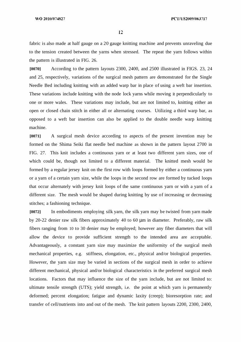
[0070] According to the pattern layouts 2300, 2400, and 2500 illustrated in FIGS. 23, 24
and 25, respectively, variations of the surgical mesh pattern are demonstrated for the Single
Needle Bed including knitting with an added warp bar in place of using a weft bar insertion.
These variations include knitting with the node lock yarns while moving it perpendicularly to
one or more wales. These variations may include, but are not limited to, knitting either an
open or closed chain stitch in either all or alternating courses. Utilizing a third warp bar, as
opposed to a weft bar insertion can also be applied to the double needle warp knitting
machine.
[0071] A surgical mesh device according to aspects of the present invention may be
formed on the Shima Seiki flat needle bed machine as shown in the pattern layout 2700 in
FIG. 27. This knit includes a continuous yarn or at least two different yarn sizes, one of
which could be, though not limited to a different material. The knitted mesh would be
formed by a regular jersey knit on the first row with loops formed by either a continuous yarn
or a yarn of a certain yarn size, while the loops in the second row are formed by tucked loops
that occur alternately with jersey knit loops of the same continuous yarn or with a yarn of a
different size. The mesh would be shaped during knitting by use of increasing or decreasing
stitches; a fashioning technique.
[0072] In embodiments employing silk yarn, the silk yarn may be twisted from yarn made
by 20-22 denier raw silk fibers approximately 40 to 60 µm in diameter. Preferably, raw silk
fibers ranging from 10 to 30 denier may be employed; however any fiber diameters that will
allow the device to provide sufficient strength to the intended area are acceptable.
Advantageously, a constant yarn size may maximize the uniformity of the surgical mesh
mechanical properties, e.g. stiffness, elongation, etc., physical and/or biological properties.
However, the yarn size may be varied in sections of the surgical mesh in order to achieve
different mechanical, physical and/or biological characteristics in the preferred surgical mesh
locations. Factors that may influence the size of the yarn include, but are not limited to:
ultimate tensile strength (UTS); yield strength, i.e. the point at which yarn is permanently
deformed; percent elongation; fatigue and dynamic laxity (creep); bioresorption rate; and
transfer of cell/nutrients into and out of the mesh. The knit pattern layouts 2200, 2300, 2400,

2500, and 2600 illustrated in FIGS. 22-26, respectively, may be knitted to any width limited
by the knitting machine width and could be knitted with any of the gauges available with the
various crochet machine or warp knitting machine. TABLE 2 outlines the fabric widths that
may be achieved using different numbers of needles on different gauge machines. It is
understood that the dimensions in TABLE 1 are approximate due to the shrink factor which
depends on stitch design, stitch density, and yarn size used.
TABLE 1
[0073] Embodiments of a prosthetic device according to the present invention may be
knitted on a fine gauge crochet knitting machine. A non-limiting list of crochet machines
capable of manufacturing the surgical mesh according to aspects of the present invention are
provided by: Changde Textile Machinery Co., Ltd.; Comez; China Textile Machinery Co.,
Ltd.; Huibang Machine; Jakkob Muller AG; Jingwei Textile Machinery Co., Ltd.; Zhejiang
Jingyi Textile Machinery Co., Ltd.; Dongguan Kyang Yhe Delicate Machine Co., Ltd.; Karl
Mayer; Sanfang Machine; Sino Techfull; Suzhou Huilong Textile Machinary Co., Ltd.;
Taiwan Giu Chun Ind. Co., Ltd.; Zhangjiagang Victor Textile; Liba; Lucas; Muller Frick;
and Texma.
[0074] Embodiments of a prosthetic device according to the present invention may be
knitted on a fine gauge warp knitting machine. A non- limiting list of warp knitting machines
capable of manufacturing the surgical mesh according to aspects of the present invention are
provided by: Comez; Diba; Jingwei Textile Machinery; Liba; Lucas; Karl Mayer; Muller
Frick; Runyuan Warp Knitting; Taiwan Giu Chun Ind.; Fujian Xingang Textile Machinery;
and Yuejian Group.
[0075] Embodiments of a prosthetic device according to the present invention may be
knitted on a fine gauge flat bed knitting machine. A non-limiting list of flat bed machines
capable of manufacturing the surgical mesh according to aspects of the present invention are
provided by: Around Star; Boosan; Cixing Textile Machine; Fengshen; Flying Tiger
Machinary; Fujian Hongqi; G & P; Gόrteks; Jinlong; JP; Jy Leh; Kauo Heng Co., Ltd.;
Matsuya; Nan Sing Machinery Limited; Nantong Sansi Instrument; Shima Seiki; Nantong
Tianyuan; and Ningbo Yuren Knitting.
[0076] FIGS. 1-20 illustrate example meshes produced according to aspects of the present
invention. Referring to FIGS. IA and B, an example mesh 100 is produced on a single
needle bed warp knitting machine according to aspects of the present invention. FIG. IA
shows the technical back IOOA of the mesh 100, and FIG. IB shows the technical front IOOB
of the mesh 100.
[0077] Referring to FIGS. 2A and B, an example mesh 200 is produced on a double
needle bed warp knitting machine according to aspects of the present invention. FIG. 2A
shows the technical front 200A of the mesh 200, and FIG. 2B shows the technical back 200B
of the mesh 200.
[0078] FIG. 3 illustrates an example mesh 300 produced with single filament silk yarn
according to aspects of the present invention.
[0079] FIG. 4 shows an example mesh 400 produced on a single needle bed warp knitting
machine according to aspects of the present invention.
[0080] FIG. 5A illustrates an example mesh 500A produced on a double needle bed warp
knitting machine. The mesh 500A has a parallelepiped pore with a section demonstrating a
plush design according to aspects of the present invention. Meanwhile, FIG. 5B illustrates an
example mesh 500B produced on a double needle bed warp knitting machine. The example
mesh 500B has a hexagonal pore according to aspects of the present invention.
[0081] FIGS. 6A and B illustrate example narrow mesh fabrics 600A and 600B according
to aspects of the present invention. The mesh fabrics 600A and 600B have varying stitch
densities incorporating a plush variation.
[0082] Referring to FIG. 7, an example mesh 700 incorporates loop pile according to
aspects of the present invention. FIG. 8 illustrates an example narrow mesh fabric 800 with
pore design achieved through variation in the yarn feed rate according to aspects of the
present invention.
[0083] FIG. 9A illustrates an example collapsed mesh fabric 900A with hexagonal-
shaped pores according to aspects of the present invention. Meanwhile, FIG. 9B illustrates

an example opened mesh fabric 900B with hexagonal shaped pores according to aspects of
the present invention.
[0084] As shown in FIG. 10, an example of a stable, non-collapsible mesh fabric 1000
includes hexagonal- shaped pores according to aspects of the present invention.
[0085] FIG. H A illustrate an example three-dimensional mesh 1100 with the same
technical front and technical back according to aspects of the present invention. FIG. H B
illustrates the 2.55 mm thickness of the three-dimensional mesh 1100. FIG. 12 illustrates
another example three-dimensional mesh 1200 with a thickness of 3.28 mm according to
aspects of the present invention.
[0086] FIGS. 13A-C illustrate an example non-porous mesh 1300 according to aspects of
the present invention. FIG. 13A shows the technical front 1300A of the non-porous mesh
1300. FIG. 13B shows the technical back 1300B of the non-porous mesh 1300. FIG. 13C
shows that non-porous mesh 1300 has a thickness of 5.87 mm.
[0087] FIG. 14A illustrates an example three-dimensional mesh 1400 with the same
technical front and technical back according to aspects of the present invention. FIG. 14B
shows that the three-dimensional mesh 1400 has a thickness of approximately 5.36 mm.
FIGS. 15A and B illustrate another example three-dimensional mesh fabric 1500 according to
aspects of the present invention. FIG. 15A shows the technical front 1500A of the fabric
1500, and FIG. 15B illustrates the technical back 1500B of the fabric 1500.
[0088] FIGS. 16-20 illustrate respective example meshes 1600, 1700, 1800, 1900, and
2000 that are produced on a double needle bed weft knitting machine. The meshes 1600,
1700, 1800, 1900, and 2000 demonstrate shaping of a mesh for a breast support application
according to aspects of the present invention.
[0089] A test method was developed to check the cutability of the surgical mesh formed
according to aspects of the present invention. In the test method, the surgical mesh evaluated
according to the number of were needed to cut the mesh with surgical scissors. The mesh
was found to cut excellently because it took one scissor stroke to cut through it. The mesh
was also cut diagonally and in circular patterns to determine how easily the mesh unraveled
and how mush it unraveled once cut. The mesh did not unravel more than one mode after
being cut in both directions. To determine further if the mesh would unravel, a suture, was
passed through the closest pore from the cut edge, and pulled. This manipulation did not

unravel the mesh. Thus, the surgical mesh is easy to cut and does not unravel after
manipulation.
[0090] Embodiments may be processed with a surface treatment, which increases
material hydrophilicity, biocompatibility, physical, and mechanical properties such as
handling for ease of cutting and graft pull-through, as well as anti-microbial and anti- fungal
coatings. Specific examples of surface treatments include, but are not limited to:
• plasma modification• protein such as but not limited to fibronectin, denatured collagen or gelatin,
collagen gels and hydrophobin by covalent link or other chemical or physicalmethod
• peptides with hydrophilic and a hydrophobic end• peptides contain one silk-binding sequence and one biologically active
sequence - biodegradable cellulose• surface sulfonation• ozone gas treatment• physically bound and chemically stabilized peptides• DNA/RNA aptamers• Peptide Nucleic Acids• Avimers• modified and unmodified polysaccharide coatings• carbohydrate coating• anti-microbial coatings• anti-fungal coatings• phosphorylcholine coatings
[0091] A method to evaluate the ease of delivery through a cannula was done to make
sure the surgical mesh could be used laparoscopically. Various lengths were rolled up and
pushed through two different standard sized cannulas using surgical graspers. The mesh was
then evaluated to determine if there was any damage done to the mesh. The mesh that was
put through the cannulas was found to have slight distortion to the corner that was held by the
grasper. The 16 cm and 18 cm lengths of mesh that were rolled up and pushed through the 8
mm cannula had minimal fraying and one distorted pore, respectively. It was also found that
no damage was done to the cannula or septum in any of the tests. It was found that
appropriately sized surgical mesh will successfully pass through a laparoscopic cannula
without damage, enabling its effective use during laparoscopic procedures.
[0092] A surgical mesh device according to aspects of the present invention has been
found to bio-resorb by 50% in approximately 100 days. In a study by Horan et al, Sprague-
Dawley rats were used to compare the bio-resorption of embodiments according to the
present invention to Mersilene™ mesh (Ethicon, Somerville, NJ). The histology reports from

the article state that after 94 days, 43% of the initial mesh of the embodiments remained
compared to 96% of the Mersilene™ mesh. It was also reported that the in growth was more
uniform with the mesh of embodiments than the Mersilene™ mesh. The Mersilene™ was
found to have less in growth in the defect region than along the abdominal wall.
[0093] Physical properties include thickness, density and pore sizes. The thickness was
measured utilizing a JlOO Kafer Dial Thickness Gauge. A Mitutoyo Digimatic Caliper was
used to find the length and width of the samples; used to calculate the density. The density
was found by multiplying the length, width and thickness of the mesh then dividing the
resulting value by the mass. The pore size was found by photographing the mesh with an
Olympus SZX7 Dissection Microscope under 0.8x magnification. The measurements were
taken using ImagePro 5.1 software and the values were averaged over several measurements.
The physical characteristics of the sample meshes, including embodiments according to the
present invention, are provided in TABLE 2 .
TABLE 2
[0094] All devices were cut to the dimensions specified in TABLE 3, for each type of
mechanical analysis. Samples were incubated in phosphate buffered saline (PBS) for 3 ±
1.25 hours at 37 ± 2 0C prior to mechanical analysis to provide characteristics in a wet
environment. Samples were removed from solution and immediately tested.
TABLE 3

[0095] Ball burst test samples were scaled down due to limitations in material
dimensions. The test fixture employed was a scaled (1:2.5) version of that recommended by
ASTM Standard D3787. The samples were centered within a fixture and burst with a 10mm
diameter ball traveling at a displacement rate of 60 mm/min. Maximum stress and stiffness
were determined from the burst test. Results can be seen in TABLE 4 .
TABLE 4
[0096] Tensile tests were preformed along the fabric formation and width axes of each
device. A lcm length of mesh on each end of the device was sandwiched between pieces of
3.0mm thick silicone sheet and mounted in pneumatic fabric clamps with a clamping pressure
of 70-85psi. Samples were loaded through displacement controlled testing at a strain rate of
100%/s (2400mm/min) and or 67%/s (1600mm/min) until failure. The ultimate tensile
strength (UTS), linear stiffness and percent elongation at break can be seen in the following
tables. Results can be found in TABLES 5-8. An entry of "NT" indicates that the data has
not yet been tested.
TABLE 5

TABLE 6
TABLE 7

TABLE 8
[0097] Tear Strength was found through a method that entailed cutting a 10 mm "tear"
into the edge, perpendicular to the long axis edge and centered along the length of the mesh.
The mesh was mounted in pneumatic fabric clamps as previously described in the tensile
testing methods. Samples were loaded through displacement controlled testing at a strain rate
of 100%/s (2400mm/min) until failure. The load at failure and the mode of failure are shown
in TABLE 9 .
TABLE 9
[0098] Tensile fatigue testing was preformed on the surgical mesh device according to
aspects of the present invention and representative predicate types including Vicryl Mesh and
Bard Mesh. Samples were loaded into the pneumatic fabric clamps as previously described
in the tensile testing methods above. Samples were submerged in PBS at room temperature
during cycling. Sinusoidal load controlled cycling was preformed to 60% of mesh ultimate
tensile strength. Number of cycles to failure was determined during the cyclic studies and
can be seen in TABLE 10, where failure was indicated by fracture or permanent deformation
in excess of 200%.
TABLE 10
[0099] A method was developed to compare the suture pull out strength of the surgical
mesh device according to aspects of the present invention to other surgical mesh on the
market. Tested mesh was sutured with three 3.5 mm diameter suture anchors (Arthrex,
Naples, FL) and secured to 15 pcf solid rigid polyurethane foam. Each device was positioned
with the center of the 20 mm width over the center anchor with a 3mm suture bite distance
employed during suturing of the mesh to the 3 anchors. The saw bone was mounted in the
lower pneumatic fabric clamp and offset to provide loading along the axis of the device when
the device was centered under the load cell. The free end of the mesh was sandwiched
between the silicone pieces and placed in the upper fabric clamp with 85 ± 5psi clamping
force. Testing was preformed under displacement control with a strain rate of 100%/s (1620
mm/min). Maximum load at break and failure mode can be seen in TABLE 11.
TABLE 11
[00100] By utilizing the pattern for the double needle bed mesh and modifying the yarn
size, yarn feed rate and/or needle bed width, the surgical mesh device according to aspects of
the present invention would meet the physical and mechanical properties necessary for a soft
or hard tissue repair depending on the application. Such properties include pore size,
thickness, ultimate tensile strength, stiffness, burst strength and suture pull out. The pore size
could be modified dependent to the feed rate to create a more open fabric and the thickness
could range from 0.40 mm up to as wide as 19.0 mm. With modifications to the pore size
and thickness the UTS, stiffness, burst strength and suture pull out would all be modified as
well, most likely tailoring the modifications of the pore size and/or thickness to meet certain
mechanical needs.
[00101] This mesh, created on the flat knitting machine would be made in such a way to
increase or decrease pore size and/or thickness by changing the yarn size and/or changing the
loop length found within the knitting settings. The loop placements in combination with the
node lock design allow changes to the shape and/or to the mechanical properties of the mesh.
A biocompatible yarn with elasticity, such as highly twisted silk, could be used for shaping.
[00102] The implantation of a mesh and subsequent testing according to aspects of the
present invention is illustrated in FIGS. 2 IA-D. FIG. 2 1A illustrates a full-thickness rat
abdominal defect created using a custom designed 1-cm stainless steel punch. The defect
appears oval in shape due to body wall tension applied. FIG. 2 IB illustrates a 4 cm x 4 cm
implant centered on top of the open defect, and held in place with single interrupted
polypropylene sutures (arrow) through the implant and muscle. FIG. 21C illustrates an
explanted specimen 94 days post implantation. FIG. 2 ID illustrates ball burst testing
performed with a 1-cm diameter ball pushed through the defect site reinforced with the mesh.
[00103] While the present invention has been described in connection with a number of
exemplary embodiments, and implementations, the present inventions are not so limited, but
rather cover various modifications, and equivalent arrangements. For example, a knitted
mesh according to aspects of the present invention may be used for a filler material. In one
application, the knitted mesh may be cut into 1 mm x 1 mm sections to separate one or more
nodes, e.g., 3 nodes. The sections may be added to fat tissue or a hydro-gel to form a solution
that can be injected into a defective area. Advantageously, the filler material may provide a
desired texture, but will not unravel.

WHAT IS CLAIMED IS:
1. A prosthetic device comprising:
a knitted mesh including at least two yarns laid in a knit direction and engaging each
other to define a plurality of nodes, the at least two yarns including a first yarn and a second
yarn extending between two nodes, the second yarn having a higher tension at the two nodes
than the first yarn, the second yarn substantially preventing the first yarn from moving at the
two nodes and substantially preventing the knitted mesh from unraveling at the nodes.
2 . The prosthetic device of claim 1, wherein the first yarn and the second yarn are
formed from different materials.
3. The prosthetic device of claim 1, wherein the first yarn and the second yarn have
different diameters.
4 . The prosthetic device of claim 1, wherein the first yarn and the second yarn have
different elastic properties.
5 . The prosthetic device of claim 1, wherein a first length of the first yarn extends
between the two nodes and a second length of the second yarn extends between the two
nodes, the first length being greater than the second length.
6 . The prosthetic device of claim 5, wherein the first yarn forms an intermediate loop
between the two nodes and the second yarn does not form a corresponding intermediate loop
between the two nodes, the first length of the first yarn being greater than the second length
of the second yarn.
7 . The prosthetic device of claim 1, wherein the first yarn is included in a first set of
yarns and the second yarn is included in a second set of yarns, the first set of yarns being
applied in a first wale direction, each of the first set of yarns forming a first series of loops at
each of a plurality of courses for the knitted mesh, the second set of yarns being applied in a
second wale direction, the second wale direction being opposite from the first wale direction,
each of the second set of yarns forming a second series of loops at every other of the plurality
of courses for the knitted mesh, the first set of yarns interlacing with the second set of yarns
at the every other course to define the nodes for the knitted mesh, the second set of yarns

having a greater tension than the first set of yarns, the difference in tension substantially
preventing the knitted mesh from unraveling at the nodes.
8. The prosthetic device of claim 1, wherein the first yarn is included in a first set of
yarns and the second yarn is included in a second set of yarns, the first set of yarns and the
second set of yarns being alternately applied in a wale direction to form staggered loops, the
first set of yarns interlacing with the second set of yarns to define the nodes for the knitted
mesh, the alternating application of the first set of yarns and the second set of yarns causing
the first set of yarns to have different tensions relative to the second set of yarns at the nodes,
the difference in tension substantially preventing the knitted mesh from unraveling at the
nodes.
9 . The prosthetic device of claim 1, wherein the first yarn is included in a first set of
yarns and the second yarn is included in a second set of yarns, the first set of yarns forming a
series of jersey loops along each of a first set of courses for a knitted mesh, the second set of
yarns forming a second series of alternating tucked loops and jersey loops along each of a
second set of courses for the knitted mesh, the second set of courses alternating with the first
set of courses, the second set of yarns having a greater tension than the first set of yarns, the
tucked loops of the second set of yarns engaging the jersey loops of the first set of yarns to
define nodes for the knitted mesh, the tucked loops substantially preventing the knitted mesh
from unraveling at the nodes.
10. The prosthetic device of claim 1, wherein the at least two yarns are formed from silk.
11. The prosthetic device of claim 10, wherein the at least two yarns are approximately 20
to 1000 µm in diameter.
12. The prosthetic device of claim 1, wherein each of the at least two yarns is
substantially constant in diameter.
13. A method for making a knitted mesh for a prosthetic device, comprising:
applying a first set of yarns in a first wale direction on a single needle bed machine,
each of the first set of yarns forming a first series of loops at each of a plurality of courses for
a knitted mesh;

applying a second set of yarns in a second wale direction on the single needle bed
machine, the second wale direction being opposite from the first wale direction, each of the
second set of yarns forming a second series of loops at every other of the plurality of courses
for the knitted mesh; and
applying a third set of yarns in every predetermined number of courses for the knitted
mesh, the application of the third set of yarns defining openings in the knitted mesh,
wherein the first set of yarns interlaces with the second set of yarns at the every other
course to define nodes for the knitted mesh, and the second set of yarns has a greater tension
than the first set of yarns, the difference in tension substantially preventing the knitted mesh
from unraveling at the nodes.
14. The method of claim 13, wherein the first, second, and third sets of yarns are formed
from silk.
15. The method of claim 14, wherein the first, second, and third sets of yarn are
approximately 20 to 1000 µm in diameter.
16. The method of claim 13, wherein the first, second, and third sets of yarns have a
substantially constant diameter.
17. A method for making a knitted mesh for a prosthetic device, comprising:
applying a first set of yarns to a first needle bed of a double needle bed machine in a
wale direction;
applying a second set of yarns to a second needle bed of the double needle bed
machine in a wale direction; and
applying a third set of yarns in every predetermined number of courses for the knitted
mesh, the application of the third set of yarns defining openings in the knitted mesh,
wherein the first set of yarns and the second set of yarns are alternately applied to
form staggered loops at the first needle bed and the second needle bed, respectively, and the
first set of yarns interlaces with the second set of yarns to define nodes for the knitted mesh,
the alternating application of the first set of yarns and the second set of yarns causing the first
set of yarns to have a different tension relative to the second set of yarns at the nodes, the
difference in tension substantially preventing the knitted mesh from unraveling at the nodes.

18. The method of claim 17, wherein the first, second, and third sets of yarns are formed
from silk.
19. The method of claim 18, wherein the first, second, and third sets of yarn are
approximately 20 to 1000 µm in diameter.
20. The method of claim 17, wherein the first, second, and third sets of yarns have a
substantially constant diameter.
2 1. A method for making a knitted mesh for a prosthetic device, comprising:
forming, on a flat needle bed machine, a first series of jersey loops along each of a
first set of courses for a knitted mesh; and
forming, on the flat needle bed machine, a second series of alternating tucked loops
and jersey loops along each of a second set of courses for the knitted mesh, the second set of
courses alternating with the first set of courses;
wherein the second set of courses has a greater tension than the first set of courses,
and the tucked loops along the second set of courses engage the jersey loops of the first set of
courses and substantially prevents the knitted mesh from unraveling at the tucked loops.
22. The method of claim 21, wherein a continuous yarn forms the first set of courses and
the second set of courses.
23 . The method of claim 21, wherein the first set of courses and the second set of courses
are formed by different yarns.
24. The method of claim 23, wherein the first set of courses and the second set of courses
are formed by different yarns having different diameters.
25. The method of claim 13, wherein the knitted mesh is formed from silk.