Wireless chargeing on mobile phones using microwaves Seminar report
26
VISVESVARAYA TECHNOLOGICAL UNIVERSITY BELGAUM - 590018 KARNATAKA “Wireless Charging of Mobile Phone using Microwaves” A seminar report submitted in partial fulfillment of the requirement for the degree Of BACHELOR OF ENGINEERING In ELECTRONICS AND COMMUNICATION Submitted by GOURAB GHOSH 1DS09EC044 2013-2014 Department of Electronics and Communication Dayananda Sagar College of Engineering Bangalore – 560 078
Transcript of Wireless chargeing on mobile phones using microwaves Seminar report

VISVESVARAYA TECHNOLOGICAL UNIVERSITY BELGAUM - 590018
KARNATAKA
“Wireless Charging of Mobile Phone using Microwaves”
A seminar report submitted in partial fulfillment of the requirement for the degree
Of
BACHELOR OF ENGINEERINGIn
ELECTRONICS AND COMMUNICATION Submitted by
GOURAB GHOSH1DS09EC044
2013-2014
Department of Electronics and Communication Dayananda Sagar College of Engineering
Bangalore – 560 078
DAYANANDA SAGAR COLLEGE OF ENGINEERING Bangalore-560 078
DEPARTMENT OF ELECTRONICS AND COMMUNICATION
CERTIFICATE
2013-14
This is to certify that the seminar entitled “ Wireless Charging of
Mobile Phone using Microwaves” is a bonafide work carried out by Mr. GOURAB
GHOSH (1DS09EC044) in the partial fulfillment of the seminar in 8th semester
Bachelors of Engineering in Dayananda Sagar College of engineering of
Visvesvaraya Technological University (VTU), Belgaum for the year 2013-14. It is
certified that all corrections/suggestions indicated for internal assessment
have been incorporated in the report deposited in the department library. The
seminar report has been approved as it satisfies the academic in respect of the
seminar prescribed for the Bachelor Of Engineering degree.
Seminar Coordinator Signature
of HOD
Seminar In-charge:
1.
2.
ACKNOWLEDGEMENT
The Satisfaction that accompanies the successful completion of any
task would be incomplete without the mention of people who made it possible,
whose proper guidance and encouragement has served as a beacon light and
crowned my effect with success. I take an opportunity to thank all the
distinguished personalities for their enormous and precious guidance
throughout the duration of this seminar.
I express my deep sense of graduate to Dr. NETAJ S. GANESAN, principal,
Dayananda Sagar College of Engineering for providing an opportunity to do
this seminar as a part of my curriculum in the partial fulfillment of the
degree course.
I would like to thank Dr. GIRISH V. ATTIMARAD, HOD, Department of
Electronic and Communication Engineering, Dayananda Sagar College of
Engineering for his never ending co-operation and for providing us
resources and all the encouragement for the completion of my technical
seminar.

I thank my seminar coordinators SNEHA LATHA, Dr. GIRISH V. ATTIMARAD
Department of Electronic and Communication Engineering, Dayananda Sagar
College of Engineering for his valuable guidance and all the encouragement
leading us throughout the completion of my technical seminar.
I am indebted to all those who have directly or indirectly helped me in
bringing out this seminar satisfactorily in the specified duration.
GOURAB GHOSH (1DS09EC044)
ABSTRACT
Mobile Phones are part of our life. It is the fastest and the easiest medium
of communication. Battery life of mobile phone is always been a problem for
manufacturers. People are complaining about their mobile’s battery life,
that they don’t have long battery life and they have to charge their phone
several times. In this paper a new idea is shown to charge your mobile phone
anywhere you want without connecting its charger. This is done using
microwaves. Microwaves are the radio waves which provide communication
between two mobile phones. The microwave is sent with the message by the
transmitter using antenna at the frequency of 2.45GHz. Here we are using

Microwaves as the source of energy to charge the phone. We have to add a
sensor, a rectenna circuit and a filer in our mobile phone to do the job. By
adding these things we can charge our phone using microwave when we talk. So
as we talk more we can charge more!!
CONTENTS
1.INTRODUCTION…………………………………………………………………1

1.1 ELECTROMAGNETIC SPECTRUM……………...……………………….2
1.2 MICROWAVE REGION……………………………...……………………...2
2. WIRELESS POWER TRANSMISSION…………………...…………………....3
2.1 WIRELESS POWER TRANSMISSION SYSTEM…...………………….....3
2.2 COMPONENTS OF WIRELESS POWER TRANSMISSION SYSTEM....4
2.2.1 MICROWAVE GENERATOR………………………………………....4
2.2.2 TRANSMITTING ANTENNA……………………………………….....4
2.2.3 RECTENNA…………………………………………………………...…4
3. DESIGN OVERVIEW…………………………………………… …...…………..5
3.1 TRANSMITTER……………………………………………………………….6
3.2 ANTENNA……………………………………………………………………...7
3.3 RECEIVER & RECEIVER DESIGN…………………………………...…8-9
3.4 THE PROCESS OF RECTIFICATION……………………………………..9
3.5 SENSOR CIRCUITRY………………………………………………………..9
4. ADVANTAGES………………………………………………………………........11
5. DISADVANTAGES……………………………….......…………………………..11
6. CONCLUSION………………………………………...…………………………..12
7. REFERENCE…………………………………………...………………………....13

INTRODUCTION Portable electronic devices are very popular nowadays. As the usage of
these portable electronic devices is increasing, the demands for longer
battery life are also increasing. These batteries need to be recharged or
replaced periodically. It is a hassle to charge or change the battery after a
while, especially when there is no power outlet around. Therefore, our team is
inspired to design a wireless battery charger. This wireless battery charger
is expected to eliminate all the hassles with today’s battery technology.
As for now, there are no known companies that are developing the wireless
battery charger. This means that there might be a good opportunity in the
market for this type of product. Moreover, people tend to spend more money for
convenience that meets the price. The outlook of this device is supported by
the above predictions.
It would be convenient not having to worry about charging or changing the
batteries and still have a working device. The advantage of this device is that
it can wirelessly charge up the batteries which can save time and money in a
long run for the general public. Base on this concept, the design team has come
up with a new way to charge the batteries wirelessly. The project is to make a
prototype device that converts microwave signals to DC power. Once the
prototype has been proved to be working, it is possible to implement this
prototype into other applications such as in television remote control, fire
alarm, clock, and places that are far to reach to change battery.

<PAGE NO-1>1.1 Electromagnetic Spectrum
As we know that when light shone through the prism it is divided in all the colors
which we called rainbow, and technically it is called visible spectrum. So light
is made of photons. Photons are bundle of energy. Light is traveling at the speed
of 3,00,000 km/hr So when light hit an object coming on its way it actually rebound
from its surface. And it comes in to our eyes and we can see the object. But color of
the object is seen by us is depend how much amount of energy is rebound as photons
from the object. But some theory can’t be explained by taking the light as the
bunch of photos. So some physicians assume that it is some kind of wave. They
define an electromagnetic sanctum of different wave lengths which is divided in
two parts. One is electric field and the other is magnetic field.
1.2 Microwave Region
Microwaves are the Radio wave which has the wave length range of 1 cm to 1 meter.
And the frequency is 300MHz to 300GHz.Each and every object on the earth absorb
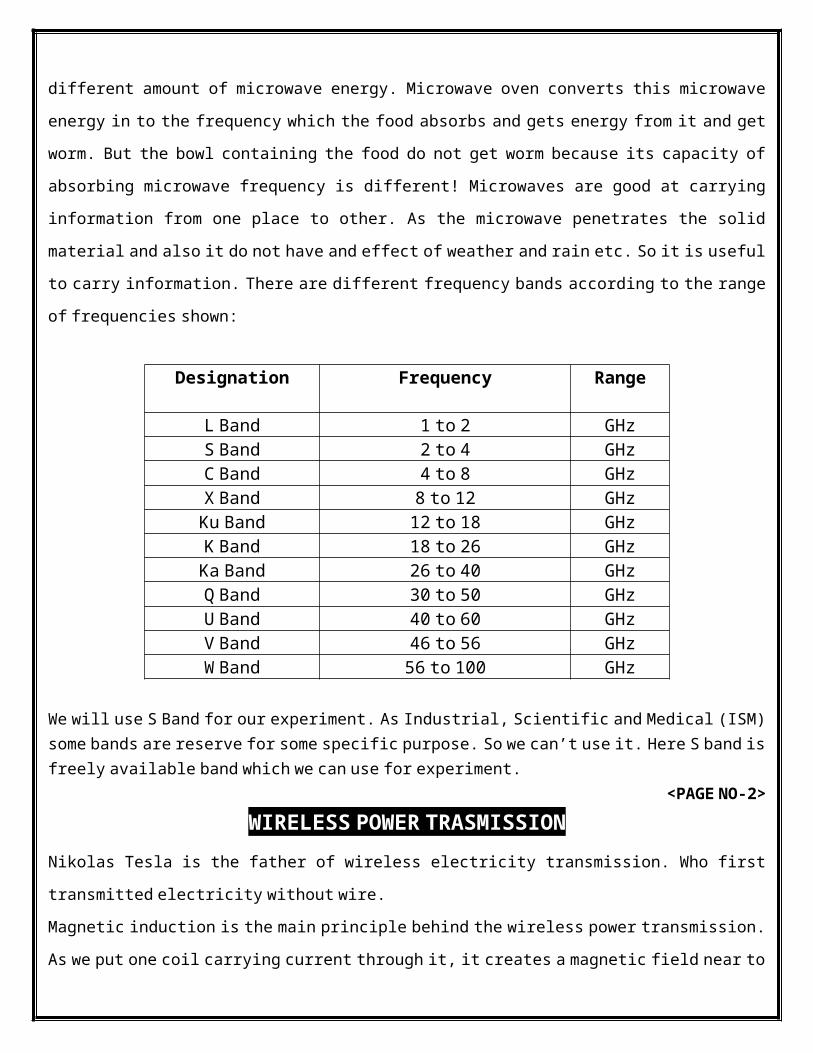
different amount of microwave energy. Microwave oven converts this microwave
energy in to the frequency which the food absorbs and gets energy from it and get
worm. But the bowl containing the food do not get worm because its capacity of
absorbing microwave frequency is different! Microwaves are good at carrying
information from one place to other. As the microwave penetrates the solid
material and also it do not have and effect of weather and rain etc. So it is useful
to carry information. There are different frequency bands according to the range
of frequencies shown:
We will use S Band for our experiment. As Industrial, Scientific and Medical (ISM) some bands are reserve for some specific purpose. So we can’t use it. Here S band is
freely available band which we can use for experiment. <PAGE NO-2>
WIRELESS POWER TRASMISSION Nikolas Tesla is the father of wireless electricity transmission. Who first
transmitted electricity without wire.
Magnetic induction is the main principle behind the wireless power transmission.
As we put one coil carrying current through it, it creates a magnetic field near to
Designation Frequency Range
L Band 1 to 2 GHz S Band 2 to 4 GHz C Band 4 to 8 GHz X Band 8 to 12 GHz Ku Band 12 to 18 GHz
K Band 18 to 26 GHz Ka Band 26 to 40 GHz
Q Band 30 to 50 GHz U Band 40 to 60 GHz V Band 46 to 56 GHz W Band 56 to 100 GHz

it. And if we put other coil over there than it is induce by the first coil and it
carry current from it! This is the simple principle behind it.
2.1 Wireless Power Transmission System William C. Brown demonstrated how power can be transfer through space using
microwaves. The concept of wireless power transmission is shown the block
diagram.
Figure1
Here as we can see there are two part. One is transmitting part and the other is the
Receiving part. At the transmitting end there is one microwave power source which
is actually producing microwaves. Which is attach to the Coax-Waveguide and here
Tuner is the one which match the impedance of the transmitting antenna and the
microwave source. Directional Coupler helps the signal to propagate in a
particular direction. It spread the Microwaves in a space and sent it to the
receiver side. Receiver side Impedance matching circuit receives the microwave
signal through Recteena circuit. This circuit is nothing but the combination of
filter circuit and the schottky Diode. Which actually convert our microwave in to
the DC power.
<PAGE NO-3>
2.2 Components of wireless power transmission system The important components of this system are Microwave generator, Transmitting
antenna, and the receiving antenna.
2.2.1. Microwave Generator The Microwave Generator is the one which generates the microwave of preferred
frequency. It generates the Microwave by the interaction of steam of elections
and the magnetic field.
2.2.2 Transmitting Antenna There are many kind of slotted wave guide antenna available. Like parabolic dish
antenna, microstrip patch antenna are the popular type of transmitting antenna.
2.2.3 Rectenna A rectenna is a rect ifying antenna , a special type of antenna that is used to
convert microwave energy into direct current electricity. A simple rectenna
element consists of a dipole antenna with an RF diode connected across the dipole
elements. The current included by the microwaves in the antenna is rectified by
the diode. Which powers a load connected across the diode. Schottky diodes are
used because they have low voltage drop and high speed so that they have low power
loss.
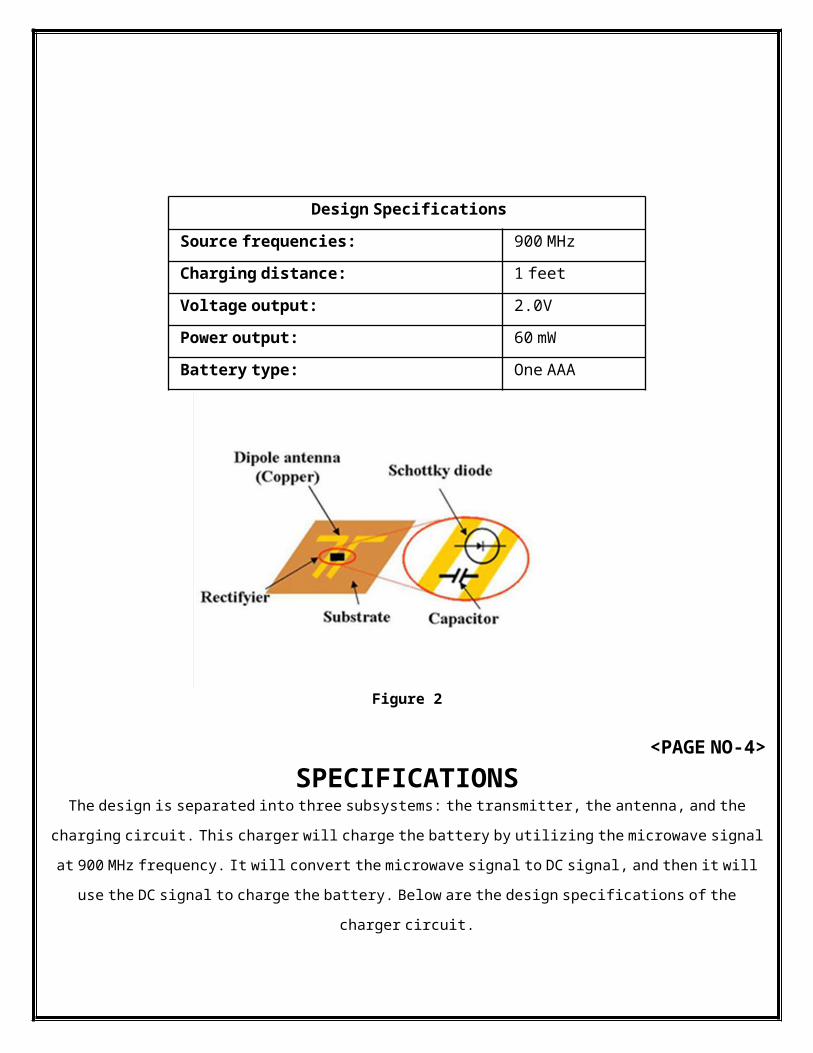
Figure 2
<PAGE NO-4>SPECIFICATIONS
The design is separated into three subsystems: the transmitter, the antenna, and the
charging circuit. This charger will charge the battery by utilizing the microwave signal
at 900 MHz frequency. It will convert the microwave signal to DC signal, and then it will
use the DC signal to charge the battery. Below are the design specifications of the
charger circuit.
Design Specifications
Source frequencies: 900 MHz Charging distance: 1 feet
Voltage output: 2.0V Power output: 60 mW
Battery type: One AAA
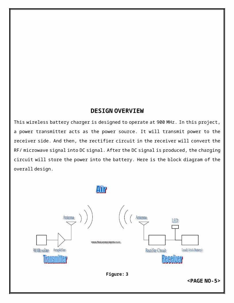
DESIGN OVERVIEW This wireless battery charger is designed to operate at 900 MHz. In this project,
a power transmitter acts as the power source. It will transmit power to the
receiver side. And then, the rectifier circuit in the receiver will convert the
RF/ microwave signal into DC signal. After the DC signal is produced, the charging
circuit will store the power into the battery. Here is the block diagram of the
overall design.
Figure: 3
<PAGE NO-5>
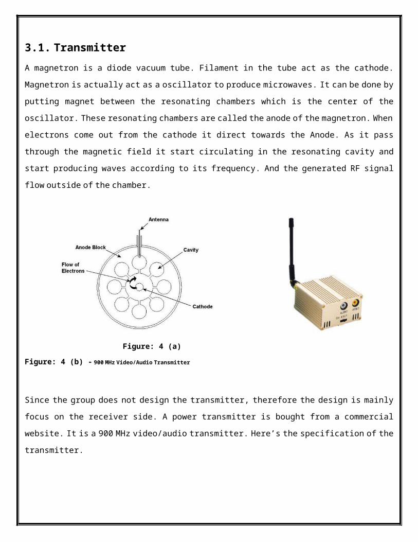
3.1. Transmitter A magnetron is a diode vacuum tube. Filament in the tube act as the cathode.
Magnetron is actually act as a oscillator to produce microwaves. It can be done by
putting magnet between the resonating chambers which is the center of the
oscillator. These resonating chambers are called the anode of the magnetron. When
electrons come out from the cathode it direct towards the Anode. As it pass
through the magnetic field it start circulating in the resonating cavity and
start producing waves according to its frequency. And the generated RF signal
flow outside of the chamber.
Figure: 4 (a)
Figure: 4 (b) - 900 MHz Video/Audio Transmitter
Since the group does not design the transmitter, therefore the design is mainly
focus on the receiver side. A power transmitter is bought from a commercial
website. It is a 900 MHz video/audio transmitter. Here’s the specification of the
transmitter.
<PAGE NO-6>
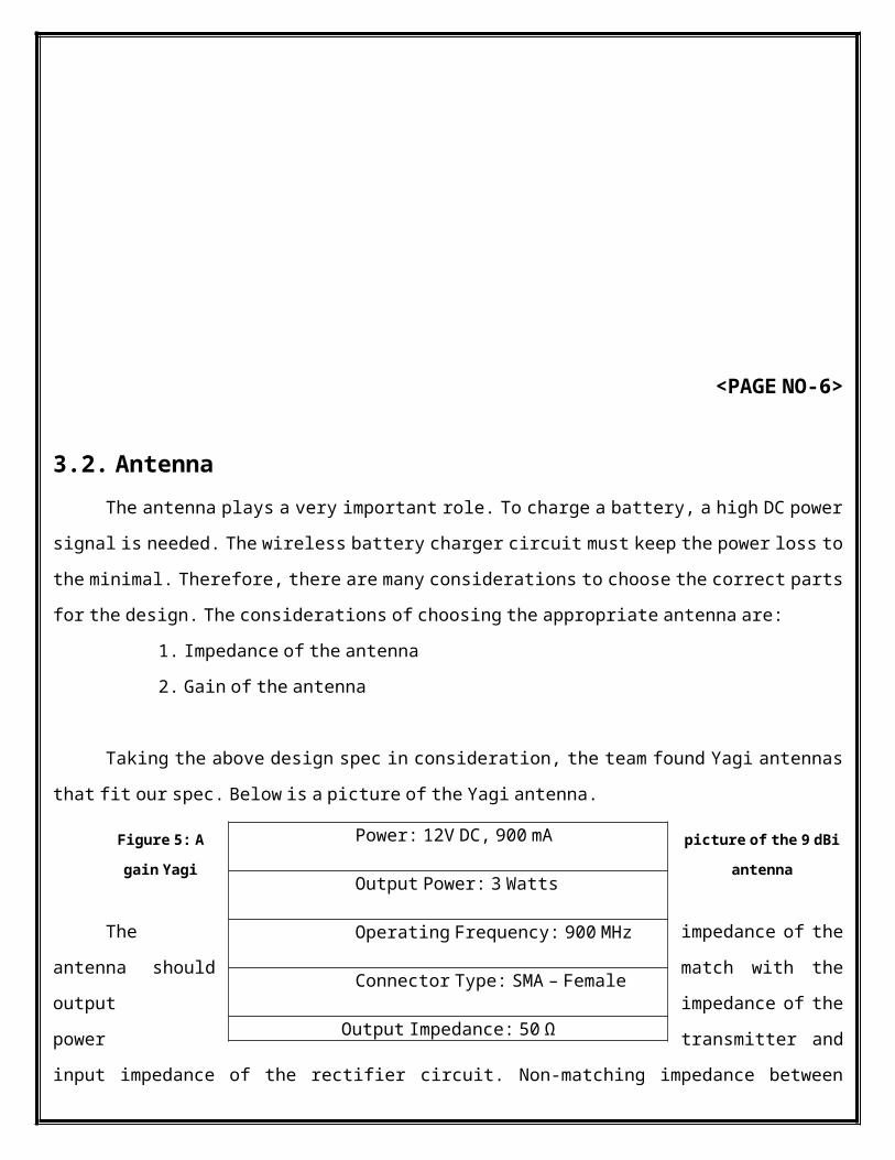
3.2. Antenna The antenna plays a very important role. To charge a battery, a high DC power
signal is needed. The wireless battery charger circuit must keep the power loss to
the minimal. Therefore, there are many considerations to choose the correct parts
for the design. The considerations of choosing the appropriate antenna are:
1. Impedance of the antenna
2. Gain of the antenna
Taking the above design spec in consideration, the team found Yagi antennas
that fit our spec. Below is a picture of the Yagi antenna.
Figure 5: A picture of the 9 dBi
gain Yagi antenna
The impedance of the
antenna should match with the
output impedance of the
power transmitter and
input impedance of the rectifier circuit. Non-matching impedance between
Power: 12V DC, 900 mA
Output Power: 3 Watts
Operating Frequency: 900 MHz
Connector Type: SMA – Female
Output Impedance: 50 Ω

circuits can cause a tremendous power loss due to signal distortion. Since the
output impedance of the transmitter is 50 Ω, the antenna should also have 50 Ω
impedance.
The higher of the antenna gain yields a better result of the design. However,
higher gain will also increase the cost and the size of the antenna. This becomes a
major factor in choosing the antenna due to the group’s limited financial
resources. After consideration, a 9 dBi Yagi antenna is chosen for the design
<PAGE NO-7> 3.3. Receiver
The receiver’s main purpose is to charge an AAA battery. A simple battery
charging theory is to run current through the battery, and apply a voltage
difference between the terminals of the battery to reverse the chemical process.
By doing so, it recharges the battery. There are other efficient and faster ways
to charge the battery, but it requires a large amount of energy which the wireless
battery charger cannot obtain, yet. Therefore, in our design, we use a straight
forward method to charge the battery.
Microwave signal is an AC signal with a frequency range of 1 GHz – 1000 GHz.
900 MHz is in between the RF/ Microwave range. No matter how high the frequency is,
AC signal is still AC signal. Therefore, the signal can also be treated as a low
frequency AC signal. In order to get a DC signal out of the AC signal, a rectifier
circuit is needed.

Figure 6: Full-wave Rectifier Circuit
A full-wave rectifier is chosen for the project due to its simplicity and
efficiency in converting the AC signal. The full-wave rectifier is consisted of
four diodes. Since the power received by the receiver will be relatively low and
the signal frequency is high, the diodes are required to have a very low turn on
voltage and operating frequency at 900 MHz. For this reason, a Schottky diode by
Skyworks is chosen for the design.
At the output of the rectifier, the signal is not a fully DC signal yet.
Thus, by adding a capacitor and a resistor can smooth out the output to become DC
signal. However, the time constant produced by the capacitor and the resistor
should be calculated carefully to fit the desired time constant.
Figure 7: Full-Wave Rectifier with Capacitor and resistor. <PAGE NO-8> Receiver Design
The basic addition to the mobile phone is going to be type of antenna that is used
to directly con-vert microwave energy into DC electricity. Actually the size of
rectenna can be reducing using the Nano technology.

Fig 8: Whole set up for charging
We also have to add a sensor at receiver side. As we know we are going to charge
the phone while a person is talking. So here sensor is used to detect wither the phone
is using microwaves or not.
3.4. The Process of Rectification Microwave can easily travel through the media but it also loses some energy. So
our key objec-tive is to rectify the circuit and to rectify the waves at the low cost.
And also we have to make the detection more sensitive. As we know that bridge
rectification is more efficient than the single diode we use this for the better
performance. We use the shottky diode to get the batter imped-ance. The Schottky
barrier diode is a ideal diode, such as for a 1 ampere limited current PN interface.
Another advantage of the Schottky barrier diode is a very low noise index that is very
important for a communication receiver; its working scope may reach20GHz.
3.5. Sensor Circuitry The sensor circuitry is a any message signal. This is very important as the
phone has to be charged as long as the user is talking. . Thus a simple frequency to
voltage converter would serve our purpose. And this converter would act as switches

to trigger the retina circuit to on. Here in India the operating frequency of the GSM
is 900 MHz to 1800 MHz. We can use LM2907 for F to V conversion. The general block
diagram for the LM2907 is given below in fig.
<PAGE NO-9>
Fig 9: Block diagram of LM2907
Thus on the reception of the signal the sensor circuitry directs the rectenna
circuit to ON and the mobile phone begins to charge using the microwave power.

<PAGE NO-10> VI. TESTING AND DATA
After building the complete final designed circuit, we needed to know
the output effectiveness in respect to distance. The following data was
taken by using a multi-meter measuring voltage and current
values versus the distance between the two antennas. Distance (ft)
Volts (V) Current (mA)
Power (mW)
0.5 3.4 27 91.8 1 3.24 17.2 55.728 1.5 3.1 9.8 30.38 2 3 7.3 21.9 2.5 2.7 4 10.8 3 1.93 1.5 2.895 3.5 1.4 0.51 0.714 4 1.29 0.03 0.0387
Volts Vs. Distance00.511.522.533.5400.511.522.533.544.5 Distance (ft)Voltage(V) Volts (V)
Figure 14a: Voltage versus distance chart Current Vs Distance05101520253000.511.522.533.544.5 Distance (ft)Current
(mA) Current (mA) Figure 14b: Current Vs. Distance Chart

ADVANTAGES1. Charging of mobile phone is done wirelessly.
2. We can saving time for chageing mobiles.
3. Wastage of power is less.
4. Better than witricity as the distance the witricity can cover is about 20
meters whereas in this technology we are using base station for transmission
that can cover more area.

5. Mobile get charged as we make call even during long journey.
DISADVANTAGES1. Radiation problems may occur.
2. Network traffic may cause problem in charging.
3. Charging depends on network coverage.
4. Rate of charging may be minute range.
<PAGE NO-11>
Marketing Plan The working prototype uses Yagi antennas for the design. The prototype may
not seem like an attractive design for today’s wireless devices; however it
could be implemented into other applications. For instance, it could be

implemented onto devices in the tower and only charge up when needed. The
team strives to improve the wireless charger using the spiral patch
antennas in the future. The spiral antenna is able to pick up a wider range
of frequencies instead of just tuned to one particular frequency. In
addition, the spiral antennas become smaller at higher frequency which is
small enough to fit in a cell phone or any wireless devices. The multiple
rectifier design will also increase the received power. Therefore, these
improvements show that this project still holds valid market demands.
CONCLUSION In conclusion, power loss and efficiency are the major problems for this
design project. Our design team has noticed the potential problem whether the
converted DC power will be significant enough to charge up the battery.
Therefore, the characteristics of the diodes should be mounted directly onto the
antenna for minimum power dissipation. In addition to harmonics, the nonlinear
diode creates a DC-bias in the resonant circuit which can be extracted without
affecting the RF/ microwave characteristics of the resonant circuit. The time
varying voltage and current relationship at the physical point of the diode in the
cavity determines the loss in the diode and, consequently, the RF/ microwave to DC
efficiency.
As the wireless technology is getting popular nowadays, the demand of
battery is also increasing. The battery needs to be recharged or changed
eventually. Therefore our team is inspired to design the wireless battery
charger. This wireless battery charger will eliminate all the hassle with the
battery.
As for now, there are no known companies which develop the wireless battery
charger. This means that the opportunity is very big. Also, people tend to spend
more money for convenience. It gives more reason that this device will have a very
good market.

<PAGE NO-12>REFERENCES
1. Espejel, J.D., “RF to DC power generation”, University of Maryland, December
2003. http://drum.umd.edu:8003/dspace/handle/1903/176
2. Hagerty, J.A., “Nonlinear Circuits and Antennas for Microwave Energy
Conversion”, University of Colorado, 2003.
http://nemes.colorado.edu/Microwave/theses.html
3. Lin, G.H., “Topological generation of Voltage Multiplier Circuits”,
September 2003.
http://www.sinc.sunysb.edu/Stu/glin/ese314/lab2.pdf#search='Topological
%20Generation%20and%20Analysis%20of%20Voltage%20Multiplier
4. Pylarinos, L. and Roger, E. “Charge Pumps: An Overview”, Department of
Electrical and Computer Engineering, University of Toronto.
http://www.eecg.toronto.edu/%7Ekphang/ece1371/chargepumps.pdf
5. Sedra, A.S. and Smith K.G, “Microelectronic Circuits”, 5 th Edition, Oxford
University, New York, 2004.
6. Stremler, F.G., “Introduction to Communication Systems”, 3 rd Edition,
Addison-Wesley, New York, 1990.
<PAGE NO-13>