Wireless Power Transmission Using Microwaves
6
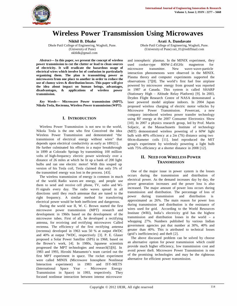
International Journal of Engineering Innovation & Research Volume 1, Issue 2, ISSN : 2277 – 5668 Copyright © 2012 IJEIR, All right reserved 114 Wireless Power Transmission Using Microwaves Nikhil B. Dhake Dhole Patil College of Engineering, Wagholi, Pune. (University of Pune) [email protected] Arati A. Dandavate Dhole Patil College of Engineering, Wagholi, Pune. (University of Pune) [email protected] Abstract— In this paper, we present the concept of wireless power transmission to cut the clutter or lead to clean sources of electricity. It will eradicate the hazardous usage of electrical wires which involve lot of confusion in particularly organizing them. The plan is transmitting power as microwaves from one place to another in order to reduce the use of clumsy wires & distribution losses. This paper will give the idea about impact on human beings, advantages, disadvantages, & applications of wireless power transmission. Key Words— Microwave Power transmission (MPT), Nikola Tesla, Rectenna, Wireless Power transmission (WPT). I. INTRODUCTION Wireless Power Transmission is not new to the world, Nikola Tesla is the one who first Conceived the idea Wireless Power Transmission and demonstrated “the transmission of electrical energy without wires" that depends upon electrical conductivity as early as 1891[1]. He further culminated his efforts in a major breakthrough in 1899 at Colorado Springs by transmitting 100 million volts of high-frequency electric power wirelessly over a distance of 26 miles at which he lit up a bank of 200 light bulbs and ran one electric motor! With this souped up version of his Tesla coil, Tesla claimed that only 5% of the transmitted energy was lost in the process. [43]. The wireless transmission of energy is common in much of the world. Radio waves are energy, and people use them to send and receive cell phone, TV, radio and Wi- Fi signals every day. The radio waves spread in all directions until they reach antennae that are tuned to the right frequency. A similar method for transferring electrical power would be both inefficient and dangerous. During the world war II, W. C. Brown started the first microwave power transmission (MPT) research and development in 1960s based on the development of the microwave tubes. First of all, he developed arectif ying antenna, for receiving and rectifying microwaves Called rectenna. The efficiency of the first rectifying antenna (rectenna) developed in 1963 was 50 % at output 4WDC and 40% at output 7WDC, respectively [3]. P. E. Glaser proposed a Solar Power Satellite (SPS) in 1968, based on the Brown’s work, [4]. In 1980s, Japanese scientists progressed the MPT technologies and research[5][6]. In 1983 and 1993, Hiroshi Matsumoto’s team carried out the first MPT experiment in space. The rocket experi ment were called MINIX (Microwave Ionosphere Nonlinear Interaction experiment) in 1983 and ISY-METS (International Space Year – Microwave Energy Transmission in Space) in 1993, respectively. The y focused nonlinear interaction between intense microwave and ionospheric plasmas. In the MINIX experiment, the y used cooker-type 800W-2.45GHz magnetron for microwave transmitter. New wave-wave-particle interaction phenomenons were observed in the MINIX. Plasma theory and computer experiments supported the observations [7][8]. The world’s first fuel free airplane powered by microwave energy from ground was reported in 1987 at Canada. This system is called SHARP (Stationary High – Altitude Relay Platform) [9]. In 2003, Dryden Flight Research Centre of NASA demonstrated a laser powered model airplane indoors. In 2004 Japan proposed wireless charging of electric motor vehicles by Microwave Power Transmission. Powercast, a new company introduced wireless power transfer technology using RF energy at the 2007 Consumer Electronics Show [10]. In 2007 a physics research group, led by Prof. Marin Soljacic, at the Massachusetts Institute of technology (MIT) demonstrated wireless powering of a 60W light bulb with 40% efficiency at a 2m (7ft) distance using two 60cm-diameter coils [11]. Intel reproduced the MIT group's experiment by wirelessly powering a light bulb with 75% efficiency at a shorter distance in 2008 [12]. II. NEED FOR WIRELESS POWER TRANSMISSION One of the major issue in power system is the losses occurs during the transmission and distribution of electrical power. As the demand increases day by day, the power generation increases and the power loss is also increased. The major amount of power loss occurs during transmission and distribution. The percentage of loss of power during transmission and distribution is approximated as 26%. The main reason for power loss during transmission and distribution is the resistance of wires used for grid. According to the World Resources Institute (WRI), India’s electricity grid has the highest transmission and distribution losses in the world – a whopping 27%. Numbers published by various Indian government agencies put that number at 30%, 40% and greater than 40%. This is attributed to technical losses (grid’s inefficiencies) and theft [2]. The above discussed problem can be solved by choose an alternative option for power transmission which could provide much higher efficiency, low transmission cost and avoid power theft. Microwave Power Transmission is one of the promising technologies and may be the righteous alternative for efficient power transmission.
-
Upload
khangminh22 -
Category
Documents
-
view
1 -
download
0
Transcript of Wireless Power Transmission Using Microwaves
International Journal of Engineering Innovation & ResearchVolume 1, Issue 2, ISSN : 2277 – 5668
Copyright © 2012 IJEIR, All right reserved 114
Wireless Power Transmission Using MicrowavesNikhil B. Dhake
Dhole Patil College of Engineering, Wagholi, Pune.(University of Pune)
Arati A. DandavateDhole Patil College of Engineering, Wagholi, Pune.
(University of Pune) [email protected]
Abstract— In this paper, we present the concept of wirelesspower transmission to cut the clutter or lead to clean sourcesof electricity. It will eradicate the hazardous usage ofelectrical wires which involve lot of confusion in particularlyorganizing them. The plan is transmitting power asmicrowaves from one place to another in order to reduce theuse of clumsy wires & distribution losses. This paper will givethe idea about impact on human beings, advantages,disadvantages, & applications of wireless powertransmission.
Key Words— Microwave Power transmission (MPT),Nikola Tesla, Rectenna, Wireless Power transmission (WPT).
I. INTRODUCTION
Wireless Power Transmission is not new to the world,Nikola Tesla is the one who first Conceived the ideaWireless Power Transmission and demonstrated “thetransmission of electrical energy without wires" thatdepends upon electrical conductivity as early as 1891[1].He further culminated his efforts in a major breakthroughin 1899 at Colorado Springs by transmitting 100 millionvolts of high-frequency electric power wirelessly over adistance of 26 miles at which he lit up a bank of 200 lightbulbs and ran one electric motor! With this souped upversion of his Tesla coil, Tesla claimed that only 5% ofthe transmitted energy was lost in the process. [43].
The wireless transmission of energy is common in muchof the world. Radio waves are energy, and people usethem to send and receive cell phone, TV, radio and Wi-Fi signals every day. The radio waves spread in alldirections until they reach antennae that are tuned to theright frequency. A similar method for transferringelectrical power would be both inefficient and dangerous.
During the world war II, W. C. Brown started the firstmicrowave power transmission (MPT) research anddevelopment in 1960s based on the development of themicrowave tubes. First of all, he developed a rectifyingantenna, for receiving and rectifying microwaves Calledrectenna. The efficiency of the first rectifying antenna(rectenna) developed in 1963 was 50 % at output 4WDCand 40% at output 7WDC, respectively [3]. P. E. Glaserproposed a Solar Power Satellite (SPS) in 1968, based onthe Brown’s work, [4]. In 1980s, Japanese scientistsprogressed the MPT technologies and research[5][6]. In1983 and 1993, Hiroshi Matsumoto’s team carried out thefirst MPT experiment in space. The rocket experimentwere called MINIX (Microwave Ionosphere NonlinearInteraction experiment) in 1983 and ISY-METS(International Space Year – Microwave EnergyTransmission in Space) in 1993, respectively. Theyfocused nonlinear interaction between intense microwave
and ionospheric plasmas. In the MINIX experiment, theyused cooker-type 800W-2.45GHz magnetron formicrowave transmitter. New wave-wave-particleinteraction phenomenons were observed in the MINIX.Plasma theory and computer experiments supported theobservations [7][8]. The world’s first fuel free airplanepowered by microwave energy from ground was reportedin 1987 at Canada. This system is called SHARP(Stationary High – Altitude Relay Platform) [9]. In 2003,Dryden Flight Research Centre of NASA demonstrated alaser powered model airplane indoors. In 2004 Japanproposed wireless charging of electric motor vehicles byMicrowave Power Transmission. Powercast, a newcompany introduced wireless power transfer technologyusing RF energy at the 2007 Consumer Electronics Show[10]. In 2007 a physics research group, led by Prof. MarinSoljacic, at the Massachusetts Institute of technology(MIT) demonstrated wireless powering of a 60W lightbulb with 40% efficiency at a 2m (7ft) distance using two60cm-diameter coils [11]. Intel reproduced the MITgroup's experiment by wirelessly powering a light bulbwith 75% efficiency at a shorter distance in 2008 [12].
II. NEED FOR WIRELESS POWERTRANSMISSION
One of the major issue in power system is the lossesoccurs during the transmission and distribution ofelectrical power. As the demand increases day by day, thepower generation increases and the power loss is alsoincreased. The major amount of power loss occurs duringtransmission and distribution. The percentage of loss ofpower during transmission and distribution isapproximated as 26%. The main reason for power lossduring transmission and distribution is the resistance ofwires used for grid. According to the World ResourcesInstitute (WRI), India’s electricity grid has the highesttransmission and distribution losses in the world – awhopping 27%. Numbers published by various Indiangovernment agencies put that number at 30%, 40% andgreater than 40%. This is attributed to technical losses(grid’s inefficiencies) and theft [2].
The above discussed problem can be solved by choosean alternative option for power transmission which couldprovide much higher efficiency, low transmission cost andavoid power theft. Microwave Power Transmission is oneof the promising technologies and may be the righteousalternative for efficient power transmission.
International Journal of Engineering Innovation & ResearchVolume 1, Issue 2, ISSN : 2277 – 5668
Copyright © 2012 IJEIR, All right reserved 115
III. ARCHITECTURE OF MICROWAVEPOWER TRANSMISSION
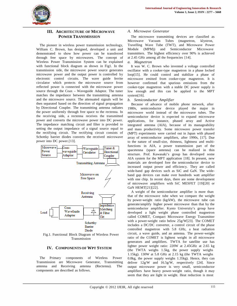
The pioneer in wireless power transmission technology,William C. Brown, has designed, developed a unit anddemonstrated to show how power can be transferredthrough free space by microwaves. The concept ofWireless Power Transmission System can be explainedwith functional block diagram as shown in Fig1. In thetransmission side, the microwave power source generatesmicrowave power and the output power is controlled byelectronic control circuits. The wave guide ferritecirculator which protects the microwave source fromreflected power is connected with the microwave powersource through the Coax – Waveguide Adaptor. The tunermatches the impedance between the transmitting antennaand the microwave source. The attenuated signals will bethen separated based on the direction of signal propagationby Directional Coupler. The transmitting antenna radiatesthe power uniformly through free space to the rectenna. Inthe receiving side, a rectenna receives the transmittedpower and converts the microwave power into DC power.The impedance matching circuit and filter is provided tosetting the output impedance of a signal source equal tothe rectifying circuit. The rectifying circuit consists ofSchottky barrier diodes converts the received microwavepower into DC power.[13].
Fig.1. Functional Block Diagram of Wireless PowerTransmission
IV. COMPONENTS OF WPT SYSTEM
The Primary components of Wireless PowerTransmission are Microwave Generator, Transmittingantenna and Receiving antenna (Rectenna). Thecomponents are described as follows.
A. Microwave Generator
The microwave transmitting devices are classified asMicrowave Vacuum Tubes (magnetron, klystron,Travelling Wave Tube (TWT), and Microwave PowerModule (MPM)) and Semiconductor Microwavetransmitters. The highest efficiency over 90% is achievedat 2.45 GHz among all the frequencies [14].a. Magnetron
It was W. C. Brown who invented a voltage controlledoscillator with a cooker-type magnetron in a phase lockedloop[15]. He could control and stabilize a phase ofmicrowave emitted from cooker-type magnetron. It ishowever confirmed that spurious emissions from thecooker-type magnetron with a stable DC power supply islow enough and this can be applied to the MPTsystem[16].b. Semiconductor Amplifier
Because of advance of mobile phone network, after1980s, semiconductor device played the major inmicrowave world instead of the microwave tubes. Thesemiconductor device is expected to expand microwaveapplications, for instance, phased array and Activeintegrated antenna (AIA), because of its manageabilityand mass productivity. Some microwave power transfer(MPT) experiments were carried out in Japan with phasedarray of semiconductor amplifiers, after 1990s, [17]. Dueto the nature of small-size, thinness, lightness and multi-functions in AIA, a power transmission part of thespacetenna (space antenna) can be realized in thinstructure. Prof. Kawasaki’s group has developed someAIA system for the MPT application [18]. In present, newmaterials are developed fore the semiconductor device toincreased output power and efficiency. They are calledwide-band gap devices such as SiC and GaN. The wide-band gap devices can make over hundreds watt amplifierwith one chip. In recent days, there are some developmentof microwave amplifiers with SiC MESFET [19][20] orGaN HEMT[21][22].
A weight of the semiconductor amplifier is more thanthat of the microwave tube when we compare the weightby power-weight ratio (kg/kW), the microwave tube cangenerate/amplify higher power microwave than that by thesemiconductor amplifier. Kyoto University’s group havedeveloped a light weight phase controlled magnetroncalled COMET, Compact Microwave Energy Transmitterwith a power-weight ratio below 25g/W[23]. The COMETincludes a DC/DC converter, a control circuit of the phasecontrolled magnetron with 5.8 GHz, a heat radiationcircuit, a wave guide, and an antenna. The power-weightratio of the COMET is lightest weight in all microwavegenerators and amplifiers. TWTA for satellite use haslighter power weight ratio: 220W at 2.45GHz at 2.65 kg(the TWTA weighs 1.5kg, the power supply weighs1.15kg). 130W at 5.8 GHz at 2.15 kg (the TWTA weighs0.8kg, the power supply weighs 1.35kg). Hence, they candeliver 12g/W and 16.5g/W, respectively [24]. Sinceoutput microwave power is very small, semiconductoramplifiers have heavy power-weight ratio, though it mayseem that they are light in weight. Heat reduction is most
International Journal of Engineering Innovation & ResearchVolume 1, Issue 2, ISSN : 2277 – 5668
Copyright © 2012 IJEIR, All right reserved 116
important problem in space. All lost power converts toheat. We need special heat reduction system in space. Ifwe use high efficient microwave transmitters, we canreduce weight of heat reduction system. We should aimfor over 80 % efficiency for the microwave transmitter,which must include all loss in phase shifters, isolators,antennas, power circuits. Especially, the SPS is a powerstation in space, therefore, heat reduction will be a seriousproblem [25].
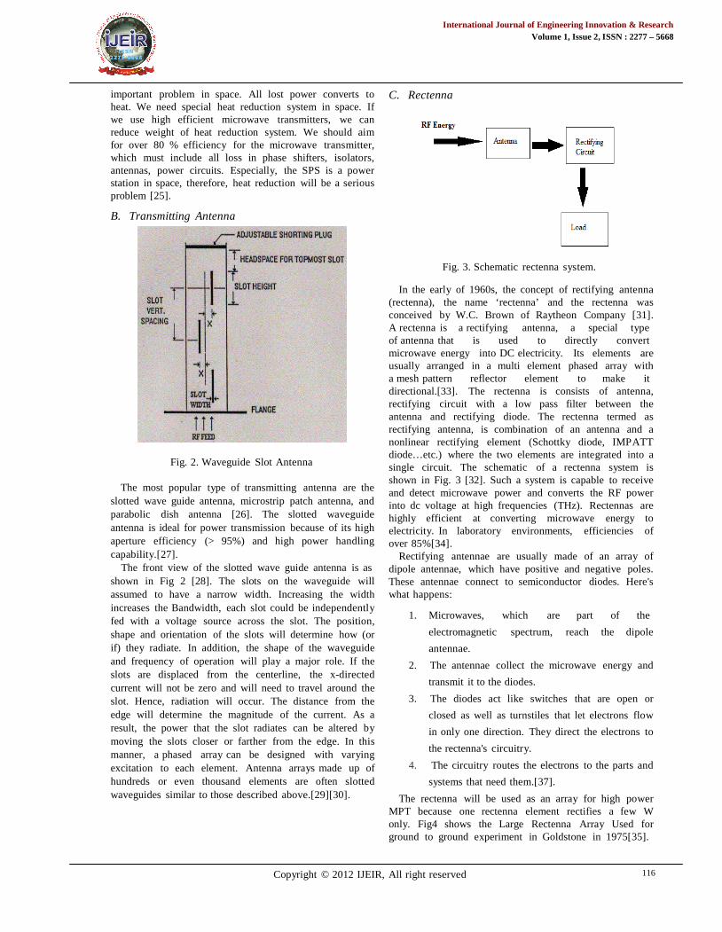
B. Transmitting Antenna
Fig. 2. Waveguide Slot Antenna
The most popular type of transmitting antenna are theslotted wave guide antenna, microstrip patch antenna, andparabolic dish antenna [26]. The slotted waveguideantenna is ideal for power transmission because of its highaperture efficiency (> 95%) and high power handlingcapability.[27].
The front view of the slotted wave guide antenna is asshown in Fig 2 [28]. The slots on the waveguide willassumed to have a narrow width. Increasing the widthincreases the Bandwidth, each slot could be independentlyfed with a voltage source across the slot. The position,shape and orientation of the slots will determine how (orif) they radiate. In addition, the shape of the waveguideand frequency of operation will play a major role. If theslots are displaced from the centerline, the x-directedcurrent will not be zero and will need to travel around theslot. Hence, radiation will occur. The distance from theedge will determine the magnitude of the current. As aresult, the power that the slot radiates can be altered bymoving the slots closer or farther from the edge. In thismanner, a phased array can be designed with varyingexcitation to each element. Antenna arrays made up ofhundreds or even thousand elements are often slottedwaveguides similar to those described above.[29][30].
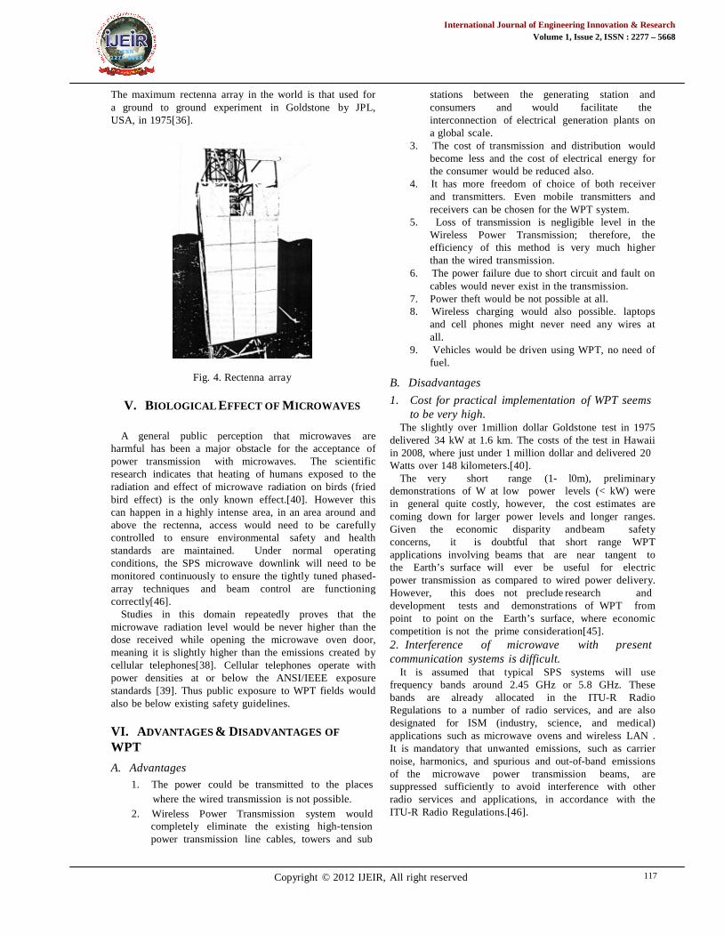
C. Rectenna
Fig. 3. Schematic rectenna system.
In the early of 1960s, the concept of rectifying antenna(rectenna), the name ‘rectenna’ and the rectenna wasconceived by W.C. Brown of Raytheon Company [31].A rectenna is a rectifying antenna, a special typeof antenna that is used to directly convertmicrowave energy into DC electricity. Its elements areusually arranged in a multi element phased array witha mesh pattern reflector element to make itdirectional.[33]. The rectenna is consists of antenna,rectifying circuit with a low pass filter between theantenna and rectifying diode. The rectenna termed asrectifying antenna, is combination of an antenna and anonlinear rectifying element (Schottky diode, IMPATTdiode…etc.) where the two elements are integrated into asingle circuit. The schematic of a rectenna system isshown in Fig. 3 [32]. Such a system is capable to receiveand detect microwave power and converts the RF powerinto dc voltage at high frequencies (THz). Rectennas arehighly efficient at converting microwave energy toelectricity. In laboratory environments, efficiencies ofover 85%[34].
Rectifying antennae are usually made of an array ofdipole antennae, which have positive and negative poles.These antennae connect to semiconductor diodes. Here'swhat happens:
1. Microwaves, which are part of the
electromagnetic spectrum, reach the dipole
antennae.
2. The antennae collect the microwave energy and
transmit it to the diodes.
3. The diodes act like switches that are open or
closed as well as turnstiles that let electrons flow
in only one direction. They direct the electrons to
the rectenna's circuitry.
4. The circuitry routes the electrons to the parts and
systems that need them.[37].
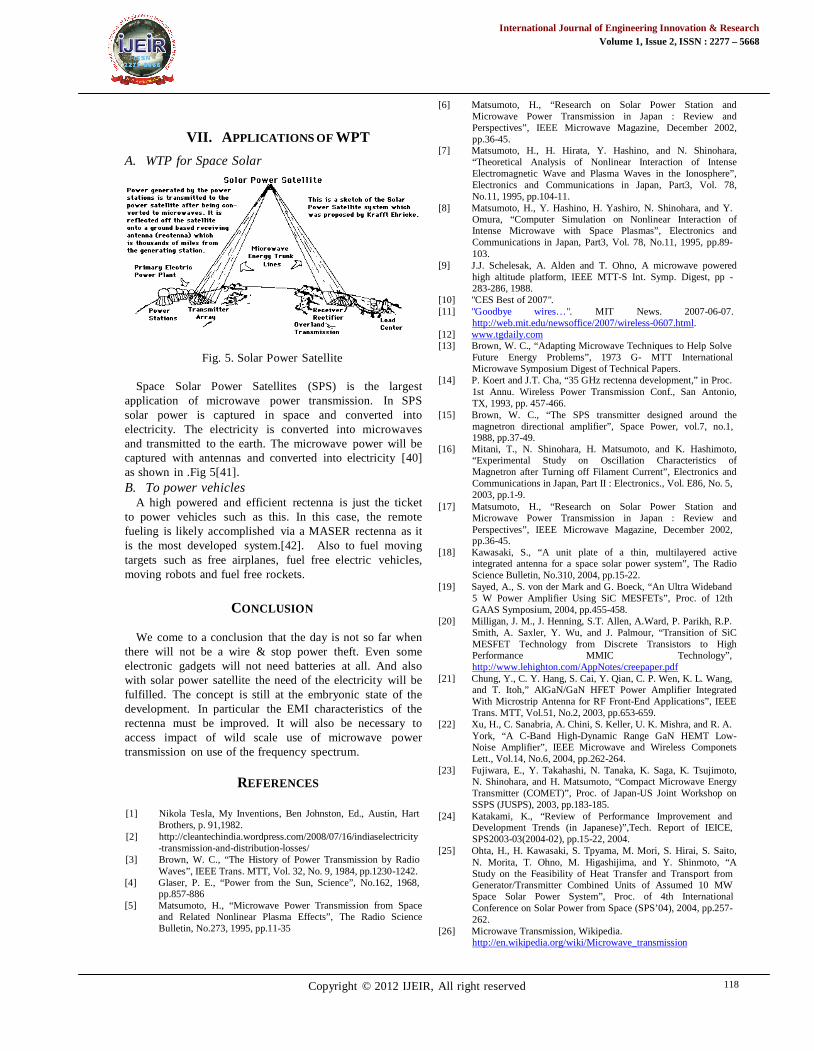
The rectenna will be used as an array for high powerMPT because one rectenna element rectifies a few Wonly. Fig4 shows the Large Rectenna Array Used forground to ground experiment in Goldstone in 1975[35].
International Journal of Engineering Innovation & ResearchVolume 1, Issue 2, ISSN : 2277 – 5668
Copyright © 2012 IJEIR, All right reserved 117
The maximum rectenna array in the world is that used fora ground to ground experiment in Goldstone by JPL,USA, in 1975[36].
Fig. 4. Rectenna array
V. BIOLOGICAL EFFECT OF MICROWAVES
A general public perception that microwaves areharmful has been a major obstacle for the acceptance ofpower transmission with microwaves. The scientificresearch indicates that heating of humans exposed to theradiation and effect of microwave radiation on birds (friedbird effect) is the only known effect.[40]. However thiscan happen in a highly intense area, in an area around andabove the rectenna, access would need to be carefullycontrolled to ensure environmental safety and healthstandards are maintained. Under normal operatingconditions, the SPS microwave downlink will need to bemonitored continuously to ensure the tightly tuned phased-array techniques and beam control are functioningcorrectly[46].
Studies in this domain repeatedly proves that themicrowave radiation level would be never higher than thedose received while opening the microwave oven door,meaning it is slightly higher than the emissions created bycellular telephones[38]. Cellular telephones operate withpower densities at or below the ANSI/IEEE exposurestandards [39]. Thus public exposure to WPT fields wouldalso be below existing safety guidelines.
VI. ADVANTAGES & DISADVANTAGES OF
WPT
A. Advantages
1. The power could be transmitted to the placeswhere the wired transmission is not possible.
2. Wireless Power Transmission system wouldcompletely eliminate the existing high-tensionpower transmission line cables, towers and sub
stations between the generating station andconsumers and would facilitate theinterconnection of electrical generation plants ona global scale.
3. The cost of transmission and distribution wouldbecome less and the cost of electrical energy forthe consumer would be reduced also.
4. It has more freedom of choice of both receiverand transmitters. Even mobile transmitters andreceivers can be chosen for the WPT system.
5. Loss of transmission is negligible level in theWireless Power Transmission; therefore, theefficiency of this method is very much higherthan the wired transmission.
6. The power failure due to short circuit and fault oncables would never exist in the transmission.
7. Power theft would be not possible at all.8. Wireless charging would also possible. laptops
and cell phones might never need any wires atall.
9. Vehicles would be driven using WPT, no need offuel.
B. Disadvantages
1. Cost for practical implementation of WPT seemsto be very high.
The slightly over 1million dollar Goldstone test in 1975delivered 34 kW at 1.6 km. The costs of the test in Hawaiiin 2008, where just under 1 million dollar and delivered 20Watts over 148 kilometers.[40].
The very short range (1- l0m), preliminarydemonstrations of W at low power levels (< kW) werein general quite costly, however, the cost estimates arecoming down for larger power levels and longer ranges.Given the economic disparity andbeam safetyconcerns, it is doubtful that short range WPTapplications involving beams that are near tangent tothe Earth’s surface will ever be useful for electricpower transmission as compared to wired power delivery.However, this does not preclude research anddevelopment tests and demonstrations of WPT frompoint to point on the Earth’s surface, where economiccompetition is not the prime consideration[45].2. Interference of microwave with presentcommunication systems is difficult.
It is assumed that typical SPS systems will usefrequency bands around 2.45 GHz or 5.8 GHz. Thesebands are already allocated in the ITU-R RadioRegulations to a number of radio services, and are alsodesignated for ISM (industry, science, and medical)applications such as microwave ovens and wireless LAN .It is mandatory that unwanted emissions, such as carriernoise, harmonics, and spurious and out-of-band emissionsof the microwave power transmission beams, aresuppressed sufficiently to avoid interference with otherradio services and applications, in accordance with theITU-R Radio Regulations.[46].
International Journal of Engineering Innovation & ResearchVolume 1, Issue 2, ISSN : 2277 – 5668
Copyright © 2012 IJEIR, All right reserved 118
VII. APPLICATIONS OF WPT
A. WTP for Space Solar
Fig. 5. Solar Power Satellite
Space Solar Power Satellites (SPS) is the largestapplication of microwave power transmission. In SPSsolar power is captured in space and converted intoelectricity. The electricity is converted into microwavesand transmitted to the earth. The microwave power will becaptured with antennas and converted into electricity [40]as shown in .Fig 5[41].B. To power vehicles
A high powered and efficient rectenna is just the ticketto power vehicles such as this. In this case, the remotefueling is likely accomplished via a MASER rectenna as itis the most developed system.[42]. Also to fuel movingtargets such as free airplanes, fuel free electric vehicles,moving robots and fuel free rockets.
CONCLUSION
We come to a conclusion that the day is not so far whenthere will not be a wire & stop power theft. Even someelectronic gadgets will not need batteries at all. And alsowith solar power satellite the need of the electricity will befulfilled. The concept is still at the embryonic state of thedevelopment. In particular the EMI characteristics of therectenna must be improved. It will also be necessary toaccess impact of wild scale use of microwave powertransmission on use of the frequency spectrum.
REFERENCES
[1] Nikola Tesla, My Inventions, Ben Johnston, Ed., Austin, HartBrothers, p. 91,1982.
[2] http://cleantechindia.wordpress.com/2008/07/16/indiaselectricity-transmission-and-distribution-losses/
[3] Brown, W. C., “The History of Power Transmission by RadioWaves”, IEEE Trans. MTT, Vol. 32, No. 9, 1984, pp.1230-1242.
[4] Glaser, P. E., “Power from the Sun, Science”, No.162, 1968,pp.857-886
[5] Matsumoto, H., “Microwave Power Transmission from Spaceand Related Nonlinear Plasma Effects”, The Radio ScienceBulletin, No.273, 1995, pp.11-35
[6] Matsumoto, H., “Research on Solar Power Station andMicrowave Power Transmission in Japan : Review andPerspectives”, IEEE Microwave Magazine, December 2002,pp.36-45.
[7] Matsumoto, H., H. Hirata, Y. Hashino, and N. Shinohara,“Theoretical Analysis of Nonlinear Interaction of IntenseElectromagnetic Wave and Plasma Waves in the Ionosphere”,Electronics and Communications in Japan, Part3, Vol. 78,No.11, 1995, pp.104-11.
[8] Matsumoto, H., Y. Hashino, H. Yashiro, N. Shinohara, and Y.Omura, “Computer Simulation on Nonlinear Interaction ofIntense Microwave with Space Plasmas”, Electronics andCommunications in Japan, Part3, Vol. 78, No.11, 1995, pp.89-103.
[9] J.J. Schelesak, A. Alden and T. Ohno, A microwave poweredhigh altitude platform, IEEE MTT-S Int. Symp. Digest, pp -283-286, 1988.
[10] "CES Best of 2007".[11] "Goodbye wires…". MIT News. 2007-06-07.
http://web.mit.edu/newsoffice/2007/wireless-0607.html.[12] www.tgdaily.com[13] Brown, W. C., “Adapting Microwave Techniques to Help Solve
Future Energy Problems”, 1973 G- MTT InternationalMicrowave Symposium Digest of Technical Papers.
[14] P. Koert and J.T. Cha, “35 GHz rectenna development,” in Proc.1st Annu. Wireless Power Transmission Conf., San Antonio,TX, 1993, pp. 457-466.
[15] Brown, W. C., “The SPS transmitter designed around themagnetron directional amplifier”, Space Power, vol.7, no.1,1988, pp.37-49.
[16] Mitani, T., N. Shinohara, H. Matsumoto, and K. Hashimoto,“Experimental Study on Oscillation Characteristics ofMagnetron after Turning off Filament Current”, Electronics andCommunications in Japan, Part II : Electronics., Vol. E86, No. 5,2003, pp.1-9.
[17] Matsumoto, H., “Research on Solar Power Station andMicrowave Power Transmission in Japan : Review andPerspectives”, IEEE Microwave Magazine, December 2002,pp.36-45.
[18] Kawasaki, S., “A unit plate of a thin, multilayered activeintegrated antenna for a space solar power system”, The RadioScience Bulletin, No.310, 2004, pp.15-22.
[19] Sayed, A., S. von der Mark and G. Boeck, “An Ultra Wideband5 W Power Amplifier Using SiC MESFETs”, Proc. of 12thGAAS Symposium, 2004, pp.455-458.
[20] Milligan, J. M., J. Henning, S.T. Allen, A.Ward, P. Parikh, R.P.Smith, A. Saxler, Y. Wu, and J. Palmour, “Transition of SiCMESFET Technology from Discrete Transistors to HighPerformance MMIC Technology”,http://www.lehighton.com/AppNotes/creepaper.pdf
[21] Chung, Y., C. Y. Hang, S. Cai, Y. Qian, C. P. Wen, K. L. Wang,and T. Itoh,” AlGaN/GaN HFET Power Amplifier IntegratedWith Microstrip Antenna for RF Front-End Applications”, IEEETrans. MTT, Vol.51, No.2, 2003, pp.653-659.
[22] Xu, H., C. Sanabria, A. Chini, S. Keller, U. K. Mishra, and R. A.York, “A C-Band High-Dynamic Range GaN HEMT Low-Noise Amplifier”, IEEE Microwave and Wireless ComponetsLett., Vol.14, No.6, 2004, pp.262-264.
[23] Fujiwara, E., Y. Takahashi, N. Tanaka, K. Saga, K. Tsujimoto,N. Shinohara, and H. Matsumoto, “Compact Microwave EnergyTransmitter (COMET)”, Proc. of Japan-US Joint Workshop onSSPS (JUSPS), 2003, pp.183-185.
[24] Katakami, K., “Review of Performance Improvement andDevelopment Trends (in Japanese)”,Tech. Report of IEICE,SPS2003-03(2004-02), pp.15-22, 2004.
[25] Ohta, H., H. Kawasaki, S. Tpyama, M. Mori, S. Hirai, S. Saito,N. Morita, T. Ohno, M. Higashijima, and Y. Shinmoto, “AStudy on the Feasibility of Heat Transfer and Transport fromGenerator/Transmitter Combined Units of Assumed 10 MWSpace Solar Power System”, Proc. of 4th InternationalConference on Solar Power from Space (SPS’04), 2004, pp.257-262.
[26] Microwave Transmission, Wikipedia.http://en.wikipedia.org/wiki/Microwave_transmission

International Journal of Engineering Innovation & ResearchVolume 1, Issue 2, ISSN : 2277 – 5668
Copyright © 2012 IJEIR, All right reserved 119
[27] Paul Wade, “W1GHZ”,Chapter 7, Slot Antennas.[28] Slot Antenna Design By Stephen Bell, KB7TRZ.
http://www.qsl.net/w6by/techtips/slot_ant.html[29] William Coburn, Marc Litz, Joseph Miletta, Neal Tesny, Lillian
Dilks, Charles Brown, and Benson King, “A Slotted-WaveguideArray for High-Power Microwave Transmission”, ArmyResearch Laboratory, January 2001.http://www.dtic.mil/cgi-bin/GetTRDoc?AD=ADA387308
[30] Slotted Waveguide Antennas.http://www.antenna-theory.com/antennas/aperture/slottedWaveguide.php
[31] Brown, W.C, “The History of the Development of the Rectenna”Proc. Of SPS microwave systems workshop, pp.271-280, Jan1980.
[32] Rakesh Kumar Yadav, Sushrut Das and, R. L. Yadava,“Rectennas Design, Development & Applications”, InternationalJournal of Engineering Science and Technology (IJEST), ISSN :0975-5462, Vol. 3 No. 10 October 2011.
[33] “Rectenna”, Wikipedia.http://en.wikipedia.org/wiki/Rectenna
[34] B. Berland, “Photovoltaic Technologies Beyond TheHorizon:Optcal Rectenna Solar Cell”, NREL/SR-520-33263,February 2003.http://www.nrel.gov/docs/fy03osti/33263.pdf
[35] Miura, T., N. Shinohara, and H. Matsumoto, “ExperimentalStudy of Rectenna Connection for Microwave PowerTransmission”, Electronics and Communications in Japan, Part2, Vol. 84, No.2,2001, pp.27-36.
[36] Dickinson, R. M., “Performance of a High-Power 2.388- GHzReceiving Array in Wireless Power Transmission over 1.54km”, 1976 MTT-S Int. Microwave Symp. Digest, 1976, pp.139-141.
[37] http://electronics.howstuffworks.com/everyday-tech/wireless-power3.htm
[38] Gabriel Gache “How Micro Ovens Work – A Cooking Oven forthe 21st century”.www.howstuffworks.com
[39] J.C. Lin, “Biological aspects of mobile communication fields,”Wireless Networks, vol. 3, pp. 439-453, 1997.
[40] Peter Vaessen, “Wireless Power Transmission”, LeonardoENERGY, September 2009.http://www.leonardo-energy.org/webfm_send/2837.
[41] http://www.spaceacts.com/STARSHIP/seh/know5.html[42] Syzygystro, “The Rectenna for Ramote Fueling”,Hubpages.
http://syzygyastro.hubpages.com/hub/The-Rectenna-for-Remote-Fuelling
[43] http://www.wlan.org.uk/dedications.htm[44] “Wireless Energy Transfer’, Wikipedia.
http://en.wikipedia.org/wiki/Wireless_energy_transfer[45] Richard M Dikinson, JPL1,Owen Maynard,Aerospace
Engr.Ret.2, “Ground Based Wireless And Wired PowerTransmission Cost Comparison”. http://trs-new.jpl.nasa.gov/dspace/bitstream/2014/17841/1/99-1291.pdf
[46] White paper on Solar Power Satellite Systems, URSI,September 2006.
AUTHOR’S PROFILE
Nikhil B. Dhake born in Jalgaon District, India on 5th
November 1989 is a student at Dhole Patil College ofEngineering, Pune, affiliated to the University of Pune.
He is in final year of Information Technology and will be granted thedegree of Bachelor of Engineering in July, 2012. He has published three
Articles in International Journal & also presentedvarious papers at National level.
Mrs. Arati A. Dandvate (B.E (E&CE), M.E(CSE),Ph.D.(CSE Pursuing)) working as HOD(ComputerEngg Dept) having 12 years of teaching experience and
2 years IT experience. She has number of national level conferences andpaper presentations in her credit.